
Ask AI
— answers from the official manualAnswers from the official manual.
Common questions
Common Questions
9 totalHow do I connect or disconnect the battery?
Make sure the charger is in OFF position, disconnected from power before connecting or disconnecting the battery plug. This prevents arcing and potential ignition of hydrogen-oxygen mixtures produced during charging.
What if the charger display is not on when power is applied?
Check AC input line, control transformer voltage, microcontroller/Cell Select connections, and ensure proper polarity of battery to charger connector cables. Also verify control transformer fuse, rectifier diodes, main transformers for issues.
How do I perform a capacitor test?
Before testing, short out capacitors with insulated screwdriver. Use RX100 ohmmeter scale to connect probes to capacitor terminals. Good capacitor shows needle deflection in one direction followed by opposite.
How do I verify DC connections?
Ensure all connections are clean and tight, inspecting for discolored or loose wires. Check DC cables' insulation condition and make sure plug contacts are properly seated.
What causes charge termination early?
Charge terminates early if HIGH VOLTS/CELL (average volts/cell >2.7V), LOW CURRENT, CHARGE TIME EXCEEDED (>9 hours to reach ~80% charged state), CABLE DISCONNECTION (disconnection during charging), or LOW VOLTAGE (<1.7V) occurs.
How do I perform a diode test?
Unbolt connection at end of flexible lead to isolate from circuit, set ohmmeter to RX100 range, place probes on heatsink and loose lead end for TEST #1. Reverse positions for TEST #2. Defective diodes show continuity in both tests or no deflection indicating open.
Full Manual
24 pages

| | |Doc No: M16448 Rev: A| |---|---|---| | | | | | | |DC: 0912| | | | |
INDUSTRIAL BATTERY CHARGER
OWNER'S MANUAL
INDUSTRIAL BATTERY CHARGER
TABLE OF CONTENTS
PAGE GENERAL INFORMATION
Safety 1 Receipt & Installation 1 General Operating Instructions 3
DESCRIPTION OF EQUIPMENT
Description 4 Features 5
OPERATING INSTRUCTIONS
3500 Series Control 6 SERVICE
Troubleshooting 9 Diode/Capacitor checkout 13 Mechanical Overview 14 AC Voltage Changeover 15 Schematics 16 AC Line Compensation 21 Parallel & Series Output Cables 22 JIC Safety Interlock Switch 22
GENERAL INFORMATION
SAFETY
Safety First! Please take time to study this manual before installing, operating or troubleshooting. Special attention should be given to WARNING and CAUTION labels on the charger and in this manual.
Battery chargers are safe when properly operated under intended use and by trained operators. Untrained operators and service personnel risk the possibility of serious injury to themselves and others.
Improper application of battery chargers can also result in extensive and costly damage to batteries and equipment. Only trained operators and service personnel that are familiar with this manual should install, operate, or troubleshoot the battery chargers.
WARNING: EXPLOSION Connect or disconnect the battery plug only when the AC line is disconnected or the charger is in the "OFF" position. Failure to follow this instruction may result in arcing and burning of the DC connector contacts. Arcing contacts may ignite a mixture of oxygen and hydrogen, which is produced during battery charging. Do not smoke, weld, grind, or use torches around batteries. DANGER: ELECTRIC SHOCK Do not touch uninsulated portion of output connector or uninsulated battery terminal. Do not operate charger unless connected to battery. Before maintenance or troubleshooting, make sure all circuits are de-energized in the following manner:
Avoid operating or troubleshooting in damp or wet locations. Use insulating gloves and shoes in such environments. Replace defective cord or wires immediately.
GENERAL SAFETY PRECAUTIONS When servicing battery chargers the main power supply switches, or other switches from which power could enter the circuit, should be locked in an open position and tagged e.g.
"Open Circuit for Repairs - DO NOT Tamper".
If it is impractical to open the main power switch use extreme caution working on energized circuits. Even though power circuits may be off, certain control circuits may still be energized. To take voltage readings on energized components, turn off the charger and attach alligator clips before turning the charger back on. This procedure will avoid sticking both hands with meter probes into a live charger, which is extremely dangerous.
Do not work alone. Have someone capable of rendering first aid nearby. Do not wear loose clothing or jewelry. Do not use bare hands to remove live parts, such as fuses. Think before you act.
RECEIPT AND INSTALLATION
Equipment Identification Chargers are identified with a model number, which appears on the charger nameplate. Certain information contained in this manual may be superseded by specific operating instructions, and schematic addendums.
Charger Model Designation e.g. 18M650TJG35 18 Battery Cells
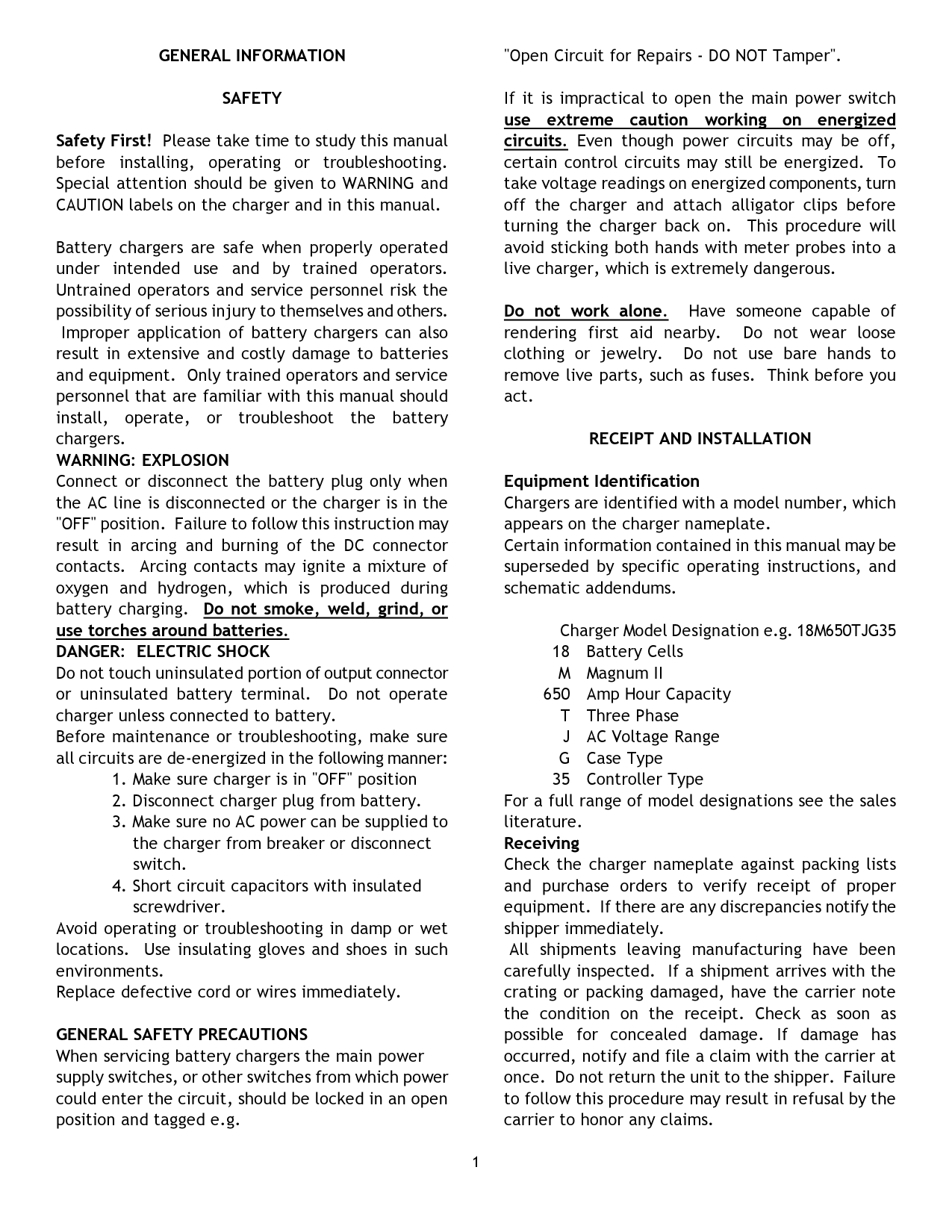
M Magnum II
650 Amp Hour Capacity T Three Phase J AC Voltage Range G Case Type
35 Controller Type For a full range of model designations see the sales literature. Receiving
Check the charger nameplate against packing lists and purchase orders to verify receipt of proper equipment. If there are any discrepancies notify the shipper immediately.
All shipments leaving manufacturing have been carefully inspected. If a shipment arrives with the crating or packing damaged, have the carrier note the condition on the receipt. Check as soon as possible for concealed damage. If damage has occurred, notify and file a claim with the carrier at once. Do not return the unit to the shipper. Failure to follow this procedure may result in refusal by the carrier to honor any claims.
Location
Operating life and performance will be influenced by charger location. Select a dry and well-ventilated location. Allow 6 inches from walls and other chargers for proper ventilation. Chargers should not be exposed to rain, high temperatures, dust, corrosive fumes, combustible materials, or explosive gases. Dusty environments may require more frequent maintenance to obtain maximum life and optimum performance.
Mounting
Some chargers may be stacked 3 high. Optional wall mounting brackets are available for various models to secure charger to wall. Contact factory for further information.
Moving and Transport
Care should be taken when lifting units with forklifts or pallet jacks. Forks should extend completely under charger so as to prevent accidents.
Grounding Follow applicable local codes or National Electric Code revisions that may supersede the following instructions. The battery charger must be grounded to prevent lethal injury. Route ground conductor through knockout on side of charger. Connect AC ground wire (green) to the ground terminal located next to fuses. The case is grounded once this connection is made. If the AC supply cable does not include a ground conductor see table on pg. 3 for proper sizing of separate ground conductor or consult the National Electrical Code.
AC Line Voltage Changeover Refer to page 15 of this manual for AC line voltage configurations. Check that jumpers are connected to the proper positions on each terminal block. On 3 phase units, check that all jumpers are positioned the same on each AC terminal block. Check the control transformer for proper AC connection. The control transformer AC voltage setting must match the setting of the AC terminal blocks. Before making any reconnection, check the charger nameplate to make sure the disconnect switch and supply wiring are of sufficient size to carry the desired input voltage and amps. Check the fuse label on inside of door to make
certain the input fuses are proper for input line voltage. INCORRECT FUSING WILL VOID CHARGER WARRANTY.
AC Line Connection Follow applicable local codes or National Electrical Code revisions that may supersede the following instructions: Make sure main power supply switches or other switches from which power could enter the circuit are locked in an open position. Check that charger is connected for proper input voltage – jumpers on AC terminal blocks match incoming AC line voltage on main panel. Refer to charger nameplate for input amps at incoming line voltage. See table on pg.3 for recommended disconnect switch, branch fuse size, power and ground cable size. Route appropriate conductor through AC knockout, which is provided on side of the charger case.
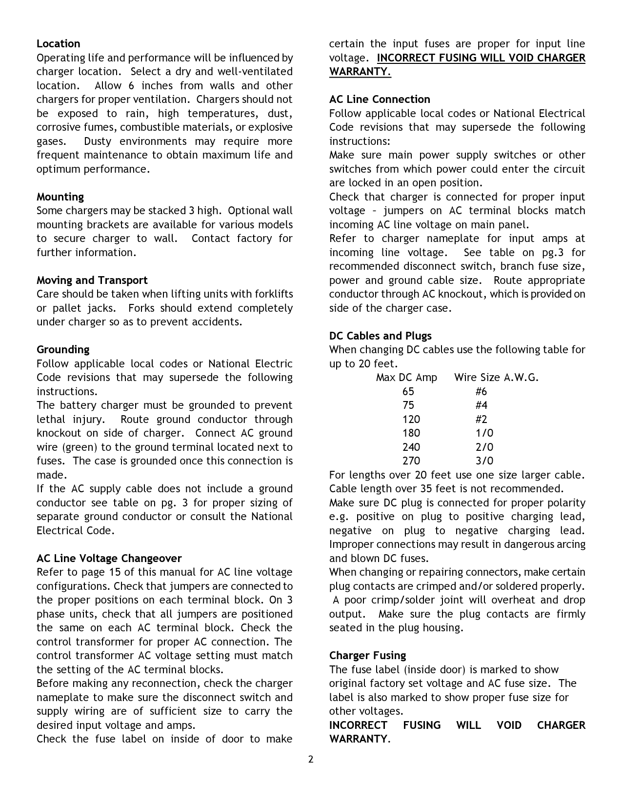
DC Cables and Plugs When changing DC cables use the following table for up to 20 feet.
Max DC Amp Wire Size A.W.G. 65 #6 75 #4 120 #2 180 1/0 240 2/0 270 3/0
For lengths over 20 feet use one size larger cable. Cable length over 35 feet is not recommended. Make sure DC plug is connected for proper polarity e.g. positive on plug to positive charging lead, negative on plug to negative charging lead. Improper connections may result in dangerous arcing and blown DC fuses. When changing or repairing connectors, make certain plug contacts are crimped and/or soldered properly.
A poor crimp/solder joint will overheat and drop output. Make sure the plug contacts are firmly seated in the plug housing.
Charger Fusing The fuse label (inside door) is marked to show original factory set voltage and AC fuse size. The label is also marked to show proper fuse size for other voltages. INCORRECT FUSING WILL VOID CHARGER WARRANTY.
Operation
See Pg.3 & 5 for specific operating features and additional information. Also refer to charger model number, which appears on charger nameplate.
Pre-Operation Make sure the charger has been installed according to the directions in this manual. Failure to do so could result in personal injury and damage to the equipment. Double check nameplate to verify charger is correct DC voltage for batteries being recharged. Amperehour capacity on nameplate should correspond to the battery ampere-hour capacity.
GENERAL OPERATING INSTRUCTIONS
WARNING EXPLOSION
Connect or disconnect the battery plug only when the AC supply is disconnected or the charger is in the "OFF" position. Failure to follow this instruction may result in arcing and burning of DC connector contacts. Arcing contacts can ignite a mixture of oxygen and hydrogen, which is produced during battery charging.
Operating Characteristics
The battery charger, when connected to a discharged battery and energized, delivers maximum rated output current. As battery voltage rises, output charge current decreases in proportion to increasing battery voltage. When the battery becomes nearly full, the charger reduces output current to a pre-established finish rate. This ensures proper mixing of the battery electrolyte.
SERVICE
Maintenance Observe all safety instructions presented in the front of this manual before attempting any maintenance or service. The charger is designed to provide years of trouble free service. Routine maintenance checks will prevent potential problems and ensure maximum performance.
Cleaning
Keep the charger free from accumulated dirt and dust buildup. Wipe or blow dirt and dust deposits from the charger interior at least twice a year or as the situation demands. Clean components will keep
the charger running cooler and more efficiently.
Connections
Make sure all connections are clean and tight. Look for discolored connections and broken or loose wires.
All DC connections are especially critical. Loose DC connections create high resistance hot spots that reduce charger output and impair efficiency. Inspect the DC cables to make sure the cable insulation is not damaged. Check charger connector for damage and check to make sure plug contacts are properly seated. See pages 9-13 for troubleshooting information.
Specific Information by Case Type and Control See specific charge control & case type on following pages for more information.
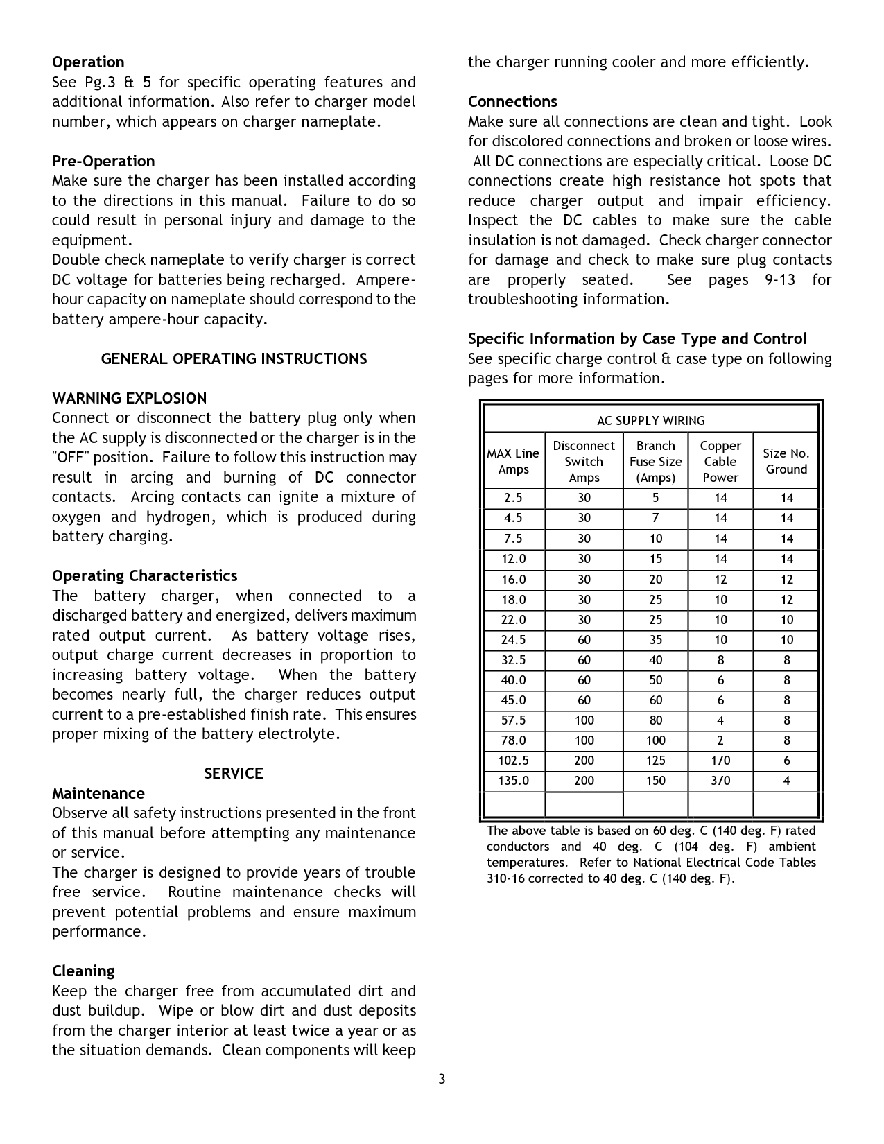
||AC SUPPLY WIRING|AC SUPPLY WIRING|AC SUPPLY WIRING|AC SUPPLY WIRING|AC SUPPLY WIRING| |---|---|---|---|---| |MAX Line Amps|Disconnect Switch Amps|Branch Fuse Size (Amps)|Copper Cable Power|Size No. Ground| |2.5|30|5|14|14| |4.5|30|7|14|14| |7.5|30|10|14|14| |12.0|30|15|14|14| |16.0|30|20|12|12| |18.0|30|25|10|12| |22.0|30|25|10|10| |24.5|60|35|10|10| |32.5|60|40|8|8| |40.0|60|50|6|8| |45.0|60|60|6|8| |57.5|100|80|4|8| |78.0|100|100|2|8| |102.5|200|125|1/0|6| |135.0|200|150|3/0|4|

| | | | | | | |---|
The above table is based on 60 deg. C (140 deg. F) rated conductors and 40 deg. C (104 deg. F) ambient temperatures. Refer to National Electrical Code Tables 310-16 corrected to 40 deg. C (140 deg. F).
Quantum II and Magnum II Industrial Battery Chargers
DESCRIPTION OF EQUIPMENT
The battery charger is designed to recharge lead acid batteries. The easy access steel case is constructed to protect internal components, and provide adequate cooling plus component accessibility. The charger is equipped with the 3500 Control. The enclosure is designed in 4 standard case types: F, G, H, and J. Page 14 of this manual shows the dimensions of each case type.
Just connect the battery to the charger and the 3500 Automatic Charge Control takes control of the charge operation. The 3500 Control determines the state of charge of the battery by accessing the rate of change of battery voltage (dv/dt) and actively compensating the dv/dt results with the rate of change of charge current (di/dt). This algorithm is based on the fact that the voltage of a lead acid battery increases as the battery becomes charged and charger current has an effect on the battery voltage.
The 3500 Control uses rate of change of voltage and current information in addition to the temperature data to verify the operating characteristics of the battery and to validate the state of charge of the battery. This assures a fault free charge cycle.
When a charger with a 3500 Control is connected to a battery, the 3500 Control delays the start of charge for five seconds to ensure all connections have been completed. This prevents dangerous electric arcing that could be hazardous around charging batteries. The 3500 Control identifies the battery as having the correct number of cells before the charger is energized. Once the charger is running, the 3500 Control continuously monitors the voltage and current conditions to quickly identify battery and charger faults that may occur. If all operation guidelines are functioning correctly, the 3500 Control continues the charging process until the battery is completely charged.
FEATURES OF THE QUANTUM II AND MAGNUM II INDUSTRIAL BATTERY CHARGER
3500 CONTROL
3500 AUTOMATIC MICROPROCESSOR CONTROL FEATURES:
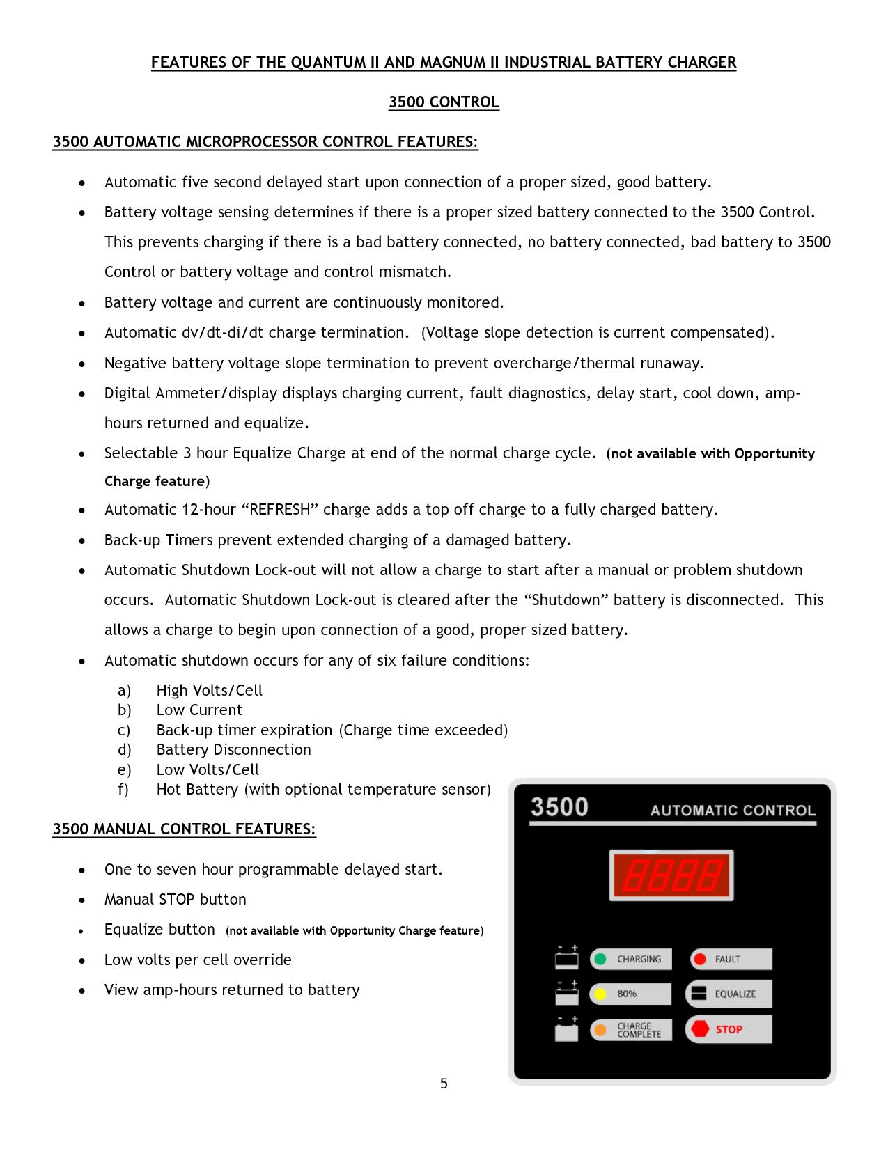

3500 MANUAL CONTROL FEATURES:
3500 CONTROL DIAGNOSTIC FEATURES:
3500 CONTROL OPERATING PROCEDURES PRELIMINARY SET-UP:
When A.C. power has been applied to the charger, a “dash” segment will sequence across the display on the front panel. This indicates the 3500 Controlled charger is in the “STANDBY MODE” of operation, awaiting a battery to be connected.
IMMEDIATE/DELAY START:
The 3500 Control may be programmed to delay the start of the charge from one to seven hours as well as an immediate start of the charge upon connection of battery to charger.
The 3500 Control is shipped from the factory set for immediate start (0 hour delay).
If a power failure occurs, no damage will occur to the battery or the charger. The 3500 control will automatically start once power returns. If a battery is still connected when power returns, the 3500 control will override any delayed start setting and initialize an immediate start of the charge. Once the charge has been terminated, the delay start will again function normally.
CHANGING IMMEDIATE/DELAY START TIME:
*********** WARNING ************** HIGH VOLTAGE MAY BE PRESENT WITHIN THE CHARGE CABINET. DISCONNECT AC POWER FROM THE CHARGER BEFORE OPENING THE CABINET DOOR.
****************************
CHARGING THE BATTERY:
Compare the number of cells and amp-hour capacity of the battery to be charged with the charger rating found on the charger nameplate. The number of cells on the battery to be charged MUST match the nameplate data. The amp-hour ratings should also match to ensure that the battery would be charged in a timely manner.
Once battery and charger ratings have been verified, connect the battery to the charger. The 3500 Control will measure the average volts/cell of the connected battery.
Once the 3500 Control verifies the connection of a good battery (between 1.7 and 2.7 volts/cell), the display will show a countdown to charge initialization. When the countdown reaches zero, the 3500 Control will turn on the charger.
If the average volts/cell reading is less than 1.7 volts, the charge will not begin and the red FAULT LED will turn on and the display will indicate Lo U. To start the charger and override low volts per cell, push and hold the stop button for more than 10 seconds. The charger will start. Continue to hold the stop button in until the battery voltage increases to greater than 1.7 volts per cell, then, deactivate the stop button.
If the average volts/cell is greater than 2.7 volts, the red FAULT LED will turn on and the display will indicate .Hi U. Again, the charge will not begin. Check charger and battery for proper voltage match.
Once the charge begins, the display will show the output charging current in amperes. The green CHARGING LED will be on. The yellow 80% CHARGED LED will be on if the average volts/cell of the battery is greater than 2.37 volts/cell.
TERMINATION OF CHARGE:
There are three ways in which the charge may be terminated. These three termination methods are CHARGE COMPLETED TERMINATION, MANUAL TERMINATION and PROBLEM SHUTDOWN TERMINATION.
display indicator. After the battery is removed, the red FAULT LED will remain flashing for one hour. The display indicator will remain on until another battery is connected to the charger. Refer to the TROUBLESHOOTING SECTION for a more complete explanation of the diagnostics.
EQUALIZE CHARGE
An equalize charge of three (3) hours beyond normal charge termination can be selected by pressing the equalize button on the front panel or door. An “E” appears in the display indicating that the equalize charge will occur at the end of the charge cycle. The ‘E” will flash when the charger is equalizing. The equalize charge can be cancelled by pressing the equalize button again before the equalize charge actually begins. Equalize is not available with optional Opportunity Charge Control.
REFRESH CHARGE:
The 3500 Control will automatically turn on every 12 hours after the charge cycle is completed, provided the battery remains connected to the charger. The charge rate of the battery will be monitored with dv/dt termination occurring typically within 20 -30 minutes. The refresh charge tops off the battery during weekends and when batteries are not used for extended periods of time. The amber LED will flash and the green charging LED will be on when the charger is in refresh mode.
COOL DOWN TIMER
The 3500 Control displays the amount of time that has accumulated from the end of a successful charge. If the charge cycle is not successful, a fault code will be displayed.
AMPERE HOURS RETURNED:
At the end of the charge cycle, the amount of ampere hours returned to the battery can be displayed by pressing the stop button. This feature is only active when the charge process has stopped and the charging LED is not illuminated. Pressing the stop button during the charge cycle will manually terminate the charge.
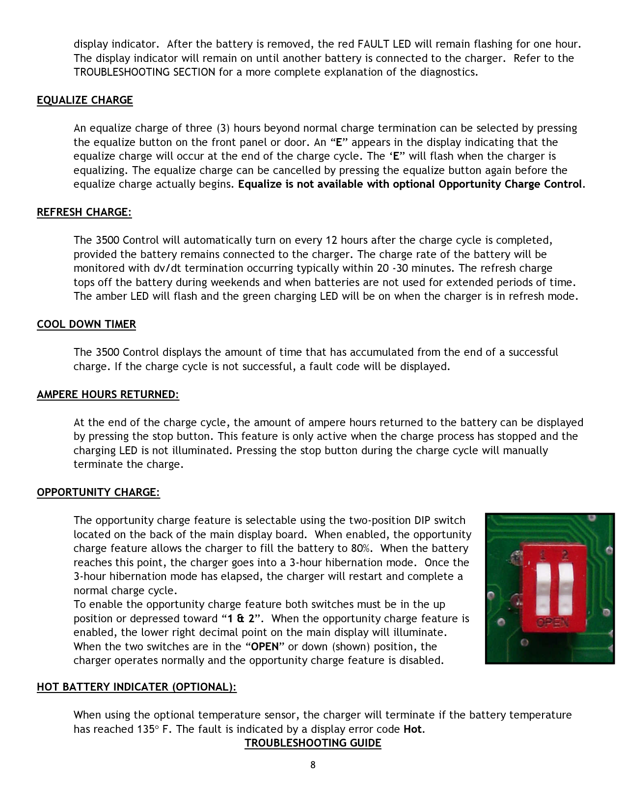
OPPORTUNITY CHARGE:
The opportunity charge feature is selectable using the two-position DIP switch located on the back of the main display board. When enabled, the opportunity charge feature allows the charger to fill the battery to 80%. When the battery reaches this point, the charger goes into a 3-hour hibernation mode. Once the 3-hour hibernation mode has elapsed, the charger will restart and complete a normal charge cycle. To enable the opportunity charge feature both switches must be in the up position or depressed toward “1 & 2”. When the opportunity charge feature is enabled, the lower right decimal point on the main display will illuminate. When the two switches are in the “OPEN” or down (shown) position, the charger operates normally and the opportunity charge feature is disabled.
HOT BATTERY INDICATER (OPTIONAL):
|| |---|
When using the optional temperature sensor, the charger will terminate if the battery temperature has reached 135° F. The fault is indicated by a display error code Hot.
TROUBLESHOOTING GUIDE
GENERAL SERVICE INFORMATION *********************** WARNING: Observe all safety instructions presented in the front of this manual before attempting any
service.
DANGER: Electric Shock Hazard - Disconnect AC Power and battery plug before any service is performed. Discharge capacitors with insulated screwdriver.
NOTE: If testing requires energized circuits, observe all safety precautions in the front of this manual. Disconnect all AC power. Apply alligator clips so that you do not have to touch any probes or part of the equipment before turning the power back on to take a reading. Follow the sequence of this troubleshooting manual step by step, as each successful procedure will aid in isolating the problem.
***********************
This troubleshooting guide deals with the Quantum II and Magnum II 3500 CONTROLLED charger. Each subsection is titled with a symptom. Locate the symptom your charger is experiencing and follow the step by step troubleshooting procedure to determine the cause of the problem. (Refer to schematic/wiring diagrams located in the back of this manual)
SYMPTOM – POWER IS APPLIED BUT THE DISPLAY IS NOT ON
AC POWER CONNECTION
• Make sure the AC input line, located at the AC Contactor, is connected to the AC power outlet. Measure the voltage at the Contactor and verify that AC power is at the charger.
CONTROL TRANSFORMER
MICROCONTROLLER/CELL SELECT CONNECTIONS
• Locate the Microcontroller board on the front panel or door and the Cell Select board inside the charger. Verify the proper connection and polarity of the board and cables.
MICROCONTROLLER BOARD
• If there is the appropriate voltage level across the Control Transformer, disconnect AC power. Then, reapply AC power. This action will reset the Microprocessor.
SYMPTOM - POWER IS APPLIED. DISPLAY IS IN IDLE MODE BUT CHARGER WILL NOT START OR CHARGE STARTS BUT IS TERMINATED IMMEDIATELY
PROPER BATTERY
• Verify that the number of cells of the battery to be charged matches the charger. Also, check the diagnostic voltage indicators.
GOOD BATTERY
• Measure the total battery voltage. Divide the voltage value measured by the number of battery cells.
This will yield an average volts per cell value. If the average volts per cell value is less than 1.7 volts or greater than 2.7 volts, then the battery is bad and should not be used.
AC & DC FUSES
• Disconnect the battery and AC input power from the charger. Verify that the fuses are not open. Replace any defective fuses and check the following:
CONTROL TRANSFORMER
If the voltage measured is extremely high or low, verify the AC input is connected to the proper Control Transformer terminals.
MAIN TRANSFORMER(s)
• Test main transformer(s) for shorted winding. Look for burned windings. Replace if defective. SYMPTOM – CHARGE TERMINATES EARLY
DISPLAY INDICATOR =
| | |---|
If this indicator is on, then the 3500 Control measured the average volts/cell to be greater than 2.7 volts.
the battery. If the average volts per cell of the battery is between 1.7 and 2.7 volts/cell, then the battery is good.
DISPLAY INDICATOR =
| | |---|
If this indicator is on, the battery on charge was not receiving current.
DISPLAY INDICATOR =
| |
|---|
This indicates that the battery did not reach 80% of full charge (approximately 2.37 vpc) within nine hours or that the battery did not charge from 80% charged to full charge within six hours.
Verify that the charger amp-hour rating matches the battery amp-hour rating.
Disconnect the battery and AC input power from the charger. Verify that the AC and DC fuses are not open. Replace any defective fuses.
DISPLAY INDICATOR =
| | |---|
This indicator will be on whenever the battery to 3500 Controlled charger charging cable is disconnected while the battery is being charged. Although the 3500 control will automatically terminate the charge when the charging cable is disconnected, always make sure to manually shutdown the charger before disconnecting the cables.
DISPLAY INDICATOR =
| | |---|
Having a flashing red FAULT LED with Lo U showing in the display indicates that the 3500 control measured the average volts/cell to be less than 1.7 volts while the battery was being charged.
Verify that the charger DC output rating matches the battery DC voltage rating.
To start the charger and override low volts per cell, push and hold the stop button for more than 10 seconds. The charger will start. Continue to hold the stop button in until the battery voltage increases to greater than 1.7 volts per cell. Then, deactivate the stop button.
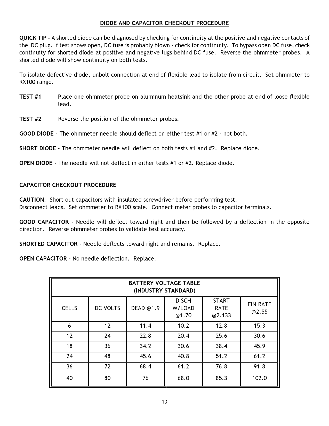
DIODE AND CAPACITOR CHECKOUT PROCEDURE
QUICK TIP - A shorted diode can be diagnosed by checking for continuity at the positive and negative contacts of the DC plug. If test shows open, DC fuse is probably blown - check for continuity. To bypass open DC fuse, check continuity for shorted diode at positive and negative lugs behind DC fuse. Reverse the ohmmeter probes. A shorted diode will show continuity on both tests.
To isolate defective diode, unbolt connection at end of flexible lead to isolate from circuit. Set ohmmeter to RX100 range.
GOOD DIODE - The ohmmeter needle should deflect on either test #1 or #2 - not both.
SHORT DIODE - The ohmmeter needle will deflect on both tests #1 and #2. Replace diode.
OPEN DIODE - The needle will not deflect in either tests #1 or #2. Replace diode.
CAPACITOR CHECKOUT PROCEDURE
CAUTION: Short out capacitors with insulated screwdriver before performing test. Disconnect leads. Set ohmmeter to RX100 scale. Connect meter probes to capacitor terminals.
GOOD CAPACITOR - Needle will deflect toward right and then be followed by a deflection in the opposite direction. Reverse ohmmeter probes to validate test accuracy.
SHORTED CAPACITOR - Needle deflects toward right and remains. Replace.
OPEN CAPACITOR - No needle deflection. Replace.
||BATTERY VOLTAGE TABLE (INDUSTRY STANDARD)|BATTERY VOLTAGE TABLE (INDUSTRY STANDARD)|BATTERY VOLTAGE TABLE (INDUSTRY STANDARD)|BATTERY VOLTAGE TABLE (INDUSTRY STANDARD)|BATTERY VOLTAGE TABLE (INDUSTRY STANDARD)|BATTERY VOLTAGE TABLE (INDUSTRY STANDARD)| |---|---|---|---|---|---|
|CELLS|DC VOLTS|DEAD @1.9|DISCH W/LOAD @1.70|START RATE @2.133|FIN RATE @2.55| |6|12|11.4|10.2|12.8|15.3| |12|24|22.8|20.4|25.6|30.6| |18|36|34.2|30.6|38.4|45.9| |24|48|45.6|40.8|51.2|61.2| |36|72|68.4|61.2|76.8|91.8| |40|80|76|68.0|85.3|102.0| | |---|
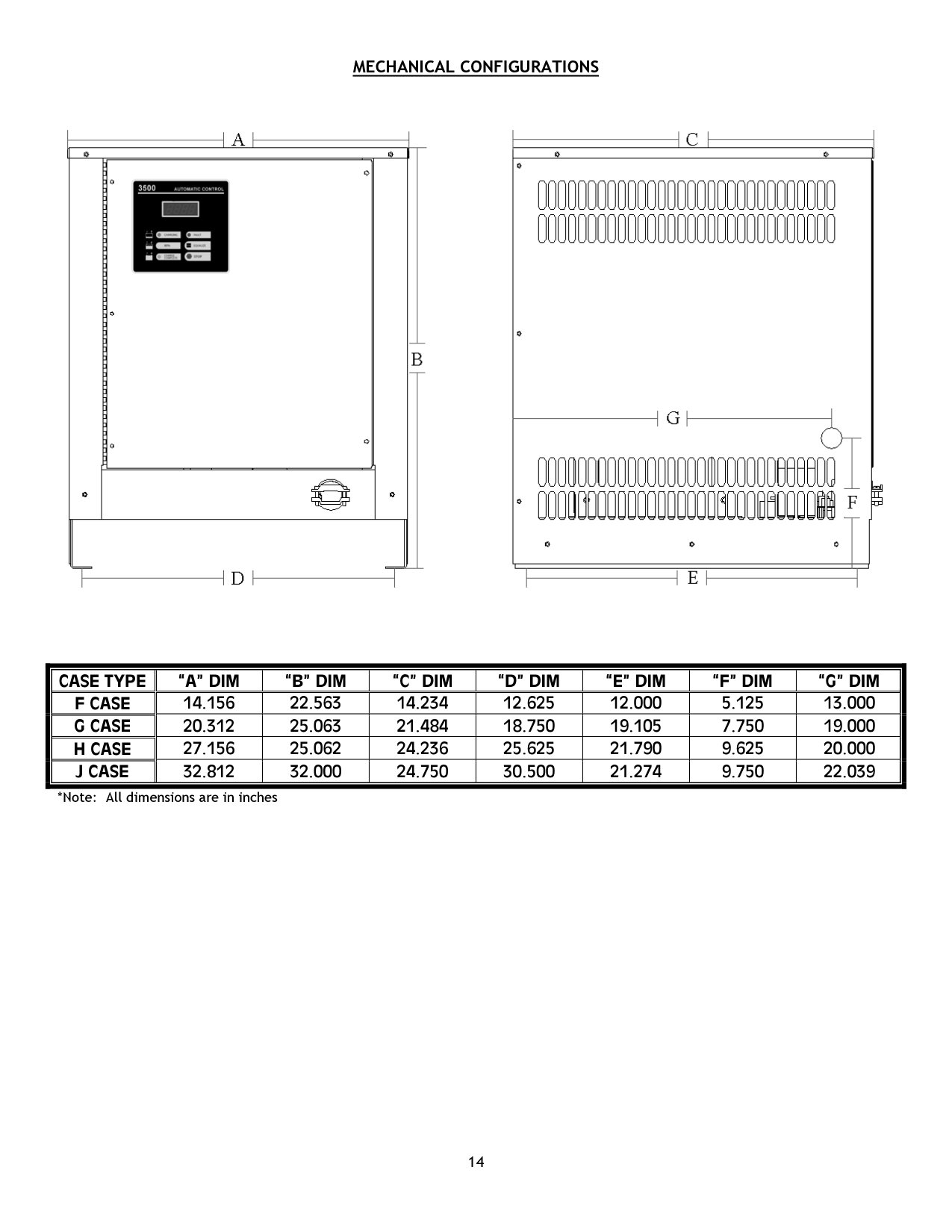
MECHANICAL CONFIGURATIONS

|CASE TYPE|“A” DIM|“B” DIM|“C” DIM|“D” DIM|“E” DIM|“F” DIM|“G” DIM| |---|---|---|---|---|---|---|---| |F CASE|14.156|22.563|14.234|12.625|12.000|5.125|13.000| |G CASE|20.312|25.063|21.484|18.750|19.105|7.750|19.000| |H CASE|27.156|25.062|24.236|25.625|21.790|9.625|20.000| |J CASE|32.812|32.000|24.750|30.500|21.274|9.750|22.039|
*Note: All dimensions are in inches
AC VOLTAGE SELECTOR BLOCKS

120/208/240 VOLT UNITS
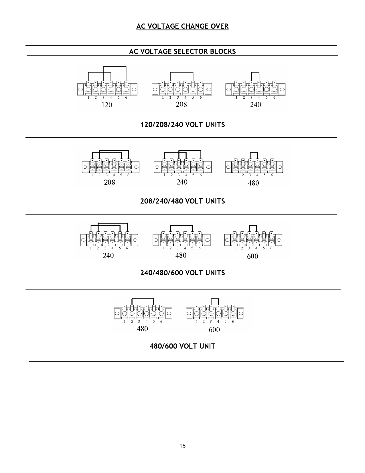

208/240/480 VOLT UNITS

240/480/600 VOLT UNITS

480/600 VOLT UNIT
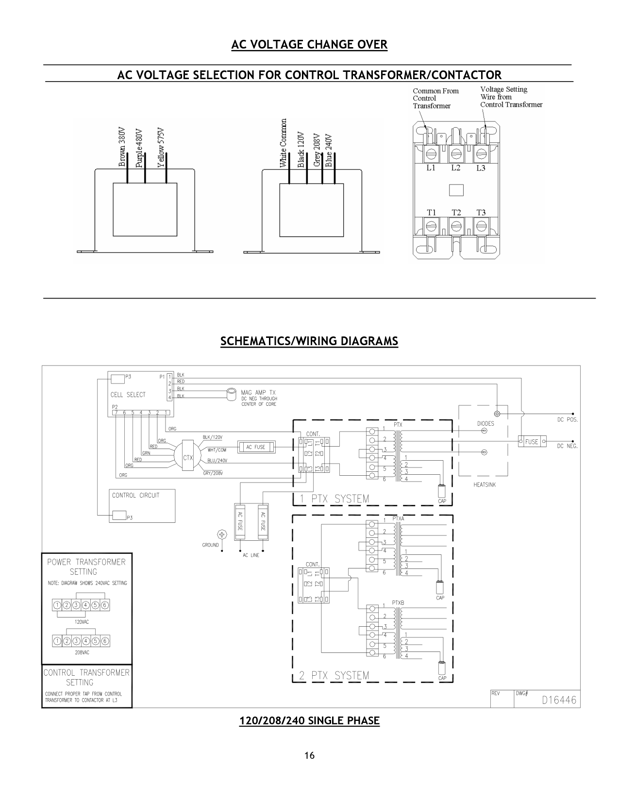
AC VOLTAGE SELECTION FOR CONTROL TRANSFORMER/CONTACTOR

|16

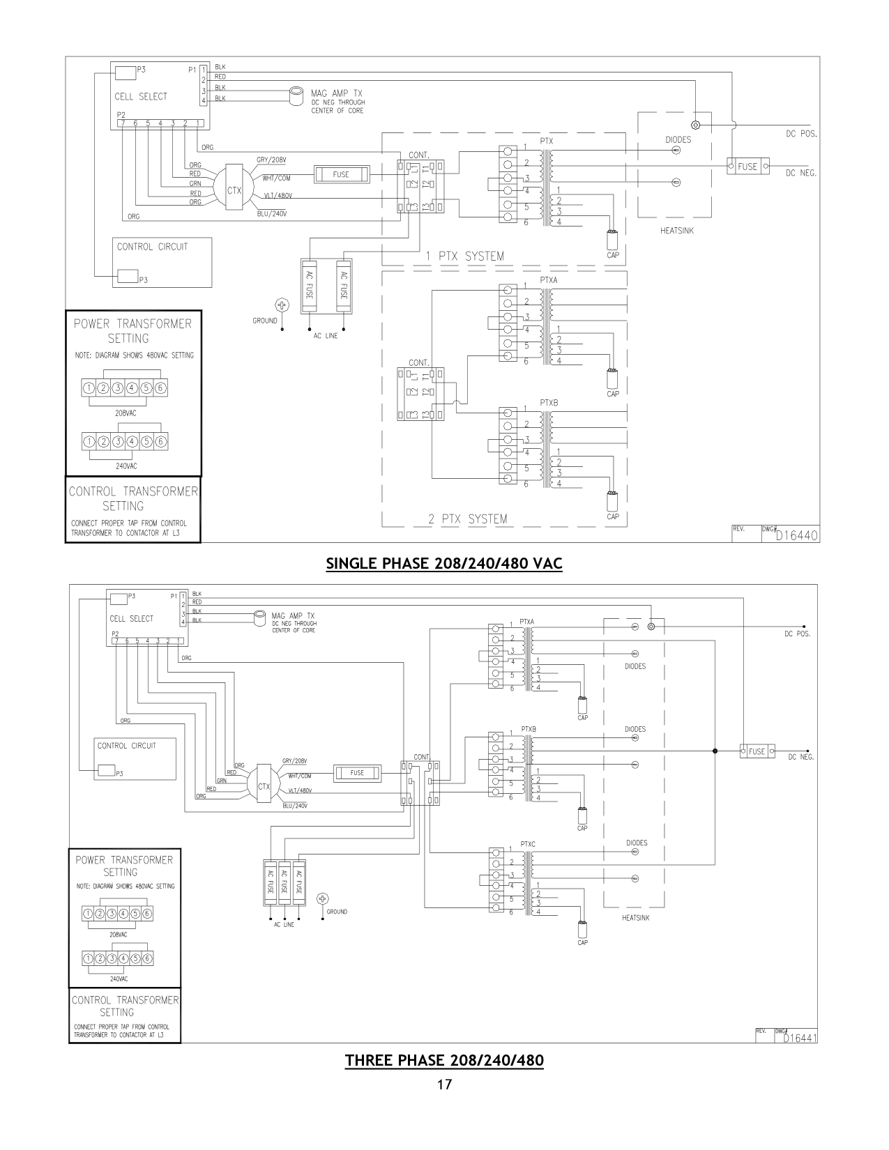
SCHEMATICS/WIRING DIAGRAMS
120/208/240 SINGLE PHASE
| |---|
| | | | |---|---|---|
| | | | | | | | | | | |---|---|---|---|---|---|---|---|---|---| | | | | | | | | | | | | | | | | | | | | | |
| | | | | | | | | | |
|---|---|---|---|---|---|---|---|---|---| | | | | | | | | | | | | | | | | | | | | | |
| | | | | | | | | | | |---|---|---|---|---|---|---|---|---|---| | | | | | | | | | | | | | | | | | | | | | |
| | | | | | | | | | | |---|---|---|---|---|---|---|---|---|---| | | | | | | | | | | | | | | | | | | | | | |
| | | | |---|---|---| | | | |
SINGLE PHASE 208/240/480 VAC
| | | |---|---| | | |
| | | |---|---|
| | |
| | | | |---|---|---|
| | | |---|---| | | |
| | | |---|---| | | |
| | | |---|---| | | |
| | | |---|---| | | |
THREE PHASE 208/240/480
| | | | |---|---|---|
| | | | | | | | | | | |---|---|---|---|---|---|---|---|---|---| | | | | | | | | | | | | | | | | | | | | | |
| | | | | | | | | |---|---|---|---|---|---|---|---| | | | | | | | | |
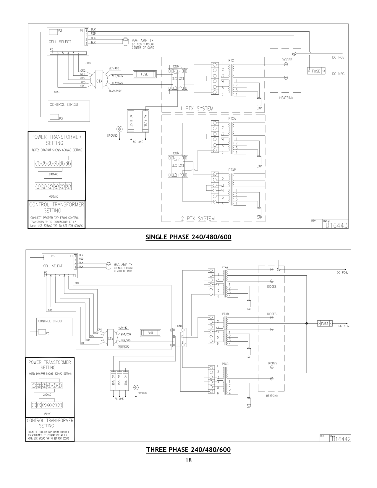
SINGLE PHASE 240/480/600
| | | |---|---| | | |
| | | |---|---| | | |
| | | | |---|---|---|
| | | |---|---|
| | |
| | | |---|---| | | |
| | | |---|---| | | |
THREE PHASE 240/480/600
| | | | | | | | | |---|---|---|---|---|---|---|---| | | | | | | | | |
| | | | |---|---|---|
| | | | |---|---|---| | | | |
| | | |---|---|
| | | | | |
| | | |---|---| | | |
| | | |---|---| | | |
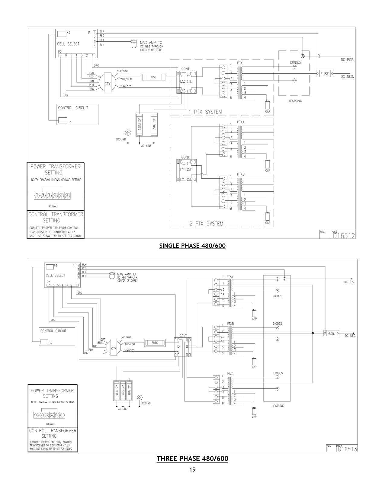
SINGLE PHASE 480/600
| | | | | | | | | |---|---|---|---|---|---|---|---| | | | | | | | | |
| | | | |---|---|---|
| | | |---|---| | | |
THREE PHASE 480/600
| | | | |---|---|---|
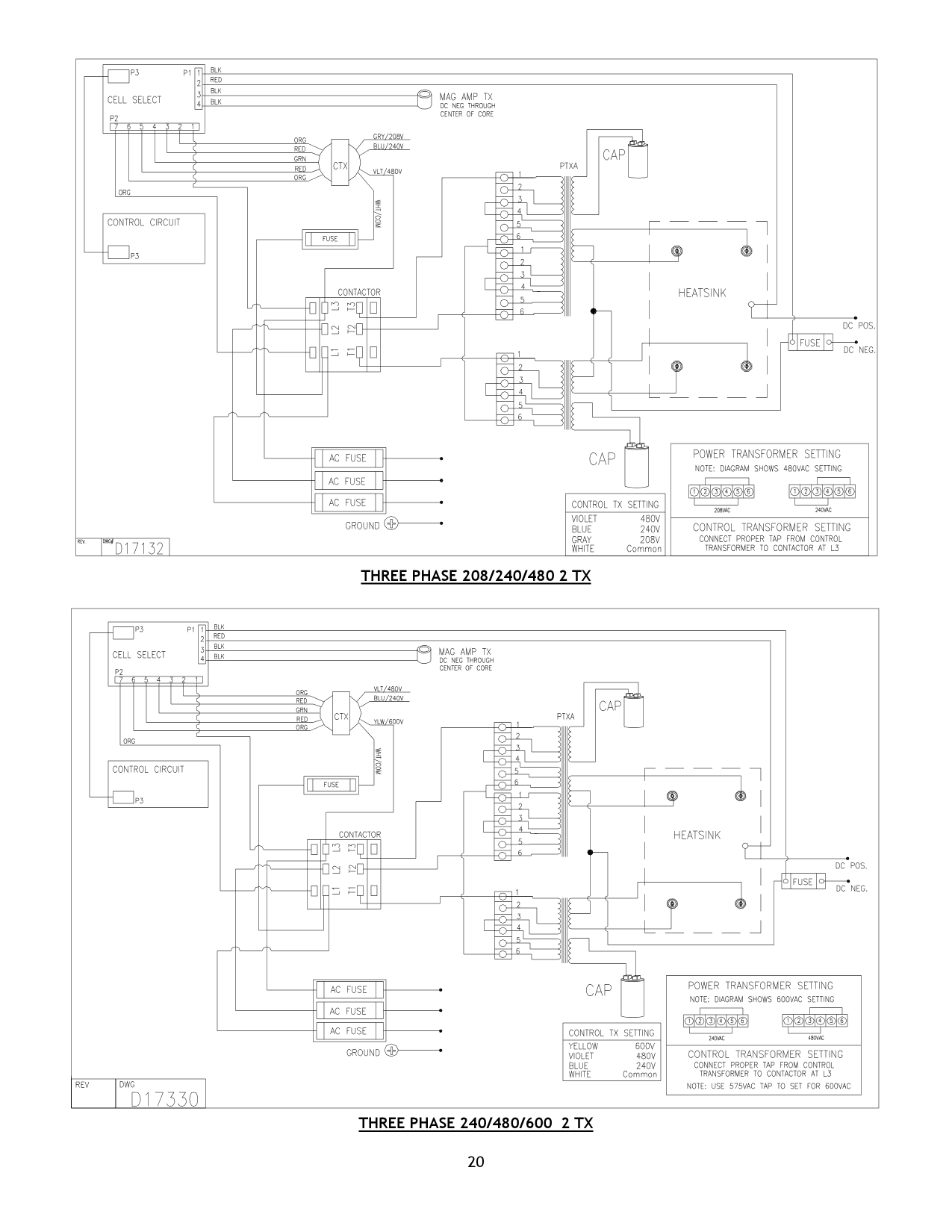
THREE PHASE 208/240/480 2 TX
| | | | | | | | | | | |---|---|---|---|---|---|---|---|---|---| | | | | | | | | | | | | | | | | | | | | | |
| | | | | | | | | | | |---|---|---|---|---|---|---|---|---|---| | | | | | | | | | | | | | | | | | | | | | |
| | | | |---|---|---|
| | | |---|---| | | |
| | |---| | |
| | |---| | |
THREE PHASE 240/480/600 2 TX
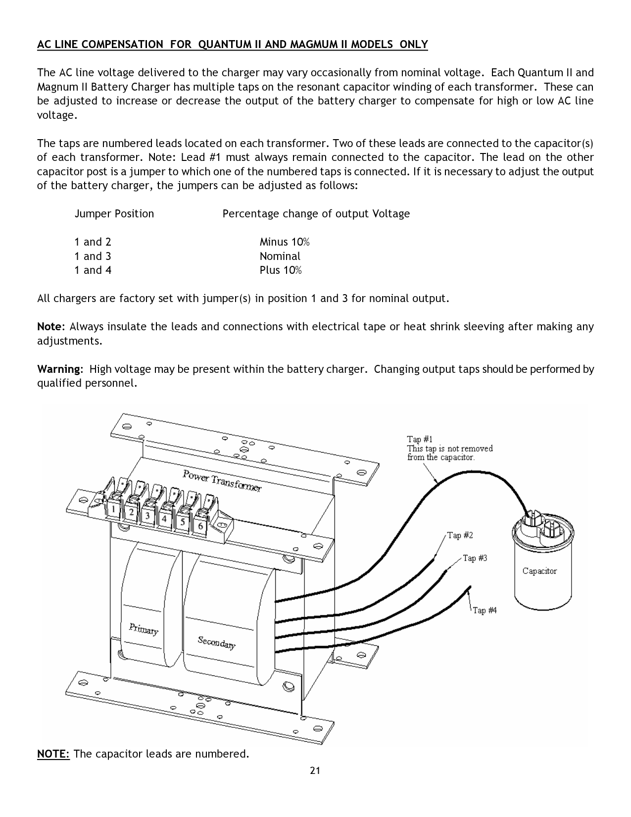
AC LINE COMPENSATION FOR QUANTUM II AND MAGMUM II MODELS ONLY
The AC line voltage delivered to the charger may vary occasionally from nominal voltage. Each Quantum II and Magnum II Battery Charger has multiple taps on the resonant capacitor winding of each transformer. These can be adjusted to increase or decrease the output of the battery charger to compensate for high or low AC line voltage.
The taps are numbered leads located on each transformer. Two of these leads are connected to the capacitor(s) of each transformer. Note: Lead #1 must always remain connected to the capacitor. The lead on the other capacitor post is a jumper to which one of the numbered taps is connected. If it is necessary to adjust the output of the battery charger, the jumpers can be adjusted as follows:
Jumper Position Percentage change of output Voltage
All chargers are factory set with jumper(s) in position 1 and 3 for nominal output.
Note: Always insulate the leads and connections with electrical tape or heat shrink sleeving after making any adjustments.
Warning: High voltage may be present within the battery charger. Changing output taps should be performed by qualified personnel.

NOTE: The capacitor leads are numbered.
PARALLEL AND SERIES OUTPUT CABLES
Parallel Charging Output Cables are an extra set of DC cables which permit two (2) batteries with the same number of cells and amp-hour capacity to be charged at the same time in parallel.
The number of cells of each battery to be charged must equal the number of cells indicated on the charger nameplate. The combined amp-hour capacity of the two (2) batteries must fall in the range of the charger.
E.g.: Two (2) 36 volt – 18 cell – 240 amp-hour batteries, connected in parallel, can be charged with one (1) 36 volt – 18 cell – 510 amp-hour charger.
Series Charging Output Cables are an extra set of DC cables which allows two (2) batteries with the same number of cells and amp-hour capacity, which are at the same state of discharge, to be charged at the same time in series.
The total number of battery cells must be equal to the number of cells noted on the battery charger nameplate. The amp-hour capacity of each battery must fall in the range of the charger rating.
E.g.: two (2) 24 volt – 12 cell – 510 amp-hour batteries connected in series can be charged with one (1) 48 volt – 24 cell – 510 amp-hour charger.
JIC SAFETY INTERLOCK SWITCH
The JIC Safety Interlock Switch option is a lock out/tag out type safety feature which consists of a fused interlock disconnect switch positioned on the cabinet door. In order to open the door, the JIC Safety Interlock Switch must be actuated. Actuation of the switch disconnects AC power from the charger circuitry thus rendering the charger in-operable if the charger door is open.
This option is available upon request.