
Ask AI
— answers from the official manualAnswers from the official manual.
Common questions
Common Questions
10 totalHow do I reset the unit's malfunction log?
To clear malfunction logs displayed on the AE-200/AE-50 controllers, bring up the Malfunction List or Malfunction Log screen and use the Clear malfunction log option. This clears all displayed errors but does not affect current system conditions.
What error codes are commonly encountered with this unit?
Refer to section 3-5 of the manual for a Malfunction Log and section 3-6 for an Error code list. Common errors include M-NET related issues (such as communication problems) and controller specific errors between AE-200 and AE-50 units.
How do I perform a factory reset on the centralized controller?
To reset the device to factory defaults, press and hold the Power button for 10 seconds until the LED flashes red. This clears all settings, and you will need to re-pair connected devices after resetting. (Page 23)
What safety measures should I take during maintenance?
During maintenance or repairs, ensure no flammable materials are near the unit and that chemical sprays do not come into contact with electrical components. Always stop operation before applying chemicals around the controller to prevent short circuits or malfunctions.
Can I back up the settings data on this device?
Yes, you can back up settings data using a USB memory device by touching [Maintenance] > [Backing up settings data], and then inserting the USB device into the designated port on the controller.
How many indoor units can be connected to an AE-200/AE-50 central controller?
Each group can contain up to 16 indoor units, and each centralized controller (AE-200 or AE-50) can control up to a total of 50 indoor units. By connecting multiple sub controllers (AE-50), you can manage up to 200 indoor units in the system.
Full Manual
88 pages
Air Conditioning Control System Centralized Controller AE-200A/AE-50A AE-200E/AE-50E
Instruction Book –Detailed operations–
| | |---|
#### Contents
######### 1. Safety precautions ..............................................................4
######### 2. Introduction .........................................................................6
######### 3. Basic operations ...............................................................11
######### 4. Practical operations ..........................................................66
######### 6. Specifications ....................................................................85Appendix: Added functions .....................................................86
Before using the controller, please read this Instruction Book carefully to ensure proper operation. Retain this manual for future reference.
Ver. 7.3
Contents

3-6. Error code list ........................................................................................................62
##### 4. Practical operations ...........................................................................................664-1. Maintenance .........................................................................................................66
4-1-1. Energy data output .....................................................................................66
##### 5. Maintenance ......................................................................................................74
##### 6. Specifications ....................................................................................................85Appendix: Added functions ......................................................................................86
1. Safety precautions
►Observe these precautions carefully to ensure safety.
►After reading this manual, pass the manual on to the end user to retain for future
reference.
►The user should keep this manual for future reference and refer to it as necessary. This manual should be made available to those who repair or relocate the units. Make sure that the manual is passed on to any future air conditioning system user.
|| |
|---| |: indicates a hazardous situation which, if not avoided, could result in death or serious injury.| |---|---| || | |---| |: indicates a hazardous situation which, if not avoided, could result in minor or moderate injury.| | |: addresses practices not related to personal injury, such as product and/or property damage.|
#### 1-1. General precautions
Do not install the controller in areas where large amounts of oil, steam, organic solvents, or corrosive gases (such as ammonia, sulfuric compounds, or acids), or areas where acidic/alkaline solutions or special chemical sprays are used frequently. These substances may significantly reduce the performance and corrode the internal parts, resulting in electric shock, malfunction, smoke, or fire.
To reduce the risk of short circuits, current leakage, electric shock, malfunction, smoke, or fire, do not wash the controller with water or any other liquid.
To reduce the risk of electric shock, malfunction, smoke, or fire, do not touch the electrical parts, USB memory, or touch panel with wet fingers.
To reduce the risk of injury or electric shock, before spraying a chemical around the controller, stop the operation and cover the controller.
To reduce the risk of injury, keep children away while installing, inspecting, or repairing the controller.
If you notice any abnormality (e.g., burning smell), stop the operation, turn off the controller, and consult your dealer. Continuing the operation may result in electric shock, malfunction, or fire.
Properly install all required covers to keep moisture and dust out of the controller. Dust accumulation and the presence of water may result in electric shock, smoke, or fire.
To reduce the risk of fire or explosion, do not place flammable materials or use flammable sprays around the controller.
To reduce the risk of electric shock or malfunction, do not touch the touch panel, switches, or buttons with a sharp object.
To avoid injury from broken glass, do not apply excessive force to the glass parts. To reduce the risk of injury, electric shock, or malfunction, avoid contact with the sharp edges of certain parts.
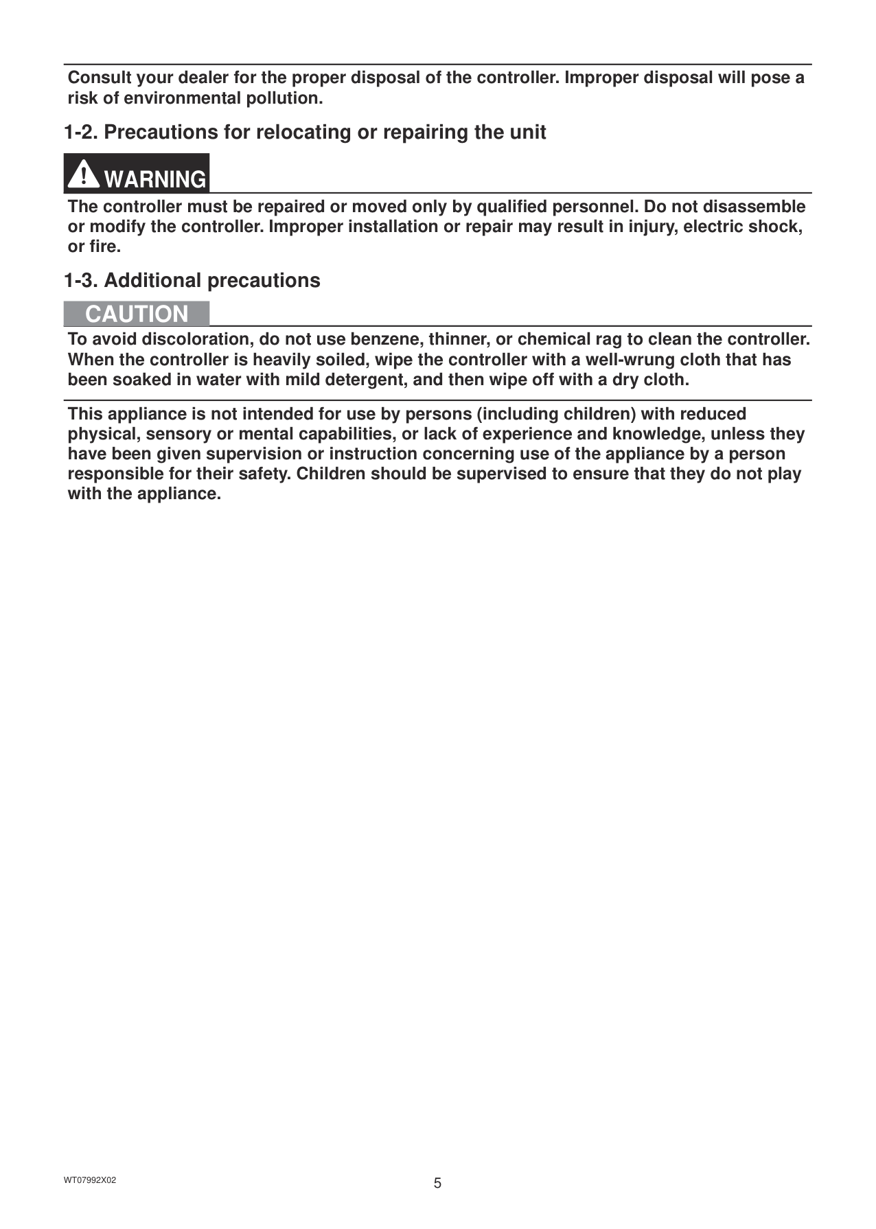
Consult your dealer for the proper disposal of the controller. Improper disposal will pose a risk of environmental pollution.
#### 1-2. Precautions for relocating or repairing the unit
The controller must be repaired or moved only by qualified personnel. Do not disassemble or modify the controller. Improper installation or repair may result in injury, electric shock, or fire.
#### 1-3. Additional precautions
To avoid discoloration, do not use benzene, thinner, or chemical rag to clean the controller. When the controller is heavily soiled, wipe the controller with a well-wrung cloth that has been soaked in water with mild detergent, and then wipe off with a dry cloth.
This appliance is not intended for use by persons (including children) with reduced physical, sensory or mental capabilities, or lack of experience and knowledge, unless they have been given supervision or instruction concerning use of the appliance by a person responsible for their safety. Children should be supervised to ensure that they do not play with the appliance.
2. Introduction
AE-200A/AE-50A/AE-200E/AE-50E is a centralized controller. EW-50A/EW-50E is an LCD-less total management system. Any connected air conditioning systems can be operated or monitored on the AE-200A/AE-50A/AE-200E/AE-50E’s LCD or the Web browser. By using a PI controller that is built-in on the AE-200A/AE-50A/EW-50A/AE-200E/AE-50E/EW-50E, the energycontrol-related status can be displayed and Peak Cut control can be performed without a use of a PI controller (PAC-YG60MCA). Each AE-200A/AE-50A/AE-200E/AE-50E can control up to a total of 50 indoor units and other equipment. By connecting AE-200A/AE-200E (main controller) and AE-50A/AE-50E/EW-50A/EW-50E (sub controllers), up to 200 indoor units and other equipment can be controlled.
#### 2-1. Terms used in this manual
#### 2-2. Required licenses
The required licenses vary, depending on the functions to be used. Refer to the License Classification List for details. Purchase the required licenses from your dealer. Refer to the Instruction Book (Initial Settings) for how to register licenses.
#### 2-3. “Group”, “Block”, and “EM block” definitions
The terms “Group” and “Block” used in this manual are defined as follows. Group: Group is a group of air conditioning units and controllers and is the smallest unit that the AE-200/AE-50 can control. The maximum number of units that each group can contain is 16. Block: Each block consists of one or more groups. Multiple groups of units in a given block can be monitored or operated collectively. EM block:EM block stands for Energy management block, and this groups multiple blocks. Use for charge apportioning units and for settings of blocks spanning AE-200 and AE-50/EW-50.
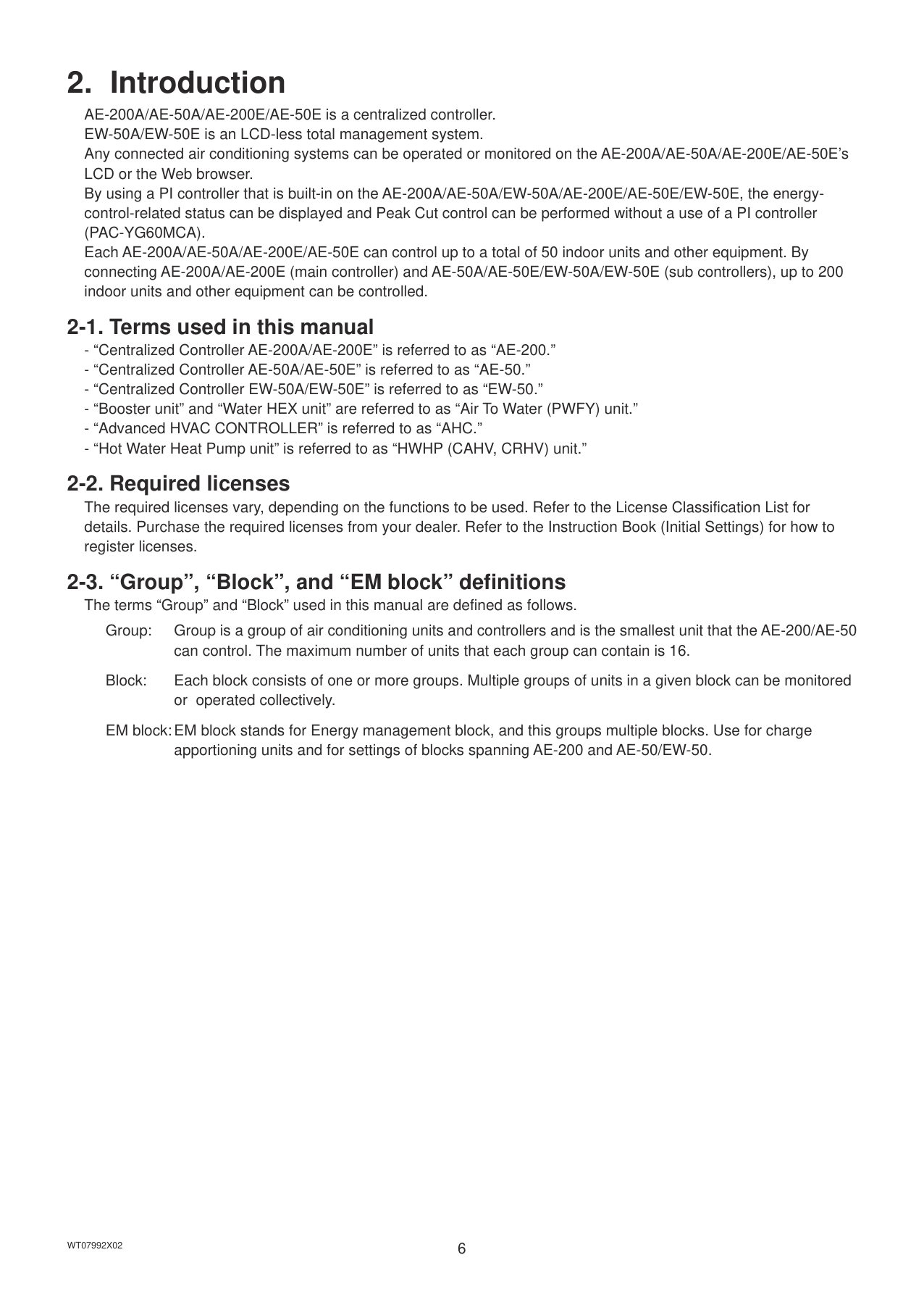
#### 2-4. Main and Sub system controllers (M-NET)
Each group can be controlled by a Main system controller or a Sub system controller. AE-200/AE-50 is exclusively for use as a Main system controller and cannot be used as a Sub system controller.
Main system controller Main system controller refers to a system controller that controls all other system controllers including the units they control. If a given system has only one system controller, that controller becomes a Main system controller. Group settings and interlock settings can be made only from a Main system controller.
Sub system controller Sub system controller refers to a system controller that is controlled by a Main system controller.
Main system controller's (AE-200/AE-50's) control range
Sub system controller's control range
|Group| |---|
|Group| |---|
|Group| |---|
|The system cannot be configured as shown in the examples below.
● Groups that are not under the control of a Main system controller cannot be controlled from a Sub system controller.
● Each group cannot be placed under the control of two or more Main system controllers.
● Sub system controllers cannot be placed under the control of two or more Main system controllers.
|Group| |---|
Main system controller
|Group| |---|
Sub system controller
|Group| |---|
|Group| |---|
Main system controller 1
|Group| |---|
Main system controller 2
|Group| |---|
|Group|
|---|
Main system controller 1
|Group| |---|
Sub system controller
|Group| |---|
Main system controller 2
|Group| |---| | |---|
#### 2-5. Controller interface
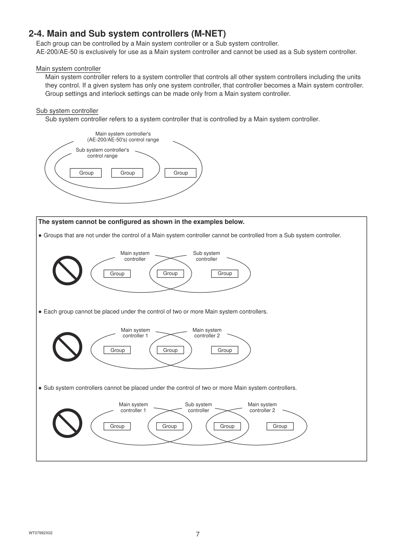
|Important
● Before using the controller, remove the protective sheet on the cover to avoid the sheet from sticking to the touch panel and causing malfunctions.
● Use the supplied L-shaped driver to remove or attach the cover.
| |---|
USB port
Power
############## Push switch
Display/Touch panel When the backlight is off, touching the panel turns the backlight on, and it will stay lit for three minutes. The backlight stays lit while an error is occurring.
|Item|Item|Item|Description| |---|---|---|---| |LED|Power|Lit in green|Power ON| |LED|Power|Unlit|Power OFF| |LED|ON/OFF|Lit in green|One or more air conditioning units are ON.|
|LED|ON/OFF|Blink in green|One or more air conditioning units or other related equipment are in error.| |LED|ON/OFF|Unlit|All air conditioning units are OFF.| |LED|Status|Blink in orange|Startup failed| |LED|Status|Blink in blue|Software update in progress| |LED|Status|Blink in pink|Software update failed| |LINK/ACT1|LINK/ACT1|Blink in orange|Data transmission in progress (LAN1)| |LINK/ACT2|LINK/ACT2|Blink in orange|BACnet® data transmission in progress (LAN2)| |Push switch|ON/OFF|ON/OFF|Used to turn the connected air conditioning units and the other related equipment ON and OFF all at once.| |Push switch|Reset|Reset|Used to reboot the AE-200/AE-50. (This will not affect the operation status of the air conditioning units.)| |USB port|USB port|USB port|Used when the settings data is backed up to or imported from a USB memory device, when the energy management data is output in a CSV format to a USB memory device, and when the software needs to be updated.|
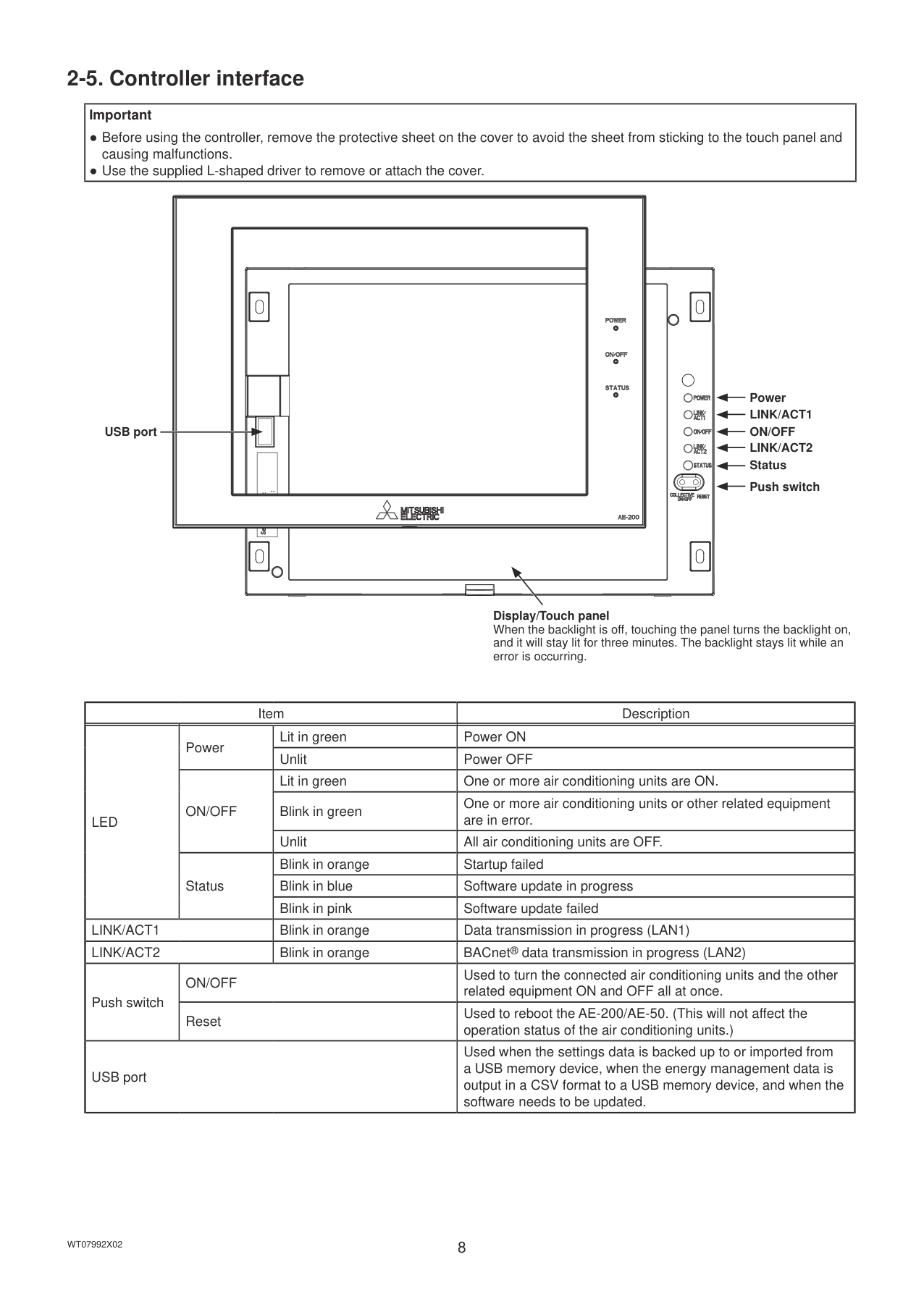
#### 2-6. Number of connectable units
The table below summarizes the number of connectable units in an AE-200/AE-50/EW-50 M-NET system.
|Unit type|Number of connectable units| |---|---| |Indoor units, independent OA processing units, LOSSNAY units, DIDO controllers (PAC-YG66DCA), Air To Water (PWFY) units, Advanced HVAC CONTROLLERs, HWHP (CAHV, CRHV) units, AI controllers (PAC-YG63MCA), PI controllers (PAC-YG60MCA)|Up to 50 units (including the interlocked LOSSNAY units)*1*2*3*4| |Indoor units, independent OA processing units, LOSSNAY units, DIDO controllers (PAC-YG66DCA), Air To Water (PWFY) units, HWHP (CAHV, CRHV) units in a group|1–16 units (Indoor units, independent OA processing units, LOSSNAY units, DIDO controllers (PAC-YG66DCA), Air To Water (PWFY) units, and HWHP (CAHV, CRHV) units cannot be combined in one group.)| |Remote controllers in a group|0–2 units| |System controllers in a group (AE-200/AE-50/EW-50 excluded)|0–4 units (Up to four remote and system controllers combined can be assigned to each group.)| |Advanced HVAC CONTROLLER in a group|0–1 unit| |LOSSNAY unit that can be interlocked with each indoor unit|1 unit| |Indoor units that can be interlocked with each LOSSNAY unit|1–16 units|
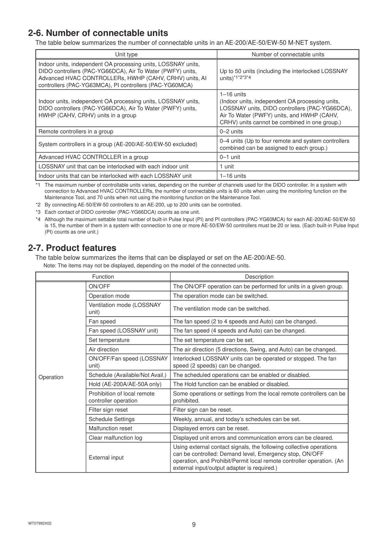
#### 2-7. Product features
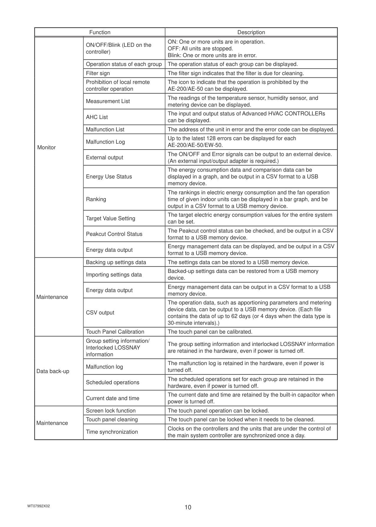
The table below summarizes the items that can be displayed or set on the AE-200/AE-50.
Note: The items may not be displayed, depending on the model of the connected units.
|Function|Function|Description| |---|---|---| |Operation|ON/OFF|The ON/OFF operation can be performed for units in a given group.| |Operation|Operation mode|The operation mode can be switched.| |Operation|Ventilation mode (LOSSNAY unit)|The ventilation mode can be switched.| |Operation|Fan speed|The fan speed (2 to 4 speeds and Auto) can be changed.| |Operation|Fan speed (LOSSNAY unit)|The fan speed (4 speeds and Auto) can be changed.| |Operation|Set temperature|The set temperature can be set.| |Operation|Air direction|The air direction (5 directions, Swing, and Auto) can be changed.| |Operation|ON/OFF/Fan speed (LOSSNAY unit)|Interlocked LOSSNAY units can be operated or stopped. The fan speed (2 speeds) can be changed.| |Operation|Schedule (Available/Not Avail.)|The scheduled operations can be enabled or disabled.| |Operation|Hold (AE-200A/AE-50A only)|The Hold function can be enabled or disabled.| |Operation|Prohibition of local remote controller operation|Some operations or settings from the local remote controllers can be prohibited.| |Operation|Filter sign reset|Filter sign can be reset.| |Operation|Schedule Settings|Weekly, annual, and today’s schedules can be set.| |Operation|Malfunction reset|Displayed errors can be reset.| |Operation|Clear malfunction log|Displayed unit errors and communication errors can be cleared.| |Operation|External input|Using external contact signals, the following collective operations can be controlled: Demand level, Emergency stop, ON/OFF operation, and Prohibit/Permit local remote controller operation. (An external input/output adapter is required.)|
|Function|Function|Description| |---|---|---| |Monitor|ON/OFF/Blink (LED on the controller)|ON: One or more units are in operation. OFF: All units are stopped. Blink: One or more units are in error.| |Monitor|Operation status of each group|The operation status of each group can be displayed.| |Monitor|Filter sign|The filter sign indicates that the filter is due for cleaning.| |Monitor|Prohibition of local remote controller operation|The icon to indicate that the operation is prohibited by the AE-200/AE-50 can be displayed.| |Monitor|Measurement List|The readings of the temperature sensor, humidity sensor, and metering device can be displayed.| |Monitor|AHC List|The input and output status of Advanced HVAC CONTROLLERs can be displayed.| |Monitor|Malfunction List|The address of the unit in error and the error code can be displayed.|
|Monitor|Malfunction Log|Up to the latest 128 errors can be displayed for each AE-200/AE-50/EW-50.| |Monitor|External output|The ON/OFF and Error signals can be output to an external device. (An external input/output adapter is required.)| |Monitor|Energy Use Status|The energy consumption data and comparison data can be displayed in a graph, and be output in a CSV format to a USB memory device.| |Monitor|Ranking|The rankings in electric energy consumption and the fan operation time of given indoor units can be displayed in a bar graph, and be output in a CSV format to a USB memory device.| |Monitor|Target Value Setting|The target electric energy consumption values for the entire system can be set.| |Monitor|Peakcut Control Status|The Peakcut control status can be checked, and be output in a CSV format to a USB memory device.| |Monitor|Energy data output|Energy management data can be displayed, and be output in a CSV format to a USB memory device.| |Maintenance|Backing up settings data|The settings data can be stored to a USB memory device.| |Maintenance|Importing settings data|Backed-up settings data can be restored from a USB memory device.| |Maintenance|Energy data output|Energy management data can be output in a CSV format to a USB memory device.| |Maintenance|CSV output|The operation data, such as apportioning parameters and metering device data, can be output to a USB memory device. (Each file contains the data of up to 62 days (or 4 days when the data type is 30-minute intervals).)| |Maintenance|Touch Panel Calibration|The touch panel can be calibrated.| |Data back-up|Group setting information/ Interlocked LOSSNAY information|The group setting information and interlocked LOSSNAY information are retained in the hardware, even if power is turned off.| |Data back-up|Malfunction log|The malfunction log is retained in the hardware, even if power is turned off.| |Data back-up|Scheduled operations|The scheduled operations set for each group are retained in the hardware, even if power is turned off.| |Data back-up|Current date and time|The current date and time are retained by the built-in capacitor when power is turned off.| |Maintenance|Screen lock function|The touch panel operation can be locked.| |Maintenance|Touch panel cleaning|The touch panel can be locked when it needs to be cleaned.| |Maintenance|Time synchronization|Clocks on the controllers and the units that are under the control of the main system controller are synchronized once a day.|
3. Basic operations
#### 3-1. Monitor/Operation
This section explains how to monitor and operate the unit groups.
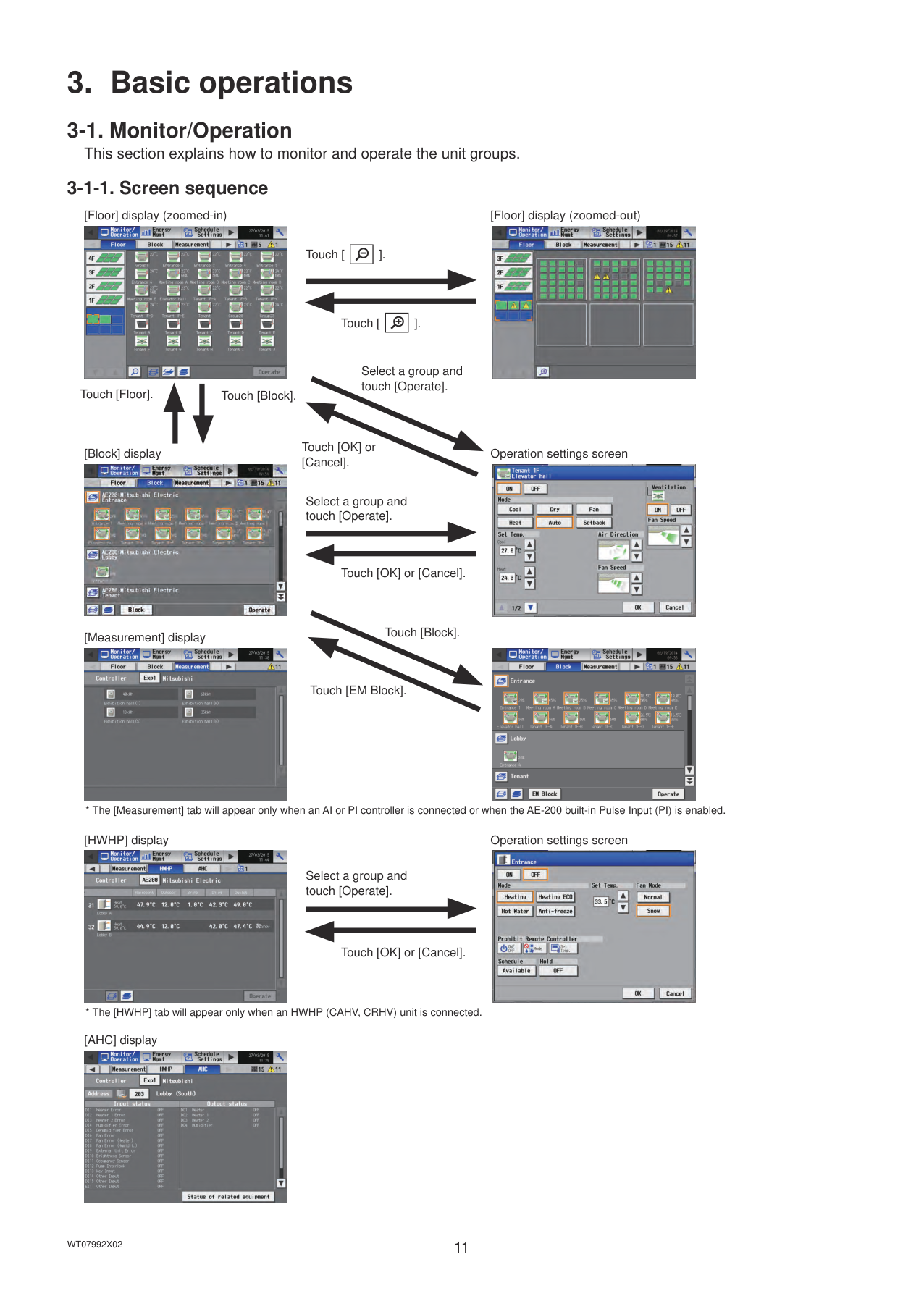
###### 3-1-1. Screen sequence
[Floor] display (zoomed-in) [Floor] display (zoomed-out)


| | |---|
Touch [
].
| | |---|
Touch [
].
Select a group and touch [Operate].
Touch [Floor].
Touch [Block].
Touch [OK] or [Cancel].
[Block] display Operation settings screen


Select a group and touch [Operate].
Touch [OK] or [Cancel].
[Measurement] display


Touch [EM Block].
Touch [Block].
Touch [OK] or [Cancel].
Select a group and touch [Operate].
[HWHP] display Operation settings screen


[AHC] display

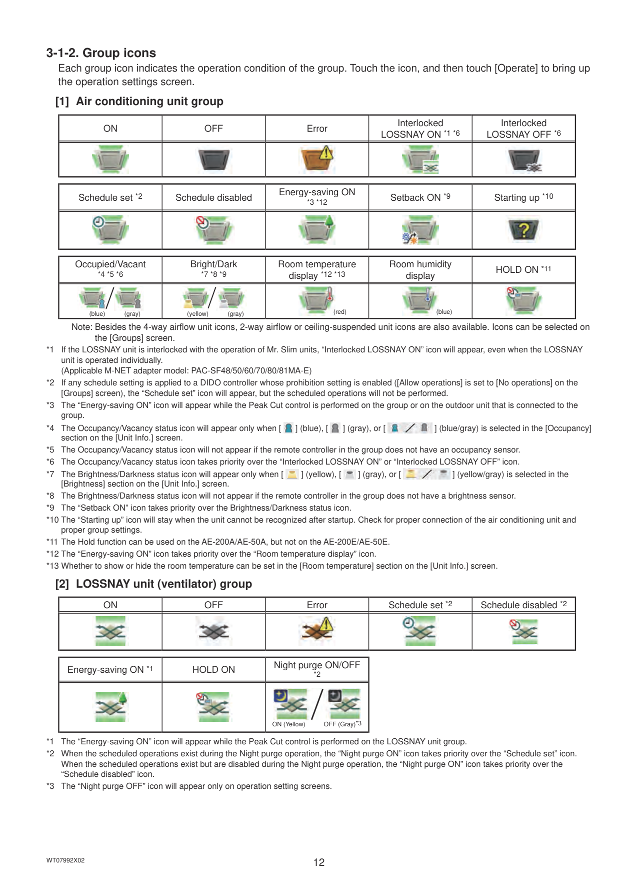
######## [1] Air conditioning unit group
|ON|OFF|Error|Interlocked LOSSNAY ON *1 *6|Interlocked LOSSNAY OFF *6| |---|---|---|---|---| ||||||
|Schedule set *2|Schedule disabled|Energy-saving ON *3 *12|Setback ON *9|Starting up *10| |---|---|---|---|---| ||||||
|Occupied/Vacant *4 *5 *6|Bright/Dark *7 *8 *9|Room temperature display *12 *13|Room humidity display|HOLD ON *11| |---|---|---|---|---| |

(gray)(blue)|

(gray)(yellow)|
(red)|
(blue)||
Note: Besides the 4-way airflow unit icons, 2-way airflow or ceiling-suspended unit icons are also available. Icons can be selected on the [Groups] screen.


|ON|OFF|Error|Schedule set *2|Schedule disabled *2| |---|---|---|---|---| ||||||
|Energy-saving ON *1|HOLD ON|Night purge ON/OFF *2| |---|---|---| |||
OFF (Gray)*3ON (Yellow)|
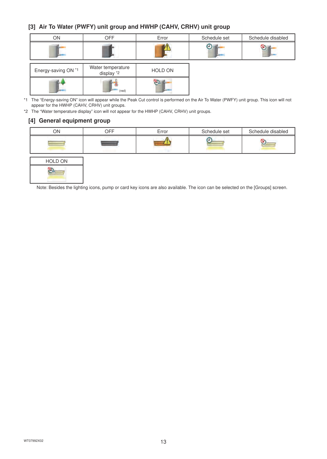
######## [3] Air To Water (PWFY) unit group and HWHP (CAHV, CRHV) unit group
|ON|OFF|Error|Schedule set|Schedule disabled| |---|---|---|---|---| ||||||
|Energy-saving ON *1|Water temperature display *2|HOLD ON| |---|---|---| ||
(red)||
|ON|OFF|Error|Schedule set|Schedule disabled| |---|---|---|---|---| ||||||
|HOLD ON| |---| ||
Note: Besides the lighting icons, pump or card key icons are also available. The icon can be selected on the [Groups] screen.
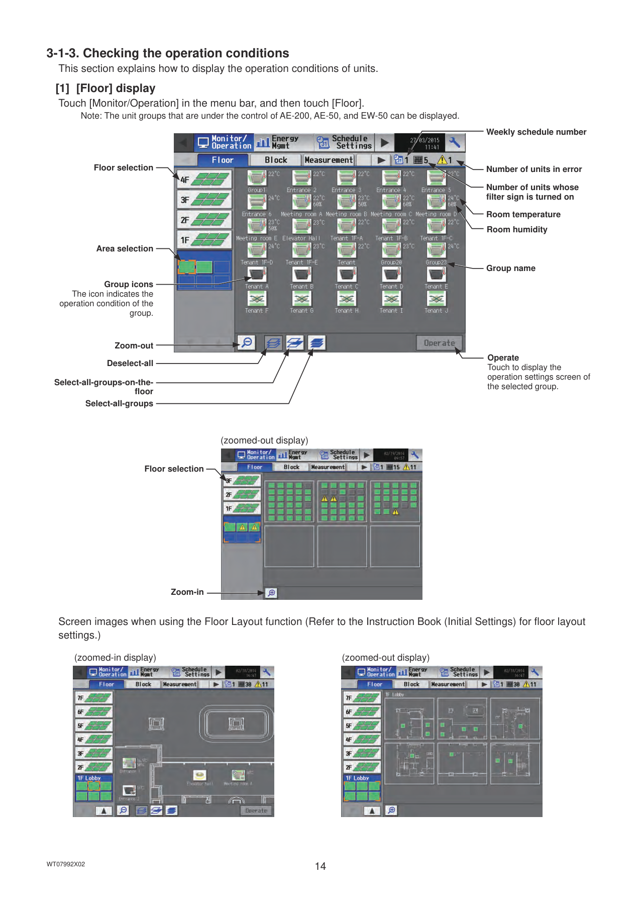
Note: The unit groups that are under the control of AE-200, AE-50, and EW-50 can be displayed.
Floor selection
Area selection
Group icons The icon indicates the
operation condition of the group.
Zoom-out Deselect-all
Select-all-groups-on-the-
floor Select-all-groups

Weekly schedule number
Number of units in error Number of units whose filter sign is turned on
Room temperature
Room humidity
Group name
Operate Touch to display the operation settings screen of the selected group.
(zoomed-out display)

Floor selection
Zoom-in
Screen images when using the Floor Layout function (Refer to the Instruction Book (Initial Settings) for floor layout settings.)
(zoomed-in display) (zoomed-out display)


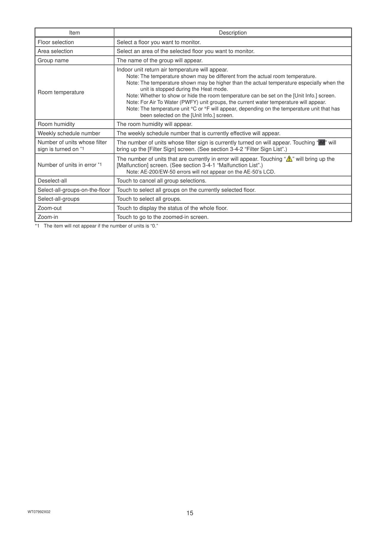
|Item|Description| |---|---| |Floor selection|Select a floor you want to monitor.|
|Area selection|Select an area of the selected floor you want to monitor.| |Group name|The name of the group will appear.| |Room temperature|Indoor unit return air temperature will appear. Note: The temperature shown may be different from the actual room temperature. Note: The temperature shown may be higher than the actual temperature especially when the
unit is stopped during the Heat mode. Note: Whether to show or hide the room temperature can be set on the [Unit Info.] screen. Note: For Air To Water (PWFY) unit groups, the current water temperature will appear. Note: The temperature unit °C or °F will appear, depending on the temperature unit that has
been selected on the [Unit Info.] screen.| |Room humidity|The room humidity will appear.| |Weekly schedule number|The weekly schedule number that is currently effective will appear.| |Number of units whose filter sign is turned on *1|The number of units whose filter sign is currently turned on will appear. Touching “ ” will bring up the [Filter Sign] screen. (See section 3-4-2 “Filter Sign List”.)
| |Number of units in error *1|The number of units that are currently in error will appear. Touching “ ” will bring up the [Malfunction] screen. (See section 3-4-1 “Malfunction List”.)
Note: AE-200/EW-50 errors will not appear on the AE-50’s LCD.| |Deselect-all|Touch to cancel all group selections.| |Select-all-groups-on-the-floor|Touch to select all groups on the currently selected floor.| |Select-all-groups|Touch to select all groups.| |Zoom-out|Touch to display the status of the whole floor.| |Zoom-in|Touch to go to the zoomed-in screen.|
############### *1 The item will not appear if the number of units is “0.”
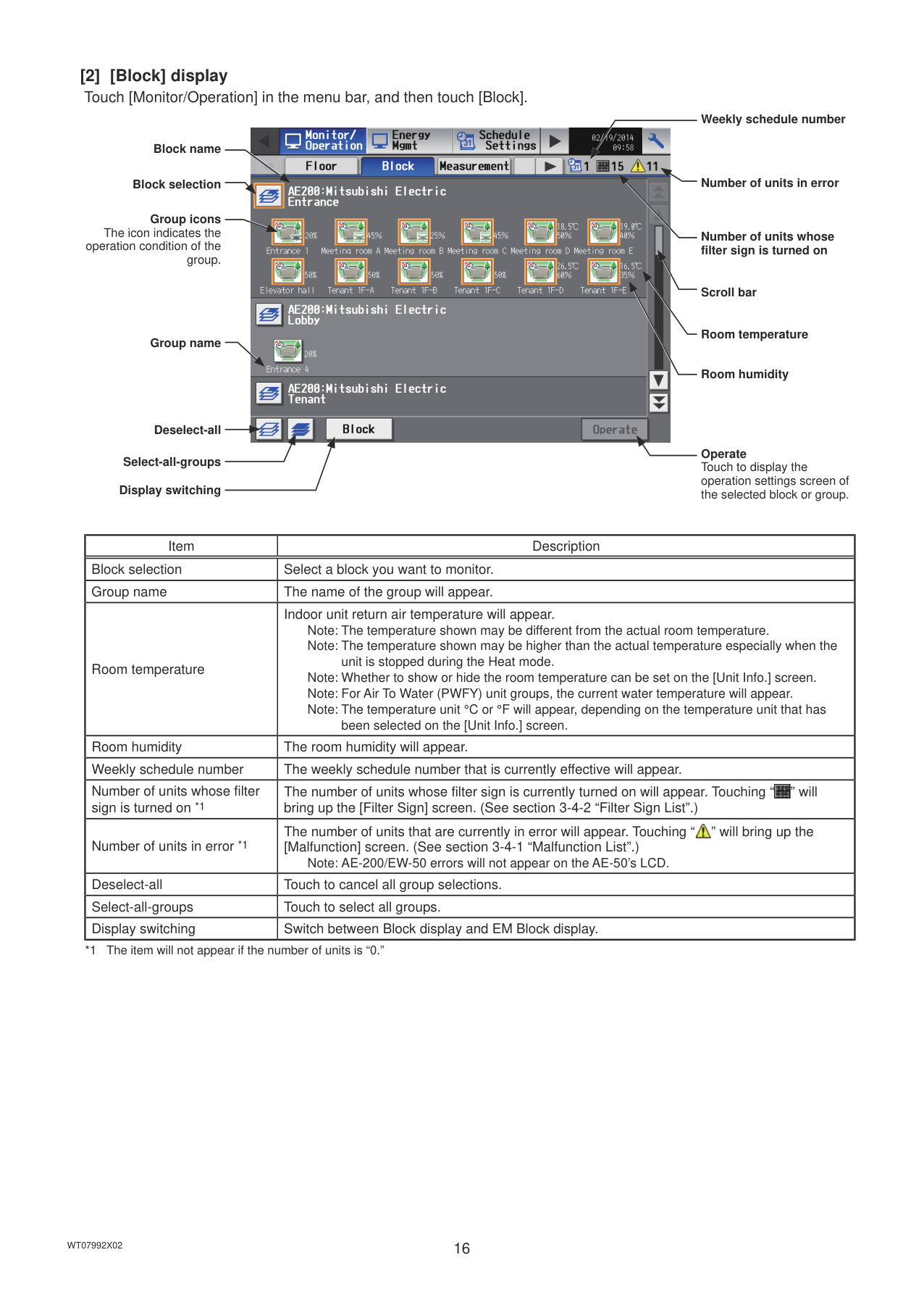
Block name
Block selection
Group icons The icon indicates the
operation condition of the group.
Group name
Deselect-all
Select-all-groups
Display switching

Weekly schedule number
Number of units in error
Number of units whose filter sign is turned on
Scroll bar
Room temperature
Room humidity
Operate Touch to display the operation settings screen of the selected block or group.
|Item|Description| |---|---| |Block selection|Select a block you want to monitor.| |Group name|The name of the group will appear.| |Room temperature|Indoor unit return air temperature will appear. Note: The temperature shown may be different from the actual room temperature. Note: The temperature shown may be higher than the actual temperature especially when the
unit is stopped during the Heat mode. Note: Whether to show or hide the room temperature can be set on the [Unit Info.] screen. Note: For Air To Water (PWFY) unit groups, the current water temperature will appear. Note: The temperature unit °C or °F will appear, depending on the temperature unit that has
been selected on the [Unit Info.] screen.| |Room humidity|The room humidity will appear.| |Weekly schedule number|The weekly schedule number that is currently effective will appear.| |Number of units whose filter sign is turned on *1|The number of units whose filter sign is currently turned on will appear. Touching “ ” will bring up the [Filter Sign] screen. (See section 3-4-2 “Filter Sign List”.)
| |Number of units in error *1|The number of units that are currently in error will appear. Touching “ ” will bring up the [Malfunction] screen. (See section 3-4-1 “Malfunction List”.)
Note: AE-200/EW-50 errors will not appear on the AE-50’s LCD.| |Deselect-all|Touch to cancel all group selections.| |Select-all-groups|Touch to select all groups.| |Display switching|Switch between Block display and EM Block display.|
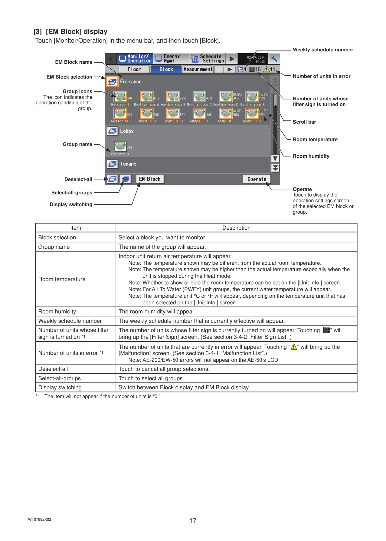
EM Block name
EM Block selection
Group icons The icon indicates the
operation condition of the group.
Group name
Deselect-all
Select-all-groups
Display switching

Weekly schedule number
Number of units in error
Number of units whose filter sign is turned on
Scroll bar
Room temperature
Room humidity
Operate Touch to display the operation settings screen of the selected EM block or group.
|Item|Description| |---|---|

|Block selection|Select a block you want to monitor.| |Group name|The name of the group will appear.| |Room temperature|Indoor unit return air temperature will appear. Note: The temperature shown may be different from the actual room temperature. Note: The temperature shown may be higher than the actual temperature especially when the
unit is stopped during the Heat mode. Note: Whether to show or hide the room temperature can be set on the [Unit Info.] screen. Note: For Air To Water (PWFY) unit groups, the current water temperature will appear. Note: The temperature unit °C or °F will appear, depending on the temperature unit that has
been selected on the [Unit Info.] screen.| |Room humidity|The room humidity will appear.| |Weekly schedule number|The weekly schedule number that is currently effective will appear.| |Number of units whose filter sign is turned on *1|The number of units whose filter sign is currently turned on will appear. Touching “ ” will bring up the [Filter Sign] screen. (See section 3-4-2 “Filter Sign List”.)
| |Number of units in error *1|The number of units that are currently in error will appear. Touching “ ” will bring up the [Malfunction] screen. (See section 3-4-1 “Malfunction List”.)
Note: AE-200/EW-50 errors will not appear on the AE-50’s LCD.| |Deselect-all|Touch to cancel all group selections.| |Select-all-groups|Touch to select all groups.| |Display switching|Switch between Block display and EM Block display.|
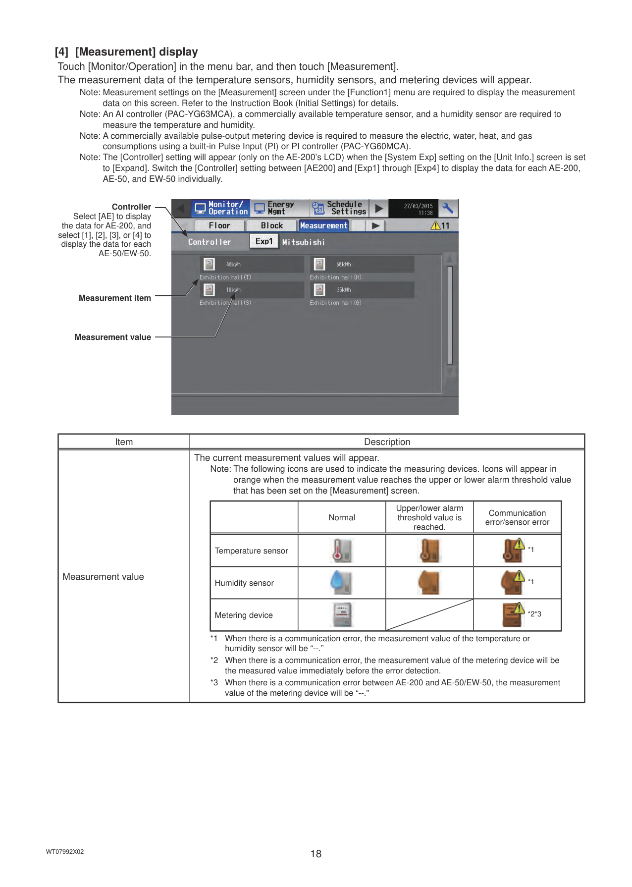
Note: Measurement settings on the [Measurement] screen under the [Function1] menu are required to display the measurement data on this screen. Refer to the Instruction Book (Initial Settings) for details. Note: An AI controller (PAC-YG63MCA), a commercially available temperature sensor, and a humidity sensor are required to measure the temperature and humidity. Note: A commercially available pulse-output metering device is required to measure the electric, water, heat, and gas consumptions using a built-in Pulse Input (PI) or PI controller (PAC-YG60MCA).
Note: The [Controller] setting will appear (only on the AE-200’s LCD) when the [System Exp] setting on the [Unit Info.] screen is set to [Expand]. Switch the [Controller] setting between [AE200] and [Exp1] through [Exp4] to display the data for each AE-200, AE-50, and EW-50 individually.

Controller Select [AE] to display
the data for AE-200, and select [1], [2], [3], or [4] to display the data for each AE-50/EW-50.
Measurement item
Measurement value
|Item|Description| |---|---| |Measurement value|The current measurement values will appear.
Note: The following icons are used to indicate the measuring devices. Icons will appear in orange when the measurement value reaches the upper or lower alarm threshold value that has been set on the [Measurement] screen.
| |Normal|Upper/lower alarm threshold value is reached.|Communication error/sensor error| |---|---|---|---| |Temperature sensor|||
*1|
|Humidity sensor|||
*1| |Metering device|| |
*2*3|
*1 When there is a communication error, the measurement value of the temperature or humidity sensor will be “--.”
*2 When there is a communication error, the measurement value of the metering device will be the measured value immediately before the error detection.
*3 When there is a communication error between AE-200 and AE-50/EW-50, the measurement value of the metering device will be “--.”
|
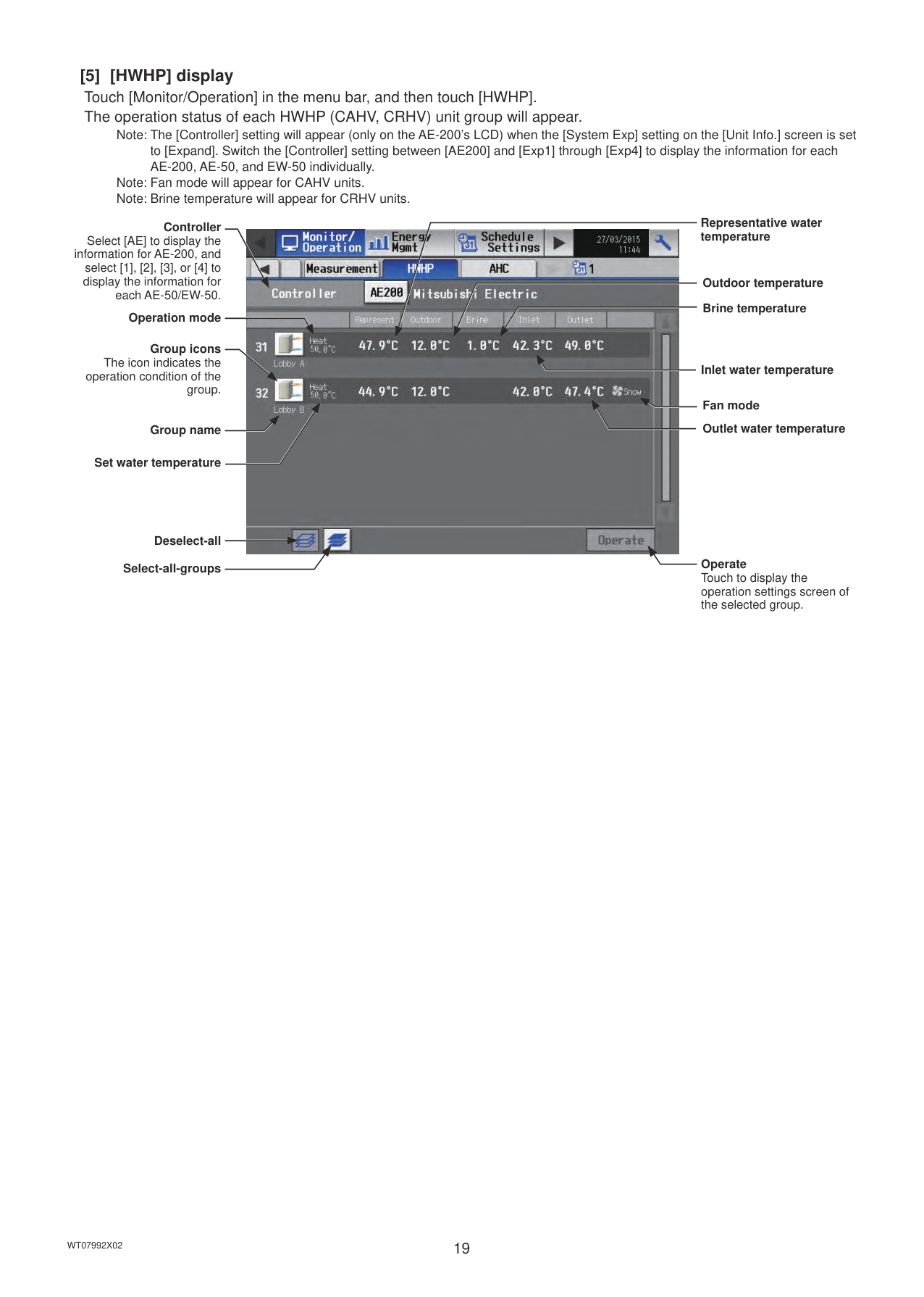
Note: The [Controller] setting will appear (only on the AE-200’s LCD) when the [System Exp] setting on the [Unit Info.] screen is set to [Expand]. Switch the [Controller] setting between [AE200] and [Exp1] through [Exp4] to display the information for each AE-200, AE-50, and EW-50 individually.
Note: Fan mode will appear for CAHV units. Note: Brine temperature will appear for CRHV units.
Controller Select [AE] to display the
information for AE-200, and select [1], [2], [3], or [4] to display the information for
each AE-50/EW-50.
Operation mode
Group icons The icon indicates the
operation condition of the group.
Group name
Set water temperature
Deselect-all Select-all-groups

Representative water temperature
Outdoor temperature
############## Brine temperature
Inlet water temperature
Fan mode
Outlet water temperature
Operate Touch to display the operation settings screen of the selected group.
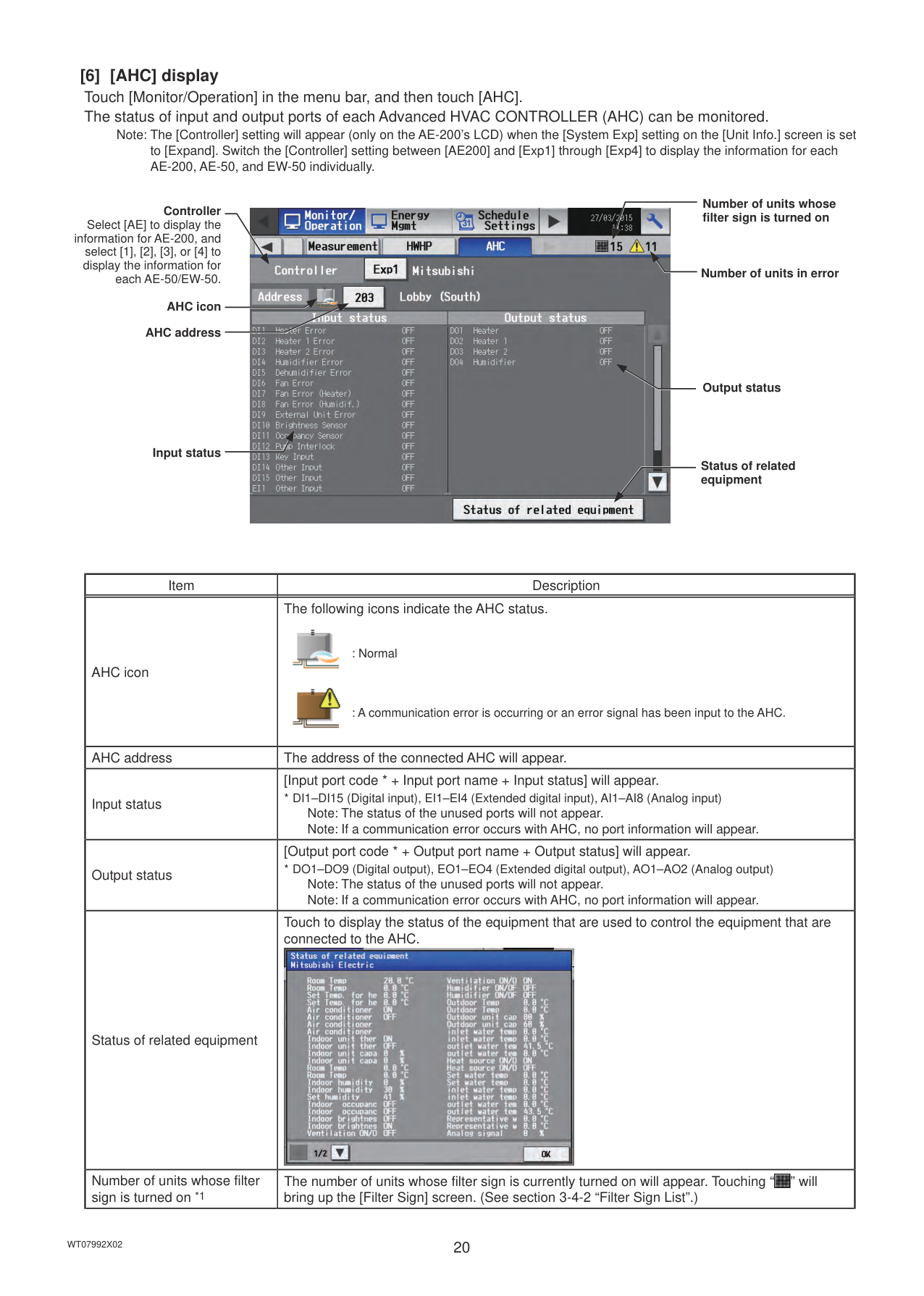
[6] [AHC] display Touch [Monitor/Operation] in the menu bar, and then touch [AHC]. The status of input and output ports of each Advanced HVAC CONTROLLER (AHC) can be monitored.
Note: The [Controller] setting will appear (only on the AE-200’s LCD) when the [System Exp] setting on the [Unit Info.] screen is set to [Expand]. Switch the [Controller] setting between [AE200] and [Exp1] through [Exp4] to display the information for each AE-200, AE-50, and EW-50 individually.
Controller Select [AE] to display the
information for AE-200, and select [1], [2], [3], or [4] to display the information for
each AE-50/EW-50.
AHC icon AHC address
Input status

Number of units whose filter sign is turned on
Number of units in error
Output status
Status of related equipment
|Item|Description| |---|---| |AHC icon|The following icons indicate the AHC status.

: Normal

: A communication error is occurring or an error signal has been input to the AHC.| |AHC address|The address of the connected AHC will appear.| |Input status|[Input port code * + Input port name + Input status] will appear.
* DI1–DI15 (Digital input), EI1–EI4 (Extended digital input), AI1–AI8 (Analog input) Note: The status of the unused ports will not appear. Note: If a communication error occurs with AHC, no port information will appear.| |Output status|[Output port code * + Output port name + Output status] will appear.
* DO1–DO9 (Digital output), EO1–EO4 (Extended digital output), AO1–AO2 (Analog output) Note: The status of the unused ports will not appear. Note: If a communication error occurs with AHC, no port information will appear.| |Status of related equipment|Touch to display the status of the equipment that are used to control the equipment that are connected to the AHC.
| |Number of units whose filter sign is turned on *1|The number of units whose filter sign is currently turned on will appear. Touching “ ” will bring up the [Filter Sign] screen. (See section 3-4-2 “Filter Sign List”.)
|
|Item|Description| |---|---| |Number of units in error *1|The number of units that are currently in error will appear. Touching “ ” will bring up the [Malfunction] screen. (See section 3-4-1 “Malfunction List”.)|
############### *1 The item will not appear if the number of units is “0.”
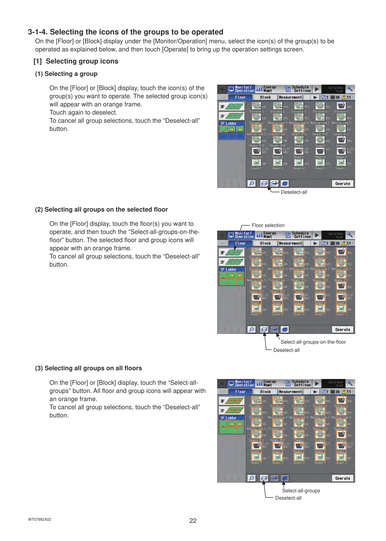
######## [1] Selecting group icons
########## (1) Selecting a group
On the [Floor] or [Block] display, touch the icon(s) of the group(s) you want to operate. The selected group icon(s) will appear with an orange frame. Touch again to deselect. To cancel all group selections, touch the “Deselect-all” button.

Deselect-all
########## (2) Selecting all groups on the selected floor
On the [Floor] display, touch the floor(s) you want to operate, and then touch the “Select-all-groups-on-thefloor” button. The selected floor and group icons will appear with an orange frame. To cancel all group selections, touch the “Deselect-all” button.
Floor selection

Select-all-groups-on-the-floor Deselect-all
########## (3) Selecting all groups on all floors
On the [Floor] or [Block] display, touch the “Select-allgroups” button. All floor and group icons will appear with an orange frame. To cancel all group selections, touch the “Deselect-all” button.

Select-all-groups
Deselect-all
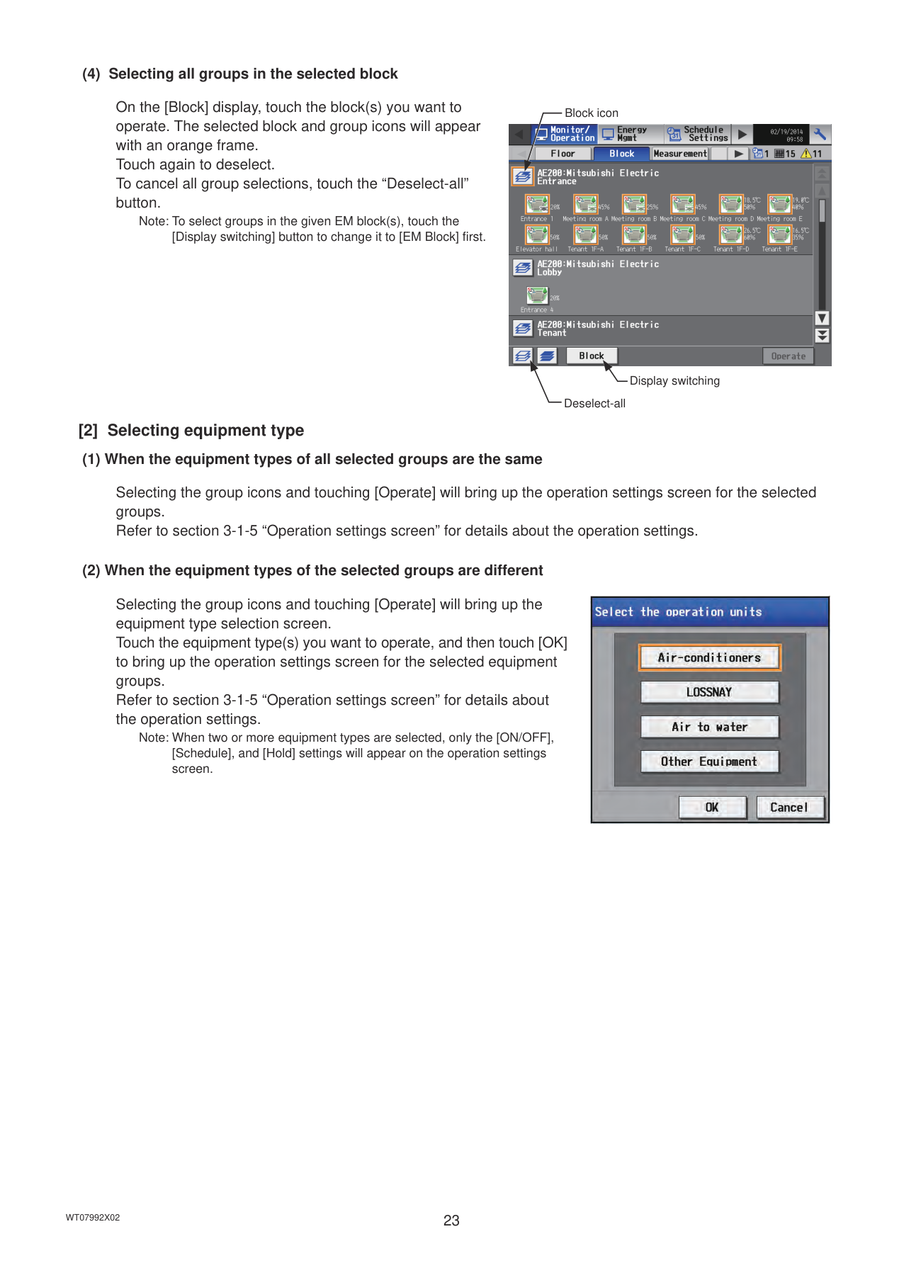
########## (4) Selecting all groups in the selected block
On the [Block] display, touch the block(s) you want to operate. The selected block and group icons will appear with an orange frame. Touch again to deselect. To cancel all group selections, touch the “Deselect-all” button.
Note: To select groups in the given EM block(s), touch the [Display switching] button to change it to [EM Block] first.
Block icon

Display switching
Deselect-all
######## [2] Selecting equipment type
########## (1) When the equipment types of all selected groups are the same
Selecting the group icons and touching [Operate] will bring up the operation settings screen for the selected groups. Refer to section 3-1-5 “Operation settings screen” for details about the operation settings.
########## (2) When the equipment types of the selected groups are different
Selecting the group icons and touching [Operate] will bring up the equipment type selection screen. Touch the equipment type(s) you want to operate, and then touch [OK] to bring up the operation settings screen for the selected equipment groups. Refer to section 3-1-5 “Operation settings screen” for details about the operation settings.
Note: When two or more equipment types are selected, only the [ON/OFF], [Schedule], and [Hold] settings will appear on the operation settings screen.

Note: The selected buttons will appear with an orange frame. Note: When the setting is changed from other controllers, the operation conditions shown on the screen will not be updated while
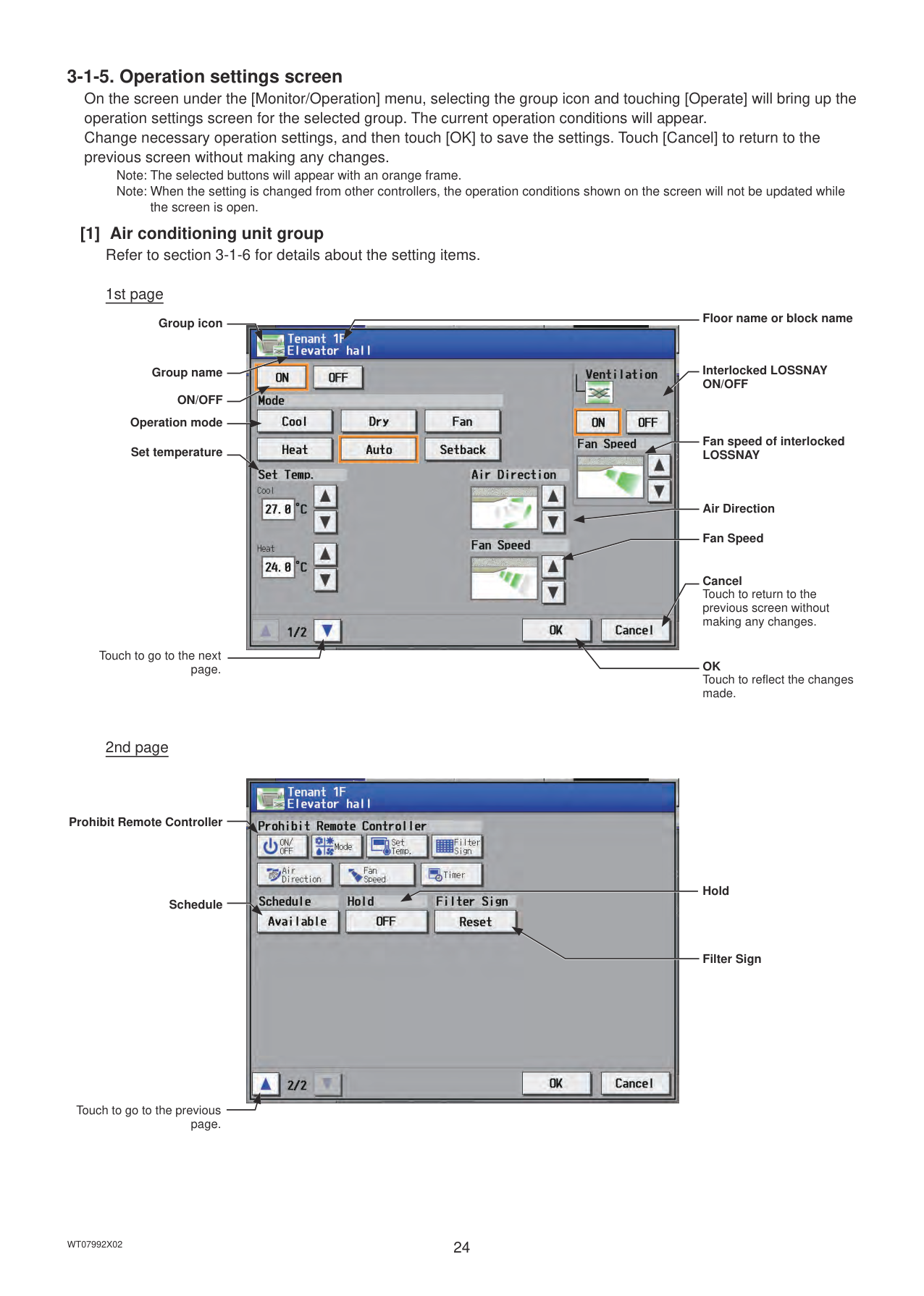
######## the screen is open. [1] Air conditioning unit group
Refer to section 3-1-6 for details about the setting items.

Group icon
Group name
ON/OFF Operation mode
Set temperature
Touch to go to the next page.
Floor name or block name
Interlocked LOSSNAY ON/OFF
Fan speed of interlocked LOSSNAY
Air Direction
Fan Speed
Cancel Touch to return to the previous screen without making any changes.
OK Touch to reflect the changes made.
Prohibit Remote Controller
Schedule
Touch to go to the previous page.

Hold
Filter Sign

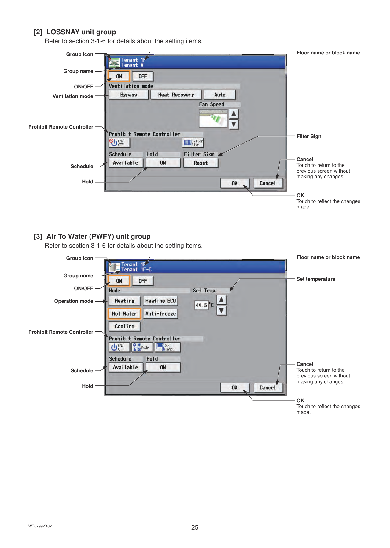
Group icon
Group name
ON/OFF
Ventilation mode
Prohibit Remote Controller
Schedule
Hold
Floor name or block name
Filter Sign
Cancel Touch to return to the previous screen without making any changes.
OK Touch to reflect the changes made.
Floor name or block name
Group icon

Group name
Set temperature
ON/OFF
Operation mode
Prohibit Remote Controller
Cancel
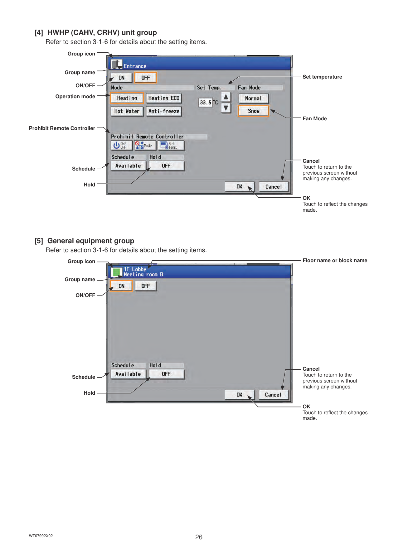
######## [4] HWHP (CAHV, CRHV) unit group
Refer to section 3-1-6 for details about the setting items.
Group icon
Group name
ON/OFF
Operation mode
Prohibit Remote Controller
Schedule
Hold

Set temperature
Fan Mode
Cancel Touch to return to the previous screen without making any changes.
OK Touch to reflect the changes made.
######## [5] General equipment group
Refer to section 3-1-6 for details about the setting items.
Floor name or block name
Group icon

Group name
ON/OFF
Cancel Touch to return to the
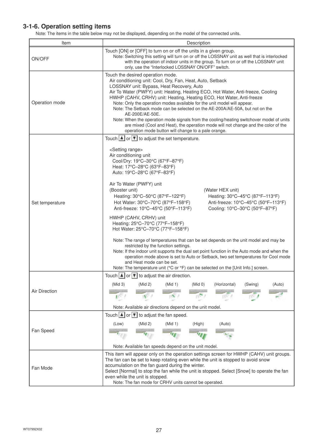
####### 3-1-6. Operation setting itemsNote: The items in the table below may not be displayed, depending on the model of the connected units.
|Item|Description| |---|---| |ON/OFF|Touch [ON] or [OFF] to turn on or off the units in a given group.
Note: Switching this setting will turn on or off the LOSSNAY unit as well that is interlocked with the operation of indoor units in the group. To turn on or off the LOSSNAY unit only, use the “Interlocked LOSSNAY ON/OFF” switch.| |Operation mode|Touch the desired operation mode. Air conditioning unit: Cool, Dry, Fan, Heat, Auto, Setback LOSSNAY unit: Bypass, Heat Recovery, Auto Air To Water (PWFY) unit: Heating, Heating ECO, Hot Water, Anti-freeze, Cooling HWHP (CAHV, CRHV) unit: Heating, Heating ECO, Hot Water, Anti-freeze
Note: Only the operation modes available for the unit model will appear. Note: The Setback mode can be selected on the AE-200A/AE-50A, but not on the
AE-200E/AE-50E.
Note: When the operation mode signals from the cooling/heating switchover model of units are mixed (Cool and Heat), the operation mode will not change and the color of the operation mode button will change to a pale orange.| |Set temperature|Touch or to adjust the set temperature.


Cool/Dry: 19°C–30°C (67°F–87°F) Heat: 17°C–28°C (63°F–83°F) Auto: 19°C–28°C (67°F–83°F)
Air To Water (PWFY) unit (Booster unit) (Water HEX unit)
Heating: 30°C–50°C (87°F–122°F) Heating: 30°C–45°C (87°F–113°F) Hot Water: 30°C–70°C (87°F–158°F) Anti-freeze: 10°C–45°C (50°F–113°F) Anti-freeze: 10°C–45°C (50°F–113°F) Cooling: 10°C–30°C (50°F–87°F)
HWHP (CAHV, CRHV) unit Heating: 25°C–70°C (77°F–158°F) Hot Water: 25°C–70°C (77°F–158°F)
Note: The range of temperatures that can be set depends on the unit model and may be restricted by the function settings.
Note: If the indoor unit supports the dual set point function in the Auto mode and when the operation mode above is set to Auto or Setback, two set temperatures for Cool mode and Heat mode can be set.
Note: The temperature unit (°C or °F) can be selected on the [Unit Info.] screen.| |Air Direction|Touch or to adjust the air direction.
(Mid 3) (Mid 2) (Mid 1) (Mid 0) (Horizontal) (Swing) (Auto)


Note: Available air directions depend on the unit model.| |Fan Speed|Touch or to adjust the fan speed.
(Low) (Mid 2) (Mid 1) (High) (Auto)


Note: Available fan speeds depend on the unit model.| |Fan Mode|This item will appear only on the operation settings screen for HWHP (CAHV) unit groups. The fan can be set to keep rotating even while the unit is stopped to avoid snow accumulation on the fan guard during the winter. Select [Normal] to stop the fan while the unit is stopped. Select [Snow] to operate the fan even while the unit is stopped.
Note: The fan mode for CRHV units cannot be operated.|
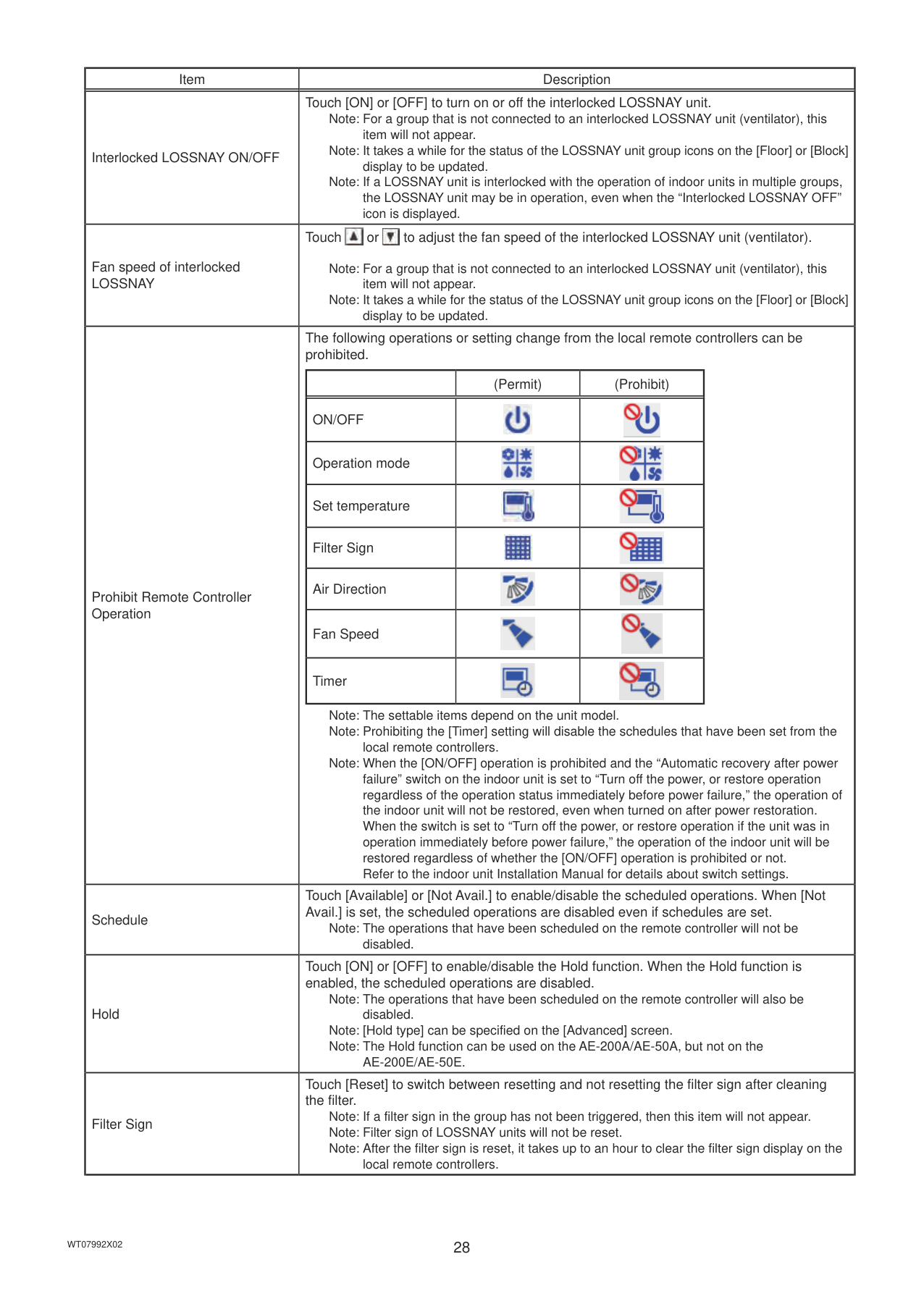
|Item|Description| |---|---| |Interlocked LOSSNAY ON/OFF|Touch [ON] or [OFF] to turn on or off the interlocked LOSSNAY unit.
Note: For a group that is not connected to an interlocked LOSSNAY unit (ventilator), this item will not appear. Note: It takes a while for the status of the LOSSNAY unit group icons on the [Floor] or [Block] display to be updated.
Note: If a LOSSNAY unit is interlocked with the operation of indoor units in multiple groups, the LOSSNAY unit may be in operation, even when the “Interlocked LOSSNAY OFF” icon is displayed.|
|Fan speed of interlocked LOSSNAY|Touch or to adjust the fan speed of the interlocked LOSSNAY unit (ventilator).
Note: For a group that is not connected to an interlocked LOSSNAY unit (ventilator), this item will not appear. Note: It takes a while for the status of the LOSSNAY unit group icons on the [Floor] or [Block] display to be updated.| |Prohibit Remote Controller Operation|The following operations or setting change from the local remote controllers can be prohibited.
| |(Permit)|(Prohibit)| |---|---|---| |ON/OFF||| |Operation mode||| |Set temperature||| |Filter Sign||| |Air Direction||| |Fan Speed||| |Timer|||
Note: The settable items depend on the unit model. Note: Prohibiting the [Timer] setting will disable the schedules that have been set from the
local remote controllers.
Note: When the [ON/OFF] operation is prohibited and the “Automatic recovery after power failure” switch on the indoor unit is set to “Turn off the power, or restore operation regardless of the operation status immediately before power failure,” the operation of the indoor unit will not be restored, even when turned on after power restoration. When the switch is set to “Turn off the power, or restore operation if the unit was in operation immediately before power failure,” the operation of the indoor unit will be restored regardless of whether the [ON/OFF] operation is prohibited or not. Refer to the indoor unit Installation Manual for details about switch settings.| |Schedule|Touch [Available] or [Not Avail.] to enable/disable the scheduled operations. When [Not Avail.] is set, the scheduled operations are disabled even if schedules are set.
Note: The operations that have been scheduled on the remote controller will not be disabled.| |Hold|Touch [ON] or [OFF] to enable/disable the Hold function. When the Hold function is enabled, the scheduled operations are disabled.
Note: The operations that have been scheduled on the remote controller will also be
disabled. Note: [Hold type] can be specified on the [Advanced] screen. Note: The Hold function can be used on the AE-200A/AE-50A, but not on the
AE-200E/AE-50E.| |Filter Sign|Touch [Reset] to switch between resetting and not resetting the filter sign after cleaning the filter.
Note: If a filter sign in the group has not been triggered, then this item will not appear. Note: Filter sign of LOSSNAY units will not be reset. Note: After the filter sign is reset, it takes up to an hour to clear the filter sign display on the
local remote controllers.|
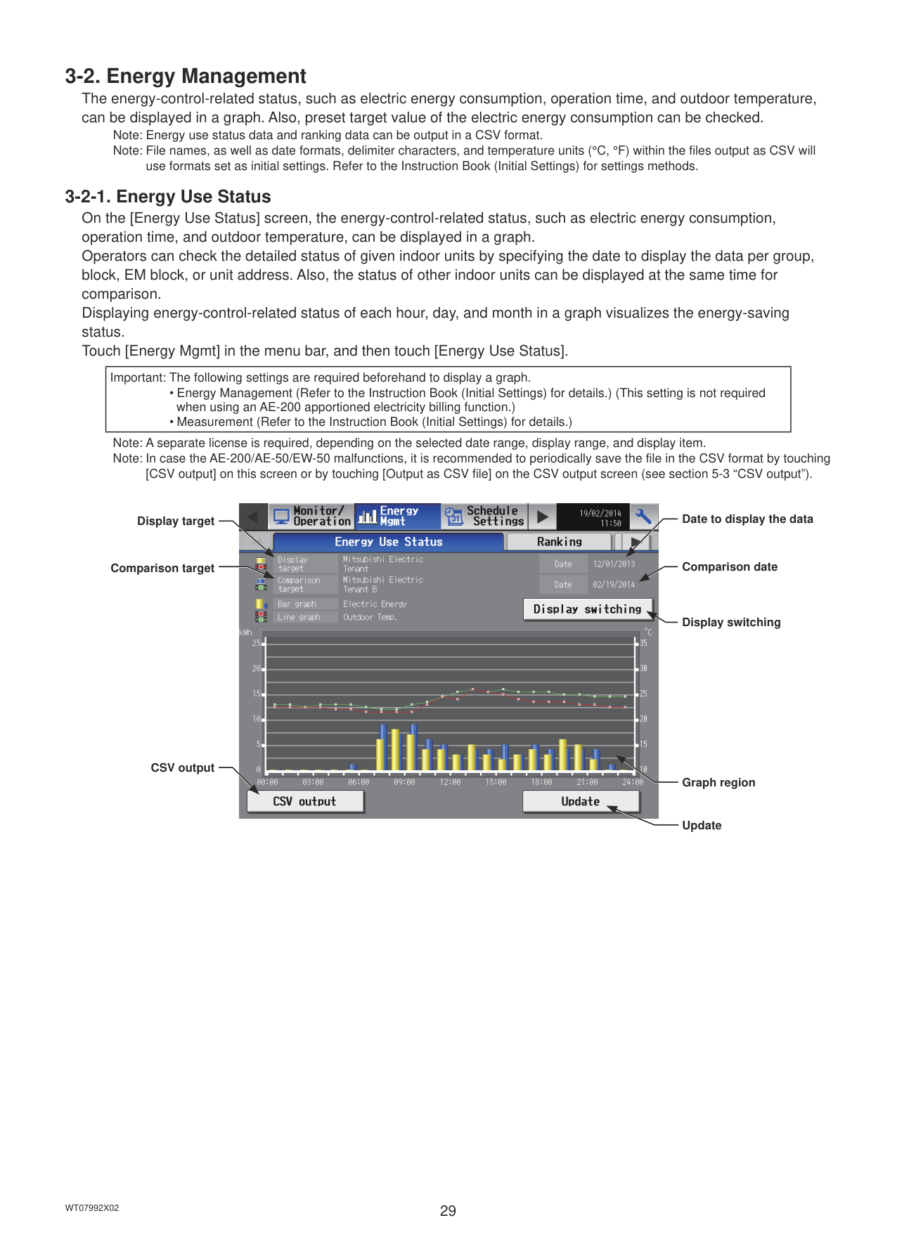
#### 3-2. Energy Management
The energy-control-related status, such as electric energy consumption, operation time, and outdoor temperature, can be displayed in a graph. Also, preset target value of the electric energy consumption can be checked.
Note: Energy use status data and ranking data can be output in a CSV format. Note: File names, as well as date formats, delimiter characters, and temperature units (°C, °F) within the files output as CSV will
use formats set as initial settings. Refer to the Instruction Book (Initial Settings) for settings methods.
|Important: The following settings are required beforehand to display a graph.
• Energy Management (Refer to the Instruction Book (Initial Settings) for details.) (This setting is not required when using an AE-200 apportioned electricity billing function.)
• Measurement (Refer to the Instruction Book (Initial Settings) for details.)
| |---|
Note: A separate license is required, depending on the selected date range, display range, and display item. Note: In case the AE-200/AE-50/EW-50 malfunctions, it is recommended to periodically save the file in the CSV format by touching
[CSV output] on this screen or by touching [Output as CSV file] on the CSV output screen (see section 5-3 “CSV output”).
Display target
Comparison target
CSV output

Date to display the data
Comparison date
Display switching
Graph region
Update
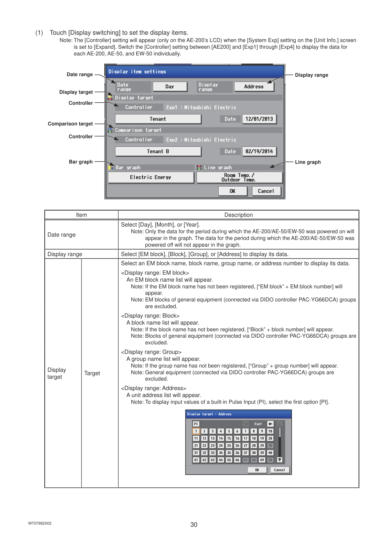
is set to [Expand]. Switch the [Controller] setting between [AE200] and [Exp1] through [Exp4] to display the data for each AE-200, AE-50, and EW-50 individually.
Date range
Display target
Controller
Comparison target
Controller
Bar graph

Display range
Line graph
|Item|Item|Description| |---|---|---| |Date range|Date range|Select [Day], [Month], or [Year].
Note: Only the data for the period during which the AE-200/AE-50/EW-50 was powered on will appear in the graph. The data for the period during which the AE-200/AE-50/EW-50 was powered off will not appear in the graph.| |Display range|Display range|Select [EM block], [Block], [Group], or [Address] to display its data.| |Display target|Target|Select an EM block name, block name, group name, or address number to display its data.
An EM block name list will appear.
Note: If the EM block name has not been registered, [“EM block” + EM block number] will appear. Note: EM blocks of general equipment (connected via DIDO controller PAC-YG66DCA) groups are excluded.
A block name list will appear. Note: If the block name has not been registered, [“Block” + block number] will appear. Note: Blocks of general equipment (connected via DIDO controller PAC-YG66DCA) groups are
excluded.
A group name list will appear. Note: If the group name has not been registered, [“Group” + group number] will appear. Note: General equipment (connected via DIDO controller PAC-YG66DCA) groups are
excluded.
Note: To display input values of a built-in Pulse Input (PI), select the first option [PI].
|| |---| |
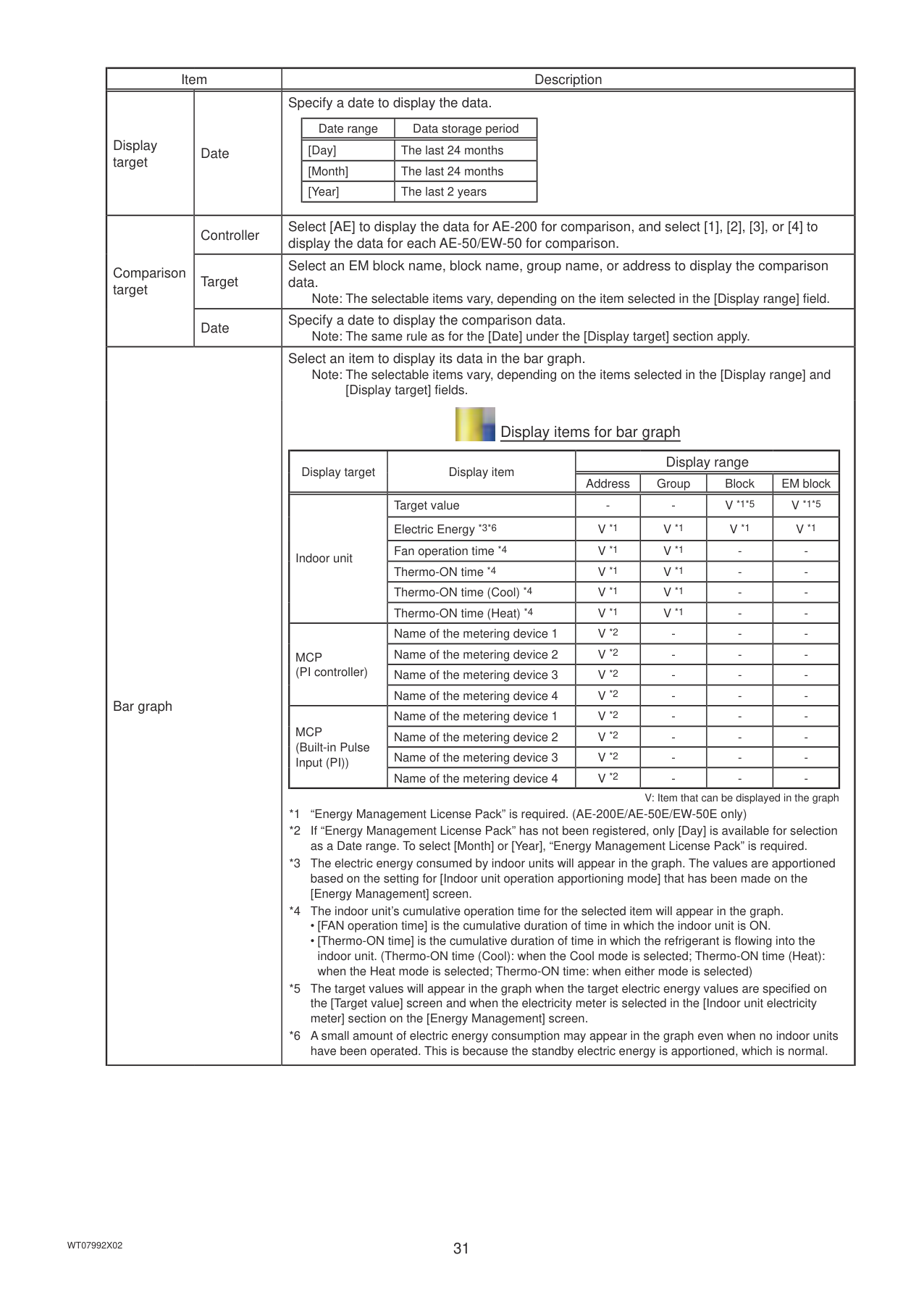
|Item|Item|Description| |---|---|---| |Display target|Date|Specify a date to display the data.
|Date range|Data storage period| |---|---| |[Day]|The last 24 months| |[Month]|The last 24 months| |[Year]|The last 2 years| | |Comparison target|Controller|Select [AE] to display the data for AE-200 for comparison, and select [1], [2], [3], or [4] to display the data for each AE-50/EW-50 for comparison.| |Comparison target|Target|Select an EM block name, block name, group name, or address to display the comparison data.
Note: The selectable items vary, depending on the item selected in the [Display range] field.| |Comparison target|Date|Specify a date to display the comparison data.
Note: The same rule as for the [Date] under the [Display target] section apply.| |Bar graph|Bar graph|Select an item to display its data in the bar graph.
Note: The selectable items vary, depending on the items selected in the [Display range] and [Display target] fields.

Display items for bar graph
|Display target|Display item|Display range|Display range|Display range|Display range| |---|---|---|---|---|---| |Display target|Display item|Address|Group|Block|EM block| |Indoor unit|Target value|-|-|V *1*5|V *1*5| |Indoor unit|Electric Energy *3*6|V *1|V *1|V *1|V *1| |Indoor unit|Fan operation time *4|V *1|V *1|-|-|
|Indoor unit|Thermo-ON time *4|V *1|V *1|-|-| |Indoor unit|Thermo-ON time (Cool) *4|V *1|V *1|-|-| |Indoor unit|Thermo-ON time (Heat) *4|V *1|V *1|-|-| |MCP (PI controller)|Name of the metering device 1|V *2|-|-|-| |MCP (PI controller)|Name of the metering device 2|V *2|-|-|-| |MCP (PI controller)|Name of the metering device 3|V *2|-|-|-| |MCP (PI controller)|Name of the metering device 4|V *2|-|-|-| |MCP (Built-in Pulse Input (PI))|Name of the metering device 1|V *2|-|-|-| |MCP (Built-in Pulse Input (PI))|Name of the metering device 2|V *2|-|-|-| |MCP (Built-in Pulse Input (PI))|Name of the metering device 3|V *2|-|-|-| |MCP (Built-in Pulse Input (PI))|Name of the metering device 4|V *2|-|-|-|
V: Item that can be displayed in the graph
*1 “Energy Management License Pack” is required. (AE-200E/AE-50E/EW-50E only)
*2 If “Energy Management License Pack” has not been registered, only [Day] is available for selection as a Date range. To select [Month] or [Year], “Energy Management License Pack” is required.
*3 The electric energy consumed by indoor units will appear in the graph. The values are apportioned based on the setting for [Indoor unit operation apportioning mode] that has been made on the [Energy Management] screen.
*4 The indoor unit’s cumulative operation time for the selected item will appear in the graph.
• [FAN operation time] is the cumulative duration of time in which the indoor unit is ON.
• [Thermo-ON time] is the cumulative duration of time in which the refrigerant is flowing into the indoor unit. (Thermo-ON time (Cool): when the Cool mode is selected; Thermo-ON time (Heat): when the Heat mode is selected; Thermo-ON time: when either mode is selected)
*5 The target values will appear in the graph when the target electric energy values are specified on the [Target value] screen and when the electricity meter is selected in the [Indoor unit electricity meter] section on the [Energy Management] screen.
*6 A small amount of electric energy consumption may appear in the graph even when no indoor units have been operated. This is because the standby electric energy is apportioned, which is normal.
|
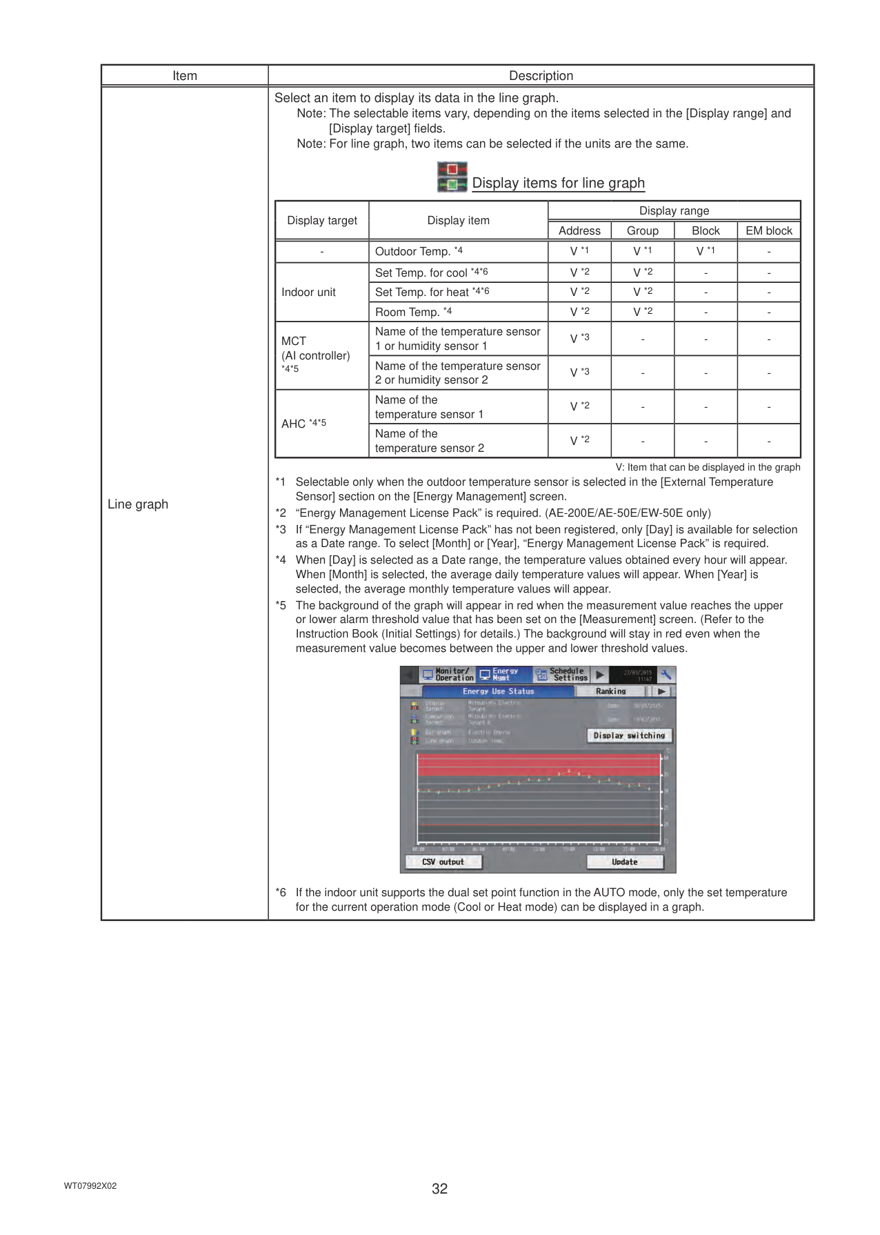
|Item|Description| |---|---| |Line graph|Select an item to display its data in the line graph.
Note: The selectable items vary, depending on the items selected in the [Display range] and [Display target] fields. Note: For line graph, two items can be selected if the units are the same.

Display items for line graph
|Display target|Display item|Display range|Display range|Display range|Display range| |---|---|---|---|---|---| |Display target|Display item|Address|Group|Block|EM block| |-|Outdoor Temp. *4|V *1|V *1|V *1|-| |Indoor unit|Set Temp. for cool *4*6|V *2|V *2|-|-| |Indoor unit|Set Temp. for heat *4*6|V *2|V *2|-|-| |Indoor unit|Room Temp. *4|V *2|V *2|-|-| |MCT (AI controller)
*4*5|Name of the temperature sensor 1 or humidity sensor 1|V *3|-|-|-| |MCT (AI controller)
*4*5|Name of the temperature sensor 2 or humidity sensor 2|V *3|-|-|-| |AHC *4*5|Name of the temperature sensor 1|V *2|-|-|-| |AHC *4*5|Name of the temperature sensor 2|V *2|-|-|-|
V: Item that can be displayed in the graph
*1 Selectable only when the outdoor temperature sensor is selected in the [External Temperature Sensor] section on the [Energy Management] screen.
*2 “Energy Management License Pack” is required. (AE-200E/AE-50E/EW-50E only)
*3 If “Energy Management License Pack” has not been registered, only [Day] is available for selection as a Date range. To select [Month] or [Year], “Energy Management License Pack” is required.
*4 When [Day] is selected as a Date range, the temperature values obtained every hour will appear. When [Month] is selected, the average daily temperature values will appear. When [Year] is selected, the average monthly temperature values will appear.
*5 The background of the graph will appear in red when the measurement value reaches the upper or lower alarm threshold value that has been set on the [Measurement] screen. (Refer to the Instruction Book (Initial Settings) for details.) The background will stay in red even when the measurement value becomes between the upper and lower threshold values.
|| |---|
*6 If the indoor unit supports the dual set point function in the AUTO mode, only the set temperature for the current operation mode (Cool or Heat mode) can be displayed in a graph.
|
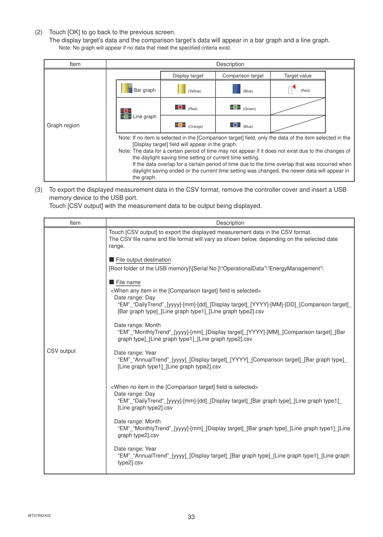
########### (2) Touch [OK] to go back to the previous screen.The display target’s data and the comparison target’s data will appear in a bar graph and a line graph.
Note: No graph will appear if no data that meet the specified criteria exist.
|Item|Description| |---|---| |Graph region|| |Display target|Comparison target|Target value| |---|---|---|---| |
Bar graph|
(Yellow)|
(Blue)|
(Red)| |
Line graph|
(Red)|
(Green)| | |
Line graph|
(Orange)|
(Blue)| |
Note: If no item is selected in the [Comparison target] field, only the data of the item selected in the [Display target] field will appear in the graph.
Note: The data for a certain period of time may not appear if it does not exist due to the changes of the daylight saving time setting or current time setting. If the data overlap for a certain period of time due to the time overlap that was occurred when daylight saving ended or the current time setting was changed, the newer data will appear in the graph.|
########### (3) To export the displayed measurement data in the CSV format, remove the controller cover and insert a USBmemory device to the USB port.Touch [CSV output] with the measurement data to be output being displayed.
|Item|Description| |---|---| |CSV output|Touch [CSV output] to export the displayed measurement data in the CSV format. The CSV file name and file format will vary as shown below, depending on the selected date range.
■ File output destination [Root folder of the USB memory]\[Serial No.]\“OperationalData”\“EnergyManagement”\
■ File name
Date range: Day “EM”_“DailyTrend”_[yyyy]-[mm]-[dd]_[Display target]_[YYYY]-[MM]-[DD]_[Comparison target]_ [Bar graph type]_[Line graph type1]_[Line graph type2].csv
Date range: Month “EM”_“MonthlyTrend”_[yyyy]-[mm]_[Display target]_[YYYY]-[MM]_[Comparison target]_[Bar graph type]_[Line graph type1]_[Line graph type2].csv
Date range: Year “EM”_“AnnualTrend”_[yyyy]_[Display target]_[YYYY]_[Comparison target]_[Bar graph type]_ [Line graph type1]_[Line graph type2].csv
Date range: Day “EM”_“DailyTrend”_[yyyy]-[mm]-[dd]_[Display target]_[Bar graph type]_[Line graph type1]_ [Line graph type2].csv
Date range: Month “EM”_“MonthlyTrend”_[yyyy]-[mm]_[Display target]_[Bar graph type]_[Line graph type1]_[Line graph type2].csv
Date range: Year “EM”_“AnnualTrend”_[yyyy]_[Display target]_[Bar graph type]_[Line graph type1]_[Line graph type2].csv|
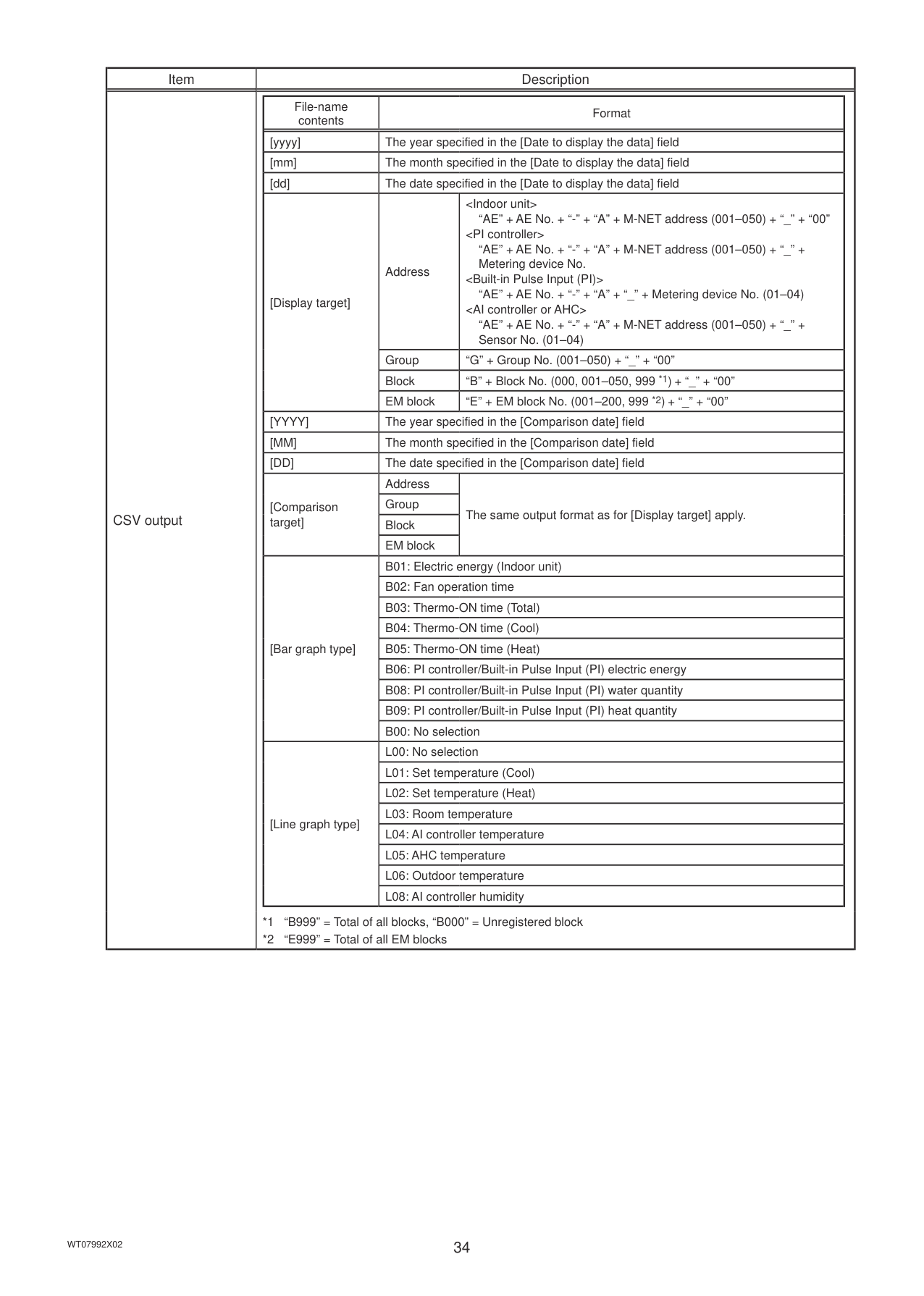
|Item|Description| |---|---| |CSV output||File-name contents|Format|Format| |---|---|---| |[yyyy]|The year specified in the [Date to display the data] field|The year specified in the [Date to display the data] field| |[mm]|The month specified in the [Date to display the data] field|The month specified in the [Date to display the data] field| |[dd]|The date specified in the [Date to display the data] field|The date specified in the [Date to display the data] field| |[Display target]|Address|
“AE” + AE No. + “-” + “A” + “_” + Metering device No. (01–04)
|[Comparison target]|Group|The same output format as for [Display target] apply.| |[Comparison target]|Block|The same output format as for [Display target] apply.| |[Comparison target]|EM block|The same output format as for [Display target] apply.| |[Bar graph type]|B01: Electric energy (Indoor unit)|B01: Electric energy (Indoor unit)| |[Bar graph type]|B02: Fan operation time|B02: Fan operation time| |[Bar graph type]|B03: Thermo-ON time (Total)|B03: Thermo-ON time (Total)| |[Bar graph type]|B04: Thermo-ON time (Cool)|B04: Thermo-ON time (Cool)| |[Bar graph type]|B05: Thermo-ON time (Heat)|B05: Thermo-ON time (Heat)| |[Bar graph type]|B06: PI controller/Built-in Pulse Input (PI) electric energy|B06: PI controller/Built-in Pulse Input (PI) electric energy| |[Bar graph type]|B08: PI controller/Built-in Pulse Input (PI) water quantity|B08: PI controller/Built-in Pulse Input (PI) water quantity| |[Bar graph type]|B09: PI controller/Built-in Pulse Input (PI) heat quantity|B09: PI controller/Built-in Pulse Input (PI) heat quantity| |[Bar graph type]|B00: No selection|B00: No selection| |[Line graph type]|L00: No selection|L00: No selection| |[Line graph type]|L01: Set temperature (Cool)|L01: Set temperature (Cool)| |[Line graph type]|L02: Set temperature (Heat)|L02: Set temperature (Heat)| |[Line graph type]|L03: Room temperature|L03: Room temperature| |[Line graph type]|L04: AI controller temperature|L04: AI controller temperature| |[Line graph type]|L05: AHC temperature|L05: AHC temperature| |[Line graph type]|L06: Outdoor temperature|L06: Outdoor temperature| |[Line graph type]|L08: AI controller humidity|L08: AI controller humidity|
*1 “B999” = Total of all blocks, “B000” = Unregistered block
*2 “E999” = Total of all EM blocks
|
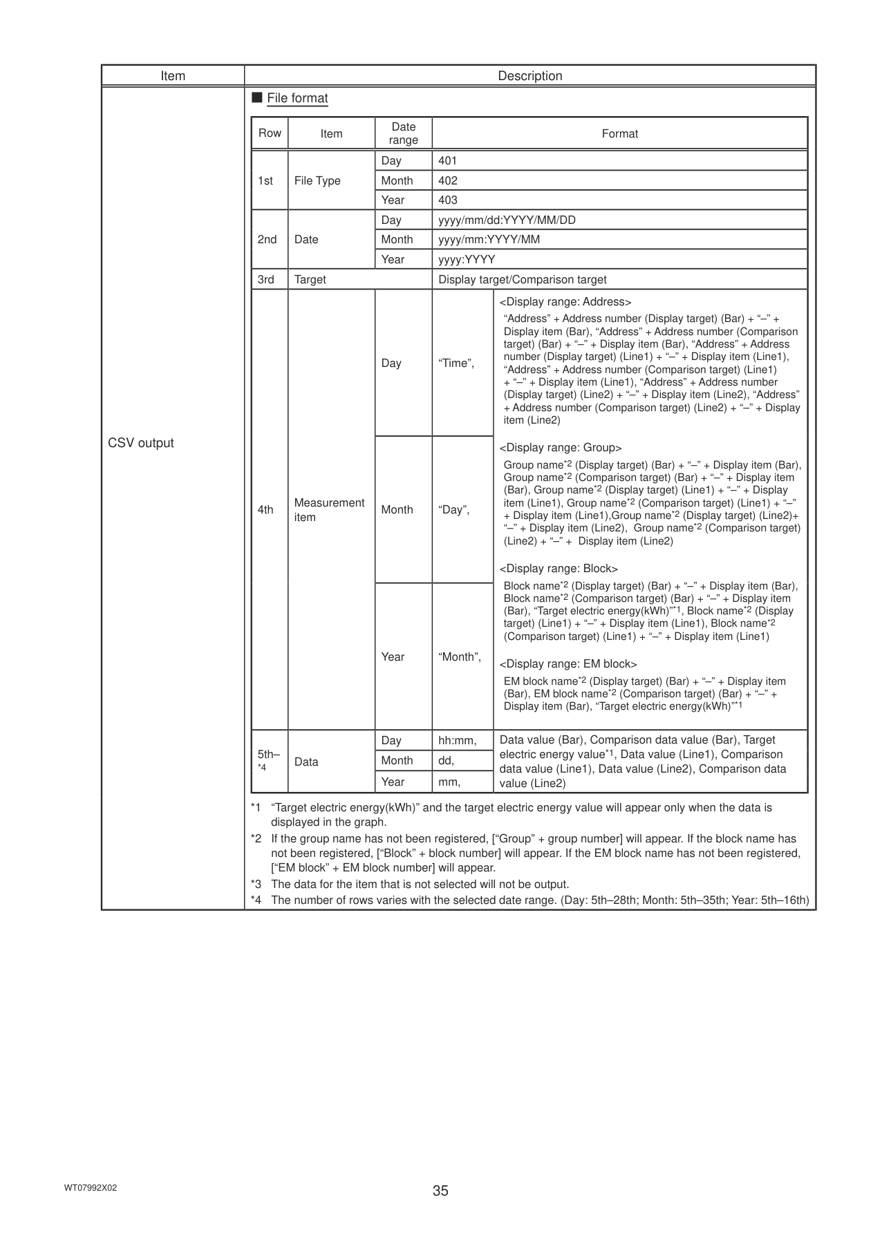
|Item|Description| |---|---| |CSV output|■ File format
|Row|Item|Date range|Format|Format| |---|---|---|---|---| |1st|File Type|Day|401|401| |1st|File Type|Month|402|402| |1st|File Type|Year|403|403| |2nd|Date|Day|yyyy/mm/dd:YYYY/MM/DD|yyyy/mm/dd:YYYY/MM/DD| |2nd|Date|Month|yyyy/mm:YYYY/MM|yyyy/mm:YYYY/MM| |2nd|Date|Year|yyyy:YYYY|yyyy:YYYY| |3rd|Target|Target|Display target/Comparison target|Display target/Comparison target|
|4th|Measurement item|Day|“Time”,|
“Address” + Address number (Display target) (Bar) + “–” + Display item (Bar), “Address” + Address number (Comparison target) (Bar) + “–” + Display item (Bar), “Address” + Address number (Display target) (Line1) + “–” + Display item (Line1), “Address” + Address number (Comparison target) (Line1) + “–” + Display item (Line1), “Address” + Address number (Display target) (Line2) + “–” + Display item (Line2), “Address” + Address number (Comparison target) (Line2) + “–” + Display item (Line2)
Group name*2 (Display target) (Bar) + “–” + Display item (Bar), Group name*2 (Comparison target) (Bar) + “–” + Display item (Bar), Group name*2 (Display target) (Line1) + “–” + Display item (Line1), Group name*2 (Comparison target) (Line1) + “–”
+ Display item (Line1),Group name*2 (Display target) (Line2)+ “–” + Display item (Line2), Group name*2 (Comparison target) (Line2) + “–” + Display item (Line2)
Block name*2 (Display target) (Bar) + “–” + Display item (Bar), Block name*2 (Comparison target) (Bar) + “–” + Display item (Bar), “Target electric energy(kWh)”*1, Block name*2 (Display target) (Line1) + “–” + Display item (Line1), Block name*2 (Comparison target) (Line1) + “–” + Display item (Line1)
EM block name*2 (Display target) (Bar) + “–” + Display item (Bar), EM block name*2 (Comparison target) (Bar) + “–” + Display item (Bar), “Target electric energy(kWh)”*1| |4th|Measurement item|Month|“Day”,|
“Address” + Address number (Display target) (Bar) + “–” + Display item (Bar), “Address” + Address number (Comparison target) (Bar) + “–” + Display item (Bar), “Address” + Address number (Display target) (Line1) + “–” + Display item (Line1), “Address” + Address number (Comparison target) (Line1) + “–” + Display item (Line1), “Address” + Address number (Display target) (Line2) + “–” + Display item (Line2), “Address” + Address number (Comparison target) (Line2) + “–” + Display item (Line2)
Group name*2 (Display target) (Bar) + “–” + Display item (Bar), Group name*2 (Comparison target) (Bar) + “–” + Display item (Bar), Group name*2 (Display target) (Line1) + “–” + Display item (Line1), Group name*2 (Comparison target) (Line1) + “–”
+ Display item (Line1),Group name*2 (Display target) (Line2)+ “–” + Display item (Line2), Group name*2 (Comparison target) (Line2) + “–” + Display item (Line2)
Block name*2 (Display target) (Bar) + “–” + Display item (Bar), Block name*2 (Comparison target) (Bar) + “–” + Display item (Bar), “Target electric energy(kWh)”*1, Block name*2 (Display target) (Line1) + “–” + Display item (Line1), Block name*2 (Comparison target) (Line1) + “–” + Display item (Line1)
EM block name*2 (Display target) (Bar) + “–” + Display item (Bar), EM block name*2 (Comparison target) (Bar) + “–” + Display item (Bar), “Target electric energy(kWh)”*1| |4th|Measurement item|Year|“Month”,|
“Address” + Address number (Display target) (Bar) + “–” + Display item (Bar), “Address” + Address number (Comparison target) (Bar) + “–” + Display item (Bar), “Address” + Address number (Display target) (Line1) + “–” + Display item (Line1), “Address” + Address number (Comparison target) (Line1) + “–” + Display item (Line1), “Address” + Address number (Display target) (Line2) + “–” + Display item (Line2), “Address” + Address number (Comparison target) (Line2) + “–” + Display item (Line2)
Group name*2 (Display target) (Bar) + “–” + Display item (Bar), Group name*2 (Comparison target) (Bar) + “–” + Display item (Bar), Group name*2 (Display target) (Line1) + “–” + Display item (Line1), Group name*2 (Comparison target) (Line1) + “–”
+ Display item (Line1),Group name*2 (Display target) (Line2)+ “–” + Display item (Line2), Group name*2 (Comparison target) (Line2) + “–” + Display item (Line2)
Block name*2 (Display target) (Bar) + “–” + Display item (Bar), Block name*2 (Comparison target) (Bar) + “–” + Display item (Bar), “Target electric energy(kWh)”*1, Block name*2 (Display target) (Line1) + “–” + Display item (Line1), Block name*2 (Comparison target) (Line1) + “–” + Display item (Line1)
EM block name*2 (Display target) (Bar) + “–” + Display item (Bar), EM block name*2 (Comparison target) (Bar) + “–” + Display item (Bar), “Target electric energy(kWh)”*1| |5th–
*4|Data|Day|hh:mm,|Data value (Bar), Comparison data value (Bar), Target electric energy value*1, Data value (Line1), Comparison data value (Line1), Data value (Line2), Comparison data value (Line2)| |5th–
*4|Data|Month|dd,|Data value (Bar), Comparison data value (Bar), Target electric energy value*1, Data value (Line1), Comparison data value (Line1), Data value (Line2), Comparison data value (Line2)| |5th–
*4|Data|Year|mm,|Data value (Bar), Comparison data value (Bar), Target electric energy value*1, Data value (Line1), Comparison data value (Line1), Data value (Line2), Comparison data value (Line2)|
*1 “Target electric energy(kWh)” and the target electric energy value will appear only when the data is displayed in the graph.
*2 If the group name has not been registered, [“Group” + group number] will appear. If the block name has not been registered, [“Block” + block number] will appear. If the EM block name has not been registered, [“EM block” + EM block number] will appear.
*3 The data for the item that is not selected will not be output.
*4 The number of rows varies with the selected date range. (Day: 5th–28th; Month: 5th–35th; Year: 5th–16th)
|
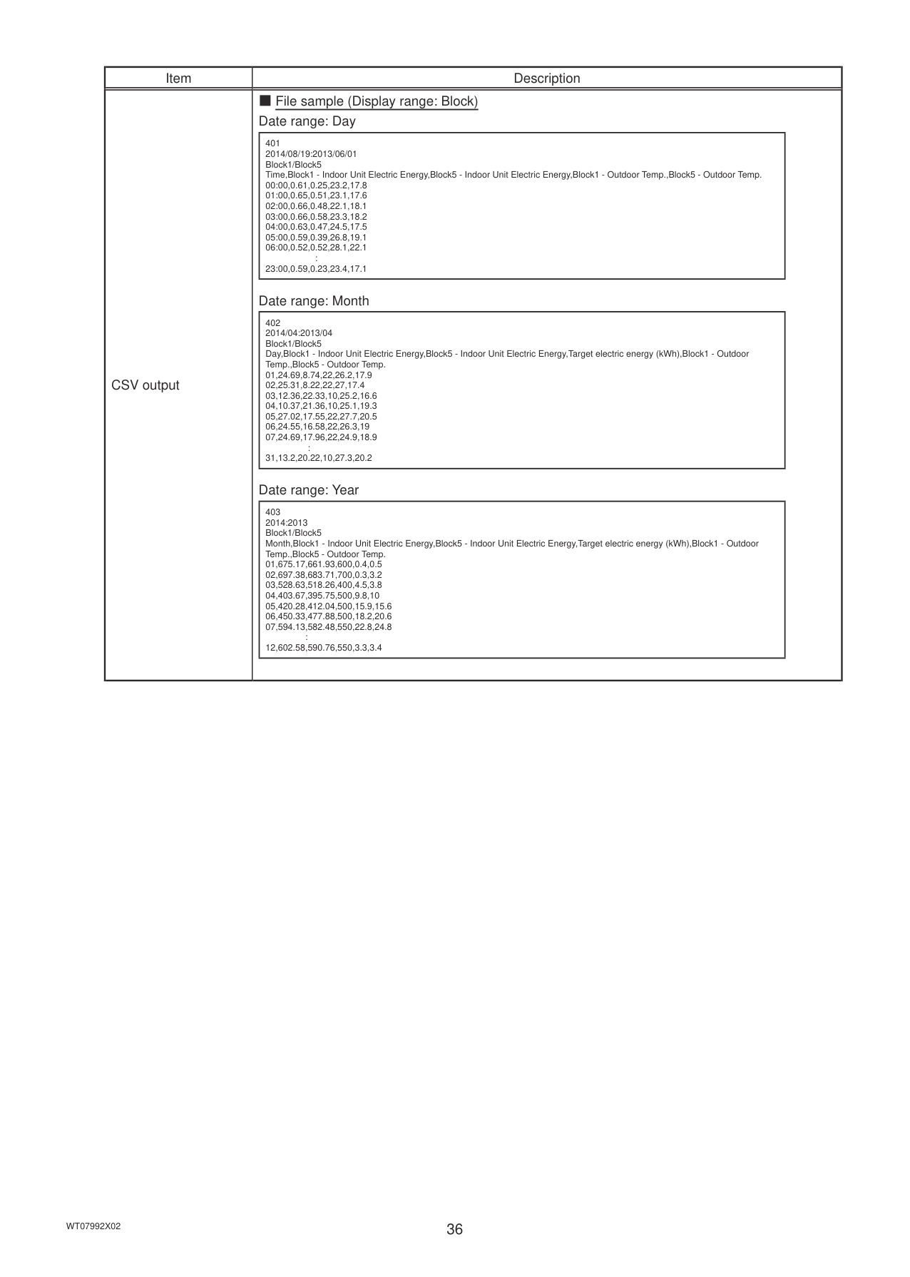
|Item|Description| |---|---| |CSV output|■ File sample (Display range: Block) Date range: Day
|401 2014/08/19:2013/06/01 Block1/Block5 Time,Block1 - Indoor Unit Electric Energy,Block5 - Indoor Unit Electric Energy,Block1 - Outdoor Temp.,Block5 - Outdoor Temp.
00:00,0.61,0.25,23.2,17.8
01:00,0.65,0.51,23.1,17.6
02:00,0.66,0.48,22.1,18.1
03:00,0.66,0.58,23.3,18.2
04:00,0.63,0.47,24.5,17.5
05:00,0.59,0.39,26.8,19.1
06:00,0.52,0.52,28.1,22.1 :
23:00,0.59,0.23,23.4,17.1| |---|
Date range: Month
|402 2014/04:2013/04 Block1/Block5 Day,Block1 - Indoor Unit Electric Energy,Block5 - Indoor Unit Electric Energy,Target electric energy (kWh),Block1 - Outdoor Temp.,Block5 - Outdoor Temp.
01,24.69,8.74,22,26.2,17.9
02,25.31,8.22,22,27,17.4
03,12.36,22.33,10,25.2,16.6
04,10.37,21.36,10,25.1,19.3
05,27.02,17.55,22,27.7,20.5
06,24.55,16.58,22,26.3,19
07,24.69,17.96,22,24.9,18.9 :
31,13.2,20.22,10,27.3,20.2| |---|
Date range: Year
|403 2014:2013 Block1/Block5 Month,Block1 - Indoor Unit Electric Energy,Block5 - Indoor Unit Electric Energy,Target electric energy (kWh),Block1 - Outdoor Temp.,Block5 - Outdoor Temp.
01,675.17,661.93,600,0.4,0.5
02,697.38,683.71,700,0.3,3.2
03,528.63,518.26,400,4.5,3.8
04,403.67,395.75,500,9.8,10
05,420.28,412.04,500,15.9,15.6
06,450.33,477.88,500,18.2,20.6
07,594.13,582.48,550,22.8,24.8 :
12,602.58,590.76,550,3.3,3.4| |---| |
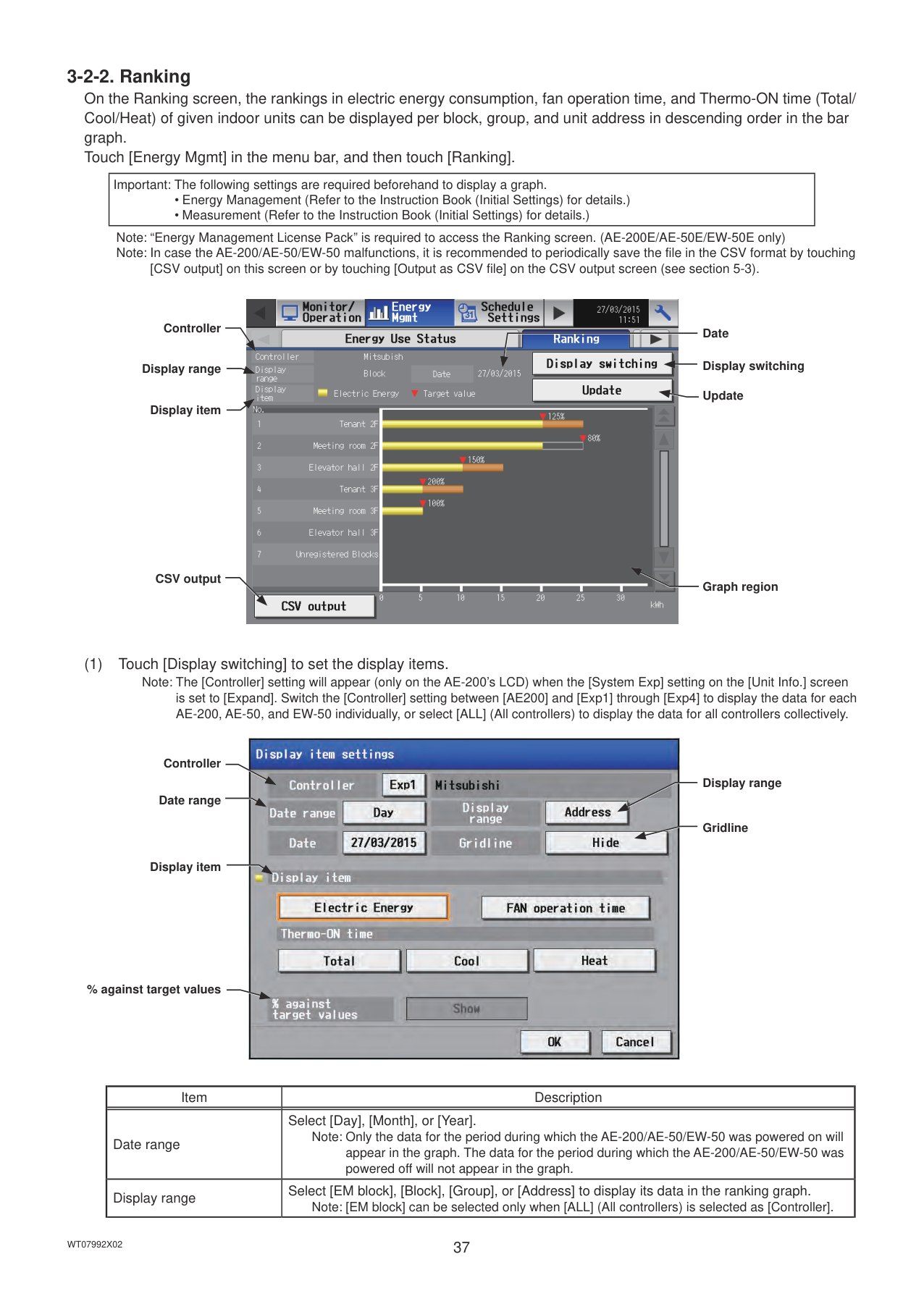
|Important: The following settings are required beforehand to display a graph.
• Energy Management (Refer to the Instruction Book (Initial Settings) for details.)
• Measurement (Refer to the Instruction Book (Initial Settings) for details.)
| |---|
Note: “Energy Management License Pack” is required to access the Ranking screen. (AE-200E/AE-50E/EW-50E only) Note: In case the AE-200/AE-50/EW-50 malfunctions, it is recommended to periodically save the file in the CSV format by touching
[CSV output] on this screen or by touching [Output as CSV file] on the CSV output screen (see section 5-3).
Controller
Display range
Display item
CSV output

Date
Display switching
Update
Graph region
is set to [Expand]. Switch the [Controller] setting between [AE200] and [Exp1] through [Exp4] to display the data for each AE-200, AE-50, and EW-50 individually, or select [ALL] (All controllers) to display the data for all controllers collectively.
Controller
Date range
Display item
% against target values

Display range
Gridline
|Item|Description| |---|---| |Date range|Select [Day], [Month], or [Year].
Note: Only the data for the period during which the AE-200/AE-50/EW-50 was powered on will appear in the graph. The data for the period during which the AE-200/AE-50/EW-50 was powered off will not appear in the graph.| |Display range|Select [EM block], [Block], [Group], or [Address] to display its data in the ranking graph.
Note: [EM block] can be selected only when [ALL] (All controllers) is selected as [Controller].|
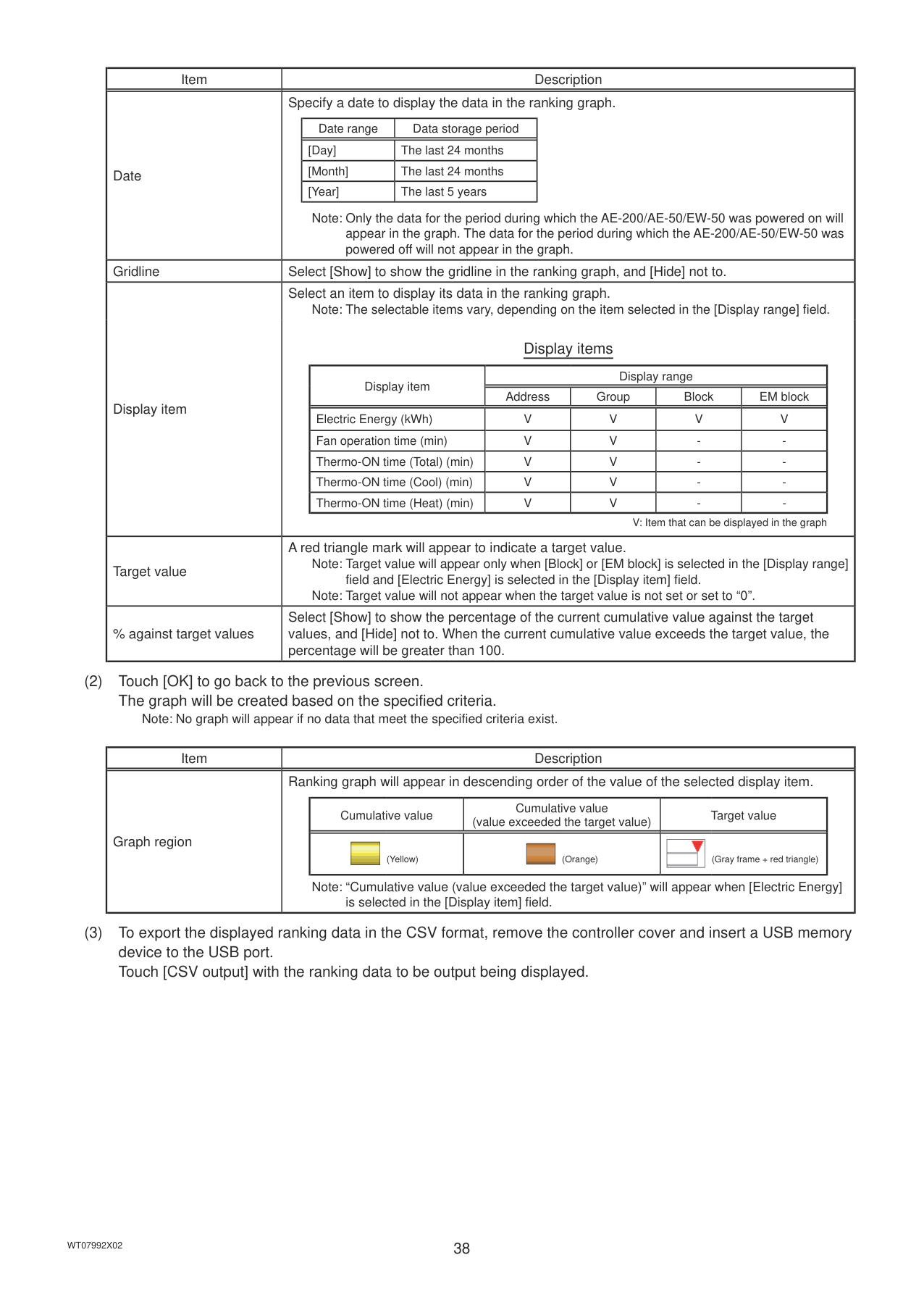
|Item|Description| |---|---| |Date|Specify a date to display the data in the ranking graph.
|Date range|Data storage period| |---|---| |[Day]|The last 24 months| |[Month]|The last 24 months| |[Year]|The last 5 years|
Note: Only the data for the period during which the AE-200/AE-50/EW-50 was powered on will appear in the graph. The data for the period during which the AE-200/AE-50/EW-50 was powered off will not appear in the graph.| |Gridline|Select [Show] to show the gridline in the ranking graph, and [Hide] not to.| |Display item|Select an item to display its data in the ranking graph.
Note: The selectable items vary, depending on the item selected in the [Display range] field.
Display items
|Display item|Display range|Display range|Display range|Display range| |---|---|---|---|---| |Display item|Address|Group|Block|EM block| |Electric Energy (kWh)|V|V|V|V| |Fan operation time (min)|V|V|-|-| |Thermo-ON time (Total) (min)|V|V|-|-| |Thermo-ON time (Cool) (min)|V|V|-|-| |Thermo-ON time (Heat) (min)|V|V|-|-|
V: Item that can be displayed in the graph| |Target value|A red triangle mark will appear to indicate a target value.
Note: Target value will appear only when [Block] or [EM block] is selected in the [Display range] field and [Electric Energy] is selected in the [Display item] field. Note: Target value will not appear when the target value is not set or set to “0”.| |% against target values|Select [Show] to show the percentage of the current cumulative value against the target values, and [Hide] not to. When the current cumulative value exceeds the target value, the percentage will be greater than 100.|
########### (2) Touch [OK] to go back to the previous screen.The graph will be created based on the specified criteria.
Note: No graph will appear if no data that meet the specified criteria exist.
|Item|Description| |---|---|
|Graph region|Ranking graph will appear in descending order of the value of the selected display item.
|Cumulative value|Cumulative value (value exceeded the target value)|Target value| |---|---|---| ||| |---|
(Yellow)||| |---|
(Orange)||| |---|
(Gray frame + red triangle)|
Note: “Cumulative value (value exceeded the target value)” will appear when [Electric Energy] is selected in the [Display item] field.|
########### (3) To export the displayed ranking data in the CSV format, remove the controller cover and insert a USB memorydevice to the USB port.Touch [CSV output] with the ranking data to be output being displayed.
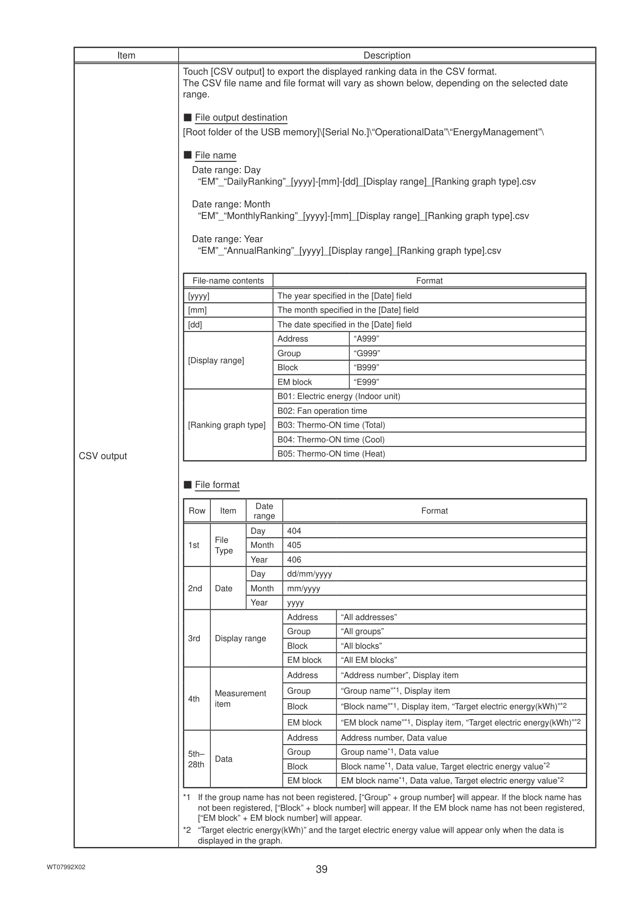
|Item|Description| |---|---| |CSV output|Touch [CSV output] to export the displayed ranking data in the CSV format. The CSV file name and file format will vary as shown below, depending on the selected date range.
■ File output destination [Root folder of the USB memory]\[Serial No.]\“OperationalData”\“EnergyManagement”\
■ File name
Date range: Day
“EM”_“DailyRanking”_[yyyy]-[mm]-[dd]_[Display range]_[Ranking graph type].csv Date range: Month
“EM”_“MonthlyRanking”_[yyyy]-[mm]_[Display range]_[Ranking graph type].csv Date range: Year
“EM”_“AnnualRanking”_[yyyy]_[Display range]_[Ranking graph type].csv
|File-name contents|Format|Format| |---|---|---| |[yyyy]|The year specified in the [Date] field|The year specified in the [Date] field| |[mm]|The month specified in the [Date] field|The month specified in the [Date] field| |[dd]|The date specified in the [Date] field|The date specified in the [Date] field| |[Display range]|Address|“A999”| |[Display range]|Group|“G999”| |[Display range]|Block|“B999”| |[Display range]|EM block|“E999”| |[Ranking graph type]|B01: Electric energy (Indoor unit)|B01: Electric energy (Indoor unit)| |[Ranking graph type]|B02: Fan operation time|B02: Fan operation time| |[Ranking graph type]|B03: Thermo-ON time (Total)|B03: Thermo-ON time (Total)| |[Ranking graph type]|B04: Thermo-ON time (Cool)|B04: Thermo-ON time (Cool)| |[Ranking graph type]|B05: Thermo-ON time (Heat)|B05: Thermo-ON time (Heat)|
■ File format
|Row|Item|Date range|Format|Format| |---|---|---|---|---| |1st|File Type|Day|404|404| |1st|File Type|Month|405|405|
|1st|File Type|Year|406|406| |2nd|Date|Day|dd/mm/yyyy|dd/mm/yyyy| |2nd|Date|Month|mm/yyyy|mm/yyyy| |2nd|Date|Year|yyyy|yyyy| |3rd|Display range|Display range|Address|“All addresses”| |3rd|Display range|Display range|Group|“All groups”| |3rd|Display range|Display range|Block|“All blocks”| |3rd|Display range|Display range|EM block|“All EM blocks”| |4th|Measurement item|Measurement item|Address|“Address number”, Display item| |4th|Measurement item|Measurement item|Group|“Group name”*1, Display item| |4th|Measurement item|Measurement item|Block|“Block name”*1, Display item, “Target electric energy(kWh)”*2| |4th|Measurement item|Measurement item|EM block|“EM block name”*1, Display item, “Target electric energy(kWh)”*2| |5th– 28th|Data|Data|Address|Address number, Data value| |5th– 28th|Data|Data|Group|Group name*1, Data value| |5th– 28th|Data|Data|Block|Block name*1, Data value, Target electric energy value*2| |5th– 28th|Data|Data|EM block|EM block name*1, Data value, Target electric energy value*2|
*1 If the group name has not been registered, [“Group” + group number] will appear. If the block name has not been registered, [“Block” + block number] will appear. If the EM block name has not been registered, [“EM block” + EM block number] will appear.
*2 “Target electric energy(kWh)” and the target electric energy value will appear only when the data is displayed in the graph.
|
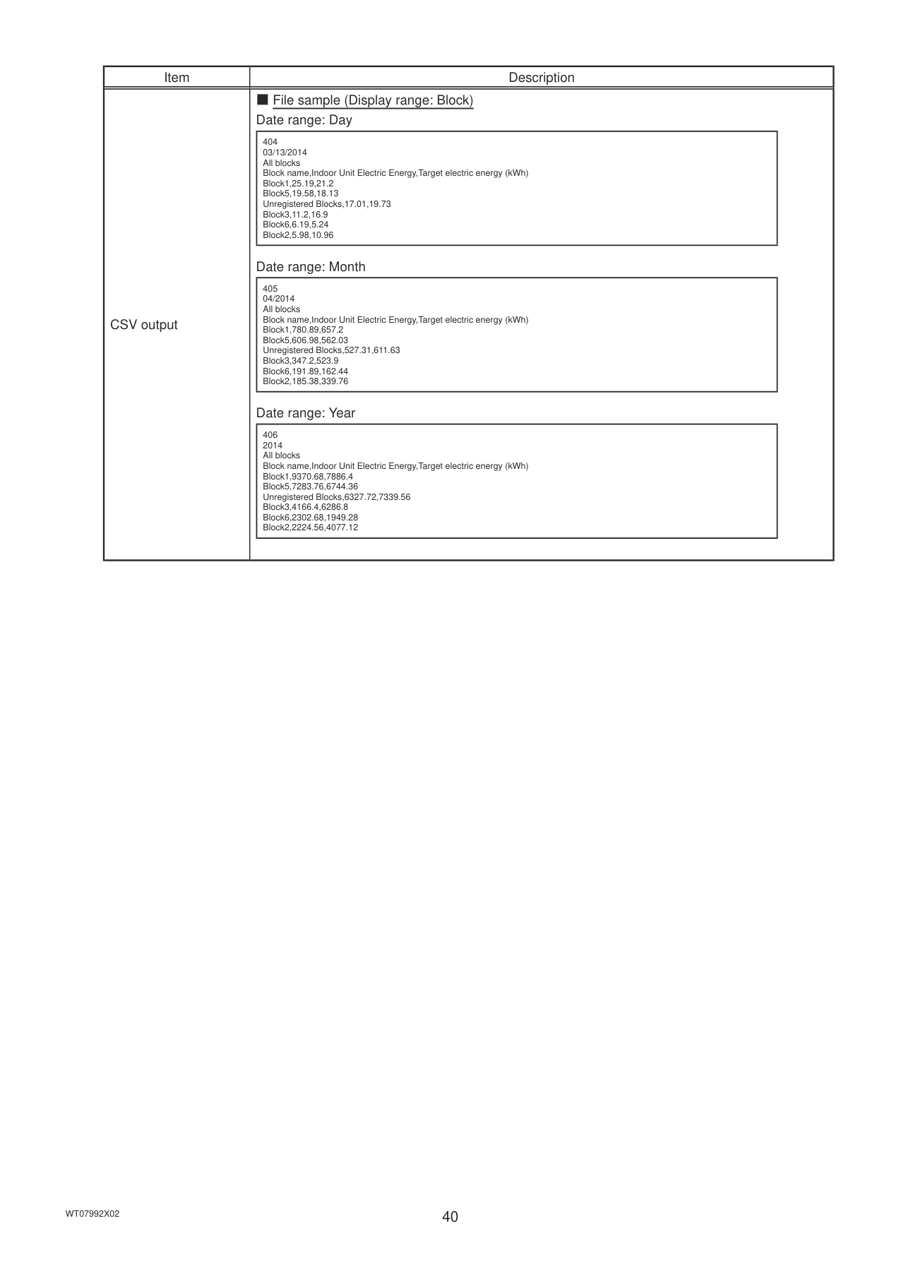
|Item|Description| |---|---| |CSV output|■ File sample (Display range: Block) Date range: Day
|404 03/13/2014 All blocks Block name,Indoor Unit Electric Energy,Target electric energy (kWh)
Block1,25.19,21.2
Block5,19.58,18.13 Unregistered Blocks,17.01,19.73 Block3,11.2,16.9
Block6,6.19,5.24
Block2,5.98,10.96
| |---|
Date range: Month
|405 04/2014 All blocks Block name,Indoor Unit Electric Energy,Target electric energy (kWh)
Block1,780.89,657.2
Block5,606.98,562.03 Unregistered Blocks,527.31,611.63 Block3,347.2,523.9
Block6,191.89,162.44
Block2,185.38,339.76
| |---|
Date range: Year
|406 2014 All blocks Block name,Indoor Unit Electric Energy,Target electric energy (kWh)
Block1,9370.68,7886.4
Block5,7283.76,6744.36 Unregistered Blocks,6327.72,7339.56 Block3,4166.4,6286.8
Block6,2302.68,1949.28
Block2,2224.56,4077.12
| |---| |
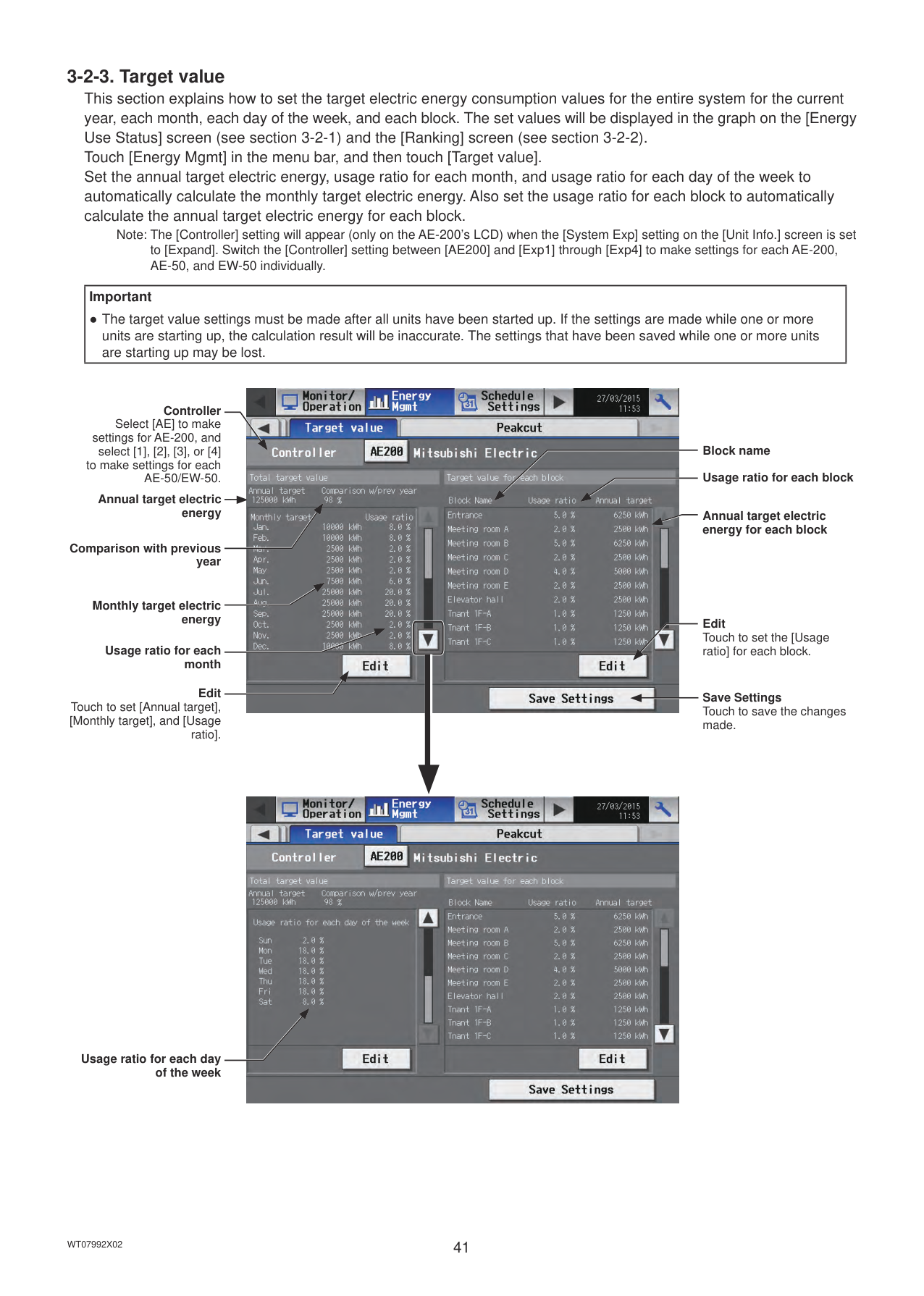
Note: The [Controller] setting will appear (only on the AE-200’s LCD) when the [System Exp] setting on the [Unit Info.] screen is set to [Expand]. Switch the [Controller] setting between [AE200] and [Exp1] through [Exp4] to make settings for each AE-200, AE-50, and EW-50 individually.
|Important
● The target value settings must be made after all units have been started up. If the settings are made while one or more units are starting up, the calculation result will be inaccurate. The settings that have been saved while one or more units are starting up may be lost.| |---|
Controller
Select [AE] to make settings for AE-200, and
select [1], [2], [3], or [4] to make settings for each
AE-50/EW-50. Annual target electric energy
Comparison with previous year
Monthly target electric energy
Usage ratio for each month
Edit Touch to set [Annual target], [Monthly target], and [Usage
ratio].

Block name Usage ratio for each block
Annual target electric energy for each block
Edit Touch to set the [Usage ratio] for each block.
Save Settings Touch to save the changes made.

Usage ratio for each day of the week

Edit
Touch to set [Annual target], [Monthly target], and [Usage ratio
for each day of the week].
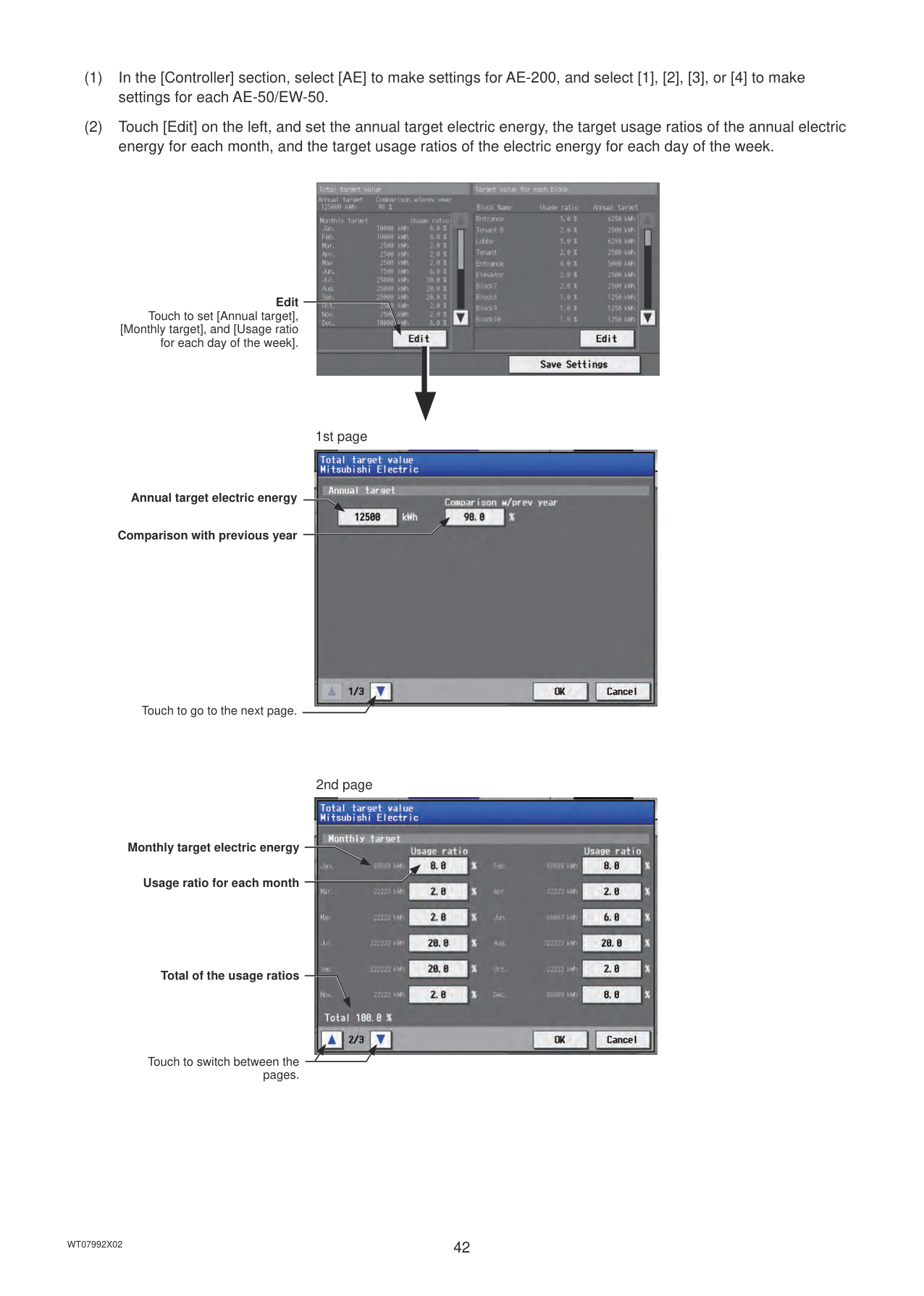
1st page

Annual target electric energy
Comparison with previous year
Touch to go to the next page.
2nd page

Monthly target electric energy
Usage ratio for each month
Total of the usage ratios
Touch to switch between the pages.
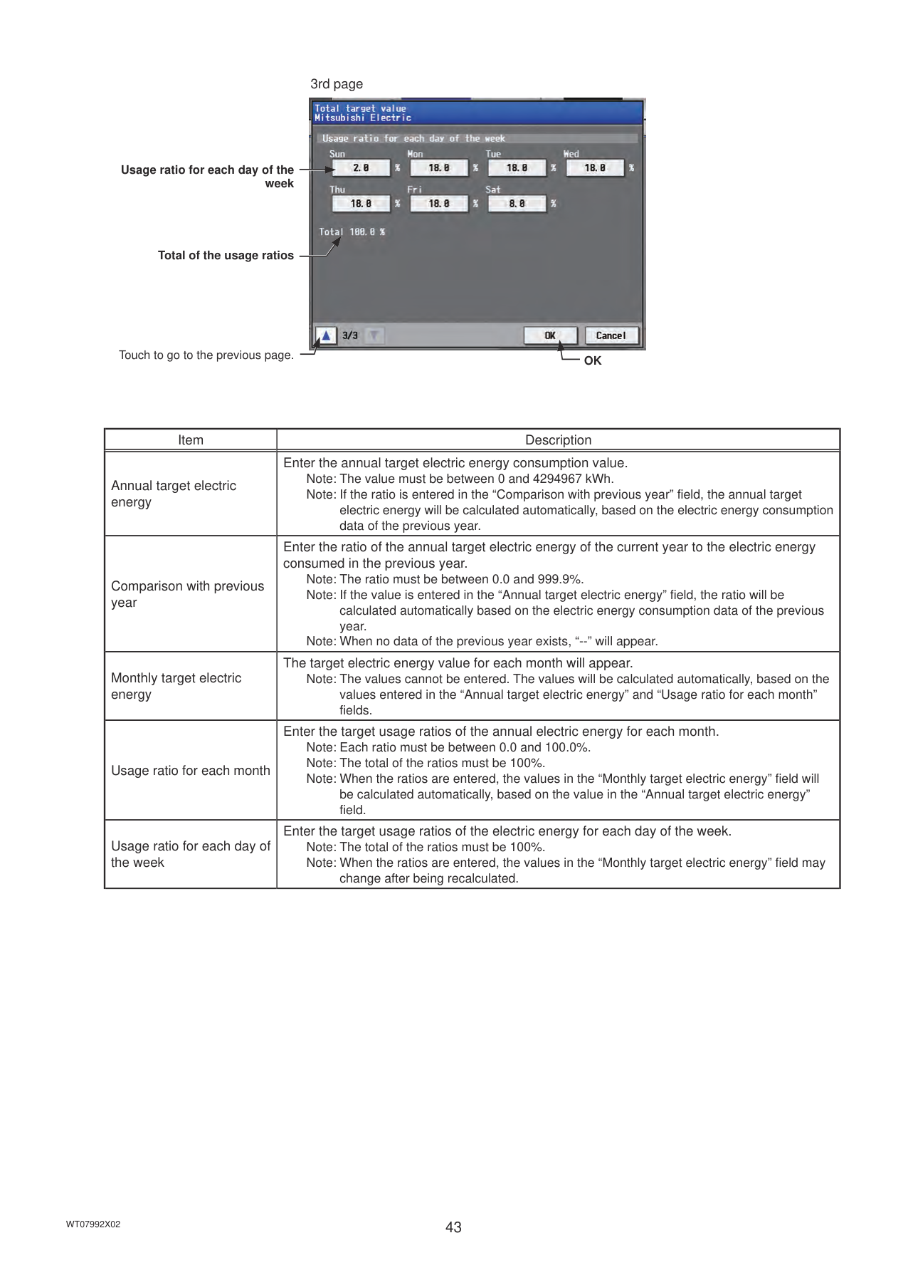
3rd page

Usage ratio for each day of the week
Total of the usage ratios
Touch to go to the previous page. OK
|Item|Description| |---|---| |Annual target electric energy|Enter the annual target electric energy consumption value. Note: The value must be between 0 and 4294967 kWh. Note: If the ratio is entered in the “Comparison with previous year” field, the annual target
electric energy will be calculated automatically, based on the electric energy consumption data of the previous year.| |Comparison with previous year|Enter the ratio of the annual target electric energy of the current year to the electric energy consumed in the previous year.
Note: The ratio must be between 0.0 and 999.9%. Note: If the value is entered in the “Annual target electric energy” field, the ratio will be
calculated automatically based on the electric energy consumption data of the previous year.
Note: When no data of the previous year exists, “--” will appear.| |Monthly target electric energy|The target electric energy value for each month will appear.
Note: The values cannot be entered. The values will be calculated automatically, based on the values entered in the “Annual target electric energy” and “Usage ratio for each month” fields.| |Usage ratio for each month|Enter the target usage ratios of the annual electric energy for each month. Note: Each ratio must be between 0.0 and 100.0%. Note: The total of the ratios must be 100%. Note: When the ratios are entered, the values in the “Monthly target electric energy” field will
be calculated automatically, based on the value in the “Annual target electric energy” field.| |Usage ratio for each day of the week|Enter the target usage ratios of the electric energy for each day of the week. Note: The total of the ratios must be 100%. Note: When the ratios are entered, the values in the “Monthly target electric energy” field may
change after being recalculated.|
########### (3) Touch [OK] to go back to the previous screen.Note: If the total of the usage ratios for each month and each day of the week are not 100%, the [OK] button cannot be
touched.
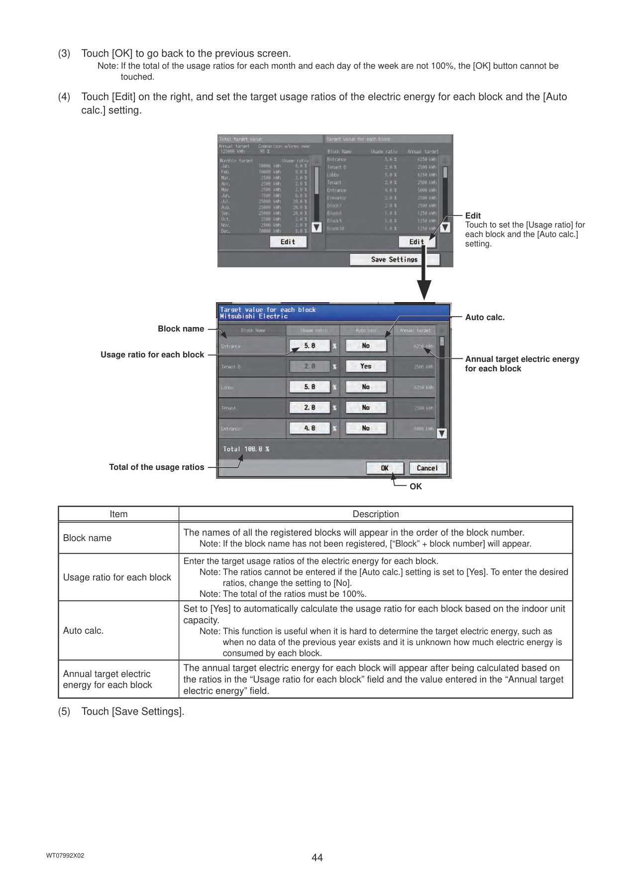
########### (4) Touch [Edit] on the right, and set the target usage ratios of the electric energy for each block and the [Autocalc.] setting.

Edit Touch to set the [Usage ratio] for each block and the [Auto calc.] setting.

Auto calc.
Block name
Usage ratio for each block
Annual target electric energy for each block
Total of the usage ratios
OK
|Item|Description| |---|---| |Block name|The names of all the registered blocks will appear in the order of the block number.
Note: If the block name has not been registered, [“Block” + block number] will appear.| |Usage ratio for each block|Enter the target usage ratios of the electric energy for each block. Note: The ratios cannot be entered if the [Auto calc.] setting is set to [Yes]. To enter the desired ratios, change the setting to [No]. Note: The total of the ratios must be 100%.| |Auto calc.|Set to [Yes] to automatically calculate the usage ratio for each block based on the indoor unit capacity.
Note: This function is useful when it is hard to determine the target electric energy, such as when no data of the previous year exists and it is unknown how much electric energy is consumed by each block.| |Annual target electric energy for each block|The annual target electric energy for each block will appear after being calculated based on the ratios in the “Usage ratio for each block” field and the value entered in the “Annual target electric energy” field.|
########### (5) Touch [Save Settings].

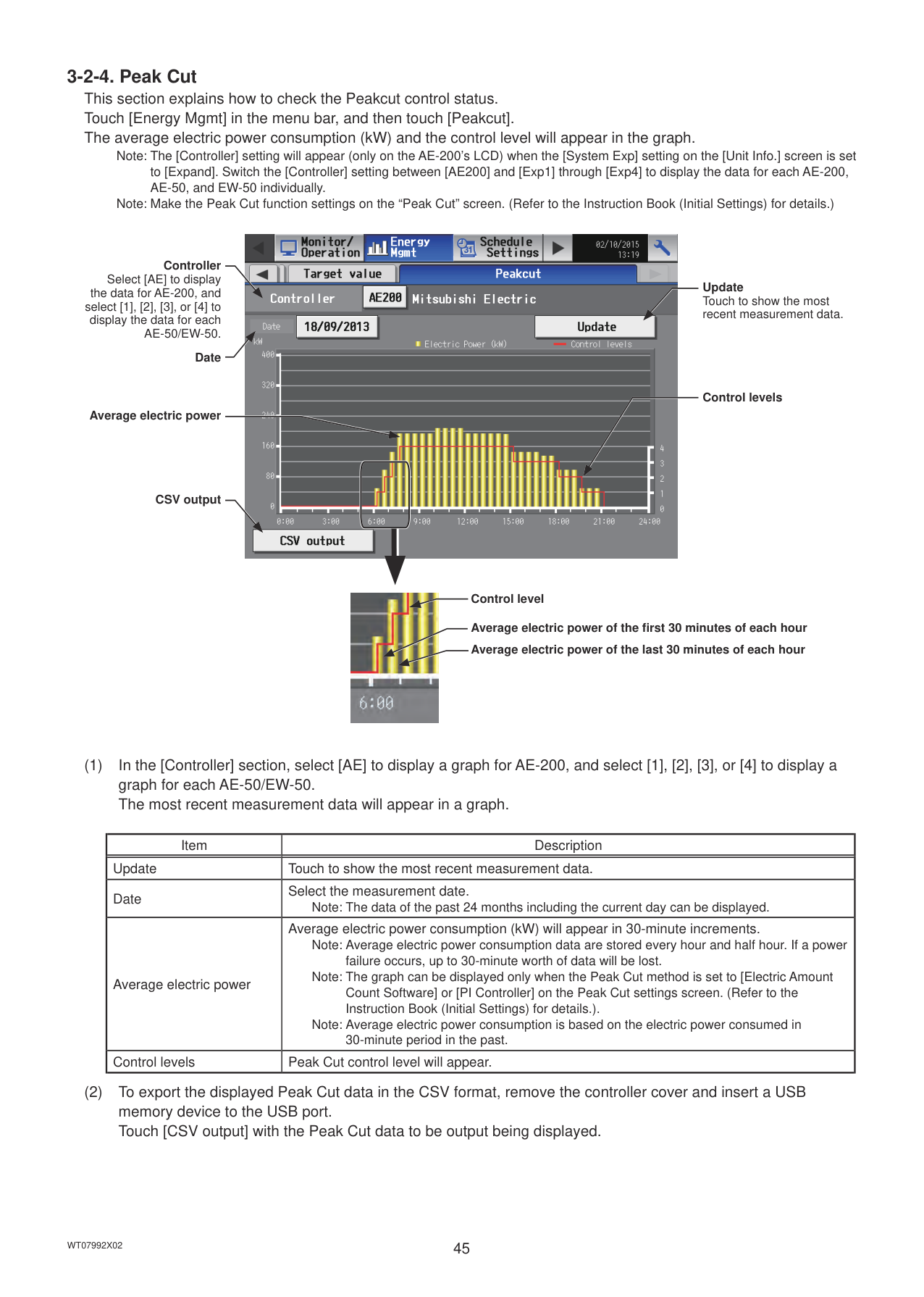
Note: The [Controller] setting will appear (only on the AE-200’s LCD) when the [System Exp] setting on the [Unit Info.] screen is set to [Expand]. Switch the [Controller] setting between [AE200] and [Exp1] through [Exp4] to display the data for each AE-200, AE-50, and EW-50 individually.
Note: Make the Peak Cut function settings on the “Peak Cut” screen. (Refer to the Instruction Book (Initial Settings) for details.)

Controller Select [AE] to display
Update Touch to show the most recent measurement data.
the data for AE-200, and select [1], [2], [3], or [4] to display the data for each AE-50/EW-50.
Date
Control levels
Average electric power
CSV output
Control level
Average electric power of the first 30 minutes of each hour Average electric power of the last 30 minutes of each hour
|Item|Description| |---|---| |Update|Touch to show the most recent measurement data.| |Date|Select the measurement date.
Note: The data of the past 24 months including the current day can be displayed.| |Average electric power|Average electric power consumption (kW) will appear in 30-minute increments.
Note: Average electric power consumption data are stored every hour and half hour. If a power failure occurs, up to 30-minute worth of data will be lost.
Note: The graph can be displayed only when the Peak Cut method is set to [Electric Amount Count Software] or [PI Controller] on the Peak Cut settings screen. (Refer to the Instruction Book (Initial Settings) for details.).
Note: Average electric power consumption is based on the electric power consumed in 30-minute period in the past.| |Control levels|Peak Cut control level will appear.|
|Item|Description| |---|---| |CSV output|Touch [CSV output] to export the displayed Peakcut control status data in the CSV format as shown below.
■ File output destination [Root folder of the USB memory]\[Serial No.]\“OperationalData”\“EnergyManagement”\
■ File name Peakcut_[yyyy]-[mm]-[dd].csv
|File-name contents|Format| |---|---|
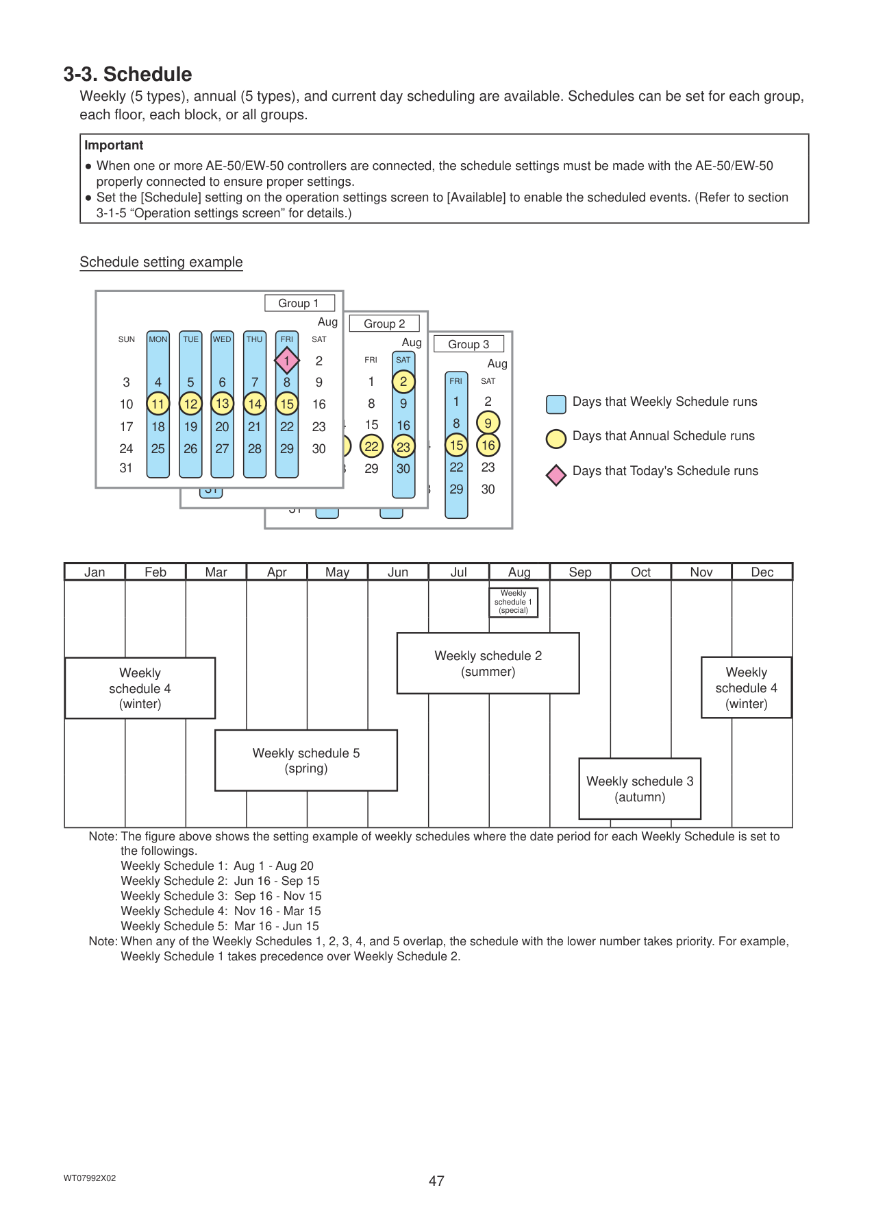
|[yyyy]|The year specified in the [Date] field| |[mm]|The month specified in the [Date] field| |[dd]|The date specified in the [Date] field|
■ File format
|Row|Item|Format| |---|---|---| |1st|File Type|123| |2nd|Date|yyyy/mm/dd *1| |3rd|Target|“Peakcut energy”| |4th|Measurement item|“Time,Power(kW),Control level”| |5th–|Data|hh:mm (1-minute intervals), average electric power consumption, control level
Note: Average electric power consumption (kW) in 30-minute period will appear in 30-minute increments.|
*1 The date will appear in the format that has been set on the [Unit Info.] screen.
■ File sample
|123 03/13/2015 Peakcut energy Time,Power(kW),Control level
00:00,8,1
00:01,8,1
00:02,8,1 : :
23:58,6,0
23:59,6,0
| |---| |
#### 3-3. Schedule
Weekly (5 types), annual (5 types), and current day scheduling are available. Schedules can be set for each group, each floor, each block, or all groups.
|Important
● When one or more AE-50/EW-50 controllers are connected, the schedule settings must be made with the AE-50/EW-50 properly connected to ensure proper settings.
● Set the [Schedule] setting on the operation settings screen to [Available] to enable the scheduled events. (Refer to section 3-1-5 “Operation settings screen” for details.)
| |---|
Schedule setting example
Group 1
Aug
Group 2
SUN MON TUE WED THU FRI SAT
Aug
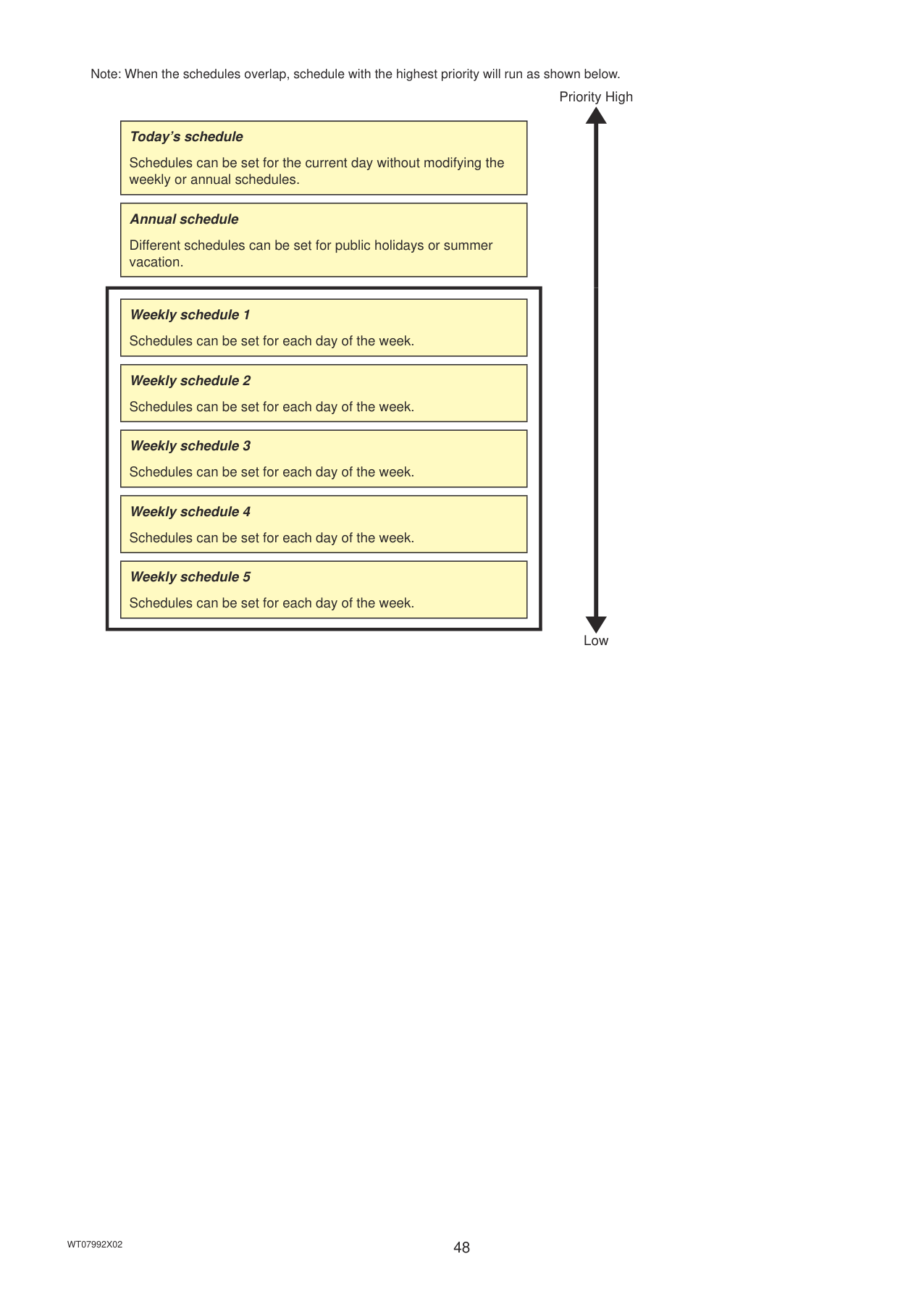
|Group 3| |---|
2 9
1 8
FRI SAT
Aug
1 8 15 22 29
2 9 16 23 30
3 10 17 24 31
4 11 18 25
5 12 19 26
6 13 20 27
7 14 21 28
FRI SAT
1 8 15 22 29
2 9 16 23 30
3 10 17 24
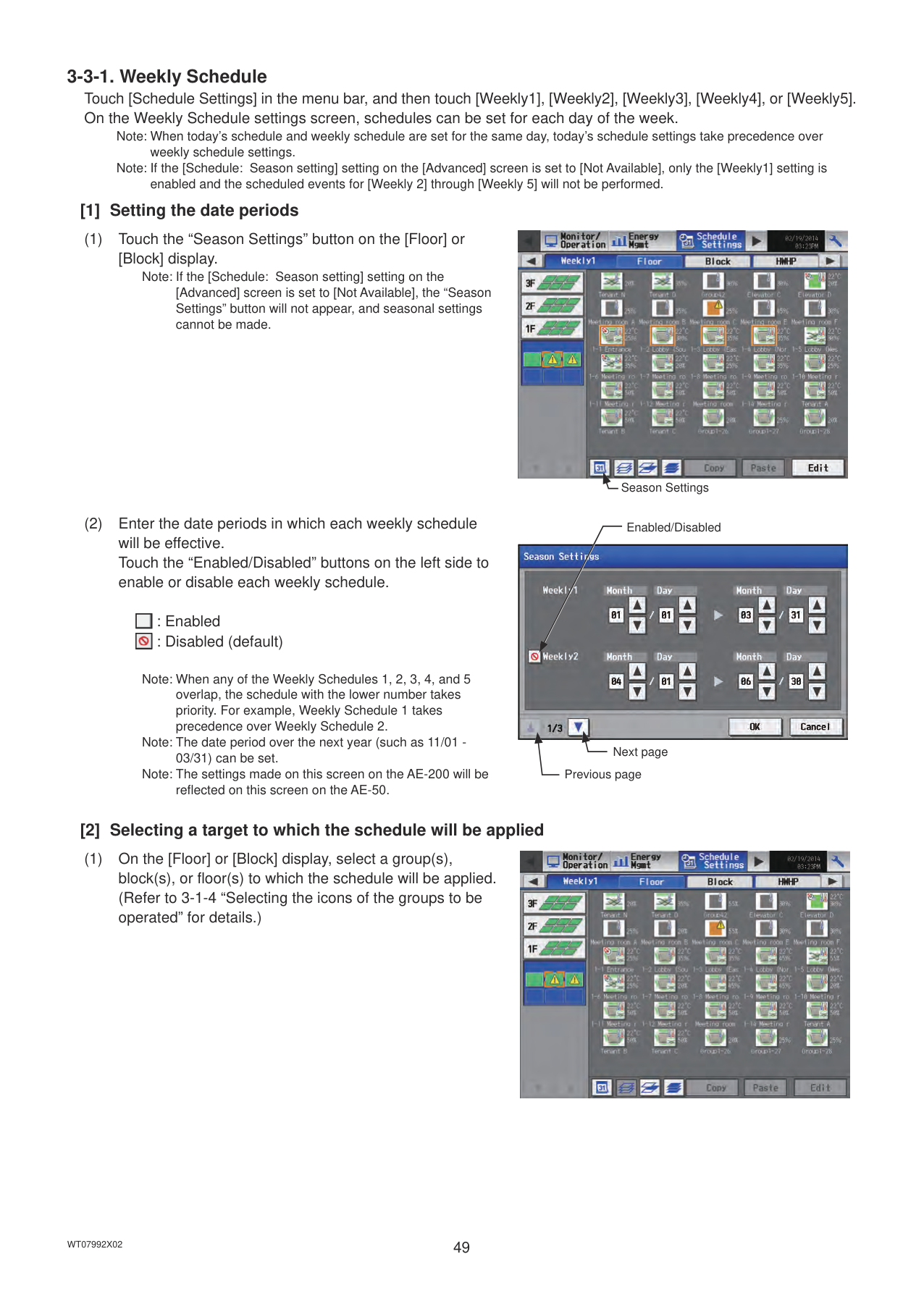
4 11 18 25
5 12 19 26
7 14 21 28
16 23 30
15 22 29
3 10 17 24 31
4 11
6 13 20 27
7 14 21 28
13 20
12 19
31
25
Days that Weekly Schedule runs
Days that Annual Schedule runs
Days that Today's Schedule runs
Jan Feb Mar Apr May Jun Jul Aug Sep Oct Nov Dec
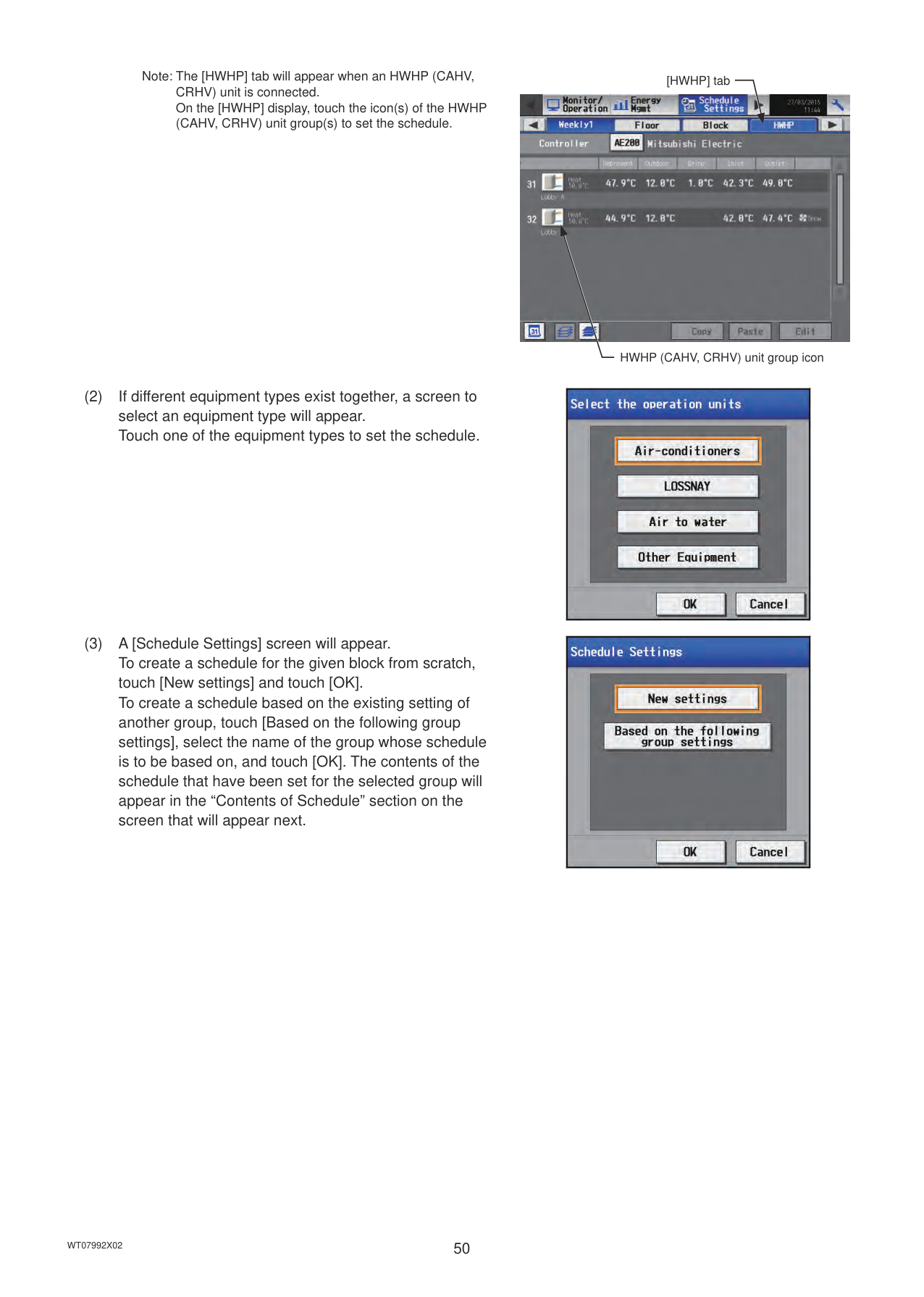
Weekly schedule 1 (special)
Weekly schedule 2 (summer)Weekly
Weekly schedule 4 (winter)
schedule 4 (winter)
Weekly schedule 5 (spring)
Weekly schedule 3 (autumn)
Note: The figure above shows the setting example of weekly schedules where the date period for each Weekly Schedule is set to the followings.
Note: When any of the Weekly Schedules 1, 2, 3, 4, and 5 overlap, the schedule with the lower number takes priority. For example, Weekly Schedule 1 takes precedence over Weekly Schedule 2.
Note: When the schedules overlap, schedule with the highest priority will run as shown below.
Priority High
|Today’s schedule
Schedules can be set for the current day without modifying the weekly or annual schedules.| |---|
|Annual schedule
Different schedules can be set for public holidays or summer vacation.| |---|
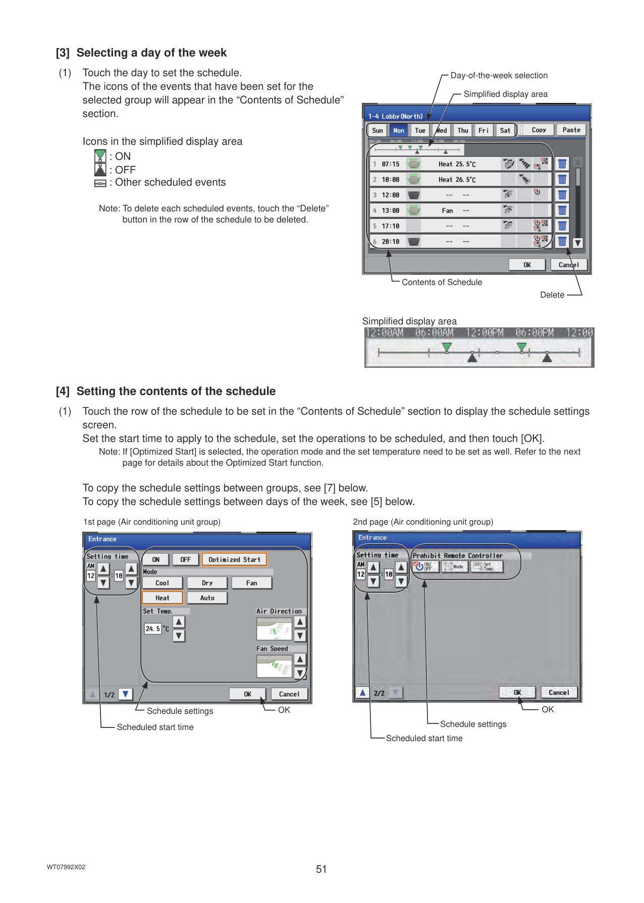
||Weekly schedule 1 Schedules can be set for each day of the week.| |---|
|Weekly schedule 2 Schedules can be set for each day of the week.| |---|
|Weekly schedule 3 Schedules can be set for each day of the week.| |---|
|Weekly schedule 4 Schedules can be set for each day of the week.| |---|
|Weekly schedule 5 Schedules can be set for each day of the week.| |---| | |---|
Low
Note: When today’s schedule and weekly schedule are set for the same day, today’s schedule settings take precedence over weekly schedule settings. Note: If the [Schedule: Season setting] setting on the [Advanced] screen is set to [Not Available], only the [Weekly1] setting is enabled and the scheduled events for [Weekly 2] through [Weekly 5] will not be performed.
######## [1] Setting the date periods
Note: If the [Schedule: Season setting] setting on the [Advanced] screen is set to [Not Available], the “Season Settings” button will not appear, and seasonal settings cannot be made.

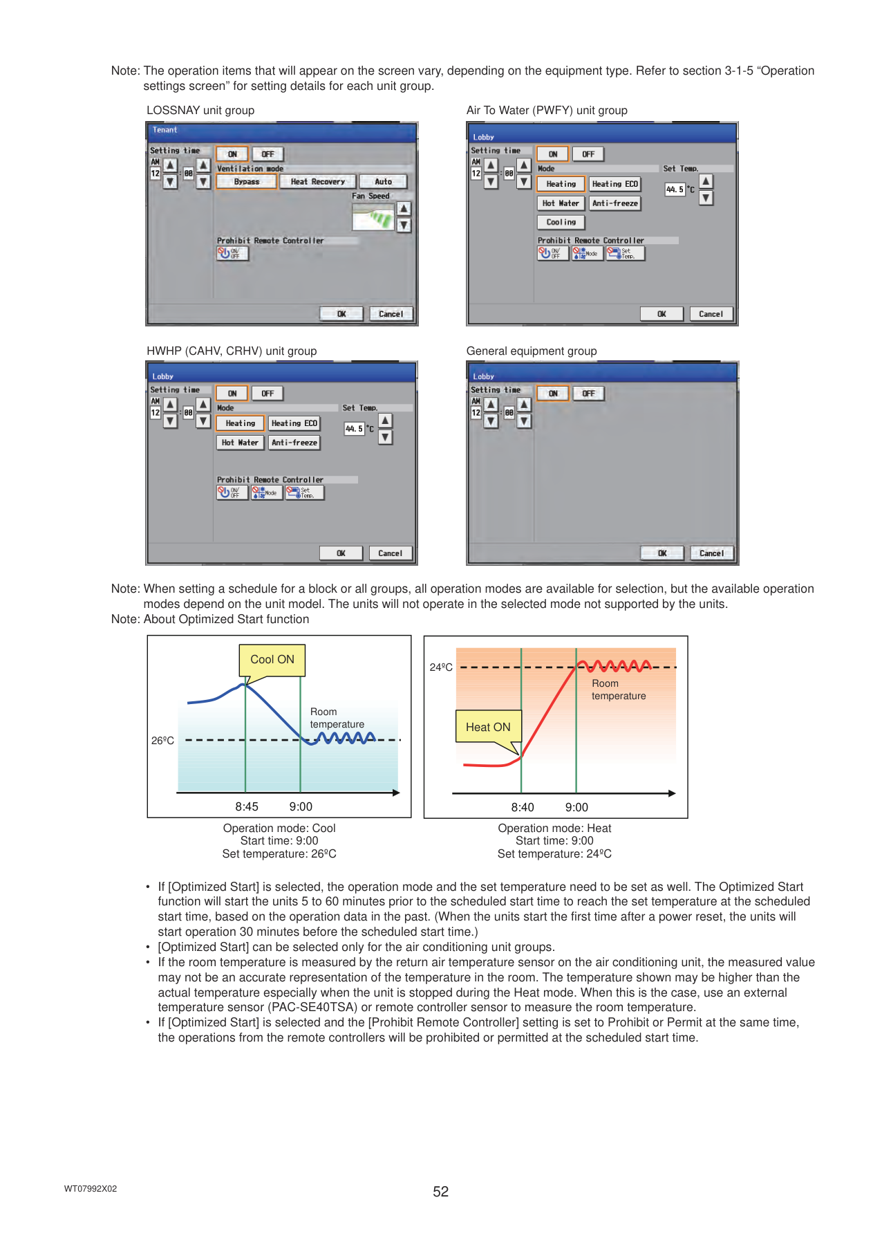
Season Settings
Enabled/Disabled

: Enabled : Disabled (default)
|| |---|
|| |---|
Note: When any of the Weekly Schedules 1, 2, 3, 4, and 5 overlap, the schedule with the lower number takes priority. For example, Weekly Schedule 1 takes precedence over Weekly Schedule 2.
Note: The date period over the next year (such as 11/01 03/31) can be set. Note: The settings made on this screen on the AE-200 will be reflected on this screen on the AE-50.
Next page Previous page
######## [2] Selecting a target to which the schedule will be applied

Note: The [HWHP] tab will appear when an HWHP (CAHV, CRHV) unit is connected. On the [HWHP] display, touch the icon(s) of the HWHP (CAHV, CRHV) unit group(s) to set the schedule.

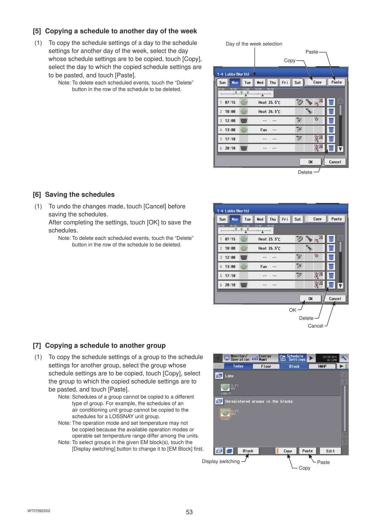
[HWHP] tab

HWHP (CAHV, CRHV) unit group icon

######## [3] Selecting a day of the week
(1) Touch the day to set the schedule. The icons of the events that have been set for the selected group will appear in the “Contents of Schedule” section.
Icons in the simplified display area : ON : OFF : Other scheduled events
|| |---| ||
|| |---|
Note: To delete each scheduled events, touch the “Delete” button in the row of the schedule to be deleted.
Day-of-the-week selection
Simplified display area

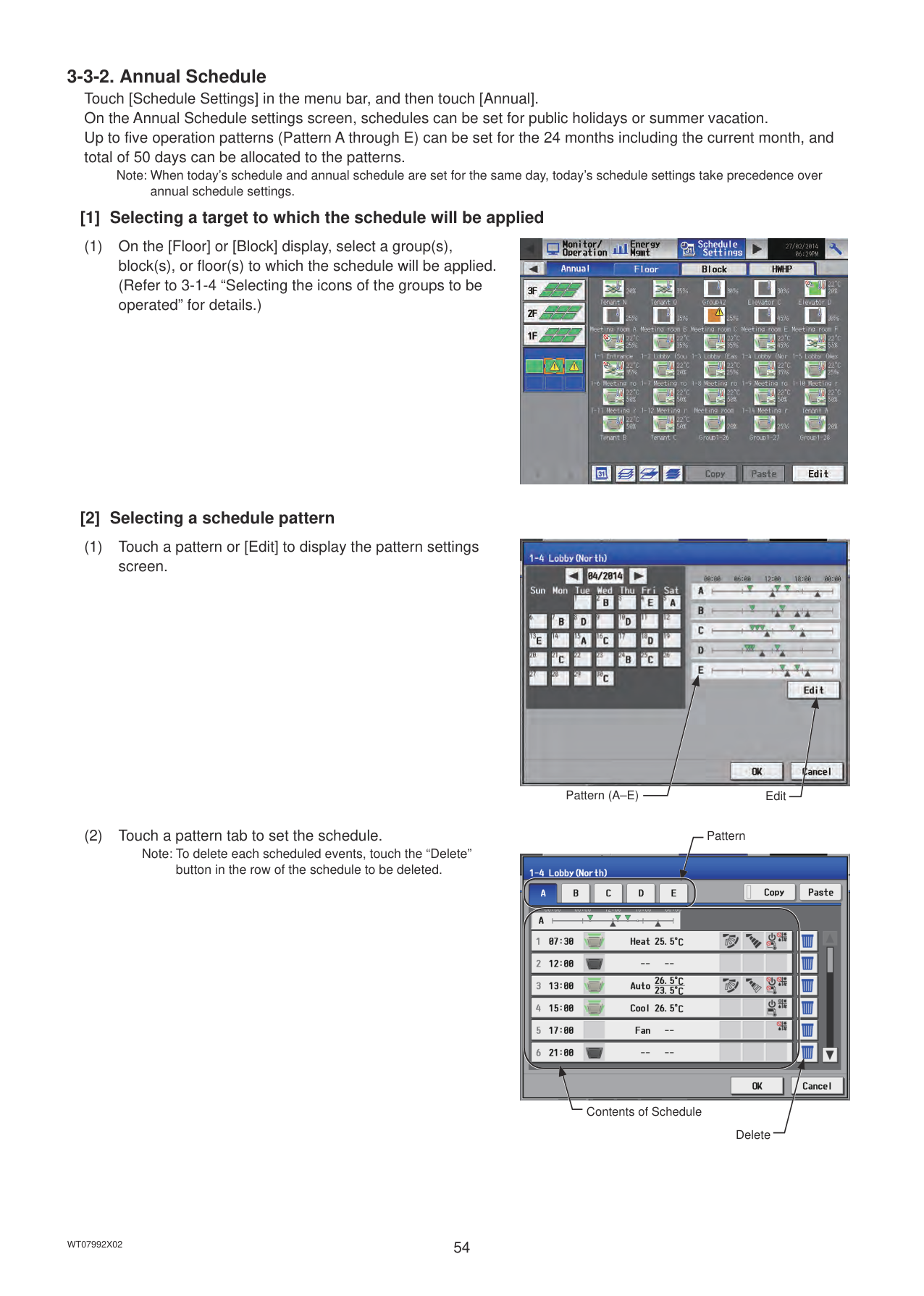
Contents of Schedule
Delete
Simplified display area

######## [4] Setting the contents of the schedule
(1) Touch the row of the schedule to be set in the “Contents of Schedule” section to display the schedule settings screen. Set the start time to apply to the schedule, set the operations to be scheduled, and then touch [OK].
Note: If [Optimized Start] is selected, the operation mode and the set temperature need to be set as well. Refer to the next page for details about the Optimized Start function.
To copy the schedule settings between groups, see [7] below. To copy the schedule settings between days of the week, see [5] below.
1st page (Air conditioning unit group)

Schedule settings OK
Scheduled start time
2nd page (Air conditioning unit group)

OK
Schedule settings
Scheduled start time
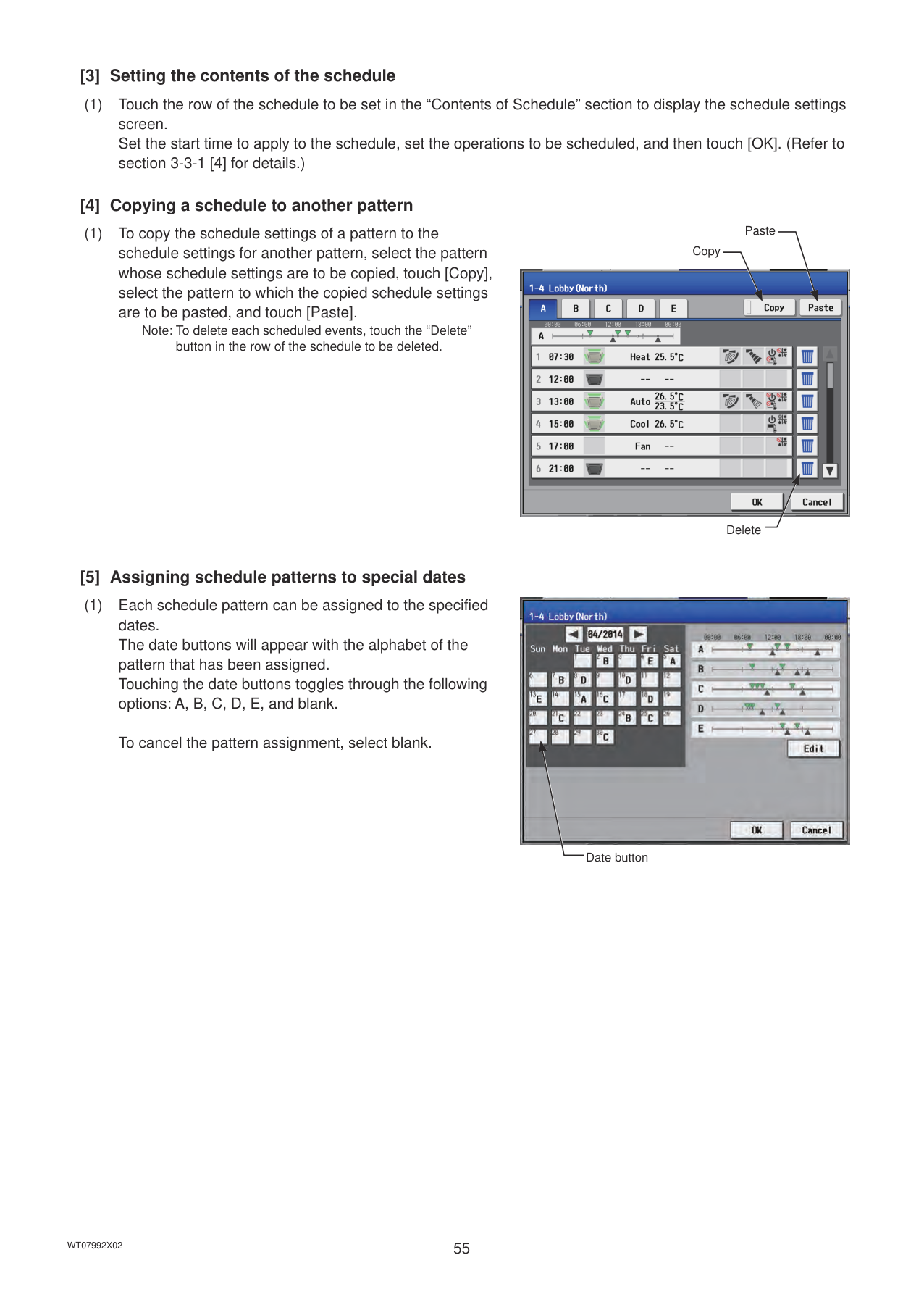
Note: The operation items that will appear on the screen vary, depending on the equipment type. Refer to section 3-1-5 “Operation settings screen” for setting details for each unit group.
LOSSNAY unit group Air To Water (PWFY) unit group


HWHP (CAHV, CRHV) unit group General equipment group


Note: When setting a schedule for a block or all groups, all operation modes are available for selection, but the available operation
modes depend on the unit model. The units will not operate in the selected mode not supported by the units. Note: About Optimized Start function
|9:008:45
26ºC
Cool ON
Room temperature| |---|
Operation mode: Cool Start time: 9:00 Set temperature: 26ºC
|9:008:40
24ºC
Heat ON
Room temperature| |---|
Operation mode: Heat Start time: 9:00 Set temperature: 24ºC
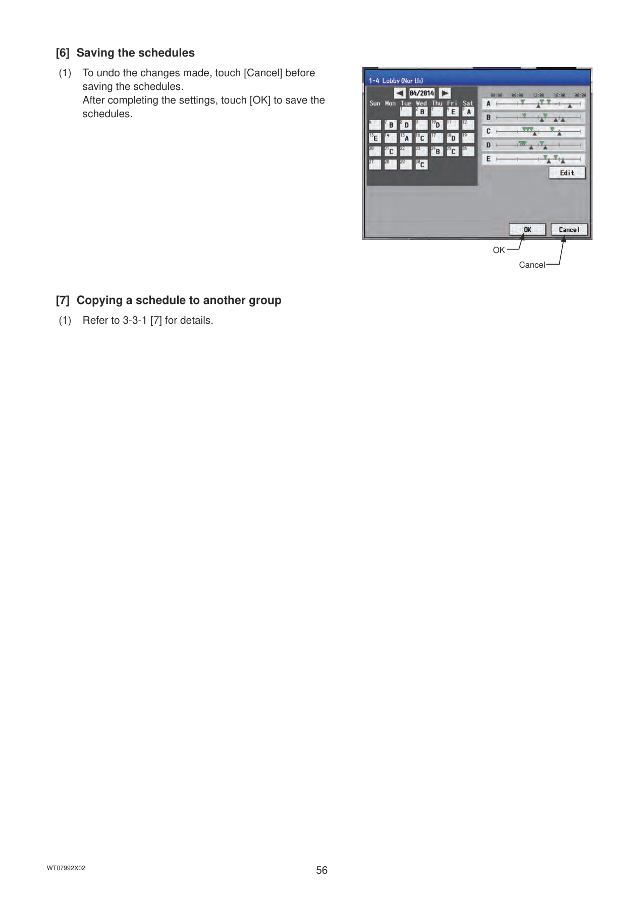
######## [5] Copying a schedule to another day of the week
(1) To copy the schedule settings of a day to the schedule settings for another day of the week, select the day whose schedule settings are to be copied, touch [Copy], select the day to which the copied schedule settings are to be pasted, and touch [Paste].
Note: To delete each scheduled events, touch the “Delete” button in the row of the schedule to be deleted.
Day of the week selection
Paste
Copy

Delete
######## [6] Saving the schedules
(1) To undo the changes made, touch [Cancel] before saving the schedules. After completing the settings, touch [OK] to save the schedules.
Note: To delete each scheduled events, touch the “Delete” button in the row of the schedule to be deleted.

OK
Delete Cancel
######## [7] Copying a schedule to another group
(1) To copy the schedule settings of a group to the schedule settings for another group, select the group whose schedule settings are to be copied, touch [Copy], select the group to which the copied schedule settings are to be pasted, and touch [Paste].
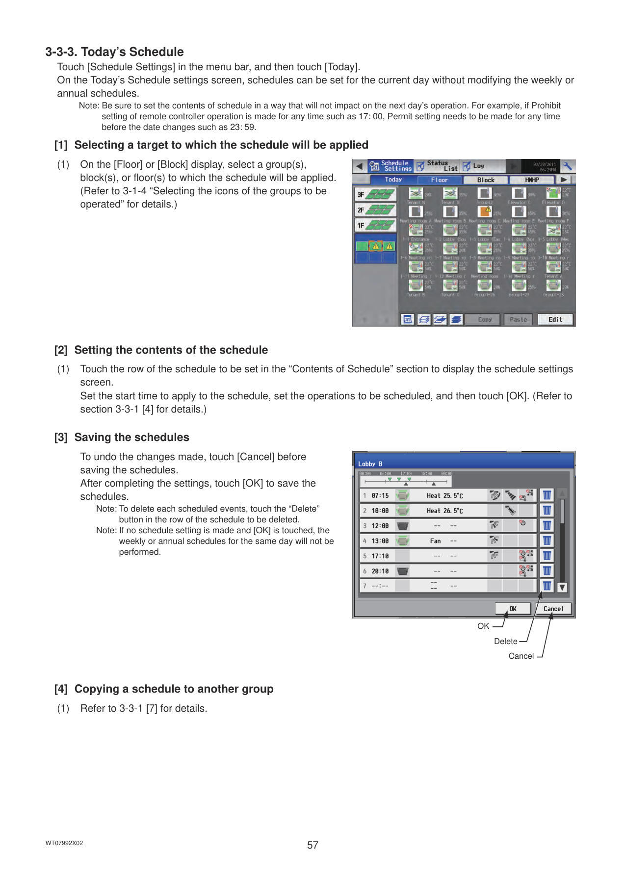

Note: Schedules of a group cannot be copied to a different type of group. For example, the schedules of an air conditioning unit group cannot be copied to the schedules for a LOSSNAY unit group.
Note: The operation mode and set temperature may not be copied because the available operation modes or operable set temperature range differ among the units.
Note: To select groups in the given EM block(s), touch the [Display switching] button to change it to [EM Block] first.
PasteDisplay switching
Copy
Note: When today’s schedule and annual schedule are set for the same day, today’s schedule settings take precedence over annual schedule settings.
######## [1] Selecting a target to which the schedule will be applied
(1) On the [Floor] or [Block] display, select a group(s), block(s), or floor(s) to which the schedule will be applied. (Refer to 3-1-4 “Selecting the icons of the groups to be operated” for details.)

######## [2] Selecting a schedule pattern
########### (1) Touch a pattern or [Edit] to display the pattern settingsscreen.
########### (2) Touch a pattern tab to set the schedule.Note: To delete each scheduled events, touch the “Delete”
button in the row of the schedule to be deleted.

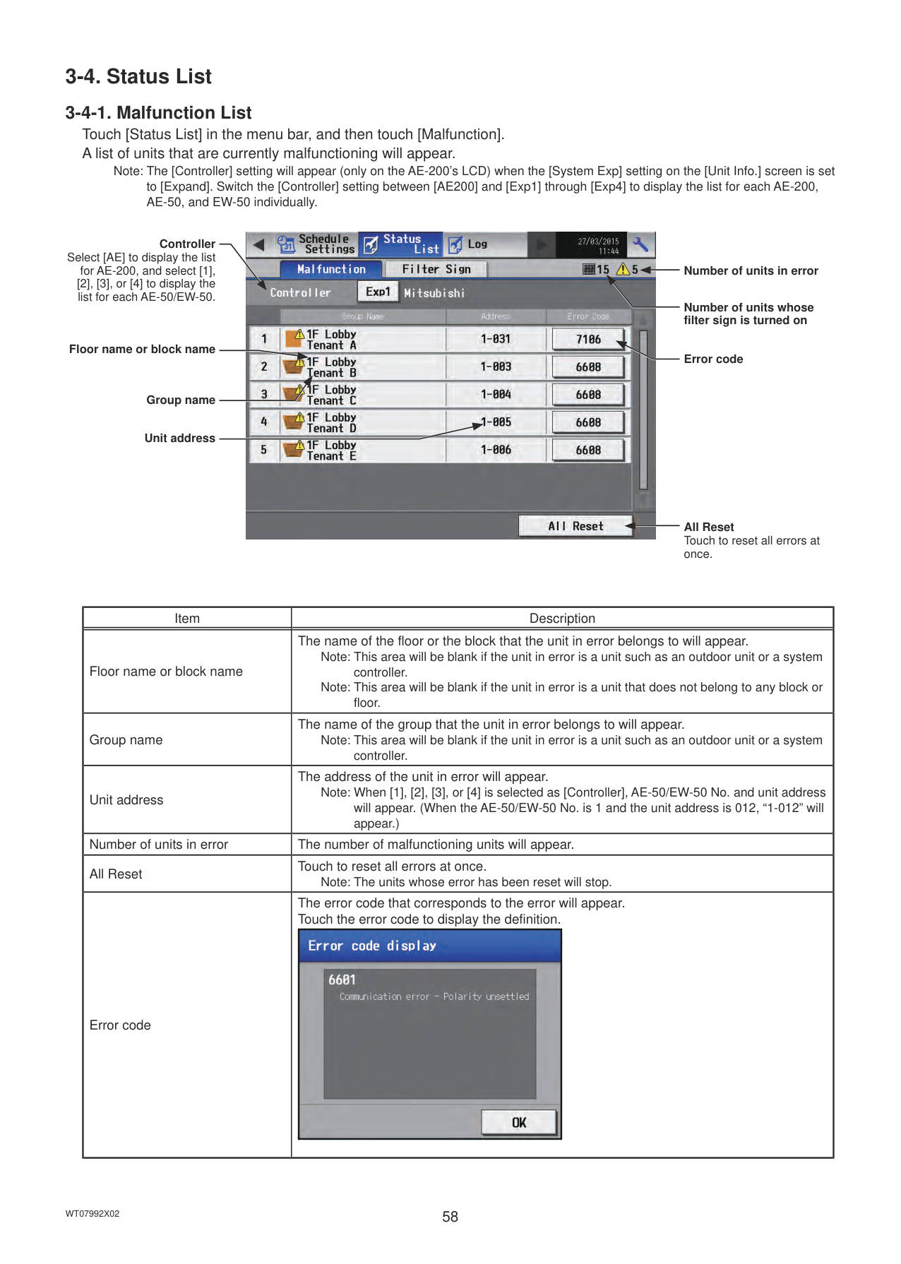
EditPattern (A–E)
Pattern

Contents of Schedule
Delete
######## [3] Setting the contents of the schedule
(1) Touch the row of the schedule to be set in the “Contents of Schedule” section to display the schedule settings screen. Set the start time to apply to the schedule, set the operations to be scheduled, and then touch [OK]. (Refer to section 3-3-1 [4] for details.)
######## [4] Copying a schedule to another pattern
(1) To copy the schedule settings of a pattern to the schedule settings for another pattern, select the pattern whose schedule settings are to be copied, touch [Copy], select the pattern to which the copied schedule settings are to be pasted, and touch [Paste].
Note: To delete each scheduled events, touch the “Delete” button in the row of the schedule to be deleted.
Paste
Copy

Delete
######## [5] Assigning schedule patterns to special dates
(1) Each schedule pattern can be assigned to the specified dates. The date buttons will appear with the alphabet of the pattern that has been assigned. Touching the date buttons toggles through the following options: A, B, C, D, E, and blank.
To cancel the pattern assignment, select blank.
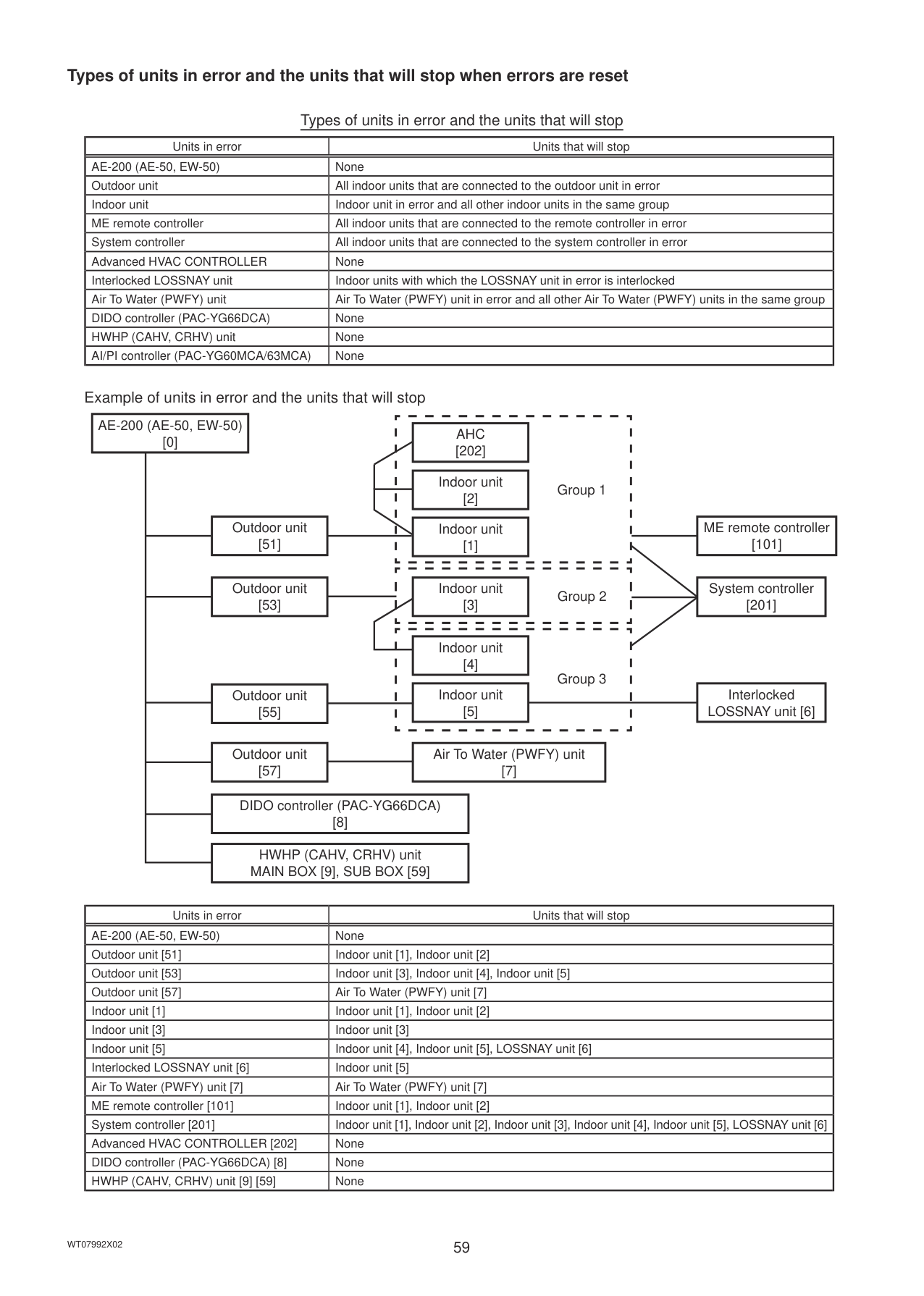

Date button
######## [6] Saving the schedules
(1) To undo the changes made, touch [Cancel] before saving the schedules. After completing the settings, touch [OK] to save the schedules.
######## [7] Copying a schedule to another group
(1) Refer to 3-3-1 [7] for details.

OK
Cancel
Note: Be sure to set the contents of schedule in a way that will not impact on the next day’s operation. For example, if Prohibit setting of remote controller operation is made for any time such as 17: 00, Permit setting needs to be made for any time before the date changes such as 23: 59.
######## [1] Selecting a target to which the schedule will be applied
(1) On the [Floor] or [Block] display, select a group(s), block(s), or floor(s) to which the schedule will be applied. (Refer to 3-1-4 “Selecting the icons of the groups to be operated” for details.)

######## [2] Setting the contents of the schedule
(1) Touch the row of the schedule to be set in the “Contents of Schedule” section to display the schedule settings screen. Set the start time to apply to the schedule, set the operations to be scheduled, and then touch [OK]. (Refer to section 3-3-1 [4] for details.)
######## [3] Saving the schedules
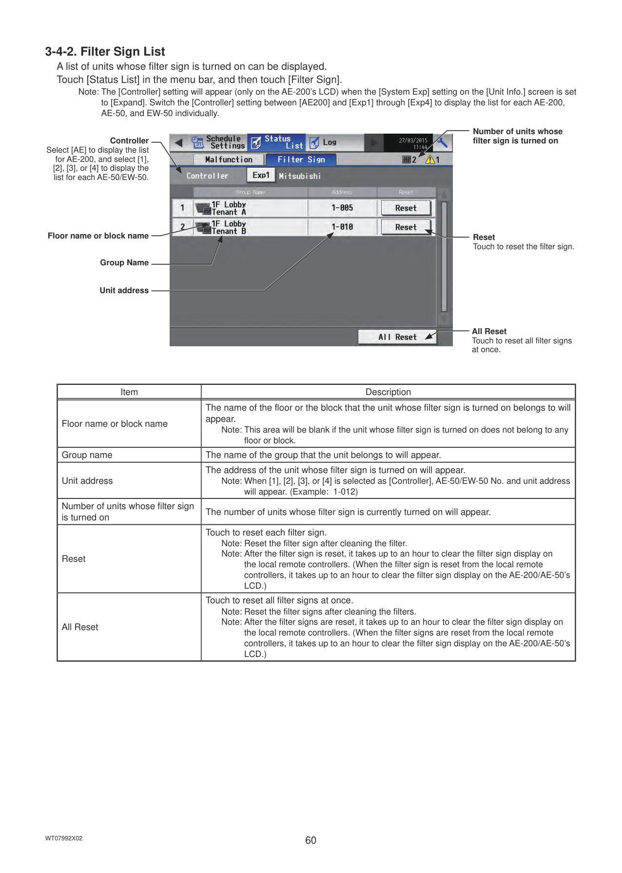
To undo the changes made, touch [Cancel] before saving the schedules. After completing the settings, touch [OK] to save the schedules.
Note: To delete each scheduled events, touch the “Delete” button in the row of the schedule to be deleted.
Note: If no schedule setting is made and [OK] is touched, the weekly or annual schedules for the same day will not be performed.

OK
Delete Cancel
######## [4] Copying a schedule to another group
(1) Refer to 3-3-1 [7] for details.
#### 3-4. Status List
Note: The [Controller] setting will appear (only on the AE-200’s LCD) when the [System Exp] setting on the [Unit Info.] screen is set to [Expand]. Switch the [Controller] setting between [AE200] and [Exp1] through [Exp4] to display the list for each AE-200, AE-50, and EW-50 individually.
Controller Select [AE] to display the list
for AE-200, and select [1], [2], [3], or [4] to display the list for each AE-50/EW-50.
Floor name or block name
Group name
Unit address
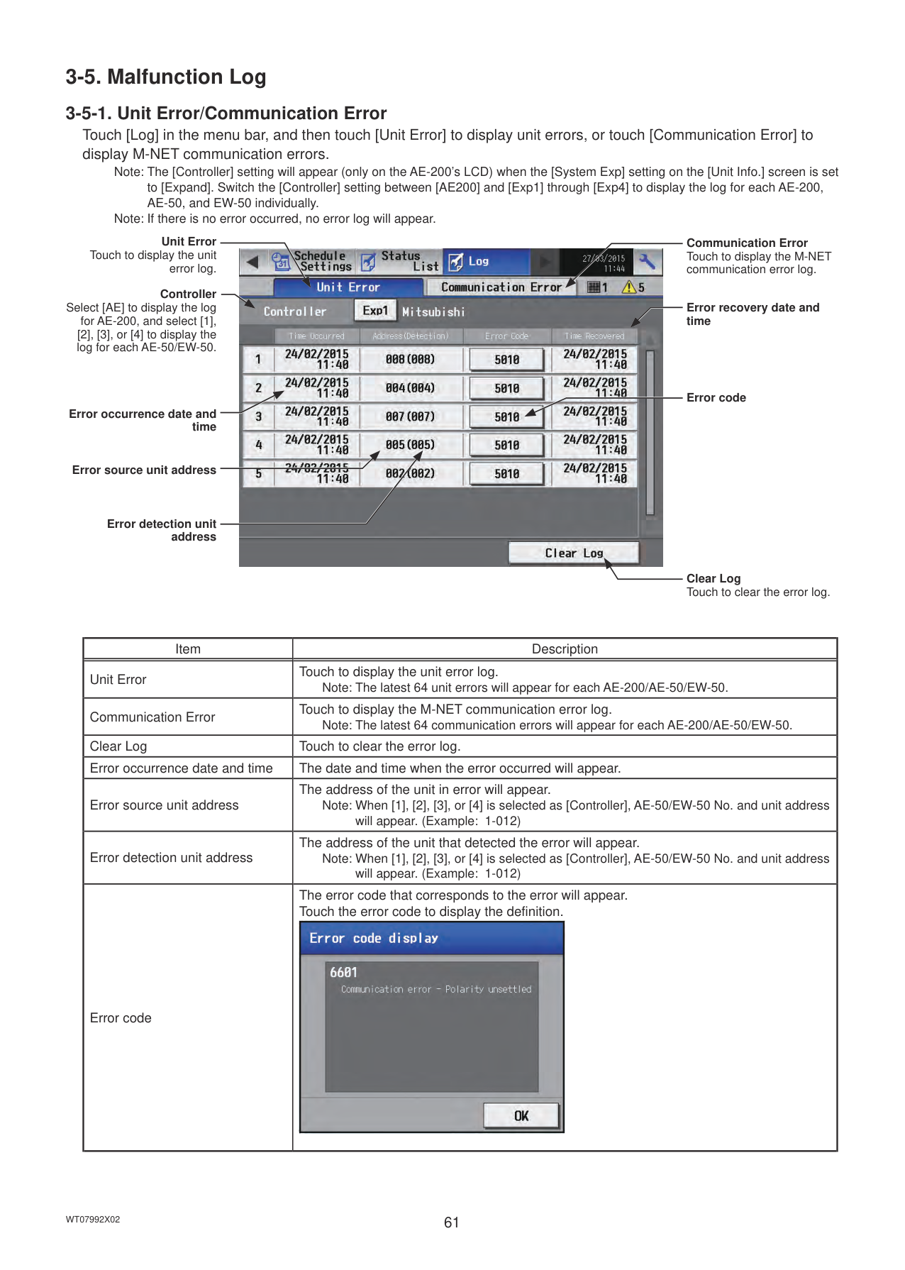

Number of units in error
############## Number of units whose filter sign is turned on
Error code
All Reset Touch to reset all errors at once.
|Item|Description| |---|---| |Floor name or block name|The name of the floor or the block that the unit in error belongs to will appear.
Note: This area will be blank if the unit in error is a unit such as an outdoor unit or a system controller. Note: This area will be blank if the unit in error is a unit that does not belong to any block or floor.| |Group name|The name of the group that the unit in error belongs to will appear.
Note: This area will be blank if the unit in error is a unit such as an outdoor unit or a system controller.| |Unit address|The address of the unit in error will appear.
Note: When [1], [2], [3], or [4] is selected as [Controller], AE-50/EW-50 No. and unit address will appear. (When the AE-50/EW-50 No. is 1 and the unit address is 012, “1-012” will appear.)| |Number of units in error|The number of malfunctioning units will appear.| |All Reset|Touch to reset all errors at once.
Note: The units whose error has been reset will stop.| |Error code|The error code that corresponds to the error will appear. Touch the error code to display the definition.
|
######## Types of units in error and the units that will stop when errors are reset
Types of units in error and the units that will stop
|Units in error|Units that will stop| |---|---| |AE-200 (AE-50, EW-50)|None| |Outdoor unit|All indoor units that are connected to the outdoor unit in error| |Indoor unit|Indoor unit in error and all other indoor units in the same group| |ME remote controller|All indoor units that are connected to the remote controller in error| |System controller|All indoor units that are connected to the system controller in error| |Advanced HVAC CONTROLLER|None| |Interlocked LOSSNAY unit|Indoor units with which the LOSSNAY unit in error is interlocked| |Air To Water (PWFY) unit|Air To Water (PWFY) unit in error and all other Air To Water (PWFY) units in the same group|
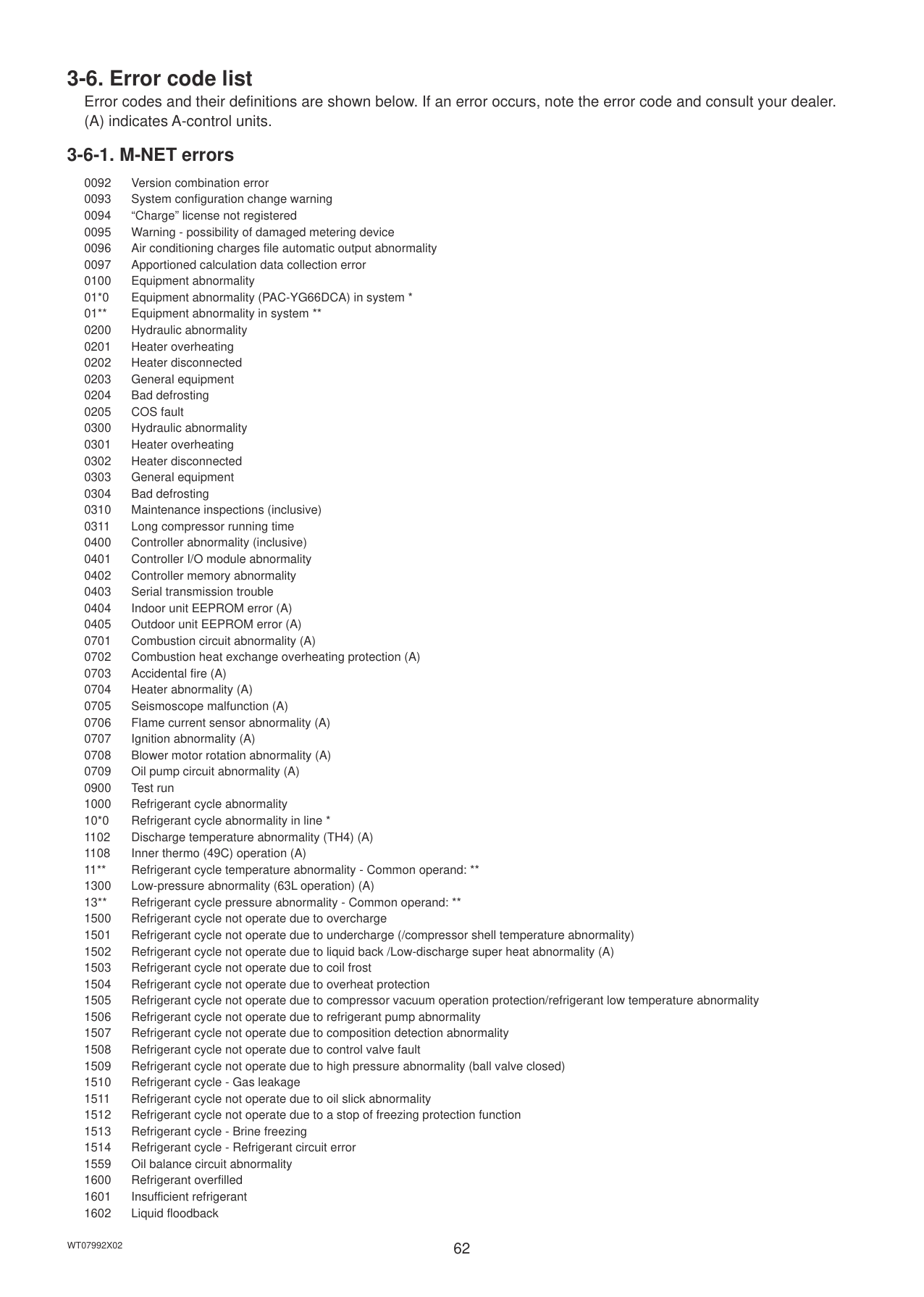
|DIDO controller (PAC-YG66DCA)|None| |HWHP (CAHV, CRHV) unit|None| |AI/PI controller (PAC-YG60MCA/63MCA)|None|
Example of units in error and the units that will stop
AE-200 (AE-50, EW-50) [0]
|AHC [202]| |---|
Indoor unit [2]
Group 3
ME remote controller [101]
| |System controller [201]| |---|---| | |System controller [201]|
Interlocked LOSSNAY unit [6]
Outdoor unit [51]
Indoor unit [1]
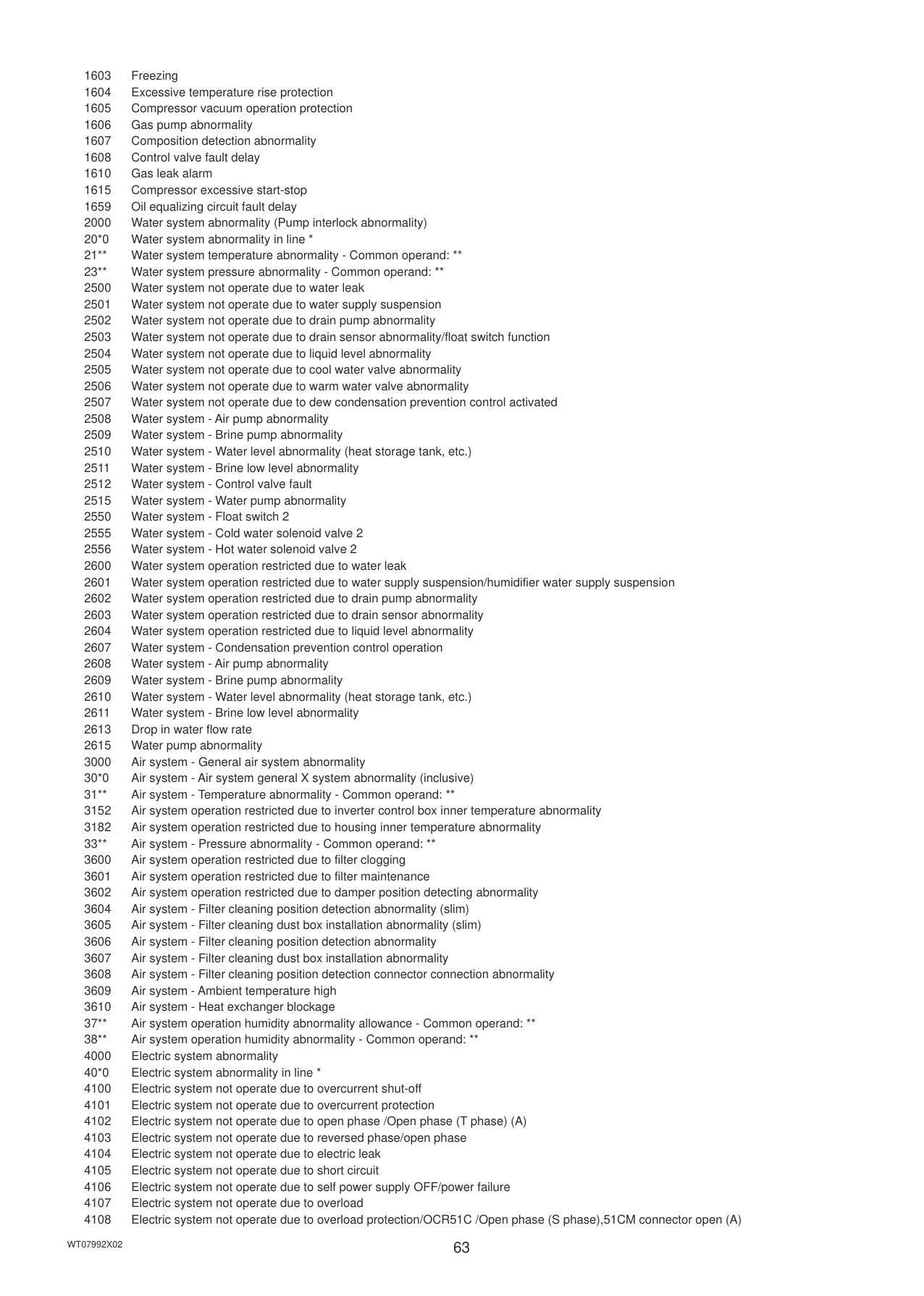
|Indoor unit [3]| |---|
Outdoor unit [53]
Indoor unit
Indoor unit
Outdoor unit [55]
Outdoor unit [57]
Air To Water (PWFY) unit [7]
DIDO controller (PAC-YG66DCA) [8]
HWHP (CAHV, CRHV) unit MAIN BOX [9], SUB BOX [59]
|Units in error|Units that will stop| |---|---| |AE-200 (AE-50, EW-50)|None| |Outdoor unit [51]|Indoor unit [1], Indoor unit [2]| |Outdoor unit [53]|Indoor unit [3], Indoor unit [4], Indoor unit [5]| |Outdoor unit [57]|Air To Water (PWFY) unit [7]| |Indoor unit [1]|Indoor unit [1], Indoor unit [2]| |Indoor unit [3]|Indoor unit [3]|
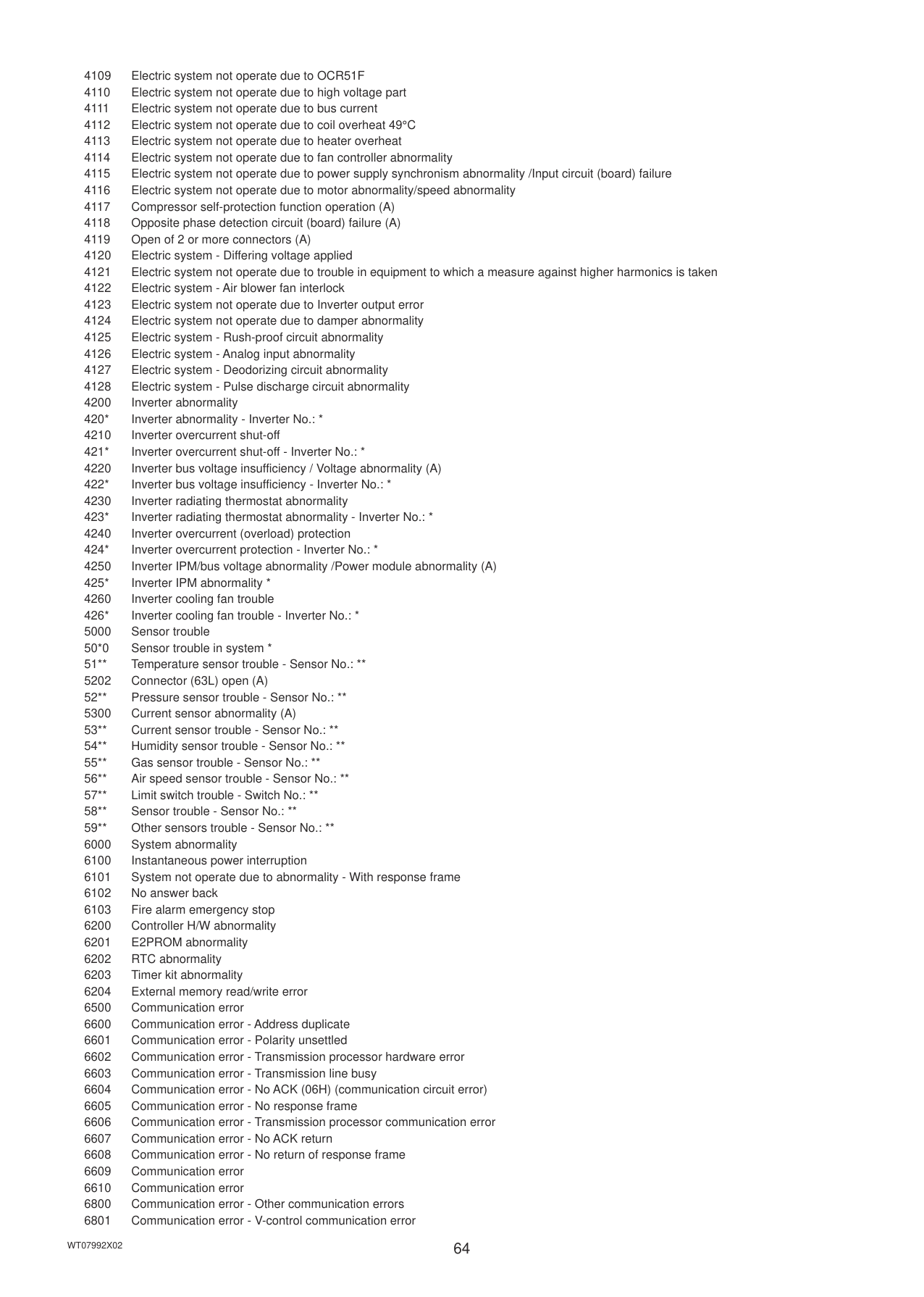
|Indoor unit [5]|Indoor unit [4], Indoor unit [5], LOSSNAY unit [6]| |Interlocked LOSSNAY unit [6]|Indoor unit [5]| |Air To Water (PWFY) unit [7]|Air To Water (PWFY) unit [7]| |ME remote controller [101]|Indoor unit [1], Indoor unit [2]| |System controller [201]|Indoor unit [1], Indoor unit [2], Indoor unit [3], Indoor unit [4], Indoor unit [5], LOSSNAY unit [6]| |Advanced HVAC CONTROLLER [202]|None| |DIDO controller (PAC-YG66DCA) [8]|None| |HWHP (CAHV, CRHV) unit [9] [59]|None|
Note: The [Controller] setting will appear (only on the AE-200’s LCD) when the [System Exp] setting on the [Unit Info.] screen is set to [Expand]. Switch the [Controller] setting between [AE200] and [Exp1] through [Exp4] to display the list for each AE-200, AE-50, and EW-50 individually.
Controller Select [AE] to display the list
for AE-200, and select [1], [2], [3], or [4] to display the list for each AE-50/EW-50.
Floor name or block name
Group Name
Unit address

Number of units whose filter sign is turned on
Reset Touch to reset the filter sign.
All Reset Touch to reset all filter signs at once.
|Item|Description|
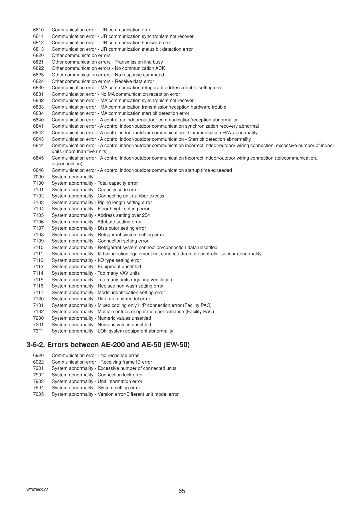
|---|---| |Floor name or block name|The name of the floor or the block that the unit whose filter sign is turned on belongs to will appear.
Note: This area will be blank if the unit whose filter sign is turned on does not belong to any floor or block.| |Group name|The name of the group that the unit belongs to will appear.| |Unit address|The address of the unit whose filter sign is turned on will appear.
Note: When [1], [2], [3], or [4] is selected as [Controller], AE-50/EW-50 No. and unit address will appear. (Example: 1-012)| |Number of units whose filter sign is turned on|The number of units whose filter sign is currently turned on will appear.| |Reset|Touch to reset each filter sign. Note: Reset the filter sign after cleaning the filter. Note: After the filter sign is reset, it takes up to an hour to clear the filter sign display on
the local remote controllers. (When the filter sign is reset from the local remote controllers, it takes up to an hour to clear the filter sign display on the AE-200/AE-50’s LCD.)| |All Reset|Touch to reset all filter signs at once. Note: Reset the filter signs after cleaning the filters. Note: After the filter signs are reset, it takes up to an hour to clear the filter sign display on
the local remote controllers. (When the filter signs are reset from the local remote controllers, it takes up to an hour to clear the filter sign display on the AE-200/AE-50’s LCD.)|
#### 3-5. Malfunction Log
Note: The [Controller] setting will appear (only on the AE-200’s LCD) when the [System Exp] setting on the [Unit Info.] screen is set to [Expand]. Switch the [Controller] setting between [AE200] and [Exp1] through [Exp4] to display the log for each AE-200, AE-50, and EW-50 individually.
Note: If there is no error occurred, no error log will appear.
Unit Error Touch to display the unit
Communication Error Touch to display the M-NET communication error log.

error log.
Controller Select [AE] to display the log
Error recovery date and time
for AE-200, and select [1], [2], [3], or [4] to display the log for each AE-50/EW-50.
Error code
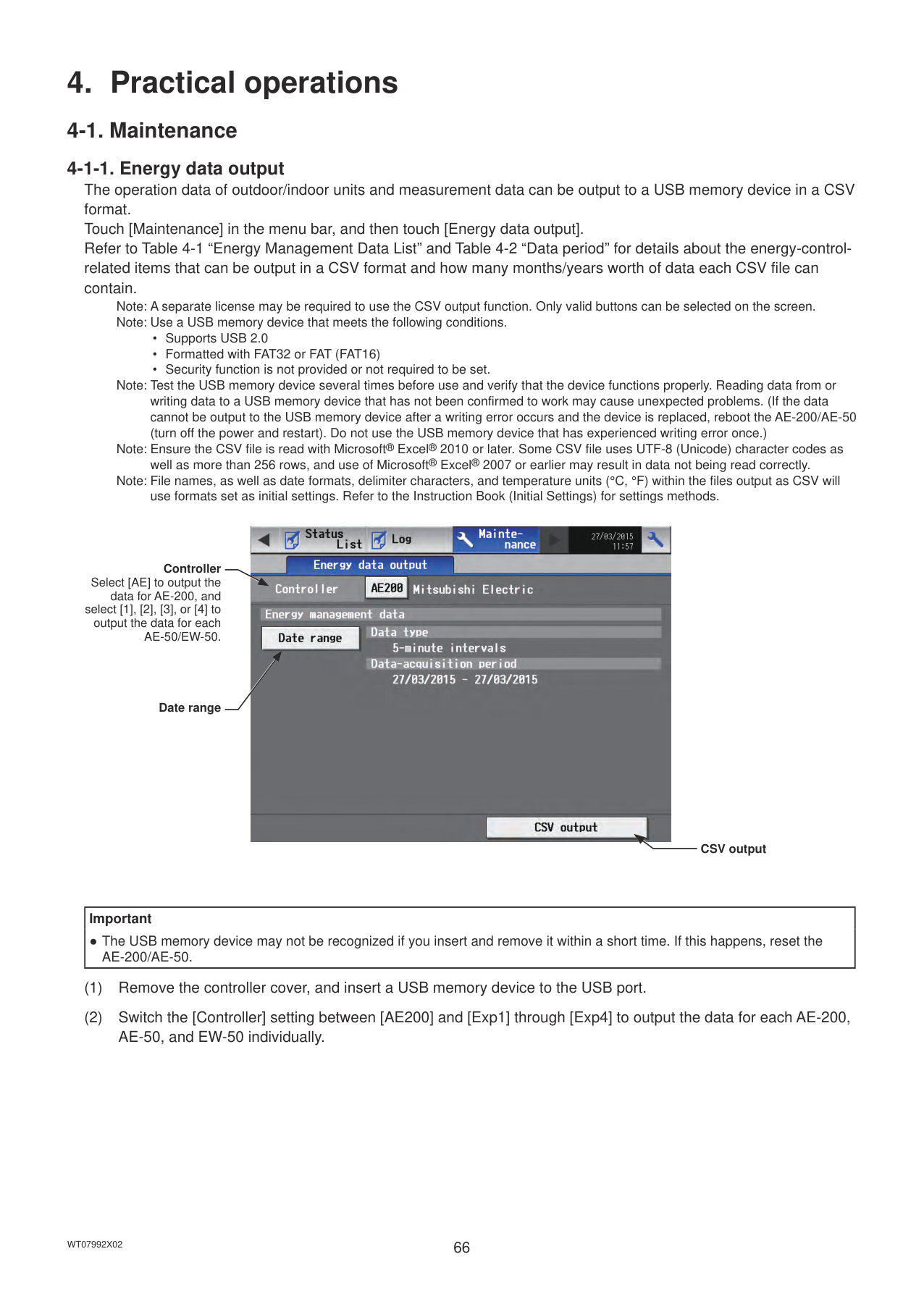
Error occurrence date and time
Error source unit address
Error detection unit address
Clear Log Touch to clear the error log.
|Item|Description| |---|---| |Unit Error|Touch to display the unit error log.
Note: The latest 64 unit errors will appear for each AE-200/AE-50/EW-50.| |Communication Error|Touch to display the M-NET communication error log.
Note: The latest 64 communication errors will appear for each AE-200/AE-50/EW-50.| |Clear Log|Touch to clear the error log.| |Error occurrence date and time|The date and time when the error occurred will appear.| |Error source unit address|The address of the unit in error will appear.
Note: When [1], [2], [3], or [4] is selected as [Controller], AE-50/EW-50 No. and unit address will appear. (Example: 1-012)| |Error detection unit address|The address of the unit that detected the error will appear.
Note: When [1], [2], [3], or [4] is selected as [Controller], AE-50/EW-50 No. and unit address will appear. (Example: 1-012)| |Error code|The error code that corresponds to the error will appear. Touch the error code to display the definition.
|
#### 3-6. Error code list
Error codes and their definitions are shown below. If an error occurs, note the error code and consult your dealer. (A) indicates A-control units.
###### 3-6-1. M-NET errors
0092 Version combination error 0093 System configuration change warning 0094 “Charge” license not registered 0095 Warning - possibility of damaged metering device 0096 Air conditioning charges file automatic output abnormality 0097 Apportioned calculation data collection error 0100 Equipment abnormality 01*0 Equipment abnormality (PAC-YG66DCA) in system * 01 Equipment abnormality in system
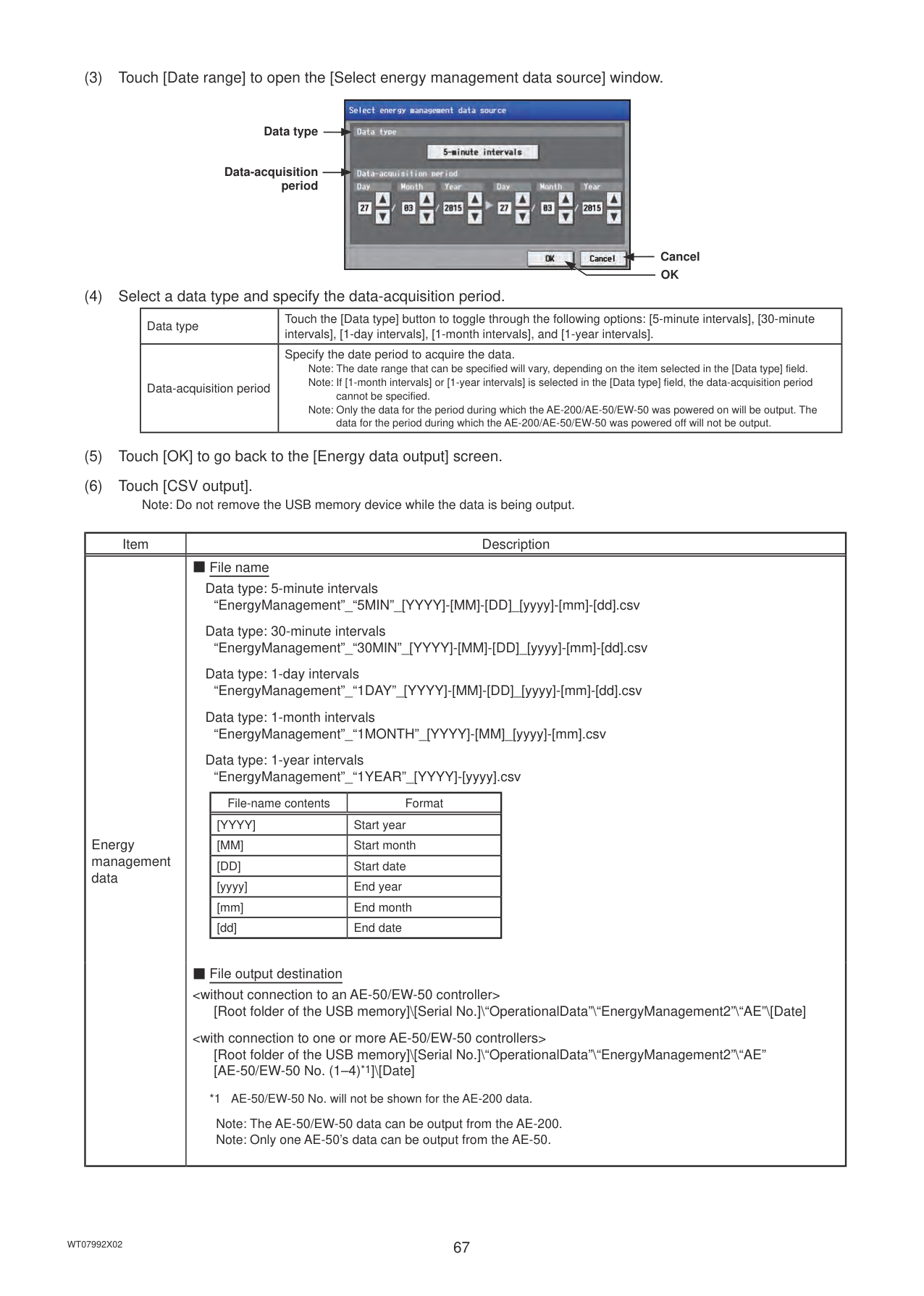
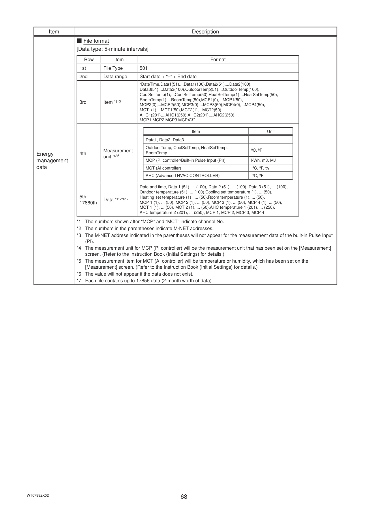
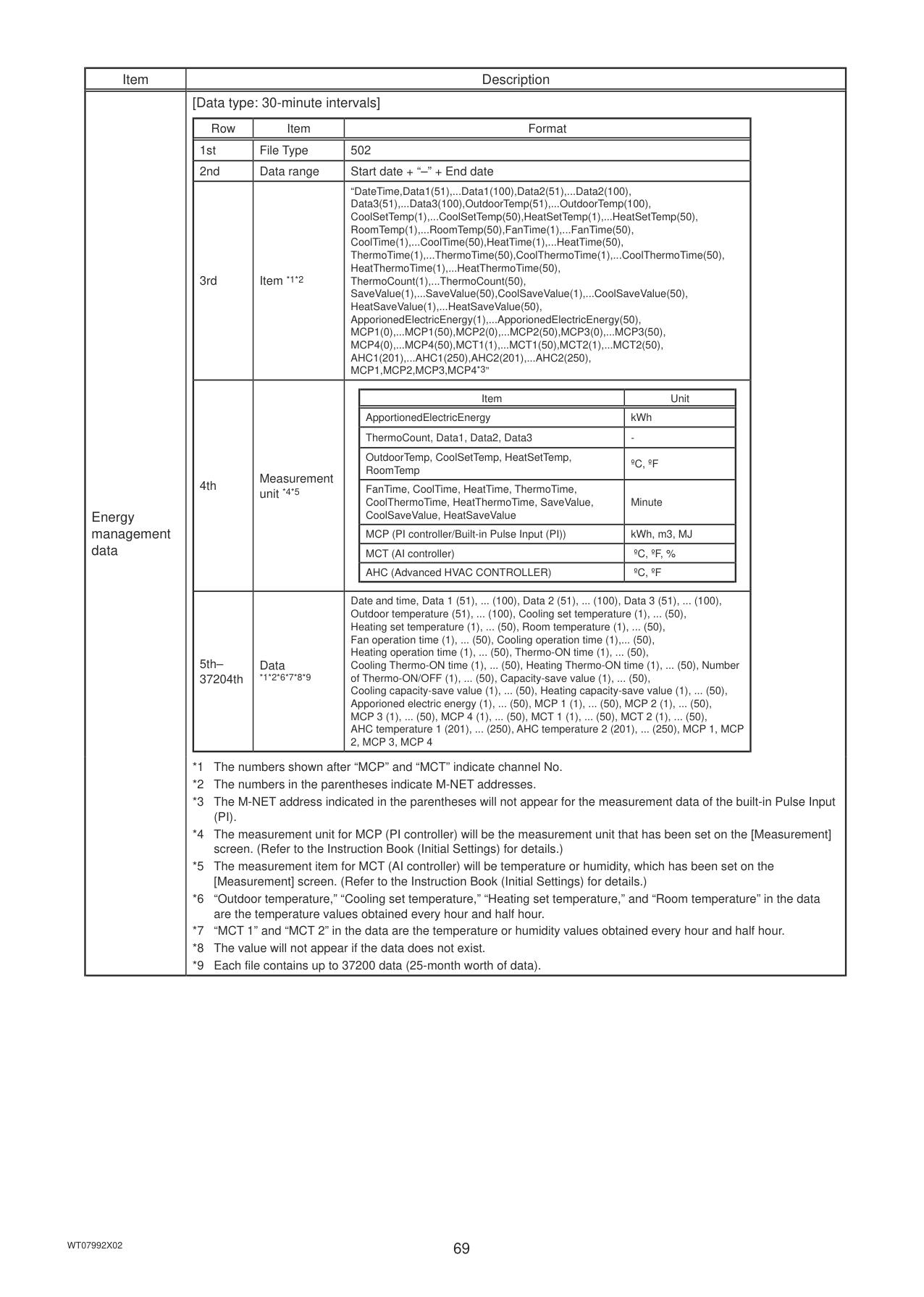
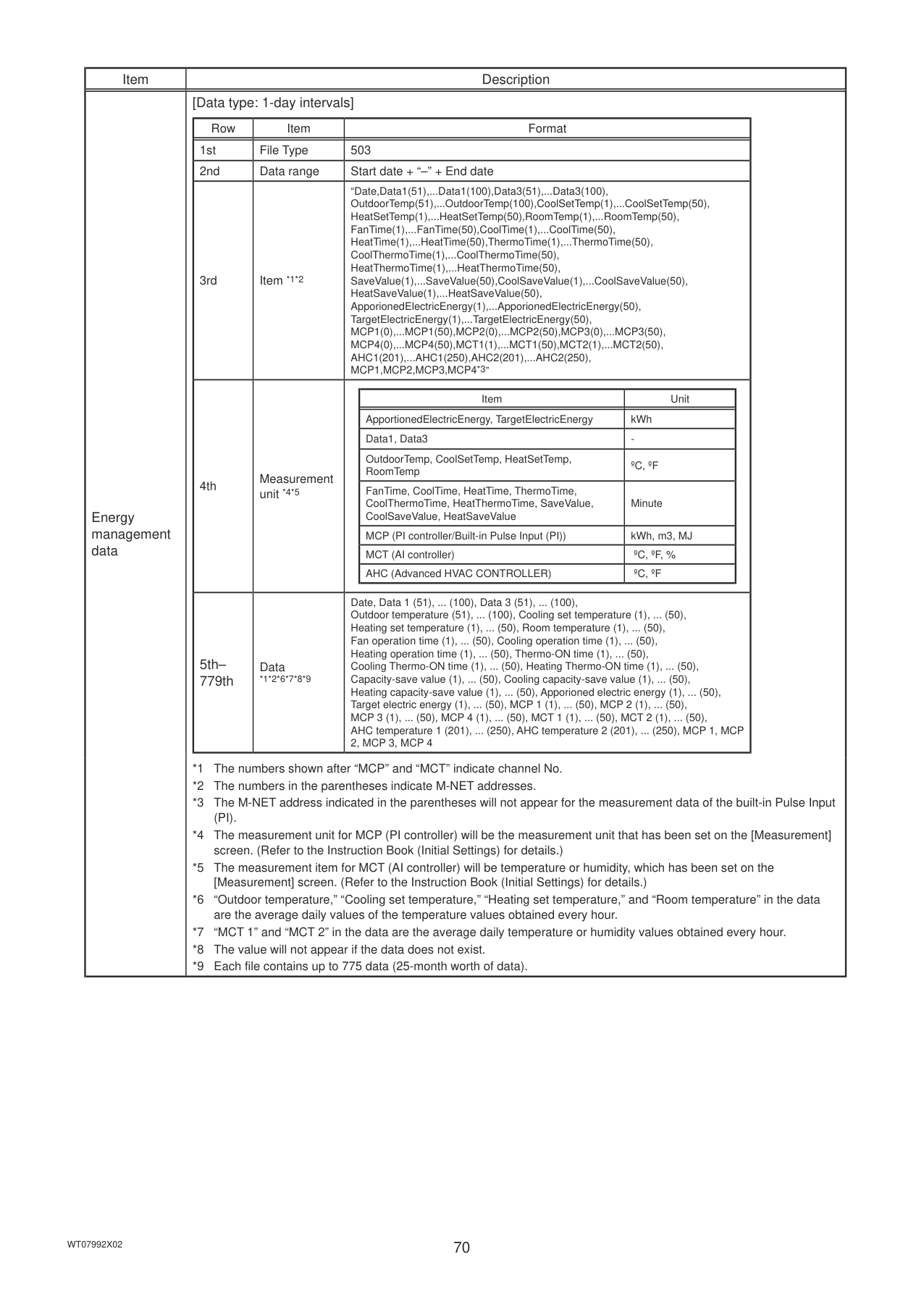
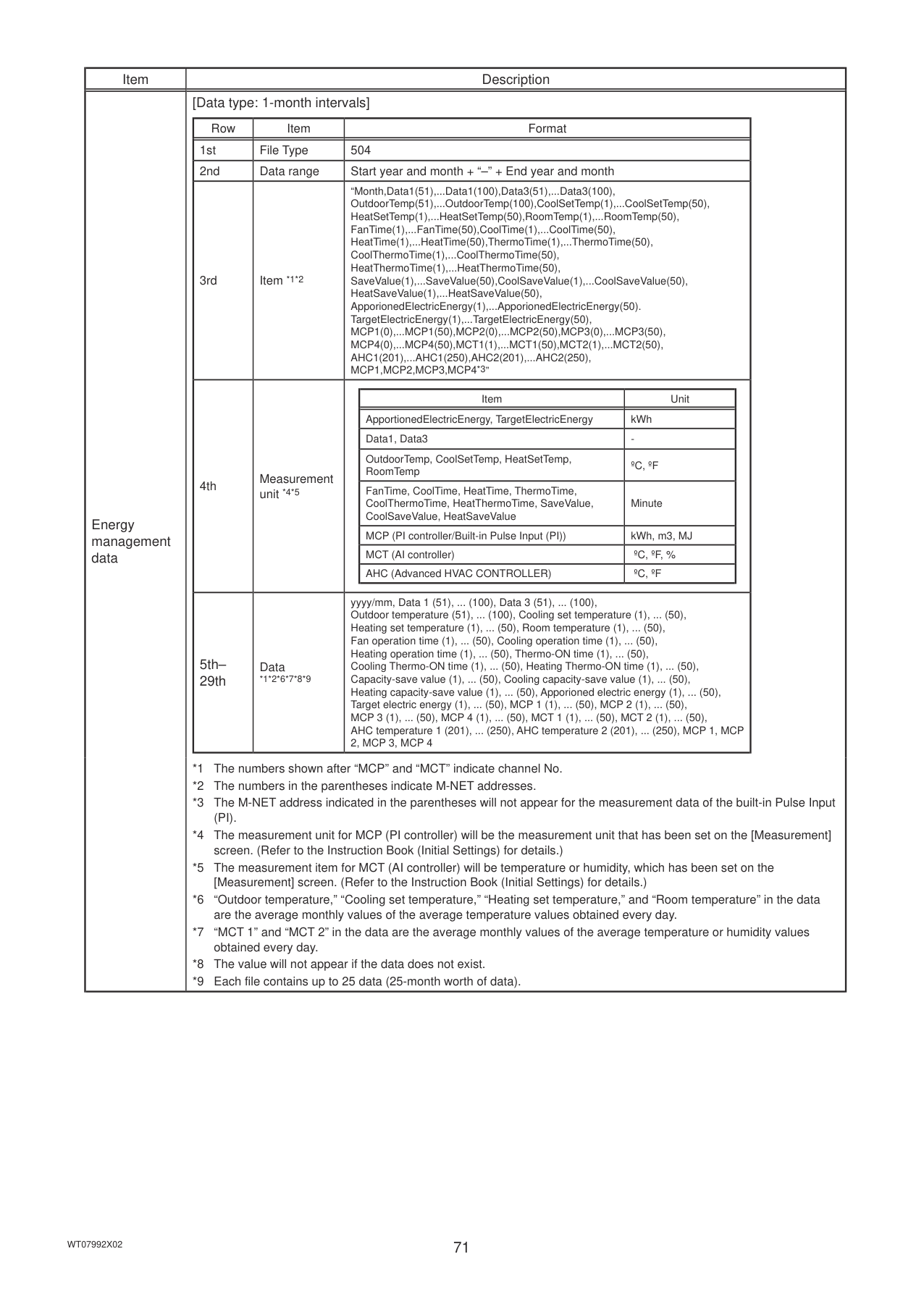
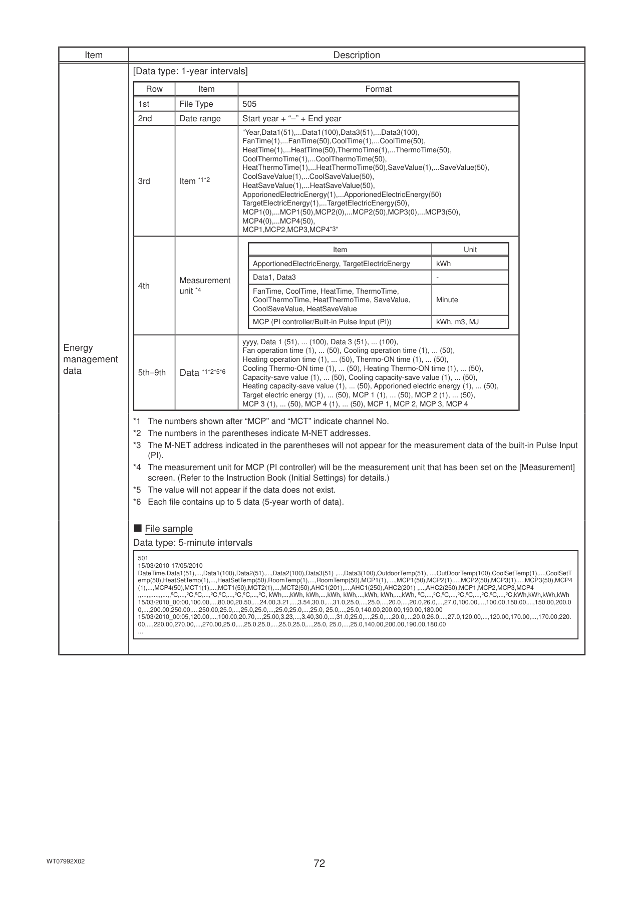
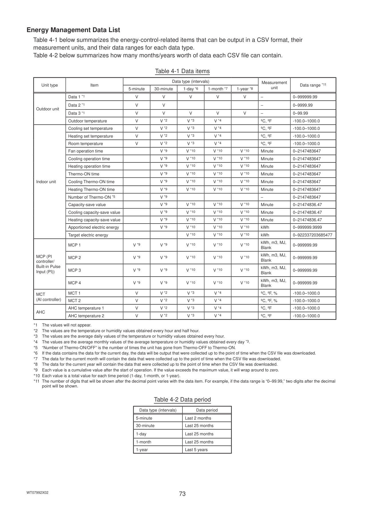
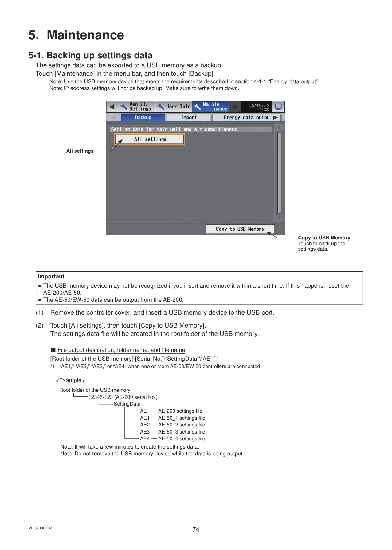
###### 3-6-2. Errors between AE-200 and AE-50 (EW-50)
6920 Communication error - No response error 6922 Communication error - Receiving frame ID error
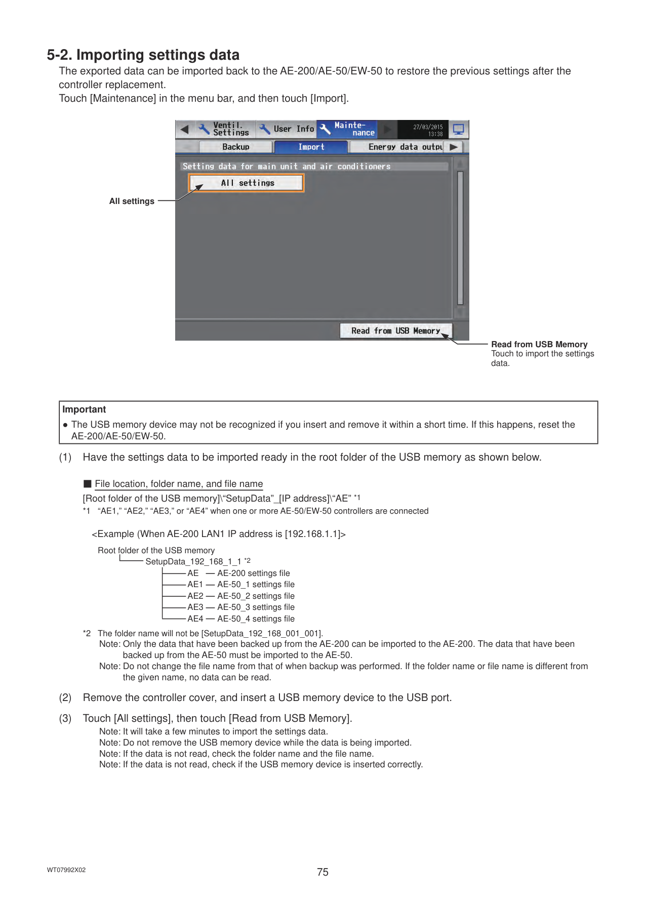
4. Practical operations
#### 4-1. Maintenance
Note: A separate license may be required to use the CSV output function. Only valid buttons can be selected on the screen. Note: Use a USB memory device that meets the following conditions.
Note: Test the USB memory device several times before use and verify that the device functions properly. Reading data from or writing data to a USB memory device that has not been confirmed to work may cause unexpected problems. (If the data cannot be output to the USB memory device after a writing error occurs and the device is replaced, reboot the AE-200/AE-50 (turn off the power and restart). Do not use the USB memory device that has experienced writing error once.)
Note: Ensure the CSV file is read with Microsoft® Excel® 2010 or later. Some CSV file uses UTF-8 (Unicode) character codes as well as more than 256 rows, and use of Microsoft® Excel® 2007 or earlier may result in data not being read correctly. Note: File names, as well as date formats, delimiter characters, and temperature units (°C, °F) within the files output as CSV will
use formats set as initial settings. Refer to the Instruction Book (Initial Settings) for settings methods.
Controller Select [AE] to output the data for AE-200, and select [1], [2], [3], or [4] to output the data for each AE-50/EW-50.
Date range

CSV output
|Important
● The USB memory device may not be recognized if you insert and remove it within a short time. If this happens, reset the AE-200/AE-50.|
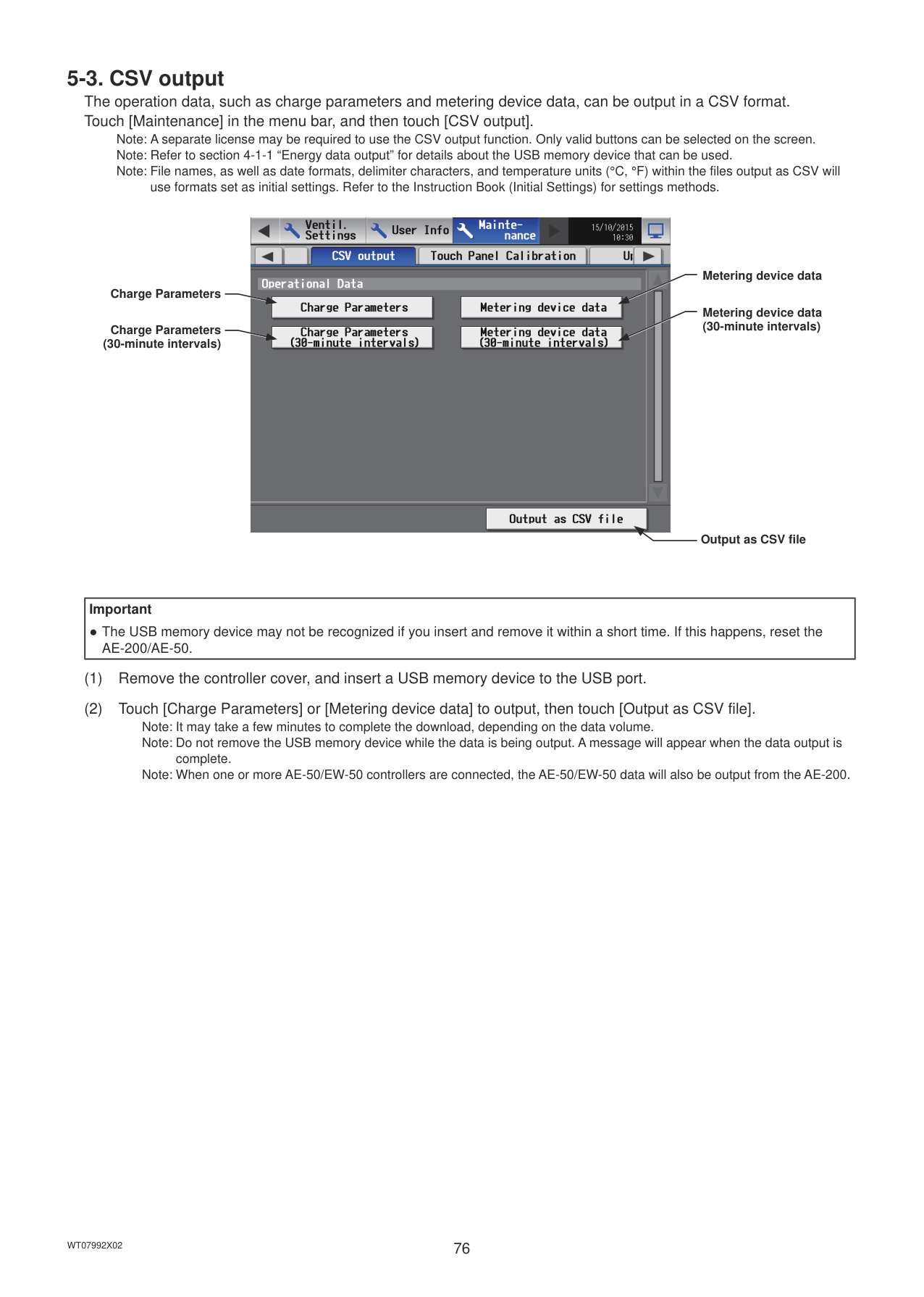
|---|
|
| |---|
|Data type|Touch the [Data type] button to toggle through the following options: [5-minute intervals], [30-minute intervals], [1-day intervals], [1-month intervals], and [1-year intervals].| |---|---| |Data-acquisition period|Specify the date period to acquire the data. Note: The date range that can be specified will vary, depending on the item selected in the [Data type] field. Note: If [1-month intervals] or [1-year intervals] is selected in the [Data type] field, the data-acquisition period
cannot be specified. Note: Only the data for the period during which the AE-200/AE-50/EW-50 was powered on will be output. The data for the period during which the AE-200/AE-50/EW-50 was powered off will not be output.|
Data type
Data-acquisition period
Cancel OK
|Item|Description| |---|---| |Energy management data|■ File name
Data type: 5-minute intervals
“EnergyManagement”_“5MIN”_[YYYY]-[MM]-[DD]_[yyyy]-[mm]-[dd].csv Data type: 30-minute intervals
“EnergyManagement”_“30MIN”_[YYYY]-[MM]-[DD]_[yyyy]-[mm]-[dd].csv Data type: 1-day intervals
“EnergyManagement”_“1DAY”_[YYYY]-[MM]-[DD]_[yyyy]-[mm]-[dd].csv Data type: 1-month intervals
“EnergyManagement”_“1MONTH”_[YYYY]-[MM]_[yyyy]-[mm].csv Data type: 1-year intervals
“EnergyManagement”_“1YEAR”_[YYYY]-[yyyy].csv
|File-name contents|Format| |---|---|
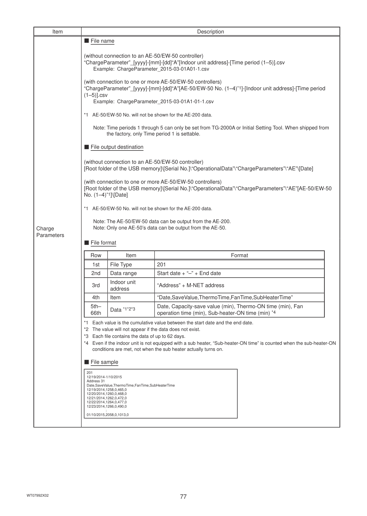
|[YYYY]|Start year| |[MM]|Start month| |[DD]|Start date| |[yyyy]|End year| |[mm]|End month| |[dd]|End date|
■ File output destination
*1 AE-50/EW-50 No. will not be shown for the AE-200 data.
Note: The AE-50/EW-50 data can be output from the AE-200. Note: Only one AE-50’s data can be output from the AE-50.|
|Item|Description| |---|---| |Energy management data|■ File format [Data type: 5-minute intervals]
|Row|Item|Format| |---|---|---| |1st|File Type|501| |2nd|Data range|Start date + “–” + End date| |3rd|Item *1*2|“DateTime,Data1(51),...Data1(100),Data2(51),...Data2(100), Data3(51),...Data3(100),OutdoorTemp(51),...OutdoorTemp(100), CoolSetTemp(1),...CoolSetTemp(50),HeatSetTemp(1),...HeatSetTemp(50), RoomTemp(1),...RoomTemp(50),MCP1(0),...MCP1(50), MCP2(0),...MCP2(50),MCP3(0),...MCP3(50),MCP4(0),...MCP4(50), MCT1(1),...MCT1(50),MCT2(1),...MCT2(50), AHC1(201),...AHC1(250),AHC2(201),...AHC2(250), MCP1,MCP2,MCP3,MCP4*3”| |4th|Measurement unit *4*5||Item|Unit| |---|---| |Data1, Data2, Data3|-| |OutdoorTemp, CoolSetTemp, HeatSetTemp, RoomTemp|ºC, ºF| |MCP (PI controller/Built-in Pulse Input (PI))|kWh, m3, MJ| |MCT (AI controller)|ºC, ºF, %| |AHC (Advanced HVAC CONTROLLER)|ºC, ºF| | |5th– 17860th|Data *1*2*6*7|Date and time, Data 1 (51), ... (100), Data 2 (51), ... (100), Data 3 (51), ... (100), Outdoor temperature (51), ... (100),Cooling set temperature (1), ... (50), Heating set temperature (1) , ... (50),Room temperature (1), ... (50), MCP 1 (1), ... (50), MCP 2 (1), ... (50), MCP 3 (1), ... (50), MCP 4 (1), ... (50), MCT 1 (1), ... (50), MCT 2 (1), ... (50),AHC temperature 1 (201), ... (250), AHC temperature 2 (201), ... (250), MCP 1, MCP 2, MCP 3, MCP 4|
*1 The numbers shown after “MCP” and “MCT” indicate channel No.
*2 The numbers in the parentheses indicate M-NET addresses.
*3 The M-NET address indicated in the parentheses will not appear for the measurement data of the built-in Pulse Input (PI).
*4 The measurement unit for MCP (PI controller) will be the measurement unit that has been set on the [Measurement] screen. (Refer to the Instruction Book (Initial Settings) for details.)
*5 The measurement item for MCT (AI controller) will be temperature or humidity, which has been set on the [Measurement] screen. (Refer to the Instruction Book (Initial Settings) for details.)
*6 The value will not appear if the data does not exist.
*7 Each file contains up to 17856 data (2-month worth of data).
|
|Item|Description| |---|---| |Energy management data|[Data type: 30-minute intervals]
|Row|Item|Format| |---|---|---| |1st|File Type|502| |2nd|Data range|Start date + “–” + End date|
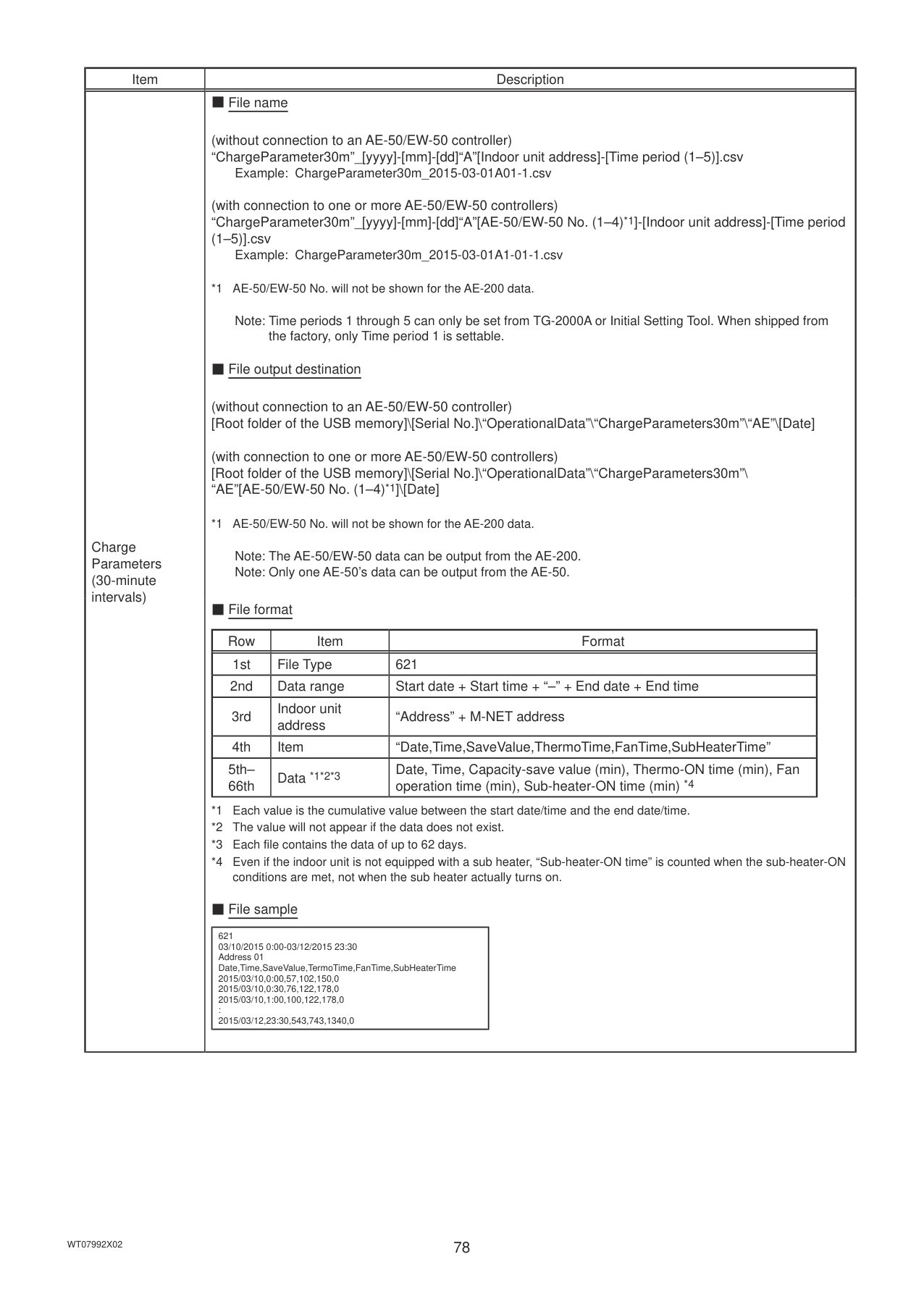
|3rd|Item *1*2|“DateTime,Data1(51),...Data1(100),Data2(51),...Data2(100), Data3(51),...Data3(100),OutdoorTemp(51),...OutdoorTemp(100), CoolSetTemp(1),...CoolSetTemp(50),HeatSetTemp(1),...HeatSetTemp(50), RoomTemp(1),...RoomTemp(50),FanTime(1),...FanTime(50), CoolTime(1),...CoolTime(50),HeatTime(1),...HeatTime(50), ThermoTime(1),...ThermoTime(50),CoolThermoTime(1),...CoolThermoTime(50), HeatThermoTime(1),...HeatThermoTime(50), ThermoCount(1),...ThermoCount(50), SaveValue(1),...SaveValue(50),CoolSaveValue(1),...CoolSaveValue(50), HeatSaveValue(1),...HeatSaveValue(50), ApporionedElectricEnergy(1),...ApporionedElectricEnergy(50), MCP1(0),...MCP1(50),MCP2(0),...MCP2(50),MCP3(0),...MCP3(50), MCP4(0),...MCP4(50),MCT1(1),...MCT1(50),MCT2(1),...MCT2(50), AHC1(201),...AHC1(250),AHC2(201),...AHC2(250), MCP1,MCP2,MCP3,MCP4*3”| |4th|Measurement unit *4*5||Item|Unit| |---|---| |ApportionedElectricEnergy|kWh| |ThermoCount, Data1, Data2, Data3|-| |OutdoorTemp, CoolSetTemp, HeatSetTemp, RoomTemp|ºC, ºF| |FanTime, CoolTime, HeatTime, ThermoTime, CoolThermoTime, HeatThermoTime, SaveValue, CoolSaveValue, HeatSaveValue|Minute| |MCP (PI controller/Built-in Pulse Input (PI))|kWh, m3, MJ| |MCT (AI controller)|ºC, ºF, %| |AHC (Advanced HVAC CONTROLLER)|ºC, ºF| | |5th– 37204th|Data
*1*2*6*7*8*9|Date and time, Data 1 (51), ... (100), Data 2 (51), ... (100), Data 3 (51), ... (100), Outdoor temperature (51), ... (100), Cooling set temperature (1), ... (50), Heating set temperature (1), ... (50), Room temperature (1), ... (50), Fan operation time (1), ... (50), Cooling operation time (1),... (50), Heating operation time (1), ... (50), Thermo-ON time (1), ... (50), Cooling Thermo-ON time (1), ... (50), Heating Thermo-ON time (1), ... (50), Number of Thermo-ON/OFF (1), ... (50), Capacity-save value (1), ... (50), Cooling capacity-save value (1), ... (50), Heating capacity-save value (1), ... (50), Apporioned electric energy (1), ... (50), MCP 1 (1), ... (50), MCP 2 (1), ... (50), MCP 3 (1), ... (50), MCP 4 (1), ... (50), MCT 1 (1), ... (50), MCT 2 (1), ... (50), AHC temperature 1 (201), ... (250), AHC temperature 2 (201), ... (250), MCP 1, MCP 2, MCP 3, MCP 4|
*1 The numbers shown after “MCP” and “MCT” indicate channel No.
*2 The numbers in the parentheses indicate M-NET addresses.
*3 The M-NET address indicated in the parentheses will not appear for the measurement data of the built-in Pulse Input (PI).
*4 The measurement unit for MCP (PI controller) will be the measurement unit that has been set on the [Measurement] screen. (Refer to the Instruction Book (Initial Settings) for details.)
*5 The measurement item for MCT (AI controller) will be temperature or humidity, which has been set on the [Measurement] screen. (Refer to the Instruction Book (Initial Settings) for details.)
*6 “Outdoor temperature,” “Cooling set temperature,” “Heating set temperature,” and “Room temperature” in the data are the temperature values obtained every hour and half hour.
*7 “MCT 1” and “MCT 2” in the data are the temperature or humidity values obtained every hour and half hour.
*8 The value will not appear if the data does not exist.
*9 Each file contains up to 37200 data (25-month worth of data).
|
|Item|Description| |---|---| |Energy management data|[Data type: 1-day intervals]
|Row|Item|Format| |---|---|---| |1st|File Type|503| |2nd|Data range|Start date + “–” + End date| |3rd|Item *1*2|“Date,Data1(51),...Data1(100),Data3(51),...Data3(100), OutdoorTemp(51),...OutdoorTemp(100),CoolSetTemp(1),...CoolSetTemp(50), HeatSetTemp(1),...HeatSetTemp(50),RoomTemp(1),...RoomTemp(50), FanTime(1),...FanTime(50),CoolTime(1),...CoolTime(50), HeatTime(1),...HeatTime(50),ThermoTime(1),...ThermoTime(50), CoolThermoTime(1),...CoolThermoTime(50), HeatThermoTime(1),...HeatThermoTime(50), SaveValue(1),...SaveValue(50),CoolSaveValue(1),...CoolSaveValue(50), HeatSaveValue(1),...HeatSaveValue(50), ApporionedElectricEnergy(1),...ApporionedElectricEnergy(50), TargetElectricEnergy(1),...TargetElectricEnergy(50), MCP1(0),...MCP1(50),MCP2(0),...MCP2(50),MCP3(0),...MCP3(50), MCP4(0),...MCP4(50),MCT1(1),...MCT1(50),MCT2(1),...MCT2(50), AHC1(201),...AHC1(250),AHC2(201),...AHC2(250), MCP1,MCP2,MCP3,MCP4*3”| |4th|Measurement unit *4*5||Item|Unit| |---|---| |ApportionedElectricEnergy, TargetElectricEnergy|kWh| |Data1, Data3|-| |OutdoorTemp, CoolSetTemp, HeatSetTemp, RoomTemp|ºC, ºF| |FanTime, CoolTime, HeatTime, ThermoTime, CoolThermoTime, HeatThermoTime, SaveValue, CoolSaveValue, HeatSaveValue|Minute| |MCP (PI controller/Built-in Pulse Input (PI))|kWh, m3, MJ| |MCT (AI controller)|ºC, ºF, %| |AHC (Advanced HVAC CONTROLLER)|ºC, ºF| | |5th– 779th|Data
*1*2*6*7*8*9|Date, Data 1 (51), ... (100), Data 3 (51), ... (100), Outdoor temperature (51), ... (100), Cooling set temperature (1), ... (50), Heating set temperature (1), ... (50), Room temperature (1), ... (50), Fan operation time (1), ... (50), Cooling operation time (1), ... (50), Heating operation time (1), ... (50), Thermo-ON time (1), ... (50), Cooling Thermo-ON time (1), ... (50), Heating Thermo-ON time (1), ... (50), Capacity-save value (1), ... (50), Cooling capacity-save value (1), ... (50), Heating capacity-save value (1), ... (50), Apporioned electric energy (1), ... (50), Target electric energy (1), ... (50), MCP 1 (1), ... (50), MCP 2 (1), ... (50), MCP 3 (1), ... (50), MCP 4 (1), ... (50), MCT 1 (1), ... (50), MCT 2 (1), ... (50), AHC temperature 1 (201), ... (250), AHC temperature 2 (201), ... (250), MCP 1, MCP 2, MCP 3, MCP 4|
*1 The numbers shown after “MCP” and “MCT” indicate channel No.
*2 The numbers in the parentheses indicate M-NET addresses.
*3 The M-NET address indicated in the parentheses will not appear for the measurement data of the built-in Pulse Input (PI).
*4 The measurement unit for MCP (PI controller) will be the measurement unit that has been set on the [Measurement] screen. (Refer to the Instruction Book (Initial Settings) for details.)
*5 The measurement item for MCT (AI controller) will be temperature or humidity, which has been set on the [Measurement] screen. (Refer to the Instruction Book (Initial Settings) for details.)
*6 “Outdoor temperature,” “Cooling set temperature,” “Heating set temperature,” and “Room temperature” in the data are the average daily values of the temperature values obtained every hour.
*7 “MCT 1” and “MCT 2” in the data are the average daily temperature or humidity values obtained every hour.
*8 The value will not appear if the data does not exist.
*9 Each file contains up to 775 data (25-month worth of data).
|
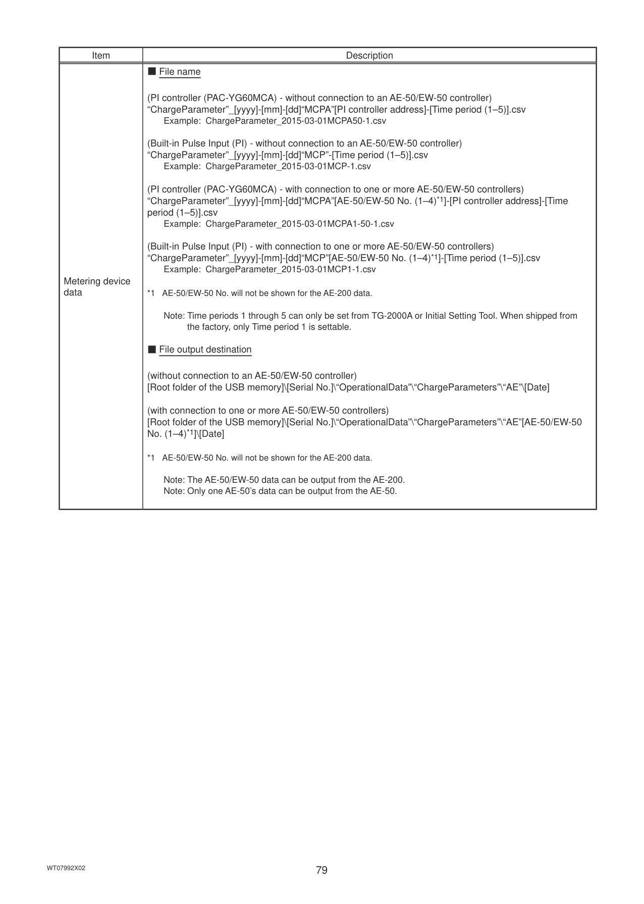
|Item|Description| |---|---| |Energy management data|[Data type: 1-month intervals]
|Row|Item|Format| |---|---|---| |1st|File Type|504| |2nd|Data range|Start year and month + “–” + End year and month| |3rd|Item *1*2|“Month,Data1(51),...Data1(100),Data3(51),...Data3(100), OutdoorTemp(51),...OutdoorTemp(100),CoolSetTemp(1),...CoolSetTemp(50), HeatSetTemp(1),...HeatSetTemp(50),RoomTemp(1),...RoomTemp(50), FanTime(1),...FanTime(50),CoolTime(1),...CoolTime(50), HeatTime(1),...HeatTime(50),ThermoTime(1),...ThermoTime(50), CoolThermoTime(1),...CoolThermoTime(50), HeatThermoTime(1),...HeatThermoTime(50), SaveValue(1),...SaveValue(50),CoolSaveValue(1),...CoolSaveValue(50), HeatSaveValue(1),...HeatSaveValue(50), ApporionedElectricEnergy(1),...ApporionedElectricEnergy(50). TargetElectricEnergy(1),...TargetElectricEnergy(50), MCP1(0),...MCP1(50),MCP2(0),...MCP2(50),MCP3(0),...MCP3(50), MCP4(0),...MCP4(50),MCT1(1),...MCT1(50),MCT2(1),...MCT2(50), AHC1(201),...AHC1(250),AHC2(201),...AHC2(250), MCP1,MCP2,MCP3,MCP4*3”| |4th|Measurement unit *4*5||Item|Unit| |---|---| |ApportionedElectricEnergy, TargetElectricEnergy|kWh| |Data1, Data3|-| |OutdoorTemp, CoolSetTemp, HeatSetTemp, RoomTemp|ºC, ºF| |FanTime, CoolTime, HeatTime, ThermoTime, CoolThermoTime, HeatThermoTime, SaveValue, CoolSaveValue, HeatSaveValue|Minute| |MCP (PI controller/Built-in Pulse Input (PI))|kWh, m3, MJ| |MCT (AI controller)|ºC, ºF, %| |AHC (Advanced HVAC CONTROLLER)|ºC, ºF| | |5th– 29th|Data
*1*2*6*7*8*9|yyyy/mm, Data 1 (51), ... (100), Data 3 (51), ... (100), Outdoor temperature (51), ... (100), Cooling set temperature (1), ... (50), Heating set temperature (1), ... (50), Room temperature (1), ... (50), Fan operation time (1), ... (50), Cooling operation time (1), ... (50), Heating operation time (1), ... (50), Thermo-ON time (1), ... (50), Cooling Thermo-ON time (1), ... (50), Heating Thermo-ON time (1), ... (50), Capacity-save value (1), ... (50), Cooling capacity-save value (1), ... (50), Heating capacity-save value (1), ... (50), Apporioned electric energy (1), ... (50), Target electric energy (1), ... (50), MCP 1 (1), ... (50), MCP 2 (1), ... (50), MCP 3 (1), ... (50), MCP 4 (1), ... (50), MCT 1 (1), ... (50), MCT 2 (1), ... (50), AHC temperature 1 (201), ... (250), AHC temperature 2 (201), ... (250), MCP 1, MCP 2, MCP 3, MCP 4|
*1 The numbers shown after “MCP” and “MCT” indicate channel No.
*2 The numbers in the parentheses indicate M-NET addresses.
*3 The M-NET address indicated in the parentheses will not appear for the measurement data of the built-in Pulse Input (PI).
*4 The measurement unit for MCP (PI controller) will be the measurement unit that has been set on the [Measurement] screen. (Refer to the Instruction Book (Initial Settings) for details.)
*5 The measurement item for MCT (AI controller) will be temperature or humidity, which has been set on the [Measurement] screen. (Refer to the Instruction Book (Initial Settings) for details.)
*6 “Outdoor temperature,” “Cooling set temperature,” “Heating set temperature,” and “Room temperature” in the data are the average monthly values of the average temperature values obtained every day.
*7 “MCT 1” and “MCT 2” in the data are the average monthly values of the average temperature or humidity values obtained every day.
*8 The value will not appear if the data does not exist.
*9 Each file contains up to 25 data (25-month worth of data).
|
|Item|Description| |---|---| |Energy management data|[Data type: 1-year intervals]
|Row|Item|Format| |---|---|---| |1st|File Type|505| |2nd|Date range|Start year + “–” + End year| |3rd|Item *1*2|“Year,Data1(51),...Data1(100),Data3(51),...Data3(100), FanTime(1),...FanTime(50),CoolTime(1),...CoolTime(50), HeatTime(1),...HeatTime(50),ThermoTime(1),...ThermoTime(50), CoolThermoTime(1),...CoolThermoTime(50), HeatThermoTime(1),...HeatThermoTime(50),SaveValue(1),...SaveValue(50), CoolSaveValue(1),...CoolSaveValue(50), HeatSaveValue(1),...HeatSaveValue(50), ApporionedElectricEnergy(1),...ApporionedElectricEnergy(50) TargetElectricEnergy(1),...TargetElectricEnergy(50), MCP1(0),...MCP1(50),MCP2(0),...MCP2(50),MCP3(0),...MCP3(50), MCP4(0),...MCP4(50), MCP1,MCP2,MCP3,MCP4*3”| |4th|Measurement unit *4||Item|Unit| |---|---| |ApportionedElectricEnergy, TargetElectricEnergy|kWh| |Data1, Data3|-|
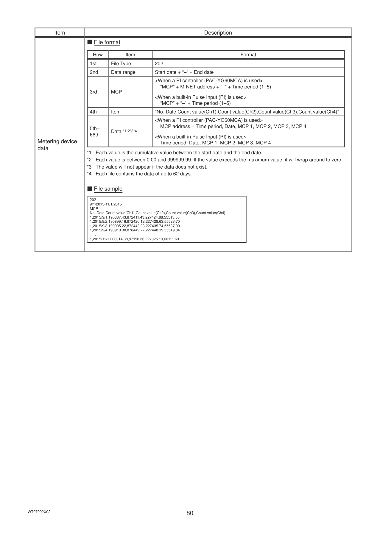
|FanTime, CoolTime, HeatTime, ThermoTime, CoolThermoTime, HeatThermoTime, SaveValue, CoolSaveValue, HeatSaveValue|Minute| |MCP (PI controller/Built-in Pulse Input (PI))|kWh, m3, MJ| | |5th–9th|Data *1*2*5*6|yyyy, Data 1 (51), ... (100), Data 3 (51), ... (100), Fan operation time (1), ... (50), Cooling operation time (1), ... (50), Heating operation time (1), ... (50), Thermo-ON time (1), ... (50), Cooling Thermo-ON time (1), ... (50), Heating Thermo-ON time (1), ... (50), Capacity-save value (1), ... (50), Cooling capacity-save value (1), ... (50), Heating capacity-save value (1), ... (50), Apporioned electric energy (1), ... (50), Target electric energy (1), ... (50), MCP 1 (1), ... (50), MCP 2 (1), ... (50), MCP 3 (1), ... (50), MCP 4 (1), ... (50), MCP 1, MCP 2, MCP 3, MCP 4|
*1 The numbers shown after “MCP” and “MCT” indicate channel No.
*2 The numbers in the parentheses indicate M-NET addresses.
*3 The M-NET address indicated in the parentheses will not appear for the measurement data of the built-in Pulse Input (PI).
*4 The measurement unit for MCP (PI controller) will be the measurement unit that has been set on the [Measurement] screen. (Refer to the Instruction Book (Initial Settings) for details.)
*5 The value will not appear if the data does not exist.
*6 Each file contains up to 5 data (5-year worth of data).
■ File sample Data type: 5-minute intervals
|501 15/03/2010-17/05/2010 DateTime,Data1(51),...,Data1(100),Data2(51),...,Data2(100),Data3(51) ,...,Data3(100),OutdoorTemp(51), ...,OutDoorTemp(100),CoolSetTemp(1),...,CoolSetT emp(50),HeatSetTemp(1),...,HeatSetTemp(50),RoomTemp(1),...,RoomTemp(50),MCP1(1), ...,MCP1(50),MCP2(1),...,MCP2(50),MCP3(1),...,MCP3(50),MCP4 (1),...,MCP4(50),MCT1(1),...,MCT1(50),MCT2(1),...,MCT2(50),AHC1(201),...,AHC1(250),AHC2(201) ,...,AHC2(250),MCP1,MCP2,MCP3,MCP4 ,,...,,,...,,,...,,ºC,...,ºC,ºC,...,ºC,ºC,...,ºC,ºC,...,ºC, kWh,...,kWh, kWh,...,kWh, kWh,...,kWh, kWh,...,kWh, ºC,...,ºC,ºC,...,ºC,ºC,...,ºC,ºC,...,ºC,kWh,kWh,kWh,kWh 15/03/2010_00:00,100.00,...,80.00,20.50,...,24.00,3.21,...,3.54,30.0,...,31.0,25.0,...,25.0,...,20.0,...,20.0,26.0,...,27.0,100.00,...,100.00,150.00,...,150.00,200.0 0,...,200.00,250.00,...,250.00,25.0,...,25.0,25.0,...,25.0,25.0,...,25.0, 25.0,...,25.0,140.00,200.00,190.00,180.00 15/03/2010_00:05,120.00,...,100.00,20.70,...,25.00,3.23,...,3.40,30.0,...,31.0,25.0,...,25.0,...,20.0,...,20.0,26.0,...,27.0,120.00,...,120.00,170.00,...,170.00,220. 00,...,220.00,270.00,...,270.00,25.0,...,25.0,25.0,...,25.0,25.0,...,25.0, 25.0,...,25.0,140.00,200.00,190.00,180.00
...| |---| |
Energy Management Data List Table 4-1 below summarizes the energy-control-related items that can be output in a CSV format, their measurement units, and their data ranges for each data type. Table 4-2 below summarizes how many months/years worth of data each CSV file can contain.
|Unit type|Item|Data type (intervals)|Data type (intervals)|Data type (intervals)|Data type (intervals)|Data type (intervals)|Measurement unit|Data range *11| |---|---|---|---|---|---|---|---|---| |Unit type|Item|5-minute|30-minute|1-day *6|1-month *7|1-year *8|Measurement unit|Data range *11| |Outdoor unit|Data 1 *1|V|V|V|V|V|–|0–999999.99| |Outdoor unit|Data 2 *1|V|V| | | |–|0–9999.99| |Outdoor unit|Data 3 *1|V|V|V|V|V|–|0–99.99| |Outdoor unit|Outdoor temperature|V|V *2|V *3|V *4| |ºC, ºF|-100.0–1000.0| |Indoor unit|Cooling set temperature|V|V *2|V *3|V *4| |ºC, ºF|-100.0–1000.0| |Indoor unit|Heating set temperature|V|V *2|V *3|V *4| |ºC, ºF|-100.0–1000.0| |Indoor unit|Room temperature|V|V *2|V *3|V *4| |ºC, ºF|-100.0–1000.0| |Indoor unit|Fan operation time| |V *9|V *10|V *10|V *10|Minute|0–2147483647| |Indoor unit|Cooling operation time| |V *9|V *10|V *10|V *10|Minute|0–2147483647| |Indoor unit|Heating operation time| |V *9|V *10|V *10|V *10|Minute|0–2147483647| |Indoor unit|Thermo-ON time| |V *9|V *10|V *10|V *10|Minute|0–2147483647| |Indoor unit|Cooling Thermo-ON time| |V *9|V *10|V *10|V *10|Minute|0–2147483647| |Indoor unit|Heating Thermo-ON time| |V *9|V *10|V *10|V *10|Minute|0–2147483647| |Indoor unit|Number of Thermo-ON *5| |V *9| | | |–|0–2147483647| |Indoor unit|Capacity-save value| |V *9|V *10|V *10|V *10|Minute|0–21474836.47| |Indoor unit|Cooling capacity-save value| |V *9|V *10|V *10|V *10|Minute|0–21474836.47| |Indoor unit|Heating capacity-save value| |V *9|V *10|V *10|V *10|Minute|0–21474836.47| |Indoor unit|Apportioned electric energy| |V *9|V *10|V *10|V *10|kWh|0–999999.9999|
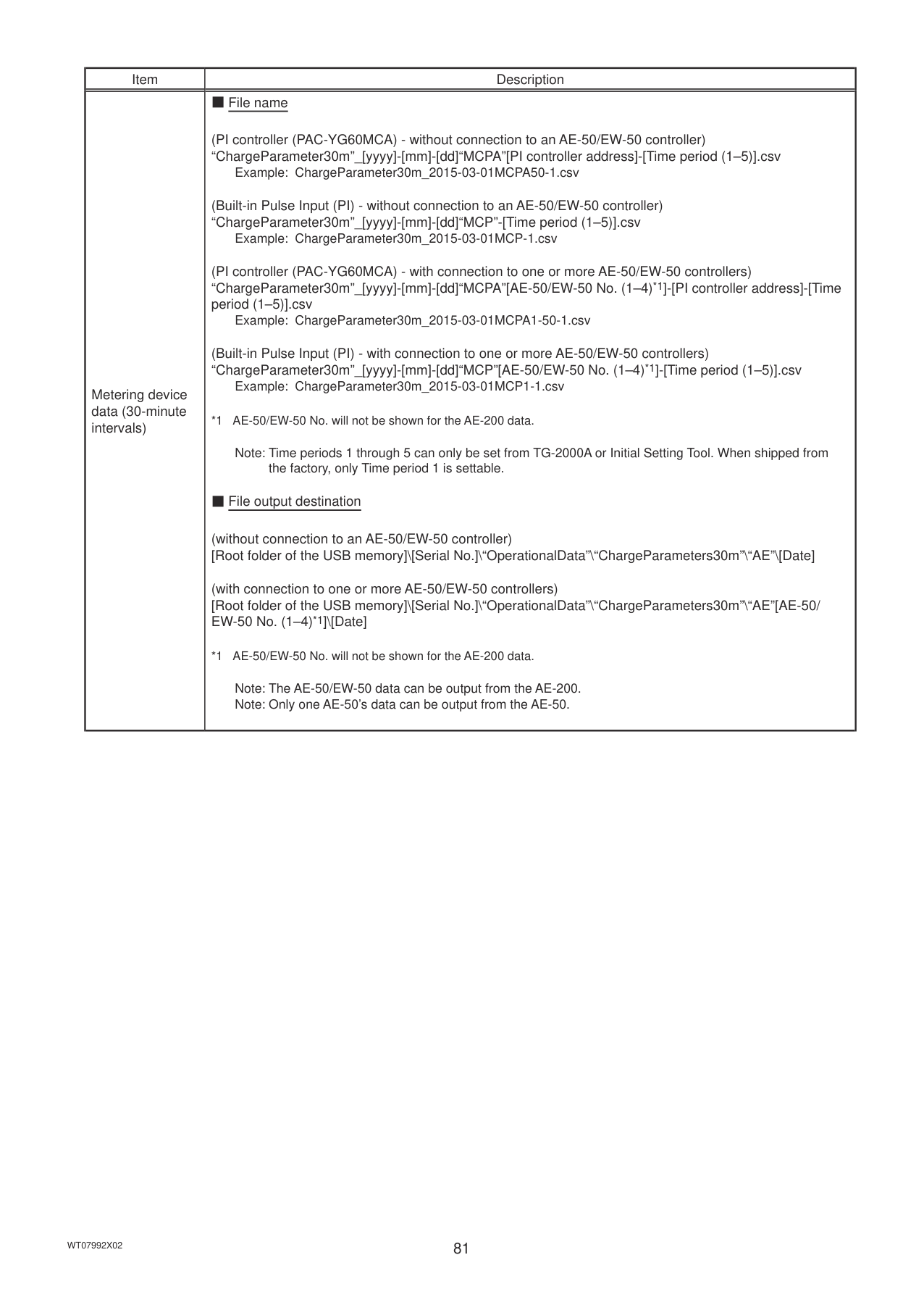
|Indoor unit|Target electric energy| | |V *10|V *10|V *10|kWh|0–922337203685477| |MCP (PI controller/ Built-in Pulse Input (PI))|MCP 1|V *9|V *9|V *10|V *10|V *10|kWh, m3, MJ, Blank|0–999999.99| |MCP (PI controller/ Built-in Pulse Input (PI))|MCP 2|V *9|V *9|V *10|V *10|V *10|kWh, m3, MJ, Blank|0–999999.99| |MCP (PI controller/ Built-in Pulse Input (PI))|MCP 3|V *9|V *9|V *10|V *10|V *10|kWh, m3, MJ, Blank|0–999999.99| |MCP (PI controller/ Built-in Pulse Input (PI))|MCP 4|V *9|V *9|V *10|V *10|V *10|kWh, m3, MJ, Blank|0–999999.99| |MCT (AI controller)|MCT 1|V|V *2|V *3|V *4| |ºC, ºF, %|-100.0–1000.0| |MCT (AI controller)|MCT 2|V|V *2|V *3|V *4| |ºC, ºF, %|-100.0–1000.0| |AHC|AHC temperature 1|V|V *2|V *3|V *4| |ºC, ºF|-100.0–1000.0| |AHC|AHC temperature 2|V|V *2|V *3|V *4| |ºC, ºF|-100.0–1000.0|
|Data type (intervals)|Data period| |---|---| |5-minute|Last 2 months| |30-minute|Last 25 months| |1-day|Last 25 months| |1-month|Last 25 months| |1-year|Last 5 years|

5. Maintenance
#### 5-1. Backing up settings data
The settings data can be exported to a USB memory as a backup. Touch [Maintenance] in the menu bar, and then touch [Backup].
Note: Use the USB memory device that meets the requirements described in section 4-1-1 “Energy data output”. Note: IP address settings will not be backed up. Make sure to write them down.
All settings

Copy to USB Memory Touch to back up the settings data.
|Important
● The USB memory device may not be recognized if you insert and remove it within a short time. If this happens, reset the AE-200/AE-50.
● The AE-50/EW-50 data can be output from the AE-200.
| |---|
■ File output destination, folder name, and file name [Root folder of the USB memory]\[Serial No.]\“SettingData”\“AE” *1
*1 “AE1,” “AE2,” “AE3,” or “AE4” when one or more AE-50/EW-50 controllers are connected
Root folder of the USB memory 12345-123 (AE-200 serial No.) SettingData
AE AE-200 settings file
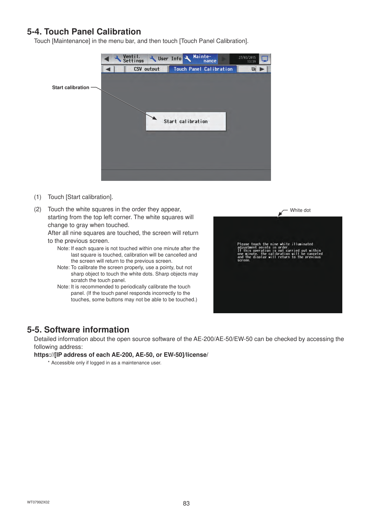
Note: It will take a few minutes to create the settings data. Note: Do not remove the USB memory device while the data is being output.
#### 5-2. Importing settings data
The exported data can be imported back to the AE-200/AE-50/EW-50 to restore the previous settings after the controller replacement. Touch [Maintenance] in the menu bar, and then touch [Import].
All settings

Read from USB Memory Touch to import the settings data.
|Important
● The USB memory device may not be recognized if you insert and remove it within a short time. If this happens, reset the AE-200/AE-50/EW-50.| |---|
■ File location, folder name, and file name [Root folder of the USB memory]\“SetupData”_[IP address]\“AE” *1
Root folder of the USB memory SetupData_192_168_1_1 *2 AE AE-200 settings file
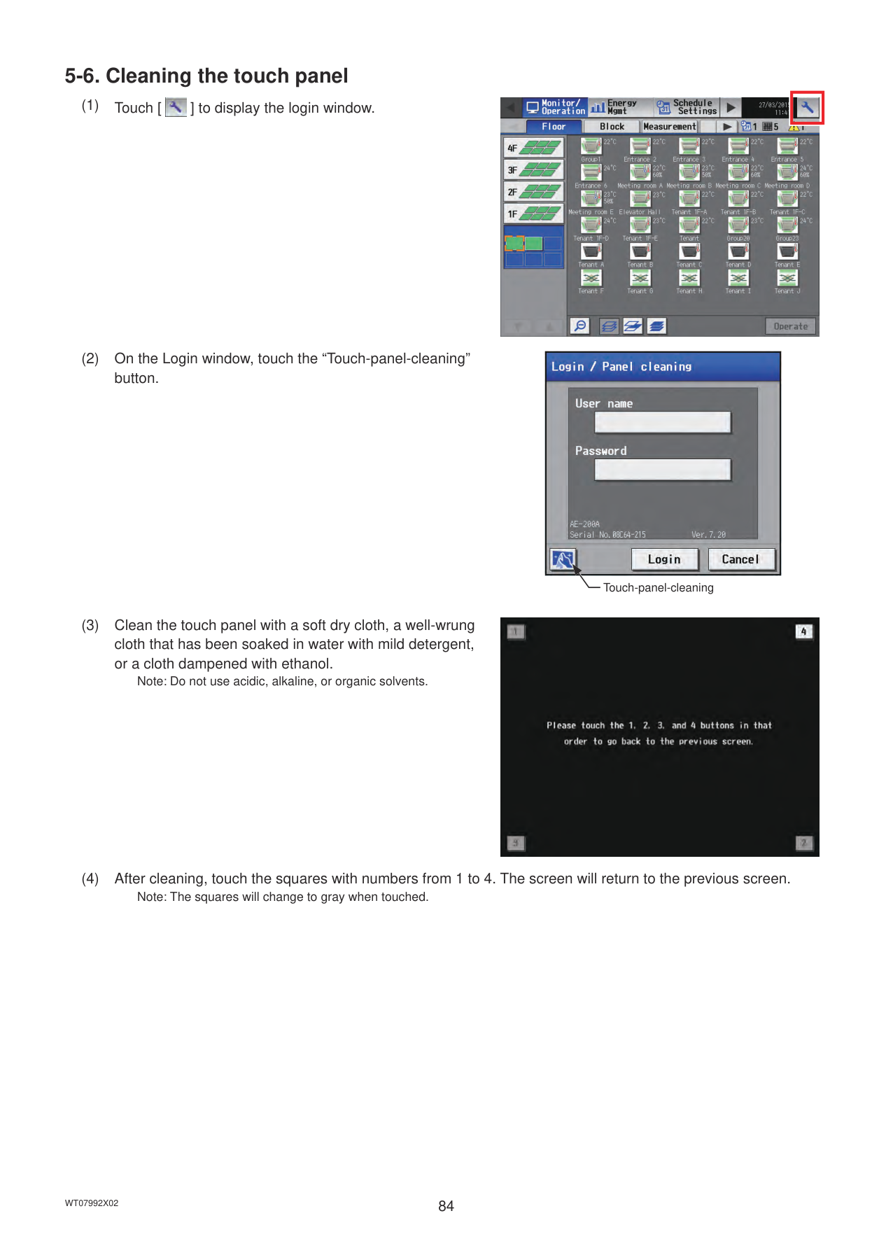
backed up from the AE-50 must be imported to the AE-50. Note: Do not change the file name from that of when backup was performed. If the folder name or file name is different from the given name, no data can be read.
#### 5-3. CSV output
The operation data, such as charge parameters and metering device data, can be output in a CSV format. Touch [Maintenance] in the menu bar, and then touch [CSV output].
Note: A separate license may be required to use the CSV output function. Only valid buttons can be selected on the screen. Note: Refer to section 4-1-1 “Energy data output” for details about the USB memory device that can be used. Note: File names, as well as date formats, delimiter characters, and temperature units (°C, °F) within the files output as CSV will
use formats set as initial settings. Refer to the Instruction Book (Initial Settings) for settings methods.
Charge Parameters
Charge Parameters (30-minute intervals)

Metering device data
Metering device data (30-minute intervals)
Output as CSV file
|Important
● The USB memory device may not be recognized if you insert and remove it within a short time. If this happens, reset the AE-200/AE-50.|
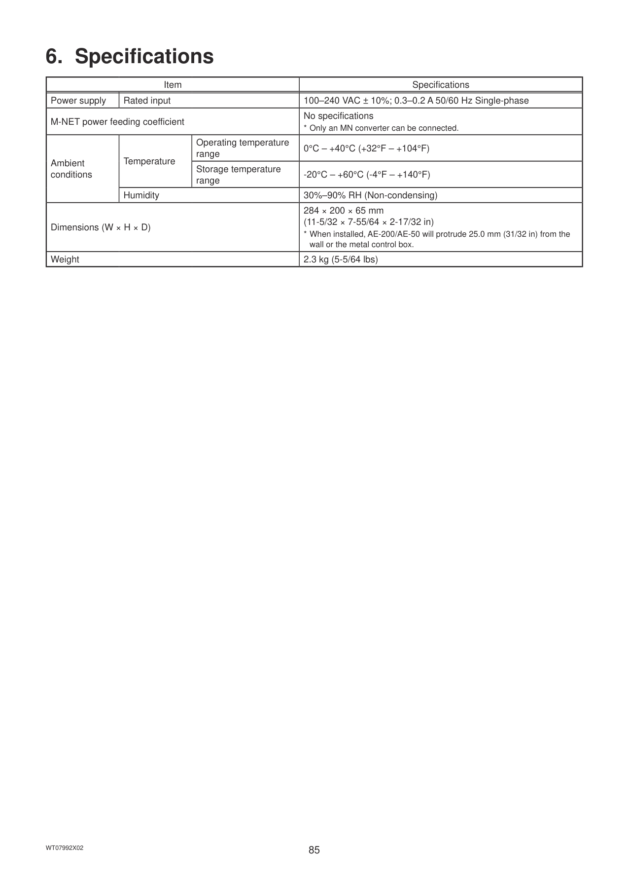
|---|
complete. Note: When one or more AE-50/EW-50 controllers are connected, the AE-50/EW-50 data will also be output from the AE-200.
|Item|Description| |---|---| |Charge Parameters|■ File name
(without connection to an AE-50/EW-50 controller) “ChargeParameter”_[yyyy]-[mm]-[dd]“A”[Indoor unit address]-[Time period (1–5)].csv
Example: ChargeParameter_2015-03-01A01-1.csv
(with connection to one or more AE-50/EW-50 controllers) “ChargeParameter”_[yyyy]-[mm]-[dd]“A”[AE-50/EW-50 No. (1–4)*1]-[Indoor unit address]-[Time period (1–5)].csv
Example: ChargeParameter_2015-03-01A1-01-1.csv
*1 AE-50/EW-50 No. will not be shown for the AE-200 data.
Note: Time periods 1 through 5 can only be set from TG-2000A or Initial Setting Tool. When shipped from the factory, only Time period 1 is settable.
■ File output destination
(without connection to an AE-50/EW-50 controller) [Root folder of the USB memory]\[Serial No.]\“OperationalData”\“ChargeParameters”\“AE”\[Date]
(with connection to one or more AE-50/EW-50 controllers) [Root folder of the USB memory]\[Serial No.]\“OperationalData”\“ChargeParameters”\“AE”[AE-50/EW-50 No. (1–4)*1]\[Date]
*1 AE-50/EW-50 No. will not be shown for the AE-200 data.
Note: The AE-50/EW-50 data can be output from the AE-200. Note: Only one AE-50’s data can be output from the AE-50.
■ File format
|Row|Item|Format| |---|---|---| |1st|File Type|201| |2nd|Data range|Start date + “–” + End date| |3rd|Indoor unit address|“Address” + M-NET address| |4th|Item|“Date,SaveValue,ThermoTime,FanTime,SubHeaterTime”| |5th– 66th|Data *1*2*3|Date, Capacity-save value (min), Thermo-ON time (min), Fan operation time (min), Sub-heater-ON time (min) *4|
*1 Each value is the cumulative value between the start date and the end date.
*2 The value will not appear if the data does not exist.
*3 Each file contains the data of up to 62 days.
*4 Even if the indoor unit is not equipped with a sub heater, “Sub-heater-ON time” is counted when the sub-heater-ON conditions are met, not when the sub heater actually turns on.
■ File sample
|201 12/19/2014-1/10/2015 Address 31 Date,SaveValue,ThermoTime,FanTime,SubHeaterTime
12/19/2014,1258,0,465,0
12/20/2014,1260,0,468,0
12/21/2014,1262,0,472,0
12/22/2014,1264,0,477,0
12/23/2014,1266,0,490,0 :
01/10/2015,2058,0,1013,0| |---| |
|Item|Description| |---|---| |Charge Parameters (30-minute intervals)|■ File name
(without connection to an AE-50/EW-50 controller) “ChargeParameter30m”_[yyyy]-[mm]-[dd]“A”[Indoor unit address]-[Time period (1–5)].csv
Example: ChargeParameter30m_2015-03-01A01-1.csv
(with connection to one or more AE-50/EW-50 controllers) “ChargeParameter30m”_[yyyy]-[mm]-[dd]“A”[AE-50/EW-50 No. (1–4)*1]-[Indoor unit address]-[Time period (1–5)].csv
Example: ChargeParameter30m_2015-03-01A1-01-1.csv
*1 AE-50/EW-50 No. will not be shown for the AE-200 data.
Note: Time periods 1 through 5 can only be set from TG-2000A or Initial Setting Tool. When shipped from the factory, only Time period 1 is settable.
■ File output destination
(without connection to an AE-50/EW-50 controller) [Root folder of the USB memory]\[Serial No.]\“OperationalData”\“ChargeParameters30m”\“AE”\[Date]
(with connection to one or more AE-50/EW-50 controllers) [Root folder of the USB memory]\[Serial No.]\“OperationalData”\“ChargeParameters30m”\ “AE”[AE-50/EW-50 No. (1–4)*1]\[Date]
*1 AE-50/EW-50 No. will not be shown for the AE-200 data.
Note: The AE-50/EW-50 data can be output from the AE-200. Note: Only one AE-50’s data can be output from the AE-50.
■ File format
|Row|Item|Format| |---|---|---| |1st|File Type|621| |2nd|Data range|Start date + Start time + “–” + End date + End time| |3rd|Indoor unit address|“Address” + M-NET address| |4th|Item|“Date,Time,SaveValue,ThermoTime,FanTime,SubHeaterTime”| |5th– 66th|Data *1*2*3|Date, Time, Capacity-save value (min), Thermo-ON time (min), Fan operation time (min), Sub-heater-ON time (min) *4|
*1 Each value is the cumulative value between the start date/time and the end date/time.
*2 The value will not appear if the data does not exist.
*3 Each file contains the data of up to 62 days.
*4 Even if the indoor unit is not equipped with a sub heater, “Sub-heater-ON time” is counted when the sub-heater-ON conditions are met, not when the sub heater actually turns on.
■ File sample
|621 03/10/2015 0:00-03/12/2015 23:30 Address 01 Date,Time,SaveValue,TermoTime,FanTime,SubHeaterTime 2015/03/10,0:00,57,102,150,0
2015/03/10,0:30,76,122,178,0
2015/03/10,1:00,100,122,178,0 : 2015/03/12,23:30,543,743,1340,0
| |---|
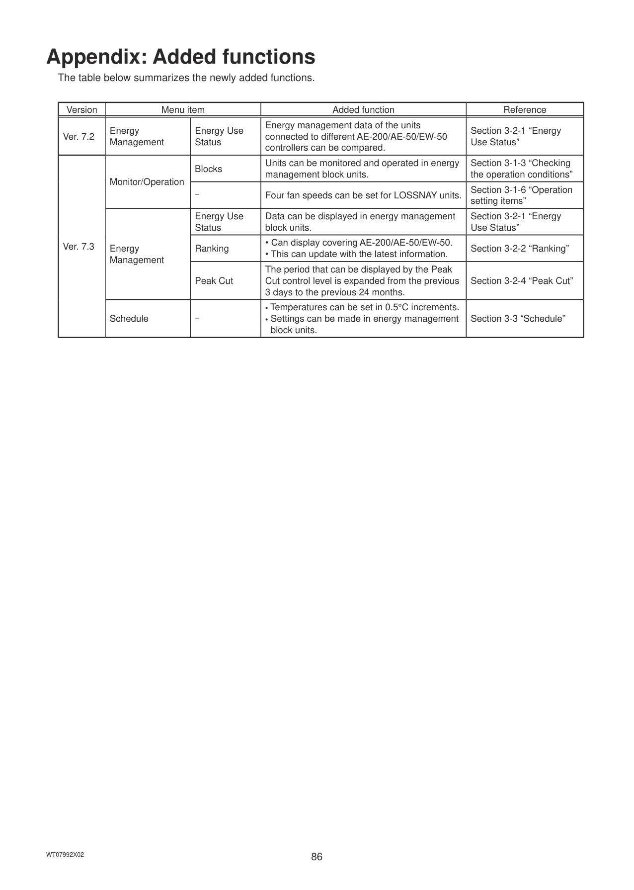
|
|Item|Description| |---|---| |Metering device data|■ File name
(PI controller (PAC-YG60MCA) - without connection to an AE-50/EW-50 controller) “ChargeParameter”_[yyyy]-[mm]-[dd]“MCPA”[PI controller address]-[Time period (1–5)].csv
Example: ChargeParameter_2015-03-01MCPA50-1.csv
(Built-in Pulse Input (PI) - without connection to an AE-50/EW-50 controller) “ChargeParameter”_[yyyy]-[mm]-[dd]“MCP”-[Time period (1–5)].csv
Example: ChargeParameter_2015-03-01MCP-1.csv
(PI controller (PAC-YG60MCA) - with connection to one or more AE-50/EW-50 controllers) “ChargeParameter”_[yyyy]-[mm]-[dd]“MCPA”[AE-50/EW-50 No. (1–4)*1]-[PI controller address]-[Time period (1–5)].csv
Example: ChargeParameter_2015-03-01MCPA1-50-1.csv
(Built-in Pulse Input (PI) - with connection to one or more AE-50/EW-50 controllers) “ChargeParameter”_[yyyy]-[mm]-[dd]“MCP”[AE-50/EW-50 No. (1–4)*1]-[Time period (1–5)].csv
Example: ChargeParameter_2015-03-01MCP1-1.csv
*1 AE-50/EW-50 No. will not be shown for the AE-200 data.
Note: Time periods 1 through 5 can only be set from TG-2000A or Initial Setting Tool. When shipped from the factory, only Time period 1 is settable.
■ File output destination
(without connection to an AE-50/EW-50 controller) [Root folder of the USB memory]\[Serial No.]\“OperationalData”\“ChargeParameters”\“AE”\[Date]
(with connection to one or more AE-50/EW-50 controllers) [Root folder of the USB memory]\[Serial No.]\“OperationalData”\“ChargeParameters”\“AE”[AE-50/EW-50 No. (1–4)*1]\[Date]
*1 AE-50/EW-50 No. will not be shown for the AE-200 data.
Note: The AE-50/EW-50 data can be output from the AE-200. Note: Only one AE-50’s data can be output from the AE-50.|
|Item|Description| |---|---| |Metering device data|■ File format
|Row|Item|Format| |---|---|---| |1st|File Type|202| |2nd|Data range|Start date + “–” + End date| |3rd|MCP|
“MCP” + M-NET address + “–” + Time period (1–5)
“MCP” + “–” + Time period (1–5)| |4th|Item|“No.,Date,Count value(Ch1),Count value(Ch2),Count value(Ch3),Count value(Ch4)”| |5th– 66th|Data *1*2*3*4|
MCP address + Time period, Date, MCP 1, MCP 2, MCP 3, MCP 4
Time period, Date, MCP 1, MCP 2, MCP 3, MCP 4|
*1 Each value is the cumulative value between the start date and the end date.
*2 Each value is between 0.00 and 999999.99. If the value exceeds the maximum value, it will wrap around to zero.
*3 The value will not appear if the data does not exist.
*4 Each file contains the data of up to 62 days.
■ File sample
|202 9/1/2015-11/1/2015 MCP 1 No.,Date,Count value(Ch1),Count value(Ch2),Count value(Ch3),Count value(Ch4)
1,2015/9/1,190887.43,872411.43,227424.88,55515.50
1,2015/9/2,190899.16,872420.12,227428.63,55526.70
1,2015/9/3,190905.22,872442.23,227435.74,55537.90
1,2015/9/4,190910.38,878449.77,227448.19,55549.84 :
1,2015/11/1,200014.38,87950.36,227925.19,60111.63| |---| |
|Item|Description| |---|---| |Metering device data (30-minute intervals)|■ File name
(PI controller (PAC-YG60MCA) - without connection to an AE-50/EW-50 controller) “ChargeParameter30m”_[yyyy]-[mm]-[dd]“MCPA”[PI controller address]-[Time period (1–5)].csv
Example: ChargeParameter30m_2015-03-01MCPA50-1.csv
(Built-in Pulse Input (PI) - without connection to an AE-50/EW-50 controller) “ChargeParameter30m”_[yyyy]-[mm]-[dd]“MCP”-[Time period (1–5)].csv
Example: ChargeParameter30m_2015-03-01MCP-1.csv
(PI controller (PAC-YG60MCA) - with connection to one or more AE-50/EW-50 controllers) “ChargeParameter30m”_[yyyy]-[mm]-[dd]“MCPA”[AE-50/EW-50 No. (1–4)*1]-[PI controller address]-[Time period (1–5)].csv
Example: ChargeParameter30m_2015-03-01MCPA1-50-1.csv
(Built-in Pulse Input (PI) - with connection to one or more AE-50/EW-50 controllers) “ChargeParameter30m”_[yyyy]-[mm]-[dd]“MCP”[AE-50/EW-50 No. (1–4)*1]-[Time period (1–5)].csv
Example: ChargeParameter30m_2015-03-01MCP1-1.csv
*1 AE-50/EW-50 No. will not be shown for the AE-200 data.
Note: Time periods 1 through 5 can only be set from TG-2000A or Initial Setting Tool. When shipped from the factory, only Time period 1 is settable.
■ File output destination
(without connection to an AE-50/EW-50 controller) [Root folder of the USB memory]\[Serial No.]\“OperationalData”\“ChargeParameters30m”\“AE”\[Date]
(with connection to one or more AE-50/EW-50 controllers) [Root folder of the USB memory]\[Serial No.]\“OperationalData”\“ChargeParameters30m”\“AE”[AE-50/ EW-50 No. (1–4)*1]\[Date]
*1 AE-50/EW-50 No. will not be shown for the AE-200 data.
Note: The AE-50/EW-50 data can be output from the AE-200. Note: Only one AE-50’s data can be output from the AE-50.|
|Item|Description| |---|---| |Metering device data (30-minute intervals)|■ File format
|Row|Item|Format| |---|---|---| |1st|File Type|622| |2nd|Data range|Start date + “–” + End date| |3rd|MCP|(PI controller (PAC-YG60MCA) - without connection to an AE-50/EW-50 controller) “MCP” + PI controller address + “–” + Time period (1–5)
(Built-in Pulse Input (PI) - without connection to an AE-50/EW-50 controller) “MCP” + “–” + Time period (1–5)
(PI controller (PAC-YG60MCA) - with connection to one or more AE-50/EW-50 controllers) “MCP” + AE-50/EW-50 No.* + “–” + PI controller address + “–” + Time period (1–5)
(Built-in Pulse Input (PI) - with connection to one or more AE-50/EW-50 controllers) “MCP” + AE-50/EW-50 No.* + “–” + Time period (1–5)
* AE-50/EW-50 No. will not be shown for the AE-200 data.|

|4th|Item|“No.,Date,Count value(Ch1),Count value(Ch2),Count value(Ch3),Count value(Ch4)”| |5th–|Data *2*3*4|(without connection to an AE-50/EW-50 controller) MCP address *1 + Time period, Date, Time, MCP 1, MCP 2, MCP 3, MCP 4
(with connection to one or more AE-50/EW-50 controllers) AE-50/EW-50 No. + MCP address *1 + Time period, Date, Time, MCP 1, MCP 2, MCP 3, MCP 4|
*1 The address will not appear for the measurement data when a built-in Pulse Input (PI) is used.
*2 Each value is the cumulative value between the start date and the end date.
*3 The value will not appear if the data does not exist.
*4 Each file contains the data of up to 62 days.
■ File sample
|622 9/1/2015-11/1/2015 MCP 1 No.,Date,Count value(Ch1),Count value(Ch2),Count value(Ch3),Count value(Ch4)
1,2015/9/1,0:00,190887.43,872411.43,227424.88,55515.50
1,2015/9/2,0:30,190899.16,872420.12,227428.63,55526.70
1,2015/9/3,1:00,190905.22,872442.23,227435.74,55537.90
1,2015/9/4,1:30,190910.38,878449.77,227448.19,55549.84 :
1,2015/11/1,23,30,200014.38,87950.36,227925.19,60111.63| |---| |
#### 5-4. Touch Panel Calibration
Touch [Maintenance] in the menu bar, and then touch [Touch Panel Calibration].
############## Start calibration

Note: If each square is not touched within one minute after the last square is touched, calibration will be cancelled and the screen will return to the previous screen.
Note: To calibrate the screen properly, use a pointy, but not sharp object to touch the white dots. Sharp objects may scratch the touch panel.
Note: It is recommended to periodically calibrate the touch panel. (If the touch panel responds incorrectly to the touches, some buttons may not be able to be touched.)
White dot

#### 5-5. Software information
Detailed information about the open source software of the AE-200/AE-50/EW-50 can be checked by accessing the following address: https://[IP address of each AE-200, AE-50, or EW-50]/license/
#### 5-6. Cleaning the touch panel
########### (1) Touch [ ] to display the login window.
########### (2) On the Login window, touch the “Touch-panel-cleaning”button.


Touch-panel-cleaning
########### (3) Clean the touch panel with a soft dry cloth, a well-wrungcloth that has been soaked in water with mild detergent,or a cloth dampened with ethanol.
Note: Do not use acidic, alkaline, or organic solvents.

########### (4) After cleaning, touch the squares with numbers from 1 to 4. The screen will return to the previous screen.Note: The squares will change to gray when touched.
6. Specifications
|Item|Item|Item|Specifications| |---|---|---|---| |Power supply|Rated input|Rated input|100–240 VAC ± 10%; 0.3–0.2 A 50/60 Hz Single-phase| |M-NET power feeding coefficient|M-NET power feeding coefficient|M-NET power feeding coefficient|No specifications
* Only an MN converter can be connected.| |Ambient conditions|Temperature|Operating temperature range|0°C – +40°C (+32°F – +104°F)| |Ambient conditions|Temperature|Storage temperature range|-20°C – +60°C (-4°F – +140°F)| |Ambient conditions|Humidity|Humidity|30%–90% RH (Non-condensing)| |Dimensions (W × H × D)|Dimensions (W × H × D)|Dimensions (W × H × D)|284 × 200 × 65 mm (11-5/32 × 7-55/64 × 2-17/32 in)
* When installed, AE-200/AE-50 will protrude 25.0 mm (31/32 in) from the wall or the metal control box.| |Weight|Weight|Weight|2.3 kg (5-5/64 lbs)|
Appendix: Added functions
The table below summarizes the newly added functions.
|Version|Menu item|Menu item|Added function|Reference| |---|---|---|---|---| |Ver. 7.2|Energy Management|Energy Use Status|Energy management data of the units connected to different AE-200/AE-50/EW-50 controllers can be compared.|Section 3-2-1 “Energy Use Status”| |Ver. 7.3|Monitor/Operation|Blocks|Units can be monitored and operated in energy management block units.|Section 3-1-3 “Checking the operation conditions”| |Ver. 7.3|Monitor/Operation|–|Four fan speeds can be set for LOSSNAY units.|Section 3-1-6 “Operation setting items”| |Ver. 7.3|Energy Management|Energy Use Status|Data can be displayed in energy management block units.|Section 3-2-1 “Energy Use Status”| |Ver. 7.3|Energy Management|Ranking|• Can display covering AE-200/AE-50/EW-50.
• This can update with the latest information.
|Section 3-2-2 “Ranking”| |Ver. 7.3|Energy Management|Peak Cut|The period that can be displayed by the Peak Cut control level is expanded from the previous 3 days to the previous 24 months.|Section 3-2-4 “Peak Cut”| |Ver. 7.3|Schedule|–|• Temperatures can be set in 0.5°C increments.
• Settings can be made in energy management block units.
|Section 3-3 “Schedule”|
|This equipment has been tested and found to comply with the limits for a Class B digital device, pursuant to Part 15 of the FCC Rules. These limits are designed to provide reasonable protection against harmful interference in a residential installation. This equipment generates, uses and can radiate radio frequency energy and, if not installed and used in accordance with the instructions, may cause harmful interference to radio communications. However, there is no guarantee that interference will not occur in a particular installation. If this equipment does cause harmful interference to radio or television reception, which can be determined by turning the equipment off and on, the user is encouraged to try to correct the interference by one or more of the following measures:
- Reorient or relocate the receiving antenna.
- Increase the separation between the equipment and receiver.
- Connect the equipment into an outlet on a circuit different from that to which the receiver is connected.
- Consult the dealer or an experienced radio/TV technician for help.
| |---|
This product is designed and intended for use in the residential, commercial and light-industrial environment.
The product at hand is based on the following EU regulations:
Please be sure to put the contact address/telephone number on this manual before handing it to the customer.
HEAD OFFICE: TOKYO BLDG., 2-7-3, MARUNOUCHI, CHIYODA-KU, TOKYO 100-8310, JAPAN
WT07992X02