
Ask AI
— answers from the official manualAnswers from the official manual.
Common questions
Common Questions
3 total Full Manual
60 pages

FCC Information and Copyright
This equipment has been tested and found to comply with the limits of a Class B digital device, pursuant to Part 15 of the FCC Rules. These limits are designed to provide reasonable protection against harmful interference in a residential installation. This equipment generates, uses, and can radiate radio frequency energy and, if not installed and used in accordance with the instructions, may cause harmful interference to radio communications. There is no guarantee that interference will not occur in a particular installation.
The vendor makes no representations or warranties with respect to the contents here and specially disclaims any implied warranties of merchantability or fitness for any purpose. Further the vendor reserves the right to revise this publication and to make changes to the contents here without obligation to notify any party beforehand. Duplication of this publication, in part or in whole, is not allowed without first obtaining the vendor’s approval in writing.
The content of this user’s manual is subject to be changed without notice and we will not be responsible for any mistakes found in this user’s manual. All the brand and product names are trademarks of their respective companies.
Dichiarazione di conformità sintetica Ai sensi dell’art. 2 comma 3 del D.M. 275 del 30/10/2002 Si dichiara che questo prodotto è conforme alle normative vigenti e soddisfa i requisiti essenziali richiesti dalle direttive 2004/108/CE, 2006/95/CE e 1999/05/CE quando ad esso applicabili
Short Declaration of conformity We declare this product is complying with the laws in force and meeting all the essential requirements as specified by the directives 2004/108/CE, 2006/95/CE and 1999/05/CE whenever these laws may be applied
Table Of Contents
FCC Information and Copyright 1
#### APPENDIX I: Specifications in Other Languages 28
Arabic ...................................................................................................................................... 28 German ................................................................................................................................... 29 Russian .................................................................................................................................... 30 Spanish ................................................................................................................................... 31 Thai ......................................................................................................................................... 32
2 | Table Of Contents
Chapter 1: Introduction
1 1 Before You Start Thank you for choosing our product. Before you start installing the motherboard, please make sure you follow the instructions below:
1.2 Package Checklist
Note » The package contents may be different due to the sales region or models in which it was sold. For
more information about the standard package in your region, please contact your dealer or sales representative.
1 3 Specifications
|Specifications|Specifications|Specifications| |---|---|---| |CPU Support|Socket AM4 supports AMD A-series APU / CPU Maximum CPU TDP (Thermal Design Power): 95Watt
* Please refer to www.biostar.com.tw for CPU support list.|Socket AM4 supports AMD A-series APU / CPU Maximum CPU TDP (Thermal Design Power): 95Watt
* Please refer to www.biostar.com.tw for CPU support list.| |Chipset|AMD A320|AMD A320| |Memory|Supports Dual Channel DDR4 1866/2133/2400/2667 2 x DDR4 DIMM Memory Slot, Max. Supports up to 32 GB Memory Each DIMM supports non-ECC 4/8/16 GB DDR4 module
* DDR4 - 2667 only for Ryzen CPU.
* Please refer to www.biostar.com.tw for Memory support list.
|Supports Dual Channel DDR4 1866/2133/2400/2667 2 x DDR4 DIMM Memory Slot, Max. Supports up to 32 GB Memory Each DIMM supports non-ECC 4/8/16 GB DDR4 module
* DDR4 - 2667 only for Ryzen CPU.
* Please refer to www.biostar.com.tw for Memory support list.
| |Storage|4x SATA III Connector (6Gb/s) : Supports AHCI & RAID 0, 1, 10|4x SATA III Connector (6Gb/s) : Supports AHCI & RAID 0, 1, 10| |LAN|Realtek RTL 8111H 10/ 100/ 1000 Mb/s auto negotiation, Half / Full duplex capability|Realtek RTL 8111H 10/ 100/ 1000 Mb/s auto negotiation, Half / Full duplex capability| |Audio Codec|ALC887 7.1 Channels, High Definition Audio|ALC887 7.1 Channels, High Definition Audio| |USB|4x USB 3.1 Gen1 (5Gb/s) port (2 on rear I/Os and 2 via internal headers) 6x USB 2.0 port (2 on rear I/Os and 4 via internal headers)|4x USB 3.1 Gen1 (5Gb/s) port (2 on rear I/Os and 2 via internal headers) 6x USB 2.0 port (2 on rear I/Os and 4 via internal headers)| |Expansion Slots|2x PCIe 3.0 x1 Slot 1x PCIe 3.0 x16 Slot : When using APU or NPU, the bandwidth is x8 speed|2x PCIe 3.0 x1 Slot 1x PCIe 3.0 x16 Slot : When using APU or NPU, the bandwidth is x8 speed| |Rear I/Os|A320MH PRO: 1x PS/2 Mouse 1x PS/2 Keyboard 1x HDMI Port
1x VGA Port
1x LAN port
2x USB 3.1 Gen1 (5Gb/s) Port
2x USB 2.0 Port
3x Audio Jack
|A320MD PRO: 1x PS/2 Mouse 1x PS/2 Keyboard 1x DVI-D Port
1x VGA Port
1x LAN port
2x USB 3.1 Gen1 (5Gb/s) Port
2x USB 2.0 Port
3x Audio Jack
| |Internal I/Os|4x SATA III 6.0Gb/s Connector 2x USB 2.0 Header (each header supports 2 USB 2.0 ports) 1x USB 3.1 Gen1 (5Gb/s) Header (each header supports 2 USB 3.1 Gen1 ports) 1x 4-Pin Power Connector 1x 24-Pin Power Connector 1x CPU Fan Connector 1x System Fan Connector 1x Front Panel Header 1x Front Audio Header 1x COM Serial Header 1x Clear CMOS Header|4x SATA III 6.0Gb/s Connector 2x USB 2.0 Header (each header supports 2 USB 2.0 ports) 1x USB 3.1 Gen1 (5Gb/s) Header (each header supports 2 USB 3.1 Gen1 ports) 1x 4-Pin Power Connector 1x 24-Pin Power Connector 1x CPU Fan Connector 1x System Fan Connector 1x Front Panel Header 1x Front Audio Header 1x COM Serial Header 1x Clear CMOS Header| |Form Factor|uATX Form Factor, 184.01 mm x 226 mm|uATX Form Factor, 184.01 mm x 226 mm| |OS Support|Windows 7(64bit) / 10(64bit) Biostar reserves the right to add or remove support for any OS with or without notice.|Windows 7(64bit) / 10(64bit) Biostar reserves the right to add or remove support for any OS with or without notice.|
1.4 Rear Panel ConnectorsA320MH PRO
##### A320MD PRO
Note » HDMI / DVI-D / VGA output require an AMD family processor with intedrated graphics. » Since the audio chip supports High Definition Audio Specification, the function of each audio jack
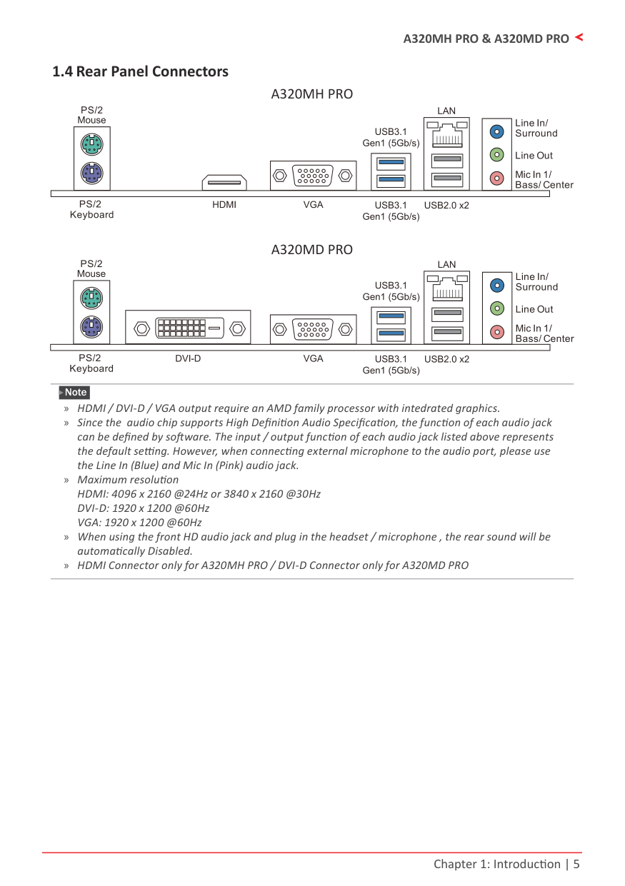
can be defined by software. The input / output function of each audio jack listed above represents the default setting. However, when connecting external microphone to the audio port, please use the Line In (Blue) and Mic In (Pink) audio jack.
» Maximum resolution HDMI: 4096 x 2160 @24Hz or 3840 x 2160 @30Hz DVI-D: 1920 x 1200 @60Hz VGA: 1920 x 1200 @60Hz
» When using the front HD audio jack and plug in the headset / microphone , the rear sound will be automatically Disabled. » HDMI Connector only for A320MH PRO / DVI-D Connector only for A320MD PRO
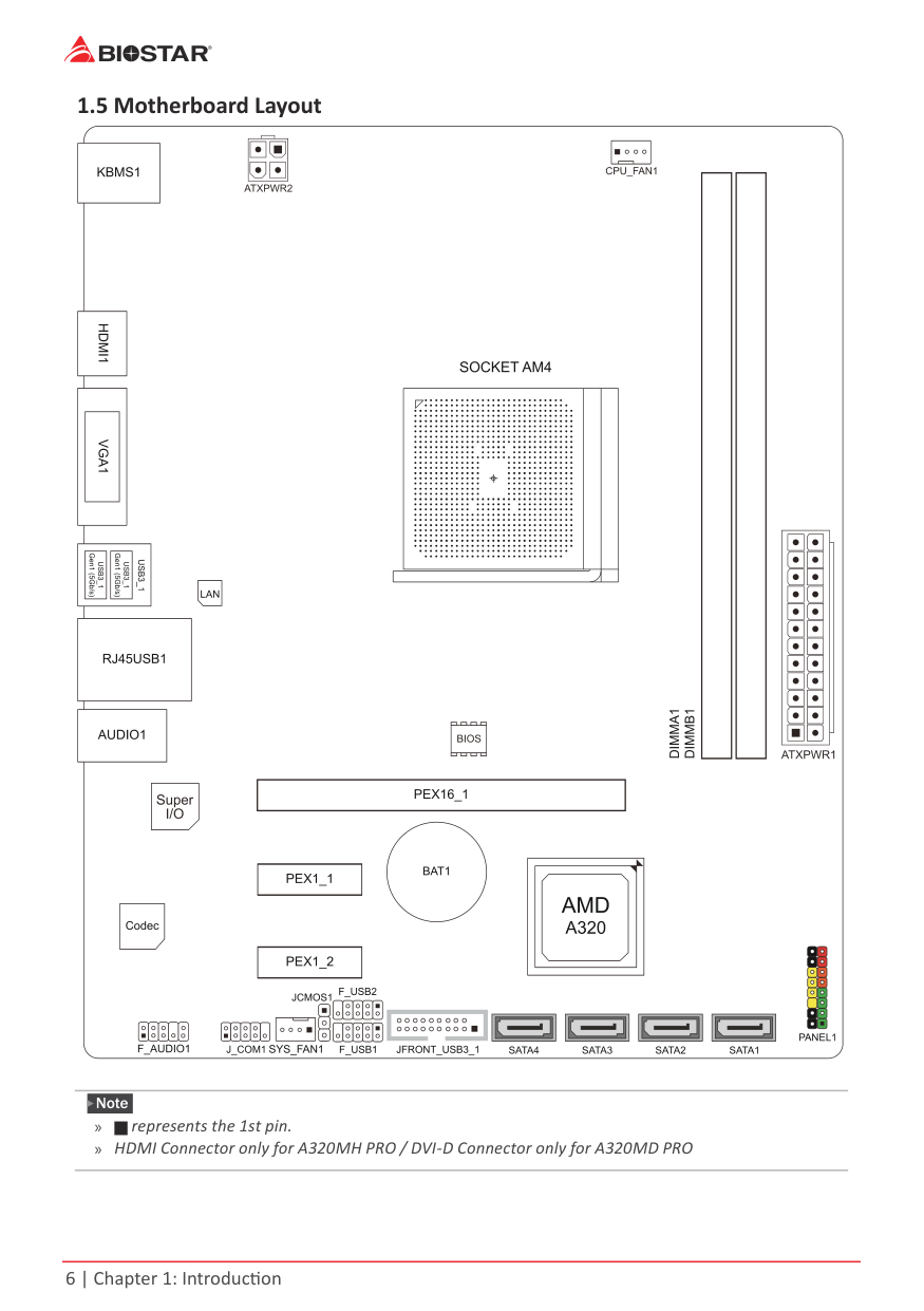
1.5 Motherboard Layout
| | | |---|---| | | |
| | | | | | | | |---|---|---|---|---|---|---| | | | | | | | | | | | | | | | |
Note » represents the 1st pin. » HDMI Connector only for A320MH PRO / DVI-D Connector only for A320MD PRO
Chapter 2: Hardware installation
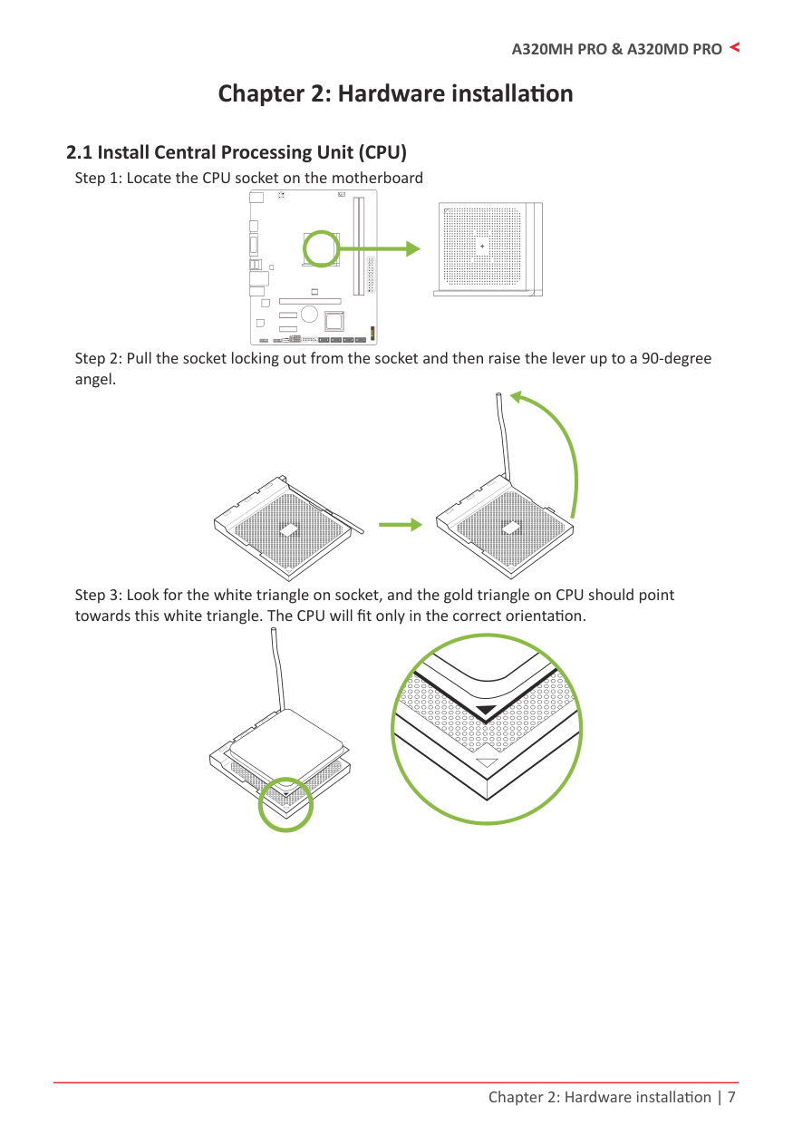
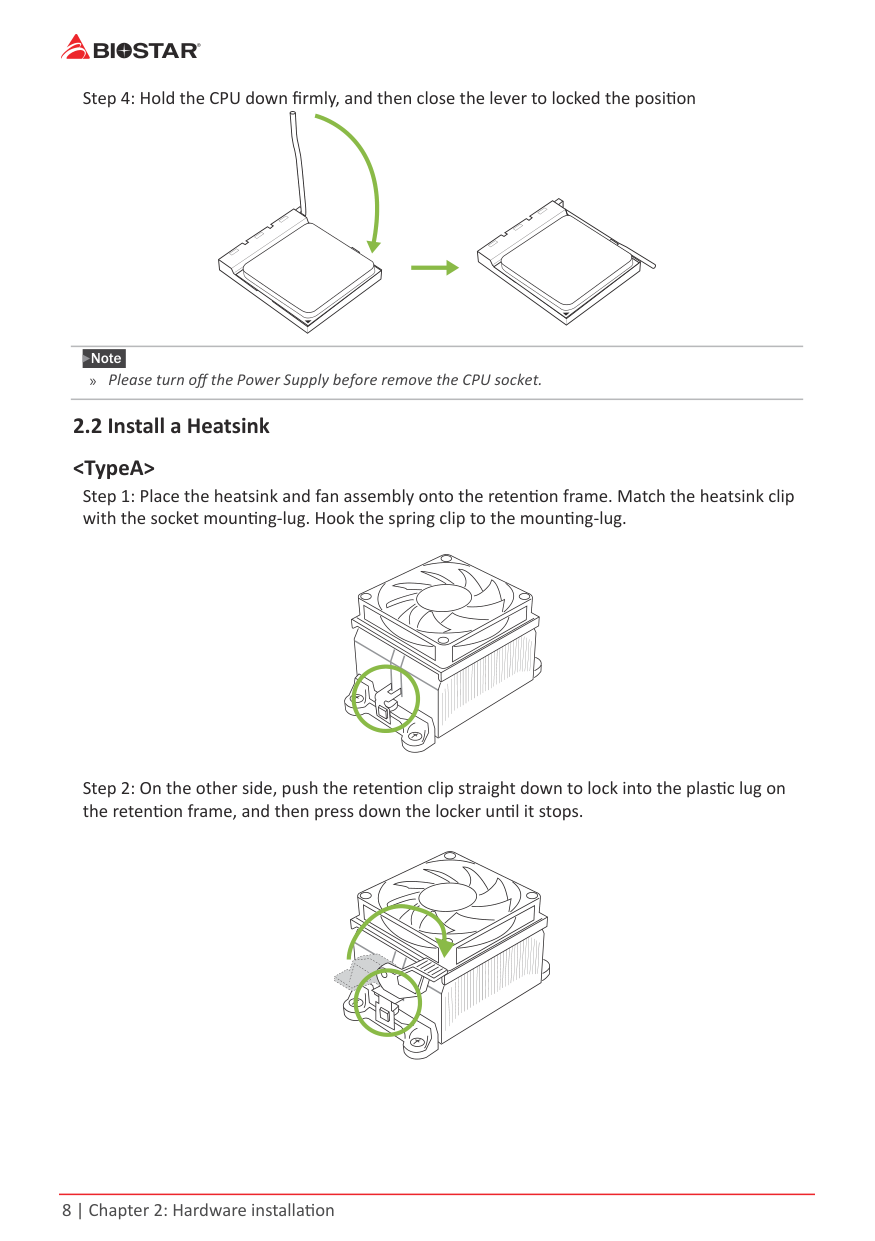
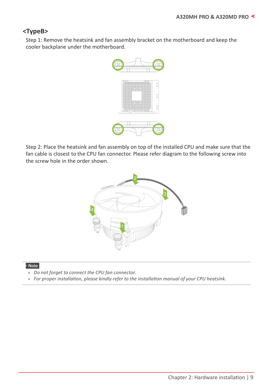
2.1 Install Central Processing Unit (CPU)
| | | |---|---| | | |
Note » Please turn off the Power Supply before remove the CPU socket.
| | | |---|---| | | |
Note » Do not forget to connect the CPU fan connector. » For proper installation, please kindly refer to the installation manual of your CPU heatsink.
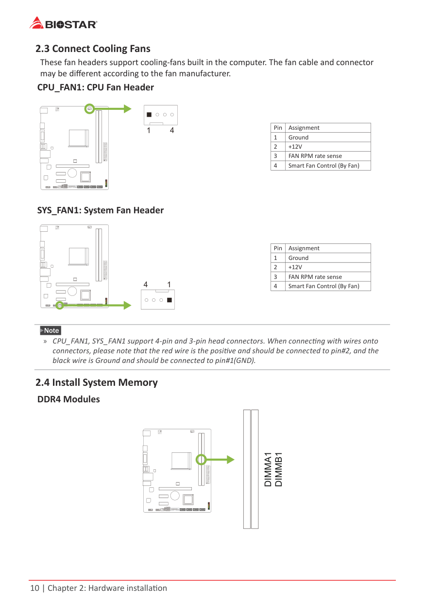
2.3 Connect Cooling Fans
These fan headers support cooling-fans built in the computer. The fan cable and connector may be different according to the fan manufacturer.
CPU_FAN1: CPU Fan Header
| | | | | |---|---|---|---| | | | | |
|Pin|Assignment| |---|---| |1|Ground|
|2|+12V| |3|FAN RPM rate sense| |4|Smart Fan Control (By Fan)|
SYS_FAN1: System Fan Header
| | | | | |---|---|---|---| | | | | |
|Pin|Assignment| |---|---| |1|Ground| |2|+12V| |3|FAN RPM rate sense| |4|Smart Fan Control (By Fan)|
Note » CPU_FAN1, SYS_FAN1 support 4-pin and 3-pin head connectors. When connecting with wires onto
connectors, please note that the red wire is the positive and should be connected to pin#2, and the black wire is Ground and should be connected to pin#1(GND).
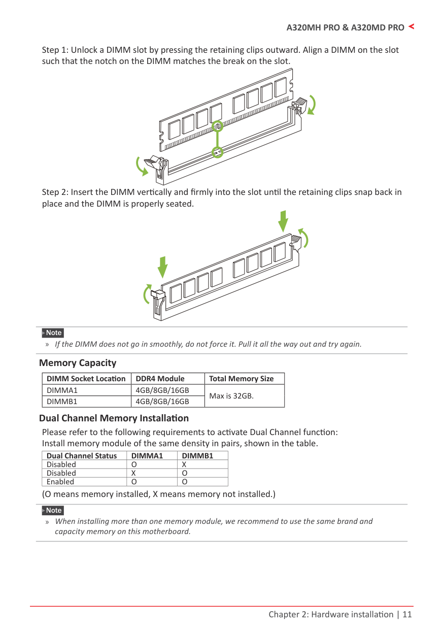
2.4 Install System MemoryDDR4 Modules
| | | | |
|---|---|---|---| | | | | |
Note » If the DIMM does not go in smoothly, do not force it. Pull it all the way out and try again.
#### Memory Capacity
|DIMM Socket Location|DDR4 Module|Total Memory Size| |---|---|---| |DIMMA1|4GB/8GB/16GB|Max is 32GB.| |DIMMB1|4GB/8GB/16GB|Max is 32GB.|
Dual Channel Memory Installation Please refer to the following requirements to activate Dual Channel function: Install memory module of the same density in pairs, shown in the table.
|Dual Channel Status|DIMMA1|DIMMB1| |---|---|---| |Disabled|O|X| |Disabled|X|O| |Enabled|O|O|
(O means memory installed, X means memory not installed.)
Note » When installing more than one memory module, we recommend to use the same brand and
capacity memory on this motherboard.
#### Ryzen - DDR Maximum Frequency Support Table
|Maximum|DIMMA1|DIMMB1| |---|---|---| |DDR4-2667|SR|--| |DDR4-2667|DR|--| |DDR4-2667|SR|SR| |DDR4-2400|DR|DR|
Note
» SR - Single-rank DIMM, 1R x4 or 1R x8. » DR - Dual-rank DIMMs, 2R x4 or 2R x8. » For the better DDR4 module compatibility, please follow the table to install your DDR4 modules.
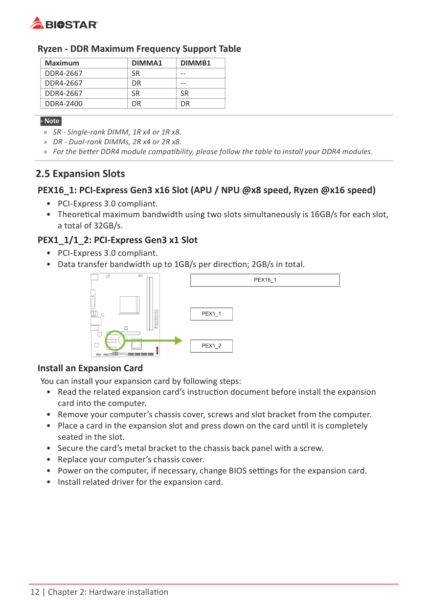
2.5 Expansion SlotsPEX16_1: PCI-Express Gen3 x16 Slot (APU / NPU @x8 speed, Ryzen @x16 speed)
#### PEX1_1/1_2: PCI-Express Gen3 x1 Slot
| | | | | |---|---|---|---| | | | | |
#### Install an Expansion Card
You can install your expansion card by following steps:
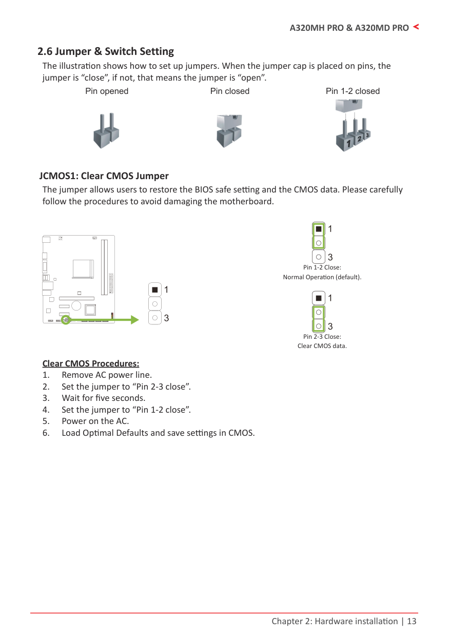
2.6 Jumper & Switch Setting
The illustration shows how to set up jumpers. When the jumper cap is placed on pins, the jumper is “close”, if not, that means the jumper is “open”.
Pin opened Pin closed Pin 1-2 closed


JCMOS1: Clear CMOS Jumper The jumper allows users to restore the BIOS safe setting and the CMOS data. Please carefully follow the procedures to avoid damaging the motherboard.
| | | | | |---|---|---|---| | | | | |
Normal Operation (default).
Clear CMOS data. Clear CMOS Procedures:
2.7 Headers & Connectors
| | | | | |---|---|---|---| | | | | |
|Pin|Assignment|Pin|Assignment| |---|---|---|---| |13|+3.3V|1|+3.3V| |14|-12V|2|+3.3V| |15|Ground|3|Ground| |16|PS_ON|4|+5V| |17|Ground|5|Ground| |18|Ground|6|+5V| |19|Ground|7|Ground| |20|NC|8|PW_OK| |21|+5V|9|Standby Voltage+5V| |22|+5V|10|+12V|
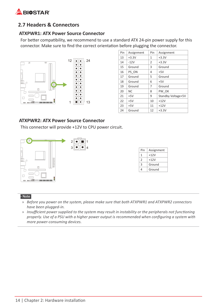
|23|+5V|11|+12V| |24|Ground|12|+3.3V|
| | | | | |---|---|---|---| | | | | |
|Pin|Assignment| |---|---| |1|+12V| |2|+12V| |3|Ground| |4|Ground|
Note » Before you power on the system, please make sure that both ATXPWR1 and ATXPWR2 connectors
have been plugged-in.
» Insufficient power supplied to the system may result in instability or the peripherals not functioning properly. Use of a PSU with a higher power output is recommended when configuring a system with more power-consuming devices.
#### PANEL1: Front Panel Header
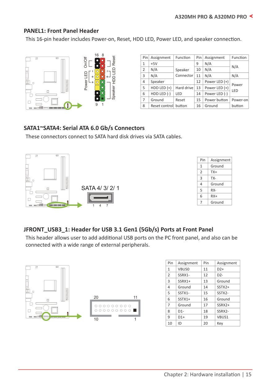
This 16-pin header includes Power-on, Reset, HDD LED, Power LED, and speaker connection.
| | | | | |---|---|---|---| | | | | |
|Pin|Assignment|Function|Pin|Assignment|Function| |---|---|---|---|---|---| |1|+5V|Speaker Connector|9|N/A|N/A| |2|N/A|Speaker Connector|10|N/A|N/A| |3|N/A|Speaker Connector|11|N/A|N/A| |4|Speaker|Speaker Connector|12|Power LED (+)|Power LED| |5|HDD LED (+)|Hard drive LED|13|Power LED (+)|Power LED| |6|HDD LED (-)|Hard drive LED|14|Power LED (-)|Power LED| |7|Ground|Reset button|15|Power button|Power-on button| |8|Reset control|Reset button|16|Ground|Power-on button|
#### SATA1~SATA4: Serial ATA 6.0 Gb/s Connectors
These connectors connect to SATA hard disk drives via SATA cables.
| | | | | |---|---|---|---| | | | | |
|Pin|Assignment| |---|---| |1|Ground| |2|TX+| |3|TX-| |4|Ground| |5|RX-| |6|RX+| |7|Ground|
JFRONT_USB3_1: Header for USB 3.1 Gen1 (5Gb/s) Ports at Front Panel This header allows user to add additional USB ports on the PC front panel, and also can be connected with a wide range of external peripherals.
| | | | | |---|---|---|---| | | | | |
|Pin|Assignment|Pin|Assignment| |---|---|---|---| |1|VBUS0|11|D2+| |2|SSRX1-|12|D2-| |3|SSRX1+|13|Ground| |4|Ground|14|SSTX2+| |5|SSTX1-|15|SSTX2-|
|6|SSTX1+|16|Ground| |7|Ground|17|SSRX2+| |8|D1-|18|SSRX2-| |9|D1+|19|VBUS1| |10|ID|20|Key|
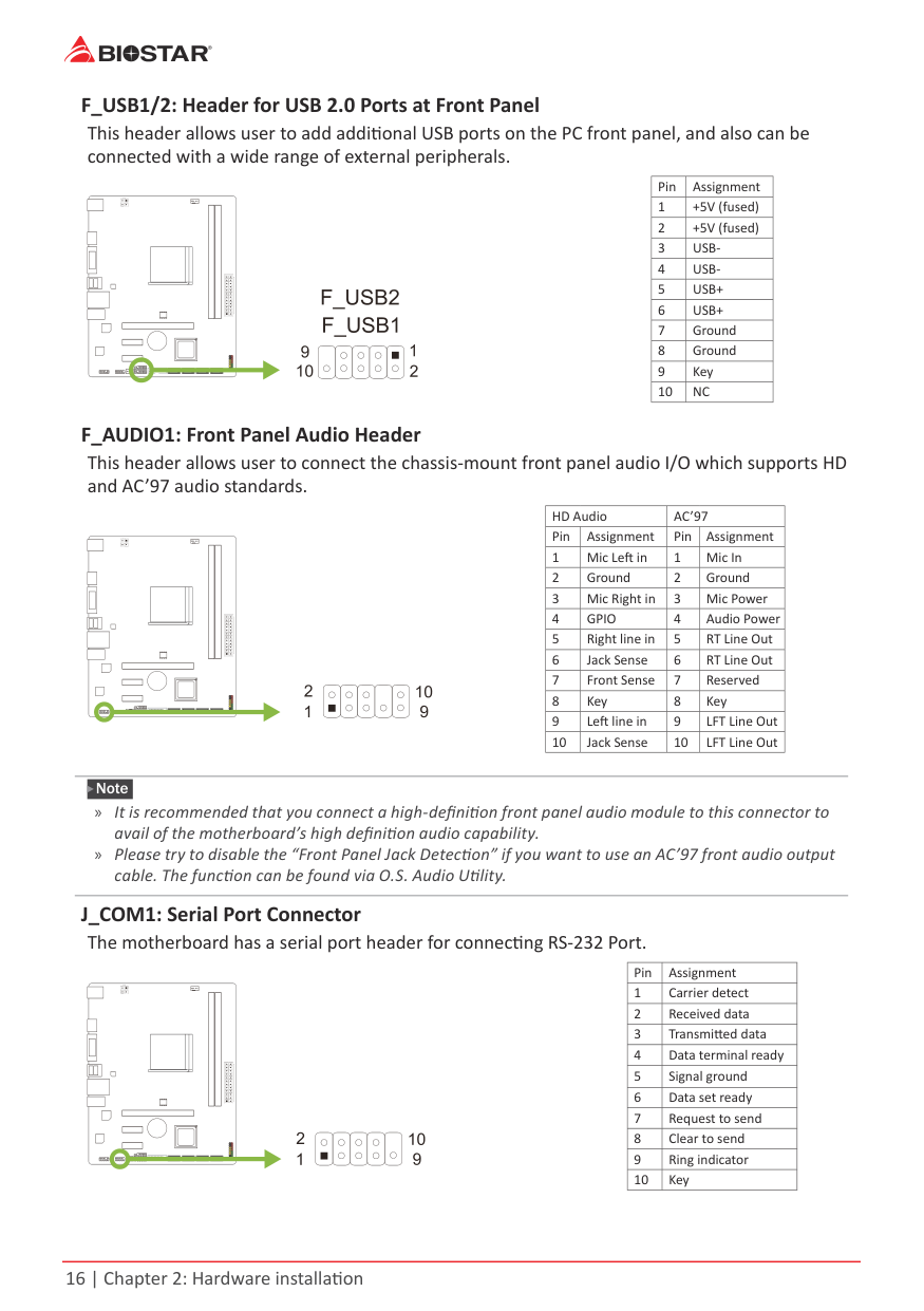
F_USB1/2: Header for USB 2.0 Ports at Front Panel This header allows user to add additional USB ports on the PC front panel, and also can be connected with a wide range of external peripherals.
|Pin|Assignment| |---|---| |1|+5V (fused)| |2|+5V (fused)| |3|USB-| |4|USB-| |5|USB+| |6|USB+| |7|Ground| |8|Ground| |9|Key| |10|NC|
| | | | | |---|---|---|---| | | | | |
F_AUDIO1: Front Panel Audio Header This header allows user to connect the chassis-mount front panel audio I/O which supports HD and AC’97 audio standards.
|HD Audio|HD Audio|AC’97|AC’97| |---|---|---|---| |Pin|Assignment|Pin|Assignment| |1|Mic Left in|1|Mic In| |2|Ground|2|Ground| |3|Mic Right in|3|Mic Power| |4|GPIO|4|Audio Power| |5|Right line in|5|RT Line Out| |6|Jack Sense|6|RT Line Out| |7|Front Sense|7|Reserved| |8|Key|8|Key| |9|Left line in|9|LFT Line Out| |10|Jack Sense|10|LFT Line Out|
| | | | | |---|---|---|---| | | | | |
Note » It is recommended that you connect a high-definition front panel audio module to this connector to
avail of the motherboard’s high definition audio capability. » Please try to disable the “Front Panel Jack Detection” if you want to use an AC’97 front audio output
cable. The function can be found via O.S. Audio Utility. J_COM1: Serial Port Connector
The motherboard has a serial port header for connecting RS-232 Port.
|Pin|Assignment| |---|---| |1|Carrier detect| |2|Received data| |3|Transmitted data| |4|Data terminal ready| |5|Signal ground| |6|Data set ready| |7|Request to send| |8|Clear to send| |9|Ring indicator| |10|Key|
| | | | | |---|---|---|---| | | | | |
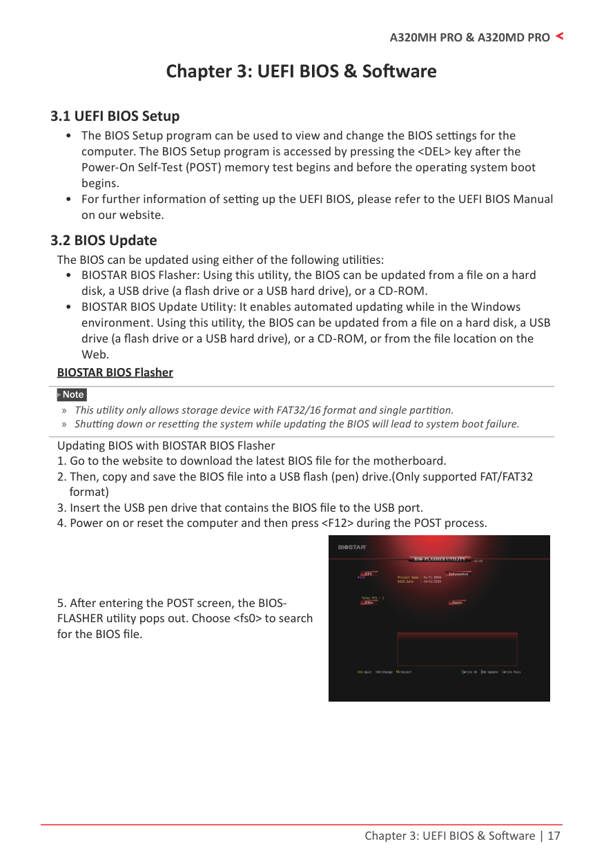
Chapter 3: UEFI BIOS & Software
3.1 UEFI BIOS Setup
###### BIOSTAR BIOS Flasher
Note » This utility only allows storage device with FAT32/16 format and single partition. » Shutting down or resetting the system while updating the BIOS will lead to system boot failure.
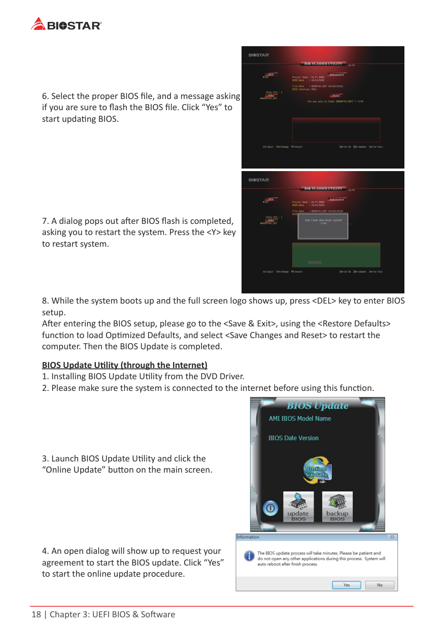
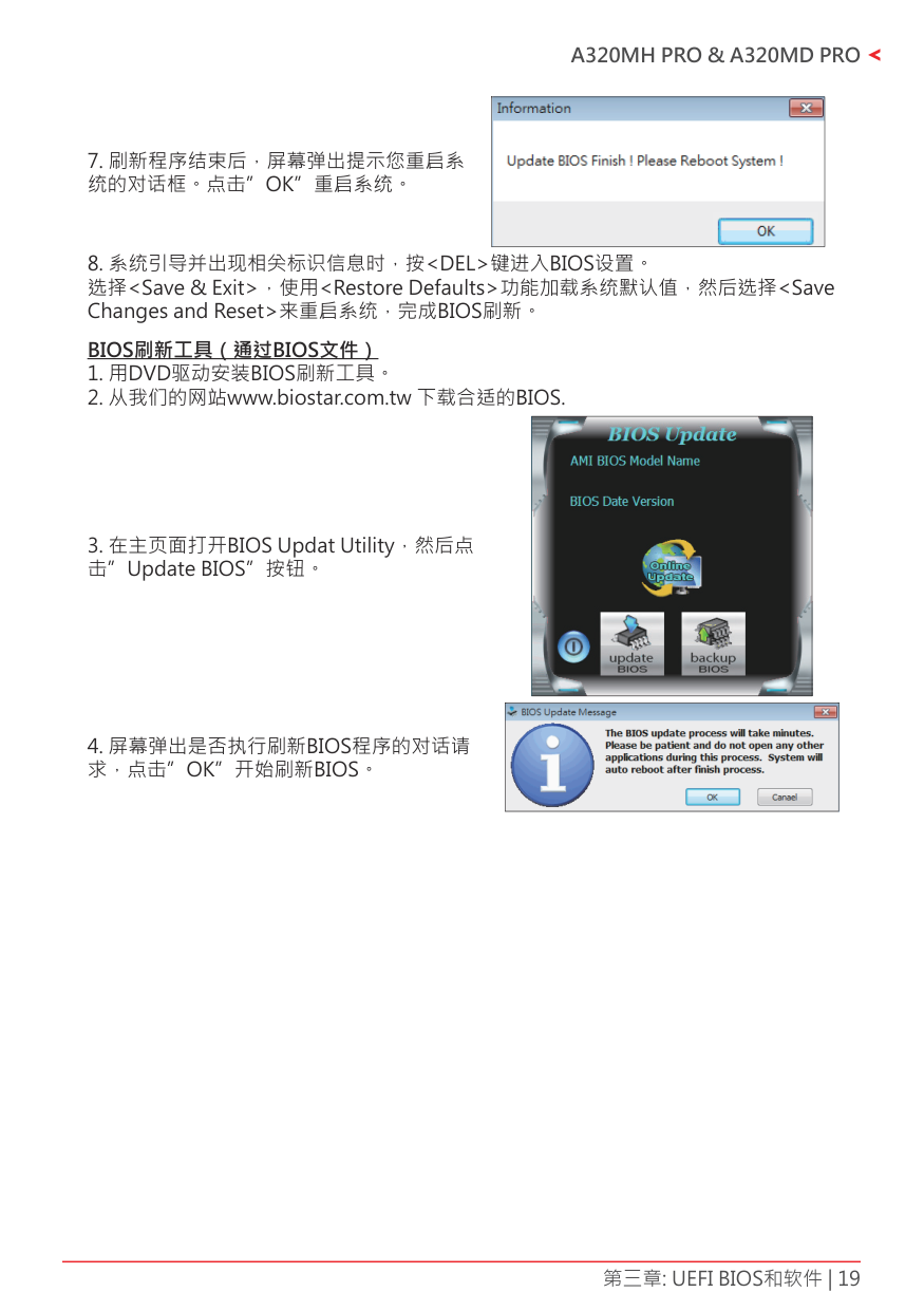
Updating BIOS with BIOSTAR BIOS Flasher


|| |---|
|| |---|
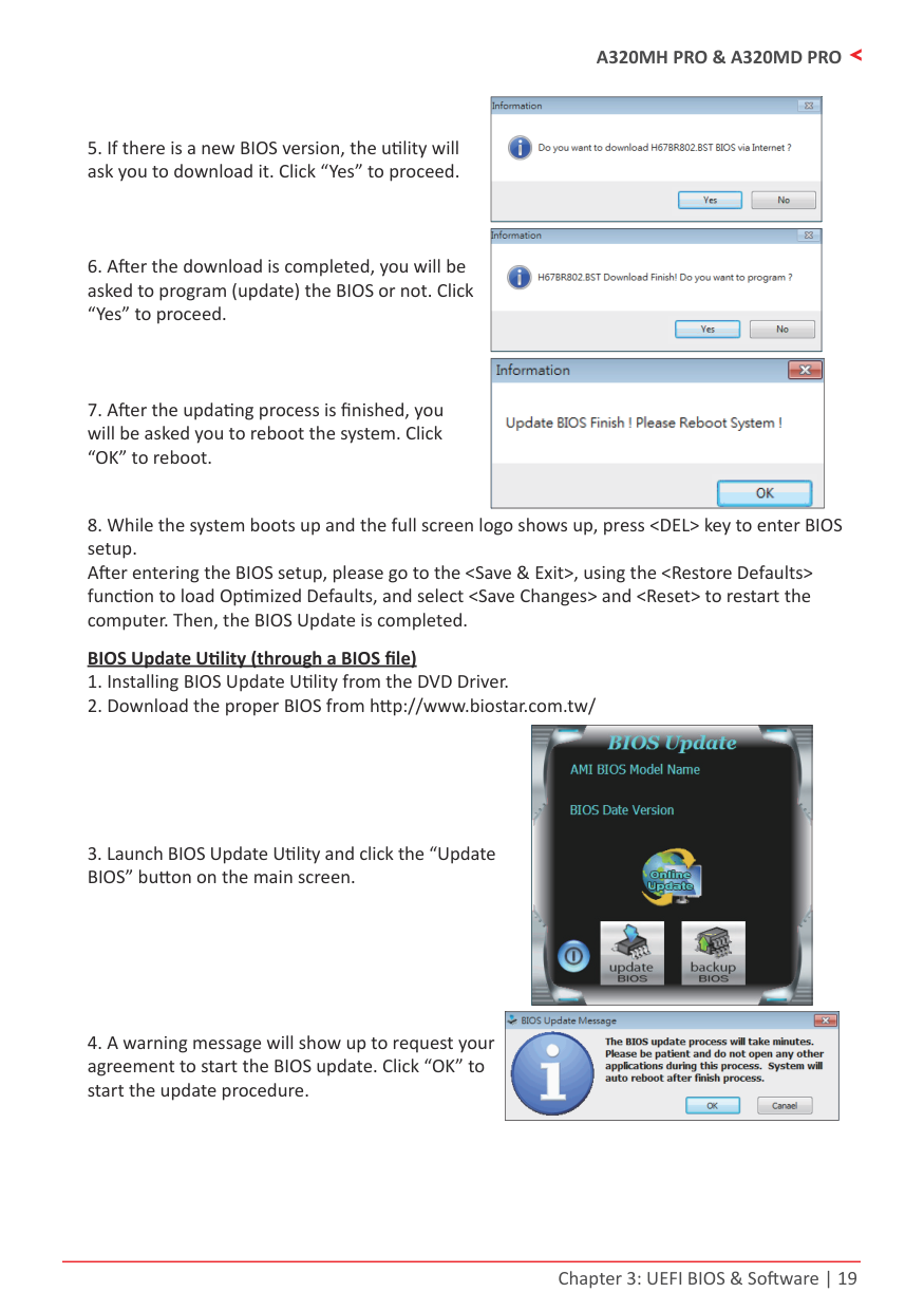
|| |---|
|| |---|
|| |---|
|| |---|
|| |---|

|| |---|

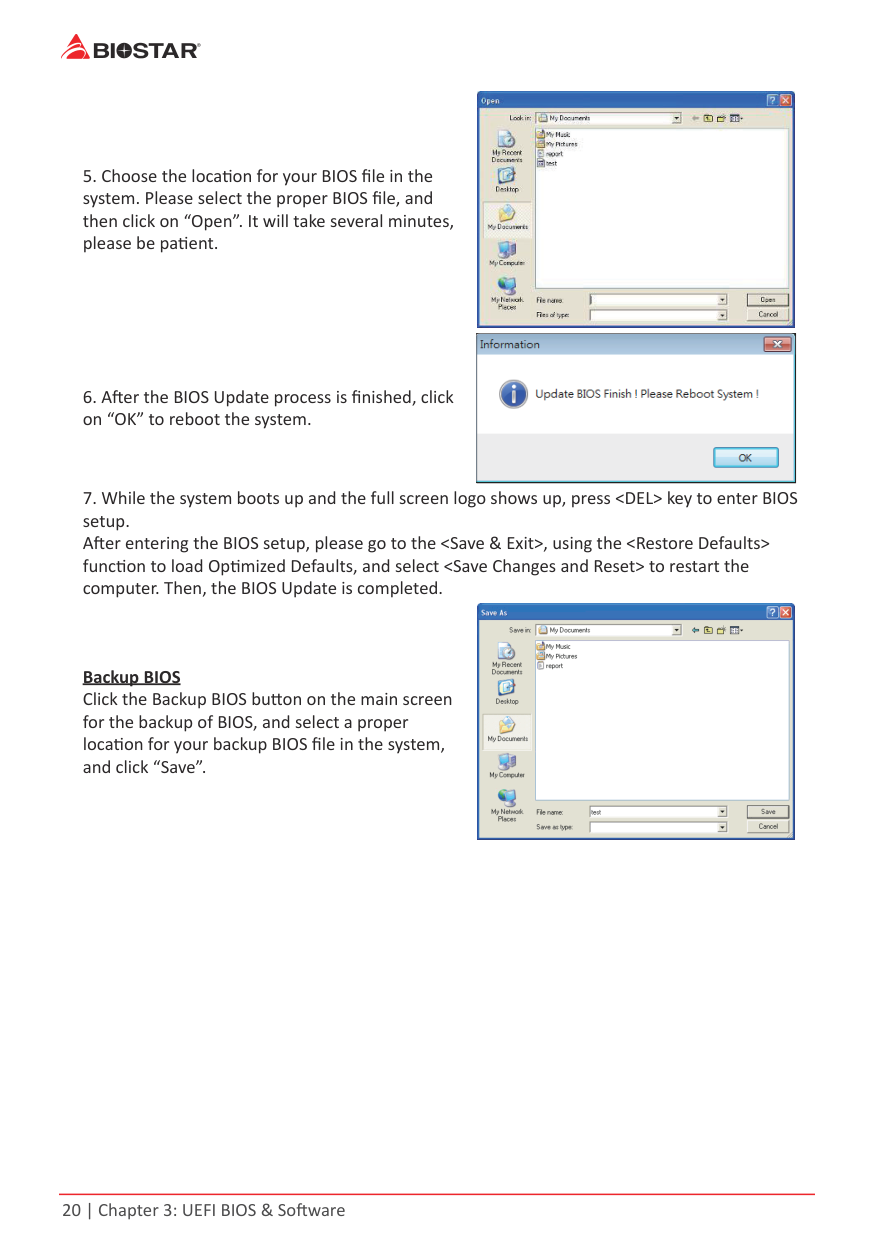
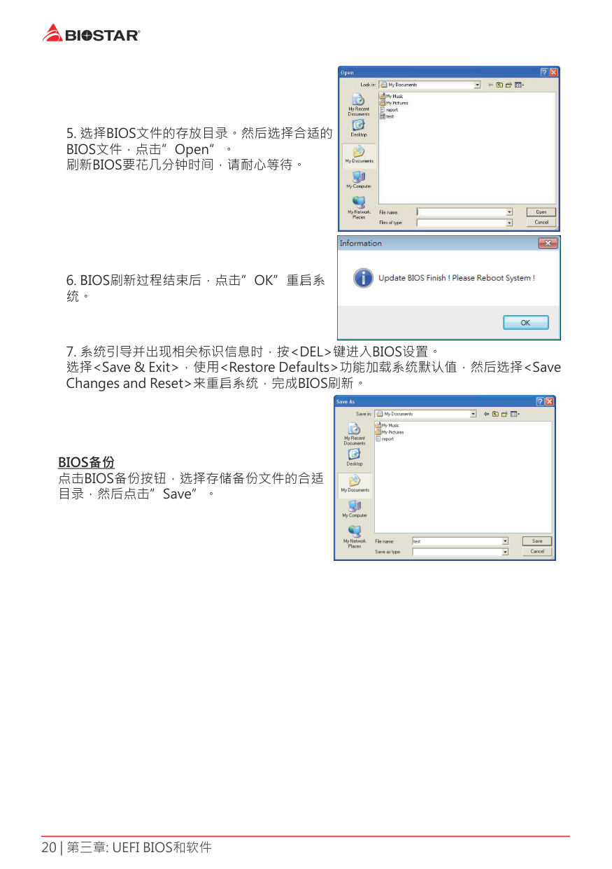
Backup BIOS Click the Backup BIOS button on the main screen for the backup of BIOS, and select a proper location for your backup BIOS file in the system, and click “Save”.
3.3 SoftwareInstalling Software
Launching Software After the installation process is completed, you will see the software icon showing on the desktop. Double-click the icon to launch it.
Note » All the information and content about following software are subject to be changed without notice.
For better performance, the software is being continuously updated. » The information and pictures described below are for your reference only. The actual information and settings on board may be slightly different from this manual.
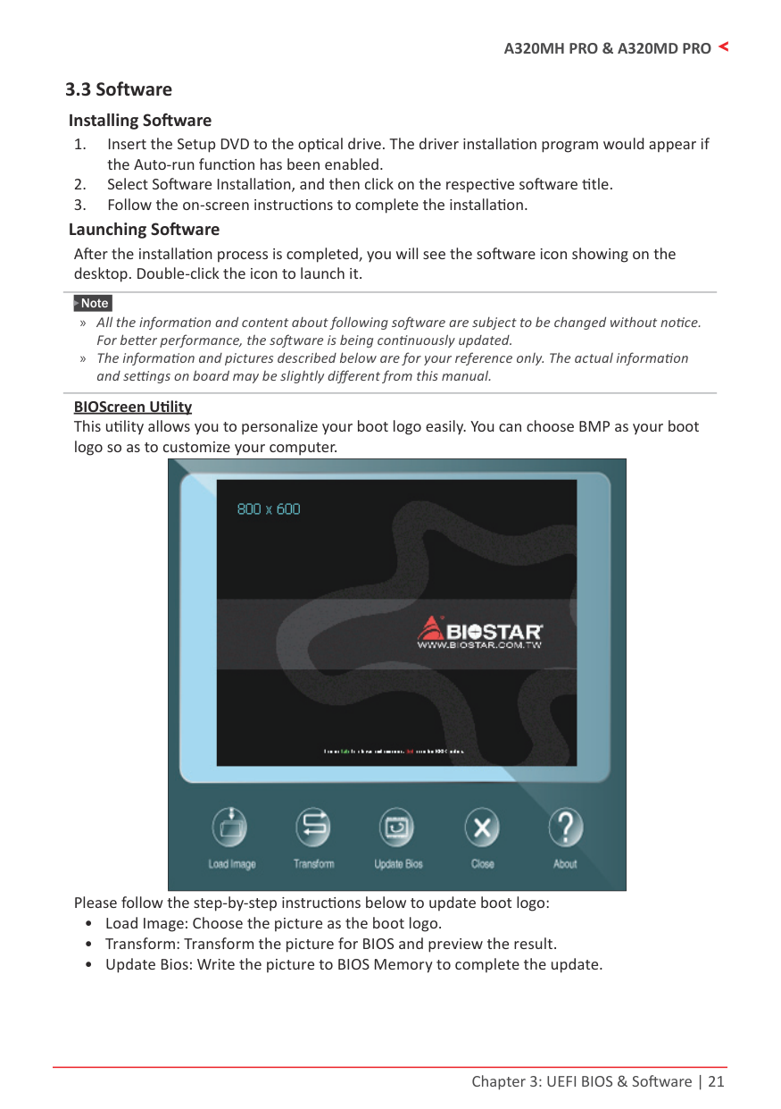
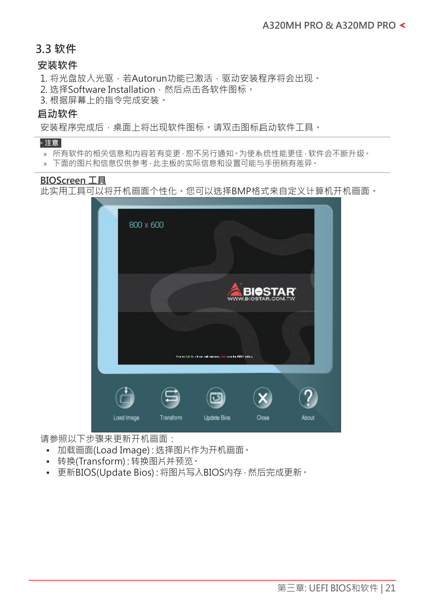
BIOScreen Utility This utility allows you to personalize your boot logo easily. You can choose BMP as your boot logo so as to customize your computer.
|| |---|
Please follow the step-by-step instructions below to update boot logo:
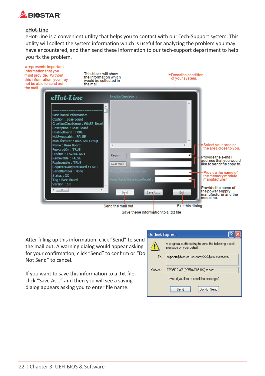
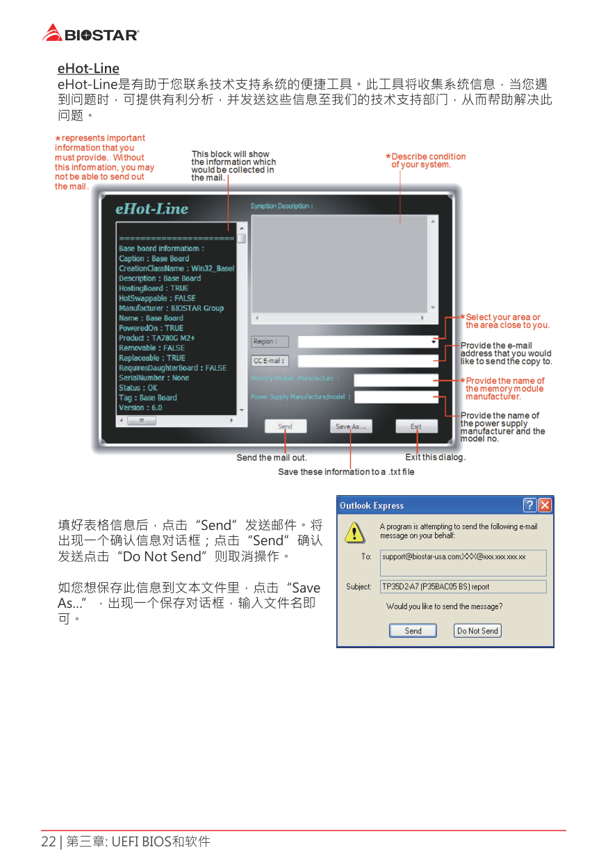
eHot-Line eHot-Line is a convenient utility that helps you to contact with our Tech-Support system. This utility will collect the system information which is useful for analyzing the problem you may have encountered, and then send these information to our tech-support department to help you fix the problem.

|| |---|
After filling up this information, click “Send” to send the mail out. A warning dialog would appear asking for your confirmation; click “Send” to confirm or “Do Not Send” to cancel.
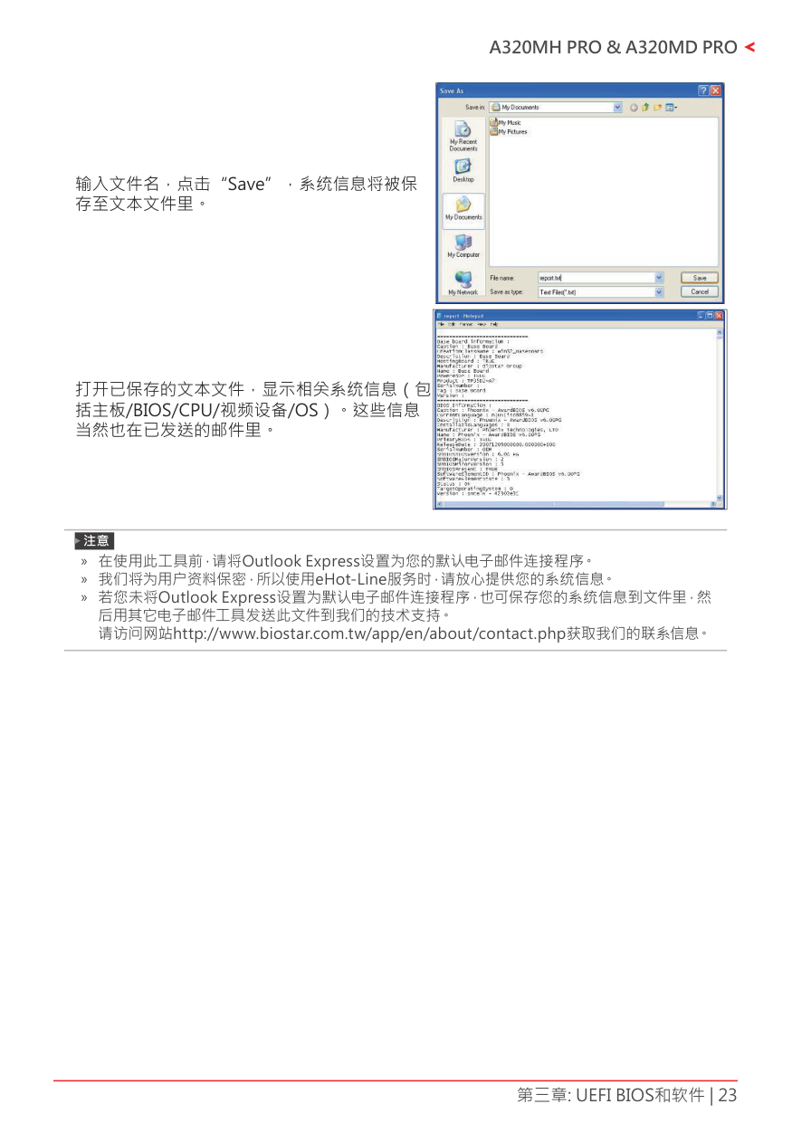
If you want to save this information to a .txt file, click “Save As…” and then you will see a saving dialog appears asking you to enter file name.
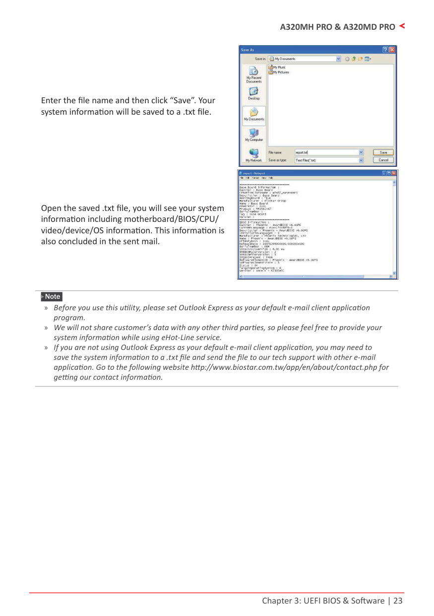
Enter the file name and then click “Save”. Your system information will be saved to a .txt file.
Open the saved .txt file, you will see your system information including motherboard/BIOS/CPU/ video/device/OS information. This information is also concluded in the sent mail.
|| |---|
|| |---|
Note » Before you use this utility, please set Outlook Express as your default e-mail client application
program. » We will not share customer’s data with any other third parties, so please feel free to provide your system information while using eHot-Line service.
» If you are not using Outlook Express as your default e-mail client application, you may need to save the system information to a .txt file and send the file to our tech support with other e-mail application. Go to the following website http://www.biostar.com.tw/app/en/about/contact.php for getting our contact information.
Chapter 4: Useful Help
4.1 Driver Installation
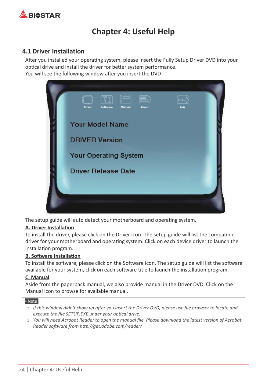
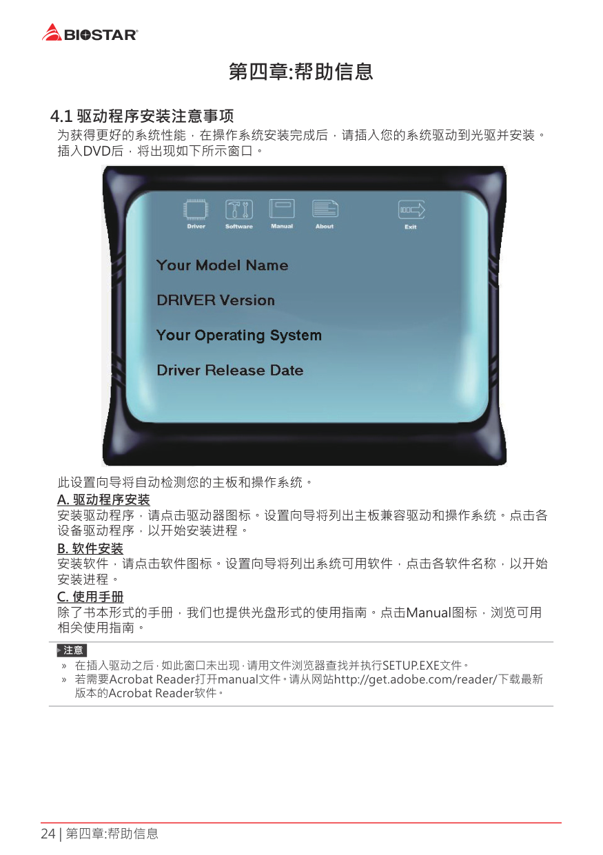
After you installed your operating system, please insert the Fully Setup Driver DVD into your optical drive and install the driver for better system performance. You will see the following window after you insert the DVD

The setup guide will auto detect your motherboard and operating system.
Note » If this window didn’t show up after you insert the Driver DVD, please use file browser to locate and
execute the file SETUP.EXE under your optical drive. » You will need Acrobat Reader to open the manual file. Please download the latest version of Acrobat Reader software from http://get.adobe.com/reader/
4.2 AMI BIOS Beep CodeBoot Block Beep Codes
|Number of Beeps|Description| |---|---| |Continuing|Memory sizing error or Memory module not found|
POST BIOS Beep Codes
|Number of Beeps|Description| |---|---| |1|Success booting.| |8|Display memory error (system video adapter)|
4.3 Troubleshooting
|Probable|Solution| |---|---| |1. There is no power in the system. Power LED does not shine; the fan of the power supply does not work
2. Indicator light on keyboard does not shine.
|1. Make sure power cable is securely plugged in.
2. Replace cable.
3. Contact technical support.
| |System is inoperative. Keyboard lights are on, power indicator lights are lit, and hard drives are running.|Using even pressure on both ends of the DIMM, press down firmly until the module snaps into place.| |System does not boot from a hard disk drive, but can be booted from optical drive.|1. Check cable running from disk to disk controller board. Make sure both ends are securely plugged in; check the drive type in the standard CMOS setup.
2. Backing up the hard drive is extremely important. All hard disks are capable of breaking down at any time.
| |System only boots from an optical drive. Hard disks can be read, applications can be used, but system fails to boot from a hard disk.|1. Back up data and applications files.
2. Reformat the hard drive. Re-install applications and data using backup disks.
| |Screen message shows “Invalid Configuration” or “CMOS Failure.”|Review system’s equipment. Make sure correct information is in setup.| |System cannot boot after user installs a second hard drive.|1. Set master/slave jumpers correctly.
2. Run SETUP program and select correct drive types. Call the drive manufacturers for compatibility with other drives.
|
CPU Overheated If the system shutdown automatically after power on system for seconds, that means the CPU protection function has been activated.
When the CPU is over heated, the motherboard will shutdown automatically to avoid a damage of the CPU, and the system may not power on again.
In this case, please double check:
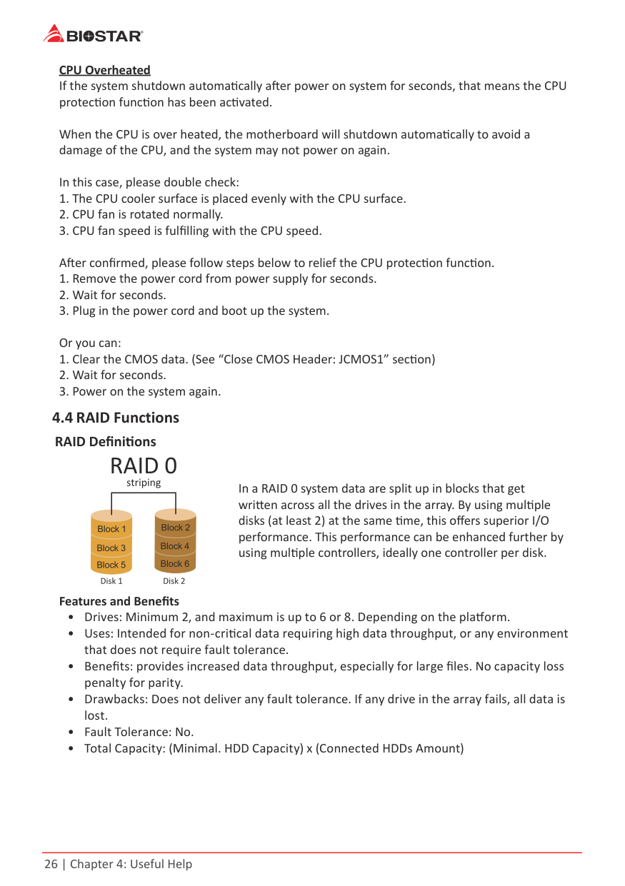
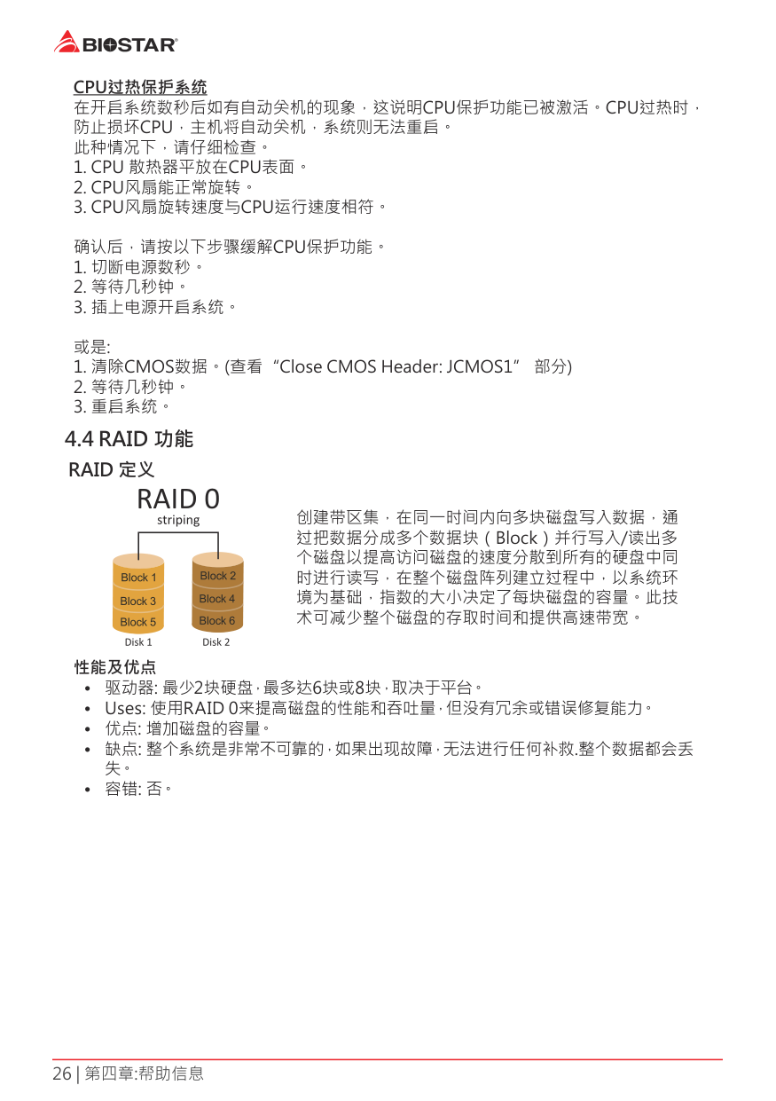
In a RAID 0 system data are split up in blocks that get written across all the drives in the array. By using multiple disks (at least 2) at the same time, this offers superior I/O performance. This performance can be enhanced further by using multiple controllers, ideally one controller per disk.
###### Features and Benefits
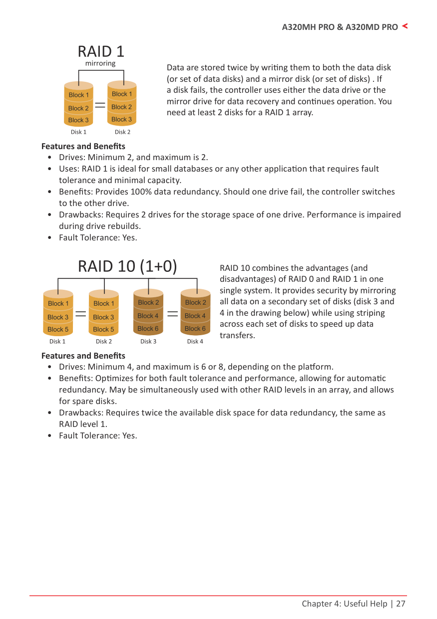
Data are stored twice by writing them to both the data disk (or set of data disks) and a mirror disk (or set of disks) . If a disk fails, the controller uses either the data drive or the mirror drive for data recovery and continues operation. You need at least 2 disks for a RAID 1 array.
###### Features and Benefits
RAID 10 combines the advantages (and disadvantages) of RAID 0 and RAID 1 in one single system. It provides security by mirroring all data on a secondary set of disks (disk 3 and 4 in the drawing below) while using striping across each set of disks to speed up data transfers.
###### Features and Benefits
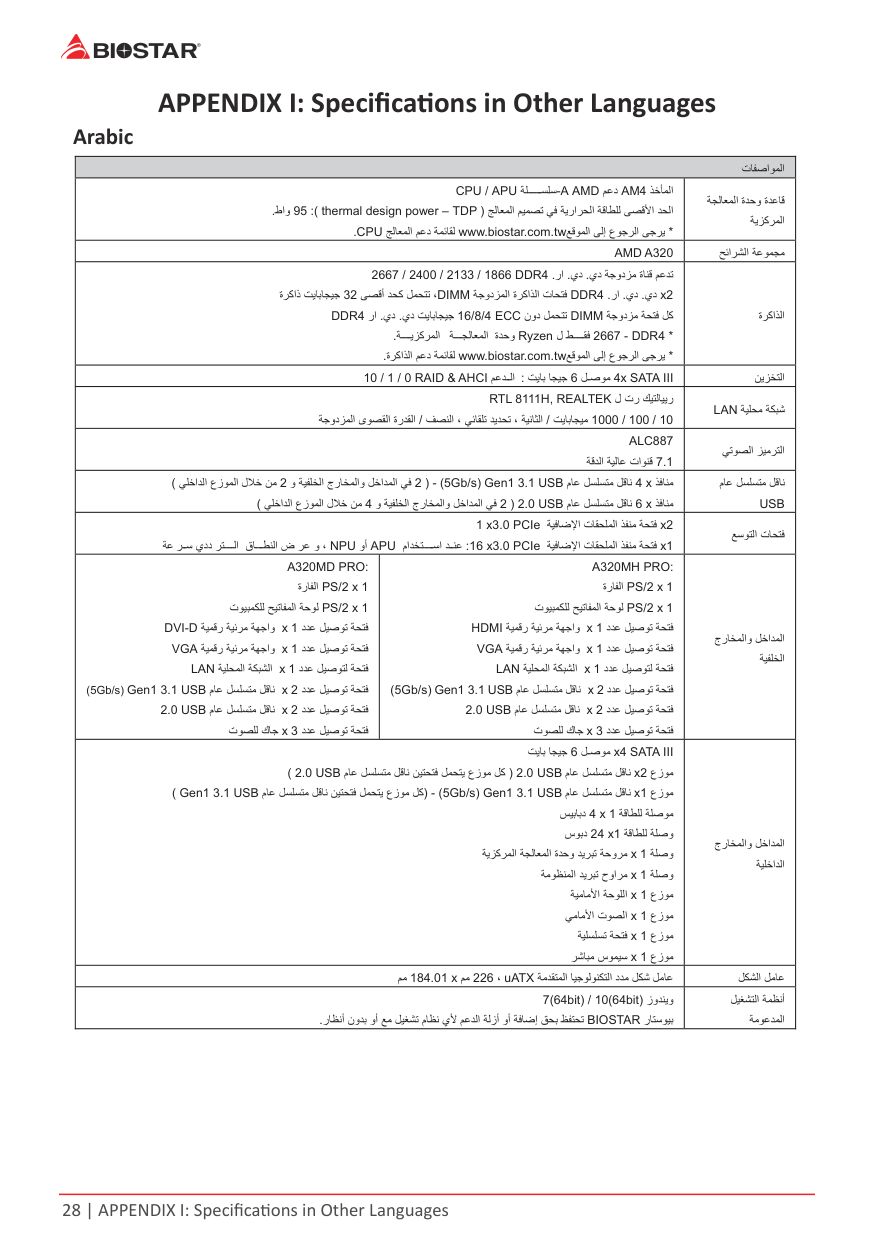
APPENDIX I: Specifications in Other Languages Arabic
|تﺎﻔﺻاﻮﻤﻟا|تﺎﻔﺻاﻮﻤﻟا|تﺎﻔﺻاﻮﻤﻟا| |---|---|---| |ﺬﺧﺄﻤﻟاAM4ﻢﻋدAMDA-APU ﺔﻠ ﺴﻠﺳ/CPU ﺞﻟﺎﻌﻤﻟا ﻢﻴﻤﺼﺗ ﻲﻓ ﺔﻳراﺮﺤﻟا ﺔﻗﺎﻄﻠﻟ ﻰﺼﻗﻷا ﺪﺤﻟا)TDP–thermal design power:(95طاو. *ﻊﻗﻮﻤﻟا ﻰﻟإ عﻮﺟﺮﻟا ﻰﺟﺮﻳwww.biostar.com.twﺞﻟﺎﻌﻤﻟا ﻢﻋد ﺔﻤﺋﺎﻘﻟCPU.|ﺬﺧﺄﻤﻟاAM4ﻢﻋدAMDA-APU ﺔﻠ ﺴﻠﺳ/CPU ﺞﻟﺎﻌﻤﻟا ﻢﻴﻤﺼﺗ ﻲﻓ ﺔﻳراﺮﺤﻟا ﺔﻗﺎﻄﻠﻟ ﻰﺼﻗﻷا ﺪﺤﻟا)TDP–thermal design power:(95طاو. *ﻊﻗﻮﻤﻟا ﻰﻟإ عﻮﺟﺮﻟا ﻰﺟﺮﻳwww.biostar.com.twﺞﻟﺎﻌﻤﻟا ﻢﻋد ﺔﻤﺋﺎﻘﻟCPU.|ﺔﺠﻟﺎﻌﻤﻟا ةﺪﺣو ةﺪﻋﺎﻗ ﺔﻳﺰآﺮﻤﻟا| |AMD A320|AMD A320|ﺢﺋاﺮﺸﻟا ﺔﻋﻮﻤﺠﻣ| |يد ﺔﺟودﺰﻣ ةﺎﻨﻗ ﻢﻋﺪﺗ.يد.را.DDR41866/2133/2400/2667 2xيد.يد.را.DDR4ﺔﺟودﺰﻤﻟا ةﺮآاﺬﻟا تﺎﺤﺘﻓDIMMﻰﺼﻗأ ﺪﺤآ ﻞﻤﺤﺘﺗ ،32ةﺮآاذ ﺖﻳﺎﺑﺎﺠﻴﺟ
ﺔﺟودﺰﻣ ﺔﺤﺘﻓ ﻞآDIMMنود ﻞﻤﺤﺘﺗECC4/8/16يد ﺖﻳﺎﺑﺎﺠﻴﺟ.يد.راDDR4
*DDR4-2667 ﻘﻓةﺪﺣو Ryzen لﺔ ﺠﻟﺎﻌﻤﻟاﺔ ﻳﺰآﺮﻤﻟا.
*ﻊﻗﻮﻤﻟا ﻰﻟإ عﻮﺟﺮﻟا ﻰﺟﺮﻳwww.biostar.com.twةﺮآاﺬﻟا ﻢﻋد ﺔﻤﺋﺎﻘﻟ.
|يد ﺔﺟودﺰﻣ ةﺎﻨﻗ ﻢﻋﺪﺗ.يد.را.DDR41866/2133/2400/2667 2xيد.يد.را.DDR4ﺔﺟودﺰﻤﻟا ةﺮآاﺬﻟا تﺎﺤﺘﻓDIMMﻰﺼﻗأ ﺪﺤآ ﻞﻤﺤﺘﺗ ،32ةﺮآاذ ﺖﻳﺎﺑﺎﺠﻴﺟ
ﺔﺟودﺰﻣ ﺔﺤﺘﻓ ﻞآDIMMنود ﻞﻤﺤﺘﺗECC4/8/16يد ﺖﻳﺎﺑﺎﺠﻴﺟ.يد.راDDR4
*DDR4-2667 ﻘﻓةﺪﺣو Ryzen لﺔ ﺠﻟﺎﻌﻤﻟاﺔ ﻳﺰآﺮﻤﻟا.
*ﻊﻗﻮﻤﻟا ﻰﻟإ عﻮﺟﺮﻟا ﻰﺟﺮﻳwww.biostar.com.twةﺮآاﺬﻟا ﻢﻋد ﺔﻤﺋﺎﻘﻟ.
|ةﺮآاﺬﻟا| |ﻞ ﺻﻮﻣ 4x SATA III6ﺖﻳﺎﺑ ﺎﺠﻴﺟ:& AHCI ﻢﻋﺪ ﻟا/ 0 RAID1/10|ﻞ ﺻﻮﻣ 4x SATA III6ﺖﻳﺎﺑ ﺎﺠﻴﺟ:& AHCI ﻢﻋﺪ ﻟا/ 0 RAID1/10|ﻦﻳﺰﺨﺘﻟا|
|ل تر ﻚﻴﺘﻟﺎﻴﻳرRTL 8111H, REALTEK 10/100/1000ﺖﻳﺎﺑﺎﺠﻴﻣ/ﻒﺼﻨﻟا ، ﻲﺋﺎﻘﻠﺗ ﺪﻳﺪﺤﺗ ، ﺔﻴﻧﺎﺜﻟا/ﺔﺟودﺰﻤﻟا ىﻮﺼﻘﻟا ةرﺪﻘﻟا|ل تر ﻚﻴﺘﻟﺎﻴﻳرRTL 8111H, REALTEK 10/100/1000ﺖﻳﺎﺑﺎﺠﻴﻣ/ﻒﺼﻨﻟا ، ﻲﺋﺎﻘﻠﺗ ﺪﻳﺪﺤﺗ ، ﺔﻴﻧﺎﺜﻟا/ﺔﺟودﺰﻤﻟا ىﻮﺼﻘﻟا ةرﺪﻘﻟا|ﺔﻴﻠﺤﻣ ﺔﻜﺒﺷLAN| |ALC887 7.1ﺔﻗﺪﻟا ﺔﻴﻟﺎﻋ تاﻮﻨﻗ|ALC887 7.1ﺔﻗﺪﻟا ﺔﻴﻟﺎﻋ تاﻮﻨﻗ|ﻲﺗﻮﺼﻟا ﺰﻴﻣﺮﺘﻟا| |ﺬﻓﺎﻨﻣ4 xمﺎﻋ ﻞﺴﻠﺴﺘﻣ ﻞﻗﺎﻧUSB3.11Gen(5Gb/s)-)2و ﺔﻴﻔﻠﺨﻟا جرﺎﺨﻤﻟاو ﻞﺧاﺪﻤﻟا ﻲﻓ2ﻲﻠﺧاﺪﻟا عزﻮﻤﻟا لﻼﺧ ﻦﻣ( ﺬﻓﺎﻨﻣ6 xمﺎﻋ ﻞﺴﻠﺴﺘﻣ ﻞﻗﺎﻧUSB2.0)2و ﺔﻴﻔﻠﺨﻟا جرﺎﺨﻤﻟاو ﻞﺧاﺪﻤﻟا ﻲﻓ4ﻲﻠﺧاﺪﻟا عزﻮﻤﻟا لﻼﺧ ﻦﻣ(|ﺬﻓﺎﻨﻣ4 xمﺎﻋ ﻞﺴﻠﺴﺘﻣ ﻞﻗﺎﻧUSB3.11Gen(5Gb/s)-)2و ﺔﻴﻔﻠﺨﻟا جرﺎﺨﻤﻟاو ﻞﺧاﺪﻤﻟا ﻲﻓ2ﻲﻠﺧاﺪﻟا عزﻮﻤﻟا لﻼﺧ ﻦﻣ( ﺬﻓﺎﻨﻣ6 xمﺎﻋ ﻞﺴﻠﺴﺘﻣ ﻞﻗﺎﻧUSB2.0)2و ﺔﻴﻔﻠﺨﻟا جرﺎﺨﻤﻟاو ﻞﺧاﺪﻤﻟا ﻲﻓ4ﻲﻠﺧاﺪﻟا عزﻮﻤﻟا لﻼﺧ ﻦﻣ(|مﺎﻋ ﻞﺴﻠﺴﺘﻣ ﻞﻗﺎﻧ USB| |2xﺔﻴﻓﺎﺿﻹا تﺎﻘﺤﻠﻤﻟا ﺬﻔﻨﻣ ﺔﺤﺘﻓPCIe1 x3.0 1xﺔﻴﻓﺎﺿﻹا تﺎﻘﺤﻠﻤﻟا ﺬﻔﻨﻣ ﺔﺤﺘﻓ16 x3.0 PCIe:ماﺪﺨﺘ ﺳا ﺪ ﻨﻋAPUوأNPU،وﺮﻋض ﺎ ﻄﻨﻟاﺮﺘ ﻟايددﺮ ﺳﺔﻋ|2xﺔﻴﻓﺎﺿﻹا تﺎﻘﺤﻠﻤﻟا ﺬﻔﻨﻣ ﺔﺤﺘﻓPCIe1 x3.0 1xﺔﻴﻓﺎﺿﻹا تﺎﻘﺤﻠﻤﻟا ﺬﻔﻨﻣ ﺔﺤﺘﻓ16 x3.0 PCIe:ماﺪﺨﺘ ﺳا ﺪ ﻨﻋAPUوأNPU،وﺮﻋض ﺎ ﻄﻨﻟاﺮﺘ ﻟايددﺮ ﺳﺔﻋ|ﻊﺳﻮﺘﻟا تﺎﺤﺘﻓ| |A320MD PRO:
1xPS/2ةرﺎﻔﻟا 1xPS/2تﻮﻴﺒﻤﻜﻠﻟ ﺢﻴﺗﺎﻔﻤﻟا ﺔﺣﻮﻟ
دﺪﻋ ﻞﻴﺻﻮﺗ ﺔﺤﺘﻓ1xﺔﻴﻤﻗر ﺔﻴﺋﺮﻣ ﺔﻬﺟاوD-DVI دﺪﻋ ﻞﻴﺻﻮﺗ ﺔﺤﺘﻓ1xﺔﻴﻤﻗر ﺔﻴﺋﺮﻣ ﺔﻬﺟاوVGA دﺪﻋ ﻞﻴﺻﻮﺘﻟ ﺔﺤﺘﻓ1xﺔﻴﻠﺤﻤﻟا ﺔﻜﺒﺸﻟاLAN دﺪﻋ ﻞﻴﺻﻮﺗ ﺔﺤﺘﻓ2xمﺎﻋ ﻞﺴﻠﺴﺘﻣ ﻞﻗﺎﻧUSB3.11Gen(5Gb/s) دﺪﻋ ﻞﻴﺻﻮﺗ ﺔﺤﺘﻓ2xمﺎﻋ ﻞﺴﻠﺴﺘﻣ ﻞﻗﺎﻧUSB2.0 دﺪﻋ ﻞﻴﺻﻮﺗ ﺔﺤﺘﻓ3xتﻮﺼﻠﻟ كﺎﺟ|A320MH PRO:
1xPS/2ةرﺎﻔﻟا 1xPS/2تﻮﻴﺒﻤﻜﻠﻟ ﺢﻴﺗﺎﻔﻤﻟا ﺔﺣﻮﻟ
دﺪﻋ ﻞﻴﺻﻮﺗ ﺔﺤﺘﻓ1xﺔﻴﻤﻗر ﺔﻴﺋﺮﻣ ﺔﻬﺟاوHDMI دﺪﻋ ﻞﻴﺻﻮﺗ ﺔﺤﺘﻓ1xﺔﻴﻤﻗر ﺔﻴﺋﺮﻣ ﺔﻬﺟاوVGA دﺪﻋ ﻞﻴﺻﻮﺘﻟ ﺔﺤﺘﻓ1xﺔﻴﻠﺤﻤﻟا ﺔﻜﺒﺸﻟاLAN دﺪﻋ ﻞﻴﺻﻮﺗ ﺔﺤﺘﻓ2xمﺎﻋ ﻞﺴﻠﺴﺘﻣ ﻞﻗﺎﻧUSB3.11Gen(5Gb/s) دﺪﻋ ﻞﻴﺻﻮﺗ ﺔﺤﺘﻓ2xمﺎﻋ ﻞﺴﻠﺴﺘﻣ ﻞﻗﺎﻧUSB2.0 دﺪﻋ ﻞﻴﺻﻮﺗ ﺔﺤﺘﻓ3xتﻮﺼﻠﻟ كﺎﺟ|جرﺎﺨﻤﻟاو ﻞﺧاﺪﻤﻟا ﺔﻴﻔﻠﺨﻟا| |ﻞ ﺻﻮﻣ x4 SATA III6ﺖﻳﺎﺑ ﺎﺠﻴﺟ عزﻮﻣ2xمﺎﻋ ﻞﺴﻠﺴﺘﻣ ﻞﻗﺎﻧUSB2.0)مﺎﻋ ﻞﺴﻠﺴﺘﻣ ﻞﻗﺎﻧ ﻦﻴﺘﺤﺘﻓ ﻞﻤﺤﺘﻳ عزﻮﻣ ﻞآUSB2.0(
عزﻮﻣ1xمﺎﻋ ﻞﺴﻠﺴﺘﻣ ﻞﻗﺎﻧUSB3.11Gen(5Gb/s)-)مﺎﻋ ﻞﺴﻠﺴﺘﻣ ﻞﻗﺎﻧ ﻦﻴﺘﺤﺘﻓ ﻞﻤﺤﺘﻳ عزﻮﻣ ﻞآUSB3.11Gen( ﺔﻗﺎﻄﻠﻟ ﺔﻠﺻﻮﻣ1x4ﺲﻴﺑﺎﺑد
ﺔﻗﺎﻄﻠﻟ ﺔﻠﺻو1x24سﻮﺑد ﺔﻠﺻو1xﺔﻳﺰآﺮﻤﻟا ﺔﺠﻟﺎﻌﻤﻟا ةﺪﺣو ﺪﻳﺮﺒﺗ ﺔﺣوﺮﻣ
ﺔﻠﺻو1xﺔﻣﻮﻈﻨﻤﻟا ﺪﻳﺮﺒﺗ حواﺮﻣ عزﻮﻣ1xﺔﻴﻣﺎﻣﻷا ﺔﺣﻮﻠﻟا عزﻮﻣ1xﻲﻣﺎﻣﻷا تﻮﺼﻟا عزﻮﻣ1xﺔﻴﻠﺴﻠﺴﺗ ﺔﺤﺘﻓ عزﻮﻣ1xﺮﺷﺎﺒﻣ سﻮﻤﻴﺳ|ﻞ ﺻﻮﻣ x4 SATA III6ﺖﻳﺎﺑ ﺎﺠﻴﺟ عزﻮﻣ2xمﺎﻋ ﻞﺴﻠﺴﺘﻣ ﻞﻗﺎﻧUSB2.0)مﺎﻋ ﻞﺴﻠﺴﺘﻣ ﻞﻗﺎﻧ ﻦﻴﺘﺤﺘﻓ ﻞﻤﺤﺘﻳ عزﻮﻣ ﻞآUSB2.0(
عزﻮﻣ1xمﺎﻋ ﻞﺴﻠﺴﺘﻣ ﻞﻗﺎﻧUSB3.11Gen(5Gb/s)-)مﺎﻋ ﻞﺴﻠﺴﺘﻣ ﻞﻗﺎﻧ ﻦﻴﺘﺤﺘﻓ ﻞﻤﺤﺘﻳ عزﻮﻣ ﻞآUSB3.11Gen( ﺔﻗﺎﻄﻠﻟ ﺔﻠﺻﻮﻣ1x4ﺲﻴﺑﺎﺑد
ﺔﻗﺎﻄﻠﻟ ﺔﻠﺻو1x24سﻮﺑد ﺔﻠﺻو1xﺔﻳﺰآﺮﻤﻟا ﺔﺠﻟﺎﻌﻤﻟا ةﺪﺣو ﺪﻳﺮﺒﺗ ﺔﺣوﺮﻣ
ﺔﻠﺻو1xﺔﻣﻮﻈﻨﻤﻟا ﺪﻳﺮﺒﺗ حواﺮﻣ عزﻮﻣ1xﺔﻴﻣﺎﻣﻷا ﺔﺣﻮﻠﻟا عزﻮﻣ1xﻲﻣﺎﻣﻷا تﻮﺼﻟا عزﻮﻣ1xﺔﻴﻠﺴﻠﺴﺗ ﺔﺤﺘﻓ عزﻮﻣ1xﺮﺷﺎﺒﻣ سﻮﻤﻴﺳ|جرﺎﺨﻤﻟاو ﻞﺧاﺪﻤﻟا ﺔﻴﻠﺧاﺪﻟا| |ﺔﻣﺪﻘﺘﻤﻟا ﺎﻴﺟﻮﻟﻮﻨﻜﺘﻟا دﺪﻣ ﻞﻜﺷ ﻞﻣﺎﻋuATX،226ﻢﻣx184.01ﻢﻣ|ﺔﻣﺪﻘﺘﻤﻟا ﺎﻴﺟﻮﻟﻮﻨﻜﺘﻟا دﺪﻣ ﻞﻜﺷ ﻞﻣﺎﻋuATX،226ﻢﻣx184.01ﻢﻣ|ﻞﻜﺸﻟا ﻞﻣﺎﻋ| |زوﺪﻨﻳو7(64bit) / 10(64bit) رﺎﺘﺳﻮﻴﺑBIOSTARرﺎﻈﻧأ نوﺪﺑ وأ ﻊﻣ ﻞﻴﻐﺸﺗ مﺎﻈﻧ يﻷ ﻢﻋﺪﻟا ﺔﻟزأ وأ ﺔﻓﺎﺿإ ﻖﺤﺑ ﻆﻔﺘﺤﺗ.|زوﺪﻨﻳو7(64bit) / 10(64bit) رﺎﺘﺳﻮﻴﺑBIOSTARرﺎﻈﻧأ نوﺪﺑ وأ ﻊﻣ ﻞﻴﻐﺸﺗ مﺎﻈﻧ يﻷ ﻢﻋﺪﻟا ﺔﻟزأ وأ ﺔﻓﺎﺿإ ﻖﺤﺑ ﻆﻔﺘﺤﺗ.|ﻞﻴﻐﺸﺘﻟا ﺔﻤﻈﻧأ ﺔﻣﻮﻋﺪﻤﻟا|
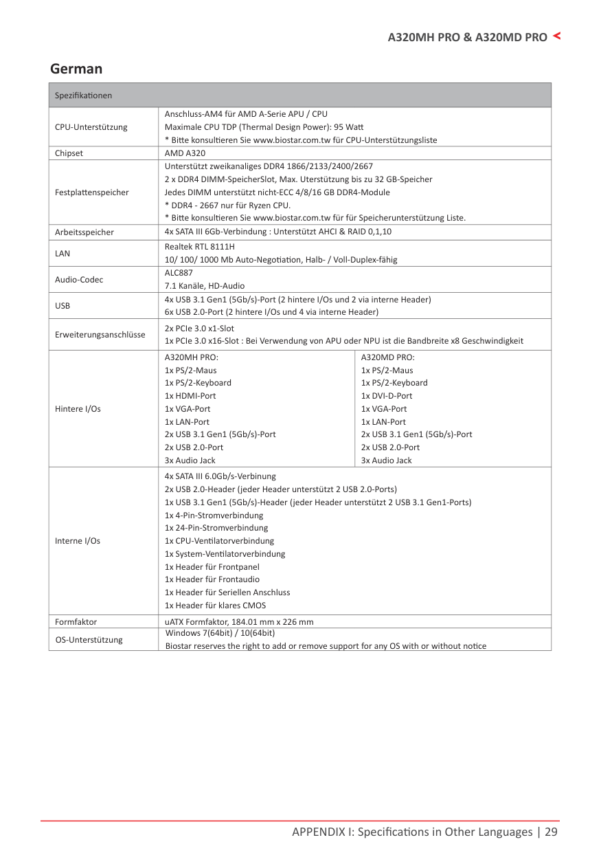
German
|Spezifikationen|Spezifikationen|Spezifikationen| |---|---|---| |CPU-Unterstützung|Anschluss-AM4 für AMD A-Serie APU / CPU Maximale CPU TDP (Thermal Design Power): 95 Watt
* Bitte konsultieren Sie www.biostar.com.tw für CPU-Unterstützungsliste|Anschluss-AM4 für AMD A-Serie APU / CPU Maximale CPU TDP (Thermal Design Power): 95 Watt
* Bitte konsultieren Sie www.biostar.com.tw für CPU-Unterstützungsliste| |Chipset|AMD A320|AMD A320| |Festplattenspeicher|Unterstützt zweikanaliges DDR4 1866/2133/2400/2667 2 x DDR4 DIMM-SpeicherSlot, Max. Uterstützung bis zu 32 GB-Speicher Jedes DIMM unterstützt nicht-ECC 4/8/16 GB DDR4-Module
* DDR4 - 2667 nur für Ryzen CPU.
* Bitte konsultieren Sie www.biostar.com.tw für für Speicherunterstützung Liste.
|Unterstützt zweikanaliges DDR4 1866/2133/2400/2667 2 x DDR4 DIMM-SpeicherSlot, Max. Uterstützung bis zu 32 GB-Speicher Jedes DIMM unterstützt nicht-ECC 4/8/16 GB DDR4-Module
* DDR4 - 2667 nur für Ryzen CPU.
* Bitte konsultieren Sie www.biostar.com.tw für für Speicherunterstützung Liste.
| |Arbeitsspeicher|4x SATA III 6Gb-Verbindung : Unterstützt AHCI & RAID 0,1,10|4x SATA III 6Gb-Verbindung : Unterstützt AHCI & RAID 0,1,10| |LAN|Realtek RTL 8111H 10/ 100/ 1000 Mb Auto-Negotiation, Halb- / Voll-Duplex-fähig|Realtek RTL 8111H 10/ 100/ 1000 Mb Auto-Negotiation, Halb- / Voll-Duplex-fähig| |Audio-Codec|ALC887 7.1 Kanäle, HD-Audio|ALC887 7.1 Kanäle, HD-Audio| |USB|4x USB 3.1 Gen1 (5Gb/s)-Port (2 hintere I/Os und 2 via interne Header) 6x USB 2.0-Port (2 hintere I/Os und 4 via interne Header)|4x USB 3.1 Gen1 (5Gb/s)-Port (2 hintere I/Os und 2 via interne Header) 6x USB 2.0-Port (2 hintere I/Os und 4 via interne Header)| |Erweiterungsanschlüsse|2x PCIe 3.0 x1-Slot 1x PCIe 3.0 x16-Slot : Bei Verwendung von APU oder NPU ist die Bandbreite x8 Geschwindigkeit|2x PCIe 3.0 x1-Slot 1x PCIe 3.0 x16-Slot : Bei Verwendung von APU oder NPU ist die Bandbreite x8 Geschwindigkeit| |Hintere I/Os|A320MH PRO: 1x PS/2-Maus 1x PS/2-Keyboard 1x HDMI-Port
1x VGA-Port
1x LAN-Port
2x USB 3.1 Gen1 (5Gb/s)-Port
2x USB 2.0-Port
3x Audio Jack
|A320MD PRO: 1x PS/2-Maus 1x PS/2-Keyboard 1x DVI-D-Port
1x VGA-Port
1x LAN-Port
2x USB 3.1 Gen1 (5Gb/s)-Port
2x USB 2.0-Port
3x Audio Jack
| |Interne I/Os|4x SATA III 6.0Gb/s-Verbinung 2x USB 2.0-Header (jeder Header unterstützt 2 USB 2.0-Ports) 1x USB 3.1 Gen1 (5Gb/s)-Header (jeder Header unterstützt 2 USB 3.1 Gen1-Ports) 1x 4-Pin-Stromverbindung 1x 24-Pin-Stromverbindung 1x CPU-Ventilatorverbindung 1x System-Ventilatorverbindung 1x Header für Frontpanel 1x Header für Frontaudio 1x Header für Seriellen Anschluss 1x Header für klares CMOS|4x SATA III 6.0Gb/s-Verbinung 2x USB 2.0-Header (jeder Header unterstützt 2 USB 2.0-Ports) 1x USB 3.1 Gen1 (5Gb/s)-Header (jeder Header unterstützt 2 USB 3.1 Gen1-Ports) 1x 4-Pin-Stromverbindung 1x 24-Pin-Stromverbindung 1x CPU-Ventilatorverbindung 1x System-Ventilatorverbindung 1x Header für Frontpanel 1x Header für Frontaudio 1x Header für Seriellen Anschluss 1x Header für klares CMOS| |Formfaktor|uATX Formfaktor, 184.01 mm x 226 mm|uATX Formfaktor, 184.01 mm x 226 mm| |OS-Unterstützung|Windows 7(64bit) / 10(64bit) Biostar reserves the right to add or remove support for any OS with or without notice|Windows 7(64bit) / 10(64bit) Biostar reserves the right to add or remove support for any OS with or without notice|
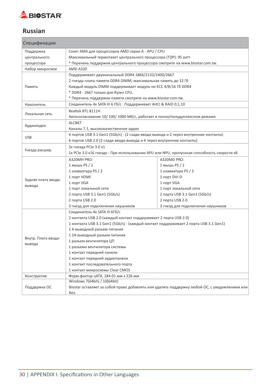
Russian
|Спецификации|Спецификации|Спецификации| |---|---|---| |Поддержка центрального процессора|Сокет AM4 для процессоров AMD серии A - APU / CPU Максимальный термопакет центрального процессора (TDP): 95 ватт
* Перечень поддержки центрального процессора смотрите на www.biostar.com.tw.|Сокет AM4 для процессоров AMD серии A - APU / CPU Максимальный термопакет центрального процессора (TDP): 95 ватт
* Перечень поддержки центрального процессора смотрите на www.biostar.com.tw.| |Набор микросхем|AMD A320|AMD A320| |Память|Поддерживает двухканальный DDR4 1866/2133/2400/2667 2 гнезда платы памяти DDR4 DIMM, максимальная память до 32 Гб Каждый модуль DIMM поддерживает модуль не-ECC 4/8/16 Гб DDR4
* DDR4 - 2667 только для Ryzen CPU.
* Перечень поддержки памяти смотрите на www.biostar.com.tw.
|Поддерживает двухканальный DDR4 1866/2133/2400/2667 2 гнезда платы памяти DDR4 DIMM, максимальная память до 32 Гб Каждый модуль DIMM поддерживает модуль не-ECC 4/8/16 Гб DDR4
* DDR4 - 2667 только для Ryzen CPU.
* Перечень поддержки памяти смотрите на www.biostar.com.tw.
| |Накопитель|Соединитель 4x SATA III 6 Гб/с : Поддерживает AHCI & RAID 0,1,10|Соединитель 4x SATA III 6 Гб/с : Поддерживает AHCI & RAID 0,1,10| |Локальная сеть|Realtek RTL 8111H Автосогласование 10/ 100/ 1000 Мб/с, работает в полно/полудуплексном режиме|Realtek RTL 8111H Автосогласование 10/ 100/ 1000 Мб/с, работает в полно/полудуплексном режиме| |Аудиокодек|ALC887 Каналы 7.1, высококачественное аудио|ALC887 Каналы 7.1, высококачественное аудио| |USB|4 портов USB 3.1 Gen1 (5Gb/s) - (2 сзади ввода-вывода и 2 через внутренние контакты) 6 портов USB 2.0 (2 сзади ввода-вывода и 4 через внутренние контакты)|4 портов USB 3.1 Gen1 (5Gb/s) - (2 сзади ввода-вывода и 2 через внутренние контакты) 6 портов USB 2.0 (2 сзади ввода-вывода и 4 через внутренние контакты)| |Гнезда расшир.|2x гнезда PCIe 3.0 x1 1x PCIe 3.0 x16 гнездо : При использовании APU или NPU, пропускная способность скорости x8|2x гнезда PCIe 3.0 x1 1x PCIe 3.0 x16 гнездо : При использовании APU или NPU, пропускная способность скорости x8| |Задняя плата вводавывода|A320MH PRO: 1 мышь PS / 2 1 клавиатура PS / 2 1 порт HDMI
1 порт VGA
1 порт локальной сети
2 порта USB 3.1 Gen1 (5Gb/s)
2 порта USB 2.0
3 гнезд для подключения наушников
|A320MD PRO: 1 мышь PS / 2 1 клавиатура PS / 2 1 порт DVI-D
1 порт VGA
1 порт локальной сети
2 порта USB 3.1 Gen1 (5Gb/s)
2 порта USB 2.0
3 гнезд для подключения наушников
| |Внутр. Плата вводавывода|Соединитель 4x SATA III 6Гб/с 2 контакта USB 2.0 (каждый контакт поддерживает 2 порта USB 2.0) 1 контакта USB 3.1 Gen1 (5Gb/s) - (каждый контакт поддерживает 2 порта USB 3.1 Gen1) 1 4-выводный разъем питания 1 24-выводный разъем питания 1 разъем вентилятора ЦП 1 разъема вентилятора системы 1 контакт передней панели 1 контакт передней аудиопанели 1 контакт последовательного порта 1 контакт микросхемы Clear CMOS|Соединитель 4x SATA III 6Гб/с 2 контакта USB 2.0 (каждый контакт поддерживает 2 порта USB 2.0) 1 контакта USB 3.1 Gen1 (5Gb/s) - (каждый контакт поддерживает 2 порта USB 3.1 Gen1) 1 4-выводный разъем питания 1 24-выводный разъем питания 1 разъем вентилятора ЦП 1 разъема вентилятора системы 1 контакт передней панели 1 контакт передней аудиопанели 1 контакт последовательного порта 1 контакт микросхемы Clear CMOS| |Конструктив|Форм-фактор uATX, 184.01 мм x 226 мм|Форм-фактор uATX, 184.01 мм x 226 мм| |Поддержка ОС|Windows 7(64bit) / 10(64bit) Biostar оставляет за собой право добавлять или удалять поддержку любой ОС, с уведомлением или без.|Windows 7(64bit) / 10(64bit) Biostar оставляет за собой право добавлять или удалять поддержку любой ОС, с уведомлением или без.|
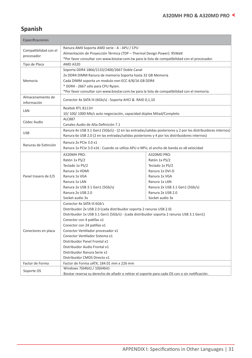
Spanish
|Especificaciones|Especificaciones|Especificaciones| |---|---|---| |Compatibilidad con el procesador|Ranura AM4 Soporta AMD serie - A - APU / CPU Alimentación de Proyección Térmica (TDP – Thermal Design Power): 95Watt
*Por favor consultar con www.biostar.com.tw para la lista de compatibilidad con el procesador.|Ranura AM4 Soporta AMD serie - A - APU / CPU Alimentación de Proyección Térmica (TDP – Thermal Design Power): 95Watt
*Por favor consultar con www.biostar.com.tw para la lista de compatibilidad con el procesador.| |Tipo de Placa|AMD A320|AMD A320| |Memoria|Soporta DDR4 1866/2133/2400/2667 Doble Canal 2x DDR4 DIMM Ranura de memoria Soporta hasta 32 GB Memoria Cada DIMM soporta un modulo non-ECC 4/8/16 GB DDR4
* DDR4 - 2667 sólo para CPU Ryzen.
*Por favor consultar con www.biostar.com.tw para la lista de compatibilidad con el memoria.
|Soporta DDR4 1866/2133/2400/2667 Doble Canal 2x DDR4 DIMM Ranura de memoria Soporta hasta 32 GB Memoria Cada DIMM soporta un modulo non-ECC 4/8/16 GB DDR4
* DDR4 - 2667 sólo para CPU Ryzen.
*Por favor consultar con www.biostar.com.tw para la lista de compatibilidad con el memoria.
| |Almacenamiento de información|Conector 4x SATA III (6Gb/s) : Soporta AHCI & RAID 0,1,10|Conector 4x SATA III (6Gb/s) : Soporta AHCI & RAID 0,1,10|
|LAN|Realtek RTL 8111H 10/ 100/ 1000 Mb/s auto negociación, capacidad dúplex Mitad/Completo|Realtek RTL 8111H 10/ 100/ 1000 Mb/s auto negociación, capacidad dúplex Mitad/Completo| |Códec Audio|ALC887 Canales Audio de Alta Definición 7.1|ALC887 Canales Audio de Alta Definición 7.1| |USB|Ranura 4x USB 3.1 Gen1 (5Gb/s) - (2 en las entradas/salidas posteriores y 2 por los distribuidores internos) Ranura 6x USB 2.0 (2 en las entradas/salidas posteriores y 4 por los distribuidores internos)|Ranura 4x USB 3.1 Gen1 (5Gb/s) - (2 en las entradas/salidas posteriores y 2 por los distribuidores internos) Ranura 6x USB 2.0 (2 en las entradas/salidas posteriores y 4 por los distribuidores internos)| |Ranuras de Extinción|Ranura 2x PCIe 3.0 x1 Ranura 1x PCIe 3.0 x16 : Cuando se utiliza APU o NPU, el ancho de banda es x8 velocidad|Ranura 2x PCIe 3.0 x1 Ranura 1x PCIe 3.0 x16 : Cuando se utiliza APU o NPU, el ancho de banda es x8 velocidad| |Panel trasero de E/S|A320MH PRO: Ratón 1x PS/2 Teclado 1x PS/2 Ranura 1x HDMI
Ranura 1x VGA
Ranura 1x LAN
Ranura 2x USB 3.1 Gen1 (5Gb/s)
Ranura 2x USB 2.0 Socket audio 3x
|A320MD PRO: Ratón 1x PS/2 Teclado 1x PS/2 Ranura 1x DVI-D
Ranura 1x VGA
Ranura 1x LAN
Ranura 2x USB 3.1 Gen1 (5Gb/s)
Ranura 2x USB 2.0 Socket audio 3x
| |Conectores en placa|Conector 4x SATA III 6Gb’s Distribuidor 2x USB 2.0 (cada distribuidor soporta 2 ranuras USB 2.0) Distribuidor 1x USB 3.1 Gen1 (5Gb/s) - (cada distribuidor soporta 2 ranuras USB 3.1 Gen1) Conector con 4 patillas x1 Conector con 24 patillas x1 Conector Ventilador procesador x1 Conector Ventilador Sistema x1 Distribuidor Panel Frontal x1 Distribuidor Audio Frontal x1 Distribuidor Ranura Serie x1 Distribuidor CMOS Directo x1|Conector 4x SATA III 6Gb’s Distribuidor 2x USB 2.0 (cada distribuidor soporta 2 ranuras USB 2.0) Distribuidor 1x USB 3.1 Gen1 (5Gb/s) - (cada distribuidor soporta 2 ranuras USB 3.1 Gen1) Conector con 4 patillas x1 Conector con 24 patillas x1 Conector Ventilador procesador x1 Conector Ventilador Sistema x1 Distribuidor Panel Frontal x1 Distribuidor Audio Frontal x1 Distribuidor Ranura Serie x1 Distribuidor CMOS Directo x1| |Factor de Forma|Factor de Forma uATX, 184.01 mm x 226 mm|Factor de Forma uATX, 184.01 mm x 226 mm| |Soporte OS|Windows 7(64bit) / 10(64bit) Biostar reserva su derecho de añadir o retirar el soporte para cada OS con o sin notificación.|Windows 7(64bit) / 10(64bit) Biostar reserva su derecho de añadir o retirar el soporte para cada OS con o sin notificación.|
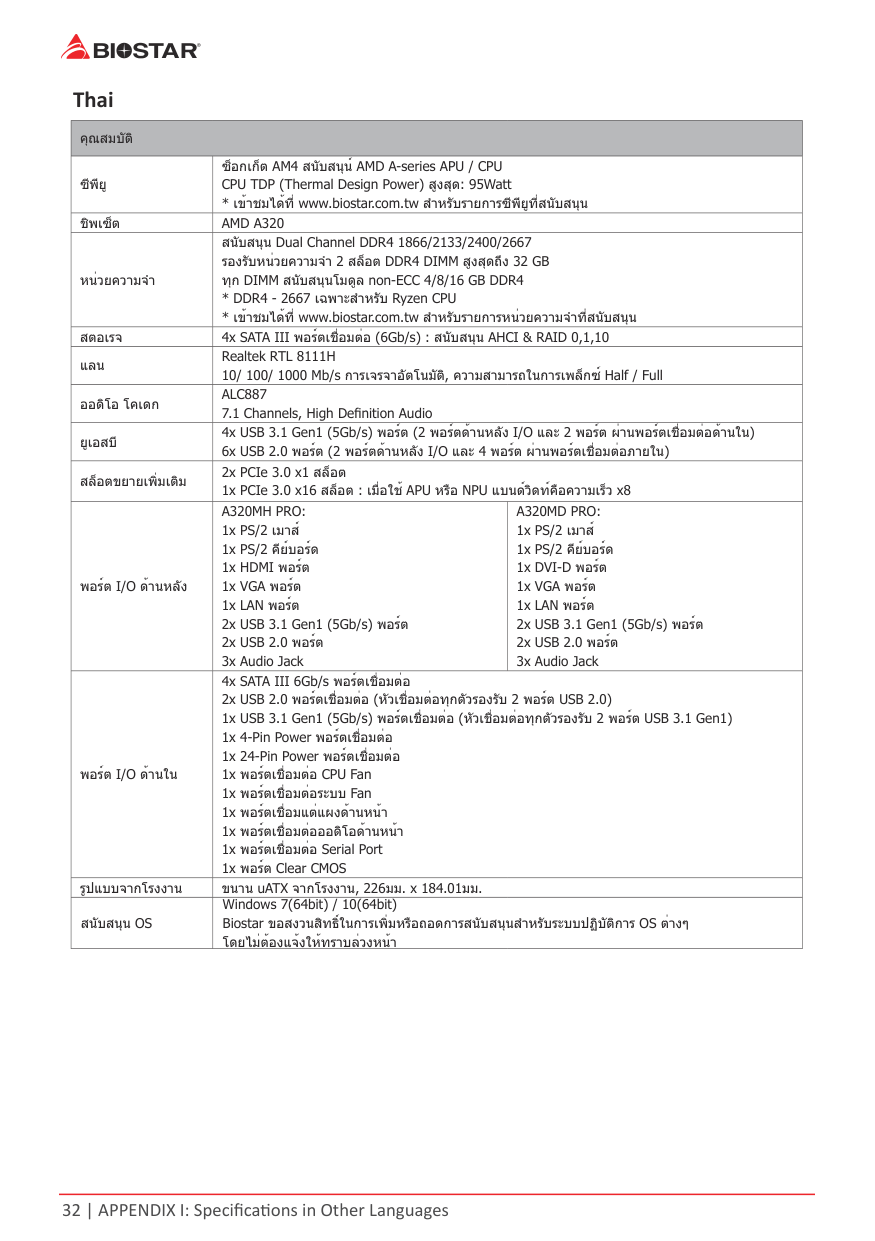
Thai
|คุณสมบัติ|คุณสมบัติ|คุณสมบัติ| |---|---|---| |ซีพียู|ซ็อกเก็ต AM4 สนับสนุน์ AMD A-series APU / CPU CPU TDP (Thermal Design Power) สูงสุด: 95Watt
* เข้าชมได้ที www.biostar.com.tw สำาหรับรายการซีพียูที่สนับสนุน|ซ็อกเก็ต AM4 สนับสนุน์ AMD A-series APU / CPU CPU TDP (Thermal Design Power) สูงสุด: 95Watt
* เข้าชมได้ที www.biostar.com.tw สำาหรับรายการซีพียูที่สนับสนุน| |ชิพเซ็ต|AMD A320|AMD A320| |หน่วยความจำา|สนับสนุน Dual Channel DDR4 1866/2133/2400/2667 รองรับหน่วยความจำา 2 สล็อต DDR4 DIMM สูงสุดถึง 32 GB ทุก DIMM สนับสนุนโมดูล non-ECC 4/8/16 GB DDR4
* DDR4 - 2667 เฉพาะสำาหรับ Ryzen CPU
* เข้าชมได้ที www.biostar.com.tw สำาหรับรายการหน่วยความจำาที่สนับสนุน
|สนับสนุน Dual Channel DDR4 1866/2133/2400/2667 รองรับหน่วยความจำา 2 สล็อต DDR4 DIMM สูงสุดถึง 32 GB ทุก DIMM สนับสนุนโมดูล non-ECC 4/8/16 GB DDR4
* DDR4 - 2667 เฉพาะสำาหรับ Ryzen CPU
* เข้าชมได้ที www.biostar.com.tw สำาหรับรายการหน่วยความจำาที่สนับสนุน
| |สตอเรจ|4x SATA III พอร์ตเชือมต่อ (6Gb/s) : สนับสนุน AHCI & RAID 0,1,10|4x SATA III พอร์ตเชือมต่อ (6Gb/s) : สนับสนุน AHCI & RAID 0,1,10| |แลน|Realtek RTL 8111H 10/ 100/ 1000 Mb/s การเจรจาอัตโนมัติ, ความสามารถในการเพล็กซ์ Half / Full|Realtek RTL 8111H 10/ 100/ 1000 Mb/s การเจรจาอัตโนมัติ, ความสามารถในการเพล็กซ์ Half / Full| |ออดิโอ โคเดก|ALC887 7.1 Channels, High Definition Audio|ALC887 7.1 Channels, High Definition Audio| |ยูเอสบี|4x USB 3.1 Gen1 (5Gb/s) พอร์ต (2 พอร์ตด้านหลัง I/O และ 2 พอร์ต ผ่านพอร์ตเชื่อมต่อด้านใน) 6x USB 2.0 พอร์ต (2 พอร์ตด้านหลัง I/O และ 4 พอร์ต ผ่านพอร์ตเชื่อมต่อภายใน)|4x USB 3.1 Gen1 (5Gb/s) พอร์ต (2 พอร์ตด้านหลัง I/O และ 2 พอร์ต ผ่านพอร์ตเชื่อมต่อด้านใน) 6x USB 2.0 พอร์ต (2 พอร์ตด้านหลัง I/O และ 4 พอร์ต ผ่านพอร์ตเชื่อมต่อภายใน)| |สล็อตขยายเพิ่มเติม|2x PCIe 3.0 x1 สล็อต 1x PCIe 3.0 x16 สล็อต : เมือใช้ APU หรือ NPU แบนด์วิดท์คือความเร็ว x8|2x PCIe 3.0 x1 สล็อต 1x PCIe 3.0 x16 สล็อต : เมือใช้ APU หรือ NPU แบนด์วิดท์คือความเร็ว x8| |พอร์ต I/O ด้านหลัง|A320MH PRO: 1x PS/2 เมาส์ 1x PS/2 คีย์บอร์ด 1x HDMI พอร์ต
1x VGA พอร์ต
1x LAN พอร์ต
2x USB 3.1 Gen1 (5Gb/s) พอร์ต
2x USB 2.0 พอร์ต
3x Audio Jack
|A320MD PRO: 1x PS/2 เมาส์ 1x PS/2 คีย์บอร์ด 1x DVI-D พอร์ต
1x VGA พอร์ต
1x LAN พอร์ต
2x USB 3.1 Gen1 (5Gb/s) พอร์ต
2x USB 2.0 พอร์ต
3x Audio Jack
| |พอร์ต I/O ด้านใน|4x SATA III 6Gb/s พอร์ตเชือมต่อ 2x USB 2.0 พอร์ตเชื่อมต่อ (หัวเชื่อมต่อทุกตัวรองรับ 2 พอร์ต USB 2.0) 1x USB 3.1 Gen1 (5Gb/s) พอร์ตเชื่อมต่อ (หัวเชื่อมต่อทุกตัวรองรับ 2 พอร์ต USB 3.1 Gen1) 1x 4-Pin Power พอร์ตเชือมต่อ 1x 24-Pin Power พอร์ตเชือมต่อ 1x พอร์ตเชือมต่อ CPU Fan 1x พอร์ตเชือมต่อระบบ Fan 1x พอร์ตเชื่อมแต่แผงด้านหน้า 1x พอร์ตเชื่อมต่อออดิโอด้านหน้า 1x พอร์ตเชือมต่อ Serial Port 1x พอร์ต Clear CMOS|4x SATA III 6Gb/s พอร์ตเชือมต่อ 2x USB 2.0 พอร์ตเชื่อมต่อ (หัวเชื่อมต่อทุกตัวรองรับ 2 พอร์ต USB 2.0) 1x USB 3.1 Gen1 (5Gb/s) พอร์ตเชื่อมต่อ (หัวเชื่อมต่อทุกตัวรองรับ 2 พอร์ต USB 3.1 Gen1) 1x 4-Pin Power พอร์ตเชือมต่อ 1x 24-Pin Power พอร์ตเชือมต่อ 1x พอร์ตเชือมต่อ CPU Fan 1x พอร์ตเชือมต่อระบบ Fan 1x พอร์ตเชื่อมแต่แผงด้านหน้า 1x พอร์ตเชื่อมต่อออดิโอด้านหน้า 1x พอร์ตเชือมต่อ Serial Port 1x พอร์ต Clear CMOS| |รูปแบบจากโรงงาน|ขนาน uATX จากโรงงาน, 226มม. x 184.01มม.|ขนาน uATX จากโรงงาน, 226มม. x 184.01มม.| |สนับสนุน OS|Windows 7(64bit) / 10(64bit) Biostar ขอสงวนสิทธิในการเพิมหรือถอดการสนับสนุนสำาหรับระบบปฏิบัติการ OS ต่างๆ โดยไม่ต้องแจ้งให้ทราบล่วงหน้า|Windows 7(64bit) / 10(64bit) Biostar ขอสงวนสิทธิในการเพิมหรือถอดการสนับสนุนสำาหรับระบบปฏิบัติการ OS ต่างๆ โดยไม่ต้องแจ้งให้ทราบล่วงหน้า|
FCC条款 依照FCC条款第15部分的规定,本装置已经通过测试并且符合Class B级数字装置的限制。 此条款限制了在安装过程中可能造成的有害射频干扰并提供了合理的防范措施。本装置在 使用时会产生无线射频辐射,如果没有依照本手册的指示安装和使用,可能会与无线通讯 装置产生干扰。然而,并不保证在特定的安装下不会发生任何干扰。 如果关闭和重新开启本设备后,仍确定本装置造成接收广播或电视的干扰,用户可以使用 以下列表中的一种或多种方法来减少干扰:
本用户手册内容的变更,恕不另行通知,制造商没有解释的义务。 本用户手册的所有内容若有任何错误,制造商没有义务为其承担任何责任。所有商标和产 品名称均有其各自所有权。 未经过书面许可,不得以任何形式(部分或全部)复制此手册信息。
#### 免责说明
所有。我们本着对用户负责的态度, 精心地编写该手册,但不保证本手册的内容完全准确无误。BIOSTAR
本手册内容系BIOSTAR
知识产权,版权归BIOSTAR
®
®
有权在不知会用户
®
的前提下对产品不断地进行改良、升级及对手册内容进行修正,实际状况请以产品实物为 准。本手册为纯技术文档,无任何暗示及影射第三方之内容,且不承担排版错误导致的用 户理解歧义。本手册中所涉及的第三方注册商标所有权归其制造商或品牌所有人。
CE符合性简短声明
我们声明此产品符合现行标准,并满足2004/108/CE, 2006/95/CE 和1999/05/CE指令规定的所有基本要求。
#### 防静电操作规则
静电可能严重损坏您的设备,在处理主板以及其它的系统设备的时候要特别注意,避免和 主板上的系统组件的不必要接触,保证在抗静电的环境下工作,避免静电放电可能对主板 造成损坏,当在您的机箱中插入或者移除设备时,请保证电源处于断开状态,厂商对于不 遵照本操作规则或者不遵守安全规范而对主板造成的损坏不负责。
| | |---|
目录
#### 第一章: 主板介绍 3
#### 第二章: 硬件安装 7
#### 第三章: UEFI BIOS和软件 17
#### 第四章:帮助信息 24
#### 附录I:产品中有毒有害物质或元素的名称及含量 28
第一章: 主板介绍
» 此清单可能因销售区域或主板型号不同而异,相关标配详情请咨询当地经销商。
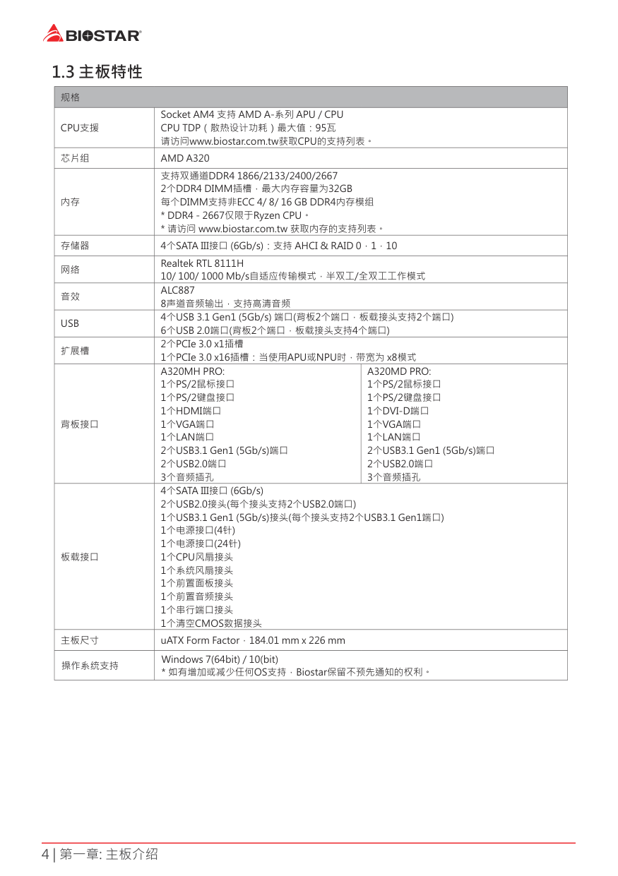
1 3 主板特性
|规格|规格|规格| |---|---|---| |CPU支援|Socket AM4 支持 AMD A-系列 APU / CPU CPU TDP(散热设计功耗)最大值:95瓦 请访问www.biostar.com.tw获取CPU的支持列表。|Socket AM4 支持 AMD A-系列 APU / CPU CPU TDP(散热设计功耗)最大值:95瓦 请访问www.biostar.com.tw获取CPU的支持列表。| |芯片组|AMD A320|AMD A320| |内存|支持双通道DDR4 1866/2133/2400/2667 2个DDR4 DIMM插槽,最大内存容量为32GB 每个DIMM支持非ECC 4/ 8/ 16 GB DDR4内存模组
* DDR4 - 2667仅限于Ryzen CPU。
* 请访问 www.biostar.com.tw 获取内存的支持列表。
|支持双通道DDR4 1866/2133/2400/2667 2个DDR4 DIMM插槽,最大内存容量为32GB 每个DIMM支持非ECC 4/ 8/ 16 GB DDR4内存模组
* DDR4 - 2667仅限于Ryzen CPU。
* 请访问 www.biostar.com.tw 获取内存的支持列表。
| |存储器|4个SATA III接口 (6Gb/s):支持 AHCI & RAID 0,1,10|4个SATA III接口 (6Gb/s):支持 AHCI & RAID 0,1,10| |网络|Realtek RTL 8111H 10/ 100/ 1000 Mb/s自适应传输模式,半双工/全双工工作模式|Realtek RTL 8111H 10/ 100/ 1000 Mb/s自适应传输模式,半双工/全双工工作模式| |音效|ALC887 8声道音频输出,支持高清音频|ALC887 8声道音频输出,支持高清音频| |USB|4个USB 3.1 Gen1 (5Gb/s) 端口(背板2个端口,板载接头支持2个端口) 6个USB 2.0端口(背板2个端口,板载接头支持4个端口)|4个USB 3.1 Gen1 (5Gb/s) 端口(背板2个端口,板载接头支持2个端口) 6个USB 2.0端口(背板2个端口,板载接头支持4个端口)| |扩展槽|2个PCIe 3.0 x1插槽 1个PCIe 3.0 x16插槽:当使用APU或NPU时,带宽为 x8模式|2个PCIe 3.0 x1插槽 1个PCIe 3.0 x16插槽:当使用APU或NPU时,带宽为 x8模式| |背板接口|A320MH PRO: 1个PS/2鼠标接口 1个PS/2键盘接口 1个HDMI端口
1个VGA端口
1个LAN端口
2个USB3.1 Gen1 (5Gb/s)端口
2个USB2.0端口
3个音频插孔
|A320MD PRO: 1个PS/2鼠标接口 1个PS/2键盘接口 1个DVI-D端口
1个VGA端口
1个LAN端口
2个USB3.1 Gen1 (5Gb/s)端口
2个USB2.0端口
3个音频插孔
| |板载接口|4个SATA III接口 (6Gb/s) 2个USB2.0接头(每个接头支持2个USB2.0端口) 1个USB3.1 Gen1 (5Gb/s)接头(每个接头支持2个USB3.1 Gen1端口) 1个电源接口(4针) 1个电源接口(24针) 1个CPU风扇接头 1个系统风扇接头 1个前置面板接头 1个前置音频接头 1个串行端口接头 1个清空CMOS数据接头|4个SATA III接口 (6Gb/s) 2个USB2.0接头(每个接头支持2个USB2.0端口) 1个USB3.1 Gen1 (5Gb/s)接头(每个接头支持2个USB3.1 Gen1端口) 1个电源接口(4针) 1个电源接口(24针) 1个CPU风扇接头 1个系统风扇接头 1个前置面板接头 1个前置音频接头 1个串行端口接头 1个清空CMOS数据接头| |主板尺寸|uATX Form Factor,184.01 mm x 226 mm|uATX Form Factor,184.01 mm x 226 mm| |操作系统支持|Windows 7(64bit) / 10(bit)
* 如有增加或减少任何OS支持,Biostar保留不预先通知的权利。|Windows 7(64bit) / 10(bit)
* 如有增加或减少任何OS支持,Biostar保留不预先通知的权利。|
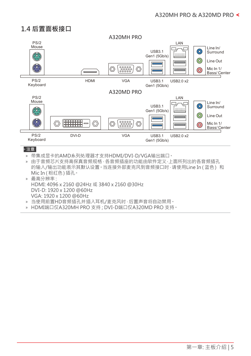
1 4 后置面板接口A320MH PRO
##### A320MD PRO
» 带集成显卡的AMD系列处理器才支持HDMI/DVI-D/VGA输出端口。 » 由于音频芯片支持高保真音频规格,各音频插座的功能由软件定义,上面所列出的各音频插孔
的输入/输出功能表示其默认设置。当连接外部麦克风到音频接口时,请使用Line In(蓝色) 和 Mic In(粉红色)插孔。
» 最 高分 辨 率: HDMI: 4096 x 2160 @24Hz 或 3840 x 2160 @30Hz DVI-D: 1920 x 1200 @60Hz VGA: 1920 x 1200 @60Hz
» 当使用前置HD音频插孔并插入耳机/麦克风时,后置声音将自动禁用。 » HDMI端口仅A320MH PRO 支持 ; DVI-D端口仅A320MD PRO 支持。
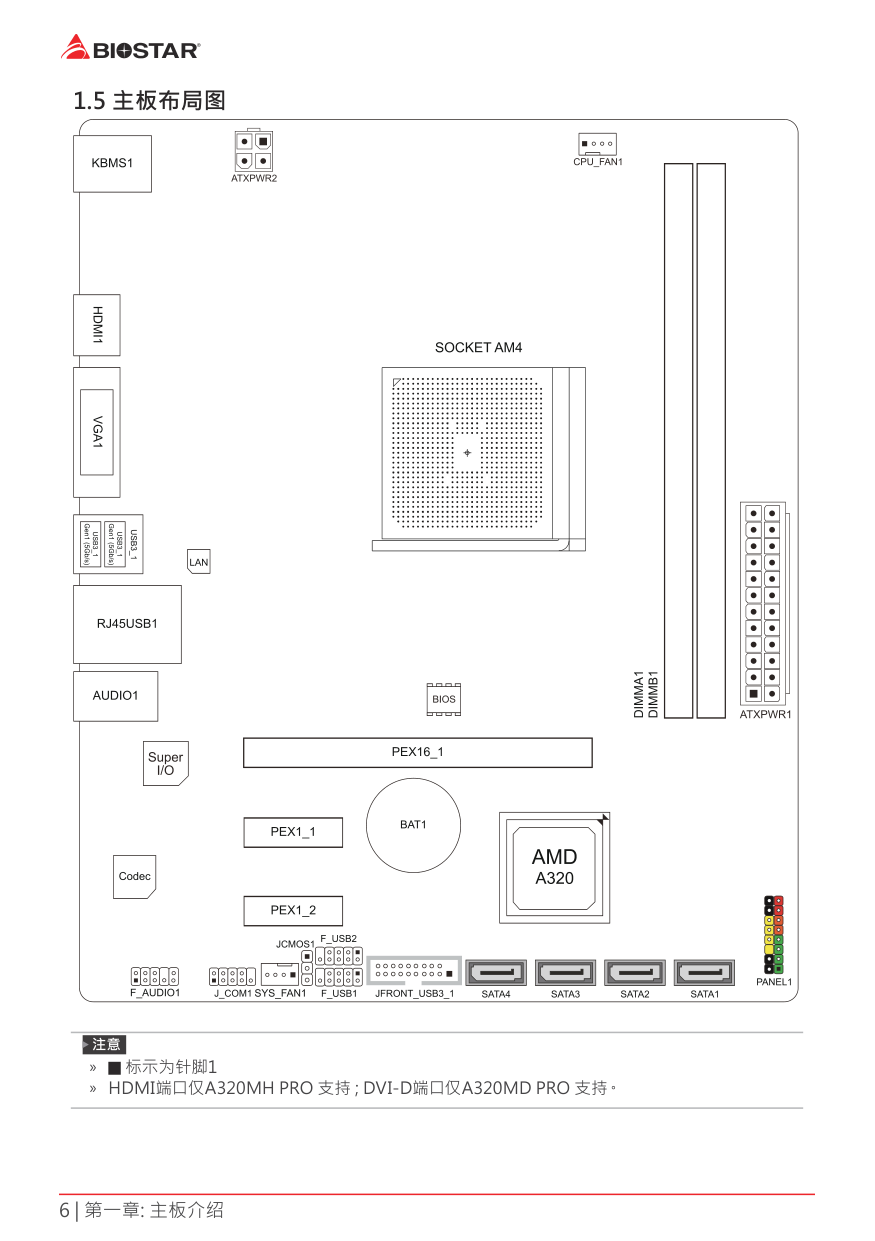
1 5 主板布局图
| | | |---|---| | | |
| | | | | | | | |---|---|---|---|---|---|---| | | | | | | | | | | | | | | | |
» 标示为针脚1 » HDMI端口仅A320MH PRO 支持 ; DVI-D端口仅A320MD PRO 支持。
第二章: 硬件安装
2 1 中央处理器(CPU)
| | | |---|---| | | |
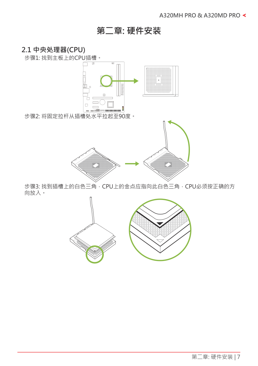
####### 步骤4: 固定CPU,将拉杆闭合。
» 请于拔除CPU插槽之前,关闭电源。
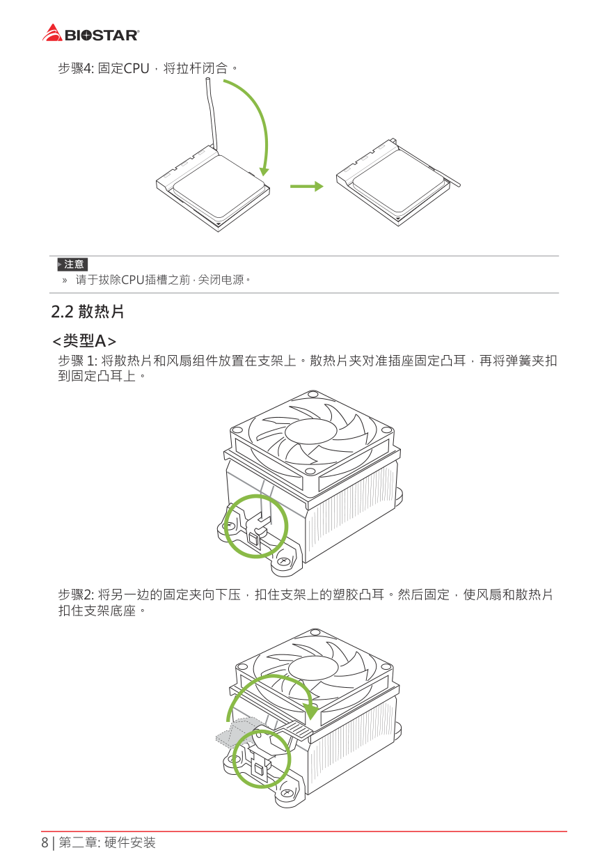
2 2 散热片
<类型A> 步骤 1: 将散热片和风扇组件放置在支架上。散热片夹对准插座固定凸耳,再将弹簧夹扣 到固定凸耳上。
步骤2: 将另一边的固定夹向下压,扣住支架上的塑胶凸耳。然后固定,使风扇和散热片 扣住支架底座。
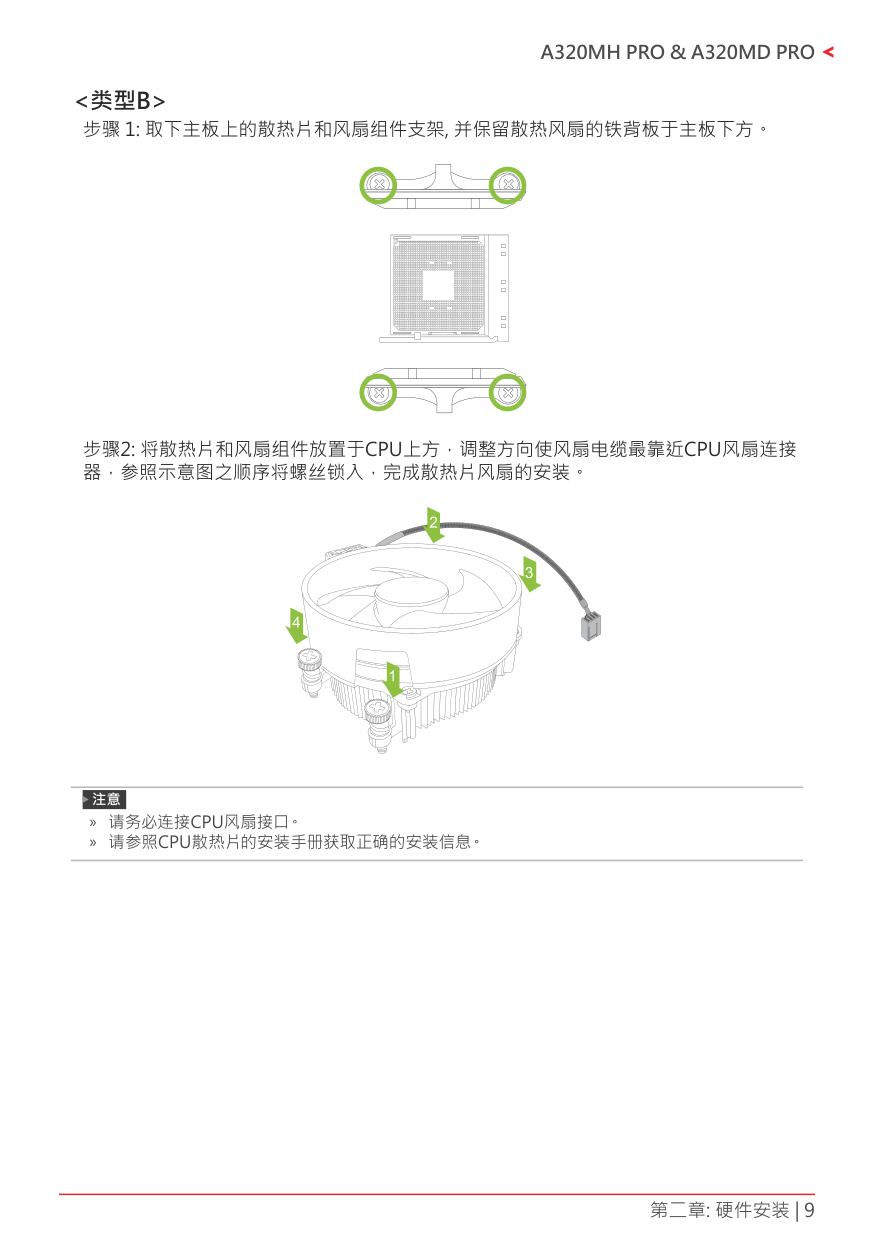
<类型B>
步骤 1: 取下主板上的散热片和风扇组件支架, 并保留散热风扇的铁背板于主板下方。
| | | |---|---| | | |
步骤2: 将散热片和风扇组件放置于CPU上方,调整方向使风扇电缆最靠近CPU风扇连接 器,参照示意图之顺序将螺丝锁入,完成散热片风扇的安装。
» 请务必连 接 C P U风 扇接口。 » 请参照CPU散热片的安装手册获取正确的安装信息。
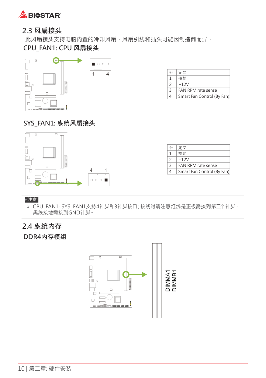
2 3 风扇接头此风扇接头支持电脑内置的冷却风扇,风扇引线和插头可能因制造商而异。
CPU_FAN1: CPU 风扇接头
| | | | | |---|---|---|---| | | | | |
|针|定义| |---|---| |1|接地| |2|+12V| |3|FAN RPM rate sense| |4|Smart Fan Control (By Fan)|
SYS_FAN1: 系统风扇接头
| | | | | |---|---|---|---| | | | | |
|针|定义| |---|---| |1|接地| |2|+12V| |3|FAN RPM rate sense| |4|Smart Fan Control (By Fan)|
» CPU_FAN1,SYS_FAN1支持4针脚和3针脚接口;接线时请注意红线是正极需接到第二个针脚, 黑线接地需接到GND针脚。
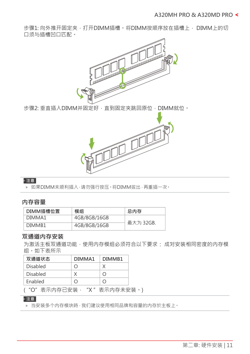
2 4 系统内存DDR4内存模组
| | | | | |---|---|---|---| | | | | |
» 如果DIMM未顺利插入,请勿强行按压。将DIMM拔出,再重插一次。
#### 内存容量
|DIMM插槽位置|模组|总内存|
|---|---|---| |DIMMA1 DIMMB1|4GB/8GB/16GB 4GB/8GB/16GB|最大为 32GB.| | | |最大为 32GB.|
双通道内存安装 为激活主板双通道功能,使用内存模组必须符合以下要求: 成对安装相同密度的内存模 组。如下表所示
|双通道状态|DIMMA1|DIMMB1| |---|---|---| |Disabled|O|X| |Disabled|X|O| |Enabled|O|O|
(“O”表示内存已安装,“X ”表示内存未安装。)
» 当安装多个内存模块時,我们建议使用相同品牌和容量的内存於主板上。
#### Ryzen - DDR最高频率支持表
|最高频率|DIMMA1|DIMMB1| |---|---|---| |DDR4-2667|SR|--| |DDR4-2667|DR|--| |DDR4-2667|SR|SR| |DDR4-2400|DR|DR|
» SR - Single-rank DIMM, 1R x4 or 1R x8。 » DR - Dual-rank DIMMs, 2R x4 or 2R x8。 » 为了更好的DDR4模块兼容性,请按照上述列表安装您的DDR4模块。
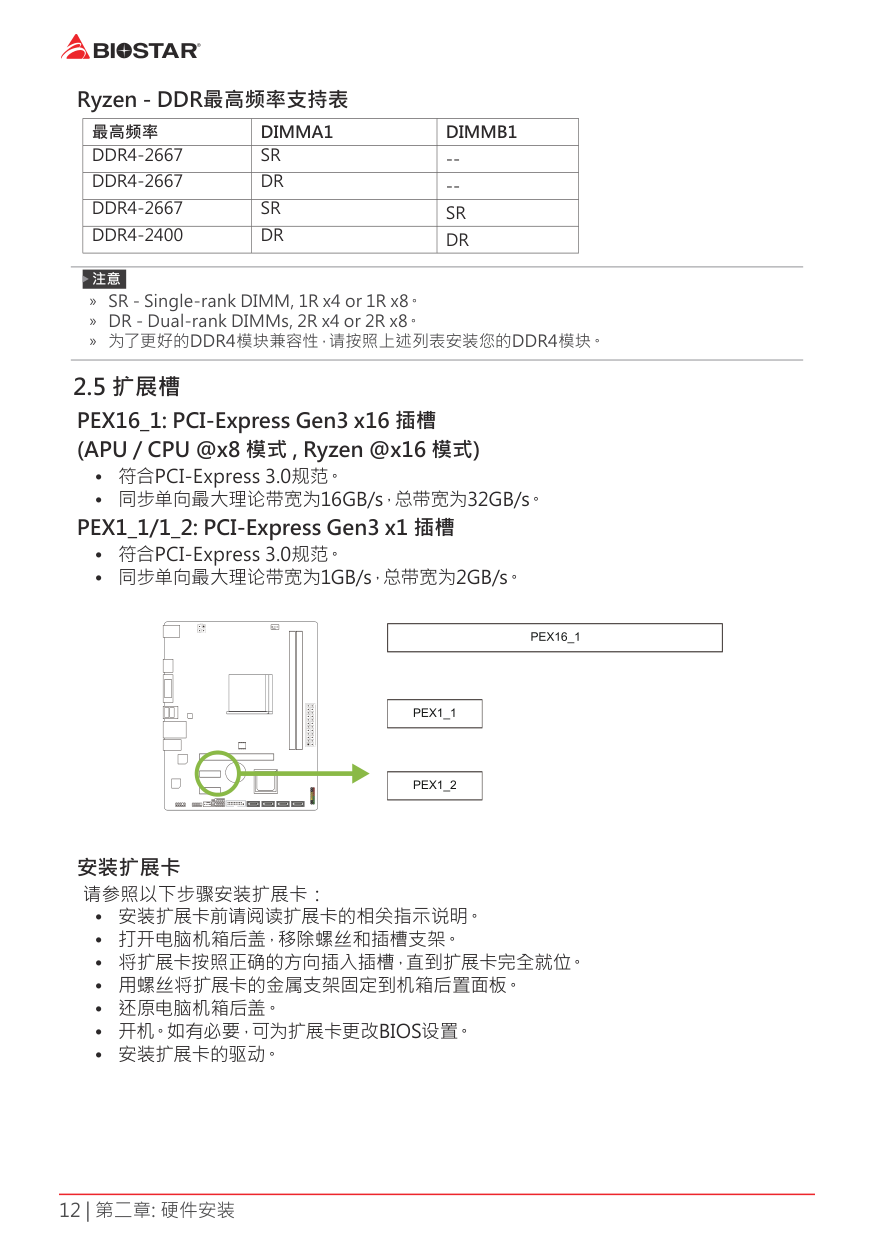
2 5 扩展槽PEX16_1: PCI-Express Gen3 x16 插槽(APU / CPU @x8 模式 , Ryzen @x16 模式)
| | | | | |---|---|---|---| | | | | |
#### 安装扩展卡
请参照以下步骤安装扩展卡:
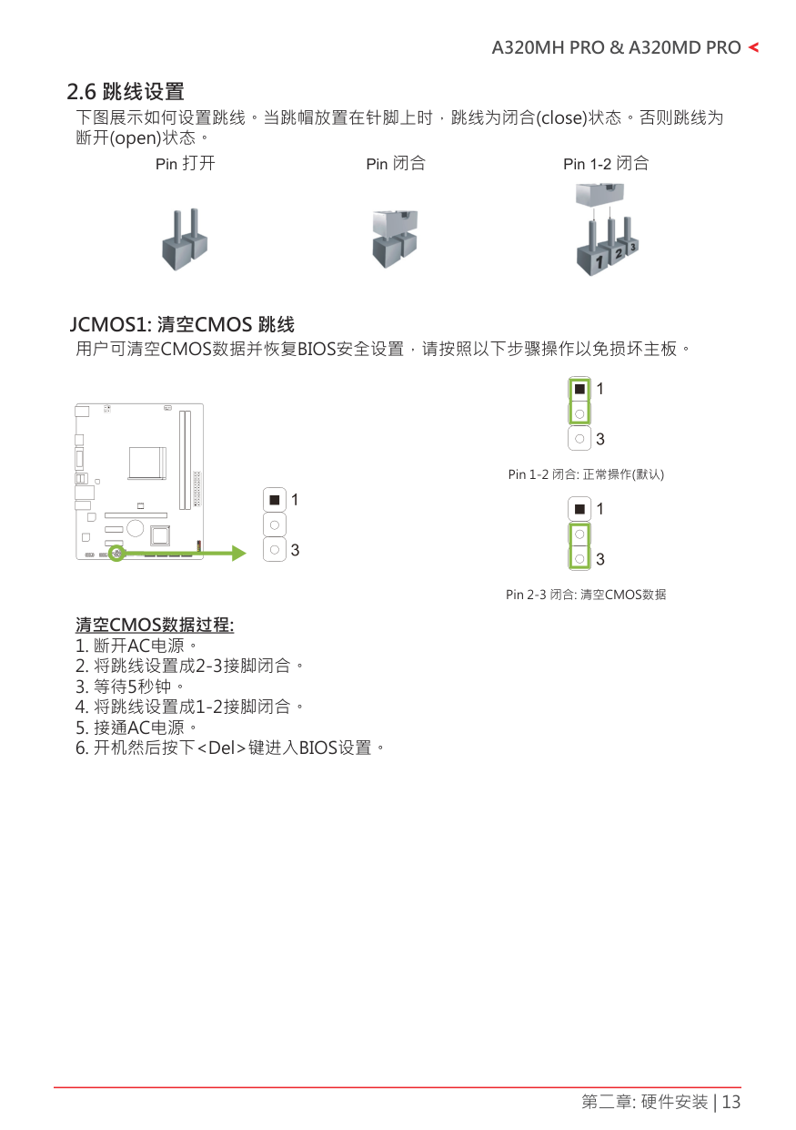
Pin 打开 Pin 闭合 Pin 1-2 闭合


#### JCMOS1: 清空CMOS 跳线
用户可清空CMOS数据并恢复BIOS安全设置,请按照以下步骤操作以免损坏主板。
| | | | | |---|---|---|---| | | | | |
2 7 接口和插槽
##### ATXPWR1: ATX电源接口为了更好的兼容性,我们建议使用标准的ATX24-pin电源供应此接口的电源。
|针|定义|针|定义| |---|---|---|---| |13|+3.3V|1|+3.3V| |14|-12V|2|+3.3V| |15|接地|3|接地| |16|PS_ON|4|+5V| |17|接地|5|接地| |18|接地|6|+5V| |19|接地|7|接地| |20|NC|8|PW_OK| |21|+5V|9|唤醒电压+5V| |22|+5V|10|+12V| |23|+5V|11|+12V| |24|接地|12|+3.3V|
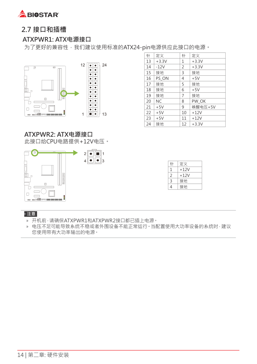
| | | | | |---|---|---|---| | | | | |
##### ATXPWR2: ATX电源接口此接口给CPU电路提供+12V电压。
| | | | | |---|---|---|---| | | | | |
|针|定义| |---|---| |1|+12V| |2|+12V| |3|接地| |4|接地|
» 开机前,请确保ATXPWR1和ATXPWR2接口都已插上电源。 » 电压不足可能导致系统不稳或者外围设备不能正常运行。当配置使用大功率设备的系统时,建议
您使用带有大功率输出的电源。
#### PANEL1: 前置面板接头
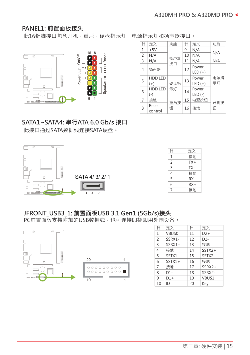
此16针脚接口包含开机,重启,硬盘指示灯,电源指示灯和扬声器接口。
|针|定义|功能|针|定义|功能| |---|---|---|---|---|---| |1|+5V|扬声器 接口|9|N/A|N/A| |2|N/A|扬声器 接口|10|N/A|N/A| |3|N/A|扬声器 接口|11|N/A|N/A| |4|扬声器|扬声器 接口|12|Power LED (+)|电源指 示灯| |5|HDD LED (+)|硬盘指 示灯|13|Power LED (+)|电源指 示灯| |6|HDD LED (-)|硬盘指 示灯|14|Power LED (-)|电源指 示灯| |7|接地|重启按 钮|15|电源按钮|开机按 钮| |8|Reset control|重启按 钮|16|接地|开机按 钮|
| | | | | |---|---|---|---| | | | | |
#### SATA1~SATA4: 串行ATA 6 0 Gb/s 接口
此接口通过SATA数据线连接SATA硬盘。
| | | | | |---|---|---|---| | | | | |
|针|定义| |---|---| |1|接地| |2|TX+| |3|TX-| |4|接地| |5|RX-| |6|RX+| |7|接地|
JFRONT_USB3_1: 前置面板USB 3 1 Gen1 (5Gb/s)接头 PC前置面板支持附加的USB数据线,也可连接即插即用外围设备。
|针|定义|针|定义| |---|---|---|---| |1|VBUS0|11|D2+| |2|SSRX1-|12|D2-| |3|SSRX1+|13|接地| |4|接地|14|SSTX2+| |5|SSTX1-|15|SSTX2-| |6|SSTX1+|16|接地| |7|接地|17|SSRX2+| |8|D1-|18|SSRX2-| |9|D1+|19|VBUS1| |10|ID|20|Key|

| | | | | |---|---|---|---| | | | | |
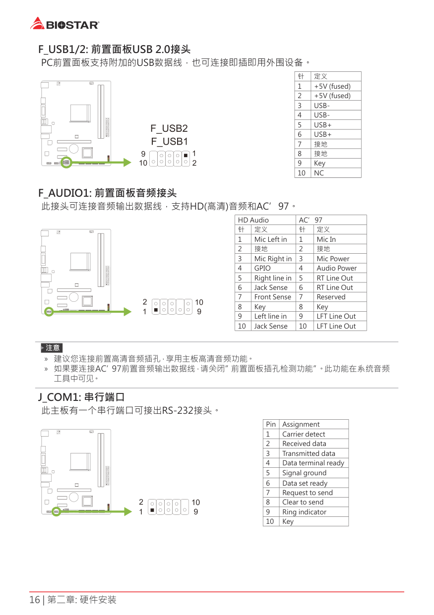
#### F_USB1/2: 前置面板USB 2 0接头
PC前置面板支持附加的USB数据线,也可连接即插即用外围设备。
|针|定义| |---|---| |1|+5V (fused)| |2|+5V (fused)| |3|USB-| |4|USB-| |5|USB+| |6|USB+| |7|接地| |8|接地| |9|Key| |10|NC|
| | | | | |---|---|---|---| | | | | |
#### F_AUDIO1: 前置面板音频接头
####### 此接头可连接音频输出数据线,支持HD(高清)音频和AC’97。
|HD Audio|HD Audio|AC’97|AC’97| |---|---|---|---| |针|定义|针|定义| |1|Mic Left in|1|Mic In| |2|接地|2|接地| |3|Mic Right in|3|Mic Power| |4|GPIO|4|Audio Power| |5|Right line in|5|RT Line Out| |6|Jack Sense|6|RT Line Out| |7|Front Sense|7|Reserved| |8|Key|8|Key| |9|Left line in|9|LFT Line Out| |10|Jack Sense|10|LFT Line Out|
| | | | | |---|---|---|---| | | | | |
» 建议您连接前置高清音频插孔,享用主板高清音频功能。 » 如果要连接AC’97前置音频输出数据线,请关闭”前置面板插孔检测功能”。此功能在系统音频
工 具中可见。
#### J_COM1: 串行端口
此主板有一个串行端口可接出RS-232接头。
| | | | | |---|---|---|---| | | | | |
|Pin|Assignment| |---|---| |1|Carrier detect| |2|Received data| |3|Transmitted data| |4|Data terminal ready| |5|Signal ground| |6|Data set ready| |7|Request to send| |8|Clear to send| |9|Ring indicator| |10|Key|
第三章: UEFI BIOS和软件
3 1 UEFI BIOS设置
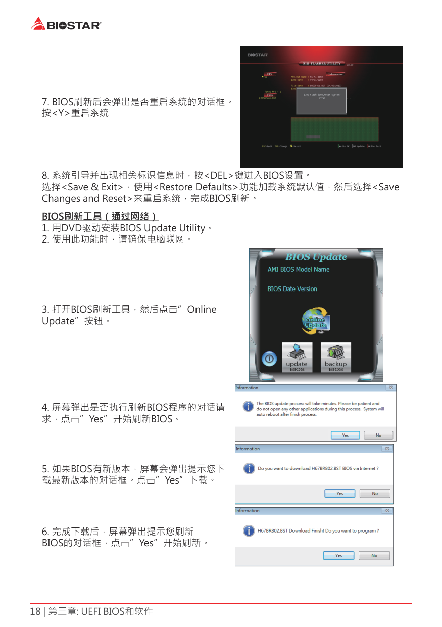
###### BIOSTAR BIOS Flasher
» 此工具仅允许可使用FAT32/16格式化或单个分区的存储设备。 » 刷新BIOS时如关机或重启系统将导致系统引导失败。
使用BIOSTAR BIOS Flasher刷新BIOS


|| |---|
|| |---|
|| |---|
|| |---|
|| |---|
||
|---|
|| |---|

|| |---|

BIOS备份 点击BIOS备份按钮,选择存储备份文件的合适 目录,然后点击”Save”。
3 3 软件安装软件
#### 启动软件
####### 安装程序完成后,桌面上将出现软件图标。请双击图标启动软件工具。
» 所有 软件 的 相 关 信息和 内 容 若 有 变 更,恕不 另行 通 知。为 使 系 统 性 能 更佳,软件 会不 断 升 级。 » 下面的图片和信息仅供参考,此主板的实际信息和设置可能与手册稍有差异。
BIOScreen 工具 此实用工具可以将开机画面个性化。您可以选择BMP格式来自定义计算机开机画面。
|| |---|
请参照以下步骤来更新开机画面:
eHot-Line eHot-Line是有助于您联系技术支持系统的便捷工具。此工具将收集系统信息,当您遇 到问题时,可提供有利分析,并发送这些信息至我们的技术支持部门,从而帮助解决此 问题。

填好表格信息后,点击“Send”发送邮件。将 出现一个确认信息对话框;点击“Send”确认 发送点击“Do Not Send”则取消操作。
如您想保存此信息到文本文件里,点击“Save As…”,出现一个保存对话框,输入文件名即 可。
|| |---|
|| |---|
输入文件名,点击“Save”,系统信息将被保 存至文本文件里。
|| |---|
打开已保存的文本文件,显示相关系统信息(包 括主板/BIOS/CPU/视频设备/OS)。这些信息 当然也在已发送的邮件里。
» 在使用此工具前,请将Outlook Express设置为您的默认电子邮件连接程序。 » 我们将为用户资料保密,所以使用eHot-Line服务时,请放心提供您的系统信息。 » 若您未将Outlook Express设置为默认电子邮件连接程序,也可保存您的系统信息到文件里,然
后用其它电子邮件工具发送此文件到我们的技术支持。 请访问网站http://www.biostar.com.tw/app/en/about/contact.php获取我们的联系信息。
第四章:帮助信息

此设置向导将自动检测您的主板和操作系统。
» 在插入驱动之后,如此窗口未出现,请用文件浏览器查找并执行SETUP.EXE文件。 » 若需要Acrobat Reader打开manual文件。请从网站http://get.adobe.com/reader/下载最新
版本的Acrobat Reader软件。
4 2 AMI BIOS 哔声代码引导模块哔声代码
|哔声次数|含义| |---|---| |持续哔声|持续哔声|
BIOS 开机自检哔声代码
|哔声次数|含义| |---|---| |1|系统引导成功| |8|显存错误(系统视频适配器)|
4 3 问题解答
|问题|解决方法| |---|---| |1. 系统没有电,电源指示灯不亮,电源风 扇不转动。
2. 键盘上的指示灯不亮。
|1. 确定电源线是否接好。
2. 更换线材。
3. 联系技术支持。
| |系统不起作用。键盘指示灯亮,电源指示 灯亮,硬盘正常运作。|用力按压内存两端,确保内存安置于插槽 中。| |系统不能从硬盘启动,能从光盘启动。|1. 检查硬盘与主板的连线,确定各连线是 否确实接好,检查标准CMOS设置中的驱 动类型。
2. 硬盘随时都有可能坏掉,所以备份硬盘 数据是很重要的。
| |系统只能从光盘启动。硬盘能被读,应用 程序能被使用,但是不能从硬盘启动。|1. 备份数据和应用程序。
2. 重新格式化硬盘。用后备盘重新安装应 用程序和数据。
| |屏幕提示“Invalid Configuration” 或 “CMOS Failure”。 再次检查系统设备,确定设定是否正确 安装了第二个硬盘|再次检查系统设备,确定设定是否正确| |安装了第二个硬盘后,系统不能启动。|1. 正确设置主/从硬盘跳线。
2. 运行安装程序,选择正确的驱动类型。 与驱动器厂商联系,寻求驱动兼容性的技 术支持。
|
CPU过热保护系统 在开启系统数秒后如有自动关机的现象,这说明CPU保护功能已被激活。CPU过热时, 防止损坏CPU,主机将自动关机,系统则无法重启。 此种情况下,请仔细检查。
创建带区集,在同一时间内向多块磁盘写入数据,通 过把数据分成多个数据块(Block)并行写入/读出多 个磁盘以提高访问磁盘的速度分散到所有的硬盘中同 时进行读写,在整个磁盘阵列建立过程中,以系统环 境为基础,指数的大小决定了每块磁盘的容量。此技 术可减少整个磁盘的存取时间和提供高速带宽。
###### 性能及优点
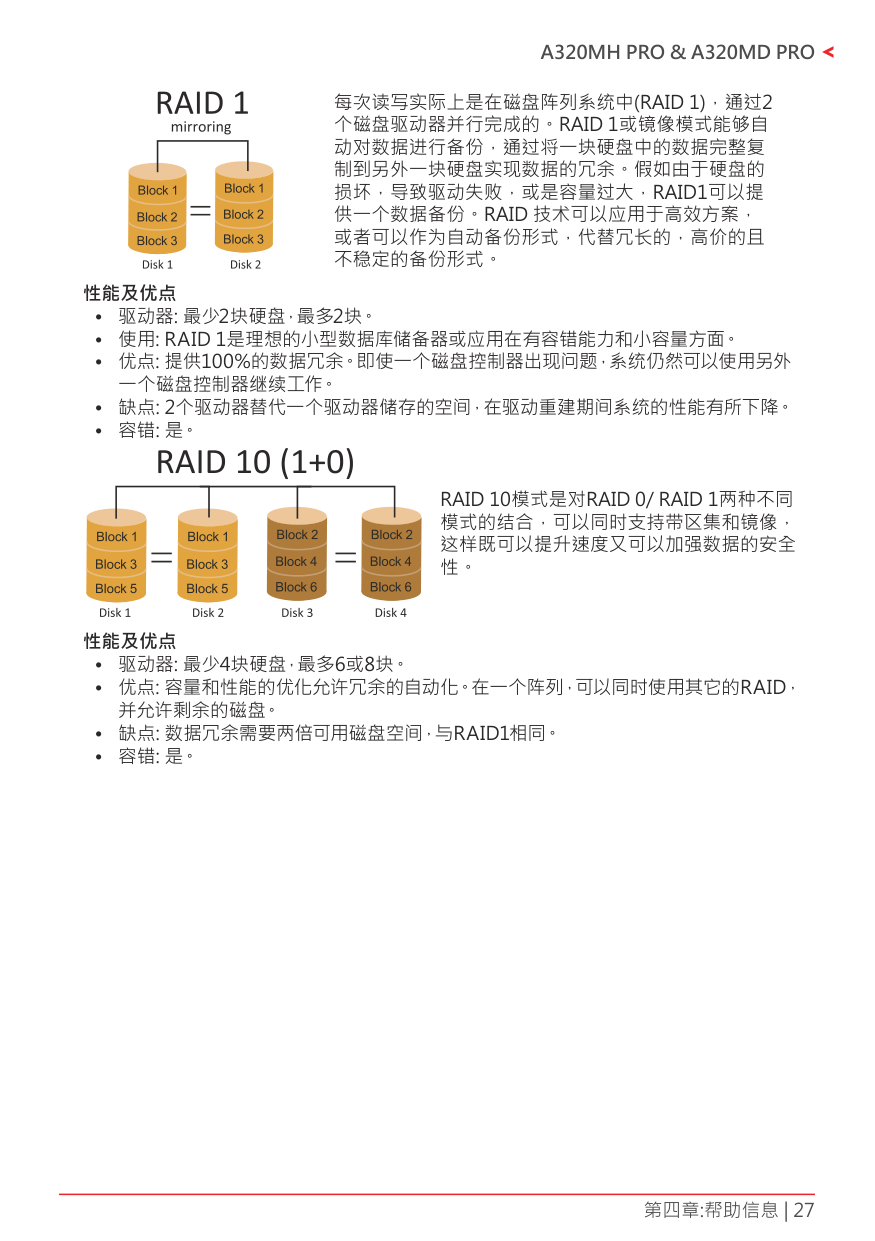
每次读写实际上是在磁盘阵列系统中(RAID 1),通过2 个磁盘驱动器并行完成的。RAID 1或镜像模式能够自 动对数据进行备份,通过将一块硬盘中的数据完整复 制到另外一块硬盘实现数据的冗余。假如由于硬盘的 损坏,导致驱动失败,或是容量过大,RAID1可以提 供一个数据备份。RAID 技术可以应用于高效方案, 或者可以作为自动备份形式,代替冗长的,高价的且 不稳定的备份形式。
###### 性能及优点
RAID 10模式是对RAID 0/ RAID 1两种不同 模式的结合,可以同时支持带区集和镜像, 这样既可以提升速度又可以加强数据的安全 性。
###### 性能及优点
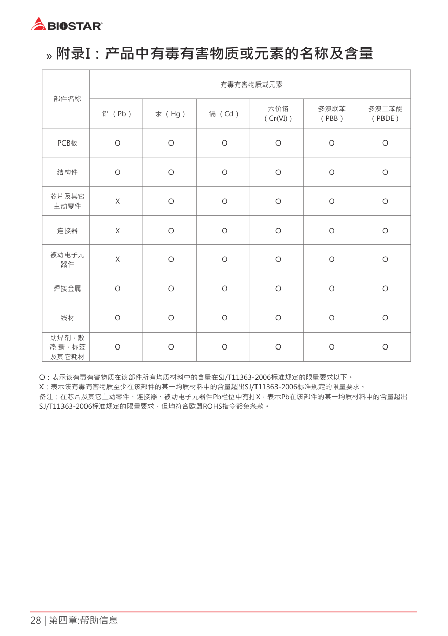
» 附录I:产品中有毒有害物质或元素的名称及含量
|部件名称|有毒有害物质或元素|有毒有害物质或元素|有毒有害物质或元素|有毒有害物质或元素|有毒有害物质或元素|有毒有害物质或元素| |---|---|---|---|---|---|---| |部件名称|铅 (Pb)|汞 (Hg)|镉 (Cd)|六价铬 (Cr(VI))|多溴联苯 (PBB)|多溴二苯醚 (PBDE)| |PCB板|O|O|O|O|O|O| |结构件|O|O|O|O|O|O| |芯片及其它 主动零件|X|O|O|O|O|O| |连接器|X|O|O|O|O|O| |被动电子元 器件|X|O|O|O|O|O| |焊接金属|O|O|O|O|O|O| |线材|O|O|O|O|O|O| |助焊剂,散 热 膏,标签 及其它耗材|O|O|O|O|O|O|
O:表示该有毒有害物质在该部件所有均质材料中的含量在SJ/T11363-2006标准规定的限量要求以下。 X:表示该有毒有害物质至少在该部件的某一均质材料中的含量超出SJ/T11363-2006标准规定的限量要求。 备注:在芯片及其它主动零件、连接器、被动电子元器件Pb栏位中有打X,表示Pb在该部件的某一均质材料中的含量超出 SJ/T11363-2006标准规定的限量要求,但均符合欧盟ROHS指令豁免条款。