
Ask AI
— answers from the official manualAnswers from the official manual.
Common questions
Common Questions
10 totalHow do I check the mower deck levelness?
To ensure proper adjustment of your Craftsman Lawn Tractor's mower deck for best cutting results, it should be leveled side-to-side and front-to-back. Side-to-side leveling involves measuring distances ‘A’ on both sides at the bottom edge from the ground; they should be equal or within 1/4 inch. Adjust lift link nuts if necessary to correct any imbalance (Page 21). Front-to-back adjustment requires raising the mower to its highest position, checking that it is approximately 1/8 to 1/2 inch lower at the front compared to the rear (Page 22).
What steps are involved in replacing a battery?
To replace your Craftsman LT2000’s battery, first lift the seat pan and disconnect both black and red cables from terminals on the old battery. Carefully remove the worn-out battery and install a new one with terminals placed in the same position as before. Start by connecting the red cable to the positive terminal followed by the black cable to the negative terminal; ensure each connection is tight (Page 25).
What maintenance tasks should I perform once a season?
For seasonal maintenance, it's recommended you replace the spark plug and clean or replace the air filter at least once annually. Additionally, inspect blades and belts for any signs of wear (Page 17).
What should I do if my mower is hard to start?
If your Craftsman mower struggles to start, check the air filter for dirt; a clean or replaced one might improve performance. Also, replace a faulty spark plug and ensure the battery is fully charged. If necessary, empty the fuel tank and refill with fresh gasoline, or replace the dirty fuel filter (Page 28).
How do I start an engine when it has a weak battery?
If your Craftsman tractor's battery is too weak to start the engine, recharge it as per the manual instructions. Alternatively, use jumper cables for immediate assistance: Connect one end of red and black cables from each battery in sequence without short-circuiting. Start operation by connecting red cable last (Page 24).
How do I adjust the throttle control cable?
Begin by ensuring that the holes 'A' in governor control lever and plate align with engine off. If they don't, loosen the clamp screw and move the throttle cable until alignment is achieved; tighten securely for adjustment (Page 26).
Full Manual
56 pages


Owner's Manual
CRAFTSMAN°
##### LAWN TRACTOR 18.5 HP, 42" Mower Electric Start
############ 6 Speed Transaxle
############### Model No. 917.274751
i_ his product has a low emission engine which operatesdifferentlyfrompreviouslybuiltengines.Beforeyoustart the engine, read and understand this Owner's Manual,
IMPORTANT: Read and follow all Safety Rules and Instructions before operating this equipment.
For answers to your questions about this product, Call: 1-800-659-5917 Sears Craftsman Help Line 5 am - 5 pm, Mon - Sat
Sears, Roebuck and Co., Hoffman Estates, IL 60179 U.S.A.
Visit our Craftsman website:www.sears.com/craftsman

Maintenance ......................................... 17 Service and Adjustments ...................... 21 Storage ................................................. 27 Troubleshooting .................................... 28 Repair Parts .......................................... 32 Sears Service ......................... Back Cover
Warranty ................................................. 2 Safety Rules ........................................... 3 Product Specifications ............................ 6 Assembly/Pre-Operation ........................ 8 Operation .............................................. 11 Maintenance Schedule ......................... 17
LIMITED WARRANTY ON CRAFTSMAN RIDING EQUIPMENT For two (2) years from the date of purchase, if this Craftsman Riding Equipment is maintained, lubricated and tuned up according to the instructions in the owner's manual, Sears will repair or replace free of charge any parts that are found to be defective in material or workmanship according to the guidelines of coverage listed below. Sears will also provide free labor for these applicable warranted parts for the two full years. During the first 30 days of purchase, there will be no charges to service the product at your home for issues covered by this warranty. (See exclusions below). For your convenience, IN HOME warranty service will still be available after the first 30 days of purchase, but a trip charge will apply. This charge will be waived if the Craftsman product is dropped off at an authorized Sears location. For the nearest authorized Sears location, please call 1-800-4-MY-HOME®. This warranty applies only while this product is within the United States.
This Warranty does not cover:
or failure to maintain the equipment according to the instructions contained in the owner's manual.
nated or oxidized (stale). In general, fuel should be used within 30 days of its purchase date.
LIMITED WARRANTY ON BATTERY For ninety (90) days from date of purchase, if any battery included with this riding equipment proves defective in material or workmanship and our testing determines the battery will not hold a charge, Sears will replace the battery at no charge. During the first 30 days of purchase, there will be no charges to replace the battery at your HOME. After the first 30 days, for your convenience, IN-HOME warranty service will still be available but a trip charge will apply. This charge will be waived if the Craftsman product is dropped off at an authorized Sears location. For the nearest authorized Sears location, please call 1-800-4-MY-HOME®.
This battery warranty applies only while this product is within the United States. This warranty gives you specific legal rights, and you may also have other rights, which vary, from state to state. Sears, Roebuck and Co.,Dept.817WA, Hoffman Estates, IL 60179
2

IMPORTANT: This cutting machine is capable of amputating hands and feet and throwing objects. Failure to observe the following safety instructions could result in serious injury or death.
riding mower safely enough to protect themselves and others from serious injury.
_IbWARNING: In order to prevent accidental starting when setting up, transporting, adjusting or making repairs, always disconnect spark plug wire and place wire where it cannot contact spark plug. _I, WARNING: Do not coast down a hill in neutral, you may lose control of the tractor. _WARNING: Tow only the attachments that are recommended by and comply with specifications of the manufacturer of your tractor. Use common sense when towing. Operate only at the lowest possible speed when on a slope. Too heavy of a load, while on a slope, is dangerous. Tires can lose traction with the ground and cause you to lose control of your tractor. _IbWARNING: Engine exhaust, some of its constituents, and certain vehicle components contain or emit chemicals known to the State of California to cause cancer and birth defects or other reproductive harm. _IbWARNING: Battery posts, terminals and related accessories contain lead and lead compounds, chemicals known to the State of California to cause cancer and birth defects or other reproductive harm. Wash hands after handling.

Slopesarea majorfactorrelatedto lossof controlandtip-overaccidents,which can resultinsevereinjury or death. Opera-
tion on allslopes requiresextracaution. If you cannotback upthe slopeor if youfeel uneasyon it, do not mow it.
mendation for weight limits for towed equipment and towing on slopes.
II1. CHILDREN Tragic accidents can occur if the operator is not alert to the presence of children. Children are often attracted to the machine and the mowing activity. Never assume that children will remain where you last saw them.

########################## GENERAL SERVICE

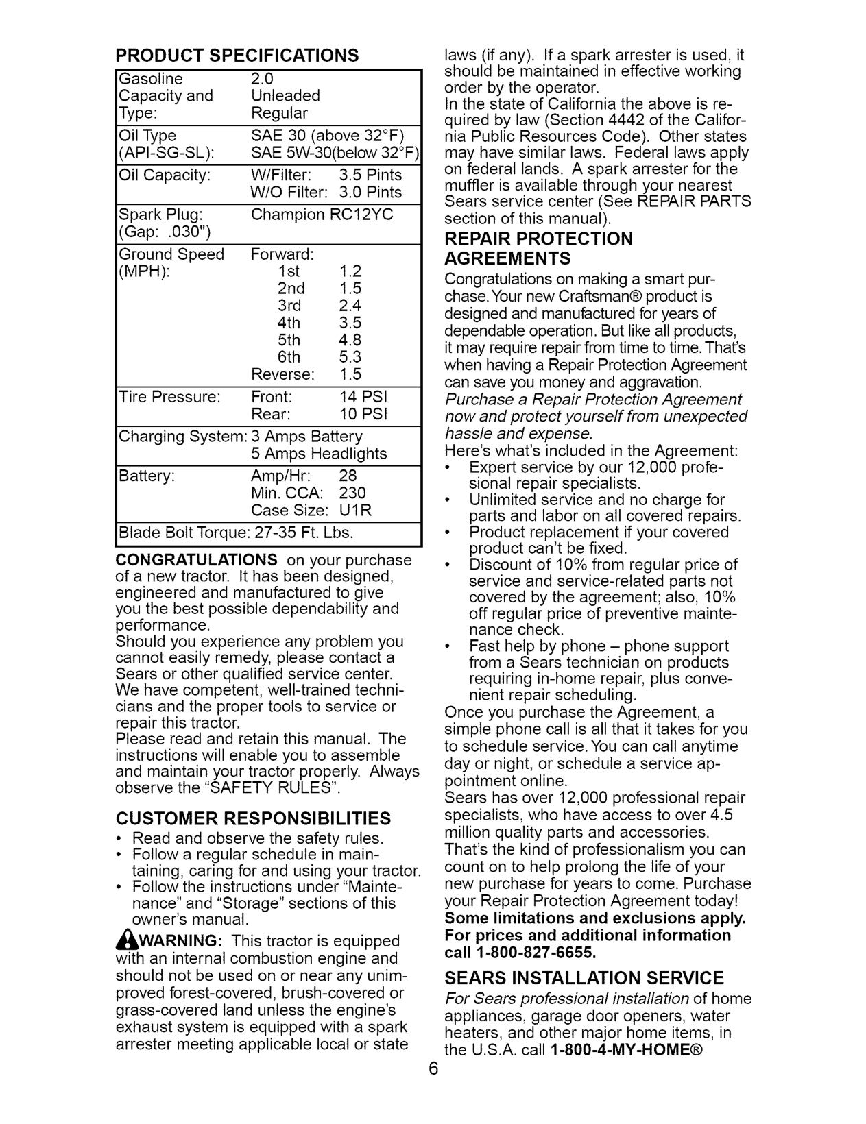
PRODUCT SPECIFICATIONS Gasoline 2.0 Capacityand Unleaded Type: Regular
laws (if any). If a spark arrester is used, it should be maintained in effective working order by the operator. In the state of California the above is required by law (Section 4442 of the California Public Resources Code). Other states may have similar laws. Federal laws apply on federal lands. A spark arrester for the muffler is available through your nearest Sears service center (See REPAIR PARTS section of this manual). REPAIR PROTECTION AGREEMENTS
OilType SAE30 (above32°F) 'API-SG-SL): SAE 5W-30(below 32°F
Oil Capacity: W/Filter: 3.5 Pints W/O Filter: 3.0 Pints
Spark Plug: Champion RC12YC (Gap: .030")
Forward:
Ground Speed (MPH):
1st 1.2 2nd 1.5 3rd 2.4
Congratulations on making a smart purchase. Your new Craftsman® product is designed and manufactured for years of dependable operation. But like all products, it may require repair from time to time. That's when having a Repair Protection Agreement can save you money and aggravation. Purchase a Repair Protection Agreement now and protect yourself from unexpected hassle and expense. Here's what's included in the Agreement:
Reverse: 1.5
Tire Pressure: Front: 14 PSI
Rear: 10 PSI Charging System: 3 Amps Battery
5 Amps Headlights
Battery: Amp/Hr: 28 Min. CCA: 230 Case Size: U1R
Blade Bolt Torque: 27-35 Ft. Lbs.
CONGRATULATIONS on your purchase of a new tractor. It has been designed, engineered and manufactured to give you the best possible dependability and performance. Should you experience any problem you cannot easily remedy, please contact a Sears or other qualified service center. We have competent, well-trained technicians and the proper tools to service or repair this tractor. Please read and retain this manual. The instructions will enable you to assemble and maintain your tractor properly. Always observe the "SAFETY RULES".
Once you purchase the Agreement, a simple phone call is all that it takes for you to schedule service. You can call anytime day or night, or schedule a service appointment online. Sears has over 12,000 professional repair specialists, who have access to over 4.5 million quality parts and accessories. That's the kind of professionalism you can count on to help prolong the life of your new purchase for years to come. Purchase your Repair Protection Agreement today! Some limitations and exclusions apply. For prices and additional information call 1-800-827-6655.
########################## CUSTOMER RESPONSIBILITIES
nance" and "Storage" sections of this owner's manual.
_,WARNING: This tractor is equipped with an internal combustion engine and should not be used on or near any unimproved forest-covered, brush-covered or grass-covered land unless the engine's exhaust system is equipped with a spark arrester meeting applicable local or state
SEARS INSTALLATION SERVICE For Sears professional installation of home appliances, garage door openers, water heaters, and other major home items, in the U.S.A. call 1-800-4-MY-HOME®

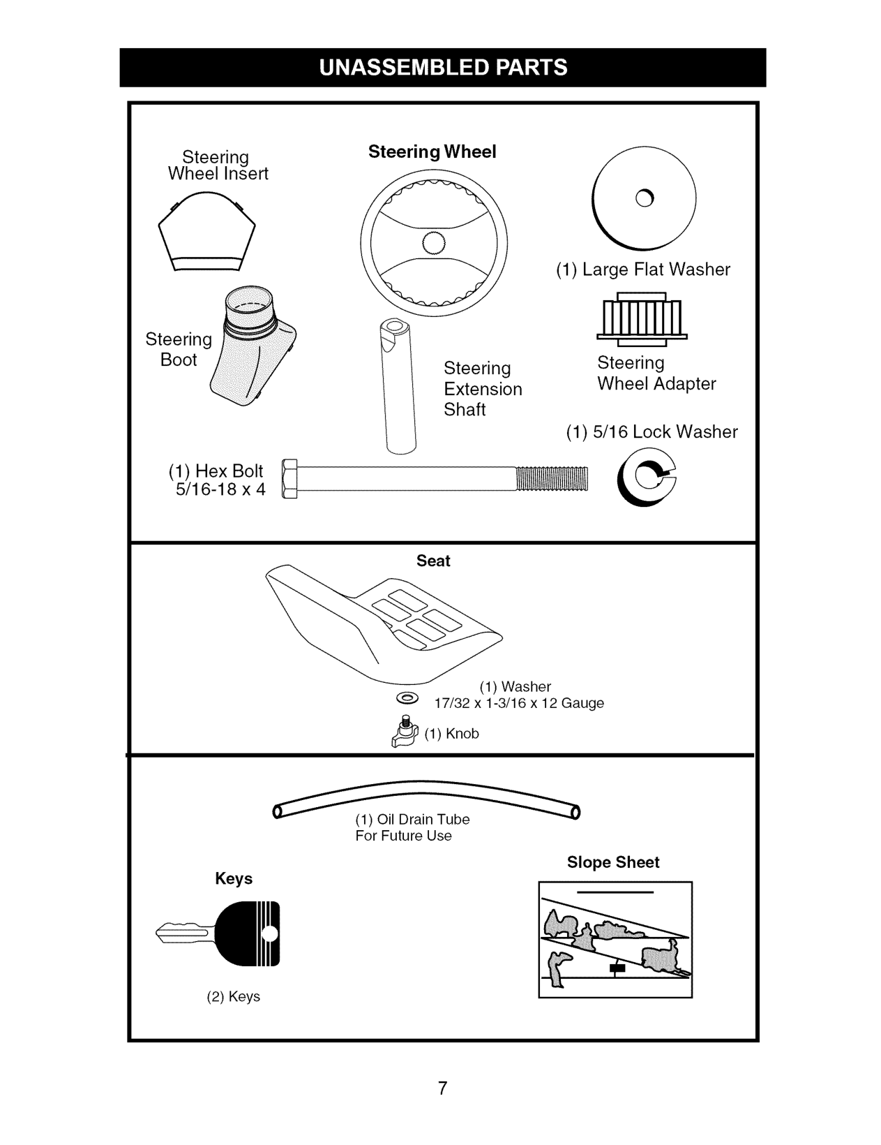
Steering Wheel
Steering Wheel Insert
@
C?
(1) Large Flat Washer
Steering Boot
I I Steering Wheel Adapter
Extension Shaft
Steering
(1) 5/16 Lock Washer
(1) Hex Bolt R 5/16-18 x 4
Seat
(1) Washer
17/32 x 1-3/16 x 12 Gauge _(1) Knob
(1) Oil Drain Tube For Future Use
########################## Slope Sheet
Keys
(2) Keys

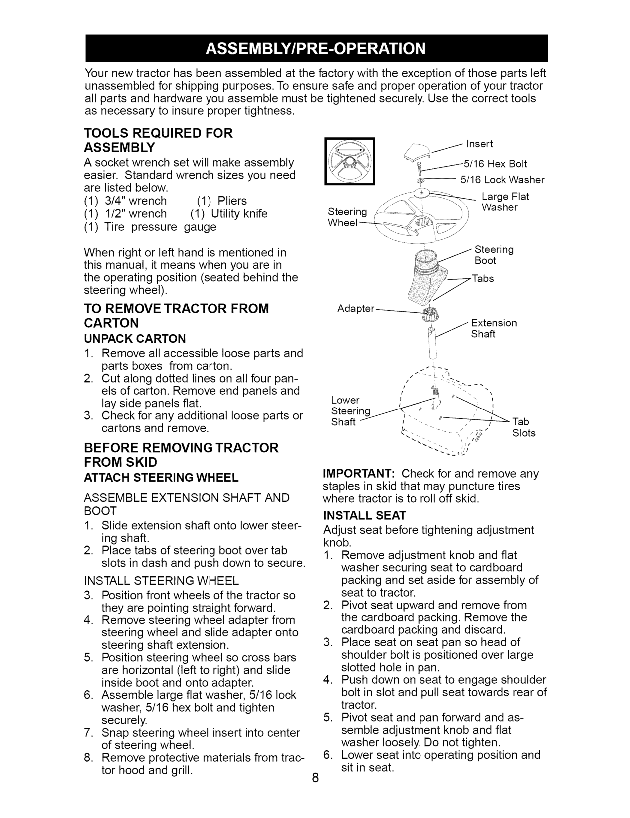
Your new tractor has been assembled at the factory with the exception of those parts left unassembled for shipping purposes. To ensure safe and proper operation of your tractor all parts and hardware you assemble must be tightened securely. Use the correct tools
######################## TOOLS REQUIRED FOR ASSEMBLY
:/Insert
A socket wrench set will make assembly easier. Standard wrench sizes you need are listed below.
_/5/16 Hex Bolt c¢_ 5/16 Lock Washer
Large Flat Washer
(1) 3/4" wrench (1) Pliers
(1) 1/2" wrench (1) Utility knife
Steering ,
J
/
(1) Tire pressure gauge
g Boot
When right or left hand is mentioned in this manual, it means when you are in the operating position (seated behind the steering wheel).
TO REMOVE TRACTOR FROM CARTON UNPACK CARTON
BEFORE REMOVING TRACTOR FROM SKID
IMPORTANT: Check for and remove any staples in skid that may puncture tires where tractor is to roll off skid. INSTALL SEAT
ATTACH STEERING WHEEL ASSEMBLE EXTENSION SHAFT AND BOOT
INSTALL STEERING WHEEL
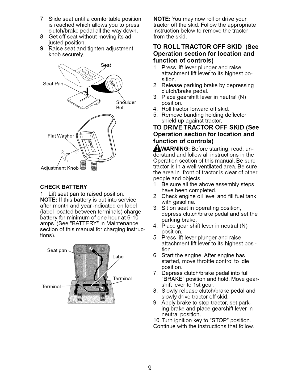
Adjust seat before tightening adjustment knob.

NOTE: You may now roll or drive your tractor off the skid. Follow the appropriate instruction below to remove the tractor from the skid.
TO ROLL TRACTOR OFF SKID (See Operation section for location and function of controls)
Seat
Seat
Bolt
TO DRIVE TRACTOR OFF SKID (See Operation section for location and function of controls)
Flat Washer
########## \
,_WARNING: Before starting, read, understand and follow all instructions in the Operation section of this manual. Be sure tractor is in a well-ventilated area. Be sure the area in front of tractor is clear of other people and objects.
Adjustment
CHECK BATTERY
Seat
Terminal

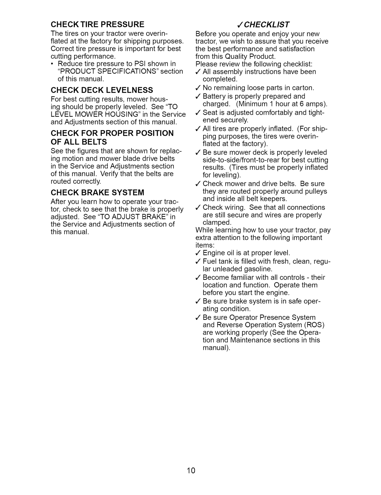
######################## CHECKTIRE PRESSURE
J CHECKL IS T
The tires on your tractor were overinflated at the factory for shipping purposes. Correct tire pressure is important for best cutting performance.
Before you operate and enjoy your new tractor, we wish to assure that you receive the best performance and satisfaction from this Quality Product. Please review the following checklist: ,/All assembly instructions have been
• Reduce tire pressure to PSI shown in "PRODUCT SPECIFICATIONS" section of this manual.
completed. ,/No remaining loose parts in carton. ,/Battery is properly prepared and
CHECK DECK LEVELNESS For best cutting results, mower housing should be properly leveled. See "TO LEVEL MOWER HOUSING" in the Service and Adjustments section of this manual.
charged. (Minimum 1 hour at 6 amps). ,/Seat is adjusted comfortably and tight-
ened securely.
,/All tires are properly inflated. (For shipping purposes, the tires were overinflated at the factory).
######################## CHECK FOR PROPER POSITION OF ALL BELTS
See the figures that are shown for replacing motion and mower blade drive belts in the Service and Adjustments section of this manual. Verify that the belts are routed correctly.
,/Be sure mower deck is properly leveled
side-to-side/front-to-rear for best cutting results. (Tires must be properly inflated for leveling).
¢" Check mower and drive belts. Be sure they are routed properly around pulleys and inside all belt keepers.
CHECK BRAKE SYSTEM After you learn how to operate your tractor, check to see that the brake is properly adjusted. See "TO ADJUST BRAKE" in the Service and Adjustments section of this manual.
¢" Check wiring. See that all connections are still secure and wires are properly clamped.
While learning how to use your tractor, pay extra attention to the following important items:
¢" Engine oil is at proper level. ¢" Fuel tank is filled with fresh, clean, regu-
lar unleaded gasoline.
¢" Become familiar with all controls - their location and function. Operate them before you start the engine.
¢" Be sure brake system is in safe operating condition.
¢" Be sure Operator Presence System and Reverse Operation System (ROS) are working properly (See the Operation and Maintenance sections in this manual).

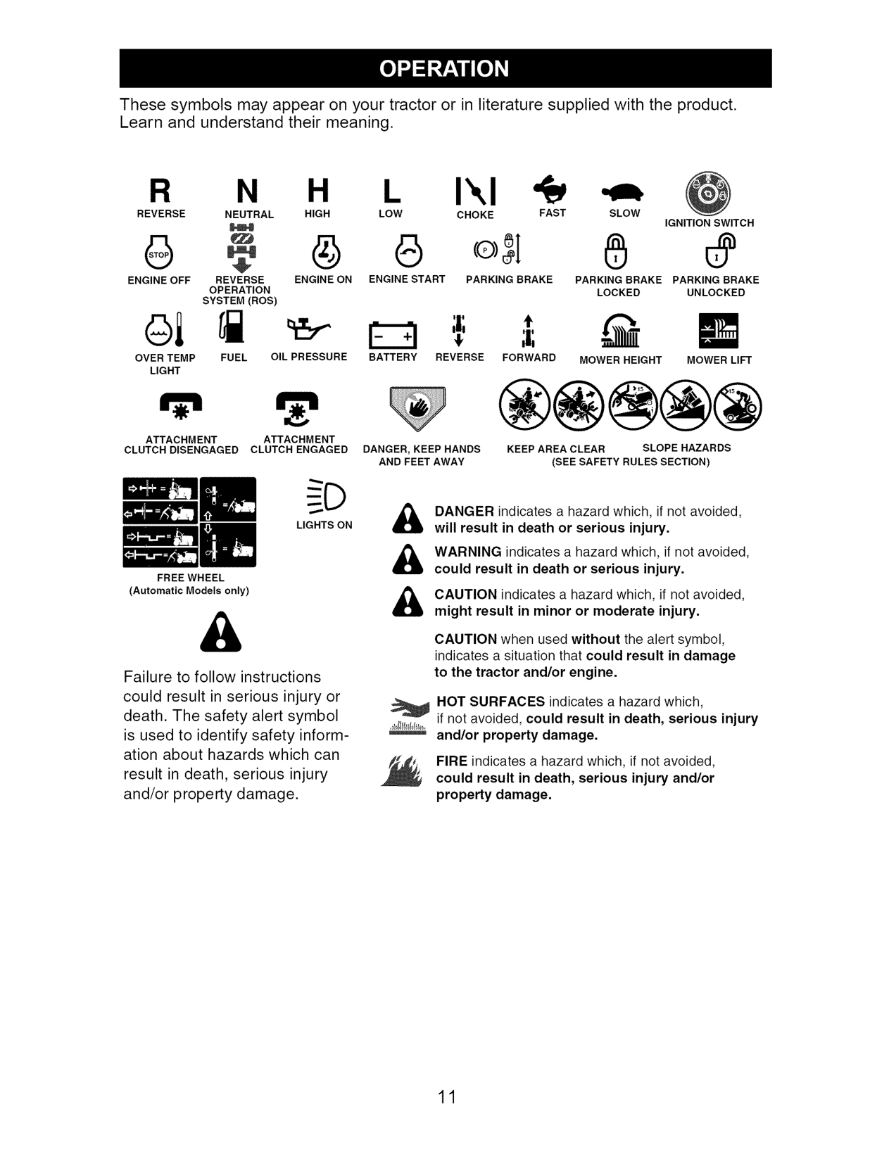
These symbols may appear on your tractor or in literature supplied with the product. Learn and understand their meaning.
######## R N H I'.,I
SLOW
REVERSE NEUTRAL HIGH LOW CHOKE FAST
IGNITION SWITCH
G G
ENGINE OFF REVERSE ENGINE ON ENGINE START PARKING BRAKE OPERATION SYSTEM (ROS)
PARKING BRAKE PARKING BRAKE LOCKED UNLOCKED
oi
t
OVER TEMP LIGHT
BATTERY REVERSEFUELOILPRESSURE
FORWARD MOWER HEIGHT MOWER LIFT
m
ATTACHMENT ATTACHMENT
KEEP AREA CLEAR SLOPE HAZARDS (SEE SAFETY RULES SECTION)
CLUTCH DISENGAGED CLUTCH ENGAGED
DANGER, KEEP HANDS AND FEET AWAY
DANGER indicates a hazard which, if not avoided,willresultindeathorseriousinjury.
LIGHTS ON
WARNING indicates a hazard which, if not avoided,couldresultindeathorseriousinjury.
FREE WHEEL (Automatic Models only)
&
CAUTION indicates a hazard which, if not avoided,mightresultinminorormoderateinjury.
CAUTION when used without the alert symbol, indicates a situation that could result in damage to the tractor and/or engine.
Failure to follow instructions could result in serious injury or death. The safety alert symbol is used to identify safety information about hazards which can result in death, serious injury and/or property damage.
NOT SURFACES indicates a hazard which, if not avoided, could result in death, serious injury and/or property damage.
FIRE indicates a hazard which, if not avoided, could result in death, serious injury and/or property damage.

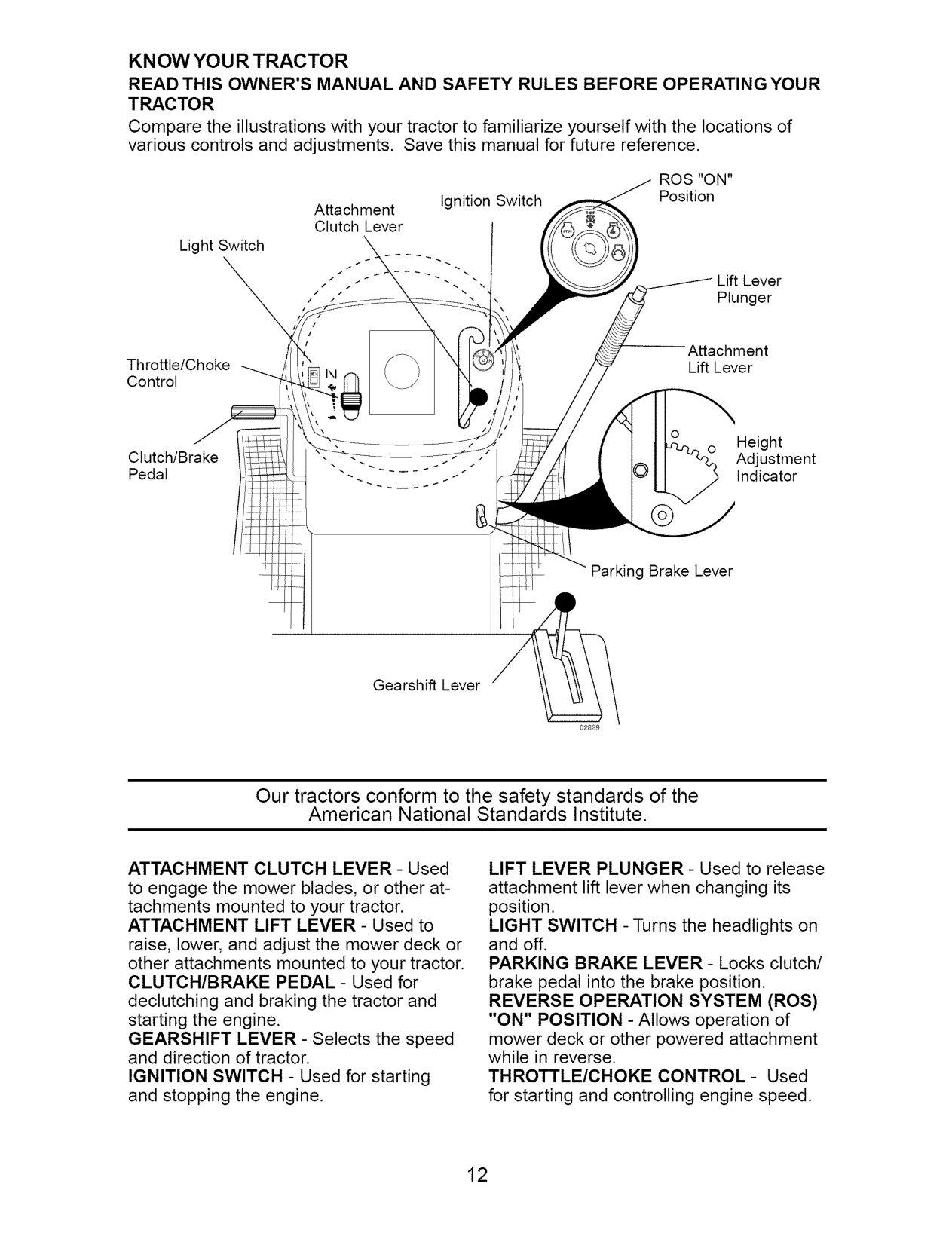
######################## KN OW YOU R TRACTOR READ THIS OWNER'S MANUAL AND SAFETY RULES BEFORE OPERATINGYOUR TRACTOR
Compare the illustrations with your tractor to familiarize yourself with the locations of various controls and adjustments. Save this manual for future reference.
ROS "ON" Position
Ignition Switch
Attachment Clutch Lever
Light Switch
Lift Lever Plunger
Attachment Lift Lever
Throttle/Choke Control
Height Adjustment Indicator
Clutch/Brake Pedal
Parking Brake Lever
Gearshift Lever
Our tractors conform to the safety standards of the American National Standards Institute.
LIFT LEVER PLUNGER - Used to release attachment lift lever when changing its position. LIGHT SWITCH - Turns the headlights on and off. PARKING BRAKE LEVER- Locks clutch/ brake pedal into the brake position. REVERSE OPERATION SYSTEM (ROS) "ON" POSITION - Allows operation of mower deck or other powered attachment while in reverse. THROTTLE/CHOKE CONTROL- Used for starting and controlling engine speed.
ATTACHMENT CLUTCH LEVER - Used to engage the mower blades, or other attachments mounted to your tractor. ATTACHMENT LIFT LEVER - Used to raise, lower, and adjust the mower deck or other attachments mounted to your tractor. CLUTCH/BRAKE PEDAL - Used for declutching and braking the tractor and starting the engine. GEARSHIFT LEVER - Selects the speed and direction of tractor. IGNITION SWITCH - Used for starting and stopping the engine.

The operation of any tractor can result in foreign objects thrown into the eyes, which can result in severe eye damage. Always wear safety glasses or eye shields while operating your tractor or performing any adjustments or repairs. We recommend a wide vision safety mask over spectacles or standard safety glasses.
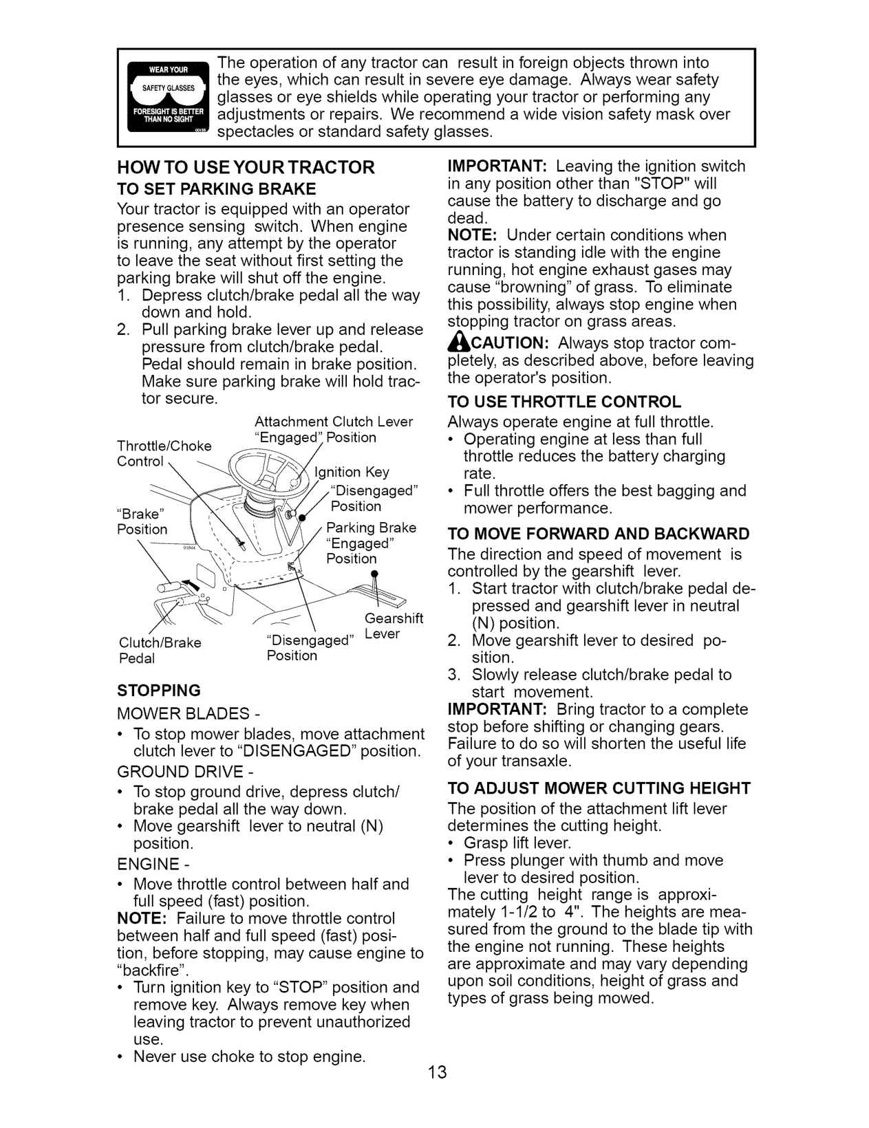
########################## HOW TO USE YOUR TRACTOR TO SET PARKING BRAKE
IMPORTANT: Leaving the ignition switch in any position other than "STOP" will cause the battery to discharge and go dead. NOTE: Under certain conditions when tractor is standing idle with the engine running, hot engine exhaust gases may cause "browning" of grass. To eliminate this possibility, always stop engine when stopping tractor on grass areas. ,_CAUTION: Always stop tractor completely, as described above, before leaving the operator's position. TO USE THROTTLE CONTROL Always operate engine at full throttle.
Your tractor is equipped with an operator presence sensing switch. When engine is running, any attempt by the operator to leave the seat without first setting the parking brake will shut off the engine.
Attachment Clutch Lever "Engaged' Position
Throttle/Choke Control
nition Key /"Disengaged" Position Parking Brake
"Brake" Position
TO MOVE FORWARD AND BACKWARD The direction and speed of movement is controlled by the gearshift lever.
ed" Position
Gearshift
Clutch/Brake "Disengaged" Lever Pedal Position
STOPPING MOWER BLADES -
IMPORTANT: Bring tractor to a complete stop before shifting or changing gears. Failure to do so will shorten the useful life of your transaxle. TO ADJUST MOWER CUTTING HEIGHT
• To stop mower blades, move attachment
clutch lever to "DISENGAGED" position. GROUND DRIVE -
The position of the attachment lift lever determines the cutting height.
ENGINE -
• Move throttle control between half and
The cutting height range is approximately 1-1/2 to 4". The heights are measured from the ground to the blade tip with the engine not running. These heights are approximate and may vary depending upon soil conditions, height of grass and types of grass being mowed.
full speed (fast) position. NOTE: Failure to move throttle control between half and full speed (fast) position, before stopping, may cause engine to "backfire".

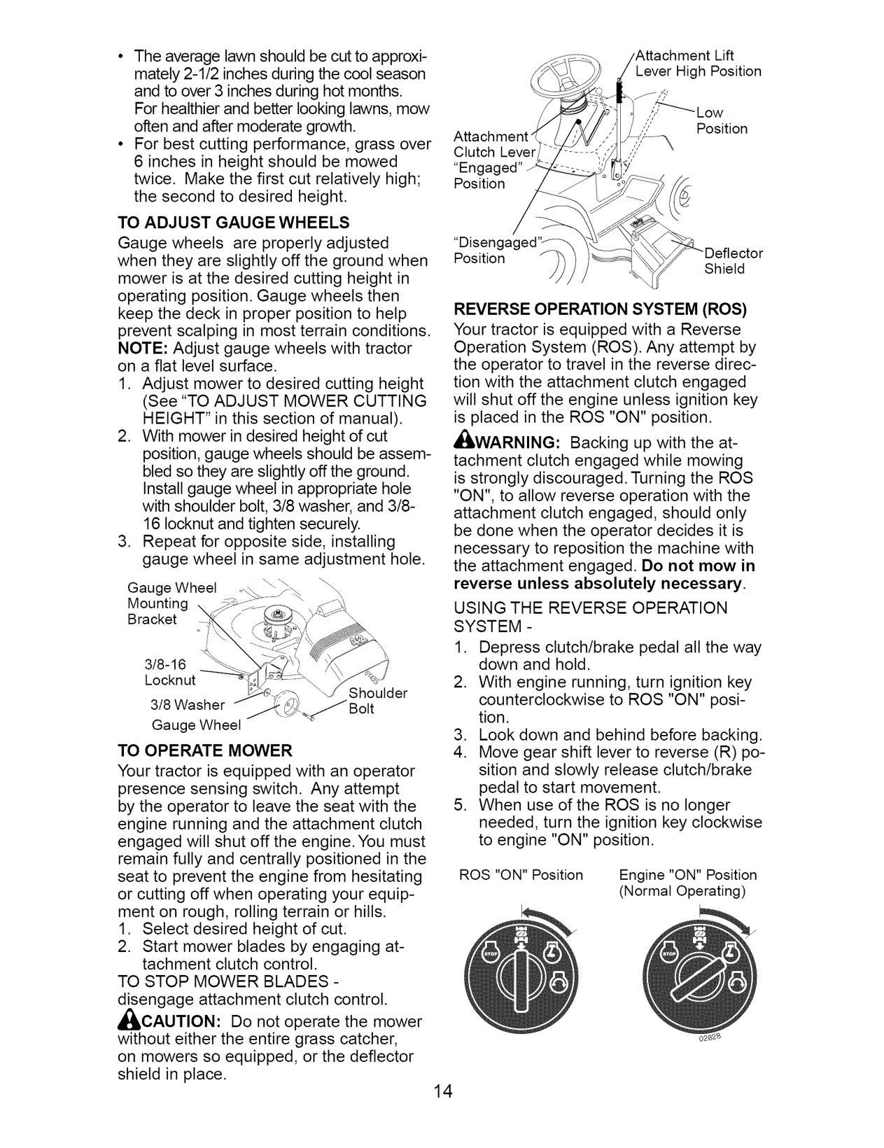
Lift Lever High Position
,!,-'_"_'-_Low ,"? Position
Clutch Lever "En( Position
//
TO ADJUST GAUGE WHEELS Gauge wheels are properly adjusted when they are slightly off the ground when mower is at the desired cutting height in operating position. Gauge wheels then keep the deck in proper position to help prevent scalping in most terrain conditions. NOTE: Adjust gauge wheels with tractor on a flat level surface.
,& Shield
\
REVERSE OPERATION SYSTEM (ROS) Your tractor is equipped with a Reverse Operation System (ROS). Any attempt by the operator to travel in the reverse direction with the attachment clutch engaged will shut off the engine unless ignition key is placed in the ROS "ON" position.
,_WARNING: Backing up with the attachment clutch engaged while mowing is strongly discouraged. Turning the ROS "ON", to allow reverse operation with the attachment clutch engaged, should only be done when the operator decides it is necessary to reposition the machine with the attachment engaged. Do not mow in reverse unless absolutely necessary. USING THE REVERSE OPERATION SYSTEM -
Gauge Wheel Mounting Bracket
3/8-16 Locknut
Shoulder
3/8 Washer
Gauge Wheel TO OPERATE MOWER Your tractor is equipped with an operator presence sensing switch. Any attempt by the operator to leave the seat with the engine running and the attachment clutch engaged will shut off the engine. You must remain fully and centrally positioned in the seat to prevent the engine from hesitating or cutting off when operating your equipment on rough, rolling terrain or hills.
ROS "ON" Position Engine "ON" Position (Normal Operating)
TO STOP MOWER BLADES disengage attachment clutch control. _IbCAUTION: Do not operate the mower without either the entire grass catcher, on mowers so equipped, or the deflector shield in place.

TO OPERATE ON HILLS
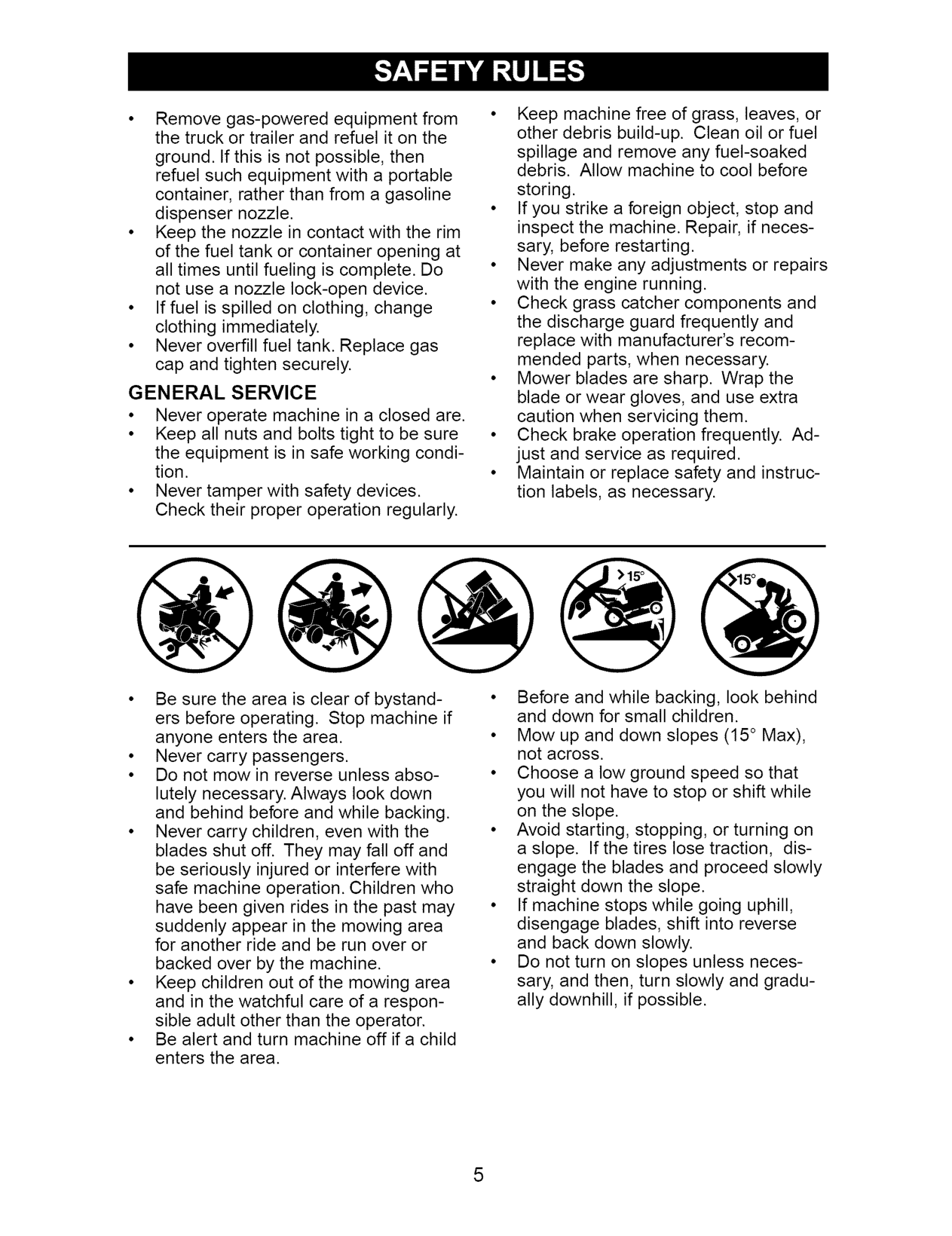
_,WARNING: Do not drive up or down hills with slopes greater than 15 ° and do not drive across any slope. Use the slope guide at the back of this manual.
########################## ADD GASOLINE
• Fill fuel tank to bottom of filler neck. Do not overfill. Use fresh, clean, regular unleaded gasoline with a minimum of 87 octane. (Use of leaded gasoline will increase carbon and lead oxide deposits and reduce valve life). Do not mix oil with gasoline. Purchase fuel in quantities that can be used within 30 days to assure fuel freshness.
,_CAUTION: Wipe off any spilled oil or fuel. Do not store, spill or use gasoline near an open flame. IMPORTANT: When operating in temperatures below32°F(0°C), use fresh, clean winter grade gasoline to help insure good cold weather starting. CAUTION: Alcohol blended fuels (called gasohol or using ethanol or methanol) can attract moisture which leads to separation and formation of acids during storage. Acidic gas can damage the fuel system of an engine while in storage. To avoid engine problems, the fuel system should be emptied before storage of 30 days or longer. Drain the gas tank, start the engine and let it run until the fuel lines and carburetor are empty. Use fresh fuel next season. See Storage Instructions for additional information. Never use engine or carburetor cleaner products in the fuel tank or permanent damage may occur.
NOTE: To protect hood from damage when transporting your tractor on a truck or a trailer, be sure hood is closed and secured to tractor. Use an appropriate means of tying hood to tractor (rope, cord, etc.).
########################## TOWING CARTS AND OTHER ATTACHMENTS
Tow only the attachments that are recommended by and comply with specifications of the manufacturer of your tractor. Use common sense when towing. Too heavy of a load, while on a slope, is dangerous. Tires can lose traction with the ground and cause you to lose control of your tractor. BEFORE STARTING THE ENGINE CHECK ENGINE OIL LEVEL The engine in your tractor has been shipped, from the factory, already filled with summer weight oil.
TO START ENGINE When starting the engine for the first time or if the engine has run out of fuel, it will take extra cranking time to move fuel from the tank to the engine.

NOTE: Before starting, read the warm and cold starting procedures below.
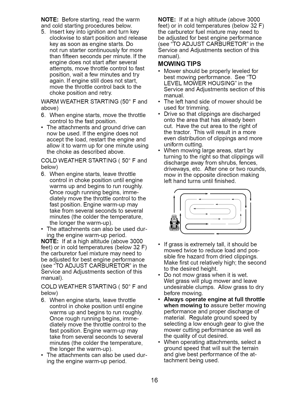
NOTE: If at a high altitude (above 3000 feet) or in cold temperatures (below 32 F) the carburetor fuel mixture may need to be adjusted for best engine performance (see "TO ADJUST CARBURETOR" in the Service and Adjustments section of this manual). MOWING TIPS
WARM WEATHER STARTING (50 ° F and above)
cut. Have the cut area to the right of the tractor. This will result in a more
even distribution of clippings and more uniform cutting.
f
1
• J
• The attachments and ground drive can now be used. If the engine does not accept the load, restart the engine and allow it to warm up for one minute using the choke as described above.
COLD WEATHER STARTING ( 50 ° F and below)
• The attachments can also be used dur-
ing the engine warm-up period. NOTE: If at a high altitude (above 3000 feet) or in cold temperatures (below 32 F) the carburetor fuel mixture may need to be adjusted for best engine performance (see "TO ADJUST CARBURETOR" in the Service and Adjustments section of this manual).
COLD WEATHER STARTING ( 50 ° F and below)
• The attachments can also be used during the engine warm-up period.

############ F,LL,NOATES
############################# REGULARSERVICE VICE DATES
Check Brake Operation if _V pCheckTirePressure Check Operator Presence and
T ROS Systems a Check for Loose Fasteners if I_s A Sharpen/Replace Mower Blades V'3 C Lubrication Chart if if
Check Transaxle Cooling ,I Check V-Belts V' Check Engine Oil Level V' V' Change Engine Oil (with oil filter) V'1,2 V f
E Change Engine Oil (without oil filter) VI_I,2 V N Clean Air Filter V_2 G clean Air Screen _1_1_2 N_ Inspect Muffler/Spark Arrester V' E Replace Oil Filter (If equipped) t1_1,2
Clean Engine Cooling Fins li_ 2 Replace Spark Plug V' I_ Replace Air Filter Paper Cartridge 11_2 Replace Fuel Filter
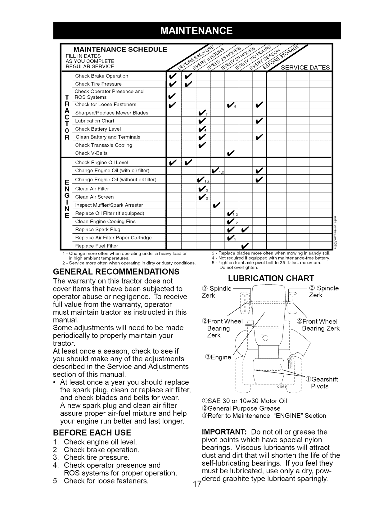
GENERAL RECOMMENDATIONS The warranty on this tractor does not cover items that have been subjected to operator abuse or negligence. To receive full value from the warranty, operator must maintain tractor as instructed in this manual. Some adjustments will need to be made periodically to properly maintain your tractor. At least once a season, check to see if you should make any of the adjustments described in the Service and Adjustments section of this manual.
####################### LUBRICATION CHART
@ SF -- @ Spindle Zerk Zerk
@Front Wheel ,
@Front Wheel Bearing Zerk
Bearing Zerk
@Engine
"_Gearshift T _i_-- ', Pivots
• At least once a year you should replace the spark plug, clean or replace air filter, and check blades and belts for wear.
_SAE 30 or 10w30 Motor Oil @General Purpose Grease @Refer to Maintenance "ENGINE" Section
A new spark plug and clean air filter assure proper air-fuel mixture and help your engine run better and last longer.
###################### BEFORE EACH USE
IMPORTANT: Do not oil or grease the pivot points which have special nylon bearings. Viscous lubricants will attract dust and dirt that will shorten the life of the self-lubricating bearings. If you feel they must be lubricated, use only a dry, pow-
7dered graphite type lubricant sparingly.1

TRACTOR Always observe safety rules when performing any maintenance. BRAKE OPERATION
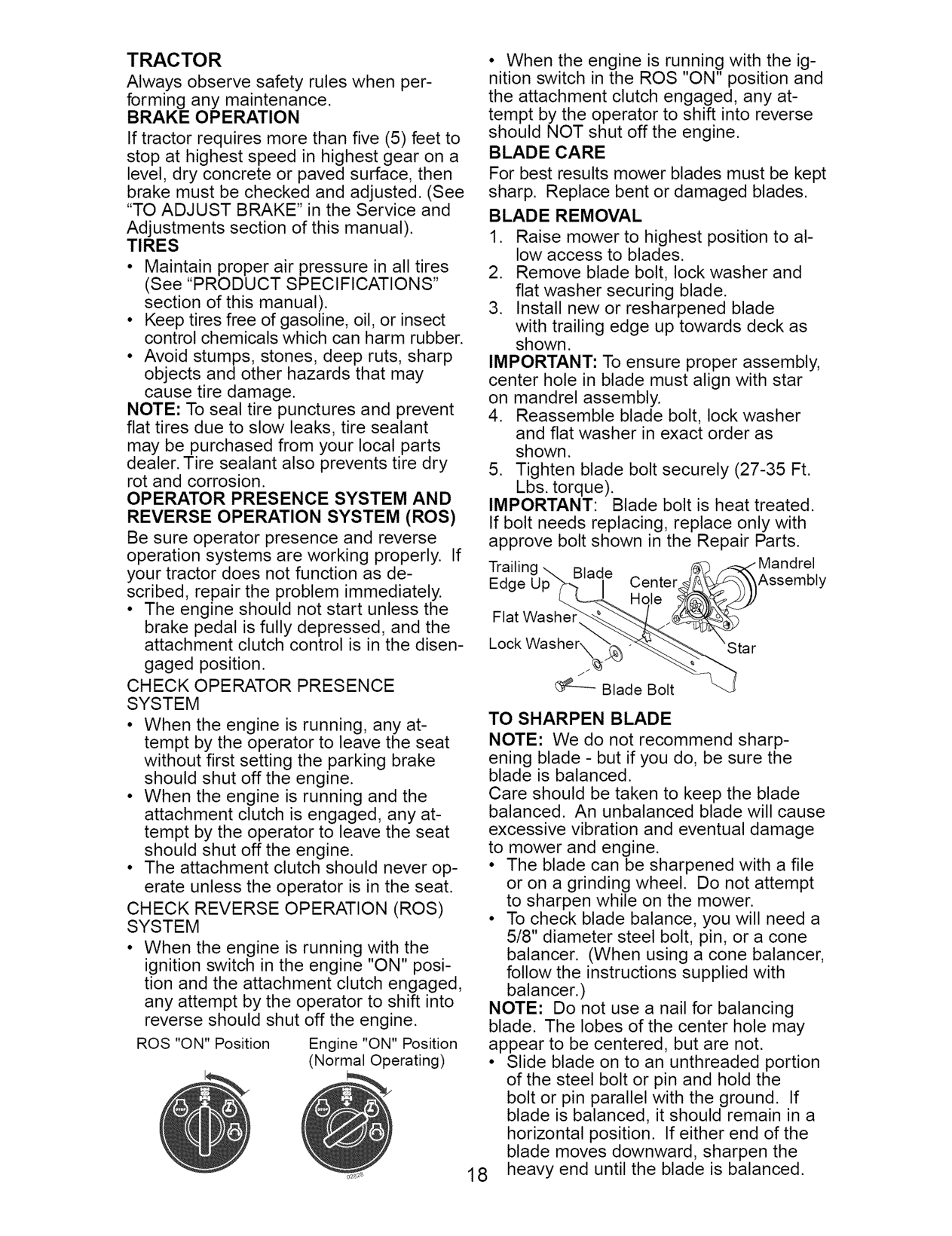
• When the engine is running with the ignition switch in the ROS "ON" position and the attachment clutch engaged, any attempt by the operator to shift into reverse should NOT shut off the engine. BLADE CARE For best results mower blades must be kept sharp. Replace bent or damaged blades. BLADE REMOVAL
If tractor requires more than five (5) feet to stop at highest speed in highest gear on a level, dry concrete or paved surface, then brake must be checked and adjusted. (See "TO ADJUST BRAKE" in the Service and Adjustments section of this manual). TIRES
IMPORTANT: To ensure proper assembly, center hole in blade must align with star on mandrel assembly.
NOTE: To seal tire punctures and prevent flat tires due to slow leaks, tire sealant may be purchased from your local parts dealer. Tire sealant also prevents tire dry rot and corrosion. OPERATOR PRESENCE SYSTEM AND REVERSE OPERATION SYSTEM (ROS) Be sure operator presence and reverse operation systems are working properly. If your tractor does not function as described, repair the problem immediately.
IMPORTANT: Blade bolt is heat treated. If bolt needs replacing, replace only with approve bolt shown in the Repair Parts.
'g Blade Edc Center Assembly
• The engine should not start unless the brake pedal is fully depressed, and the attachment clutch control is in the disengaged position.
Flat Washe Lock Washer\
j_
CHECK OPERATOR PRESENCE SYSTEM
Blade Bolt
TO SHARPEN BLADE NOTE: We do not recommend sharpening blade - but if you do, be sure the blade is balanced. Care should be taken to keep the blade balanced. An unbalanced blade will cause excessive vibration and eventual damage to mower and engine.
CHECK REVERSE OPERATION (ROS) SYSTEM
• When the engine is running with the ignition switch in the engine "ON" position and the attachment clutch engaged, any attempt by the operator to shift into reverse should shut off the engine.
NOTE: Do not use a nail for balancing blade. The lobes of the center hole may appear to be centered, but are not.
ROS "ON" Position Engine "ON" Position (Normal Operating)
• Slide blade on to an unthreaded portion of the steel bolt or pin and hold the bolt or pin parallel with the ground. If blade is balanced, it should remain in a horizontal position. If either end of the blade moves downward, sharpen the
18 heavy end until the blade is balanced.

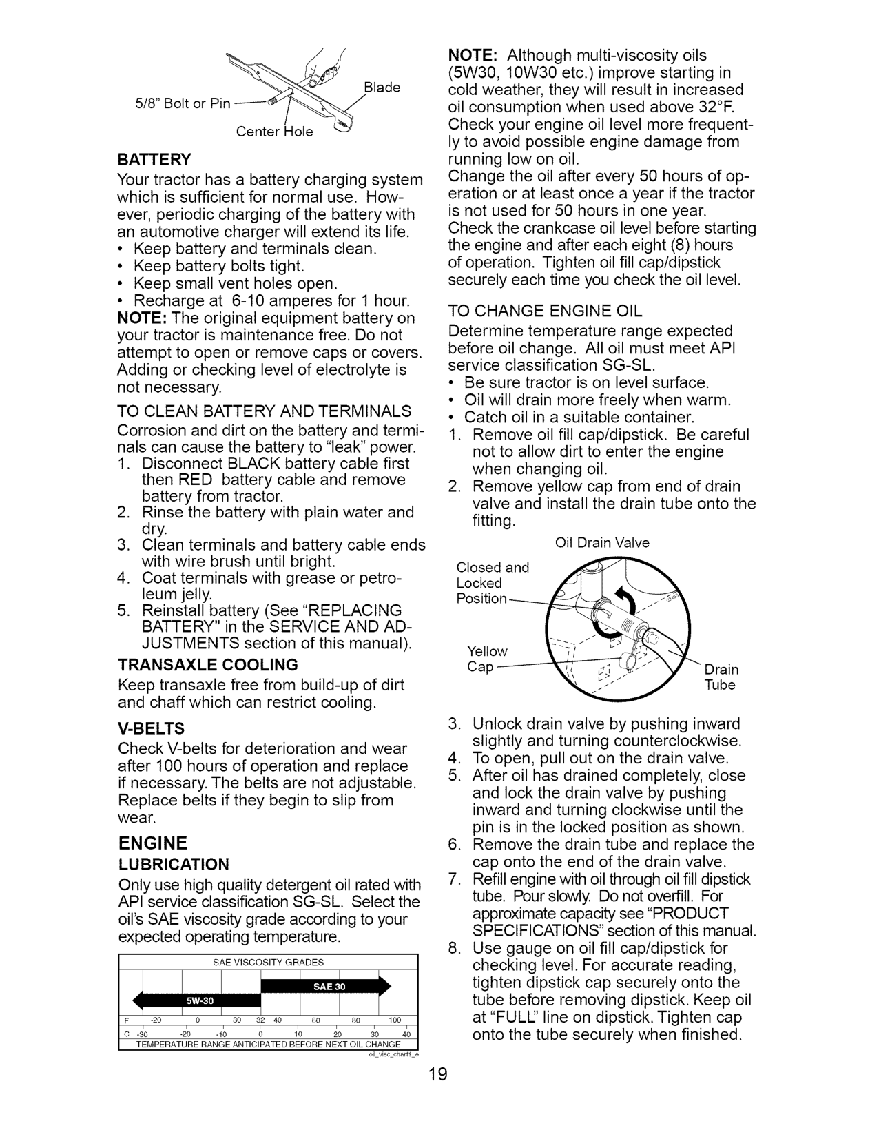
NOTE: Although multi-viscosity oils (5W30, 10W30 etc.)improve starting in cold weather, they will result in increased oil consumption when used above 32°R Check your engine oil level more frequently to avoid possible engine damage from running low on oil. Change the oil after every 50 hours of operation or at least once a year if the tractor is not used for 50 hours in one year. Check the crankcase oil level before starting the engine and after each eight (8) hours of operation. Tighten oil fill cap/dipstick securely each time you check the oil level.
Blade
5/8" Bolt or Pin
Center Hole BATT E RY
Your tractor has a battery charging system which is sufficient for normal use. How-
ever, periodic charging of the battery with an automotive charger will extend its life.
TO CHANGE ENGINE OIL Determine temperature range expected before oil change. All oil must meet API service classification SG-SL
Corrosion and dirt on the battery and terminals can cause the battery to "leak" power.
Oil Drain Valve
Drain Tube
TRANSAXLE COOLING Keep transaxle free from build-up of dirt and chaff which can restrict cooling. V-BELTS Check V-belts for deterioration and wear after 100 hours of operation and replace if necessary. The belts are not adjustable. Replace belts if they begin to slip from wear. ENGINE LUBRICATION
Only use high quality detergent oil rated with API service classification SG-SL Select the
oil's SAE viscosity grade according to your expected operating temperature.
SAE VISCOSITY GRADES
-20 0 30 32 40 60 80 100
-30 -20 -10 0 10 20 30 40 TEMPERATURE RANGE ANTICIPATED BEFORE NEXT OIL CHANGE
o]1 vJsccha_H ÷

ENGINE OIL FILTER Replace the engine oil filter every season or every other oil change if the tractor is used more than 100 hours in one year.
ENGINE COOLING SYSTEM Debris may clog the engine's air cooling system. Remove blower housing and clean area shown to prevent overheating and engine damage.
AIR FILTER Your engine will not run properly using a dirty air filter. Replace pre-cleaner after every 25 hours of operation or every season. Service paper cartridge every 100 hours of operation or every season, whichever occurs first. Service air cleaner more often under dusty conditions.
Clean out chaff Air Screen _ and debris
NOTE: If very dirty or damaged, replace cartridge.
MUFFLER Inspect and replace corroded muffler and spark arrester (if equipped) as it could create a fire hazard and/or damage. SPARK PLUG(S)
Replace spark plug(s) at the beginning of each mowing season or after every 100 hours of operation, whichever occurs first. Spark plug type and gap setting are shown in "PRODUCT SPECIFICATIONS" section of this manual.
IMPORTANT: Petroleum solvents, such as kerosene, are not to be used to clean the cartridge. They may cause deterioration of the cartridge. Do not oil cartridge. Do not use pressurized air to clean cartridge.
IN-LINE FUEL FILTER The fuel filter should be replaced once each season. If fuel filter becomes clogged, obstructing fuel flow to carburetor, replacement is required.
Cla
__C
--_ _" Fuel Filter CLEANING
artridge Pre-cleaner_ _
Tabs _Slots
We do not recommend using a garden hose or pressure washer to clean your tractor unless the engine and transmission are covered to keep water out. Water in engine or transmission will shorten the useful life of your tractor. Use compressed air or a leaf blower to remove grass,
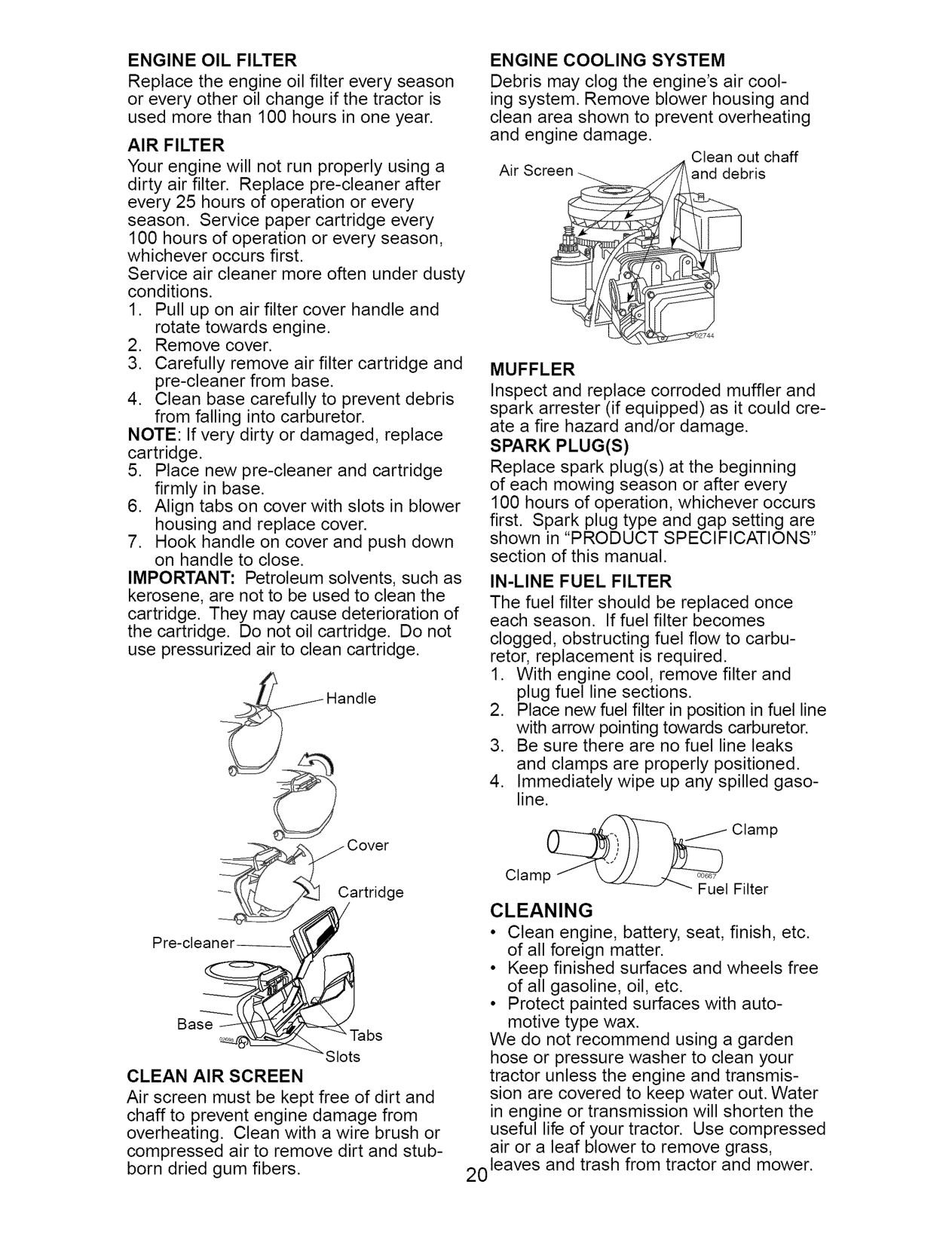
CLEAN AIR SCREEN Air screen must be kept free of dirt and chaff to prevent engine damage from overheating. Clean with a wire brush or compressed air to remove dirt and stubborn dried gum fibers.
20 leaves and trash from tractor and mower.

#################### _ ARNING: TO AVOID SERIOUSSERVICEORADJUSTMENTS:
IMPORTANT: If an attachment other than the mower deck is to be mounted on the tractor, remove the front links and hook the clutch spring Into square hole in frame. TO INSTALL MOWER
TRACTOR TO REMOVE MOWER Mower will be easier to remove from the right side of tractor.
Small
Small Retainer S
Retainer S
Anti-Sway
Collar_
Retainer Springs Sides)
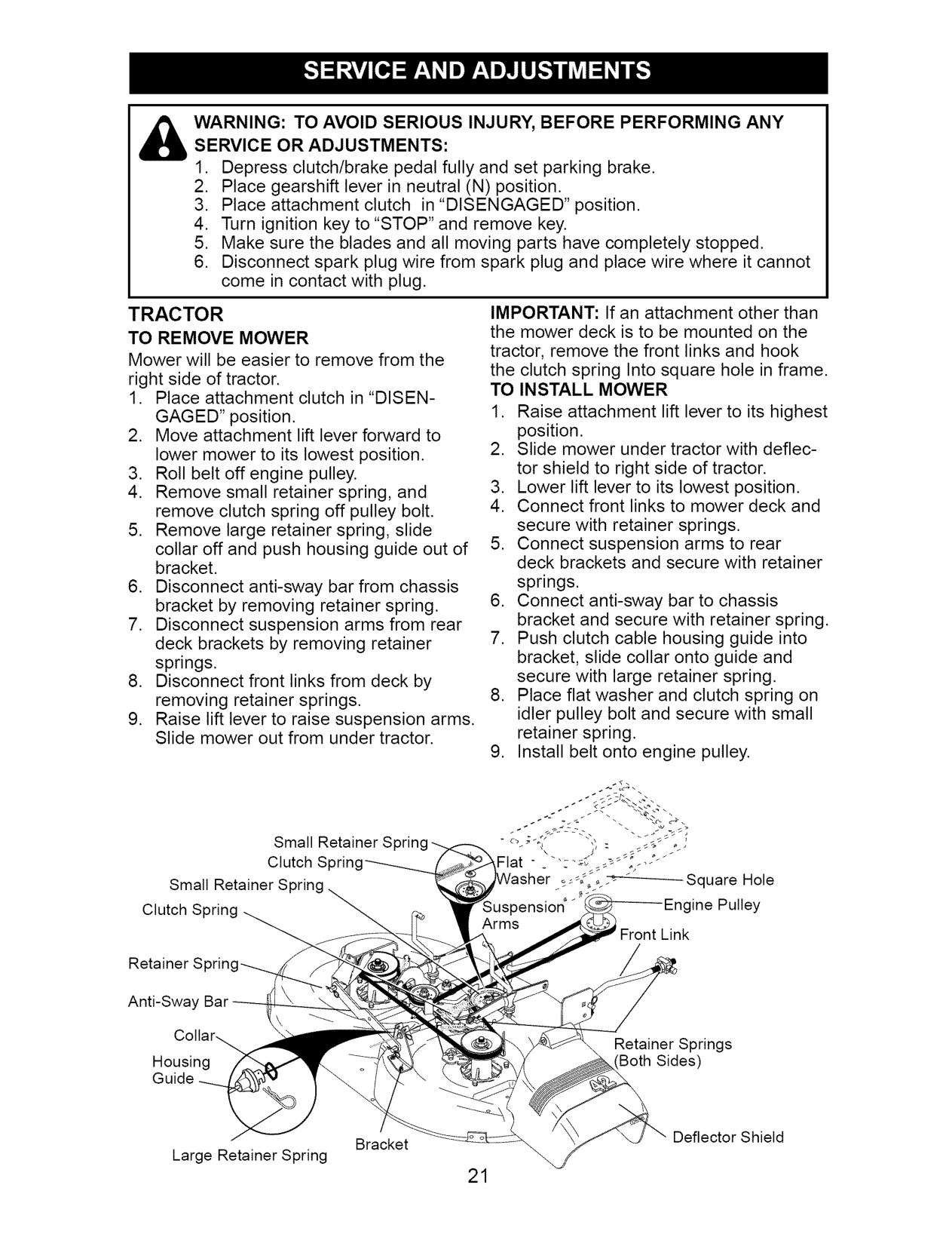
Housing Guide
Deflector Shield
Bracket Large Retainer Spring

TO LEVEL MOWER HOUSING Adjust the mower while tractor is parked on level ground or driveway. Make sure tires are properly inflated (See "PRODUCT SPECIFICATIONS" section of this manual). If tires are over or underinflated, you will not properly adjust your mower. SIDE-TO-SIDE ADJUSTMENT
at front than rear, tighten nut "F" against trunnion on both front links.
Both Front. Unks Should beEqual in Length
NOTE: Each full turn of adjustment nut will change mower height about 1/8".
• Recheck measurements after adjusting.
Bottom edge Bottom edge of of mower tor___ _'_ r0_er to ground ground \ f /_,t_ _,/I //
,_E
Trunnion
Lift Link Nu_ Adjustment
Front Links
FRONT-TO-BACK ADJUSTMENT IMPORTANT: Deck must be level side-to
########################## TO REPLACE MOWER BLADE DRIVE BELT
side. If the following front-to-back adjustment is necessary, be sure to adjust both front links equally so mower will stay level side-to-side. To obtain the best cutting results, the mower housing should be adjusted so
The mower blade drive belt may be replaced without tools. Park the tractor on level surface. Engage parking brake. BELT REMOVAL -
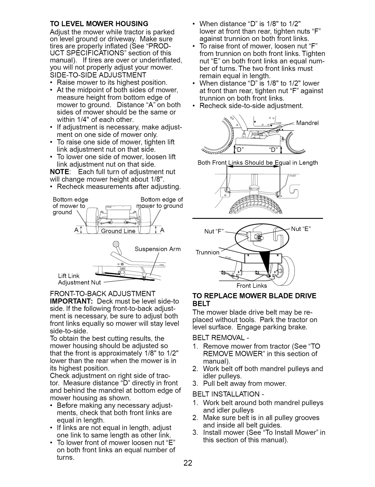
that the front is approximately 1/8" to 1/2" lower than the rear when the mower is in
its highest position. Check adjustment on right side of tractor. Measure distance "D" directly in front and behind the mandrel at bottom edge of mower housing as shown.

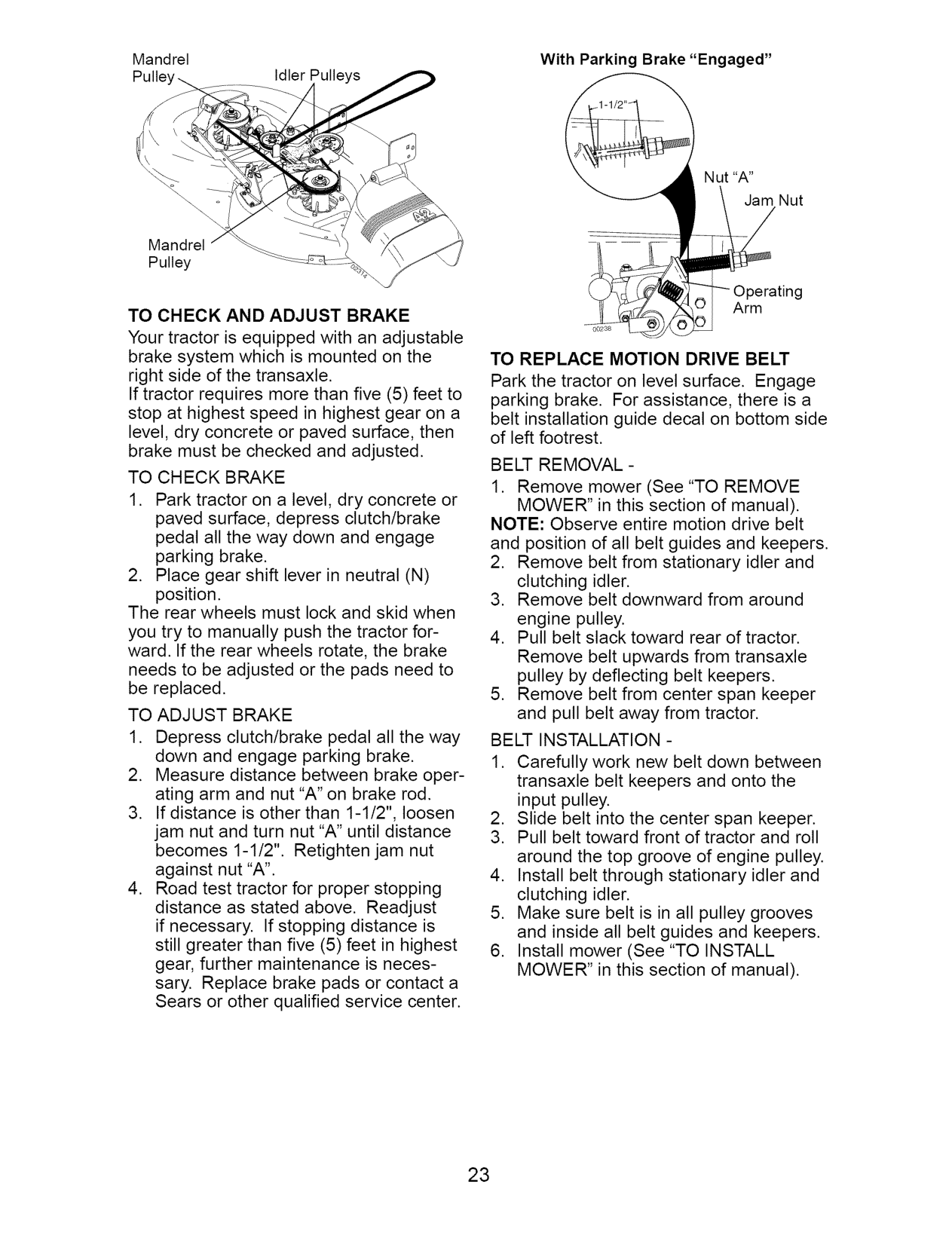
Mandrel With Parking Brake "Engaged" Idler Pulleys
Mandrel Pulley
TO CHECK AND ADJUST BRAKE Your tractor is equipped with an adjustable brake system which is mounted on the right side of the transaxle. If tractor requires more than five (5) feet to stop at highest speed in highest gear on a level, dry concrete or paved surface, then brake must be checked and adjusted. TO CHECK BRAKE
TO REPLACE MOTION DRIVE BELT Park the tractor on level surface. Engage parking brake. For assistance, there is a belt installation guide decal on bottom side of left footrest. BELT REMOVAL -
NOTE: Observe entire motion drive belt and position of all belt guides and keepers.
The rear wheels must lock and skid when you try to manually push the tractor forward. If the rear wheels rotate, the brake needs to be adjusted or the pads need to be replaced. TO ADJUST BRAKE
BELT INSTALLATION -

########################## TO REMOVE WHEEL FOR REPAIRS
Engine
Center
Clutching
Keeper
Stationary Idler Transaxle
########################## TRANSAXLE GEAR SHIFT LEVER NEUTRAL ADJUSTMENT
Washers
The transaxle should be in neutral when the gear shift lever is in neutral (N) (lock gate) position. The adjustment is preset
Retaining Ring
Axle Cover
Square Key _ (Rear Wheel Only) v
########################## TO START ENGINE WITH AWEAK BATTERY
_,WARNING: Lead-acid batteries generate explosive gases. Keep sparks, flame and smoking materials away from batteries. Always wear eye protection when around batteries. If your battery is too weak to start the engine, it should be recharged. (See "BATTERY" in the MAINTENANCE section of this manual). If "jumper cables" are used for emergency starting, follow this procedure: IMPORTANT: Your tractor is equipped with a 12 volt system. The other vehicle must also be a 12 volt system. Do not use your tractor battery to start other vehicles. TO ATTACH JUMPER CABLES -
Neutral Lock Gate Gearshift

########################## ..... ..... ,:,.... Adjustment Bolt TO ADJUST STEERING WHEEL ALIGN-
MENT lIfsteeringwheelcrossbarsareno horizontal (left to right) when wheels are positioned straight forward, remove steering wheel and reassemble with crossbars horizontal. Tighten securely.
FRONT WHEEL TOE-IN/CAM BER The front wheel toe-in and camber are not adjustable on your tractor. If damage has occurred to affect the front wheel toe-in or camber, contact a Sears or other qualified service center.

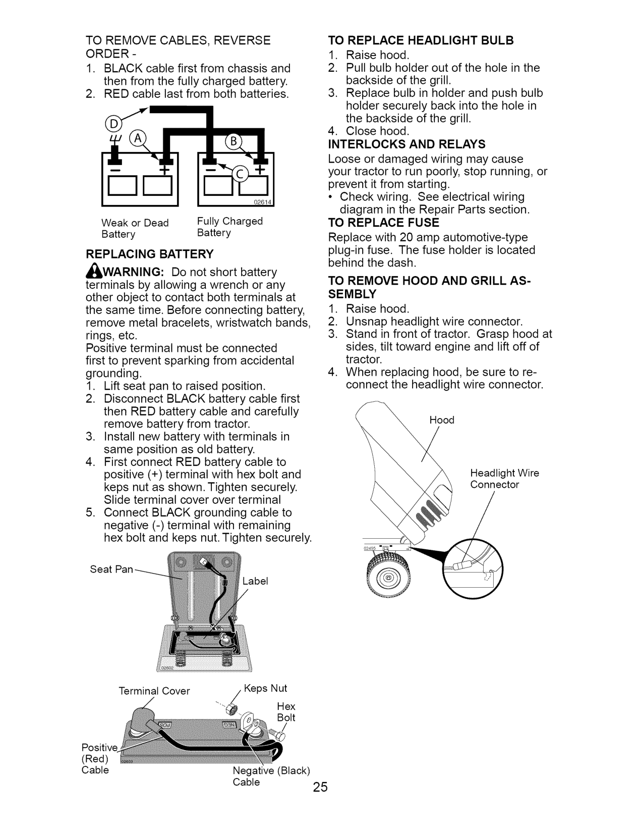
########################## TO REPLACE HEADLIGHT BULB
TO REMOVE CABLES, REVERSE ORDER -
Loose or damaged wiring may cause your tractor to run poorly, stop running, or prevent it from starting.
0261 1
• Check wiring. See electrical wiring
diagram in the Repair Parts section. TO REPLACE FUSE Replace with 20 amp automotive-type plug-in fuse. The fuse holder is located behind the dash.
Weak or Dead Fully Charged Battery Battery
########################## REPLACING BATTERY
_IbWARNING: Do not short battery terminals by allowing a wrench or any other object to contact both terminals at the same time. Before connecting battery, remove metal bracelets, wristwatch bands, rings, etc. Positive terminal must be connected first to prevent sparking from accidental grounding.
########################## TO REMOVE HOOD AND GRILL ASSEMBLY
Hood
Headlight Wire Connector
O2495 =
Label
Terminal Cover Keps Nut
"-_/ Hex Bolt
Positive (Red) Cable Negative (Black)
Cable 25

########################## ENGINE
IMPORTANT: Damage to the needle valve and the seat in carburetor may result if screw is turned in too tight. PRELIMINARY SETTING -
Maintenance, repair, or replacement of the emission control devices and systems, which are being done at the customers expense, may be performed by any non-road engine repair establishment or individual. Warranty repairs must be performed by an authorized engine manufacturer's service outlet.
###################### TO ADJUST THROTTLE CONTROL CABLE
FINAL SETTING -
The throttle control has been preset at the factory and adjustment should not be necessary. Check adjustment as described below before loosening cable. If adjustment is necessary, proceed as follows:
ACCELERATION TEST -
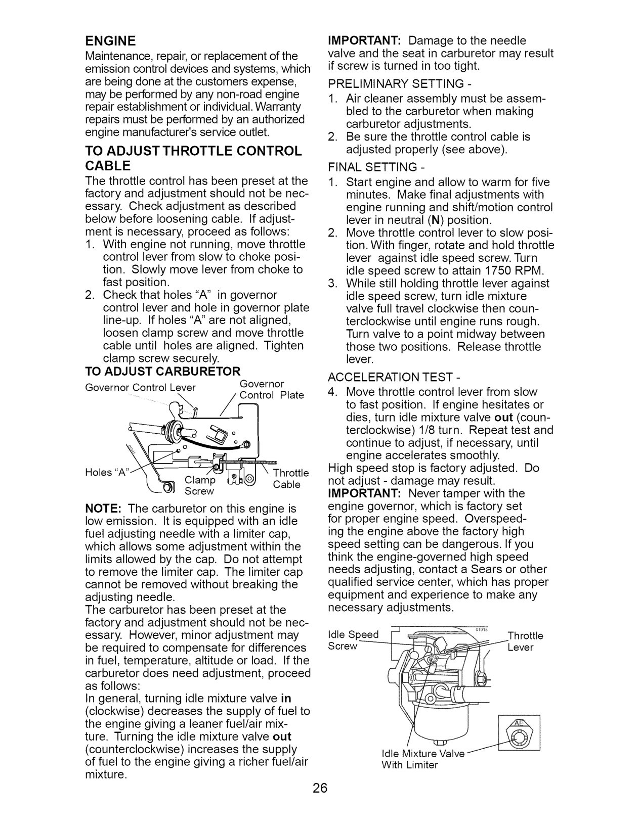
TO ADJUST CARBURETOR Governor Control Lever Governor
Plate
High speed stop is factory adjusted. Do not adjust - damage may result. IMPORTANT: Never tamper with the engine governor, which is factory set for proper engine speed. Overspeeding the engine above the factory high speed setting can be dangerous. If you think the engine-governed high speed needs adjusting, contact a Sears or other qualified service center, which has proper equipment and experience to make any necessary adjustments.
Holes Throttle
Clamp Cable Screw
NOTE: The carburetor on this engine is low emission. It is equipped with an idle fuel adjusting needle with a limiter cap,
which allows some adjustment within the limits allowed by the cap. Do not attempt to remove the limiter cap. The limiter cap cannot be removed without breaking the adjusting needle. The carburetor has been preset at the factory and adjustment should not be necessary. However, minor adjustment may be required to compensate for differences in fuel, temperature, altitude or load. If the carburetor does need adjustment, proceed as follows: In general, turning idle mixture valve in (clockwise) decreases the supply of fuel to the engine giving a leaner fuel/air mixture. Turning the idle mixture valve out (counterclockwise) increases the supply of fuel to the engine giving a richer fuel/air mixture.
Idle Speed [- _ Throttle Screw Lever
With Limiter

Immediately prepare your tractor for storage at the end of the season or if the tractor will not be used for 30 days or more. _ICAUTION: Never store the tractor with gasoline in the tank inside a building where fumes may reach an open flame or spark. Allow the engine to cool before storing in any enclosure. TRACTOR Remove mower from tractor for winter storage. When mower is to be stored for a period of time, clean it thoroughly, remove all dirt, grease, leaves, etc. Store in a clean, dry area.
blended fuels (called gasohol or using ethanol or methanol) can attract moisture which leads to separation and formation of acids during storage. Acidic gas can damage the fuel system of an engine while in storage.
Drain oil (with engine warm) and replace with clean engine oil. (See "ENGINE" in the Maintenance section of this manual). CYLINDER(S)
########################## BATTERY
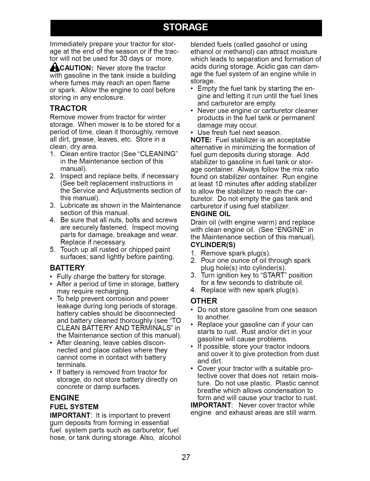
ture. Do not use plastic. Plastic cannot breathe which allows condensation to
ENGINE FUEL SYSTEM IMPORTANT: It is important to prevent gum deposits from forming in essential fuel system parts such as carburetor, fuel hose, or tank during storage. Also, alcohol
form and will cause your tractor to rust. IMPORTANT: Never cover tractor while engine and exhaust areas are still warm.

######################## PROBLEM Will not start
######################## CAUSE
######################## 3ORRECTION
Hard to start
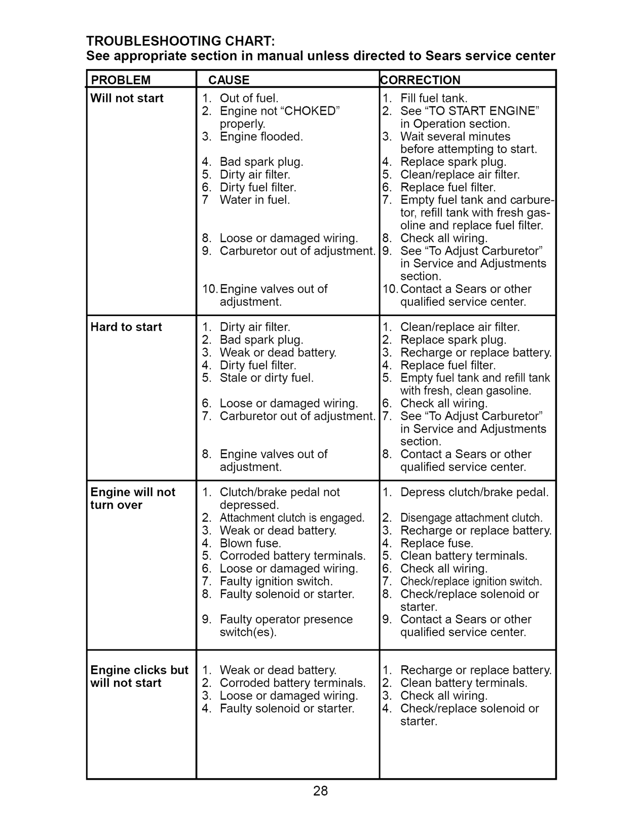
Engine will not turn over
Engine clicks but will not start

######################## CAUSE CORRECTION
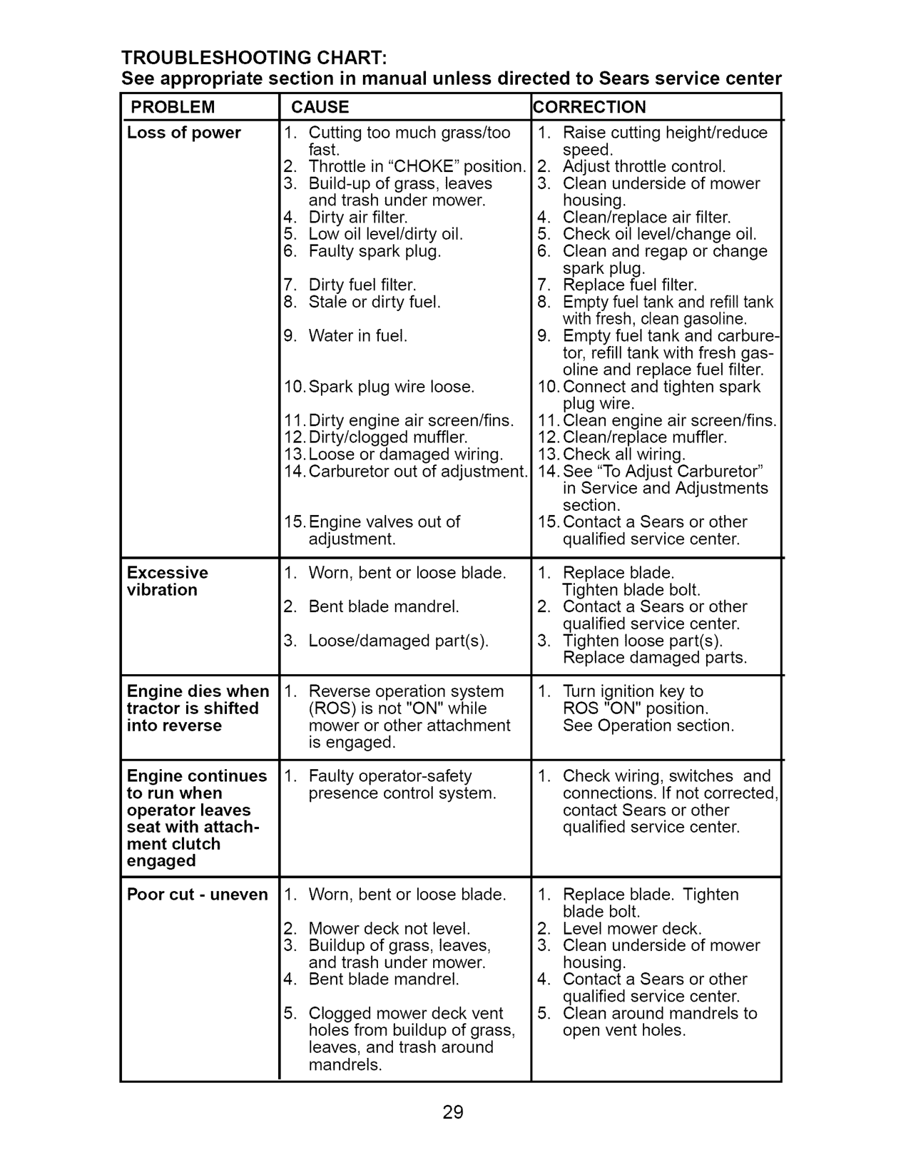
PROBLEM Loss of power
######################## Excessive vibration
Engine dies when tractor is shifted
. Reverse operation system (ROS) is not "ON" while mower or other attachment is engaged.
into reverse
Engine continues to run when operator leaves seat with attachment clutch engaged
Faulty operator-safety presence control system.
Check wiring, switches and connections. If not corrected contact Sears or other qualified service center.
.
Poor cut - uneven
Worn, bent or loose blade. Mower deck not level. Buildup of grass, leaves, and trash under mower. Bent blade mandrel. Clogged mower deck vent holes from buildup of grass, leaves, and trash around mandrels.
.

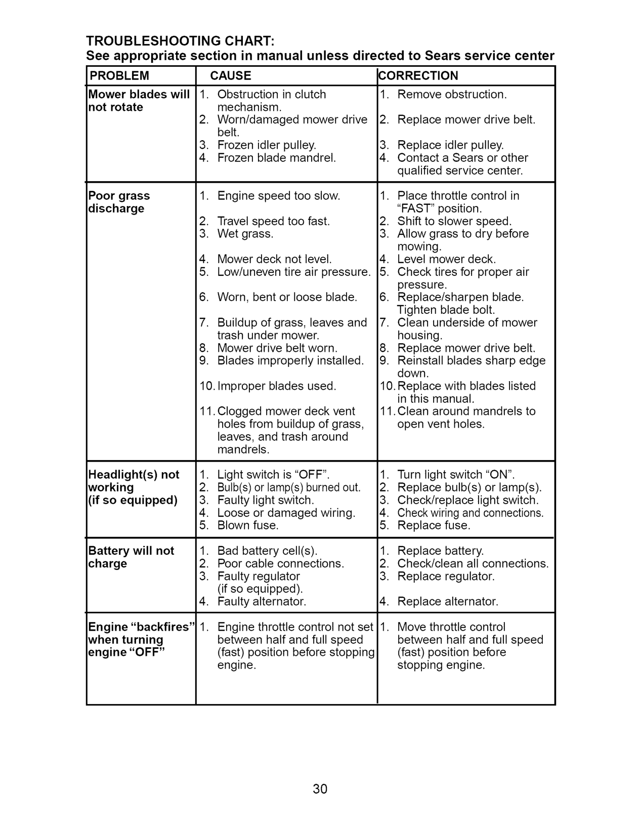
PROBLEM CAUSE CORRECTION 1•
Mower blades will not rotate
Remove obstruction.
Replace mower drive belt.

Poor grass discharge
•Clogged mower deck vent holes from buildup of grass, leaves, and trash around mandrels.
Headlight(s) not working (if so equipped)
######################## Battery will not charge
Move throttle control between half and full speed (fast) position before stopping engine•
Engine "backfires" when turning engine "OFF"
• Engine throttle control not set between half and full speed (fast) position before stopping engine•
•

######################## SCHEMATIC
02836 193374 / 390
STARTER
AMMETER FUSE
(OPTIONAL)
############################### I I I7©
WHITE
i i i i i i i
########################### ' , I
BLAOK
BLAOK
BLACK
GRAY
REVERSE SWITCH
SHORTING CONNECTOR
NOT IN REVERSE
K
SPARKPLUGSIGNITION......................0GAP0 UNIT (2PLUGS
ONTWINCYL. ENGINES)

.... cHO,JHOUR_; .....
FUEL (OPTIONAL)
LINEBLUE CHARGING SYSTEM OUTPUT 28 VOLTS AG MIN. @ 3600 RPM
3 AMP DC @ 3600 RPM
(CHARGING SYSTEM DISCONNECTED)
FUEL SHUT-OFF _// _/ 04 k_A__J'k_jREDSOLENOID......................... i LIGHTING SYSTEM OUTPUT
' 5 AMPAC @ 3600 RPM DIODE ALTERNATOR _ 0 ' r-, I'
= LIGHTSWITCH =
AC MIN. (LIGHTS
BRO WN BLACK
NOTE YOUR TRACTOR IS EQUIPPED WITH A SPECIAL ALTERNATOR SYSTEM. THE LIGHTS ARE NOT CONNECTED TO THE
####################### • ©
NON-REMOVABLE REMOVABLE CONNECTIONS CONNECTIONS
BATTERY, BUT HAVE THEIR OWN ELECTRICAL SOURCE.
BECAUSE OF THIS, THE BRIGHTNESS OF THE LIGHTS WILL CHANGE WITH ENGINE SPEED. AT IDLE THE LIGHTS WILL DIM. AS THE ENGINE IS
############################## IGNITION SWITCH
WIRING INSULATED CLIPS NOTE: IF WIRING INSULATED CLIPS WERE REMOVED FOR SERVICING OF
################################# POSITION CIRCUIT "MAKE"
OFF M+G+A1 RUN/OVERRIDE B+A1
UNIT, THEY SHOULD BE REPLACEDSPEEDEDUP,THELIGHTS WILL BECOME THEIR BRIGHTEST. TO PROPERLY SECURE YOUR WIRING.
RUN B+A1 L+A2 START B + S + A1
02836

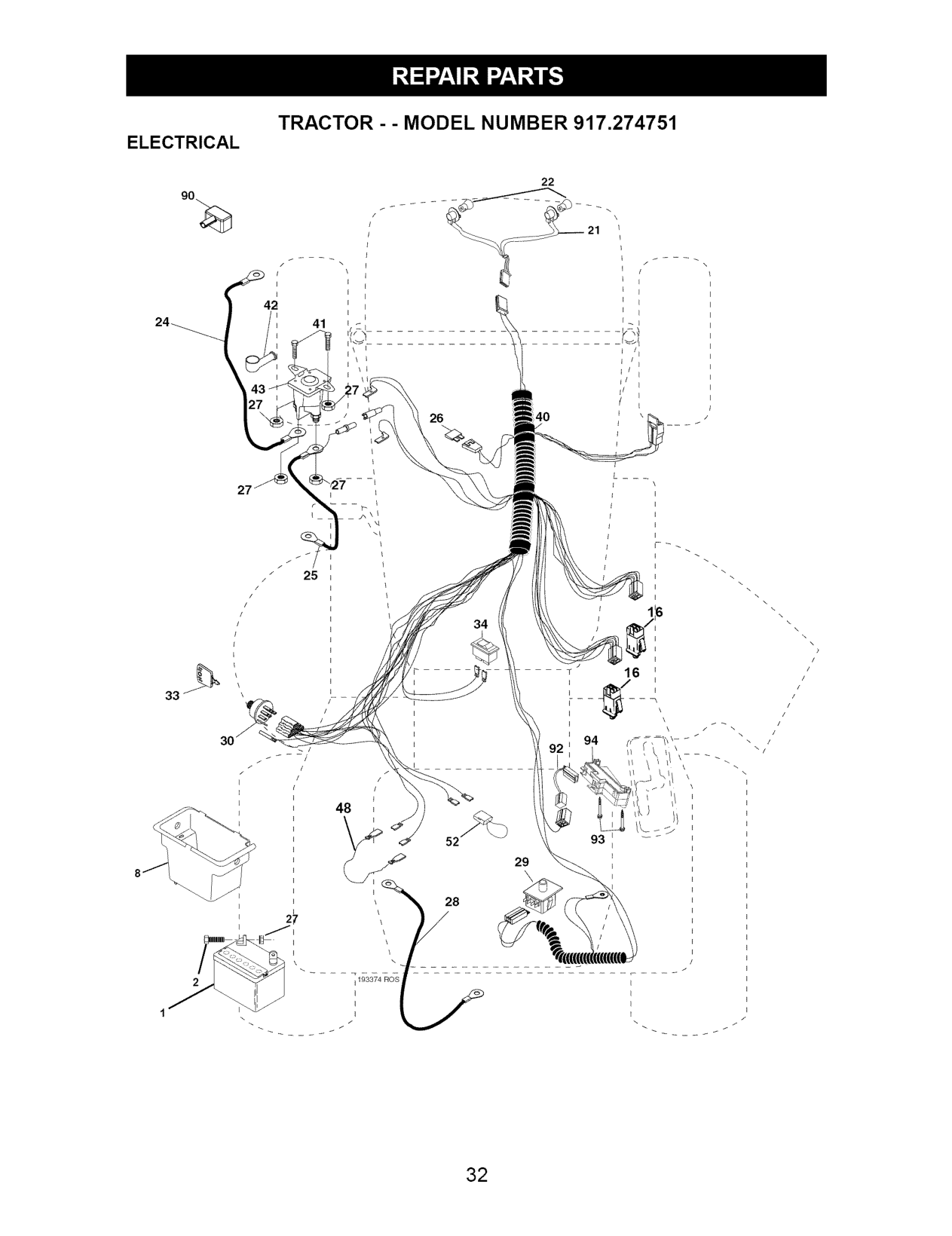
TRACTOR - - MODEL NUMBER 917.274751
ELECTRICAL
26
34
/
! i
/
/ \
•
############################## 48 _/
52 93 _
28
########### 27 ___/_-_k"...... ...................................................°
_:;r_r_74_Us .................................................................7

ELECTRICAL
########################## KEY PART NO. NO. DESCRIPTION

48 140844 Adapter Ammeter 52 141940 Protection Wire Loop 90 180449 Cover Terminal
NOTE: All component dimensions given in U.S. inches
1 inch = 25.4 mm

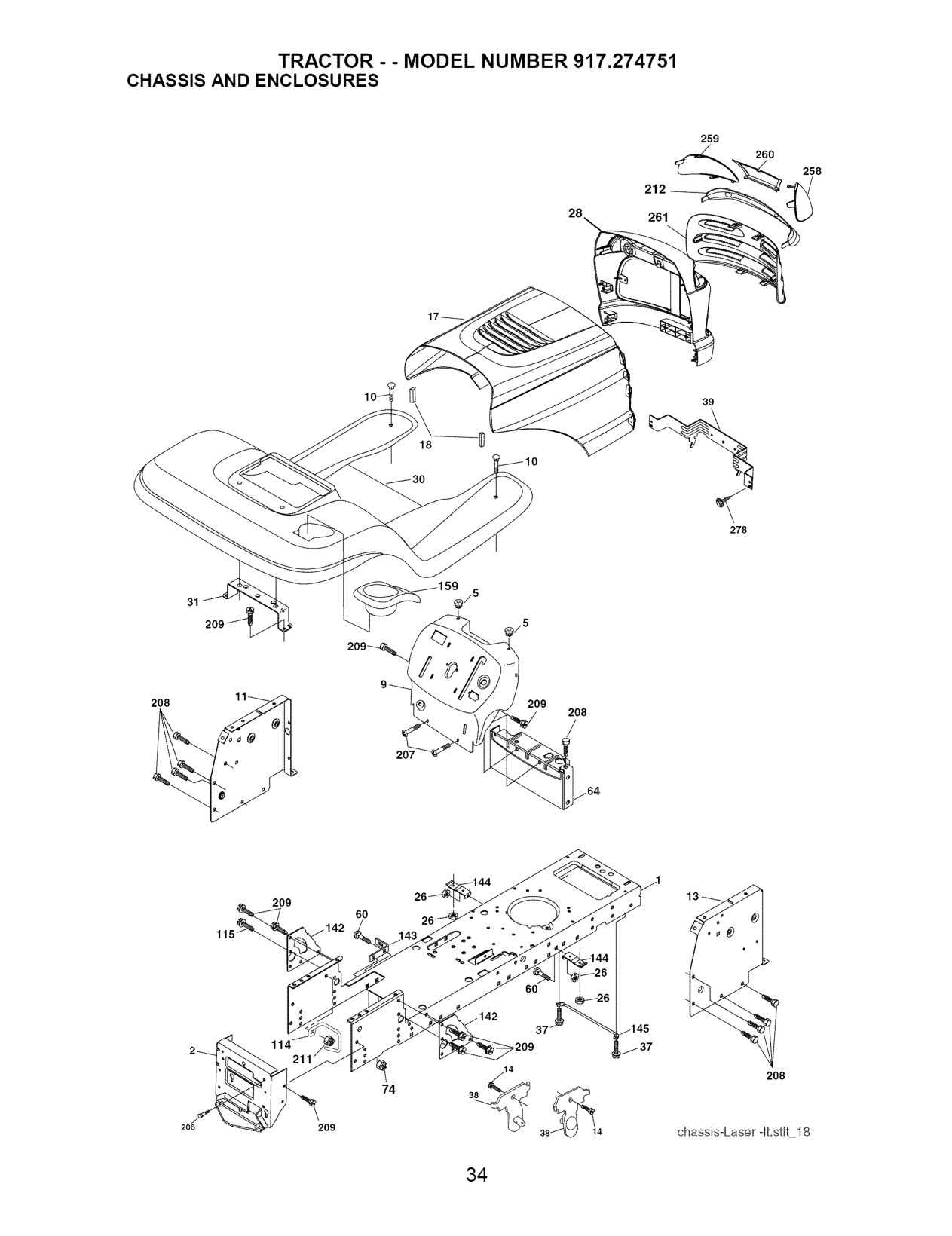
######################## TRACTOR - - MODEL NUMBER 917,274751 CHASSIS AND ENCLOSURES
259
260
258
212 261
28
39
18
278
5
31
@/5
208
209
208
################# /
207
################################ 209
60
_37
################################## 2_
208
74
209
206
chassis-Laser -It.stk 18

######################## TRACTOR - - MODEL NUMBER 917.274751 CHASSIS AND ENCLOSURES
############################ KEY PART NO. NO. DESCRIPTION
1 174619 Chassis 2 176554 Drawbar 5 155272 Bumper Hood/Dash
60 72140606 Bolt Rdhd Sqnk 3/8-16 unc x 1 64 154798 Dash Lower STLT 74 STD541437 Nut Crownlock 3/8-16 unc
NOTE: All component dimensions given in U.S. inches
1 inch = 25.4 mm

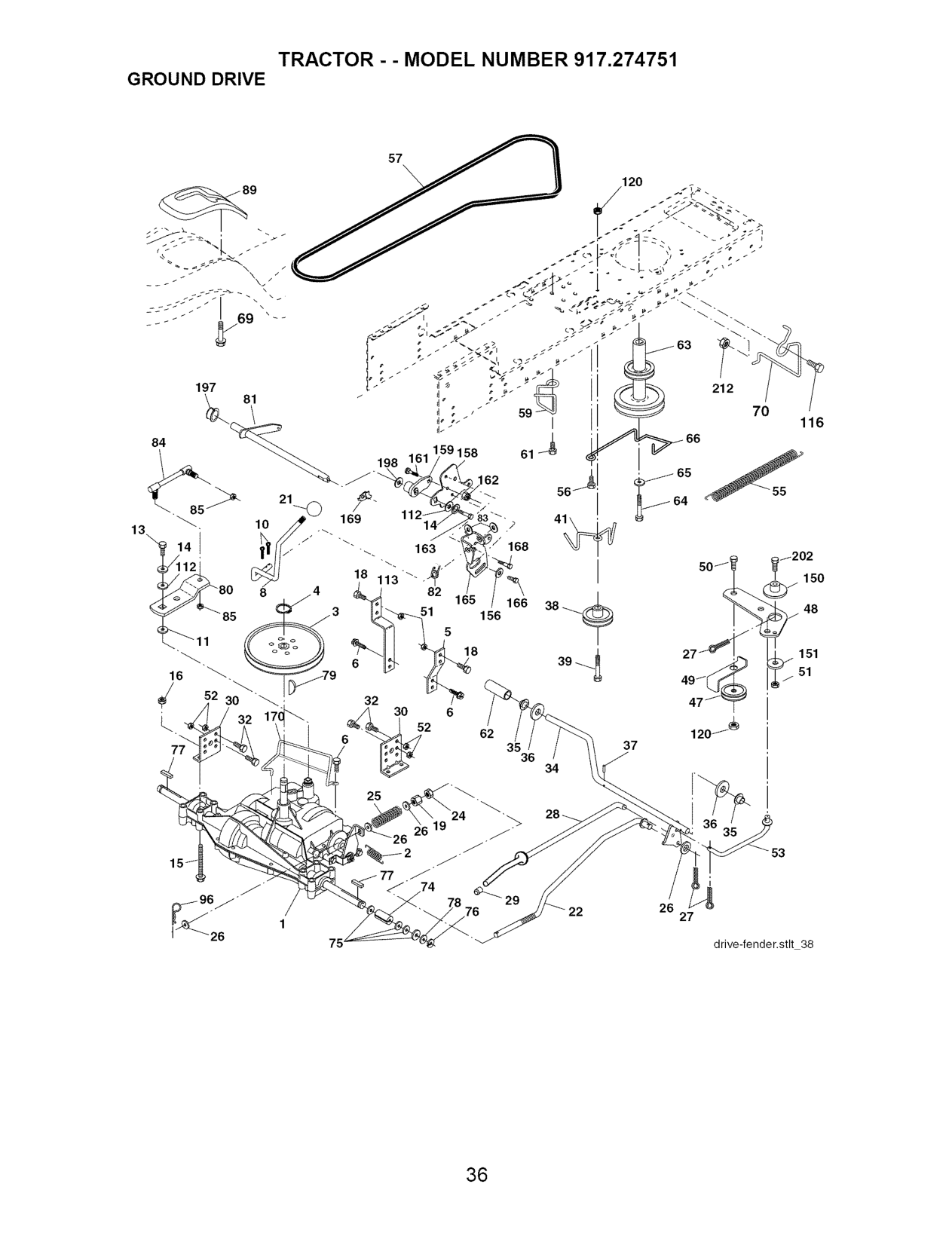
######################## TRACTOR- MODEL NUMBER 917.274751 GROUND DRIVE
############################## 25
i
############################## 27

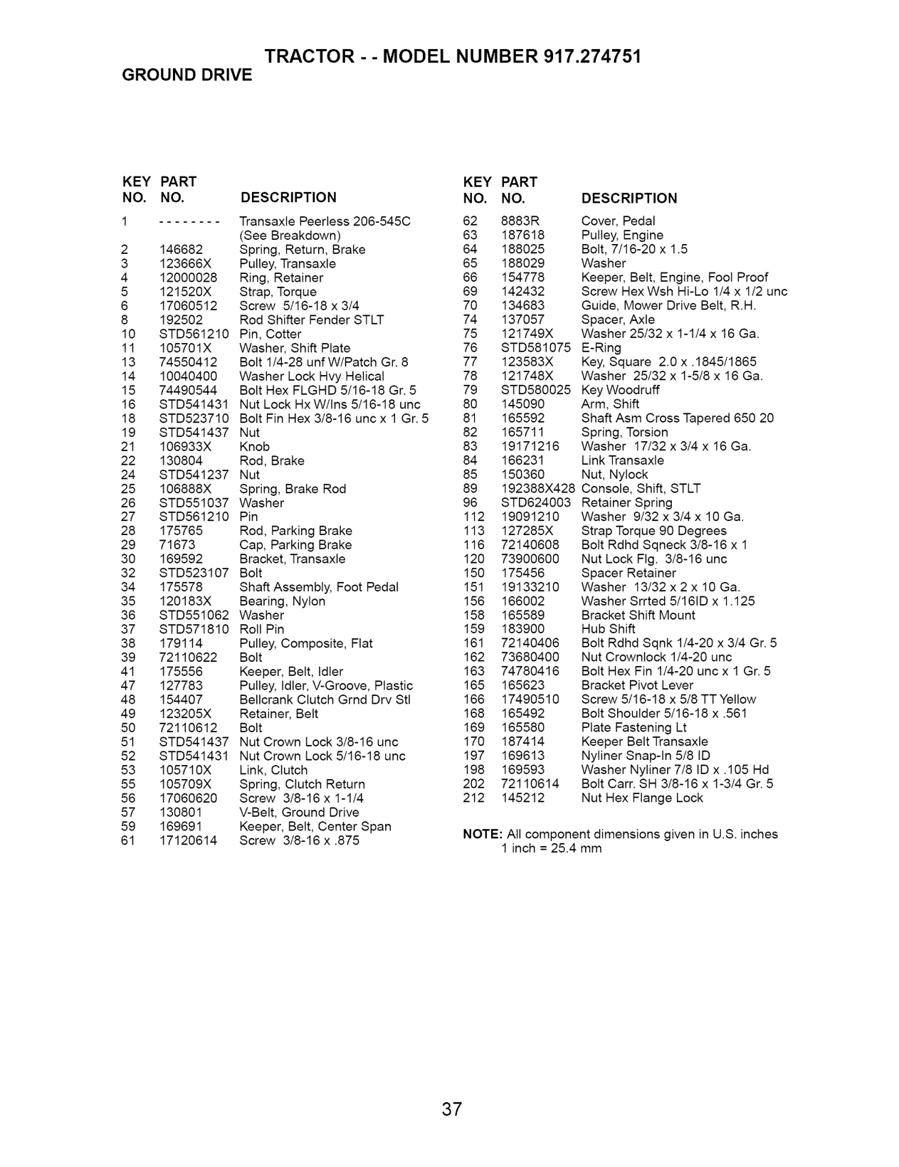
######################## TRACTOR -- MODEL NUMBER 917.274751 GROUND DRIVE
############################## KEY PART KEY PART NO. NO. DESCRIPTION NO. NO.
############################## DESCRIPTION
Cover, Pedal Pulley, Engine Bolt, 7/16-20 x 1.5 Washer Keeper, Belt, Engine, Fool Proof Screw HexWsh Hi-Lo 1/4 x 1/2 uric Guide, Mower Drive Belt, R.H. Spacer, Axle Washer 25/32 x 1-1/4 x 16 Ga.
10 STD561210 Pin, Cotter 75 121749X 11 105701X Washer, Shift Plate 76
STD581075 E-Ring Key, Square 2.0 x .1845/1865 Washer 25132 x 1-518 x 16 Ga.
Key Woodruff Arm, Shift Shaft Asm Cross Tapered 650 20 Spring, Torsion Washer 17132 x 3/4 x 16 Ga. Link Transaxle Nut, Nylock
192388X428 Console, Shift, STLT Retainer Spring Washer 9/32 x 3/4 x 10 Ga.
Strap Torque 90 Degrees Bolt Rdhd Sqneck 3/8-16 x 1 Nut Lock Fig. 3/8-16 unc Spacer Retainer Washer 13/32 x 2 x 10 Ga. Washer Srrted 5/161D x 1.125 Bracket Shift Mount Hub Shift Bolt Rdhd Sqnk 1/4-20 x 3/4 Gr. 5 Nut Crownlock 1/4-20 unc Bolt Hex Fin 1/4-20 uncx 1 Gr. 5 Bracket Pivot Lever Screw 5t16-18 x 5t8 TT Yellow Bolt Shoulder 5/16-18 x .561 Plate Fastening Lt Keeper Belt Transaxle Nyliner Snap-in 5/8 ID Washer Nyliner 7/8 ID x .105 Hd Bolt Carr. SH 3/8-16 x 1-314 Gr. 5 Nut Hex Flange Lock

NOTE: All component dimensions given in U.S. inches
1 inch = 25.4 mm

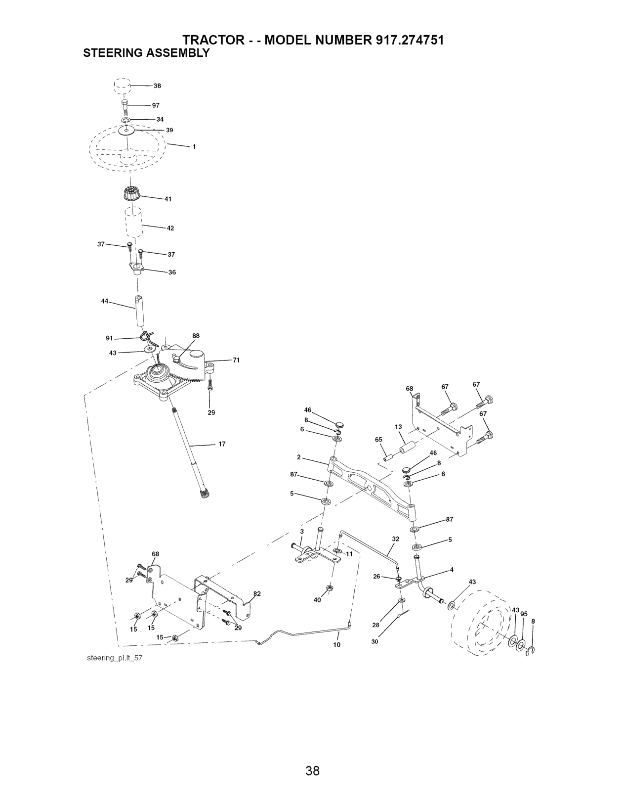
######################## TRACTOR - - MODEL NUMBER 917,274751 STEERING ASSEMBLY
########################### -2J_39
L
####### i!2--37
67
68 67
46
67
13
65
26
43
/ /
15
10 30
steering pl,lt 57

######################## STEERING ASSEMBLY
############################ KEY PART NO. NO. DESCRIPTION
91 175553 Clip Steering 95 188967 Washer Hardened 97 74780564 Bolt 5/16-18 unc x 4" Gr. 5
NOTE: All component dimensions given in U.S. inches
1 inch = 25.4 mm

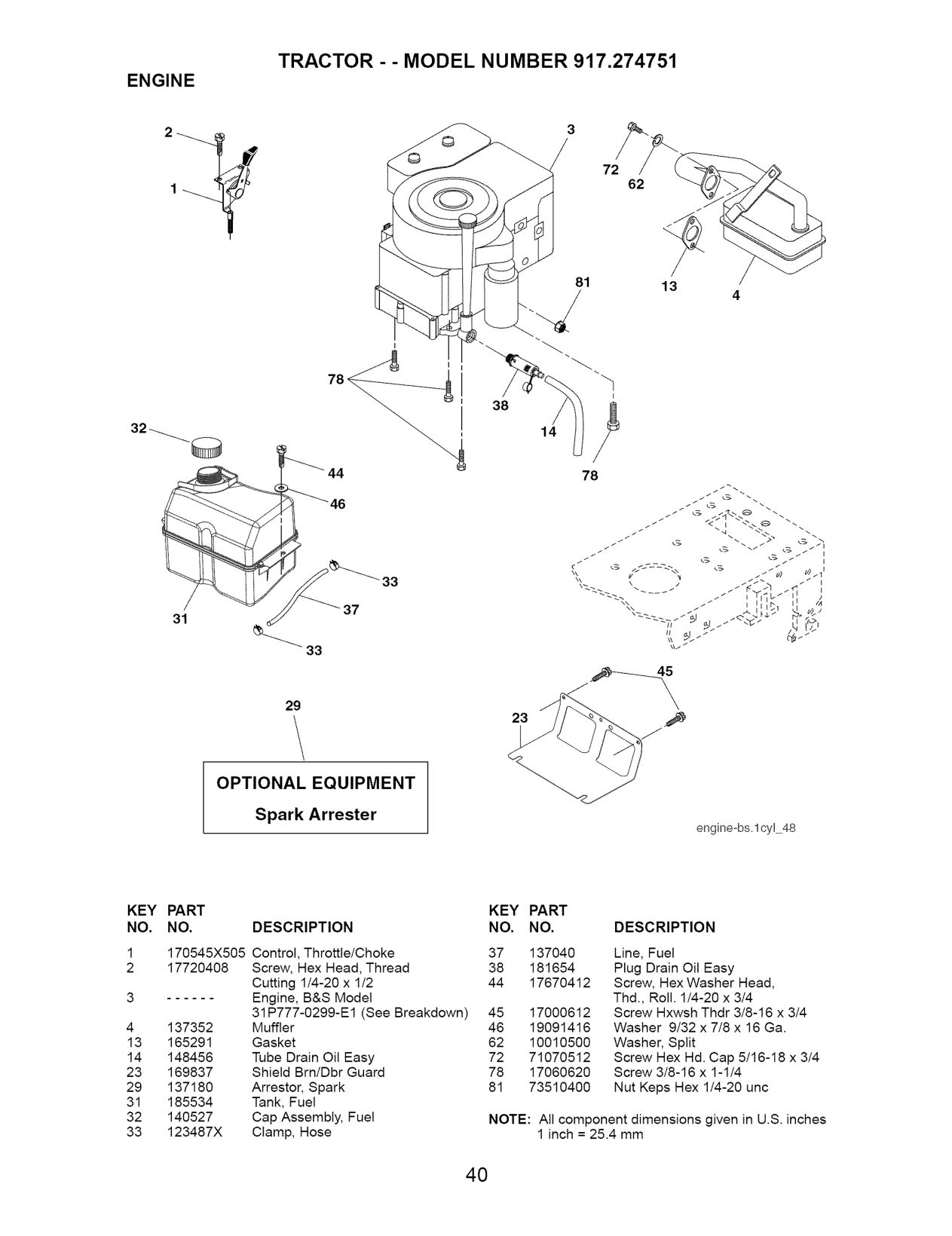
###################### TRACTOR - - MODEL NUMBER 917,274751
ENGINE
72
62
81
13
4
38
14
33
37
31
######### \
29
23
OPTIONAL EQUIPMENT Spark Arrester
engine-bs.lcy! 48
########################## KEY PART NO. NO.
############################ KEY PART DESCRIPTION NO. NO.
############################ DESCRIPTION
137040 181654
Control, Throttle/Choke 37 Screw, Hex Head, Thread 38 Cutting 114-20 x 112 44 Engine, B&S Model 31P777-0299-E1 (See Breakdown) 45 Muffler 46 Gasket 62 Tube Drain Oil Easy 72 Shield Brn/Dbr Guard 78 Arrestor, Spark 81 Tank, Fuel Cap Assembly, Fuel Clamp, Hose
Line, Fuel Plug Drain Oil Easy Screw, Hex Washer Head, Thd., Roll. 1/4-20 x 3/4 Screw Hxwsh Thdr 3/8-16 x 3/4 Washer 9/32 x 7/8 x 16 Ga. Washer, Split Screw Hex Hd. Cap 5/16-18 x 3/4 Screw 3/8-16 x 1-1/4 Nut Keps Hex 1/4-20 unc
17670412 17000612 19091416 10010500 71070512 17060620 73510400
NOTE: All component dimensions given in U.S. inches
1 inch = 25.4 mm

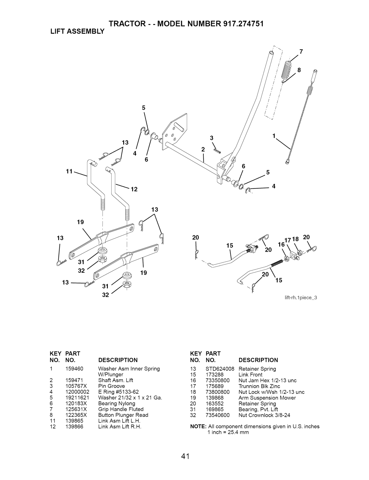
######################## LIFT ASSEMBLY
7
3 2
13
13
20
20
19
.../
32
lift-rh.lpiece 3
########################## KEY NO.
PART NO. 159460
############################## KEY PART NO. NO. DESCRIPTION
############################## DESCRIPTION
Washer Asm Inner Spring W/Plunger Shaft Asm. Lift Pin Groove E Ring #5133-62 Washer 21/32 x 1 x 21 Ga. Bearing Nylong Grip Handle Fluted Button Plunger Read Link Asm Lift L.H. Link Asm Lift R.H.
13 STD624008 Retainer Spring
159471 105767X 12000002 19211621 120183X 125631X 122365X
139865 139866
NOTE: All component dimensions given in U.S. inches
1 inch = 25.4 mm

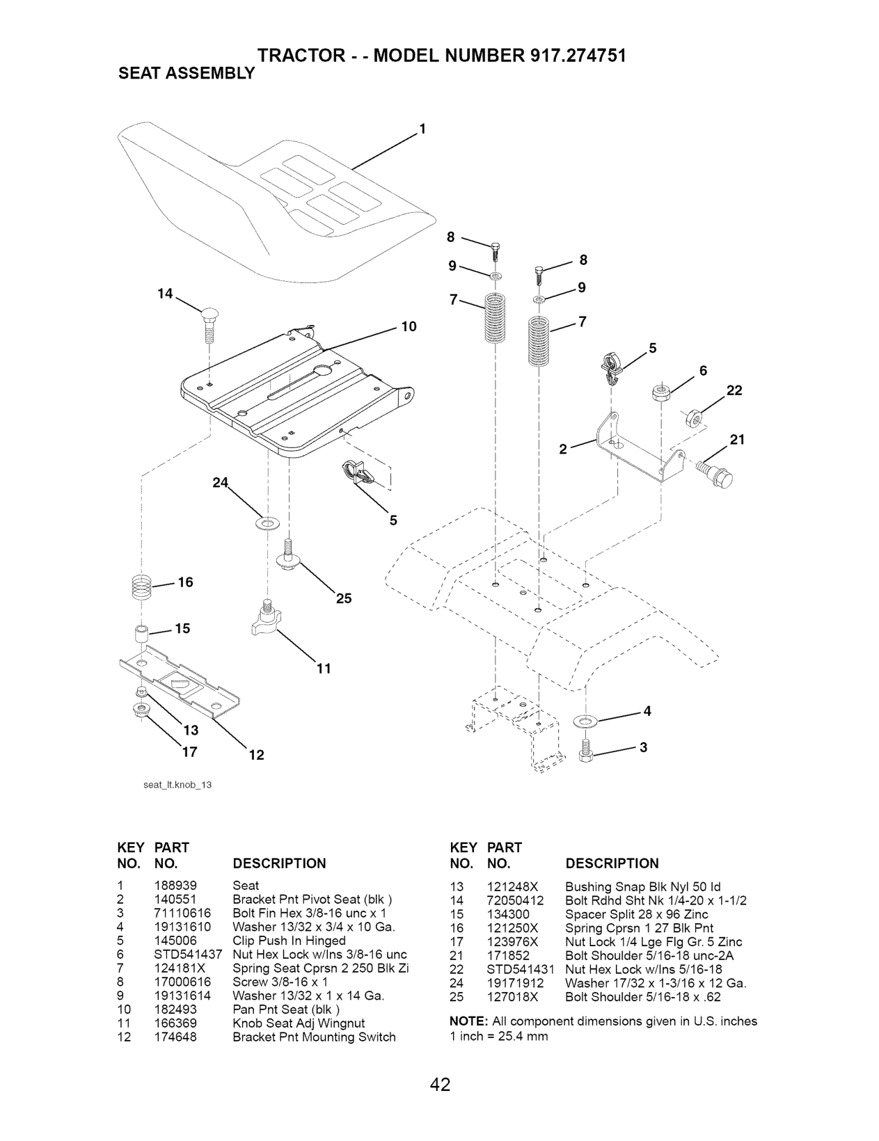
######################## SEAT ASSEMBLY
J
25
17
12
seat ILknob 13
KEY PART NO. NO. DESCRIPTION
############################## KEY PART NO. NO. DESCRIPTION
Bushing Snap BIk Nyl 50 Id Bolt Rdhd Sht Nk 1/4-20 x 1-1/2
Spacer Split 28 x 96 Zinc Spring Cprsn 1 27 BIk Pnt Nut Lock 1/4 Lge Fig Gr. 5 Zinc Bolt Shoulder 5116-18 unc-2A Nut Hex Lock w/Ins 5116-18 Washer 17/32 x 1-3116 x 12 Ga. Bolt Shoulder 5116-18 x .62
NOTE: All component dimensions given in U.S. inches 1 inch = 25.4 mm

###################### TRACTOR - - MODEL NUMBER 917,274751
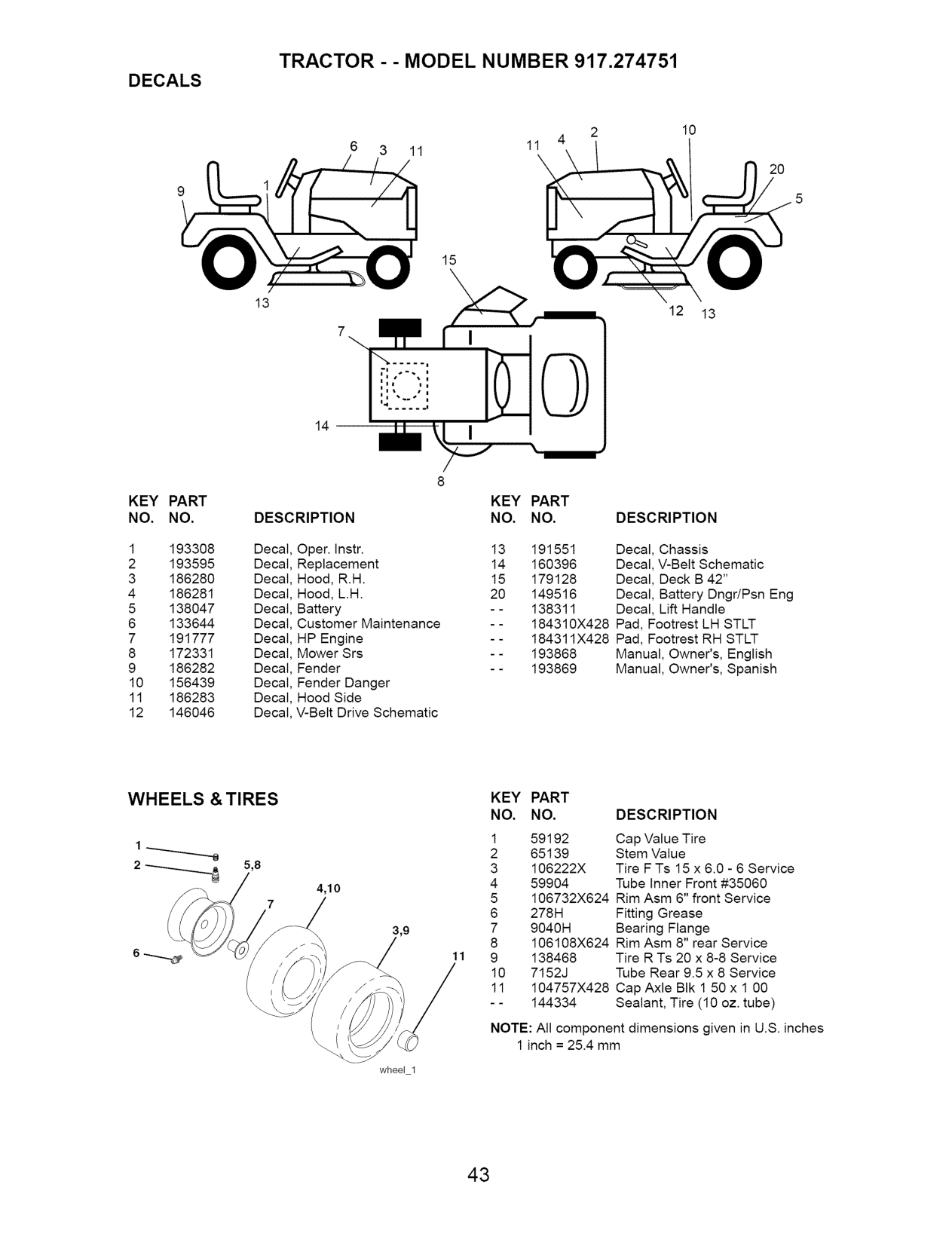
DECALS
lO
3 11 11
2o
15
########## \
13
12 13
14
KEY PART NO. NO.
KEY PART DESCRIPTION NO. NO.
############################ DESCRIPTION

Decal Oper. Instr. 13 191551 Replacement 14 160396 Hood, R.H. 15 179128 Hood, L.H. 20 149516 Battery - - 138311 Customer Maintenance - - 184310X428 HP Engine - - 184311X428 Mower Srs - - 193868 Fender - - 193869 Fender Danger Hood Side V-Belt Drive Schematic
Decal, Chassis Decal, V-Belt Schematic Decal, Deck B 42" Decal, Battery Dngr/Psn Eng Decal, Lift Handle Pad, Footrest LH STLT Pad, Footrest RH STLT Manual, Owner's, English Manual, Owner's, Spanish
######################## WHEELS &TIRES
############################## KEY PART NO. NO. DESCRIPTION
2 5,8
4,10
7
11
6 -----_
1 inch = 25.4 mm
wheel 1

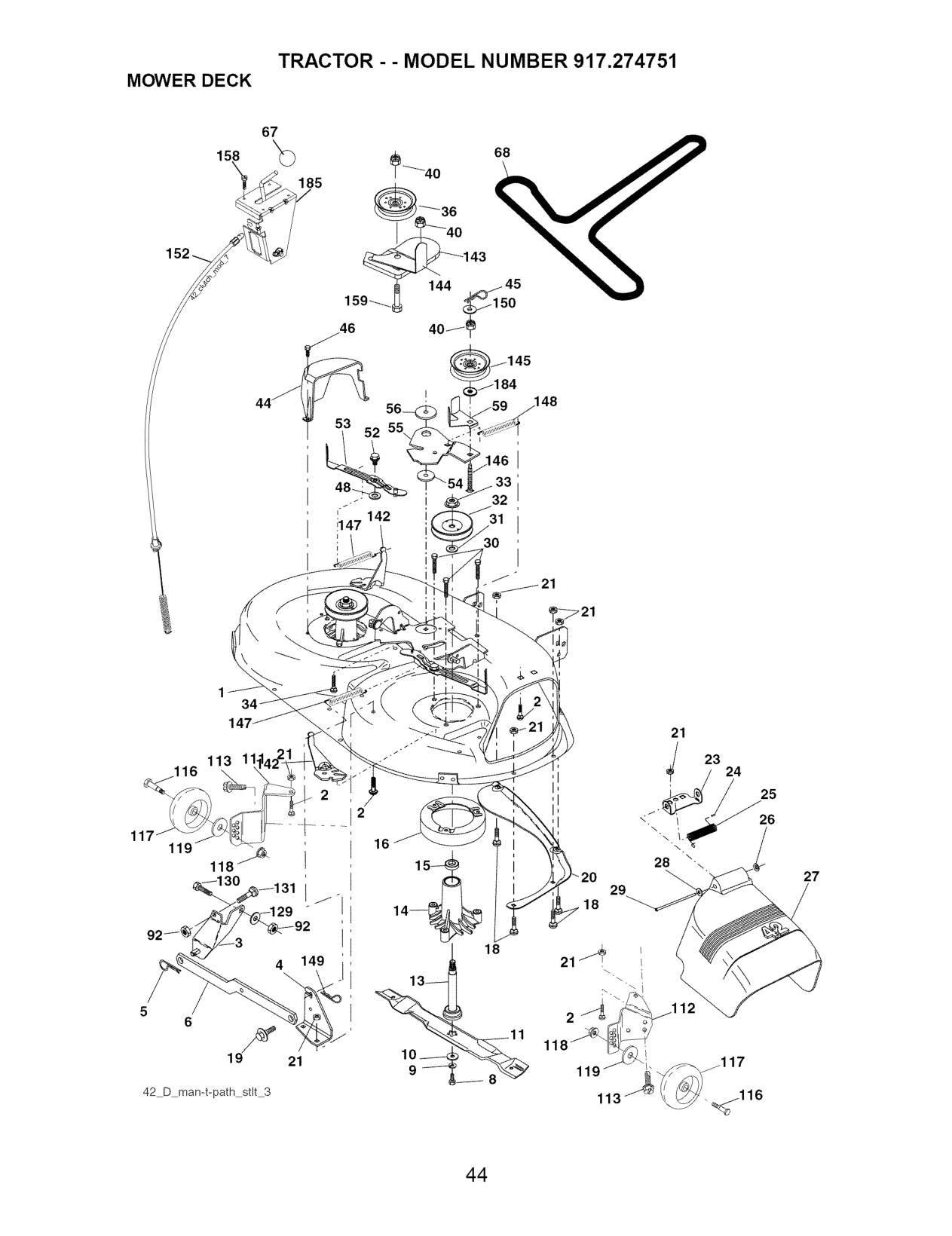
: 142 il 47
21
23
113 11 _116
24
################# i i
25 26
117
16
118/_.
27
29 18
14--
18
13--
12
5
#### if
6
10_ 9_
21
119 _ 117
18 v
42 D man-t-path stlt 3

############################ KEY PART KEY PART NO. NO. DESCRIPTION NO. NO. DESCRIPTION
Arm Assembly, Pad, Brake Washer, Hardened Arm, Idler Spacer, Retainer Guard, TUV Idler Knob Custom Oval V-Belt Nut
Mower Deck Assembly, 42" 53 184907 Bolt 54 178515
Bracket Assembly, Sway Bar, Front 55 155046 Bracket Sway Bar 38142" Deck 56 165723 Retainer Spring 59 141043 Bar Sway Deck 67 184939 Bolt, Hex 3/8-24 x 1.25 Gr. 8 68 144959 Washer, Lock 92 STD541437 Washer, Hardened 111 179292 (The following blades are available) 112 179293 Blade, 42" Hi-Lift 113 17000510 (For bagging or discharging) 116 4898H Blade, 42" Mulching Std 117 188606 (For mulching mowers only) 118 73930600 Blade, 42" Mulching Premium 119 19121414 (For better wear when mulching) 129 19131312
Bracket Gauge Wheel Lh Bracket Gauge Wheel Rh Screw 5t16-18 unc Bolt Shoulder Wheel Gauge Nut Centerlock 318-16 unc Washer 3/8 x 7/8 x 4 Ga. Washer 13/32 x 13/16 x 12 Ga. Bolt, Fin Hex 3/8-16 unc x 1 Gr. 5 Bolt, Rdhd Sqnk 318-16 unc x 1 Arm Spring Brake Mower Bracket Arm Idler 42" Keeper Belt 42" Clutch Cable Pulley Idler Flat Bolt Carriage idler Spring Extension Spring Return idler Retainer Spring Yellow Zinc Washer 9/32 x 3/4 x 10 Ga. Cable Clutch 42 In Screw HexThd Cut 1/4-20 x 1/2 Bolt Rdhd Sqn 3/8-16 unc x 3/4 Washer 13/32 x 7/8 x 10 Ga. Head Asm. Cable Clutch Mandrel Assembly (includes Housing, Shaft and Shaft Hardware Only - Pulley Not Included) Replacement Mower, Complete (Std. Deck-Order separately gauge wheel components key nos. 116 - 119)
############################# -- 134149
-- 139775
Shaft Assembly, Mandrel, Vented 130 STD523710 Housing, Mandrel, Vented 131 STD533710
Bearing, Ball, Mandrel 142 165890 Stripper, Vented Mower Deck 143 157109 Bolt, Carriage 5/16-18 x 5/8 144 158634 Bolt, Shoulder 145 165888 Baffle, Vortex 146 171977 Nut Crownlock 5/16-18 unc 147 131335 Bracket, Deflector 148 169022 Cap, Sleeve 149 165898 Spring, Torsion, Deflector 150 19091210 Nut, Push 152 169676 Shield, Deflector 158 17720408 Washer 11/32 x5/8 x 16 Ga. 159 72140614 Rod, Hinge 184 19131410 Screw Thdrol Washer Head 185 188234 Washer, Spacer - - 130794 Pulley, Mandrel Nut, Toplock, Flanged Bolt Carr. Sh 3/8-16 x 1-1/2 Gr. 5 Pulley, Idler, Flat - - 171491 Nut Lock 3/8-16 unc Guard, Mandrel, L.H. Retainer Screw, Thd. Roll 1/4-20 x 5t8 Washer, Hardened Bolt, Shoulder 5/16-18 unc
NOTE: All component dimensions given in U.S. inches
1 inch = 25.4 mm

51
,52
47
2g
############################## 42A
79
MODEL and SERIAL NUMBERS HERE Model et S_riel
42
Ch ffre c

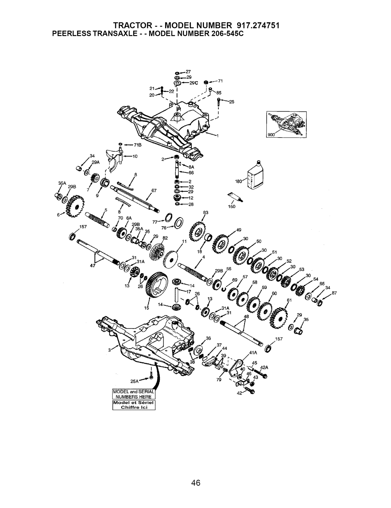
REF PART REF PART NO. NO. DESCRIPTION NO. NO. DESCRIPTION
Brake Lever Screw 1/4 - 20 x 1-1 /4" Screw 1/4 - 20 x 2 1/4" Locknut 5 / 16 - 24 Brake Pad Holder Spacer .2625 x 1.0 Brake Lever Bracket Axle (11-15 / 16" Long) Axle (16 - 1 2" long)
Transaxle Cover 41A 790079
772147 780086A 770128 776395 776409 778364
Needle Bearing 5/8" 792073A Transaxle Case 42A 792085A
Countershaft 792075 Output Shaft 790025 Spur Gear (38 teeth) 786066 Spur Gear (15 teeth) 786086 Spur Gear (11 teeth) 774690 Shift Key 48 774691 Woodruff Key #9 49 778356 Shift Collar 50 778338 Shift Rod & Fork 51 778354 Bevel Gear (30 teeth) 52 778352 Input Bevel Pinion (13 teeth) 53 778350 Bevel Gear (13 teeth) 54 778346 (Include. 14) 56 778355 Bevel Pinion (13 teeth) 57 778337 (Include. 13) 58 778353 Ring Gear (43 teeth) 59 778351 Drive Pin 60 778349 Spacer 1.130 X .695 61 778345 Ball 5/16" dia 65 780189 Set Screw 3/8 - 16 x 3/8" 66 776422 Spring .310 OD x .625 L 67 776396 Screw 1/4 - 20 x 1-1/4" 69 792170 Screw 1/4-20 x 1-3/8" 70 786187 Retaining Ring (pkg of 2) 71 788069 Retaining Ring 71B 788092 Retaining Ring 76 780090 Thrust Washer .627 ID x .031W 77 788078A Thrust Washer .762 ID x .031W 79 792144 Thrust Washer .762 ID x .031W 82 778333 Anti-Rotation Washer .632 Cup Washer 1.127 ID x .032W 83 Flat Washer .750 ID x .056W 85 (Use As Needed) 87 Fiat Washer .750 ID x .062W 150 Oil Seal 5/8" 157 Bushing .563 180 Flanged Bushing 5 / 8" ID 900 Flanged Bushing .751 Brake Disk Brake Pad Plate Brake Pad (pkg of 2) Dowel Pin Flat Washer .312 ID x .059W
6A 778369 778330 792180
)ur Gear (29 teeth) )ur Gear (27 teeth) )ur Gear (23 teeth) )ur Gear (19 teeth) )ur Gear (16 teeth) )ur Gear (15 teeth) )ur Gear (11 teeth) 3ur Gear (13 teeth) 3ur Gear (17 teeth) 3ur Gear (21 teeth)
8A 792047 784352
Flat Washer .563 ID x .062W Input Shaft Shifter & Brake Shaft Retaining Ring Spacer .890 Square Cut Ring "O" Ring Flat Washer 1.128 ID x .058W Inverted Retaining Ring Spring .430 OD x .5000 L Bevel & Spur Gear (30 & 13 teeth) Spur Gear (27 teeth) Oil Fill Plug Oil Seal 9 / 16" Liquid Gasket RTV Silicone Oil Seal 3/4" Gear Oil 80W90 Replacement MST - 206-545C Transaxle
778338 792154
788089A 788093A 788088A 730229A 794712
NOTE: All component dimensions given in U.S. inches 1 inch = 25.4 mm

16,
43,_
############# 684I'11_
584_ _'
############# 9_
1330 REPAIR MANUAL I
307_
1264'_
11329REPLACEMENTENGINEI
146,_
358 ENGINE GASKET SET
3@
24 @
8680 9430
741
20@ 6170
1022
2_
###### _% °°1_ 0
524 _ 8420
I 1019 LABEL KIT ]
I
I 1058 OWNER'S MANUAL
12
I 1036EMISSIONLABELI
15_
22_
750 &
200 89

1027(_

1095 VALVE GASKET SET
617 0
238
868
################# ,¢
35
1022
6170
525
103_
####################### 1524F_
1022
404 # 914 614 _
1119_ 789
58
801 @
643
803_
579_46_ _ 508_
802
1070
729 697 _
1005
I044_
1040

363#
305%

B
84A _8
127A
1091 J
127 G
o_
276A@
947A [_
################ NIKKI J
1127_ %:___
947_
e,,
118
1266A <_>
977
527(_
51_ 1370 276@
1266 0
121A CARBURETOR OVERHAUL KIT
121 CARBURETOR OVERHAUL KIT 231 "_ 987 ('o)
_ 96A _ 634A9 104A _ 127A O

276 @ _=}63419
997A 137A[ 1266A <_
93_
############## 10_A_ o
95
6170 1266A <-->

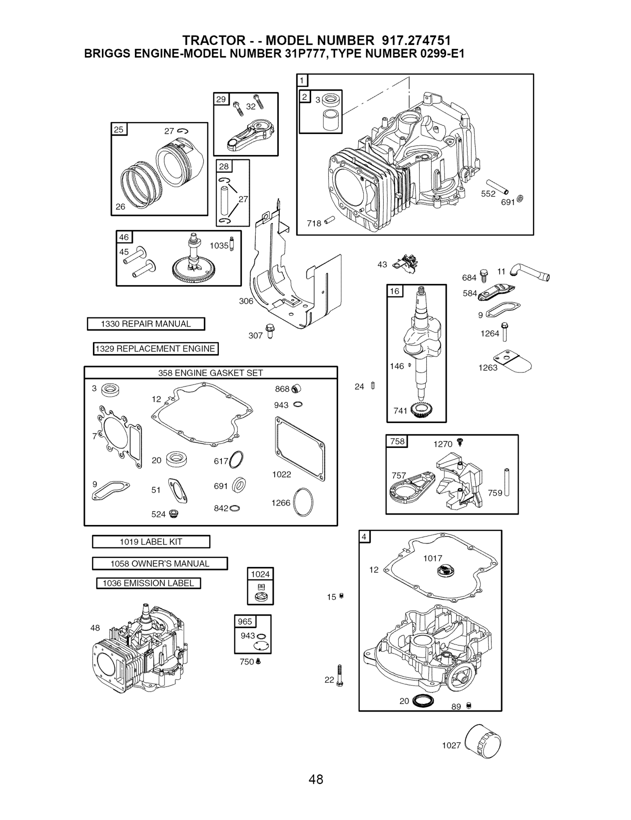
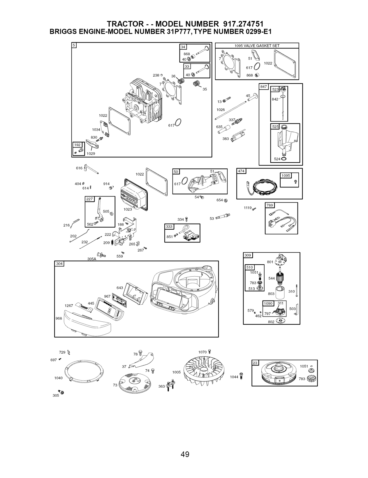
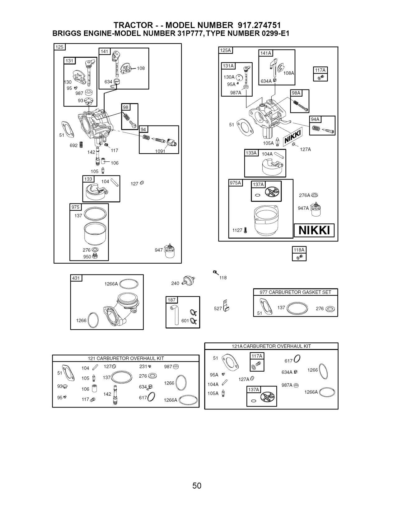
###################### TRACTOR -- MODEL NUMBER 917.274751
########################## BRIGGS ENGINE-MODEL NUMBER 31P777, TYPE NUMBER 0299-E1
############################## KEY PART KEY PART NO. NO. DESCRIPTION NO. NO. DESCRIPTION
O Seat-inlet Valve-Choke (Manual Choke) Valve-Choke (Nikki)
O Jet-Main (Standard) O Jet-Main (Standard) (Nikki)
Jet-Main (High Altitude) Jet-Main (High Altitude) (Nikki) Kit-Carburetor Overhaul Kit-Carburetor Overhaul (Nikki) Carburetor Carburetor (For Complete Carburetor, Service with 698445) Plug-Welch
-- 699054 Piston Assembly (.020" 131A 699501 Oversize) 133 494381
-- 697559 Ring Set (.020" Oversize) 135 698780

O Plug-Welch (Nikki) Valve-Throttle Valve-Throttle (Nikki) Kit-Throttle Shaft Kit-Throttle Shaft (Nikki) Float-Carburetor Float-Carburetor (Nikki) Tube-Fuel Transfer
O5 Gasket-Float Bowl O Gasket-Float Bowl (Nikki)
Kit-Choke Shaft (Manual Choke) Kit-Choke Shaft (Nikki)
-- 697263 Rod-Connecting (.020"
Undersize) 141A 698778
O Nozzle-Carburetor Key-Timing Line-Fuel Screw (Control Bracket) Adjuster-Rocker Arm Link-Mechanical Governor Spring-Governor Link-Choke Bracket-Control Lever-Governor Control Spring-Governor Cap-Valve Filter-Fuel Clamp-Casing Screw (Casing Clamp)
O5 Washer-Sealing Washer-Sealing Housing-Blower Screw (Blower Housing) Screw (Blower Housing) Shield-Cylinder Screw (Cylinder Shield) Motor-Starter
Included in Engine Gasket Set, Key. No. 358 Included in Carburetor Overhaul Kit, Key. No. 121 Included in Carburetor Gasket Set, Key. No. 977 Included in Valve Gasket Set, Key. No. 1095

NOTE: All component dimensions given in U.S. inches
1 inch = 25.4 mm

############################ KEY PART KEY PART NO. NO. DESCRIPTION NO. NO. DESCRIPTION
462 691261 Washer (Starter Cable) 975A 699502 Bowl-Float (Nikki) 474 696459 Alternator 977 690192 Gasket Set-Carburetor
503 691532 Strap-Starter 987 691326 O Seal-Throttle Shaft 505 691251 Nut (Governor Control Lever) 987A 698777 O Seal-Throttle Shaft (Nikki) 510 693699 Drive-Starter 1005 699043 Fan-Flywheel 513 692024 Clutch-Drive 1017 690770 Screen-Oil Pump
601 95162 Clamp-Hose 1036 695700 Label-Emission 614 691620 Pin-Cotter 1040 699852 Plate-Trim
Choke) 1059 698516 Kit-Screw/Washer 634A 698779 O Spring/Seal Assembly (Nikki) 1070 690372 Screw (Flywheel Fan) 635 691909 Boot-Spark Plug 1090 691293 Retainer-Brush 643 698401 Retainer-Air Filter 1091 691333 Cap-Limiter 654 690958 Nut (Carburetor) 1095 690190 Gasket Set-Valve 684 697157 Screw (Breather Passage 1119 691183 Screw (Alternator)
Cover) 1127 695407 Screw-Float Bowl 691 692407 ° Seal-Governor Shaft 1263 697124 Reed-Breather 692 690572 Spring-Detent 1264 697104 Screw (Breather Reed)
697 690372 Screw (Drive Cap) 1266 691917 °0 SeaI-O Ring (intake Elbow) 718 690959 Pin-Locating 1266A 697123 O SeaI-O Ring (intake Elbow) 729 691224 Clip-Wire 1267 697424 Latch-Blower Housing 741 697128 Gear-Timing 1270 697156 Plug-AVS Counterweight 750 691033 Screw (Oil Pump Cover) 1329 31Q777-0036 Replacement Engine

######################### 53


##################### 54

################## SUGGESTED GUIDE FOR SIGHTING SLOPES FOR SAFE OPERATION
ONLY RIDE UP AND DOWN HILL, NOT ACROSS HILL
(O1 O'1
15 DEGREES MAX,
_ ARNING: To avoid serious injury, operate your tractor up and down the face of slopes, never across the face. Do not mow slopes greater than 15 degrees. Make turns gradually to prevent tipping or loss of control. Exercise extreme caution when changing direction on slopes.
t. Fold this page along dotted _ine indicated above.

Your Home For repair - in your home - of all major brand appliances, lawn and garden equipment, or heating and cooling systems, no matter who made it, no matter who sold it! For the replacement parts, accessories and
owner's manuals that you need to do-it-yourself. For Sears professional installation of home appliances and items like garage door openers and water heaters.
1-800-4-MY-HOME ® Anytime, day or night
(1-800-469-4663) (U.S.A. and Canada) www.sears.com www.sears.ca
################### Our Home
For repair of carry-in products like vacuums, lawn equipment, and electronics, call or go on-line for the nearest Sears Parts and Repair Center.
!_i_!JJJJJJJJJJJJJJJJiii_i
_iiiiiiiiiiiiiiiiiii_i
iiiiiiiiiiiiiiiiiiii iiiiiiiiiiiiiiiiiiii iiiiiiiiiiiiiiiiiiii iiiiiiiiiiiiiiiiiiii iiiiiiiiiiiiiiiiiiii iiiiiiiiiiiiiiiiiiii iiiiiiiiiiiiiiiiiiii iiiiiiiiiiiiiiiiiiii iiiiiiiiiiiiiiiiiiii iiiiiiiiiiiiiiiiiiii iiiiiiiiiiiiiiiiiiii iiiiiiiiiiiiiiiiiiii
1-800-488-1222 Anytime, day or night (U.S.A. only)
www.sears.com
To purchase a protection agreement (U.S.A.) or maintenance agreement (Canada) on a product serviced by Sears:
!!!!!!!!!!!!!L
iiiiiiiiiiiiiiiiii iiiiiiiiiiiiiiiiii iiiiiiiiiiiiiiiiii iiiiiiiiiiiiiiiiii iiiiiiiiiiiiiiiiii iiiiiiiiiiiiiiiiii iiiiiiiiiiiiiiiiii HHHHHHHH_
1-800-827-6655 (U.S.A.) 1-800-361-6665 (Canada)
iiiiiiiiiiiiiii
Para pedir servicio de reparaci6n a domicilio, y para ordenar piezas:
Au Canada pour service en frangais: 1-800-LE-FOYER Mc (1-800-533-6937)
###################### 1-888-SU-HOGAR sM
www.sears.ca
(1-888-784-6427)
SEARS
© Sears, Roebuckand Co. TM SM®RegisteredTrademark/Trademark/- Service Mark of Sears, Roebuck and Co. ® Marca Registrada / TMMarca de Fabrica / SMMarca de Servicio de Sears, Roebuck and Co. MCMarque de commerce / MDMarque deposee de Sears, Roebuck and Co.
193868 Rev. 2 09.21.04 TR/RD/TR Printed in U.S.A.