
Ask AI
— answers from the official manualAnswers from the official manual.
Common questions
Common Questions
10 totalHow do I install the cutting head shield?
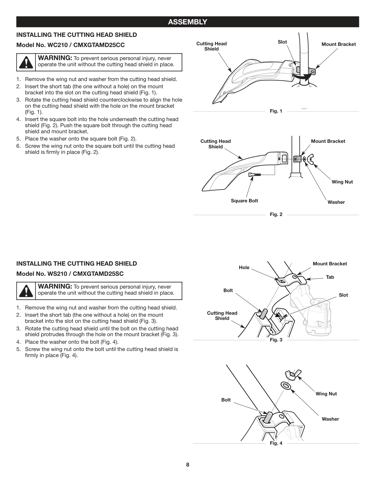
Remove the wing nut and washer from the cutting head shield, insert the short tab without a hole into the slot on the shield, rotate the shield counterclockwise to align holes on both parts, push the square bolt through, place the washer onto the bolt, and screw the wing nut tightly until the shield is securely in place (Fig. 2 for model WC210/CMXGTAMD25CC). (Page 8)
What should I do if the trimming line gets tangled or cut off?
If the trimming line is tangled or cut, turn the knob counterclockwise to loosen the coupler and remove the damaged attachment. Replace with a new attachment as per installation instructions (Fig. 5). (Page 10-12)
How do I clean the air filter?
Open the air filter cover and remove the air filter from inside. Wash in detergent water, rinse thoroughly, dry completely, lightly coat with SAE 30 oil, squeeze to remove excess oil, then reinstall the air filter and close the cover (Fig. 23). (Page 19)
How do I adjust the idle speed?
Start the engine and release the throttle control to let it idle. If the engine stops, slowly increase the idle speed by turning the screw clockwise; if the cutting head spins, decrease by turning counterclockwise (Fig. 24). (Page 18)
How do I replace and maintain a spark plug?
After stopping and cooling the engine, remove the spark plug boot, clean around the plug, inspect for cracks or dirt; if fouled or dirty, replace with part #753-06847 or an equivalent Champion RDJ7J. Set air gap at 0.025 in., reinstall plug tightly (Fig. 25). (Page 19)
How do I store the product safely?
Drain fuel, run engine to consume remaining fuel, clean unit thoroughly and inspect for loose or damaged parts, repair/replace any issues found. Store in a dry, well-ventilated place out of reach of children (Page 18).
Full Manual
48 pages

OPERATOR’S MANUAL | MANUAL DEL OPERADOR
ELECTRIC START CAPABLE 2-CYCLE GAS TRIMMERS DESBROZADORAS DE GAS DE 2 TIEMPOS CON CAPACIDAD PARA ARRANQUE ELÉCTRICO
WC210 | WS210
CMXGTAMD25CC | CMXGTAMD25SC
IF YOU HAVE QUESTIONS OR COMMENTS, CONTACT US. SI TIENE DUDAS O COMENTARIOS, CONTÁCTENOS.
1-888-331-4569 WWW.CRAFTSMAN.COM
769-22930 / 00 08/19
##### TABLE OF CONTENTS
Safety . . . . . . . . . . . . . . . . . . . . . . . . . . . . . . . . . . . . . . . . . . . . . . .2 Know Your Unit . . . . . . . . . . . . . . . . . . . . . . . . . . . . . . . . . . . . . . . .6 Specifications . . . . . . . . . . . . . . . . . . . . . . . . . . . . . . . . . . . . . . . . .7 Assembly . . . . . . . . . . . . . . . . . . . . . . . . . . . . . . . . . . . . . . . . . . . . .8 Oil and Fuel . . . . . . . . . . . . . . . . . . . . . . . . . . . . . . . . . . . . . . . . . .11 Starting and Stopping . . . . . . . . . . . . . . . . . . . . . . . . . . . . . . . . . .12 Operation . . . . . . . . . . . . . . . . . . . . . . . . . . . . . . . . . . . . . . . . . . .14 Maintenance . . . . . . . . . . . . . . . . . . . . . . . . . . . . . . . . . . . . . . . . .16 Cleaning and Storage . . . . . . . . . . . . . . . . . . . . . . . . . . . . . . . . . .19 Troubleshooting . . . . . . . . . . . . . . . . . . . . . . . . . . . . . . . . . . . . . .20 Warranty . . . . . . . . . . . . . . . . . . . . . . . . . . . . . . . . . . . . . . . . . . . .21 Service Numbers . . . . . . . . . . . . . . . . . . . . . . . . . . . . . .Back Cover
All information, illustrations, and specifications in this manual are based on the latest product information available at the time of printing. We reserve the right to make changes at any time without notice.
The product may vary slightly from the illustrations contained in this manual.
NOTE: This operator's manual covers multiple models. Features may vary by model. Not all features in this manual are applicable to all models. The model depicted may differ from yours.
#### SAFETY
|The purpose of safety symbols is to attract your attention to possible dangers. The safety symbols, and their explanations, deserve your careful attention and understanding. The safety warnings do not by themselves eliminate any danger. The instructions or warnings they give are not substitutes for proper accident prevention measures.| |---|
|SYMBOL MEANING| |---|
| |DANGER:Signals an EXTREME hazard. Failure to obey a safety DANGER symbol WILL result in serious injury or death to yourself or to others.| |---|---|
| |WARNING:Signals a SERIOUS hazard. Failure to obey a safety WARNING symbol CAN result in serious injury to yourself or to others.| |---|---|
| |CAUTION:Signals a MODERATE hazard. Failure to obey a safety CAUTION symbol MAY result in property damage or injury to yourself or to others.| |---|---|
NOTE: Advises you of information or instructions vital to the
operation or maintenance of the equipment.
##### SPARK ARRESTOR NOTE
NOTE: For users on U.S. Forest Land and in the states of California, Maine, Oregon and Washington. All U.S. Forest Land and the state of California (Public Resources Codes 4442 and 4443), Oregon and Washington require, by law that certain internal combustion engines operated on forest brush and/or grass-covered areas be equipped with a spark arrestor, maintained in effective working order, or the engine be constructed, equipped and maintained for the prevention of fire. Check with your state or local authorities for regulations pertaining to these requirements. Failure to follow these requirements could subject you to liability or a fine. This unit is factory equipped with a spark arrestor. If it requires replacement, contact your local service dealer to install the appropriate muffler assembly.
| |WARNING:This product can expose you to chemicals including engine exhaust, which is known to the State of California to cause cancer, and carbon monoxide, which is known to the State of California to cause birth defects or other reproductive harm. For more information go to www.P65Warnings.ca.gov.| |---|---|
Read the operator’s manual and follow all warnings and safety instructions. Failure to do so can result in serious injury to the operator and/or bystanders.
• IMPORTANT SAFETY INSTRUCTIONS •
##### READ ALL INSTRUCTIONS BEFORE OPERATING
##### SAFETY WARNINGS FOR GAS UNITS
| |WARNING:When using the unit, all safety instructions must be followed. Please read these instructions before operating the unit in order to ensure the safety of the operator and any bystanders. Please keep these instructions for later use.| |---|---|
| |WARNING:Gasoline is highly flammable and its vapors can explode if ignited. Take the following precautions:| |---|---|
##### WHILE OPERATING
##### OTHER SAFETY WARNINGS
SAVE THESE INSTRUCTIONS
##### • SAFETY & INTERNATIONAL SYMBOLS •
This operator's manual describes safety and international symbols and pictographs that may appear on this product. Read the operator's manual for complete safety, assembly, operating and maintenance and repair information.
###### SYMBOL MEANING SYMBOL MEANING
| |• SAFETY ALERT SYMBOL
Indicates danger, warning or caution. May be used in conjunction with other symbols or pictographs.| |---|---| | |• READ OPERATOR'S MANUAL
WARNING:Read the operator’s manual(s) and follow all warnings and safety instructions. Failure to do so can result in serious injury to the operator and/or bystanders.| | |• WEAR EYE AND HEARING PROTECTION
WARNING:Thrown objects and loud noise can cause severe eye injury and hearing loss. Wear eye protection meeting current ANSI / ISEA Z87.1 standards and ear protection when operating this unit. Use a full face shield when needed.| | |• WEAR FOOT PROTECTION
Always wear heavy-duty, non-slip footwear when operating this unit.| | |• WEAR HAND PROTECTION
Always wear heavy-duty, non-slip gloves when handling this unit.| | |• HANDLE POSITION
Make sure the handle is positioned beyond the end of the safety label.| | |• UNLEADED FUEL
Always use clean, fresh unleaded fuel.| | |• OIL
Refer to operator’s manual for the proper type of oil.| | |• DO NOT USE E85 FUEL IN THIS UNIT
CAUTION:It has been proven that fuel containing greater than 10% ethanol will likely damage this engine and void the warranty.|
| |• ON/OFF STOP CONTROL
ON / START / RUN| |---|---| | |• ON/OFF STOP CONTROL
OFF or STOP| | |• PRIMER BULB
Push primer bulb, fully and slowly, 10 times.| | |• CHOKE CONTROL
1. • FULL choke position
2. • PARTIAL choke position
3. • RUN choke position
| | |• THROWN OBJECTS CAN CAUSE SEVERE INJURY
WARNING:Small objects can be
propelled at high speed, causing injury.| |Min. 50 ft
15 m
|• KEEP BYSTANDERS AWAY
WARNING:Keep all bystanders, especially children and pets, at least 50 feet (15 m) from the operating area.| | |• HOT SURFACE
WARNING:Do not touch a hot muffler or cylinder. You may get burned. These parts get extremely hot from operation. When turned off, they remain hot for a short time.| | |• SHARP BLADE
WARNING:There is a sharp blade on the cutting head shield. To prevent serious injury, do not touch the line cutting blade.| | |• DO NOT REPLACE CUTTING HEADS WITH BLADES*
WARNING:When using a trimmer, to prevent serious injury, do not replace the cutting head with rigid or metal blades.
*This warning does not apply to units equipped with blades, such as edgers and brush cutters.|
#### KNOW YOUR UNIT

|Model No. WC210 / CMXGTAMD25CC| |---|
Spark PlugMuffler
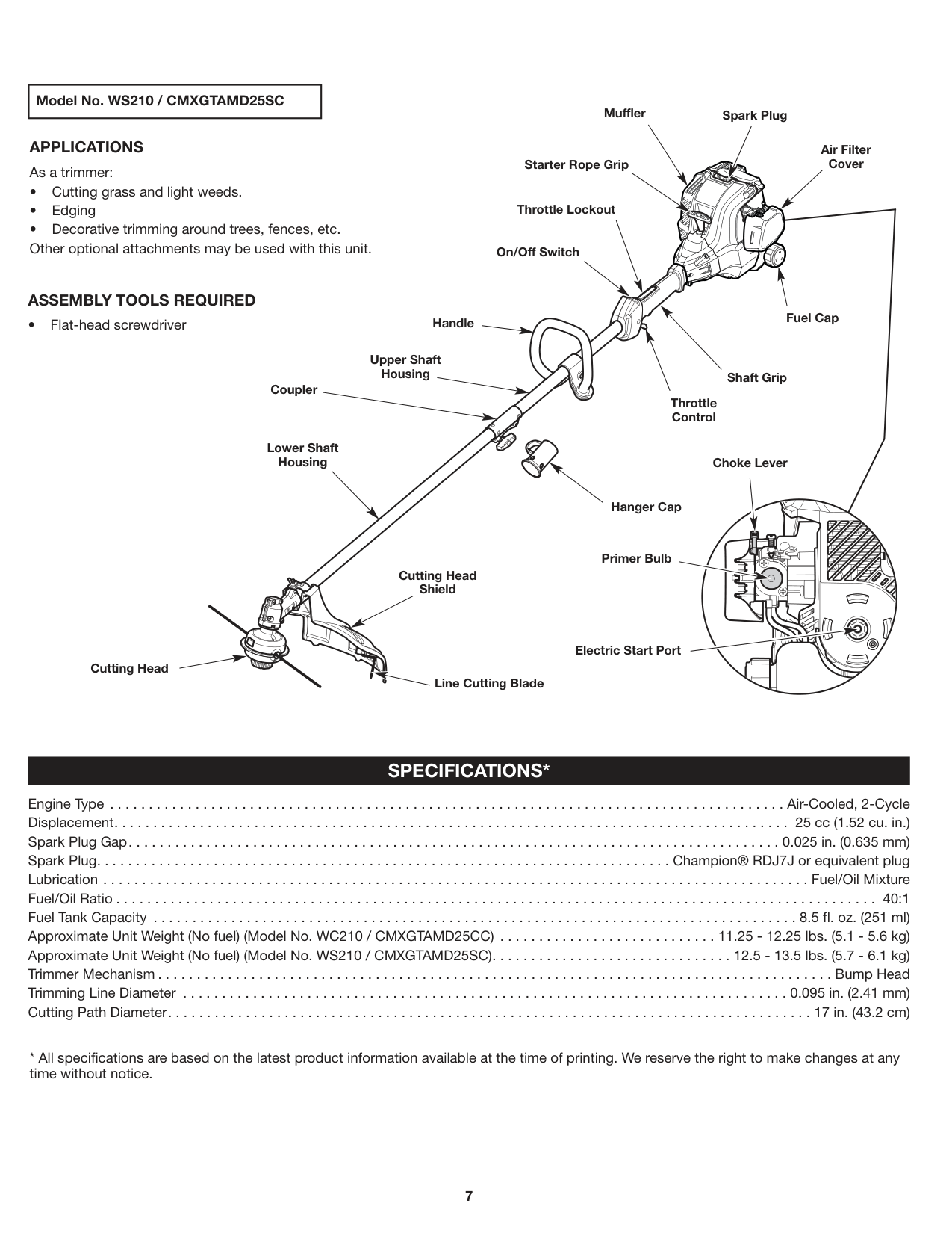
##### APPLICATIONS As a trimmer:
Air Filter Cover
Starter Rope Grip
ASSEMBLY TOOLS REQUIRED
Throttle Lockout
On/Off Switch
Fuel CapHandle
Upper Shaft Housing
Shaft Grip
Coupler
Throttle Control
Lower Shaft Housing
Choke Lever
| | | | |---|---|---| | | | |
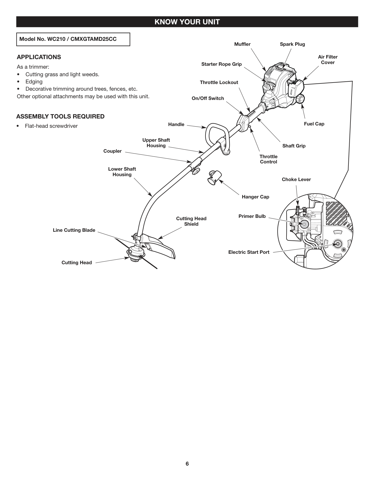
Hanger Cap
Primer Bulb
Cutting Head Shield
| | | |---|---| | | |
| | | | |---|---|---| | | | |
Line Cutting Blade
| | | |---|---| | | |
Electric Start Port
Cutting Head
|Model No. WS210 / CMXGTAMD25SC| |---|
Spark PlugMuffler
##### APPLICATIONS As a trimmer:
Air Filter Cover
Starter Rope Grip
ASSEMBLY TOOLS REQUIRED
Throttle Lockout
On/Off Switch
Fuel CapHandle
Upper Shaft Housing
Shaft Grip
Coupler
Throttle Control
Lower Shaft Housing
Choke Lever
| | | | |---|---|---| | | | |
Hanger Cap
Primer Bulb
| | | |---|---| | | |
Cutting Head Shield
| | | | |---|---|---| | | | |
| | | |---|---| | | |
Electric Start Port
| | |---| | | | |
Cutting Head
Line Cutting Blade
#### SPECIFICATIONS*
Engine Type . . . . . . . . . . . . . . . . . . . . . . . . . . . . . . . . . . . . . . . . . . . . . . . . . . . . . . . . . . . . . . . . . . . . . . . . . . . . . . . . . . . . . . . Air-Cooled, 2-Cycle Displacement. . . . . . . . . . . . . . . . . . . . . . . . . . . . . . . . . . . . . . . . . . . . . . . . . . . . . . . . . . . . . . . . . . . . . . . . . . . . . . . . . . . . . . . 25 cc (1.52 cu. in.) Spark Plug Gap. . . . . . . . . . . . . . . . . . . . . . . . . . . . . . . . . . . . . . . . . . . . . . . . . . . . . . . . . . . . . . . . . . . . . . . . . . . . . . . . . . . . 0.025 in. (0.635 mm) Spark Plug. . . . . . . . . . . . . . . . . . . . . . . . . . . . . . . . . . . . . . . . . . . . . . . . . . . . . . . . . . . . . . . . . . . . . . . . . . Champion® RDJ7J or equivalent plug Lubrication . . . . . . . . . . . . . . . . . . . . . . . . . . . . . . . . . . . . . . . . . . . . . . . . . . . . . . . . . . . . . . . . . . . . . . . . . . . . . . . . . . . . . . . . . . . Fuel/Oil Mixture Fuel/Oil Ratio . . . . . . . . . . . . . . . . . . . . . . . . . . . . . . . . . . . . . . . . . . . . . . . . . . . . . . . . . . . . . . . . . . . . . . . . . . . . . . . . . . . . . . . . . . . . . . . . . . 40:1 Fuel Tank Capacity . . . . . . . . . . . . . . . . . . . . . . . . . . . . . . . . . . . . . . . . . . . . . . . . . . . . . . . . . . . . . . . . . . . . . . . . . . . . . . . . . . . 8.5 fl. oz. (251 ml) Approximate Unit Weight (No fuel) (Model No. WC210 / CMXGTAMD25CC) . . . . . . . . . . . . . . . . . . . . . . . . . . . . 11.25 - 12.25 lbs. (5.1 - 5.6 kg) Approximate Unit Weight (No fuel) (Model No. WS210 / CMXGTAMD25SC). . . . . . . . . . . . . . . . . . . . . . . . . . . . . . . 12.5 - 13.5 lbs. (5.7 - 6.1 kg) Trimmer Mechanism . . . . . . . . . . . . . . . . . . . . . . . . . . . . . . . . . . . . . . . . . . . . . . . . . . . . . . . . . . . . . . . . . . . . . . . . . . . . . . . . . . . . . . . Bump Head Trimming Line Diameter . . . . . . . . . . . . . . . . . . . . . . . . . . . . . . . . . . . . . . . . . . . . . . . . . . . . . . . . . . . . . . . . . . . . . . . . . . . . . . 0.095 in. (2.41 mm) Cutting Path Diameter. . . . . . . . . . . . . . . . . . . . . . . . . . . . . . . . . . . . . . . . . . . . . . . . . . . . . . . . . . . . . . . . . . . . . . . . . . . . . . . . . . . 17 in. (43.2 cm)
#### ASSEMBLY
##### INSTALLING THE CUTTING HEAD SHIELD Model No. WC210 / CMXGTAMD25CC
Slot
Mount BracketCutting Head Shield
| |WARNING: To prevent serious personal injury, never operate the unit without the cutting head shield in place.| |---|---|
Fig. 1
Mount Bracket
Cutting Head Shield
| | | | |---|---|---| | | | |
Wing Nut
WasherSquare Bolt
Fig. 2
##### INSTALLING THE CUTTING HEAD SHIELD Model No. WS210 / CMXGTAMD25SC
| |WARNING: To prevent serious personal injury, never operate the unit without the cutting head shield in place.| |---|---|
Mount Bracket
Hole
Tab
Bolt
Slot
Cutting Head Shield
Fig. 3
Wing Nut
Bolt
Washer
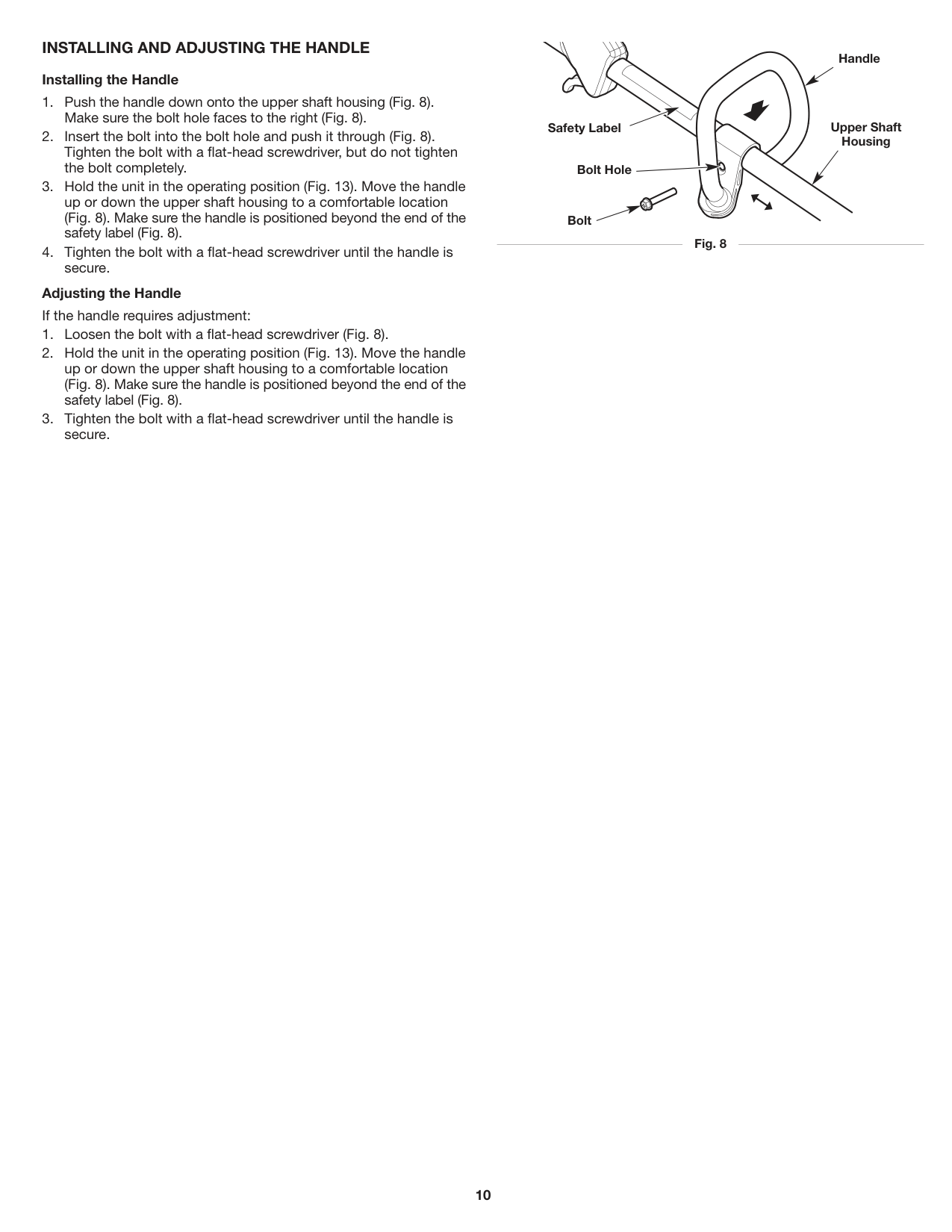
Fig. 4
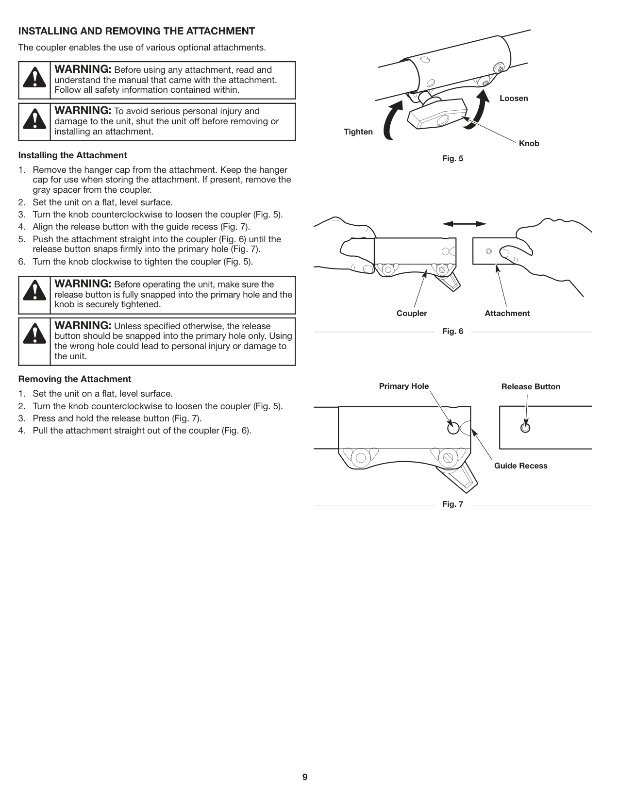
INSTALLING AND REMOVING THE ATTACHMENT The coupler enables the use of various optional attachments.
| |WARNING: Before using any attachment, read and understand the manual that came with the attachment. Follow all safety information contained within.| |---|---|
| |WARNING: To avoid serious personal injury and damage to the unit, shut the unit off before removing or installing an attachment.| |---|---|
###### Installing the Attachment
| |WARNING: Before operating the unit, make sure the release button is fully snapped into the primary hole and the knob is securely tightened.| |---|---|
| |WARNING: Unless specified otherwise, the release button should be snapped into the primary hole only. Using the wrong hole could lead to personal injury or damage to the unit.| |---|---|
###### Removing the Attachment
Loosen
Tighten
Knob
Fig. 5
Coupler Attachment
Fig. 6
Primary Hole
Release Button
Guide Recess
Fig. 7
##### INSTALLING AND ADJUSTING THE HANDLE Installing the Handle
Adjusting the Handle If the handle requires adjustment:
Handle
Upper Shaft Housing
Safety Label
Bolt Hole
Bolt
Fig. 8
#### OIL AND FUEL
##### OIL AND FUEL MIXING INSTRUCTIONS
The use of old and/or improperly mixed fuel is the most common cause of performance problems. Use only fresh, clean unleaded gasoline. Follow the instructions carefully for the proper gasoline/oil mixture.
Definition of Blended Fuels Today's fuels are often a blend of gasoline and oxygenates such as ethanol, methanol or MTBE (ether). Alcohol-blended fuel absorbs water. As little as 1% water in the fuel can make fuel and oil separate, forming acids when stored. ALWAYS use fresh fuel (less than 30 days old). NOTE: Dispose of old fuel according to federal, state and local
regulations. Using Blended Fuels If using a blended fuel:
| |CAUTION: DO NOT USE E85 FUEL IN THIS UNIT. It has been proven that fuel containing greater than 10% ethanol will likely damage this engine and void the warranty.| |---|---|
###### Using Fuel Additives
The container of 2-cycle oil provided with this unit includes a fuel additive to help inhibit corrosion and minimize gum deposits. Always use the brand of 2-cycle oil that came with this unit. If this is unavailable, use a 2-cycle oil designed for air-cooled engines and mix it with a fuel additive, such as STA-BIL Fuel Stabilizer or an equivalent. Add 0.8 oz. (23 ml) of fuel additive per gallon of fuel, according to the instructions on the container. NEVER add fuel additives directly to the unit's fuel tank.
Mixing the Fuel NOTE: This unit comes with a 3.2 oz. (95 ml) container of 2-cycle
oil. To obtain the correct fuel mixture described below, pour the entire container into one gallon of unleaded gasoline.
##### FUELING THE UNIT
| |WARNING: Gasoline is extremely flammable. Ignited vapors may explode. Always stop the engine and allow it to cool before filling the fuel tank. Do not smoke while filling the tank. Keep sparks and open flames at a distance from the area.| |---|---|
| |WARNING: Remove the fuel cap slowly to avoid injury from fuel spray. Never operate the unit without the fuel cap securely in place.| |---|---|
| |WARNING: Add fuel in a clean, well-ventilated outdoor area. Wipe up any spilled fuel immediately. Avoid creating a source of ignition for spilled fuel. Do not start the engine until fuel vapors dissipate.| |---|---|
NOTE: Do not overfill the tank.
| |CAUTION: For proper engine operation and maximum reliability, pay strict attention to the gasoline and oil mixing instructions on the 2-cycle oil container. Using improperly mixed fuel can severely damage the engine.| |---|---|
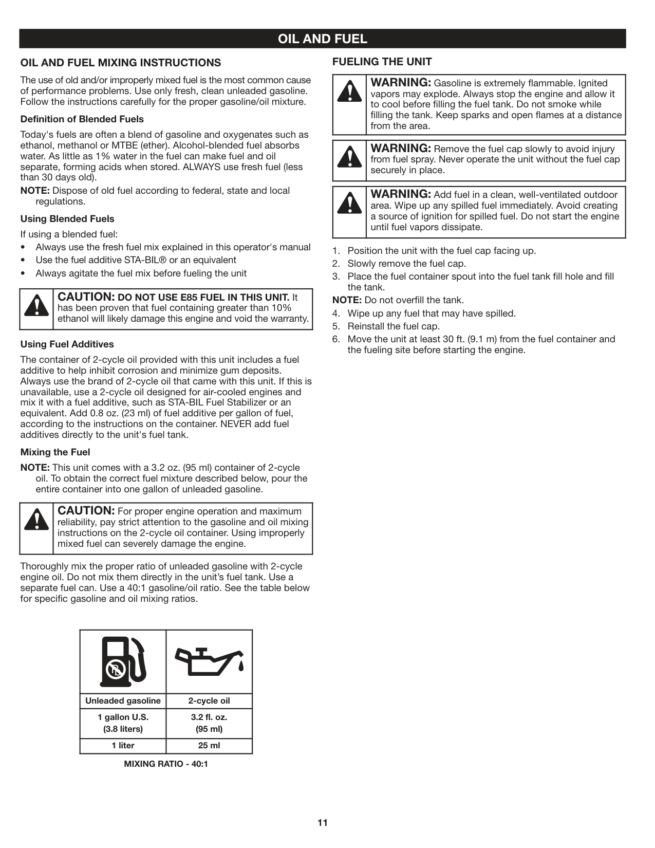
Thoroughly mix the proper ratio of unleaded gasoline with 2-cycle engine oil. Do not mix them directly in the unit’s fuel tank. Use a separate fuel can. Use a 40:1 gasoline/oil ratio. See the table below for specific gasoline and oil mixing ratios.
| | | |---|---| |Unleaded gasoline|2-cycle oil| |1 gallon U.S. (3.8 liters)|3.2 fl. oz. (95 ml)| |1 liter|25 ml|
####### MIXING RATIO - 40:1
#### STARTING AND STOPPING
| |WARNING: Operate this unit only in a well-ventilated outdoor area. Carbon monoxide exhaust fumes can be lethal in a confined area.| |---|---|
| |WARNING: Avoid accidentally starting the unit. To avoid serious injury, the operator and the unit must be in a stable position when pulling the starter rope (Fig. 11).| |---|---|
STARTING INSTRUCTIONS NOTE: To prevent the throttle control from being squeezed
accidentally, this unit has a throttle lockout. The throttle control cannot be squeezed unless the throttle lockout is also engaged.
NOTE: There is no need to turn the unit on. The On/Off switch is in
the On ( I ) position at all times (Fig. 9). Before Starting the Unit
NOTE: Continue to SQUEEZE and HOLD the throttle lockout and the throttle control for ALL further steps.
NOTE: The engine is properly warmed up when it accelerates
without hesitation.
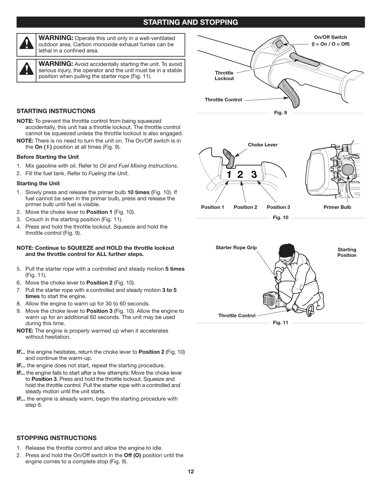
On/Off Switch (I = On / O = Off)
Throttle Lockout
Throttle Control
Fig. 9
Choke Lever
Primer BulbPosition 3Position 2Position 1
Fig. 10
Starter Rope Grip
Starting Position
Throttle Control
Fig. 11
IF... the engine hesitates, return the choke lever to Position 2 (Fig. 10)
and continue the warm-up. IF... the engine does not start, repeat the starting procedure. IF... the engine fails to start after a few attempts: Move the choke lever to Position 3. Press and hold the throttle lockout. Squeeze and hold the throttle control. Pull the starter rope with a controlled and steady motion until the unit starts.
IF... the engine is already warm, begin the starting procedure with
step 6.
##### STOPPING INSTRUCTIONS
#### USING THE ELECTRIC START ACCESSORY
This unit can be started with an optional electric start accessory (items sold separately). Refer to the electric start accessory operator’s manual for the proper use of this feature. Please contact your local Craftsman retailer, call 1-888-331-4569 or visit www.craftsman.com for more information.
STARTING INSTRUCTIONS NOTE: To prevent the throttle control from being squeezed
accidentally, this unit has a throttle lockout. The throttle control cannot be squeezed unless the throttle lockout is also engaged.
NOTE: There is no need to turn the unit on. The On/Off switch is in
the On ( I ) position at all times (Fig. 9). Before Starting the Unit
Read the Operator's Manual that came with the electric start accessory before attempting these instructions.
NOTE: Continue to SQUEEZE and HOLD the throttle lockout and the throttle control for ALL further steps.
NOTE: The engine is properly warmed up when it accelerates
without hesitation.
| | | | |---|---|---| | | | |
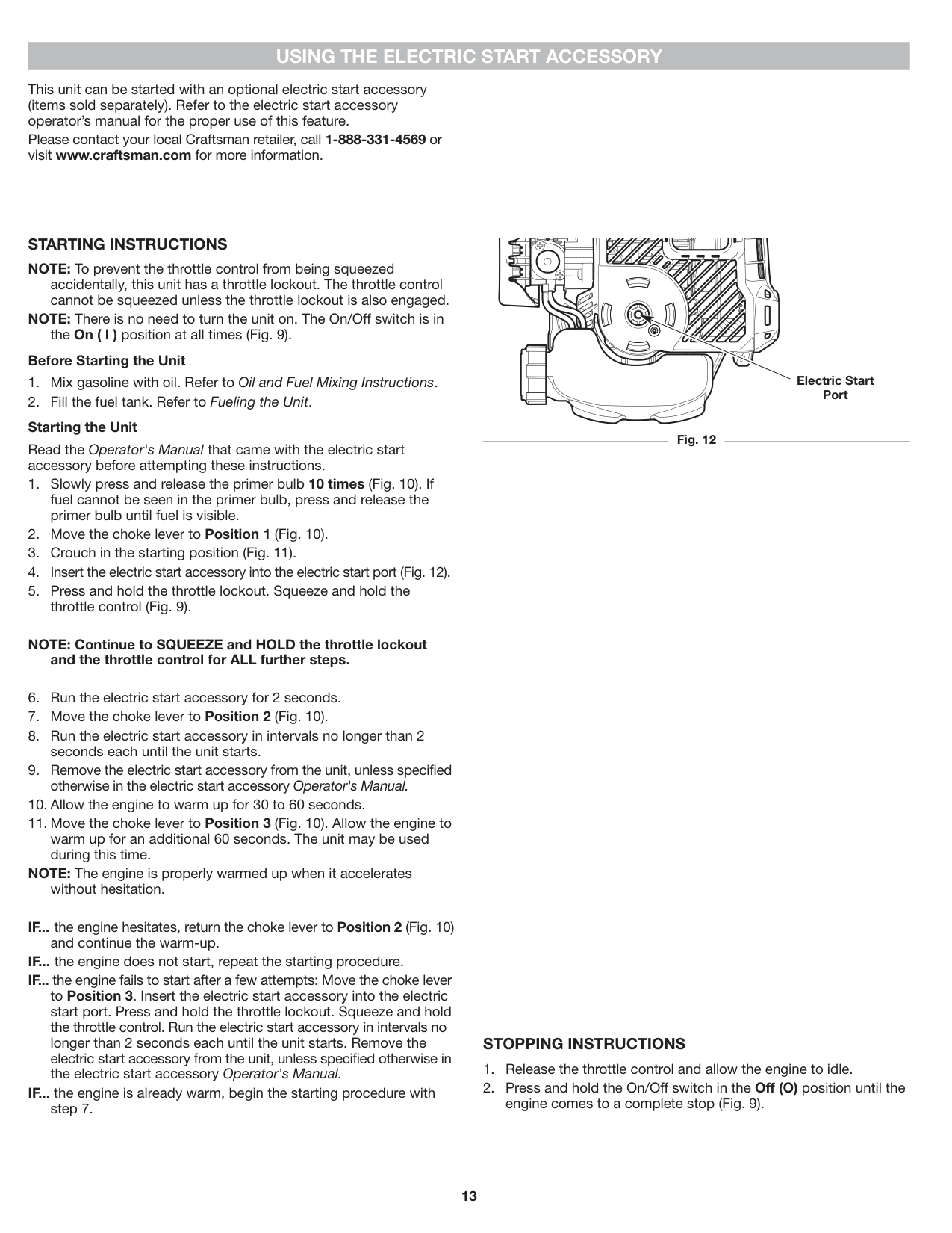
Electric Start Port
Fig. 12
IF... the engine hesitates, return the choke lever to Position 2 (Fig. 10)
and continue the warm-up. IF... the engine does not start, repeat the starting procedure. IF... the engine fails to start after a few attempts: Move the choke lever
to Position 3. Insert the electric start accessory into the electric start port. Press and hold the throttle lockout. Squeeze and hold the throttle control. Run the electric start accessory in intervals no longer than 2 seconds each until the unit starts. Remove the electric start accessory from the unit, unless specified otherwise in the electric start accessory Operator's Manual.
IF... the engine is already warm, begin the starting procedure with
step 7.
##### STOPPING INSTRUCTIONS
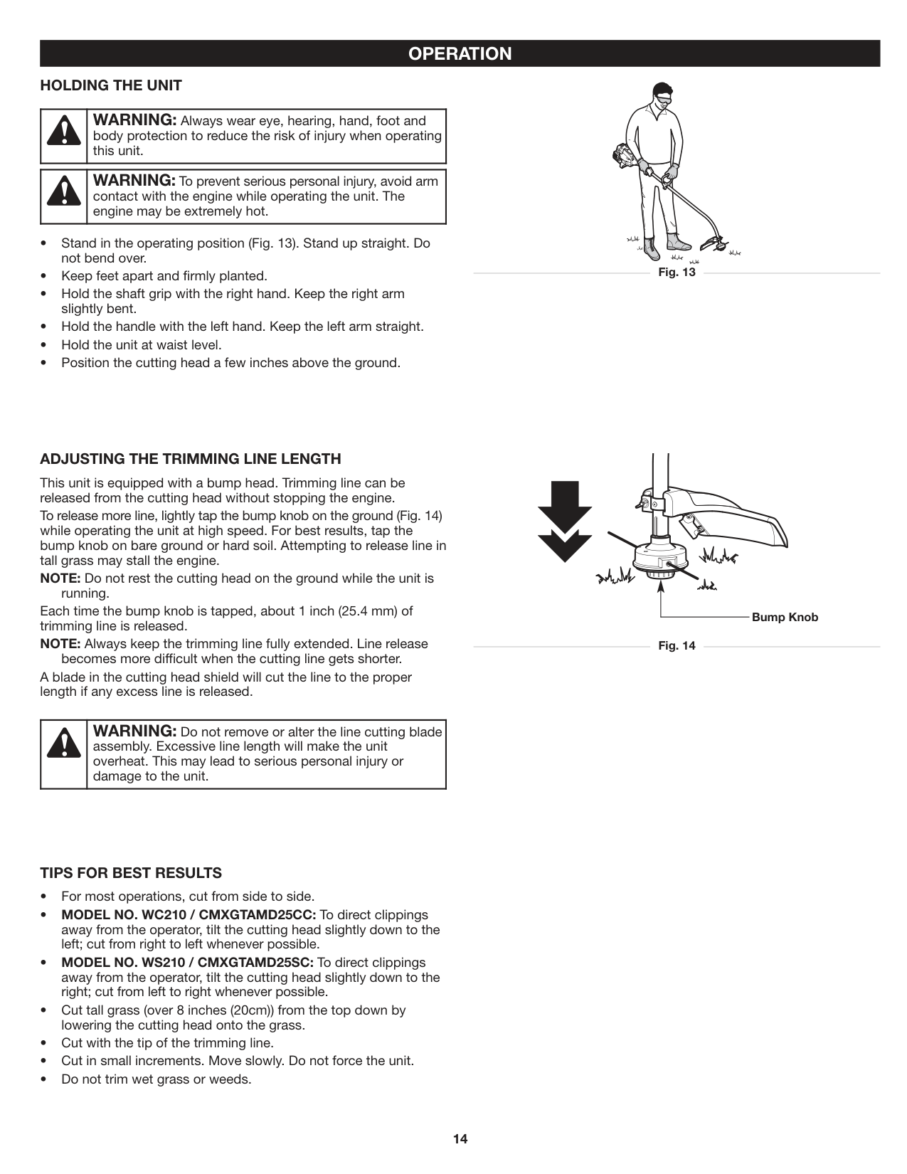
#### OPERATION HOLDING THE UNIT
| |WARNING: Always wear eye, hearing, hand, foot and body protection to reduce the risk of injury when operating this unit.| |---|---|
| |WARNING: To prevent serious personal injury, avoid arm contact with the engine while operating the unit. The engine may be extremely hot.| |---|---|
ADJUSTING THE TRIMMING LINE LENGTH This unit is equipped with a bump head. Trimming line can be released from the cutting head without stopping the engine. To release more line, lightly tap the bump knob on the ground (Fig. 14) while operating the unit at high speed. For best results, tap the bump knob on bare ground or hard soil. Attempting to release line in tall grass may stall the engine. NOTE: Do not rest the cutting head on the ground while the unit is
running. Each time the bump knob is tapped, about 1 inch (25.4 mm) of trimming line is released. NOTE: Always keep the trimming line fully extended. Line release becomes more difficult when the cutting line gets shorter. A blade in the cutting head shield will cut the line to the proper length if any excess line is released.
Bump Knob
| |WARNING: Do not remove or alter the line cutting blade assembly. Excessive line length will make the unit overheat. This may lead to serious personal injury or damage to the unit.| |---|---|
##### TIPS FOR BEST RESULTS
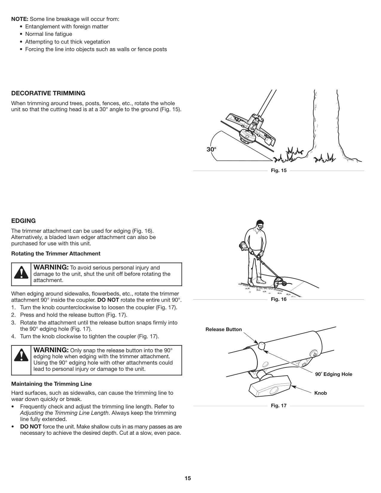
NOTE: Some line breakage will occur from:
##### DECORATIVE TRIMMING
When trimming around trees, posts, fences, etc., rotate the whole unit so that the cutting head is at a 30° angle to the ground (Fig. 15).
Fig. 15
##### EDGING
The trimmer attachment can be used for edging (Fig. 16). Alternatively, a bladed lawn edger attachment can also be purchased for use with this unit.
###### Rotating the Trimmer Attachment
When edging around sidewalks, flowerbeds, etc., rotate the trimmer attachment 90° inside the coupler. DO NOT rotate the entire unit 90°.
###### Maintaining the Trimming Line
Hard surfaces, such as sidewalks, can cause the trimming line to wear down quickly or break.
| |WARNING: Only snap the release button into the 90° edging hole when edging with the trimmer attachment. Using the 90° edging hole with other attachments could lead to personal injury or damage to the unit.| |---|---|
| |WARNING: To avoid serious personal injury and damage to the unit, shut the unit off before rotating the attachment.| |---|---|
Release Button
90˚ Edging Hole
Knob
#### MAINTENANCE
| |WARNING: To avoid serious personal injury, always stop the engine and allow it to cool before cleaning or maintaining the unit. Never perform cleaning or maintenance while the unit is running. Disconnect the spark plug wire to prevent the unit from starting accidentally.| |---|---|
| |WARNING: Wear protective clothing and observe all safety instructions to prevent serious personal injury.| |---|---|
##### MAINTENANCE SCHEDULE
Perform these required maintenance procedures at the frequency stated in the table. These procedures should also be a part of any seasonal tune-up.
NOTE: Some maintenance procedures may require special tools or skills. If you are unsure about these procedures, take the unit to an authorized service dealer. Call 1-888-331-4569 for more information.
NOTE: Maintenance, replacement, or repair of the emission control devices and system may be performed by an authorized service dealer. Call 1-888-331-4569 for more information.
NOTE: Please read the California/EPA statement that came with the unit for a complete listing of terms and coverage for the emissions control devices, such as the spark arrestor, muffler, carburetor, etc.
|FREQUENCY|MAINTENANCE REQUIRED| |---|---| |Every 10 hours|• Clean and re-oil the air filter. Refer to Maintaining the Air Filter.| |Every 25 hours|• Check the spark plug condition and gap. Refer to Maintaining the Spark Plug.|
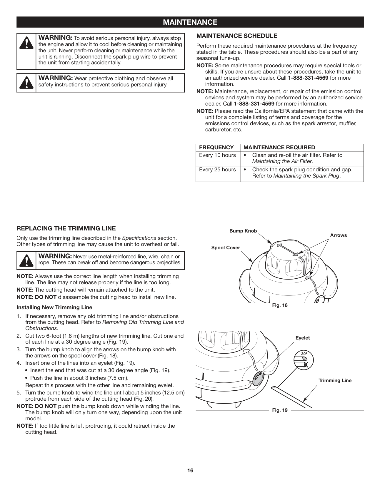
##### REPLACING THE TRIMMING LINE
Bump Knob
Arrows
Only use the trimming line described in the Specifications section. Other types of trimming line may cause the unit to overheat or fail.
Spool Cover
| |WARNING: Never use metal-reinforced line, wire, chain or rope. These can break off and become dangerous projectiles.| |---|---|
NOTE: Always use the correct line length when installing trimming line. The line may not release properly if the line is too long. NOTE: The cutting head will remain attached to the unit. NOTE: DO NOT disassemble the cutting head to install new line.
Fig. 18
###### Installing New Trimming Line
Eyelet

30º
X
Trimming Line
NOTE: DO NOT push the bump knob down while winding the line. The bump knob will only turn one way, depending upon the unit model.
Fig. 19
NOTE: If too little line is left protruding, it could retract inside the
cutting head.
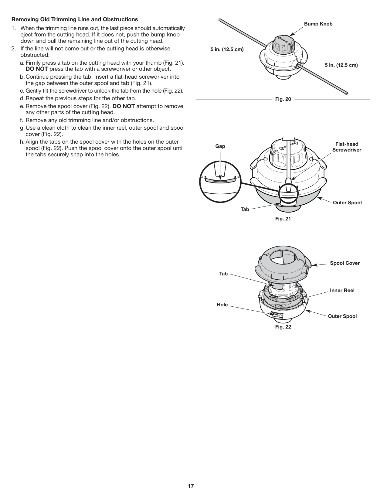
###### Removing Old Trimming Line and Obstructions
Bump Knob
5 in. (12.5 cm)
5 in. (12.5 cm)
Fig. 20
Flat-head Screwdriver
Gap
Outer Spool
Tab

Fig. 21
Spool Cover Tab
Inner Reel
Hole
Outer Spool
Fig. 22
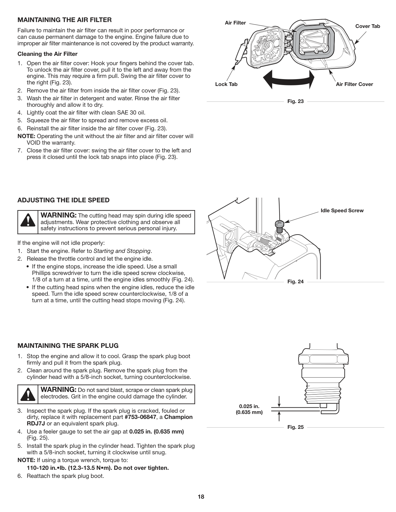
##### MAINTAINING THE AIR FILTER
Failure to maintain the air filter can result in poor performance or can cause permanent damage to the engine. Engine failure due to improper air filter maintenance is not covered by the product warranty.
###### Cleaning the Air Filter
NOTE: Operating the unit without the air filter and air filter cover will
VOID the warranty.
Air Filter
Cover Tab
Air Filter CoverLock Tab
Fig. 23
##### ADJUSTING THE IDLE SPEED
| |WARNING: The cutting head may spin during idle speed adjustments. Wear protective clothing and observe all safety instructions to prevent serious personal injury.| |---|---|

If the engine will not idle properly:
Idle Speed Screw
Fig. 24
##### MAINTAINING THE SPARK PLUG
NOTE: If using a torque wrench, torque to: 110-120 in.•lb. (12.3-13.5 N•m). Do not over tighten.
| |WARNING: Do not sand blast, scrape or clean spark plug electrodes. Grit in the engine could damage the cylinder.| |---|---|
| | | | |---|---|---| | | | |
0.025 in. (0.635 mm)
Fig. 25
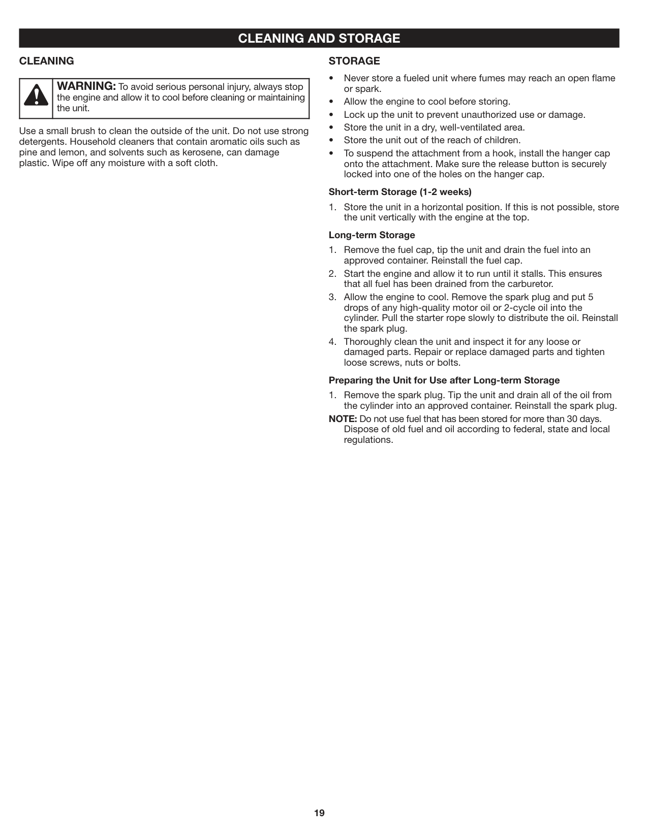
#### CLEANING AND STORAGE CLEANING
##### STORAGE
| |WARNING: To avoid serious personal injury, always stop the engine and allow it to cool before cleaning or maintaining the unit.| |---|---|
Use a small brush to clean the outside of the unit. Do not use strong detergents. Household cleaners that contain aromatic oils such as pine and lemon, and solvents such as kerosene, can damage plastic. Wipe off any moisture with a soft cloth.
###### Short-term Storage (1-2 weeks)
the unit vertically with the engine at the top. Long-term Storage
###### Preparing the Unit for Use after Long-term Storage
NOTE: Do not use fuel that has been stored for more than 30 days. Dispose of old fuel and oil according to federal, state and local regulations.
#### TROUBLESHOOTING
|PROBLEM|SOLUTION| |---|---| |The cutting head is bound with grass The cutting head is out of line The inner reel is bound up The cutting head is dirty The line is welded The line is twisted
Not enough line is extended
There is oil, cleaner or lubricant in the cutting head
The fuel tank is empty The primer bulb was not pressed enough
The engine is flooded The fuel is old (over 30 days) and/or improperly mixed The spark plug is fouled
The fuel is old (over 30 days) and/or improperly mixed The cutting head is bound with grass The air filter is dirty
The air filter is dirty The fuel is old (over 30 days) and/or improperly mixed The idle speed is incorrect
The fuel is old (over 30 days) and/or improperly mixed The air filter is dirty The spark plug is fouled
THE ENGINE WILL NOT START
THE ENGINE WILL NOT IDLE
THE ENGINE WILL NOT ACCELERATE
THE ENGINE LACKS POWER OR STALLS
THE CUTTING HEAD WILL NOT ADVANCE LINE
THE CUTTING LINE ADVANCES UNCONTROLLABLY|Stop the engine and clean the cutting head Refill the cutting head with new line Rewind the line Clean the inner reel and outer spool Open the cutting head and remove the welded section Rewind the line Stop the unit, push the bump knob and pull the line until 4 inches (102 mm) is outside of the cutting head
Clean and thoroughly dry the cutting head
Fill the fuel tank with properly-mixed fuel Press the primer bulb 10 times or until fuel is visible Move the choke lever to Position 3, press the throttle lockout, squeeze the throttle control and pull the starter rope until the engine starts Drain the fuel tank and add fresh, properly-mixed fuel Replace the spark plug
Drain the fuel tank and add fresh, properly-mixed fuel Stop the engine and clean the cutting head Clean or replace the air filter
Clean or replace the air filter Drain the fuel tank and add fresh, properly-mixed fuel Adjust the idle speed
Drain the fuel tank and add fresh, properly-mixed fuel Clean or replace the air filter Replace the spark plug
|
If further assistance is required, contact an authorized service center.
#### WARRANTY MTD LLC LIMITED WARRANTY FOR CRAFTSMAN® BRANDED HANDHELD PRODUCT
###### Limited Warranty
The limited warranty set forth herein is given by MTD LLC to the Initial Purchaser (as defined herein) with respect to new Craftsman branded hand held product (“Product”). This limited warranty does not cover Emission Control Systems and is not a Federal Emission Control Warranty Statement as defined by U.S. federal law. Please refer to the Federal Emission Control Warranty Statement in the operator’s manual for warranties covering Emission Control Systems.
###### Scope Of The Limited Warranty
MTD LLC offers a limited warranty to the Initial Purchaser for residential or otherwise non-commercial use of the Product: subject to the Exclusions defined herein, during the Warranty Period (defined herein). The “Initial Purchaser” is the first person to purchase the Product from an authorized Craftsman branded product dealer, distributor and/or retailer (each a “Retailer”). Except as otherwise set forth herein, the limited warranty period for this new Product purchased by the Initial Purchaser is two (2) years from the date of purchase as shown on the original sales receipt for the Product (“Warranty Period”).
###### Defects In Workmanship Or Materials
Subject to the Exclusions, the Product is warranted to be free from manufacturing defects in either workmanship or materials for the Warranty Period. During the Warranty Period, MTD LLC will, at its option, either repair or replace any original part that is covered by this limited warranty and is determined to be defective in workmanship or material.
###### To Qualify For This Limited Warranty, The Product:
###### Who Can Perform Repairs Under This Warranty?
In order to qualify for the limited warranty as set forth herein, the repairs made under warranty must be performed by an authorized warranty service provider.
###### How To Get Service Under This Limited Warranty
To locate an authorized warranty service provider, contact your authorized Retailer or contact www.craftsman.com/warranty or call toll-free 888-331-4569. A COPY OF YOUR SALES RECEIPT IS REQUIRED FOR WARRANTY SERVICE.
What This Limited Warranty Does Not Cover This Limited Warranty Does Not Cover The Following (the “Exclusions”):
###### This Warranty Does Not Cover And MTD LLC Disclaims Any Responsibility For:
Limitations:
How State Law Relates To This Warranty. This limited warranty gives you specific legal rights, and you may also have other rights, which vary from state to state.
##### TABLA DE CONTENIDO
Seguridad . . . . . . . . . . . . . . . . . . . . . . . . . . . . . . . . . . . . . . . . . . .23 Conozca su unidad . . . . . . . . . . . . . . . . . . . . . . . . . . . . . . . . . . . .27 Especificaciones . . . . . . . . . . . . . . . . . . . . . . . . . . . . . . . . . . . . . .28 Ensamblaje . . . . . . . . . . . . . . . . . . . . . . . . . . . . . . . . . . . . . . . . . .29 Aceite y combustible . . . . . . . . . . . . . . . . . . . . . . . . . . . . . . . . . . .32 Arranque y parada . . . . . . . . . . . . . . . . . . . . . . . . . . . . . . . . . . . .33 Operación . . . . . . . . . . . . . . . . . . . . . . . . . . . . . . . . . . . . . . . . . . .35 Mantenimiento . . . . . . . . . . . . . . . . . . . . . . . . . . . . . . . . . . . . . . .37 Limpieza y almacenamiento . . . . . . . . . . . . . . . . . . . . . . . . . . . . .41 Localización y solución de problemas . . . . . . . . . . . . . . . . . . . . .42 Garantía . . . . . . . . . . . . . . . . . . . . . . . . . . . . . . . . . . . . . . . . . . . . .43 Números de servicio . . . . . . . . . . . . . . . . . . . . . . . . .Contraportada
Toda la información, las ilustraciones y las especificaciones contenidas en este manual se basan en la información más reciente disponible en el momento de impresión del manual. Nos reservamos el derecho de hacer cambios en cualquier momento sin aviso previo. El producto puede variar ligeramente de las ilustraciones contenidas en este manual.
NOTA: Este manual del operador cubre múltiples modelos. Las características pueden variar según los modelos. No todas las características de este manual son aplicables a todos los modelos. El modelo descripto puede diferir del suyo.
#### SEGURIDAD
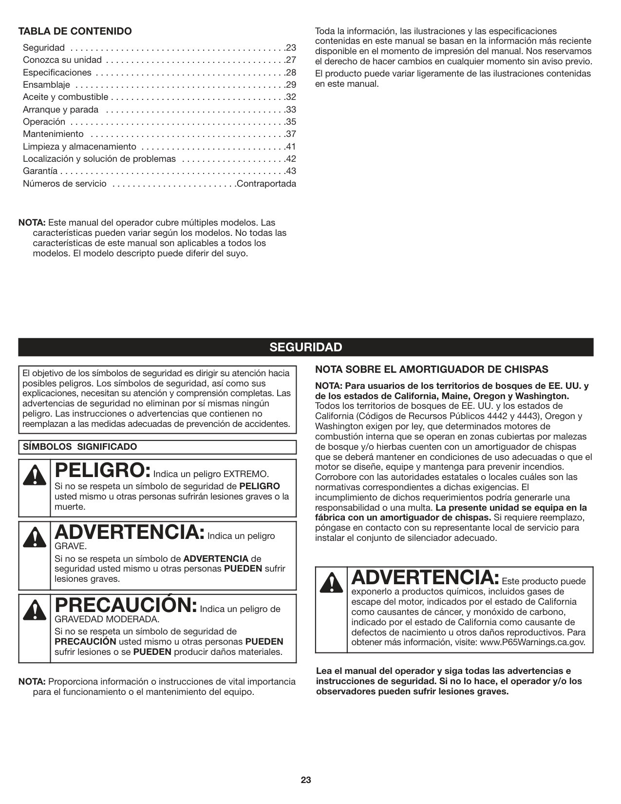
|El objetivo de los símbolos de seguridad es dirigir su atención hacia posibles peligros. Los símbolos de seguridad, así como sus explicaciones, necesitan su atención y comprensión completas. Las advertencias de seguridad no eliminan por sí mismas ningún peligro. Las instrucciones o advertencias que contienen no reemplazan a las medidas adecuadas de prevención de accidentes.| |---|
|SÍMBOLOS SIGNIFICADO| |---|
| |PELIGRO:Indica un peligro EXTREMO. Si no se respeta un símbolo de seguridad de PELIGRO usted mismo u otras personas sufrirán lesiones graves o la muerte.| |---|---|
| |ADVERTENCIA:Indica un peligro GRAVE. Si no se respeta un símbolo de ADVERTENCIA de seguridad usted mismo u otras personas PUEDEN sufrir lesiones graves.| |---|---|
| |PRECAUCIÓN:Indica un peligro de GRAVEDAD MODERADA. Si no se respeta un símbolo de seguridad de
PRECAUCIÓN usted mismo u otras personas PUEDEN sufrir lesiones o se PUEDEN producir daños materiales.| |---|---|
NOTA: Proporciona información o instrucciones de vital importancia
para el funcionamiento o el mantenimiento del equipo.
##### NOTA SOBRE EL AMORTIGUADOR DE CHISPAS
NOTA: Para usuarios de los territorios de bosques de EE. UU. y de los estados de California, Maine, Oregon y Washington. Todos los territorios de bosques de EE. UU. y los estados de California (Códigos de Recursos Públicos 4442 y 4443), Oregon y Washington exigen por ley, que determinados motores de combustión interna que se operan en zonas cubiertas por malezas de bosque y/o hierbas cuenten con un amortiguador de chispas que se deberá mantener en condiciones de uso adecuadas o que el motor se diseñe, equipe y mantenga para prevenir incendios. Corrobore con las autoridades estatales o locales cuáles son las normativas correspondientes a dichas exigencias. El incumplimiento de dichos requerimientos podría generarle una responsabilidad o una multa. La presente unidad se equipa en la fábrica con un amortiguador de chispas. Si requiere reemplazo, póngase en contacto con su representante local de servicio para instalar el conjunto de silenciador adecuado.
| |ADVERTENCIA:Este producto puede exponerlo a productos químicos, incluidos gases de escape del motor, indicados por el estado de California como causantes de cáncer, y monóxido de carbono, indicado por el estado de California como causante de defectos de nacimiento u otros daños reproductivos. Para obtener más información, visite: www.P65Warnings.ca.gov.| |---|---|
Lea el manual del operador y siga todas las advertencias e instrucciones de seguridad. Si no lo hace, el operador y/o los observadores pueden sufrir lesiones graves.
• INSTRUCCIONES DE SEGURIDAD IMPORTANTES •
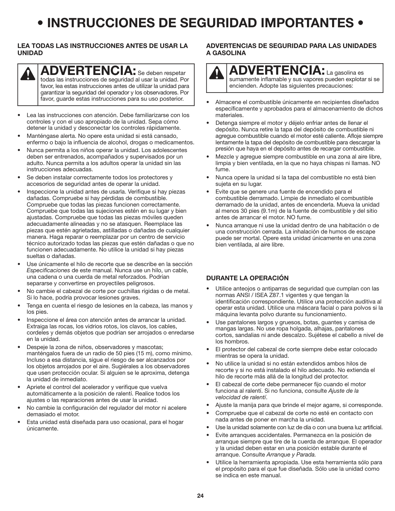
##### LEA TODAS LAS INSTRUCCIONES ANTES DE USAR LA UNIDAD
| |ADVERTENCIA:Se deben respetar
todas las instrucciones de seguridad al usar la unidad. Por favor, lea estas instrucciones antes de utilizar la unidad para garantizar la seguridad del operador y los observadores. Por favor, guarde estas instrucciones para su uso posterior.| |---|---|
##### ADVERTENCIAS DE SEGURIDAD PARA LAS UNIDADES A GASOLINA
| |ADVERTENCIA:La gasolina es sumamente inflamable y sus vapores pueden explotar si se encienden. Adopte las siguientes precauciones:| |---|---|
##### DURANTE LA OPERACIÓN
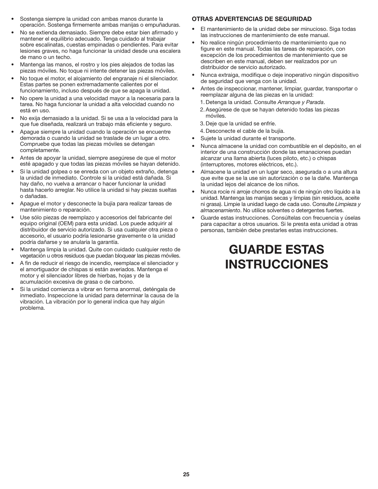
##### OTRAS ADVERTENCIAS DE SEGURIDAD
GUARDE ESTAS INSTRUCCIONES
##### • SÍMBOLOS INTERNACIONALES Y DE SEGURIDAD •
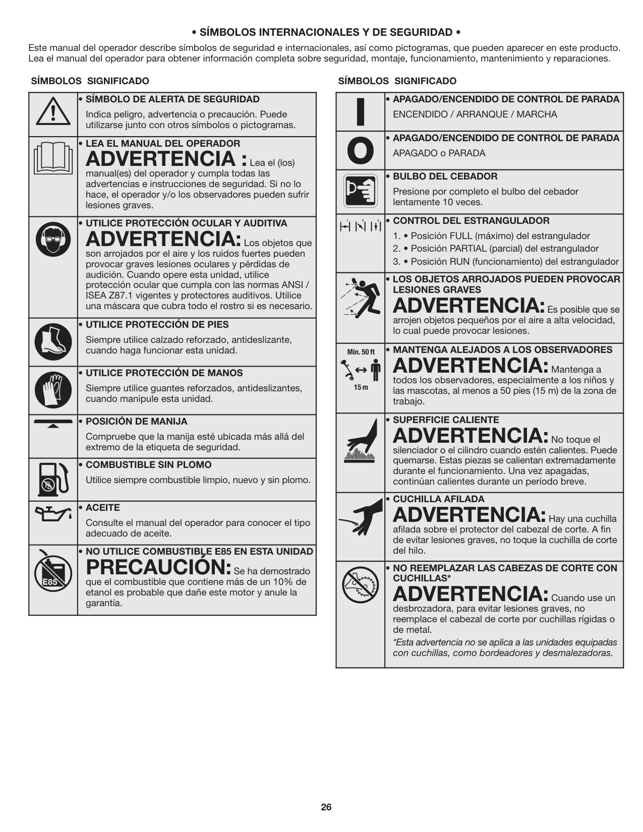
Este manual del operador describe símbolos de seguridad e internacionales, así como pictogramas, que pueden aparecer en este producto. Lea el manual del operador para obtener información completa sobre seguridad, montaje, funcionamiento, mantenimiento y reparaciones.
###### SÍMBOLOS SIGNIFICADO SÍMBOLOS SIGNIFICADO
| |• SÍMBOLO DE ALERTA DE SEGURIDAD
Indica peligro, advertencia o precaución. Puede utilizarse junto con otros símbolos o pictogramas.| |---|---| | |• LEA EL MANUAL DEL OPERADOR
ADVERTENCIA :Lea el (los) manual(es) del operador y cumpla todas las advertencias e instrucciones de seguridad. Si no lo hace, el operador y/o los observadores pueden sufrir lesiones graves.| | |• UTILICE PROTECCIÓN OCULAR Y AUDITIVA
ADVERTENCIA:Los objetos que son arrojados por el aire y los ruidos fuertes pueden provocar graves lesiones oculares y pérdidas de audición. Cuando opere esta unidad, utilice protección ocular que cumpla con las normas ANSI / ISEA Z87.1 vigentes y protectores auditivos. Utilice una máscara que cubra todo el rostro si es necesario.| | |• UTILICE PROTECCIÓN DE PIES
Siempre utilice calzado reforzado, antideslizante, cuando haga funcionar esta unidad.| | |• UTILICE PROTECCIÓN DE MANOS
Siempre utilice guantes reforzados, antideslizantes, cuando manipule esta unidad.| | |• POSICIÓN DE MANIJA
Compruebe que la manija esté ubicada más allá del extremo de la etiqueta de seguridad.| | |• COMBUSTIBLE SIN PLOMO
Utilice siempre combustible limpio, nuevo y sin plomo.| | |• ACEITE
Consulte el manual del operador para conocer el tipo adecuado de aceite.| | |• NO UTILICE COMBUSTIBLE E85 EN ESTA UNIDAD
PRECAUCIÓN:Se ha demostrado que el combustible que contiene más de un 10% de etanol es probable que dañe este motor y anule la garantía.|
| |• APAGADO/ENCENDIDO DE CONTROL DE PARADA
ENCENDIDO / ARRANQUE / MARCHA| |---|---| | |• APAGADO/ENCENDIDO DE CONTROL DE PARADA
APAGADO o PARADA| | |• BULBO DEL CEBADOR
Presione por completo el bulbo del cebador lentamente 10 veces.| | |• CONTROL DEL ESTRANGULADOR
1. • Posición FULL (máximo) del estrangulador
2. • Posición PARTIAL (parcial) del estrangulador
3. • Posición RUN (funcionamiento) del estrangulador
| | |• LOS OBJETOS ARROJADOS PUEDEN PROVOCAR LESIONES GRAVES
ADVERTENCIA:Es posible que se arrojen objetos pequeños por el aire a alta velocidad, lo cual puede provocar lesiones.| |Min. 50 ft
15 m
|• MANTENGA ALEJADOS A LOS OBSERVADORES
ADVERTENCIA:Mantenga a todos los observadores, especialmente a los niños y las mascotas, al menos a 50 pies (15 m) de la zona de trabajo.| | |• SUPERFICIE CALIENTE
ADVERTENCIA:No toque el silenciador o el cilindro cuando estén calientes. Puede quemarse. Estas piezas se calientan extremadamente durante el funcionamiento. Una vez apagadas, continúan calientes durante un período breve.| | |• CUCHILLA AFILADA
ADVERTENCIA:Hay una cuchilla afilada sobre el protector del cabezal de corte. A fin de evitar lesiones graves, no toque la cuchilla de corte del hilo.| | |• NO REEMPLAZAR LAS CABEZAS DE CORTE CON CUCHILLAS*
ADVERTENCIA:Cuando use un desbrozadora, para evitar lesiones graves, no reemplace el cabezal de corte por cuchillas rígidas o de metal.
*Esta advertencia no se aplica a las unidades equipadas con cuchillas, como bordeadores y desmalezadoras.|
#### CONOZCA SU UNIDAD
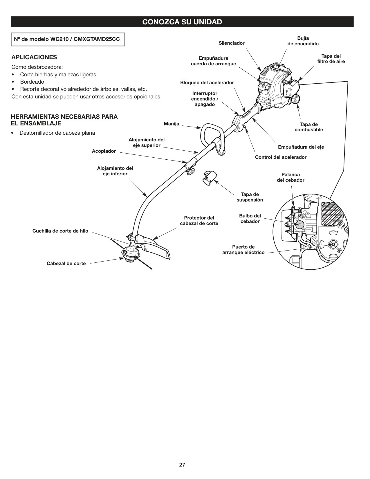
|Nº de modelo WC210 / CMXGTAMD25CC| |---|
Bujía de encendidoSilenciador
APLICACIONES Como desbrozadora:
Empuñadura cuerda de arranque
HERRAMIENTAS NECESARIAS PARA EL ENSAMBLAJE
Bloqueo del acelerador
Interruptor encendido / apagado
Manija
Alojamiento del eje superior
Acoplador
Alojamiento del eje inferior
Tapa del filtro de aire
Tapa de combustible
Empuñadura del eje
Control del acelerador
Palanca del cebador
Tapa de suspensión
| | | | |---|---|---| | | | |
Bulbo del cebador Cuchilla de corte de hilo
Protector del cabezal de corte
| | | |---|---| | | |
| | | |---|---| | | |
| | | | |---|---|---| | | | |
Cabezal de corte
Puerto de arranque eléctrico
| | |---| | | | |
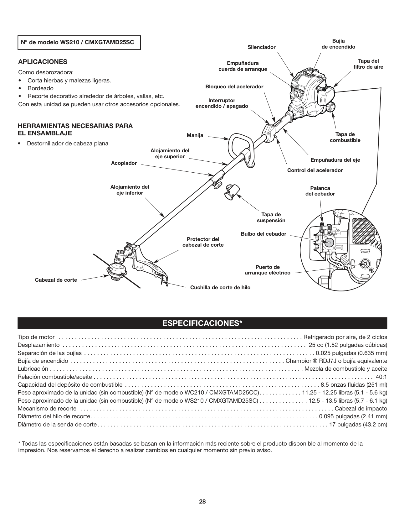
|Nº de modelo WS210 / CMXGTAMD25SC| |---|
Bujía de encendidoSilenciador
APLICACIONES Como desbrozadora:
Empuñadura cuerda de arranque
HERRAMIENTAS NECESARIAS PARA EL ENSAMBLAJE
Bloqueo del acelerador
Interruptor encendido / apagado
Manija
Alojamiento del eje superior
Acoplador
Tapa del filtro de aire
Tapa de combustible
Empuñadura del eje
Control del acelerador
Alojamiento del eje inferior
Protector del cabezal de corte
Tapa de suspensión
Bulbo del cebador
Palanca del cebador
| | | |---|---| | | |
| | | |---|---| | | |
| | | | |---|---|---| | | | |
| | | |
|---|---|---| | | | |
Cabezal de corte
Puerto de arranque eléctrico
Cuchilla de corte de hilo
#### ESPECIFICACIONES*
Tipo de motor . . . . . . . . . . . . . . . . . . . . . . . . . . . . . . . . . . . . . . . . . . . . . . . . . . . . . . . . . . . . . . . . . . . . . . . . . . . Refrigerado por aire, de 2 ciclos Desplazamiento . . . . . . . . . . . . . . . . . . . . . . . . . . . . . . . . . . . . . . . . . . . . . . . . . . . . . . . . . . . . . . . . . . . . . . . . . . . 25 cc (1.52 pulgadas cúbicas) Separación de las bujías . . . . . . . . . . . . . . . . . . . . . . . . . . . . . . . . . . . . . . . . . . . . . . . . . . . . . . . . . . . . . . . . . . . . . . . 0.025 pulgadas (0.635 mm) Bujía de encendido . . . . . . . . . . . . . . . . . . . . . . . . . . . . . . . . . . . . . . . . . . . . . . . . . . . . . . . . . . . . . . . . . . Champion® RDJ7J o bujía equivalente Lubricación . . . . . . . . . . . . . . . . . . . . . . . . . . . . . . . . . . . . . . . . . . . . . . . . . . . . . . . . . . . . . . . . . . . . . . . . . . . . . . Mezcla de combustible y aceite Relación combustible/aceite . . . . . . . . . . . . . . . . . . . . . . . . . . . . . . . . . . . . . . . . . . . . . . . . . . . . . . . . . . . . . . . . . . . . . . . . . . . . . . . . . . . . . . 40:1 Capacidad del depósito de combustible . . . . . . . . . . . . . . . . . . . . . . . . . . . . . . . . . . . . . . . . . . . . . . . . . . . . . . . . . . . . 8.5 onzas fluidas (251 ml) Peso aproximado de la unidad (sin combustible) (N° de modelo WC210 / CMXGTAMD25CC). . . . . . . . . . . . . 11.25 - 12.25 libras (5.1 - 5.6 kg) Peso aproximado de la unidad (sin combustible) (N° de modelo WS210 / CMXGTAMD25SC) . . . . . . . . . . . . . . . 12.5 - 13.5 libras (5.7 - 6.1 kg) Mecanismo de recorte . . . . . . . . . . . . . . . . . . . . . . . . . . . . . . . . . . . . . . . . . . . . . . . . . . . . . . . . . . . . . . . . . . . . . . . . . . . . . . Cabezal de impacto Diámetro del hilo de recorte. . . . . . . . . . . . . . . . . . . . . . . . . . . . . . . . . . . . . . . . . . . . . . . . . . . . . . . . . . . . . . . . . . . . . . 0.095 pulgadas (2.41 mm) Diámetro de la senda de corte. . . . . . . . . . . . . . . . . . . . . . . . . . . . . . . . . . . . . . . . . . . . . . . . . . . . . . . . . . . . . . . . . . . . . . . 17 pulgadas (43.2 cm)
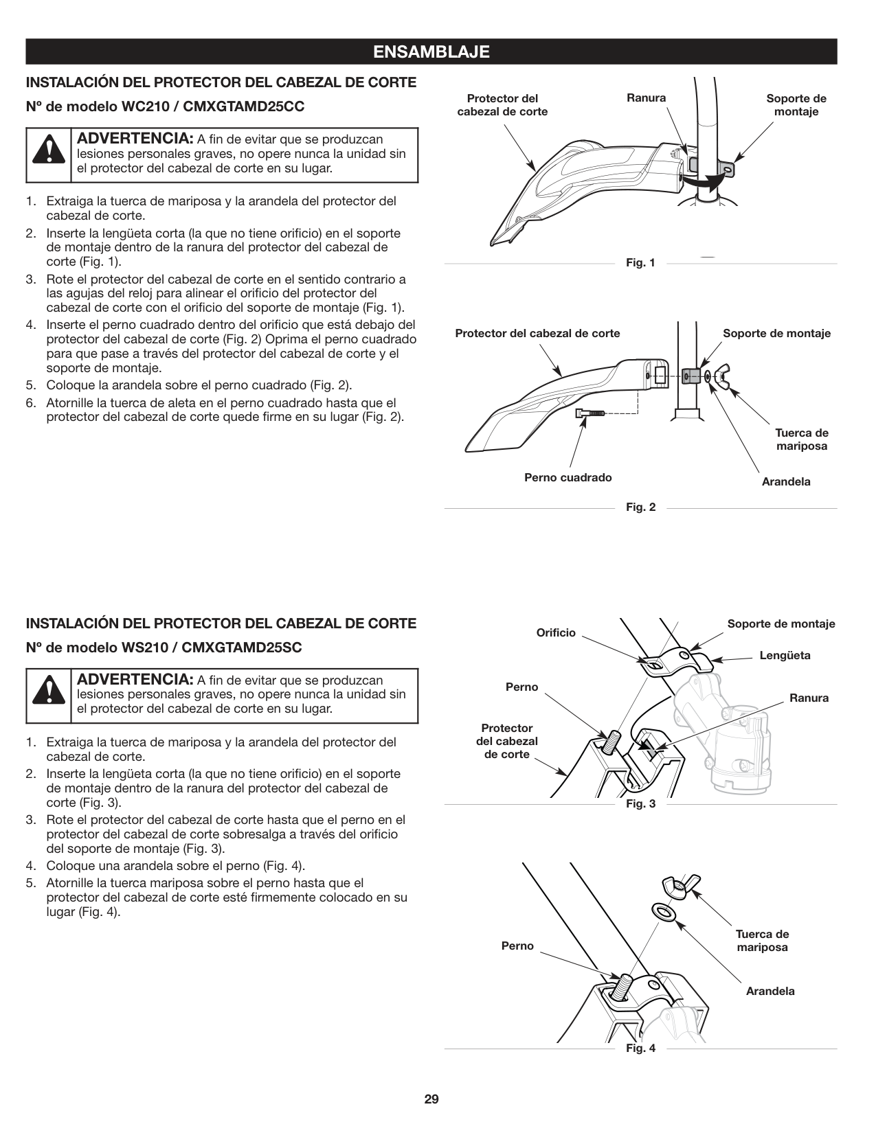
#### ENSAMBLAJE INSTALACIÓN DEL PROTECTOR DEL CABEZAL DE CORTE Nº de modelo WC210 / CMXGTAMD25CC
Ranura
Soporte de montaje
Protector del cabezal de corte
| |ADVERTENCIA: A fin de evitar que se produzcan lesiones personales graves, no opere nunca la unidad sin el protector del cabezal de corte en su lugar.| |---|---|
Fig. 1
Protector del cabezal de corte Soporte de montaje
| | | | |---|---|---| | | | |
Tuerca de mariposa
ArandelaPerno cuadrado
Fig. 2
##### INSTALACIÓN DEL PROTECTOR DEL CABEZAL DE CORTE Nº de modelo WS210 / CMXGTAMD25SC
Soporte de montaje
Orificio
Lengüeta
| |ADVERTENCIA: A fin de evitar que se produzcan lesiones personales graves, no opere nunca la unidad sin el protector del cabezal de corte en su lugar.| |---|---|
Perno
Ranura
Protector del cabezal de corte
Fig. 3
Tuerca de mariposa
Perno
Arandela
Fig. 4
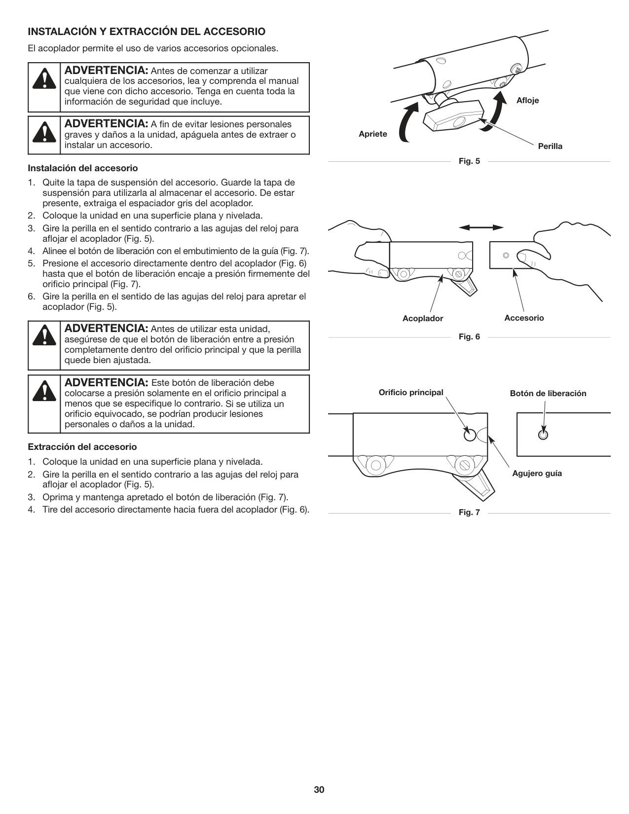
INSTALACIÓN Y EXTRACCIÓN DEL ACCESORIO El acoplador permite el uso de varios accesorios opcionales.
| |ADVERTENCIA: Antes de comenzar a utilizar cualquiera de los accesorios, lea y comprenda el manual que viene con dicho accesorio. Tenga en cuenta toda la información de seguridad que incluye.| |---|---|
| |ADVERTENCIA: A fin de evitar lesiones personales graves y daños a la unidad, apáguela antes de extraer o instalar un accesorio.| |---|---|
###### Instalación del accesorio
| |ADVERTENCIA: Antes de utilizar esta unidad, asegúrese de que el botón de liberación entre a presión completamente dentro del orificio principal y que la perilla quede bien ajustada.| |---|---|
ADVERTENCIA: Este botón de liberación debe colocarse a presión solamente en el orificio principal a menos que se especifique lo contrario. Si se utiliza un orificio equivocado, se podrían producir lesiones personales o daños a la unidad.
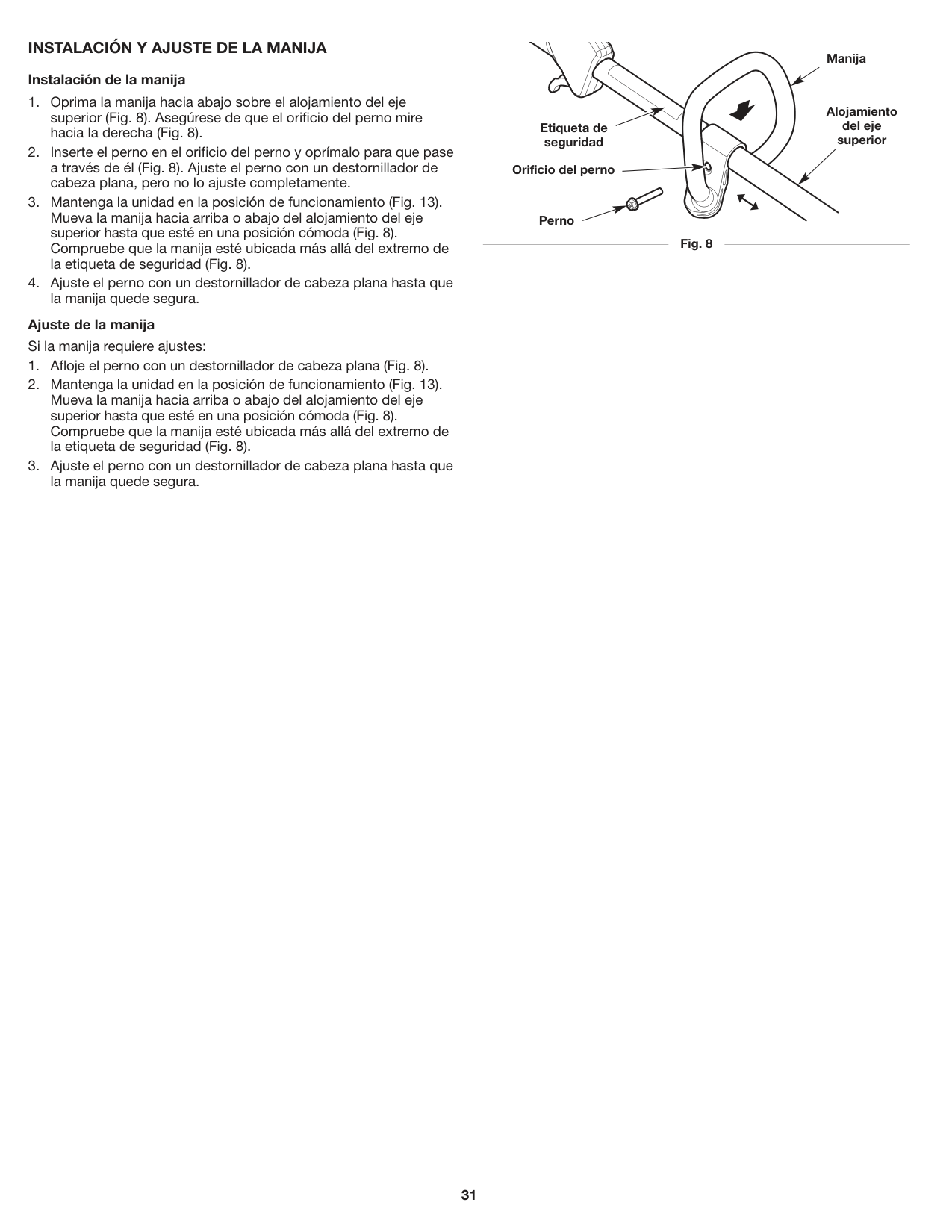
###### Extracción del accesorio
Afloje
Apriete
Perilla
Fig. 7
Acoplador Accesorio
Orificio principal Botón de liberación
Agujero guía
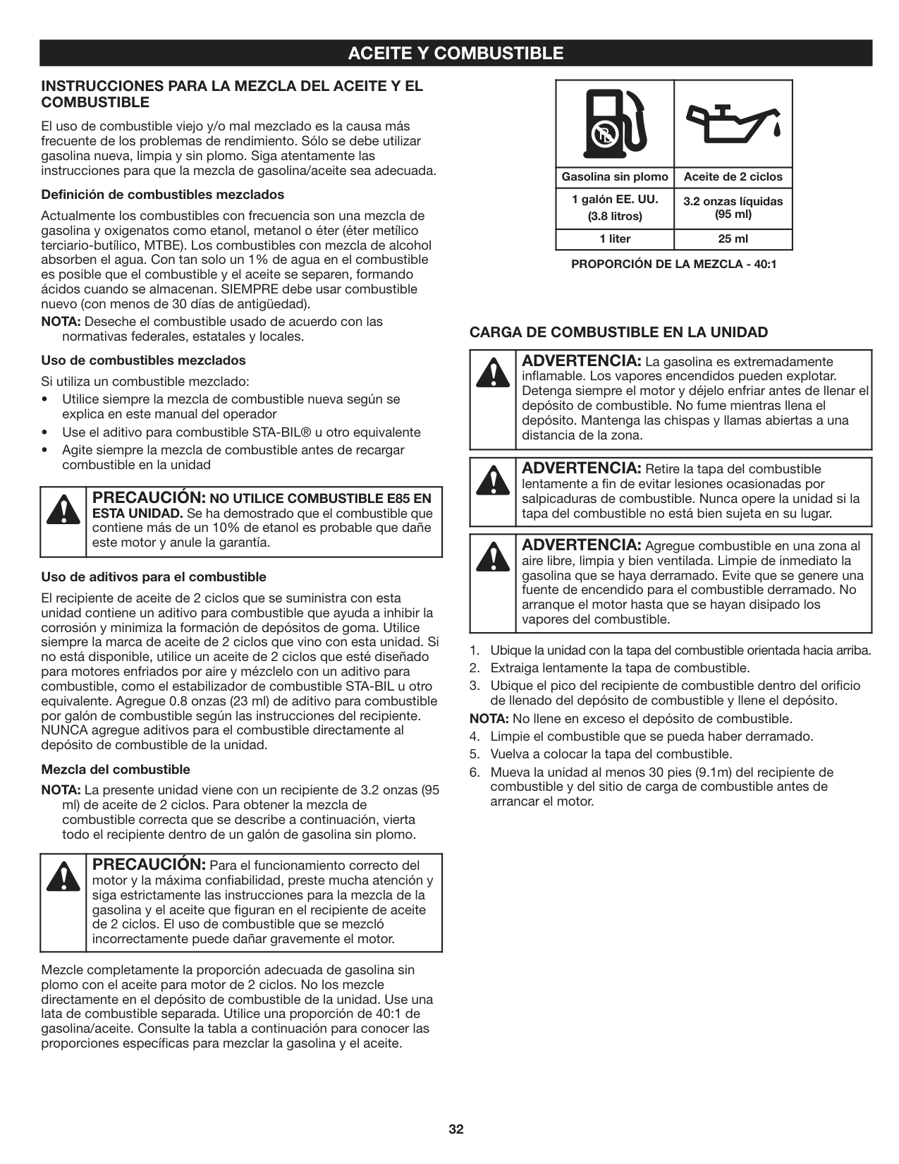
##### INSTALACIÓN Y AJUSTE DE LA MANIJA Instalación de la manija
Ajuste de la manija Si la manija requiere ajustes:
Manija
Alojamiento del eje superior
Etiqueta de seguridad
Orificio del perno
Perno
Fig. 8
#### ACEITE Y COMBUSTIBLE
##### INSTRUCCIONES PARA LA MEZCLA DEL ACEITE Y EL COMBUSTIBLE
El uso de combustible viejo y/o mal mezclado es la causa más frecuente de los problemas de rendimiento. Sólo se debe utilizar gasolina nueva, limpia y sin plomo. Siga atentamente las instrucciones para que la mezcla de gasolina/aceite sea adecuada.
Definición de combustibles mezclados Actualmente los combustibles con frecuencia son una mezcla de gasolina y oxigenatos como etanol, metanol o éter (éter metílico terciario-butílico, MTBE). Los combustibles con mezcla de alcohol absorben el agua. Con tan solo un 1% de agua en el combustible es posible que el combustible y el aceite se separen, formando ácidos cuando se almacenan. SIEMPRE debe usar combustible nuevo (con menos de 30 días de antigüedad). NOTA: Deseche el combustible usado de acuerdo con las
normativas federales, estatales y locales. Uso de combustibles mezclados Si utiliza un combustible mezclado:
| |PRECAUCIÓN: NO UTILICE COMBUSTIBLE E85 EN ESTA UNIDAD. Se ha demostrado que el combustible que contiene más de un 10% de etanol es probable que dañe este motor y anule la garantía.| |---|---|
###### Uso de aditivos para el combustible
El recipiente de aceite de 2 ciclos que se suministra con esta unidad contiene un aditivo para combustible que ayuda a inhibir la corrosión y minimiza la formación de depósitos de goma. Utilice siempre la marca de aceite de 2 ciclos que vino con esta unidad. Si no está disponible, utilice un aceite de 2 ciclos que esté diseñado para motores enfriados por aire y mézclelo con un aditivo para combustible, como el estabilizador de combustible STA-BIL u otro equivalente. Agregue 0.8 onzas (23 ml) de aditivo para combustible por galón de combustible según las instrucciones del recipiente. NUNCA agregue aditivos para el combustible directamente al depósito de combustible de la unidad.
Mezcla del combustible NOTA: La presente unidad viene con un recipiente de 3.2 onzas (95
ml) de aceite de 2 ciclos. Para obtener la mezcla de combustible correcta que se describe a continuación, vierta todo el recipiente dentro de un galón de gasolina sin plomo.
| |PRECAUCIÓN: Para el funcionamiento correcto del motor y la máxima confiabilidad, preste mucha atención y siga estrictamente las instrucciones para la mezcla de la gasolina y el aceite que figuran en el recipiente de aceite de 2 ciclos. El uso de combustible que se mezcló incorrectamente puede dañar gravemente el motor.| |---|---|
Mezcle completamente la proporción adecuada de gasolina sin plomo con el aceite para motor de 2 ciclos. No los mezcle directamente en el depósito de combustible de la unidad. Use una lata de combustible separada. Utilice una proporción de 40:1 de gasolina/aceite. Consulte la tabla a continuación para conocer las proporciones específicas para mezclar la gasolina y el aceite.
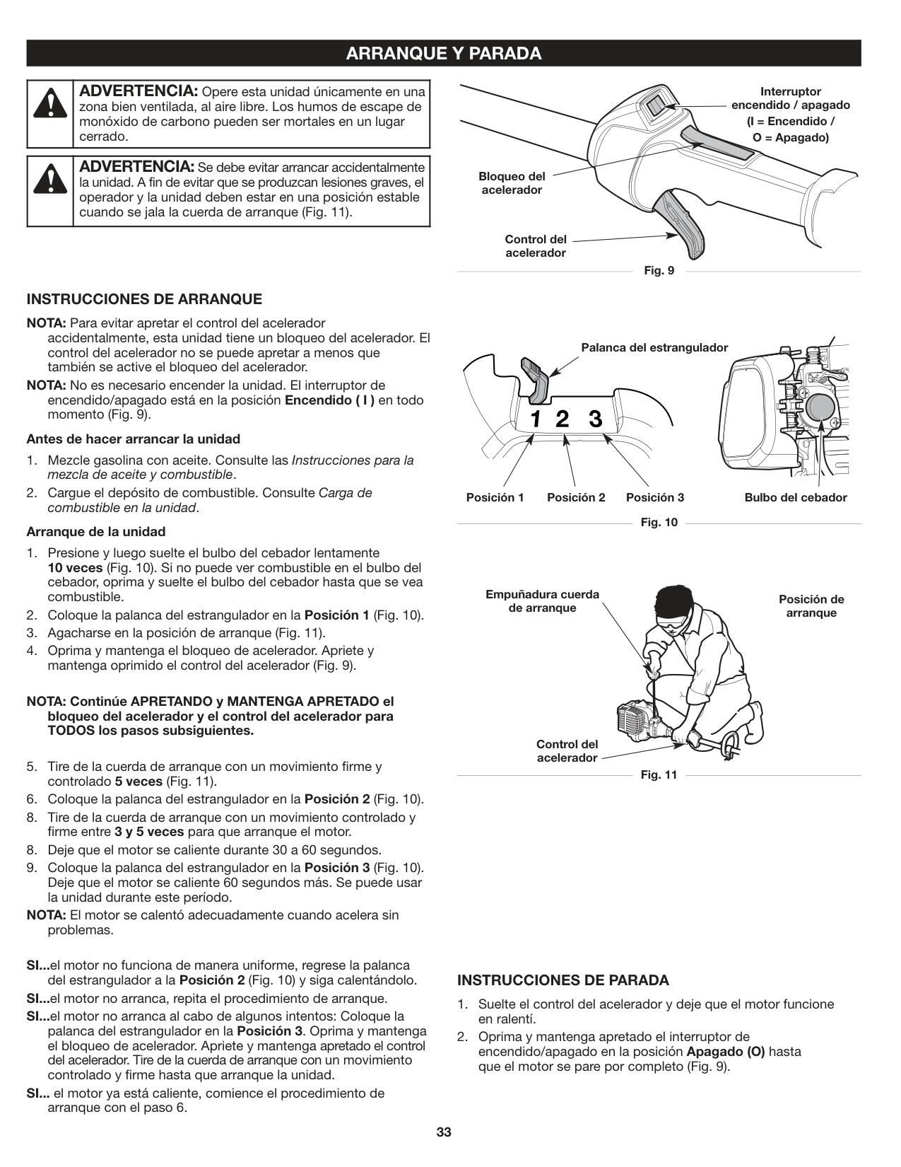
| | | |---|---| |Gasolina sin plomo|Aceite de 2 ciclos| |1 galón EE. UU. (3.8 litros)|3.2 onzas líquidas (95 ml)| |1 liter|25 ml|
####### PROPORCIÓN DE LA MEZCLA - 40:1
##### CARGA DE COMBUSTIBLE EN LA UNIDAD
| |ADVERTENCIA: La gasolina es extremadamente inflamable. Los vapores encendidos pueden explotar. Detenga siempre el motor y déjelo enfriar antes de llenar el depósito de combustible. No fume mientras llena el depósito. Mantenga las chispas y llamas abiertas a una distancia de la zona.| |---|---|
| |ADVERTENCIA: Retire la tapa del combustible lentamente a fin de evitar lesiones ocasionadas por salpicaduras de combustible. Nunca opere la unidad si la tapa del combustible no está bien sujeta en su lugar.| |---|---|
| |ADVERTENCIA: Agregue combustible en una zona al aire libre, limpia y bien ventilada. Limpie de inmediato la gasolina que se haya derramado. Evite que se genere una fuente de encendido para el combustible derramado. No arranque el motor hasta que se hayan disipado los vapores del combustible.| |---|---|
#### ARRANQUE Y PARADA
| |ADVERTENCIA: Opere esta unidad únicamente en una zona bien ventilada, al aire libre. Los humos de escape de monóxido de carbono pueden ser mortales en un lugar cerrado.| |---|---|
| |ADVERTENCIA: Se debe evitar arrancar accidentalmente la unidad. A fin de evitar que se produzcan lesiones graves, el operador y la unidad deben estar en una posición estable cuando se jala la cuerda de arranque (Fig. 11).| |---|---|
INSTRUCCIONES DE ARRANQUE NOTA: Para evitar apretar el control del acelerador
accidentalmente, esta unidad tiene un bloqueo del acelerador. El control del acelerador no se puede apretar a menos que también se active el bloqueo del acelerador.
NOTA: No es necesario encender la unidad. El interruptor de encendido/apagado está en la posición Encendido ( I ) en todo momento (Fig. 9).
###### Antes de hacer arrancar la unidad
###### Arranque de la unidad
NOTA: Continúe APRETANDO y MANTENGA APRETADO el bloqueo del acelerador y el control del acelerador para TODOS los pasos subsiguientes.
NOTA: El motor se calentó adecuadamente cuando acelera sin
problemas.
Interruptor encendido / apagado (I = Encendido / O = Apagado)
Bloqueo del acelerador
Control del acelerador
Fig. 9
Palanca del estrangulador
Bulbo del cebadorPosición 3Posición 2Posición 1
Fig. 10
Empuñadura cuerda de arranque
Posición de arranque
Control del acelerador
Fig. 11
SI...el motor no funciona de manera uniforme, regrese la palanca
del estrangulador a la Posición 2 (Fig. 10) y siga calentándolo. SI...el motor no arranca, repita el procedimiento de arranque. SI...el motor no arranca al cabo de algunos intentos: Coloque la
palanca del estrangulador en la Posición 3. Oprima y mantenga el bloqueo de acelerador. Apriete y mantenga apretado el control del acelerador. Tire de la cuerda de arranque con un movimiento controlado y firme hasta que arranque la unidad.
SI... el motor ya está caliente, comience el procedimiento de
arranque con el paso 6.
##### INSTRUCCIONES DE PARADA
#### USO DEL ACCESORIO DE ARRANQUE ELÉCTRICO
Esta unidad se puede arrancar con un accesorio de arranque eléctrico opcional (artículos que se venden por separado). Consulte el manual del operador del accesorio de arranque eléctrico para obtener instrucciones para el uso adecuado de esta función. Para más información, comuníquese con su distribuidor local Craftsman llamando al 1-888-331-4569 o visite www.craftsman.com.
INSTRUCCIONES DE ARRANQUE NOTA: Para evitar apretar el control del acelerador
accidentalmente, esta unidad tiene un bloqueo del acelerador. El control del acelerador no se puede apretar a menos que también se active el bloqueo del acelerador.
NOTA: No es necesario encender la unidad. El interruptor de encendido/apagado está en la posición Encendido ( I ) en todo momento (Fig. 9).
###### Antes de hacer arrancar la unidad
###### Arranque de la unidad
Lea el Manual del operador del accesorio de arranque eléctrico antes de intentar proceder con estas instrucciones.
NOTA: Continúe APRETANDO y MANTENGA APRETADO el bloqueo del acelerador y el control del acelerador para TODOS los pasos subsiguientes.
NOTA: El motor se calentó adecuadamente cuando acelera sin
problemas.
| | | | |---|---|---| | | | |
| |
|---| | | | |
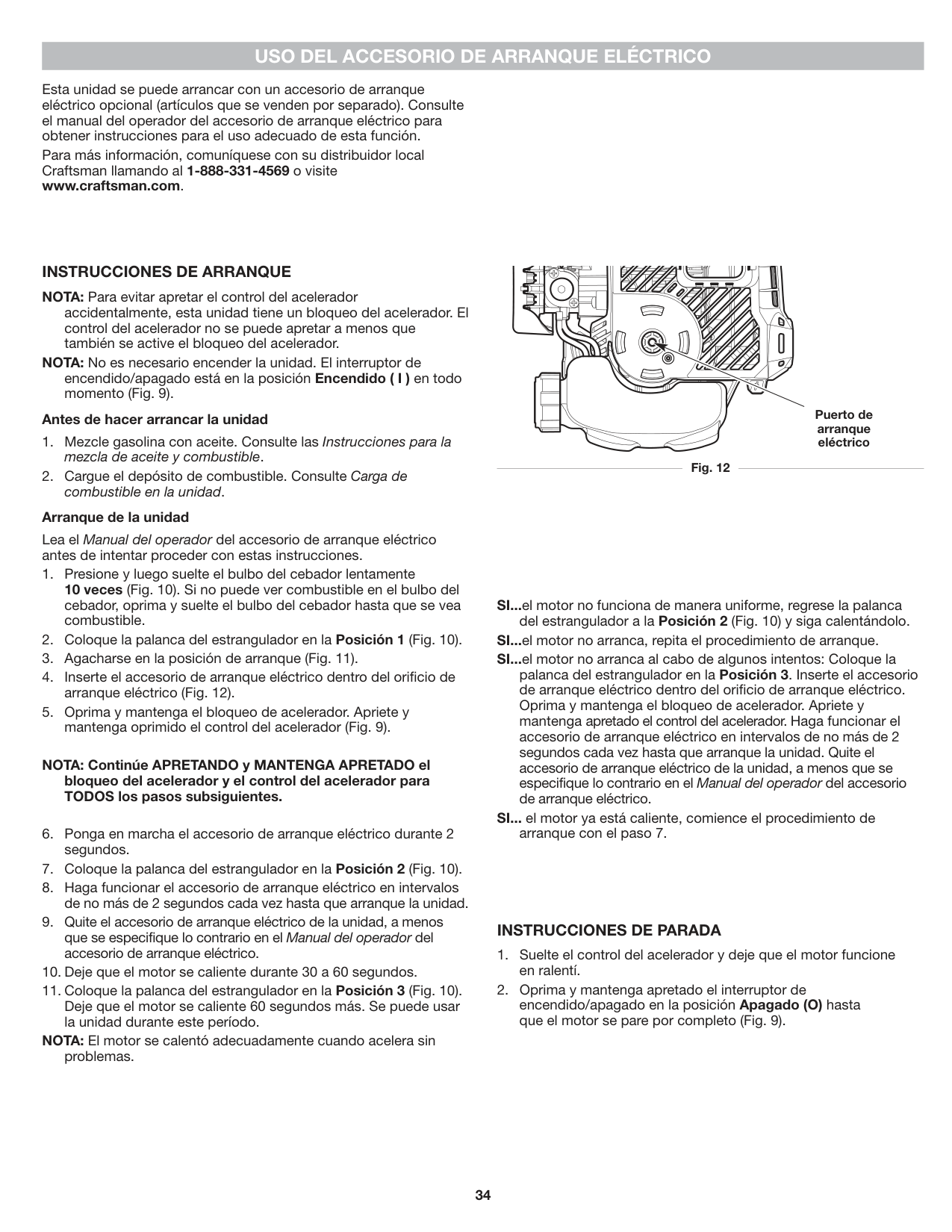
Puerto de arranque eléctrico
Fig. 12
SI...el motor no funciona de manera uniforme, regrese la palanca
del estrangulador a la Posición 2 (Fig. 10) y siga calentándolo. SI...el motor no arranca, repita el procedimiento de arranque. SI...el motor no arranca al cabo de algunos intentos: Coloque la
palanca del estrangulador en la Posición 3. Inserte el accesorio de arranque eléctrico dentro del orificio de arranque eléctrico. Oprima y mantenga el bloqueo de acelerador. Apriete y mantenga apretado el control del acelerador. Haga funcionar el accesorio de arranque eléctrico en intervalos de no más de 2 segundos cada vez hasta que arranque la unidad. Quite el accesorio de arranque eléctrico de la unidad, a menos que se especifique lo contrario en el Manual del operador del accesorio de arranque eléctrico.
SI... el motor ya está caliente, comience el procedimiento de
arranque con el paso 7.
##### INSTRUCCIONES DE PARADA
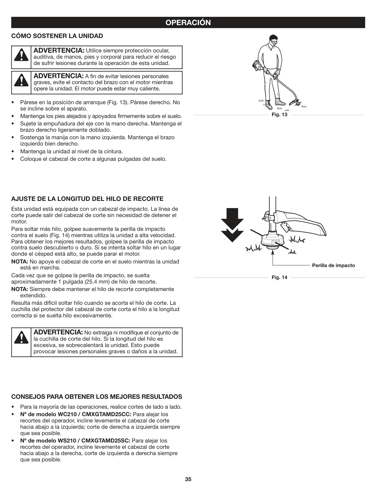
#### OPERACIÓN CÓMO SOSTENER LA UNIDAD
| |ADVERTENCIA: Utilice siempre protección ocular, auditiva, de manos, pies y corporal para reducir el riesgo de sufrir lesiones durante la operación de esta unidad.| |---|---|
| |ADVERTENCIA: A fin de evitar lesiones personales graves, evite el contacto del brazo con el motor mientras opere la unidad. El motor puede estar muy caliente.| |---|---|
AJUSTE DE LA LONGITUD DEL HILO DE RECORTE Esta unidad está equipada con un cabezal de impacto. La línea de corte puede salir del cabezal de corte sin necesidad de detener el motor. Para soltar más hilo, golpee suavemente la perilla de impacto contra el suelo (Fig. 14) mientras utiliza la unidad a alta velocidad. Para obtener los mejores resultados, golpee la perilla de impacto contra suelo descubierto o duro. Si se intenta soltar hilo en un lugar donde el césped está alto, se puede parar el motor. NOTA: No apoye el cabezal de corte en el suelo mientras la unidad
está en marcha. Cada vez que se golpea la perilla de impacto, se suelta aproximadamente 1 pulgada (25.4 mm) de hilo de recorte. NOTA: Siempre debe mantener el hilo de recorte completamente
extendido. Resulta más difícil soltar hilo cuando se acorta el hilo de corte. La cuchilla del protector del cabezal de corte corta el hilo a la longitud correcta si se suelta hilo excesivamente.
Perilla de impacto
| |ADVERTENCIA: No extraiga ni modifique el conjunto de la cuchilla de corte del hilo. Si la longitud del hilo es excesiva, se sobrecalentará la unidad. Esto puede provocar lesiones personales graves o daños a la unidad.| |---|---|
##### CONSEJOS PARA OBTENER LOS MEJORES RESULTADOS
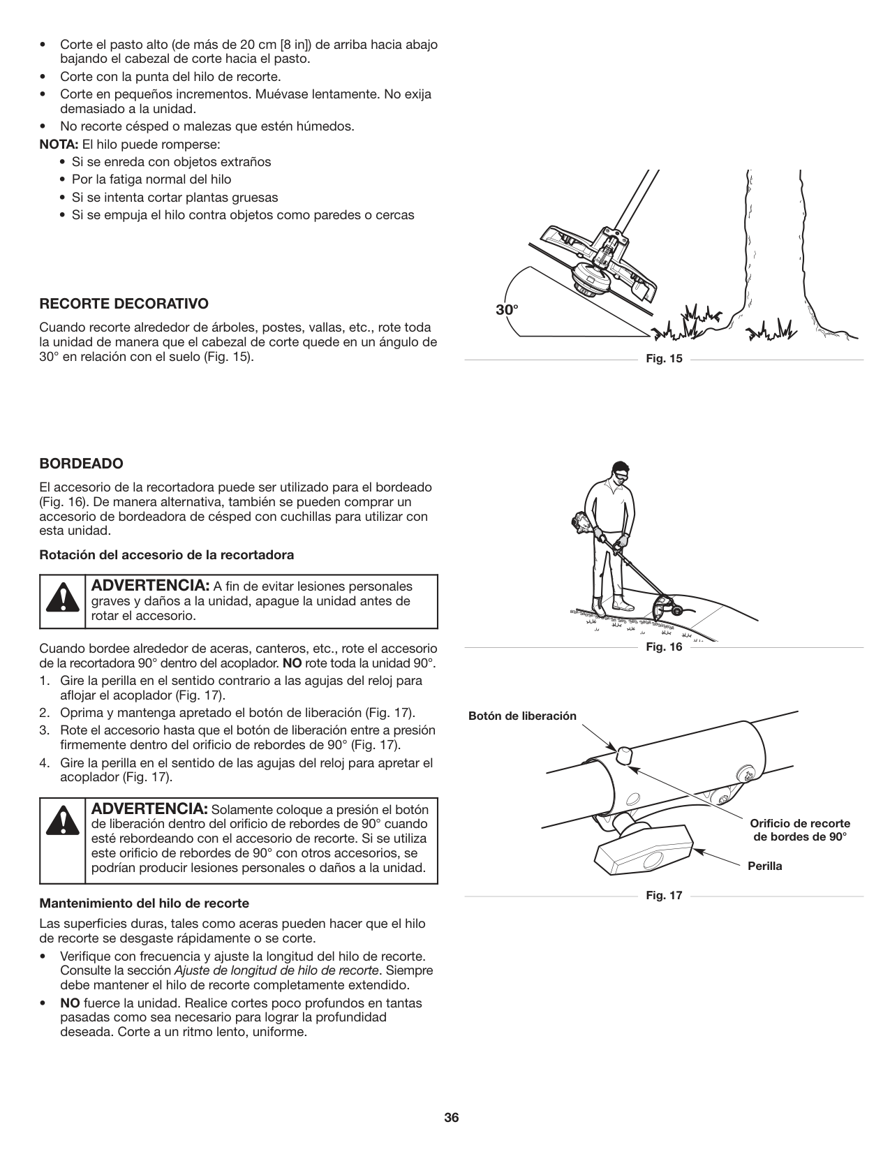
##### RECORTE DECORATIVO
Cuando recorte alrededor de árboles, postes, vallas, etc., rote toda la unidad de manera que el cabezal de corte quede en un ángulo de 30° en relación con el suelo (Fig. 15). Fig. 15
##### BORDEADO
El accesorio de la recortadora puede ser utilizado para el bordeado (Fig. 16). De manera alternativa, también se pueden comprar un accesorio de bordeadora de césped con cuchillas para utilizar con esta unidad.
###### Rotación del accesorio de la recortadora
Cuando bordee alrededor de aceras, canteros, etc., rote el accesorio de la recortadora 90° dentro del acoplador. NO rote toda la unidad 90°.
###### Mantenimiento del hilo de recorte
Las superficies duras, tales como aceras pueden hacer que el hilo de recorte se desgaste rápidamente o se corte.
| |ADVERTENCIA: Solamente coloque a presión el botón de liberación dentro del orificio de rebordes de 90° cuando esté rebordeando con el accesorio de recorte. Si se utiliza este orificio de rebordes de 90° con otros accesorios, se podrían producir lesiones personales o daños a la unidad.| |---|---|
| |ADVERTENCIA: A fin de evitar lesiones personales graves y daños a la unidad, apague la unidad antes de rotar el accesorio.| |---|---|
Botón de liberación
Orificio de recorte de bordes de 90°
Perilla
#### MANTENIMIENTO
| |ADVERTENCIA: A fin de evitar lesiones personales graves, siempre pare el motor y deje que se enfríe antes de limpiar o mantener la unidad. No realice ninguna tarea de limpieza o mantenimiento mientras la unidad esté en funcionamiento. Desconecte el cable de la bujía para evitar que la unidad arranque accidentalmente.| |---|---|
| |ADVERTENCIA: Utilice vestimenta de protección y respete todas las instrucciones de seguridad para evitar que se produzcan lesiones personales graves.| |---|---|
PLAN DE MANTENIMIENTO Lleve a cabo los procedimientos necesarios de mantenimiento con la frecuencia indicada en la tabla. Estos procedimientos deberán también formar parte de cualquier ajuste de temporada. NOTA: Es posible que algunos procedimientos de mantenimiento
requieran herramientas o habilidades especiales. Si no está seguro acerca de estos procedimientos, lleve la unidad a un distribuidor de servicio autorizado. Para más información, llame al 1-888-331-4569.
NOTA: Los trabajos de mantenimiento, reemplazo o reparación de los dispositivos y los sistemas de control de emisiones puede realizarlos un distribuidor de servicio autorizado. Para más información, llame al 1-888-331-4569.
NOTA: Para ver la lista completa de términos y la cobertura de los dispositivos de control de emisiones como parachispas, silenciador, carburador, etc., lea la declaración de California/ EPA que viene junto con la unidad.
|FRECUENCIA|MANTENIMIENTO REQUERIDA| |---|---| |Cada 10 horas|• Limpie y vuelva a lubricar el filtro de aire. Consulte Mantenimiento del filtro de aire.| |Cada 25 horas|• Controle el estado y la separación de la bujía de encendido. Consulte Mantenimiento de la bujía de encendido.|
REEMPLAZO DEL HILO DE RECORTE Use únicamente el hilo de recorte que se describe en la sección Especificaciones. Otros tipos de hilo de recorte pueden causar el recalentamiento o la falla de la unidad.
| |ADVERTENCIA: Nunca use un hilo, un cable, una cadena o una cuerda de metal reforzados. Podrían separarse y convertirse en proyectiles peligrosos.| |---|---|
NOTA: Utilice siempre la longitud de hilo correcta al instalar el hilo de recorte. Es posible que el hilo no se suelte adecuadamente si está demasiado largo.
NOTA: El cabezal de corte permanecerá conectado a la unidad. NOTA: NO desmonte el cabezal de corte para instalar un hilo nuevo.
###### Instalación del hilo de recorte nuevo
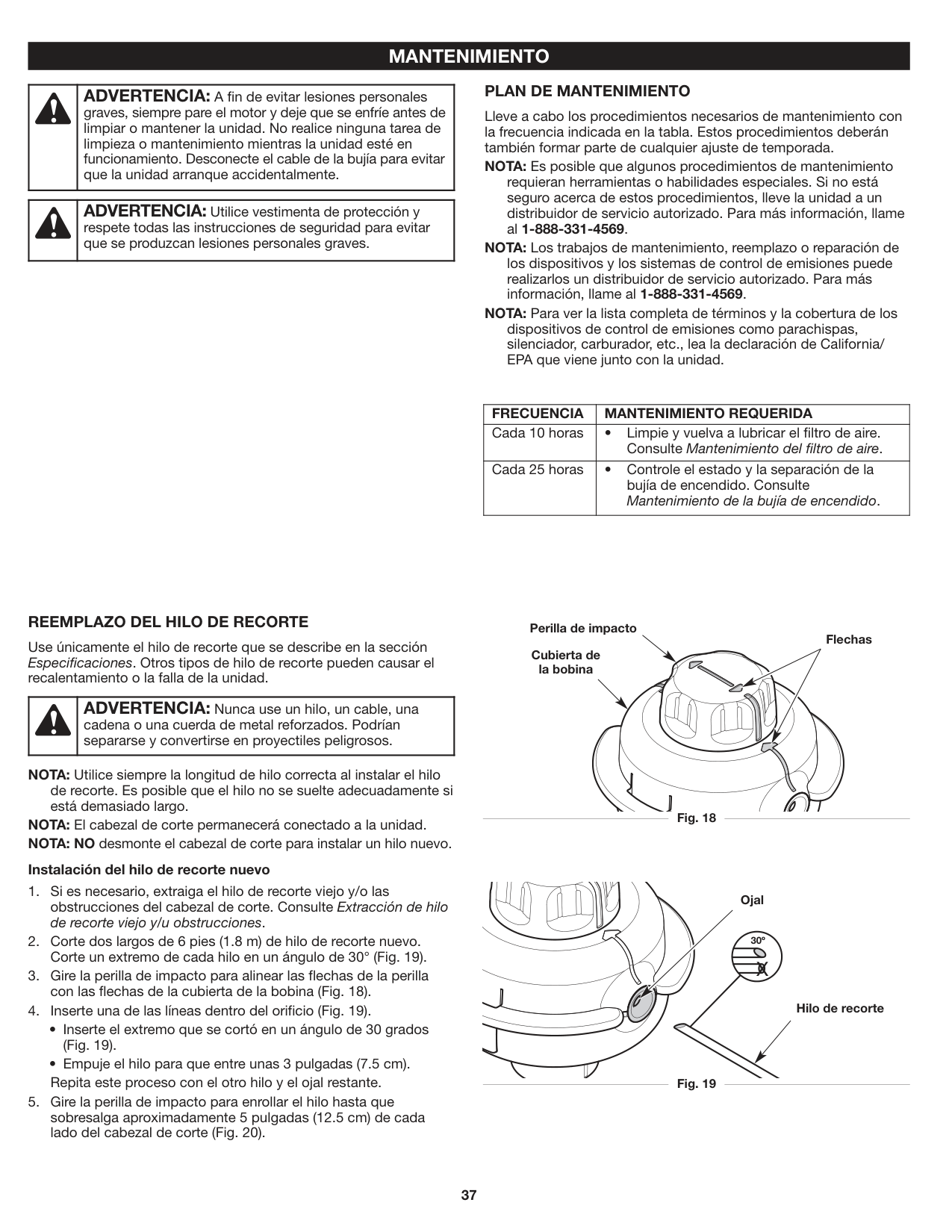
Perilla de impacto
Flechas Cubierta de la bobina
Fig. 18
Ojal
30º
X
Hilo de recorte
Fig. 19
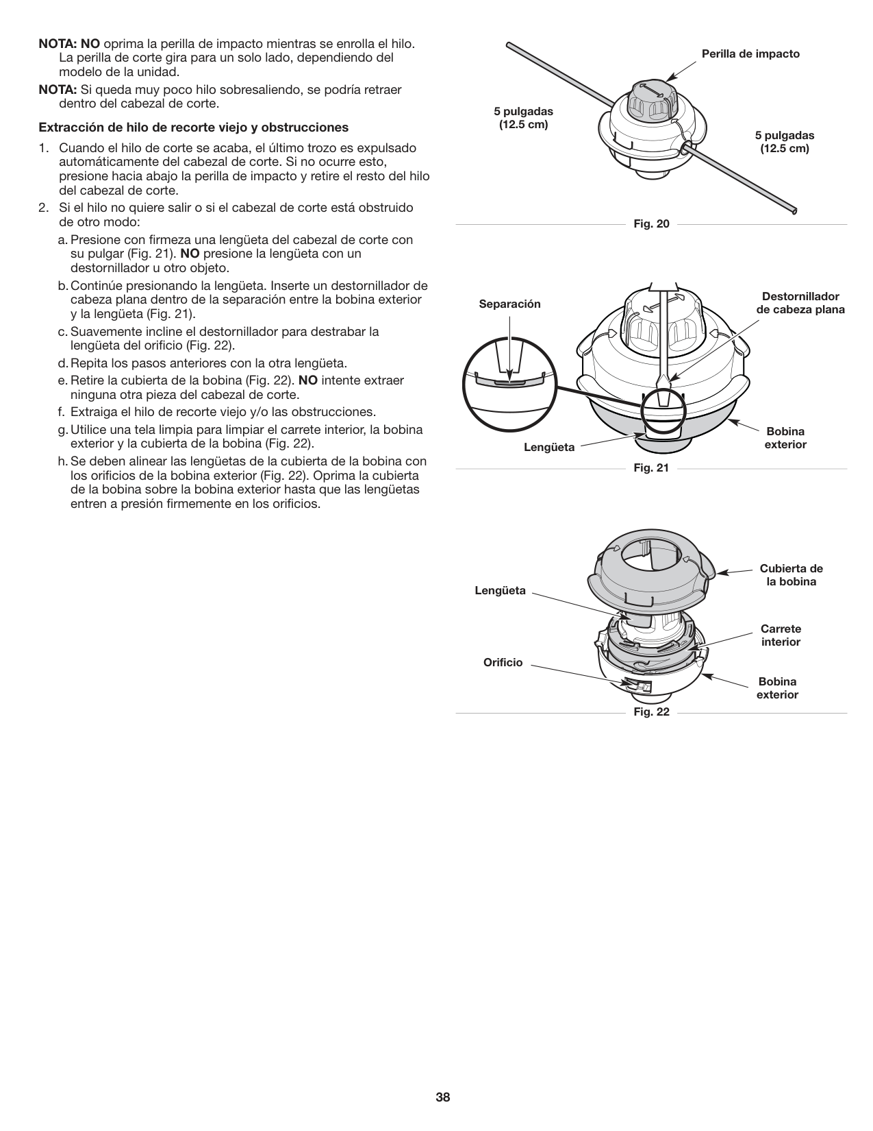
NOTA: NO oprima la perilla de impacto mientras se enrolla el hilo. La perilla de corte gira para un solo lado, dependiendo del modelo de la unidad.
NOTA: Si queda muy poco hilo sobresaliendo, se podría retraer
dentro del cabezal de corte.
###### Extracción de hilo de recorte viejo y obstrucciones
de otro modo:
Perilla de impacto
5 pulgadas (12.5 cm)
5 pulgadas (12.5 cm)
Fig. 20
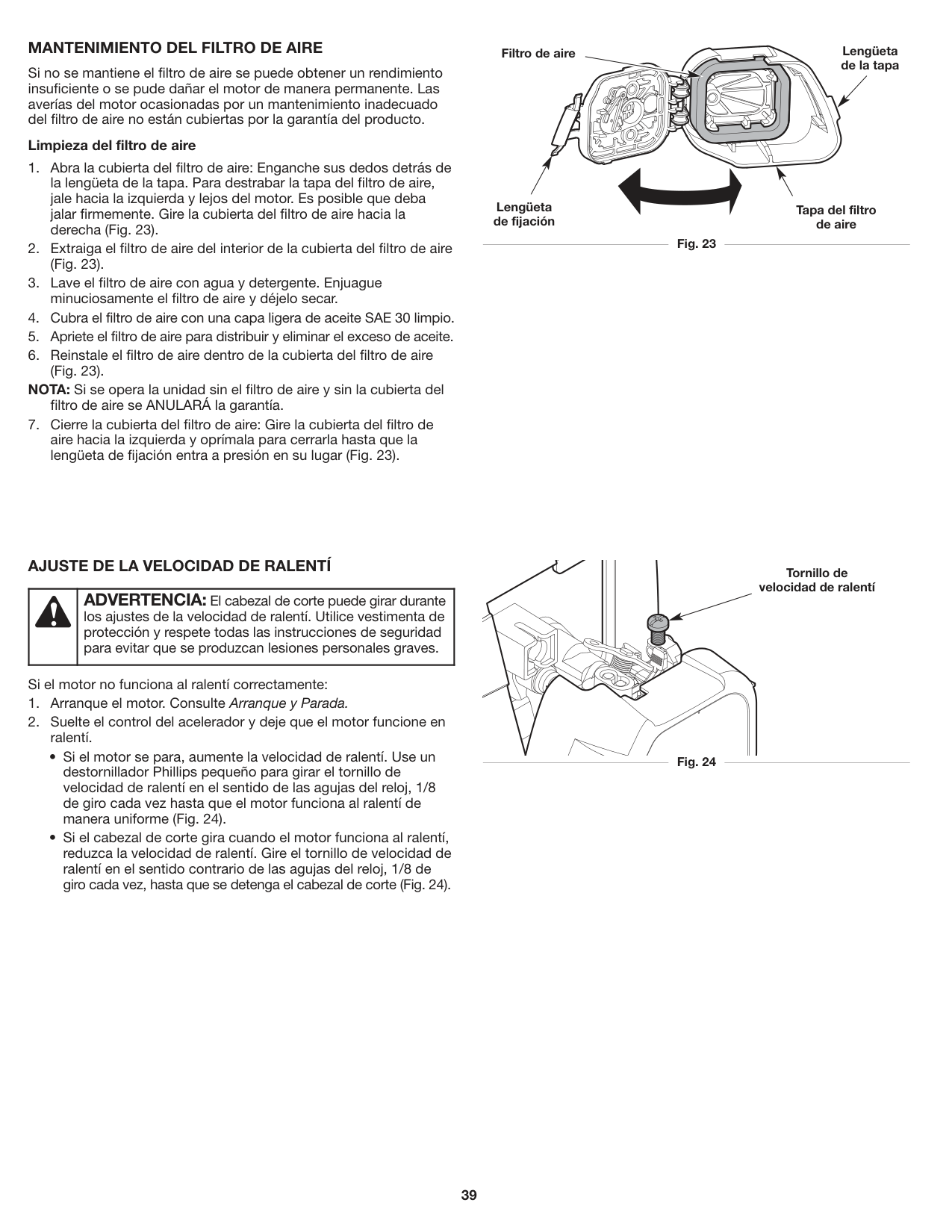
Destornillador de cabeza plana
Separación
Bobina exterior
Lengüeta

Fig. 21
Cubierta de
la bobina Lengüeta
Carrete interior
Orificio
Bobina exterior
Fig. 22
##### MANTENIMIENTO DEL FILTRO DE AIRE
Si no se mantiene el filtro de aire se puede obtener un rendimiento insuficiente o se pude dañar el motor de manera permanente. Las averías del motor ocasionadas por un mantenimiento inadecuado del filtro de aire no están cubiertas por la garantía del producto.
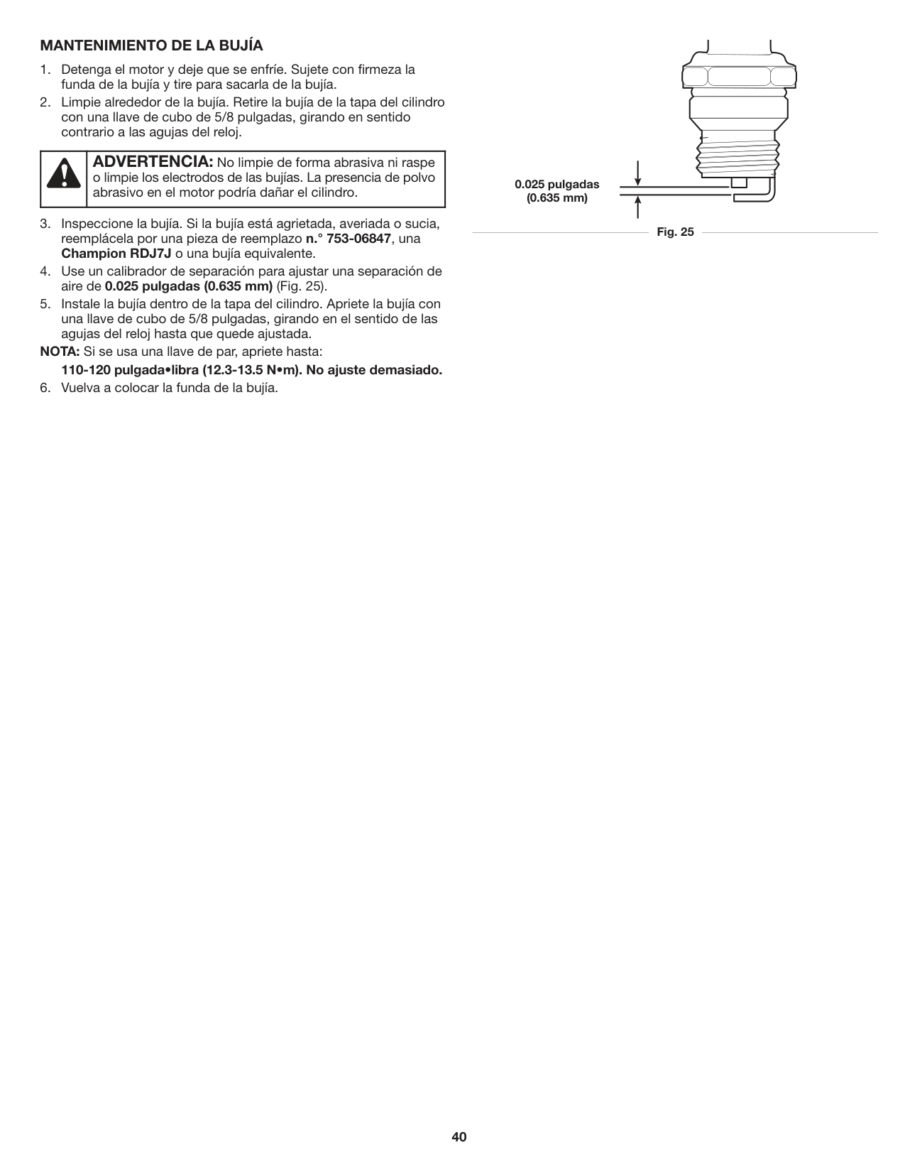
###### Limpieza del filtro de aire
NOTA: Si se opera la unidad sin el filtro de aire y sin la cubierta del
filtro de aire se ANULARÁ la garantía.
Lengüeta de la tapa
Filtro de aire
Lengüeta de fijación
Tapa del filtro de aire
Fig. 23

##### AJUSTE DE LA VELOCIDAD DE RALENTÍ
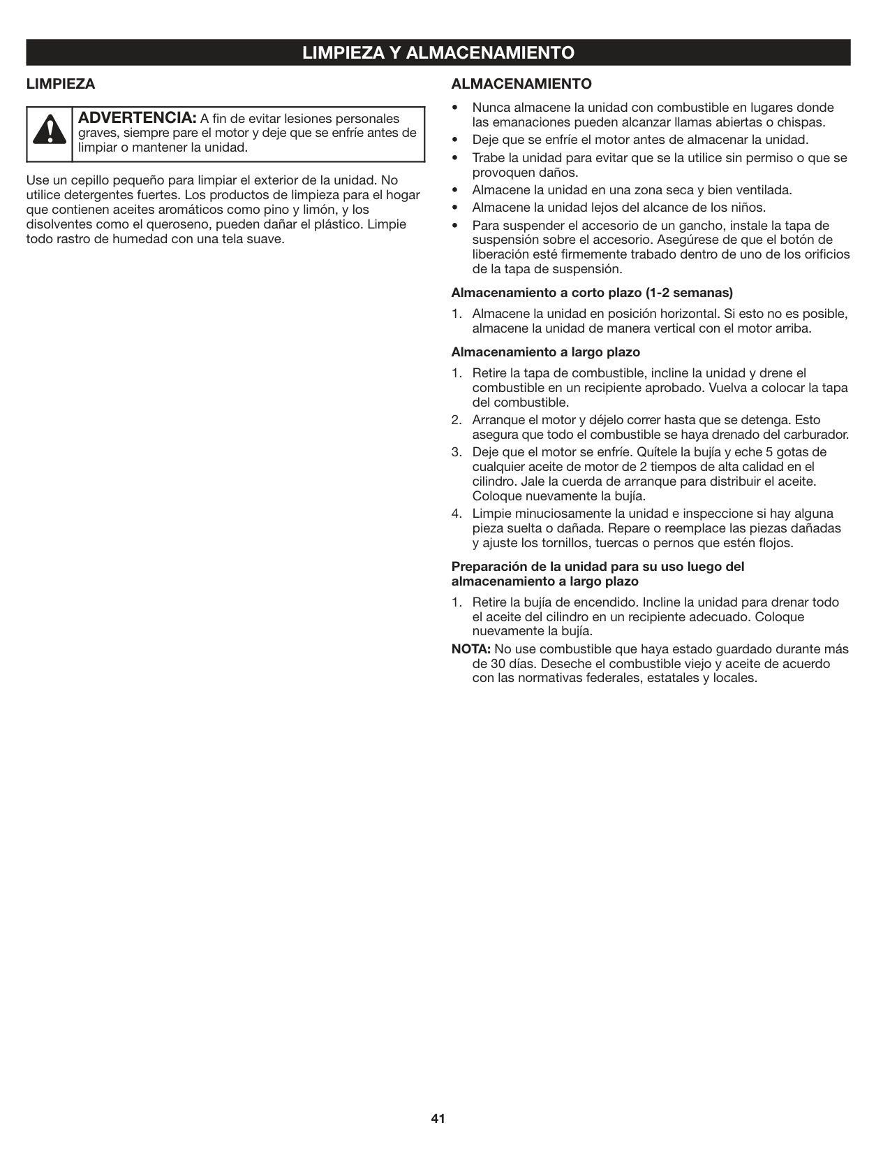
| |ADVERTENCIA: El cabezal de corte puede girar durante los ajustes de la velocidad de ralentí. Utilice vestimenta de protección y respete todas las instrucciones de seguridad para evitar que se produzcan lesiones personales graves.| |---|---|
Si el motor no funciona al ralentí correctamente:
Tornillo de velocidad de ralentí
Fig. 24
##### MANTENIMIENTO DE LA BUJÍA
NOTA: Si se usa una llave de par, apriete hasta: 110-120 pulgada•libra (12.3-13.5 N•m). No ajuste demasiado.
| |ADVERTENCIA: No limpie de forma abrasiva ni raspe o limpie los electrodos de las bujías. La presencia de polvo abrasivo en el motor podría dañar el cilindro.| |---|---|
| | | | |---|---|---| | | | |
0.025 pulgadas (0.635 mm)
Fig. 25

#### LIMPIEZA Y ALMACENAMIENTO LIMPIEZA
##### ALMACENAMIENTO
| |ADVERTENCIA: A fin de evitar lesiones personales graves, siempre pare el motor y deje que se enfríe antes de limpiar o mantener la unidad.| |---|---|
Use un cepillo pequeño para limpiar el exterior de la unidad. No utilice detergentes fuertes. Los productos de limpieza para el hogar que contienen aceites aromáticos como pino y limón, y los disolventes como el queroseno, pueden dañar el plástico. Limpie todo rastro de humedad con una tela suave.
###### Almacenamiento a corto plazo (1-2 semanas)
almacene la unidad de manera vertical con el motor arriba. Almacenamiento a largo plazo
Preparación de la unidad para su uso luego del almacenamiento a largo plazo
NOTA: No use combustible que haya estado guardado durante más de 30 días. Deseche el combustible viejo y aceite de acuerdo con las normativas federales, estatales y locales.
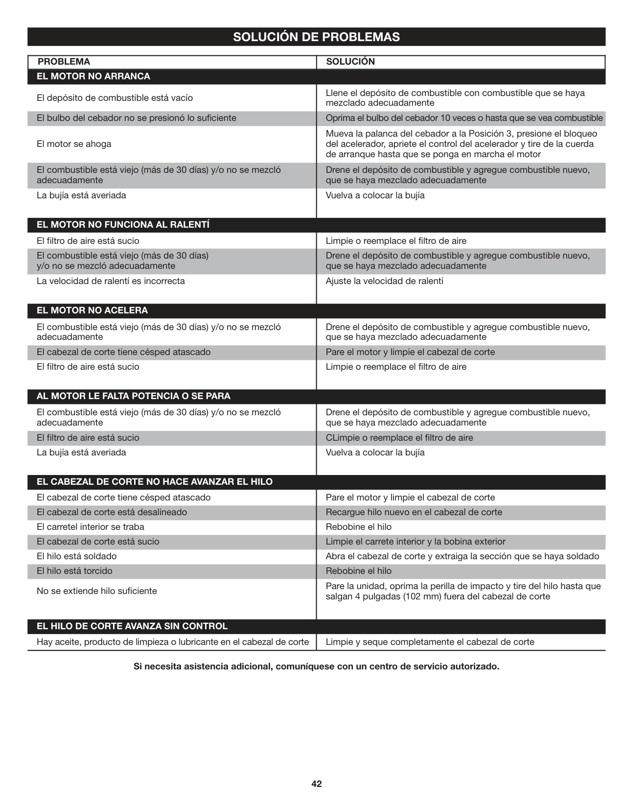
#### SOLUCIÓN DE PROBLEMAS
|PROBLEMA|SOLUCIÓN| |---|---| |El cabezal de corte tiene césped atascado El cabezal de corte está desalineado El carretel interior se traba El cabezal de corte está sucio El hilo está soldado El hilo está torcido
No se extiende hilo suficiente
Hay aceite, producto de limpieza o lubricante en el cabezal de corte
El depósito de combustible está vacío El bulbo del cebador no se presionó lo suficiente El motor se ahoga El combustible está viejo (más de 30 días) y/o no se mezcló adecuadamente La bujía está averiada
El combustible está viejo (más de 30 días) y/o no se mezcló adecuadamente
El cabezal de corte tiene césped atascado El filtro de aire está sucio
El filtro de aire está sucio El combustible está viejo (más de 30 días) y/o no se mezcló adecuadamente La velocidad de ralentí es incorrecta
El combustible está viejo (más de 30 días) y/o no se mezcló adecuadamente
El filtro de aire está sucio La bujía está averiada
EL MOTOR NO ARRANCA
EL MOTOR NO FUNCIONA AL RALENTÍ
EL MOTOR NO ACELERA
AL MOTOR LE FALTA POTENCIA O SE PARA
EL CABEZAL DE CORTE NO HACE AVANZAR EL HILO
EL HILO DE CORTE AVANZA SIN CONTROL|Pare el motor y limpie el cabezal de corte Recargue hilo nuevo en el cabezal de corte Rebobine el hilo Limpie el carrete interior y la bobina exterior Abra el cabezal de corte y extraiga la sección que se haya soldado Rebobine el hilo Pare la unidad, oprima la perilla de impacto y tire del hilo hasta que salgan 4 pulgadas (102 mm) fuera del cabezal de corte
Limpie y seque completamente el cabezal de corte
Llene el depósito de combustible con combustible que se haya mezclado adecuadamente
Oprima el bulbo del cebador 10 veces o hasta que se vea combustible Mueva la palanca del cebador a la Posición 3, presione el bloqueo del acelerador, apriete el control del acelerador y tire de la cuerda de arranque hasta que se ponga en marcha el motor Drene el depósito de combustible y agregue combustible nuevo, que se haya mezclado adecuadamente Vuelva a colocar la bujía
Drene el depósito de combustible y agregue combustible nuevo, que se haya mezclado adecuadamente
Pare el motor y limpie el cabezal de corte Limpie o reemplace el filtro de aire
Limpie o reemplace el filtro de aire Drene el depósito de combustible y agregue combustible nuevo, que se haya mezclado adecuadamente Ajuste la velocidad de ralentí
Drene el depósito de combustible y agregue combustible nuevo, que se haya mezclado adecuadamente
CLimpie o reemplace el filtro de aire Vuelva a colocar la bujía
|
Si necesita asistencia adicional, comuníquese con un centro de servicio autorizado.

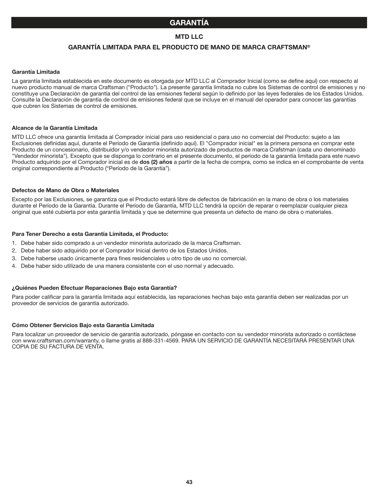
#### GARANTÍA MTD LLC GARANTÍA LIMITADA PARA EL PRODUCTO DE MANO DE MARCA CRAFTSMAN®
###### Garantía Limitada
La garantía limitada establecida en este documento es otorgada por MTD LLC al Comprador Inicial (como se define aquí) con respecto al nuevo producto manual de marca Craftsman ("Producto"). La presente garantía limitada no cubre los Sistemas de control de emisiones y no constituye una Declaración de garantía del control de las emisiones federal según lo definido por las leyes federales de los Estados Unidos. Consulte la Declaración de garantía de control de emisiones federal que se incluye en el manual del operador para conocer las garantías que cubren los Sistemas de control de emisiones.
###### Alcance de la Garantía Limitada
MTD LLC ofrece una garantía limitada al Comprador inicial para uso residencial o para uso no comercial del Producto: sujeto a las Exclusiones definidas aquí, durante el Período de Garantía (definido aquí). El "Comprador inicial" es la primera persona en comprar este Producto de un concesionario, distribuidor y/o vendedor minorista autorizado de productos de marca Crafstman (cada uno denominado "Vendedor minorista"). Excepto que se disponga lo contrario en el presente documento, el período de la garantía limitada para este nuevo Producto adquirido por el Comprador inicial es de dos (2) años a partir de la fecha de compra, como se indica en el comprobante de venta original correspondiente al Producto (“Período de la Garantía”).
###### Defectos de Mano de Obra o Materiales
Excepto por las Exclusiones, se garantiza que el Producto estará libre de defectos de fabricación en la mano de obra o los materiales durante el Período de la Garantía. Durante el Período de Garantía, MTD LLC tendrá la opción de reparar o reemplazar cualquier pieza original que esté cubierta por esta garantía limitada y que se determine que presenta un defecto de mano de obra o materiales.
###### Para Tener Derecho a esta Garantía Limitada, el Producto:
###### ¿Quiénes Pueden Efectuar Reparaciones Bajo esta Garantía?
Para poder calificar para la garantía limitada aquí establecida, las reparaciones hechas bajo esta garantía deben ser realizadas por un proveedor de servicios de garantía autorizado.
###### Cómo Obtener Servicios Bajo esta Garantía Limitada
Para localizar un proveedor de servicio de garantía autorizado, póngase en contacto con su vendedor minorista autorizado o contáctese con www.craftsman.com/warranty, o llame gratis al 888-331-4569. PARA UN SERVICIO DE GARANTÍA NECESITARÁ PRESENTAR UNA COPIA DE SU FACTURA DE VENTA.
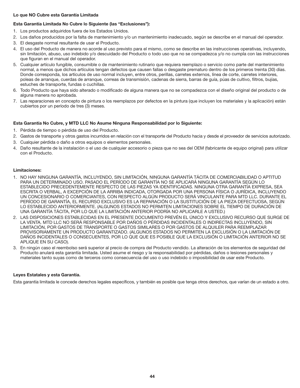
Lo que NO Cubre esta Garantía Limitada Esta Garantía Limitada No Cubre lo Siguiente (las “Exclusiones”):
###### Esta Garantía No Cubre, y MTD LLC No Asume Ninguna Responsabilidad por lo Siguiente:
Limitaciones:
Leyes Estatales y esta Garantía. Esta garantía limitada le concede derechos legales específicos, y también es posible que tenga otros derechos, que varían de un estado a otro.
TO ORDER REPLACEMENT PARTS OR SCHEDULE REPAIR SERVICE
PARA ORDENAR PIEZAS O PEDIR SERVICIO DE REPARACIÓN
1-888-331-4569
CRAFTSMAN® IS A REGISTERED TRADEMARK OFSTANLEY BLACK & DECKER, INC., USED UNDER LICENSE. ES UNA MARCA REGISTRADA DESTANLEY BLACK & DECKER, INC., UTILIZADA BAJO LICENCIA.
© 2019 CRAFTSMAN
PRODUCT MANUFACTURED BY: / PRODUCTO FABRICADO POR: MTD LLC P.O. Box 361131 Cleveland, OH 44136-0019
U.S. & CANADA ONLY • SÓLO EN EE.UU. Y CANADÁ