Ctek Mxs 5 0 Battery Charger manual
Battery Chargers · 10 Q&As

Ctek Mxs 5 0 Battery Charger

Ask AI

— answers from the official manual

Answers from the official manual.

Common questions

Common Questions

10 total
1

What should I do if the error lamp is lit?

If the error lamp is on, check that the charger’s positive lead is connected to the battery's positive pole and that you are charging a 12V battery. If issues persist after restarting the charger by pressing the MODE button, the battery may be severely sulfated or defective and needs to be replaced.

2

What is the significance of the power lamp blinking?

If the power lamp blinks, it indicates that the charger has entered energy save mode due to lack of activity for more than two minutes when not connected to a battery.

3

How do I safely connect the battery terminals of the MXS 5.0 charger?

To avoid a spark near the battery which can cause an explosion, first position yourself and the free end of the cable as far away from the battery as possible. Connect the positive (red) clip to the positive post of the battery, then connect the negative (black) clip to the negative post.

4

How do I choose between different charging programs on the MXS 5.0?

Press the MODE-button repeatedly until the desired charging program (Small Battery Program, Normal Battery Program) and options (AGM Option, RECOND Option) are lit. The selected settings will be memorized for future use.

5

What safety precautions should I follow when working with a lead-acid battery?

Always work in a well-ventilated area, keep away from flames and sparks, wear complete eye protection and clothing protection. Stay clear of fan blades, belts, pulleys, and other moving parts that can cause injury.

6

Why should I avoid charging a frozen battery?

Charging a frozen battery is discouraged because the freezing temperature affects its chemical composition and electrical integrity. It could result in damage to the battery or charger, or even cause it to explode.

Show 4 more questions

Full Manual

14 pages
Page 1

![image 1](MXS_5.0_NA-manual-low-CA-EN_images/imageFile1.png)

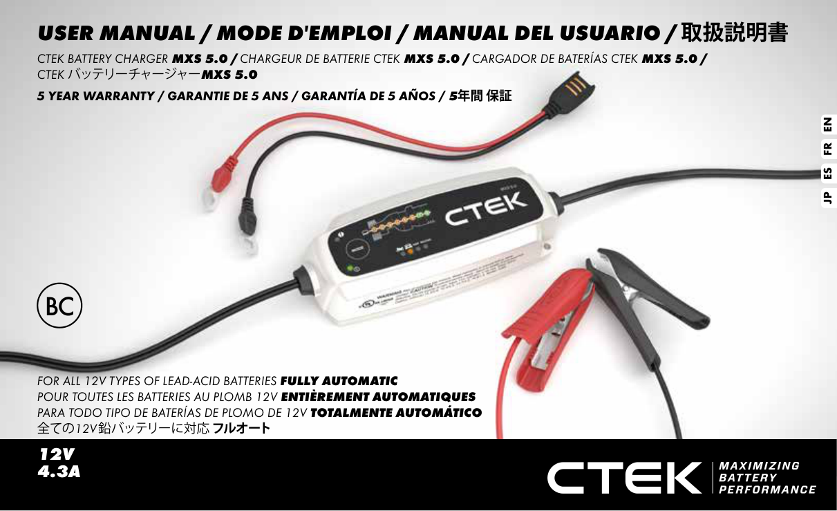
USER MANUAL / MODE D'EMPLOI / MANUAL DEL USUARIO / 取扱説明書

CTEK BATTERY CHARGER MXS 5.0 / CHARGEUR DE BATTERIE CTEK MXS 5.0 / CARGADOR DE BATERÍAS CTEK MXS 5.0 / CTEKバッテリーチャージャーMXS 5.0

##### 5 YEAR WARRANTY / GARANTIE DE 5 ANS / GARANTÍA DE 5 AÑOS / 5年間 保証

ENFRESJP

FOR ALL 12V TYPES OF LEAD-ACID BATTERIES FULLY AUTOMATIC POUR TOUTES LES BATTERIES AU PLOMB 12V ENTIÈREMENT AUTOMATIQUES PARA TODO TIPO DE BATERÍAS DE PLOMO DE 12V TOTALMENTE AUTOMÁTICO 全ての12V鉛バッテリーに対応フルオート

12V 4.3A

MANUAL

IMPORTANT SAFETY INSTRUCTIONS CALIFORNIA PROPOSITION 65 WARNING: This product contains chemical known to the state of California to cause cancer or reproductive toxicity.

INTRODUCTION MXS 5.0 (1090) is a switch mode charger with both float and pulse maintenance and is a part of a series of battery chargers from CTEK Sweden AB. These chargers represent the latest technology within battery charging. A MXS 5.0 (1090) gives the battery maximum life.

  • 1. SAVE THESE INSTRUCTIONS
  • – This manual contains important safety and operating instructions for battery charger model MXS 5.0 (1090).
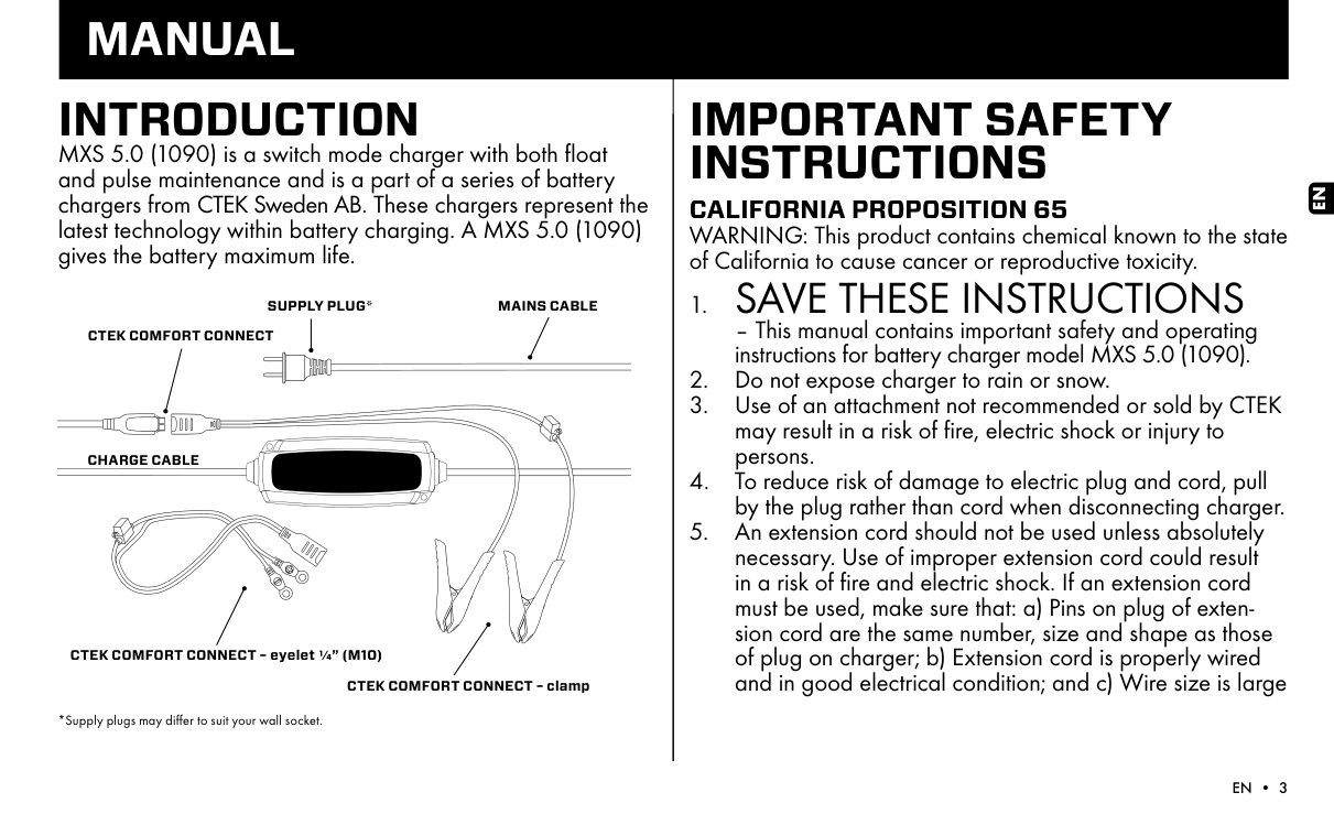
  • 2. Do not expose charger to rain or snow.
  • Page 2

  • 3. Use of an attachment not recommended or sold by CTEK may result in a risk of fire, electric shock or injury to persons.
  • 4. To reduce risk of damage to electric plug and cord, pull by the plug rather than cord when disconnecting charger.
  • 5. An extension cord should not be used unless absolutely necessary. Use of improper extension cord could result in a risk of fire and electric shock. If an extension cord must be used, make sure that: a) Pins on plug of extension cord are the same number, size and shape as those of plug on charger; b) Extension cord is properly wired and in good electrical condition; and c) Wire size is large
  • SUPPLY PLUG*

    MAINS CABLE

    CTEK COMFORT CONNECT

    CHARGE CABLE

    CTEK COMFORT CONNECT – eyelet ¼” (M10)

    CTEK COMFORT CONNECT – clamp

    *Supply plugs may differ to suit your wall socket.

    EN

    enough for AC ampere rating of charger as specified in “RECOMMENDED MINIMUM AWG SIZE FOR AC EXTENSION CORDS”.

  • 6. Do not operate charger with damaged cord or plug – return the charger to the retailer.
  • 7. Do not operate charger if it has received a sharp blow, been dropped or otherwise damaged in any way; take it to the retailer.
  • Page 3

  • 8. Do not disassemble charger; take it to the retailer when service or repair is required. Incorrect reassembly may result in a risk of electrical shock or fire.
  • 9. To reduce risk of electric shock, unplug charger from AC outlet before attempting any maintenance or cleaning.
  • 10. WARNING - RISK OF EXPLOSIVE GASES
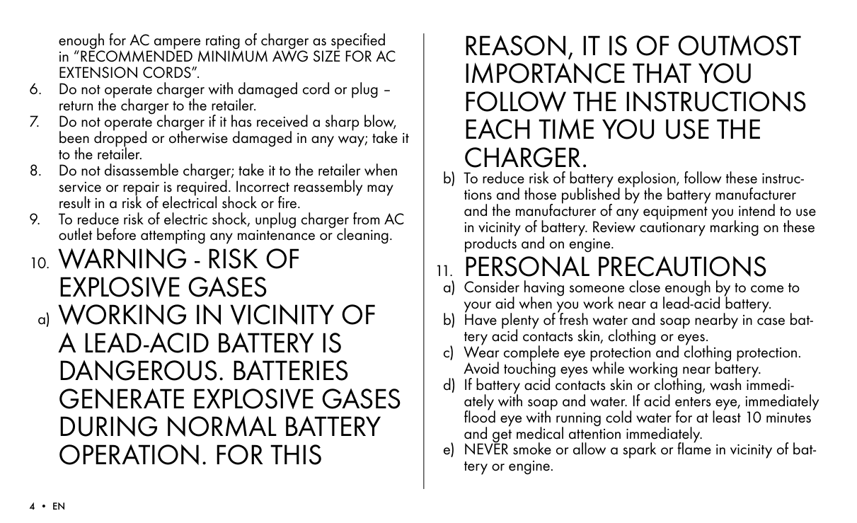
  • a) WORKING IN VICINITY OF A LEAD-ACID BATTERY IS DANGEROUS. BATTERIES GENERATE EXPLOSIVE GASES DURING NORMAL BATTERY OPERATION. FOR THIS

    REASON, IT IS OF OUTMOST IMPORTANCE THAT YOU FOLLOW THE INSTRUCTIONS EACH TIME YOU USE THE CHARGER.

    b) To reduce risk of battery explosion, follow these instructions and those published by the battery manufacturer and the manufacturer of any equipment you intend to use in vicinity of battery. Review cautionary marking on these products and on engine.

    11. PERSONAL PRECAUTIONS

  • a) Consider having someone close enough by to come to your aid when you work near a lead-acid battery.
  • b) Have plenty of fresh water and soap nearby in case battery acid contacts skin, clothing or eyes.
  • c) Wear complete eye protection and clothing protection. Avoid touching eyes while working near battery.
  • d) If battery acid contacts skin or clothing, wash immediately with soap and water. If acid enters eye, immediately flood eye with running cold water for at least 10 minutes and get medical attention immediately.
  • e) NEVER smoke or allow a spark or flame in vicinity of battery or engine.
  • f) Be extra cautious to reduce risk of dropping a metal tool onto battery. It might spark or short-circuit battery or other electrical part that may cause explosion.
  • g) Remove personal metal items such as rings, bracelets, necklaces, and watches when working with lead-acid battery. A lead-acid battery can produce a short-circuit current high enough to weld a ring or the like to metal, causing a severe burn.
  • h) Use charger for charging a LEAD-ACID battery only. It is not intended to supply power to a low voltage electrical system other than in a starter-motor application. Do not use battery charger for charging dry-cell batteries that are commonly used with home appliances. These batteries may burst and cause injury to persons and damage to property.
  • i) NEVER charge a frozen battery.
  • Page 4

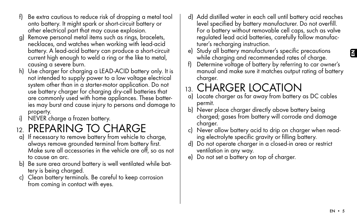
    12. PREPARING TO CHARGE

  • a) If necessary to remove battery from vehicle to charge, always remove grounded terminal from battery first. Make sure all accessories in the vehicle are off, so as not to cause an arc.
  • b) Be sure area around battery is well ventilated while battery is being charged.
  • c) Clean battery terminals. Be careful to keep corrosion from coming in contact with eyes.
  • d) Add distilled water in each cell until battery acid reaches level specified by battery manufacturer. Do not overfill. For a battery without removable cell caps, such as valve regulated lead acid batteries, carefully follow manufacturer’s recharging instruction.
  • e) Study all battery manufacturer’s specific precautions while charging and recommended rates of charge.
  • f) Determine voltage of battery by referring to car owner’s manual and make sure it matches output rating of battery charger.
  • 13. CHARGER LOCATION

  • a) Locate charger as far away from battery as DC cables permit.
  • b) Never place charger directly above battery being charged; gases from battery will corrode and damage charger.
  • c) Never allow battery acid to drip on charger when reading electrolyte specific gravity or filling battery.
  • d) Do not operate charger in a closed-in area or restrict ventilation in any way.
  • e) Do not set a battery on top of charger.
  • EN

    14. DC CONNECTIONPRECAUTIONS

    Page 5

  • a) Connect and disconnect dc output clips only after setting any charger switches to “off” position and removing AC cord from electric outlet. Never allow clips to touch each other.
  • b) Attach clips to battery and chassis as indicated in 15(e), 15(f), 16(b) through 16(d).
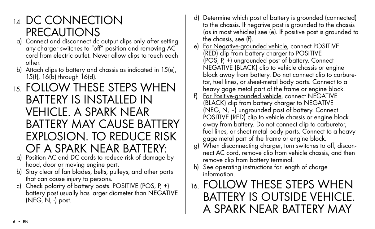
  • 15. FOLLOW THESE STEPS WHENBATTERY IS INSTALLED INVEHICLE. A SPARK NEARBATTERY MAY CAUSE BATTERYEXPLOSION. TO REDUCE RISKOF A SPARK NEAR BATTERY:

  • a) Position AC and DC cords to reduce risk of damage by hood, door or moving engine part.
  • b) Stay clear of fan blades, belts, pulleys, and other parts that can cause injury to persons.
  • c) Check polarity of battery posts. POSITIVE (POS, P, +) battery post usually has larger diameter than NEGATIVE (NEG, N, -) post.
  • d) Determine which post of battery is grounded (connected) to the chassis. If negative post is grounded to the chassis (as in most vehicles) see (e). If positive post is grounded to the chassis, see (f).
  • e) For Negative-grounded vehicle, connect POSITIVE (RED) clip from battery charger to POSITIVE (POS, P, +) ungrounded post of battery. Connect NEGATIVE (BLACK) clip to vehicle chassis or engine block away from battery. Do not connect clip to carburetor, fuel lines, or sheet-metal body parts. Connect to a heavy gage metal part of the frame or engine block.
  • f) For Positive-grounded vehicle, connect NEGATIVE (BLACK) clip from battery charger to NEGATIVE (NEG, N, –) ungrounded post of battery. Connect POSITIVE (RED) clip to vehicle chassis or engine block away from battery. Do not connect clip to carburetor, fuel lines, or sheet-metal body parts. Connect to a heavy gage metal part of the frame or engine block.
  • g) When disconnecting charger, turn switches to off, disconnect AC cord, remove clip from vehicle chassis, and then remove clip from battery terminal.
  • h) See operating instructions for length of charge information.
  • 16. FOLLOW THESE STEPS WHEN BATTERY IS OUTSIDE VEHICLE. A SPARK NEAR BATTERY MAY

    CAUSE BATTERY EXPLOSION. TO REDUCE RISK OF A SPARK NEAR BATTERY:

  • a) Check polarity of battery terminals. POSITIVE (POS, P, +) battery post usually has a larger diameter than NEGATIVE (NEG, N, -) post.
  • b) Connect POSITIVE (RED) charger clip to POSITIVE (POS, P, +) post of battery.
  • Page 6

  • c) Position yourself and free end of cable as far away from battery as possible – then connect NEGATIVE (BLACK) charger clip to NEGATIVE (NEG, N, -) post of battery.
  • d) Do not face battery when making the final connection.
  • e) When disconnecting charger, always do so in reverse sequence of connecting procedure and break first connection while as far away from battery as practical.
  • f) A marine (boat) battery must be removed and charged on shore. To charge it on board requires equipment specially designed for marine use.
  • IMPORTANT SAFETY INFORMATION!

  • • Charge no other batteries than specified in TECHNICAL INFORMATION.
  • • Check the charger cables prior to use. Ensure that no cracks have occurred in the cables or in the bend protec-
  • tion. A charger with damaged cables must be returned to the retailer.

  • • Ensure that the cabling does not jam or comes into contact with hot surfaces or sharp edges.
  • • Never charge a damaged battery.
  • • Never place the charger on top of the battery when charging.
  • • Avoid covering the charger.
  • • All batteries fail sooner or later. A battery that fails during charging is normally taken care of by the chargers advanced control, but some rare errors in the battery could still exist. Don’t leave any battery during charging unattended for a longer period of time.
  • • If power consumers like fitted alarms and navigation computers are connected to the battery, the charging process takes longer and may drain the battery.
  • • Always check that the charger has switched to STEP 7 before leaving the charger unattended and connected for long periods. If the charger has not switched to STEP 7 within 50 hours, this is an indication of an error. Disconnect the charger.
  • • Batteries consume water during use and charging. For batteries where water can be added, the water level should be checked regularly. If the water level is low add distilled water.
  • • This appliance is not designed for use by young children or people who cannot read or understand the manual unless they are under the supervision of a responsible person to
  • Page 7

    EN

    ensure that they can use the battery charger safely. Store and use the battery charger out of the reach of children, and ensure that children cannot play with the charger.

  • • Connection to the mains supply must be in accordance with the national regulations for electrical installations.
  • • Do not extend the charge cable.
  • • For safe use place the charger with the bottom down when installing and charging.
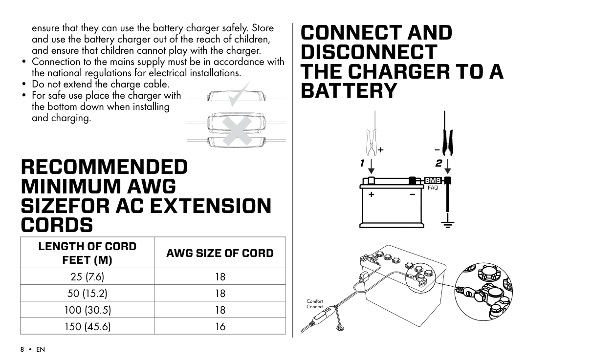
  • RECOMMENDED MINIMUM AWG SIZEFOR AC EXTENSION CORDS

    |LENGTH OF CORD FEET (M)|AWG SIZE OF CORD| |---|---| |25 (7.6)|18| |50 (15.2)|18| |100 (30.5)|18| |150 (45.6)|16|

    CONNECT AND DISCONNECT THE CHARGER TO A BATTERY

    #### 1 2

    FAQ

    Page 8

    Comfort Connect

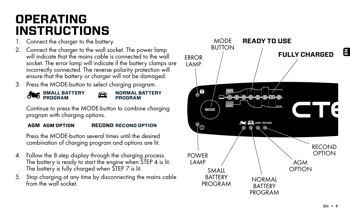
    OPERATING INSTRUCTIONS

  • 1. Connect the charger to the battery.
  • 2. Connect the charger to the wall socket. The power lamp will indicate that the mains cable is connected to the wall socket. The error lamp will indicate if the battery clamps are incorrectly connected. The reverse polarity protection will ensure that the battery or charger will not be damaged.
  • 3. Press the MODE-button to select charging program.
  • SMALL BATTERY PROGRAM

    NORMAL BATTERY PROGRAM

    Continue to press the MODE-button to combine charging program with charging options.

    AGM AGM OPTION RECOND RECOND OPTION

    Press the MODE-button several times until the desired combination of charging program and options are lit.

  • 4. Follow the 8-step display through the charging process. The battery is ready to start the engine when STEP 4 is lit. The battery is fully charged when STEP 7 is lit.
  • 5. Stop charging at any time by disconnecting the mains cable from the wall socket.
  • READY TO USEMODE BUTTON

    EN

    Page 9

    FULLY CHARGED

    ERROR LAMP

    AGM RECOND

    RECOND OPTION

    POWER LAMP

    AGM OPTION

    SMALL BATTERY PROGRAM

    NORMAL BATTERY PROGRAM

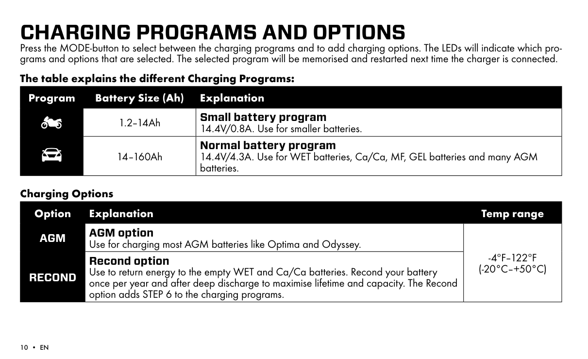
    CHARGING PROGRAMS AND OPTIONS Press the MODE-button to select between the charging programs and to add charging options. The LEDs will indicate which programs and options that are selected. The selected program will be memorised and restarted next time the charger is connected.

    The table explains the different Charging Programs:

    |Program|Battery Size (Ah)|Explanation| |---|---|---| | |1.2–14Ah|Small battery program 14.4V/0.8A. Use for smaller batteries.| | |14–160Ah|Normal battery program 14.4V/4.3A. Use for WET batteries, Ca/Ca, MF, GEL batteries and many AGM batteries.|

    Page 10

    Charging Options

    |Option|Explanation|Temp range| |---|---|---| |AGM|AGM option Use for charging most AGM batteries like Optima and Odyssey.|-4ºF–122ºF (-20°C–+50°C)| |RECOND|Recond option Use to return energy to the empty WET and Ca/Ca batteries. Recond your battery once per year and after deep discharge to maximise lifetime and capacity. The Recond option adds STEP 6 to the charging programs.|-4ºF–122ºF (-20°C–+50°C)|

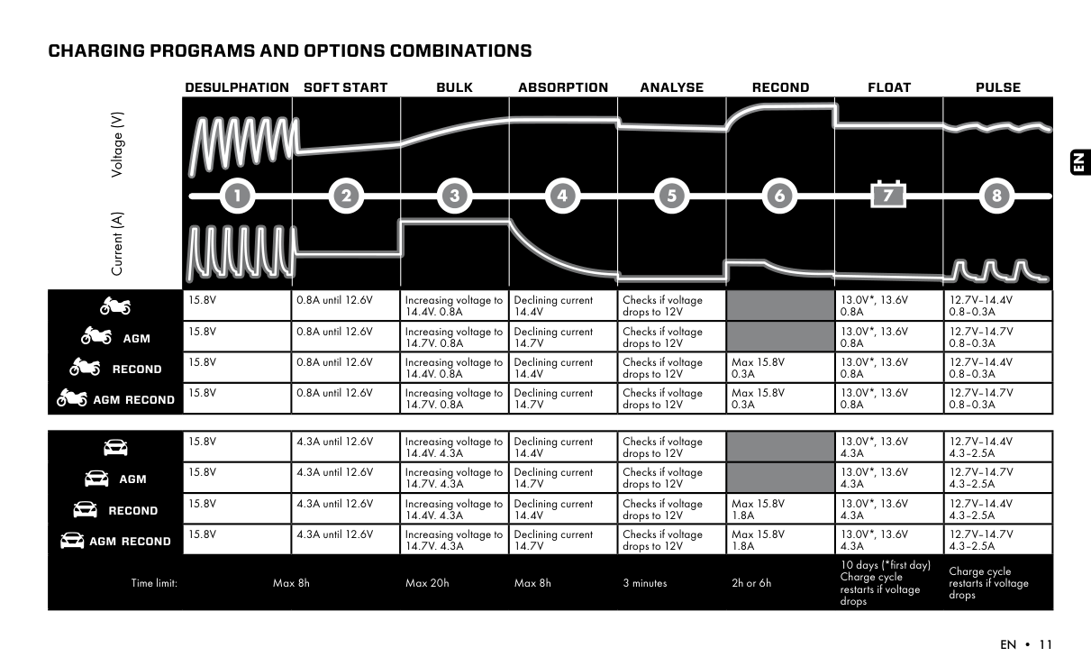
    CHARGING PROGRAMS AND OPTIONS COMBINATIONS

    Current (A) Voltage (V)

    DESULPHATION SOFT START BULK ABSORPTION ANALYSE RECOND FLOAT PULSE

    AGM

    RECOND

    AGM RECOND

    15.8V 0.8A until 12.6V Increasing voltage to 14.4V. 0.8A

    15.8V 0.8A until 12.6V Increasing voltage to 14.7V. 0.8A

    Page 11

    15.8V 0.8A until 12.6V Increasing voltage to 14.4V. 0.8A

    15.8V 0.8A until 12.6V Increasing voltage to 14.7V. 0.8A

    Declining current 14.4V

    Declining current 14.7V

    Declining current 14.4V

    Declining current 14.7V

    Checks if voltage drops to 12V

    Checks if voltage drops to 12V

    Checks if voltage drops to 12V

    Checks if voltage drops to 12V

    Max 15.8V 0.3A

    Max 15.8V 0.3A

    Page 12

    13.0V*, 13.6V 0.8A

    13.0V*, 13.6V 0.8A

    13.0V*, 13.6V 0.8A

    13.0V*, 13.6V 0.8A

    12.7V–14.4V 0.8–0.3A

    12.7V–14.7V 0.8–0.3A

    12.7V–14.4V 0.8–0.3A

    12.7V–14.7V 0.8–0.3A

    EN

    | |15.8V|4.3A until 12.6V|Increasing voltage to 14.4V. 4.3A|Declining current 14.4V|Checks if voltage drops to 12V| |13.0V*, 13.6V 4.3A|12.7V–14.4V 4.3–2.5A| |---|---|---|---|---|---|---|---|---| |AGM|15.8V|4.3A until 12.6V|Increasing voltage to 14.7V. 4.3A|Declining current 14.7V|Checks if voltage drops to 12V| |13.0V*, 13.6V 4.3A|12.7V–14.7V 4.3–2.5A| |RECOND|15.8V|4.3A until 12.6V|Increasing voltage to 14.4V. 4.3A|Declining current 14.4V|Checks if voltage drops to 12V|Max 15.8V 1.8A|13.0V*, 13.6V 4.3A|12.7V–14.4V 4.3–2.5A| |AGM RECOND|15.8V|4.3A until 12.6V|Increasing voltage to 14.7V. 4.3A|Declining current 14.7V|Checks if voltage drops to 12V|Max 15.8V 1.8A|13.0V*, 13.6V 4.3A|12.7V–14.7V 4.3–2.5A| |Time limit:|Max 8h|Max 8h|Max 20h|Max 8h|3 minutes|2h or 6h|10 days (*first day) Charge cycle restarts if voltage drops|Charge cycle restarts if voltage drops|
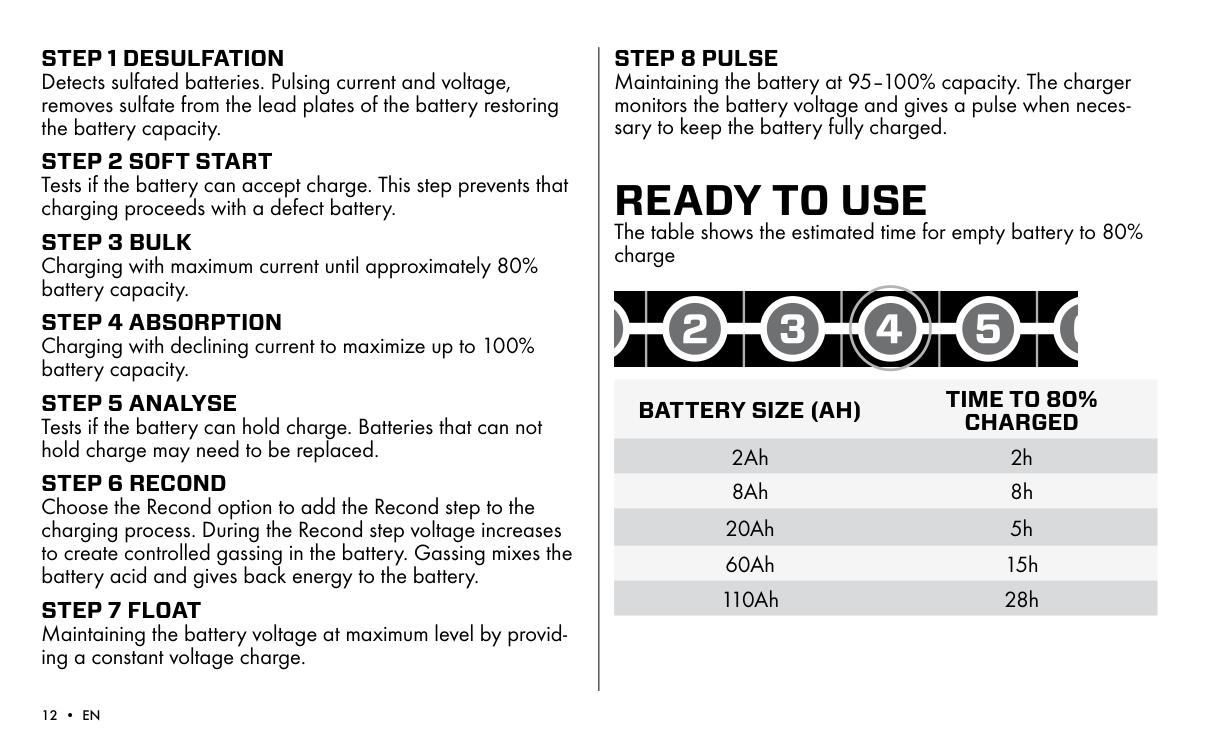
    Page 13

  • STEP 1 DESULFATION Detects sulfated batteries. Pulsing current and voltage, removes sulfate from the lead plates of the battery restoring the battery capacity.
  • STEP 2 SOFT START Tests if the battery can accept charge. This step prevents that charging proceeds with a defect battery.
  • STEP 3 BULK Charging with maximum current until approximately 80% battery capacity.
  • STEP 4 ABSORPTION Charging with declining current to maximize up to 100% battery capacity.
  • STEP 5 ANALYSE Tests if the battery can hold charge. Batteries that can not hold charge may need to be replaced.
  • STEP 6 RECOND Choose the Recond option to add the Recond step to the charging process. During the Recond step voltage increases to create controlled gassing in the battery. Gassing mixes the battery acid and gives back energy to the battery.
  • STEP 7 FLOAT Maintaining the battery voltage at maximum level by providing a constant voltage charge.
  • STEP 8 PULSE

    Maintaining the battery at 95–100% capacity. The charger monitors the battery voltage and gives a pulse when necessary to keep the battery fully charged.

    READY TO USE The table shows the estimated time for empty battery to 80% charge

    BATTERY SIZE (AH) TIME TO 80% CHARGED

    2Ah 2h 8Ah 8h

    20Ah 5h 60Ah 15h 110Ah 28h
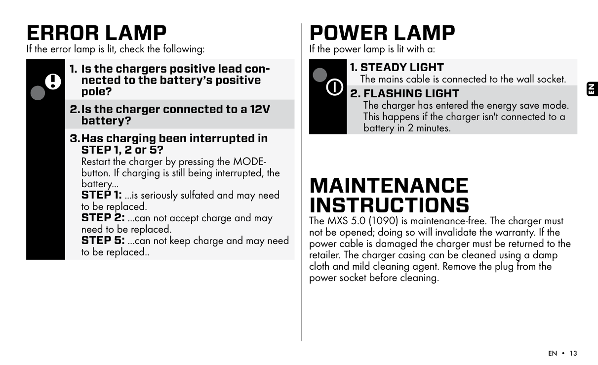
    ERROR LAMP

    If the error lamp is lit, check the following:

    Page 14

  • 1. Is the chargers positive lead connected to the battery’s positive pole?
  • 2.Is the charger connected to a 12V battery?
  • 3.Has charging been interrupted in STEP 1, 2 or 5? Restart the charger by pressing the MODEbutton. If charging is still being interrupted, the battery...
  • STEP 1: ...is seriously sulfated and may need to be replaced.
  • STEP 2: ...can not accept charge and may need to be replaced. STEP 5: ...can not keep charge and may need to be replaced..
  • POWER LAMP

    If the power lamp is lit with a:

  • 1. STEADY LIGHT The mains cable is connected to the wall socket.
  • 2. FLASHING LIGHT The charger has entered the energy save mode. This happens if the charger isn't connected to a battery in 2 minutes.
  • MAINTENANCE INSTRUCTIONS The MXS 5.0 (1090) is maintenance-free. The charger must not be opened; doing so will invalidate the warranty. If the power cable is damaged the charger must be returned to the retailer. The charger casing can be cleaned using a damp cloth and mild cleaning agent. Remove the plug from the power socket before cleaning.

    EN

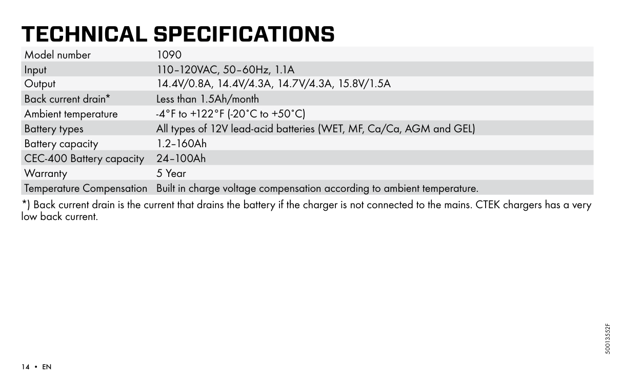
    TECHNICAL SPECIFICATIONS Model number 1090 Input 110–120VAC, 50–60Hz, 1.1A Output 14.4V/0.8A, 14.4V/4.3A, 14.7V/4.3A, 15.8V/1.5A Back current drain* Less than 1.5Ah/month Ambient temperature -4°F to +122°F (-20˚C to +50˚C) Battery types All types of 12V lead-acid batteries (WET, MF, Ca/Ca, AGM and GEL) Battery capacity 1.2–160Ah CEC-400 Battery capacity 24–100Ah Warranty 5 Year Temperature Compensation Built in charge voltage compensation according to ambient temperature.

    *) Back current drain is the current that drains the battery if the charger is not connected to the mains. CTEK chargers has a very low back current.

    50013552F

    LIMITED WARRANTY CTEK Power Inc., issues this limited warranty to the original purchaser of this product. This limited warranty is not transferable. The warranty applies to manufacturing faults and material defects. The customer must return the product for inspection together with the receipt of purchase to the retailer. CTEK Power Inc. will, in its sole discretion, either (i) return the product to customer if it is not determined to be defective, or (ii) without regard to whether or not the original product is determined to be defective, either (A) provide customer with a new replacement product of the same or comparable model to customer, or (B) provide customer with a full refund for the product purchase price. This warranty is void if the battery charger has been opened, handled carelessly or repaired by anyone other than CTEK Power Inc. or its authorized representatives. THE FOREGOING WARRANTY, RIGHTS AND REMEDIES ARE EXCLUSIVE AND IN LIEU OF ALL OTHER WARRANTIES, RIGHTS OR REMEDIES, EXPRESS OR IMPLIED, WHICH MAY OTHERWISE BE AVAILABLE; ALL OTHER WARRANTIES, INCLUDING BUT NOT LIMITED TO, ANY WARRANTY OF MERCHANTABILITY OR FITNESS FOR A PARTICULAR PURPOSE, ARE HEREBY EXPRESSLY DISCLAIMED, EXCLUDED AND WAIVED BY CUSTOMER TO THE FULLEST EXTENT PERMITTED BY LAW. UNDER NO CIRCUMSTANCES SHALL CTEK POWER INC. OR ANY AFFILIATED PARTY THEREOF BE LIABLE FOR ANY INDIRECT, INCIDENTAL, PUNITIVE OR CONSEQUENTIAL DAMAGES OF ANY KIND.

    SUPPORT For support, FAQ, latest revised manual and more information about CTEK products: www.ctek.com

    EN

    More from Ctek

    Similar Battery Chargers