
Electrolux EW6T5227F6 Front-Load Washing Machine
Ask AI
— answers from the official manualAnswers from the official manual.
Common questions
Common Questions
17 totalHow do I prevent drainage issues?
Regularly check and clean the drain pump filter to prevent blockages and ensure the drainage system is not blocked. This maintenance task helps avoid drainage problems during operation.
How do I access the diagnostic cycle on my Electrolux washing machine?
Press and hold down the START/PAUSE button along with a neighboring OPTION button, switch off, then turn on by rotating the program selector clockwise until the LEDs start flashing (at least 2 seconds). The first position will test button functionality while moving further positions activate component diagnostics.
What does the E11 error code indicate and how should I proceed?
E11 signifies difficulty in filling water due to several issues like low water pressure, improper fitting of drain or fill pipes, faulty solenoid valve, etc. The cycle pauses with door locked; check for these issues.
Why does my washing machine show error E43 and how can I fix it?
E43 denotes problems related to the safety interlock triac circuit. This often requires professional service intervention as it involves potential electrical issues that could be dangerous without proper knowledge (Refer diagnostic table for exact causes).
What should I do if water leaks during the wash cycle?
Error E35 suggests possible faults including leaking circuits, incorrect valve positioning or blockages affecting drainage mechanism. A safety drain operation continues attempting to correct this issue for a period.
How can I reset the configuration errors in my washing machine?
Configuration alarms such as E93 indicate incorrect setup data which needs specific corrections that might require professional intervention since these cannot be self-corrected (Refer to troubleshooting guidelines provided for steps).
Show 11 more questions
What causes Alarm E24 and how should I troubleshoot it?
Why does my washer display E00 and what actions should I take?
How do I read the rapid reading of alarm codes on my Electrolux washer?
How do I load laundry into the EW6T5227F6?
What is the SensiCare System and how does it work?
What should I do if the washing machine doesn't start?
How do I clean and maintain the drum?
What is the maximum load capacity of this washing machine?
How should I maintain the lid seal?
What detergent should I use and where do I add it?
What should I check if water is not flowing properly into the machine?
Full Manual
59 pages

SERVICE MANUAL WASHING


| |Washing machines: Guide to diagnostics ENV06 of electronic controls
EWM1100| | |---|---|---| |© ELECTROLUX HOME PRODUCTS ITALY S.p.A. Spares Operations Italy Corso Lino Zanussi, 30
Publication number
I - 33080 PORCIA /PN (ITALY) Fax +39 0434 394096 Edition: 2007-10-16
|599 70 32-47| |---|
EN
|Washing machines: Guide to diagnostics ENV06 of electronic controls
EWM1100| |
Contents
INTRODUCTION
The purpose of this Service Manual is to provide a simple and clear description of the procedure to be followed by service engineers when confronted by problems identified by the various alarm codes generated by appliances with the EWM1100 electronic control system.
Depending on the configuration of the appliance, the alarm codes may be displayed partially or completely to the user (the alarm codes are generally displayed partially). The diagnostic system can be used by service engineers for the following purposes:
♦ To read the alarms
♦ To cancel alarm conditions stored in memory
♦ To test the operation of the appliance
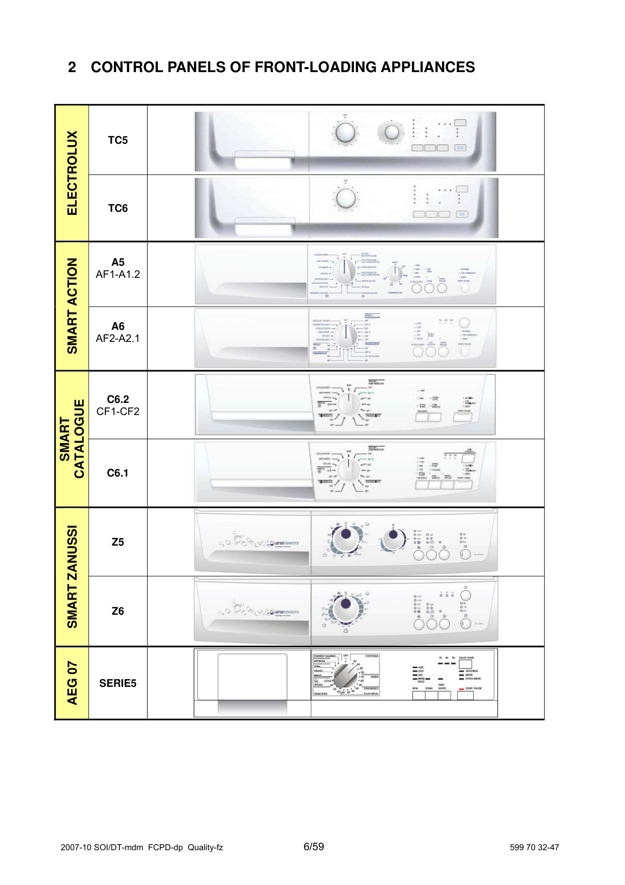
2 CONTROL PANELS OF FRONT-LOADING APPLIANCES
|ELECTROLUX|TC5|| |---|---|---| |ELECTROLUX|TC6|| |SMART ACTION|A5 AF1-A1.2|| |SMART ACTION|A6 AF2-A2.1|| |SMART
CATALOGUE|C6.2 CF1-CF2|| |SMART
CATALOGUE|C6.1|| |SMART ZANUSSI|Z5|| |SMART ZANUSSI|Z6|| |AEG 07|SERIE5||
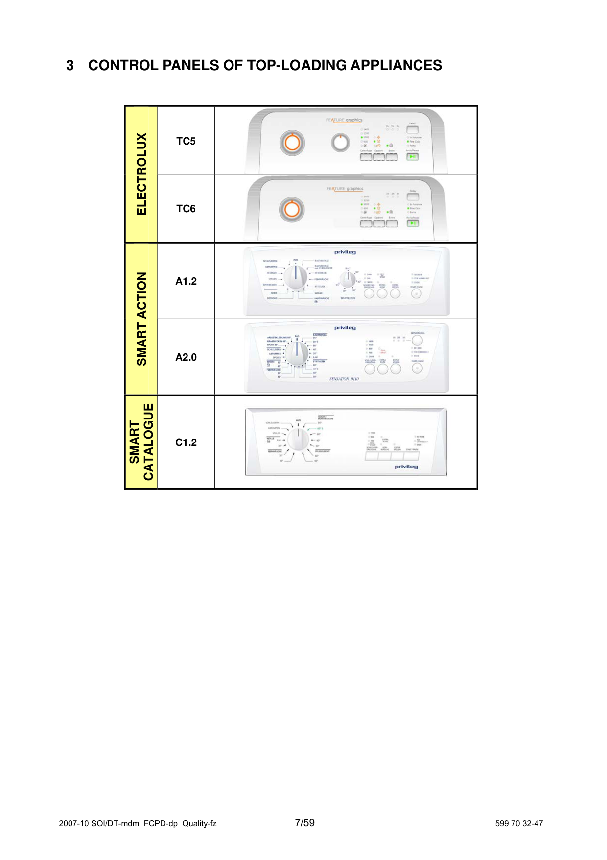
3 CONTROL PANELS OF TOP-LOADING APPLIANCES
|ELECTROLUX
|TC5|| |---|---|---| |ELECTROLUX
|TC6|| |SMART ACTION|A1.2|| |SMART ACTION|A2.0|| |SMART
CATALOGUE|C1.2||
4 DIAGNOSTIC SYSTEM
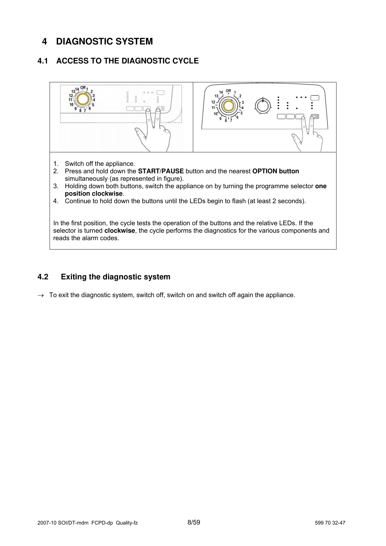
#### 4.1 ACCESS TO THE DIAGNOSTIC CYCLE
||| |---|---| |1. Switch off the appliance.
2. Press and hold down the START/PAUSE button and the nearest OPTION button simultaneously (as represented in figure).
3. Holding down both buttons, switch the appliance on by turning the programme selector one position clockwise.
4. Continue to hold down the buttons until the LEDs begin to flash (at least 2 seconds).
In the first position, the cycle tests the operation of the buttons and the relative LEDs. If the selector is turned clockwise, the cycle performs the diagnostics for the various components and reads the alarm codes.|1. Switch off the appliance.
2. Press and hold down the START/PAUSE button and the nearest OPTION button simultaneously (as represented in figure).
3. Holding down both buttons, switch the appliance on by turning the programme selector one position clockwise.
4. Continue to hold down the buttons until the LEDs begin to flash (at least 2 seconds).
In the first position, the cycle tests the operation of the buttons and the relative LEDs. If the selector is turned clockwise, the cycle performs the diagnostics for the various components and reads the alarm codes.|
#### 4.2 Exiting the diagnostic system
→ To exit the diagnostic system, switch off, switch on and switch off again the appliance.
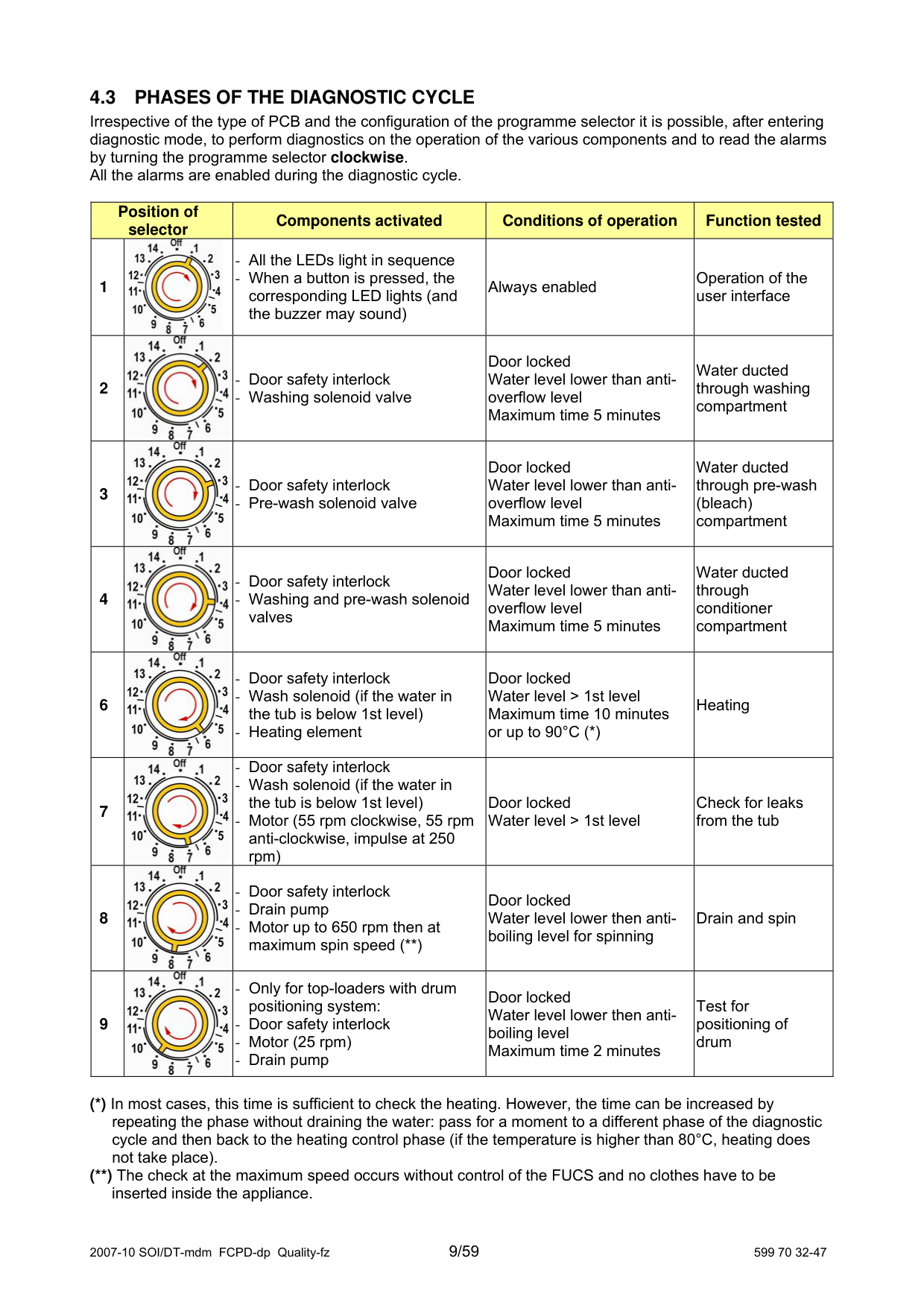
#### 4.3 PHASES OF THE DIAGNOSTIC CYCLE
Irrespective of the type of PCB and the configuration of the programme selector it is possible, after entering diagnostic mode, to perform diagnostics on the operation of the various components and to read the alarms by turning the programme selector clockwise. All the alarms are enabled during the diagnostic cycle.
|Position of selector
|Position of selector
|Components activated|Conditions of operation|Function tested| |---|---|---|---|---| |1||- All the LEDs light in sequence
- When a button is pressed, the corresponding LED lights (and the buzzer may sound)
|Always enabled|Operation of the user interface| |2||- Door safety interlock
- Washing solenoid valve
|Door locked Water level lower than antioverflow level Maximum time 5 minutes|Water ducted through washing compartment| |3||- Door safety interlock
- Pre-wash solenoid valve
|Door locked Water level lower than antioverflow level Maximum time 5 minutes|Water ducted through pre-wash (bleach) compartment| |4||- Door safety interlock
- Washing and pre-wash solenoid valves
|Door locked Water level lower than antioverflow level Maximum time 5 minutes|Water ducted through conditioner compartment| |6||- Door safety interlock
- Wash solenoid (if the water in the tub is below 1st level)
- Heating element
|Door locked Water level > 1st level Maximum time 10 minutes or up to 90°C (*)|Heating|
|7||- Door safety interlock
- Wash solenoid (if the water in the tub is below 1st level)
- Motor (55 rpm clockwise, 55 rpm anti-clockwise, impulse at 250 rpm)
|Door locked Water level > 1st level|Check for leaks from the tub| |8||- Door safety interlock
- Drain pump
- Motor up to 650 rpm then at maximum spin speed (**)
|Door locked Water level lower then antiboiling level for spinning|Drain and spin| |9||- Only for top-loaders with drum positioning system:
- Door safety interlock
- Motor (25 rpm)
- Drain pump
|Door locked Water level lower then antiboiling level Maximum time 2 minutes|Test for positioning of drum|
(*) In most cases, this time is sufficient to check the heating. However, the time can be increased by repeating the phase without draining the water: pass for a moment to a different phase of the diagnostic cycle and then back to the heating control phase (if the temperature is higher than 80°C, heating does not take place).
(**) The check at the maximum speed occurs without control of the FUCS and no clothes have to be
inserted inside the appliance.
5 ALARMS
#### 5.1 Displaying the alarms to the user
The alarms displayed to the user are listed below:
Door open Drain difficulty (dirty filter) Water fill difficulty (closet tap)
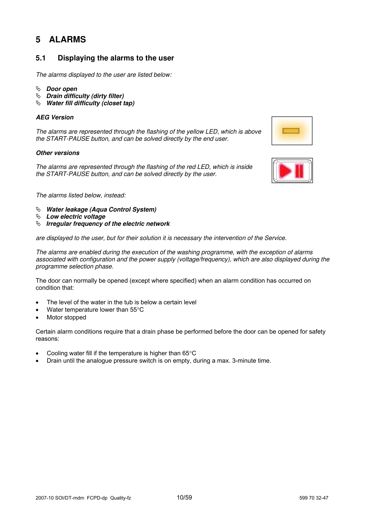
AEG Version
The alarms are represented through the flashing of the yellow LED, which is above the START-PAUSE button, and can be solved directly by the end user.
####### Other versions
The alarms are represented through the flashing of the red LED, which is inside the START-PAUSE button, and can be solved directly by the user.
|| |---|
|| |---|
The alarms listed below, instead:
Water leakage (Aqua Control System) Low electric voltage Irregular frequency of the electric network
are displayed to the user, but for their solution it is necessary the intervention of the Service. The alarms are enabled during the execution of the washing programme, with the exception of alarms associated with configuration and the power supply (voltage/frequency), which are also displayed during the programme selection phase.
The door can normally be opened (except where specified) when an alarm condition has occurred on condition that:
Certain alarm conditions require that a drain phase be performed before the door can be opened for safety reasons:
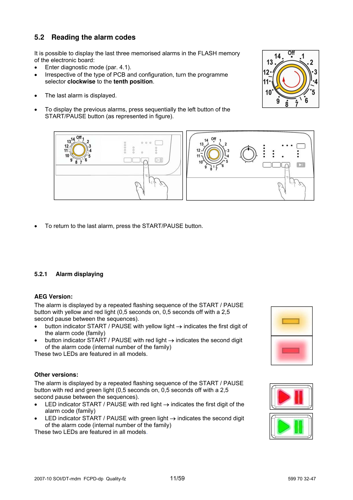
#### 5.2 Reading the alarm codes
It is possible to display the last three memorised alarms in the FLASH memory of the electronic board:
|| |---|
AEG Version: The alarm is displayed by a repeated flashing sequence of the START / PAUSE button with yellow and red light (0,5 seconds on, 0,5 seconds off with a 2,5 second pause between the sequences).
|| |---|
|| |---|
|| |---| ||
These two LEDs are featured in all models.
Other versions: The alarm is displayed by a repeated flashing sequence of the START / PAUSE button with red and green light (0,5 seconds on, 0,5 seconds off with a 2,5 second pause between the sequences).
These two LEDs are featured in all models.
|| |---|
|| |---|
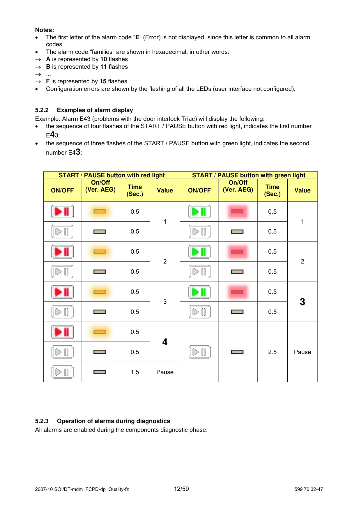
####### Notes:
→ ...
→ F is represented by 15 flashes
• Configuration errors are shown by the flashing of all the LEDs (user interface not configured).
|START / PAUSE button with red light|START / PAUSE button with red light|START / PAUSE button with red light|START / PAUSE button with red light|START / PAUSE button with green light|START / PAUSE button with green light|START / PAUSE button with green light|START / PAUSE button with green light| |---|---|---|---|---|---|---|---| |ON/OFF|On/Off (Ver. AEG)
|Time (Sec.)
|Value|ON/OFF|On/Off (Ver. AEG)
|Time (Sec.)
|Value| |||0.5|1|||0.5|1| |||0.5|1|||0.5|1| |||0.5|2|||0.5|2
| |||0.5|2|||0.5|2
| |||0.5|3|||0.5|3| |||0.5|3|||0.5|3| |||0.5|4
|||2.5|Pause| |||0.5|4
|||2.5|Pause| |||1.5|Pause|||2.5|Pause|
#### 5.3 Rapid reading of alarm codes
The last three alarm codes can be displayed even if the programme selector is not in the tenth position (diagnostics) or if the appliance is in normal operating mode (e.g. during the execution of the washing programme):
→ Press and hold down START/PAUSE and the nearest option button (as to enter the DIAGNOSTICS), for at least two seconds: the LEDs initially switch off, and then display the flashing sequence indicating the last alarm.
→ To display the previous alarms press the left button of the START/PAUSE button sequentially.
→ To return to the last alarm, press the START/PAUSE button.
→ The alarm sequence continues as long as the two buttons are held down.
→ The alarm reading system is as described in paragraph 5.2.1.
→ While the alarms are displayed, the appliance continues to perform the cycle or, if in the programme selection phase, maintains the previously-selected options in memory.
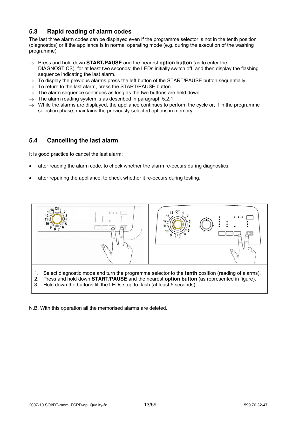
#### 5.4 Cancelling the last alarm
It is good practice to cancel the last alarm:
||| |---|---| |1. Select diagnostic mode and turn the programme selector to the tenth position (reading of alarms).
2. Press and hold down START/PAUSE and the nearest option button (as represented in figure).
3. Hold down the buttons till the LEDs stop to flash (at least 5 seconds).
|1. Select diagnostic mode and turn the programme selector to the tenth position (reading of alarms).
2. Press and hold down START/PAUSE and the nearest option button (as represented in figure).
3. Hold down the buttons till the LEDs stop to flash (at least 5 seconds).
|
N.B. With this operation all the memorised alarms are deleted.
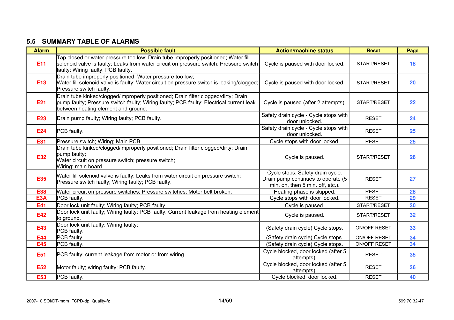
#### 5.5 SUMMARY TABLE OF ALARMS
||Alarm|Possible fault|Action/machine status| | |---|---|---|---| ||Alarm|Possible fault|Action/machine status| | |---|---|---|---| ||Alarm|Possible fault|Action/machine status| | |---|---|---|---| ||Alarm|Possible fault|Action/machine status| | |---|---|---|---| ||Alarm|Possible fault|Action/machine status| | |---|---|---|---| | |---|---|---|---|---| |E11|Tap closed or water pressure too low; Drain tube improperly positioned; Water fill solenoid valve is faulty; Leaks from water circuit on pressure switch; Pressure switch faulty; Wiring faulty; PCB faulty.|Cycle is paused with door locked.| | | |E13|Drain tube improperly positioned; Water pressure too low; Water fill solenoid valve is faulty; Water circuit on pressure switch is leaking/clogged; Pressure switch faulty.|Cycle is paused with door locked.| | | |E21|Drain tube kinked/clogged/improperly positioned; Drain filter clogged/dirty; Drain pump faulty; Pressure switch faulty; Wiring faulty; PCB faulty; Electrical current leak between heating element and ground.|Cycle is paused (after 2 attempts).| | | |E23|Drain pump faulty; Wiring faulty; PCB faulty.|Safety drain cycle - Cycle stops with door unlocked.| | | |E24|PCB faulty.|Safety drain cycle - Cycle stops with door unlocked.| | | |E31|Pressure switch; Wiring; Main PCB.|Cycle stops with door locked.| | | |E32|Drain tube kinked/clogged/improperly positioned; Drain filter clogged/dirty; Drain pump faulty; Water circuit on pressure switch; pressure switch; Wiring; main board.|Cycle is paused.| | | |E35|Water fill solenoid valve is faulty; Leaks from water circuit on pressure switch; Pressure switch faulty; Wiring faulty; PCB faulty.|Cycle stops. Safety drain cycle. Drain pump continues to operate (5 min. on, then 5 min. off, etc.).| | | |E38|Water circuit on pressure switches; Pressure switches; Motor belt broken.|Heating phase is skipped.| | | |E3A|PCB faulty.|Cycle stops with door locked.| | | |E41|Door lock unit faulty; Wiring faulty; PCB faulty.|Cycle is paused.| | | |E42|Door lock unit faulty; Wiring faulty; PCB faulty. Current leakage from heating element to ground.|Cycle is paused.| | | |E43|Door lock unit faulty; Wiring faulty; PCB faulty.|(Safety drain cycle) Cycle stops.| | | |E44|PCB faulty.|(Safety drain cycle) Cycle stops.| | | |E45|PCB faulty.|(Safety drain cycle) Cycle stops.| | | |E51|PCB faulty; current leakage from motor or from wiring.|Cycle blocked, door locked (after 5 attempts).| | | |E52|Motor faulty; wiring faulty; PCB faulty.|Cycle blocked, door locked (after 5 attempts).| | | |E53|PCB faulty.|Cycle blocked, door locked.| | |
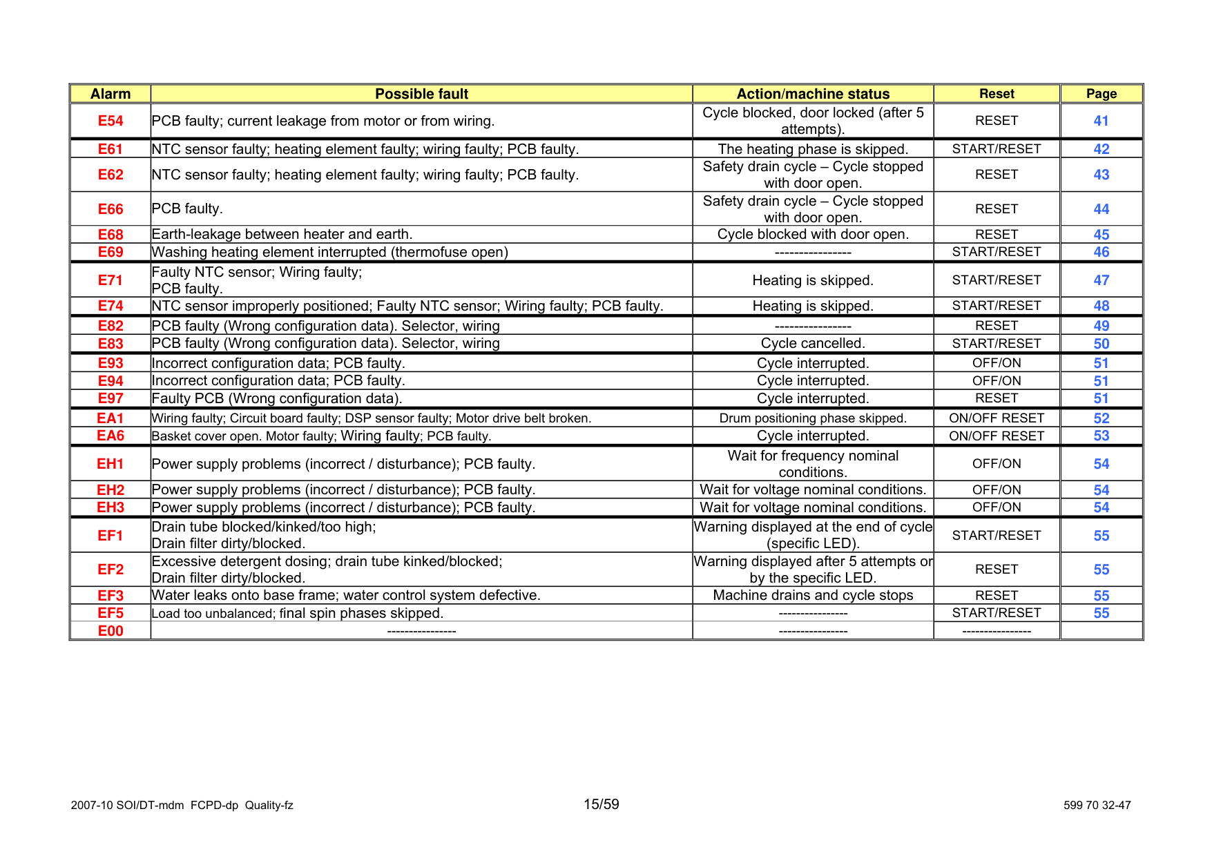
||Alarm|Possible fault|Action/machine status| | |---|---|---|---| ||Alarm|Possible fault|Action/machine status| | |---|---|---|---| ||Alarm|Possible fault|Action/machine status| | |---|---|---|---| ||Alarm|Possible fault|Action/machine status| | |---|---|---|---| ||Alarm|Possible fault|Action/machine status| | |---|---|---|---| | |---|---|---|---|---| |E54|PCB faulty; current leakage from motor or from wiring.|Cycle blocked, door locked (after 5 attempts).| | | |E61|NTC sensor faulty; heating element faulty; wiring faulty; PCB faulty.|The heating phase is skipped.| | | |E62|NTC sensor faulty; heating element faulty; wiring faulty; PCB faulty.|Safety drain cycle – Cycle stopped with door open.| | | |E66|PCB faulty.|Safety drain cycle – Cycle stopped with door open.| | | |E68|Earth-leakage between heater and earth.|Cycle blocked with door open.| | | |E69|Washing heating element interrupted (thermofuse open)|----------------| | | |E71|Faulty NTC sensor; Wiring faulty; PCB faulty.|Heating is skipped.| | | |E74|NTC sensor improperly positioned; Faulty NTC sensor; Wiring faulty; PCB faulty.|Heating is skipped.| | | |E82|PCB faulty (Wrong configuration data). Selector, wiring|----------------| | | |E83|PCB faulty (Wrong configuration data). Selector, wiring|Cycle cancelled.| | | |E93|Incorrect configuration data; PCB faulty.|Cycle interrupted.| | | |E94|Incorrect configuration data; PCB faulty.|Cycle interrupted.| | | |E97|Faulty PCB (Wrong configuration data).|Cycle interrupted.| | | |EA1|Wiring faulty; Circuit board faulty; DSP sensor faulty; Motor drive belt broken.|Drum positioning phase| | | |EA6|Basket cover open. Motor faulty; Wiring faulty; PCB faulty.|Cycle interrupted.| | | |EH1|Power supply problems (incorrect / disturbance); PCB faulty.|Wait for frequency nominal conditions.| | | |EH2|Power supply problems (incorrect / disturbance); PCB faulty.|Wait for voltage nominal conditions.| | | |EH3|Power supply problems (incorrect / disturbance); PCB faulty.|Wait for voltage nominal conditions.| | | |EF1|Drain tube blocked/kinked/too high; Drain filter dirty/blocked.|Warning displayed at the end of cycle (specific LED).| | | |EF2|Excessive detergent dosing; drain tube kinked/blocked; Drain filter dirty/blocked.|Warning displayed after 5 attempts or by the specific LED.| | | |EF3|Water leaks onto base frame; water control system defective.|Machine drains and cycle stops| | | |EF5|Load too unbalanced; final spin phases skipped.|----------------|START/RESET| | |E00|----------------|----------------|----------------| |
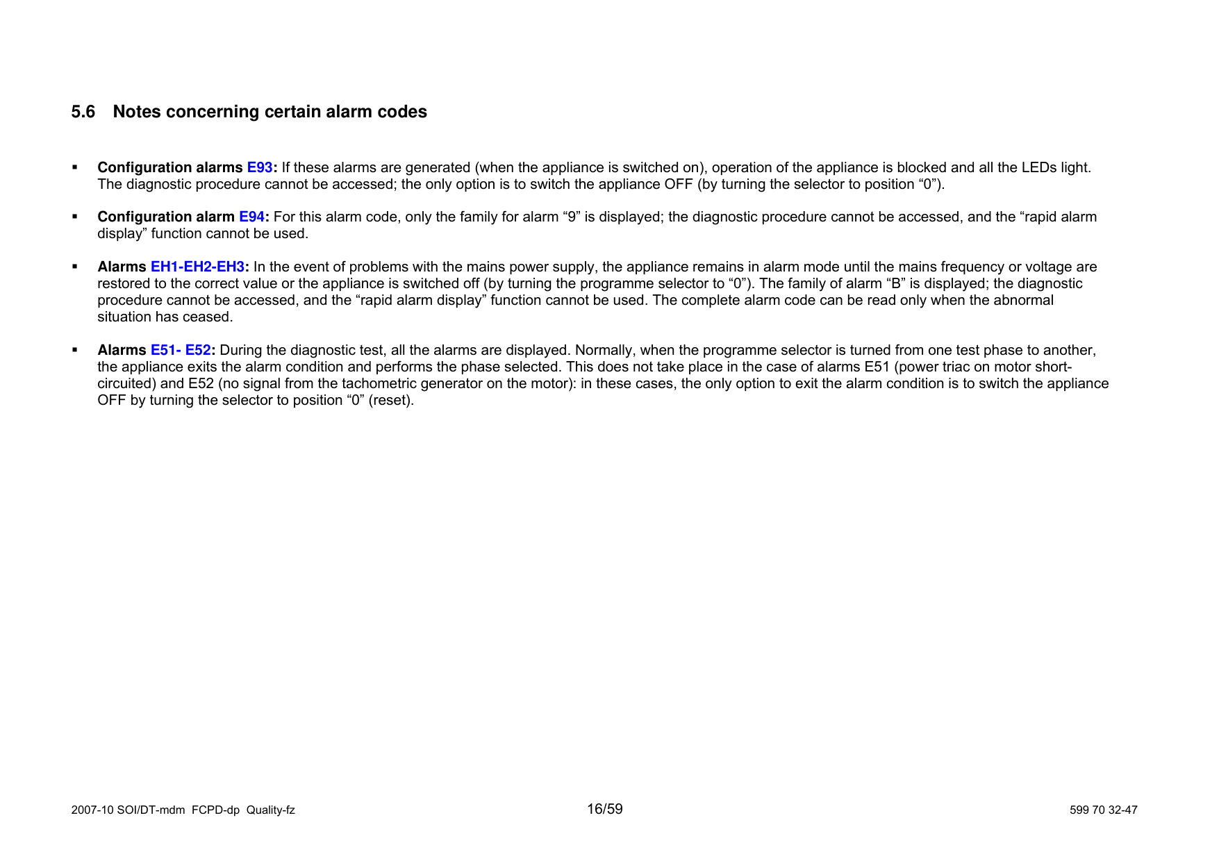
#### 5.6 Notes concerning certain alarm codes
Configuration alarms E93: If these alarms are generated (when the appliance is switched on), operation of the appliance is blocked and all the LEDs light The diagnostic procedure cannot be accessed; the only option is to switch the appliance OFF (by turning the selector to positio
Configuration alarm E94: For this alarm code, only the family for alarm “9” is displayed; the diagnostic procedure cann display” function cannot be used.
Alarms EH1-EH2-EH3: In the event of problems with the mains power supply, the appliance remains in alarm mode until the mains frequency or voltage restored to the correct value or the appliance is switched off (by turning the programme selector to “0”). The family of alarm procedure cannot be accessed, and the “rapid alarm display” function cannot be used. The complete alarm code can be read only w situation has ceased.
Alarms E51- E52: During the diagnostic test, all the alarms are displayed. Normally, when the programme selector is turned from one test phase the appliance exits the alarm condition and performs the phase selected. This does not take place in the case of alarms E51 (po circuited) and E52 (no signal from the tachometric generator on the motor): in these cases, the only option to exit the alarm c OFF by turning the selector to position “0” (reset).
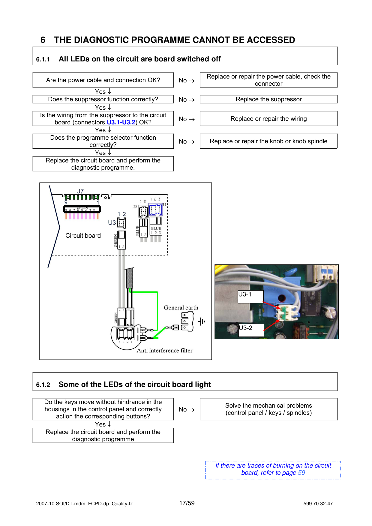
6 THE DIAGNOSTIC PROGRAMME CANNOT BE ACCESSED
|6.1.1 All LEDs on the circuit are board switched off| |---|
|Are the power cable and connection OK?| |---|
|Replace or repair the power cable, check the connector| |---|
No → Yes ↓
|Does the suppressor function correctly?| |---|
|Replace the suppressor| |---|
No → Yes ↓
|Is the wiring from the suppressor to the circuit board (connectors U3.1-U3.2) OK?| |---|
|Replace or repair the wiring| |---|
No → Yes ↓
|Does the programme selector function correctly?| |---|
|Replace or repair the knob or knob spindle| |---|
No → Yes ↓
|Replace the circuit board and perform the diagnostic programme.| |---|
|
Circuit board| |---|
|
|U3-1| |---|
|U3-2| |---| | |---|
|6.1.2 Some of the LEDs of the circuit board light| |---|
|Do the keys move without hindrance in the housings in the control panel and correctly action the corresponding buttons?| |---|
|Solve the mechanical problems (control panel / keys / spindles)| |---|
No → Yes ↓
|Replace the circuit board and perform the diagnostic programme| |---|
|If there are traces of burning on the circuit board, refer to page 59| |---|
7 TROUBLESHOOTING ACCORDING TO ALARM CODES
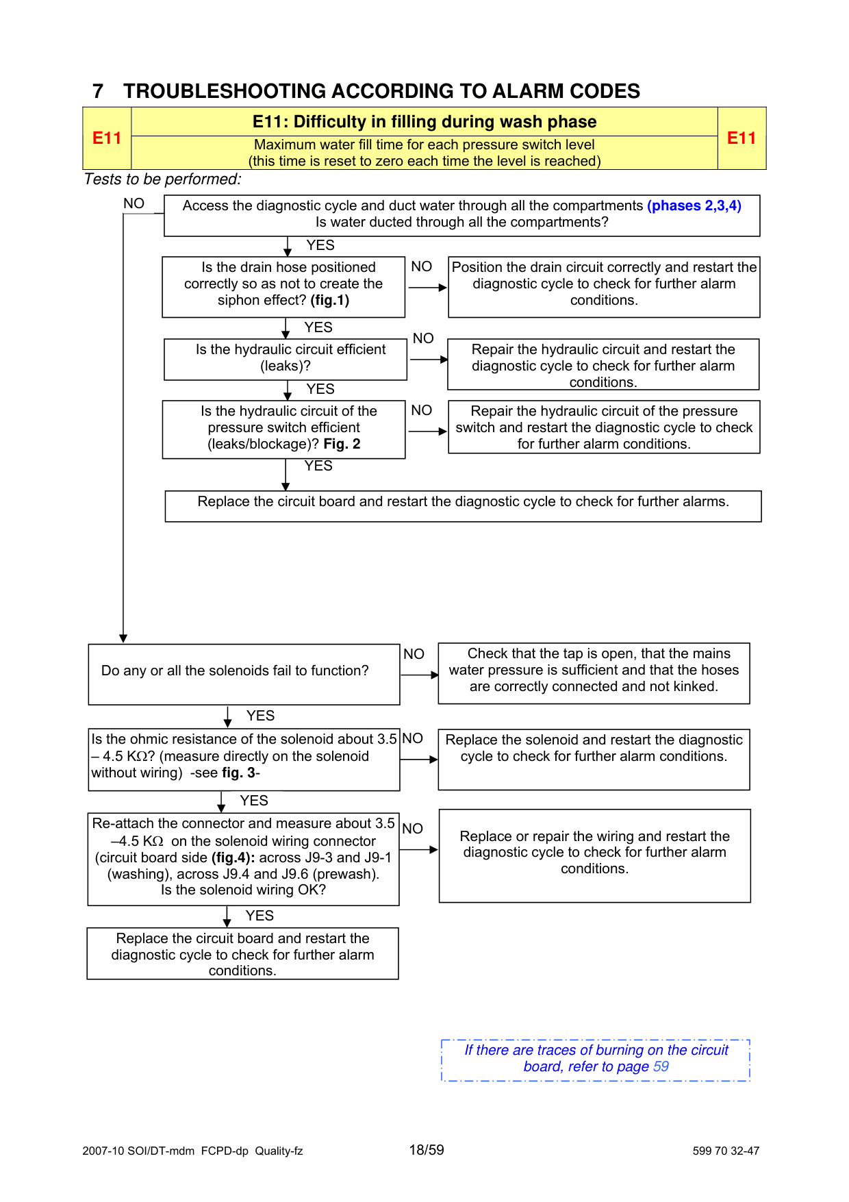
|E11|E11: Difficulty in filling during wash phase|E11| |---|---|---| |E11|Maximum water fill time for each pressure switch level (this time is reset to zero each time the level is reached)
|E11|
Tests to be performed:
NO
Access the diagnostic cycle and duct water through all the compartments (phases 2,3,4) Is water ducted through all the compartments?
YES
|Position the drain circuit correctly and restart the diagnostic cycle to check for further alarm conditions.| |---|
NO
Is the drain hose positioned
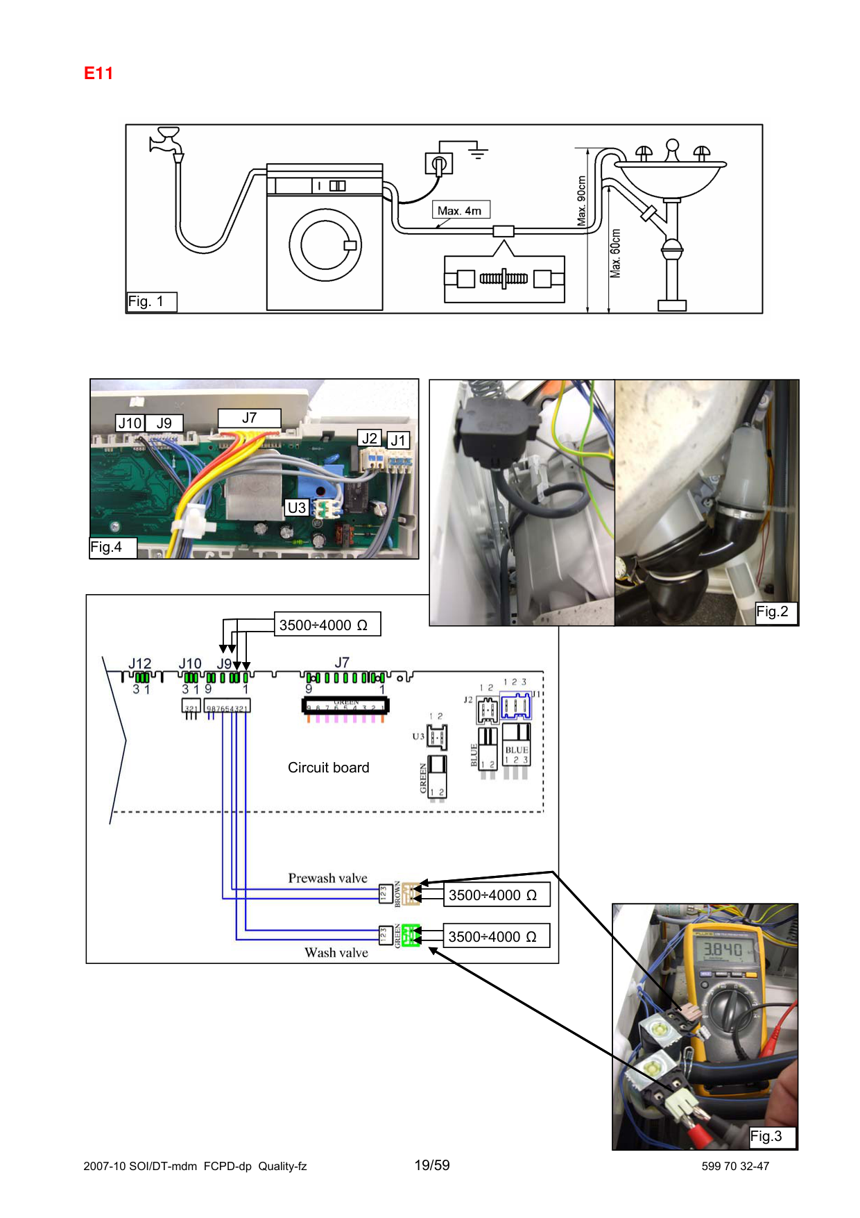
correctly so as not to create the siphon effect? (fig.1)
YES
NO Is the hydraulic circuit efficient
|Repair the hydraulic circuit and restart the diagnostic cycle to check for further alarm conditions.| |---|
(leaks)?
YES
|Repair the hydraulic circuit of the pressure switch and restart the diagnostic cycle to check for further alarm conditions.| |---|
NO
Is the hydraulic circuit of the
pressure switch efficient (leaks/blockage)? Fig. 2
YES
Replace the circuit board and restart the diagnostic cycle to check for further alarms.
|Check that the tap is open, that the mains
water pressure is sufficient and that the hoses are correctly connected and not kinked.| |---|
|Do any or all the solenoids fail to function?| |---|
NO
|YES| |---|
|Is the ohmic resistance of the solenoid about 3.5
– 4.5 KΩ? (measure directly on the solenoid without wiring) -see fig. 3-| |---|
|Replace the solenoid and restart the diagnostic cycle to check for further alarm conditions.| |---|
NO
| |YES| | |---|---|---| |Re-attach the connector and measure about 3.5 –4.5 KΩ on the solenoid wiring connector (circuit board side (fig.4): across J9-3 and J9-1 (washing), across J9.4 and J9.6 (prewash). Is the solenoid wiring OK?|Re-attach the connector and measure about 3.5 –4.5 KΩ on the solenoid wiring connector (circuit board side (fig.4): across J9-3 and J9-1 (washing), across J9.4 and J9.6 (prewash). Is the solenoid wiring OK?|Re-attach the connector and measure about 3.5 –4.5 KΩ on the solenoid wiring connector (circuit board side (fig.4): across J9-3 and J9-1 (washing), across J9.4 and J9.6 (prewash). Is the solenoid wiring OK?|
|Replace or repair the wiring and restart the diagnostic cycle to check for further alarm conditions.| |---|
NO
| |YES| | |---|---|---| |Replace the circuit board and restart the diagnostic cycle to check for further alarm conditions.|Replace the circuit board and restart the diagnostic cycle to check for further alarm conditions.|Replace the circuit board and restart the diagnostic cycle to check for further alarm conditions.|
|If there are traces of burning on the circuit board, refer to page 59| |---|

|Fig. 1| |---|


|J7| |---|
|J10|J9| |---|---|
|J2| |---|
|J1| |---|
|U3| |---|
Fig.4

Fig.2
3500÷4000 Ω
3500÷4000 Ω
Circuit board
|3500÷4000 Ω3500÷4000Ω| |---|
|

|Fig.3| |---| | |---|
|3500÷4000 Ω3500÷4000Ω| |---|
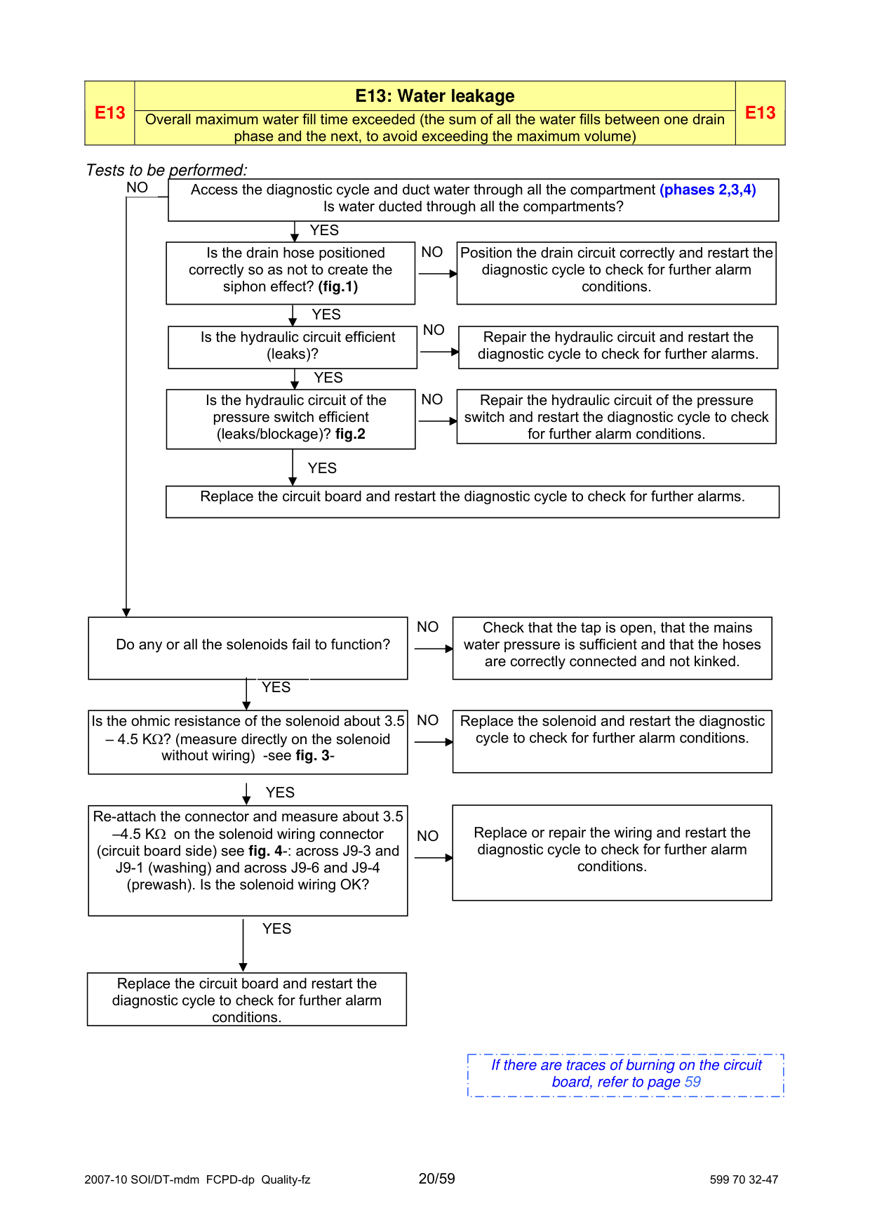
|E13
|E13: Water leakage|E13| |---|---|---| |E13
|Overall maximum water fill time exceeded (the sum of all the water fills between one drain phase and the next, to avoid exceeding the maximum volume)
|E13|
###### Tests to be performed:
NO
Access the diagnostic cycle and duct water through all the compartment (phases 2,3,4) Is water ducted through all the compartments?
YES
|Position the drain circuit correctly and restart the diagnostic cycle to check for further alarm conditions.| |---|
NO
Is the drain hose positioned
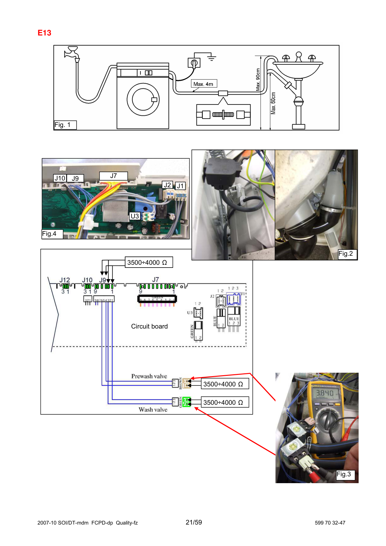
correctly so as not to create the siphon effect? (fig.1)
YES
NO Is the hydraulic circuit efficient
|Repair the hydraulic circuit and restart the diagnostic cycle to check for further alarms.| |---|
(leaks)?
YES
|Repair the hydraulic circuit of the pressure switch and restart the diagnostic cycle to check for further alarm conditions.| |---|
NO
Is the hydraulic circuit of the
pressure switch efficient (leaks/blockage)? fig.2
YES
|Replace the circuit board and restart the diagnostic cycle to check for further alarms.| |---|
|Do any or all the solenoids fail to function?|Do any or all the solenoids fail to function?|Do any or all the solenoids fail to function?| |---|---|---| | |YES| | |Is the ohmic resistance of the solenoid about 3.5 – 4.5 KΩ? (measure directly on the solenoid without wiring) -see fig. 3-|Is the ohmic resistance of the solenoid about 3.5 – 4.5 KΩ? (measure directly on the solenoid without wiring) -see fig. 3-|Is the ohmic resistance of the solenoid about 3.5 – 4.5 KΩ? (measure directly on the solenoid without wiring) -see fig. 3-|
|Check that the tap is open, that the mains
water pressure is sufficient and that the hoses are correctly connected and not kinked.| |---|
NO
|Replace the solenoid and restart the diagnostic cycle to check for further alarm conditions.| |---|
NO
|YES| |---|
|Replace or repair the wiring and restart the diagnostic cycle to check for further alarm conditions.| |---|
|Re-attach the connector and measure about 3.5 –4.5 KΩ on the solenoid wiring connector (circuit board side) see fig. 4-: across J9-3 and J9-1 (washing) and across J9-6 and J9-4 (prewash). Is the solenoid wiring OK?| |---|
NO
|YES| |---|
|Replace the circuit board and restart the diagnostic cycle to check for further alarm conditions.| |---|
|If there are traces of burning on the circuit board, refer to page 59| |---|

|Fig. 1| |---|


|J7| |---|
|J10|J9| |---|---|
|J2| |---|
|J1| |---|
|U3| |---|
Fig.4

Fig.2
3500÷4000 Ω
Circuit board

|3500÷4000 Ω| |---|
|3500÷4000 Ω| |---|
|Fig.3| |---|
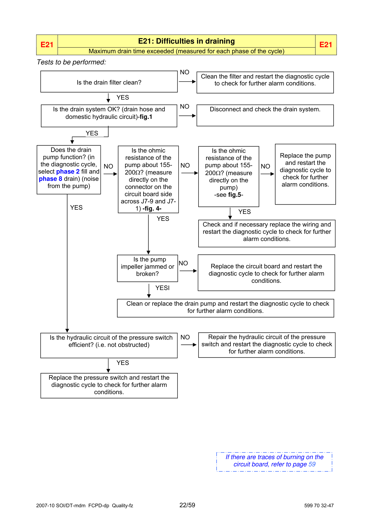
|E21|E21: Difficulties in draining|E21| |---|---|---| |E21|Maximum drain time exceeded (measured for each phase of the cycle)|E21|
###### Tests to be performed:
NO
|Is the drain filter clean?| |---|
|Clean the filter and restart the diagnostic cycle to check for further alarm conditions.| |---|
|YES| |---|
NO
|Is the drain system OK? (drain hose and domestic hydraulic circuit)-fig.1|Is the drain system OK? (drain hose and domestic hydraulic circuit)-fig.1|
|---|---| |YES| |
|Disconnect and check the drain system.| |---|
|Replace the pump and restart the diagnostic cycle to check for further alarm conditions.| |---|
|Does the drain
pump function? (in the diagnostic cycle, select phase 2 fill and phase 8 drain) (noise from the pump)| |---|
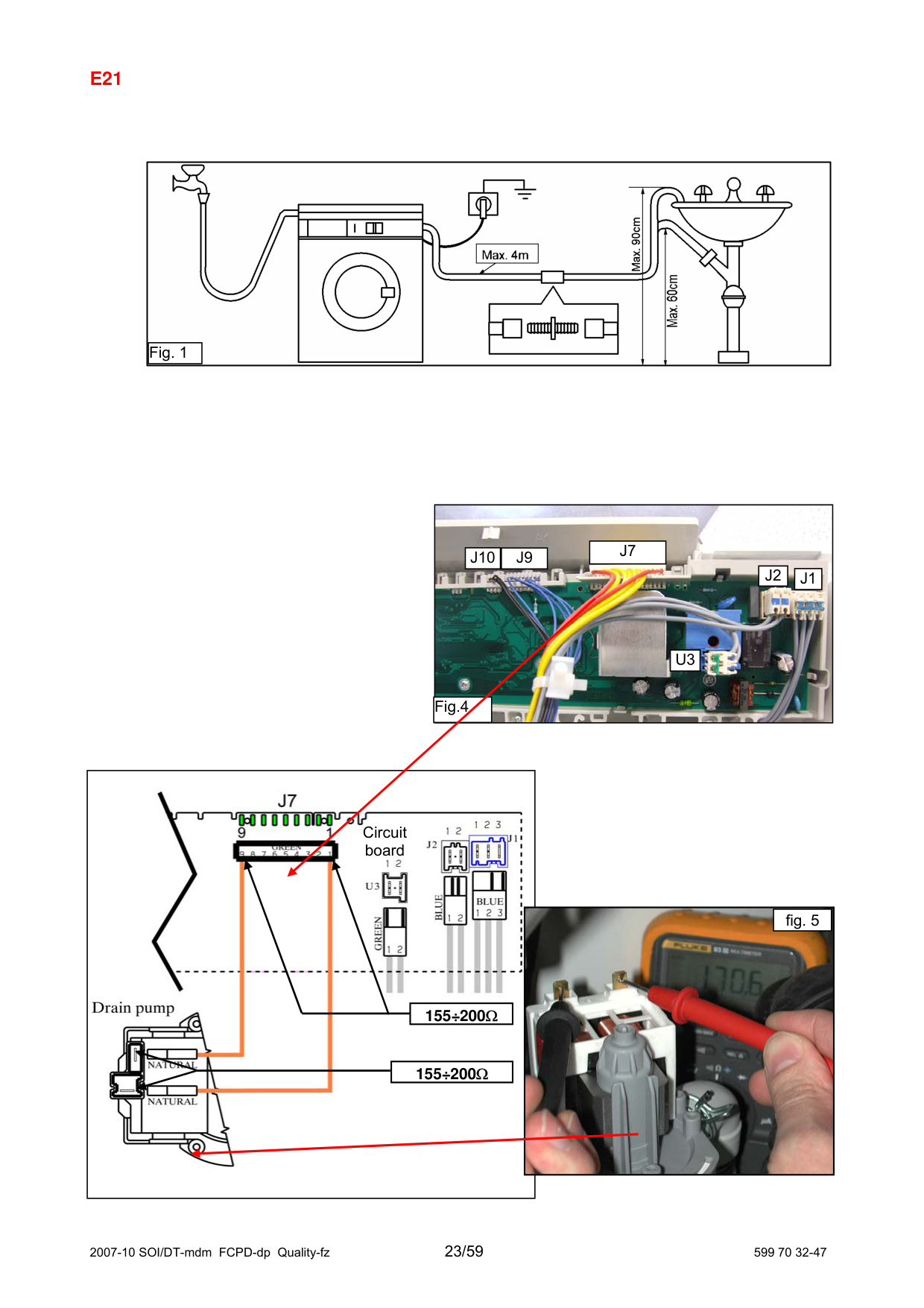
|Is the ohmic resistance of the pump about 155200Ω? (measure directly on the connector on the circuit board side across J7-9 and J71) -fig. 4-| |---|
|Is the ohmic resistance of the pump about 155200Ω? (measure directly on the pump) -see fig.5-| |---|
NO
NO
NO
|YES| |---|
|YES| |---|
|YES| |---|
|Check and if necessary replace the wiring and restart the diagnostic cycle to check for further alarm conditions.| |---|
|Replace the circuit board and restart the diagnostic cycle to check for further alarm conditions.| |---|
|Is the pump
impeller jammed or broken?| |---|
NO
|YESI| |---|
|Clean or replace the drain pump and restart the diagnostic cycle to check for further alarm conditions.| |---|
|Repair the hydraulic circuit of the pressure switch and restart the diagnostic cycle to check for further alarm conditions.| |---|
|Is the hydraulic circuit of the pressure switch efficient? (i.e. not obstructed)| |---|
NO
|YES| |---|
|Replace the pressure switch and restart the diagnostic cycle to check for further alarm conditions.| |---|
|If there are traces of burning on the circuit board, refer to page 59| |---|
#### E21

|Fig. 1| |---|

|J7| |---|
|J10|J9| |---|---|
|J2| |---|
|J1| |---|
|U3| |---|
Fig.4

Circuit board

|fig. 5| |---|
| |155÷200Ω| |---|---| | |155÷200Ω|
|155÷200Ω| |---|
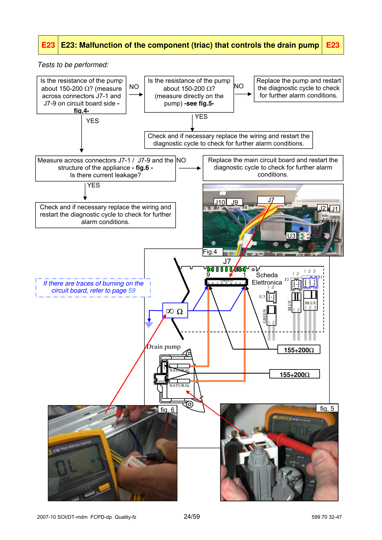
|E23|E23: Malfunction of the component (triac) that controls the drain pump|E23| |---|---|---|
###### Tests to be performed:
|Is the resistance of the pump about 150-200 Ω? (measure across connectors J7-1 and J7-9 on circuit board side fig.4-| |---|
|Replace the pump and restart the diagnostic cycle to check for further alarm conditions.| |---|
Is the resistance of the pump about 150-200 Ω? (measure directly on the pump) -see fig.5-
NO NO
YES
|YES| |---|
Check and if necessary replace the wiring and restart the diagnostic cycle to check for further alarm conditions.
|Replace the main circuit board and restart the diagnostic cycle to check for further alarm conditions.| |---|
Measure across connectors J7-1 / J7-9 and the structure of the appliance - fig.6 Is there current leakage?
NO
YES

|J7| |---|
|J10|J9| |---|---|
Check and if necessary replace the wiring and restart the diagnostic cycle to check for further alarm conditions.
|J2| |---|
|J1| |---|
|U3| |---|
Fig.4

Scheda Elettronica
If there are traces of burning on the circuit board, refer to page 59
|∞ Ω| | |---|---| |∞ Ω| |
| |155÷200Ω| |---|---| | |155÷200Ω|
|155÷200Ω| |---|

fig. 5

fig. 6
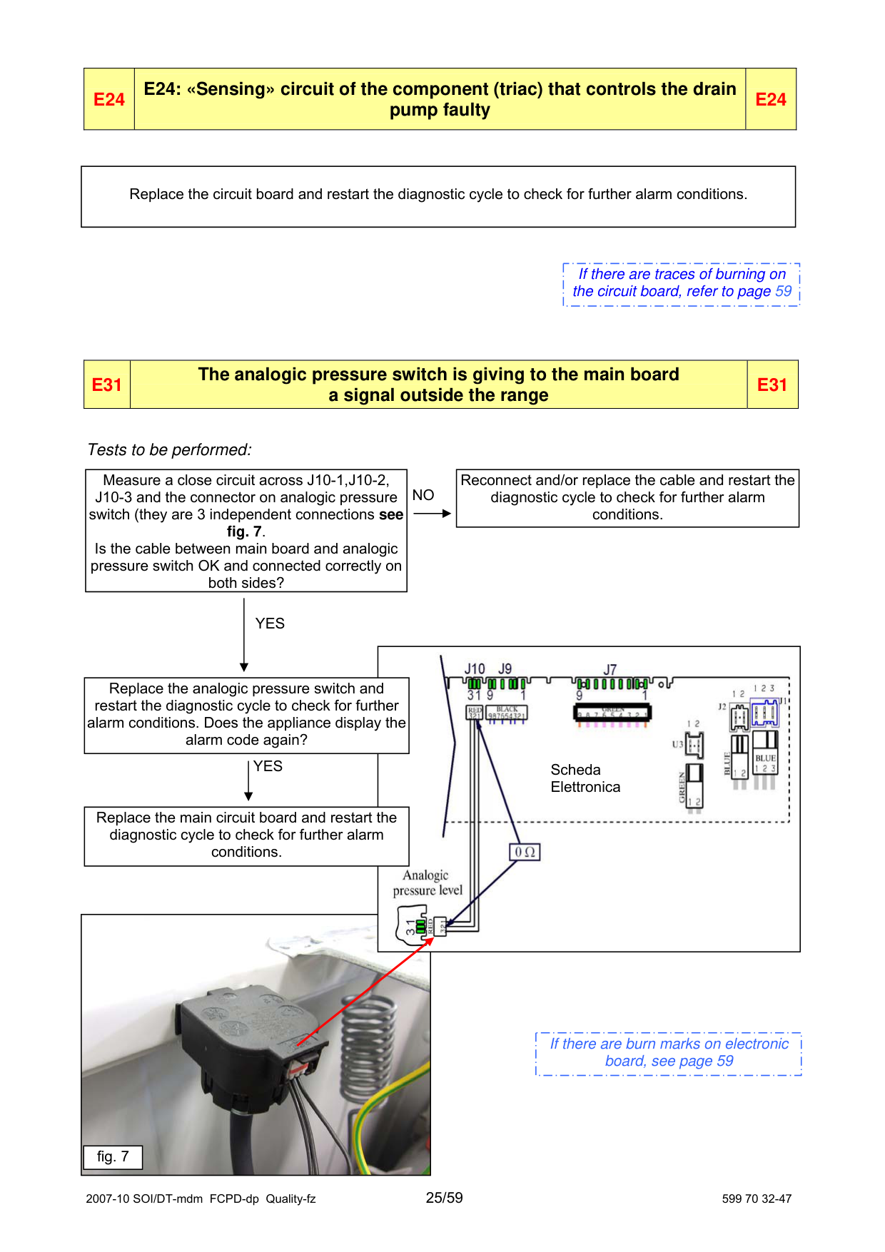
|E24|E24: «Sensing» circuit of the component (triac) that controls the drain pump faulty
|E24| |---|---|---|
|Replace the circuit board and restart the diagnostic cycle to check for further alarm conditions.| |---|
|If there are traces of burning on the circuit board, refer to page 59| |---|
|E31|The analogic pressure switch is giving to the main board a signal outside the range
|E31| |---|---|---|
###### Tests to be performed:
|Measure a close circuit across J10-1,J10-2, J10-3 and the connector on analogic pressure switch (they are 3 independent connections see fig. 7. Is the cable between main board and analogic pressure switch OK and connected correctly on both sides?| |---|
|Reconnect and/or replace the cable and restart the diagnostic cycle to check for further alarm conditions.| |---|
NO
|YES| |---|

Replace the analogic pressure switch and restart the diagnostic cycle to check for further alarm conditions. Does the appliance display the alarm code again?
YES
Scheda Elettronica
Replace the main circuit board and restart the diagnostic cycle to check for further alarm conditions.

|If there are burn marks on electronic board, see page 59| |---|
|fig. 7| |---|
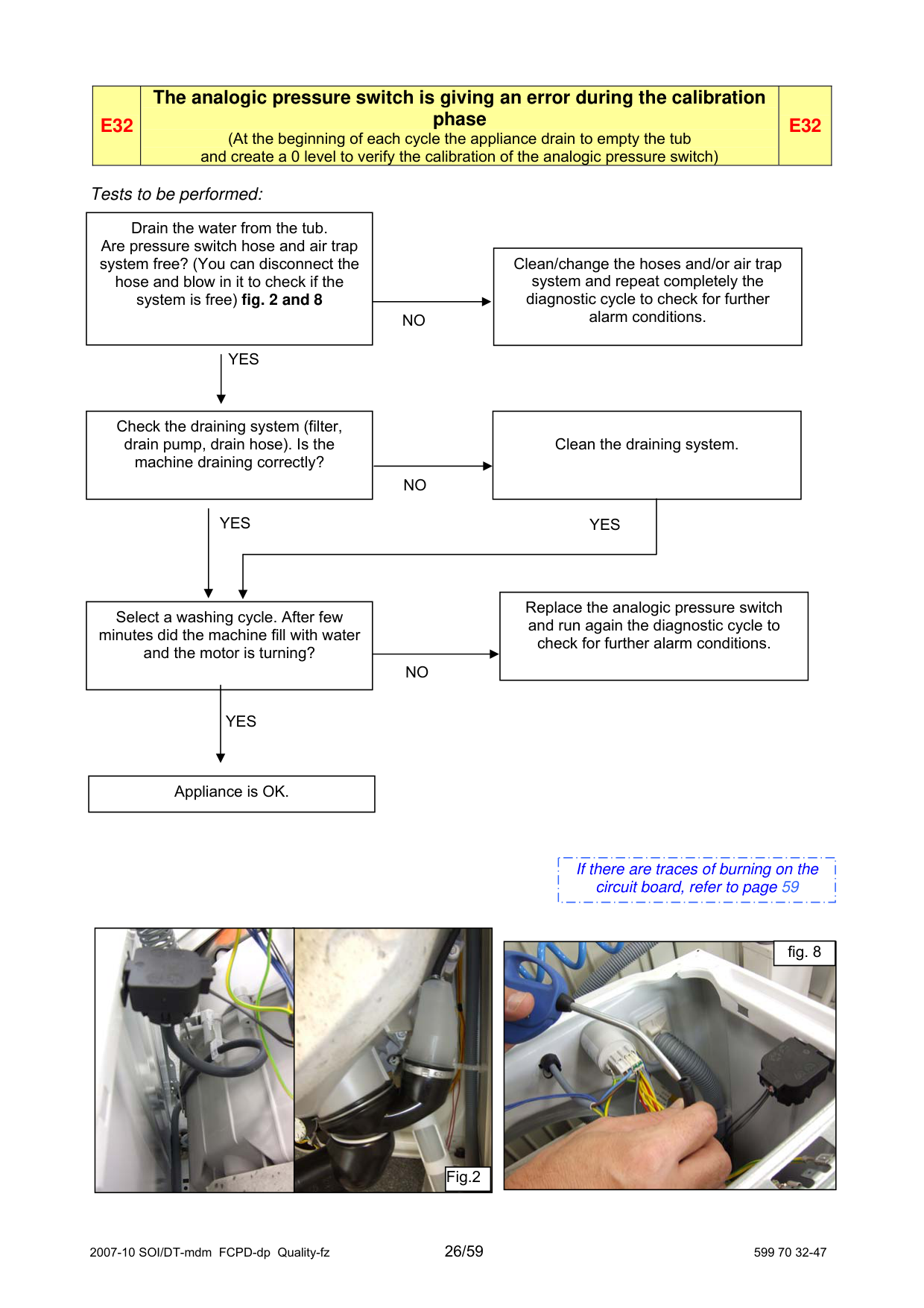
|E32|The analogic pressure switch is giving an error during the calibration phase (At the beginning of each cycle the appliance drain to empty the tub and create a 0 level to verify the calibration of the analogic pressure switch)
|E32| |---|---|---|
###### Tests to be performed:
|Drain the water from the tub. Are pressure switch hose and air trap system free? (You can disconnect the hose and blow in it to check if the system is free) fig. 2 and 8| |---|
|Clean/change the hoses and/or air trap system and repeat completely the diagnostic cycle to check for further alarm conditions.| |---|
NO
|YES| |---|
|Check the draining system (filter, drain pump, drain hose). Is the machine draining correctly?| |---|
Clean the draining system.
NO
YESYES
|Replace the analogic pressure switch and run again the diagnostic cycle to check for further alarm conditions.| |---|
|Select a washing cycle. After few minutes did the machine fill with water and the motor is turning?| |---|
NO
|YES| |---|
|Appliance is OK.| |---|
|If there are traces of burning on the circuit board, refer to page 59| |---|


Fig.2
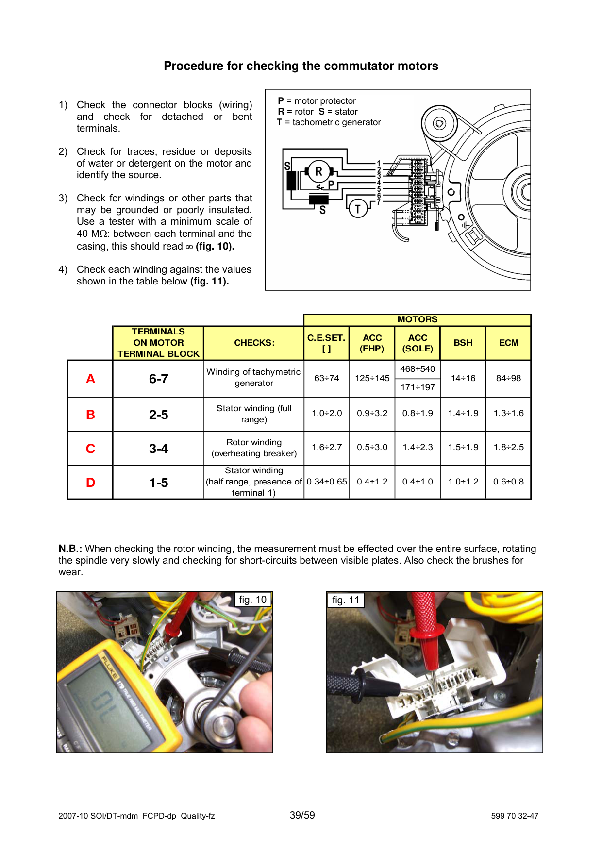

fig. 8
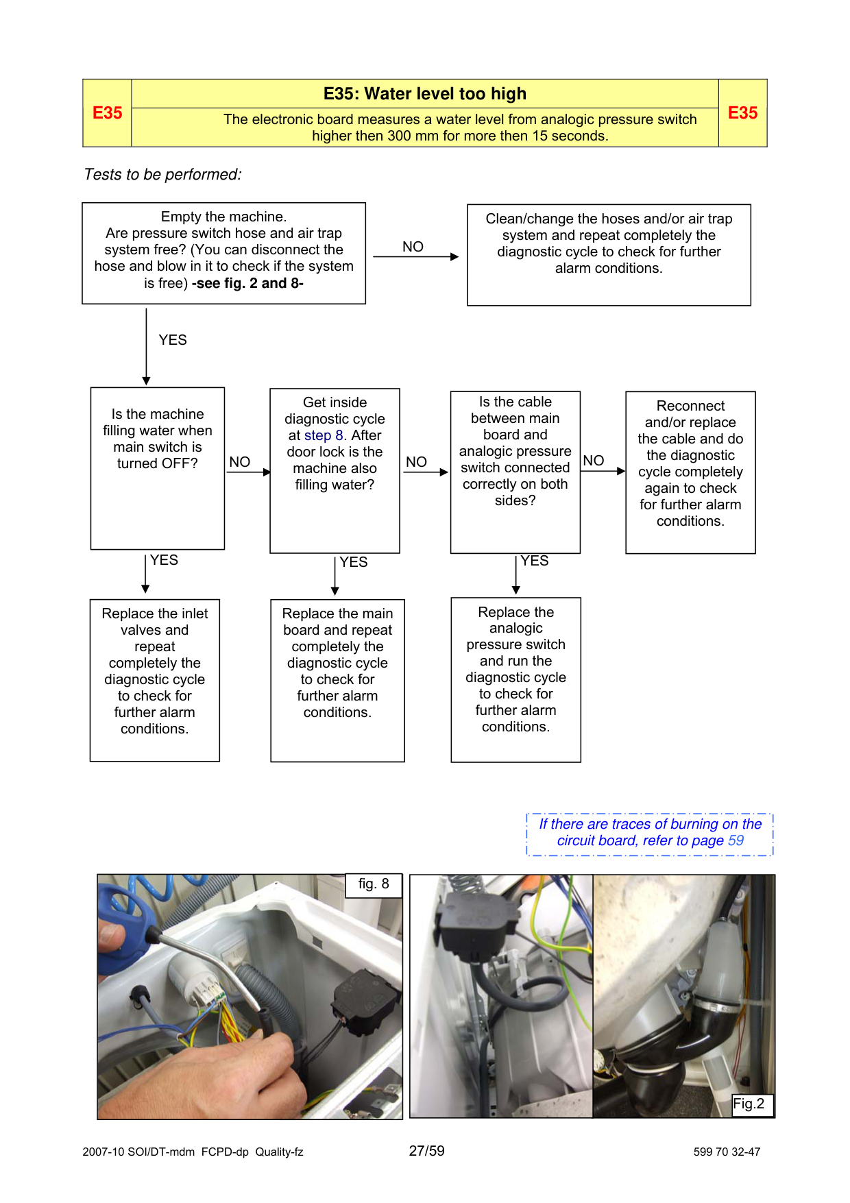
|E35
|E35: Water level too high|E35| |---|---|---| |E35
|The electronic board measures a water level from analogic pressure switch higher then 300 mm for more then 15 seconds.
|E35|
###### Tests to be performed:
|Empty the machine. Are pressure switch hose and air trap system free? (You can disconnect the hose and blow in it to check if the system is free) -see fig. 2 and 8-| |---|
|Clean/change the hoses and/or air trap system and repeat completely the diagnostic cycle to check for further alarm conditions.| |---|
NO
|YES| |---|
|Reconnect and/or replace the cable and do the diagnostic cycle completely again to check for further alarm conditions.| |---|
Is the cable between main board and analogic pressure switch connected correctly on both sides?
Get inside diagnostic cycle at step 8. After door lock is the machine also filling water?
Is the machine filling water when main switch is turned OFF?
NONONO
YES
YES YES
Replace the analogic pressure switch and run the diagnostic cycle to check for further alarm conditions.
Replace the inlet valves and repeat completely the diagnostic cycle to check for further alarm conditions.
Replace the main board and repeat completely the diagnostic cycle to check for further alarm conditions.
|If there are traces of burning on the circuit board, refer to page 59| |---|


fig. 8
Fig.2
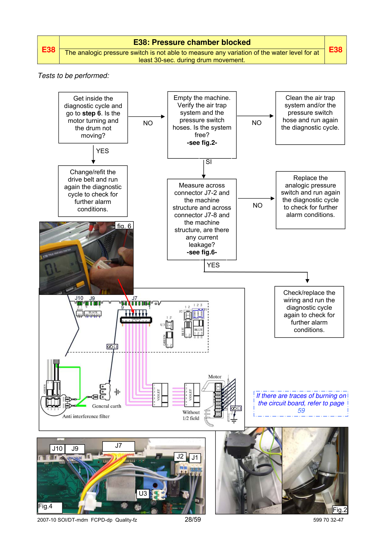
|E38
|E38: Pressure chamber blocked|E38| |---|---|---| |E38
|The analogic pressure switch is not able to measure any variation of the water level for at least 30-sec. during drum movement.
|E38|
###### Tests to be performed:
|Clean the air trap system and/or the pressure switch hose and run again the diagnostic cycle.| |---|
|Get inside the diagnostic cycle and go to step 6. Is the motor turning and the drum not moving?| |---|
Empty the machine. Verify the air trap system and the pressure switch hoses. Is the system free? -see fig.2-
NO NO
YES
SI
Change/refit the drive belt and run again the diagnostic cycle to check for further alarm conditions.
|Replace the analogic pressure switch and run again the diagnostic cycle to check for further alarm conditions.| |---|
Measure across connector J7-2 and the machine structure and across connector J7-8 and the machine structure, are there any current leakage? -see fig.6-
NO

fig. 6
YES
|Check/replace the wiring and run the diagnostic cycle again to check for further alarm conditions.| |---|

|If there are traces of burning on the circuit board, refer to page 59| |---|


|
|J10|J9| |---|---|
|J7| |---|
|J2| |---|
|J1| |---|
|U3| |---|
|Fig.4| |---| | |---|
Fig.2
|E3A|E3A: Problems with “Sensing” circuit of the heating element relay|E3A| |---|---|---|
###### Tests to be performed:
|Replace the circuit board and run the diagnostic cycle again to check for further alarm conditions.| |---|
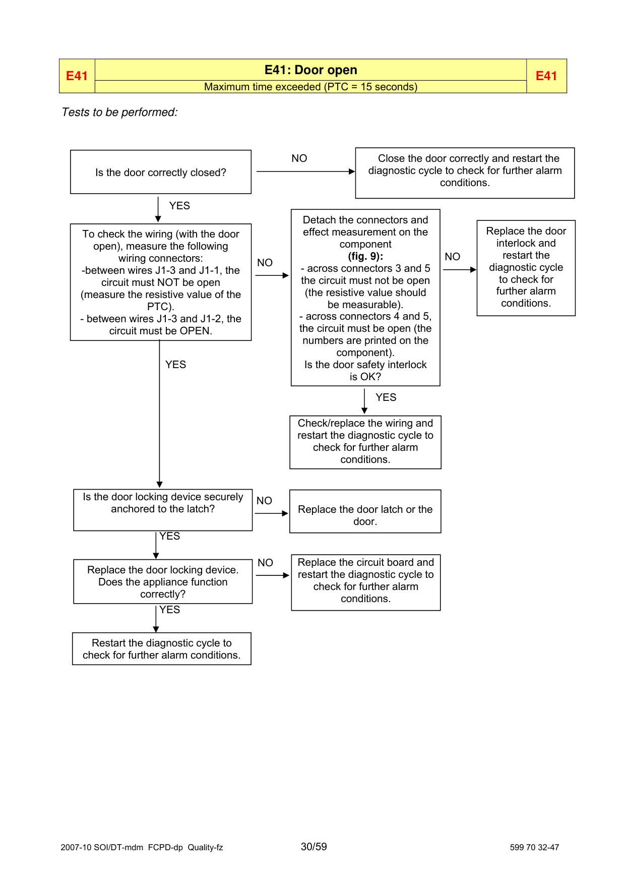
|E41|E41: Door open|E41| |---|---|---| |E41|Maximum time exceeded (PTC = 15 seconds)|E41|
###### Tests to be performed:
|Close the door correctly and restart the
diagnostic cycle to check for further alarm conditions.| |---|
|Is the door correctly closed?| |---|
NO
|YES| |---|
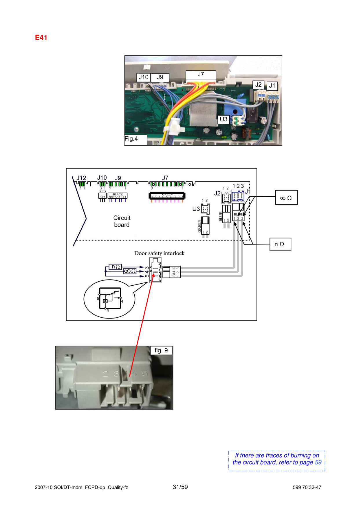
|Detach the connectors and effect measurement on the component (fig. 9):
- across connectors 3 and 5 the circuit must not be open
(the resistive value should be measurable).
- across connectors 4 and 5, the circuit must be open (the
numbers are printed on the component). Is the door safety interlock is OK?| |---|
|Replace the door interlock and restart the diagnostic cycle to check for further alarm conditions.| |---|
|To check the wiring (with the door open), measure the following wiring connectors: -between wires J1-3 and J1-1, the circuit must NOT be open (measure the resistive value of the PTC). - between wires J1-3 and J1-2, the circuit must be OPEN.| |---|
NO
NO
|YES| |---|
|YES| |---|
|Check/replace the wiring and restart the diagnostic cycle to check for further alarm conditions.| |---|
|Replace the door latch or the door.| |---|
Is the door locking device securely anchored to the latch?
NO
YES
|Replace the circuit board and restart the diagnostic cycle to check for further alarm conditions.| |---|
NO
Replace the door locking device. Does the appliance function correctly?
YES
Restart the diagnostic cycle to check for further alarm conditions.
#### E41

|J7| |---|
|J10|J9| |---|---|
|J2| |---|
|J1| |---|
|U3| |---|
Fig.4
|
Circuit board
| |---|
|∞ Ω| |---|
|n Ω| |---|
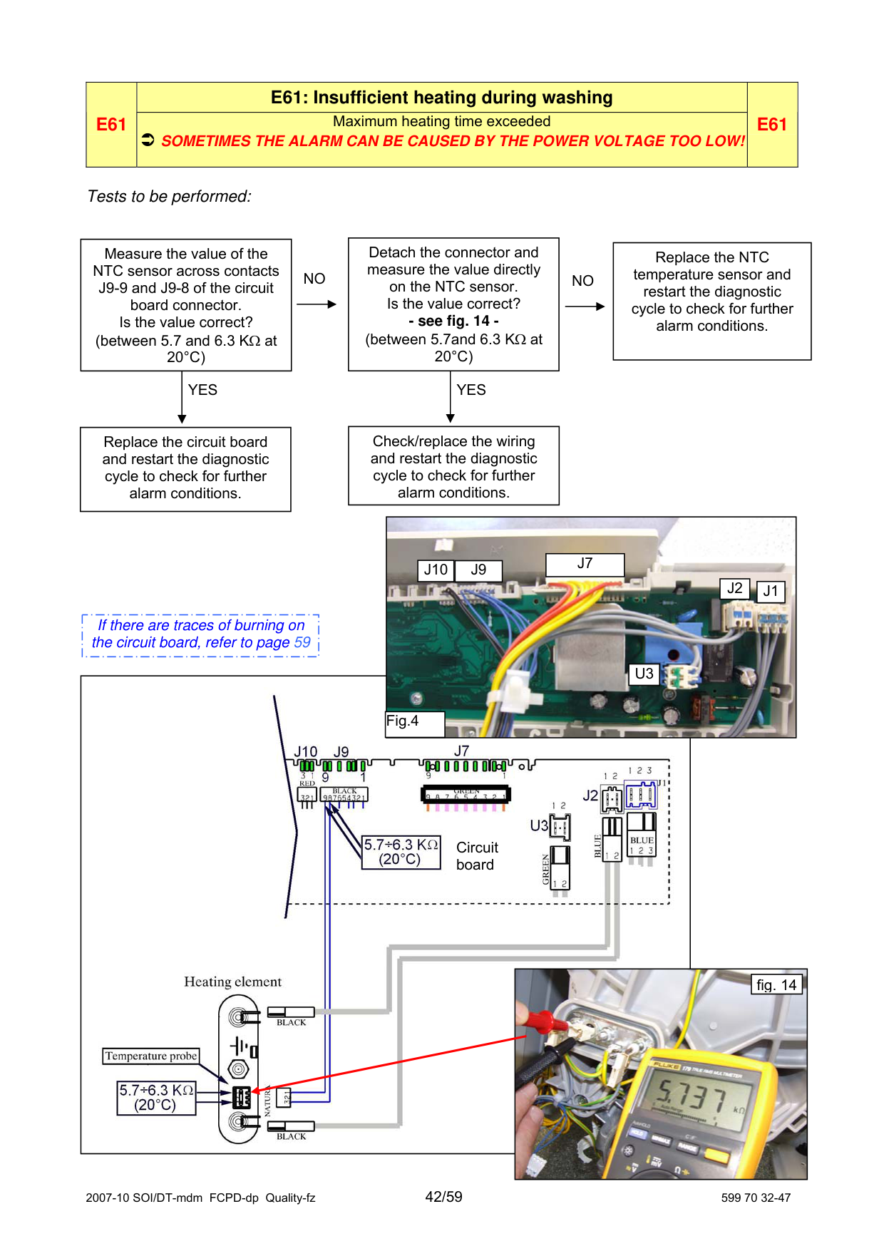

fig. 9
|If there are traces of burning on the circuit board, refer to page 59| |---|
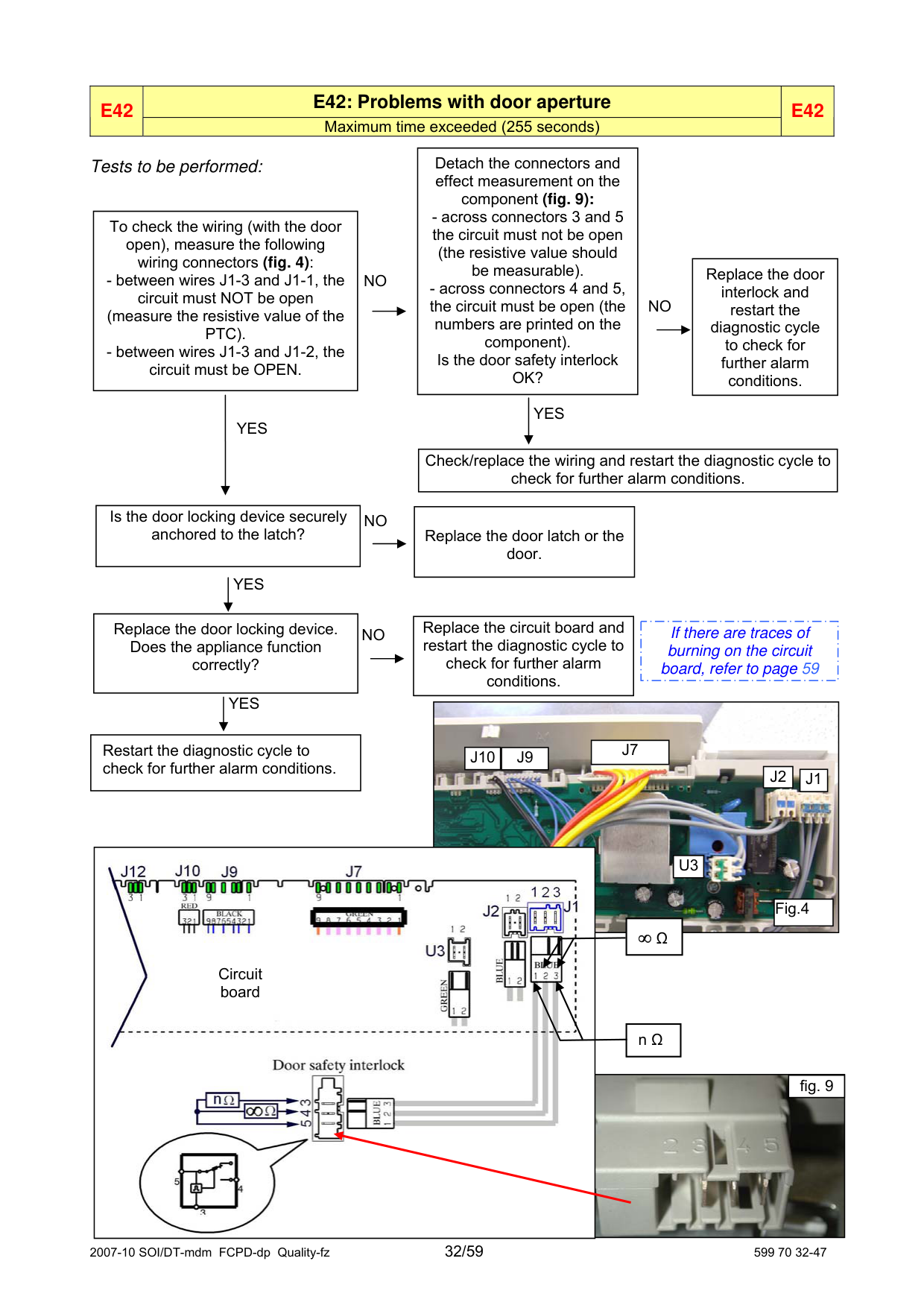
|E42|E42: Problems with door aperture|E42| |---|---|---| |E42|Maximum time exceeded (255 seconds)|E42|
|Detach the connectors and effect measurement on the component (fig. 9):
- across connectors 3 and 5 the circuit must not be open
(the resistive value should be measurable).
- across connectors 4 and 5, the circuit must be open (the
numbers are printed on the component). Is the door safety interlock OK?| |---|
Tests to be performed:
|To check the wiring (with the door open), measure the following wiring connectors (fig. 4):
- between wires J1-3 and J1-1, the circuit must NOT be open
(measure the resistive value of the PTC).
- between wires J1-3 and J1-2, the circuit must be OPEN.
| |---|
|Replace the door interlock and restart the diagnostic cycle to check for further alarm conditions.| |---|
NO
NO
YES
|YES| |---|
Check/replace the wiring and restart the diagnostic cycle to check for further alarm conditions.
|Is the door locking device securely anchored to the latch?| |---|
|Replace the door latch or the door.| |---|
NO
YES
|Replace the circuit board and restart the diagnostic cycle to check for further alarm conditions.| |---|
Replace the door locking device. Does the appliance function correctly?
|If there are traces of burning on the circuit board, refer to page 59| |---|
NO
YES

|J7| |---|
Restart the diagnostic cycle to check for further alarm conditions.
|J10|J9| |---|---|
|J2| |---|
|J1| |---|

|U3| |---|
|Fig.4| |---|
#### ∞ Ω
Circuit board
|n Ω| |---|

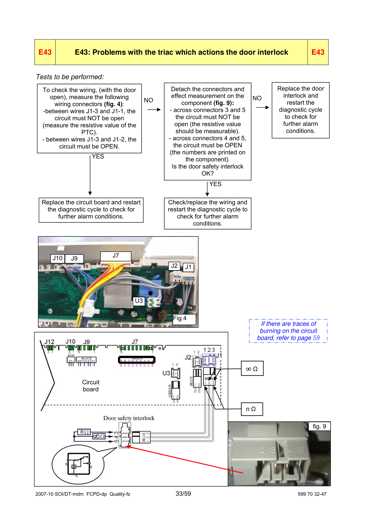
|E43|E43: Problems with the triac which actions the door interlock|E43| |---|---|---|
Tests to be performed:
|Replace the door interlock and restart the diagnostic cycle to check for further alarm conditions.| |---|
Detach the connectors and effect measurement on the component (fig. 9):
To check the wiring, (with the door open), measure the following wiring connectors (fig. 4): -between wires J1-3 and J1-1, the circuit must NOT be open (measure the resistive value of the PTC). - between wires J1-3 and J1-2, the circuit must be OPEN.
NO
NO
(the numbers are printed on the component). Is the door safety interlock OK?
YES
YES
Replace the circuit board and restart the diagnostic cycle to check for further alarm conditions.
Check/replace the wiring and restart the diagnostic cycle to check for further alarm conditions.
|
|J10|J9| |---|---|
|J7| |---|
|J2| |---|
|J1| |---|
|U3| |---|
|Fig.4| |---| | |---|
|If there are traces of burning on the circuit board, refer to page 59| |---|

|∞ Ω| |---|
Circuit board
|n Ω| |---|


|E44|E44: Door closure «sensing» circuit faulty|E44| |---|---|---|
###### Tests to be performed:
|Replace the circuit board and restart the diagnostic cycle to check for further alarm conditions.| |---|
|E45|E45: Problems with the «sensing» circuit of the triac that actions the door interlock
|E45| |---|---|---|
###### Tests to be performed:
|Replace the circuit board and restart the diagnostic cycle to check for further alarm conditions.| |---|
|If there are traces of burning on the circuit board, refer to page 59| |---|
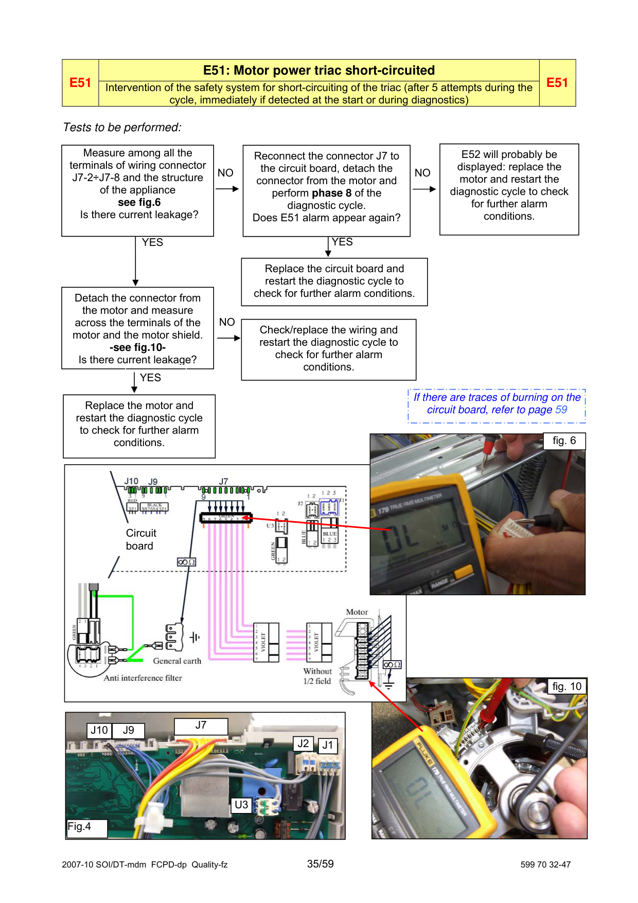
|E52 will probably be displayed: replace the motor and restart the diagnostic cycle to check for further alarm conditions.| |---|
Measure among all the terminals of wiring connector J7-2÷J7-8 and the structure of the appliance see fig.6 Is there current leakage?
Reconnect the connector J7 to the circuit board, detach the connector from the motor and perform phase 8 of the diagnostic cycle. Does E51 alarm appear again?
NO NO
YESYES
Replace the circuit board and restart the diagnostic cycle to check for further alarm conditions.
Detach the connector from the motor and measure across the terminals of the motor and the motor shield. -see fig.10Is there current leakage?
NO
|Check/replace the wiring and restart the diagnostic cycle to check for further alarm conditions.| |---|
YES
|If there are traces of burning on the circuit board, refer to page 59| |---|
Replace the motor and restart the diagnostic cycle to check for further alarm conditions.

fig. 6

Circuit board

fig. 10
|
|J10|J9| |---|---|
|J7| |---|
|J2| |---|
|J1| |---|
|U3| |---|
|Fig.4| |---| | |---|
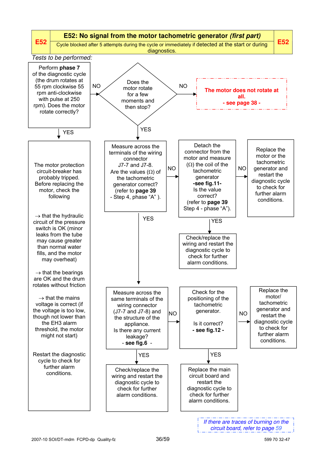
|Perform phase 7 of the diagnostic cycle (the drum rotates at 55 rpm clockwise 55 rpm anti-clockwise with pulse at 250 rpm). Does the motor rotate correctly?| |---|
|The motor does not rotate at all. - see page 38 -| |---|
Does the motor rotate for a few moments and then stop?
NO
NO
|YES| |---|
|YES| |---|
|Replace the motor or the tachometric generator and restart the diagnostic cycle to check for further alarm conditions.| |---|
|The motor protection circuit-breaker has probably tripped. Before replacing the motor, check the following
→ that the hydraulic circuit of the pressure switch is OK (minor leaks from the tube may cause greater than normal water fills, and the motor may overheat)
→ that the bearings are OK and the drum rotates without friction
→ that the mains voltage is correct (if the voltage is too low, though not lower than the EH3 alarm threshold, the motor might not start)
Restart the diagnostic cycle to check for further alarm conditions.| |---|
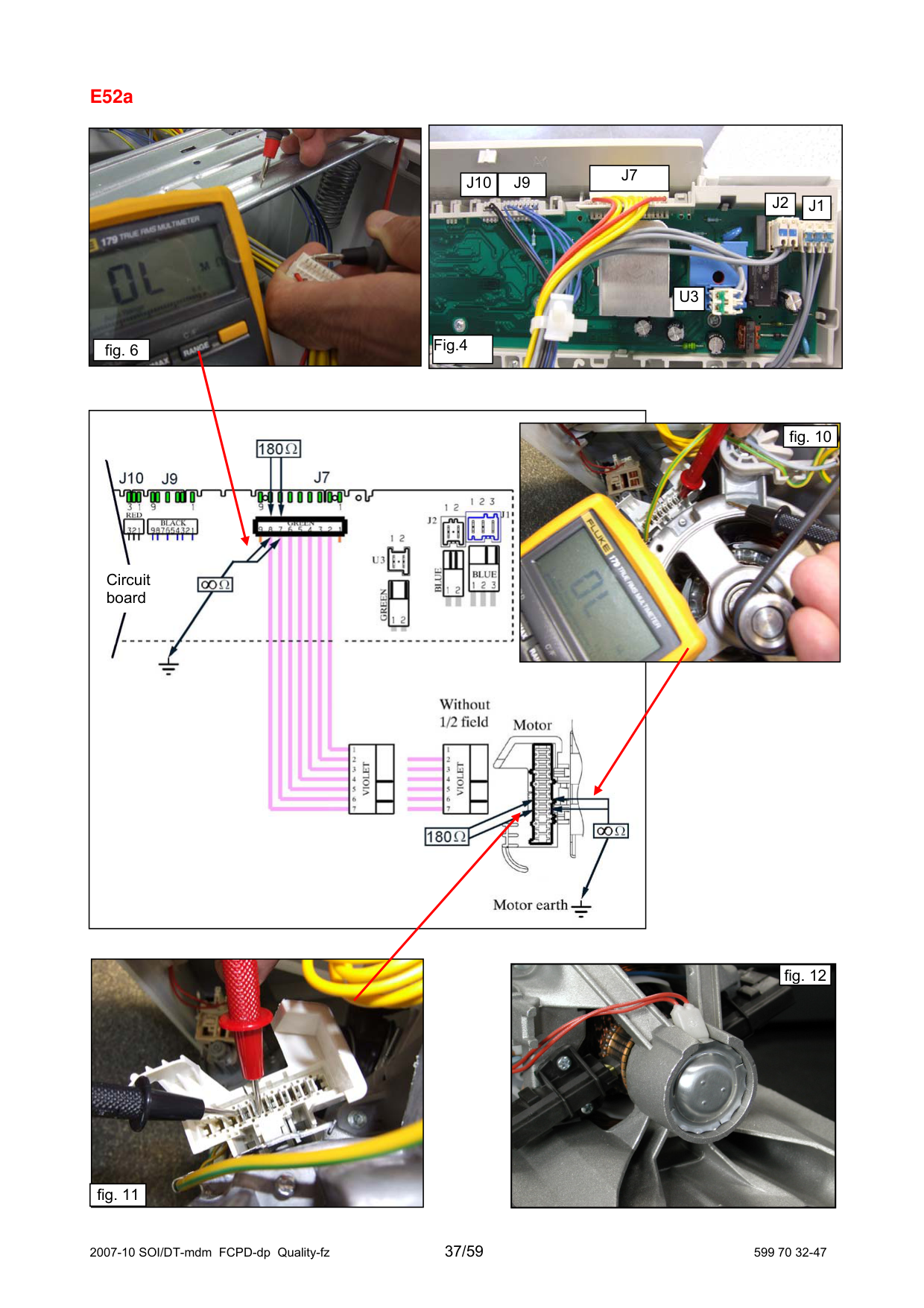
|Measure across the terminals of the wiring connector J7-7 and J7-8. Are the values (Ω) of the tachometric generator correct? (refer to page 39 - Step 4, phase “A” ).| |---|
Detach the connector from the motor and measure (Ω) the coil of the tachometric generator -see fig.11Is the value correct? (refer to page 39 Step 4 - phase “A”).
NO
NO
|YES| |---|
YES
Check/replace the wiring and restart the diagnostic cycle to check for further alarm conditions.
|Replace the motor/ tachometric generator and restart the diagnostic cycle to check for further alarm conditions.| |---|
|Check for the positioning of the tachometric generator.
Is it correct? - see fig.12 -| |---|
|Measure across the same terminals of the wiring connector (J7-7 and J7-8) and the structure of the appliance. Is there any current leakage? - see fig.6 -| |---|
NO
NO
|YES
| |---|
|YES| |---|
|Replace the main circuit board and restart the diagnostic cycle to check for further alarm conditions.| |---|
|Check/replace the wiring and restart the diagnostic cycle to check for further alarm conditions.| |---|
|If there are traces of burning on the circuit board, refer to page 59| |---|
#### E52a
|
|J10|J9| |---|---|
|J7| |---|
|J2| |---|
|J1| |---|
|U3| |---|
|Fig.4| |---| | |---|
|
|fig. 6| |---| | |---|


|fig. 10| |---|
Circuit board


fig. 12
fig. 11
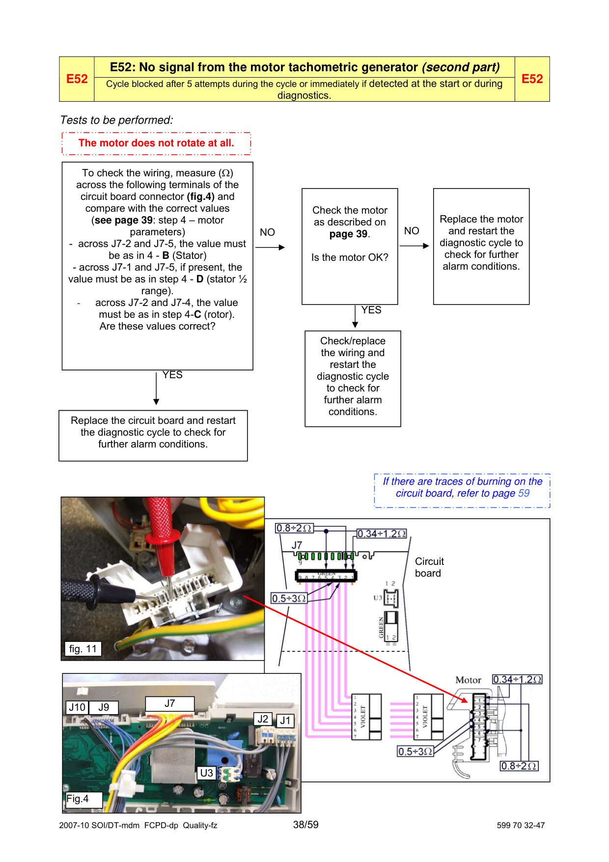
|The motor does not rotate at all.| |---|
To check the wiring, measure (Ω) across the following terminals of the circuit board connector (fig.4) and compare with the correct values (see page 39: step 4 – motor parameters)
|Replace the motor and restart the diagnostic cycle to check for further alarm conditions.| |---|
Check the motor as described on page 39.
NO
NO
Is the motor OK?
value must be as in step 4 - D (stator ½ range). - across J7-2 and J7-4, the value must be as in step 4-C (rotor). Are these values correct?
YES
Check/replace the wiring and restart the diagnostic cycle to check for further alarm conditions.
YES
Replace the circuit board and restart the diagnostic cycle to check for further alarm conditions.
|If there are traces of burning on the circuit board, refer to page 59| |---|


Circuit board
|fig. 11| |---|

|J7| |---|
|J10|J9| |---|---|
J2
|J1| |---|
|U3| |---|
|Fig.4| |---|
#### Procedure for checking the commutator motors
|
P = motor protector R = rotor S = stator T = tachometric generator| |---|
A
######### MOTORS
TERMINALS ON MOTOR TERMINAL BLOCK
C.E.SET. [ ]
ACC (FHP)
ACC (SOLE)
CHECKS:
BSH ECM
468÷540 171÷197
6-7 Winding of tachymetricgenerator 63÷74 125÷145 14÷16 84÷98
Stator winding (half range, presence of terminal 1)
0.34÷0.65 0.4÷1.2 0.4÷1.0 1.0÷1.2 0.6÷0.8
N.B.: When checking the rotor winding, the measurement must be effected over the entire surface, rotating the spindle very slowly and checking for short-circuits between visible plates. Also check the brushes for wear.
|
|fig. 10| |---| | |---|
|
|fig. 11| |---| | |---|
|E53|E53: Problems with the "Sensing" circuit of the triac which powers the motor
|E53| |---|---|---|
###### Tests to be performed:
|Replace the circuit board and restart the diagnostic cycle to check for further alarm conditions.| |---|
|If there are traces of burning on the circuit board, refer to page 59| |---|
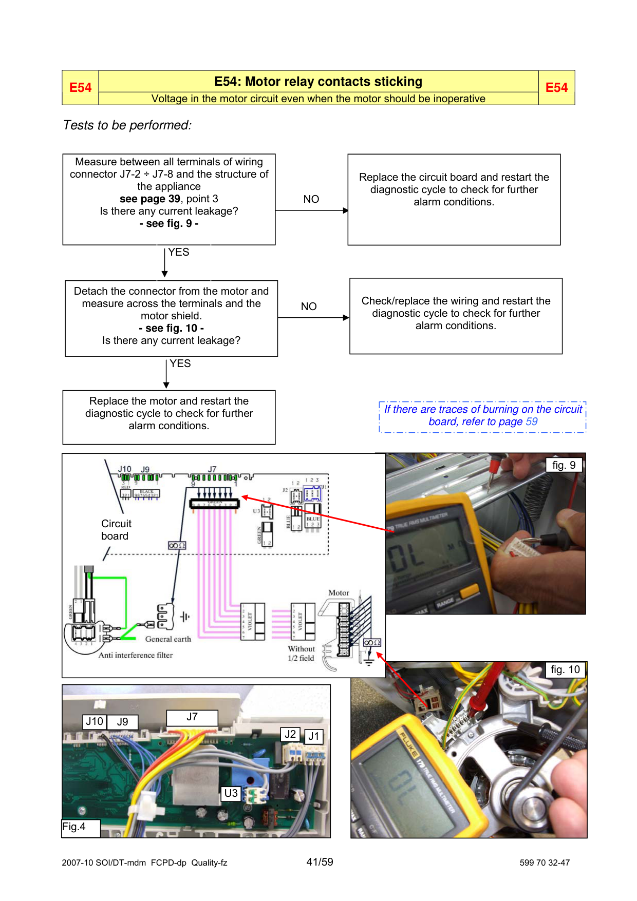
|E54
|E54: Motor relay contacts sticking|E54| |---|---|---| |E54
|Voltage in the motor circuit even when the motor should be inoperative|E54|
##### Tests to be performed:
|Replace the circuit board and restart the diagnostic cycle to check for further alarm conditions.| |---|
Measure between all terminals of wiring connector J7-2 ÷ J7-8 and the structure of the appliance see page 39, point 3 Is there any current leakage? - see fig. 9 -
NO
YES
|Check/replace the wiring and restart the diagnostic cycle to check for further alarm conditions.| |---|
Detach the connector from the motor and measure across the terminals and the motor shield. - see fig. 10 Is there any current leakage?
NO
YES
Replace the motor and restart the diagnostic cycle to check for further alarm conditions.
|If there are traces of burning on the circuit board, refer to page 59| |---|


|fig. 9| |---|
Circuit board

fig. 10

|J7| |---|
|J10|J9| |---|---|
|J2| |---|
|J1| |---|
|U3| |---|
Fig.4
|E61|E61: Insufficient heating during washing|E61
| |---|---|---| |E61|Maximum heating time exceeded
SOMETIMES THE ALARM CAN BE CAUSED BY THE POWER VOLTAGE TOO LOW!
|E61
|
###### Tests to be performed:
|Detach the connector and measure the value directly on the NTC sensor. Is the value correct? - see fig. 14 (between 5.7and 6.3 KΩ at 20°C)| |---|
|Measure the value of the NTC sensor across contacts J9-9 and J9-8 of the circuit board connector. Is the value correct? (between 5.7 and 6.3 KΩ at 20°C)| |---|
|Replace the NTC temperature sensor and restart the diagnostic cycle to check for further alarm conditions.| |---|
NO
NO
|YES| |---|
|YES| |---|
|Check/replace the wiring and restart the diagnostic cycle to check for further alarm conditions.| |---|
|Replace the circuit board and restart the diagnostic cycle to check for further alarm conditions.| |---|

|J7| |---|
|J10|J9| |---|---|
|J2| |---|
|J1| |---|
|If there are traces of burning on the circuit board, refer to page 59| |---|
U3

Fig.4
Circuit board

|fig. 14| |---|
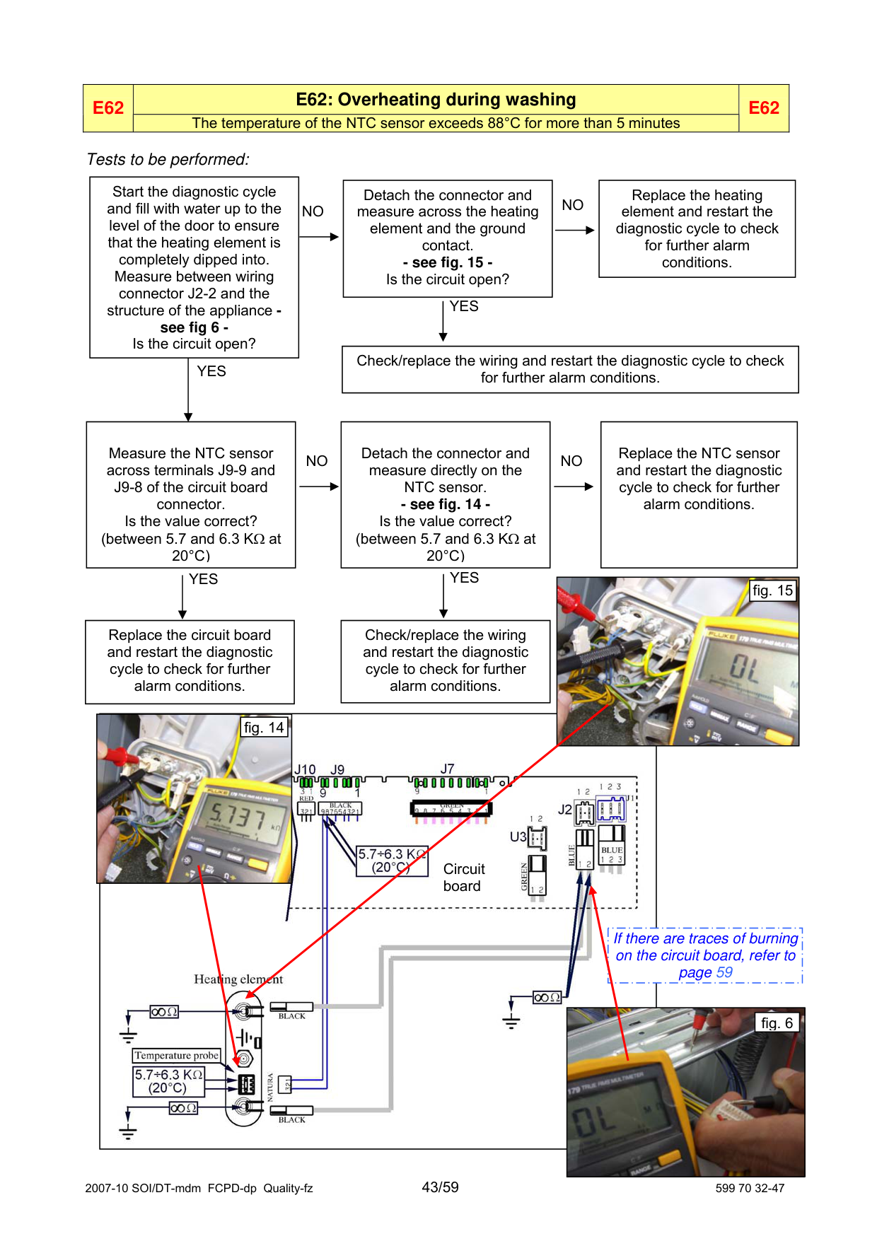
|E62|E62: Overheating during washing|E62
| |---|---|---| |E62|The temperature of the NTC sensor exceeds 88°C for more than 5 minutes|E62
|
###### Tests to be performed:
|Start the diagnostic cycle and fill with water up to the level of the door to ensure that the heating element is completely dipped into. Measure between wiring connector J2-2 and the structure of the appliance see fig 6 Is the circuit open?|Start the diagnostic cycle and fill with water up to the level of the door to ensure that the heating element is completely dipped into. Measure between wiring connector J2-2 and the structure of the appliance see fig 6 Is the circuit open?|Start the diagnostic cycle and fill with water up to the level of the door to ensure that the heating element is completely dipped into. Measure between wiring connector J2-2 and the structure of the appliance see fig 6 Is the circuit open?|
|---|---|---| | |YES| |
|Replace the heating element and restart the diagnostic cycle to check for further alarm conditions.| |---|
Detach the connector and measure across the heating element and the ground contact. - see fig. 15 Is the circuit open?
NO
NO
YES
Check/replace the wiring and restart the diagnostic cycle to check for further alarm conditions.
|Replace the NTC sensor and restart the diagnostic cycle to check for further alarm conditions.| |---|
Measure the NTC sensor across terminals J9-9 and J9-8 of the circuit board connector. Is the value correct? (between 5.7 and 6.3 KΩ at 20°C)
Detach the connector and measure directly on the NTC sensor. - see fig. 14 Is the value correct? (between 5.7 and 6.3 KΩ at 20°C)
NO
NO
YES
YES

|fig. 15| |---|
Replace the circuit board and restart the diagnostic cycle to check for further alarm conditions.
Check/replace the wiring and restart the diagnostic cycle to check for further alarm conditions.


|fig. 14| |---|
Circuit board
If there are traces of burning on the circuit board, refer to page 59

|fig. 6| |---|
|E66|E66: The contacts of the heating element power relay are always closed
|E66| |---|---|---|
###### Tests to be performed:
|Replace the circuit board and restart the diagnostic cycle to check for further alarm conditions.| |---|
Measure across connector J2-1/J2-2 on the circuit board and the structure of the appliance. (Fig. 6) Is there any current leakage?
NO
YES
|Replace the heating element and restart the diagnostic cycle to check for further alarm conditions.| |---|
Detach the connector and measure across the heating element and the ground contact. - fig. 15 Is the circuit open?
NO
YES
|If there are traces of burning on the circuit board, refer to page 59| |---|
Check/replace the wiring and restart the diagnostic cycle to check for further alarm conditions.
fig. 6


|J7| |---|
|J10|J9| |---|---|
|J2| |---|
|J1| |---|
|U3| |---|
Fig.4


fig. 15
Circuit board
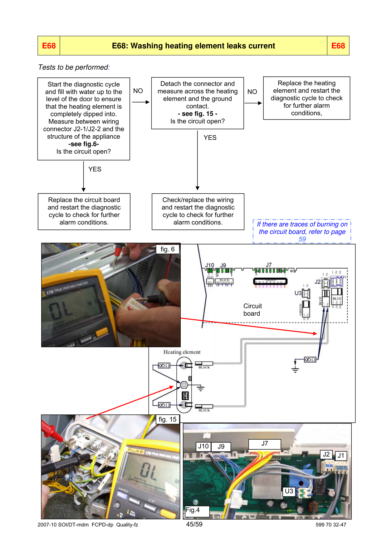
|Replace the heating element and restart the diagnostic cycle to check for further alarm conditions,| |---|
|Detach the connector and measure across the heating element and the ground contact. - see fig. 15 Is the circuit open?| |---|
|Start the diagnostic cycle and fill with water up to the level of the door to ensure that the heating element is completely dipped into. Measure between wiring connector J2-1/J2-2 and the structure of the appliance -see fig.6Is the circuit open?| |---|
NO NO
|YES| |---|
|YES| |---|
|Replace the circuit board and restart the diagnostic cycle to check for further alarm conditions.| |---|
|Check/replace the wiring and restart the diagnostic cycle to check for further alarm conditions.| |---|
|If there are traces of burning on the circuit board, refer to page 59| |---|


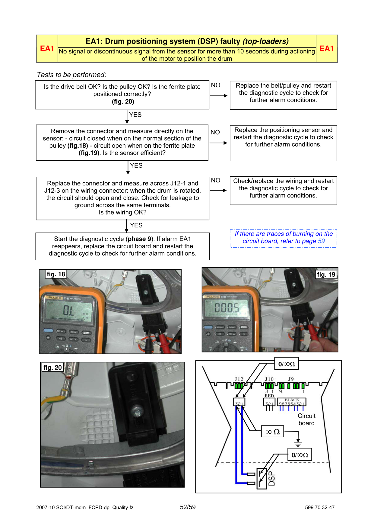
fig. 6
Circuit board

fig. 15
|
|J10|J9| |---|---|
|J7| |---|
|J2| |---|
|J1| |---|
|U3| |---|
|Fig.4| |---| | |---|
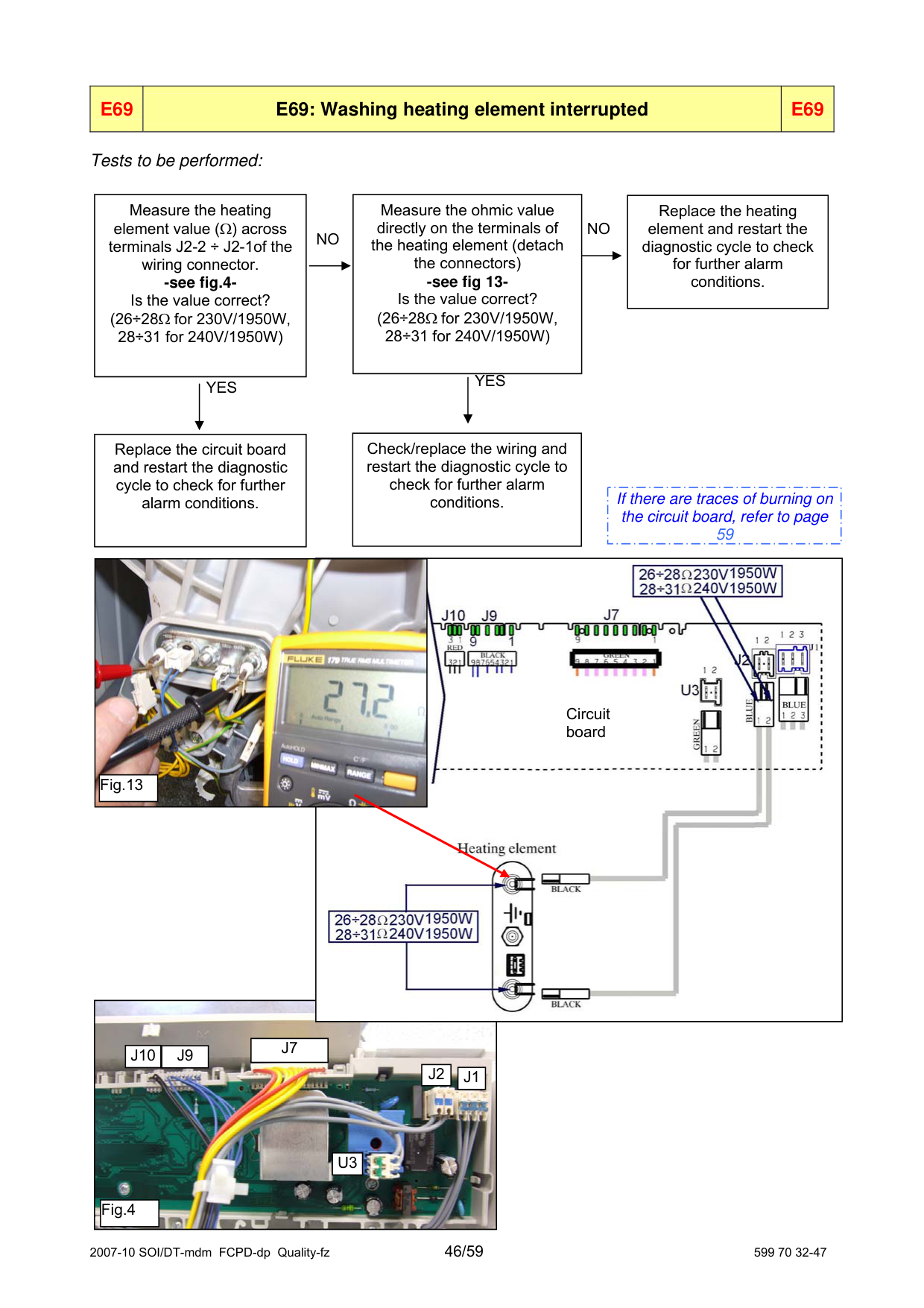
|Replace the heating element and restart the diagnostic cycle to check for further alarm conditions.| |---|
Measure the heating element value (Ω) across terminals J2-2 ÷ J2-1of the wiring connector. -see fig.4Is the value correct? (26÷28Ω for 230V/1950W, 28÷31 for 240V/1950W)
Measure the ohmic value directly on the terminals of the heating element (detach the connectors) -see fig 13Is the value correct? (26÷28Ω for 230V/1950W, 28÷31 for 240V/1950W)
NO
NO
YES
YES
Check/replace the wiring and restart the diagnostic cycle to check for further alarm conditions.
Replace the circuit board and restart the diagnostic cycle to check for further alarm conditions.
|If there are traces of burning on the circuit board, refer to page 59| |---|


Circuit board
|Fig.13| |---|

|J7| |---|
|J10|J9| |---|---|
|J2| |---|
|J1| |---|
|U3| |---|
|Fig.4| |---|
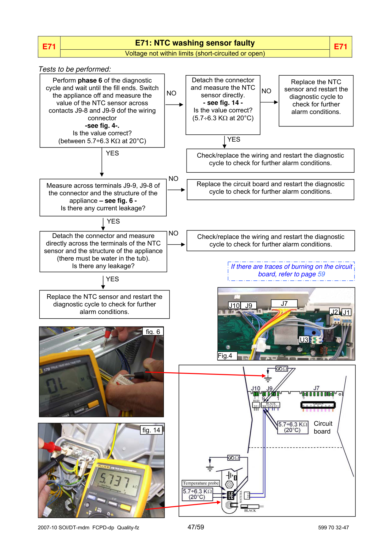
|E71|E71: NTC washing sensor faulty|E71| |---|---|---| |E71|Voltage not within limits (short-circuited or open)|E71|
###### Tests to be performed:
|Perform phase 6 of the diagnostic cycle and wait until the fill ends. Switch the appliance off and measure the value of the NTC sensor across contacts J9-8 and J9-9 dof the wiring connector -see fig. 4-. Is the value correct? (between 5.7÷6.3 KΩ at 20°C)|Perform phase 6 of the diagnostic cycle and wait until the fill ends. Switch the appliance off and measure the value of the NTC sensor across contacts J9-8 and J9-9 dof the wiring connector -see fig. 4-. Is the value correct? (between 5.7÷6.3 KΩ at 20°C)|Perform phase 6 of the diagnostic cycle and wait until the fill ends. Switch the appliance off and measure the value of the NTC sensor across contacts J9-8 and J9-9 dof the wiring connector -see fig. 4-. Is the value correct? (between 5.7÷6.3 KΩ at 20°C)| |---|---|---| | |YES| |
|Replace the NTC sensor and restart the diagnostic cycle to check for further alarm conditions.| |---|
Detach the connector and measure the NTC sensor directly. - see fig. 14 Is the value correct? (5.7÷6.3 KΩ at 20°C)
NONO
YES
Check/replace the wiring and restart the diagnostic cycle to check for further alarm conditions.
NO
|Replace the circuit board and restart the diagnostic cycle to check for further alarm conditions.| |---|
Measure across terminals J9-9, J9-8 of the connector and the structure of the appliance – see fig. 6 Is there any current leakage?
YES
NO
|Check/replace the wiring and restart the diagnostic cycle to check for further alarm conditions.| |---|
Detach the connector and measure directly across the terminals of the NTC sensor and the structure of the appliance (there must be water in the tub). Is there any leakage?
|If there are traces of burning on the circuit board, refer to page 59| |---|
YES

Replace the NTC sensor and restart the diagnostic cycle to check for further alarm conditions.
|J7| |---|
|J10|J9| |---|---|
|J2| |---|
|J1| |---|

fig. 6
|U3| |---|
Fig.4
|
Circuit board| |---|
|
|fig. 14| |---|
| |---|
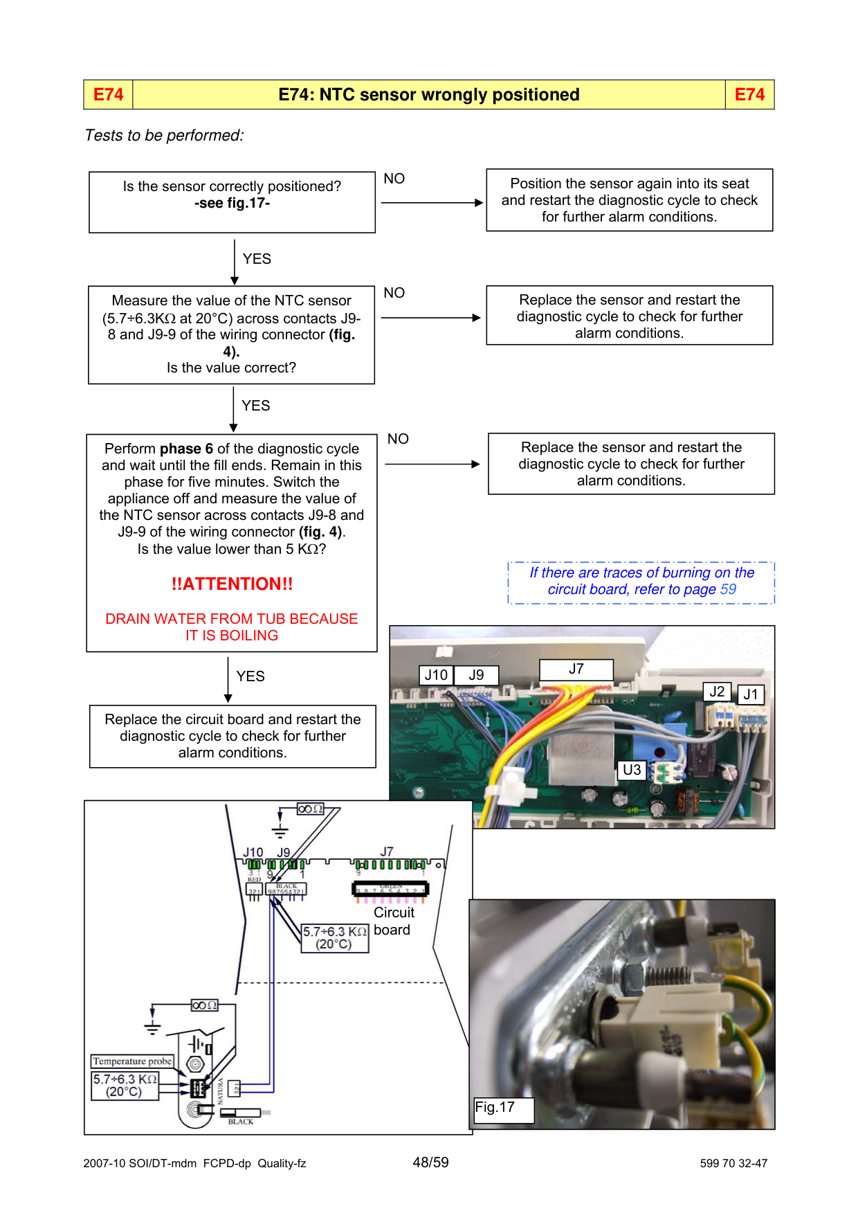
|E74|E74: NTC sensor wrongly positioned|E74| |---|---|---|
###### Tests to be performed:
|Position the sensor again into its seat and restart the diagnostic cycle to check for further alarm conditions.| |---|
NO
|Is the sensor correctly positioned? -see fig.17-| |---|
|YES| |---|
NO
|Replace the sensor and restart the diagnostic cycle to check for further alarm conditions.| |---|
|Measure the value of the NTC sensor (5.7÷6.3KΩ at 20°C) across contacts J98 and J9-9 of the wiring connector (fig. 4). Is the value correct?| |---|
|YES| |---|
NO
|Replace the sensor and restart the diagnostic cycle to check for further alarm conditions.| |---|
|Perform phase 6 of the diagnostic cycle and wait until the fill ends. Remain in this phase for five minutes. Switch the appliance off and measure the value of the NTC sensor across contacts J9-8 and J9-9 of the wiring connector (fig. 4). Is the value lower than 5 KΩ?
!!ATTENTION!! DRAIN WATER FROM TUB BECAUSE IT IS BOILING| |---|
|If there are traces of burning on the circuit board, refer to page 59| |---|

|J7| |---|
|YES| |---|
|J10|J9| |---|---|
|J2| |---|
|J1| |---|
|Replace the circuit board and restart the diagnostic cycle to check for further alarm conditions.| |---|
|U3| |---|


Circuit board
|Fig.17| |---|
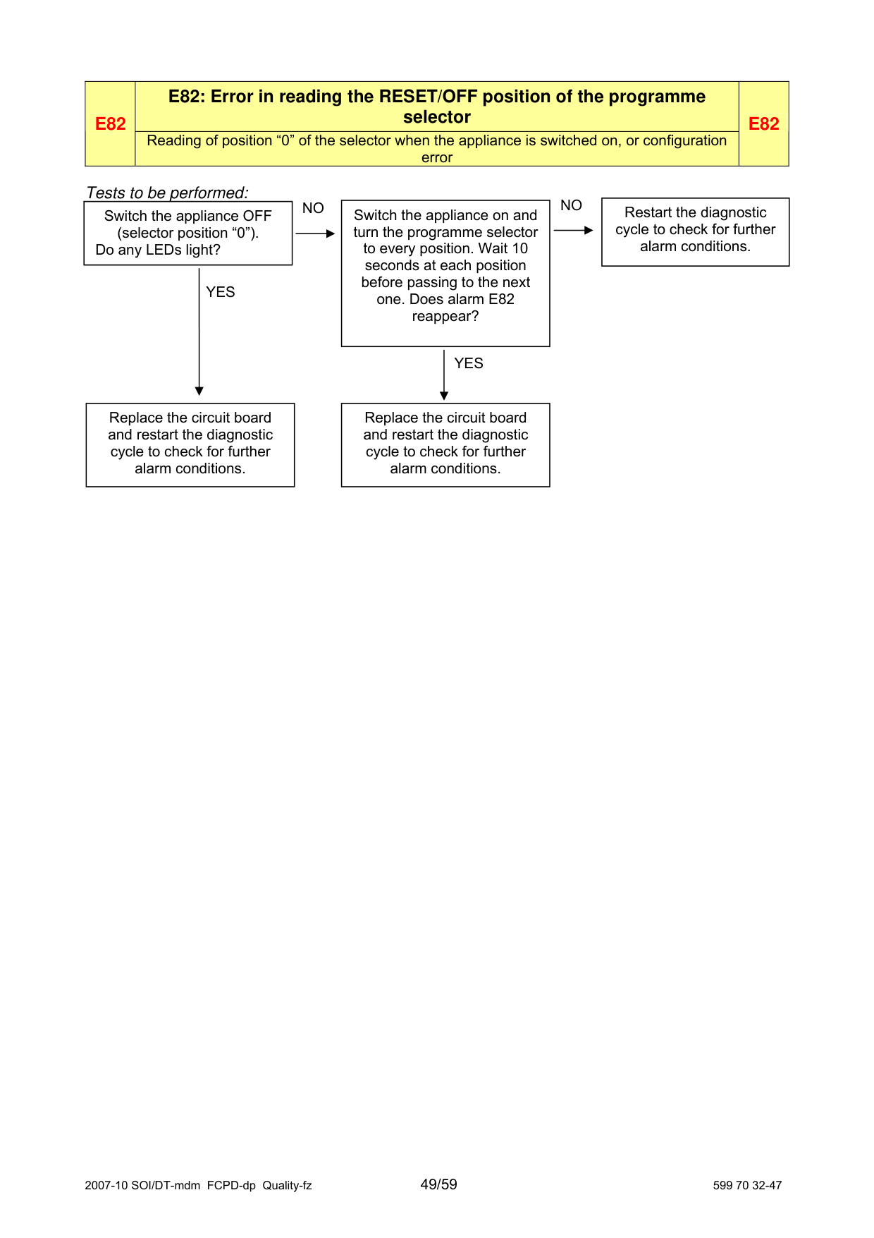
|E82|E82: Error in reading the RESET/OFF position of the programme selector
|E82| |---|---|---| |E82|Reading of position “0” of the selector when the appliance is switched on, or configuration error
|E82|
###### Tests to be performed:
NONO
|Restart the diagnostic cycle to check for further alarm conditions.| |---|
|Switch the appliance on and turn the programme selector to every position. Wait 10 seconds at each position before passing to the next one. Does alarm E82 reappear?| |---|
|Switch the appliance OFF (selector position “0”). Do any LEDs light?| |---|
|YES| |---|
|YES| |---|
|Replace the circuit board and restart the diagnostic cycle to check for further alarm conditions.| |---|
||SI| |---|
Replace the circuit board and restart the diagnostic cycle to check for further alarm conditions.| |---|
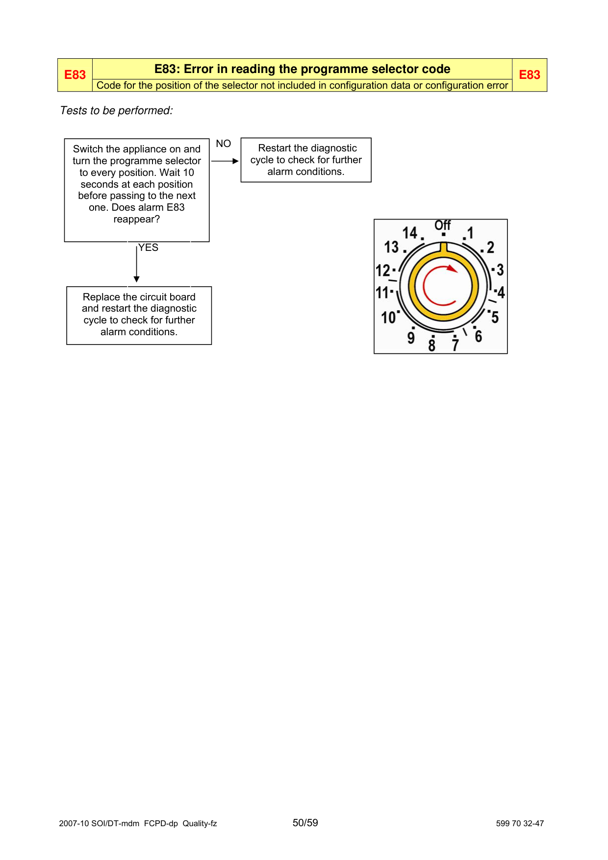
|E83|E83: Error in reading the programme selector code|E83| |---|---|---| |E83|Code for the position of the selector not included in configuration data or configuration error|E83|
###### Tests to be performed:
|Restart the diagnostic cycle to check for further alarm conditions.| |---|
NO
Switch the appliance on and turn the programme selector to every position. Wait 10 seconds at each position before passing to the next one. Does alarm E83 reappear?
|| |---|
YES
Replace the circuit board and restart the diagnostic cycle to check for further alarm conditions.
|E93|E93: Incorrect machine configuration|E93| |---|---|---| |E93|Incongruence in configuration values when switching on|E93|
Tests to be performed:
|Possible configuration error Replace the circuit board and restart the diagnostic cycle to check for further alarm conditions.| |---|
|E94|E94: Incorrect configuration of washing cycle|E94| |---|---|---| |E94|Incongruence in configuration values when switching on|E94|
Tests to be performed:
|Possible configuration error Replace the circuit board and restart the diagnostic cycle to check for further alarm conditions.| |---|
|E97|E97: Incongruence between selector version and configuration data|E97| |---|---|---| |E97|Difference between the configuration data for the programmes and those for recognition of the selector
|E97|
Tests to be performed:
|Possible configuration error Replace the circuit board and restart the diagnostic cycle to check for further alarm conditions.| |---|
|Is the drive belt OK? Is the pulley OK? Is the ferrite plate positioned correctly? (fig. 20)| |---|
|Replace the belt/pulley and restart the diagnostic cycle to check for further alarm conditions.| |---|
NO
| |YES| |---|---|
|Remove the connector and measure directly on the sensor: - circuit closed when on the normal section of the pulley (fig.18) - circuit open when on the ferrite plate (fig.19). Is the sensor efficient?| |---|
|Replace the positioning sensor and restart the diagnostic cycle to check for further alarm conditions.| |---|
NO
| |YES| |---|---|
|Check/replace the wiring and restart the diagnostic cycle to check for further alarm conditions.| |---|
NO
|Replace the connector and measure across J12-1 and J12-3 on the wiring connector: when the drum is rotated, the circuit should open and close. Check for leakage to ground across the same terminals. Is the wiring OK?|Replace the connector and measure across J12-1 and J12-3 on the wiring connector: when the drum is rotated, the circuit should open and close. Check for leakage to ground across the same terminals. Is the wiring OK?|Replace the connector and measure across J12-1 and J12-3 on the wiring connector: when the drum is rotated, the circuit should open and close. Check for leakage to ground across the same terminals. Is the wiring OK?| |---|---|---| | |YES| |
|If there are traces of burning on the circuit board, refer to page 59| |---|
|Start the diagnostic cycle (phase 9). If alarm EA1 reappears, replace the circuit board and restart the diagnostic cycle to check for further alarm conditions.| |---|
|
|fig. 19| |---| | |---|

####### fig. 18
0/∞Ω

|
|fig. 20| |---| | |---|
Circuit board
∞ Ω
| |0/∞Ω| |---|---| | |0/∞Ω|
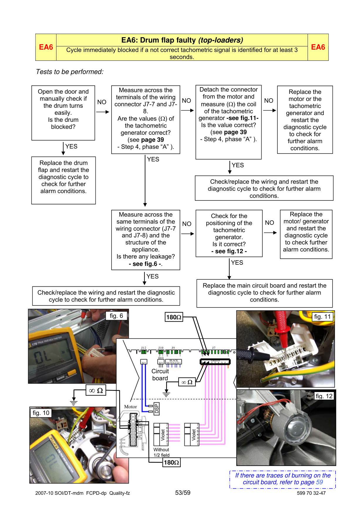
|Detach the connector from the motor and measure (Ω) the coil of the tachometric generator -see fig.11Is the value correct? (see page 39 - Step 4, phase “A” ).| |---|
|Open the door and manually check if the drum turns easily. Is the drum blocked?| |---|
|Measure across the terminals of the wiring connector J7-7 and J78. Are the values (Ω) of the tachometric generator correct? (see page 39 - Step 4, phase “A” ).| |---|
|Replace the motor or the tachometric generator and restart the diagnostic cycle to check for further alarm conditions.| |---|
NO NO NO
| |YES| |---|---|
| |YES| |---|---| | | |
|Replace the drum flap and restart the diagnostic cycle to check for further alarm conditions.| |---|
| |YES| |---|---|
|Check/replace the wiring and restart the diagnostic cycle to check for further alarm conditions.| |---|
|Check for the positioning of the tachometric generator. Is it correct? - see fig.12 -| |---|
|Replace the motor/ generator and restart the diagnostic cycle to check further alarm conditions.| |---|
|Measure across the same terminals of the wiring connector (J7-7 and J7-8) and the structure of the appliance. Is there any leakage? - see fig.6 -.| |---|
NO NO
| |YES| |---|---| | | |
| |YES| |---|---|
|Replace the main circuit board and restart the diagnostic cycle to check for further alarm conditions.| |---|
|Check/replace the wiring and restart the diagnostic cycle to check for further alarm conditions.| |---|


|fig. 6| |---|
|180Ω| | |---|---| |180Ω| |
|fig. 11| |---|

Circuit board
|∞ Ω| |---|
|∞ Ω| |---|

|fig. 12| |---|

|fig. 10| |---|
180Ω
|If there are traces of burning on the circuit board, refer to page 59| |---|
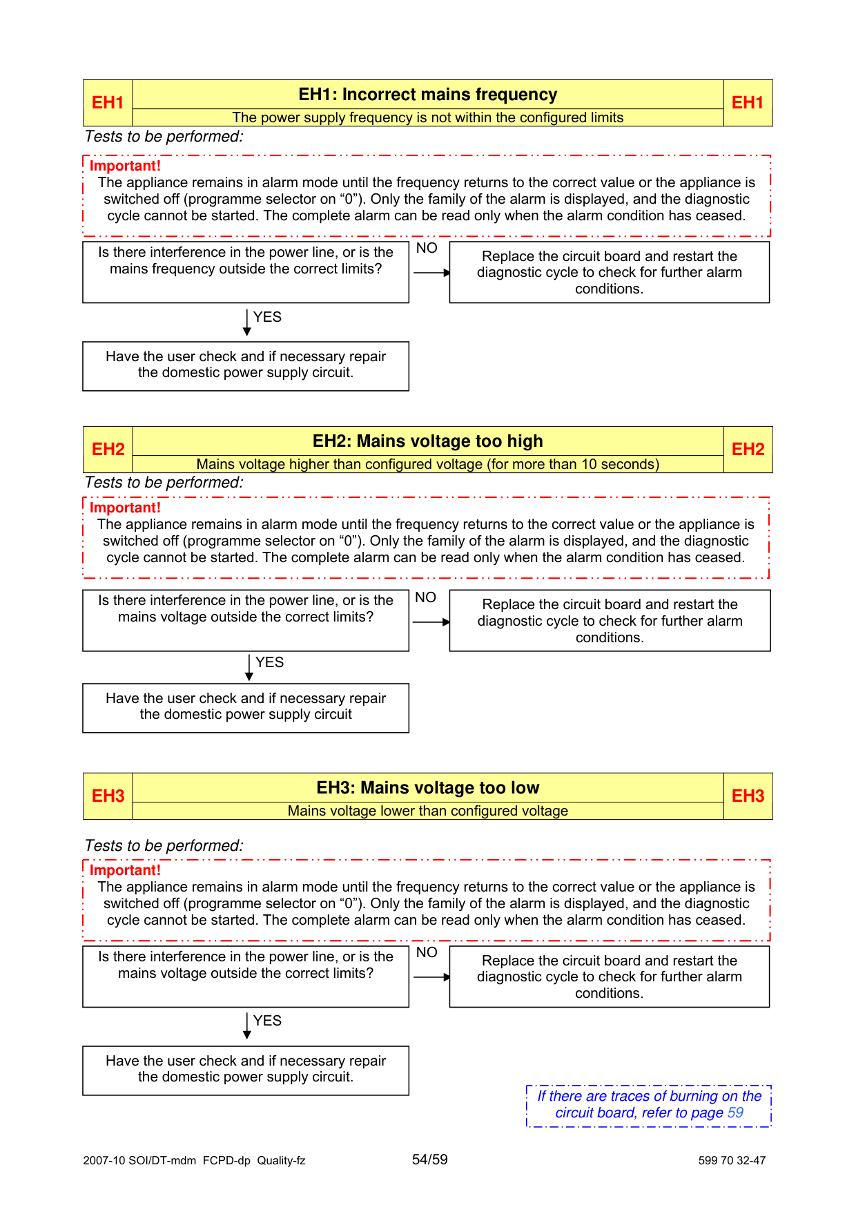
|EH1|EH1: Incorrect mains frequency|EH1| |---|---|---| |EH1|The power supply frequency is not within the configured limits|EH1|
Tests to be performed:
|Important!
The appliance remains in alarm mode until the frequency returns to the correct value or the appliance is switched off (programme selector on “0”). Only the family of the alarm is displayed, and the diagnostic cycle cannot be started. The complete alarm can be read only when the alarm condition has ceased.| |---|
NO
|Is there interference in the power line, or is the mains frequency outside the correct limits?|Is there interference in the power line, or is the mains frequency outside the correct limits?|Is there interference in the power line, or is the mains frequency outside the correct limits?| |---|---|---| | |YES| | |Have the user check and if necessary repair the domestic power supply circuit.|Have the user check and if necessary repair the domestic power supply circuit.|Have the user check and if necessary repair the domestic power supply circuit.|
|Replace the circuit board and restart the diagnostic cycle to check for further alarm conditions.| |---|
|EH2
|EH2: Mains voltage too high|EH2| |---|---|---| |EH2
|Mains voltage higher than configured voltage (for more than 10 seconds)|EH2|
Tests to be performed:
|Important!
The appliance remains in alarm mode until the frequency returns to the correct value or the appliance is switched off (programme selector on “0”). Only the family of the alarm is displayed, and the diagnostic cycle cannot be started. The complete alarm can be read only when the alarm condition has ceased.| |---|
NO
|Replace the circuit board and restart the diagnostic cycle to check for further alarm conditions.| |---|
Is there interference in the power line, or is the mains voltage outside the correct limits?
YES
Have the user check and if necessary repair the domestic power supply circuit
|EH3|EH3: Mains voltage too low|EH3
| |---|---|---| |EH3|Mains voltage lower than configured voltage|EH3
|
Tests to be performed:
|Important!
The appliance remains in alarm mode until the frequency returns to the correct value or the appliance is switched off (programme selector on “0”). Only the family of the alarm is displayed, and the diagnostic cycle cannot be started. The complete alarm can be read only when the alarm condition has ceased.| |---|
NO
|Is there interference in the power line, or is the mains voltage outside the correct limits?|Is there interference in the power line, or is the mains voltage outside the correct limits?|Is there interference in the power line, or is the mains voltage outside the correct limits?| |---|---|---| | |YES
| | |Have the user check and if necessary repair the domestic power supply circuit.|Have the user check and if necessary repair the domestic power supply circuit.|Have the user check and if necessary repair the domestic power supply circuit.|
|Replace the circuit board and restart the diagnostic cycle to check for further alarm conditions.| |---|
|If there are traces of burning on the circuit board, refer to page 59| |---|
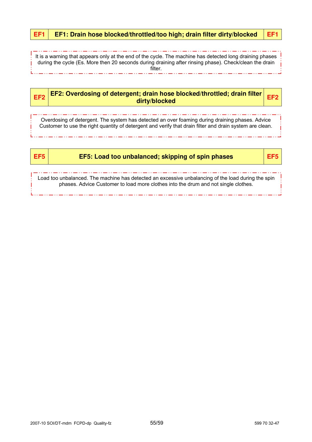
|EF1|EF1: Drain hose blocked/throttled/too high; drain filter dirty/blocked|EF1| |---|---|---|
|It is a warning that appears only at the end of the cycle. The machine has detected long draining phases during the cycle (Es. More then 20 seconds during draining after rinsing phase). Check/clean the drain filter.| |---|
|EF2|EF2: Overdosing of detergent; drain hose blocked/throttled; drain filter dirty/blocked
|EF2| |---|---|---|
|Overdosing of detergent. The system has detected an over foaming during draining phases. Advice Customer to use the right quantity of detergent and verify that drain filter and drain system are clean.| |---|
|EF5|EF5: Load too unbalanced; skipping of spin phases|EF5| |---|---|---|
|Load too unbalanced. The machine has detected an excessive unbalancing of the load during the spin phases. Advice Customer to load more clothes into the drum and not single clothes.| |---|
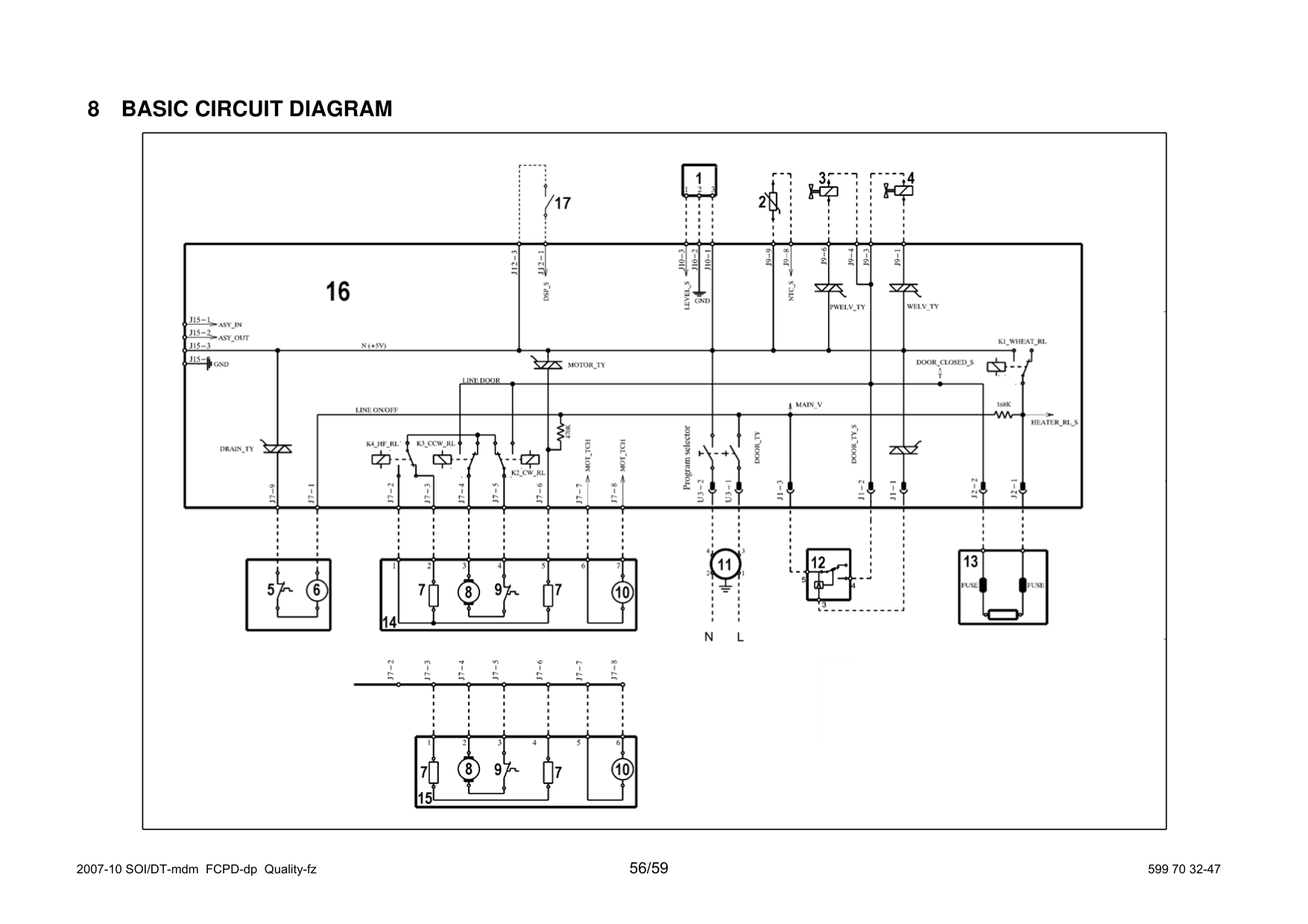
8 BASIC CIRCUIT DIAGRAM

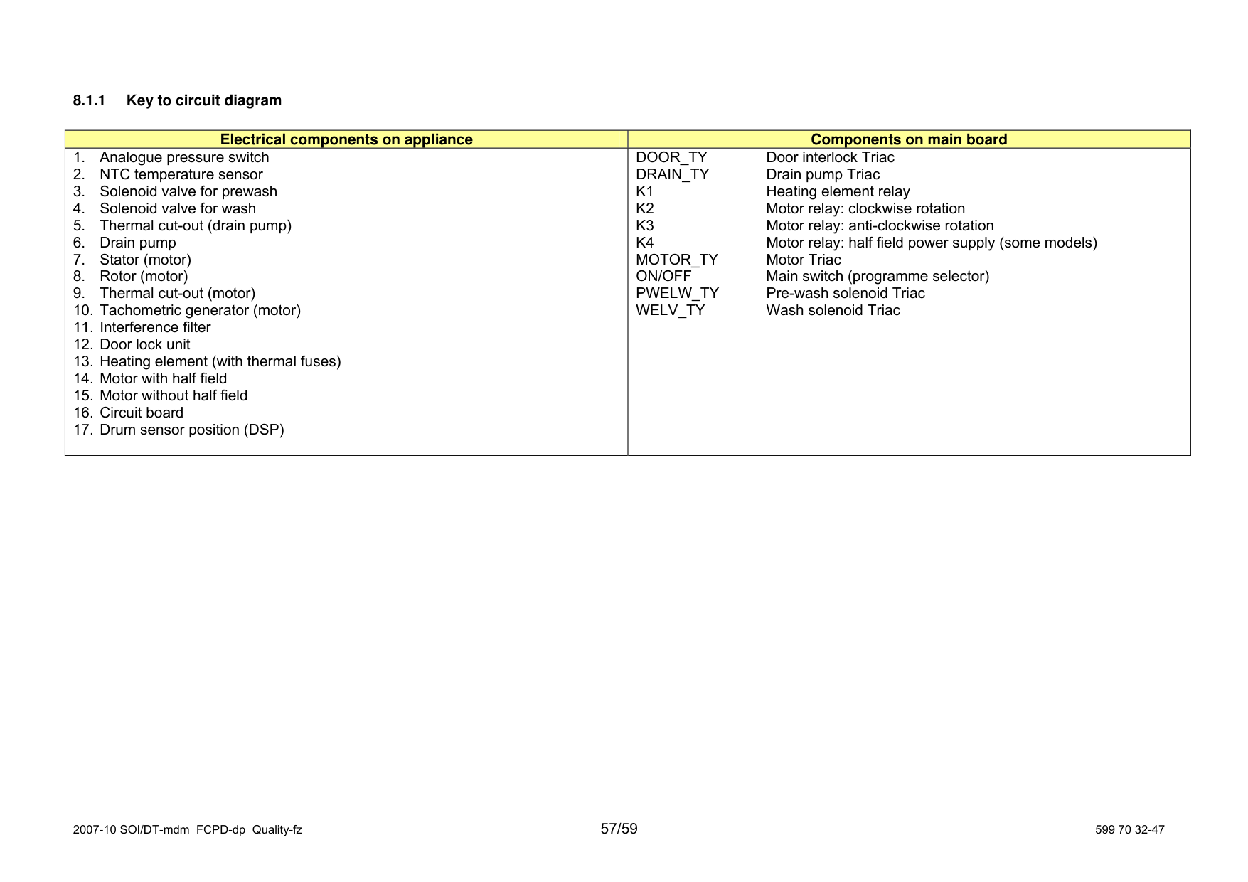
####### 8.1.1 Key to circuit diagram
|Electrical components on appliance|Components on main board| |---|---| |1. Analogue pressure switch
2. NTC temperature sensor
3. Solenoid valve for prewash
4. Solenoid valve for wash
5. Thermal cut-out (drain pump)
6. Drain pump
7. Stator (motor)
8. Rotor (motor)
9. Thermal cut-out (motor)
10. Tachometric generator (motor)
11. Interference filter
12. Door lock unit
13. Heating element (with thermal fuses)
14. Motor with half field
15. Motor without half field
16. Circuit board
17. Drum sensor position (DSP)
|DOOR_TY Door interlock Triac DRAIN_TY Drain pump Triac
K1 Heating element relay
K2 Motor relay: clockwise rotation
K3 Motor relay: anti-clockwise rotation
K4 Motor relay: half field power supply (some models) MOTOR_TY Motor Triac ON/OFF Main switch (programme selector) PWELW_TY Pre-wash solenoid Triac WELV_TY Wash solenoid Triac
|
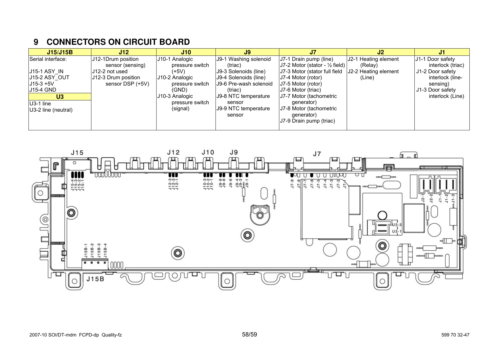
9 CONNECTORS ON CIRCUIT BOARD
|J15/J15B|J12|J10|J9|J7| | | |---|---|---|---|---|---|---| |Serial interface:
J15-1 ASY_IN
J15-2 ASY_OUT
J15-3 +5V
J15-4 GND
|J12-1Drum position sensor (sensing)
J12-2 not used
J12-3 Drum position sensor DSP (+5V)
|J10-1 Analogic pressure switch (+5V)
J10-2 Analogic pressure switch (GND)
J10-3 Analogic pressure switch (signal)
|J9-1 Washing solenoid (triac)
J9-3 Solenoids (line)
J9-4 Solenoids (line) J9-6 Pre-wash solenoid
(triac)
J9-8 NTC temperature sensor
J9-9 NTC temperature sensor
|J7-1 Drain pump (line)
J7-2 Motor (stator - ½ field)
J7-3 Motor (stator full field
J7-4 Motor (rotor)
J7-5 Motor (rotor)
J7-6 Motor (triac)
J7-7 Motor (tachometric generator)
J7-8 Motor (tachometric generator)
J7-9 Drain pump (triac)
|J2-1 Heating element
J2-2 Heating element
| | |U3|J12-1Drum position sensor (sensing)
J12-2 not used
J12-3 Drum position sensor DSP (+5V)
|J10-1 Analogic pressure switch (+5V)
J10-2 Analogic pressure switch (GND)
J10-3 Analogic pressure switch (signal)
|J9-1 Washing solenoid (triac)
J9-3 Solenoids (line)
J9-4 Solenoids (line) J9-6 Pre-wash solenoid
(triac)
J9-8 NTC temperature sensor
J9-9 NTC temperature sensor
|J7-1 Drain pump (line)
J7-2 Motor (stator - ½ field)
J7-3 Motor (stator full field
J7-4 Motor (rotor)
J7-5 Motor (rotor)
J7-6 Motor (triac)
J7-7 Motor (tachometric generator)
J7-8 Motor (tachometric generator)
J7-9 Drain pump (triac)
|J2-1 Heating element
J2-2 Heating element
| | |U3-1 line
U3-2 line (neutral)
|J12-1Drum position sensor (sensing)
J12-2 not used
J12-3 Drum position sensor DSP (+5V)
|J10-1 Analogic pressure switch (+5V)
J10-2 Analogic pressure switch (GND)
J10-3 Analogic pressure switch (signal)
|J9-1 Washing solenoid (triac)
J9-3 Solenoids (line)
J9-4 Solenoids (line) J9-6 Pre-wash solenoid
(triac)
J9-8 NTC temperature sensor
J9-9 NTC temperature sensor
|J7-1 Drain pump (line)
J7-2 Motor (stator - ½ field)
J7-3 Motor (stator full field
J7-4 Motor (rotor)
J7-5 Motor (rotor)
J7-6 Motor (triac)
J7-7 Motor (tachometric generator)
J7-8 Motor (tachometric generator)
J7-9 Drain pump (triac)
|J2-1 Heating element
J2-2 Heating element
| |

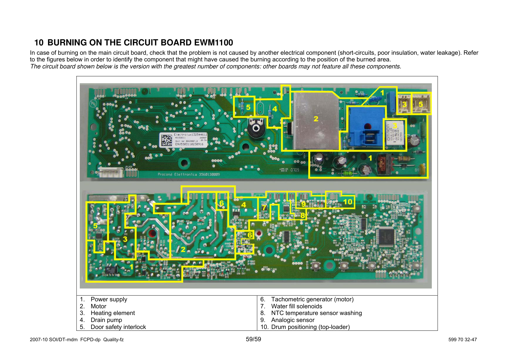
10 BURNING ON THE CIRCUIT BOARD EWM1100
In case of burning on the main circuit board, check that the problem is not caused by another electrical component (short-circu to the figures below in order to identify the component that might have caused the burning according to the position of the bur The circuit board shown below is the version with the greatest number of components: other boards may not feature all these com
||| |---|---| |1. Power supply
2. Motor
3. Heating element
4. Drain pump
5. Door safety interlock
|6. Tachometric generator (motor)
7. Water fill solenoids
8. NTC temperature sensor washing
9. Analogic sensor
10. Drum positioning (top-loader)
|