
Ask AI
— answers from the official manualAnswers from the official manual.
Common questions
Common Questions
10 totalHow can I power the Flexim FLUXUS F721 ultrasonic flowmeter?
The Flexim FLUXUS F721 can be powered by a range of electrical sources: 100...230 V/50...60 Hz, 20...32 V DC, or 11...16 V DC. (Page 2)
What flow measurement accuracy can I expect from the Flexim FLUXUS F721?
The repeatability is within ±0.15% of measured value ±0.005 m/s for the Flexim FLUXUS F721. (Page 2)
How do I calibrate and program the FLUXUS F721 transmitter?
Calibration and configuration can be done through the USB or LAN interfaces, using software such as FluxDiagReader for basic reading of measured values and parameters, while the optional FluxDiag provides full measurement data analysis and parameter setting capabilities. (Page 3)
What is the measuring cycle range on Flexim FLUXUS F721?
The Flexim FLUXUS F721 supports a measurable cycle from 100 to 1000 Hz. (Page 2)
What is the minimum ambient temperature rating for operation of the Flexim FLUXUS F721?
The minimum operating ambient temperature for standard housing models is -40 °C without display operation. (Page 2)
Can I install output signals on my Flexim FLUXUS F721 device?
You can configure switchable current outputs ranging from 4...20 mA up to a precision of ±3 μA for the Flexim FLUXUS F721. (Page 4)
Full Manual
12 pages

Technical Specification TSFLUXUS_F72xV3-0-0-0EN_Leu
Flexim FLUXUS F721, F722 Ultrasonic Flowmeter


Permanently Installed Ultrasonic Flowmeter for Liquids Features
##### Applications
• Chemical industry, petrochemical industry, oil and gas industry, pharmaceutical industry, semiconductor industry, manufacturing industries, building technology/energy management, water and wastewater industry, mining industries


Transmitter Technical data
| | |FLUXUS F721-NNN-*A F721-NNN-*S|FLUXUS F721-A2N-*A F721-A2N-*S|FLUXUS F721-F2N-*A F721-F2N-*S|FLUXUS F722-NNN-*A F722-NNN-*S|FLUXUS F722-A2N-*A F722-A2N-*S|FLUXUS F722-F2N-*A F722-F2N-*S| |---|---|---|---|---|---|---|---| | | |
|
|
|
|
|
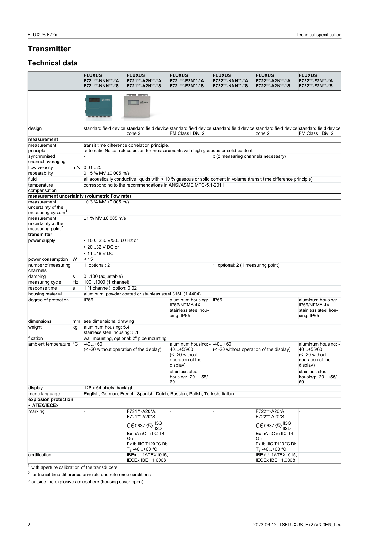
| |design| |standard field device|standard field device zone 2|standard field device FM Class I Div. 2|standard field device|standard field device zone 2|standard field device FM Class I Div. 2| |measurement|measurement|measurement|measurement|measurement|measurement|measurement|measurement| |measurement principle| |transit time difference correlation principle, automatic NoiseTrek selection for measurements with high gaseous or solid content|transit time difference correlation principle, automatic NoiseTrek selection for measurements with high gaseous or solid content|transit time difference correlation principle, automatic NoiseTrek selection for measurements with high gaseous or solid content|transit time difference correlation principle, automatic NoiseTrek selection for measurements with high gaseous or solid content|transit time difference correlation principle, automatic NoiseTrek selection for measurements with high gaseous or solid content|transit time difference correlation principle, automatic NoiseTrek selection for measurements with high gaseous or solid content| |synchronised channel averaging| |-|-|-|x (2 measuring channels necessary)|x (2 measuring channels necessary)|x (2 measuring channels necessary)| |flow velocity|m/s|0.01...25|0.01...25|0.01...25|0.01...25|0.01...25|0.01...25| |repeatability| |0.15 % MV ±0.005 m/s|0.15 % MV ±0.005 m/s|0.15 % MV ±0.005 m/s|0.15 % MV ±0.005 m/s|0.15 % MV ±0.005 m/s|0.15 % MV ±0.005 m/s| |fluid| |all acoustically conductive liquids with < 10 % gaseous or solid content in volume (transit time difference principle)|all acoustically conductive liquids with < 10 % gaseous or solid content in volume (transit time difference principle)|all acoustically conductive liquids with < 10 % gaseous or solid content in volume (transit time difference principle)|all acoustically conductive liquids with < 10 % gaseous or solid content in volume (transit time difference principle)|all acoustically conductive liquids with < 10 % gaseous or solid content in volume (transit time difference principle)|all acoustically conductive liquids with < 10 % gaseous or solid content in volume (transit time difference principle)| |temperature compensation| |corresponding to the recommendations in ANSI/ASME MFC-5.1-2011|corresponding to the recommendations in ANSI/ASME MFC-5.1-2011|corresponding to the recommendations in ANSI/ASME MFC-5.1-2011|corresponding to the recommendations in ANSI/ASME MFC-5.1-2011|corresponding to the recommendations in ANSI/ASME MFC-5.1-2011|corresponding to the recommendations in ANSI/ASME MFC-5.1-2011| |measurement uncertainty (volumetric flow rate)|measurement uncertainty (volumetric flow rate)|measurement uncertainty (volumetric flow rate)|measurement uncertainty (volumetric flow rate)|measurement uncertainty (volumetric flow rate)|measurement uncertainty (volumetric flow rate)|measurement uncertainty (volumetric flow rate)|measurement uncertainty (volumetric flow rate)| |measurement uncertainty of the measuring system1| |±0.3 % MV ±0.005 m/s|±0.3 % MV ±0.005 m/s|±0.3 % MV ±0.005 m/s|±0.3 % MV ±0.005 m/s|±0.3 % MV ±0.005 m/s|±0.3 % MV ±0.005 m/s| |measurement uncertainty at the measuring point2| |±1 % MV ±0.005 m/s|±1 % MV ±0.005 m/s|±1 % MV ±0.005 m/s|±1 % MV ±0.005 m/s|±1 % MV ±0.005 m/s|±1 % MV ±0.005 m/s|
|transmitter|transmitter|transmitter|transmitter|transmitter|transmitter|transmitter|transmitter| |power supply| |• 100...230 V/50...60 Hz or
• 20...32 V DC or
• 11...16 V DC
|• 100...230 V/50...60 Hz or
• 20...32 V DC or
• 11...16 V DC
|• 100...230 V/50...60 Hz or
• 20...32 V DC or
• 11...16 V DC
|• 100...230 V/50...60 Hz or
• 20...32 V DC or
• 11...16 V DC
|• 100...230 V/50...60 Hz or
• 20...32 V DC or
• 11...16 V DC
|• 100...230 V/50...60 Hz or
• 20...32 V DC or
• 11...16 V DC
| |power consumption|W|< 15|< 15|< 15|< 15|< 15|< 15| |number of measuring channels| |1, optional: 2|1, optional: 2|1, optional: 2|1, optional: 2 (1 measuring point)|1, optional: 2 (1 measuring point)|1, optional: 2 (1 measuring point)| |damping|s|0...100 (adjustable)|0...100 (adjustable)|0...100 (adjustable)|0...100 (adjustable)|0...100 (adjustable)|0...100 (adjustable)| |measuring cycle|Hz|100...1000 (1 channel)|100...1000 (1 channel)|100...1000 (1 channel)|100...1000 (1 channel)|100...1000 (1 channel)|100...1000 (1 channel)| |response time|s|1 (1 channel), option: 0.02|1 (1 channel), option: 0.02|1 (1 channel), option: 0.02|1 (1 channel), option: 0.02|1 (1 channel), option: 0.02|1 (1 channel), option: 0.02| |housing material| |aluminum, powder coated or stainless steel 316L (1.4404)|aluminum, powder coated or stainless steel 316L (1.4404)|aluminum, powder coated or stainless steel 316L (1.4404)|aluminum, powder coated or stainless steel 316L (1.4404)|aluminum, powder coated or stainless steel 316L (1.4404)|aluminum, powder coated or stainless steel 316L (1.4404)| |degree of protection| |IP66|IP66|aluminum housing: IP66/NEMA 4X stainless steel housing: IP65|IP66|IP66|aluminum housing: IP66/NEMA 4X stainless steel housing: IP65| |dimensions|mm|see dimensional drawing|see dimensional drawing|see dimensional drawing|see dimensional drawing|see dimensional drawing|see dimensional drawing| |weight|kg|aluminum housing: 5.4 stainless steel housing: 5.1|aluminum housing: 5.4 stainless steel housing: 5.1|aluminum housing: 5.4 stainless steel housing: 5.1|aluminum housing: 5.4 stainless steel housing: 5.1|aluminum housing: 5.4 stainless steel housing: 5.1|aluminum housing: 5.4 stainless steel housing: 5.1| |fixation| |wall mounting, optional: 2" pipe mounting|wall mounting, optional: 2" pipe mounting|wall mounting, optional: 2" pipe mounting|wall mounting, optional: 2" pipe mounting|wall mounting, optional: 2" pipe mounting|wall mounting, optional: 2" pipe mounting| |ambient temperature|°C|-40...+60 (< -20 without operation of the display)|-40...+60 (< -20 without operation of the display)|aluminum housing: 40...+55/60 (< -20 without operation of the display) stainless steel housing: -20...+55/ 60|-40...+60 (< -20 without operation of the display)|-40...+60 (< -20 without operation of the display)|aluminum housing: 40...+55/60 (< -20 without operation of the display) stainless steel housing: -20...+55/ 60| |display| |128 x 64 pixels, backlight|128 x 64 pixels, backlight|128 x 64 pixels, backlight|128 x 64 pixels, backlight|128 x 64 pixels, backlight|128 x 64 pixels, backlight| |menu language| |English, German, French, Spanish, Dutch, Russian, Polish, Turkish, Italian|English, German, French, Spanish, Dutch, Russian, Polish, Turkish, Italian|English, German, French, Spanish, Dutch, Russian, Polish, Turkish, Italian|English, German, French, Spanish, Dutch, Russian, Polish, Turkish, Italian|English, German, French, Spanish, Dutch, Russian, Polish, Turkish, Italian|English, German, French, Spanish, Dutch, Russian, Polish, Turkish, Italian| |explosion protection|explosion protection|explosion protection|explosion protection|explosion protection|explosion protection|explosion protection|explosion protection| |• ATEX/IECEx|• ATEX/IECEx|• ATEX/IECEx|• ATEX/IECEx|• ATEX/IECEx|• ATEX/IECEx|• ATEX/IECEx|• ATEX/IECEx| |marking| |-|F721-A20*A, F721-A20*S:
Ex nA nC ic IIC T4 Gc Ex tb IIIC T120 °C Db Ta -40...+60 °C
II3G II2D
0637
|-|-|F722-A20*A, F722-A20*S:
Ex nA nC ic IIC T4 Gc Ex tb IIIC T120 °C Db Ta -40...+60 °C
II3G II2D
0637
|-| |certification| |-|IBExU11ATEX1015, IECEx IBE 11.0008|-|-|IBExU11ATEX1015, IECEx IBE 11.0008|-|
| | |FLUXUS F721-NNN-*A F721-NNN-*S|FLUXUS F721-A2N-*A F721-A2N-*S|FLUXUS F721-F2N-*A F721-F2N-*S|FLUXUS F722-NNN-*A F722-NNN-*S|FLUXUS F722-A2N-*A F722-A2N-*S|FLUXUS F722-F2N-*A F722-F2N-*S| |---|---|---|---|---|---|---|---| |• FM|• FM|• FM|• FM|• FM|• FM|• FM|• FM| |marking| |-|-|F721-F202, F721-F203:
NI/Cl. I,II,III/ Div. 2/GP. A,B,C,D,E, F,G/
T5 F721-F201:
NI/Cl. I,II,III/ Div. 2/GP. A,B,C,D,E, F,G/ T4A
|-|-|F722-F202, F722-F203:
NI/Cl. I,II,III/ Div. 2/GP. A,B,C,D,E, F,G/
T5 F722-F201:
NI/Cl. I,II,III/ Div. 2/GP. A,B,C,D,E, F,G/ T4A
| |measuring functions|measuring functions|measuring functions|measuring functions|measuring functions|measuring functions|measuring functions|measuring functions| |physical quantities| |volumetric flow rate, mass flow rate, flow velocity, thermal energy rate (if temperature inputs are installed)|volumetric flow rate, mass flow rate, flow velocity, thermal energy rate (if temperature inputs are installed)|volumetric flow rate, mass flow rate, flow velocity, thermal energy rate (if temperature inputs are installed)|volumetric flow rate, mass flow rate, flow velocity, thermal energy rate (if temperature inputs are installed)|volumetric flow rate, mass flow rate, flow velocity, thermal energy rate (if temperature inputs are installed)|volumetric flow rate, mass flow rate, flow velocity, thermal energy rate (if temperature inputs are installed)| |totaliser| |volume, mass, optional: thermal energy|volume, mass, optional: thermal energy|volume, mass, optional: thermal energy|volume, mass, optional: thermal energy|volume, mass, optional: thermal energy|volume, mass, optional: thermal energy| |calculation functions| |average, difference, sum (2 measuring channels necessary)|average, difference, sum (2 measuring channels necessary)|average, difference, sum (2 measuring channels necessary)|average, difference, sum (2 measuring channels necessary)|average, difference, sum (2 measuring channels necessary)|average, difference, sum (2 measuring channels necessary)| |diagnostic functions| |sound speed, signal amplitude, SNR, SCNR, standard deviation of amplitudes and transit times|sound speed, signal amplitude, SNR, SCNR, standard deviation of amplitudes and transit times|sound speed, signal amplitude, SNR, SCNR, standard deviation of amplitudes and transit times|sound speed, signal amplitude, SNR, SCNR, standard deviation of amplitudes and transit times|sound speed, signal amplitude, SNR, SCNR, standard deviation of amplitudes and transit times|sound speed, signal amplitude, SNR, SCNR, standard deviation of amplitudes and transit times| |communication interfaces|communication interfaces|communication interfaces|communication interfaces|communication interfaces|communication interfaces|communication interfaces|communication interfaces| |service interfaces| |measured value transmission, parametrisation of the transmitter:
• USB3
• LAN3
|measured value transmission, parametrisation of the transmitter:
• USB3
• LAN3
|measured value transmission, parametrisation of the transmitter:
• USB3
• LAN3
|measured value transmission, parametrisation of the transmitter:
• USB3
• LAN3
|measured value transmission, parametrisation of the transmitter:
• USB3
• LAN3
|measured value transmission, parametrisation of the transmitter:
• USB3
• LAN3
| |process interfaces| |max. 1 option:
• RS485 (ASCII sender)
• Modbus RTU
• BACnet MS/TP
• M-Bus
• HART
• Profibus PA
• FF H1
• Modbus TCP
• BACnet IP
|max. 1 option:
• RS485 (ASCII sender)
• Modbus RTU
• BACnet MS/TP
• HART
• Profibus PA
• FF H1
• Modbus TCP
• BACnet IP
|max. 1 option:
• RS485 (ASCII sender)
• Modbus RTU
• BACnet MS/TP
• HART
• Profibus PA
• FF H1
• Modbus TCP
• BACnet IP
|max. 1 option:
• RS485 (ASCII sender)
• Modbus RTU
• BACnet MS/TP
• M-Bus
• HART
• Profibus PA
• FF H1
• Modbus TCP
• BACnet IP
|max. 1 option:
• RS485 (ASCII sender)
• Modbus RTU
• BACnet MS/TP
• HART
• Profibus PA
• FF H1
• Modbus TCP
• BACnet IP
|max. 1 option:
• RS485 (ASCII sender)
• Modbus RTU
• BACnet MS/TP
• HART
• Profibus PA
• FF H1
• Modbus TCP
• BACnet IP
| |accessories|accessories|accessories|accessories|accessories|accessories|accessories|accessories|
|data transmission kit| |USB cable|USB cable|USB cable|USB cable|USB cable|USB cable| |software| |• FluxDiagReader: reading of measured values and parameters, graphical representation
• FluxDiag (optional): reading of measurement data, graphical representation, report generation, parametrisation of the transmitter
|• FluxDiagReader: reading of measured values and parameters, graphical representation
• FluxDiag (optional): reading of measurement data, graphical representation, report generation, parametrisation of the transmitter
|• FluxDiagReader: reading of measured values and parameters, graphical representation
• FluxDiag (optional): reading of measurement data, graphical representation, report generation, parametrisation of the transmitter
|• FluxDiagReader: reading of measured values and parameters, graphical representation
• FluxDiag (optional): reading of measurement data, graphical representation, report generation, parametrisation of the transmitter
|• FluxDiagReader: reading of measured values and parameters, graphical representation
• FluxDiag (optional): reading of measurement data, graphical representation, report generation, parametrisation of the transmitter
|• FluxDiagReader: reading of measured values and parameters, graphical representation
• FluxDiag (optional): reading of measurement data, graphical representation, report generation, parametrisation of the transmitter
| |data logger|data logger|data logger|data logger|data logger|data logger|data logger|data logger| |loggable values| |all physical quantities, totalised physical quantities and diagnostic values|all physical quantities, totalised physical quantities and diagnostic values|all physical quantities, totalised physical quantities and diagnostic values|all physical quantities, totalised physical quantities and diagnostic values|all physical quantities, totalised physical quantities and diagnostic values|all physical quantities, totalised physical quantities and diagnostic values| |capacity| |max. 800 000 measured values|max. 800 000 measured values|max. 800 000 measured values|max. 800 000 measured values|max. 800 000 measured values|max. 800 000 measured values| |outputs|outputs|outputs|outputs|outputs|outputs|outputs|outputs| | | |The outputs are galvanically isolated from the transmitter.|The outputs are galvanically isolated from the transmitter.|The outputs are galvanically isolated from the transmitter.|The outputs are galvanically isolated from the transmitter.|The outputs are galvanically isolated from the transmitter.|The outputs are galvanically isolated from the transmitter.| |number| |on request|on request|on request|on request|on request|on request| |• switchable current output|• switchable current output|• switchable current output|• switchable current output|• switchable current output|• switchable current output|• switchable current output|• switchable current output| | | |All switchable current outputs are jointly switched to active or passive.|All switchable current outputs are jointly switched to active or passive.|All switchable current outputs are jointly switched to active or passive.|All switchable current outputs are jointly switched to active or passive.|All switchable current outputs are jointly switched to active or passive.|All switchable current outputs are jointly switched to active or passive.| |range|mA|4...20 (3.2...22)|4...20 (3.2...22)|4...20 (3.2...22)|4...20 (3.2...22)|4...20 (3.2...22)|4...20 (3.2...22)| |accuracy| |0.04 % MV ±3 μA|0.04 % MV ±3 μA|0.04 % MV ±3 μA|0.04 % MV ±3 μA|0.04 % MV ±3 μA|0.04 % MV ±3 μA| |active output| |Rext < 250 Ω|Rext < 250 Ω|Rext < 250 Ω|Rext < 250 Ω|Rext < 250 Ω|Rext < 250 Ω| |passive output| |Uext = 8...30 V, depending on Rext (Rext < 1 kΩ at 30 V)|Uext = 8...30 V, depending on Rext (Rext < 1 kΩ at 30 V)|Uext = 8...30 V, depending on Rext (Rext < 1 kΩ at 30 V)|Uext = 8...30 V, depending on Rext (Rext < 1 kΩ at 30 V)|Uext = 8...30 V, depending on Rext (Rext < 1 kΩ at 30 V)|Uext = 8...30 V, depending on Rext (Rext < 1 kΩ at 30 V)| |• HART|• HART|• HART|• HART|• HART|• HART|• HART|• HART| |range|mA|4...20|4...20|4...20|4...20|4...20|4...20| |accuracy| |0.1 % MV ±15 μA|0.1 % MV ±15 μA|0.1 % MV ±15 μA|0.1 % MV ±15 μA|0.1 % MV ±15 μA|0.1 % MV ±15 μA| |active output| |Uint = 24 V, Rext < 500 Ω|Uint = 24 V, Rext < 500 Ω|Uint = 24 V, Rext < 500 Ω|Uint = 24 V, Rext < 500 Ω|Uint = 24 V, Rext < 500 Ω|Uint = 24 V, Rext < 500 Ω| |passive output| |Uext = 10...24 V DC, depending on Rext (Rext < 1 kΩ at 24 V)|Uext = 10...24 V DC, depending on Rext (Rext < 1 kΩ at 24 V)|Uext = 10...24 V DC, depending on Rext (Rext < 1 kΩ at 24 V)|Uext = 10...24 V DC, depending on Rext (Rext < 1 kΩ at 24 V)|Uext = 10...24 V DC, depending on Rext (Rext < 1 kΩ at 24 V)|Uext = 10...24 V DC, depending on Rext (Rext < 1 kΩ at 24 V)| |• voltage output|• voltage output|• voltage output|• voltage output|• voltage output|• voltage output|• voltage output|• voltage output| |range|V|0...1 or 0...10|0...1 or 0...10|0...1 or 0...10|0...1 or 0...10|0...1 or 0...10|0...1 or 0...10| |accuracy| |0...1 V: 0.1 % MV ±1 mV 0...10 V: 0.1 % MV ±10 mV|0...1 V: 0.1 % MV ±1 mV 0...10 V: 0.1 % MV ±10 mV|0...1 V: 0.1 % MV ±1 mV 0...10 V: 0.1 % MV ±10 mV|0...1 V: 0.1 % MV ±1 mV 0...10 V: 0.1 % MV ±10 mV|0...1 V: 0.1 % MV ±1 mV 0...10 V: 0.1 % MV ±10 mV|0...1 V: 0.1 % MV ±1 mV 0...10 V: 0.1 % MV ±10 mV| |internal resistance| |Rint = 500 Ω|Rint = 500 Ω|Rint = 500 Ω|Rint = 500 Ω|Rint = 500 Ω|Rint = 500 Ω| |• frequency output|• frequency output|• frequency output|• frequency output|• frequency output|• frequency output|• frequency output|• frequency output| |range|kHz|0...5|0...5|0...5|0...5|0...5|0...5| |optorelay| |24 V/4 mA, Rint = 66.5 Ω|24 V/4 mA, Rint = 66.5 Ω|24 V/4 mA, Rint = 66.5 Ω|24 V/4 mA, Rint = 66.5 Ω|24 V/4 mA, Rint = 66.5 Ω|24 V/4 mA, Rint = 66.5 Ω|
| | |FLUXUS F721-NNN-*A F721-NNN-*S|FLUXUS F721-A2N-*A F721-A2N-*S|FLUXUS F721-F2N-*A F721-F2N-*S|FLUXUS F722-NNN-*A F722-NNN-*S|FLUXUS F722-A2N-*A F722-A2N-*S|FLUXUS F722-F2N-*A F722-F2N-*S| |---|---|---|---|---|---|---|---| |• digital output|• digital output|• digital output|• digital output|• digital output|• digital output|• digital output|• digital output| |functions| |• frequency output
• binary output
• pulse output
|• frequency output
• binary output
• pulse output
|• frequency output
• binary output
• pulse output
|• frequency output
• binary output
• pulse output
|• frequency output
• binary output
• pulse output
|• frequency output
• binary output
• pulse output
| |number| |3|3|3|3|3|3| |operating parameters| |5...30 V/< 100 mA|5...30 V/< 100 mA|5...30 V/< 100 mA|5...30 V/< 100 mA|5...30 V/< 100 mA|5...30 V/< 100 mA|
|frequency output
• range|kHz|0...5|0...5|0...5|0...5|0...5|0...5| |binary output
• binary output as alarm output| |limit, change of flow direction or error|limit, change of flow direction or error|limit, change of flow direction or error|limit, change of flow direction or error|limit, change of flow direction or error|limit, change of flow direction or error| |pulse output
• functions
• pulse value
• pulse width
|units ms|mainly for totalising 0.01...1000 0.05...1000|mainly for totalising 0.01...1000 0.05...1000|mainly for totalising 0.01...1000 0.05...1000|mainly for totalising 0.01...1000 0.05...1000|mainly for totalising 0.01...1000 0.05...1000|mainly for totalising 0.01...1000 0.05...1000| |inputs|inputs|inputs|inputs|inputs|inputs|inputs|inputs| | | |The inputs are galvanically isolated from the transmitter.|The inputs are galvanically isolated from the transmitter.|The inputs are galvanically isolated from the transmitter.|The inputs are galvanically isolated from the transmitter.|The inputs are galvanically isolated from the transmitter.|The inputs are galvanically isolated from the transmitter.| |number| |max. 4, on request|max. 4, on request|max. 4, on request|max. 4, on request|max. 4, on request|max. 4, on request| |• temperature input|• temperature input|• temperature input|• temperature input|• temperature input|• temperature input|• temperature input|• temperature input| |type| |Pt100/Pt1000|Pt100/Pt1000|Pt100/Pt1000|Pt100/Pt1000|Pt100/Pt1000|Pt100/Pt1000| |connection| |4-wire|4-wire|4-wire|4-wire|4-wire|4-wire| |range|°C|-150...+560|-150...+560|-150...+560|-150...+560|-150...+560|-150...+560| |resolution|K|0.01|0.01|0.01|0.01|0.01|0.01| |accuracy| |±0.01 % MV ±0.03 K|±0.01 % MV ±0.03 K|±0.01 % MV ±0.03 K|±0.01 % MV ±0.03 K|±0.01 % MV ±0.03 K|±0.01 % MV ±0.03 K| |• current input|• current input|• current input|• current input|• current input|• current input|• current input|• current input| |accuracy| |0.1 % MV ±10 μA|0.1 % MV ±10 μA|0.1 % MV ±10 μA|0.1 % MV ±10 μA|0.1 % MV ±10 μA|0.1 % MV ±10 μA| |active input
• range|mA|Uint = 24 V, Rint = 50 Ω, Pint < 0.5 W, not short-circuit proof 0...20|Uint = 24 V, Rint = 50 Ω, Pint < 0.5 W, not short-circuit proof 0...20|Uint = 24 V, Rint = 50 Ω, Pint < 0.5 W, not short-circuit proof 0...20|Uint = 24 V, Rint = 50 Ω, Pint < 0.5 W, not short-circuit proof 0...20|Uint = 24 V, Rint = 50 Ω, Pint < 0.5 W, not short-circuit proof 0...20|Uint = 24 V, Rint = 50 Ω, Pint < 0.5 W, not short-circuit proof 0...20| |passive input
• range|mA|Rint = 50 Ω, Pint < 0.3 W
-20...+20|Rint = 50 Ω, Pint < 0.3 W
-20...+20|Rint = 50 Ω, Pint < 0.3 W
-20...+20|Rint = 50 Ω, Pint < 0.3 W
-20...+20|Rint = 50 Ω, Pint < 0.3 W
-20...+20|Rint = 50 Ω, Pint < 0.3 W
-20...+20| |• voltage input|• voltage input|• voltage input|• voltage input|• voltage input|• voltage input|• voltage input|• voltage input| |range|V|0...1|0...1|0...1|0...1|0...1|0...1| |accuracy| |0.1 % MV ±1 mV|0.1 % MV ±1 mV|0.1 % MV ±1 mV|0.1 % MV ±1 mV|0.1 % MV ±1 mV|0.1 % MV ±1 mV| |internal resistance| |Rint = 1 MΩ|Rint = 1 MΩ|Rint = 1 MΩ|Rint = 1 MΩ|Rint = 1 MΩ|Rint = 1 MΩ| |• binary input|• binary input|• binary input|• binary input|• binary input|• binary input|• binary input|• binary input| |switching signal| |5...30 V, 1 mA|5...30 V, 1 mA|5...26 V, 1 mA|5...30 V, 1 mA|5...30 V, 1 mA|5...26 V, 1 mA| |functions| |• reset of the measured values
• reset of the totalisers
• stop of the totalisers
• activation of the measuring mode for highly dynamic flows
|• reset of the measured values
• reset of the totalisers
• stop of the totalisers
• activation of the measuring mode for highly dynamic flows
|• reset of the measured values
• reset of the totalisers
• stop of the totalisers
• activation of the measuring mode for highly dynamic flows
|• reset of the measured values
• reset of the totalisers
• stop of the totalisers
• activation of the measuring mode for highly dynamic flows
|• reset of the measured values
• reset of the totalisers
• stop of the totalisers
• activation of the measuring mode for highly dynamic flows
|• reset of the measured values
• reset of the totalisers
• stop of the totalisers
• activation of the measuring mode for highly dynamic flows
|
####### 1 with aperture calibration of the transducers 2 for transit time difference principle and reference conditions 3 outside the explosive atmosphere (housing cover open)
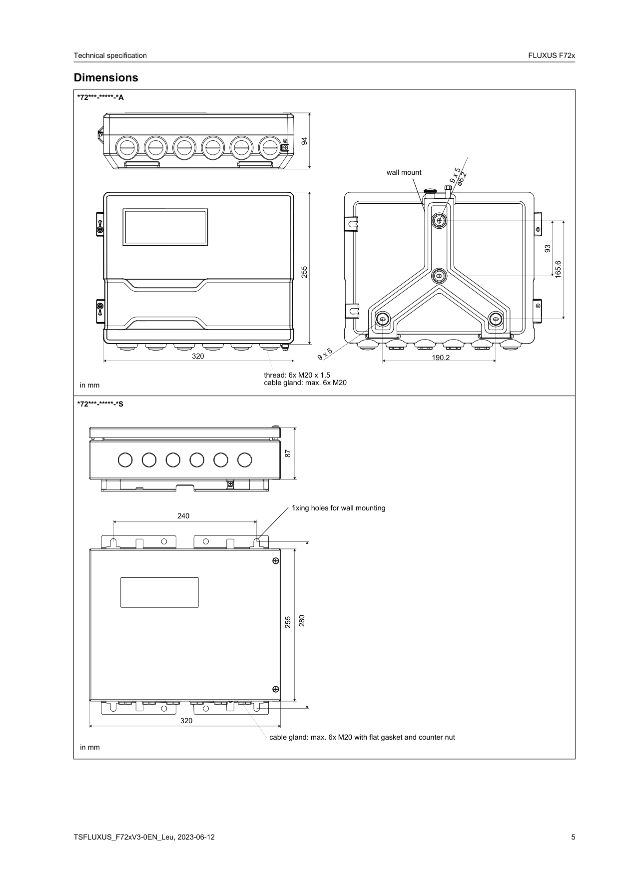
#### Dimensions
94
9 x 5ø6.2
wall mount
| | | | |---|---|---| | | | |
255
| | | |---|---| | | |
| | | |---|---| |320
| |
9 x 5
190.2
thread: 6x M20 x 1.5 cable gland: max. 6x M20
in mm
93
165.6
280 87
fixing holes for wall mounting
240
255
320
cable gland: max. 6x M20 with flat gasket and counter nut
in mm
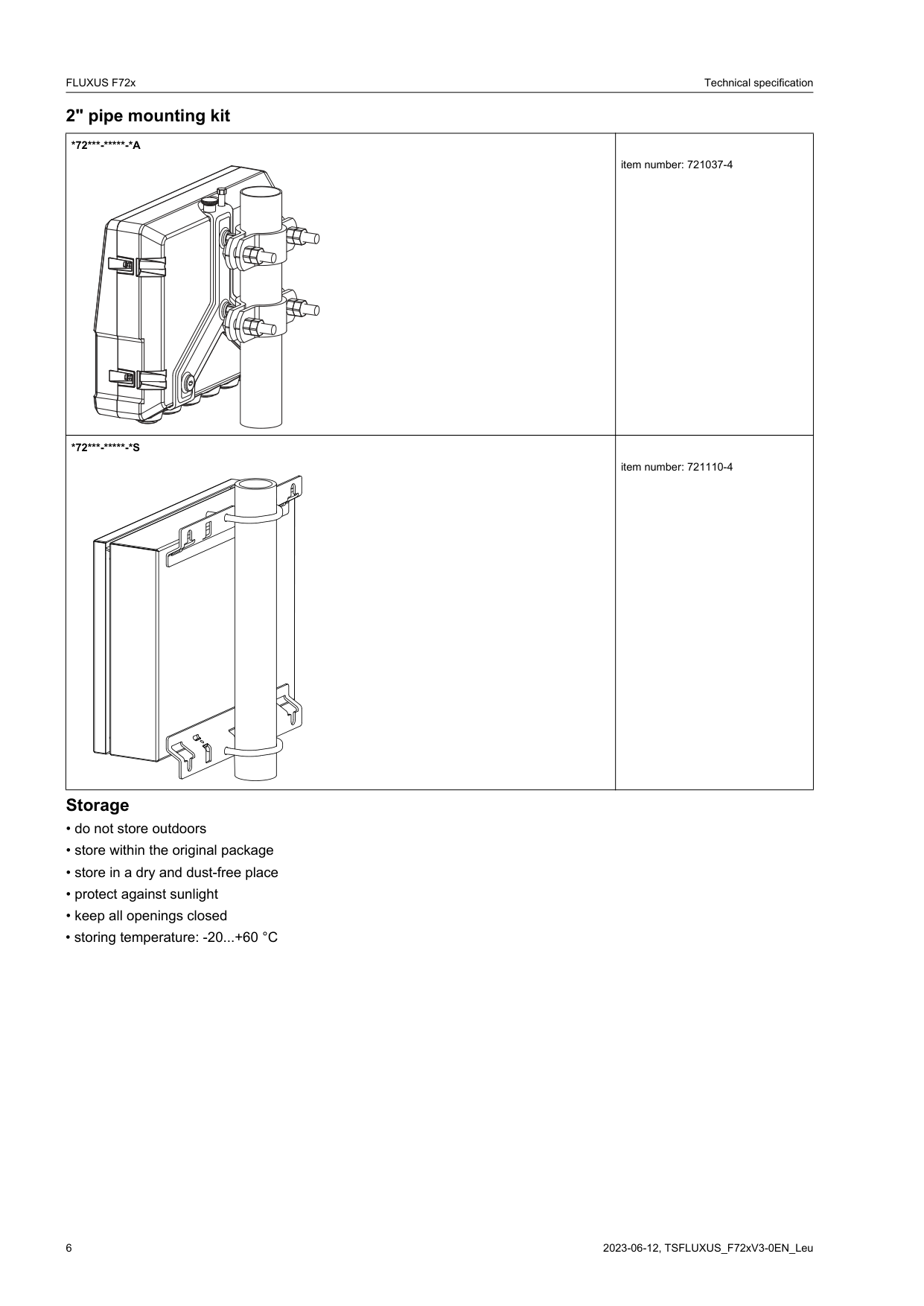
2" pipe mounting kit
Storage
|*72*-***-*A
|item number: 721037-4| |---|---| |*72*-***-*S
|item number: 721110-4|
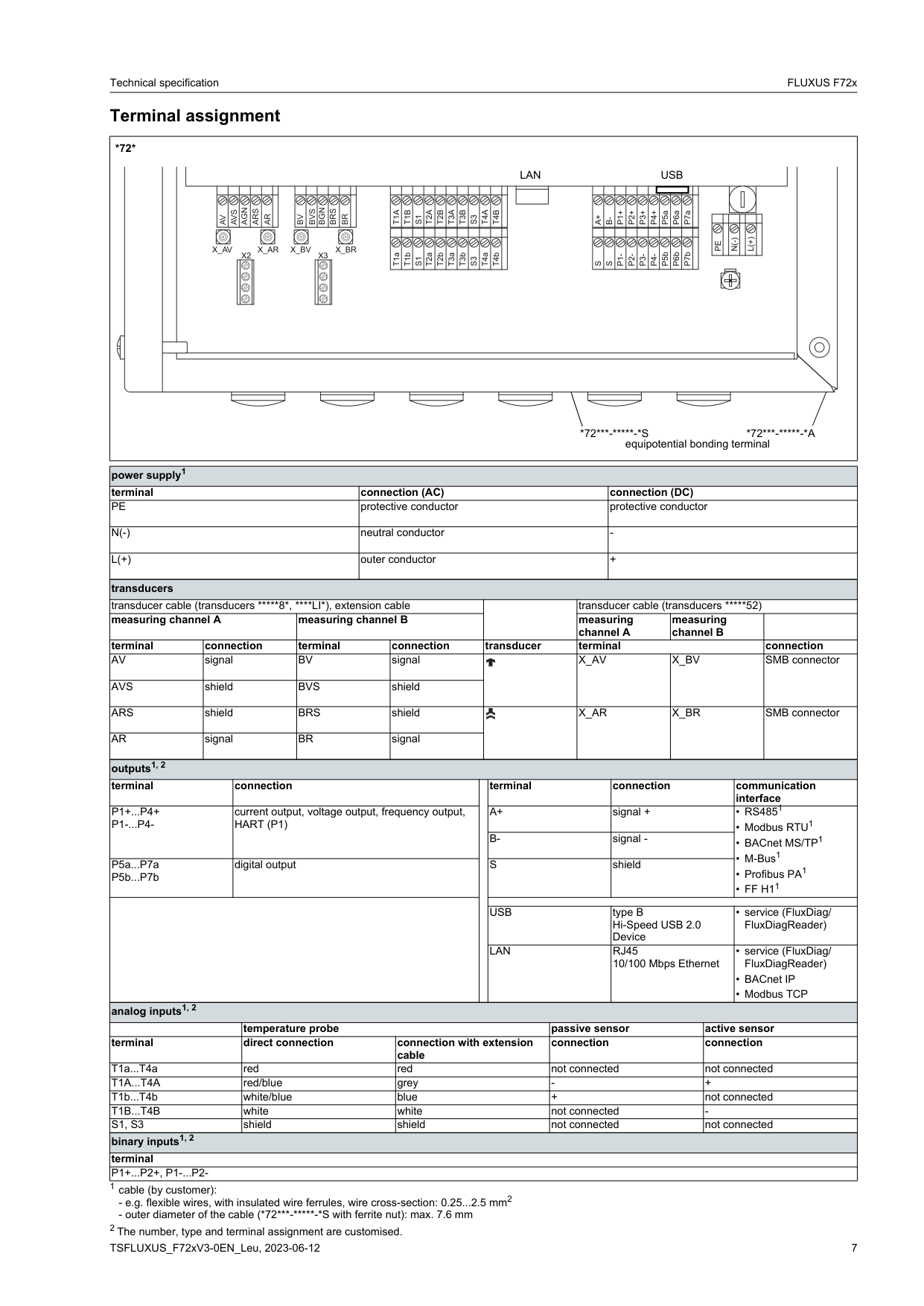
#### Terminal assignment
###### *72*
AGN
ARS
AVS
AR
AV
BGN
BRS
BVS
BR
BV
X_AV X_AR X_BV X_BR
X2 X3
| | | |---|---|
| | | |---|---|
LAN USB
T1A
T1B
T2A
T2B
T3A
T3B
T4B T4A
S1
S3
| | | | | | | | | | | | |---|---|---|---|---|---|---|---|---|---|---| |T1a|T1b|S1|T2a|T2b|T3a|T3b|S3|T4a|T4b| |
P1+
P2+
P3+
P4+
P6a
P7a
P5a
A+
B-
P5b
P6b
P7b
P1-
P2-
P3-
P4-
S
S
| | | | | | | |---|---|---|---|---|---| |PE| |N(-)| |L(+)| |
| | | | |---|---|---| | | | |
*72*-*-*S *72*-*-*A equipotential bonding terminal
|power supply1|power supply1|power supply1|power supply1|power supply1|power supply1|power supply1|power supply1|power supply1|power supply1|power supply1|power supply1|power supply1|power supply1|power supply1|power supply1|power supply1|power supply1|power supply1| |---|---|---|---|---|---|---|---|---|---|---|---|---|---|---|---|---|---|---| |terminal|terminal|terminal|terminal|terminal|connection (AC)|connection (AC)|connection (AC)|connection (AC)|connection (AC)|connection (AC)|connection (AC)|connection (AC)|connection (DC)|connection (DC)|connection (DC)|connection (DC)|connection (DC)|connection (DC)| |PE|PE|PE|PE|PE|protective conductor|protective conductor|protective conductor|protective conductor|protective conductor|protective conductor|protective conductor|protective conductor|protective conductor|protective conductor|protective conductor|protective conductor|protective conductor|protective conductor| |N(-)|N(-)|N(-)|N(-)|N(-)|neutral conductor|neutral conductor|neutral conductor|neutral conductor|neutral conductor|neutral conductor|neutral conductor|neutral conductor|-|-|-|-|-|-| |L(+)|L(+)|L(+)|L(+)|L(+)|outer conductor|outer conductor|outer conductor|outer conductor|outer conductor|outer conductor|outer conductor|outer conductor|+|+|+|+|+|+| |transducers|transducers|transducers|transducers|transducers|transducers|transducers|transducers|transducers|transducers|transducers|transducers|transducers|transducers|transducers|transducers|transducers|transducers|transducers| |transducer cable (transducers *8*, **LI*), extension cable|transducer cable (transducers *8*, LI*), extension cable|transducer cable (transducers *8*, LI*), extension cable|transducer cable (transducers *8*, LI*), extension cable|transducer cable (transducers *8*, LI*), extension cable|transducer cable (transducers *8*, LI*), extension cable|transducer cable (transducers *8*, LI*), extension cable|transducer cable (transducers *8*, LI*), extension cable|transducer cable (transducers *8*, LI*), extension cable| | | |transducer cable (transducers *52)|transducer cable (transducers *52)|transducer cable (transducers *52)|transducer cable (transducers *52)|transducer cable (transducers *52)|transducer cable (transducers *52)|transducer cable (transducers ***52)| |measuring channel A|measuring channel A|measuring channel A|measuring channel A|measuring channel B|measuring channel B|measuring channel B|measuring channel B|measuring channel B| | | |measuring channel A|measuring channel A|measuring channel A|measuring channel B|measuring channel B|measuring channel B| | |terminal|connection|connection|connection|terminal|terminal|connection|connection|connection|transducer|transducer|transducer|terminal|terminal|terminal|terminal|terminal|terminal|connection| |AV|signal|signal|signal|BV|BV|signal|signal|signal||||X_AV|X_AV|X_AV|X_BV|X_BV|X_BV|SMB connector| |AVS|shield|shield|shield|BVS|BVS|shield|shield|shield||||X_AV|X_AV|X_AV|X_BV|X_BV|X_BV|SMB connector| |ARS|shield|shield|shield|BRS|BRS|shield|shield|shield||||X_AR|X_AR|X_AR|X_BR|X_BR|X_BR|SMB connector| |AR|signal|signal|signal|BR|BR|signal|signal|signal||||X_AR|X_AR|X_AR|X_BR|X_BR|X_BR|SMB connector| |outputs1, 2|outputs1, 2|outputs1, 2|outputs1, 2|outputs1, 2|outputs1, 2|outputs1, 2|outputs1, 2|outputs1, 2|outputs1, 2|outputs1, 2|outputs1, 2|outputs1, 2|outputs1, 2|outputs1, 2|outputs1, 2|outputs1, 2|outputs1, 2|outputs1, 2| |terminal|terminal|connection|connection|connection|connection|connection|connection| | |terminal|terminal|terminal|terminal|connection|connection|connection|communication interface
1|communication interface
1| |P1+...P4+ P1-...P4-|P1+...P4+ P1-...P4-|current output, voltage output, frequency output, HART (P1)|current output, voltage output, frequency output, HART (P1)|current output, voltage output, frequency output, HART (P1)|current output, voltage output, frequency output, HART (P1)|current output, voltage output, frequency output, HART (P1)|current output, voltage output, frequency output, HART (P1)| | |A+|A+|A+|A+|signal +|signal +|signal +|• RS485
• Modbus RTU1
• BACnet MS/TP1
• M-Bus1
• Profibus PA1
• FF H11
|• RS485
• Modbus RTU1
• BACnet MS/TP1
• M-Bus1
• Profibus PA1
• FF H11
| |P1+...P4+ P1-...P4-|P1+...P4+ P1-...P4-|current output, voltage output, frequency output, HART (P1)|current output, voltage output, frequency output, HART (P1)|current output, voltage output, frequency output, HART (P1)|current output, voltage output, frequency output, HART (P1)|current output, voltage output, frequency output, HART (P1)|current output, voltage output, frequency output, HART (P1)| | |B-|B-|B-|B-|signal -|signal -|signal -|• RS485
• Modbus RTU1
• BACnet MS/TP1
• M-Bus1
• Profibus PA1
• FF H11
|• RS485
• Modbus RTU1
• BACnet MS/TP1
• M-Bus1
• Profibus PA1
• FF H11
| |P5a...P7a
P5b...P7b
|P5a...P7a
P5b...P7b
|digital output|digital output|digital output|digital output|digital output|digital output| | |S|S|S|S|shield|shield|shield|• RS485
• Modbus RTU1
• BACnet MS/TP1
• M-Bus1
• Profibus PA1
• FF H11
|• RS485
• Modbus RTU1
• BACnet MS/TP1
• M-Bus1
• Profibus PA1
• FF H11
| | | | | | | | | | | | | | | | | | | | | | | | | | | | | | | |USB|USB|USB|USB|type B Hi-Speed USB 2.0 Device|type B Hi-Speed USB 2.0 Device|type B Hi-Speed USB 2.0 Device|• service (FluxDiag/ FluxDiagReader)|• service (FluxDiag/ FluxDiagReader)| | | | | | | | | | | |LAN|LAN|LAN|LAN|RJ45 10/100 Mbps Ethernet|RJ45 10/100 Mbps Ethernet|RJ45 10/100 Mbps Ethernet|• service (FluxDiag/ FluxDiagReader)
• BACnet IP
• Modbus TCP
|• service (FluxDiag/ FluxDiagReader)
• BACnet IP
• Modbus TCP
| |analog inputs1, 2|analog inputs1, 2|analog inputs1, 2|analog inputs1, 2|analog inputs1, 2|analog inputs1, 2|analog inputs1, 2|analog inputs1, 2|analog inputs1, 2|analog inputs1, 2|analog inputs1, 2|analog inputs1, 2|analog inputs1, 2|analog inputs1, 2|analog inputs1, 2|analog inputs1, 2|analog inputs1, 2|analog inputs1, 2|analog inputs1, 2| | | | |temperature probe|temperature probe|temperature probe|temperature probe|temperature probe|temperature probe|temperature probe|temperature probe|passive sensor|passive sensor|passive sensor|passive sensor|passive sensor|active sensor|active sensor|active sensor| |terminal|terminal|terminal|direct connection|direct connection|direct connection|direct connection|connection with extension cable|connection with extension cable|connection with extension cable|connection with extension cable|connection|connection|connection|connection|connection|connection|connection|connection|
|T1a...T4a|T1a...T4a|T1a...T4a|red|red|red|red|red|red|red|red|not connected|not connected|not connected|not connected|not connected|not connected|not connected|not connected| |T1A...T4A|T1A...T4A|T1A...T4A|red/blue|red/blue|red/blue|red/blue|grey|grey|grey|grey|-|-|-|-|-|+|+|+| |T1b...T4b|T1b...T4b|T1b...T4b|white/blue|white/blue|white/blue|white/blue|blue|blue|blue|blue|+|+|+|+|+|not connected|not connected|not connected| |T1B...T4B|T1B...T4B|T1B...T4B|white|white|white|white|white|white|white|white|not connected|not connected|not connected|not connected|not connected|-|-|-| |S1, S3|S1, S3|S1, S3|shield|shield|shield|shield|shield|shield|shield|shield|not connected|not connected|not connected|not connected|not connected|not connected|not connected|not connected| |binary inputs1, 2|binary inputs1, 2|binary inputs1, 2|binary inputs1, 2|binary inputs1, 2|binary inputs1, 2|binary inputs1, 2|binary inputs1, 2|binary inputs1, 2|binary inputs1, 2|binary inputs1, 2|binary inputs1, 2|binary inputs1, 2|binary inputs1, 2|binary inputs1, 2|binary inputs1, 2|binary inputs1, 2|binary inputs1, 2|binary inputs1, 2| |terminal|terminal|terminal|terminal|terminal|terminal|terminal|terminal|terminal|terminal|terminal|terminal|terminal|terminal|terminal|terminal|terminal|terminal|terminal| |P1+...P2+, P1-...P2-|P1+...P2+, P1-...P2-|P1+...P2+, P1-...P2-|P1+...P2+, P1-...P2-|P1+...P2+, P1-...P2-|P1+...P2+, P1-...P2-|P1+...P2+, P1-...P2-|P1+...P2+, P1-...P2-|P1+...P2+, P1-...P2-|P1+...P2+, P1-...P2-|P1+...P2+, P1-...P2-|P1+...P2+, P1-...P2-|P1+...P2+, P1-...P2-|P1+...P2+, P1-...P2-|P1+...P2+, P1-...P2-|P1+...P2+, P1-...P2-|P1+...P2+, P1-...P2-|P1+...P2+, P1-...P2-|P1+...P2+, P1-...P2-|
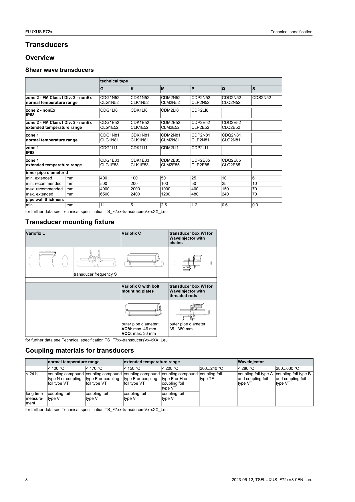
Transducers Overview Shear wave transducers
| | | |technical type|technical type|technical type|technical type|technical type|technical type| |---|---|---|---|---|---|---|---|---| | | | |G|K|M|P|Q|S| | | | | | | | | | | |zone 2 - FM Class I Div. 2 - nonEx normal temperature range|zone 2 - FM Class I Div. 2 - nonEx normal temperature range|zone 2 - FM Class I Div. 2 - nonEx normal temperature range|CDG1N52 CLG1N52|CDK1N52 CLK1N52|CDM2N52 CLM2N52|CDP2N52 CLP2N52|CDQ2N52 CLQ2N52|CDS2N52| | | | | | | | | | | |zone 2 - nonEx IP68|zone 2 - nonEx IP68|zone 2 - nonEx IP68|CDG1LI8|CDK1LI8|CDM2LI8|CDP2LI8| | | | | | | | | | | | | |zone 2 - FM Class I Div. 2 - nonEx extended temperature range|zone 2 - FM Class I Div. 2 - nonEx extended temperature range|zone 2 - FM Class I Div. 2 - nonEx extended temperature range|CDG1E52 CLG1E52|CDK1E52 CLK1E52|CDM2E52 CLM2E52|CDP2E52 CLP2E52|CDQ2E52 CLQ2E52| | | | | | | | | | | | |zone 1 normal temperature range|zone 1 normal temperature range|zone 1 normal temperature range|CDG1N81 CLG1N81|CDK1N81 CLK1N81|CDM2N81 CLM2N81|CDP2N81 CLP2N81|CDQ2N81 CLQ2N81| | | | | | | | | | | | |zone 1 IP68|zone 1 IP68|zone 1 IP68|CDG1LI1|CDK1LI1|CDM2LI1|CDP2LI1| | | | | | | | | | | | | |zone 1 extended temperature range|zone 1 extended temperature range|zone 1 extended temperature range|CDG1E83 CLG1E83|CDK1E83 CLK1E83|CDM2E85 CLM2E85|CDP2E85 CLP2E85|CDQ2E85 CLQ2E85| | | | | | | | | | | | |inner pipe diameter d|inner pipe diameter d|inner pipe diameter d|inner pipe diameter d|inner pipe diameter d|inner pipe diameter d|inner pipe diameter d|inner pipe diameter d| | |min. extended|mm| |400|100|50|25|10|6|
|min. recommended|mm| |500|200|100|50|25|10| |max. recommended|mm| |4000|2000|1000|400|150|70| |max. extended|mm| |6500|2400|1200|480|240|70| |pipe wall thickness|pipe wall thickness|pipe wall thickness|pipe wall thickness|pipe wall thickness|pipe wall thickness|pipe wall thickness|pipe wall thickness| | |min.|mm| |11|5|2.5|1.2|0.6|0.3|
for further data see Technical specification TS_F7xx-transducersVx-xXX_Leu
#### Transducer mounting fixture
|Variofix L
|Variofix L
|Variofix C|transducer box WI for WaveInjector with chains| |---|---|---|---| | |transducer frequency S
| | | | | | | | | | |Variofix C with bolt mounting plates|transducer box WI for WaveInjector with threaded rods| | | |outer pipe diameter:
VCM: max. 46 mm VCQ: max. 36 mm
|outer pipe diameter: 35...380 mm
|
for further data see Technical specification TS_F7xx-transducersVx-xXX_Leu
#### Coupling materials for transducers
| |normal temperature range|normal temperature range|extended temperature range|extended temperature range|extended temperature range|WaveInjector|WaveInjector| |---|---|---|---|---|---|---|---| | |< 100 °C|< 170 °C|< 150 °C|< 200 °C|200...240 °C|< 280 °C|280...630 °C| |< 24 h|coupling compound type N or coupling foil type VT|coupling compound type E or coupling foil type VT|coupling compound type E or coupling foil type VT|coupling compound type E or H or coupling foil type VT|coupling foil type TF|coupling foil type A and coupling foil type VT|coupling foil type B and coupling foil type VT| |long time measurement|coupling foil type VT|coupling foil type VT|coupling foil type VT|coupling foil type VT|coupling foil type TF|coupling foil type A and coupling foil type VT|coupling foil type B and coupling foil type VT|
for further data see Technical specification TS_F7xx-transducersVx-xXX_Leu
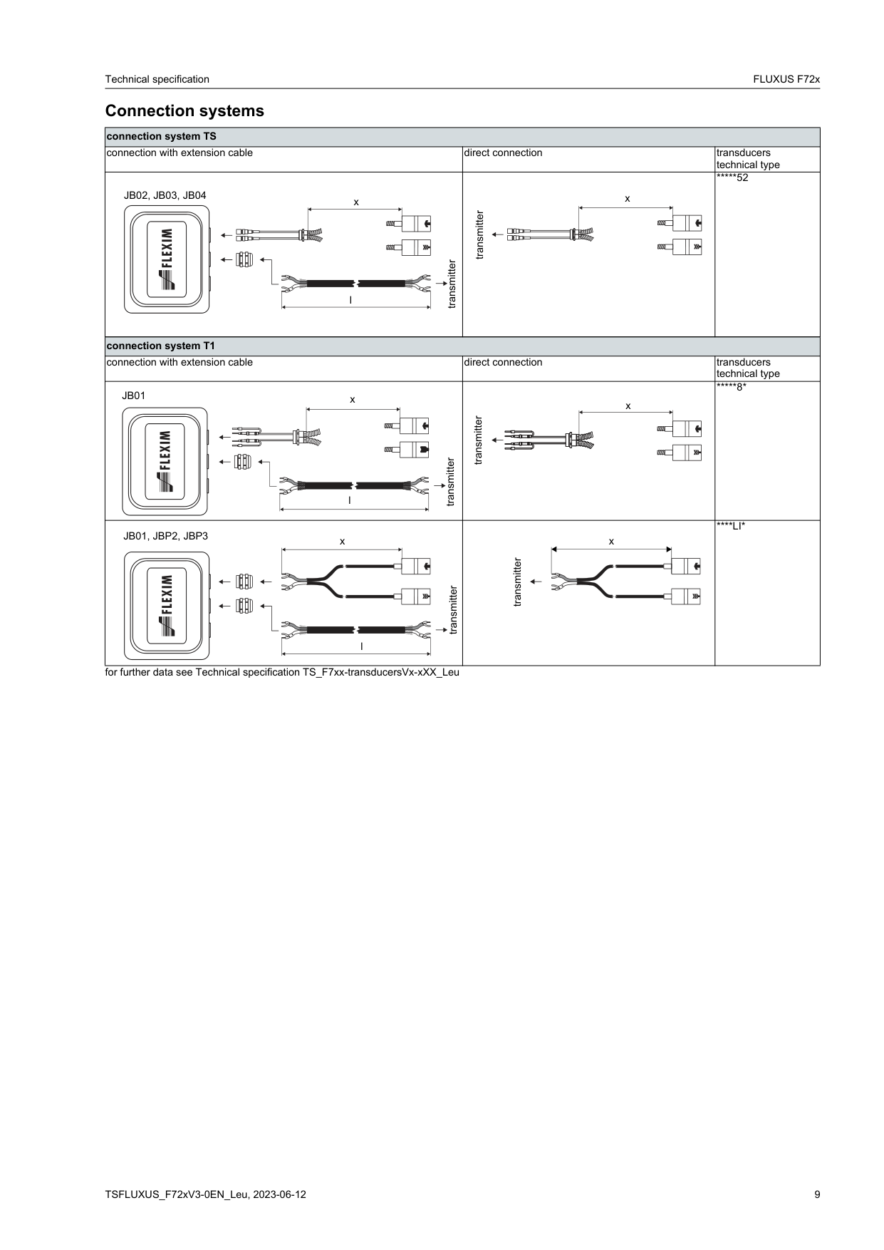
#### Connection systems
|connection system TS|connection system TS|connection system TS| |---|---|---| |connection with extension cable|direct connection|transducers technical type| |transmitter
JB02, JB03, JB04
x
l|transmitter
x|*52| |connection system T1|connection system T1|connection system T1|

|connection with extension cable|direct connection|transducers technical type| |transmitter
JB01 x
l|transmitter
x|*8*| |transmitter
x
l
JB01, JBP2, JBP3|transmitter
x
|****LI*|
for further data see Technical specification TS_F7xx-transducersVx-xXX_Leu
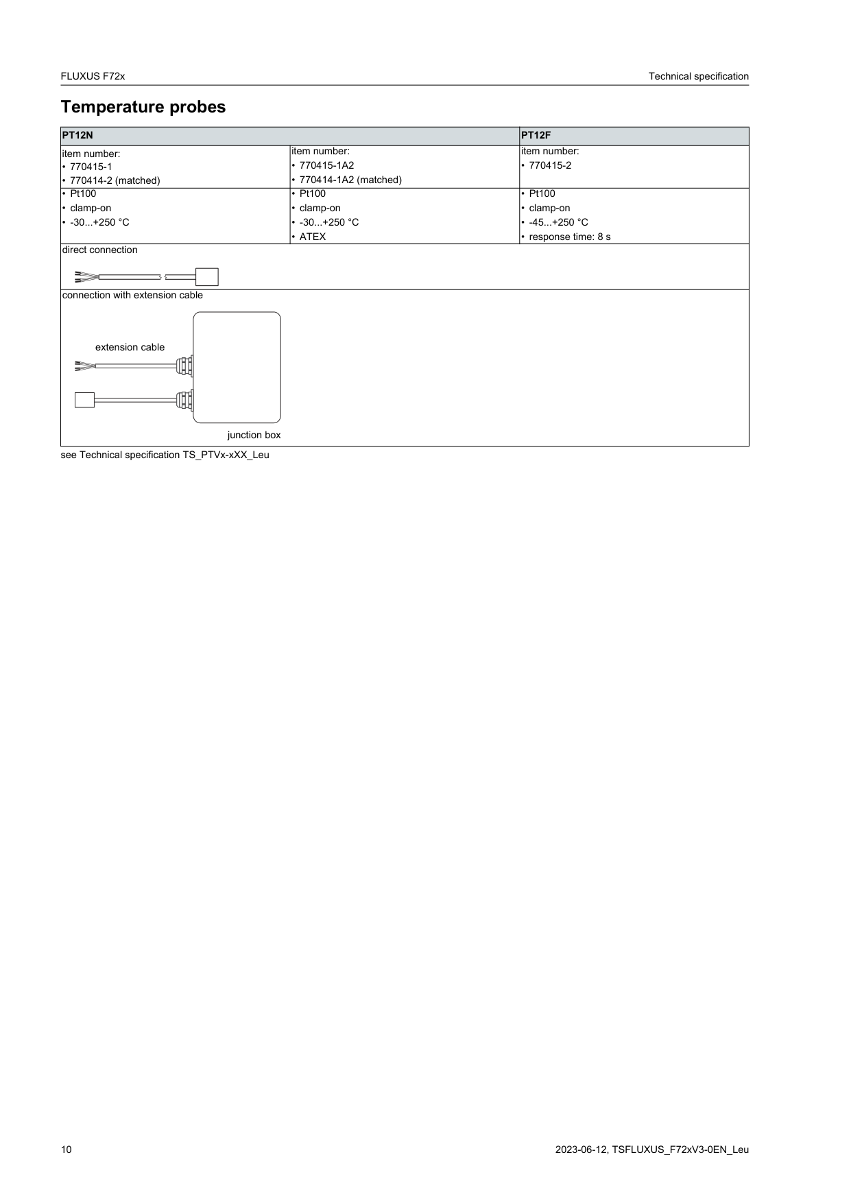
Temperature probes
|PT12N|PT12N|PT12F| |---|---|---| |item number:
• 770415-1
• 770414-2 (matched)
|item number:
• 770415-1A2
• 770414-1A2 (matched)
|item number:
• 770415-2| |• Pt100
• clamp-on
• -30...+250 °C
|• Pt100
• clamp-on
• -30...+250 °C
• ATEX
|• Pt100
• clamp-on
• -45...+250 °C
• response time: 8 s
| |direct connection
|direct connection
|direct connection
| |connection with extension cable
extension cable
junction box|connection with extension cable
extension cable
junction box|connection with extension cable
extension cable
junction box|
see Technical specification TS_PTVx-xXX_Leu
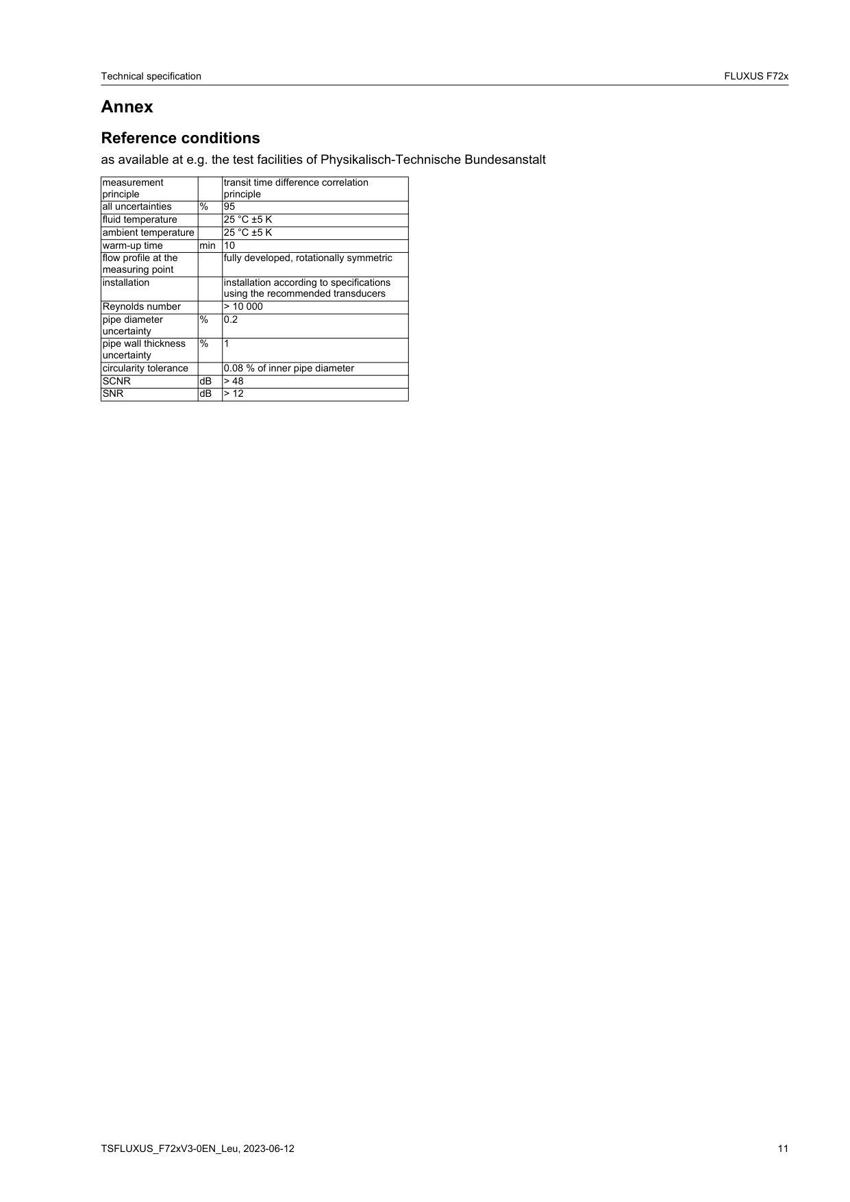
Annex Reference conditions as available at e.g. the test facilities of Physikalisch-Technische Bundesanstalt
|measurement principle| |transit time difference correlation principle| |---|---|---| |all uncertainties|%|95| |fluid temperature| |25 °C ±5 K| |ambient temperature| |25 °C ±5 K| |warm-up time|min|10| |flow profile at the measuring point| |fully developed, rotationally symmetric| |installation| |installation according to specifications using the recommended transducers| |Reynolds number| |> 10 000| |pipe diameter uncertainty|%|0.2| |pipe wall thickness uncertainty|%|1| |circularity tolerance| |0.08 % of inner pipe diameter| |SCNR|dB|> 48| |SNR|dB|> 12|
Technical Specification TSFLUXUS_F72xV3-0-0-0EN_Leu
For more information: Emerson.com © 2023 Emerson. All rights reserved. Emerson Terms and Conditions of Sale are available upon request. The Emerson logo is a trademark and service mark of Emerson Electric Co. Flexim is a mark of one of the Emerson family of companies. All other marks are the property of their respective owners.

