
Fluke 101 Basic Digital Multimeter
Ask AI
— answers from the official manualAnswers from the official manual.
Common questions
Common Questions
15 totalWhat type and how many batteries does the Fluke 101 use, and what is the expected battery life?
The Fluke 101 uses 2 AAA batteries (NEDA 24A, IEC LR03). The minimum battery life is 200 hours. The low battery indicator on the display will show when batteries need to be replaced to prevent incorrect measurements. (Page 20)
What should I do if the Fluke 101 is not going to be used for an extended period?
Remove the batteries if the Product is not used for an extended period of time, or if stored in temperatures above 50 °C. If the batteries are not removed, battery leakage can damage the Product. (Page 8)
How do I measure capacitance with the Fluke 101?
Turn the rotary switch to the capacitance setting, connect the red test lead to the input terminal and the black test lead to the COM terminal, then touch the probes to the capacitor leads. Allow the reading to stabilize, which can take up to 18 seconds, then read the capacitance value on the display. (Page 14)
How do I clean the terminals on the Fluke 101?
Turn the Product off and remove the test leads, then shake out any dirt that may be in the terminals. Soak a new swab with isopropyl alcohol and work around the inside of each input terminal, then use a new swab to apply a light coat of fine machine oil to the inside of each terminal. Dirt or moisture in the terminals can affect readings. (Page 18)
What is the warranty period for the Fluke 101, and what does it cover?
The Fluke 101 is warranted to be free from defects in material and workmanship for one year from the date of purchase. This warranty does not cover fuses, disposable batteries, or damage from accident, neglect, misuse, alteration, contamination, or abnormal conditions of operation or handling. To obtain service during the warranty period, contact the nearest Fluke authorized service center to obtain return authorization information. (Page 2)
How do I safely use the Data Hold function on the Fluke 101?
To hold the present reading, push the HOLD button; push it again to resume normal operation. You should not use the HOLD function to measure unknown potentials, as when HOLD is turned on, the display does not change when a different potential is measured. This could result in possible electrical shock, fire, or personal injury. (Page 10)
Show 9 more questions
What is the safety rating and maximum voltage for the Fluke 101?
How often should the Fluke 101 be calibrated, and who should perform repairs?
How do I disable the Auto Power Off feature on the Fluke 101?
How do I test for continuity with the Fluke 101?
How do I replace the batteries in my Fluke 101?
How often should I calibrate my Fluke 101 multimeter?
What safety precautions are important when using a Fluke 101?
What should I do if my Fluke 101 stops responding?
What happens if I don't replace the batteries in my Fluke 101?
Full Manual
28 pages
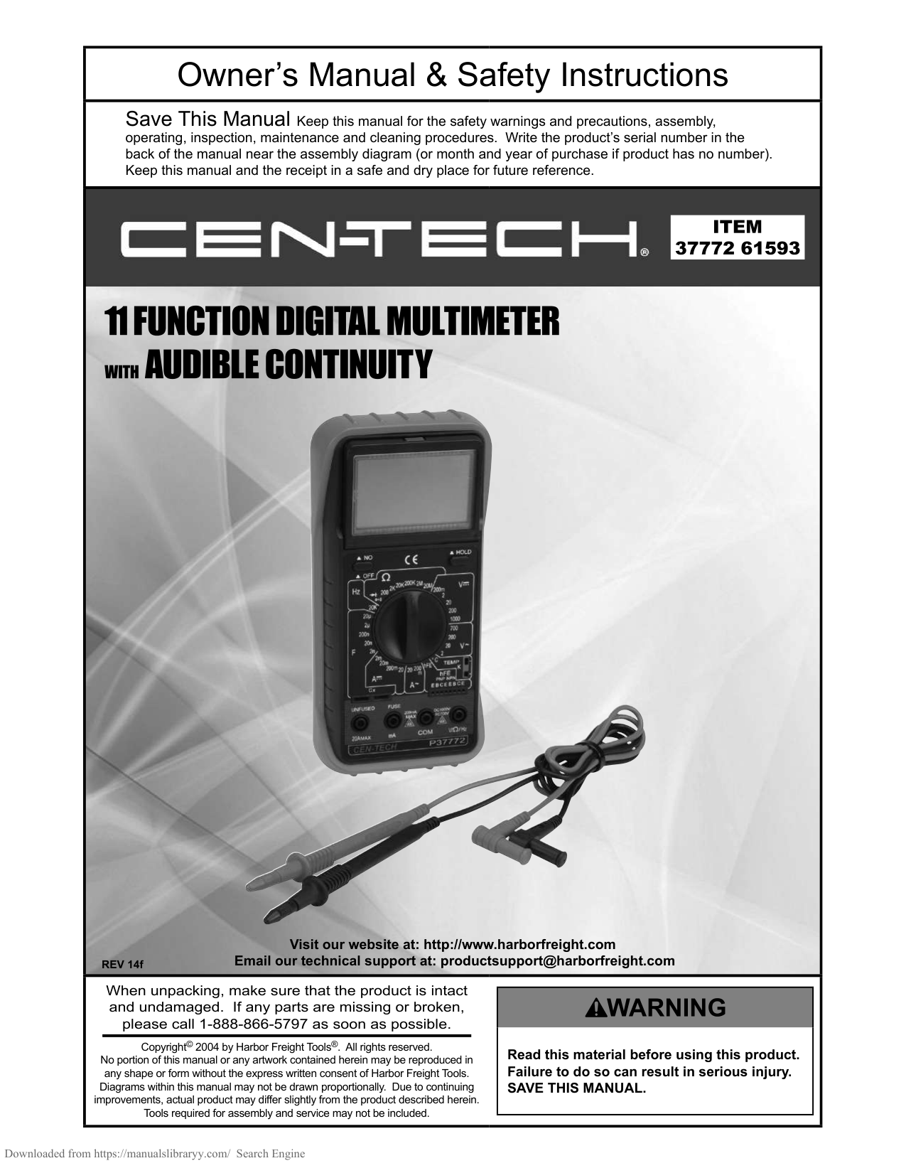
101
Digital Multimeter Users Manual
July 2013, Rev. 1, 10/15 © 2013-2015 Fluke Corporation. All rights reserved. Specifications are subject to change without notice. All product names are trademarks of their respective companies.
#### LIMITED WARRANTY AND LIMITATION OF LIABILITY
This Fluke product will be free from defects in material and workmanship for one year from the date of purchase. This warranty does not cover fuses, disposable batteries, or damage from accident, neglect, misuse, alteration, contamination, or abnormal conditions of operation or handling. Resellers are not authorized to extend any other warranty on Fluke’s behalf. To obtain service during the warranty period, contact your nearest Fluke authorized service center to obtain return authorization information, then send the product to that Service Center with a description of the problem.
THIS WARRANTY IS YOUR ONLY REMEDY. NO OTHER WARRANTIES, SUCH AS FITNESS FOR A PARTICULAR PURPOSE, ARE EXPRESSED OR IMPLIED. FLUKE IS NOT LIABLE FOR ANY SPECIAL, INDIRECT, INCIDENTAL OR CONSEQUENTIAL DAMAGES OR LOSSES, ARISING FROM ANY CAUSE OR THEORY. Since some states or countries do not allow the exclusion or limitation of an implied warranty or of incidental or consequential damages, this limitation of liability may not apply to you.
11/99
Fluke Corporation P.O. Box 9090 Everett, WA 98206-9090 U.S.A.
Fluke Europe B.V. P.O. Box 1186 5602 BD Eindhoven The Netherlands
Table of Contents
#### Title Page
Introduction ............................................................................................................... 1 How to Contact Fluke ............................................................................................... 1 Safety Information .................................................................................................... 2 Instrument Overview................................................................................................. 7
Terminals .............................................................................................................. 7 Display .................................................................................................................. 8
Auto Power Off ......................................................................................................... 9 Measurements .......................................................................................................... 10 Data Hold ............................................................................................................. 10 Measure AC and DC Voltage ............................................................................... 10 Measure Resistance ............................................................................................. 12 Test for Continuity ................................................................................................ 12 Test Diodes .......................................................................................................... 14 Measure Capacitance .......................................................................................... 14 Measure Frequency and Duty Cycle .................................................................... 15
i
101 Users Manual
Maintenance ............................................................................................................. 17 General Maintenance ........................................................................................... 18 Replace Batteries ................................................................................................. 19
Service and Parts ..................................................................................................... 20 General Specifications.............................................................................................. 20 Accuracy Specifications............................................................................................ 22
ii
Introduction The Fluke 101 Multimeter (the Product) is a 6000-count instrument. The Product is battery powered with a digital display. How to Contact Fluke To contact Fluke, call one of the following telephone numbers:
Or, visit Fluke's website at www.fluke.com.
To register your product, visit http://register.fluke.com. To view, print, or download the latest manual supplement, visit http://us.fluke.com/usen/support/manuals. Safety Information The Fluke 101 complies with IEC 61010-1 CAT III 600 V measurement category. See General Specifications.
A Warning identifies conditions and procedures that are dangerous to the user. A Caution identifies conditions and procedures that could cause damage to the Product or the equipment under test.
XW Warning
To prevent possible electrical shock, fire, or personal injury:
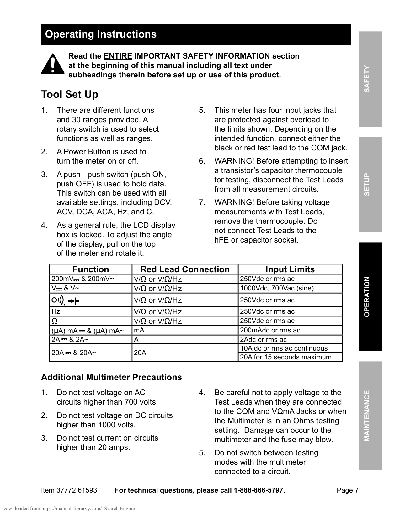
Table 1 is a list of the symbols used on the Product and in this manual.
###### Table 1. Symbols
||Consult user documentation.||Earth| |---|---|---|---| |W|WARNING. RISK OF DANGER.||Capacitance| |X|WARNING. HAZARDOUS VOLTAGE. Risk of electric shock.||Diode|
||AC (Alternating Current)||Both direct and alternating current| ||DC (Direct Current)||Battery| |Ã|Conforms to relevant South Korean EMC Standards||Certified by TÜV SÜD Product Service.| |P|Conforms to European Union directives.|)|Certified by CSA Group to North American safety standards.|
###### Table 1. Symbols (cont.)
||Measurement Category II is applicable to test and measuring circuits connected directly to utilization points (socket outlets and similar points) of the low-voltage MAINS installation.| |---|---| ||Measurement Category III is applicable to test and measuring circuits connected to the distribution part of the building’s low-voltage MAINS installation.|
||Measurement Category IV is applicable to test and measuring circuits connected at the source of the building’s low-voltage MAINS installation.| |~|This product complies with the WEEE Directive marking requirements. The affixed label indicates that you must not discard this electrical/electronic product in domestic household waste. Product Category: With reference to the equipment types in the WEEE Directive Annex I, this product is classed as category 9 "Monitoring and Control Instrumentation" product. Do not dispose of this product as unsorted municipal waste.|
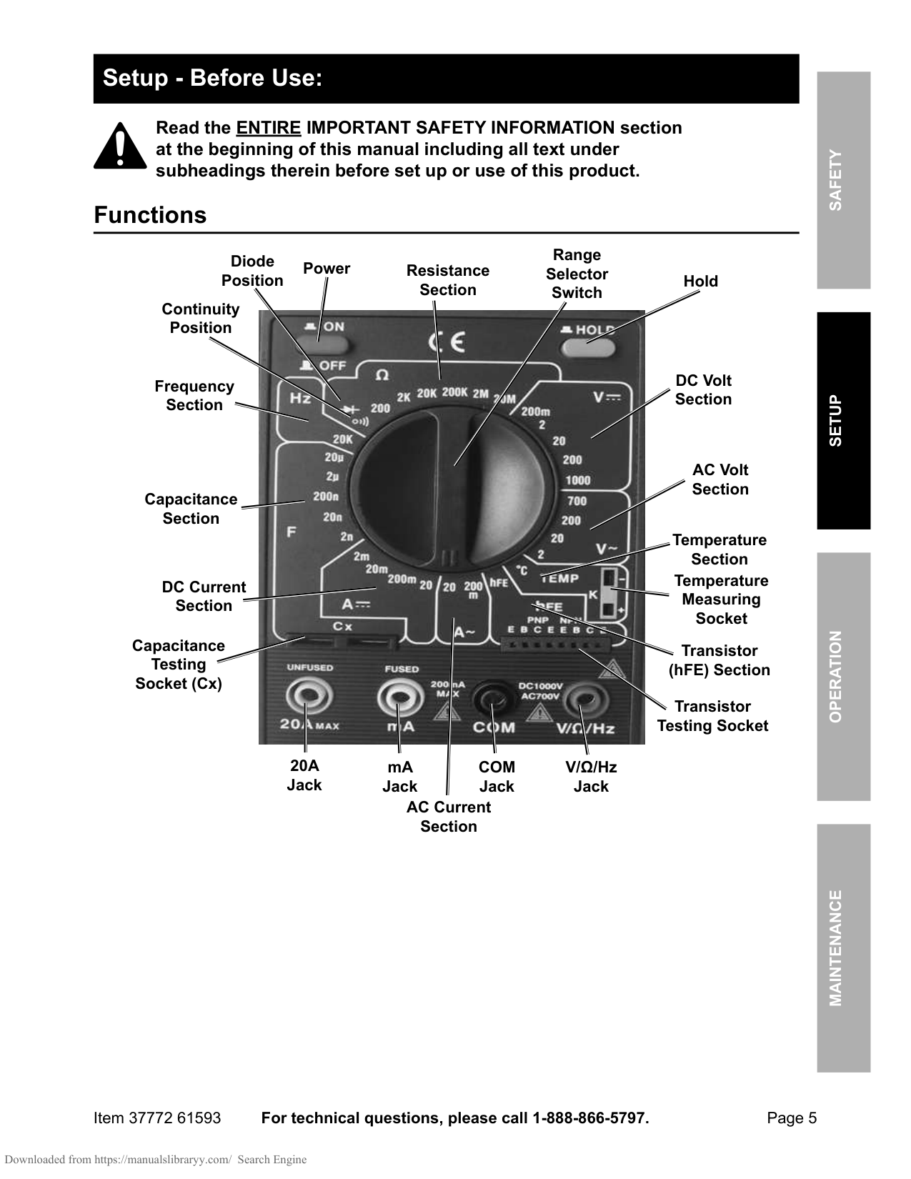
Instrument Overview
Instrument Overview Terminals
|1
2
hkm01.eps|1
2
hkm01.eps| |---|---| |Item|Description|
||Common (return) terminal for all measurements.| ||Input terminal for all measurements.|
Display Figure 1 and Table 2 show the items on the Product display.
|1 2 3 4 5 6 7 8
9
10
11
12
1314
| |---|
###### hkm02.eps Figure 1. Display
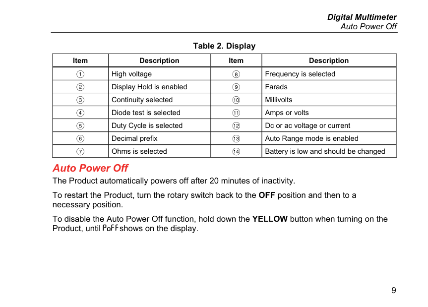
###### Auto Power Off Table 2. Display
|Item|Description|Item|Description| |---|---|---|---| ||High voltage||Frequency is selected| ||Display Hold is enabled||Farads| ||Continuity selected||Millivolts| ||Diode test is selected||Amps or volts| ||Duty Cycle is selected||Dc or ac voltage or current| ||Decimal prefix||Auto Range mode is enabled|
||Ohms is selected||Battery is low and should be changed|
Auto Power Off The Product automatically powers off after 20 minutes of inactivity. To restart the Product, turn the rotary switch back to the OFF position and then to a necessary position. To disable the Auto Power Off function, hold down the YELLOW button when turning on the Product, until shows on the display.
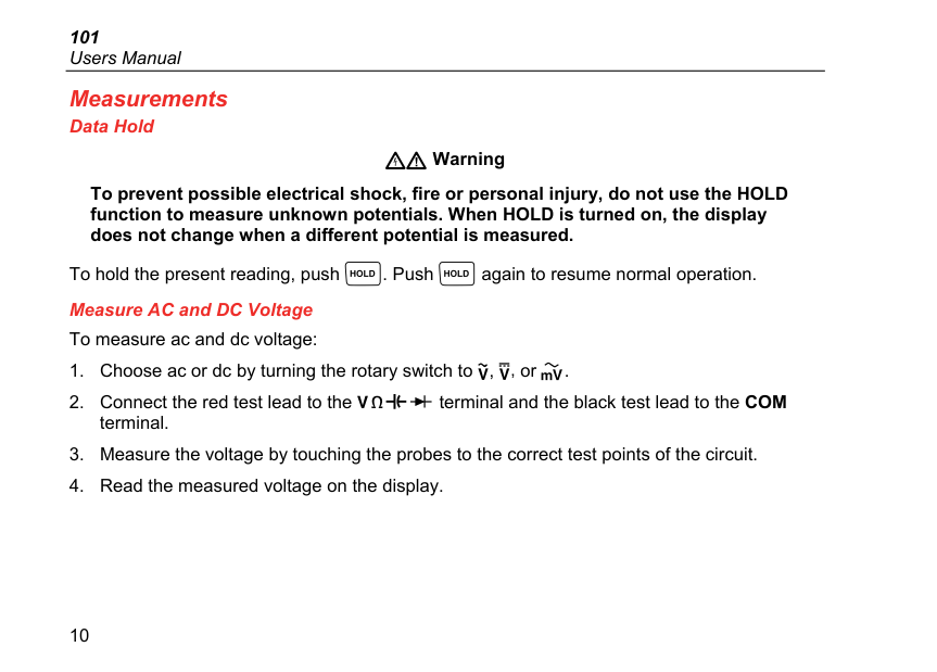
Measurements Data Hold
XW Warning
To prevent possible electrical shock, fire or personal injury, do not use the HOLD function to measure unknown potentials. When HOLD is turned on, the display does not change when a different potential is measured.
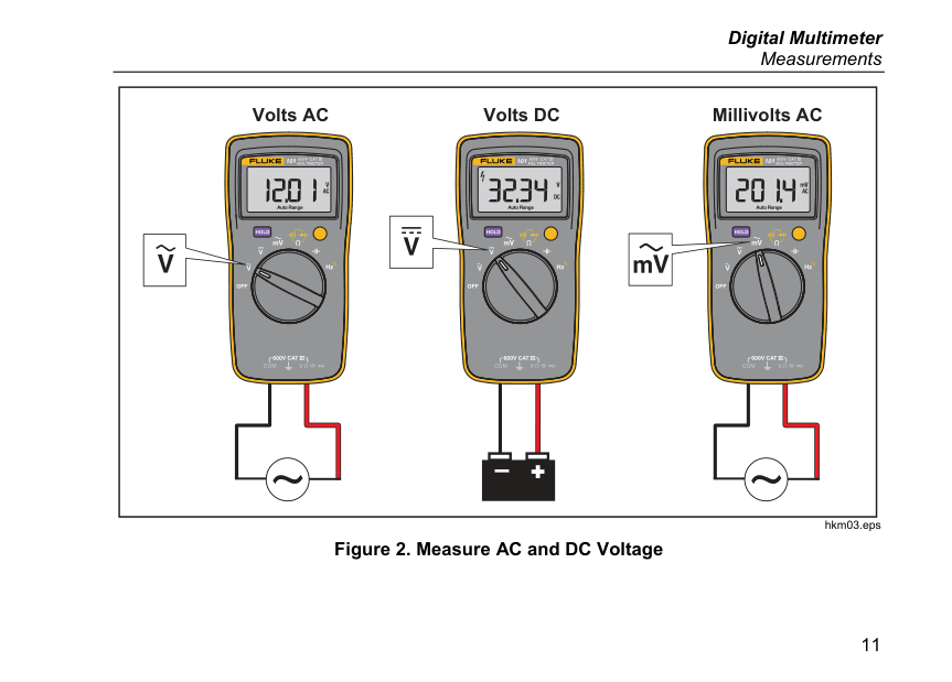
To hold the present reading, push . Push again to resume normal operation. Measure AC and DC Voltage To measure ac and dc voltage:
|m
Volts AC Volts DC Millivolts AC| |---|
###### hkm03.eps Figure 2. Measure AC and DC Voltage
###### Measure Resistance
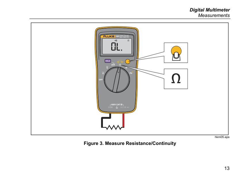
With the resistance mode selected, push the YELLOW button once to activate the continuity mode. If the resistance is <70 Ω, the beeper sounds continuously, designating a short circuit. If the Product reads , the circuit is open.
|m| |---|
###### hkm05.eps Figure 3. Measure Resistance/Continuity
###### Test Diodes
. This can be used to distinguish the anode and cathode sides of a diode. Measure Capacitance
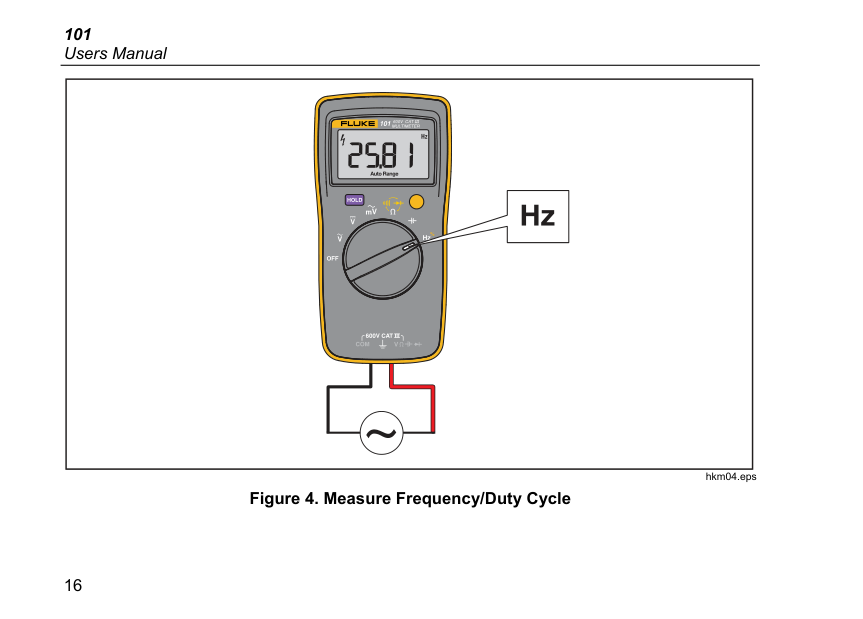
###### Measure Frequency and Duty Cycle To measure frequency:
|m| |---|
###### hkm04.eps Figure 4. Measure Frequency/Duty Cycle
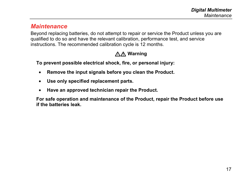
Maintenance Beyond replacing batteries, do not attempt to repair or service the Product unless you are qualified to do so and have the relevant calibration, performance test, and service instructions. The recommended calibration cycle is 12 months.
XW Warning
To prevent possible electrical shock, fire, or personal injury:
For safe operation and maintenance of the Product, repair the Product before use if the batteries leak.
###### General Maintenance
Periodically wipe the case with a damp cloth and mild detergent. Do not use abrasives or solvents. Dirt or moisture in the terminals can affect readings.
To clean the terminals:
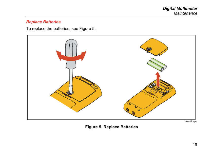
Replace Batteries To replace the batteries, see Figure 5.
###### hkm07.eps Figure 5. Replace Batteries
Service and Parts If the Product fails, first check the batteries. Then, review this manual to make sure you are operating the Product correctly. Replacement parts are:
|Item|Fluke Part Number| |---|---| |Batteries|2838018| |Battery door|4319659| |Test leads TL175|4306653| |Screws|4320657|
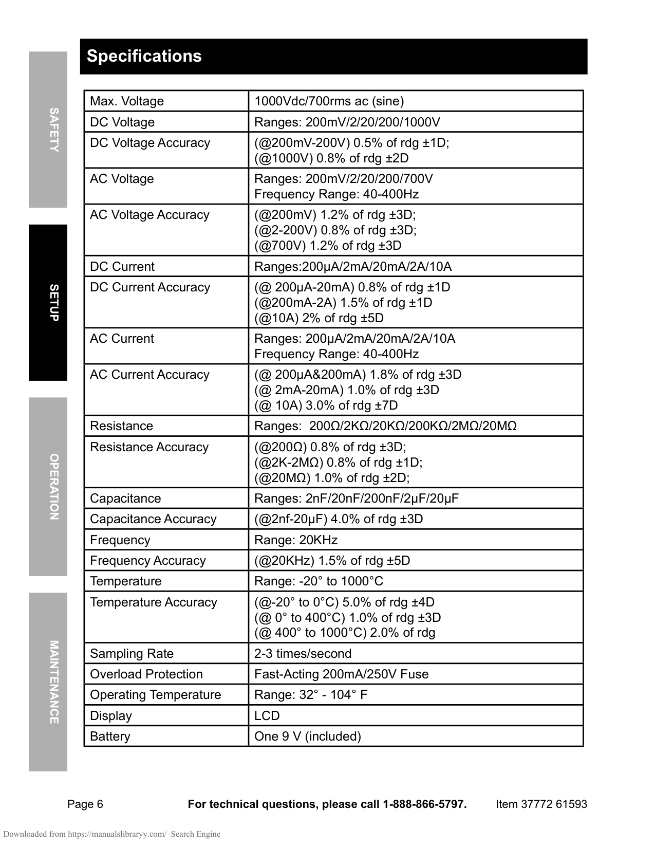
General Specifications Maximum voltage between any terminal and Earth Ground.............................................. 600 V Display (LCD)..................................................... 6000 counts, update rate 3/sec Battery Type....................................................... 2 AAA, NEDA 24A, IEC LR03 Battery Life......................................................... 200 hours minimum Temperature
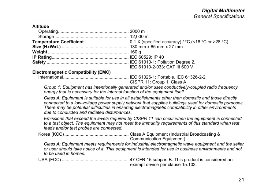
Operating ........................................................ 0 °C to 40 °C Storage........................................................... -30 °C to 60 °C
######## Relative Humidity
Operating Humidity ......................................... Non-condensing when <10 °C; ≤90 % at 10 °C to 30 °C; ≤75 % at 30 °C to 40 °C (Non-condensing)
Operating Humidity, 40 MΩ Range ................. ≤80 % at 10 °C to 30 °C; ≤70 % at 30 °C to 40 °C (Non-condensing)
General Specifications
Altitude Operating ........................................................ 2000 m Storage ........................................................... 12,000 m
Temperature Coefficient ................................... 0.1 X (specified accuracy) / °C (<18 °C or >28 °C) Size (HxWxL) ..................................................... 130 mm x 65 mm x 27 mm Weight................................................................ 160 g IP Rating............................................................. IEC 60529: IP 40 Safety ................................................................. IEC 61010-1: Pollution Degree 2,
IEC 61010-2-033: CAT III 600 V Electromagnetic Compatibility (EMC)
International .................................................... IEC 61326-1: Portable, IEC 61326-2-2
CISPR 11: Group 1, Class A Group 1: Equipment has intentionally generated and/or uses conductively-coupled radio frequency energy that is necessary for the internal function of the equipment itself. Class A: Equipment is suitable for use in all establishments other than domestic and those directly connected to a low-voltage power supply network that supplies buildings used for domestic purposes. There may be potential difficulties in ensuring electromagnetic compatibility in other environments due to conducted and radiated disturbances. Emissions that exceed the levels required by CISPR 11 can occur when the equipment is connected to a test object. The equipment may not meet the immunity requirements of this standard when test leads and/or test probes are connected.
Korea (KCC)................................................... Class A Equipment (Industrial Broadcasting &
Communication Equipment) Class A: Equipment meets requirements for industrial electromagnetic wave equipment and the seller or user should take notice of it. This equipment is intended for use in business environments and not to be used in homes.
USA (FCC) ..................................................... 47 CFR 15 subpart B. This product is considered an exempt device per clause 15.103.
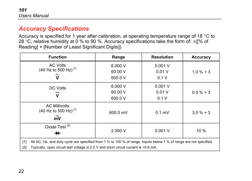
Accuracy Specifications Accuracy is specified for 1 year after calibration, at operating temperature range of 18 °C to 28 °C, relative humidity at 0 % to 90 %. Accuracy specifications take the form of: ±([% of Reading] + [Number of Least Significant Digits])
|Function|Range|Resolution|Accuracy| |---|---|---|---| |AC Volts (40 Hz to 500 Hz) [1]
|6.000 V 60.00 V 600.0 V|0.001 V 0.01 V 0.1 V|1.0 % + 3| |DC Volts |6.000 V 60.00 V 600.0 V|0.001 V 0.01 V 0.1 V|0.5 % + 3|
|AC Millivolts (40 Hz to 500 Hz) [1]
|600.0 mV|0.1 mV|3.0 % + 3| |Diode Test [2] |2.000 V|0.001 V|10 %| |[1] All AC, Hz, and duty cycle are specified from 1 % to 100 % of range. Inputs below 1 % of range are not specified.
[2] Typically, open circuit test voltage is 2.0 V and short circuit current is <0.6 mA.
|[1] All AC, Hz, and duty cycle are specified from 1 % to 100 % of range. Inputs below 1 % of range are not specified.
[2] Typically, open circuit test voltage is 2.0 V and short circuit current is <0.6 mA.
|[1] All AC, Hz, and duty cycle are specified from 1 % to 100 % of range. Inputs below 1 % of range are not specified.
[2] Typically, open circuit test voltage is 2.0 V and short circuit current is <0.6 mA.
|[1] All AC, Hz, and duty cycle are specified from 1 % to 100 % of range. Inputs below 1 % of range are not specified.
[2] Typically, open circuit test voltage is 2.0 V and short circuit current is <0.6 mA.
|
####### Accuracy Specifications
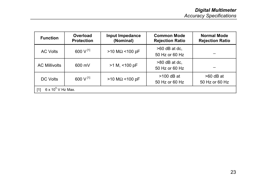
|Function|Overload Protection|Input Impedance (Nominal)|Common Mode Rejection Ratio|Normal Mode Rejection Ratio| |---|---|---|---|---| |AC Volts|600 V [1]|>10 MΩ<100 pF|>60 dB at dc, 50 Hz or 60 Hz|_| |AC Millivolts|600 mV|>1 M, <100 pF|>80 dB at dc, 50 Hz or 60 Hz|_| |DC Volts|600 V [1]|>10 MΩ<100 pF|>100 dB at 50 Hz or 60 Hz|>60 dB at 50 Hz or 60 Hz| |[1] 6 x 10⁵ V Hz Max.|[1] 6 x 10⁵ V Hz Max.|[1] 6 x 10⁵ V Hz Max.|[1] 6 x 10⁵ V Hz Max.|[1] 6 x 10⁵ V Hz Max.|
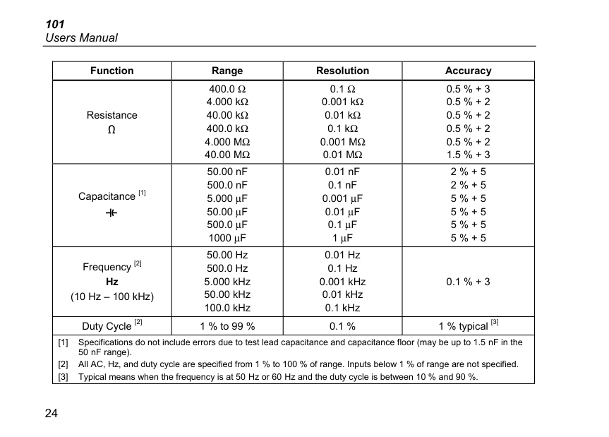
|Function|Range|Resolution|Accuracy| |---|---|---|---| |Resistance |400.0 Ω 4.000 kΩ 40.00 kΩ 400.0 kΩ 4.000 MΩ 40.00 MΩ|0.1 Ω 0.001 kΩ 0.01 kΩ 0.1 kΩ 0.001 MΩ 0.01 MΩ|0.5 % + 3 0.5 % + 2 0.5 % + 2 0.5 % + 2
0.5 % + 2
1.5 % + 3
| |Capacitance [1] |50.00 nF 500.0 nF 5.000 μF 50.00 μF 500.0 μF 1000 μF|0.01 nF 0.1 nF 0.001 μF 0.01 μF 0.1 μF 1 μF|2 % + 5 2 % + 5 5 % + 5 5 % + 5 5 % + 5 5 % + 5| |Frequency [2] Hz (10 Hz – 100 kHz)|50.00 Hz 500.0 Hz 5.000 kHz 50.00 kHz 100.0 kHz|0.01 Hz 0.1 Hz 0.001 kHz 0.01 kHz 0.1 kHz|0.1 % + 3| |Duty Cycle [2]|1 % to 99 %|0.1 %|1 % typical [3]| |[1] Specifications do not include errors due to test lead capacitance and capacitance floor (may be up to 1.5 nF in the 50 nF range).
[2] All AC, Hz, and duty cycle are specified from 1 % to 100 % of range. Inputs below 1 % of range are not specified.
[3] Typical means when the frequency is at 50 Hz or 60 Hz and the duty cycle is between 10 % and 90 %.
|[1] Specifications do not include errors due to test lead capacitance and capacitance floor (may be up to 1.5 nF in the 50 nF range).
[2] All AC, Hz, and duty cycle are specified from 1 % to 100 % of range. Inputs below 1 % of range are not specified.
[3] Typical means when the frequency is at 50 Hz or 60 Hz and the duty cycle is between 10 % and 90 %.
|