
Ask AI
— answers from the official manualAnswers from the official manual.
Common questions
Common Questions
8 totalHow do I set the system using a Master or Main type code?
To set the system with a Master or Main type code, enter the code followed by 1, 2, or 3 for Part 1, Part 2, or Part 3 setting respectively. The exit tone may sound depending on system settings.
How do I remove zones using a Master level user code?
Enter the Master level user code and press NO to enter the zone removal mode, then input the specific zone number followed by YES. Continue removing required zones until all needed changes are made.
What should I do if my Gardtec 800 Series system goes into a fault condition due to mains failure?
In case of a mains power failure, the display shows 'Power Cut FAULT'. After entering your user code twice, exit premises as directed and contact the installation company for further assistance.
How do I test my system?
Enter a Master or Main level code then press NO three times to access testing mode. Press YES for full testing, otherwise select specific areas by pressing NO until the desired area appears, then confirm with YES and proceed through test sequences.
How do I program User Codes on the Gardtec 800 Series?
To program a new user code, enter Master Code and choose 'Program USER CODES', then input desired User Number followed by your chosen code. Select required level of access from options shown.
How do I perform maintenance on my Gardtec 800 Series system?
The manual does not provide detailed steps for routine maintenance, focusing instead on contacting your installation company to ensure servicing complies with legal requirements and insurance terms.
Full Manual
48 pages
||GARDTEC 800 Series
User Instructions


| |---| | |---|
Contents User Information......................................................... 2 Introduction................................................................... 3 User Code Types.......................................................... 3 - 4 Setting The System ...................................................... 6 Unsetting The System .................................................. 7 Part Setting The System............................................... 7 Area Setting.................................................................. 9 Removing Zones........................................................... 10 Testing The System...................................................... 11 Viewing The Event Log................................................. 12 Changing The Chime Status......................................... 13 Programming User Codes ............................................ 15 Programming Time & Date ........................................... 18 User Initiating Remote Access ..................................... 19 Resetting After An Alarm .............................................. 20 Setting Engineer Authorisation ..................................... 23 Mains Failure ................................................................ 25 Setting the system with Mains Fail ............................... 25 Re-setting the display after a Mains Fail....................... 26 Setting the system with Line Fault................................ 27 System G-Tag............................................................... 28 Advanced Code Programming (Control Codes) ........... 29 Advanced Setting & Unsetting using Group Area Codes 32 Setting using Group Area Code.................................... 32 Programming Group Area User Codes......................... 33 Setting using Group Master & Group Main Codes ....... 36 Unsetting using Group Area Code................................ 37 Unsetting using Group Master & Group Main Codes ... 37 Adding Areas ................................................................ 38 Display Blanking ........................................................... 39 Keypad Alert - If Fitted.................................................. 40 Keypad Tamper ............................................................ 40 System Tampers........................................................... 40 System Attributes.......................................................... 41 Service Record ............................................................. 43 User Chart .................................................................... 44 ACE Instructions........................................................... 45 Programming ACE Keyfobs onto your System............. 46
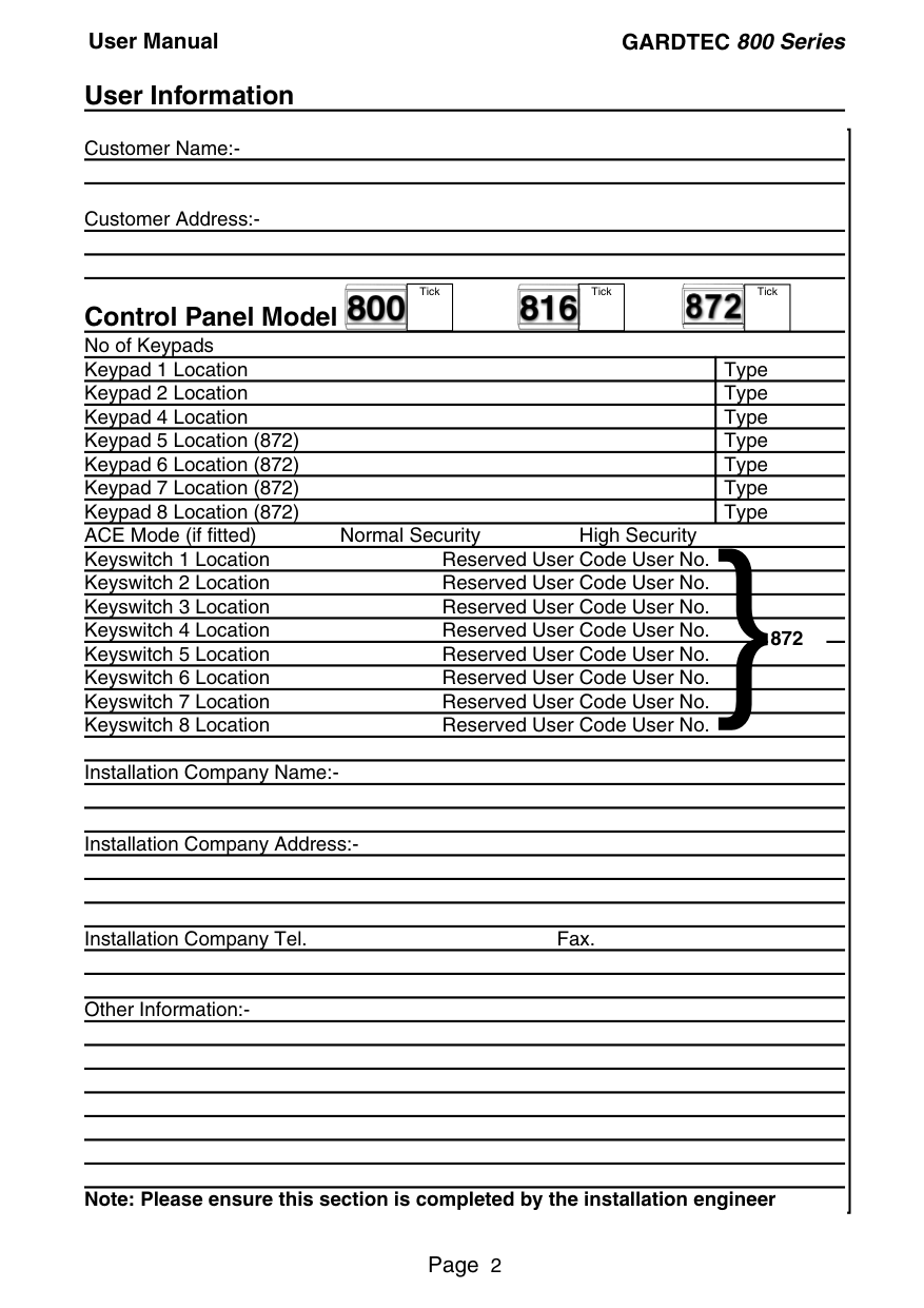
##### User Information
Customer Name:-
Customer Address:-


Tick Tick Tick
##### Control Panel Model No of Keypads
}872
Installation Company Address:-
Installation Company Tel. Fax.
Other Information:-
Note: Please ensure this section is completed by the installation engineer
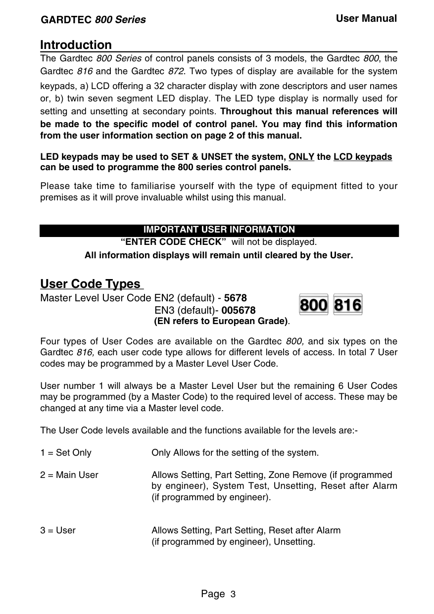
##### Introduction
The Gardtec 800 Series of control panels consists of 3 models, the Gardtec 800, the Gardtec 816 and the Gardtec 872. Two types of display are available for the system keypads, a) LCD offering a 32 character display with zone descriptors and user names or, b) twin seven segment LED display. The LED type display is normally used for setting and unsetting at secondary points. Throughout this manual references will be made to the specific model of control panel. You may find this information from the user information section on page 2 of this manual.
LED keypads may be used to SET & UNSET the system, ONLY the LCD keypads can be used to programme the 800 series control panels.
Please take time to familiarise yourself with the type of equipment fitted to your premises as it will prove invaluable whilst using this manual.
######### IMPORTANT USER INFORMATION
If the Control Panel is non EN then all displays will be shown and “ENTER CODE CHECK” will not be displayed. All information displays will remain until cleared by the User.
User Code Types Master Level User Code EN2 (default) - 5678
EN3 (default)- 005678 (EN refers to European Grade).


Four types of User Codes are available on the Gardtec 800, and six types on the Gardtec 816, each user code type allows for different levels of access. In total 7 User codes may be programmed by a Master Level User Code.
User number 1 will always be a Master Level User but the remaining 6 User Codes may be programmed (by a Master Code) to the required level of access. These may be changed at any time via a Master level code.
The User Code levels available and the functions available for the levels are:-
Codes, Set Time/Date, Reset After Alarm (if programmed by engineer), Unsetting.
Cleaner Part Set (from part cleaner set system). Control Code Levels (affecting an output) Control Allows an output that has been pre-programmed by the installation
company to be operated. May also have an attribute of Can or Can’t Unset. Control level codes can never Set a system.
User Code Types Master Level User Code EN2 (default) - 5678

EN3 (default)- 005678
99 user codes are available offering 19 code types with varying levels of access to the system. User number 1 will always be a Master Level User but the remaining User Codes may be programmed (by a Master Code) to the required level of access. These may be changed at any time via a Master level code
The User Code levels available and the functions available for the levels are:Master Allows Setting, Unsetting, Zone Remove (if programmed by
engineer), Test System, View Log, Chime On/Off, User Codes, Set Time/Date, Reset After Alarm (if programmed by engineer), Unsetting.
Cleaner Full System Setting (from unset system), Cleaner Area Unsetting (from set system), Cleaner Part Set (from part cleaner set system).
Area 1 to 7 User Allows Area 1 to 7 Setting, Area 1 to 7 Part Setting, Area 1 to 7 Unsetting.
Main User Allows Setting, Part Setting, Zone Remove (if programmed & Main User 1 to 7 by engineer), System Test, Unsetting, Reset after Alarm (if
programmed by engineer). Main User 1 to 7 are specific to their area.
Control Used for control of other equipment (see installation company for details).
Set Only Only Allows for the setting of the system.
Group Code Levels (affecting group or groups of areas) Group Master Allows Setting, Part Setting, Area Setting, Zone Remove, System
Test, Viewing the Log, Chime On/Off, Program User Codes, Set Time/Date, Unsetting. Will also allow setting/unsetting of individual areas for greater system control
Group Main Allows Setting, Part Setting, Area Setting, Zone Remove, System Test, Unsetting. Will also allow setting/unsetting of individual areas for greater system control
Group Area Allows group setting/unsetting/part setting of a selected group of areas.
Group Area Codes are classed as an Advanced User Function as they allow for greater flexibility on systems that are using multiple areas. For details on using Group Area Codes please refer to the section Advanced Setting and Unsetting Using Group Area Codes on page 32.
Control Code Levels (affecting an output) Control Allows an output that has been pre-programmed by the installation
company to be operated. May also have an attribute of Can or Can’t Unset. Control level codes can never Set a system.


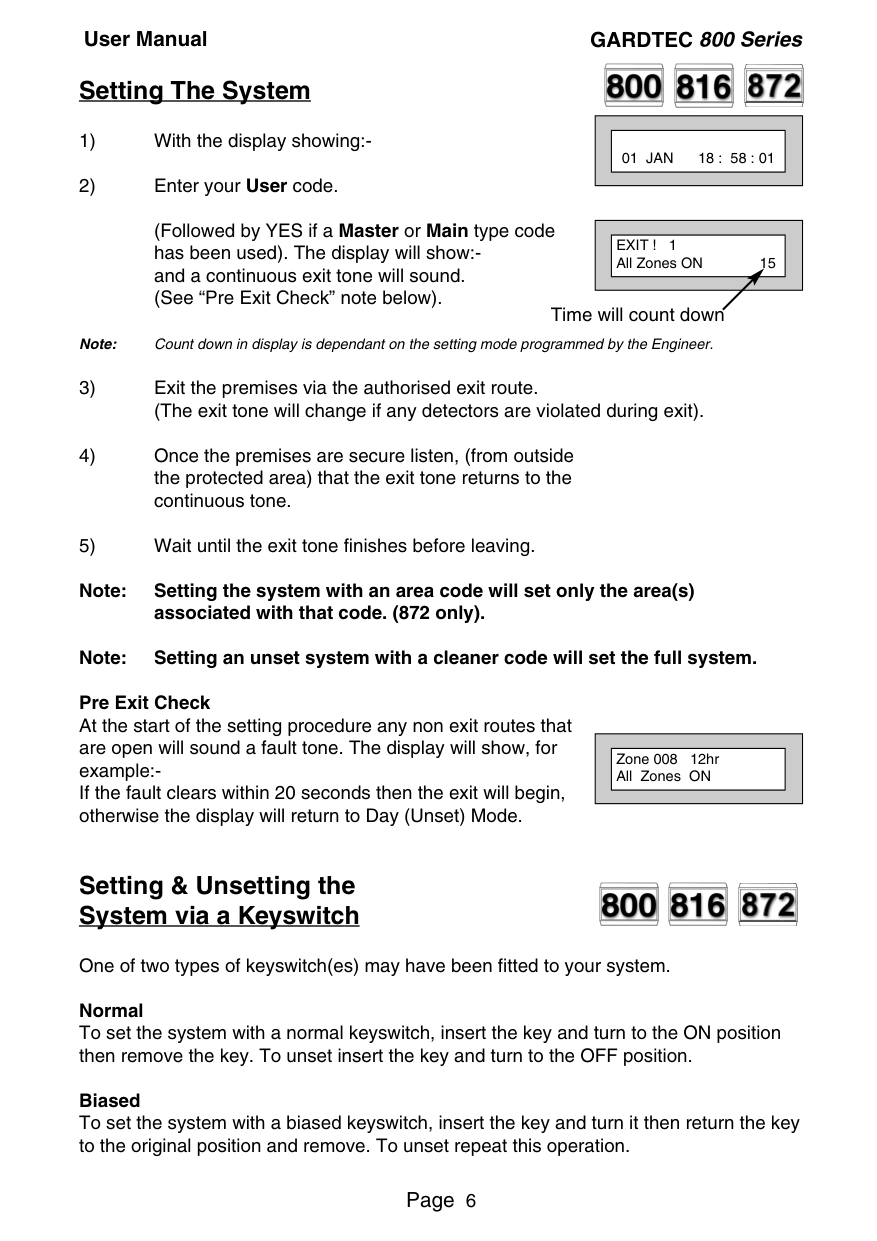
##### Setting The System
||01 JAN 18 : 58 : 01| |---| | |---|
(Followed by YES if a Master or Main type code has been used). The display will show:and a continuous exit tone will sound. (See “Pre Exit Check” note below).
Note: Count down in display is dependant on the setting mode programmed by the Engineer.
||EXIT ! 1 All Zones ON 15| |---| |
|---|
Time will count down
######### Note: Setting the system with an area code will set only the area(s)
associated with that code. (872 only). Note: Setting an unset system with a cleaner code will set the full system. Pre Exit Check At the start of the setting procedure any non exit routes that are open will sound a fault tone. The display will show, for example:If the fault clears within 20 seconds then the exit will begin, otherwise the display will return to Day (Unset) Mode.
||Zone 008 12hr All Zones ON| |---| | |---|
##### Setting & Unsetting the System via a Keyswitch


One of two types of keyswitch(es) may have been fitted to your system. Normal To set the system with a normal keyswitch, insert the key and turn to the ON position then remove the key. To unset insert the key and turn to the OFF position. Biased To set the system with a biased keyswitch, insert the key and turn it then return the key to the original position and remove. To unset repeat this operation.


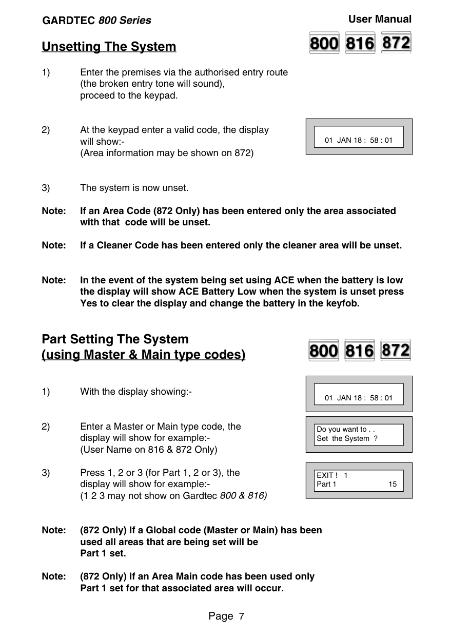
##### Unsetting The System
||01 JAN 18 : 58 : 01| |---| | |---|
Note: If an Area Code (872 Only) has been entered only the area associated with that code will be unset.
Note: If a Cleaner Code has been entered only the cleaner area will be unset.
Note: In the event of the system being set using ACE when the battery is low the display will show ACE Battery Low when the system is unset press Yes to clear the display and change the battery in the keyfob.
##### Part Setting The System (using Master & Main type codes)


||01 JAN 18 : 58 : 01| |---| | |---|
||Do you want to . . Set the System ?| |---| | |---|
||EXIT ! 1 Part 1 15| |---| | |---|
Note: (872 Only) If a Global code (Master or Main) has been used all areas that are being set will be Part 1 set.
Note: (872 Only) If an Area Main code has been used only Part 1 set for that associated area will occur.
##### Part Setting System (using Area 1 to 7 codes)

||01 JAN 18 : 58 : 01| |---| | |---|
||EXIT ! 1 All Zones ON 15| |---| | |---|
||EXIT ! 1 Part 1 20| |---| | |---|
##### Area Setting (using Master or global Main codes)

Areas will need to have been set up by the installation company.
||01 JAN 18 : 58 : 01| |---| | |---|
||Do you want to . . SET the System ?| |---| | |---|
||EXIT ! 1234567C All Zones ON 30| |---| | |---|
Note: Areas must first be programmed by the installation company before they will appear on the display.
##### Area Setting (using Area codes)

Area codes are only effective to their own area with the exception of the cleaner area. This may be turned off by an area code (only if all areas are in the unset condition). Use is the same as Setting the system shown on page 6 but only the relevant area will be set.
##### Removing Zones (Master & Main codes only)


If programmed by the installation company individual zones may be removed, this may only be done by a Master or Main level of code. It should be noted that if an Area Main code is being used, only zones associated with that area may be removed.
||01 JAN 18 : 58 : 01| |---| | |---|
||Do you want to . . SET the System ?| |---| | |---|
||Do you want to . . REMOVE Zones ?| |---| | |---|
||Enter Zone No. - then + YES or - NO| |---| | |---|
||Enter Zone No. - then + YES or - NO| |---| | |---|
||Do you want to . . SET the System ?| |---| |
|---|
######### Note: Zone remove is only effective for the one set.
##### Testing The System (Master & Main codes only)


||01 JAN 18 : 58 : 01| |---| | |---|
||Do you want to . . SET the System ?| |---| | |---|
||Do you want to . . REMOVE Zones ?| |---| | |---|
||Do you want to . . TEST the System ?| |---| |
|---|
||Test ALL Areas ?| |---| | |---|
||1=Status 4 = Strobe 6 = Sounder 9 = Bell| |---| | |---|
||< All Zones ok > TESTING . . .| |---| | |---|
||01 JAN 18 : 58 : 01| |---| | |---|
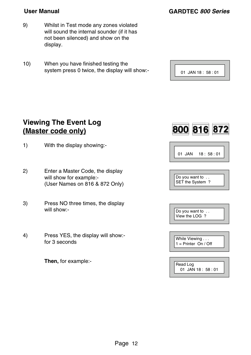
##### Viewing The Event Log (Master code only)
Then, for example:-


||01 JAN 18 : 58 : 01| |---| | |---|
||Do you want to . . SET the System ?| |---| | |---|
||Do you want to . . View the LOG ?| |---| | |---|
||While Viewing . . . 1 = Printer On / Off| |---| | |---|
||Read Log 01 JAN 18 : 58 : 01| |---| | |---|
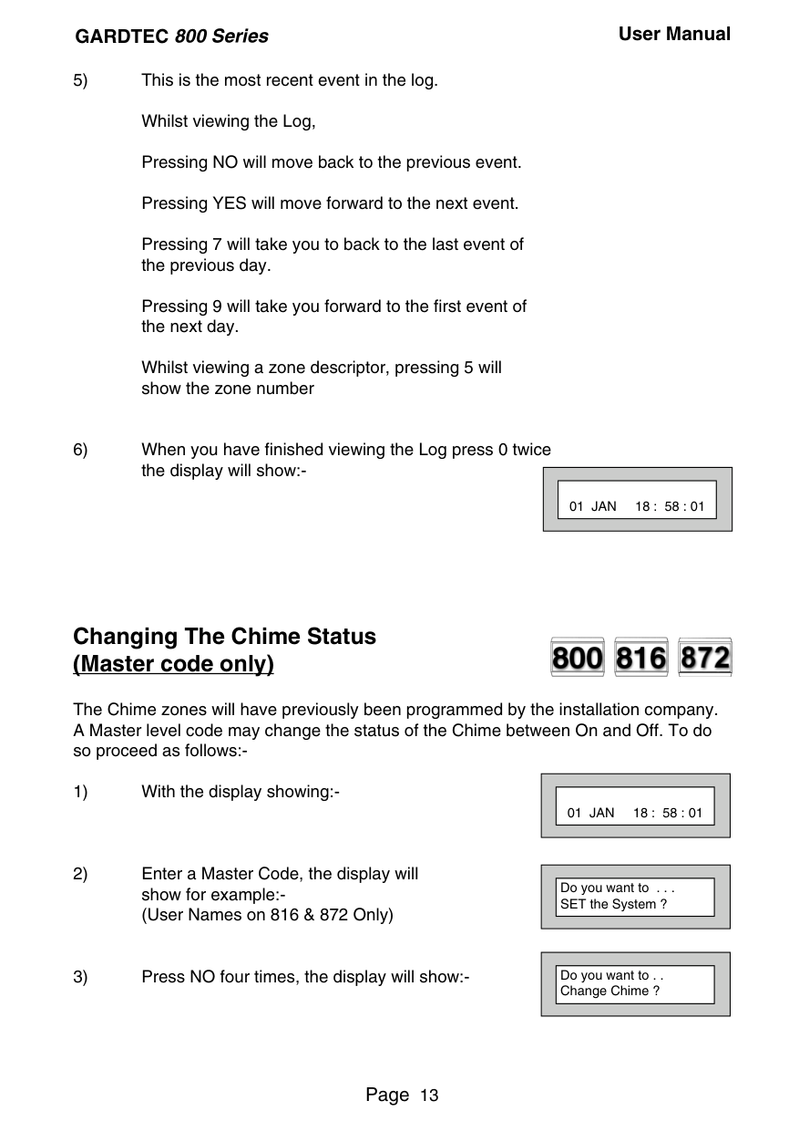
Pressing 7 will take you to back to the last event of the previous day.
Pressing 9 will take you forward to the first event of the next day.
Whilst viewing a zone descriptor, pressing 5 will show the zone number
||01 JAN 18 : 58 : 01| |---| | |---|
##### Changing The Chime Status (Master code only)


The Chime zones will have previously been programmed by the installation company. A Master level code may change the status of the Chime between On and Off. To do so proceed as follows:-
||01 JAN 18 : 58 : 01| |---| | |---|
||Do you want to . . . SET the System ?| |---| | |---|
||Do you want to . . Change Chime ?| |---| | |---|
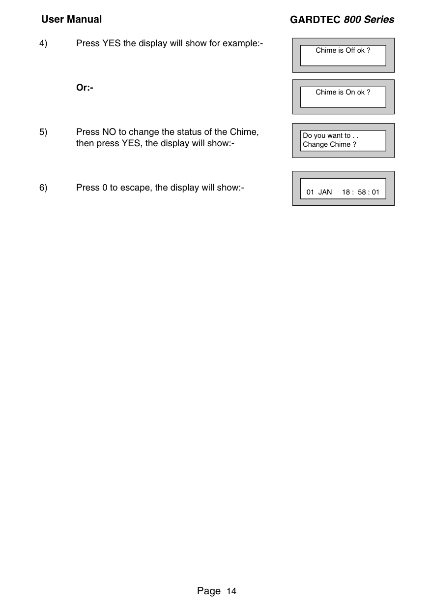
Or:-
||Chime is Off ok ?| |---| | |---|
||Chime is On ok ?| |---| | |---|
||Do you want to . . Change Chime ?| |---| | |---|
||01 JAN 18 : 58 : 01| |---| | |---|
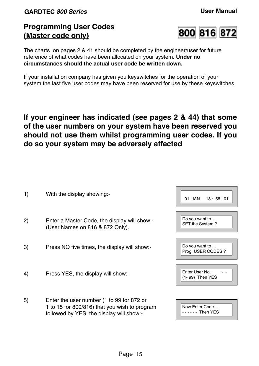
##### Programming User Codes (Master code only)


The charts on pages 2 & 41 should be completed by the engineer/user for future reference of what codes have been allocated on your system. Under no circumstances should the actual user code be written down.
If your installation company has given you keyswitches for the operation of your system the last five user codes may have been reserved for use by these keyswitches.
##### If your engineer has indicated (see pages 2 & 44) that some of the user numbers on your system have been reserved you should not use them whilst programming user codes. If you do so your system may be adversely affected
||01 JAN 18 : 58 : 01| |---| | |---|
||Do you want to . . SET the System ?| |---| | |---|
||Do you want to . . Prog. USER CODES ?| |---| | |---|
||Enter User No. - (1- 99) Then YES| |---| | |---|
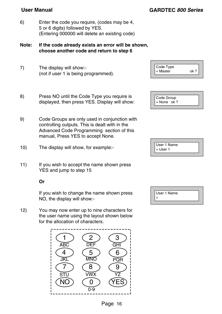
||Now Enter Code . . - - - - - - Then YES| |---| | |---|
Note: If the code already exists an error will be shown, choose another code and return to step 6
If you wish to change the name shown press NO, the display will show:-
||Code Type
= Master ok ?| |---| | |---|
||Code Group
= None ok ?| |---| | |---|
||User 1 Name
= User 1| |---| | |---|
||User 1 Name >| |---| | |---|
|123 4 56 789 0 YESNO
ABC DEF GHI
JKL MNO PQR
STU VWX YZ
0-9| |---|
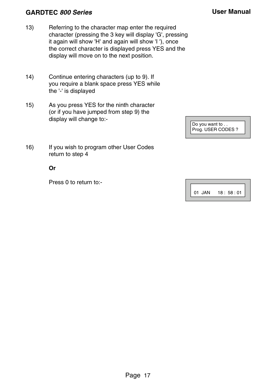
||Do you want to . . Prog. USER CODES ?| |---| | |---|
||01 JAN 18 : 58 : 01| |---| | |---|


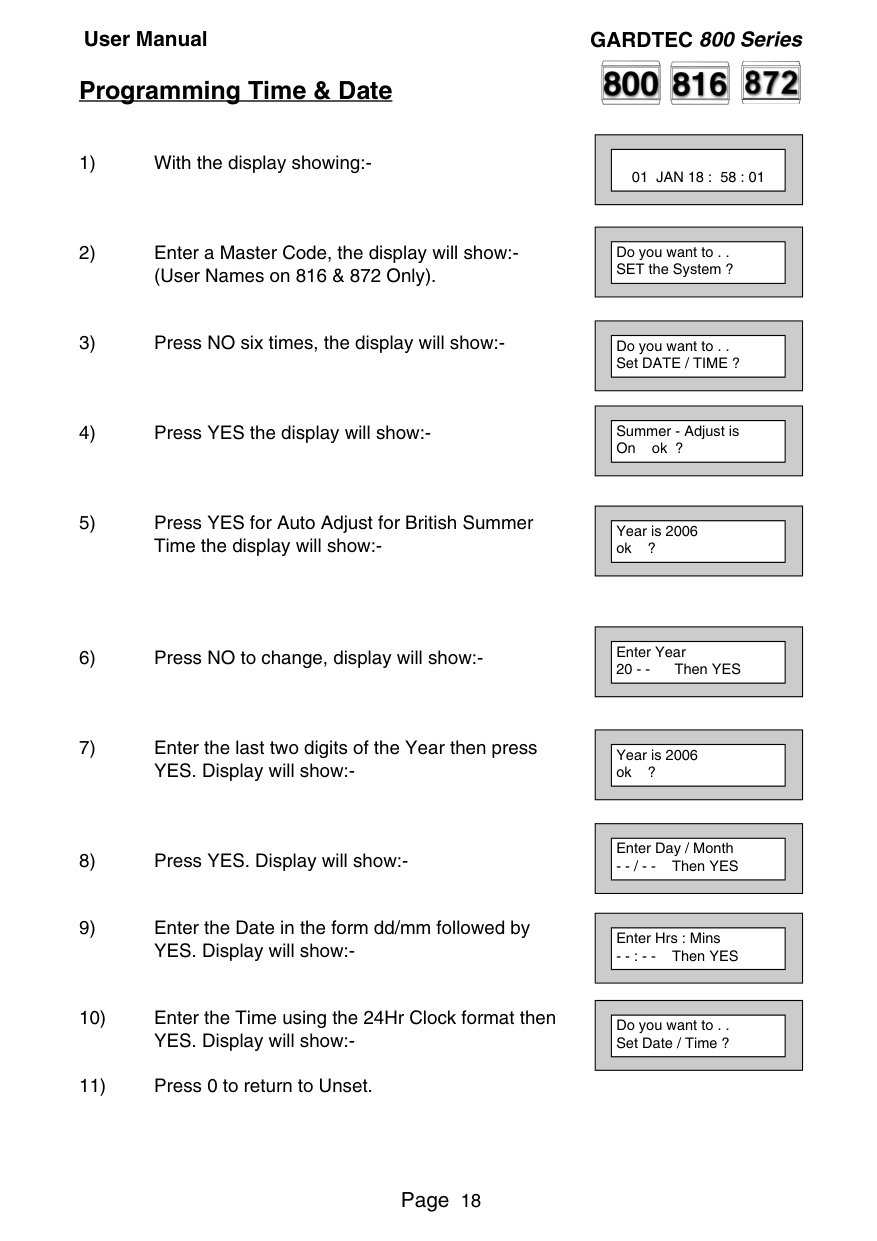
##### Programming Time & Date
||01 JAN 18 : 58 : 01| |---| | |---|
||Do you want to . . SET the System ?| |---| | |---|
||Do you want to . . Set DATE / TIME ?| |---| | |---|
||Summer - Adjust is On ok ?| |---| | |---|
||Year is 2006 ok ?| |---| | |---|
||Enter Year 20 - - Then YES| |---| | |---|
||Year is 2006 ok ?| |---| | |---|
||Enter Day / Month
- - / - - Then YES| |---| | |---|
||Enter Hrs : Mins
- - : - - Then YES| |---| | |---|
||Do you want to . . Set Date / Time ?| |---| | |---|


##### User Initiating Remote Access (Optional)
Access Remote allows your installation company to examine your system and reprogram system settings as you need the changes without the need for an engineer to visit your premises.
If your system has remote communications fitted your installation company may have programmed the system so that you initialise the Access Remote call (usually on lines with incoming calls barred).
To initiate the Remote Call follow the instructions below.
Until Connection Then:-
||01 JAN 18 : 58 : 01| |---| | |---|
||Do you want to . . SET the System ?| |---| | |---|
||Do you want to . . Access Remote ?| |---| | |---|
||Please WAIT|
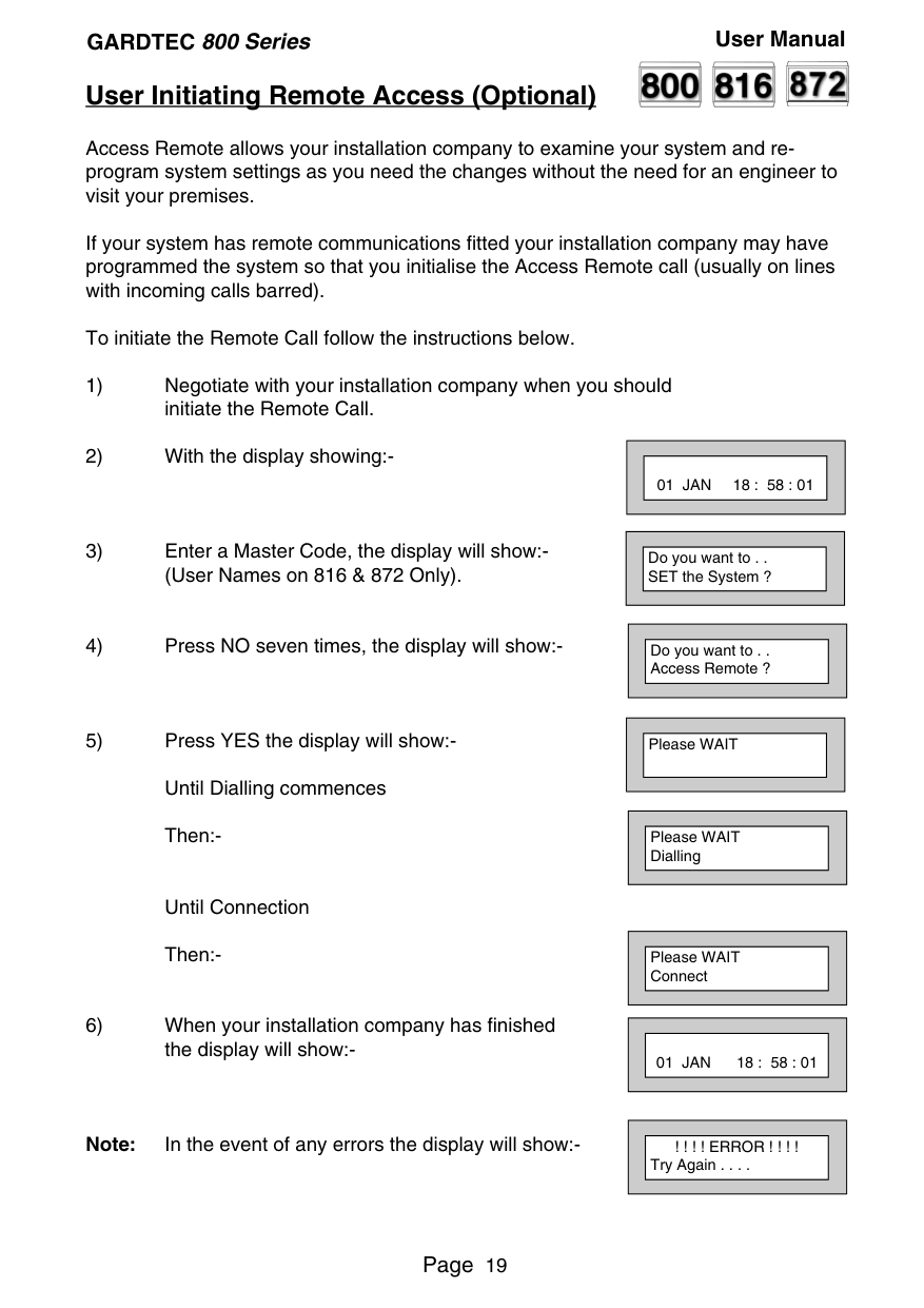
|---| | |---|
||Please WAIT Dialling| |---| | |---|
||Please WAIT Connect| |---| | |---|
||01 JAN 18 : 58 : 01| |---| | |---|
||! ! ! ! ERROR ! ! ! ! Try Again . . . .| |---| | |---|
Note: In the event of any errors the display will show:-


##### Resetting After an Alarm Fault and Alarm Displays
Your installation company will have programmed the reset modes for your system so that it complies to your insurance company and legislation requirements.
Your installation company will have informed you as to the type of reset that your system is set for.
######### Before attempting to reset your system ensure that the system is Un-set.
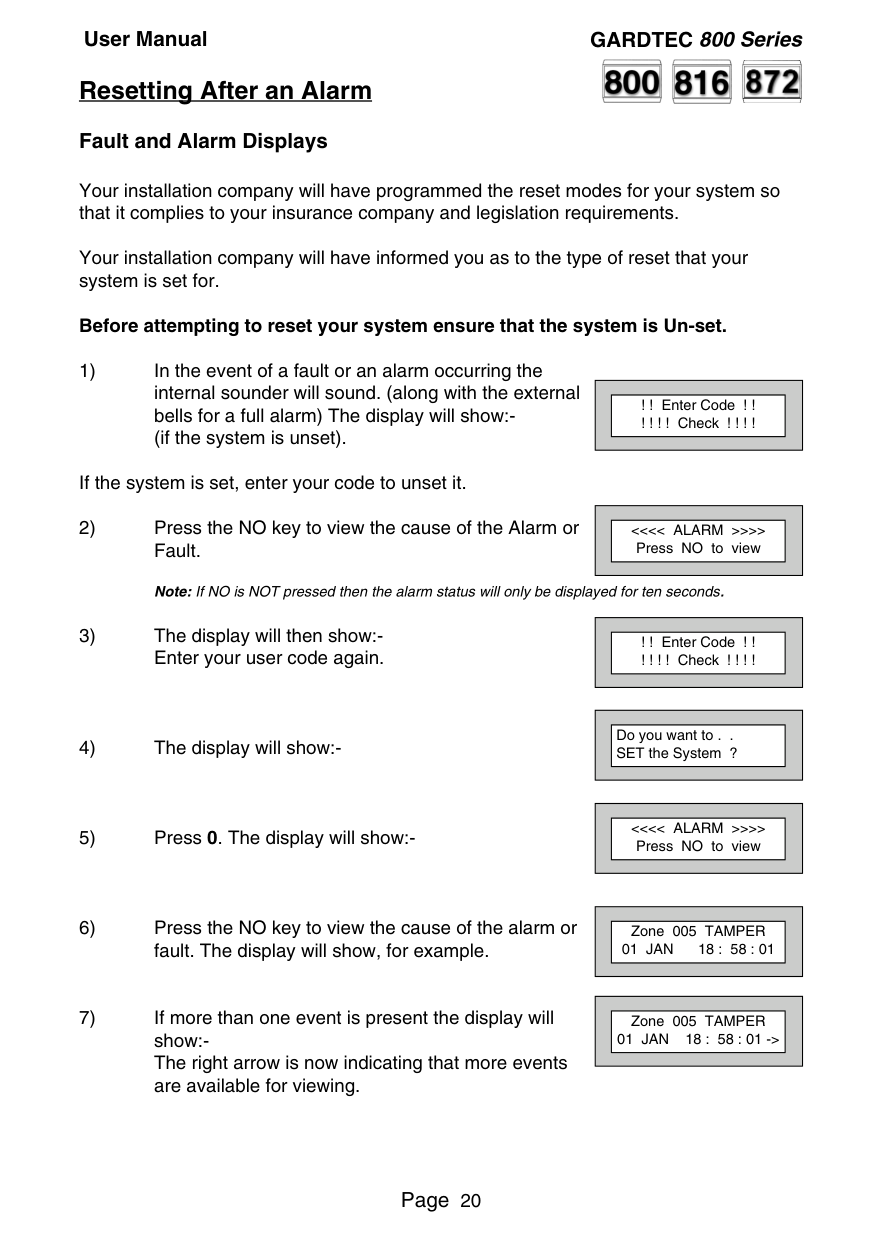
If the system is set, enter your code to unset it.
||! ! Enter Code ! ! ! ! ! ! Check ! ! ! !| |---| | |---|
||<<<< ALARM >>>> Press NO to view| |---| | |---|
||! ! Enter Code ! ! ! ! ! ! Check ! ! ! !| |---| | |---|
||Do you want to . . SET the System ?| |---| | |---|
||<<<< ALARM >>>> Press NO to view| |---| | |---|
||Zone 005 TAMPER 01 JAN 18 : 58 : 01|
|---| | |---|
||Zone 005 TAMPER 01 JAN 18 : 58 : 01 ->| |---| | |---|
||Zone 005 TAMPER 01 JAN 18 : 58 : 01 <-| |---| | |---|
The left arrow now indicates that you are at the end of events. The NO key may be used to scroll back the opposite way.
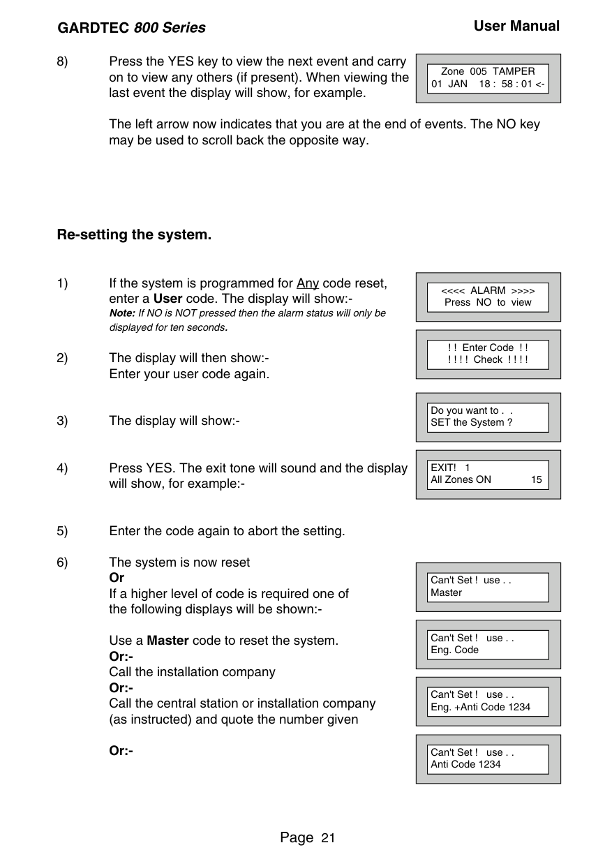
####### Re-setting the system.
Use a Master code to reset the system. Or:Call the installation company Or:Call the central station or installation company (as instructed) and quote the number given
######### Or:-
||<<<< ALARM >>>> Press NO to view| |---| | |---|
||! ! Enter Code ! ! ! ! ! ! Check ! ! ! !|
|---| | |---|
||Do you want to . . SET the System ?| |---| | |---|
||EXIT! 1 All Zones ON 15| |---| | |---|
||Can't Set ! use . . Master| |---| | |---|
||Can't Set ! use . . Eng. Code| |---| | |---|
||Can't Set ! use . . Eng. +Anti Code 1234| |---| | |---|
||Can't Set ! use . . Anti Code 1234| |---| | |---|
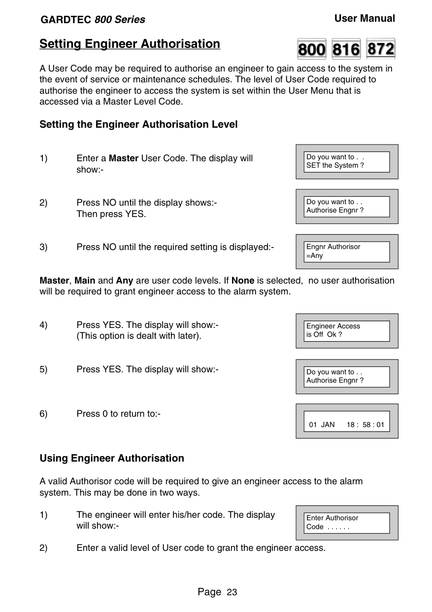
##### Setting Engineer Authorisation


A User Code may be required to authorise an engineer to gain access to the system in the event of service or maintenance schedules. The level of User Code required to authorise the engineer to access the system is set within the User Menu that is accessed via a Master Level Code.
####### Setting the Engineer Authorisation Level
||Do you want to . . SET the System ?| |---| | |---|
Master, Main and Any are user code levels. If None is selected, no user authorisation will be required to grant engineer access to the alarm system.
||Do you want to . . Authorise Engnr ?| |---| | |---|
||Engnr Authorisor
=Any| |---| | |---|
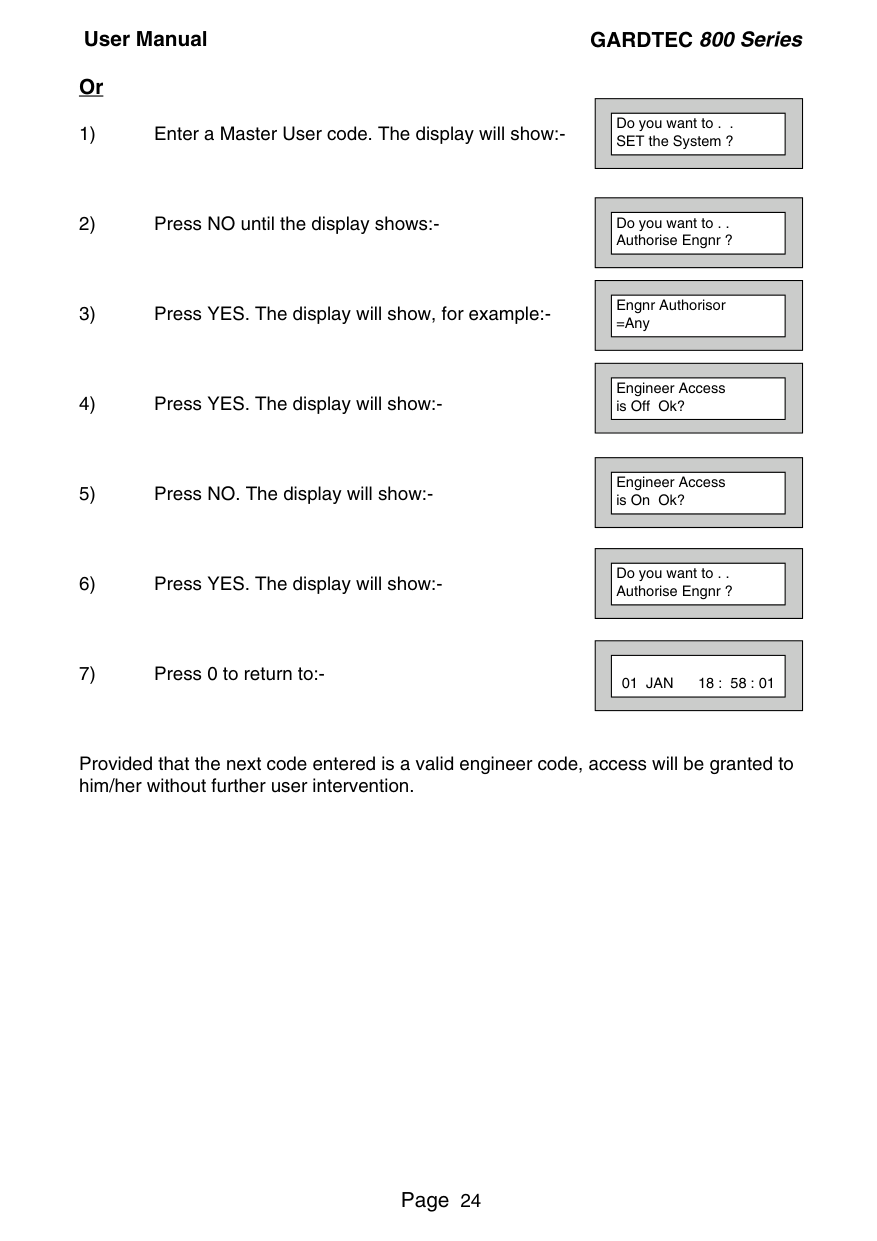
||Engineer Access is Off Ok ?| |---| | |---|
||Do you want to . . Authorise Engnr ?| |---| | |---|
||01 JAN 18 : 58 : 01| |---| | |---|
####### Using Engineer Authorisation
A valid Authorisor code will be required to give an engineer access to the alarm system. This may be done in two ways.
||Enter Authorisor Code . . . . . .| |---| | |---|
####### Or
||Do you want to . . SET the System ?|
|---| | |---|
||Do you want to . . Authorise Engnr ?| |---| | |---|
||Engnr Authorisor
=Any| |---| | |---|
||Engineer Access is Off Ok?| |---| | |---|
||Engineer Access is On Ok?| |---| | |---|
||Do you want to . . Authorise Engnr ?| |---| | |---|
||01 JAN 18 : 58 : 01| |---| | |---|
Provided that the next code entered is a valid engineer code, access will be granted to him/her without further user intervention.


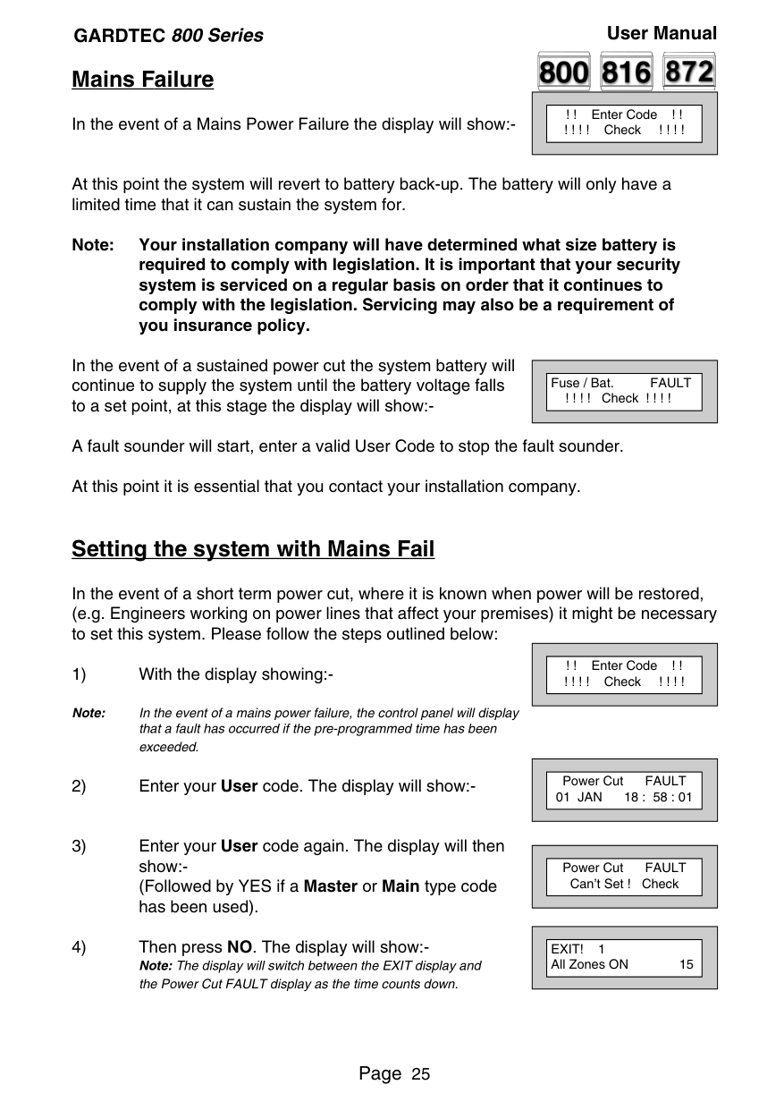
##### Mains Failure
||! ! Enter Code ! ! ! ! ! ! Check ! ! ! !| |---| | |---|
In the event of a Mains Power Failure the display will show:-
At this point the system will revert to battery back-up. The battery will only have a limited time that it can sustain the system for.
Note: Your installation company will have determined what size battery is required to comply with legislation. It is important that your security system is serviced on a regular basis on order that it continues to comply with the legislation. Servicing may also be a requirement of you insurance policy.
In the event of a sustained power cut the system battery will continue to supply the system until the battery voltage falls to a set point, at this stage the display will show:-
||Fuse / Bat. FAULT ! ! ! ! Check ! ! ! !| |---| | |---|
A fault sounder will start, enter a valid User Code to stop the fault sounder. At this point it is essential that you contact your installation company.
##### Setting the system with Mains Fail
In the event of a short term power cut, where it is known when power will be restored, (e.g. Engineers working on power lines that affect your premises) it might be necessary to set this system. Please follow the steps outlined below:
||! ! Enter Code ! ! ! ! ! ! Check ! ! ! !| |---| | |---|
Note: In the event of a mains power failure, the control panel will display that a fault has occurred if the pre-programmed time has been exceeded.
||Power Cut FAULT 01 JAN 18 : 58 : 01| |---| | |---|
||Power Cut FAULT Can’t Set ! Check| |---| | |---|
||EXIT! 1 All Zones ON 15| |---| | |---|
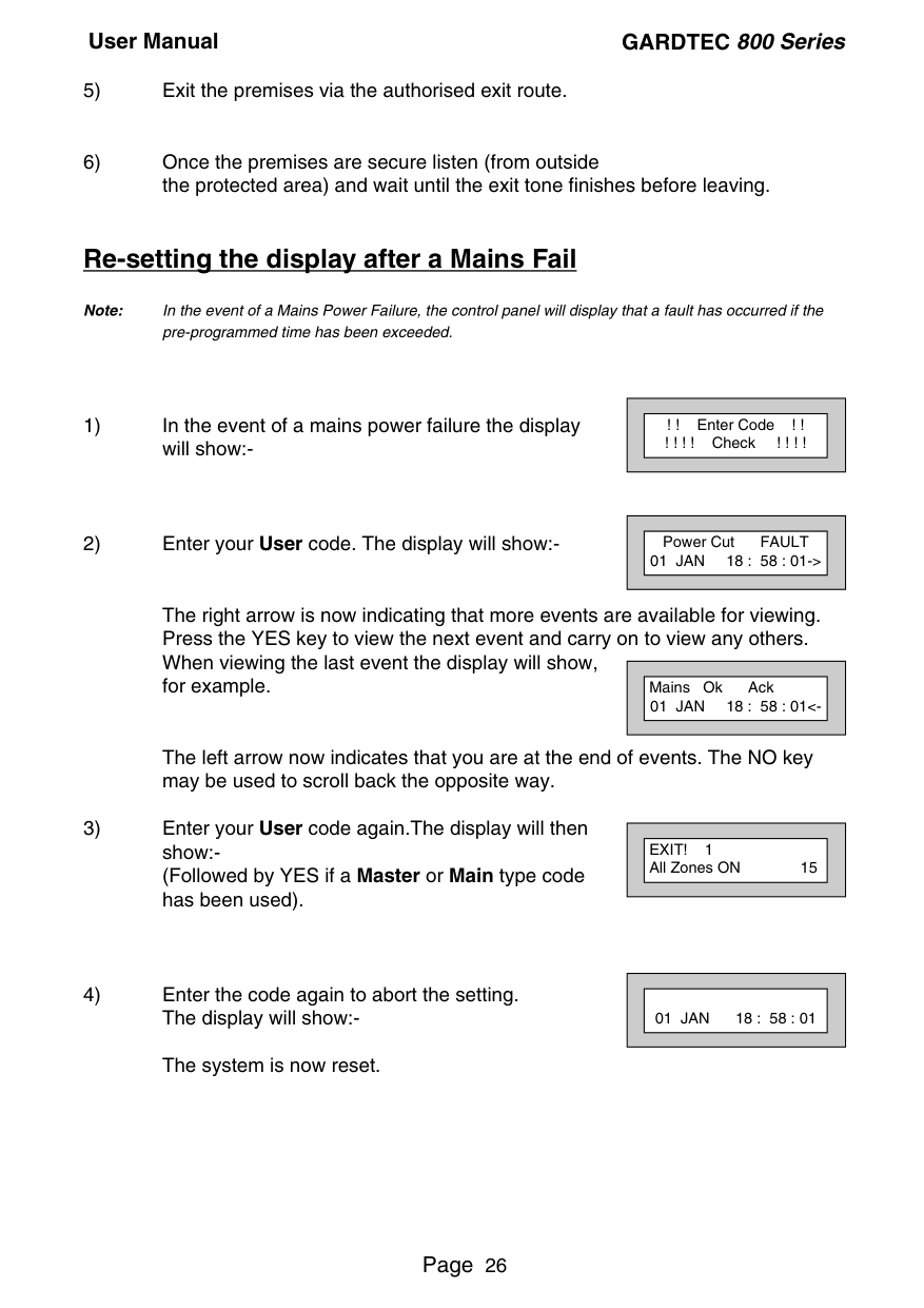
##### Re-setting the display after a Mains Fail
Note: In the event of a Mains Power Failure, the control panel will display that a fault has occurred if the
pre-programmed time has been exceeded.
The right arrow is now indicating that more events are available for viewing. Press the YES key to view the next event and carry on to view any others. When viewing the last event the display will show, for example.
The left arrow now indicates that you are at the end of events. The NO key may be used to scroll back the opposite way.
||! ! Enter Code ! ! ! ! ! ! Check ! ! ! !|
|---| | |---|
||Power Cut FAULT 01 JAN 18 : 58 : 01->| |---| | |---|
||Mains Ok Ack 01 JAN 18 : 58 : 01<-| |---| | |---|
||EXIT! 1 All Zones ON 15| |---| | |---|
||01 JAN 18 : 58 : 01| |---| | |---|
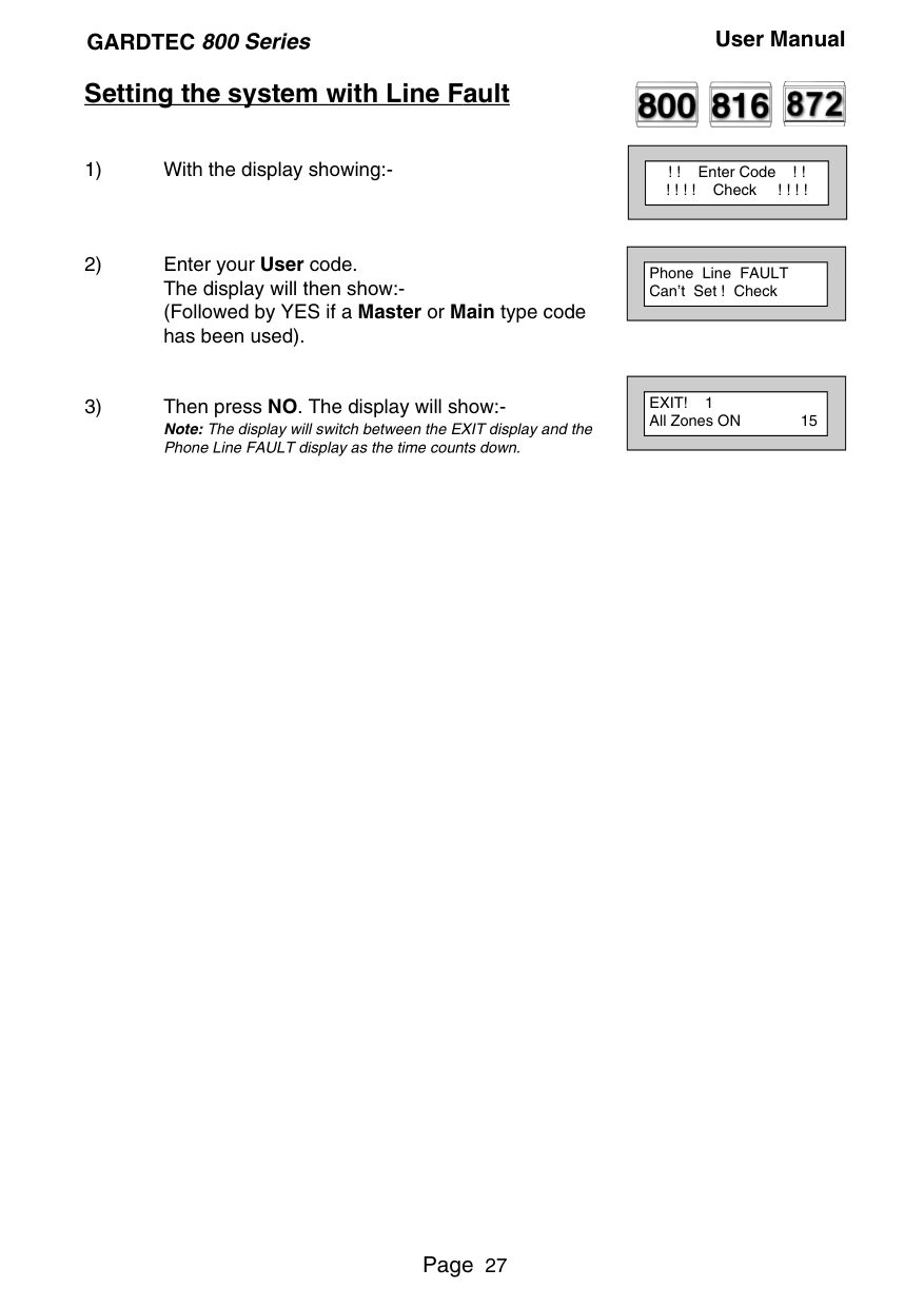
##### Setting the system with Line Fault


||! ! Enter Code ! ! ! ! ! ! Check ! ! ! !| |---|
| |---|
||Phone Line FAULT Can’t Set ! Check| |---| | |---|
||EXIT! 1 All Zones ON 15| |---| | |---|
##### System G-Tag


G-Tag Readers are available in three variants, with the reader built into the display area of an LCD RKP, as an Internal Stand alone Reader or as an External Stand alone Reader. When using G-Tag the system may be Set / Unset by presenting a valid Tag to one of the Readers.
Each Tag is programmed onto the system as an individual User Code therefore giving indication via the system Log of who has set and unset the system. As the Tags are a close proximity device the risk of code capture is eliminated.
When programming the G-Tags follow the normal Programming Codes instructions to the point when you are asked for the Code, for example
||Now Enter Code . .
- - - - - - Then YES| |---| | |---|
At this point present your G-Tag to the reader and the code will be entered. If you have more than one reader on your system the G-Tag MUST be programmed onto each of the readers on the same User Number. Because of this it is essential that you use good housekeeping for the G-Tags. Mark each of the G-Tags and record what User Number the G-Tag has been allocated to. The readers will be allocated to a specific keypad. The G-Tag information is stored in the keypad therefore a single keypad having two readers would only require the G-Tag to be programmed into one of its readers For multiple keypads with readers the sequence for programming the G-Tags would be.
##### Advanced Code Programming (Control Codes)

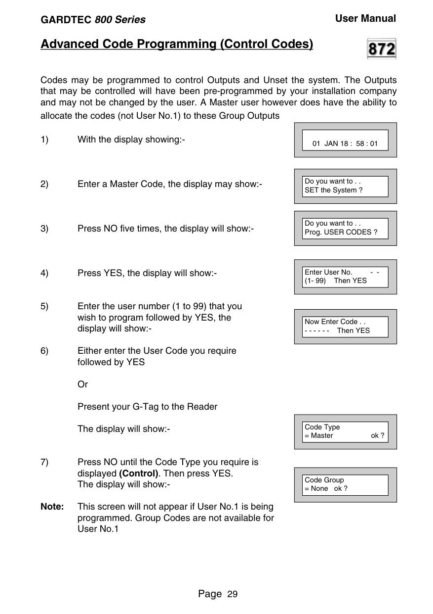
Codes may be programmed to control Outputs and Unset the system. The Outputs that may be controlled will have been pre-programmed by your installation company and may not be changed by the user. A Master user however does have the ability to allocate the codes (not User No.1) to these Group Outputs
||01 JAN 18 : 58 : 01| |---| | |---|
||Do you want to . . SET the System ?| |---| | |---|
||Do you want to . . Prog. USER CODES ?| |---| | |---|
||Enter User No. - (1- 99) Then YES| |---| | |---|
||Now Enter Code . .
- - - - - - Then YES|
|---| | |---|
||Code Type
= Master ok ?| |---| | |---|
||Code Group
= None ok ?| |---| | |---|
Note: This screen will not appear if User No.1 is being programmed. Group Codes are not available for User No.1
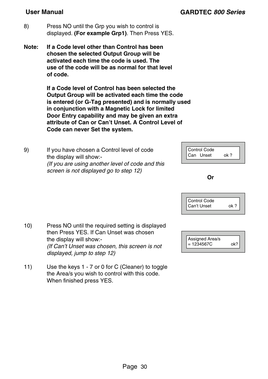
Note: If a Code level other than Control has been chosen the selected Output Group will be activated each time the code is used. The use of the code will be as normal for that level of code.
If a Code level of Control has been selected the Output Group will be activated each time the code is entered (or G-Tag presented) and is normally used in conjunction with a Magnetic Lock for limited Door Entry capability and may be given an extra attribute of Can or Can’t Unset. A Control Level of Code can never Set the system.
Or
||Control Code Can Unset ok ?| |---| | |---|
||Control Code Can’t Unset ok ?| |---| | |---|
||Assigned Area/s
= 1234567C ok?| |---| | |---|
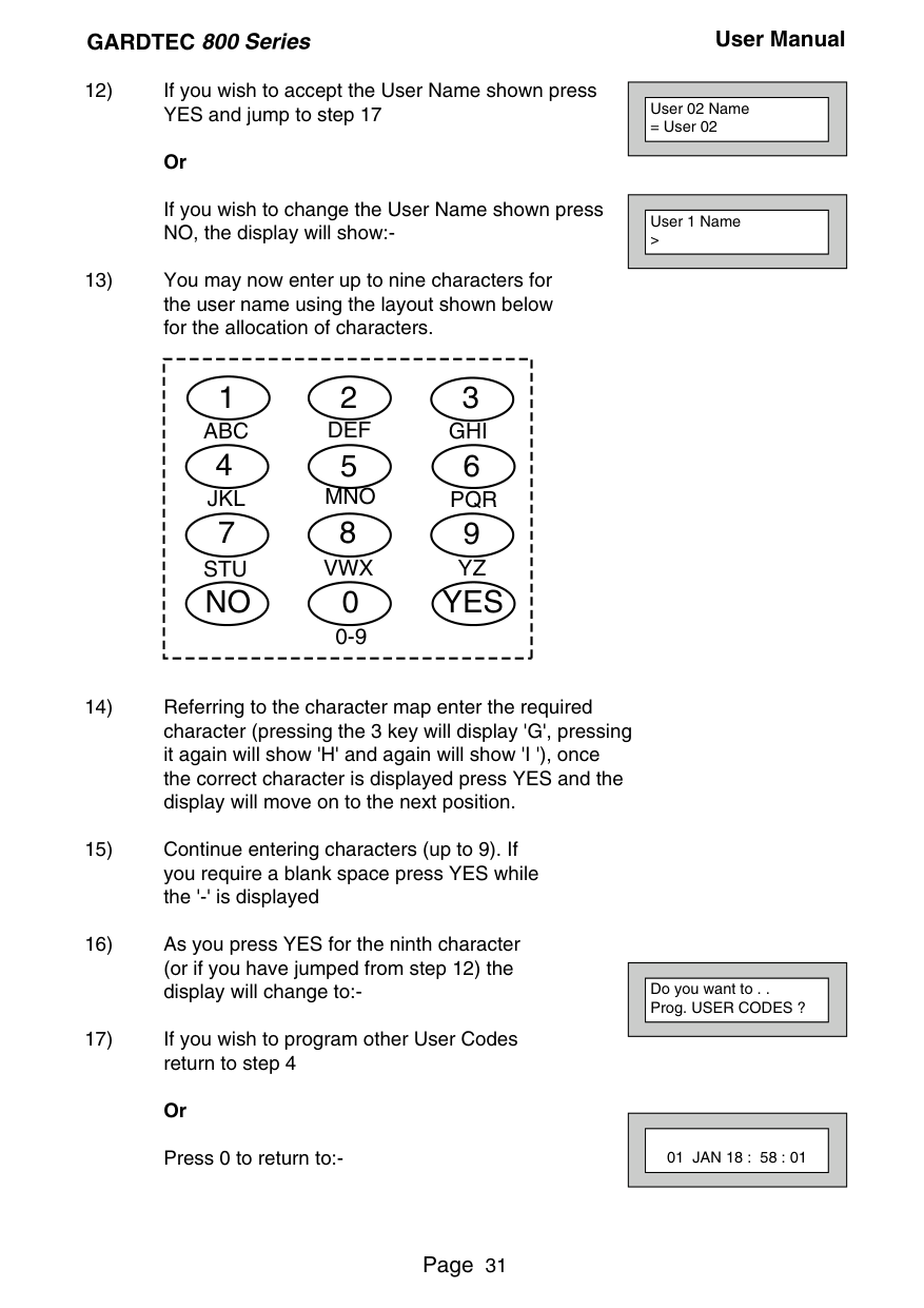
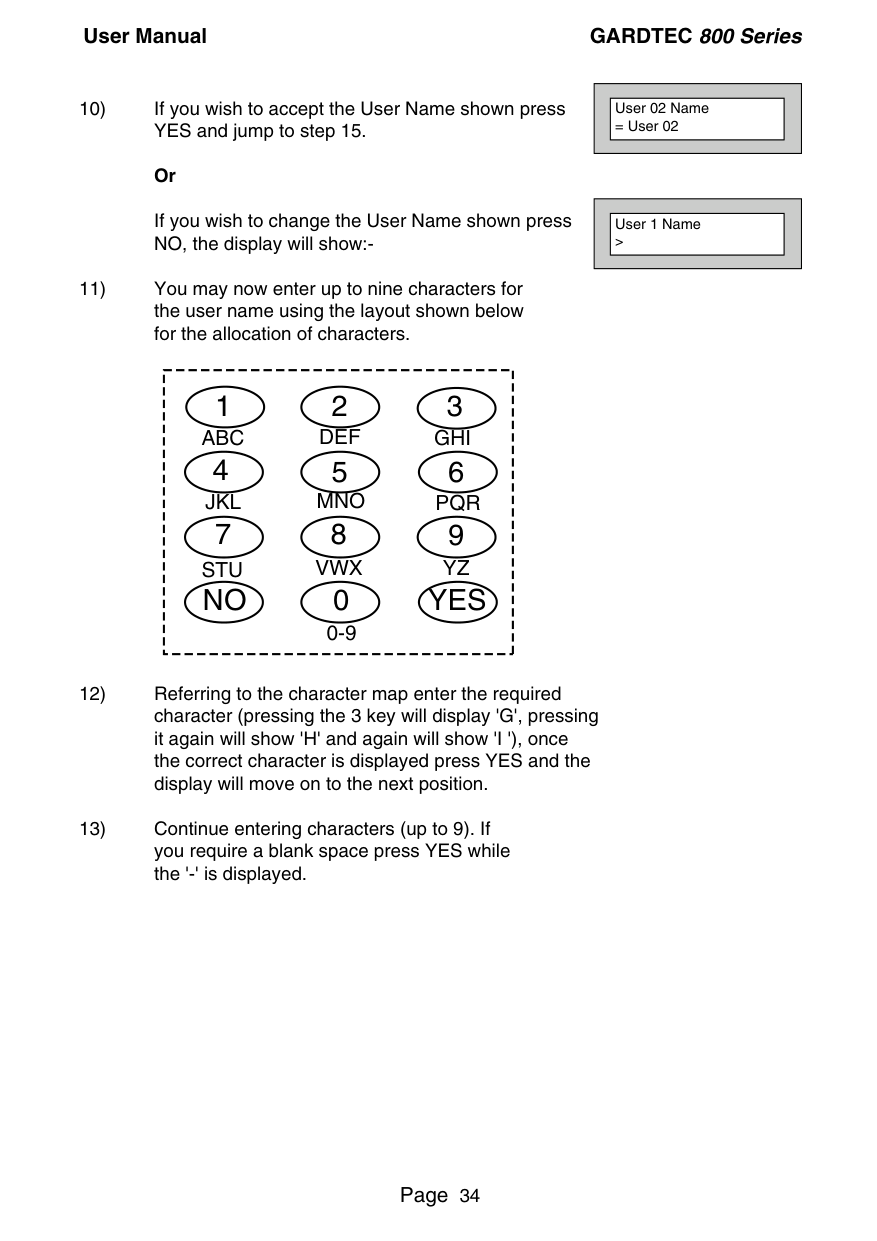
If you wish to change the User Name shown press NO, the display will show:-
||User 02 Name
= User 02| |---| | |---|
||User 1 Name >| |---| | |---|
|123 4 56 789 0 YESNO
ABC DEF GHI
JKL MNO PQR
STU VWX YZ
0-9| |---|
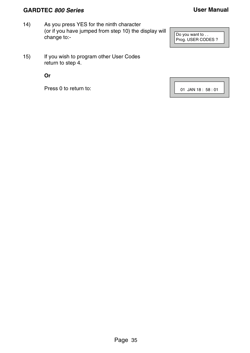
||Do you want to . . Prog. USER CODES ?| |---| | |---|
||01 JAN 18 : 58 : 01| |---| | |---|
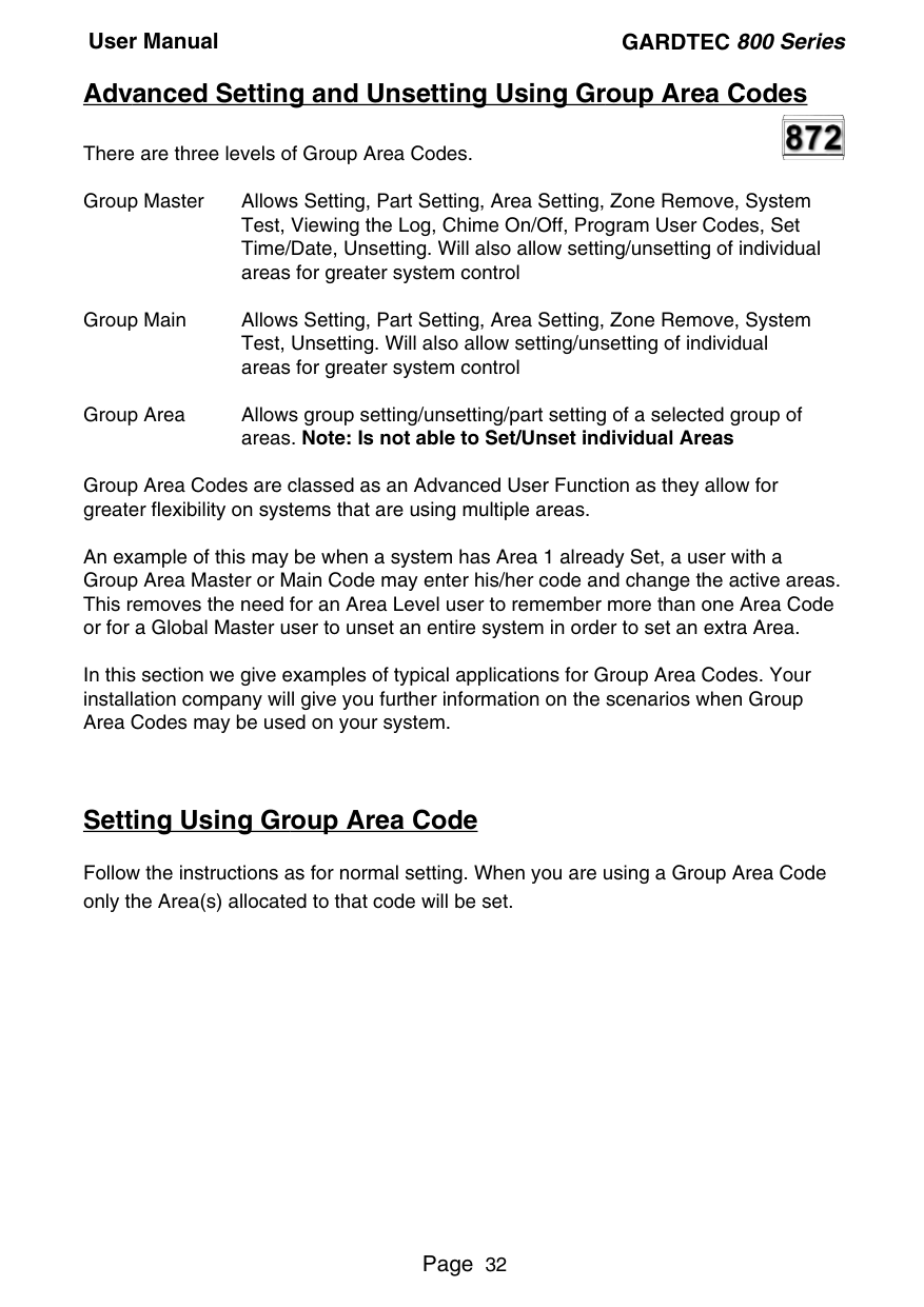
Advanced Setting and Unsetting Using Group Area Codes There are three levels of Group Area Codes. Group Master Allows Setting, Part Setting, Area Setting, Zone Remove, System

Test, Viewing the Log, Chime On/Off, Program User Codes, Set Time/Date, Unsetting. Will also allow setting/unsetting of individual areas for greater system control
Group Main Allows Setting, Part Setting, Area Setting, Zone Remove, System Test, Unsetting. Will also allow setting/unsetting of individual areas for greater system control
Group Area Allows group setting/unsetting/part setting of a selected group of areas. Note: Is not able to Set/Unset individual Areas
Group Area Codes are classed as an Advanced User Function as they allow for greater flexibility on systems that are using multiple areas.
An example of this may be when a system has Area 1 already Set, a user with a Group Area Master or Main Code may enter his/her code and change the active areas. This removes the need for an Area Level user to remember more than one Area Code or for a Global Master user to unset an entire system in order to set an extra Area.
In this section we give examples of typical applications for Group Area Codes. Your installation company will give you further information on the scenarios when Group Area Codes may be used on your system.
##### Setting Using Group Area Code
Follow the instructions as for normal setting. When you are using a Group Area Code only the Area(s) allocated to that code will be set.
###### GARDTEC 800 Series User Manual

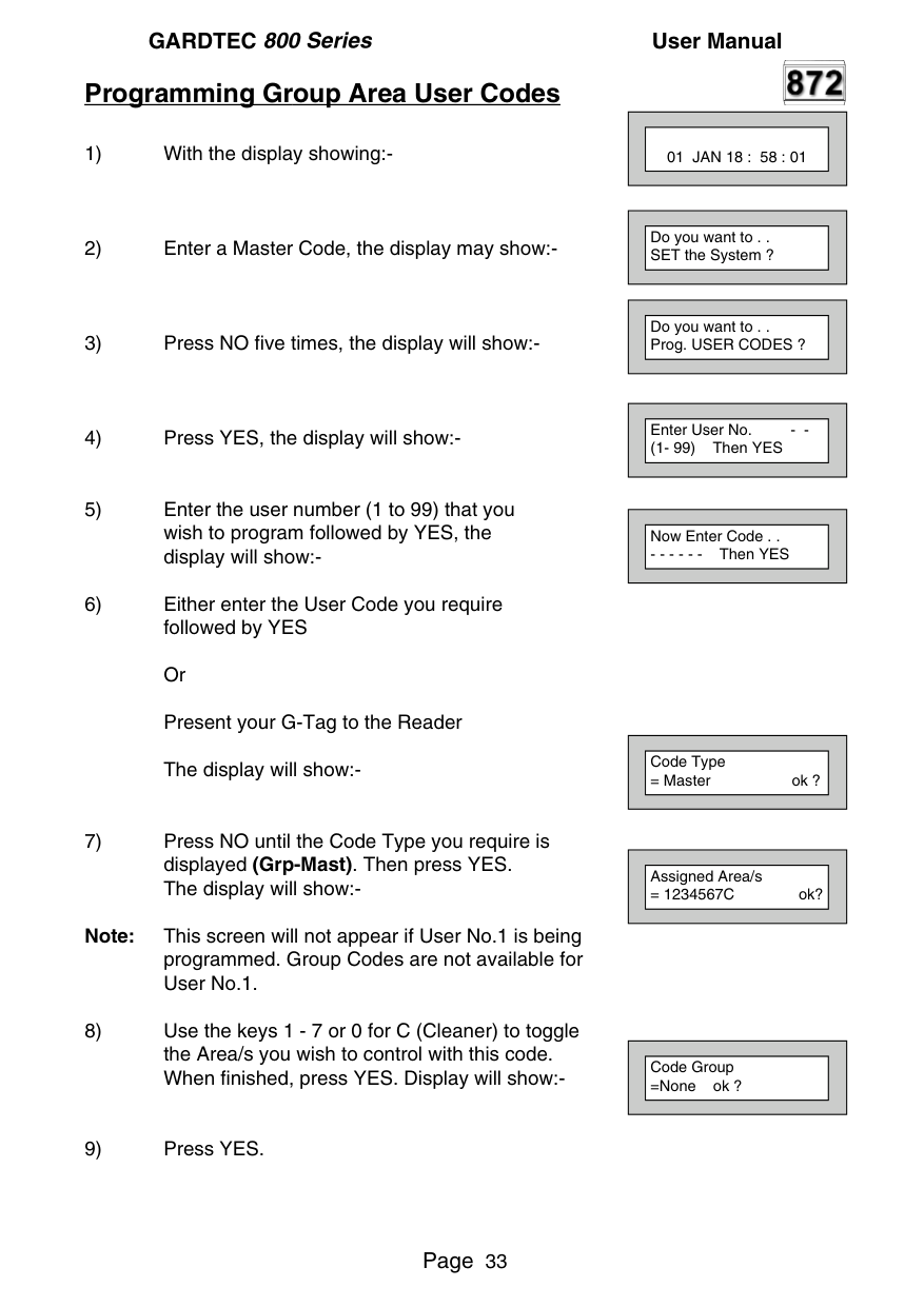
##### Programming Group Area User Codes
||01 JAN 18 : 58 : 01| |---| | |---|
Note: This screen will not appear if User No.1 is being programmed. Group Codes are not available for User No.1.
||Do you want to . . SET the System ?| |---| | |---|
||Do you want to . . Prog. USER CODES ?| |---| | |---|
||Enter User No. - (1- 99) Then YES| |---| | |---|
||Now Enter Code . .
- - - - - - Then YES| |---| | |---|
||Code Type
= Master ok ?| |---| | |---|
||Assigned Area/s
= 1234567C ok?| |---| | |---|
||Code Group
=None ok ?| |---| | |---|
||User 02 Name
= User 02| |---| | |---|
If you wish to change the User Name shown press NO, the display will show:-
||User 1 Name >| |---| | |---|
|123 4 56 789 0 YESNO
ABC DEF GHI
JKL MNO PQR
STU VWX YZ
0-9| |---|
||Do you want to . . Prog. USER CODES ?| |---| | |---|
||01 JAN 18 : 58 : 01| |---| | |---|

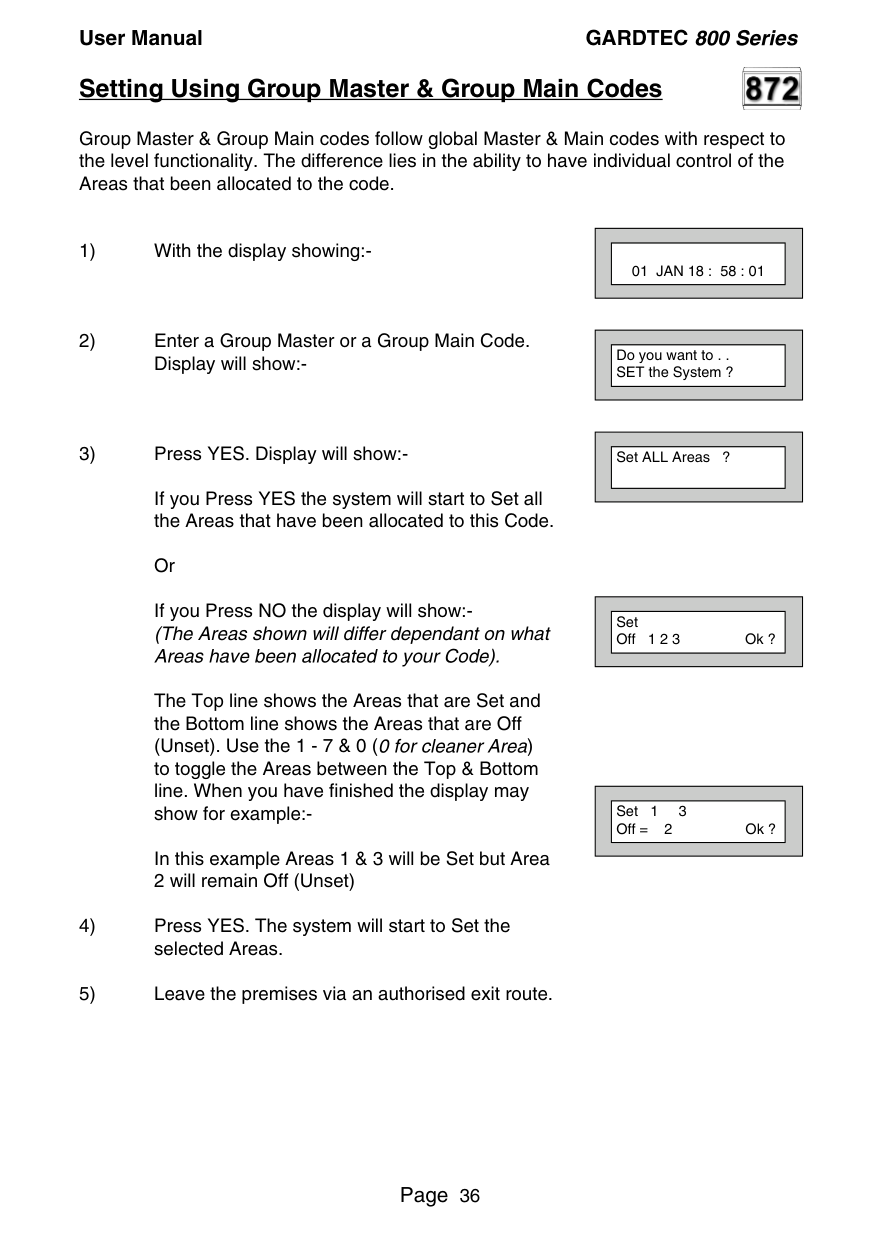
##### Setting Using Group Master & Group Main Codes
Group Master & Group Main codes follow global Master & Main codes with respect to the level functionality. The difference lies in the ability to have individual control of the Areas that been allocated to the code.
If you Press YES the system will start to Set all the Areas that have been allocated to this Code.
Or If you Press NO the display will show:(The Areas shown will differ dependant on what Areas have been allocated to your Code).
The Top line shows the Areas that are Set and the Bottom line shows the Areas that are Off (Unset). Use the 1 - 7 & 0 (0 for cleaner Area) to toggle the Areas between the Top & Bottom line. When you have finished the display may show for example:-
In this example Areas 1 & 3 will be Set but Area 2 will remain Off (Unset)
||01 JAN 18 : 58 : 01| |---| | |---|
||Do you want to . . SET the System ?| |---| | |---|
||Set ALL Areas ?| |---| | |---|
||Set Off 1 2 3 Ok ?| |---| | |---|
||Set 1 3 Off = 2 Ok ?| |---| | |---|

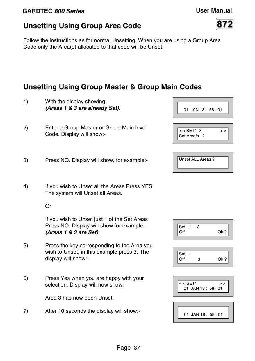
##### Unsetting Using Group Area Code
Follow the instructions as for normal Unsetting. When you are using a Group Area Code only the Area(s) allocated to that code will be Unset.
##### Unsetting Using Group Master & Group Main Codes
If you wish to Unset just 1 of the Set Areas Press NO. Display will show for example:(Areas 1 & 3 are Set).
||01 JAN 18 : 58 : 01| |---| | |---|
||< < SET1 3 > > Set Area/s ?| |---| | |---|
||Unset ALL Areas ?| |---| | |---|
||Set 1 3 Off Ok ?| |---| | |---|
||Set 1 Off = 3 Ok ?| |---| | |---|
||< < SET1 > > 01 JAN 18 : 58 : 01| |---| | |---|
||01 JAN 18 : 58 : 01| |---| | |---|
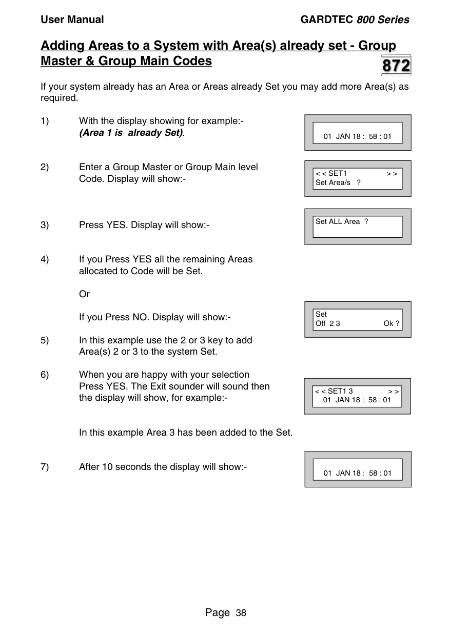
##### Adding Areas to a System with Area(s) already set - Group Master & Group Main Codes

If your system already has an Area or Areas already Set you may add more Area(s) as required.
In this example Area 3 has been added to the Set.
||01 JAN 18 : 58 : 01|
|---| | |---|
||< < SET1 > > Set Area/s ?| |---| | |---|
||Set ALL Area ?| |---| | |---|
||Set Off 2 3 Ok ?| |---| | |---|
||< < SET1 3 > > 01 JAN 18 : 58 : 01| |---| | |---|
||01 JAN 18 : 58 : 01| |---| | |---|
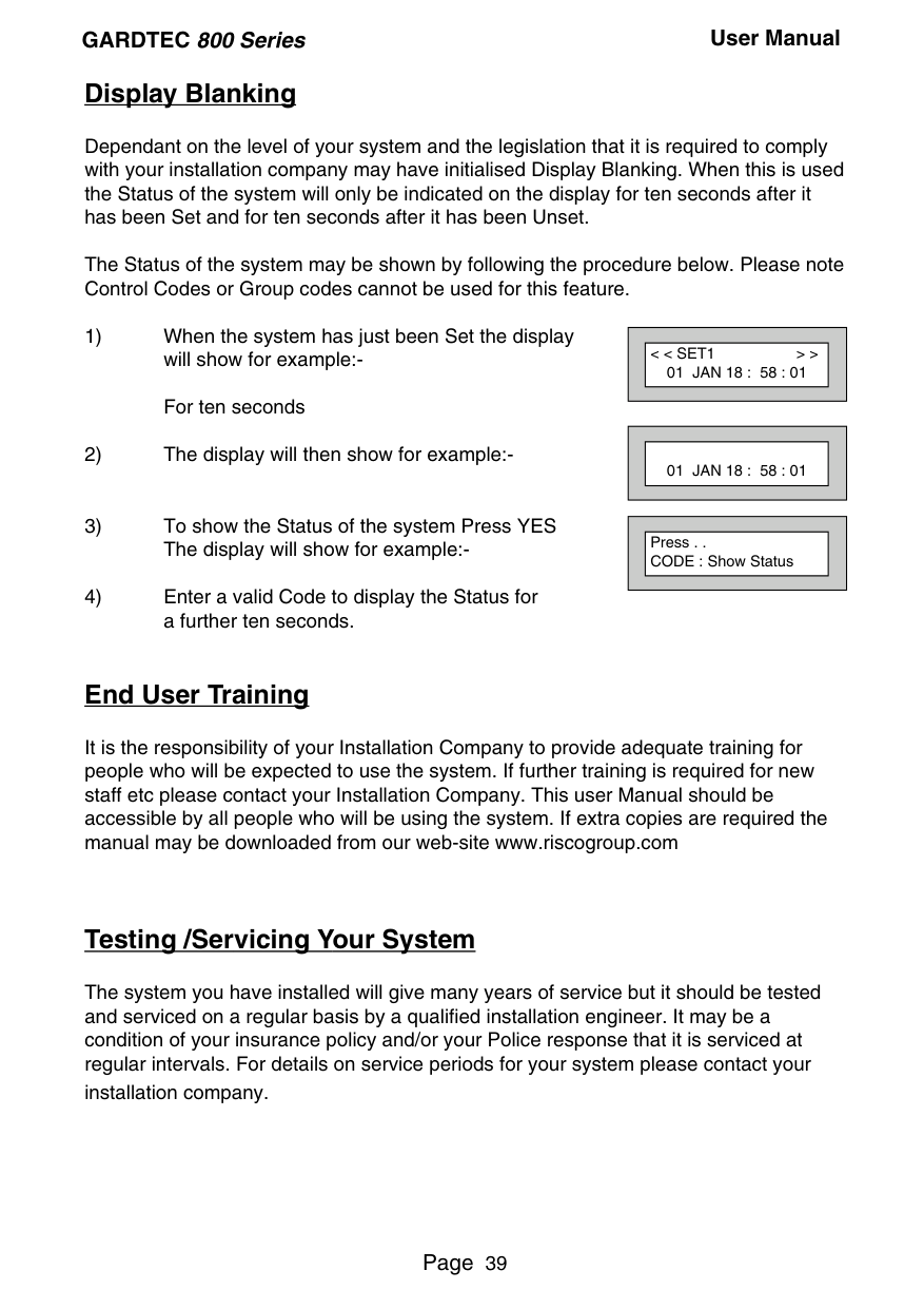
##### Display Blanking
Dependant on the level of your system and the legislation that it is required to comply with your installation company may have initialised Display Blanking. When this is used the Status of the system will only be indicated on the display for ten seconds after it has been Set and for ten seconds after it has been Unset.
The Status of the system may be shown by following the procedure below. Please note Control Codes or Group codes cannot be used for this feature.
||< < SET1 > > 01 JAN 18 : 58 : 01| |---| | |---|
||01 JAN 18 : 58 : 01| |---| | |---|
||Press . . CODE : Show Status| |---| | |---|
##### End User Training
It is the responsibility of your Installation Company to provide adequate training for people who will be expected to use the system. If further training is required for new staff etc please contact your Installation Company. This user Manual should be accessible by all people who will be using the system. If extra copies are required the manual may be downloaded from our web-site www.riscogroup.com
##### Testing /Servicing Your System
The system you have installed will give many years of service but it should be tested and serviced on a regular basis by a qualified installation engineer. It may be a condition of your insurance policy and/or your Police response that it is serviced at regular intervals. For details on service periods for your system please contact your installation company.
##### Keypad Alert - If Fitted


If programmed by your installation company, the two PA keys (if programmed by the engineer), when pressed together will act as alert keys. The exact function will depend on what they have been programmed for. But for example, if they are programmed as panic, pressing them will activate the alarm when the system is set or unset.
##### Keypad Tamper
The keypad will monitor the number keys that are pressed without a valid User Code being entered. More than 24 key presses will cause a keypad tamper. This will be displayed as Keypad x Tamper and will require a valid User Code entry to stop the sounders. If the system was Unset only the internal sounders will operate. If the system was Set, a full alarm will be generated.
##### System Tampers
The full security system is tampered, any attempt to remove covers from Keypads, Control Panel, Keypads, Bell Box(es) or detectors will cause a tamper alarm. This also applies to cut cables. If the system is Unset when the Tamper occurs the alarm will be internal sounders only. If the system is Set a full alarm will be generated.
The alarm may be silenced by entering a valid User Code. The system may only be Reset when the Tamper has been cleared, otherwise another Tamper alarm will be generated.
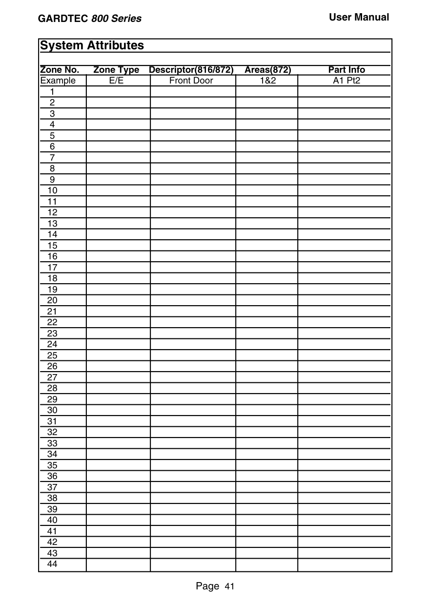
|System Attributes
Zone No. Zone Type Descriptor(816/872) Areas(872) Part Info|System Attributes
Zone No. Zone Type Descriptor(816/872) Areas(872) Part Info|System Attributes
Zone No. Zone Type Descriptor(816/872) Areas(872) Part Info|System Attributes
Zone No. Zone Type Descriptor(816/872) Areas(872) Part Info|System Attributes
Zone No. Zone Type Descriptor(816/872) Areas(872) Part Info| |---|---|---|---|---| |Example|E/E|Front Door|1&2|A1 Pt2| |1| | | | | |2| | | | | |3| | | | | |4| | | | | |5| | | | | |6| | | | | |7| | | | | |8| | | | | |9| | | | | |10| | | | | |11| | | | | |12| | | | | |13| | | | | |14| | | | | |15| | | | | |16| | | | | |17| | | | | |18| | | | | |19| | | | | |20| | | | | |21| | | | | |22| | | | | |23| | | | | |24| | | | | |25| | | | | |26| | | | | |27| | | | | |28| | | | | |29| | | | | |30| | | | | |31| | | | | |32| | | | | |33| | | | | |34| | | | | |35| | | | | |36| | | | | |37| | | | | |38| | | | |
|39| | | | | |40| | | | | |41| | | | | |42| | | | | |43| | | | | |44| | | | |
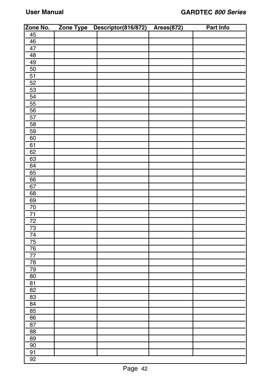
|Zone No. Zone Type Descriptor(816/872) Areas(872) Part Info
|45| | | | | |---|---|---|---|---| |46| | | | | |47| | | | | |48| | | | | |49| | | | | |50| | | | | |51| | | | | |52| | | | | |53| | | | | |54| | | | | |55| | | | | |56| | | | | |57| | | | | |58| | | | | |59| | | | | |60| | | | | |61| | | | | |62| | | | | |63| | | | | |64| | | | | |65| | | | | |66| | | | | |67| | | | | |68| | | | | |69| | | | | |70| | | | | |71| | | | | |72| | | | | |73| | | | | |74| | | | | |75| | | | | |76| | | | | |77| | | | | |78| | | | | |79| | | | |
|80| | | | | |81| | | | | |82| | | | | |83| | | | | |84| | | | | |85| | | | | |86| | | | | |87| | | | | |88| | | | | |89| | | | | |90| | | | | |91| | | | |
92| |---|
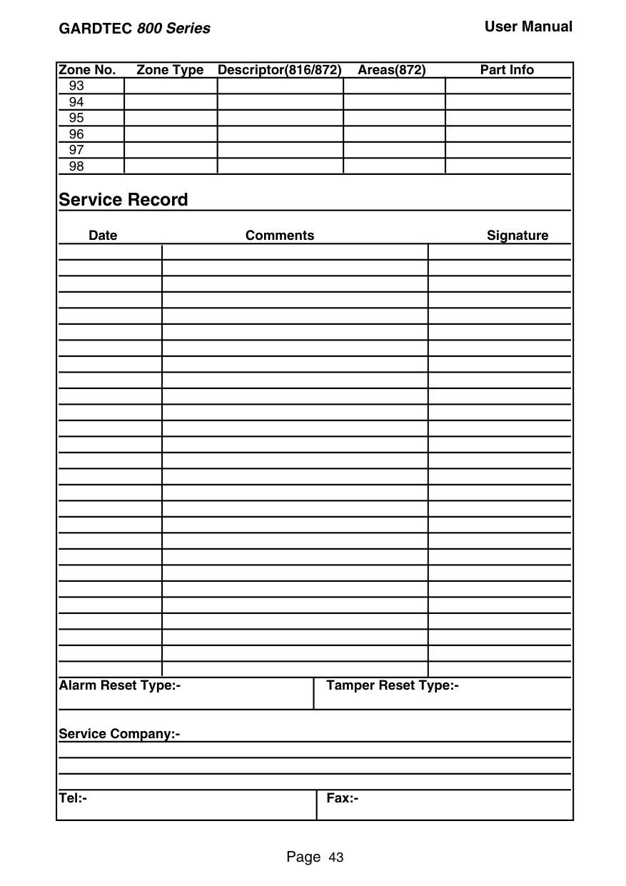
|Zone No. Zone Type Descriptor(816/872) Areas(872) Part Info
|93| | | | | |---|---|---|---|---| |94| | | | | |95| | | | | |96| | | | | |97| | | | | |98| | | | |
Service Record
| | | | | |---|---|---|---| | | | | | | | | | | | | | | | | | | | | | | | | | | | | | | | | | | | | | | | | | | | | | | | | | | | | | | | | | | | | | | | | | | | | | | | | | | | | | | | | | | | | | | | | | | | | | | |
| | | | | | | | | | | | | | | | | | | | | | | | | | | | | | | | | | | |larm Reset Type:-|larm Reset Type:-|Tamper Reset Type:-|Tamper Reset Type:-|
Date Comments Signature
Service Company:-
|Zone No. Zone Type Descriptor(816/872) Areas(872) Part Info
|93| | | | | |---|---|---|---|---| |94| | | | | |95| | | | | |96| | | | | |97| | | | | |98| | | | |
Service Record
| | | | | |---|---|---|---| | | | | | | | | | | | | | | | | | | | | | | | | | | | | | | | | | | | | | | | | | | | | | | | | | | | | | | | | | | | | | | | | | | | | | | | | | | | | | | | | | | | | | | | | | | | | | | | | | | | | | | | | | | | | | | | | | | | | | | | | | | | | | | | | | | |larm Reset Type:-|larm Reset Type:-|Tamper Reset Type:-|Tamper Reset Type:-|
Date Comments Signature
Service Company:-
| |---|---| |Tel:-|Fax:-|


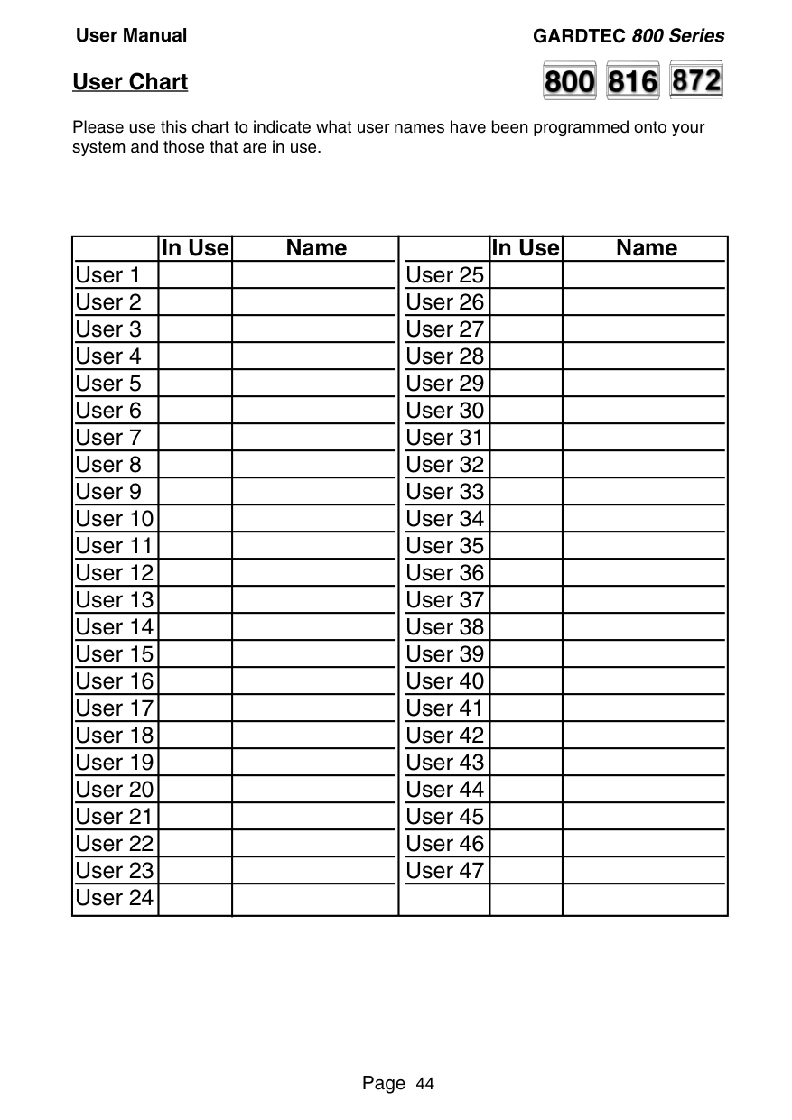
##### User Chart
Please use this chart to indicate what user names have been programmed onto your system and those that are in use.
##### In Use Name


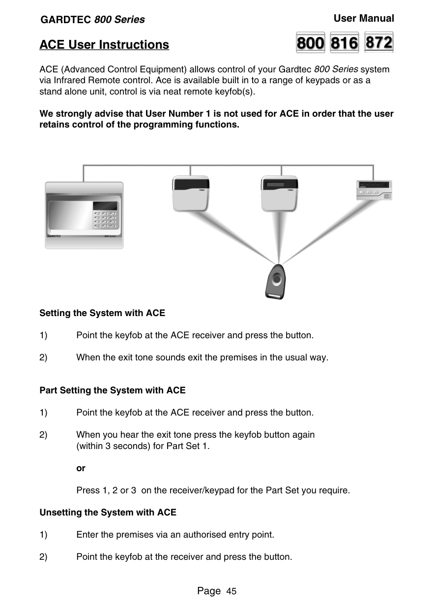
##### ACE User Instructions
ACE (Advanced Control Equipment) allows control of your Gardtec 800 Seriessystem via Infrared Remote control. Ace is available built in to a range of keypads or as a stand alone unit, control is via neat remote keyfob(s).
We strongly advise that User Number 1 is not used for ACE in order that the user retains control of the programming functions.

Setting the System with ACE
######### Part Setting the System with ACE
######### Unsetting the System with ACE
##### Programming ACE Keyfobs onto your System


Each keyfob will occupy a User number. The number of keyfobs that may be used is limited by the maximum number of user codes available on the system up to a maximum of fourteen.
Note: When programming the fob onto more than one receiver (on the same system) the button on the fob MUST be held down continuously between programming onto the first and other ACE receivers.
Note: In all cases when the ACE is used only Master & Main user levels will allow part setting via the keyfob. Other code levels will only allow part setting in conjunction with the keypad.
||RISCO Group UK Ltd
Commerce House, Whitbrook Way Stakehill Distribution Park, Middleton. Manchester. M24 2SS United Kingdom
Internet: www.riscogroup.com e-mail: sales@riscogroup.co.uk
RISCO Group UK Ltd reserve the right to amend the software and features without prior notice.


| |---| | |---|
PR5893 Rev 1.0
5IN800PDUM