
Ask AI
— answers from the official manualAnswers from the official manual.
Common questions
Common Questions
9 totalHow do I change the weight setting on the Gold S Gym Xr45?
Insert a Weight Pin (26) under the desired Weight (22). Insert the Weight Pin so that the bent end touches the weight stack and turn it downward. Use the WEIGHT RESISTANCE CHART on page 24 to determine approximate resistance at each exercise station.
How do I attach a Lat Bar to the Gold S Gym Xr45?
Attach the Lat Bar (35) to the High Cable (55) at the high pulley station with a Cable Clip (37). Make sure it is securely fastened and in the correct starting position for the intended exercise.
What should I do if the cables aren't moving smoothly around the pulleys?
Pull each cable a few times to ensure they move freely. If one is stuck, find and correct the problem. Incorrect installation can lead to damage during heavy use.
How do I lock the weight stack after exercising?
Insert the Lock Pin (89) through a Weight Guide (21), then secure the Lock (88) on it. This prevents unauthorized use of the equipment between workouts.
How often should I lubricate the moving parts of my Gold S Gym Xr45?
Apply grease regularly, especially after assembly and periodically during use. Parts requiring lubrication include Cable Pivots (39), Arm Pins (40), and Pulleys.
How do I adjust the resistance on each station?
Adjust using different weights as specified in the WEIGHT RESISTANCE CHART on page 24. Cable routing varies by station, so follow instructions for the desired exercise.
Full Manual
32 pages
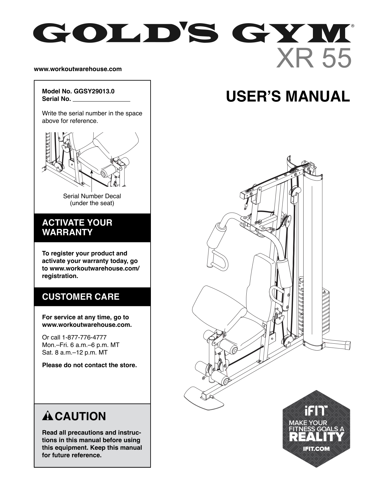
www.workoutwarehouse.com
Model No. GGSY29013.0 Serial No.
Write the serial number in the space above for reference.
USER’S MANUAL
Serial Number Decal (under the seat)
ACTIVATE YOUR WARRANTY
To register your product and activate your warranty today, go to www.workoutwarehouse.com/ registration.
CUSTOMER CARE
For service at any time, go to www.workoutwarehouse.com.
Or call 1-877-776-4777 Mon.–Fri. 6 a.m.–6 p.m. MT Sat. 8 a.m.–12 p.m. MT
Please do not contact the store.
CAUTION
Read all precautions and instructions in this manual before using this equipment. Keep this manual for future reference.
TABLE OF CONTENTS
WARNING DECAL PLACEMENT . . . . . . . . . . . . . . . . . . . . . . . . . . . . . . . . . . . . . . . . . . . . . . . . . . . . . . . . . . . . . . .2 IMPORTANT PRECAUTIONS ..................................................................3 BEFORE YOU BEGIN. . . . . . . . . . . . . . . . . . . . . . . . . . . . . . . . . . . . . . . . . . . . . . . . . . . . . . . . . . . . . . . . . . . . . . . .5 PART IDENTIFICATION CHART. . . . . . . . . . . . . . . . . . . . . . . . . . . . . . . . . . . . . . . . . . . . . . . . . . . . . . . . . . . . . . . .6 ASSEMBLY . . . . . . . . . . . . . . . . . . . . . . . . . . . . . . . . . . . . . . . . . . . . . . . . . . . . . . . . . . . . . . . . . . . . . . . . . . . . . . . .7 ADJUSTMENT ............................................................................22 WEIGHT RESISTANCE CHART. . . . . . . . . . . . . . . . . . . . . . . . . . . . . . . . . . . . . . . . . . . . . . . . . . . . . . . . . . . . . . .24 MAINTENANCE ...........................................................................25 EXERCISE GUIDELINES ....................................................................26 CABLE DIAGRAM. . . . . . . . . . . . . . . . . . . . . . . . . . . . . . . . . . . . . . . . . . . . . . . . . . . . . . . . . . . . . . . . . . . . . . . . . .28 PART LIST. . . . . . . . . . . . . . . . . . . . . . . . . . . . . . . . . . . . . . . . . . . . . . . . . . . . . . . . . . . . . . . . . . . . . . . . . . . . . . . .29 EXPLODED DRAWING. . . . . . . . . . . . . . . . . . . . . . . . . . . . . . . . . . . . . . . . . . . . . . . . . . . . . . . . . . . . . . . . . . . . . .30 ORDERING REPLACEMENT PARTS .................................................. Back Cover LIMITED WARRANTY. . . . . . . . . . . . . . . . . . . . . . . . . . . . . . . . . . . . . . . . . . . . . . . . . . . . . . . . . . . . . . . Back Cover
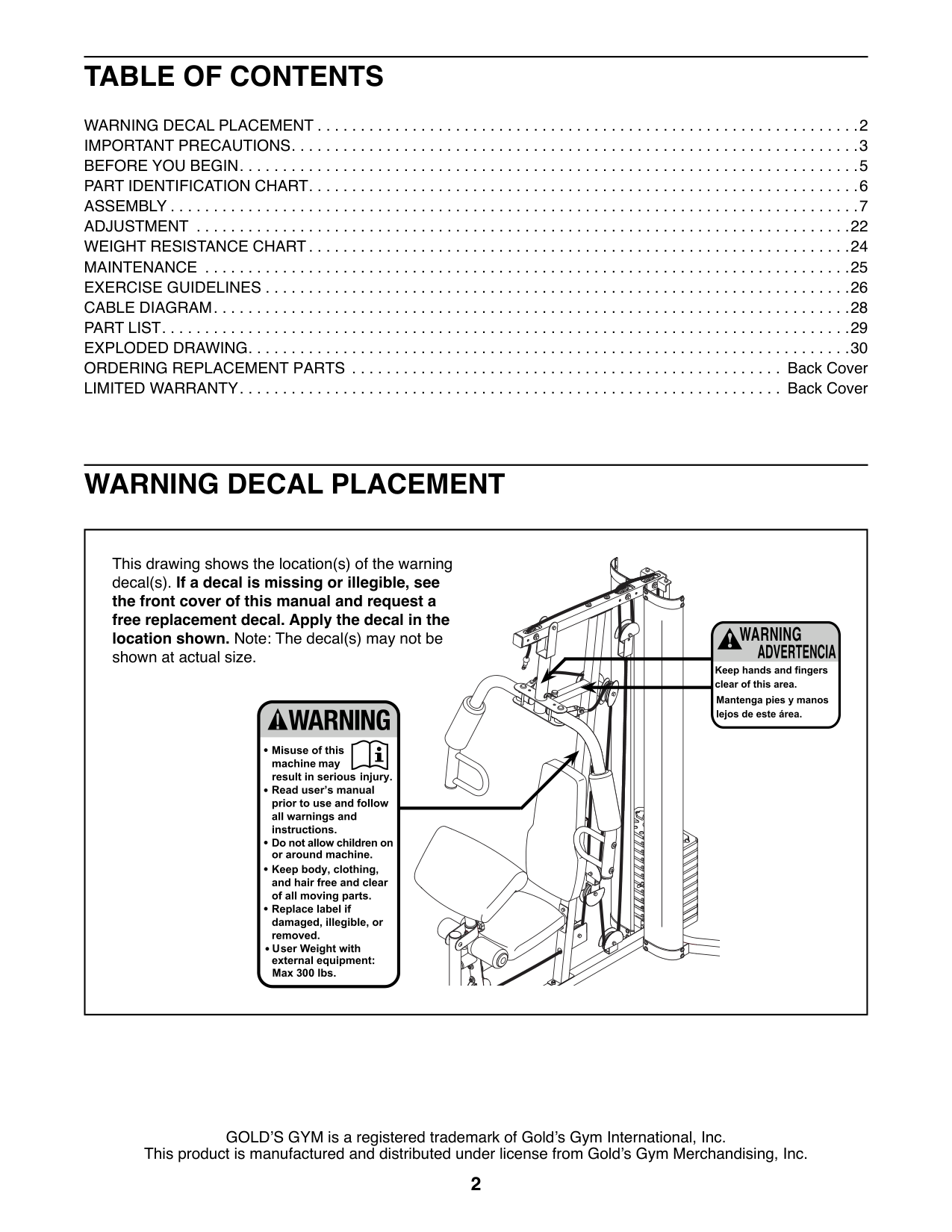
WARNING DECAL PLACEMENT
This drawing shows the location(s) of the warning decal(s). If a decal is missing or illegible, see the front cover of this manual and request a free replacement decal. Apply the decal in the location shown. Note: The decal(s) may not be shown at actual size.
GOLD’S GYM is a registered trademark of Gold’s Gym International, Inc. This product is manufactured and distributed under license from Gold’s Gym Merchandising, Inc.
IMPORTANT PRECAUTIONS
WARNING:To reduce the risk of serious injury, read all important precautions and instructions in this manual and all warnings on your weight system before using your weight system. ICON assumes no responsibility for personal injury or property damage sustained by or through the use of this product.
| | | | |---|---|---| | | | | | | | | | | | | | | | |
STANDARD SERVICE PLANS
| | | | | |---|---|---|---| | | | | | | | | | | | | | | | | | | | |
all
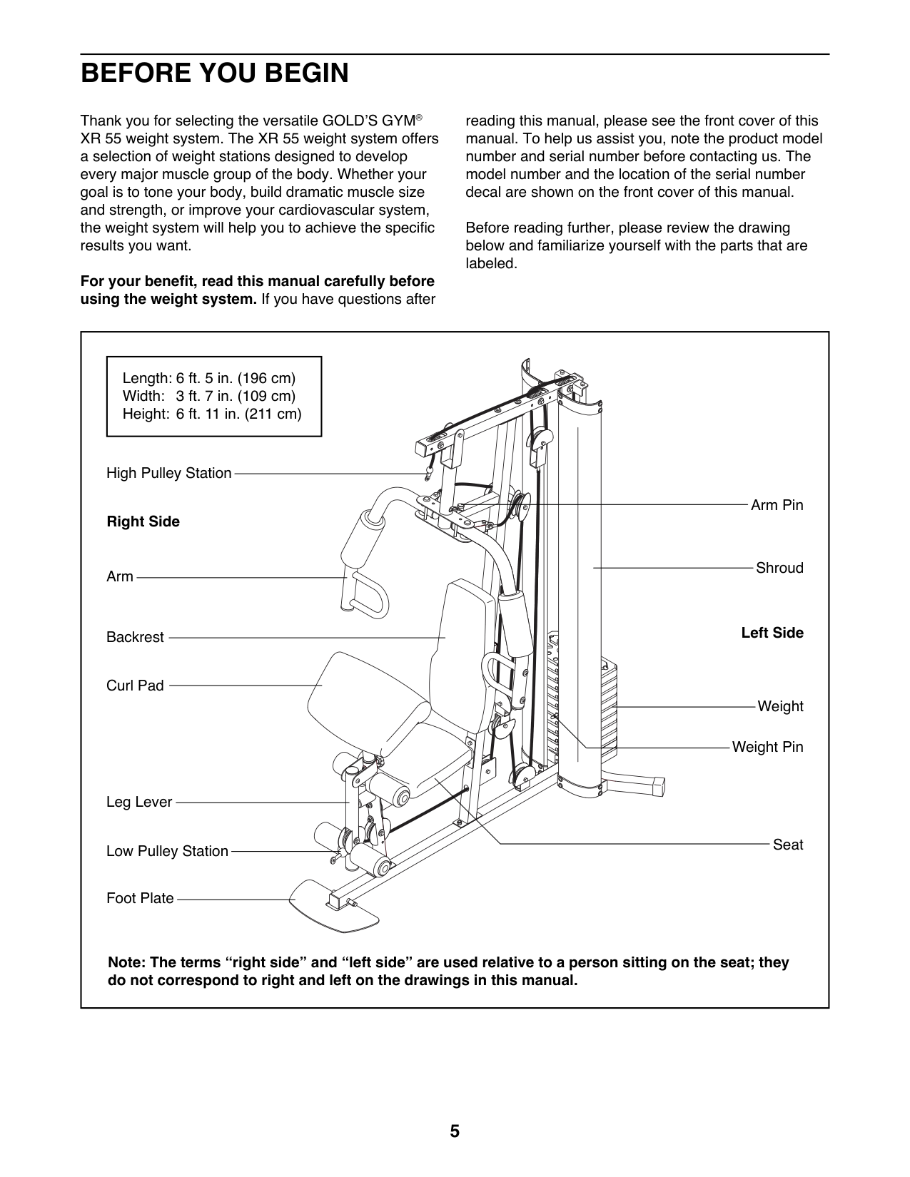
BEFORE YOU BEGIN
Thank you for selecting the versatile GOLD’S GYM® XR 55 weight system. The XR 55 weight system offers a selection of weight stations designed to develop every major muscle group of the body. Whether your goal is to tone your body, build dramatic muscle size and strength, or improve your cardiovascular system, the weight system will help you to achieve the specific results you want.
For your benefit, read this manual carefully before using the weight system. If you have questions after
reading this manual, please see the front cover of this manual. To help us assist you, note the product model number and serial number before contacting us. The model number and the location of the serial number decal are shown on the front cover of this manual.
Before reading further, please review the drawing below and familiarize yourself with the parts that are labeled.
||Length: 6 ft. 5 in. (196 cm) Width: 3 ft. 7 in. (109 cm) Height: 6 ft. 11 in. (211 cm)| |---|
Shroud
High Pulley Station
Low Pulley Station
Right Side
Left SideBackrest
Weight
Weight Pin
Leg Lever
Foot Plate
Seat
Arm
Arm Pin
Curl Pad
Note: The terms “right side” and “left side” are used relative to a person sitting on the seat; they do not correspond to right and left on the drawings in this manual.| |---|
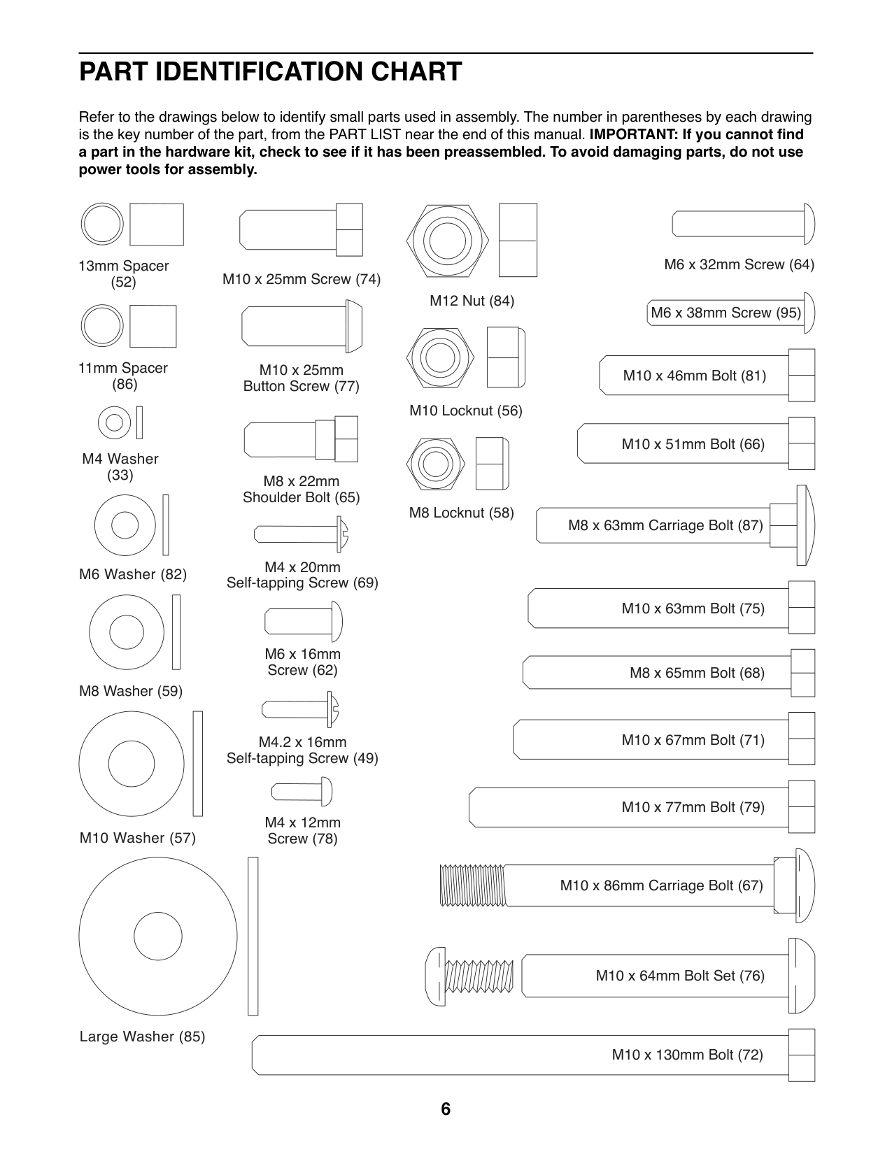
PART IDENTIFICATION CHART
Refer to the drawings below to identify small parts used in assembly. The number in parentheses by each drawing is the key number of the part, from the PART LIST near the end of this manual. IMPORTANT: If you cannot find a part in the hardware kit, check to see if it has been preassembled. To avoid damaging parts, do not use power tools for assembly.
| | | |---|---| | | | | | | | | |
| | |---| | |
M6 x 32mm Screw (64)
13mm Spacer (52)
M10 x 25mm Screw (74)
M12 Nut (84)
M6 x 38mm Screw (95)
| | |---| | |
| | | |---|---| |M10 x 46mm Bolt (81)| | |M10 x 46mm Bolt (81)| | | | |
11mm Spacer (86)
M10 x 25mm Button Screw (77)
M10 Locknut (56)
| | | |---|---| |M10 x 51mm Bolt (66)| | |M10 x 51mm Bolt (66)| | | | |
| | |---| | |
M4 Washer (33)
M8 x 22mm Shoulder Bolt (65)
M8 Locknut (58)
| | | |---|---| | | |
M8 x 63mm Carriage Bolt (87)
M4 x 20mm Self-tapping Screw (69)
M6 Washer (82)
| | | |---|---| |M10 x 63mm Bolt (75)| | |M10 x 63mm Bolt (75)| | | | |
M6 x 16mm Screw (62)
| | | |---|---| |M8 x 65mm Bolt (68)| | |M8 x 65mm Bolt (68)| | | | |
M8 Washer (59)
| | | |---|---| | | |
| | | |---|---| |M10 x 67mm Bolt (71)| | |M10 x 67mm Bolt (71)| | | | |
M4.2 x 16mm Self-tapping Screw (49)
| | | |---|---| |M10 x 77mm Bolt (79)| | |M10 x 77mm Bolt (79)| | | | |
M4 x 12mm Screw (78)
M10 Washer (57)
M10 x 86mm Carriage Bolt (67)
| | | |---|---| |M10 x 64mm Bolt Set (76)| | | | |
Large Washer (85)
| | |
|---|---| |M10 x 130mm Bolt (72)| | |M10 x 130mm Bolt (72)| | | | |
ASSEMBLY
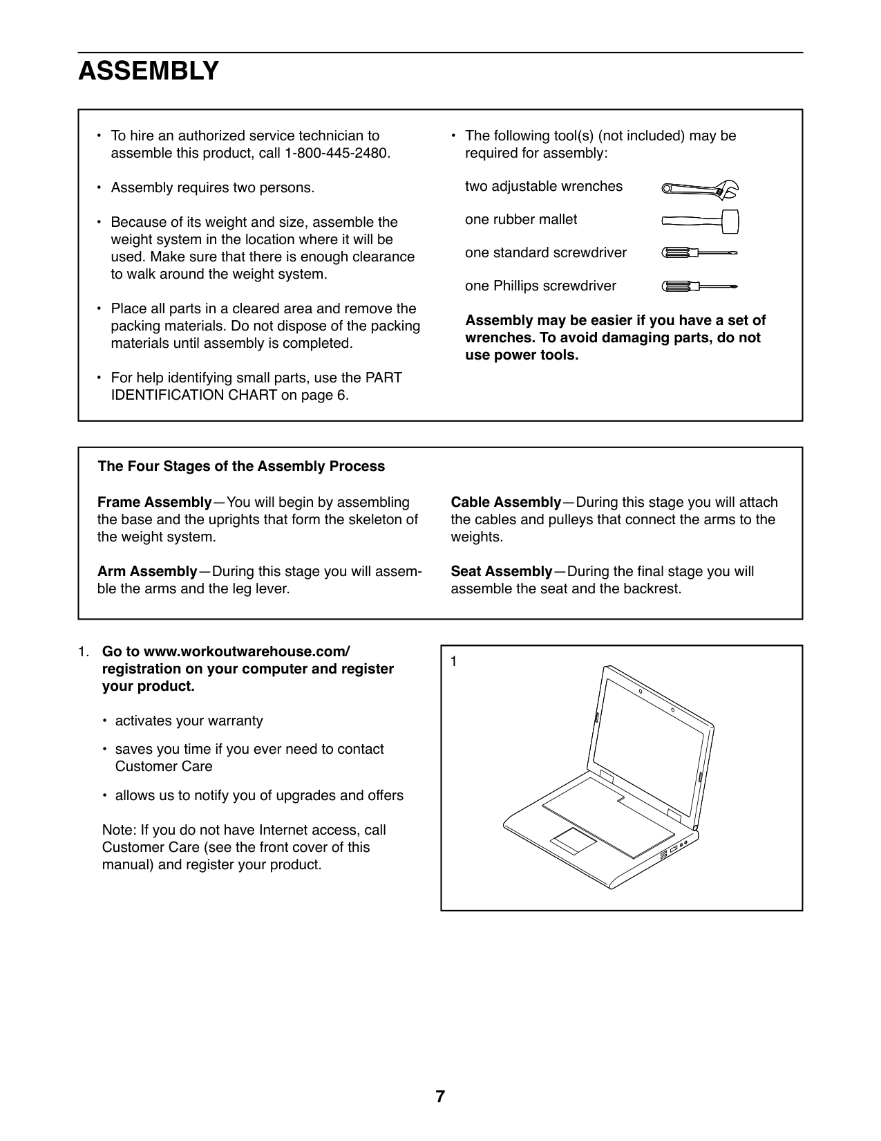
• The following tool(s) (not included) may be required for assembly: two adjustable wrenches one rubber mallet one standard screwdriver one Phillips screwdriver
Assembly may be easier if you have a set of wrenches. To avoid damaging parts, do not use power tools.
##### The Four Stages of the Assembly Process
Frame Assembly—You will begin by assembling the base and the uprights that form the skeleton of the weight system.
Cable Assembly—During this stage you will attach the cables and pulleys that connect the arms to the weights.
Arm Assembly—During this stage you will assemble the arms and the leg lever.
Seat Assembly—During the final stage you will assemble the seat and the backrest.
|1| |---|
##### 1. Go to www.workoutwarehouse.com/registration on your computer and registeryour product.
Note: If you do not have Internet access, call Customer Care (see the front cover of this manual) and register your product.
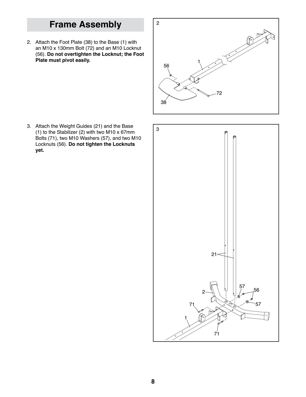
(56). Do not overtighten the Locknut; the Foot Plate must pivot easily.
Frame Assembly
(1) to the Stabilizer (2) with two M10 x 67mm Bolts (71), two M10 Washers (57), and two M10 Locknuts (56). Do not tighten the Locknuts yet.
|2
1
38
56
72| |---|
|3
56
71
71
2
57
57
21
1| |---|
|4
87
58
1
58
3| |---|
|5
7
58
58
87
1
| |---|
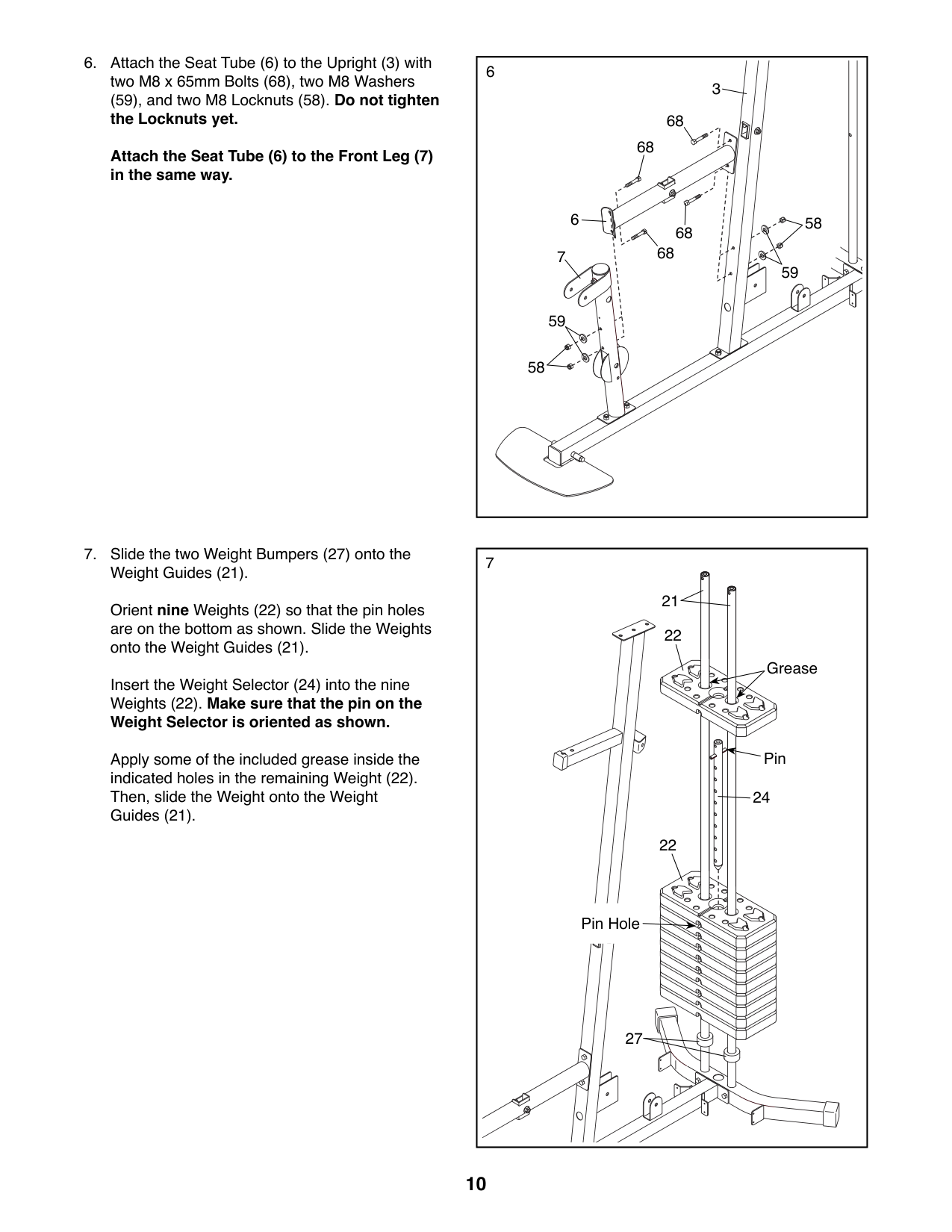
(59), and two M8 Locknuts (58). Do not tighten the Locknuts yet. Attach the Seat Tube (6) to the Front Leg (7) in the same way.
6
3
68
68
6
68
68
7
59
58
58
59
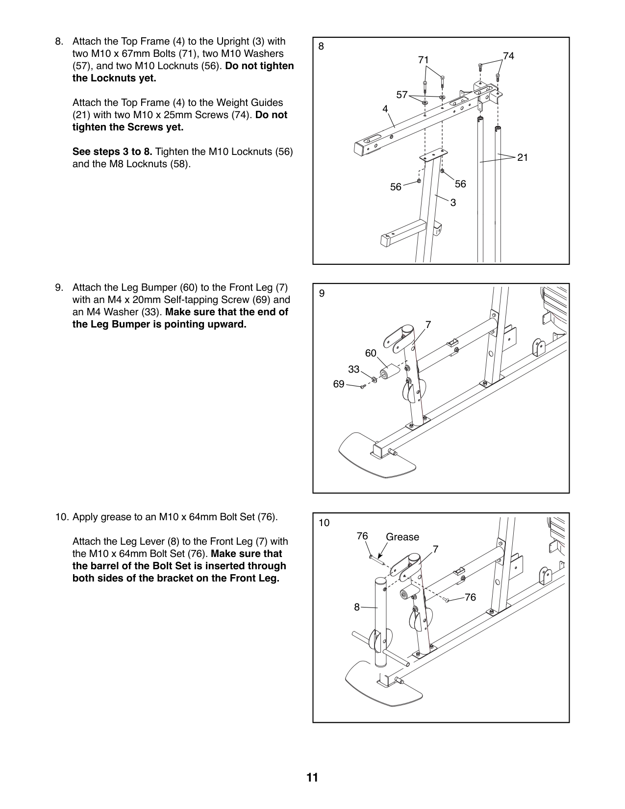
Orient nine Weights (22) so that the pin holes are on the bottom as shown. Slide the Weights onto the Weight Guides (21).
Insert the Weight Selector (24) into the nine Weights (22). Make sure that the pin on the Weight Selector is oriented as shown.
Apply some of the included grease inside the indicated holes in the remaining Weight (22). Then, slide the Weight onto the Weight Guides (21).
|7
21
27
22
22
24
Pin
Pin Hole
Grease
| |---|
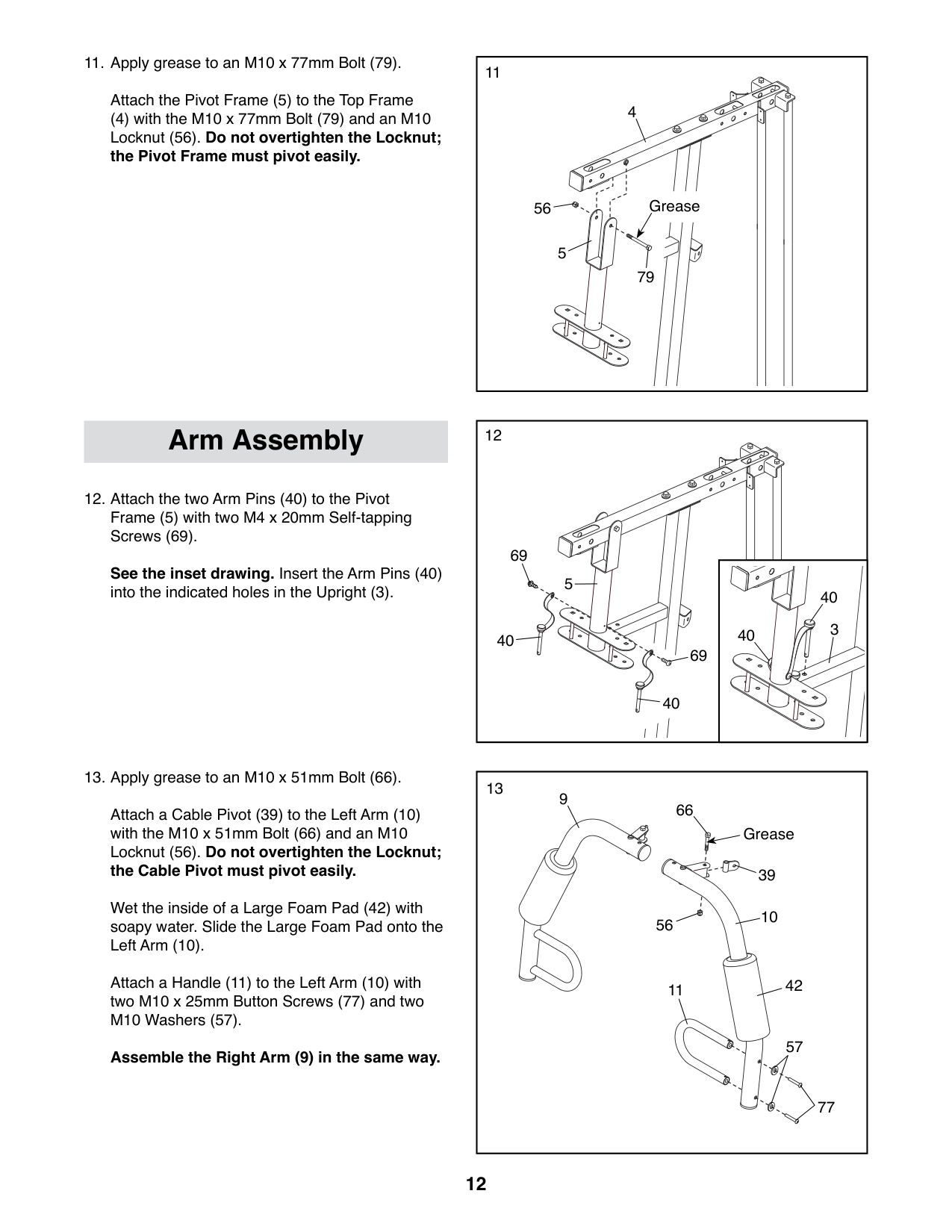
##### (57), and two M10 Locknuts (56). Do not tighten the Locknuts yet.
Attach the Top Frame (4) to the Weight Guides
(21) with two M10 x 25mm Screws (74). Do not tighten the Screws yet. See steps 3 to 8. Tighten the M10 Locknuts (56) and the M8 Locknuts (58).
Attach the Leg Lever (8) to the Front Leg (7) with the M10 x 64mm Bolt Set (76). Make sure that the barrel of the Bolt Set is inserted through both sides of the bracket on the Front Leg.
8
74
71
4
21
56
3
7
60 33
69
76
Grease
7
76
8
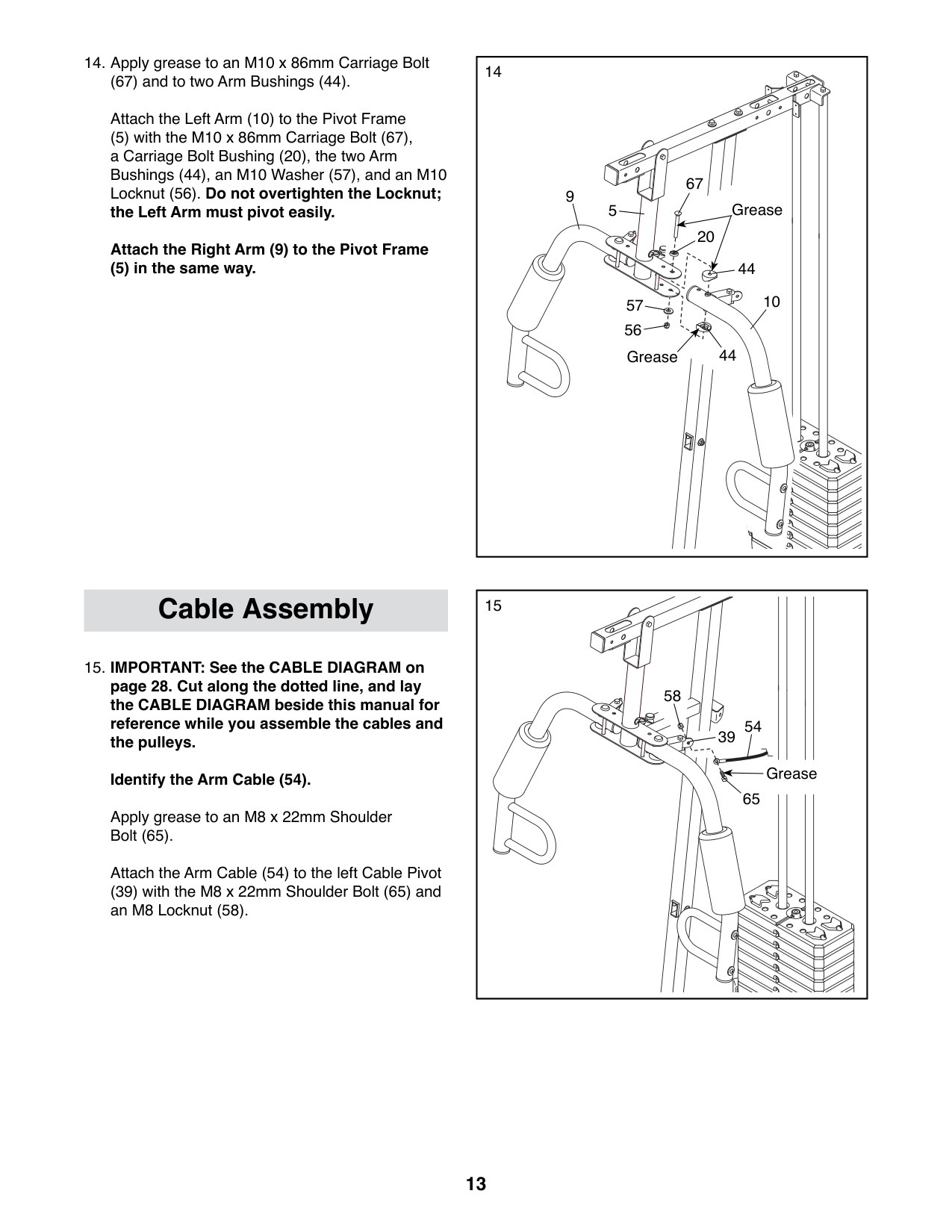
Attach the Pivot Frame (5) to the Top Frame
(4) with the M10 x 77mm Bolt (79) and an M10 Locknut (56). Do not overtighten the Locknut; the Pivot Frame must pivot easily.
12Arm Assembly
See the inset drawing. Insert the Arm Pins (40) into the indicated holes in the Upright (3).
5
69
69
40
40
13
11
10
39
57
77
66
56
9
42
Grease
Attach a Cable Pivot (39) to the Left Arm (10) with the M10 x 51mm Bolt (66) and an M10 Locknut (56). Do not overtighten the Locknut; the Cable Pivot must pivot easily.
Wet the inside of a Large Foam Pad (42) with soapy water. Slide the Large Foam Pad onto the Left Arm (10).
Attach a Handle (11) to the Left Arm (10) with two M10 x 25mm Button Screws (77) and two M10 Washers (57).

Assemble the Right Arm (9) in the same way.
11
4
56 Grease
5
79
40
40 3
(67) and to two Arm Bushings (44). Attach the Left Arm (10) to the Pivot Frame
(5) with the M10 x 86mm Carriage Bolt (67), a Carriage Bolt Bushing (20), the two Arm Bushings (44), an M10 Washer (57), and an M10 Locknut (56). Do not overtighten the Locknut; the Left Arm must pivot easily. Attach the Right Arm (9) to the Pivot Frame
(5) in the same way.
|14
10
9
44
56
67
57
20
5
44
Grease
Grease
|14
10
9
44
56
67
57
20
5
44
Grease
Grease
| |---|---| | | |
15Cable Assembly
58
54 39
Grease
65
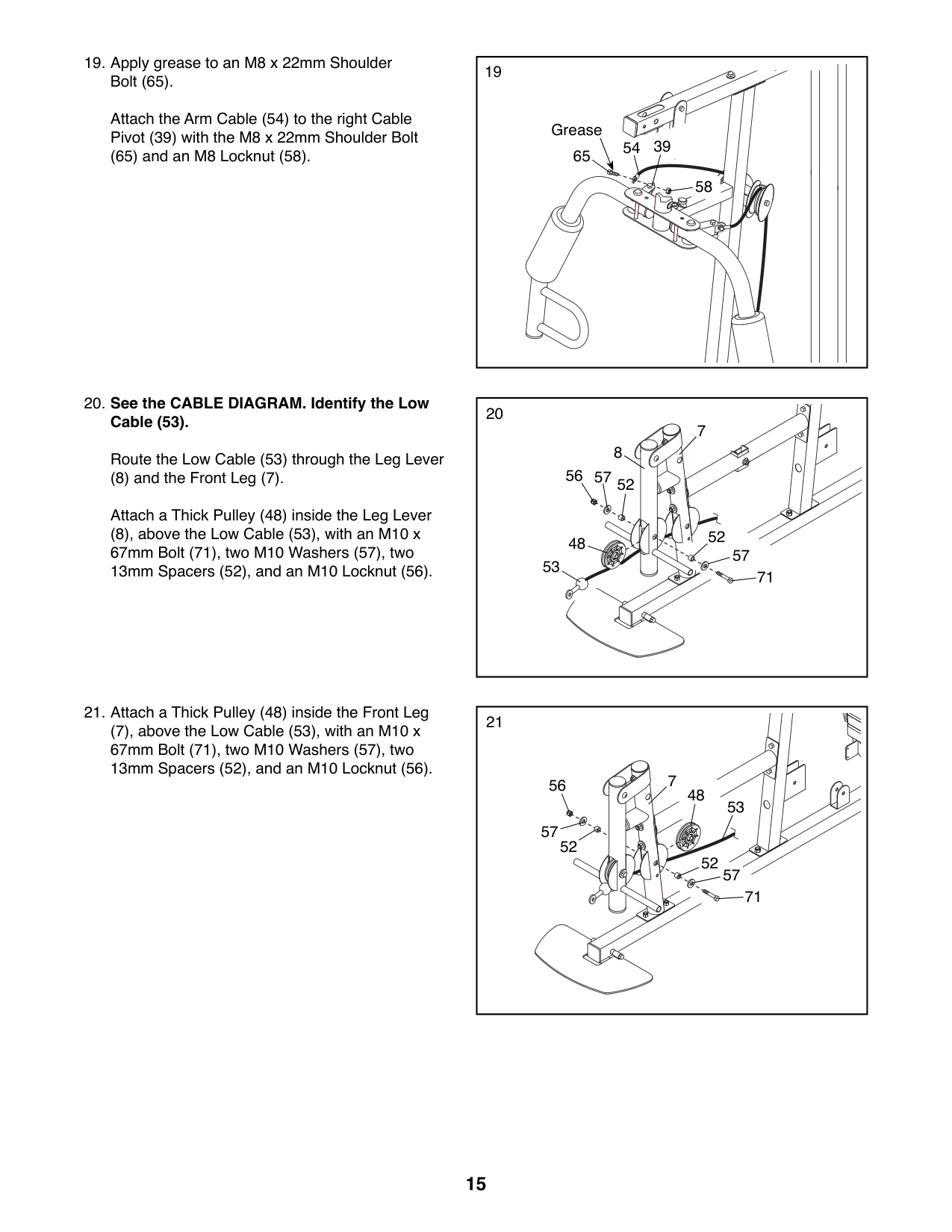
Apply grease to an M8 x 22mm Shoulder Bolt (65).
Attach the Arm Cable (54) to the left Cable Pivot (39) with the M8 x 22mm Shoulder Bolt (65) and an M8 Locknut (58).
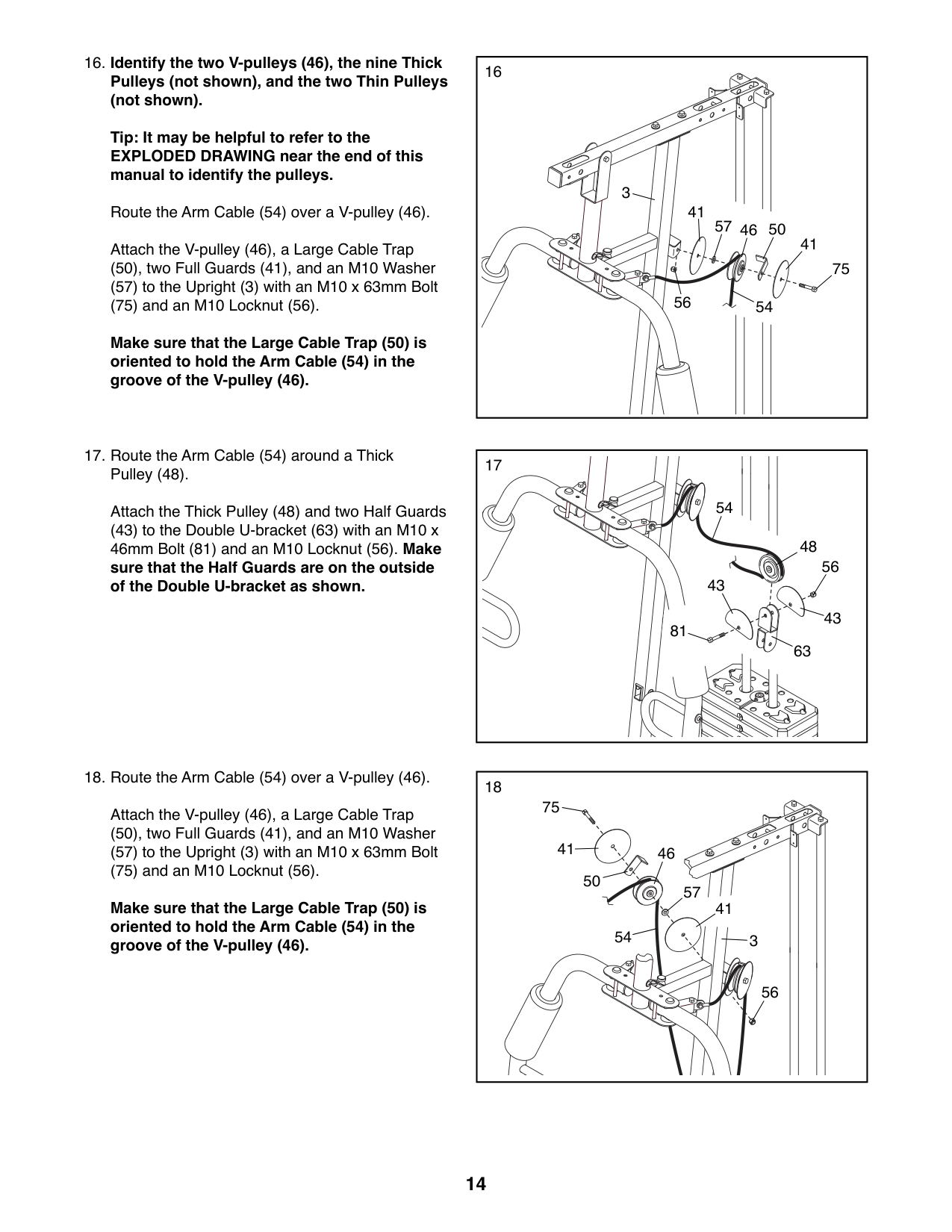
##### 16. Identify the two V-pulleys (46), the nine ThickPulleys (not shown), and the two Thin Pulleys(not shown).
Tip: It may be helpful to refer to the EXPLODED DRAWING near the end of this manual to identify the pulleys.
Route the Arm Cable (54) over a V-pulley (46). Attach the V-pulley (46), a Large Cable Trap
(50), two Full Guards (41), and an M10 Washer (57) to the Upright (3) with an M10 x 63mm Bolt (75) and an M10 Locknut (56).
Make sure that the Large Cable Trap (50) is oriented to hold the Arm Cable (54) in the groove of the V-pulley (46).
16
3
41
57 46 50
41
75 54
56
###### 17. Route the Arm Cable (54) around a ThickPulley (48).
Attach the Thick Pulley (48) and two Half Guards
(43) to the Double U-bracket (63) with an M10 x 46mm Bolt (81) and an M10 Locknut (56). Make sure that the Half Guards are on the outside of the Double U-bracket as shown.
###### 18. Route the Arm Cable (54) over a V-pulley (46).
Attach the V-pulley (46), a Large Cable Trap
(50), two Full Guards (41), and an M10 Washer (57) to the Upright (3) with an M10 x 63mm Bolt (75) and an M10 Locknut (56).
Make sure that the Large Cable Trap (50) is oriented to hold the Arm Cable (54) in the groove of the V-pulley (46).
54
48
56
43
43
81
63
75
41
46 50
57
41
54
3
56
Attach the Arm Cable (54) to the right Cable Pivot (39) with the M8 x 22mm Shoulder Bolt
(65) and an M8 Locknut (58).
19
65
Grease
Route the Low Cable (53) through the Leg Lever
(8) and the Front Leg (7). Attach a Thick Pulley (48) inside the Leg Lever
(8), above the Low Cable (53), with an M10 x 67mm Bolt (71), two M10 Washers (57), two 13mm Spacers (52), and an M10 Locknut (56).
(7), above the Low Cable (53), with an M10 x 67mm Bolt (71), two M10 Washers (57), two 13mm Spacers (52), and an M10 Locknut (56).
54 39
58
8
7
53
52
52
57
57
48
71
56
52
52
48
53
57
71
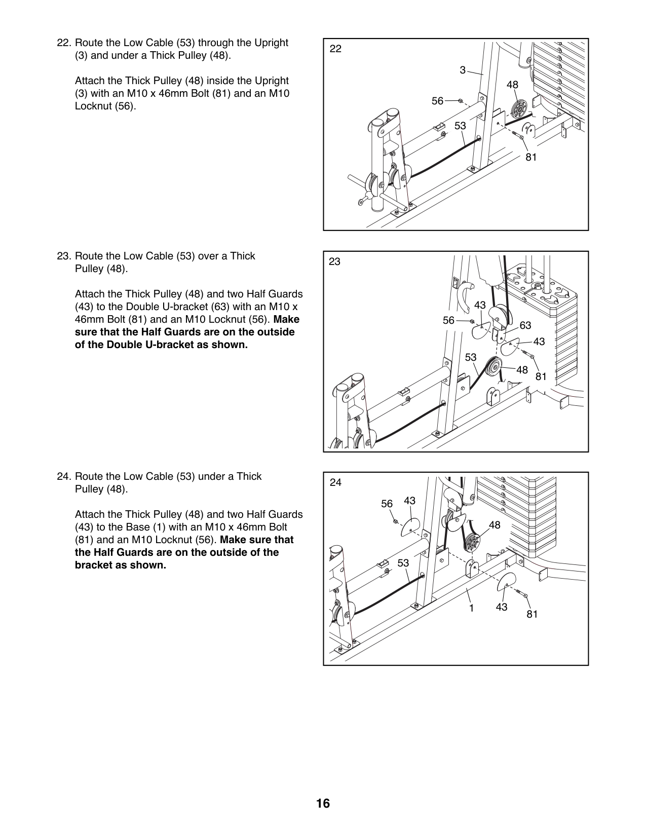
(3) and under a Thick Pulley (48).
Attach the Thick Pulley (48) inside the Upright (3) with an M10 x 46mm Bolt (81) and an M10 Locknut (56).
Attach the Thick Pulley (48) and two Half Guards
(43) to the Double U-bracket (63) with an M10 x 46mm Bolt (81) and an M10 Locknut (56). Make sure that the Half Guards are on the outside of the Double U-bracket as shown.
56
48
81
81
3
Attach the Thick Pulley (48) and two Half Guards
(43) to the Base (1) with an M10 x 46mm Bolt
(81) and an M10 Locknut (56). Make sure that the Half Guards are on the outside of the bracket as shown.
53
43
56
63
43
53
48
24
43
56
48
53
431
81
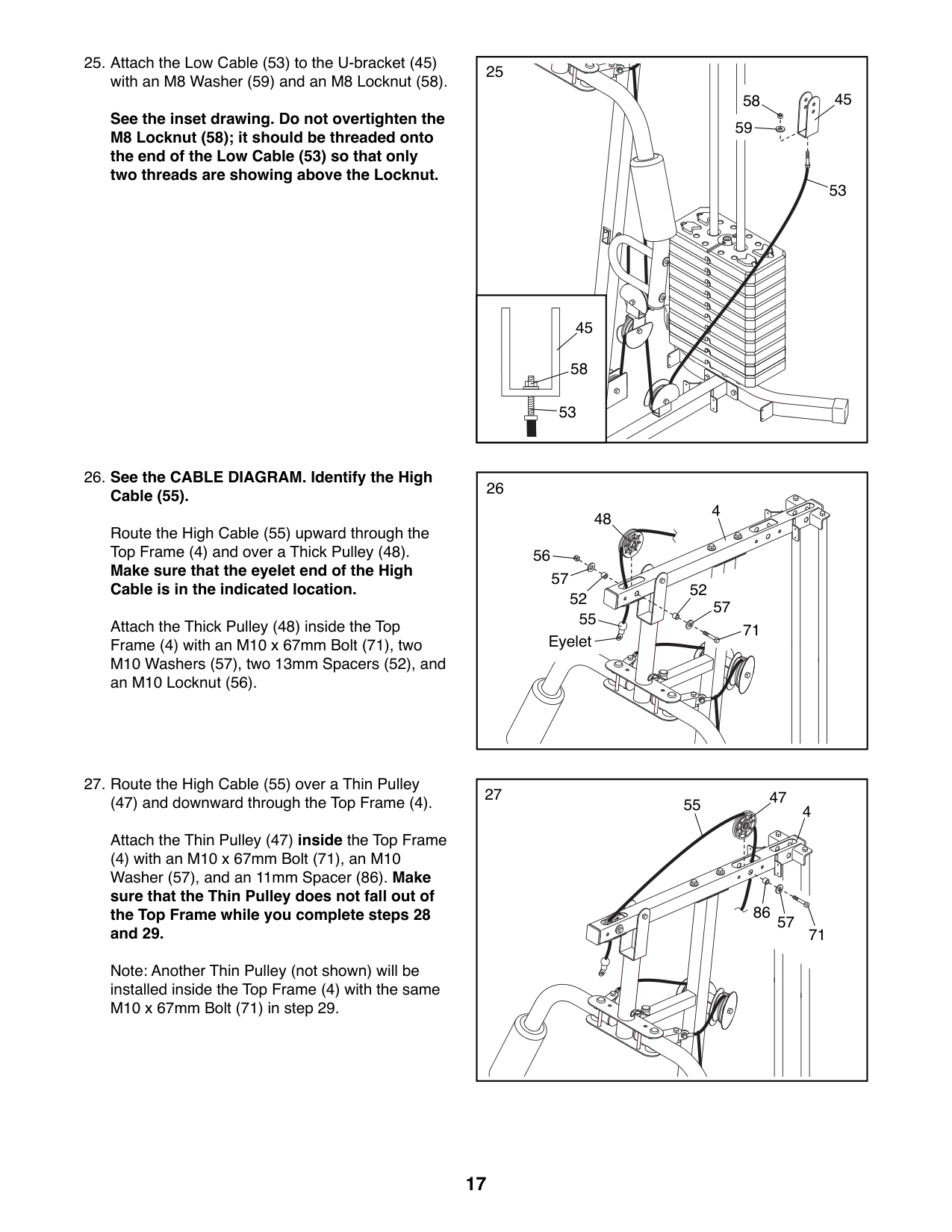
See the inset drawing. Do not overtighten the M8 Locknut (58); it should be threaded onto the end of the Low Cable (53) so that only two threads are showing above the Locknut.
##### 26. See the CABLE DIAGRAM. Identify the HighCable (55).
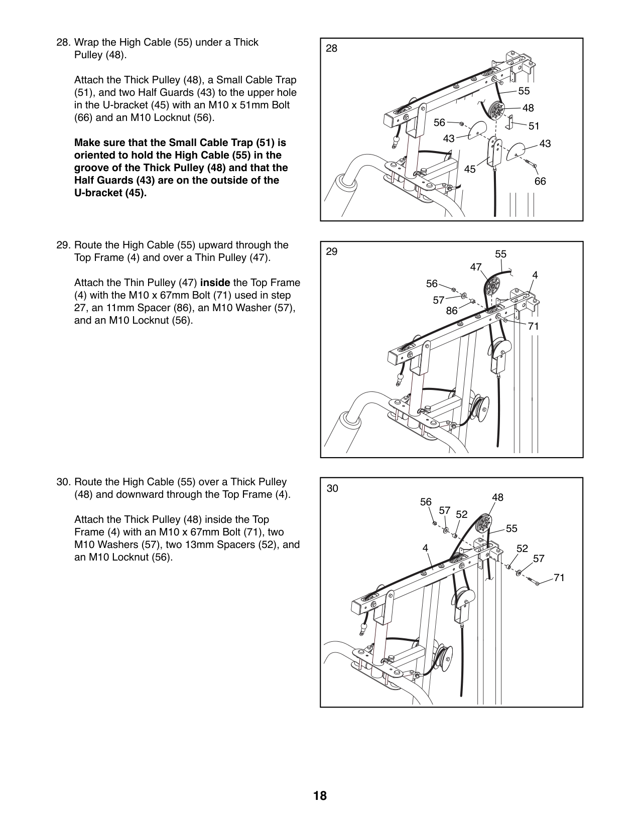
Route the High Cable (55) upward through the Top Frame (4) and over a Thick Pulley (48). Make sure that the eyelet end of the High Cable is in the indicated location.
Attach the Thick Pulley (48) inside the Top Frame (4) with an M10 x 67mm Bolt (71), two M10 Washers (57), two 13mm Spacers (52), and an M10 Locknut (56).
###### 27. Route the High Cable (55) over a Thin Pulley
(47) and downward through the Top Frame (4). Attach the Thin Pulley (47) inside the Top Frame
(4) with an M10 x 67mm Bolt (71), an M10 Washer (57), and an 11mm Spacer (86). Make sure that the Thin Pulley does not fall out of the Top Frame while you complete steps 28 and 29.
Note: Another Thin Pulley (not shown) will be installed inside the Top Frame (4) with the same M10 x 67mm Bolt (71) in step 29.
53
45
58
53
48
4
55
52
52
71
Eyelet
47
455
86
57
71
Attach the Thick Pulley (48), a Small Cable Trap (51), and two Half Guards (43) to the upper hole in the U-bracket (45) with an M10 x 51mm Bolt
(66) and an M10 Locknut (56).
Make sure that the Small Cable Trap (51) is oriented to hold the High Cable (55) in the groove of the Thick Pulley (48) and that the Half Guards (43) are on the outside of the U-bracket (45).
(48) and downward through the Top Frame (4). Attach the Thick Pulley (48) inside the Top Frame (4) with an M10 x 67mm Bolt (71), two M10 Washers (57), two 13mm Spacers (52), and an M10 Locknut (56).
Attach the Thin Pulley (47) inside the Top Frame
(4) with the M10 x 67mm Bolt (71) used in step 27, an 11mm Spacer (86), an M10 Washer (57), and an M10 Locknut (56).
55
48
5156
4343 45
66
55 47
4
56
57
86
71
48 57
56
52
55
4
52
57
71
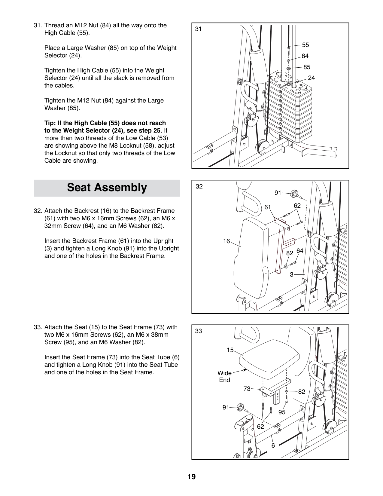
Place a Large Washer (85) on top of the Weight Selector (24).
Tighten the High Cable (55) into the Weight Selector (24) until all the slack is removed from the cables.
Tighten the M12 Nut (84) against the Large Washer (85).
Tip: If the High Cable (55) does not reach to the Weight Selector (24), see step 25. If more than two threads of the Low Cable (53) are showing above the M8 Locknut (58), adjust the Locknut so that only two threads of the Low Cable are showing.
55
(61) with two M6 x 16mm Screws (62), an M6 x 32mm Screw (64), and an M6 Washer (82).
Insert the Backrest Frame (61) into the Upright
(3) and tighten a Long Knob (91) into the Upright and one of the holes in the Backrest Frame.
31
Seat Assembly 91
61 62
16
64
82
3
15
Insert the Seat Frame (73) into the Seat Tube (6) and tighten a Long Knob (91) into the Seat Tube and one of the holes in the Seat Frame.
Wide End
73
82
91
95
62
6
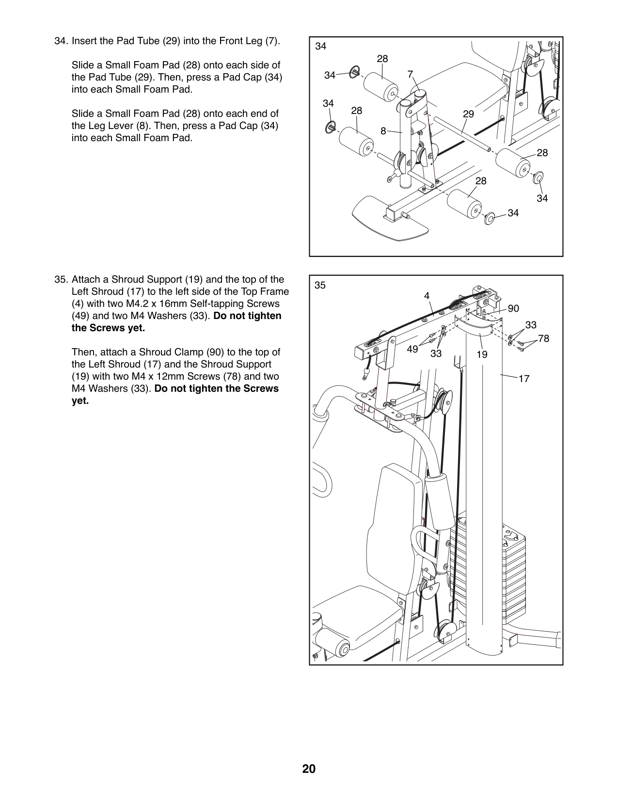
Slide a Small Foam Pad (28) onto each side of the Pad Tube (29). Then, press a Pad Cap (34) into each Small Foam Pad.
Slide a Small Foam Pad (28) onto each end of the Leg Lever (8). Then, press a Pad Cap (34) into each Small Foam Pad.
(4) with two M4.2 x 16mm Self-tapping Screws (49) and two M4 Washers (33). Do not tighten the Screws yet.
Then, attach a Shroud Clamp (90) to the top of the Left Shroud (17) and the Shroud Support
(19) with two M4 x 12mm Screws (78) and two M4 Washers (33). Do not tighten the Screws yet.
34
28
7
34
34
28
29
8
28
28
34
34
|35
78 49
33
90
33
4
19
17| |---|
36
17
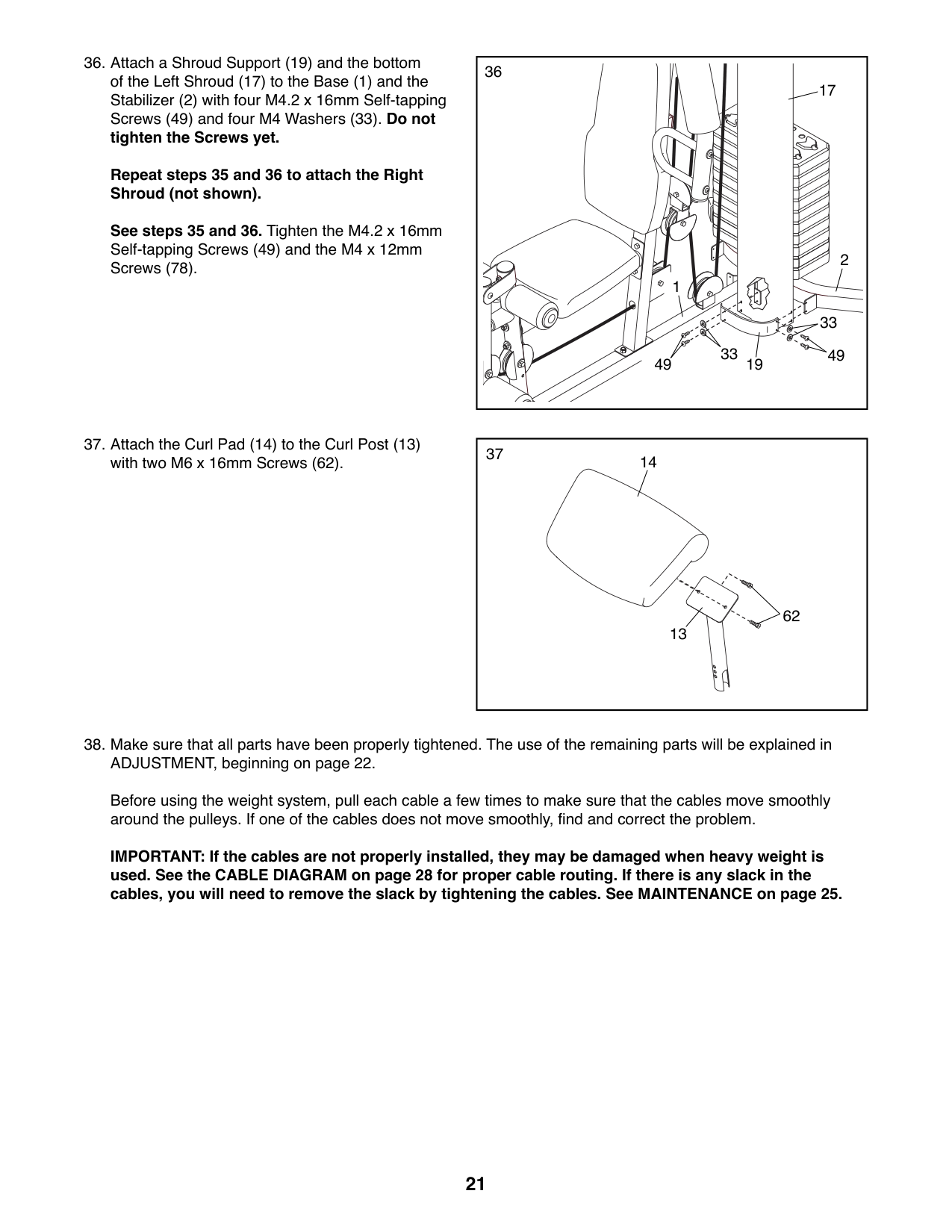
##### Repeat steps 35 and 36 to attach the Right Shroud (not shown).
See steps 35 and 36. Tighten the M4.2 x 16mm Self-tapping Screws (49) and the M4 x 12mm Screws (78). 2
1
33 33
49 1949
|37
14
13
62
| |---|
Before using the weight system, pull each cable a few times to make sure that the cables move smoothly around the pulleys. If one of the cables does not move smoothly, find and correct the problem.
IMPORTANT: If the cables are not properly installed, they may be damaged when heavy weight is used. See the CABLE DIAGRAM on page 28 for proper cable routing. If there is any slack in the cables, you will need to remove the slack by tightening the cables. See MAINTENANCE on page 25.
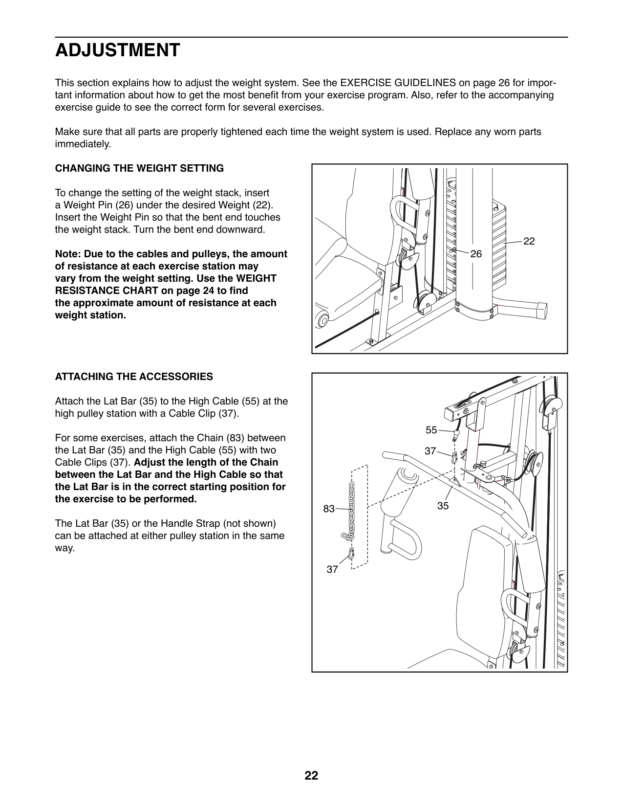
ADJUSTMENT
This section explains how to adjust the weight system. See the EXERCISE GUIDELINES on page 26 for important information about how to get the most benefit from your exercise program. Also, refer to the accompanying exercise guide to see the correct form for several exercises.
Make sure that all parts are properly tightened each time the weight system is used. Replace any worn parts immediately.
##### CHANGING THE WEIGHT SETTING
To change the setting of the weight stack, insert a Weight Pin (26) under the desired Weight (22). Insert the Weight Pin so that the bent end touches the weight stack. Turn the bent end downward.
22
26
Note: Due to the cables and pulleys, the amount of resistance at each exercise station may vary from the weight setting. Use the WEIGHT RESISTANCE CHART on page 24 to find the approximate amount of resistance at each weight station.
##### ATTACHING THE ACCESSORIES
Attach the Lat Bar (35) to the High Cable (55) at the high pulley station with a Cable Clip (37).
55 37
For some exercises, attach the Chain (83) between the Lat Bar (35) and the High Cable (55) with two Cable Clips (37). Adjust the length of the Chain between the Lat Bar and the High Cable so that the Lat Bar is in the correct starting position for the exercise to be performed.
35
83
The Lat Bar (35) or the Handle Strap (not shown) can be attached at either pulley station in the same way.
37
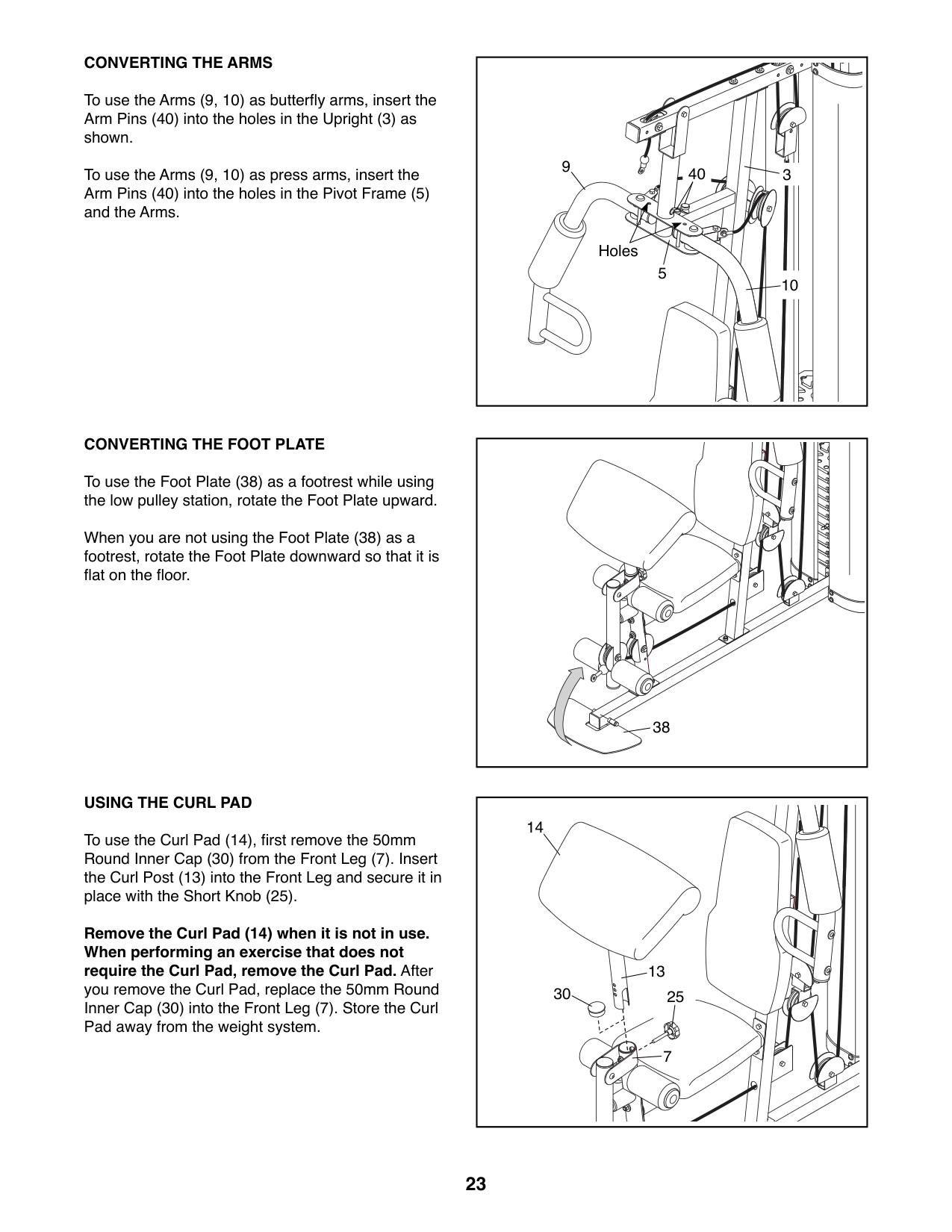
##### CONVERTING THE ARMS
To use the Arms (9, 10) as butterfly arms, insert the Arm Pins (40) into the holes in the Upright (3) as shown.
To use the Arms (9, 10) as press arms, insert the Arm Pins (40) into the holes in the Pivot Frame (5) and the Arms.
##### CONVERTING THE FOOT PLATE
To use the Foot Plate (38) as a footrest while using the low pulley station, rotate the Foot Plate upward.
When you are not using the Foot Plate (38) as a footrest, rotate the Foot Plate downward so that it is flat on the floor.
##### USING THE CURL PAD
To use the Curl Pad (14), first remove the 50mm Round Inner Cap (30) from the Front Leg (7). Insert the Curl Post (13) into the Front Leg and secure it in place with the Short Knob (25).
Remove the Curl Pad (14) when it is not in use. When performing an exercise that does not require the Curl Pad, remove the Curl Pad. After
you remove the Curl Pad, replace the 50mm Round Inner Cap (30) into the Front Leg (7). Store the Curl Pad away from the weight system.
9
40 3
Holes
5
10
38
14
13
30
25
7
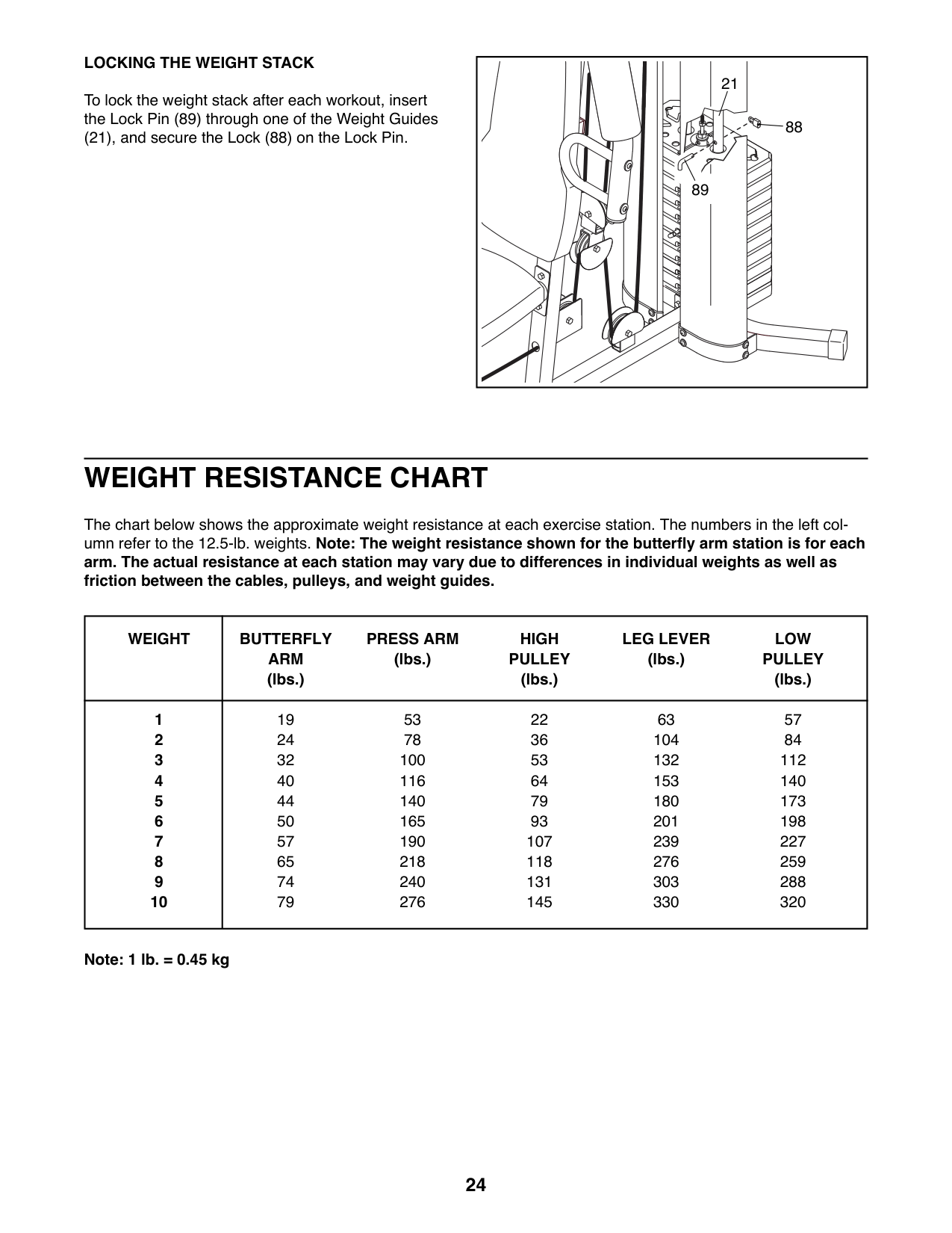
##### LOCKING THE WEIGHT STACK
To lock the weight stack after each workout, insert the Lock Pin (89) through one of the Weight Guides
(21), and secure the Lock (88) on the Lock Pin.
21
88
89
| | | | |---|---|---| | | | |
WEIGHT RESISTANCE CHART
The chart below shows the approximate weight resistance at each exercise station. The numbers in the left column refer to the 12.5-lb. weights. Note: The weight resistance shown for the butterfly arm station is for each arm. The actual resistance at each station may vary due to differences in individual weights as well as friction between the cables, pulleys, and weight guides.
|WEIGHT|BUTTERFLY ARM (lbs.)
PRESS ARM (lbs.)
HIGH PULLEY (lbs.)
LEG LEVER (lbs.)
LOW PULLEY (lbs.)| |---|---| |1
2
3
4
5
6
7
8
9
10
|19 24 32 40 44 50 57 65 74 79
53 78 100 116 140 165 190 218 240 276
22 36 53 64 79 93 107 118 131 145
63 104 132 153 180 201 239 276 303 330
57 84 112 140 173 198 227 259 288 320|
Note: 1 lb. = 0.45 kg
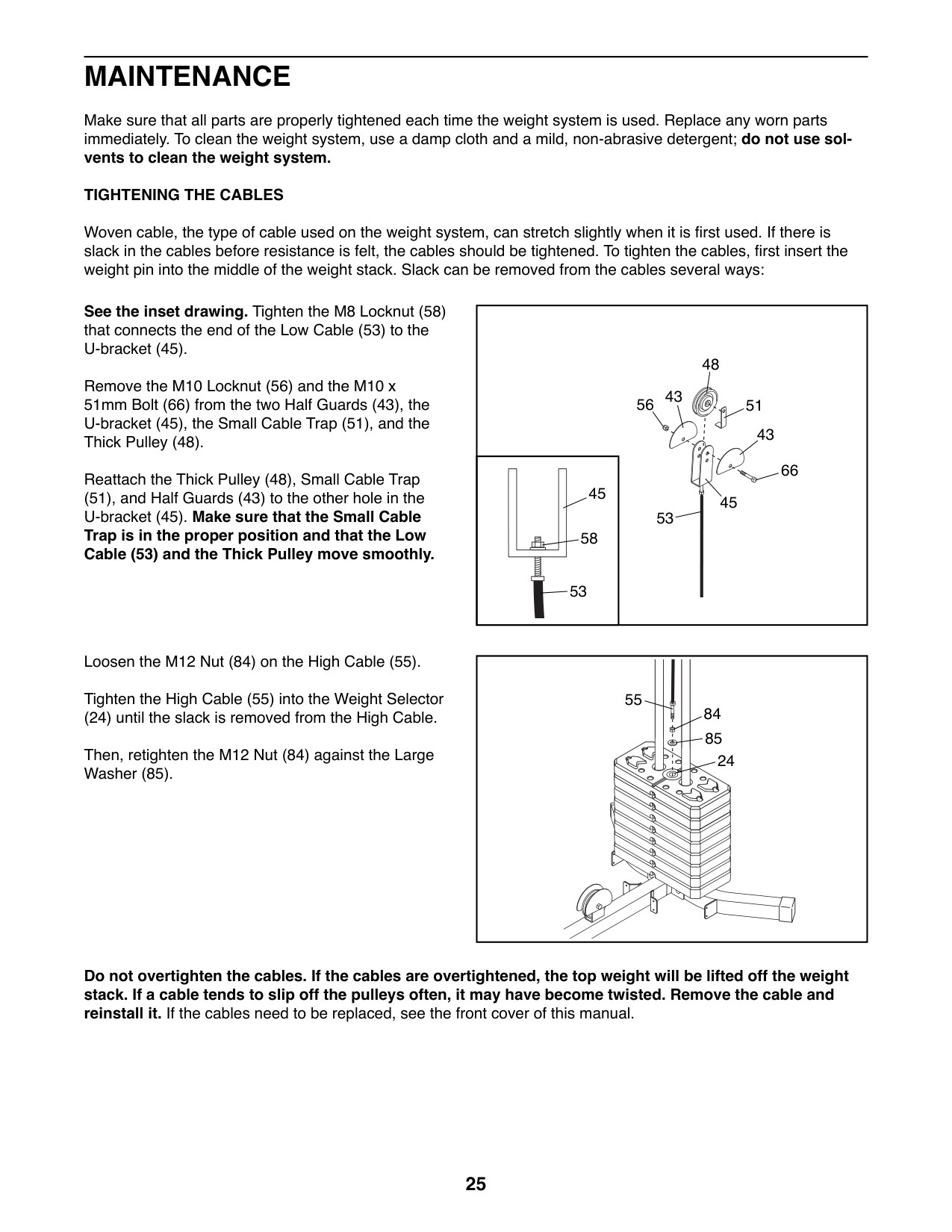
MAINTENANCE
Make sure that all parts are properly tightened each time the weight system is used. Replace any worn parts immediately. To clean the weight system, use a damp cloth and a mild, non-abrasive detergent; do not use solvents to clean the weight system. TIGHTENING THE CABLES
Woven cable, the type of cable used on the weight system, can stretch slightly when it is first used. If there is slack in the cables before resistance is felt, the cables should be tightened. To tighten the cables, first insert the weight pin into the middle of the weight stack. Slack can be removed from the cables several ways:
See the inset drawing. Tighten the M8 Locknut (58) that connects the end of the Low Cable (53) to the U-bracket (45).
Remove the M10 Locknut (56) and the M10 x 51mm Bolt (66) from the two Half Guards (43), the U-bracket (45), the Small Cable Trap (51), and the Thick Pulley (48).
Reattach the Thick Pulley (48), Small Cable Trap
(51), and Half Guards (43) to the other hole in the U-bracket (45). Make sure that the Small Cable Trap is in the proper position and that the Low Cable (53) and the Thick Pulley move smoothly.
Loosen the M12 Nut (84) on the High Cable (55). Tighten the High Cable (55) into the Weight Selector
(24) until the slack is removed from the High Cable. Then, retighten the M12 Nut (84) against the Large Washer (85).
48
43 56
51
43
66
45
45 53
58
53
55
Do not overtighten the cables. If the cables are overtightened, the top weight will be lifted off the weight stack. If a cable tends to slip off the pulleys often, it may have become twisted. Remove the cable and reinstall it. If the cables need to be replaced, see the front cover of this manual.
EXERCISE GUIDELINES
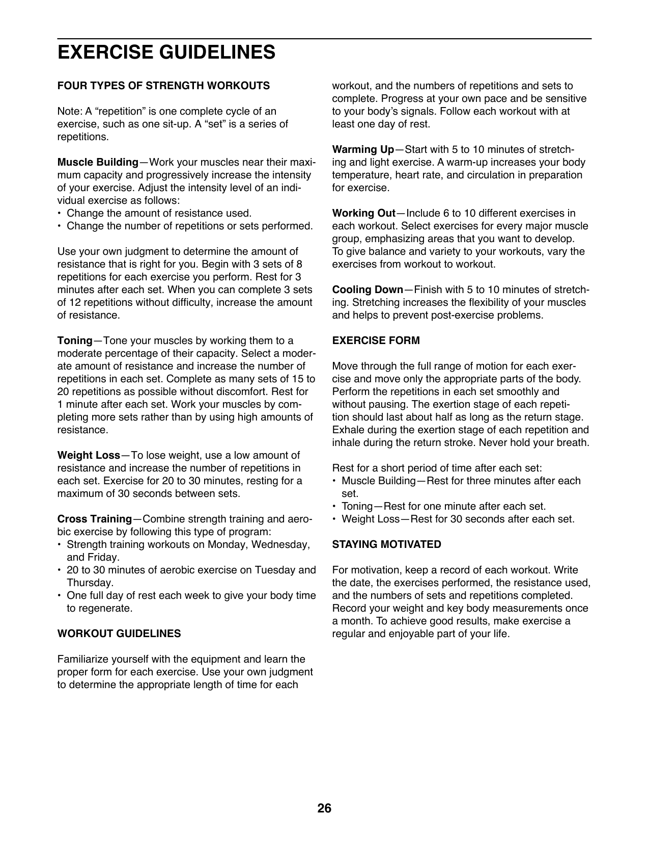
##### FOUR TYPES OF STRENGTH WORKOUTS
Note: A “repetition” is one complete cycle of an exercise, such as one sit-up. A “set” is a series of repetitions.
Muscle Building—Work your muscles near their maximum capacity and progressively increase the intensity of your exercise. Adjust the intensity level of an individual exercise as follows:
Use your own judgment to determine the amount of resistance that is right for you. Begin with 3 sets of 8 repetitions for each exercise you perform. Rest for 3 minutes after each set. When you can complete 3 sets of 12 repetitions without difficulty, increase the amount of resistance.
Toning—Tone your muscles by working them to a moderate percentage of their capacity. Select a moderate amount of resistance and increase the number of repetitions in each set. Complete as many sets of 15 to 20 repetitions as possible without discomfort. Rest for 1 minute after each set. Work your muscles by completing more sets rather than by using high amounts of resistance.
Weight Loss—To lose weight, use a low amount of resistance and increase the number of repetitions in each set. Exercise for 20 to 30 minutes, resting for a maximum of 30 seconds between sets.
Cross Training—Combine strength training and aerobic exercise by following this type of program:
##### WORKOUT GUIDELINES
Familiarize yourself with the equipment and learn the proper form for each exercise. Use your own judgment to determine the appropriate length of time for each
workout, and the numbers of repetitions and sets to complete. Progress at your own pace and be sensitive to your body’s signals. Follow each workout with at least one day of rest.
Warming Up—Start with 5 to 10 minutes of stretching and light exercise. A warm-up increases your body temperature, heart rate, and circulation in preparation for exercise.
Working Out—Include 6 to 10 different exercises in each workout. Select exercises for every major muscle group, emphasizing areas that you want to develop. To give balance and variety to your workouts, vary the exercises from workout to workout.
Cooling Down—Finish with 5 to 10 minutes of stretching. Stretching increases the flexibility of your muscles and helps to prevent post-exercise problems.
##### EXERCISE FORM
Move through the full range of motion for each exercise and move only the appropriate parts of the body. Perform the repetitions in each set smoothly and without pausing. The exertion stage of each repetition should last about half as long as the return stage. Exhale during the exertion stage of each repetition and inhale during the return stroke. Never hold your breath.
Rest for a short period of time after each set:
For motivation, keep a record of each workout. Write the date, the exercises performed, the resistance used, and the numbers of sets and repetitions completed. Record your weight and key body measurements once a month. To achieve good results, make exercise a regular and enjoyable part of your life.
##### EXERCISE LOG
Make copies of this page, and use the copies to schedule and record your strength and aerobic workouts. Scheduling and recording your workouts will help you to make exercise a regular and enjoyable part of your life.
Strength Date:
|Exercise|Lbs.|Sets|Reps|Exercise|Lbs.|Sets|Reps| |---|---|---|---|---|---|---|---| |1.| | | |6.| | | | |2.| | | |7.| | | | |3.| | | |8.| | | | |4.| | | |9.| | | | |5.| | | |10.| | | |
Aerobic Date:
|Exercise|Time|Distance|Speed| |---|---|---|---| | | | | |
Strength Date:
Aerobic Date:
Strength Date:
Aerobic Date:
|Exercise|Lbs.|Sets|Reps|Exercise|Lbs.|Sets|Reps| |---|---|---|---|---|---|---|---| |1.| | | |6.| | | | |2.| | | |7.| | | | |3.| | | |8.| | | | |4.| | | |9.| | | | |5.| | | |10.| | | |
|Exercise|Time|Distance|Speed| |---|---|---|---| | | | | |
|Exercise|Lbs.|Sets|Reps|Exercise|Lbs.|Sets|Reps| |---|---|---|---|---|---|---|---| |1.| | | |6.| | | | |2.| | | |7.| | | | |3.| | | |8.| | | | |4.| | | |9.| | | | |5.| | | |10.| | | |
|Exercise|Time|Distance|Speed| |---|---|---|---| | | | | |
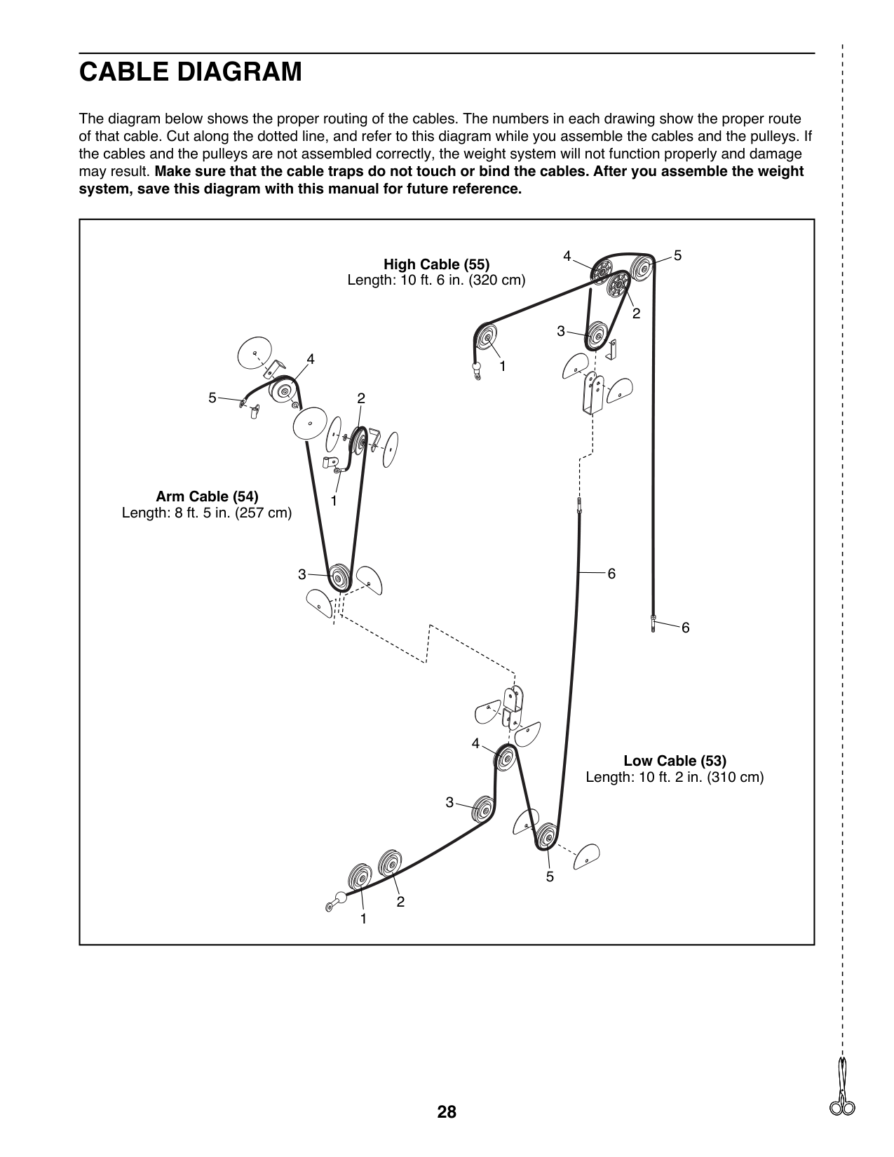
CABLE DIAGRAM
The diagram below shows the proper routing of the cables. The numbers in each drawing show the proper route of that cable. Cut along the dotted line, and refer to this diagram while you assemble the cables and the pulleys. If the cables and the pulleys are not assembled correctly, the weight system will not function properly and damage may result. Make sure that the cable traps do not touch or bind the cables. After you assemble the weight system, save this diagram with this manual for future reference.
|1
2
4
2
3
4 5
5
Arm Cable (54) Length: 8 ft. 5 in. (257 cm)
High Cable (55) Length: 10 ft. 6 in. (320 cm)
Low Cable (53) Length: 10 ft. 2 in. (310 cm)
3
1
6
1
2
3
4
5
6| |---|
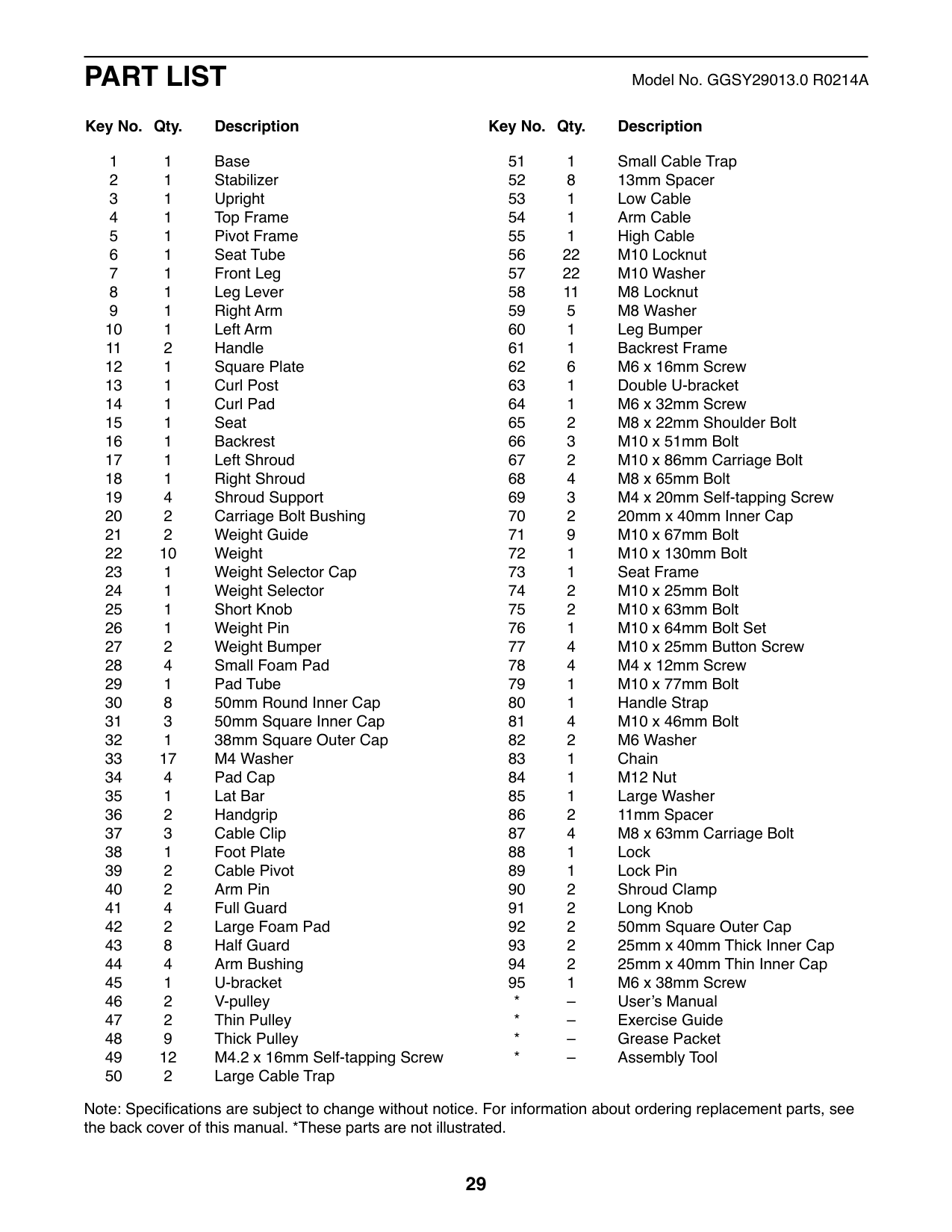
PART LIST Model No. GGSY29013.0 R0214A
##### Key No. Qty. Description Key No. Qty. Description
Note: Specifications are subject to change without notice. For information about ordering replacement parts, see the back cover of this manual. *These parts are not illustrated.
5 67
56
79
69
3536
65 54
6720
39
58
20
40
66
44
14
57
69 57
42
66 44
56
58
39
30
36
44
56
40
30
56
9
54 65
77
44
56
11
57
62
42 11
10
13
30
15
57
37
80
83
94
77
57
30
73
34
82
94
28
95
62 68
29
93
91
30
25
6
68
76
7
56
30
68
48
57
52
68
60
76 69
5756
34
33
4356
28
71
52
52
57
34
58
48
71
48
58
28
52
71 8
57
1
71
43
53
81
34 28
30
31 87
56
38
87
72
48
74
56
48
57
31
71 56
52
48 56 51
56
57
86
43
43
52
57
43
57
81
63
43
52 57
71
56
56
86
4
66
57
43 43
52
71 47
4831
53
57
81
71
48
78 33
90
55
75
19
90
41
33
33
50
49
78
46
33
19
55
84
56
41
57
46
50 41
75
41
85
22
12
32
21
3
56
24
91
18 16
70
88
62 61
17
89
22
23
93
82
26
59
58
64
92
48
70
56
81 58
27
27
57
56
58
49
57
33
19
33
33
2
92
49
49
33
19
ORDERING REPLACEMENT PARTS
To order replacement parts, please see the front cover of this manual. To help us assist you, be prepared to provide the following information when contacting us:
||ICON Health & Fitness, Inc. (ICON) warrants this product to be free from defects in workmanship and material, under normal use and service conditions. Parts and labor are warranted for ninety (90) days from the date of purchase.
This warranty extends only to the original purchaser (customer). ICON’s obligation under this warranty is limited to repairing or replacing, at ICON’s option, the product through one of its authorized service centers. All repairs for which warranty claims are made must be preauthorized by ICON. If the product is shipped to a service center, freight charges to and from the service center will be the customer’s responsibility. If replacement parts are shipped while the product is under warranty, the customer will be responsible for a minimal handling charge. For in-home service, the customer will be responsible for a minimal trip charge. This warranty does not extend to freight damage to the product. This warranty will automatically be voided if the product is used as a store display model, if the product is purchased or transported outside the USA, if all instructions in this manual are not followed, if the product is abused or improperly or abnormally used, or if the product is used for commercial or rental purposes. No other warranty beyond that specifically set forth above is authorized by ICON.
ICON is not responsible or liable for indirect, special, or consequential damages arising out of or in connection with the use or performance of the product; damages with respect to any economic loss, loss of property, loss of revenues or profits, loss of enjoyment or use, or costs of removal or installation; or other consequential damages of any kind. Some states do not allow the exclusion or limitation of incidental or consequential damages. Accordingly, the above limitation may not apply to the customer.
The warranty extended hereunder is in lieu of any and all other warranties, and any implied warranties of merchantability or fitness for a particular purpose are limited in their scope and duration to the terms set forth herein. Some states do not allow limitations on how long an implied warranty lasts. Accordingly, the above limitation may not apply to the customer.
This warranty provides specific legal rights; the customer may have other rights that vary from state to state. ICON Health & Fitness, Inc., 1500 S. 1000 W., Logan, UT 84321-9813| |---|
|LIMITED WARRANTY
IMPORTANT: To protect your fitness equipment with an extended service plan, see page 4.| |---| | |---|
Part No. 355219 R0214A Printed in China © 2014 ICON IP, Inc.