
Ask AI
— answers from the official manualAnswers from the official manual.
Common questions
Common Questions
29 totalHow do I silence alarms and troubles on the 6820?
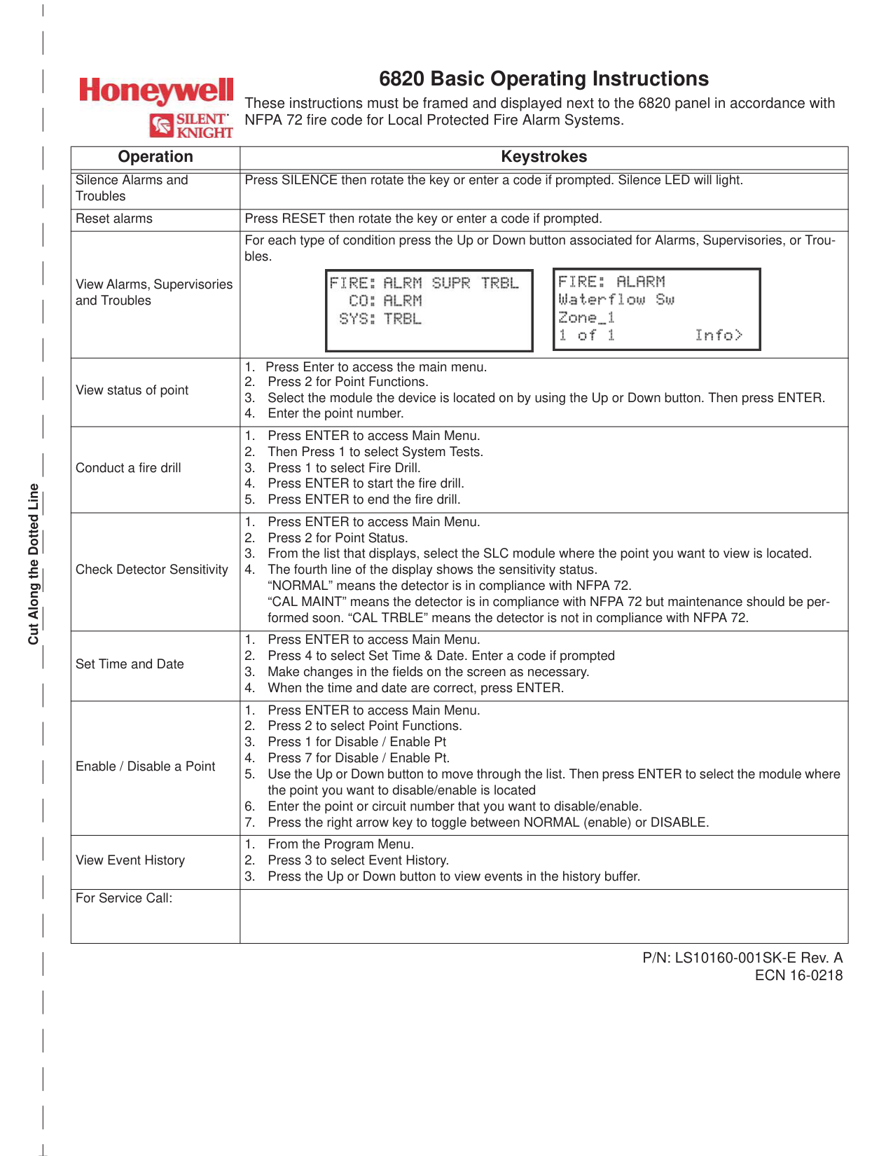
Press SILENCE then rotate the key or enter a code if prompted. The Silence LED will light to confirm the action has been taken. (Page 1)
How do I reset an alarm on the 6820?
Press RESET then rotate the key or enter a code if prompted. This step should be performed after silencing the alarm. (Page 1)
How do I conduct a fire drill on the 6820?
Press ENTER to access the Main Menu, then press 1 for System Tests, and press 1 again to select Fire Drill. Press ENTER to start the fire drill, and press ENTER again when you are ready to end it. (Page 1)
How do I check the sensitivity status of a detector on the 6820?
Press ENTER to access the Main Menu, press 2 for Point Status, then select the SLC module where the point is located. The fourth line of the display will show the sensitivity status. (Page 1)
What do the detector sensitivity status messages mean on the 6820?
'NORMAL' means the detector is in compliance with NFPA 72. 'CAL MAINT' means the detector is in compliance with NFPA 72 but maintenance should be performed soon, while 'CAL TRBLE' means the detector is not in compliance with NFPA 72. (Page 1)
How do I view the event history on the 6820?
From the Program Menu, press 3 to select Event History. Use the Up or Down button to scroll through events stored in the history buffer. (Page 1)
Show 23 more questions
How do I set the time and date on the 6820?
How do I view alarms, supervisories, and troubles on the 6820?
How do I check the status of a specific point on the 6820?
How do I silence alarms and troubles on my Honeywell 6820?
What steps are involved in conducting a fire drill using the Honeywell 6820 panel?
How can I view detector sensitivity levels on my Honeywell 6820 system?
How do I set the time and date on Honeywell's 6820 fire panel?
How do I enable or disable a point on the Honeywell 6820 panel?
How do I disable or enable a point on the 6820?
What is the maximum number of remote annunciators allowed for a Honeywell 6820 fire alarm control panel?
How should the Honeywell 6820 fire alarm system be maintained to prevent malfunction?
What are the environmental specifications for operating a Honeywell 6820 control panel?
How do I connect AC power to the Honeywell 6820 control panel?
What communication networks does the Honeywell 6820 support?
How do I test the integrity of signal wiring in a Honeywell 6820 system?
How many total points will a Honeywell 6820 control panel accommodate?
What are the limitations of smoke detectors in a Honeywell 6820 system?
Which software is required for programming Honeywell 6820 control panels?
How do I view the event history on Honeywell 6820?
What does 'CAL MAINT' mean when checking detector sensitivity on Honeywell's 6820?
How do I reset alarms if they are triggered on Honeywell's 6820 panel?
What should I do if my detector shows 'CAL TRBLE' in its sensitivity status check on Honeywell's 6820 panel?
How many days of fire drill history can I view on Honeywell's 6820 panel?
Full Manual
170 pages

6820/6820EVS
Addressable Fire Alarm Conrol Panel
Manual
Document LS10144-001SK-E Rev: E 4/6/2022 ECN: 151062
Fire Alarm & Emergency Communication System Limitations While a life safety system may lower insurance rates, it is not a substitute for life and property insurance! An automatic fire alarm system—typically made up of smoke detectors, heat detectors, manual pull stations, audible warning devices, and a fire alarm control panel (FACP) with remote notification capability—can provide early warning of a developing fire. Such a system, however, does not assure protection against property damage or loss of life resulting from a fire. An emergency communication system—typically made up of an automatic fire alarm system (as described above) and a life safety communication system that may include an autonomous control unit (ACU), local operating console (LOC), voice communication, and other various interoperable communication methods—can broadcast a mass notification message. Such a system, however, does not assure protection against property damage or loss of life resulting from a fire or life safety event. The Manufacturer recommends that smoke and/or heat detectors be located throughout a protected premises following the recommendations of the current edition of the National Fire Protection Association Standard 72 (NFPA 72), manufacturer's recommendations, State and local codes, and the recommendations contained in the Guide for Proper Use of System Smoke Detectors, which is made available at no charge to all installing dealers. This document can be found at http://www.systemsensor.com/appguides/. A study by the Federal Emergency Management Agency (an agency of the United States government) indicated that smoke detectors may not go off in as many as 35% of all fires. While fire alarm systems are designed to provide early warning against fire, they do not guarantee warning or protection against fire. A fire alarm system may not provide timely or adequate warning, or simply may not function, for a variety of reasons:
IMPORTANT! Smoke detectors must be installed in the same room as the control panel and in rooms used by the system for the connection of alarm transmission wiring, communications, signaling, and/or power. If detectors are not so located, a developing fire may damage the alarm system, compromising its ability to report a fire.
Audible warning devices such as bells, horns, strobes, speakers and displays may not alert people if these devices are located on the other side of closed or partly open doors or are located on another floor of a building. Any warning device may fail to alert people with a disability or those who have recently consumed drugs, alcohol, or medication. Please note that:
Smoke detectors may not sense fire where smoke cannot reach the detectors such as in chimneys, in or behind walls, on roofs, or on the other side of closed doors. Smoke detectors also may not sense a fire on another level or floor of a building. A second-floor detector, for example, may not sense a first-floor or basement fire. Particles of combustion or “smoke” from a developing fire may not reach the sensing chambers of smoke detectors because:
A life safety system will not operate without any electrical power. If AC power fails, the system will operate from standby batteries only for a specified time and only if the batteries have been properly maintained and replaced regularly.
Equipment used in the system may not be technically compatible with the control panel. It is essential to use only equipment listed for service with your control panel.
############### Alarm Signaling Communications:
The amount of “smoke” present may be insufficient to alarm smoke detectors. Smoke detectors are designed to alarm at various levels of smoke density. If such density levels are not created by a developing fire at the location of detectors, the detectors will not go into alarm. Smoke detectors, even when working properly, have sensing limitations. Detectors that have photoelectronic sensing chambers tend to detect smoldering fires better than flaming fires, which have little visible smoke. Detectors that have ionizing-type sensing chambers tend to detect fast-flaming fires better than smoldering fires. Because fires develop in different ways and are often unpredictable in their growth, neither type of detector is necessarily best and a given type of detector may not provide adequate warning of a fire. Smoke detectors cannot be expected to provide adequate warning of fires caused by arson, children playing with matches (especially in bedrooms), smoking in bed, and violent explosions (caused by escaping gas, improper storage of flammable materials, etc.). Heat detectors do not sense particles of combustion and alarm only when heat on their sensors increases at a predetermined rate or reaches a predetermined level. Rate-of-rise heat detectors may be subject to reduced sensitivity over time. For this reason, the rate-ofrise feature of each detector should be tested at least once per year by a qualified fire protection specialist. Heat detectors are designed to protect property, not life.
The most common cause of life safety system malfunction is inadequate maintenance. To keep the entire life safety system in excellent working order, ongoing maintenance is required per the manufacturer's recommendations, and UL and NFPA standards. At a minimum, the requirements of NFPA 72 shall be followed. Environments with large amounts of dust, dirt, or high air velocity require more frequent maintenance. A maintenance agreement should be arranged through the local manufacturer's representative. Maintenance should be scheduled as required by National and/or local fire codes and should be performed by authorized professional life safety system installers only. Adequate written records of all inspections should be kept.
Limit-F-2020
Installation Precautions Adherence to the following will aid in problem-free installation with long-term reliability:
Like all solid state electronic devices, this system may operate erratically or can be damaged when subjected to lightning induced transients. Although no system is completely immune from lightning transients and interference, proper grounding will reduce susceptibility. Overhead or outside aerial wiring is not recommended, due to an increased susceptibility to nearby lightning strikes. Consult with the Technical Services Department if any problems are anticipated or encountered.
WARNING - Several different sources of power can be connected to the fire alarm control panel. Disconnect all sources of power before servicing. Control unit and associated equipment may be damaged by removing and/or inserting cards, modules, or interconnecting cables while the unit is energized. Do not attempt to install, service, or operate this unit until manuals are read and understood.
CAUTION - System Re-acceptance Test after Software Changes: To ensure proper system operation, this product must be tested in accordance with NFPA 72 after any programming operation or change in site-specific software. Re-acceptance testing is required after any change, addition or deletion of system components, or after any modification, repair or adjustment to system hardware or wiring. All components, circuits, system operations, or software functions known to be affected by a change must be 100% tested. In addition, to ensure that other operations are not inadvertently affected, at least 10% of initiating devices that are not directly affected by the change, up to a maximum of 50 devices, must also be tested and proper system operation verified.

Disconnect AC power and batteries prior to removing or inserting circuit boards. Failure to do so can damage circuits.
Remove all electronic assemblies prior to any drilling, filing, reaming, or punching of the enclosure. When possible, make all cable entries from the sides or rear. Before making modifications, verify that they will not interfere with battery, transformer, or printed circuit board location.
Do not tighten screw terminals more than 9 in-lbs. Over-tightening may damage threads, resulting in reduced terminal contact pressure and difficulty with screw terminal removal.
This system contains static-sensitive components. Always ground yourself with a proper wrist strap before handling any circuits so that static charges are removed from the body. Use static suppressive packaging to protect electronic assemblies removed from the unit.
This system meets NFPA requirements for operation at 0-49º C/32120º F and at a relative humidity 93% ± 2% RH (non-condensing) at 32°C ± 2°C (90°F ± 3°F). However, the useful life of the system's standby batteries and the electronic components may be adversely affected by extreme temperature ranges and humidity. Therefore, it is recommended that this system and its peripherals be installed in an environment with a normal room temperature of 15-27º C/60-80º F. Verify that wire sizes are adequate for all initiating and indicating device loops. Most devices cannot tolerate more than a 10% I.R. drop from the specified device voltage.
Units with a touchscreen display should be cleaned with a dry, clean, lint free/microfiber cloth. If additional cleaning is required, apply a small amount of Isopropyl alcohol to the cloth and wipe clean. Do not use detergents, solvents, or water for cleaning. Do not spray liquid directly onto the display.
Follow the instructions in the installation, operating, and programming manuals. These instructions must be followed to avoid damage to the control panel and associated equipment. FACP operation and reliability depend upon proper installation.
Precau-D2-11-2017
|FCC Warning
WARNING: This equipment generates, uses, and can radiate radio frequency energy and if not installed and used in accordance with the instruction manual may cause interference to radio communications. It has been tested and found to comply with the limits for class A computing devices pursuant to Subpart B of Part 15 of FCC Rules, which is designed to provide reasonable protection against such interference when devices are operated in a commercial environment. Operation of this equipment in a residential area is likely to cause interference, in which case the user will be required to correct the interference at his or her own expense.
Canadian Requirements
This digital apparatus does not exceed the Class A limits for radiation noise emissions from digital apparatus set out in the Radio Interference Regulations of the Canadian Department of Communications.
Le present appareil numerique n'emet pas de bruits radioelectriques depassant les limites applicables aux appareils numeriques de la classe A prescrites dans le Reglement sur le brouillage radioelectrique edicte par le ministere des Communications du Canada.| |---|
Flexput®, Honeywell®, JumpStart®, Silent Knight®, and SWIFT® are registered trademarks of Honeywell International Inc.Microsoft® and Windows® are registered trademarks of the Microsoft Corporation. Chrome™ and Google™ are trademarks of Google Inc. Firefox® is a registered trademark of The Mozilla Foundation.
################### ©2022. All rights reserved. Unauthorized use of this document is strictly prohibited.
#### Software Downloads
In order to supply the latest features and functionality in fire alarm and life safety technology to our customers, we make frequent upgrades to the embedded software in our products. To ensure that you are installing and programming the latest features, we strongly recommend that you download the most current version of software for each product prior to commissioning any system. Contact Technical Support with any questions about software and the appropriate version for a specific application.
#### Documentation Feedback
Your feedback helps us keep our documentation up-to-date and accurate. If you have any comments or suggestions about our online Help or printed manuals, you can email us.
Please include the following information:
Send email messages to:
########### FireSystems.TechPubs@honeywell.com
Please note this email address is for documentation feedback only. If you have any technical issues, please contact Technical Services.

This symbol (shown left) on the product(s) and / or accompanying documents means that used electrical and electronic products should not be mixed with general household waste. For proper treatment, recovery and recycling, contact your local authorities or dealer and ask for the correct method of disposal.
Electrical and electronic equipment contains materials, parts and substances, which can be dangerous to the environment and harmful to human health if the waste of electrical and electronic equipment (WEEE) is not disposed of correctly.
#### Table of Contents
########### Section 1: Introduction ................................................................................................................................................... 10

########### Section 2: Agency Listings, Approvals, and Requirements........................................................................................ 14
########### Section 3: Before You Begin Installation ...................................................................................................................... 17
########### Section 4: Control Panel Installation............................................................................................................................. 26
4.6: SBUS Wiring ...................................................................................................................................................................................................31
4.7: 6855 Remote Annunciator Installation............................................................................................................................................................34
4.8: 5860 Remote Annunciator Installation............................................................................................................................................................37
4.9: 6860 Remote Annunciator Installation............................................................................................................................................................39
4.10: 5815XL Installation......................................................................................................................................................................................41
4.11: 6815 Installation.............................................................................................................................................................................................42
4.12: 5824 Serial/Parallel Interface Module Installation........................................................................................................................................43
4.13: 5880 LED I/O Module...................................................................................................................................................................................44
########### Section 5: Common Communications Link .................................................................................................................. 61
########### Section 6: Network Management ................................................................................................................................... 67
########### Section 7: Programming Overview................................................................................................................................ 74
########### Section 8: Programming................................................................................................................................................. 90
########### Section 9: System Operation........................................................................................................................................ 110
9.6: Releasing Operations.....................................................................................................................................................................................123
########### Section 10: Emergency Voice System Operation....................................................................................................... 127
########### Section 11: Reporting ................................................................................................................................................... 138
########### Section 12: Testing and Troubleshooting................................................................................................................... 149
########### Section 13: Installation Records.................................................................................................................................. 153
##### Section 1: Introduction
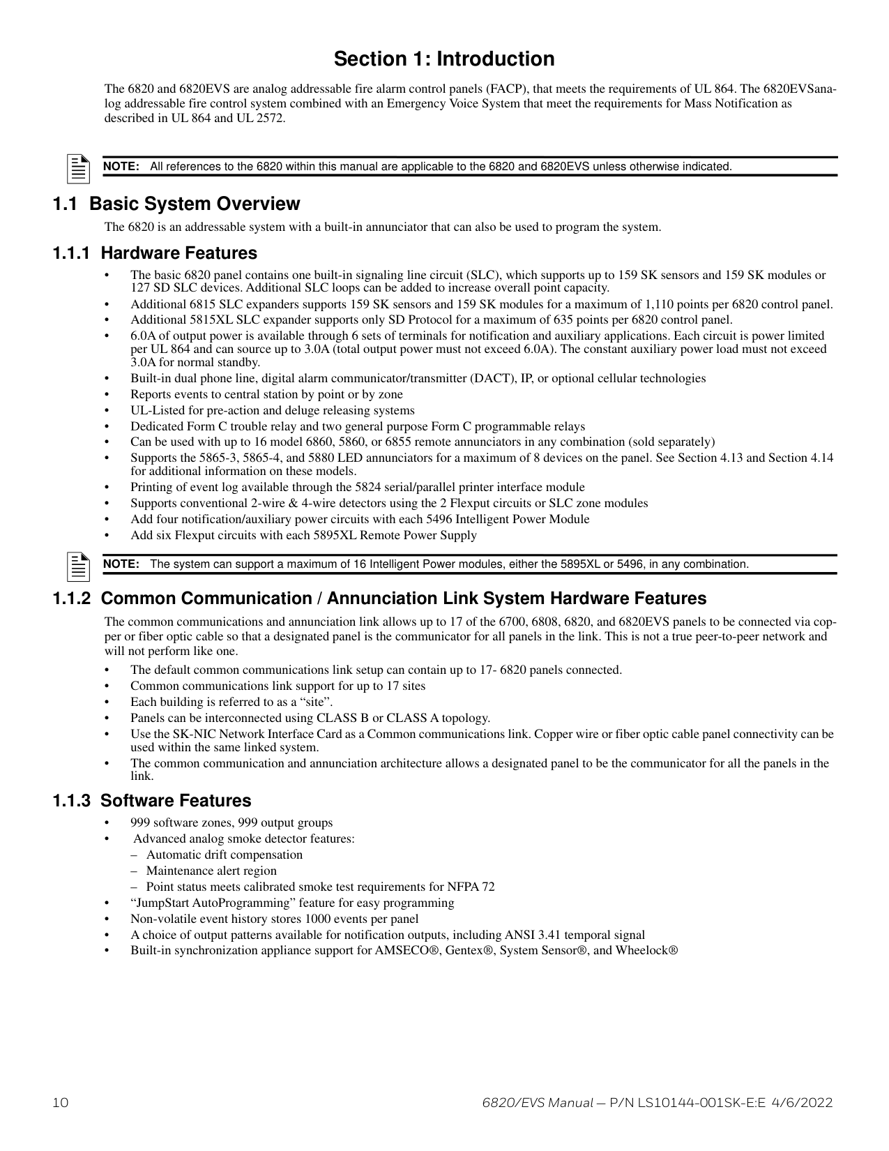
The 6820 and 6820EVS are analog addressable fire alarm control panels (FACP), that meets the requirements of UL 864. The 6820EVSanalog addressable fire control system combined with an Emergency Voice System that meet the requirements for Mass Notification as described in UL 864 and UL 2572.
NOTE: All references to the 6820 within this manual are applicable to the 6820 and 6820EVS unless otherwise indicated.
######## 1.1.1 Hardware Features
NOTE: The system can support a maximum of 16 Intelligent Power modules, either the 5895XL or 5496, in any combination.
######## 1.1.2 Common Communication / Annunciation Link System Hardware Features
The common communications and annunciation link allows up to 17 of the 6700, 6808, 6820, and 6820EVS panels to be connected via copper or fiber optic cable so that a designated panel is the communicator for all panels in the link. This is not a true peer-to-peer network and will not perform like one.
######## 1.1.3 Software Features
Terms Used in this Manual Introduction
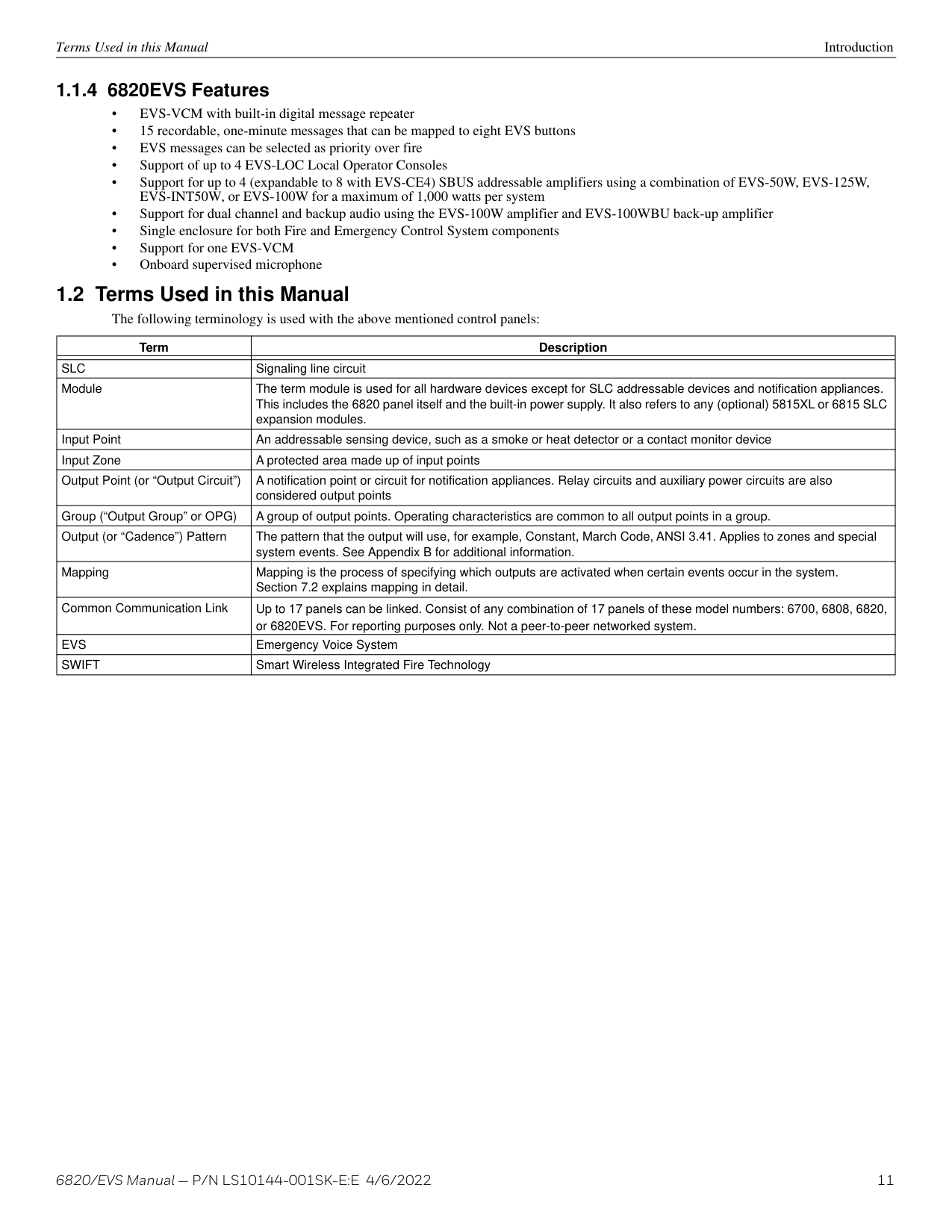
######## 1.1.4 6820EVS Features
|Term|Description| |---|---| | | | |SLC|Signaling line circuit| |Module|The term module is used for all hardware devices except for SLC addressable devices and notification appliances. This includes the 6820 panel itself and the built-in power supply. It also refers to any (optional) 5815XL or 6815 SLC expansion modules.| |Input Point|An addressable sensing device, such as a smoke or heat detector or a contact monitor device| |Input Zone|A protected area made up of input points| |Output Point (or “Output Circuit”)|A notification point or circuit for notification appliances. Relay circuits and auxiliary power circuits are also considered output points| |Group (“Output Group” or OPG)|A group of output points. Operating characteristics are common to all output points in a group.| |Output (or “Cadence”) Pattern|The pattern that the output will use, for example, Constant, March Code, ANSI 3.41. Applies to zones and special system events. See Appendix B for additional information.| |Mapping|Mapping is the process of specifying which outputs are activated when certain events occur in the system. Section 7.2 explains mapping in detail.| |Common Communication Link|Up to 17 panels can be linked. Consist of any combination of 17 panels of these model numbers: 6700, 6808, 6820, or 6820EVS. For reporting purposes only. Not a peer-to-peer networked system.| |EVS|Emergency Voice System| |SWIFT|Smart Wireless Integrated Fire Technology|
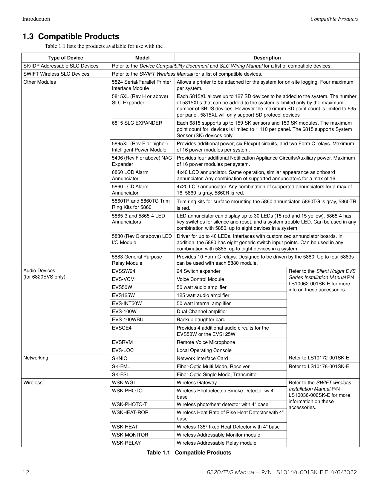
Introduction Compatible Products
|Type of Device|Model|Description|Description| |---|---|---|---| | | | | | |SK/IDP Addressable SLC Devices|Refer to the Device Compatibility Document and SLC Wiring Manual for a list of compatible devices.|Refer to the Device Compatibility Document and SLC Wiring Manual for a list of compatible devices.|Refer to the Device Compatibility Document and SLC Wiring Manual for a list of compatible devices.| |SWIFT Wireless SLC Devices|Refer to the SWIFT Wireless Manual for a list of compatible devices.|Refer to the SWIFT Wireless Manual for a list of compatible devices.|Refer to the SWIFT Wireless Manual for a list of compatible devices.| |Other Modules|5824 Serial/Parallel Printer Interface Module|Allows a printer to be attached for the system for on-site logging. Four maximum per system.|Allows a printer to be attached for the system for on-site logging. Four maximum per system.| |Other Modules|5815XL (Rev H or above) SLC Expander|Each 5815XL allows up to 127 SD devices to be added to the system. The number of 5815XLs that can be added to the system is limited only by the maximum number of SBUS devices. However the maximum SD point count is limited to 635 per panel. 5815XL will only support SD protocol devices|Each 5815XL allows up to 127 SD devices to be added to the system. The number of 5815XLs that can be added to the system is limited only by the maximum number of SBUS devices. However the maximum SD point count is limited to 635 per panel. 5815XL will only support SD protocol devices| |Other Modules|6815 SLC EXPANDER|Each 6815 supports up to 159 SK sensors and 159 SK modules. The maximum point count for devices is limited to 1,110 per panel. The 6815 supports System Sensor (SK) devices only.|Each 6815 supports up to 159 SK sensors and 159 SK modules. The maximum point count for devices is limited to 1,110 per panel. The 6815 supports System Sensor (SK) devices only.| |Other Modules|5895XL (Rev F or higher) Intelligent Power Module|Provides additional power, six Flexput circuits, and two Form C relays. Maximum of 16 power modules per system.|Provides additional power, six Flexput circuits, and two Form C relays. Maximum of 16 power modules per system.| |Other Modules|5496 (Rev F or above) NAC Expander|Provides four additional Notification Appliance Circuits/Auxiliary power. Maximum of 16 power modules per system.|Provides four additional Notification Appliance Circuits/Auxiliary power. Maximum of 16 power modules per system.| |Other Modules|6860 LCD Alarm Annunciator|4x40 LCD annunciator. Same operation, similar appearance as onboard annunciator. Any combination of supported annunciators for a max of 16.|4x40 LCD annunciator. Same operation, similar appearance as onboard annunciator. Any combination of supported annunciators for a max of 16.| |Other Modules|5860 LCD Alarm Annunciator|4x20 LCD annunciator. Any combination of supported annunciators for a max of
16. 5860 is gray, 5860R is red.|4x20 LCD annunciator. Any combination of supported annunciators for a max of
16. 5860 is gray, 5860R is red.| |Other Modules|5860TR and 5860TG Trim Ring Kits for 5860|Trim ring kits for surface mounting the 5860 annunciator. 5860TG is gray, 5860TR is red.|Trim ring kits for surface mounting the 5860 annunciator. 5860TG is gray, 5860TR is red.| |Other Modules|5865-3 and 5865-4 LED Annunciators|LED annunciator can display up to 30 LEDs (15 red and 15 yellow). 5865-4 has key switches for silence and reset, and a system trouble LED. Can be used in any combination with 5880, up to eight devices in a system.|LED annunciator can display up to 30 LEDs (15 red and 15 yellow). 5865-4 has key switches for silence and reset, and a system trouble LED. Can be used in any combination with 5880, up to eight devices in a system.| |Other Modules|5880 (Rev C or above) LED I/O Module|Driver for up to 40 LEDs. Interfaces with customized annunciator boards. In addition, the 5880 has eight generic switch input points. Can be used in any combination with 5865, up to eight devices in a system.|Driver for up to 40 LEDs. Interfaces with customized annunciator boards. In addition, the 5880 has eight generic switch input points. Can be used in any combination with 5865, up to eight devices in a system.| |Other Modules|5883 General Purpose Relay Module|Provides 10 Form C relays. Designed to be driven by the 5880. Up to four 5883s can be used with each 5880 module.|Provides 10 Form C relays. Designed to be driven by the 5880. Up to four 5883s can be used with each 5880 module.| |Audio Devices (for 6820EVS only)|EVSSW24|24 Switch expander|Refer to the Silent Knight EVS Series Installation Manual PN LS10062-001SK-E for more info on these accessories.| |Audio Devices (for 6820EVS only)|EVS-VCM|Voice Control Module|Refer to the Silent Knight EVS Series Installation Manual PN LS10062-001SK-E for more info on these accessories.| |Audio Devices (for 6820EVS only)|EVS50W|50 watt audio amplifier|Refer to the Silent Knight EVS Series Installation Manual PN LS10062-001SK-E for more info on these accessories.| |Audio Devices (for 6820EVS only)|EVS125W|125 watt audio amplifier|Refer to the Silent Knight EVS Series Installation Manual PN LS10062-001SK-E for more info on these accessories.| |Audio Devices (for 6820EVS only)|EVS-INT50W|50 watt internal amplifier|Refer to the Silent Knight EVS Series Installation Manual PN LS10062-001SK-E for more info on these accessories.| |Audio Devices (for 6820EVS only)|EVS-100W|Dual Channel amplifier|Refer to the Silent Knight EVS Series Installation Manual PN LS10062-001SK-E for more info on these accessories.| |Audio Devices (for 6820EVS only)|EVS-100WBU|Backup daughter card|Refer to the Silent Knight EVS Series Installation Manual PN LS10062-001SK-E for more info on these accessories.| |Audio Devices (for 6820EVS only)|EVSCE4|Provides 4 additional audio circuits for the EVS50W or the EVS125W|Refer to the Silent Knight EVS Series Installation Manual PN LS10062-001SK-E for more info on these accessories.| |Audio Devices (for 6820EVS only)|EVSRVM|Remote Voice Microphone|Refer to the Silent Knight EVS Series Installation Manual PN LS10062-001SK-E for more info on these accessories.| |Audio Devices (for 6820EVS only)|EVS-LOC|Local Operating Console|Refer to the Silent Knight EVS Series Installation Manual PN LS10062-001SK-E for more info on these accessories.| |Networking|SKNIC|Network Interface Card|Refer to LS10172-001SK-E| |Networking|SK-FML|Fiber-Optic Multi Mode, Receiver|Refer to LS10178-001SK-E| |Networking|SK-FSL|Fiber-Optic Single Mode, Transmitter|Refer to LS10178-001SK-E| |Wireless|WSK-WGI|Wireless Gateway|Refer to the SWIFT wireless Installation Manual P/N LS10036-000SK-E for more information on these accessories.| |Wireless|WSK-PHOTO|Wireless Photoelectric Smoke Detector w/ 4" base|Refer to the SWIFT wireless Installation Manual P/N LS10036-000SK-E for more information on these accessories.| |Wireless|WSK-PHOTO-T|Wireless photo/heat detector with 4" base|Refer to the SWIFT wireless Installation Manual P/N LS10036-000SK-E for more information on these accessories.| |Wireless|WSKHEAT-ROR|Wireless Heat Rate of Rise Heat Detector with 4” base|Refer to the SWIFT wireless Installation Manual P/N LS10036-000SK-E for more information on these accessories.| |Wireless|WSK-HEAT|Wireless 135° fixed Heat Detector with 4” base|Refer to the SWIFT wireless Installation Manual P/N LS10036-000SK-E for more information on these accessories.| |Wireless|WSK-MONITOR|Wireless Addressable Monitor module|Refer to the SWIFT wireless Installation Manual P/N LS10036-000SK-E for more information on these accessories.| |Wireless|WSK-RELAY|Wireless Addressable Relay module|Refer to the SWIFT wireless Installation Manual P/N LS10036-000SK-E for more information on these accessories.|
############# Table 1.1 Compatible Products
Related Documentation Introduction
|Type of Device|Model|Description|Description| |---|---|---|---| | | | | | |Miscellaneous|7860 Telephone Cord|RJ31X cord for connecting phone line to the 6820|RJ31X cord for connecting phone line to the 6820| |Miscellaneous|HFSS Honeywell Fire Software Suite|For communication and panel programming with a Windows-based computer. Enables remote viewing of detector status and event history.|For communication and panel programming with a Windows-based computer. Enables remote viewing of detector status and event history.| |Miscellaneous|RBB|Remote Battery Box for mounting backup batteries up to 35AH that are too large to fit into the main control panel cabinet. Dimensions: 16" W x 10" H x 6" D (40.64 cm W x 25.4 cm H x 15.24 cm D)|Remote Battery Box for mounting backup batteries up to 35AH that are too large to fit into the main control panel cabinet. Dimensions: 16" W x 10" H x 6" D (40.64 cm W x 25.4 cm H x 15.24 cm D)| |Miscellaneous|RBB|Remote Battery Box for mounting backup batteries that are too large to fit into the main control panel cabinet. Dimensions: 16" W x 10" H x 6" D (40.64 cm W x 25.4 cm H x 15.24 cm D).|Remote Battery Box for mounting backup batteries that are too large to fit into the main control panel cabinet. Dimensions: 16" W x 10" H x 6" D (40.64 cm W x 25.4 cm H x 15.24 cm D).| |Miscellaneous|CELL-MOD|Cellular board with Plastic Enclosure|Refer to the CELL-CABSK/CELL-MOD Installation Manual P/N LS10182-001SK-E for more information.|
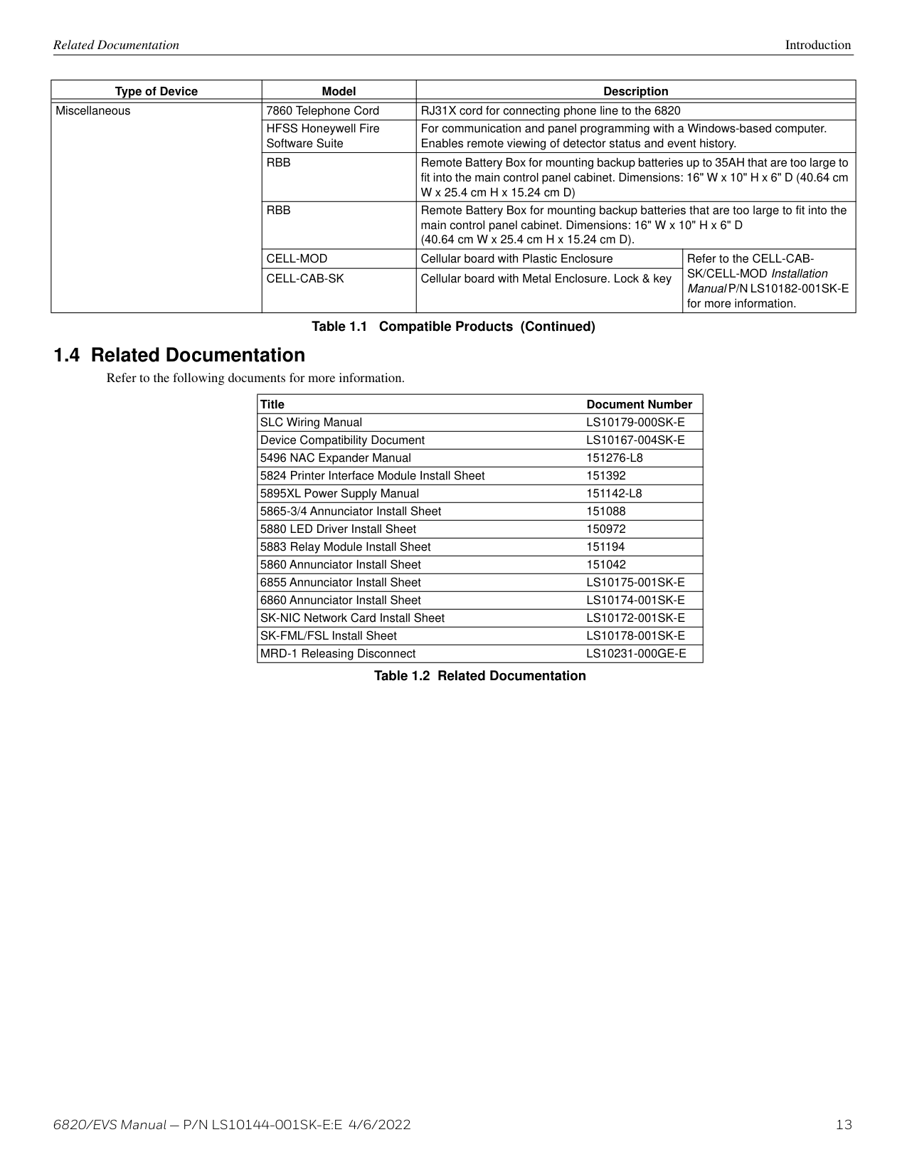
|Miscellaneous|CELL-CAB-SK|Cellular board with Metal Enclosure. Lock & key|Refer to the CELL-CABSK/CELL-MOD Installation Manual P/N LS10182-001SK-E for more information.|
Table 1.1 Compatible Products (Continued)
|Title Document Number| |---| |SLC Wiring Manual LS10179-000SK-E| |Device Compatibility Document LS10167-004SK-E| |5496 NAC Expander Manual 151276-L8| |5824 Printer Interface Module Install Sheet 151392| |5895XL Power Supply Manual 151142-L8| |5865-3/4 Annunciator Install Sheet 151088| |5880 LED Driver Install Sheet 150972| |5883 Relay Module Install Sheet 151194| |5860 Annunciator Install Sheet 151042| |6855 Annunciator Install Sheet LS10175-001SK-E| |6860 Annunciator Install Sheet LS10174-001SK-E| |SK-NIC Network Card Install Sheet LS10172-001SK-E| |SK-FML/FSL Install Sheet LS10178-001SK-E| |MRD-1 Releasing Disconnect LS10231-000GE-E|
Table 1.2 Related Documentation
##### Section 2: Agency Listings, Approvals, and Requirements
Manufacturer: Honeywell Silent Knight Model Number: 6820/EVS FCC registration number: US: HS9AL10A2100 Ringer equivalence: 1.0A Type of jack: RJ31X Facility Interface Codes: Loop Start: 02LS2 Service Order Code: 9.0F
This equipment complies with Part 68 of the FCC rules and the requirements adopted by ACTA. On the inside cover of this equipment is a label that contains, among other information, a product identifier. If requested, this information must be provided to the telephone company. A plug and jack used to connect this equipment to the premises wiring and telephone network must comply with the applicable FCC Part 68 rules and requirements adopted by the ACTA. A compliant telephone cord (not provided) and modular jack must be utilized with this product. It is designed to be used with a modular jack that is also compliant.
The REN (ringer equivalence number) provided on this installation sheet is used to determine the number of devices that may be connected to the public switched telephone network. This number must not exceed 5.0. Since this product has an REN of 1.0A, the number of devices is limited. The REN number is embedded in the FCC registration number as 10A.
If the 6820 causes harm to the telephone network, the telephone company will notify you in advance that the temporarily discontinuance of service may be required. But if advance notice is not practical, the telephone company will notify the customer as soon as possible. Also, you will be advised of your right to file a complaint with the FCC if you believe it is necessary.
The telephone company may make changes in its facilities, equipment, operations or procedures that could affect the operation of the equipment. If this happens the telephone company will provide advance notice in order for you to make necessary modifications to maintain uninterrupted service.
If trouble is experienced with the 6820, for repair or warranty information, contactHoneywell Silent Knight at 800.446.6444 or www.silentknight.com. If the equipment is causing harm to the telephone network, the telephone company may request that you disconnect the 6820 until the problem has been resolved.
This product cannot be adjusted or repaired in the field. It must be returned to the factory for service. This equipment is not designed for use with party line service. Connection to party line service is subject to state tariffs. You may contact the state public utility commission, public service commission or corporation commission for information. Since the 6820 is a commercial fire alarm panel, it must be connected upstream of all other equipment utilizing the phone lines. If you have questions about the installation, contact your telephone company or a qualified installer.
WARNING: FCC PART 15
!
THIS DEVICE HAS BEEN VERIFIED TO COMPLY WITH FCC RULES PART 15. OPERATION IS SUBJECT TO THE FOLLOWING CONDITIONS: (1) THIS DEVICE MAY NOT CAUSE RADIO INTERFERENCE, AND (2) THIS DEVICE MUST ACCEPT ANY INTERFERENCE RECEIVED, INCLUDING INTERFERENCE THAT MAY CAUSE UNDESIRED OPERATION.
CAUTION: INSTALLATION AND TEST
!
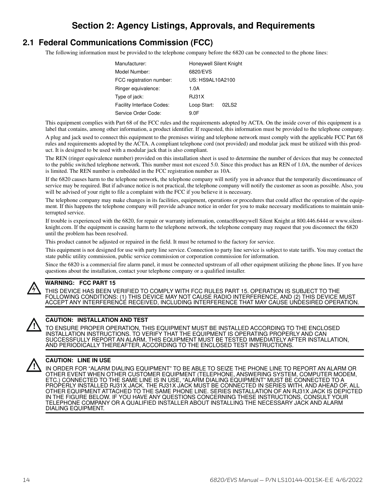
TO ENSURE PROPER OPERATION, THIS EQUIPMENT MUST BE INSTALLED ACCORDING TO THE ENCLOSED INSTALLATION INSTRUCTIONS. TO VERIFY THAT THE EQUIPMENT IS OPERATING PROPERLY AND CAN SUCCESSFULLY REPORT AN ALARM, THIS EQUIPMENT MUST BE TESTED IMMEDIATELY AFTER INSTALLATION, AND PERIODICALLY THEREAFTER, ACCORDING TO THE ENCLOSED TEST INSTRUCTIONS.
CAUTION: LINE IN USE
!
IN ORDER FOR “ALARM DIALING EQUIPMENT” TO BE ABLE TO SEIZE THE PHONE LINE TO REPORT AN ALARM OR OTHER EVENT WHEN OTHER CUSTOMER EQUIPMENT (TELEPHONE, ANSWERING SYSTEM, COMPUTER MODEM, ETC.) CONNECTED TO THE SAME LINE IS IN USE, “ALARM DIALING EQUIPMENT” MUST BE CONNECTED TO A PROPERLY INSTALLED RJ31X JACK. THE RJ31X JACK MUST BE CONNECTED IN SERIES WITH, AND AHEAD OF, ALL OTHER EQUIPMENT ATTACHED TO THE SAME PHONE LINE. SERIES INSTALLATION OF AN RJ31X JACK IS DEPICTED IN THE FIGURE BELOW. IF YOU HAVE ANY QUESTIONS CONCERNING THESE INSTRUCTIONS, CONSULT YOUR TELEPHONE COMPANY OR A QUALIFIED INSTALLER ABOUT INSTALLING THE NECESSARY JACK AND ALARM DIALING EQUIPMENT.
Underwriters Laboratories (UL) Agency Listings, Approvals, and Requirements
###### 2.2 Underwriters Laboratories (UL)
General requirements are described in this section. When installing an individual device, refer to the specific section of the manual for additional requirements. The following subsections list specific requirements for each type of installation (for example, Central Station Fire Alarm systems, Local Protected Fire Alarm systems, and so on). See Section 9.6 for information on releasing operation.
For product compliance, refer to the UL/ULC listing cards located on the UL online certification directory. https://iq.ulprospector.com
Minimum system requirements are one Silent Knight addressable initiating device and either a 5220, Keltron 3158, or the built-in Digital Alarm Communicator Transmitter (DACT).
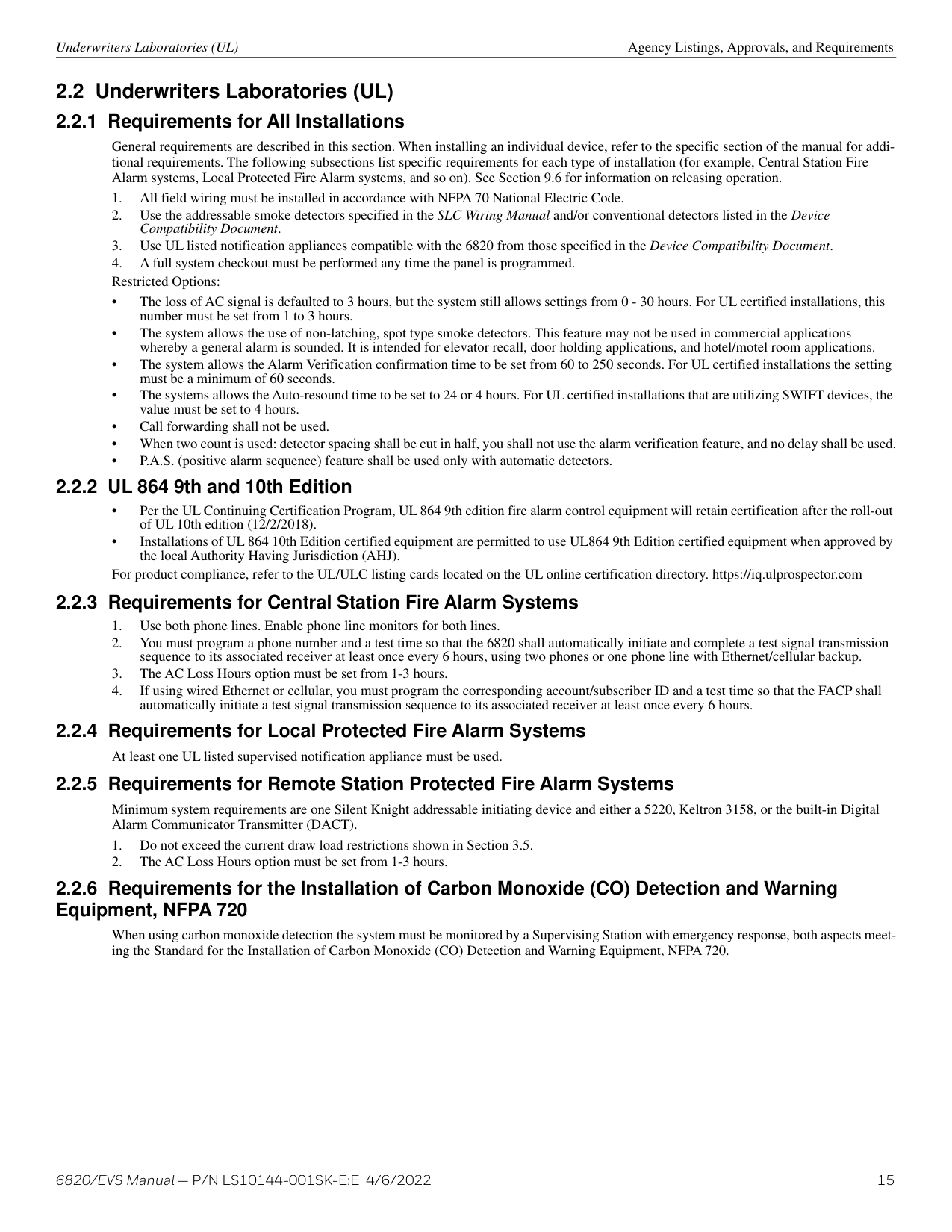
When using carbon monoxide detection the system must be monitored by a Supervising Station with emergency response, both aspects meeting the Standard for the Installation of Carbon Monoxide (CO) Detection and Warning Equipment, NFPA 720.
Agency Listings, Approvals, and Requirements Underwriters Laboratories (UL)
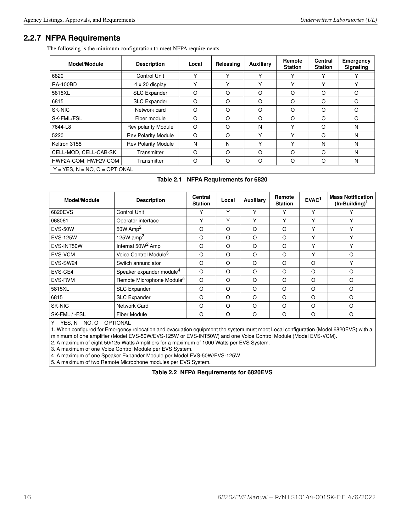
|Model/Module|Description|Local|Releasing|Auxiliary|Remote Station|Central Station|Emergency Signaling| |---|---|---|---|---|---|---|---| | | | | | | | | | |6820|Control Unit|Y|Y|Y|Y|Y|Y| |RA-10BD|4x20display|Y|Y|Y|Y|Y|Y| |5815XL|SLC Expander|O|O|O|O|O|O| |6815|SLC Expander|O|O|O|O|O|O| |SK-NIC|Netwokcard|O|O|O|O|O|O| |SK-ML/FSL|Fibermodule|O|O|O|O|O|O| |7644-L8|Rev polarity Module|O|O|N|Y|O|N| |5220|Rev Polarity Module|O|O|Y|Y|O|N| |Keltron 3158|Rev Polarity Module|N|N|Y|Y|N|N| |CEL-MOD,CELCAB-SK|Transmiter| |O|O|O|O|N| |HWF2A-COM,HWF2V-COM|Transmiter| |O|O|O|O|N| |Y = YES, N = NO, O = OPTIONAL|Y = YES, N = NO, O = OPTIONAL|Y = YES, N = NO, O = OPTIONAL|Y = YES, N = NO, O = OPTIONAL|Y = YES, N = NO, O = OPTIONAL|Y = YES, N = NO, O = OPTIONAL|Y = YES, N = NO, O = OPTIONAL|Y = YES, N = NO, O = OPTIONAL|
############# Table 2.1 NFPA Requirements for 6820
|Model/Module|Description|Central Station|Local|Auxiliary|Remote Station|EVAC1|Mass Notification (In-Building)1| |---|---|---|---|---|---|---|---| | | | | | | | | | |6820EVS|Control Unit|Y|Y|Y|Y|Y|Y| |068061|Operator interface|Y|Y|Y|Y|Y|Y| |EVS-50W|50W Amp2|O|O|O| | | | |EVS-125W|125W amp2|O|O|O| | | | |EVS-INT50W|Internal 50W2 Amp|O|O|O|O|Y|Y| |EVS-VCM|Voice Control Module3|O|O|O| | | | |EVS-SW24|Switch annunciator|O|O|O|O|O|Y| |EVS-CE4|Speaker expander module4|O|O|O| | | | |EVS-RVM|Remote Microphone Module5|O|O|O| | | | |5815XL|SLC Expander|O|O|O|O|O|O| |6815|SLC Expander|O|O|O|O|O|O| |SK-NIC|Network Card|O|O|O|O|O|O| |SK-FML / -FSL|Fiber Module|O|O|O|O|O|O| |Y = YES, N = NO, O = OPTIONAL
1. When configured for Emergency relocation and evacuation equipment the system must meet Local configuration (Model 6820EVS) with a minimum of one amplifier (Model EVS-50W/EVS-125W or EVS-INT50W) and one Voice Control Module (Model EVS-VCM).
2. A maximum of eight 50/125 Watts Amplifiers for a maximum of 1000 Watts per EVS System.
3. A maximum of one Voice Control Module per EVS System.
4. A maximum of one Speaker Expander Module per Model EVS-50W/EVS-125W.
5. A maximum of two Remote Microphone modules per EVS System.
|Y = YES, N = NO, O = OPTIONAL
1. When configured for Emergency relocation and evacuation equipment the system must meet Local configuration (Model 6820EVS) with a minimum of one amplifier (Model EVS-50W/EVS-125W or EVS-INT50W) and one Voice Control Module (Model EVS-VCM).
2. A maximum of eight 50/125 Watts Amplifiers for a maximum of 1000 Watts per EVS System.
3. A maximum of one Voice Control Module per EVS System.
4. A maximum of one Speaker Expander Module per Model EVS-50W/EVS-125W.
5. A maximum of two Remote Microphone modules per EVS System.
|
############# Table 2.2 NFPA Requirements for 6820EVS
##### Section 3: Before You Begin Installation
This section of the manual is intended to help you plan your tasks to facilitate a smooth installation. Please read this section thoroughly, especially if you are installing a 6820 panel for the first time.
###### 3.1 Inventory
When the 6820 shipment is received, check that all the parts have been included in the shipment. The shipment consist of one of each of the following:
###### 3.2 Environmental Specifications
It is important to protect the 6820 control panel from water. To prevent water damage, the following precautions should be followed when installing the units:
###### 3.3 Software Downloads
In order to supply the latest features and functionality in fire alarm and life safety technology to our customers, we make frequent upgrades to the embedded software in our products. To ensure that you are installing and programming the latest features, we strongly recommend that you download the most current version of software for each product prior to commissioning any system. Contact Technical Support with any questions about software and the appropriate version for a specific application. Software updates can be found at www.silentknight.com.
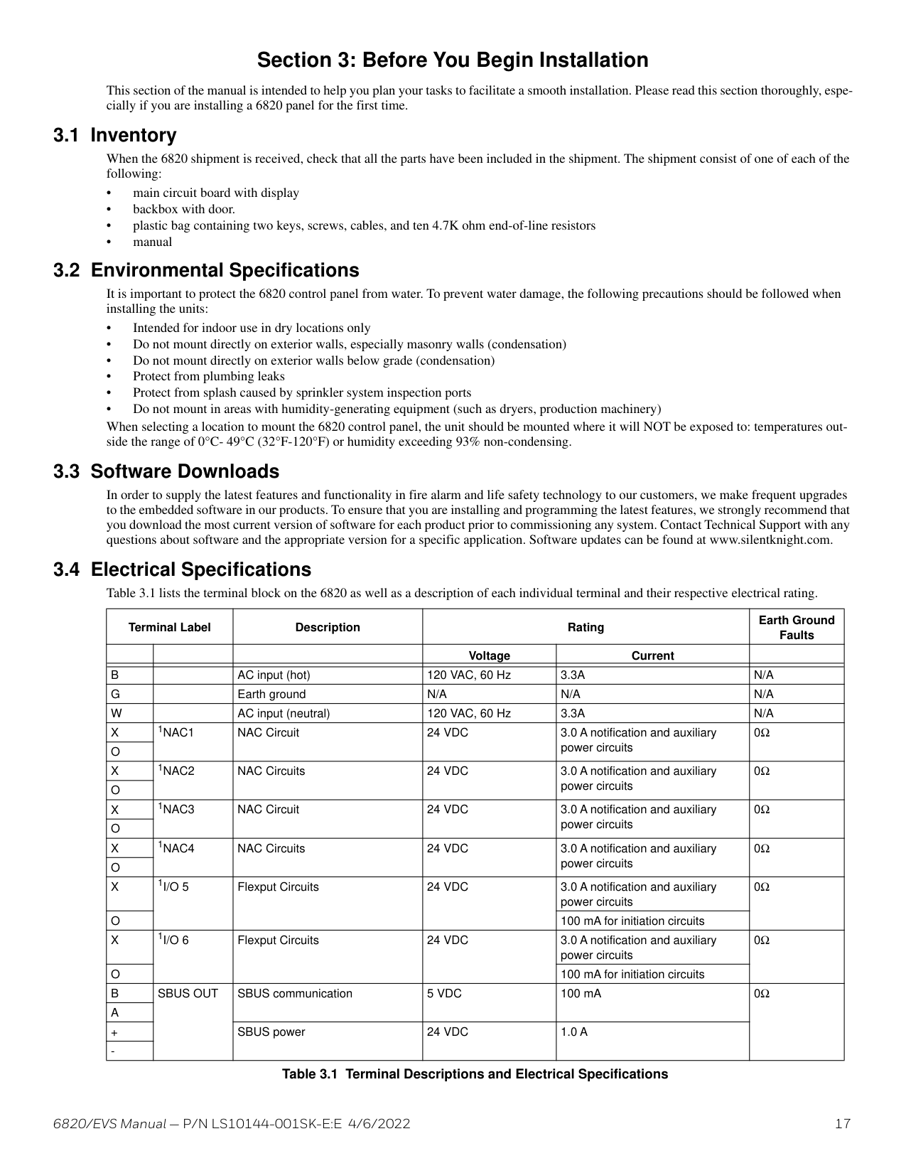
####### 3.4 Electrical SpecificationsTable 3.1 lists the terminal block on the 6820 as well as a description of each individual terminal and their respective electrical rating.
|Terminal Label|Terminal Label|Description|Rating|Rating|Earth Ground Faults| |---|---|---|---|---|---| | | | |Voltage|Current| | | | | | | | | |B| |AC input (hot)|120 VAC, 60 Hz|3.3A|N/A| |G| |Earth ground|N/A|N/A|N/A| |W| |AC input (neutral)|120 VAC, 60 Hz|3.3A|N/A| |X|1NAC1|NAC Circuit|24 VDC|3.0 A notification and auxiliary power circuits|0Ω| |O|1NAC1|NAC Circuit|24 VDC|3.0 A notification and auxiliary power circuits|0Ω| |X|1NAC2|NAC Circuits|24 VDC|3.0 A notification and auxiliary power circuits|0Ω| |O|1NAC2|NAC Circuits|24 VDC|3.0 A notification and auxiliary power circuits|0Ω| |X|1NAC3|NAC Circuit|24 VDC|3.0 A notification and auxiliary power circuits|0Ω| |O|1NAC3|NAC Circuit|24 VDC|3.0 A notification and auxiliary power circuits|0Ω| |X|1NAC4|NAC Circuits|24 VDC|3.0 A notification and auxiliary power circuits|0Ω| |O|1NAC4|NAC Circuits|24 VDC|3.0 A notification and auxiliary power circuits|0Ω| |X|1I/O 5|Flexput Circuits|24 VDC|3.0 A notification and auxiliary power circuits|0Ω| |O|1I/O 5|Flexput Circuits|24 VDC|100 mA for initiation circuits|0Ω| |X|1I/O 6|Flexput Circuits|24 VDC|3.0 A notification and auxiliary power circuits|0Ω| |O|1I/O 6|Flexput Circuits|24 VDC|100 mA for initiation circuits|0Ω| |B|SBUS OUT|SBUS communication|5 VDC|100 mA|0Ω| |A|SBUS OUT|SBUS communication|5 VDC|100 mA|0Ω| |+|SBUS OUT|SBUS power|24 VDC|1.0 A|0Ω| |-|SBUS OUT|SBUS power|24 VDC|1.0 A|0Ω|
Table 3.1 Terminal Descriptions and Electrical Specifications
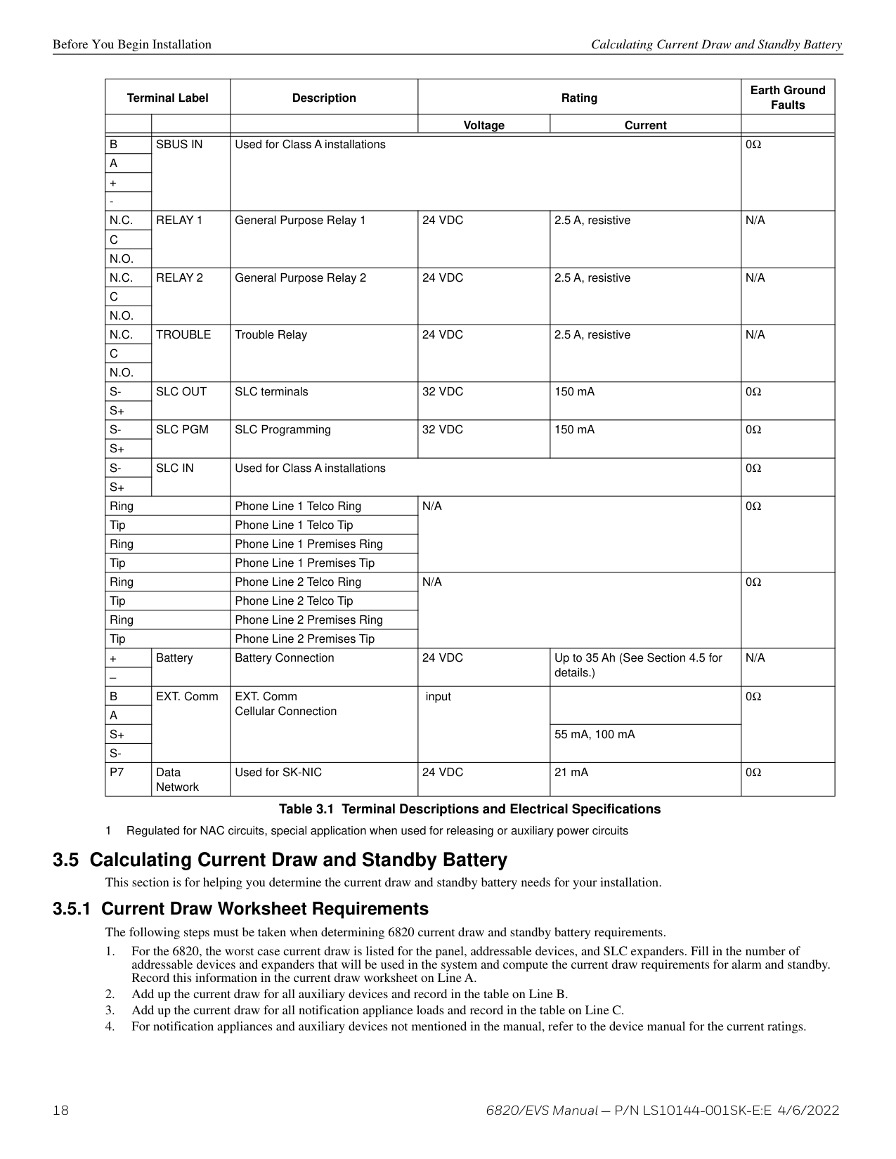
|Terminal Label|Terminal Label|Description|Rating|Rating|Earth Ground Faults| |---|---|---|---|---|---| | | | |Voltage|Current| | | | | | | | | |B|SBUS IN|Used for Class A installations|Used for Class A installations|Used for Class A installations|0Ω| |A|SBUS IN|Used for Class A installations|Used for Class A installations|Used for Class A installations|0Ω|
|+|SBUS IN|Used for Class A installations|Used for Class A installations|Used for Class A installations|0Ω| |-|SBUS IN|Used for Class A installations|Used for Class A installations|Used for Class A installations|0Ω| |N.C.|RELAY 1|General Purpose Relay 1|24 VDC|2.5 A, resistive|N/A| |C|RELAY 1|General Purpose Relay 1|24 VDC|2.5 A, resistive|N/A| |N.O.|RELAY 1|General Purpose Relay 1|24 VDC|2.5 A, resistive|N/A| |N.C.|RELAY 2|General Purpose Relay 2|24 VDC|2.5 A, resistive|N/A| |C|RELAY 2|General Purpose Relay 2|24 VDC|2.5 A, resistive|N/A| |N.O.|RELAY 2|General Purpose Relay 2|24 VDC|2.5 A, resistive|N/A| |N.C.|TROUBLE|Trouble Relay|24 VDC|2.5 A, resistive|N/A| |C|TROUBLE|Trouble Relay|24 VDC|2.5 A, resistive|N/A| |N.O.|TROUBLE|Trouble Relay|24 VDC|2.5 A, resistive|N/A| |S-|SLC OUT|SLC terminals|32 VDC|150 mA|0Ω| |S+|SLC OUT|SLC terminals|32 VDC|150 mA|0Ω| |S-|SLC PGM|SLC Programming|32 VDC|150 mA|0Ω| |S+|SLC PGM|SLC Programming|32 VDC|150 mA|0Ω| |S-|SLC IN|Used for Class A installations|Used for Class A installations|Used for Class A installations|0Ω| |S+|SLC IN|Used for Class A installations|Used for Class A installations|Used for Class A installations|0Ω| |Ring|Ring|Phone Line 1 Telco Ring|N/A|N/A|0Ω| |Tip|Tip|Phone Line 1 Telco Tip|N/A|N/A|0Ω| |Ring|Ring|Phone Line 1 Premises Ring|N/A|N/A|0Ω| |Tip|Tip|Phone Line 1 Premises Tip|N/A|N/A|0Ω| |Ring|Ring|Phone Line 2 Telco Ring|N/A|N/A|0Ω| |Tip|Tip|Phone Line 2 Telco Tip|N/A|N/A|0Ω| |Ring|Ring|Phone Line 2 Premises Ring|N/A|N/A|0Ω| |Tip|Tip|Phone Line 2 Premises Tip|N/A|N/A|0Ω| |+|Battery|Battery Connection|24 VDC|Up to 35 Ah (See Section 4.5 for details.)|N/A| |–|Battery|Battery Connection|24 VDC|Up to 35 Ah (See Section 4.5 for details.)|N/A| |B|EXT. Comm|EXT. Comm Cellular Connection|input| |0Ω| |A|EXT. Comm|EXT. Comm Cellular Connection|input| |0Ω| |S+|EXT. Comm|EXT. Comm Cellular Connection|input|55 mA, 100 mA|0Ω| |S-|EXT. Comm|EXT. Comm Cellular Connection|input|55 mA, 100 mA|0Ω| |P7|Data Network|Used for SK-NIC|24 VDC|21 mA|0Ω|
############# Table 3.1 Terminal Descriptions and Electrical Specifications
1 Regulated for NAC circuits, special application when used for releasing or auxiliary power circuits
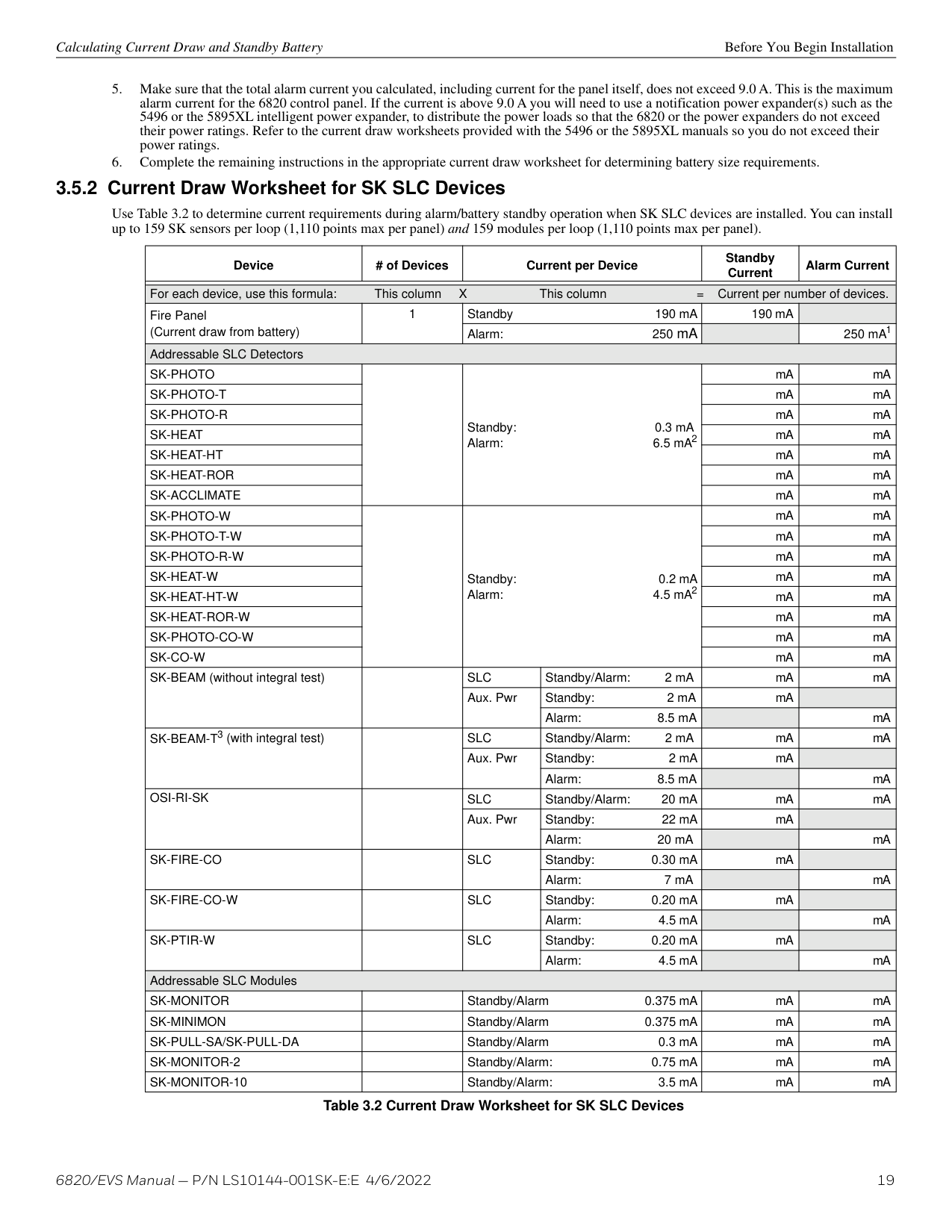
######## 3.5.2 Current Draw Worksheet for SK SLC Devices
Use Table 3.2 to determine current requirements during alarm/battery standby operation when SK SLC devices are installed. You can install up to 159 SK sensors per loop (1,110 points max per panel) and 159 modules per loop (1,110 points max per panel).
|Device|# of Devices|Current per Device|Current per Device|Standby Current|Alarm Current| |---|---|---|---|---|---| |For each device, use this formula: This column X This column = Current per number of devices.|For each device, use this formula: This column X This column = Current per number of devices.|For each device, use this formula: This column X This column = Current per number of devices.|For each device, use this formula: This column X This column = Current per number of devices.|For each device, use this formula: This column X This column = Current per number of devices.|For each device, use this formula: This column X This column = Current per number of devices.| |Fire Panel (Current draw from battery)|1|Standby 190 mA|Standby 190 mA|190 mA| | |Fire Panel (Current draw from battery)|1|Alarm: 250 mA|Alarm: 250 mA| |250 mA1| |Addressable SLC Detectors|Addressable SLC Detectors|Addressable SLC Detectors|Addressable SLC Detectors|Addressable SLC Detectors|Addressable SLC Detectors| |SK-PHOTO| |Standby: 0.3 mA Alarm: 6.5 mA2|Standby: 0.3 mA Alarm: 6.5 mA2|mA|mA| |SK-PHOTO-T| |Standby: 0.3 mA Alarm: 6.5 mA2|Standby: 0.3 mA Alarm: 6.5 mA2|mA|mA| |SK-PHOTO-R| |Standby: 0.3 mA Alarm: 6.5 mA2|Standby: 0.3 mA Alarm: 6.5 mA2|mA|mA| |SK-HEAT| |Standby: 0.3 mA Alarm: 6.5 mA2|Standby: 0.3 mA Alarm: 6.5 mA2|mA|mA| |SK-HEAT-HT| |Standby: 0.3 mA Alarm: 6.5 mA2|Standby: 0.3 mA Alarm: 6.5 mA2|mA|mA| |SK-HEAT-ROR| |Standby: 0.3 mA Alarm: 6.5 mA2|Standby: 0.3 mA Alarm: 6.5 mA2|mA|mA| |SK-ACCLIMATE| |Standby: 0.3 mA Alarm: 6.5 mA2|Standby: 0.3 mA Alarm: 6.5 mA2|mA|mA| |SK-PHOTO-W| |Standby: 0.2 mA Alarm: 4.5 mA2|Standby: 0.2 mA Alarm: 4.5 mA2|mA|mA| |SK-PHOTO-T-W| |Standby: 0.2 mA Alarm: 4.5 mA2|Standby: 0.2 mA Alarm: 4.5 mA2|mA|mA| |SK-PHOTO-R-W| |Standby: 0.2 mA Alarm: 4.5 mA2|Standby: 0.2 mA Alarm: 4.5 mA2|mA|mA| |SK-HEAT-W| |Standby: 0.2 mA Alarm: 4.5 mA2|Standby: 0.2 mA Alarm: 4.5 mA2|mA|mA| |SK-HEAT-HT-W| |Standby: 0.2 mA Alarm: 4.5 mA2|Standby: 0.2 mA Alarm: 4.5 mA2|mA|mA| |SK-HEAT-ROR-W| |Standby: 0.2 mA Alarm: 4.5 mA2|Standby: 0.2 mA Alarm: 4.5 mA2|mA|mA| |SK-PHOTO-CO-W| |Standby: 0.2 mA Alarm: 4.5 mA2|Standby: 0.2 mA Alarm: 4.5 mA2|mA|mA| |SK-CO-W| |Standby: 0.2 mA Alarm: 4.5 mA2|Standby: 0.2 mA Alarm: 4.5 mA2|mA|mA| |SK-BEAM (without integral test)| |SLC|Standby/Alarm: 2 mA|mA|mA| |SK-BEAM (without integral test)| |Aux. Pwr|Standby: 2 mA|mA| | |SK-BEAM (without integral test)| |Aux. Pwr|Alarm: 8.5 mA| |mA| |SK-BEAM-T3 (with integral test)| |SLC|Standby/Alarm: 2 mA|mA|mA| |SK-BEAM-T3 (with integral test)| |Aux. Pwr|Standby: 2 mA|mA| | |SK-BEAM-T3 (with integral test)| |Aux. Pwr|Alarm: 8.5 mA| |mA| |OSI-RI-SK| |SLC|Standby/Alarm: 20 mA|mA|mA| |OSI-RI-SK| |Aux. Pwr|Standby: 22 mA|mA| | |OSI-RI-SK| |Aux. Pwr|Alarm: 20 mA| |mA| |SK-FIRE-CO| |SLC|Standby: 0.30 mA|mA| | |SK-FIRE-CO| |SLC|Alarm: 7 mA| |mA| |SK-FIRE-CO-W| |SLC|Standby: 0.20 mA|mA| | |SK-FIRE-CO-W| |SLC|Alarm: 4.5 mA| |mA| |SK-PTIR-W| |SLC|Standby: 0.20 mA|mA| | |SK-PTIR-W| |SLC|Alarm: 4.5 mA| |mA| |Addressable SLC Modules|Addressable SLC Modules|Addressable SLC Modules|Addressable SLC Modules|Addressable SLC Modules|Addressable SLC Modules| |SK-MONITOR| |Standby/Alarm 0.375 mA|Standby/Alarm 0.375 mA|mA|mA| |SK-MINIMON| |Standby/Alarm 0.375 mA|Standby/Alarm 0.375 mA|mA|mA| |SK-PULL-SA/SK-PULL-DA| |Standby/Alarm 0.3 mA|Standby/Alarm 0.3 mA|mA|mA| |SK-MONITOR-2| |Standby/Alarm: 0.75 mA|Standby/Alarm: 0.75 mA|mA|mA| |SK-MONITOR-10| |Standby/Alarm: 3.5 mA|Standby/Alarm: 3.5 mA|mA|mA|
############# Table 3.2 Current Draw Worksheet for SK SLC Devices
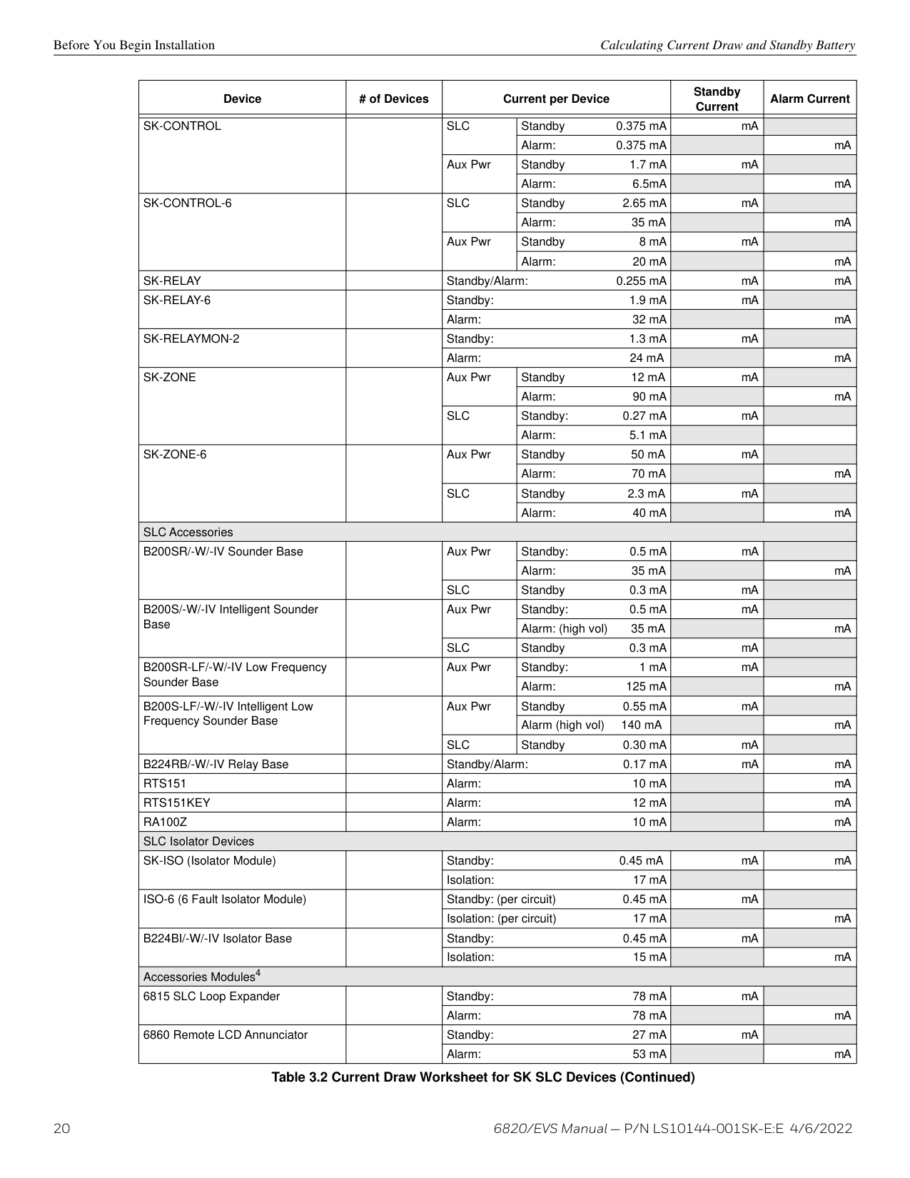
|Device|# of Devices|Current per Device|Current per Device|Standby Current|Alarm Current| |---|---|---|---|---|---| | | | | | | | |SK-CONTROL| |SLC|Standby 0.375 mA|mA| | |SK-CONTROL| |SLC|Alarm: 0.375 mA| |mA| |SK-CONTROL| |Aux Pwr|Standby 1.7 mA|mA| | |SK-CONTROL| |Aux Pwr|Alarm: 6.5mA| |mA| |SK-CONTROL-6| |SLC|Standby 2.65 mA|mA| | |SK-CONTROL-6| |SLC|Alarm: 35 mA| |mA| |SK-CONTROL-6| |Aux Pwr|Standby 8 mA|mA| |
|SK-CONTROL-6| |Aux Pwr|Alarm: 20 mA| |mA| |SK-RELAY| |Standby/Alarm: 0.255 mA|Standby/Alarm: 0.255 mA|mA|mA| |SK-RELAY-6| |Standby: 1.9 mA|Standby: 1.9 mA|mA| | |SK-RELAY-6| |Alarm: 32 mA|Alarm: 32 mA| |mA| |SK-RELAYMON-2| |Standby: 1.3 mA|Standby: 1.3 mA|mA| | |SK-RELAYMON-2| |Alarm: 24 mA|Alarm: 24 mA| |mA| |SK-ZONE| |Aux Pwr|Standby 12 mA|mA| | |SK-ZONE| |Aux Pwr|Alarm: 90 mA| |mA| |SK-ZONE| |SLC|Standby: 0.27 mA|mA| | |SK-ZONE| |SLC|Alarm: 5.1 mA| | | |SK-ZONE-6| |Aux Pwr|Standby 50 mA|mA| | |SK-ZONE-6| |Aux Pwr|Alarm: 70 mA| |mA| |SK-ZONE-6| |SLC|Standby 2.3 mA|mA| | |SK-ZONE-6| |SLC|Alarm: 40 mA| |mA| |SLC Accessories|SLC Accessories|SLC Accessories|SLC Accessories|SLC Accessories|SLC Accessories| |B200SR/-W/-IV Sounder Base| |Aux Pwr|Standby: 0.5 mA|mA| | |B200SR/-W/-IV Sounder Base| |Aux Pwr|Alarm: 35 mA| |mA| |B200SR/-W/-IV Sounder Base| |SLC|Standby 0.3 mA|mA| | |B200S/-W/-IV Intelligent Sounder Base| |Aux Pwr|Standby: 0.5 mA|mA| | |B200S/-W/-IV Intelligent Sounder Base| |Aux Pwr|Alarm: (high vol) 35 mA| |mA| |B200S/-W/-IV Intelligent Sounder Base| |SLC|Standby 0.3 mA|mA| | |B200SR-LF/-W/-IV Low Frequency Sounder Base| |Aux Pwr|Standby: 1 mA|mA| | |B200SR-LF/-W/-IV Low Frequency Sounder Base| |Aux Pwr|Alarm: 125 mA| |mA| |B200S-LF/-W/-IV Intelligent Low Frequency Sounder Base| |Aux Pwr|Standby 0.55 mA|mA| | |B200S-LF/-W/-IV Intelligent Low Frequency Sounder Base| |Aux Pwr|Alarm (high vol) 140 mA| |mA| |B200S-LF/-W/-IV Intelligent Low Frequency Sounder Base| |SLC|Standby 0.30 mA|mA| | |B224RB/-W/-IV Relay Base| |Standby/Alarm: 0.17 mA|Standby/Alarm: 0.17 mA|mA|mA| |RTS151| |Alarm: 10 mA|Alarm: 10 mA| |mA| |RTS151KEY| |Alarm: 12 mA|Alarm: 12 mA| |mA| |RA100Z| |Alarm: 10 mA|Alarm: 10 mA| |mA| |SLC Isolator Devices|SLC Isolator Devices|SLC Isolator Devices|SLC Isolator Devices|SLC Isolator Devices|SLC Isolator Devices| |SK-ISO (Isolator Module)| |Standby: 0.45 mA|Standby: 0.45 mA|mA|mA| |SK-ISO (Isolator Module)| |Isolation: 17 mA|Isolation: 17 mA| | | |ISO-6 (6 Fault Isolator Module)| |Standby: (per circuit) 0.45 mA|Standby: (per circuit) 0.45 mA|mA| | |ISO-6 (6 Fault Isolator Module)| |Isolation: (per circuit) 17 mA|Isolation: (per circuit) 17 mA| |mA| |B224BI/-W/-IV Isolator Base| |Standby: 0.45 mA|Standby: 0.45 mA|mA| | |B224BI/-W/-IV Isolator Base| |Isolation: 15 mA|Isolation: 15 mA| |mA| |Accessories Modules4|Accessories Modules4|Accessories Modules4|Accessories Modules4|Accessories Modules4|Accessories Modules4| |6815 SLC Loop Expander| |Standby: 78 mA|Standby: 78 mA|mA| | |6815 SLC Loop Expander| |Alarm: 78 mA|Alarm: 78 mA| |mA| |6860 Remote LCD Annunciator| |Standby: 27 mA|Standby: 27 mA|mA| | |6860 Remote LCD Annunciator| |Alarm: 53 mA|Alarm: 53 mA| |mA|
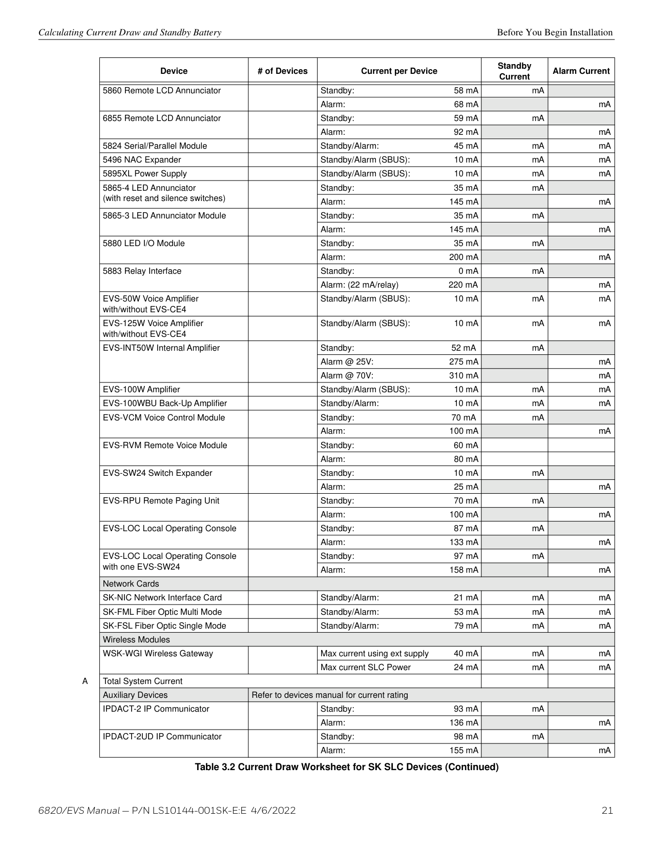
|Device|# of Devices|Current per Device|Standby Current|Alarm Current| |---|---|---|---|---| | | | | | | |5860 Remote LCD Annunciator| |Standby: 58 mA|mA| | |5860 Remote LCD Annunciator| |Alarm: 68 mA| |mA| |6855 Remote LCD Annunciator| |Standby: 59 mA|mA| | |6855 Remote LCD Annunciator| |Alarm: 92 mA| |mA| |5824 Serial/Parallel Module| |Standby/Alarm: 45 mA|mA|mA| |5496 NAC Expander| |Standby/Alarm (SBUS): 10 mA|mA|mA| |5895XL Power Supply| |Standby/Alarm (SBUS): 10 mA|mA|mA| |5865-4 LED Annunciator (with reset and silence switches)| |Standby: 35 mA|mA| | |5865-4 LED Annunciator (with reset and silence switches)| |Alarm: 145 mA| |mA| |5865-3 LED Annunciator Module| |Standby: 35 mA|mA| |
|5865-3 LED Annunciator Module| |Alarm: 145 mA| |mA| |5880 LED I/O Module| |Standby: 35 mA|mA| | |5880 LED I/O Module| |Alarm: 200 mA| |mA| |5883 Relay Interface| |Standby: 0 mA|mA| | |5883 Relay Interface| |Alarm: (22 mA/relay) 220 mA| |mA| |EVS-50W Voice Amplifier with/without EVS-CE4| |Standby/Alarm (SBUS): 10 mA|mA|mA| |EVS-125W Voice Amplifier with/without EVS-CE4| |Standby/Alarm (SBUS): 10 mA|mA|mA| |EVS-INT50W Internal Amplifier| |Standby: 52 mA|mA| | |EVS-INT50W Internal Amplifier| |Alarm @ 25V: 275 mA| |mA| |EVS-INT50W Internal Amplifier| |Alarm @ 70V: 310 mA| |mA| |EVS-100W Amplifier| |Standby/Alarm (SBUS): 10 mA|mA|mA| |EVS-100WBU Back-Up Amplifier| |Standby/Alarm: 10 mA|mA|mA| |EVS-VCM Voice Control Module| |Standby: 70 mA|mA| | |EVS-VCM Voice Control Module| |Alarm: 100 mA| |mA| |EVS-RVM Remote Voice Module| |Standby: 60 mA| | | |EVS-RVM Remote Voice Module| |Alarm: 80 mA| | | |EVS-SW24 Switch Expander| |Standby: 10 mA|mA| | |EVS-SW24 Switch Expander| |Alarm: 25 mA| |mA| |EVS-RPU Remote Paging Unit| |Standby: 70 mA|mA| | |EVS-RPU Remote Paging Unit| |Alarm: 100 mA| |mA| |EVS-LOC Local Operating Console| |Standby: 87 mA|mA| | |EVS-LOC Local Operating Console| |Alarm: 133 mA| |mA| |EVS-LOC Local Operating Console with one EVS-SW24| |Standby: 97 mA|mA| | |EVS-LOC Local Operating Console with one EVS-SW24| |Alarm: 158 mA| |mA| |Network Cards| | | | | |SK-NIC Network Interface Card| |Standby/Alarm: 21 mA|mA|mA| |SK-FML Fiber Optic Multi Mode| |Standby/Alarm: 53 mA|mA|mA| |SK-FSL Fiber Optic Single Mode| |Standby/Alarm: 79 mA|mA|mA| |Wireless Modules|Wireless Modules|Wireless Modules|Wireless Modules|Wireless Modules| |WSK-WGI Wireless Gateway| |Max current using ext supply 40 mA|mA|mA| |WSK-WGI Wireless Gateway| |Max current SLC Power 24 mA|mA|mA| |A Total System Current|A Total System Current|A Total System Current| | | |Auxiliary Devices|Refer to devices manual for current rating|Refer to devices manual for current rating|Refer to devices manual for current rating|Refer to devices manual for current rating| |IPDACT-2 IP Communicator| |Standby: 93 mA|mA| | |IPDACT-2 IP Communicator| |Alarm: 136 mA| |mA| |IPDACT-2UD IP Communicator| |Standby: 98 mA|mA| | |IPDACT-2UD IP Communicator| |Alarm: 155 mA| |mA|
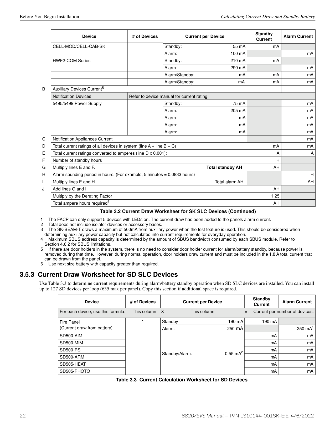
|Device|# of Devices|Current per Device|Standby Current|Alarm Current| |---|---|---|---|---| |CELL-MOD/CELL-CAB-SK| |Standby: 55 mA|mA| | |CELL-MOD/CELL-CAB-SK| |Alarm: 100 mA| |mA| |HWF2-COM Series| |Standby: 210 mA|mA| | |HWF2-COM Series| |Alarm: 290 mA| |mA| | | |Alarm/Standby: mA|mA|mA| | | |Alarm/Standby: mA|mA|mA| |B Auxiliary Devices Current5|B Auxiliary Devices Current5|B Auxiliary Devices Current5| | | |Notification Devices|Refer to device manual for current rating|Refer to device manual for current rating|Refer to device manual for current rating|Refer to device manual for current rating| |5495/5499 Power Supply| |Standby: 75 mA| |mA| |5495/5499 Power Supply| |Alarm: 205 mA| |mA| | | |Alarm: mA| |mA| | | |Alarm: mA| |mA| | | |Alarm: mA| |mA| |C Notification Appliances Current|C Notification Appliances Current|C Notification Appliances Current| |mA| |D Total current ratings of all devices in system (line A + line B + C)|D Total current ratings of all devices in system (line A + line B + C)|D Total current ratings of all devices in system (line A + line B + C)|mA|mA| |E Total current ratings converted to amperes (line D x 0.001):|E Total current ratings converted to amperes (line D x 0.001):|E Total current ratings converted to amperes (line D x 0.001):|A|A|
|F Number of standby hours|F Number of standby hours|F Number of standby hours|H| | |G Multiply lines E and F. Total standby AH|G Multiply lines E and F. Total standby AH|G Multiply lines E and F. Total standby AH|AH| | |H Alarm sounding period in hours. (For example, 5 minutes = 0.0833 hours)|H Alarm sounding period in hours. (For example, 5 minutes = 0.0833 hours)|H Alarm sounding period in hours. (For example, 5 minutes = 0.0833 hours)| |H| |I Multiply lines E and H. Total alarm AH|I Multiply lines E and H. Total alarm AH|I Multiply lines E and H. Total alarm AH| |AH| |J Add lines G and I.|J Add lines G and I.|J Add lines G and I.|AH| | |Multiply by the Derating Factor|Multiply by the Derating Factor|Multiply by the Derating Factor|1.25| | |Total ampere hours required6|Total ampere hours required6|Total ampere hours required6|AH| |
Table 3.2 Current Draw Worksheet for SK SLC Devices (Continued)
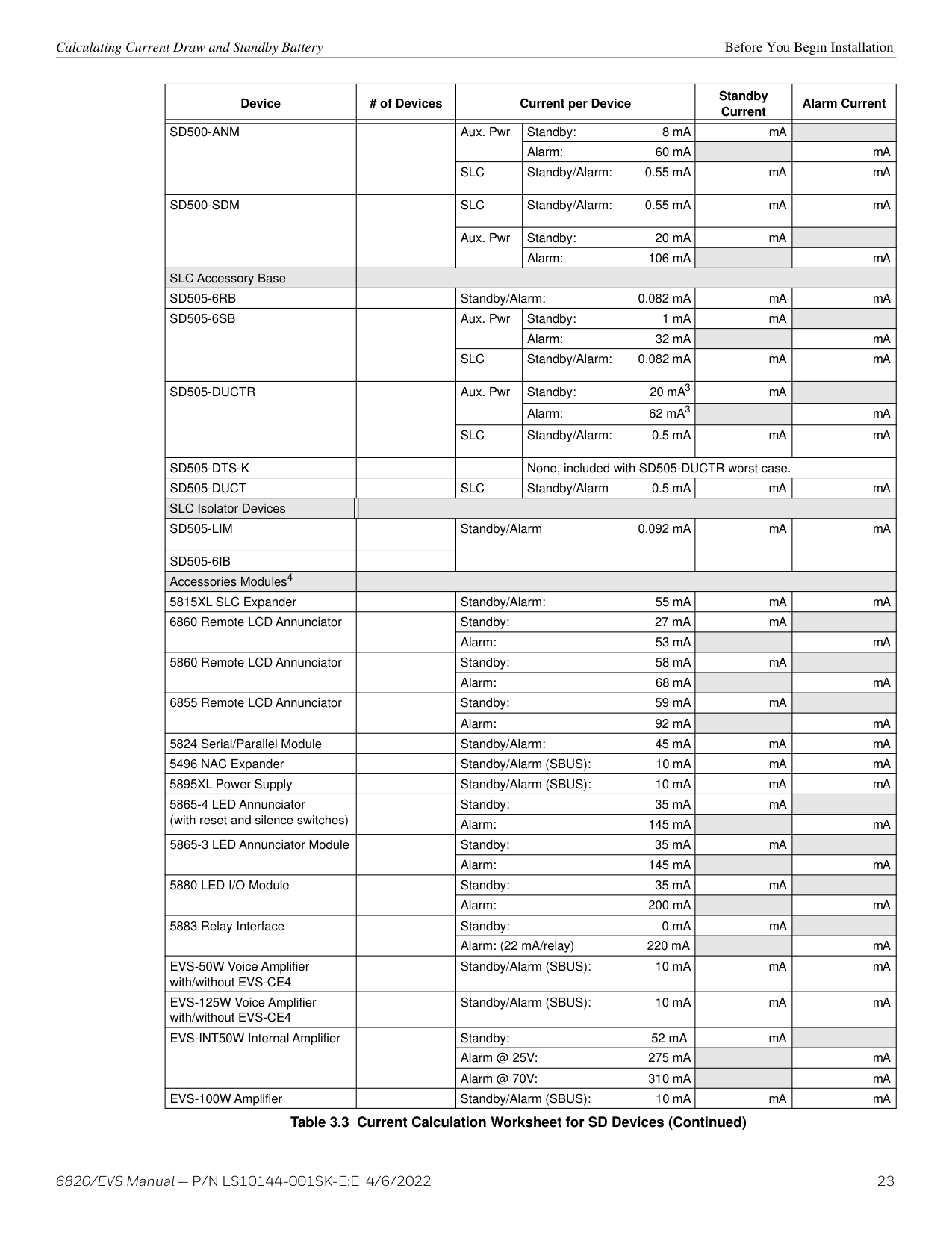
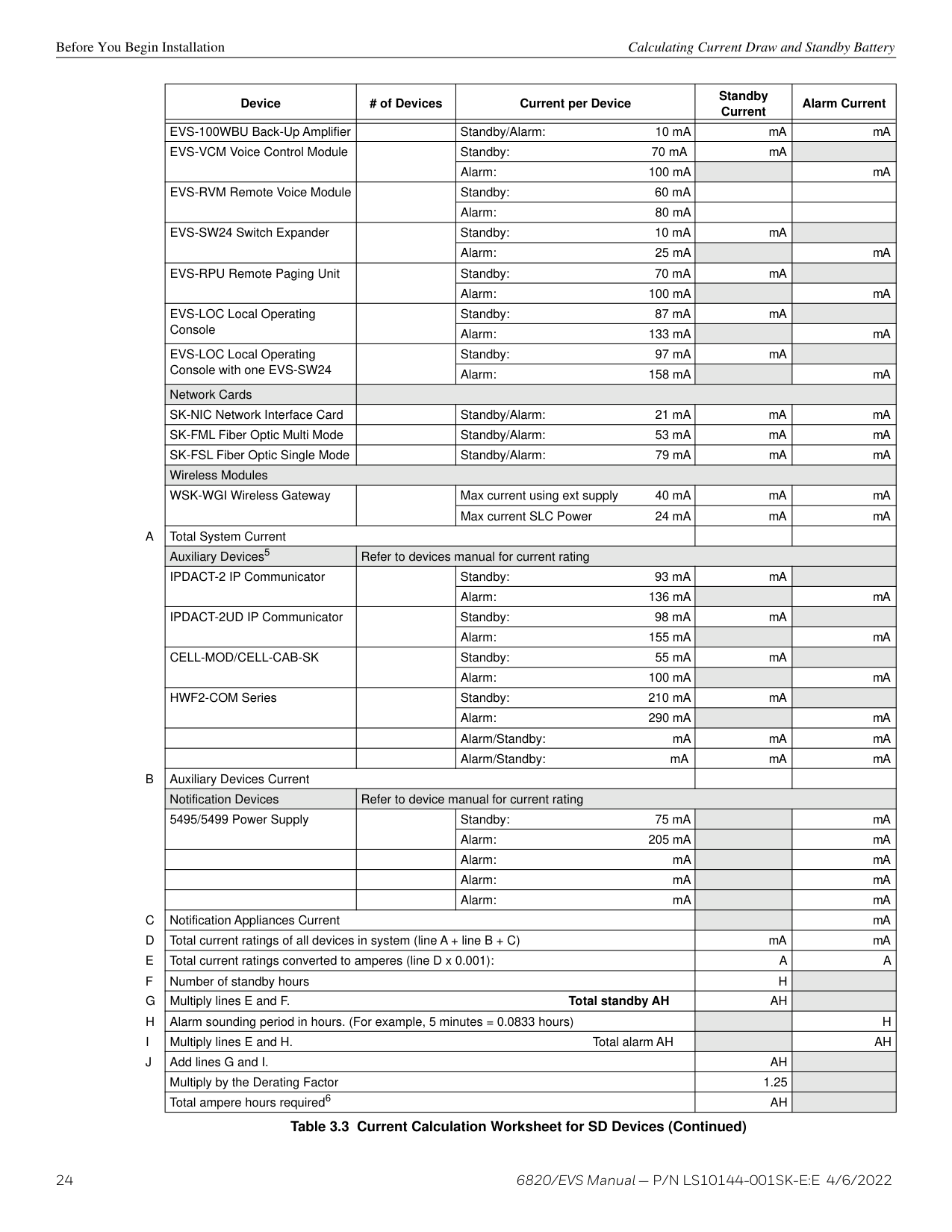
######## 3.5.3 Current Draw Worksheet for SD SLC Devices
Use Table 3.3 to determine current requirements during alarm/battery standby operation when SD SLC devices are installed. You can install up to 127 SD devices per loop (635 max per panel). Copy this section if additional space is required.
|Device|# of Devices|Current per Device|Standby Current|Alarm Current| |---|---|---|---|---| |For each device, use this formula: This column X This column = Current per number of devices.|For each device, use this formula: This column X This column = Current per number of devices.|For each device, use this formula: This column X This column = Current per number of devices.|For each device, use this formula: This column X This column = Current per number of devices.|For each device, use this formula: This column X This column = Current per number of devices.| |Fire Panel (Current draw from battery)|1|Standby 190 mA|190 mA| | |Fire Panel (Current draw from battery)|1|Alarm: 250 mA| |250 mA1| |SD500-AIM| |Standby/Alarm: 0.55 mA2|mA|mA| |SD500-MIM| |Standby/Alarm: 0.55 mA2|mA|mA| |SD500-PS| |Standby/Alarm: 0.55 mA2|mA|mA| |SD500-ARM| |Standby/Alarm: 0.55 mA2|mA|mA| |SD505-HEAT| |Standby/Alarm: 0.55 mA2|mA|mA| |SD505-PHOTO| |Standby/Alarm: 0.55 mA2|mA|mA|
Table 3.3 Current Calculation Worksheet for SD Devices
|Device|# of Devices|Current per Device|Current per Device|Standby Current|Alarm Current| |---|---|---|---|---|---| | | | | | | | |SD500-ANM| |Aux. Pwr|Standby: 8 mA|mA| | |SD500-ANM| |Aux. Pwr|Alarm: 60 mA| |mA| |SD500-ANM| |SLC|Standby/Alarm: 0.55 mA|mA|mA| |SD500-SDM| |SLC|Standby/Alarm: 0.55 mA|mA|mA| |SD500-SDM| |Aux. Pwr|Standby: 20 mA|mA| | |SD500-SDM| |Aux. Pwr|Alarm: 106 mA| |mA| |SLC Accessory Base| | | | | | |SD505-6RB| |Standby/Alarm: 0.082 mA|Standby/Alarm: 0.082 mA|mA|mA| |SD505-6SB| |Aux. Pwr|Standby: 1 mA|mA| | |SD505-6SB| |Aux. Pwr|Alarm: 32 mA| |mA| |SD505-6SB| |SLC|Standby/Alarm: 0.082 mA|mA|mA| |SD505-DUCTR| |Aux. Pwr|Standby: 20 mA3|mA| | |SD505-DUCTR| |Aux. Pwr|Alarm: 62 mA3| |mA| |SD505-DUCTR| |SLC|Standby/Alarm: 0.5 mA|mA|mA| |SD505-DTS-K| | |None, included with SD505-DUCTR worst case.|None, included with SD505-DUCTR worst case.|None, included with SD505-DUCTR worst case.| |SD505-DUCT| |SLC|Standby/Alarm 0.5 mA|mA|mA|
|SLC Isolator Devices| | | | | | |SD505-LIM| |Standby/Alarm 0.092 mA|Standby/Alarm 0.092 mA|mA|mA| |SD505-6IB| |Standby/Alarm 0.092 mA|Standby/Alarm 0.092 mA|mA|mA| |Accessories Modules4| | | | | | |5815XL SLC Expander| |Standby/Alarm: 55 mA|Standby/Alarm: 55 mA|mA|mA| |6860 Remote LCD Annunciator| |Standby: 27 mA|Standby: 27 mA|mA| | |6860 Remote LCD Annunciator| |Alarm: 53 mA|Alarm: 53 mA| |mA| |5860 Remote LCD Annunciator| |Standby: 58 mA|Standby: 58 mA|mA| | |5860 Remote LCD Annunciator| |Alarm: 68 mA|Alarm: 68 mA| |mA| |6855 Remote LCD Annunciator| |Standby: 59 mA|Standby: 59 mA|mA| | |6855 Remote LCD Annunciator| |Alarm: 92 mA|Alarm: 92 mA| |mA| |5824 Serial/Parallel Module| |Standby/Alarm: 45 mA|Standby/Alarm: 45 mA|mA|mA| |5496 NAC Expander| |Standby/Alarm (SBUS): 10 mA|Standby/Alarm (SBUS): 10 mA|mA|mA| |5895XL Power Supply| |Standby/Alarm (SBUS): 10 mA|Standby/Alarm (SBUS): 10 mA|mA|mA| |5865-4 LED Annunciator (with reset and silence switches)| |Standby: 35 mA|Standby: 35 mA|mA| | |5865-4 LED Annunciator (with reset and silence switches)| |Alarm: 145 mA|Alarm: 145 mA| |mA| |5865-3 LED Annunciator Module| |Standby: 35 mA|Standby: 35 mA|mA| | |5865-3 LED Annunciator Module| |Alarm: 145 mA|Alarm: 145 mA| |mA| |5880 LED I/O Module| |Standby: 35 mA|Standby: 35 mA|mA| | |5880 LED I/O Module| |Alarm: 200 mA|Alarm: 200 mA| |mA| |5883 Relay Interface| |Standby: 0 mA|Standby: 0 mA|mA| | |5883 Relay Interface| |Alarm: (22 mA/relay) 220 mA|Alarm: (22 mA/relay) 220 mA| |mA| |EVS-50W Voice Amplifier with/without EVS-CE4| |Standby/Alarm (SBUS): 10 mA|Standby/Alarm (SBUS): 10 mA|mA|mA| |EVS-125W Voice Amplifier with/without EVS-CE4| |Standby/Alarm (SBUS): 10 mA|Standby/Alarm (SBUS): 10 mA|mA|mA| |EVS-INT50W Internal Amplifier| |Standby: 52 mA|Standby: 52 mA|mA| | |EVS-INT50W Internal Amplifier| |Alarm @ 25V: 275 mA|Alarm @ 25V: 275 mA| |mA| |EVS-INT50W Internal Amplifier| |Alarm @ 70V: 310 mA|Alarm @ 70V: 310 mA| |mA| |EVS-100W Amplifier| |Standby/Alarm (SBUS): 10 mA|Standby/Alarm (SBUS): 10 mA|mA|mA|
|Device|# of Devices|Current per Device|Standby Current|Alarm Current| |---|---|---|---|---| | | | | | | |EVS-100WBU Back-Up Amplifier| |Standby/Alarm: 10 mA|mA|mA| |EVS-VCM Voice Control Module| |Standby: 70 mA|mA| | |EVS-VCM Voice Control Module| |Alarm: 100 mA| |mA| |EVS-RVM Remote Voice Module| |Standby: 60 mA| | | |EVS-RVM Remote Voice Module| |Alarm: 80 mA| | | |EVS-SW24 Switch Expander| |Standby: 10 mA|mA| | |EVS-SW24 Switch Expander| |Alarm: 25 mA| |mA| |EVS-RPU Remote Paging Unit| |Standby: 70 mA|mA| | |EVS-RPU Remote Paging Unit| |Alarm: 100 mA| |mA| |EVS-LOC Local Operating Console| |Standby: 87 mA|mA| | |EVS-LOC Local Operating Console| |Alarm: 133 mA| |mA| |EVS-LOC Local Operating Console with one EVS-SW24| |Standby: 97 mA|mA| | |EVS-LOC Local Operating Console with one EVS-SW24| |Alarm: 158 mA| |mA| |Network Cards| | | | | |SK-NIC Network Interface Card| |Standby/Alarm: 21 mA|mA|mA| |SK-FML Fiber Optic Multi Mode| |Standby/Alarm: 53 mA|mA|mA| |SK-FSL Fiber Optic Single Mode| |Standby/Alarm: 79 mA|mA|mA| |Wireless Modules|Wireless Modules|Wireless Modules|Wireless Modules|Wireless Modules| |WSK-WGI Wireless Gateway| |Max current using ext supply 40 mA|mA|mA| |WSK-WGI Wireless Gateway| |Max current SLC Power 24 mA|mA|mA| |A Total System Current|A Total System Current|A Total System Current| | | |Auxiliary Devices5|Refer to devices manual for current rating|Refer to devices manual for current rating|Refer to devices manual for current rating|Refer to devices manual for current rating| |IPDACT-2 IP Communicator| |Standby: 93 mA|mA| | |IPDACT-2 IP Communicator| |Alarm: 136 mA| |mA|
|IPDACT-2UD IP Communicator| |Standby: 98 mA|mA| | |IPDACT-2UD IP Communicator| |Alarm: 155 mA| |mA| |CELL-MOD/CELL-CAB-SK| |Standby: 55 mA|mA| | |CELL-MOD/CELL-CAB-SK| |Alarm: 100 mA| |mA| |HWF2-COM Series| |Standby: 210 mA|mA| | |HWF2-COM Series| |Alarm: 290 mA| |mA| | | |Alarm/Standby: mA|mA|mA| | | |Alarm/Standby: mA|mA|mA| |B Auxiliary Devices Current|B Auxiliary Devices Current|B Auxiliary Devices Current| | | |Notification Devices|Refer to device manual for current rating|Refer to device manual for current rating|Refer to device manual for current rating|Refer to device manual for current rating| |5495/5499 Power Supply| |Standby: 75 mA| |mA| |5495/5499 Power Supply| |Alarm: 205 mA| |mA| | | |Alarm: mA| |mA| | | |Alarm: mA| |mA| | | |Alarm: mA| |mA| |C Notification Appliances Current|C Notification Appliances Current|C Notification Appliances Current| |mA| |D Total current ratings of all devices in system (line A + line B + C)|D Total current ratings of all devices in system (line A + line B + C)|D Total current ratings of all devices in system (line A + line B + C)|mA|mA| |E Total current ratings converted to amperes (line D x 0.001):|E Total current ratings converted to amperes (line D x 0.001):|E Total current ratings converted to amperes (line D x 0.001):|A|A| |F Number of standby hours|F Number of standby hours|F Number of standby hours|H| | |G Multiply lines E and F. Total standby AH|G Multiply lines E and F. Total standby AH|G Multiply lines E and F. Total standby AH|AH| | |H Alarm sounding period in hours. (For example, 5 minutes = 0.0833 hours)|H Alarm sounding period in hours. (For example, 5 minutes = 0.0833 hours)|H Alarm sounding period in hours. (For example, 5 minutes = 0.0833 hours)| |H| |I Multiply lines E and H. Total alarm AH|I Multiply lines E and H. Total alarm AH|I Multiply lines E and H. Total alarm AH| |AH| |J Add lines G and I.|J Add lines G and I.|J Add lines G and I.|AH| | |Multiply by the Derating Factor|Multiply by the Derating Factor|Multiply by the Derating Factor|1.25| | |Total ampere hours required6|Total ampere hours required6|Total ampere hours required6|AH| |
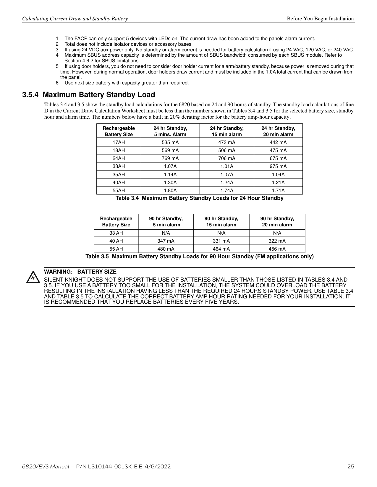
######## 3.5.4 Maximum Battery Standby Load
Tables 3.4 and 3.5 show the standby load calculations for the 6820 based on 24 and 90 hours of standby. The standby load calculations of line D in the Current Draw Calculation Worksheet must be less than the number shown in Tables 3.4 and 3.5 for the selected battery size, standby hour and alarm time. The numbers below have a built in 20% derating factor for the battery amp-hour capacity.
|Rechargeable Battery Size|24 hr Standby, 5 mins. Alarm|24 hr Standby, 15 min alarm|24 hr Standby, 20 min alarm| |---|---|---|---| | | | | | |17AH|535 mA|473 mA|442 mA| |18AH|569 mA|506 mA|475 mA| |24AH|769 mA|706 mA|675 mA| |33AH|1.07A|1.01A|975 mA| |35AH|1.14A|1.07A|1.04A| |40AH|1.30A|1.24A|1.21A| |55AH|1.80A|1.74A|1.71A|
Table 3.4 Maximum Battery Standby Loads for 24 Hour Standby
|Rechargeable Battery Size|90 hr Standby, 5 min alarm|90 hr Standby, 15 min alarm|90 hr Standby, 20 min alarm| |---|---|---|---| | | | | | |33 AH|N/A|N/A|N/A|
|40 AH|347 mA|331 mA|322 mA| |55 AH|480 mA|464 mA|456 mA|
Table 3.5 Maximum Battery Standby Loads for 90 Hour Standby (FM applications only)
WARNING: BATTERY SIZE
!
SILENT KNIGHT DOES NOT SUPPORT THE USE OF BATTERIES SMALLER THAN THOSE LISTED IN TABLES 3.4 AND 3.5. IF YOU USE A BATTERY TOO SMALL FOR THE INSTALLATION, THE SYSTEM COULD OVERLOAD THE BATTERY RESULTING IN THE INSTALLATION HAVING LESS THAN THE REQUIRED 24 HOURS STANDBY POWER. USE TABLE 3.4 AND TABLE 3.5 TO CALCULATE THE CORRECT BATTERY AMP HOUR RATING NEEDED FOR YOUR INSTALLATION. IT IS RECOMMENDED THAT YOU REPLACE BATTERIES EVERY FIVE YEARS.
##### Section 4: Control Panel Installation
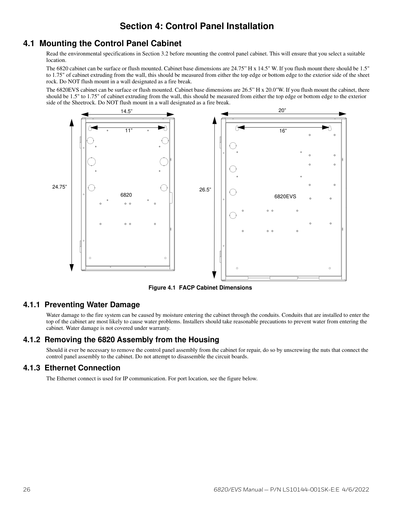
###### 4.1 Mounting the Control Panel Cabinet
Read the environmental specifications in Section 3.2 before mounting the control panel cabinet. This will ensure that you select a suitable location.
The 6820 cabinet can be surface or flush mounted. Cabinet base dimensions are 24.75” H x 14.5" W. If you flush mount there should be 1.5" to 1.75" of cabinet extruding from the wall, this should be measured from either the top edge or bottom edge to the exterior side of the sheet rock. Do NOT flush mount in a wall designated as a fire break.
The 6820EVS cabinet can be surface or flush mounted. Cabinet base dimensions are 26.5” H x 20.0"W. If you flush mount the cabinet, there should be 1.5" to 1.75" of cabinet extruding from the wall, this should be measured from either the top edge or bottom edge to the exterior side of the Sheetrock. Do NOT flush mount in a wall designated as a fire break.
20”
14.5”
11”
16”
24.75”
26.5” 6820 6820EVS
Figure 4.1 FACP Cabinet Dimensions
Water damage to the fire system can be caused by moisture entering the cabinet through the conduits. Conduits that are installed to enter the top of the cabinet are most likely to cause water problems. Installers should take reasonable precautions to prevent water from entering the cabinet. Water damage is not covered under warranty.
Should it ever be necessary to remove the control panel assembly from the cabinet for repair, do so by unscrewing the nuts that connect the control panel assembly to the cabinet. Do not attempt to disassemble the circuit boards.
Board Assembly Diagram Control Panel Installation
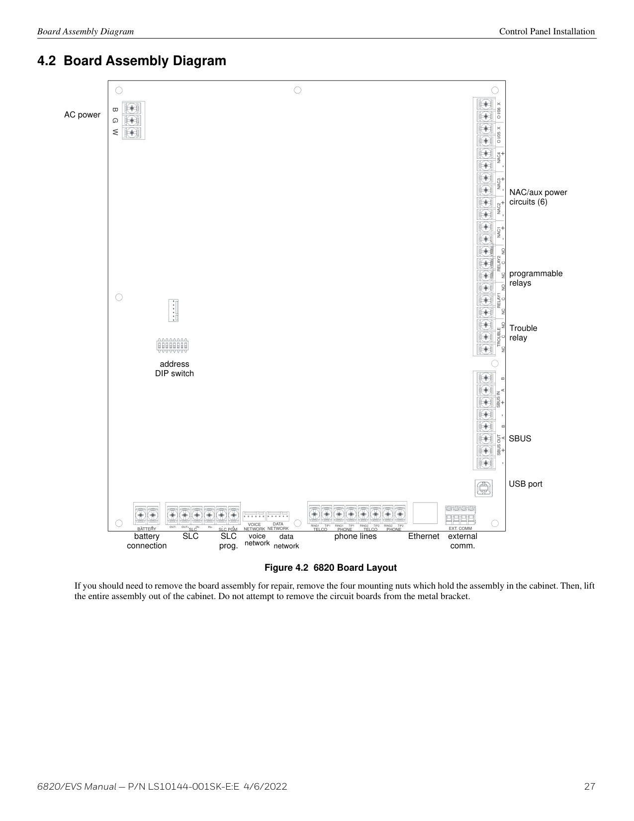
###### 4.2 Board Assembly Diagram
AC power
|EXT. COMM
VOICE NETWORK
DATA NETWORK TELCO PHONE TELCO PHONESLC SLC PGMBATTERY
B G W
RING1 TIP1 RING1 TIP1 RING2 TIP2 RING2 TIP2OUT- OUT+ IN- IN+- +- +
TROUBLESBUS OUTSBUS IN
NC C NO- +A B- +A B
RELAY1
NC C NO
RELAY2
NC C NO
NAC1 NAC2 NAC3 NAC4 O I/05 X O I/06 X
+ - + - + - + -
address DIP switch| |---|
NAC/aux power circuits (6)
programmable relays
Trouble relay
SBUS
USB port
phone lines Ethernet external comm.
battery connection
SLC SLC prog.
voice network
data network
############# Figure 4.2 6820 Board Layout
If you should need to remove the board assembly for repair, remove the four mounting nuts which hold the assembly in the cabinet. Then, lift the entire assembly out of the cabinet. Do not attempt to remove the circuit boards from the metal bracket.
Control Panel Installation Wiring Specifications
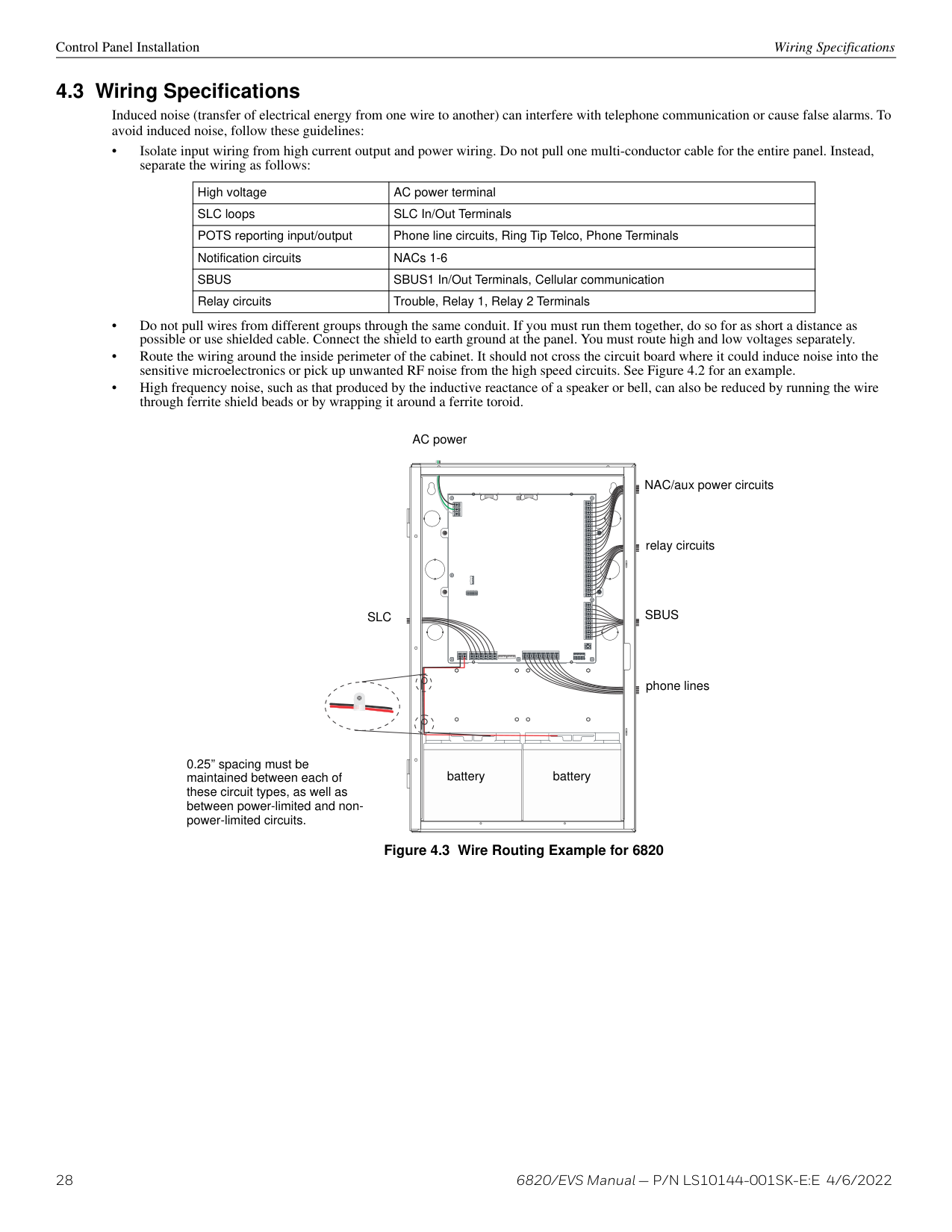
###### 4.3 Wiring Specifications
Induced noise (transfer of electrical energy from one wire to another) can interfere with telephone communication or cause false alarms. To avoid induced noise, follow these guidelines:
|High voltage|AC power terminal| |---|---| |SLC loops|SLC In/Out Terminals| |POTS reporting input/output|Phone line circuits, Ring Tip Telco, Phone Terminals| |Notification circuits|NACs 1-6| |SBUS|SBUS1 In/Out Terminals, Cellular communication| |Relay circuits|Trouble, Relay 1, Relay 2 Terminals|
AC power
NAC/aux power circuits
relay circuits
SLC
SBUS
phone lines
0.25” spacing must be maintained between each of these circuit types, as well as between power-limited and nonpower-limited circuits.
battery battery
Figure 4.3 Wire Routing Example for 6820
AC Power Connection Control Panel Installation
AC power
NAC/aux power circuits
relay circuits
SBUS
SLC
| | | |---|---| | | | | | |
phone lines
| | | | | | |---|---|---|---|---| | | | | | |
0.25” spacing must be maintained between each of these circuit types, as well as between power-limited and nonpower-limited circuits.
battery battery
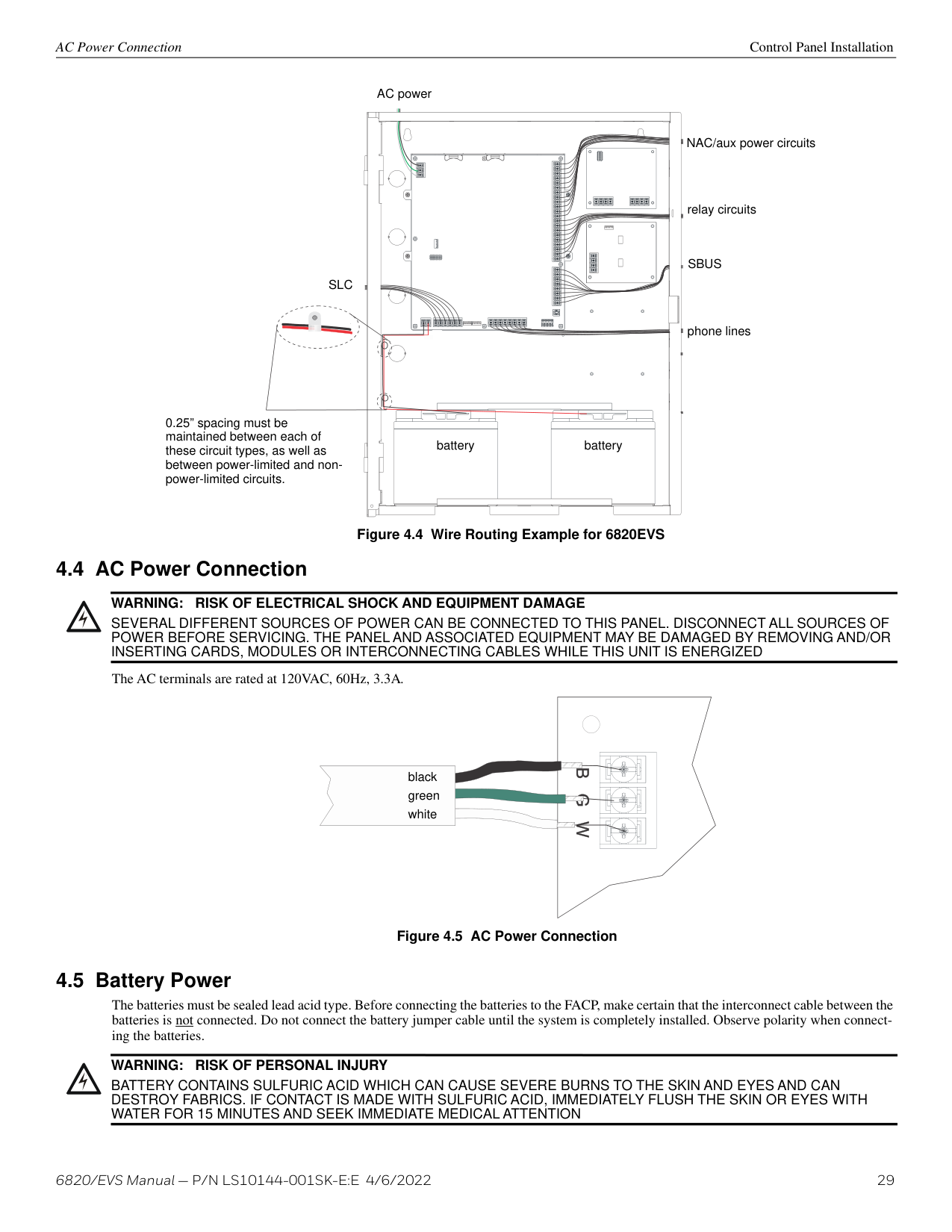
Figure 4.4 Wire Routing Example for 6820EVS
###### 4.4 AC Power Connection
WARNING: RISK OF ELECTRICAL SHOCK AND EQUIPMENT DAMAGE
!
SEVERAL DIFFERENT SOURCES OF POWER CAN BE CONNECTED TO THIS PANEL. DISCONNECT ALL SOURCES OF POWER BEFORE SERVICING. THE PANEL AND ASSOCIATED EQUIPMENT MAY BE DAMAGED BY REMOVING AND/OR INSERTING CARDS, MODULES OR INTERCONNECTING CABLES WHILE THIS UNIT IS ENERGIZED
The AC terminals are rated at 120VAC, 60Hz, 3.3A.

black green white


| | | |---|---|
| | |
Figure 4.5 AC Power Connection
###### 4.5 Battery Power
The batteries must be sealed lead acid type. Before connecting the batteries to the FACP, make certain that the interconnect cable between the batteries is not connected. Do not connect the battery jumper cable until the system is completely installed. Observe polarity when connecting the batteries.
WARNING: RISK OF PERSONAL INJURY
!
BATTERY CONTAINS SULFURIC ACID WHICH CAN CAUSE SEVERE BURNS TO THE SKIN AND EYES AND CAN DESTROY FABRICS. IF CONTACT IS MADE WITH SULFURIC ACID, IMMEDIATELY FLUSH THE SKIN OR EYES WITH WATER FOR 15 MINUTES AND SEEK IMMEDIATE MEDICAL ATTENTION
Control Panel Installation Battery Power
The control panel battery charge capacity is 7 to 35 AH. Use 12V batteries of the same AH rating. Determine the correct AH rating as per the standby load calculation (see Section 3.5).
Wire batteries in series to produce a 24-volt equivalent. Do not parallel batteries to increase the AH rating. It is recommended to replace batteries every five years.
| | | |---|---| | | |
| | | |---|---| | | |
| | | |---|---| | | |
| | | |---|---| | | |
| | | |---|---| | | |
– +
OUT– OUT+ IN– IN+
SLC
BATTERY
red black
battery jumper (P/N 140694) shipped with panel
_ _+
+
Figure 4.6 Battery Connection
######## 4.5.1 Battery Accessory Cabinets
Model RBB accessory cabinet can be used when your backup battery requirements use batteries that are too large to fit into the main control panel cabinet. The RBB cabinet holds batteries up to the 35 AH size. The RBB dimensions are 16" W x 10" H x 6" D (40.64 cm W x 25.4 cm H x 15.24 cm D).
Installing the RBB Accessory Cabinet and Batteries To properly install the accessory cabinet and backup batteries, follow these steps:
| | | | |---|---|---| | |cabinet mounting holes| | | | | |
Figure 4.7 RBB Cabinet Mounting Holes
| | | |---|---| | | | | | | | | | | | | | | | | | |
############# Figure 4.8 Splicing Control Panel Battery Cable to RBB Battery Cable Extenders
RBB cabinet cover screws
| | | |---|---| | | | | | |
| | | |---|---| | | | | | |
+ - + -
conduit
conduit coupler
| | | |---|---| | | | | | |
| | | |---|---| | | |
RBB cabinet cover screws
############# Figure 4.9 Battery Connections in the RBB Cabinet
NOTE: Figure 4.3 is an example of how the wire connections can be routed. However, any other cabinet knock-outs (on either the main control panel or the RBB cabinet), that are not previously being used may be utilized to connect conduit between the two cabinets.
| | | |---|---| | | | | | |
| | | |---|---| | | |
cabinet mounting holes
| | | |---|---| | | | | | |
| | | |---|---| | | | | | |
Figure 4.10 Cover Plate Mounting Keyholes and Cover Mounting Screws Alignment
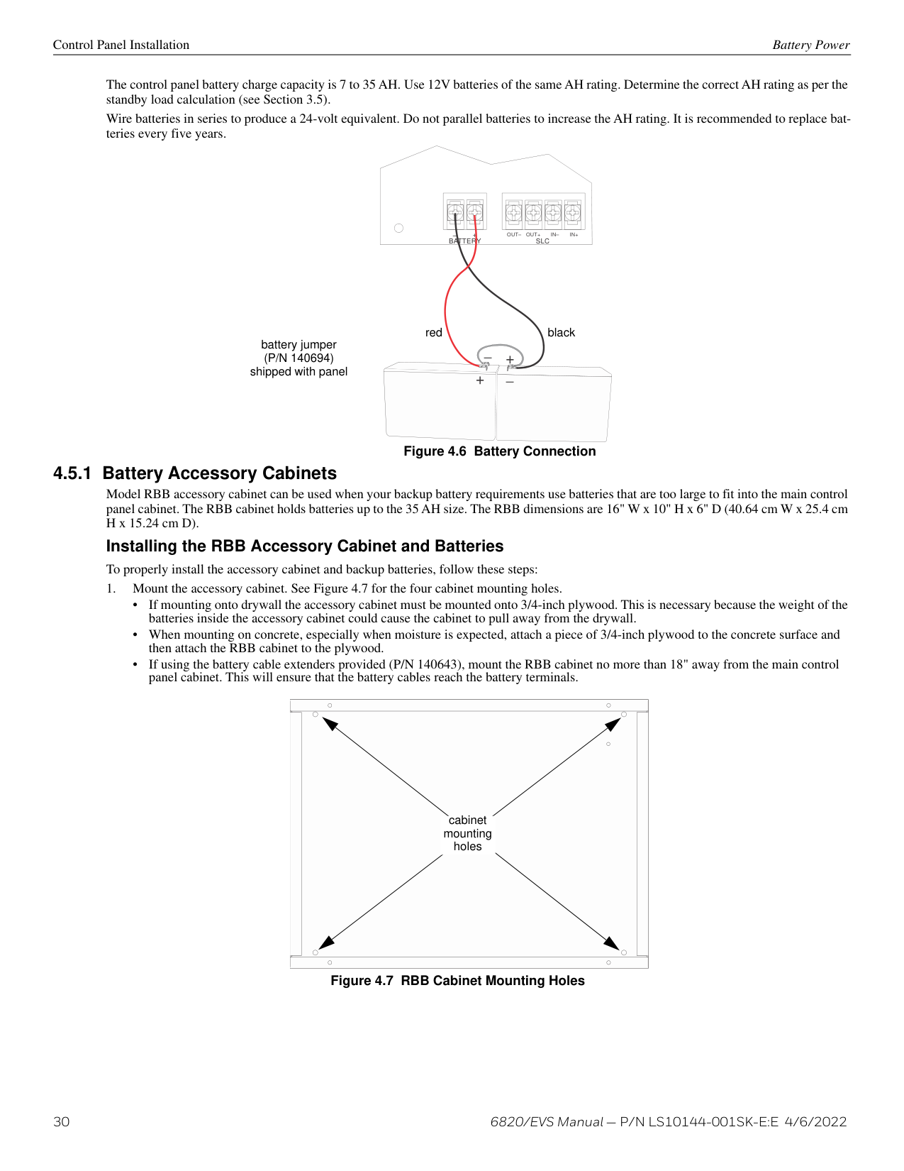
Control Panel Installation SBUS Wiring
######## 4.6.1 Calculating Wiring Distance for SBUS Modules
The following instructions will guide you in determining the type of wire and the maximum wiring distance that can be used with control panel SBUS accessory modules. To calculate the wire gauge that must be used to connect SBUS modules to the control panel, it is necessary to calculate the total worst case current draw for all modules on a single SBUS circuit. The total worst case current draw is calculated by adding the individual worst case currents for each module. The individual worst case values are shown in the table below. .
NOTE: Total worst case current draw on a single SBUS cannot exceed 1 amp. If a large number of accessory modules are required, and the worst case current draw will exceed the 1 amp limit, then the current draw must be distributed using 5895XL Power Expanders. Each 5895XL Power Expander provides an additional SBUS, with an additional 1 amp of SBUS current. Wiring distance calculations are done separately for each 5895XL, and separately for each control panel SBUS.
|Model Number|Worst Case Current Draw| |---|---| | | | |6860, 6855, 5860 Fire Annunciators|0.120 amps| |5815XL SLC Loop|0.150 amps| |6815 SLC Loop Expander|0.078 amps| |5824 Serial/Parallel Printer Interface Module|0.040 amps| |5880 LED I/O Module|0.250 amps| |5865 LED Annunciator|0.200 amps| |5895XL Intelligent Power Supply|0.010 amps| |5496 NAC Expander|0.010 amps| |EVS-50W|0.010 amps| |EVS-125W|0.010 amps| |EVS-VCM / EVS-VCM with EVS-SW241|0.080 amps /0.105 amps2| |EVS-LOC / EVS-LOC with EVS-SW241|0.080 amps / 0.105 amps2| |EVS-100W|0.010 amps| |EVS-100W with EVS-100WBU|0.010 amps| |SK-NIC Network Interface Card|0.021 amps| |CELL-MOD/CELL-CAB-SK|0.145 amps| |SK-F485C Fiber Converter|0.125 amps|
############# Table 4.1 SBUS Device Current Draw
NOTE: Refer to Table 3.2 for SK devices or Table 3.3 if using SD SLC devices for the maximum number of each type of device that can be used per system.
After calculating the total worst case current draw, refer to Table 4.2 below for the maximum distance the modules can be located from the panel on a single wire run. The table ensures 6.0 volts of line drop maximum. In general, the wire length is limited by resistance, but for heavier wire gauges, capacitance is the limiting factor.
These cases are marked in the chart with an asterisk (*). Maximum length can never be more than 6,000 feet, regardless of gauge used. The formula used to generate this chart is shown in the note below.The following formulas were used to generate the wire distance chart:
|Wiring Distance: SBUS Modules to Panel|Wiring Distance: SBUS Modules to Panel|Wiring Distance: SBUS Modules to Panel|Wiring Distance: SBUS Modules to Panel|Wiring Distance: SBUS Modules to Panel| |---|---|---|---|---| |Total Worst Case Current Draw (amps)|22 Gauge|18 Gauge|16 Gauge|14 Gauge| | | | | | | |0.100|1852 ft.|4688 ft.|* 6000 ft.|* 6000 ft.| |0.200|926 ft.|2344 ft.|3731 ft.|5906 ft.| |0.300|617 ft.|1563 ft.|2488 ft.|3937 ft.| |0.400|463 ft.|1172 ft.|1866 ft.|2953 ft.| |0.500|370 ft.|938 ft.|1493 ft.|2362 ft.| |0.600|309 ft.|781 ft.|1244 ft.|1969 ft.| |0.700|265 ft.|670 ft.|1066 ft.|1687 ft.| |0.800|231 ft.|586 ft.|933 ft.|1476 ft.| |0.900|206 ft.|521 ft.|829 ft.|1312 ft.|
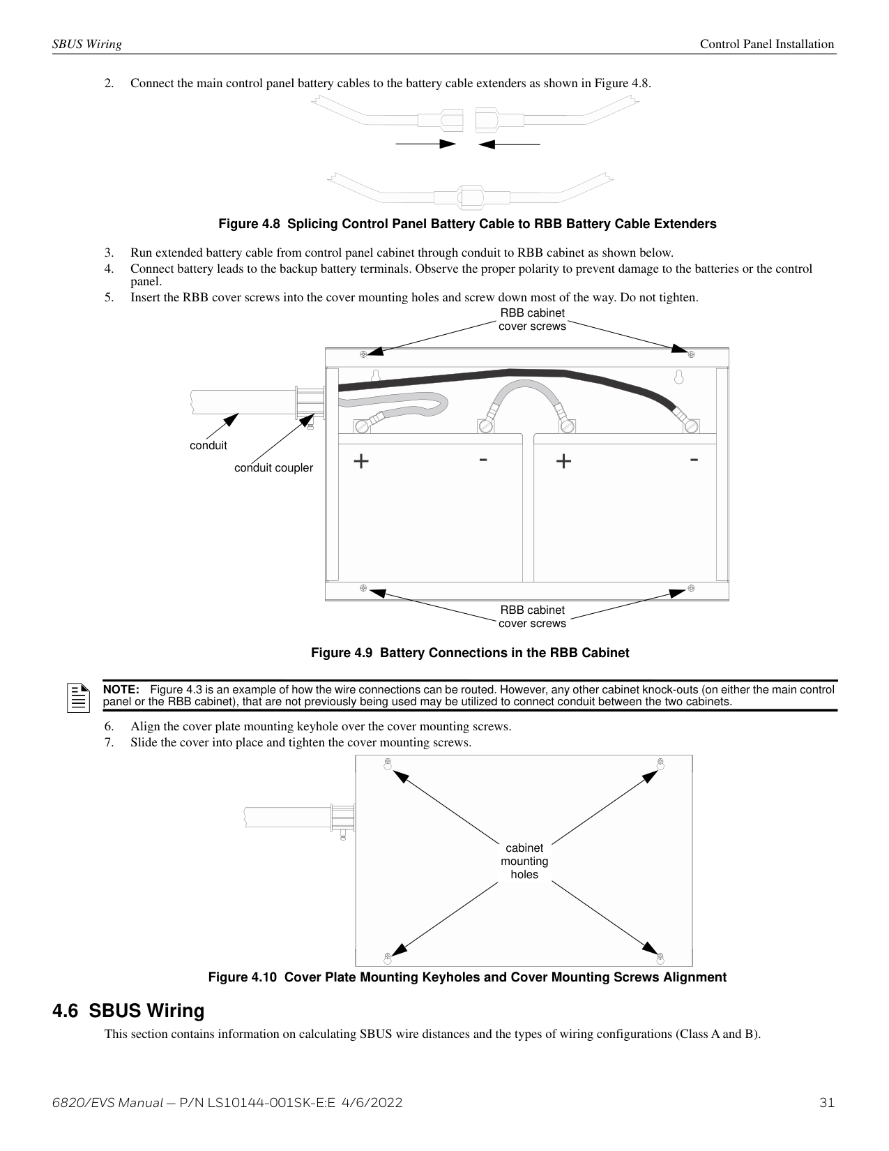
|1.000 (Max)|185 ft.|469 ft.|746 ft.|1181 ft.|
############# Table 4.2 Wire Distances Per Wire Gauge Using Copper Wire
Maximum Resistance (Ohms) = 6.0 Volts Total Worst Case Current Draw (amps)
Maximum Wire Length (Feet) = (6000 feet maximum)
Maximum Resistance (Ohms)
where: Rpu = Ohms per 1000 feet for various wire gauges (see table below)
|Wire Gauge|Ohms per 1000 feet (Rpu)| |---|---| | | | |22|16.2| |18|6.4| |16|4.02| |14|2.54|
############# Table 4.3 Typical Wire Resistance Per 1000 ft. Using Copper Wire
Wiring Distance calculation example: Suppose a system is configured with the following SBUS modules: 2 - Module 6860 Fire Annunciators 1 - 5895XL Intelligent Power Expander 1 - 5865 LED Annunciator 1 - 5824 Serial/Parallel Interface Module The total worst case current is calculated as follows:
|6860 Current Draw|= 2 x 0.120 amps|= 0.240 amps| |---|---|---| |5895XL Current Draw|= 1 x 0.010 amps|= 0.010 amps| |5865 Current Draw|= 1 x 0.200 amps|= 0.200 amps| |5824 Current Draw|= 1 x 0.040 amps|= 0.040 amps| |Total Worst Case Current Draw|Total Worst Case Current Draw|= 0.490 amps|
Table 4.4 Worst Case Current Draw NOTE: For assistance with SBUS calculations, please refer to www.silentknight.com.
Using this value, and referring to the Wiring Distance table, it can be found that the available options are: 370 feet maximum using 22 Gauge wire 938 feet maximum using 18 Gauge wire[
1493 feet maximum using 16 Gauge wire 2,362 feet maximum using 14 Gauge wire
SBUS OUTSBUS IN- +A B- +A B
FACP
SBUS device
| | | |---|---| | | |
| | |
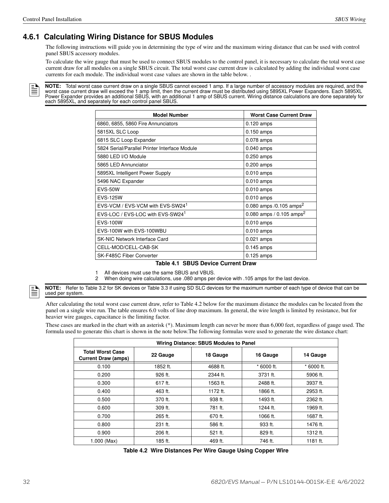
|---|---| | | |
| | | | |---|---|---| | | | | | | | | | | | | | | | | | | | |
For proper system supervision do not use looped wire under terminals marked A, B, +, and - of the SBUS device connectors. Break wire runs to provide supervision of connections.
supervised, power-limited
EXT. COMM
Figure 4.11 SBUS Class A Wiring
SBUS OUTSBUS IN- +A B- +A B
FACP
| | | |---|---| | | |
| | | |---|---| | | |
SBUS device
| | | |---|---| | | |
| | | |---|---| | | |
| | | | |---|---|---| | | | | | | | | | | | | | | | | | | | |
supervised, power-limited
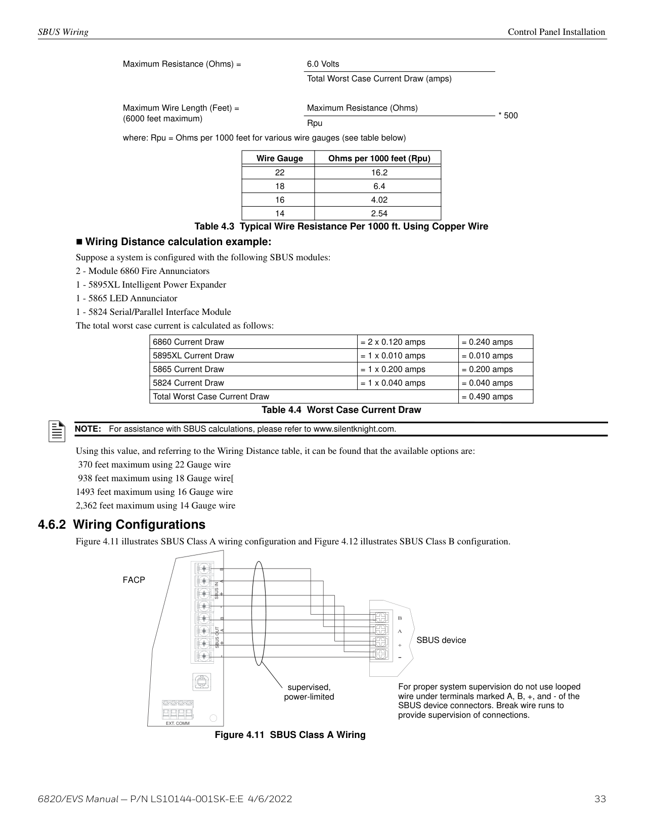
EXT. COMM
############# Figure 4.12 SBUS Class B Wiring
###### 4.7 6855 Remote Annunciator Installation
The optional model 6855 Remote Annunciator, is shown in Figure 4.13. The 6855 can be surface or flush mounted. Up to 12 annunciators can be added to the 6808 system in any combination.
| | || | |---| | | |Model 6855

| | |---|---|---| | | || | |---| | | |Model 6855

| | | | || | |---| | | |Model 6855

| | | | || | |---| | | |Model 6855

| | | | || | |---| | | |Model 6855

| | | | || | |---| | | |Model 6855

| | | | || | |---| | | |Model 6855

| | | | || | |---| | | |Model 6855

| | | | || | |---| | | |Model 6855

| | | | || | |---|
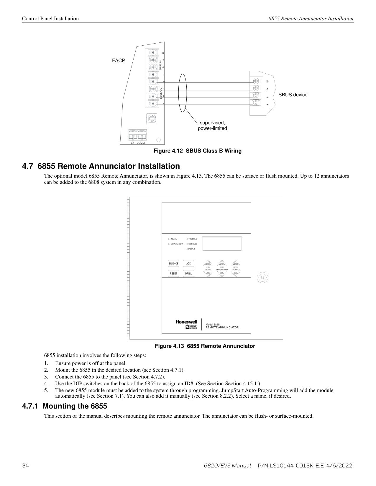
| | |Model 6855

| | | | || | |---| | | |Model 6855

| | | | || | |---| | | |Model 6855

| | | | || | |---| | | |Model 6855

| | | | || | |---| | | |Model 6855

| | | | || | |---| | | |Model 6855

| | | | || | |---| | | |Model 6855

| | | | || | |---| | | |Model 6855

| | | | || | |---| | | |Model 6855

| | | | || | |---| | | |Model 6855

| | | | || | |---| | | |Model 6855

| | | | || | |---| | | |Model 6855

|
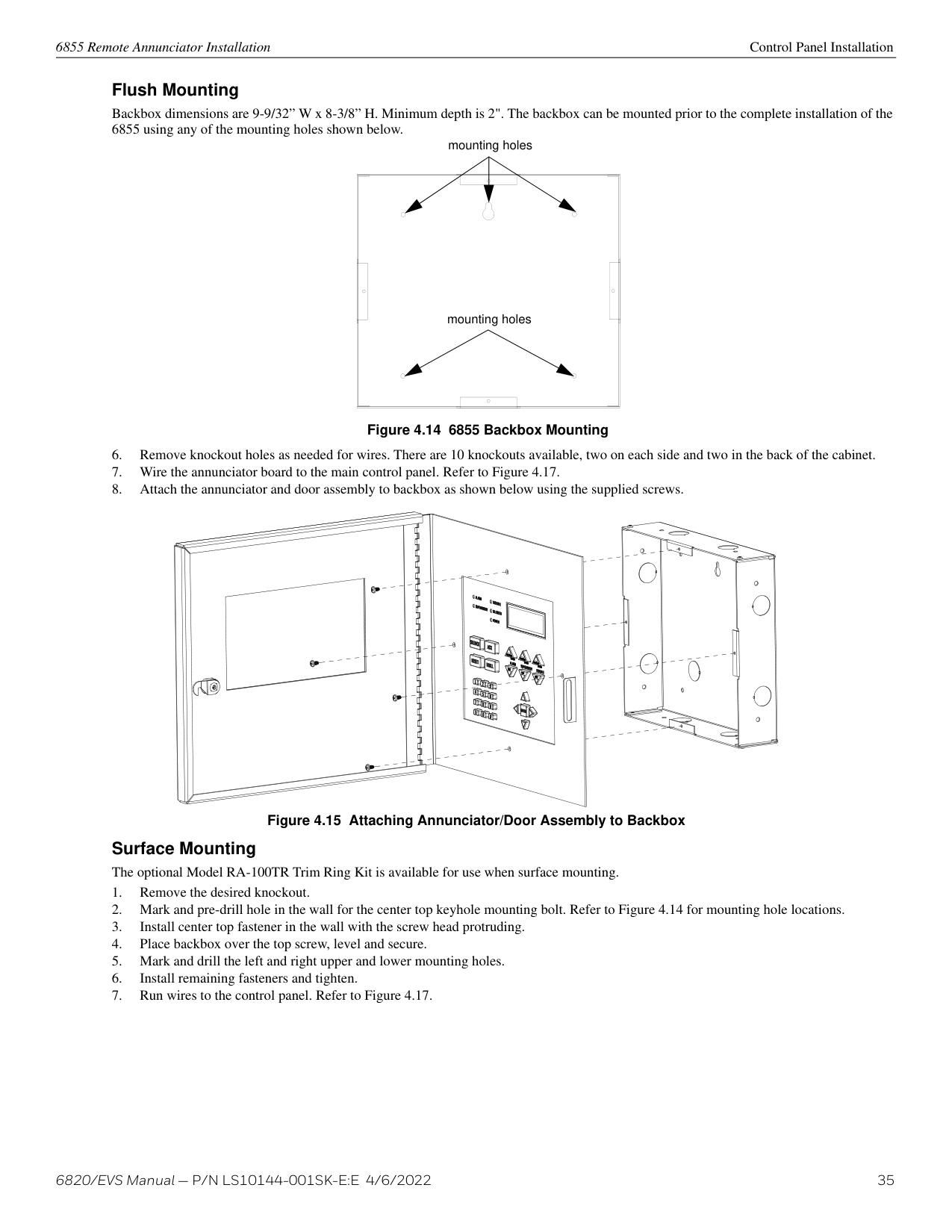
| | | || | |---| | | |Model 6855

| | | | || | |---| | | |Model 6855

| | | | || | |---| | | |Model 6855

| | | | || | |---| | | |Model 6855

| | | | || | |---| | | |Model 6855

| | | | || | |---| | | |Model 6855

| | | | || | |---| | | |Model 6855

| | | | || | |---| | | |Model 6855

| | | | || | |---| | | |Model 6855

| | | | || | |---| | | |Model 6855

| | | | || | |---| | | |Model 6855

| | | | || |
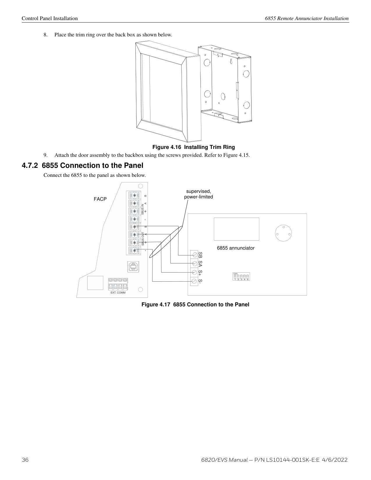
|---| | | |Model 6855

| | | | || | |---| | | |Model 6855

| | | | || | |---| | | |Model 6855

| | | | || | |---| | | |Model 6855

| | | | || | |---| | | |Model 6855

| | | | || | |---| | | |Model 6855

| | | | || | |---| | | |Model 6855

| | | | || | |---| | | |Model 6855

| | | | || | |---| | | |Model 6855

| | | | || | |---| | | |Model 6855

| | | | || | |---| | | |Model 6855

| | | | || | |---| | |
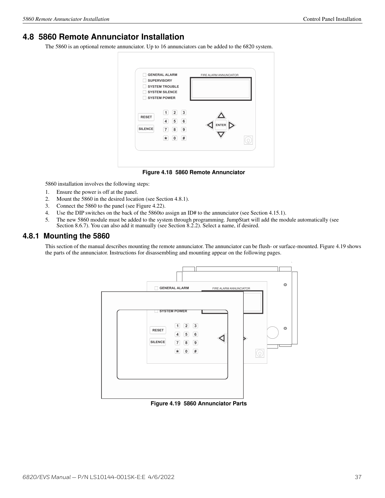
|Model 6855

| | | | || | |---| | | |Model 6855

| | | | || | |---| | | |Model 6855

| |
############# Figure 4.13 6855 Remote Annunciator
6855 installation involves the following steps:
6855 Remote Annunciator Installation Control Panel Installation
########## Flush Mounting
Backbox dimensions are 9-9/32” W x 8-3/8” H. Minimum depth is 2". The backbox can be mounted prior to the complete installation of the 6855 using any of the mounting holes shown below.
mounting holes
mounting holes
Figure 4.14 6855 Backbox Mounting
Figure 4.15 Attaching Annunciator/Door Assembly to Backbox
Surface Mounting The optional Model RA-100TR Trim Ring Kit is available for use when surface mounting.
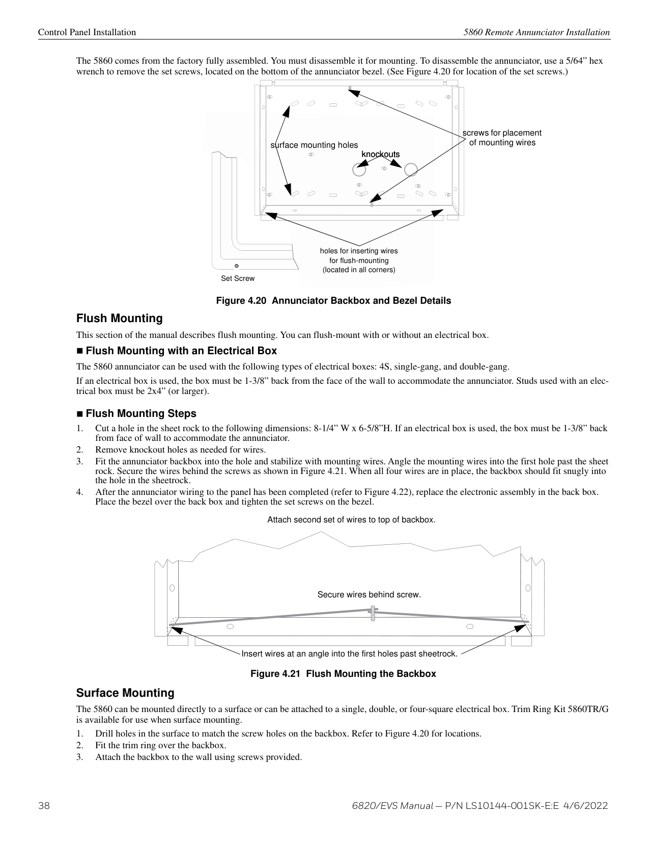
Figure 4.16 Installing Trim Ring
supervised, power-limitedFACP
SBUS OUTSBUS IN- +A B- +A B
6855 annunciator
SBSAS+S-
EXT. COMM
Figure 4.17 6855 Connection to the Panel
5860 Remote Annunciator Installation Control Panel Installation
|FIRE ALARM ANNUNCIATOR| |---|
############# Figure 4.18 5860 Remote Annunciator
5860 installation involves the following steps:
######## 4.8.1 Mounting the 5860
This section of the manual describes mounting the remote annunciator. The annunciator can be flush- or surface-mounted. Figure 4.19 shows the parts of the annunciator. Instructions for disassembling and mounting appear on the following pages.
FIRE ALARM ANNUNCIATOR
############# Figure 4.19 5860 Annunciator Parts
Control Panel Installation 5860 Remote Annunciator Installation
The 5860 comes from the factory fully assembled. You must disassemble it for mounting. To disassemble the annunciator, use a 5/64” hex wrench to remove the set screws, located on the bottom of the annunciator bezel. (See Figure 4.20 for location of the set screws.)
screws for placement of mounting wires
surface mounting holes
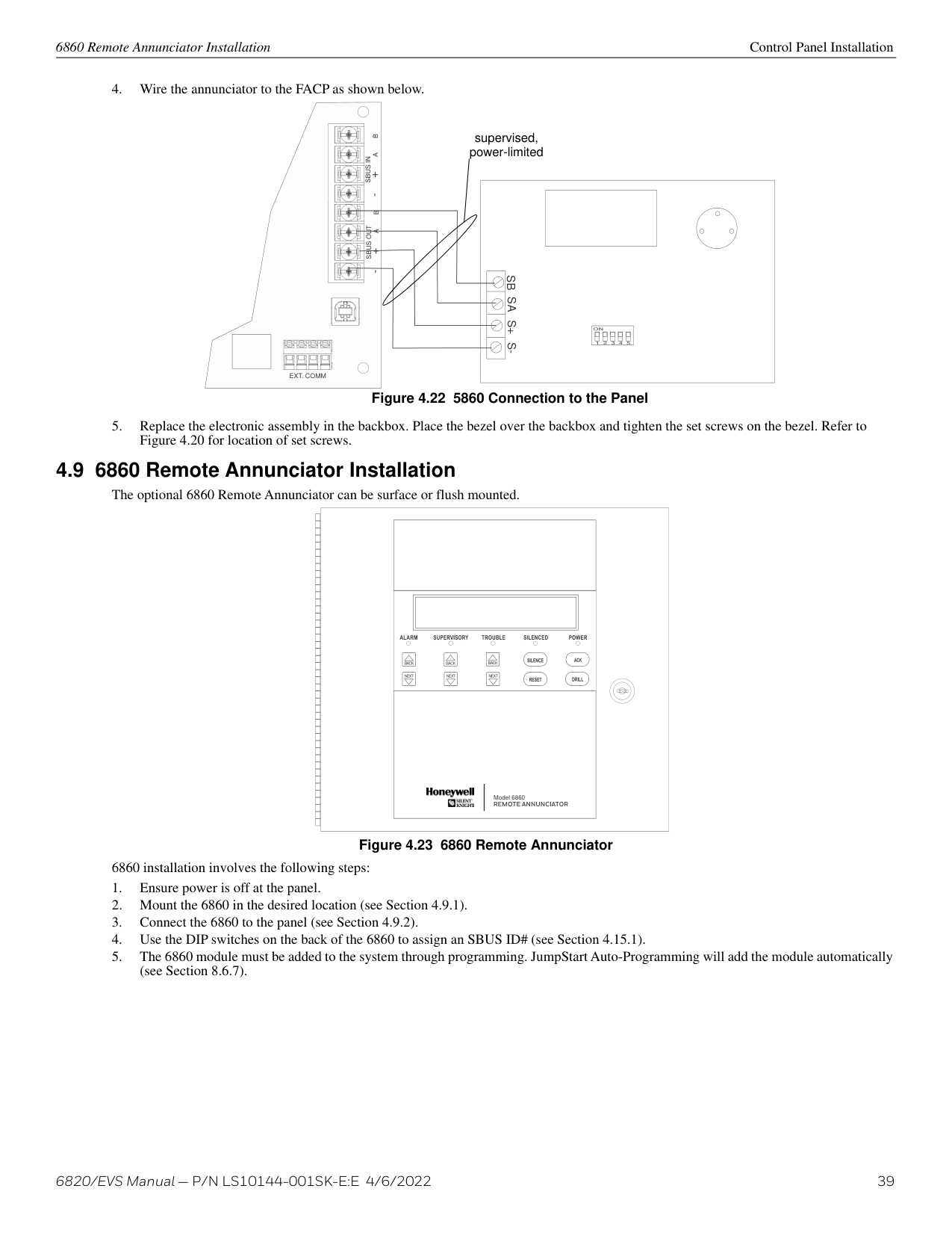
knockouts
holes for inserting wires for flush-mounting (located in all corners)
Set Screw
############# Figure 4.20 Annunciator Backbox and Bezel Details
Flush Mounting This section of the manual describes flush mounting. You can flush-mount with or without an electrical box.
Flush Mounting with an Electrical Box The 5860 annunciator can be used with the following types of electrical boxes: 4S, single-gang, and double-gang. If an electrical box is used, the box must be 1-3/8” back from the face of the wall to accommodate the annunciator. Studs used with an electrical box must be 2x4” (or larger).
########### Flush Mounting Steps
Attach second set of wires to top of backbox.
|Secure wires behind screw.
|Secure wires behind screw.
|Secure wires behind screw.
|Secure wires behind screw.
|Secure wires behind screw.
| |---|---|---|---|---| | | | | | |
Insert wires at an angle into the first holes past sheetrock.
############# Figure 4.21 Flush Mounting the Backbox
########## Surface Mounting
The 5860 can be mounted directly to a surface or can be attached to a single, double, or four-square electrical box. Trim Ring Kit 5860TR/G is available for use when surface mounting.
6860 Remote Annunciator Installation Control Panel Installation
supervised, power-limited
SBUS OUTSBUS IN- +A B- +A B
SBSAS+S-
| | | |---|---| | | | | | |
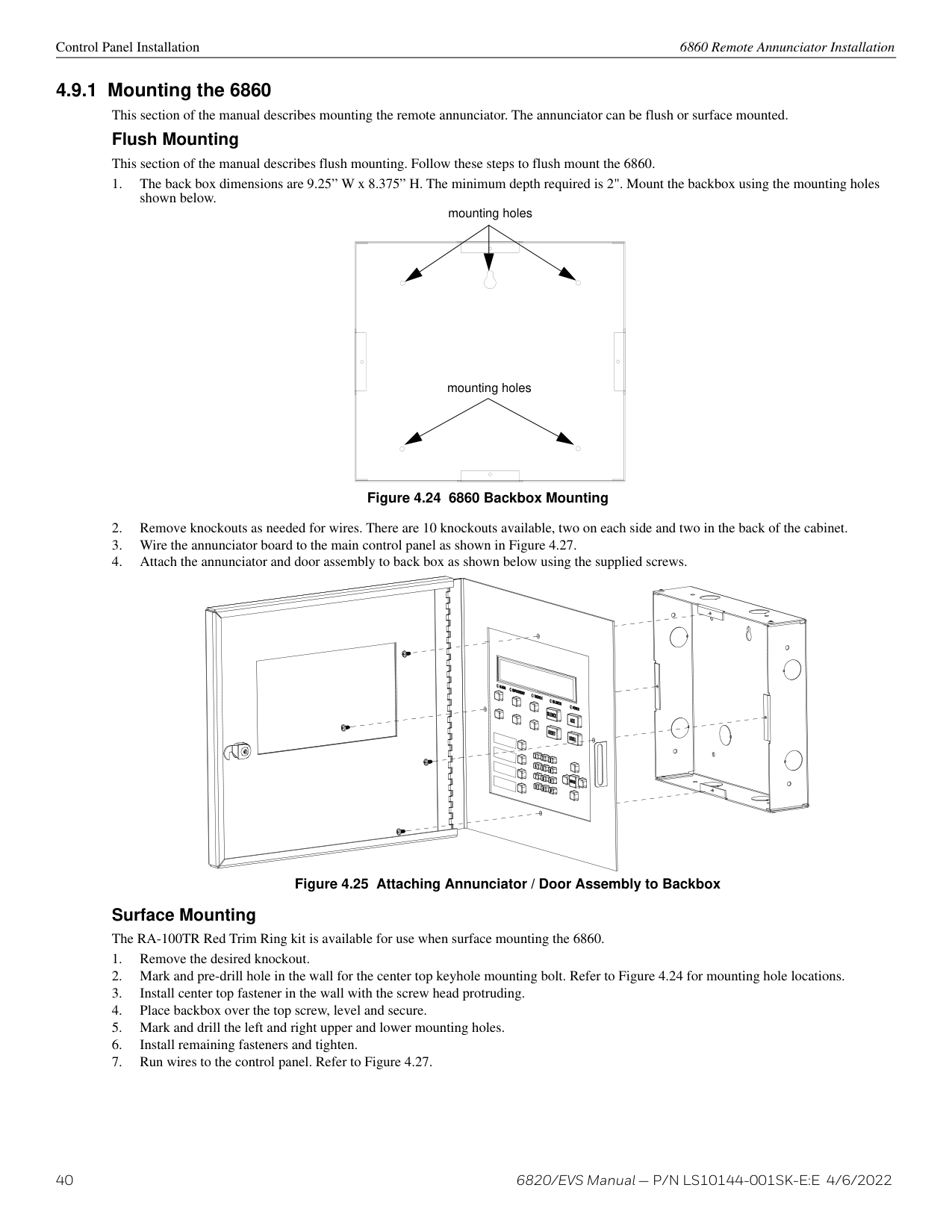
| | | | | |
EXT. COMM
############# Figure 4.22 5860 Connection to the Panel
| | || | |---| ||BACK| |---|
|BACK| |---|
BACK
|NEXT| |---|
|NEXT| |---|
NEXT| |Model 6860

| | |---|---|---| | | || | |---| ||BACK| |---|
|BACK| |---|
BACK
|NEXT| |---|
|NEXT| |---|
NEXT| |Model 6860

| | | | || | |---| ||BACK| |---|
|BACK| |---|
BACK
|NEXT| |---|
|NEXT| |---|
NEXT| |Model 6860

| | | | || | |---| ||BACK| |---|
|BACK| |---|
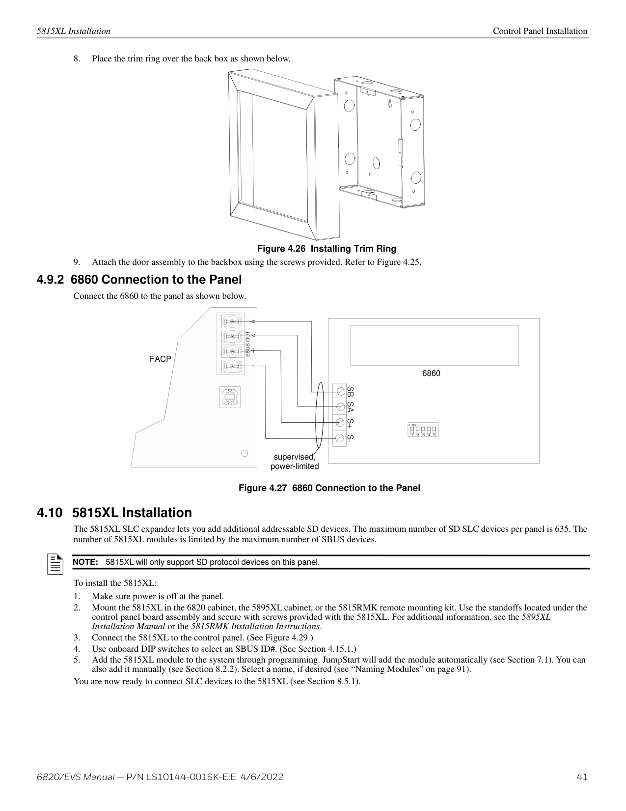
BACK
|NEXT| |---|
|NEXT| |---|
NEXT| |Model 6860

| | | | || | |---| ||BACK| |---|
|BACK| |---|
BACK
|NEXT| |---|
|NEXT| |---|
NEXT| |Model 6860

| | | | || | |---| ||BACK| |---|
|BACK| |---|
BACK
|NEXT| |---|
|NEXT| |---|
NEXT| |Model 6860

| | | | || | |---| ||BACK| |---|
|BACK| |---|
BACK
|NEXT| |---|
|NEXT| |---|
NEXT| |Model 6860

| | | | || | |---| ||BACK| |---|
|BACK| |---|
BACK
|NEXT| |---|
|NEXT| |---|
NEXT|
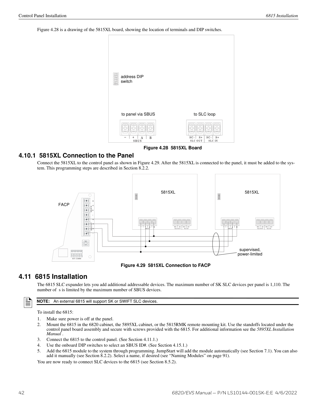
|Model 6860

| | | | || | |---| ||BACK| |---|
|BACK| |---|
BACK
|NEXT| |---|
|NEXT| |---|
NEXT| |Model 6860

| | | | || | |---| ||BACK| |---|
|BACK| |---|
BACK
|NEXT| |---|
|NEXT| |---|
NEXT| |Model 6860

| | | | || | |---| ||BACK| |---|
|BACK| |---|
BACK
|NEXT| |---|
|NEXT| |---|
NEXT| |Model 6860

| | | | || | |---| ||BACK| |---|
|BACK| |---|
BACK
|NEXT| |---|
|NEXT| |---|
NEXT| |Model 6860

| | | | || | |---| ||BACK|
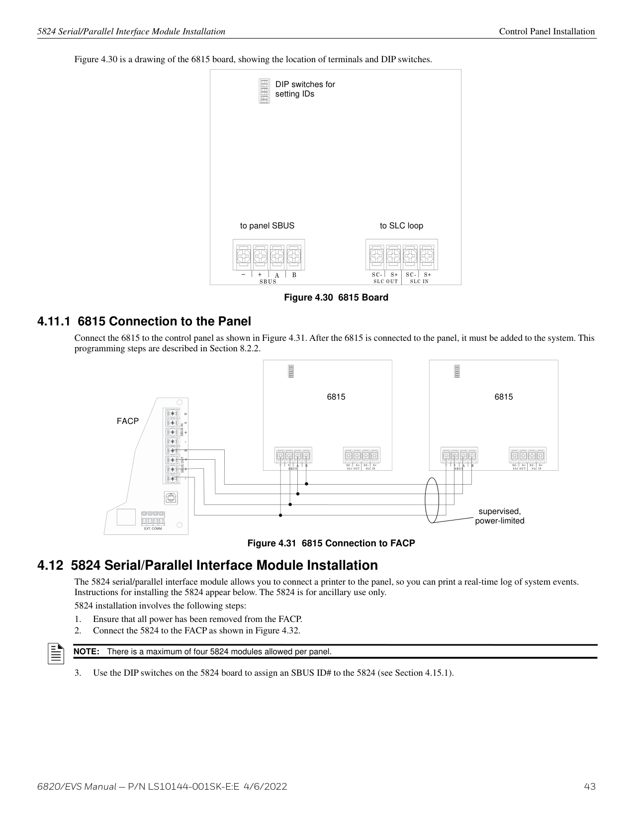
|---|
|BACK| |---|
BACK
|NEXT| |---|
|NEXT| |---|
NEXT| |Model 6860

| | | | || | |---| ||BACK| |---|
|BACK| |---|
BACK
|NEXT| |---|
|NEXT| |---|
NEXT| |Model 6860

| | | | || | |---| ||BACK| |---|
|BACK| |---|
BACK
|NEXT| |---|
|NEXT| |---|
NEXT| |Model 6860

| | | | || | |---| ||BACK| |---|
|BACK| |---|
BACK
|NEXT| |---|
|NEXT| |---|
NEXT| |Model 6860

| | | | || | |---| ||BACK| |---|
|BACK| |---|
BACK
|NEXT| |---|
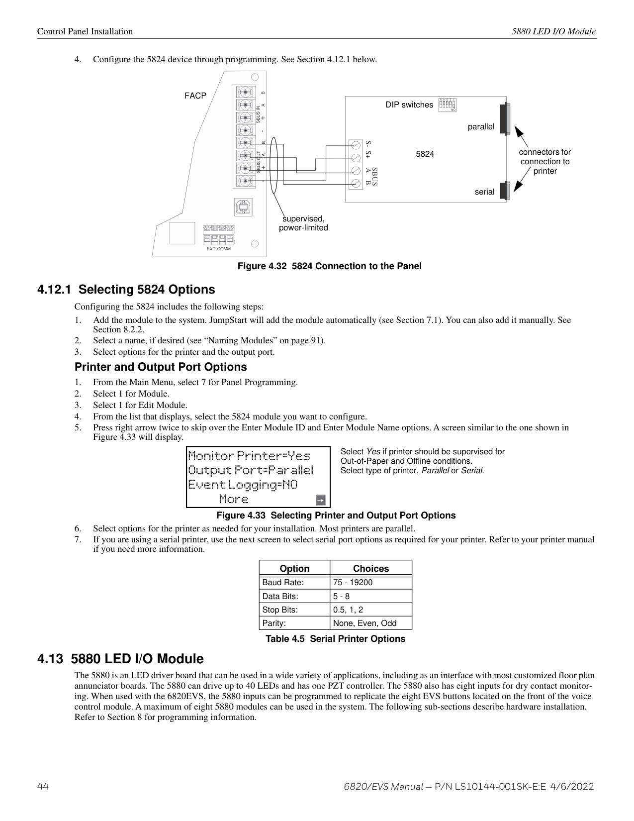
|NEXT| |---|
NEXT| |Model 6860

| | | | || | |---| ||BACK| |---|
|BACK| |---|
BACK
|NEXT| |---|
|NEXT| |---|
NEXT| |Model 6860

| | | | || | |---| ||BACK| |---|
|BACK| |---|
BACK
|NEXT| |---|
|NEXT| |---|
NEXT| |Model 6860

| | | | || | |---| ||BACK| |---|
|BACK| |---|
BACK
|NEXT| |---|
|NEXT| |---|
NEXT| |Model 6860

| | | | || | |---| ||BACK| |---|
|BACK| |---|
BACK
|NEXT| |---|
|NEXT| |---|
NEXT| |Model 6860

| |
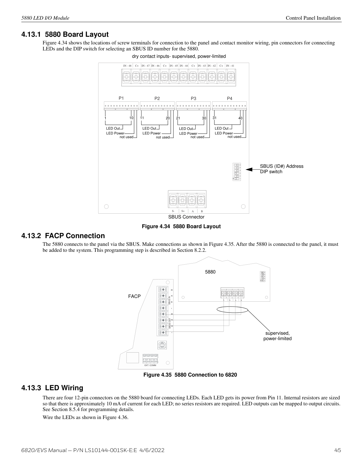
| | || | |---| ||BACK| |---|
|BACK| |---|
BACK
|NEXT| |---|
|NEXT| |---|
NEXT| |Model 6860

| | | | || | |---| ||BACK| |---|
|BACK| |---|
BACK
|NEXT| |---|
|NEXT| |---|
NEXT| |Model 6860

| | | | || | |---| ||BACK| |---|
|BACK| |---|
BACK
|NEXT| |---|
|NEXT| |---|
NEXT| |Model 6860

| | | | || | |---| ||BACK| |---|
|BACK| |---|
BACK
|NEXT| |---|
|NEXT| |---|
NEXT| |Model 6860

| | | | || | |---| ||BACK| |---|
|BACK|
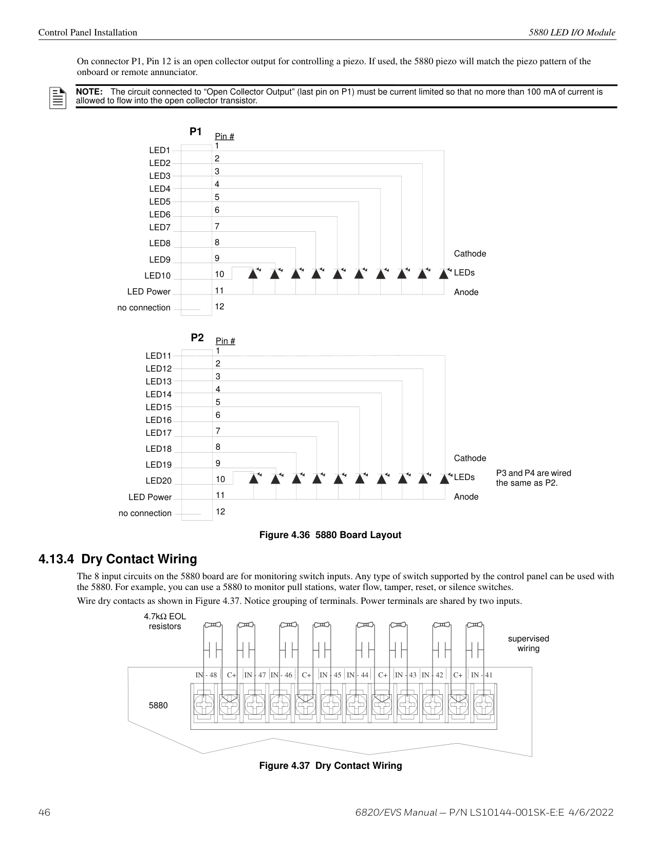
|---|
BACK
|NEXT| |---|
|NEXT| |---|
NEXT| |Model 6860

| | | | || | |---| ||BACK| |---|
|BACK| |---|
BACK
|NEXT| |---|
|NEXT| |---|
NEXT| |Model 6860

| | | | || | |---| ||BACK| |---|
|BACK| |---|
BACK
|NEXT| |---|
|NEXT| |---|
NEXT| |Model 6860

| | | | || | |---| ||BACK| |---|
|BACK| |---|
BACK
|NEXT| |---|
|NEXT| |---|
NEXT| |Model 6860

| | | | || | |---| ||BACK| |---|
|BACK| |---|
BACK
|NEXT| |---|
|NEXT| |---|
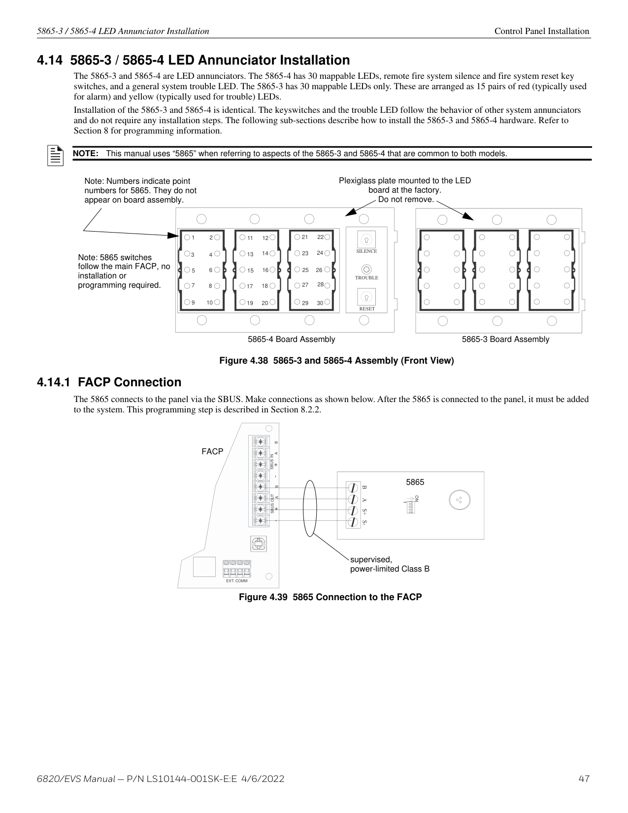
NEXT| |Model 6860

| | | | || | |---| ||BACK| |---|
|BACK| |---|
BACK
|NEXT| |---|
|NEXT| |---|
NEXT| |Model 6860

| | | | || | |---| ||BACK| |---|
|BACK| |---|
BACK
|NEXT| |---|
|NEXT| |---|
NEXT| |Model 6860

| | | | || | |---| ||BACK| |---|
|BACK| |---|
BACK
|NEXT| |---|
|NEXT| |---|
NEXT| |Model 6860

| | | | || | |---| ||BACK| |---|
|BACK| |---|
BACK
|NEXT| |---|
|NEXT| |---|
NEXT| |Model 6860

| | | | || | |---|
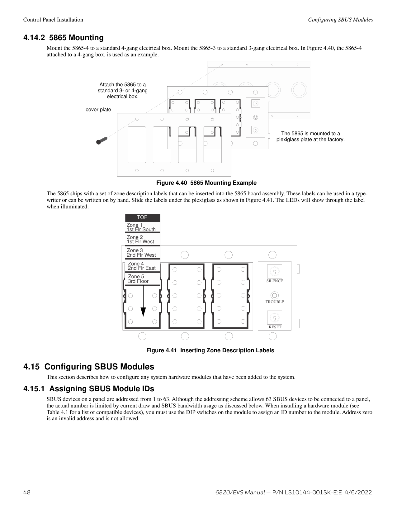
||BACK| |---|
|BACK| |---|
BACK
|NEXT| |---|
|NEXT| |---|
NEXT| |Model 6860

| | | | || | |---| ||BACK| |---|
|BACK| |---|
BACK
|NEXT| |---|
|NEXT| |---|
NEXT| |Model 6860

| | | | || | |---| ||BACK| |---|
|BACK| |---|
BACK
|NEXT| |---|
|NEXT| |---|
NEXT| |Model 6860

| | | | || | |---| ||BACK| |---|
|BACK| |---|
BACK
|NEXT| |---|
|NEXT| |---|
NEXT| |Model 6860

| | | | || | |---| ||BACK| |---|
|BACK| |---|
BACK
|NEXT|
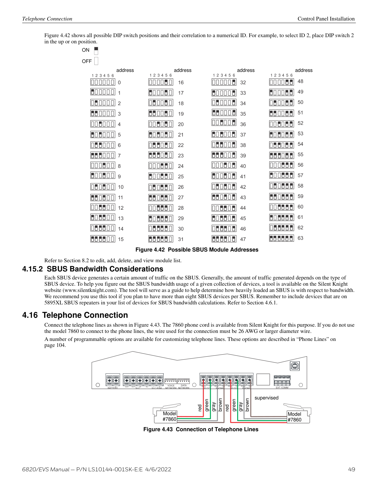
|---|
|NEXT| |---|
NEXT| |Model 6860

| | | | || | |---| ||BACK| |---|
|BACK| |---|
BACK
|NEXT| |---|
|NEXT| |---|
NEXT| |Model 6860

| | | | || | |---| ||BACK| |---|
|BACK| |---|
BACK
|NEXT| |---|
|NEXT| |---|
NEXT| |Model 6860

| | | | || | |---| ||BACK| |---|
|BACK| |---|
BACK
|NEXT| |---|
|NEXT| |---|
NEXT| |Model 6860

| | | | || | |---| ||BACK| |---|
|BACK| |---|
BACK
|NEXT| |---|
|NEXT| |---|
NEXT| |Model 6860

|
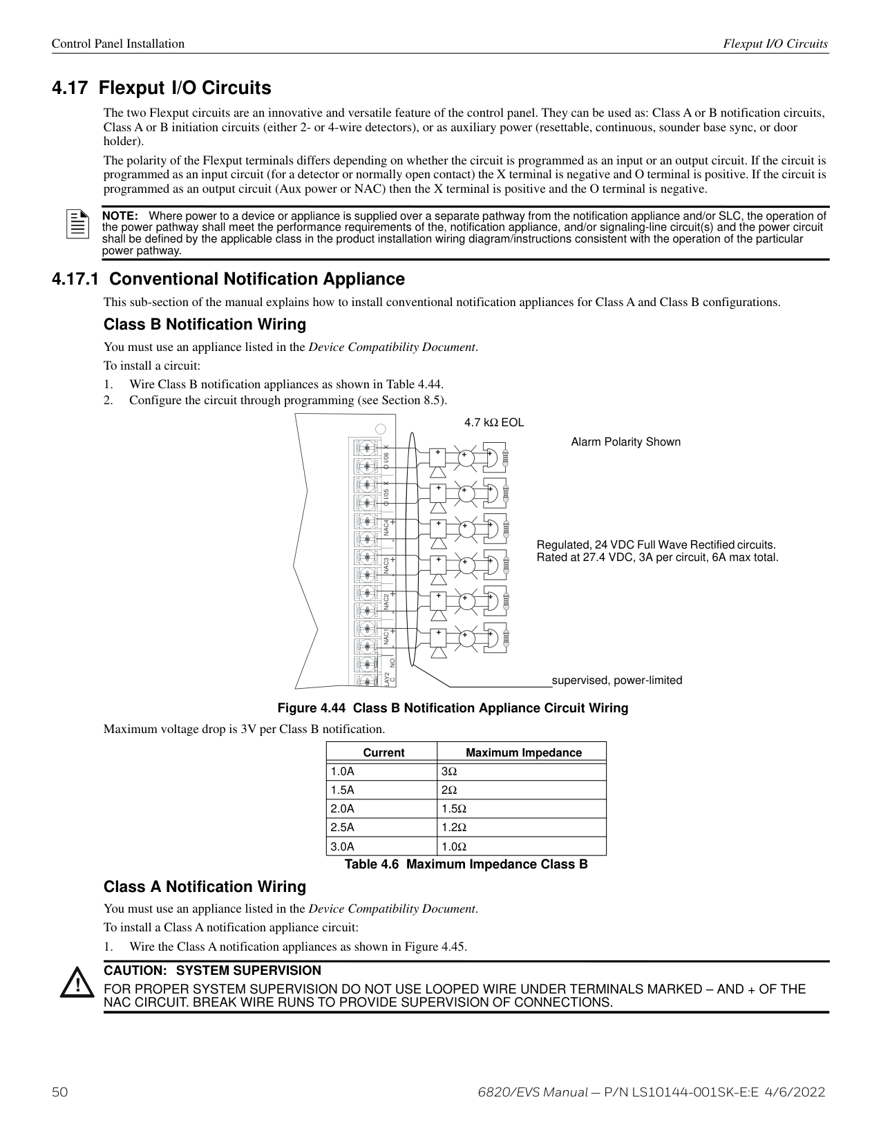
| | | || | |---| ||BACK| |---|
|BACK| |---|
BACK
|NEXT| |---|
|NEXT| |---|
NEXT| |Model 6860

| | | | || | |---| ||BACK| |---|
|BACK| |---|
BACK
|NEXT| |---|
|NEXT| |---|
NEXT| |Model 6860

| | | | || | |---| ||BACK| |---|
|BACK| |---|
BACK
|NEXT| |---|
|NEXT| |---|
NEXT| |Model 6860

| |
############# Figure 4.23 6860 Remote Annunciator
6860 installation involves the following steps:
Control Panel Installation 6860 Remote Annunciator Installation
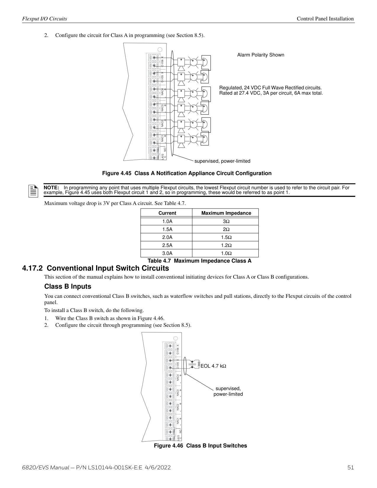
mounting holes
mounting holes
Figure 4.24 6860 Backbox Mounting
Figure 4.25 Attaching Annunciator / Door Assembly to Backbox
Surface Mounting The RA-100TR Red Trim Ring kit is available for use when surface mounting the 6860.
5815XL Installation Control Panel Installation
############# Figure 4.26 Installing Trim Ring
FACP
SBUS OUT- +A B
| | | | |---|---|---| | | | | | | | | | | | | | | | | | | | |
supervised, power-limited
SBSAS+S-
6860
Figure 4.27 6860 Connection to the Panel
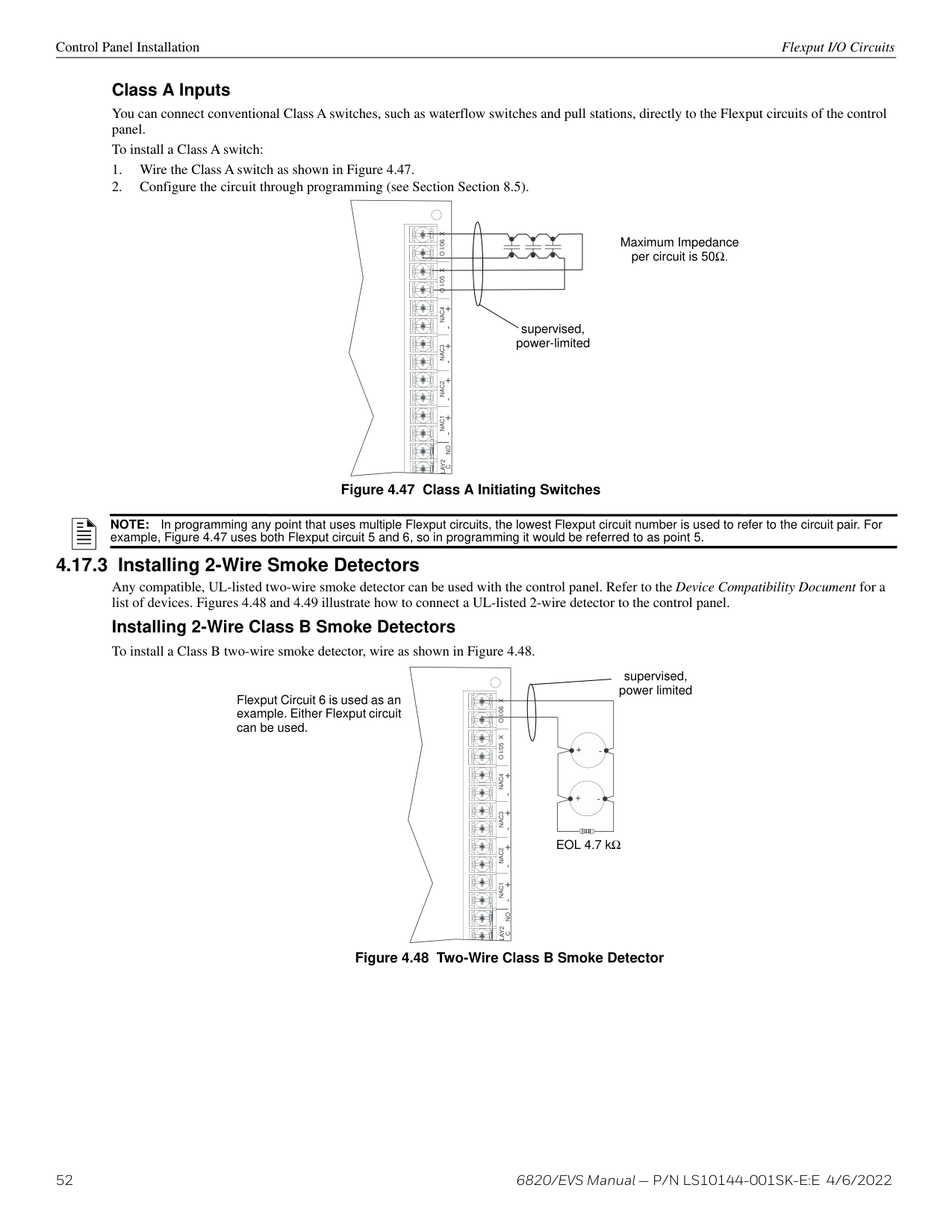
###### 4.10 5815XL Installation
The 5815XL SLC expander lets you add additional addressable SD devices. The maximum number of SD SLC devices per panel is 635. The number of 5815XL modules is limited by the maximum number of SBUS devices.
NOTE: 5815XL will only support SD protocol devices on this panel.
To install the 5815XL:
You are now ready to connect SLC devices to the 5815XL (see Section 8.5.1).
Control Panel Installation 6815 Installation
Figure 4.28 is a drawing of the 5815XL board, showing the location of terminals and DIP switches.
ON
address DIP switch
1234
to panel via SBUS to SLC loop
| | | |---|---| | | |
| | | |---|---| | | |
| | | |---|---| | | |
| | | |---|---| | | |
| | | |---|---| | | |
| | | |---|---|
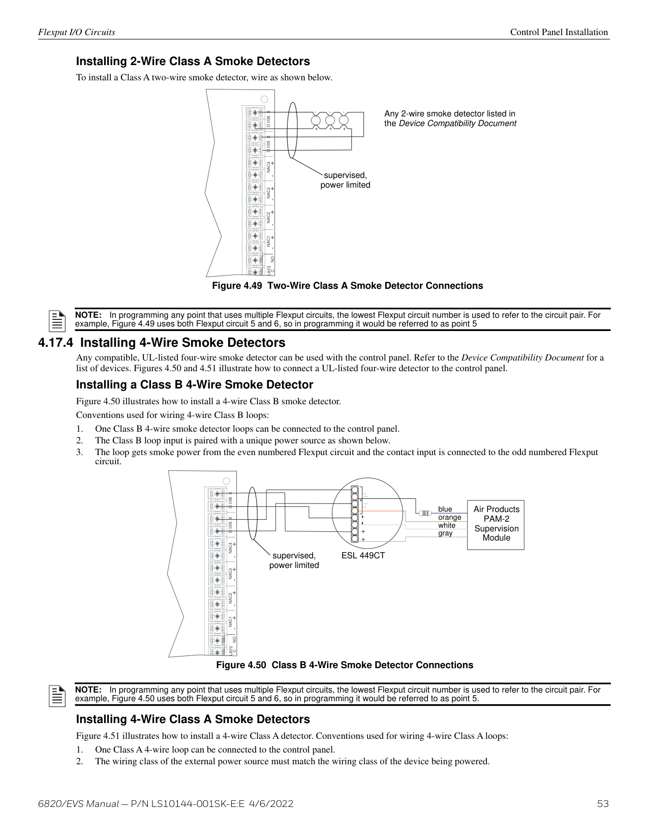
| | |
| | | |---|---| | | |
| | | |---|---| | | |
################# – + A B
####################### S+ SC- S+SC-
SBUS
SLC OUT
SLC IN
Figure 4.28 5815XL Board
######## 4.10.1 5815XL Connection to the Panel
Connect the 5815XL to the control panel as shown in Figure 4.29. After the 5815XL is connected to the panel, it must be added to the system. This programming steps are described in Section 8.2.2.
5815XL 5815XL
ON
ON
12345
12345
SBUS OUTSBUS IN- +A B- +A B
FACP
######################## – + A B
######################## – + A B
########################## S+ SC- S+SC-
########################## S+ SC- S+SC-
SBUS
SBUS
SLCOUT
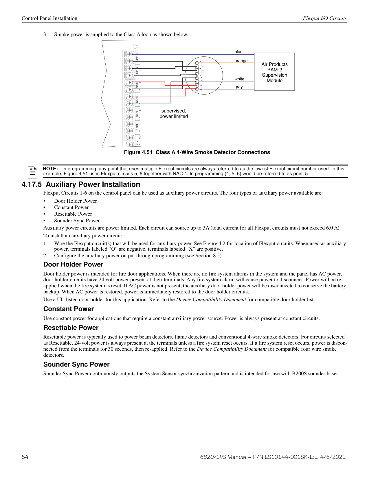
SLCIN
SLCOUT
SLCIN
supervised, power-limited
EXT. COMM
############# Figure 4.29 5815XL Connection to FACP
###### 4.11 6815 Installation
The 6815 SLC expander lets you add additional addressable devices. The maximum number of SK SLC devices per panel is 1,110. The number of s is limited by the maximum number of SBUS devices.
NOTE: An external 6815 will support SK or SWIFT SLC devices.
To install the 6815:
add it manually (see Section 8.2.2). Select a name, if desired (see “Naming Modules” on page 91). You are now ready to connect SLC devices to the 6815 (see Section 8.5.2).
5824 Serial/Parallel Interface Module Installation Control Panel Installation
Figure 4.30 is a drawing of the 6815 board, showing the location of terminals and DIP switches.
DIP switches for setting IDs
ON
12345
to panel SBUS to SLC loop
| | | |---|---| | | |
| | | |---|---| | | |
| | | |---|---| | | |
| | |
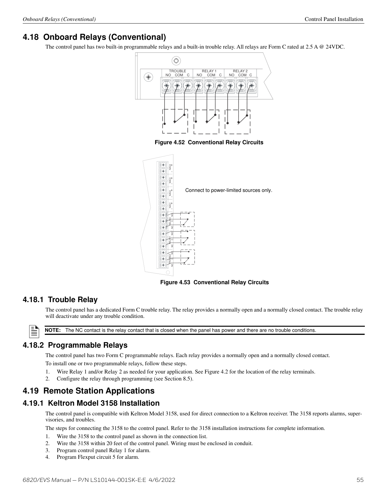
|---|---| | | |
| | | |---|---| | | |
| | | |---|---| | | |
| | | |---|---| | | |
| | | |---|---| | | |
################ – + A B
###################### S+ SC- S+SC-
SBUS
SLC OUT
SLC IN
############# Figure 4.30 6815 Board
######## 4.11.1 6815 Connection to the Panel
Connect the 6815 to the control panel as shown in Figure 4.31. After the 6815 is connected to the panel, it must be added to the system. This programming steps are described in Section 8.2.2.
ON EXT. COMM
ON
12345
6815 6815
SBUS OUTSBUS IN- +A B- +A B
FACP
| | | |---|---| | | |
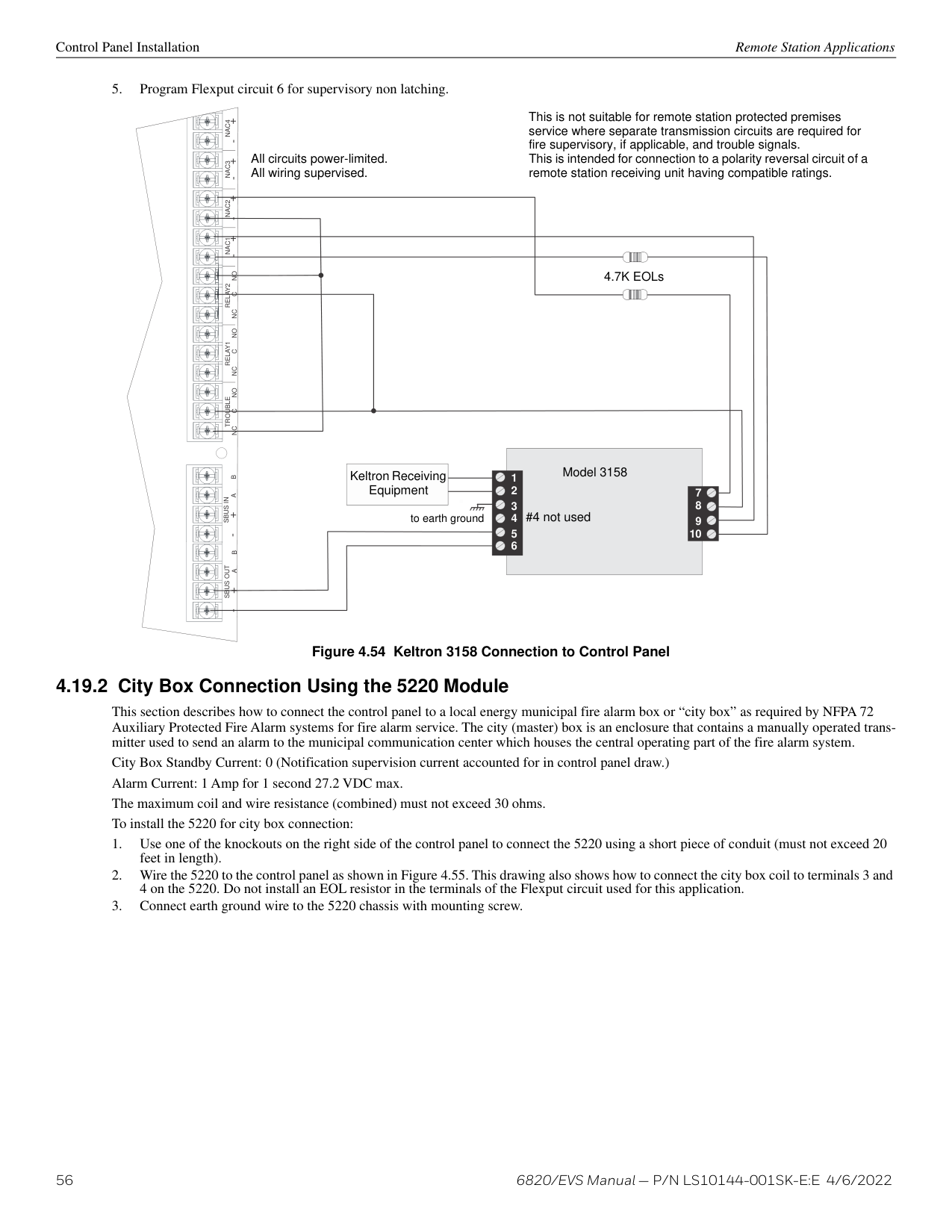
| | | |---|---| | | |
| | | |---|---| | | |
| | | |---|---| | | |
| | | |---|---| | | |
| | | |---|---| | | |
| | | |---|---| | | |
| | | |---|---| | | |
| | | |---|---| | | |
| | | |---|---| | | |
| | | |---|---| | | |
| | | |---|---| | | |
| | | |---|---|
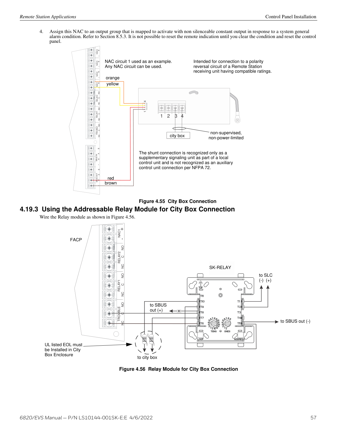
| | |
| | | |---|---| | | |
| | | |---|---| | | |
| | | |---|---| | | |
| | | | | |---|---|---|---| | | | | | | | | | |
######################### – + A B
######################### – + A B
########################### S+ SC- S+SC-
########################### S+ SC- S+SC-
SBUS
SBUS
SLC OUT
SLC IN
SLC OUT
SLC IN
supervised, power-limited
############# Figure 4.31 6815 Connection to FACP
###### 4.12 5824 Serial/Parallel Interface Module Installation
The 5824 serial/parallel interface module allows you to connect a printer to the panel, so you can print a real-time log of system events. Instructions for installing the 5824 appear below. The 5824 is for ancillary use only.
5824 installation involves the following steps:
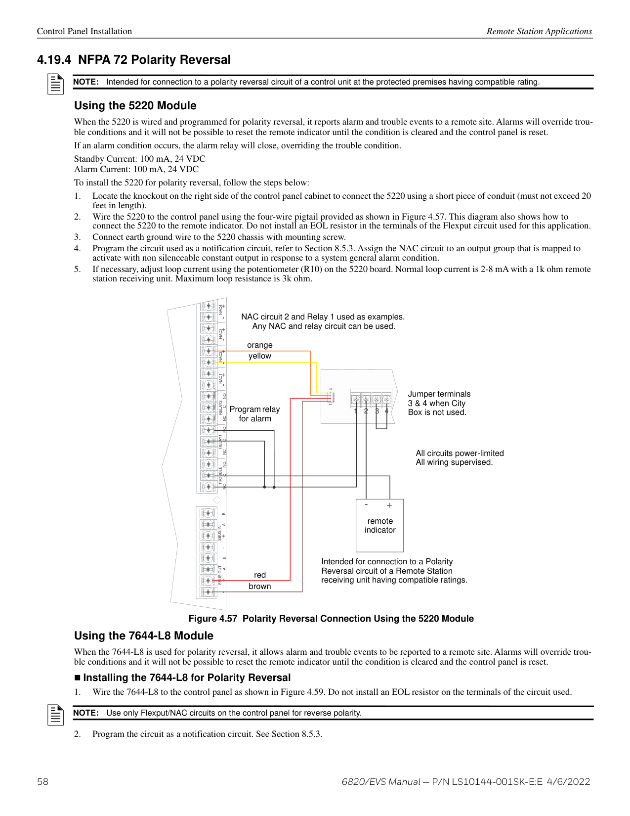
NOTE: There is a maximum of four 5824 modules allowed per panel.
FACP
SBUS OUTSBUS IN- +A B- +A B
|ON
12345
| |---|
DIP switches
parallel
S-S+
5824 connectors for
connection to printer
SBUS
AB
serial
supervised, power-limited
EXT. COMM
Figure 4.32 5824 Connection to the Panel
Select Yes if printer should be supervised for Out-of-Paper and Offline conditions. Select type of printer, Parallel or Serial.
|Monitor Printer=Yes Output Port=Parallel Event Logging=NO
More|
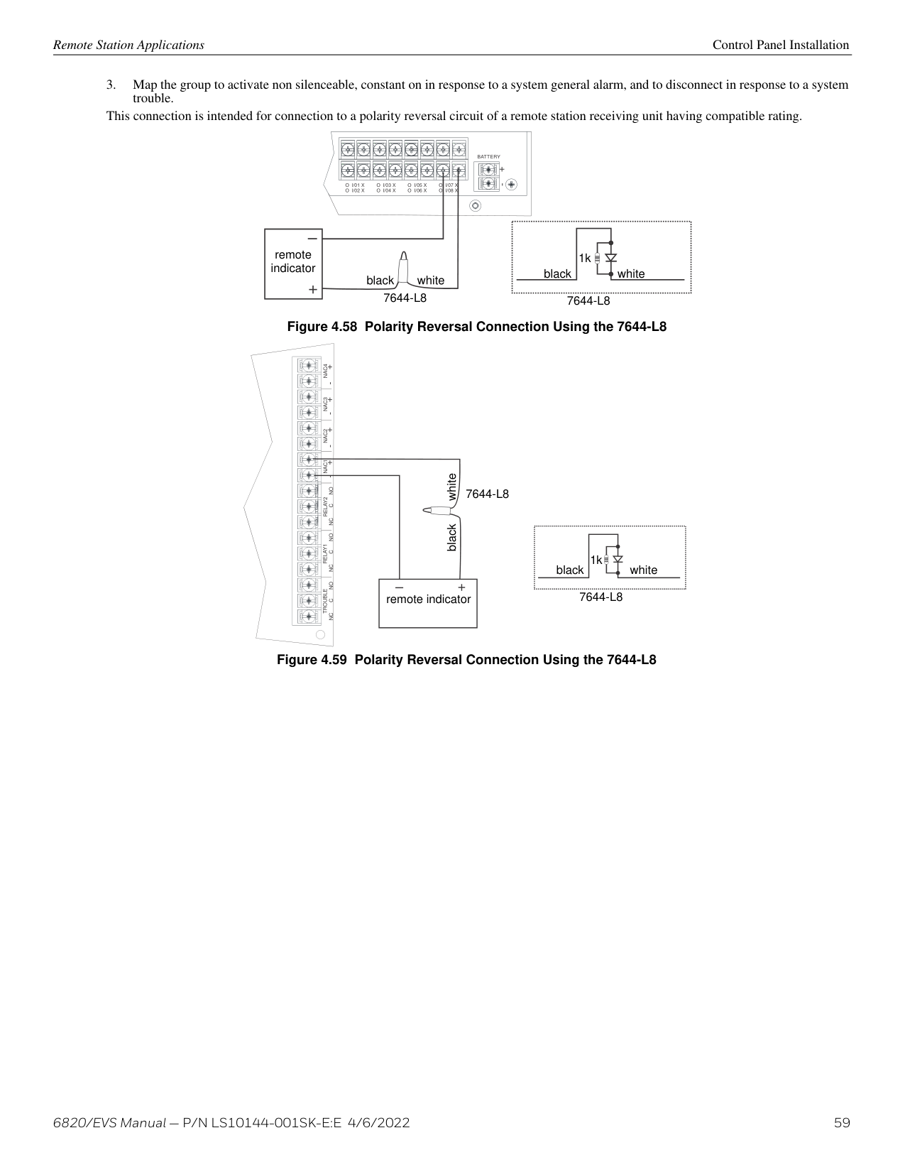
|---|
############# Figure 4.33 Selecting Printer and Output Port Options
|Option|Choices| |---|---| | | | |Baud Rate:|75 - 19200| |Data Bits:|5 - 8| |Stop Bits:|0.5, 1, 2| |Parity:|None, Even, Odd|
Table 4.5 Serial Printer Options
###### 4.13 5880 LED I/O Module
The 5880 is an LED driver board that can be used in a wide variety of applications, including as an interface with most customized floor plan annunciator boards. The 5880 can drive up to 40 LEDs and has one PZT controller. The 5880 also has eight inputs for dry contact monitoring. When used with the 6820EVS, the 5880 inputs can be programmed to replicate the eight EVS buttons located on the front of the voice control module. A maximum of eight 5880 modules can be used in the system. The following sub-sections describe hardware installation. Refer to Section 8 for programming information.
5880 LED I/O Module Control Panel Installation
######## 4.13.1 5880 Board Layout
Figure 4.34 shows the locations of screw terminals for connection to the panel and contact monitor wiring, pin connectors for connecting LEDs and the DIP switch for selecting an SBUS ID number for the 5880.
dry contact inputs- supervised, power-limited
|S- S+ A B
IN - 48 C+ IN - 47 IN - 46 C+ IN - 45 IN - 44 C+ IN - 43 IN - 42 C+ IN - 41
P1 P2 P3 P4
|1|1| |---|---| |LED Out| |
10
|11|11| |---|---| |LED Out| |
20
|21|21| |---|---| |LED Out| |
30 31 40
LED Power not used
LED Power not used
LED Power not used
LED Out LED Power
not used| |---|
SBUS (ID#) Address DIP switch
SBUS Connector
Figure 4.34 5880 Board Layout
######## 4.13.2 FACP Connection
The 5880 connects to the panel via the SBUS. Make connections as shown in Figure 4.35. After the 5880 is connected to the panel, it must be added to the system. This programming step is described in Section 8.2.2.
5880
|ON
234 5| |---|
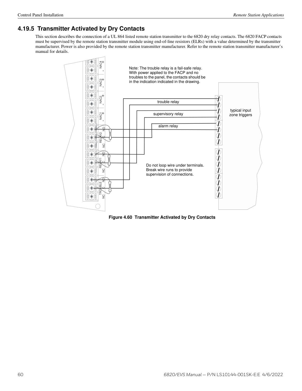
SBUS OUTSBUS IN- +A B- +A B
| | | |---|---| | | |
| | | |---|---| | | |
FACP
S- S+ A B
supervised, power-limited
| | | | |---|---|---| | | | | | | | | | | | | | | | |
EXT. COMM
############# Figure 4.35 5880 Connection to 6820
######## 4.13.3 LED Wiring
There are four 12-pin connectors on the 5880 board for connecting LEDs. Each LED gets its power from Pin 11. Internal resistors are sized so that there is approximately 10 mA of current for each LED; no series resistors are required. LED outputs can be mapped to output circuits. See Section 8.5.4 for programming details.
Wire the LEDs as shown in Figure 4.36.
On connector P1, Pin 12 is an open collector output for controlling a piezo. If used, the 5880 piezo will match the piezo pattern of the onboard or remote annunciator.
NOTE: The circuit connected to “Open Collector Output” (last pin on P1) must be current limited so that no more than 100 mA of current is allowed to flow into the open collector transistor.
Pin #
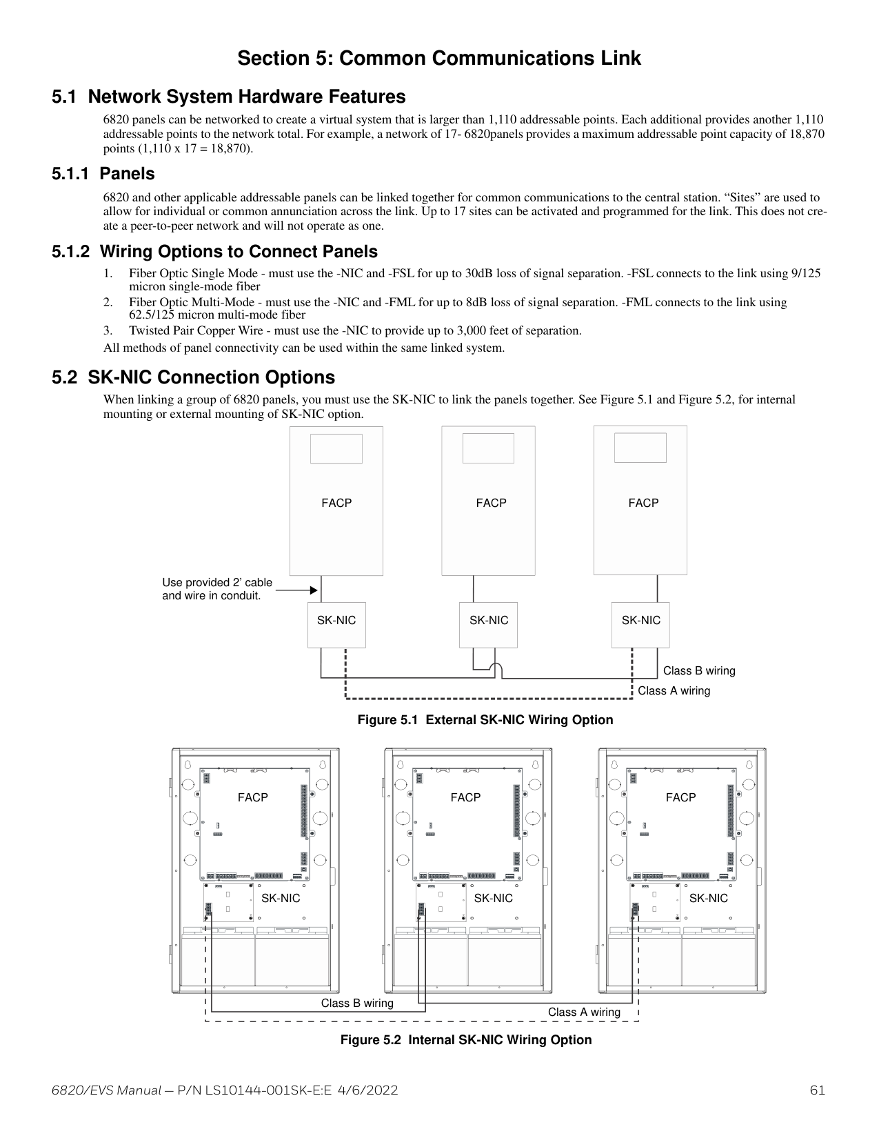
LED1 LED2 LED3 LED4 LED5 LED6 LED7 LED8 LED9
Cathode LEDs Anode
LED10
LED Power no connection
Cathode LEDs Anode
LED Power no connection
Figure 4.36 5880 Board Layout
P3 and P4 are wired the same as P2.
######## 4.13.4 Dry Contact Wiring
The 8 input circuits on the 5880 board are for monitoring switch inputs. Any type of switch supported by the control panel can be used with the 5880. For example, you can use a 5880 to monitor pull stations, water flow, tamper, reset, or silence switches.
Wire dry contacts as shown in Figure 4.37. Notice grouping of terminals. Power terminals are shared by two inputs.
4.7kΩ EOL resistors
supervised wiring
5880
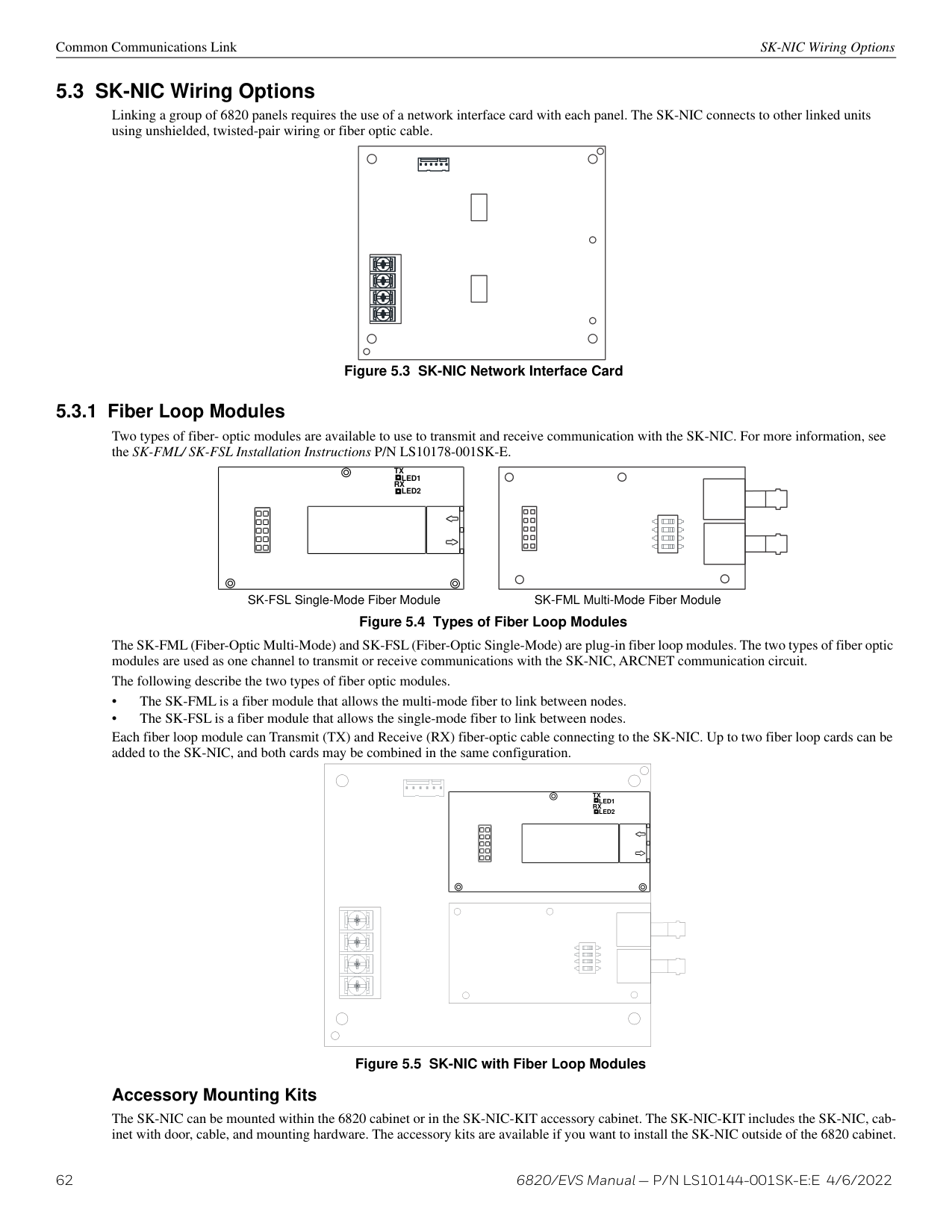
IN - 48 C+ IN - 47 IN - 46 C+ IN - 45 IN - 44 C+ IN - 43 IN - 42 C+ IN - 41
############# Figure 4.37 Dry Contact Wiring
5865-3 / 5865-4 LED Annunciator Installation Control Panel Installation
###### 4.14 5865-3 / 5865-4 LED Annunciator Installation
The 5865-3 and 5865-4 are LED annunciators. The 5865-4 has 30 mappable LEDs, remote fire system silence and fire system reset key switches, and a general system trouble LED. The 5865-3 has 30 mappable LEDs only. These are arranged as 15 pairs of red (typically used for alarm) and yellow (typically used for trouble) LEDs.
Installation of the 5865-3 and 5865-4 is identical. The keyswitches and the trouble LED follow the behavior of other system annunciators and do not require any installation steps. The following sub-sections describe how to install the 5865-3 and 5865-4 hardware. Refer to Section 8 for programming information.
NOTE: This manual uses “5865” when referring to aspects of the 5865-3 and 5865-4 that are common to both models.
Plexiglass plate mounted to the LED board at the factory. Do not remove.
Note: Numbers indicate point numbers for 5865. They do not appear on board assembly.
|SILENCE
TROUBLE
RESET| |---|
|12
9 10
11 12 21 22
19 20 29 30
34
5 6
7 8
13 14
15 16
17 18
23 24
25 26
27 28| |---|
Note: 5865 switches follow the main FACP, no installation or programming required.
5865-4 Board Assembly 5865-3 Board Assembly
############# Figure 4.38 5865-3 and 5865-4 Assembly (Front View)
######## 4.14.1 FACP Connection
The 5865 connects to the panel via the SBUS. Make connections as shown below. After the 5865 is connected to the panel, it must be added to the system. This programming step is described in Section 8.2.2.
SBUS OUTSBUS IN- +A B- +A B
FACP
5865
supervised, power-limited Class B
EXT. COMM
Figure 4.39 5865 Connection to the FACP
Control Panel Installation Configuring SBUS Modules
######## 4.14.2 5865 Mounting
Mount the 5865-4 to a standard 4-gang electrical box. Mount the 5865-3 to a standard 3-gang electrical box. In Figure 4.40, the 5865-4 attached to a 4-gang box, is used as an example.
Attach the 5865 to a standard 3- or 4-gang electrical box.
cover plate
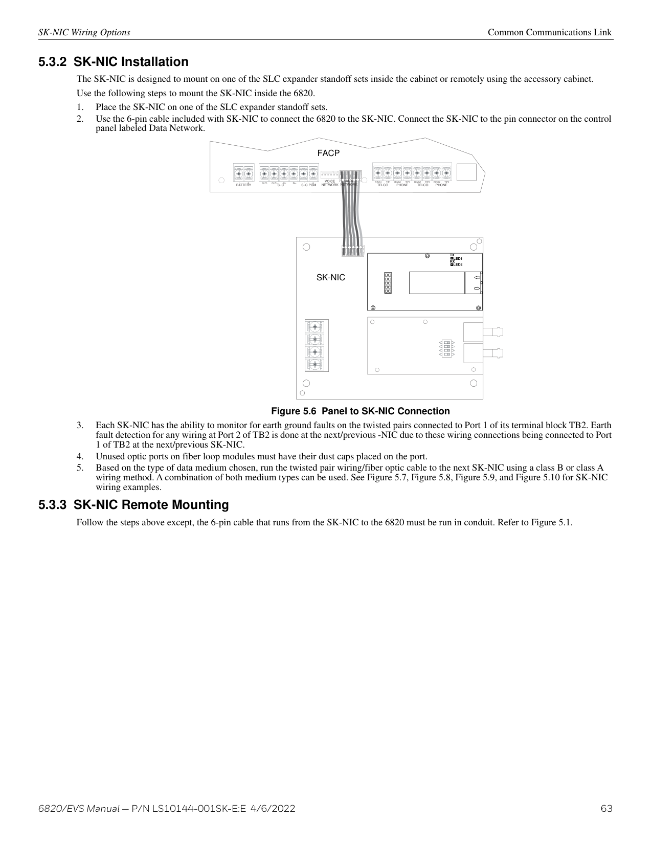
The 5865 is mounted to a plexiglass plate at the factory.
############# Figure 4.40 5865 Mounting Example
The 5865 ships with a set of zone description labels that can be inserted into the 5865 board assembly. These labels can be used in a typewriter or can be written on by hand. Slide the labels under the plexiglass as shown in Figure 4.41. The LEDs will show through the label when illuminated.
TOP
|SILENCE
TROUBLE
RESET| |---|
############# Figure 4.41 Inserting Zone Description Labels
4.15 Configuring SBUS Modules
This section describes how to configure any system hardware modules that have been added to the system.
######## 4.15.1 Assigning SBUS Module IDs
SBUS devices on a panel are addressed from 1 to 63. Although the addressing scheme allows 63 SBUS devices to be connected to a panel, the actual number is limited by current draw and SBUS bandwidth usage as discussed below. When installing a hardware module (see Table 4.1 for a list of compatible devices), you must use the DIP switches on the module to assign an ID number to the module. Address zero is an invalid address and is not allowed.
Telephone Connection Control Panel Installation
Figure 4.42 shows all possible DIP switch positions and their correlation to a numerical ID. For example, to select ID 2, place DIP switch 2 in the up or on position.
ON OFF
address address address address
145623 145623 1 45 623 1 45 623
############# Figure 4.42 Possible SBUS Module Addresses
Refer to Section 8.2 to edit, add, delete, and view module list.
######## 4.15.2 SBUS Bandwidth Considerations
Each SBUS device generates a certain amount of traffic on the SBUS. Generally, the amount of traffic generated depends on the type of SBUS device. To help you figure out the SBUS bandwidth usage of a given collection of devices, a tool is available on the Silent Knight website (www.silentknight.com). The tool will serve as a guide to help determine how heavily loaded an SBUS is with respect to bandwidth. We recommend you use this tool if you plan to have more than eight SBUS devices per SBUS. Remember to include devices that are on 5895XL SBUS repeaters in your list of devices for SBUS bandwidth calculations. Refer to Section 4.6.1.
###### 4.16 Telephone Connection
Connect the telephone lines as shown in Figure 4.43. The 7860 phone cord is available from Silent Knight for this purpose. If you do not use the model 7860 to connect to the phone lines, the wire used for the connection must be 26 AWG or larger diameter wire. A number of programmable options are available for customizing telephone lines. These options are described in “Phone Lines” on page 104.
DATA NETWORK TELCO PHONE TELCO PHONESLC SLC PGMBATTERY RING1 TIP1 RING1 TIP1 RING2 TIP2 RING2 TIP2OUT- OUT+ IN- IN+- +- +
VOICE NETWORK
| | | | |
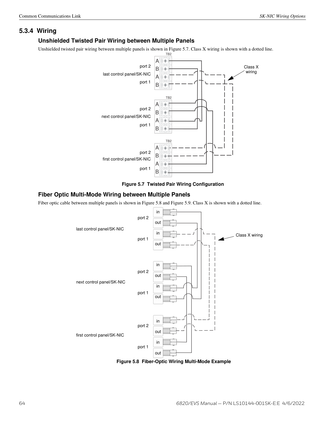
|---|---|---|---| | | | | | | | | | |
EXT. COMM
supervised
brown
brown
green
green
gray
gray
red
red
Model #7860
############# Figure 4.43 Connection of Telephone Lines
Model #7860
###### 4.17 Flexput I/O Circuits
The two Flexput circuits are an innovative and versatile feature of the control panel. They can be used as: Class A or B notification circuits, Class A or B initiation circuits (either 2- or 4-wire detectors), or as auxiliary power (resettable, continuous, sounder base sync, or door holder).
The polarity of the Flexput terminals differs depending on whether the circuit is programmed as an input or an output circuit. If the circuit is programmed as an input circuit (for a detector or normally open contact) the X terminal is negative and O terminal is positive. If the circuit is programmed as an output circuit (Aux power or NAC) then the X terminal is positive and the O terminal is negative.
NOTE: Where power to a device or appliance is supplied over a separate pathway from the notification appliance and/or SLC, the operation of the power pathway shall meet the performance requirements of the, notification appliance, and/or signaling-line circuit(s) and the power circuit shall be defined by the applicable class in the product installation wiring diagram/instructions consistent with the operation of the particular power pathway.
4.7 kΩ EOL
Alarm Polarity Shown
NAC1 NAC2 NAC3 NAC4O I/05 X O I/06 X
+
+
+
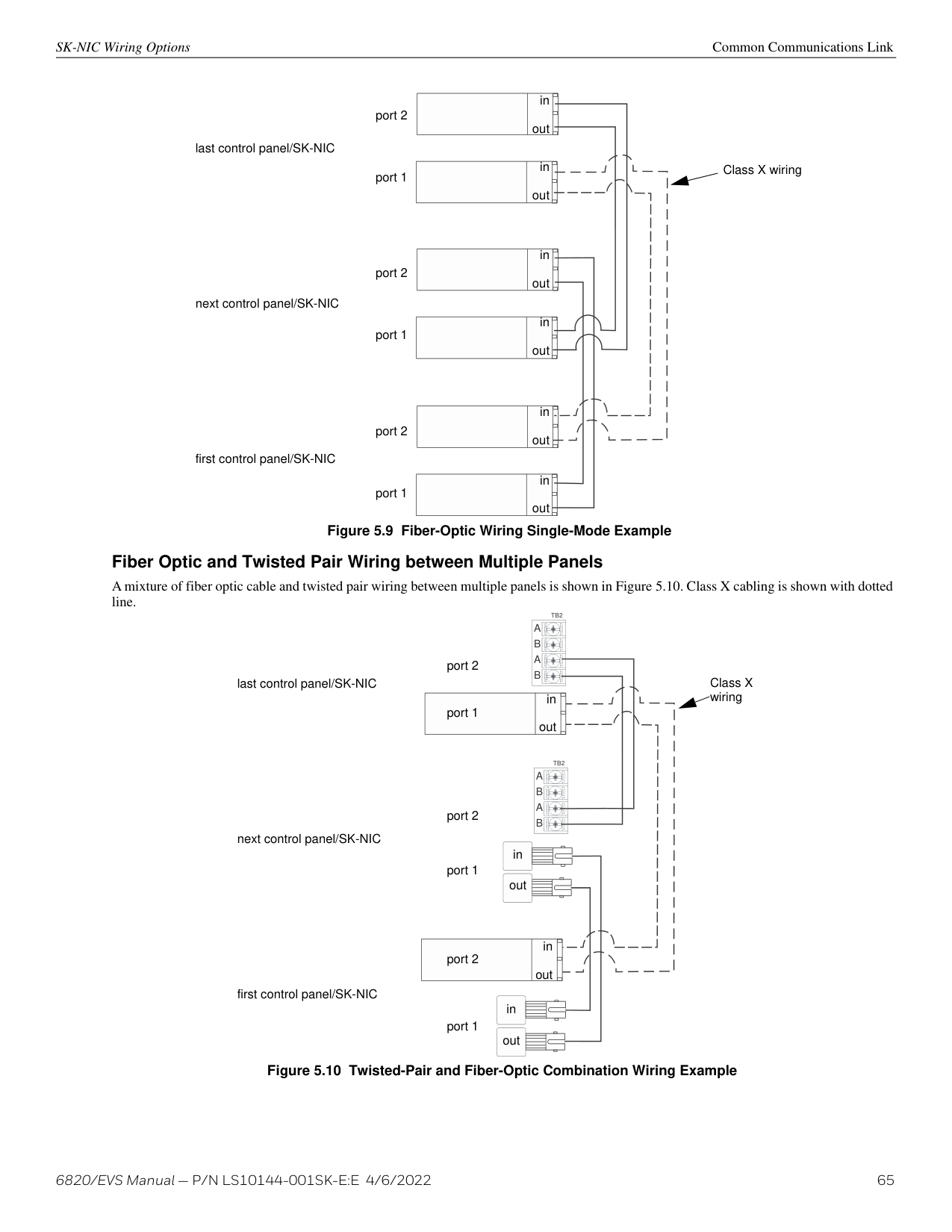
| | |---| | |
+
+
+
+ - + - + - + -
+
+
+
| | |---| | | | |
Regulated, 24 VDC Full Wave Rectified circuits. Rated at 27.4 VDC, 3A per circuit, 6A max total.
+
+
+
| | |---| | | | |
+
+
+
| | |---| | | | |
+
+
+
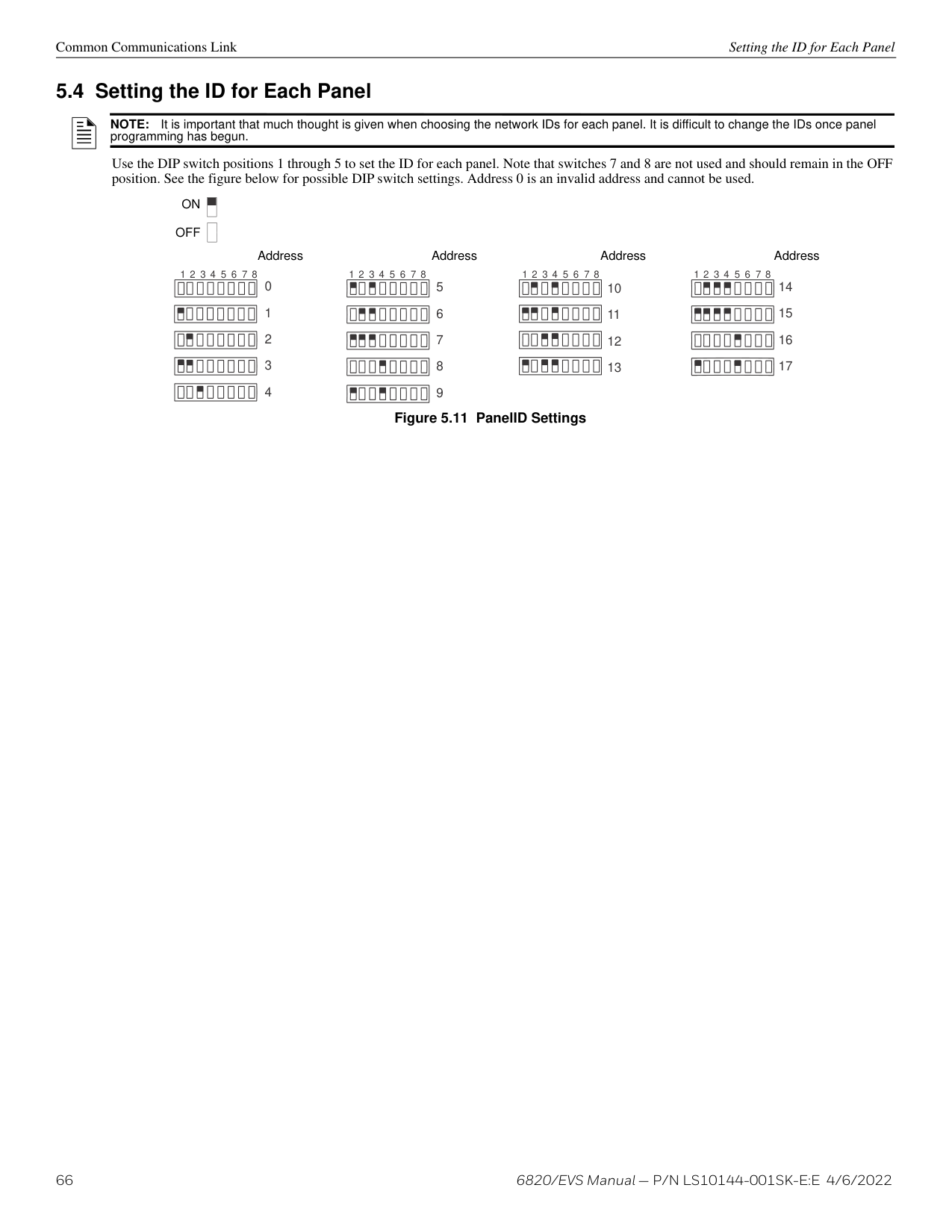
| | |---| | | | |
C NO
supervised, power-limited Figure 4.44 Class B Notification Appliance Circuit Wiring
LAY2
Maximum voltage drop is 3V per Class B notification.
|Current|Maximum Impedance| |---|---| | | | |1.0A|3Ω| |1.5A|2Ω| |2.0A|1.5Ω| |2.5A|1.2Ω| |3.0A|1.0Ω|
Table 4.6 Maximum Impedance Class B
Class A Notification Wiring You must use an appliance listed in the Device Compatibility Document. To install a Class A notification appliance circuit:
CAUTION: SYSTEM SUPERVISION
!
FOR PROPER SYSTEM SUPERVISION DO NOT USE LOOPED WIRE UNDER TERMINALS MARKED – AND + OF THE NAC CIRCUIT. BREAK WIRE RUNS TO PROVIDE SUPERVISION OF CONNECTIONS.
Alarm Polarity Shown
NAC1 NAC2 NAC3 NAC4O I/05 X O I/06 X
| |+| | |---|---|---| | | |+| | | | |
+
+
+
+
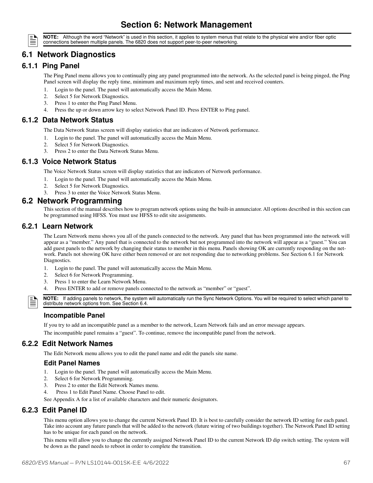
Regulated, 24 VDC Full Wave Rectified circuits. Rated at 27.4 VDC, 3A per circuit, 6A max total.
+ - + - + - + -
| |+| | |---|---|---| | | |+| | | | |
+
+
+
+
| |+|+| |---|---|---| | | | |
+
+
+
+
C NO
LAY2
supervised, power-limited
Figure 4.45 Class A Notification Appliance Circuit Configuration
NOTE: In programming any point that uses multiple Flexput circuits, the lowest Flexput circuit number is used to refer to the circuit pair. For example, Figure 4.45 uses both Flexput circuit 1 and 2, so in programming, these would be referred to as point 1.
Maximum voltage drop is 3V per Class A circuit. See Table 4.7.
|Current|Maximum Impedance| |---|---| | | | |1.0A|3Ω| |1.5A|2Ω| |2.0A|1.5Ω| |2.5A|1.2Ω| |3.0A|1.0Ω|
############# Table 4.7 Maximum Impedance Class A
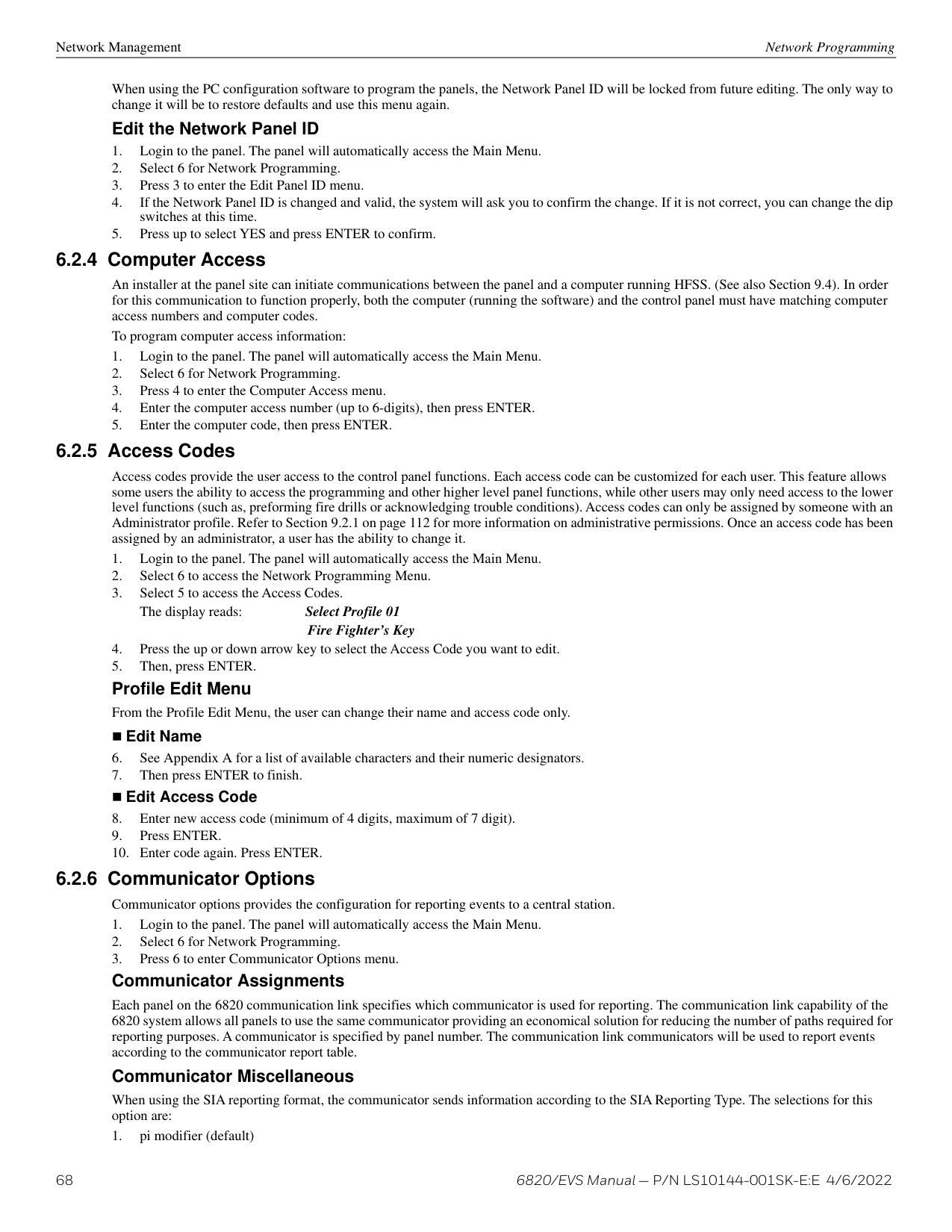
You can connect conventional Class B switches, such as waterflow switches and pull stations, directly to the Flexput circuits of the control panel.
To install a Class B switch, do the following.
NAC1 NAC2 NAC3 NAC4O I/05 X O I/06 X
EOL 4.7 kΩ
| | |---| | | | |
+ - + - + - + -
supervised, power-limited
C NO
LAY2
############# Figure 4.46 Class B Input Switches
########## Class A Inputs
You can connect conventional Class A switches, such as waterflow switches and pull stations, directly to the Flexput circuits of the control panel.
To install a Class A switch:
NAC1 NAC2 NAC3 NAC4O I/05 X O I/06 X
Maximum Impedance per circuit is 50Ω.
+ - + - + - + -
supervised, power-limited
C NO
LAY2
############# Figure 4.47 Class A Initiating Switches
NOTE: In programming any point that uses multiple Flexput circuits, the lowest Flexput circuit number is used to refer to the circuit pair. For example, Figure 4.47 uses both Flexput circuit 5 and 6, so in programming it would be referred to as point 5.
######## 4.17.3 Installing 2-Wire Smoke Detectors
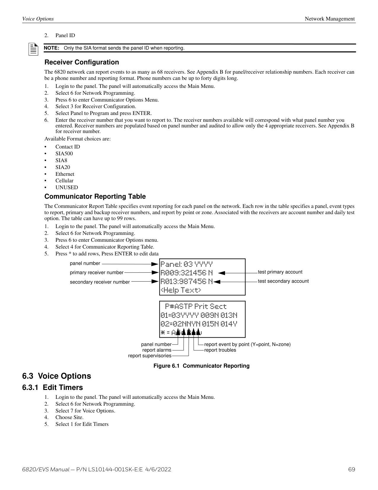
Any compatible, UL-listed two-wire smoke detector can be used with the control panel. Refer to the Device Compatibility Document for a list of devices. Figures 4.48 and 4.49 illustrate how to connect a UL-listed 2-wire detector to the control panel.
Installing 2-Wire Class B Smoke Detectors To install a Class B two-wire smoke detector, wire as shown in Figure 4.48.
supervised, power limited
Flexput Circuit 6 is used as an example. Either Flexput circuit can be used.
NAC1 NAC2 NAC3 NAC4O I/05 X O I/06 X
+ - + - + - + -
EOL 4.7 kΩ
C NO
LAY2
############# Figure 4.48 Two-Wire Class B Smoke Detector
Installing 2-Wire Class A Smoke Detectors To install a Class A two-wire smoke detector, wire as shown below.
Any 2-wire smoke detector listed in the Device Compatibility Document
NAC1 NAC2 NAC3 NAC4O I/05 X O I/06 X
+-
+
+
+ - + - + - + -
supervised, power limited
C NO
LAY2
############# Figure 4.49 Two-Wire Class A Smoke Detector Connections
NOTE: In programming any point that uses multiple Flexput circuits, the lowest Flexput circuit number is used to refer to the circuit pair. For
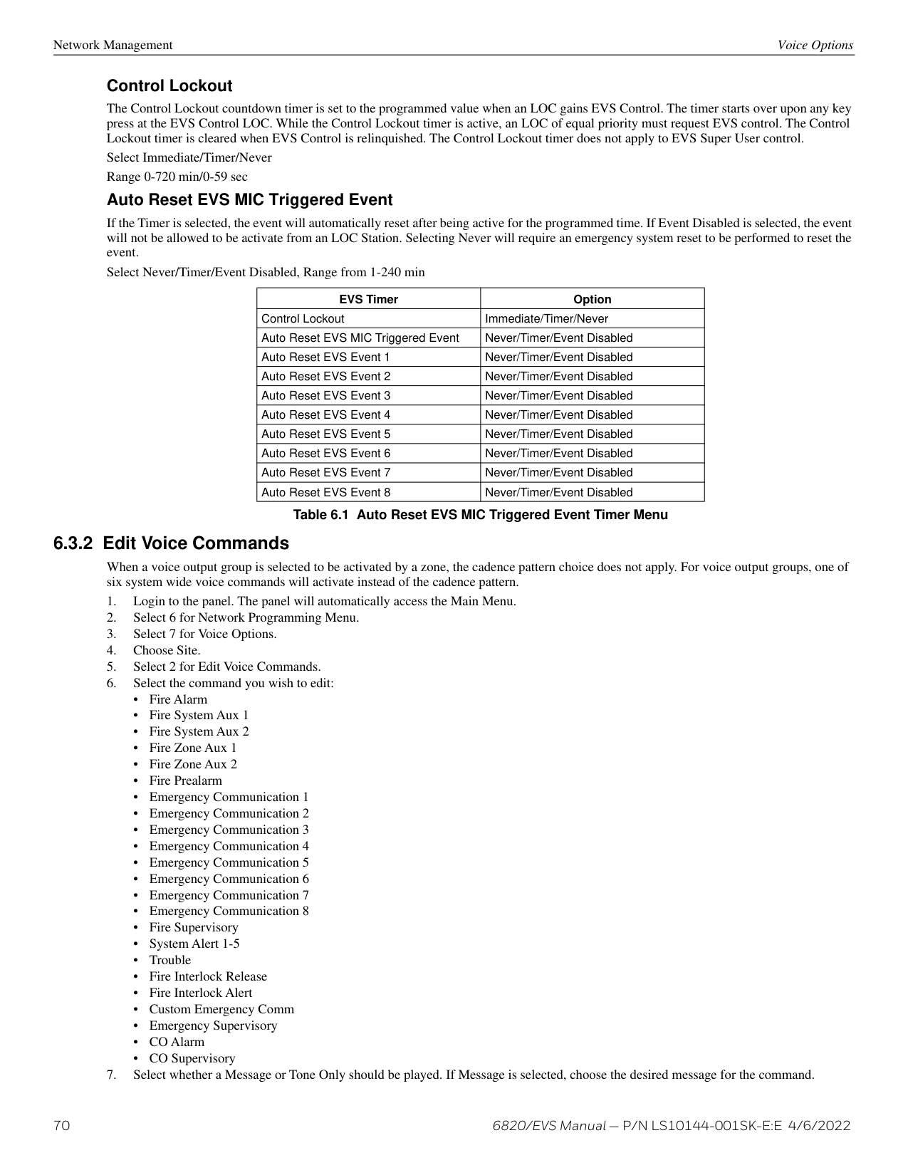
++
LAY2
C NO
NAC1 NAC2 NAC3 NAC4O I/05 X O I/06 X
+ - + - + - + -
Figure 4.50 Class B 4-Wire Smoke Detector Connections
Air Products PAM-2 Supervision Module
blue orange white gray
supervised, power limited
ESL 449CT
NOTE: In programming any point that uses multiple Flexput circuits, the lowest Flexput circuit number is used to refer to the circuit pair. For
######## 4.17.4 Installing 4-Wire Smoke Detectors
Any compatible, UL-listed four-wire smoke detector can be used with the control panel. Refer to the Device Compatibility Document for a list of devices. Figures 4.50 and 4.51 illustrate how to connect a UL-listed four-wire detector to the control panel.
########## Installing a Class B 4-Wire Smoke Detector
Installing 4-Wire Class A Smoke Detectors
blue orange
white gray
Air Products PAM-2 Supervision Module
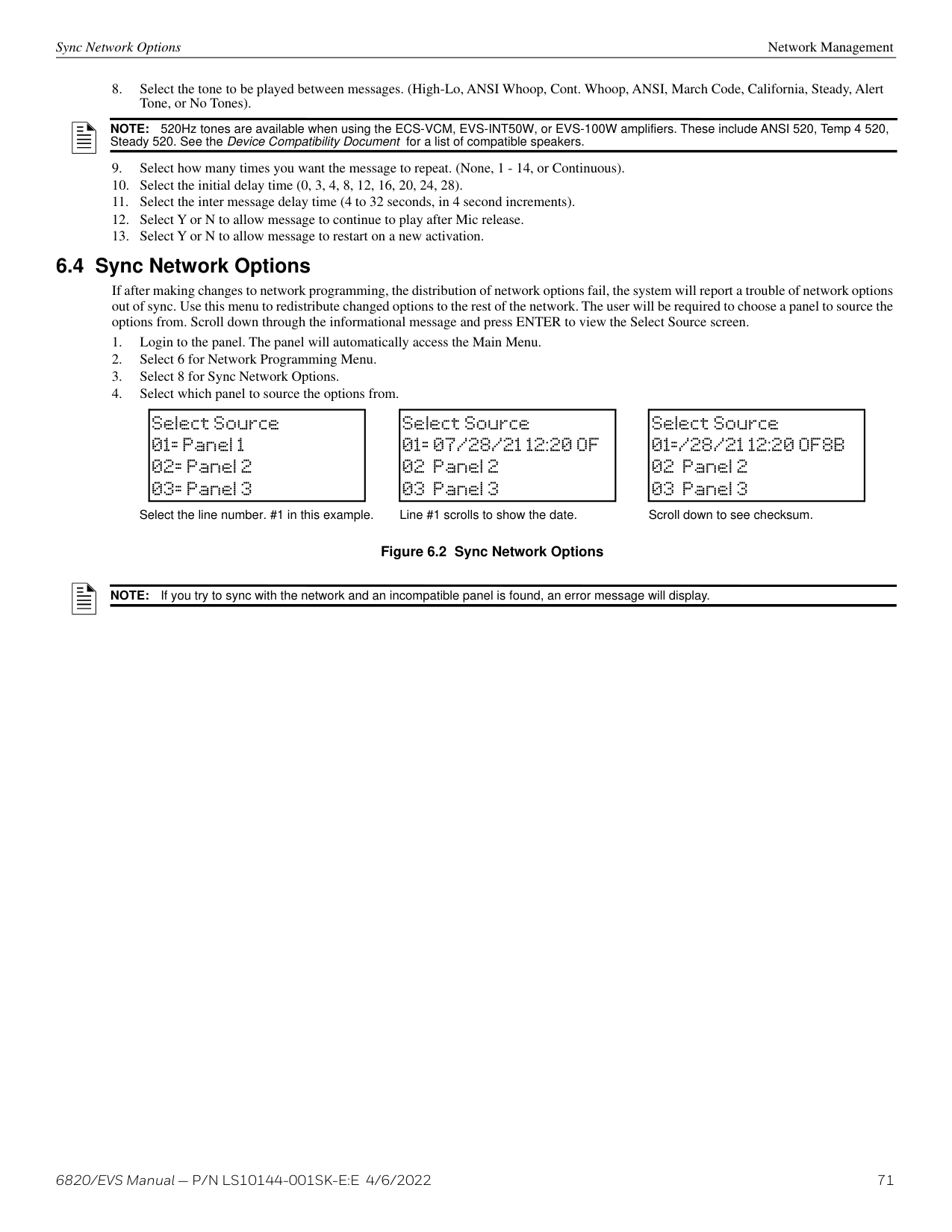
supervised, power limited
Figure 4.51 Class A 4-Wire Smoke Detector Connections
NOTE: In programming, any point that uses multiple Flexput circuits are always referred to as the lowest Flexput circuit number used. In this example, Figure 4.51 uses Flexput circuits 5, 6 together with NAC 4. In programming (4, 5, 6) would be referred to as point 5.
Door holder power is intended for fire door applications. When there are no fire system alarms in the system and the panel has AC power, door holder circuits have 24 volt power present at their terminals. Any fire system alarm will cause power to disconnect. Power will be reapplied when the fire system is reset. If AC power is not present, the auxiliary door holder power will be disconnected to conserve the battery backup. When AC power is restored, power is immediately restored to the door holder circuits. Use a UL-listed door holder for this application. Refer to the Device Compatibility Document for compatible door holder list. Constant Power Use constant power for applications that require a constant auxiliary power source. Power is always present at constant circuits. Resettable Power
Resettable power is typically used to power beam detectors, flame detectors and conventional 4-wire smoke detectors. For circuits selected as Resettable, 24-volt power is always present at the terminals unless a fire system reset occurs. If a fire system reset occurs, power is disconnected from the terminals for 30 seconds, then re-applied. Refer to the Device Compatibility Document for compatible four wire smoke detectors.
Sounder Sync Power Sounder Sync Power continuously outputs the System Sensor synchronization pattern and is intended for use with B200S sounder bases.
Onboard Relays (Conventional) Control Panel Installation
The control panel has a dedicated Form C trouble relay. The relay provides a normally open and a normally closed contact. The trouble relay will deactivate under any trouble condition.
RELAY 2TROUBLE COMNO C
RELAY 1 COMNO C
NO CCOM
############# Figure 4.52 Conventional Relay Circuits
+ - + - + - + -
NAC1 NAC2 NAC3 NAC4
Connect to power-limited sources only.
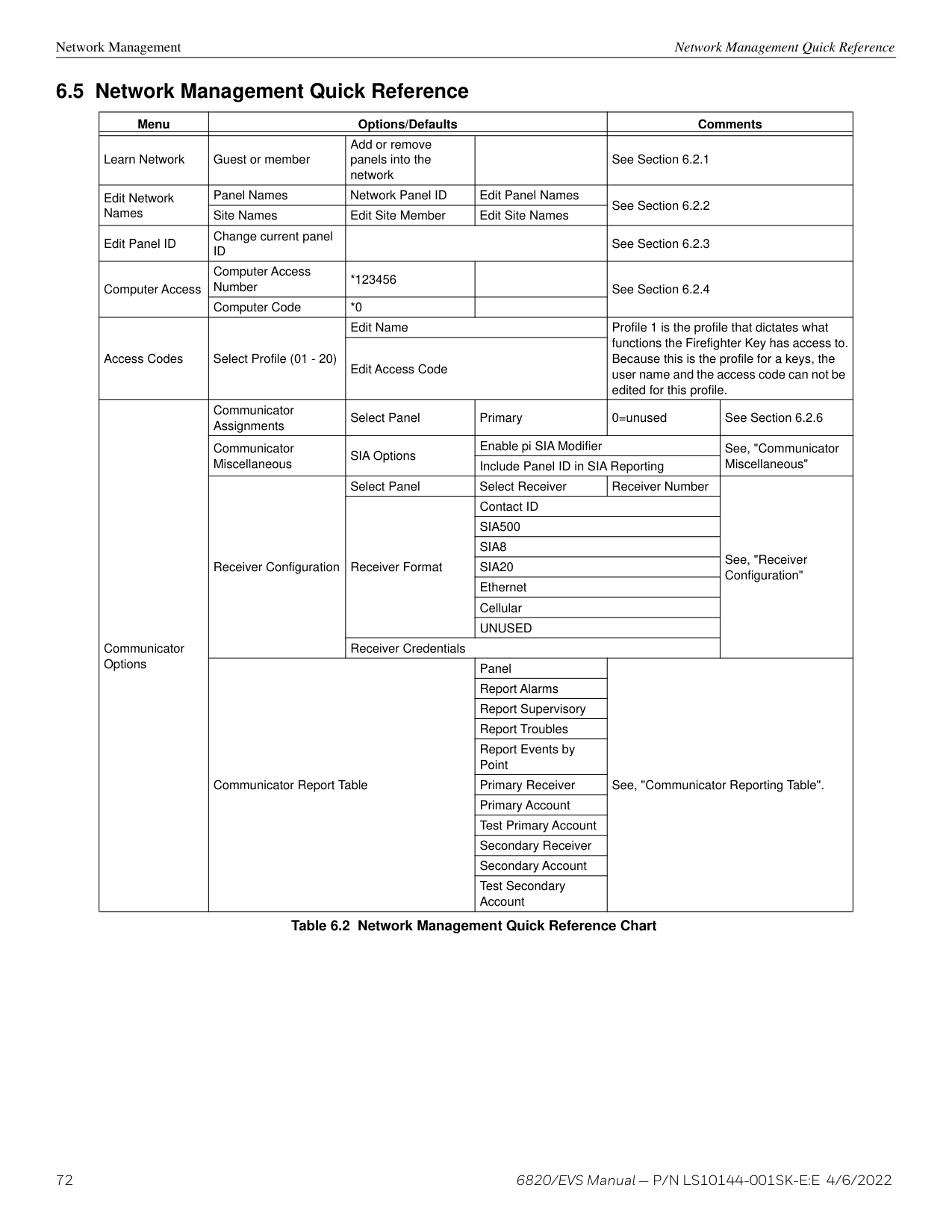
NC C NO
NC C NO
NC C NO
TROUBLE
############# Figure 4.53 Conventional Relay Circuits
NOTE: The NC contact is the relay contact that is closed when the panel has power and there are no trouble conditions.
######## 4.19.1 Keltron Model 3158 Installation
The control panel is compatible with Keltron Model 3158, used for direct connection to a Keltron receiver. The 3158 reports alarms, supervisories, and troubles.
The steps for connecting the 3158 to the control panel. Refer to the 3158 installation instructions for complete information.
This is not suitable for remote station protected premises service where separate transmission circuits are required for fire supervisory, if applicable, and trouble signals. This is intended for connection to a polarity reversal circuit of a remote station receiving unit having compatible ratings.
+ - + - + - + -
NAC1 NAC2 NAC3 NAC4
All circuits power-limited. All wiring supervised.
4.7K EOLs
NC C NO
NC C NO
NC C NO
TROUBLE
Model 3158
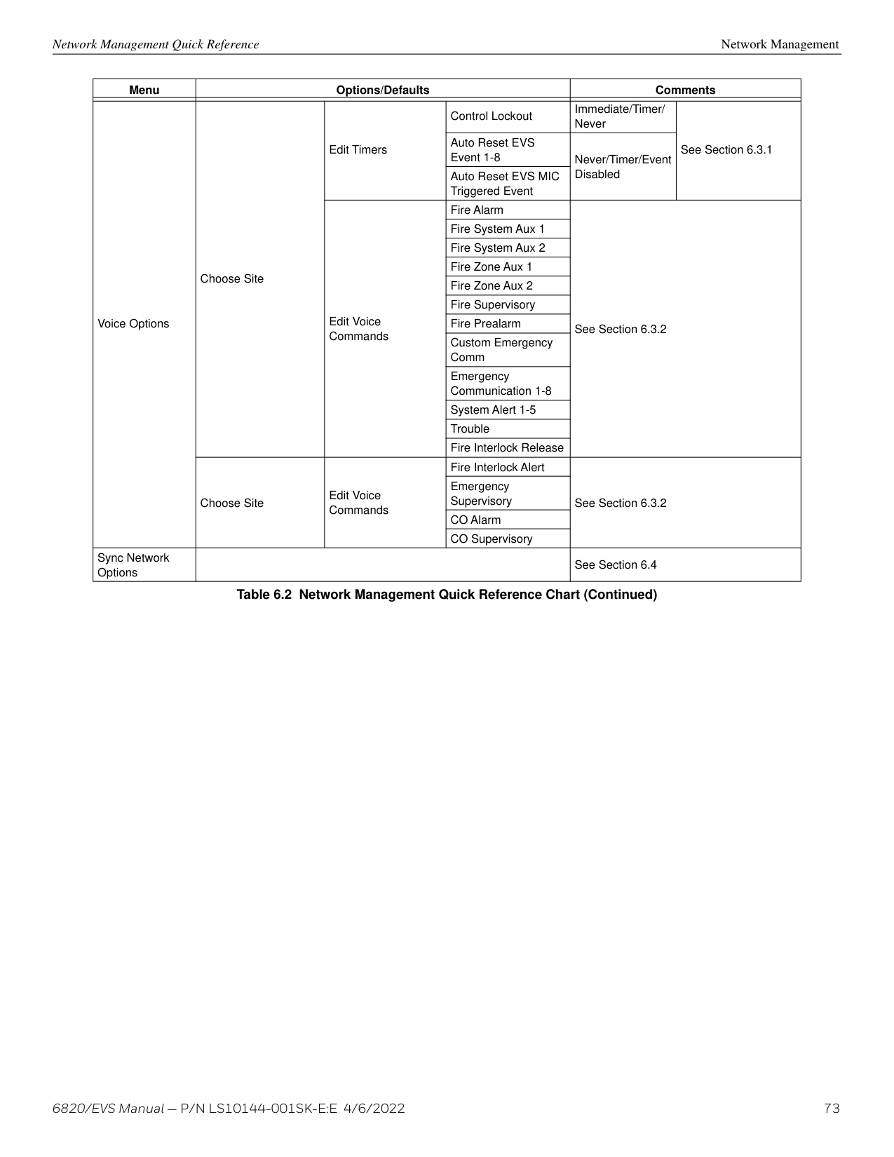
Keltron Receiving Equipment
SBUS OUTSBUS IN- +A B- +A B
to earth ground #4 not used
############# Figure 4.54 Keltron 3158 Connection to Control Panel
######## 4.19.2 City Box Connection Using the 5220 Module
This section describes how to connect the control panel to a local energy municipal fire alarm box or “city box” as required by NFPA 72 Auxiliary Protected Fire Alarm systems for fire alarm service. The city (master) box is an enclosure that contains a manually operated transmitter used to send an alarm to the municipal communication center which houses the central operating part of the fire alarm system. City Box Standby Current: 0 (Notification supervision current accounted for in control panel draw.) Alarm Current: 1 Amp for 1 second 27.2 VDC max. The maximum coil and wire resistance (combined) must not exceed 30 ohms. To install the 5220 for city box connection:
NAC1 NAC2 NAC3 NAC4
+ - + - + - + -
NAC circuit 1 used as an example. Any NAC circuit can be used.
Intended for connection to a polarity reversal circuit of a Remote Station receiving unit having compatible ratings.
orange yellow
NC C NO
NC C NO
14
| | | |---|---|

| | | | | |
| | | |---|---| | | | | | |
123 4
NC C NO
TROUBLE
non-supervised, non-power-limitedcity box
SBUS OUTSBUS IN- +A B- +A B
The shunt connection is recognized only as a supplementary signaling unit as part of a local control unit and is not recognized as an auxiliary control unit connection per NFPA 72.
red brown
############# Figure 4.55 City Box Connection
+ -
NC C NO NAC1
FACP
NC C NO
to SBUS out (+)
NC C NO
TROUBLE
UL listed EOL must be Installed in City Box Enclosure
to city box
SK-RELAY
| | | | |---|---|---|
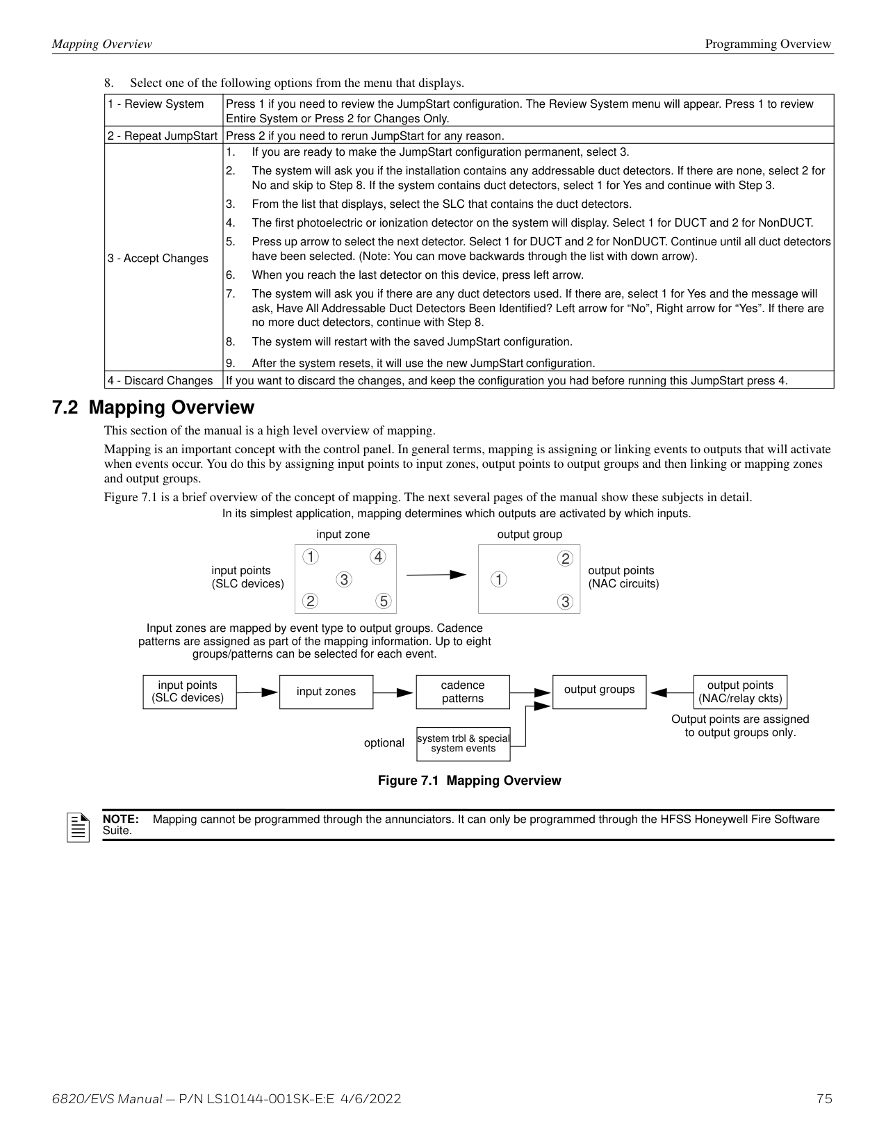
| | | | |---|---|---|
to SLC (-) (+)
to SBUS out (-)
############# Figure 4.56 Relay Module for City Box Connection
######## 4.19.4 NFPA 72 Polarity Reversal
NOTE: Intended for connection to a polarity reversal circuit of a control unit at the protected premises having compatible rating.
Using the 5220 Module When the 5220 is wired and programmed for polarity reversal, it reports alarm and trouble events to a remote site. Alarms will override trouble conditions and it will not be possible to reset the remote indicator until the condition is cleared and the control panel is reset. If an alarm condition occurs, the alarm relay will close, overriding the trouble condition. Standby Current: 100 mA, 24 VDC Alarm Current: 100 mA, 24 VDC To install the 5220 for polarity reversal, follow the steps below:
+ - + - + - + -
NAC1 NAC2 NAC3 NAC4
NAC circuit 2 and Relay 1 used as examples. Any NAC and relay circuit can be used.
orange yellow
14
Jumper terminals 3 & 4 when City Box is not used.
NC C NO
NC C NO
Program relay for alarm
1234
All circuits power-limited All wiring supervised.
NC C NO
TROUBLE
-
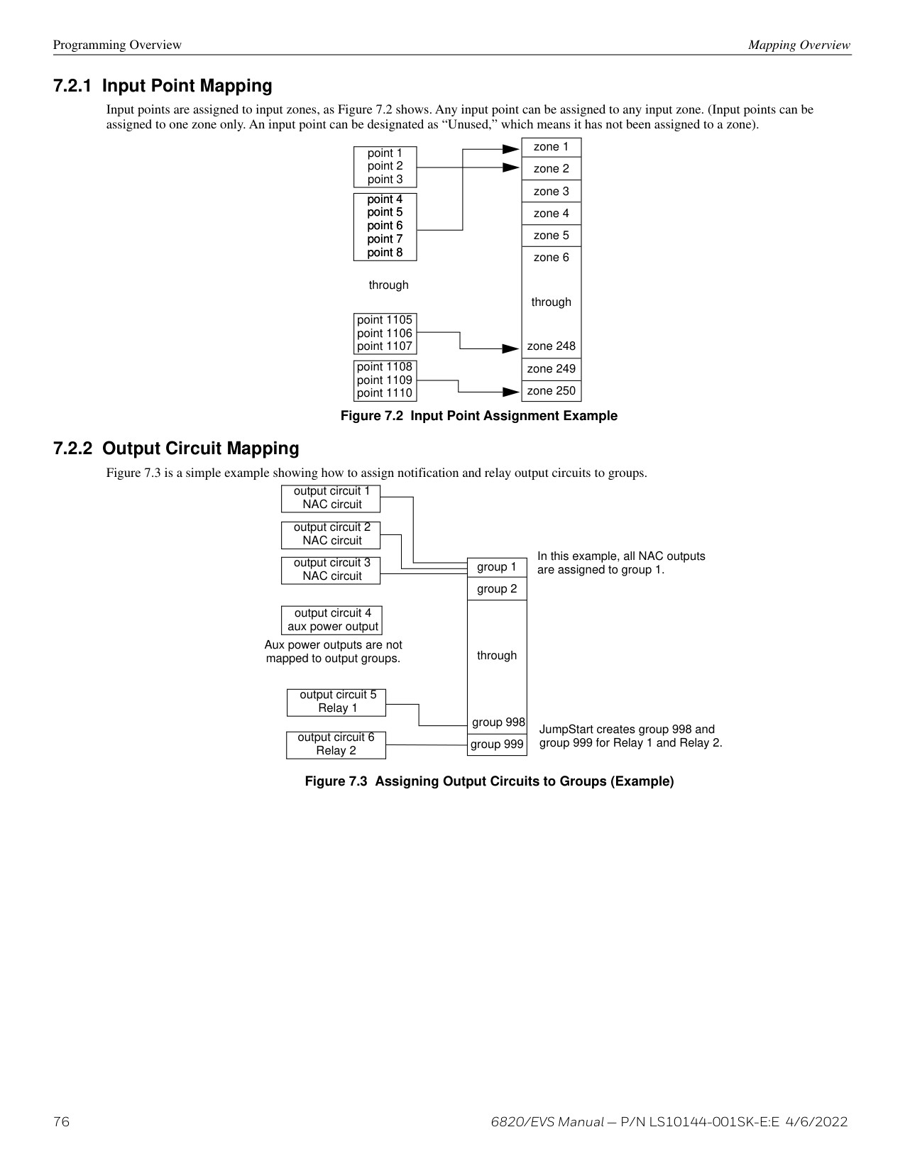
+
SBUS OUTSBUS IN- +A B- +A B
remote indicator
Intended for connection to a Polarity Reversal circuit of a Remote Station receiving unit having compatible ratings.
red brown
############# Figure 4.57 Polarity Reversal Connection Using the 5220 Module
########## Using the 7644-L8 Module
When the 7644-L8 is used for polarity reversal, it allows alarm and trouble events to be reported to a remote site. Alarms will override trouble conditions and it will not be possible to reset the remote indicator until the condition is cleared and the control panel is reset.
########### Installing the 7644-L8 for Polarity Reversal
NOTE: Use only Flexput/NAC circuits on the control panel for reverse polarity.
This connection is intended for connection to a polarity reversal circuit of a remote station receiving unit having compatible rating.
| | |---| | |
| | |---| | |
| | |---| | | | |
| | |---| | | | |
BATTERY
| | |---| | |
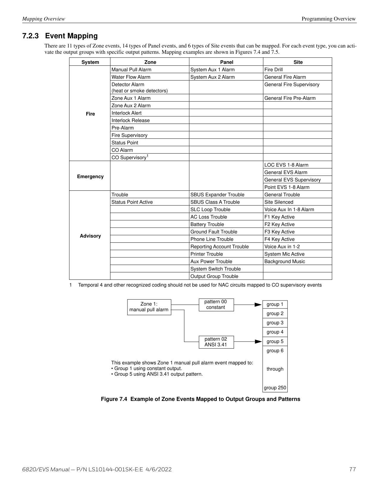
| | |---| | | | |
| | |---| | |
+ -
O I/03 X O I/04 X
O I/07 X O I/08 X
remote indicator
1k
black white 7644-L87644-L8
black white
+
############# Figure 4.58 Polarity Reversal Connection Using the 7644-L8
NAC1 NAC2 NAC3 NAC4
+ - + - + - + -
black white
7644-L8
NC C NO
NC C NO
1k
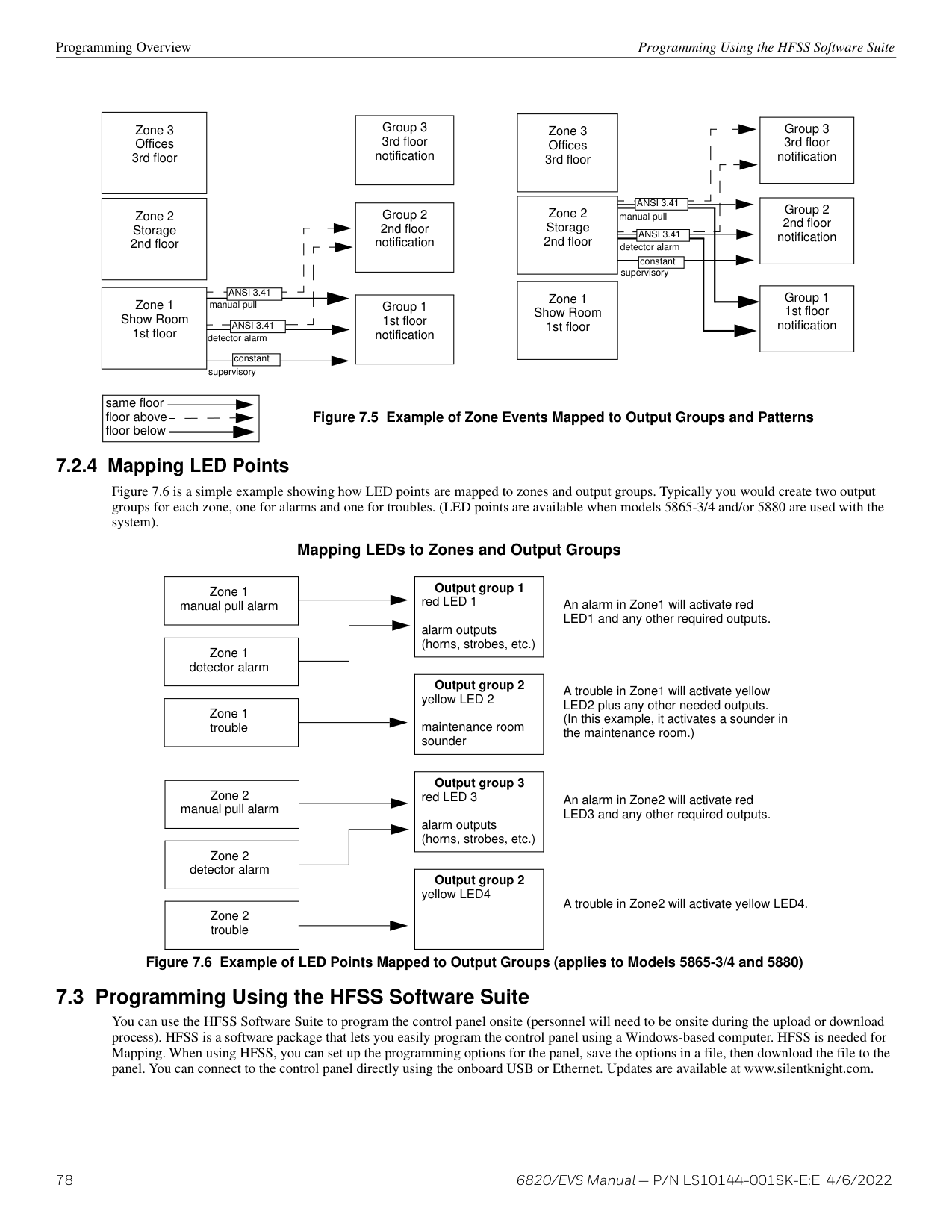
black white 7644-L8
–
NC C NO
+
TROUBLE
remote indicator
############# Figure 4.59 Polarity Reversal Connection Using the 7644-L8
######## 4.19.5 Transmitter Activated by Dry Contacts
This section describes the connection of a UL 864 listed remote station transmitter to the 6820 dry relay contacts. The 6820 FACP contacts must be supervised by the remote station transmitter module using end-of-line resistors (ELRs) with a value determined by the transmitter manufacturer. Power is also provided by the remote station transmitter manufacturer. Refer to the remote station transmitter manufacturer’s manual for details.
+ - + - + - + -
NAC1 NAC2 NAC3 NAC4
Note: The trouble relay is a fail-safe relay. With power applied to the FACP and no troubles to the panel, the contacts should be in the indication indicated in the drawing.
trouble relay
typical input zone triggers
supervisory relay
alarm relay
NC C NO
NC C NO
Do not loop wire under terminals. Break wire runs to provide supervision of connections.
NC C NO
TROUBLE
############# Figure 4.60 Transmitter Activated by Dry Contacts
##### Section 5: Common Communications Link
###### 5.1 Network System Hardware Features
6820 panels can be networked to create a virtual system that is larger than 1,110 addressable points. Each additional provides another 1,110 addressable points to the network total. For example, a network of 17- 6820panels provides a maximum addressable point capacity of 18,870 points (1,110 x 17 = 18,870).
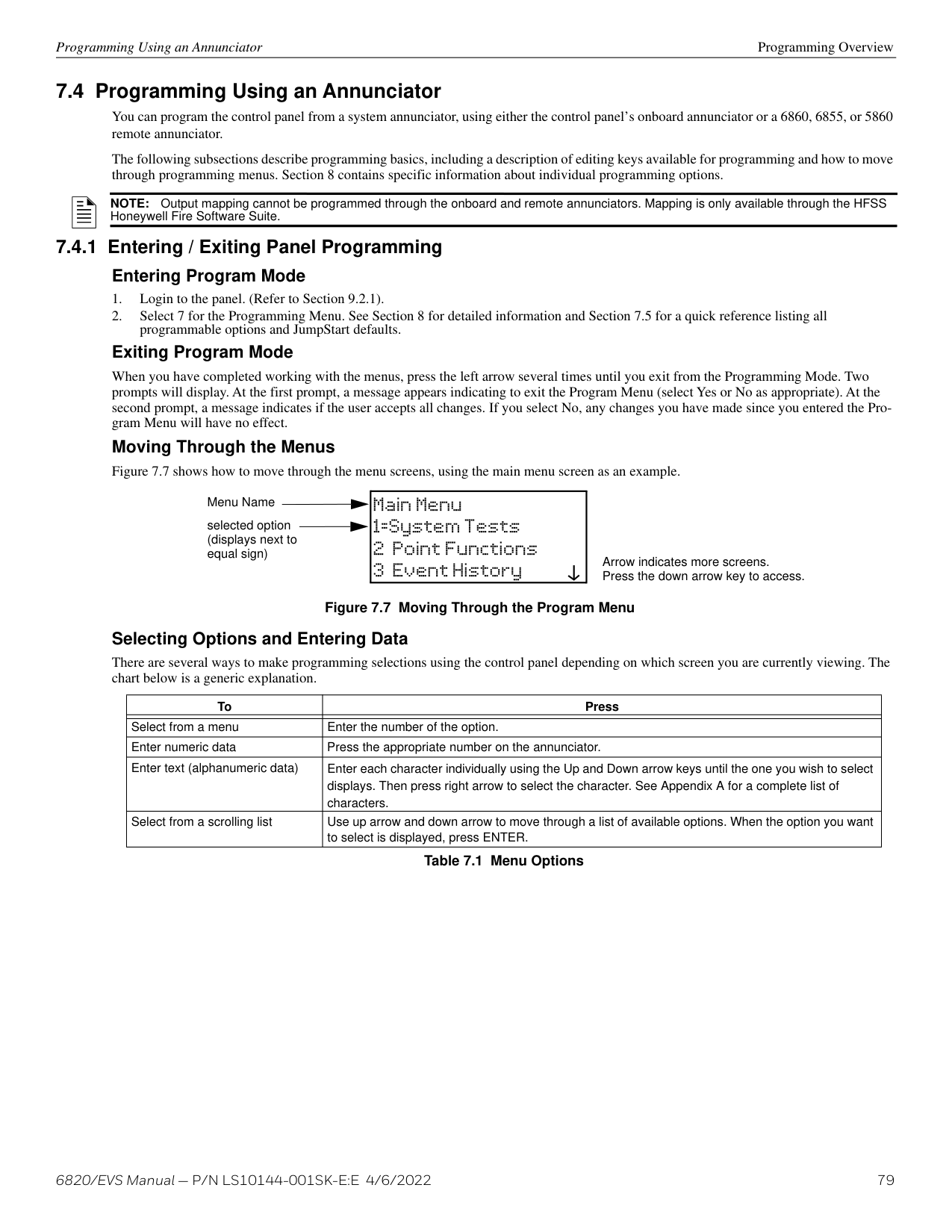
6820 and other applicable addressable panels can be linked together for common communications to the central station. “Sites” are used to allow for individual or common annunciation across the link. Up to 17 sites can be activated and programmed for the link. This does not create a peer-to-peer network and will not operate as one.
###### 5.2 SK-NIC Connection Options
When linking a group of 6820 panels, you must use the SK-NIC to link the panels together. See Figure 5.1 and Figure 5.2, for internal mounting or external mounting of SK-NIC option.
FACP FACP FACP
Use provided 2’ cable and wire in conduit.
SK-NIC SK-NIC SK-NIC
Class B wiring Class A wiring
############# Figure 5.1 External SK-NIC Wiring Option
| |FACP| | |---|---|---| | |FACP| |
| |FACP| | |---|---|---| | |FACP| |
| |FACP| | |---|---|---| | |FACP| |
SK-NIC SK-NIC SK-NIC
Class B wiring
############# Class A wiring Figure 5.2 Internal SK-NIC Wiring Option
###### 5.3 SK-NIC Wiring Options
Linking a group of 6820 panels requires the use of a network interface card with each panel. The SK-NIC connects to other linked units using unshielded, twisted-pair wiring or fiber optic cable.
| | |---|
############# Figure 5.3 SK-NIC Network Interface Card
######## 5.3.1 Fiber Loop Modules
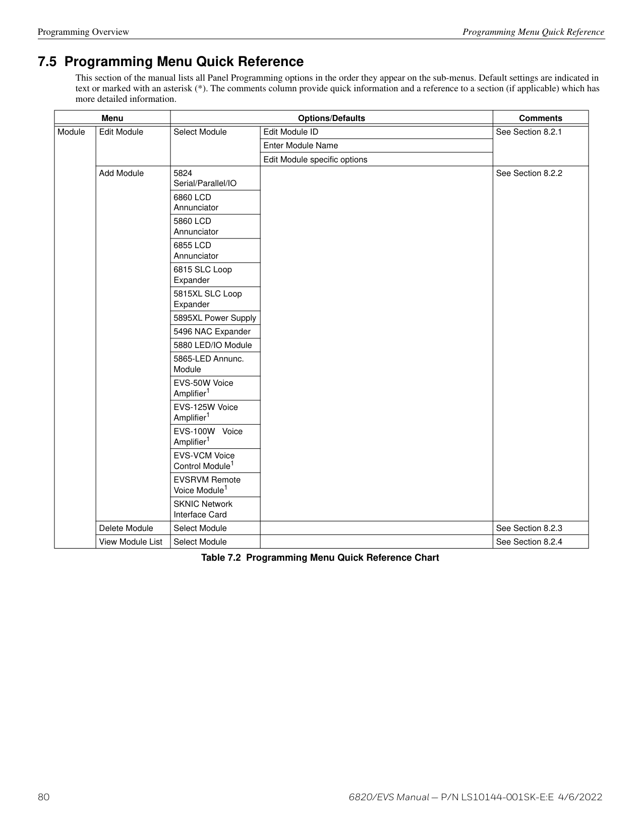
Two types of fiber- optic modules are available to use to transmit and receive communication with the SK-NIC. For more information, see the SK-FML/ SK-FSL Installation Instructions P/N LS10178-001SK-E.
|LED1 LED2
RX
TX| |---|
| | | | |---|---|---| | | | | | | | | | | | | | | | | | | | | | | | | | | | | | | | |
SK-FSL Single-Mode Fiber Module SK-FML Multi-Mode Fiber Module
############# Figure 5.4 Types of Fiber Loop Modules
The SK-FML (Fiber-Optic Multi-Mode) and SK-FSL (Fiber-Optic Single-Mode) are plug-in fiber loop modules. The two types of fiber optic modules are used as one channel to transmit or receive communications with the SK-NIC, ARCNET communication circuit.
The following describe the two types of fiber optic modules.
• The SK-FML is a fiber module that allows the multi-mode fiber to link between nodes. • The SK-FSL is a fiber module that allows the single-mode fiber to link between nodes. Each fiber loop module can Transmit (TX) and Receive (RX) fiber-optic cable connecting to the SK-NIC. Up to two fiber loop cards can be added to the SK-NIC, and both cards may be combined in the same configuration.
TX
LED1 LED2
RX
| | | | |---|---|---| | | | | | | | | | | | | | | | | | | | | | | | | | | | | | | | |
############# Figure 5.5 SK-NIC with Fiber Loop Modules
########## Accessory Mounting Kits
The SK-NIC can be mounted within the 6820 cabinet or in the SK-NIC-KIT accessory cabinet. The SK-NIC-KIT includes the SK-NIC, cabinet with door, cable, and mounting hardware. The accessory kits are available if you want to install the SK-NIC outside of the 6820 cabinet.
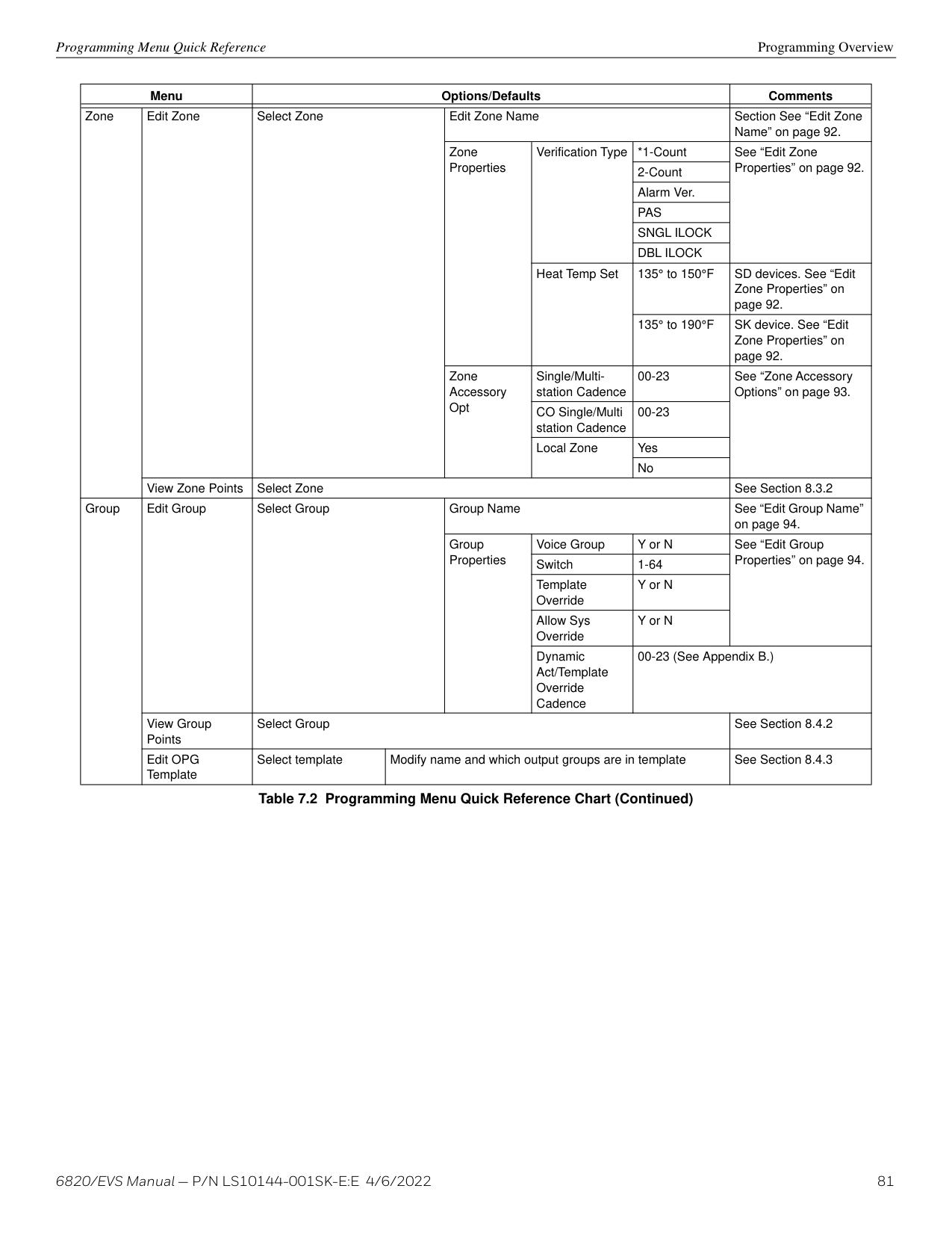
FACP
DATA NETWORK TELCO PHONE TELCO PHONESLC SLC PGMBATTERY RING1 TIP1 RING1 TIP1 RING2 TIP2 RING2 TIP2OUT- OUT+ IN- IN+- +- +
VOICE NETWORK
|LED1 LED2
RX
TX| |---|
SK-NIC
| | | |---|---| | | | | | | | | | | | | | | | | | | | | | | | |
Figure 5.6 Panel to SK-NIC Connection
######## 5.3.4 Wiring
Unshielded Twisted Pair Wiring between Multiple Panels Unshielded twisted pair wiring between multiple panels is shown in Figure 5.7. Class X wiring is shown with a dotted line.
TB2
A B A B
port 2
Class X wiring
last control panel/SK-NIC
TB2
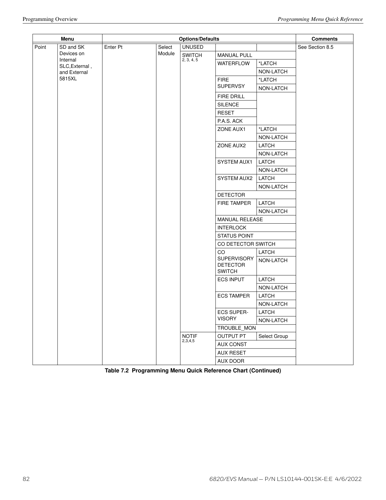
next control panel/SK-NIC
TB2
A B
first control panel/SK-NIC
port 1
############# Figure 5.7 Twisted Pair Wiring Configuration
Fiber Optic Multi-Mode Wiring between Multiple Panels Fiber optic cable between multiple panels is shown in Figure 5.8 and Figure 5.9. Class X is shown with a dotted line.
in
port 2
out
last control panel/SK-NIC
in
Class X wiring
in
out
in
out
out
next control panel/SK-NIC
in
out
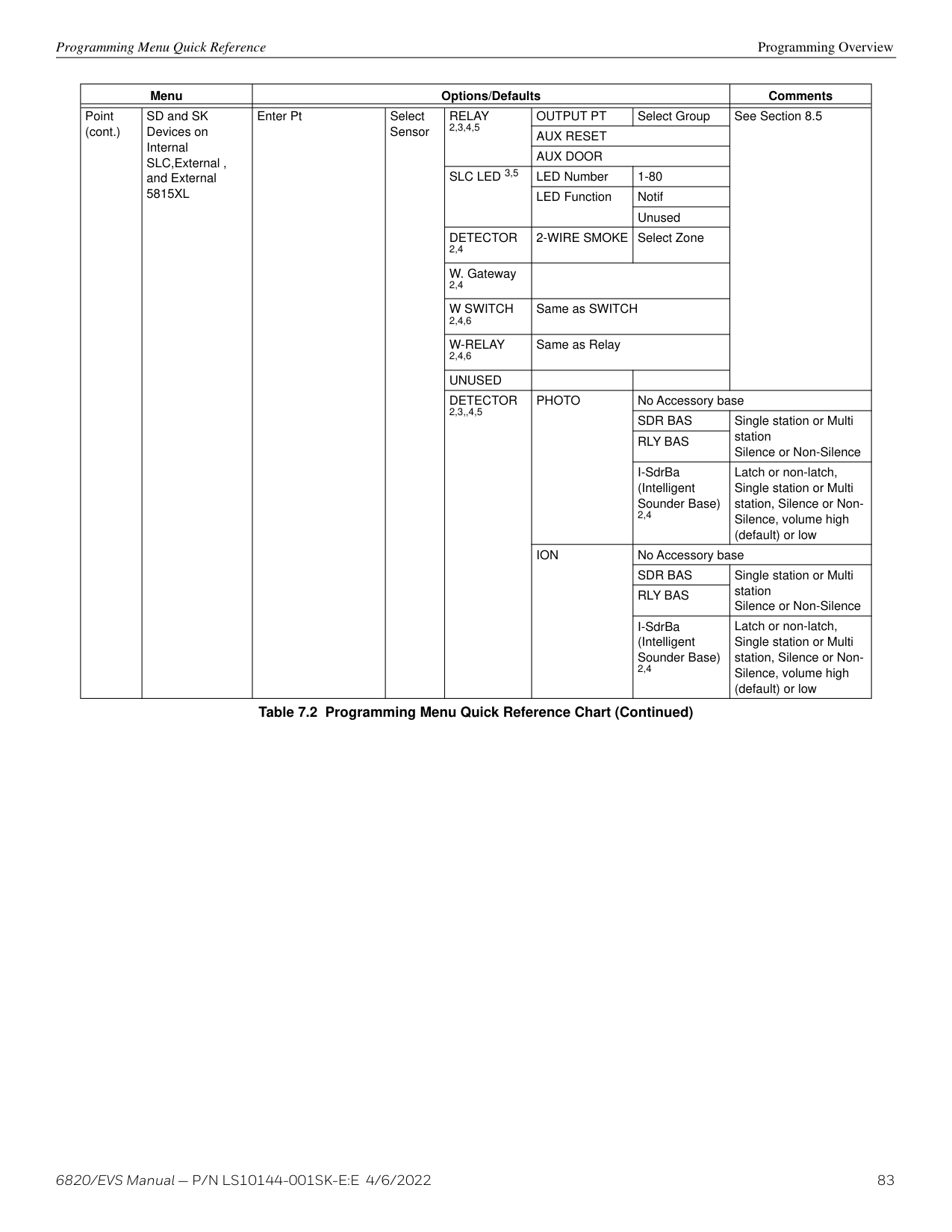
in
out
first control panel/SK-NIC
port 1
############# Figure 5.8 Fiber-Optic Wiring Multi-Mode Example
in out
port 2
last control panel/SK-NIC
in out
Class X wiring
in out
next control panel/SK-NIC
in out
in out
first control panel/SK-NIC
in out
port 1
############# Figure 5.9 Fiber-Optic Wiring Single-Mode Example
########## Fiber Optic and Twisted Pair Wiring between Multiple Panels
A mixture of fiber optic cable and twisted pair wiring between multiple panels is shown in Figure 5.10. Class X cabling is shown with dotted line.
TB2
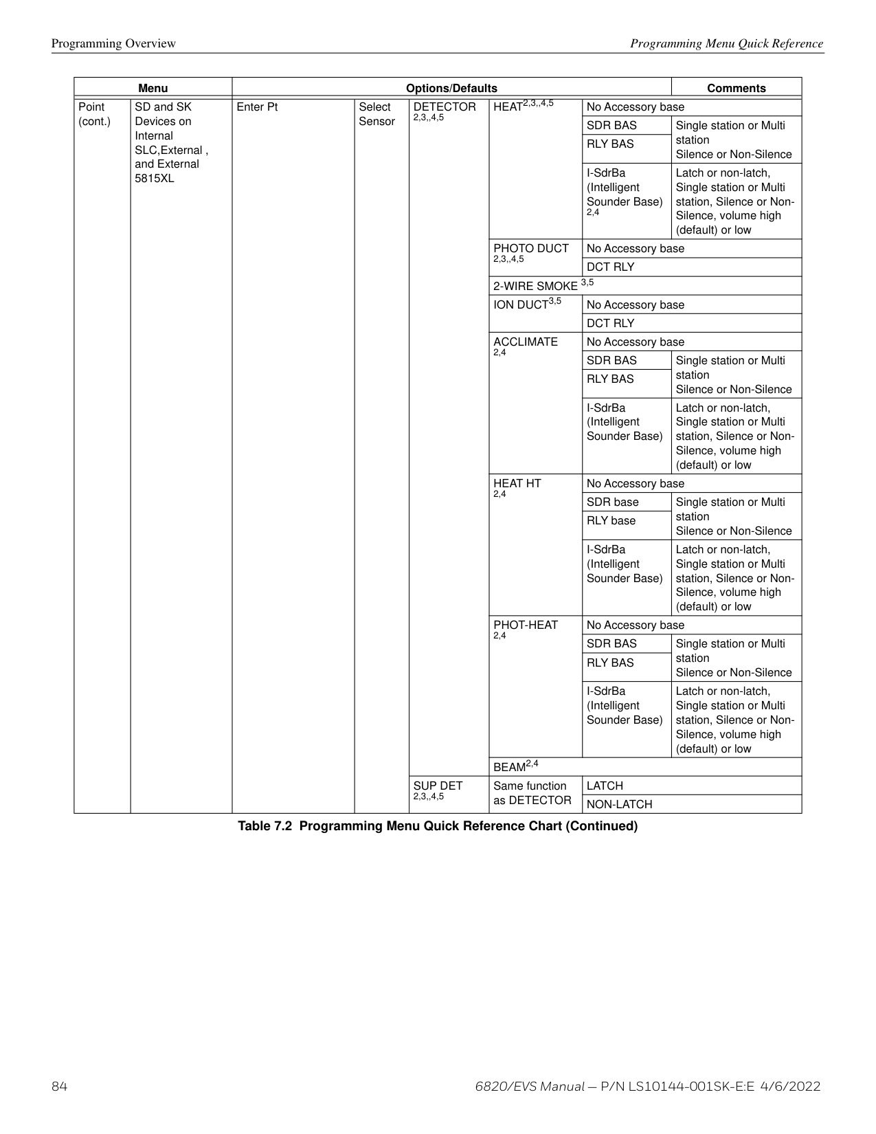
Class X wiring
last control panel/SK-NIC
in out
TB2
|A
B
A
B
| |---|
next control panel/SK-NIC
in
out
in out
first control panel/SK-NIC
in
out
############# Figure 5.10 Twisted-Pair and Fiber-Optic Combination Wiring Example
Common Communications Link Setting the ID for Each Panel
###### 5.4 Setting the ID for Each Panel
NOTE: It is important that much thought is given when choosing the network IDs for each panel. It is difficult to change the IDs once panel programming has begun.
Use the DIP switch positions 1 through 5 to set the ID for each panel. Note that switches 7 and 8 are not used and should remain in the OFF position. See the figure below for possible DIP switch settings. Address 0 is an invalid address and cannot be used.
ON OFF
Address Address Address Address
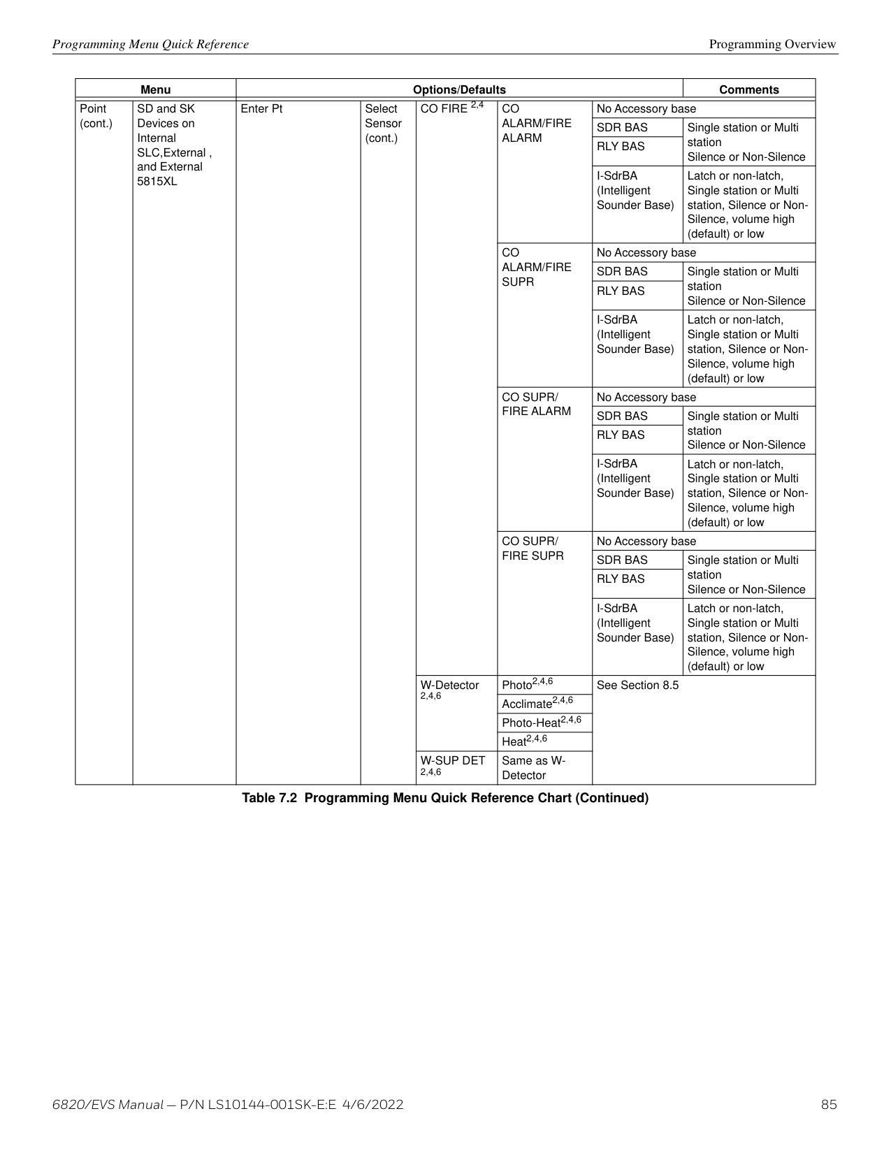
17845623
17845623 1 7 845623 1 7 845623
Figure 5.11 PanelID Settings
##### Section 6: Network Management
NOTE: Although the word “Network” is used in this section, it applies to system menus that relate to the physical wire and/or fiber optic connections between multiple panels. The 6820 does not support peer-to-peer networking.
###### 6.1 Network Diagnostics
The Ping Panel menu allows you to continually ping any panel programmed into the network. As the selected panel is being pinged, the Ping Panel screen will display the reply time, minimum and maximum reply times, and sent and received counters.
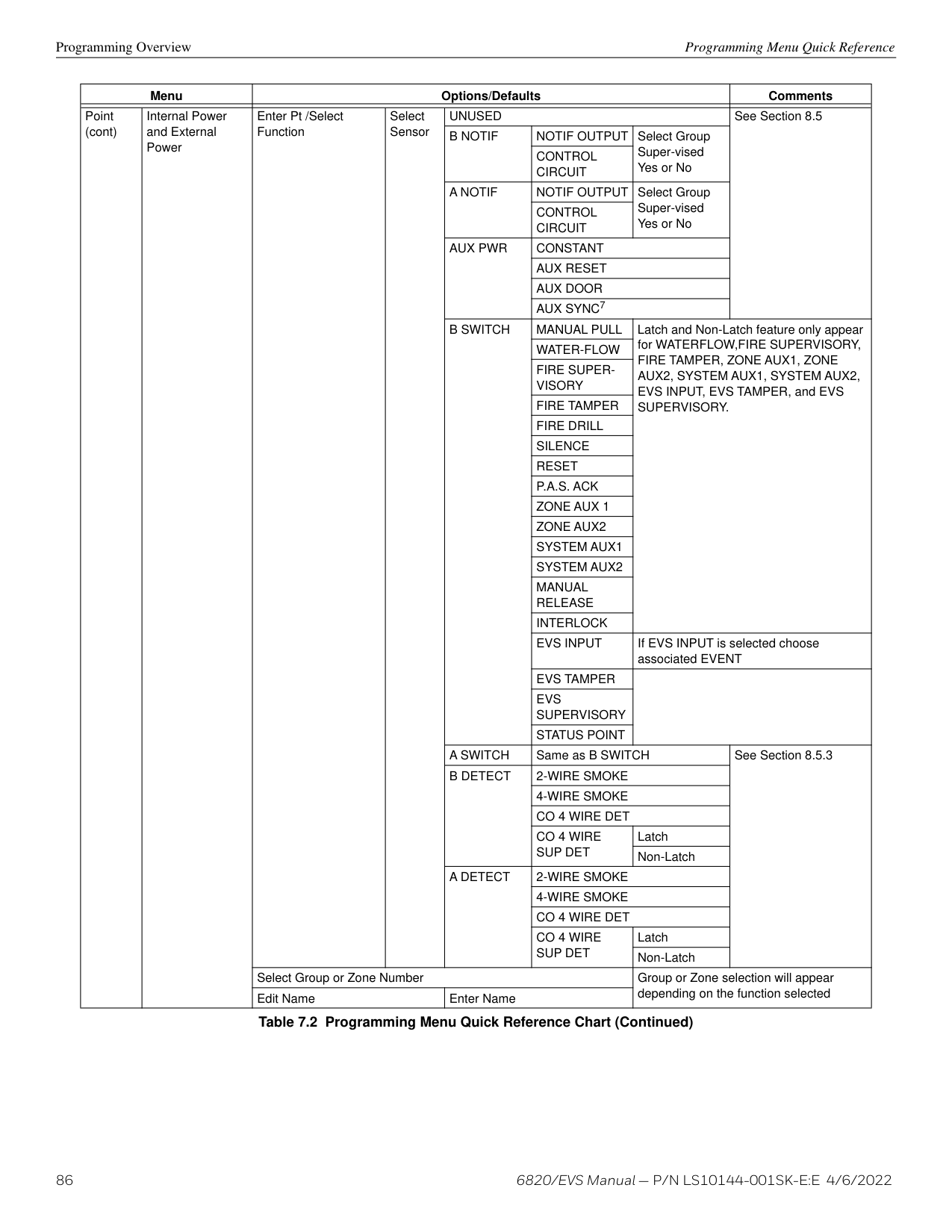
###### 6.2 Network Programming
This section of the manual describes how to program network options using the built-in annunciator. All options described in this section can be programmed using HFSS. You must use HFSS to edit site assignments.
######## 6.2.1 Learn Network
The Learn Network menu shows you all of the panels connected to the network. Any panel that has been programmed into the network will appear as a “member.” Any panel that is connected to the network but not programmed into the network will appear as a “guest.” You can add guest panels to the network by changing their status to member in this menu. Panels showing OK are currently responding on the network. Panels not showing OK have either been removed or are not responding due to networking problems. See Section 6.1 for Network Diagnostics.
NOTE: If adding panels to network, the system will automatically run the Sync Network Options. You will be required to select which panel to distribute network options from. See Section 6.4.
Incompatible Panel If you try to add an incompatible panel as a member to the network, Learn Network fails and an error message appears. The incompatible panel remains a “guest”. To continue, remove the incompatible panel from the network.
######### 6.2.2 Edit Network NamesThe Edit Network menu allows you to edit the panel name and edit the panels site name.Edit Panel Names
######## 6.2.3 Edit Panel ID
This menu option allows you to change the current Network Panel ID. It is best to carefully consider the network ID setting for each panel. Take into account any future panels that will be added to the network (future wiring of two buildings together). The Network Panel ID setting has to be unique for each panel on the network. This menu will allow you to change the currently assigned Network Panel ID to the current Network ID dip switch setting. The system will be down as the panel needs to reboot in order to complete the transition.
Network Management Network Programming
When using the PC configuration software to program the panels, the Network Panel ID will be locked from future editing. The only way to change it will be to restore defaults and use this menu again.
########## Edit the Network Panel ID
######## 6.2.4 Computer Access
An installer at the panel site can initiate communications between the panel and a computer running HFSS. (See also Section 9.4). In order for this communication to function properly, both the computer (running the software) and the control panel must have matching computer access numbers and computer codes.
To program computer access information:
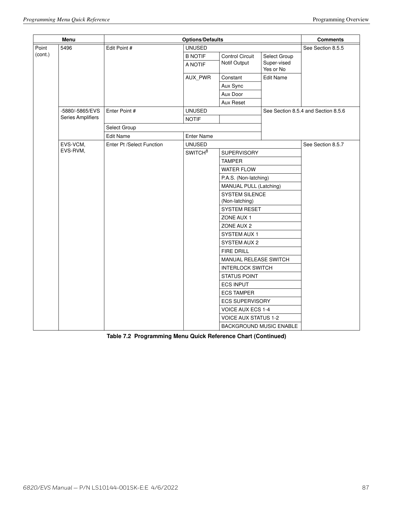
######## 6.2.5 Access Codes
Access codes provide the user access to the control panel functions. Each access code can be customized for each user. This feature allows some users the ability to access the programming and other higher level panel functions, while other users may only need access to the lower level functions (such as, preforming fire drills or acknowledging trouble conditions). Access codes can only be assigned by someone with an Administrator profile. Refer to Section 9.2.1 on page 112 for more information on administrative permissions. Once an access code has been assigned by an administrator, a user has the ability to change it.
Fire Fighter’s Key
Edit Name
Edit Access Code
######### 6.2.6 Communicator OptionsCommunicator options provides the configuration for reporting events to a central station.
Each panel on the 6820 communication link specifies which communicator is used for reporting. The communication link capability of the 6820 system allows all panels to use the same communicator providing an economical solution for reducing the number of paths required for reporting purposes. A communicator is specified by panel number. The communication link communicators will be used to report events according to the communicator report table. Communicator Miscellaneous When using the SIA reporting format, the communicator sends information according to the SIA Reporting Type. The selections for this option are:
Voice Options Network Management
NOTE: Only the SIA format sends the panel ID when reporting.
########## Receiver Configuration
The 6820 network can report events to as many as 68 receivers. See Appendix B for panel/receiver relationship numbers. Each receiver can be a phone number and reporting format. Phone numbers can be up to forty digits long.
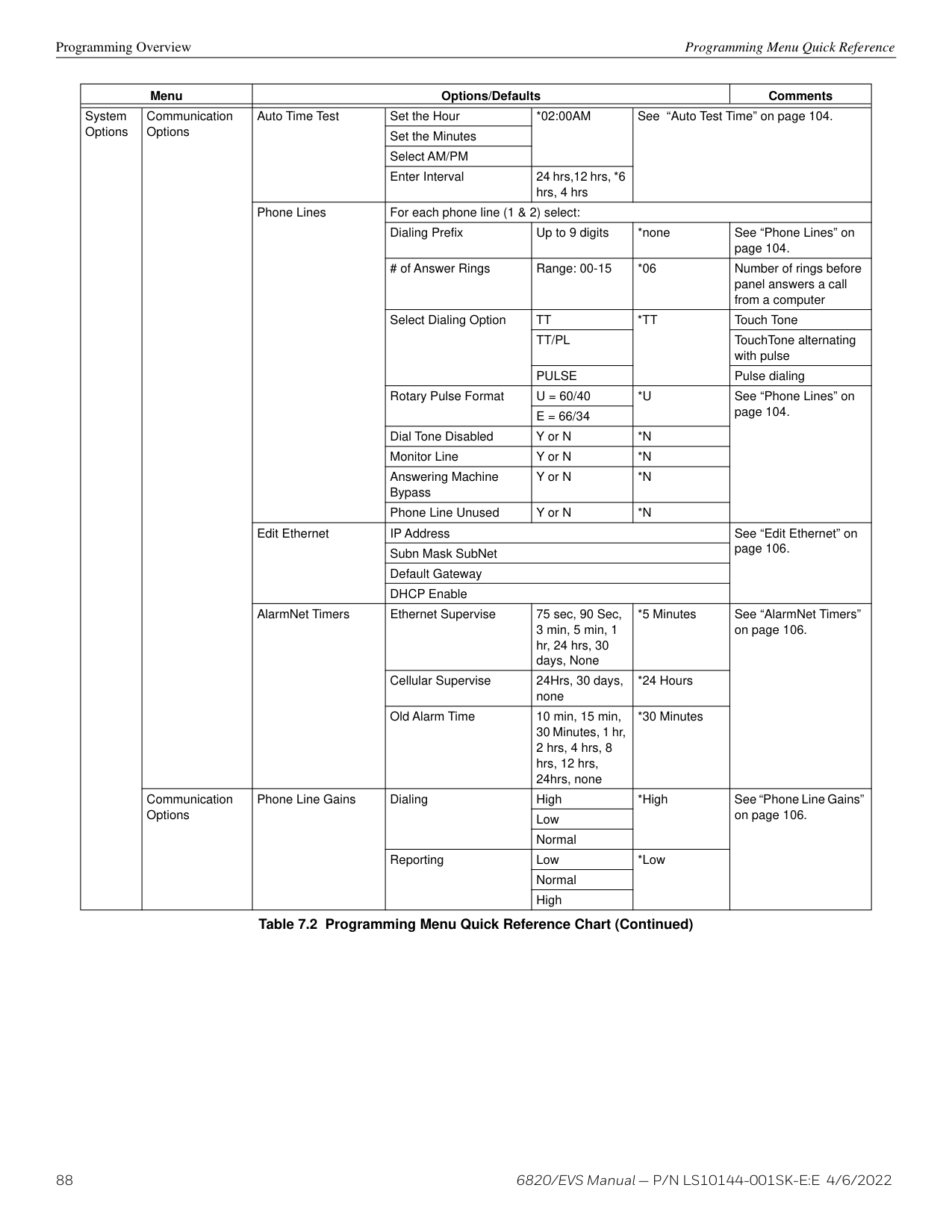
Available Format choices are:
The Communicator Report Table specifies event reporting for each panel on the network. Each row in the table specifies a panel, event types to report, primary and backup receiver numbers, and report by point or zone. Associated with the receivers are account number and daily test option. The table can have up to 99 rows.
panel number primary receiver number secondary receiver number
Panel: 03 YYYY R009:321456 N R013:987456 N
test primary account test secondary account
P#ASTP Prit Sect
01=03YYYY 009N 013N 02=02NNYN 015N 014Y * = Add Row
panel number
report event by point (Y=point, N=zone) report troubles
report alarms report supervisories
Figure 6.1 Communicator Reporting
###### 6.3 Voice Options
######## 6.3.1 Edit Timers
Network Management Voice Options
########## Control Lockout
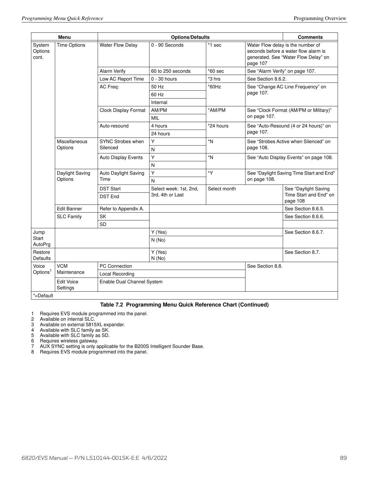
The Control Lockout countdown timer is set to the programmed value when an LOC gains EVS Control. The timer starts over upon any key press at the EVS Control LOC. While the Control Lockout timer is active, an LOC of equal priority must request EVS control. The Control Lockout timer is cleared when EVS Control is relinquished. The Control Lockout timer does not apply to EVS Super User control.
Select Immediate/Timer/Never Range 0-720 min/0-59 sec Auto Reset EVS MIC Triggered Event
If the Timer is selected, the event will automatically reset after being active for the programmed time. If Event Disabled is selected, the event will not be allowed to be activate from an LOC Station. Selecting Never will require an emergency system reset to be performed to reset the event.
Select Never/Timer/Event Disabled, Range from 1-240 min
|EVS Timer|Option| |---|---| |Control Lockout|Immediate/Timer/Never| |Auto Reset EVS MIC Triggered Event|Never/Timer/Event Disabled| |Auto Reset EVS Event 1|Never/Timer/Event Disabled| |Auto Reset EVS Event 2|Never/Timer/Event Disabled| |Auto Reset EVS Event 3|Never/Timer/Event Disabled| |Auto Reset EVS Event 4|Never/Timer/Event Disabled| |Auto Reset EVS Event 5|Never/Timer/Event Disabled| |Auto Reset EVS Event 6|Never/Timer/Event Disabled| |Auto Reset EVS Event 7|Never/Timer/Event Disabled| |Auto Reset EVS Event 8|Never/Timer/Event Disabled|
############# Table 6.1 Auto Reset EVS MIC Triggered Event Timer Menu
######## 6.3.2 Edit Voice Commands
When a voice output group is selected to be activated by a zone, the cadence pattern choice does not apply. For voice output groups, one of six system wide voice commands will activate instead of the cadence pattern.
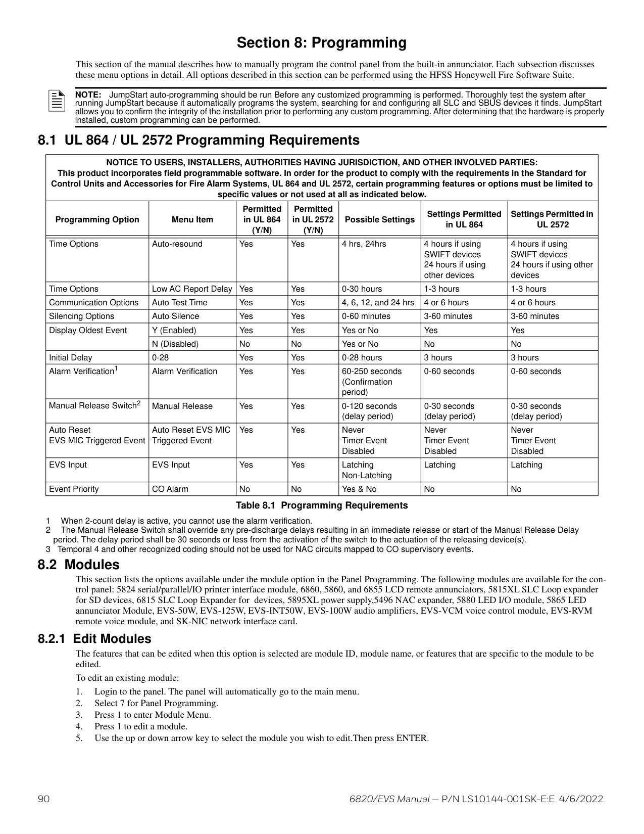
Sync Network Options Network Management
NOTE: 520Hz tones are available when using the ECS-VCM, EVS-INT50W, or EVS-100W amplifiers. These include ANSI 520, Temp 4 520, Steady 520. See the Device Compatibility Document for a list of compatible speakers.
###### 6.4 Sync Network Options
If after making changes to network programming, the distribution of network options fail, the system will report a trouble of network options out of sync. Use this menu to redistribute changed options to the rest of the network. The user will be required to choose a panel to source the options from. Scroll down through the informational message and press ENTER to view the Select Source screen.
|Select Source
01= Panel 1
02= Panel 2
03= Panel 3
| |---|
|Select Source
01= 07/28/21 12:20 OF
02 Panel 2
03 Panel 3
| |---|
|Select Source 01=/28/21 12:20 OF8B
02 Panel 2
03 Panel 3
| |---|
Select the line number. #1 in this example. Line #1 scrolls to show the date. Scroll down to see checksum.
############# Figure 6.2 Sync Network Options
NOTE: If you try to sync with the network and an incompatible panel is found, an error message will display.
Network Management Network Management Quick Reference
###### 6.5 Network Management Quick Reference
|Menu|Options/Defaults|Options/Defaults|Options/Defaults|Comments|Comments| |---|---|---|---|---|---| | | | | | | | |Learn Network|Guest or member|Add or remove panels into the network| |See Section 6.2.1|See Section 6.2.1| |Edit Network Names|Panel Names|Network Panel ID|Edit Panel Names|See Section 6.2.2|See Section 6.2.2| |Edit Network Names|Site Names|Edit Site Member|Edit Site Names|See Section 6.2.2|See Section 6.2.2| |Edit Panel ID|Change current panel ID| | |See Section 6.2.3|See Section 6.2.3|
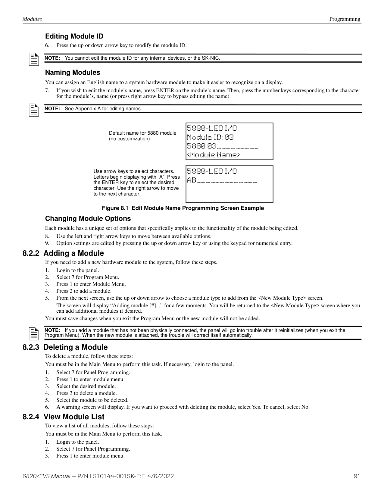
|Computer Access|Computer Access Number|*123456| |See Section 6.2.4|See Section 6.2.4| |Computer Access|Computer Code|*0| |See Section 6.2.4|See Section 6.2.4| |Access Codes|Select Profile (01 - 20)|Edit Name|Edit Name|Profile 1 is the profile that dictates what functions the Firefighter Key has access to. Because this is the profile for a keys, the user name and the access code can not be edited for this profile.|Profile 1 is the profile that dictates what functions the Firefighter Key has access to. Because this is the profile for a keys, the user name and the access code can not be edited for this profile.| |Access Codes|Select Profile (01 - 20)|Edit Access Code|Edit Access Code|Profile 1 is the profile that dictates what functions the Firefighter Key has access to. Because this is the profile for a keys, the user name and the access code can not be edited for this profile.|Profile 1 is the profile that dictates what functions the Firefighter Key has access to. Because this is the profile for a keys, the user name and the access code can not be edited for this profile.| |Communicator Options|Communicator Assignments|Select Panel|Primary|0=unused|See Section 6.2.6| |Communicator Options|Communicator Miscellaneous|SIA Options|Enable pi SIA Modifier|Enable pi SIA Modifier|See, "Communicator Miscellaneous"| |Communicator Options|Communicator Miscellaneous|SIA Options|Include Panel ID in SIA Reporting|Include Panel ID in SIA Reporting|See, "Communicator Miscellaneous"| |Communicator Options|Receiver Configuration|Select Panel|Select Receiver|Receiver Number|See, "Receiver Configuration"| |Communicator Options|Receiver Configuration|Receiver Format|Contact ID|Contact ID|See, "Receiver Configuration"| |Communicator Options|Receiver Configuration|Receiver Format|SIA500|SIA500|See, "Receiver Configuration"| |Communicator Options|Receiver Configuration|Receiver Format|SIA8|SIA8|See, "Receiver Configuration"| |Communicator Options|Receiver Configuration|Receiver Format|SIA20|SIA20|See, "Receiver Configuration"| |Communicator Options|Receiver Configuration|Receiver Format|Ethernet|Ethernet|See, "Receiver Configuration"| |Communicator Options|Receiver Configuration|Receiver Format|Cellular|Cellular|See, "Receiver Configuration"| |Communicator Options|Receiver Configuration|Receiver Format|UNUSED|UNUSED|See, "Receiver Configuration"| |Communicator Options|Receiver Configuration|Receiver Credentials|Receiver Credentials|Receiver Credentials|See, "Receiver Configuration"| |Communicator Options|Communicator Report Table|Communicator Report Table|Panel|See, "Communicator Reporting Table".|See, "Communicator Reporting Table".| |Communicator Options|Communicator Report Table|Communicator Report Table|Report Alarms|See, "Communicator Reporting Table".|See, "Communicator Reporting Table".| |Communicator Options|Communicator Report Table|Communicator Report Table|Report Supervisory|See, "Communicator Reporting Table".|See, "Communicator Reporting Table".| |Communicator Options|Communicator Report Table|Communicator Report Table|Report Troubles|See, "Communicator Reporting Table".|See, "Communicator Reporting Table".| |Communicator Options|Communicator Report Table|Communicator Report Table|Report Events by Point|See, "Communicator Reporting Table".|See, "Communicator Reporting Table".| |Communicator Options|Communicator Report Table|Communicator Report Table|Primary Receiver|See, "Communicator Reporting Table".|See, "Communicator Reporting Table".| |Communicator Options|Communicator Report Table|Communicator Report Table|Primary Account|See, "Communicator Reporting Table".|See, "Communicator Reporting Table".| |Communicator Options|Communicator Report Table|Communicator Report Table|Test Primary Account|See, "Communicator Reporting Table".|See, "Communicator Reporting Table".| |Communicator Options|Communicator Report Table|Communicator Report Table|Secondary Receiver|See, "Communicator Reporting Table".|See, "Communicator Reporting Table".| |Communicator Options|Communicator Report Table|Communicator Report Table|Secondary Account|See, "Communicator Reporting Table".|See, "Communicator Reporting Table".| |Communicator Options|Communicator Report Table|Communicator Report Table|Test Secondary Account|See, "Communicator Reporting Table".|See, "Communicator Reporting Table".|
Table 6.2 Network Management Quick Reference Chart
Network Management Quick Reference Network Management
|Menu|Options/Defaults|Options/Defaults|Options/Defaults|Comments|Comments| |---|---|---|---|---|---| | | | | | | | |Voice Options|Choose Site|Edit Timers|Control Lockout|Immediate/Timer/ Never|See Section 6.3.1| |Voice Options|Choose Site|Edit Timers|Auto Reset EVS Event 1-8|Never/Timer/Event Disabled|See Section 6.3.1| |Voice Options|Choose Site|Edit Timers|Auto Reset EVS MIC Triggered Event|Never/Timer/Event Disabled|See Section 6.3.1| |Voice Options|Choose Site|Edit Voice Commands|Fire Alarm|See Section 6.3.2|See Section 6.3.2| |Voice Options|Choose Site|Edit Voice Commands|Fire System Aux 1|See Section 6.3.2|See Section 6.3.2| |Voice Options|Choose Site|Edit Voice Commands|Fire System Aux 2|See Section 6.3.2|See Section 6.3.2| |Voice Options|Choose Site|Edit Voice Commands|Fire Zone Aux 1|See Section 6.3.2|See Section 6.3.2| |Voice Options|Choose Site|Edit Voice Commands|Fire Zone Aux 2|See Section 6.3.2|See Section 6.3.2| |Voice Options|Choose Site|Edit Voice Commands|Fire Supervisory|See Section 6.3.2|See Section 6.3.2| |Voice Options|Choose Site|Edit Voice Commands|Fire Prealarm|See Section 6.3.2|See Section 6.3.2| |Voice Options|Choose Site|Edit Voice Commands|Custom Emergency Comm|See Section 6.3.2|See Section 6.3.2| |Voice Options|Choose Site|Edit Voice Commands|Emergency Communication 1-8|See Section 6.3.2|See Section 6.3.2| |Voice Options|Choose Site|Edit Voice Commands|System Alert 1-5|See Section 6.3.2|See Section 6.3.2| |Voice Options|Choose Site|Edit Voice Commands|Trouble|See Section 6.3.2|See Section 6.3.2| |Voice Options|Choose Site|Edit Voice Commands|Fire Interlock Release|See Section 6.3.2|See Section 6.3.2| |Voice Options|Choose Site|Edit Voice Commands|Fire Interlock Alert|See Section 6.3.2|See Section 6.3.2| |Voice Options|Choose Site|Edit Voice Commands|Emergency Supervisory|See Section 6.3.2|See Section 6.3.2| |Voice Options|Choose Site|Edit Voice Commands|CO Alarm|See Section 6.3.2|See Section 6.3.2| |Voice Options|Choose Site|Edit Voice Commands|CO Supervisory|See Section 6.3.2|See Section 6.3.2| |Sync Network Options| | | |See Section 6.4|See Section 6.4|
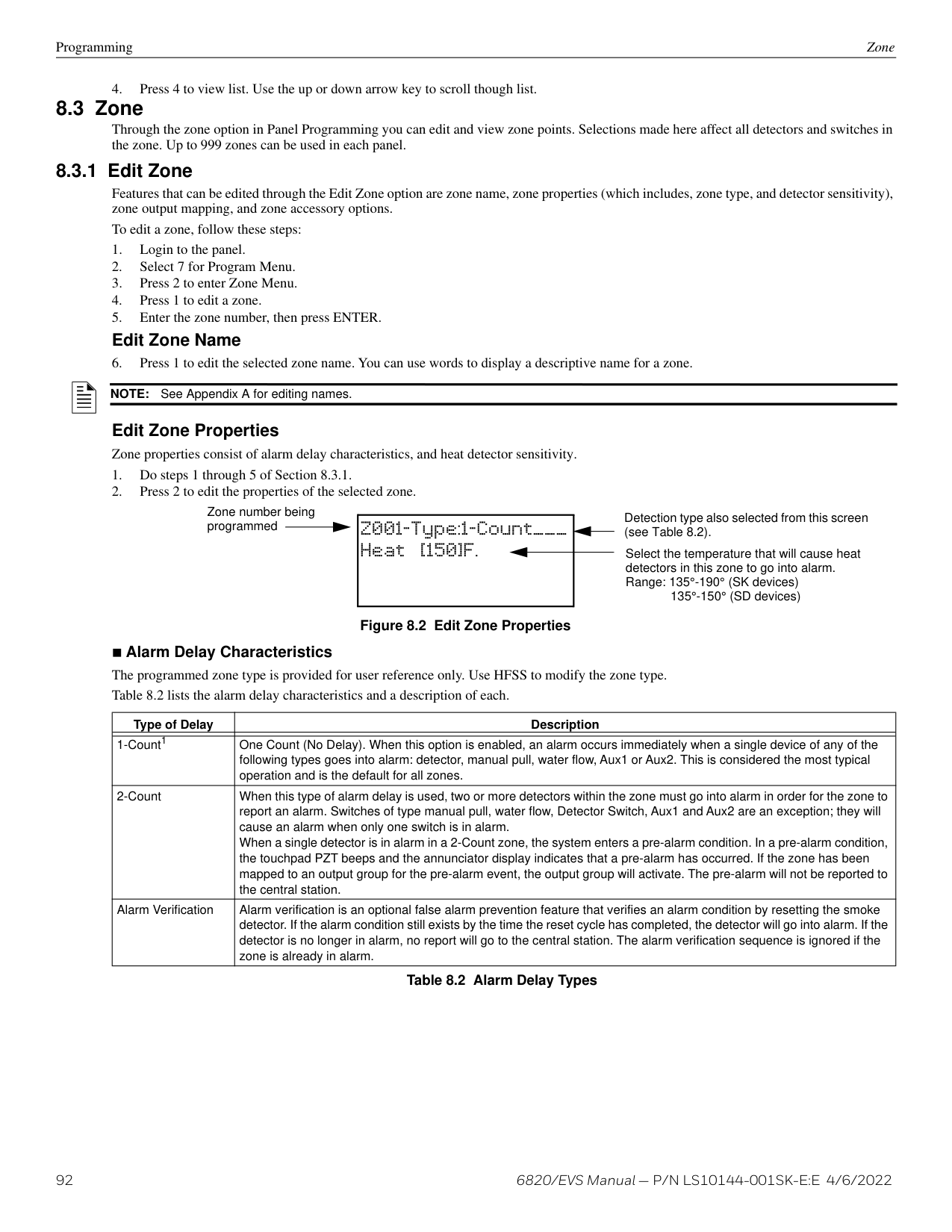
############# Table 6.2 Network Management Quick Reference Chart (Continued)
##### Section 7: Programming Overview
This section of the manual is intended to give you an overview of the programming process. Please read this section of the manual carefully, especially if you are programming the control panel for the first time.
The JumpStart Auto-programming feature automates many programming tasks and selects default options for the system. JumpStart should be at least once when you are installing the system. See Section 7.1 for details. After you run JumpStart, you may need to do some additional programming depending on your installation. Section 8 of this manual covers manual programmable options in detail.
Programming the panel can be thought of as a three part process. You must program:
###### 7.1 JumpStart Auto-Programming
The JumpStart Auto-Programming feature allows for faster system setup. When you run JumpStart AutoProgramming, the panel searches for expanders and SLC devices not currently in the system. The new devices are added in their default configuration. At the end of the JumpStart you can choose to not accept the new devices and go back to the configuration you had before. JumpStart saves the installer from having to program options for each device. Depending on the application, the installer may need to make some changes after JumpStart completes. See Section 7.1.3 for complete details about running JumpStart.
######## 7.1.1 Input Points
The first JumpStart on the panel in default configuration will determine the number and type of input points (detectors or contact monitor modules) on each SLC loop. JumpStart Auto-Programming assigns the correct detector type (heat, ionization or photoelectric), so the installer does not need to edit the device type for detectors. Any contact monitor modules on the system will be assigned type “Manual Pull.” The installer will need to manually change the switch type if manual pull is not correct.
The first JumpStart AutoProgramming creates one zone (Zone 1) and assigns all input points to Zone 1. Zone 1 is mapped to Output Group 1.
######## 7.1.2 Output Points
The 6820 JumpStart creates three output groups. The 6820EVS with amplifiers will create four output groups. The output circuits are assigned as follows:
Circuits 1-6 Configured as Notification and assigned to Group 1. Circuit 7 (Relay 1) Assigned to Group 998. Circuit 8 (Relay 2) Assigned to Group 999. Amplifier Circuits Assigned to Group 2. JumpStart automatically programs Zone 1 to activate Group 2. Addressable output points (Relay modules) All addressable relay devices will be configured as “Output Pt” (general purpose output point) and assigned to Group 1.
NOTE: Relay output is constant even if the zone activating the relay is programmed with an output pattern.
######## 7.1.3 Running JumpStart Auto-Programming
Run JumpStart Auto-Programming immediately after you have addressed and connected all input devices (detectors, pull stations, and so on) and output devices (notification appliances, relays, and so on).
NOTE: If you need to install a few devices after you have run JumpStart, you can install them manually or run JumpStart again at a later time. JumpStart will keep user options, such as names, for devices already installed. Follow instructions in Section 7 for configuration.
To run JumpStart AutoProgramming, follow these steps.
|1 - Review System|Press 1 if you need to review the JumpStart configuration. The Review System menu will appear. Press 1 to review Entire System or Press 2 for Changes Only.| |---|---|
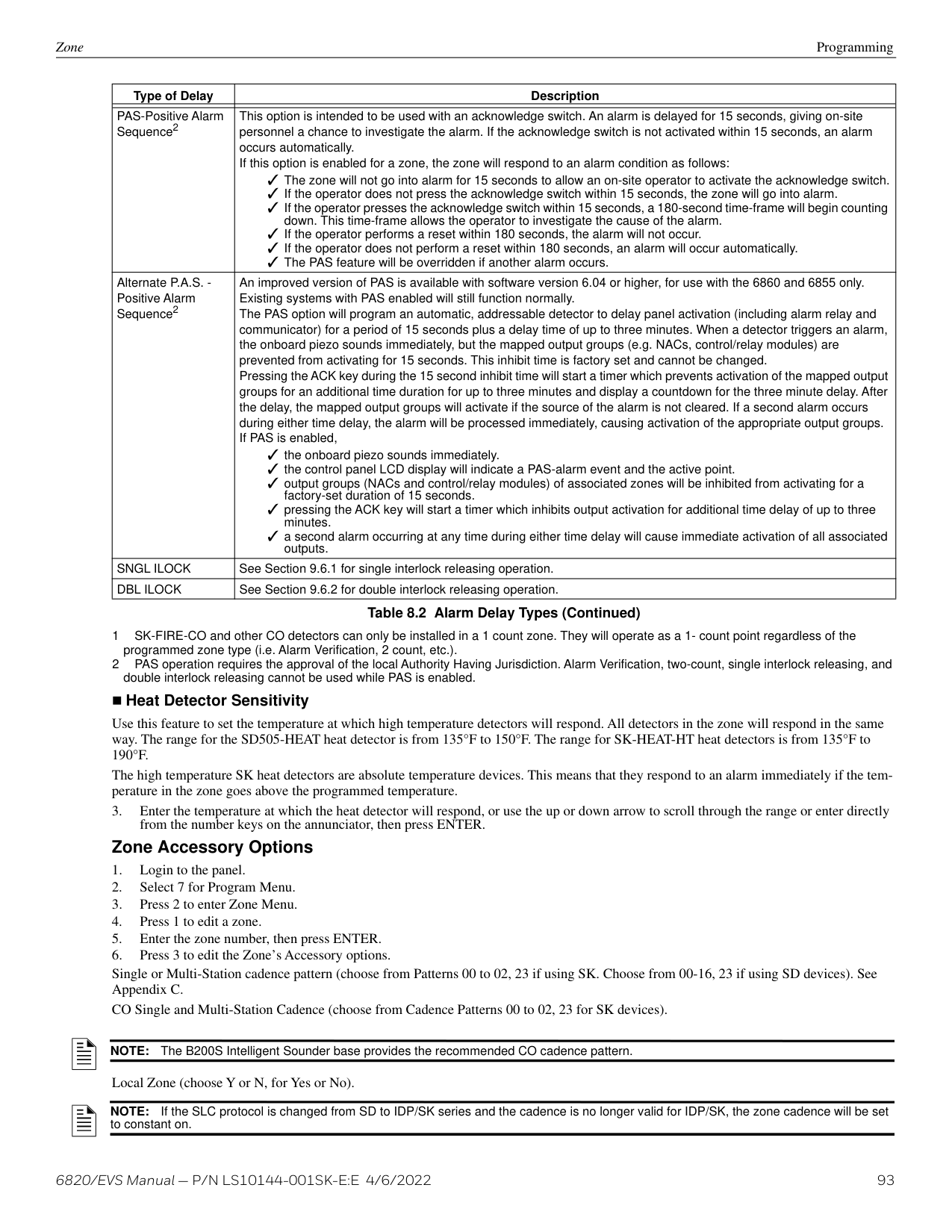
|2 - Repeat JumpStart|Press 2 if you need to rerun JumpStart for any reason.| |3 - Accept Changes|1. If you are ready to make the JumpStart configuration permanent, select 3.
2. The system will ask you if the installation contains any addressable duct detectors. If there are none, select 2 for No and skip to Step 8. If the system contains duct detectors, select 1 for Yes and continue with Step 3.
3. From the list that displays, select the SLC that contains the duct detectors.
4. The first photoelectric or ionization detector on the system will display. Select 1 for DUCT and 2 for NonDUCT.
5. Press up arrow to select the next detector. Select 1 for DUCT and 2 for NonDUCT. Continue until all duct detectors have been selected. (Note: You can move backwards through the list with down arrow).
6. When you reach the last detector on this device, press left arrow.
7. The system will ask you if there are any duct detectors used. If there are, select 1 for Yes and the message will ask, Have All Addressable Duct Detectors Been Identified? Left arrow for “No”, Right arrow for “Yes”. If there are no more duct detectors, continue with Step 8.
8. The system will restart with the saved JumpStart configuration.
9. After the system resets, it will use the new JumpStart configuration.
| |4 - Discard Changes|If you want to discard the changes, and keep the configuration you had before running this JumpStart press 4.|
Mapping is an important concept with the control panel. In general terms, mapping is assigning or linking events to outputs that will activate when events occur. You do this by assigning input points to input zones, output points to output groups and then linking or mapping zones and output groups.
Figure 7.1 is a brief overview of the concept of mapping. The next several pages of the manual show these subjects in detail.
In its simplest application, mapping determines which outputs are activated by which inputs. input zone output group
|1
2
3
4
5
| |---|
|1
3
2| |---|
input points (SLC devices)
output points (NAC circuits)
Input zones are mapped by event type to output groups. Cadence patterns are assigned as part of the mapping information. Up to eight groups/patterns can be selected for each event.
|input points (SLC devices)| |---|
|input zones| | |---|---| |input zones| |
|cadence patterns| | |---|---| |cadence patterns| |
|output groups| |---|
| |output points (NAC/relay ckts)| |---|---| | |output points (NAC/relay ckts)|
Output points are assigned to output groups only.system trbl & special
system eventsoptional
############# Figure 7.1 Mapping Overview
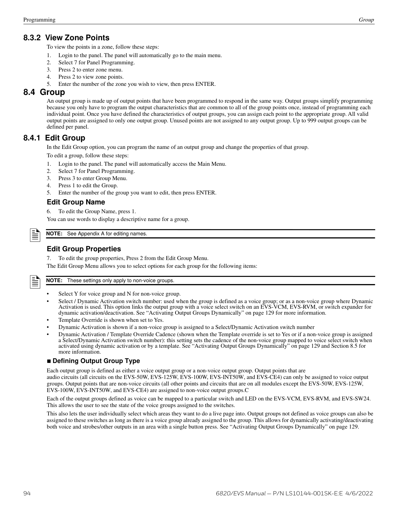
NOTE: Mapping cannot be programmed through the annunciators. It can only be programmed through the HFSS Honeywell Fire Software Suite.
Programming Overview Mapping Overview
######## 7.2.1 Input Point Mapping
Input points are assigned to input zones, as Figure 7.2 shows. Any input point can be assigned to any input zone. (Input points can be assigned to one zone only. An input point can be designated as “Unused,” which means it has not been assigned to a zone).
|zone 1| |---| |zone 2| |zone 3| |zone 4| |zone 5| |zone 6
through
zone 248| |zone 249| |zone 250|
|point 1
point 2
point 3
| | | |---|---|---| |point 1
point 2
point 3
| | | |point 4
point 5
point 6
|point 4
point 5
point 6
| |
|point 7
point 8
| |---|
through
############# Figure 7.2 Input Point Assignment Example
######### 7.2.2 Output Circuit MappingFigure 7.3 is a simple example showing how to assign notification and relay output circuits to groups.
In this example, all NAC outputs are assigned to group 1.
output circuit 3 NAC circuit
|output circuit 4 aux power output|
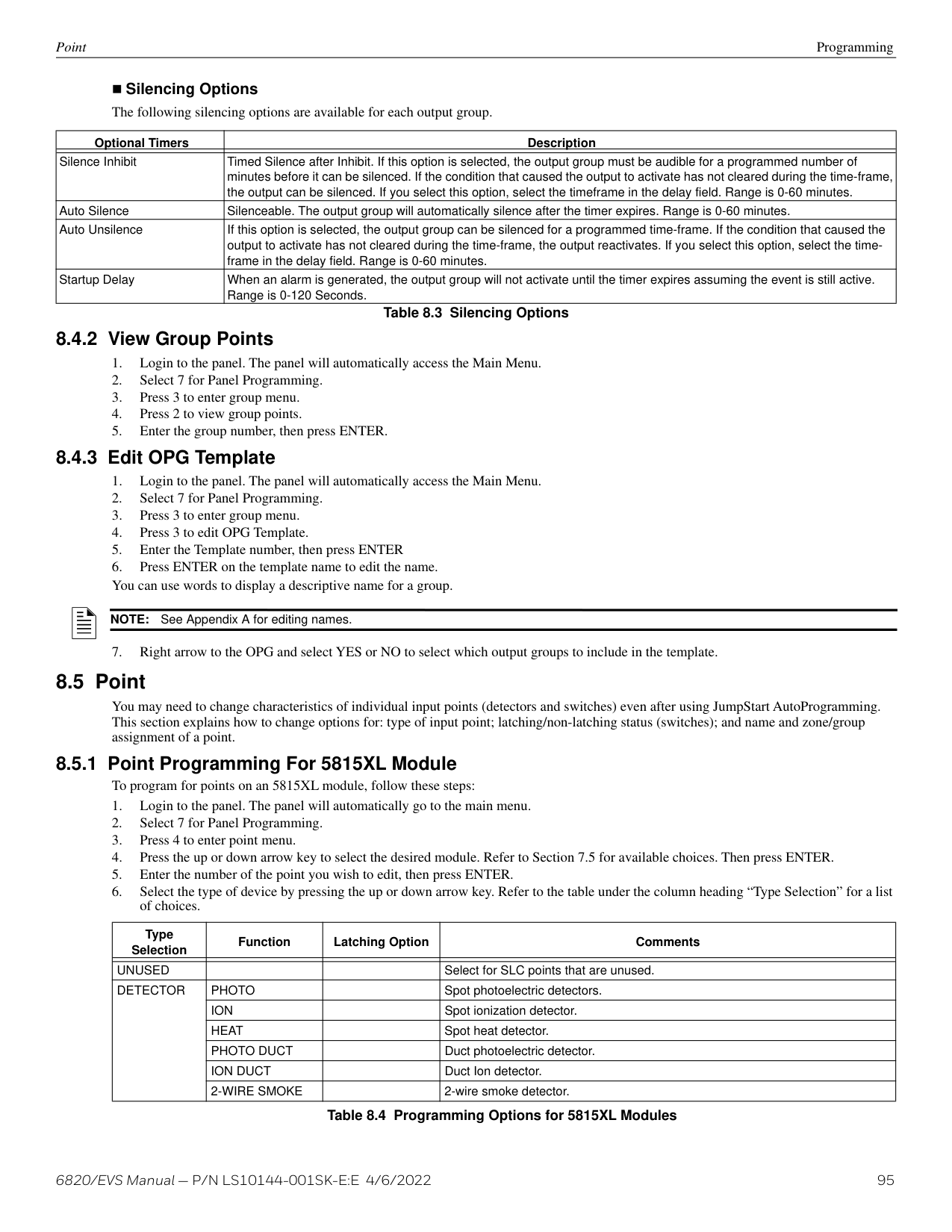
|---|
Aux power outputs are not mapped to output groups.
through
group 998 group 999
JumpStart creates group 998 and group 999 for Relay 1 and Relay 2.
############# Figure 7.3 Assigning Output Circuits to Groups (Example)
######## 7.2.3 Event Mapping
There are 11 types of Zone events, 14 types of Panel events, and 6 types of Site events that can be mapped. For each event type, you can activate the output groups with specific output patterns. Mapping examples are shown in Figures 7.4 and 7.5.
|System|Zone|Panel|Site| |---|---|---|---| |Fire|Manual Pull Alarm|System Aux 1 Alarm|Fire Drill| |Fire|Water Flow Alarm|System Aux 2 Alarm|General Fire Alarm| |Fire|Detector Alarm (heat or smoke detectors)| |General Fire Supervisory| |Fire|Zone Aux 1 Alarm| |General Fire Pre-Alarm| |Fire|Zone Aux 2 Alarm| | | |Fire|Interlock Alert| | | |Fire|Interlock Release| | | |Fire|Pre-Alarm| | | |Fire|Fire Supervisory| | | |Fire|Status Point| | | |Fire|CO Alarm| | | |Fire|CO Supervisory1| | | |Emergency| | |LOC EVS 1-8 Alarm| |Emergency| | |General EVS Alarm| |Emergency| | |General EVS Supervisory| |Emergency| | |Point EVS 1-8 Alarm| |Advisory|Trouble|SBUS Expander Trouble|General Trouble| |Advisory|Status Point Active|SBUS Class A Trouble|Site Silenced| |Advisory| |SLC Loop Trouble|Voice Aux In 1-8 Alarm| |Advisory| |AC Loss Trouble|F1 Key Active| |Advisory| |Battery Trouble|F2 Key Active| |Advisory| |Ground Fault Trouble|F3 Key Active| |Advisory| |Phone Line Trouble|F4 Key Active| |Advisory| |Reporting Account Trouble|Voice Aux in 1-2| |Advisory| |Printer Trouble|System Mic Active| |Advisory| |Aux Power Trouble|Background Music| |Advisory| |System Switch Trouble| | |Advisory| |Output Group Trouble| |
1 Temporal 4 and other recognized coding should not be used for NAC circuits mapped to CO supervisory events
pattern 00 constant
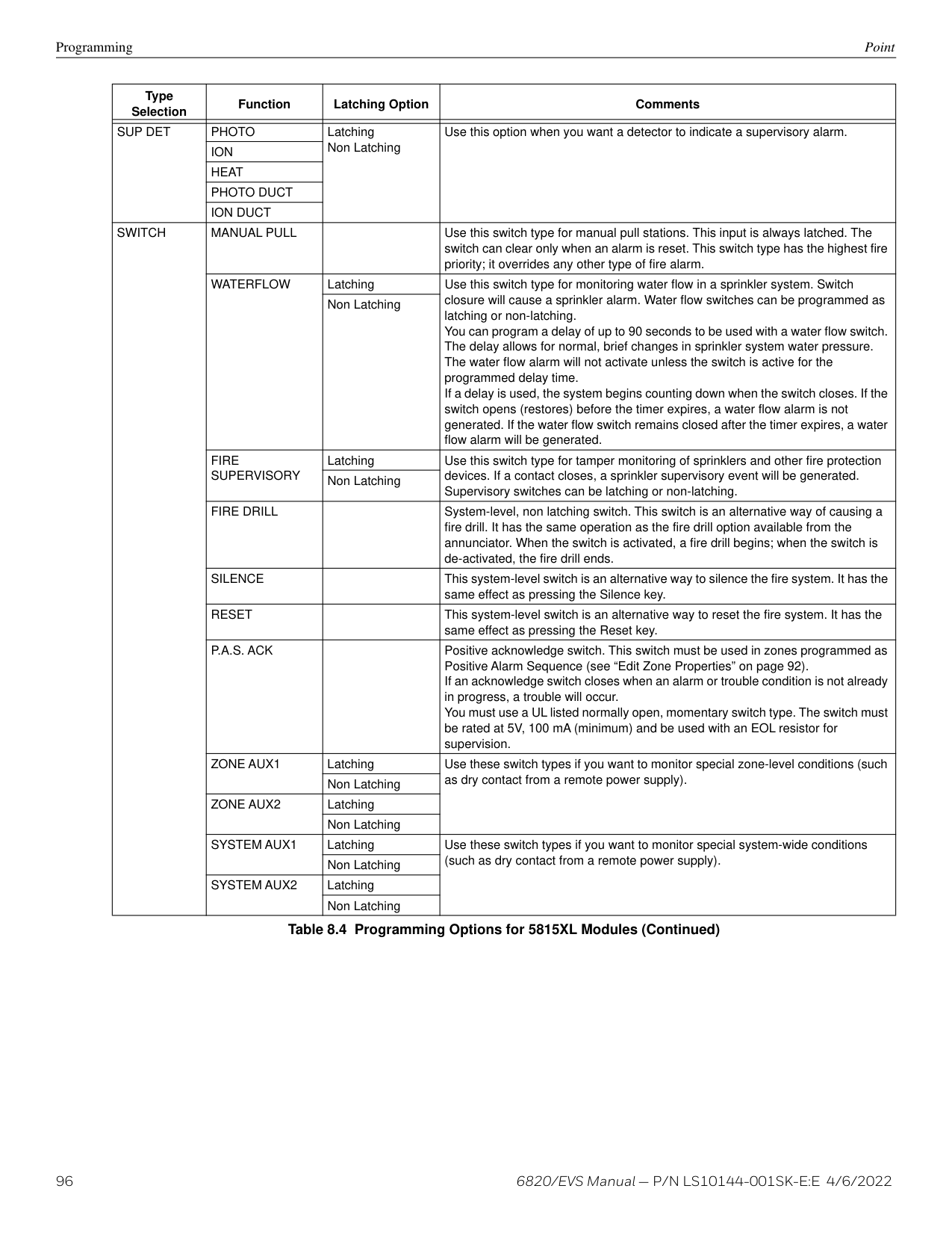
|group 1| |---| |group 2| |group 3| |group 4| |group 5| |group 6
through
group 250|
Zone 1: manual pull alarm
pattern 02 ANSI 3.41
This example shows Zone 1 manual pull alarm event mapped to:
############# Figure 7.4 Example of Zone Events Mapped to Output Groups and Patterns
Programming Overview Programming Using the HFSS Software Suite
|Zone 3 Offices 3rd floor| |---|
|Group 3 3rd floor notification| |---|
|Zone 2 Storage 2nd floor| |---|
|Group 2 2nd floor notification| |---|
ANSI 3.41
|Group 1 1st floor notification| |---|
Zone 1 Show Room 1st floor
manual pull
ANSI 3.41
detector alarm
constant
supervisory
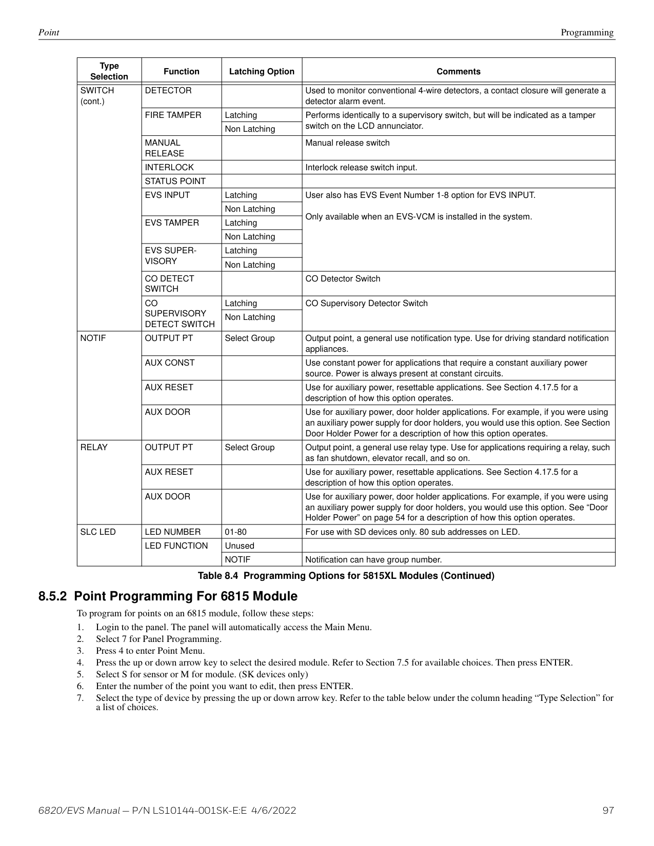
|Zone 3 Offices 3rd floor| |---|
|Group 3 3rd floor notification| |---|
ANSI 3.41
|Group 2 2nd floor notification| |---|
Zone 2 Storage 2nd floor
manual pull
ANSI 3.41
detector alarm
constant
supervisory
|Zone 1 Show Room 1st floor| |---|
|Group 1 1st floor notification| |---|
|same floor floor above floor below| |---|
############# Figure 7.5 Example of Zone Events Mapped to Output Groups and Patterns
######## 7.2.4 Mapping LED Points
Figure 7.6 is a simple example showing how LED points are mapped to zones and output groups. Typically you would create two output groups for each zone, one for alarms and one for troubles. (LED points are available when models 5865-3/4 and/or 5880 are used with the system).
########### Mapping LEDs to Zones and Output Groups
|Zone 1 manual pull alarm| |---|
detector alarm
|Zone 1 trouble| | |---|---|
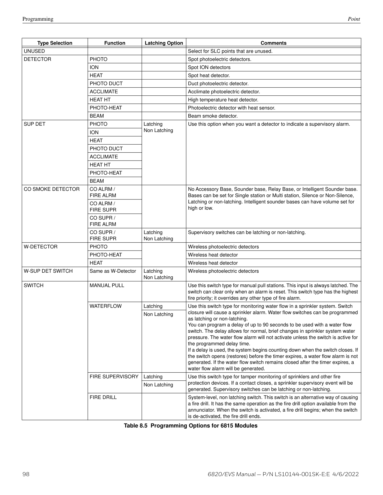
|Zone 1 trouble| |
|Output group 1 red LED 1 alarm outputs (horns, strobes, etc.)| |---|
|Output group 2 yellow LED 2 maintenance room sounder| |---|
|Output group 3 red LED 3 alarm outputs (horns, strobes, etc.)| |---|
An alarm in Zone2 will activate red LED3 and any other required outputs.
|Output group 2 yellow LED4| |---|
|Zone 2 manual pull alarm| | |---|---| |Zone 2 manual pull alarm| |
detector alarm
|Zone 2 trouble| | |---|---| |Zone 2 trouble| |
Figure 7.6 Example of LED Points Mapped to Output Groups (applies to Models 5865-3/4 and 5880)
###### 7.3 Programming Using the HFSS Software Suite
You can use the HFSS Software Suite to program the control panel onsite (personnel will need to be onsite during the upload or download process). HFSS is a software package that lets you easily program the control panel using a Windows-based computer. HFSS is needed for Mapping. When using HFSS, you can set up the programming options for the panel, save the options in a file, then download the file to the panel. You can connect to the control panel directly using the onboard USB or Ethernet. Updates are available at www.silentknight.com.
Programming Using an Annunciator Programming Overview
###### 7.4 Programming Using an Annunciator
You can program the control panel from a system annunciator, using either the control panel’s onboard annunciator or a 6860, 6855, or 5860 remote annunciator.
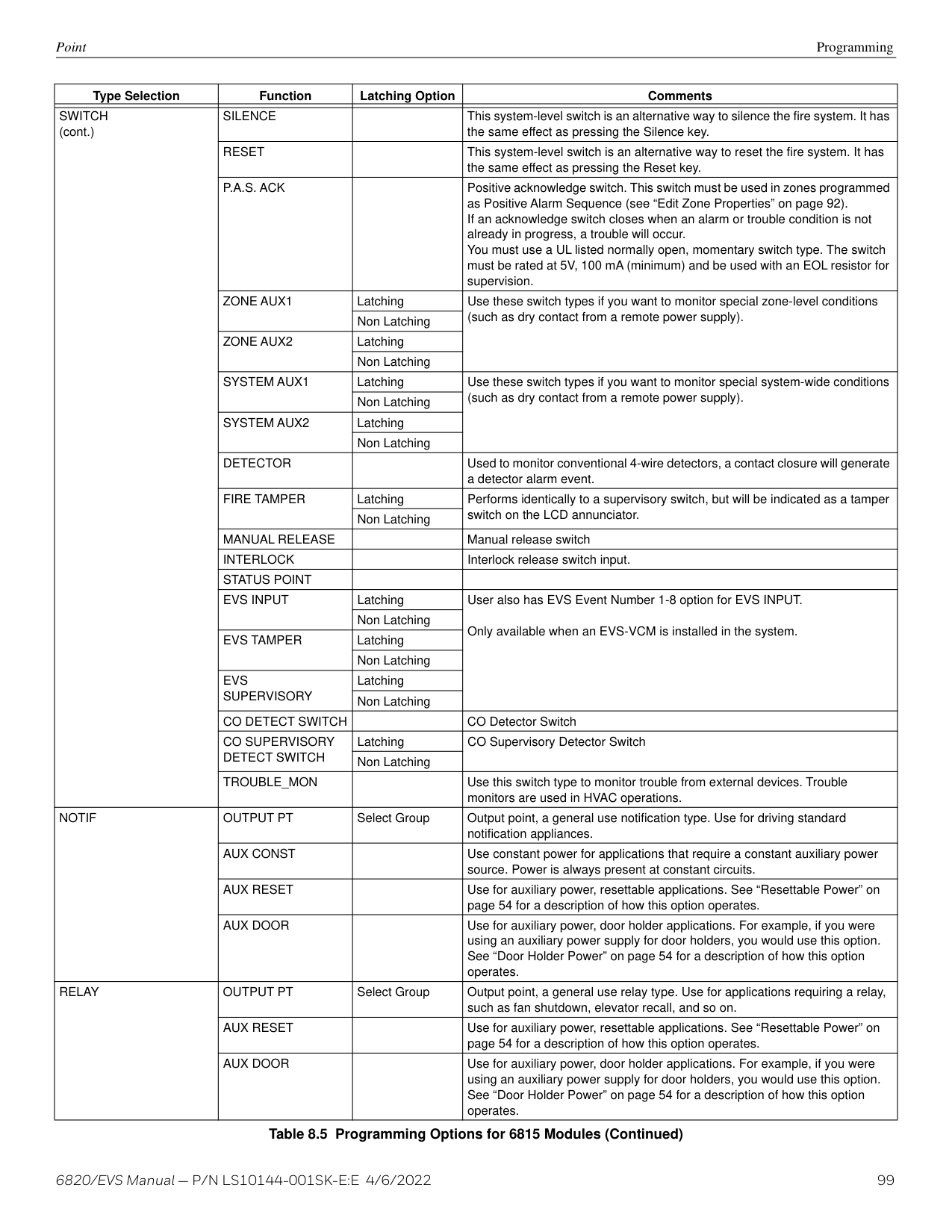
The following subsections describe programming basics, including a description of editing keys available for programming and how to move through programming menus. Section 8 contains specific information about individual programming options.
NOTE: Output mapping cannot be programmed through the onboard and remote annunciators. Mapping is only available through the HFSS Honeywell Fire Software Suite.
######## 7.4.1 Entering / Exiting Panel ProgrammingEntering Program Mode
########## Exiting Program Mode
When you have completed working with the menus, press the left arrow several times until you exit from the Programming Mode. Two prompts will display. At the first prompt, a message appears indicating to exit the Program Menu (select Yes or No as appropriate). At the second prompt, a message indicates if the user accepts all changes. If you select No, any changes you have made since you entered the Program Menu will have no effect.
Moving Through the Menus Figure 7.7 shows how to move through the menu screens, using the main menu screen as an example.
Menu Name selected option (displays next to equal sign)
|Main Menu 1=System Tests
2 Point Functions
3 Event History
| |---|
Arrow indicates more screens. Press the down arrow key to access.
############# Figure 7.7 Moving Through the Program Menu
########## Selecting Options and Entering Data
There are several ways to make programming selections using the control panel depending on which screen you are currently viewing. The chart below is a generic explanation.
|To|Press| |---|---| | | | |Select from a menu|Enter the number of the option.| |Enter numeric data|Press the appropriate number on the annunciator.| |Enter text (alphanumeric data)|Enter each character individually using the Up and Down arrow keys until the one you wish to select displays. Then press right arrow to select the character. See Appendix A for a complete list of characters.| |Select from a scrolling list|Use up arrow and down arrow to move through a list of available options. When the option you want to select is displayed, press ENTER.|
Table 7.1 Menu Options
###### 7.5 Programming Menu Quick Reference
This section of the manual lists all Panel Programming options in the order they appear on the sub-menus. Default settings are indicated in text or marked with an asterisk (*). The comments column provide quick information and a reference to a section (if applicable) which has more detailed information.
|Menu|Menu|Options/Defaults|Options/Defaults|Comments| |---|---|---|---|---| | | | | | | |Module|Edit Module|Select Module|Edit Module ID|See Section 8.2.1| |Module|Edit Module|Select Module|Enter Module Name|See Section 8.2.1| |Module|Edit Module|Select Module|Edit Module specific options|See Section 8.2.1| |Module|Add Module|5824 Serial/Parallel/IO| |See Section 8.2.2| |Module|Add Module|6860 LCD Annunciator| |See Section 8.2.2| |Module|Add Module|5860 LCD Annunciator| |See Section 8.2.2| |Module|Add Module|6855 LCD Annunciator| |See Section 8.2.2| |Module|Add Module|6815 SLC Loop Expander| |See Section 8.2.2| |Module|Add Module|5815XL SLC Loop Expander| |See Section 8.2.2|
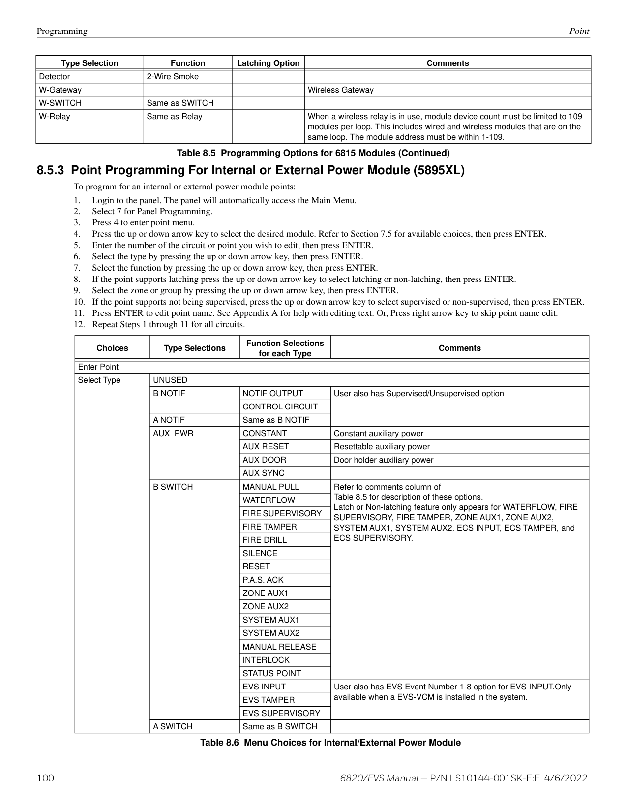
|Module|Add Module|5895XL Power Supply| |See Section 8.2.2| |Module|Add Module|5496 NAC Expander| |See Section 8.2.2| |Module|Add Module|5880 LED/IO Module| |See Section 8.2.2| |Module|Add Module|5865-LED Annunc. Module| |See Section 8.2.2| |Module|Add Module|EVS-50W Voice Amplifier1| |See Section 8.2.2| |Module|Add Module|EVS-125W Voice Amplifier1| |See Section 8.2.2| |Module|Add Module|EVS-100W Voice Amplifier1| |See Section 8.2.2| |Module|Add Module|EVS-VCM Voice Control Module1| |See Section 8.2.2| |Module|Add Module|EVSRVM Remote Voice Module1| |See Section 8.2.2| |Module|Add Module|SKNIC Network Interface Card| |See Section 8.2.2| |Module|Delete Module|Select Module| |See Section 8.2.3| |Module|View Module List|Select Module| |See Section 8.2.4|
############# Table 7.2 Programming Menu Quick Reference Chart
|Menu|Menu|Options/Defaults|Options/Defaults|Options/Defaults|Options/Defaults|Options/Defaults|Comments| |---|---|---|---|---|---|---|---| | | | | | | | | | |Zone|Edit Zone|Select Zone|Select Zone|Edit Zone Name|Edit Zone Name|Edit Zone Name|Section See “Edit Zone Name” on page 92.| |Zone|Edit Zone|Select Zone|Select Zone|Zone Properties|Verification Type|*1-Count|See “Edit Zone Properties” on page 92.| |Zone|Edit Zone|Select Zone|Select Zone|Zone Properties|Verification Type|2-Count|See “Edit Zone Properties” on page 92.| |Zone|Edit Zone|Select Zone|Select Zone|Zone Properties|Verification Type|Alarm Ver.|See “Edit Zone Properties” on page 92.| |Zone|Edit Zone|Select Zone|Select Zone|Zone Properties|Verification Type|PAS|See “Edit Zone Properties” on page 92.| |Zone|Edit Zone|Select Zone|Select Zone|Zone Properties|Verification Type|SNGL ILOCK|See “Edit Zone Properties” on page 92.| |Zone|Edit Zone|Select Zone|Select Zone|Zone Properties|Verification Type|DBL ILOCK|See “Edit Zone Properties” on page 92.| |Zone|Edit Zone|Select Zone|Select Zone|Zone Properties|Heat Temp Set|135° to 150°F|SD devices. See “Edit Zone Properties” on page 92.| |Zone|Edit Zone|Select Zone|Select Zone|Zone Properties|Heat Temp Set|135° to 190°F|SK device. See “Edit Zone Properties” on page 92.| |Zone|Edit Zone|Select Zone|Select Zone|Zone Accessory Opt|Single/Multistation Cadence|00-23|See “Zone Accessory Options” on page 93.| |Zone|Edit Zone|Select Zone|Select Zone|Zone Accessory Opt|CO Single/Multi station Cadence|00-23|See “Zone Accessory Options” on page 93.| |Zone|Edit Zone|Select Zone|Select Zone|Zone Accessory Opt|Local Zone|Yes|See “Zone Accessory Options” on page 93.| |Zone|Edit Zone|Select Zone|Select Zone|Zone Accessory Opt|Local Zone|No|See “Zone Accessory Options” on page 93.| |Zone|View Zone Points|Select Zone|Select Zone|Select Zone|Select Zone|Select Zone|See Section 8.3.2| |Group|Edit Group|Select Group|Select Group|Group Name|Group Name|Group Name|See “Edit Group Name” on page 94.| |Group|Edit Group|Select Group|Select Group|Group Properties|Voice Group|Y or N|See “Edit Group Properties” on page 94.| |Group|Edit Group|Select Group|Select Group|Group Properties|Switch|1-64|See “Edit Group Properties” on page 94.| |Group|Edit Group|Select Group|Select Group|Group Properties|Template Override|Y or N|See “Edit Group Properties” on page 94.| |Group|Edit Group|Select Group|Select Group|Group Properties|Allow Sys Override|Y or N|See “Edit Group Properties” on page 94.| |Group|Edit Group|Select Group|Select Group|Group Properties|Dynamic Act/Template Override Cadence|00-23 (See Appendix B.)|00-23 (See Appendix B.)| |Group|View Group Points|Select Group|Select Group|Select Group|Select Group|Select Group|See Section 8.4.2| |Group|Edit OPG Template|Select template|Modify name and which output groups are in template|Modify name and which output groups are in template|Modify name and which output groups are in template|Modify name and which output groups are in template|See Section 8.4.3|
############# Table 7.2 Programming Menu Quick Reference Chart (Continued)
|Menu|Menu|Options/Defaults|Options/Defaults|Options/Defaults|Options/Defaults|Options/Defaults|Comments| |---|---|---|---|---|---|---|---| | | | | | | | | | |Point|SD and SK Devices on Internal SLC,External , and External 5815XL|Enter Pt|Select Module|UNUSED| | |See Section 8.5| |Point|SD and SK Devices on Internal SLC,External , and External 5815XL|Enter Pt|Select Module|SWITCH 2, 3, 4, 5|MANUAL PULL|MANUAL PULL|See Section 8.5| |Point|SD and SK Devices on Internal SLC,External , and External 5815XL|Enter Pt|Select Module|SWITCH 2, 3, 4, 5|WATERFLOW|*LATCH|See Section 8.5| |Point|SD and SK Devices on Internal SLC,External , and External 5815XL|Enter Pt|Select Module|SWITCH 2, 3, 4, 5|WATERFLOW|NON-LATCH|See Section 8.5| |Point|SD and SK Devices on Internal SLC,External , and External 5815XL|Enter Pt|Select Module|SWITCH 2, 3, 4, 5|FIRE SUPERVSY|*LATCH|See Section 8.5| |Point|SD and SK Devices on Internal SLC,External , and External 5815XL|Enter Pt|Select Module|SWITCH 2, 3, 4, 5|FIRE SUPERVSY|NON-LATCH|See Section 8.5| |Point|SD and SK Devices on Internal SLC,External , and External 5815XL|Enter Pt|Select Module|SWITCH 2, 3, 4, 5|FIRE DRILL| |See Section 8.5| |Point|SD and SK Devices on Internal SLC,External , and External 5815XL|Enter Pt|Select Module|SWITCH 2, 3, 4, 5|SILENCE| |See Section 8.5| |Point|SD and SK Devices on Internal SLC,External , and External 5815XL|Enter Pt|Select Module|SWITCH 2, 3, 4, 5|RESET| |See Section 8.5|
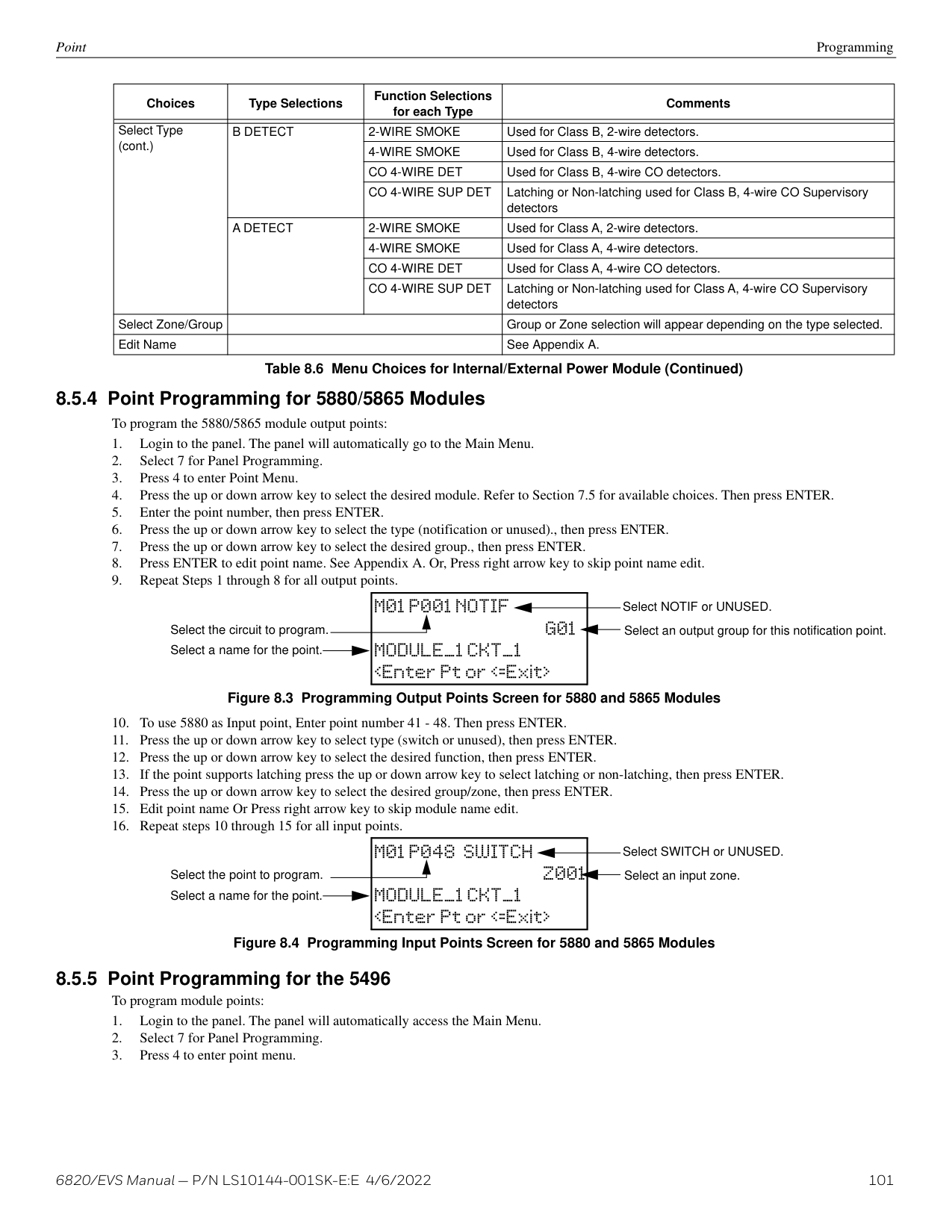
|Point|SD and SK Devices on Internal SLC,External , and External 5815XL|Enter Pt|Select Module|SWITCH 2, 3, 4, 5|P.A.S. ACK| |See Section 8.5| |Point|SD and SK Devices on Internal SLC,External , and External 5815XL|Enter Pt|Select Module|SWITCH 2, 3, 4, 5|ZONE AUX1|*LATCH|See Section 8.5| |Point|SD and SK Devices on Internal SLC,External , and External 5815XL|Enter Pt|Select Module|SWITCH 2, 3, 4, 5|ZONE AUX1|NON-LATCH|See Section 8.5| |Point|SD and SK Devices on Internal SLC,External , and External 5815XL|Enter Pt|Select Module|SWITCH 2, 3, 4, 5|ZONE AUX2|LATCH|See Section 8.5| |Point|SD and SK Devices on Internal SLC,External , and External 5815XL|Enter Pt|Select Module|SWITCH 2, 3, 4, 5|ZONE AUX2|NON-LATCH|See Section 8.5| |Point|SD and SK Devices on Internal SLC,External , and External 5815XL|Enter Pt|Select Module|SWITCH 2, 3, 4, 5|SYSTEM AUX1|LATCH|See Section 8.5| |Point|SD and SK Devices on Internal SLC,External , and External 5815XL|Enter Pt|Select Module|SWITCH 2, 3, 4, 5|SYSTEM AUX1|NON-LATCH|See Section 8.5| |Point|SD and SK Devices on Internal SLC,External , and External 5815XL|Enter Pt|Select Module|SWITCH 2, 3, 4, 5|SYSTEM AUX2|LATCH|See Section 8.5| |Point|SD and SK Devices on Internal SLC,External , and External 5815XL|Enter Pt|Select Module|SWITCH 2, 3, 4, 5|SYSTEM AUX2|NON-LATCH|See Section 8.5| |Point|SD and SK Devices on Internal SLC,External , and External 5815XL|Enter Pt|Select Module|SWITCH 2, 3, 4, 5|DETECTOR|DETECTOR|See Section 8.5| |Point|SD and SK Devices on Internal SLC,External , and External 5815XL|Enter Pt|Select Module|SWITCH 2, 3, 4, 5|FIRE TAMPER|LATCH|See Section 8.5| |Point|SD and SK Devices on Internal SLC,External , and External 5815XL|Enter Pt|Select Module|SWITCH 2, 3, 4, 5|FIRE TAMPER|NON-LATCH|See Section 8.5| |Point|SD and SK Devices on Internal SLC,External , and External 5815XL|Enter Pt|Select Module|SWITCH 2, 3, 4, 5|MANUAL RELEASE|MANUAL RELEASE|See Section 8.5| |Point|SD and SK Devices on Internal SLC,External , and External 5815XL|Enter Pt|Select Module|SWITCH 2, 3, 4, 5|INTERLOCK|INTERLOCK|See Section 8.5| |Point|SD and SK Devices on Internal SLC,External , and External 5815XL|Enter Pt|Select Module|SWITCH 2, 3, 4, 5|STATUS POINT|STATUS POINT|See Section 8.5| |Point|SD and SK Devices on Internal SLC,External , and External 5815XL|Enter Pt|Select Module|SWITCH 2, 3, 4, 5|CO DETECTOR SWITCH|CO DETECTOR SWITCH|See Section 8.5| |Point|SD and SK Devices on Internal SLC,External , and External 5815XL|Enter Pt|Select Module|SWITCH 2, 3, 4, 5|CO SUPERVISORY DETECTOR SWITCH|LATCH|See Section 8.5| |Point|SD and SK Devices on Internal SLC,External , and External 5815XL|Enter Pt|Select Module|SWITCH 2, 3, 4, 5|CO SUPERVISORY DETECTOR SWITCH|NON-LATCH|See Section 8.5| |Point|SD and SK Devices on Internal SLC,External , and External 5815XL|Enter Pt|Select Module|SWITCH 2, 3, 4, 5|ECS INPUT|LATCH|See Section 8.5| |Point|SD and SK Devices on Internal SLC,External , and External 5815XL|Enter Pt|Select Module|SWITCH 2, 3, 4, 5|ECS INPUT|NON-LATCH|See Section 8.5| |Point|SD and SK Devices on Internal SLC,External , and External 5815XL|Enter Pt|Select Module|SWITCH 2, 3, 4, 5|ECS TAMPER|LATCH|See Section 8.5| |Point|SD and SK Devices on Internal SLC,External , and External 5815XL|Enter Pt|Select Module|SWITCH 2, 3, 4, 5|ECS TAMPER|NON-LATCH|See Section 8.5| |Point|SD and SK Devices on Internal SLC,External , and External 5815XL|Enter Pt|Select Module|SWITCH 2, 3, 4, 5|ECS SUPERVISORY|LATCH|See Section 8.5| |Point|SD and SK Devices on Internal SLC,External , and External 5815XL|Enter Pt|Select Module|SWITCH 2, 3, 4, 5|ECS SUPERVISORY|NON-LATCH|See Section 8.5| |Point|SD and SK Devices on Internal SLC,External , and External 5815XL|Enter Pt|Select Module|SWITCH 2, 3, 4, 5|TROUBLE_MON|TROUBLE_MON|See Section 8.5| |Point|SD and SK Devices on Internal SLC,External , and External 5815XL|Enter Pt|Select Module|NOTIF 2,3,4,5|OUTPUT PT|Select Group|See Section 8.5| |Point|SD and SK Devices on Internal SLC,External , and External 5815XL|Enter Pt|Select Module|NOTIF 2,3,4,5|AUX CONST|AUX CONST|See Section 8.5| |Point|SD and SK Devices on Internal SLC,External , and External 5815XL|Enter Pt|Select Module|NOTIF 2,3,4,5|AUX RESET|AUX RESET|See Section 8.5| |Point|SD and SK Devices on Internal SLC,External , and External 5815XL|Enter Pt|Select Module|NOTIF 2,3,4,5|AUX DOOR|AUX DOOR|See Section 8.5|
|Menu|Menu|Options/Defaults|Options/Defaults|Options/Defaults|Options/Defaults|Options/Defaults|Comments| |---|---|---|---|---|---|---|---| | | | | | | | | | |Point (cont.)|SD and SK Devices on Internal SLC,External , and External 5815XL|Enter Pt|Select Sensor|RELAY 2,3,4,5|OUTPUT PT|Select Group|See Section 8.5| |Point (cont.)|SD and SK Devices on Internal SLC,External , and External 5815XL|Enter Pt|Select Sensor|RELAY 2,3,4,5|AUX RESET|AUX RESET|See Section 8.5| |Point (cont.)|SD and SK Devices on Internal SLC,External , and External 5815XL|Enter Pt|Select Sensor|RELAY 2,3,4,5|AUX DOOR|AUX DOOR|See Section 8.5| |Point (cont.)|SD and SK Devices on Internal SLC,External , and External 5815XL|Enter Pt|Select Sensor|SLC LED 3,5|LED Number|1-80|See Section 8.5| |Point (cont.)|SD and SK Devices on Internal SLC,External , and External 5815XL|Enter Pt|Select Sensor|SLC LED 3,5|LED Function|Notif|See Section 8.5| |Point (cont.)|SD and SK Devices on Internal SLC,External , and External 5815XL|Enter Pt|Select Sensor|SLC LED 3,5|LED Function|Unused|See Section 8.5| |Point (cont.)|SD and SK Devices on Internal SLC,External , and External 5815XL|Enter Pt|Select Sensor|DETECTOR 2,4|2-WIRE SMOKE|Select Zone|See Section 8.5| |Point (cont.)|SD and SK Devices on Internal SLC,External , and External 5815XL|Enter Pt|Select Sensor|W. Gateway 2,4| | |See Section 8.5| |Point (cont.)|SD and SK Devices on Internal SLC,External , and External 5815XL|Enter Pt|Select Sensor|W SWITCH 2,4,6|Same as SWITCH|Same as SWITCH|See Section 8.5| |Point (cont.)|SD and SK Devices on Internal SLC,External , and External 5815XL|Enter Pt|Select Sensor|W-RELAY 2,4,6|Same as Relay|Same as Relay|See Section 8.5| |Point (cont.)|SD and SK Devices on Internal SLC,External , and External 5815XL|Enter Pt|Select Sensor|UNUSED| | |See Section 8.5| |Point (cont.)|SD and SK Devices on Internal SLC,External , and External 5815XL|Enter Pt|Select Sensor|DETECTOR 2,3,,4,5|PHOTO|No Accessory base|No Accessory base| |Point (cont.)|SD and SK Devices on Internal SLC,External , and External 5815XL|Enter Pt|Select Sensor|DETECTOR 2,3,,4,5|PHOTO|SDR BAS|Single station or Multi station Silence or Non-Silence| |Point (cont.)|SD and SK Devices on Internal SLC,External , and External 5815XL|Enter Pt|Select Sensor|DETECTOR 2,3,,4,5|PHOTO|RLY BAS|Single station or Multi station Silence or Non-Silence| |Point (cont.)|SD and SK Devices on Internal SLC,External , and External 5815XL|Enter Pt|Select Sensor|DETECTOR 2,3,,4,5|PHOTO|I-SdrBa (Intelligent Sounder Base) 2,4|Latch or non-latch, Single station or Multi station, Silence or NonSilence, volume high (default) or low| |Point (cont.)|SD and SK Devices on Internal SLC,External , and External 5815XL|Enter Pt|Select Sensor|DETECTOR 2,3,,4,5|ION|No Accessory base|No Accessory base| |Point (cont.)|SD and SK Devices on Internal SLC,External , and External 5815XL|Enter Pt|Select Sensor|DETECTOR 2,3,,4,5|ION|SDR BAS|Single station or Multi station Silence or Non-Silence| |Point (cont.)|SD and SK Devices on Internal SLC,External , and External 5815XL|Enter Pt|Select Sensor|DETECTOR 2,3,,4,5|ION|RLY BAS|Single station or Multi station Silence or Non-Silence| |Point (cont.)|SD and SK Devices on Internal SLC,External , and External 5815XL|Enter Pt|Select Sensor|DETECTOR 2,3,,4,5|ION|I-SdrBa (Intelligent Sounder Base) 2,4|Latch or non-latch, Single station or Multi station, Silence or NonSilence, volume high (default) or low|
############# Table 7.2 Programming Menu Quick Reference Chart (Continued)
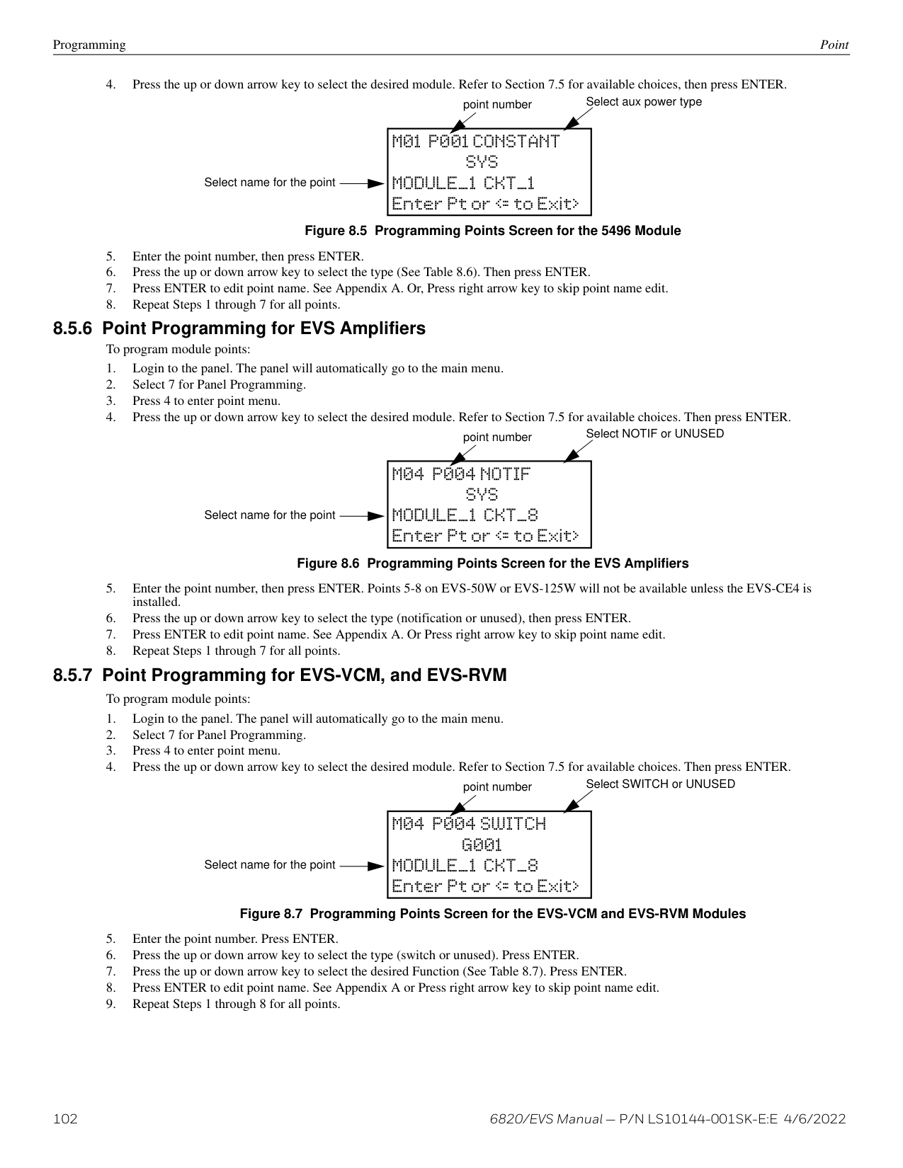
|Menu|Menu|Options/Defaults|Options/Defaults|Options/Defaults|Options/Defaults|Options/Defaults|Comments| |---|---|---|---|---|---|---|---| | | | | | | | | | |Point (cont.)|SD and SK Devices on Internal SLC,External , and External 5815XL|Enter Pt|Select Sensor|DETECTOR 2,3,,4,5|HEAT2,3,,4,5|No Accessory base|No Accessory base| |Point (cont.)|SD and SK Devices on Internal SLC,External , and External 5815XL|Enter Pt|Select Sensor|DETECTOR 2,3,,4,5|HEAT2,3,,4,5|SDR BAS|Single station or Multi station Silence or Non-Silence| |Point (cont.)|SD and SK Devices on Internal SLC,External , and External 5815XL|Enter Pt|Select Sensor|DETECTOR 2,3,,4,5|HEAT2,3,,4,5|RLY BAS|Single station or Multi station Silence or Non-Silence| |Point (cont.)|SD and SK Devices on Internal SLC,External , and External 5815XL|Enter Pt|Select Sensor|DETECTOR 2,3,,4,5|HEAT2,3,,4,5|I-SdrBa (Intelligent Sounder Base) 2,4|Latch or non-latch, Single station or Multi station, Silence or NonSilence, volume high (default) or low| |Point (cont.)|SD and SK Devices on Internal SLC,External , and External 5815XL|Enter Pt|Select Sensor|DETECTOR 2,3,,4,5|PHOTO DUCT 2,3,,4,5|No Accessory base|No Accessory base| |Point (cont.)|SD and SK Devices on Internal SLC,External , and External 5815XL|Enter Pt|Select Sensor|DETECTOR 2,3,,4,5|PHOTO DUCT 2,3,,4,5|DCT RLY|DCT RLY| |Point (cont.)|SD and SK Devices on Internal SLC,External , and External 5815XL|Enter Pt|Select Sensor|DETECTOR 2,3,,4,5|2-WIRE SMOKE 3,5|2-WIRE SMOKE 3,5|2-WIRE SMOKE 3,5| |Point (cont.)|SD and SK Devices on Internal SLC,External , and External 5815XL|Enter Pt|Select Sensor|DETECTOR 2,3,,4,5|ION DUCT3,5|No Accessory base|No Accessory base| |Point (cont.)|SD and SK Devices on Internal SLC,External , and External 5815XL|Enter Pt|Select Sensor|DETECTOR 2,3,,4,5|ION DUCT3,5|DCT RLY|DCT RLY| |Point (cont.)|SD and SK Devices on Internal SLC,External , and External 5815XL|Enter Pt|Select Sensor|DETECTOR 2,3,,4,5|ACCLIMATE 2,4|No Accessory base|No Accessory base| |Point (cont.)|SD and SK Devices on Internal SLC,External , and External 5815XL|Enter Pt|Select Sensor|DETECTOR 2,3,,4,5|ACCLIMATE 2,4|SDR BAS|Single station or Multi station Silence or Non-Silence| |Point (cont.)|SD and SK Devices on Internal SLC,External , and External 5815XL|Enter Pt|Select Sensor|DETECTOR 2,3,,4,5|ACCLIMATE 2,4|RLY BAS|Single station or Multi station Silence or Non-Silence| |Point (cont.)|SD and SK Devices on Internal SLC,External , and External 5815XL|Enter Pt|Select Sensor|DETECTOR 2,3,,4,5|ACCLIMATE 2,4|I-SdrBa (Intelligent Sounder Base)|Latch or non-latch, Single station or Multi station, Silence or NonSilence, volume high (default) or low| |Point (cont.)|SD and SK Devices on Internal SLC,External , and External 5815XL|Enter Pt|Select Sensor|DETECTOR 2,3,,4,5|HEAT HT 2,4|No Accessory base|No Accessory base| |Point (cont.)|SD and SK Devices on Internal SLC,External , and External 5815XL|Enter Pt|Select Sensor|DETECTOR 2,3,,4,5|HEAT HT 2,4|SDR base|Single station or Multi station Silence or Non-Silence| |Point (cont.)|SD and SK Devices on Internal SLC,External , and External 5815XL|Enter Pt|Select Sensor|DETECTOR 2,3,,4,5|HEAT HT 2,4|RLY base|Single station or Multi station Silence or Non-Silence| |Point (cont.)|SD and SK Devices on Internal SLC,External , and External 5815XL|Enter Pt|Select Sensor|DETECTOR 2,3,,4,5|HEAT HT 2,4|I-SdrBa (Intelligent Sounder Base)|Latch or non-latch, Single station or Multi station, Silence or NonSilence, volume high (default) or low| |Point (cont.)|SD and SK Devices on Internal SLC,External , and External 5815XL|Enter Pt|Select Sensor|DETECTOR 2,3,,4,5|PHOT-HEAT 2,4|No Accessory base|No Accessory base| |Point (cont.)|SD and SK Devices on Internal SLC,External , and External 5815XL|Enter Pt|Select Sensor|DETECTOR 2,3,,4,5|PHOT-HEAT 2,4|SDR BAS|Single station or Multi station Silence or Non-Silence| |Point (cont.)|SD and SK Devices on Internal SLC,External , and External 5815XL|Enter Pt|Select Sensor|DETECTOR 2,3,,4,5|PHOT-HEAT 2,4|RLY BAS|Single station or Multi station Silence or Non-Silence| |Point (cont.)|SD and SK Devices on Internal SLC,External , and External 5815XL|Enter Pt|Select Sensor|DETECTOR 2,3,,4,5|PHOT-HEAT 2,4|I-SdrBa (Intelligent Sounder Base)|Latch or non-latch, Single station or Multi station, Silence or NonSilence, volume high (default) or low| |Point (cont.)|SD and SK Devices on Internal SLC,External , and External 5815XL|Enter Pt|Select Sensor|DETECTOR 2,3,,4,5|BEAM2,4|BEAM2,4|BEAM2,4| |Point (cont.)|SD and SK Devices on Internal SLC,External , and External 5815XL|Enter Pt|Select Sensor|SUP DET 2,3,,4,5|Same function as DETECTOR|LATCH|LATCH| |Point (cont.)|SD and SK Devices on Internal SLC,External , and External 5815XL|Enter Pt|Select Sensor|SUP DET 2,3,,4,5|Same function as DETECTOR|NON-LATCH|NON-LATCH|
|Menu|Menu|Options/Defaults|Options/Defaults|Options/Defaults|Options/Defaults|Options/Defaults|Comments| |---|---|---|---|---|---|---|---| | | | | | | | | | |Point (cont.)|SD and SK Devices on Internal SLC,External , and External 5815XL|Enter Pt|Select Sensor (cont.)|CO FIRE 2,4|CO ALARM/FIRE ALARM|No Accessory base|No Accessory base| |Point (cont.)|SD and SK Devices on Internal SLC,External , and External 5815XL|Enter Pt|Select Sensor (cont.)|CO FIRE 2,4|CO ALARM/FIRE ALARM|SDR BAS|Single station or Multi station Silence or Non-Silence| |Point (cont.)|SD and SK Devices on Internal SLC,External , and External 5815XL|Enter Pt|Select Sensor (cont.)|CO FIRE 2,4|CO ALARM/FIRE ALARM|RLY BAS|Single station or Multi station Silence or Non-Silence| |Point (cont.)|SD and SK Devices on Internal SLC,External , and External 5815XL|Enter Pt|Select Sensor (cont.)|CO FIRE 2,4|CO ALARM/FIRE ALARM|I-SdrBA (Intelligent Sounder Base)|Latch or non-latch, Single station or Multi station, Silence or NonSilence, volume high (default) or low| |Point (cont.)|SD and SK Devices on Internal SLC,External , and External 5815XL|Enter Pt|Select Sensor (cont.)|CO FIRE 2,4|CO ALARM/FIRE SUPR|No Accessory base|No Accessory base| |Point (cont.)|SD and SK Devices on Internal SLC,External , and External 5815XL|Enter Pt|Select Sensor (cont.)|CO FIRE 2,4|CO ALARM/FIRE SUPR|SDR BAS|Single station or Multi station Silence or Non-Silence| |Point (cont.)|SD and SK Devices on Internal SLC,External , and External 5815XL|Enter Pt|Select Sensor (cont.)|CO FIRE 2,4|CO ALARM/FIRE SUPR|RLY BAS|Single station or Multi station Silence or Non-Silence| |Point (cont.)|SD and SK Devices on Internal SLC,External , and External 5815XL|Enter Pt|Select Sensor (cont.)|CO FIRE 2,4|CO ALARM/FIRE SUPR|I-SdrBA (Intelligent Sounder Base)|Latch or non-latch, Single station or Multi station, Silence or NonSilence, volume high (default) or low| |Point (cont.)|SD and SK Devices on Internal SLC,External , and External 5815XL|Enter Pt|Select Sensor (cont.)|CO FIRE 2,4|CO SUPR/ FIRE ALARM|No Accessory base|No Accessory base| |Point (cont.)|SD and SK Devices on Internal SLC,External , and External 5815XL|Enter Pt|Select Sensor (cont.)|CO FIRE 2,4|CO SUPR/ FIRE ALARM|SDR BAS|Single station or Multi station Silence or Non-Silence| |Point (cont.)|SD and SK Devices on Internal SLC,External , and External 5815XL|Enter Pt|Select Sensor (cont.)|CO FIRE 2,4|CO SUPR/ FIRE ALARM|RLY BAS|Single station or Multi station Silence or Non-Silence| |Point (cont.)|SD and SK Devices on Internal SLC,External , and External 5815XL|Enter Pt|Select Sensor (cont.)|CO FIRE 2,4|CO SUPR/ FIRE ALARM|I-SdrBA (Intelligent Sounder Base)|Latch or non-latch, Single station or Multi station, Silence or NonSilence, volume high (default) or low| |Point (cont.)|SD and SK Devices on Internal SLC,External , and External 5815XL|Enter Pt|Select Sensor (cont.)|CO FIRE 2,4|CO SUPR/ FIRE SUPR|No Accessory base|No Accessory base| |Point (cont.)|SD and SK Devices on Internal SLC,External , and External 5815XL|Enter Pt|Select Sensor (cont.)|CO FIRE 2,4|CO SUPR/ FIRE SUPR|SDR BAS|Single station or Multi station Silence or Non-Silence| |Point (cont.)|SD and SK Devices on Internal SLC,External , and External 5815XL|Enter Pt|Select Sensor (cont.)|CO FIRE 2,4|CO SUPR/ FIRE SUPR|RLY BAS|Single station or Multi station Silence or Non-Silence| |Point (cont.)|SD and SK Devices on Internal SLC,External , and External 5815XL|Enter Pt|Select Sensor (cont.)|CO FIRE 2,4|CO SUPR/ FIRE SUPR|I-SdrBA (Intelligent Sounder Base)|Latch or non-latch, Single station or Multi station, Silence or NonSilence, volume high (default) or low| |Point (cont.)|SD and SK Devices on Internal SLC,External , and External 5815XL|Enter Pt|Select Sensor (cont.)|W-Detector 2,4,6|Photo2,4,6|See Section 8.5|See Section 8.5| |Point (cont.)|SD and SK Devices on Internal SLC,External , and External 5815XL|Enter Pt|Select Sensor (cont.)|W-Detector 2,4,6|Acclimate2,4,6|See Section 8.5|See Section 8.5| |Point (cont.)|SD and SK Devices on Internal SLC,External , and External 5815XL|Enter Pt|Select Sensor (cont.)|W-Detector 2,4,6|Photo-Heat2,4,6|See Section 8.5|See Section 8.5| |Point (cont.)|SD and SK Devices on Internal SLC,External , and External 5815XL|Enter Pt|Select Sensor (cont.)|W-Detector 2,4,6|Heat2,4,6|See Section 8.5|See Section 8.5| |Point (cont.)|SD and SK Devices on Internal SLC,External , and External 5815XL|Enter Pt|Select Sensor (cont.)|W-SUP DET 2,4,6|Same as WDetector|See Section 8.5|See Section 8.5|
############# Table 7.2 Programming Menu Quick Reference Chart (Continued)
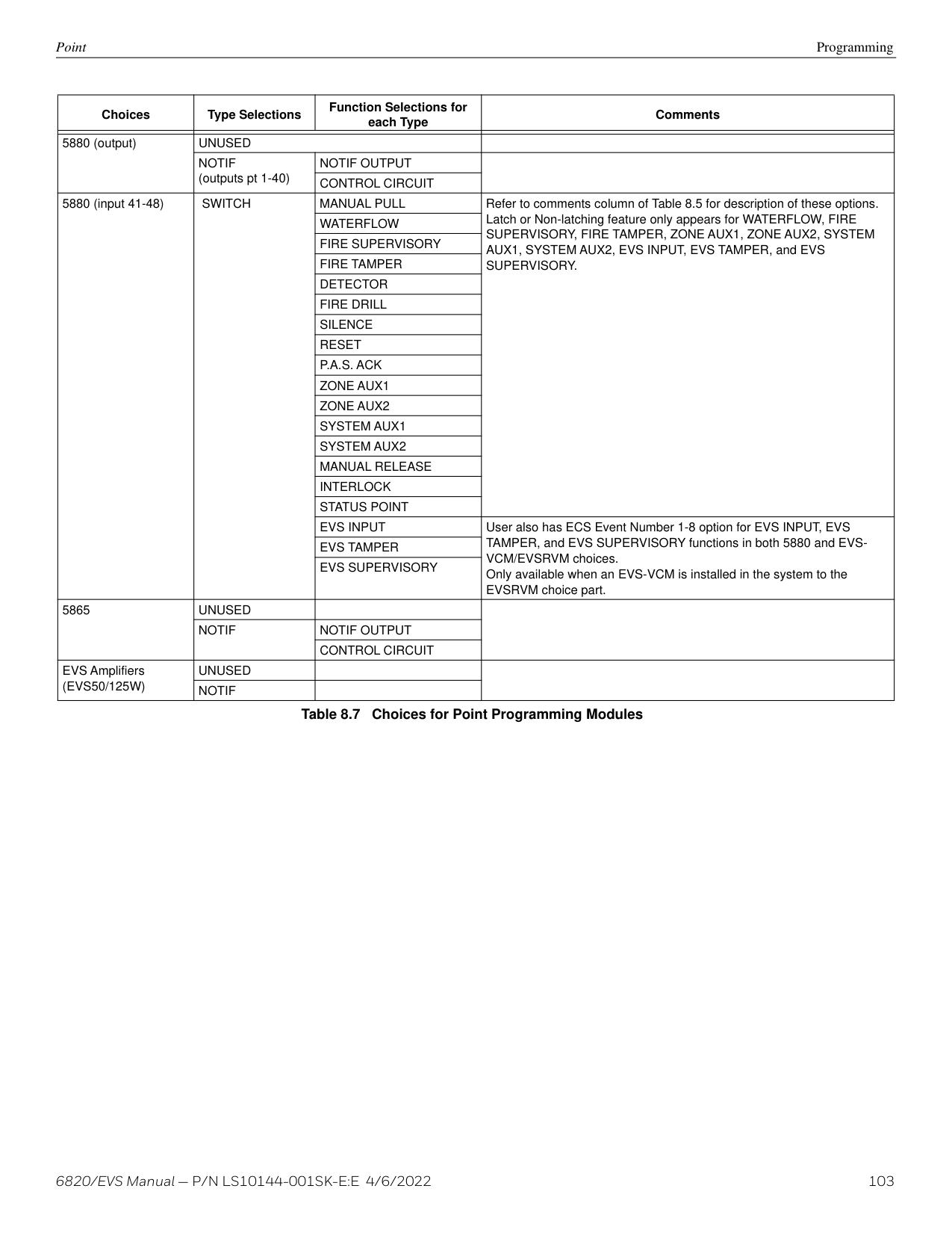
|Menu|Menu|Options/Defaults|Options/Defaults|Options/Defaults|Options/Defaults|Options/Defaults|Comments| |---|---|---|---|---|---|---|---| | | | | | | | | | |Point (cont)|Internal Power and External Power|Enter Pt /Select Function|Select Sensor|UNUSED|UNUSED|UNUSED|See Section 8.5| |Point (cont)|Internal Power and External Power|Enter Pt /Select Function|Select Sensor|B NOTIF|NOTIF OUTPUT|Select Group Super-vised Yes or No|See Section 8.5| |Point (cont)|Internal Power and External Power|Enter Pt /Select Function|Select Sensor|B NOTIF|CONTROL CIRCUIT|Select Group Super-vised Yes or No|See Section 8.5| |Point (cont)|Internal Power and External Power|Enter Pt /Select Function|Select Sensor|A NOTIF|NOTIF OUTPUT|Select Group Super-vised Yes or No|See Section 8.5| |Point (cont)|Internal Power and External Power|Enter Pt /Select Function|Select Sensor|A NOTIF|CONTROL CIRCUIT|Select Group Super-vised Yes or No|See Section 8.5| |Point (cont)|Internal Power and External Power|Enter Pt /Select Function|Select Sensor|AUX PWR|CONSTANT|CONSTANT|See Section 8.5| |Point (cont)|Internal Power and External Power|Enter Pt /Select Function|Select Sensor|AUX PWR|AUX RESET|AUX RESET|See Section 8.5| |Point (cont)|Internal Power and External Power|Enter Pt /Select Function|Select Sensor|AUX PWR|AUX DOOR|AUX DOOR|See Section 8.5| |Point (cont)|Internal Power and External Power|Enter Pt /Select Function|Select Sensor|AUX PWR|AUX SYNC7|AUX SYNC7|See Section 8.5| |Point (cont)|Internal Power and External Power|Enter Pt /Select Function|Select Sensor|B SWITCH|MANUAL PULL|Latch and Non-Latch feature only appear for WATERFLOW,FIRE SUPERVISORY, FIRE TAMPER, ZONE AUX1, ZONE AUX2, SYSTEM AUX1, SYSTEM AUX2, EVS INPUT, EVS TAMPER, and EVS SUPERVISORY.|Latch and Non-Latch feature only appear for WATERFLOW,FIRE SUPERVISORY, FIRE TAMPER, ZONE AUX1, ZONE AUX2, SYSTEM AUX1, SYSTEM AUX2, EVS INPUT, EVS TAMPER, and EVS SUPERVISORY.| |Point (cont)|Internal Power and External Power|Enter Pt /Select Function|Select Sensor|B SWITCH|WATER-FLOW|Latch and Non-Latch feature only appear for WATERFLOW,FIRE SUPERVISORY, FIRE TAMPER, ZONE AUX1, ZONE AUX2, SYSTEM AUX1, SYSTEM AUX2, EVS INPUT, EVS TAMPER, and EVS SUPERVISORY.|Latch and Non-Latch feature only appear for WATERFLOW,FIRE SUPERVISORY, FIRE TAMPER, ZONE AUX1, ZONE AUX2, SYSTEM AUX1, SYSTEM AUX2, EVS INPUT, EVS TAMPER, and EVS SUPERVISORY.| |Point (cont)|Internal Power and External Power|Enter Pt /Select Function|Select Sensor|B SWITCH|FIRE SUPERVISORY|Latch and Non-Latch feature only appear for WATERFLOW,FIRE SUPERVISORY, FIRE TAMPER, ZONE AUX1, ZONE AUX2, SYSTEM AUX1, SYSTEM AUX2, EVS INPUT, EVS TAMPER, and EVS SUPERVISORY.|Latch and Non-Latch feature only appear for WATERFLOW,FIRE SUPERVISORY, FIRE TAMPER, ZONE AUX1, ZONE AUX2, SYSTEM AUX1, SYSTEM AUX2, EVS INPUT, EVS TAMPER, and EVS SUPERVISORY.| |Point (cont)|Internal Power and External Power|Enter Pt /Select Function|Select Sensor|B SWITCH|FIRE TAMPER|Latch and Non-Latch feature only appear for WATERFLOW,FIRE SUPERVISORY, FIRE TAMPER, ZONE AUX1, ZONE AUX2, SYSTEM AUX1, SYSTEM AUX2, EVS INPUT, EVS TAMPER, and EVS SUPERVISORY.|Latch and Non-Latch feature only appear for WATERFLOW,FIRE SUPERVISORY, FIRE TAMPER, ZONE AUX1, ZONE AUX2, SYSTEM AUX1, SYSTEM AUX2, EVS INPUT, EVS TAMPER, and EVS SUPERVISORY.| |Point (cont)|Internal Power and External Power|Enter Pt /Select Function|Select Sensor|B SWITCH|FIRE DRILL|Latch and Non-Latch feature only appear for WATERFLOW,FIRE SUPERVISORY, FIRE TAMPER, ZONE AUX1, ZONE AUX2, SYSTEM AUX1, SYSTEM AUX2, EVS INPUT, EVS TAMPER, and EVS SUPERVISORY.|Latch and Non-Latch feature only appear for WATERFLOW,FIRE SUPERVISORY, FIRE TAMPER, ZONE AUX1, ZONE AUX2, SYSTEM AUX1, SYSTEM AUX2, EVS INPUT, EVS TAMPER, and EVS SUPERVISORY.| |Point (cont)|Internal Power and External Power|Enter Pt /Select Function|Select Sensor|B SWITCH|SILENCE|Latch and Non-Latch feature only appear for WATERFLOW,FIRE SUPERVISORY, FIRE TAMPER, ZONE AUX1, ZONE AUX2, SYSTEM AUX1, SYSTEM AUX2, EVS INPUT, EVS TAMPER, and EVS SUPERVISORY.|Latch and Non-Latch feature only appear for WATERFLOW,FIRE SUPERVISORY, FIRE TAMPER, ZONE AUX1, ZONE AUX2, SYSTEM AUX1, SYSTEM AUX2, EVS INPUT, EVS TAMPER, and EVS SUPERVISORY.| |Point (cont)|Internal Power and External Power|Enter Pt /Select Function|Select Sensor|B SWITCH|RESET|Latch and Non-Latch feature only appear for WATERFLOW,FIRE SUPERVISORY, FIRE TAMPER, ZONE AUX1, ZONE AUX2, SYSTEM AUX1, SYSTEM AUX2, EVS INPUT, EVS TAMPER, and EVS SUPERVISORY.|Latch and Non-Latch feature only appear for WATERFLOW,FIRE SUPERVISORY, FIRE TAMPER, ZONE AUX1, ZONE AUX2, SYSTEM AUX1, SYSTEM AUX2, EVS INPUT, EVS TAMPER, and EVS SUPERVISORY.| |Point (cont)|Internal Power and External Power|Enter Pt /Select Function|Select Sensor|B SWITCH|P.A.S. ACK|Latch and Non-Latch feature only appear for WATERFLOW,FIRE SUPERVISORY, FIRE TAMPER, ZONE AUX1, ZONE AUX2, SYSTEM AUX1, SYSTEM AUX2, EVS INPUT, EVS TAMPER, and EVS SUPERVISORY.|Latch and Non-Latch feature only appear for WATERFLOW,FIRE SUPERVISORY, FIRE TAMPER, ZONE AUX1, ZONE AUX2, SYSTEM AUX1, SYSTEM AUX2, EVS INPUT, EVS TAMPER, and EVS SUPERVISORY.| |Point (cont)|Internal Power and External Power|Enter Pt /Select Function|Select Sensor|B SWITCH|ZONE AUX 1|Latch and Non-Latch feature only appear for WATERFLOW,FIRE SUPERVISORY, FIRE TAMPER, ZONE AUX1, ZONE AUX2, SYSTEM AUX1, SYSTEM AUX2, EVS INPUT, EVS TAMPER, and EVS SUPERVISORY.|Latch and Non-Latch feature only appear for WATERFLOW,FIRE SUPERVISORY, FIRE TAMPER, ZONE AUX1, ZONE AUX2, SYSTEM AUX1, SYSTEM AUX2, EVS INPUT, EVS TAMPER, and EVS SUPERVISORY.| |Point (cont)|Internal Power and External Power|Enter Pt /Select Function|Select Sensor|B SWITCH|ZONE AUX2|Latch and Non-Latch feature only appear for WATERFLOW,FIRE SUPERVISORY, FIRE TAMPER, ZONE AUX1, ZONE AUX2, SYSTEM AUX1, SYSTEM AUX2, EVS INPUT, EVS TAMPER, and EVS SUPERVISORY.|Latch and Non-Latch feature only appear for WATERFLOW,FIRE SUPERVISORY, FIRE TAMPER, ZONE AUX1, ZONE AUX2, SYSTEM AUX1, SYSTEM AUX2, EVS INPUT, EVS TAMPER, and EVS SUPERVISORY.| |Point (cont)|Internal Power and External Power|Enter Pt /Select Function|Select Sensor|B SWITCH|SYSTEM AUX1|Latch and Non-Latch feature only appear for WATERFLOW,FIRE SUPERVISORY, FIRE TAMPER, ZONE AUX1, ZONE AUX2, SYSTEM AUX1, SYSTEM AUX2, EVS INPUT, EVS TAMPER, and EVS SUPERVISORY.|Latch and Non-Latch feature only appear for WATERFLOW,FIRE SUPERVISORY, FIRE TAMPER, ZONE AUX1, ZONE AUX2, SYSTEM AUX1, SYSTEM AUX2, EVS INPUT, EVS TAMPER, and EVS SUPERVISORY.| |Point (cont)|Internal Power and External Power|Enter Pt /Select Function|Select Sensor|B SWITCH|SYSTEM AUX2|Latch and Non-Latch feature only appear for WATERFLOW,FIRE SUPERVISORY, FIRE TAMPER, ZONE AUX1, ZONE AUX2, SYSTEM AUX1, SYSTEM AUX2, EVS INPUT, EVS TAMPER, and EVS SUPERVISORY.|Latch and Non-Latch feature only appear for WATERFLOW,FIRE SUPERVISORY, FIRE TAMPER, ZONE AUX1, ZONE AUX2, SYSTEM AUX1, SYSTEM AUX2, EVS INPUT, EVS TAMPER, and EVS SUPERVISORY.| |Point (cont)|Internal Power and External Power|Enter Pt /Select Function|Select Sensor|B SWITCH|MANUAL RELEASE|Latch and Non-Latch feature only appear for WATERFLOW,FIRE SUPERVISORY, FIRE TAMPER, ZONE AUX1, ZONE AUX2, SYSTEM AUX1, SYSTEM AUX2, EVS INPUT, EVS TAMPER, and EVS SUPERVISORY.|Latch and Non-Latch feature only appear for WATERFLOW,FIRE SUPERVISORY, FIRE TAMPER, ZONE AUX1, ZONE AUX2, SYSTEM AUX1, SYSTEM AUX2, EVS INPUT, EVS TAMPER, and EVS SUPERVISORY.| |Point (cont)|Internal Power and External Power|Enter Pt /Select Function|Select Sensor|B SWITCH|INTERLOCK|Latch and Non-Latch feature only appear for WATERFLOW,FIRE SUPERVISORY, FIRE TAMPER, ZONE AUX1, ZONE AUX2, SYSTEM AUX1, SYSTEM AUX2, EVS INPUT, EVS TAMPER, and EVS SUPERVISORY.|Latch and Non-Latch feature only appear for WATERFLOW,FIRE SUPERVISORY, FIRE TAMPER, ZONE AUX1, ZONE AUX2, SYSTEM AUX1, SYSTEM AUX2, EVS INPUT, EVS TAMPER, and EVS SUPERVISORY.| |Point (cont)|Internal Power and External Power|Enter Pt /Select Function|Select Sensor|B SWITCH|EVS INPUT|If EVS INPUT is selected choose associated EVENT|If EVS INPUT is selected choose associated EVENT| |Point (cont)|Internal Power and External Power|Enter Pt /Select Function|Select Sensor|B SWITCH|EVS TAMPER| | | |Point (cont)|Internal Power and External Power|Enter Pt /Select Function|Select Sensor|B SWITCH|EVS SUPERVISORY| | | |Point (cont)|Internal Power and External Power|Enter Pt /Select Function|Select Sensor|B SWITCH|STATUS POINT| | | |Point (cont)|Internal Power and External Power|Enter Pt /Select Function|Select Sensor|A SWITCH|Same as B SWITCH|Same as B SWITCH|See Section 8.5.3| |Point (cont)|Internal Power and External Power|Enter Pt /Select Function|Select Sensor|B DETECT|2-WIRE SMOKE|2-WIRE SMOKE|See Section 8.5.3| |Point (cont)|Internal Power and External Power|Enter Pt /Select Function|Select Sensor|B DETECT|4-WIRE SMOKE|4-WIRE SMOKE|See Section 8.5.3| |Point (cont)|Internal Power and External Power|Enter Pt /Select Function|Select Sensor|B DETECT|CO 4 WIRE DET|CO 4 WIRE DET|See Section 8.5.3| |Point (cont)|Internal Power and External Power|Enter Pt /Select Function|Select Sensor|B DETECT|CO 4 WIRE SUP DET|Latch|See Section 8.5.3| |Point (cont)|Internal Power and External Power|Enter Pt /Select Function|Select Sensor|B DETECT|CO 4 WIRE SUP DET|Non-Latch|See Section 8.5.3| |Point (cont)|Internal Power and External Power|Enter Pt /Select Function|Select Sensor|A DETECT|2-WIRE SMOKE|2-WIRE SMOKE|See Section 8.5.3| |Point (cont)|Internal Power and External Power|Enter Pt /Select Function|Select Sensor|A DETECT|4-WIRE SMOKE|4-WIRE SMOKE|See Section 8.5.3| |Point (cont)|Internal Power and External Power|Enter Pt /Select Function|Select Sensor|A DETECT|CO 4 WIRE DET|CO 4 WIRE DET|See Section 8.5.3| |Point (cont)|Internal Power and External Power|Enter Pt /Select Function|Select Sensor|A DETECT|CO 4 WIRE SUP DET|Latch|See Section 8.5.3| |Point (cont)|Internal Power and External Power|Enter Pt /Select Function|Select Sensor|A DETECT|CO 4 WIRE SUP DET|Non-Latch|See Section 8.5.3| |Point (cont)|Internal Power and External Power|Select Group or Zone Number|Select Group or Zone Number|Select Group or Zone Number|Select Group or Zone Number|Group or Zone selection will appear depending on the function selected|Group or Zone selection will appear depending on the function selected| |Point (cont)|Internal Power and External Power|Edit Name|Edit Name|Enter Name|Enter Name|Group or Zone selection will appear depending on the function selected|Group or Zone selection will appear depending on the function selected|
############# Table 7.2 Programming Menu Quick Reference Chart (Continued)
|Menu|Menu|Options/Defaults|Options/Defaults|Options/Defaults|Options/Defaults|Comments| |---|---|---|---|---|---|---| | | | | | | | | |Point (cont.)|5496|Edit Point #|UNUSED|UNUSED|UNUSED|See Section 8.5.5| |Point (cont.)|5496|Edit Point #|B NOTIF|Control Circuit Notif Output|Select Group Super-vised Yes or No|See Section 8.5.5| |Point (cont.)|5496|Edit Point #|A NOTIF|Control Circuit Notif Output|Select Group Super-vised Yes or No|See Section 8.5.5| |Point (cont.)|5496|Edit Point #|AUX_PWR|Constant|Edit Name|See Section 8.5.5| |Point (cont.)|5496|Edit Point #|AUX_PWR|Aux Sync|Edit Name|See Section 8.5.5| |Point (cont.)|5496|Edit Point #|AUX_PWR|Aux Door|Edit Name|See Section 8.5.5| |Point (cont.)|5496|Edit Point #|AUX_PWR|Aux Reset|Edit Name|See Section 8.5.5|
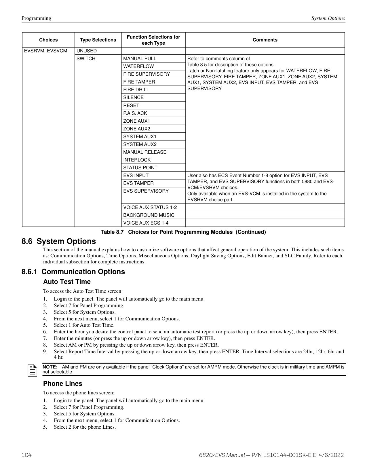
|Point (cont.)|-5880/-5865/EVS Series Amplifiers|Enter Point #|UNUSED|UNUSED|See Section 8.5.4 and Section 8.5.6|See Section 8.5.4 and Section 8.5.6| |Point (cont.)|-5880/-5865/EVS Series Amplifiers|Enter Point #|NOTIF| |See Section 8.5.4 and Section 8.5.6|See Section 8.5.4 and Section 8.5.6| |Point (cont.)|-5880/-5865/EVS Series Amplifiers|Select Group|Select Group|Select Group|See Section 8.5.4 and Section 8.5.6|See Section 8.5.4 and Section 8.5.6| |Point (cont.)|-5880/-5865/EVS Series Amplifiers|Edit Name|Enter Name|Enter Name|See Section 8.5.4 and Section 8.5.6|See Section 8.5.4 and Section 8.5.6| |Point (cont.)|EVS-VCM, EVS-RVM,|Enter Pt /Select Function|UNUSED|UNUSED|UNUSED|See Section 8.5.7| |Point (cont.)|EVS-VCM, EVS-RVM,|Enter Pt /Select Function|SWITCH8|SUPERVISORY|SUPERVISORY|See Section 8.5.7| |Point (cont.)|EVS-VCM, EVS-RVM,|Enter Pt /Select Function|SWITCH8|TAMPER|TAMPER|See Section 8.5.7| |Point (cont.)|EVS-VCM, EVS-RVM,|Enter Pt /Select Function|SWITCH8|WATER FLOW|WATER FLOW|See Section 8.5.7| |Point (cont.)|EVS-VCM, EVS-RVM,|Enter Pt /Select Function|SWITCH8|P.A.S. (Non-latching)|P.A.S. (Non-latching)|See Section 8.5.7| |Point (cont.)|EVS-VCM, EVS-RVM,|Enter Pt /Select Function|SWITCH8|MANUAL PULL (Latching)|MANUAL PULL (Latching)|See Section 8.5.7| |Point (cont.)|EVS-VCM, EVS-RVM,|Enter Pt /Select Function|SWITCH8|SYSTEM SILENCE (Non-latching)|SYSTEM SILENCE (Non-latching)|See Section 8.5.7| |Point (cont.)|EVS-VCM, EVS-RVM,|Enter Pt /Select Function|SWITCH8|SYSTEM RESET|SYSTEM RESET|See Section 8.5.7| |Point (cont.)|EVS-VCM, EVS-RVM,|Enter Pt /Select Function|SWITCH8|ZONE AUX 1|ZONE AUX 1|See Section 8.5.7| |Point (cont.)|EVS-VCM, EVS-RVM,|Enter Pt /Select Function|SWITCH8|ZONE AUX 2|ZONE AUX 2|See Section 8.5.7| |Point (cont.)|EVS-VCM, EVS-RVM,|Enter Pt /Select Function|SWITCH8|SYSTEM AUX 1|SYSTEM AUX 1|See Section 8.5.7| |Point (cont.)|EVS-VCM, EVS-RVM,|Enter Pt /Select Function|SWITCH8|SYSTEM AUX 2|SYSTEM AUX 2|See Section 8.5.7| |Point (cont.)|EVS-VCM, EVS-RVM,|Enter Pt /Select Function|SWITCH8|FIRE DRILL|FIRE DRILL|See Section 8.5.7| |Point (cont.)|EVS-VCM, EVS-RVM,|Enter Pt /Select Function|SWITCH8|MANUAL RELEASE SWITCH|MANUAL RELEASE SWITCH|See Section 8.5.7| |Point (cont.)|EVS-VCM, EVS-RVM,|Enter Pt /Select Function|SWITCH8|INTERLOCK SWITCH|INTERLOCK SWITCH|See Section 8.5.7| |Point (cont.)|EVS-VCM, EVS-RVM,|Enter Pt /Select Function|SWITCH8|STATUS POINT|STATUS POINT|See Section 8.5.7| |Point (cont.)|EVS-VCM, EVS-RVM,|Enter Pt /Select Function|SWITCH8|ECS INPUT|ECS INPUT|See Section 8.5.7| |Point (cont.)|EVS-VCM, EVS-RVM,|Enter Pt /Select Function|SWITCH8|ECS TAMPER|ECS TAMPER|See Section 8.5.7| |Point (cont.)|EVS-VCM, EVS-RVM,|Enter Pt /Select Function|SWITCH8|ECS SUPERVISORY|ECS SUPERVISORY|See Section 8.5.7| |Point (cont.)|EVS-VCM, EVS-RVM,|Enter Pt /Select Function|SWITCH8|VOICE AUX ECS 1-4|VOICE AUX ECS 1-4|See Section 8.5.7| |Point (cont.)|EVS-VCM, EVS-RVM,|Enter Pt /Select Function|SWITCH8|VOICE AUX STATUS 1-2|VOICE AUX STATUS 1-2|See Section 8.5.7| |Point (cont.)|EVS-VCM, EVS-RVM,|Enter Pt /Select Function|SWITCH8|BACKGROUND MUSIC ENABLE|BACKGROUND MUSIC ENABLE|See Section 8.5.7|
############# Table 7.2 Programming Menu Quick Reference Chart (Continued)
|Menu|Menu|Options/Defaults|Options/Defaults|Options/Defaults|Options/Defaults|Comments| |---|---|---|---|---|---|---| | | | | | | | | |System Options|Communication Options|Auto Time Test|Set the Hour|*02:00AM|See “Auto Test Time” on page 104.|See “Auto Test Time” on page 104.| |System Options|Communication Options|Auto Time Test|Set the Minutes|*02:00AM|See “Auto Test Time” on page 104.|See “Auto Test Time” on page 104.| |System Options|Communication Options|Auto Time Test|Select AM/PM|*02:00AM|See “Auto Test Time” on page 104.|See “Auto Test Time” on page 104.| |System Options|Communication Options|Auto Time Test|Enter Interval|24 hrs,12 hrs, *6 hrs, 4 hrs|See “Auto Test Time” on page 104.|See “Auto Test Time” on page 104.| |System Options|Communication Options|Phone Lines|For each phone line (1 & 2) select:|For each phone line (1 & 2) select:|For each phone line (1 & 2) select:|For each phone line (1 & 2) select:| |System Options|Communication Options|Phone Lines|Dialing Prefix|Up to 9 digits|*none|See “Phone Lines” on page 104.| |System Options|Communication Options|Phone Lines|# of Answer Rings|Range: 00-15|*06|Number of rings before panel answers a call from a computer| |System Options|Communication Options|Phone Lines|Select Dialing Option|TT|*TT|Touch Tone| |System Options|Communication Options|Phone Lines|Select Dialing Option|TT/PL|*TT|TouchTone alternating with pulse| |System Options|Communication Options|Phone Lines|Select Dialing Option|PULSE|*TT|Pulse dialing| |System Options|Communication Options|Phone Lines|Rotary Pulse Format|U = 60/40|*U|See “Phone Lines” on page 104.| |System Options|Communication Options|Phone Lines|Rotary Pulse Format|E = 66/34|*U|See “Phone Lines” on page 104.| |System Options|Communication Options|Phone Lines|Dial Tone Disabled|Y or N|*N|See “Phone Lines” on page 104.| |System Options|Communication Options|Phone Lines|Monitor Line|Y or N|*N|See “Phone Lines” on page 104.| |System Options|Communication Options|Phone Lines|Answering Machine Bypass|Y or N|*N|See “Phone Lines” on page 104.| |System Options|Communication Options|Phone Lines|Phone Line Unused|Y or N|*N|See “Phone Lines” on page 104.| |System Options|Communication Options|Edit Ethernet|IP Address|IP Address|IP Address|See “Edit Ethernet” on page 106.| |System Options|Communication Options|Edit Ethernet|Subn Mask SubNet|Subn Mask SubNet|Subn Mask SubNet|See “Edit Ethernet” on page 106.| |System Options|Communication Options|Edit Ethernet|Default Gateway|Default Gateway|Default Gateway|See “Edit Ethernet” on page 106.| |System Options|Communication Options|Edit Ethernet|DHCP Enable|DHCP Enable|DHCP Enable|See “Edit Ethernet” on page 106.| |System Options|Communication Options|AlarmNet Timers|Ethernet Supervise|75 sec, 90 Sec, 3 min, 5 min, 1 hr, 24 hrs, 30 days, None|*5 Minutes|See “AlarmNet Timers” on page 106.| |System Options|Communication Options|AlarmNet Timers|Cellular Supervise|24Hrs, 30 days, none|*24 Hours|See “AlarmNet Timers” on page 106.| |System Options|Communication Options|AlarmNet Timers|Old Alarm Time|10 min, 15 min, 30 Minutes, 1 hr, 2 hrs, 4 hrs, 8 hrs, 12 hrs, 24hrs, none|*30 Minutes|See “AlarmNet Timers” on page 106.| |System Options|Communication Options|Phone Line Gains|Dialing|High|*High|See “Phone Line Gains” on page 106.|
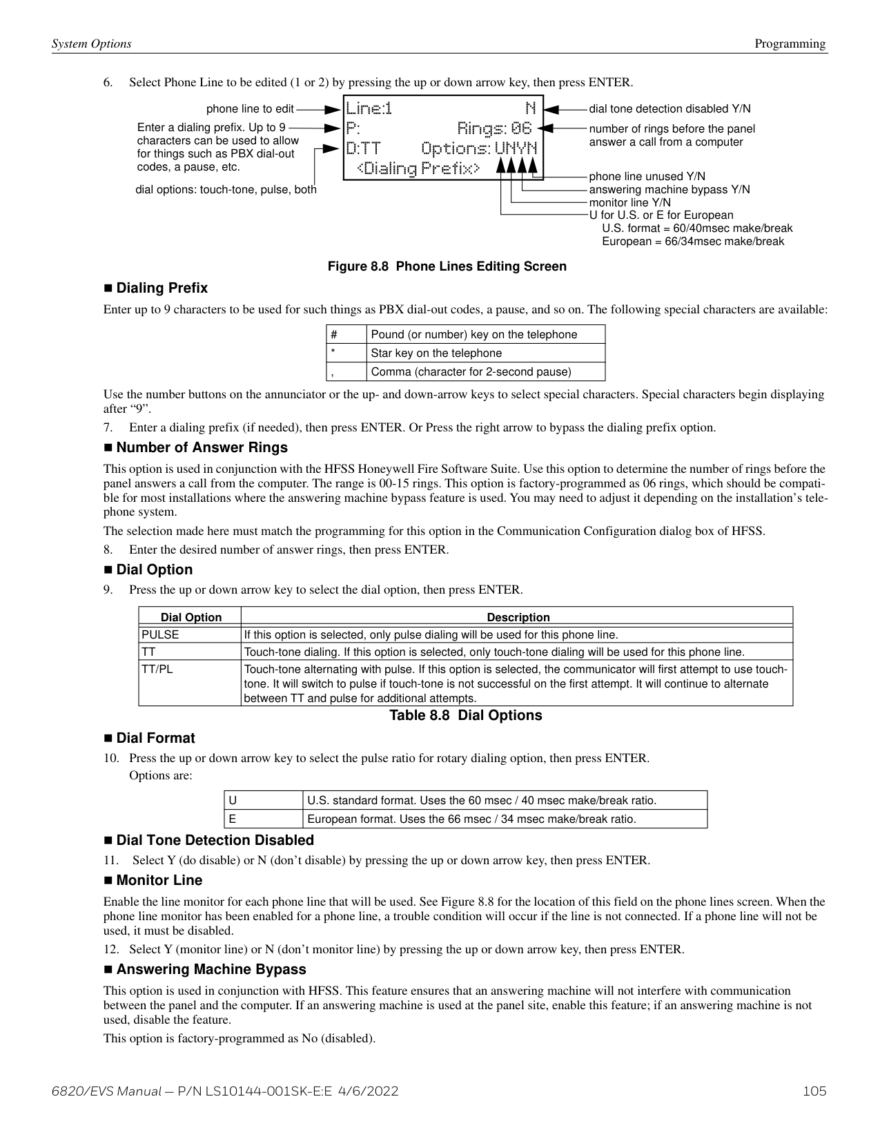
|System Options|Communication Options|Phone Line Gains|Dialing|Low|*High|See “Phone Line Gains” on page 106.| |System Options|Communication Options|Phone Line Gains|Dialing|Normal|*High|See “Phone Line Gains” on page 106.| |System Options|Communication Options|Phone Line Gains|Reporting|Low|*Low|See “Phone Line Gains” on page 106.| |System Options|Communication Options|Phone Line Gains|Reporting|Normal|*Low|See “Phone Line Gains” on page 106.| |System Options|Communication Options|Phone Line Gains|Reporting|High|*Low|See “Phone Line Gains” on page 106.|
############# Table 7.2 Programming Menu Quick Reference Chart (Continued)
|Menu|Menu|Options/Defaults|Options/Defaults|Options/Defaults|Options/Defaults|Comments| |---|---|---|---|---|---|---| | | | | | | | | |System Options cont.|Time Options|Water Flow Delay|0 - 90 Seconds|*1 sec|Water Flow delay is the number of seconds before a water flow alarm is generated. See “Water Flow Delay” on page 107|Water Flow delay is the number of seconds before a water flow alarm is generated. See “Water Flow Delay” on page 107| |System Options cont.|Time Options|Alarm Verify|60 to 250 seconds|*60 sec|See “Alarm Verify” on page 107.|See “Alarm Verify” on page 107.| |System Options cont.|Time Options|Low AC Report Time|0 - 30 hours|*3 hrs|See Section 8.6.2.|See Section 8.6.2.| |System Options cont.|Time Options|AC Freq:|50 Hz|*60Hz|See “Change AC Line Frequency” on page 107.|See “Change AC Line Frequency” on page 107.| |System Options cont.|Time Options|AC Freq:|60 Hz|*60Hz|See “Change AC Line Frequency” on page 107.|See “Change AC Line Frequency” on page 107.| |System Options cont.|Time Options|AC Freq:|Internal|*60Hz|See “Change AC Line Frequency” on page 107.|See “Change AC Line Frequency” on page 107.| |System Options cont.|Time Options|Clock Display Format|AM/PM|*AM/PM|See “Clock Format (AM/PM or Military)” on page 107.|See “Clock Format (AM/PM or Military)” on page 107.| |System Options cont.|Time Options|Clock Display Format|MIL|*AM/PM|See “Clock Format (AM/PM or Military)” on page 107.|See “Clock Format (AM/PM or Military)” on page 107.| |System Options cont.|Time Options|Auto-resound|4 hours|*24 hours|See “Auto-Resound (4 or 24 hours)” on page 107.|See “Auto-Resound (4 or 24 hours)” on page 107.| |System Options cont.|Time Options|Auto-resound|24 hours|*24 hours|See “Auto-Resound (4 or 24 hours)” on page 107.|See “Auto-Resound (4 or 24 hours)” on page 107.| |System Options cont.|Miscellaneous Options|SYNC Strobes when Silenced|Y|*N|See “Strobes Active when Silenced” on page 108.|See “Strobes Active when Silenced” on page 108.| |System Options cont.|Miscellaneous Options|SYNC Strobes when Silenced|N|*N|See “Strobes Active when Silenced” on page 108.|See “Strobes Active when Silenced” on page 108.| |System Options cont.|Miscellaneous Options|Auto Display Events|Y|*N|See “Auto Display Events” on page 108.|See “Auto Display Events” on page 108.| |System Options cont.|Miscellaneous Options|Auto Display Events|N|*N|See “Auto Display Events” on page 108.|See “Auto Display Events” on page 108.| |System Options cont.|Daylight Saving Options|Auto Daylight Saving Time|Y|*Y|See “Daylight Saving Time Start and End” on page 108.|See “Daylight Saving Time Start and End” on page 108.| |System Options cont.|Daylight Saving Options|Auto Daylight Saving Time|N|*Y|See “Daylight Saving Time Start and End” on page 108.|See “Daylight Saving Time Start and End” on page 108.| |System Options cont.|Daylight Saving Options|DST Start|Select week: 1st, 2nd, 3rd, 4th or Last|Select month|Select month|See “Daylight Saving Time Start and End” on page 108| |System Options cont.|Daylight Saving Options|DST End|Select week: 1st, 2nd, 3rd, 4th or Last|Select month|Select month|See “Daylight Saving Time Start and End” on page 108| |System Options cont.|Edit Banner|Refer to Appendix A.| | | |See Section 8.6.5.| |System Options cont.|SLC Family|SK| | | |See Section 8.6.6.| |System Options cont.|SLC Family|SD| | | | | |Jump Start AutoPrg| | |Y (Yes)|Y (Yes)|Y (Yes)|See Section 8.6.7.| |Jump Start AutoPrg| | |N (No)|N (No)|N (No)|See Section 8.6.7.| |Restore Defaults| | |Y (Yes) N (No)|Y (Yes) N (No)|Y (Yes) N (No)|See Section 8.7.| |Voice Options1|VCM Maintenance|PC Connection|PC Connection|PC Connection|See Section 8.8.|See Section 8.8.| |Voice Options1|VCM Maintenance|Local Recording|Local Recording|Local Recording|See Section 8.8.|See Section 8.8.| |Voice Options1|Edit Voice Settings|Enable Dual Channel System|Enable Dual Channel System|Enable Dual Channel System|See Section 8.8.|See Section 8.8.| |*=Default|*=Default|*=Default|*=Default|*=Default|*=Default|*=Default|
############# Table 7.2 Programming Menu Quick Reference Chart (Continued)
##### Section 8: Programming
This section of the manual describes how to manually program the control panel from the built-in annunciator. Each subsection discusses these menu options in detail. All options described in this section can be performed using the HFSS Honeywell Fire Software Suite.
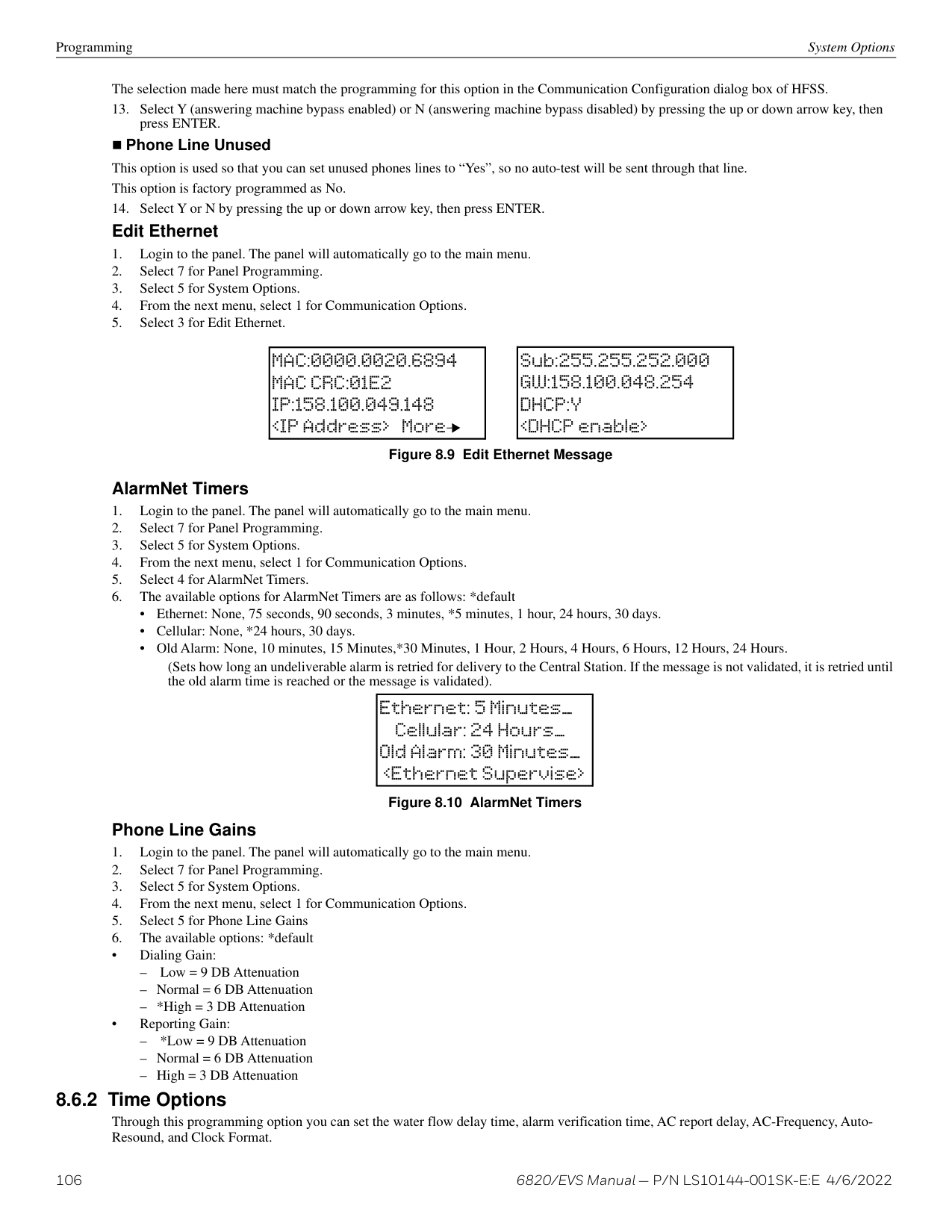
NOTE: JumpStart auto-programming should be run Before any customized programming is performed. Thoroughly test the system after running JumpStart because it automatically programs the system, searching for and configuring all SLC and SBUS devices it finds. JumpStart allows you to confirm the integrity of the installation prior to performing any custom programming. After determining that the hardware is properly installed, custom programming can be performed.
|NOTICE TO USERS, INSTALLERS, AUTHORITIES HAVING JURISDICTION, AND OTHER INVOLVED PARTIES: This product incorporates field programmable software. In order for the product to comply with the requirements in the Standard for Control Units and Accessories for Fire Alarm Systems, UL 864 and UL 2572, certain programming features or options must be limited to specific values or not used at all as indicated below.|NOTICE TO USERS, INSTALLERS, AUTHORITIES HAVING JURISDICTION, AND OTHER INVOLVED PARTIES: This product incorporates field programmable software. In order for the product to comply with the requirements in the Standard for Control Units and Accessories for Fire Alarm Systems, UL 864 and UL 2572, certain programming features or options must be limited to specific values or not used at all as indicated below.|NOTICE TO USERS, INSTALLERS, AUTHORITIES HAVING JURISDICTION, AND OTHER INVOLVED PARTIES: This product incorporates field programmable software. In order for the product to comply with the requirements in the Standard for Control Units and Accessories for Fire Alarm Systems, UL 864 and UL 2572, certain programming features or options must be limited to specific values or not used at all as indicated below.|NOTICE TO USERS, INSTALLERS, AUTHORITIES HAVING JURISDICTION, AND OTHER INVOLVED PARTIES: This product incorporates field programmable software. In order for the product to comply with the requirements in the Standard for Control Units and Accessories for Fire Alarm Systems, UL 864 and UL 2572, certain programming features or options must be limited to specific values or not used at all as indicated below.|NOTICE TO USERS, INSTALLERS, AUTHORITIES HAVING JURISDICTION, AND OTHER INVOLVED PARTIES: This product incorporates field programmable software. In order for the product to comply with the requirements in the Standard for Control Units and Accessories for Fire Alarm Systems, UL 864 and UL 2572, certain programming features or options must be limited to specific values or not used at all as indicated below.|NOTICE TO USERS, INSTALLERS, AUTHORITIES HAVING JURISDICTION, AND OTHER INVOLVED PARTIES: This product incorporates field programmable software. In order for the product to comply with the requirements in the Standard for Control Units and Accessories for Fire Alarm Systems, UL 864 and UL 2572, certain programming features or options must be limited to specific values or not used at all as indicated below.|NOTICE TO USERS, INSTALLERS, AUTHORITIES HAVING JURISDICTION, AND OTHER INVOLVED PARTIES: This product incorporates field programmable software. In order for the product to comply with the requirements in the Standard for Control Units and Accessories for Fire Alarm Systems, UL 864 and UL 2572, certain programming features or options must be limited to specific values or not used at all as indicated below.| |---|---|---|---|---|---|---| |Programming Option|Menu Item|Permitted in UL 864 (Y/N)|Permitted in UL 2572 (Y/N)|Possible Settings|Settings Permitted in UL 864|Settings Permitted in UL 2572| | | | | | | | | |Time Options|Auto-resound|Yes|Yes|4 hrs, 24hrs|4 hours if using SWIFT devices 24 hours if using other devices|4 hours if using SWIFT devices 24 hours if using other devices| |Time Options|Low AC Report Delay|Yes|Yes|0-30 hours|1-3 hours|1-3 hours| |Communication Options|Auto Test Time|Yes|Yes|4, 6, 12, and 24 hrs|4 or 6 hours|4 or 6 hours| |Silencing Options|Auto Silence|Yes|Yes|0-60 minutes|3-60 minutes|3-60 minutes| |Display Oldest Event|Y (Enabled)|Yes|Yes|Yes or No|Yes|Yes| |Display Oldest Event|N (Disabled)|No|No|Yes or No|No|No| |Initial Delay|0-28|Yes|Yes|0-28 hours|3 hours|3 hours| |Alarm Verification1|Alarm Verification|Yes|Yes|60-250 seconds (Confirmation period)|0-60 seconds|0-60 seconds| |Manual Release Switch2|Manual Release|Yes|Yes|0-120 seconds (delay period)|0-30 seconds (delay period)|0-30 seconds (delay period)| |Auto Reset EVS MIC Triggered Event|Auto Reset EVS MIC Triggered Event|Yes|Yes|Never Timer Event Disabled|Never Timer Event Disabled|Never Timer Event Disabled| |EVS Input|EVS Input|Yes|Yes|Latching Non-Latching|Latching|Latching| |Event Priority|CO Alarm|No|No|Yes & No|No|No|
############# Table 8.1 Programming Requirements
This section lists the options available under the module option in the Panel Programming. The following modules are available for the control panel: 5824 serial/parallel/IO printer interface module, 6860, 5860, and 6855 LCD remote annunciators, 5815XL SLC Loop expander for SD devices, 6815 SLC Loop Expander for devices, 5895XL power supply,5496 NAC expander, 5880 LED I/O module, 5865 LED annunciator Module, EVS-50W, EVS-125W, EVS-INT50W, EVS-100W audio amplifiers, EVS-VCM voice control module, EVS-RVM remote voice module, and SK-NIC network interface card.
######## 8.2.1 Edit Modules
The features that can be edited when this option is selected are module ID, module name, or features that are specific to the module to be edited. To edit an existing module:
Modules Programming
########## Editing Module ID
Naming Modules You can assign an English name to a system hardware module to make it easier to recognize on a display.
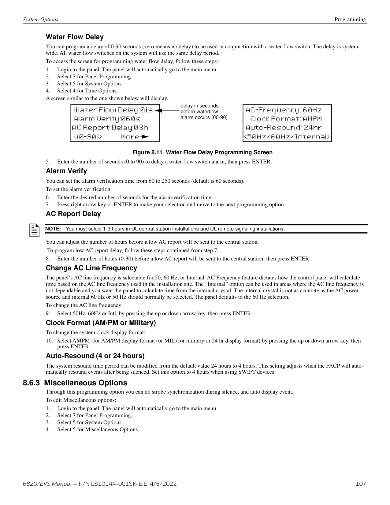
.
Changing Module Options Each module has a unique set of options that specifically applies to the functionality of the module being edited.
NOTE: You cannot edit the module ID for any internal devices, or the SK-NIC.
NOTE: See Appendix A for editing names.
|5880-LED I/O Module ID: 03 5880 03_________
Default name for 5880 module (no customization)
|5880-LED I/O AB_____________| |---|
Use arrow keys to select characters. Letters begin displaying with “A”. Press the ENTER key to select the desired character. Use the right arrow to move to the next character.
############# Figure 8.1 Edit Module Name Programming Screen Example
The screen will display “Adding module [#]...” for a few moments. You will be returned to the
You must save changes when you exit the Program Menu or the new module will not be added.
NOTE: If you add a module that has not been physically connected, the panel will go into trouble after it reinitializes (when you exit the Program Menu). When the new module is attached, the trouble will correct itself automatically.
Programming Zone
###### 8.3 Zone
Through the zone option in Panel Programming you can edit and view zone points. Selections made here affect all detectors and switches in the zone. Up to 999 zones can be used in each panel.
######## 8.3.1 Edit Zone
Features that can be edited through the Edit Zone option are zone name, zone properties (which includes, zone type, and detector sensitivity), zone output mapping, and zone accessory options.
To edit a zone, follow these steps:
NOTE: See Appendix A for editing names.
Edit Zone Properties Zone properties consist of alarm delay characteristics, and heat detector sensitivity.
Zone number being programmed
Detection type also selected from this screen (see Table 8.2).Z001-Type:1-Count___ Heat [150]F.
Select the temperature that will cause heat detectors in this zone to go into alarm. Range: 135°-190° (SK devices)
############# 135°-150° (SD devices) Figure 8.2 Edit Zone Properties
Alarm Delay Characteristics The programmed zone type is provided for user reference only. Use HFSS to modify the zone type. Table 8.2 lists the alarm delay characteristics and a description of each.
|Type of Delay|Description| |---|---| | | | |1-Count1|One Count (No Delay). When this option is enabled, an alarm occurs immediately when a single device of any of the following types goes into alarm: detector, manual pull, water flow, Aux1 or Aux2. This is considered the most typical operation and is the default for all zones.| |2-Count|When this type of alarm delay is used, two or more detectors within the zone must go into alarm in order for the zone to report an alarm. Switches of type manual pull, water flow, Detector Switch, Aux1 and Aux2 are an exception; they will cause an alarm when only one switch is in alarm. When a single detector is in alarm in a 2-Count zone, the system enters a pre-alarm condition. In a pre-alarm condition, the touchpad PZT beeps and the annunciator display indicates that a pre-alarm has occurred. If the zone has been mapped to an output group for the pre-alarm event, the output group will activate. The pre-alarm will not be reported to the central station.| |Alarm Verification|Alarm verification is an optional false alarm prevention feature that verifies an alarm condition by resetting the smoke detector. If the alarm condition still exists by the time the reset cycle has completed, the detector will go into alarm. If the detector is no longer in alarm, no report will go to the central station. The alarm verification sequence is ignored if the zone is already in alarm.|
Table 8.2 Alarm Delay Types
Zone Programming
|Type of Delay|Description| |---|---| | | |
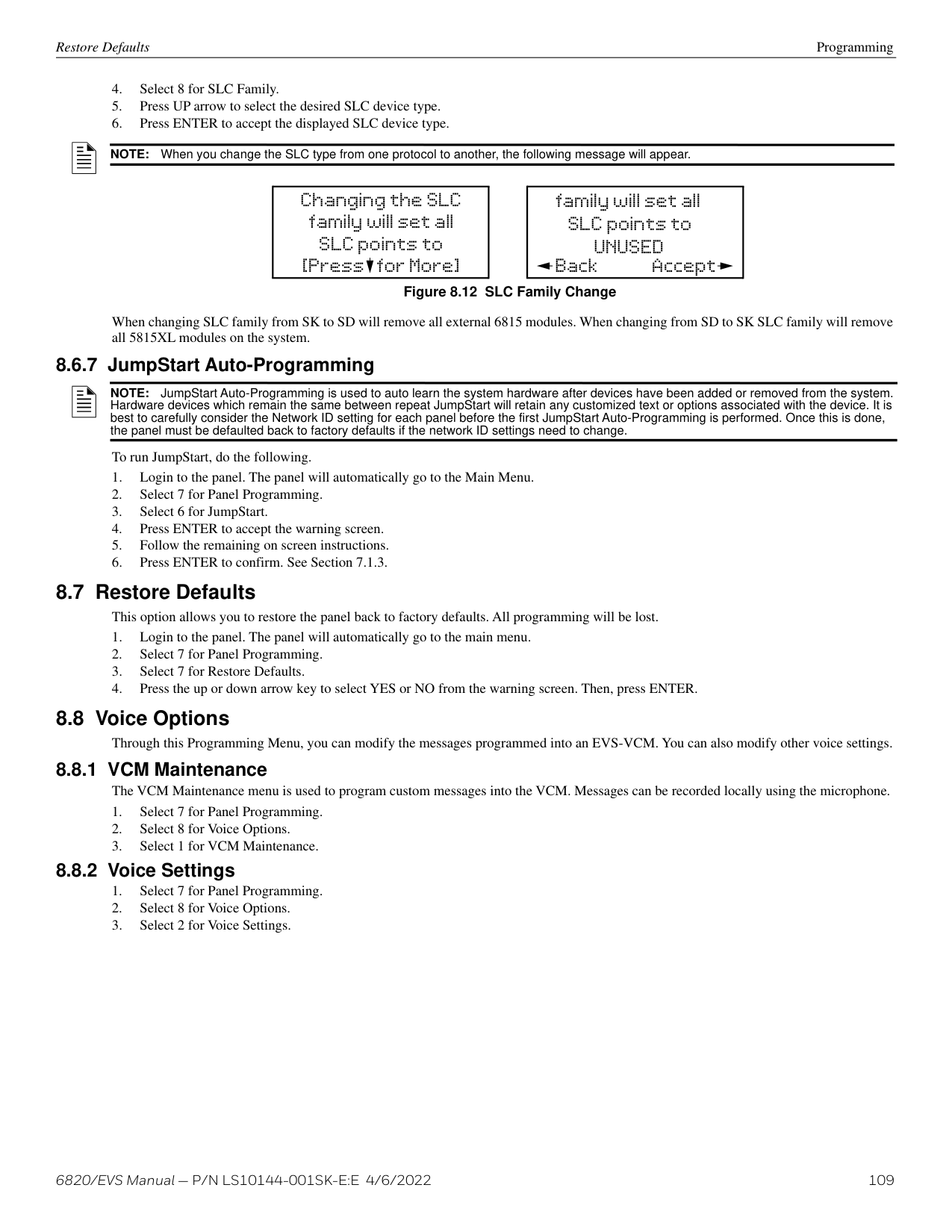
|PAS-Positive Alarm Sequence2|This option is intended to be used with an acknowledge switch. An alarm is delayed for 15 seconds, giving on-site personnel a chance to investigate the alarm. If the acknowledge switch is not activated within 15 seconds, an alarm occurs automatically. If this option is enabled for a zone, the zone will respond to an alarm condition as follows:
The zone will not go into alarm for 15 seconds to allow an on-site operator to activate the acknowledge switch. If the operator does not press the acknowledge switch within 15 seconds, the zone will go into alarm. If the operator presses the acknowledge switch within 15 seconds, a 180-second time-frame will begin counting down. This time-frame allows the operator to investigate the cause of the alarm. If the operator performs a reset within 180 seconds, the alarm will not occur. If the operator does not perform a reset within 180 seconds, an alarm will occur automatically. The PAS feature will be overridden if another alarm occurs.| |Alternate P.A.S. Positive Alarm Sequence2|An improved version of PAS is available with software version 6.04 or higher, for use with the 6860 and 6855 only. Existing systems with PAS enabled will still function normally. The PAS option will program an automatic, addressable detector to delay panel activation (including alarm relay and communicator) for a period of 15 seconds plus a delay time of up to three minutes. When a detector triggers an alarm, the onboard piezo sounds immediately, but the mapped output groups (e.g. NACs, control/relay modules) are prevented from activating for 15 seconds. This inhibit time is factory set and cannot be changed. Pressing the ACK key during the 15 second inhibit time will start a timer which prevents activation of the mapped output groups for an additional time duration for up to three minutes and display a countdown for the three minute delay. After the delay, the mapped output groups will activate if the source of the alarm is not cleared. If a second alarm occurs during either time delay, the alarm will be processed immediately, causing activation of the appropriate output groups. If PAS is enabled,
the onboard piezo sounds immediately. the control panel LCD display will indicate a PAS-alarm event and the active point. output groups (NACs and control/relay modules) of associated zones will be inhibited from activating for a factory-set duration of 15 seconds. pressing the ACK key will start a timer which inhibits output activation for additional time delay of up to three minutes. a second alarm occurring at any time during either time delay will cause immediate activation of all associated outputs.| |SNGL ILOCK|See Section 9.6.1 for single interlock releasing operation.| |DBL ILOCK|See Section 9.6.2 for double interlock releasing operation.|
############# Table 8.2 Alarm Delay Types (Continued)
########### Heat Detector Sensitivity
Use this feature to set the temperature at which high temperature detectors will respond. All detectors in the zone will respond in the same way. The range for the SD505-HEAT heat detector is from 135°F to 150°F. The range for SK-HEAT-HT heat detectors is from 135°F to 190°F.
The high temperature SK heat detectors are absolute temperature devices. This means that they respond to an alarm immediately if the temperature in the zone goes above the programmed temperature.
from the number keys on the annunciator, then press ENTER. Zone Accessory Options
NOTE: The B200S Intelligent Sounder base provides the recommended CO cadence pattern.
Local Zone (choose Y or N, for Yes or No).
NOTE: If the SLC protocol is changed from SD to IDP/SK series and the cadence is no longer valid for IDP/SK, the zone cadence will be set to constant on.
Programming Group
###### 8.4 Group
An output group is made up of output points that have been programmed to respond in the same way. Output groups simplify programming because you only have to program the output characteristics that are common to all of the group points once, instead of programming each individual point. Once you have defined the characteristics of output groups, you can assign each point to the appropriate group. All valid output points are assigned to only one output group. Unused points are not assigned to any output group. Up to 999 output groups can be defined per panel.
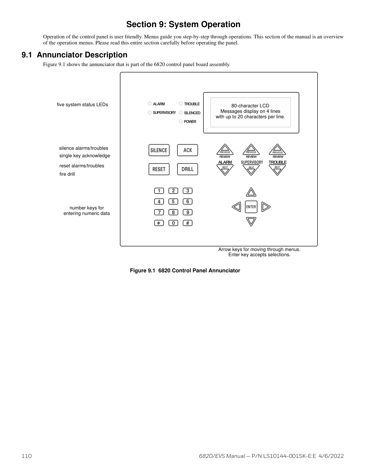
Edit Group Properties
NOTE: See Appendix A for editing names.
NOTE: These settings only apply to non-voice groups.
########### Defining Output Group Type
Each output group is defined as either a voice output group or a non-voice output group. Output points that are audio circuits (all circuits on the EVS-50W, EVS-125W, EVS-100W, EVS-INT50W, and EVS-CE4) can only be assigned to voice output groups. Output points that are non-voice circuits (all other points and circuits that are on all modules except the EVS-50W, EVS-125W, EVS-100W, EVS-INT50W, and EVS-CE4) are assigned to non-voice output groups.C
Each of the output groups defined as voice can be mapped to a particular switch and LED on the EVS-VCM, EVS-RVM, and EVS-SW24. This allows the user to see the state of the voice groups assigned to the switches.
This also lets the user individually select which areas they want to do a live page into. Output groups not defined as voice groups can also be assigned to these switches as long as there is a voice group already assigned to the group. This allows for dynamically activating/deactivating both voice and strobes/other outputs in an area with a single button press. See “Activating Output Groups Dynamically” on page 129.
Silencing Options The following silencing options are available for each output group.
|Optional Timers|Description| |---|---| | | | |Silence Inhibit|Timed Silence after Inhibit. If this option is selected, the output group must be audible for a programmed number of minutes before it can be silenced. If the condition that caused the output to activate has not cleared during the time-frame, the output can be silenced. If you select this option, select the timeframe in the delay field. Range is 0-60 minutes.| |Auto Silence|Silenceable. The output group will automatically silence after the timer expires. Range is 0-60 minutes.| |Auto Unsilence|If this option is selected, the output group can be silenced for a programmed time-frame. If the condition that caused the output to activate has not cleared during the time-frame, the output reactivates. If you select this option, select the timeframe in the delay field. Range is 0-60 minutes.| |Startup Delay|When an alarm is generated, the output group will not activate until the timer expires assuming the event is still active. Range is 0-120 Seconds.|
############# Table 8.3 Silencing Options
######## 8.4.2 View Group Points
######## 8.4.3 Edit OPG Template
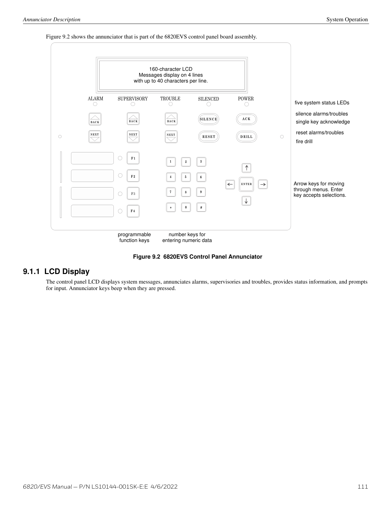
NOTE: See Appendix A for editing names.
###### 8.5 Point
You may need to change characteristics of individual input points (detectors and switches) even after using JumpStart AutoProgramming. This section explains how to change options for: type of input point; latching/non-latching status (switches); and name and zone/group assignment of a point.
######## 8.5.1 Point Programming For 5815XL ModuleTo program for points on an 5815XL module, follow these steps:
|Type Selection|Function|Latching Option|Comments| |---|---|---|---| | | | | | |UNUSED| | |Select for SLC points that are unused.| |DETECTOR|PHOTO| |Spot photoelectric detectors.| |DETECTOR|ION| |Spot ionization detector.| |DETECTOR|HEAT| |Spot heat detector.| |DETECTOR|PHOTO DUCT| |Duct photoelectric detector.| |DETECTOR|ION DUCT| |Duct Ion detector.| |DETECTOR|2-WIRE SMOKE| |2-wire smoke detector.|
############# Table 8.4 Programming Options for 5815XL Modules
|Type Selection|Function|Latching Option|Comments| |---|---|---|---| | | | | | |SUP DET|PHOTO|Latching Non Latching|Use this option when you want a detector to indicate a supervisory alarm.| |SUP DET|ION|Latching Non Latching|Use this option when you want a detector to indicate a supervisory alarm.| |SUP DET|HEAT|Latching Non Latching|Use this option when you want a detector to indicate a supervisory alarm.| |SUP DET|PHOTO DUCT|Latching Non Latching|Use this option when you want a detector to indicate a supervisory alarm.| |SUP DET|ION DUCT|Latching Non Latching|Use this option when you want a detector to indicate a supervisory alarm.| |SWITCH|MANUAL PULL| |Use this switch type for manual pull stations. This input is always latched. The switch can clear only when an alarm is reset. This switch type has the highest fire priority; it overrides any other type of fire alarm.| |SWITCH|WATERFLOW|Latching|Use this switch type for monitoring water flow in a sprinkler system. Switch closure will cause a sprinkler alarm. Water flow switches can be programmed as latching or non-latching. You can program a delay of up to 90 seconds to be used with a water flow switch. The delay allows for normal, brief changes in sprinkler system water pressure. The water flow alarm will not activate unless the switch is active for the programmed delay time. If a delay is used, the system begins counting down when the switch closes. If the switch opens (restores) before the timer expires, a water flow alarm is not generated. If the water flow switch remains closed after the timer expires, a water flow alarm will be generated.| |SWITCH|WATERFLOW|Non Latching|Use this switch type for monitoring water flow in a sprinkler system. Switch closure will cause a sprinkler alarm. Water flow switches can be programmed as latching or non-latching. You can program a delay of up to 90 seconds to be used with a water flow switch. The delay allows for normal, brief changes in sprinkler system water pressure. The water flow alarm will not activate unless the switch is active for the programmed delay time. If a delay is used, the system begins counting down when the switch closes. If the switch opens (restores) before the timer expires, a water flow alarm is not generated. If the water flow switch remains closed after the timer expires, a water flow alarm will be generated.| |SWITCH|FIRE SUPERVISORY|Latching|Use this switch type for tamper monitoring of sprinklers and other fire protection devices. If a contact closes, a sprinkler supervisory event will be generated. Supervisory switches can be latching or non-latching.| |SWITCH|FIRE SUPERVISORY|Non Latching|Use this switch type for tamper monitoring of sprinklers and other fire protection devices. If a contact closes, a sprinkler supervisory event will be generated. Supervisory switches can be latching or non-latching.| |SWITCH|FIRE DRILL| |System-level, non latching switch. This switch is an alternative way of causing a fire drill. It has the same operation as the fire drill option available from the annunciator. When the switch is activated, a fire drill begins; when the switch is de-activated, the fire drill ends.| |SWITCH|SILENCE| |This system-level switch is an alternative way to silence the fire system. It has the same effect as pressing the Silence key.| |SWITCH|RESET| |This system-level switch is an alternative way to reset the fire system. It has the same effect as pressing the Reset key.| |SWITCH|P.A.S. ACK| |Positive acknowledge switch. This switch must be used in zones programmed as Positive Alarm Sequence (see “Edit Zone Properties” on page 92). If an acknowledge switch closes when an alarm or trouble condition is not already in progress, a trouble will occur. You must use a UL listed normally open, momentary switch type. The switch must be rated at 5V, 100 mA (minimum) and be used with an EOL resistor for supervision.| |SWITCH|ZONE AUX1|Latching|Use these switch types if you want to monitor special zone-level conditions (such as dry contact from a remote power supply).| |SWITCH|ZONE AUX1|Non Latching|Use these switch types if you want to monitor special zone-level conditions (such as dry contact from a remote power supply).| |SWITCH|ZONE AUX2|Latching|Use these switch types if you want to monitor special zone-level conditions (such as dry contact from a remote power supply).| |SWITCH|ZONE AUX2|Non Latching|Use these switch types if you want to monitor special zone-level conditions (such as dry contact from a remote power supply).| |SWITCH|SYSTEM AUX1|Latching|Use these switch types if you want to monitor special system-wide conditions (such as dry contact from a remote power supply).| |SWITCH|SYSTEM AUX1|Non Latching|Use these switch types if you want to monitor special system-wide conditions (such as dry contact from a remote power supply).| |SWITCH|SYSTEM AUX2|Latching|Use these switch types if you want to monitor special system-wide conditions (such as dry contact from a remote power supply).|
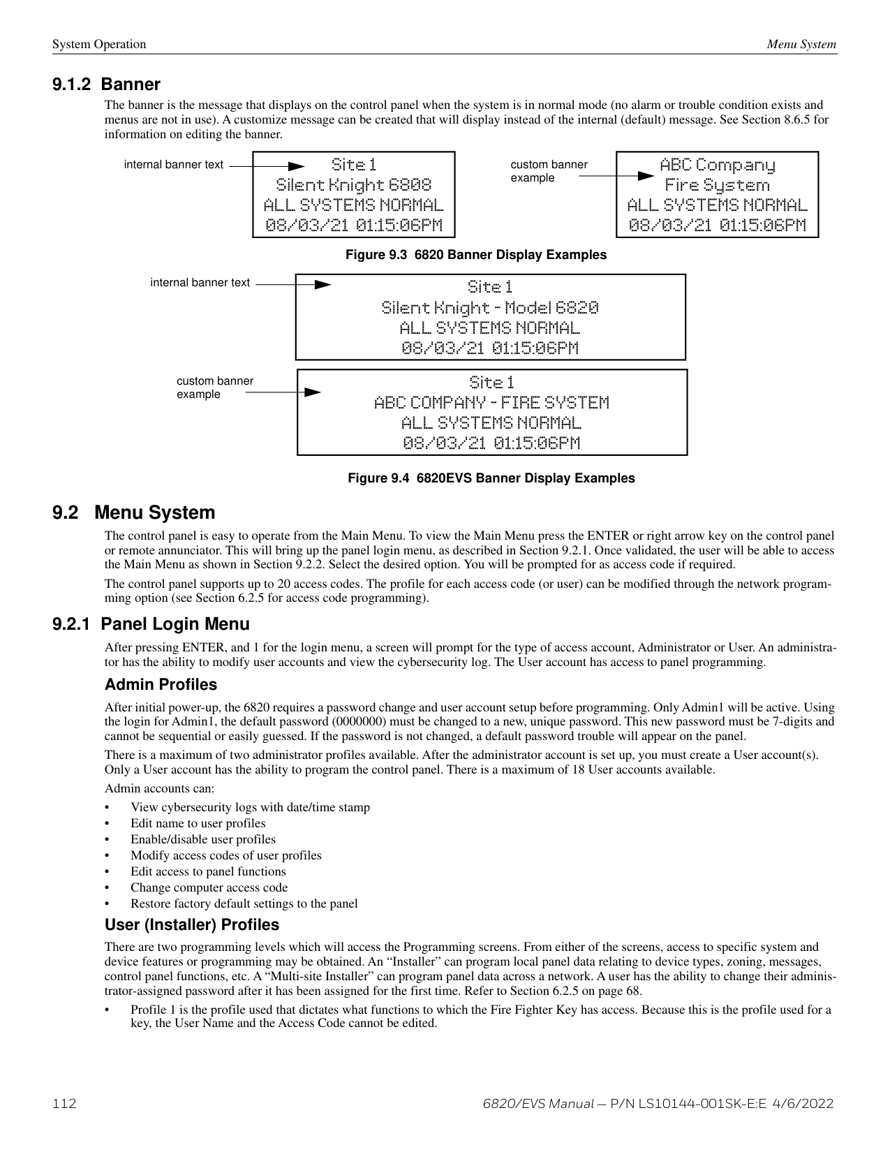
|SWITCH|SYSTEM AUX2|Non Latching|Use these switch types if you want to monitor special system-wide conditions (such as dry contact from a remote power supply).|
############# Table 8.4 Programming Options for 5815XL Modules (Continued)
|Type Selection|Function|Latching Option|Comments| |---|---|---|---| | | | | | |SWITCH (cont.)|DETECTOR| |Used to monitor conventional 4-wire detectors, a contact closure will generate a detector alarm event.| |SWITCH (cont.)|FIRE TAMPER|Latching|Performs identically to a supervisory switch, but will be indicated as a tamper switch on the LCD annunciator.| |SWITCH (cont.)|FIRE TAMPER|Non Latching|Performs identically to a supervisory switch, but will be indicated as a tamper switch on the LCD annunciator.| |SWITCH (cont.)|MANUAL RELEASE| |Manual release switch| |SWITCH (cont.)|INTERLOCK| |Interlock release switch input.| |SWITCH (cont.)|STATUS POINT| | | |SWITCH (cont.)|EVS INPUT|Latching|User also has EVS Event Number 1-8 option for EVS INPUT.
Only available when an EVS-VCM is installed in the system.| |SWITCH (cont.)|EVS INPUT|Non Latching|User also has EVS Event Number 1-8 option for EVS INPUT.
Only available when an EVS-VCM is installed in the system.| |SWITCH (cont.)|EVS TAMPER|Latching|User also has EVS Event Number 1-8 option for EVS INPUT.
Only available when an EVS-VCM is installed in the system.| |SWITCH (cont.)|EVS TAMPER|Non Latching|User also has EVS Event Number 1-8 option for EVS INPUT.
Only available when an EVS-VCM is installed in the system.| |SWITCH (cont.)|EVS SUPERVISORY|Latching|User also has EVS Event Number 1-8 option for EVS INPUT.
Only available when an EVS-VCM is installed in the system.| |SWITCH (cont.)|EVS SUPERVISORY|Non Latching|User also has EVS Event Number 1-8 option for EVS INPUT.
Only available when an EVS-VCM is installed in the system.| |SWITCH (cont.)|CO DETECT SWITCH| |CO Detector Switch| |SWITCH (cont.)|CO SUPERVISORY DETECT SWITCH|Latching|CO Supervisory Detector Switch| |SWITCH (cont.)|CO SUPERVISORY DETECT SWITCH|Non Latching|CO Supervisory Detector Switch| |NOTIF|OUTPUT PT|Select Group|Output point, a general use notification type. Use for driving standard notification appliances.| |NOTIF|AUX CONST| |Use constant power for applications that require a constant auxiliary power source. Power is always present at constant circuits.| |NOTIF|AUX RESET| |Use for auxiliary power, resettable applications. See Section 4.17.5 for a description of how this option operates.| |NOTIF|AUX DOOR| |Use for auxiliary power, door holder applications. For example, if you were using an auxiliary power supply for door holders, you would use this option. See Section Door Holder Power for a description of how this option operates.| |RELAY|OUTPUT PT|Select Group|Output point, a general use relay type. Use for applications requiring a relay, such as fan shutdown, elevator recall, and so on.| |RELAY|AUX RESET| |Use for auxiliary power, resettable applications. See Section 4.17.5 for a description of how this option operates.| |RELAY|AUX DOOR| |Use for auxiliary power, door holder applications. For example, if you were using an auxiliary power supply for door holders, you would use this option. See “Door Holder Power” on page 54 for a description of how this option operates.| |SLC LED|LED NUMBER|01-80|For use with SD devices only. 80 sub addresses on LED.| |SLC LED|LED FUNCTION|Unused| | |SLC LED|LED FUNCTION|NOTIF|Notification can have group number.|
############# Table 8.4 Programming Options for 5815XL Modules (Continued)
######## 8.5.2 Point Programming For 6815 ModuleTo program for points on an 6815 module, follow these steps:
|Type Selection|Function|Latching Option|Comments| |---|---|---|---| | | | | | |UNUSED| | |Select for SLC points that are unused.| |DETECTOR|PHOTO| |Spot photoelectric detectors.| |DETECTOR|ION| |Spot ION detectors| |DETECTOR|HEAT| |Spot heat detector.| |DETECTOR|PHOTO DUCT| |Duct photoelectric detector.| |DETECTOR|ACCLIMATE| |Acclimate photoelectric detector.|
|DETECTOR|HEAT HT| |High temperature heat detector.| |DETECTOR|PHOTO-HEAT| |Photoelectric detector with heat sensor.| |DETECTOR|BEAM| |Beam smoke detector.| |SUP DET|PHOTO|Latching Non Latching|Use this option when you want a detector to indicate a supervisory alarm.| |SUP DET|ION|Latching Non Latching|Use this option when you want a detector to indicate a supervisory alarm.| |SUP DET|HEAT|Latching Non Latching|Use this option when you want a detector to indicate a supervisory alarm.| |SUP DET|PHOTO DUCT|Latching Non Latching|Use this option when you want a detector to indicate a supervisory alarm.| |SUP DET|ACCLIMATE|Latching Non Latching|Use this option when you want a detector to indicate a supervisory alarm.| |SUP DET|HEAT HT|Latching Non Latching|Use this option when you want a detector to indicate a supervisory alarm.| |SUP DET|PHOTO-HEAT|Latching Non Latching|Use this option when you want a detector to indicate a supervisory alarm.| |SUP DET|BEAM|Latching Non Latching|Use this option when you want a detector to indicate a supervisory alarm.| |CO SMOKE DETECTOR|CO ALRM / FIRE ALRM| |No Accessory Base, Sounder base, Relay Base, or Intelligent Sounder base. Bases can be set for Single station or Multi station, Silence or Non-Silence, Latching or non-latching. Intelligent sounder bases can have volume set for high or low.| |CO SMOKE DETECTOR|CO ALRM / FIRE SUPR| |No Accessory Base, Sounder base, Relay Base, or Intelligent Sounder base. Bases can be set for Single station or Multi station, Silence or Non-Silence, Latching or non-latching. Intelligent sounder bases can have volume set for high or low.| |CO SMOKE DETECTOR|CO SUPR / FIRE ALRM| |No Accessory Base, Sounder base, Relay Base, or Intelligent Sounder base. Bases can be set for Single station or Multi station, Silence or Non-Silence, Latching or non-latching. Intelligent sounder bases can have volume set for high or low.| |CO SMOKE DETECTOR|CO SUPR / FIRE SUPR|Latching Non Latching|Supervisory switches can be latching or non-latching.| |W-DETECTOR|PHOTO| |Wireless photoelectric detectors| |W-DETECTOR|PHOTO-HEAT| |Wireless heat detector| |W-DETECTOR|HEAT| |Wireless heat detector| |W-SUP DET SWITCH|Same as W-Detector|Latching Non Latching|Wireless photoelectric detectors| |SWITCH|MANUAL PULL| |Use this switch type for manual pull stations. This input is always latched. The switch can clear only when an alarm is reset. This switch type has the highest fire priority; it overrides any other type of fire alarm.| |SWITCH|WATERFLOW|Latching|Use this switch type for monitoring water flow in a sprinkler system. Switch closure will cause a sprinkler alarm. Water flow switches can be programmed as latching or non-latching. You can program a delay of up to 90 seconds to be used with a water flow switch. The delay allows for normal, brief changes in sprinkler system water pressure. The water flow alarm will not activate unless the switch is active for the programmed delay time. If a delay is used, the system begins counting down when the switch closes. If the switch opens (restores) before the timer expires, a water flow alarm is not generated. If the water flow switch remains closed after the timer expires, a water flow alarm will be generated.| |SWITCH|WATERFLOW|Non Latching|Use this switch type for monitoring water flow in a sprinkler system. Switch closure will cause a sprinkler alarm. Water flow switches can be programmed as latching or non-latching. You can program a delay of up to 90 seconds to be used with a water flow switch. The delay allows for normal, brief changes in sprinkler system water pressure. The water flow alarm will not activate unless the switch is active for the programmed delay time. If a delay is used, the system begins counting down when the switch closes. If the switch opens (restores) before the timer expires, a water flow alarm is not generated. If the water flow switch remains closed after the timer expires, a water flow alarm will be generated.| |SWITCH|FIRE SUPERVISORY|Latching|Use this switch type for tamper monitoring of sprinklers and other fire protection devices. If a contact closes, a sprinkler supervisory event will be generated. Supervisory switches can be latching or non-latching.| |SWITCH|FIRE SUPERVISORY|Non Latching|Use this switch type for tamper monitoring of sprinklers and other fire protection devices. If a contact closes, a sprinkler supervisory event will be generated. Supervisory switches can be latching or non-latching.| |SWITCH|FIRE DRILL| |System-level, non latching switch. This switch is an alternative way of causing a fire drill. It has the same operation as the fire drill option available from the annunciator. When the switch is activated, a fire drill begins; when the switch is de-activated, the fire drill ends.|
############# Table 8.5 Programming Options for 6815 Modules
|Type Selection|Function|Latching Option|Comments| |---|---|---|---| | | | | | |SWITCH (cont.)|SILENCE| |This system-level switch is an alternative way to silence the fire system. It has the same effect as pressing the Silence key.| |SWITCH (cont.)|RESET| |This system-level switch is an alternative way to reset the fire system. It has the same effect as pressing the Reset key.| |SWITCH (cont.)|P.A.S. ACK| |Positive acknowledge switch. This switch must be used in zones programmed as Positive Alarm Sequence (see “Edit Zone Properties” on page 92). If an acknowledge switch closes when an alarm or trouble condition is not already in progress, a trouble will occur. You must use a UL listed normally open, momentary switch type. The switch must be rated at 5V, 100 mA (minimum) and be used with an EOL resistor for supervision.| |SWITCH (cont.)|ZONE AUX1|Latching|Use these switch types if you want to monitor special zone-level conditions (such as dry contact from a remote power supply).| |SWITCH (cont.)|ZONE AUX1|Non Latching|Use these switch types if you want to monitor special zone-level conditions (such as dry contact from a remote power supply).| |SWITCH (cont.)|ZONE AUX2|Latching|Use these switch types if you want to monitor special zone-level conditions (such as dry contact from a remote power supply).| |SWITCH (cont.)|ZONE AUX2|Non Latching|Use these switch types if you want to monitor special zone-level conditions (such as dry contact from a remote power supply).| |SWITCH (cont.)|SYSTEM AUX1|Latching|Use these switch types if you want to monitor special system-wide conditions (such as dry contact from a remote power supply).| |SWITCH (cont.)|SYSTEM AUX1|Non Latching|Use these switch types if you want to monitor special system-wide conditions (such as dry contact from a remote power supply).| |SWITCH (cont.)|SYSTEM AUX2|Latching|Use these switch types if you want to monitor special system-wide conditions (such as dry contact from a remote power supply).| |SWITCH (cont.)|SYSTEM AUX2|Non Latching|Use these switch types if you want to monitor special system-wide conditions (such as dry contact from a remote power supply).| |SWITCH (cont.)|DETECTOR| |Used to monitor conventional 4-wire detectors, a contact closure will generate a detector alarm event.| |SWITCH (cont.)|FIRE TAMPER|Latching|Performs identically to a supervisory switch, but will be indicated as a tamper switch on the LCD annunciator.| |SWITCH (cont.)|FIRE TAMPER|Non Latching|Performs identically to a supervisory switch, but will be indicated as a tamper switch on the LCD annunciator.| |SWITCH (cont.)|MANUAL RELEASE| |Manual release switch| |SWITCH (cont.)|INTERLOCK| |Interlock release switch input.| |SWITCH (cont.)|STATUS POINT| | | |SWITCH (cont.)|EVS INPUT|Latching|User also has EVS Event Number 1-8 option for EVS INPUT.
Only available when an EVS-VCM is installed in the system.| |SWITCH (cont.)|EVS INPUT|Non Latching|User also has EVS Event Number 1-8 option for EVS INPUT.
Only available when an EVS-VCM is installed in the system.| |SWITCH (cont.)|EVS TAMPER|Latching|User also has EVS Event Number 1-8 option for EVS INPUT.
Only available when an EVS-VCM is installed in the system.| |SWITCH (cont.)|EVS TAMPER|Non Latching|User also has EVS Event Number 1-8 option for EVS INPUT.
Only available when an EVS-VCM is installed in the system.| |SWITCH (cont.)|EVS SUPERVISORY|Latching|User also has EVS Event Number 1-8 option for EVS INPUT.
Only available when an EVS-VCM is installed in the system.| |SWITCH (cont.)|EVS SUPERVISORY|Non Latching|User also has EVS Event Number 1-8 option for EVS INPUT.
Only available when an EVS-VCM is installed in the system.| |SWITCH (cont.)|CO DETECT SWITCH| |CO Detector Switch| |SWITCH (cont.)|CO SUPERVISORY DETECT SWITCH|Latching|CO Supervisory Detector Switch|
|SWITCH (cont.)|CO SUPERVISORY DETECT SWITCH|Non Latching|CO Supervisory Detector Switch| |SWITCH (cont.)|TROUBLE_MON| |Use this switch type to monitor trouble from external devices. Trouble monitors are used in HVAC operations.| |NOTIF|OUTPUT PT|Select Group|Output point, a general use notification type. Use for driving standard notification appliances.| |NOTIF|AUX CONST| |Use constant power for applications that require a constant auxiliary power source. Power is always present at constant circuits.| |NOTIF|AUX RESET| |Use for auxiliary power, resettable applications. See “Resettable Power” on page 54 for a description of how this option operates.| |NOTIF|AUX DOOR| |Use for auxiliary power, door holder applications. For example, if you were using an auxiliary power supply for door holders, you would use this option. See “Door Holder Power” on page 54 for a description of how this option operates.| |RELAY|OUTPUT PT|Select Group|Output point, a general use relay type. Use for applications requiring a relay, such as fan shutdown, elevator recall, and so on.| |RELAY|AUX RESET| |Use for auxiliary power, resettable applications. See “Resettable Power” on page 54 for a description of how this option operates.| |RELAY|AUX DOOR| |Use for auxiliary power, door holder applications. For example, if you were using an auxiliary power supply for door holders, you would use this option. See “Door Holder Power” on page 54 for a description of how this option operates.|
############# Table 8.5 Programming Options for 6815 Modules (Continued)
|Type Selection|Function|Latching Option|Comments| |---|---|---|---| | | | | | |Detector|2-Wire Smoke| | | |W-Gateway| | |Wireless Gateway| |W-SWITCH|Same as SWITCH| | | |W-Relay|Same as Relay| |When a wireless relay is in use, module device count must be limited to 109 modules per loop. This includes wired and wireless modules that are on the same loop. The module address must be within 1-109.|
Table 8.5 Programming Options for 6815 Modules (Continued)
######## 8.5.3 Point Programming For Internal or External Power Module (5895XL)To program for an internal or external power module points:
|Choices|Type Selections|Function Selections for each Type|Comments| |---|---|---|---| |Enter Point|Enter Point|Enter Point|Enter Point| |Select Type|UNUSED|UNUSED|UNUSED| |Select Type|B NOTIF|NOTIF OUTPUT|User also has Supervised/Unsupervised option| |Select Type|B NOTIF|CONTROL CIRCUIT|User also has Supervised/Unsupervised option| |Select Type|A NOTIF|Same as B NOTIF|User also has Supervised/Unsupervised option| |Select Type|AUX_PWR|CONSTANT|Constant auxiliary power| |Select Type|AUX_PWR|AUX RESET|Resettable auxiliary power| |Select Type|AUX_PWR|AUX DOOR|Door holder auxiliary power| |Select Type|AUX_PWR|AUX SYNC| | |Select Type|B SWITCH|MANUAL PULL|Refer to comments column of Table 8.5 for description of these options. Latch or Non-latching feature only appears for WATERFLOW, FIRE SUPERVISORY, FIRE TAMPER, ZONE AUX1, ZONE AUX2, SYSTEM AUX1, SYSTEM AUX2, ECS INPUT, ECS TAMPER, and ECS SUPERVISORY.| |Select Type|B SWITCH|WATERFLOW|Refer to comments column of Table 8.5 for description of these options. Latch or Non-latching feature only appears for WATERFLOW, FIRE SUPERVISORY, FIRE TAMPER, ZONE AUX1, ZONE AUX2, SYSTEM AUX1, SYSTEM AUX2, ECS INPUT, ECS TAMPER, and ECS SUPERVISORY.| |Select Type|B SWITCH|FIRE SUPERVISORY|Refer to comments column of Table 8.5 for description of these options. Latch or Non-latching feature only appears for WATERFLOW, FIRE SUPERVISORY, FIRE TAMPER, ZONE AUX1, ZONE AUX2, SYSTEM AUX1, SYSTEM AUX2, ECS INPUT, ECS TAMPER, and ECS SUPERVISORY.| |Select Type|B SWITCH|FIRE TAMPER|Refer to comments column of Table 8.5 for description of these options. Latch or Non-latching feature only appears for WATERFLOW, FIRE SUPERVISORY, FIRE TAMPER, ZONE AUX1, ZONE AUX2, SYSTEM AUX1, SYSTEM AUX2, ECS INPUT, ECS TAMPER, and ECS SUPERVISORY.| |Select Type|B SWITCH|FIRE DRILL|Refer to comments column of Table 8.5 for description of these options. Latch or Non-latching feature only appears for WATERFLOW, FIRE SUPERVISORY, FIRE TAMPER, ZONE AUX1, ZONE AUX2, SYSTEM AUX1, SYSTEM AUX2, ECS INPUT, ECS TAMPER, and ECS SUPERVISORY.| |Select Type|B SWITCH|SILENCE|Refer to comments column of Table 8.5 for description of these options. Latch or Non-latching feature only appears for WATERFLOW, FIRE SUPERVISORY, FIRE TAMPER, ZONE AUX1, ZONE AUX2, SYSTEM AUX1, SYSTEM AUX2, ECS INPUT, ECS TAMPER, and ECS SUPERVISORY.|
|Select Type|B SWITCH|RESET|Refer to comments column of Table 8.5 for description of these options. Latch or Non-latching feature only appears for WATERFLOW, FIRE SUPERVISORY, FIRE TAMPER, ZONE AUX1, ZONE AUX2, SYSTEM AUX1, SYSTEM AUX2, ECS INPUT, ECS TAMPER, and ECS SUPERVISORY.| |Select Type|B SWITCH|P.A.S. ACK|Refer to comments column of Table 8.5 for description of these options. Latch or Non-latching feature only appears for WATERFLOW, FIRE SUPERVISORY, FIRE TAMPER, ZONE AUX1, ZONE AUX2, SYSTEM AUX1, SYSTEM AUX2, ECS INPUT, ECS TAMPER, and ECS SUPERVISORY.| |Select Type|B SWITCH|ZONE AUX1|Refer to comments column of Table 8.5 for description of these options. Latch or Non-latching feature only appears for WATERFLOW, FIRE SUPERVISORY, FIRE TAMPER, ZONE AUX1, ZONE AUX2, SYSTEM AUX1, SYSTEM AUX2, ECS INPUT, ECS TAMPER, and ECS SUPERVISORY.| |Select Type|B SWITCH|ZONE AUX2|Refer to comments column of Table 8.5 for description of these options. Latch or Non-latching feature only appears for WATERFLOW, FIRE SUPERVISORY, FIRE TAMPER, ZONE AUX1, ZONE AUX2, SYSTEM AUX1, SYSTEM AUX2, ECS INPUT, ECS TAMPER, and ECS SUPERVISORY.| |Select Type|B SWITCH|SYSTEM AUX1|Refer to comments column of Table 8.5 for description of these options. Latch or Non-latching feature only appears for WATERFLOW, FIRE SUPERVISORY, FIRE TAMPER, ZONE AUX1, ZONE AUX2, SYSTEM AUX1, SYSTEM AUX2, ECS INPUT, ECS TAMPER, and ECS SUPERVISORY.| |Select Type|B SWITCH|SYSTEM AUX2|Refer to comments column of Table 8.5 for description of these options. Latch or Non-latching feature only appears for WATERFLOW, FIRE SUPERVISORY, FIRE TAMPER, ZONE AUX1, ZONE AUX2, SYSTEM AUX1, SYSTEM AUX2, ECS INPUT, ECS TAMPER, and ECS SUPERVISORY.| |Select Type|B SWITCH|MANUAL RELEASE|Refer to comments column of Table 8.5 for description of these options. Latch or Non-latching feature only appears for WATERFLOW, FIRE SUPERVISORY, FIRE TAMPER, ZONE AUX1, ZONE AUX2, SYSTEM AUX1, SYSTEM AUX2, ECS INPUT, ECS TAMPER, and ECS SUPERVISORY.| |Select Type|B SWITCH|INTERLOCK|Refer to comments column of Table 8.5 for description of these options. Latch or Non-latching feature only appears for WATERFLOW, FIRE SUPERVISORY, FIRE TAMPER, ZONE AUX1, ZONE AUX2, SYSTEM AUX1, SYSTEM AUX2, ECS INPUT, ECS TAMPER, and ECS SUPERVISORY.| |Select Type|B SWITCH|STATUS POINT|Refer to comments column of Table 8.5 for description of these options. Latch or Non-latching feature only appears for WATERFLOW, FIRE SUPERVISORY, FIRE TAMPER, ZONE AUX1, ZONE AUX2, SYSTEM AUX1, SYSTEM AUX2, ECS INPUT, ECS TAMPER, and ECS SUPERVISORY.| |Select Type|B SWITCH|EVS INPUT|User also has EVS Event Number 1-8 option for EVS INPUT.Only available when a EVS-VCM is installed in the system.| |Select Type|B SWITCH|EVS TAMPER|User also has EVS Event Number 1-8 option for EVS INPUT.Only available when a EVS-VCM is installed in the system.| |Select Type|B SWITCH|EVS SUPERVISORY|User also has EVS Event Number 1-8 option for EVS INPUT.Only available when a EVS-VCM is installed in the system.| |Select Type|A SWITCH|Same as B SWITCH| |
Table 8.6 Menu Choices for Internal/External Power Module
|Choices|Type Selections|Function Selections for each Type|Comments| |---|---|---|---| | | | | | |Select Type (cont.)|B DETECT|2-WIRE SMOKE|Used for Class B, 2-wire detectors.| |Select Type (cont.)|B DETECT|4-WIRE SMOKE|Used for Class B, 4-wire detectors.| |Select Type (cont.)|B DETECT|CO 4-WIRE DET|Used for Class B, 4-wire CO detectors.| |Select Type (cont.)|B DETECT|CO 4-WIRE SUP DET|Latching or Non-latching used for Class B, 4-wire CO Supervisory detectors| |Select Type (cont.)|A DETECT|2-WIRE SMOKE|Used for Class A, 2-wire detectors.| |Select Type (cont.)|A DETECT|4-WIRE SMOKE|Used for Class A, 4-wire detectors.| |Select Type (cont.)|A DETECT|CO 4-WIRE DET|Used for Class A, 4-wire CO detectors.| |Select Type (cont.)|A DETECT|CO 4-WIRE SUP DET|Latching or Non-latching used for Class A, 4-wire CO Supervisory detectors| |Select Zone/Group| | |Group or Zone selection will appear depending on the type selected.| |Edit Name| | |See Appendix A.|
Table 8.6 Menu Choices for Internal/External Power Module (Continued)
######## 8.5.4 Point Programming for 5880/5865 ModulesTo program the 5880/5865 module output points:
Select NOTIF or UNUSED. Select an output group for this notification point.Select the circuit to program. Select a name for the point.
M01 P001 NOTIF
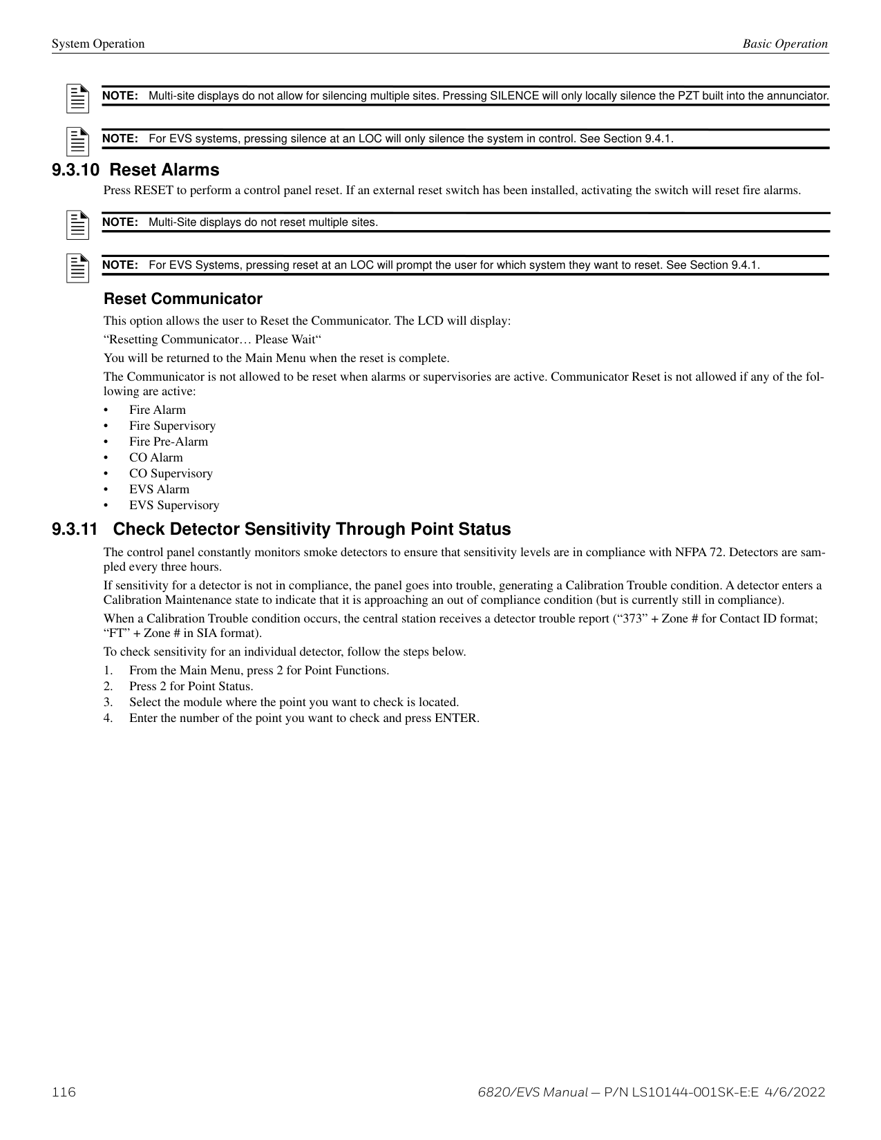
G01
MODULE_1 CKT_1
Figure 8.3 Programming Output Points Screen for 5880 and 5865 Modules
Select SWITCH or UNUSED. Select an input zone.Select the point to program. Select a name for the point.
M01 P048 SWITCH
Z001
MODULE_1 CKT_1
############# Figure 8.4 Programming Input Points Screen for 5880 and 5865 Modules
######## 8.5.5 Point Programming for the 5496To program module points:
point number Select aux power type
|M01 P001 CONSTANT SYS MODULE_1 CKT_1 Enter Pt or <= to Exit>| |---|
Select name for the point
Figure 8.5 Programming Points Screen for the 5496 Module
######## 8.5.6 Point Programming for EVS AmplifiersTo program module points:
point number Select NOTIF or UNUSED
|M04 P004 NOTIF
SYS MODULE_1 CKT_8 Enter Pt or <= to Exit>| |---|
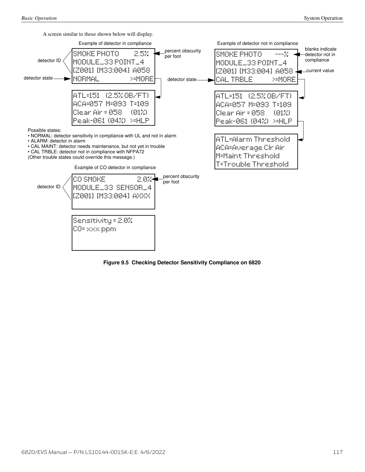
Select name for the point
Figure 8.6 Programming Points Screen for the EVS Amplifiers
######## 8.5.7 Point Programming for EVS-VCM, and EVS-RVMTo program module points:
point number Select SWITCH or UNUSED
|M04 P004 SWITCH
G001 MODULE_1 CKT_8 Enter Pt or <= to Exit>| |---|
Select name for the point
Figure 8.7 Programming Points Screen for the EVS-VCM and EVS-RVM Modules
|Choices|Type Selections|Function Selections for each Type|Comments| |---|---|---|---| | | | | | |5880 (output)|UNUSED|UNUSED| | |5880 (output)|NOTIF (outputs pt 1-40)|NOTIF OUTPUT| | |5880 (output)|NOTIF (outputs pt 1-40)|CONTROL CIRCUIT| | |5880 (input 41-48)|SWITCH|MANUAL PULL|Refer to comments column of Table 8.5 for description of these options. Latch or Non-latching feature only appears for WATERFLOW, FIRE SUPERVISORY, FIRE TAMPER, ZONE AUX1, ZONE AUX2, SYSTEM AUX1, SYSTEM AUX2, EVS INPUT, EVS TAMPER, and EVS SUPERVISORY.| |5880 (input 41-48)|SWITCH|WATERFLOW|Refer to comments column of Table 8.5 for description of these options. Latch or Non-latching feature only appears for WATERFLOW, FIRE SUPERVISORY, FIRE TAMPER, ZONE AUX1, ZONE AUX2, SYSTEM AUX1, SYSTEM AUX2, EVS INPUT, EVS TAMPER, and EVS SUPERVISORY.| |5880 (input 41-48)|SWITCH|FIRE SUPERVISORY|Refer to comments column of Table 8.5 for description of these options. Latch or Non-latching feature only appears for WATERFLOW, FIRE SUPERVISORY, FIRE TAMPER, ZONE AUX1, ZONE AUX2, SYSTEM AUX1, SYSTEM AUX2, EVS INPUT, EVS TAMPER, and EVS SUPERVISORY.| |5880 (input 41-48)|SWITCH|FIRE TAMPER|Refer to comments column of Table 8.5 for description of these options. Latch or Non-latching feature only appears for WATERFLOW, FIRE SUPERVISORY, FIRE TAMPER, ZONE AUX1, ZONE AUX2, SYSTEM AUX1, SYSTEM AUX2, EVS INPUT, EVS TAMPER, and EVS SUPERVISORY.| |5880 (input 41-48)|SWITCH|DETECTOR|Refer to comments column of Table 8.5 for description of these options. Latch or Non-latching feature only appears for WATERFLOW, FIRE SUPERVISORY, FIRE TAMPER, ZONE AUX1, ZONE AUX2, SYSTEM AUX1, SYSTEM AUX2, EVS INPUT, EVS TAMPER, and EVS SUPERVISORY.| |5880 (input 41-48)|SWITCH|FIRE DRILL|Refer to comments column of Table 8.5 for description of these options. Latch or Non-latching feature only appears for WATERFLOW, FIRE SUPERVISORY, FIRE TAMPER, ZONE AUX1, ZONE AUX2, SYSTEM AUX1, SYSTEM AUX2, EVS INPUT, EVS TAMPER, and EVS SUPERVISORY.| |5880 (input 41-48)|SWITCH|SILENCE|Refer to comments column of Table 8.5 for description of these options. Latch or Non-latching feature only appears for WATERFLOW, FIRE SUPERVISORY, FIRE TAMPER, ZONE AUX1, ZONE AUX2, SYSTEM AUX1, SYSTEM AUX2, EVS INPUT, EVS TAMPER, and EVS SUPERVISORY.| |5880 (input 41-48)|SWITCH|RESET|Refer to comments column of Table 8.5 for description of these options. Latch or Non-latching feature only appears for WATERFLOW, FIRE SUPERVISORY, FIRE TAMPER, ZONE AUX1, ZONE AUX2, SYSTEM AUX1, SYSTEM AUX2, EVS INPUT, EVS TAMPER, and EVS SUPERVISORY.| |5880 (input 41-48)|SWITCH|P.A.S. ACK|Refer to comments column of Table 8.5 for description of these options. Latch or Non-latching feature only appears for WATERFLOW, FIRE SUPERVISORY, FIRE TAMPER, ZONE AUX1, ZONE AUX2, SYSTEM AUX1, SYSTEM AUX2, EVS INPUT, EVS TAMPER, and EVS SUPERVISORY.| |5880 (input 41-48)|SWITCH|ZONE AUX1|Refer to comments column of Table 8.5 for description of these options. Latch or Non-latching feature only appears for WATERFLOW, FIRE SUPERVISORY, FIRE TAMPER, ZONE AUX1, ZONE AUX2, SYSTEM AUX1, SYSTEM AUX2, EVS INPUT, EVS TAMPER, and EVS SUPERVISORY.| |5880 (input 41-48)|SWITCH|ZONE AUX2|Refer to comments column of Table 8.5 for description of these options. Latch or Non-latching feature only appears for WATERFLOW, FIRE SUPERVISORY, FIRE TAMPER, ZONE AUX1, ZONE AUX2, SYSTEM AUX1, SYSTEM AUX2, EVS INPUT, EVS TAMPER, and EVS SUPERVISORY.| |5880 (input 41-48)|SWITCH|SYSTEM AUX1|Refer to comments column of Table 8.5 for description of these options. Latch or Non-latching feature only appears for WATERFLOW, FIRE SUPERVISORY, FIRE TAMPER, ZONE AUX1, ZONE AUX2, SYSTEM AUX1, SYSTEM AUX2, EVS INPUT, EVS TAMPER, and EVS SUPERVISORY.| |5880 (input 41-48)|SWITCH|SYSTEM AUX2|Refer to comments column of Table 8.5 for description of these options. Latch or Non-latching feature only appears for WATERFLOW, FIRE SUPERVISORY, FIRE TAMPER, ZONE AUX1, ZONE AUX2, SYSTEM AUX1, SYSTEM AUX2, EVS INPUT, EVS TAMPER, and EVS SUPERVISORY.| |5880 (input 41-48)|SWITCH|MANUAL RELEASE|Refer to comments column of Table 8.5 for description of these options. Latch or Non-latching feature only appears for WATERFLOW, FIRE SUPERVISORY, FIRE TAMPER, ZONE AUX1, ZONE AUX2, SYSTEM AUX1, SYSTEM AUX2, EVS INPUT, EVS TAMPER, and EVS SUPERVISORY.| |5880 (input 41-48)|SWITCH|INTERLOCK|Refer to comments column of Table 8.5 for description of these options. Latch or Non-latching feature only appears for WATERFLOW, FIRE SUPERVISORY, FIRE TAMPER, ZONE AUX1, ZONE AUX2, SYSTEM AUX1, SYSTEM AUX2, EVS INPUT, EVS TAMPER, and EVS SUPERVISORY.| |5880 (input 41-48)|SWITCH|STATUS POINT|Refer to comments column of Table 8.5 for description of these options. Latch or Non-latching feature only appears for WATERFLOW, FIRE SUPERVISORY, FIRE TAMPER, ZONE AUX1, ZONE AUX2, SYSTEM AUX1, SYSTEM AUX2, EVS INPUT, EVS TAMPER, and EVS SUPERVISORY.| |5880 (input 41-48)|SWITCH|EVS INPUT|User also has ECS Event Number 1-8 option for EVS INPUT, EVS TAMPER, and EVS SUPERVISORY functions in both 5880 and EVSVCM/EVSRVM choices. Only available when an EVS-VCM is installed in the system to the EVSRVM choice part.| |5880 (input 41-48)|SWITCH|EVS TAMPER|User also has ECS Event Number 1-8 option for EVS INPUT, EVS TAMPER, and EVS SUPERVISORY functions in both 5880 and EVSVCM/EVSRVM choices. Only available when an EVS-VCM is installed in the system to the EVSRVM choice part.| |5880 (input 41-48)|SWITCH|EVS SUPERVISORY|User also has ECS Event Number 1-8 option for EVS INPUT, EVS TAMPER, and EVS SUPERVISORY functions in both 5880 and EVSVCM/EVSRVM choices. Only available when an EVS-VCM is installed in the system to the EVSRVM choice part.| |5865|UNUSED| | | |5865|NOTIF|NOTIF OUTPUT| | |5865|NOTIF|CONTROL CIRCUIT| |
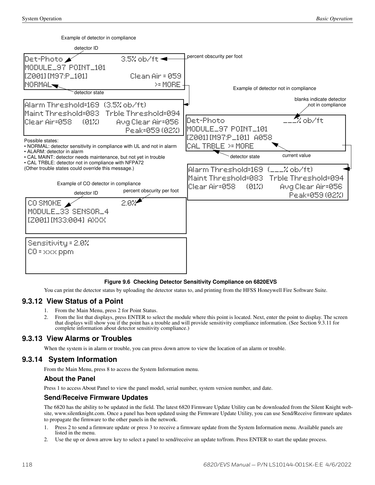
|EVS Amplifiers (EVS50/125W)|UNUSED| | | |EVS Amplifiers (EVS50/125W)|NOTIF| | |
############# Table 8.7 Choices for Point Programming Modules
|Choices|Type Selections|Function Selections for each Type|Comments| |---|---|---|---| | | | | | |EVSRVM, EVSVCM|UNUSED| | | |EVSRVM, EVSVCM|SWITCH|MANUAL PULL|Refer to comments column of Table 8.5 for description of these options. Latch or Non-latching feature only appears for WATERFLOW, FIRE SUPERVISORY, FIRE TAMPER, ZONE AUX1, ZONE AUX2, SYSTEM AUX1, SYSTEM AUX2, EVS INPUT, EVS TAMPER, and EVS SUPERVISORY| |EVSRVM, EVSVCM|SWITCH|WATERFLOW|Refer to comments column of Table 8.5 for description of these options. Latch or Non-latching feature only appears for WATERFLOW, FIRE SUPERVISORY, FIRE TAMPER, ZONE AUX1, ZONE AUX2, SYSTEM AUX1, SYSTEM AUX2, EVS INPUT, EVS TAMPER, and EVS SUPERVISORY| |EVSRVM, EVSVCM|SWITCH|FIRE SUPERVISORY|Refer to comments column of Table 8.5 for description of these options. Latch or Non-latching feature only appears for WATERFLOW, FIRE SUPERVISORY, FIRE TAMPER, ZONE AUX1, ZONE AUX2, SYSTEM AUX1, SYSTEM AUX2, EVS INPUT, EVS TAMPER, and EVS SUPERVISORY| |EVSRVM, EVSVCM|SWITCH|FIRE TAMPER|Refer to comments column of Table 8.5 for description of these options. Latch or Non-latching feature only appears for WATERFLOW, FIRE SUPERVISORY, FIRE TAMPER, ZONE AUX1, ZONE AUX2, SYSTEM AUX1, SYSTEM AUX2, EVS INPUT, EVS TAMPER, and EVS SUPERVISORY| |EVSRVM, EVSVCM|SWITCH|FIRE DRILL|Refer to comments column of Table 8.5 for description of these options. Latch or Non-latching feature only appears for WATERFLOW, FIRE SUPERVISORY, FIRE TAMPER, ZONE AUX1, ZONE AUX2, SYSTEM AUX1, SYSTEM AUX2, EVS INPUT, EVS TAMPER, and EVS SUPERVISORY| |EVSRVM, EVSVCM|SWITCH|SILENCE|Refer to comments column of Table 8.5 for description of these options. Latch or Non-latching feature only appears for WATERFLOW, FIRE SUPERVISORY, FIRE TAMPER, ZONE AUX1, ZONE AUX2, SYSTEM AUX1, SYSTEM AUX2, EVS INPUT, EVS TAMPER, and EVS SUPERVISORY| |EVSRVM, EVSVCM|SWITCH|RESET|Refer to comments column of Table 8.5 for description of these options. Latch or Non-latching feature only appears for WATERFLOW, FIRE SUPERVISORY, FIRE TAMPER, ZONE AUX1, ZONE AUX2, SYSTEM AUX1, SYSTEM AUX2, EVS INPUT, EVS TAMPER, and EVS SUPERVISORY| |EVSRVM, EVSVCM|SWITCH|P.A.S. ACK|Refer to comments column of Table 8.5 for description of these options. Latch or Non-latching feature only appears for WATERFLOW, FIRE SUPERVISORY, FIRE TAMPER, ZONE AUX1, ZONE AUX2, SYSTEM AUX1, SYSTEM AUX2, EVS INPUT, EVS TAMPER, and EVS SUPERVISORY| |EVSRVM, EVSVCM|SWITCH|ZONE AUX1|Refer to comments column of Table 8.5 for description of these options. Latch or Non-latching feature only appears for WATERFLOW, FIRE SUPERVISORY, FIRE TAMPER, ZONE AUX1, ZONE AUX2, SYSTEM AUX1, SYSTEM AUX2, EVS INPUT, EVS TAMPER, and EVS SUPERVISORY| |EVSRVM, EVSVCM|SWITCH|ZONE AUX2|Refer to comments column of Table 8.5 for description of these options. Latch or Non-latching feature only appears for WATERFLOW, FIRE SUPERVISORY, FIRE TAMPER, ZONE AUX1, ZONE AUX2, SYSTEM AUX1, SYSTEM AUX2, EVS INPUT, EVS TAMPER, and EVS SUPERVISORY| |EVSRVM, EVSVCM|SWITCH|SYSTEM AUX1|Refer to comments column of Table 8.5 for description of these options. Latch or Non-latching feature only appears for WATERFLOW, FIRE SUPERVISORY, FIRE TAMPER, ZONE AUX1, ZONE AUX2, SYSTEM AUX1, SYSTEM AUX2, EVS INPUT, EVS TAMPER, and EVS SUPERVISORY| |EVSRVM, EVSVCM|SWITCH|SYSTEM AUX2|Refer to comments column of Table 8.5 for description of these options. Latch or Non-latching feature only appears for WATERFLOW, FIRE SUPERVISORY, FIRE TAMPER, ZONE AUX1, ZONE AUX2, SYSTEM AUX1, SYSTEM AUX2, EVS INPUT, EVS TAMPER, and EVS SUPERVISORY| |EVSRVM, EVSVCM|SWITCH|MANUAL RELEASE|Refer to comments column of Table 8.5 for description of these options. Latch or Non-latching feature only appears for WATERFLOW, FIRE SUPERVISORY, FIRE TAMPER, ZONE AUX1, ZONE AUX2, SYSTEM AUX1, SYSTEM AUX2, EVS INPUT, EVS TAMPER, and EVS SUPERVISORY| |EVSRVM, EVSVCM|SWITCH|INTERLOCK|Refer to comments column of Table 8.5 for description of these options. Latch or Non-latching feature only appears for WATERFLOW, FIRE SUPERVISORY, FIRE TAMPER, ZONE AUX1, ZONE AUX2, SYSTEM AUX1, SYSTEM AUX2, EVS INPUT, EVS TAMPER, and EVS SUPERVISORY| |EVSRVM, EVSVCM|SWITCH|STATUS POINT|Refer to comments column of Table 8.5 for description of these options. Latch or Non-latching feature only appears for WATERFLOW, FIRE SUPERVISORY, FIRE TAMPER, ZONE AUX1, ZONE AUX2, SYSTEM AUX1, SYSTEM AUX2, EVS INPUT, EVS TAMPER, and EVS SUPERVISORY| |EVSRVM, EVSVCM|SWITCH|EVS INPUT|User also has ECS Event Number 1-8 option for EVS INPUT, EVS TAMPER, and EVS SUPERVISORY functions in both 5880 and EVSVCM/EVSRVM choices. Only available when an EVS-VCM is installed in the system to the EVSRVM choice part.| |EVSRVM, EVSVCM|SWITCH|EVS TAMPER|User also has ECS Event Number 1-8 option for EVS INPUT, EVS TAMPER, and EVS SUPERVISORY functions in both 5880 and EVSVCM/EVSRVM choices. Only available when an EVS-VCM is installed in the system to the EVSRVM choice part.| |EVSRVM, EVSVCM|SWITCH|EVS SUPERVISORY|User also has ECS Event Number 1-8 option for EVS INPUT, EVS TAMPER, and EVS SUPERVISORY functions in both 5880 and EVSVCM/EVSRVM choices. Only available when an EVS-VCM is installed in the system to the EVSRVM choice part.| |EVSRVM, EVSVCM|SWITCH|VOICE AUX STATUS 1-2| | |EVSRVM, EVSVCM|SWITCH|BACKGROUND MUSIC| | |EVSRVM, EVSVCM|SWITCH|VOICE AUX ECS 1-4| |
############# Table 8.7 Choices for Point Programming Modules (Continued)
###### 8.6 System Options
This section of the manual explains how to customize software options that affect general operation of the system. This includes such items as: Communication Options, Time Options, Miscellaneous Options, Daylight Saving Options, Edit Banner, and SLC Family. Refer to each individual subsection for complete instructions.
######## 8.6.1 Communication OptionsAuto Test TimeTo access the Auto Test Time screen:
NOTE: AM and PM are only available if the panel “Clock Options” are set for AMPM mode. Otherwise the clock is in military time and AMPM is not selectable
Phone Lines To access the phone lines screen:
Dialing Prefix Enter up to 9 characters to be used for such things as PBX dial-out codes, a pause, and so on. The following special characters are available:
Use the number buttons on the annunciator or the up- and down-arrow keys to select special characters. Special characters begin displaying after “9”.
Number of Answer Rings
This option is used in conjunction with the HFSS Honeywell Fire Software Suite. Use this option to determine the number of rings before the panel answers a call from the computer. The range is 00-15 rings. This option is factory-programmed as 06 rings, which should be compatible for most installations where the answering machine bypass feature is used. You may need to adjust it depending on the installation’s telephone system.
The selection made here must match the programming for this option in the Communication Configuration dialog box of HFSS.
Dial Option
Dial Format
Dial Tone Detection Disabled
Monitor Line
Enable the line monitor for each phone line that will be used. See Figure 8.8 for the location of this field on the phone lines screen. When the phone line monitor has been enabled for a phone line, a trouble condition will occur if the line is not connected. If a phone line will not be used, it must be disabled.
phone line to edit
dial tone detection disabled Y/N number of rings before the panel answer a call from a computer
Line:1 N P: Rings: 06 D:TT Options: UNYN
Enter a dialing prefix. Up to 9 characters can be used to allow for things such as PBX dial-out codes, a pause, etc.
phone line unused Y/N answering machine bypass Y/N monitor line Y/N U for U.S. or E for European
dial options: touch-tone, pulse, both
U.S. format = 60/40msec make/break European = 66/34msec make/break
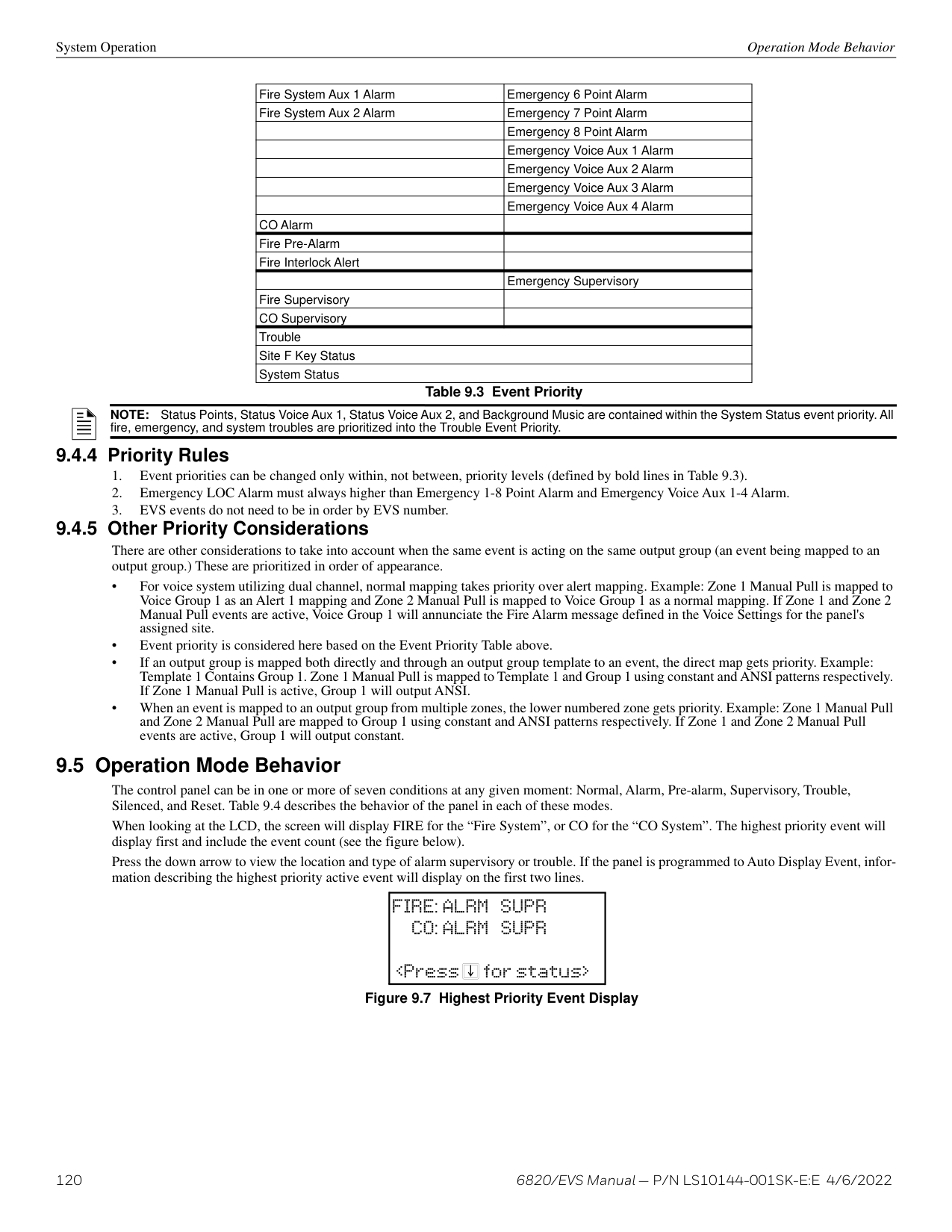
############# Figure 8.8 Phone Lines Editing Screen
|#|Pound (or number) key on the telephone| |---|---| |*|Star key on the telephone| |,|Comma (character for 2-second pause)|
|Dial Option|Description| |---|---| | | | |PULSE|If this option is selected, only pulse dialing will be used for this phone line.| |TT|Touch-tone dialing. If this option is selected, only touch-tone dialing will be used for this phone line.| |TT/PL|Touch-tone alternating with pulse. If this option is selected, the communicator will first attempt to use touchtone. It will switch to pulse if touch-tone is not successful on the first attempt. It will continue to alternate between TT and pulse for additional attempts.|
Table 8.8 Dial Options
|U|U.S. standard format. Uses the 60 msec / 40 msec make/break ratio.| |---|---| |E|European format. Uses the 66 msec / 34 msec make/break ratio.|
########### Answering Machine Bypass
This option is used in conjunction with HFSS. This feature ensures that an answering machine will not interfere with communication between the panel and the computer. If an answering machine is used at the panel site, enable this feature; if an answering machine is not used, disable the feature.
This option is factory-programmed as No (disabled).
The selection made here must match the programming for this option in the Communication Configuration dialog box of HFSS.
Phone Line Unused This option is used so that you can set unused phones lines to “Yes”, so no auto-test will be sent through that line. This option is factory programmed as No.
|Sub:255.255.252.000 GW:158.100.048.254 DHCP:Y
|MAC:0000.0020.6894 MAC CRC:01E2 IP:158.100.049.148
|Ethernet: 5 Minutes_ Cellular: 24 Hours_ Old Alarm: 30 Minutes_
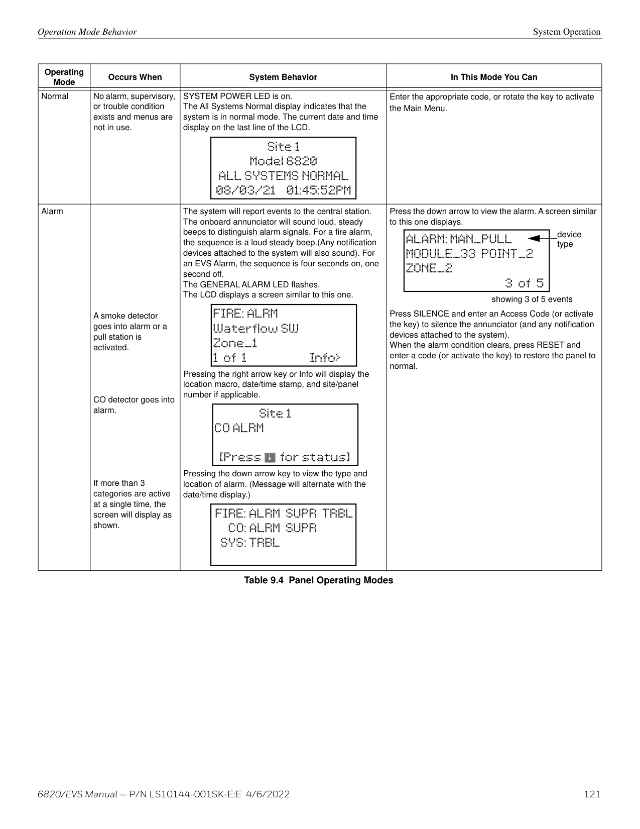
########## AlarmNet Timers
(Sets how long an undeliverable alarm is retried for delivery to the Central Station. If the message is not validated, it is retried until the old alarm time is reached or the message is validated).
########## Phone Line Gains
######## 8.6.2 Time Options
Through this programming option you can set the water flow delay time, alarm verification time, AC report delay, AC-Frequency, AutoResound, and Clock Format.
########## Water Flow Delay
You can program a delay of 0-90 seconds (zero means no delay) to be used in conjunction with a water flow switch. The delay is systemwide. All water flow switches on the system will use the same delay period.
To access the screen for programming water flow delay, follow these steps:
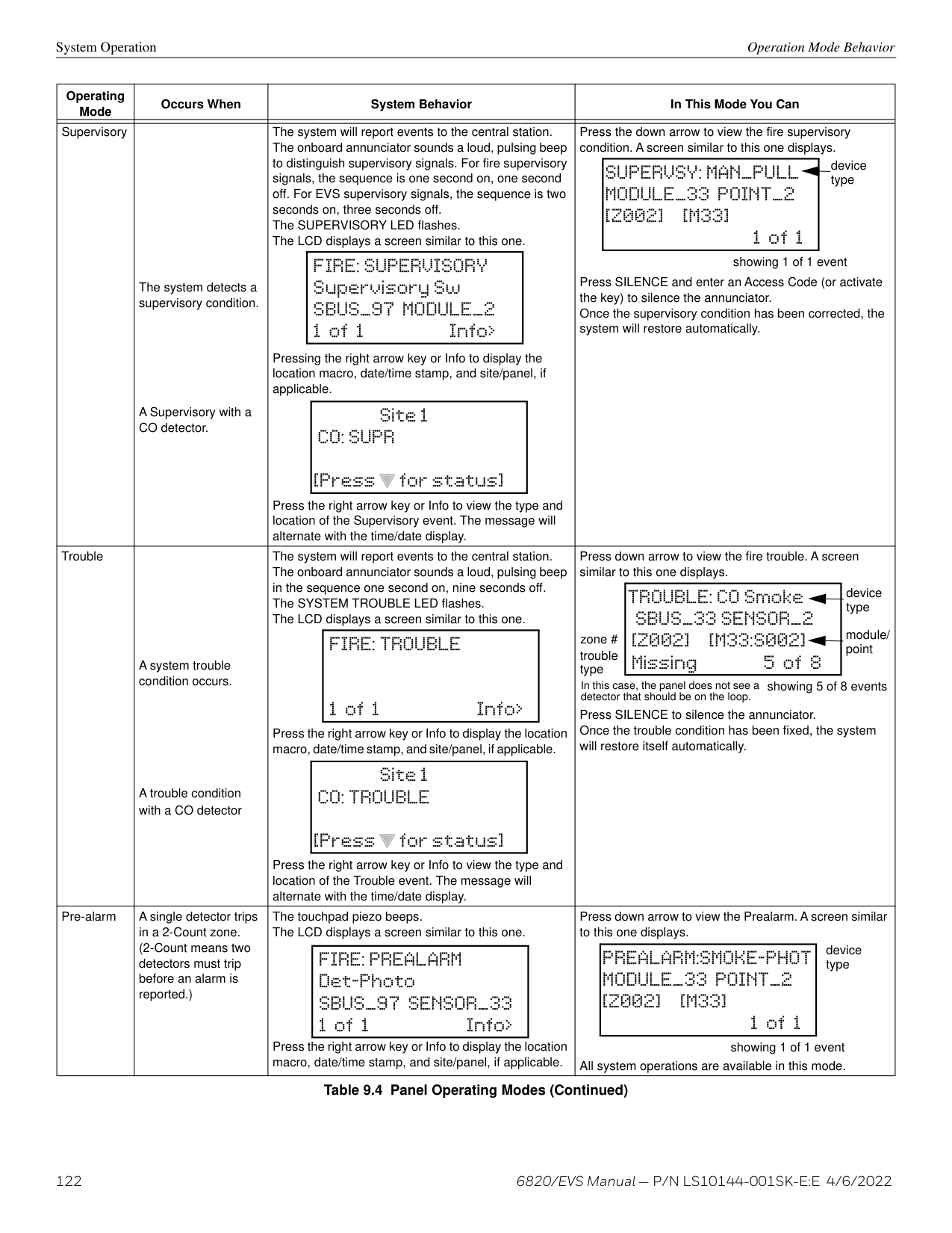
You can adjust the number of hours before a low AC report will be sent to the central station. To program low AC report delay, follow these steps continued from step 7.
The panel’s AC line frequency is selectable for 50, 60 Hz, or Internal. AC Frequency feature dictates how the control panel will calculate time based on the AC line frequency used in the installation site. The “Internal” option can be used in areas where the AC line frequency is not dependable and you want the panel to calculate time from the internal crystal. The internal crystal is not as accurate as the AC power source and internal 60 Hz or 50 Hz should normally be selected. The panel defaults to the 60 Hz selection.
To change the AC line frequency:
delay in seconds before waterflow alarm occurs (00-90)
|Water Flow Delay:01s Alarm Verify:060s AC Report Delay:03h <(0-90)> More| |---|
|AC-Frequency: 60Hz
Clock Format: AMPM Auto-Resound: 24hr <50Hz/60Hz/Internal>| |---|
############# Figure 8.11 Water Flow Delay Programming Screen
NOTE: You must select 1-3 hours in UL central station installations and UL remote signaling installations.
########## Auto-Resound (4 or 24 hours)
The system resound time period can be modified from the default value 24 hours to 4 hours. This setting adjusts when the FACP will automatically resound events after being silenced. Set this option to 4 hours when using SWIFT devices
########## Strobes Active when Silenced
When “SYNC Strobe:” is selected as Y (Yes), the strobes will continue to flash when the system is silenced and will stop flashing when the system is reset.
NOTE: The “SYNC Strobe” only functions with outputs that use a synchronized output pattern.
When this feature is programmed Y (Yes), the highest priority event of the system in control will automatically display on the control panel and remote annunciators after there has been no activity on any system touch pad for two minutes.
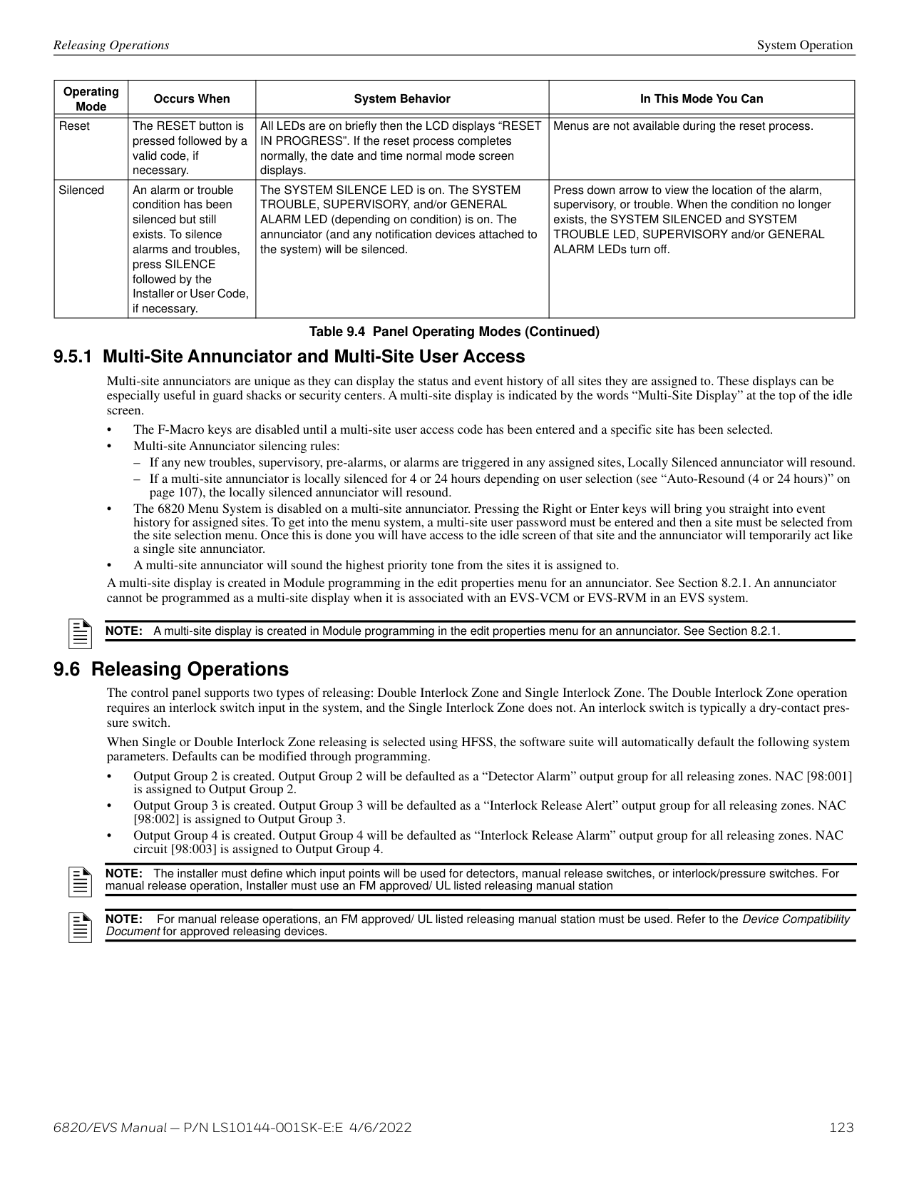
######## 8.6.4 Daylight Saving OptionsTo edit Daylight Saving Time:
The control panel has an automatic DST (Daylight Saving Time) adjustment feature. If this feature is not enabled (set to No), the Daylight Saving Time change is not made to the system clock. To enable or disable DST adjustment continue programming:
This option lets you to adjust the week and month Daylight Saving Time (DST) starts and ends. For this feature to work, you must enable (set to Yes) the Automatic Daylight Savings Adjustment option under Daylight Savings Options. The default values for the DST Start and End are:
DST Start: The second Sunday in March DST End: The first Sunday in November To set the start and end for Daylight Saving Time:
######## 8.6.5 Edit Banner
The banner is the message that displays on the panel LCD when the system is normal; that is, when no alarms or troubles exist and the system menus are not in use. A custom banner of up to 40 characters can be created. This will automatically be centered when shown.
If a custom message is not created, the system will use the internal banner. You cannot change the internal banner. To customize the banner display message:
######## 8.6.6 SLC Family
The 6820 supports SD, Intelligent Device Protocol (IDP) or SK Series SLC devices. You must configure the 6820 to accept the protocol of the devices you are installing. You cannot mix SLC devices of different protocols.
Restore Defaults Programming
NOTE: When you change the SLC type from one protocol to another, the following message will appear.
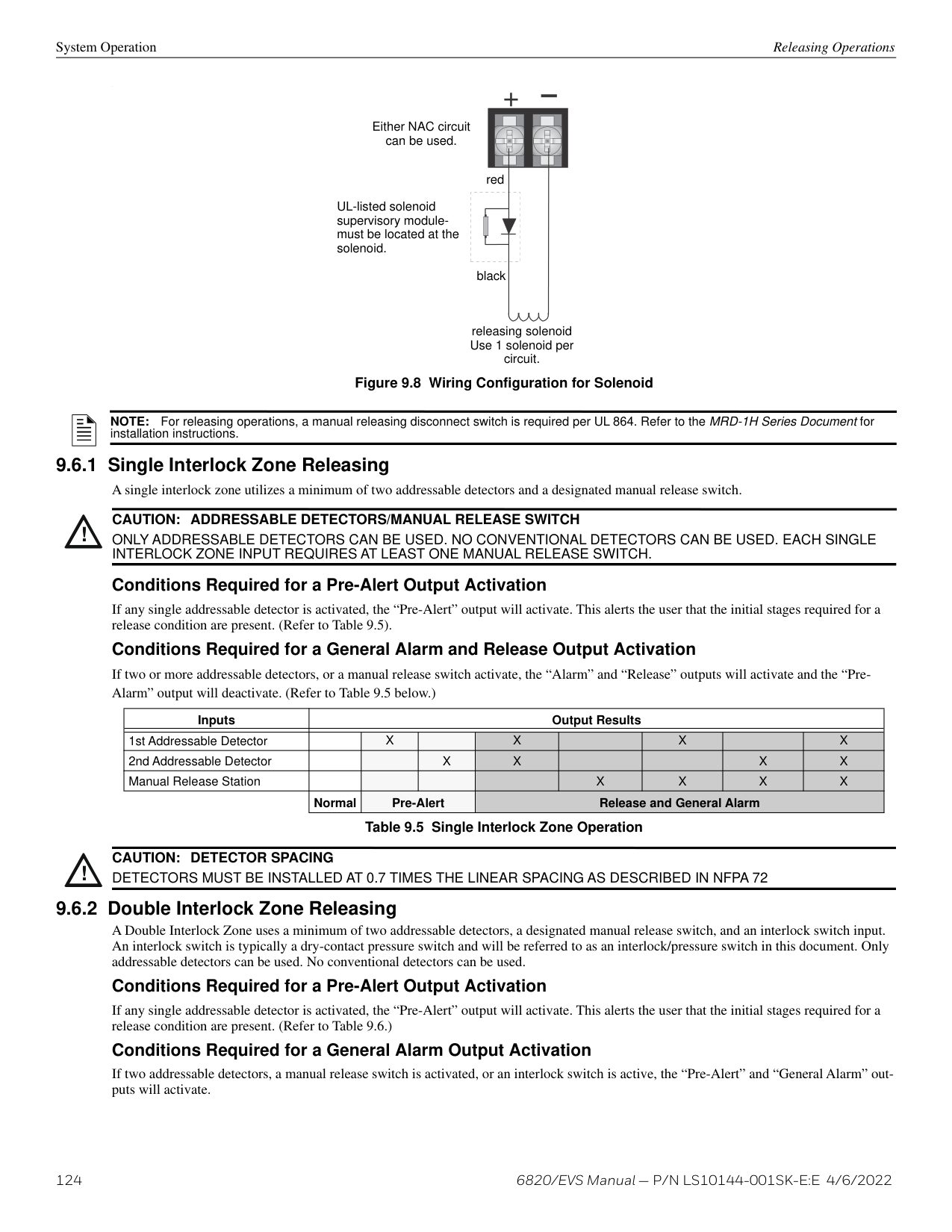
|Changing the SLC family will set all SLC points to [Press for More]| |---|
|Back Accept
family will set all SLC points to UNUSED| |---|
############# Figure 8.12 SLC Family Change
When changing SLC family from SK to SD will remove all external 6815 modules. When changing from SD to SK SLC family will remove all 5815XL modules on the system.
######## 8.6.7 JumpStart Auto-Programming
NOTE: JumpStart Auto-Programming is used to auto learn the system hardware after devices have been added or removed from the system. Hardware devices which remain the same between repeat JumpStart will retain any customized text or options associated with the device. It is best to carefully consider the Network ID setting for each panel before the first JumpStart Auto-Programming is performed. Once this is done, the panel must be defaulted back to factory defaults if the network ID settings need to change.
To run JumpStart, do the following.
##### Section 9: System Operation
Operation of the control panel is user friendly. Menus guide you step-by-step through operations. This section of the manual is an overview of the operation menus. Please read this entire section carefully before operating the panel.
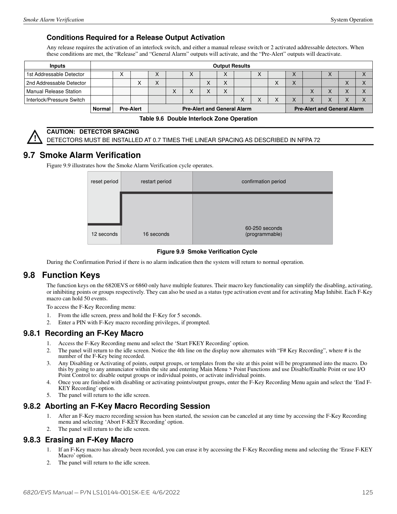
five system status LEDs
silence alarms/troubles single key acknowledge
reset alarms/troubles fire drill
number keys for entering numeric data
##################### ALARM TROUBLE SILENCED POWER
SUPERVISORY
|80-character LCD Messages display on 4 lines with up to 20 characters per line.| |---|
123 4 7
56
8 9
REVIEW
REVIEW REVIEW
ALARM TROUBLE
Arrow keys for moving through menus. Enter key accepts selections.
############# Figure 9.1 6820 Control Panel Annunciator
Annunciator Description System Operation
Figure 9.2 shows the annunciator that is part of the 6820EVS control panel board assembly.
|||160-character LCD Messages display on 4 lines with up to 40 characters per line.| |---| | |---| | |---|
ACK
SILENCE
BACK BACK
BACK
NEXT NEXT
NEXT
DRILLRESET
2 3
1
4
5 6
ENTER
7 8 9
five system status LEDs
silence alarms/troubles single key acknowledge
reset alarms/troubles fire drill
Arrow keys for moving through menus. Enter key accepts selections.
programmable function keys
number keys for entering numeric data
############# Figure 9.2 6820EVS Control Panel Annunciator
######## 9.1.1 LCD Display
The control panel LCD displays system messages, annunciates alarms, supervisories and troubles, provides status information, and prompts for input. Annunciator keys beep when they are pressed.
System Operation Menu System
######## 9.1.2 Banner
The banner is the message that displays on the control panel when the system is in normal mode (no alarm or trouble condition exists and menus are not in use). A customize message can be created that will display instead of the internal (default) message. See Section 8.6.5 for information on editing the banner.
internal banner text custom banner example
Site 1 Silent Knight 6808 ALL SYSTEMS NORMAL 08/03/21 01:15:06PM
ABC Company Fire System ALL SYSTEMS NORMAL 08/03/21 01:15:06PM
Figure 9.3 6820 Banner Display Examples
internal banner text
Site 1 Silent Knight - Model 6820 ALL SYSTEMS NORMAL 08/03/21 01:15:06PM
custom banner example
Site 1 ABC COMPANY - FIRE SYSTEM ALL SYSTEMS NORMAL 08/03/21 01:15:06PM
############# Figure 9.4 6820EVS Banner Display Examples
The control panel is easy to operate from the Main Menu. To view the Main Menu press the ENTER or right arrow key on the control panel or remote annunciator. This will bring up the panel login menu, as described in Section 9.2.1. Once validated, the user will be able to access the Main Menu as shown in Section 9.2.2. Select the desired option. You will be prompted for as access code if required.
The control panel supports up to 20 access codes. The profile for each access code (or user) can be modified through the network programming option (see Section 6.2.5 for access code programming).
######## 9.2.1 Panel Login Menu
After pressing ENTER, and 1 for the login menu, a screen will prompt for the type of access account, Administrator or User. An administrator has the ability to modify user accounts and view the cybersecurity log. The User account has access to panel programming.
########## Admin Profiles
After initial power-up, the 6820 requires a password change and user account setup before programming. Only Admin1 will be active. Using the login for Admin1, the default password (0000000) must be changed to a new, unique password. This new password must be 7-digits and cannot be sequential or easily guessed. If the password is not changed, a default password trouble will appear on the panel.
There is a maximum of two administrator profiles available. After the administrator account is set up, you must create a User account(s). Only a User account has the ability to program the control panel. There is a maximum of 18 User accounts available.
Admin accounts can:
There are two programming levels which will access the Programming screens. From either of the screens, access to specific system and device features or programming may be obtained. An “Installer” can program local panel data relating to device types, zoning, messages, control panel functions, etc. A “Multi-site Installer” can program panel data across a network. A user has the ability to change their administrator-assigned password after it has been assigned for the first time. Refer to Section 6.2.5 on page 68.
Menu System System Operation
• Profile 2 is defaulted as “Installer” and profile 3 is defaulted to “Multi-Site Installer”. Profiles 4-18 are empty profiles available for assignment. User profiles 2-18 can be edited for name and panel functions. Table 9.1 lists the panel functions that can be selected for each user profile.
|Type of Function|Selectable Functions| |---|---| | | | |Panel Operations|System Reset| |Panel Operations|System Silence| |Panel Operations|System Ack| |Panel Operations|Fire Drill Key| |Panel Operations|*F1 Function Key| |Panel Operations|*F2 Function Key|
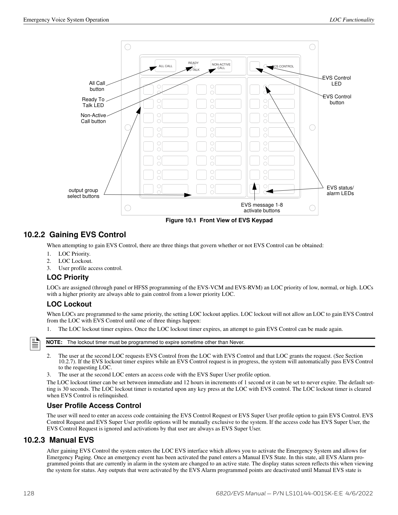
|Panel Operations|*F3 Function Key| |Panel Operations|*F4 Function Key| |Panel Menus|System Tests| |Panel Menus|Fire Drill Menu| |Panel Menus|Indicator Test| |Panel Menus|Walk Test-No Report| |Panel Menus|Walk Test -With Report| |Panel Menus|Communicator Test| |Panel Menus|Clear History Buffer| |Panel Menus|Point Functions| |Panel Menus|Disable/Enable Point| |Panel Menus|Point Status| |Panel Menus|Set SLC Device Address| |Panel Menus|SLC Single Device Locater| |Panel Menus|SLC Multiple Device Locater| |Panel Menus|I/O Point Control| |Panel Menus|Event History| |Panel Menus|Set Time & Date| |Panel Menus|System Information| |Panel Menus|Network Diagnostics| |Panel Menus|Network Programming| |Panel Menus|Panel Programming| |Panel Menus|Send/Receive Firmware Update| |*Function Keys are only available on the 6860 LCD annunciator.|*Function Keys are only available on the 6860 LCD annunciator.|
########### Table 9.1 User Profile Selectable Panel Functions
########## Invalid Password/Panel Timeout
If a password is entered incorrectly or is not a valid password, the panel will display an error message. You must hit ENTER or the left arrow key and re-enter the password correctly. After ten invalid attempts, the panel will panel will lock for 30 seconds and then you can try again. However, if the password has been forgotten, record the 20-character code displayed on the panel and contact Technical Services. After proper authentication, the password will be supplied.
|Main Menu Options|Description| |---|---| | | | |1- System Tests|Access to Fire Drill, Indicator Test, Walk Tests, Communicator Test, Clear History Buffer, Manual AlarmNet Registration and Manual Communicator Reset.| |2- Point Functions|Enable/disable points, Point Status, SLC Single Device Locater, SLC Multiple Device Locater, and I/O Point Control.| |3- Event History|Display event history on the LCD. See Section 9.3.3 for more information.| |4- Set Time & Date|Set time and date for the system| |5- Network Diagnostics|Ping Panel and Data Network Status| |6- Network Programming|Access Learn Network, Edit Network Names, Edit Panel ID, Computer Access, Access Codes, Communicator Options, Voice Options, Sync Network Options| |7- Panel Programming|Brings up a set of menus for programming the panel. These options are described in detail in Section 8.| |8- System Information|Menus to view information about the panel such as model, ID, serial number, revision, send or receive firmware updates and feature registration activation|
Table 9.2 Main Menu Options
|To move through the menus:|Use the up and down arrow key to move the cursor through the options in a menu. Use the left arrow key to move to a previous menu.| |---|---| |To select an option:|Enter the number of the option, or press ENTER if the option has the = symbol next to it.| |Exit Menu|Press the left arrow.|
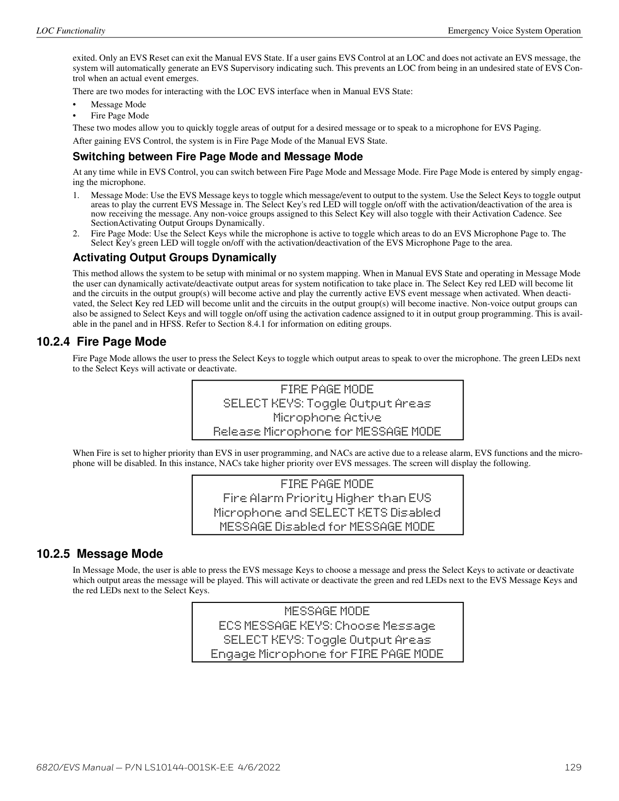
###### 9.3 Basic Operation
######## 9.3.1 Setting Time and Date
NOTE: The panel’s time is as accurate as the input AC power line frequency and may drift over time if the frequency fluctuates.
######## 9.3.2 Disable / Enable a Point
Inhibiting an output group prevents the group from being utilized by system mapping. While inhibited, no event in the system can activate the output group.
######## 9.3.3 View Event History
Use the View Event History feature to display events on LCD. From the Main Menu, press 3 to select Event History. Events will begin displaying with most recent events first.
The panel can store up to 1000 events. When it reaches its 1000-event capacity, it will delete the oldest events to make room for the new events as they occur. In networked setups, each panel stores up to 1000 of its own events. When using the HFSS Software Suite, all 1000 events from every panel in the network will be uploaded.
On multi-site displays, pressing ENTER or right arrow brings you directly into View Event History and allows you to view the Event History from every panel in each of the sites that the multi-site display is assigned to.
To clear the event history From the Installer menu select 1 for System Tests. From the test menu select 6 Clear History Buffer. Single Key Acknowledge
This feature allows the user to press the ACK and display the oldest un-acknowledged event in the system. Pressing ACK again will acknowledge the event, then display the next oldest un-acknowledged event without pressing the arrow keys.
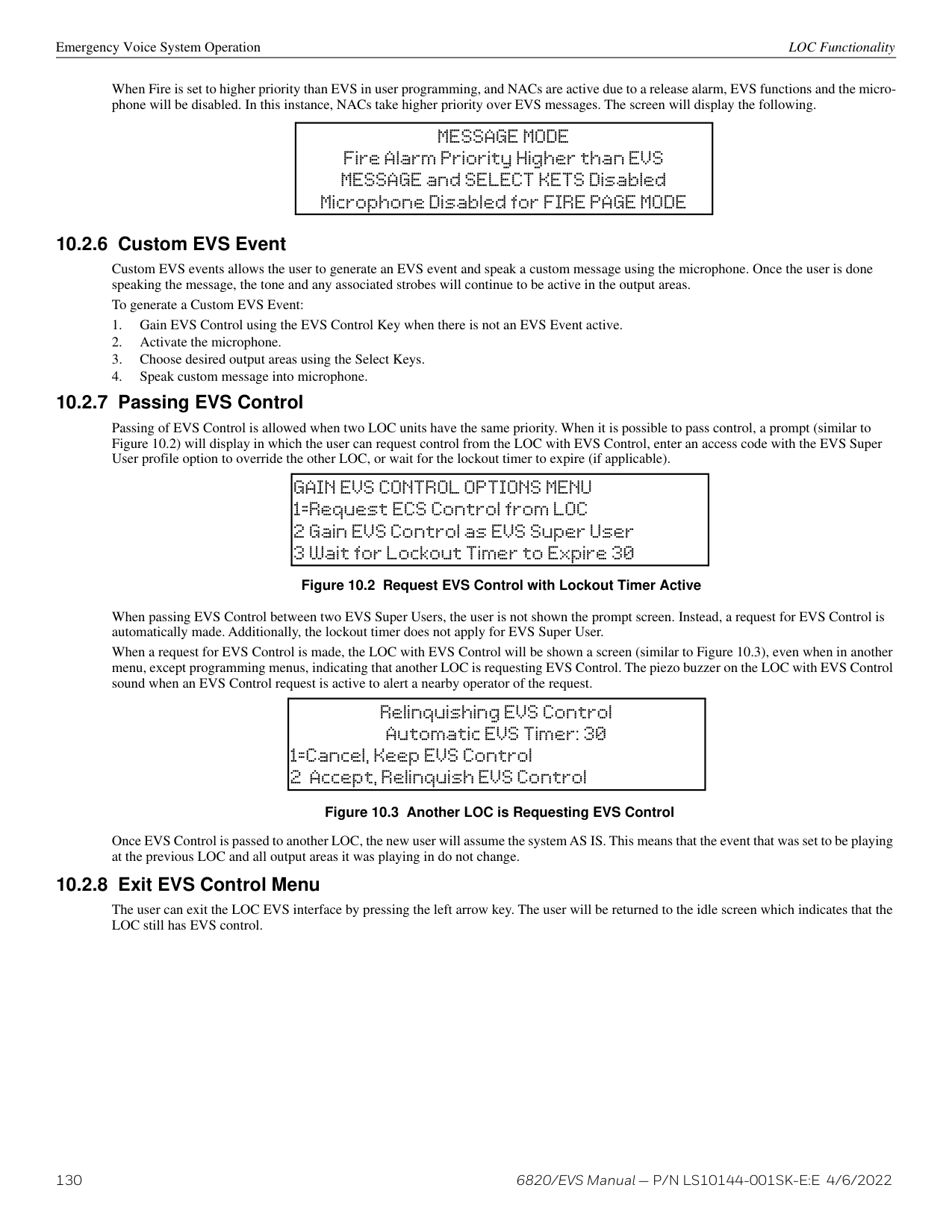
This test will run for approximately 15 minutes or until the user manually exits. You can press any key to end manually while the test is still in progress. When the test ends, you will be returned to the Test Menu.
Walk Test is a feature which allows one person to test the fire alarm system. The Walk Test will run for 4 hours or until the user manually exits. If an alarm or pre-alarm condition is occurring in the system, you will not be able to enter the walk test. A walk test may only be initiated if the test is enabled in the user profile.
Select 4 for Walk Test-with Report. The LCD will display “WALK TEST STOPPED” on Line 1 and “ENTER = start test” on Line 3. Enter the time period you wish the NAC circuit to be active for each alarm (06 to 180 seconds) If you select this option, central station reporting will occur as normal during the walk test.
The panel generates a TEST report to the central station when the walk test begins. During a walk test, the panel’s normal fire alarm function is completely disabled, placing the panel in a local trouble condition. All zones respond as 1-Count zones (respond when a single detector is in alarm) during a walk test. Each alarm initiated during the walk test will be reported and stored in the event history buffer.
CAUTION: ALARM VERIFICATION
!
IF ANY ALARM VERIFICATION ZONES ARE BEING USED, THE USER WILL BE ASKED IF THEY WISH TO DISABLE ALARM VERIFICATION DURING WALK TEST. THIS OCCURS FOR EITHER WALK TEST OPTION.
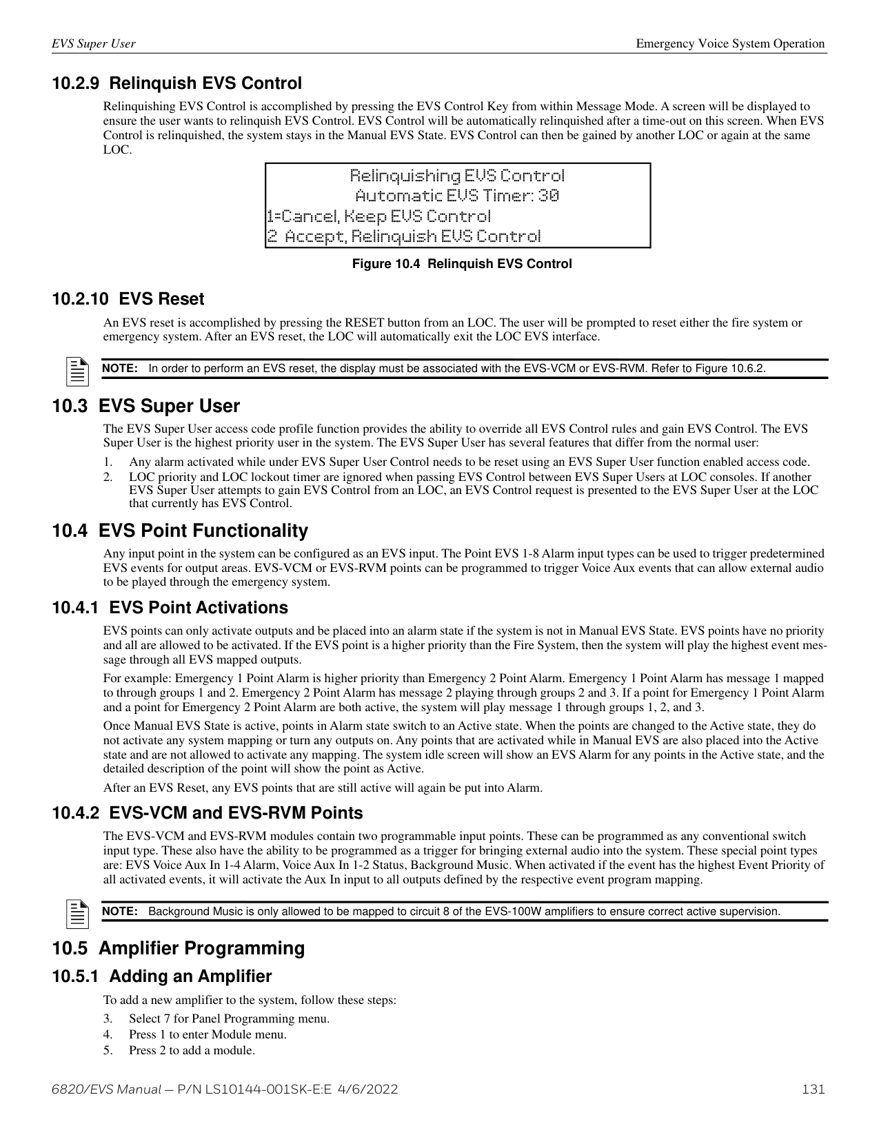
NOTE: The panel does not do a full 30 second reset on resettable power outputs. As soon as the device is back to normal, the panel is ready to go to the next device.
Press SILENCE to turn off silenceable outputs and annunciator PZTs. If an external silence switch has been installed, activating the switch will silence alarms or troubles. If you are already using system menus when you press SILENCE, you will not need to enter your code.
NOTE: Alarm and trouble signals that have been silenced, but the detector remains un-restored, will resound every 4 or 24 hours depending on user selection until the detector is restored. Refer to “Auto-Resound (4 or 24 hours)” on page 94.
NOTE: Multi-site displays do not allow for silencing multiple sites. Pressing SILENCE will only locally silence the PZT built into the annunciator.
NOTE: For EVS systems, pressing silence at an LOC will only silence the system in control. See Section 9.4.1.
Reset Communicator This option allows the user to Reset the Communicator. The LCD will display: “Resetting Communicator… Please Wait“ You will be returned to the Main Menu when the reset is complete. The Communicator is not allowed to be reset when alarms or supervisories are active. Communicator Reset is not allowed if any of the following are active:
NOTE: Multi-Site displays do not reset multiple sites.
NOTE: For EVS Systems, pressing reset at an LOC will prompt the user for which system they want to reset. See Section 9.4.1.
The control panel constantly monitors smoke detectors to ensure that sensitivity levels are in compliance with NFPA 72. Detectors are sampled every three hours.
If sensitivity for a detector is not in compliance, the panel goes into trouble, generating a Calibration Trouble condition. A detector enters a Calibration Maintenance state to indicate that it is approaching an out of compliance condition (but is currently still in compliance). When a Calibration Trouble condition occurs, the central station receives a detector trouble report (“373” + Zone # for Contact ID format; “FT” + Zone # in SIA format). To check sensitivity for an individual detector, follow the steps below.
A screen similar to those shown below will display.
Example of detector in compliance Example of detector not in compliance
blanks indicate detector not in compliance
percent obscurity per foot
|SMOKE PHOTO 2.5% MODULE_33 POINT_4 [Z001] [M33:004] A058 NORMAL >=MORE
| | |---|---| |SMOKE PHOTO 2.5% MODULE_33 POINT_4 [Z001] [M33:004] A058 NORMAL >=MORE
| | ||ACA=057 M=093 T=109 Clear Air = 058 (01%) Peak-061 (04%) >=HLP
ATL=151 (2.5% OB/FT)| |---| ||ACA=057 M=093 T=109 Clear Air = 058 (01%) Peak-061 (04%) >=HLP
ATL=151 (2.5% OB/FT)| |---| |
|SMOKE PHOTO ---% MODULE_33 POINT_4 [Z001] [M33:004] A058 CAL TRBLE >=MORE| |---|
detector ID
current value
detector state
detector state
|ACA=057 M=093 T=109 Clear Air = 058 (01%) Peak-061 (04%) >=HLP
ATL=151 (2.5% OB/FT)| |---|
|ATL=151 (2.5% OB/FT) ACA=057 M=093 T=109 Clear Air = 058 (01%) Peak-061 (04%) >=HLP| | |---|---| |ATL=151 (2.5% OB/FT) ACA=057 M=093 T=109 Clear Air = 058 (01%) Peak-061 (04%) >=HLP| | | | |
Possible states:
|ATL=Alarm Threshold ACA=Average Clr Air M=Maint Threshold T=Trouble Threshold| |---|
Example of CO detector in compliance
percent obscurity per foot
|CO SMOKE 2.0% MODULE_33 SENSOR_4 [Z001] [M33:004] AXXX| |---|
detector ID
|Sensitivity = 2.0% CO= xxx ppm| |---|
############# Figure 9.5 Checking Detector Sensitivity Compliance on 6820
Example of detector in compliance detector ID
percent obscurity per foot
Det-Photo 3.5% ob/ft MODULE_97 POINT_101 [Z001] [M97:P_101] Clean Air = 059 NORMAL >= MORE
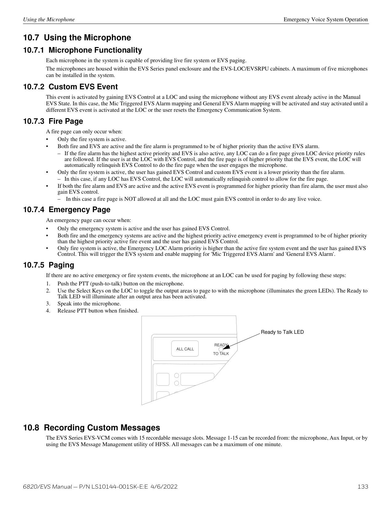
Example of detector not in compliance
detector state
blanks indicate detector not in compliance
|Alarm Threshold=169 (3.5% ob/ft) Maint Threshold=083 Trble Threshold=094 Clear Air=058 (01%) Avg Clear Air=056
Peak=059 (02%)| |---|
Det-Photo ___% ob/ft MODULE_97 POINT_101 [Z001] [M97:P_101] A058 CAL TRBLE >= MORE
Possible states:
detector state current value
|Alarm Threshold=169 (___% ob/ft) Maint Threshold=083 Trble Threshold=094 Clear Air=058 (01%) Avg Clear Air=056
Peak=059 (02%)| |---|
Example of CO detector in compliance
percent obscurity per foot detector ID
|CO SMOKE 2.0% MODULE_33 SENSOR_4 [Z001] [M33:004] AXXX
| |---|
|Sensitivity = 2.0% CO = xxx ppm| |---|
############# Figure 9.6 Checking Detector Sensitivity Compliance on 6820EVS
You can print the detector status by uploading the detector status to, and printing from the HFSS Honeywell Fire Software Suite.
The 6820 has the ability to be updated in the field. The latest 6820 Firmware Update Utility can be downloaded from the Silent Knight website, www.silentknight.com. Once a panel has been updated using the Firmware Update Utility, you can use Send/Receive firmware updates to propagate the firmware to the other panels in the network.
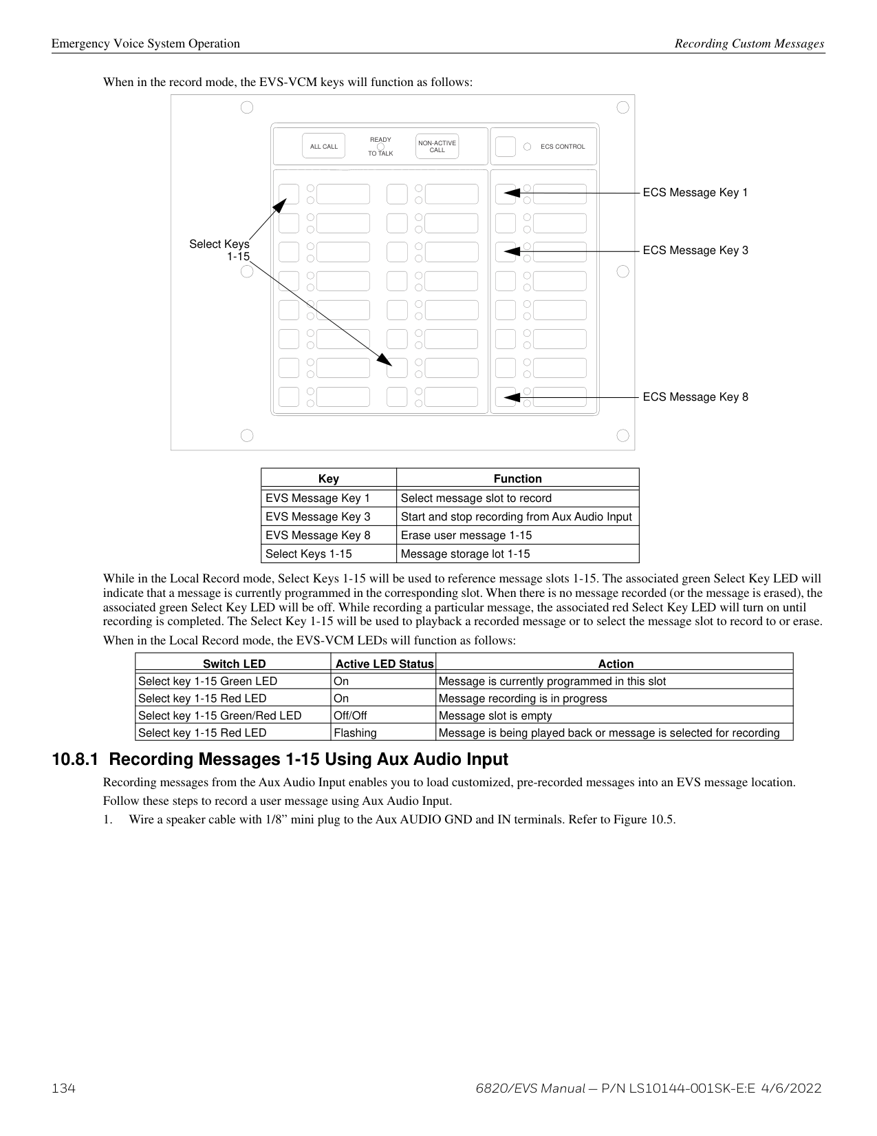
Event Priority System Operation
########## Ethernet Info
AlarmNet Info
|
IP:000.000.000.000 DHCP: Y Next| |---|
|
Sub: 000.000.000.000 GW: 000.000.000.000 Back MAC CRC:0000| |---|
######## 9.4.1 System Control
The 820EVS control panel integrates both a fire and emergency system into one. When events are active from both systems the control panel makes intelligent decisions to determine which system should be controlling outputs. This is called System Control. This manual will refer to the fire or emergency systems having System Control, this means that the system has an active alarm or supervisory event that has a higher event priority than an active alarm or supervisory event from the other system. For this consideration, the control panel looks at the highest priority event active on each system. When both systems are active, the system with control will activate System Override. System Override is activated on the lower priority, non-System Control panel system (fire or emergency system.)
######## 9.4.2 System Override
System Override temporarily disengages output group activations from the system being overridden. This is done to not provide conflicting messages and signaling and help with reducing confusion of the building occupants.
When output groups are supposed to be active but are not because System Control has activated System Override, they are re-activated every 30 seconds for 2-3 seconds to indicate to the building occupants that there is still an event active. This will only occur when the system with System Control is not using the output group. The System Override option is programmable for non-voice output groups on a per output group basis through the panel output group programming menus and in HFSS. In these places the option is called Allow System Override and defaults to YES. It is also possible to not reactivate the output groups every 30 seconds when System Override is active on a per system basis. This option is programmable in HFSS. There are times when you would not want to allow System Override for an output group. For example: fire is programmed to an elevator relay to bring the elevator to the bottom floor for fire only. If fire and EVS are active with EVS being the higher priority event, you still need the elevator to move to the bottom floor and only audible and visual notification appliances must be overridden. In this case, the output group assigned to the relay would be set to NO on the Allow System Override setting. See Section 8.4.1 to edit group properties.
######## 9.4.3 Event Priority
Each event type (see Table 9.3) has a priority level assigned to it. When more than one event type is active, the panel uses the Event Priority Table to determine which event mapping to use to control output groups. The Event Priority Table can be modified using HFSS. It is strongly recommended that before each installation a risk analysis is done by the stake holders (property owners, AHJ, occupants, etc…) to determine which events take precedence over others.
The Emergency LOC Alarm entry in the Event Priority Table encompasses all EVS Alarm Events that can be activated from an LOC (LOC Mic Triggered EVS Alarm and LOC EVS 1 Alarm through LOC EVS 8 Alarm). By default, these events do not have a priority - they can be activated in any order. A programming option in HFSS exists to force a priority scheme for the LOC EVS Alarm Events. When this option is enabled, the lower numbered the EVS event is, the higher priority it has (e.g. LOC EVS 1 Alarm is higher priority than LOC EVS 8 Alarm). With this priority scheme, once a higher priority EVS Event has been activated, an EVS reset must be performed before a lower priority EVS Event can be activated.
The Event Priority Table contains the following events for modification.
|Fire System|Emergency System| |---|---| |Fire Manual Pull Alarm|Emergency LOC Alarm| |Fire Detector Alarm|Emergency 1 Point Alarm| |Fire Water Flow Alarm|Emergency 2 Point Alarm| |Fire Interlock Release Alarm|Emergency 3 Point Alarm| |Fire Zone Aux 1 Alarm|Emergency 4 Point Alarm| |Fire Zone Aux 2 Alarm|Emergency 5 Point Alarm|
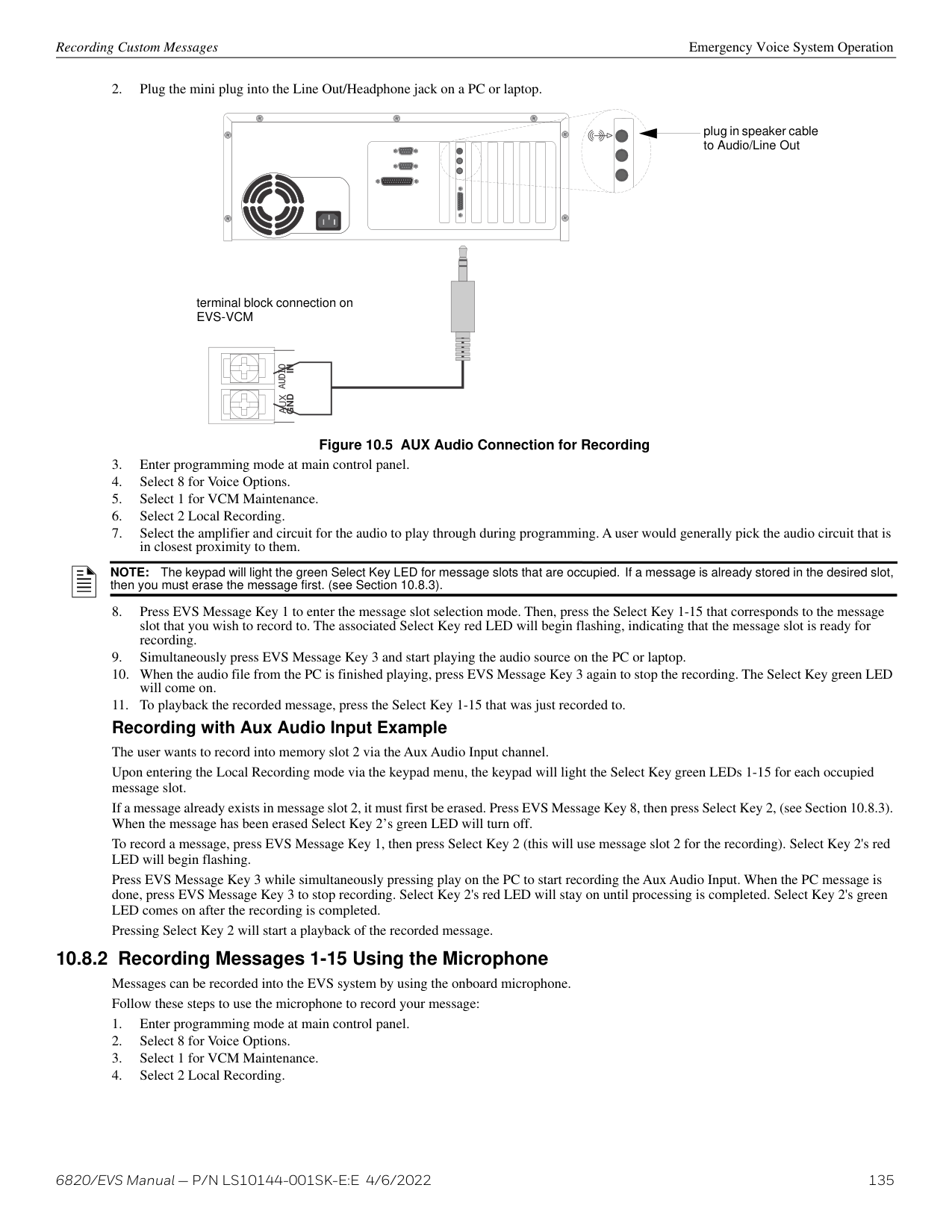
############# Table 9.3 Event Priority
|Fire System Aux 1 Alarm|Emergency 6 Point Alarm| |---|---| |Fire System Aux 2 Alarm|Emergency 7 Point Alarm| | |Emergency 8 Point Alarm| | |Emergency Voice Aux 1 Alarm| | |Emergency Voice Aux 2 Alarm| | |Emergency Voice Aux 3 Alarm| | |Emergency Voice Aux 4 Alarm| |CO Alarm| | |Fire Pre-Alarm| | |Fire Interlock Alert| | | |Emergency Supervisory| |Fire Supervisory| | |CO Supervisory| | |Trouble|Trouble| |Site F Key Status|Site F Key Status| |System Status|System Status|
############# Table 9.3 Event Priority
NOTE: Status Points, Status Voice Aux 1, Status Voice Aux 2, and Background Music are contained within the System Status event priority. All fire, emergency, and system troubles are prioritized into the Trouble Event Priority.
######## 9.4.4 Priority Rules
######## 9.4.5 Other Priority Considerations
There are other considerations to take into account when the same event is acting on the same output group (an event being mapped to an output group.) These are prioritized in order of appearance.
###### 9.5 Operation Mode Behavior
The control panel can be in one or more of seven conditions at any given moment: Normal, Alarm, Pre-alarm, Supervisory, Trouble, Silenced, and Reset. Table 9.4 describes the behavior of the panel in each of these modes.
When looking at the LCD, the screen will display FIRE for the “Fire System”, or CO for the “CO System”. The highest priority event will display first and include the event count (see the figure below). Press the down arrow to view the location and type of alarm supervisory or trouble. If the panel is programmed to Auto Display Event, information describing the highest priority active event will display on the first two lines.
|FIRE: ALRM SUPR CO: ALRM SUPR
| |---|
############# Figure 9.7 Highest Priority Event Display
Operation Mode Behavior System Operation
|Operating Mode|Occurs When|System Behavior|In This Mode You Can|
|---|---|---|---| | | | | | |Normal|No alarm, supervisory, or trouble condition exists and menus are not in use.|SYSTEM POWER LED is on. The All Systems Normal display indicates that the system is in normal mode. The current date and time display on the last line of the LCD.
|Site 1 Model 6820 ALL SYSTEMS NORMAL 08/03/21 01:45:52PM| |---| |Enter the appropriate code, or rotate the key to activate the Main Menu.| |Alarm|A smoke detector goes into alarm or a pull station is activated.
CO detector goes into alarm.
If more than 3 categories are active at a single time, the screen will display as shown.|The system will report events to the central station. The onboard annunciator will sound loud, steady beeps to distinguish alarm signals. For a fire alarm, the sequence is a loud steady beep.(Any notification devices attached to the system will also sound). For an EVS Alarm, the sequence is four seconds on, one second off. The GENERAL ALARM LED flashes. The LCD displays a screen similar to this one.
Pressing the right arrow key or Info will display the location macro, date/time stamp, and site/panel number if applicable.
Pressing the down arrow key to view the type and location of alarm. (Message will alternate with the date/time display.)
|FIRE: ALRM Waterflow SW Zone_1 1 of 1 Info>| |---|
|Site 1 CO ALRM
[Press for status]| |---|
|FIRE: ALRM SUPR TRBL
CO: ALRM SUPR SYS: TRBL| |---| |Press the down arrow to view the alarm. A screen similar to this one displays.
Press SILENCE and enter an Access Code (or activate the key) to silence the annunciator (and any notification devices attached to the system). When the alarm condition clears, press RESET and enter a code (or activate the key) to restore the panel to normal.
ALARM: MAN_PULL MODULE_33 POINT_2 ZONE_2
3 of 5
device type
showing 3 of 5 events|
############# Table 9.4 Panel Operating Modes
|Operating Mode|Occurs When|System Behavior|In This Mode You Can| |---|---|---|---| | | | | | |Supervisory|The system detects a supervisory condition.
A Supervisory with a CO detector.|The system will report events to the central station. The onboard annunciator sounds a loud, pulsing beep to distinguish supervisory signals. For fire supervisory signals, the sequence is one second on, one second off. For EVS supervisory signals, the sequence is two seconds on, three seconds off. The SUPERVISORY LED flashes. The LCD displays a screen similar to this one.
Pressing the right arrow key or Info to display the location macro, date/time stamp, and site/panel, if applicable.
Press the right arrow key or Info to view the type and location of the Supervisory event. The message will alternate with the time/date display.
|FIRE: SUPERVISORY Supervisory Sw SBUS_97 MODULE_2 1 of 1 Info>| |---|
|Site 1 CO: SUPR [Press for status]| |---| |Press the down arrow to view the fire supervisory condition. A screen similar to this one displays.
Press SILENCE and enter an Access Code (or activate the key) to silence the annunciator. Once the supervisory condition has been corrected, the system will restore automatically.
|SUPERVSY: MAN_PULL MODULE_33 POINT_2 [Z002] [M33]
1 of 1
| |---|
device type
showing 1 of 1 event| |Trouble|A system trouble condition occurs.
A trouble condition with a CO detector|The system will report events to the central station. The onboard annunciator sounds a loud, pulsing beep in the sequence one second on, nine seconds off. The SYSTEM TROUBLE LED flashes. The LCD displays a screen similar to this one.
Press the right arrow key or Info to display the location macro, date/time stamp, and site/panel, if applicable.
Press the right arrow key or Info to view the type and location of the Trouble event. The message will alternate with the time/date display.
|FIRE: TROUBLE 1 of 1 Info>| |---|
|Site 1 CO: TROUBLE [Press for status]| |---| |Press down arrow to view the fire trouble. A screen similar to this one displays.
Press SILENCE to silence the annunciator. Once the trouble condition has been fixed, the system will restore itself automatically.
|TROUBLE: CO Smoke SBUS_33 SENSOR_2 [Z002] [M33:S002] Missing 5 of 8
| |---|
showing 5 of 8 events
device type
module/ point
zone #
In this case, the panel does not see a detector that should be on the loop.
trouble type| |Pre-alarm|A single detector trips in a 2-Count zone. (2-Count means two detectors must trip before an alarm is reported.)|The touchpad piezo beeps. The LCD displays a screen similar to this one.
Press the right arrow key or Info to display the location macro, date/time stamp, and site/panel, if applicable.
|FIRE: PREALARM Det-Photo SBUS_97 SENSOR_33 1 of 1 Info>| |---| |Press down arrow to view the Prealarm. A screen similar to this one displays.
All system operations are available in this mode.
|PREALARM:SMOKE-PHOT MODULE_33 POINT_2 [Z002] [M33]
1 of 1| |---|
device type
showing 1 of 1 event|
############# Table 9.4 Panel Operating Modes (Continued)
Releasing Operations System Operation
|Operating Mode|Occurs When|System Behavior|In This Mode You Can| |---|---|---|---| | | | | | |Reset|The RESET button is pressed followed by a valid code, if necessary.|All LEDs are on briefly then the LCD displays “RESET IN PROGRESS”. If the reset process completes normally, the date and time normal mode screen displays.|Menus are not available during the reset process.| |Silenced|An alarm or trouble condition has been silenced but still exists. To silence alarms and troubles, press SILENCE followed by the Installer or User Code, if necessary.|The SYSTEM SILENCE LED is on. The SYSTEM TROUBLE, SUPERVISORY, and/or GENERAL ALARM LED (depending on condition) is on. The annunciator (and any notification devices attached to the system) will be silenced.|Press down arrow to view the location of the alarm, supervisory, or trouble. When the condition no longer exists, the SYSTEM SILENCED and SYSTEM TROUBLE LED, SUPERVISORY and/or GENERAL ALARM LEDs turn off.|
############# Table 9.4 Panel Operating Modes (Continued)
######## 9.5.1 Multi-Site Annunciator and Multi-Site User Access
Multi-site annunciators are unique as they can display the status and event history of all sites they are assigned to. These displays can be especially useful in guard shacks or security centers. A multi-site display is indicated by the words “Multi-Site Display” at the top of the idle screen.
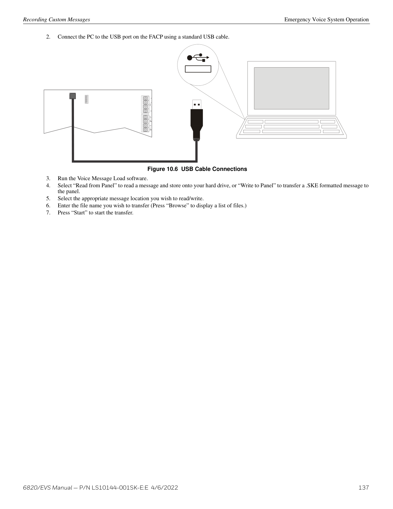
NOTE: A multi-site display is created in Module programming in the edit properties menu for an annunciator. See Section 8.2.1.
###### 9.6 Releasing Operations
The control panel supports two types of releasing: Double Interlock Zone and Single Interlock Zone. The Double Interlock Zone operation requires an interlock switch input in the system, and the Single Interlock Zone does not. An interlock switch is typically a dry-contact pressure switch.
When Single or Double Interlock Zone releasing is selected using HFSS, the software suite will automatically default the following system parameters. Defaults can be modified through programming.
NOTE: The installer must define which input points will be used for detectors, manual release switches, or interlock/pressure switches. For manual release operation, Installer must use an FM approved/ UL listed releasing manual station
NOTE: For manual release operations, an FM approved/ UL listed releasing manual station must be used. Refer to the Device Compatibility Document for approved releasing devices.
System Operation Releasing Operations
+ –
.
Either NAC circuit can be used.
red
UL-listed solenoid supervisory modulemust be located at the solenoid.
black
releasing solenoid Use 1 solenoid per circuit.
############# Figure 9.8 Wiring Configuration for Solenoid
NOTE: For releasing operations, a manual releasing disconnect switch is required per UL 864. Refer to the MRD-1H Series Document for installation instructions.
CAUTION: ADDRESSABLE DETECTORS/MANUAL RELEASE SWITCH
!
ONLY ADDRESSABLE DETECTORS CAN BE USED. NO CONVENTIONAL DETECTORS CAN BE USED. EACH SINGLE INTERLOCK ZONE INPUT REQUIRES AT LEAST ONE MANUAL RELEASE SWITCH.

########## Conditions Required for a Pre-Alert Output Activation
If any single addressable detector is activated, the “Pre-Alert” output will activate. This alerts the user that the initial stages required for a release condition are present. (Refer to Table 9.5).
########## Conditions Required for a General Alarm and Release Output Activation
If two or more addressable detectors, or a manual release switch activate, the “Alarm” and “Release” outputs will activate and the “PreAlarm” output will deactivate. (Refer to Table 9.5 below.)
|Inputs|Output Results|Output Results|Output Results|Output Results|Output Results|Output Results|Output Results|Output Results| |---|---|---|---|---|---|---|---|---| | | | | | | | | | | |1st Addressable Detector| |X| |X| |X| |X| |2nd Addressable Detector| | |X|X| | |X|X| |Manual Release Station| | | | |X|X|X|X| | |Normal|Pre-Alert|Pre-Alert|Release and General Alarm|Release and General Alarm|Release and General Alarm|Release and General Alarm|Release and General Alarm|
Table 9.5 Single Interlock Zone Operation
CAUTION: DETECTOR SPACING DETECTORS MUST BE INSTALLED AT 0.7 TIMES THE LINEAR SPACING AS DESCRIBED IN NFPA 72
!
######## 9.6.2 Double Interlock Zone Releasing
A Double Interlock Zone uses a minimum of two addressable detectors, a designated manual release switch, and an interlock switch input. An interlock switch is typically a dry-contact pressure switch and will be referred to as an interlock/pressure switch in this document. Only addressable detectors can be used. No conventional detectors can be used.
########## Conditions Required for a Pre-Alert Output Activation
If any single addressable detector is activated, the “Pre-Alert” output will activate. This alerts the user that the initial stages required for a release condition are present. (Refer to Table 9.6.)
########## Conditions Required for a General Alarm Output Activation
If two addressable detectors, a manual release switch is activated, or an interlock switch is active, the “Pre-Alert” and “General Alarm” outputs will activate.
Smoke Alarm Verification System Operation
########## Conditions Required for a Release Output Activation
Any release requires the activation of an interlock switch, and either a manual release switch or 2 activated addressable detectors. When these conditions are met, the “Release” and “General Alarm” outputs will activate, and the “Pre-Alert” outputs will deactivate.
|Inputs|Output Results|Output Results|Output Results|Output Results|Output Results|Output Results|Output Results|Output Results|Output Results|Output Results|Output Results|Output Results|Output Results|Output Results|Output Results|Output Results| |---|---|---|---|---|---|---|---|---|---|---|---|---|---|---|---|---| | | | | | | | | | | | | | | | | | | |1st Addressable Detector| |X| |X| |X| |X| |X| |X| |X| |X| |2nd Addressable Detector| | |X|X| | |X|X| | |X|X| | |X|X| |Manual Release Station| | | | |X|X|X|X| | | | |X|X|X|X| |Interlock/Pressure Switch| | | | | | | | |X|X|X|X|X|X|X|X| | |Normal|Pre-Alert|Pre-Alert|Pre-Alert and General Alarm|Pre-Alert and General Alarm|Pre-Alert and General Alarm|Pre-Alert and General Alarm|Pre-Alert and General Alarm|Pre-Alert and General Alarm|Pre-Alert and General Alarm|Pre-Alert and General Alarm|Pre-Alert and General Alarm|Pre-Alert and General Alarm|Pre-Alert and General Alarm|Pre-Alert and General Alarm|Pre-Alert and General Alarm|
Table 9.6 Double Interlock Zone Operation
CAUTION: DETECTOR SPACING DETECTORS MUST BE INSTALLED AT 0.7 TIMES THE LINEAR SPACING AS DESCRIBED IN NFPA 72
!
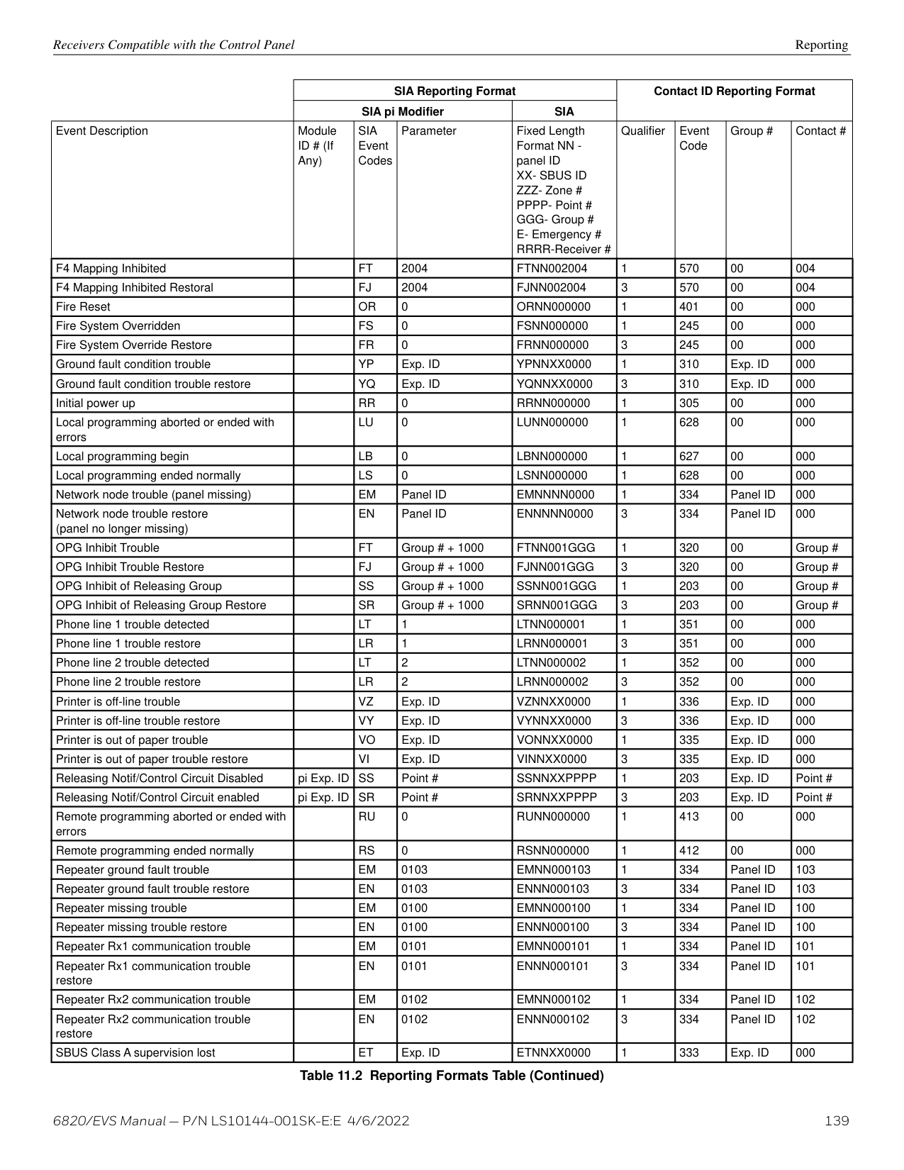
During the Confirmation Period if there is no alarm indication then the system will return to normal operation.
|reset period|restart period|confirmation period| |---|---|---| |reset period|16 seconds|60-250 seconds (programmable)| |12 seconds|16 seconds|60-250 seconds (programmable)|
############# Figure 9.9 Smoke Verification Cycle
The function keys on the 6820EVS or 6860 only have multiple features. Their macro key functionality can simplify the disabling, activating, or inhibiting points or groups respectively. They can also be used as a status type activation event and for activating Map Inhibit. Each F-Key macro can hold 50 events.
To access the F-Key Recording menu:
######## 9.8.1 Recording an F-Key Macro
######## 9.8.2 Aborting an F-Key Macro Recording Session
######## 9.8.3 Erasing an F-Key Macro
System Operation Function Keys
######## 9.8.4 Using a Recorded F-Key Macro
######## 9.8.5 F-Key Status Event
When an F-Key is enabled, it activates its corresponding F-Key Active event. This is a status type event that can activate outputs without showing any status on annunciator displays. This should be used for ancillary purposes only.
######## 9.8.6 F-Key Map Inhibit
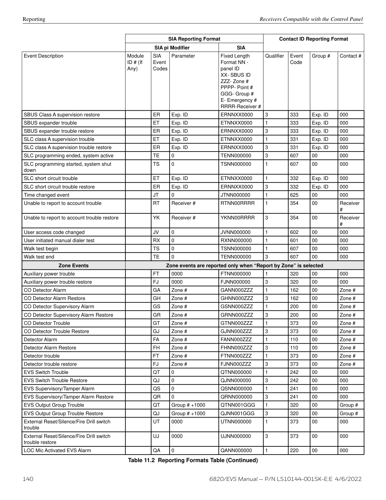
The F-Keys have the ability to disable event - output group mapping for the purpose of simulating that the map doesn’t exist. This can be setup to allow for testing purposes where notification of an entire building is not desired during the test. This option is programmable for each output group map through HFSS.
When an F-Key is active and a map in the system is set to be disable by Map Inhibit, the system will show a trouble event indicating it as such.
##### Section 10: Emergency Voice System Operation
###### 10.1 Overview
The 6820EVS control panel and accessories provides features to meet the requirements for a Mass Notification Systems as described in NFPA 72 and is compliant with the UL 2572 standard. The EVS (Emergency Voice System) is integrated with the fire alarm and voice evacuation functions of the control panel. In a networked panel system, only one panel can be chosen to be the voice evacuation/EVS panel for the site.
There are two ways for activating EVS in the 6820EVS panel: EVS Point Activations EVS Point Activation involves using pre-determined EVS Alarm input points to activate EVS Alarm events. These events cause output areas to activate based on mapping that is programmed into the system at installation. This is very similar to the traditional mapping that the fire system has utilized to date. Manual LOC Activations Manual LOC Activation involves using the LOC EVS interface to activate EVS Events, choose output areas, and
speak through a microphone. These selections are not pre-determined and allow the user to make system functionality decisions when the event is actually happening. This requires the activation of Manual EVS State which bypasses EVS Point Activations. See Section 10.2.3.
###### 10.2 LOC Functionality
An LOC (Local Operating Console) consists of either the EVS series panel (EVS-VCM Voice Control Module and the Fire Alarm Control Panel) or the EVS-LOC (EVS-RVM Remote Voice Module and its associated 6860 keypad.) An LOC is created by adding an EVS-VCM or EVS-RVM to the system and associating a keypad to it. The LOC provides eight buttons for activating the EVS messages, a button to gain and request EVS Control, and a microphone for live paging. There can be up to 16 LOC devices in the system. In a networked panel system, all of the LOCs must be connected through SBUS to the panel that includes the EVS-VCM.
The EVS Control LED is used to indicate the status of EVS Control in the system. When the LED is on solid, the LOC has EVS Control within the system. When the LED is blinking, another LOC has gained EVS Control in the system.
########## EVS Message Keys
EVS Message Keys are used in Message Mode to select which EVS Message is to be played. If pressed when the LOC does not have EVS Control, the system will automatically try to gain EVS Control before allowing the EVS Event to be activated. See Section 10.2.2.
########## EVS Message LEDs
The red EVS Message LEDs indicate the active EVS Message and any previously active EVS messages. The green LEDs indicate the EVS Message was selected in message mode and that the LOC has EVS control.
NOTE: For LOC-activated emergency alarm events, if an area is programmed through mapping to be active, that area is automatically selected and can not be deactivated using the Select Keys.
Select Key LEDs The Select Key LEDs are used to indicate which output areas are active for a microphone page or system events.
NOTE: These are only active when the microphone PTT (push-to-talk) is engaged.
READY TO TALK
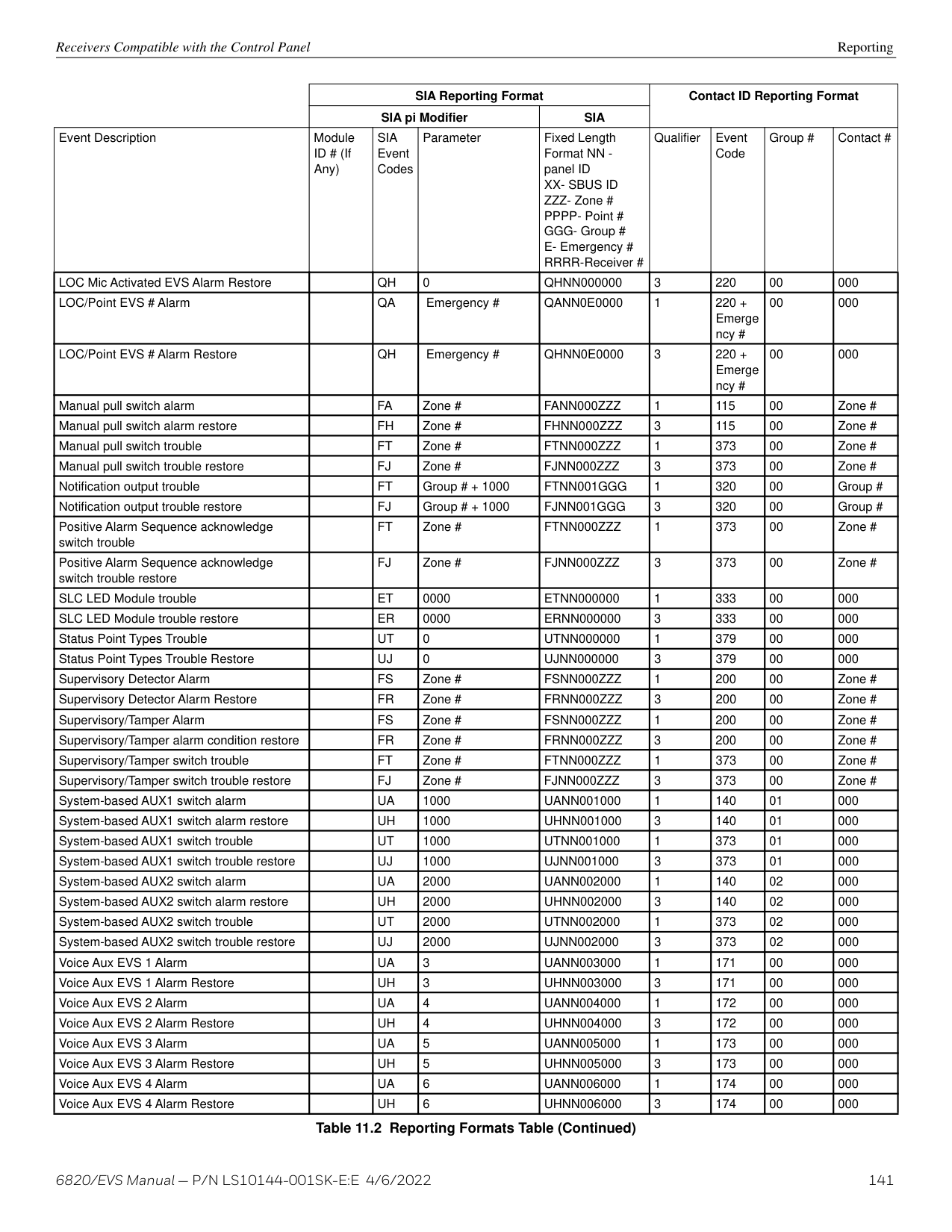
NON-ACTIVE CALL
ALL CALL ECS CONTROL
EVS Control LED
All Call button
EVS Control button
Ready To Talk LED
Non-Active Call button
EVS status/ alarm LEDs
output group select buttons
EVS message 1-8 activate buttons
Figure 10.1 Front View of EVS Keypad
LOCs are assigned (through panel or HFSS programming of the EVS-VCM and EVS-RVM) an LOC priority of low, normal, or high. LOCs with a higher priority are always able to gain control from a lower priority LOC.
########## LOC Lockout
When LOCs are programmed to the same priority, the setting LOC lockout applies. LOC lockout will not allow an LOC to gain EVS Control from the LOC with EVS Control until one of three things happen:
NOTE: The lockout timer must be programmed to expire sometime other than Never.
The user will need to enter an access code containing the EVS Control Request or EVS Super User profile option to gain EVS Control. EVS Control Request and EVS Super User profile options will be mutually exclusive to the system. If the access code has EVS Super User, the EVS Control Request is ignored and activations by that user are always as EVS Super User.
######## 10.2.3 Manual EVS
After gaining EVS Control the system enters the LOC EVS interface which allows you to activate the Emergency System and allows for Emergency Paging. Once an emergency event has been activated the panel enters a Manual EVS State. In this state, all EVS Alarm programmed points that are currently in alarm in the system are changed to an active state. The display status screen reflects this when viewing the system for status. Any outputs that were activated by the EVS Alarm programmed points are deactivated until Manual EVS state is
LOC Functionality Emergency Voice System Operation
exited. Only an EVS Reset can exit the Manual EVS State. If a user gains EVS Control at an LOC and does not activate an EVS message, the system will automatically generate an EVS Supervisory indicating such. This prevents an LOC from being in an undesired state of EVS Control when an actual event emerges.
There are two modes for interacting with the LOC EVS interface when in Manual EVS State:
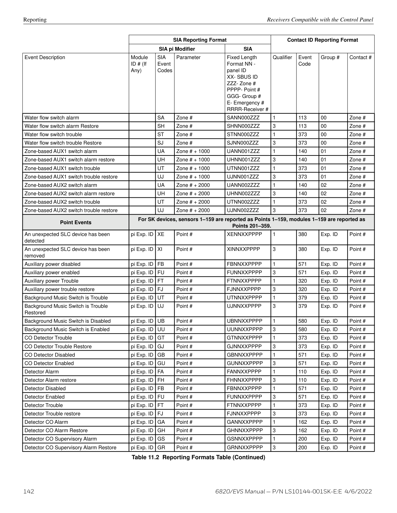
At any time while in EVS Control, you can switch between Fire Page Mode and Message Mode. Fire Page Mode is entered by simply engaging the microphone.
########## Activating Output Groups Dynamically
This method allows the system to be setup with minimal or no system mapping. When in Manual EVS State and operating in Message Mode the user can dynamically activate/deactivate output areas for system notification to take place in. The Select Key red LED will become lit and the circuits in the output group(s) will become active and play the currently active EVS event message when activated. When deactivated, the Select Key red LED will become unlit and the circuits in the output group(s) will become inactive. Non-voice output groups can also be assigned to Select Keys and will toggle on/off using the activation cadence assigned to it in output group programming. This is available in the panel and in HFSS. Refer to Section 8.4.1 for information on editing groups.
######## 10.2.4 Fire Page Mode
Fire Page Mode allows the user to press the Select Keys to toggle which output areas to speak to over the microphone. The green LEDs next to the Select Keys will activate or deactivate.
|FIRE PAGE MODE SELECT KEYS: Toggle Output Areas Microphone Active Release Microphone for MESSAGE MODE| |---|
When Fire is set to higher priority than EVS in user programming, and NACs are active due to a release alarm, EVS functions and the microphone will be disabled. In this instance, NACs take higher priority over EVS messages. The screen will display the following.
|FIRE PAGE MODE Fire Alarm Priority Higher than EVS Microphone and SELECT KETS Disabled MESSAGE Disabled for MESSAGE MODE| |---|
######## 10.2.5 Message Mode
In Message Mode, the user is able to press the EVS message Keys to choose a message and press the Select Keys to activate or deactivate which output areas the message will be played. This will activate or deactivate the green and red LEDs next to the EVS Message Keys and the red LEDs next to the Select Keys.
|MESSAGE MODE ECS MESSAGE KEYS: Choose Message SELECT KEYS: Toggle Output Areas Engage Microphone for FIRE PAGE MODE| |---|
When Fire is set to higher priority than EVS in user programming, and NACs are active due to a release alarm, EVS functions and the microphone will be disabled. In this instance, NACs take higher priority over EVS messages. The screen will display the following.
|MESSAGE MODE Fire Alarm Priority Higher than EVS MESSAGE and SELECT KETS Disabled Microphone Disabled for FIRE PAGE MODE| |---|
######## 10.2.6 Custom EVS Event
Custom EVS events allows the user to generate an EVS event and speak a custom message using the microphone. Once the user is done speaking the message, the tone and any associated strobes will continue to be active in the output areas. To generate a Custom EVS Event:
######## 10.2.7 Passing EVS Control
Passing of EVS Control is allowed when two LOC units have the same priority. When it is possible to pass control, a prompt (similar to Figure 10.2) will display in which the user can request control from the LOC with EVS Control, enter an access code with the EVS Super User profile option to override the other LOC, or wait for the lockout timer to expire (if applicable).
|GAIN EVS CONTROL OPTIONS MENU 1=Request ECS Control from LOC
2 Gain EVS Control as EVS Super User
3 Wait for Lockout Timer to Expire 30
| |---|
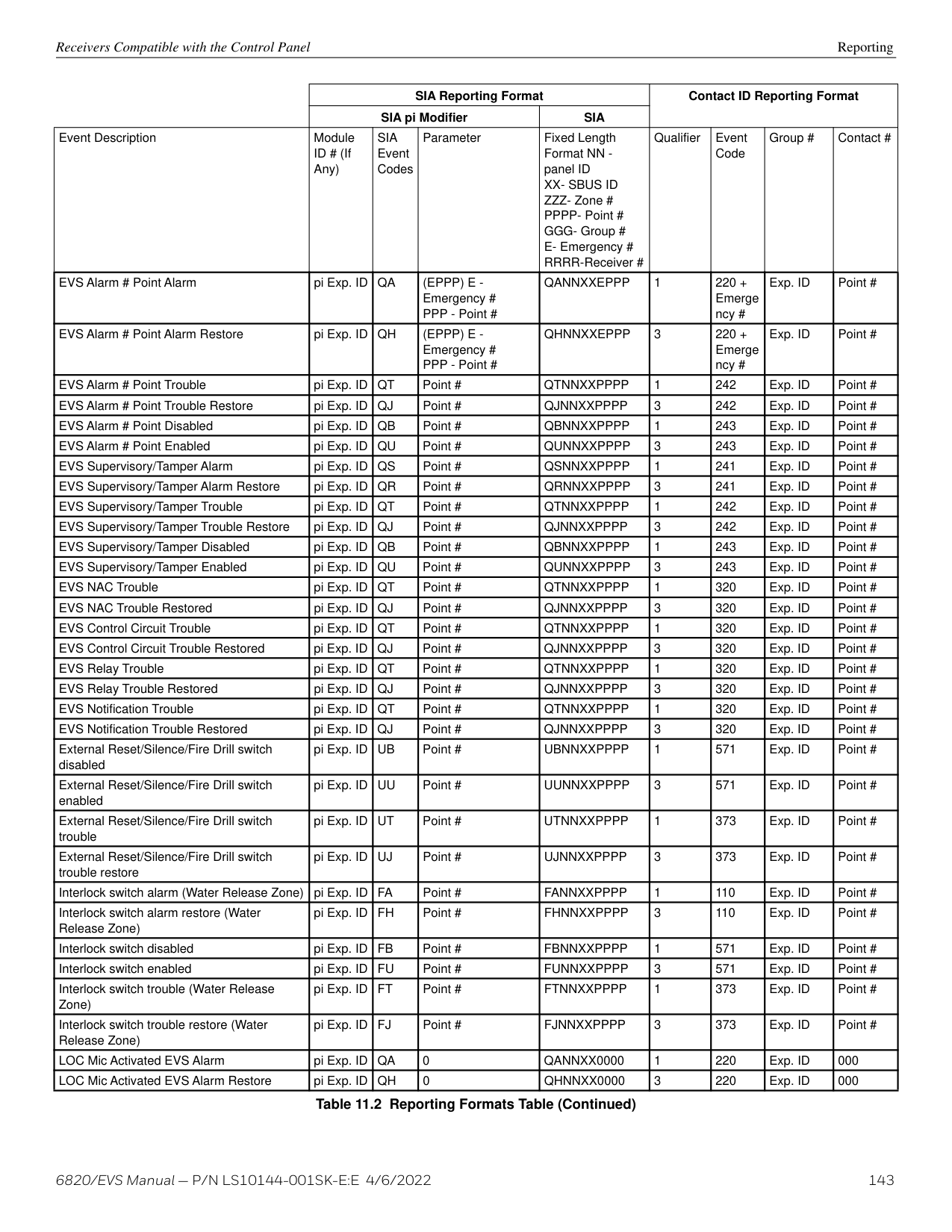
Figure 10.2 Request EVS Control with Lockout Timer Active
When passing EVS Control between two EVS Super Users, the user is not shown the prompt screen. Instead, a request for EVS Control is automatically made. Additionally, the lockout timer does not apply for EVS Super User.
When a request for EVS Control is made, the LOC with EVS Control will be shown a screen (similar to Figure 10.3), even when in another menu, except programming menus, indicating that another LOC is requesting EVS Control. The piezo buzzer on the LOC with EVS Control sound when an EVS Control request is active to alert a nearby operator of the request.
|Relinquishing EVS Control Automatic EVS Timer: 30
1=Cancel, Keep EVS Control 2 Accept, Relinquish EVS Control| |---|
Figure 10.3 Another LOC is Requesting EVS Control
Once EVS Control is passed to another LOC, the new user will assume the system AS IS. This means that the event that was set to be playing at the previous LOC and all output areas it was playing in do not change.
######## 10.2.8 Exit EVS Control Menu
The user can exit the LOC EVS interface by pressing the left arrow key. The user will be returned to the idle screen which indicates that the LOC still has EVS control.
EVS Super User Emergency Voice System Operation
######## 10.2.9 Relinquish EVS Control
Relinquishing EVS Control is accomplished by pressing the EVS Control Key from within Message Mode. A screen will be displayed to ensure the user wants to relinquish EVS Control. EVS Control will be automatically relinquished after a time-out on this screen. When EVS Control is relinquished, the system stays in the Manual EVS State. EVS Control can then be gained by another LOC or again at the same LOC.
|Relinquishing EVS Control Automatic EVS Timer: 30
1=Cancel, Keep EVS Control 2 Accept, Relinquish EVS Control| |---|
############# Figure 10.4 Relinquish EVS Control
######## 10.2.10 EVS Reset
An EVS reset is accomplished by pressing the RESET button from an LOC. The user will be prompted to reset either the fire system or emergency system. After an EVS reset, the LOC will automatically exit the LOC EVS interface.
NOTE: In order to perform an EVS reset, the display must be associated with the EVS-VCM or EVS-RVM. Refer to Figure 10.6.2.
###### 10.3 EVS Super User
The EVS Super User access code profile function provides the ability to override all EVS Control rules and gain EVS Control. The EVS Super User is the highest priority user in the system. The EVS Super User has several features that differ from the normal user:
EVS Super User attempts to gain EVS Control from an LOC, an EVS Control request is presented to the EVS Super User at the LOC that currently has EVS Control.
###### 10.4 EVS Point Functionality
Any input point in the system can be configured as an EVS input. The Point EVS 1-8 Alarm input types can be used to trigger predetermined EVS events for output areas. EVS-VCM or EVS-RVM points can be programmed to trigger Voice Aux events that can allow external audio to be played through the emergency system.
EVS points can only activate outputs and be placed into an alarm state if the system is not in Manual EVS State. EVS points have no priority and all are allowed to be activated. If the EVS point is a higher priority than the Fire System, then the system will play the highest event message through all EVS mapped outputs.
For example: Emergency 1 Point Alarm is higher priority than Emergency 2 Point Alarm. Emergency 1 Point Alarm has message 1 mapped to through groups 1 and 2. Emergency 2 Point Alarm has message 2 playing through groups 2 and 3. If a point for Emergency 1 Point Alarm and a point for Emergency 2 Point Alarm are both active, the system will play message 1 through groups 1, 2, and 3.
Once Manual EVS State is active, points in Alarm state switch to an Active state. When the points are changed to the Active state, they do not activate any system mapping or turn any outputs on. Any points that are activated while in Manual EVS are also placed into the Active state and are not allowed to activate any mapping. The system idle screen will show an EVS Alarm for any points in the Active state, and the detailed description of the point will show the point as Active.
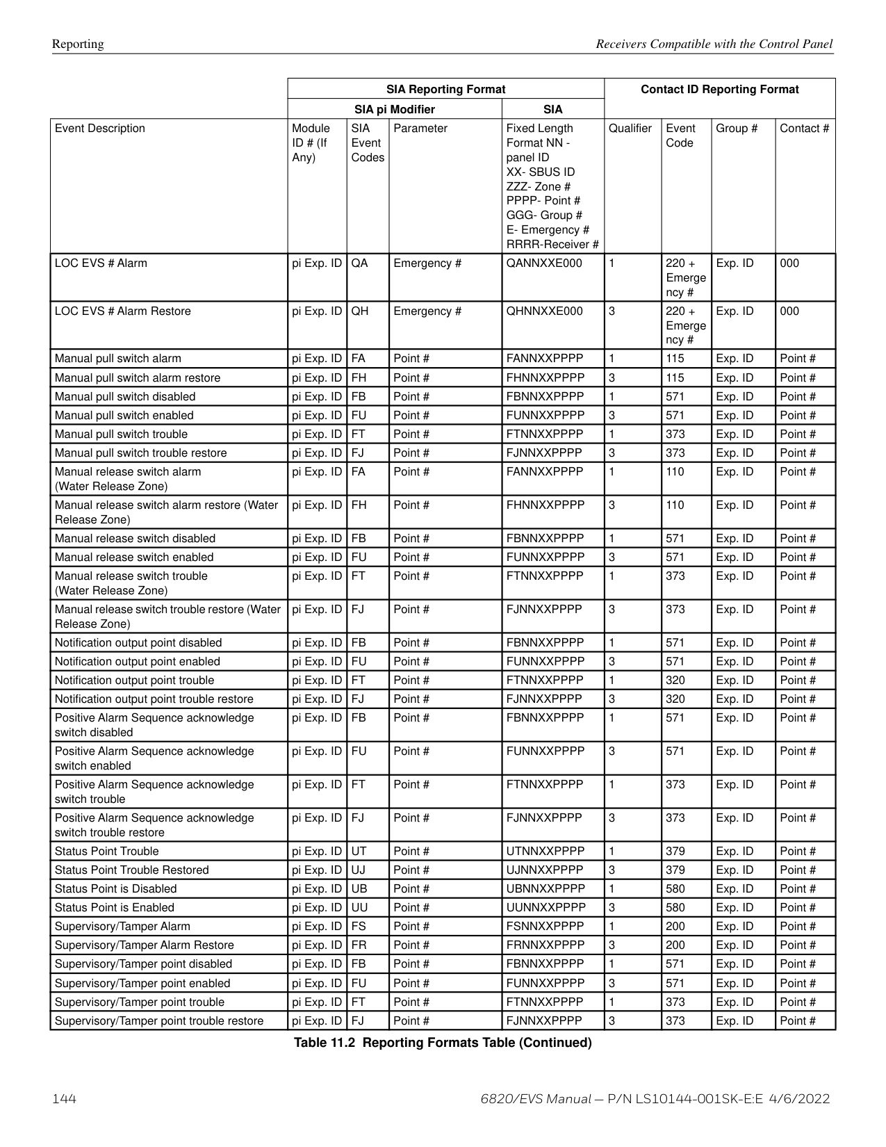
After an EVS Reset, any EVS points that are still active will again be put into Alarm.
The EVS-VCM and EVS-RVM modules contain two programmable input points. These can be programmed as any conventional switch input type. These also have the ability to be programmed as a trigger for bringing external audio into the system. These special point types are: EVS Voice Aux In 1-4 Alarm, Voice Aux In 1-2 Status, Background Music. When activated if the event has the highest Event Priority of all activated events, it will activate the Aux In input to all outputs defined by the respective event program mapping.
NOTE: Background Music is only allowed to be mapped to circuit 8 of the EVS-100W amplifiers to ensure correct active supervision.
###### 10.5 Amplifier Programming
Emergency Voice System Operation LOC Programming
The screen will display “Adding module [#]...” for a few moments. You will be returned to the New Module Type screen where you can select another module(s) if desired.
You must save changes when you exit the Program Menu or the new module will not be added. For more information, see Section 8.2.2. If you Add a Module that has not been physically connected, the panel will go into trouble after it re-initializes (when you exit the Program Menu with changes accepted). When the new module is attached, the trouble will restore automatically the next time you power up the FACP.
######## 10.5.2 Editing an Amplifier
When editing amplifiers, the features that may be edited are: module ID, module name, amplifier module, EVS-CE4 installed (Yes or No), and output voltage. To edit an existing module:
From the next screen, add either an EVS-VCM The screen will display “Adding module [#]...” for a few moments. You will be returned to the
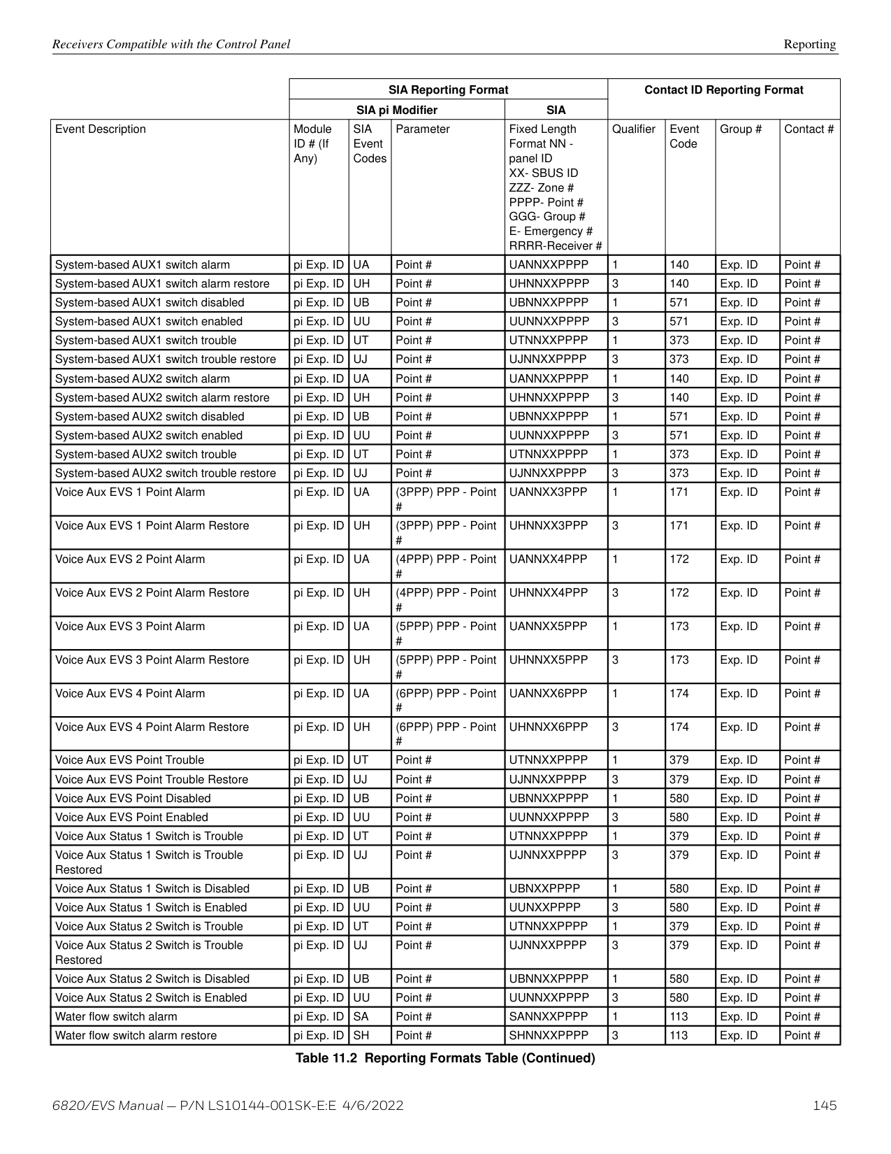
NOTE: If you add a module to panel programming that has not been physically connected, the panel will go into trouble after it re-initializes (when you exit the Program Menu). When the new module is attached, the trouble will restore automatically the next time you power up the system.
Settings that are specific to an LOC are modified by editing the EVS-VCM or EVS-RVM expander module of the LOC. These options may include: number of switch expanders installed, microphone type, microphone gain, auxiliary gain, tone gain, message gain, keypad priority, and associated keypad.
NOTE: You can also use HFSS to edit an LOC.
To edit an existing module:
Each device is assigned a Priority level: Low, Normal, or High. This is modified by editing the LOC’s EVS-VCM or EVS-RVM module. By default, the EVS-VCM has a high LOC priority. The EVS-RVM is defaulted to normal LOC priority.
########## LOC Association
To create an LOC, an annunciator must be associated to an EVS-VCM or EVS-RVM. This done by editing the EVS-VCM or EVS-RVM module and selecting the correct annunciator for the associated device. During JumpStart, the EVS-VCM is automatically associated with the internal annunciator. The association for other LOC consoles in the system must be performed in programming.
Using the Microphone Emergency Voice System Operation
###### 10.7 Using the Microphone
The microphones are housed within the EVS Series panel enclosure and the EVS-LOC/EVSRPU cabinets. A maximum of five microphones can be installed in the system.
This event is activated by gaining EVS Control at a LOC and using the microphone without any EVS event already active in the Manual EVS State. In this case, the Mic Triggered EVS Alarm mapping and General EVS Alarm mapping will be activated and stay activated until a different EVS event is activated at the LOC or the user resets the Emergency Communication System.
– If the fire alarm has the highest active priority and EVS is also active, any LOC can do a fire page given LOC device priority rules are followed. If the user is at the LOC with EVS Control, and the fire page is of higher priority that the EVS event, the LOC will automatically relinquish EVS Control to do the fire page when the user engages the microphone.
– In this case, if any LOC has EVS Control, the LOC will automatically relinquish control to allow for the fire page.
– In this case a fire page is NOT allowed at all and the LOC must gain EVS control in order to do any live voice.
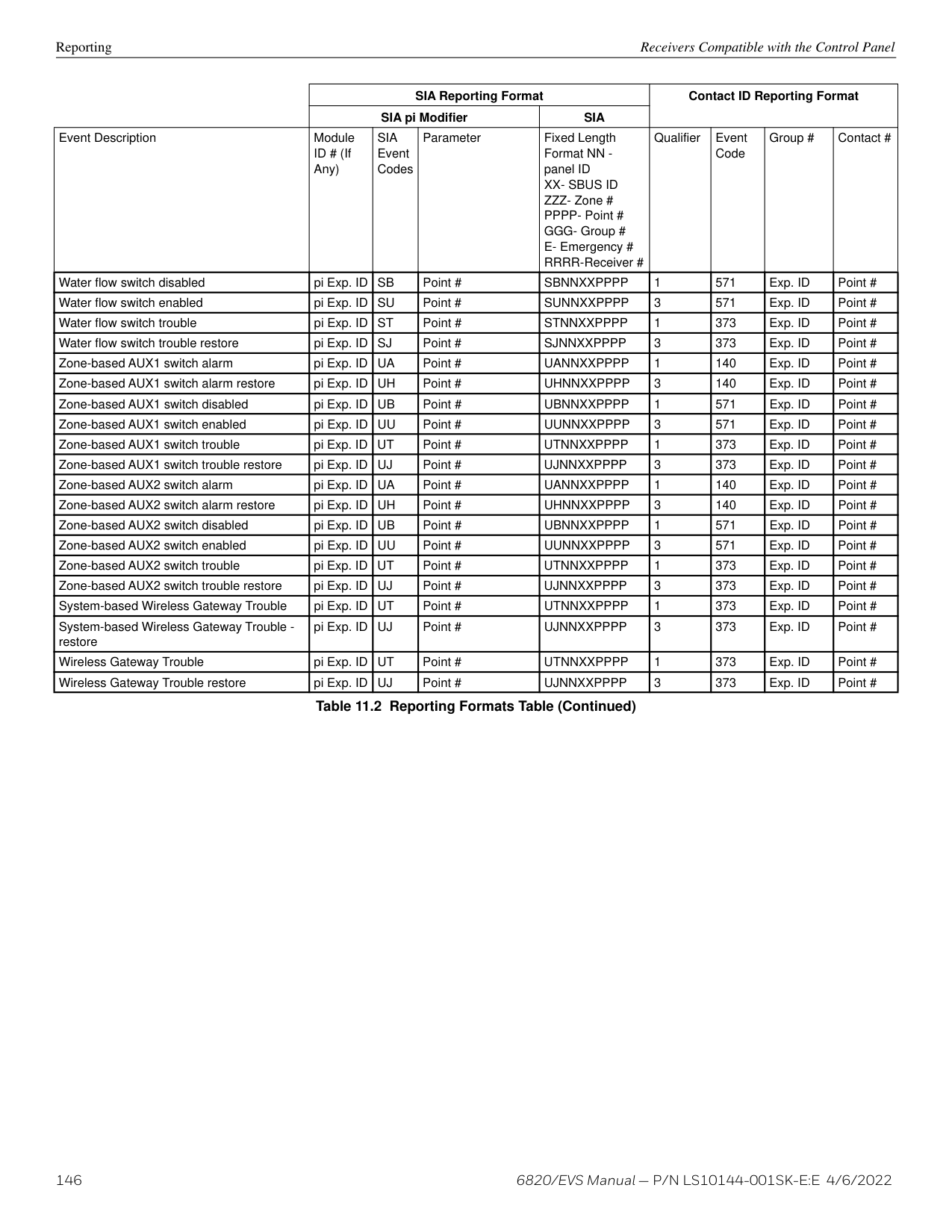
Ready to Talk LED
READY TO TALK
ALL CALL
###### 10.8 Recording Custom Messages
The EVS Series EVS-VCM comes with 15 recordable message slots. Message 1-15 can be recorded from: the microphone, Aux Input, or by using the EVS Message Management utility of HFSS. All messages can be a maximum of one minute.
When in the record mode, the EVS-VCM keys will function as follows:
READY TO TALK
NON-ACTIVE CALL
ALL CALL ECS CONTROL
ECS Message Key 1
Select Keys 1-15
ECS Message Key 3
ECS Message Key 8
|Key|Function| |---|---| | | | |EVS Message Key 1|Select message slot to record| |EVS Message Key 3|Start and stop recording from Aux Audio Input| |EVS Message Key 8|Erase user message 1-15| |Select Keys 1-15|Message storage lot 1-15|
While in the Local Record mode, Select Keys 1-15 will be used to reference message slots 1-15. The associated green Select Key LED will indicate that a message is currently programmed in the corresponding slot. When there is no message recorded (or the message is erased), the associated green Select Key LED will be off. While recording a particular message, the associated red Select Key LED will turn on until recording is completed. The Select Key 1-15 will be used to playback a recorded message or to select the message slot to record to or erase.
When in the Local Record mode, the EVS-VCM LEDs will function as follows:
|Switch LED|Active LED Status|Action| |---|---|---| | | | | |Select key 1-15 Green LED|On|Message is currently programmed in this slot| |Select key 1-15 Red LED|On|Message recording is in progress| |Select key 1-15 Green/Red LED|Off/Off|Message slot is empty| |Select key 1-15 Red LED|Flashing|Message is being played back or message is selected for recording|
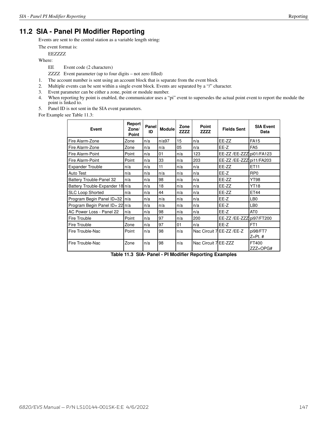
plug in speaker cable to Audio/Line Out
terminal block connection on EVS-VCM
| | | |---|---| | | |
INGND
AUXAUDIO
| | | |---|---| | | |
############# Figure 10.5 AUX Audio Connection for Recording
NOTE: The keypad will light the green Select Key LED for message slots that are occupied. If a message is already stored in the desired slot, then you must erase the message first. (see Section 10.8.3).
Upon entering the Local Recording mode via the keypad menu, the keypad will light the Select Key green LEDs 1-15 for each occupied message slot.
If a message already exists in message slot 2, it must first be erased. Press EVS Message Key 8, then press Select Key 2, (see Section 10.8.3). When the message has been erased Select Key 2’s green LED will turn off.
To record a message, press EVS Message Key 1, then press Select Key 2 (this will use message slot 2 for the recording). Select Key 2's red LED will begin flashing. Press EVS Message Key 3 while simultaneously pressing play on the PC to start recording the Aux Audio Input. When the PC message is done, press EVS Message Key 3 to stop recording. Select Key 2's red LED will stay on until processing is completed. Select Key 2's green LED comes on after the recording is completed. Pressing Select Key 2 will start a playback of the recorded message.
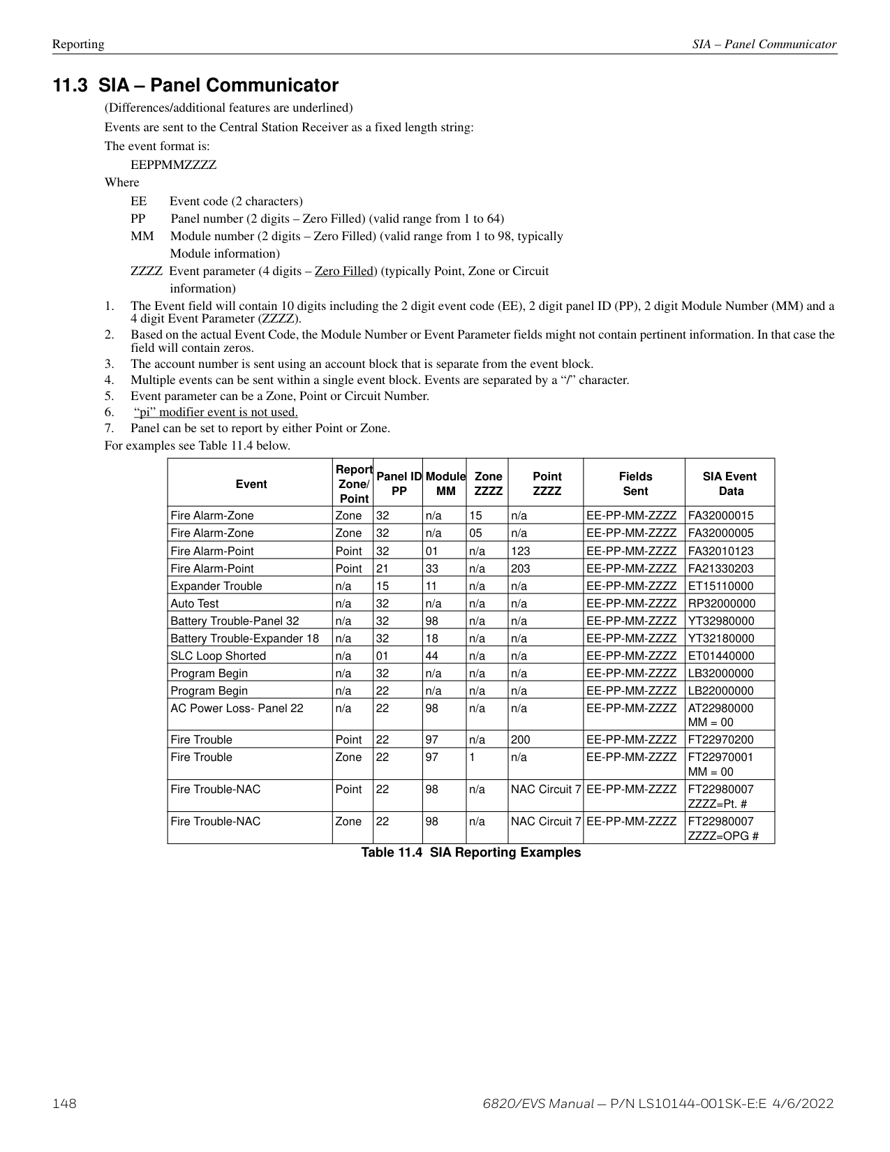
NOTE: The keypad will light the green Select Key LED for message slots that are occupied. If a message is already stored in the desired slot, then you must erase the message first. (See Section 10.8.3).
Upon entering the Local Recording mode via the keypad menu, the keypad will light the Select Key green LEDs for 1-15 for each occupied message slot.
If a message already exists in message slot 5, it must first be erased. Press EVS Message key 8, then press Select Key 5, (see Section 10.8.3). When the message has been erased Select Key 5's green LED will turn off. To record a message, press EVS Message Key 1, press Select Key 5 (this will use message slot 5 for the recording). Select Key 5's red LED will begin flashing. Press the push-to-talk button on the microphone and speak your message. Release the PTT button to save your message. Select Key 5's red LED stays on until processing is completed. Select Key 5's green LED comes on after the recording is completed. Pressing Select Key 5 will start a playback of the recorded message.
NOTE: The keypad will light the green Select Key LEDs for message slots that are occupied (can be erased).
The HFSS Voice Message Load Software is a software support utility that is used to download recorded messages (in .SKE format stored on your PC hard drive) to the various message locations of the EVS Series keypad. Messages can be uploaded from the EVS-VCM, stored, and used again in similar installations.
To read/write .SKE formatted messages to and from the main panel, follow these steps:
| |SBUSVBUS 2 INVBUS 2 OUT
+
+
AB| |---|---| | |SBUSVBUS 2 INVBUS 2 OUT
+
+
AB|
| | | | |---|---|---| | | | |
############# Figure 10.6 USB Cable Connections
##### Section 11: Reporting
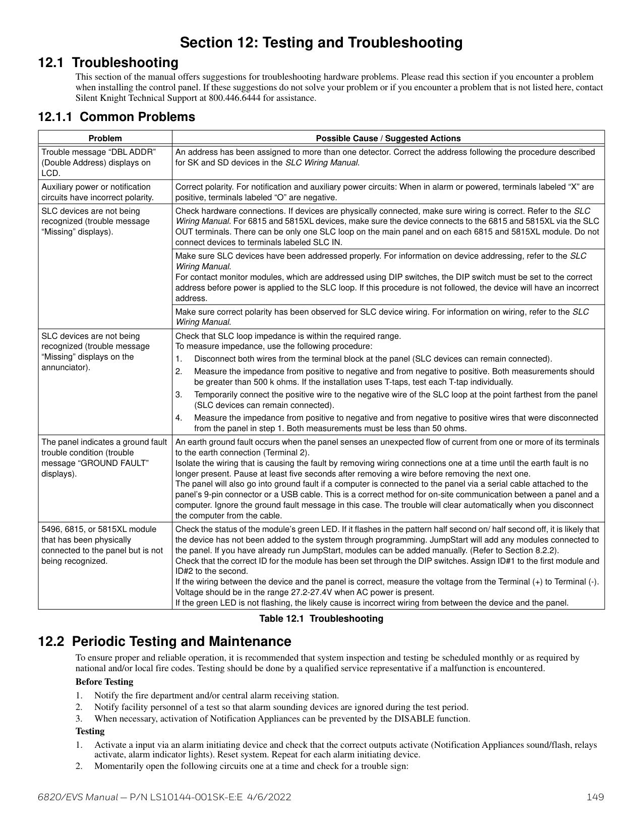
This section lists receivers that are compatible with this control panel, and the reporting codes sent by the control panel for SIA and Contact ID formats.
###### 11.1 Receivers Compatible with the Control PanelTable 11.1 shows receivers compatible with the control panel.
|Manufacturer|Model|Format| |---|---|---| | | | | |Silent Knight by Honeywell|Model 9800|SIA and Contact ID| |Silent Knight by Honeywell|Model 9000 (SIA formats)|SIA| |Honeywell Security|AlarmNet 7810-ir|IP and Cellular Receiver, Contact ID only| |Ademco|MX8000|SIA and Contact ID| |Ademco|Model 685 (Contact ID )|Contact ID| |Sur-Gard|SG-MLR2-DG (V. 1.64 or higher)|SIA and Contact ID| |Osborne Hoffman|Quickalert|SIA and Contact ID|
| |SIA Reporting Format|SIA Reporting Format|SIA Reporting Format|SIA Reporting Format|Contact ID Reporting Format|Contact ID Reporting Format|Contact ID Reporting Format|Contact ID Reporting Format| |---|---|---|---|---|---|---|---|---| | |SIA pi Modifier|SIA pi Modifier|SIA pi Modifier|SIA|Contact ID Reporting Format|Contact ID Reporting Format|Contact ID Reporting Format|Contact ID Reporting Format| |Event Description|Module ID # (If Any)|SIA Event Codes|Parameter|Fixed Length Format NN panel ID XX- SBUS ID ZZZ- Zone # PPPP- Point # GGG- Group # E- Emergency # RRRR-Receiver #|Qualifier|Event Code|Group #|Contact #| |System Events|System Events are reported when either “Report by Point” or Report by Zone is selected|System Events are reported when either “Report by Point” or Report by Zone is selected|System Events are reported when either “Report by Point” or Report by Zone is selected|System Events are reported when either “Report by Point” or Report by Zone is selected|System Events are reported when either “Report by Point” or Report by Zone is selected|System Events are reported when either “Report by Point” or Report by Zone is selected|System Events are reported when either “Report by Point” or Report by Zone is selected|System Events are reported when either “Report by Point” or Report by Zone is selected| |AC power low trouble| |AT|0|ATNN000000|1|301|00|000| |AC power low trouble restore| |AR|0|ARNN000000|3|301|00|000| |Auto dialer test communications trouble line 1| |YC|1|YCNN000001|1|350|Receiver #|001| |Auto dialer test communications trouble line 1 restore| |YK|1|YKNN000001|3|350|Receiver #|001| |Auto dialer test communications trouble line 2| |YC|2|YCNN000002|1|350|Receiver #|002| |Auto dialer test communications trouble line 2 restore| |YK|2|YKNN000002|3|350|Receiver #|002| |Automatic test normal| |RP|0|RPNN000000|1|602|00|000| |Automatic test off normal| |RY|0|RYNN000000|1|608|00|000| |Battery voltage trouble| |YT|Exp. ID|YTNNXX0000|1|302|Exp. ID|000| |Battery voltage trouble restore| |YR|Exp. ID|YRNNXX0000|3|302|Exp. ID|000| |Date changed event| |JD|0|JDNN000000|1|625|00|000| |EVS Reset| |OR|1|ORNN000001|1|401|00|001| |Emergency System Overridden| |QS|0|QSNN000000|1|244|00|000| |Emergency System Overridden Restore| |QR|0|QRNN000000|3|244|00|000| |Fire drill has begun| |FI|0|FINN000000|1|604|00|000| |Fire drill has ended| |FK|0|FKNN000000|3|604|00|000| |F1 Mapping Inhibited| |FT|2001|FTNN002001|1|570|00|001| |F1 Mapping Inhibited Restoral| |FJ|2001|FJNN002001|3|570|00|001| |F2 Mapping Inhibited| |FT|2002|FTNN002002|1|570|00|002| |F2 Mapping Inhibited Restoral| |FJ|2002|FJNN002002|3|570|00|002| |F3 Mapping Inhibited| |FT|2003|FTNN002003|1|570|00|003| |F3 Mapping Inhibited Restoral| |FJ|2003|FJNN002003|3|570|00|003|
Table 11.2 Reporting Formats Table
| |SIA Reporting Format|SIA Reporting Format|SIA Reporting Format|SIA Reporting Format|Contact ID Reporting Format|Contact ID Reporting Format|Contact ID Reporting Format|Contact ID Reporting Format| |---|---|---|---|---|---|---|---|---| | |SIA pi Modifier|SIA pi Modifier|SIA pi Modifier|SIA|Contact ID Reporting Format|Contact ID Reporting Format|Contact ID Reporting Format|Contact ID Reporting Format| |Event Description|Module ID # (If Any)|SIA Event Codes|Parameter|Fixed Length Format NN panel ID XX- SBUS ID ZZZ- Zone # PPPP- Point # GGG- Group # E- Emergency # RRRR-Receiver #|Qualifier|Event Code|Group #|Contact #| |F4 Mapping Inhibited| |FT|2004|FTNN002004|1|570|00|004| |F4 Mapping Inhibited Restoral| |FJ|2004|FJNN002004|3|570|00|004|
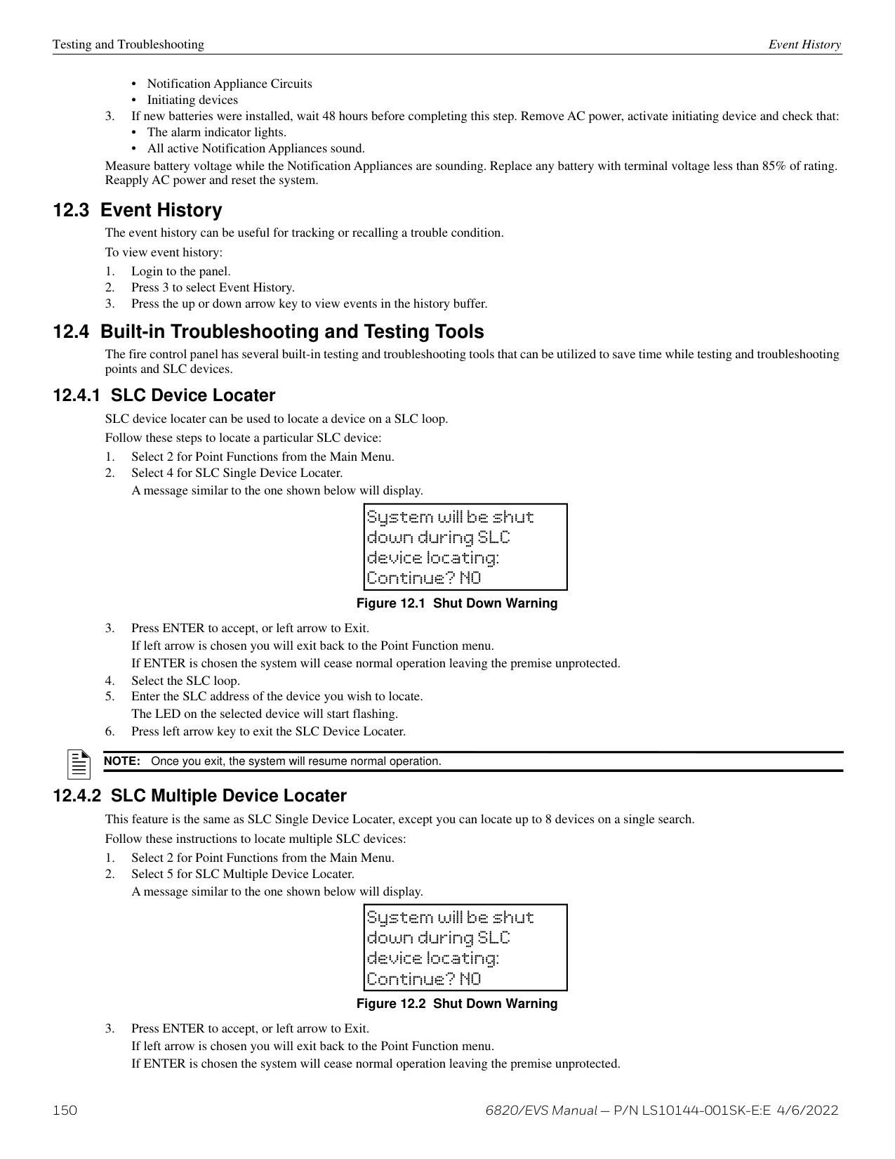
|Fire Reset| |OR|0|ORNN000000|1|401|00|000| |Fire System Overridden| |FS|0|FSNN000000|1|245|00|000| |Fire System Override Restore| |FR|0|FRNN000000|3|245|00|000| |Ground fault condition trouble| |YP|Exp. ID|YPNNXX0000|1|310|Exp. ID|000| |Ground fault condition trouble restore| |YQ|Exp. ID|YQNNXX0000|3|310|Exp. ID|000| |Initial power up| |RR|0|RRNN000000|1|305|00|000| |Local programming aborted or ended with errors| |LU|0|LUNN000000|1|628|00|000| |Local programming begin| |LB|0|LBNN000000|1|627|00|000| |Local programming ended normally| |LS|0|LSNN000000|1|628|00|000| |Network node trouble (panel missing)| |EM|Panel ID|EMNNNN0000|1|334|Panel ID|000| |Network node trouble restore (panel no longer missing)| |EN|Panel ID|ENNNNN0000|3|334|Panel ID|000| |OPG Inhibit Trouble| |FT|Group # + 1000|FTNN001GGG|1|320|00|Group #| |OPG Inhibit Trouble Restore| |FJ|Group # + 1000|FJNN001GGG|3|320|00|Group #| |OPG Inhibit of Releasing Group| |SS|Group # + 1000|SSNN001GGG|1|203|00|Group #| |OPG Inhibit of Releasing Group Restore| |SR|Group # + 1000|SRNN001GGG|3|203|00|Group #| |Phone line 1 trouble detected| |LT|1|LTNN000001|1|351|00|000| |Phone line 1 trouble restore| |LR|1|LRNN000001|3|351|00|000| |Phone line 2 trouble detected| |LT|2|LTNN000002|1|352|00|000| |Phone line 2 trouble restore| |LR|2|LRNN000002|3|352|00|000| |Printer is off-line trouble| |VZ|Exp. ID|VZNNXX0000|1|336|Exp. ID|000| |Printer is off-line trouble restore| |VY|Exp. ID|VYNNXX0000|3|336|Exp. ID|000| |Printer is out of paper trouble| |VO|Exp. ID|VONNXX0000|1|335|Exp. ID|000| |Printer is out of paper trouble restore| |VI|Exp. ID|VINNXX0000|3|335|Exp. ID|000| |Releasing Notif/Control Circuit Disabled|pi Exp. ID|SS|Point #|SSNNXXPPPP|1|203|Exp. ID|Point #| |Releasing Notif/Control Circuit enabled|pi Exp. ID|SR|Point #|SRNNXXPPPP|3|203|Exp. ID|Point #| |Remote programming aborted or ended with errors| |RU|0|RUNN000000|1|413|00|000| |Remote programming ended normally| |RS|0|RSNN000000|1|412|00|000| |Repeater ground fault trouble| |EM|0103|EMNN000103|1|334|Panel ID|103| |Repeater ground fault trouble restore| |EN|0103|ENNN000103|3|334|Panel ID|103| |Repeater missing trouble| |EM|0100|EMNN000100|1|334|Panel ID|100| |Repeater missing trouble restore| |EN|0100|ENNN000100|3|334|Panel ID|100| |Repeater Rx1 communication trouble| |EM|0101|EMNN000101|1|334|Panel ID|101| |Repeater Rx1 communication trouble restore| |EN|0101|ENNN000101|3|334|Panel ID|101| |Repeater Rx2 communication trouble| |EM|0102|EMNN000102|1|334|Panel ID|102| |Repeater Rx2 communication trouble restore| |EN|0102|ENNN000102|3|334|Panel ID|102| |SBUS Class A supervision lost| |ET|Exp. ID|ETNNXX0000|1|333|Exp. ID|000|
| |SIA Reporting Format|SIA Reporting Format|SIA Reporting Format|SIA Reporting Format|Contact ID Reporting Format|Contact ID Reporting Format|Contact ID Reporting Format|Contact ID Reporting Format| |---|---|---|---|---|---|---|---|---| | |SIA pi Modifier|SIA pi Modifier|SIA pi Modifier|SIA|Contact ID Reporting Format|Contact ID Reporting Format|Contact ID Reporting Format|Contact ID Reporting Format| |Event Description|Module ID # (If Any)|SIA Event Codes|Parameter|Fixed Length Format NN panel ID XX- SBUS ID ZZZ- Zone # PPPP- Point # GGG- Group # E- Emergency # RRRR-Receiver #|Qualifier|Event Code|Group #|Contact #| |SBUS Class A supervision restore| |ER|Exp. ID|ERNNXX0000|3|333|Exp. ID|000| |SBUS expander trouble| |ET|Exp. ID|ETNNXX0000|1|333|Exp. ID|000| |SBUS expander trouble restore| |ER|Exp. ID|ERNNXX0000|3|333|Exp. ID|000| |SLC class A supervision trouble| |ET|Exp. ID|ETNNXX0000|1|331|Exp. ID|000| |SLC class A supervision trouble restore| |ER|Exp. ID|ERNNXX0000|3|331|Exp. ID|000| |SLC programming ended, system active| |TE|0|TENN000000|3|607|00|000| |SLC programming started, system shut down| |TS|0|TSNN000000|1|607|00|000| |SLC short circuit trouble| |ET|Exp. ID|ETNNXX0000|1|332|Exp. ID|000| |SLC short circuit trouble restore| |ER|Exp. ID|ERNNXX0000|3|332|Exp. ID|000| |Time changed event| |JT|0|JTNN000000|1|625|00|000| |Unable to report to account trouble| |RT|Receiver #|RTNN00RRRR|1|354|00|Receiver #| |Unable to report to account trouble restore| |YK|Receiver #|YKNN00RRRR|3|354|00|Receiver #| |User access code changed| |JV|0|JVNN000000|1|602|00|000| |User initiated manual dialer test| |RX|0|RXNN000000|1|601|00|000| |Walk test begin| |TS|0|TSNN000000|1|607|00|000|
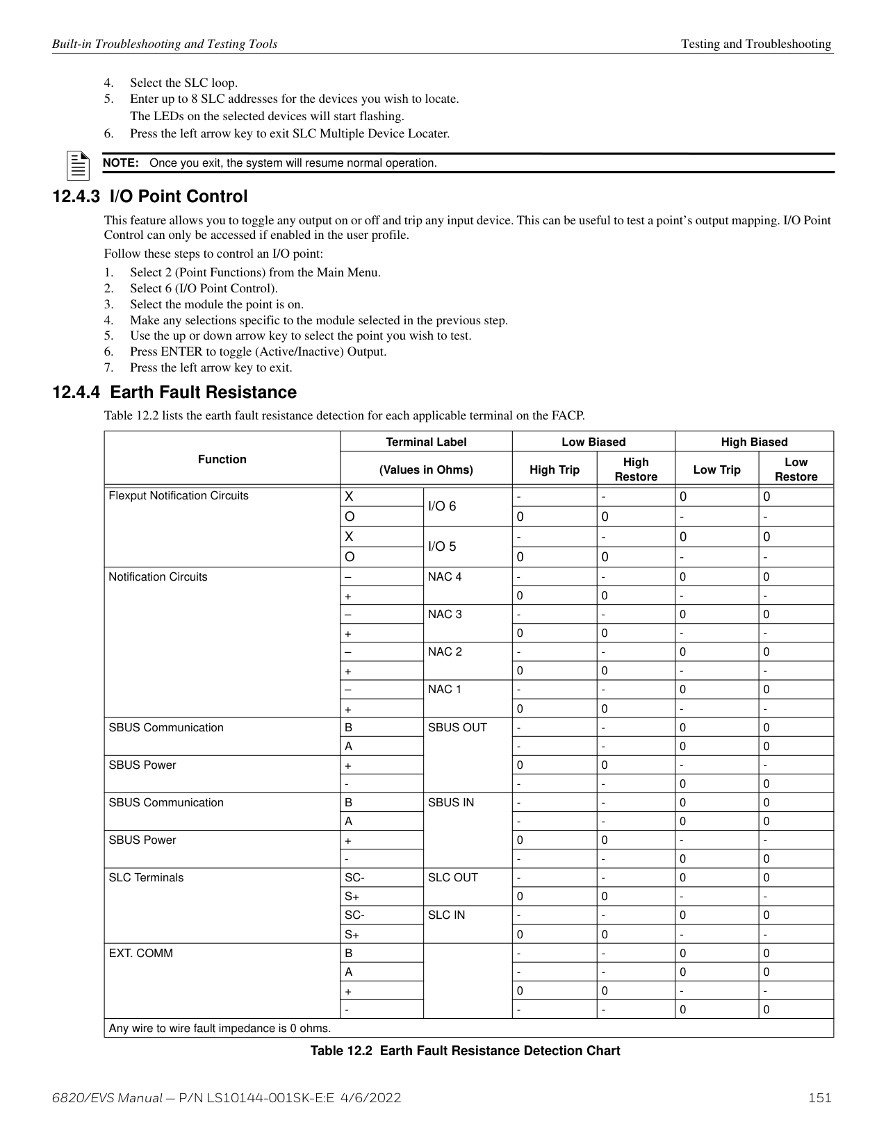
|Walk test end| |TE|0|TENN000000|3|607|00|000| |Zone Events|Zone events are reported only when “Report by Zone” is selected|Zone events are reported only when “Report by Zone” is selected|Zone events are reported only when “Report by Zone” is selected|Zone events are reported only when “Report by Zone” is selected|Zone events are reported only when “Report by Zone” is selected|Zone events are reported only when “Report by Zone” is selected|Zone events are reported only when “Report by Zone” is selected|Zone events are reported only when “Report by Zone” is selected| |Auxiliary power trouble| |FT|0000|FTNN000000|1|320|00|000| |Auxiliary power trouble restore| |FJ|0000|FJNN000000|3|320|00|000| |CO Detector Alarm| |GA|Zone #|GANN000ZZZ|1|162|00|Zone #| |CO Detector Alarm Restore| |GH|Zone #|GHNN000ZZZ|3|162|00|Zone #| |CO Detector Supervisory Alarm| |GS|Zone #|GSNN000ZZZ|1|200|00|Zone #| |CO Detector Supervisory Alarm Restore| |GR|Zone #|GRNN000ZZZ|3|200|00|Zone #| |CO Detector Trouble| |GT|Zone #|GTNN000ZZZ|1|373|00|Zone #| |CO Detector Trouble Restore| |GJ|Zone #|GJNN000ZZZ|3|373|00|Zone #| |Detector Alarm| |FA|Zone #|FANN000ZZZ|1|110|00|Zone #| |Detector Alarm Restore| |FH|Zone #|FHNN000ZZZ|3|110|00|Zone #| |Detector trouble| |FT|Zone #|FTNN000ZZZ|1|373|00|Zone #| |Detector trouble restore| |FJ|Zone #|FJNN000ZZZ|3|373|00|Zone #| |EVS Switch Trouble| |QT|0|QTNN000000|1|242|00|000| |EVS Switch Trouble Restore| |QJ|0|QJNN000000|3|242|00|000| |EVS Supervisory/Tamper Alarm| |QS|0|QSNN000000|1|241|00|000| |EVS Supervisory/Tamper Alarm Restore| |QR|0|QRNN000000|3|241|00|000| |EVS Output Group Trouble| |QT|Group # +1000|QTNN001GGG|1|320|00|Group #| |EVS Output Group Trouble Restore| |QJ|Group # +1000|QJNN001GGG|3|320|00|Group #| |External Reset/Silence/Fire Drill switch trouble| |UT|0000|UTNN000000|1|373|00|000| |External Reset/Silence/Fire Drill switch trouble restore| |UJ|0000|UJNN000000|3|373|00|000| |LOC Mic Activated EVS Alarm| |QA|0|QANN000000|1|220|00|000|
| |SIA Reporting Format|SIA Reporting Format|SIA Reporting Format|SIA Reporting Format|Contact ID Reporting Format|Contact ID Reporting Format|Contact ID Reporting Format|Contact ID Reporting Format| |---|---|---|---|---|---|---|---|---| | |SIA pi Modifier|SIA pi Modifier|SIA pi Modifier|SIA|Contact ID Reporting Format|Contact ID Reporting Format|Contact ID Reporting Format|Contact ID Reporting Format| |Event Description|Module ID # (If Any)|SIA Event Codes|Parameter|Fixed Length Format NN panel ID XX- SBUS ID ZZZ- Zone # PPPP- Point # GGG- Group # E- Emergency # RRRR-Receiver #|Qualifier|Event Code|Group #|Contact #| |LOC Mic Activated EVS Alarm Restore| |QH|0|QHNN000000|3|220|00|000| |LOC/Point EVS # Alarm| |QA|Emergency #|QANN0E0000|1|220 + Emerge ncy #|00|000| |LOC/Point EVS # Alarm Restore| |QH|Emergency #|QHNN0E0000|3|220 + Emerge ncy #|00|000| |Manual pull switch alarm| |FA|Zone #|FANN000ZZZ|1|115|00|Zone #| |Manual pull switch alarm restore| |FH|Zone #|FHNN000ZZZ|3|115|00|Zone #| |Manual pull switch trouble| |FT|Zone #|FTNN000ZZZ|1|373|00|Zone #| |Manual pull switch trouble restore| |FJ|Zone #|FJNN000ZZZ|3|373|00|Zone #| |Notification output trouble| |FT|Group # + 1000|FTNN001GGG|1|320|00|Group #| |Notification output trouble restore| |FJ|Group # + 1000|FJNN001GGG|3|320|00|Group #| |Positive Alarm Sequence acknowledge switch trouble| |FT|Zone #|FTNN000ZZZ|1|373|00|Zone #| |Positive Alarm Sequence acknowledge switch trouble restore| |FJ|Zone #|FJNN000ZZZ|3|373|00|Zone #| |SLC LED Module trouble| |ET|0000|ETNN000000|1|333|00|000| |SLC LED Module trouble restore| |ER|0000|ERNN000000|3|333|00|000| |Status Point Types Trouble| |UT|0|UTNN000000|1|379|00|000| |Status Point Types Trouble Restore| |UJ|0|UJNN000000|3|379|00|000| |Supervisory Detector Alarm| |FS|Zone #|FSNN000ZZZ|1|200|00|Zone #| |Supervisory Detector Alarm Restore| |FR|Zone #|FRNN000ZZZ|3|200|00|Zone #| |Supervisory/Tamper Alarm| |FS|Zone #|FSNN000ZZZ|1|200|00|Zone #| |Supervisory/Tamper alarm condition restore| |FR|Zone #|FRNN000ZZZ|3|200|00|Zone #| |Supervisory/Tamper switch trouble| |FT|Zone #|FTNN000ZZZ|1|373|00|Zone #| |Supervisory/Tamper switch trouble restore| |FJ|Zone #|FJNN000ZZZ|3|373|00|Zone #| |System-based AUX1 switch alarm| |UA|1000|UANN001000|1|140|01|000| |System-based AUX1 switch alarm restore| |UH|1000|UHNN001000|3|140|01|000| |System-based AUX1 switch trouble| |UT|1000|UTNN001000|1|373|01|000| |System-based AUX1 switch trouble restore| |UJ|1000|UJNN001000|3|373|01|000| |System-based AUX2 switch alarm| |UA|2000|UANN002000|1|140|02|000| |System-based AUX2 switch alarm restore| |UH|2000|UHNN002000|3|140|02|000| |System-based AUX2 switch trouble| |UT|2000|UTNN002000|1|373|02|000|

|System-based AUX2 switch trouble restore| |UJ|2000|UJNN002000|3|373|02|000| |Voice Aux EVS 1 Alarm| |UA|3|UANN003000|1|171|00|000| |Voice Aux EVS 1 Alarm Restore| |UH|3|UHNN003000|3|171|00|000| |Voice Aux EVS 2 Alarm| |UA|4|UANN004000|1|172|00|000| |Voice Aux EVS 2 Alarm Restore| |UH|4|UHNN004000|3|172|00|000| |Voice Aux EVS 3 Alarm| |UA|5|UANN005000|1|173|00|000| |Voice Aux EVS 3 Alarm Restore| |UH|5|UHNN005000|3|173|00|000| |Voice Aux EVS 4 Alarm| |UA|6|UANN006000|1|174|00|000| |Voice Aux EVS 4 Alarm Restore| |UH|6|UHNN006000|3|174|00|000|
| |SIA Reporting Format|SIA Reporting Format|SIA Reporting Format|SIA Reporting Format|Contact ID Reporting Format|Contact ID Reporting Format|Contact ID Reporting Format|Contact ID Reporting Format| |---|---|---|---|---|---|---|---|---| | |SIA pi Modifier|SIA pi Modifier|SIA pi Modifier|SIA|Contact ID Reporting Format|Contact ID Reporting Format|Contact ID Reporting Format|Contact ID Reporting Format| |Event Description|Module ID # (If Any)|SIA Event Codes|Parameter|Fixed Length Format NN panel ID XX- SBUS ID ZZZ- Zone # PPPP- Point # GGG- Group # E- Emergency # RRRR-Receiver #|Qualifier|Event Code|Group #|Contact #| |Water flow switch alarm| |SA|Zone #|SANN000ZZZ|1|113|00|Zone #| |Water flow switch alarm Restore| |SH|Zone #|SHNN000ZZZ|3|113|00|Zone #| |Water flow switch trouble| |ST|Zone #|STNN000ZZZ|1|373|00|Zone #| |Water flow switch trouble Restore| |SJ|Zone #|SJNN000ZZZ|3|373|00|Zone #| |Zone-based AUX1 switch alarm| |UA|Zone # + 1000|UANN001ZZZ|1|140|01|Zone #| |Zone-based AUX1 switch alarm restore| |UH|Zone # + 1000|UHNN001ZZZ|3|140|01|Zone #| |Zone-based AUX1 switch trouble| |UT|Zone # + 1000|UTNN001ZZZ|1|373|01|Zone #| |Zone-based AUX1 switch trouble restore| |UJ|Zone # + 1000|UJNN001ZZZ|3|373|01|Zone #| |Zone-based AUX2 switch alarm| |UA|Zone # + 2000|UANN002ZZZ|1|140|02|Zone #| |Zone-based AUX2 switch alarm restore| |UH|Zone # + 2000|UHNN002ZZZ|3|140|02|Zone #| |Zone-based AUX2 switch trouble| |UT|Zone # + 2000|UTNN002ZZZ|1|373|02|Zone #| |Zone-based AUX2 switch trouble restore| |UJ|Zone # + 2000|UJNN002ZZZ|3|373|02|Zone #| |Point Events|For SK devices, sensors 1–159 are reported as Points 1–159, modules 1–159 are reported as Points 201–359.|For SK devices, sensors 1–159 are reported as Points 1–159, modules 1–159 are reported as Points 201–359.|For SK devices, sensors 1–159 are reported as Points 1–159, modules 1–159 are reported as Points 201–359.|For SK devices, sensors 1–159 are reported as Points 1–159, modules 1–159 are reported as Points 201–359.|For SK devices, sensors 1–159 are reported as Points 1–159, modules 1–159 are reported as Points 201–359.|For SK devices, sensors 1–159 are reported as Points 1–159, modules 1–159 are reported as Points 201–359.|For SK devices, sensors 1–159 are reported as Points 1–159, modules 1–159 are reported as Points 201–359.|For SK devices, sensors 1–159 are reported as Points 1–159, modules 1–159 are reported as Points 201–359.| |An unexpected SLC device has been detected|pi Exp. ID|XE|Point #|XENNXXPPPP|1|380|Exp. ID|Point #| |An unexpected SLC device has been removed|pi Exp. ID|XI|Point #|XINNXXPPPP|3|380|Exp. ID|Point #| |Auxiliary power disabled|pi Exp. ID|FB|Point #|FBNNXXPPPP|1|571|Exp. ID|Point #| |Auxiliary power enabled|pi Exp. ID|FU|Point #|FUNNXXPPPP|3|571|Exp. ID|Point #| |Auxiliary power Trouble|pi Exp. ID|FT|Point #|FTNNXXPPPP|1|320|Exp. ID|Point #| |Auxiliary power trouble restore|pi Exp. ID|FJ|Point #|FJNNXXPPPP|3|320|Exp. ID|Point #| |Background Music Switch is Trouble|pi Exp. ID|UT|Point #|UTNNXXPPPP|1|379|Exp. ID|Point #| |Background Music Switch is Trouble Restored|pi Exp. ID|UJ|Point #|UJNNXXPPPP|3|379|Exp. ID|Point #| |Background Music Switch is Disabled|pi Exp. ID|UB|Point #|UBNNXXPPPP|1|580|Exp. ID|Point #| |Background Music Switch is Enabled|pi Exp. ID|UU|Point #|UUNNXXPPPP|3|580|Exp. ID|Point #| |CO Detector Trouble|pi Exp. ID|GT|Point #|GTNNXXPPPP|1|373|Exp. ID|Point #| |CO Detector Trouble Restore|pi Exp. ID|GJ|Point #|GJNNXXPPPP|3|373|Exp. ID|Point #| |CO Detector Disabled|pi Exp. ID|GB|Point #|GBNNXXPPPP|1|571|Exp. ID|Point #| |CO Detector Enabled|pi Exp. ID|GU|Point #|GUNNXXPPPP|3|571|Exp. ID|Point #| |Detector Alarm|pi Exp. ID|FA|Point #|FANNXXPPPP|1|110|Exp. ID|Point #| |Detector Alarm restore|pi Exp. ID|FH|Point #|FHNNXXPPPP|3|110|Exp. ID|Point #| |Detector Disabled|pi Exp. ID|FB|Point #|FBNNXXPPPP|1|571|Exp. ID|Point #| |Detector Enabled|pi Exp. ID|FU|Point #|FUNNXXPPPP|3|571|Exp. ID|Point #| |Detector Trouble|pi Exp. ID|FT|Point #|FTNNXXPPPP|1|373|Exp. ID|Point #| |Detector Trouble restore|pi Exp. ID|FJ|Point #|FJNNXXPPPP|3|373|Exp. ID|Point #| |Detector CO Alarm|pi Exp. ID|GA|Point #|GANNXXPPPP|1|162|Exp. ID|Point #| |Detector CO Alarm Restore|pi Exp. ID|GH|Point #|GHNNXXPPPP|3|162|Exp. ID|Point #| |Detector CO Supervisory Alarm|pi Exp. ID|GS|Point #|GSNNXXPPPP|1|200|Exp. ID|Point #| |Detector CO Supervisory Alarm Restore|pi Exp. ID|GR|Point #|GRNNXXPPPP|3|200|Exp. ID|Point #|
| |SIA Reporting Format|SIA Reporting Format|SIA Reporting Format|SIA Reporting Format|Contact ID Reporting Format|Contact ID Reporting Format|Contact ID Reporting Format|Contact ID Reporting Format| |---|---|---|---|---|---|---|---|---| | |SIA pi Modifier|SIA pi Modifier|SIA pi Modifier|SIA|Contact ID Reporting Format|Contact ID Reporting Format|Contact ID Reporting Format|Contact ID Reporting Format|
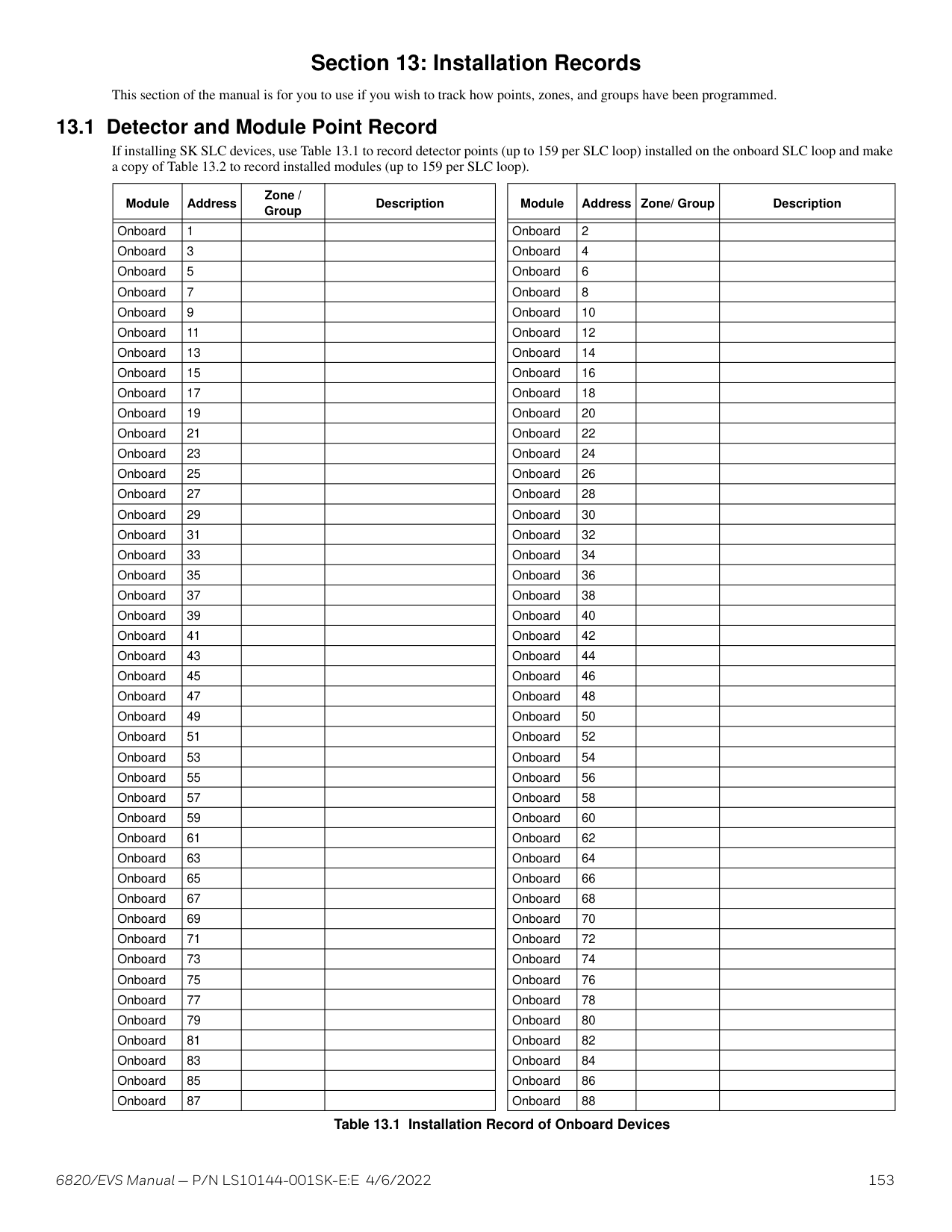
|Event Description|Module ID # (If Any)|SIA Event Codes|Parameter|Fixed Length Format NN panel ID XX- SBUS ID ZZZ- Zone # PPPP- Point # GGG- Group # E- Emergency # RRRR-Receiver #|Qualifier|Event Code|Group #|Contact #| |EVS Alarm # Point Alarm|pi Exp. ID|QA|(EPPP) E Emergency # PPP - Point #|QANNXXEPPP|1|220 + Emerge ncy #|Exp. ID|Point #| |EVS Alarm # Point Alarm Restore|pi Exp. ID|QH|(EPPP) E Emergency # PPP - Point #|QHNNXXEPPP|3|220 + Emerge ncy #|Exp. ID|Point #| |EVS Alarm # Point Trouble|pi Exp. ID|QT|Point #|QTNNXXPPPP|1|242|Exp. ID|Point #| |EVS Alarm # Point Trouble Restore|pi Exp. ID|QJ|Point #|QJNNXXPPPP|3|242|Exp. ID|Point #| |EVS Alarm # Point Disabled|pi Exp. ID|QB|Point #|QBNNXXPPPP|1|243|Exp. ID|Point #| |EVS Alarm # Point Enabled|pi Exp. ID|QU|Point #|QUNNXXPPPP|3|243|Exp. ID|Point #| |EVS Supervisory/Tamper Alarm|pi Exp. ID|QS|Point #|QSNNXXPPPP|1|241|Exp. ID|Point #| |EVS Supervisory/Tamper Alarm Restore|pi Exp. ID|QR|Point #|QRNNXXPPPP|3|241|Exp. ID|Point #| |EVS Supervisory/Tamper Trouble|pi Exp. ID|QT|Point #|QTNNXXPPPP|1|242|Exp. ID|Point #| |EVS Supervisory/Tamper Trouble Restore|pi Exp. ID|QJ|Point #|QJNNXXPPPP|3|242|Exp. ID|Point #| |EVS Supervisory/Tamper Disabled|pi Exp. ID|QB|Point #|QBNNXXPPPP|1|243|Exp. ID|Point #| |EVS Supervisory/Tamper Enabled|pi Exp. ID|QU|Point #|QUNNXXPPPP|3|243|Exp. ID|Point #| |EVS NAC Trouble|pi Exp. ID|QT|Point #|QTNNXXPPPP|1|320|Exp. ID|Point #| |EVS NAC Trouble Restored|pi Exp. ID|QJ|Point #|QJNNXXPPPP|3|320|Exp. ID|Point #| |EVS Control Circuit Trouble|pi Exp. ID|QT|Point #|QTNNXXPPPP|1|320|Exp. ID|Point #| |EVS Control Circuit Trouble Restored|pi Exp. ID|QJ|Point #|QJNNXXPPPP|3|320|Exp. ID|Point #| |EVS Relay Trouble|pi Exp. ID|QT|Point #|QTNNXXPPPP|1|320|Exp. ID|Point #| |EVS Relay Trouble Restored|pi Exp. ID|QJ|Point #|QJNNXXPPPP|3|320|Exp. ID|Point #| |EVS Notification Trouble|pi Exp. ID|QT|Point #|QTNNXXPPPP|1|320|Exp. ID|Point #| |EVS Notification Trouble Restored|pi Exp. ID|QJ|Point #|QJNNXXPPPP|3|320|Exp. ID|Point #| |External Reset/Silence/Fire Drill switch disabled|pi Exp. ID|UB|Point #|UBNNXXPPPP|1|571|Exp. ID|Point #| |External Reset/Silence/Fire Drill switch enabled|pi Exp. ID|UU|Point #|UUNNXXPPPP|3|571|Exp. ID|Point #| |External Reset/Silence/Fire Drill switch trouble|pi Exp. ID|UT|Point #|UTNNXXPPPP|1|373|Exp. ID|Point #| |External Reset/Silence/Fire Drill switch trouble restore|pi Exp. ID|UJ|Point #|UJNNXXPPPP|3|373|Exp. ID|Point #| |Interlock switch alarm (Water Release Zone)|pi Exp. ID|FA|Point #|FANNXXPPPP|1|110|Exp. ID|Point #| |Interlock switch alarm restore (Water Release Zone)|pi Exp. ID|FH|Point #|FHNNXXPPPP|3|110|Exp. ID|Point #| |Interlock switch disabled|pi Exp. ID|FB|Point #|FBNNXXPPPP|1|571|Exp. ID|Point #| |Interlock switch enabled|pi Exp. ID|FU|Point #|FUNNXXPPPP|3|571|Exp. ID|Point #| |Interlock switch trouble (Water Release Zone)|pi Exp. ID|FT|Point #|FTNNXXPPPP|1|373|Exp. ID|Point #| |Interlock switch trouble restore (Water Release Zone)|pi Exp. ID|FJ|Point #|FJNNXXPPPP|3|373|Exp. ID|Point #| |LOC Mic Activated EVS Alarm|pi Exp. ID|QA|0|QANNXX0000|1|220|Exp. ID|000| |LOC Mic Activated EVS Alarm Restore|pi Exp. ID|QH|0|QHNNXX0000|3|220|Exp. ID|000|
| |SIA Reporting Format|SIA Reporting Format|SIA Reporting Format|SIA Reporting Format|Contact ID Reporting Format|Contact ID Reporting Format|Contact ID Reporting Format|Contact ID Reporting Format| |---|---|---|---|---|---|---|---|---| | |SIA pi Modifier|SIA pi Modifier|SIA pi Modifier|SIA|Contact ID Reporting Format|Contact ID Reporting Format|Contact ID Reporting Format|Contact ID Reporting Format| |Event Description|Module ID # (If Any)|SIA Event Codes|Parameter|Fixed Length Format NN panel ID XX- SBUS ID ZZZ- Zone # PPPP- Point # GGG- Group # E- Emergency # RRRR-Receiver #|Qualifier|Event Code|Group #|Contact #| |LOC EVS # Alarm|pi Exp. ID|QA|Emergency #|QANNXXE000|1|220 + Emerge ncy #|Exp. ID|000| |LOC EVS # Alarm Restore|pi Exp. ID|QH|Emergency #|QHNNXXE000|3|220 + Emerge ncy #|Exp. ID|000| |Manual pull switch alarm|pi Exp. ID|FA|Point #|FANNXXPPPP|1|115|Exp. ID|Point #| |Manual pull switch alarm restore|pi Exp. ID|FH|Point #|FHNNXXPPPP|3|115|Exp. ID|Point #| |Manual pull switch disabled|pi Exp. ID|FB|Point #|FBNNXXPPPP|1|571|Exp. ID|Point #| |Manual pull switch enabled|pi Exp. ID|FU|Point #|FUNNXXPPPP|3|571|Exp. ID|Point #| |Manual pull switch trouble|pi Exp. ID|FT|Point #|FTNNXXPPPP|1|373|Exp. ID|Point #| |Manual pull switch trouble restore|pi Exp. ID|FJ|Point #|FJNNXXPPPP|3|373|Exp. ID|Point #| |Manual release switch alarm (Water Release Zone)|pi Exp. ID|FA|Point #|FANNXXPPPP|1|110|Exp. ID|Point #| |Manual release switch alarm restore (Water Release Zone)|pi Exp. ID|FH|Point #|FHNNXXPPPP|3|110|Exp. ID|Point #| |Manual release switch disabled|pi Exp. ID|FB|Point #|FBNNXXPPPP|1|571|Exp. ID|Point #| |Manual release switch enabled|pi Exp. ID|FU|Point #|FUNNXXPPPP|3|571|Exp. ID|Point #| |Manual release switch trouble (Water Release Zone)|pi Exp. ID|FT|Point #|FTNNXXPPPP|1|373|Exp. ID|Point #| |Manual release switch trouble restore (Water Release Zone)|pi Exp. ID|FJ|Point #|FJNNXXPPPP|3|373|Exp. ID|Point #| |Notification output point disabled|pi Exp. ID|FB|Point #|FBNNXXPPPP|1|571|Exp. ID|Point #| |Notification output point enabled|pi Exp. ID|FU|Point #|FUNNXXPPPP|3|571|Exp. ID|Point #| |Notification output point trouble|pi Exp. ID|FT|Point #|FTNNXXPPPP|1|320|Exp. ID|Point #| |Notification output point trouble restore|pi Exp. ID|FJ|Point #|FJNNXXPPPP|3|320|Exp. ID|Point #|
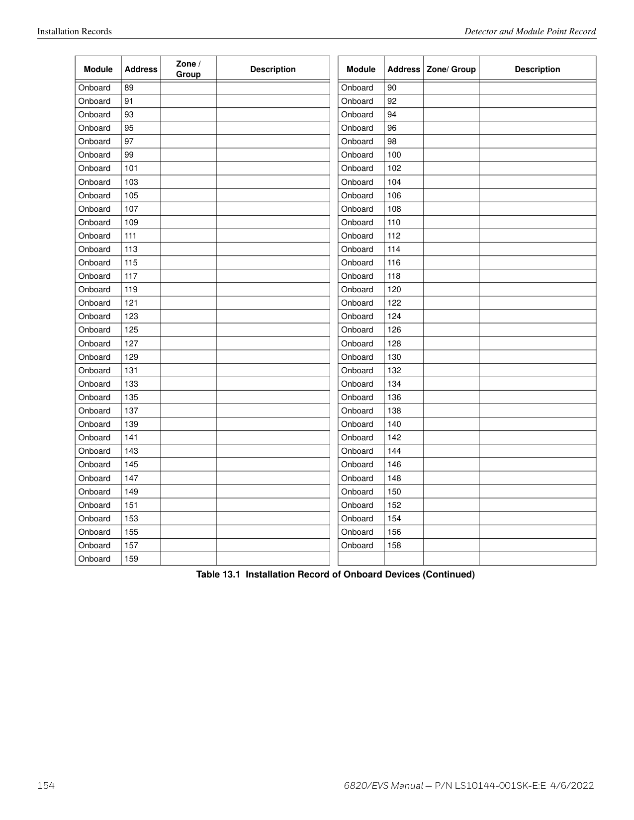
|Positive Alarm Sequence acknowledge switch disabled|pi Exp. ID|FB|Point #|FBNNXXPPPP|1|571|Exp. ID|Point #| |Positive Alarm Sequence acknowledge switch enabled|pi Exp. ID|FU|Point #|FUNNXXPPPP|3|571|Exp. ID|Point #| |Positive Alarm Sequence acknowledge switch trouble|pi Exp. ID|FT|Point #|FTNNXXPPPP|1|373|Exp. ID|Point #| |Positive Alarm Sequence acknowledge switch trouble restore|pi Exp. ID|FJ|Point #|FJNNXXPPPP|3|373|Exp. ID|Point #| |Status Point Trouble|pi Exp. ID|UT|Point #|UTNNXXPPPP|1|379|Exp. ID|Point #| |Status Point Trouble Restored|pi Exp. ID|UJ|Point #|UJNNXXPPPP|3|379|Exp. ID|Point #| |Status Point is Disabled|pi Exp. ID|UB|Point #|UBNNXXPPPP|1|580|Exp. ID|Point #| |Status Point is Enabled|pi Exp. ID|UU|Point #|UUNNXXPPPP|3|580|Exp. ID|Point #| |Supervisory/Tamper Alarm|pi Exp. ID|FS|Point #|FSNNXXPPPP|1|200|Exp. ID|Point #| |Supervisory/Tamper Alarm Restore|pi Exp. ID|FR|Point #|FRNNXXPPPP|3|200|Exp. ID|Point #| |Supervisory/Tamper point disabled|pi Exp. ID|FB|Point #|FBNNXXPPPP|1|571|Exp. ID|Point #| |Supervisory/Tamper point enabled|pi Exp. ID|FU|Point #|FUNNXXPPPP|3|571|Exp. ID|Point #| |Supervisory/Tamper point trouble|pi Exp. ID|FT|Point #|FTNNXXPPPP|1|373|Exp. ID|Point #| |Supervisory/Tamper point trouble restore|pi Exp. ID|FJ|Point #|FJNNXXPPPP|3|373|Exp. ID|Point #|
| |SIA Reporting Format|SIA Reporting Format|SIA Reporting Format|SIA Reporting Format|Contact ID Reporting Format|Contact ID Reporting Format|Contact ID Reporting Format|Contact ID Reporting Format| |---|---|---|---|---|---|---|---|---| | |SIA pi Modifier|SIA pi Modifier|SIA pi Modifier|SIA|Contact ID Reporting Format|Contact ID Reporting Format|Contact ID Reporting Format|Contact ID Reporting Format| |Event Description|Module ID # (If Any)|SIA Event Codes|Parameter|Fixed Length Format NN panel ID XX- SBUS ID ZZZ- Zone # PPPP- Point # GGG- Group # E- Emergency # RRRR-Receiver #|Qualifier|Event Code|Group #|Contact #| |System-based AUX1 switch alarm|pi Exp. ID|UA|Point #|UANNXXPPPP|1|140|Exp. ID|Point #| |System-based AUX1 switch alarm restore|pi Exp. ID|UH|Point #|UHNNXXPPPP|3|140|Exp. ID|Point #| |System-based AUX1 switch disabled|pi Exp. ID|UB|Point #|UBNNXXPPPP|1|571|Exp. ID|Point #| |System-based AUX1 switch enabled|pi Exp. ID|UU|Point #|UUNNXXPPPP|3|571|Exp. ID|Point #| |System-based AUX1 switch trouble|pi Exp. ID|UT|Point #|UTNNXXPPPP|1|373|Exp. ID|Point #| |System-based AUX1 switch trouble restore|pi Exp. ID|UJ|Point #|UJNNXXPPPP|3|373|Exp. ID|Point #| |System-based AUX2 switch alarm|pi Exp. ID|UA|Point #|UANNXXPPPP|1|140|Exp. ID|Point #| |System-based AUX2 switch alarm restore|pi Exp. ID|UH|Point #|UHNNXXPPPP|3|140|Exp. ID|Point #| |System-based AUX2 switch disabled|pi Exp. ID|UB|Point #|UBNNXXPPPP|1|571|Exp. ID|Point #| |System-based AUX2 switch enabled|pi Exp. ID|UU|Point #|UUNNXXPPPP|3|571|Exp. ID|Point #| |System-based AUX2 switch trouble|pi Exp. ID|UT|Point #|UTNNXXPPPP|1|373|Exp. ID|Point #| |System-based AUX2 switch trouble restore|pi Exp. ID|UJ|Point #|UJNNXXPPPP|3|373|Exp. ID|Point #| |Voice Aux EVS 1 Point Alarm|pi Exp. ID|UA|(3PPP) PPP - Point #|UANNXX3PPP|1|171|Exp. ID|Point #| |Voice Aux EVS 1 Point Alarm Restore|pi Exp. ID|UH|(3PPP) PPP - Point #|UHNNXX3PPP|3|171|Exp. ID|Point #| |Voice Aux EVS 2 Point Alarm|pi Exp. ID|UA|(4PPP) PPP - Point #|UANNXX4PPP|1|172|Exp. ID|Point #| |Voice Aux EVS 2 Point Alarm Restore|pi Exp. ID|UH|(4PPP) PPP - Point #|UHNNXX4PPP|3|172|Exp. ID|Point #| |Voice Aux EVS 3 Point Alarm|pi Exp. ID|UA|(5PPP) PPP - Point #|UANNXX5PPP|1|173|Exp. ID|Point #| |Voice Aux EVS 3 Point Alarm Restore|pi Exp. ID|UH|(5PPP) PPP - Point #|UHNNXX5PPP|3|173|Exp. ID|Point #| |Voice Aux EVS 4 Point Alarm|pi Exp. ID|UA|(6PPP) PPP - Point #|UANNXX6PPP|1|174|Exp. ID|Point #| |Voice Aux EVS 4 Point Alarm Restore|pi Exp. ID|UH|(6PPP) PPP - Point #|UHNNXX6PPP|3|174|Exp. ID|Point #| |Voice Aux EVS Point Trouble|pi Exp. ID|UT|Point #|UTNNXXPPPP|1|379|Exp. ID|Point #| |Voice Aux EVS Point Trouble Restore|pi Exp. ID|UJ|Point #|UJNNXXPPPP|3|379|Exp. ID|Point #| |Voice Aux EVS Point Disabled|pi Exp. ID|UB|Point #|UBNNXXPPPP|1|580|Exp. ID|Point #| |Voice Aux EVS Point Enabled|pi Exp. ID|UU|Point #|UUNNXXPPPP|3|580|Exp. ID|Point #| |Voice Aux Status 1 Switch is Trouble|pi Exp. ID|UT|Point #|UTNNXXPPPP|1|379|Exp. ID|Point #| |Voice Aux Status 1 Switch is Trouble Restored|pi Exp. ID|UJ|Point #|UJNNXXPPPP|3|379|Exp. ID|Point #| |Voice Aux Status 1 Switch is Disabled|pi Exp. ID|UB|Point #|UBNXXPPPP|1|580|Exp. ID|Point #| |Voice Aux Status 1 Switch is Enabled|pi Exp. ID|UU|Point #|UUNXXPPPP|3|580|Exp. ID|Point #| |Voice Aux Status 2 Switch is Trouble|pi Exp. ID|UT|Point #|UTNNXXPPPP|1|379|Exp. ID|Point #| |Voice Aux Status 2 Switch is Trouble Restored|pi Exp. ID|UJ|Point #|UJNNXXPPPP|3|379|Exp. ID|Point #| |Voice Aux Status 2 Switch is Disabled|pi Exp. ID|UB|Point #|UBNNXXPPPP|1|580|Exp. ID|Point #| |Voice Aux Status 2 Switch is Enabled|pi Exp. ID|UU|Point #|UUNNXXPPPP|3|580|Exp. ID|Point #| |Water flow switch alarm|pi Exp. ID|SA|Point #|SANNXXPPPP|1|113|Exp. ID|Point #| |Water flow switch alarm restore|pi Exp. ID|SH|Point #|SHNNXXPPPP|3|113|Exp. ID|Point #|
| |SIA Reporting Format|SIA Reporting Format|SIA Reporting Format|SIA Reporting Format|Contact ID Reporting Format|Contact ID Reporting Format|Contact ID Reporting Format|Contact ID Reporting Format|

|---|---|---|---|---|---|---|---|---| | |SIA pi Modifier|SIA pi Modifier|SIA pi Modifier|SIA|Contact ID Reporting Format|Contact ID Reporting Format|Contact ID Reporting Format|Contact ID Reporting Format| |Event Description|Module ID # (If Any)|SIA Event Codes|Parameter|Fixed Length Format NN panel ID XX- SBUS ID ZZZ- Zone # PPPP- Point # GGG- Group # E- Emergency # RRRR-Receiver #|Qualifier|Event Code|Group #|Contact #| |Water flow switch disabled|pi Exp. ID|SB|Point #|SBNNXXPPPP|1|571|Exp. ID|Point #| |Water flow switch enabled|pi Exp. ID|SU|Point #|SUNNXXPPPP|3|571|Exp. ID|Point #| |Water flow switch trouble|pi Exp. ID|ST|Point #|STNNXXPPPP|1|373|Exp. ID|Point #| |Water flow switch trouble restore|pi Exp. ID|SJ|Point #|SJNNXXPPPP|3|373|Exp. ID|Point #| |Zone-based AUX1 switch alarm|pi Exp. ID|UA|Point #|UANNXXPPPP|1|140|Exp. ID|Point #| |Zone-based AUX1 switch alarm restore|pi Exp. ID|UH|Point #|UHNNXXPPPP|3|140|Exp. ID|Point #| |Zone-based AUX1 switch disabled|pi Exp. ID|UB|Point #|UBNNXXPPPP|1|571|Exp. ID|Point #| |Zone-based AUX1 switch enabled|pi Exp. ID|UU|Point #|UUNNXXPPPP|3|571|Exp. ID|Point #| |Zone-based AUX1 switch trouble|pi Exp. ID|UT|Point #|UTNNXXPPPP|1|373|Exp. ID|Point #| |Zone-based AUX1 switch trouble restore|pi Exp. ID|UJ|Point #|UJNNXXPPPP|3|373|Exp. ID|Point #| |Zone-based AUX2 switch alarm|pi Exp. ID|UA|Point #|UANNXXPPPP|1|140|Exp. ID|Point #| |Zone-based AUX2 switch alarm restore|pi Exp. ID|UH|Point #|UHNNXXPPPP|3|140|Exp. ID|Point #| |Zone-based AUX2 switch disabled|pi Exp. ID|UB|Point #|UBNNXXPPPP|1|571|Exp. ID|Point #| |Zone-based AUX2 switch enabled|pi Exp. ID|UU|Point #|UUNNXXPPPP|3|571|Exp. ID|Point #| |Zone-based AUX2 switch trouble|pi Exp. ID|UT|Point #|UTNNXXPPPP|1|373|Exp. ID|Point #| |Zone-based AUX2 switch trouble restore|pi Exp. ID|UJ|Point #|UJNNXXPPPP|3|373|Exp. ID|Point #| |System-based Wireless Gateway Trouble|pi Exp. ID|UT|Point #|UTNNXXPPPP|1|373|Exp. ID|Point #| |System-based Wireless Gateway Trouble restore|pi Exp. ID|UJ|Point #|UJNNXXPPPP|3|373|Exp. ID|Point #| |Wireless Gateway Trouble|pi Exp. ID|UT|Point #|UTNNXXPPPP|1|373|Exp. ID|Point #| |Wireless Gateway Trouble restore|pi Exp. ID|UJ|Point #|UJNNXXPPPP|3|373|Exp. ID|Point #|
############# Table 11.2 Reporting Formats Table (Continued)
SIA - Panel PI Modifier Reporting Reporting
EEZZZZ
Where: EE Event code (2 characters) ZZZZ Event parameter (up to four digits – not zero filled)
|Event|Report Zone/ Point|Panel ID|Module|Zone ZZZZ|Point ZZZZ|Fields Sent|SIA Event Data| |---|---|---|---|---|---|---|---| |Fire Alarm-Zone|Zone|n/a|n/a97|15|n/a|EE-ZZ|FA15| |Fire Alarm-Zone|Zone|n/a|n/a|05|n/a|EE-Z|FA5| |Fire Alarm-Point|Point|n/a|01|n/a|123|EE-ZZ /EE-ZZZ|pi01/FA123| |Fire Alarm-Point|Point|n/a|33|n/a|203|EE-ZZ /EE-ZZZ|pi11/FA203| |Expander Trouble|n/a|n/a|11|n/a|n/a|EE-ZZ|ET11| |Auto Test|n/a|n/a|n/a|n/a|n/a|EE-Z|RP0| |Battery Trouble-Panel 32|n/a|n/a|98|n/a|n/a|EE-ZZ|YT98| |Battery Trouble-Expander 18|n/a|n/a|18|n/a|n/a|EE-ZZ|YT18| |SLC Loop Shorted|n/a|n/a|44|n/a|n/a|EE-ZZ|ET44| |Program Begin Panel ID=32|n/a|n/a|n/a|n/a|n/a|EE-Z|LB0| |Program Begin Panel ID= 22|n/a|n/a|n/a|n/a|n/a|EE-Z|LB0| |AC Power Loss - Panel 22|n/a|n/a|98|n/a|n/a|EE-Z|AT0|
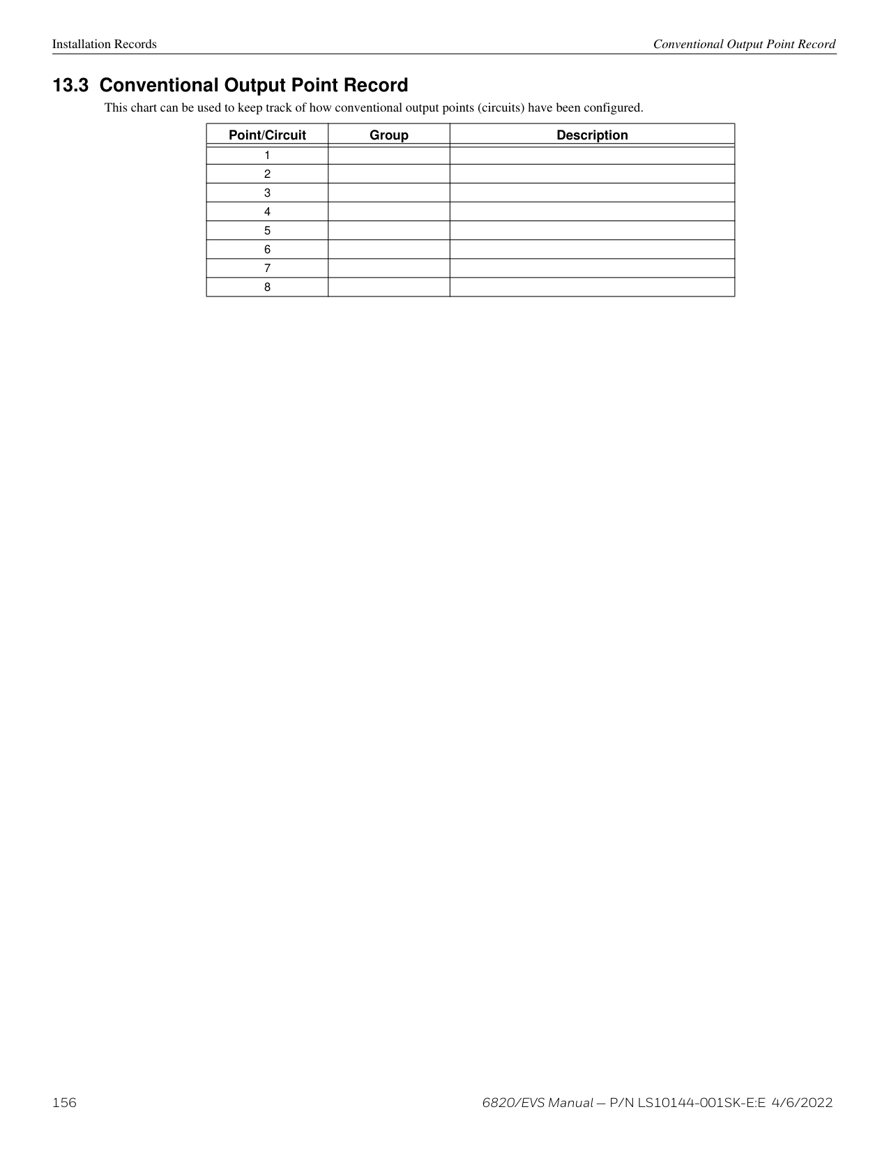
|Fire Trouble|Point|n/a|97|n/a|200|EE-ZZ /EE-ZZZ|pi97/FT200| |Fire Trouble|Zone|n/a|97|01|n/a|EE-Z|FT1| |Fire Trouble-Nac|Point|n/a|98|n/a|Nac Circuit 7|EE-ZZ /EE-Z|pi98/FT7 Z=Pt. #| |Fire Trouble-Nac|Zone|n/a|98|n/a|Nac Circuit 7|EE-ZZZ|FT400 ZZZ=OPG#|
############# Table 11.3 SIA- Panel - PI Modifier Reporting Examples
Reporting SIA – Panel Communicator
EEPPMMZZZZ
Where EE Event code (2 characters) PP Panel number (2 digits – Zero Filled) (valid range from 1 to 64) MM Module number (2 digits – Zero Filled) (valid range from 1 to 98, typically
Module information) ZZZZ Event parameter (4 digits – Zero Filled) (typically Point, Zone or Circuit information)
|Event|Report Zone/ Point|Panel ID PP|Module MM|Zone ZZZZ|Point ZZZZ|Fields Sent|SIA Event Data| |---|---|---|---|---|---|---|---| |Fire Alarm-Zone|Zone|32|n/a|15|n/a|EE-PP-MM-ZZZZ|FA32000015| |Fire Alarm-Zone|Zone|32|n/a|05|n/a|EE-PP-MM-ZZZZ|FA32000005| |Fire Alarm-Point|Point|32|01|n/a|123|EE-PP-MM-ZZZZ|FA32010123| |Fire Alarm-Point|Point|21|33|n/a|203|EE-PP-MM-ZZZZ|FA21330203| |Expander Trouble|n/a|15|11|n/a|n/a|EE-PP-MM-ZZZZ|ET15110000| |Auto Test|n/a|32|n/a|n/a|n/a|EE-PP-MM-ZZZZ|RP32000000| |Battery Trouble-Panel 32|n/a|32|98|n/a|n/a|EE-PP-MM-ZZZZ|YT32980000| |Battery Trouble-Expander 18|n/a|32|18|n/a|n/a|EE-PP-MM-ZZZZ|YT32180000| |SLC Loop Shorted|n/a|01|44|n/a|n/a|EE-PP-MM-ZZZZ|ET01440000| |Program Begin|n/a|32|n/a|n/a|n/a|EE-PP-MM-ZZZZ|LB32000000| |Program Begin|n/a|22|n/a|n/a|n/a|EE-PP-MM-ZZZZ|LB22000000| |AC Power Loss- Panel 22|n/a|22|98|n/a|n/a|EE-PP-MM-ZZZZ|AT22980000 MM = 00| |Fire Trouble|Point|22|97|n/a|200|EE-PP-MM-ZZZZ|FT22970200| |Fire Trouble|Zone|22|97|1|n/a|EE-PP-MM-ZZZZ|FT22970001 MM = 00| |Fire Trouble-NAC|Point|22|98|n/a|NAC Circuit 7|EE-PP-MM-ZZZZ|FT22980007 ZZZZ=Pt. #| |Fire Trouble-NAC|Zone|22|98|n/a|NAC Circuit 7|EE-PP-MM-ZZZZ|FT22980007 ZZZZ=OPG #|
############# Table 11.4 SIA Reporting Examples
##### Section 12: Testing and Troubleshooting
###### 12.1 Troubleshooting
This section of the manual offers suggestions for troubleshooting hardware problems. Please read this section if you encounter a problem when installing the control panel. If these suggestions do not solve your problem or if you encounter a problem that is not listed here, contact Silent Knight Technical Support at 800.446.6444 for assistance.
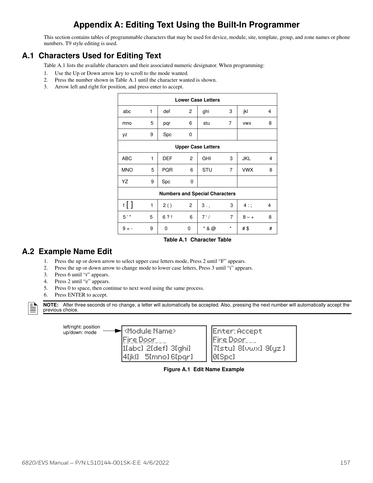
|Problem|Possible Cause / Suggested Actions| |---|---| | | | |Trouble message “DBL ADDR” (Double Address) displays on LCD.|An address has been assigned to more than one detector. Correct the address following the procedure described for SK and SD devices in the SLC Wiring Manual.| |Auxiliary power or notification circuits have incorrect polarity.|Correct polarity. For notification and auxiliary power circuits: When in alarm or powered, terminals labeled “X” are positive, terminals labeled “O” are negative.| |SLC devices are not being recognized (trouble message “Missing” displays).|Check hardware connections. If devices are physically connected, make sure wiring is correct. Refer to the SLC
Wiring Manual. For 6815 and 5815XL devices, make sure the device connects to the 6815 and 5815XL via the SLC OUT terminals. There can be only one SLC loop on the main panel and on each 6815 and 5815XL module. Do not connect devices to terminals labeled SLC IN.| |SLC devices are not being recognized (trouble message “Missing” displays).|Make sure SLC devices have been addressed properly. For information on device addressing, refer to the SLC Wiring Manual. For contact monitor modules, which are addressed using DIP switches, the DIP switch must be set to the correct address before power is applied to the SLC loop. If this procedure is not followed, the device will have an incorrect address.| |SLC devices are not being recognized (trouble message “Missing” displays).|Make sure correct polarity has been observed for SLC device wiring. For information on wiring, refer to the SLC Wiring Manual.| |SLC devices are not being recognized (trouble message “Missing” displays on the annunciator).|Check that SLC loop impedance is within the required range. To measure impedance, use the following procedure:
1. Disconnect both wires from the terminal block at the panel (SLC devices can remain connected).
2. Measure the impedance from positive to negative and from negative to positive. Both measurements should be greater than 500 k ohms. If the installation uses T-taps, test each T-tap individually.
3. Temporarily connect the positive wire to the negative wire of the SLC loop at the point farthest from the panel (SLC devices can remain connected).
4. Measure the impedance from positive to negative and from negative to positive wires that were disconnected from the panel in step 1. Both measurements must be less than 50 ohms.
| |The panel indicates a ground fault trouble condition (trouble message “GROUND FAULT” displays).|An earth ground fault occurs when the panel senses an unexpected flow of current from one or more of its terminals to the earth connection (Terminal 2). Isolate the wiring that is causing the fault by removing wiring connections one at a time until the earth fault is no longer present. Pause at least five seconds after removing a wire before removing the next one. The panel will also go into ground fault if a computer is connected to the panel via a serial cable attached to the panel’s 9-pin connector or a USB cable. This is a correct method for on-site communication between a panel and a computer. Ignore the ground fault message in this case. The trouble will clear automatically when you disconnect the computer from the cable.| |5496, 6815, or 5815XL module that has been physically connected to the panel but is not being recognized.|Check the status of the module’s green LED. If it flashes in the pattern half second on/ half second off, it is likely that the device has not been added to the system through programming. JumpStart will add any modules connected to the panel. If you have already run JumpStart, modules can be added manually. (Refer to Section 8.2.2). Check that the correct ID for the module has been set through the DIP switches. Assign ID#1 to the first module and ID#2 to the second. If the wiring between the device and the panel is correct, measure the voltage from the Terminal (+) to Terminal (-). Voltage should be in the range 27.2-27.4V when AC power is present. If the green LED is not flashing, the likely cause is incorrect wiring from between the device and the panel.|
############# Table 12.1 Troubleshooting
###### 12.2 Periodic Testing and Maintenance
To ensure proper and reliable operation, it is recommended that system inspection and testing be scheduled monthly or as required by national and/or local fire codes. Testing should be done by a qualified service representative if a malfunction is encountered.
############# Before Testing
Testing and Troubleshooting Event History
The fire control panel has several built-in testing and troubleshooting tools that can be utilized to save time while testing and troubleshooting points and SLC devices.

|System will be shut down during SLC device locating: Continue? NO| |---|
NOTE: Once you exit, the system will resume normal operation.
|System will be shut down during SLC device locating: Continue? NO| |---|
Built-in Troubleshooting and Testing Tools Testing and Troubleshooting
NOTE: Once you exit, the system will resume normal operation.
This feature allows you to toggle any output on or off and trip any input device. This can be useful to test a point’s output mapping. I/O Point Control can only be accessed if enabled in the user profile.
Follow these steps to control an I/O point:
|Function|Terminal Label|Terminal Label|Low Biased|Low Biased|High Biased|High Biased| |---|---|---|---|---|---|---|
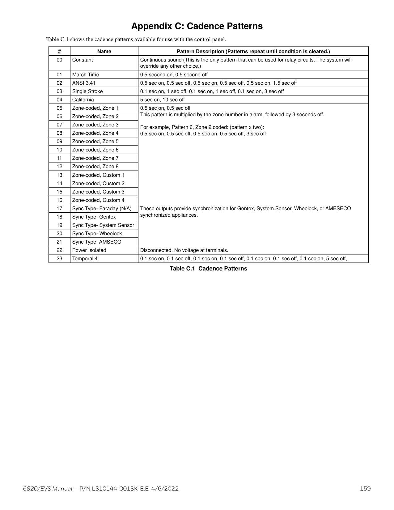
|Function|(Values in Ohms)|(Values in Ohms)|High Trip|High Restore|Low Trip|Low Restore| | | | | | | | | |Flexput Notification Circuits|X|I/O 6|-|-|0|0| |Flexput Notification Circuits|O|I/O 6|0|0|-| | |Flexput Notification Circuits|X|I/O 5|-|-|0|0| |Flexput Notification Circuits|O|I/O 5|0|0|-| | |Notification Circuits|–|NAC 4|-|-|0|0| |Notification Circuits|+|NAC 4|0|0| | | |Notification Circuits|–|NAC3|-| |0|0| |Notification Circuits|+|NAC3|0|0| | | |Notification Circuits|–|NAC2|-| |0|0| |Notification Circuits|+|NAC2|0|0| | | |Notification Circuits|–|NAC1|-| |0|0| |Notification Circuits|+|NAC1|0|0| | | |SBUS Communication|B|SBUS OUT|-|-|0|0| |SBUS Communication|A|SBUS OUT|-|-| | | |SBUS Power|+|SBUS OUT|0|0|-|-| |SBUS Power|-|SBUS OUT|-|-| | | |SBUS Communication|B|SBUS IN|-|-|0|0| |SBUS Communication|A|SBUS IN|-|-| | | |SBUS Power|+|SBUS IN|0|0|-|-| |SBUS Power|-|SBUS IN|-|-| | | |SLC Terminals|SC-|SLC OUT|-|-|0|0| |SLC Terminals|S+|SLC OUT|0|0|-|-| |SLC Terminals|SC-|SLC IN|-|-|0|0| |SLC Terminals|S+|SLC IN|0|0|-|-| |EXT. COMM|B| |-|-|0|0| |EXT. COMM|A| |-|-| | | |EXT. COMM|+| |0|0| | | |EXT. COMM|-| |-|-| | | |Any wire to wire fault impedance is 0 ohms.|Any wire to wire fault impedance is 0 ohms.|Any wire to wire fault impedance is 0 ohms.|Any wire to wire fault impedance is 0 ohms.|Any wire to wire fault impedance is 0 ohms.|Any wire to wire fault impedance is 0 ohms.|Any wire to wire fault impedance is 0 ohms.|
0
0
0
0
0 0
############# Table 12.2 Earth Fault Resistance Detection Chart

##### Notes
##### Section 13: Installation Records
This section of the manual is for you to use if you wish to track how points, zones, and groups have been programmed.
###### 13.1 Detector and Module Point Record
If installing SK SLC devices, use Table 13.1 to record detector points (up to 159 per SLC loop) installed on the onboard SLC loop and make a copy of Table 13.2 to record installed modules (up to 159 per SLC loop).
|Module|Address|Zone / Group| | |---|---|---|---| | | | | | |Onboard|1| | | |Onboard|3| | | |Onboard|5| | | |Onboard|7| | | |Onboard|9| | | |Onboard|11| | | |Onboard|13| | | |Onboard|15| | | |Onboard|17| | | |Onboard|19| | | |Onboard|21| | | |Onboard|23| | | |Onboard|25| | | |Onboard|27| | | |Onboard|29| | | |Onboard|31| | | |Onboard|33| | | |Onboard|35| | | |Onboard|37| | | |Onboard|39| | | |Onboard|41| | | |Onboard|43| | | |Onboard|45| | | |Onboard|47| | | |Onboard|49| | | |Onboard|51| | | |Onboard|53| | | |Onboard|55| | | |Onboard|57| | | |Onboard|59| | | |Onboard|61| | | |Onboard|63| | | |Onboard|65| | | |Onboard|67| | | |Onboard|69| | | |Onboard|71| | | |Onboard|73| | | |Onboard|75| | | |Onboard|77| | | |Onboard|79| | | |Onboard|81| | | |Onboard|83| | | |Onboard|85| | | |Onboard|87| | |
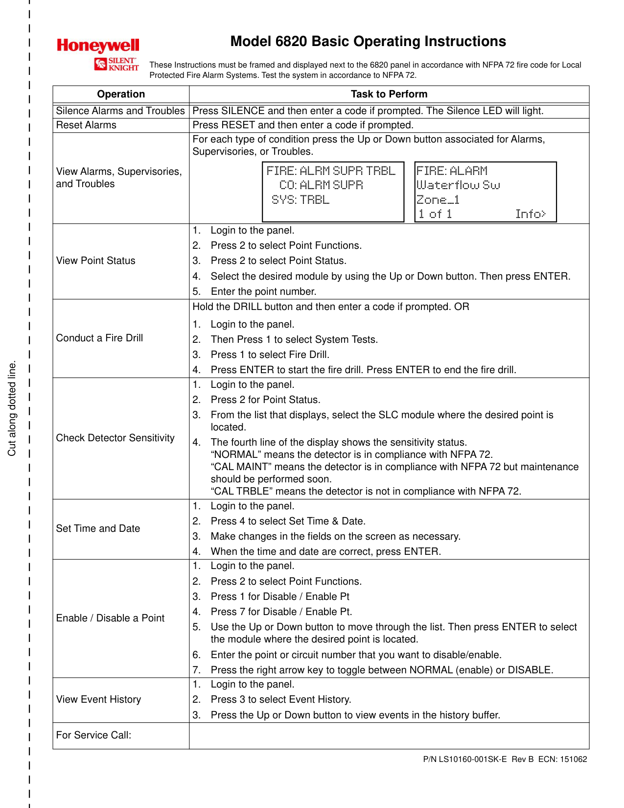
|Module|Address|Zone/ Group|Description| |---|---|---|---| | | | | | | | | | | |Onboard|4| | | |Onboard|6| | | |Onboard|8| | | |Onboard|10| | | |Onboard|12| | | |Onboard|14| | | |Onboard|16| | | |Onboard|18| | | |Onboard|20| | | |Onboard|22| | | |Onboard|24| | | |Onboard|26| | | |Onboard|28| | | |Onboard|30| | | |Onboard|32| | | |Onboard|34| | | |Onboard|36| | | |Onboard|38| | | |Onboard|40| | | |Onboard|42| | | |Onboard|44| | | |Onboard|46| | | |Onboard|48| | | |Onboard|50| | | |Onboard|52| | | |Onboard|54| | | |Onboard|56| | | |Onboard|58| | | |Onboard|60| | | |Onboard|62| | | |Onboard|64| | | |Onboard|66| | | |Onboard|68| | | |Onboard|70| | | |Onboard|72| | | |Onboard|74| | | |Onboard|76| | | |Onboard|78| | | |Onboard|80| | | |Onboard|82| | | |Onboard|84| | | |Onboard|86| | | |Onboard|88| | |
############# Table 13.1 Installation Record of Onboard Devices
Installation Records Detector and Module Point Record
|Module|Address|Zone / Group|Description| |---|---|---|---|

| | | | | |Onboard|89| | | |Onboard|91| | | |Onboard|93| | | |Onboard|95| | | |Onboard|97| | | |Onboard|99| | | |Onboard|101| | | |Onboard|103| | | |Onboard|105| | | |Onboard|107| | | |Onboard|109| | | |Onboard|111| | | |Onboard|113| | | |Onboard|115| | | |Onboard|117| | | |Onboard|119| | | |Onboard|121| | | |Onboard|123| | | |Onboard|125| | | |Onboard|127| | | |Onboard|129| | | |Onboard|131| | | |Onboard|133| | | |Onboard|135| | | |Onboard|137| | | |Onboard|139| | | |Onboard|141| | | |Onboard|143| | | |Onboard|145| | | |Onboard|147| | | |Onboard|149| | | |Onboard|151| | | |Onboard|153| | | |Onboard|155| | | |Onboard|157| | | |Onboard|159| | |
|Module|Address|Zone/ Group|Description| |---|---|---|---| | | | | | |Onboard|90| | | |Onboard|92| | | |Onboard|94| | | |Onboard|96| | | |Onboard|98| | | |Onboard|100| | | |Onboard|102| | | |Onboard|104| | | |Onboard|106| | | |Onboard|108| | | |Onboard|110| | | |Onboard|112| | | |Onboard|114| | | |Onboard|116| | | |Onboard|118| | |
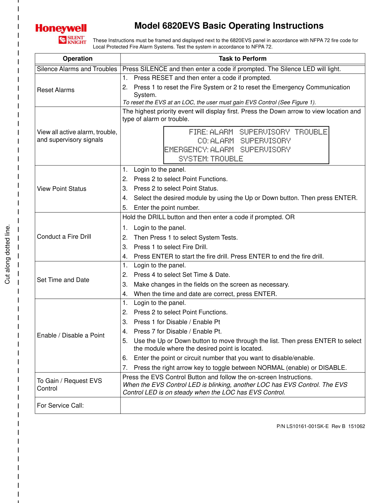
|Onboard|120| | | |Onboard|122| | | |Onboard|124| | | |Onboard|126| | | |Onboard|128| | | |Onboard|130| | | |Onboard|132| | | |Onboard|134| | | |Onboard|136| | | |Onboard|138| | | |Onboard|140| | | |Onboard|142| | | |Onboard|144| | | |Onboard|146| | | |Onboard|148| | | |Onboard|150| | | |Onboard|152| | | |Onboard|154| | | |Onboard|156| | | |Onboard|158| | | | | | | |
############# Table 13.1 Installation Record of Onboard Devices (Continued)
Additional SLC Devices Installation Records
###### 13.2 Additional SLC Devices
Use the table below to record devices installed on additional 6815/5815XL modules. Make a copy of this page if additional pages are needed.
|Module|Addr|Zone / Group|Description| |---|---|---|---| | | | | | | | | | | | | | | | | | | | | | | | | | | | | | | | | | | | | | | | | | | | | | | | | | | | | | | | | | | | | | | | | | | | | | | | | | | | | | | | | | | | | | | | | | | | | | | | | | | | | | | | | | | | | | | | | | | | | | | | |

| | | | | | | | | | | | | | | | | | | | | | | | | | | | | | | | | | | | | | | | | | | | | | | | | | | | | | | | | | | | | | | | | | | | | | | | | | | | | | | | | | | | | | | | | | | | | | | | | | | | | | | | | | | | | | | | | | | | | | | | | | | | | | | | | | | | | | | | | | | |
|Module|Addr|Zone/ Group|Description| |---|---|---|---| | | | | | | | | | | | | | | | | | | | | | | | | | | | | | | | | | | | | | | | | | | | | | | | | | | | | | | | | | | | | | | | | | | | | | | | | | | | | | | | | | | | | | | | | | | | | | | | | | | | | | | | | | | | | | | | | | | | | | | | | | | | | |
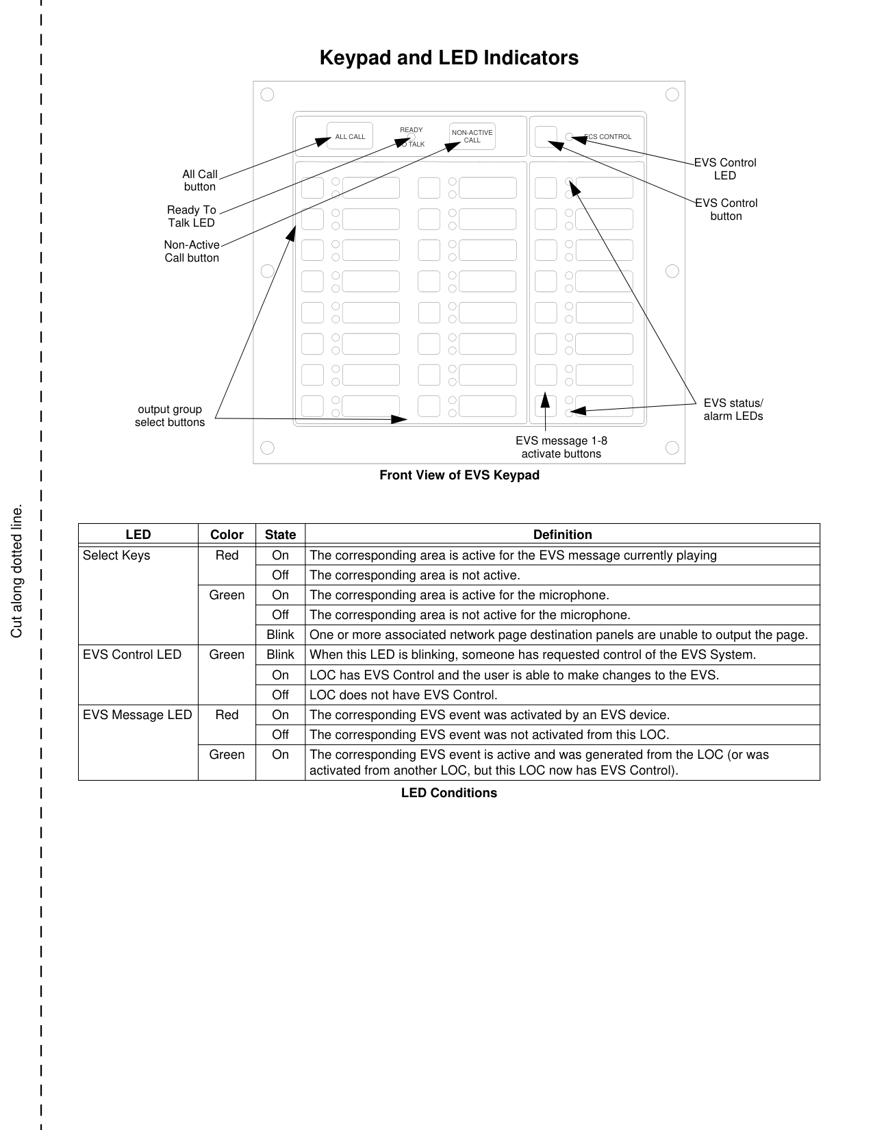
| | | | | | | | | | | | | | | | | | | | | | | | | | | | | | | | | | | | | | | | | | | | | | | | | | | | | | | | | | | | | | | | | | | | | | | | | | | | | | | | | | | | | | | | | | | | | | | | | | | | | | | | | | | | | | | | | | | | | | | | | | | | | | | | | | | | | | |
############# Table 13.2 Installation Record of Devices Installed on 6815/5815XL
Installation Records Conventional Output Point Record
|Point/Circuit|Group|Description| |---|---|---| | | | | |1| | | |2| | | |3| | | |4| | | |5| | | |6| | | |7| | | |8| | |
##### Appendix A: Editing Text Using the Built-In Programmer
This section contains tables of programmable characters that may be used for device, module, site, template, group, and zone names or phone numbers. T9 style editing is used.

|Lower Case Letters|Lower Case Letters|Lower Case Letters|Lower Case Letters| |---|---|---|---| |abc 1|def 2|ghi 3|jkl 4| |mno 5|pqr 6|stu 7|vwx 8| |yz 9|Spc 0| | | |Upper Case Letters|Upper Case Letters|Upper Case Letters|Upper Case Letters| |ABC 1|DEF 2|GHI 3|JKL 4| |MNO 5|PQR 6|STU 7|VWX 8| |YZ 9|Spc 0| | | |Numbers and Special Characters|Numbers and Special Characters|Numbers and Special Characters|Numbers and Special Characters| |1 [ ] 1|2 ( ) 2|3 . , 3|4 : ; 4| |5 ’ " 5|6 ? ! 6|7 ‘ / 7|8 – + 8| |9 = - 9|0 0|* & @ *|# $ #|
############# Table A.1 Character Table
NOTE: After three seconds of no change, a letter will automatically be accepted. Also, pressing the next number will automatically accept the previous choice.
left/right: position up/down: mode
|
_ _ _ _ _ _ _ _ _ _ _| |---|
|Enter: Accept Fire Door 7[stu] 8[vwx] 9[yz ] 0[Spc]
_ _ _ _ _ _ _ _ _ _ _| |---|
############# Figure A.1 Edit Name Example
##### Appendix B: Expanded Receiver/Panel Relationship
The available receiver number will correspond with what panel number you entered. Receiver numbers are populated based on panel number and audited to allow only the 4 appropriate receivers. See Section 6.2.6.
|Panel|Available Receiver Numbers|Available Receiver Numbers|Available Receiver Numbers|Available Receiver Numbers| |---|---|---|---|---| | | | | | | |1|1|2|3|4| |2|5|6|7|8| |3|9|10|11|12| |4|13|14|15|16| |5|17|18|19|20| |6|21|22|23|24|
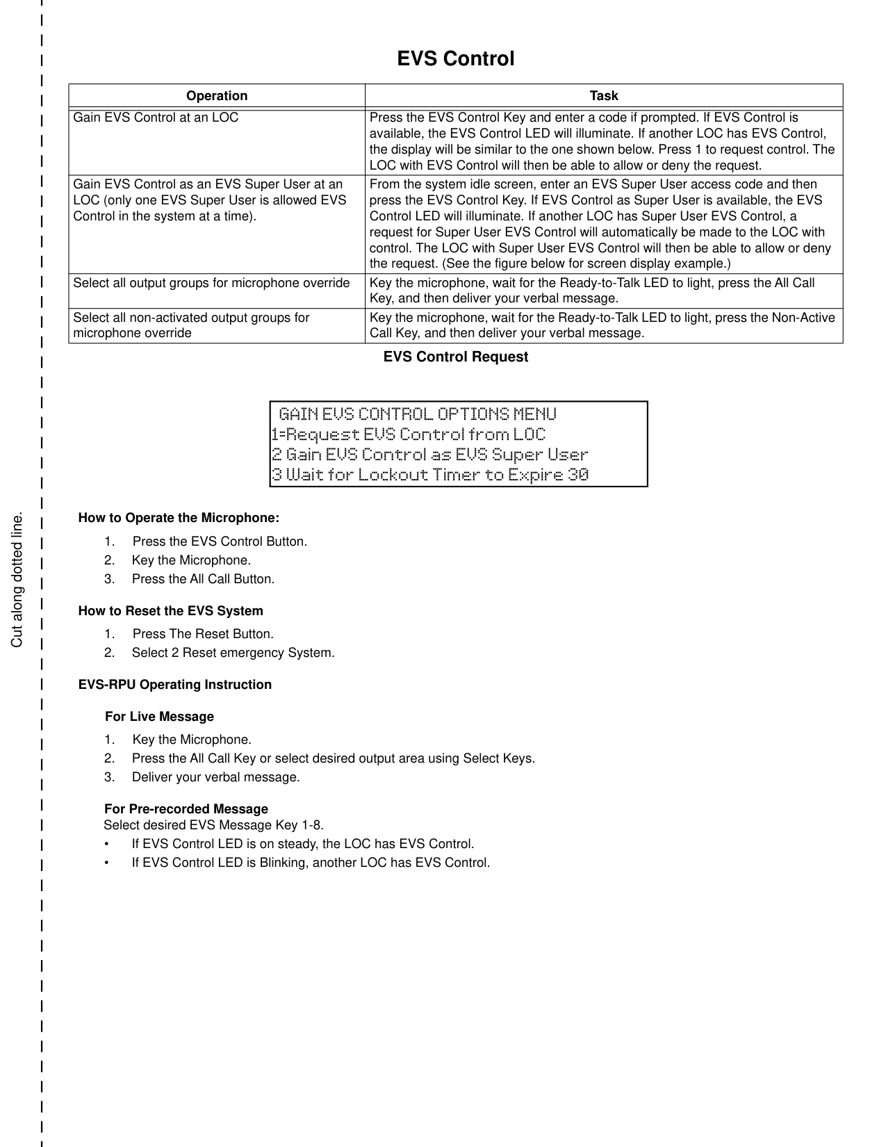
|7|25|26|27|28| |8|29|30|31|32| |9|33|34|35|36| |10|37|38|39|40| |11|41|42|43|44| |12|45|46|47|48| |13|49|50|51|52| |14|53|54|55|56| |15|57|58|59|60| |16|61|62|63|64| |17|65|66|67|68|
############# Table B.1 Receiver/Panel Relationship
##### Appendix C: Cadence Patterns
Table C.1 shows the cadence patterns available for use with the control panel.
|#|Name|Pattern Description (Patterns repeat until condition is cleared.)| |---|---|---| |00|Constant|Continuous sound (This is the only pattern that can be used for relay circuits. The system will override any other choice.)| |01|March Time|0.5 second on, 0.5 second off| |02|ANSI 3.41|0.5 sec on, 0.5 sec off, 0.5 sec on, 0.5 sec off, 0.5 sec on, 1.5 sec off| |03|Single Stroke|0.1 sec on, 1 sec off, 0.1 sec on, 1 sec off, 0.1 sec on, 3 sec off| |04|California|5 sec on, 10 sec off| |05|Zone-coded, Zone 1|0.5 sec on, 0.5 sec off This pattern is multiplied by the zone number in alarm, followed by 3 seconds off.
For example, Pattern 6, Zone 2 coded: (pattern x two): 0.5 sec on, 0.5 sec off, 0.5 sec on, 0.5 sec off, 3 sec off| |06|Zone-coded, Zone 2|0.5 sec on, 0.5 sec off This pattern is multiplied by the zone number in alarm, followed by 3 seconds off.
For example, Pattern 6, Zone 2 coded: (pattern x two): 0.5 sec on, 0.5 sec off, 0.5 sec on, 0.5 sec off, 3 sec off| |07|Zone-coded, Zone 3|0.5 sec on, 0.5 sec off This pattern is multiplied by the zone number in alarm, followed by 3 seconds off.
For example, Pattern 6, Zone 2 coded: (pattern x two): 0.5 sec on, 0.5 sec off, 0.5 sec on, 0.5 sec off, 3 sec off| |08|Zone-coded, Zone 4|0.5 sec on, 0.5 sec off This pattern is multiplied by the zone number in alarm, followed by 3 seconds off.
For example, Pattern 6, Zone 2 coded: (pattern x two): 0.5 sec on, 0.5 sec off, 0.5 sec on, 0.5 sec off, 3 sec off| |09|Zone-coded, Zone 5|0.5 sec on, 0.5 sec off This pattern is multiplied by the zone number in alarm, followed by 3 seconds off.
For example, Pattern 6, Zone 2 coded: (pattern x two): 0.5 sec on, 0.5 sec off, 0.5 sec on, 0.5 sec off, 3 sec off| |10|Zone-coded, Zone 6|0.5 sec on, 0.5 sec off This pattern is multiplied by the zone number in alarm, followed by 3 seconds off.
For example, Pattern 6, Zone 2 coded: (pattern x two): 0.5 sec on, 0.5 sec off, 0.5 sec on, 0.5 sec off, 3 sec off| |11|Zone-coded, Zone 7|0.5 sec on, 0.5 sec off This pattern is multiplied by the zone number in alarm, followed by 3 seconds off.
For example, Pattern 6, Zone 2 coded: (pattern x two): 0.5 sec on, 0.5 sec off, 0.5 sec on, 0.5 sec off, 3 sec off| |12|Zone-coded, Zone 8|0.5 sec on, 0.5 sec off This pattern is multiplied by the zone number in alarm, followed by 3 seconds off.
For example, Pattern 6, Zone 2 coded: (pattern x two): 0.5 sec on, 0.5 sec off, 0.5 sec on, 0.5 sec off, 3 sec off| |13|Zone-coded, Custom 1|0.5 sec on, 0.5 sec off This pattern is multiplied by the zone number in alarm, followed by 3 seconds off.
For example, Pattern 6, Zone 2 coded: (pattern x two): 0.5 sec on, 0.5 sec off, 0.5 sec on, 0.5 sec off, 3 sec off| |14|Zone-coded, Custom 2|0.5 sec on, 0.5 sec off This pattern is multiplied by the zone number in alarm, followed by 3 seconds off.
For example, Pattern 6, Zone 2 coded: (pattern x two): 0.5 sec on, 0.5 sec off, 0.5 sec on, 0.5 sec off, 3 sec off| |15|Zone-coded, Custom 3|0.5 sec on, 0.5 sec off This pattern is multiplied by the zone number in alarm, followed by 3 seconds off.
For example, Pattern 6, Zone 2 coded: (pattern x two): 0.5 sec on, 0.5 sec off, 0.5 sec on, 0.5 sec off, 3 sec off| |16|Zone-coded, Custom 4|0.5 sec on, 0.5 sec off This pattern is multiplied by the zone number in alarm, followed by 3 seconds off.
For example, Pattern 6, Zone 2 coded: (pattern x two): 0.5 sec on, 0.5 sec off, 0.5 sec on, 0.5 sec off, 3 sec off| |17|Sync Type- Faraday (N/A)|These outputs provide synchronization for Gentex, System Sensor, Wheelock, or AMESECO synchronized appliances.| |18|Sync Type- Gentex|These outputs provide synchronization for Gentex, System Sensor, Wheelock, or AMESECO synchronized appliances.| |19|Sync Type- System Sensor|These outputs provide synchronization for Gentex, System Sensor, Wheelock, or AMESECO synchronized appliances.| |20|Sync Type- Wheelock|These outputs provide synchronization for Gentex, System Sensor, Wheelock, or AMESECO synchronized appliances.| |21|Sync Type- AMSECO|These outputs provide synchronization for Gentex, System Sensor, Wheelock, or AMESECO synchronized appliances.| |22|Power Isolated|Disconnected. No voltage at terminals.| |23|Temporal 4|0.1 sec on, 0.1 sec off, 0.1 sec on, 0.1 sec off, 0.1 sec on, 0.1 sec off, 0.1 sec on, 5 sec off,|
############# Table C.1 Cadence Patterns
##### Appendix D: Panel Security
Panel Installation / Maintenance Security Checklist System Description: ________________________________________________________________ System Location: __________________________________________________________________ Installer: _________________________________________________ Date: ___________________
######## Complete the following Cybersecurity Tasks for Each Panel Installation

Security and Data Protection Communication Security - Level 1 Stored Data Security - Level 0 Physical Security - Level 1 Access Control Security - Level 1
Cut along dotted line.
##### Model 6820 Basic Operating Instructions

These Instructions must be framed and displayed next to the 6820 panel in accordance with NFPA 72 fire code for Local Protected Fire Alarm Systems. Test the system in accordance to NFPA 72.
|Operation|Task to Perform| |---|---| | | | |Silence Alarms and Troubles|Press SILENCE and then enter a code if prompted. The Silence LED will light.| |Reset Alarms|Press RESET and then enter a code if prompted.| |View Alarms, Supervisories, and Troubles|For each type of condition press the Up or Down button associated for Alarms, Supervisories, or Troubles.
|FIRE: ALRM SUPR TRBL
CO: ALRM SUPR SYS: TRBL| |---|
|FIRE: ALARM Waterflow Sw Zone_1 1 of 1 Info>| |---| | |View Point Status|1. Login to the panel.
2. Press 2 to select Point Functions.
3. Press 2 to select Point Status.
4. Select the desired module by using the Up or Down button. Then press ENTER.
5. Enter the point number.
| |Conduct a Fire Drill|Hold the DRILL button and then enter a code if prompted. OR
1. Login to the panel.
2. Then Press 1 to select System Tests.
3. Press 1 to select Fire Drill.
4. Press ENTER to start the fire drill. Press ENTER to end the fire drill.
| |Check Detector Sensitivity|1. Login to the panel.
2. Press 2 for Point Status.
3. From the list that displays, select the SLC module where the desired point is located.
4. The fourth line of the display shows the sensitivity status. “NORMAL” means the detector is in compliance with NFPA 72. “CAL MAINT” means the detector is in compliance with NFPA 72 but maintenance should be performed soon. “CAL TRBLE” means the detector is not in compliance with NFPA 72.
| |Set Time and Date|1. Login to the panel.
2. Press 4 to select Set Time & Date.
3. Make changes in the fields on the screen as necessary.
4. When the time and date are correct, press ENTER.
| |Enable / Disable a Point|1. Login to the panel.
2. Press 2 to select Point Functions.
3. Press 1 for Disable / Enable Pt
4. Press 7 for Disable / Enable Pt.
5. Use the Up or Down button to move through the list. Then press ENTER to select the module where the desired point is located.
6. Enter the point or circuit number that you want to disable/enable.
7. Press the right arrow key to toggle between NORMAL (enable) or DISABLE.
| |View Event History|1. Login to the panel.
2. Press 3 to select Event History.
3. Press the Up or Down button to view events in the history buffer.
| |For Service Call:| |
P/N LS10160-001SK-E Rev B ECN: 151062
############ Cut along dotted line.
Cut along dotted line.
##### Model 6820EVS Basic Operating Instructions

These Instructions must be framed and displayed next to the 6820EVS panel in accordance with NFPA 72 fire code for Local Protected Fire Alarm Systems. Test the system in accordance to NFPA 72.
|Operation|Task to Perform| |---|---| | | | |Silence Alarms and Troubles|Press SILENCE and then enter a code if prompted. The Silence LED will light.|

|Reset Alarms|1. Press RESET and then enter a code if prompted.
2. Press 1 to reset the Fire System or 2 to reset the Emergency Communication System.
To reset the EVS at an LOC, the user must gain EVS Control (See Figure 1).| |View all active alarm, trouble, and supervisory signals|The highest priority event will display first. Press the Down arrow to view location and type of alarm or trouble.
|FIRE: ALARM SUPERVISORY TROUBLE
CO: ALARM SUPERVISORY EMERGENCY: ALARM SUPERVISORY
SYSTEM: TROUBLE| |---| | |View Point Status|1. Login to the panel.
2. Press 2 to select Point Functions.
3. Press 2 to select Point Status.
4. Select the desired module by using the Up or Down button. Then press ENTER.
5. Enter the point number.
| |Conduct a Fire Drill|Hold the DRILL button and then enter a code if prompted. OR
1. Login to the panel.
2. Then Press 1 to select System Tests.
3. Press 1 to select Fire Drill.
4. Press ENTER to start the fire drill. Press ENTER to end the fire drill.
| |Set Time and Date|1. Login to the panel.
2. Press 4 to select Set Time & Date.
3. Make changes in the fields on the screen as necessary.
4. When the time and date are correct, press ENTER.
| |Enable / Disable a Point|1. Login to the panel.
2. Press 2 to select Point Functions.
3. Press 1 for Disable / Enable Pt
4. Press 7 for Disable / Enable Pt.
5. Use the Up or Down button to move through the list. Then press ENTER to select the module where the desired point is located.
6. Enter the point or circuit number that you want to disable/enable.
7. Press the right arrow key to toggle between NORMAL (enable) or DISABLE.
| |To Gain / Request EVS Control|Press the EVS Control Button and follow the on-screen Instructions. When the EVS Control LED is blinking, another LOC has EVS Control. The EVS Control LED is on steady when the LOC has EVS Control.| |For Service Call:| |
P/N LS10161-001SK-E Rev B 151062
############ Cut along dotted line.
Cut along dotted line.
##### Keypad and LED Indicators
READY TO TALK
NON-ACTIVE CALL
ALL CALL ECS CONTROL
EVS Control LED
All Call button
EVS Control button
Ready To Talk LED
Non-Active Call button
EVS status/ alarm LEDs
output group select buttons
EVS message 1-8 activate buttons
Front View of EVS Keypad
|LED|Color|State|Definition| |---|---|---|---| | | | | | |Select Keys|Red|On|The corresponding area is active for the EVS message currently playing| |Select Keys|Red|Off|The corresponding area is not active.| |Select Keys|Green|On|The corresponding area is active for the microphone.| |Select Keys|Green|Off|The corresponding area is not active for the microphone.| |Select Keys|Green|Blink|One or more associated network page destination panels are unable to output the page.| |EVS Control LED|Green|Blink|When this LED is blinking, someone has requested control of the EVS System.| |EVS Control LED|Green|On|LOC has EVS Control and the user is able to make changes to the EVS.| |EVS Control LED|Green|Off|LOC does not have EVS Control.| |EVS Message LED|Red|On|The corresponding EVS event was activated by an EVS device.| |EVS Message LED|Red|Off|The corresponding EVS event was not activated from this LOC.|

|EVS Message LED|Green|On|The corresponding EVS event is active and was generated from the LOC (or was activated from another LOC, but this LOC now has EVS Control).|
LED Conditions
############ Cut along dotted line.
Cut along dotted line.
##### EVS Control
|Operation|Task| |---|---| | | | |Gain EVS Control at an LOC|Press the EVS Control Key and enter a code if prompted. If EVS Control is available, the EVS Control LED will illuminate. If another LOC has EVS Control, the display will be similar to the one shown below. Press 1 to request control. The LOC with EVS Control will then be able to allow or deny the request.| |Gain EVS Control as an EVS Super User at an LOC (only one EVS Super User is allowed EVS Control in the system at a time).|From the system idle screen, enter an EVS Super User access code and then press the EVS Control Key. If EVS Control as Super User is available, the EVS Control LED will illuminate. If another LOC has Super User EVS Control, a request for Super User EVS Control will automatically be made to the LOC with control. The LOC with Super User EVS Control will then be able to allow or deny the request. (See the figure below for screen display example.)| |Select all output groups for microphone override|Key the microphone, wait for the Ready-to-Talk LED to light, press the All Call Key, and then deliver your verbal message.| |Select all non-activated output groups for microphone override|Key the microphone, wait for the Ready-to-Talk LED to light, press the Non-Active Call Key, and then deliver your verbal message.|
EVS Control Request
|GAIN EVS CONTROL OPTIONS MENU 1=Request EVS Control from LOC
2 Gain EVS Control as EVS Super User
3 Wait for Lockout Timer to Expire 30
| |---|
############# How to Operate the Microphone:
############# For Live Message
############ Cut along dotted line.
#### Manufacturer Warranties and Limitation of Liability
Manufacturer Warranties. Subject to the limitations set forth herein, Manufacturer warrants that the Products manufactured by it in its Northford, Connecticut facility and sold by it to its authorized Distributors shall be free, under normal use and service, from defects in material and workmanship for a period of thirty six months (36) months from the date of manufacture (effective Jan. 1, 2009). The Products manufactured and sold by Manufacturer are date stamped at the time of production. Manufacturer does not warrant Products that are not manufactured by it in its Northford, Connecticut facility but assigns to its Distributor, to the extent possible, any warranty offered by the manufacturer of such product. This warranty shall be void if a Product is altered, serviced or repaired by anyone other than Manufacturer or its authorized Distributors. This warranty shall also be void if there is a failure to maintain the Products and the systems in which they operate in proper working conditions.
MANUFACTURER MAKES NO FURTHER WARRANTIES, AND DISCLAIMS ANY AND ALL OTHER WARRANTIES, EITHER EXPRESSED OR IMPLIED, WITH RESPECT TO THE PRODUCTS, TRADEMARKS, PROGRAMS AND SERVICES RENDERED BY MANUFACTURER INCLUDING WITHOUT LIMITATION, INFRINGEMENT, TITLE, MERCHANTABILITY, OR FITNESS FOR ANY PARTICULAR PURPOSE. MANUFACTURER SHALL NOT BE LIABLE FOR ANY PERSONAL INJURY OR DEATH WHICH MAY ARISE IN THE COURSE OF, OR AS A RESULT OF, PERSONAL, COMMERCIAL OR INDUSTRIAL USES OF ITS PRODUCTS.
This document constitutes the only warranty made by Manufacturer with respect to its products and replaces all previous warranties and is the only warranty made by Manufacturer. No increase or alteration, written or verbal, of the obligation of this warranty is authorized. Manufacturer does not represent that its products will prevent any loss by fire or otherwise.
Warranty Claims. Manufacturer shall replace or repair, at Manufacturer's discretion, each part returned by its authorized Distributor and acknowledged by Manufacturer to be defective, provided that such part shall have been returned to Manufacturer with all charges prepaid and the authorized Distributor has completed Manufacturer's Return Material Authorization form. The replacement part shall come from Manufacturer's stock and may be new or refurbished. THE FOREGOING IS DISTRIBUTOR'S SOLE AND EXCLUSIVE REMEDY IN THE EVENT OF A WARRANTY CLAIM.
Warn-HL-08-2009.fm
6820/EVS Manual — P/N LS10144-001SK-E:E 4/6/2022 169
Honeywell Silent Knight 12 Clintonville Road Northford, CT 06472-1610 203.484.7161 www.silentknight.com
LS10144-001SK-E | E | 04-22 ©2022 Honeywell International Inc.
