
Ask AI
— answers from the official manualAnswers from the official manual.
Common questions
Common Questions
9 totalHow do I factory reset the BGW320-500?
Press and hold the Reset button on the back panel for longer than 10 seconds until the Service LED starts blinking white and WPS LED starts blinking green. After releasing, the Service LED will turn solid white and other LEDs will be off after 15 seconds. This performs a factory reset. (Page 23)
What should I do if the gateway does not detect my fiber cable?
Make sure that the SFP optic module is installed properly, use the correct fiber cable, and ensure it's plugged into a valid wall jack. Also confirm AT&T has activated your fiber line. If issues persist after checking these areas, contact AT&T support at 1-800-288-2020 or via their website (www.att.com/support). (Page 23)
How do I set up my Ethernet connection with the BGW320-500?
Connect one end of the Ethernet cable to one of the 1Gbps or 5Gbps Ethernet ports on your BGW320-500. Connect the other end to your computer's Ethernet port. The gateway must have an IP address automatically assigned in DHCP mode. Verify a green Light Emitting Diode (LED) appears when connecting to ensure proper functioning. See Status Indicator Lights for LED behavior details (Page 18).
Where should I place the BGW320-500 to prevent overheating?
Ensure the device is placed vertically on a flat surface with at least two inches of clearance around all sides except the bottom. Avoid areas exposed to direct sunlight or heat sources as this can cause an overheated condition signified by red LED indicator and need positioning adjustment. Make sure it's properly ventilated in a location where temperatures remain within 32° F to 107°F (Page 25).
How do I connect telephones for VoIP service on the BGW320-500?
Connect one end of a phone cable to the RJ14 jack labeled 'Phone' on your BGW320-500. For one line, directly attach it to the telephone device. To support two lines simultaneously, apply an Inner-Out Pair Splitter Adapter before splitting and plugging into each handset individually (Page 19).
What is the process for connecting broadband internet using fiber optic?
Plug one end of a fiber optic cable to the BGW320-500 XGS-PON Broadband Gateway's SFP/SFP+ cage. Connect other end into the wall outlet provided by AT&T. If both installation types are attempted simultaneously, interference may occur; only use the method configured by AT&T (Page 17).
Full Manual
30 pages
BGW320-500 XGS-PON Broadband Gateway Release 1.0 Install and Operation Guide
BGW320-500 XGS-PON Broadband Gateway
Release 1.0

INSTALL AND OPERATION GUIDE Revision 0.8.7
HUMAX Copyrights and Trademarks © 2019 HUMAX Co., Ltd. All Rights Reserved.
No part of this publication may be reproduced in any form or by any means or used to make any derivative work (such as translation, transformation, or adaptation) without written permission from HUMAX Co., Ltd. (“HUMAX”). HUMAX reserves the right to revise this publication and to make changes in content from time to time without obligation on the part of HUMAX to provide notification of such revision or change. HUMAX and the HUMAX logo are all trademarks of HUMAX Co., Ltd. Other trademarks and trade names may be used in this document to refer to either the entities claiming the marks or the names of their products. HUMAX disclaims proprietary interest in the marks and names of others. HUMAX provides this guide without warranty of any kind, implied or expressed, including, but not limited to, the implied warranties of merchantability and fitness for a particular purpose.HUMAX may make improvements or changes in the product(s) described in this manual at any time. The capabilities, system requirements and/or compatibility with third-party products described herein are subject to change without notice.
2© Copyright 2019 HUMAX. All rights reserved.
#### Table of Contents
CHAPTER CONTENTS PAGE

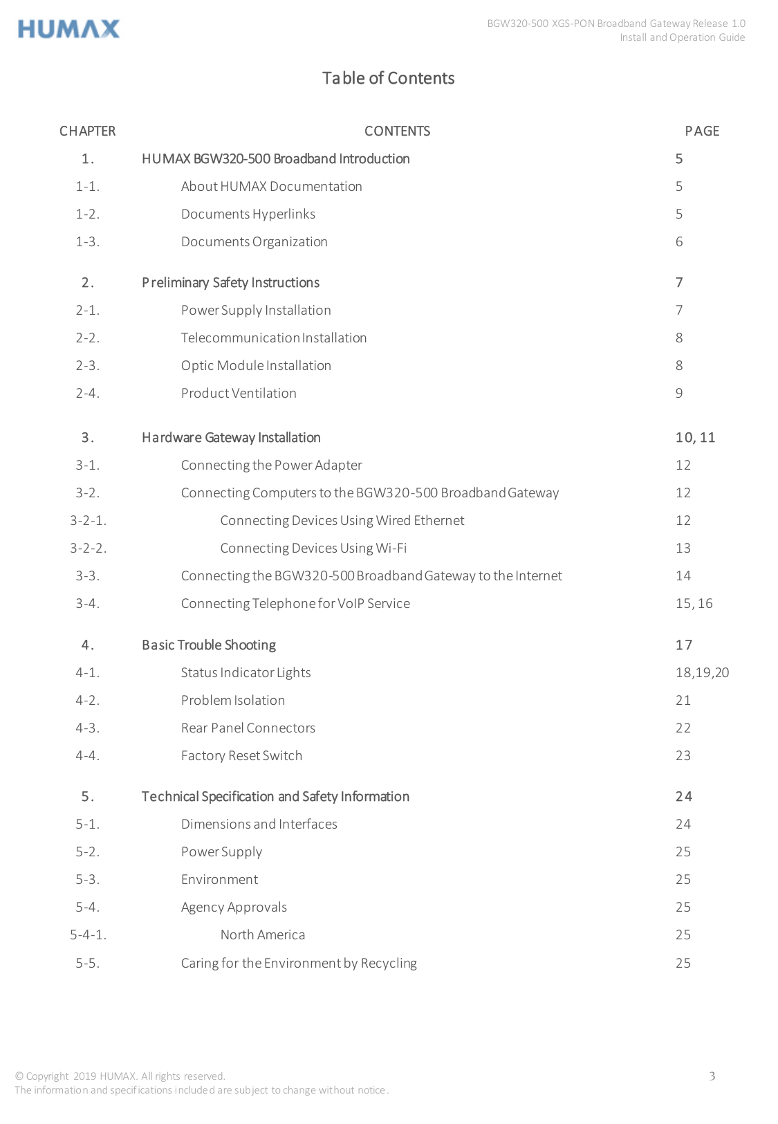
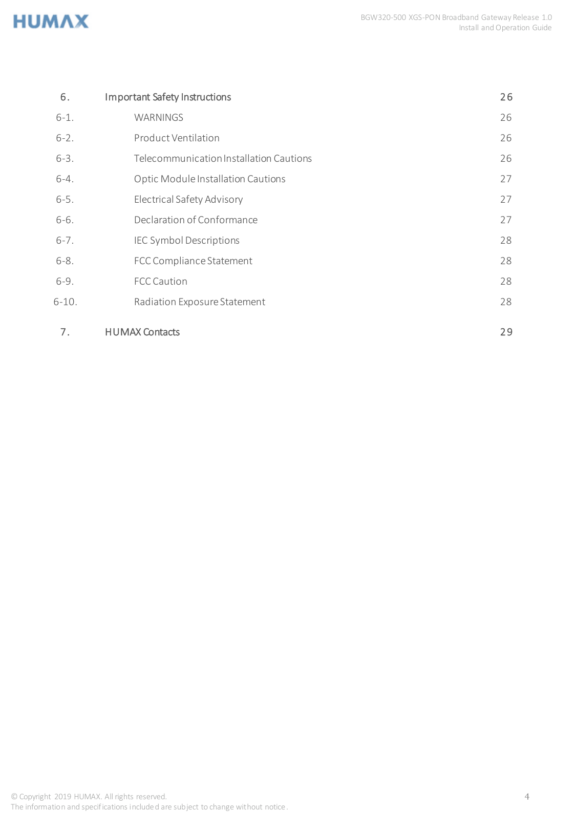
####### 7. HUMAX Contacts 29
CHAPTER 1
1. HUMAX BGW320-500 XGS-PON Broadband Gateway Introduction
The BGW320-500 XGS-PON Broadband Gateway hardware platform can host different software. The Advanced Residential Gateway supports VoIP, IPv6, video delivery, security firewall, and extensive remote management features.
The BGW320-500Broadband Gateway delivers robust video, primary line telephony, and high-speed data over broadband networks via high-speed Internet connectivity. The four Gigabit Ethernet ports can be separated into different services allowing the configuration of dedicated ports for data. It is designed for advanced XGS-PON network service deployments and supports Quality of Service (QoS) enabled features including:
1-1. About HUMAX Documentation
This guide presents basic operational concepts, and provides step-by-step instructions for the hardware installation and basic troubleshooting of the HUMAX BGW320-500 XGS-PON Broadband Gateway.

Note:For the purposes of this manual the HUMAX BGW320-500 XGS-PON Broadband Gateway may also be referred to simply as the gateway.
1-2 Documentation Hyperlinks
The hyperlink resides in the page number that follows the title. For example, to access Hardware Gateway Installation in the hyperlink below, hover the mouse over the page number in parenthesis until the finger pointer appears, and then click.
Hardware Gateway Installation (page 10)
1-3 Document Organization
This hardware install and operation guide consists of six product information chapters presented as follows:
CHAPTER 2
2. Preliminary Safety Instructions

Warning: Do not use before reading these instructions. Do not connect the Ethernet ports to a carrier or carriage service provider’s telecommunications network or facility unless:
2-1. Power Supply Installation
Connect the power supply cord to the power jack on the BGW320-500 XGS-PON Broadband Gateway. Plug the power supply into an appropriate electrical outlet.

Warning: The power supply must be connected to a mains outlet with a protective earth connection. Do not defeat the protective earth connection.

Warning: Use only the power supply and cord that came with the BGW320-500 XGS-PON Broadband Gateway. Failure to use the authorized power supply and cord may cause electric shock, fire, bodily injury, and/or property damage. If the power supply or cord becomes damaged or needs to be replaced, to obtain an authorized replacement please contact AT&T customer service by phone (1.800.288.2020) or via website (www.att.com/support).

Caution:Depending on the power supply provided with the product, either the direct plug-in power supply blades, power supply cord plug or the appliance coupler serves as the mains power disconnect. It is important that the direct plug-in power supply, socket-outlet or appliance coupler be located so it is readily accessible.
2-2. Telecommunication Installation
When using telephone equipment, basic safety precautions should always be followed to reduce the risk of fire, electric shock, and injury, including the following:


2-3. Optic Module Installation
When using SFP/SFP+ optic module, basic safety precautions should always be followed to reduce the risk of fire, electric shock, and injury, including the following:


2-4. Product Ventilation
The BGW320-500 XGS-PON Broadband Gateway is intended for use in a consumer's home. Position the device in an upright vertical position located where ambient temperatures remain within a range of 32°- 107°F (0°- 41.7°C). The BGW320-500 XGS-PON Broadband Gateway should not be used in locations exposed to outside heat radiation or where it is subject to trapping of its own heat. The product should have at least two inches of clearance on all sides except the bottom when properly installed and should not be placed inside tightly enclosed spaces unless proper ventilation is provided.

###### WARNING : RISK OF OVERHEATING IF NOT PROPERLY VENTILATED

###### SAVE THESE INSTRUCTIONS
CHAPTER 3
3. Hardware Gateway Installation
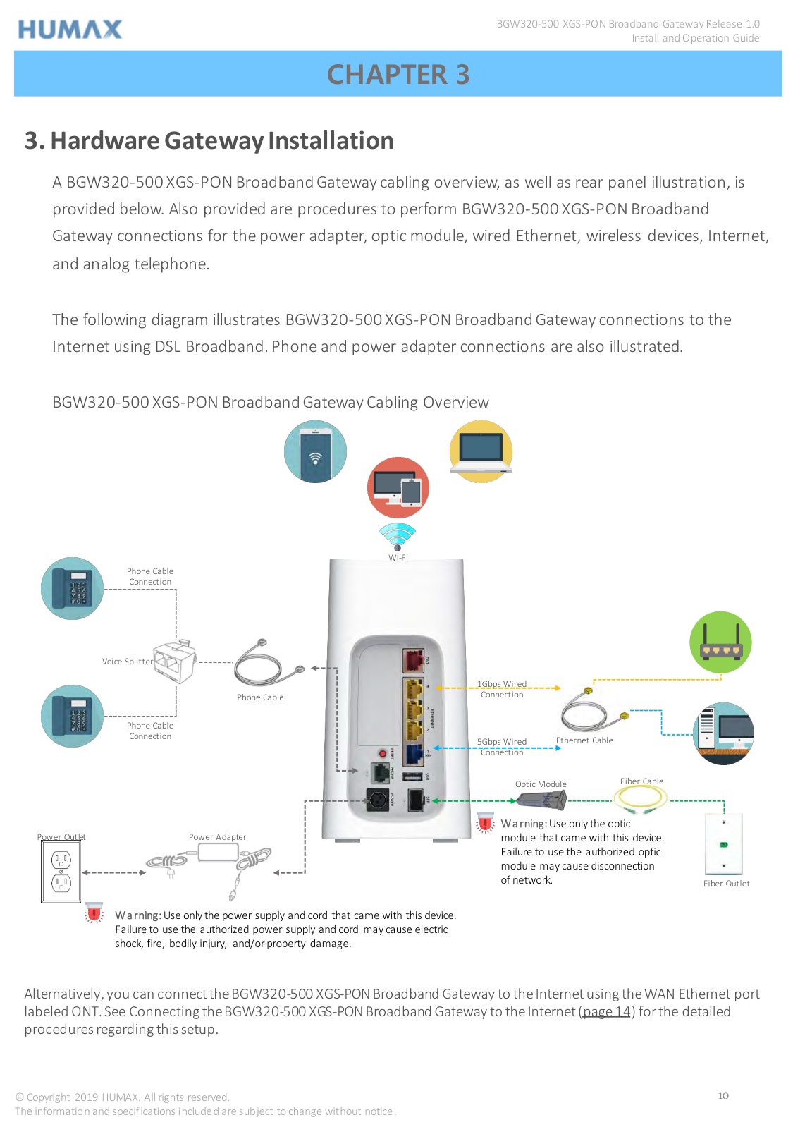
A BGW320-500 XGS-PON Broadband Gateway cabling overview, as well as rear panel illustration, is provided below. Also provided are procedures to perform BGW320-500 XGS-PON Broadband Gateway connections for the power adapter, optic module, wired Ethernet, wireless devices, Internet, and analog telephone.
The following diagram illustrates BGW320-500 XGS-PON Broadband Gateway connections to the Internet using DSL Broadband. Phone and power adapter connections are also illustrated.
BGW320-500 XGS-PON Broadband Gateway Cabling Overview


Wi-Fi

Phone Cable Connection


Voice Splitter
1Gbps Wired Connection


Phone Cable

Phone Cable Connection
Ethernet Cable
5Gbps Wired Connection
Fiber Cable
Optic Module


Warning:Use only the optic module that came with this device. Failure to use the authorized optic module may cause disconnection of network.
Power Outlet
Power Adapter


Fiber Outlet

Warning:Use only the power supply and cord that came with this device. Failure to use the authorized power supply and cord may cause electric shock, fire, bodily injury, and/or property damage.
######## Alternatively, you can connect the BGW320-500 XGS-PON Broadband Gateway to the Internet using the WAN Ethernet port labeled ONT. See Connecting the BGW320-500 XGS-PON Broadband Gateway to the Internet (page14) for the detailed procedures regarding this setup.
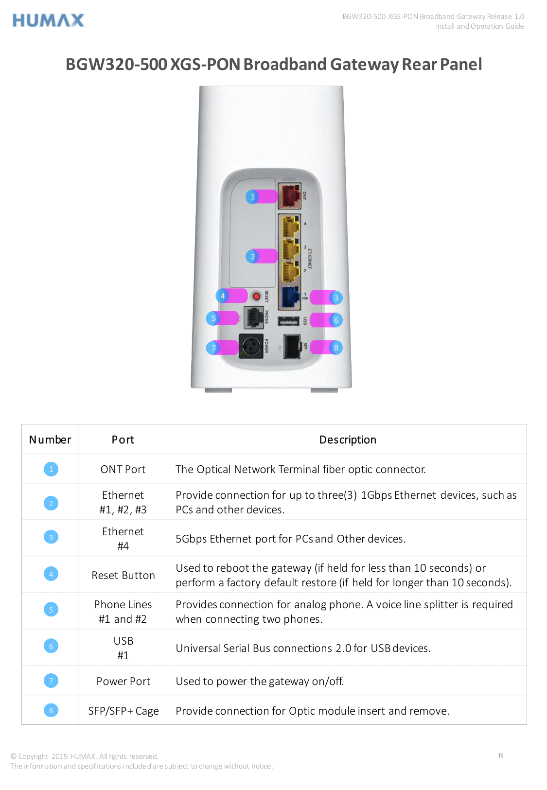
BGW320-500 XGS-PON Broadband Gateway Rear Panel

3
6
8
7
|Number|Port|Description| |---|---|---| |1|ONT Port|The Optical Network Terminal fiber optic connector.| |2|Ethernet #1, #2, #3|Provide connection for up to three(3) 1Gbps Ethernet devices, such as PCs and other devices.| |3|Ethernet #4|5Gbps Ethernet port for PCs and Other devices.| |4|Reset Button|Used to reboot the gateway (if held for less than 10 seconds) or perform a factory default restore (if held for longer than 10 seconds).| |5|Phone Lines #1 and #2|Provides connection for analog phone. A voice line splitter is required when connecting two phones.| |6|USB #1|Universal Serial Bus connections 2.0 for USB devices.| |7|Power Port|Used to power the gateway on/off.| |8|SFP/SFP+ Cage|Provide connection for Optic module insert and remove.|
3-1. Connecting the Power Adapter
The power adapter supplies power to the BGW320-500 XGS-PON Broadband Gateway.
After the BGW320-500 XGS-PON Broadband Gateway is powered on, the power light blinks white. For all power light indications, see Status Indicator Lights (page 18, 19,20) under Basic Troubleshooting.

Warning: Use only the power supply and cord that came with the BGW320-500 XGS-PON Broadband Gateway. Failure to use the authorized power supply and cord may cause electric shock, fire, bodily injury, and/or property damage. If the power supply or cord becomes damaged or needs to be replaced, to obtain an authorized replacement please contact AT&T customer service by phone (1.800.288.2020) or via website (www.att.com/support).
3-2. Connecting Computers to the BGW320-500 XGS-PONBroadband Gateway
The first computer you connect can be used to configure the BGW320-500 XGS-PON Broadband Gateway settings. You can connect more computers and other devices to the BGW320-500 XGS-PON Broadband Gateway using wireless or wired Ethernet.
3-2-1. Connecting Devices Using Wired Ethernet
The BGW320-500 XGS-PON Broadband Gateway has four wired Ethernet ports (three 1Gbps Ethernet ports and one 5Gbps Ethernet port) that can be used to connect computers or other devices. As shown in the illustration below, to connect a computer to the BGW320-500 XGS-PON Broadband Gateway:

Note: To use 5Gbps Ethernet port, recommended to connect with CAT-7 Ethernet cable.
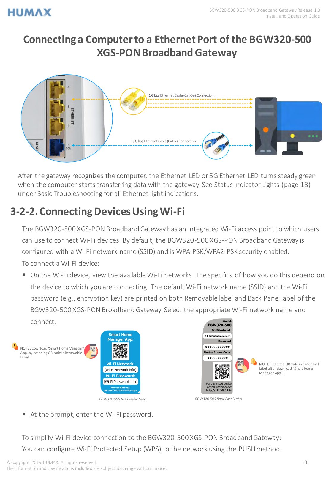
Connecting a Computer to a Ethernet Port of the BGW320-500 XGS-PON Broadband Gateway


1GbpsEthernet Cable (Cat-5e) Connection.

5GbpsEthernet Cable (Cat-7) Connection.
After the gateway recognizes the computer, the Ethernet LED or 5G Ethernet LED turns steady green when the computer starts transferring data with the gateway. See Status Indicator Lights (page 18) under Basic Troubleshooting for all Ethernet light indications.
3-2-2. Connecting Devices Using Wi-Fi
The BGW320-500 XGS-PON Broadband Gateway has an integrated Wi-Fi access point to which users can use to connect Wi-Fi devices. By default, the BGW320-500 XGS-PON Broadband Gateway is configured with a Wi-Fi network name (SSID) and is WPA-PSK/WPA2-PSK security enabled. To connect a Wi-Fi device:


NOTE : Download “Smart Home Manager” App. by scanning QR code in Removable Label.


NOTE : Scan the QR code in back panel label after download “Smart Home Manager App”.

BGW320-500 Removable Label BGW320-500 Back Panel Label
To simplify Wi-Fi device connection to the BGW320-500 XGS-PON Broadband Gateway: You can configure Wi-Fi Protected Setup (WPS) to the network using the PUSH method.
3-3. Connecting the BGW320-500 XGS-PON Broadband Gatewayto the Internet


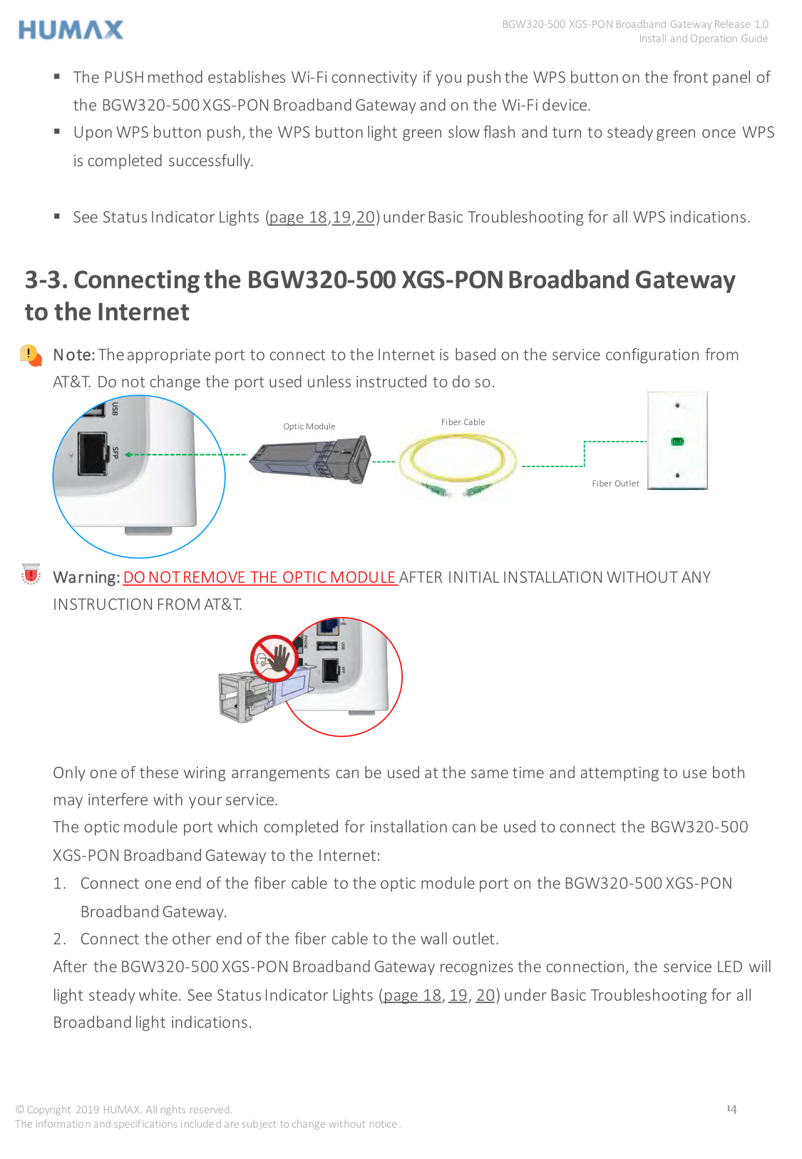
Note:The appropriate port to connect to the Internet is based on the service configuration from AT&T. Do not change the port used unless instructed to do so.


Fiber Cable
Optic Module


Fiber Outlet
Warning:DO NOT REMOVE THE OPTIC MODULE AFTER INITIAL INSTALLATION WITHOUT ANY INSTRUCTION FROM AT&T.


Only one of these wiring arrangements can be used at the same time and attempting to use both may interfere with your service. The optic module port which completed for installation can be used to connect the BGW320-500 XGS-PON Broadband Gateway to the Internet:


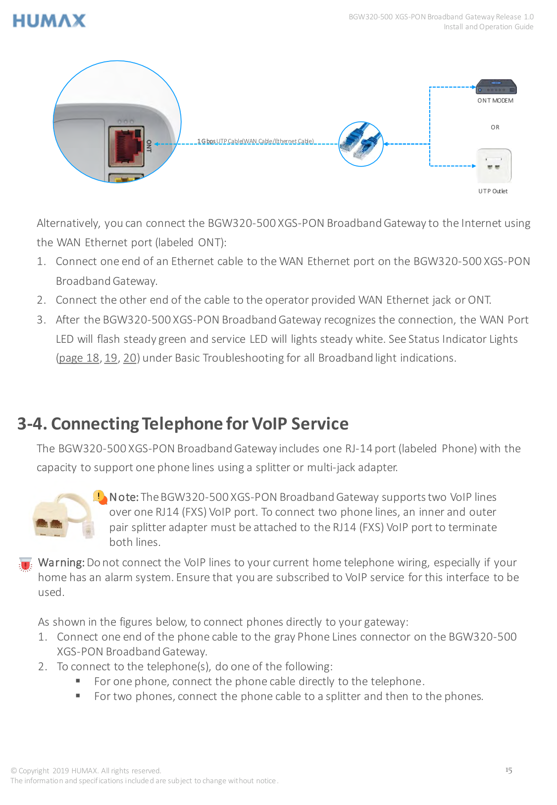
ONT MODEM

OR
1GbpsUTP Cable(WAN Cable/Ethernet Cable)

UTP Outlet
Alternatively, you can connect the BGW320-500 XGS-PON Broadband Gateway to the Internet using the WAN Ethernet port (labeled ONT):
3-4. Connecting Telephone for VoIP Service
The BGW320-500 XGS-PON Broadband Gateway includes one RJ-14 port (labeled Phone) with the capacity to support one phone lines using a splitter or multi-jack adapter.


Note:The BGW320-500 XGS-PON Broadband Gateway supports two VoIP lines over one RJ14 (FXS) VoIP port. To connect two phone lines, an inner and outer pair splitter adapter must be attached to the RJ14 (FXS) VoIP port to terminate both lines.
Warning:Do not connect the VoIP lines to your current home telephone wiring, especially if your home has an alarm system. Ensure that you are subscribed to VoIP service for this interface to be used.

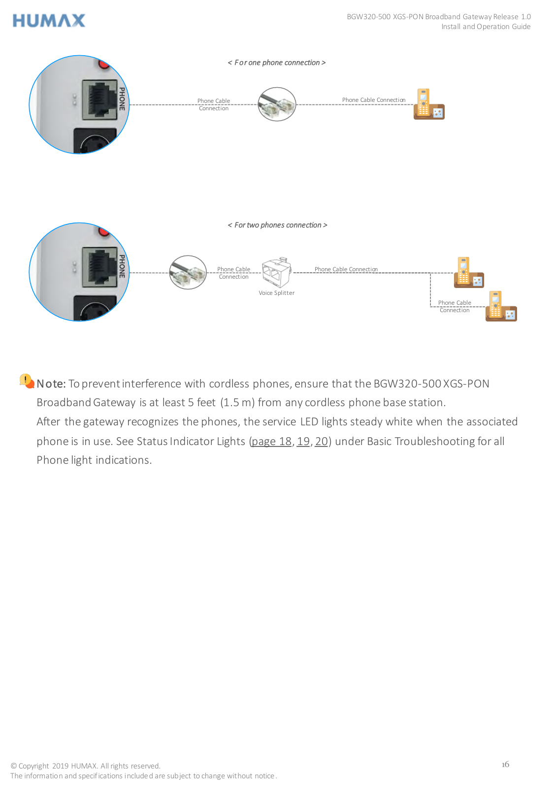
As shown in the figures below, to connect phones directly to your gateway:

< For one phone connection >


Phone Cable Connection
Phone Cable Connection
< For two phones connection >


Phone Cable Connection
Phone Cable Connection
Voice Splitter

Phone Cable Connection

Note: To prevent interference with cordless phones, ensure that the BGW320-500 XGS-PON Broadband Gateway is at least 5 feet (1.5 m) from any cordless phone base station. After the gateway recognizes the phones, the service LED lights steady white when the associated phone is in use. See Status Indicator Lights (page 18,19,20) under Basic Troubleshooting for all Phone light indications.
CHAPTER 4
4. Basic Trouble Shooting
This chapter provides simple troubleshooting suggestions for issues with the initial configuration of the BGW320-500 XGS-PON Broadband Gateway. The following topics are covered:
4-1. Status Indicator Lights
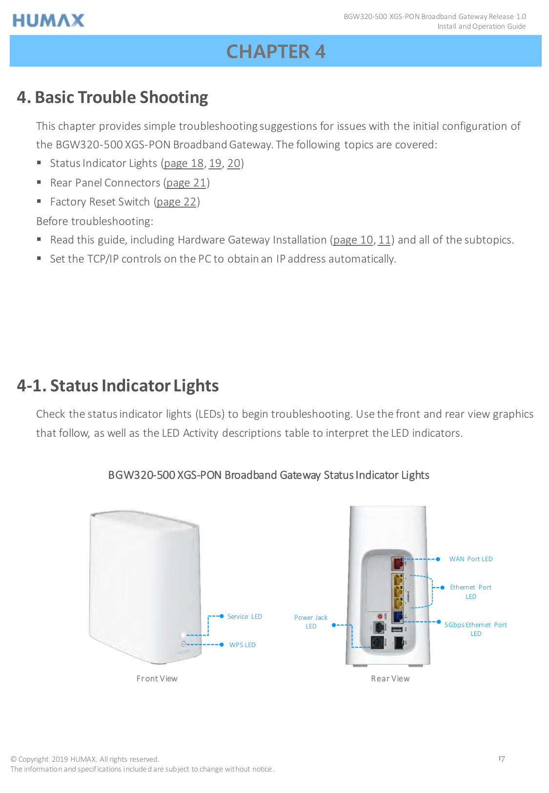
Check the status indicator lights (LEDs) to begin troubleshooting. Use the front and rear view graphics that follow, as well as the LED Activity descriptions table to interpret the LED indicators.
BGW320-500 XGS-PON Broadband Gateway Status Indicator Lights


WAN Port LED
Ethernet Port LED
Service LED
Power Jack LED
5Gbps Ethernet Port LED
WPS LED
######### Front View Rear View
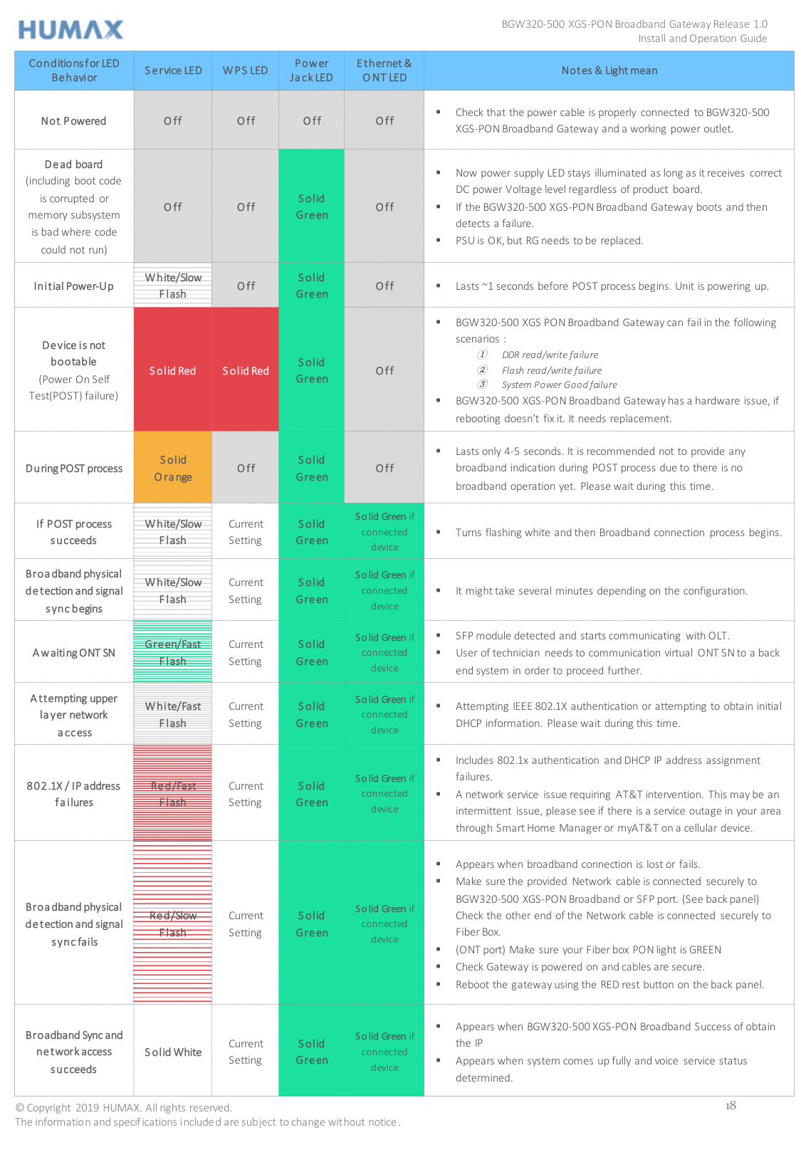
|Conditions for LED Behavior|Service LED|WPS LED|Power Jack LED|Ethernet & ONT LED|Notes & Light mean| |---|---|---|---|---|---| |Not Powered|Off|Off|Off|Off| Check that the power cable is properly connected to BGW320-500
XGS-PON Broadband Gateway and a working power outlet.| |Dead board (including boot code is corrupted or memory subsystem is bad where code could not run)|Off|Off|Solid Green|Off| Now power supply LED stays illuminated as long as it receives correct DC power Voltage level regardless of product board.
If the BGW320-500 XGS-PON Broadband Gateway boots and then detects a failure.
PSU is OK, but RG needs to be replaced.
| |Initial Power-Up|White/Slow Flash|Off|Solid Green|Off| Lasts ~1 seconds before POST process begins. Unit is powering up.| |Device is not bootable (Power On Self Test(POST) failure)|Solid Red|Solid Red|Solid Green|Off| BGW320-500 XGS PON Broadband Gateway can fail in the following scenarios :
① DDR read/write failure
② Flash read/write failure
③ System Power Good failure
BGW320-500 XGS-PON Broadband Gateway has a hardware issue, if rebooting doesn’t fix it. It needs replacement.
| |During POST process|Solid Orange|Off|Solid Green|Off| Lasts only 4-5 seconds. It is recommended not to provide any broadband indication during POST process due to there is no broadband operation yet. Please wait during this time.| |If POST process succeeds|White/Slow Flash|Current Setting|Solid Green|Solid Green if connected device| Turns flashing white and then Broadband connection process begins.|
|Broadband physical detection and signal sync begins|White/Slow Flash|Current Setting|Solid Green|Solid Green if connected device| It might take several minutes depending on the configuration.| |Awaiting ONT SN|Green/Fast Flash|Current Setting|Solid Green|Solid Green if connected device| SFP module detected and starts communicating with OLT.
User of technician needs to communication virtual ONT SN to a back end system in order to proceed further.
| |Attempting upper layer network access|White/Fast Flash|Current Setting|Solid Green|Solid Green if connected device| Attempting IEEE 802.1X authentication or attempting to obtain initial
DHCP information. Please wait during this time.| |802.1X / IP address failures|Red/Fast Flash|Current Setting|Solid Green|Solid Green if connected device| Includes 802.1x authentication and DHCP IP address assignment failures.
A network service issue requiring AT&T intervention. This may be an intermittent issue, please see if there is a service outage in your area through Smart Home Manager or myAT&T on a cellular device.
| |Broadband physical detection and signal sync fails|Red/Slow Flash|Current Setting|Solid Green|Solid Green if connected device| Appears when broadband connection is lost or fails.
Make sure the provided Network cable is connected securely to BGW320-500 XGS-PON Broadband or SFP port. (See back panel) Check the other end of the Network cable is connected securely to Fiber Box.
(ONT port) Make sure your Fiber box PON light is GREEN
Check Gateway is powered on and cables are secure.
Reboot the gateway using the RED rest button on the back panel.
| |Broadband Sync and network access succeeds|Solid White|Current Setting|Solid Green|Solid Green if connected device| Appears when BGW320-500 XGS-PON Broadband Success of obtain the IP
Appears when system comes up fully and voice service status determined.
|
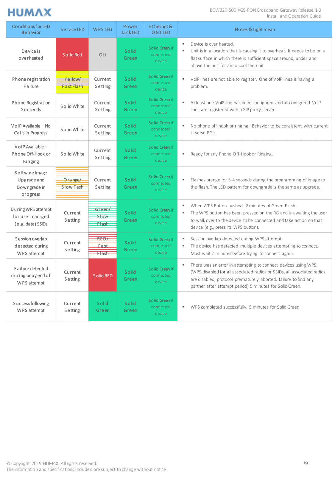
|Conditions for LED Behavior|Service LED|WPS LED|Power Jack LED|Ethernet & ONT LED|Notes & Light mean| |---|---|---|---|---|---| |Device is overheated|Solid Red|Off|Solid Green|Solid Green if connected device| Device is over heated.
Unit is in a location that is causing it to overheat. It needs to be on a flat surface in which there is sufficient space around, under and above the unit for air to cool the unit.
| |Phone registration Failure|Yellow/ Fast Flash|Current Setting|Solid Green|Solid Green if connected device| VoIP lines are not able to register. One of VoIP lines is having a
problem.| |Phone Registration Succeeds|Solid White|Current Setting|Solid Green|Solid Green if connected device| At least one VoIP line has been configured and all configured VoIP
lines are registered with a SIP proxy server.| |VoIP Available – No Calls in Progress|Solid White|Current Setting|Solid Green|Solid Green if connected device| No phone off-hook or ringing. Behavior to be consistent with current
U-verse RG's.| |VoIP Available – Phone Off-Hook or Ringing|Solid White|Current Setting|Solid Green|Solid Green if connected device| Ready forany Phone Off-Hook or Ringing.| |Software Image Upgrade and Downgrade in progress|Orange/ Slow Flash|Current Setting|Solid Green|Solid Green if connected device| Flashes orange for 3-4 seconds during the programming of image to
the flash. The LED pattern for downgrade is the same as upgrade.| |During WPS attempt for user managed (e.g. data) SSIDs|Current Setting|Green/ Slow Flash|Solid Green|Solid Green if connected device| When WPS Button pushed. 2 minutes of Green Flash.
The WPS button has been pressed on the RG and is awaiting the user to walk over to the device to be connected and take action on that device (e.g., press its WPS button).
| |Session overlap detected during WPS attempt|Current Setting|RED/ Fast Flash|Solid Green|Solid Green if connected device| Session overlap detected during WPS attempt.
The device has detected multiple devices attempting to connect. Must wait 2 minutes before trying to connect again.
| |Failure detected during or by end of WPS attempt|Current Setting|Solid RED|Solid Green|Solid Green if connected device| There was an error in attempting to connect devices using WPS. (WPS disabled for all associated radios or SSIDs, all associated radios are disabled, protocol prematurely aborted, failure to find any partner after attempt period) 5 minutes for Solid Green.| |Success following WPS attempt|Current Setting|Solid Green|Solid Green|Solid Green if connected device| WPS completed successfully. 5 minutes for Solid Green.|
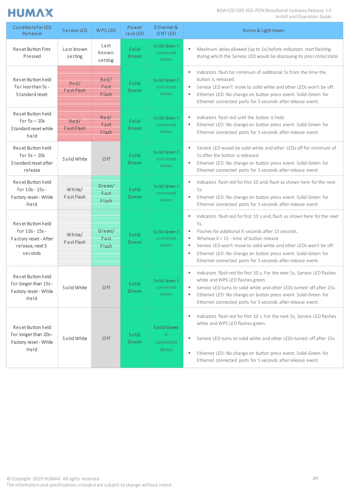
|Conditions for LED Behavior|Service LED|WPS LED|Power Jack LED|Ethernet & ONT LED|Notes & Light mean| |---|---|---|---|---|---| |Reset ButtonFirst Pressed|Last known setting|Last known setting|Solid Green|Solid Green if connected device| Maximum delay allowed (up to 1s) before indicators start flashing
during which the Service LED would be displaying its prior color/state.| |Reset Button held for less than 5s Standard reset|Red/ Fast Flash|Red/ Fast Flash|Solid Green|Solid Green if connected device| Indicators flash for minimum of additional 5s from the time the button is released.
Service LED won’t move to solid white and other LEDs won’t be off.
Ethernet LED: No change on button press event. Solid-Green for Ethernet connected ports for 5 seconds after release event.
| |Reset Button held for 5s – 10s Standard reset while held|Red/ Fast Flash|Red/ Fast Flash|Solid Green|Solid Green if connected device| Indicators flash red until the button is held.
Ethernet LED: No change on button press event. Solid-Green for Ethernet connected ports for 5 seconds after release event.
|
|Reset Button held for 5s – 10s Standard reset after release|Solid White|Off|Solid Green|Solid Green if connected device| Service LED would be solid white and other LEDs off for minimum of 5s after the button is released.
Ethernet LED: No change on button press event. Solid-Green for Ethernet connected ports for 5 seconds after release event.
| |Reset Button held for 10s - 15s Factory reset - While Held|White/ FastFlash|Green/ Fast Flash|Solid Green|Solid Green if connected device| Indicators flash red for first 10 and, flash as shown here for the next 5s.
Ethernet LED: No change on button press event. Solid-Green for Ethernet connected ports for 5 seconds after release event
| |Reset Button held for 10s - 15s Factory reset - After release, next 5 seconds|White/ FastFlash|Green/ Fast Flash|Solid Green|Solid Green if connected device| Indicators flash red for first 10 s and, flash as shown here for the next 5s.
Flashes for additional X seconds after 15 seconds.
Whereas X = 15 - time of button release
Service LED won’t move to solid white and other LEDs won’t be off.
Ethernet LED: No change on button press event. Solid-Green for Ethernet connected ports for 5 seconds after release event.
| |Reset Button held for longer than 15s Factory reset - While Held|Solid White|Off|Solid Green|Solid Green if connected device| Indicators flash red for first 10 s. For the next 5s, Service LED flashes white and WPS LED flashes green.
Service LED turns to solid white and other LEDs turned off after 15s.
Ethernet LED: No change on button press event. Solid-Green for Ethernet connected ports for 5 seconds after release event.
| |Reset Button held for longerthan 20s Factory reset - While Held|Solid White|Off|Solid Green|Solid Green if connected device| Indicators flash red for first 10 s. For the next 5s, Service LED flashes white and WPS LED flashes green.
Service LED turns to solid white and other LEDs turned off after 15s.
Ethernet LED: No change on button press event. Solid-Green for Ethernet connected ports for 5 seconds after release event.
|
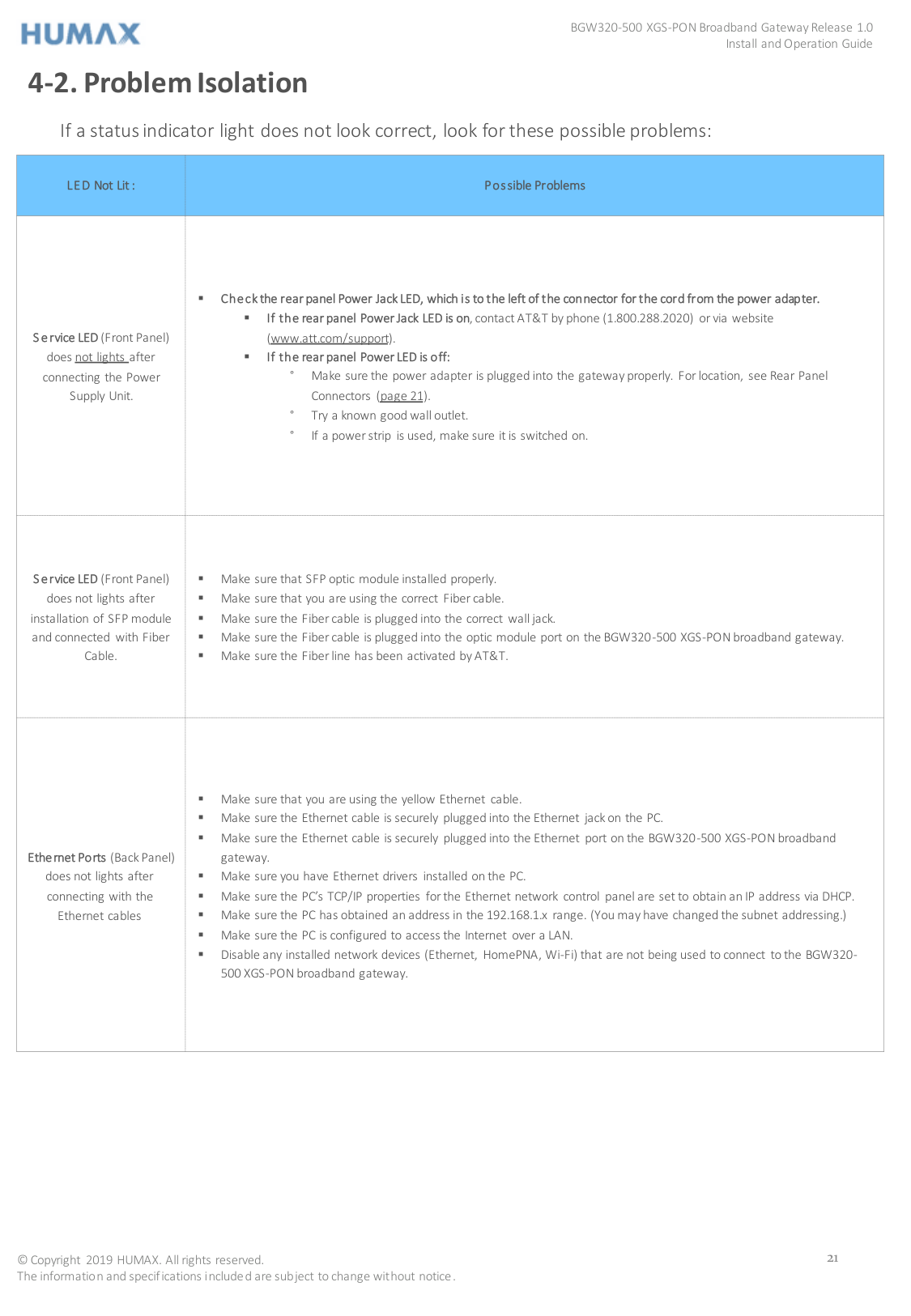
4-2. Problem Isolation
If a status indicator light does not look correct, look for these possible problems:
|LED Not Lit :|Possible Problems| |---|---| |Service LED (Front Panel) does not lights after connecting the Power Supply Unit.
| Check the rear panel Power Jack LED, which is to the left of the connector for the cord from the power adapter.
If the rear panel Power Jack LED is on, contact AT&T by phone (1.800.288.2020) or via website (www.att.com/support).
If the rear panel Power LED is off: ° Make sure the power adapter is plugged into the gateway properly. For location, see Rear Panel
Connectors (page 21). ° Try a known good wall outlet. ° If a power strip is used, make sure it is switched on.
| |Service LED (Front Panel) does not lights after
installation of SFP module and connected with Fiber Cable.| Make sure that SFP optic module installed properly.
Make sure that you are using the correct Fiber cable.
Make sure the Fiber cable is plugged into the correct wall jack.
Make sure the Fiber cable is plugged into the optic module port on the BGW320-500 XGS-PON broadband gateway.
Make sure the Fiber line has been activated by AT&T.
| |Ethernet Ports (Back Panel) does not lights after connecting with the Ethernet cables| Make sure that you are using the yellow Ethernet cable.
Make sure the Ethernet cable is securely plugged into the Ethernet jack on the PC.
Make sure the Ethernet cable is securely plugged into the Ethernet port on the BGW320-500 XGS-PON broadband gateway.
Make sure you have Ethernet drivers installed on the PC.
Make sure the PC’s TCP/IP properties for the Ethernet network control panel are set to obtain an IP address via DHCP.
Make sure the PC has obtained an address in the 192.168.1.x range. (You may have changed the subnet addressing.)
Make sure the PC is configured to access the Internet over a LAN.
Disable any installed network devices (Ethernet, HomePNA, Wi-Fi) that are not being used to connect to the BGW320500 XGS-PON broadband gateway.
|
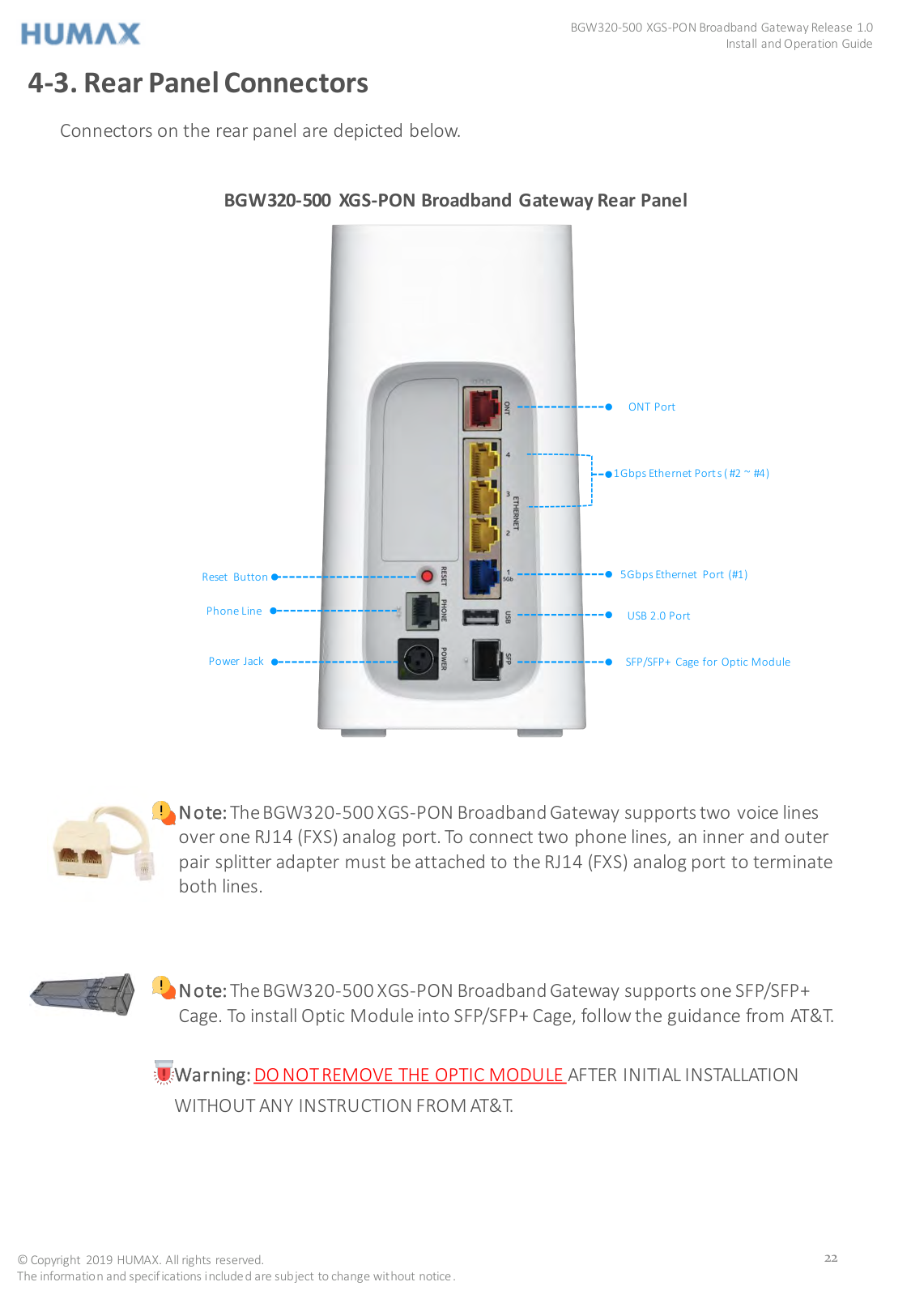
4-3. Rear Panel Connectors
Connectors on the rear panel are depicted below.

##### BGW320-500 XGS-PON Broadband Gateway Rear Panel
ONT Port
1Gbps Ethernet Ports (#2 ~ #4)
5Gbps Ethernet Port (#1)
Reset Button
Phone Line
USB 2.0 Port
SFP/SFP+ Cage for Optic ModulePower Jack


Note:The BGW320-500 XGS-PON Broadband Gateway supports two voice lines over one RJ14 (FXS) analog port. To connect two phone lines, an inner and outer pair splitter adapter must be attached to the RJ14 (FXS) analog port to terminate both lines.


Note:The BGW320-500 XGS-PON Broadband Gateway supports one SFP/SFP+ Cage. To install Optic Module into SFP/SFP+ Cage, follow the guidance from AT&T.

Warning:DO NOT REMOVE THE OPTIC MODULE AFTER INITIAL INSTALLATION WITHOUT ANY INSTRUCTION FROM AT&T.
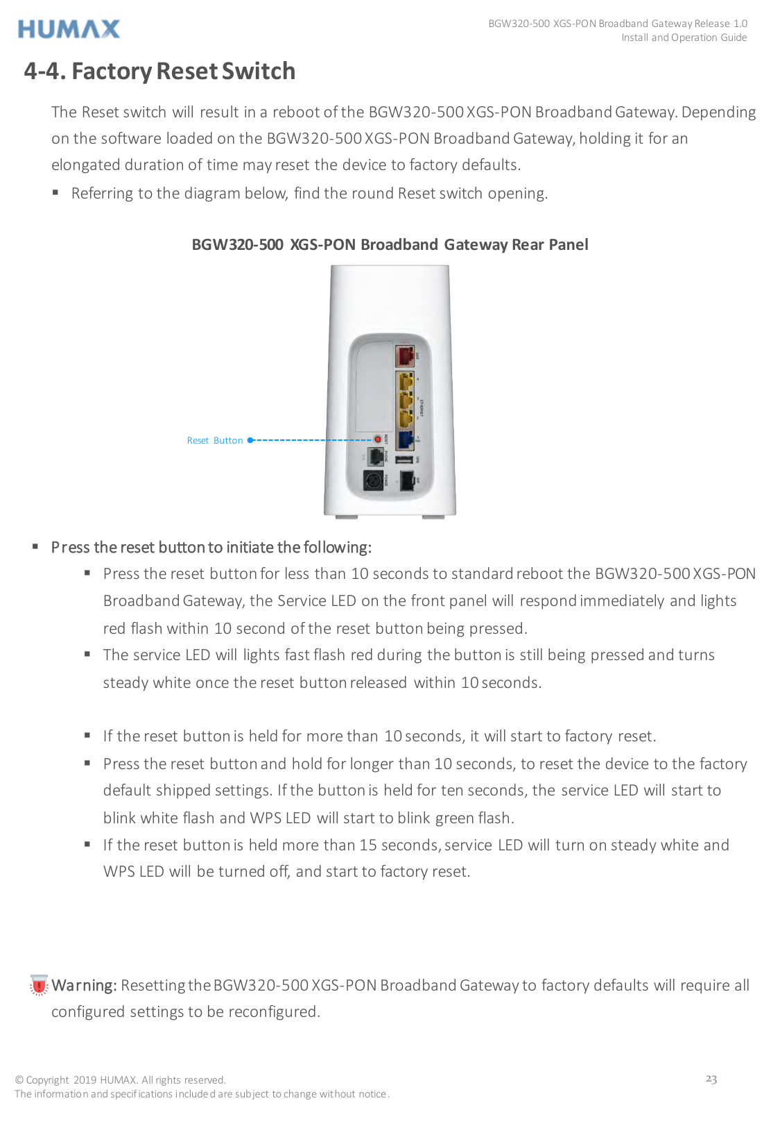
4-4. Factory Reset Switch
The Reset switch will result in a reboot of the BGW320-500 XGS-PON Broadband Gateway. Depending on the software loaded on the BGW320-500 XGS-PON Broadband Gateway, holding it for an elongated duration of time may reset the device to factory defaults.
BGW320-500 XGS-PON Broadband Gateway Rear Panel
Reset Button


Warning: Resetting the BGW320-500 XGS-PON Broadband Gateway to factory defaults will require all configured settings to be reconfigured.
CHAPTER 5
5. Technical Specifications and Safety Information
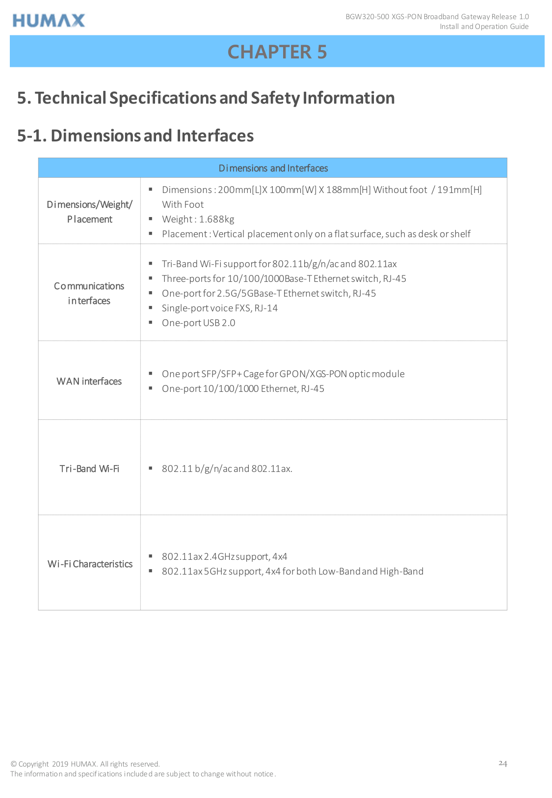
5-1. Dimensions and Interfaces
|Dimensions and Interfaces|Dimensions and Interfaces| |---|---| |Dimensions/Weight/ Placement| Dimensions : 200mm[L]X 100mm[W] X 188mm[H] Without foot / 191mm[H] With Foot
Weight : 1.688kg
Placement :Vertical placement only on a flat surface, such as desk or shelf
| |Communications interfaces| Tri-Band Wi-Fi support for 802.11b/g/n/ac and 802.11ax
Three-ports for 10/100/1000Base-T Ethernet switch, RJ-45
One-portfor 2.5G/5GBase-T Ethernet switch, RJ-45
Single-port voice FXS, RJ-14
One-port USB 2.0
| |WAN interfaces| One port SFP/SFP+ Cage for GPON/XGS-PONoptic module
One-port 10/100/1000 Ethernet, RJ-45
| |Tri-Band Wi-Fi| 802.11 b/g/n/ac and 802.11ax.| |Wi-Fi Characteristics| 802.11ax2.4GHz support, 4x4
802.11ax 5GHz support, 4x4for both Low-Band and High-Band
|
5-2. Power Supply
This product is intended to be supplied with a Listed Direct Plug-In AC/DC power adapter rated @12V 4A DC for all BGW320-xxx models.
The AC/DC power adapter supplied with this product is designed to ensure your personal safety and to be compatible with this equipment. Use only the power adapter that was provided with the gateway.
5-3. Environment
Operating temperature: 0°C to 41.7°C (32° F to 107°F); 8% to 95% (Non Condensing) Relative Humidity Storage temperature: –40°C to 80° C (–40° F to 176°F)
5-4. Agency Approval
Safety Approvals:
5-5. Caring for the Environment by Recycling
Recycling your HUMAX Equipment Please do not dispose of this product with your residential or commercial waste. Some countries or regions have set up systems to collect and recycle electrical and electronic waste items. Contact your local authorities for information about practices established for your region. If collection systems are not available, contact HUMAX Customer Service for assistance at https://humaxdigital.com/environmental-management.
CHAPTER 6
6. Important SafetyInstructions

Warning: Do not use before reading these instructions.
Do not connect the Broadband Ethernet port (labeled ONT) to a carrier or carriage service provider’s telecommunications network or facility unless: A) You have the written consent of the network or facility manager, or B)The connection is in accordance with a connection permit or connection rules. Connection of the Ethernet ports may cause a hazard or damage to the telecommunication network or facility, or persons, with consequential liability for substantial compensation.
6-1. WARNINGS
The power supply must be connected to an outlet. Do not defeat the protective earth connection. The direct plug-in power supply serves as the main power disconnect; locate the direct plug-in power supply near the product for easy access.
6-2. Product Ventilation
The gateway is intended for residential use. Position the gateway in an upright vertical position and
locate it where temperatures remain within a range of 32°– 107°F (0° – 41.7°C) and where heat from the unit itself is not trapped. There must be at least two inches (2") of clearance on all sides except the bottom.
6-3. Telecommunication Installation Cautions
6-4. Optic Module Installation Cautions
It is strongly recommended that you do not install or remove the SFP module with/without fiberoptic cables attached to it because of the potential of damaging the cable, the cable connector, or the optical interfaces in the SFP module. Disconnect all cables before removing or installing an SFP module. Removing and inserting an SFP module can shorten its useful life, so you should not remove and insert SFP modules any more often than is absolutely necessary.
6-5. Electrical Safety Advisory
Telephone companies report that electrical surges, typically lightning transients, are very destructive to customer terminal equipment connected to AC power sources. This has been identified as a major nationwide problem. Therefore it is advised that this equipment be connected to AC power through the use of a surge arrestor or similar protection device.
6-6. Declaration of Conformance
Warning:This is a Class B product. In a domestic environment this product may cause radio interference, in which case the user may be required to take adequate measures. Adequate measures include increasing the physical distance between this product and other electrical devices. Changes or modifications to this unit not expressly approved by the party responsible for compliance could void the user’s authority to operate the equipment. United States: This device complies with Part 15 of the FCC Rules. Operation is subject to the following two conditions:


This equipment has been tested and found to comply with the limits for a Class B digital device, pursuant to Part 15 of the FCC Rules. These limits are designed to provide reasonable protection against harmful interference in a residential installation. This equipment generates, uses, and can radiate radio frequency energy and, if not installed and used in accordance with the instructions, may cause harmful interference to radio communications. However, there is no guarantee that interference will not occur in a particular installation. If this equipment does cause harmful interference to radio or television reception, which can be determined by turning the equipment off and on, the user is encouraged to try to correct the interference by one or more of the following measures:
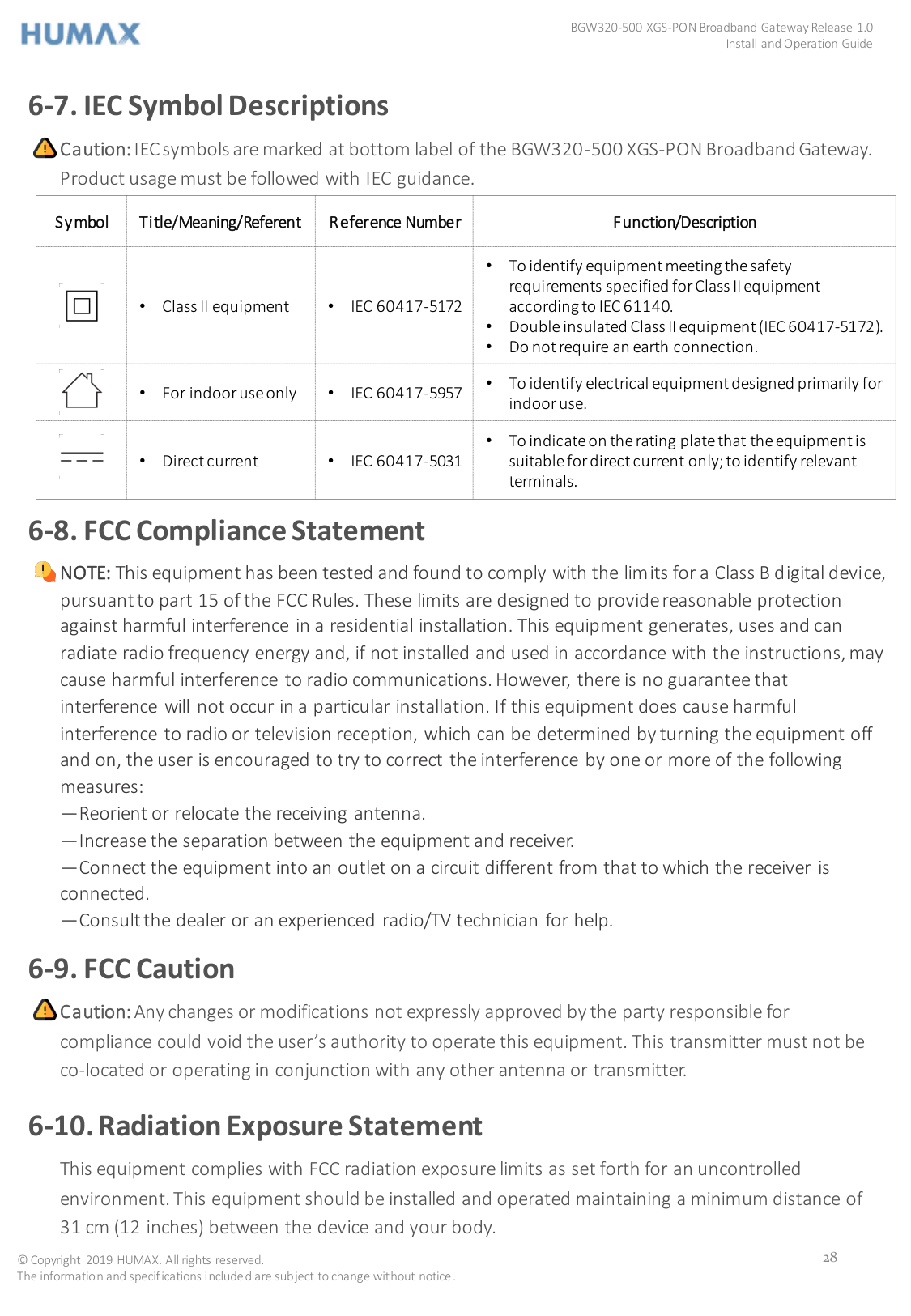
Caution:IEC symbols are marked at bottom label of the BGW320-500 XGS-PON Broadband Gateway. Product usage must be followed with IEC guidance.

|Symbol|Title/Meaning/Referent|Reference Number|Function/Description| |---|---|---|---| ||• Class II equipment|• IEC 60417-5172|• To identify equipment meeting the safety requirements specified for Class II equipment according to IEC 61140.
• Doubleinsulated Class II equipment (IEC 60417-5172).
• Do not require an earth connection.
| ||• For indoor use only|• IEC 60417-5957|• To identify electrical equipment designed primarily for
indoor use.| ||• Direct current|• IEC 60417-5031|• To indicate on the rating plate that the equipment is suitable for direct current only; to identify relevant terminals.|

NOTE: This equipment has been tested and found to comply with the limits for a Class B digital device, pursuant to part 15 of the FCC Rules. These limits are designed to provide reasonable protection against harmful interference in a residential installation. This equipment generates, uses and can radiate radio frequency energy and, if not installed and used in accordance with the instructions, may cause harmful interference to radio communications. However, there is no guarantee that interference will not occur in a particular installation. If this equipment does cause harmful
interference to radio or television reception, which can be determined by turning the equipment off and on, the user is encouraged to try to correct the interference by one or more of the following measures:
—Reorient or relocate the receiving antenna.
—Increase the separation between the equipment and receiver.
—Connect the equipment into an outlet on a circuit different from that to which the receiver is connected.
—Consult the dealer or an experienced radio/TV technician for help.
Caution:Any changes or modifications not expressly approved by the party responsible for compliance could void the user’s authority to operate this equipment. This transmitter must not be co-located or operating in conjunction with any other antenna or transmitter.


This equipment complies with FCC radiation exposure limits as set forth for an uncontrolled environment. This equipment should be installed and operated maintaining a minimum distance of 31 cm (12 inches) between the device and your body.
CHAPTER 7
7. HUMAX Contacts
Technical Services
For technical support on HUMAX products you can contact us on the web.
On the Web www.humaxdigital.com There you will be able to access:
HUMAX AMERICAS REGIONAL HEADQUARTER 15641 Red Hill Avenue Suite 150 Tustin CA 92780
COLORADO RIGIONAL OFFICE(SALES & BUSINESS DEVELOPMENT) 6400S.Fiddlers Green Circle Suite 250 Greenwood Village CO 80111
www.humaxamericas.com