
Ask AI
— answers from the official manualAnswers from the official manual.
Common questions
Common Questions
9 totalHow do I set up the Wi-Fi connection for the Smart-upp?
To set up a Wi-Fi connection, download and install the Itho Daalderop Climate Connect-app on your smartphone or tablet. Then use the app to connect your Smart-upp to your home network via Bluetooth by activating AP MODE in the service menu (page 25). Follow the instructions within the app to complete the connection process.
What should I do if there is no water coming from the safety group's expansion outlet?
If no water comes out of the expansion outlet during heating, immediately turn off the power and open the hot water tap to relieve water pressure. Consult the troubleshooting guide (page 32) for further assistance.
How do I reset the temperature sensors if they encounter an error?
Resetting a temperature sensor error can be done by pressing and holding the Back button in operational status until the LED indicator flashes green twice. Alternatively, use ERROR RESET from the SERVICE menu (page 35). If the issue persists, replace the faulty sensor or control board as directed in the diagnosis of error messages section.
What should I do if an error occurs and requires a reset?
In case of an error message such as E24 or E25, reset the error by pressing the Back button for about five seconds during operational status. The LED indicator will flash green twice to confirm; you can also use ERROR RESET from SERVICE menu (page 39). If issues continue, contact an installer or service organization.
How can I ensure the heater prevents legionella bacteria during periods of disuse?
If the Smart-upp has been turned off for more than three days, perform a procedure to prevent legionella: enable the BOOST function and wait ten minutes until water reaches its set temperature. Open the hot tap and flush out cold water before reheating with the booster function (page 29).
What causes HMI error H1 and how can it be resolved?
An HMI software error H1 can be caused by a lack of communication with the RF module. Try resetting or replacing the HMI controller as identified in the error message guide (page 34).
Full Manual
44 pages
BItho DaalderopSmart-upp
Manual
######### Translation of the original document.
Introduction
This manual contains important information about the safe and proper installation and commissioning of the product.
Read this manual carefully before commencing with the installation.
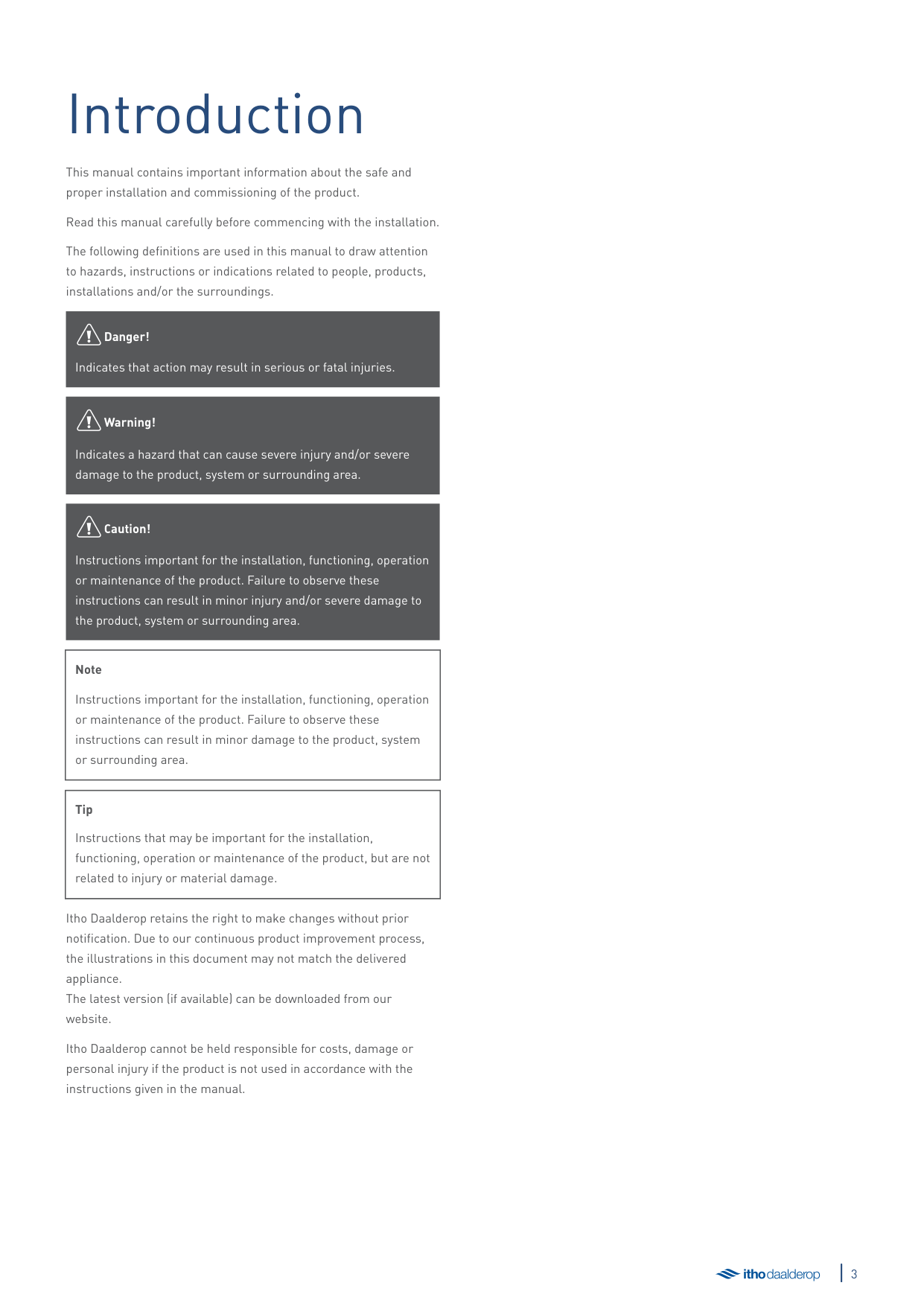
The following definitions are used in this manual to draw attention to hazards, instructions or indications related to people, products, installations and/or the surroundings.
äDanger!
Indicates that action may result in serious or fatal injuries.
äWarning!
Indicates a hazard that can cause severe injury and/or severe damage to the product, system or surrounding area.
äCaution!
Instructions important for the installation, functioning, operation or maintenance of the product. Failure to observe these instructions can result in minor injury and/or severe damage to the product, system or surrounding area.
|Note
Instructions important for the installation, functioning, operation or maintenance of the product. Failure to observe these instructions can result in minor damage to the product, system or surrounding area.| |---|
|Tip
Instructions that may be important for the installation, functioning, operation or maintenance of the product, but are not related to injury or material damage.| |---|
Itho Daalderop retains the right to make changes without prior notification. Due to our continuous product improvement process, the illustrations in this document may not match the delivered appliance. The latest version (if available) can be downloaded from our website.
Itho Daalderop cannot be held responsible for costs, damage or personal injury if the product is not used in accordance with the instructions given in the manual.

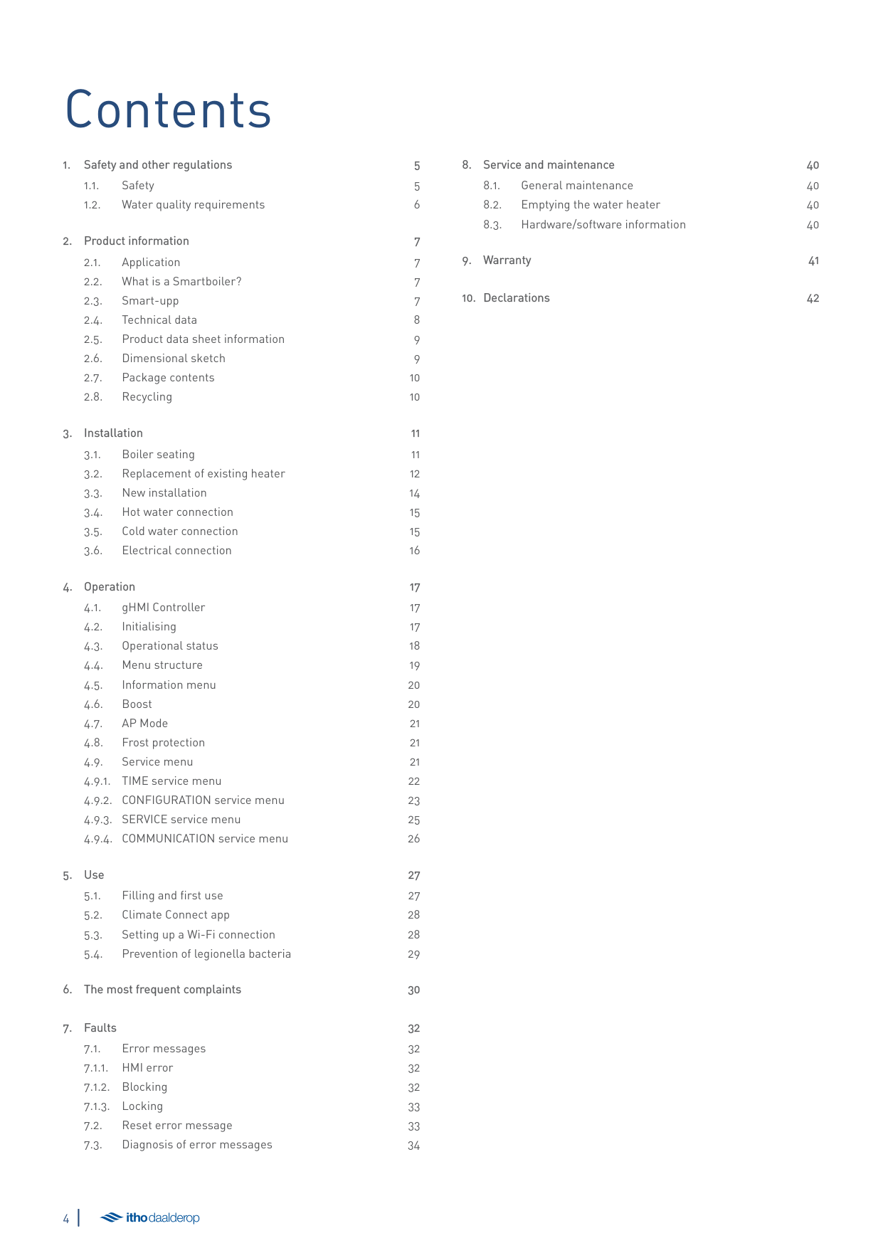
Contents
1. Safety and other regulations
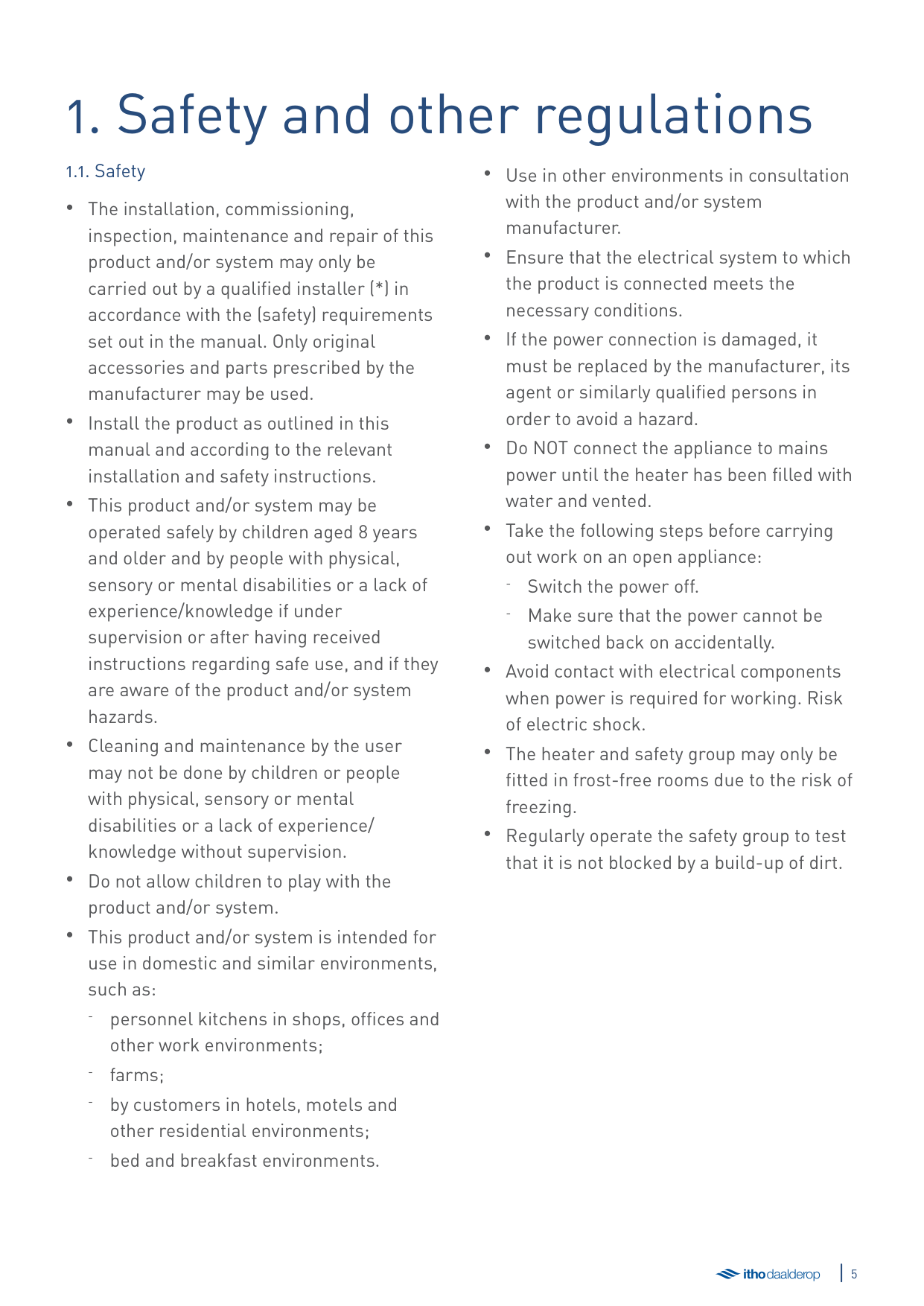
*)The Netherlands: A qualified installer is an installer employed by a central heating or mechanical installation company registered with the Chamber of Commerce and listed in the SEI accreditation register (Foundation for Accreditation of Installation Companies) or which has a Sterkin accreditation.
Belgium A qualified installer is a technician employed by an HVAC or electrical installation company registered with the Crossroads Bank for Enterprises with a valid VAT number.
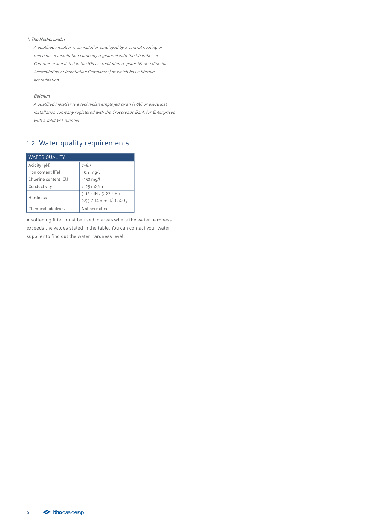
##### 1.2. Water quality requirements
|WATER QUALITY|WATER QUALITY| |---|---| |Acidity (pH)|7–8.5| |Iron content (Fe)|‹ 0.2 mg/l| |Chlorine content (Cl)|‹ 150 mg/l| |Conductivity|‹ 125 mS/m| |Hardness|3-12 °dH / 5-22 °fH / 0.53-2.14 mmol/l CaCO3| |Chemical additives|Not permitted|
A softening filter must be used in areas where the water hardness exceeds the values stated in the table. You can contact your water supplier to find out the water hardness level.
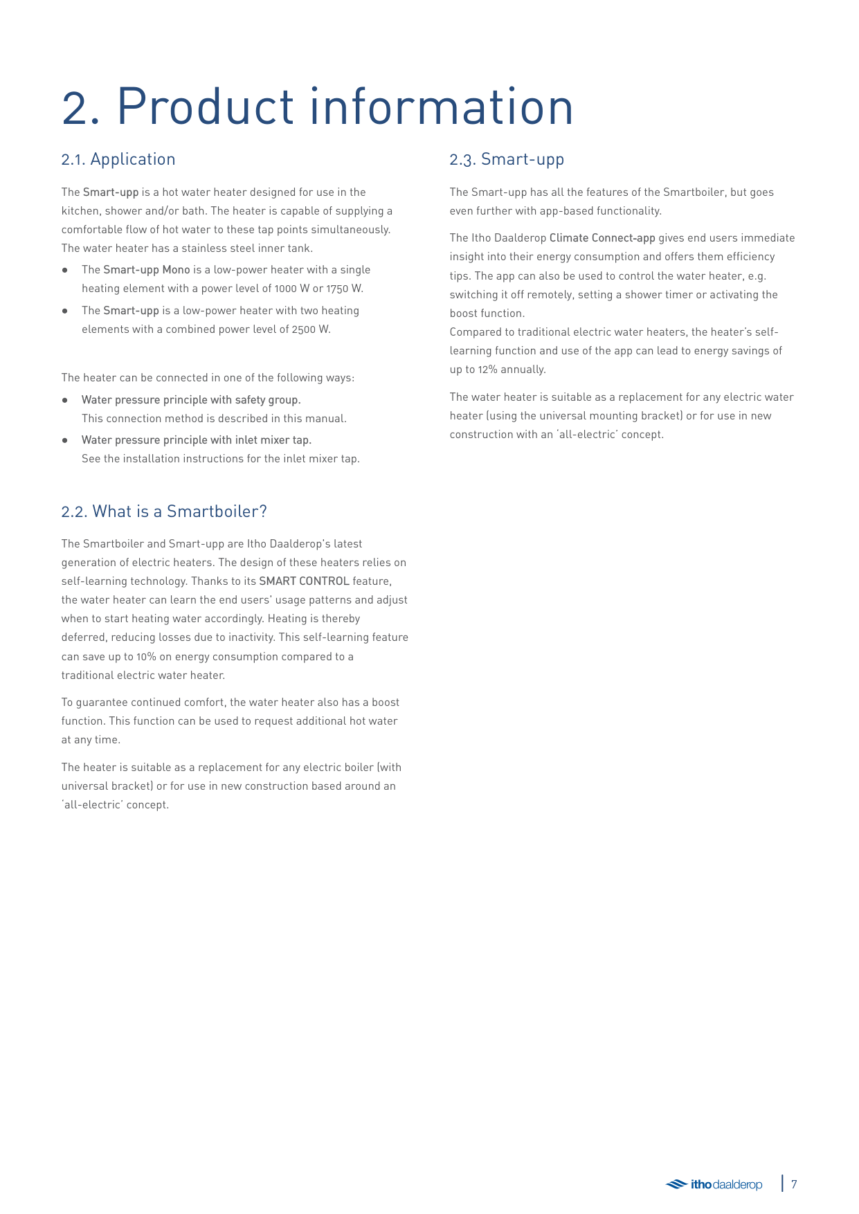
2. Product information
##### 2.1. Application
##### 2.3. Smart-upp
The Smart-upp is a hot water heater designed for use in the kitchen, shower and/or bath. The heater is capable of supplying a comfortable flow of hot water to these tap points simultaneously. The water heater has a stainless steel inner tank.
The heater can be connected in one of the following ways:
The Smart-upp has all the features of the Smartboiler, but goes even further with app-based functionality.
The Itho Daalderop Climate Connect‑app gives end users immediate insight into their energy consumption and offers them efficiency tips. The app can also be used to control the water heater, e.g. switching it off remotely, setting a shower timer or activating the boost function. Compared to traditional electric water heaters, the heater’s selflearning function and use of the app can lead to energy savings of up to 12% annually.
The water heater is suitable as a replacement for any electric water heater (using the universal mounting bracket) or for use in new construction with an ‘all-electric’ concept.
##### 2.2. What is a Smartboiler?
The Smartboiler and Smart-upp are Itho Daalderop's latest generation of electric heaters. The design of these heaters relies on self-learning technology. Thanks to its SMART CONTROL feature, the water heater can learn the end users' usage patterns and adjust when to start heating water accordingly. Heating is thereby deferred, reducing losses due to inactivity. This self-learning feature can save up to 10% on energy consumption compared to a traditional electric water heater.
To guarantee continued comfort, the water heater also has a boost function. This function can be used to request additional hot water at any time.
The heater is suitable as a replacement for any electric boiler (with universal bracket) or for use in new construction based around an ‘all-electric’ concept.
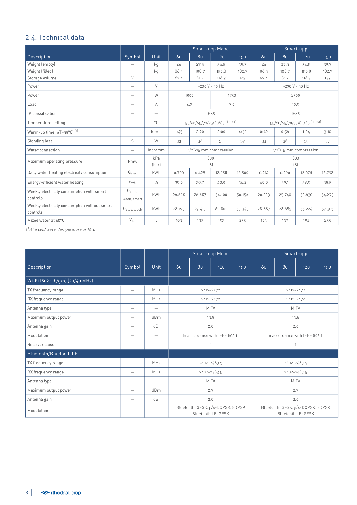
##### 2.4. Technical data
|Description|Symbol|Unit|Smart-upp Mono|Smart-upp Mono|Smart-upp Mono|Smart-upp Mono|Smart-upp|Smart-upp|Smart-upp|Smart-upp| |---|---|---|---|---|---|---|---|---|---|---| |Description|Symbol|Unit|60|80|120|150|60|80|120|150| |Weight (empty)| |kg|24|27.5|34.5|39.7|24|27.5|34.5|39.7| |Weight (filled)| |kg|86.5|108.7|150.8|182.7|86.5|108.7|150.8|182.7| |Storage volume|V|l|62.4|81.2|116.3|143|62.4|81.2|116.3|143| |Power|—|V|~230 V - 50 Hz|~230 V - 50 Hz|~230 V - 50 Hz|~230 V - 50 Hz|~230 V - 50 Hz|~230 V - 50 Hz|~230 V - 50 Hz|~230 V - 50 Hz| |Power|—|W|1000|1000|1750|1750|2500|2500|2500|2500| |Load|—|A|4.3|4.3|7.6|7.6|10.9|10.9|10.9|10.9| |IP classification|—|—|IPX5|IPX5|IPX5|IPX5|IPX5|IPX5|IPX5|IPX5| |Temperature setting|—|°C|55/60/65/70/75/80/85 (boost)|55/60/65/70/75/80/85 (boost)|55/60/65/70/75/80/85 (boost)|55/60/65/70/75/80/85 (boost)|55/60/65/70/75/80/85 (boost)|55/60/65/70/75/80/85 (boost)|55/60/65/70/75/80/85 (boost)|55/60/65/70/75/80/85 (boost)| |Warm-up time (∆T=55°C) (1)|—|h:min|1:45|2:20|2:00|4:30|0:42|0:56|1:24|3:10| |Standing loss|S|W|33|36|50|57|33|36|50|57| |Water connection|—|inch/mm|1/2"/15 mm compression|1/2"/15 mm compression|1/2"/15 mm compression|1/2"/15 mm compression|1/2"/15 mm compression|1/2"/15 mm compression|1/2"/15 mm compression|1/2"/15 mm compression| |Maximum operating pressure|Pmw|kPa (bar)|800 (8)|800 (8)|800 (8)|800 (8)|800 (8)|800 (8)|800 (8)|800 (8)| |Daily water heating electricity consumption|Qelec|kWh|6.700|6.425|12.658|13.500|6.214|6.296|12.678|12.792| |Energy-efficient water heating|ƞwh|%|39.0|39.7|40.0|36.2|40.0|39.1|38.9|38.5| |Weekly electricity consumption with smart controls|Qelec, week, smart|kWh|26.608|26.687|54.100|56.156|26.223|25.740|52.630|54.873| |Weekly electricity consumption without smart controls|Qelec, week|kWh|28.193|29.417|60.800|57.343|28.887|28.685|55.224|57.305| |Mixed water at 40°C|V40|l|103|137|193|255|103|137|194|255|
1) At a cold water temperature of 10°C.
|Description|Symbol|Unit|Smart-upp Mono|Smart-upp Mono|Smart-upp Mono|Smart-upp Mono|Smart-upp|Smart-upp|Smart-upp|Smart-upp| |---|---|---|---|---|---|---|---|---|---|---| |Description|Symbol|Unit|60|80|120|150|60|80|120|150| |Wi-Fi (802.11b/g/n) (20/40 MHz)|Wi-Fi (802.11b/g/n) (20/40 MHz)|Wi-Fi (802.11b/g/n) (20/40 MHz)| | | | | | | | | |TX frequency range| |MHz|2412–2472|2412–2472|2412–2472|2412–2472|2412–2472|2412–2472|2412–2472|2412–2472| |RX frequency range|—|MHz|2412–2472|2412–2472|2412–2472|2412–2472|2412–2472|2412–2472|2412–2472|2412–2472| |Antenna type|—|—|MIFA|MIFA|MIFA|MIFA|MIFA|MIFA|MIFA|MIFA| |Maximum output power|—|dBm|13.8|13.8|13.8|13.8|13.8|13.8|13.8|13.8| |Antenna gain|—|dBi|2.0|2.0|2.0|2.0|2.0|2.0|2.0|2.0| |Modulation| | |In accordance with IEEE 802.11|In accordance with IEEE 802.11|In accordance with IEEE 802.11|In accordance with IEEE 802.11|In accordance with IEEE 802.11|In accordance with IEEE 802.11|In accordance with IEEE 802.11|In accordance with IEEE 802.11| |Receiver class|—|—|1|1|1|1|1|1|1|1| |Bluetooth/Bluetooth LE|Bluetooth/Bluetooth LE|Bluetooth/Bluetooth LE| | | | | | | | | |TX frequency range|—|MHz|2402–2483.5|2402–2483.5|2402–2483.5|2402–2483.5|2402–2483.5|2402–2483.5|2402–2483.5|2402–2483.5| |RX frequency range|—|MHz|2402–2483.5|2402–2483.5|2402–2483.5|2402–2483.5|2402–2483.5|2402–2483.5|2402–2483.5|2402–2483.5| |Antenna type| | |MIFA|MIFA|MIFA|MIFA|MIFA|MIFA|MIFA|MIFA| |Maximum output power|—|dBm|2.7|2.7|2.7|2.7|2.7|2.7|2.7|2.7| |Antenna gain|—|dBi|2.0|2.0|2.0|2.0|2.0|2.0|2.0|2.0| |Modulation|—|—|Bluetooth: GFSK, ρ/4-DQPSK, 8DPSK Bluetooth LE: GFSK|Bluetooth: GFSK, ρ/4-DQPSK, 8DPSK Bluetooth LE: GFSK|Bluetooth: GFSK, ρ/4-DQPSK, 8DPSK Bluetooth LE: GFSK|Bluetooth: GFSK, ρ/4-DQPSK, 8DPSK Bluetooth LE: GFSK|Bluetooth: GFSK, ρ/4-DQPSK, 8DPSK Bluetooth LE: GFSK|Bluetooth: GFSK, ρ/4-DQPSK, 8DPSK Bluetooth LE: GFSK|Bluetooth: GFSK, ρ/4-DQPSK, 8DPSK Bluetooth LE: GFSK|Bluetooth: GFSK, ρ/4-DQPSK, 8DPSK Bluetooth LE: GFSK|
##### 2.5. Product data sheet information
|Itho Daalderop|Itho Daalderop|Itho Daalderop|Smart-upp Mono|Smart-upp Mono|Smart-upp Mono|Smart-upp Mono|Smart-upp|Smart-upp|Smart-upp|Smart-upp| |---|---|---|---|---|---|---|---|---|---|---| |Description|Symbol|Unit|60|80|120|150|60|80|120|150| |Declared load profile| | |M|M|L|L|M|M|L|L| |Water heating energy efficiency class| | |B|B|C|C|B|B|C|C| |Energy-efficient water heating (1)|ƞwh|%|39|40|40|36|40|40|39|39| |Annual water heating electricity consumption (1)|AEC|kWh|1317|1294|2556|2907|1230|1312|2632|2670| |Thermostat temperature setting (2)|—|°C|65|65|65|65|65|65|65|65| |Sound power level, indoors|LWA|dB|15|15|15|15|15|15|15|15| |Specific precautions to be taken for assembly, installation or maintenance|Specific precautions to be taken for assembly, installation or maintenance|Specific precautions to be taken for assembly, installation or maintenance|Read the manual before installation and use|Read the manual before installation and use|Read the manual before installation and use|Read the manual before installation and use|Read the manual before installation and use|Read the manual before installation and use|Read the manual before installation and use|Read the manual before installation and use|
1) Applies only with smart control function enabled. 2) To be set by the user.
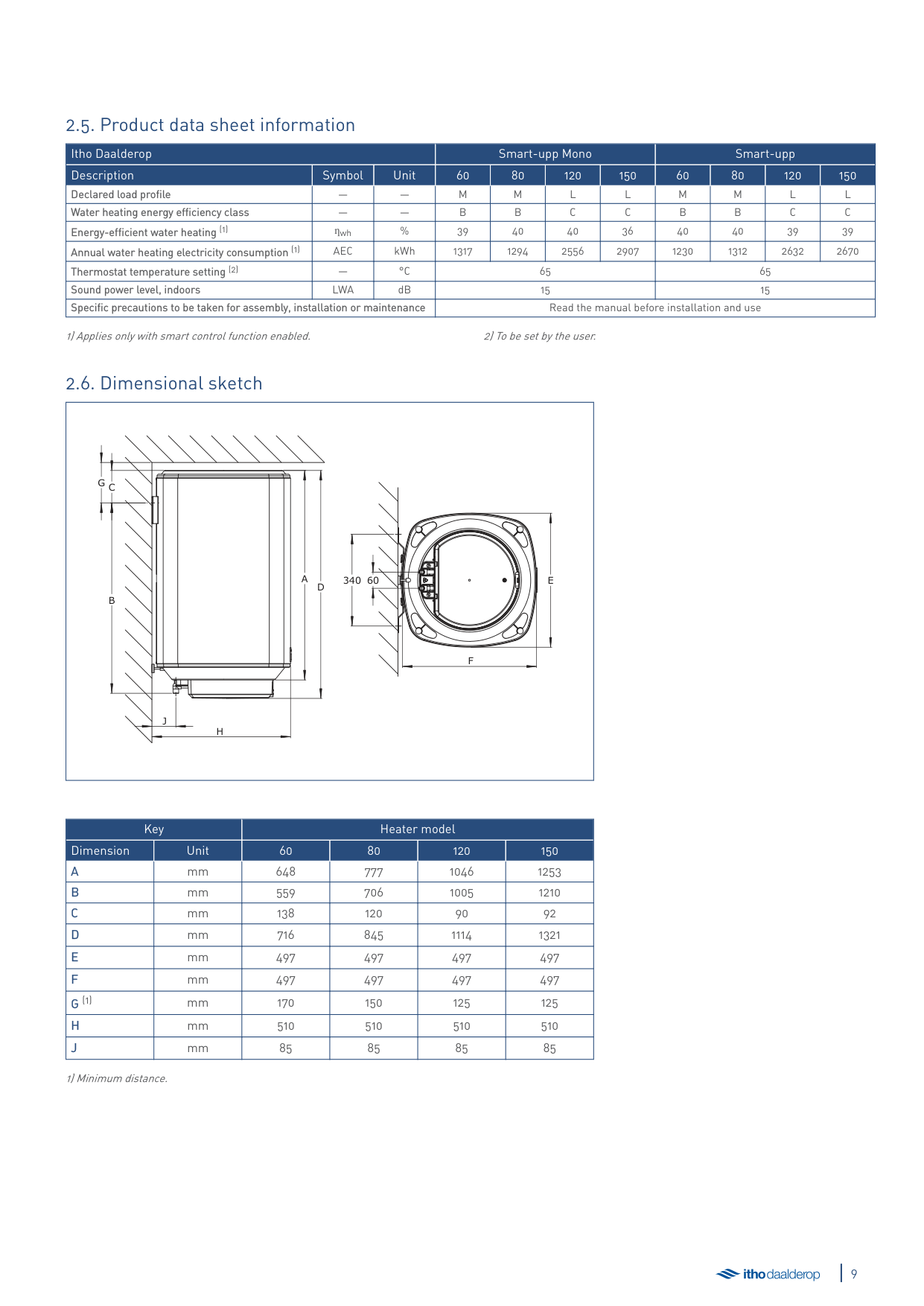
##### 2.6. Dimensional sketch
|H
J
CG
B
A
D
340 60 E
F
| |---|
|Key|Key|Heater model|Heater model|Heater model|Heater model| |---|---|---|---|---|---| |Dimension|Unit|60|80|120|150| |A|mm|648|777|1046|1253| |B|mm|559|706|1005|1210| |C|mm|138|120|90|92| |D|mm|716|845|1114|1321| |E|mm|497|497|497|497| |F|mm|497|497|497|497| |G (1)|mm|170|150|125|125| |H|mm|510|510|510|510| |J|mm|85|85|85|85|
1) Minimum distance.
##### 2.7. Package contents
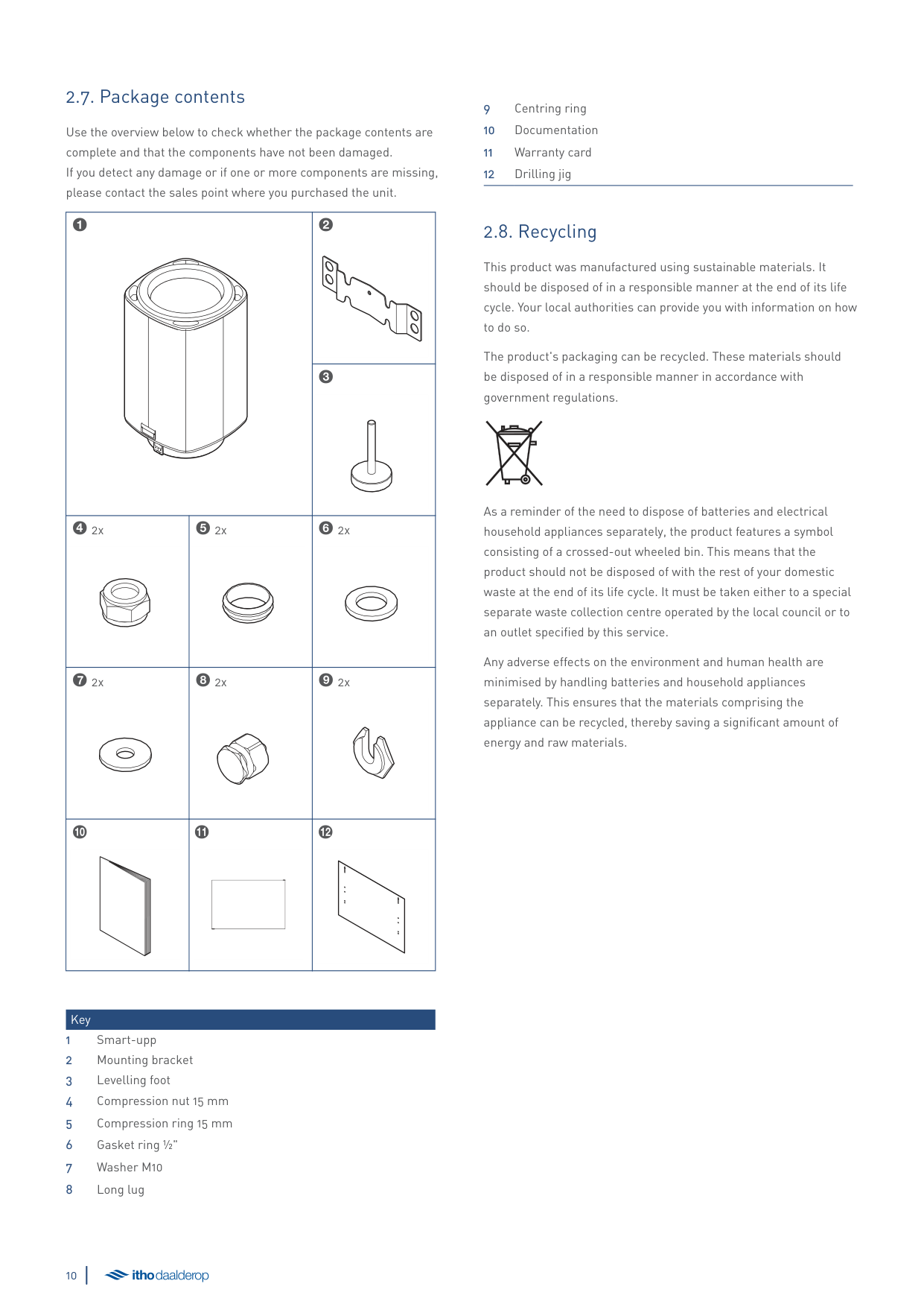
Use the overview below to check whether the package contents are complete and that the components have not been damaged. If you detect any damage or if one or more components are missing, please contact the sales point where you purchased the unit.
|1
|1
|2
| |---|---|---| |1
|1
|3
| |42x
|52x
|62x
| |72x
|82x
|92x
| |0
|!
|@
|
Key
##### 2.8. Recycling
This product was manufactured using sustainable materials. It should be disposed of in a responsible manner at the end of its life cycle. Your local authorities can provide you with information on how to do so.
The product's packaging can be recycled. These materials should be disposed of in a responsible manner in accordance with government regulations.
As a reminder of the need to dispose of batteries and electrical household appliances separately, the product features a symbol consisting of a crossed-out wheeled bin. This means that the product should not be disposed of with the rest of your domestic waste at the end of its life cycle. It must be taken either to a special separate waste collection centre operated by the local council or to an outlet specified by this service.
Any adverse effects on the environment and human health are minimised by handling batteries and household appliances separately. This ensures that the materials comprising the appliance can be recycled, thereby saving a significant amount of energy and raw materials.
3. Installation
äWarning!
NEVER turn on the power during installation to prevent damage to the product.
Make the following preparations:
To replace an existing heater, follow the instructions under Replacement of existing heater on page 12.
Otherwise, continue from New installation on page 14.
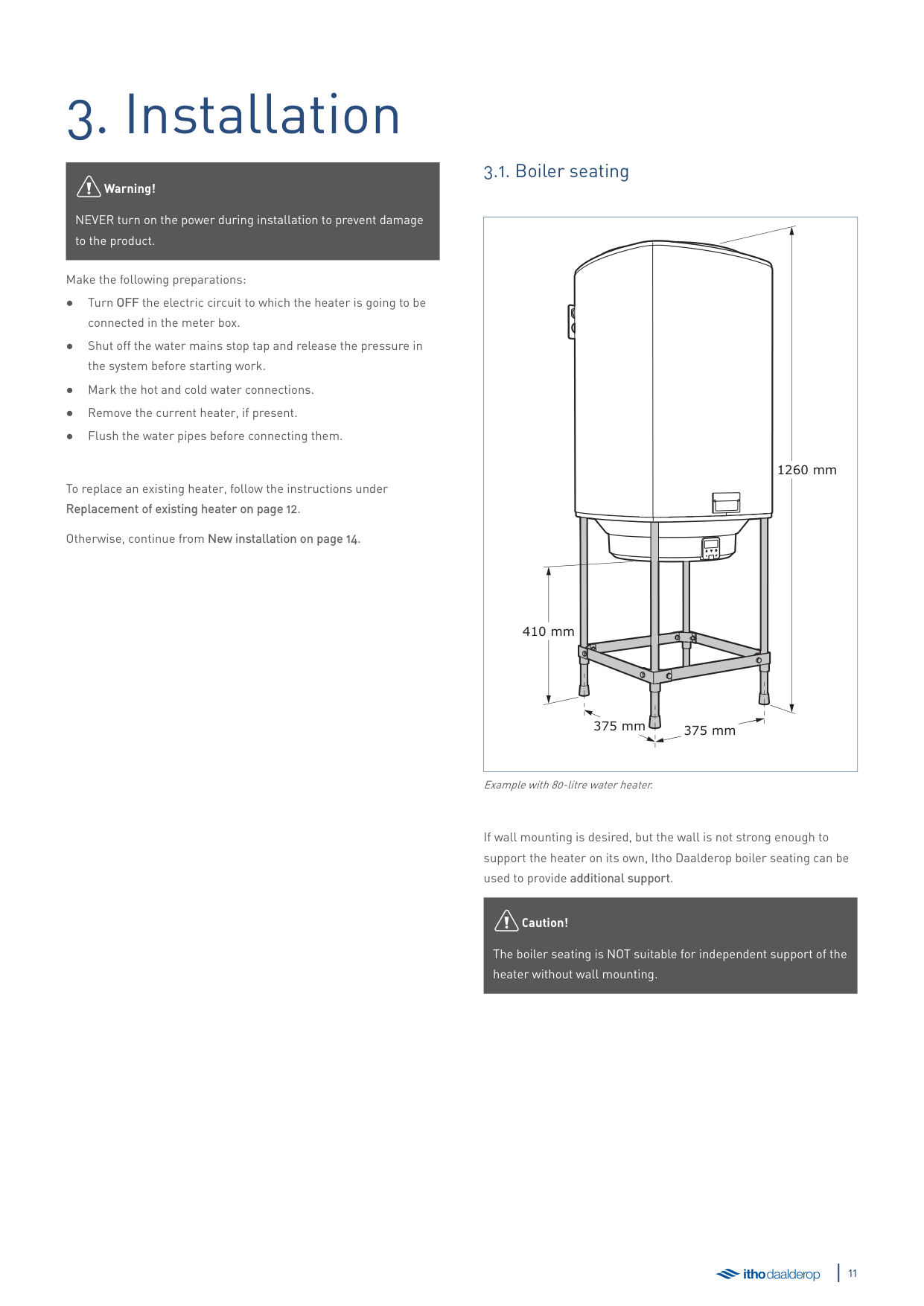
##### 3.1. Boiler seating
|1260 mm
375 mm 375 mm
410 mm| |---|
Example with 80-litre water heater.
If wall mounting is desired, but the wall is not strong enough to support the heater on its own, Itho Daalderop boiler seating can be used to provide additional support.
äCaution!
The boiler seating is NOT suitable for independent support of the heater without wall mounting.
##### 3.2. Replacement of existing heater
The mounting bracket design enables the most common existing heaters to be replaced without needing to drill new holes or replace the piping. If this is not possible, install the heater according to the instructions under New installation on page 14.
|J
| |---|
| |Standard|Long| |---|---|---| | | | | |J (mm)|85|100|
| | |---|
| | |---|
|Standard|Reverse| |---|---| | | |
| | |---|
####### K
| |Heater model|Heater model|Heater model|Heater model| |---|---|---|---|---| |Dimension|60|80|120|150|
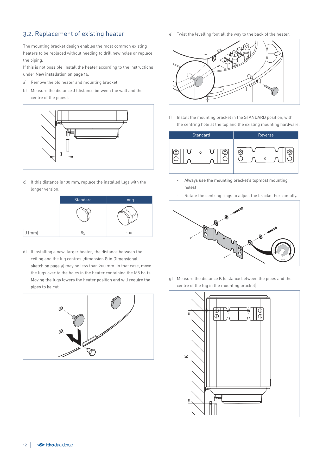
|K (mm)|559|705|1005|1208|
| | |---|
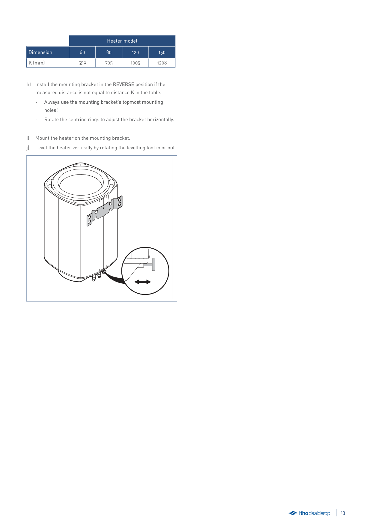
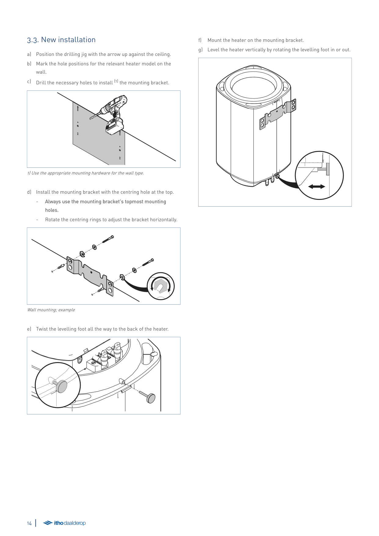
##### 3.3. New installation
| | |---|
1) Use the appropriate mounting hardware for the wall type.
| | |---|
Wall mounting; example
| | |---|
| | |---|
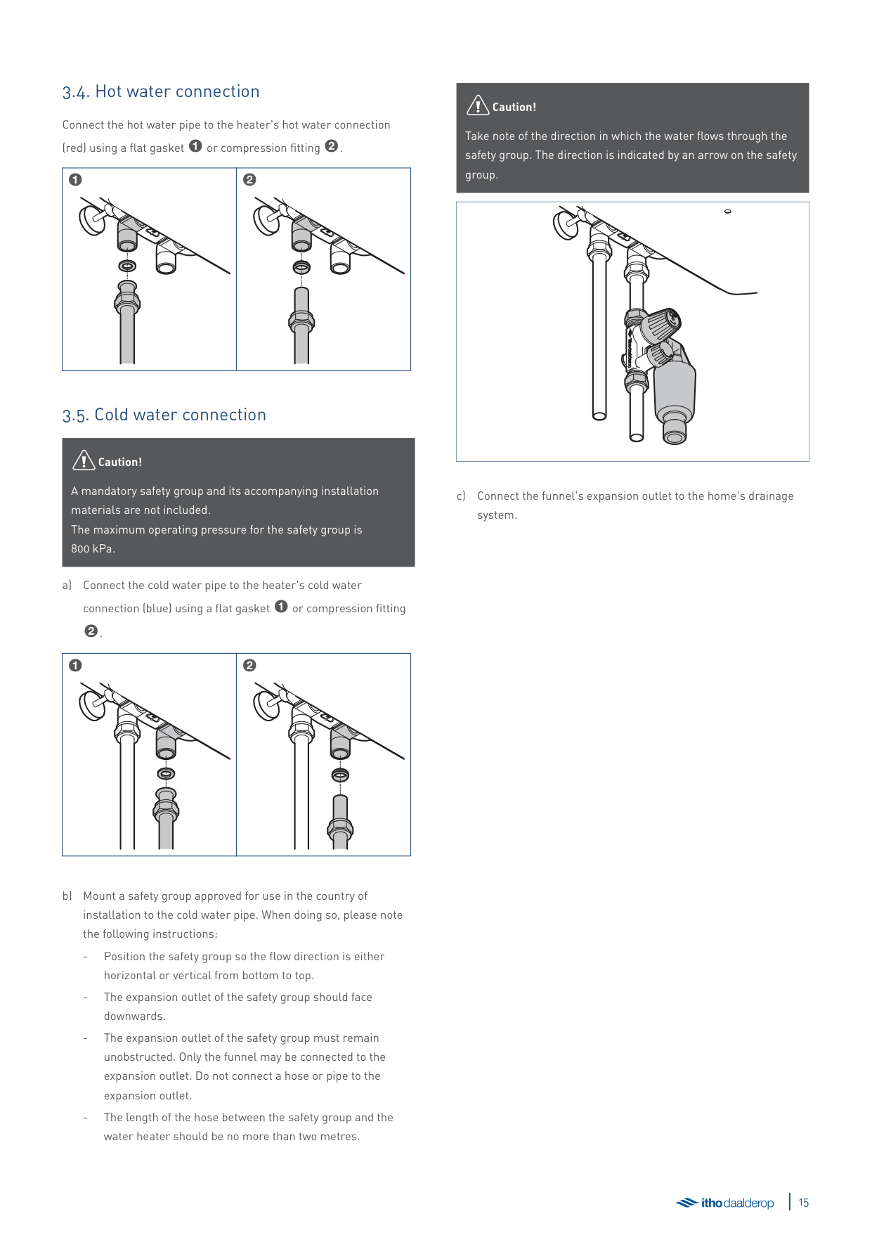
##### 3.4. Hot water connection
Connect the hot water pipe to the heater's hot water connection
(red) using a flat gasket 1or compression fitting2.
|1
|2
| |---|---|
##### 3.5. Cold water connection
äCaution!
A mandatory safety group and its accompanying installation materials are not included. The maximum operating pressure for the safety group is 800 kPa.
connection (blue) using a flat gasket 1or compression fitting
|1
|2
| |---|---|
äCaution!
Take note of the direction in which the water flows through the safety group. The direction is indicated by an arrow on the safety group.
| | |---|
c) Connect the funnel's expansion outlet to the home's drainage system.
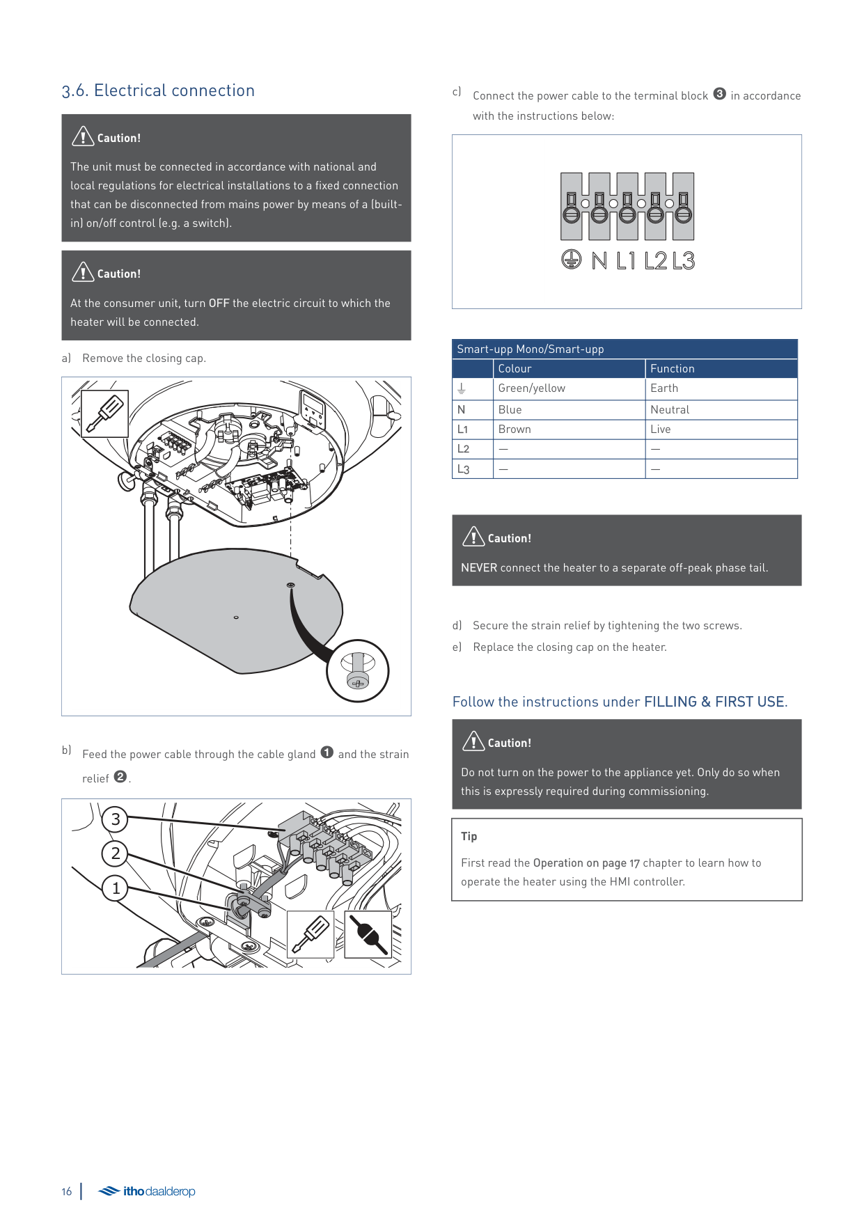
##### 3.6. Electrical connection
äCaution!
The unit must be connected in accordance with national and local regulations for electrical installations to a fixed connection that can be disconnected from mains power by means of a (builtin) on/off control (e.g. a switch).
äCaution!
At the consumer unit, turn OFF the electric circuit to which the heater will be connected.
| | |---|
|1
2
3
| |---|
c) Connect the power cable to the terminal block 3in accordance
with the instructions below:
| | |---|
|Smart-upp Mono/Smart-upp|Smart-upp Mono/Smart-upp|Smart-upp Mono/Smart-upp| |---|---|---| | |Colour|Function| |W|Green/yellow|Earth| |N|Blue|Neutral| |L1|Brown|Live| |L2|—|—| |L3|—|—|
äCaution!
NEVER connect the heater to a separate off-peak phase tail.
###### Follow the instructions under FILLING & FIRST USE.
äCaution!
Do not turn on the power to the appliance yet. Only do so when this is expressly required during commissioning.
|Tip
First read the Operation on page 17 chapter to learn how to operate the heater using the HMI controller.| |---|
4. Operation
##### 4.1. gHMI Controller
The Smart-upp is equipped with a gHMI controller.
|2
| | | | |---|---|---| | | | | | | | |
3
4
5
1
| | | |---|---| | | | | | |
6| |---|
Key
The appliance has various statuses, menus and messages which can be displayed on the screen, namely:
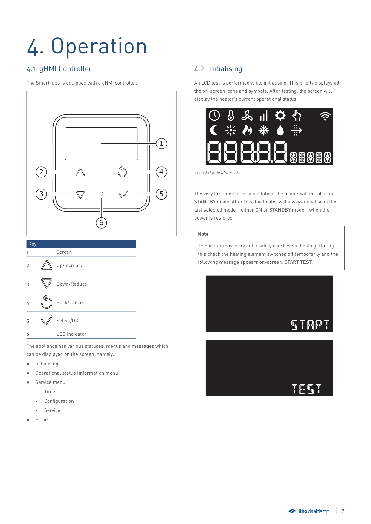
##### 4.2. Initialising
######### An LCD test is performed while initialising. This briefly displays all the on-screen icons and symbols. After testing, the screen will display the heater's current operational status.
The LED indicator is off.
The very first time (after installation) the heater will initialise in STANDBY mode. After this, the heater will always initialise in the last selected mode – either ON or STANDBY mode – when the power is restored.
|Note
The heater may carry out a safety check while heating. During this check the heating element switches off temporarily and the following message appears on-screen: START TEST.| |---|
#### start
#### test
##### 4.3. Operational status
The screen is disabled during normal operation. The LED indicator is continuously lit in light blue. Press any button to activate the screen and display the current operational status.
The screen can display the following icons with these meanings:
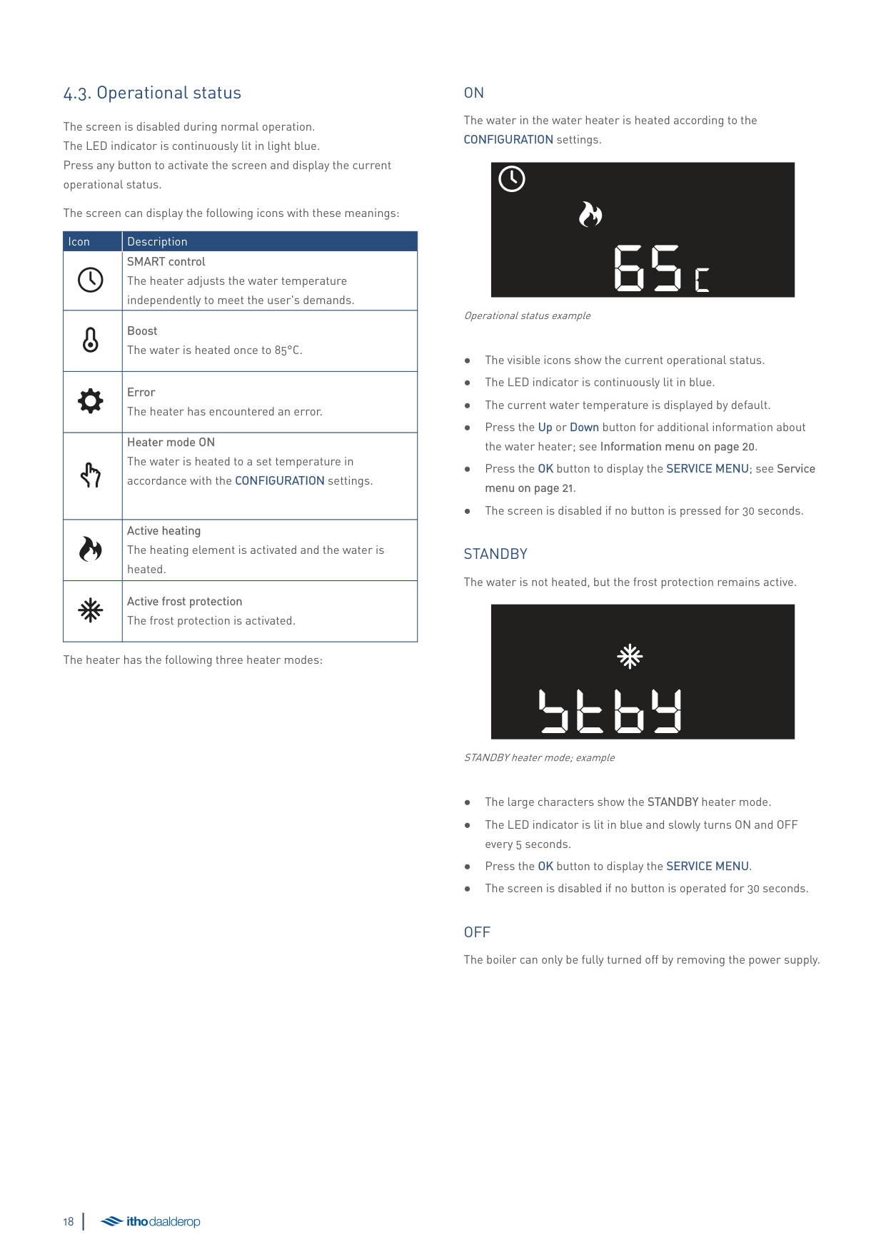
|Icon|Description| |---|---| | |SMART control The heater adjusts the water temperature independently to meet the user's demands.| | |Boost The water is heated once to 85°C.| | |Error The heater has encountered an error.| | |Heater mode ON The water is heated to a set temperature in accordance with the CONFIGURATION settings.| | |Active heating The heating element is activated and the water is heated.| | |Active frost protection The frost protection is activated.|
The heater has the following three heater modes:
ON The water in the water heater is heated according to the CONFIGURATION settings.
65c
Operational status example
STANDBY The water is not heated, but the frost protection remains active.
STBY
STANDBY heater mode; example
OFF The boiler can only be fully turned off by removing the power supply.
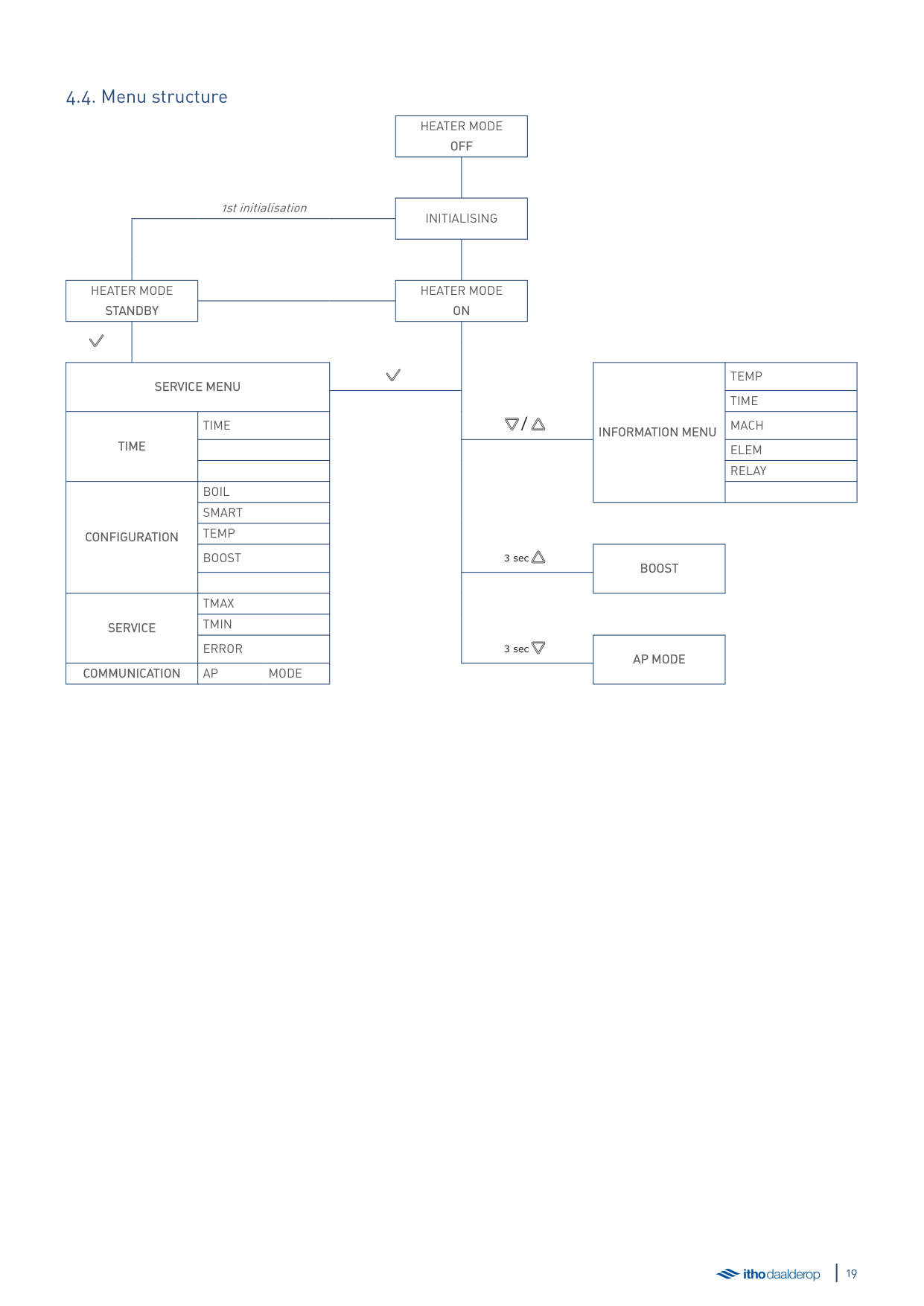
1st initialisation
HEATER MODE OFF
INITIALISING
HEATER MODE STANDBY
HEATER MODE ON
SERVICE MENU
TEMP TIME
TIME
CONFIGURATION
TIME / MACH
INFORMATION MENU
ELEM RELAY
BOIL SMART TEMP BOOST 3 sec
BOOST
TMAX TMIN ERROR 3 sec
SERVICE
######## AP MODE COMMUNICATION AP MODE
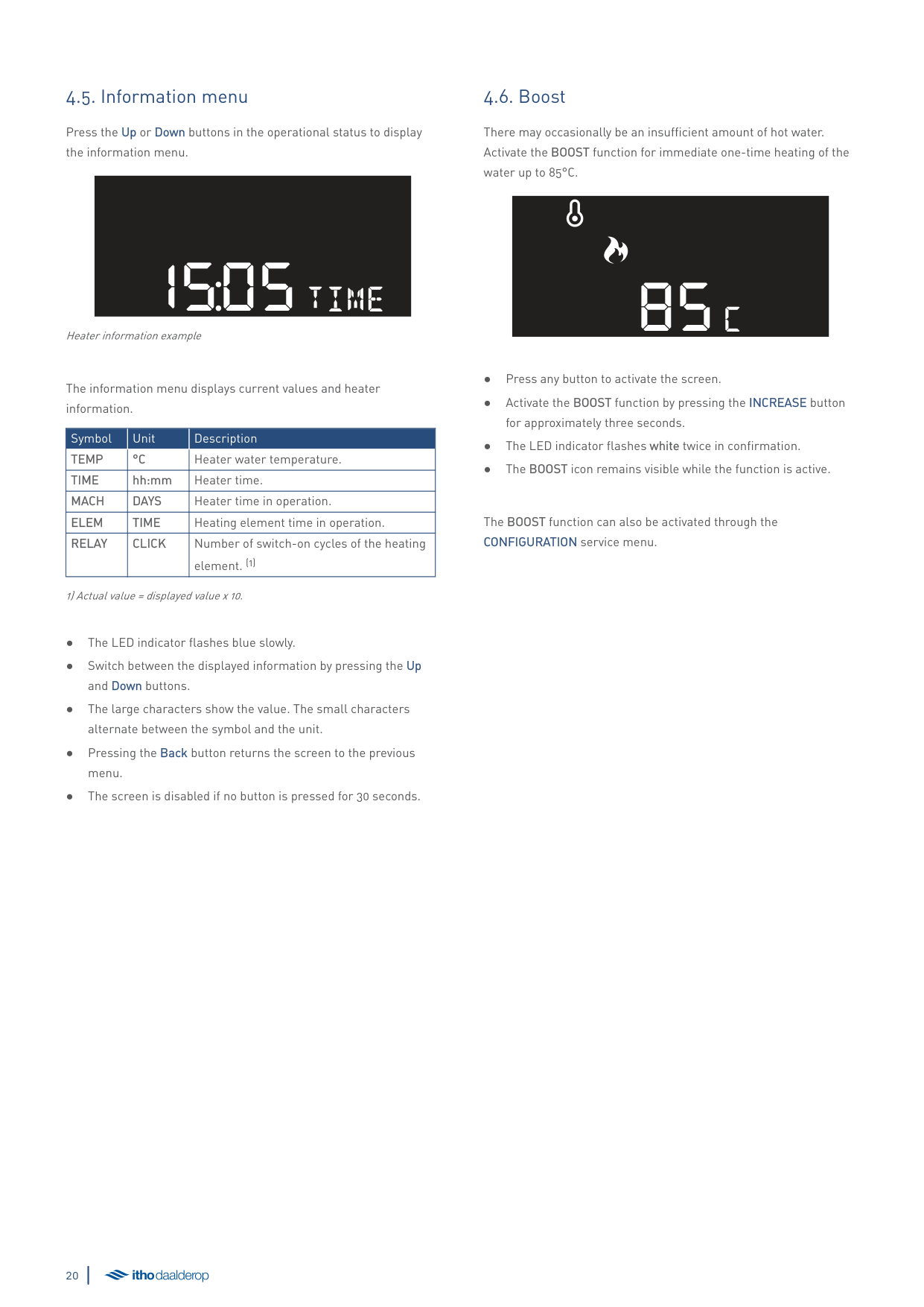
##### 4.5. Information menu
Press the Up or Down buttons in the operational status to display the information menu.
1505time
Heater information example
######### The information menu displays current values and heater information.
|Symbol|Unit|Description| |---|---|---| |TEMP|°C|Heater water temperature.| |TIME|hh:mm|Heater time.| |MACH|DAYS|Heater time in operation.| |ELEM|TIME|Heating element time in operation.| |RELAY|CLICK|Number of switch-on cycles of the heating element. (1)|
1) Actual value = displayed value x 10.
##### 4.6. Boost
There may occasionally be an insufficient amount of hot water. Activate the BOOST function for immediate one-time heating of the water up to 85°C.
85c
The BOOST function can also be activated through the CONFIGURATION service menu.
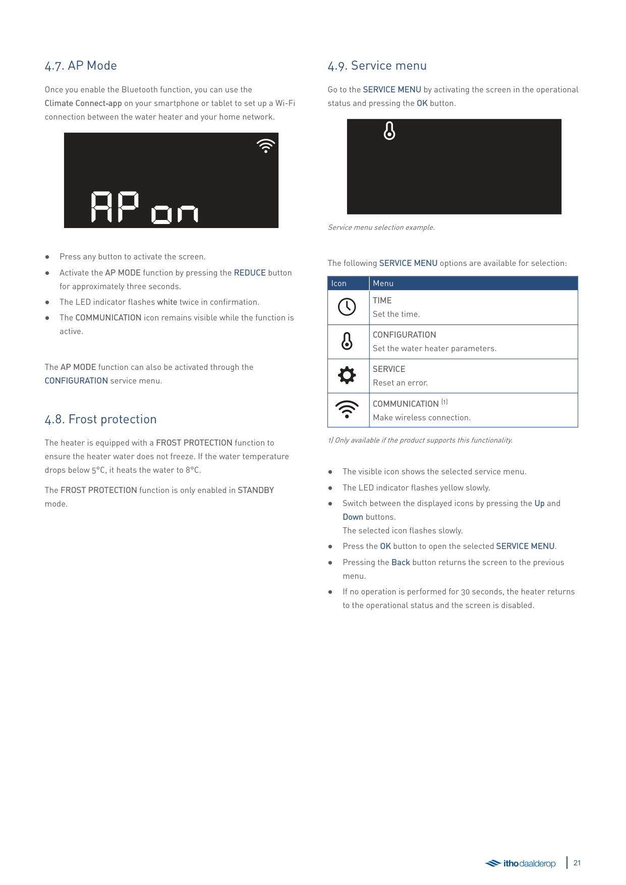
##### 4.7. AP Mode
Once you enable the Bluetooth function, you can use the Climate Connect‑app on your smartphone or tablet to set up a Wi-Fi connection between the water heater and your home network.
AP ON
The AP MODE function can also be activated through the CONFIGURATION service menu.
##### 4.8. Frost protection
The heater is equipped with a FROST PROTECTION function to ensure the heater water does not freeze. If the water temperature drops below 5°C, it heats the water to 8°C.
The FROST PROTECTION function is only enabled in STANDBY mode.
##### 4.9. Service menu
######### Go to the SERVICE MENU by activating the screen in the operational status and pressing the OK button.
Service menu selection example.
######### The following SERVICE MENU options are available for selection:
|Icon|Menu| |---|---| | |TIME Set the time.| | |CONFIGURATION Set the water heater parameters.|
| |SERVICE Reset an error.| | |COMMUNICATION (1) Make wireless connection.|
1) Only available if the product supports this functionality.
###### 4.9.1. TIME service menu
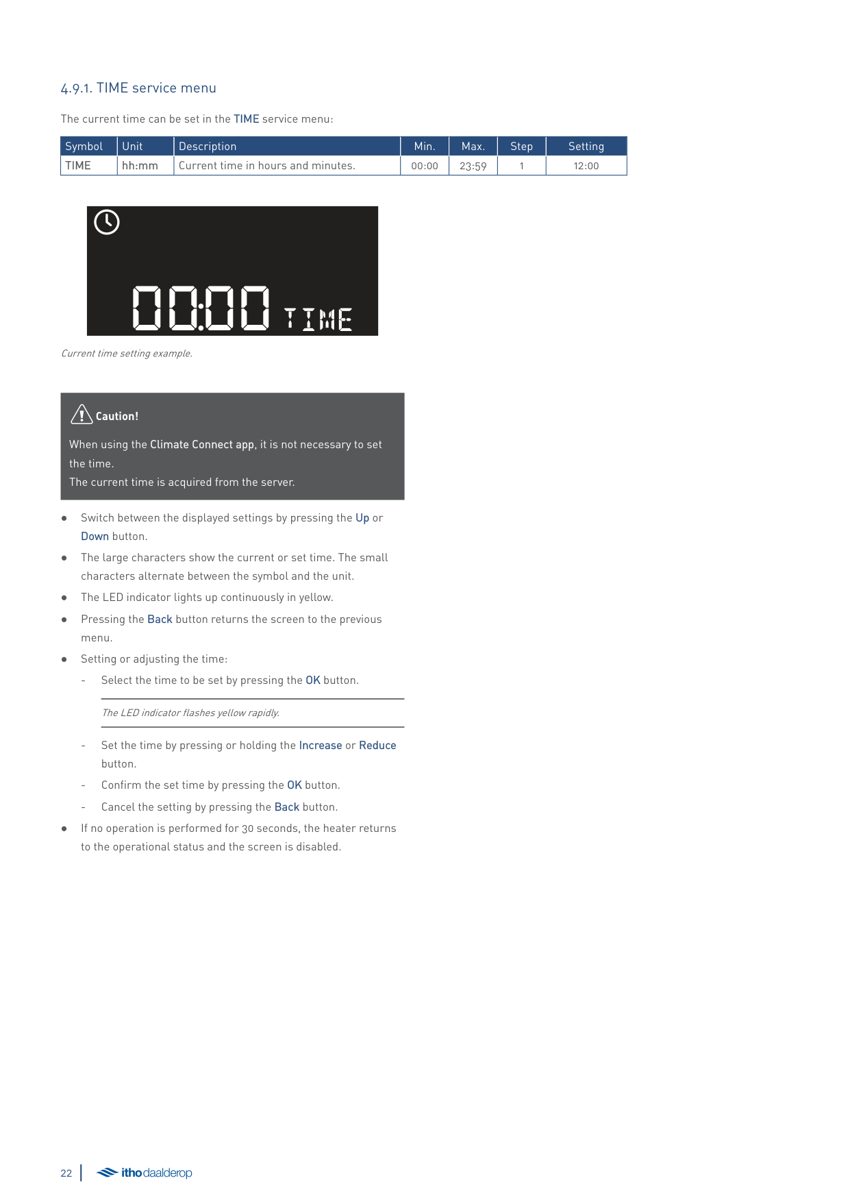
The current time can be set in the TIME service menu:
|Symbol|Unit|Description|Min.|Max.|Step|Setting| |---|---|---|---|---|---|---| |TIME|hh:mm|Current time in hours and minutes.|00:00|23:59|1|12:00|
0000time
Current time setting example.
äCaution!
When using the Climate Connect app, it is not necessary to set the time. The current time is acquired from the server.
The LED indicator flashes yellow rapidly.
###### 4.9.2. CONFIGURATION service menu
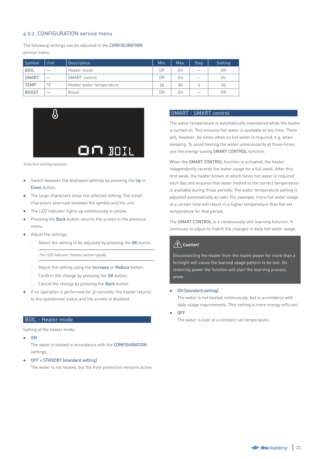
The following settings can be adjusted in the CONFIGURATION service menu:
|Symbol|Unit|Description|Min.|Max.|Step|Setting| |---|---|---|---|---|---|---| |BOIL|—|Heater mode|Off|On|—|Off| |SMART|—|SMART control|Off|On|—|On| |TEMP|°C|Heater water temperature|55|80|5|65| |BOOST|—|Boost|Off|On|—|Off|
ONboil
Selection setting example.
The LED indicator flashes yellow rapidly.
BOIL - Heater mode Setting of the heater mode.
###### SMART - SMART control
The water temperature is automatically maintained while the heater is turned on. This ensures hot water is available at any time. There will, however, be times when no hot water is required, e.g. when sleeping. To avoid heating the water unnecessarily at those times, use the energy-saving SMART CONTROL function.
When the SMART CONTROL function is activated, the heater independently records hot water usage for a full week. After this first week, the heater knows at which times hot water is required each day and ensures that water heated to the correct temperature is available during those periods. The water temperature setting is adjusted automatically as well. For example, more hot water usage at a certain time will result in a higher temperature than the set temperature for that period.
The SMART CONTROL is a continuously self-learning function. It continues to adjust to match the changes in daily hot water usage.
äCaution!
Disconnecting the heater from the mains power for more than a fortnight will cause the learned usage pattern to be lost. On restoring power the function will start the learning process anew.
###### TEMP - Heater temperature
The maximum temperature of the heater's water. Min. 55°C | Max. 80°C | +/- 5°C.
######## ● 65°C [standard setting]
###### BOOST – Immediate heating
There may occasionally be an insufficient amount of hot water. Activate the BOOST function for immediate one-time heating of the water up to 85°C. After the water has warmed up, the water heater will return to the CONFIGURATION settings.
The BOOST function is enabled in ON mode and alongside the SMART CONTROL function.
###### 4.9.3. SERVICE service menu
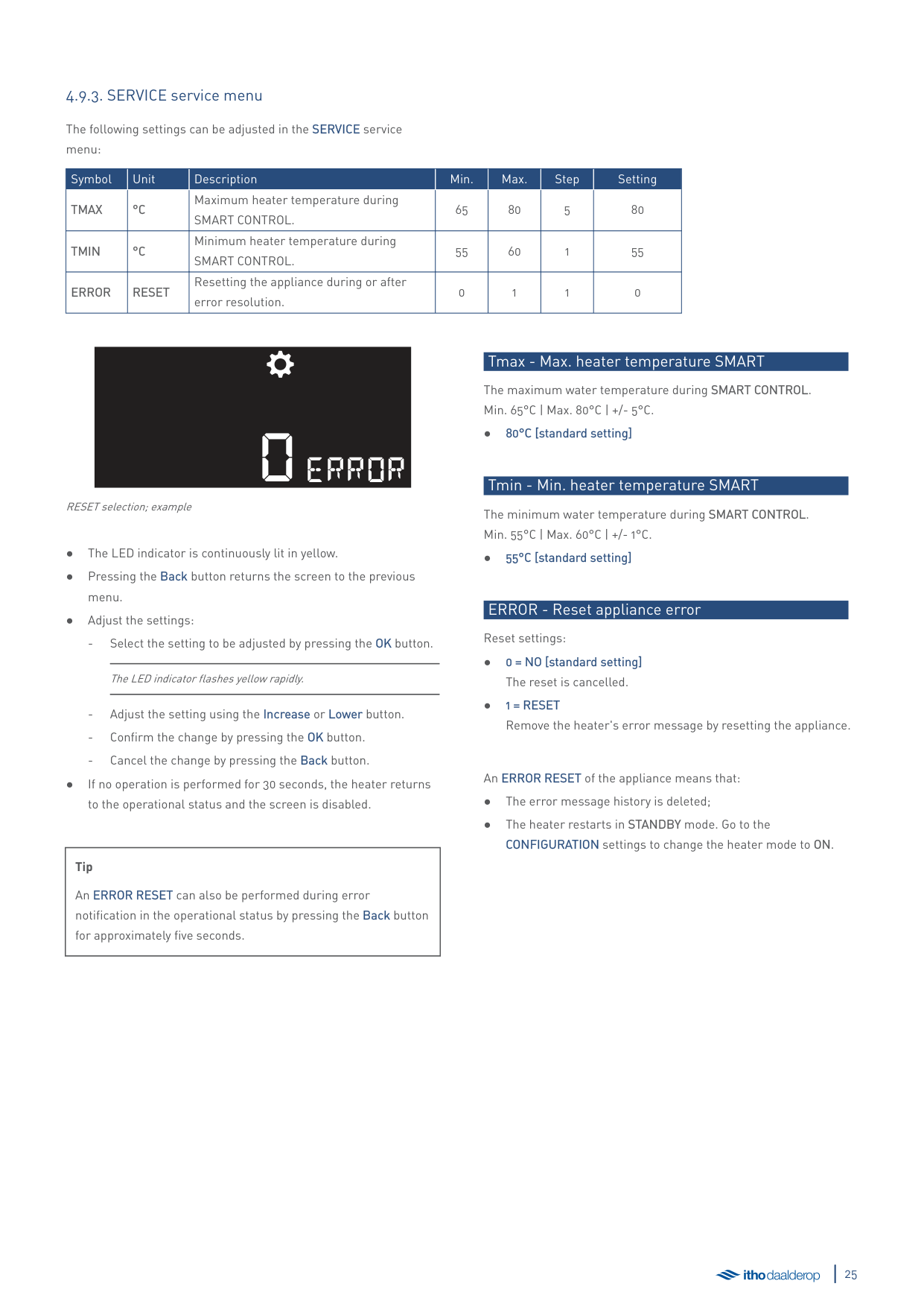
The following settings can be adjusted in the SERVICE service menu:
|Symbol|Unit|Description|Min.|Max.|Step|Setting| |---|---|---|---|---|---|---| |TMAX|°C|Maximum heater temperature during SMART CONTROL.|65|80|5|80| |TMIN|°C|Minimum heater temperature during SMART CONTROL.|55|60|1|55| |ERROR|RESET|Resetting the appliance during or after error resolution.|0|1|1|0|
0ERROR
RESET selection; example
The LED indicator flashes yellow rapidly.
|Tip
An ERROR RESET can also be performed during error notification in the operational status by pressing the Back button for approximately five seconds.| |---|
###### Tmax - Max. heater temperature SMART
The maximum water temperature during SMART CONTROL. Min. 65°C | Max. 80°C | +/- 5°C.
######## ● 80°C [standard setting]
###### Tmin - Min. heater temperature SMART
The minimum water temperature during SMART CONTROL. Min. 55°C | Max. 60°C | +/- 1°C.
######## ● 55°C [standard setting]
ERROR - Reset appliance error Reset settings:
An ERROR RESET of the appliance means that:
###### 4.9.4. COMMUNICATION service menu
The following settings can be adjusted in the COMMUNICATION service menu:
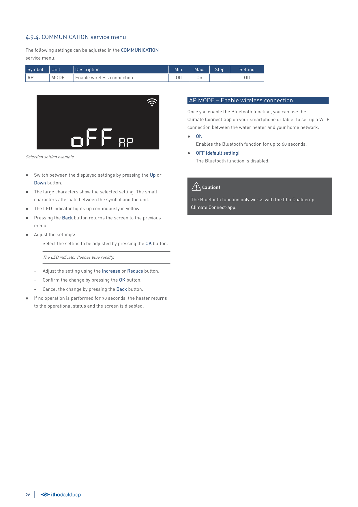
|Symbol|Unit|Description|Min.|Max.|Step|Setting| |---|---|---|---|---|---|---| |AP|MODE|Enable wireless connection|Off|On|—|Off|
offap
Selection setting example.
● Switch between the displayed settings by pressing the Up or
Down button.
menu.
● Adjust the settings:
The LED indicator flashes blue rapidly.
● If no operation is performed for 30 seconds, the heater returns
to the operational status and the screen is disabled.
###### AP MODE – Enable wireless connection
Once you enable the Bluetooth function, you can use the Climate Connect‑app on your smartphone or tablet to set up a Wi-Fi connection between the water heater and your home network.
äCaution!
The Bluetooth function only works with the Itho Daalderop Climate Connect‑app.
5. Use
##### 5.1. Filling and first use
äCaution!
Do not turn on the power to the appliance yet. Only do so when this is expressly required during commissioning.
äCaution!
Check the system for leaks during filling and initial heating.
If the appliance does not have power, check the fuse in the fuse box and replace it if necessary. If that fuse is also not the cause of the problem, contact Itho Daalderop.
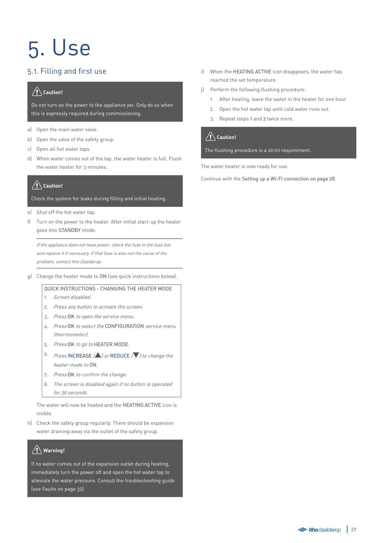
|QUICK INSTRUCTIONS - CHANGING THE HEATER MODE
1. Screen disabled.
2. Press any button to activate the screen.
3. PressOK to open the service menu.
4. PressOK to select theCONFIGURATION service menu (thermometer).
5. PressOK to go toHEATER MODE.
6. PressINCREASE ([) orREDUCE (]) to change the heater mode toON.
7. PressOK to confirm the change.
8. The screen is disabled again if no button is operated for 30 seconds.
| |---|
The water will now be heated and the HEATING ACTIVE icon is visible.
äWarning!
If no water comes out of the expansion outlet during heating, immediately turn the power off and open the hot water tap to alleviate the water pressure. Consult the troubleshooting guide (see Faults on page 32).
äCaution!
The flushing procedure is a strict requirement.
The water heater is now ready for use. Continue with the Setting up a Wi-Fi connection on page 28.
##### 5.2. Climate Connect app
Only one Climate Connect account per productThe Itho Daalderop Climate Connect app is intended for end users and provides many useful features:
Want to know more about the Climate Connect‑app? Go to https://www.ithodaalderop.nl/climateconnect.
To use these functionalities, you must set up a Wi-Fi connection between the water heater and your home network using the Climate Connect‑app. Once the water heater is connected to your home network, end users gain immediate insight into energy consumption and can receive tips on how to improve efficiency. The app can also be used to control the water heater, e.g. switching it off remotely, setting a shower timer or activating the boost function.
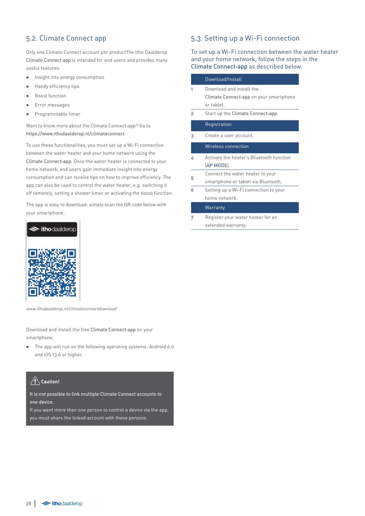
The app is easy to download: simply scan the QR code below with your smartphone.
www.ithodaalderop.nl/climateconnectdownload
Download and install the free Climate Connect‑app on your smartphone.
äCaution!
It is not possible to link multiple Climate Connect accounts to one device. If you want more than one person to control a device via the app, you must share the linked account with these persons.
##### 5.3. Setting up a Wi-Fi connection
###### To set up a Wi-Fi connection between the water heater and your home network, follow the steps in the Climate Connect‑app as described below.
Download/Install
Connect the water heater to your smartphone or tablet via Bluetooth.
##### 5.4. Prevention of legionella bacteria
Leaving the heater in STANDBY mode for more than a week may lead to the presence of legionella bacteria. For this reason, adhere to the following procedure when turning the heater back on again:
äWarning!
Prevent water mist during rinsing.
äCaution!
Perform this procedure prior to use whenever the heater has been turned off for more than three days.
6. The most frequentcomplaints
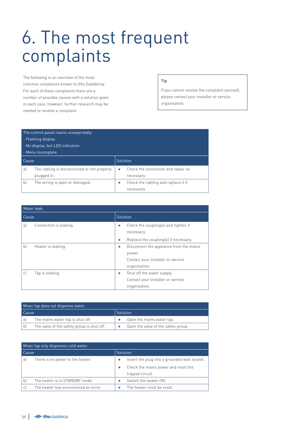
The following is an overview of the most common complaints known to Itho Daalderop. For each of these complaints there are a number of possible causes with a solution given in each case, however, further research may be needed to resolve a complaint.
|Tip
If you cannot resolve the complaint yourself, please contact your installer or service organisation.| |---|
|The control panel reacts unexpectedly:
- Flashing display
- No display, but LED indication
- Menu incomplete
|The control panel reacts unexpectedly:
- Flashing display
- No display, but LED indication
- Menu incomplete
| |---|---| |Cause|Solution| |a) The cabling is disconnected or not properly plugged in.|● Check the connection and repair as
necessary.| |b) The wiring is open or damaged.|● Check the cabling and replace it if
necessary.|
|Water leak.|Water leak.| |---|---| |Cause|Solution| |a) Connection is leaking.|● Check the coupling(s) and tighten if necessary.
● Replace the coupling(s) if necessary.
| |b) Heater is leaking.|● Disconnect the appliance from the mains power. Contact your installer or service organisation.| |c) Tap is leaking.|● Shut off the water supply. Contact your installer or service organisation.|
|Mixer tap does not dispense water.|Mixer tap does not dispense water.| |---|---| |Cause|Solution| |a) The mains water tap is shut off.|● Open the mains water tap.| |b) The valve of the safety group is shut off.|● Open the valve of the safety group.|
|Mixer tap only dispenses cold water.|Mixer tap only dispenses cold water.| |---|---| |Cause|Solution| |a) There is no power to the heater.|● Insert the plug into a grounded wall socket.
● Check the mains power and reset the tripped circuit.
|
|b) The heater is in STANDBY mode.|● Switch the heater ON.| |c) The heater has encountered an error.|● The heater must be reset.|
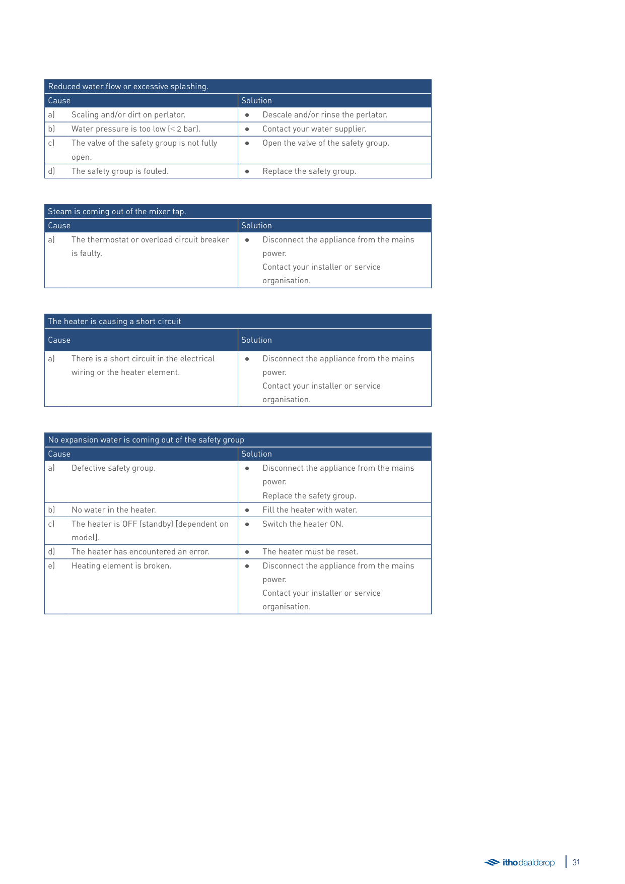
|Reduced water flow or excessive splashing.|Reduced water flow or excessive splashing.| |---|---| |Cause|Solution| |a) Scaling and/or dirt on perlator.|● Descale and/or rinse the perlator.| |b) Water pressure is too low (˂ 2 bar).|● Contact your water supplier.| |c) The valve of the safety group is not fully open.|● Open the valve of the safety group.| |d) The safety group is fouled.|● Replace the safety group.|
|Steam is coming out of the mixer tap.|Steam is coming out of the mixer tap.| |---|---| |Cause|Solution| |a) The thermostat or overload circuit breaker is faulty.|● Disconnect the appliance from the mains power. Contact your installer or service organisation.|
|The heater is causing a short circuit|The heater is causing a short circuit| |---|---| |Cause|Solution| |a) There is a short circuit in the electrical wiring or the heater element.|● Disconnect the appliance from the mains power. Contact your installer or service organisation.|
|No expansion water is coming out of the safety group|No expansion water is coming out of the safety group| |---|---| |Cause|Solution| |a) Defective safety group.|● Disconnect the appliance from the mains power. Replace the safety group.| |b) No water in the heater.|● Fill the heater with water.| |c) The heater is OFF (standby) [dependent on model].|● Switch the heater ON.| |d) The heater has encountered an error.|● The heater must be reset.| |e) Heating element is broken.|● Disconnect the appliance from the mains power. Contact your installer or service organisation.|
7. Faults
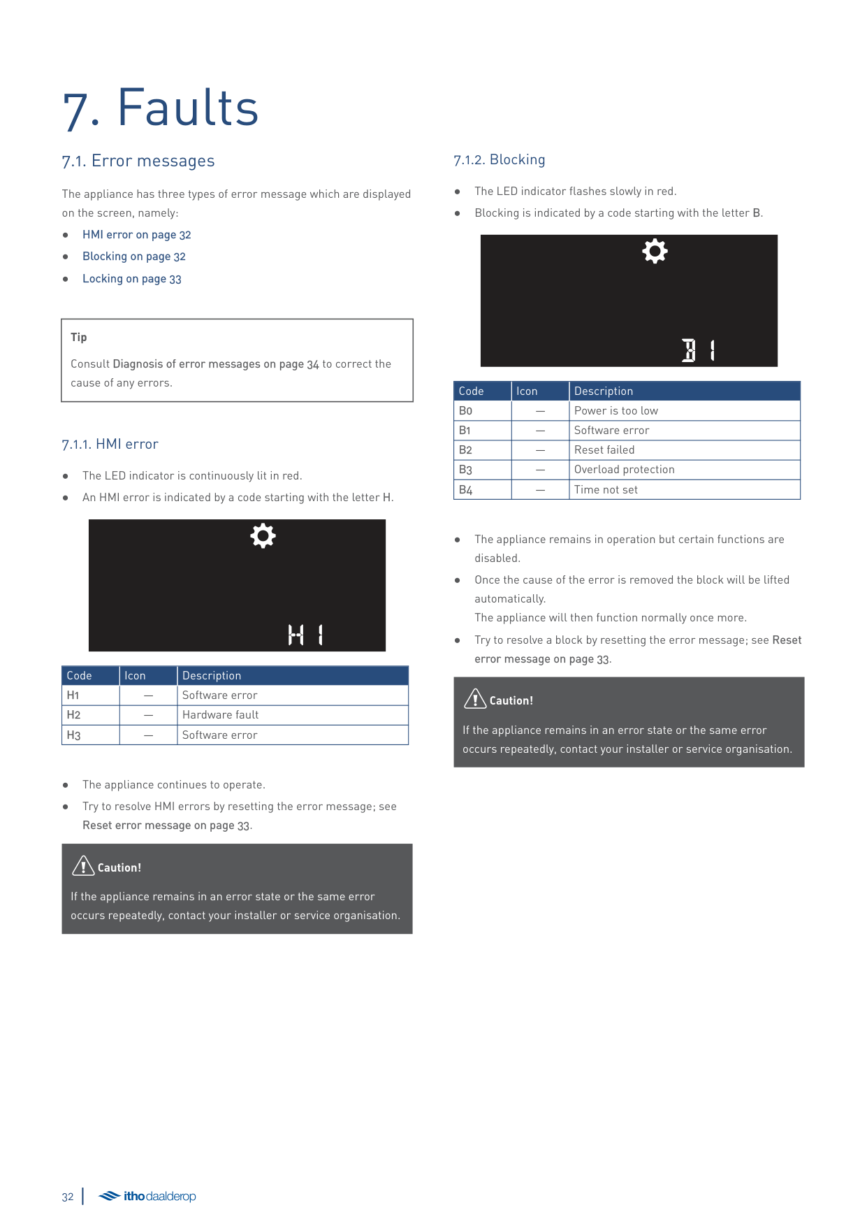
##### 7.1. Error messages
The appliance has three types of error message which are displayed on the screen, namely:
|Tip
Consult Diagnosis of error messages on page 34 to correct the cause of any errors.| |---|
H1
|Code|Icon|Description| |---|---|---| |H1|—|Software error| |H2|—|Hardware fault| |H3|—|Software error|
äCaution!
If the appliance remains in an error state or the same error occurs repeatedly, contact your installer or service organisation.
###### 7.1.2. Blocking
B1
|Code|Icon|Description| |---|---|---| |B0|—|Power is too low| |B1|—|Software error| |B2|—|Reset failed| |B3|—|Overload protection| |B4|—|Time not set|
äCaution!
If the appliance remains in an error state or the same error occurs repeatedly, contact your installer or service organisation.
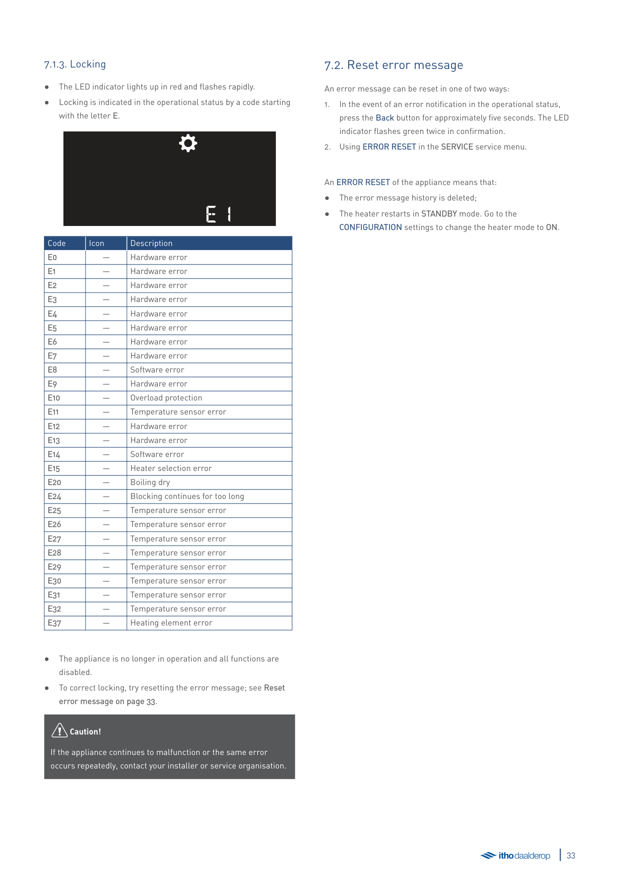
###### 7.1.3. Locking
e1
|Code|Icon|Description| |---|---|---| |E0|—|Hardware error| |E1|—|Hardware error| |E2|—|Hardware error| |E3|—|Hardware error| |E4|—|Hardware error| |E5|—|Hardware error| |E6|—|Hardware error| |E7|—|Hardware error|
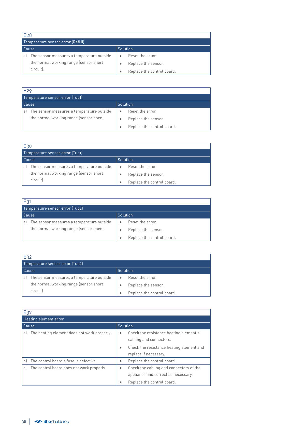
|E8|—|Software error| |E9|—|Hardware error| |E10|—|Overload protection| |E11|—|Temperature sensor error| |E12|—|Hardware error| |E13|—|Hardware error| |E14|—|Software error| |E15|—|Heater selection error| |E20|—|Boiling dry| |E24|—|Blocking continues for too long| |E25|—|Temperature sensor error| |E26|—|Temperature sensor error| |E27|—|Temperature sensor error| |E28|—|Temperature sensor error| |E29|—|Temperature sensor error| |E30|—|Temperature sensor error| |E31|—|Temperature sensor error| |E32|—|Temperature sensor error| |E37|—|Heating element error|
äCaution!
If the appliance continues to malfunction or the same error occurs repeatedly, contact your installer or service organisation.
##### 7.2. Reset error message
An error message can be reset in one of two ways:
An ERROR RESET of the appliance means that:
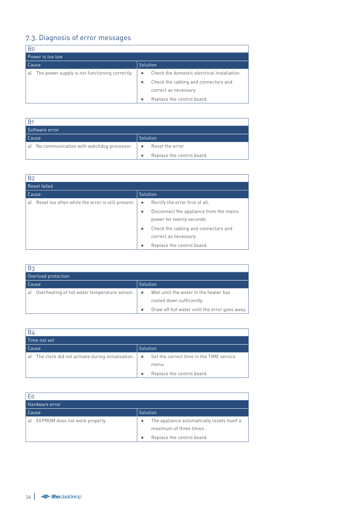
##### 7.3. Diagnosis of error messages
|B0|B0| |---|---| |Power is too low|Power is too low| |Cause|Solution| |a) The power supply is not functioning correctly.|● Check the domestic electrical installation.
● Check the cabling and connectors and correct as necessary.
● Replace the control board.
|
|B1|B1| |---|---| |Software error|Software error| |Cause|Solution| |a) No communication with watchdog processor.|● Reset the error.
● Replace the control board.
|
|B2|B2| |---|---| |Reset failed|Reset failed| |Cause|Solution| |a) Reset too often while the error is still present.|● Rectify the error first of all.
● Disconnect the appliance from the mains power for twenty seconds.
● Check the cabling and connectors and correct as necessary.
● Replace the control board.
|
|B3|B3| |---|---| |Overload protection|Overload protection| |Cause|Solution| |a) Overheating of hot water temperature sensor.|● Wait until the water in the heater has cooled down sufficiently.
● Draw off hot water until the error goes away.
|
|B4|B4| |---|---| |Time not set|Time not set|
|Cause|Solution| |a) The clock did not activate during initialisation.|● Set the correct time in the TIME service menu.
● Replace the control board.
|
|E0|E0| |---|---| |Hardware error|Hardware error| |Cause|Solution| |a) EEPROM does not work properly.|● The appliance automatically resets itself a maximum of three times.
● Replace the control board.
|
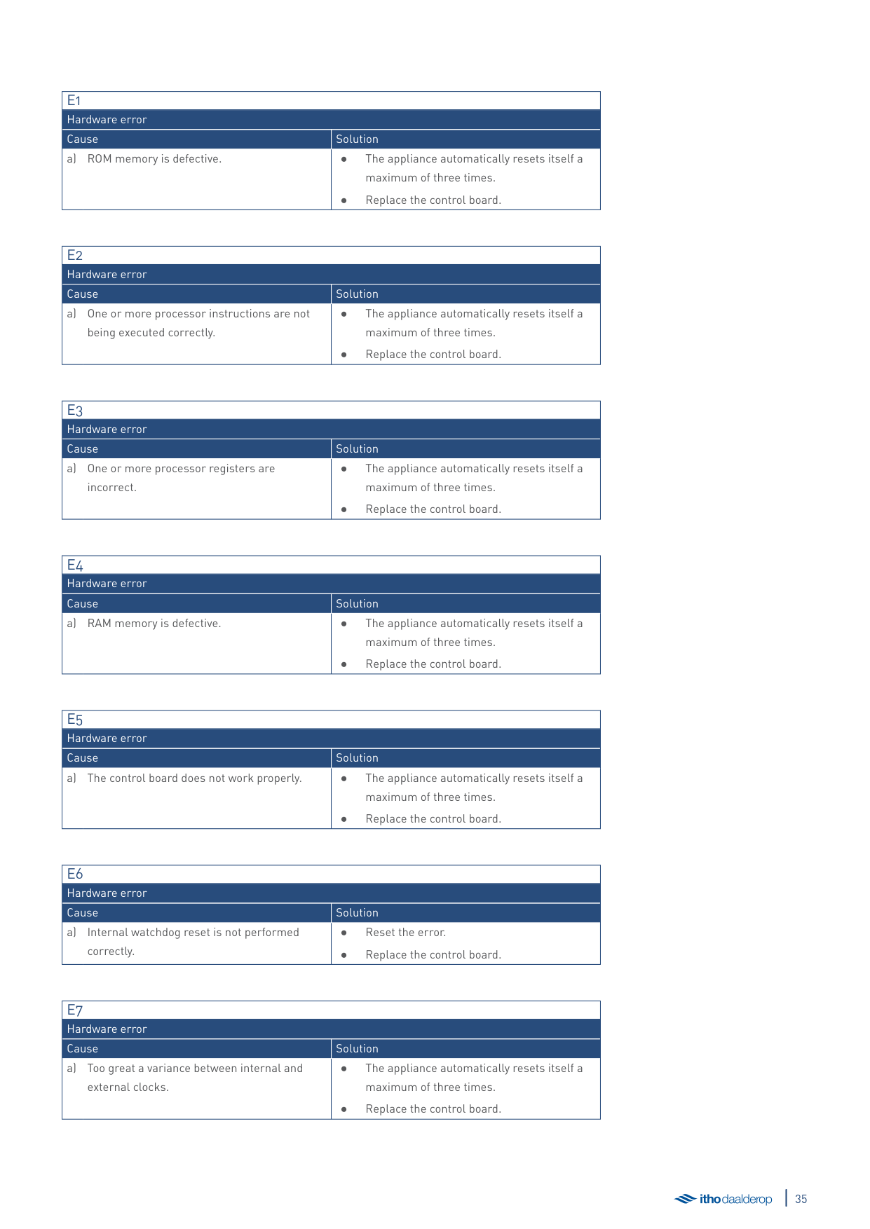
|E1|E1| |---|---| |Hardware error|Hardware error| |Cause|Solution| |a) ROM memory is defective.|● The appliance automatically resets itself a maximum of three times.
● Replace the control board.
|
|E2|E2| |---|---| |Hardware error|Hardware error| |Cause|Solution| |a) One or more processor instructions are not being executed correctly.|● The appliance automatically resets itself a maximum of three times.
● Replace the control board.
|
|E3|E3| |---|---| |Hardware error|Hardware error| |Cause|Solution| |a) One or more processor registers are incorrect.|● The appliance automatically resets itself a maximum of three times.
● Replace the control board.
|
|E4|E4| |---|---| |Hardware error|Hardware error| |Cause|Solution| |a) RAM memory is defective.|● The appliance automatically resets itself a maximum of three times.
● Replace the control board.
|
|E5|E5| |---|---| |Hardware error|Hardware error| |Cause|Solution| |a) The control board does not work properly.|● The appliance automatically resets itself a maximum of three times.
● Replace the control board.
|
|E6|E6| |---|---| |Hardware error|Hardware error| |Cause|Solution| |a) Internal watchdog reset is not performed correctly.|● Reset the error.
● Replace the control board.
|
|E7|E7| |---|---| |Hardware error|Hardware error| |Cause|Solution| |a) Too great a variance between internal and external clocks.|● The appliance automatically resets itself a maximum of three times.
● Replace the control board.
|
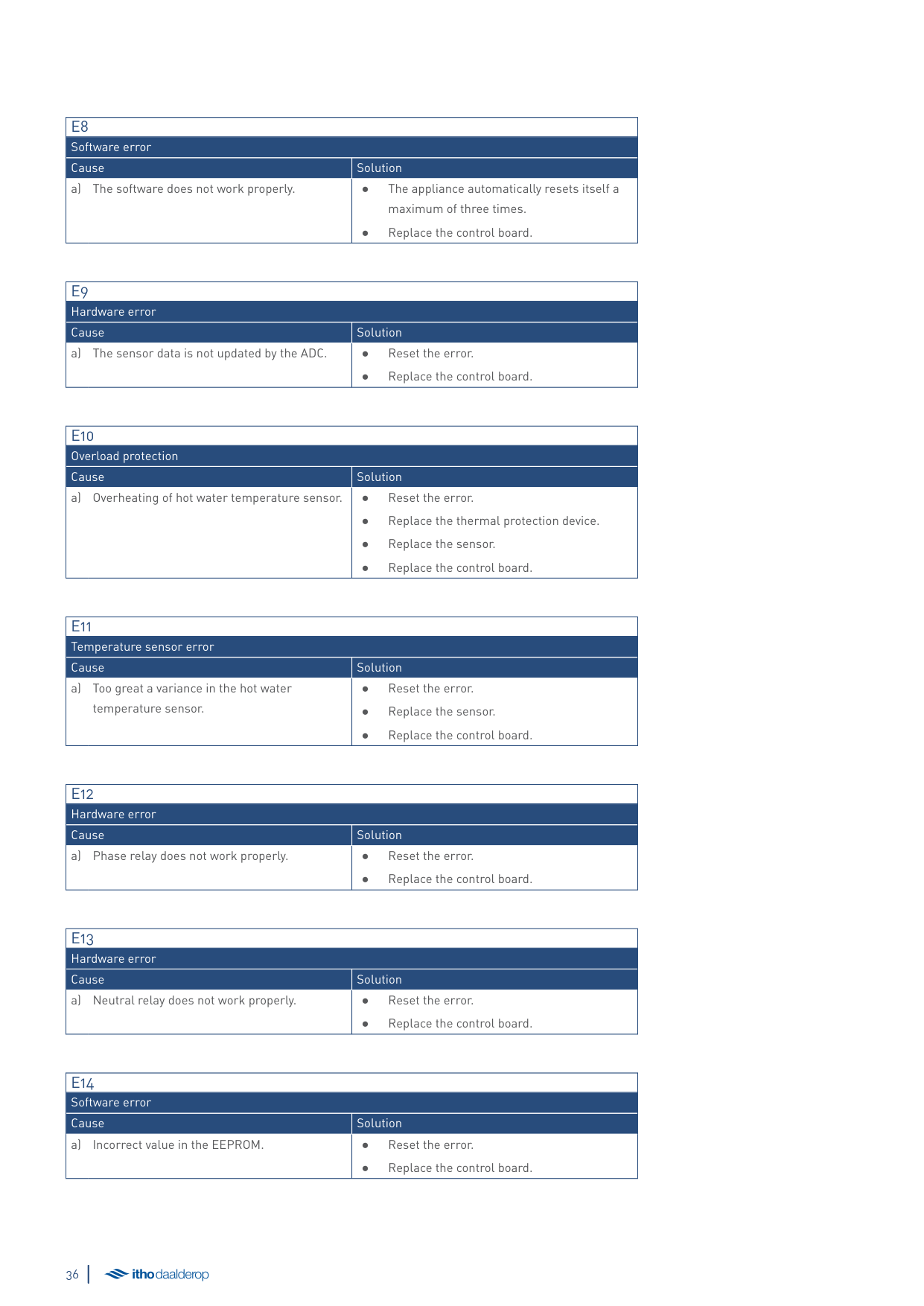
|E8|E8| |---|---| |Software error|Software error| |Cause|Solution| |a) The software does not work properly.|● The appliance automatically resets itself a maximum of three times.
● Replace the control board.
|
|E9|E9| |---|---| |Hardware error|Hardware error| |Cause|Solution| |a) The sensor data is not updated by the ADC.|● Reset the error.
● Replace the control board.
|
|E10|E10| |---|---|
|Overload protection|Overload protection| |Cause|Solution| |a) Overheating of hot water temperature sensor.|● Reset the error.
● Replace the thermal protection device.
● Replace the sensor.
● Replace the control board.
|
|E11|E11| |---|---| |Temperature sensor error|Temperature sensor error| |Cause|Solution| |a) Too great a variance in the hot water temperature sensor.|● Reset the error.
● Replace the sensor.
● Replace the control board.
|
|E12|E12| |---|---| |Hardware error|Hardware error| |Cause|Solution| |a) Phase relay does not work properly.|● Reset the error.
● Replace the control board.
|
|E13|E13| |---|---| |Hardware error|Hardware error| |Cause|Solution| |a) Neutral relay does not work properly.|● Reset the error.
● Replace the control board.
|
|E14|E14| |---|---| |Software error|Software error| |Cause|Solution| |a) Incorrect value in the EEPROM.|● Reset the error.
● Replace the control board.
|
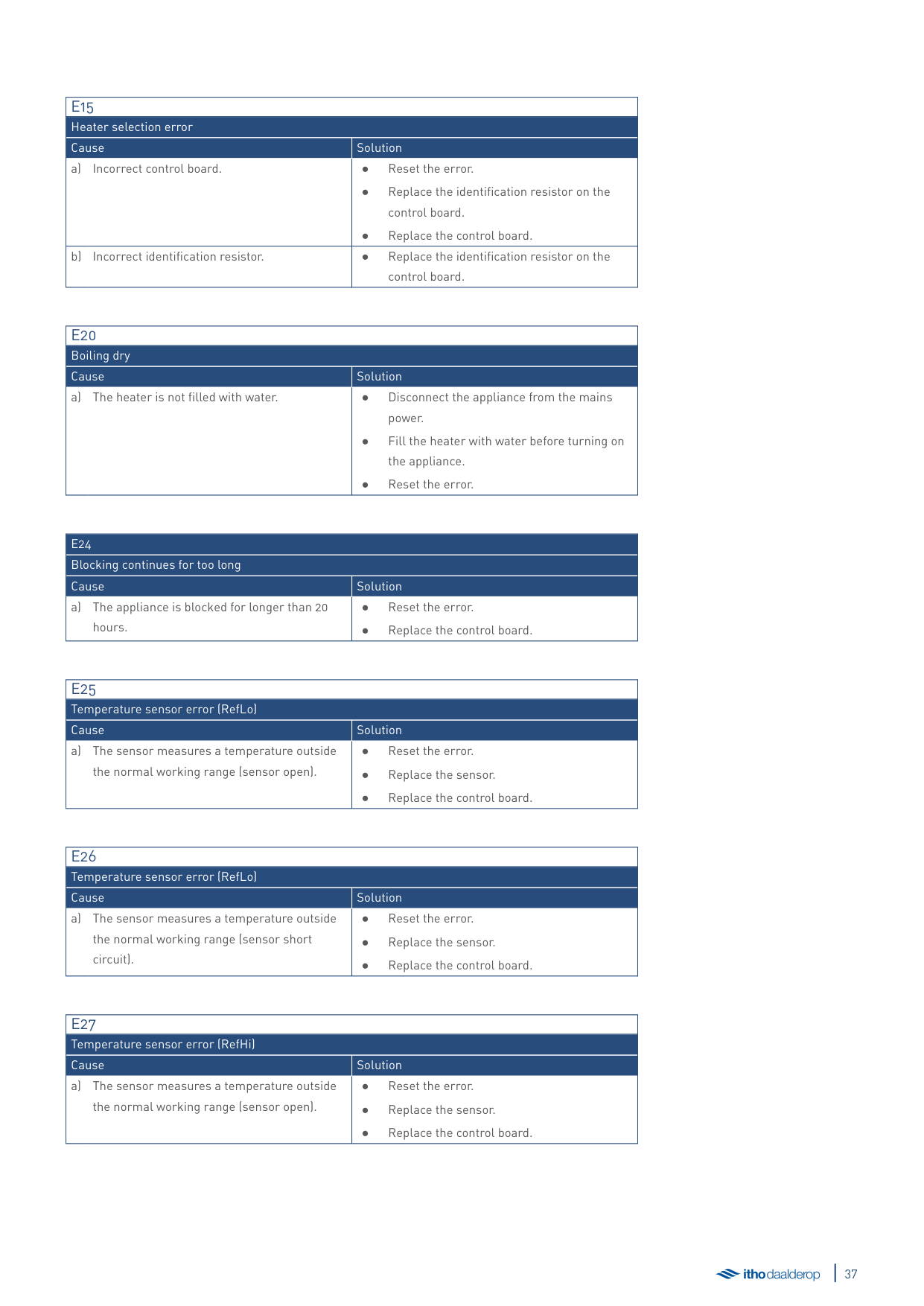
|E15|E15| |---|---| |Heater selection error|Heater selection error| |Cause|Solution| |a) Incorrect control board.|● Reset the error.
● Replace the identification resistor on the control board.
● Replace the control board.
|
|b) Incorrect identification resistor.|● Replace the identification resistor on the
control board.|
|E20|E20| |---|---| |Boiling dry|Boiling dry| |Cause|Solution| |a) The heater is not filled with water.|● Disconnect the appliance from the mains power.
● Fill the heater with water before turning on the appliance.
● Reset the error.
|
|E24|E24| |---|---| |Blocking continues for too long|Blocking continues for too long| |Cause|Solution| |a) The appliance is blocked for longer than 20 hours.|● Reset the error.
● Replace the control board.
|
|E25|E25| |---|---| |Temperature sensor error (RefLo)|Temperature sensor error (RefLo)| |Cause|Solution| |a) The sensor measures a temperature outside the normal working range (sensor open).|● Reset the error.
● Replace the sensor.
● Replace the control board.
|
|E26|E26| |---|---| |Temperature sensor error (RefLo)|Temperature sensor error (RefLo)| |Cause|Solution| |a) The sensor measures a temperature outside the normal working range (sensor short circuit).|● Reset the error.
● Replace the sensor.
● Replace the control board.
|
|E27|E27| |---|---| |Temperature sensor error (RefHi)|Temperature sensor error (RefHi)| |Cause|Solution| |a) The sensor measures a temperature outside the normal working range (sensor open).|● Reset the error.
● Replace the sensor.
● Replace the control board.
|
|E28|E28| |---|---| |Temperature sensor error (RefHi)|Temperature sensor error (RefHi)| |Cause|Solution| |a) The sensor measures a temperature outside the normal working range (sensor short circuit).|● Reset the error.
● Replace the sensor.
● Replace the control board.
|
|E29|E29| |---|---| |Temperature sensor error (Tup1)|Temperature sensor error (Tup1)| |Cause|Solution| |a) The sensor measures a temperature outside the normal working range (sensor open).|● Reset the error.
● Replace the sensor.
● Replace the control board.
|
|E30|E30| |---|---| |Temperature sensor error (Tup1)|Temperature sensor error (Tup1)| |Cause|Solution| |a) The sensor measures a temperature outside the normal working range (sensor short circuit).|● Reset the error.
● Replace the sensor.
● Replace the control board.
|
|E31|E31| |---|---| |Temperature sensor error (Tup2)|Temperature sensor error (Tup2)| |Cause|Solution| |a) The sensor measures a temperature outside the normal working range (sensor open).|● Reset the error.
● Replace the sensor.
● Replace the control board.
|
|E32|E32| |---|---| |Temperature sensor error (Tup2)|Temperature sensor error (Tup2)| |Cause|Solution| |a) The sensor measures a temperature outside the normal working range (sensor short circuit).|● Reset the error.
● Replace the sensor.
● Replace the control board.
|
|E37|E37| |---|---| |Heating element error|Heating element error|
|Cause|Solution| |a) The heating element does not work properly.|● Check the resistance heating element's cabling and connectors.
● Check the resistance heating element and replace if necessary.
| |b) The control board's fuse is defective.|● Replace the control board.| |c) The control board does not work properly.|● Check the cabling and connectors of the appliance and correct as necessary.
● Replace the control board.
|
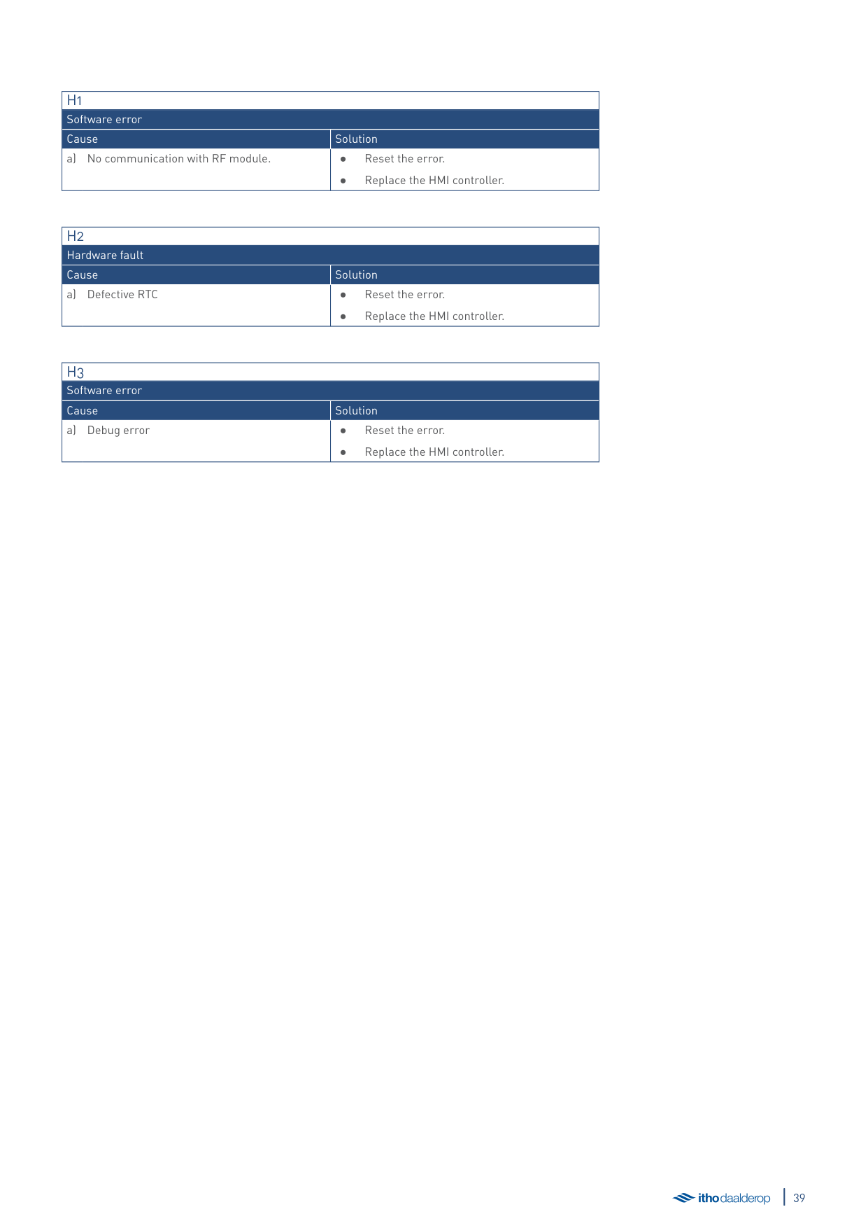
|H1|H1| |---|---| |Software error|Software error| |Cause|Solution| |a) No communication with RF module.|● Reset the error.
● Replace the HMI controller.
|
|H2|H2| |---|---| |Hardware fault|Hardware fault| |Cause|Solution| |a) Defective RTC|● Reset the error.
● Replace the HMI controller.
|
|H3|H3| |---|---| |Software error|Software error| |Cause|Solution| |a) Debug error|● Reset the error.
● Replace the HMI controller.
|
8. Service and maintenance
##### 8.1. General maintenance
##### 8.3. Hardware/software information
In principle, the heater is maintenance-free. The heater casing can be cleaned with a normal, non-abrasive household cleaning agent.
Depending on the intensity of use and the composition of the mains water, scale deposits can build up in the heater. Please consult your installer.
##### 8.2. Emptying the water heater

äCaution!
During the next step, a small amount of water may exit the heater's inlet hose until the water inside the heater has built up a vacuum.
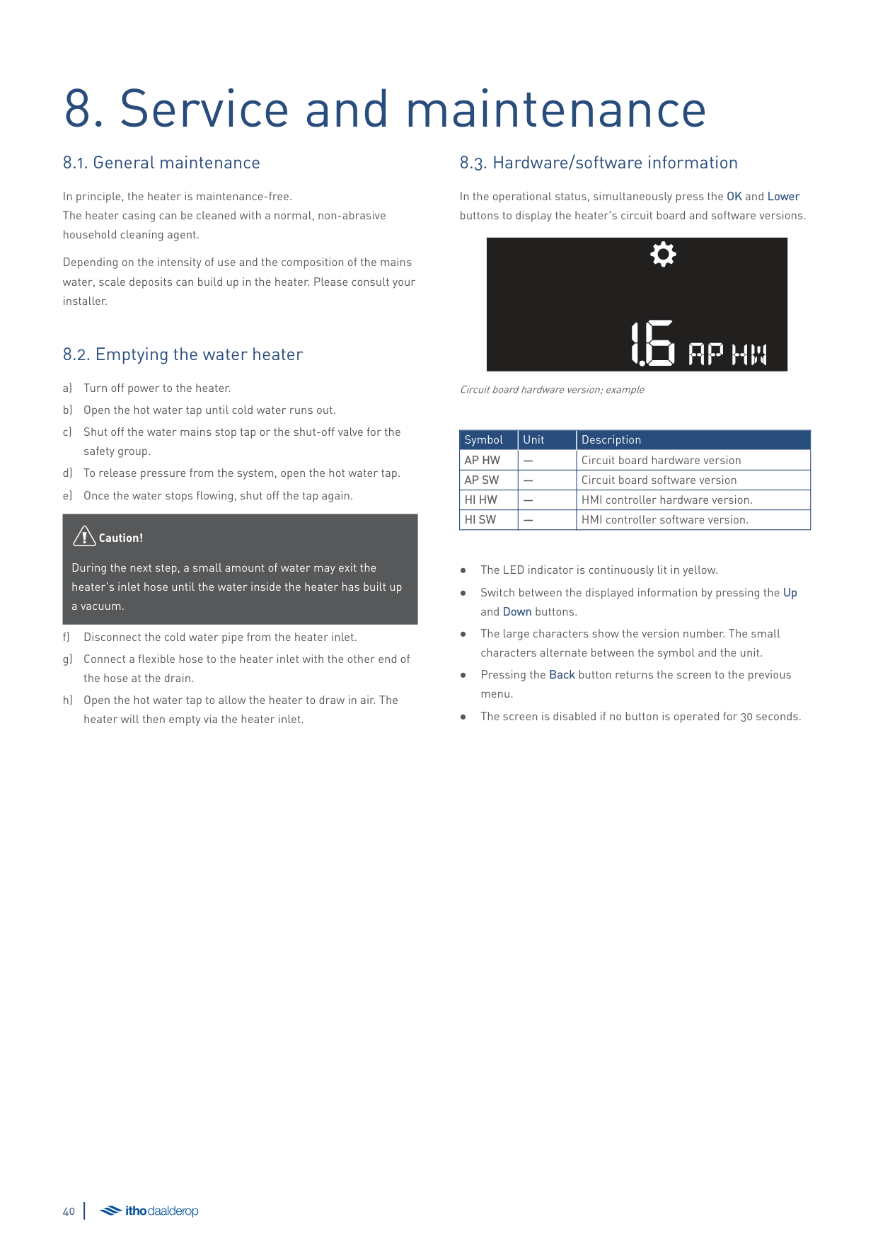
In the operational status, simultaneously press the OK and Lower buttons to display the heater's circuit board and software versions.
16AP HW
Circuit board hardware version; example
|Symbol|Unit|Description| |---|---|---| |AP HW|—|Circuit board hardware version| |AP SW|—|Circuit board software version| |HI HW|—|HMI controller hardware version.| |HI SW|—|HMI controller software version.|
9. Warranty
All Itho Daalderop products are covered by a standard two-year factory warranty. During this period, the product or product component will be repaired or replaced free of charge. The warranty conditions include provisions and exclusions.
For the full warranty conditions and/or supplementary warranty terms or conditions, see the relevant product page on our website.
If there are problems with the operation of our product, we recommend that the consumer first reads the manual.
10. Declarations
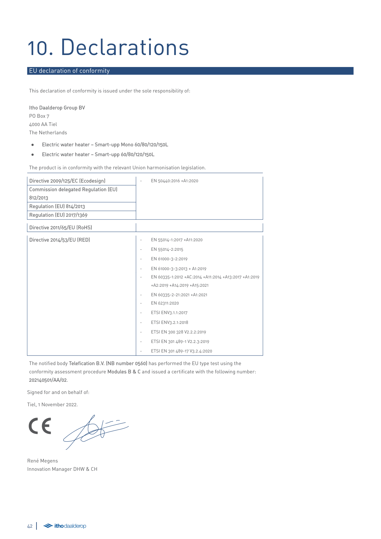
###### EU declaration of conformity
This declaration of conformity is issued under the sole responsibility of:
Itho Daalderop Group BV PO Box 7 4000 AA Tiel The Netherlands
The product is in conformity with the relevant Union harmonisation legislation.
|Directive 2009/125/EC (Ecodesign)|- EN 50440:2016 +A1:2020| |---|---| |Commission delegated Regulation (EU) 812/2013|- EN 50440:2016 +A1:2020| |Regulation (EU) 814/2013|- EN 50440:2016 +A1:2020| |Regulation (EU) 2017/1369|- EN 50440:2016 +A1:2020|
######## Directive 2011/65/EU (RoHS) Directive 2014/53/EU (RED) - EN 55014-1:2017 +A11:2020
+A2:2019 +A14:2019 +A15:2021
The notified body Telefication B.V. (NB number 0560) has performed the EU type test using the conformity assessment procedure Modules B & C and issued a certificate with the following number: 202140501/AA/02.
Signed for and on behalf of: Tiel, 1 November 2022.
René Megens Innovation Manager DHW & CH
The Netherlands E info@ithodaalderop.nl I www.ithodaalderop.nl Consumers Please consult your installer or service organisation. I www.ithodaalderop.nl/dealerlocator Professionals | Technical helpdesk T 088 427 57 70 E idsupport@ithodaalderop.nl
Belgium E info@ithodaalderop.be I www.ithodaalderop.be Consumers/Professionals T 02 207 96 30 Service requests only E service@ithodaalderop.be
01-05434-002 | ID 2022-10-05-0913