
Ask AI
— answers from the official manualAnswers from the official manual.
Common questions
Common Questions
10 totalHow do I perform a factory reset on the [product]?
Press and hold the Power button for 10 seconds until the LED flashes red to clear all settings and return the device to factory defaults. Re-pairing any connected devices will be necessary after the reset. (Page 23)
What are the safety precautions I need to follow when installing this air conditioning unit?
Follow all safety instructions and precautions found in Section 1 Important Safety Instructions of the manual, including proper installation by certified personnel and adherence to electrical safety regulations. Incorrect installation could result in electric shock or malfunction (Page 4-7).
What should I do if I encounter refrigerant leakage during maintenance?
Use a leak detector or soap water to find leaks; apply soap water to joints and observe for 3 minutes. If bubbles appear, there is a leak that needs repair (Page 20).
How do I maintain high voltage capacitors safely?
Wait at least 20 minutes after turning off the power supply to allow discharge of high voltages in capacitors before performing maintenance; measure between points A and B with a meter to ensure safe discharge (Page 19).
What should I do if the air conditioner does not start?
Review common troubleshooting steps for malfunction in Section 3.4 on page 35, such as checking connection wires and ensuring correct wiring sequence (Page 35).
How do I troubleshoot error code E2?
Error code E2 indicates anti-freezing protection tripped, check if the indoor temperature is too low or if heat exchanger is obstructed. Clean components as necessary (Page 34).
Full Manual
40 pages
Installation and Maintenance Manual
###### "P" SERIES 9K - 12K 220V INVERTER-DRIVEN AIR CONDITIONING UNITS
|Type|Model| |---|---| |INDOOR UNIT|DHP09NWB21S DCP09NWB21S DHP12NWB21S DCP12NWB21S|
|Type|Model| |---|---| |OUTDOOR UNIT|DHP09CSB21S DCP09CSB21S DHP12CSB21S DCP12CSB21S
|
|PLEASE READ AND UNDERSTAND THIS MANUAL BEFORE USING THIS INVERTER-DRIVEN AIR CONDITIONING UNIT. KEEP THIS MANUAL FOR FUTURE REFERENCE.| |---|


########## Important Notice
########## Product Inspection upon Arrival
Table of Contents

2.1 Installation Dimension Diagram ................................................................................... ...1
Appendix:........................................................................................................................26
Customer Service, Technical Support...................................................30
Table of contents
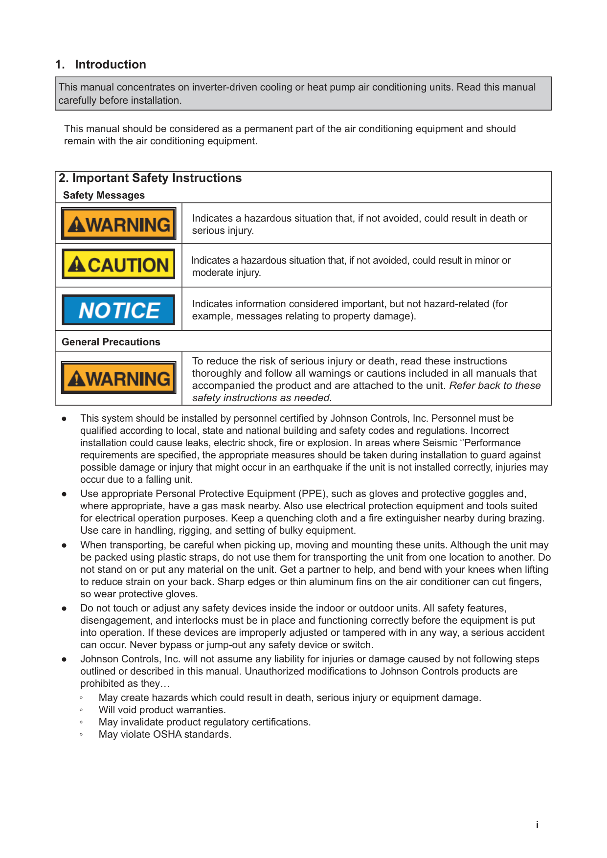
########## 1. Introduction
|This manual concentrates on inverter-driven cooling or heat pump air conditioning units. Read this manual carefully before installation.| |---|
This manual should be considered as a permanent part of the air conditioning equipment and should remain with the air conditioning equipment.
|2. Important Safety Instructions
Safety Messages|2. Important Safety Instructions
Safety Messages| |---|---| ||| |---| |Indicates a hazardous situation that, if not avoided, could result in death or serious injury.| ||Indicates a hazardous situation that, if not avoided, could result in minor or moderate injury.| ||Indicates information considered important, but not hazard-related (for example, messages relating to property damage).| |General Precautions|General Precautions| ||| |---| |To reduce the risk of serious injury or death, read these instructions thoroughly and follow all warnings or cautions included in all manuals that accompanied the product and are attached to the unit. Refer back to these safety instructions as needed.|
########### i
||Take the following precautions to reduce the risk of property damage.| |---|---|
########### Installation Precautions
|||
|---| |To reduce the risk of serious injury or death, the following installation precautions must be followed.| |---|---|
construct a strong wood or metal frame to provide added support. ▫ A room: Properly insulate any refrigerant tubing run inside a room to prevent “sweating” that can cause dripping and water damage to wall and floors. ▫ Damp or uneven areas: Use a raised concrete pad or concrete blocks to provide a solid, level foundation for the unit to prevent water damage and abnormal vibration. ▫ An area with high winds: Securely anchor the outdoor unit down with bolts and a metal frame. Provide a suitable air baffle. ▫ A snowy area (only for heat pump model): Install the outdoor unit on a raised platform that is higher than drifting snow. Provide snow vents.
above a kitchen stove. ▫ Where oil (including machinery oil) may be present. ▫ Where corrosive gases such as chlorine, bromine, or sulfide can accumulate, such as near a hot
tub or hot spring. ▫ Where dense, salt-laden airflow is heavy, such as in coastal regions. ▫ Where the air quality is of high acidity. ▫ Where harmful gases can be generated from decomposition.
########### ii
After installation work for the system has been completed, explain the “Safety Precautions,” the proper use and maintenance of the unit to the customer according to the information in all manuals that came with the system. All manuals and warranty information must be given to the user or left near the Indoor Unit.
########### Refrigerant Precautions

To reduce the risk of serious injury or death, the following refrigerant precautions must be followed.
########### Electrical Precautions
||| |---| |Take the following precautions to reduce the risk of electric shock, fire or explosion resulting in serious injury or death.| |---|---|
referred to below.
▫ If the power source cables for this device* and the new air conditioner unit are located in close
proximity to each other.
Device*: (Example): A lift, container crane, rectifier for electric railway, inverter power device, arc furnace, electric furnace, large-sized induction motor and large-sized switch.
Regarding the cases mentioned above, surge voltage may be inducted into the power supply cables for the packaged air conditioner due to a rapid change in power consumption of the device and an activation of a switch. Check field regulations and standards before performing electrical work in order to protect the power supply for the new air conditioner unit.
########### iv
########### v
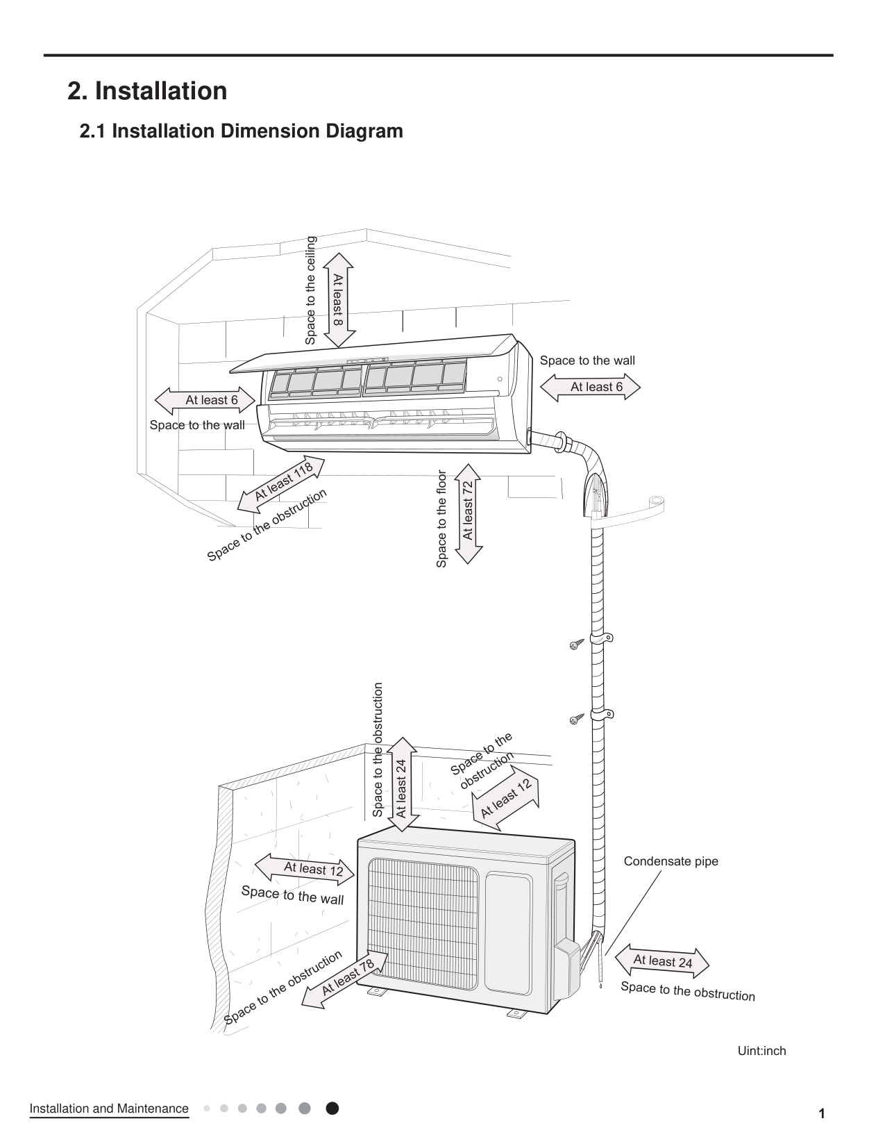
2. Installation
####### 2.1 Installation Dimension Diagram
12
Condensate
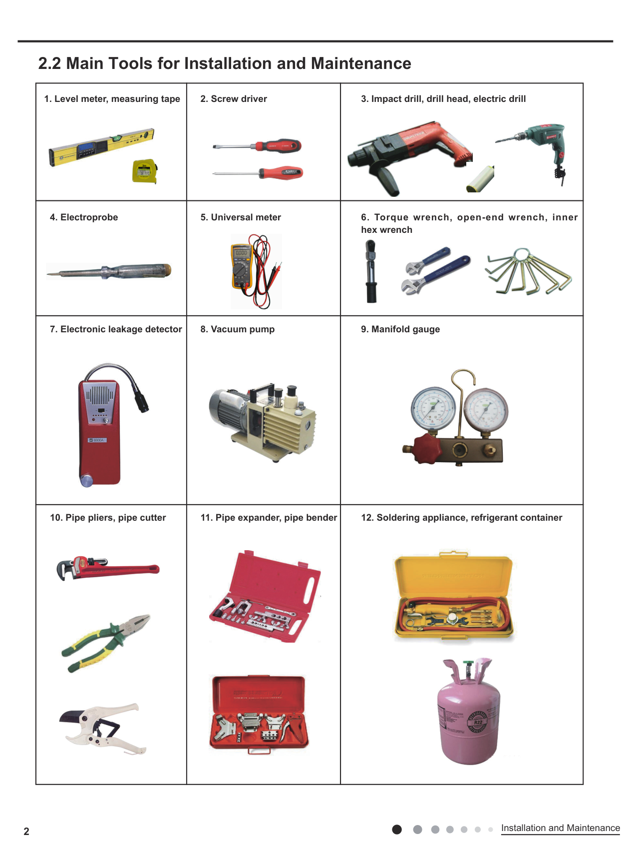
#### 2.2 Main Tools for Installation and Maintenance
|1. Level meter, measuring tape

|2. Screw driver

|3. Impact drill, drill head, electric drill


| |---|---|---| |4. Electroprobe
|5. Universal meter
|6. Torque wrench, open-end wrench, inner hex wrench


| |7. Electronic leakage detector
|8. Vacuum pump
|9. Manifold gauge
| |10. Pipe pliers, pipe cutter


|11. Pipe expander, pipe bender

|12. Soldering appliance, refrigerant container

|
Installation and Maintenance
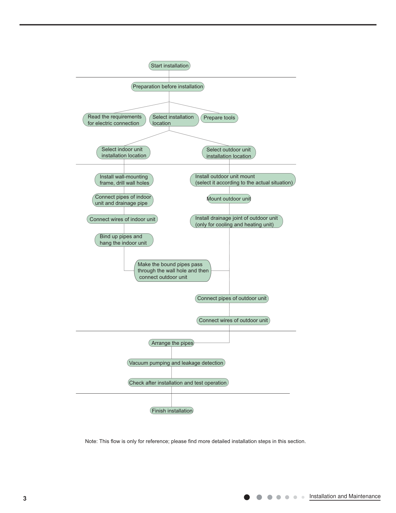
Start installation
| | | |---|---| | | |
Preparation before installation
Prepare toolsRead the requirements for electric connection
Select installation location
Select indoor unit installation location
Select outdoor unit installation location
| | | | |---|---|---| | | | |
Install outdoor unit mount (select it according to the actual situation)
Install wall-mounting frame, drill wall holes
Connect pipes of indoor unit and drainage pipe
Mount outdoor unit
Install drainage joint of outdoor unit (only for cooling and heating unit)
Connect wires of indoor unit
Bind up pipes and hang the indoor unit
Make the bound pipes pass through the wall hole and then
connect outdoor unit
Connect pipes of outdoor unit
Connect wires of outdoor unit
| | | |---|---| | | |
Arrange the pipes
Vacuum pumping and leakage detection
Check after installation and test operation
| | | |---|---| | | |
Finish installation
Note: This flow is only for reference; please find more detailed installation steps in this section.
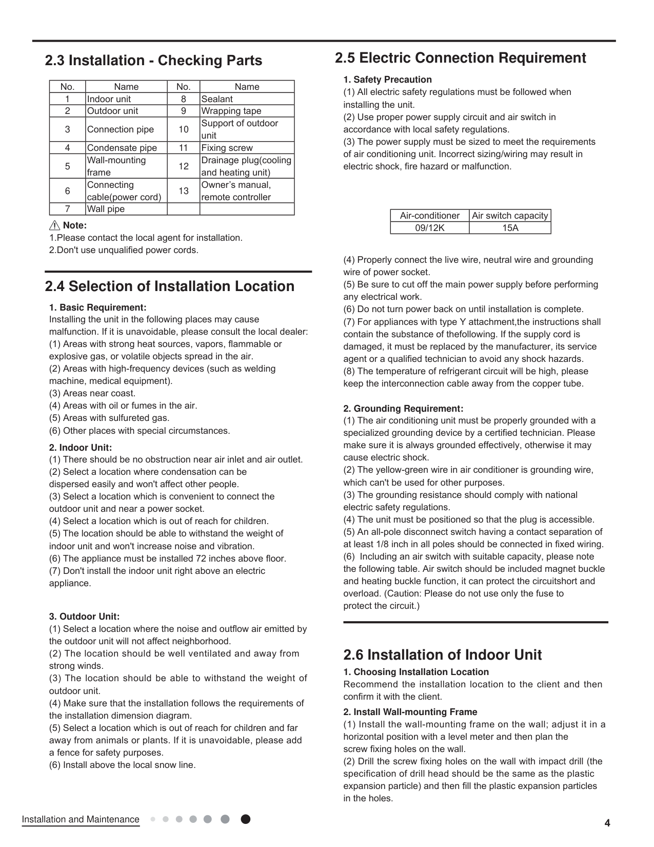
| | | | | |---|---|---|---| |1| |8|Sealant| |2| |9| | |3| |10| | |4|Condensate |11| | |5| |12| | |6| |13| | |7| | | |
################ Note:
s
in the holes.
a
es an
s
s the
a s
(6) Install above the local snow line.
############### 1. Safety Precaution
| | | |---|---| | | |
page
n
n
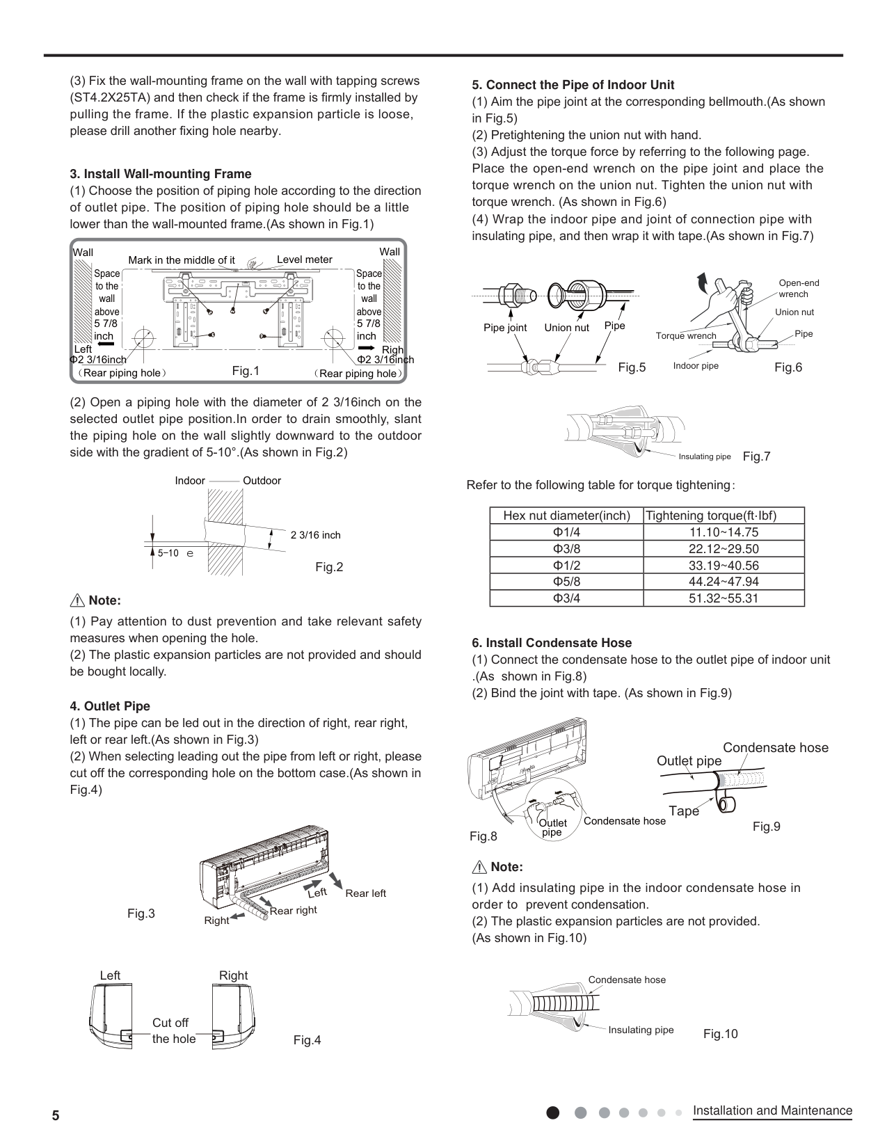
############### 3. Install Wall-mounting Frame
n
Wall
Wall
Mark in the middle of it Level meter
Space to the wall above
Space to the wall above
Open-end wrench
| | | |---|---| | | |
| | | | |---|---|---| | | | |
Union nut Union nutPipe joint Pipe
5 7/8 inch
5 7/8 inch
Pipe
Torque wrench
Left
Righ
Φ2 3/16inch
Φ2 3/16inch
Indoor pipe
Rear piping hole
Rear piping hole
n
Insulating pipe
Indoor Outdoor
torque tightening
| |·| |---|---| | |11.10~14.75| | |22.12~29.50| | |33.19~40.56| | |44.24~47.94| | |51.32~55.31|
2 3/16 inch
e
Note:
n
############### 4. Outlet Pipe
n
Condensate hose
Outlet pipe
n
Tape
Condensate hose
Outlet pipe
Note:
condensate
Left
Rear left
Rear right
Right
n
Left Right
Condensate hose
| | | |---|---| | | | | | |
| | | |---|---| | | | | | |
Cut off the hole
Insulating pipe
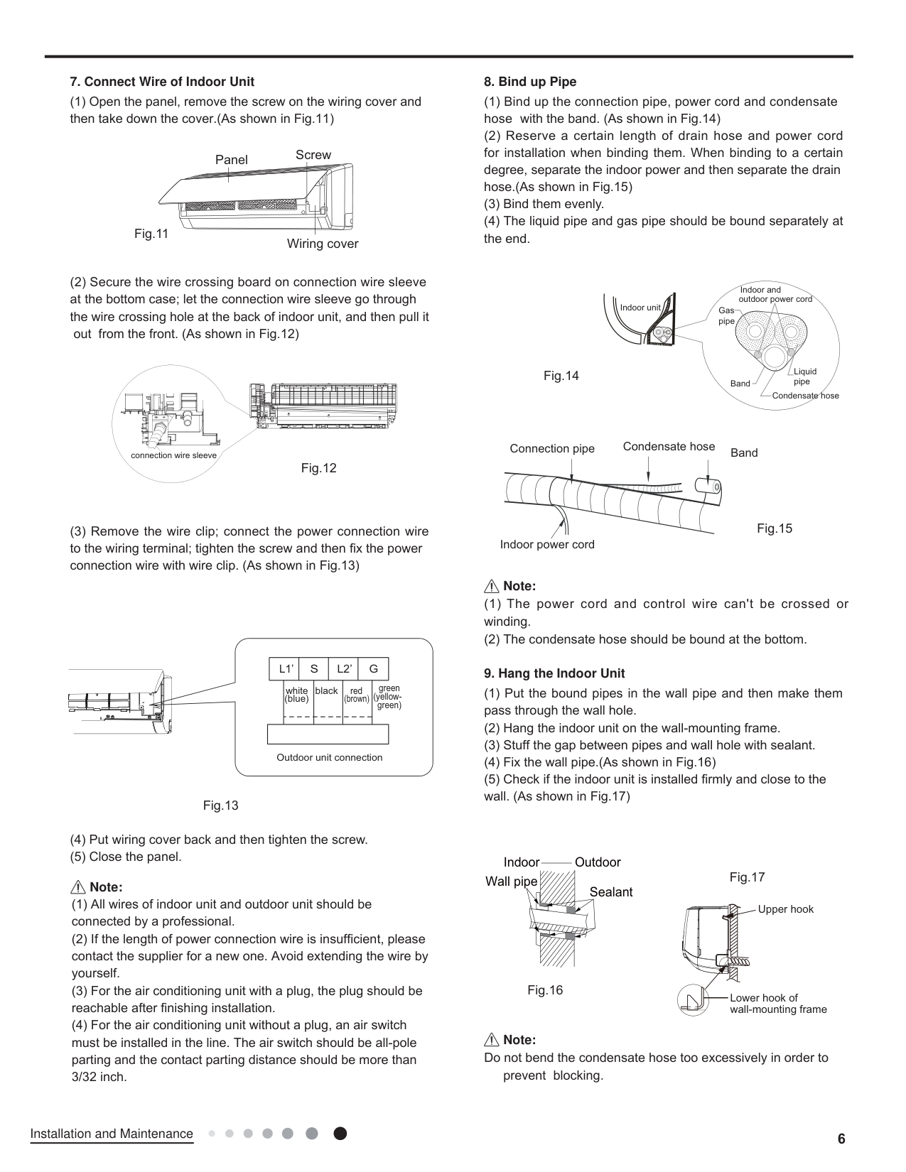
############### 7. Connect Wire of Indoor Unit
n
ScrewPanel
Wiring cover
Secure
n
| | | |---|---| | | | | | |
connection wire sleeve
| | | | | | | | | | | | | | | | | | | | | |---|---|---|---|---|---|---|---|---|---|---|---|---|---|---|---|---|---|---|---|
n
|L1’|L1’|S|S|L2’|L2’|G|G| |---|---|---|---|---|---|---|---| | |white (blue)|white (blue)|black|black|red (brown)|red (brown)| | | | | | | | | | | | | | | | | | | |
green green)
(yellow-
Outdoor unit connection
############### 8. Bind up Pipecondensate
hos n
n
Indoor and outdoor power cord
Indoor unit Gas pipe
Liquid pipe
Band
Condensate hose
Condensate hose BandConnection pipe
Indoor power cord
################ Note:
condensate
############### 9. Hang the Indoor Unit
n
sealant n
################ Note:
Indoor Outdoor Wall pipe
Sealant
################ Note:
condensate
Upper hook
Lower hook of wall-mounting frame
####### 2.7 Installation of Outdoor Unit
############### 1. Secure the Support of Outdoor Unit(Select it according tothe actual installation situation)
Secure
Note:
n
6
Drain vent At least 1 1/6 inch above the floor
Chassis
Outdoor drain joint Condensate hose
############### 2. Install Drain Joint(only for cooling and heating unit)
condensate
############### 3. Fix Outdoor Unit
n
Foot holes
Foot holes
############### 4. Connect Indoor and Outdoor Pipes
n
n
Liquid pipe
Liquid valve
gas pipe
gas valve
Pipe joint
Union nut
torque tightening
| |·| |---|---| | |11.10~14.75| | |22.12~29.50|
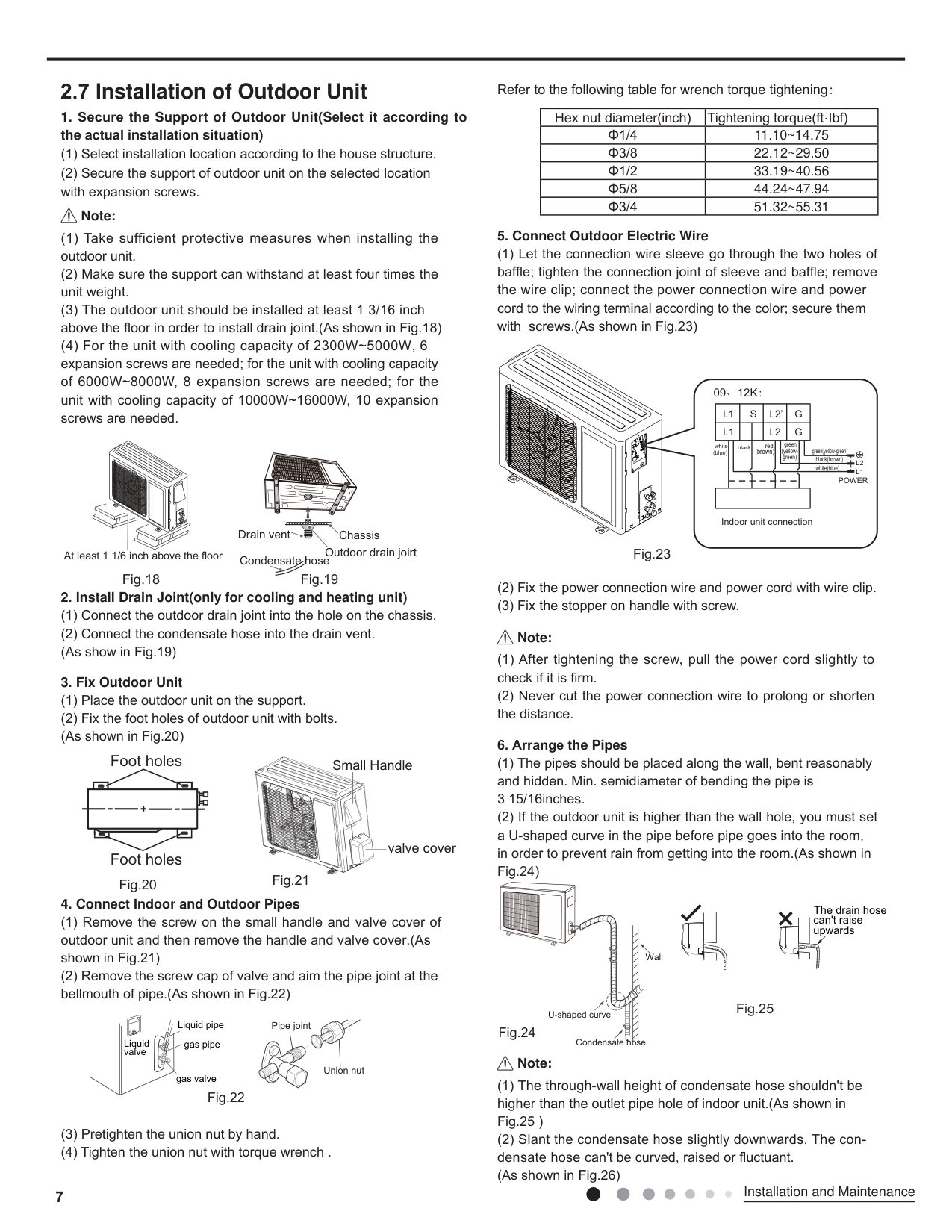
| |33.19~40.56| | |44.24~47.94| | |51.32~55.31|
secure n
09、12K:
G L1
S L2’L1’
L2 G
green
redblack
white (blue)
(yellow-(brown)
green(yellow-green) black(brown) white(blue)
green)
POWER
Indoor unit connection
Note:
es
n
The drain hose can't raise upwards
| | | | |---|---|---| | | | |
Wall
U-shaped curve
Condensate hose
Note:
condensate n
by
condensate condensate or n
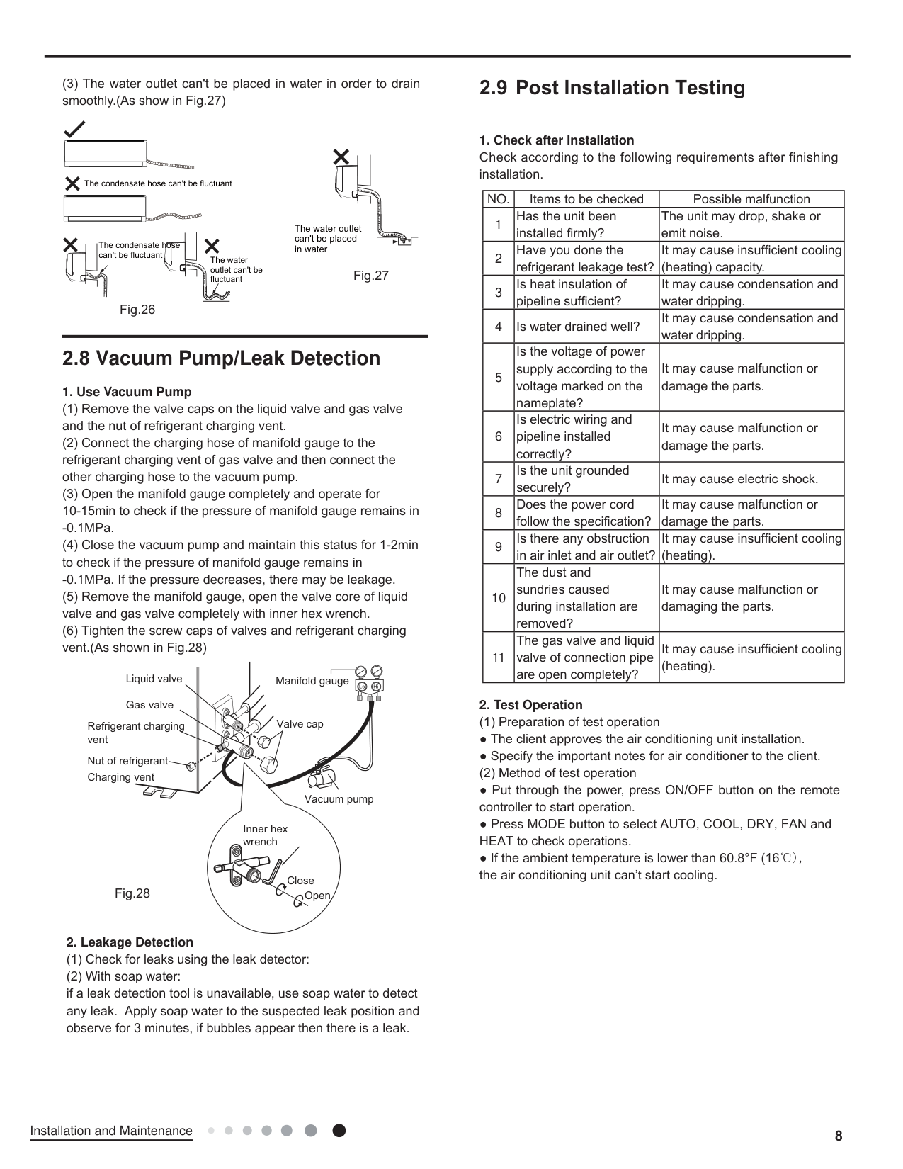
The condensate hose can't be fluctuant
The condensate hose can't be fluctuant
The water outlet can't be fluctuant
The water outlet can't be placed in water
####### 2.8 Vacuum Pump/Leak Detection
############### 1. Use Vacuum Pump
-0.1MPa.
-0.1MPa. If the pressure decreases, there may be leakage.
Liquid valve Gas valve
Manifold gauge
Lo Hi
Valve cap
Refrigerant charging vent
Nut of refrigerant Charging vent
Vacuum pump
Inner hex wrench
Close
Open
############### 2. Leakage Detection
####### 2.9 Post Installation Testing
|NO.| | | |---|---|---| |1| | | |2| | | |3| | | |4| | | |5| | | |6| | | |7| |shock| |8| | | |9| | | |10| | | |11| | |
ing unit
operations
60.8°F ( ), ing unit
3. Maintenance
##### 3.1 Precautions before Maintenance
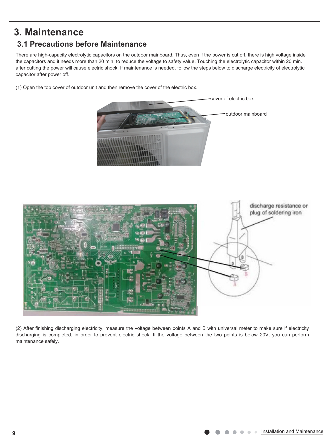
There are high-capacity electrolytic capacitors on the outdoor mainboard. Thus, even if the power is cut off, there is high voltage inside the capacitors and it needs more than 20 min. to reduce the voltage to safety value. Touching the electrolytic capacitor within 20 min. after cutting the power will cause electric shock. If maintenance is needed, follow the steps below to discharge electricity of electrolytic capacitor after power off.

cover of electric box
outdoor mainboard

9
Installation and Maintenance
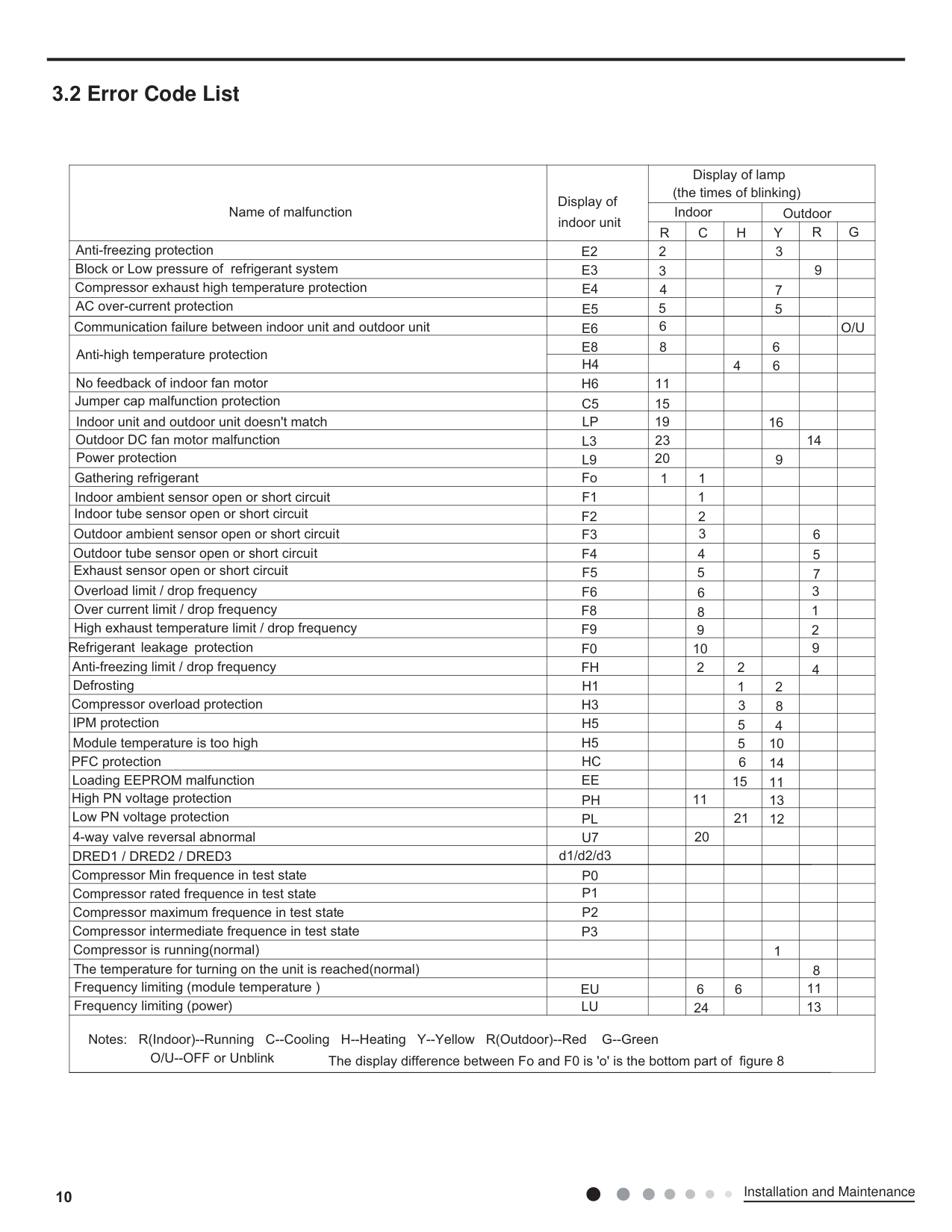
####### 3.2 Error Code List
|Name of malfunction|Display of indoor unit|Display of lamp (the times of blinking)|Display of lamp (the times of blinking)|Display of lamp (the times of blinking)|Display of lamp (the times of blinking)|Display of lamp (the times of blinking)|Display of lamp (the times of blinking)| |---|---|---|---|---|---|---|---| |Name of malfunction|Display of indoor unit|Indoor|Indoor|Indoor|Outdoor|Outdoor|Outdoor| |Name of malfunction|Display of indoor unit|R|C|H|Y|R|G| |Anti-freezing protection|E2|2| | |3| | | |Block or Low pressure of refrigerant system|E3|3| | | |9| | |Compressor exhaust high temperature protection|E4|4| | |7| | | |AC over-current protection|E5|5| | |5| | | |Communication failure between indoor unit and outdoor unit|E6|6| | | | |O/U| |Anti-high temperature protection|E8|8| | |6| | | |Anti-high temperature protection|H4| | |4|6| | | |No feedback of indoor fan motor|H6|11| | | | | | |Jumper cap malfunction protection|C5|15| | | | | | |Indoor unit and outdoor unit doesn't match|LP|19| | |16| | |
|Outdoor DC fan motor malfunction|L3|23| | | |14| | |Power protection|L9|20| | |9| | | |Gathering refrigerant|Fo|1|1| | | | | |Indoor ambient sensor open or short circuit|F1| |1| | | | | |Indoor tube sensor open or short circuit|F2| |2| | | | | |Outdoor ambient sensor open or short circuit|F3| |3| | |6| | |Outdoor tube sensor open or short circuit|F4| |4| | |5| | |Exhaust sensor open or short circuit|F5| |5| | |7| | |Overload limit / drop frequency|F6| |6| | |3| | |Over current limit / drop frequency|F8| |8| | |1| | |High exhaust temperature limit / drop frequency|F9| |9| | |2| | |Refrigerant leakage protection|F0| |10| | |9| | |Anti-freezing limit / drop frequency|FH| |2|2| |4| | |Defrosting|H1| | |1|2| | | |Compressor overload protection|H3| | |3|8| | | |IPM protection|H5| | |5|4| | | |Module temperature is too high|H5| | |5|10| | | |PFC protection|HC| | |6|14| | | |Loading EEPROM malfunction|EE| | |15|11| | | |High PN voltage protection|PH| |11| |13| | | |Low PN voltage protection|PL| | |21|12| | | |4-way valve reversal abnormal|U7| |20| | | | | |DRED1 / DRED2 / DRED3|d1/d2/d3| | | | | | | |Compressor Min frequence in test state|P0| | | | | | | |Compressor rated frequence in test state|P1| | | | | | | |Compressor maximum frequence in test state|P2| | | | | | | |Compressor intermediate frequence in test state|P3| | | | | | | |Compressor is running(normal)| | | | |1| | | |The temperature for turning on the unit is reached(normal)| | | | | |8| | |Frequency limiting (module temperature )|EU| |6|6| |11| | |Frequency limiting (power)|LU| |24| | |13| | |O/U--OFF or Unblink
Notes: R(Indoor)--Running C--Cooling H--Heating Y--Yellow R(Outdoor)--Red G--Green The display difference between Fo and F0 is 'o' is the bottom part of figure 8|O/U--OFF or Unblink
Notes: R(Indoor)--Running C--Cooling H--Heating Y--Yellow R(Outdoor)--Red G--Green The display difference between Fo and F0 is 'o' is the bottom part of figure 8|O/U--OFF or Unblink
Notes: R(Indoor)--Running C--Cooling H--Heating Y--Yellow R(Outdoor)--Red G--Green The display difference between Fo and F0 is 'o' is the bottom part of figure 8|O/U--OFF or Unblink
Notes: R(Indoor)--Running C--Cooling H--Heating Y--Yellow R(Outdoor)--Red G--Green The display difference between Fo and F0 is 'o' is the bottom part of figure 8|O/U--OFF or Unblink
Notes: R(Indoor)--Running C--Cooling H--Heating Y--Yellow R(Outdoor)--Red G--Green The display difference between Fo and F0 is 'o' is the bottom part of figure 8|O/U--OFF or Unblink
Notes: R(Indoor)--Running C--Cooling H--Heating Y--Yellow R(Outdoor)--Red G--Green The display difference between Fo and F0 is 'o' is the bottom part of figure 8|O/U--OFF or Unblink
Notes: R(Indoor)--Running C--Cooling H--Heating Y--Yellow R(Outdoor)--Red G--Green The display difference between Fo and F0 is 'o' is the bottom part of figure 8|O/U--OFF or Unblink
Notes: R(Indoor)--Running C--Cooling H--Heating Y--Yellow R(Outdoor)--Red G--Green The display difference between Fo and F0 is 'o' is the bottom part of figure 8|
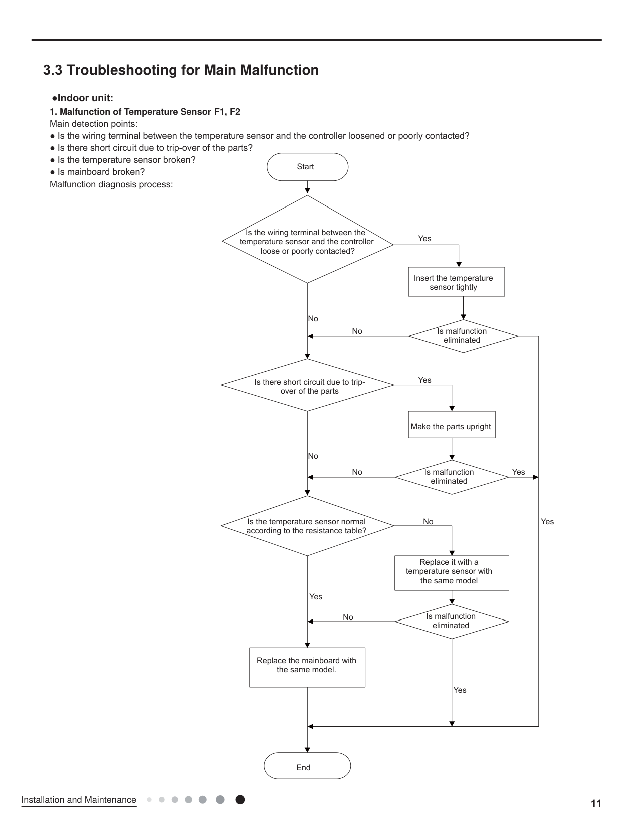
####### 3.3 Troubleshooting for Main Malfunction
| | | |---|---| | | |
| | | |---|---|
| | |
| | | |---|---| | | |
| | | |---|---| | | |
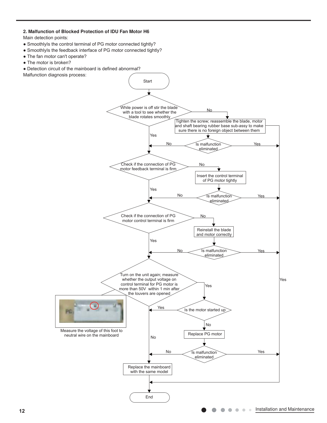
############### 2. Malfunction of Blocked Protection of IDU Fan Motor H6
|| |---|
| | | |---|---| | | |
| | | |---|---| | | |
| | | |---|---| | | |
############### 3. Malfunction of Protection of Jumper Cap C5
|| |---|
| | | |---|---| | | |
| |
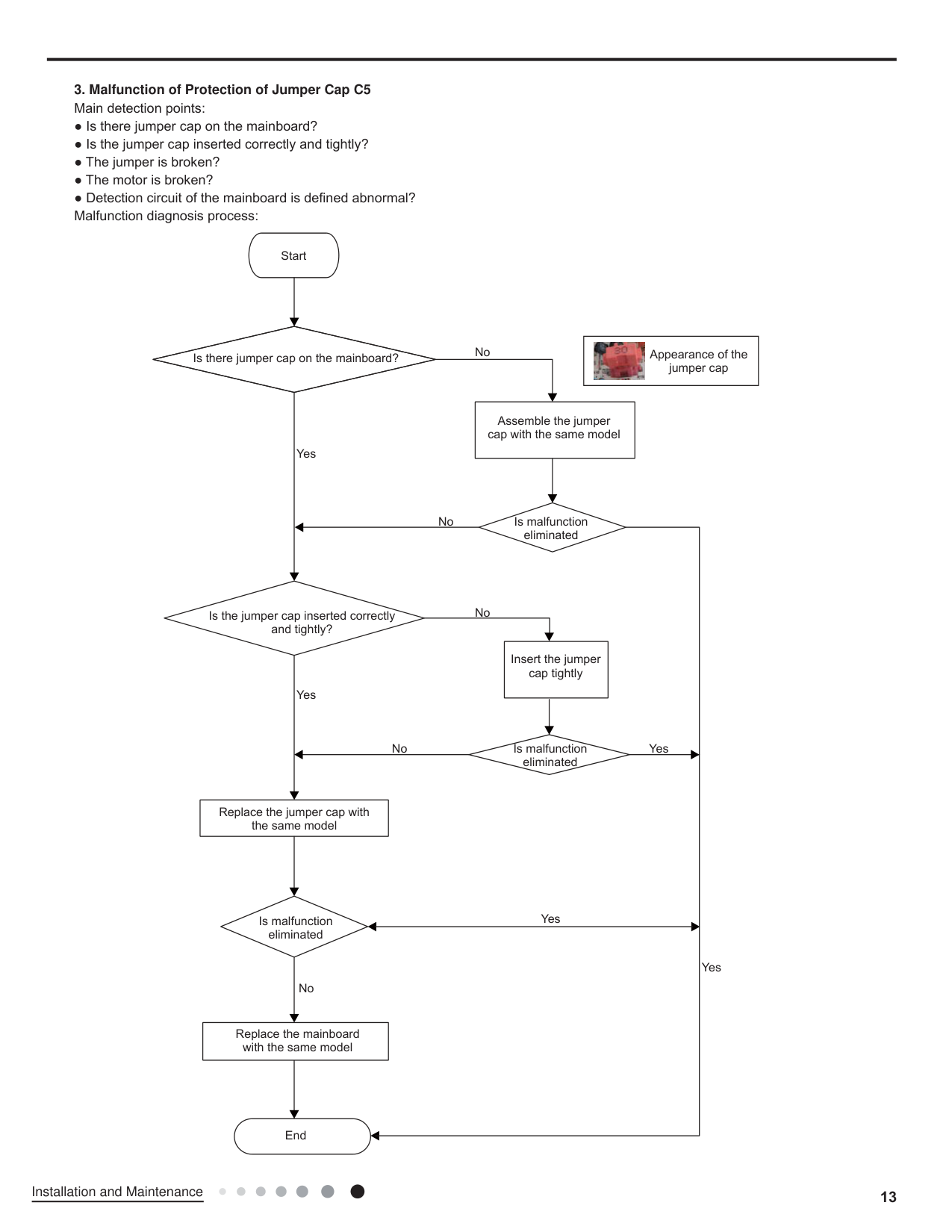
|---|
| | | |---|---| | | |
| | | |---|---| | | |
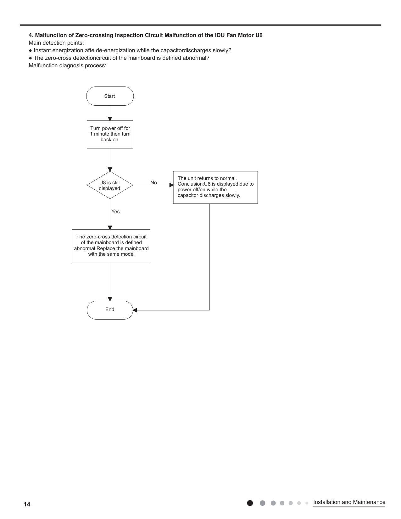
############### 4. Malfunction of Zero-crossing Inspection Circuit Malfunction of the IDU Fan Motor U8
|n|n| |---|---| | | |
| | | |---|---| | | |
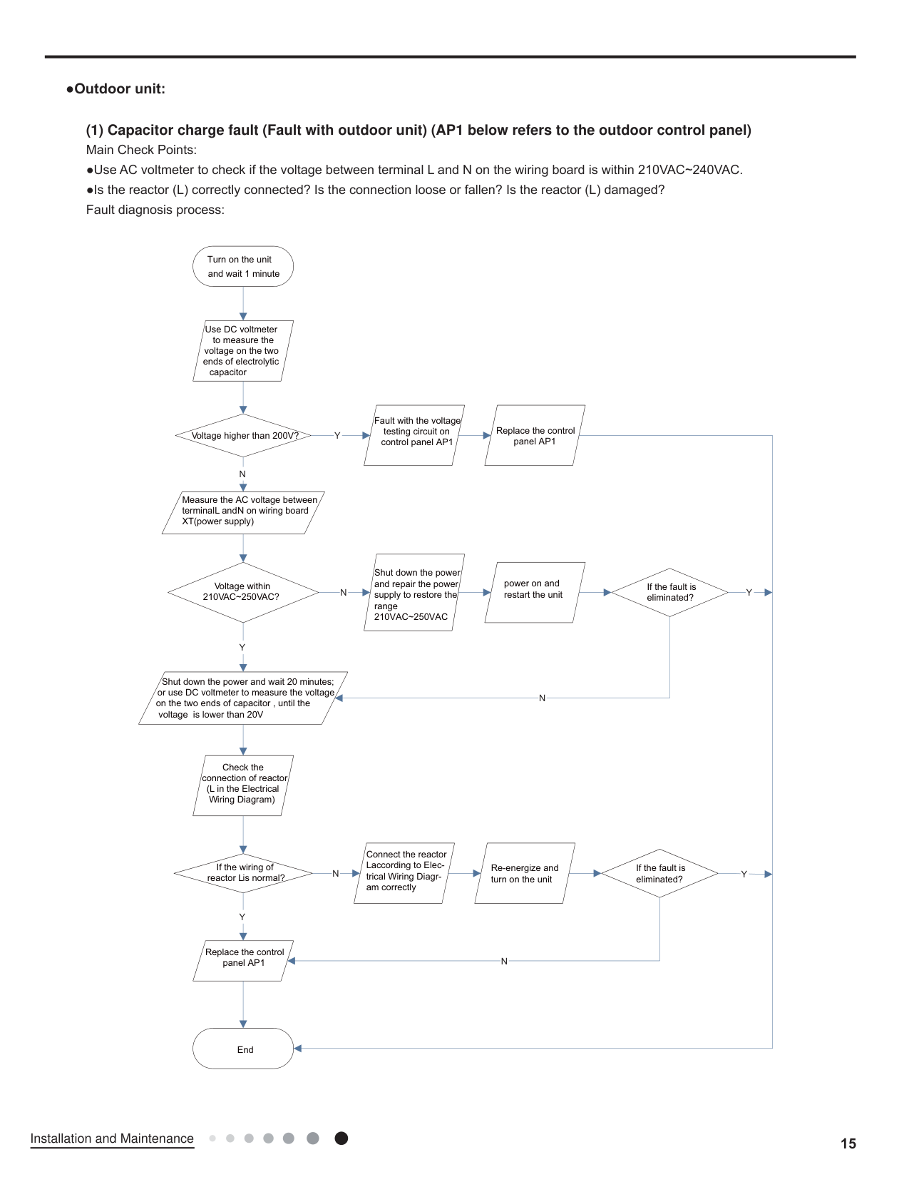
############# (1) Capacitor charge fault (Fault with outdoor unit) (AP1 below refers to the outdoor control panel)
Turn on the unit and wait 1 minute
Use DC voltmeter to measure the
voltage on the two ends of electrolytic
capacitor
Fault with the voltage testing circuit on control panel AP1
Replace the control panel AP1
Y
Voltage higher than 200V?
N
Measure the AC voltage between terminalL and N on wiring board XT(power supply)
Shut down the power and repair the power supply to restore the range 210VAC~250VAC
power on and restart the unit
Voltage within 210VAC~250VAC?
If the fault is eliminated?
N
Y
Shut down the power and wait 20 minutes; or use DC voltmeter to measure the voltage on the two ends of capacitor , until the
N
voltage is lower than 20V
Check the connection of reactor
(L in the Electrical Wiring Diagram)
Connect the reactor Laccording to Electrical Wiring Diagram correctly
If the wiring of reactor Lis normal?
Re-energize and turn on the unit
If the fault is eliminated?
N
Y
Replace the control panel AP1
N
Y
Y
End
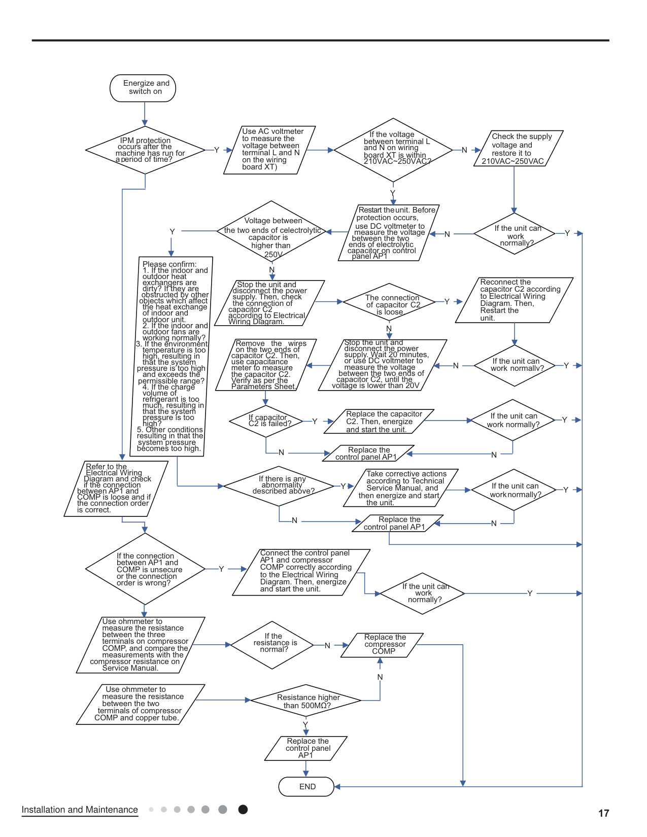
############# (2) IPM Protection, Out-of-step Fault, Compressor Phase Overcurrent (AP1 below refers to the outdoor controlpanel)
Energize and switch on
Use AC voltmeter to measure the voltage between terminal L and N on the wiring board XT)
If the voltage between terminal L and N on wiring board XT is within 210VAC~250VAC?
Check the supply voltage and restore it to 210VAC~250VAC
IPM protection
occurs after the machine has run for aperiod of time?
Y N
Y
Restart the unit. Before protection occurs,
Voltage between the two ends of celectrolytic
use DC voltmeter to measure the voltage
If the unit can
Y
YN
work normally?
capacitor is
between the two ends of electrolytic capacitor on control
higher than 250V
panel AP1
Please confirm:
N
Reconnect the capacitor C2 according to Electrical Wiring Diagram. Then, Restart the unit.
Stop the unit and disconnect the power supply. Then, check the connection of
The connection of capacitor C2
objects which affect the heat exchange of indoor and outdoor unit.
Y
capacitor C2 according to Electrical Wiring Diagram.
is loose.
N
Stop the unit and disconnect the power supply. Wait 20 minutes, or use DC voltmeter to measure the voltage between the two ends of capacitor C2, until the voltage is lower than 20V
Remove the wires on the two ends of
capacitor C2. Then, use capacitance meter to measure the capacitor C2. Verify as per the Parameters Sheet.
If the unit can work normallv? Y
N
pressure is too high and exceeds the permissible range?
Replace the capacitor C2. Then, energize and start the unit.
If the unit can work normally?
If capacitor C2 is failed?
Y
Y
Replace the control panel AP1
N
N
Refer to the Electrical Wiring
Take corrective actions according to Technical Service Manual, and
Diagram and check if the connection
If there is any abnormality
If the unit can work normally?
YY
described above?
between AP1 and COMP is loose and if the connection order is correct.
then energize and start the unit.
Replace the control panel AP1
N N
Connect the control panel AP1 and compressor COMP correctly according to the Electrical Wiring Diagram. Then, energize and start the unit.
If the connection between AP1 and COMP is unsecure or the connection order is wrong?
Y
If the unit can
work normally?
Y
Use ohmmeter to measure the resistance between the three terminals on compressor COMP, and compare the measurements with the
If the
Replace the compressor COMP
resistance is normal?
N
compressor resistance on Service Manual.
N
Use ohmmeter to measure the resistance between the two
Resistance higher than 500MΩ?
terminals of compressor COMP and copper tube.
Y
Replace the control panel
AP1
END
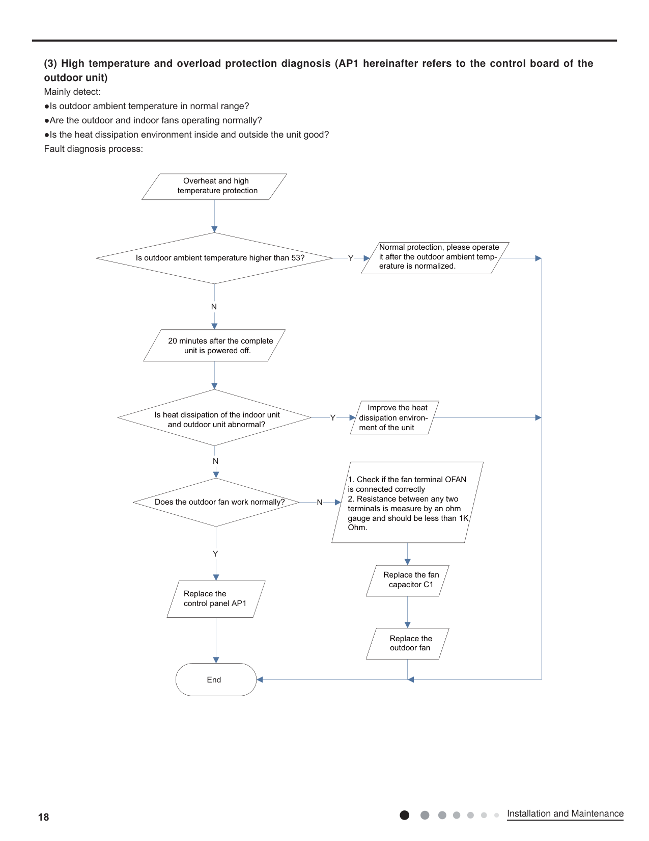
############# (3) High temperature and overload protection diagnosis (AP1 hereinafter refers to the control board of theoutdoor unit)
Overheat and high temperature protection
Is outdoor ambient temperature higher than 53?
Y
Normal protection, please operate it after the outdoor ambient temperature is normalized.
N
20 minutes after the complete unit is powered off.
Is heat dissipation of the indoor unit and outdoor unit abnormal?
Improve the heat dissipation environment of the unit
Y
N
Does the outdoor fan work normally?
N
Y
Replace the fan capacitor C1
Replace the control panel AP1
Replace the outdoor fan
End
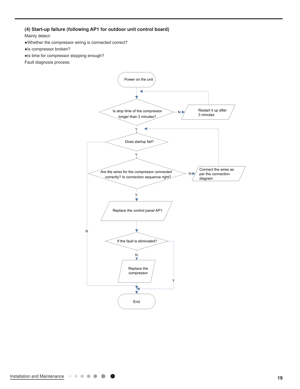
############# (4) Start-up failure (following AP1 for outdoor unit control board)
Power on the unit
Restart it up after 3 minutes
Is stop time of the compressor longer than 3 minutes?
N
Y
Does startup fail?
Y
Connect the wires as per the connection diagram
Are the wires for the compressor connected correctly? Is connection sequence right?
N
Y
Replace the control panel AP1
N
If the fault is eliminated?
N
Replace the compressor
Y
End
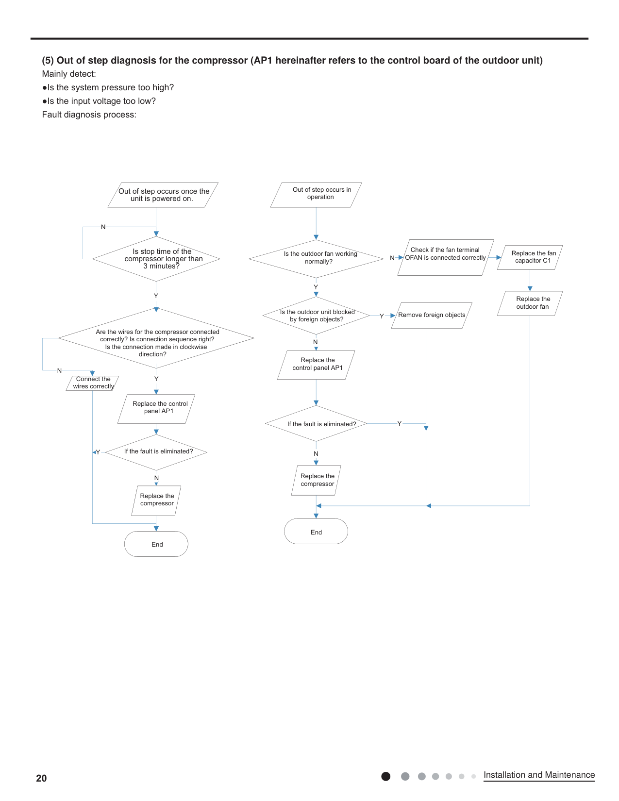
############# (5) Out of step diagnosis for the compressor (AP1 hereinafter refers to the control board of the outdoor unit)
Out of step occurs once the unit is powered on.
N
Is stop time of the compressor longer than 3 minutes?
Y
N
Are the wires for the compressor connected correctly? Is connection sequence right? Is the connection made in clockwise
direction?
Connect the wires correctly
Y
Replace the control panel AP1
Y
If the fault is eliminated?
N
Replace the compressor
End
Out of step occurs in operation
Is the outdoor fan working normally?
Y
Is the outdoor unit blocked by foreign objects?
N
Replace the control panel AP1
N
Check if the fan terminal OFAN is connected correctly
Y
Remove foreign objects
Replace the fan capacitor C1
Replace the outdoor fan
If the fault is eliminated?
N
Replace the compressor
End
Y
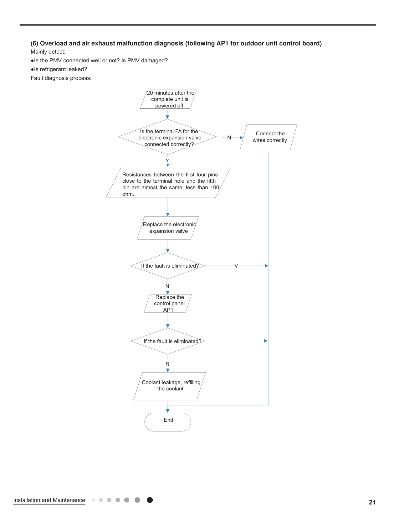
############# (6) Overload and air exhaust malfunction diagnosis (following AP1 for outdoor unit control board)
20 minutes after the complete unit is powered off
Is the terminal FA for the electronic expansion valve connected correctly?
N

Resistances between the first four pins close to the terminal hole and the fifth pin are almost the same, less than 100 ohm.
Connect the wires correctly
Replace the electronic expansion valve
If the fault is eliminated?
N
Replace the
control panel AP1
If the fault is eliminated?
N
Coolant leakage, refilling the coolant
End
Y
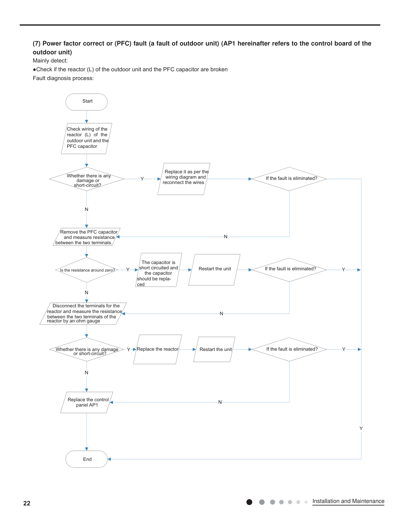
############# (7) Power factor correct or (PFC) fault (a fault of outdoor unit) (AP1 hereinafter refers to the control board of theoutdoor unit)
Start
Check wiring of the reactor (L) of the outdoor unit and the PFC capacitor
Replace it as per the wiring diagram and
Whether there is any damage or short-circuit?
If the fault is eliminated?
Y
reconnect the wires
N
Remove the PFC capacitor and measure resistance between the two terminals.
N
The capacitor is short circuited and the capacitor should be replaced
Restart the unit If the fault is eliminated?
Y
Is the resistance around zero?
N
Disconnect the terminals for the reactor and measure the resistance between the two terminals of the reactor by an ohm gauge
N
Replace the reactor Restart the unit If the fault is eliminated?
Whether there is any damage or short-circuit?
################## Y
N
Replace the control panel AP1
N
Y
Y
Y
End
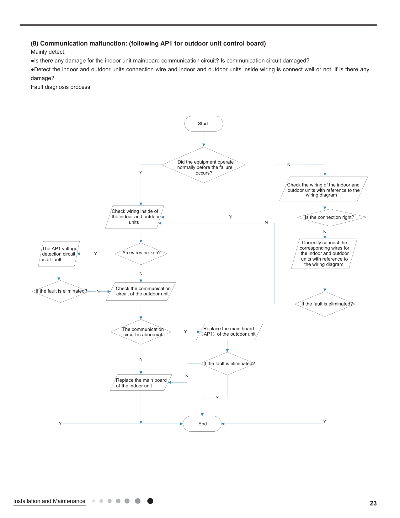
############# (8) Communication malfunction: (following AP1 for outdoor unit control board)
Start
Y
Did the equipment operate normally before the failure occurs?
N
Check the wiring of the indoor and outdoor units with reference to the
wiring diagram
Check wiring inside of the indoor and outdoor
Is the connection right?
Y
units
N
N
Correctly connect the corresponding wires for the indoor and outdoor units with reference to the wiring diagram
The AP1 voltage detection circuit is at fault
Are wires broken?
Y
N
Check the communication circuit of the outdoor unit
If the fault is eliminated?
N
If the fault is eliminated?
Y
Replace the main board
The communication circuit is abnormal
Y
AP1 of the outdoor unit
N
If the fault is eliminated?
N
Replace the main board of the indoor unit
Y
Y
End
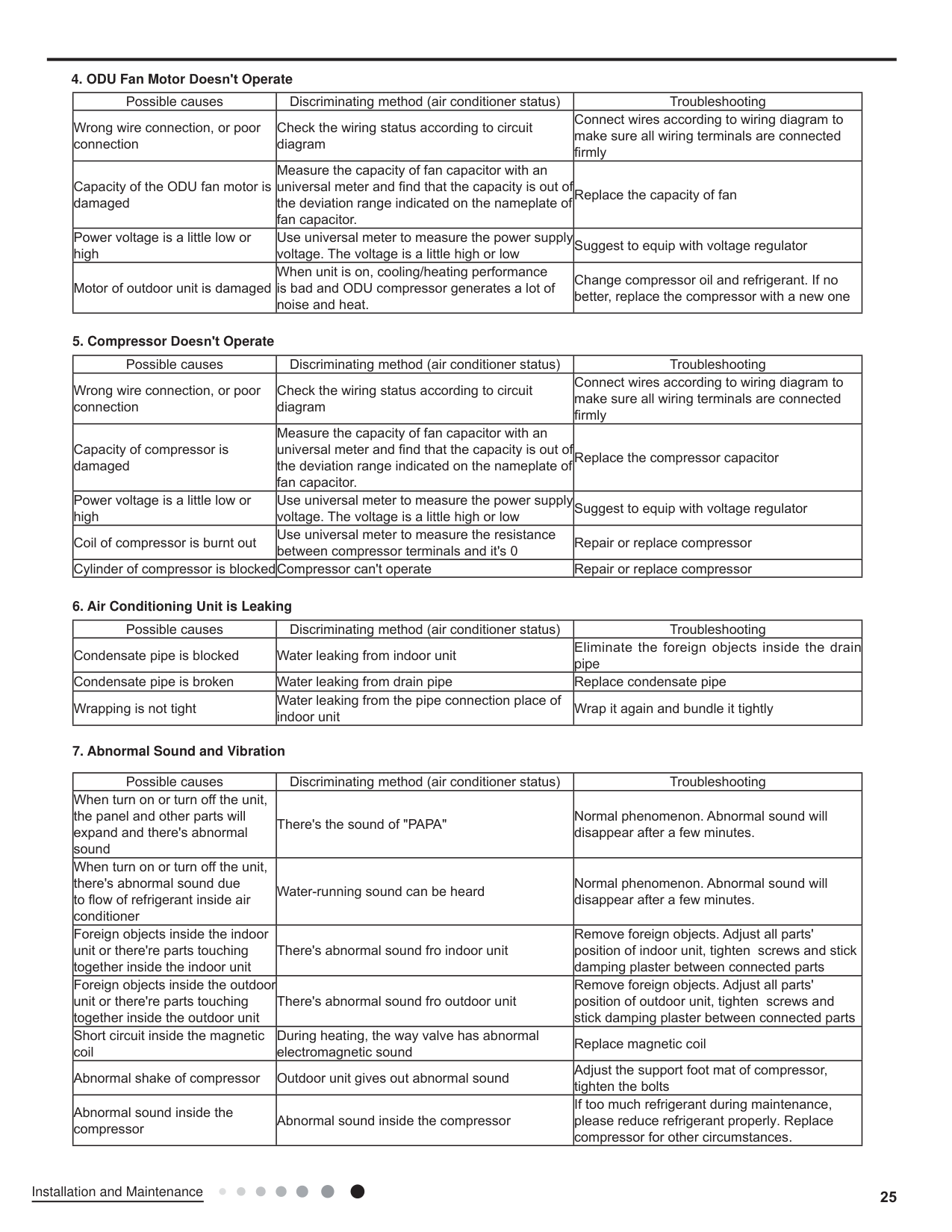
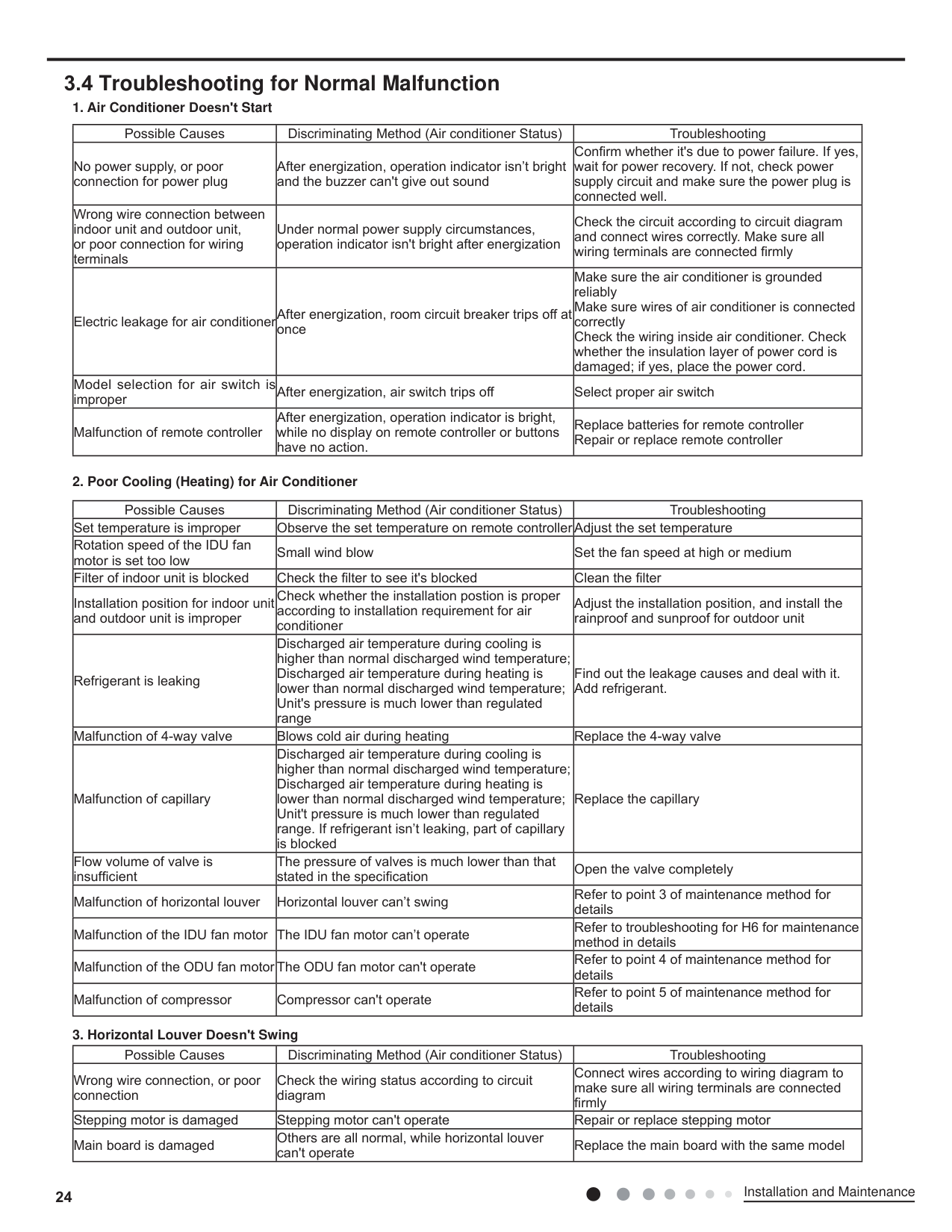
####### 3.4 Troubleshooting for Normal Malfunction
| | | | |---|---|---| | | | | | | | | | | | | | | | | | | | |
| | | | |---|---|---| | | | | | | | | | | | | | | | | | | | | | |s air| | | | | | | | | | | | | | | | | | | | | | | | | |
| | | | |---|---|---| | | | | | | | | | | | |
| | | | |---|---|---| | | | |
| | | | | | | | | | | |
| | | | |---|---|---| | | | | | | | | | | | | | | | | | | | |
| | | | |---|---|---| |Condensate| |pipe| |Condensate| |condensate| | | | |
| | | | |---|---|---| | | | | | | | | | | | | | | | | | | | | | | | | | | | |
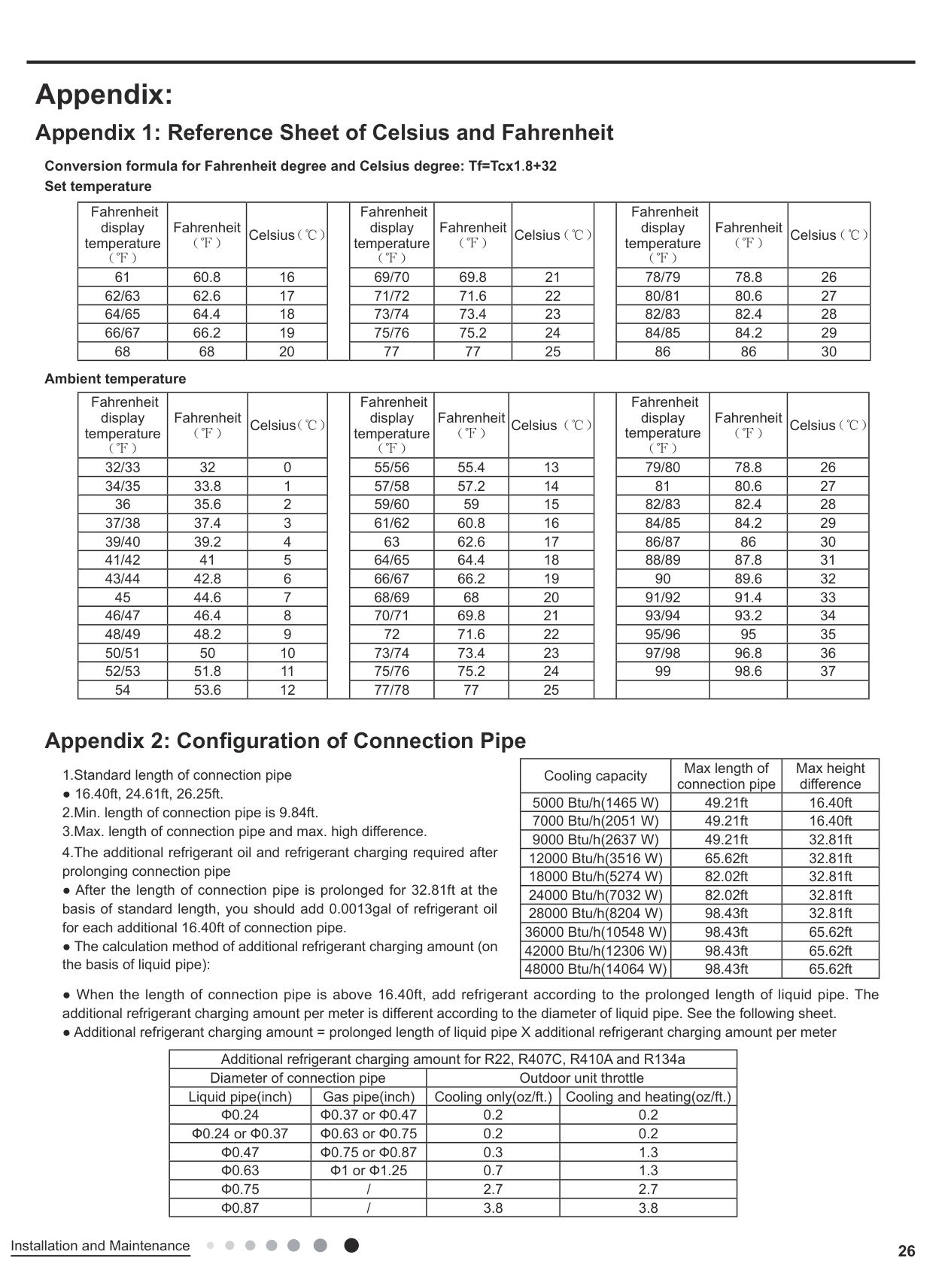
Appendix:
Conversion formula for Fahrenheit degree and Celsius degree: Tf=Tcx1.8+32
Set temperature
|Fahrenheit display temperature (℉)|Fahrenheit (℉)|Celsius(℃| |Fahrenheit display temperature (℉)|Fahrenheit (℉)|Celsius(℃| |Fahrenheit display temperature (℉)|Fahrenheit (℉)|Celsius(℃)| |---|---|---|---|---|---|---|---|---|---|---| |61|60.8|16| |69/70|69.8|21| |78/79|78.8|26| |62/63|62.6|17| |71/72|71.6|22| |80/81|80.6|27| |64/65|64.4|18| |73/74|73.4|23| |82/83|82.4|28| |66/67|66.2|19| |75/76|75.2|24| |84/85|84.2|29| |68|68|20| |77|77|25| |86|86|30|
Ambient temperature
|Fahrenheit display temperature (℉)|Fahrenheit (℉)|Celsius(℃| |Fahrenheit display temperature (℉)|Fahrenheit (℉)|Celsius(℃| |Fahrenheit display temperature (℉)|Fahrenheit (℉)|Celsius(℃)| |---|---|---|---|---|---|---|---|---|---|---| |32/33|32|0| |55/56|55.4|13| |79/80|78.8|26| |34/35|33.8|1| |57/58|57.2|14| |81|80.6|27| |36|35.6|2| |59/60|59|15| |82/83|82.4|28| |37/38|37.4|3| |61/62|60.8|16| |84/85|84.2|29| |39/40|39.2|4| |63|62.6|17| |86/87|86|30| |41/42|41|5| |64/65|64.4|18| |88/89|87.8|31| |43/44|42.8|6| |66/67|66.2|19| |90|89.6|32| |45|44.6|7| |68/69|68|20| |91/92|91.4|33| |46/47|46.4|8| |70/71|69.8|21| |93/94|93.2|34| |48/49|48.2|9| |72|71.6|22| |95/96|95|35| |50/51|50|10| |73/74|73.4|23| |97/98|96.8|36| |52/53|51.8|11| |75/76|75.2|24| |99|98.6|37| |54|53.6|12| |77/78|77|25| | | | |
|Cooling capacity|Max length of connection pipe|Max height difference| |---|---|---| |5000 Btu/h(1465 W)|49.21ft|16.40ft| |7000 Btu/h(2051 W)|49.21ft|16.40ft| |9000 Btu/h(2637 W)|49.21ft|32.81ft| |12000 Btu/h(3516 W)|65.62ft|32.81ft| |18000 Btu/h(5274 W)|82.02ft|32.81ft| |24000 Btu/h(7032 W)|82.02ft|32.81ft| |28000 Btu/h(8204 W)|98.43ft|32.81ft| |36000 Btu/h(10548 W)|98.43ft|65.62ft| |42000 Btu/h(12306 W)|98.43ft|65.62ft| |48000 Btu/h(14064 W)|98.43ft|65.62ft|
● 16.40ft, 24.61ft, 26.25ft.
|Additional refrigerant charging amount for R22, R407C, R410A and R134a|Additional refrigerant charging amount for R22, R407C, R410A and R134a|Additional refrigerant charging amount for R22, R407C, R410A and R134a|Additional refrigerant charging amount for R22, R407C, R410A and R134a| |---|---|---|---| |Diameter of connection pipe|Diameter of connection pipe|Outdoor unit throttle|Outdoor unit throttle| |Liquid pipe(inch)|Gas pipe(inch)|Cooling only(oz/ft.)|Cooling and heating(oz/ft.)| |Ф0.24|Ф0.37 or Ф0.47|0.2|0.2| |Ф0.24 or Ф0.37|Ф0.63 or Ф0.75|0.2|0.2| |Ф0.47|Ф0.75 or Ф0.87|0.3|1.3| |Ф0.63|Ф1 or Ф1.25|0.7|1.3| |Ф0.75|/|2.7|2.7| |Ф0.87|/|3.8|3.8|
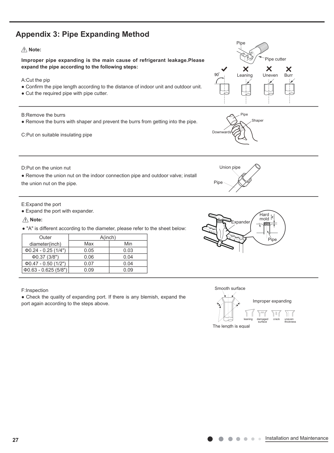
##### Appendix 3: Pipe Expanding Method
Pipe
Note:
Pipe cutter
############## Improper pipe expanding is the main cause of refrigerant leakage.Please expand the pipe according to the following steps:
Leaning Uneven Burr
● Remove the burrs with shaper and prevent the burrs from getting into the pipe.
● Remove the union nut on the indoor connection pipe and outdoor valve; install the union nut on the pipe.
| | | |---|---| | | |
Pipe
Shaper
Downwards
Union pipe
Pipe
Hard mold
Note:
Expander
|Outer diameter(inch)|A(inch)|A(inch)| |---|---|---| |Outer diameter(inch)|Max|Min| |Ф0.24 - 0.25 (1/4")|0.05|0.03| |Ф0.37 (3/8")|0.06|0.04| |Ф0.47 - 0.50 (1/2")|0.07|0.04| |Ф0.63 - 0.625 (5/8")|0.09|0.09|
Pipe
Smooth surface
Improper expanding
leaning damaged surface
crack uneven thickness
The length is equal
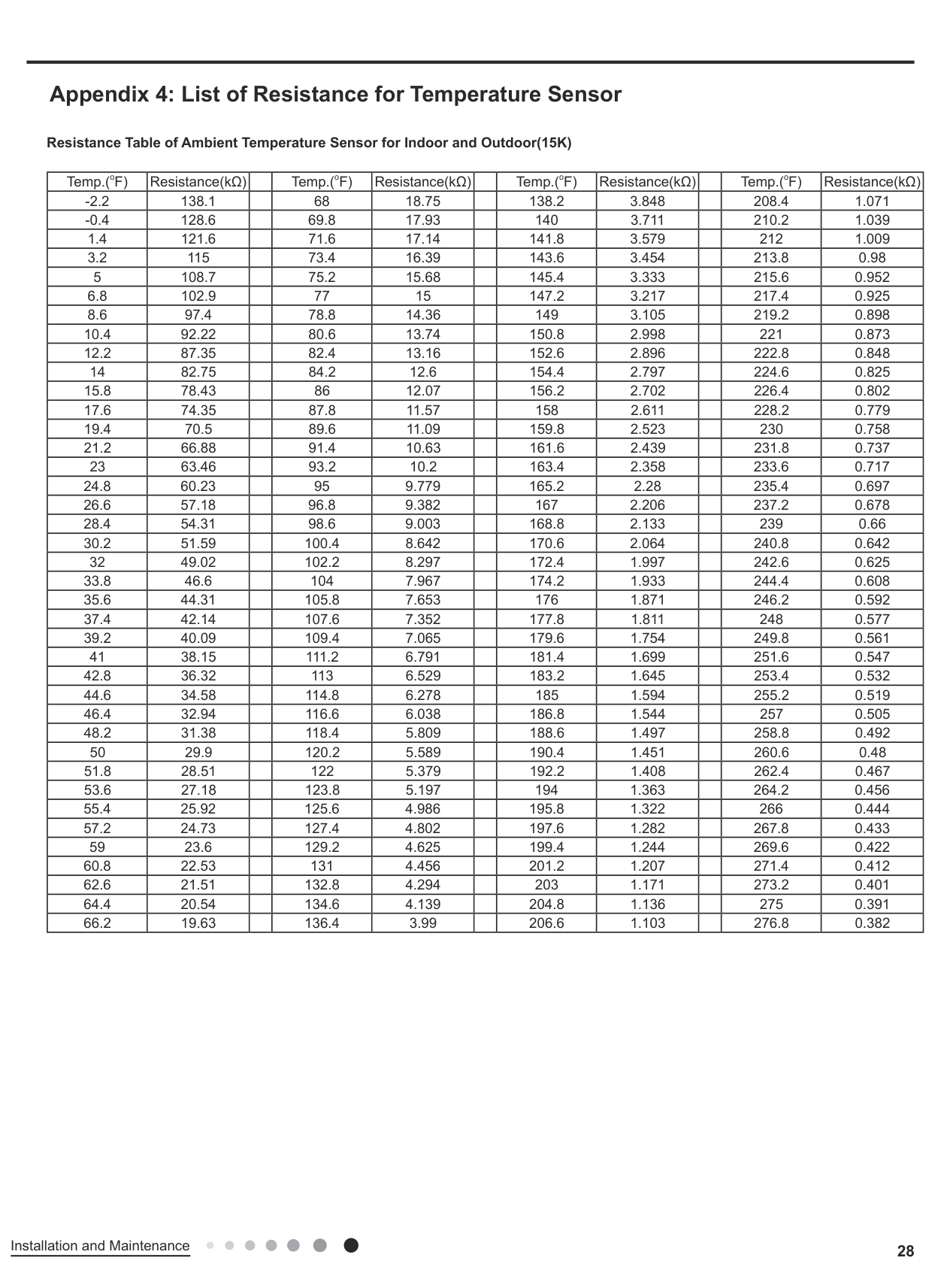
##### Appendix 4: List of Resistance for Temperature Sensor
Resistance Table of Ambient Temperature Sensor for Indoor and Outdoor(15K)
|Temp.(oF)|Resistance(kΩ)| |Temp.(oF)|Resistance(kΩ)| |Temp.(oF)|Resistance(kΩ)| |Temp.(oF)|Resistance(kΩ)| |---|---|---|---|---|---|---|---|---|---|---| |-2.2|138.1| |68|18.75| |138.2|3.848| |208.4|1.071| |-0.4|128.6| |69.8|17.93| |140|3.711| |210.2|1.039| |1.4|121.6| |71.6|17.14| |141.8|3.579| |212|1.009| |3.2|115| |73.4|16.39| |143.6|3.454| |213.8|0.98| |5|108.7| |75.2|15.68| |145.4|3.333| |215.6|0.952| |6.8|102.9| |77|15| |147.2|3.217| |217.4|0.925| |8.6|97.4| |78.8|14.36| |149|3.105| |219.2|0.898| |10.4|92.22| |80.6|13.74| |150.8|2.998| |221|0.873| |12.2|87.35| |82.4|13.16| |152.6|2.896| |222.8|0.848| |14|82.75| |84.2|12.6| |154.4|2.797| |224.6|0.825| |15.8|78.43| |86|12.07| |156.2|2.702| |226.4|0.802| |17.6|74.35| |87.8|11.57| |158|2.611| |228.2|0.779| |19.4|70.5| |89.6|11.09| |159.8|2.523| |230|0.758| |21.2|66.88| |91.4|10.63| |161.6|2.439| |231.8|0.737| |23|63.46| |93.2|10.2| |163.4|2.358| |233.6|0.717| |24.8|60.23| |95|9.779| |165.2|2.28| |235.4|0.697| |26.6|57.18| |96.8|9.382| |167|2.206| |237.2|0.678| |28.4|54.31| |98.6|9.003| |168.8|2.133| |239|0.66| |30.2|51.59| |100.4|8.642| |170.6|2.064| |240.8|0.642| |32|49.02| |102.2|8.297| |172.4|1.997| |242.6|0.625| |33.8|46.6| |104|7.967| |174.2|1.933| |244.4|0.608| |35.6|44.31| |105.8|7.653| |176|1.871| |246.2|0.592| |37.4|42.14| |107.6|7.352| |177.8|1.811| |248|0.577| |39.2|40.09| |109.4|7.065| |179.6|1.754| |249.8|0.561| |41|38.15| |111.2|6.791| |181.4|1.699| |251.6|0.547|

|42.8|36.32| |113|6.529| |183.2|1.645| |253.4|0.532| |44.6|34.58| |114.8|6.278| |185|1.594| |255.2|0.519| |46.4|32.94| |116.6|6.038| |186.8|1.544| |257|0.505| |48.2|31.38| |118.4|5.809| |188.6|1.497| |258.8|0.492| |50|29.9| |120.2|5.589| |190.4|1.451| |260.6|0.48| |51.8|28.51| |122|5.379| |192.2|1.408| |262.4|0.467| |53.6|27.18| |123.8|5.197| |194|1.363| |264.2|0.456| |55.4|25.92| |125.6|4.986| |195.8|1.322| |266|0.444| |57.2|24.73| |127.4|4.802| |197.6|1.282| |267.8|0.433| |59|23.6| |129.2|4.625| |199.4|1.244| |269.6|0.422| |60.8|22.53| |131|4.456| |201.2|1.207| |271.4|0.412| |62.6|21.51| |132.8|4.294| |203|1.171| |273.2|0.401| |64.4|20.54| |134.6|4.139| |204.8|1.136| |275|0.391| |66.2|19.63| |136.4|3.99| |206.6|1.103| |276.8|0.382|
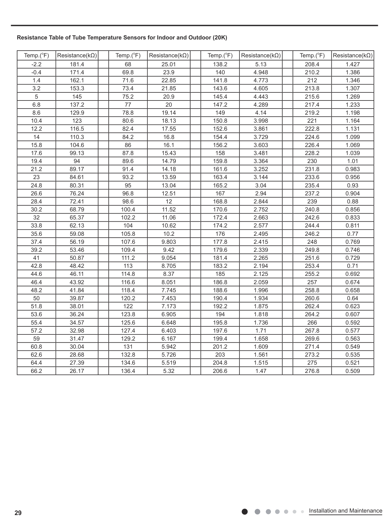
############## Resistance Table of Tube Temperature Sensors for Indoor and Outdoor (20K)
|Temp.(oF)|Resistance(kΩ)| |Temp.(oF)|Resistance(kΩ)| |Temp.(oF)|Resistance(kΩ)| |Temp.(oF)|Resistance(kΩ)| |---|---|---|---|---|---|---|---|---|---|---| |-2.2|181.4| |68|25.01| |138.2|5.13| |208.4|1.427| |-0.4|171.4| |69.8|23.9| |140|4.948| |210.2|1.386| |1.4|162.1| |71.6|22.85| |141.8|4.773| |212|1.346| |3.2|153.3| |73.4|21.85| |143.6|4.605| |213.8|1.307| |5|145| |75.2|20.9| |145.4|4.443| |215.6|1.269| |6.8|137.2| |77|20| |147.2|4.289| |217.4|1.233| |8.6|129.9| |78.8|19.14| |149|4.14| |219.2|1.198| |10.4|123| |80.6|18.13| |150.8|3.998| |221|1.164| |12.2|116.5| |82.4|17.55| |152.6|3.861| |222.8|1.131| |14|110.3| |84.2|16.8| |154.4|3.729| |224.6|1.099| |15.8|104.6| |86|16.1| |156.2|3.603| |226.4|1.069| |17.6|99.13| |87.8|15.43| |158|3.481| |228.2|1.039| |19.4|94| |89.6|14.79| |159.8|3.364| |230|1.01| |21.2|89.17| |91.4|14.18| |161.6|3.252| |231.8|0.983| |23|84.61| |93.2|13.59| |163.4|3.144| |233.6|0.956| |24.8|80.31| |95|13.04| |165.2|3.04| |235.4|0.93| |26.6|76.24| |96.8|12.51| |167|2.94| |237.2|0.904| |28.4|72.41| |98.6|12| |168.8|2.844| |239|0.88| |30.2|68.79| |100.4|11.52| |170.6|2.752| |240.8|0.856| |32|65.37| |102.2|11.06| |172.4|2.663| |242.6|0.833| |33.8|62.13| |104|10.62| |174.2|2.577| |244.4|0.811| |35.6|59.08| |105.8|10.2| |176|2.495| |246.2|0.77| |37.4|56.19| |107.6|9.803| |177.8|2.415| |248|0.769| |39.2|53.46| |109.4|9.42| |179.6|2.339| |249.8|0.746| |41|50.87| |111.2|9.054| |181.4|2.265| |251.6|0.729| |42.8|48.42| |113|8.705| |183.2|2.194| |253.4|0.71| |44.6|46.11| |114.8|8.37| |185|2.125| |255.2|0.692| |46.4|43.92| |116.6|8.051| |186.8|2.059| |257|0.674| |48.2|41.84| |118.4|7.745| |188.6|1.996| |258.8|0.658| |50|39.87| |120.2|7.453| |190.4|1.934| |260.6|0.64| |51.8|38.01| |122|7.173| |192.2|1.875| |262.4|0.623| |53.6|36.24| |123.8|6.905| |194|1.818| |264.2|0.607| |55.4|34.57| |125.6|6.648| |195.8|1.736| |266|0.592| |57.2|32.98| |127.4|6.403| |197.6|1.71| |267.8|0.577| |59|31.47| |129.2|6.167| |199.4|1.658| |269.6|0.563| |60.8|30.04| |131|5.942| |201.2|1.609| |271.4|0.549| |62.6|28.68| |132.8|5.726| |203|1.561| |273.2|0.535| |64.4|27.39| |134.6|5.519| |204.8|1.515| |275|0.521| |66.2|26.17| |136.4|5.32| |206.6|1.47| |276.8|0.509|
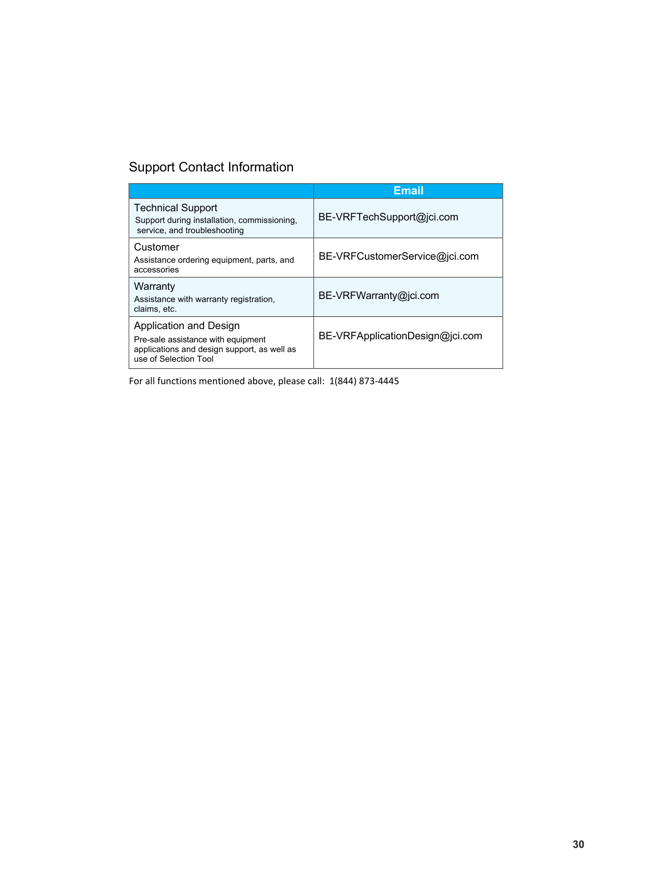
######### Support Contact Information
| |Email| |---|---| |Technical Support Support during installation, commissioning,
service, and troubleshooting|BE-VRFTechSupport@jci.com| |Customer ServiceAssistance ordering equipment, parts, and accessories
|BE-VRFCustomerService@jci.com| |Warranty Assistance with warranty registration, warrantyclaims, etc.
|BE-VRFWarranty@jci.com| |Application and Design
Pre-sale assistance with equipment applications and design support, as well as use of Selection Tool|BE-VRFApplicationDesign@jci.com|
For all functions mentioned above, please call: 1(844) 873-4445
30
Product improvement, specifications and appearance in this manual are subject to change without prior notice.
######## © Johnson Controls, Inc. USA LIT - 12012182