
Ask AI
— answers from the official manualAnswers from the official manual.
Common questions
Common Questions
39 totalWhat are the key safety precautions I need to follow when operating the Dynasty 280?
Key safety precautions include: wearing dry, hole-free insulating gloves and body protection; disconnecting input power before servicing; keeping the machine properly grounded; protecting yourself from arc rays by wearing an approved welding helmet with proper shade filter lenses; maintaining proper ventilation to remove welding fumes and gases; and keeping flammables at least 35 feet away from the welding arc. Only qualified persons should install, operate, maintain, and repair the unit. (Pages 9-11)
How do I properly connect input power to the Dynasty 280?
The Dynasty 280 can be connected to three-phase or single-phase input power ranging from 208V to 575V. Detailed electrical service guides for proper connection are provided in Sections 5-6 (for Dynasty models), 5-8 (for three-phase connections), and 5-9 (for single-phase connections). Always verify supply ground and attach the proper grounding conductor first before making other connections. (Pages 23-27)
Can the Dynasty 280 be used in damp locations, and what special precautions apply?
Additional safety precautions are required when using the Dynasty 280 in damp locations, confined spaces, or situations with high risk of contact with the workpiece or ground. In these conditions, use the following in order of preference: 1) a semiautomatic DC constant voltage (wire) welder, 2) a DC manual (stick) welder, or 3) an AC welder with reduced open-circuit voltage. Use dry insulating mats or covers to insulate yourself from work and ground, and do not work alone. (Page 9)
What should I do if the Dynasty 280 overheats during welding?
If the unit overheats, welding output will stop, a help message will be displayed on the voltmeter/ammeter, and the cooling fan will begin running. Wait 15 minutes for the unit to cool down before resuming. Before restarting, reduce the welding current, voltage, or duty cycle to prevent the issue from recurring.
What is the welding current range of the Dynasty 280?
The Dynasty 280 has a welding current range of 1 to 280 amperes. For stick (SMAW) welding, the range is 5 to 280 amperes, while for TIG welding, the current range depends on the diameter of the tungsten electrode. The maximum open-circuit voltage is 60V, with a low open-circuit voltage of 8–15V available. (Page 11)
What is the duty cycle of the Dynasty 280 at 280 amperes in stick (SMAW) mode with three-phase input?
At 280 amperes with three-phase input, the Dynasty 280 has a duty cycle of 15% for stick (SMAW) welding. This means the unit can weld for approximately 1.5 minutes out of every 10-minute period at that output. Exceeding the duty cycle can damage the machine or torch and will void the warranty.
Show 33 more questions
What input voltage range is compatible with the Dynasty 280?
What coolant should I use with the water cooler accessory on the Dynasty 280?
What fuse size is recommended for the Dynasty 280 on a 230V single-phase circuit?
How far should I keep the Dynasty 280 from surrounding walls or objects for proper ventilation?
How long must I wait after turning off the Dynasty 280 before touching internal components?
What are the weight and dimensions of the Dynasty 280 power source?
What input voltage range does the Dynasty 280 accept?
What is the duty cycle (Fator de Trabalho) of the Dynasty 280 for stick welding?
What should I do if the machine overheats and stops welding?
What fuse size is recommended for the Dynasty 280 running on 230V single-phase power?
What refrigerant/coolant should I use in the water cooler connected to the Dynasty 280?
What is the operating temperature range of the Dynasty 280?
How much clearance does the Dynasty 280 need around it for proper airflow?
How long should I wait before touching internal components after turning the Dynasty 280 off?
What welding cable size should I use for 250 amperes at a total circuit length of 200 feet?
What is the Dynasty 280 and what welding processes does it support?
What are the welding amperage specifications for the Dynasty 280?
How should I select and prepare a tungsten electrode for the Dynasty 280?
What is the duty cycle rating for the Dynasty 280 at different amperage levels?
What routine maintenance is required for the Dynasty 280?
What dimensions and weight specifications should I know about the Dynasty 280?
What electromagnetic field (EMF) precautions should I follow when using the Dynasty 280?
What maintenance steps are recommended for my Dynasty 280?
How do I operate AC TIG mode on my Dynasty 280?
How can I troubleshoot if my Miller Dynasty 280 displays error code B1?
What safety measures should I take when handling compressed gas cylinders with my Dynasty 280?
How do I set up input power connections for my Dynasty 280 welding machine?
How can I avoid electrical shock when working with my Dynasty 280?
What do I need to know about welding in restricted spaces?
How do I safely lift and move my Dynasty 280?
What safety considerations are there regarding EMF and implanted medical devices?
How do I properly dispose of my Dynasty 280 when it's no longer needed?
What is the operating temperature range for the Dynasty 280?
Full Manual
84 pages
|For product information, Owner’s Manual translations, and more, visit
www.MillerWelds.com
| |---|


################ OM-253086T 2017-10
Processes
TIG (GTAW) Welding

Stick (SMAW) Welding

Description


208−575 Volt Models W/Autoline Arc Welding Power Source
Dynasty 280 Maxstar 280
#### CE And Non-CE Models
From Miller to You
Thank you and congratulations on choosing Miller. Now you can get the job done and get it done right. We know you don’t have time to do it any other way.
That’s why when Niels Miller first started building arc welders in 1929, he made sure his products offered long-lasting value and superior quality. Like you, his customers couldn’t afford anything less. Miller products had to be more than the best they could be. They had to be the best you could buy.
Today, the people that build and sell Miller products continue the tradition. They’re just as committed to providing equipment and service that meets the high standards of quality and value established in 1929. This Owner’s Manual is designed to help you get the most out of your Miller products. Please take time to read the Safety precautions. They will help you protect yourself against potential hazards on the worksite.
We’ve made installation and operation quick and easy. With Miller you can count on years of reliable service with proper maintenance. And if for some reason the unit needs repair, there’s a Troubleshooting section that will help you figure out what the problem is. The parts list will then help you to decide the exact part you may need to fix the problem. Warranty and service information for your particular model are also provided.
Miller is the first welding equipment manufacturer in the U.S.A. to be registered to the ISO 9001 Quality System Standard.


Miller Electric manufactures a full line of welders and welding related equipment. For information on other quality Miller products, contact your local Miller distributor to receive the latest full line catalog or individual specification sheets. To locate your nearest distributor or service agency call 1-800-4-A-Miller, or visit us at www.MillerWelds.com on the web.
Mil_Thank 2017−06
|
Working as hard as you do − every power source from Miller is backed by the most hassle-free warranty in the business.

| |---|
####################### SECTION 1 − SAFETY PRECAUTIONS - READ BEFORE USING 1.................................
####################### SECTION 2 − CONSIGNES DE SÉCURITÉ − LIRE AVANT UTILISATION 5...........................
####################### SECTION 3 − DEFINITIONS 9..................................................................
####################### SECTION 4 − SPECIFICATIONS 13..............................................................
####################### SECTION 5 − INSTALLATION 19................................................................
####################### SECTION 6 − DYNASTY 280 OPERATION 32.....................................................
####################### SECTION 7 − DYNASTY 280 DX OPERATION 37..................................................
########## DECLARATION OF CONFORMITY

for European Community (CE marked) products.
MILLER Electric Mfg. Co., 1635 Spencer Street, Appleton, WI 54914 U.S.A. declares that the product(s) identified in this declaration conform to the essential requirements and provisions of the stated Council Directive(s) and Standard(s).
Product/Apparatus Identification:
|Product|Stock Number| |---|---|
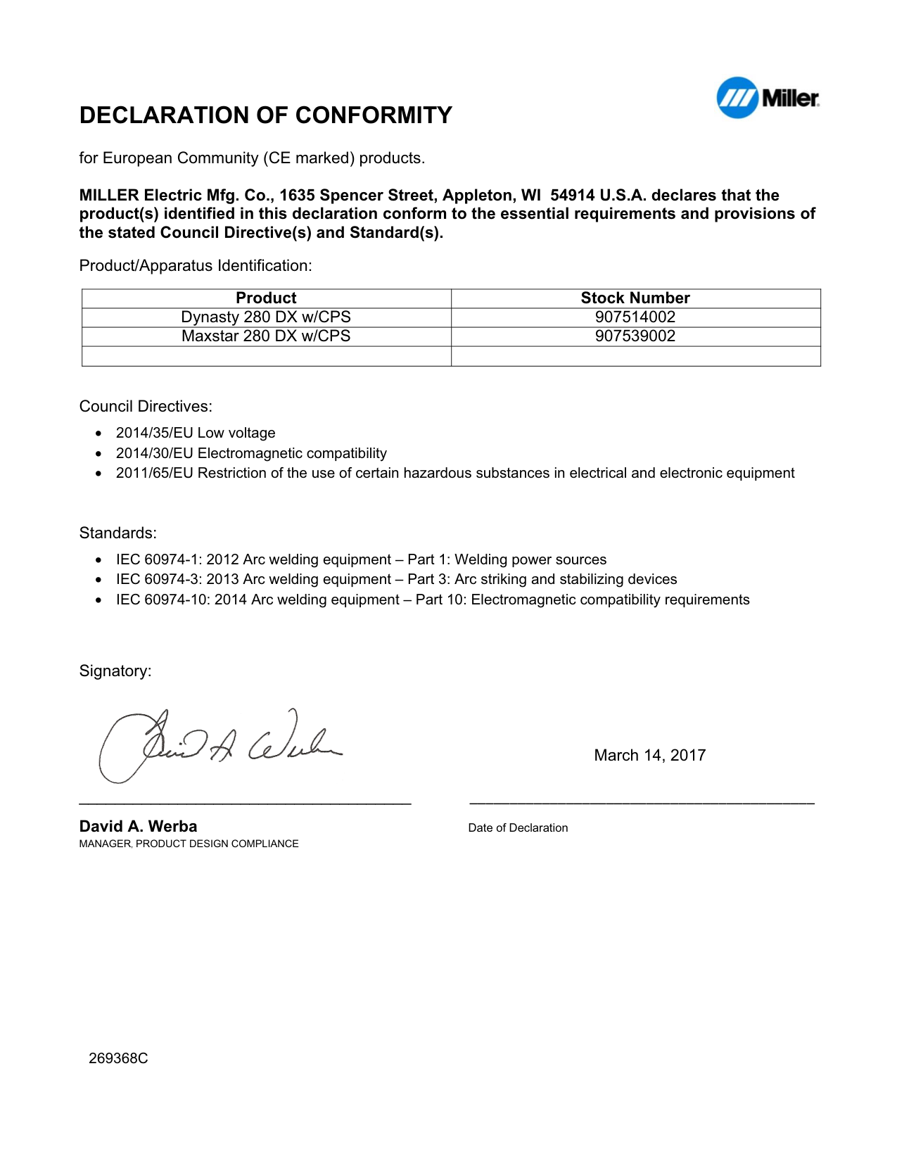
|Dynasty 280 DX w/CPS|907514002| |Maxstar 280 DX w/CPS|907539002| | | |
Council Directives:
Standards:
Signatory:

March 14, 2017
_____________________________________ ___________________________________________ David A. Werba Date of Declaration MANAGER, PRODUCT DESIGN COMPLIANCE
269368C
| | |---|
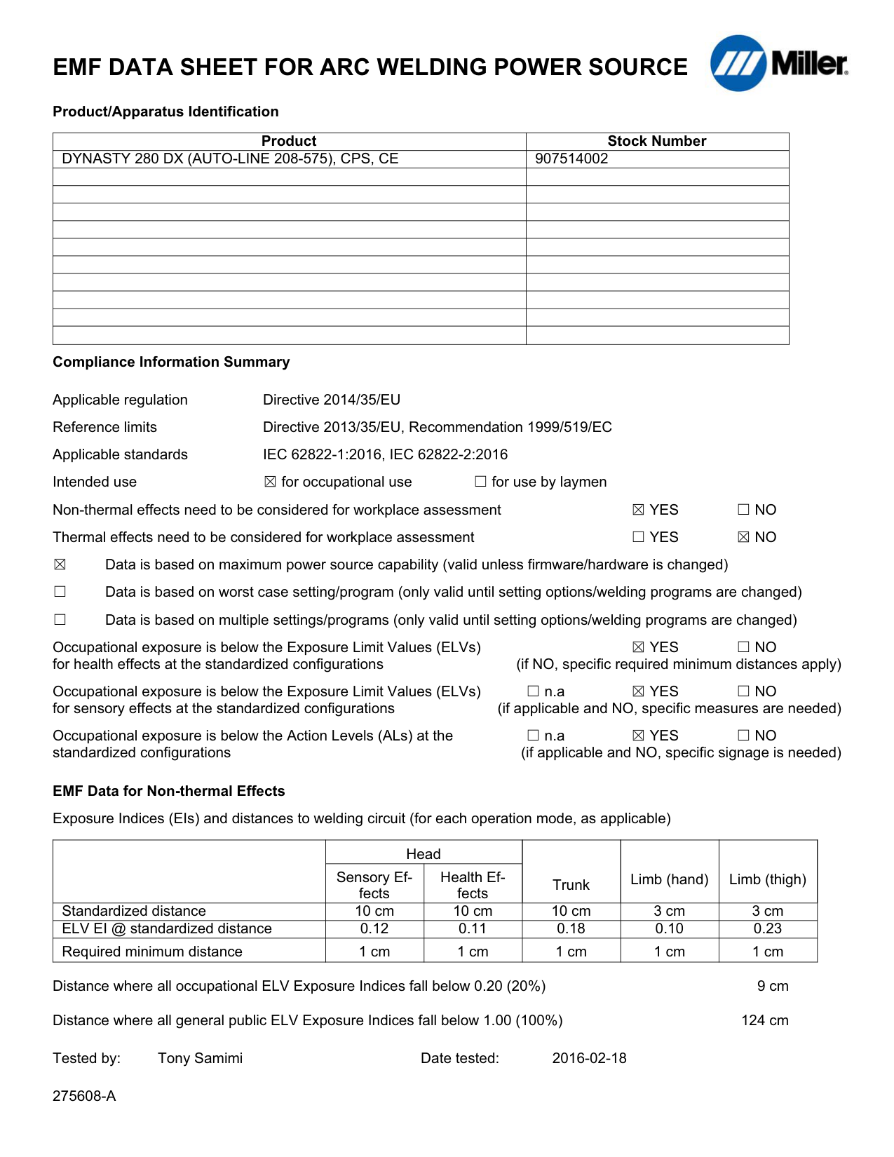
########## EMF DATA SHEET FOR ARC WELDING POWER SOURCE
Product/Apparatus Identification

|Product|Stock Number| |---|---| |DYNASTY 280 DX (AUTO-LINE 208-575), CPS, CE|907514002| | | | | | | | | | | | | | | | | | | | | | | | |

| | | | | |
Compliance Information Summary
Applicable regulation Directive 2014/35/EU Reference limits Directive 2013/35/EU, Recommendation 1999/519/EC Applicable standards IEC 62822-1:2016, IEC 62822-2:2016 Intended use for occupational use for use by laymen Non-thermal effects need to be considered for workplace assessment YES NO Thermal effects need to be considered for workplace assessment YES NO Data is based on maximum power source capability (valid unless firmware/hardware is changed) Data is based on worst case setting/program (only valid until setting options/welding programs are changed) Data is based on multiple settings/programs (only valid until setting options/welding programs are changed)
Occupational exposure is below the Exposure Limit Values (ELVs) YES NO for health effects at the standardized configurations (if NO, specific required minimum distances apply)
Occupational exposure is below the Exposure Limit Values (ELVs) n.a YES NO for sensory effects at the standardized configurations (if applicable and NO, specific measures are needed)
Occupational exposure is below the Action Levels (ALs) at the n.a YES NO standardized configurations (if applicable and NO, specific signage is needed)
EMF Data for Non-thermal Effects Exposure Indices (EIs) and distances to welding circuit (for each operation mode, as applicable)
| |Head|Head|Trunk|Limb (hand)|Limb (thigh)| |---|---|---|---|---|---| | |Sensory Effects|Health Effects|Trunk|Limb (hand)|Limb (thigh)| |Standardized distance|10 cm|10 cm|10 cm|3 cm|3 cm| |ELV EI @ standardized distance|0.12|0.11|0.18|0.10|0.23| |Required minimum distance|1 cm|1 cm|1 cm|1 cm|1 cm|
Distance where all occupational ELV Exposure Indices fall below 0.20 (20%) 9 cm Distance where all general public ELV Exposure Indices fall below 1.00 (100%) 124 cm Tested by: Tony Samimi Date tested: 2016-02-18
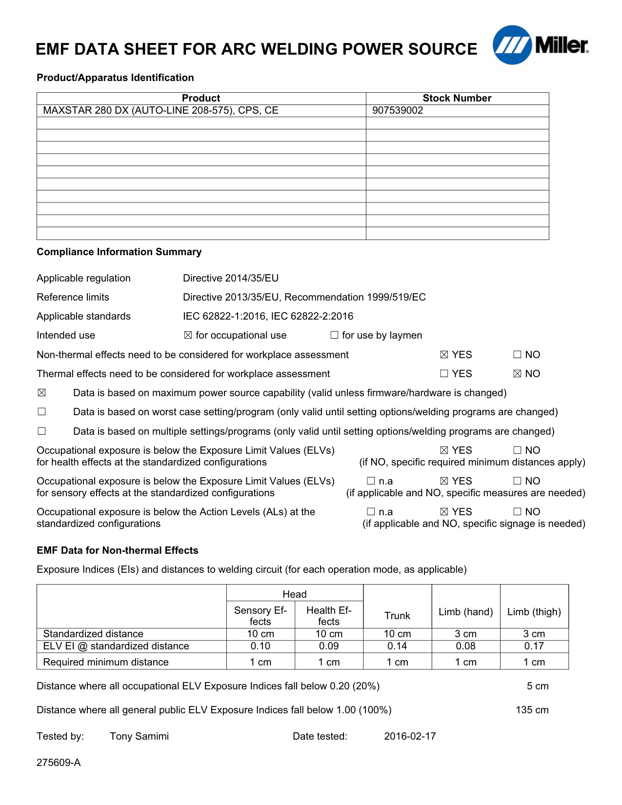
########## EMF DATA SHEET FOR ARC WELDING POWER SOURCE
Product/Apparatus Identification

|Product|Stock Number| |---|---| |MAXSTAR 280 DX (AUTO-LINE 208-575), CPS, CE|907539002| | | | | | | | | | | | | | | | | | | | | | | | | | | | | | |
Compliance Information Summary
Applicable regulation Directive 2014/35/EU Reference limits Directive 2013/35/EU, Recommendation 1999/519/EC Applicable standards IEC 62822-1:2016, IEC 62822-2:2016 Intended use for occupational use for use by laymen Non-thermal effects need to be considered for workplace assessment YES NO Thermal effects need to be considered for workplace assessment YES NO Data is based on maximum power source capability (valid unless firmware/hardware is changed) Data is based on worst case setting/program (only valid until setting options/welding programs are changed) Data is based on multiple settings/programs (only valid until setting options/welding programs are changed)
Occupational exposure is below the Exposure Limit Values (ELVs) YES NO for health effects at the standardized configurations (if NO, specific required minimum distances apply)
Occupational exposure is below the Exposure Limit Values (ELVs) n.a YES NO for sensory effects at the standardized configurations (if applicable and NO, specific measures are needed)
Occupational exposure is below the Action Levels (ALs) at the n.a YES NO standardized configurations (if applicable and NO, specific signage is needed)
EMF Data for Non-thermal Effects Exposure Indices (EIs) and distances to welding circuit (for each operation mode, as applicable)
| |Head|Head|Trunk|Limb (hand)|Limb (thigh)| |---|---|---|---|---|---| | |Sensory Effects|Health Effects|Trunk|Limb (hand)|Limb (thigh)| |Standardized distance|10 cm|10 cm|10 cm|3 cm|3 cm| |ELV EI @ standardized distance|0.10|0.09|0.14|0.08|0.17| |Required minimum distance|1 cm|1 cm|1 cm|1 cm|1 cm|
Distance where all occupational ELV Exposure Indices fall below 0.20 (20%) 5 cm Distance where all general public ELV Exposure Indices fall below 1.00 (100%) 135 cm Tested by: Tony Samimi Date tested: 2016-02-17
########## SECTION 1 − SAFETY PRECAUTIONS - READ BEFORE USING
som 2015−09
7
Protect yourself and others from injury — read, follow, and save these important safety precautions and operating instructions.
############# 1-1. Symbol Usage
DANGER! − Indicates a hazardous situation which, if not avoided, will result in death or serious injury. The possible hazards are shown in the adjoining symbols or explained in the text.
Indicates a hazardous situation which, if not avoided, could result in death or serious injury. The possible hazards are shown in the adjoining symbols or explained in the text.
NOTICE − Indicates statements not related to personal injury.
############# 1-2. Arc Welding Hazards
Indicates special instructions.
| | | | |---|---|---|
This group of symbols means Warning! Watch Out! ELECTRIC SHOCK, MOVING PARTS, and HOT PARTS hazards. Consult symbols and related instructions below for necessary actions to avoid the hazards.
The symbols shown below are used throughout this manual to call attention to and identify possible hazards. When you see the symbol, watch out, and follow the related instructions to avoid the hazard. The safety information given below is only a summary of the more complete safety information found in the Safety Standards listed in Section 1-5. Read and follow all Safety Standards.
Only qualified persons should install, operate, maintain, and repair this unit.
During operation, keep everybody, especially children, away.
| | |---| | |
################ ELECTRIC SHOCK can kill.
Touching live electrical parts can cause fatal shocks or severe burns. The electrode and work circuit is electrically live whenever the output is on. The input power circuit and machine internal circuits are also live when power is on. In semiautomatic or automatic wire welding, the wire, wire reel, drive roll housing, and all metal parts touching the welding wire are electrically live. Incorrectly installed or improperly grounded equipment is a hazard.
Do not touch live electrical parts.
Wear dry, hole-free insulating gloves and body protection.
Insulate yourself from work and ground using dry insulating mats or covers big enough to prevent any physical contact with the work or ground.
Do not use AC output in damp areas, if movement is confined, or if there is a danger of falling. Use AC output ONLY if required for the welding process. If AC output is required, use remote output control if present on unit.
Additional safety precautions are required when any of the following electrically hazardous conditions are present: in damp locations or while wearing wet clothing; on metal structures such as floors, gratings, or scaffolds; when in cramped positions such as sitting, kneeling, or lying; or when there is a high risk of unavoidable or accidental contact with the workpiece or ground. For these conditions, use the following equipment in order presented: 1) a semiautomatic DC constant voltage (wire) welder, 2) a DC manual (stick) welder, or 3) an AC welder with reduced open-circuit voltage. In most situations, use of a DC, constant voltage wire welder is recommended. And, do not work alone!
Disconnect input power or stop engine before installing or servicing this equipment. Lockout/tagout input power according to OSHA 29 CFR 1910.147 (see Safety Standards).
Properly install, ground, and operate this equipment according to its Owner’s Manual and national, state, and local codes.
Always verify the supply ground − check and be sure that input power cord ground wire is properly connected to ground terminal in disconnect box or that cord plug is connected to a properly grounded receptacle outlet.
When making input connections, attach proper grounding conductor first − double-check connections. Keep cords dry, free of oil and grease, and protected from hot metal and sparks.
Frequently inspect input power cord and ground conductor for damage or bare wiring – replace immediately if damaged – bare wiring can kill.
Turn off all equipment when not in use. Do not use worn, damaged, undersized, or repaired cables. Do not drape cables over your body. If earth grounding of the workpiece is required, ground it directly with a separate cable. Do not touch electrode if you are in contact with the work, ground, or another electrode from a different machine.
Do not touch electrode holders connected to two welding machines at the same time since double open-circuit voltage will be present.
Use only well-maintained equipment. Repair or replace damaged parts at once. Maintain unit according to manual. Wear a safety harness if working above floor level. Keep all panels and covers securely in place. Clamp work cable with good metal-to-metal contact to workpiece or worktable as near the weld as practical. Insulate work clamp when not connected to workpiece to prevent contact with any metal object.
Do not connect more than one electrode or work cable to any single weld output terminal. Disconnect cable for process not in use.
Use GFCI protection when operating auxiliary equipment in damp or wet locations.
################ SIGNIFICANT DC VOLTAGE exists in inverter welding power sources AFTER removal of input power.
Turn Off inverter, disconnect input power, and discharge input capacitors according to instructions in Maintenance Section before touching any parts.
| | |---|
################ HOT PARTS can burn.
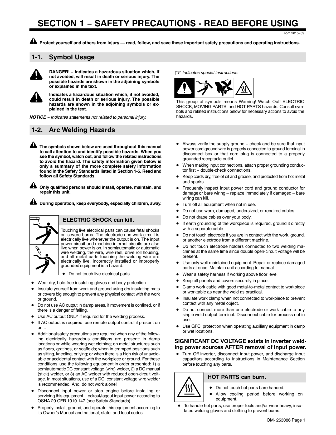
Do not touch hot parts bare handed. Allow cooling period before working on equipment.
To handle hot parts, use proper tools and/or wear heavy, insulated welding gloves and clothing to prevent burns.
| | |---|
################### FUMES AND GASES can be hazardous.
Welding produces fumes and gases. Breathing these fumes and gases can be hazardous to your health.
Keep your head out of the fumes. Do not breathe the fumes. If inside, ventilate the area and/or use local forced ventilation at the arc to remove welding fumes and gases. The recommended way to determine adequate ventilation is to sample for the composition and quantity of fumes and gases to which personnel are exposed. If ventilation is poor, wear an approved air-supplied respirator.
Read and understand the Safety Data Sheets (SDSs) and the manufacturer’s instructions for adhesives, coatings, cleaners, consumables, coolants, degreasers, fluxes, and metals.
Work in a confined space only if it is well ventilated, or while wearing an air-supplied respirator. Always have a trained watchperson nearby. Welding fumes and gases can displace air and lower the oxygen level causing injury or death. Be sure the breathing air is safe.
Do not weld in locations near degreasing, cleaning, or spraying operations. The heat and rays of the arc can react with vapors to form highly toxic and irritating gases.
Do not weld on coated metals, such as galvanized, lead, or cadmium plated steel, unless the coating is removed from the weld area, the area is well ventilated, and while wearing an air-supplied respirator. The coatings and any metals containing these elements can give off toxic fumes if welded.
| | |---|
################ ARC RAYS can burn eyes and skin.
Arc rays from the welding process produce intense visible and invisible (ultraviolet and infrared) rays that can burn eyes and skin. Sparks fly off from the weld.
Wear an approved welding helmet fitted with a proper shade of filter lenses to protect your face and eyes from arc rays and sparks when welding or watching (see ANSI Z49.1 and Z87.1 listed in Safety Standards).
Wear approved safety glasses with side shields under your helmet. Use protective screens or barriers to protect others from flash, glare and sparks; warn others not to watch the arc.
Wear body protection made from durable, flame−resistant material (leather, heavy cotton, wool). Body protection includes oil-free clothing such as leather gloves, heavy shirt, cuffless trousers, high shoes, and a cap.
| | |---|
################## WELDING can cause fire or explosion.
Welding on closed containers, such as tanks, drums, or pipes, can cause them to blow up. Sparks can fly off from the welding arc. The flying sparks, hot workpiece, and hot equipment can cause fires and
burns. Accidental contact of electrode to metal objects can cause sparks, explosion, overheating, or fire. Check and be sure the area is safe before doing any welding.
Remove all flammables within 35 ft (10.7 m) of the welding arc. If this is not possible, tightly cover them with approved covers. Do not weld where flying sparks can strike flammable material. Protect yourself and others from flying sparks and hot metal. Be alert that welding sparks and hot materials from welding can easily go through small cracks and openings to adjacent areas. Watch for fire, and keep a fire extinguisher nearby. Be aware that welding on a ceiling, floor, bulkhead, or partition can cause fire on the hidden side.
Do not weld on containers that have held combustibles, or on closed containers such as tanks, drums, or pipes unless they are properly prepared according to AWS F4.1 and AWS A6.0 (see Safety Standards).
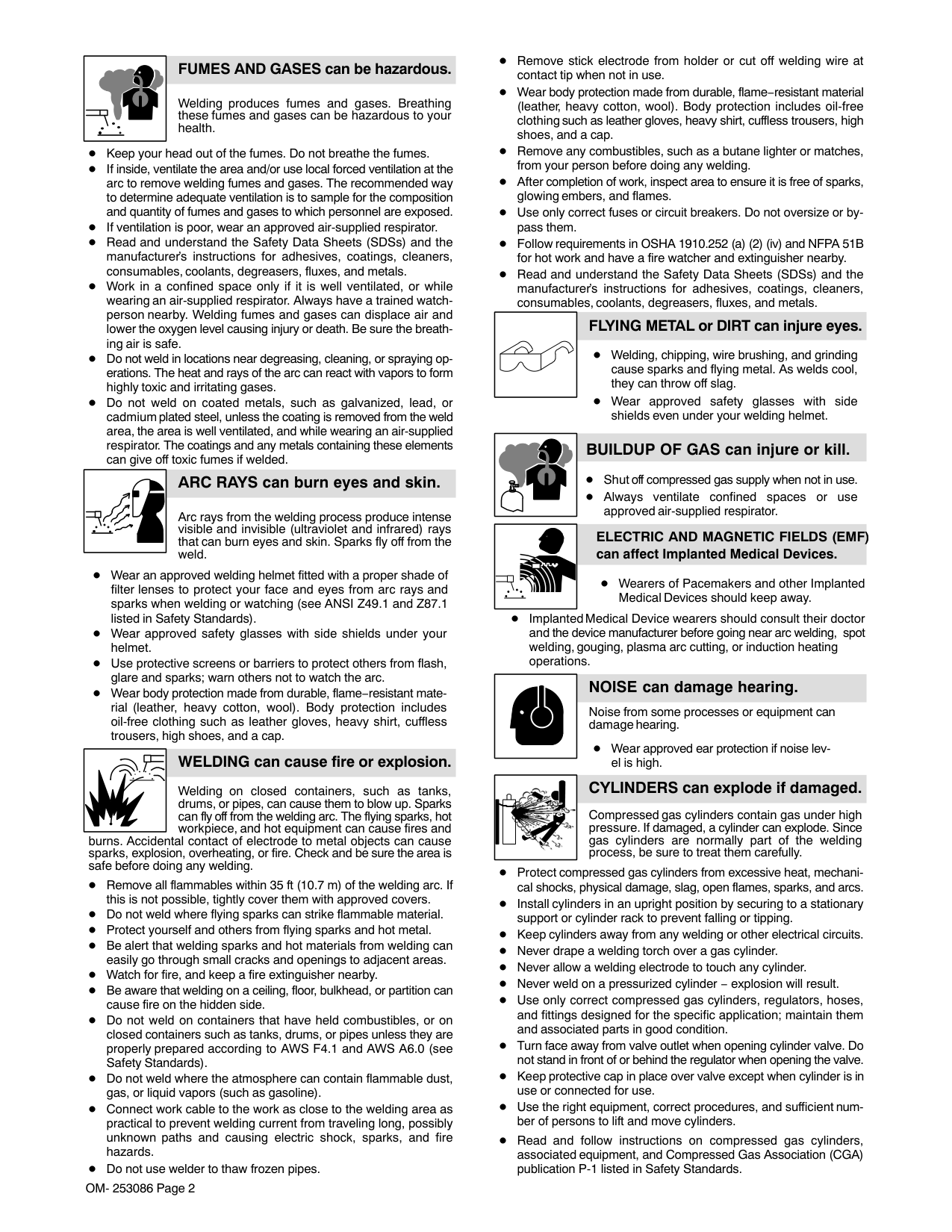
Do not weld where the atmosphere can contain flammable dust, gas, or liquid vapors (such as gasoline).
Connect work cable to the work as close to the welding area as practical to prevent welding current from traveling long, possibly unknown paths and causing electric shock, sparks, and fire hazards.
Do not use welder to thaw frozen pipes.
Remove stick electrode from holder or cut off welding wire at contact tip when not in use.
Wear body protection made from durable, flame−resistant material (leather, heavy cotton, wool). Body protection includes oil-free clothing such as leather gloves, heavy shirt, cuffless trousers, high shoes, and a cap.
Remove any combustibles, such as a butane lighter or matches, from your person before doing any welding. After completion of work, inspect area to ensure it is free of sparks, glowing embers, and flames. Use only correct fuses or circuit breakers. Do not oversize or bypass them. Follow requirements in OSHA 1910.252 (a) (2) (iv) and NFPA 51B for hot work and have a fire watcher and extinguisher nearby.
Read and understand the Safety Data Sheets (SDSs) and the manufacturer’s instructions for adhesives, coatings, cleaners, consumables, coolants, degreasers, fluxes, and metals.
################### FLYING METAL or DIRT can injure eyes.
Welding, chipping, wire brushing, and grinding cause sparks and flying metal. As welds cool, they can throw off slag.
Wear approved safety glasses with side shields even under your welding helmet.
################ BUILDUP OF GAS can injure or kill.
Shut off compressed gas supply when not in use. Always ventilate confined spaces or use approved air-supplied respirator.
| | |---|
###################### ELECTRIC AND MAGNETIC FIELDS (EMF) can affect Implanted Medical Devices.
Wearers of Pacemakers and other Implanted Medical Devices should keep away.
Implanted Medical Device wearers should consult their doctor and the device manufacturer before going near arc welding, spot welding, gouging, plasma arc cutting, or induction heating operations.
| | |---|
################ NOISE can damage hearing.
Noise from some processes or equipment can damage hearing.
Wear approved ear protection if noise level is high.
|| |---|
################ CYLINDERS can explode if damaged.
Compressed gas cylinders contain gas under high pressure. If damaged, a cylinder can explode. Since gas cylinders are normally part of the welding process, be sure to treat them carefully.
Protect compressed gas cylinders from excessive heat, mechanical shocks, physical damage, slag, open flames, sparks, and arcs. Install cylinders in an upright position by securing to a stationary support or cylinder rack to prevent falling or tipping. Keep cylinders away from any welding or other electrical circuits. Never drape a welding torch over a gas cylinder. Never allow a welding electrode to touch any cylinder. Never weld on a pressurized cylinder − explosion will result.
Use only correct compressed gas cylinders, regulators, hoses, and fittings designed for the specific application; maintain them and associated parts in good condition.
Turn face away from valve outlet when opening cylinder valve. Do not stand in front of or behind the regulator when opening the valve. Keep protective cap in place over valve except when cylinder is in use or connected for use. Use the right equipment, correct procedures, and sufficient number of persons to lift and move cylinders.
Read and follow instructions on compressed gas cylinders, associated equipment, and Compressed Gas Association (CGA) publication P-1 listed in Safety Standards.
############# 1-3. Additional Symbols For Installation, Operation, And Maintenance
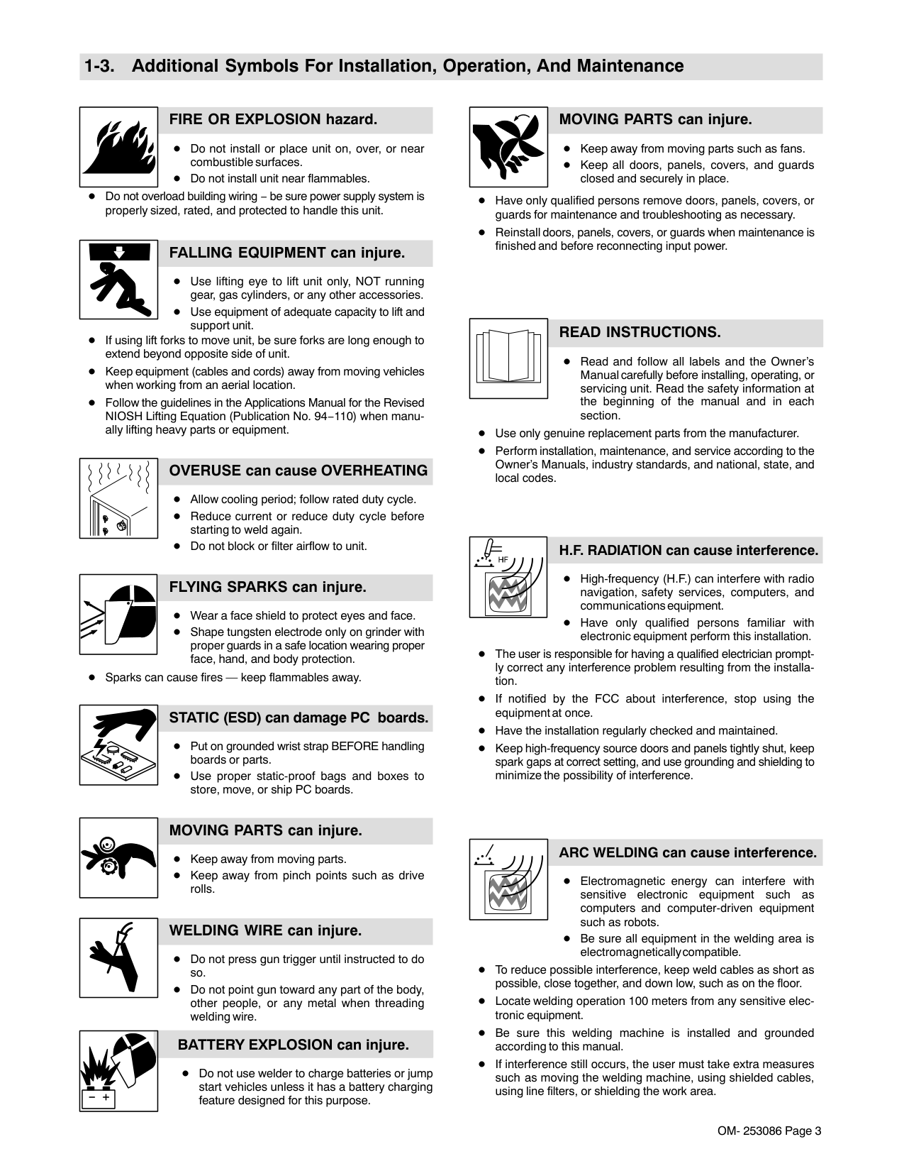
################ FIRE OR EXPLOSION hazard.
Do not install or place unit on, over, or near combustible surfaces. Do not install unit near flammables.
Do not overload building wiring − be sure power supply system is properly sized, rated, and protected to handle this unit.
################ FALLING EQUIPMENT can injure.
Use lifting eye to lift unit only, NOT running gear, gas cylinders, or any other accessories. Use equipment of adequate capacity to lift and support unit.
If using lift forks to move unit, be sure forks are long enough to extend beyond opposite side of unit.
Keep equipment (cables and cords) away from moving vehicles when working from an aerial location.
Follow the guidelines in the Applications Manual for the Revised NIOSH Lifting Equation (Publication No. 94−110) when manually lifting heavy parts or equipment.
################ OVERUSE can cause OVERHEATING
Allow cooling period; follow rated duty cycle. Reduce current or reduce duty cycle before starting to weld again. Do not block or filter airflow to unit.
################ FLYING SPARKS can injure.
Wear a face shield to protect eyes and face.
Shape tungsten electrode only on grinder with proper guards in a safe location wearing proper face, hand, and body protection.
Sparks can cause fires — keep flammables away.
################## STATIC (ESD) can damage PC boards.
Put on grounded wrist strap BEFORE handling boards or parts. Use proper static-proof bags and boxes to store, move, or ship PC boards.
################ MOVING PARTS can injure.
Keep away from moving parts. Keep away from pinch points such as drive rolls.
################ WELDING WIRE can injure.
Do not press gun trigger until instructed to do so.
Do not point gun toward any part of the body, other people, or any metal when threading welding wire.
################## BATTERY EXPLOSION can injure.
Do not use welder to charge batteries or jump start vehicles unless it has a battery charging feature designed for this purpose.
################ MOVING PARTS can injure.
Keep away from moving parts such as fans. Keep all doors, panels, covers, and guards closed and securely in place.
Have only qualified persons remove doors, panels, covers, or guards for maintenance and troubleshooting as necessary. Reinstall doors, panels, covers, or guards when maintenance is finished and before reconnecting input power.
################ READ INSTRUCTIONS.
Read and follow all labels and the Owner’s Manual carefully before installing, operating, or servicing unit. Read the safety information at the beginning of the manual and in each section.
Use only genuine replacement parts from the manufacturer.
Perform installation, maintenance, and service according to the Owner’s Manuals, industry standards, and national, state, and local codes.
#################### H.F. RADIATION can cause interference.
High-frequency (H.F.) can interfere with radio navigation, safety services, computers, and communications equipment.
Have only qualified persons familiar with electronic equipment perform this installation.
The user is responsible for having a qualified electrician promptly correct any interference problem resulting from the installation.
If notified by the FCC about interference, stop using the equipment at once. Have the installation regularly checked and maintained.
Keep high-frequency source doors and panels tightly shut, keep spark gaps at correct setting, and use grounding and shielding to minimize the possibility of interference.
| | |---|
#################### ARC WELDING can cause interference.
Electromagnetic energy can interfere with sensitive electronic equipment such as computers and computer-driven equipment such as robots.
Be sure all equipment in the welding area is electromagnetically compatible.
To reduce possible interference, keep weld cables as short as possible, close together, and down low, such as on the floor.
Locate welding operation 100 meters from any sensitive electronic equipment. Be sure this welding machine is installed and grounded according to this manual.
If interference still occurs, the user must take extra measures such as moving the welding machine, using shielded cables, using line filters, or shielding the work area.
############# 1-4. California Proposition 65 Warnings
Welding or cutting equipment produces fumes or gases which contain chemicals known to the State of California to cause birth defects and, in some cases, cancer. (California Health & Safety Code Section 25249.5 et seq.)
This product contains chemicals, including lead, known to the state of California to cause cancer, birth defects, or other reproductive harm. Wash hands after use.
############# 1-5. Principal Safety Standards
Safety in Welding, Cutting, and Allied Processes, ANSI Standard Z49.1, is available as a free download from the American Welding Society at http://www.aws.org or purchased from Global Engineering Documents (phone: 1-877-413-5184, website: www.global.ihs.com).
Safe Practices for the Preparation of Containers and Piping for Welding and Cutting, American Welding Society Standard AWS F4.1, from Global Engineering Documents (phone: 1-877-413-5184, website: www.global.ihs.com).
Safe Practices for Welding and Cutting Containers that have Held Combustibles, American Welding Society Standard AWS A6.0, from Global Engineering Documents (phone: 1-877-413-5184, website: www.global.ihs.com).
National Electrical Code, NFPA Standard 70, from National Fire Protection Association, Quincy, MA 02269 (phone: 1-800-344-3555, website: www.nfpa.org and www. sparky.org).
Safe Handling of Compressed Gases in Cylinders, CGA Pamphlet P-1, from Compressed Gas Association, 14501 George Carter Way, Suite 103, Chantilly, VA 20151 (phone: 703-788-2700, website:www.cganet.com).
Safety in Welding, Cutting, and Allied Processes, CSA Standard W117.2, from Canadian Standards Association, Standards Sales, 5060 Spectrum Way, Suite 100, Mississauga, Ontario, Canada L4W 5NS (phone: 800-463-6727, website: www.csagroup.org).
Safe Practice For Occupational And Educational Eye And Face Protection, ANSI Standard Z87.1, from American National Standards Institute, 25 West 43rd Street, New York, NY 10036 (phone: 212-642-4900, website: www.ansi.org).
Standard for Fire Prevention During Welding, Cutting, and Other Hot Work, NFPA Standard 51B, from National Fire Protection Association, Quincy, MA 02269 (phone: 1-800-344-3555, website: www.nfpa.org). OSHA, Occupational Safety and Health Standards for General Industry, Title 29, Code of Federal Regulations (CFR), Part 1910, Subpart Q, and Part 1926, Subpart J, from U.S. Government Printing Office, Superintendent of Documents, P.O. Box 371954, Pittsburgh, PA 15250-7954 (phone: 1-866-512-1800) (there are 10 OSHA Regional Officesphone for Region 5, Chicago, is 312-353-2220, website: www.osha.gov).
Applications Manual for the Revised NIOSH Lifting Equation, The National Institute for Occupational Safety and Health (NIOSH), 1600 Clifton Rd, Atlanta, GA 30329-4027 (phone: 1-800-232-4636, website: www.cdc.gov/NIOSH).
############# 1-6. EMF Information
Electric current flowing through any conductor causes localized electric and magnetic fields (EMF). The current from arc welding (and allied processes including spot welding, gouging, plasma arc cutting, and induction heating operations) creates an EMF field around the welding circuit. EMF fields can interfere with some medical implants, e.g. pacemakers. Protective measures for persons wearing medical implants have to be taken. For example, restrict access for passers−by or conduct individual risk assessment for welders. All welders should use the following procedures in order to minimize exposure to EMF fields from the welding circuit:
####################### About Implanted Medical Devices:
Implanted Medical Device wearers should consult their doctor and the device manufacturer before performing or going near arc welding, spot welding, gouging, plasma arc cutting, or induction heating operations. If cleared by your doctor, then following the above procedures is recommended.
########## SECTION 2 − CONSIGNES DE SÉCURITÉ − LIRE AVANT UTILISATION
fre_som_2015−09
7
Pour écarter les risques de blessure pour vous−même et pour autrui — lire, appliquer et ranger en lieu sûr ces consignes relatives aux précautions de sécurité et au mode opératoire.
############# 2-1. Symboles utilisés
DANGER! − Indique une situation dangereuse qui si on l’évite pas peut donner la mort ou des blessures graves. Les dangers possibles sont montrés par les symboles joints ou sont expliqués dans le texte.
Indique une situation dangereuse qui si on l’évite pas peut donner la mort ou des blessures graves. Les dangers possibles sont montrés par les symboles joints ou sont expliqués dans le texte.
AVIS − Indique des déclarations pas en relation avec des blessures personnelles.
############# 2-2. Dangers relatifs au soudage à l’arc
Indique des instructions spécifiques.
| | | | |---|---|---|
Ce groupe de symboles veut dire Avertissement! Attention! DANGER DE CHOC ELECTRIQUE, PIECES EN MOUVEMENT, et PIECES CHAUDES. Consulter les symboles et les instructions ci-dessous y afférant pour les actions nécessaires afin d’éviter le danger.
Les symboles représentés ci-dessous sont utilisés dans ce manuel pour attirer l’attention et identifier les dangers possibles. En présence de l’un de ces symboles, prendre garde et suivre les instructions afférentes pour éviter tout risque. Les instructions en matière de sécurité indiquées ci-dessous ne constituent qu’un sommaire des instructions de sécurité plus complètes fournies dans les normes de sécurité énumérées dans la Section 2-5. Lire et observer toutes les normes de sécurité.
Seul un personnel qualifié est autorisé à installer, faire fonctionner, entretenir et réparer cet appareil.
Pendant le fonctionnement, maintenir à distance toutes les personnes, notamment les enfants de l’appareil.
| | |---| | |
################ UNE DÉCHARGE ÉLECTRIQUE peut entraîner la mort.
Le contact d’organes électriques sous tension peut provoquer des accidents mortels ou des brûlures graves. Le circuit de l’électrode et de la pièce est sous tension lorsque le courant est délivré à la sortie. Le circuit d’alimentation et les circuits internes de la machine sont également sous tension lorsque l’alimentation est sur Marche. Dans le mode de soudage avec du fil, le fil, le dérouleur, le bloc de commande du rouleau et toutes les parties métalliques en contact avec le fil sont sous tension électrique. Un équipement installé ou mis à la terre de manière incorrecte ou impropre constitue un danger.
Ne pas toucher aux pièces électriques sous tension. Porter des gants isolants et des vêtements de protection secs et sans trous.
S’isoler de la pièce à couper et du sol en utilisant des housses ou des tapis assez grands afin d’éviter tout contact physique avec la pièce à couper ou le sol.
Ne pas se servir de source électrique à courant électrique dans les zones humides, dans les endroits confinés ou là où on risque de tomber.
Se servir d’une source électrique à courant électrique UNIQUEMENT si le procédé de soudage le demande.
Si l’utilisation d’une source électrique à courant électrique s’avère nécessaire, se servir de la fonction de télécommande si l’appareil en est équipé.
D’autres consignes de sécurité sont nécessaires dans les conditions suivantes : risques électriques dans un environnement humide ou si l’on porte des vêtements mouillés ; sur des structures métalliques telles que sols, grilles ou échafaudages ; en position coincée comme assise, à genoux ou couchée ; ou s’il y a un risque élevé de contact inévitable ou accidentel avec la pièce à souder ou le sol. Dans ces conditions, utiliser les équipements suivants, dans l’ordre indiqué : 1) un poste à souder DC à tension constante (à fil), 2) un poste à souder DC manuel (électrode) ou 3) un poste à souder AC à tension à vide réduite. Dans la plupart des situations, l’utilisation d’un poste à souder DC à fil à tension constante est recommandée. En outre, ne pas travailler seul !
Couper l’alimentation ou arrêter le moteur avant de procéder à l’installation, à la réparation ou à l’entretien de l’appareil. Déverrouiller l’alimentation selon la norme OSHA 29 CFR 1910.147 (voir normes de sécurité).
Installez, mettez à la terre et utilisez correctement cet équipement conformément à son Manuel d’Utilisation et aux réglementations nationales, gouvernementales et locales.
Toujours vérifier la terre du cordon d’alimentation. Vérifier et s’assurer que le fil de terre du cordon d’alimentation est bien raccordé à la borne de terre du sectionneur ou que la fiche du cordon est raccordée à une prise correctement mise à la terre.
En effectuant les raccordements d’entrée, fixer d’abord le conducteur de mise à la terre approprié et contre-vérifier les connexions. Les câbles doivent être exempts d’humidité, d’huile et de graisse; protégez−les contre les étincelles et les pièces métalliques chaudes.
Vérifier fréquemment le cordon d’alimentation et le conducteur de mise à la terre afin de s’assurer qu’il n’est pas altéré ou dénudé −, le remplacer immédiatement s’il l’est −. Un fil dénudé peut entraîner la mort.
L’équipement doit être hors tension lorsqu’il n’est pas utilisé. Ne pas utiliser des câbles usés, endommagés, de grosseur insuffisante ou mal épissés. Ne pas enrouler les câbles autour du corps. Si la pièce soudée doit être mise à la terre, le faire directement avec un câble distinct. Ne pas toucher l’électrode quand on est en contact avec la pièce, la terre ou une électrode provenant d’une autre machine.
Ne pas toucher des porte électrodes connectés à deux machines en même temps à cause de la présence d’une tension à vide doublée.
N’utiliser qu’un matériel en bon état. Réparer ou remplacer sur-lechamp les pièces endommagées. Entretenir l’appareil conformément à ce manuel.
Porter un harnais de sécurité si l’on doit travailler au-dessus du sol. S’assurer que tous les panneaux et couvercles sont correctement en place.
Fixer le câble de retour de façon à obtenir un bon contact métalmétal avec la pièce à souder ou la table de travail, le plus près possible de la soudure.
Isoler la pince de masse quand pas mis à la pièce pour éviter le contact avec tout objet métallique.
Ne pas raccorder plus d’une électrode ou plus d’un câble de masse à une même borne de sortie de soudage. Débrancher le câble pour le procédé non utilisé.
Utiliser une protection différentielle lors de l’utilisation d’un équipement auxiliaire dans des endroits humides ou mouillés.
################ Il reste une TENSION DC NON NÉGLIGEABLE dans les sources de soudage onduleur UNE FOIS l’alimentation coupée.
Arrêter les convertisseurs, débrancher le courant électrique et décharger les condensateurs d’alimentation selon les instructions indiquées dans la partie Entretien avant de toucher les pièces.
| | |---|
################ LES PIÈCES CHAUDES peuvent provoquer des brûlures.
Ne pas toucher à mains nues les parties chaudes. Prévoir une période de refroidissement avant de travailler à l’équipement.
Ne pas toucher aux pièces chaudes, utiliser les outils recommandés et porter des gants de soudage et des vêtements épais pour éviter les brûlures.
| | |---|
################ LES FUMÉES ET LES GAZ peuvent être dangereux.
Le soudage génère des fumées et des gaz. Leur inhalation peut être dangereux pour votre santé.
Eloigner votre tête des fumées. Ne pas respirer les fumées.
À l’intérieur, ventiler la zone et/ou utiliser une ventilation forcée au niveau de l’arc pour l’évacuation des fumées et des gaz de soudage. Pour déterminer la bonne ventilation, il est recommandé de procéder à un prélèvement pour la composition et la quantité de fumées et de gaz auxquels est exposé le personnel.
Si la ventilation est médiocre, porter un respirateur anti-vapeurs approuvé.
Lire et comprendre les fiches de données de sécurité et les instructions du fabricant concernant les adhésifs, les revêtements, les nettoyants, les consommables, les produits de refroidissement, les dégraisseurs, les flux et les métaux.
Travailler dans un espace fermé seulement s’il est bien ventilé ou en portant un respirateur à alimentation d’air. Demander toujours à un surveillant dûment formé de se tenir à proximité. Des fumées et des gaz de soudage peuvent déplacer l’air et abaisser le niveau d’oxygène provoquant des blessures ou des accidents mortels. S’assurer que l’air de respiration ne présente aucun danger.
Ne pas souder dans des endroits situés à proximité d’opérations de dégraissage, de nettoyage ou de pulvérisation. La chaleur et les rayons de l’arc peuvent réagir en présence de vapeurs et former des gaz hautement toxiques et irritants.
Ne pas souder des métaux munis d’un revêtement, tels que l’acier galvanisé, plaqué en plomb ou au cadmium à moins que le revêtement n’ait été enlevé dans la zone de soudure, que l’endroit soit bien ventilé, et en portant un respirateur à alimentation d’air. Les revêtements et tous les métaux renfermant ces éléments peuvent dégager des fumées toxiques en cas de soudage.
| | |---|
################ LES RAYONS DE L’ARC peuvent provoquer des brûlures dans les yeux et sur la peau.
Le rayonnement de l’arc du procédé de soudage génère des rayons visibles et invisibles intenses (ultraviolets e
infrarouges) susceptibles de provoquer des brûlures dans les yeux et sur la peau. Des étincelles sont projetées pendant le soudage.
Porter un casque de soudage approuvé muni de verres filtrants approprié pour protéger visage et yeux pour protéger votre visage et vos yeux pendant le soudage ou pour regarder (voir ANSI Z49.1 et Z87.1 énuméré dans les normes de sécurité).
Porter des lunettes de sécurité avec écrans latéraux même sous votre casque.
Avoir recours à des écrans protecteurs ou à des rideaux pour protéger les autres contre les rayonnements les éblouissements et les étincelles ; prévenir toute personne sur les lieux de ne pas regarder l’arc.
Porter un équipement de protection pour le corps fait d’un matériau résistant et ignifuge (cuir, coton robuste, laine). La protection du corps comporte des vêtements sans huile comme par ex. des gants de cuir, une chemise solide, des pantalons sans revers, des chaussures hautes et une casquette.
| | |---|
################ LE SOUDAGE peut provoquer un incendie ou une explosion.
Le soudage effectué sur des conteneurs fermés tels que des réservoirs, tambours ou des conduites peut provoquer leur éclatement. Des étincelles peuvent
être projetées de l’arc de soudure. La projection d’étincelles, des
pièces chaudes et des équipements chauds peut provoquer des incendies et des brûlures. Le contact accidentel de l’électrode avec des objets métalliques peut provoquer des étincelles, une explosion, un sur-
chauffement ou un incendie. Avant de commencer le soudage, vérifier et s’assurer que l’endroit ne présente pas de danger.
Déplacer toutes les substances inflammables à une distance de 10,7 m de l’arc de soudage. En cas d’impossibilité les recouvrir soigneusement avec des protections homologués.
Ne pas souder dans un endroit là où des étincelles peuvent tomber sur des substances inflammables. Se protéger et d’autres personnes de la projection d’étincelles et de métal chaud.
Des étincelles et des matériaux chauds du soudage peuvent facilement passer dans d’autres zones en traversant de petites fissures et des ouvertures.
Surveiller tout déclenchement d’incendie et tenir un extincteur à proximité. Le soudage effectué sur un plafond, plancher, paroi ou séparation peut déclencher un incendie de l’autre côté.
Ne pas effectuer le soudage sur des conteneurs fermés tels que des réservoirs, tambours, ou conduites, à moins qu’ils n’aient été préparés correctement conformément à AWS F4.1 et AWS A6.0 (voir les Normes de Sécurité).
Ne pas souder là où l’air ambiant pourrait contenir des poussières, gaz ou émanations inflammables (vapeur d’essence, par exemple).
Brancher le câble de masse sur la pièce le plus près possible de la zone de soudage pour éviter le transport du courant sur une longue distance par des chemins inconnus éventuels en provoquant des risques d’électrocution, d’étincelles et d’incendie.
Ne pas utiliser le poste de soudage pour dégeler des conduites gelées. En cas de non utilisation, enlever la baguette d’électrode du porteélectrode ou couper le fil à la pointe de contact.
Porter un équipement de protection pour le corps fait d’un matériau résistant et ignifuge (cuir, coton robuste, laine). La protection du corps comporte des vêtements sans huile comme par ex. des gants de cuir, une chemise solide, des pantalons sans revers, des chaussures hautes et une casquette.
Avant de souder, retirer toute substance combustible de vos poches telles qu’un allumeur au butane ou des allumettes. Une fois le travail achevé, assurez−vous qu’il ne reste aucune trace d’étincelles incandescentes ni de flammes. Utiliser exclusivement des fusibles ou coupe−circuits appropriés. Ne pas augmenter leur puissance; ne pas les ponter.
Suivre les recommandations dans OSHA 1910.252(a)(2)(iv) et NFPA 51B pour les travaux à chaud et avoir de la surveillance et un extincteur à proximité.
Lire et comprendre les fiches de données de sécurité et les instructions du fabricant concernant les adhésifs, les revêtements, les nettoyants, les consommables, les produits de refroidissement, les dégraisseurs, les flux et les métaux.
################ DES PIECES DE METAL ou DES SALETES peuvent provoquer des blessures dans les yeux.
Le soudage, l’écaillement, le passage de la pièce à la brosse en fil de fer, et le meulage génèrent des étincelles et des particules métalliques volantes. Pendant la période de refroidissement des soudures, elles risquent de projeter du laitier.
Porter des lunettes de sécurité avec écrans latéraux ou un écran facial.
| | |---|
################ LES ACCUMULATIONS DE GAZ risquent de provoquer des blessures ou même la mort.
Fermer l’alimentation du gaz comprimé en cas de non utilisation.
Veiller toujours à bien aérer les espaces confinés ou se servir d’un respirateur d’adduction d’air homologué.
| | |---|
###################### Les CHAMPS ÉLECTROMAGNÉTIQUES (CEM) peuvent affecter les implants médicaux.
Les porteurs de stimulateurs cardiaques et autres implants médicaux doivent rester à distance.
Les porteurs d’implants médicaux doivent consulter leur médecin et le fabricant du dispositif avant de s’approcher de la zone où se déroule du soudage à l’arc, du soudage par points, du gougeage, de la découpe plasma ou une opération de chauffage par induction.
| | |---|
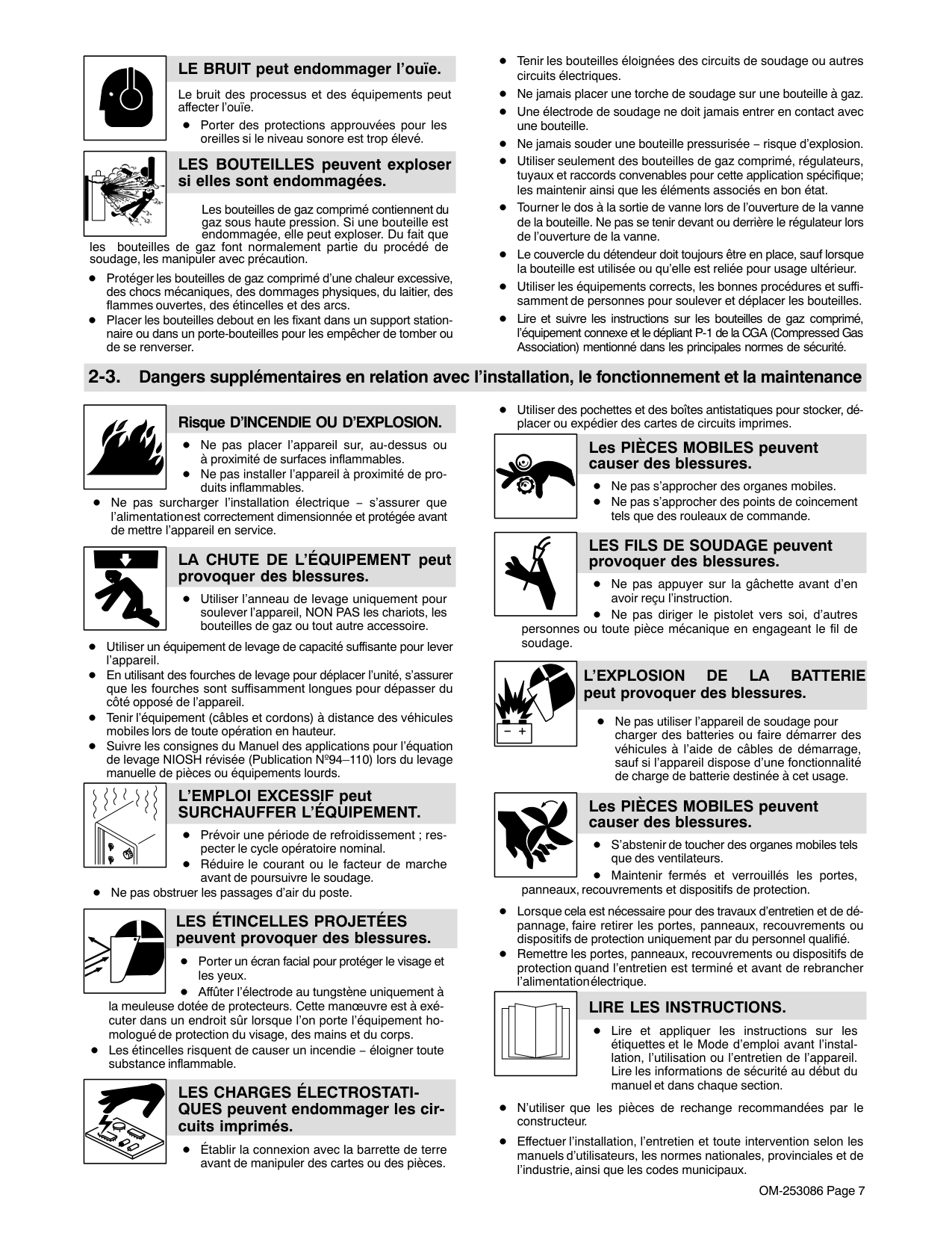
################ LE BRUIT peut endommager l’ouïe.
Le bruit des processus et des équipements peut affecter l’ouïe.
Porter des protections approuvées pour les oreilles si le niveau sonore est trop élevé.
|| |---|
################ LES BOUTEILLES peuvent exploser si elles sont endommagées.
Les bouteilles de gaz comprimé contiennent du gaz sous haute pression. Si une bouteille est endommagée, elle peut exploser. Du fait que
les bouteilles de gaz font normalement partie du procédé de soudage, les manipuler avec précaution.
Protéger les bouteilles de gaz comprimé d’une chaleur excessive, des chocs mécaniques, des dommages physiques, du laitier, des flammes ouvertes, des étincelles et des arcs.
Placer les bouteilles debout en les fixant dans un support stationnaire ou dans un porte-bouteilles pour les empêcher de tomber ou de se renverser.
Tenir les bouteilles éloignées des circuits de soudage ou autres circuits électriques.
Ne jamais placer une torche de soudage sur une bouteille à gaz. Une électrode de soudage ne doit jamais entrer en contact avec une bouteille. Ne jamais souder une bouteille pressurisée − risque d’explosion. Utiliser seulement des bouteilles de gaz comprimé, régulateurs, tuyaux et raccords convenables pour cette application spécifique; les maintenir ainsi que les éléments associés en bon état.
Tourner le dos à la sortie de vanne lors de l’ouverture de la vanne de la bouteille. Ne pas se tenir devant ou derrière le régulateur lors de l’ouverture de la vanne.
Le couvercle du détendeur doit toujours être en place, sauf lorsque la bouteille est utilisée ou qu’elle est reliée pour usage ultérieur.
Utiliser les équipements corrects, les bonnes procédures et suffisamment de personnes pour soulever et déplacer les bouteilles. Lire et suivre les instructions sur les bouteilles de gaz comprimé, l’équipement connexe et le dépliant P-1 de la CGA (Compressed Gas Association) mentionné dans les principales normes de sécurité.
############# 2-3. Dangers supplémentaires en relation avec l’installation, le fonctionnement et la maintenance
################## Risque D’INCENDIE OU D’EXPLOSION.
Ne pas placer l’appareil sur, au-dessus ou à proximité de surfaces inflammables. Ne pas installer l’appareil à proximité de produits inflammables.
Ne pas surcharger l’installation électrique − s’assurer que l’alimentation est correctement dimensionnée et protégée avant de mettre l’appareil en service.
| | |---|
################ LA CHUTE DE L’ÉQUIPEMENT peut provoquer des blessures.
Utiliser l’anneau de levage uniquement pour soulever l’appareil, NON PAS les chariots, les bouteilles de gaz ou tout autre accessoire.
Utiliser un équipement de levage de capacité suffisante pour lever l’appareil.
En utilisant des fourches de levage pour déplacer l’unité, s’assurer que les fourches sont suffisamment longues pour dépasser du côté opposé de l’appareil.
Tenir l’équipement (câbles et cordons) à distance des véhicules mobiles lors de toute opération en hauteur.
Suivre les consignes du Manuel des applications pour l’équation de levage NIOSH révisée (Publication Nº94–110) lors du levage manuelle de pièces ou équipements lourds.
################ L’EMPLOI EXCESSIF peut SURCHAUFFER L’ÉQUIPEMENT.
Prévoir une période de refroidissement ; respecter le cycle opératoire nominal. Réduire le courant ou le facteur de marche avant de poursuivre le soudage.
Ne pas obstruer les passages d’air du poste.
################ LES ÉTINCELLES PROJETÉES peuvent provoquer des blessures.
Porter un écran facial pour protéger le visage et les yeux.
Affûter l’électrode au tungstène uniquement à la meuleuse dotée de protecteurs. Cette manœuvre est à exécuter dans un endroit sûr lorsque l’on porte l’équipement homologué de protection du visage, des mains et du corps.
Les étincelles risquent de causer un incendie − éloigner toute substance inflammable.
| | |---|
################ LES CHARGES ÉLECTROSTATIQUES peuvent endommager les circuits imprimés.
Établir la connexion avec la barrette de terre avant de manipuler des cartes ou des pièces.
Utiliser des pochettes et des boîtes antistatiques pour stocker, déplacer ou expédier des cartes de circuits imprimes.
################ Les PIÈCES MOBILES peuvent causer des blessures.
Ne pas s’approcher des organes mobiles. Ne pas s’approcher des points de coincement tels que des rouleaux de commande.
################ LES FILS DE SOUDAGE peuvent provoquer des blessures.
Ne pas appuyer sur la gâchette avant d’en avoir reçu l’instruction. Ne pas diriger le pistolet vers soi, d’autres
personnes ou toute pièce mécanique en engageant le fil de soudage.
################## L’EXPLOSION DE LA BATTERIE peut provoquer des blessures.
Ne pas utiliser l’appareil de soudage pour charger des batteries ou faire démarrer des véhicules à l’aide de câbles de démarrage, sauf si l’appareil dispose d’une fonctionnalité de charge de batterie destinée à cet usage.
| | |---|
################ Les PIÈCES MOBILES peuvent causer des blessures.
S’abstenir de toucher des organes mobiles tels que des ventilateurs. Maintenir fermés et verrouillés les portes,
panneaux, recouvrements et dispositifs de protection.
Lorsque cela est nécessaire pour des travaux d’entretien et de dépannage, faire retirer les portes, panneaux, recouvrements ou dispositifs de protection uniquement par du personnel qualifié.

Remettre les portes, panneaux, recouvrements ou dispositifs de protection quand l’entretien est terminé et avant de rebrancher l’alimentation électrique.
| | |---|
################ LIRE LES INSTRUCTIONS.
Lire et appliquer les instructions sur les étiquettes et le Mode d’emploi avant l’installation, l’utilisation ou l’entretien de l’appareil. Lire les informations de sécurité au début du manuel et dans chaque section.
N’utiliser que les pièces de rechange recommandées par le constructeur.
Effectuer l’installation, l’entretien et toute intervention selon les manuels d’utilisateurs, les normes nationales, provinciales et de l’industrie, ainsi que les codes municipaux.
| | |---|
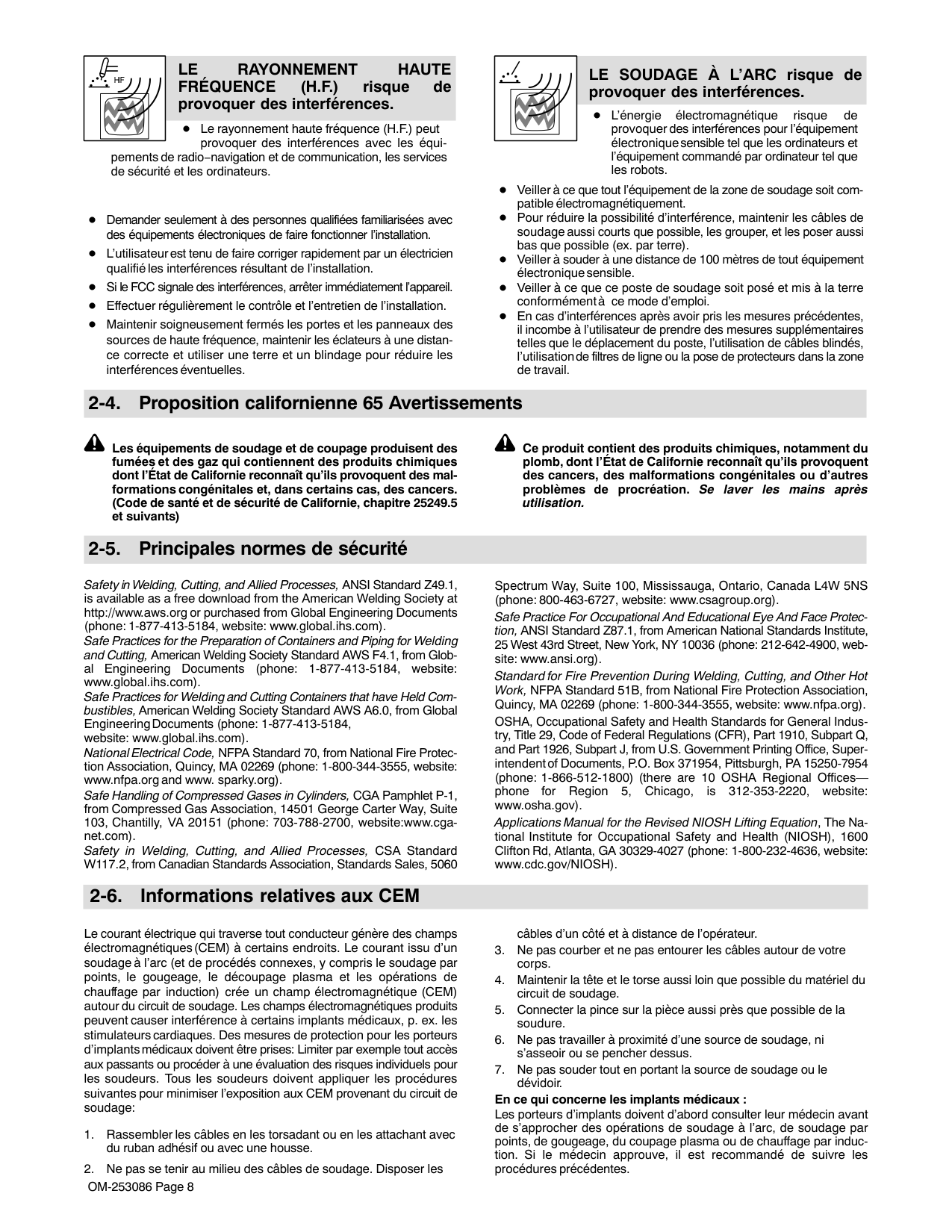
################ LE RAYONNEMENT HAUTE FRÉQUENCE (H.F.) risque de provoquer des interférences.
Le rayonnement haute fréquence (H.F.) peut provoquer des interférences avec les équi-
pements de radio−navigation et de communication, les services de sécurité et les ordinateurs.
Demander seulement à des personnes qualifiées familiarisées avec des équipements électroniques de faire fonctionner l’installation. L’utilisateur est tenu de faire corriger rapidement par un électricien qualifié les interférences résultant de l’installation. Si le FCC signale des interférences, arrêter immédiatement l’appareil. Effectuer régulièrement le contrôle et l’entretien de l’installation.
Maintenir soigneusement fermés les portes et les panneaux des sources de haute fréquence, maintenir les éclateurs à une distance correcte et utiliser une terre et un blindage pour réduire les interférences éventuelles.
| | |---|
################ LE SOUDAGE À L’ARC risque de provoquer des interférences.
L’énergie électromagnétique risque de provoquer des interférences pour l’équipement électronique sensible tel que les ordinateurs et l’équipement commandé par ordinateur tel que les robots.
Veiller à ce que tout l’équipement de la zone de soudage soit compatible électromagnétiquement.
Pour réduire la possibilité d’interférence, maintenir les câbles de soudage aussi courts que possible, les grouper, et les poser aussi bas que possible (ex. par terre).
Veiller à souder à une distance de 100 mètres de tout équipement électronique sensible. Veiller à ce que ce poste de soudage soit posé et mis à la terre conformément à ce mode d’emploi.
En cas d’interférences après avoir pris les mesures précédentes, il incombe à l’utilisateur de prendre des mesures supplémentaires telles que le déplacement du poste, l’utilisation de câbles blindés, l’utilisation de filtres de ligne ou la pose de protecteurs dans la zone de travail.
############# 2-4. Proposition californienne 65 Avertissements
Les équipements de soudage et de coupage produisent des fumées et des gaz qui contiennent des produits chimiques dont l’État de Californie reconnaît qu’ils provoquent des malformations congénitales et, dans certains cas, des cancers. (Code de santé et de sécurité de Californie, chapitre 25249.5 et suivants)
Ce produit contient des produits chimiques, notamment du plomb, dont l’État de Californie reconnaît qu’ils provoquent des cancers, des malformations congénitales ou d’autres problèmes de procréation. Se laver les mains après utilisation.
############# 2-5. Principales normes de sécurité
Safety in Welding, Cutting, and Allied Processes, ANSI Standard Z49.1, is available as a free download from the American Welding Society at http://www.aws.org or purchased from Global Engineering Documents (phone: 1-877-413-5184, website: www.global.ihs.com).
Safe Practices for the Preparation of Containers and Piping for Welding and Cutting, American Welding Society Standard AWS F4.1, from Global Engineering Documents (phone: 1-877-413-5184, website: www.global.ihs.com).
Safe Practices for Welding and Cutting Containers that have Held Combustibles, American Welding Society Standard AWS A6.0, from Global Engineering Documents (phone: 1-877-413-5184, website: www.global.ihs.com).
National Electrical Code, NFPA Standard 70, from National Fire Protection Association, Quincy, MA 02269 (phone: 1-800-344-3555, website: www.nfpa.org and www. sparky.org).
Safe Handling of Compressed Gases in Cylinders, CGA Pamphlet P-1, from Compressed Gas Association, 14501 George Carter Way, Suite 103, Chantilly, VA 20151 (phone: 703-788-2700, website:www.cganet.com).
Safety in Welding, Cutting, and Allied Processes, CSA Standard W117.2, from Canadian Standards Association, Standards Sales, 5060
Spectrum Way, Suite 100, Mississauga, Ontario, Canada L4W 5NS (phone: 800-463-6727, website: www.csagroup.org).
Safe Practice For Occupational And Educational Eye And Face Protection, ANSI Standard Z87.1, from American National Standards Institute, 25 West 43rd Street, New York, NY 10036 (phone: 212-642-4900, website: www.ansi.org).
Standard for Fire Prevention During Welding, Cutting, and Other Hot Work, NFPA Standard 51B, from National Fire Protection Association, Quincy, MA 02269 (phone: 1-800-344-3555, website: www.nfpa.org). OSHA, Occupational Safety and Health Standards for General Industry, Title 29, Code of Federal Regulations (CFR), Part 1910, Subpart Q, and Part 1926, Subpart J, from U.S. Government Printing Office, Superintendent of Documents, P.O. Box 371954, Pittsburgh, PA 15250-7954 (phone: 1-866-512-1800) (there are 10 OSHA Regional Officesphone for Region 5, Chicago, is 312-353-2220, website: www.osha.gov).
Applications Manual for the Revised NIOSH Lifting Equation, The National Institute for Occupational Safety and Health (NIOSH), 1600 Clifton Rd, Atlanta, GA 30329-4027 (phone: 1-800-232-4636, website: www.cdc.gov/NIOSH).
############# 2-6. Informations relatives aux CEM
Le courant électrique qui traverse tout conducteur génère des champs électromagnétiques (CEM) à certains endroits. Le courant issu d’un soudage à l’arc (et de procédés connexes, y compris le soudage par points, le gougeage, le découpage plasma et les opérations de chauffage par induction) crée un champ électromagnétique (CEM) autour du circuit de soudage. Les champs électromagnétiques produits peuvent causer interférence à certains implants médicaux, p. ex. les stimulateurs cardiaques. Des mesures de protection pour les porteurs d’implants médicaux doivent être prises: Limiter par exemple tout accès aux passants ou procéder à une évaluation des risques individuels pour les soudeurs. Tous les soudeurs doivent appliquer les procédures suivantes pour minimiser l’exposition aux CEM provenant du circuit de soudage:
####################### En ce qui concerne les implants médicaux :
Les porteurs d’implants doivent d’abord consulter leur médecin avant de s’approcher des opérations de soudage à l’arc, de soudage par points, de gougeage, du coupage plasma ou de chauffage par induction. Si le médecin approuve, il est recommandé de suivre les procédures précédentes.
####### SECTION 3 − DEFINITIONS
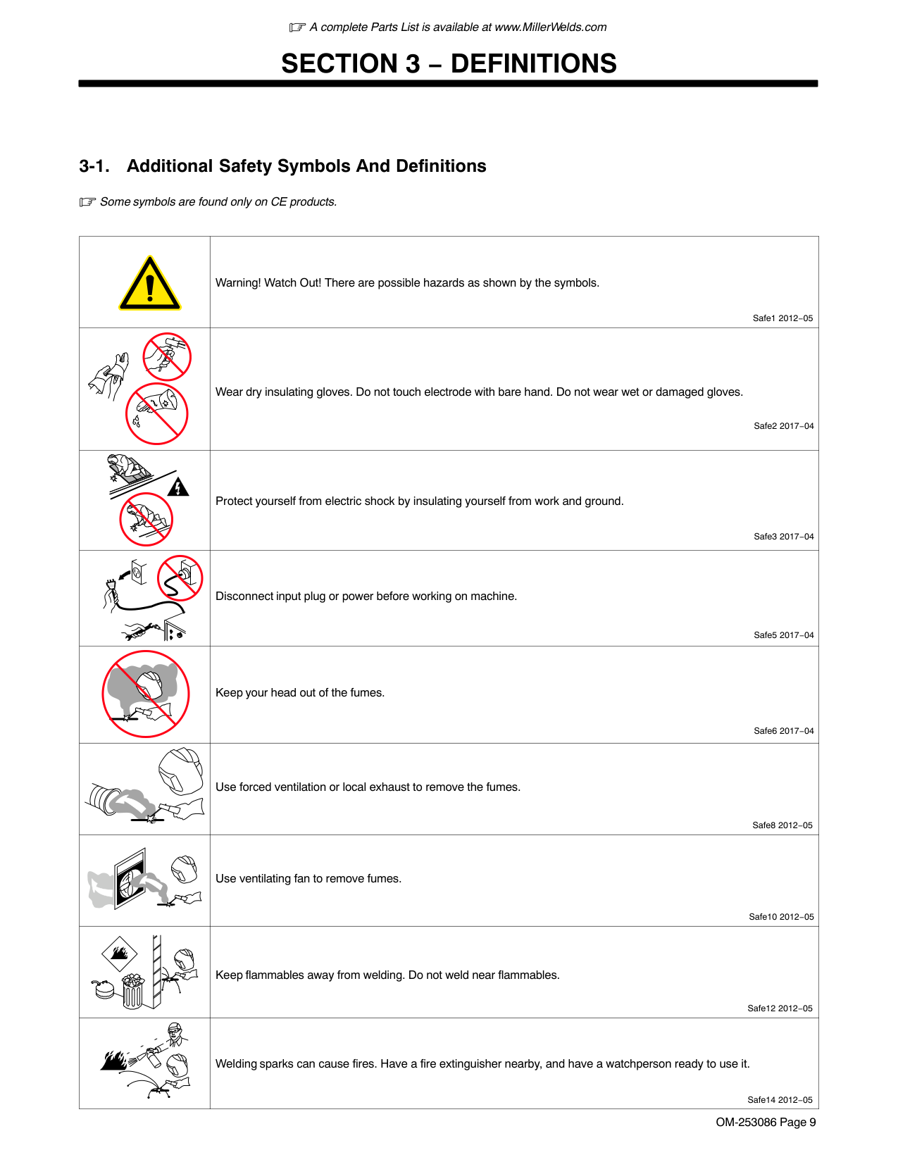
############# 3-1. Additional Safety Symbols And Definitions
Some symbols are found only on CE products.
| |Warning! Watch Out! There are possible hazards as shown by the symbols.
Safe1 2012−05| |---|---|
| |Wear dry insulating gloves. Do not touch electrode with bare hand. Do not wear wet or damaged gloves.
Safe2 2017−04| | |Protect yourself from electric shock by insulating yourself from work and ground.
Safe3 2017−04| | |Disconnect input plug or power before working on machine.
Safe5 2017−04| | |Keep your head out of the fumes.
Safe6 2017−04| | |Use forced ventilation or local exhaust to remove the fumes.
Safe8 2012−05| | |Use ventilating fan to remove fumes.
Safe10 2012−05| | |Keep flammables away from welding. Do not weld near flammables.
Safe12 2012−05| | |Welding sparks can cause fires. Have a fire extinguisher nearby, and have a watchperson ready to use it.
Safe14 2012−05|
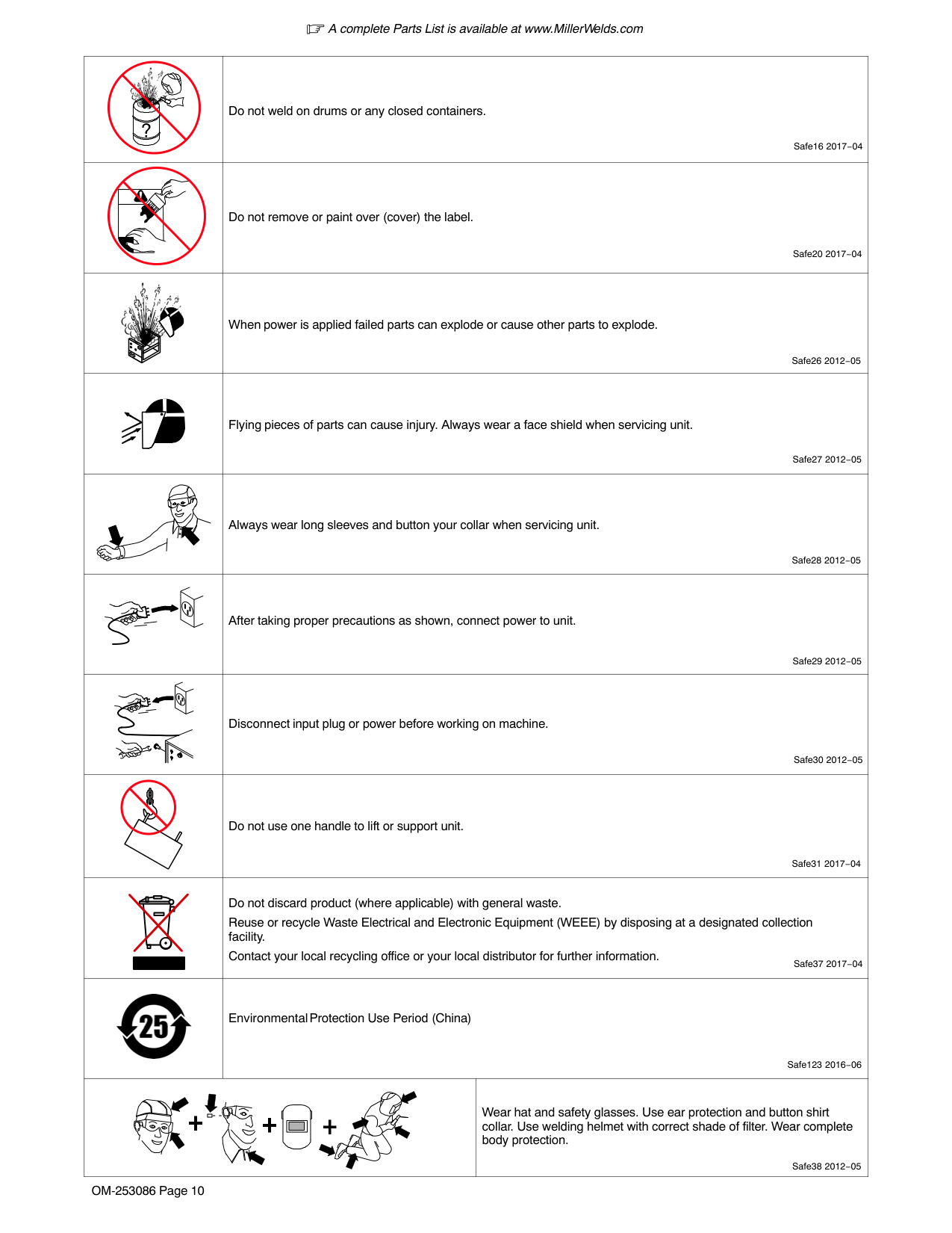
||Do not weld on drums or any closed containers.
Safe16 2017−04|Do not weld on drums or any closed containers.
Safe16 2017−04| |---|---|---| | |Do not remove or paint over (cover) the label.
Safe20 2017−04|Do not remove or paint over (cover) the label.
Safe20 2017−04| ||When power is applied failed parts can explode or cause other parts to explode.
Safe26 2012−05|When power is applied failed parts can explode or cause other parts to explode.
Safe26 2012−05| | |Flying pieces of parts can cause injury. Always wear a face shield when servicing unit.
Safe27 2012−05|Flying pieces of parts can cause injury. Always wear a face shield when servicing unit.
Safe27 2012−05| | |Always wear long sleeves and button your collar when servicing unit.
Safe28 2012−05|Always wear long sleeves and button your collar when servicing unit.
Safe28 2012−05| | |After taking proper precautions as shown, connect power to unit.
Safe29 2012−05|After taking proper precautions as shown, connect power to unit.
Safe29 2012−05| | |Disconnect input plug or power before working on machine.
Safe30 2012−05|Disconnect input plug or power before working on machine.
Safe30 2012−05| | |Do not use one handle to lift or support unit.
Safe31 2017−04|Do not use one handle to lift or support unit.
Safe31 2017−04| | |Do not discard product (where applicable) with general waste. Reuse or recycle Waste Electrical and Electronic Equipment (WEEE) by disposing at a designated collection facility.
Contact your local recycling office or your local distributor for further information. Safe37 2017−04|Do not discard product (where applicable) with general waste. Reuse or recycle Waste Electrical and Electronic Equipment (WEEE) by disposing at a designated collection facility.
Contact your local recycling office or your local distributor for further information. Safe37 2017−04| ||Environmental Protection Use Period (China)
Safe123 2016−06|Environmental Protection Use Period (China)
Safe123 2016−06| | | |Wear hat and safety glasses. Use ear protection and button shirt collar. Use welding helmet with correct shade of filter. Wear complete body protection.
Safe38 2012−05|
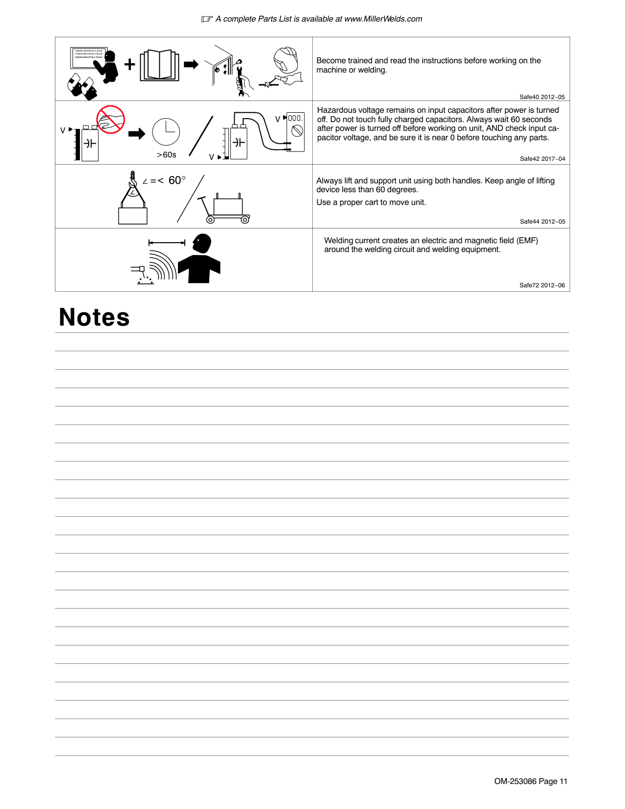
| |Become trained and read the instructions before working on the machine or welding.
Safe40 2012−05| |---|---| |>60s
V V
V|Hazardous voltage remains on input capacitors after power is turned off. Do not touch fully charged capacitors. Always wait 60 seconds after power is turned off before working on unit, AND check input capacitor voltage, and be sure it is near 0 before touching any parts.
Safe42 2017−04| |=< 60°
|Always lift and support unit using both handles. Keep angle of lifting device less than 60 degrees.
Use a proper cart to move unit.
Safe44 2012−05| | |Welding current creates an electric and magnetic field (EMF) around the welding circuit and welding equipment.
Safe72 2012−06|
##### Notes
############# 3-2. Miscellaneous Symbols And Definitions
|A|Amperes| |---|---| | |Panel−Local| | |Gas Tungsten Arc Welding (GTAW)| | |Shielded Metal Arc Welding (SMAW)| |V|Volts| | |Voltage Input| | |3 Phase Static Frequency Converter-Transfo rmer-Rectifier| | |Voltage Output| | |Circuit Breaker| | |Remote| | |Lift-Arc Start (GTAW)| | |Protective Earth (Ground)| | |Postflow Timer| | |Preflow Timer|
|S|Seconds| | |On| | |Off| | |Positive| | |Negative|
| |Alternating Current| |---|---| | |Gas Input| | |Gas Output| |I2|Rated Welding Current| |X|Duty Cycle| | |Direct Current| | |Line Connection| |U2|Conventional Load Voltage| |U1|Primary Voltage| |IP|Degree Of Protection| |I1max|Rated Maximum Supply Current| |I1eff|Maximum Effective Supply Current| |U0|Rated No Load Voltage (OCV)| | |Pulse Background Amperage| | |Initial Amperage| | |Increase/ Decrease Of Quantity| | |Normal Trigger Operation (GTAW)| | |Two-Step Trigger Operation (GTAW)| | |Four-Step Trigger Operation (GTAW)| | |Percent|
|Hz|Hertz| |---|---| | |Recall From Memory| | |Arc Force (DIG)| | |HF Impulse Starting (GTAW)| | |Final Slope| | |Final Amperage| | |Pulse Percent On Time| | |Initial Slope| | |Contactor Control (Stick)| | |Pulser On-Off| | |TIG Weld Amps And Peak Amps While Pulsing| | |Pulse Frequency| | |Background Amps| | |Process| | |Pulser| | |Sequence| | |Output| | |Adjust| ||S|
|---| |Suitable For Areas Of Increased Shock Hazard|
####### SECTION 4 − SPECIFICATIONS
############# 4-1. Serial Number And Rating Label Location
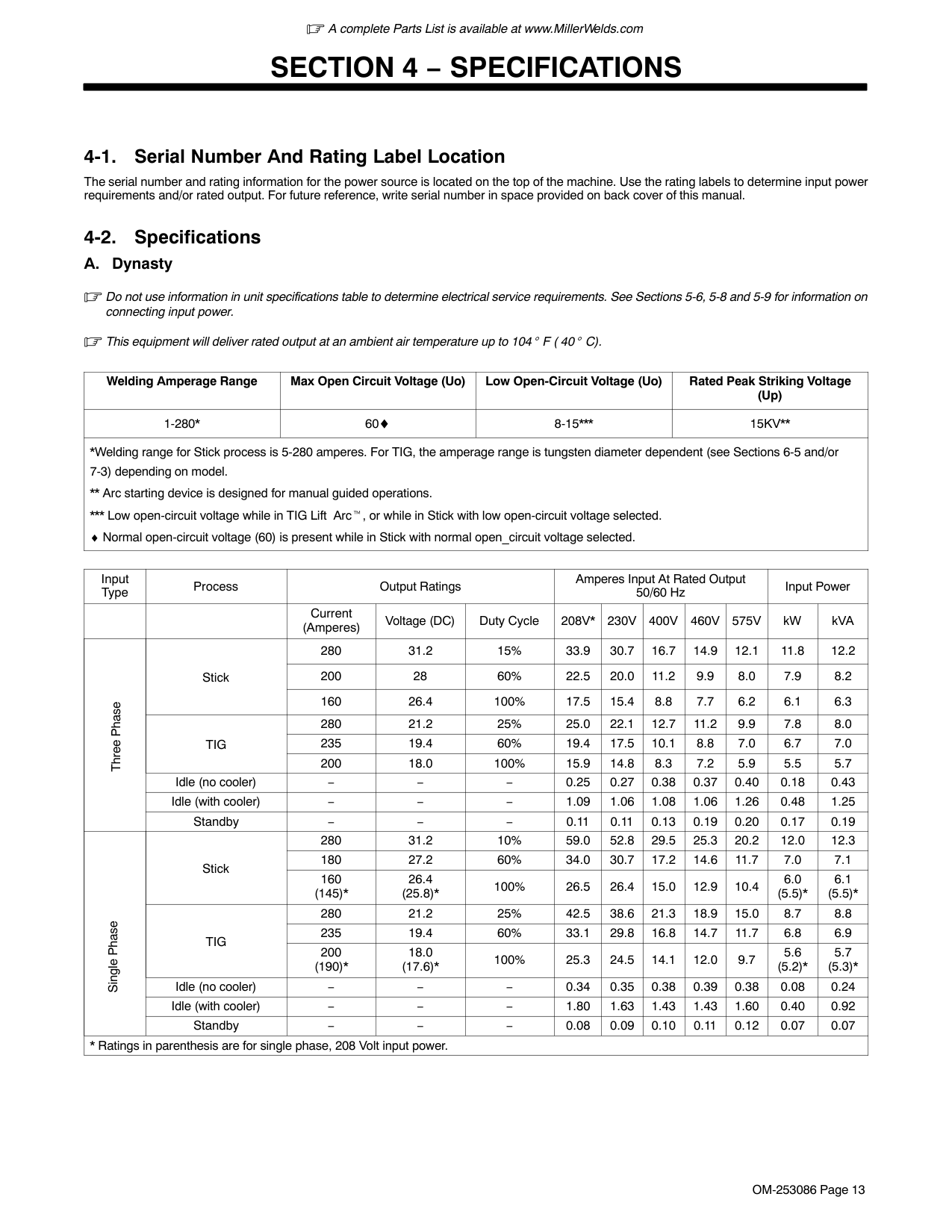
The serial number and rating information for the power source is located on the top of the machine. Use the rating labels to determine input power requirements and/or rated output. For future reference, write serial number in space provided on back cover of this manual.
############# 4-2. Specifications
################ A. Dynasty
Do not use information in unit specifications table to determine electrical service requirements. See Sections 5-6, 5-8 and 5-9 for information on connecting input power.
This equipment will deliver rated output at an ambient air temperature up to 104 F ( 40 C).
|Welding Amperage Range|Max Open Circuit Voltage (Uo)|Low Open-Circuit Voltage (Uo)|Rated Peak Striking Voltage (Up)| |---|---|---|---| |1-280*|60♦|8-15*|15KV| |*Welding range for Stick process is 5-280 amperes. For TIG, the amperage range is tungsten diameter dependent (see Sections 6-5 and/or 7-3) depending on model.
Arc starting device is designed for manual guided operations.
* Low open-circuit voltage while in TIG Lift Arc , or while in Stick with low open-circuit voltage selected.
♦ Normal open-circuit voltage (60) is present while in Stick with normal open_circuit voltage selected.|*Welding range for Stick process is 5-280 amperes. For TIG, the amperage range is tungsten diameter dependent (see Sections 6-5 and/or 7-3) depending on model.
Arc starting device is designed for manual guided operations.
* Low open-circuit voltage while in TIG Lift Arc , or while in Stick with low open-circuit voltage selected.
♦ Normal open-circuit voltage (60) is present while in Stick with normal open_circuit voltage selected.|
|Input Type|Process|Output Ratings|Output Ratings|Output Ratings|Amperes Input At Rated Output 50/60 Hz|Amperes Input At Rated Output 50/60 Hz|Amperes Input At Rated Output 50/60 Hz|Amperes Input At Rated Output 50/60 Hz|Amperes Input At Rated Output 50/60 Hz|Input Power|Input Power| |---|---|---|---|---|---|---|---|---|---|---|---| | | |Current (Amperes)|Voltage (DC)|Duty Cycle|208V*|230V|400V|460V|575V|kW|kVA| |Three Phase|Stick|280|31.2|15%|33.9|30.7|16.7|14.9|12.1|11.8|12.2| |Three Phase|Stick|200|28|60%|22.5|20.0|11.2|9.9|8.0|7.9|8.2| |Three Phase|Stick|160|26.4|100%|17.5|15.4|8.8|7.7|6.2|6.1|6.3| |Three Phase|TIG|280|21.2|25%|25.0|22.1|12.7|11.2|9.9|7.8|8.0| |Three Phase|TIG|235|19.4|60%|19.4|17.5|10.1|8.8|7.0|6.7|7.0| |Three Phase|TIG|200|18.0|100%|15.9|14.8|8.3|7.2|5.9|5.5|5.7| |Three Phase|Idle (no cooler)|−|−|−|0.25|0.27|0.38|0.37|0.40|0.18|0.43| |Three Phase|Idle (with cooler)|−|−|−|1.09|1.06|1.08|1.06|1.26|0.48|1.25| |Three Phase|Standby|−|−|−|0.11|0.11|0.13|0.19|0.20|0.17|0.19| |Single Phase|Stick|280|31.2|10%|59.0|52.8|29.5|25.3|20.2|12.0|12.3| |Single Phase|Stick|180|27.2|60%|34.0|30.7|17.2|14.6|11.7|7.0|7.1| |Single Phase|Stick|160 (145)*|26.4 (25.8)*|100%|26.5|26.4|15.0|12.9|10.4|6.0 (5.5)*|6.1 (5.5)*| |Single Phase|TIG|280|21.2|25%|42.5|38.6|21.3|18.9|15.0|8.7|8.8| |Single Phase|TIG|235|19.4|60%|33.1|29.8|16.8|14.7|11.7|6.8|6.9| |Single Phase|TIG|200 (190)*|18.0 (17.6)*|100%|25.3|24.5|14.1|12.0|9.7|5.6 (5.2)*|5.7 (5.3)*| |Single Phase|Idle (no cooler)|−|−|−|0.34|0.35|0.38|0.39|0.38|0.08|0.24| |Single Phase|Idle (with cooler)|−|−|−|1.80|1.63|1.43|1.43|1.60|0.40|0.92| |Single Phase|Standby|−|−|−|0.08|0.09|0.10|0.11|0.12|0.07|0.07| |* Ratings in parenthesis are for single phase, 208 Volt input power.|* Ratings in parenthesis are for single phase, 208 Volt input power.|* Ratings in parenthesis are for single phase, 208 Volt input power.|* Ratings in parenthesis are for single phase, 208 Volt input power.|* Ratings in parenthesis are for single phase, 208 Volt input power.|* Ratings in parenthesis are for single phase, 208 Volt input power.|* Ratings in parenthesis are for single phase, 208 Volt input power.|* Ratings in parenthesis are for single phase, 208 Volt input power.|* Ratings in parenthesis are for single phase, 208 Volt input power.|* Ratings in parenthesis are for single phase, 208 Volt input power.|* Ratings in parenthesis are for single phase, 208 Volt input power.|* Ratings in parenthesis are for single phase, 208 Volt input power.|
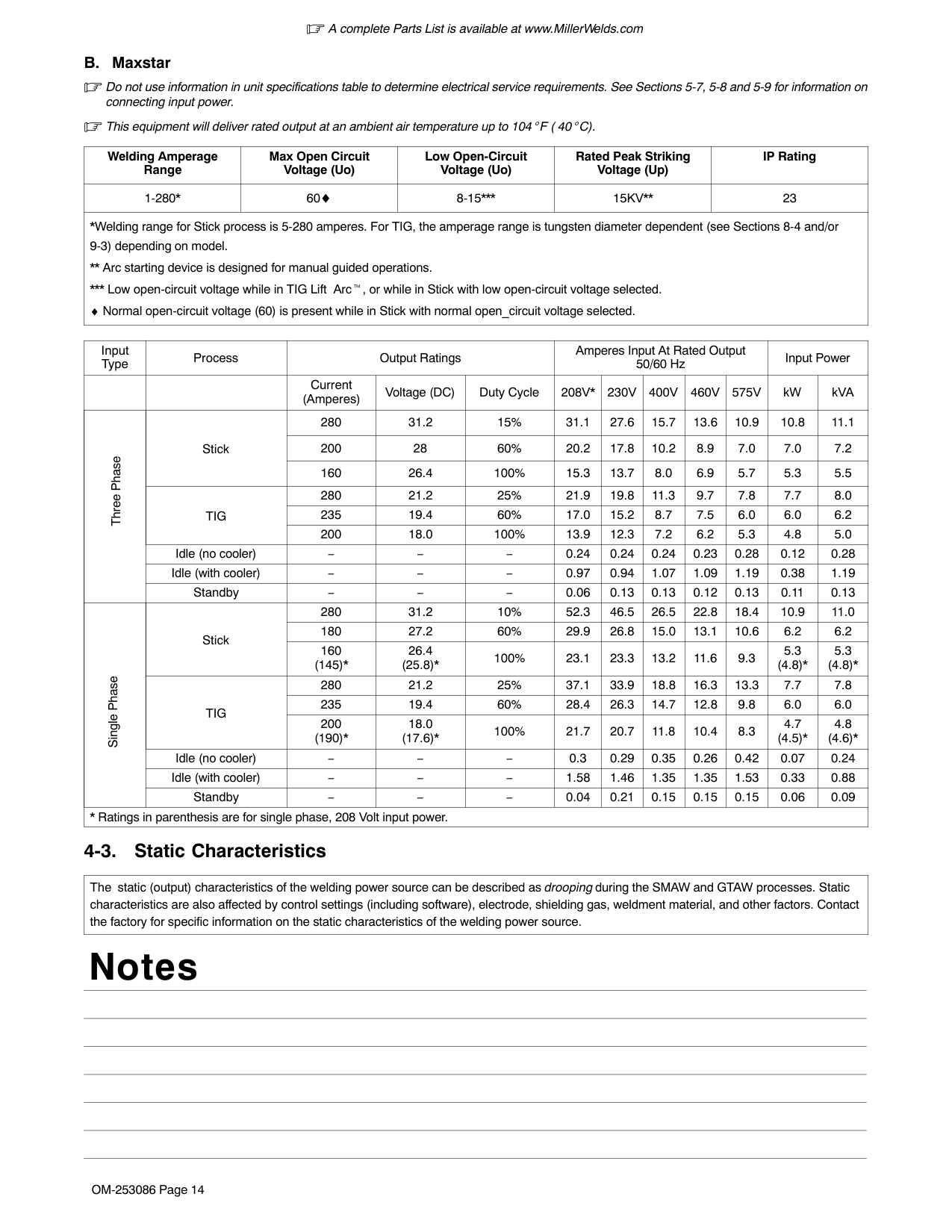
################ B. Maxstar
Do not use information in unit specifications table to determine electrical service requirements. See Sections 5-7, 5-8 and 5-9 for information on connecting input power.
This equipment will deliver rated output at an ambient air temperature up to 104 F ( 40 C).
|Welding Amperage Range|Max Open Circuit Voltage (Uo)|Low Open-Circuit Voltage (Uo)|Rated Peak Striking Voltage (Up)|IP Rating| |---|---|---|---|---| |1-280*|60♦|8-15*|15KV|23| |*Welding range for Stick process is 5-280 amperes. For TIG, the amperage range is tungsten diameter dependent (see Sections 8-4 and/or 9-3) depending on model.
Arc starting device is designed for manual guided operations.
* Low open-circuit voltage while in TIG Lift Arc , or while in Stick with low open-circuit voltage selected.
♦ Normal open-circuit voltage (60) is present while in Stick with normal open_circuit voltage selected.|*Welding range for Stick process is 5-280 amperes. For TIG, the amperage range is tungsten diameter dependent (see Sections 8-4 and/or 9-3) depending on model.
Arc starting device is designed for manual guided operations.
* Low open-circuit voltage while in TIG Lift Arc , or while in Stick with low open-circuit voltage selected.
♦ Normal open-circuit voltage (60) is present while in Stick with normal open_circuit voltage selected.|
|Input Type|Process|Output Ratings|Output Ratings|Output Ratings|Amperes Input At Rated Output 50/60 Hz|Amperes Input At Rated Output 50/60 Hz|Amperes Input At Rated Output 50/60 Hz|Amperes Input At Rated Output 50/60 Hz|Amperes Input At Rated Output 50/60 Hz|Input Power|Input Power| |---|---|---|---|---|---|---|---|---|---|---|---| | | |Current (Amperes)|Voltage (DC)|Duty Cycle|208V*|230V|400V|460V|575V|kW|kVA| |Three Phase|Stick|280|31.2|15%|31.1|27.6|15.7|13.6|10.9|10.8|11.1| |Three Phase|Stick|200|28|60%|20.2|17.8|10.2|8.9|7.0|7.0|7.2| |Three Phase|Stick|160|26.4|100%|15.3|13.7|8.0|6.9|5.7|5.3|5.5| |Three Phase|TIG|280|21.2|25%|21.9|19.8|11.3|9.7|7.8|7.7|8.0| |Three Phase|TIG|235|19.4|60%|17.0|15.2|8.7|7.5|6.0|6.0|6.2| |Three Phase|TIG|200|18.0|100%|13.9|12.3|7.2|6.2|5.3|4.8|5.0| |Three Phase|Idle (no cooler)|−|−|−|0.24|0.24|0.24|0.23|0.28|0.12|0.28| |Three Phase|Idle (with cooler)|−|−|−|0.97|0.94|1.07|1.09|1.19|0.38|1.19| |Three Phase|Standby|−|−|−|0.06|0.13|0.13|0.12|0.13|0.11|0.13| |Single Phase|Stick|280|31.2|10%|52.3|46.5|26.5|22.8|18.4|10.9|11.0| |Single Phase|Stick|180|27.2|60%|29.9|26.8|15.0|13.1|10.6|6.2|6.2| |Single Phase|Stick|160 (145)*|26.4 (25.8)*|100%|23.1|23.3|13.2|11.6|9.3|5.3 (4.8)*|5.3 (4.8)*| |Single Phase|TIG|280|21.2|25%|37.1|33.9|18.8|16.3|13.3|7.7|7.8| |Single Phase|TIG|235|19.4|60%|28.4|26.3|14.7|12.8|9.8|6.0|6.0| |Single Phase|TIG|200 (190)*|18.0 (17.6)*|100%|21.7|20.7|11.8|10.4|8.3|4.7 (4.5)*|4.8 (4.6)*| |Single Phase|Idle (no cooler)|−|−|−|0.3|0.29|0.35|0.26|0.42|0.07|0.24| |Single Phase|Idle (with cooler)|−|−|−|1.58|1.46|1.35|1.35|1.53|0.33|0.88| |Single Phase|Standby|−|−|−|0.04|0.21|0.15|0.15|0.15|0.06|0.09| |* Ratings in parenthesis are for single phase, 208 Volt input power.|* Ratings in parenthesis are for single phase, 208 Volt input power.|* Ratings in parenthesis are for single phase, 208 Volt input power.|* Ratings in parenthesis are for single phase, 208 Volt input power.|* Ratings in parenthesis are for single phase, 208 Volt input power.|* Ratings in parenthesis are for single phase, 208 Volt input power.|* Ratings in parenthesis are for single phase, 208 Volt input power.|* Ratings in parenthesis are for single phase, 208 Volt input power.|* Ratings in parenthesis are for single phase, 208 Volt input power.|* Ratings in parenthesis are for single phase, 208 Volt input power.|* Ratings in parenthesis are for single phase, 208 Volt input power.|* Ratings in parenthesis are for single phase, 208 Volt input power.|
############# 4-3. Static Characteristics
|The static (output) characteristics of the welding power source can be described as droopingduring the SMAW and GTAW processes. Static characteristics are also affected by control settings (including software), electrode, shielding gas, weldment material, and other factors. Contact the factory for specific information on the static characteristics of the welding power source.| |---|
##### Notes
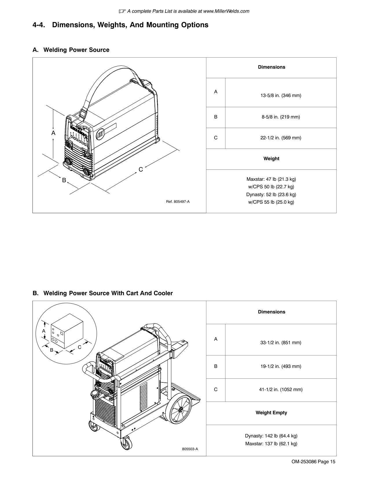
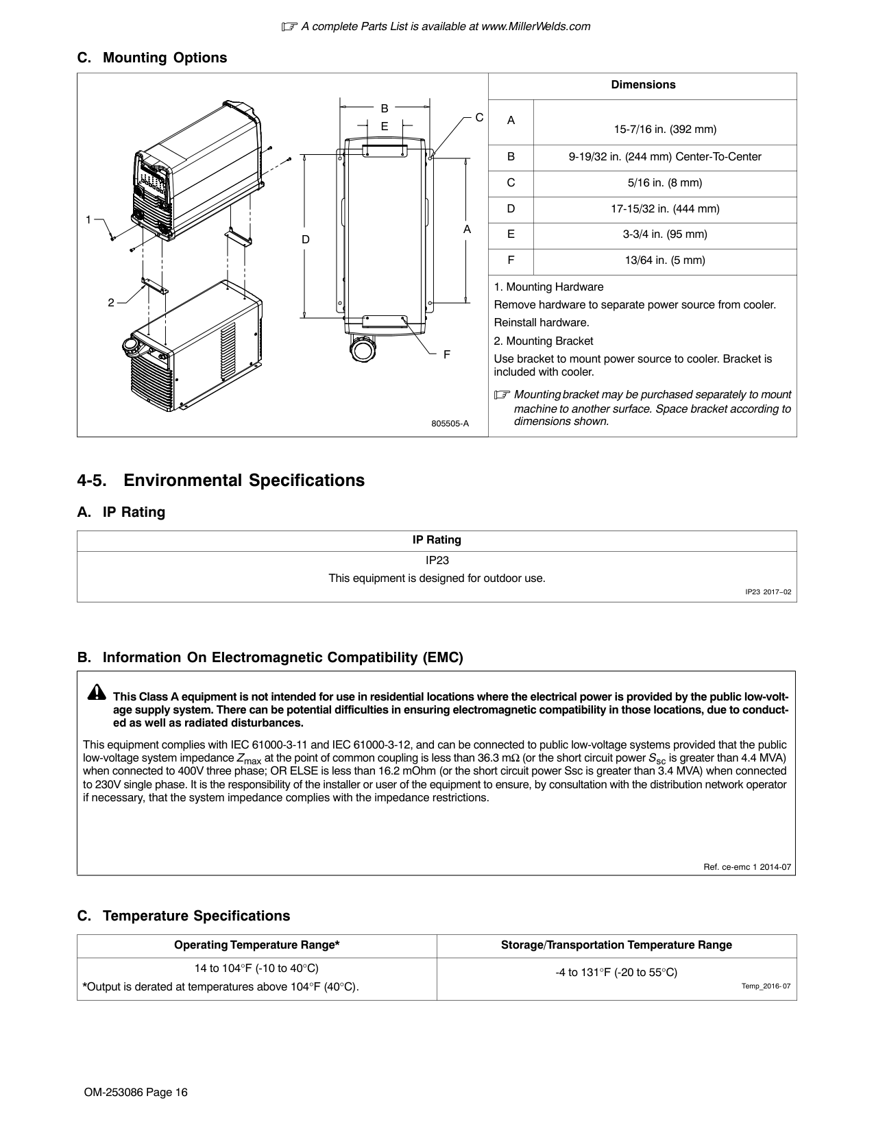
############# 4-4. Dimensions, Weights, And Mounting Options
|Ref. 805497-A
A
B
C|Dimensions|Dimensions| |---|---|---| |Ref. 805497-A
A
B
C|A|13-5/8 in. (346 mm)| |Ref. 805497-A
A
B
C|B|8-5/8 in. (219 mm)|
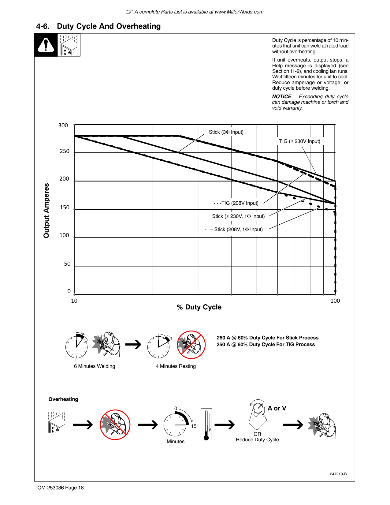
|Ref. 805497-A
A
B
C|C|22-1/2 in. (569 mm)| |Ref. 805497-A
A
B
C|Weight|Weight| |Ref. 805497-A
A
B
C|Maxstar: 47 lb (21.3 kg) w/CPS 50 lb (22.7 kg) Dynasty: 52 lb (23.6 kg) w/CPS 55 lb (25.0 kg)|Maxstar: 47 lb (21.3 kg) w/CPS 50 lb (22.7 kg) Dynasty: 52 lb (23.6 kg) w/CPS 55 lb (25.0 kg)|
|B
A
C
805503-A|Dimensions|Dimensions| |---|---|---| |B
A
C
805503-A|A|33-1/2 in. (851 mm)| |B
A
C
805503-A|B|19-1/2 in. (493 mm)| |B
A
C
805503-A|C|41-1/2 in. (1052 mm)| |B
A
C
805503-A|Weight Empty|Weight Empty| |B
A
C
805503-A|Dynasty: 142 lb (64.4 kg) Maxstar: 137 lb (62.1 kg)|Dynasty: 142 lb (64.4 kg) Maxstar: 137 lb (62.1 kg)|
|805505-A
1
2
D
F
A
B
C E
|Dimensions|Dimensions| |---|---|---| |805505-A
1
2
D
F
A
B
C E
|A|15-7/16 in. (392 mm)| |805505-A
1
2
D
F
A
B
C E
|B|9-19/32 in. (244 mm) Center-To-Center| |805505-A
1
2
D
F
A
B
C E
|C|5/16 in. (8 mm)| |805505-A
1
2
D
F
A
B
C E
|D|17-15/32 in. (444 mm)| |805505-A
1
2
D
F
A
B
C E
|E|3-3/4 in. (95 mm)| |805505-A
1
2
D
F
A
B
C E
|F|13/64 in. (5 mm)| |805505-A
1
2
D
F
A
B
C E
|1. Mounting Hardware Remove hardware to separate power source from cooler. Reinstall hardware.
2. Mounting Bracket
Use bracket to mount power source to cooler. Bracket is included with cooler.
Mounting bracket may be purchased separately to mount machine to another surface. Space bracket according to dimensions shown.|1. Mounting Hardware Remove hardware to separate power source from cooler. Reinstall hardware.
2. Mounting Bracket
Use bracket to mount power source to cooler. Bracket is included with cooler.
Mounting bracket may be purchased separately to mount machine to another surface. Space bracket according to dimensions shown.|
############# 4-5. Environmental Specifications
|IP Rating| |---| |IP23 This equipment is designed for outdoor use.
IP23 2017−02|
|Ref. ce-emc 1 2014-07
This Class A equipment is not intended for use in residential locations where the electrical power is provided by the public low-voltage supply system. There can be potential difficulties in ensuring electromagnetic compatibility in those locations, due to conducted as well as radiated disturbances.
This equipment complies with IEC 61000-3-11 and IEC 61000-3-12, and can be connected to public low-voltage systems provided that the public low-voltage system impedance Zmax at the point of common coupling is less than 36.3 mΩ (or the short circuit power Ssc is greater than 4.4 MVA) when connected to 400V three phase; OR ELSE is less than 16.2 mOhm (or the short circuit power Ssc is greater than 3.4 MVA) when connected to 230V single phase. It is the responsibility of the installer or user of the equipment to ensure, by consultation with the distribution network operator if necessary, that the system impedance complies with the impedance restrictions.| |---|
|Operating Temperature Range*|Storage/Transportation Temperature Range|
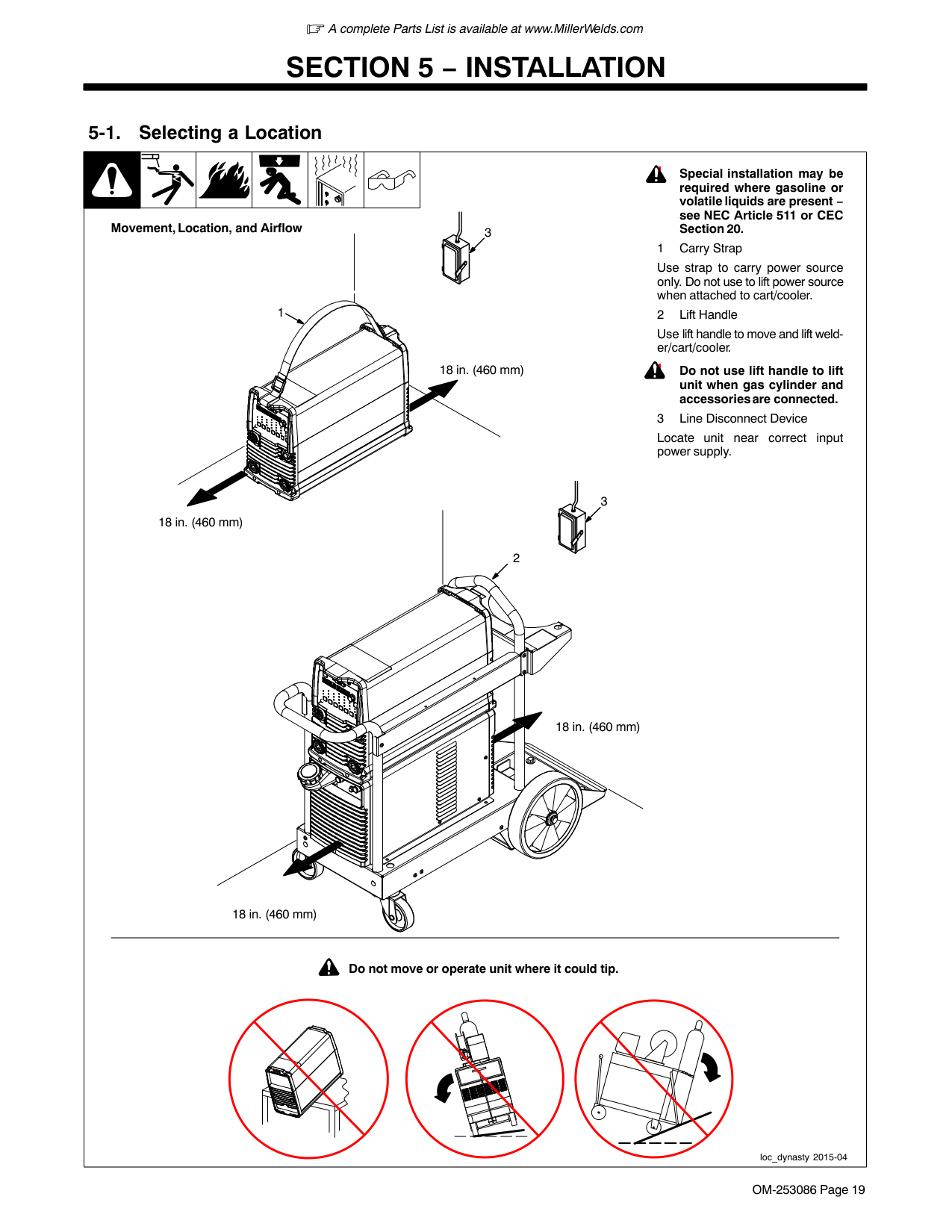
|---|---| |14 to 104°F (-10 to 40°C)
*Output is derated at temperatures above 104°F (40°C).|-4 to 131°F (-20 to 55°C)
Temp_2016-07|
|China EEP Hazardous Substance Information|China EEP Hazardous Substance Information|China EEP Hazardous Substance Information|China EEP Hazardous Substance Information|China EEP Hazardous Substance Information|China EEP Hazardous Substance Information|China EEP Hazardous Substance Information| |---|---|---|---|---|---|---| |Component Name ( ) (if applicable)|Hazardous Substance|Hazardous Substance|Hazardous Substance|Hazardous Substance|Hazardous Substance|Hazardous Substance| |Component Name ( ) (if applicable)|Pb|Hg|Cd|Cr6|PBB|PBDE| |Brass and Copper Parts|X|O|O|O|O|O| |Coupling Devices|X|O|O|O|O|O| |Switching Devices|O|O|X|O|O|O| |Cable and Cable Accessories|X|O|O|O|O|O| |Batteries|X|O|O|O|O|O| | SJ/T 11364 . This table is prepared in accordance with China SJ/T 11364.| SJ/T 11364 . This table is prepared in accordance with China SJ/T 11364.| SJ/T 11364 . This table is prepared in accordance with China SJ/T 11364.| SJ/T 11364 . This table is prepared in accordance with China SJ/T 11364.| SJ/T 11364 . This table is prepared in accordance with China SJ/T 11364.| SJ/T 11364 . This table is prepared in accordance with China SJ/T 11364.| SJ/T 11364 . This table is prepared in accordance with China SJ/T 11364.| |O:
GB/T26572 . Indicates that the concentration of the Hazardous Substance in all homogeneous materials of the part is below the relevant threshold of China GB/T 26572.|O:
GB/T26572 . Indicates that the concentration of the Hazardous Substance in all homogeneous materials of the part is below the relevant threshold of China GB/T 26572.|O:
GB/T26572 . Indicates that the concentration of the Hazardous Substance in all homogeneous materials of the part is below the relevant threshold of China GB/T 26572.|O:
GB/T26572 . Indicates that the concentration of the Hazardous Substance in all homogeneous materials of the part is below the relevant threshold of China GB/T 26572.|O:
GB/T26572 . Indicates that the concentration of the Hazardous Substance in all homogeneous materials of the part is below the relevant threshold of China GB/T 26572.|O:
GB/T26572 . Indicates that the concentration of the Hazardous Substance in all homogeneous materials of the part is below the relevant threshold of China GB/T 26572.|O:
GB/T26572 . Indicates that the concentration of the Hazardous Substance in all homogeneous materials of the part is below the relevant threshold of China GB/T 26572.| |X:
GB/T26572 . Indicates that the concentration of the Hazardous Substance in at least one homogeneous material of the part is above the relevant threshold of China GB/T 26572.|X:
GB/T26572 . Indicates that the concentration of the Hazardous Substance in at least one homogeneous material of the part is above the relevant threshold of China GB/T 26572.|X:
GB/T26572 . Indicates that the concentration of the Hazardous Substance in at least one homogeneous material of the part is above the relevant threshold of China GB/T 26572.|X:
GB/T26572 . Indicates that the concentration of the Hazardous Substance in at least one homogeneous material of the part is above the relevant threshold of China GB/T 26572.|X:
GB/T26572 . Indicates that the concentration of the Hazardous Substance in at least one homogeneous material of the part is above the relevant threshold of China GB/T 26572.|X:
GB/T26572 . Indicates that the concentration of the Hazardous Substance in at least one homogeneous material of the part is above the relevant threshold of China GB/T 26572.|X:
GB/T26572 . Indicates that the concentration of the Hazardous Substance in at least one homogeneous material of the part is above the relevant threshold of China GB/T 26572.| | SJ/Z11388 . The EFUP value of this EEP is defined in accordance with China SJ/Z 11388. EEP_2016−06| SJ/Z11388 . The EFUP value of this EEP is defined in accordance with China SJ/Z 11388. EEP_2016−06| SJ/Z11388 . The EFUP value of this EEP is defined in accordance with China SJ/Z 11388. EEP_2016−06| SJ/Z11388 . The EFUP value of this EEP is defined in accordance with China SJ/Z 11388. EEP_2016−06| SJ/Z11388 . The EFUP value of this EEP is defined in accordance with China SJ/Z 11388. EEP_2016−06| SJ/Z11388 . The EFUP value of this EEP is defined in accordance with China SJ/Z 11388. EEP_2016−06||
##### Notes
############# 4-6. Duty Cycle And Overheating
| | |Duty Cycle is percentage of 10 minutes that unit can weld at rated load without overheating.| |---|---|---| |247219-B
If unit overheats, output stops, a Help message is displayed (see Section 11-2), and cooling fan runs. Wait fifteen minutes for unit to cool. Reduce amperage or voltage, or duty cycle before welding.
NOTICE − Exceeding duty cycle can damage machine or torch and void warranty.
6 Minutes Welding 4 Minutes Resting
Overheating
0
15
A or V
OR Reduce Duty CycleMinutes
250 A @ 60% Duty Cycle For Stick Process 250 A @ 60% Duty Cycle For TIG Process
0
50
100
150
200
250
300
10 100
Stick (≥ 230V, 1Φ Input)
- − Stick (208V, 1Φ Input)
‐ ‐ ‐TIG (208V Input)
TIG (≥ 230V Input)
Stick (3Φ Input)
Output Amperes
% Duty Cycle|247219-B
If unit overheats, output stops, a Help message is displayed (see Section 11-2), and cooling fan runs. Wait fifteen minutes for unit to cool. Reduce amperage or voltage, or duty cycle before welding.
NOTICE − Exceeding duty cycle can damage machine or torch and void warranty.
6 Minutes Welding 4 Minutes Resting
Overheating
0
15
A or V
OR Reduce Duty CycleMinutes
250 A @ 60% Duty Cycle For Stick Process 250 A @ 60% Duty Cycle For TIG Process
0
50
100
150
200
250
300
10 100
Stick (≥ 230V, 1Φ Input)
- − Stick (208V, 1Φ Input)
‐ ‐ ‐TIG (208V Input)
TIG (≥ 230V Input)
Stick (3Φ Input)
Output Amperes
% Duty Cycle|
####### SECTION 5 − INSTALLATION
############# 5-1. Selecting a Location
####################### Movement, Location, and Airflow 3
1
18 in. (460 mm)
3
18 in. (460 mm)
2
18 in. (460 mm)
! Special installation may be required where gasoline or volatile liquids are present − see NEC Article 511 or CEC Section 20.
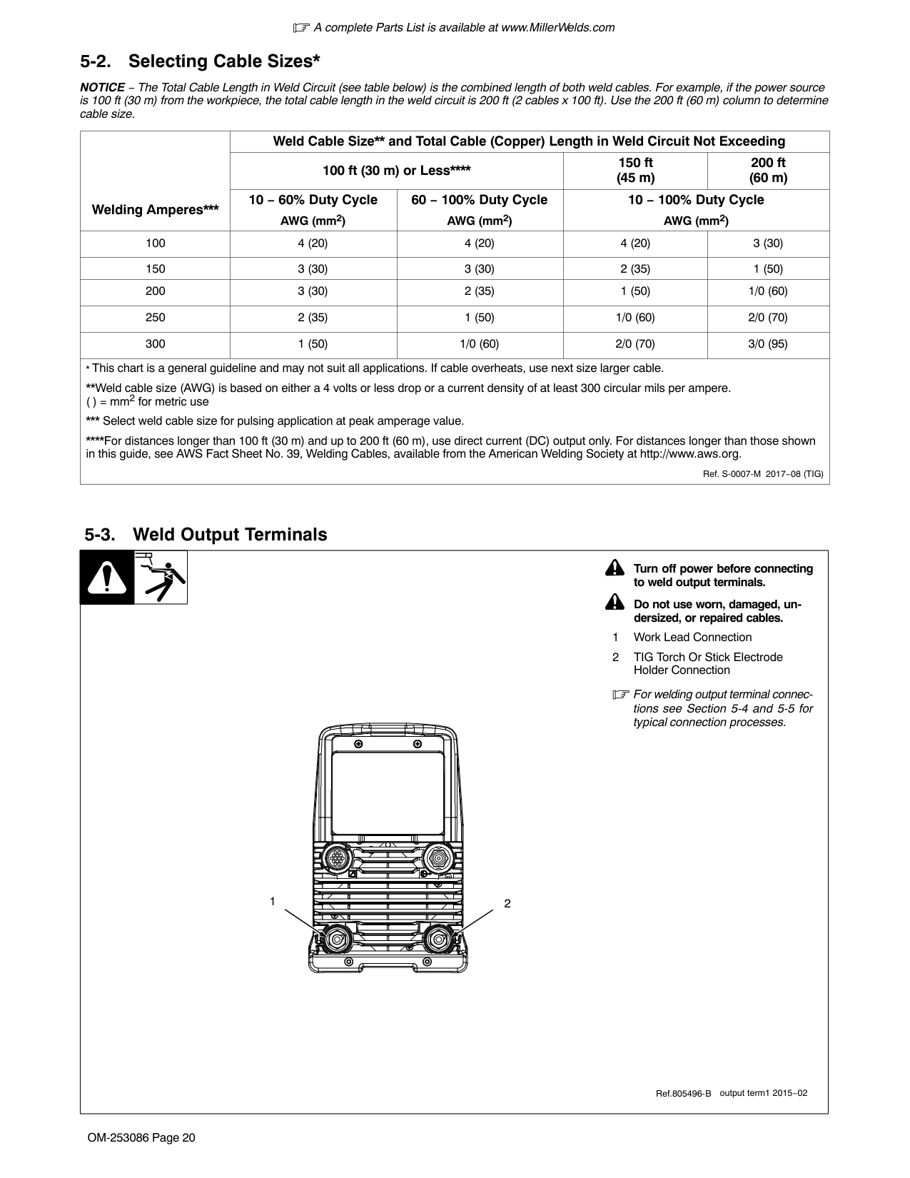
Use strap to carry power source only. Do not use to lift power source when attached to cart/cooler.
Use lift handle to move and lift welder/cart/cooler.
! Do not use lift handle to lift unit when gas cylinder and accessories are connected.
Locate unit near correct input power supply.
18 in. (460 mm)
! Do not move or operate unit where it could tip.
loc_dynasty 2015-04
############# 5-2. Selecting Cable Sizes*
NOTICE − The Total Cable Length in Weld Circuit (see table below) is the combined length of both weld cables. For example, if the power source is 100 ft (30 m) from the workpiece, the total cable length in the weld circuit is 200 ft (2 cables x 100 ft). Use the 200 ft (60 m) column to determine cable size.
|Welding Amperes*|Weld Cable Size and Total Cable (Copper) Length in Weld Circuit Not Exceeding|Weld Cable Size and Total Cable (Copper) Length in Weld Circuit Not Exceeding|Weld Cable Size and Total Cable (Copper) Length in Weld Circuit Not Exceeding|Weld Cable Size** and Total Cable (Copper) Length in Weld Circuit Not Exceeding| |---|---|---|---|---| |Welding Amperes*|100 ft (30 m) or Less|100 ft (30 m) or Less**|150 ft (45 m)|200 ft (60 m)| |Welding Amperes***|10 − 60% Duty Cycle AWG (mm2)|60 − 100% Duty Cycle AWG (mm2)|10 − 100% Duty Cycle AWG (mm2)|10 − 100% Duty Cycle AWG (mm2)| |100|4 (20)|4 (20)|4 (20)|3 (30)| |150|3 (30)|3 (30)|2 (35)|1 (50)| |200|3 (30)|2 (35)|1 (50)|1/0 (60)| |250|2 (35)|1 (50)|1/0 (60)|2/0 (70)| |300|1 (50)|1/0 (60)|2/0 (70)|3/0 (95)| |* This chart is a general guideline and may not suit all applications. If cable overheats, use next size larger cable.
Weld cable size (AWG) is based on either a 4 volts or less drop or a current density of at least 300 circular mils per ampere. ( ) = mm2 for metric use
* Select weld cable size for pulsing application at peak amperage value.
**For distances longer than 100 ft (30 m) and up to 200 ft (60 m), use direct current (DC) output only. For distances longer than those shown in this guide, see AWS Fact Sheet No. 39, Welding Cables, available from the American Welding Society at http://www.aws.org.
Ref. S-0007-M 2017−08 (TIG)|* This chart is a general guideline and may not suit all applications. If cable overheats, use next size larger cable.
Weld cable size (AWG) is based on either a 4 volts or less drop or a current density of at least 300 circular mils per ampere. ( ) = mm2 for metric use
* Select weld cable size for pulsing application at peak amperage value.
For distances longer than 100 ft (30 m) and up to 200 ft (60 m), use direct current (DC) output only. For distances longer than those shown in this guide, see AWS Fact Sheet No. 39, Welding Cables, available from the American Welding Society at http://www.aws.org.
Ref. S-0007-M 2017−08 (TIG)|* This chart is a general guideline and may not suit all applications. If cable overheats, use next size larger cable.
Weld cable size (AWG) is based on either a 4 volts or less drop or a current density of at least 300 circular mils per ampere. ( ) = mm2 for metric use
* Select weld cable size for pulsing application at peak amperage value.
**For distances longer than 100 ft (30 m) and up to 200 ft (60 m), use direct current (DC) output only. For distances longer than those shown in this guide, see AWS Fact Sheet No. 39, Welding Cables, available from the American Welding Society at http://www.aws.org.
Ref. S-0007-M 2017−08 (TIG)|
############# 5-3. Weld Output Terminals
| | |! Turn off power before connecting
to weld output terminals.
! Do not use worn, damaged, un-
| |---|---|---| |dersized, or repaired cables.
1 Work Lead Connection
2 TIG Torch Or Stick Electrode Holder Connection
For welding output terminal connections see Section 5-4 and 5-5 for typical connection processes.
1 2
output term1 2015−02
| | |---| | |
Ref.805496-B|dersized, or repaired cables.
1 Work Lead Connection
2 TIG Torch Or Stick Electrode Holder Connection
For welding output terminal connections see Section 5-4 and 5-5 for typical connection processes.
1 2
output term1 2015−02
| | |---| | |
Ref.805496-B|dersized, or repaired cables.
1 Work Lead Connection
2 TIG Torch Or Stick Electrode Holder Connection
For welding output terminal connections see Section 5-4 and 5-5 for typical connection processes.
1 2
output term1 2015−02
| | |---|
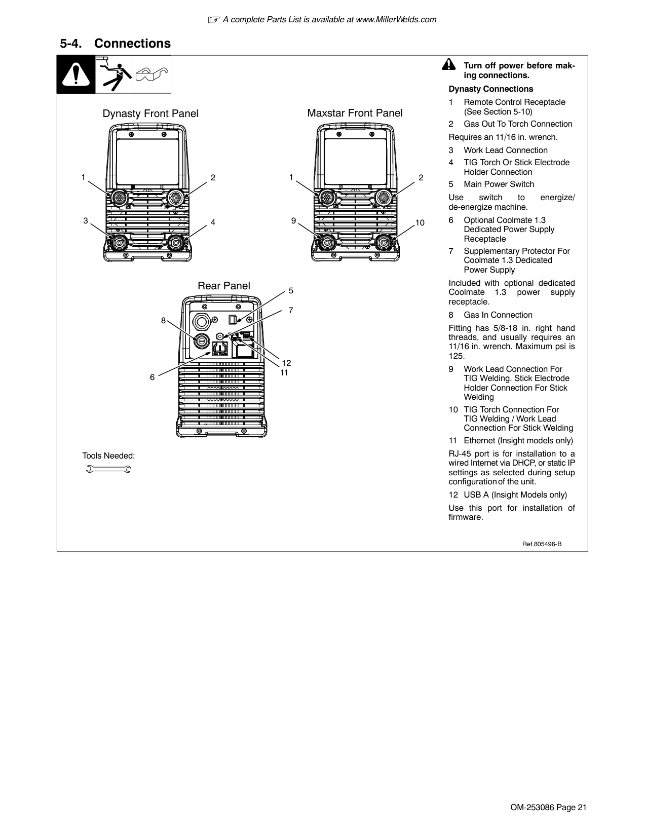
| |
Ref.805496-B|
############# 5-4. Connections
Maxstar Front Panel
Dynasty Front Panel
21
21
3 4
9 10
5Rear Panel
7 8
6
Tools Needed:
! Turn off power before mak-
ing connections. Dynasty Connections
Use switch to energize/ de-energize machine.
Included with optional dedicated Coolmate 1.3 power supply receptacle.
Fitting has 5/8-18 in. right hand threads, and usually requires an 11/16 in. wrench. Maximum psi is 125.
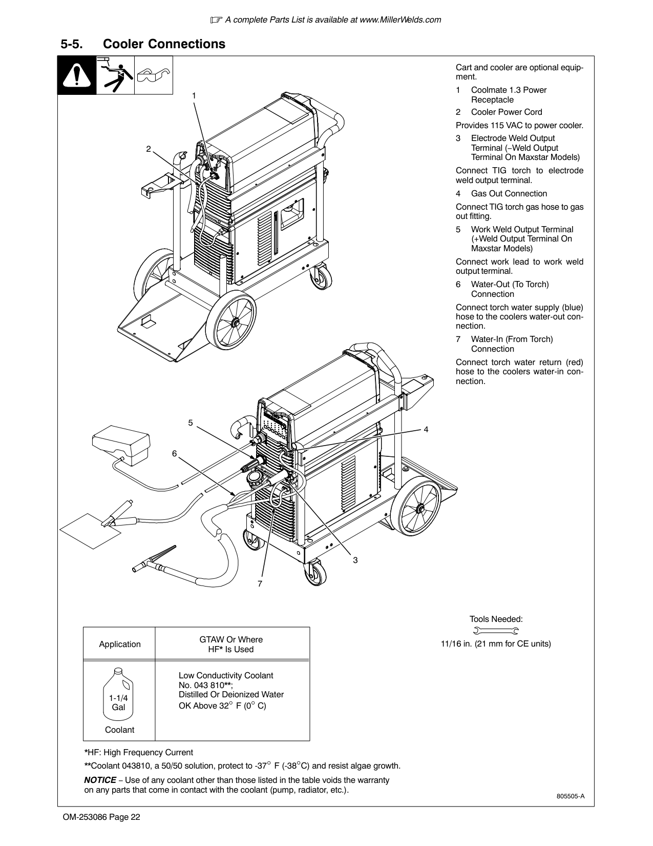
RJ-45 port is for installation to a wired Internet via DHCP, or static IP settings as selected during setup configuration of the unit.
Use this port for installation of firmware.
Ref.805496-B
############# 5-5. Cooler Connections
| | | |Cart and cooler are optional equipment.
1 Coolmate 1.3 Power 1| |---|---|---|---| |Receptacle
2 Cooler Power Cord Provides 115 VAC to power cooler.
3 Electrode Weld Output Terminal (−Weld Output Terminal On Maxstar Models)
Connect TIG torch to electrode weld output terminal.
4 Gas Out Connection
Connect TIG torch gas hose to gas out fitting.
5 Work Weld Output Terminal (+Weld Output Terminal On Maxstar Models)
Connect work lead to work weld output terminal.
6 Water-Out (To Torch) Connection
Connect torch water supply (blue) hose to the coolers water-out connection.
7 Water-In (From Torch) Connection
Connect torch water return (red) hose to the coolers water-in connection.
|Application|GTAW Or Where HF* Is Used| |---|---| | | | |Coolant
1-1/4 Gal|Low Conductivity Coolant No. 043 810**; Distilled Or Deionized Water OK Above 32° F (0° C)|
*HF: High Frequency Current
**Coolant 043810, a 50/50 solution, protect to -37° F (-38°C) and resist algae growth.
3
4
5
6
7
805505-A
2
Tools Needed:
11/16 in. (21 mm for CE units)
NOTICE − Use of any coolant other than those listed in the table voids the warranty on any parts that come in contact with the coolant (pump, radiator, etc.).|Receptacle
2 Cooler Power Cord Provides 115 VAC to power cooler.
3 Electrode Weld Output Terminal (−Weld Output Terminal On Maxstar Models)
Connect TIG torch to electrode weld output terminal.
4 Gas Out Connection
Connect TIG torch gas hose to gas out fitting.
5 Work Weld Output Terminal (+Weld Output Terminal On Maxstar Models)
Connect work lead to work weld output terminal.
6 Water-Out (To Torch) Connection
Connect torch water supply (blue) hose to the coolers water-out connection.
7 Water-In (From Torch) Connection
Connect torch water return (red) hose to the coolers water-in connection.
|Application|GTAW Or Where HF* Is Used| |---|---| | | | |Coolant
1-1/4 Gal|Low Conductivity Coolant No. 043 810**; Distilled Or Deionized Water OK Above 32° F (0° C)|
*HF: High Frequency Current
**Coolant 043810, a 50/50 solution, protect to -37° F (-38°C) and resist algae growth.
3
4
5
6
7
805505-A
2
Tools Needed:
11/16 in. (21 mm for CE units)
NOTICE − Use of any coolant other than those listed in the table voids the warranty on any parts that come in contact with the coolant (pump, radiator, etc.).|
############# 5-6. Electrical Service Guide (Dynasty) Elec Serv 2017−01
################ A. Electrical Service Guide For Three-Phase Operation
Failure to follow these electrical service guide recommendations could create an electric shock or fire hazard. These recommendations are for a dedicated circuit sized for the rated output and duty cycle of the welding power source.
In dedicated circuit installations, the National Electrical Code (NEC) allows the receptacle or conductor rating to be less than the rating of the circuit protection device. All components of the circuit must be physically compatible. See NEC articles 210.21, 630.11, and 630.12.
Actual input voltage should not fall below 188 volts AC or rise above 632 volts AC. If actual input voltage is outside this range, unit may not operate according to specifications.
| |60 Hz 3 Phase|60 Hz 3 Phase|60 Hz 3 Phase|60 Hz 3 Phase|60 Hz 3 Phase|60 Hz 3 Phase| |---|---|---|---|---|---|---| |Input Voltage (V)|208|230|380|400|460|575|
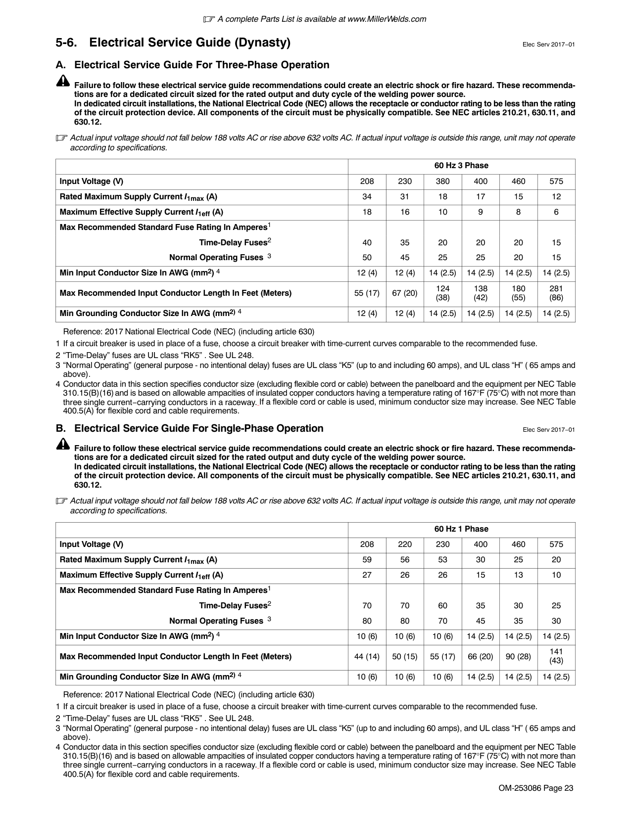
|Rated Maximum Supply Current I1max (A)|34|31|18|17|15|12| |Maximum Effective Supply Current I1eff (A)|18|16|10|9|8|6| |Max Recommended Standard Fuse Rating In Amperes1 Time-Delay Fuses2 Normal Operating Fuses 3|40 50
|35 45|20 25
|20 25
|20 20|15 15
| |Min Input Conductor Size In AWG (mm2) 4|12 (4)|12 (4)|14 (2.5)|14 (2.5)|14 (2.5)|14 (2.5)| |Max Recommended Input Conductor Length In Feet (Meters)|55 (17)|67 (20)|124 (38)|138 (42)|180 (55)|281 (86)| |Min Grounding Conductor Size In AWG (mm2) 4|12 (4)|12 (4)|14 (2.5)|14 (2.5)|14 (2.5)|14 (2.5)|
Reference: 2017 National Electrical Code (NEC) (including article 630)
################ B. Electrical Service Guide For Single-Phase Operation Elec Serv 2017−01
Failure to follow these electrical service guide recommendations could create an electric shock or fire hazard. These recommendations are for a dedicated circuit sized for the rated output and duty cycle of the welding power source.
In dedicated circuit installations, the National Electrical Code (NEC) allows the receptacle or conductor rating to be less than the rating of the circuit protection device. All components of the circuit must be physically compatible. See NEC articles 210.21, 630.11, and 630.12.
Actual input voltage should not fall below 188 volts AC or rise above 632 volts AC. If actual input voltage is outside this range, unit may not operate according to specifications.
| |60 Hz 1 Phase|60 Hz 1 Phase|60 Hz 1 Phase|60 Hz 1 Phase|60 Hz 1 Phase|60 Hz 1 Phase| |---|---|---|---|---|---|---| |Input Voltage (V)|208|220|230|400|460|575| |Rated Maximum Supply Current I1max (A)|59|56|53|30|25|20| |Maximum Effective Supply Current I1eff (A)|27|26|26|15|13|10| |Max Recommended Standard Fuse Rating In Amperes1 Time-Delay Fuses2 Normal Operating Fuses 3|70 80
|70 80
|60 70|35 45
|30 35
|25 30
| |Min Input Conductor Size In AWG (mm2) 4|10 (6)|10 (6)|10 (6)|14 (2.5)|14 (2.5)|14 (2.5)| |Max Recommended Input Conductor Length In Feet (Meters)|44 (14)|50 (15)|55 (17)|66 (20)|90 (28)|141 (43)| |Min Grounding Conductor Size In AWG (mm2) 4|10 (6)|10 (6)|10 (6)|14 (2.5)|14 (2.5)|14 (2.5)|
############# 5-7. Electrical Service Guide (Maxstar) Elec Serv 2017−01A. Electrical Service Guide For Three-Phase Operation
Failure to follow these electrical service guide recommendations could create an electric shock or fire hazard. These recommendations are for a dedicated circuit sized for the rated output and duty cycle of the welding power source.
In dedicated circuit installations, the National Electrical Code (NEC) allows the receptacle or conductor rating to be less than the rating of the circuit protection device. All components of the circuit must be physically compatible. See NEC articles 210.21, 630.11, and 630.12.
Actual input voltage should not fall below 188 volts AC or rise above 632 volts AC. If actual input voltage is outside this range, unit may not operate according to specifications.
| |60 Hz 3 Phase|60 Hz 3 Phase|60 Hz 3 Phase|60 Hz 3 Phase|60 Hz 3 Phase|60 Hz 3 Phase| |---|---|---|---|---|---|---| |Input Voltage (V)|208|230|380|400|460|575| |Rated Maximum Supply Current I1max (A)|31|28|17|16|14|11| |Maximum Effective Supply Current I1eff (A)|16|14|9|8|7|6| |Max Recommended Standard Fuse Rating In Amperes1 Time-Delay Fuses2 Normal Operating Fuses 3|35 45
|35 40|20 25
|20 20
|15 20|15 15
| |Min Input Conductor Size In AWG (mm2) 4|12 (4)|14 (2.5)|14 (2.5)|14 (2.5)|14 (2.5)|14 (2.5)|
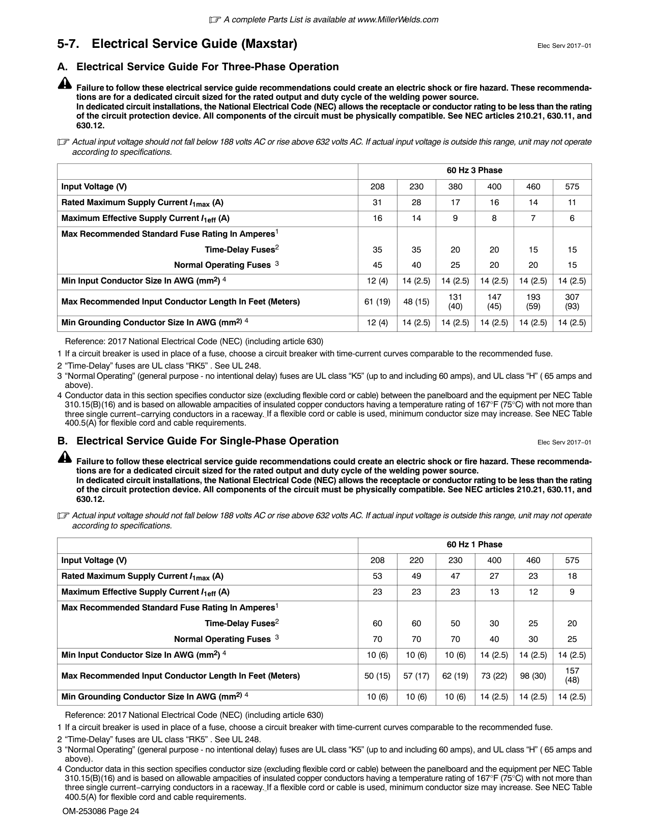
|Max Recommended Input Conductor Length In Feet (Meters)|61 (19)|48 (15)|131 (40)|147 (45)|193 (59)|307 (93)| |Min Grounding Conductor Size In AWG (mm2) 4|12 (4)|14 (2.5)|14 (2.5)|14 (2.5)|14 (2.5)|14 (2.5)|
Reference: 2017 National Electrical Code (NEC) (including article 630) 1 If a circuit breaker is used in place of a fuse, choose a circuit breaker with time-current curves comparable to the recommended fuse. 2 “Time-Delay” fuses are UL class “RK5” . See UL 248. 3 “Normal Operating” (general purpose - no intentional delay) fuses are UL class “K5” (up to and including 60 amps), and UL class “H” ( 65 amps and
above).
4 Conductor data in this section specifies conductor size (excluding flexible cord or cable) between the panelboard and the equipment per NEC Table 310.15(B)(16) and is based on allowable ampacities of insulated copper conductors having a temperature rating of 167°F (75°C) with not more than three single current−carrying conductors in a raceway. If a flexible cord or cable is used, minimum conductor size may increase. See NEC Table 400.5(A) for flexible cord and cable requirements.
################ B. Electrical Service Guide For Single-Phase Operation Elec Serv 2017−01
Failure to follow these electrical service guide recommendations could create an electric shock or fire hazard. These recommendations are for a dedicated circuit sized for the rated output and duty cycle of the welding power source.
In dedicated circuit installations, the National Electrical Code (NEC) allows the receptacle or conductor rating to be less than the rating of the circuit protection device. All components of the circuit must be physically compatible. See NEC articles 210.21, 630.11, and 630.12.
Actual input voltage should not fall below 188 volts AC or rise above 632 volts AC. If actual input voltage is outside this range, unit may not operate according to specifications.
| |60 Hz 1 Phase|60 Hz 1 Phase|60 Hz 1 Phase|60 Hz 1 Phase|60 Hz 1 Phase|60 Hz 1 Phase| |---|---|---|---|---|---|---| |Input Voltage (V)|208|220|230|400|460|575| |Rated Maximum Supply Current I1max (A)|53|49|47|27|23|18| |Maximum Effective Supply Current I1eff (A)|23|23|23|13|12|9| |Max Recommended Standard Fuse Rating In Amperes1 Time-Delay Fuses2 Normal Operating Fuses 3|60 70
|60 70
|50 70|30 40
|25 30
|20 25
| |Min Input Conductor Size In AWG (mm2) 4|10 (6)|10 (6)|10 (6)|14 (2.5)|14 (2.5)|14 (2.5)| |Max Recommended Input Conductor Length In Feet (Meters)|50 (15)|57 (17)|62 (19)|73 (22)|98 (30)|157 (48)| |Min Grounding Conductor Size In AWG (mm2) 4|10 (6)|10 (6)|10 (6)|14 (2.5)|14 (2.5)|14 (2.5)|
############# 5-8. Connecting Three-Phase Input Power
| | | |3| |---|---|---|---| |= GND/PE Earth Ground
|L1 L2 L3| | |---|---| |L1 L2 L3| |
2
1
3
4
5
6
7
Tools Needed:
input2 2012−05 − 803766-C / Ref. 805496-A|= GND/PE Earth Ground
|L1 L2 L3| | |---|---| |L1 L2 L3| |
2
1
3
4
5
6
7
Tools Needed:
input2 2012−05 − 803766-C / Ref. 805496-A|= GND/PE Earth Ground
|L1 L2 L3| | |---|---| |L1 L2 L3| |
2
1
3
4
5
6
7
Tools Needed:
input2 2012−05 − 803766-C / Ref. 805496-A|= GND/PE Earth Ground
|L1 L2 L3| | |---|---| |L1 L2 L3| |
2
1
3
4
5
6
7
Tools Needed:
input2 2012−05 − 803766-C / Ref. 805496-A|
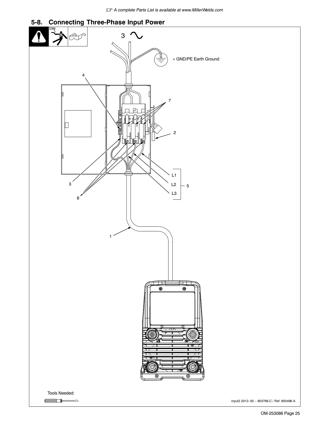
| | | | | |---|---|---|---| |input2 2012−05
! Installation must meet all National and Local Codes − have only qualified persons make this installation.
! Disconnect and lockout/tagout input power before connecting input conductors from unit. Follow established procedures regarding the installation and removal of lockout/tagout devices.
! Always connect green or green/yellow conductor to supply grounding terminal first, and never to a line terminal.
NOTICE − The Auto-Line circuitry in this unit automatically adapts the power source to the
primary voltage being applied. Check input voltage available at site. This unit can be connected to any input power between 208−575 VAC without removing cover to relink the power source.
See rating label on unit and check input voltage available at site.
For Three-Phase Operation
1 Input Power Cord.
2 Disconnect Device (switch shown in the OFF position)
3 Green Or Green/Yellow Grounding Conductor
4 Disconnect Device Grounding Terminal
5 Input Conductors (L1, L2 And L3)
6 Disconnect Device Line Terminals
Connect green or green/yellow grounding conductor to disconnect device grounding terminal first.
Connect input conductors L1, L2, and L3 to disconnect device line terminals.
7 Overcurrent Protection
Select type and size of overcurrent protection using Section 5-6 (fused disconnect switch shown).
Close and secure door on disconnect device. Follow established lockout/tagout procedures to put unit in service.|input2 2012−05
! Installation must meet all National and Local Codes − have only qualified persons make this installation.
! Disconnect and lockout/tagout input power before connecting input conductors from unit. Follow established procedures regarding the installation and removal of lockout/tagout devices.
! Always connect green or green/yellow conductor to supply grounding terminal first, and never to a line terminal.
NOTICE − The Auto-Line circuitry in this unit automatically adapts the power source to the
primary voltage being applied. Check input voltage available at site. This unit can be connected to any input power between 208−575 VAC without removing cover to relink the power source.
See rating label on unit and check input voltage available at site.
For Three-Phase Operation
1 Input Power Cord.
2 Disconnect Device (switch shown in the OFF position)
3 Green Or Green/Yellow Grounding Conductor
4 Disconnect Device Grounding Terminal
5 Input Conductors (L1, L2 And L3)
6 Disconnect Device Line Terminals
Connect green or green/yellow grounding conductor to disconnect device grounding terminal first.
Connect input conductors L1, L2, and L3 to disconnect device line terminals.
7 Overcurrent Protection
Select type and size of overcurrent protection using Section 5-6 (fused disconnect switch shown).
Close and secure door on disconnect device. Follow established lockout/tagout procedures to put unit in service.|
##### Notes
######### Work like a Pro!
Pros weld and cut
safely. Read the safety rules at the beginning of this manual.
############# 5-9. Connecting Single-Phase Input Power
1
|8|8| | |---|---|---| | | | | | | | | | | | | | | | | |3|3| |
=GND/PE Earth Ground
7
| | | |---|---| | | |
L1 L2
1
1
6
2

3
6
4
5
Tools Needed:
input1 2012−05 − 803766-C / Ref. 805496-A
| | | | | |---|---|---|---| |Input1 2012−05
! Installation must meet all National and Local Codes − have only qualified persons make this installation.
! Disconnect and lockout/tagout input power before connecting input conductors from unit. Follow established procedures regarding the installation and removal of lockout/tagout devices.
! Always connect green or green/yellow conductor to supply grounding terminal first, and never to a line terminal.
NOTICE − The Auto-Line circuitry in this unit automatically adapts the power source to the primary voltage being applied. Check input voltage available at site. This unit can be con-
nected to any input power between 208−575 VAC without removing cover to relink the power source.
See rating label on unit and check input voltage available at site.
1 Black And White Input Conductor (L1 And L2)
2 Red Input Conductor
3 Green Or Green/Yellow Grounding Conductor
4 Insulation Sleeving
5 Electrical Tape Insulate and isolate red conductor as shown.
6 Input Power Cord.
7 Disconnect Device (switch shown in the OFF position)
8 Disconnect Device Grounding Terminal
9 Disconnect Device Line Terminals
Connect green or green/yellow grounding conductor to disconnect device grounding terminal first.
Connect input conductors L1 and L2 to disconnect device line terminals.
10 Overcurrent Protection
Select type and size of overcurrent protection using Section 5-6 (fused disconnect switch shown).
Close and secure door on disconnect device. Follow established lockout/tagout procedures to put unit in service.|Input1 2012−05
! Installation must meet all National and Local Codes − have only qualified persons make this installation.
! Disconnect and lockout/tagout input power before connecting input conductors from unit. Follow established procedures regarding the installation and removal of lockout/tagout devices.
! Always connect green or green/yellow conductor to supply grounding terminal first, and never to a line terminal.
NOTICE − The Auto-Line circuitry in this unit automatically adapts the power source to the primary voltage being applied. Check input voltage available at site. This unit can be con-
nected to any input power between 208−575 VAC without removing cover to relink the power source.
See rating label on unit and check input voltage available at site.
1 Black And White Input Conductor (L1 And L2)
2 Red Input Conductor
3 Green Or Green/Yellow Grounding Conductor
4 Insulation Sleeving
5 Electrical Tape Insulate and isolate red conductor as shown.
6 Input Power Cord.
7 Disconnect Device (switch shown in the OFF position)
8 Disconnect Device Grounding Terminal
9 Disconnect Device Line Terminals
Connect green or green/yellow grounding conductor to disconnect device grounding terminal first.
Connect input conductors L1 and L2 to disconnect device line terminals.
10 Overcurrent Protection
Select type and size of overcurrent protection using Section 5-6 (fused disconnect switch shown).
Close and secure door on disconnect device. Follow established lockout/tagout procedures to put unit in service.|
##### Notes
######### Work like a Pro!
Pros weld and cut
safely. Read the safety rules at the beginning of this manual.
############# 5-10. Remote 14 Receptacle Information
|805497-A
AJ
B
K I
C L NH
D M G E F
| | | | |---|---|---|---| |805497-A
AJ
B
K I
C L NH
D M G E F
|15 VOLTS DC
OUTPUT CONTACTOR|A|Contactor control +15 volts DC, referenced to G.| |805497-A
AJ
B
K I
C L NH
D M G E F
|15 VOLTS DC
OUTPUT CONTACTOR|B|Contact closure to A completes 15 volts DC contactor control circuit and enables output.| |805497-A
AJ
B
K I
C L NH
D M G E F
|REMOTE OUTPUT CONTROL|C|Output to remote control; +10 volts DC output to remote control.| |805497-A
AJ
B
K I
C L NH
D M G E F
|REMOTE OUTPUT CONTROL|D|Remote control circuit common.| |805497-A
AJ
B
K I
C L NH
D M G E F
|REMOTE OUTPUT CONTROL|E|0 to +10 volts DC input command signal from remote control.
*Reconfigurable as input for Output Enable (Weld Stop) − used to remotely stop the weld outside the normal welding cycle. Connection to the D socket must be maintained at all times. If the connection is broken, output stops, and Auto Stop is displayed.| |805497-A
AJ
B
K I
C L NH
D M G E F
|Output Signals|F|Current feedback; +1 volt DC per 100 amperes.| |805497-A
AJ
B
K I
C L NH
D M G E F
|Output Signals|H|Voltage feedback; +1 volt DC per 10 volts output.| |805497-A
AJ
B
K I
C L NH
D M G E F
|Output Signals|I*|Valid arc indication closed to socket G with valid arc. Electrical specifications: open collector transistor (see Section 5-11 for connection example).| |805497-A
AJ
B
K I
C L NH
D M G E F
|Output Signals|J*|Arc length control lockout closed to socket G during Initial and Final Amperage and Slope, and during the background time of a <=10 Hz pulse waveform. Electrical specifications: open collector transistor (see Section 5-11 for connection example).| |805497-A
AJ
B
K I
C L NH
D M G E F
|COMMON|G|Return for all output signals: F, H, I, J and A.| |805497-A
AJ
B
K I
C L NH
D M G E F
|CHASSIS|K|Chassis| |805497-A
AJ
B
K I
C L NH
D M G E F
|Serial Communication Bus
|L**|Modbus Common (RS485 Common)| |805497-A
AJ
B
K I
C L NH
D M G E F
|Serial Communication Bus
|M**|Modbus D1 (RS485 B+)| |805497-A
AJ
B
K I
C L NH
D M G E F
|Serial Communication Bus
|N**|Modbus D0 (RS485 A-)| |If a remote hand control, like the RHC-14, is connected to the Remote 14 receptacle, some current value above min. must be set on the remote control before the Panel or Remote contactor is turned on. Failure to do so will cause current to be controlled by the panel control, and the remote hand control will not function.
*Available with optional Automation Expansion memory card..
Available with optional Modbus Expansion memory card. Modbus serial communication provides access to all front panel parameters and machine functionality. See Owner’s Manual 265415 for a list of Modbus registers. Modbus expansion also includes functionality of Automation, AC Independent Amplitude (Dynasty only), Hot Wire and Hot Start Adjust Expansions.
Sockets G and K are electrically isloated from each other.|If a remote hand control, like the RHC-14, is connected to the Remote 14 receptacle, some current value above min. must be set on the remote control before the Panel or Remote contactor is turned on. Failure to do so will cause current to be controlled by the panel control, and the remote hand control will not function.
*Available with optional Automation Expansion memory card..
Available with optional Modbus Expansion memory card. Modbus serial communication provides access to all front panel parameters and machine functionality. See Owner’s Manual 265415 for a list of Modbus registers. Modbus expansion also includes functionality of Automation, AC Independent Amplitude (Dynasty only), Hot Wire and Hot Start Adjust Expansions.
Sockets G and K are electrically isloated from each other.|
Socket Socket Information

############# 5-11. Simple Automation Application
Pin I, J: Collector
Pin G: Emitter
Coil resistance plus R should be chosen to limit current to 75 mA
CR1
+
R
−
User supplied power up to 27 volts DC peak
CR1 To User Equipment
############# 5-12. Software Updates
|A computer with an SD memory card port, or SD memory card reader is required to download software updates.
The SD logo is a registered trademark of SD-3C LLC.

| |---|
|
2
1. On your web browser, go to http://www.millerwelds.com/support/system-setup-and-software/tig-software.
2. Select System Installation Instructions (PDF) and follow the instructions. 1
| |---|
|805496-A
Software updates may reset machine back to default values.
Card Requirements: Full size memory card required.
1 Memory Card Port
2 Indicator LED
Insert card containing new software into port while machine is on, (but not while welding). Inserting card while welding will interrupt the welding process.
LED indicator blinks green when machine is reading from or writing to the card, and the meter displays go blank. The update time may vary
up to three minutes. Do Not remove card while LED is blinking green.
After successfully reading from or writing to the card, the LED switches from blinking to continuous green, and the meter illuminates. The machine is now ready for use.
Troubleshooting:
Indicator LED is blinking red: Error updating software, or software is not compatible. Try removing and inserting card.
Indicator LED is continuous red: Cannot read card. Card might be bad.
1
2
Dynasty 280 DX Shown| |---|

##### Notes
####### SECTION 6 − DYNASTY 280 OPERATION
############# 6-1. Dynasty 280 Controls

| | | | |---|---|---| | | | |
543
1
2
6
8
Use to put machine into low power consumption mode.
This button can also be used to clear some errors. See Section 11-3.
Use control to change preset amperage value. If a remote control is used, preset amperage value is the maximum amperage output available. This control also functions as a parameter change control while in the menu mode (see Sections 6-2 thru 6-6).
This port is used to add features to the machine and update software to the boards within the machine. Indicator is lit while card
is being accessed (see Section 5-12D).
Displays actual rectified average voltage when voltage is present at the weld output terminals. It is also used to display parameter descriptions while in the menu.
Displays actual rectified average amperage while welding and preset amperage while idle. It is also used to display parameter selection options while in the menu.

Press button to scroll through available parameters for the selected process. Hold button to enter set-up mode (see Sections 6-2 thru 6-6).
247222-D
Blue indicator illuminates when output is on.
Use to select one of the following processes:
|The memory card port uses an SD memory card. The SD logo is a registered trademark of SD-3C LLC.| |---|
############# 6-2. Accessing Control Panel Menu: AC TIG

| | | | |---|---|---| | | | |
2 3 4
1
150A
AC AV
Press Menu button to cycle through parameters that can be set.
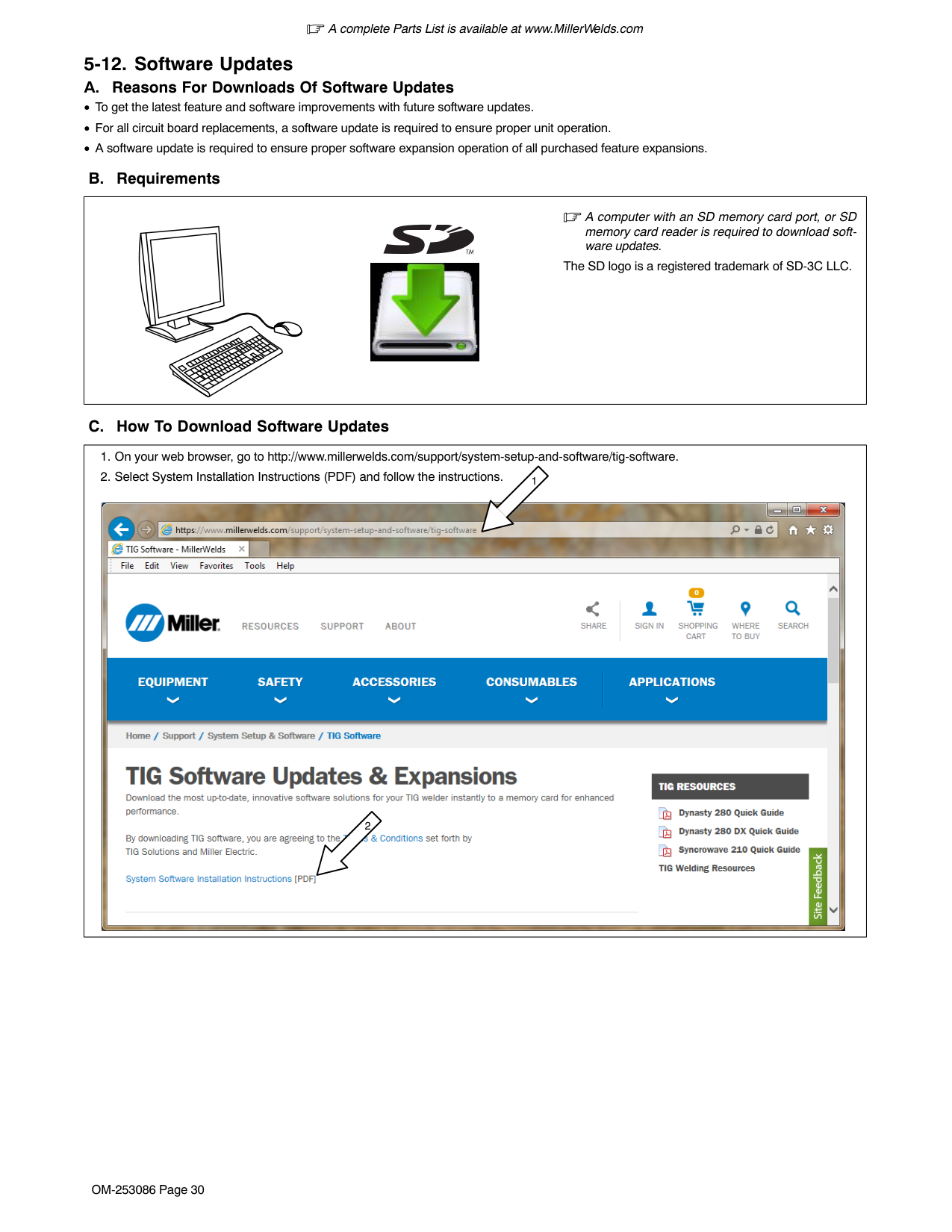
Rotate Encoder to adjust parameter setting.
Parameter automatically returns to amperage setting 15 seconds after Encoder is inactive.
####################### Amperage Control:
Controls the average AC welding amperage output. Limits the maximum output of a remote amperage device.
In AC, the user will be setting the rectified average value of the AC current, ([AC AV] will be displayed).
75%BAL
FREQ POST
120H
AUTO
[BAL] Balance Control:* (% EN) Controls Oxide Cleaning Increasing setting reduces oxide cleaning. Range is 60 to 80%. (See tips below). [FREQ]* Frequency Control:
Increasing setting narrows arc width. Range is 70 to 150 Hertz. (See tips below).
####################### [POST] Post Flow Control:
Controls the length of time gas flows after welding stops. Range is AUTO, OFF − 50T (seconds). AUTO calculates the time based on the maximum amperage of each welding cycle. The minimum time is 8 seconds. Auto = maximum amperage/10.
*PRO−SET provides PROfessionally developed SETtings for the weld process. To use PRO−SET, press the menu button to display the parameter and adjust the encoder until PRO−SET flashes on the display. PRO−SET flashes one time and reveals the professional setting for the parameter.
TIP: AC Balance controls the cleaning action. If floating black spots appear in the puddle, the balance setting is too high. Turn the balance down until puddle becomes clear.
| | |---| | |
| | |---| | |
TIP: AC Frequency controls the width of the arc cone. For thin fillet welds (less than 1/4 in.) set the frequency to 120 Hz. This frequency setting provides a focused stable arc and produces a narrow weld. For outside corner or groove welds on heavy material, a wide weld may be required. Lower the frequency to between 70 and100 Hz. This frequency setting produces a wider weld.
| | | | |---|---|---| | | | |
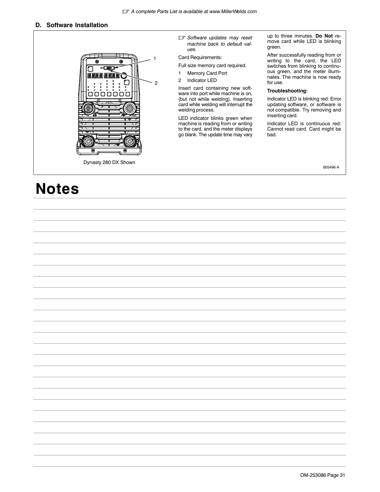
| | | | |---|---|---| | | | |
############# 6-3. Accessing Control Panel Menu: DC TIG
Press Menu button to cycle through parameters that can be set.

| | | | |---|---|---| | | | |
2 3 4
1
Parameter automatically returns to amperage setting 15 seconds after Encoder is inactive.
150A
Amperage Control:
Controls the welding amperage output. Limits the maximum output of a remote amperage device.
[PPS]* Pulse Control:
Reduces heat input to minimize distortion and increase travel speed. Set PPS (pulses per second). The range is OFF−250 PPS. The Background Amperage and Peak Amperage are not adjustable. Background Amperage equals 25% of Peak amperage. Peak amperage Time equals 40%.
[POST] Post Flow Control:
Controls the length of time gas flows after welding stops. Range is AUTO, OFF−50T (seconds). AUTO calculates the time based on the maximum amperage of each weld cycle. The minimum time is eight seconds. Auto = maximum amperage/10.
OFFPPS POST
*PRO−SET: provides PROfessionally developed SETtings for the welding process. To use PRO−SET, press the menu button to display the parameter and adjust the encoder until PRO−SET flashes on the display. PRO−SET flashes one time and reveals the professional setting for the parameter.
AUTO
247222-D

############# 6-4. Accessing Control Panel Menu: AC And DC Stick
Press Menu button to cycle through parameters that can be set.

| | | | |---|---|---| | | | |
2 3 4
1
Parameter automatically returns to amperage setting 15 seconds after Encoder is inactive.
110A
####################### Amperage Control:
Controls the welding amperage output. Limits the maximum output of a remote amperage device.
In AC, the user will be setting the rectified average value of the AC current. [AC AV]will be displayed.
####################### [DIG]* Arc Force Control:
Controls the amount of additional amperage at low voltage (short arc length) conditions. Adjust the force of the arc for different joint configurations and electrodes. Range is OFF−100%. Features PRO−SET values for 6010 and 7018 electrodes.
| | | | | | |---|---|---|---|---| | | | | | |
Or
110A

30%DIG
############# 6-5. Accessing User Setup Menu: AC And DC TIG

| | | | |---|---|---| | | | |
2 3 4
1
USER
MENU
Or
| | | | | | |---|---|---|---|---| | | | | | |
Press and hold Menu button for approximately two seconds to access machine configuration menus. Use Menu button to cycle through parameters that can be set.
Rotate Encoder to adjust parameter setting.
To exit menu, press and hold Menu button until Menu Off is displayed.
STRT
HF
3/32TUNG RMT
STD
247222-D
Arc Starting Method Selection: [STRT] [HF] Is a non-contact starting method (see Section16-1). [STRT] [LIFT] Is a contact starting method (see Section16-1).

####################### Tungsten Diameter Selection:
Each tungsten size has preset starting parameters specific to that diameter for optimized starting. Range is 0.020 in.−1/8 in. or 0.5 mm−3.2 mm.
Trigger Mode Selection: [RMT] [STD]
Typically used with a remote foot or hand control. RMT STD requires a maintained contact closure to enable weld output. Amperage can be controlled with a remote potentiometer, or it can be set at the control panel.
[RMT] [HOLD]
Remote control required. Allows the operator to weld without holding the trigger closed. To start the weld, operator presses and releases trigger. To stop the weld, the operator again presses and releases the trigger. In this mode, only the output contactor is controlled by the remote control. Amperage must be set on the control panel.
[OUT] [ON] Output on. (Lift Only) ! Weld output terminals are energized at all
times when displays read [OUT] [ON].
No remote control or trigger required. Amperage can be controlled at the control panel or with a remote potentiometer. Blue output on LED illuminates to indicate output is on.
############# 6-6. Accessing User Setup Menu: AC And DC Stick

| | | | |---|---|---| | | | |
1
23 4
USER
MENU
1 Menu Button Press and hold Menu button for approximately 2 seconds to access machine configuration menus. Use Menu button to cycle through parameters that can be set. 2 Parameter Display 3 Setting Display 4 Encoder Rotate Encoder to adjust parameter setting.
To exit menu, press and hold Menu button until Menu Off is displayed.
| | | | | | |---|---|---|---|---| | | | | | |
Or
HOTS
ON

Arc Starting Method Selection: [HOTS] [ON] Provides additional amperage while striking the electrode to prevent the electrode from sticking.
ONOUT
[HOTS OFF] No additional starting amperage to assist in starting the electrode. Trigger Mode Selection: [RMT] [STD]
Typically used with a remote foot or hand control. RMT STD requires a maintained contact closure to enable weld output. Amperage can be controlled with a remote potentiometer, or it can be set at the control panel.
[OUT] [ON] ! Weld output terminals are energized at all
times when displays read [OUT] [ON].
No remote control or trigger required. Amperage can be controlled at the control panel or with a remote potentiometer. Blue output on LED illuminates to indicate output is on.
####### SECTION 7 − DYNASTY 280 DX OPERATION
############# 7-1. Dynasty 280 DX Controls

| | | | |---|---|---| | | | |
7
1
54
3
2
6
| | | | | | |---|---|---|---|---| | | | | | |
| | | | | |---|---|---|---| | | | | | | | | | |
| | |

|---|---| | | |
280589-A
For all front panel switch pad controls: press switch pad to turn on light and enable function.
Green on nameplate indicates a TIG function, Gray indicates a Stick function.
This button can also be used to clear some errors. See Section 11-3.
This port is used to add features to the machine and update software to the boards within the machine. Indicator is lit while card is being accessed.
Displays actual rectified average voltage when voltage is present at the weld output terminals. It is also used to display parameter descriptions while in the menu.
Displays actual rectified average amperage while welding and preset amperage while idle. It is also used to display parameter selection options while in the menu.
Use this control in conjunction with the encoder to set the average weld amperage or peak amperage if the Pulser is active.
Optional - Use item 6 and 2 to set constant voltage when the V-Sense Feeder - DC MIG (GMAW) process is selected.
############# 7-2. Accessing Control Panel Menu

| | | | |---|---|---| | | | |
1234

150A
5
| | | | |---|---|---| | | | | | | | |
Rotate Encoder to adjust parameter setting.
Amperage
Controls the welding amperage output. Limits the maximum output of a remote amperage device.
In AC, the user will be setting the rectified average value of the AC current, ( [AC AV] will be displayed).
Optional - Set polarity to DC to be able to select the V-Sense Feeder process. Output (electrode) is set to DCEP constant voltage for DC MIG (GMAW). Output selection is set to ON.
| | | |---|---| | | |
150AAC AV
280589-A
####################### Polarity Selection
Select output type AC or DC. With DC selected, the electrode will be negative (DCEN) for TIG, and positive (DCEP) for Stick.
Process Selection TIG HF Impulse − is a non-contact arc starting method for AC and DC TIG welding (see Section 16-1). TIG Lift-Arc − Is a contact arc starting method for AC and DC TIG welding (see Section 16-1). Stick − Select AC or DC Stick (SMAW) welding. Trigger Mode Selection (See Section 10-4 for additional trigger function options). [RMT] [STD]
Typical setting for a remote foot or hand control. RMT STD requires a maintained contact closure to enable weld output. Amperage can be controlled with a remote potentiometer, or it can be set at the control panel.
[RMT] 2T [HOLD] (TIG Only)
Remote control required. Allows the operator to weld without holding the trigger closed. To start the weld, operator presses and releases trigger. To stop the weld, the operator again presses and releases the trigger. In this mode, only the output contactor is controlled by the remote control. Amperage must be set on the control panel. (see Section 10-4).
[OUT] [ON] Output on. (Stick and TIG Lift Only) ! Weld output terminals are energized at all times when displays read [OUT] [ON].

No remote control or trigger required. Amperage can be controlled at the control panel or with a remote potentiometer. Blue output on LED illuminates to indicate output is on.
*PRO−SET provides PROfessionally developed SETtings for the weld process PRO−SET flashes one time and reveals the professional setting for the parameter.
Pulse Control
Pulsing is available in the TIG process. Controls can be adjusted while welding.
100PPS
Reduces heat input to minimize distortion and increase travel speed. Range is 01. to 500 (pulses per second).
Press switch pad to enable pulser. [PPS]* Pulses Per Second: Range is 0.1− 500. [PK T]* Peak Amperage Time: Range is 5−95% [BK A]* Background Amperage Time: Range is 5− 95% of peak amperage value.
40%PK T
See Section 16-2 for additional Pulser information, or visit: http:/www.millerwelds.com/resources/ welding-resources/
25%BK A
####################### Sequencer Control
The welding output can be programmed to specific amperages and durations for repetitive applications. Sequencer is only available in the TIG process. Sequencer is disabled if a remote control with variable amperage is connected to the machine.
INTL
20A
[INTL] Initial Amperage: Range is min − 280 amps. [ISLP] Initial Slope Time: Range is OFF − 50.0T (seconds). [FSLP] Final Slope Time: Range is OFF − 50.0T (seconds). [FNL] Final Amperage: Range is min − 280 amps. (See Sections 10-2 and 10-3 for setting weld time.)
ISLP
OFF
OFF
FSLP
Gas/DIG Control [PRE] Preflow Time: Controls length of time gas flows prior to arc start. Range is OFF−25T (seconds). [POST] Post Flow Time:
FNL
10A
Increasing setting increases length of time gas flows after welding stops. Range is OFF − 50T (seconds). AUTO calculates the time based on the maximum amperage of each welding cycle. The minimum time is 8 seconds. Auto = maximum amperage/10.
0.2T AUTO
PRE POST

[DIG]* Arc Force Control:
Controls the amount of additional amperage at low voltage (short arc length) conditions. Adjust the force of the arc for different joint configurations and electrodes. Range is OFF − 100%. PRO-Set values available for both 6010 and 7018 electrodes
+
CARBon ARC Gouging can be selected at one step above DIG’s 100%.
30%DIG
[IND]+ Arc Control (Inductance)
Controls the dynamic properties of the arc to control the puddle. The 0% setting gives a minimum inductance, that is a stiff, fast responding arc, and a small, fast freezing puddle. The 99% gives maximum inductance, that is a soft, slow responding, low-spatter arc, and high puddle fluiditiy. The 100% setting gives a universal setting for FLUXCORE wire. Range: Solid wire 0-99% FLUXCORE wire 100% Select a setting best suited for the application.
30%INDOptional
Selectable with Process V-Sense Feeder
AC Waveshape Control [BAL] Balance Control (%EN) TIG Only:
75% 120H
BAL FREQ
Controls oxide cleaning. Increasing the setting reduces cleaning. Range is BALL, 50 − 99%. Stick is fixed at 50%. “BALL” sets the Balance to 30%. This is to allow the operator to form a ball on the tip of the tungsten. It is not for normal welding operation. (See tips in Section 6-2).
| | | |---|---| | | |
[FREQ] AC Frequency (Hz): Controls arc width. Increasing the setting narrows the arc width. Range is 20 to 400 Hz. (See Section 6-2).
############# 7-3. Accessing User Setup Menu

| | | | |---|---|---| | | | |
1345
USER
MENU

To access the User Functions, press and hold the Amperage (A) and the Gas/DIG controls until [USER] [MENU] is displayed. To scroll through the user menu functions, press and release the Gas/ DIG control.
Rotate Encoder to adjust parameter setting.
To exit user menu, press Amperage and Gas/DIG controls at the same time and then release, or turn power off.
Optional - See Section 7-1 and 7-2 for information.
| | | | |---|---|---| | | | | | | | |
2
3/32TUNG RMT
2T
SAMEENEP
WAVEAC ONHOTS
280589-A
####################### Tungsten Diameter Selection
Each tungsten size has preset starting parameters specific to that diameter for optimized starting. Range is 0.020−1/8 in. or 0.5−3.2 mm. To manually set starting parameters, see Section 16-3.
Output Trigger Mode Functions See Section 10-4 to reconfigure RMT functions. Independent Amperage Control (CE Models Only)
[ENEP] [SAME] - standard mode of operation for controlling AC amperage setting.
[ENEP] [INDP] - for AC TIG welding allows the user to set the EP amperage independently from the EN amperage. When [ON], the user can set the EP waveshape (sine, square, triangle) independently from the EN waveshape (see Section 7-4).
####################### AC Waveshape Selection:
Use Encoder to select between advanced squarewave [ADVS], soft squarewave [SOFT], sine wave [SINE], or triangle wave [TRI]. The default is Soft.

Application: Use advance squarewave when a more focused arc is required for better directional control. Use soft squarewave when a softer arc with a more fluid puddle is desired. Use sine wave to simulate a conventional power source. Use triangular waveshape when the effects of peak amperage with reduced overall heat input is required to help control distortion on thin materials.
Arc Starting Mode Selection (Stick) [HOTS] [ON] Provides additional amperage while striking the electrode to prevent the electrode from sticking. [HOTS] [OFF] No additional starting amperage to assist in starting the electrode.
############# 7-4. AC Independent Expansion
AC Independent Expansion is available on

| | | | |---|---|---| | | | |
DX models with SD expansion card and on CE models with feature enable through the user menu (see Section 7-3).
################ A. AC Independent Amperage
|1
2
3
1 AC Waveshape Control Press switch pad until desired function is selected.
2 Encoder Control (Set Value)
3 Ammeter (Displays Value)
4 Voltmeter (Parameter Selection)
EN Amperage [EN] - Use with AC TIG only to select electrode negative amperage value.
EP Amperage [EP] -Use with AC TIG only to select electrode positive amperage value.
Both Balance and AC Frequency LEDs light when either EN or EP Amperage is selected.
5 Amperage Control
Average Amperage Control: Setting EN Amperage, EP Amperage, Balance, and Frequency values creates an average amperage. The operator can change the average amperage value while maintaining the same EN amperage to EP amperage ratio at the existing balance and frequency. To change the average amperage value, press the Amperage switch pad and turn the Encoder control. The changing average value is displayed on the ammeter. Example: If EN Amperage is 150, EP Amperage is 100, Balance is 75%, and Frequency is 120, the average amperage is 138 amps. If you press the Amperage switch pad and turn the Encoder control until 69 amps is displayed, the EN amperage is now 75 and EP amperage is now 50. The balance remains 75%, and the frequency is still 120, and the 1.5 to 1 EN amperage to EP amperage ratio is maintained.
5
4
150 A 150 A
EN EP| |---|
################ B. AC Independent Waveshape
|See Section 7-3 for additional information on Accessing User Setup Menu. The [ACEN], [ACEP] option replaces the [AC] option.
1 Amperage
2 Gas/DIG Control
3 Parameter Display
Press Gas/DIG switch pad until [ACEN] is displayed. Press the A switch pad to toggle between [ACEN] and [ACEP].
4 Setting Display
5 Encoder Control
Use Encoder to select between advanced squarewave [ADVS], soft squarewave [SOFT], sine wave [SINE], or triangle wave [TRI]. The default is [SOFT].
6 Optional
Optional - See Section 7-1 and 7-2 for information.
MENU
2
3 4
USER
SOFT SOFT
ACEN ACEP
15
280589-A
6
| | | | |---|---|---| | | | | | |---|
####### SECTION 8 − MAXSTAR 280 OPERATION
############# 8-1. Maxstar 280 Controls

| | | | |---|---|---| | | | |
1
543
2

6
7
HF START
LIFT ARC
Schedule 1 Schedule 2
8
247218-C
For all front panel switch pad controls: press switch pad to turn on light and enable function.
Green on nameplate indicates a TIG function, Gray indicates a Stick function.
Use to put machine into low power consumption mode.
This button can also be used to clear some errors. See Section 11-3.
Use control to change preset amperage value. If a remote control is used, preset amperage value is the maximum amperage output available. This control also functions as a parameter change control while in the menu mode (see Section 8-2 thru 8-5).
This port is used to add features to the machine and update software to the boards within the machine, Indicator is lit while card is being accessed.
Displays actual voltage when voltage is present at the weld output terminals. It is also used to display parameter descriptions while in the menu.
Displays actual amperage while welding and preset amperage while idle. It is also used to display parameter selection options while in the menu.
Press button to scroll through available parameters for the selected process. Hold button at desired parameter to enter set-up mode (see Section 8-2 thru 8-5).

Use control to select one of the following processes:
DC Stick (2 positions) − Used for welding steels.
Two schedules allow the user to have two sets of parameters active and easily selectable at one time.
############# 8-2. Accessing Control Panel Menu: DC TIG HF And Lift Arc
Press Menu button to cycle through parameters that can be set.

| | | | |---|---|---| | | | |
1
2 3 4
Rotate Encoder to adjust parameter setting.
Parameter automatically re− turns to amperage setting 15 seconds after Encoder is inactive.
150A
####################### Or
LIFT ARC
HF START
Schedule 1 Schedule 2
Amperage Control: Controls the welding amperage output. Limits the
maximum output of a remote amperage device.150A

####################### [PPS]* Pulse Control:
Reduces heat input to minimize distortion and increase travel speed. Set PPS (pulses per second). The range is OFF−250 PPS. The Background Amperage and Peak Amperage are not adjustable. Background Amperage equals 25% of Peak amperage. Peak amperage Time equals 40%.
OFFPPS POST
AUTO
####################### [POST] Post Flow Control:
Controls the length of time gas flows after welding stops. Range is AUTO, OFF−50T (seconds). AUTO calculates the time based on the maximum amperage of each weld cycle. The minimum time is 8 seconds. Auto equals maximum amperage/10.
*PRO−SET provides PROfessionally developed SETtings for the weld process. To use PRO−SET, press the menu button to display the parameter and adjust the encoder until PRO−SET flashes on the display. PRO−SET flashes one time and reveals the professional setting for the parameter.
############# 8-3. Accessing Control Panel Menu: DC Stick
Press Menu button to cycle through parameters that can be set.

| | | | |---|---|---| | | | |
1
2 3 4
Rotate Encoder to adjust parameter setting.
Parameter automatically returns to amperage setting 15 seconds after Encoder is inactive.
110A
LIFT ARC
HF START
| | | | | | |---|---|---|---|---| | | | | | |

Schedule 1 Schedule 2
####################### Or
Amperage Control:
110A
Controls the welding amperage output. Limits the maximum output of a remote amperage device.
####################### [DIG]* Arc Force Control:
Controls the amount of additional amperage at low voltage (short arc length) conditions. Adjust the force of the arc for different joint configurations and electrodes. Range is OFF−100%. Features PRO-Set values for both 6010 and 7018 electrodes.
30%DIG
*PRO−SET provides PROfessionally developed SETtings for the weld process. To use PRO−SET, press the menu button to display the parameter and adjust the encoder until PRO−SET flashes on the display. PRO−SET flashes one time and reveals the professional setting for the parameter.
*CARB-ARC at one step above DIG’s 100% CARBon ARC Gouging can be selected.
############# 8-4. Accessing User Setup Menu: DC TIG HF And Lift-Arc

| | | | |---|---|---| | | | |
2 3 4
1
USER
MENU
####################### Or
Press and hold Menu button for approximately 2 seconds to access machine configuration menus. Use Menu button to cycle through parameters that can be set.
Rotate Encoder to adjust parameter setting.

To exit menu, press and hold Menu button until Menu Off is displayed.
| | | | | | |---|---|---|---|---| | | | | | |
LIFT ARC
HF START
Schedule 1 Schedule 2
####################### Tungsten Diameter Selection:
3/32TUNG
Each tungsten size has preset starting parameters specific to that diameter for optimized starting. Range is 0.020 in.−1/8 in. or 0.5 mm−3.2 mm. To manually set starting parameters, see Section 16-3.
STDRMT
Trigger Mode Selection (See Section for 10-4 for additional trigger function options). [RMT] [STD]
Typical setting for a remote foot or hand control. RMT STD requires a maintained contact closure to enable weld output. Amperage can be controlled with a remote potentiometer, or it can be set at the control panel.
[RMT] [HOLD]
Remote control required. Allows the operator to weld without holding the trigger closed. To start the weld, operator presses and releases trigger. To stop the weld, the operator again presses and releases the trigger. In this mode, only the output contactor is controlled by the remote control. Amperage must be set on the control panel. (see Section 10-4).
[OUT] [ON] Output on. (Lift only) ! Weld output terminals are energized at all
times when displays read [OUT] [ON].
No remote control or trigger required. Amperage can be controlled at the control panel or with a remote potentiometer. Blue output on LED illuminates to indicate output is on. Not valid with HF start.
############# 8-5. Accessing User Setup Menu: DC Stick
1 Menu Button Press and hold Menu button for approximately 2 seconds to access machine configuration menus. Use Menu button to cycle through parameters that can be set. 2 Parameter Display 3 Setting Display 4 Encoder Rotate Encoder to adjust parameter setting.

| | | | |---|---|---| | | | |
2 3 4
1

To exit menu, press and hold Menu button until Menu Off is displayed.
MENUUSER
LIFT ARC
HF START
| | | | | | |---|---|---|---|---| | | | | | |
Schedule 1 Schedule 2
####################### Or
ONHOTS
Arc Starting Mode Selection:
[HOTS] [ON] Provides additional amperage while striking the electrode to prevent the electrode from sticking. [HOTS] [OFF] No additional starting amperage to assist in starting the electrode.
ONOUT
Trigger Mode Selection: [RMT] [STD]
Typical setting for a remote foot or hand control. RMT STD requires a maintained contact closure to enable weld output. Amperage can be controlled with a remote potentiometer, or it can be set at the control panel.
[OUT] [ON] ! Weld output terminals are energized at all
times when displays read [OUT] [ON].
No remote control or trigger required. Amperage can be controlled at the control panel or with a remote potentiometer. Blue output on LED illuminates to indicate output is on.
####### SECTION 9 − MAXSTAR 280 DX OPERATION
############# 9-1. Maxstar 280 DX Controls

| | | | |---|---|---| | | | |
3
54

1
2
6
| | | | | | |---|---|---|---|---| | | | | | |
| | | | | |---|---|---|---| | | | | | | | | | |
247216-D
For all front panel switch pad controls: press switch pad to turn on light and enable function.
Green on nameplate indicates a TIG function, Gray indicates a Stick function.
1 Standby Button Use to put machine into low power consumption mode.
This button can also be used to clear some errors. See Section 11-3.
Use encoder control in conjunction with applicable front panel function switch pads to change values for that function.
Displays actual amperage while welding and preset amperage while idle. It is also used to display parameter selection options while in the menu.
Use this control in conjunction with the encoder to set the weld amperage or peak amperage if the Pulser is active.
############# 9-2. Accessing Control Panel Menu

| | | |

|---|---|---| | | | |
1 2 3 4
150A
Rotate Encoder to adjust parameter setting.
The Amperage Control controls the welding amperage output, and limits the maximum output of a remote amperage device.
| | | | | |---|---|---|---| | | | | | | | | | |
247216-D
150A
Process Selection: TIG HF Impulse − is a non-contact arc starting method for TIG welding (see Section 16-1). TIG Lift-Arc − Is a contact arc starting method for TIG welding (see Section 16-1). Stick − Select for DC Stick (SMAW) welding. Electrode polarity is determined by the welding cable connections. Trigger Mode Selection: (See Section for 10-4 for additional trigger function options). [RMT] [STD]
Typical setting for a remote foot or hand control. RMT STD requires a maintained contact closure to enable weld output. Amperage can be controlled with a remote potentiometer, or it can be set at the control panel.
[RMT] 2T [HOLD] (TIG Only)
Remote control required. Allows the operator to weld without holding the trigger closed. To start the weld, operator presses and releases trigger. To stop the weld, the operator again presses and releases the trigger. In this mode, only the output contactor is controlled by the remote control. Amperage must be set on the control panel. (see Section 10-4).
[OUT] [ON] Output on. (Stick and TIG Lift only)
! Weld output terminals are energized at all times when displays read [OUT] [ON]. No remote control or trigger required. Amperage can be controlled at the control panel or with a remote potentiometer. Blue output on LED illuminates to indicate output is on.
*PRO−SET provides PROfessionally developed SETtings for the weld process. PRO−SET flashes one time and reveals the professional setting for the parameter.
100PPS
40%PK T
25%BK A
INTL

20A
ISLP
OFF
FSLP
OFF
FNL
10A
0.2T AUTO
PRE POST
30%DIG
Pulse Control
Pulsing is available while in the TIG process. Controls can be adjusted while welding.
Reduces heat input to minimize distortion and increase travel speed. Range is 01. to 500 (pulses per second).
Press switch pad to enable pulser. [PPS]* Pulses Per Second: Range is 0.1 to 500. [PK T]* Peak Amperage Time: Range is 5 to 95%. [BK A]* Background Amperage Time: Range is 5 to 95% of peak amperage value.
See Section 16-2 for additional Pulser information, or visit http://www.millerwelds.com/resources/ welding-resources/
####################### Sequencer Control
The welding output can be programmed to specific amperages and durations for repetitive applications. Sequencer is only available in the TIG process. Sequencer is disabled if a remote control with variable amperage is connected to the machine.
[INTL] Initial Amperage: Range is min to 280 amps.
[ISLP] Initial Slope Time: Range is OFF to 25T (seconds).
[FSLP] Final Slope Time: Range is OFF to 25T (seconds).
[FNL] Final Amperage: Range is min to 280 amps.
(See Sections 10-2 and 10-3 for setting weld time.)
Gas/DIG Control [PRE] Preflow Time: Controls length of time gas flows prior to arc start. Range is OFF to 50T (seconds). [POST] Post Flow Time:
Increasing setting increases length of time gas flows after welding stops. Range is OFF to 50T (seconds). AUTO calculates the time based on the maximum amperage of each welding cycle. The minimum time is eight seconds. Auto equals maximum amperage divided by 10.
[DIG]* Arc Force Control:

Controls the amount of additional amperage at low voltage (short arc length) conditions. Adjust the force of the arc for different joint configurations and electrodes. Range is OFF to 100%. PRO-Set values available for both 6010 and 7018 electrodes.
CARBon ARC Gouging can be selected at one step above DIG’s 100%.
############# 9-3. Accessing User Setup Menu

| | | | |---|---|---| | | | |
To access the User functions, press and hold the Amperage (A) and the Gas/DIG controls until USER MENU is displayed. To scroll through the user menu functions, press and release the Gas/DIG control.
1
3 4
5
Rotate Encoder to adjust parameter setting.
Parameter automatically returns to amperage setting 15 seconds after Encoder is inactive.
USER
MENU
To exit user menu, press and release Amperage and Gas/DIG controls at the same time, or turn power off.
| | | | | |---|---|---|---| | | | | |
| | | | | |---|---|---|---| | | | | | | | | | |
2

| | | | |---|---|---| | | | |
247216-D
3/32TUNG RMT ONHOTS
####################### Tungsten Diameter Selection:
Each tungsten size has preset starting parameters specific to that diameter for optimized starting. Range is 0.020−1/8 in. or 0.5−3.2 mm. To manually set starting parameters, see Section 16-3.
2T
Output Trigger Mode Functions: See Section 10-4 to reconfigure RMT functions. Arc Starting Mode Selection: [HOTS] [ON] Provides additional amperage while striking the electrode to prevent the electrode from sticking. [HOTS] [OFF] No additional starting amperage to assist in starting the electrode.
####### SECTION 10 − ADVANCED MENU FUNCTIONS
############# 10-1. Accessing Tech Menu For Dynasty/Maxstar 280 Models

| | | | |---|---|---| | | | |
2 3 4
1
TECH
MENU
Press and hold Menu button for approximately four seconds to scroll past User Menu to Tech Menu. Use Menu button to cycle through parameters that can be set.
Rotate Encoder to adjust parameter setting.
Dynasty 280 shown, Maxstar menus are the same. Menu order may vary.

To exit Tech Menu, press and hold menu button approximately one second, or turn power off.
Settings in the Tech Menu are global, meaning they may pertain to all or some of the process.
247222-D
T/CYARC
[ARC] [T/CY] Arc Timer: Monitors hours, minutes, and cycles of valid arc on. To view, rotate encoder. To reset, rotate encoder until [RESET] [YES] is displayed. Press Menu button to display [RESET] [Done]. Displays turn to [000] [000].
LOGERR [ERR] [LOG] Error Log:Use to view last eight logged error events.
Each event may list multiple Error Codes. See Section 11-3.
OFFSLEP
[SLEP] Sleep Timer: Turns power off after the machine exceeds the programmed idle time without operation. Press the Standby button to turn power on. To set or change time, rotate encoder to desired time. Timer range: 1, 5, 10, 20, 30, 45 minutes or one hour.
OFFSTUC
[STUC] Stick Stuck: Detects if the electrode is stuck or shorted to the workpiece. Turns weld output off to aid in freeing the electrode. To turn on, rotate encoder. Not recommended for air carbon arc or large diameter electrodes.
NORMOCV
[OCV] Open Circuit Voltage: Allows user to select between Normal (NORM) and Low open circuit voltage. Low reduces open circuit voltage to between 8 and 15 volts. To select, turn encoder.
AUTOCOOL [COOL] Cooler Power(Optional):Selectsbetween [OFF], [ON]
(Non CE models Only), and [AUTO]. [OFF] disables the power supply to the receptacle. [ON] enables the power supply to the receptacle. [AUTO] provides power to the receptacle when the TIG process is active.
RSETMACH WARESOFT
[MACH] [RESET] Machine Reset: Resets all machine values back to factory defaults. To reset, turn encoder to [RESET] [YES]. Then press Menu button. [RESET] [DONE] will be displayed when the reset is complete and factory defaults have been restored.
[SOFT] [WARE] Software Number: Software number and revision will be displayed.
NUMSERL [SERL] [NUM] Serial Number:If serial number displayed does
not match serial number of machine, see Section 11-3.

Press and hold Amperage and Gas/Dig buttons for approximately two seconds to scroll past User Menu to Tech Menu. Use Gas/Dig button to cycle through parameters that can be set.
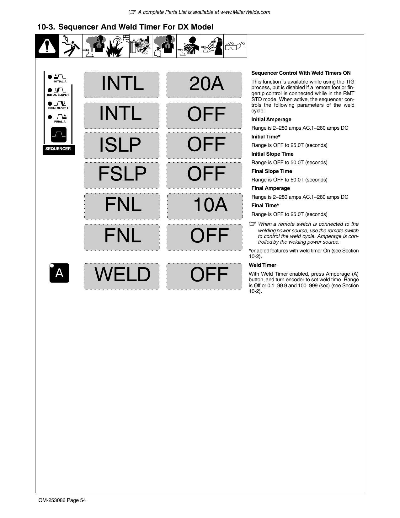
Rotate Encoder to adjust parameter setting.
Dynasty 280DX shown. Maxstar menus are the same. Menu order may vary.
To exit Tech Menu, press Amperage and Gas/DIG controls at the same time.
| | | | |---|---|---| | | | |
3 5
1
4
MENU
TECH
6
| | | | |---|---|---| | | | | | | | |
Optional - V-Sense Feeder (DC MIG) process.
| | | | | |---|---|---|---| | | | | | | | | | |
2
| | | |---|---| | | |
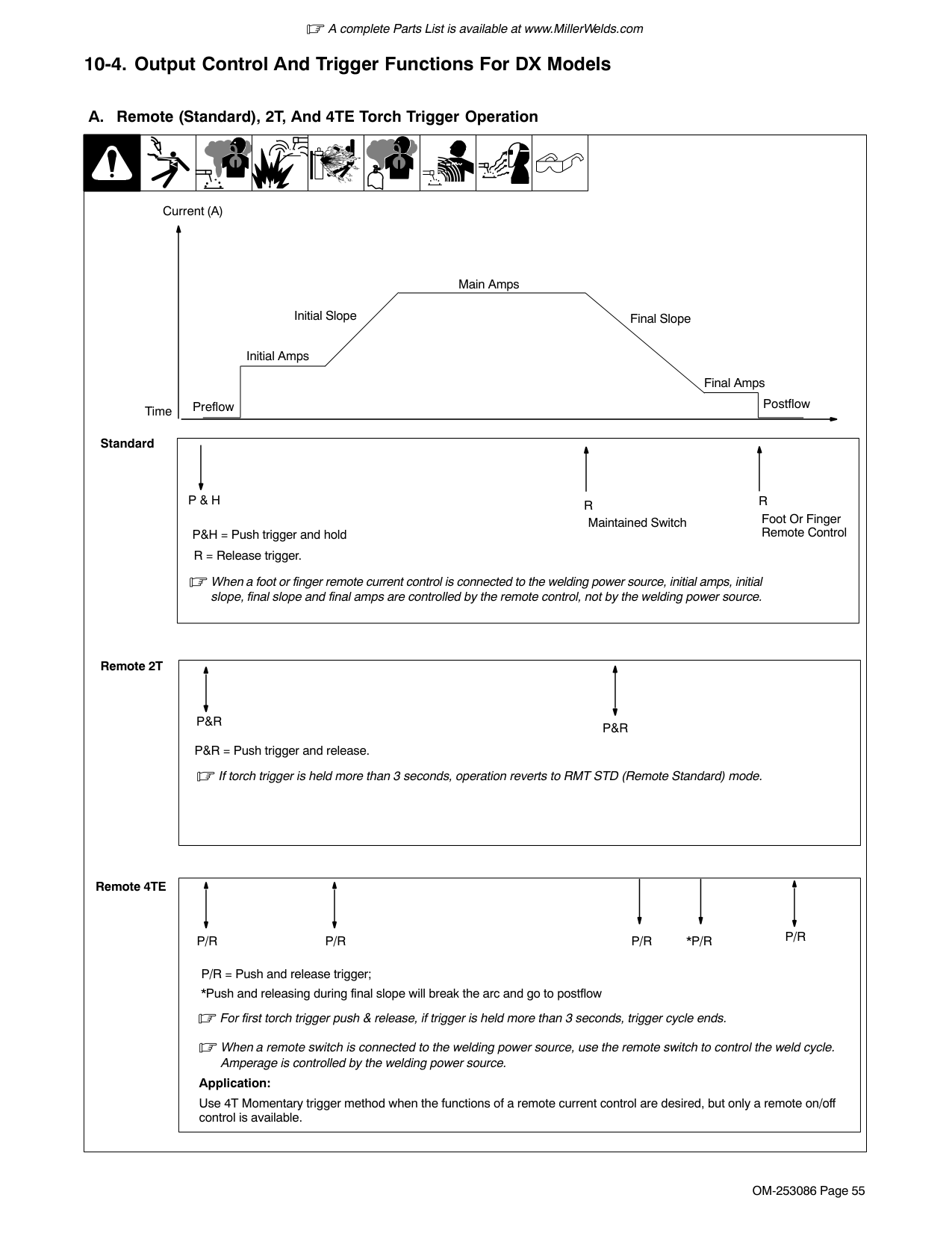
250859-A
T/CYARC
AUTOCOOL
LOGERR
OFFLOCK V/AMETR OFFEXPC
OFFSLEP
OFFSTUC
NORMOCV
RSETMACH WARESOFT
TMRSWELD
OFF
NUMSERL
[ARC] [T/CY] Arc Timer: Monitors hours, minutes, and cycles of valid arc on. To view these different elements, rotate encoder. To reset, rotate encoder until [RESET] [YES] is displayed. Press Menu button to display [RESET] [Done]. Displays turn to [000] [000].
[ERR] [LOG] Error Log: Use to view last eight logged error events. Each event may list multiple Error Codes. See Section 11-3.
[SLEP] Sleep Timer: Turns power off after the machine exceeds the programmed idle time without operation. Press the Standby button to turn power on. To set or change time, rotate encoder to desired time. Timer range: 1, 5, 10, 20, 30, 45 minutes or one hour.
[STUC] Stick Stuck: Detects if the electrode is stuck or shorted to the workpiece. Turns weld output off to aid in freeing the electrode. To turn on, rotate encoder. Not recommended for air carbon arc or large diameter electrodes.
[OCV] Open Circuit Voltage: Allows user to select between Normal (NORM) and Low open circuit voltage. Low reduces open circuit voltage to between 8 and 15 volts. To select, turn encoder.
Optional - OCV selection can be made while in the V-Sense Feeder (DC MIG) process also applies.
[WELD] [TMRS] Weld Timers: [ON] enable and [OFF] disable the feature. See Section 10-3 for information on setting weld timers. Weld Timers work with or without Sequencer feature.
[COOL] Cooler Auxiliary Power (Optional): Selects between [OFF], [ON] (Non CE models Only), and [AUTO]. [OFF] disables the power supply to the receptacle. [ON] enables the power supply to the receptacle. [AUTO] provides power to the receptacle when the TIG process is active.
[LOCK] Limits user control and adjustability of machine. See Section 10-5 For instructions and operation.
[METR] Meter Display while welding and preset amperage, with pulser on, meters can be set to display the following: [V/A] − Welding: average voltage and amperage
Preset: peak amperage [OFF] − Welding: [PULS] [WELD] Preset: peak amperage [AVG] −Welding: average voltage and amperage Preset: average amperage
[EXPC] External Pulse Control Commands: Turn on when it is desired to control machine from an external source. When command is on, a command voltage of 0− 10 volts DC equals off − 280 amps.
[MACH] [RESET] Machine Reset: Resets all machine values back to factory defaults. To reset, turn encoder to [RESET] [YES]. Then press Amperage button. [RESET] [DONE] will be displayed when the reset is complete and factory defaults have been restored.

[SOFT] [WARE] Software Number: Software number and revision will be displayed.
[SERL] [NUM] Serial Number: If serial number displayed does not match serial number of machine, see Section 11-3.

| | | | |---|---|---| | | | |
Sequencer Control With Weld Timers ON
INTL INTL
20A
This function is available while using the TIG process, but is disabled if a remote foot or fingertip control is connected while in the RMT STD mode. When active, the sequencer controls the following parameters of the weld cycle:
OFF
Initial Amperage Range is 2−280 amps AC,1−280 amps DC Initial Time* Range is OFF to 25.0T (seconds) Initial Slope Time Range is OFF to 50.0T (seconds) Final Slope Time Range is OFF to 50.0T (seconds) Final Amperage Range is 2−280 amps AC,1−280 amps DC Final Time* Range is OFF to 25.0T (seconds)
OFFISLP
FSLP FNL OFFFNL
OFF 10A
When a remote switch is connected to the welding power source, use the remote switch to control the weld cycle. Amperage is controlled by the welding power source.
*enabled features with weld timer On (see Section 10-2).
####################### Weld Timer
OFFWELD
With Weld Timer enabled, press Amperage (A) button, and turn encoder to set weld time. Range is Off or 0.1−99.9 and 100−999 (sec) (see Section 10-2).
############# 10-4. Output Control And Trigger Functions For DX Models
################ A. Remote (Standard), 2T, And 4TE Torch Trigger Operation

| | | |

|---|---|---| | | | |
Current (A)
Main Amps
Initial Slope Final Slope
Initial Amps
Final Amps Time
Postflow
Preflow
Standard
|R RP & H
Maintained Switch Foot Or Finger Remote ControlP&H = Push trigger and hold R = Release trigger.
When a foot or finger remote current control is connected to the welding power source, initial amps, initial slope, final slope and final amps are controlled by the remote control, not by the welding power source.| |---|
Remote 2T
|P&R
P&R P&R = Push trigger and release.
If torch trigger is held more than 3 seconds, operation reverts to RMT STD (Remote Standard) mode.| |---|
Remote 4TE
|For first torch trigger push & release, if trigger is held more than 3 seconds, trigger cycle ends.
P/R P/R P/R P/R
P/R = Push and release trigger;
*Push and releasing during final slope will break the arc and go to postflow
*P/R
When a remote switch is connected to the welding power source, use the remote switch to control the weld cycle. Amperage is controlled by the welding power source.
Application:
Use 4T Momentary trigger method when the functions of a remote current control are desired, but only a remote on/off control is available.| |---|
################ B. 3T Specific Trigger Method

| | | | |---|---|---| | | | |
Current (A)
Remote Trigger Operation
*

A B CDE Preflow Initial Amps/Initial Slope Main Amps Final Slope /Final Amps Postflow
3T requires a specific type of remote control with two independent momentarycontact switches. One will be designated initial switch, and it must be connected between Remote 14 receptacle pins A and B. The second will be designated as the final switch, and it must be connected between Remote 14 receptacle pins D and E.
Initial slope rate is the rate of amperage change determined by the initial amperage, initial slope time, and main amperage.
Final slope rate is the rate of amperage change determined by the main amperage, final slope time, and final amperage.
####################### Operation:
If an initial switch closure is not made again before preflow time ends, gas flow stops, the timer resets, and an initial switch press and release is necessary to start the weld sequence again.
C. When main amperage level is reached,
initial switch can be released.
####################### Application:
With the use of two remote switches instead of potentiometers, 3T gives the operator the ability to infinitely increase, decrease, or pause and hold amperage within the range determined by the initial, main, and final amperages.
################ C. 4T, 4Tm And 4TL Specific Trigger Method


| | | | |---|---|---| | | | |
Current (A)
####################### 4T and 4Tm Torch Trigger Operation
Main Amps
Initial Slope
Final Slope
Initial Amps
Final Amps
Postflow
Preflow
P/H R P/H R
*P/R
*P/R
P/H = Push and hold trigger; R = Release trigger;
*4T only: P/R = Push trigger and release in less than 3/4 seconds
####################### 4T and 4Tm Application:
Use 4T and 4Tm (modified) trigger methods when the functions of a remote current control are desired, but only a remote on/off control is available.
4T* allows the operator to toggle between weld current and final current.
When a remote switch is connected to the welding power source, use the remote switch to control the weld cycle. Amperage is controlled by the welding power source.
####################### 4TL Application:
The ability to change current levels without either initial slope or final slope, gives the operator the opportunity to adjust filler metal without breaking the arc.
4TL (mini logic) allows the operator to toggle between initial slope or main amps and initial amps. Final Amperage is not available. Final slope always slopes to minimum amperage and ends the cycle.

When a remote switch is connected to the welding power source, use the remote switch to control the weld cycle. Amperage is controlled by the welding power source.
####################### 4TL Torch Trigger Operation
Current (A)
Main Amps
Final Slope
Initial Slope
**
Initial Amps
**
Preflow
Postflow
P/H R P/R P/R P/R P/R P/R P/H
P/H = Push and hold trigger; R = Release trigger; P/R = Push trigger and release in less than 3/4 seconds
** = Arc can be extinguished at final slope rate at any time by pushing and holding trigger
############# 10-5. Lockout Functions

| | | | |---|---|---| | | | |
LOCK CODE
+
1
OFF
| | | | |---|---|---| | | | |

| | | |
+ Optional - Available in voltage-sensing capable machines.
2
| | | |---|---| | | |
280859-A
See Section 10-2 for information on how to access Lockout Functions.
There are four (1−4) different lockout levels. Each successive level allows the operator more flexibility.
Before activating lockout levels, be sure that all procedures and parameters are established. Parameter adjustment is limited while lockout levels are active.
To turn On lockout feature, proceed as follows:
Press Amperage (A) control to toggle between the lock off and code off displays. Toggle control until [CODE] [OFF] is displayed
Turn encoder to select a lockout code number. Select a number between 1 and 999. The number will appear on the amperage, right, display.
Remember (write down) this code number, as you will need this number to turn this feature off, or make changes to your settings.
Toggle Amperage control until [LOCK] is displayed. You may now select a lockout level. See table below for the degree of adjustability associated with each lock level. Exit Advanced Functions according to Section 10-2.
To turn Off lockout feature, proceed as follows:
Toggle Amperage control until Code is displayed. Use encoder control to enter the same code number that was used to turn on the lockout feature. Press the Amperage control. The amperage meter display will turn to [OFF]. Lockout is now off. Exit Advanced Functions according to Section 10-2.
############# 10-6. Lockout Levels Defined
|Minimum Adjustability|Minimum Adjustability|Degree Of Adjustability|Degree Of Adjustability|Degree Of Adjustability|Degree Of Adjustability|Maximum Adjustability|Maximum Adjustability| |---|---|---|---|---|---|---|---| |Lock Level 1|Lock Level 1|Lock Level 2|Lock Level 2|Lock Level 3|Lock Level 3|Lock Level 4|Lock Level 4| |Adjustable|Locked|Adjustable|Locked|Adjustable|Locked|Adjustable|Locked| | |Panel Amps| |Panel Amps|Panel Amps +/- 10%| |Remote Amps (min−panel)| | | | | | | | |Panel Amps +/- 10%| | | |Polarity (Dyn Only)|Polarity (Dyn Only)| |Polarity (Dyn Only)| |Polarity (Dyn Only)| | | |Process|Process| |Process| |Process| | |Output| |Output| |Output| |Output| | | |Pulser| |Pulser|Pulser (on/off only)| |Pulser (on/off only)| |

| |Sequencer| |Sequencer| |Sequencer| |Sequencer| | |Gas/DIG| |Gas/DIG| |Gas/DIG| |Gas/DIG| | |Waveshape| |Waveshape| |Waveshape| |Waveshape|
####### SECTION 11 − MAINTENANCE AND TROUBLESHOOTING
############# 11-1. Routine Maintenance
! Disconnect power before maintaining.
Maintain more often during severe conditions.
################ A. Welding Power Source
| |= Check = Change = Clean Δ = Repair = Replace
* To be done by Factory Authorized Service Agent|= Check = Change = Clean Δ = Repair = Replace
* To be done by Factory Authorized Service Agent|= Check = Change = Clean Δ = Repair = Replace
* To be done by Factory Authorized Service Agent| |---|---|---|---| |Every 3 Months|Labels
|Gas Hoses| | |Every 3 Months
|Δ Cables And Cords|Δ Cables And Cords|Δ Cables And Cords| |Every 6 Months
|:During heavy service, clean monthly.
! Do not remove case when blowing out inside of unit|:During heavy service, clean monthly.
! Do not remove case when blowing out inside of unit|:During heavy service, clean monthly.
! Do not remove case when blowing out inside of unit|
################ B. Optional Cooler
| |= Check = Change = Clean Δ = Repair = Replace
* To be done by Factory Authorized Service Agent|= Check = Change = Clean Δ = Repair = Replace
* To be done by Factory Authorized Service Agent| |---|---|---| |Every 3 Months|Coolant Strainer, durning heavy service, clean more frequently.|Blow out heat exchanger fins. Check coolant level. Top off with distilled or deionized water if necessary.
| |Every 6 Months
|Hoses Labels
|Hoses Labels
| |Every 12 Months
|Replace coolant.|Replace coolant.|
############# 11-2. Voltmeter/Ammeter Display Messages
|All directions are in reference to the front of the unit. All circuitry referred to is located inside the unit.
1 [RELE] [ASE] / [TRIG] [GER]
Remote 14 receptacle contactor control (Pins A−B) must be opened before proceeding.
2 [UN S] [HORT] / [OUTP] [UT]
Short on weld output connections must be removed before proceeding. See Section 11-3 if display shows after weld output connections have been verified as not having a short.
3 [OVER] [TEMP]
Over temperature condition has occurred. Error will clear after temperatures reach acceptable levels.
4 Latching Errors:
When one of the following errors occurs, the Standby LED flashes. To clear error, press Standby button or turn off power. See Section 11-3 if error does not clear or happens frequently.
[CHEK] [INPT] Check Input High or low voltage has been sensed. Have a qualified person check input voltage. [WELD] [CABL] Weld Cable
An error relate to the weld cables has been sensed. Straighten out or shorten weld cables. If carbon arc gouging, adjust DIG setting to CARBon ARC. See Section 6-4 (Dynasty),7-2 (Dynasty DX), 8-3 (Maxstar) or 9-2 (Maxstar DX).
[SEE] [O.M.] See Owner’s Manual: See Section 11-3. [COOL] [PWR] Cooler Power
An error related to the CoolMate 1.3 Power has occurred. When error will not clear or occurs frequently, and cooler can plugged into a nearby 115 volt AC receptacle, or machine can be used without the Cooler Power, turn Cooler Power off (see Section 10-1).
5 [NOT] [VALD]
Message is displayed when attempting an incompatible setup; i.e., pressing AC Waveshape while in DC.
6 [LOCK] [LEV1], 2, 3, 4
Is displayed when attempting adjustments that are incompatible with the active selected lock level.
7 [SOFT] [WARE] [NOT] [VALD]
A software compatibility error has been detected. A software update is required (see Section 5-12 Software Updates).see Section 11-3 if display shows after a software update is performed.
1
2
3
4
6
5
|RELE| |---|
|ASE| |---|
TRIG GER
|UN S| |---|
|HORT| |---|
OUTP UT
OVER TEMP
Release Trigger
Un Short Output
Over Temperature Error
Latching Errors: CHEK INPT WELD CABL SEE O.M. }Latching Errors:
NOT VALD
Not Valid
LOCK LEV1
Lock Level
COOL PWR
|SOFT| |---|
|WARE| |---|
NOT VALD
Software Not Valid
7
| |---|
############# 11-3. Troubleshooting Table

| | | | | | | | |---|---|---|---|---|---|---|
|Trouble|Remedy| |---|---| |No weld output; unit completely inoperative.
|Place line disconnect switch in On position (see Section 5-8 or 5-9).| |No weld output; unit completely inoperative.
|Check and replace line fuse(s), if necessary, or reset circuit breaker (see Section 5-8 or 5-9).| |No weld output; unit completely inoperative.
|Check for proper input power connections (see Section 5-8 or 5-9).| |No weld output; meter display On.
|If using remote control, be sure correct process is enabled to provide output control at Remote 14 receptacle (see Section 5-10 as applicable).| |No weld output; meter display On.
|Input voltage outside acceptable range of variation (see Section 5-6).| |No weld output; meter display On.
|Check, repair, or replace remote control.| |No weld output; meter display On.
|Unit overheated. Allow unit to cool with fan On (see Section 4-6).| |Erratic or improper weld output.
|Use proper size and type of weld cable (see Section 5-2).| |Erratic or improper weld output.
|Clean and tighten all weld connections (see Section 11-1).| |Fan not operating.
|Check for and remove anything blocking fan movement.| |Fan not operating.
|Have Factory Authorized Service Agent check fan motor.| |Wandering arc.|Use proper size tungsten (see Section 15).| |Wandering arc.|Use properly prepared tungsten (see Section 15).| |Wandering arc.|Reduce gas flow rate.| |Tungsten electrode oxidizing and not remaining bright after conclusion of weld.|Shield weld zone from drafts.| |Tungsten electrode oxidizing and not remaining bright after conclusion of weld.|Increase postflow time.| |Tungsten electrode oxidizing and not remaining bright after conclusion of weld.|Check and tighten all gas fittings (see Section 11-1A).| |Tungsten electrode oxidizing and not remaining bright after conclusion of weld.|Water in torch. Refer to torch manual.| |Blank Display.|Verify Power to machine.| |Blank Display.|A software update may be required (see Section 5‐12, Software Updates). Contact the factory if display remains blank after a software update is performed.| |Error message [ERR] [LOG] is displayed.|Contact a Factory Authorized Service Agent for an explanation of the error code.| |Latching Errors see Section 11-2.|Contact a Factory Authorized Service Agent if error does not clear or happens frequently.| |Error message [SEE] [O.M.] is displayed.|Contact a Factory Authorized Service Agent.| |Tech Menu (See Section 10) [SERL][NUM] is selected, and serial number displayed does not match serial number of machine.|Contact a Factory Authorized Service Agent.| |Error message [UN S] [HORT] / [OUTP] [UT] is displayed.|Contact a Factory Authorized Service Agent if display shows after weld output connections have been verified as not having a short.| |Error message [SOFT] [WARE] [NOT] [VALD] is displayed.|Contact Factory Authorized Service Agent if display shows after a software update is performed.|
############# 11-4. Blowing Out Inside of Unit
! Do not remove case when
blowing out inside of unit.
To blow out unit, direct airflow through front and back louvers as shown.
805497-A
############# 11-5. Coolant Maintenance
| | | | ||! Disconnect input power be-
fore maintaining. 1 Coolant Filter| |---|---|---|---|---|---| |T25 Torx
Tools Needed:
805502-A
Unscrew housing to clean filter.
Changing coolant: Drain coolant by tipping unit to the front, or use suction pump. Fill with clean water and run for 10 minutes. Drain and refill with coolant.
If replacing hoses, use hoses compatible with ethylene glycol, such as Buna-N, Neoprene, or Hypalon. Oxy-acetylene hoses are not compatible with any product containing ethylene glycol.
1
|Application|GTAW Or Where HF* Is Used|

|---|---| | | | |Coolant|Low Conductivity Coolant No. 043810**; Distilled Or Deionized Water OK Above 32° F (0° C)|
*HF: High Frequency Current
**Coolant 043810, a 50/50 solution, protects to -37° F (-38°C) and resist algae growth.
NOTICE −Use of any coolant other than that listed in the table voids the warranty on any parts that come in contact with the coolant (pump, radiator, etc.).|T25 Torx
Tools Needed:
805502-A
Unscrew housing to clean filter.
Changing coolant: Drain coolant by tipping unit to the front, or use suction pump. Fill with clean water and run for 10 minutes. Drain and refill with coolant.
If replacing hoses, use hoses compatible with ethylene glycol, such as Buna-N, Neoprene, or Hypalon. Oxy-acetylene hoses are not compatible with any product containing ethylene glycol.
1
|Application|GTAW Or Where HF* Is Used| |---|---| | | | |Coolant|Low Conductivity Coolant No. 043810**; Distilled Or Deionized Water OK Above 32° F (0° C)|
*HF: High Frequency Current
**Coolant 043810, a 50/50 solution, protects to -37° F (-38°C) and resist algae growth.
NOTICE −Use of any coolant other than that listed in the table voids the warranty on any parts that come in contact with the coolant (pump, radiator, etc.).|
####### SECTION 12 − PARTS LIST
############# 12-1. Recommended Spare Parts
Dia. Mkgs.
Part No.
Description
Quantity
Recommended Spare Parts
239494 Screen, Filter Lp Cyl 100x100x0.0045 SST A 1................ .... ...................... 043810 Coolant 1................ .... .......................................................
+When ordering a component originally displaying a precautionary label, the label should also be ordered. To maintain the factory original performance of your equipment, use only Manufacturer’s Suggested Replacement Parts. Model and serial number required when ordering parts from your local distributor.
##### Notes
######### Work like a Pro!
Pros weld and cut

safely. Read the safety rules at the beginning of this manual.
####### SECTION 13 − ELECTRICAL DIAGRAMS
| | | |---|---| | | |
| | | |---|---| | | |
| | | | | | | | | | | | | | |---|---|---|---|---|---|---|---|---|---|---|---|---| | | | | | | | | | | | | | | | | | | | | | | | | | | | | | | | | | | | | | | | | | |
| | | |---|---| | | |
| | | | |---|---|---| | | | |
| | | |---|---| | | |
| | | |---|---| | | | | | | | | |
| | | | |---|---|---| | | | | | | | | | | | |

| | | |---|---| | | | | | | | | |
| | | |---|---| | | | | | |
################ Figure 13-1. Circuit Diagram For Dynasty 280
255980-F
| | | | | | | | | | | | | | |---|---|---|---|---|---|---|---|---|---|---|---|---| | | | | | | | | | | | | | | | | | | | | | | | | | | | | | | | | | | | | | | | | | |
| | | |---|---| | | |
| | | |---|---| | | |
| | | | |---|---|---| | | | |
| | | | |---|---|---| | | | | | | | | | | | |
################ 255981-GFigure 13-2. Circuit Diagram For Maxstar 280
####### SECTION 14 − HIGH FREQUENCY

############# 14-1. Welding Processes Requiring High Frequency
1
|Work| |---|
TIG
1 High-Frequency Voltage
TIG − helps arc jump air gap between torch and workpiece and/ or stabilize the arc.
high_freq 5/10 − S-0693
############# 14-2. Installation Showing Possible Sources Of HF Interference
13
50 ft (15 m)
####################### Weld Zone
11, 12
9 8
7
1
10
3
2
4 5 6
14
######## Best Practices Not Followed
Sources of Direct High-Frequency Radiation
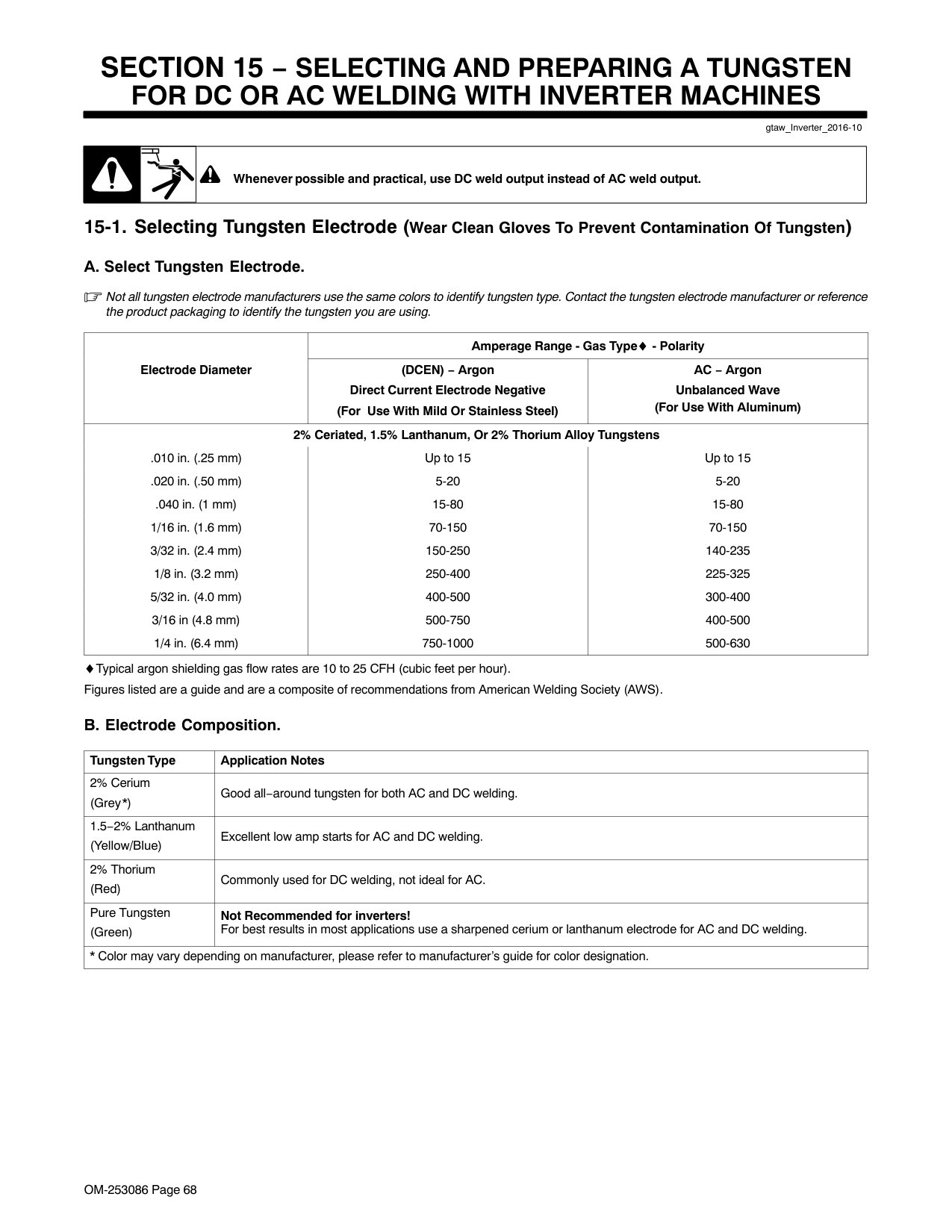
Sources of Conduction of High Frequency
7 Input Power Cable 8 Line Disconnect Device 9 Input Supply Wiring
Sources of Reradiation of High Frequency
S-0694
############# 14-3. Recommended Installation To Reduce HF Interference
####################### Weld Zone
3 50 ft (15 m)
50 ft (15 m)
5
1
6
2
8
4
8
Ground all metal objects and all wiring in welding zone using #12 AWG wire.
Ground workpiece if required by codes.
Nonmetal Building
7
9
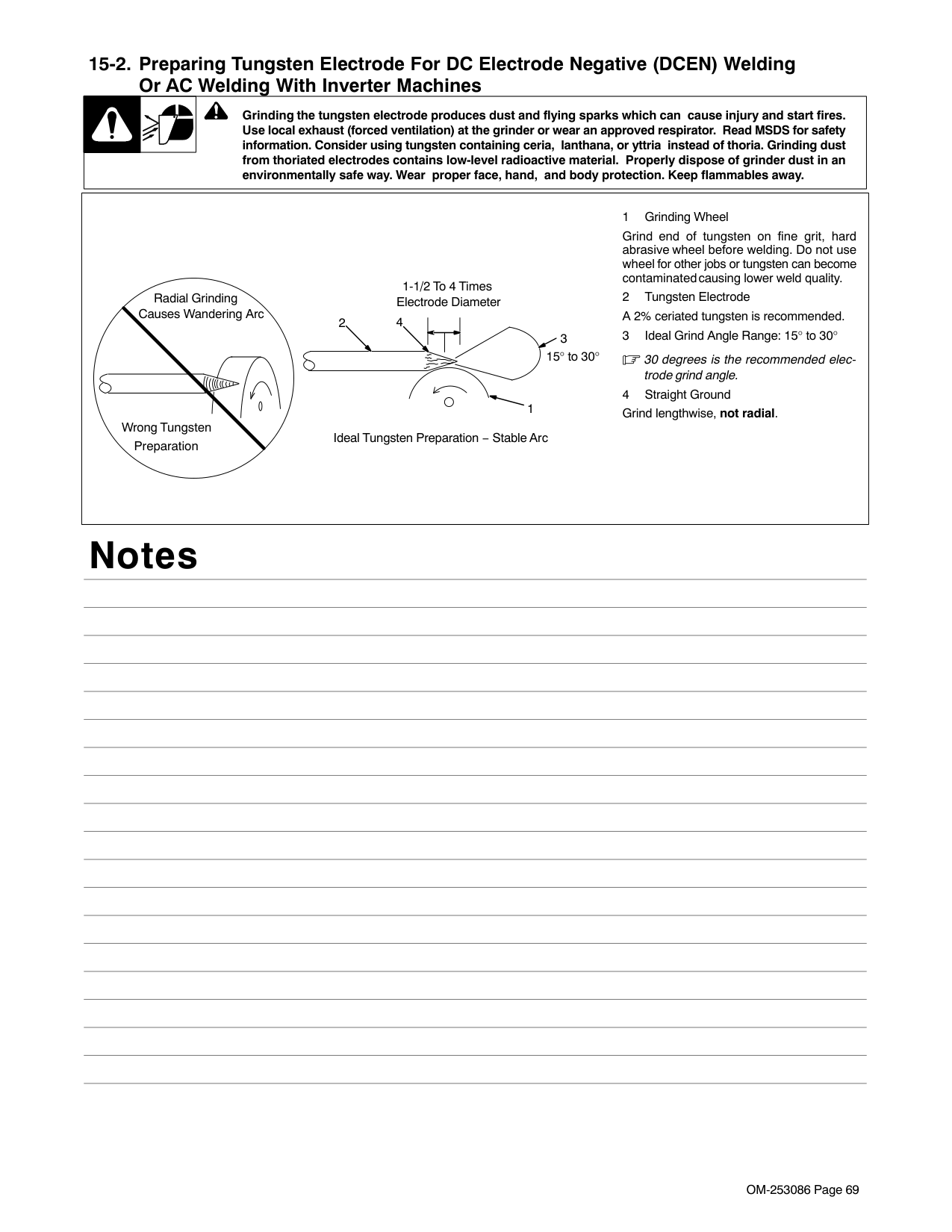
######## Best Practices Followed
####################### Metal Building
8
8
11
10
Ref. S-0695 / Ref. S-0695
Ground metal machine case (clean paint from around hole in case, and use case screw), work output terminal, line disconnect device, input supply, and worktable.
Midpoint between high-frequency source and welding torch.
A circle 50 ft (15 m) from center point in all directions.
Keep cables short and close together.
Electrically join (bond) all conduit sections using copper straps or braided wire. Ground conduit every 50 ft (15 m).
Locate high-frequency source at least 50 ft (15 m) away from power and phone lines.
Consult the National Electrical Code for specifications.
####################### Metal Building Requirements

Bolt or weld building panels together, install copper straps or braided wire across seams, and ground frame.
Cover all windows and doorways with grounded copper screen of not more than 1/4 in. (6.4 mm) mesh.
####### SECTION 15 − SELECTING AND PREPARING A TUNGSTEN FOR DC OR AC WELDING WITH INVERTER MACHINES
gtaw_Inverter_2016-10
| | |Whenever possible and practical, use DC weld output instead of AC weld output.| |---|---|---|
Not all tungsten electrode manufacturers use the same colors to identify tungsten type. Contact the tungsten electrode manufacturer or reference the product packaging to identify the tungsten you are using.
Amperage Range - Gas Type♦ - Polarity Electrode Diameter (DCEN) − Argon
Direct Current Electrode Negative (For Use With Mild Or Stainless Steel)
AC − Argon Unbalanced Wave (For Use With Aluminum) 2% Ceriated, 1.5% Lanthanum, Or 2% Thorium Alloy Tungstens
.010 in. (.25 mm) Up to 15 Up to 15
.020 in. (.50 mm) 5-20 5-20
.040 in. (1 mm) 15-80 15-80 1/16 in. (1.6 mm) 70-150 70-150 3/32 in. (2.4 mm) 150-250 140-235
1/8 in. (3.2 mm) 250-400 225-325 5/32 in. (4.0 mm) 400-500 300-400 3/16 in (4.8 mm) 500-750 400-500 1/4 in. (6.4 mm) 750-1000 500-630
♦Typical argon shielding gas flow rates are 10 to 25 CFH (cubic feet per hour). Figures listed are a guide and are a composite of recommendations from American Welding Society (AWS).
|Tungsten Type|Application Notes| |---|---| |2% Cerium (Grey*)|Good all−around tungsten for both AC and DC welding.| |1.5−2% Lanthanum (Yellow/Blue)|Excellent low amp starts for AC and DC welding.| |2% Thorium (Red)|Commonly used for DC welding, not ideal for AC.| |Pure Tungsten (Green)|Not Recommended for inverters! For best results in most applications use a sharpened cerium or lanthanum electrode for AC and DC welding.| |* Color may vary depending on manufacturer, please refer to manufacturer’s guide for color designation.|* Color may vary depending on manufacturer, please refer to manufacturer’s guide for color designation.|

| | |Grinding the tungsten electrode produces dust and flying sparks which can cause injury and start fires. Use local exhaust (forced ventilation) at the grinder or wear an approved respirator. Read MSDS for safety information. Consider using tungsten containing ceria, lanthana, or yttria instead of thoria. Grinding dust| |---|---|---| |from thoriated electrodes contains low-level radioactive material. Properly dispose of grinder dust in an environmentally safe way. Wear proper face, hand, and body protection. Keep flammables away.|from thoriated electrodes contains low-level radioactive material. Properly dispose of grinder dust in an environmentally safe way. Wear proper face, hand, and body protection. Keep flammables away.|from thoriated electrodes contains low-level radioactive material. Properly dispose of grinder dust in an environmentally safe way. Wear proper face, hand, and body protection. Keep flammables away.|
|Ideal Tungsten Preparation − Stable Arc
1 Grinding Wheel
Grind end of tungsten on fine grit, hard abrasive wheel before welding. Do not use wheel for other jobs or tungsten can become contaminated causing lower weld quality.
2 Tungsten Electrode A 2% ceriated tungsten is recommended.
3 Ideal Grind Angle Range: 15° to 30°
30 degrees is the recommended electrode grind angle.
4 Straight Ground
Grind lengthwise, not radial.1
3
Causes Wandering Arc
2
Wrong Tungsten
Radial Grinding
Preparation
15° to 30°
4
1-1/2 To 4 Times Electrode Diameter
| |---|
##### Notes
####### SECTION 16 − TIG PROCEDURES
gtaw_Inverter_2011-06 For additional resources on welding, visit http://www.millerwelds.com/resources/welding-resources/
############# 16-1. Lift-Arc And HF TIG Start Procedures

| | | | |---|---|---| | | | |
Lift-Arc Start Method
1
2
1 − 2 Seconds“Touch”
Do NOT Strike Like A Match!
####################### Lift-Arc Start
When Lift-Arc button light is On, start arc as follows:
Touch tungsten electrode to workpiece at weld start point, enable output and shielding gas with torch trigger, foot control, or hand control.Hold electrode to workpiece for 1-2 seconds, and slowly lift electrode. Arc is formed when electrode is lifted.
Normal open-circuit voltage is not present before tungsten electrode touches workpiece; only a low sensing voltage is present between electrode and workpiece. The solid-state output contactor does not energize until after electrode is touching workpiece. This allows electrode to touch workpiece without overheating, sticking, or getting contaminated.

####################### Application:
Lift-Arc is used for the DCEN or AC GTAW process when HF Start method is not permitted, or to replace the scratch method.
####################### HF Start
When HF Start button light is On, start arc as follows:
High frequency turns on to help start arc when output is enabled. High frequency turns off when arc is started, and turns on whenever arc is broken to help restart arc.
####################### Application:
HF start is used for the DCEN GTAW process when a non-contact arc starting method is required.
############# 16-2. Pulser Control
|1
3
2
| | | |---|---| |Percent (%) Peak Time Control Setting|Pulsed Output Waveforms| | | | |Peak 50%/Background 50% Balanced 50%
|Peak Amp
| |Bkg Amp|Bkg Amp| |---|---|---| | | | |
PPS| |More Time At Peak Amperage
(80%)| | |More Time At
Background Amperage
(20%)| |
4
1 Pulser Control
Pulsing is available while using the TIG process. Controls can be adjusted while welding.
Press switch pad to enable pulser. ON - When illuminated, this LED indicates the pulser is on. Press switch pad until desired parameter LED is illuminated. To turn Pulser off, press and release switch pad until the On LED turns off.
2 Encoder Control (Set Value)
3 Ammeter (Displays Value) See Section 7-2 or 9-2 for all Pulser parameter ranges.
PPS - Pulse frequency or pulses per second, is the number of pulse cycles per second. Pulse frequency helps reduce heat input, part warpage, and helps weld bead cosmetics. The higher the PPS setting, the smoother the ripple effect, the narrower the weld bead, and the more cooling you get. By setting PPS on the lower end, the pulse is slower, and the weld bead wider. This slow pulsing helps agitate the weld puddle to help release gas trapped in the weldment, and help reduce porosity (very useful in aluminum welding). Some beginners use a slower pulse rate (2-4 pps) to help them with their timing on adding filler material. An experienced welder may have the PPS setting much higher, depending on their personal preferences, and on what they are trying to accomplish.
PEAK t - (PEAK t) is the percentage of time in each cycle, spent at peak amperage (main amperage). Peak amperage is set with the Amperage control (see Section 9-1). If one pulse per second is being used, and peak time is set at 50%, one-half second is spent at peak amperage, and the other 50%, or one-half second, is spent at the background amperage. Increasing peak time increases time spent at peak amperage, which increases heat input into the part. A good starting point for peak time is about 50-60%. To find a good ratio, you will have to experiment a bit, but the idea is to decrease heat input into the part, and increase the cosmetics of the weld.
BKGND A - (Background amps) is set as a percentage of the peak amps setting. If peak amps is set at 200, and background amps at 50%, your background amps is 100 amps when the machine pulses on the background side of the cycle. The lower background amperage helps reduce heat input. Increasing or decreasing background amps increases or decreases the overall average amperage, which helps determine how fluid your puddle is on the background side of the pulse cycle. Overall, you want your puddle to shrink to about one-half the size, but still remain fluid. To start with, set background amps at about 20-30% for stainless/carbon steel, or at about 35-50% for aluminum alloys.
4 Pulsed Output Waveforms
Example shows affect changing the Peak Time control has on the pulsed output waveform.
Application:
Pulsing refers to the alternating raising and lowering of the weld output at a specific rate. The raised portions of the weld output are controlled in width, height, and frequency, forming pulses of weld output. These pulses and the lower amperage level between them (called the background amperage) alternately heat and cool the molten weld puddle. The combined effect gives the operator better control of penetration, bead width, crowning, undercutting, and heat input. Controls can be adjusted while welding.
Pulsing can also be used for filler material addition technique training.
Function is enabled, when LED is lit| |---|
############# 16-3. General (GEN) Tungsten Programmable TIG Starting Parameters (DX Models Only)

1 Encoder Control 2 Parameter Display 3 Amperage Button
| | | | |---|---|---| | | | |
Once inside the machine set up menu, tungsten parameter values can be manually changed by pressing the Amperage switch pad to step through each adjustable parameter. Turn encoder to change the value.
2
1
GENTUNG

3
| | | | |---|---|---| | | | | | | | |
| | | |---|---| | | |
247220-D
Current (A)
Available Parameter Settings
Start Amperage
Preset Amperage Minimum
Start Time
Start Slope Time
Parameter

####### SECTION 17 − STICK WELDING (SMAW) GUIDELINES
############# 17-1. Electrode and Amperage Selection Chart
|ELECTRODE|DIAMETER|AMPERAGE
RANGE|AMPERAGE
RANGE|AMPERAGE
RANGE|AMPERAGE
RANGE|AMPERAGE
RANGE|AMPERAGE
RANGE|AMPERAGE
RANGE|AMPERAGE
RANGE|AMPERAGE
RANGE| |---|---|---|---|---|---|---|---|---|---|---| |ELECTRODE|DIAMETER|50
100
150
200
250
300
350
400
450|50
100
150
200
250
300
350
400
450|50
100
150
200
250
300
350
400
450|50
100
150
200
250
300
350
400
450|50
100
150
200
250
300
350
400
450|50
100
150
200
250
300
350
400
450|50
100
150
200
250
300
350
400
450|50
100
150
200
250
300
350
400
450|50
100
150
200
250
300
350
400
450| |6010 &
6011
|3/32| | | | | | | | | | |6010 &
6011
|1/8| | | | | | | | | | |6010 &
6011
|5/32| | | | | | | | | | |6010 &
6011
|3/16| | | | | | | | | | |6010 &
6011
|7/32| | | | | | | | | | |6010 &
6011
|1/4| | | | | | | | | | |6013|1/16| | | | | | | | | | |6013|5/64| | | | | | | | | | |6013|3/32| | | | | | | | | | |6013|1/8| | | | | | | | | | |6013|5/32| | | | | | | | | | |6013|3/16| | | | | | | | | | |6013|7/32| | | | | | | | | | |6013|1/4| | | | | | | | | | |7014|3/32| | | | | | | | | | |7014|1/8| | | | | | | | | | |7014|5/32| | | | | | | | | | |7014|3/16| | | | | | | | | | |7014|7/32| | | | | | | | | | |7014|1/4| | | | | | | | | | |7018|3/32| | | | | | | | | | |7018|1/8| | | | | | | | | | |7018|5/32| | | | | | | | | | |7018|3/16| | | | | | | | | | |7018|7/32| | | | | | | | | | |7018|1/4| | | | | | | | | | |7024|3/32| | | | | | | | | | |7024|1/8| | | | | | | | | | |7024|5/32| | | | | | | | | | |7024|3/16| | | | | | | | | | |7024|7/32| | | | | | | | | | |7024|1/4| | | | | | | | | | |Ni-Cl|3/32| | | | | | | | | |

|Ni-Cl|1/8| | | | | | | | | | |Ni-Cl|5/32| | | | | | | | | | |Ni-Cl|3/16| | | | | | | | | | |308L|3/32| | | | | | | | | | |308L|1/8| | | | | | | | | | |308L|5/32| | | | | | | | | |
|ELECTRODE
|DC*|AC|POSITION
|PENETRATION|USAGE| |---|---|---|---|---|---| |6010|EP| |ALL|DEEP|MIN. PREP, ROUGH HIGH SPATTER| |6011|EP| |ALL|DEEP|MIN. PREP, ROUGH HIGH SPATTER| |6013|EP,EN| |ALL|LOW|GENERAL| |7014|EP,EN| |ALL|MED|SMOOTH, EASY, FAST| |7018|EP| |ALL|MED|LOW HYDROGEN, STRONG| |7024|EP,EN| |FLAT HORIZ*|LOW|SMOOTH, EASY, FASTER| |NI-CL|EP| |ALL|LOW|CAST IRON| |308L|EP| |ALL|LOW|STAINLESS| |*EP = ELECTRODE POSITIVE (REVERSE POLARITY)|*EP = ELECTRODE POSITIVE (REVERSE POLARITY)|*EP = ELECTRODE POSITIVE (REVERSE POLARITY)|*EP = ELECTRODE POSITIVE (REVERSE POLARITY)|*EP = ELECTRODE POSITIVE (REVERSE POLARITY)|*EP = ELECTRODE POSITIVE (REVERSE POLARITY)|
EN = ELECTRODE NEGATIVE (STRAIGHT POLARITY)
Ref. S-087985-A
##### Notes
############ Start Your Professional Welding Career Now!

400 Trade Square East, Troy, Ohio 45373 1-800-332-9448 www.welding.org
############ Over 80,000 trained since 1930!
|Warranty Questions?
Call 1-800-4-A-MILLER for your local Miller distributor.


Your distributor also gives you ...
Service You always get the fast, reliable response you need. Most replacement parts can be in your hands in 24 hours.
Support Need fast answers to the tough welding questions? Contact your distributor. The expertise of the distributor and Miller is there to help you, every step of the way.| |---|
Effective January 1, 2017 (Equipment with a serial number preface of MH or newer)
This limited warranty supersedes all previous Miller warranties and is exclusive with no other guarantees or warranties expressed or implied.

LIMITED WARRANTY − Subject to the terms and conditions below, Miller Electric Mfg. Co., Appleton, Wisconsin, warrants to its original retail purchaser that new Miller equipment sold after the effective date of this limited warranty is free of defects in material and workmanship at the time it is shipped by Miller. THIS WARRANTY IS EXPRESSLY IN LIEU OF ALL OTHER WARRANTIES, EXPRESS OR IMPLIED, INCLUDING THE WARRANTIES OF MERCHANTABILITY AND FITNESS.
Within the warranty periods listed below, Miller will repair or replace any warranted parts or components that fail due to such defects in material or workmanship. Miller must be notified in writing within thirty (30) days of such defect or failure, at which time Miller will provide instructions on the warranty claim procedures to be followed. If notification is submitted as an online warranty claim, the claim must include a detailed description of the fault and the troubleshooting steps taken to identify failed components and the cause of their failure.
Miller’s True Blue® Limited Warranty shall not apply to:
Miller shall honor warranty claims on warranted equipment listed below in the event of such a failure within the warranty time periods. All warranty time periods start on the delivery date of the equipment to the original end-user purchaser, and not to exceed twelve months after the equipment is shipped to a North American distributor or eighteen months after the equipment is shipped to an International distributor.
MILLER PRODUCTS ARE INTENDED FOR PURCHASE AND USE BY COMMERCIAL/INDUSTRIAL USERS AND PERSONS TRAINED AND EXPERIENCED IN THE USE AND MAINTENANCE OF WELDING EQUIPMENT.
In the event of a warranty claim covered by this warranty, the exclusive remedies shall be, at Miller’s option: (1) repair; or (2) replacement; or, where authorized in writing by Miller in appropriate cases, (3) the reasonable cost of repair or replacement at an authorized Miller service station; or (4) payment of or credit for the purchase price (less reasonable depreciation based upon actual use) upon return of the goods at customer’s risk and expense. Miller’s option of repair or replacement will be F.O.B., Factory at Appleton, Wisconsin, or F.O.B. at a Miller authorized service facility as determined by Miller. Therefore no compensation or reimbursement for transportation costs of any kind will be allowed.
TO THE EXTENT PERMITTED BY LAW, THE REMEDIES PROVIDED HEREIN ARE THE SOLE AND EXCLUSIVE REMEDIES. IN NO EVENT SHALL MILLER BE LIABLE FOR DIRECT, INDIRECT, SPECIAL, INCIDENTAL OR CONSEQUENTIAL DAMAGES (INCLUDING LOSS OF PROFIT), WHETHER BASED ON CONTRACT, TORT OR ANY OTHER LEGAL THEORY.
ANY EXPRESS WARRANTY NOT PROVIDED HEREIN AND ANY IMPLIED WARRANTY, GUARANTY OR REPRESENTATION AS TO PERFORMANCE, AND ANY REMEDY FOR BREACH OF CONTRACT TORT OR ANY OTHER LEGAL THEORY WHICH, BUT FOR THIS PROVISION, MIGHT ARISE BY IMPLICATION, OPERATION OF LAW, CUSTOM OF TRADE OR COURSE OF DEALING, INCLUDING ANY IMPLIED WARRANTY OF MERCHANTABILITY OR FITNESS FOR PARTICULAR PURPOSE, WITH RESPECT TO ANY AND ALL EQUIPMENT FURNISHED BY MILLER IS EXCLUDED AND DISCLAIMED BY MILLER.
Some states in the U.S.A. do not allow limitations of how long an implied warranty lasts, or the exclusion of incidental, indirect, special or consequential damages, so the above limitation or exclusion may not apply to you. This warranty provides specific legal rights, and other rights may be available, but may vary from state to state.
In Canada, legislation in some provinces provides for certain additional warranties or remedies other than as stated herein, and to the extent that they may not be waived, the limitations and exclusions set out above may not apply. This Limited Warranty provides specific legal rights, and other rights may be available, but may vary from province to province.
miller_warr 2017-01
##### Owner’s Record
Please complete and retain with your personal records.
################# Model Name Serial/Style Number
Purchase Date (Date which equipment was delivered to original customer.)
Distributor
Address
City
State Zip
##### For Service
########### Contact a DISTRIBUTOR or SERVICE AGENCY near you.
Always provide Model Name and Serial/Style Number.
Contact your Distributor for:
Welding Supplies and Consumables Options and Accessories Personal Safety Equipment Service and Repair Replacement Parts Training (Schools, Videos, Books) Technical Manuals (Servicing Information and Parts) Circuit Diagrams Welding Process Handbooks
To locate a Distributor or Service Agency visit www.millerwelds.com or call 1-800-4-A-Miller
Contact the Delivering Carrier to:
File a claim for loss or damage during shipment.
For assistance in filing or settling claims, contact your distributor and/or equipment manufacturer’s Transportation Department.
ORIGINAL INSTRUCTIONS − PRINTED IN USA © 2017 Miller Electric Mfg. Co. 2017−01
|Miller Electric Mfg. Co. An Illinois Tool Works Company 1635 West Spencer Street Appleton, WI 54914 USA
International Headquarters−USA USA Phone: 920-735-4505 Auto-Attended USA & Canada FAX: 920-735-4134 International FAX: 920-735-4125
For International Locations Visit www.MillerWelds.com

| |---|