
Ask AI
— answers from the official manualAnswers from the official manual.
Common questions
Common Questions
9 totalHow do I safely disconnect power from the SGA 100 before installation?
To ensure safety when installing the SGA 100, turn off and disconnect input power or shut off the engine if applicable. This prevents electric shock risks during setup.
What steps are required to connect spool gun trigger controls and gas supply?
First, slide the spoolgun gas hose onto barbed fitting on SGA 100 control box. Then, connect spoolgun trigger control plug to matching receptacle on SGA 100 control box.
What tools are needed for connecting the welding cable if my unit lacks a 1/2 inch weld cable stud?
You will need an Allen wrench, wire cutter, stripper, pliers, and possibly a crescent wrench. Remove gun securing nut first, then slide terminal and connect spoolgun weld cable to terminal.
What is the correct gas type for SGA 100 when welding aluminum?
For welding aluminum with the SGA 100, use 100% argon shielding gas. This ensures optimal quality of welds on this material.
How do I install the SGA 100C contactor control box?
After removing contactor box, follow hook-up procedure similar to an SGA 100. Cut and strip insulation back from ring terminal and weld cable ends, then secure them in terminals with set screws.
What are the safety precautions for using the spool gun?
Handle parts carefully and beware of electric shock from touching electrode; wear insulated welding gloves and clothing to prevent burns and use proper handling tools.
Full Manual
9 pages
2022-06 OM-190753NOWNER’SMANUAL
SGA 100 And SGA 100C
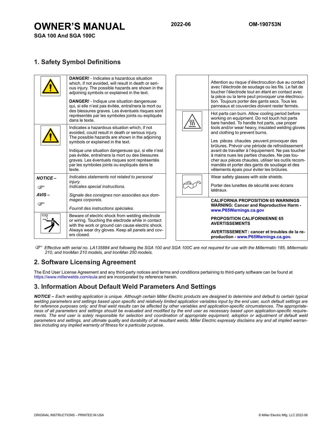
1. Safety Symbol Definitions
| |DANGER! - Indicates a hazardous situation which, if not avoided, will result in death or serious injury. The possible hazards are shown in the adjoining symbols or explained in the text.
DANGER! - Indique une situation dangereuse qui, si elle n’est pas évitée, entraînera la mort ou des blessures graves. Les éventuels risques sont représentés par les symboles joints ou expliqués dans le texte.| |---|---| | |Indicates a hazardous situation which, if not avoided, could result in death or serious injury. The possible hazards are shown in the adjoining symbols or explained in the text.
Indique une situation dangereuse qui, si elle n’est pas évitée, entraînera la mort ou des blessures graves. Les éventuels risques sont représentés par les symboles joints ou expliqués dans le texte.| |NOTICE –
AVIS –|Indicates statements not related to personal injury. Indicates special instructions.
Signale des consignes non associées aux dommages corporels.
Fournit des instructions spéciales.| | |Beware of electric shock from welding electrode or wiring. Touching the electrode while in contact with the work or ground can cause electric shock. Always wear dry gloves. Keep all panels and covers closed.|
| |Attention au risque d’électrocution due au contact avec l’électrode de soudage ou les fils. Le fait de toucher l’électrode tout en étant en contact avec la pièce ou la terre peut provoquer une électrocution. Toujours porter des gants secs. Tous les panneaux et couvercles doivent rester fermés.| |---|---| | |Hot parts can burn. Allow cooling period before working on equipment. Do not touch hot parts bare handed. To handle hot parts, use proper tools and/or wear heavy, insulated welding gloves and clothing to prevent burns.
Les pièces chaudes peuvent provoquer des brûlures. Prévoir une période de refroidissement avant de travailler à l’équipement. Ne pas toucher à mains nues les parties chaudes. Ne pas toucher aux pièces chaudes, utiliser les outils recommandés et porter des gants de soudage et des vêtements épais pour éviter les brûlures.| | |Wear safety glasses with side shields. Porter des lunettes de sécurité avec écrans latéraux.| |CALIFORNIA PROPOSITION 65 WARNINGS WARNING: Cancer and Reproductive Harm www.P65Warnings.ca.gov
PROPOSITION CALIFORNIENNE 65 AVERTISSEMENTS
AVERTISSEMENT: cancer et troubles de la reproduction - www.P65Warnings.ca.gov.|CALIFORNIA PROPOSITION 65 WARNINGS WARNING: Cancer and Reproductive Harm www.P65Warnings.ca.gov
PROPOSITION CALIFORNIENNE 65 AVERTISSEMENTS
AVERTISSEMENT: cancer et troubles de la reproduction - www.P65Warnings.ca.gov.|
Effective with serial no. LA135884 and following the SGA 100 and SGA 100C are not required for use with the Millermatic 185, Millermatic 210, and IronMan 210 models, and IronMan 250 models.
2. Software Licensing Agreement
The End User License Agreement and any third-party notices and terms and conditions pertaining to third-party software can be found at https://www.millerwelds.com/eula and are incorporated by reference herein.
3. Information About Default Weld Parameters And Settings
NOTICE – Each welding application is unique. Although certain Miller Electric products are designed to determine and default to certain typical welding parameters and settings based upon specific and relatively limited application variables input by the end user, such default settings are for reference purposes only; and final weld results can be affected by other variables and application-specific circumstances. The appropriateness of all parameters and settings should be evaluated and modified by the end user as necessary based upon application-specific requirements. The end user is solely responsible for selection and coordination of appropriate equipment, adoption or adjustment of default weld parameters and settings, and ultimate quality and durability of all resultant welds. Miller Electric expressly disclaims any and all implied warranties including any implied warranty of fitness for a particular purpose.
ORIGINAL INSTRUCTIONS – PRINTED IN USA © Miller Electric Mfg. LLC 2022-06
|Input Power|Single-Phase 115 Volts AC, .5 Amperes, 60 Hertz| |---|---| |Control Circuit Voltage Provided To Spool Gun|36 Volts DC| |Welding Power Source Type|Constant Voltage (CV) DC, With or Without Contactor| |Connections|Gun Trigger Controls, Gas And Weld Cables| |Welding Process|DC Gas Metal Arc Welding (GMAW)| |Input Power Cord With Plug|10 ft (3 m)| |Overall Dimensions|SGA 100: 13 in. (330 mm) L x 8 in. (203 mm) W x 5 in. (127 mm) H SGA 100C: 13 in. (330 mm) L x 8 in. (203 mm) W x 9 in. (229 mm) H| |Weight|SGA 100: 10 lb (4.5 kg); SGA 100 C: 13 lb (5.9 kg)|
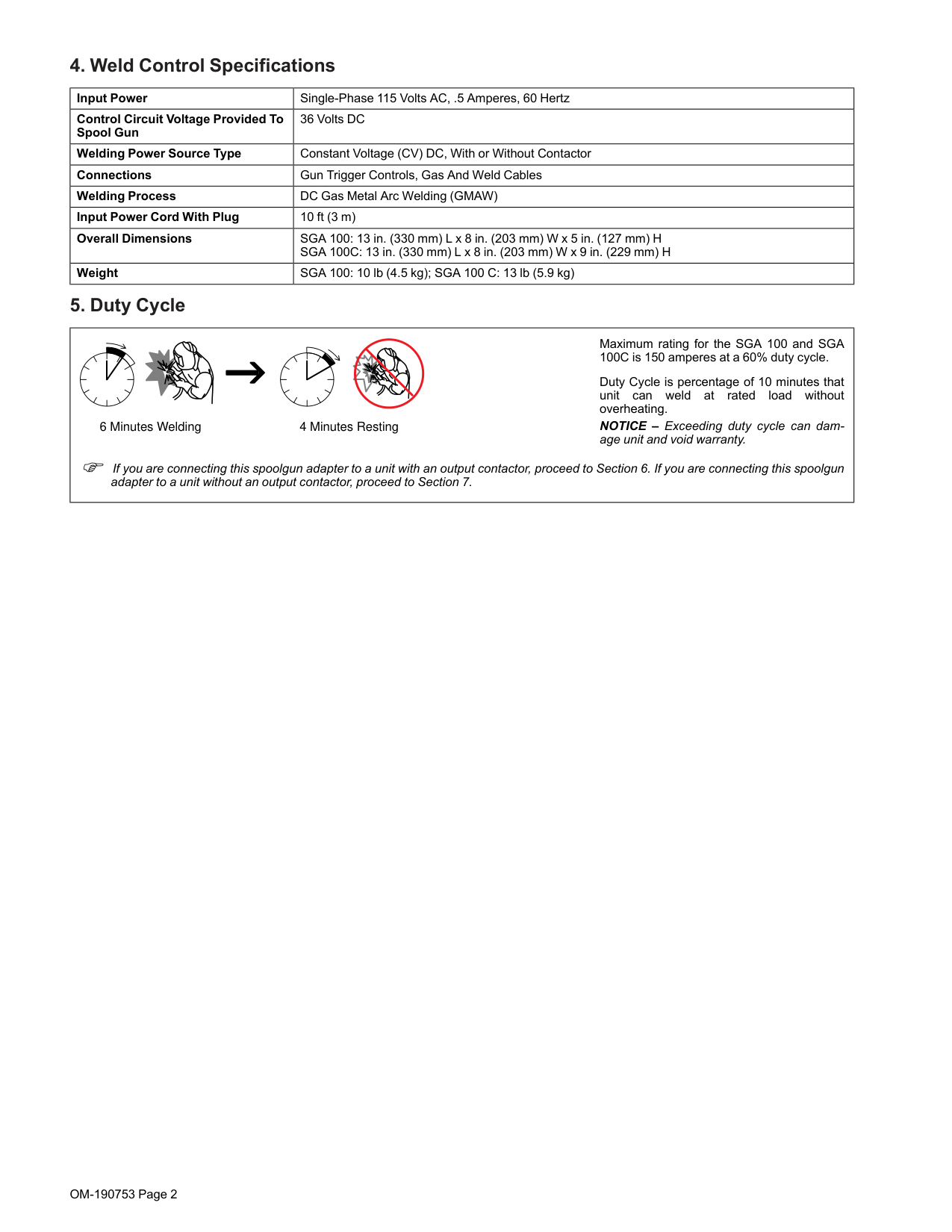
6 Minutes Welding 4 Minutes Resting
Maximum rating for the SGA 100 and SGA 100C is 150 amperes at a 60% duty cycle.
Duty Cycle is percentage of 10 minutes that unit can weld at rated load without overheating.
NOTICE – Exceeding duty cycle can damage unit and void warranty.
If you are connecting this spoolgun adapter to a unit with an output contactor, proceed to Section 6. If you are connecting this spoolgun adapter to a unit without an output contactor, proceed to Section 7.
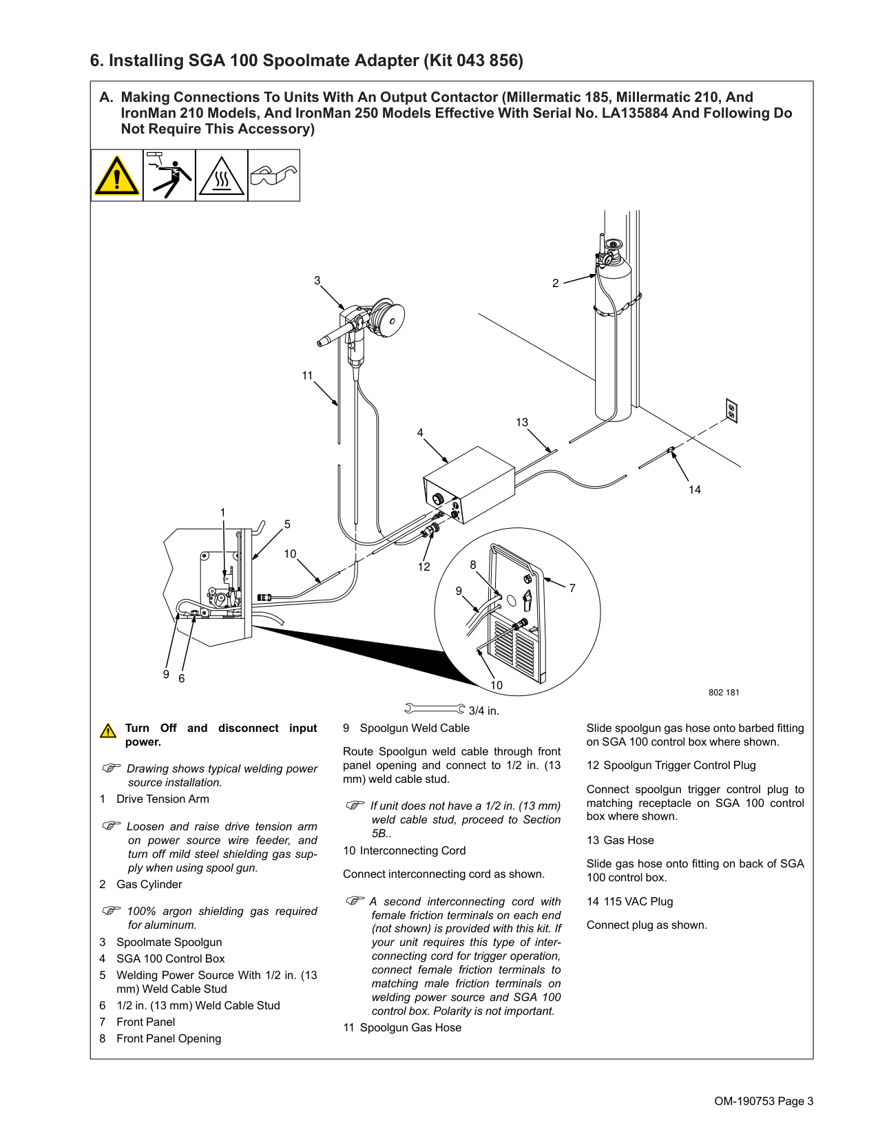
6. Installing SGA 100 Spoolmate Adapter (Kit 043 856)
#### A. Making Connections To Units With An Output Contactor (Millermatic 185, Millermatic 210, And IronMan 210 Models, And IronMan 250 Models Effective With Serial No. LA135884 And Following Do Not Require This Accessory)
23
11
13
4
14 1
5
10
8 9
12
7
NGO’s
9
6
10
802 181
3/4 in.
##### Turn Off and disconnect input power.
Connect spoolgun trigger control plug to matching receptacle on SGA 100 control box where shown.
Slide gas hose onto fitting on back of SGA 100 control box.
Route Spoolgun weld cable through front panel opening and connect to 1/2 in. (13 mm) weld cable stud.
If unit does not have a 1/2 in. (13 mm) weld cable stud, proceed to Section 5B..
A second interconnecting cord with female friction terminals on each end (not shown) is provided with this kit. If your unit requires this type of interconnecting cord for trigger operation, connect female friction terminals to matching male friction terminals on welding power source and SGA 100 control box. Polarity is not important.
flathead philips head wrench
Drawing shows typical welding power source installation.
Loosen and raise drive tension arm on power source wire feeder, and turn off mild steel shielding gas supply when using spool gun.
100% argon shielding gas required for aluminum.
knife
steelbrush nutdriver
chippinghammer
heavy-duty workclamp wirecutter frontcutter
| | |---| | | | |
OM-190753 Page 3
#### B. Connecting Spoolmate Spoolgun Weld Cable To Units Without A 1/2 in. Weld Cable Stud
2
| | | |---|---| | | | | | |
4
tools/
1/2 in.
| | | |---|---| | | |
allen_wrench
allen_wrench
allen_set
philips head wrench
3
5
1
802 181
| | | | | |---|---|---|---| | | | | |
5/16 in.
pliers
##### Turn Off and disconnect input power.
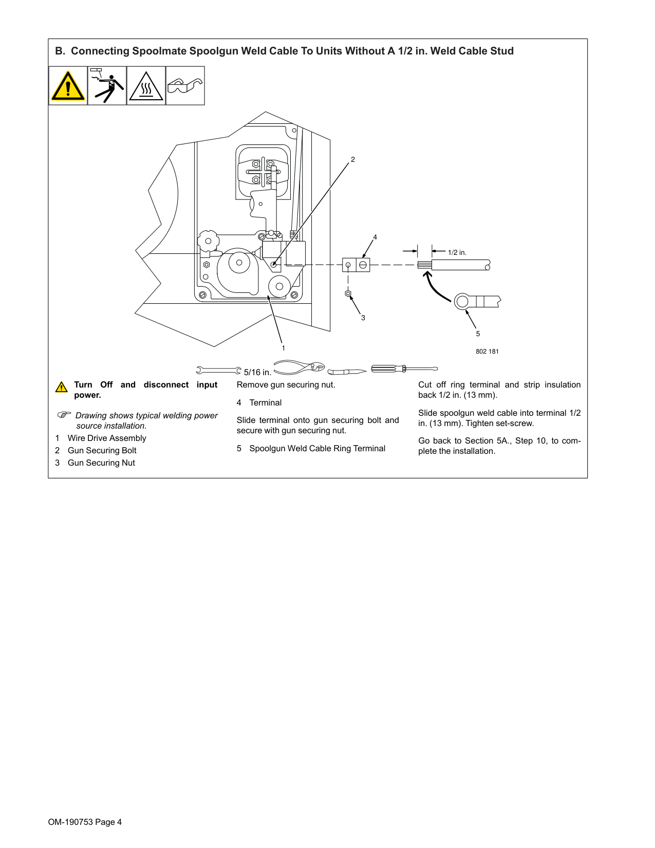
Slide terminal onto gun securing bolt and secure with gun securing nut.
Cut off ring terminal and strip insulation back 1/2 in. (13 mm).
allen_wrench philips head wrench
allen_set
knife steelbrush
pliers
needlenose steelbrush nutdriver
flathead philips head wrench
crescent wrench
Slide spoolgun weld cable into terminal 1/2 in. (13 mm). Tighten set-screw.
Drawing shows typical welding power source installation.
Go back to Section 5A., Step 10, to complete the installation.
| | | | | |---|---|---|---| | | | | | | | | | | | | | | |
pliers knife
needlenose steelbrush nutdriver
e steelbrush
nutdriver
| | | | |---|---|---| | | | | | | | |
| | |---| | | | | | | | |
| | | |---|---| | | |
| | | |---|---| | | |
| | |---| | | | |
| | | |---|---| | | |
| | | | |---|---|---| | | | |
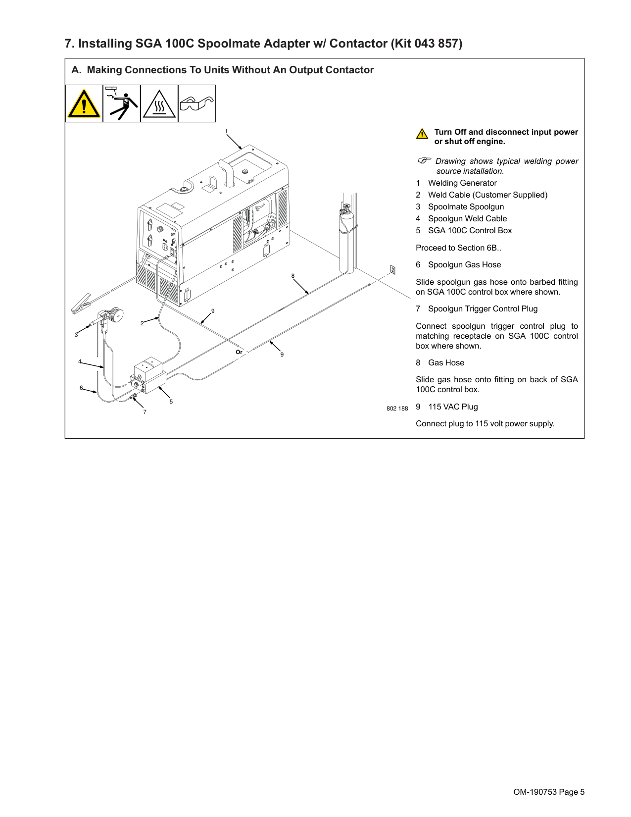
7. Installing SGA 100C Spoolmate Adapter w/ Contactor (Kit 043 857)
#### A. Making Connections To Units Without An Output Contactor
3
1
9
2
4
Or
8
9
6
5
7
##### Turn Off and disconnect input power or shut off engine.
802 188
Drawing shows typical welding power source installation.
Slide spoolgun gas hose onto barbed fitting on SGA 100C control box where shown.
Connect spoolgun trigger control plug to matching receptacle on SGA 100C control box where shown.
Slide gas hose onto fitting on back of SGA 100C control box.
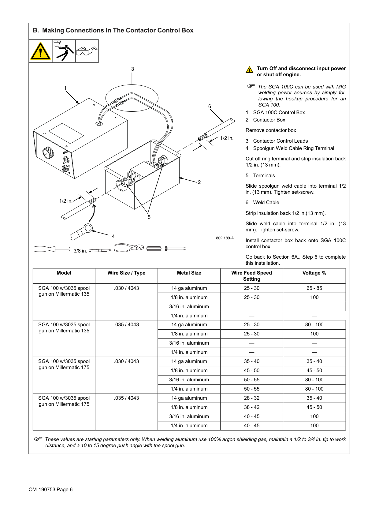
#### B. Making Connections In The Contactor Control Box
##### Turn Off and disconnect input power or shut off engine.
3
The SGA 100C can be used with MIG welding power sources by simply following the hookup procedure for an SGA 100.
1
6
Cut off ring terminal and strip insulation back 1/2 in. (13 mm).
Slide spoolgun weld cable into terminal 1/2 in. (13 mm). Tighten set-screw.
1/2 in.
NGO’s tools/
NGO’s tools/
2
| | | |---|---| |flat|e|
| | | | |---|---|---| | | | | | | | |
1/2 in.
allen_wrench
flathead
philips head wrench
crescent wrench
allen_set
wrench
crescent wrench
5
Slide weld cable into terminal 1/2 in. (13 mm). Tighten set-screw.
4
802 189-A
Install contactor box back onto SGA 100C control box.
| | | | |---|---|---| | | | |
3/8 in.
Go back to Section 6A., Step 6 to complete this installation.
allen_wrench wrench
steelbrush nutdriver
crescent wrench
chippinghammer
chippinghammer
Model Wire Size / Type Metal Size Wire Feed Speed Setting
Voltage %
SGA 100 w/3035 spool gun on Millermatic 135
.030 / 4043 14 ga aluminum 25 - 30 65 - 85
1/8 in. aluminum 25 - 30 100 3/16 in. aluminum — —
| | | |---|---| | | |
| | | |---|---| | | | | | |
pliers
needlenose steelbrush nutdriver
1/4 in. aluminum — —
heavy-duty workclamp light-duty workclamp wirecutter
ht-duty workclamp
stripcrimp
heavy-duty workclamp light-duty workclamp frontcutter
stripcrimp
chippinghammer
SGA 100 w/3035 spool gun on Millermatic 135
.035 / 4043 14 ga aluminum 25 - 30 80 - 100
1/8 in. aluminum 25 - 30 100 3/16 in. aluminum — —
1/4 in. aluminum — —
SGA 100 w/3035 spool gun on Millermatic 175
.030 / 4043 14 ga aluminum 35 - 40 35 - 40
1/8 in. aluminum 45 - 50 45 - 50 3/16 in. aluminum 50 - 55 80 - 100
solderiron stripcrimp
heavy-duty workclamp light-duty workclamp wirecutter frontcutter
torque screwdriver
torque screwdriver
1/4 in. aluminum 50 - 55 80 - 100
SGA 100 w/3035 spool gun on Millermatic 175
.035 / 4043 14 ga aluminum 28 - 32 35 - 40
drilltorque wrenchsocket wrench greasegun
greasegun filterwrench
greasegun
drilltorque wrenchsocket wrench
filterwrench
1/8 in. aluminum 38 - 42 45 - 50 3/16 in. aluminum 40 - 45 100
1/4 in. aluminum 40 - 45 100
torque screwdriver
handream
These values are starting parameters only. When welding aluminum use 100% argon shielding gas, maintain a 1/2 to 3/4 in. tip to work distance, and a 10 to 15 degree push angle with the spool gun.
drilltorque wrenchsocket wrench greasegun filterwrench
| | | |---|---| | | |
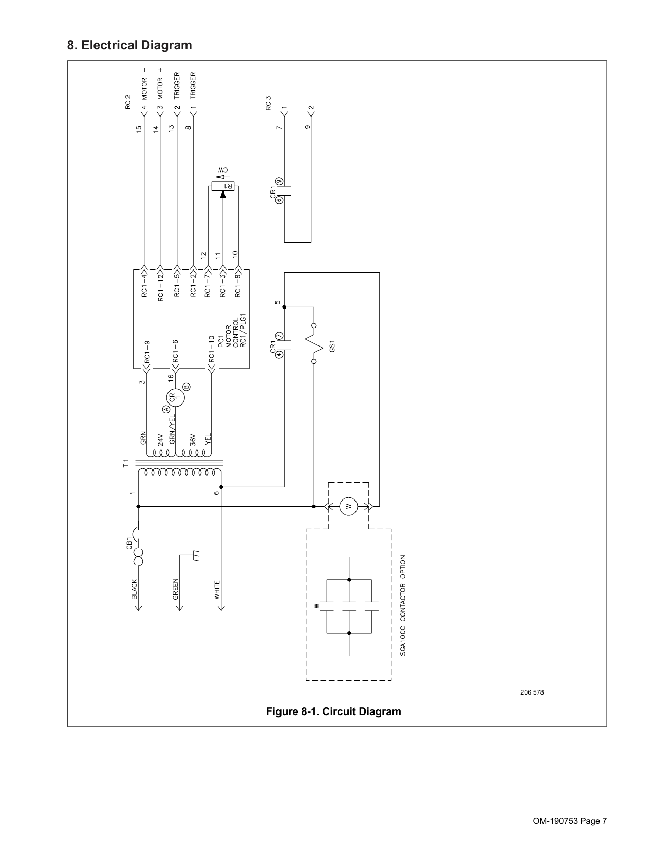
8. Electrical Diagram
206 578 Figure 8-1. Circuit Diagram
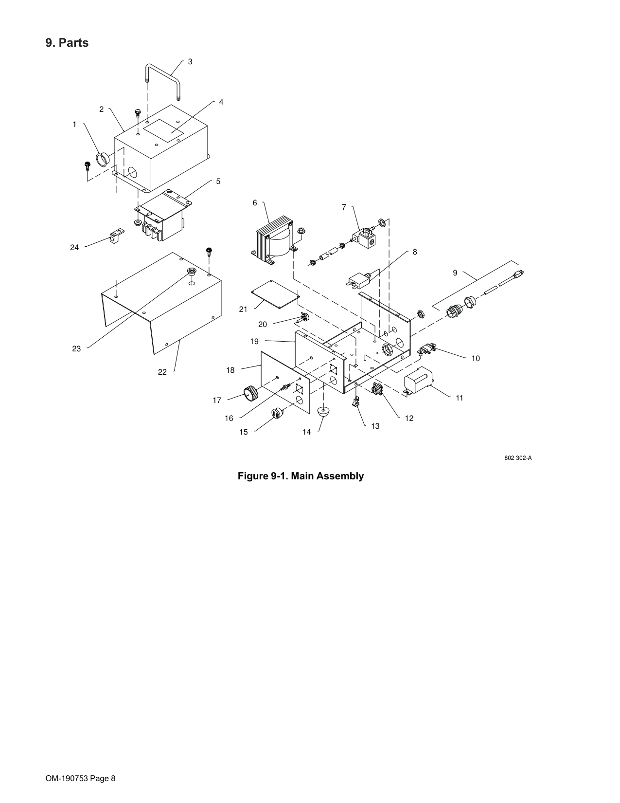
9. Parts
3
1
2
6
22
21
18
7
8
17
12
16
13 1415
9
10
11
#### Figure 9-1. Main Assembly
802 302-A
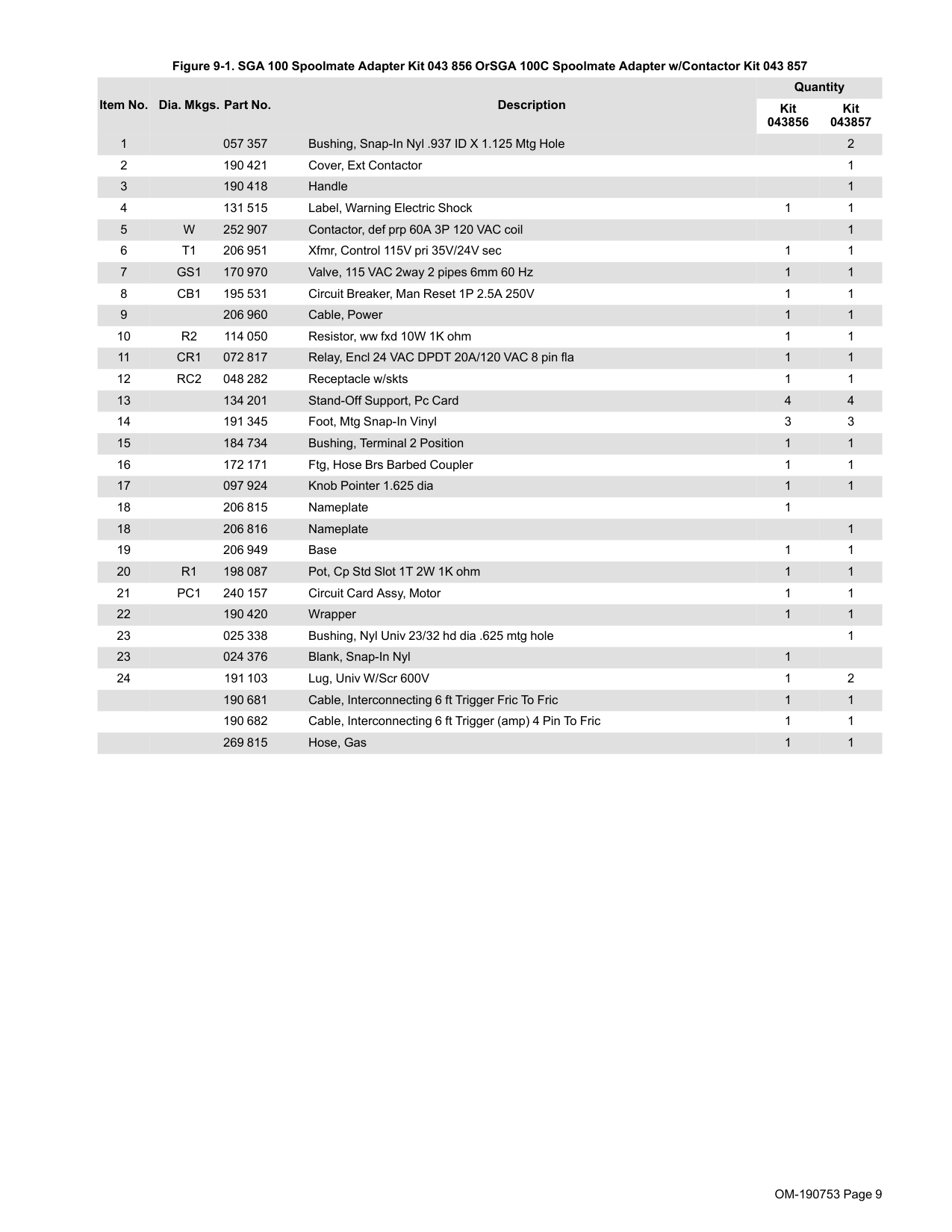
Figure 9-1. SGA 100 Spoolmate Adapter Kit 043 856 OrSGA 100C Spoolmate Adapter w/Contactor Kit 043 857
Quantity Kit 043856
Item No. Dia. Mkgs. Part No. Description
Kit 043857