
Ask AI
— answers from the official manualAnswers from the official manual.
Common questions
Common Questions
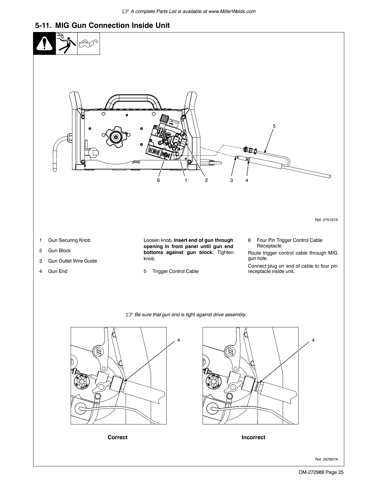
19 totalWhat is included in the Miller Multimatic 215 package?
The Miller Multimatic 215 comes with a MIG/multiprocess power source, MIG gun, TIG kit, cable electrode holder, work cable, 6.5 ft. power cord, flow gauge regulator with gas hose, Hobart spool of .030 in. solid wire, 2 contact tips, Quick Select drive roll for flux-cored wire, material thickness gauge, and hook-and-loop cord wraps. Note that shielding gas and safety equipment must be purchased separately.
How do I change drive rolls or wire inlet guide on my Miller Multimatic 215?
Refer to Section 7-3 for detailed instructions. Disconnect power supply, wait 5 minutes, and unplug the machine before making any changes to prevent electrical injury.
How do I safely handle compressed gas cylinders for my Miller Multimatic 215?
Protect compressed gas cylinders from excessive heat, mechanical shocks, physical damage, slag, open flames, sparks, and arcs. Install cylinders in an upright position by securing to a stationary support or cylinder rack to prevent falling or tipping. Keep cylinders away from welding circuits and do not allow weld equipment near cylinders.
How can I set up the Miller Multimatic 215 for TIG (GTAW) welding?
For TIG welding, follow the process/polarity table provided in Section 5-9 of your manual to establish connections and settings. Use DCEN polarity by connecting the negative cable to the workpiece and positive cable to the tungsten electrode.
What should I do if my Miller Multimatic 215 overheats?
If your unit overheats, wait fifteen minutes for it to cool before attempting to weld again. Reduce amperage or duty cycle settings as specified in Sections 4-7 through 4-9 of the manual.
What are the safety precautions during MIG (GMAW) welding?
Maintain proper ventilation and avoid breathing fumes or gases. Ensure that all electrical parts are properly grounded when connecting your device for MIG welding as outlined in Section 5-1 of the manual.
Show 13 more questions
What are the duty cycle specifications for Stick (SMAW) welding?
How can I install the MVP (Multi-Voltage Plug) on my Miller Multimatic 215?
What welding processes does the Miller Multimatic 215 support?
Can the Miller Multimatic 215 weld aluminum, and what thickness can it handle?
How do I set up the Miller Multimatic 215 for operation?
What power sources can the Miller Multimatic 215 connect to?
What should I do if the Miller Multimatic 215 shuts down during welding?
How do I troubleshoot poor weld quality on the Miller Multimatic 215?
What should I check if the Miller Multimatic 215 has wire feeding issues?
What do I do if the Miller Multimatic 215 has no power?
What material thicknesses can the Miller Multimatic 215 weld?
What should I do if an error code appears while using my Miller Multimatic 215?
What safety measures should be taken when setting up my welding environment?
Full Manual
76 pages


OM-272989D 2019−02
Processes

Multiprocess Welding
Description


Arc Welding Power Source Wire Feeder
Multimatic 215
File: MultiprocessFor product information, Owner’s Manual translations, and more, visit
######### www.MillerWelds.com

From Miller to You
Thank you and congratulations on choosing Miller. Now you can get the job done and get it done right. We know you don’t have time to do it any other way.
That’s why when Niels Miller first started building arc welders in 1929, he made sure his products offered long-lasting value and superior quality. Like you, his customers couldn’t afford anything less. Miller products had to be more than the best they could be. They had to be the best you could buy.
Today, the people that build and sell Miller products continue the tradition. They’re just as committed to providing equipment and service that meets the high standards of quality and value established in 1929. This Owner’s Manual is designed to help you get the most out of your Miller products. Please take time to read the Safety Precautions. They will help you protect yourself against potential hazards on the worksite.
We’ve made installation and operation quick and easy. With Miller, you can count on years of reliable service with proper maintenance. And if for some reason the unit needs repair, there’s a Troubleshooting section that will help you figure out what the problem is, and our extensive service network is there to help fix the problem. Warranty and maintenance information for your particular model are also provided.

Miller is the first welding equipment manufacturer in the U.S.A. to be registered to the ISO 9001 Quality System Standard.

Miller Electric manufactures a full line of welders and welding-related equipment. For information on other quality Miller products, contact your local Miller distributor to receive the latest full line catalog or individual specification sheets. To locate your nearest distributor or service agency call 1-800-4-A-Miller, or visit us at www.MillerWelds.com on the web.
Mil_Thank1 2019−01
|
Working as hard as you do − every power source from Miller is backed by the most hassle-free warranty in the business.

| |---|
################ SECTION 1 − SAFETY PRECAUTIONS - READ BEFORE USING 1.................................
################ SECTION 2 − CONSIGNES DE SÉCURITÉ − LIRE AVANT UTILISATION 5...........................
################ SECTION 3 − DEFINITIONS 9..................................................................
################ SECTION 4 − SPECIFICATIONS 11..............................................................
################ SECTION 5 − INSTALLATION 16................................................................
##### SECTION 1 − SAFETY PRECAUTIONS - READ BEFORE USING
som 2018−01
7
Protect yourself and others from injury — read, follow, and save these important safety precautions and operating instructions.
####### 1-1. Symbol Usage
DANGER! − Indicates a hazardous situation which, if not avoided, will result in death or serious injury. The possible hazards are shown in the adjoining symbols or explained in the text.
Indicates a hazardous situation which, if not avoided, could result in death or serious injury. The possible hazards are shown in the adjoining symbols or explained in the text.
NOTICE − Indicates statements not related to personal injury.
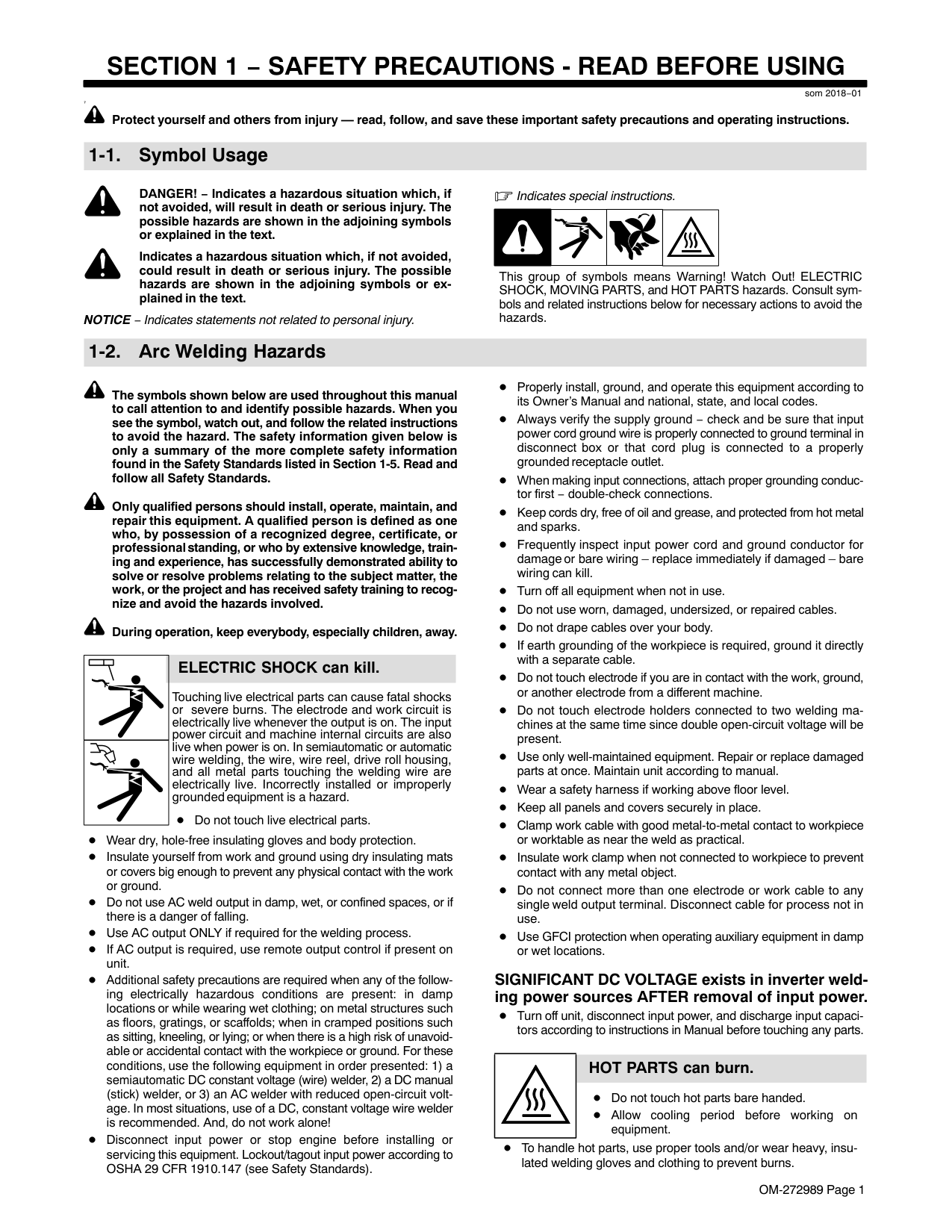
####### 1-2. Arc Welding Hazards
Indicates special instructions.
| | | | |---|---|---|
This group of symbols means Warning! Watch Out! ELECTRIC SHOCK, MOVING PARTS, and HOT PARTS hazards. Consult symbols and related instructions below for necessary actions to avoid the hazards.
The symbols shown below are used throughout this manual to call attention to and identify possible hazards. When you see the symbol, watch out, and follow the related instructions to avoid the hazard. The safety information given below is only a summary of the more complete safety information found in the Safety Standards listed in Section 1-5. Read and follow all Safety Standards.
Only qualified persons should install, operate, maintain, and repair this equipment. A qualified person is defined as one who, by possession of a recognized degree, certificate, or professional standing, or who by extensive knowledge, training and experience, has successfully demonstrated ability to solve or resolve problems relating to the subject matter, the work, or the project and has received safety training to recognize and avoid the hazards involved.
During operation, keep everybody, especially children, away.
| | |---| | |
######### ELECTRIC SHOCK can kill.
Touching live electrical parts can cause fatal shocks or severe burns. The electrode and work circuit is electrically live whenever the output is on. The input power circuit and machine internal circuits are also live when power is on. In semiautomatic or automatic wire welding, the wire, wire reel, drive roll housing, and all metal parts touching the welding wire are electrically live. Incorrectly installed or improperly grounded equipment is a hazard.
Do not touch live electrical parts.
Wear dry, hole-free insulating gloves and body protection.
Insulate yourself from work and ground using dry insulating mats or covers big enough to prevent any physical contact with the work or ground.
Do not use AC weld output in damp, wet, or confined spaces, or if there is a danger of falling. Use AC output ONLY if required for the welding process. If AC output is required, use remote output control if present on unit.
Additional safety precautions are required when any of the following electrically hazardous conditions are present: in damp locations or while wearing wet clothing; on metal structures such as floors, gratings, or scaffolds; when in cramped positions such as sitting, kneeling, or lying; or when there is a high risk of unavoidable or accidental contact with the workpiece or ground. For these conditions, use the following equipment in order presented: 1) a semiautomatic DC constant voltage (wire) welder, 2) a DC manual (stick) welder, or 3) an AC welder with reduced open-circuit voltage. In most situations, use of a DC, constant voltage wire welder is recommended. And, do not work alone!
Disconnect input power or stop engine before installing or servicing this equipment. Lockout/tagout input power according to OSHA 29 CFR 1910.147 (see Safety Standards).
Properly install, ground, and operate this equipment according to its Owner’s Manual and national, state, and local codes.
Always verify the supply ground − check and be sure that input power cord ground wire is properly connected to ground terminal in disconnect box or that cord plug is connected to a properly grounded receptacle outlet.
When making input connections, attach proper grounding conductor first − double-check connections. Keep cords dry, free of oil and grease, and protected from hot metal and sparks.
Frequently inspect input power cord and ground conductor for damage or bare wiring – replace immediately if damaged – bare wiring can kill.
Turn off all equipment when not in use. Do not use worn, damaged, undersized, or repaired cables. Do not drape cables over your body. If earth grounding of the workpiece is required, ground it directly with a separate cable. Do not touch electrode if you are in contact with the work, ground, or another electrode from a different machine.
Do not touch electrode holders connected to two welding machines at the same time since double open-circuit voltage will be present.
Use only well-maintained equipment. Repair or replace damaged parts at once. Maintain unit according to manual. Wear a safety harness if working above floor level. Keep all panels and covers securely in place. Clamp work cable with good metal-to-metal contact to workpiece or worktable as near the weld as practical. Insulate work clamp when not connected to workpiece to prevent contact with any metal object.
Do not connect more than one electrode or work cable to any single weld output terminal. Disconnect cable for process not in use.
Use GFCI protection when operating auxiliary equipment in damp or wet locations.
######### SIGNIFICANT DC VOLTAGE exists in inverter welding power sources AFTER removal of input power.
Turn off unit, disconnect input power, and discharge input capacitors according to instructions in Manual before touching any parts.
| | |---|
######### HOT PARTS can burn.
Do not touch hot parts bare handed. Allow cooling period before working on equipment.
To handle hot parts, use proper tools and/or wear heavy, insulated welding gloves and clothing to prevent burns.
| | |---|
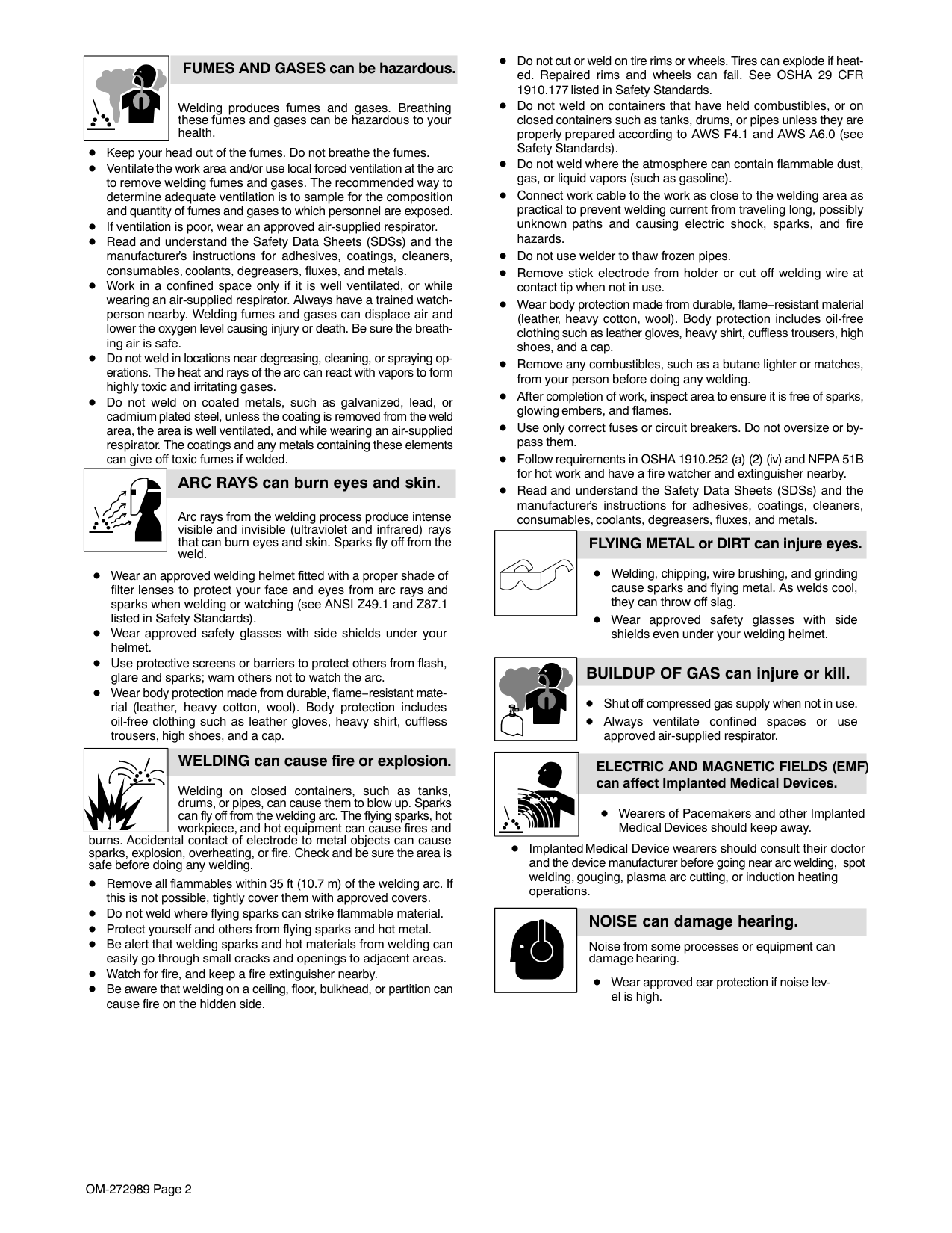
############ FUMES AND GASES can be hazardous.
Welding produces fumes and gases. Breathing these fumes and gases can be hazardous to your health.
Keep your head out of the fumes. Do not breathe the fumes. Ventilate the work area and/or use local forced ventilation at the arc to remove welding fumes and gases. The recommended way to determine adequate ventilation is to sample for the composition and quantity of fumes and gases to which personnel are exposed. If ventilation is poor, wear an approved air-supplied respirator.
Read and understand the Safety Data Sheets (SDSs) and the manufacturer’s instructions for adhesives, coatings, cleaners, consumables, coolants, degreasers, fluxes, and metals.
Work in a confined space only if it is well ventilated, or while wearing an air-supplied respirator. Always have a trained watchperson nearby. Welding fumes and gases can displace air and lower the oxygen level causing injury or death. Be sure the breathing air is safe.
Do not weld in locations near degreasing, cleaning, or spraying operations. The heat and rays of the arc can react with vapors to form highly toxic and irritating gases.
Do not weld on coated metals, such as galvanized, lead, or cadmium plated steel, unless the coating is removed from the weld area, the area is well ventilated, and while wearing an air-supplied respirator. The coatings and any metals containing these elements can give off toxic fumes if welded.
| | |---|
######### ARC RAYS can burn eyes and skin.
Arc rays from the welding process produce intense visible and invisible (ultraviolet and infrared) rays that can burn eyes and skin. Sparks fly off from the weld.
Wear an approved welding helmet fitted with a proper shade of filter lenses to protect your face and eyes from arc rays and sparks when welding or watching (see ANSI Z49.1 and Z87.1 listed in Safety Standards).
Wear approved safety glasses with side shields under your helmet. Use protective screens or barriers to protect others from flash, glare and sparks; warn others not to watch the arc.
Wear body protection made from durable, flame−resistant material (leather, heavy cotton, wool). Body protection includes oil-free clothing such as leather gloves, heavy shirt, cuffless trousers, high shoes, and a cap.
| | |---|
########### WELDING can cause fire or explosion.
Welding on closed containers, such as tanks, drums, or pipes, can cause them to blow up. Sparks can fly off from the welding arc. The flying sparks, hot workpiece, and hot equipment can cause fires and
burns. Accidental contact of electrode to metal objects can cause sparks, explosion, overheating, or fire. Check and be sure the area is safe before doing any welding.
Remove all flammables within 35 ft (10.7 m) of the welding arc. If this is not possible, tightly cover them with approved covers. Do not weld where flying sparks can strike flammable material. Protect yourself and others from flying sparks and hot metal. Be alert that welding sparks and hot materials from welding can easily go through small cracks and openings to adjacent areas. Watch for fire, and keep a fire extinguisher nearby. Be aware that welding on a ceiling, floor, bulkhead, or partition can cause fire on the hidden side.
Do not cut or weld on tire rims or wheels. Tires can explode if heated. Repaired rims and wheels can fail. See OSHA 29 CFR 1910.177 listed in Safety Standards.
Do not weld on containers that have held combustibles, or on closed containers such as tanks, drums, or pipes unless they are properly prepared according to AWS F4.1 and AWS A6.0 (see Safety Standards).
Do not weld where the atmosphere can contain flammable dust, gas, or liquid vapors (such as gasoline).
Connect work cable to the work as close to the welding area as practical to prevent welding current from traveling long, possibly unknown paths and causing electric shock, sparks, and fire hazards.
Do not use welder to thaw frozen pipes. Remove stick electrode from holder or cut off welding wire at contact tip when not in use.
Wear body protection made from durable, flame−resistant material (leather, heavy cotton, wool). Body protection includes oil-free clothing such as leather gloves, heavy shirt, cuffless trousers, high shoes, and a cap.
Remove any combustibles, such as a butane lighter or matches, from your person before doing any welding. After completion of work, inspect area to ensure it is free of sparks, glowing embers, and flames. Use only correct fuses or circuit breakers. Do not oversize or bypass them. Follow requirements in OSHA 1910.252 (a) (2) (iv) and NFPA 51B for hot work and have a fire watcher and extinguisher nearby.
Read and understand the Safety Data Sheets (SDSs) and the manufacturer’s instructions for adhesives, coatings, cleaners, consumables, coolants, degreasers, fluxes, and metals.
############ FLYING METAL or DIRT can injure eyes.
Welding, chipping, wire brushing, and grinding cause sparks and flying metal. As welds cool, they can throw off slag.
Wear approved safety glasses with side shields even under your welding helmet.
######### BUILDUP OF GAS can injure or kill.
Shut off compressed gas supply when not in use. Always ventilate confined spaces or use approved air-supplied respirator.
| | |---|
############### ELECTRIC AND MAGNETIC FIELDS (EMF) can affect Implanted Medical Devices.
Wearers of Pacemakers and other Implanted Medical Devices should keep away.
Implanted Medical Device wearers should consult their doctor and the device manufacturer before going near arc welding, spot welding, gouging, plasma arc cutting, or induction heating operations.
| | |---|
######### NOISE can damage hearing.
Noise from some processes or equipment can damage hearing.
Wear approved ear protection if noise level is high.
||
|---|
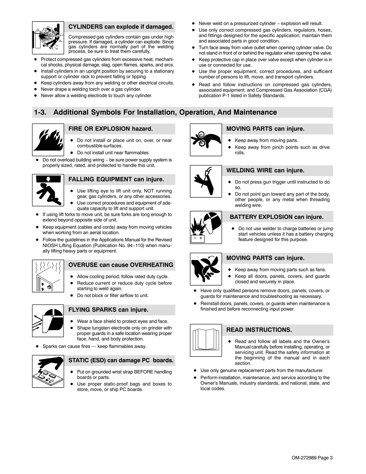
######### CYLINDERS can explode if damaged.
Compressed gas cylinders contain gas under high pressure. If damaged, a cylinder can explode. Since gas cylinders are normally part of the welding process, be sure to treat them carefully.
Protect compressed gas cylinders from excessive heat, mechanical shocks, physical damage, slag, open flames, sparks, and arcs. Install cylinders in an upright position by securing to a stationary support or cylinder rack to prevent falling or tipping. Keep cylinders away from any welding or other electrical circuits. Never drape a welding torch over a gas cylinder. Never allow a welding electrode to touch any cylinder.
Never weld on a pressurized cylinder − explosion will result.
Use only correct compressed gas cylinders, regulators, hoses, and fittings designed for the specific application; maintain them and associated parts in good condition.
Turn face away from valve outlet when opening cylinder valve. Do not stand in front of or behind the regulator when opening the valve. Keep protective cap in place over valve except when cylinder is in use or connected for use. Use the proper equipment, correct procedures, and sufficient number of persons to lift, move, and transport cylinders.
Read and follow instructions on compressed gas cylinders, associated equipment, and Compressed Gas Association (CGA) publication P-1 listed in Safety Standards.
####### 1-3. Additional Symbols For Installation, Operation, And Maintenance
######### FIRE OR EXPLOSION hazard.
Do not install or place unit on, over, or near combustible surfaces. Do not install unit near flammables.
Do not overload building wiring − be sure power supply system is properly sized, rated, and protected to handle this unit.
######### FALLING EQUIPMENT can injure.
Use lifting eye to lift unit only, NOT running gear, gas cylinders, or any other accessories. Use correct procedures and equipment of adequate capacity to lift and support unit.
If using lift forks to move unit, be sure forks are long enough to extend beyond opposite side of unit.
Keep equipment (cables and cords) away from moving vehicles when working from an aerial location.
Follow the guidelines in the Applications Manual for the Revised NIOSH Lifting Equation (Publication No. 94−110) when manually lifting heavy parts or equipment.
######### OVERUSE can cause OVERHEATING
Allow cooling period; follow rated duty cycle. Reduce current or reduce duty cycle before starting to weld again. Do not block or filter airflow to unit.
######### FLYING SPARKS can injure.
Wear a face shield to protect eyes and face.
Shape tungsten electrode only on grinder with proper guards in a safe location wearing proper face, hand, and body protection.
Sparks can cause fires — keep flammables away.
########### STATIC (ESD) can damage PC boards.
Put on grounded wrist strap BEFORE handling boards or parts. Use proper static-proof bags and boxes to store, move, or ship PC boards.
######### MOVING PARTS can injure.
Keep away from moving parts. Keep away from pinch points such as drive rolls.
######### WELDING WIRE can injure.
Do not press gun trigger until instructed to do so.
Do not point gun toward any part of the body, other people, or any metal when threading welding wire.
########### BATTERY EXPLOSION can injure.
Do not use welder to charge batteries or jump start vehicles unless it has a battery charging feature designed for this purpose.
######### MOVING PARTS can injure.
Keep away from moving parts such as fans. Keep all doors, panels, covers, and guards closed and securely in place.
Have only qualified persons remove doors, panels, covers, or guards for maintenance and troubleshooting as necessary. Reinstall doors, panels, covers, or guards when maintenance is finished and before reconnecting input power.
| | |---|
######### READ INSTRUCTIONS.
Read and follow all labels and the Owner’s Manual carefully before installing, operating, or servicing unit. Read the safety information at the beginning of the manual and in each section.
Use only genuine replacement parts from the manufacturer.
Perform installation, maintenance, and service according to the Owner’s Manuals, industry standards, and national, state, and local codes.
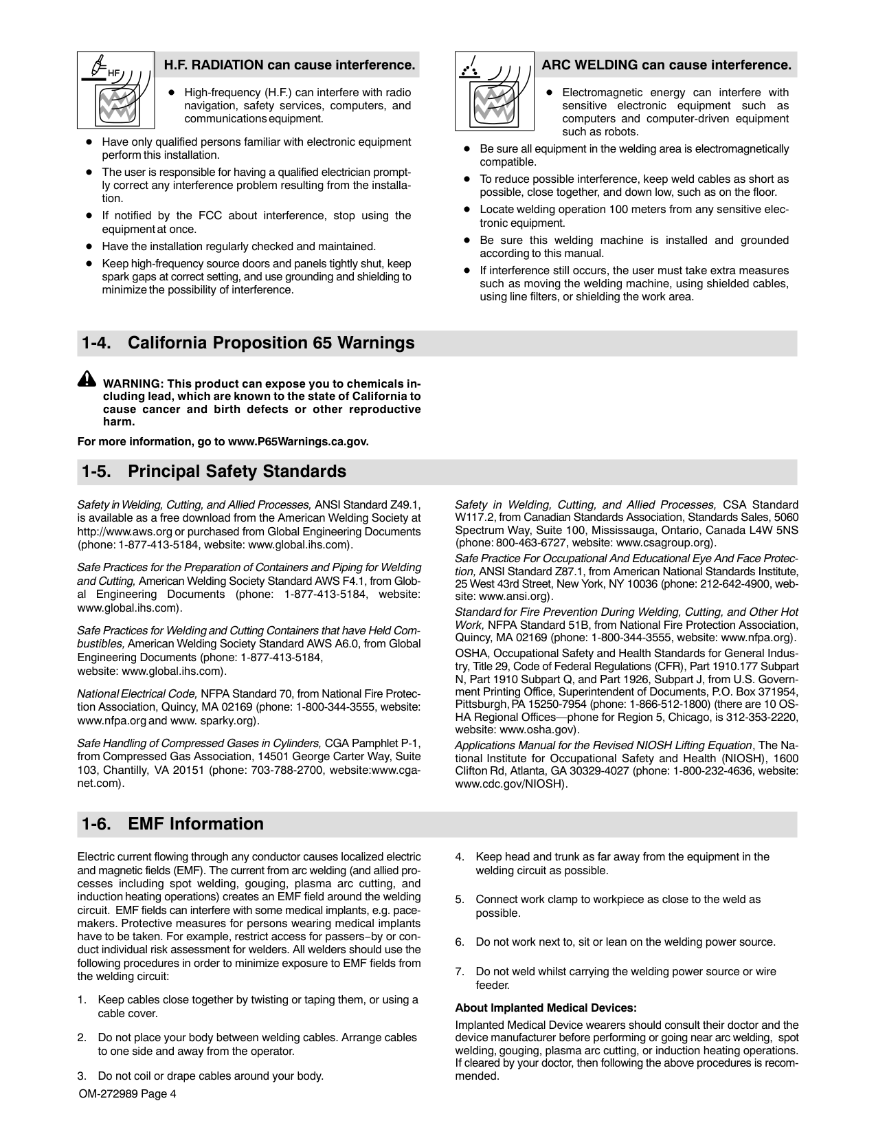
############# H.F. RADIATION can cause interference.
############# ARC WELDING can cause interference.
High-frequency (H.F.) can interfere with radio navigation, safety services, computers, and communications equipment.
Electromagnetic energy can interfere with sensitive electronic equipment such as computers and computer-driven equipment such as robots.
Have only qualified persons familiar with electronic equipment perform this installation.
Be sure all equipment in the welding area is electromagnetically compatible.
The user is responsible for having a qualified electrician promptly correct any interference problem resulting from the installation.
To reduce possible interference, keep weld cables as short as possible, close together, and down low, such as on the floor.
Locate welding operation 100 meters from any sensitive electronic equipment. Be sure this welding machine is installed and grounded according to this manual.
If notified by the FCC about interference, stop using the equipment at once. Have the installation regularly checked and maintained.
Keep high-frequency source doors and panels tightly shut, keep spark gaps at correct setting, and use grounding and shielding to minimize the possibility of interference.
If interference still occurs, the user must take extra measures such as moving the welding machine, using shielded cables, using line filters, or shielding the work area.
####### 1-4. California Proposition 65 Warnings
WARNING: This product can expose you to chemicals including lead, which are known to the state of California to cause cancer and birth defects or other reproductive harm.
For more information, go to www.P65Warnings.ca.gov.
####### 1-5. Principal Safety Standards
Safety in Welding, Cutting, and Allied Processes, ANSI Standard Z49.1, is available as a free download from the American Welding Society at http://www.aws.org or purchased from Global Engineering Documents (phone: 1-877-413-5184, website: www.global.ihs.com).
Safe Practices for the Preparation of Containers and Piping for Welding and Cutting, American Welding Society Standard AWS F4.1, from Global Engineering Documents (phone: 1-877-413-5184, website: www.global.ihs.com).
Safe Practices for Welding and Cutting Containers that have Held Combustibles, American Welding Society Standard AWS A6.0, from Global Engineering Documents (phone: 1-877-413-5184, website: www.global.ihs.com).
National Electrical Code, NFPA Standard 70, from National Fire Protection Association, Quincy, MA 02169 (phone: 1-800-344-3555, website: www.nfpa.org and www. sparky.org).
Safe Handling of Compressed Gases in Cylinders, CGA Pamphlet P-1, from Compressed Gas Association, 14501 George Carter Way, Suite 103, Chantilly, VA 20151 (phone: 703-788-2700, website:www.cganet.com).
Safety in Welding, Cutting, and Allied Processes, CSA Standard W117.2, from Canadian Standards Association, Standards Sales, 5060 Spectrum Way, Suite 100, Mississauga, Ontario, Canada L4W 5NS (phone: 800-463-6727, website: www.csagroup.org).
Safe Practice For Occupational And Educational Eye And Face Protection, ANSI Standard Z87.1, from American National Standards Institute, 25 West 43rd Street, New York, NY 10036 (phone: 212-642-4900, website: www.ansi.org).
Standard for Fire Prevention During Welding, Cutting, and Other Hot Work, NFPA Standard 51B, from National Fire Protection Association, Quincy, MA 02169 (phone: 1-800-344-3555, website: www.nfpa.org). OSHA, Occupational Safety and Health Standards for General Industry, Title 29, Code of Federal Regulations (CFR), Part 1910.177 Subpart N, Part 1910 Subpart Q, and Part 1926, Subpart J, from U.S. Government Printing Office, Superintendent of Documents, P.O. Box 371954, Pittsburgh, PA 15250-7954 (phone: 1-866-512-1800) (there are 10 OSHA Regional Offices—phone for Region 5, Chicago, is 312-353-2220, website: www.osha.gov).
Applications Manual for the Revised NIOSH Lifting Equation, The National Institute for Occupational Safety and Health (NIOSH), 1600 Clifton Rd, Atlanta, GA 30329-4027 (phone: 1-800-232-4636, website: www.cdc.gov/NIOSH).
####### 1-6. EMF Information
Electric current flowing through any conductor causes localized electric and magnetic fields (EMF). The current from arc welding (and allied processes including spot welding, gouging, plasma arc cutting, and induction heating operations) creates an EMF field around the welding circuit. EMF fields can interfere with some medical implants, e.g. pacemakers. Protective measures for persons wearing medical implants have to be taken. For example, restrict access for passers−by or conduct individual risk assessment for welders. All welders should use the following procedures in order to minimize exposure to EMF fields from the welding circuit:
################ About Implanted Medical Devices:
Implanted Medical Device wearers should consult their doctor and the device manufacturer before performing or going near arc welding, spot welding, gouging, plasma arc cutting, or induction heating operations. If cleared by your doctor, then following the above procedures is recommended.
##### SECTION 2 − CONSIGNES DE SÉCURITÉ − LIRE AVANT UTILISATION
som_2018−01_fre
7
Pour écarter les risques de blessure pour vous−même et pour autrui — lire, appliquer et ranger en lieu sûr ces consignes relatives aux précautions de sécurité et au mode opératoire.
####### 2-1. Symboles utilisés
DANGER! − Indique une situation dangereuse qui si on l’évite pas peut donner la mort ou des blessures graves. Les dangers possibles sont montrés par les symboles joints ou sont expliqués dans le texte.
Indique une situation dangereuse qui si on l’évite pas peut donner la mort ou des blessures graves. Les dangers possibles sont montrés par les symboles joints ou sont expliqués dans le texte.
AVIS − Indique des déclarations pas en relation avec des blessures personnelles.
####### 2-2. Dangers relatifs au soudage à l’arc
Indique des instructions spécifiques.
| | | | |---|---|---|
Ce groupe de symboles veut dire Avertissement! Attention! DANGER DE CHOC ELECTRIQUE, PIECES EN MOUVEMENT, et PIECES CHAUDES. Consulter les symboles et les instructions ci-dessous y afférant pour les actions nécessaires afin d’éviter le danger.
Les symboles représentés ci-dessous sont utilisés dans ce manuel pour attirer l’attention et identifier les dangers possibles. En présence de l’un de ces symboles, prendre garde et suivre les instructions afférentes pour éviter tout risque. Les instructions en matière de sécurité indiquées ci-dessous ne constituent qu’un sommaire des instructions de sécurité plus complètes fournies dans les normes de sécurité énumérées dans la Section 2-5. Lire et observer toutes les normes de sécurité.
L’installation, l’utilisation, l’entretien et les réparations ne doivent être confiés qu’à des personnes qualifiées. Une personne qualifiée est définie comme celle qui, par la possession d’un diplôme reconnu, d’un certificat ou d’un statut professionnel, ou qui, par une connaissance, une formation et une expérience approfondies, a démontré avec succès sa capacité à résoudre les problèmes liés à la tâche, le travail ou le projet et a reçu une formation en sécurité afin de reconnaître et d’éviter les risques inhérents.
Pendant le fonctionnement, maintenir à distance toutes les personnes, notamment les enfants de l’appareil.
| | |---| | |
######### UNE DÉCHARGE ÉLECTRIQUE peut entraîner la mort.
Le contact d’organes électriques sous tension peut provoquer des accidents mortels ou des brûlures graves. Le circuit de l’électrode et de la pièce est sous tension lorsque le courant est délivré à la sortie. Le circuit d’alimentation et les circuits internes de la machine sont également sous tension lorsque l’alimentation est sur Marche. Dans le mode de soudage avec du fil, le fil, le dérouleur, le bloc de commande du rouleau et toutes les parties métalliques en contact avec le fil sont sous tension électrique. Un équipement installé ou mis à la terre de manière incorrecte ou impropre constitue un danger.
Ne pas toucher aux pièces électriques sous tension. Porter des gants isolants et des vêtements de protection secs et sans trous.
S’isoler de la pièce à couper et du sol en utilisant des housses ou des tapis assez grands afin d’éviter tout contact physique avec la pièce à couper ou le sol.
Ne pas utiliser de sortie de soudage CA dans des zones humides ou confinées ou s’il y a un risque de chute. Se servir d’une source électrique à courant électrique UNIQUEMENT si le procédé de soudage le demande.
Si l’utilisation d’une source électrique à courant électrique s’avère nécessaire, se servir de la fonction de télécommande si l’appareil en est équipé.
D’autres consignes de sécurité sont nécessaires dans les conditions suivantes : risques électriques dans un environnement humide ou si l’on porte des vêtements mouillés ; sur des structures métalliques telles que sols, grilles ou échafaudages ; en position coincée comme assise, à genoux ou couchée ; ou s’il y a un risque élevé de contact inévitable ou accidentel avec la pièce à souder ou le sol. Dans ces conditions, utiliser les équipements suivants, dans l’ordre indiqué : 1) un poste à souder DC à tension constante (à fil), 2) un poste à souder DC manuel (électrode) ou 3) un poste à souder AC à tension à vide réduite. Dans la plupart des situations,
l’utilisation d’un poste à souder DC à fil à tension constante est recommandée. En outre, ne pas travailler seul !

Couper l’alimentation ou arrêter le moteur avant de procéder à l’installation, à la réparation ou à l’entretien de l’appareil. Déverrouiller l’alimentation selon la norme OSHA 29 CFR 1910.147 (voir normes de sécurité).
Installez, mettez à la terre et utilisez correctement cet équipement conformément à son Manuel d’Utilisation et aux réglementations nationales, gouvernementales et locales.
Toujours vérifier la terre du cordon d’alimentation. Vérifier et s’assurer que le fil de terre du cordon d’alimentation est bien raccordé à la borne de terre du sectionneur ou que la fiche du cordon est raccordée à une prise correctement mise à la terre.
En effectuant les raccordements d’entrée, fixer d’abord le conducteur de mise à la terre approprié et contre-vérifier les connexions. Les câbles doivent être exempts d’humidité, d’huile et de graisse; protégez−les contre les étincelles et les pièces métalliques chaudes.
Vérifier fréquemment le cordon d’alimentation et le conducteur de mise à la terre afin de s’assurer qu’il n’est pas altéré ou dénudé −, le remplacer immédiatement s’il l’est −. Un fil dénudé peut entraîner la mort.
L’équipement doit être hors tension lorsqu’il n’est pas utilisé. Ne pas utiliser des câbles usés, endommagés, de grosseur insuffisante ou mal épissés. Ne pas enrouler les câbles autour du corps. Si la pièce soudée doit être mise à la terre, le faire directement avec un câble distinct. Ne pas toucher l’électrode quand on est en contact avec la pièce, la terre ou une électrode provenant d’une autre machine.
Ne pas toucher des porte électrodes connectés à deux machines en même temps à cause de la présence d’une tension à vide doublée.
N’utiliser qu’un matériel en bon état. Réparer ou remplacer sur-lechamp les pièces endommagées. Entretenir l’appareil conformément à ce manuel.
Porter un harnais de sécurité si l’on doit travailler au-dessus du sol. S’assurer que tous les panneaux et couvercles sont correctement en place.
Fixer le câble de retour de façon à obtenir un bon contact métalmétal avec la pièce à souder ou la table de travail, le plus près possible de la soudure.
Isoler la pince de masse quand pas mis à la pièce pour éviter le contact avec tout objet métallique.
Ne pas raccorder plus d’une électrode ou plus d’un câble de masse à une même borne de sortie de soudage. Débrancher le câble pour le procédé non utilisé.
Utiliser une protection différentielle lors de l’utilisation d’un équipement auxiliaire dans des endroits humides ou mouillés.
######### Il reste une TENSION DC NON NÉGLIGEABLE dans les sources de soudage onduleur UNE FOIS l’alimentation coupée.
Éteignez l’unité, débranchez le courant électrique, et déchargez les condensateurs d’alimentation selon les instructions indiquées dans le manuel avant de toucher les pièces.
| | |---|
######### LES PIÈCES CHAUDES peuvent provoquer des brûlures.
Ne pas toucher à mains nues les parties chaudes. Prévoir une période de refroidissement avant de travailler à l’équipement.
Ne pas toucher aux pièces chaudes, utiliser les outils recommandés et porter des gants de soudage et des vêtements épais pour éviter les brûlures.
| |
|---|
######### LES FUMÉES ET LES GAZ peuvent être dangereux.
Le soudage génère des fumées et des gaz. Leur inhalation peut être dangereux pour votre santé.
Eloigner votre tête des fumées. Ne pas respirer les fumées.
À l’intérieur, ventiler la zone et/ou utiliser une ventilation forcée au niveau de l’arc pour l’évacuation des fumées et des gaz de soudage. Pour déterminer la bonne ventilation, il est recommandé de procéder à un prélèvement pour la composition et la quantité de fumées et de gaz auxquelles est exposé le personnel.
Si la ventilation est médiocre, porter un respirateur anti-vapeurs approuvé.
Lire et comprendre les fiches de données de sécurité et les instructions du fabricant concernant les adhésifs, les revêtements, les nettoyants, les consommables, les produits de refroidissement, les dégraisseurs, les flux et les métaux.
Travailler dans un espace fermé seulement s’il est bien ventilé ou en portant un respirateur à alimentation d’air. Demander toujours à un surveillant dûment formé de se tenir à proximité. Des fumées et des gaz de soudage peuvent déplacer l’air et abaisser le niveau d’oxygène provoquant des blessures ou des accidents mortels. S’assurer que l’air de respiration ne présente aucun danger.
Ne pas souder dans des endroits situés à proximité d’opérations de dégraissage, de nettoyage ou de pulvérisation. La chaleur et les rayons de l’arc peuvent réagir en présence de vapeurs et former des gaz hautement toxiques et irritants.
Ne pas souder des métaux munis d’un revêtement, tels que l’acier galvanisé, plaqué en plomb ou au cadmium à moins que le revêtement n’ait été enlevé dans la zone de soudure, que l’endroit soit bien ventilé, et en portant un respirateur à alimentation d’air. Les revêtements et tous les métaux renfermant ces éléments peuvent dégager des fumées toxiques en cas de soudage.
| | |---|
######### LES RAYONS DE L’ARC peuvent provoquer des brûlures dans les yeux et sur la peau.
Le rayonnement de l’arc du procédé de soudage génère des rayons visibles et invisibles intenses (ultraviolets e
infrarouges) susceptibles de provoquer des brûlures dans les yeux et sur la peau. Des étincelles sont projetées pendant le soudage.
Porter un casque de soudage approuvé muni de verres filtrants approprié pour protéger visage et yeux pour protéger votre visage et vos yeux pendant le soudage ou pour regarder (voir ANSI Z49.1 et Z87.1 énuméré dans les normes de sécurité).
Porter des lunettes de sécurité avec écrans latéraux même sous votre casque.
Avoir recours à des écrans protecteurs ou à des rideaux pour protéger les autres contre les rayonnements les éblouissements et les étincelles ; prévenir toute personne sur les lieux de ne pas regarder l’arc.
Porter un équipement de protection pour le corps fait d’un matériau résistant et ignifuge (cuir, coton robuste, laine). La protection du corps comporte des vêtements sans huile comme par ex. des gants de cuir, une chemise solide, des pantalons sans revers, des chaussures hautes et une casquette.
| | |---|
######### LE SOUDAGE peut provoquer un incendie ou une explosion.
Le soudage effectué sur des conteneurs fermés tels que des réservoirs, tambours ou des conduites peut provoquer leur éclatement. Des étincelles peuvent
être projetées de l’arc de soudure. La projection d’étincelles, des
pièces chaudes et des équipements chauds peut provoquer des incendies et des brûlures. Le contact accidentel de l’électrode avec des objets métalliques peut provoquer des étincelles, une explosion, un surchauffement ou un incendie. Avant de commencer le soudage, vérifier et s’assurer que l’endroit ne présente pas de danger.
Déplacer toutes les substances inflammables à une distance de 10,7 m de l’arc de soudage. En cas d’impossibilité les recouvrir soigneusement avec des protections homologués.
Ne pas souder dans un endroit là où des étincelles peuvent tomber sur des substances inflammables. Se protéger et d’autres personnes de la projection d’étincelles et de métal chaud.
Des étincelles et des matériaux chauds du soudage peuvent facilement passer dans d’autres zones en traversant de petites fissures et des ouvertures.
Surveiller tout déclenchement d’incendie et tenir un extincteur à proximité. Le soudage effectué sur un plafond, plancher, paroi ou séparation peut déclencher un incendie de l’autre côté.
Ne pas couper ou souder des jantes ou des roues. Les pneus peuvent exploser s’ils sont chauffés. Les jantes et les roues réparées peuvent défaillir. Voir OSHA 29 CFR 1910.177 énuméré dans les normes de sécurité.
Ne pas effectuer le soudage sur des conteneurs fermés tels que des réservoirs, tambours, ou conduites, à moins qu’ils n’aient été préparés correctement conformément à AWS F4.1 et AWS A6.0 (voir les Normes de Sécurité).
Ne pas souder là où l’air ambiant pourrait contenir des poussières, gaz ou émanations inflammables (vapeur d’essence, par exemple).
Brancher le câble de masse sur la pièce le plus près possible de la zone de soudage pour éviter le transport du courant sur une longue distance par des chemins inconnus éventuels en provoquant des risques d’électrocution, d’étincelles et d’incendie.
Ne pas utiliser le poste de soudage pour dégeler des conduites gelées. En cas de non utilisation, enlever la baguette d’électrode du porteélectrode ou couper le fil à la pointe de contact.
Porter un équipement de protection pour le corps fait d’un matériau résistant et ignifuge (cuir, coton robuste, laine). La protection du corps comporte des vêtements sans huile comme par ex. des gants de cuir, une chemise solide, des pantalons sans revers, des chaussures hautes et une casquette.
Avant de souder, retirer toute substance combustible de vos poches telles qu’un allumeur au butane ou des allumettes. Une fois le travail achevé, assurez−vous qu’il ne reste aucune trace d’étincelles incandescentes ni de flammes. Utiliser exclusivement des fusibles ou coupe−circuits appropriés. Ne pas augmenter leur puissance; ne pas les ponter.
Suivre les recommandations dans OSHA 1910.252(a)(2)(iv) et NFPA 51B pour les travaux à chaud et avoir de la surveillance et un extincteur à proximité.
Lire et comprendre les fiches de données de sécurité et les instructions du fabricant concernant les adhésifs, les revêtements, les nettoyants, les consommables, les produits de refroidissement, les dégraisseurs, les flux et les métaux.
######### DES PIECES DE METAL ou DES SALETES peuvent provoquer des blessures dans les yeux.
Le soudage, l’écaillement, le passage de la pièce à la brosse en fil de fer, et le meulage génèrent des étincelles et des particules métalliques volantes. Pendant la période de refroidissement des soudures, elles risquent de projeter du laitier.
Porter des lunettes de sécurité avec écrans latéraux ou un écran facial.
| | |---|
######### LES ACCUMULATIONS DE GAZ risquent de provoquer des blessures ou même la mort.
Fermer l’alimentation du gaz comprimé en cas de non utilisation.
Veiller toujours à bien aérer les espaces confinés ou se servir d’un respirateur d’adduction d’air homologué.
| | |---|
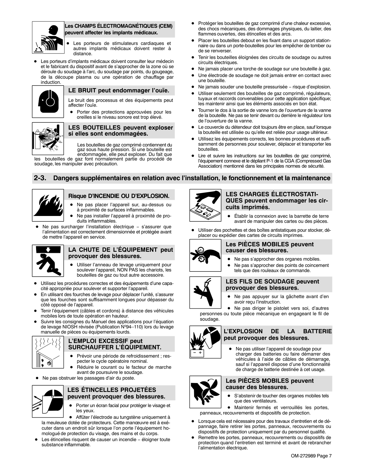
############### Les CHAMPS ÉLECTROMAGNÉTIQUES (CEM) peuvent affecter les implants médicaux.
Les porteurs de stimulateurs cardiaques et autres implants médicaux doivent rester à distance.
Les porteurs d’implants médicaux doivent consulter leur médecin et le fabricant du dispositif avant de s’approcher de la zone où se déroule du soudage à l’arc, du soudage par points, du gougeage, de la découpe plasma ou une opération de chauffage par induction.
| | |---|
######### LE BRUIT peut endommager l’ouïe.
Le bruit des processus et des équipements peut affecter l’ouïe.
Porter des protections approuvées pour les oreilles si le niveau sonore est trop élevé.
|| |---|
LES BOUTEILLES peuvent exploser si elles sont endommagées.
Les bouteilles de gaz comprimé contiennent du gaz sous haute pression. Si une bouteille est endommagée, elle peut exploser. Du fait que
les bouteilles de gaz font normalement partie du procédé de soudage, les manipuler avec précaution.

Protéger les bouteilles de gaz comprimé d’une chaleur excessive, des chocs mécaniques, des dommages physiques, du laitier, des flammes ouvertes, des étincelles et des arcs.
Placer les bouteilles debout en les fixant dans un support stationnaire ou dans un porte-bouteilles pour les empêcher de tomber ou de se renverser.
Tenir les bouteilles éloignées des circuits de soudage ou autres circuits électriques.
Ne jamais placer une torche de soudage sur une bouteille à gaz. Une électrode de soudage ne doit jamais entrer en contact avec une bouteille. Ne jamais souder une bouteille pressurisée − risque d’explosion. Utiliser seulement des bouteilles de gaz comprimé, régulateurs, tuyaux et raccords convenables pour cette application spécifique; les maintenir ainsi que les éléments associés en bon état.
Tourner le dos à la sortie de vanne lors de l’ouverture de la vanne de la bouteille. Ne pas se tenir devant ou derrière le régulateur lors de l’ouverture de la vanne.
Le couvercle du détendeur doit toujours être en place, sauf lorsque la bouteille est utilisée ou qu’elle est reliée pour usage ultérieur.
Utilisez les équipements corrects, les bonnes procédures et suffisamment de personnes pour soulever, déplacer et transporter les bouteilles.
Lire et suivre les instructions sur les bouteilles de gaz comprimé, l’équipement connexe et le dépliant P-1 de la CGA (Compressed Gas Association) mentionné dans les principales normes de sécurité.
####### 2-3. Dangers supplémentaires en relation avec l’installation, le fonctionnement et la maintenance
########### Risque D’INCENDIE OU D’EXPLOSION.
Ne pas placer l’appareil sur, au-dessus ou à proximité de surfaces inflammables. Ne pas installer l’appareil à proximité de produits inflammables.
Ne pas surcharger l’installation électrique − s’assurer que l’alimentation est correctement dimensionnée et protégée avant de mettre l’appareil en service.
| | |---|
######### LA CHUTE DE L’ÉQUIPEMENT peut provoquer des blessures.
Utiliser l’anneau de levage uniquement pour soulever l’appareil, NON PAS les chariots, les bouteilles de gaz ou tout autre accessoire.
Utilisez les procédures correctes et des équipements d’une capacité appropriée pour soulever et supporter l’appareil.
En utilisant des fourches de levage pour déplacer l’unité, s’assurer que les fourches sont suffisamment longues pour dépasser du côté opposé de l’appareil.
Tenir l’équipement (câbles et cordons) à distance des véhicules mobiles lors de toute opération en hauteur.
Suivre les consignes du Manuel des applications pour l’équation de levage NIOSH révisée (Publication Nº94–110) lors du levage manuelle de pièces ou équipements lourds.
######### L’EMPLOI EXCESSIF peut SURCHAUFFER L’ÉQUIPEMENT.
Prévoir une période de refroidissement ; respecter le cycle opératoire nominal. Réduire le courant ou le facteur de marche avant de poursuivre le soudage.
Ne pas obstruer les passages d’air du poste.
######### LES ÉTINCELLES PROJETÉES peuvent provoquer des blessures.
Porter un écran facial pour protéger le visage et les yeux.
Affûter l’électrode au tungstène uniquement à la meuleuse dotée de protecteurs. Cette manœuvre est à exécuter dans un endroit sûr lorsque l’on porte l’équipement homologué de protection du visage, des mains et du corps.
Les étincelles risquent de causer un incendie − éloigner toute substance inflammable.
| | |---|
######### LES CHARGES ÉLECTROSTATIQUES peuvent endommager les circuits imprimés.
Établir la connexion avec la barrette de terre avant de manipuler des cartes ou des pièces.
Utiliser des pochettes et des boîtes antistatiques pour stocker, déplacer ou expédier des cartes de circuits imprimes.
######### Les PIÈCES MOBILES peuvent causer des blessures.
Ne pas s’approcher des organes mobiles. Ne pas s’approcher des points de coincement tels que des rouleaux de commande.
######### LES FILS DE SOUDAGE peuvent provoquer des blessures.
Ne pas appuyer sur la gâchette avant d’en avoir reçu l’instruction. Ne pas diriger le pistolet vers soi, d’autres
personnes ou toute pièce mécanique en engageant le fil de soudage.
########### L’EXPLOSION DE LA BATTERIE peut provoquer des blessures.
Ne pas utiliser l’appareil de soudage pour charger des batteries ou faire démarrer des véhicules à l’aide de câbles de démarrage, sauf si l’appareil dispose d’une fonctionnalité de charge de batterie destinée à cet usage.
| | |---|
######### Les PIÈCES MOBILES peuvent causer des blessures.
S’abstenir de toucher des organes mobiles tels que des ventilateurs. Maintenir fermés et verrouillés les portes,
panneaux, recouvrements et dispositifs de protection.
Lorsque cela est nécessaire pour des travaux d’entretien et de dépannage, faire retirer les portes, panneaux, recouvrements ou dispositifs de protection uniquement par du personnel qualifié.
Remettre les portes, panneaux, recouvrements ou dispositifs de protection quand l’entretien est terminé et avant de rebrancher l’alimentation électrique.
Effectuer régulièrement le contrôle et l’entretien de l’installation.
| | |---|
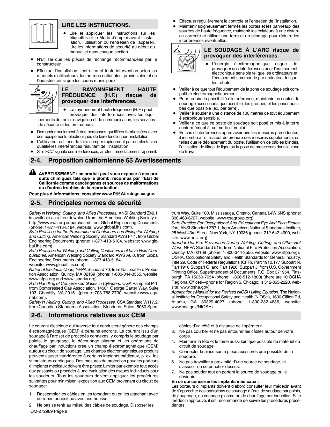
######### LIRE LES INSTRUCTIONS.
Maintenir soigneusement fermés les portes et les panneaux des sources de haute fréquence, maintenir les éclateurs à une distance correcte et utiliser une terre et un blindage pour réduire les interférences éventuelles.
Lire et appliquer les instructions sur les étiquettes et le Mode d’emploi avant l’installation, l’utilisation ou l’entretien de l’appareil. Lire les informations de sécurité au début du manuel et dans chaque section.
| | |---|
######### LE SOUDAGE À L’ARC risque de provoquer des interférences.
N’utiliser que les pièces de rechange recommandées par le constructeur.
L’énergie électromagnétique risque de provoquer des interférences pour l’équipement électronique sensible tel que les ordinateurs et l’équipement commandé par ordinateur tel que les robots.
Effectuer l’installation, l’entretien et toute intervention selon les manuels d’utilisateurs, les normes nationales, provinciales et de l’industrie, ainsi que les codes municipaux.
| | |---|
######### LE RAYONNEMENT HAUTE FRÉQUENCE (H.F.) risque de provoquer des interférences.
Veiller à ce que tout l’équipement de la zone de soudage soit compatible électromagnétiquement.
Pour réduire la possibilité d’interférence, maintenir les câbles de soudage aussi courts que possible, les grouper, et les poser aussi bas que possible (ex. par terre).
Le rayonnement haute fréquence (H.F.) peut provoquer des interférences avec les équi-
Veiller à souder à une distance de 100 mètres de tout équipement électronique sensible. Veiller à ce que ce poste de soudage soit posé et mis à la terre conformément à ce mode d’emploi.
pements de radio−navigation et de communication, les services de sécurité et les ordinateurs.
Demander seulement à des personnes qualifiées familiarisées avec des équipements électroniques de faire fonctionner l’installation. L’utilisateur est tenu de faire corriger rapidement par un électricien qualifié les interférences résultant de l’installation. Si le FCC signale des interférences, arrêter immédiatement l’appareil.
En cas d’interférences après avoir pris les mesures précédentes, il incombe à l’utilisateur de prendre des mesures supplémentaires telles que le déplacement du poste, l’utilisation de câbles blindés, l’utilisation de filtres de ligne ou la pose de protecteurs dans la zone de travail.
####### 2-4. Proposition californienne 65 Avertissements
AVERTISSEMENT : ce produit peut vous exposer à des produits chimiques tels que le plomb, reconnus par l’État de Californie comme cancérigènes et sources de malformations ou d’autres troubles de la reproduction.
Pour plus d’informations, consulter www.P65Warnings.ca.gov.
####### 2-5. Principales normes de sécurité
trum Way, Suite 100, Mississauga, Ontario, Canada L4W 5NS (phone: 800-463-6727, website: www.csagroup.org).
Safety in Welding, Cutting, and Allied Processes, ANSI Standard Z49.1, is available as a free download from the American Welding Society at http://www.aws.org or purchased from Global Engineering Documents (phone: 1-877-413-5184, website: www.global.ihs.com).
Safe Practice For Occupational And Educational Eye And Face Protection, ANSI Standard Z87.1, from American National Standards Institute, 25 West 43rd Street, New York, NY 10036 (phone: 212-642-4900, website: www.ansi.org).
Safe Practices for the Preparation of Containers and Piping for Welding and Cutting, American Welding Society Standard AWS F4.1, from Global Engineering Documents (phone: 1-877-413-5184, website: www.global.ihs.com).
Standard for Fire Prevention During Welding, Cutting, and Other Hot Work, NFPA Standard 51B, from National Fire Protection Association, Quincy, MA 02169 (phone: 1-800-344-3555, website: www.nfpa.org). OSHA, Occupational Safety and Health Standards for General Industry, Title 29, Code of Federal Regulations (CFR), Part 1910.177 Subpart N, Part 1910 Subpart Q, and Part 1926, Subpart J, from U.S. Government Printing Office, Superintendent of Documents, P.O. Box 371954, Pittsburgh, PA 15250-7954 (phone: 1-866-512-1800) (there are 10 OSHA Regional Offices—phone for Region 5, Chicago, is 312-353-2220, website: www.osha.gov).
Safe Practices for Welding and Cutting Containers that have Held Combustibles, American Welding Society Standard AWS A6.0, from Global Engineering Documents (phone: 1-877-413-5184, website: www.global.ihs.com).
National Electrical Code, NFPA Standard 70, from National Fire Protection Association, Quincy, MA 02169 (phone: 1-800-344-3555, website: www.nfpa.org and www. sparky.org).
Safe Handling of Compressed Gases in Cylinders, CGA Pamphlet P-1, from Compressed Gas Association, 14501 George Carter Way, Suite 103, Chantilly, VA 20151 (phone: 703-788-2700, website:www.cganet.com).
Applications Manual for the Revised NIOSH Lifting Equation, The National Institute for Occupational Safety and Health (NIOSH), 1600 Clifton Rd, Atlanta, GA 30329-4027 (phone: 1-800-232-4636, website: www.cdc.gov/NIOSH).
Safety in Welding, Cutting, and Allied Processes, CSA Standard W117.2, from Canadian Standards Association, Standards Sales, 5060 Spec-
####### 2-6. Informations relatives aux CEM
Le courant électrique qui traverse tout conducteur génère des champs électromagnétiques (CEM) à certains endroits. Le courant issu d’un soudage à l’arc (et de procédés connexes, y compris le soudage par points, le gougeage, le découpage plasma et les opérations de chauffage par induction) crée un champ électromagnétique (CEM) autour du circuit de soudage. Les champs électromagnétiques produits peuvent causer interférence à certains implants médicaux, p. ex. les stimulateurs cardiaques. Des mesures de protection pour les porteurs d’implants médicaux doivent être prises: Limiter par exemple tout accès aux passants ou procéder à une évaluation des risques individuels pour les soudeurs. Tous les soudeurs doivent appliquer les procédures suivantes pour minimiser l’exposition aux CEM provenant du circuit de soudage:
################ En ce qui concerne les implants médicaux :
Les porteurs d’implants doivent d’abord consulter leur médecin avant de s’approcher des opérations de soudage à l’arc, de soudage par points, de gougeage, du coupage plasma ou de chauffage par induction. Si le médecin approuve, il est recommandé de suivre les procédures précédentes.
SECTION 3 − DEFINITIONS
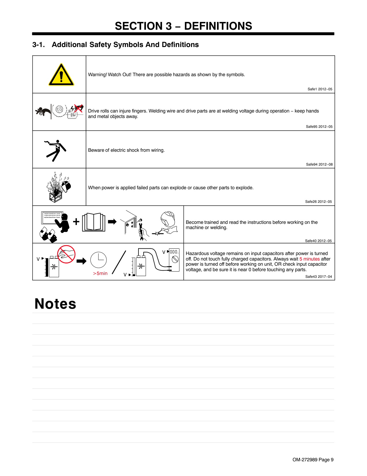
| |Warning! Watch Out! There are possible hazards as shown by the symbols.
Safe1 2012−05|Warning! Watch Out! There are possible hazards as shown by the symbols.
Safe1 2012−05| |---|---|---| | |Drive rolls can injure fingers. Welding wire and drive parts are at welding voltage during operation − keep hands and metal objects away.
Safe95 2012−05|Drive rolls can injure fingers. Welding wire and drive parts are at welding voltage during operation − keep hands and metal objects away.
Safe95 2012−05| | |Beware of electric shock from wiring.
Safe94 2012−08|Beware of electric shock from wiring.
Safe94 2012−08| ||When power is applied failed parts can explode or cause other parts to explode.
Safe26 2012−05|When power is applied failed parts can explode or cause other parts to explode.
Safe26 2012−05| | | |Become trained and read the instructions before working on the machine or welding.
Safe40 2012−05| |>5min
V V
V|>5min
V V
V|Hazardous voltage remains on input capacitors after power is turned off. Do not touch fully charged capacitors. Always wait 5 minutes after power is turned off before working on unit, OR check input capacitor voltage, and be sure it is near 0 before touching any parts.
Safe43 2017−04|
Notes
| |Remote| |---|---|
| |Circuit Breaker| | |Positive| | |Negative| |X|Duty Cycle| | |Line Connection| ||S| |---| |Suitable for Some Hazardous Locations| | |Increase| |Hz|Hertz| | |Single Phase Static Frequency ConverterTransformerRectifier| | |Lift Arc (GTAW) TIG / Remote| | |Wire Feed Slow Run-In|
|A|Amperage| |---|---| |V|Voltage| |U0|Rated No Load Voltage (OCV)| | |Direct Current (DC)| | |Alternating Current (AC)| |U1|Primary Voltage| |U2|Conventional Load Voltage| |I2|Rated Welding Current| | |Input Power Or Input Voltage| | |Gas Input| |IP|Internal Protection Rating| | |Single Phase| | |Unlocked| | |Locked|
Notes
| |Gas Tungsten Arc Welding (GTAW) Torch| |---|---| | |Shielded Metal Arc Welding (SMAW)| | |Shielded Metal Arc (SMAW) Electrode Holder| | |Gas Metal Arc Welding (GMAW)| | |Gas Metal Arc Welding (GMAW) MIG / Gun Control| | |Self-Shielded Flux Cored Arc Welding (FCAW)|
| |Wire Feed Spool Gun| | |Gas Tungsten Arc Welding (GTAW) / Tungsten Inert Gas (TIG) Welding| | |Gas Postflow| | |Gas Preflow| | |Cold Jog (Inch) Toward Workpiece|
SECTION 4 − SPECIFICATIONS
####### 4-1. Serial Number And Rating Label Location
The serial number and rating information for this product is located on the back of unit. Use rating label to determine input power requirements and/or rated output. For future reference, write serial number in space provided on back cover of this manual.
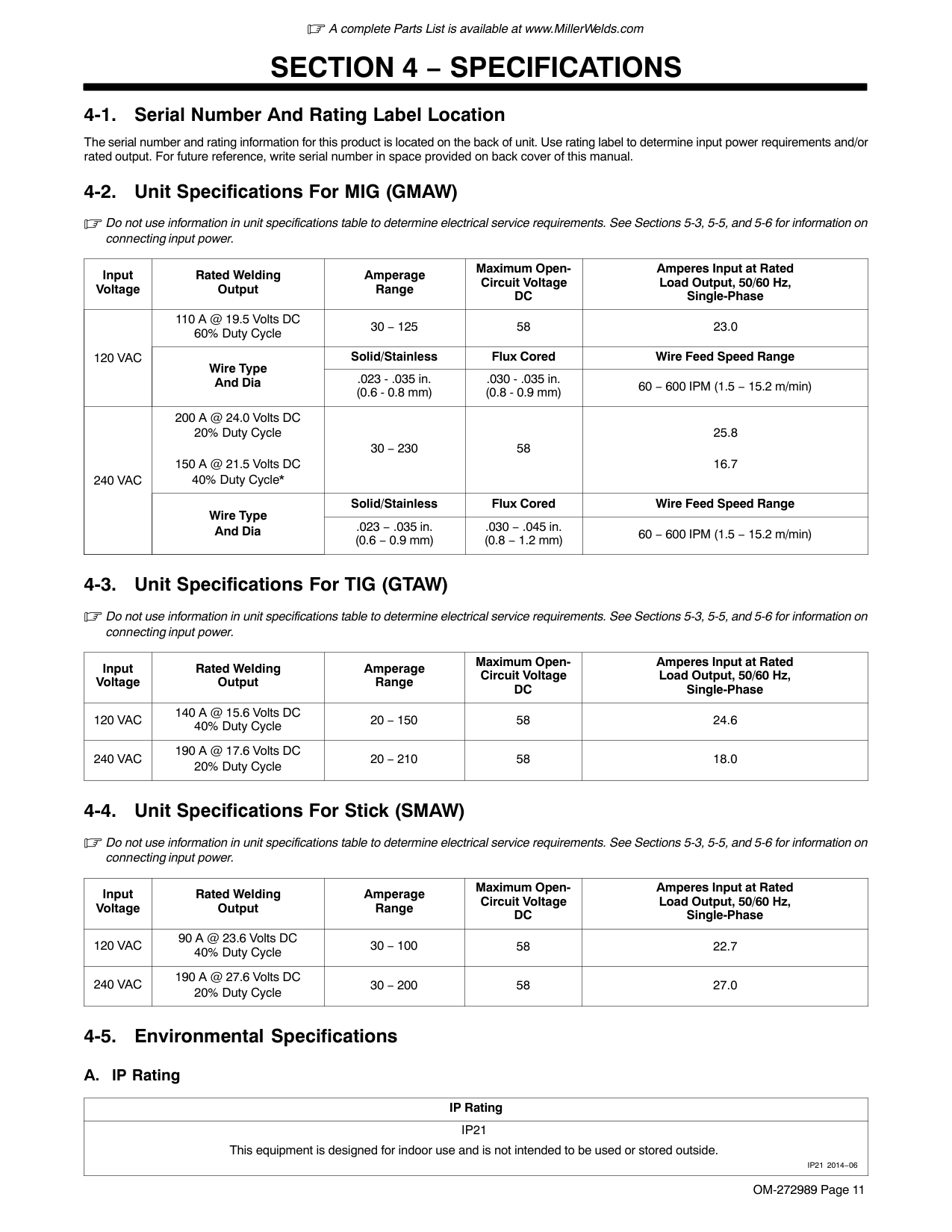
####### 4-2. Unit Specifications For MIG (GMAW)
Do not use information in unit specifications table to determine electrical service requirements. See Sections 5-3, 5-5, and 5-6 for information on connecting input power.
|Input Voltage|Rated Welding Output|Amperage Range|Maximum OpenCircuit Voltage DC|Amperes Input at Rated Load Output, 50/60 Hz, Single-Phase| |---|---|---|---|---| |120 VAC|110 A @ 19.5 Volts DC 60% Duty Cycle|30 − 125|58|23.0| |120 VAC|Wire Type And Dia|Solid/Stainless|Flux Cored|Wire Feed Speed Range| |120 VAC|Wire Type And Dia|.023 - .035 in. (0.6 - 0.8 mm)|.030 - .035 in. (0.8 - 0.9 mm)|60 − 600 IPM (1.5 − 15.2 m/min)| |240 VAC|200 A @ 24.0 Volts DC 20% Duty Cycle
150 A @ 21.5 Volts DC 40% Duty Cycle*|30 − 230|58|25.8
16.7| |240 VAC|Wire Type And Dia|Solid/Stainless|Flux Cored|Wire Feed Speed Range| |240 VAC|Wire Type And Dia|.023 − .035 in. (0.6 − 0.9 mm)|.030 − .045 in. (0.8 − 1.2 mm)|60 − 600 IPM (1.5 − 15.2 m/min)|
####### 4-3. Unit Specifications For TIG (GTAW)
Do not use information in unit specifications table to determine electrical service requirements. See Sections 5-3, 5-5, and 5-6 for information on connecting input power.
|Input Voltage|Rated Welding Output|Amperage Range|Maximum OpenCircuit Voltage DC|Amperes Input at Rated Load Output, 50/60 Hz, Single-Phase| |---|---|---|---|---| |120 VAC|140 A @ 15.6 Volts DC 40% Duty Cycle|20 − 150|58|24.6| |240 VAC|190 A @ 17.6 Volts DC 20% Duty Cycle|20 − 210|58|18.0|
####### 4-4. Unit Specifications For Stick (SMAW)
Do not use information in unit specifications table to determine electrical service requirements. See Sections 5-3, 5-5, and 5-6 for information on connecting input power.
|Input Voltage|Rated Welding Output|Amperage Range|Maximum OpenCircuit Voltage DC|Amperes Input at Rated Load Output, 50/60 Hz, Single-Phase| |---|---|---|---|---| |120 VAC|90 A @ 23.6 Volts DC 40% Duty Cycle|30 − 100|58|22.7| |240 VAC|190 A @ 27.6 Volts DC 20% Duty Cycle|30 − 200|58|27.0|
####### 4-5. Environmental SpecificationsA. IP Rating
|IP Rating| |---| |IP21 This equipment is designed for indoor use and is not intended to be used or stored outside.
IP21 2014−06|
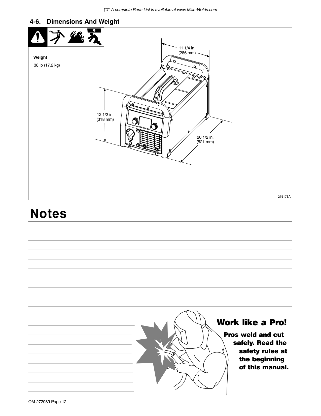
####### 4-6. Dimensions And Weight
Weight
38 lb (17.2 kg)
11 1/4 in. (286 mm)
12 1/2 in. (318 mm)
20 1/2 in. (521 mm)
Notes
275173A
#### Work like a Pro!
Pros weld and cut
safely. Read the safety rules at the beginning of this manual.
####### 4-7. Duty Cycle And Overheating For MIG (GMAW)
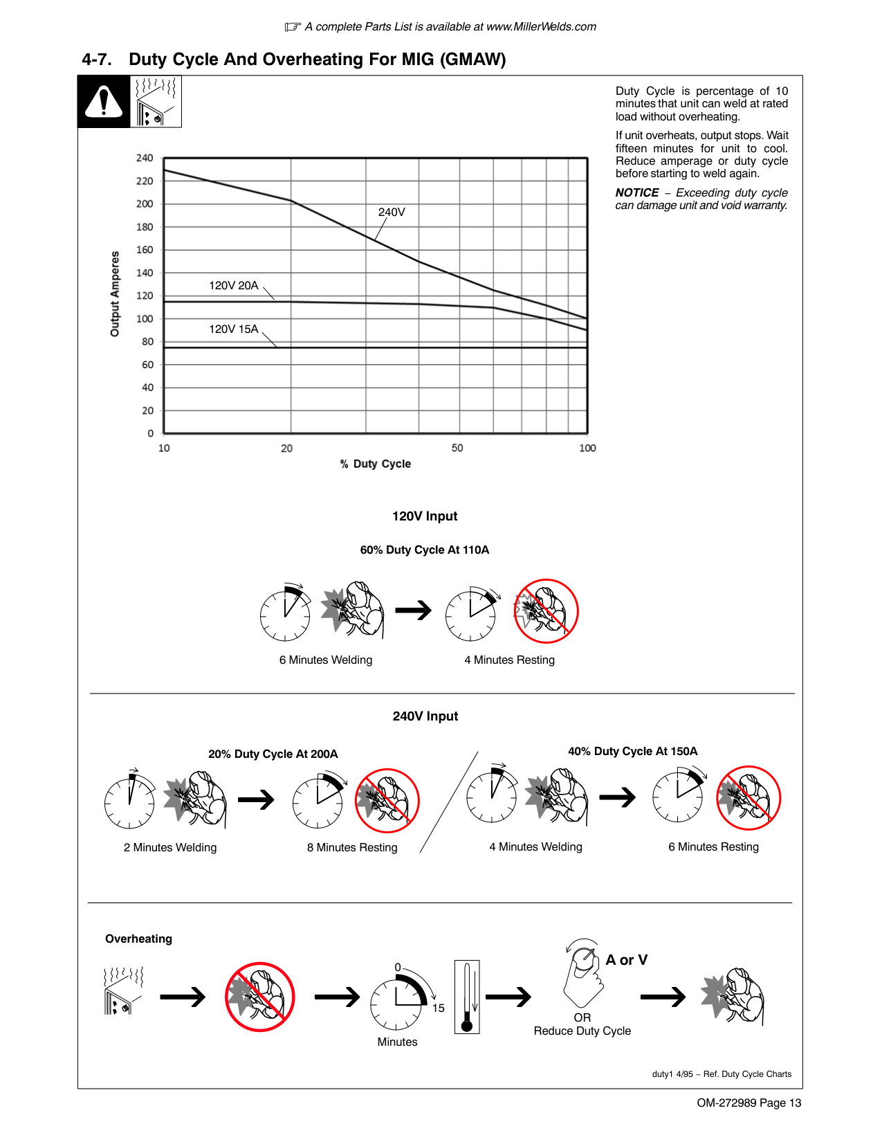
| | |Duty Cycle is percentage of 10 minutes that unit can weld at rated load without overheating.| |---|---|---| |
If unit overheats, output stops. Wait fifteen minutes for unit to cool. Reduce amperage or duty cycle before starting to weld again.
NOTICE − Exceeding duty cycle can damage unit and void warranty.
4 Minutes Welding 6 Minutes Resting2 Minutes Welding 8 Minutes Resting
Overheating
0
15
A or V
OR Reduce Duty Cycle Minutes
duty1 4/95 − Ref. Duty Cycle Charts
60% Duty Cycle At 110A
120V Input
240V Input
20% Duty Cycle At 200A 40% Duty Cycle At 150A
6 Minutes Welding 4 Minutes Resting
240V
120V 20A
120V 15A
|
####### 4-8. Duty Cycle And Overheating For TIG (GTAW)
| | |Duty Cycle is percentage of 10 minutes that unit can weld at rated load without overheating.| |---|---|---| |
If unit overheats, output stops. Wait fifteen minutes for unit to cool. Reduce amperage or duty cycle before starting to weld again.
NOTICE − Exceeding duty cycle can damage unit and void warranty.
4 Minutes Welding 6 Minutes Resting
2 Minutes Welding 8 Minutes Resting
Overheating
0
15
A or V
OR Reduce Duty Cycle Minutes
duty1 4/95 − Ref. Duty Cycle Charts
40% Duty Cycle At 140A
120V Input
240V Input
20% Duty Cycle At 190A
120V 15A
120V 20A
240V
|
####### 4-9. Duty Cycle And Overheating For Stick (SMAW)
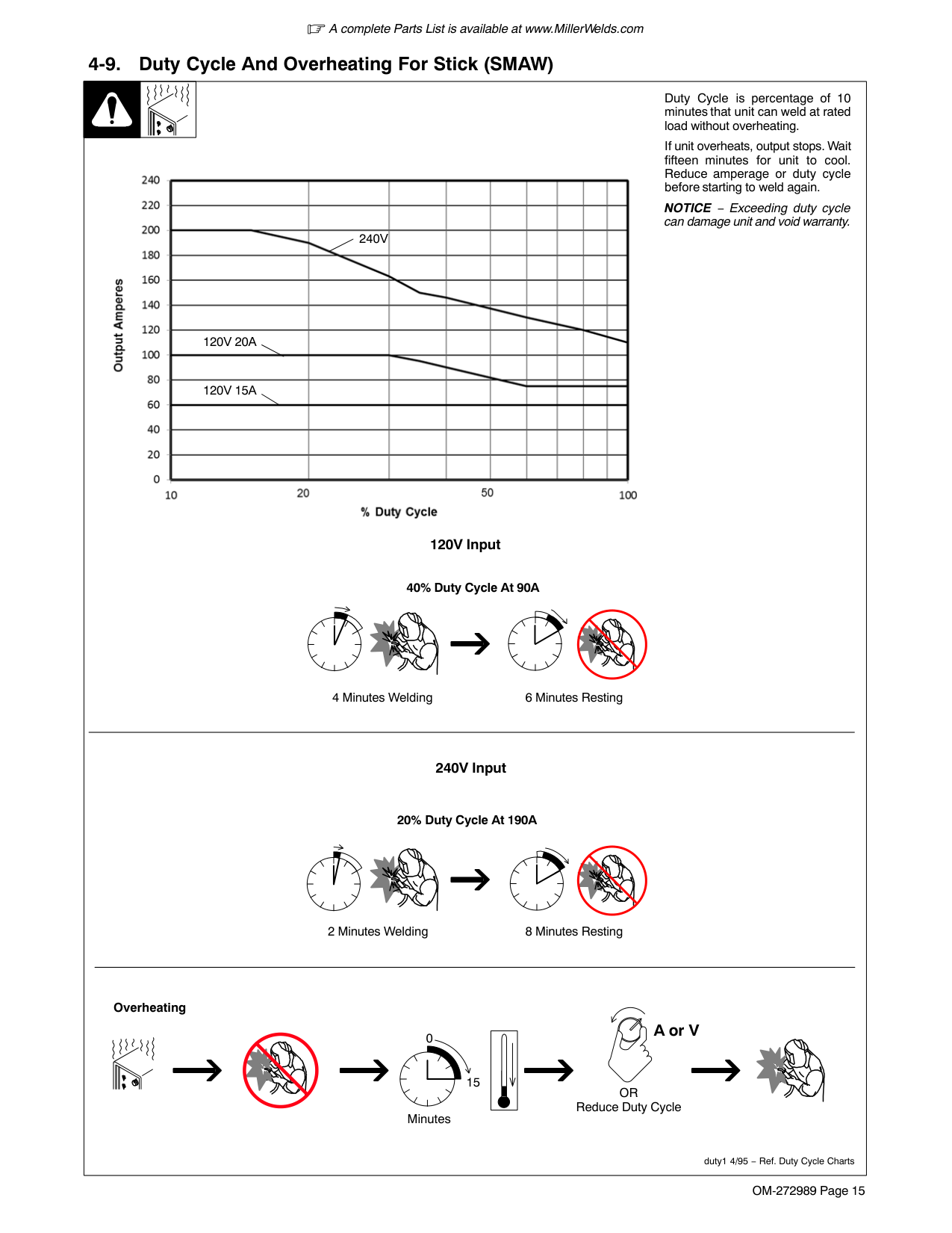
| | |Duty Cycle is percentage of 10 minutes that unit can weld at rated load without overheating.| |---|---|---| |If unit overheats, output stops. Wait fifteen minutes for unit to cool. Reduce amperage or duty cycle before starting to weld again.
NOTICE − Exceeding duty cycle can damage unit and void warranty.
4 Minutes Welding 6 Minutes Resting
2 Minutes Welding 8 Minutes Resting
Overheating
0
15
A or V
OR Reduce Duty Cycle Minutes
duty1 4/95 − Ref. Duty Cycle Charts
40% Duty Cycle At 90A
120V Input
240V Input
20% Duty Cycle At 190A

240V
120V 20A
120V 15A
|If unit overheats, output stops. Wait fifteen minutes for unit to cool. Reduce amperage or duty cycle before starting to weld again.
NOTICE − Exceeding duty cycle can damage unit and void warranty.
4 Minutes Welding 6 Minutes Resting
2 Minutes Welding 8 Minutes Resting
Overheating
0
15
A or V
OR Reduce Duty Cycle Minutes
duty1 4/95 − Ref. Duty Cycle Charts
40% Duty Cycle At 90A
120V Input
240V Input
20% Duty Cycle At 190A

240V
120V 20A
120V 15A
|
SECTION 5 − INSTALLATION
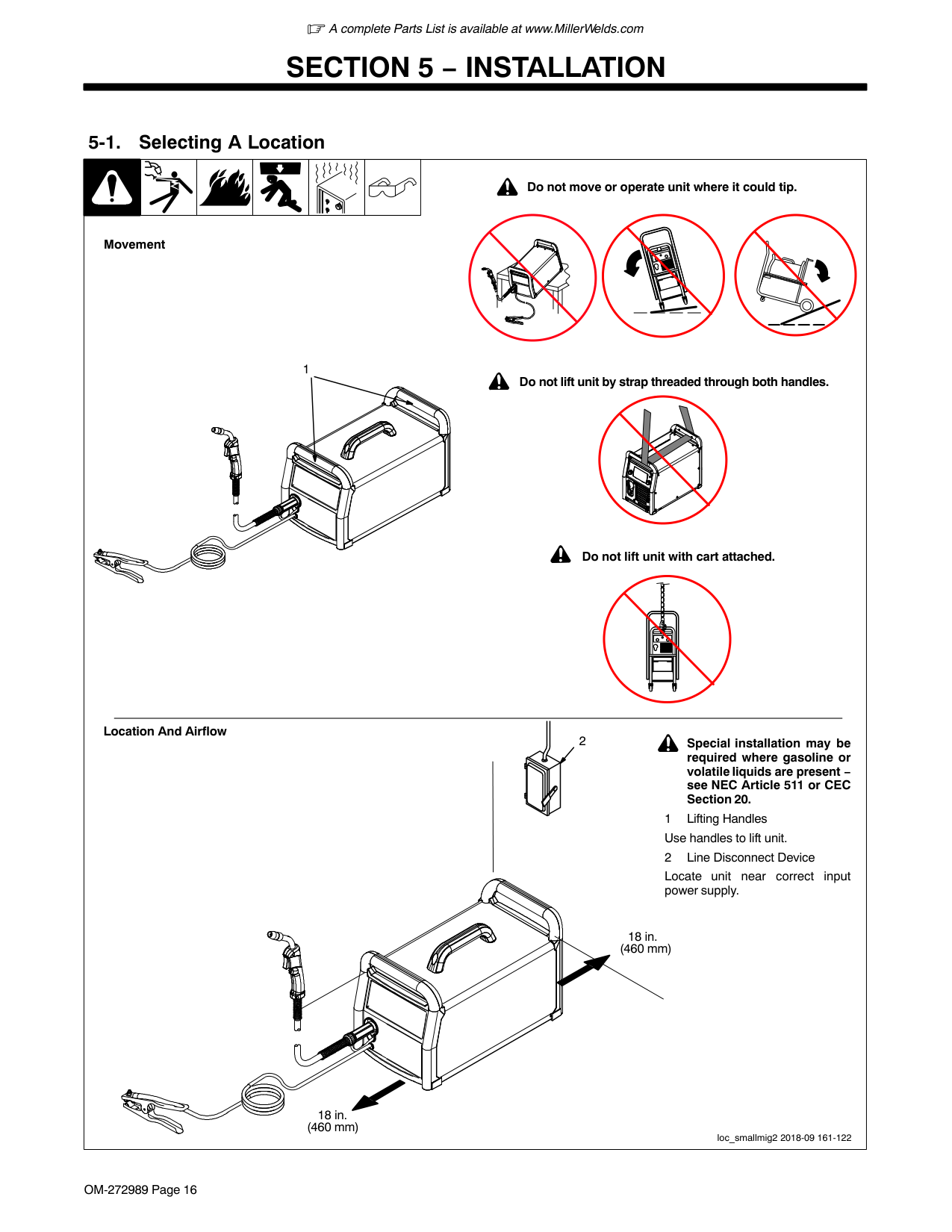
####### 5-1. Selecting A Location
! Do not move or operate unit where it could tip.
Movement
1
! Do not lift unit by strap threaded through both handles.
! Do not lift unit with cart attached.
Location And Airflow
! Special installation may be required where gasoline or volatile liquids are present − see NEC Article 511 or CEC Section 20.
2
Locate unit near correct input power supply.
18 in. (460 mm)
18 in. (460 mm)
loc_smallmig2 2018-09 161-122
####### 5-2. Multi−Voltage Plug (MVP) Connection
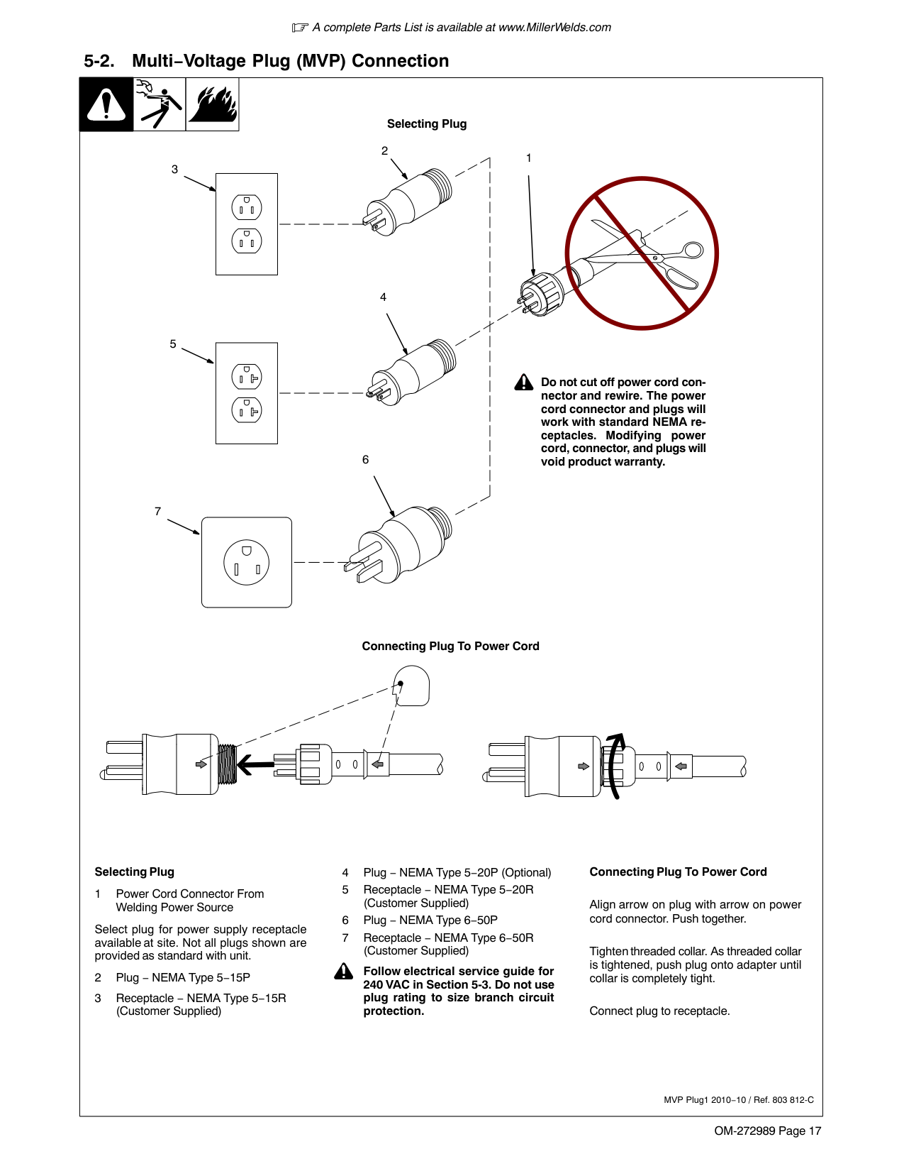
| | | |Selecting Plug| |---|---|---|---| |Selecting Plug
1 Power Cord Connector From Welding Power Source
Select plug for power supply receptacle available at site. Not all plugs shown are provided as standard with unit.
2 Plug − NEMA Type 5−15P
3 Receptacle − NEMA Type 5−15R (Customer Supplied)
4 Plug − NEMA Type 5−20P (Optional)
5 Receptacle − NEMA Type 5−20R (Customer Supplied)
6 Plug − NEMA Type 6−50P
7 Receptacle − NEMA Type 6−50R (Customer Supplied)
! Follow electrical service guide for 240 VAC in Section 5-3. Do not use plug rating to size branch circuit protection.
Connecting Plug To Power Cord
Align arrow on plug with arrow on power cord connector. Push together.
Tighten threaded collar. As threaded collar is tightened, push plug onto adapter until collar is completely tight.
Connect plug to receptacle.
MVP Plug1 2010−10 / Ref. 803 812-C
! Do not cut off power cord connector and rewire. The power cord connector and plugs will work with standard NEMA receptacles. Modifying power cord, connector, and plugs will void product warranty.
3
2
7
4
5
6
1
Connecting Plug To Power Cord|Selecting Plug
1 Power Cord Connector From Welding Power Source
Select plug for power supply receptacle available at site. Not all plugs shown are provided as standard with unit.
2 Plug − NEMA Type 5−15P
3 Receptacle − NEMA Type 5−15R (Customer Supplied)
4 Plug − NEMA Type 5−20P (Optional)
5 Receptacle − NEMA Type 5−20R (Customer Supplied)
6 Plug − NEMA Type 6−50P
7 Receptacle − NEMA Type 6−50R (Customer Supplied)
! Follow electrical service guide for 240 VAC in Section 5-3. Do not use plug rating to size branch circuit protection.
Connecting Plug To Power Cord
Align arrow on plug with arrow on power cord connector. Push together.
Tighten threaded collar. As threaded collar is tightened, push plug onto adapter until collar is completely tight.
Connect plug to receptacle.
MVP Plug1 2010−10 / Ref. 803 812-C
! Do not cut off power cord connector and rewire. The power cord connector and plugs will work with standard NEMA receptacles. Modifying power cord, connector, and plugs will void product warranty.
3
2
7
4
5
6
1
Connecting Plug To Power Cord|
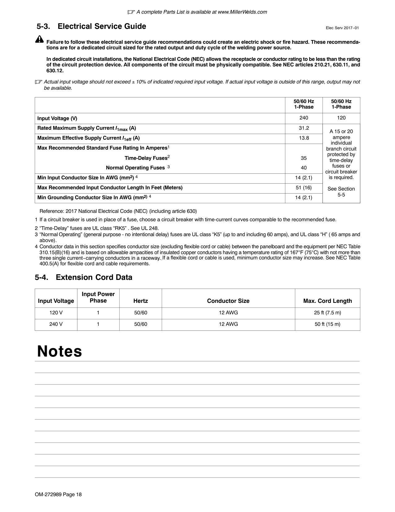
Failure to follow these electrical service guide recommendations could create an electric shock or fire hazard. These recommendations are for a dedicated circuit sized for the rated output and duty cycle of the welding power source.
In dedicated circuit installations, the National Electrical Code (NEC) allows the receptacle or conductor rating to be less than the rating of the circuit protection device. All components of the circuit must be physically compatible. See NEC articles 210.21, 630.11, and 630.12.
Actual input voltage should not exceed 10% of indicated required input voltage. If actual input voltage is outside of this range, output may not be available.
| |50/60 Hz 1-Phase|50/60 Hz 1-Phase| |---|---|---| |Input Voltage (V)|240|120| |Rated Maximum Supply Current I1max (A)|31.2|A 15 or 20 ampere individual branch circuit protected by time-delay fuses or circuit breaker is required.
See Section 5-5| |Maximum Effective Supply Current I1eff (A)|13.8|A 15 or 20 ampere individual branch circuit protected by time-delay fuses or circuit breaker is required.
See Section 5-5| |Max Recommended Standard Fuse Rating In Amperes1 Time-Delay Fuses2 Normal Operating Fuses 3
|35 40|A 15 or 20 ampere individual branch circuit protected by time-delay fuses or circuit breaker is required.
See Section 5-5| |Min Input Conductor Size In AWG (mm2) 4|14 (2.1)|A 15 or 20 ampere individual branch circuit protected by time-delay fuses or circuit breaker is required.
See Section 5-5| |Max Recommended Input Conductor Length In Feet (Meters)|51 (16)|A 15 or 20 ampere individual branch circuit protected by time-delay fuses or circuit breaker is required.
See Section 5-5| |Min Grounding Conductor Size In AWG (mm2) 4|14 (2.1)|A 15 or 20 ampere individual branch circuit protected by time-delay fuses or circuit breaker is required.
See Section 5-5|
Reference: 2017 National Electrical Code (NEC) (including article 630)
|Input Voltage|Input Power Phase|Hertz|Conductor Size|Max. Cord Length| |---|---|---|---|---| |120 V|1|50/60|12 AWG|25 ft (7.5 m)| |240 V|1|50/60|12 AWG|50 ft (15 m)|
Notes
####### 5-5. Connecting 120 Volt Input Power
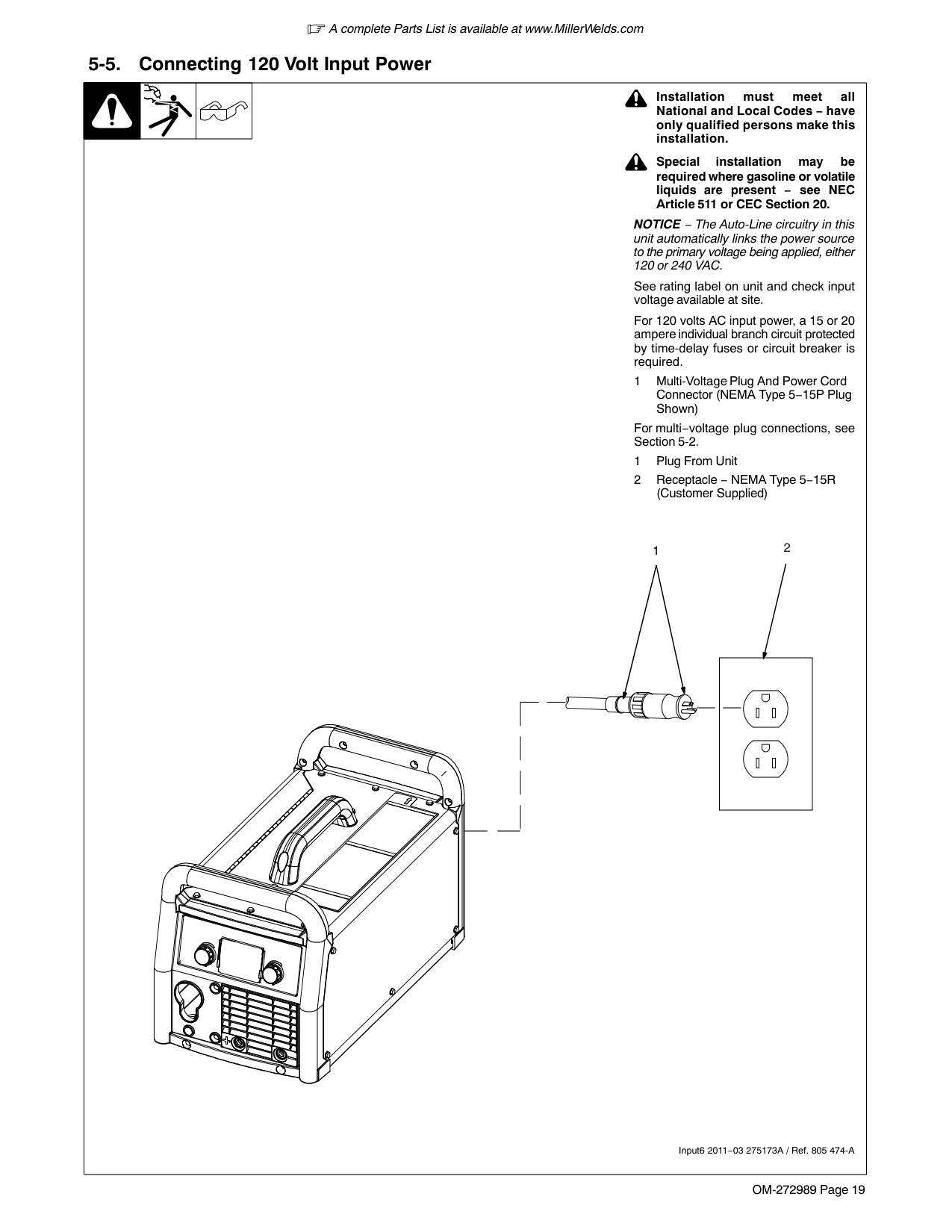
| | | |! Installation must meet all National and Local Codes − have only qualified persons make this installation.| |---|---|---|---| |Input6 2011−03 275173A / Ref. 805 474-A
1
! Special installation may be required where gasoline or volatile liquids are present − see NEC Article 511 or CEC Section 20.
NOTICE − The Auto-Line circuitry in this unit automatically links the power source to the primary voltage being applied, either 120 or 240 VAC.
See rating label on unit and check input voltage available at site.
For 120 volts AC input power, a 15 or 20 ampere individual branch circuit protected by time-delay fuses or circuit breaker is required.
1 Multi-Voltage Plug And Power Cord Connector (NEMA Type 5−15P Plug Shown)
For multi−voltage plug connections, see Section 5-2.
1 Plug From Unit
2 Receptacle − NEMA Type 5−15R (Customer Supplied)
2|Input6 2011−03 275173A / Ref. 805 474-A
1
! Special installation may be required where gasoline or volatile liquids are present − see NEC Article 511 or CEC Section 20.
NOTICE − The Auto-Line circuitry in this unit automatically links the power source to the primary voltage being applied, either 120 or 240 VAC.
See rating label on unit and check input voltage available at site.
For 120 volts AC input power, a 15 or 20 ampere individual branch circuit protected by time-delay fuses or circuit breaker is required.
1 Multi-Voltage Plug And Power Cord Connector (NEMA Type 5−15P Plug Shown)
For multi−voltage plug connections, see Section 5-2.
1 Plug From Unit
2 Receptacle − NEMA Type 5−15R (Customer Supplied)
2|
####### 5-6. Connecting 1-Phase Input Power For 240 VAC
| | | | | |---|---|---|---| |input4 2012-05 − 803 766-C / Ref. 802 443-A / 275173A
Tools Needed:
L1L2
240 VAC, 1
8
2
1
L1 L2
1
=GND/PE Earth Ground
6
| | | |---|---| | | |
5
3
4
7|input4 2012-05 − 803 766-C / Ref. 802 443-A / 275173A
Tools Needed:
L1L2
240 VAC, 1
8
2
1
L1 L2
1
=GND/PE Earth Ground
6
| | | |---|---| | | |
5
3
4
7|input4 2012-05 − 803 766-C / Ref. 802 443-A / 275173A
Tools Needed:
L1L2
240 VAC, 1
8
2
1
L1 L2
1
=GND/PE Earth Ground
6
| | | |---|---| | | |
5
3
4
7|input4 2012-05 − 803 766-C / Ref. 802 443-A / 275173A
Tools Needed:
L1L2
240 VAC, 1
8
2
1
L1 L2
1
=GND/PE Earth Ground
6
| | | |---|---| | | |
5
3
4
7|
| | | | | |---|---|---|---|
|input4 2012−05 − 803 766-C
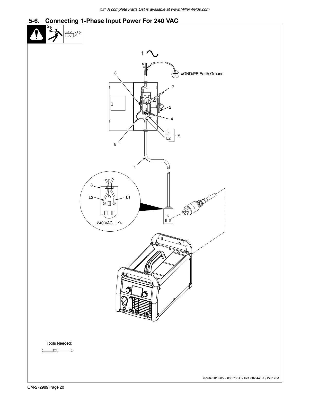
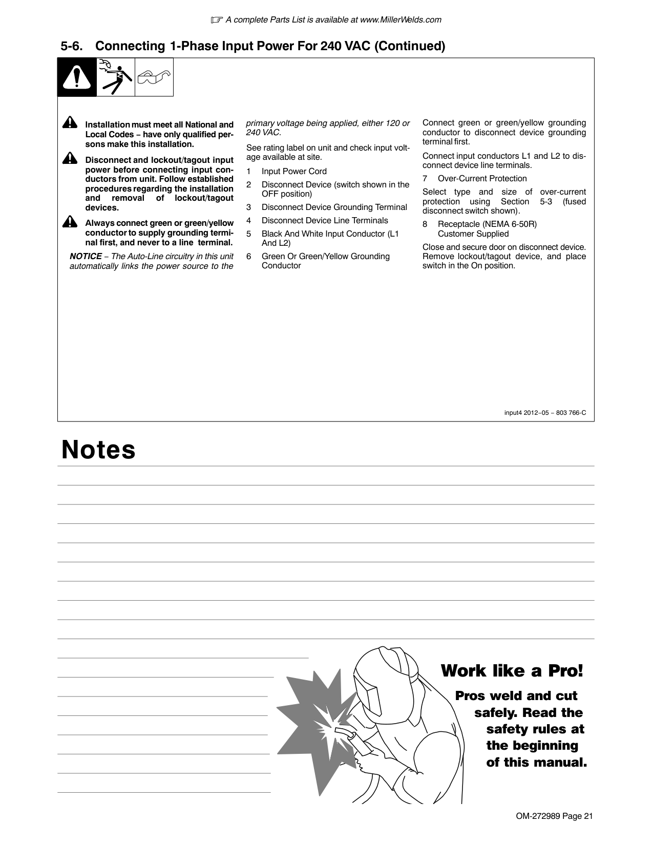
! Installation must meet all National and Local Codes − have only qualified persons make this installation.
! Disconnect and lockout/tagout input power before connecting input conductors from unit. Follow established procedures regarding the installation and removal of lockout/tagout devices.
! Always connect green or green/yellow conductor to supply grounding terminal first, and never to a line terminal.
NOTICE − The Auto-Line circuitry in this unit automatically links the power source to the
primary voltage being applied, either 120 or 240 VAC.
See rating label on unit and check input voltage available at site.
1 Input Power Cord
2 Disconnect Device (switch shown in the OFF position)
3 Disconnect Device Grounding Terminal
4 Disconnect Device Line Terminals
5 Black And White Input Conductor (L1 And L2)
6 Green Or Green/Yellow Grounding Conductor
Connect green or green/yellow grounding conductor to disconnect device grounding terminal first.
Connect input conductors L1 and L2 to disconnect device line terminals.
7 Over-Current Protection
Select type and size of over-current protection using Section 5-3 (fused disconnect switch shown).
8 Receptacle (NEMA 6-50R) Customer Supplied
Close and secure door on disconnect device. Remove lockout/tagout device, and place switch in the On position.
|input4 2012−05 − 803 766-C
! Installation must meet all National and Local Codes − have only qualified persons make this installation.
! Disconnect and lockout/tagout input power before connecting input conductors from unit. Follow established procedures regarding the installation and removal of lockout/tagout devices.
! Always connect green or green/yellow conductor to supply grounding terminal first, and never to a line terminal.
NOTICE − The Auto-Line circuitry in this unit automatically links the power source to the
primary voltage being applied, either 120 or 240 VAC.
See rating label on unit and check input voltage available at site.
1 Input Power Cord
2 Disconnect Device (switch shown in the OFF position)
3 Disconnect Device Grounding Terminal
4 Disconnect Device Line Terminals
5 Black And White Input Conductor (L1 And L2)
6 Green Or Green/Yellow Grounding Conductor
Connect green or green/yellow grounding conductor to disconnect device grounding terminal first.
Connect input conductors L1 and L2 to disconnect device line terminals.
7 Over-Current Protection
Select type and size of over-current protection using Section 5-3 (fused disconnect switch shown).
8 Receptacle (NEMA 6-50R) Customer Supplied
Close and secure door on disconnect device. Remove lockout/tagout device, and place switch in the On position.
|
Notes
#### Work like a Pro!
Pros weld and cut
safely. Read the safety rules at the beginning of this manual.
####### 5-7. Stick Welding Connections
| | | |! Turn off unit and disconnect input power before making connections.| |---|---|---|---| |Ref. 275166A
1 Positive Weld Output Receptacle
2 Negative Weld Output Receptacle
3 Stick Electrode Holder And Cable
4 Work Clamp And Cable
Connect stick electrode holder cable to the positive weld output receptacle, and connect work clamp to negative weld output receptacle.
Ensure all connections are tight.
4
1
2
3|Ref. 275166A
1 Positive Weld Output Receptacle
2 Negative Weld Output Receptacle
3 Stick Electrode Holder And Cable
4 Work Clamp And Cable
Connect stick electrode holder cable to the positive weld output receptacle, and connect work clamp to negative weld output receptacle.
Ensure all connections are tight.
4
1
2
3|
####### 5-8. TIG Welding Connections DCEN (Direct Current Electrode Negative)
1
4
2
3
! Turn off unit and disconnect input power before making connections.
Connect TIG torch cable to the negative weld output receptacle and connect work cable to positive weld output receptacle.
Ensure all connections are tight.
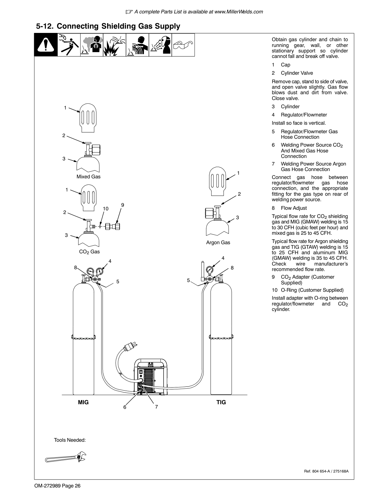
Route control cable through MIG gun hole.
Connect foot control or finger tip control to remote control receptacle.
Use Argon gas for TIG welding (see Section 5-12).
8
5
| | | |---|---| | | |
6
7
| | | |---|---| | | |
9
Ref. 275166A / Ref. 275167A / Ref. 275168A
####### 5-9. Process/Polarity Table
|Process|Polarity|Cable Connections|Cable Connections| |---|---|---|---| |Process|Polarity|Wire Drive Assembly Cable|Work Cable| |GMAW − Solid wire with shielding gas|DCEP − Reverse polarity|Connect to positive (+) output receptacle|Connect to negative (−) output receptacle| |FCAW − Self-shielding wire − no shielding gas|DCEN − Straight Polarity|Connect to negative (−) output receptacle|Connect to positive (+) output receptacle|
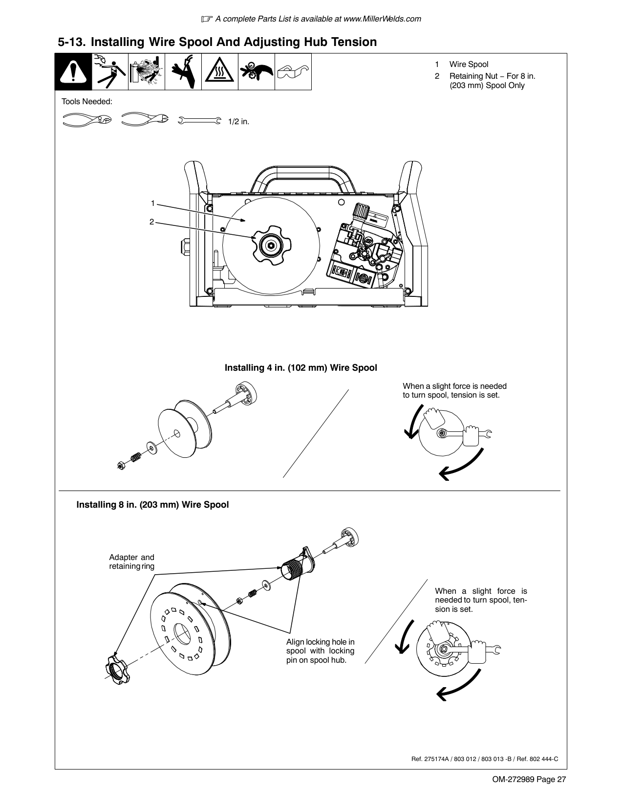
####### 5-10. MIG Welding Connections
1
2
3
4
MIG − DCEP (Direct Current Electrode Positive)
6
75
1
2
3
4
Flux-Cored − DCEN (Direct Current Electrode Negative)
8
! Turn off unit and disconnect input power before making connections.
Ensure all connections are tight.
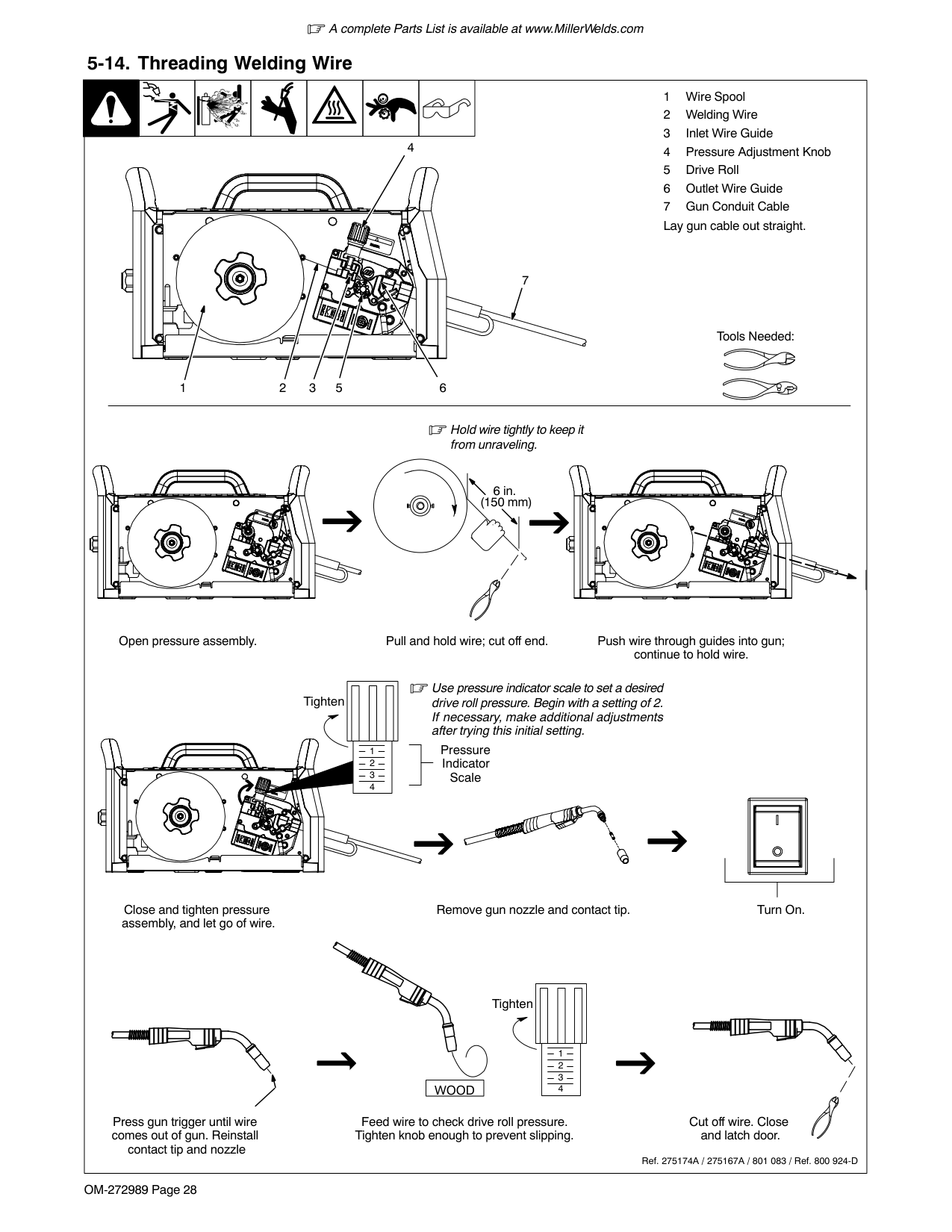
Connect gun end to drive assembly (see Section 5-11).
Route trigger control cable through MIG gun hole.
Ref. 275172A / Ref. 275167A / Ref. 275168A
Connect plug on end of cable to four pin receptacle inside unit.
8 MIG Shielding Gas Connection
Use 75/25 mix or CO2 shielding gas for solid wire. Use Argon shielding gas for aluminum wire with spool gun (see Section 5-12).
####### 5-11. MIG Gun Connection Inside Unit
| | | | | |---|---|---|---| |Ref. 275167A
1 Gun Securing Knob
2 Gun Block
3 Gun Outlet Wire Guide
4 Gun End
Loosen knob. Insert end of gun through opening in front panel until gun end bottoms against gun block. Tighten knob.
5 Trigger Control Cable
6 Four Pin Trigger Control Cable
Receptacle Route trigger control cable through MIG gun hole.
Connect plug on end of cable to four pin receptacle inside unit.
Correct Incorrect
Be sure that gun end is tight against drive assembly.
44
Ref. 267807A
36
5
214
|Ref. 275167A
1 Gun Securing Knob
2 Gun Block
3 Gun Outlet Wire Guide
4 Gun End
Loosen knob. Insert end of gun through opening in front panel until gun end bottoms against gun block. Tighten knob.
5 Trigger Control Cable
6 Four Pin Trigger Control Cable
Receptacle Route trigger control cable through MIG gun hole.
Connect plug on end of cable to four pin receptacle inside unit.
Correct Incorrect
Be sure that gun end is tight against drive assembly.
44
Ref. 267807A
36
5
214
|
####### 5-12. Connecting Shielding Gas Supply
| | | | | | | |Obtain gas cylinder and chain to running gear, wall, or other stationary support so cylinder cannot fall and break off valve.| |---|---|---|---|---|---|---|---| |1 Cap
2 Cylinder Valve
Remove cap, stand to side of valve, and open valve slightly. Gas flow blows dust and dirt from valve. Close valve.
3 Cylinder
4 Regulator/Flowmeter Install so face is vertical.
5 Regulator/Flowmeter Gas Hose Connection
6 Welding Power Source CO2 And Mixed Gas Hose Connection
7 Welding Power Source Argon Gas Hose Connection
Connect gas hose between regulator/flowmeter gas hose connection, and the appropriate fitting for the gas type on rear of welding power source.
8 Flow Adjust
Typical flow rate for CO2 shielding gas and MIG (GMAW) welding is 15 to 30 CFH (cubic feet per hour) and mixed gas is 25 to 45 CFH.
Typical flow rate for Argon shielding gas and TIG (GTAW) welding is 15 to 25 CFH and aluminum MIG (GMAW) welding is 35 to 45 CFH. Check wire manufacturer’s recommended flow rate.
9CO2Adapter (Customer Supplied)
10 O-Ring (Customer Supplied)
Install adapter with O-ring between regulator/flowmeter and CO2 cylinder.
Ref. 804 654-A / 275168A
Tools Needed:
1
2
3
Argon Gas CO2 Gas
1
2
3
Mixed Gas
1
2
3
10
9
8
4
5
4
5
8
6 7
MIG TIG|1 Cap
2 Cylinder Valve
Remove cap, stand to side of valve, and open valve slightly. Gas flow blows dust and dirt from valve. Close valve.
3 Cylinder
4 Regulator/Flowmeter Install so face is vertical.
5 Regulator/Flowmeter Gas Hose Connection
6 Welding Power Source CO2 And Mixed Gas Hose Connection
7 Welding Power Source Argon Gas Hose Connection
Connect gas hose between regulator/flowmeter gas hose connection, and the appropriate fitting for the gas type on rear of welding power source.
8 Flow Adjust
Typical flow rate for CO2 shielding gas and MIG (GMAW) welding is 15 to 30 CFH (cubic feet per hour) and mixed gas is 25 to 45 CFH.
Typical flow rate for Argon shielding gas and TIG (GTAW) welding is 15 to 25 CFH and aluminum MIG (GMAW) welding is 35 to 45 CFH. Check wire manufacturer’s recommended flow rate.
9CO2Adapter (Customer Supplied)
10 O-Ring (Customer Supplied)
Install adapter with O-ring between regulator/flowmeter and CO2 cylinder.
Ref. 804 654-A / 275168A
Tools Needed:
1
2
3
Argon Gas CO2 Gas
1
2
3
Mixed Gas
1
2
3
10
9
8
4
5
4
5
8
6 7
MIG TIG|
####### 5-13. Installing Wire Spool And Adjusting Hub Tension
| | || | | | |1 Wire Spool
2 Retaining Nut − For 8 in. (203 mm) Spool Only
| |---|---|---|---|---|---|---|---| |When a slight force is needed to turn spool, tension is set.
1/2 in.
Tools Needed:
Ref. 275174A / 803 012 / 803 013 -B / Ref. 802 444-C
Installing 8 in. (203 mm) Wire Spool
Installing 4 in. (102 mm) Wire Spool
2
1
When a slight force is needed to turn spool, tension is set.
Align locking hole in spool with locking pin on spool hub.
Adapter and retaining ring|When a slight force is needed to turn spool, tension is set.
1/2 in.
Tools Needed:
Ref. 275174A / 803 012 / 803 013 -B / Ref. 802 444-C
Installing 8 in. (203 mm) Wire Spool
Installing 4 in. (102 mm) Wire Spool
2
1
When a slight force is needed to turn spool, tension is set.
Align locking hole in spool with locking pin on spool hub.
Adapter and retaining ring|
####### 5-14. Threading Welding Wire
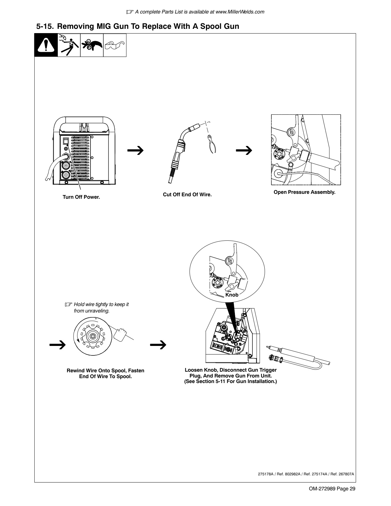

| | | | |---|---|---| | | | |
4
7
Tools Needed:
5213 6
Hold wire tightly to keep it from unraveling.
6 in. (150 mm)
Open pressure assembly. Pull and hold wire; cut off end. Push wire through guides into gun; continue to hold wire.
Use pressure indicator scale to set a desired drive roll pressure. Begin with a setting of 2. If necessary, make additional adjustments after trying this initial setting.
| | | | | | |---|---|---|---|---| |1
2
3
4
|1
2
3
4
|1
2
3
4
|1
2
3
4
|1
2
3
4
|
Tighten
Pressure Indicator Scale
| | |
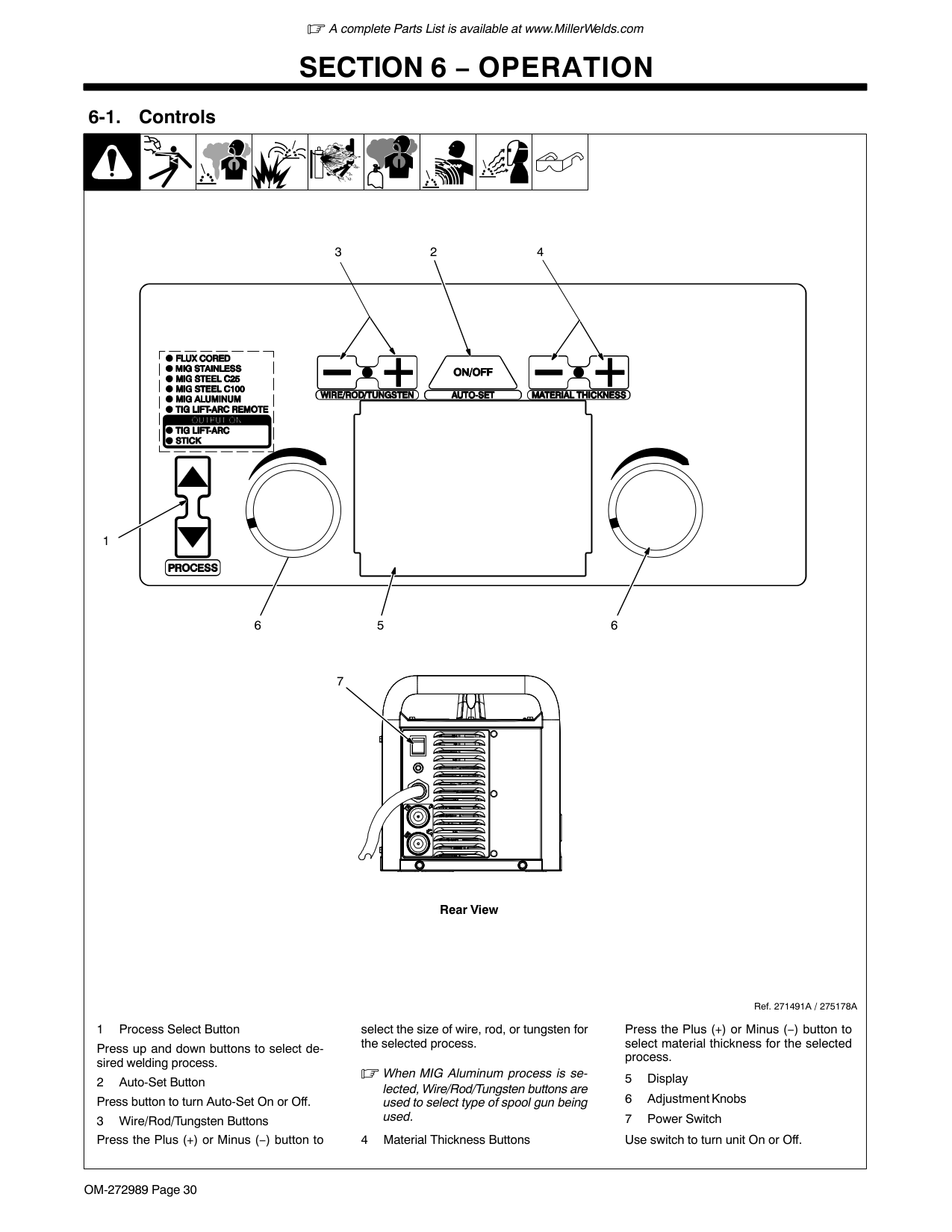
|---|---| | | |
| | |---|
| | | |---|---| | | |
Close and tighten pressure assembly, and let go of wire.
Remove gun nozzle and contact tip. Turn On.
Tighten
| | | | | | |---|---|---|---|---| | | | | | |
| | | | | | |---|---|---|---|---| | | | | | |
|WOOD| |---|
Press gun trigger until wire comes out of gun. Reinstall contact tip and nozzle

Feed wire to check drive roll pressure. Tighten knob enough to prevent slipping.
Cut off wire. Close and latch door.
Ref. 275174A / 275167A / 801 083 / Ref. 800 924-D
####### 5-15. Removing MIG Gun To Replace With A Spool Gun
| | | | | | |---|---|---|---|---| |Open Pressure Assembly.
Hold wire tightly to keep it from unraveling.
Rewind Wire Onto Spool, Fasten End Of Wire To Spool.
Cut Off End Of Wire.
Loosen Knob, Disconnect Gun Trigger Plug, And Remove Gun From Unit. (See Section 5-11 For Gun Installation.)
275178A / Ref. 802982A / Ref. 275174A / Ref. 267807A
Knob
Turn Off Power.|Open Pressure Assembly.
Hold wire tightly to keep it from unraveling.
Rewind Wire Onto Spool, Fasten End Of Wire To Spool.
Cut Off End Of Wire.
Loosen Knob, Disconnect Gun Trigger Plug, And Remove Gun From Unit. (See Section 5-11 For Gun Installation.)
275178A / Ref. 802982A / Ref. 275174A / Ref. 267807A
Knob
Turn Off Power.|
####### 6-1. Controls
SECTION 6 − OPERATION

| | | | |---|---|---| | | | |
1
23 4
| | |---|
6
5
6
7
| |
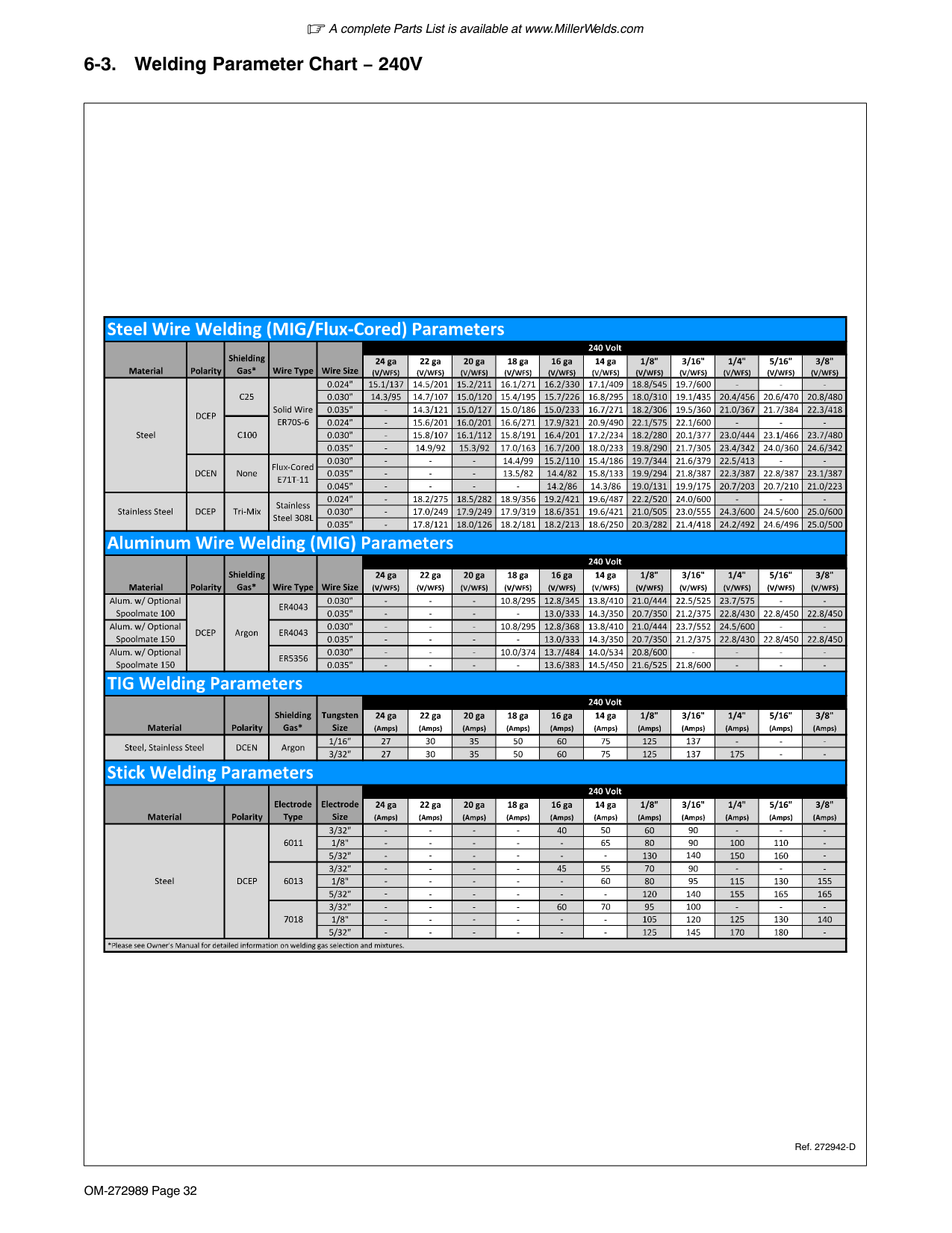
|---| | |
Rear View
Press up and down buttons to select desired welding process.
select the size of wire, rod, or tungsten for the selected process.
When MIG Aluminum process is selected, Wire/Rod/Tungsten buttons are used to select type of spool gun being used.
4 Material Thickness Buttons
Ref. 271491A / 275178A
Press the Plus (+) or Minus (−) button to select material thickness for the selected process.
####### 6-2. Welding Parameter Chart − 120V
|Ref. 272942-D| |---|
####### 6-3. Welding Parameter Chart − 240V
|Ref. 272942-D| |---|
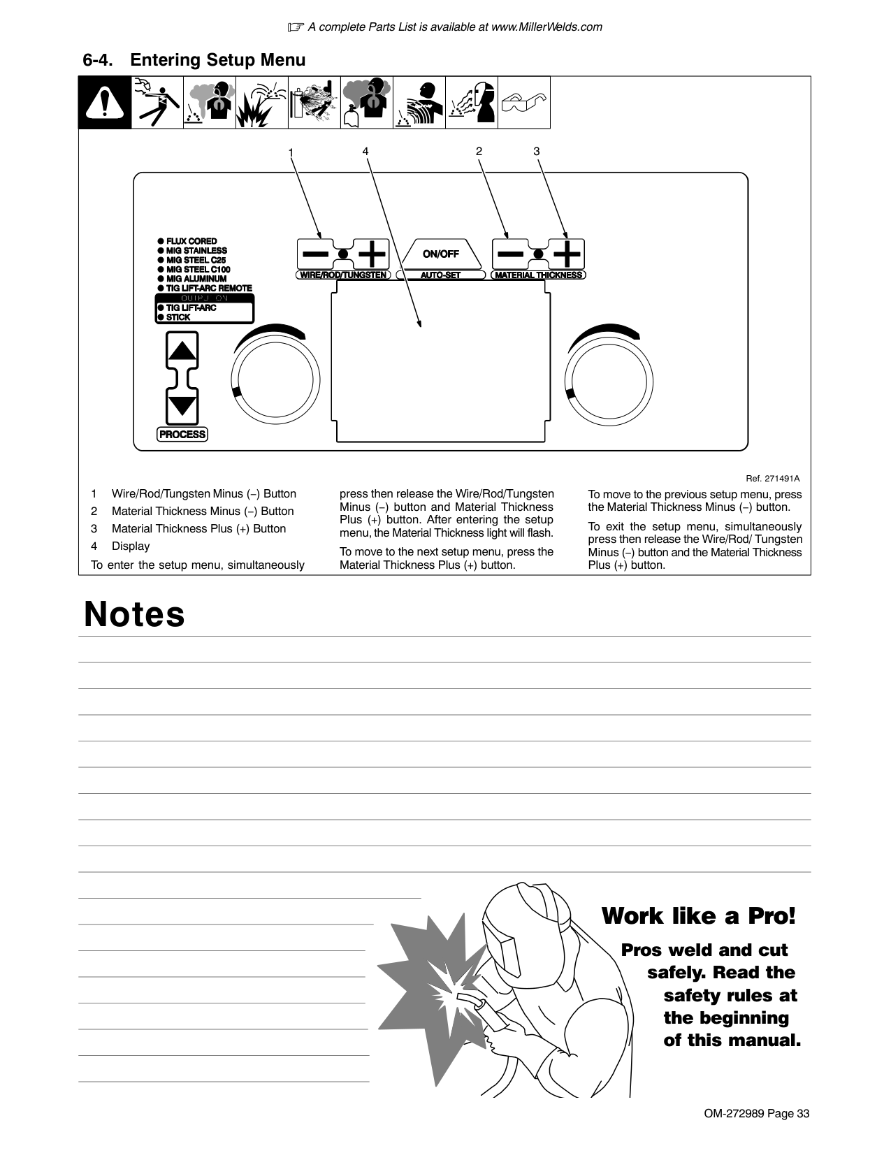
| | | | || | | | | | |---|---|---|---|---|---|---|---|---|---| |1 Wire/Rod/Tungsten Minus (−) Button
2 Material Thickness Minus (−) Button
3 Material Thickness Plus (+) Button
4 Display To enter the setup menu, simultaneously
press then release the Wire/Rod/Tungsten Minus (−) button and Material Thickness Plus (+) button. After entering the setup menu, the Material Thickness light will flash.
To move to the next setup menu, press the Material Thickness Plus (+) button.
To move to the previous setup menu, press the Material Thickness Minus (−) button.
To exit the setup menu, simultaneously press then release the Wire/Rod/ Tungsten Minus (−) button and the Material Thickness Plus (+) button.
Ref. 271491A
1 234|1 Wire/Rod/Tungsten Minus (−) Button
2 Material Thickness Minus (−) Button
3 Material Thickness Plus (+) Button
4 Display To enter the setup menu, simultaneously
press then release the Wire/Rod/Tungsten Minus (−) button and Material Thickness Plus (+) button. After entering the setup menu, the Material Thickness light will flash.
To move to the next setup menu, press the Material Thickness Plus (+) button.
To move to the previous setup menu, press the Material Thickness Minus (−) button.
To exit the setup menu, simultaneously press then release the Wire/Rod/ Tungsten Minus (−) button and the Material Thickness Plus (+) button.
Ref. 271491A
1 234|
Notes
#### Work like a Pro!
Pros weld and cut
safely. Read the safety rules at the beginning of this manual.
####### 6-5. Internal Motor 24 Inch Calibration (Menu 1 Of 10)
| | | | || | | | | | |---|---|---|---|---|---|---|---|---|---| |The unit’s internal drive motor is calibrated at the factory. No calibration is needed unless drive motor or control board is changed.
1 Wire/Rod/Tungsten Minus (−) Button
2 Material Thickness Plus (+) Button
3 Material Thickness Minus (−) Button
4 Left Adjustment Knob
5 Right Adjustment Knob Cut wire flush at nozzle.
Follow instructions in Section 6-4 to enter the setup menu.
To perform a motor calibration 24 in. run-out test at 100 IPM, turn left Adjustment knob, and
verify that a check mark appears next to 100 IPM. Wait for the lock symbol to change from unlocked to locked.
Be sure wire is cut flush at nozzle, then trigger the MIG gun. Motor will feed approximately 24 in. of wire through gun.
Cut wire flush at nozzle and measure run-out. If length of run-out is not 24 in., turn left Adjustment knob to increase/decrease length of run-out.
Wait for lock symbol to change from unlocked to locked and repeat test.
To perform a motor calibration 24 in. run-out test at 500 IPM, turn right Adjustment knob, and verify that a check mark appears next to 500 IPM.
Wait for the lock symbol to change from unlocked to locked.
Be sure wire is cut flush at nozzle, then trigger the MIG gun. Motor will feed approximately 24 in. of wire through gun.
Cut wire flush at nozzle and measure run-out. If length of run-out is not 24 in., turn right Adjustment knob to increase/decrease length of run-out.
Wait for lock symbol to change from unlocked to locked and repeat test.
To exit menu, simultaneously press and release the Wire/Rod/Tungsten Minus (−) button and Material Thickness Plus (+) button, or turn unit off and on.
Ref. 271491A
1 324 5
|The unit’s internal drive motor is calibrated at the factory. No calibration is needed unless drive motor or control board is changed.
1 Wire/Rod/Tungsten Minus (−) Button
2 Material Thickness Plus (+) Button
3 Material Thickness Minus (−) Button
4 Left Adjustment Knob
5 Right Adjustment Knob Cut wire flush at nozzle.
Follow instructions in Section 6-4 to enter the setup menu.
To perform a motor calibration 24 in. run-out test at 100 IPM, turn left Adjustment knob, and
verify that a check mark appears next to 100 IPM. Wait for the lock symbol to change from unlocked to locked.
Be sure wire is cut flush at nozzle, then trigger the MIG gun. Motor will feed approximately 24 in. of wire through gun.
Cut wire flush at nozzle and measure run-out. If length of run-out is not 24 in., turn left Adjustment knob to increase/decrease length of run-out.
Wait for lock symbol to change from unlocked to locked and repeat test.
To perform a motor calibration 24 in. run-out test at 500 IPM, turn right Adjustment knob, and verify that a check mark appears next to 500 IPM.
Wait for the lock symbol to change from unlocked to locked.
Be sure wire is cut flush at nozzle, then trigger the MIG gun. Motor will feed approximately 24 in. of wire through gun.
Cut wire flush at nozzle and measure run-out. If length of run-out is not 24 in., turn right Adjustment knob to increase/decrease length of run-out.
Wait for lock symbol to change from unlocked to locked and repeat test.
To exit menu, simultaneously press and release the Wire/Rod/Tungsten Minus (−) button and Material Thickness Plus (+) button, or turn unit off and on.
Ref. 271491A
1 324 5
|
####### 6-6. Internal Motor Run-In Speed (Menu 2 Of 10)

| | | | |---|---|---| | | | |
1 23

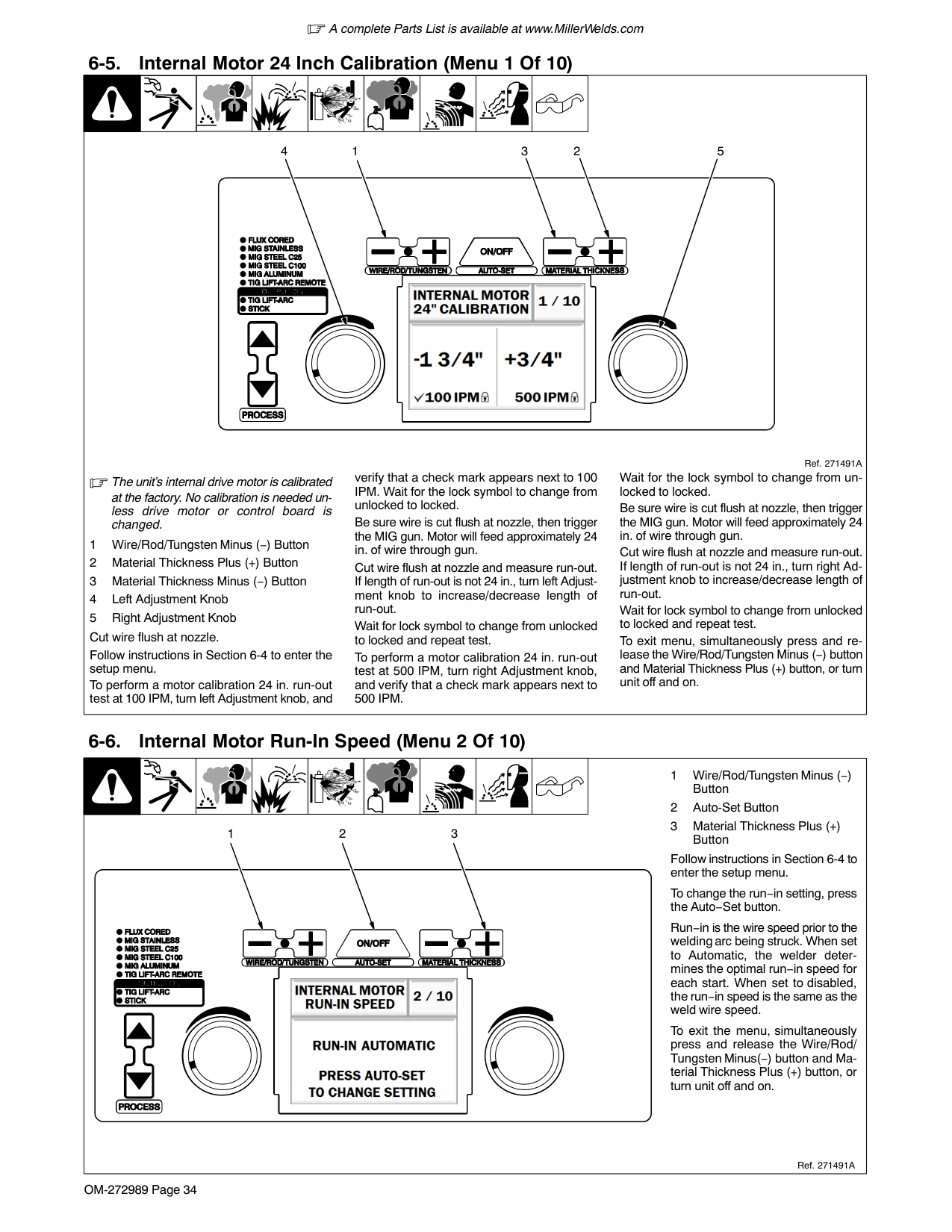
Follow instructions in Section 6-4 to enter the setup menu.
To change the run−in setting, press the Auto−Set button.
Run−in is the wire speed prior to the welding arc being struck. When set to Automatic, the welder determines the optimal run−in speed for each start. When set to disabled, the run−in speed is the same as the weld wire speed.
To exit the menu, simultaneously press and release the Wire/Rod/ Tungsten Minus(−) button and Material Thickness Plus (+) button, or turn unit off and on.
####### 6-7. Spoolmate 24 Inch Calibration (Menu 3 Of 10)

| | | | |---|---|---| | | | |
1 23

4 5
Spoolmate 100 and 150 drive motors are unique to this welding power source. Motor calibration is necessary any time a different Spoolmate 100 or 150 is connected to the Multimatic 215.
Connect Spoolmate to unit. Cut wire flush at nozzle. Follow instructions in Section 6-4 to enter the setup menu.
To perform a Spoolmate calibration 24 in. run-out test at 200 IPM, turn left Adjustment knob, and verify that a check mark appears next to 200 IPM.
Wait for the lock symbol to change from unlocked to locked.
Cut wire flush at nozzle and then trigger the Spoolmate.
Spoolmate will feed approximately 24 in. of wire through gun.
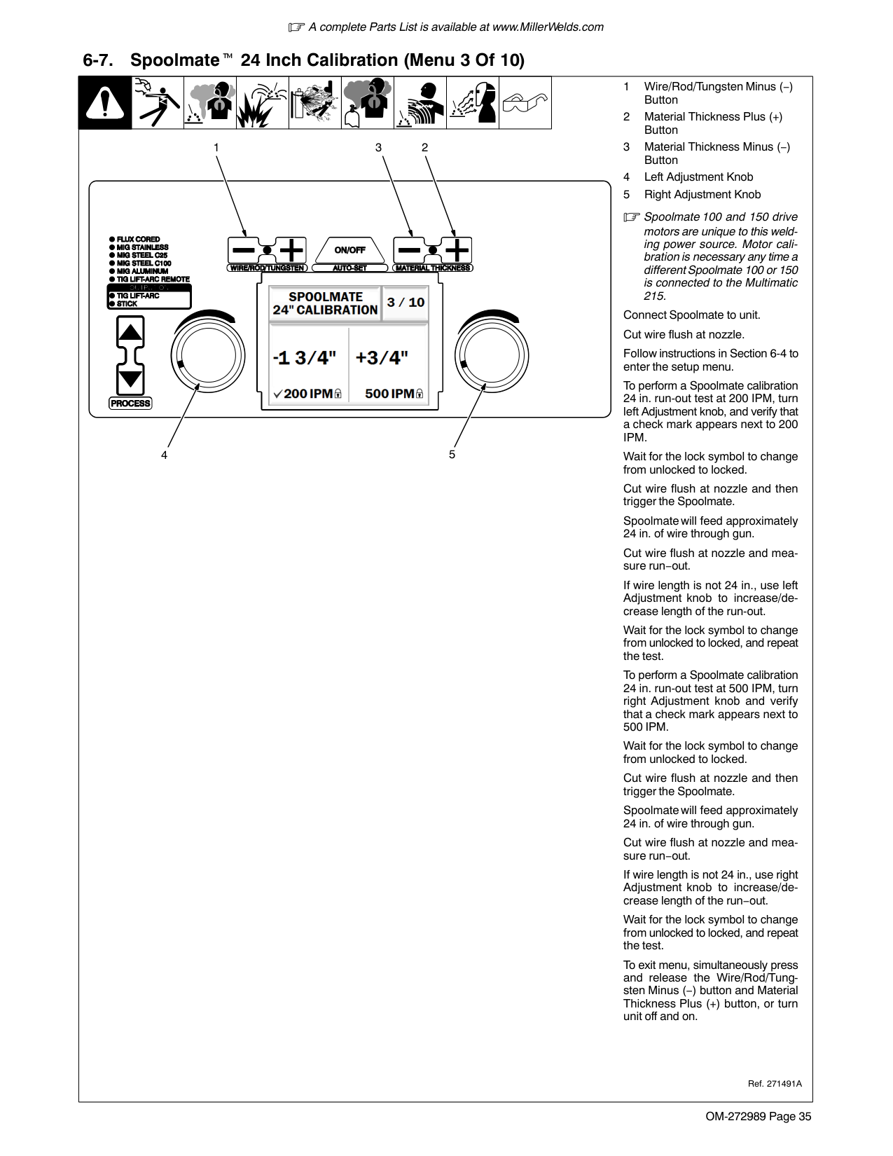
Cut wire flush at nozzle and measure run−out.
If wire length is not 24 in., use left Adjustment knob to increase/decrease length of the run-out.
Wait for the lock symbol to change from unlocked to locked, and repeat the test.
To perform a Spoolmate calibration 24 in. run-out test at 500 IPM, turn right Adjustment knob and verify that a check mark appears next to 500 IPM.
Wait for the lock symbol to change from unlocked to locked.
Cut wire flush at nozzle and then trigger the Spoolmate.
Spoolmate will feed approximately 24 in. of wire through gun.
Cut wire flush at nozzle and measure run−out.
If wire length is not 24 in., use right Adjustment knob to increase/decrease length of the run−out.
Wait for the lock symbol to change from unlocked to locked, and repeat the test.
To exit menu, simultaneously press and release the Wire/Rod/Tungsten Minus (−) button and Material Thickness Plus (+) button, or turn unit off and on.
| | | | || | | | |1 Wire/Rod/Tungsten Minus (−) Button
2 Auto-Set Button
3 Material Thickness Plus (+)
| |---|---|---|---|---|---|---|---|---|---| |
Button
Follow instructions in Section 6-4 to enter the setup menu.
To change the run−in setting, press the Auto−Set button.
Run−in is the speed of the wire prior to the welding arc being struck.
When set to Automatic, the welder determines the optimal run−in speed for each start.
When set to Disabled, the run−in speed is the same as the weld wire speed.
To exit menu, simultaneously press and release the Wire/Rod/Tungsten Minus (−) button and Material Thickness Plus (+) button, or turn unit off and on.
Ref. 271491A
1 23
|

| | | | |---|---|---|
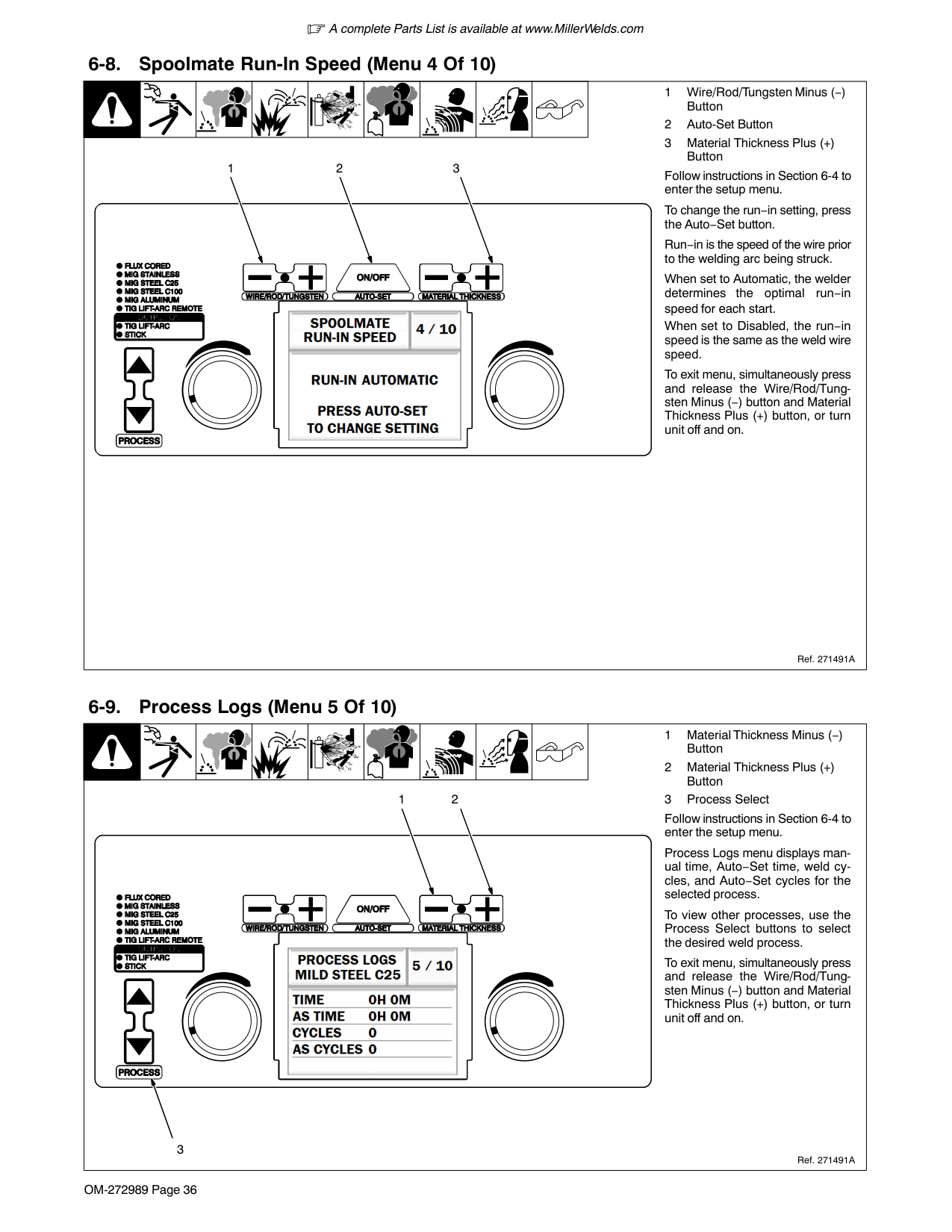
| | | |
1 2
Follow instructions in Section 6-4 to enter the setup menu.
Process Logs menu displays manual time, Auto−Set time, weld cycles, and Auto−Set cycles for the selected process.
To view other processes, use the Process Select buttons to select the desired weld process.

To exit menu, simultaneously press and release the Wire/Rod/Tungsten Minus (−) button and Material Thickness Plus (+) button, or turn unit off and on.
3
####### 6-10. Primary Logs (Menu 6 Of 10)
| | | | || | | | |1 Material Thickness Minus (−) Button
2 Material Thickness Plus (+) Button
| |---|---|---|---|---|---|---|---|---|---| |Follow instructions in Section 6-4 to enter the setup menu.
Primary Logs menu displays power cycles, 120 volt time, and 240 volt time.
To exit menu, simultaneously press and release the Wire/Rod/Tungsten Minus (−) button and Material Thickness Plus (+) button, or turn unit off and on.
Ref. 271491A
1 2
|Follow instructions in Section 6-4 to enter the setup menu.
Primary Logs menu displays power cycles, 120 volt time, and 240 volt time.
To exit menu, simultaneously press and release the Wire/Rod/Tungsten Minus (−) button and Material Thickness Plus (+) button, or turn unit off and on.
Ref. 271491A
1 2
|
####### 6-11. Error Logs (Menu 7 Of 10)
| | | | || | | | |1 Material Thickness Minus (−) Button
2 Material Thickness Plus (+) Button
| |---|---|---|---|---|---|---|---|---|---| |Follow instructions in Section 6-4 to enter the setup menu.
Error Logs screen displays welder over−temperature errors, shorted output errors, shorted trigger errors, motor current errors, and stuck electrode errors.
To exit menu, simultaneously press and release the Wire/Rod/Tungsten Minus (−) button and Material Thickness Plus (+) button, or turn unit off and on.
Ref. 271491A
1 2
|Follow instructions in Section 6-4 to enter the setup menu.
Error Logs screen displays welder over−temperature errors, shorted output errors, shorted trigger errors, motor current errors, and stuck electrode errors.
To exit menu, simultaneously press and release the Wire/Rod/Tungsten Minus (−) button and Material Thickness Plus (+) button, or turn unit off and on.
Ref. 271491A
1 2
|
####### 6-12. Factory Reset (Menu 8 Of 10)
| | | | || | | | |1 Material Thickness Minus (−) Button
2 Material Thickness Plus (+) Button
| |---|---|---|---|---|---|---|---|---|---| |3 Auto-Set Button
A Factory Reset will reset the primary logs data, process logs data, error logs data, selected process, and all process settings. Motor calibration settings, Spoolmate Calibration settings, and software information will all be retained.
Follow instructions in Section 6-4 to enter the setup menu.
To perform a Factory Reset, press the Auto−Set button.
To exit menu, simultaneously press and release the Wire/Rod/Tungsten Minus (−) button and Material Thickness Plus (+) button, or turn unit off and on.
Ref. 271491A
1 23

|3 Auto-Set Button
A Factory Reset will reset the primary logs data, process logs data, error logs data, selected process, and all process settings. Motor calibration settings, Spoolmate Calibration settings, and software information will all be retained.
Follow instructions in Section 6-4 to enter the setup menu.
To perform a Factory Reset, press the Auto−Set button.
To exit menu, simultaneously press and release the Wire/Rod/Tungsten Minus (−) button and Material Thickness Plus (+) button, or turn unit off and on.
Ref. 271491A
1 23

|
####### 6-13. Display Software (Menu 9 Of 10)
| | | | || | | | |Display Software information is for factory and service use only.|
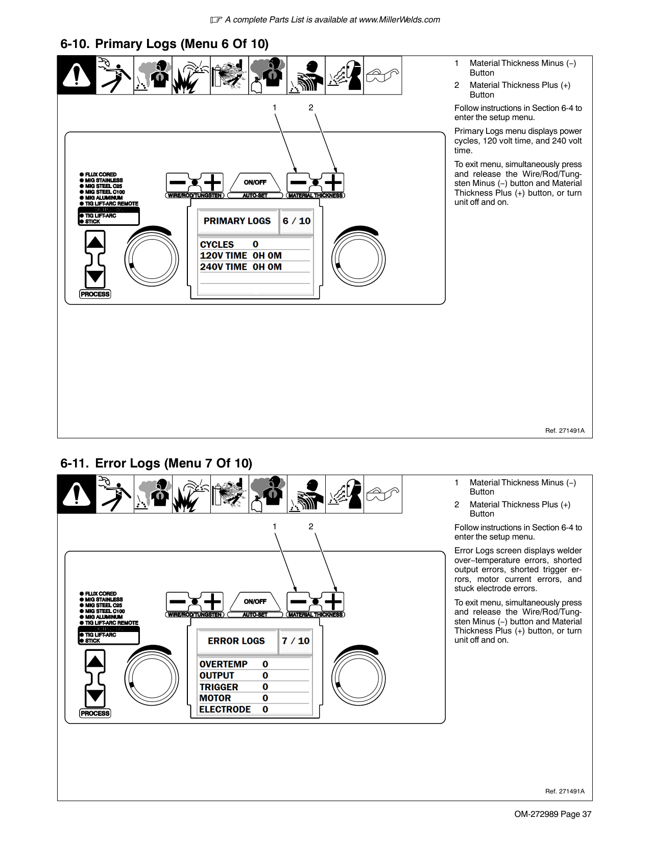
|---|---|---|---|---|---|---|---|---|---| |Follow instructions in Section 6-4 to enter the setup menu.
To exit menu, simultaneously press and release the Wire/Rod/Tungsten Minus (−) button and Material Thickness Plus (+) button, or turn unit off and on.
Ref. 271491A
|Follow instructions in Section 6-4 to enter the setup menu.
To exit menu, simultaneously press and release the Wire/Rod/Tungsten Minus (−) button and Material Thickness Plus (+) button, or turn unit off and on.
Ref. 271491A
|Follow instructions in Section 6-4 to enter the setup menu.
To exit menu, simultaneously press and release the Wire/Rod/Tungsten Minus (−) button and Material Thickness Plus (+) button, or turn unit off and on.
Ref. 271491A
|Follow instructions in Section 6-4 to enter the setup menu.
To exit menu, simultaneously press and release the Wire/Rod/Tungsten Minus (−) button and Material Thickness Plus (+) button, or turn unit off and on.
Ref. 271491A
|Follow instructions in Section 6-4 to enter the setup menu.
To exit menu, simultaneously press and release the Wire/Rod/Tungsten Minus (−) button and Material Thickness Plus (+) button, or turn unit off and on.
Ref. 271491A
|Follow instructions in Section 6-4 to enter the setup menu.
To exit menu, simultaneously press and release the Wire/Rod/Tungsten Minus (−) button and Material Thickness Plus (+) button, or turn unit off and on.
Ref. 271491A
|Follow instructions in Section 6-4 to enter the setup menu.
To exit menu, simultaneously press and release the Wire/Rod/Tungsten Minus (−) button and Material Thickness Plus (+) button, or turn unit off and on.
Ref. 271491A
|Follow instructions in Section 6-4 to enter the setup menu.
To exit menu, simultaneously press and release the Wire/Rod/Tungsten Minus (−) button and Material Thickness Plus (+) button, or turn unit off and on.
Ref. 271491A
|Follow instructions in Section 6-4 to enter the setup menu.
To exit menu, simultaneously press and release the Wire/Rod/Tungsten Minus (−) button and Material Thickness Plus (+) button, or turn unit off and on.
Ref. 271491A
|Follow instructions in Section 6-4 to enter the setup menu.
To exit menu, simultaneously press and release the Wire/Rod/Tungsten Minus (−) button and Material Thickness Plus (+) button, or turn unit off and on.
Ref. 271491A
|
| | | | || | | | |Control Software information is for factory and service use only.| |---|---|---|---|---|---|---|---|---|---| |Follow instructions in Section 6-4 to enter the setup menu.
To exit menu, simultaneously press and release the Wire/Rod/Tungsten Minus (−) button and Material Thickness Plus (+) button, or turn unit off and on.
Ref. 271491A
|Follow instructions in Section 6-4 to enter the setup menu.
To exit menu, simultaneously press and release the Wire/Rod/Tungsten Minus (−) button and Material Thickness Plus (+) button, or turn unit off and on.
Ref. 271491A
|Follow instructions in Section 6-4 to enter the setup menu.
To exit menu, simultaneously press and release the Wire/Rod/Tungsten Minus (−) button and Material Thickness Plus (+) button, or turn unit off and on.
Ref. 271491A
|Follow instructions in Section 6-4 to enter the setup menu.
To exit menu, simultaneously press and release the Wire/Rod/Tungsten Minus (−) button and Material Thickness Plus (+) button, or turn unit off and on.
Ref. 271491A
|Follow instructions in Section 6-4 to enter the setup menu.
To exit menu, simultaneously press and release the Wire/Rod/Tungsten Minus (−) button and Material Thickness Plus (+) button, or turn unit off and on.
Ref. 271491A
|Follow instructions in Section 6-4 to enter the setup menu.
To exit menu, simultaneously press and release the Wire/Rod/Tungsten Minus (−) button and Material Thickness Plus (+) button, or turn unit off and on.
Ref. 271491A
|Follow instructions in Section 6-4 to enter the setup menu.
To exit menu, simultaneously press and release the Wire/Rod/Tungsten Minus (−) button and Material Thickness Plus (+) button, or turn unit off and on.
Ref. 271491A
|Follow instructions in Section 6-4 to enter the setup menu.
To exit menu, simultaneously press and release the Wire/Rod/Tungsten Minus (−) button and Material Thickness Plus (+) button, or turn unit off and on.
Ref. 271491A
|Follow instructions in Section 6-4 to enter the setup menu.
To exit menu, simultaneously press and release the Wire/Rod/Tungsten Minus (−) button and Material Thickness Plus (+) button, or turn unit off and on.
Ref. 271491A
|Follow instructions in Section 6-4 to enter the setup menu.
To exit menu, simultaneously press and release the Wire/Rod/Tungsten Minus (−) button and Material Thickness Plus (+) button, or turn unit off and on.
Ref. 271491A
|
Notes
SECTION 7 − MAINTENANCE &TROUBLESHOOTING
|! Disconnect power
before maintaining.
Maintain more often during severe conditions.| |---|
||= Check = Change = Clean = Replace
* To be done by Factory Authorized Service Agent|= Check = Change = Clean = Replace
* To be done by Factory Authorized Service Agent|= Check = Change = Clean = Replace
* To be done by Factory Authorized Service Agent|= Check = Change = Clean = Replace
* To be done by Factory Authorized Service Agent|Reference| |---|---|---|---|---|---| |Every 3 Months
|Damaged Or Unreadable Labels|Repair Or Replace Cracked Weld Cable| | | | |Every 6 Months|OR
Inside Unit
|Clean Drive Rolls| | | |
| | |1 Supplementary Protector CB1 CB1 protects unit from overload. If CB1 opens, unit shuts down.
| |---|---|---| |275178A
Reset supplementary protector.
1|275178A
Reset supplementary protector.
1|275178A
Reset supplementary protector.
1|
####### 7-3. Changing Drive Roll Or Wire Inlet Guide
| | | |1 Inlet Wire Guide
Remove guide by pressing on barbed area or cutting off one end| |---|---|---|---|
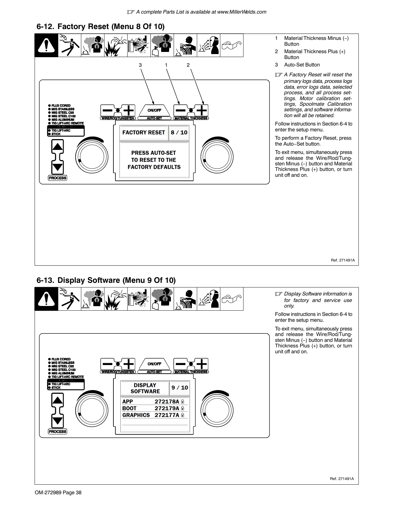
|267893A
2
1
3
near housing and pulling it out of hole. Push new guide into hole from rear until it snaps in place.
2 Drive Roll
The drive roll includes three different sized grooves. The text aligned with the drive roll retaining pin indicates the selected groove.
3 Retaining Pin
To secure drive roll, locate open slot and push drive roll completely over retaining pin, then rotate drive roll to desired slot.
See Section 13-1 for optional drive rolls.
.024 Groove .030−.035 Groove
.030-.035 V-Knurled Groove
|Groove|Compatible Wire| |---|---| |.024|.024 Solid Wire| |.030−.035|.030−.035 Solid Wire| |.030−.035 V-Knurled|.030−.035 Flux-Core|
Table 7-1. Drive Roll Grooves And Wire Type Compatibility|267893A
2
1
3
near housing and pulling it out of hole. Push new guide into hole from rear until it snaps in place.
2 Drive Roll
The drive roll includes three different sized grooves. The text aligned with the drive roll retaining pin indicates the selected groove.
3 Retaining Pin
To secure drive roll, locate open slot and push drive roll completely over retaining pin, then rotate drive roll to desired slot.
See Section 13-1 for optional drive rolls.
.024 Groove .030−.035 Groove
.030-.035 V-Knurled Groove
|Groove|Compatible Wire| |---|---| |.024|.024 Solid Wire| |.030−.035|.030−.035 Solid Wire| |.030−.035 V-Knurled|.030−.035 Flux-Core|
Table 7-1. Drive Roll Grooves And Wire Type Compatibility|
####### 7-4. Error Messages
| | | | | | | | | |---|---|---|---|---|---|---|---|
|Message|Error|Remedy| |---|---|---| |Overtemp−Please wait while the welder cools down.|Internal temperature of welder has exceeded the maximum limit.|Wait for unit to cool down. If the fan is not running, contact Miller Electric Mfg. Co. service department.| |Shorted trigger−Release 4−pin trigger to clear error.|MIG gun or spool gun trigger is engaged on power up.|Release 4−pin trigger to clear error.| |Shorted trigger−Release 4−pin trigger to clear error.|MIG gun is held during jog for more than 16 feet of wire.|Release 4−pin trigger to clear error.| |Shorted trigger−Release 4−pin trigger to clear error.|Spool gun is held during jog for more than 10 seconds.|Release 4−pin trigger to clear error.| |Shorted trigger−Release 4−pin trigger to clear error.|MIG gun or spool gun trigger is engaged for more than 1 second after the arc is broken.|Release 4−pin trigger to clear error.| |Shorted trigger−Release 4−pin trigger to clear error.|After an overtemp error, the MIG or spool gun trigger is held after the welder has completed cooling.|Release 4−pin trigger to clear error.| |Shorted trigger−Release 4−pin trigger to clear error.|MIG gun or spool gun trigger is engaged while the process is changed to Flux Cored or a MIG process.|Release 4−pin trigger to clear error.| |Shorted trigger−Release 4−pin trigger to clear error.|MIG gun or spool gun trigger lead voltage exceeds 9 volts caused by the electrode being shorted to the trigger lead.|Fix or replace damaged gun.| |Shorted trigger−Release 4−pin trigger to clear error.|MIG gun or spool gun trigger leads are shorted together.|Fix or replace damaged gun.| |Shorted trigger-Release 8−pin trigger to clear error.|The 8−pin trigger is engage on power up.|Release the 8−pin trigger.|
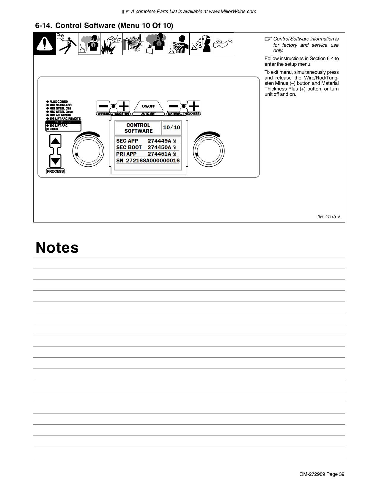
|Shorted trigger-Release 8−pin trigger to clear error.|The 8−pin trigger is engage while the process is changed to TIG Lift−Arc Remote.|Release the 8−pin trigger.| |Shorted trigger-Release trigger to clear error.|The 4−pin or 8−pin trigger is held during TIG preflow for more than 10 seconds.|Release the 4−pin or 8−pin triggers.| |Shorted output-First remove short, then pull trigger to clear error.|The welding wire came into contact with the workpiece while jogging wire.|Remove short and pull trigger, or wait 30 seconds to clear error.| |Shorted output-First remove short, then pull trigger to clear error.|MIG gun or spool gun contact tip came into contact with the workpiece while welding.|Remove short and pull trigger, or wait 30 seconds to clear error.| |Shorted output-First remove short, then pull trigger to clear error.|The weld voltage is less than 10 volts for more than 0.2 seconds while welding.|Remove short and pull trigger, or wait 30 seconds to clear error.| |Shorted output-First remove short, then pull trigger to clear error.|Output rectifier is damaged.|Contact Miller Electric Mfg. Co. service department.| |Shorted output-First remove short, then pull trigger to clear error.|Control board is damaged.|Contact Miller Electric Mfg. Co. service department.| |Stuck electrode-Free stuck electrode to clear error.|Stick welding electrode has become stuck in weld puddle and turned output off.|Remove Stick welding electrode from workpiece and output will turn back on after about one second.| |Stuck electrode-Free tungsten to clear error.
|Tungsten electrode has become stuck in weld puddle and turned output off.|Remove the tungsten from workpiece and output will turn back on after about one second.| |Stuck electrode-Free tungsten to clear error.
|Tungsten has contacted workpiece for more than 5 seconds without starting an arc.|Remove the tungsten from workpiece and output will turn back on after about one second.| |Motor error−Motor has drawn too much current.|Too much pressure on pressure adjust knob.|Reduce pressure on the pressure adjust knob.| |Motor error−Motor has drawn too much current.|The gun liner is obstructed.|Clear obstruction or replace gun liner.| |Motor error−Motor has drawn too much current.|The gun contact tip is obstructed.|Clear obstruction or replace contact tip.| |Motor error−Motor has drawn too much current.|The welding wire is entangled.|Untangle welding wire.| |Motor error−Motor has drawn too much current.|The control board is damaged.|Contact Miller Electric Mfg. Co. service department.|
|Message|Error|Remedy| |---|---|---| |Fan error-The fan is running too slow or is damaged.|The fan blades are obstructed.|Clear obstruction from fan.| |Fan error-The fan is running too slow or is damaged.|The fan wiring harness is disconnected.|Reconnect the fan.| |Fan error-The fan is running too slow or is damaged.|The fan is damaged.|Contact Miller Electric Mfg. Co. service department.| |Fan error-The fan is running too slow or is damaged.|The control board is damaged.|Contact Miller Electric Mfg. Co. service department.| |Thermal error−Primary thermistor range error.|The primary circuit thermistor is unplugged.|Reconnect the primary circuit thermistor.| |Thermal error−Primary thermistor range error.|The primary circuit thermistor is reading too high or too low for a valid temperature.|Contact Miller Electric Mfg. Co. service department.| |Thermal error−Primary thermistor range error.|The control board is damaged.|Contact Miller Electric Mfg. Co. service department.| |Thermal error−Secondary thermistor range error.|The secondary circuit thermistor is unplugged.|Reconnect the secondary circuit thermistor.| |Thermal error−Secondary thermistor range error.|The secondary circuit thermistor is reading too high or too low for a valid temperature.|Contact Miller Electric Mfg. Co. service department.| |Thermal error−Secondary thermistor range error.|The control board is damaged.|Contact Miller Electric Mfg. Co. service department.| |Boost error−Cycle power to clear error.|The primary boost has not successfully been established.|Cycle power to clear error. If this error persists after a power cycle, contact Miller Electric Mfg. Co. service department.| |Over voltage−Cycle power to clear error.|Primary voltage is above 310 volts.|Reduce primary voltage below 310 volts.| |Under voltage−Cycle power to clear error.|The primary voltage is below 90 volts.|Increase primary voltage above 90 volts.| |Network error−Communication between micros has been lost.|The two microcontrollers on the control board are no longer communicating.|Cycle power to clear error. If this error persists after a power cycle, contact Miller Electric Mfg. Co. service department.| |Network error−Communication between boards has been lost.|The wiring harness between the control board and interface board is damaged.|Cycle power to clear error. If this error persists after a power cycle, contact Miller Electric Mfg. Co. service department.| |Network error−Communication between boards has been lost.|The control board is damaged.|Cycle power to clear error. If this error persists after a power cycle, contact Miller Electric Mfg. Co. service department.| |Network error−Communication between boards has been lost.|The interface board is damaged.|Cycle power to clear error. If this error persists after a power cycle, contact Miller Electric Mfg. Co. service department.| |Cable error−Connect wire feed housing cable to clear error.|A process that requires a welding gun to be attached to the internal motor is selected, but the wire feed housing cable is not attached to either the positive stud or negative stud of the power source.|Connect wire drive assembly cable to either the positive or negative stud, or select a different process.| |Cable error−Connect wire feed housing cable to clear error.|The control board is damaged.|Contact Miller Electric Mfg. Co. service department.| |Cable error−Wire feed housing cable is touching electrode or work.|A process that does not require a welding gun to be attached to the internal motor is selected, but the wire drive assembly cable is attached to either the positive or negative stud of the power source.|Remove wire drive assembly cable from either the positive or negative stud, or select a different process.| |Cable error−Wire feed housing cable is touching electrode or work.|The control board is damaged.|Contact Miller Electric Mfg. Co. service department.|
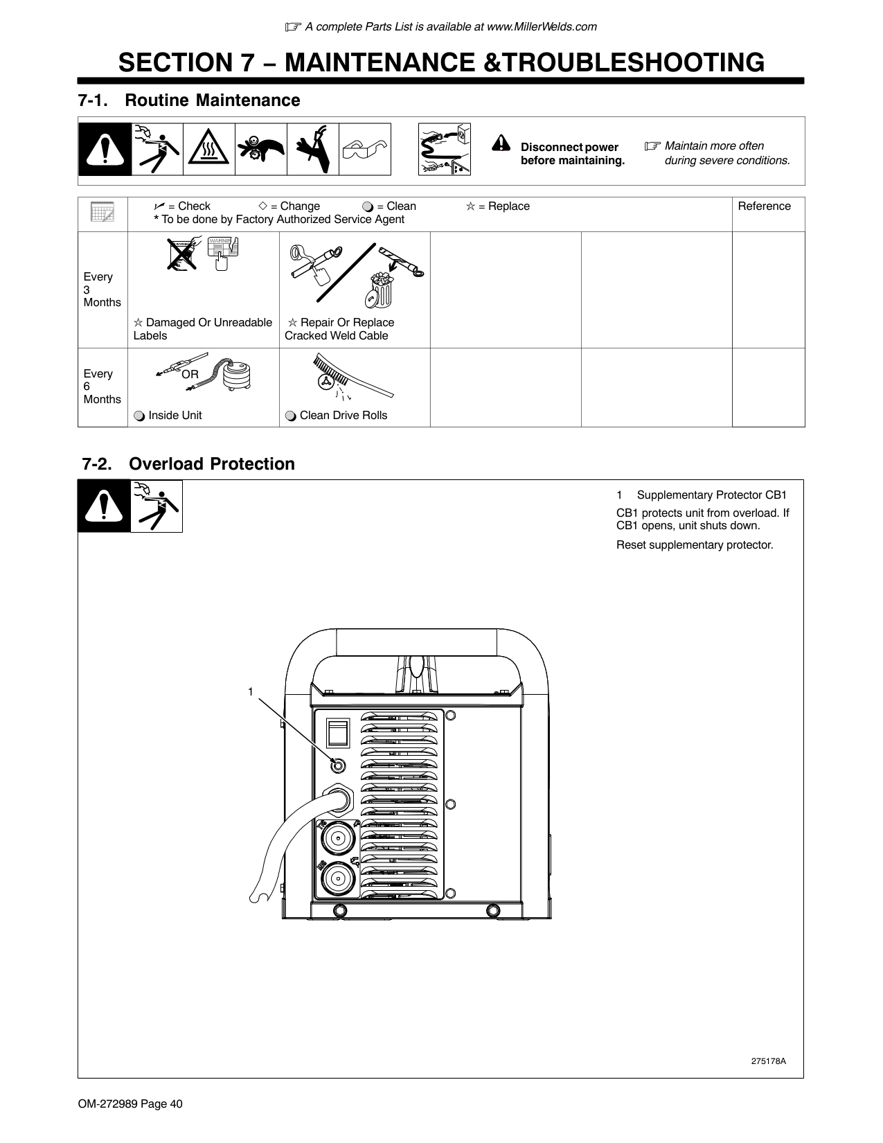
####### 7-5. Troubleshooting
| | | | | | | | |---|---|---|---|---|---|---|
|Trouble|Remedy| |---|---| |No weld output; unit completely inoperative.
|Place line disconnect switch in On position.| |No weld output; unit completely inoperative.
|Check and replace line fuse(s), if necessary, or reset supplementary protector.| |No weld output; unit completely inoperative.
|Be sure power cord is plugged in and that receptacle is receiving input power.| |No weld output; unit is on.|Check and secure loose weld cable(s) into receptacle(s).| |No weld output; unit is on.|Check and correct poor connection of work clamp to workpiece.| |Erratic or improper welding arc or output.
|Use proper size and type of weld cable (see your Distributor).| |Erratic or improper welding arc or output.
|Clean and tighten weld connections.| |Erratic or improper welding arc or output.
|Verify electrode polarity; check and correct poor connections to workpiece.| |Fan not operating.
|Unit not warmed up enough to require fan cooling.| |Fan not operating.
|Check for and remove anything blocking fan movement.| |Fan not operating.
|Have Factory Authorized Service Agent check fan motor and control circuitry.| |Stick welding problems: Hard starts; poor welding characteristics; unusual spattering.
|Use proper type and size of electrode.| |Stick welding problems: Hard starts; poor welding characteristics; unusual spattering.
|Verify electrode polarity; check and correct poor connections.| |Stick welding problems: Hard starts; poor welding characteristics; unusual spattering.
|Make sure a remote control is not connected.| |TIG welding problems: Wandering arc; hard starts; poor welding characteristics; spattering problems.
|Use proper type and size of tungsten.| |TIG welding problems: Wandering arc; hard starts; poor welding characteristics; spattering problems.
|Use properly prepared tungsten.| |TIG welding problems: Wandering arc; hard starts; poor welding characteristics; spattering problems.
|Verify electrode polarity.| |TIG welding problems: Tungsten electrode oxidizing and not remaining bright after welding.|Shield weld zone from drafts.| |TIG welding problems: Tungsten electrode oxidizing and not remaining bright after welding.|Check for correct type shielding gas.| |TIG welding problems: Tungsten electrode oxidizing and not remaining bright after welding.|Check and tighten gas fittings.| |TIG welding problems: Tungsten electrode oxidizing and not remaining bright after welding.|Verify electrode polarity.|
Notes
SECTION 8 − ELECTRICAL DIAGRAM
| | | |---|---| | | |
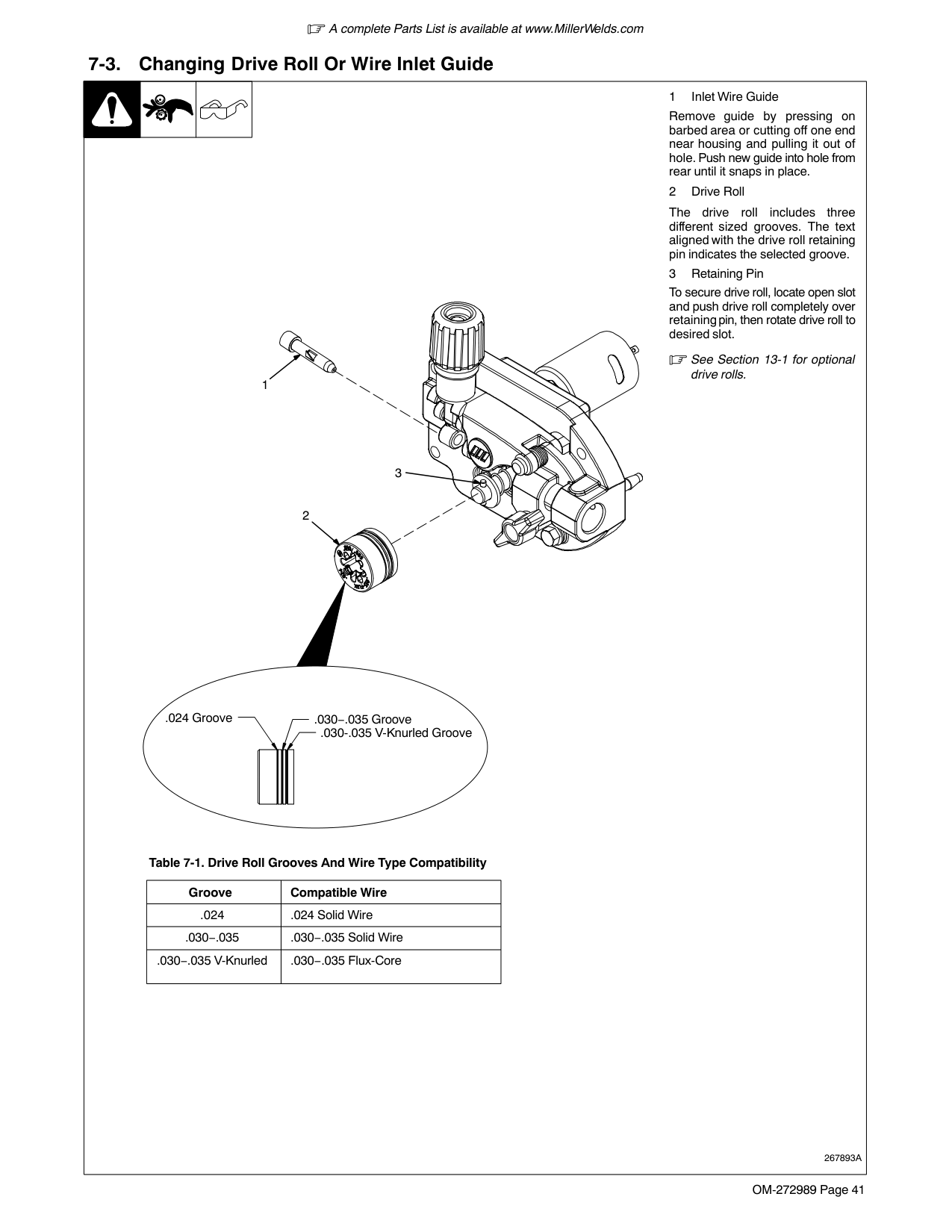
Figure 8-1. Circuit Diagram
| | | |---|---| | | | | | |
| | | | | | | | | | | | |---|---|---|---|---|---|---|---|---|---|---|
################## 272984-A
SECTION 9 − GMAW WELDING (MIG) GUIDELINES
####### 9-1. Typical GMAW (MIG) Process Connections
Regulator/ Flowmeter
Wire Feeder/ Welding Power Source
! Weld current can damage electronic parts in vehicles. Disconnect both battery cables before welding on a vehicle. Place work clamp as close to the weld as possible.
Shielding Gas
Gun
Gas
Workpiece
Work Clamp
GMAW1 2018−01 (GMAW Only) − Ref. 801909-A
####### 9-2. Typical GMAW (MIG) Process Control Settings
| | | | | | | | |These settings are guidelines only. Material and wire type, joint design, fitup, position, shielding gas, etc. affect settings. Test welds to be sure they comply to specifications.| |---|---|---|---|---|---|---|---|---| | | |1 Material Thickness Material thickness determines weld parameters.
1/16 or 0.0625 in.
1
|1 Material Thickness Material thickness determines weld parameters.
1/16 or 0.0625 in.
1
|1 Material Thickness Material thickness determines weld parameters.
1/16 or 0.0625 in.
1
|1 Material Thickness Material thickness determines weld parameters.
1/16 or 0.0625 in.
1
|1 Material Thickness Material thickness determines weld parameters.
1/16 or 0.0625 in.
1
|1 Material Thickness Material thickness determines weld parameters.
1/16 or 0.0625 in.
1
|1 Material Thickness Material thickness determines weld parameters.
1/16 or 0.0625 in.
1
|
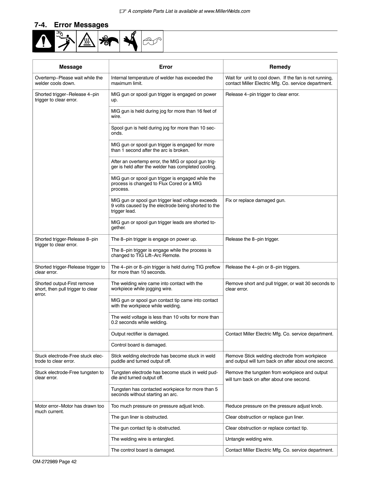
|Convert material thickness to amperage (A): 0.001 in. (0.025 mm) = 1 ampere 0.0625 in. (1.59 mm) 0.001 = 62.5 A
2 Select Wire Size See table below.
3 Select Wire Feed Speed (Amperage)
Wire feed speed (amperage) controls weld penetration.
See table below.
4 Select Voltage Voltage controls height and width of weld bead.
Low Voltage: wire stubs into work High Voltage: arc is unstable (spatter)
Set voltage midway between high and low voltage.
2
3 4
|
|Wire Size|Amperage Range|Recommended Wire Feed Speed|Wire Feed Speed*| |---|---|---|---| |0.023 in. (0.58 mm)|30−90 A|3.5 in. (89 mm) per amp|3.5 x 62.5 A = 219 ipm (5.56 mpm)| |0.030 in. (0.76 mm)|40−145 A|2 in. (51 mm) per amp|2 x 62.5 A = 125 ipm (3.19 mpm)| |0.035 in. (0.89 mm)|50−180 A|1.6 in. (41 mm) per amp|1.6 x 62.5 A = 100 ipm (2.56 mpm)| |*62.5 A based on 1/16 in. (1.6 mm) material thickness. ipm = inches per minute; mpm = meters per minute|*62.5 A based on 1/16 in. (1.6 mm) material thickness. ipm = inches per minute; mpm = meters per minute|*62.5 A based on 1/16 in. (1.6 mm) material thickness. ipm = inches per minute; mpm = meters per minute|*62.5 A based on 1/16 in. (1.6 mm) material thickness. ipm = inches per minute; mpm = meters per minute|
####### 9-3. Holding And Positioning Welding Gun
Welding wire is energized when gun trigger is pressed. Before lowering helmet and pressing trigger, be sure wire is no more than 1/2 in. (13 mm) past end of nozzle, and tip of wire is positioned correctly on seam.
1
(9 to 13 mm)
3
2
5
4
0-15
0-15
45
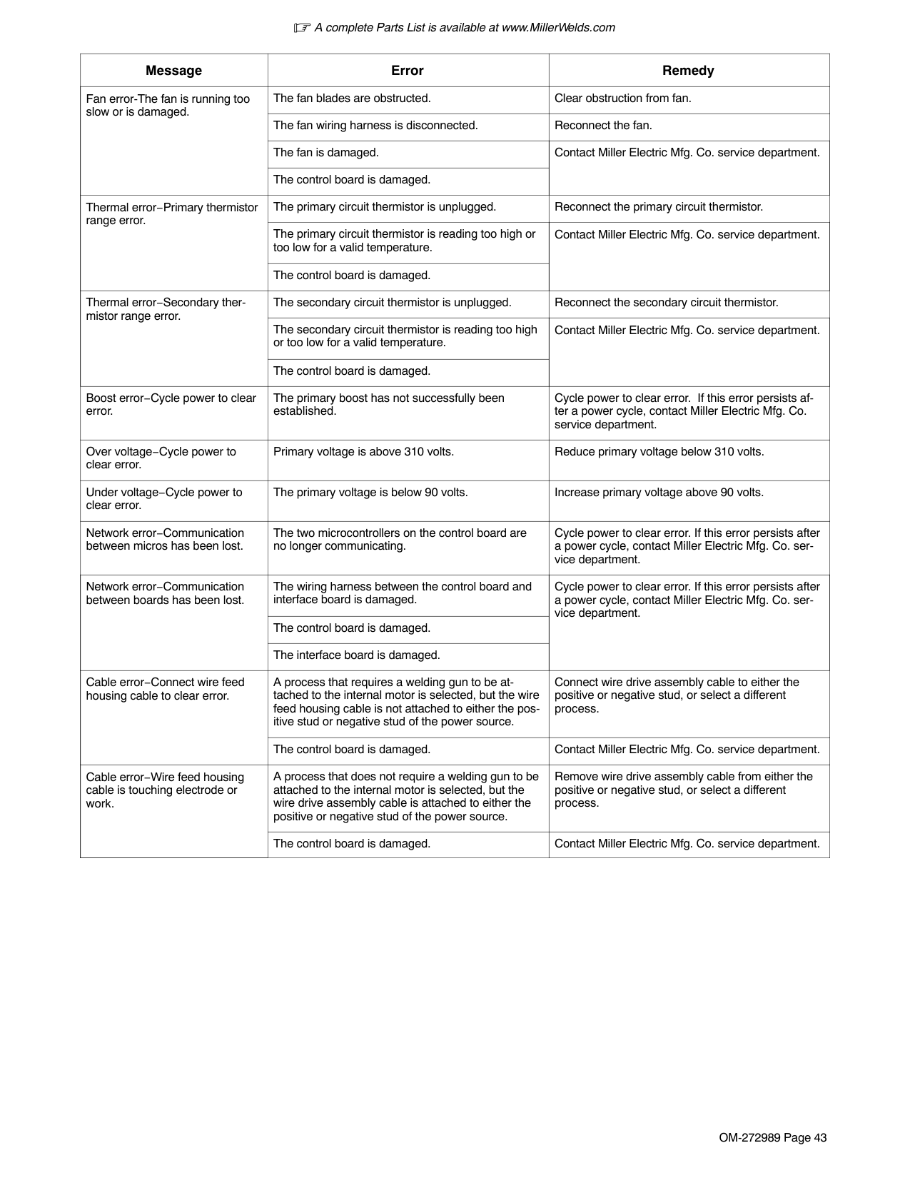
90 90
45
End View of Work Angle Side View of Gun Angle Groove Welds
End View of Work Angle Side View of Gun Angle Fillet Welds
####### 9-4. Conditions That Affect Weld Bead Shape
10 10
S-0421-A
Weld bead shape depends on gun angle, direction of travel, electrode extension (stickout), travel speed, thickness of base metal, wire feed speed (weld current), and voltage.
Push Perpendicular Drag
Gun Angles And Weld Bead Profiles
Short Normal Long Short Normal Long
Fillet Weld Electode Extensions (Stickout)Electrode Extensions (Stickout)
Slow
Normal Fast
Gun Travel Speed
S-0634
| | | | | | | | | | |1 Large Spatter Deposits
2 Rough, Uneven Bead
3 Slight Crater During Welding
| |---|---|---|---|---|---|---|---|---|---|---| |4 Bad Overlap
5 Poor Penetration
5
423
1
S-0053-A|4 Bad Overlap
5 Poor Penetration
5
423
1
S-0053-A|4 Bad Overlap
5 Poor Penetration
5
423
1
S-0053-A|4 Bad Overlap
5 Poor Penetration
5
423
1
S-0053-A|4 Bad Overlap
5 Poor Penetration
5
423
1
S-0053-A|4 Bad Overlap
5 Poor Penetration
5
423
1
S-0053-A|4 Bad Overlap
5 Poor Penetration
5
423
1
S-0053-A|4 Bad Overlap
5 Poor Penetration
5
423
1
S-0053-A|4 Bad Overlap
5 Poor Penetration
5
423
1
S-0053-A|4 Bad Overlap
5 Poor Penetration
5
423
1
S-0053-A|4 Bad Overlap
5 Poor Penetration
5
423
1
S-0053-A|
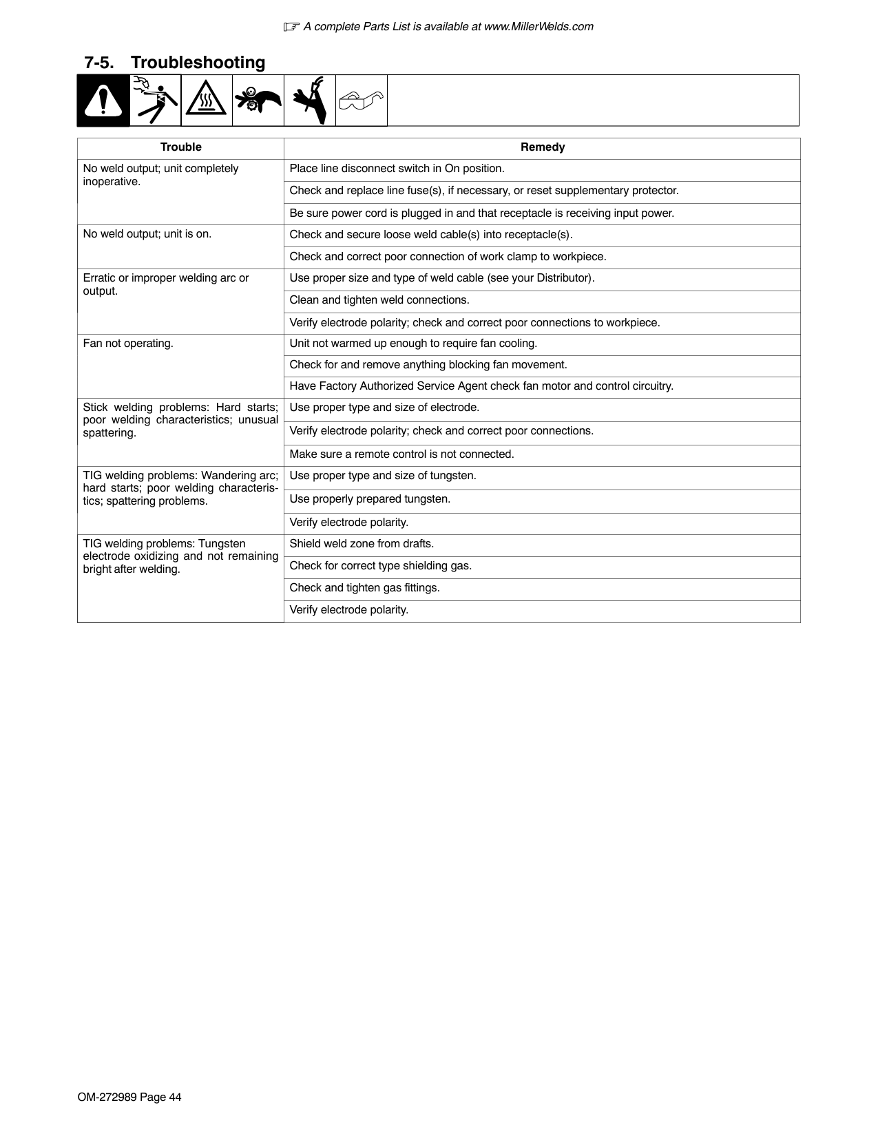
1 2
3
1
2 3
4
| | | |---|---|
5
Normally, a single stringer bead is satisfactory for most narrow groove weld joints; however, for wide groove weld joints or bridging across gaps, a weave bead or multiple stringer beads works better.
Use weave patterns to cover a wide area in one pass of the electrode.
S-0054-A
Weld a new bead or layer for each 1/8 in. (3.2 mm) thickness in metals being welded.
S-0052-B

####### 9-8. Troubleshooting − Excessive Spatter
|| | |---| | |
Excessive Spatter − scattering of molten metal particles that cool to solid form near weld bead.
S-0636|| | |---| | |
Excessive Spatter − scattering of molten metal particles that cool to solid form near weld bead.
S-0636| |---|---| |Possible Causes|Corrective Actions| |Wire feed speed too high.|Select lower wire feed speed.| |Voltage too high.|Select lower voltage range.| |Electrode extension (stickout) too long.|Use shorter electrode extension (stickout).| |Workpiece dirty.|Remove all grease, oil, moisture, rust, paint, undercoating, and dirt from work surface before welding.| |Insufficient shielding gas at welding arc.|Increase flow of shielding gas at regulator/flowmeter and/or prevent drafts near welding arc.| |Dirty welding wire.
|Use clean, dry welding wire.| |Dirty welding wire.
|Eliminate pickup of oil or lubricant on welding wire from feeder or liner.| |Incorrect polarity.|Check polarity required by welding wire, and change to correct polarity at welding power source.|
####### 9-9. Troubleshooting − Porosity
|Porosity − small cavities or holes resulting from gas pockets in weld metal.
S-0635|Porosity − small cavities or holes resulting from gas pockets in weld metal.
S-0635| |---|---| |Possible Causes|Corrective Actions| |Insufficient shielding gas at welding arc.
|Increase flow of shielding gas at regulator/flowmeter and/or prevent drafts near welding arc.| |Insufficient shielding gas at welding arc.
|Remove spatter from gun nozzle.| |Insufficient shielding gas at welding arc.
|Check gas hoses for leaks.| |Insufficient shielding gas at welding arc.
|Place nozzle 1/4 to 1/2 in. (6-13 mm) from workpiece.| |Insufficient shielding gas at welding arc.
|Hold gun near bead at end of weld until molten metal solidifies.| |Wrong gas.|Use welding grade shielding gas; change to different gas.| |Dirty welding wire.
|Use clean, dry welding wire.| |Dirty welding wire.
|Eliminate pick up of oil or lubricant on welding wire from feeder or liner.| |Workpiece dirty.
|Remove all grease, oil, moisture, rust, paint, coatings, and dirt from work surface before welding.| |Workpiece dirty.
|Use a more highly deoxidizing welding wire (contact supplier).| |Welding wire extends too far out of nozzle.|Be sure welding wire extends not more than 1/2 in. (13 mm) beyond nozzle.|
####### 9-10. Troubleshooting − Excessive Penetration
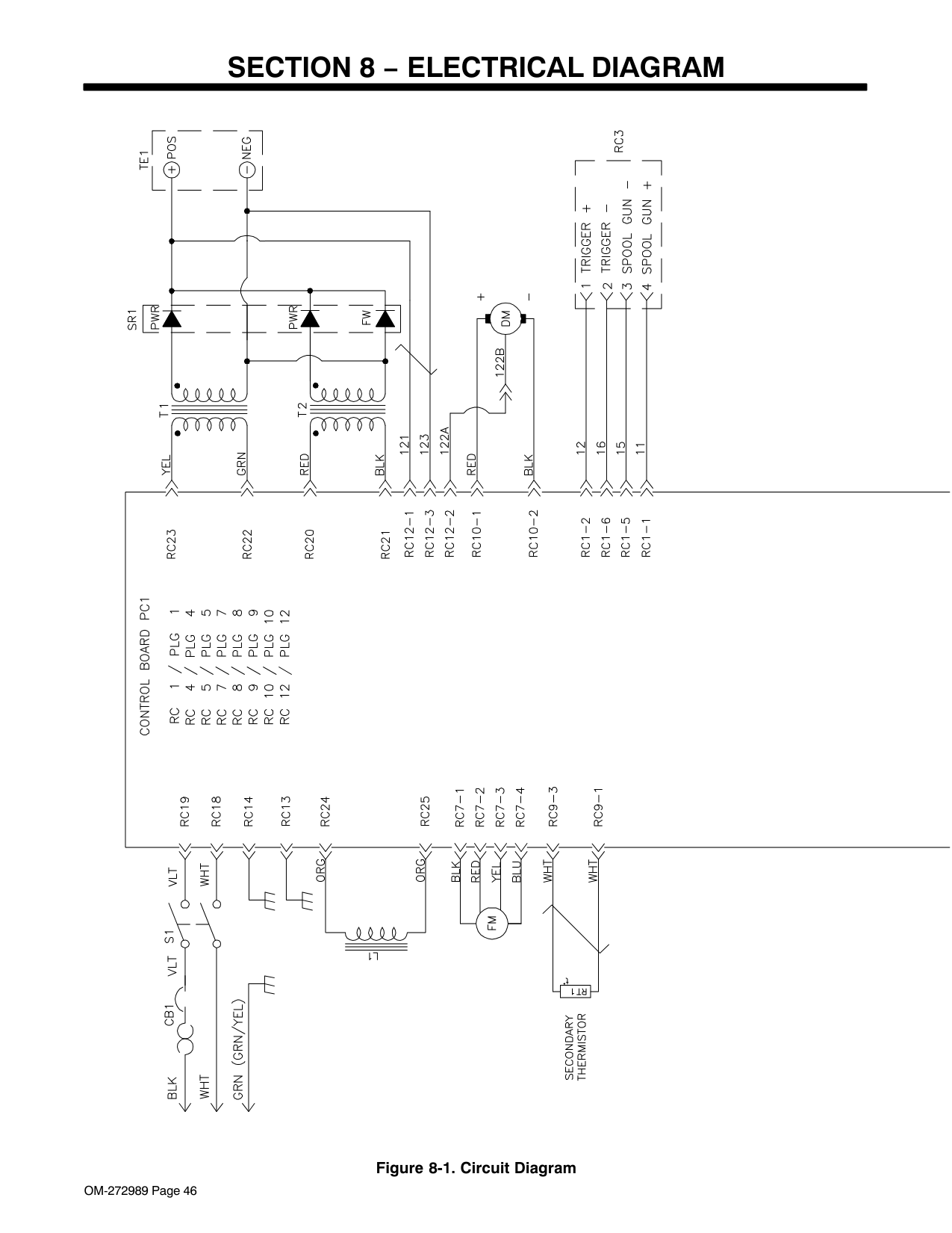
|Good Penetration
Excessive Penetration − weld metal melting through base metal and hanging underneath weld.
Excessive Penetration
S-0639|Good Penetration
Excessive Penetration − weld metal melting through base metal and hanging underneath weld.
Excessive Penetration
S-0639| |---|---| |Possible Causes|Corrective Actions| |Excessive heat input.
|Select lower voltage range and reduce wire feed speed.| |Excessive heat input.
|Increase travel speed.|
####### 9-11. Troubleshooting − Lack Of Penetration
|| | | | |---|---|---| | | | |
Lack Of Penetration − shallow fusion between weld metal and base metal.
Lack of Penetration Good Penetration
S-0638|| | | | |---|---|---| | | | |
Lack Of Penetration − shallow fusion between weld metal and base metal.
Lack of Penetration Good Penetration
S-0638| |---|---| |Possible Causes|Corrective Actions| |Improper joint preparation.|Material too thick. Joint preparation and design must provide access to bottom of groove while maintaining proper welding wire extension and arc characteristics.| |Improper weld technique.
|Maintain normal gun angle of 0 to 15 degrees to achieve maximum penetration.| |Improper weld technique.
|Keep arc on leading edge of weld puddle.| |Improper weld technique.
|Be sure welding wire extends not more than 1/2 in. (13 mm) beyond nozzle.| |Insufficient heat input.
|Select higher wire feed speed and/or select higher voltage range.| |Insufficient heat input.
|Reduce travel speed.| |Incorrect polarity.|Check polarity required by welding wire, and change to correct polarity at welding power source.|
####### 9-12. Troubleshooting − Incomplete Fusion
|Incomplete Fusion − failure of weld metal to fuse completely with base metal or a preceeding weld bead.
S-0637|Incomplete Fusion − failure of weld metal to fuse completely with base metal or a preceeding weld bead.
S-0637| |---|---| |Possible Causes|Corrective Actions| |Workpiece dirty.|Remove all grease, oil, moisture, rust, paint, undercoating, and dirt from work surface before welding.| |Insufficient heat input.|Select higher voltage range and/or adjust wire feed speed.| |Improper welding technique.
|Place stringer bead in proper location(s) at joint during welding.| |Improper welding technique.
|Adjust work angle or widen groove to access bottom during welding.| |Improper welding technique.
|Momentarily hold arc on groove side walls when using weaving technique.| |Improper welding technique.
|Keep arc on leading edge of weld puddle.| |Improper welding technique.
|Use correct gun angle of 0 to 15 degrees.|
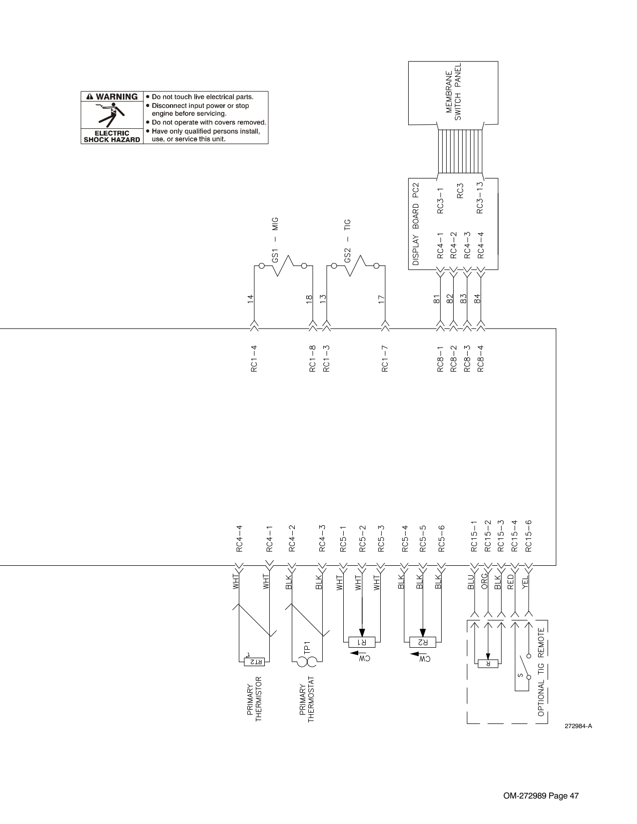
####### 9-13. Troubleshooting − Burn-Through
|Burn-Through − weld metal melting completely through base metal resulting in holes where no metal remains.
S-0640|Burn-Through − weld metal melting completely through base metal resulting in holes where no metal remains.
S-0640| |---|---| |Possible Causes|Corrective Actions| |Excessive heat input.
|Select lower voltage range and reduce wire feed speed.| |Excessive heat input.
|Increase and/or maintain steady travel speed.|
|| | |---| | |
Waviness Of Bead − weld metal that is not parallel and does not cover joint formed by base metal.
S-0641|| | |---| | |
Waviness Of Bead − weld metal that is not parallel and does not cover joint formed by base metal.
S-0641| |---|---| |Possible Causes|Corrective Actions| |Welding wire extends too far out of nozzle.|Be sure welding wire extends not more than 1/2 in. (13 mm) beyond nozzle.| |Unsteady hand.|Support hand on solid surface or use two hands.|
|Distortion − contraction of weld metal during welding that forces base metal to move.
Base metal moves in the direction of the weld bead.
S-0642|Distortion − contraction of weld metal during welding that forces base metal to move.
Base metal moves in the direction of the weld bead.
S-0642| |---|---| |Possible Causes|Corrective Actions| |Excessive heat input.
|Use restraint (clamp) to hold base metal in position.| |Excessive heat input.
|Make tack welds along joint before starting welding operation.| |Excessive heat input.
|Select lower voltage range and/or reduce wire feed speed.| |Excessive heat input.
|Increase travel speed.| |Excessive heat input.
|Weld in small segments and allow cooling between welds.|
Notes
####### 9-16. Common GMAW (MIG) Shielding Gases
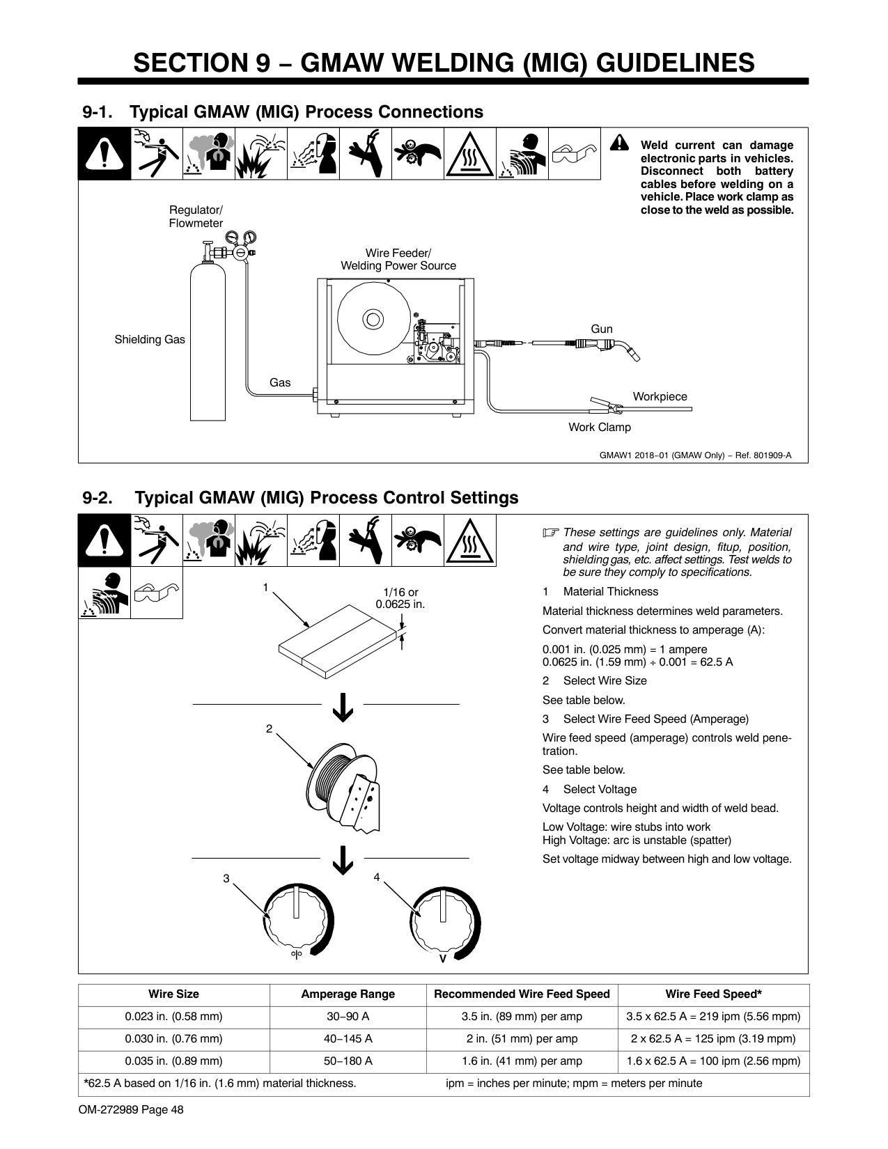
This is a general chart for common gases and where they are used. Many different combinations (mixtures) of shielding gases have been developed over the years. The most commonly used shielding gases are listed in the following table.
|Gas|Application|Application|Application|Application|Application|Application|Application| |---|---|---|---|---|---|---|---| |Gas|Spray Arc Steel|Short Circuiting Steel|Spray Arc Stainless Steel|Short Circuiting Stainless Steel|Spray Arc Aluminum|Short Circuiting Aluminum|GMAW-P| |Argon| | | | |All Positions|All Positions|All Positions| |Argon + 1% O2|Flat & Horizontal Fillet| |Flat & Horizontal Fillet| | | |All Positions| |Argon + 2% O2|Flat & Horizontal Fillet| |Flat & Horizontal Fillet| | | |All Positions| |Argon + 5% CO2|Flat & Horizontal Fillet| | | | | |All Positions| |Argon + 10% CO2|Flat & Horizontal Fillet|All Positions| | | | |All Positions| |Argon + 25% CO2| |All Positions| | | | | | |Argon + 50% CO2| |All Positions| | | | | | |CO2| |All Positions| | | | | | |Helium| | | | |All Positions1| | | |Argon + Helium| | | | |All Positions1| | | |Tri-Mix2| | | |All Positions| | | |
####### 9-17. Troubleshooting Guide For Semiautomatic Welding Equipment
|Problem|Probable Cause|Remedy| |---|---|---| |Wire feed motor operates, but wire does not feed.|Too little pressure on wire feed rolls.|Increase pressure setting on wire feed rolls.| |Wire feed motor operates, but wire does not feed.|Incorrect wire feed rolls.|Check size stamped on wire feed rolls, replace to match wire size and type if necessary.| |Wire feed motor operates, but wire does not feed.|Wire spool brake pressure too high.|Decrease brake pressure on wire spool.| |Wire feed motor operates, but wire does not feed.|Restriction in the gun and/or assembly.|Check and replace cable, gun, and contact tip if damaged. Check size of contact tip and cable liner, replace if necessary.| |Wire curling up in front of the wire feed rolls (bird nesting).|Too much pressure on wire feed rolls.|Decrease pressure setting on wire feed rolls.| |Wire curling up in front of the wire feed rolls (bird nesting).|Incorrect cable liner or gun contact tip size.|Check size of contact tip and check cable liner length and diameter, replace if necessary.| |Wire curling up in front of the wire feed rolls (bird nesting).|Gun end not inserted into drive housing properly.|Loosen gun securing bolt in drive housing and push gun end into housing just enough so it does not touch wire feed rolls.| |Wire curling up in front of the wire feed rolls (bird nesting).|Dirty or damaged (kinked) liner.|Replace liner.| |Wire feeds, but no gas flows.|Gas cylinder empty.|Replace empty gas cylinder.| |Wire feeds, but no gas flows.|Gas nozzle plugged.|Clean or replace gas nozzle.| |Wire feeds, but no gas flows.|Gas cylinder valve not open or flowmeter not adjusted.|Open gas valve at cylinder and adjust flow rate.| |Wire feeds, but no gas flows.|Restriction in gas line.|Check gas hose between flowmeter and wire feeder, and gas hose in gun and cable assembly.| |Wire feeds, but no gas flows.|Loose or broken wires to gas solenoid.|Have Factory Authorized Service Agent repair wiring.| |Wire feeds, but no gas flows.|Gas solenoid valve not operating.|Have Factory Authorized Service Agent replace gas solenoid valve.|
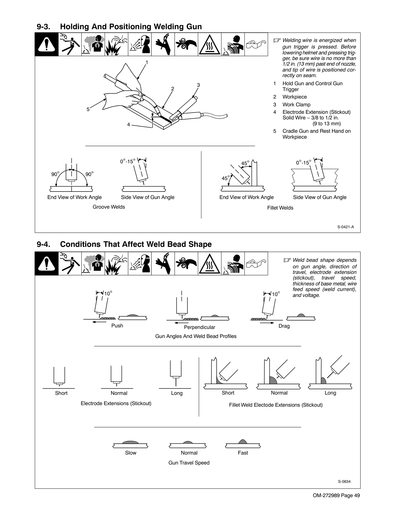
|Wire feeds, but no gas flows.|Incorrect primary voltage connected to welding power source.|Check primary voltage and relink welding power source for correct voltage.| |Welding arc not stable.|Wire slipping in drive rolls.|Adjust pressure setting on wire feed rolls. Replace worn drive rolls if necessary.| |Welding arc not stable.|Wrong size gun liner or contact tip.|Match liner and contact tip to wire size and type.| |Welding arc not stable.|Incorrect voltage setting for selected wire feed speed on welding power source.|Readjust welding parameters.| |Welding arc not stable.|Loose connections at the gun weld cable or work cable.|Check and tighten all connections.| |Welding arc not stable.|Gun in poor shape or loose connection inside gun.|Repair or replace gun as necessary.|
SECTION 10 − STICK WELDING (SMAW) GUIDELINES
| | | | | | | | |! Weld current starts when electrode touches workpiece.| |---|---|---|---|---|---|---|---|---| |stick 2018-01 − 151593
! Weld current can damage electronic parts in vehicles. Disconnect both battery cables before welding on a vehicle. Place work clamp as close to the weld as possible.
Always wear appropriate personal protective clothing.
1 Workpiece
Make sure workpiece is clean before welding.
2 Work Clamp
Place as close to the weld as possible.
3 Electrode
Before striking an arc, insert an electrode in the electrode holder. A small diameter electrode requires less current than a large one. Follow recommendations of the electrode manufacturer when setting weld amperage (see Section 10-2).
4 Insulated Electrode Holder
5 Electrode Holder Position
6 Arc Length
Arc length is the distance from the electrode to the workpiece. A short arc with correct amperage will give a sharp, crackling sound. Correct arc length is related to electrode diameter. Examine the weld bead to determine if the arc length is correct.
Arc length for 1/16 and 3/32 in. diameter electrodes should be about 1/16 in. (1.6 mm); arc length for 1/8 and 5/32 in. electrodes should be about 1/8 in. (3 mm).
7 Slag
Use a chipping hammer and wire brush to remove slag. Remove slag and check weld bead before making another weld pass.
1
4
3
5
2
7
6
Tools Needed: Equipment Needed:
Constant Current Welding Power Source|stick 2018-01 − 151593
! Weld current can damage electronic parts in vehicles. Disconnect both battery cables before welding on a vehicle. Place work clamp as close to the weld as possible.
Always wear appropriate personal protective clothing.
1 Workpiece
Make sure workpiece is clean before welding.
2 Work Clamp
Place as close to the weld as possible.
3 Electrode
Before striking an arc, insert an electrode in the electrode holder. A small diameter electrode requires less current than a large one. Follow recommendations of the electrode manufacturer when setting weld amperage (see Section 10-2).
4 Insulated Electrode Holder
5 Electrode Holder Position
6 Arc Length
Arc length is the distance from the electrode to the workpiece. A short arc with correct amperage will give a sharp, crackling sound. Correct arc length is related to electrode diameter. Examine the weld bead to determine if the arc length is correct.
Arc length for 1/16 and 3/32 in. diameter electrodes should be about 1/16 in. (1.6 mm); arc length for 1/8 and 5/32 in. electrodes should be about 1/8 in. (3 mm).
7 Slag
Use a chipping hammer and wire brush to remove slag. Remove slag and check weld bead before making another weld pass.
1
4
3
5
2
7
6
Tools Needed: Equipment Needed:
Constant Current Welding Power Source|
####### 10-2. Electrode And Amperage Selection Chart
| | | | | | | | | | |---|---|---|---|---|---|---|---|---| |Ref. S-087 985-A
|ELECTRODE|DIAMETER|AMPERAGE
RANGE|AMPERAGE
RANGE|AMPERAGE
RANGE|AMPERAGE
RANGE|AMPERAGE
RANGE|AMPERAGE
RANGE|AMPERAGE
RANGE|AMPERAGE
RANGE|AMPERAGE
RANGE| |---|---|---|---|---|---|---|---|---|---|---| |ELECTRODE|DIAMETER|50
100
150
200
250
300
350
400
450|50
100
150
200
250
300
350
400
450|50
100
150
200
250
300
350
400
450|50
100
150
200
250
300
350
400
450|50
100
150
200
250
300
350
400
450|50
100
150
200
250
300
350
400
450|50
100
150
200
250
300
350
400
450|50
100
150
200
250
300
350
400
450|50
100
150
200
250
300
350
400
450| |6010 &
6011
|3/32| | | | | | | | | | |6010 &
6011
|1/8| | | | | | | | | | |6010 &
6011
|5/32| | | | | | | | | | |6010 &
6011
|3/16| | | | | | | | | | |6010 &
6011
|7/32| | | | | | | | | | |6010 &
6011
|1/4| | | | | | | | | | |6013|1/16| | | | | | | | | | |6013|5/64| | | | | | | | | | |6013|3/32| | | | | | | | | | |6013|1/8| | | | | | | | | | |6013|5/32| | | | | | | | | | |6013|3/16| | | | | | | | | | |6013|7/32| | | | | | | | | | |6013|1/4| | | | | | | | | | |7014|3/32| | | | | | | | | | |7014|1/8| | | | | | | | | |
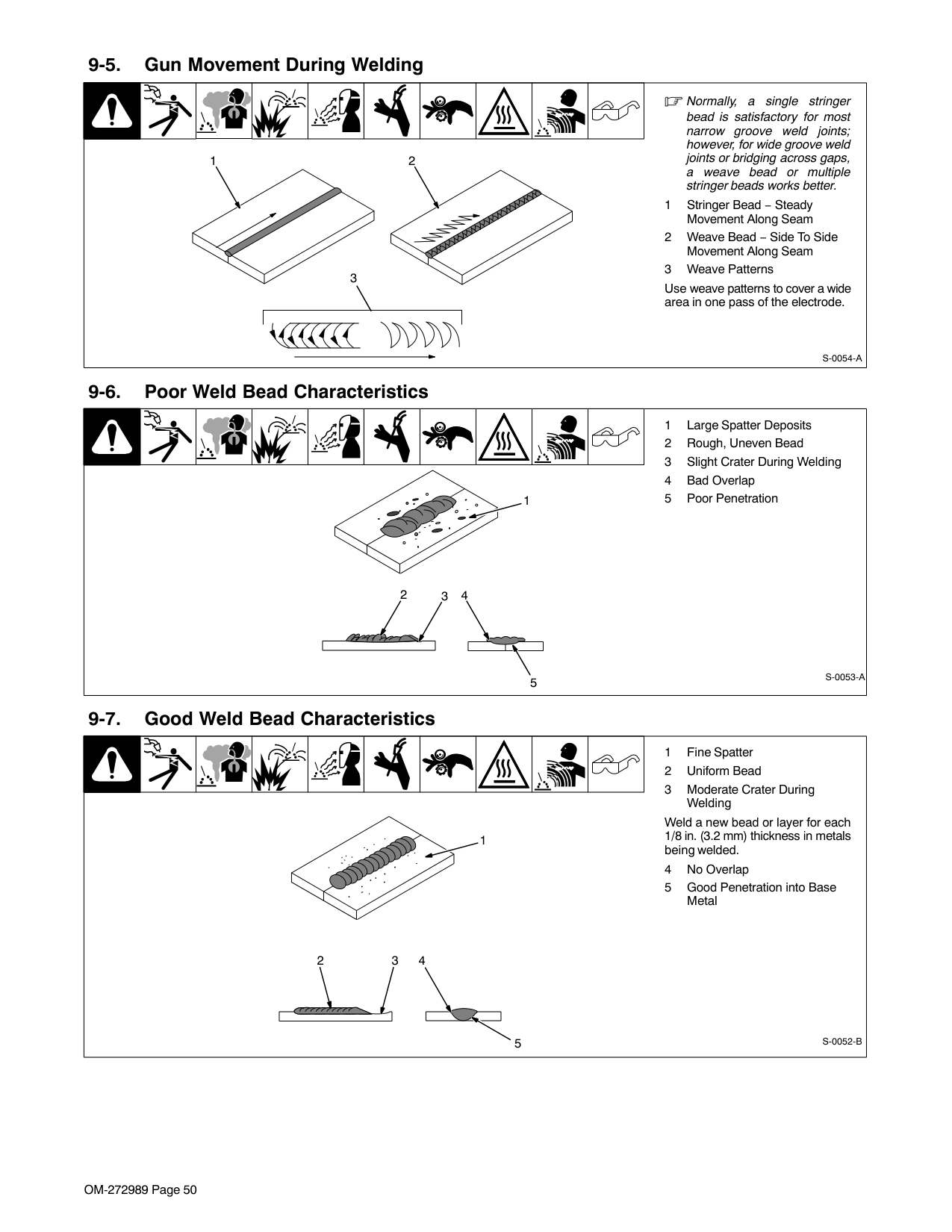
|7014|5/32| | | | | | | | | | |7014|3/16| | | | | | | | | | |7014|7/32| | | | | | | | | | |7014|1/4| | | | | | | | | | |7018|3/32| | | | | | | | | | |7018|1/8| | | | | | | | | | |7018|5/32| | | | | | | | | | |7018|3/16| | | | | | | | | | |7018|7/32| | | | | | | | | | |7018|1/4| | | | | | | | | | |7024|3/32| | | | | | | | | | |7024|1/8| | | | | | | | | | |7024|5/32| | | | | | | | | | |7024|3/16| | | | | | | | | | |7024|7/32| | | | | | | | | | |7024|1/4| | | | | | | | | | |Ni-Cl|3/32| | | | | | | | | | |Ni-Cl|1/8| | | | | | | | | | |Ni-Cl|5/32| | | | | | | | | | |Ni-Cl|3/16| | | | | | | | | | |308L|3/32| | | | | | | | | | |308L|1/8| | | | | | | | | | |308L|5/32| | | | | | | | | |
|ELECTRODE
|DC*|AC|POSITION|PENETRATION
|USAGE
| |---|---|---|---|---|---| |6010|EP| |ALL|DEEP|MIN. PREP, ROUGH HIGH SPATTER| |6011|EP| |ALL|DEEP|MIN. PREP, ROUGH HIGH SPATTER| |6013|EP,EN| |ALL|LOW|GENERAL| |7014|EP,EN| |ALL|MED|SMOOTH, EASY, FAST| |7018|EP| |ALL|MED|LOW HYDROGEN, STRONG| |7024|EP,EN| |FLAT HORIZ*|LOW|SMOOTH, EASY, FASTER| |NI-CL|EP| |ALL|LOW|CAST IRON| |308L|EP| |ALL|LOW|STAINLESS| |*EP = ELECTRODE POSITIVE (REVERSE POLARITY)|*EP = ELECTRODE POSITIVE (REVERSE POLARITY)|*EP = ELECTRODE POSITIVE (REVERSE POLARITY)|*EP = ELECTRODE POSITIVE (REVERSE POLARITY)|*EP = ELECTRODE POSITIVE (REVERSE POLARITY)|*EP = ELECTRODE POSITIVE (REVERSE POLARITY)|
EN = ELECTRODE NEGATIVE (STRAIGHT POLARITY)|Ref. S-087 985-A
|ELECTRODE|DIAMETER|AMPERAGE
RANGE|AMPERAGE
RANGE|AMPERAGE
RANGE|AMPERAGE
RANGE|AMPERAGE
RANGE|AMPERAGE
RANGE|AMPERAGE
RANGE|AMPERAGE
RANGE|AMPERAGE
RANGE| |---|---|---|---|---|---|---|---|---|---|---| |ELECTRODE|DIAMETER|50
100
150
200
250
300
350
400
450|50
100
150
200
250
300
350
400
450|50
100
150
200
250
300
350
400
450|50
100
150
200
250
300
350
400
450|50
100
150
200
250
300
350
400
450|50
100
150
200
250
300
350
400
450|50
100
150
200
250
300
350
400
450|50
100
150
200
250
300
350
400
450|50
100
150
200
250
300
350
400
450| |6010 &
6011
|3/32| | | | | | | | | | |6010 &
6011
|1/8| | | | | | | | | | |6010 &
6011
|5/32| | | | | | | | | | |6010 &
6011
|3/16| | | | | | | | | |
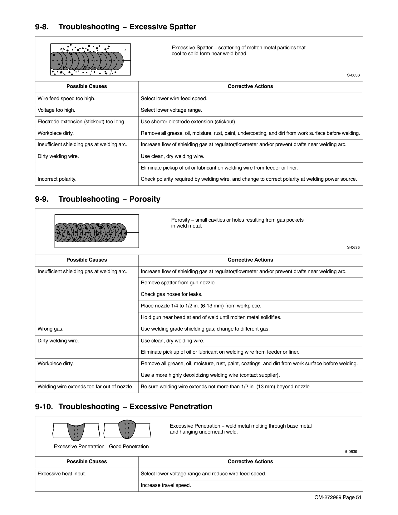
|6010 &
6011
|7/32| | | | | | | | | | |6010 &
6011
|1/4| | | | | | | | | | |6013|1/16| | | | | | | | | | |6013|5/64| | | | | | | | | | |6013|3/32| | | | | | | | | | |6013|1/8| | | | | | | | | | |6013|5/32| | | | | | | | | | |6013|3/16| | | | | | | | | | |6013|7/32| | | | | | | | | | |6013|1/4| | | | | | | | | | |7014|3/32| | | | | | | | | | |7014|1/8| | | | | | | | | | |7014|5/32| | | | | | | | | | |7014|3/16| | | | | | | | | | |7014|7/32| | | | | | | | | | |7014|1/4| | | | | | | | | | |7018|3/32| | | | | | | | | | |7018|1/8| | | | | | | | | | |7018|5/32| | | | | | | | | | |7018|3/16| | | | | | | | | | |7018|7/32| | | | | | | | | | |7018|1/4| | | | | | | | | | |7024|3/32| | | | | | | | | | |7024|1/8| | | | | | | | | | |7024|5/32| | | | | | | | | | |7024|3/16| | | | | | | | | | |7024|7/32| | | | | | | | | | |7024|1/4| | | | | | | | | | |Ni-Cl|3/32| | | | | | | | | | |Ni-Cl|1/8| | | | | | | | | | |Ni-Cl|5/32| | | | | | | | | | |Ni-Cl|3/16| | | | | | | | | | |308L|3/32| | | | | | | | | | |308L|1/8| | | | | | | | | | |308L|5/32| | | | | | | | | |
|ELECTRODE
|DC*|AC|POSITION|PENETRATION
|USAGE
| |---|---|---|---|---|---| |6010|EP| |ALL|DEEP|MIN. PREP, ROUGH HIGH SPATTER| |6011|EP| |ALL|DEEP|MIN. PREP, ROUGH HIGH SPATTER| |6013|EP,EN| |ALL|LOW|GENERAL| |7014|EP,EN| |ALL|MED|SMOOTH, EASY, FAST|
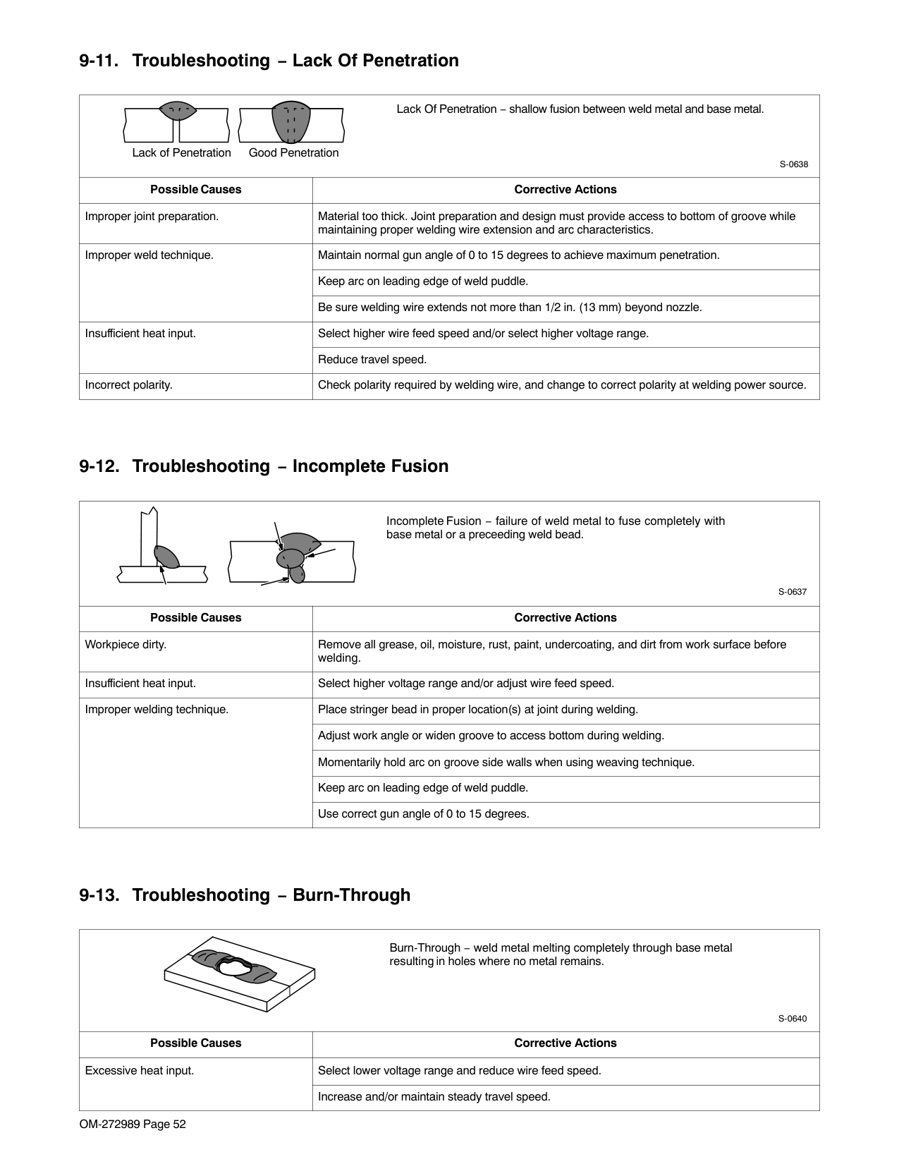
|7018|EP| |ALL|MED|LOW HYDROGEN, STRONG| |7024|EP,EN| |FLAT HORIZ*|LOW|SMOOTH, EASY, FASTER| |NI-CL|EP| |ALL|LOW|CAST IRON| |308L|EP| |ALL|LOW|STAINLESS| |*EP = ELECTRODE POSITIVE (REVERSE POLARITY)|*EP = ELECTRODE POSITIVE (REVERSE POLARITY)|*EP = ELECTRODE POSITIVE (REVERSE POLARITY)|*EP = ELECTRODE POSITIVE (REVERSE POLARITY)|*EP = ELECTRODE POSITIVE (REVERSE POLARITY)|*EP = ELECTRODE POSITIVE (REVERSE POLARITY)|
EN = ELECTRODE NEGATIVE (STRAIGHT POLARITY)|Ref. S-087 985-A
|ELECTRODE|DIAMETER|AMPERAGE
RANGE|AMPERAGE
RANGE|AMPERAGE
RANGE|AMPERAGE
RANGE|AMPERAGE
RANGE|AMPERAGE
RANGE|AMPERAGE
RANGE|AMPERAGE
RANGE|AMPERAGE
RANGE| |---|---|---|---|---|---|---|---|---|---|---| |ELECTRODE|DIAMETER|50
100
150
200
250
300
350
400
450|50
100
150
200
250
300
350
400
450|50
100
150
200
250
300
350
400
450|50
100
150
200
250
300
350
400
450|50
100
150
200
250
300
350
400
450|50
100
150
200
250
300
350
400
450|50
100
150
200
250
300
350
400
450|50
100
150
200
250
300
350
400
450|50
100
150
200
250
300
350
400
450| |6010 &
6011
|3/32| | | | | | | | | | |6010 &
6011
|1/8| | | | | | | | | | |6010 &
6011
|5/32| | | | | | | | | | |6010 &
6011
|3/16| | | | | | | | | | |6010 &
6011
|7/32| | | | | | | | | | |6010 &
6011
|1/4| | | | | | | | | | |6013|1/16| | | | | | | | | | |6013|5/64| | | | | | | | | | |6013|3/32| | | | | | | | | | |6013|1/8| | | | | | | | | | |6013|5/32| | | | | | | | | | |6013|3/16| | | | | | | | | | |6013|7/32| | | | | | | | | | |6013|1/4| | | | | | | | | | |7014|3/32| | | | | | | | | | |7014|1/8| | | | | | | | | | |7014|5/32| | | | | | | | | | |7014|3/16| | | | | | | | | | |7014|7/32| | | | | | | | | | |7014|1/4| | | | | | | | | | |7018|3/32| | | | | | | | | | |7018|1/8| | | | | | | | | | |7018|5/32| | | | | | | | | | |7018|3/16| | | | | | | | | | |7018|7/32| | | | | | | | | | |7018|1/4| | | | | | | | | | |7024|3/32| | | | | | | | | | |7024|1/8| | | | | | | | | | |7024|5/32| | | | | | | | | | |7024|3/16| | | | | | | | | | |7024|7/32| | | | | | | | | | |7024|1/4| | | | | | | | | | |Ni-Cl|3/32| | | | | | | | | |
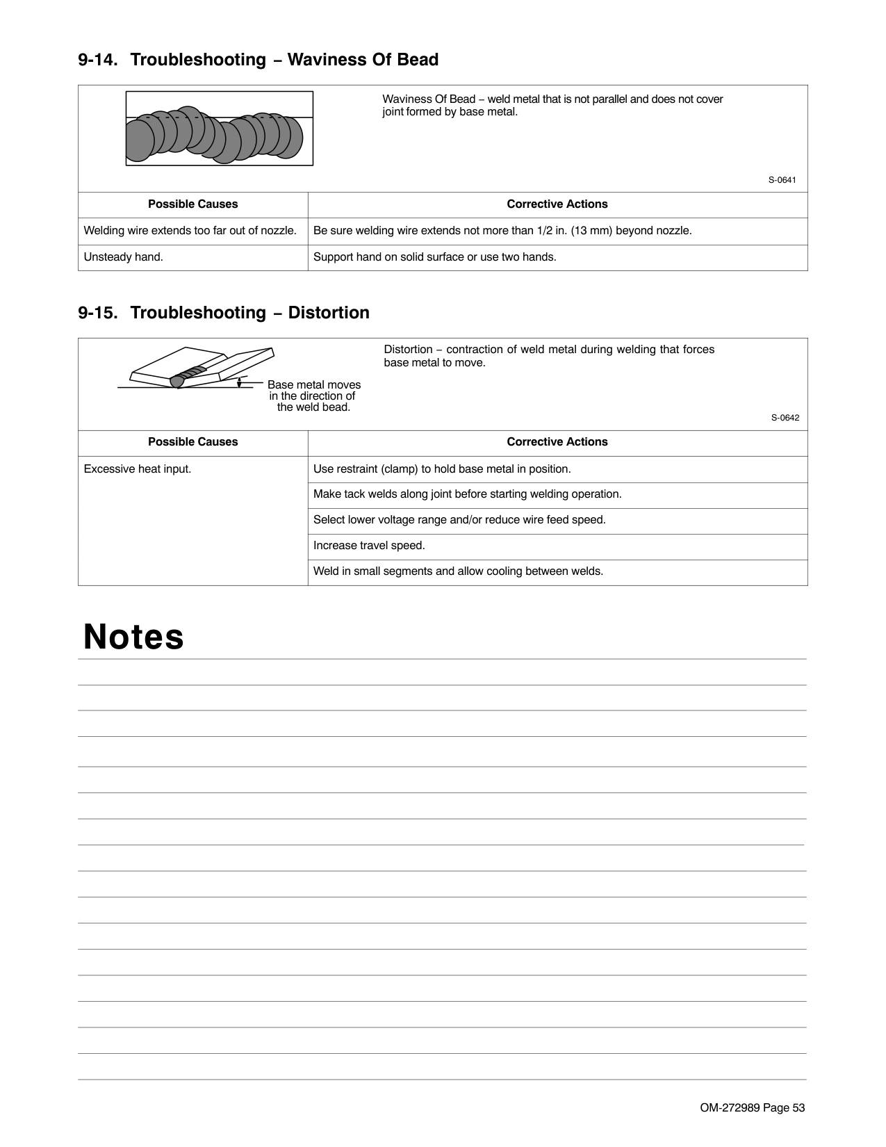
|Ni-Cl|1/8| | | | | | | | | | |Ni-Cl|5/32| | | | | | | | | | |Ni-Cl|3/16| | | | | | | | | | |308L|3/32| | | | | | | | | | |308L|1/8| | | | | | | | | | |308L|5/32| | | | | | | | | |
|ELECTRODE
|DC*|AC|POSITION|PENETRATION
|USAGE
| |---|---|---|---|---|---| |6010|EP| |ALL|DEEP|MIN. PREP, ROUGH HIGH SPATTER| |6011|EP| |ALL|DEEP|MIN. PREP, ROUGH HIGH SPATTER| |6013|EP,EN| |ALL|LOW|GENERAL| |7014|EP,EN| |ALL|MED|SMOOTH, EASY, FAST| |7018|EP| |ALL|MED|LOW HYDROGEN, STRONG| |7024|EP,EN| |FLAT HORIZ*|LOW|SMOOTH, EASY, FASTER| |NI-CL|EP| |ALL|LOW|CAST IRON| |308L|EP| |ALL|LOW|STAINLESS| |*EP = ELECTRODE POSITIVE (REVERSE POLARITY)|*EP = ELECTRODE POSITIVE (REVERSE POLARITY)|*EP = ELECTRODE POSITIVE (REVERSE POLARITY)|*EP = ELECTRODE POSITIVE (REVERSE POLARITY)|*EP = ELECTRODE POSITIVE (REVERSE POLARITY)|*EP = ELECTRODE POSITIVE (REVERSE POLARITY)|
EN = ELECTRODE NEGATIVE (STRAIGHT POLARITY)|Ref. S-087 985-A
|ELECTRODE|DIAMETER|AMPERAGE
RANGE|AMPERAGE
RANGE|AMPERAGE
RANGE|AMPERAGE
RANGE|AMPERAGE
RANGE|AMPERAGE
RANGE|AMPERAGE
RANGE|AMPERAGE
RANGE|AMPERAGE
RANGE| |---|---|---|---|---|---|---|---|---|---|---| |ELECTRODE|DIAMETER|50
100
150
200
250
300
350
400
450|50
100
150
200
250
300
350
400
450|50
100
150
200
250
300
350
400
450|50
100
150
200
250
300
350
400
450|50
100
150
200
250
300
350
400
450|50
100
150
200
250
300
350
400
450|50
100
150
200
250
300
350
400
450|50
100
150
200
250
300
350
400
450|50
100
150
200
250
300
350
400
450| |6010 &
6011
|3/32| | | | | | | | | | |6010 &
6011
|1/8| | | | | | | | | | |6010 &
6011
|5/32| | | | | | | | | | |6010 &
6011
|3/16| | | | | | | | | | |6010 &
6011
|7/32| | | | | | | | | | |6010 &
6011
|1/4| | | | | | | | | | |6013|1/16| | | | | | | | | | |6013|5/64| | | | | | | | | | |6013|3/32| | | | | | | | | | |6013|1/8| | | | | | | | | | |6013|5/32| | | | | | | | | | |6013|3/16| | | | | | | | | | |6013|7/32| | | | | | | | | | |6013|1/4| | | | | | | | | | |7014|3/32| | | | | | | | | | |7014|1/8| | | | | | | | | | |7014|5/32| | | | | | | | | | |7014|3/16| | | | | | | | | | |7014|7/32| | | | | | | | | | |7014|1/4| | | | | | | | | | |7018|3/32| | | | | | | | | |
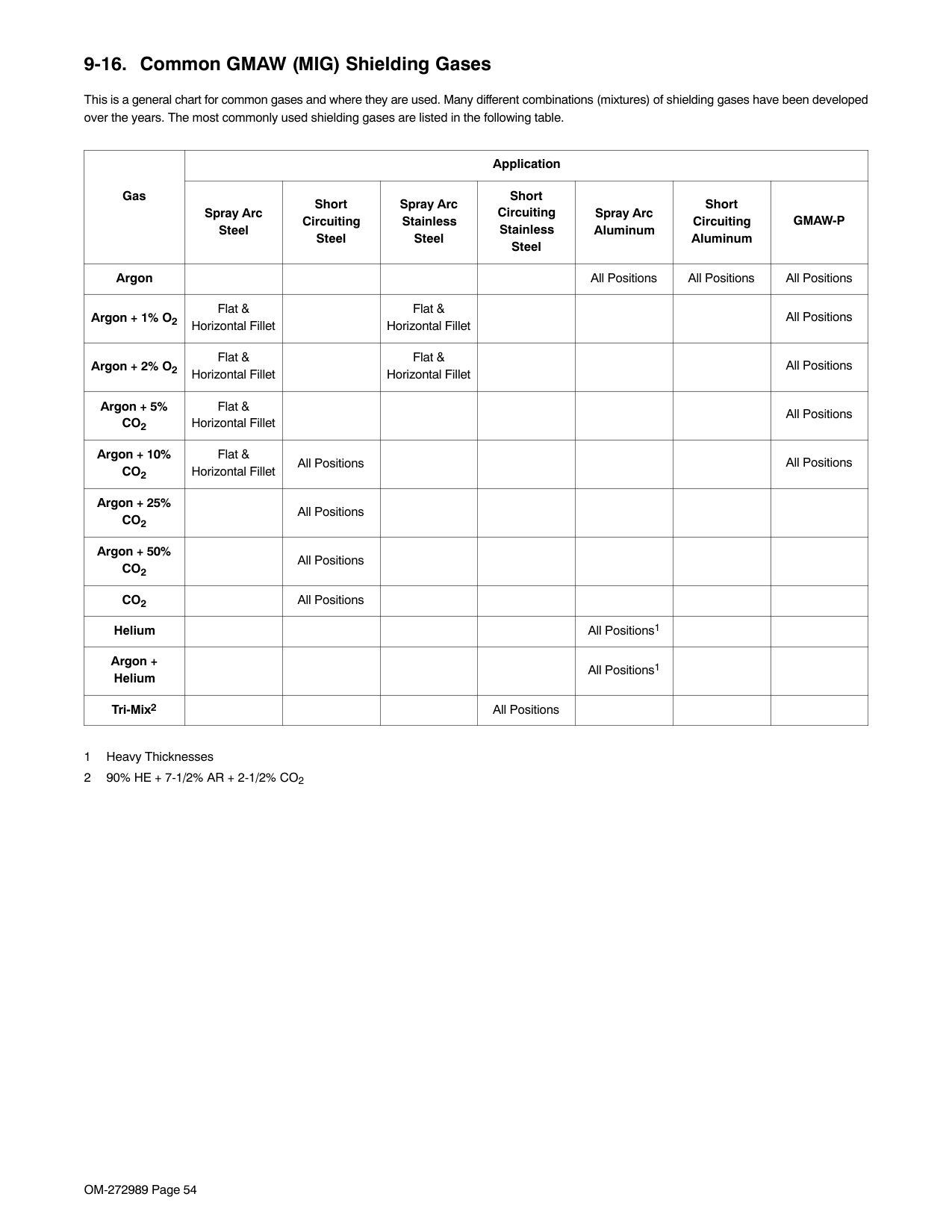
|7018|1/8| | | | | | | | | | |7018|5/32| | | | | | | | | | |7018|3/16| | | | | | | | | | |7018|7/32| | | | | | | | | | |7018|1/4| | | | | | | | | | |7024|3/32| | | | | | | | | | |7024|1/8| | | | | | | | | | |7024|5/32| | | | | | | | | | |7024|3/16| | | | | | | | | | |7024|7/32| | | | | | | | | | |7024|1/4| | | | | | | | | | |Ni-Cl|3/32| | | | | | | | | | |Ni-Cl|1/8| | | | | | | | | | |Ni-Cl|5/32| | | | | | | | | | |Ni-Cl|3/16| | | | | | | | | | |308L|3/32| | | | | | | | | | |308L|1/8| | | | | | | | | | |308L|5/32| | | | | | | | | |
|ELECTRODE
|DC*|AC|POSITION|PENETRATION
|USAGE
| |---|---|---|---|---|---| |6010|EP| |ALL|DEEP|MIN. PREP, ROUGH HIGH SPATTER| |6011|EP| |ALL|DEEP|MIN. PREP, ROUGH HIGH SPATTER| |6013|EP,EN| |ALL|LOW|GENERAL| |7014|EP,EN| |ALL|MED|SMOOTH, EASY, FAST| |7018|EP| |ALL|MED|LOW HYDROGEN, STRONG| |7024|EP,EN| |FLAT HORIZ*|LOW|SMOOTH, EASY, FASTER| |NI-CL|EP| |ALL|LOW|CAST IRON| |308L|EP| |ALL|LOW|STAINLESS| |*EP = ELECTRODE POSITIVE (REVERSE POLARITY)|*EP = ELECTRODE POSITIVE (REVERSE POLARITY)|*EP = ELECTRODE POSITIVE (REVERSE POLARITY)|*EP = ELECTRODE POSITIVE (REVERSE POLARITY)|*EP = ELECTRODE POSITIVE (REVERSE POLARITY)|*EP = ELECTRODE POSITIVE (REVERSE POLARITY)|
EN = ELECTRODE NEGATIVE (STRAIGHT POLARITY)|Ref. S-087 985-A
|ELECTRODE|DIAMETER|AMPERAGE
RANGE|AMPERAGE
RANGE|AMPERAGE
RANGE|AMPERAGE
RANGE|AMPERAGE
RANGE|AMPERAGE
RANGE|AMPERAGE
RANGE|AMPERAGE
RANGE|AMPERAGE
RANGE| |---|---|---|---|---|---|---|---|---|---|---| |ELECTRODE|DIAMETER|50
100
150
200
250
300
350
400
450|50
100
150
200
250
300
350
400
450|50
100
150
200
250
300
350
400
450|50
100
150
200
250
300
350
400
450|50
100
150
200
250
300
350
400
450|50
100
150
200
250
300
350
400
450|50
100
150
200
250
300
350
400
450|50
100
150
200
250
300
350
400
450|50
100
150
200
250
300
350
400
450| |6010 &
6011
|3/32| | | | | | | | | | |6010 &
6011
|1/8| | | | | | | | | | |6010 &
6011
|5/32| | | | | | | | | | |6010 &
6011
|3/16| | | | | | | | | | |6010 &
6011
|7/32| | | | | | | | | | |6010 &
6011
|1/4| | | | | | | | | | |6013|1/16| | | | | | | | | | |6013|5/64| | | | | | | | | | |6013|3/32| | | | | | | | | |
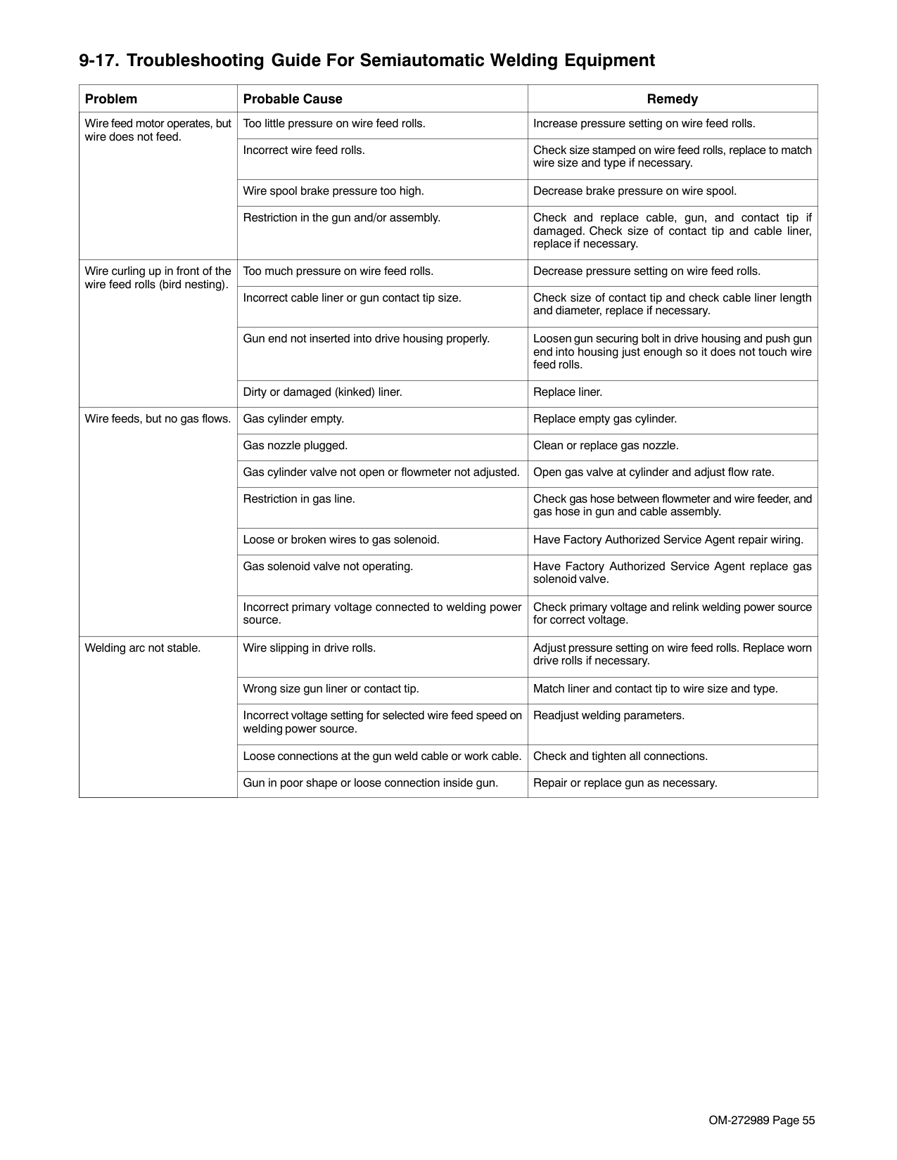
|6013|1/8| | | | | | | | | | |6013|5/32| | | | | | | | | | |6013|3/16| | | | | | | | | | |6013|7/32| | | | | | | | | | |6013|1/4| | | | | | | | | | |7014|3/32| | | | | | | | | | |7014|1/8| | | | | | | | | | |7014|5/32| | | | | | | | | | |7014|3/16| | | | | | | | | | |7014|7/32| | | | | | | | | | |7014|1/4| | | | | | | | | | |7018|3/32| | | | | | | | | | |7018|1/8| | | | | | | | | | |7018|5/32| | | | | | | | | | |7018|3/16| | | | | | | | | | |7018|7/32| | | | | | | | | | |7018|1/4| | | | | | | | | | |7024|3/32| | | | | | | | | | |7024|1/8| | | | | | | | | | |7024|5/32| | | | | | | | | | |7024|3/16| | | | | | | | | | |7024|7/32| | | | | | | | | | |7024|1/4| | | | | | | | | | |Ni-Cl|3/32| | | | | | | | | | |Ni-Cl|1/8| | | | | | | | | | |Ni-Cl|5/32| | | | | | | | | | |Ni-Cl|3/16| | | | | | | | | | |308L|3/32| | | | | | | | | | |308L|1/8| | | | | | | | | | |308L|5/32| | | | | | | | | |
|ELECTRODE
|DC*|AC|POSITION|PENETRATION
|USAGE
| |---|---|---|---|---|---| |6010|EP| |ALL|DEEP|MIN. PREP, ROUGH HIGH SPATTER| |6011|EP| |ALL|DEEP|MIN. PREP, ROUGH HIGH SPATTER| |6013|EP,EN| |ALL|LOW|GENERAL| |7014|EP,EN| |ALL|MED|SMOOTH, EASY, FAST| |7018|EP| |ALL|MED|LOW HYDROGEN, STRONG| |7024|EP,EN| |FLAT HORIZ*|LOW|SMOOTH, EASY, FASTER| |NI-CL|EP| |ALL|LOW|CAST IRON| |308L|EP| |ALL|LOW|STAINLESS| |*EP = ELECTRODE POSITIVE (REVERSE POLARITY)|*EP = ELECTRODE POSITIVE (REVERSE POLARITY)|*EP = ELECTRODE POSITIVE (REVERSE POLARITY)|*EP = ELECTRODE POSITIVE (REVERSE POLARITY)|*EP = ELECTRODE POSITIVE (REVERSE POLARITY)|*EP = ELECTRODE POSITIVE (REVERSE POLARITY)|
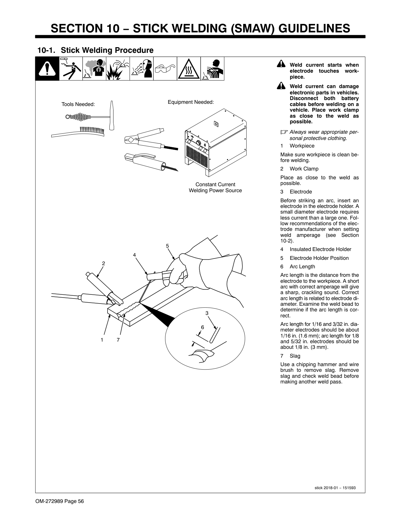
EN = ELECTRODE NEGATIVE (STRAIGHT POLARITY)|Ref. S-087 985-A
|ELECTRODE|DIAMETER|AMPERAGE
RANGE|AMPERAGE
RANGE|AMPERAGE
RANGE|AMPERAGE
RANGE|AMPERAGE
RANGE|AMPERAGE
RANGE|AMPERAGE
RANGE|AMPERAGE
RANGE|AMPERAGE
RANGE| |---|---|---|---|---|---|---|---|---|---|---| |ELECTRODE|DIAMETER|50
100
150
200
250
300
350
400
450|50
100
150
200
250
300
350
400
450|50
100
150
200
250
300
350
400
450|50
100
150
200
250
300
350
400
450|50
100
150
200
250
300
350
400
450|50
100
150
200
250
300
350
400
450|50
100
150
200
250
300
350
400
450|50
100
150
200
250
300
350
400
450|50
100
150
200
250
300
350
400
450| |6010 &
6011
|3/32| | | | | | | | | | |6010 &
6011
|1/8| | | | | | | | | | |6010 &
6011
|5/32| | | | | | | | | | |6010 &
6011
|3/16| | | | | | | | | | |6010 &
6011
|7/32| | | | | | | | | | |6010 &
6011
|1/4| | | | | | | | | | |6013|1/16| | | | | | | | | | |6013|5/64| | | | | | | | | | |6013|3/32| | | | | | | | | | |6013|1/8| | | | | | | | | | |6013|5/32| | | | | | | | | | |6013|3/16| | | | | | | | | | |6013|7/32| | | | | | | | | | |6013|1/4| | | | | | | | | | |7014|3/32| | | | | | | | | | |7014|1/8| | | | | | | | | | |7014|5/32| | | | | | | | | | |7014|3/16| | | | | | | | | | |7014|7/32| | | | | | | | | | |7014|1/4| | | | | | | | | | |7018|3/32| | | | | | | | | | |7018|1/8| | | | | | | | | | |7018|5/32| | | | | | | | | | |7018|3/16| | | | | | | | | | |7018|7/32| | | | | | | | | | |7018|1/4| | | | | | | | | | |7024|3/32| | | | | | | | | | |7024|1/8| | | | | | | | | | |7024|5/32| | | | | | | | | | |7024|3/16| | | | | | | | | | |7024|7/32| | | | | | | | | | |7024|1/4| | | | | | | | | | |Ni-Cl|3/32| | | | | | | | | | |Ni-Cl|1/8| | | | | | | | | | |Ni-Cl|5/32| | | | | | | | | | |Ni-Cl|3/16| | | | | | | | | | |308L|3/32| | | | | | | | | | |308L|1/8| | | | | | | | | |
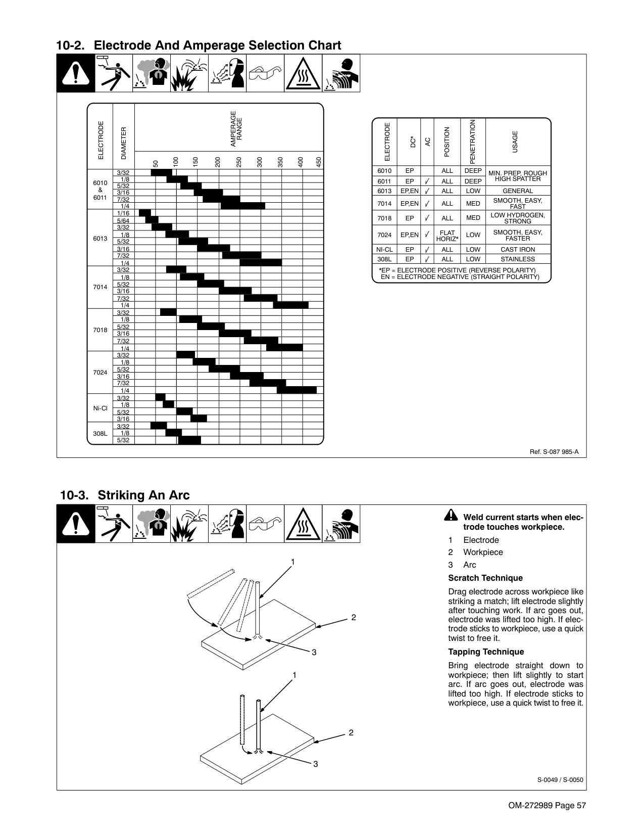
|308L|5/32| | | | | | | | | |
|ELECTRODE
|DC*|AC|POSITION|PENETRATION
|USAGE
| |---|---|---|---|---|---| |6010|EP| |ALL|DEEP|MIN. PREP, ROUGH HIGH SPATTER| |6011|EP| |ALL|DEEP|MIN. PREP, ROUGH HIGH SPATTER| |6013|EP,EN| |ALL|LOW|GENERAL| |7014|EP,EN| |ALL|MED|SMOOTH, EASY, FAST| |7018|EP| |ALL|MED|LOW HYDROGEN, STRONG| |7024|EP,EN| |FLAT HORIZ*|LOW|SMOOTH, EASY, FASTER| |NI-CL|EP| |ALL|LOW|CAST IRON| |308L|EP| |ALL|LOW|STAINLESS| |*EP = ELECTRODE POSITIVE (REVERSE POLARITY)|*EP = ELECTRODE POSITIVE (REVERSE POLARITY)|*EP = ELECTRODE POSITIVE (REVERSE POLARITY)|*EP = ELECTRODE POSITIVE (REVERSE POLARITY)|*EP = ELECTRODE POSITIVE (REVERSE POLARITY)|*EP = ELECTRODE POSITIVE (REVERSE POLARITY)|
EN = ELECTRODE NEGATIVE (STRAIGHT POLARITY)|Ref. S-087 985-A
|ELECTRODE|DIAMETER|AMPERAGE
RANGE|AMPERAGE
RANGE|AMPERAGE
RANGE|AMPERAGE
RANGE|AMPERAGE
RANGE|AMPERAGE
RANGE|AMPERAGE
RANGE|AMPERAGE
RANGE|AMPERAGE
RANGE| |---|---|---|---|---|---|---|---|---|---|---| |ELECTRODE|DIAMETER|50
100
150
200
250
300
350
400
450|50
100
150
200
250
300
350
400
450|50
100
150
200
250
300
350
400
450|50
100
150
200
250
300
350
400
450|50
100
150
200
250
300
350
400
450|50
100
150
200
250
300
350
400
450|50
100
150
200
250
300
350
400
450|50
100
150
200
250
300
350
400
450|50
100
150
200
250
300
350
400
450| |6010 &
6011
|3/32| | | | | | | | | | |6010 &
6011
|1/8| | | | | | | | | | |6010 &
6011
|5/32| | | | | | | | | | |6010 &
6011
|3/16| | | | | | | | | | |6010 &
6011
|7/32| | | | | | | | | | |6010 &
6011
|1/4| | | | | | | | | | |6013|1/16| | | | | | | | | | |6013|5/64| | | | | | | | | | |6013|3/32| | | | | | | | | | |6013|1/8| | | | | | | | | | |6013|5/32| | | | | | | | | | |6013|3/16| | | | | | | | | | |6013|7/32| | | | | | | | | | |6013|1/4| | | | | | | | | | |7014|3/32| | | | | | | | | | |7014|1/8| | | | | | | | | | |7014|5/32| | | | | | | | | | |7014|3/16| | | | | | | | | | |7014|7/32| | | | | | | | | | |7014|1/4| | | | | | | | | | |7018|3/32| | | | | | | | | | |7018|1/8| | | | | | | | | | |7018|5/32| | | | | | | | | | |7018|3/16| | | | | | | | | | |7018|7/32| | | | | | | | | | |7018|1/4| | | | | | | | | |
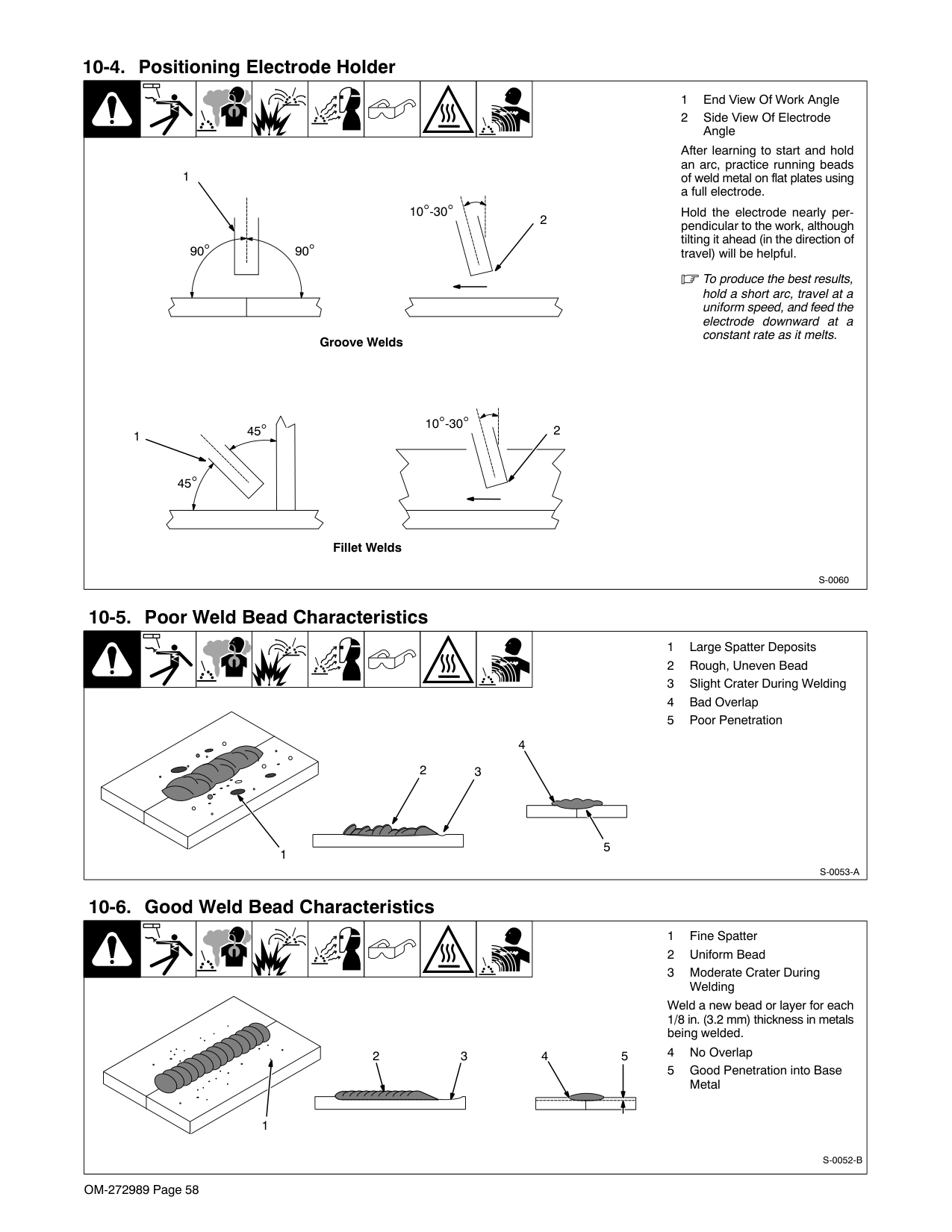
|7024|3/32| | | | | | | | | | |7024|1/8| | | | | | | | | | |7024|5/32| | | | | | | | | | |7024|3/16| | | | | | | | | | |7024|7/32| | | | | | | | | | |7024|1/4| | | | | | | | | | |Ni-Cl|3/32| | | | | | | | | | |Ni-Cl|1/8| | | | | | | | | | |Ni-Cl|5/32| | | | | | | | | | |Ni-Cl|3/16| | | | | | | | | | |308L|3/32| | | | | | | | | | |308L|1/8| | | | | | | | | | |308L|5/32| | | | | | | | | |
|ELECTRODE
|DC*|AC|POSITION|PENETRATION
|USAGE
| |---|---|---|---|---|---| |6010|EP| |ALL|DEEP|MIN. PREP, ROUGH HIGH SPATTER| |6011|EP| |ALL|DEEP|MIN. PREP, ROUGH HIGH SPATTER| |6013|EP,EN| |ALL|LOW|GENERAL| |7014|EP,EN| |ALL|MED|SMOOTH, EASY, FAST| |7018|EP| |ALL|MED|LOW HYDROGEN, STRONG| |7024|EP,EN| |FLAT HORIZ*|LOW|SMOOTH, EASY, FASTER| |NI-CL|EP| |ALL|LOW|CAST IRON| |308L|EP| |ALL|LOW|STAINLESS| |*EP = ELECTRODE POSITIVE (REVERSE POLARITY)|*EP = ELECTRODE POSITIVE (REVERSE POLARITY)|*EP = ELECTRODE POSITIVE (REVERSE POLARITY)|*EP = ELECTRODE POSITIVE (REVERSE POLARITY)|*EP = ELECTRODE POSITIVE (REVERSE POLARITY)|*EP = ELECTRODE POSITIVE (REVERSE POLARITY)|
EN = ELECTRODE NEGATIVE (STRAIGHT POLARITY)|Ref. S-087 985-A
|ELECTRODE|DIAMETER|AMPERAGE
RANGE|AMPERAGE
RANGE|AMPERAGE
RANGE|AMPERAGE
RANGE|AMPERAGE
RANGE|AMPERAGE
RANGE|AMPERAGE
RANGE|AMPERAGE
RANGE|AMPERAGE
RANGE| |---|---|---|---|---|---|---|---|---|---|---| |ELECTRODE|DIAMETER|50
100
150
200
250
300
350
400
450|50
100
150
200
250
300
350
400
450|50
100
150
200
250
300
350
400
450|50
100
150
200
250
300
350
400
450|50
100
150
200
250
300
350
400
450|50
100
150
200
250
300
350
400
450|50
100
150
200
250
300
350
400
450|50
100
150
200
250
300
350
400
450|50
100
150
200
250
300
350
400
450| |6010 &
6011
|3/32| | | | | | | | | | |6010 &
6011
|1/8| | | | | | | | | | |6010 &
6011
|5/32| | | | | | | | | | |6010 &
6011
|3/16| | | | | | | | | | |6010 &
6011
|7/32| | | | | | | | | | |6010 &
6011
|1/4| | | | | | | | | | |6013|1/16| | | | | | | | | | |6013|5/64| | | | | | | | | | |6013|3/32| | | | | | | | | | |6013|1/8| | | | | | | | | | |6013|5/32| | | | | | | | | | |6013|3/16| | | | | | | | | | |6013|7/32| | | | | | | | | | |6013|1/4| | | | | | | | | |
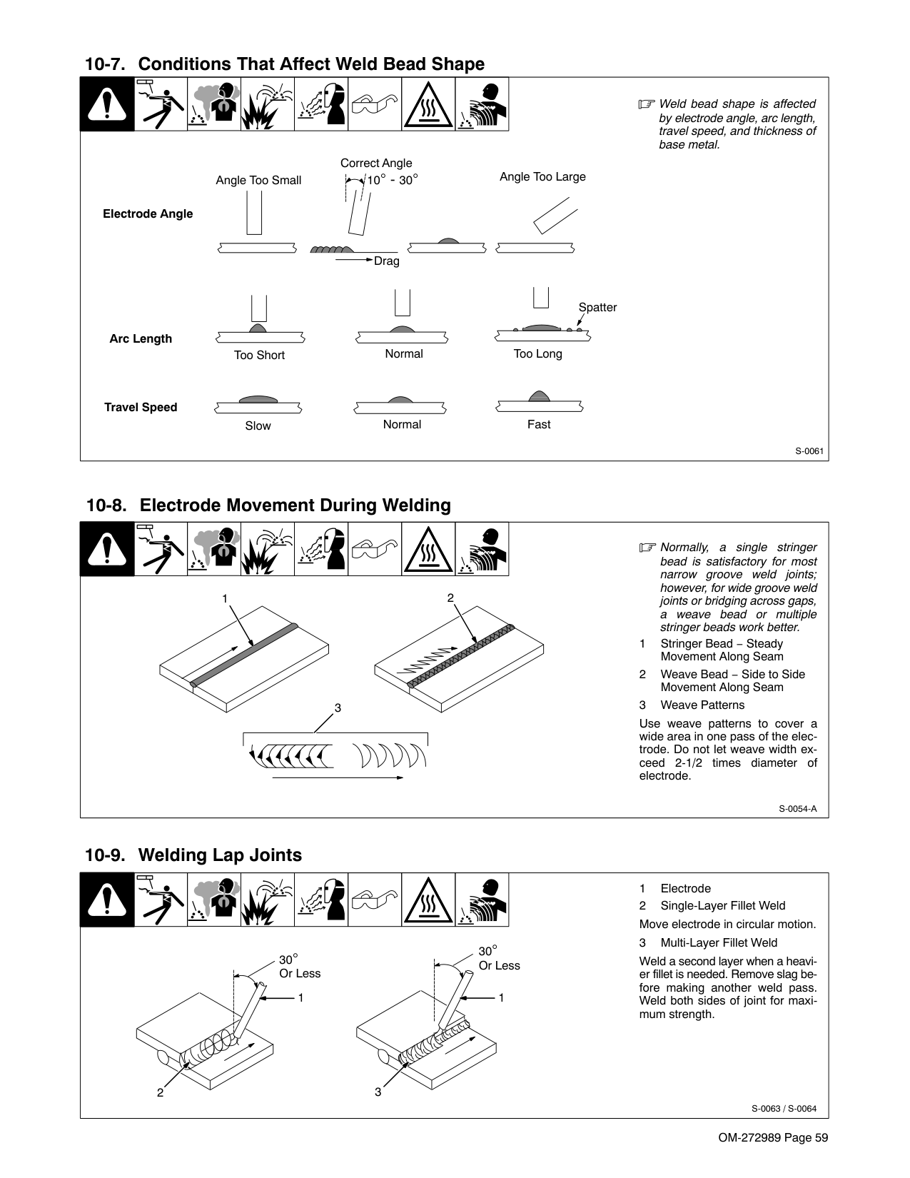
|7014|3/32| | | | | | | | | | |7014|1/8| | | | | | | | | | |7014|5/32| | | | | | | | | | |7014|3/16| | | | | | | | | | |7014|7/32| | | | | | | | | | |7014|1/4| | | | | | | | | | |7018|3/32| | | | | | | | | | |7018|1/8| | | | | | | | | | |7018|5/32| | | | | | | | | | |7018|3/16| | | | | | | | | | |7018|7/32| | | | | | | | | | |7018|1/4| | | | | | | | | | |7024|3/32| | | | | | | | | | |7024|1/8| | | | | | | | | | |7024|5/32| | | | | | | | | | |7024|3/16| | | | | | | | | | |7024|7/32| | | | | | | | | | |7024|1/4| | | | | | | | | | |Ni-Cl|3/32| | | | | | | | | | |Ni-Cl|1/8| | | | | | | | | | |Ni-Cl|5/32| | | | | | | | | | |Ni-Cl|3/16| | | | | | | | | | |308L|3/32| | | | | | | | | | |308L|1/8| | | | | | | | | | |308L|5/32| | | | | | | | | |
|ELECTRODE
|DC*|AC|POSITION|PENETRATION
|USAGE
| |---|---|---|---|---|---| |6010|EP| |ALL|DEEP|MIN. PREP, ROUGH HIGH SPATTER| |6011|EP| |ALL|DEEP|MIN. PREP, ROUGH HIGH SPATTER| |6013|EP,EN| |ALL|LOW|GENERAL| |7014|EP,EN| |ALL|MED|SMOOTH, EASY, FAST| |7018|EP| |ALL|MED|LOW HYDROGEN, STRONG| |7024|EP,EN| |FLAT HORIZ*|LOW|SMOOTH, EASY, FASTER| |NI-CL|EP| |ALL|LOW|CAST IRON| |308L|EP| |ALL|LOW|STAINLESS| |*EP = ELECTRODE POSITIVE (REVERSE POLARITY)|*EP = ELECTRODE POSITIVE (REVERSE POLARITY)|*EP = ELECTRODE POSITIVE (REVERSE POLARITY)|*EP = ELECTRODE POSITIVE (REVERSE POLARITY)|*EP = ELECTRODE POSITIVE (REVERSE POLARITY)|*EP = ELECTRODE POSITIVE (REVERSE POLARITY)|
EN = ELECTRODE NEGATIVE (STRAIGHT POLARITY)|Ref. S-087 985-A
|ELECTRODE|DIAMETER|AMPERAGE
RANGE|AMPERAGE
RANGE|AMPERAGE
RANGE|AMPERAGE
RANGE|AMPERAGE
RANGE|AMPERAGE
RANGE|AMPERAGE
RANGE|AMPERAGE
RANGE|AMPERAGE
RANGE| |---|---|---|---|---|---|---|---|---|---|---| |ELECTRODE|DIAMETER|50
100
150
200
250
300
350
400
450|50
100
150
200
250
300
350
400
450|50
100
150
200
250
300
350
400
450|50
100
150
200
250
300
350
400
450|50
100
150
200
250
300
350
400
450|50
100
150
200
250
300
350
400
450|50
100
150
200
250
300
350
400
450|50
100
150
200
250
300
350
400
450|50
100
150
200
250
300
350
400
450| |6010 &
6011
|3/32| | | | | | | | | | |6010 &
6011
|1/8| | | | | | | | | |
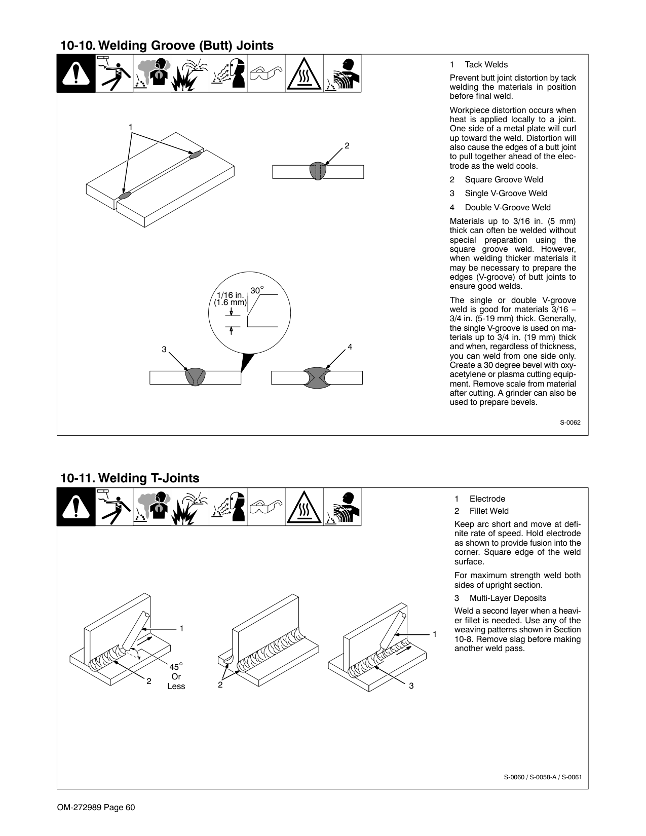
|6010 &
6011
|5/32| | | | | | | | | | |6010 &
6011
|3/16| | | | | | | | | | |6010 &
6011
|7/32| | | | | | | | | | |6010 &
6011
|1/4| | | | | | | | | | |6013|1/16| | | | | | | | | | |6013|5/64| | | | | | | | | | |6013|3/32| | | | | | | | | | |6013|1/8| | | | | | | | | | |6013|5/32| | | | | | | | | | |6013|3/16| | | | | | | | | | |6013|7/32| | | | | | | | | | |6013|1/4| | | | | | | | | | |7014|3/32| | | | | | | | | | |7014|1/8| | | | | | | | | | |7014|5/32| | | | | | | | | | |7014|3/16| | | | | | | | | | |7014|7/32| | | | | | | | | | |7014|1/4| | | | | | | | | | |7018|3/32| | | | | | | | | | |7018|1/8| | | | | | | | | | |7018|5/32| | | | | | | | | | |7018|3/16| | | | | | | | | | |7018|7/32| | | | | | | | | | |7018|1/4| | | | | | | | | | |7024|3/32| | | | | | | | | | |7024|1/8| | | | | | | | | | |7024|5/32| | | | | | | | | | |7024|3/16| | | | | | | | | | |7024|7/32| | | | | | | | | | |7024|1/4| | | | | | | | | | |Ni-Cl|3/32| | | | | | | | | | |Ni-Cl|1/8| | | | | | | | | | |Ni-Cl|5/32| | | | | | | | | | |Ni-Cl|3/16| | | | | | | | | | |308L|3/32| | | | | | | | | | |308L|1/8| | | | | | | | | | |308L|5/32| | | | | | | | | |
|ELECTRODE
|DC*|AC|POSITION|PENETRATION
|USAGE
| |---|---|---|---|---|---| |6010|EP| |ALL|DEEP|MIN. PREP, ROUGH HIGH SPATTER| |6011|EP| |ALL|DEEP|MIN. PREP, ROUGH HIGH SPATTER|
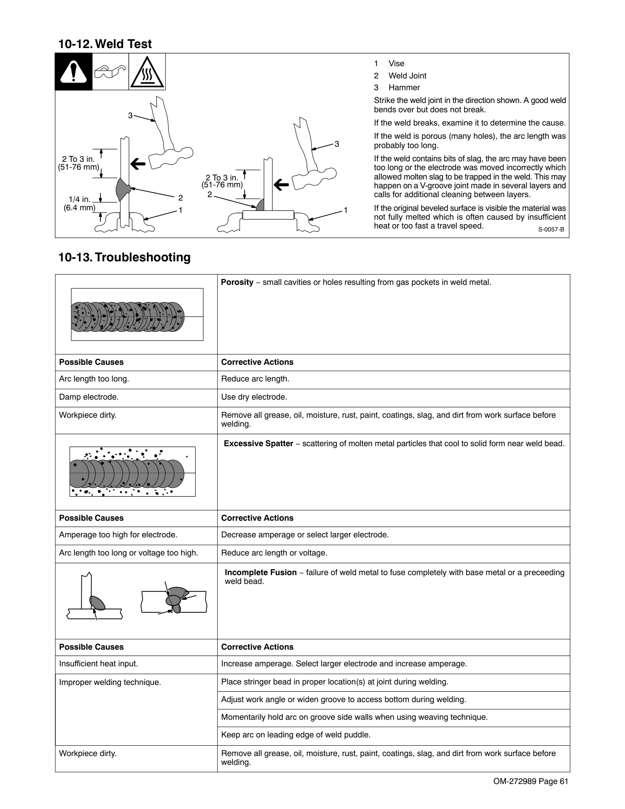
|6013|EP,EN| |ALL|LOW|GENERAL| |7014|EP,EN| |ALL|MED|SMOOTH, EASY, FAST| |7018|EP| |ALL|MED|LOW HYDROGEN, STRONG| |7024|EP,EN| |FLAT HORIZ*|LOW|SMOOTH, EASY, FASTER| |NI-CL|EP| |ALL|LOW|CAST IRON| |308L|EP| |ALL|LOW|STAINLESS| |*EP = ELECTRODE POSITIVE (REVERSE POLARITY)|*EP = ELECTRODE POSITIVE (REVERSE POLARITY)|*EP = ELECTRODE POSITIVE (REVERSE POLARITY)|*EP = ELECTRODE POSITIVE (REVERSE POLARITY)|*EP = ELECTRODE POSITIVE (REVERSE POLARITY)|*EP = ELECTRODE POSITIVE (REVERSE POLARITY)|
EN = ELECTRODE NEGATIVE (STRAIGHT POLARITY)|
####### 10-3. Striking An Arc
| | | | | | | | |! Weld current starts when electrode touches workpiece. 1 Electrode| |---|---|---|---|---|---|---|---|---| |S-0049 / S-0050
2 Workpiece
3 Arc Scratch Technique
Drag electrode across workpiece like striking a match; lift electrode slightly after touching work. If arc goes out, electrode was lifted too high. If electrode sticks to workpiece, use a quick twist to free it.
Tapping Technique
Bring electrode straight down to workpiece; then lift slightly to start arc. If arc goes out, electrode was lifted too high. If electrode sticks to workpiece, use a quick twist to free it.
1
2
3
1
3
2|S-0049 / S-0050
2 Workpiece
3 Arc Scratch Technique
Drag electrode across workpiece like striking a match; lift electrode slightly after touching work. If arc goes out, electrode was lifted too high. If electrode sticks to workpiece, use a quick twist to free it.
Tapping Technique
Bring electrode straight down to workpiece; then lift slightly to start arc. If arc goes out, electrode was lifted too high. If electrode sticks to workpiece, use a quick twist to free it.
1
2
3
1
3
2|
####### 10-4. Positioning Electrode Holder
| | | | | | | | |1 End View Of Work Angle
2 Side View Of Electrode Angle
| |---|---|---|---|---|---|---|---|---| |S-0060
90 90
10-30
45
45 10-30
After learning to start and hold an arc, practice running beads of weld metal on flat plates using a full electrode.
Hold the electrode nearly perpendicular to the work, although tilting it ahead (in the direction of travel) will be helpful.
To produce the best results, hold a short arc, travel at a uniform speed, and feed the electrode downward at a constant rate as it melts.
1
1
2
2
Groove Welds
Fillet Welds|S-0060
90 90
10-30
45
45 10-30
After learning to start and hold an arc, practice running beads of weld metal on flat plates using a full electrode.
Hold the electrode nearly perpendicular to the work, although tilting it ahead (in the direction of travel) will be helpful.
To produce the best results, hold a short arc, travel at a uniform speed, and feed the electrode downward at a constant rate as it melts.
1
1
2
2
Groove Welds
Fillet Welds|
####### 10-5. Poor Weld Bead Characteristics
| | | |---|---|
4 2 3
| | | |---|---|
5
1
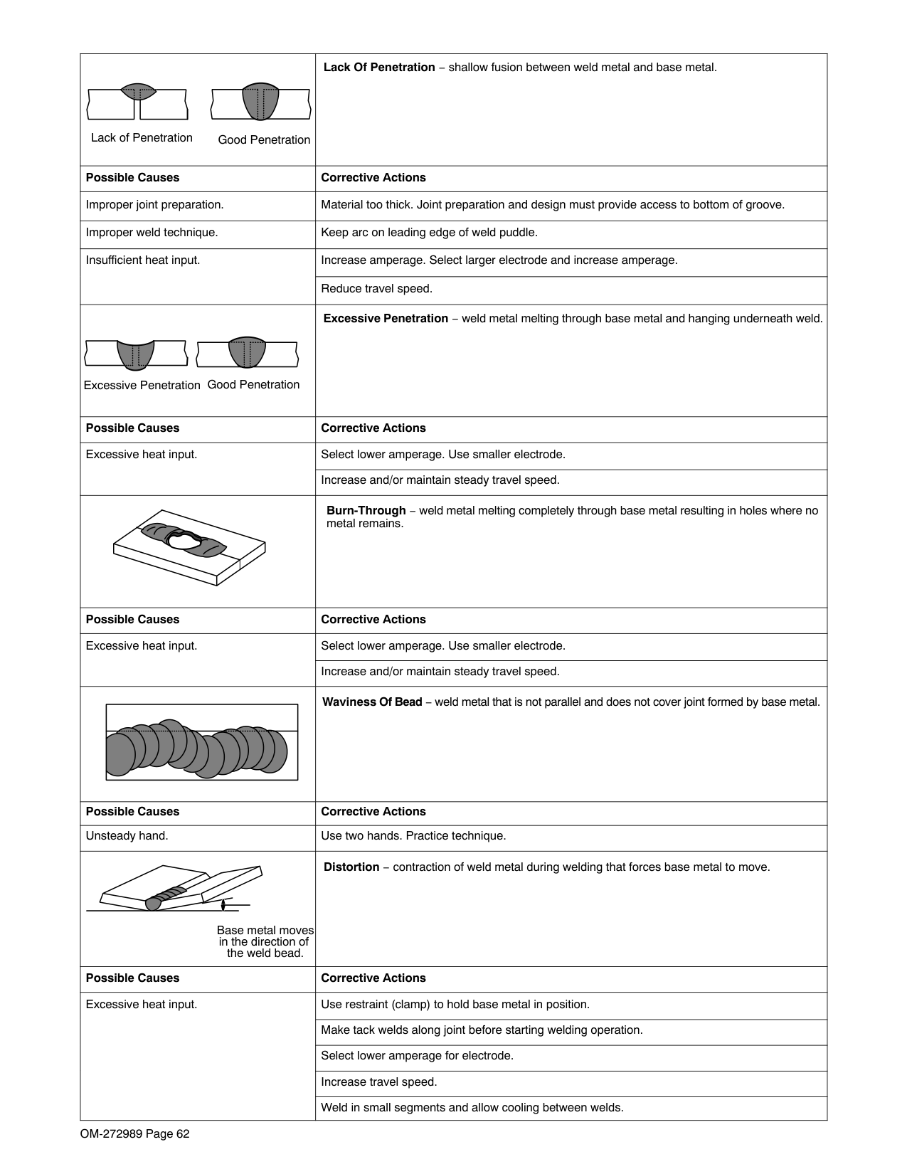
S-0053-A
####### 10-6. Good Weld Bead Characteristics
| | | |---|---|
5234
Weld a new bead or layer for each 1/8 in. (3.2 mm) thickness in metals being welded.
1
S-0052-B
| | | |---|---|
| | | | | | | | |Normally, a single stringer bead is satisfactory for most narrow groove weld joints;| |---|---|---|---|---|---|---|---|---| |S-0054-A
however, for wide groove weld joints or bridging across gaps, a weave bead or multiple stringer beads work better.
1 Stringer Bead − Steady Movement Along Seam
2 Weave Bead − Side to Side Movement Along Seam
3 Weave Patterns
Use weave patterns to cover a wide area in one pass of the electrode. Do not let weave width exceed 2-1/2 times diameter of electrode.
1 2
3|S-0054-A
however, for wide groove weld joints or bridging across gaps, a weave bead or multiple stringer beads work better.
1 Stringer Bead − Steady Movement Along Seam
2 Weave Bead − Side to Side Movement Along Seam
3 Weave Patterns
Use weave patterns to cover a wide area in one pass of the electrode. Do not let weave width exceed 2-1/2 times diameter of electrode.
1 2
3|
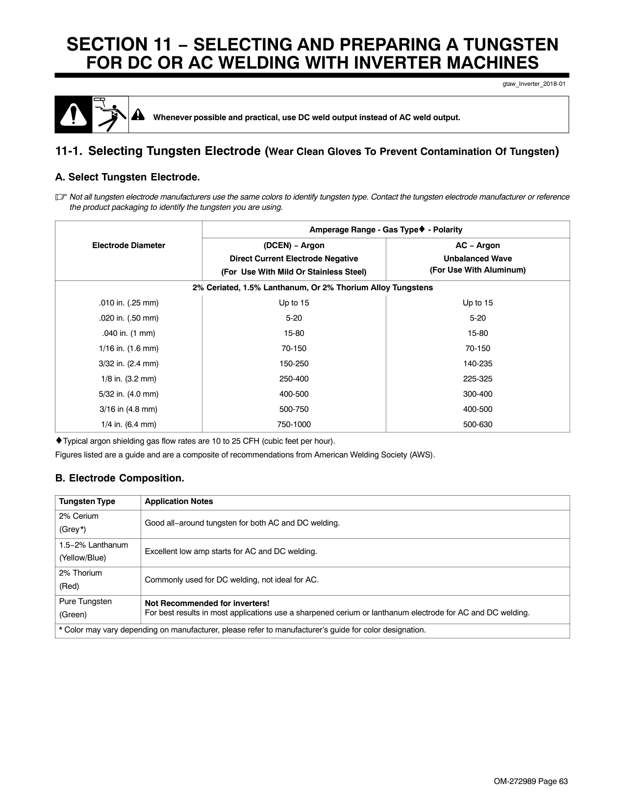
Correct Angle
Angle Too Small Angle Too Large
10 - 30
Electrode Angle
Drag
Spatter
Arc Length
Too Short Normal Too Long
Travel Speed
Slow Normal Fast
| | | |---|---|
30 Or Less
30 Or Less
1 1
2 3
Weld bead shape is affected by electrode angle, arc length, travel speed, and thickness of base metal.
S-0061
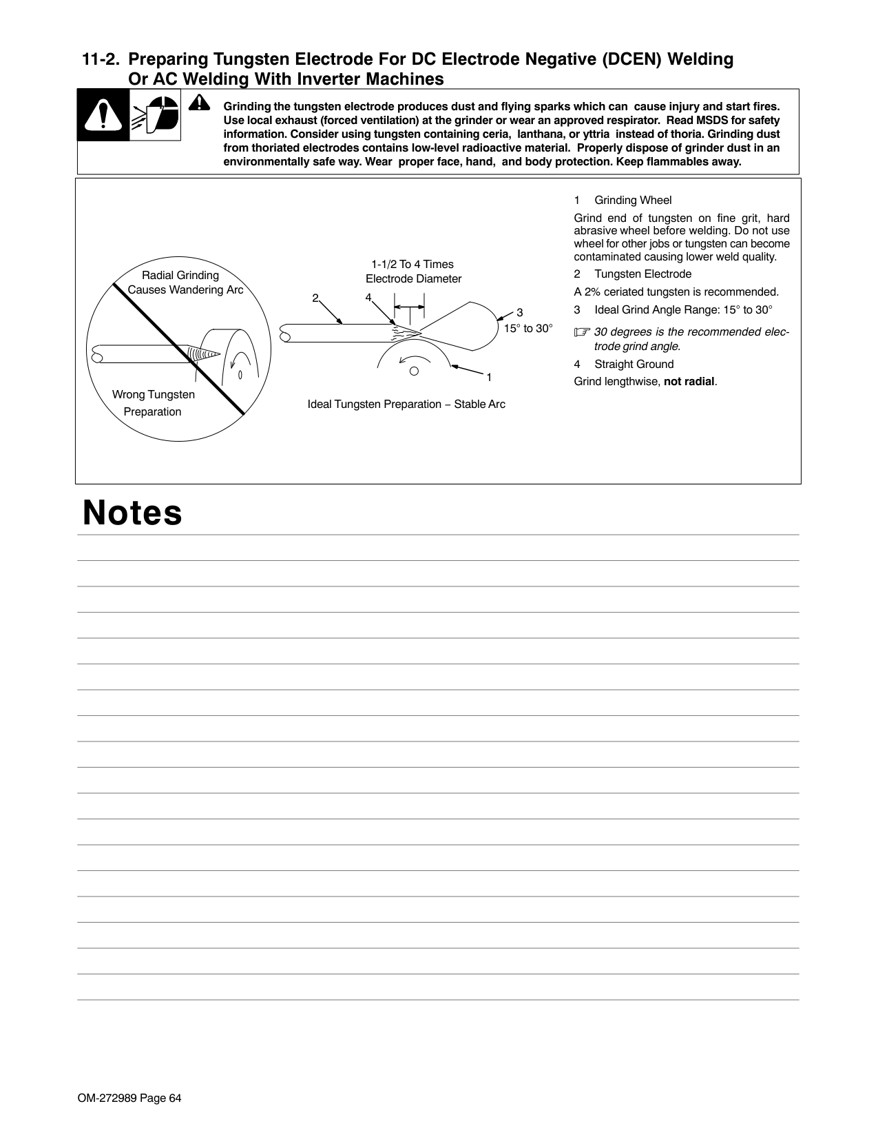
Weld a second layer when a heavier fillet is needed. Remove slag before making another weld pass. Weld both sides of joint for maximum strength.
S-0063 / S-0064
####### 10-10.Welding Groove (Butt) Joints
| | | |---|---|
1
2
30
1/16 in. (1.6 mm)
3 4
Prevent butt joint distortion by tack welding the materials in position before final weld.
Workpiece distortion occurs when heat is applied locally to a joint. One side of a metal plate will curl up toward the weld. Distortion will also cause the edges of a butt joint to pull together ahead of the electrode as the weld cools.
Materials up to 3/16 in. (5 mm) thick can often be welded without special preparation using the square groove weld. However, when welding thicker materials it may be necessary to prepare the edges (V-groove) of butt joints to ensure good welds.
The single or double V-groove weld is good for materials 3/16 − 3/4 in. (5-19 mm) thick. Generally, the single V-groove is used on materials up to 3/4 in. (19 mm) thick and when, regardless of thickness, you can weld from one side only. Create a 30 degree bevel with oxyacetylene or plasma cutting equipment. Remove scale from material after cutting. A grinder can also be used to prepare bevels.
S-0062
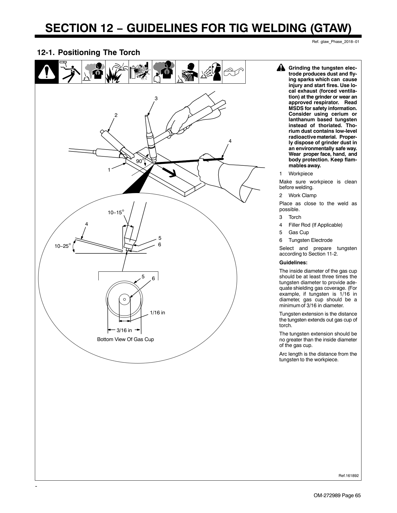
####### 10-11. Welding T-Joints
| | | | | | | | |1 Electrode
2 Fillet Weld Keep arc short and move at defi-
| |---|---|---|---|---|---|---|---|---| |S-0060 / S-0058-A / S-0061
nite rate of speed. Hold electrode as shown to provide fusion into the corner. Square edge of the weld surface.
For maximum strength weld both sides of upright section.
3 Multi-Layer Deposits
Weld a second layer when a heavier fillet is needed. Use any of the weaving patterns shown in Section 10-8. Remove slag before making another weld pass.
45 Or Less
1
2
1
32
|S-0060 / S-0058-A / S-0061
nite rate of speed. Hold electrode as shown to provide fusion into the corner. Square edge of the weld surface.
For maximum strength weld both sides of upright section.
3 Multi-Layer Deposits
Weld a second layer when a heavier fillet is needed. Use any of the weaving patterns shown in Section 10-8. Remove slag before making another weld pass.
45 Or Less
1
2
1
32
|
####### 10-12.Weld Test
3
3
2 To 3 in.
(51-76 mm)
2 To 3 in.
(51-76 mm)
2
2 1
1/4 in.
(6.4 mm)
1
Strike the weld joint in the direction shown. A good weld bends over but does not break.
If the weld breaks, examine it to determine the cause. If the weld is porous (many holes), the arc length was probably too long.
If the weld contains bits of slag, the arc may have been too long or the electrode was moved incorrectly which allowed molten slag to be trapped in the weld. This may happen on a V-groove joint made in several layers and calls for additional cleaning between layers.
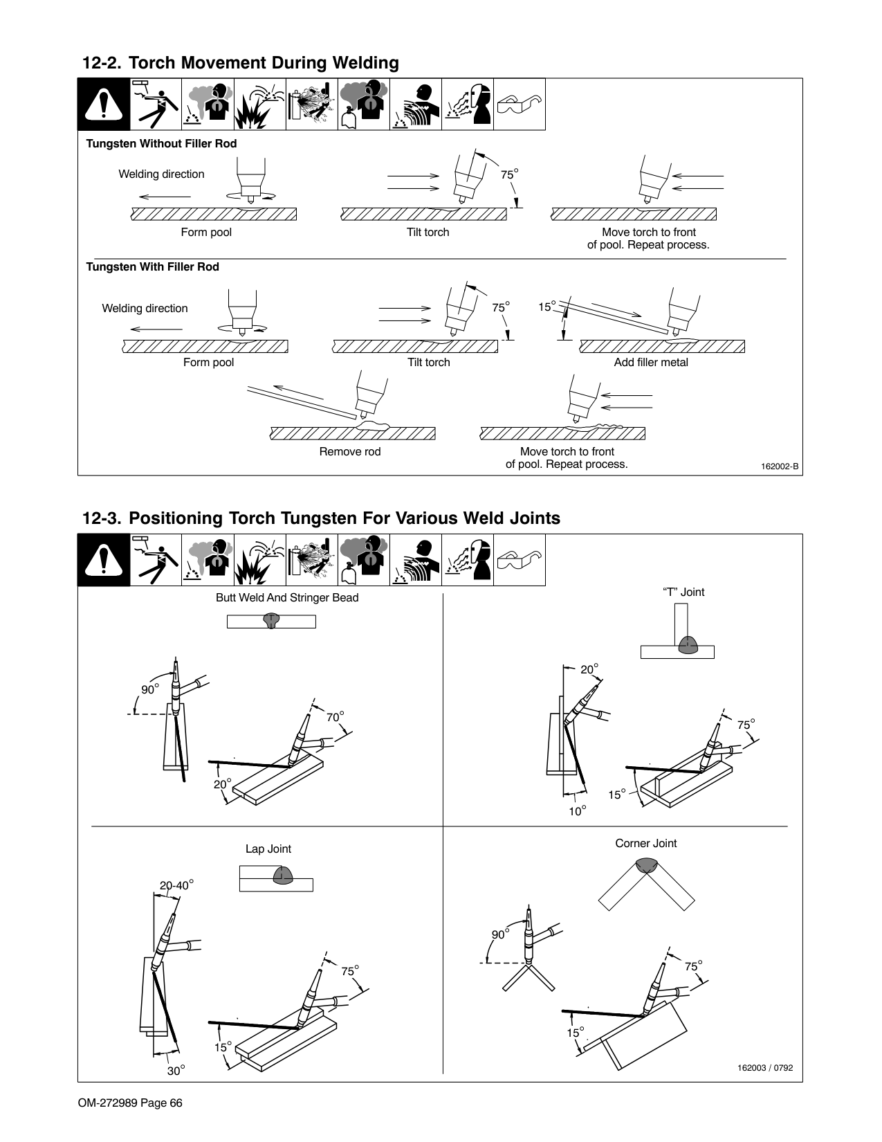
If the original beveled surface is visible the material was not fully melted which is often caused by insufficient heat or too fast a travel speed.
S-0057-B
####### 10-13.Troubleshooting
| |Porosity − small cavities or holes resulting from gas pockets in weld metal.| |---|---| |Possible Causes|Corrective Actions| |Arc length too long.|Reduce arc length.| |Damp electrode.|Use dry electrode.| |Workpiece dirty.|Remove all grease, oil, moisture, rust, paint, coatings, slag, and dirt from work surface before welding.| | |Excessive Spatter − scattering of molten metal particles that cool to solid form near weld bead.| |Possible Causes|Corrective Actions| |Amperage too high for electrode.|Decrease amperage or select larger electrode.| |Arc length too long or voltage too high.|Reduce arc length or voltage.| | |Incomplete Fusion − failure of weld metal to fuse completely with base metal or a preceeding weld bead.| |Possible Causes|Corrective Actions| |Insufficient heat input.|Increase amperage. Select larger electrode and increase amperage.| |Improper welding technique.|Place stringer bead in proper location(s) at joint during welding.| |Improper welding technique.|Adjust work angle or widen groove to access bottom during welding.| |Improper welding technique.|Momentarily hold arc on groove side walls when using weaving technique.| |Improper welding technique.|Keep arc on leading edge of weld puddle.| |Workpiece dirty.|Remove all grease, oil, moisture, rust, paint, coatings, slag, and dirt from work surface before welding.|
|Lack of Penetration Good Penetration|Lack Of Penetration − shallow fusion between weld metal and base metal.| |---|---| |Possible Causes|Corrective Actions| |Improper joint preparation.|Material too thick. Joint preparation and design must provide access to bottom of groove.| |Improper weld technique.|Keep arc on leading edge of weld puddle.| |Insufficient heat input.
|Increase amperage. Select larger electrode and increase amperage.| |Insufficient heat input.
|Reduce travel speed.| |Good PenetrationExcessive Penetration|Excessive Penetration − weld metal melting through base metal and hanging underneath weld.| |Possible Causes|Corrective Actions| |Excessive heat input.
|Select lower amperage. Use smaller electrode.| |Excessive heat input.
|Increase and/or maintain steady travel speed.| | |Burn-Through − weld metal melting completely through base metal resulting in holes where no metal remains.| |Possible Causes|Corrective Actions| |Excessive heat input.
|Select lower amperage. Use smaller electrode.|
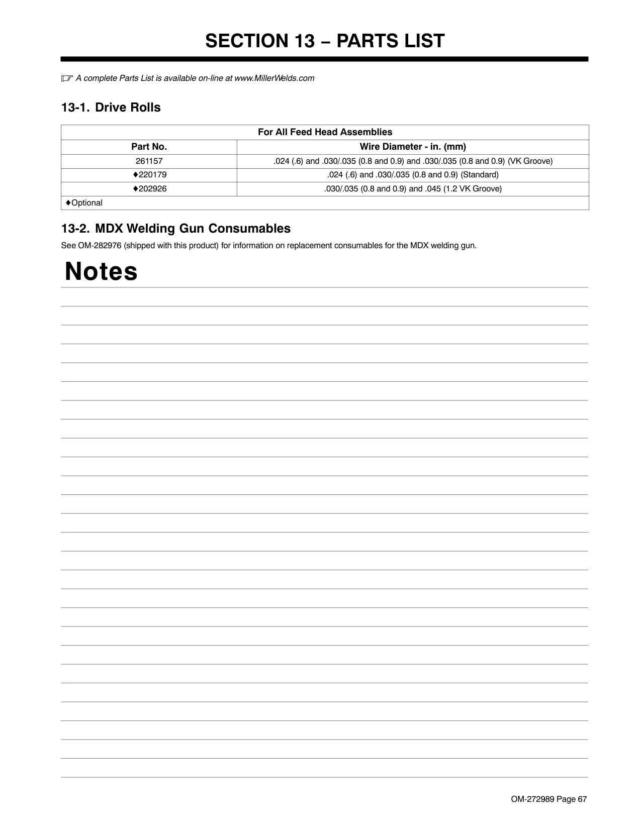
|Excessive heat input.
|Increase and/or maintain steady travel speed.| | |Waviness Of Bead − weld metal that is not parallel and does not cover joint formed by base metal.| |Possible Causes|Corrective Actions| |Unsteady hand.|Use two hands. Practice technique.| |Base metal moves in the direction of the weld bead.|Distortion − contraction of weld metal during welding that forces base metal to move.| |Possible Causes|Corrective Actions| |Excessive heat input.
|Use restraint (clamp) to hold base metal in position.| |Excessive heat input.
|Make tack welds along joint before starting welding operation.| |Excessive heat input.
|Select lower amperage for electrode.| |Excessive heat input.
|Increase travel speed.| |Excessive heat input.
|Weld in small segments and allow cooling between welds.|
SECTION 11 − SELECTING AND PREPARING A TUNGSTEN FOR DC OR AC WELDING WITH INVERTER MACHINES
gtaw_Inverter_2018-01
| | |Whenever possible and practical, use DC weld output instead of AC weld output.| |---|---|---|
Not all tungsten electrode manufacturers use the same colors to identify tungsten type. Contact the tungsten electrode manufacturer or reference the product packaging to identify the tungsten you are using.
Amperage Range - Gas Type - Polarity Electrode Diameter (DCEN) − Argon
Direct Current Electrode Negative (For Use With Mild Or Stainless Steel)
AC − Argon Unbalanced Wave (For Use With Aluminum) 2% Ceriated, 1.5% Lanthanum, Or 2% Thorium Alloy Tungstens
.010 in. (.25 mm) Up to 15 Up to 15
.020 in. (.50 mm) 5-20 5-20
.040 in. (1 mm) 15-80 15-80 1/16 in. (1.6 mm) 70-150 70-150 3/32 in. (2.4 mm) 150-250 140-235
1/8 in. (3.2 mm) 250-400 225-325 5/32 in. (4.0 mm) 400-500 300-400 3/16 in (4.8 mm) 500-750 400-500 1/4 in. (6.4 mm) 750-1000 500-630

Typical argon shielding gas flow rates are 10 to 25 CFH (cubic feet per hour). Figures listed are a guide and are a composite of recommendations from American Welding Society (AWS).
|Tungsten Type|Application Notes| |---|---| |2% Cerium (Grey*)|Good all−around tungsten for both AC and DC welding.| |1.5−2% Lanthanum (Yellow/Blue)|Excellent low amp starts for AC and DC welding.| |2% Thorium (Red)|Commonly used for DC welding, not ideal for AC.| |Pure Tungsten (Green)|Not Recommended for inverters! For best results in most applications use a sharpened cerium or lanthanum electrode for AC and DC welding.| |* Color may vary depending on manufacturer, please refer to manufacturer’s guide for color designation.|* Color may vary depending on manufacturer, please refer to manufacturer’s guide for color designation.|
| | |Grinding the tungsten electrode produces dust and flying sparks which can cause injury and start fires. Use local exhaust (forced ventilation) at the grinder or wear an approved respirator. Read MSDS for safety information. Consider using tungsten containing ceria, lanthana, or yttria instead of thoria. Grinding dust| |---|---|---| |from thoriated electrodes contains low-level radioactive material. Properly dispose of grinder dust in an environmentally safe way. Wear proper face, hand, and body protection. Keep flammables away.|from thoriated electrodes contains low-level radioactive material. Properly dispose of grinder dust in an environmentally safe way. Wear proper face, hand, and body protection. Keep flammables away.|from thoriated electrodes contains low-level radioactive material. Properly dispose of grinder dust in an environmentally safe way. Wear proper face, hand, and body protection. Keep flammables away.|
|Ideal Tungsten Preparation − Stable Arc
1 Grinding Wheel
Grind end of tungsten on fine grit, hard abrasive wheel before welding. Do not use wheel for other jobs or tungsten can become contaminated causing lower weld quality.
2 Tungsten Electrode A 2% ceriated tungsten is recommended.
3 Ideal Grind Angle Range: 15 to 30
30 degrees is the recommended electrode grind angle.
4 Straight Ground
Grind lengthwise, not radial.1
3
Causes Wandering Arc
2
Wrong Tungsten
Radial Grinding
Preparation
15 to 30
4
1-1/2 To 4 Times Electrode Diameter
| |---|
Notes
SECTION 12 − GUIDELINES FOR TIG WELDING (GTAW)
Ref. gtaw_Phase_2018−01
####### 12-1. Positioning The Torch
| | | | || | | | |! Grinding the tungsten electrode produces dust and flying sparks which can cause injury and start fires. Use lo-| |---|---|---|---|---|---|---|---|---|---| |Ref.161892
cal exhaust (forced ventilation) at the grinder or wear an approved respirator. Read MSDS for safety information. Consider using cerium or lanthanum based tungsten instead of thoriated. Thorium dust contains low-level radioactive material. Properly dispose of grinder dust in an environmentally safe way. Wear proper face, hand, and body protection. Keep flammables away.
1 Workpiece
Make sure workpiece is clean before welding.
2 Work Clamp
Place as close to the weld as possible.
3 Torch
4 Filler Rod (If Applicable)
5 Gas Cup
6 Tungsten Electrode
Select and prepare tungsten according to Section 11-2.
Guidelines:
The inside diameter of the gas cup should be at least three times the tungsten diameter to provide adequate shielding gas coverage. (For example, if tungsten is 1/16 in diameter, gas cup should be a minimum of 3/16 in diameter.
Tungsten extension is the distance the tungsten extends out gas cup of torch.
The tungsten extension should be no greater than the inside diameter of the gas cup.
Arc length is the distance from the tungsten to the workpiece.
1
10−25
10−15
6
2
3
4
90
4
5
3/16 in
1/16 in
65
Bottom View Of Gas Cup|Ref.161892
cal exhaust (forced ventilation) at the grinder or wear an approved respirator. Read MSDS for safety information. Consider using cerium or lanthanum based tungsten instead of thoriated. Thorium dust contains low-level radioactive material. Properly dispose of grinder dust in an environmentally safe way. Wear proper face, hand, and body protection. Keep flammables away.
1 Workpiece
Make sure workpiece is clean before welding.
2 Work Clamp
Place as close to the weld as possible.
3 Torch
4 Filler Rod (If Applicable)
5 Gas Cup
6 Tungsten Electrode
Select and prepare tungsten according to Section 11-2.
Guidelines:
The inside diameter of the gas cup should be at least three times the tungsten diameter to provide adequate shielding gas coverage. (For example, if tungsten is 1/16 in diameter, gas cup should be a minimum of 3/16 in diameter.
Tungsten extension is the distance the tungsten extends out gas cup of torch.
The tungsten extension should be no greater than the inside diameter of the gas cup.
Arc length is the distance from the tungsten to the workpiece.
1
10−25
10−15
6
2
3
4
90
4
5
3/16 in
1/16 in
65
Bottom View Of Gas Cup|
-

####### 12-2. Torch Movement During Welding
| | | | || | | | | | |---|---|---|---|---|---|---|---|---|---| |162002-B
Tungsten Without Filler Rod
Tungsten With Filler Rod
Form pool Tilt torch Move torch to front of pool. Repeat process.
75
75Welding direction
Form pool Tilt torch Add filler metal
Move torch to front of pool. Repeat process.
Remove rod
Welding direction 15
|162002-B
Tungsten Without Filler Rod
Tungsten With Filler Rod
Form pool Tilt torch Move torch to front of pool. Repeat process.
75
75Welding direction
Form pool Tilt torch Add filler metal
Move torch to front of pool. Repeat process.
Remove rod
Welding direction 15
|162002-B
Tungsten Without Filler Rod
Tungsten With Filler Rod
Form pool Tilt torch Move torch to front of pool. Repeat process.
75
75Welding direction
Form pool Tilt torch Add filler metal
Move torch to front of pool. Repeat process.
Remove rod
Welding direction 15
|162002-B
Tungsten Without Filler Rod
Tungsten With Filler Rod
Form pool Tilt torch Move torch to front of pool. Repeat process.
75
75Welding direction
Form pool Tilt torch Add filler metal
Move torch to front of pool. Repeat process.
Remove rod
Welding direction 15
|162002-B
Tungsten Without Filler Rod
Tungsten With Filler Rod
Form pool Tilt torch Move torch to front of pool. Repeat process.
75
75Welding direction
Form pool Tilt torch Add filler metal
Move torch to front of pool. Repeat process.
Remove rod
Welding direction 15
|162002-B
Tungsten Without Filler Rod
Tungsten With Filler Rod
Form pool Tilt torch Move torch to front of pool. Repeat process.
75
75Welding direction
Form pool Tilt torch Add filler metal
Move torch to front of pool. Repeat process.
Remove rod
Welding direction 15
|162002-B
Tungsten Without Filler Rod
Tungsten With Filler Rod
Form pool Tilt torch Move torch to front of pool. Repeat process.
75
75Welding direction
Form pool Tilt torch Add filler metal
Move torch to front of pool. Repeat process.
Remove rod
Welding direction 15
|162002-B
Tungsten Without Filler Rod
Tungsten With Filler Rod
Form pool Tilt torch Move torch to front of pool. Repeat process.
75
75Welding direction
Form pool Tilt torch Add filler metal
Move torch to front of pool. Repeat process.
Remove rod
Welding direction 15
|162002-B
Tungsten Without Filler Rod
Tungsten With Filler Rod
Form pool Tilt torch Move torch to front of pool. Repeat process.
75
75Welding direction
Form pool Tilt torch Add filler metal
Move torch to front of pool. Repeat process.
Remove rod
Welding direction 15
|162002-B
Tungsten Without Filler Rod
Tungsten With Filler Rod
Form pool Tilt torch Move torch to front of pool. Repeat process.
75
75Welding direction
Form pool Tilt torch Add filler metal
Move torch to front of pool. Repeat process.
Remove rod
Welding direction 15
|
####### 12-3. Positioning Torch Tungsten For Various Weld Joints
| | | | || | | | | | |---|---|---|---|---|---|---|---|---|---| |162003 / 0792
75
70
90
20
20
10
15
75
20-40
30
15
75
90
15
Butt Weld And Stringer Bead “T” Joint
Lap Joint Corner Joint|162003 / 0792
75
70
90
20
20
10
15
75
20-40
30
15
75
90
15
Butt Weld And Stringer Bead “T” Joint
Lap Joint Corner Joint|162003 / 0792
75
70
90
20
20
10
15
75
20-40
30
15
75
90
15
Butt Weld And Stringer Bead “T” Joint
Lap Joint Corner Joint|162003 / 0792
75
70
90
20
20
10
15
75
20-40
30
15
75
90
15
Butt Weld And Stringer Bead “T” Joint
Lap Joint Corner Joint|162003 / 0792
75
70
90
20
20
10
15
75
20-40
30
15
75
90
15
Butt Weld And Stringer Bead “T” Joint
Lap Joint Corner Joint|162003 / 0792
75
70
90
20
20
10
15
75
20-40
30
15
75
90
15
Butt Weld And Stringer Bead “T” Joint
Lap Joint Corner Joint|162003 / 0792
75
70
90
20
20
10
15
75
20-40
30
15
75
90
15
Butt Weld And Stringer Bead “T” Joint
Lap Joint Corner Joint|162003 / 0792
75
70
90
20
20
10
15
75
20-40
30
15
75
90
15
Butt Weld And Stringer Bead “T” Joint
Lap Joint Corner Joint|162003 / 0792
75
70
90
20
20
10
15
75
20-40
30
15
75
90
15
Butt Weld And Stringer Bead “T” Joint
Lap Joint Corner Joint|162003 / 0792
75
70
90
20
20
10
15
75
20-40
30
15
75
90
15
Butt Weld And Stringer Bead “T” Joint
Lap Joint Corner Joint|
SECTION 13 − PARTS LIST
A complete Parts List is available on-line at www.MillerWelds.com
####### 13-1. Drive Rolls
|For All Feed Head Assemblies|For All Feed Head Assemblies| |---|---| |Part No.|Wire Diameter - in. (mm)| |261157|.024 (.6) and .030/.035 (0.8 and 0.9) and .030/.035 (0.8 and 0.9) (VK Groove)| |220179|.024 (.6) and .030/.035 (0.8 and 0.9) (Standard)| |202926|.030/.035 (0.8 and 0.9) and .045 (1.2 VK Groove)| |Optional|Optional|
####### 13-2. MDX Welding Gun Consumables
See OM-282976 (shipped with this product) for information on replacement consumables for the MDX welding gun.
Notes
|Warranty Questions?
Call 1-800-4-A-MILLER for your local Miller distributor.


Your distributor also gives you ...
Service You always get the fast, reliable response you need. Most replacement parts can be in your hands in 24 hours.
Support Need fast answers to the tough welding questions? Contact your distributor. The expertise of the distributor and Miller is there to help you, every step of the way.| |---|
Effective January 1, 2019 (Equipment with a serial number preface of MK or newer)

This limited warranty supersedes all previous Miller warranties and is exclusive with no other guarantees or warranties expressed or implied.
LIMITED WARRANTY − Subject to the terms and conditions below, Miller Electric Mfg. LLC, Appleton, Wisconsin, warrants to authorized distributors that new Miller equipment sold after the effective date of this limited warranty is free of defects in material and workmanship at the time it is shipped by Miller. THIS WARRANTY IS EXPRESSLY IN LIEU OF ALL OTHER WARRANTIES, EXPRESS OR IMPLIED, INCLUDING THE WARRANTIES OF MERCHANTABILITY AND FITNESS.
Within the warranty periods listed below, Miller will repair or replace any warranted parts or components that fail due to such defects in material or workmanship. Miller must be notified in writing within thirty (30) days of such defect or failure, at which time Miller will provide instructions on the warranty claim procedures to be followed. Notifications submitted as online warranty claims must provide detailed descriptions of the fault and troubleshooting steps taken to diagnose failed parts. Warranty claims that lack the required information as defined in the Miller Service Operation Guide (SOG) may be denied by Miller.
Miller shall honor warranty claims on warranted equipment listed below in the event of a defect within the warranty coverage time periods listed below. Warranty time periods start on the delivery date of the equipment to the end-user purchaser, or 12 months after the equipment is shipped to a North American distributor, or 18 months after the equipment is shipped to an international distributor, whichever occurs first.
Miller’s True Blue Limited Warranty shall not apply to:
MILLER PRODUCTS ARE INTENDED FOR COMMERCIAL AND INDUSTRIAL USERS TRAINED AND EXPERIENCED IN THE USE AND MAINTENANCE OF WELDING EQUIPMENT.
The exclusive remedies for warranty claims are, at Miller’s option, either: (1) repair; or (2) replacement; or, if approved in writing by Miller, (3) the pre-approved cost of repair or replacement at an authorized Miller service station; or (4) payment of or credit for the purchase price (less reasonable depreciation based upon use). Products may not be returned without Miller’s written approval. Return shipment shall be at customer’s risk and expense.
The above remedies are F.O.B. Appleton, WI, or Miller’s authorized service facility. Transportation and freight are the customer’s responsibility. TO THE EXTENT PERMITTED BY LAW, THE REMEDIES HEREIN ARE THE SOLE AND EXCLUSIVE REMEDIES REGARDLESS OF THE LEGAL THEORY. IN NO EVENT SHALL MILLER BE LIABLE FOR DIRECT, INDIRECT, SPECIAL, INCIDENTAL OR CONSEQUENTIAL DAMAGES (INCLUDING LOSS OF PROFIT) REGARDLESS OF THE LEGAL THEORY. ANY WARRANTY NOT PROVIDED HEREIN AND ANY IMPLIED WARRANTY, GUARANTY, OR REPRESENTATION,
INCLUDING ANY IMPLIED WARRANTY OF MERCHANTABILITY OR FITNESS FOR PARTICULAR PURPOSE, ARE EXCLUDED AND DISCLAIMED BY MILLER.
Some US states do not allow limiting the duration of an implied warranty or the exclusion of certain damages, so the above limitations may not apply to you. This warranty provides specific legal rights, and other rights may be available depending on your state. In Canada, some provinces provide additional warranties or remedies, and to the extent the law prohibits their waiver, the limitations set out above may not apply. This Limited Warranty provides specific legal rights, and other rights may be available, but may vary by province.
mil dom warr 2019-01
Owner’s Record
Please complete and retain with your personal records.
########## Model Name Serial/Style Number
Purchase Date (Date which equipment was delivered to original customer.)
Distributor
Address
City
State Zip
For Service
###### Contact a DISTRIBUTOR or SERVICE AGENCY near you.
Always provide Model Name and Serial/Style Number.
Contact your Distributor for:
Welding Supplies and Consumables Options and Accessories Personal Safety Equipment Service and Repair Replacement Parts Training (Schools, Videos, Books) Technical Manuals (Servicing Information and Parts) Circuit Diagrams Welding Process Handbooks
To locate a Distributor or Service Agency visit www.millerwelds.com or call 1-800-4-A-Miller
Contact the Delivering Carrier to:
File a claim for loss or damage during shipment.
For assistance in filing or settling claims, contact your distributor and/or equipment manufacturer’s Transportation Department.
ORIGINAL INSTRUCTIONS − PRINTED IN USA 2019 Miller Electric Mfg. LLC 2019−01
|Miller Electric Mfg. LLC An Illinois Tool Works Company 1635 West Spencer Street Appleton, WI 54914 USA
International Headquarters−USA USA Phone: 920-735-4505 Auto-Attended USA & Canada FAX: 920-735-4134 International FAX: 920-735-4125
For International Locations Visit www.MillerWelds.com

| |---|