
Ask AI
— answers from the official manualAnswers from the official manual.
Common questions
Common Questions
10 totalHow do I set the water heater to factory defaults?
To reset the Navien NPE 240A2 to factory settings, press and hold the Power button until the LED flashes red and then releases. This action will clear all user settings and revert to manufacturer defaults requiring reconfiguration of connected devices, as found on page 37.
What is the range of input heat capacity for this water heater?
The NPE-240A model has a heat capacity (input) ranging from 19,900 BTU/H to 199,900 BTU/H for both natural gas and propane gas configurations, as specified in the specifications table on page 5.
How do I properly install the condensate drain?
To connect a condensate drain, attach a pipe of at least 1/2 in (inner diameter) to the fitting located at the bottom of the water heater. The pipe must be made from corrosion-resistant material such as PVC or CPVC and should slope downward with a minimum pitch of 1/4 inch per foot. Direct the open end into an appropriate drain, as described on page 26.
What actions should I take if my water heater displays 'Error'?
When encountering an error code on the NPE-240A2 front panel, press the Reset button to clear the issue. If it persists or recurs, consult pages 37 and 51 for diagnostic steps and contact a professional installer.
What are the gas pipe size requirements for this model?
The water heater requires connecting gas supply piping of sizes between 1/2 to 3/4 in (inner diameter). The specific sizing is dependent on the distance from the main line to ensure proper pressure and delivery. Referencing pages 17-19 provides detailed guidance.
How can I set up the hot water recirculation mode for this model?
To configure hot water recirculation, first connect the return line and remove any caps on existing fittings. Then, for internal recirculation mode, adjust the front panel DIP switches as outlined in the manual’s table (page 21). For external recirculation, modify settings according to page 20 instructions.
Full Manual
85 pages

Installation Manual
NPE Condensing Water Heaters
Model NPE-180A NPE-210A NPE-240A NPE-150S NPE-180S NPE-210S NPE-240S


Keep this manual near this water heater for future reference whenever maintenance or service is required.
|WARNING If the information in these instructions is not followed exactly, a fire or explosion may result, causing property damage, personal injury or death.| |---|
Do not store or use gasoline or other flammable vapors and liquids in the vicinity of this or any other appliance.
What to do if you smell gas Do not try to light any appliance. Do not touch any electrical switch; do not use any phone in your building. Immediately call your gas supplier from a neighbor’s phone. Follow the gas supplier’s instructions. If you cannot reach your gas supplier, call the fire department.
Installation and service must be performed by a qualified installer, service agency or the gas supplier. The installation must conform with local codes or, in the absence of local codes, the National Fuel Gas Code, ANSIZ223.1/NFPA 54 and/or CSA B149.1, Natural Gas and Propane Installation Code. When applicable, the installation must conform with the Manufactured Home Construction and Safety Standard, Title 24 CFR, Part 3280 and/or CAN/CSA Z240 MH Series, Mobile Homes.
| | | | | | | | | | | | | | | | | | | | | | | | | | | | | | | | | | | | | | | | | | | | | | | | | | | | | | | | | | | | | | | | | | | | | | | | | | | | | | | | | | | | | | | | | | | | | | | | | | | | | | | | | | | | | | | | | | | | | | | | | | | | | | | | | | | | | | | | | | | | | | | | | | | | | | | | | | | | | | | | | | | | | | | | | | | | | | | | | | | | | | | | | | | | | | | |---|---|---|---|---|---|---|---|---|---|---|---|---|---|---|---|---|---|---|---|---|---|---|---|---|---|---|---|---|---|---|---|---|---|---|---|---|---|---|---|---|---|---|---|---|---|---|---|---|---|---|---|---|---|---|---|---|---|---|---|---|---|---|---|---|---|---|---|---|---|---|---|---|---|---|---|---|---|---|---|---|---|---|---|---|---|---|---|---|---|---|---|---|---|---|---|---|---|---|---|---|---|---|---|---|---|---|---|---|---|---|---|---|---|---|---|---|---|---|---|---|---|---|---|---|---|---|---|---|---|---|---|---|---|---|---|---|---|---|---|---|---|---|---|---|---|---|---|---|---|---|---|---|---|---|---|---|---|---|---|---|---|---|---|---|---|---|---|---|---|---|---|---|---|---|---|---|---|---|---|---|---|---|---|---|---|---|---|---|---| | | | | | | | | | | | | | | | | | | | | | | | | | | | | | | | | | | | | | | | | | | | | | | | | | | | | | | | | | | | | | | | | | | | | | | | | | | | | | | | | | | | | | | | | | | | | | | | | | | | | | | | | | | | | | | | | | | | | | | | | | | | | | | | | | | | | | | | | | | | | | | | | | | | | | | | | | | | | | | | | | | | | | | | | | | | | | | | | | | | | | | | | | | | | | | | | | | | | | | | | | | | | | | | | | | | | | | | | | | | | | | | | | | | | | | | | | | | | | | | | | | | | | | | | | | | | | | | | | | | | | | | | | | | | | | | | | | | | | | | | | | | | | | | | | | | | | | | | | | | | | | | | | | | | | | | | | | | | | | | | | | | | | | | | | | | | | | | | | | | | | | | | | | | | | | | | | | | | | | | | | | | | | | | | | | | | | | | | | | | | | | | | | | | | | | | | | | | | | | | | | | | | | | | | | | | | | | | | | | | | | | | | | | | | | | | | | | | | | | | | | | | | | | | | | | | | | | | | | | | | | | | | | | | | | | | | | | | | | | | | | | | | | | | | | | | | | | | | | | | | | | | | | | | | | | | | | | | | | | | | | | | | | | | | | | | | | | | | | | | | | | | | | | | | | | | | | | | | | | | | | | | | | | | | | | | | | | | | | | | | | | | | | | | | | | | | | | | | | | | | | | | | | | | | | | | | | | | | | | | | | | | | | | | | | | | | | | | | | | | | | | | | | | | | | | | | | | | | | | | | | | | | | | | | | | | | | | | | | | | | | | | | | | | | | | | | | | | | | | | | | | | | | | | | | | | | | | | | | | | | | | | | | | | | | | | | | | | | | | | | | | | | | | | | | | | | | | | | | | | | | | | | | | | | | | | | | | | | | | | | | | | | | | | | | | | | | | | | | | | | | | | | | | | | | | | | | | | | | | | | | | | | | | | | | | | | | | | | | | | | | | | | | | | | | | | | | | | | | | | | | | | | | | | | | | | | | | | | | | | | | | | | | | | | | | | | | | | | | | | | | | | | | | | | | | | | | | | | | | | | | | | | | | | | | | | | | | | | | | | | | | | | | | | | | | | | | | | | | | | | | | | | | | | | | | | | | | | | | | | | | | | | | | | | | | | | | | | | | | | | | | | | | | | | | | | | | | | | | | | | | | | | | | | | | | | | | | | | | | | | | | | | | | | | | | | | | | | | | | | | | | | | | | | | | | | | | | | | | | | | | | | | | | | | | | | | | | | | | | | | | | | | | | | | | | | | | | | | | | | | | | | | | | | | | | | | | | | | | | | | | | | | | | | | | | | | | | | | | | | | | | | | | | | | | | | | | | | | | | | | | | | | | | | | | | | | | | | | | | | | | | | | | | | | | | | | | | | | | | | | | | | | | | | | | | | | | | | | | | | | | | | | | | | | | | | | | | | | | | | | | | | | | | | | | | | | | | | | | | | | | | | | | | | | | | | | | | | | | | | | | | | | | | | | | | | | | | | | | | | | | | | | | | | | | | | | | | | | | | | | | | | | | | | | | | | | | | | | | | | | | | | | | | | | | | | | | | | | | | | | | | | | | | | | | | | | | | | | | | | | | | | | | | | | | | | | | | | | | | | | | | | | | | | | | | | | | | | | | | | | | | | | | | | | | | | | | | | | | | | | | | | | | | | | | | | | | | | | | | | | | | | | | | | | | | | | | | | | | | | | | | | | | | | | | | | | | | | | | | | | | | | | | | | | | | | | | | | | | | | | | | | | | | | | | | | | | | | | | | | | | | | | | | | | | | | | | | | | | | | | | | | | | | | | | | | | | | | | | | | | | | | | | | | | | | | | | | | | | | | | | | | | | | | | | | | | | | | | | | | | | | | | | | | | | | | | | | | | | | | | | | | | | | | | | | | | | | | | | | | | | | | | | | | | | | | | | | | | | | | | | | | | | | | | | | | | | | | | | | | | | | | | | | | | | | | | | | | | | | | | | | | | | | | | | | | | | | | | | | | | | | | | | | | | | | | | | | | | | | | | | | | | | | | | | | | | | | | | | | | | | | | | | | | | | | | | | | | | | | | | | | | | | | | | | | | | | | | | | | | | | | | | | | | | | | | | | | | | | | | | | | | | | | | | | | | | | | | | | | | | | | | | | | | | | | | | | | | | | | | | | | | | | | | | | |
#### Contents
########## 6. Appendixes 54
2Contents
#### 1. Safety Information
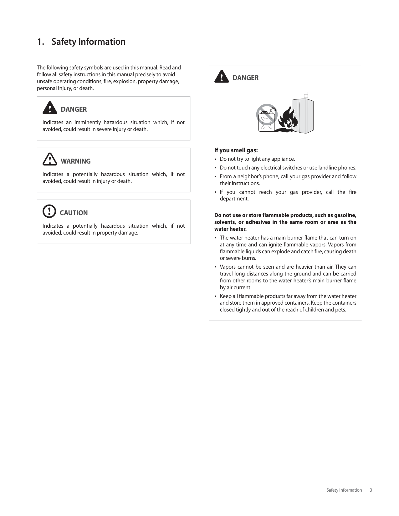
The following safety symbols are used in this manual. Read and follow all safety instructions in this manual precisely to avoid unsafe operating conditions, fire, explosion, property damage, personal injury, or death.
|DANGER
Indicates an imminently hazardous situation which, if not avoided, could result in severe injury or death.| |---|
|WARNING
Indicates a potentially hazardous situation which, if not avoided, could result in injury or death.| |---|
|CAUTION
Indicates a potentially hazardous situation which, if not avoided, could result in property damage.| |---|
|DANGER
If you smell gas: Do not try to light any appliance. Do not touch any electrical switches or use landline phones. From a neighbor’s phone, call your gas provider and follow their instructions. If you cannot reach your gas provider, call the fire department.
Do not use or store flammable products, such as gasoline, solvents, or adhesives in the same room or area as the water heater.
The water heater has a main burner flame that can turn on at any time and can ignite flammable vapors. Vapors from flammable liquids can explode and catch fire, causing death or severe burns.
Vapors cannot be seen and are heavier than air. They can travel long distances along the ground and can be carried from other rooms to the water heater’s main burner flame by air current.
Keep all flammable products far away from the water heater and store them in approved containers. Keep the containers closed tightly and out of the reach of children and pets.| |---|
3Safety Information
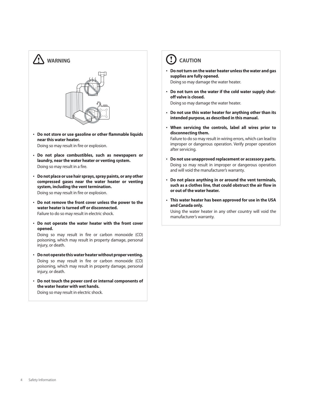
|WARNING
Do not store or use gasoline or other flammable liquids near this water heater. Doing so may result in fire or explosion.
Do not place combustibles, such as newspapers or laundry, near the water heater or venting system. Doing so may result in a fire.
Do not place or use hair sprays, spray paints, or any other compressed gases near the water heater or venting system, including the vent termination.
Doing so may result in fire or explosion.
Do not remove the front cover unless the power to the water heater is turned off or disconnected. Failure to do so may result in electric shock.
Do not operate the water heater with the front cover opened.
Doing so may result in fire or carbon monoxide (CO) poisoning, which may result in property damage, personal injury, or death.
Do not operate this water heater without proper venting. Doing so may result in fire or carbon monoxide (CO) poisoning, which may result in property damage, personal injury, or death.
Do not touch the power cord or internal components of the water heater with wet hands. Doing so may result in electric shock.| |---|
|CAUTION
Do not turn on the water heater unless the water and gas supplies are fully opened. Doing so may damage the water heater.
Do not turn on the water if the cold water supply shutoff valve is closed. Doing so may damage the water heater.
Do not use this water heater for anything other than its intended purpose, as described in this manual.
When servicing the controls, label all wires prior to disconnecting them.
Failure to do so may result in wiring errors, which can lead to improper or dangerous operation. Verify proper operation after servicing.
Do not use unapproved replacement or accessory parts. Doing so may result in improper or dangerous operation and will void the manufacturer’s warranty.
Do not place anything in or around the vent terminals, such as a clothes line, that could obstruct the air flow in or out of the water heater.
This water heater has been approved for use in the USA and Canada only.
Using the water heater in any other country will void the manufacturer’s warranty.| |---|
################### 4 Safety Information
#### 2. About the Water Heater
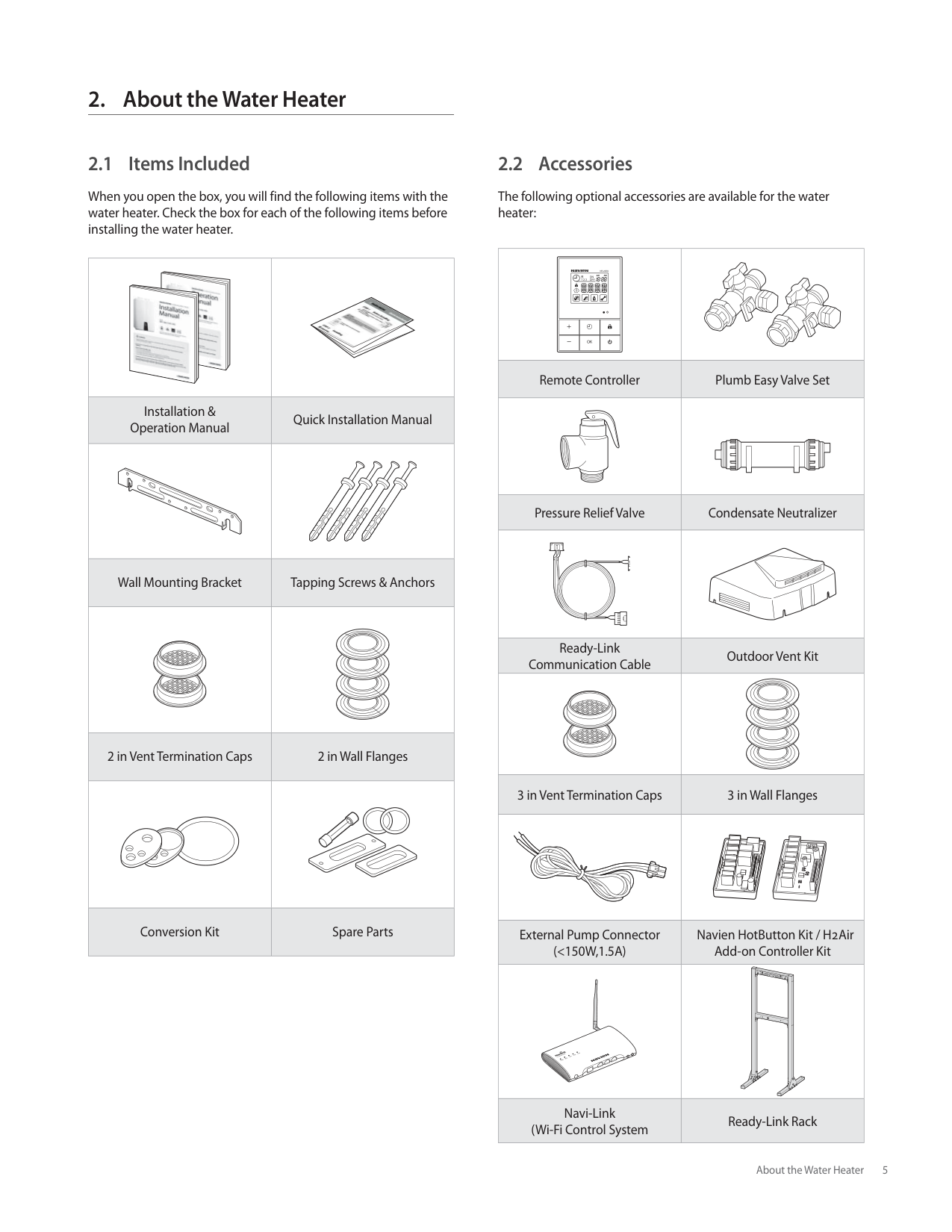
###### 2.1 Items Included
When you open the box, you will find the following items with the water heater. Check the box for each of the following items before installing the water heater.
|
|| |---|---| |Installation & Operation Manual|Quick Installation Manual| | | | |Wall Mounting Bracket|Tapping Screws & Anchors| | | | |2 in Vent Termination Caps|2 in Wall Flanges| | | | |Conversion Kit|Spare Parts|
###### 2.2 Accessories
The following optional accessories are available for the water heater:
| | | |---|---| |Remote Controller|Plumb Easy Valve Set| | | | |Pressure Relief Valve|Condensate Neutralizer| | | | |Ready-Link Communication Cable|Outdoor Vent Kit| | | | |3 in Vent Termination Caps|3 in Wall Flanges| | | | |External Pump Connector (<150W,1.5A)|Navien HotButton Kit / H2Air Add-on Controller Kit| | | | |Navi-Link (Wi-Fi Control System|Ready-Link Rack|
###### 2.3 Specifications
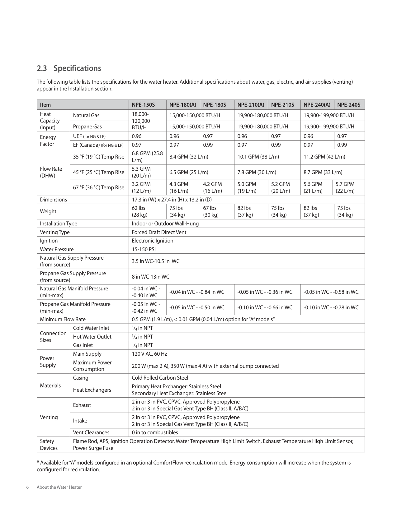
The following table lists the specifications for the water heater. Additional specifications about water, gas, electric, and air supplies (venting) appear in the Installation section.
|Item|Item|NPE-150S|NPE-180(A)|NPE-180S|NPE-210(A)|NPE-210S|NPE-240(A)|NPE-240(A)|NPE-240S| |---|---|---|---|---|---|---|---|---|---| |Heat Capacity (Input)|Natural Gas|18,000120,000 BTU/H|15,000-150,000 BTU/H|15,000-150,000 BTU/H|19,900-180,000 BTU/H|19,900-180,000 BTU/H|19,900-199,900 BTU/H|19,900-199,900 BTU/H|19,900-199,900 BTU/H| |Heat Capacity (Input)|Propane Gas|18,000120,000 BTU/H|15,000-150,000 BTU/H|15,000-150,000 BTU/H|19,900-180,000 BTU/H|19,900-180,000 BTU/H|19,900-199,900 BTU/H|19,900-199,900 BTU/H|19,900-199,900 BTU/H| |Energy Factor|UEF (for NG & LP)|0.96|0.96|0.97|0.96|0.97|0.96|0.96|0.97| |Energy Factor|EF (Canada) (for NG & LP)|0.97|0.97|0.99|0.97|0.99|0.97|0.97|0.99| |Flow Rate (DHW)|35 °F (19 °C) Temp Rise|6.8 GPM (25.8 L/m)|8.4 GPM (32 L/m)|8.4 GPM (32 L/m)|10.1 GPM (38 L/m)|10.1 GPM (38 L/m)|11.2 GPM (42 L/m)|11.2 GPM (42 L/m)|11.2 GPM (42 L/m)| |Flow Rate (DHW)|45 °F (25 °C) Temp Rise|5.3 GPM (20 L/m)|6.5 GPM (25 L/m)|6.5 GPM (25 L/m)|7.8 GPM (30 L/m)|7.8 GPM (30 L/m)|8.7 GPM (33 L/m)|8.7 GPM (33 L/m)|8.7 GPM (33 L/m)| |Flow Rate (DHW)|67 °F (36 °C) Temp Rise|3.2 GPM (12 L/m)|4.3 GPM (16 L/m)|4.2 GPM (16 L/m)|5.0 GPM (19 L/m)|5.2 GPM (20 L/m)|5.6 GPM (21 L/m)|5.7 GPM (22 L/m)|5.7 GPM (22 L/m)| |Dimensions|Dimensions|17.3 in (W) x 27.4 in (H) x 13.2 in (D)|17.3 in (W) x 27.4 in (H) x 13.2 in (D)|17.3 in (W) x 27.4 in (H) x 13.2 in (D)|17.3 in (W) x 27.4 in (H) x 13.2 in (D)|17.3 in (W) x 27.4 in (H) x 13.2 in (D)|17.3 in (W) x 27.4 in (H) x 13.2 in (D)|17.3 in (W) x 27.4 in (H) x 13.2 in (D)|17.3 in (W) x 27.4 in (H) x 13.2 in (D)| |Weight|Weight|62 lbs (28 kg)|75 lbs (34 kg)|67 lbs (30 kg)|82 lbs (37 kg)|75 lbs (34 kg)|82 lbs (37 kg)|82 lbs (37 kg)|75 lbs (34 kg)| |Installation Type|Installation Type|Indoor or Outdoor Wall-Hung|Indoor or Outdoor Wall-Hung|Indoor or Outdoor Wall-Hung|Indoor or Outdoor Wall-Hung|Indoor or Outdoor Wall-Hung|Indoor or Outdoor Wall-Hung|Indoor or Outdoor Wall-Hung|Indoor or Outdoor Wall-Hung| |Venting Type|Venting Type|Forced Draft Direct Vent|Forced Draft Direct Vent|Forced Draft Direct Vent|Forced Draft Direct Vent|Forced Draft Direct Vent|Forced Draft Direct Vent|Forced Draft Direct Vent|Forced Draft Direct Vent| |Ignition|Ignition|Electronic Ignition|Electronic Ignition|Electronic Ignition|Electronic Ignition|Electronic Ignition|Electronic Ignition|Electronic Ignition|Electronic Ignition| |Water Pressure|Water Pressure|15-150 PSI|15-150 PSI|15-150 PSI|15-150 PSI|15-150 PSI|15-150 PSI|15-150 PSI|15-150 PSI| |Natural Gas Supply Pressure (from source)|Natural Gas Supply Pressure (from source)|3.5 in WC-10.5 in WC|3.5 in WC-10.5 in WC|3.5 in WC-10.5 in WC|3.5 in WC-10.5 in WC|3.5 in WC-10.5 in WC|3.5 in WC-10.5 in WC|3.5 in WC-10.5 in WC|3.5 in WC-10.5 in WC| |Propane Gas Supply Pressure (from source)|Propane Gas Supply Pressure (from source)|8 in WC-13in WC|8 in WC-13in WC|8 in WC-13in WC|8 in WC-13in WC|8 in WC-13in WC|8 in WC-13in WC|8 in WC-13in WC|8 in WC-13in WC| |Natural Gas Manifold Pressure (min-max)|Natural Gas Manifold Pressure (min-max)|-0.04 in WC -
-0.40 in WC
|-0.04 in WC - -0.84 in WC|-0.04 in WC - -0.84 in WC|-0.05 in WC - -0.36 in WC|-0.05 in WC - -0.36 in WC|-0.05 in WC - -0.58 in WC|-0.05 in WC - -0.58 in WC|-0.05 in WC - -0.58 in WC| |Propane Gas Manifold Pressure (min-max)|Propane Gas Manifold Pressure (min-max)|-0.05 in WC -
-0.42 in WC
|-0.05 in WC - -0.50 in WC|-0.05 in WC - -0.50 in WC|-0.10 in WC - -0.66 in WC|-0.10 in WC - -0.66 in WC|-0.10 in WC - -0.78 in WC|-0.10 in WC - -0.78 in WC|-0.10 in WC - -0.78 in WC| |Minimum Flow Rate|Minimum Flow Rate|0.5 GPM (1.9 L/m), < 0.01 GPM (0.04 L/m) option for “A” models*|0.5 GPM (1.9 L/m), < 0.01 GPM (0.04 L/m) option for “A” models*|0.5 GPM (1.9 L/m), < 0.01 GPM (0.04 L/m) option for “A” models*|0.5 GPM (1.9 L/m), < 0.01 GPM (0.04 L/m) option for “A” models*|0.5 GPM (1.9 L/m), < 0.01 GPM (0.04 L/m) option for “A” models*|0.5 GPM (1.9 L/m), < 0.01 GPM (0.04 L/m) option for “A” models*|0.5 GPM (1.9 L/m), < 0.01 GPM (0.04 L/m) option for “A” models*|0.5 GPM (1.9 L/m), < 0.01 GPM (0.04 L/m) option for “A” models*| |Connection Sizes|Cold Water Inlet|3/4 in NPT|3/4 in NPT|3/4 in NPT|3/4 in NPT|3/4 in NPT|3/4 in NPT|3/4 in NPT|3/4 in NPT| |Connection Sizes|Hot Water Outlet|3/4 in NPT|3/4 in NPT|3/4 in NPT|3/4 in NPT|3/4 in NPT|3/4 in NPT|3/4 in NPT|3/4 in NPT| |Connection Sizes|Gas Inlet|3/4 in NPT|3/4 in NPT|3/4 in NPT|3/4 in NPT|3/4 in NPT|3/4 in NPT|3/4 in NPT|3/4 in NPT| |Power Supply|Main Supply|120 V AC, 60 Hz|120 V AC, 60 Hz|120 V AC, 60 Hz|120 V AC, 60 Hz|120 V AC, 60 Hz|120 V AC, 60 Hz|120 V AC, 60 Hz|120 V AC, 60 Hz| |Power Supply|Maximum Power Consumption|200 W (max 2 A), 350 W (max 4 A) with external pump connected|200 W (max 2 A), 350 W (max 4 A) with external pump connected|200 W (max 2 A), 350 W (max 4 A) with external pump connected|200 W (max 2 A), 350 W (max 4 A) with external pump connected|200 W (max 2 A), 350 W (max 4 A) with external pump connected|200 W (max 2 A), 350 W (max 4 A) with external pump connected|200 W (max 2 A), 350 W (max 4 A) with external pump connected|200 W (max 2 A), 350 W (max 4 A) with external pump connected| |Materials|Casing|Cold Rolled Carbon Steel|Cold Rolled Carbon Steel|Cold Rolled Carbon Steel|Cold Rolled Carbon Steel|Cold Rolled Carbon Steel|Cold Rolled Carbon Steel|Cold Rolled Carbon Steel|Cold Rolled Carbon Steel| |Materials|Heat Exchangers|Primary Heat Exchanger: Stainless Steel Secondary Heat Exchanger: Stainless Steel|Primary Heat Exchanger: Stainless Steel Secondary Heat Exchanger: Stainless Steel|Primary Heat Exchanger: Stainless Steel Secondary Heat Exchanger: Stainless Steel|Primary Heat Exchanger: Stainless Steel Secondary Heat Exchanger: Stainless Steel|Primary Heat Exchanger: Stainless Steel Secondary Heat Exchanger: Stainless Steel|Primary Heat Exchanger: Stainless Steel Secondary Heat Exchanger: Stainless Steel|Primary Heat Exchanger: Stainless Steel Secondary Heat Exchanger: Stainless Steel|Primary Heat Exchanger: Stainless Steel Secondary Heat Exchanger: Stainless Steel|
|Venting|Exhaust|2 in or 3 in PVC, CPVC, Approved Polypropylene 2 in or 3 in Special Gas Vent Type BH (Class II, A/B/C)|2 in or 3 in PVC, CPVC, Approved Polypropylene 2 in or 3 in Special Gas Vent Type BH (Class II, A/B/C)|2 in or 3 in PVC, CPVC, Approved Polypropylene 2 in or 3 in Special Gas Vent Type BH (Class II, A/B/C)|2 in or 3 in PVC, CPVC, Approved Polypropylene 2 in or 3 in Special Gas Vent Type BH (Class II, A/B/C)|2 in or 3 in PVC, CPVC, Approved Polypropylene 2 in or 3 in Special Gas Vent Type BH (Class II, A/B/C)|2 in or 3 in PVC, CPVC, Approved Polypropylene 2 in or 3 in Special Gas Vent Type BH (Class II, A/B/C)|2 in or 3 in PVC, CPVC, Approved Polypropylene 2 in or 3 in Special Gas Vent Type BH (Class II, A/B/C)|2 in or 3 in PVC, CPVC, Approved Polypropylene 2 in or 3 in Special Gas Vent Type BH (Class II, A/B/C)| |Venting|Intake|2 in or 3 in PVC, CPVC, Approved Polypropylene 2 in or 3 in Special Gas Vent Type BH (Class II, A/B/C)|2 in or 3 in PVC, CPVC, Approved Polypropylene 2 in or 3 in Special Gas Vent Type BH (Class II, A/B/C)|2 in or 3 in PVC, CPVC, Approved Polypropylene 2 in or 3 in Special Gas Vent Type BH (Class II, A/B/C)|2 in or 3 in PVC, CPVC, Approved Polypropylene 2 in or 3 in Special Gas Vent Type BH (Class II, A/B/C)|2 in or 3 in PVC, CPVC, Approved Polypropylene 2 in or 3 in Special Gas Vent Type BH (Class II, A/B/C)|2 in or 3 in PVC, CPVC, Approved Polypropylene 2 in or 3 in Special Gas Vent Type BH (Class II, A/B/C)|2 in or 3 in PVC, CPVC, Approved Polypropylene 2 in or 3 in Special Gas Vent Type BH (Class II, A/B/C)|2 in or 3 in PVC, CPVC, Approved Polypropylene 2 in or 3 in Special Gas Vent Type BH (Class II, A/B/C)| |Venting|Vent Clearances|0 in to combustibles|0 in to combustibles|0 in to combustibles|0 in to combustibles|0 in to combustibles|0 in to combustibles|0 in to combustibles|0 in to combustibles| |Safety Devices|Flame Rod, APS, Ignition Operation Detector, Water Temperature High Limit Switch, Exhaust Temperature High Limit Sensor, Power Surge Fuse|Flame Rod, APS, Ignition Operation Detector, Water Temperature High Limit Switch, Exhaust Temperature High Limit Sensor, Power Surge Fuse|Flame Rod, APS, Ignition Operation Detector, Water Temperature High Limit Switch, Exhaust Temperature High Limit Sensor, Power Surge Fuse|Flame Rod, APS, Ignition Operation Detector, Water Temperature High Limit Switch, Exhaust Temperature High Limit Sensor, Power Surge Fuse|Flame Rod, APS, Ignition Operation Detector, Water Temperature High Limit Switch, Exhaust Temperature High Limit Sensor, Power Surge Fuse|Flame Rod, APS, Ignition Operation Detector, Water Temperature High Limit Switch, Exhaust Temperature High Limit Sensor, Power Surge Fuse|Flame Rod, APS, Ignition Operation Detector, Water Temperature High Limit Switch, Exhaust Temperature High Limit Sensor, Power Surge Fuse|Flame Rod, APS, Ignition Operation Detector, Water Temperature High Limit Switch, Exhaust Temperature High Limit Sensor, Power Surge Fuse|Flame Rod, APS, Ignition Operation Detector, Water Temperature High Limit Switch, Exhaust Temperature High Limit Sensor, Power Surge Fuse|
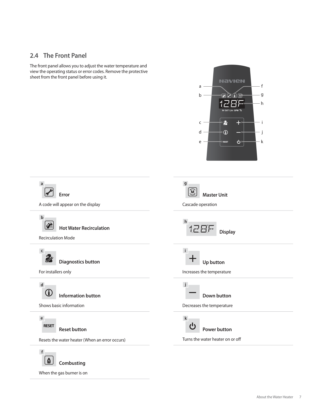
###### 2.4 The Front Panel
The front panel allows you to adjust the water temperature and view the operating status or error codes. Remove the protective sheet from the front panel before using it.
|g| |---|
|a| |---|
Error
Master Unit A code will appear on the display Cascade operation
|b| |---|
|h| |---|
Hot Water Recirculation
Display Recirculation Mode
|c| |---|
Diagnostics button
|i| |---|
############ Up button
For installers only Increases the temperature
|d| |---|
Information button
|j| |---|
############ Down button
Shows basic information Decreases the temperature
|e| |---|
Reset button
|k| |---|
############ Power button
Resets the water heater (When an error occurs) Turns the water heater on or off
|f| |---|
############ Combusting
When the gas burner is on
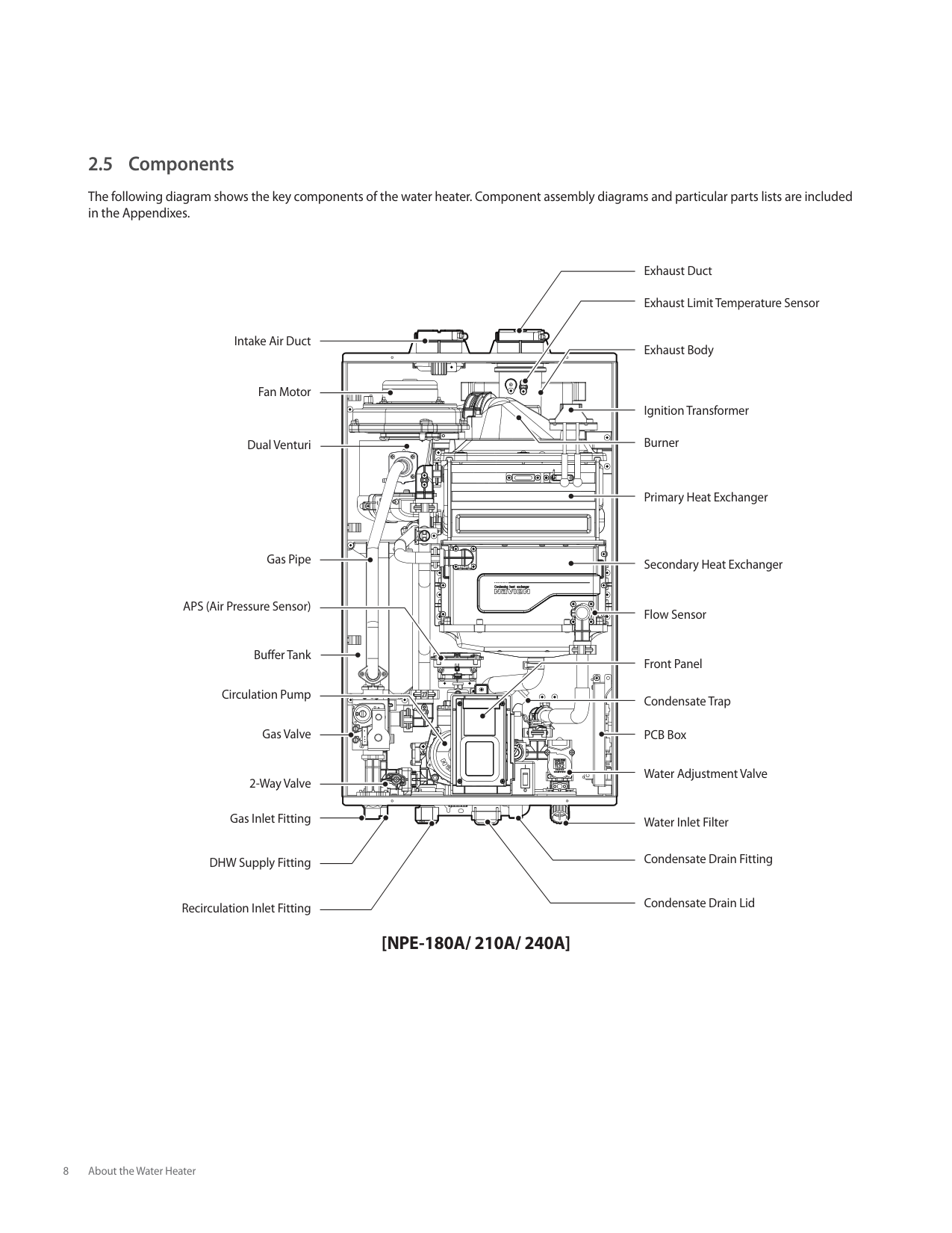
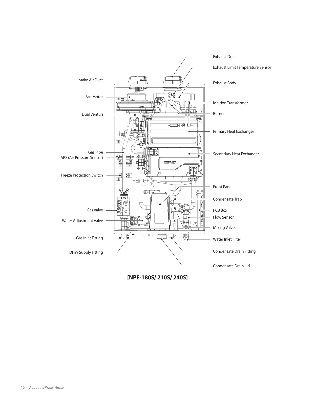
###### 2.5 Components
The following diagram shows the key components of the water heater. Component assembly diagrams and particular parts lists are included in the Appendixes.
Intake Air Duct
| | | | | | | | | | |---|---|---|---|---|---|---|---|---| | | | | | | | | | |
Fan Motor
Dual Venturi
| | | | | | | | | | | | |---|---|---|---|---|---|---|---|---|---|---| | | | | | | | | | | | |
Exhaust Duct Exhaust Limit Temperature Sensor
Exhaust Body
Ignition Transformer
Burner
Primary Heat Exchanger
Gas Pipe
APS (Air Pressure Sensor)
Buffer Tank
Circulation Pump
Gas Valve
2-Way Valve
Gas Inlet Fitting
DHW Supply Fitting
Recirculation Inlet Fitting
####### [NPE-180A/ 210A/ 240A]
Secondary Heat Exchanger
Flow Sensor
Front Panel
Condensate Trap
PCB Box
Water Adjustment Valve
Water Inlet Filter
Condensate Drain Fitting
Condensate Drain Lid
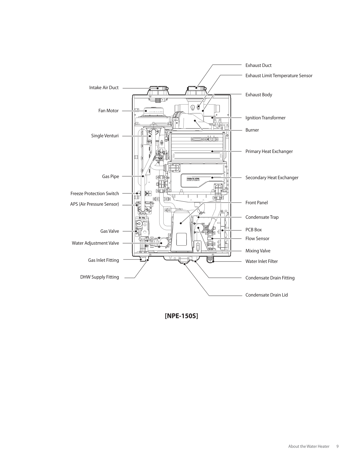
Fan Motor
Ignition Transformer
Burner
| | | |---|---| | | | | | |
Single Venturi
Primary Heat Exchanger
| | | | |---|---|---| | | | | | | | |
Gas Pipe
Secondary Heat Exchanger
Freeze Protection Switch
Front Panel
APS (Air Pressure Sensor)
Condensate Trap
PCB Box
Gas Valve
Flow Sensor
Water Adjustment Valve
Mixing Valve Water Inlet Filter
Gas Inlet Fitting
DHW Supply Fitting
Condensate Drain Fitting
Condensate Drain Lid
####### [NPE-150S]
| | | | |---|---|---| | | | | | | | | | | | | | | | | | | | | | | | | | | | | | | | | | | | | | | | | | | | | | | | | | | | | | | | |
Fan Motor
Ignition Transformer
Burner
Dual Venturi
Primary Heat Exchanger
Gas Pipe APS (Air Pressure Sensor)
Secondary Heat Exchanger
Freeze Protection Switch
Front Panel
Condensate Trap
Gas Valve
PCB Box
Flow Sensor
Water Adjustment Valve
Mixing Valve
Gas Inlet Fitting
Water Inlet Filter
DHW Supply Fitting
Condensate Drain Fitting
####### [NPE-180S/ 210S/ 240S]
Condensate Drain Lid
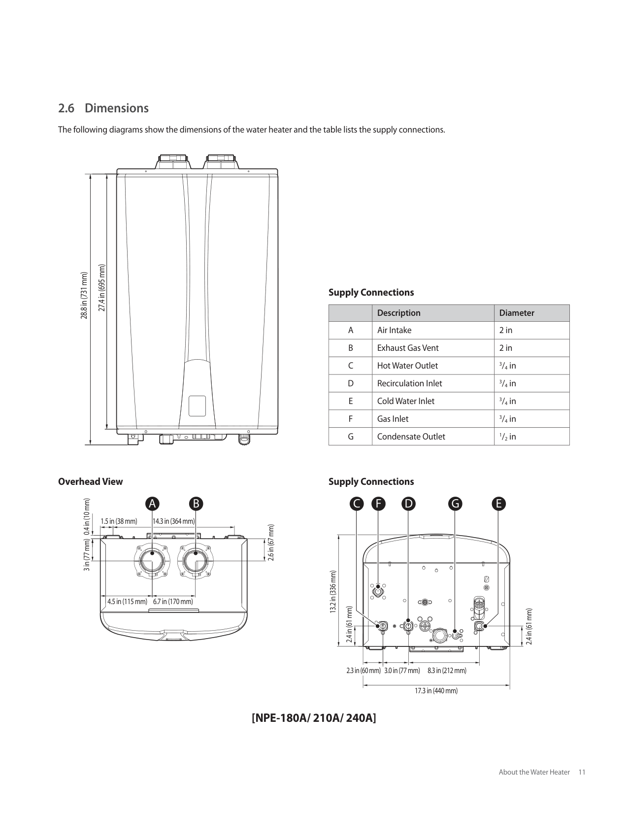
###### 2.6 Dimensions
The following diagrams show the dimensions of the water heater and the table lists the supply connections.
| | | | | | |---|---|---|---|---| | | | | | |
| | | | | | |---|---|---|---|---| | | | | | |
27.4 in (695 mm) 28.8 in (731 mm)
Supply Connections
| |Description|Diameter| |---|---|---| |A|Air Intake|2 in| |B|Exhaust Gas Vent|2 in| |C|Hot Water Outlet|3/4 in| |D|Recirculation Inlet|3/4 in| |E|Cold Water Inlet|3/4 in| |F|Gas Inlet|3/4 in| |G|Condensate Outlet|1/2 in|
Overhead View
A B
0.4 in (10 mm)
1.5 in (38 mm) 14.3 in (364 mm)
2.6 in (67 mm)
3 in (77 mm)
6.7 in (170 mm)4.5 in (115 mm)
Supply Connections
C F D G E
13.2 in (336 mm)
2.4 in (61 mm)
####### [NPE-180A/ 210A/ 240A]
| | | | | |---|---|---|---| | | | | |
27.4 in (695 mm) 28.8 in (731 mm)
| | | |---|---| | | |
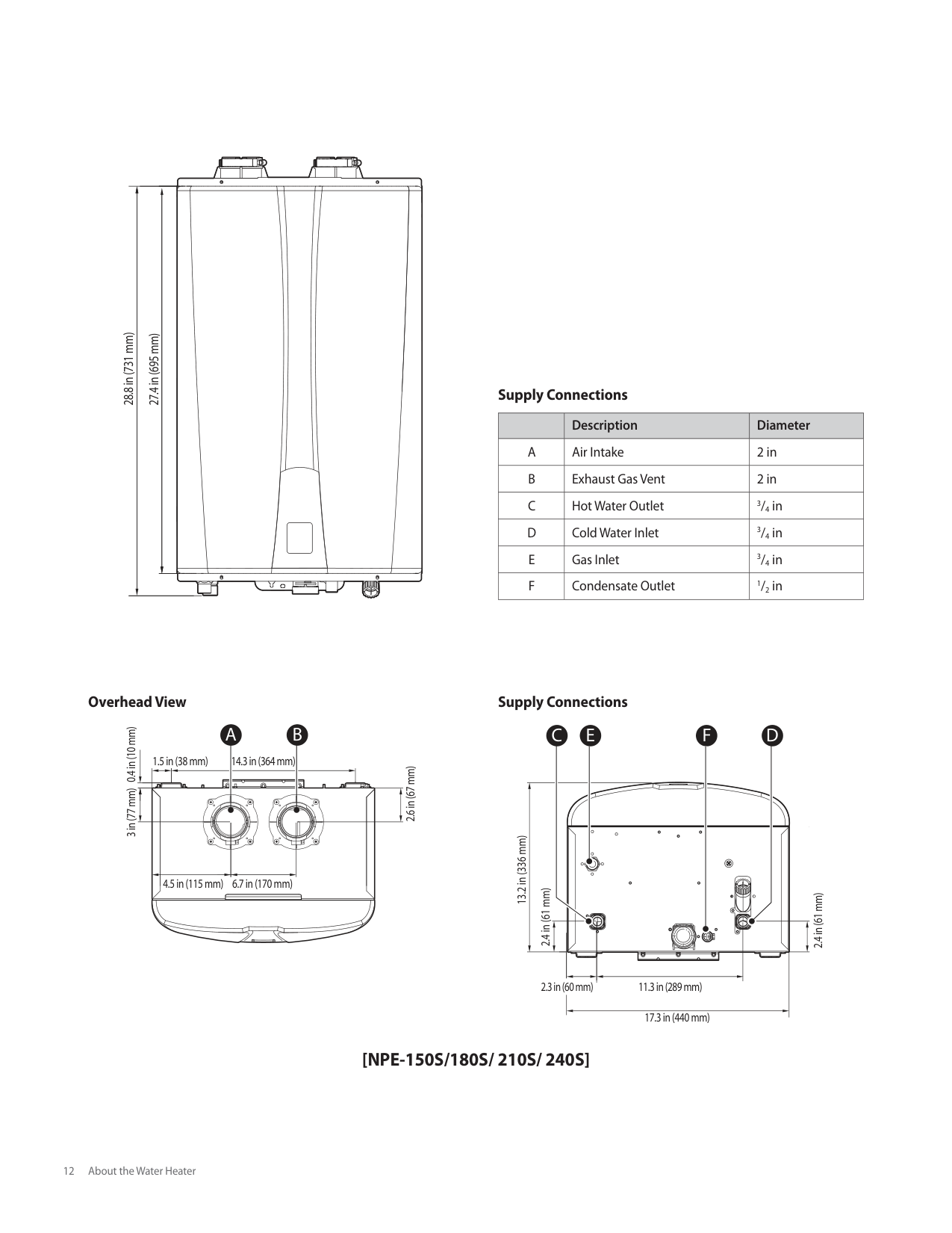
Supply Connections
| |Description|Diameter| |---|---|---| |A|Air Intake|2 in| |B|Exhaust Gas Vent|2 in| |C|Hot Water Outlet|3/4 in| |D|Cold Water Inlet|3/4 in| |E|Gas Inlet|3/4 in| |F|Condensate Outlet|1/2 in|
Overhead View
A B
0.4 in (10 mm)
1.5 in (38 mm) 14.3 in (364 mm)
2.6 in (67 mm)
3 in (77 mm)
6.7 in (170 mm)4.5 in (115 mm)
Supply Connections
######## C F DE
13.2 in (336 mm)
| | | |---|---| | | |
2.4 in (61 mm)
2.4 in (61 mm)
| | | |---|---| | | |
2.3 in (60 mm) 11.3 in (289 mm)
17.3 in (440 mm)
####### [NPE-150S/180S/ 210S/ 240S]
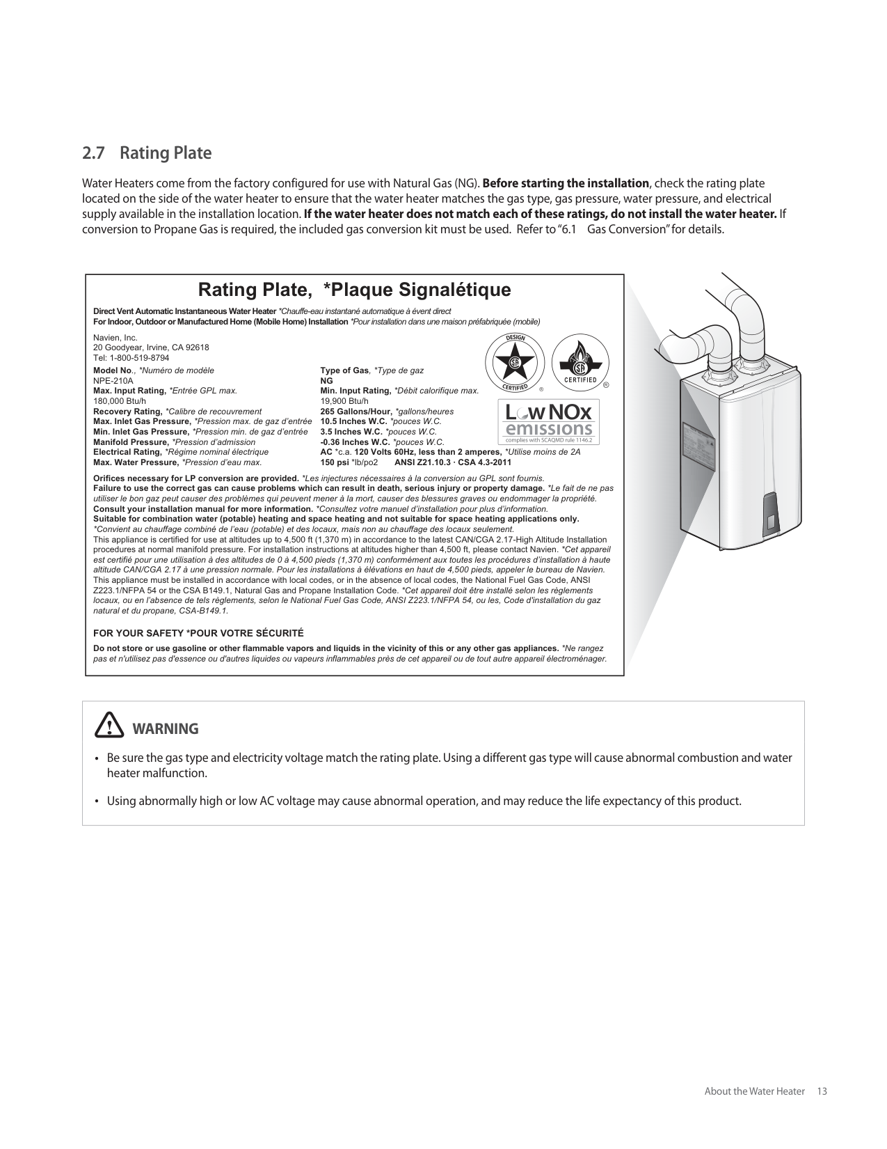
###### 2.7 Rating Plate
Water Heaters come from the factory configured for use with Natural Gas (NG). Before starting the installation, check the rating plate located on the side of the water heater to ensure that the water heater matches the gas type, gas pressure, water pressure, and electrical supply available in the installation location. If the water heater does not match each of these ratings, do not install the water heater. If conversion to Propane Gas is required, the included gas conversion kit must be used. Refer to “6.1 Gas Conversion” for details.
|Rating Plate, *Plaque Signalétique
Direct Vent Automatic Instantaneous Water Heater *Chauffe-eau instantané automatique à évent direct For Indoor, Outdoor or Manufactured Home (Mobile Home) Installation *Pour installation dans une maison préfabriquée (mobile)
Navien, Inc. 20 Goodyear, Irvine, CA 92618 Tel: 1-800-519-8794
Orifices necessary for LP conversion are provided. *Les injectures nécessaires à la conversion au GPL sont fournis. Failure to use the correct gas can cause problems which can result in death, serious injury or property damage. *Le fait de ne pas utiliser le bon gaz peut causer des problèmes qui peuvent mener à la mort, causer des blessures graves ou endommager la propriété. Consult your installation manual for more information. *Consultez votre manuel d’installation pour plus d’information. Suitable for combination water (potable) heating and space heating and not suitable for space heating applications only.
*Convient au chauffage combiné de l’eau (potable) et des locaux, mais non au chauffage des locaux seulement. This appliance is certified for use at altitudes up to 4,500 ft (1,370 m) in accordance to the latest CAN/CGA 2.17-High Altitude Installation procedures at normal manifold pressure. For installation instructions at altitudes higher than 4,500 ft, please contact Navien. *Cet appareil est certifié pour une utilisation à des altitudes de 0 à 4,500 pieds (1,370 m) conformément aux toutes les procédures d’installation à haute altitude CAN/CGA 2.17 à une pression normale. Pour les installations à élévations en haut de 4,500 pieds, appeler le bureau de Navien. This appliance must be installed in accordance with local codes, or in the absence of local codes, the National Fuel Gas Code, ANSI Z223.1/NFPA 54 or the CSA B149.1, Natural Gas and Propane Installation Code. *Cet appareil doit être installé selon les règlements locaux, ou en l’absence de tels règlements, selon le National Fuel Gas Code, ANSI Z223.1/NFPA 54, ou les, Code d'installation du gaz natural et du propane, CSA-B149.1.
Model No., *Numéro de modèle NPE-210A Max. Input Rating, *Entrée GPL max. 180,000 Btu/h Recovery Rating, *Calibre de recouvrement Max. Inlet Gas Pressure, *Pression max. de gaz d’entrée Min. Inlet Gas Pressure, *Pression min. de gaz d’entrée Manifold Pressure, *Pression d’admission Electrical Rating, *Régime nominal électrique Max. Water Pressure, *Pression d’eau max.
Type of Gas, *Type de gaz NG Min. Input Rating, *Débit calorifique max. 19,900 Btu/h 265 Gallons/Hour, *gallons/heures 10.5 Inches W.C. *pouces W.C. 3.5 Inches W.C. *pouces W.C.
-0.36 Inches W.C. *pouces W.C. AC *c.a. 120 Volts 60Hz, less than 2 amperes, *Utilise moins de 2A 150 psi *lb/po2 ANSI Z21.10.3 · CSA 4.3-2011
FOR YOUR SAFETY *POUR VOTRE SÉCURITÉ Do not store or use gasoline or other flammable vapors and liquids in the vicinity of this or any other gas appliances. *Ne rangez pas et n'utilisez pas d'essence ou d'autres liquides ou vapeurs inflammables près de cet appareil ou de tout autre appareil électroménager.| |---|


|WARNING
Be sure the gas type and electricity voltage match the rating plate. Using a different gas type will cause abnormal combustion and water heater malfunction.
Using abnormally high or low AC voltage may cause abnormal operation, and may reduce the life expectancy of this product.| |---|
#### 3. Installing the Water Heater
###### 3.1 Choosing an Installation Location
When choosing an installation location, you must ensure that the location provides adequate clearance for the water heater, adequate venting and drainage options, and sufficient access to gas, water, and electrical supplies. Carefully consider the following factors when choosing an installation location:
################ About Water Quality
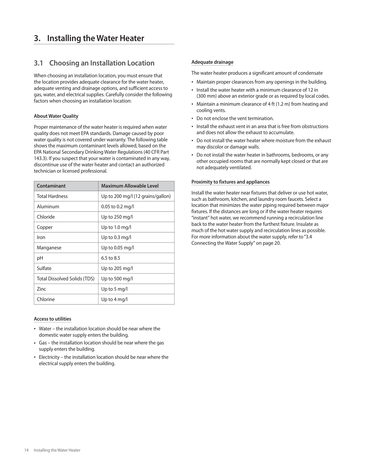
Proper maintenance of the water heater is required when water quality does not meet EPA standards. Damage caused by poor water quality is not covered under warranty. The following table shows the maximum contaminant levels allowed, based on the EPA National Secondary Drinking Water Regulations (40 CFR Part 143.3). If you suspect that your water is contaminated in any way, discontinue use of the water heater and contact an authorized technician or licensed professional.
|Contaminant|Maximum Allowable Level| |---|---| |Total Hardness|Up to 200 mg/l (12 grains/gallon)| |Aluminum|0.05 to 0.2 mg/l| |Chloride|Up to 250 mg/l| |Copper|Up to 1.0 mg/l| |Iron|Up to 0.3 mg/l| |Manganese|Up to 0.05 mg/l| |pH|6.5 to 8.5| |Sulfate|Up to 205 mg/l| |Total Dissolved Solids (TDS)|Up to 500 mg/l| |Zinc|Up to 5 mg/l| |Chlorine|Up to 4 mg/l|
Access to utilities Water – the installation location should be near where the domestic water supply enters the building. Gas – the installation location should be near where the gas supply enters the building. Electricity – the installation location should be near where the electrical supply enters the building.
Adequate drainage The water heater produces a significant amount of condensate
Maintain proper clearances from any openings in the building. Install the water heater with a minimum clearance of 12 in (300 mm) above an exterior grade or as required by local codes. Maintain a minimum clearance of 4 ft (1.2 m) from heating and cooling vents. Do not enclose the vent termination. Install the exhaust vent in an area that is free from obstructions and does not allow the exhaust to accumulate. Do not install the water heater where moisture from the exhaust may discolor or damage walls.
Do not install the water heater in bathrooms, bedrooms, or any other occupied rooms that are normally kept closed or that are not adequately ventilated.
################ Proximity to fixtures and appliances
Install the water heater near fixtures that deliver or use hot water, such as bathroom, kitchen, and laundry room faucets. Select a location that minimizes the water piping required between major fixtures. If the distances are long or if the water heater requires “instant“ hot water, we recommend running a recirculation line back to the water heater from the furthest fixture. Insulate as much of the hot water supply and recirculation lines as possible. For more information about the water supply, refer to “3.4 Connecting the Water Supply“ on page 20.
################ Adequate installation clearances
Install the water heater in an area that allows for service and maintenance access to utility connections, piping, filters, and traps. Based on the installation location, ensure the following clearances are maintained:
|Clearance from:|Indoor Installation|Outdoor Installation| |---|---|---| |Top|9 in (229 mm) minimum|36 in (900 mm) minimum| |Back|0.5 in (20 mm) minimum|0.5 in (20 mm) minimum| |Front|4 in (100 mm) minimum|24 in (600 mm) minimum| |Sides|3 in (76 mm) minimum|3 in (76 mm) minimum| |Bottom|12 in (300 mm) minimum|12 in (300 mm) minimum|
Clean, debris and chemical-free combustion air Do not install the water heater in areas where dust and debris may accumulate or where hair sprays, spray detergents, chlorine, or similar chemicals are used. Do not install the water heater in areas where gasoline or other flammables are used or stored. Ensure that combustible materials are stored away from the water heater and that hanging laundry or similar items do not obstruct access to the water heater or its venting.
In commercial locations, do not install the water heater in areas with greasy fumes or heavy amounts of steam or take measures to prevent fumes and steam from entering the water heater.
################ High Elevation Installations
This water heater may be installed at elevations up to 10,100 ft (3,078 m) for use with Natural Gas and 4,500 ft (1,370 m) for use with Propane. Refer to “3.8.2 Setting the Front Panel DIP Switches” on page 37 for the appropriate altitude setting.
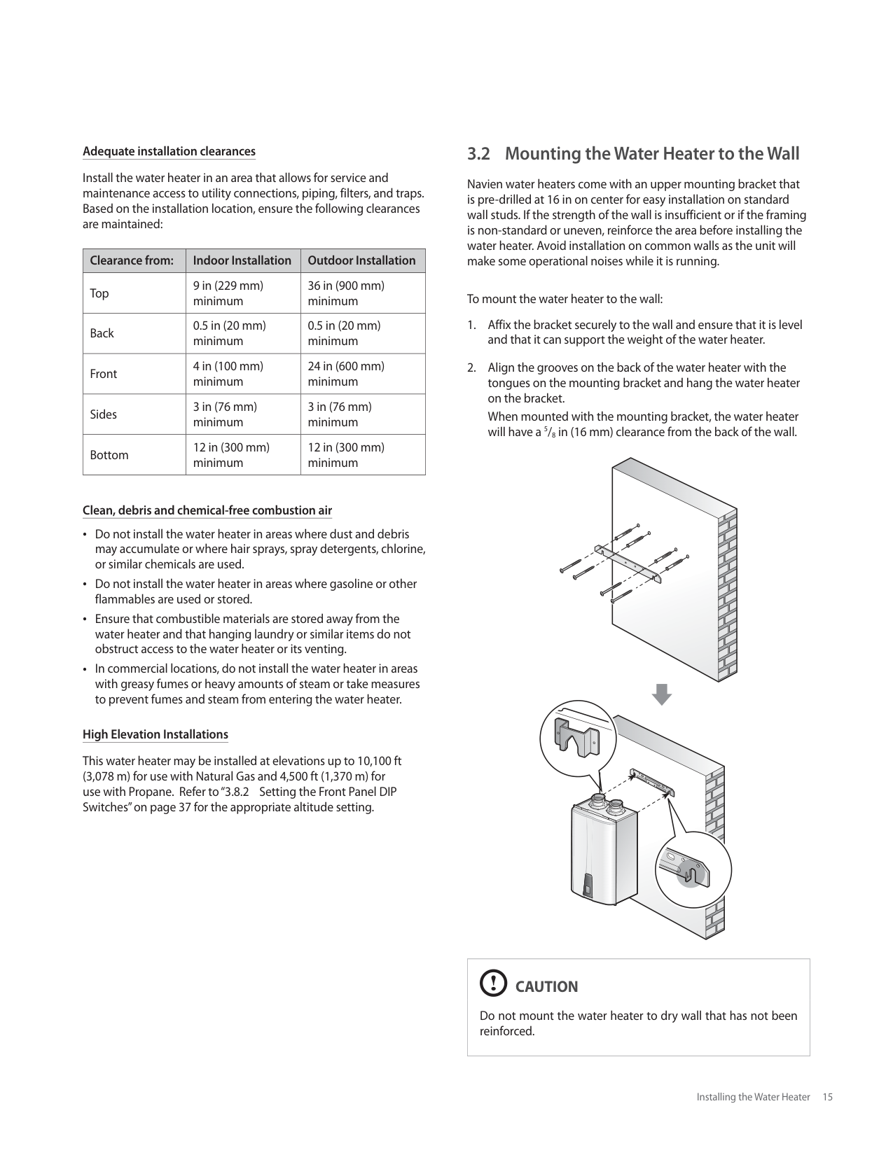
###### 3.2 Mounting the Water Heater to the Wall
Navien water heaters come with an upper mounting bracket that is pre-drilled at 16 in on center for easy installation on standard wall studs. If the strength of the wall is insufficient or if the framing is non-standard or uneven, reinforce the area before installing the water heater. Avoid installation on common walls as the unit will make some operational noises while it is running.
To mount the water heater to the wall:


|CAUTION
Do not mount the water heater to dry wall that has not been reinforced.| |---|
###### 3.3 Connecting the Gas Supply
|WARNING
Before connecting the gas supply, determine the gas type and pressure for the water heater by referring to the rating plate. Use only the same gas type indicated on the rating plate. Using a different gas type will result in abnormal combustion and malfunction of the water heater. Gas supplies should be connected by a licensed professional only.
The appliance and its gas connection must be leak tested before placing the appliance in operation.
This water heater cannot be converted from natural gas to propane or vice versa without a Navien gas conversion kit. Do not attempt a field conversion of this water heater without a Navien gas conversion kit. Doing so will result in dangerous operating conditions and will void the warranty.| |---|
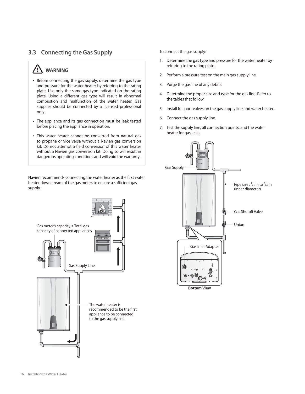
Navien recommends connecting the water heater as the first water heater downstream of the gas meter, to ensure a sufficient gas supply.
Gas meter’s capacity ≥ Total gas capacity of connected appliances
| | | |---|---| | | |
Gas Supply Line
The water heater is recommended to be the first appliance to be connected to the gas supply line.
To connect the gas supply:
| | | |---|---| | | |
Gas Supply
Pipe size : 1/2 in to 3/4 in (inner diameter)
Gas Shutoff Valve
Union
Gas Inlet Adapter
| | | |---|---| | | |
Bottom View
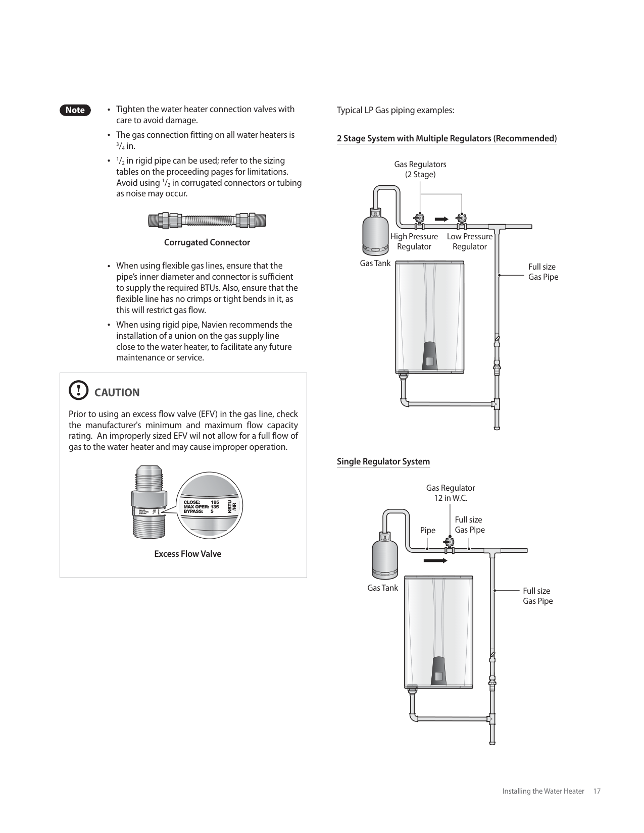
Note Tighten the water heater connection valves with care to avoid damage. The gas connection fitting on all water heaters is 3/4 in. 1/2 in rigid pipe can be used; refer to the sizing tables on the proceeding pages for limitations. Avoid using 1/2 in corrugated connectors or tubing as noise may occur.
################ Corrugated Connector
When using flexible gas lines, ensure that the pipe’s inner diameter and connector is sufficient to supply the required BTUs. Also, ensure that the flexible line has no crimps or tight bends in it, as this will restrict gas flow.
When using rigid pipe, Navien recommends the installation of a union on the gas supply line close to the water heater, to facilitate any future maintenance or service.
|CAUTION
Prior to using an excess flow valve (EFV) in the gas line, check the manufacturer's minimum and maximum flow capacity rating. An improperly sized EFV wil not allow for a full flow of gas to the water heater and may cause improper operation.
CLOSE: 195 MAX OPER: 135 BYPASS: 5
KBTU
/HR
CLOSE: 195 MAX OPER: 135 BYPASS: 5
KBTU
/HR
Excess Flow Valve| |---|
Typical LP Gas piping examples:
################ 2 Stage System with Multiple Regulators (Recommended)
Gas Regulators (2 Stage)
| | |---| | | | |
| | | |---|---| | | | | | | | | | | | | | | | | | | | | |
High Pressure Regulator
Low Pressure Regulator
Gas Tank
Full size Gas Pipe
################ Single Regulator System
Gas Regulator 12 in W.C.
Full size Gas PipePipe
| | | | | | | |---|---|---|---|---|---| | | | | | | |
| | | |---|---| | | | | | | | | | | | | | | | | | | | | |
Gas Tank Full size Gas Pipe
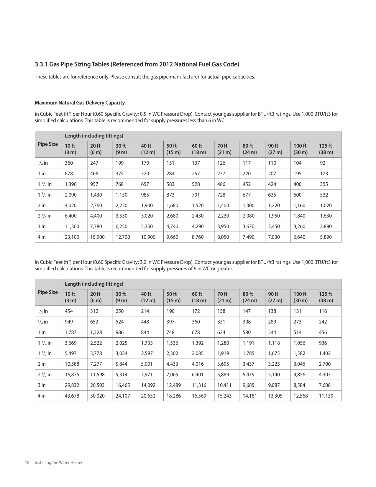
################ Maximum Natural Gas Delivery Capacity
in Cubic Feet (ft3) per Hour (0.60 Specific Gravity; 0.5 in WC Pressure Drop). Contact your gas supplier for BTU/ft3 ratings. Use 1,000 BTU/ft3 for simplified calculations. This table is recommended for supply pressures less than 6 in WC.
|Pipe Size|Length (including fittings)|Length (including fittings)|Length (including fittings)|Length (including fittings)|Length (including fittings)|Length (including fittings)|Length (including fittings)|Length (including fittings)|Length (including fittings)|Length (including fittings)|Length (including fittings)| |---|---|---|---|---|---|---|---|---|---|---|---| |Pipe Size|10 ft (3 m)|20 ft (6 m)|30 ft (9 m)|40 ft (12 m)|50 ft (15 m)|60 ft (18 m)|70 ft (21 m)|80 ft (24 m)|90 ft (27 m)|100 ft (30 m)|125 ft (38 m)| |3/4 in|360|247|199|170|151|137|126|117|110|104|92| |1 in|678|466|374|320|284|257|237|220|207|195|173| |1 1/4 in|1,390|957|768|657|583|528|486|452|424|400|355| |1 1/2 in|2,090|1,430|1,150|985|873|791|728|677|635|600|532| |2 in|4,020|2,760|2,220|1,900|1,680|1,520|1,400|1,300|1,220|1,160|1,020| |2 1/2 in|6,400|4,400|3,530|3,020|2,680|2,430|2,230|2,080|1,950|1,840|1,630| |3 in|11,300|7,780|6,250|5,350|4,740|4,290|3,950|3,670|3,450|3,260|2,890| |4 in|23,100|15,900|12,700|10,900|9,660|8,760|8,050|7,490|7,030|6,640|5,890|
in Cubic Feet (ft3) per Hour (0.60 Specific Gravity; 3.0 in WC Pressure Drop). Contact your gas supplier for BTU/ft3 ratings. Use 1,000 BTU/ft3 for simplified calculations. This table is recommended for supply pressures of 6 in WC or greater.
|Pipe Size|Length (including fittings)|Length (including fittings)|Length (including fittings)|Length (including fittings)|Length (including fittings)|Length (including fittings)|Length (including fittings)|Length (including fittings)|Length (including fittings)|Length (including fittings)|Length (including fittings)| |---|---|---|---|---|---|---|---|---|---|---|---| |Pipe Size|10 ft (3 m)|20 ft (6 m)|30 ft (9 m)|40 ft (12 m)|50 ft (15 m)|60 ft (18 m)|70 ft (21 m)|80 ft (24 m)|90 ft (27 m)|100 ft (30 m)|125 ft (38 m)| |1/2 in|454|312|250|214|190|172|158|147|138|131|116| |3/4 in|949|652|524|448|397|360|331|308|289|273|242| |1 in|1,787|1,228|986|844|748|678|624|580|544|514|456| |1 1/4 in|3,669|2,522|2,025|1,733|1,536|1,392|1,280|1,191|1,118|1,056|936| |1 1/2 in|5,497|3,778|3,034|2,597|2,302|2,085|1,919|1,785|1,675|1,582|1,402| |2 in|10,588|7,277|5,844|5,001|4,433|4,016|3,695|3,437|3,225|3,046|2,700| |2 1/2 in|16,875|11,598|9,314|7,971|7,065|6,401|5,889|5,479|5,140|4,856|4,303| |3 in|29,832|20,503|16,465|14,092|12,489|11,316|10,411|9,685|9,087|8,584|7,608| |4 in|43,678|30,020|24,107|20,632|18,286|16,569|15,243|14,181|13,305|12,568|11,139|
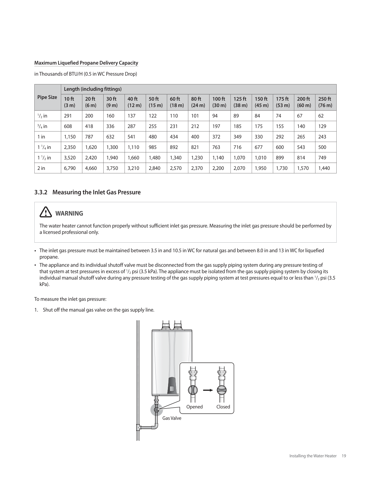
Maximum Liquefied Propane Delivery Capacity in Thousands of BTU/H (0.5 in WC Pressure Drop)
|Pipe Size|Length (including fittings)|Length (including fittings)|Length (including fittings)|Length (including fittings)|Length (including fittings)|Length (including fittings)|Length (including fittings)|Length (including fittings)|Length (including fittings)|Length (including fittings)|Length (including fittings)|Length (including fittings)|Length (including fittings)| |---|---|---|---|---|---|---|---|---|---|---|---|---|---| |Pipe Size|10 ft (3 m)|20 ft (6 m)|30 ft (9 m)|40 ft (12 m)|50 ft (15 m)|60 ft (18 m)|80 ft (24 m)|100 ft (30 m)|125 ft (38 m)|150 ft (45 m)|175 ft (53 m)|200 ft (60 m)|250 ft (76 m)| |1/2 in|291|200|160|137|122|110|101|94|89|84|74|67|62| |3/4 in|608|418|336|287|255|231|212|197|185|175|155|140|129| |1 in|1,150|787|632|541|480|434|400|372|349|330|292|265|243| |1 1/4 in|2,350|1,620|1,300|1,110|985|892|821|763|716|677|600|543|500| |1 1/2 in|3,520|2,420|1,940|1,660|1,480|1,340|1,230|1,140|1,070|1,010|899|814|749| |2 in|6,790|4,660|3,750|3,210|2,840|2,570|2,370|2,200|2,070|1,950|1,730|1,570|1,440|
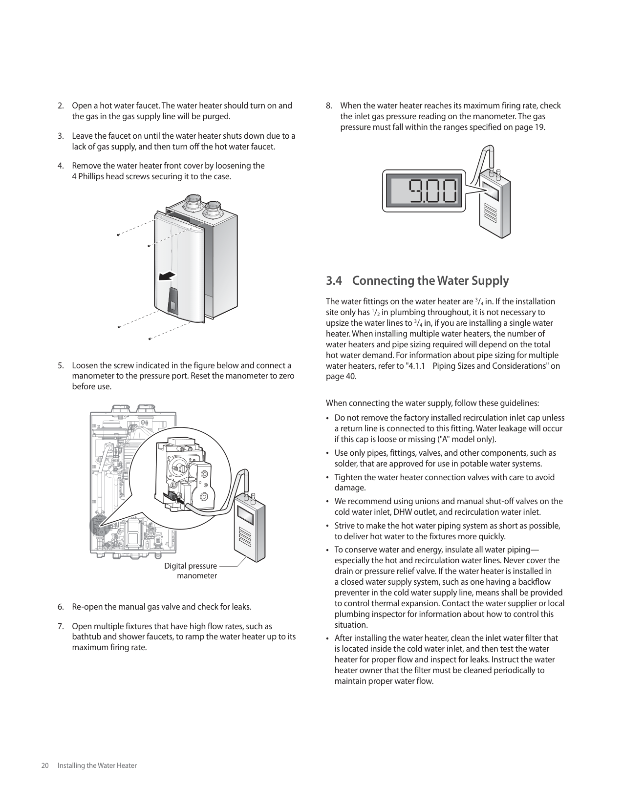
########## 3.3.2 Measuring the Inlet Gas Pressure
|WARNING
The water heater cannot function properly without sufficient inlet gas pressure. Measuring the inlet gas pressure should be performed by a licensed professional only.| |---|
The inlet gas pressure must be maintained between 3.5 in and 10.5 in WC for natural gas and between 8.0 in and 13 in WC for liquefied propane. The appliance and its individual shutoff valve must be disconnected from the gas supply piping system during any pressure testing of that system at test pressures in excess of 1/2 psi (3.5 kPa). The appliance must be isolated from the gas supply piping system by closing its individual manual shutoff valve during any pressure testing of the gas supply piping system at test pressures equal to or less than 1/2 psi (3.5 kPa).
To measure the inlet gas pressure:
| | | |---|---| | | | | | |
Opened Closed
Gas Valve


| | | | | | | | | |---|---|---|---|---|---|---|---| | | | | | | | | |
| | | | | |---|---|---|---| | | | | | | | | | | | | | | | | | | | | | | | | | | | | | | | | | | | | | | | | | | | | | | | | | |
| | | |---|---|
Digital pressure manometer
###### 3.4 Connecting the Water Supply
The water fittings on the water heater are 3/4 in. If the installation site only has 1/2 in plumbing throughout, it is not necessary to upsize the water lines to 3/4 in, if you are installing a single water heater. When installing multiple water heaters, the number of water heaters and pipe sizing required will depend on the total hot water demand. For information about pipe sizing for multiple water heaters, refer to "4.1.1 Piping Sizes and Considerations" on page 40.
When connecting the water supply, follow these guidelines: Do not remove the factory installed recirculation inlet cap unless a return line is connected to this fitting. Water leakage will occur if this cap is loose or missing ("A" model only). Use only pipes, fittings, valves, and other components, such as solder, that are approved for use in potable water systems. Tighten the water heater connection valves with care to avoid damage. We recommend using unions and manual shut-off valves on the cold water inlet, DHW outlet, and recirculation water inlet. Strive to make the hot water piping system as short as possible, to deliver hot water to the fixtures more quickly. To conserve water and energy, insulate all water pipingespecially the hot and recirculation water lines. Never cover the drain or pressure relief valve. If the water heater is installed in a closed water supply system, such as one having a backflow preventer in the cold water supply line, means shall be provided to control thermal expansion. Contact the water supplier or local plumbing inspector for information about how to control this situation. After installing the water heater, clean the inlet water filter that is located inside the cold water inlet, and then test the water heater for proper flow and inspect for leaks. Instruct the water heater owner that the filter must be cleaned periodically to maintain proper water flow.
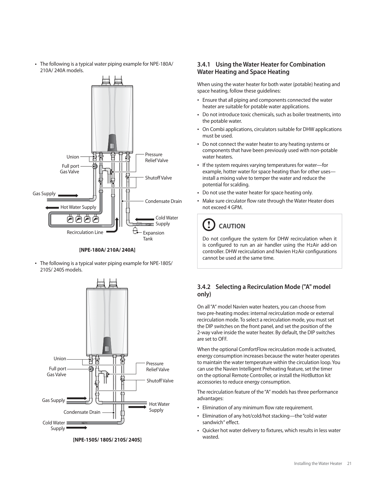
The following is a typical water piping example for NPE-180A/ 210A/ 240A models.
Pressure Relief Valve
Union
Full port Gas Valve
Shutoff Valve
Gas Supply
Condensate Drain
Hot Water Supply
Cold Water Supply
Recirculation Line
Expansion Tank
############### [NPE-180A/ 210A/ 240A]
The following is a typical water piping example for NPE-180S/ 210S/ 240S models.
| | | | | | |---|---|---|---|---| | | | | | | | | | | | | | | | | | |
| | | |---|---| | | |
Union
Pressure Relief Valve
Full port Gas Valve
Shutoff Valve
Gas Supply
Hot Water Supply
Condensate Drain
Cold Water Supply
############### [NPE-150S/ 180S/ 210S/ 240S]
########## 3.4.1 Using the Water Heater for CombinationWater Heating and Space Heating
When using the water heater for both water (potable) heating and space heating, follow these guidelines:
Ensure that all piping and components connected the water heater are suitable for potable water applications. Do not introduce toxic chemicals, such as boiler treatments, into the potable water. On Combi applications, circulators suitable for DHW applications must be used. Do not connect the water heater to any heating systems or components that have been previously used with non-potable water heaters. If the system requires varying temperatures for water—for example, hotter water for space heating than for other usesinstall a mixing valve to temper the water and reduce the potential for scalding. Do not use the water heater for space heating only. Make sure circulator flow rate through the Water Heater does not exceed 4 GPM.
|CAUTION
Do not configure the system for DHW recirculation when it is configured to run an air handler using the H2Air add-on controller. DHW recirculation and Navien H2Air configurations cannot be used at the same time.| |---|
########## 3.4.2 Selecting a Recirculation Mode ("A" modelonly)
On all “A“ model Navien water heaters, you can choose from two pre-heating modes: internal recirculation mode or external recirculation mode. To select a recirculation mode, you must set the DIP switches on the front panel, and set the position of the 2-way valve inside the water heater. By default, the DIP switches are set to OFF.
When the optional ComfortFlow recirculation mode is activated, energy consumption increases because the water heater operates to maintain the water temperature within the circulation loop. You can use the Navien Intelligent Preheating feature, set the timer on the optional Remote Controller, or install the HotButton kit accessories to reduce energy consumption.
The recirculation feature of the “A“ models has three performance advantages:
Elimination of any minimum flow rate requirement. Elimination of any hot/cold/hot stacking—the “cold water sandwich“ effect. Quicker hot water delivery to fixtures, which results in less water wasted.
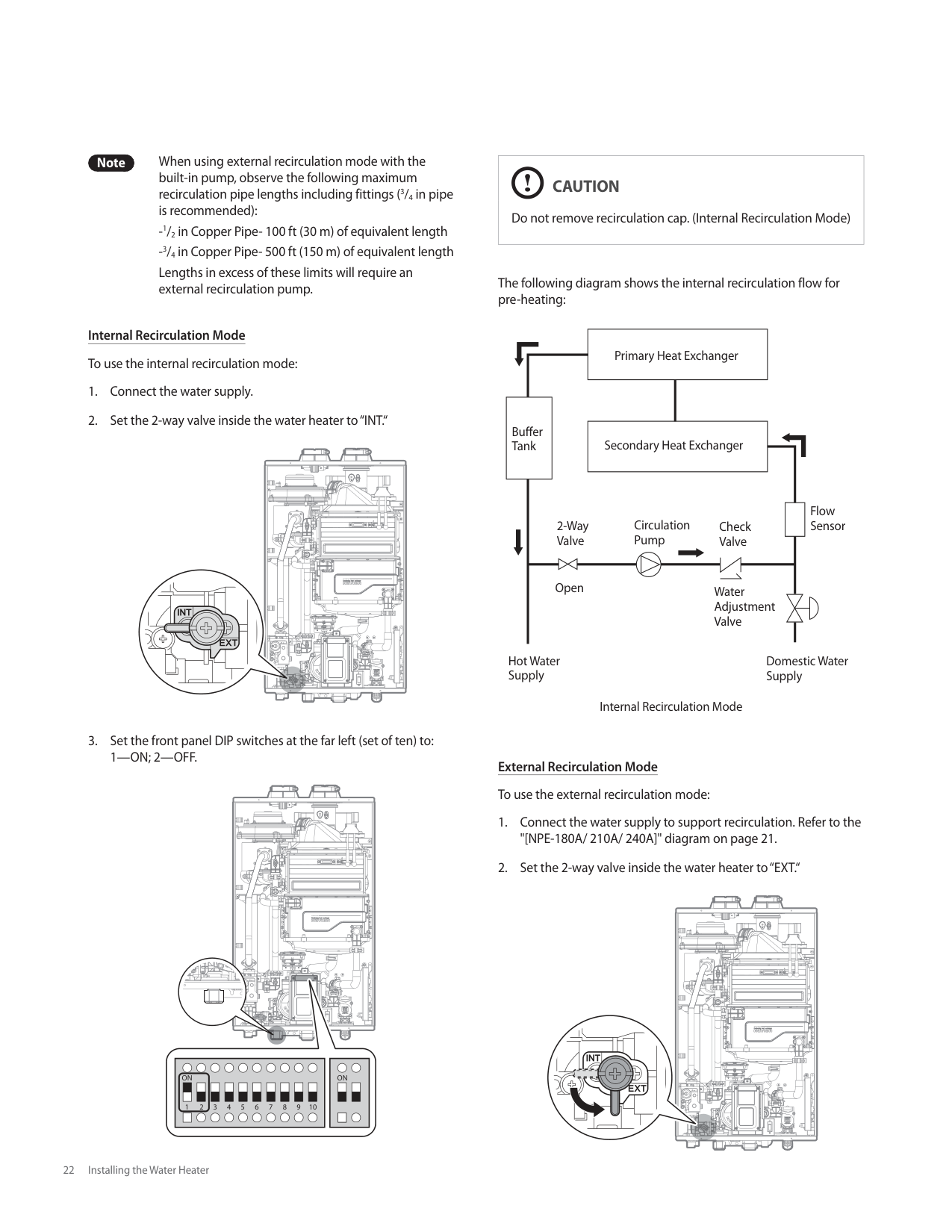
Note When using external recirculation mode with the built-in pump, observe the following maximum recirculation pipe lengths including fittings (3/4 in pipe is recommended):
Internal Recirculation Mode To use the internal recirculation mode:
| | | | | | | | | |---|---|---|---|---|---|---|---| | | | | | | | | |
| | | | |---|---|---|
| | | |---|---|
| | | |---|---| | | |
| | | | |---|---|---| | | | |
| | |---| | |
| | | |---|---| | | |
| | | |---|---| | | | | | |
| | | | | | | | | |---|---|---|---|---|---|---|---|
| | | | | | | | |
| | | | |---|---|---| | | | |
| | | |---|---| | | |
| | |---| | |
| | | |---|---|
| | | |---|---| | | |
| | | |---|---|
|ON| |---|
|ON
1 2 3 4 5 6 7 8 9 10| |---|
|CAUTION
Do not remove recirculation cap. (Internal Recirculation Mode)| |---|
The following diagram shows the internal recirculation flow for pre-heating:
Primary Heat Exchanger
Buffer Tank
Secondary Heat Exchanger
Flow Sensor
Circulation Pump
2-Way Valve
Check Valve
Open
Water Adjustment Valve
Hot Water Supply
Domestic Water Supply
Internal Recirculation Mode
External Recirculation Mode To use the external recirculation mode:
| | | | | | | | | |---|---|---|---|---|---|---|---| | | | | | | | | |
| | | | |---|---|---| | | | |
| | | |---|---| | | |
| | | | |---|---|---| | | | | | | | |
| | | |---|---| | | |
| | | |---|---| | | | | | |
| | | |---|---| | | |
| | | |---|---|
| | | | |---|---|---|
| | |---| | |
| | | |---|---| | | |
| | | | |---|---|---| | | | |
| | |---| | |
| | | |---|---| | | |
|1 2 3 4 5 6 7 8 9 10
ON ON
| |---|
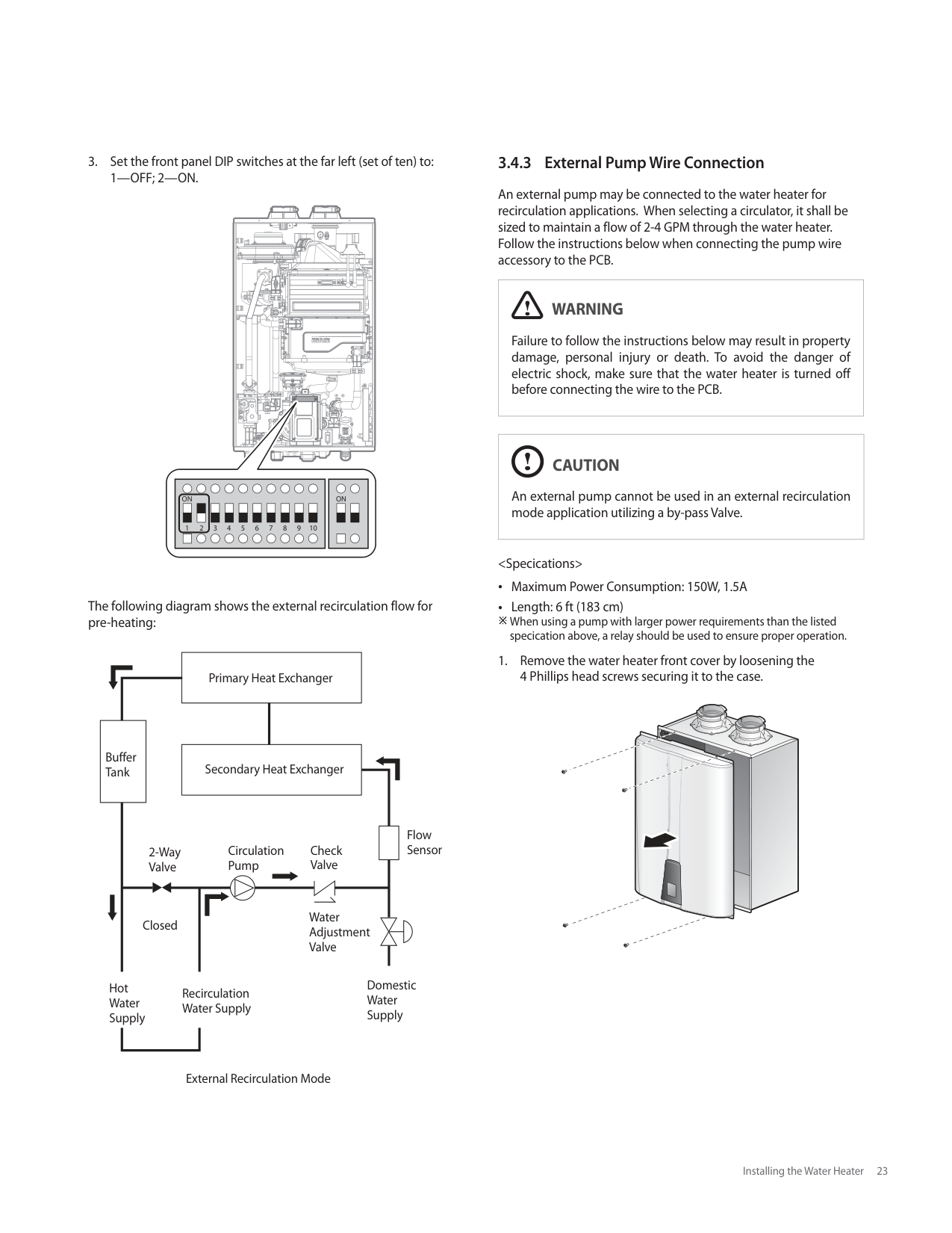
The following diagram shows the external recirculation flow for pre-heating:
Primary Heat Exchanger
Buffer Tank
Secondary Heat Exchanger
Flow Sensor
Check Valve
Circulation Pump
2-Way Valve
Water Adjustment Valve
Closed
Domestic Water Supply
Hot Water Supply
Recirculation Water Supply
External Recirculation Mode
########## 3.4.3 External Pump Wire Connection
An external pump may be connected to the water heater for recirculation applications. When selecting a circulator, it shall be sized to maintain a flow of 2-4 GPM through the water heater. Follow the instructions below when connecting the pump wire accessory to the PCB.
|WARNING
Failure to follow the instructions below may result in property damage, personal injury or death. To avoid the danger of electric shock, make sure that the water heater is turned off before connecting the wire to the PCB.| |---|
|CAUTION
An external pump cannot be used in an external recirculation mode application utilizing a by-pass Valve.| |---|


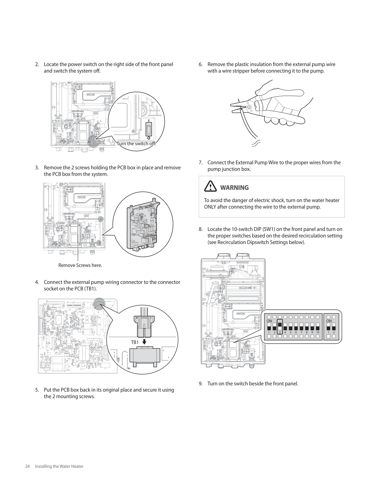
| | | | |---|---|---| | | | |
| | | |---|---| | | |
| | | | |---|---|---| | | | | | | | |
| | | | |---|---|---| | | | |
| | | | |---|---|---| | | | | | | | |
Turn the switch off.
| | | | |---|---|---|
| | | |---|---| | | |
| | | |---|---| | | |
| | | |---|---| | | |
| | | |
|---|---|---| | | | | | | | |
Remove Screws here.
| | | |---|---| | | |
| | | |---|---| | | |
| | | | | |---|---|---|---| | | | | | | | | | | | | | | |
| | | |---|---|
| | |---| | | | |
| | |---| | | | |
| | |---| | |
| | |---| | |
| | |---| | |
| | | | |---|---|---| | | | |
| | | |---|---|
| | |
| | |---| | |
| | | | |---|---|---| | | | | | | | |
| | | |---|---| | | |
| | | | |---|---|---| | | | |
| | | |---|---|
| | | | |---|---|---| | | | |
| | | |---|---|
| | |---| | | | | | |
| | | |---|---| | | | | | |
| | |---| | |
| | | |---|---| | | |
| | | | |---|---|---|
| | | | |---|---|---|
| | | | |---|---|---| | | | |
| | |---| | |
| | |---| | |
| | |---| | |
| | |---| | |
| | |---| | |
| | | |---|---| | | |
| | | |---|---| | | | | | |
| | | |---|---| | | | | | |
| | |---| | |
| | | | | | | | |---|---|---|---|---|---|---| | | | | | | | | | | | | | | | |
TB1
|WARNING
To avoid the danger of electric shock, turn on the water heater ONLY after connecting the wire to the external pump.| |---|
| | | | |---|---|---| | | | |
| | | |---|---| | | |
| | | |---|---| | | |
| | | | |---|---|---| | | | |
| | |---| | |
| | |---| | |
| | |---| | |
| | |---| | |
| | |---| | |
| | |---| | |
| |
|---| | |
| | |---| | |
| | |---| | |
| | |---| | |
1 2 3 1 24 5 6 7 8 9 10
ON ON
CHG
Condensate Gas
Domestic Hot Water
Domestic Cold Water
Domestic Recirculation Return
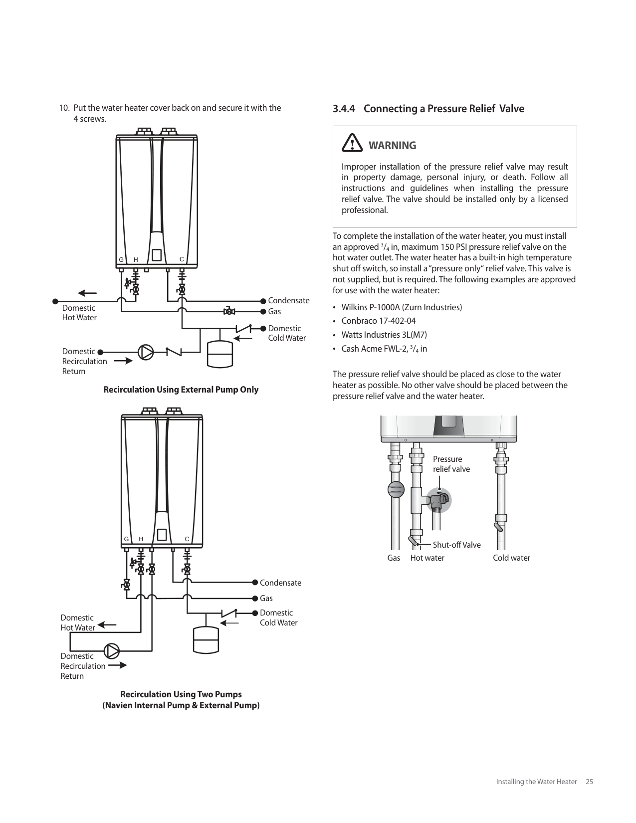
############### Recirculation Using External Pump Only
CHG
| | | |---|---| | | |
Condensate Gas Domestic Cold Water
Domestic Hot Water
Domestic Recirculation Return
############### Recirculation Using Two Pumps (Navien Internal Pump & External Pump)
3.4.4 Connecting a Pressure Relief Valve
######### WARNING
Improper installation of the pressure relief valve may result in property damage, personal injury, or death. Follow all instructions and guidelines when installing the pressure relief valve. The valve should be installed only by a licensed professional.
To complete the installation of the water heater, you must install an approved 3/4 in, maximum 150 PSI pressure relief valve on the hot water outlet. The water heater has a built-in high temperature shut off switch, so install a “pressure only“ relief valve. This valve is not supplied, but is required. The following examples are approved for use with the water heater:
Wilkins P-1000A (Zurn Industries) Conbraco 17-402-04 Watts Industries 3L(M7) Cash Acme FWL-2, 3/4 in
The pressure relief valve should be placed as close to the water heater as possible. No other valve should be placed between the pressure relief valve and the water heater.
Pressure relief valve
Shut-off Valve Cold waterHot waterGas
When installing the valve, follow these guidelines: Ensure that the discharge capacity of the pressure relief valve is equal to or greater than the maximum pressure rating of the water heater. Ensure that the maximum BTU/H rating on the pressure relief valve is equal to or greater than the maximum input BTU/H rating of the water heater. Direct the discharge piping of the pressure relief valve so that hot water will not splash on anyone or any nearby equipment. Attach the discharge line to the pressure relief valve and run the end of the line to within 6-12 in (150-300 mm) of the floor. Ensure that the discharge line will allow free and complete drainage without restriction. Do not install a reducing coupling or other restriction on the discharge line. If the relief valve discharges periodically, this may be due to thermal expansion in a closed water supply system. Contact the water supplier or local plumbing inspector on how to correct this situation. Do not plug the relief valve.
###### 3.5 Connecting the Condensate Drain
The Navien Condensing Water Heater creates condensation when it operates. This condensation has an acidic pH of 3-5. Follow all local codes and regulations when disposing of condensate from the water heater. We recommend draining the condensate into a laundry tub, as the alkali in laundry detergent will neutralize the acid in the condensate. However, other suitable waste drain locations may be used according to local codes.
|CAUTION
Do not cap or plug the integrated condensate line. If prevented from draining, condensate can damage the water heater.
The condensate line must have a negative slope to drain properly.| |---|
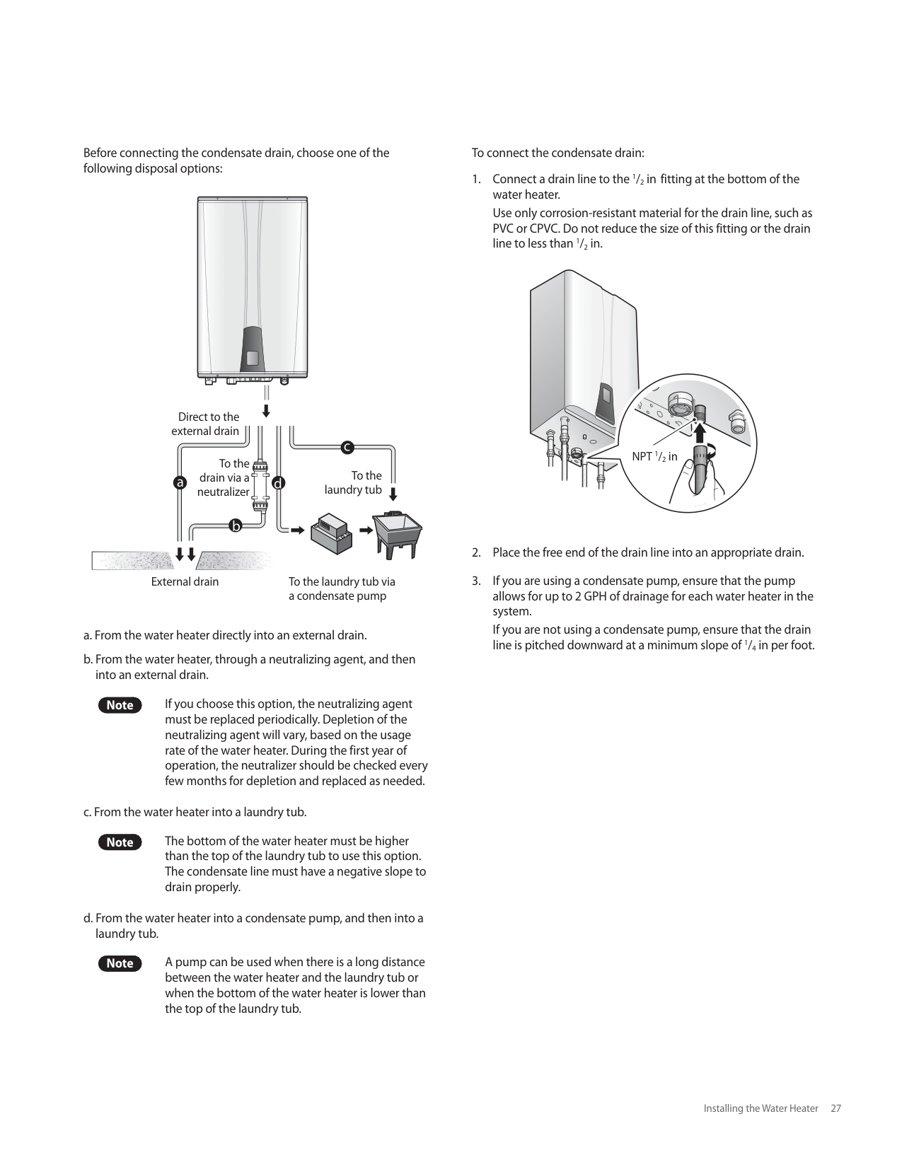
Before connecting the condensate drain, choose one of the following disposal options:
Direct to the external drain
To the drain via a neutralizer
To the laundry tub
External drain To the laundry tub via a condensate pump
Note If you choose this option, the neutralizing agent must be replaced periodically. Depletion of the neutralizing agent will vary, based on the usage rate of the water heater. During the first year of operation, the neutralizer should be checked every few months for depletion and replaced as needed.
Note The bottom of the water heater must be higher than the top of the laundry tub to use this option. The condensate line must have a negative slope to drain properly.
Note A pump can be used when there is a long distance between the water heater and the laundry tub or when the bottom of the water heater is lower than the top of the laundry tub.
To connect the condensate drain:
NPT 1/2 in
######### 3.5.1 Condensate Neutralizer Kit
|WARNING
To avoid damaging the appliance, the neutralizer inlet and discharge must be lower than the condensate drain.
Do NOT allow exhaust flue gases to vent through the neutralizer. Leakage can cause injury or death from carbon monoxide.
The connection between the appliance and the neutralizer must be installed to prevent the backflow of condensate into the appliance.
Do not connect more than one appliance to the neutralizer.| |---|
If option 'b' is selected for condensate disposal, the Navien condensate neutralizer kit is recommended. The condensate from the appliance flows through the neutralizing media and increases the pH of the condensate. An increased pH prevents corrosion of the installation's drainage system and the public sewer system.
Installation The inlet has a center connection port and the outlet has an offset connection. Install the neutralizer on the wall or the floor and secure it using the brackets supplied with the kit. If the neutralizer is installed horizontally, rotate the neutralizer to position the outlet at the highest point (Figure 1). If the neutralizer is mounted vertically, ensure that the outlet is higher than the inlet (Figure 2). Ensure that the condensate runs freely to the drain. Ensure all connections are made to prevent the backflow of condensate. Use corrosion resistant piping and secure all piping to prevent movement.
Note Do not install condensate piping in areas where the temperature drops below freezing point. Protect piping in high pedestrian areas from damage and vibration.
For increased safety when the condensate drain blocks, install a Y-fitting. Connect the Y-fitting as shown in the installation diagram and ensure that the condensate runs freely to the drain. Ensure that the discharge connection is accessible. Access to the discharge connection is required for maintenance and pH testing. If there is insufficient gradient for drainage, install a drainage pump designed for boiler and water heater condensate removal.
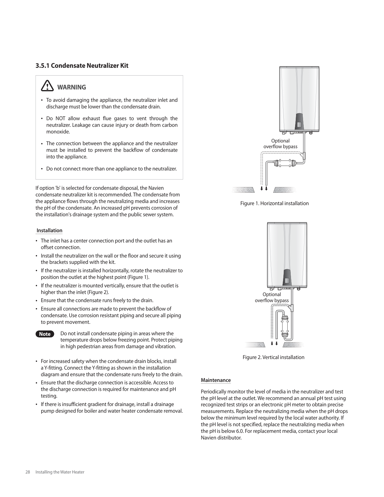
| | | | |---|---|---| | | | | | | | | | | | |
Optional overflow bypass
| | | |---|---| | | |
| | | | |---|---|---| |Optional overflow bypass| | | |Optional overflow bypass| | | |Optional overflow bypass| | |
################ Maintenance
Periodically monitor the level of media in the neutralizer and test the pH level at the outlet. We recommend an annual pH test using recognized test strips or an electronic pH meter to obtain precise measurements. Replace the neutralizing media when the pH drops below the minimum level required by the local water authority. If the pH level is not specified, replace the neutralizing media when the pH is below 6.0. For replacement media, contact your local Navien distributor.
###### 3.6 Venting the Water Heater
|WARNING
Improper venting of the water heater can result in excessive levels of carbon monoxide, which can lead to severe personal injury or death. This water heater must be vented in accordance with the “Venting of Equipment“ section of the latest edition of the ANSI Z223.1/NFPA 54 Natural Fuel Gas Code in the USA and/or the “Venting systems and air supply for water heaters“ section of the latest version of the CAN/CGA B149.1 Natural Gas and Propane Installation Code in Canada, as well as all applicable local building codes and regulations. Follow all instructions and guidelines when venting the water heater. Venting should be performed only by a licensed professional.| |---|
The water heater must be properly vented to ensure a constant supply of clean intake air and to ensure that exhaust air is properly removed from living areas. When venting the water heater, follow these guidelines:
Do not install the water heater in areas with contaminated air (containing a high level of dust, sawdust, sand, flour, aerosols, or any other such airborne contaminants), as contaminants can cause operational problems. The warranty does not cover damage caused by contaminants in the installation area. If you must install the water heater in an area with contaminated air, use direct venting to supply air from outside the building. We recommend regular filter cleaning and maintenance in these areas. For best results, keep the venting system as short and straight as possible. Locate the water heater as close as possible to the vent termination. Do not connect the water heater vent to a vent for any other gas water heater or vent stack. For horizontal runs, slope the horizontal section upward toward the vent termination at a rate of 1/4 in per foot (2 % slope). Create an airtight seal at each joint in the exhaust and intake air pipes from the water heater collar to the vent termination. To avoid moisture and frost build-up and to maintain clearances to openings on adjacent homes, 45° elbows, 90° elbows, or tees may be attached to the end of the termination vent pipe to direct the exhaust plumes away from buildings, as long as the total allowable vent lengths, maximum number of elbows, and distances to air intake restrictions are observed.
Do not store hazardous or flammable substances near the vent termination. If this water heater will be installed in areas where snow is known to accumulate, protect the vent termination from blockage. Ensure that the vent termination is at least 12 in (305 mm) above the highest anticipated snow line, or as required by local codes, whichever is greater. Support the vent pipe with hangers at regular intervals or as required by local codes. Exhaust and intake air pipes must be supported at least every 4 ft (1.2 m). The vent for this appliance shall not terminate over public walkways; or near soffit vents or crawl space vents or where condensate or vapor could create a nuisance or hazard or cause property damage; or where condensate or vapor could cause damage or could be detrimental to the operation of regulators, relief valves, or other equipment.
########## 3.6.1 Selecting a Vent Type
All water heaters are prepared at the factory to be direct vent (sealed combustion) water heaters that draw all of their required combustion air directly from outside the building. Navien recommends direct air vent installations whenever possible to avoid back drafting cold air through the water heater. If you cannot use a direct vent, ensure that an ample supply of make-up air is available in the installation location.
Navien also recommends installing a new vent system with this appliance. If reusing an existing vent system, thoroughly inspect it for punctures, cracks, or blockages prior to connecting it to the water heater.
################ Direct Venting
The water heater uses 2 in or 3 in diameter exhaust and 2 in or 3 in diameter intake air ducts. To ensure the draw of air directly from and exhaust of air directly to the outside of the building, create an airtight seal from the water heater collar to the vent termination.
Intake materials can be made of ABS, PVC, CPVC, PP, galvanized steel, corrugated aluminum or any other such materials. If you use a corrugated material, ensure that there is not inadvertent crimping of, or damage to, the intake air pipe.
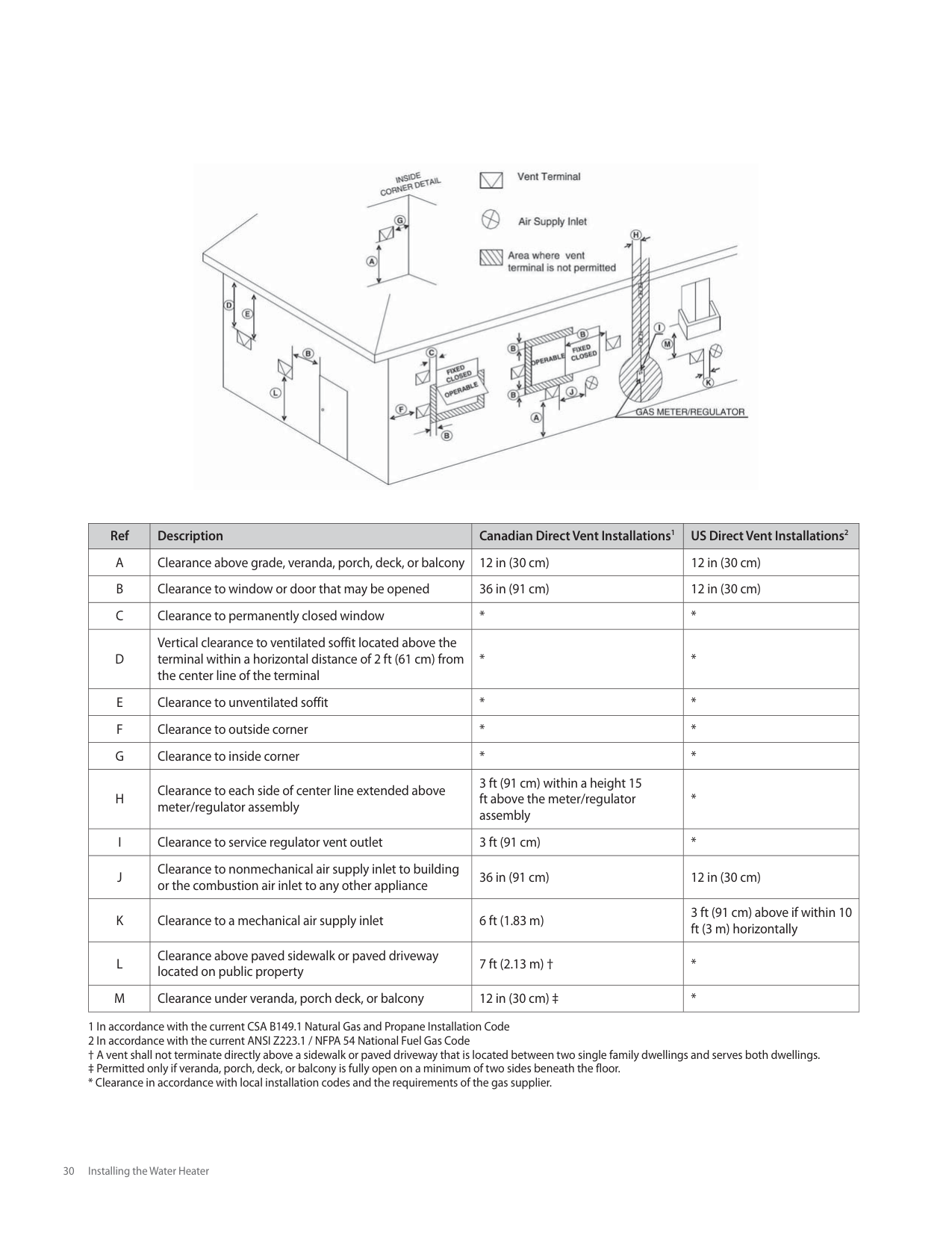
When using direct venting, maintain the following venting clearances, as required by ANSI Z21.10.3 and the National Fuel Gas Code, ANSI Z223.1/NFPA 54, and CAN/CGA B149.1 Natural Gas and Propane Installation Code:

|Ref|Description|Canadian Direct Vent Installations1|US Direct Vent Installations2| |---|---|---|---| |A|Clearance above grade, veranda, porch, deck, or balcony|12 in (30 cm)|12 in (30 cm)| |B|Clearance to window or door that may be opened|36 in (91 cm)|12 in (30 cm)| |C|Clearance to permanently closed window|*|*|
|D|Vertical clearance to ventilated soffit located above the terminal within a horizontal distance of 2 ft (61 cm) from the center line of the terminal|*|*| |E|Clearance to unventilated soffit|*|*| |F|Clearance to outside corner|*|*| |G|Clearance to inside corner|*|*| |H|Clearance to each side of center line extended above meter/regulator assembly|3 ft (91 cm) within a height 15 ft above the meter/regulator assembly|*| |I|Clearance to service regulator vent outlet|3 ft (91 cm)|*| |J|Clearance to nonmechanical air supply inlet to building or the combustion air inlet to any other appliance|36 in (91 cm)|12 in (30 cm)| |K|Clearance to a mechanical air supply inlet|6 ft (1.83 m)|3 ft (91 cm) above if within 10 ft (3 m) horizontally| |L|Clearance above paved sidewalk or paved driveway located on public property|7 ft (2.13 m) †|*| |M|Clearance under veranda, porch deck, or balcony|12 in (30 cm) ‡|*|
################ Non-Direct Venting (Single Pipe)
If, at any time, the installation location could experience negative pressure, there is a possibility of back drafting cold air through the water heater’s heat exchanger. This situation could lead to the freezing of the heat exchanger and malfunction of the water heater.
However, building codes in most jurisdictions disallow negative pressures in residences. In a home with a well-balanced air supply, the heat exchanger should not be in danger of freezing. Because the cause of back drafting is not considered a manufacturing problem, any freezing damage which occurs from back drafting will not be covered by the Navien warranty. If there is any question about the possibility of back drafting in the installation location, use a direct venting system for the water heater.
When installed in a manufactured home (mobile home), all combustion air must be supplied from the outdoors as described on page 28.
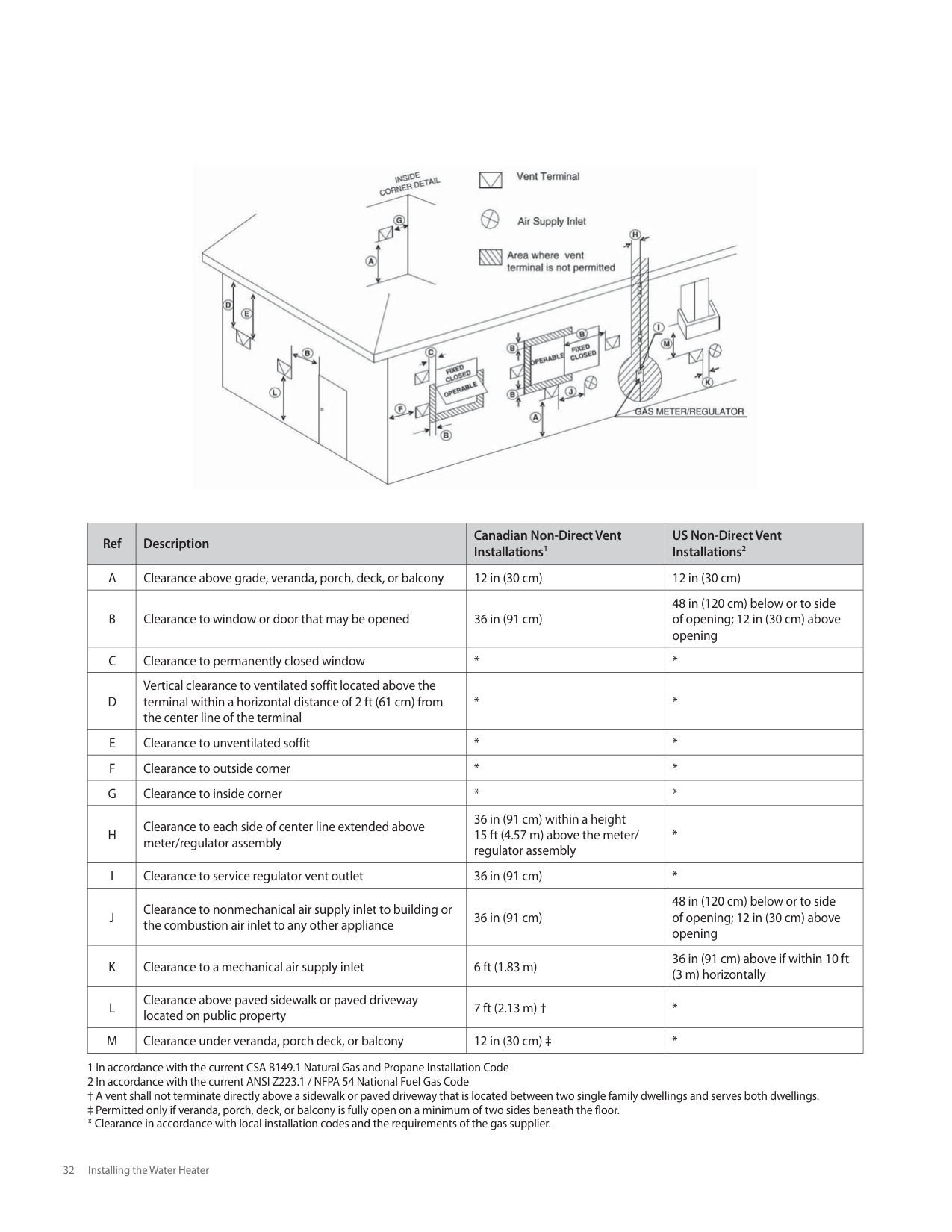
When using non-direct venting, maintain non-direct vent clearances shown on page 32 as required by ANSI Z21.10.3 and the National Fuel Gas Code, ANSI Z223.1/NFPA 54, and CAN/ CSA B149.1 Natural Gas And Propane Installation Code.
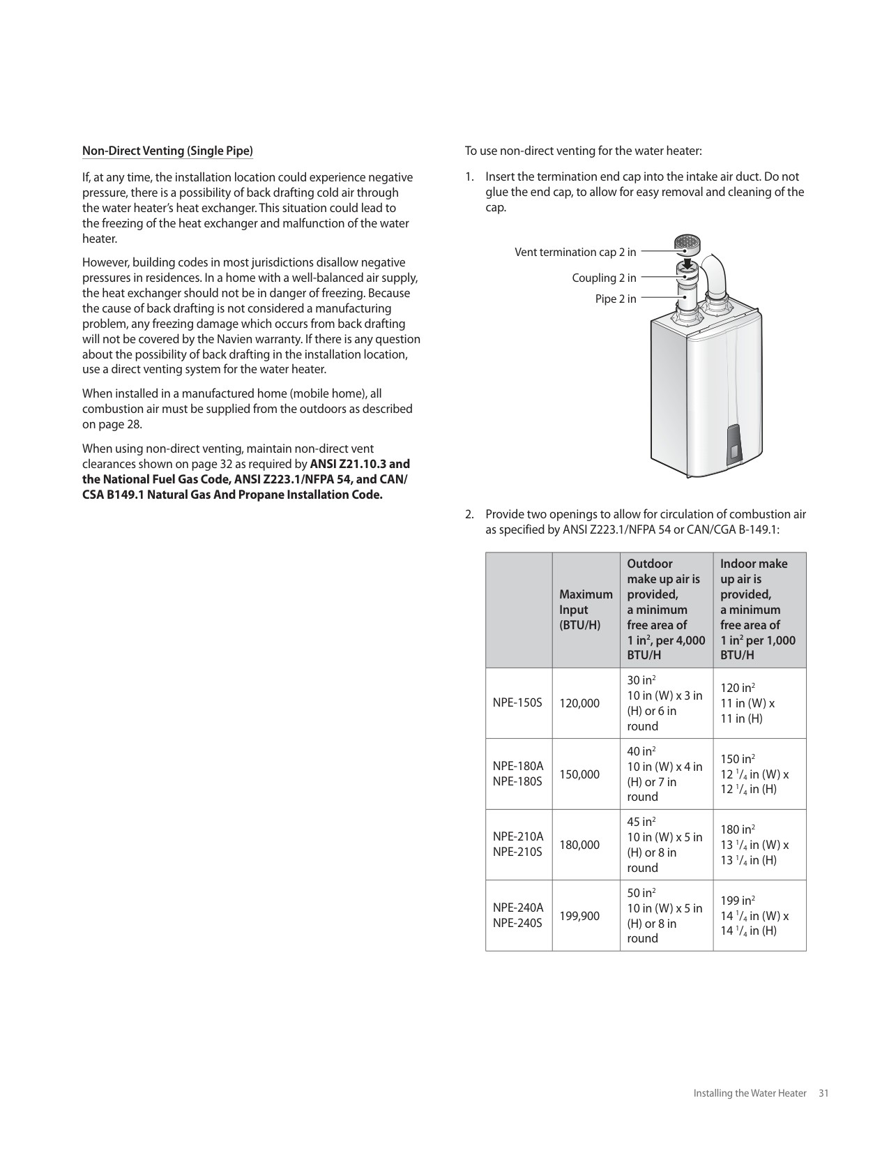
To use non-direct venting for the water heater:
Vent termination cap 2 in Coupling 2 in Pipe 2 in


| |Maximum Input (BTU/H)|Outdoor make up air is provided, a minimum free area of 1 in2, per 4,000 BTU/H|Indoor make up air is provided, a minimum free area of 1 in2 per 1,000 BTU/H| |---|---|---|---| |NPE-150S|120,000|30 in2 10 in (W) x 3 in (H) or 6 in round|120 in2 11 in (W) x 11 in (H)| |NPE-180A NPE-180S|150,000|40 in2 10 in (W) x 4 in (H) or 7 in round|150 in2 12 1/4 in (W) x 12 1/4 in (H)| |NPE-210A NPE-210S|180,000|45 in2 10 in (W) x 5 in (H) or 8 in round|180 in2 13 1/4 in (W) x 13 1/4 in (H)| |NPE-240A NPE-240S|199,900|50 in2 10 in (W) x 5 in (H) or 8 in round|199 in2 14 1/4 in (W) x 14 1/4 in (H)|

|Ref|Description|Canadian Non-Direct Vent Installations1|US Non-Direct Vent Installations2| |---|---|---|---| |A|Clearance above grade, veranda, porch, deck, or balcony|12 in (30 cm)|12 in (30 cm)| |B|Clearance to window or door that may be opened|36 in (91 cm)|48 in (120 cm) below or to side of opening; 12 in (30 cm) above opening| |C|Clearance to permanently closed window|*|*| |D|Vertical clearance to ventilated soffit located above the terminal within a horizontal distance of 2 ft (61 cm) from the center line of the terminal|*|*| |E|Clearance to unventilated soffit|*|*| |F|Clearance to outside corner|*|*| |G|Clearance to inside corner|*|*|
|H|Clearance to each side of center line extended above meter/regulator assembly|36 in (91 cm) within a height 15 ft (4.57 m) above the meter/ regulator assembly|*| |I|Clearance to service regulator vent outlet|36 in (91 cm)|*| |J|Clearance to nonmechanical air supply inlet to building or the combustion air inlet to any other appliance|36 in (91 cm)|48 in (120 cm) below or to side of opening; 12 in (30 cm) above opening| |K|Clearance to a mechanical air supply inlet|6 ft (1.83 m)|36 in (91 cm) above if within 10 ft (3 m) horizontally| |L|Clearance above paved sidewalk or paved driveway located on public property|7 ft (2.13 m) †|*| |M|Clearance under veranda, porch deck, or balcony|12 in (30 cm) ‡|*|
1 In accordance with the current CSA B149.1 Natural Gas and Propane Installation Code 2 In accordance with the current ANSI Z223.1 / NFPA 54 National Fuel Gas Code † A vent shall not terminate directly above a sidewalk or paved driveway that is located between two single family dwellings and serves both dwellings. ‡ Permitted only if veranda, porch, deck, or balcony is fully open on a minimum of two sides beneath the floor.
########## 3.6.2 Selecting Vent Pipe Materials
Venting requirements differ in the US and Canada. Consult the following chart or the most recent edition of ANSI Z223.1/ NFPA 54 or CAN/CGA B149.1, as well as all applicable local codes and regulations when selecting vent pipe materials. Do not use cellular core PVC (ASTM F891), cellular core CPVC, Radel® (polyphenolsulfone) for the exhaust vent.
|Locale|Recommended Vent Materials| |---|---| |USA|PVC Schedule 40 (Solid Core) CPVC Schedule 40 or 80 (Solid Core) Approved Polypropylene*| |Canada**|Type BH Special Gas Vent Class IIA (PVC) Type BH Special Gas Vent Class IIB (CPVC) Type BH Special Gas Vent Class IIC (Polypropylene)|
|CAUTION
This water heater has a built-in control to limit the exhaust temperature to 149°F (65°C). As a result, the Navien water heater can be vented with Schedule 40 PVC. If the incoming (or recirculation return) water temperature does not exceed 150°F (66°C), the exhaust temperature will not exceed 149 °F (65 °C).
However, if you set the water heater at a temperature above 150 °F (66 °C) and you are also incorporating either an external recirculation loop or a combination heating system, the exhaust temperature can exceed 149 °F (65 °C). In that case, you must use Schedule 40 or 80 CPVC or Approved Polypropylene in the USA or Type BH Special Gas Vent Class IIB (CPVC) or Class IC (Polypropylene) that conforms to ULC-S636 in Canada.
In systems with 2 in vents, if the exhaust temperature exceeds 149 °F (65 °C), CPVC pipe (field supplied) must be used for the first 3 ft of equivalent pipe length. For systems with 3 in vents, if the exhaust temperature exceeds 149 °F (65 °C), CPVC pipe (field supplied) must be used for the first 5 in of equivalent pipe length.| |---|
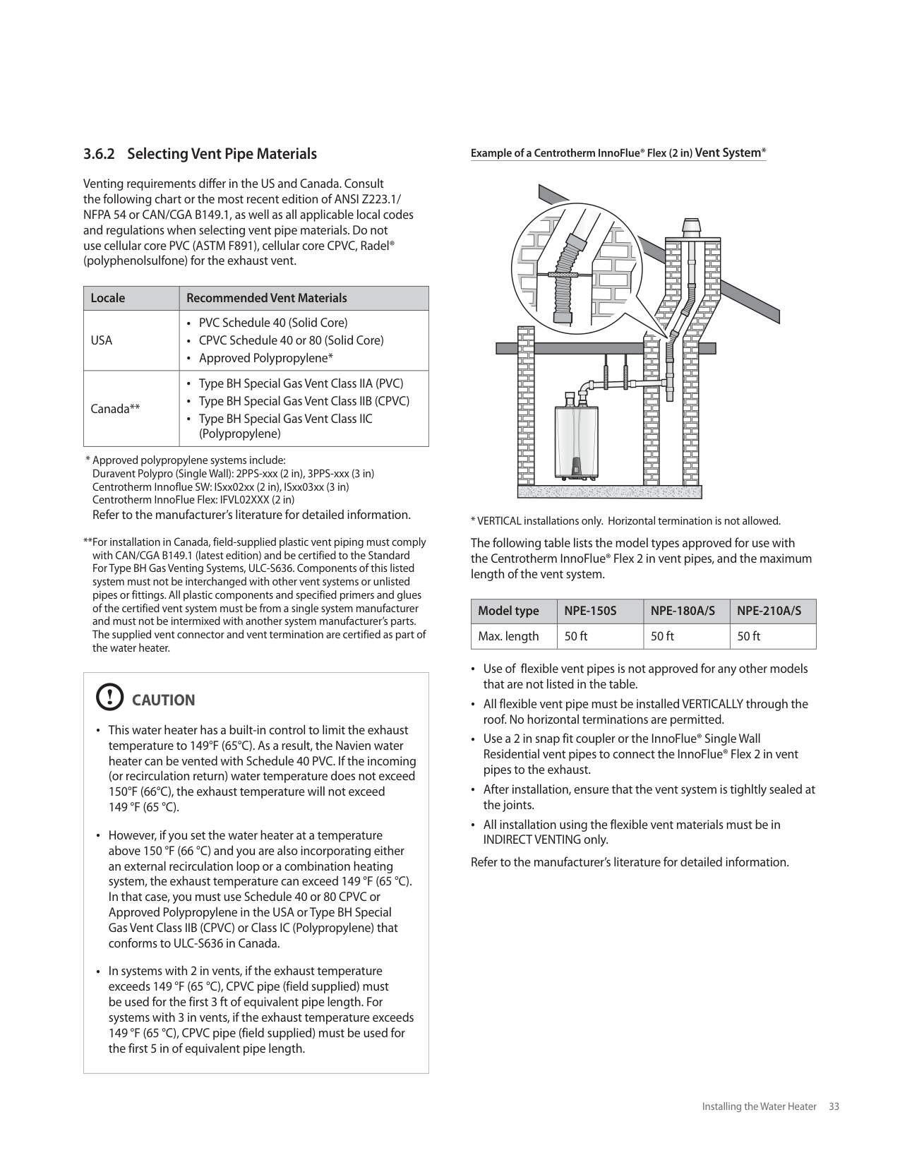
################ Example of a Centrotherm InnoFlue® Flex (2 in) Vent System*
| | | | | |---|---|---|---| | | | | | | | | | |
The following table lists the model types approved for use with the Centrotherm InnoFlue® Flex 2 in vent pipes, and the maximum length of the vent system.
|Model type|NPE-150S|NPE-180A/S|NPE-210A/S| |---|---|---|---| |Max. length|50 ft|50 ft|50 ft|
Use of flexible vent pipes is not approved for any other models that are not listed in the table. All flexible vent pipe must be installed VERTICALLY through the roof. No horizontal terminations are permitted. Use a 2 in snap fit coupler or the InnoFlue® Single Wall Residential vent pipes to connect the InnoFlue® Flex 2 in vent pipes to the exhaust. After installation, ensure that the vent system is tighltly sealed at the joints. All installation using the flexible vent materials must be in INDIRECT VENTING only.
Refer to the manufacturer’s literature for detailed information.
########## 3.6.3 Measuring Vent Length
|Vent Size|Maximum Length|Maximum # of Elbows|Equivalent Lengths| |---|---|---|---| |2 in|60 ft (18 m)|6|Reduce the maximum vent length accordingly for each elbow used:
Each 90° elbow equates to 8 linear ft (2.4 m) of vent Each 45° elbow equates to 4 linear ft (1.2 m) of vent| |3 in|150 ft (45 m)|8|Reduce the maximum vent length accordingly for each elbow used:
Each 90° elbow equates to 5 linear ft (1.5 m) of vent Each 45° elbow equates to 3 linear ft (0.9 m) of vent|
Note The Maximum Length does not include any elbows.
If using a concentric termination as shown on pages 34-36, count this as 5 linear ft (1.5 m) of vent.
The maximum vent lengths at high altitudes are the same as shown in the table above.
########## 3.6.4 Terminating the Vent
Before installing the water heater, determine what type of vent termination is appropriate for the installation location and situation. Examples in this section describe typical venting configurations, but they do not include all possible options.
Along with 2 in and 3 in PVC Concentric Terminations shown on pages 35-36, the following terminations can also be used:
IPEX Low Profile Termination Kits:
Refer to the vent manufacturer's instructions for detailed installation procedures.
Indoor Water Heater Installation Venting Examples The following are some possible indoor venting options:
2 in or 3 in Two-pipe Sidewall Venting
Intake Air
Exhaust Gas


Interior View
Do not vertically stack terminations on sidewalls.
12 in (300 mm) min.
12 in (300 mm) min.
Exhaust Gas
Intake Air
Exterior View
Non-concentric Sidewall Venting – Air is drawn from a different location at a minimum of 12 in (300 mm) from the exhaust termination. Try to minimize the length of the intake air pipe with this venting.
12 in (300 mm) min. *
12 in (300 mm) above the highest anticipated snow level, or as required by local codes, whichever is greater
Combustion Air
Combustion Air
Maintain 12 in (300 mm) min. clearance above highest anticipated snow level or grade.
| | | | | |---|---|---|---|
Vent Vent
1 in (25 mm) min.
|CAUTION
Refer to the figures below for the orientation of vent if the IPEX low profile vent kit if it is used for termination.
| |---|
2 in or 3 in Two-pipe Vertical Venting – Intake and exhaust pipes do not have to terminate in the same area.
36 in (900 mm) min.
Exhaust Gas
12 in (300 mm) min.
Intake Air
12 in (300 mm) min.
| | | | |---|---|---| | | | | | | | | | | | |
12 in (300 mm) min. From any obstruction (above, below, left, or right)
| | | | | |---|---|---|---| | | | | |
| | | |---|---| | | |
Concentric Roof Venting
Vent
Combustion Air
| | |---| | |
Maintain 12 in (300 mm) min. (18 in (450 mm) min. for Canada) clearance above highest anticipated snow level. Maximum of 24 in (600 mm) above roof
| | |---| | |
| | | |
Combustion Air
Vent
################ Outdoor Installation
Outdoor installation should only be considered in mild climates. Freezing temperatures or contaminated air can damage the water heater. When installing the water heater outdoors, maintain clearances from building openings, as described in the “Non-Direct Venting (Single Pipe)“ section on page 31. Outdoor installation areas should be in an open, unroofed area and should allow for the following minimum clearances from the water heater:
Top
Exhaust Gas
Intake Air


Back
Side
Side
Front

Bottom
|Bottom|12 in| |---|---| |Back|0.5 in| |Sides|3 in| |Front|24 in| |Top|36 in|
When installing a water heater outdoors, follow these guidelines: The Navien Outdoor Vent Kit must be used to ensure proper operation of the water heater. Ensure that there is plenty of clearance around the air intake and that it is adequately protected to prevent any debris, liquids, or flammable gases from entering the air intake. If the water heater is installed under an eave, maintain a clearance of 3 ft or more from the eave to the top of the water heater vent terminals.
###### 3.7 Connecting the Power Supply
|WARNING
Improperly connecting the power supply can result in electrical shock and electrocution. Follow all applicable electrical codes of the local authority having jurisdiction. In the absence of such requirements, follow the latest edition of the National Electrical Code (NFPA 70) in the USA or the latest edition of CSA C22.1 Canadian Electrical Code Part 1 in Canada. Connecting the power supply should be performed only by a licensed professional.| |---|
When connecting the power supply, follow these guidelines: Do not connect the electric supply until all plumbing and gas piping is complete and the water heater has been filled with water. Do not connect the water heater to a 220-240 V AC power supply. Doing so will damage the water heater and void the warranty. All water heaters come with a factory-installed, 3-pronged (grounded) plug. The water heater can be plugged into any grounded electrical outlet nearby, as it requires only 2-4 Amps. It is not necessary to run a dedicated electrical line to the water heater. If local codes require the water heater to be wired directly, remove and discard the factory-installed plug. Install a power switch between the breaker and the water heater to facilitate end-user maintenance and servicing. Connect the water heater to a 110-120 V AC at 60 Hz with a maximum of 2 A (4 A if an external pump is connected) rating electrical supply. The water heater must be electrically grounded. If using the power plug, ensure that the electrical outlet you connect the water heater to is properly grounded. If wiring the water heater directly to a power supply, do not attach the ground wire to either the gas or the water piping as plastic pipe or dielectric unions may prevent proper grounding. We recommend using a surge protector to protect the water heater from power surges. If there is a power failure in cold weather areas, the freeze prevention system in the water heater will not operate and may result in freezing of the heat exchanger. In cold weather areas where power failures are common, you must completely drain the water heater to prevent damage if the power will be off for any extended period of time. A battery back-up (available at most computer retailers) may be used to supply hot water during periods of power outages. Damage caused by freezing is not covered under warranty.
###### 3.8 Setting the DIP Switches
The water heater has two DIP switch locations: on the main circuit board (PCB) and on the front panel. Each location has two sets of DIP switches that control the functionality of the water heater. Set the DIP switches appropriately, based on the installation environment.
########## 3.8.1 Circuit Board DIP Switches
The two sets of DIP switches on the circuit board configure the water heater’s model settings. These configurations are set at the factory and should not be changed.
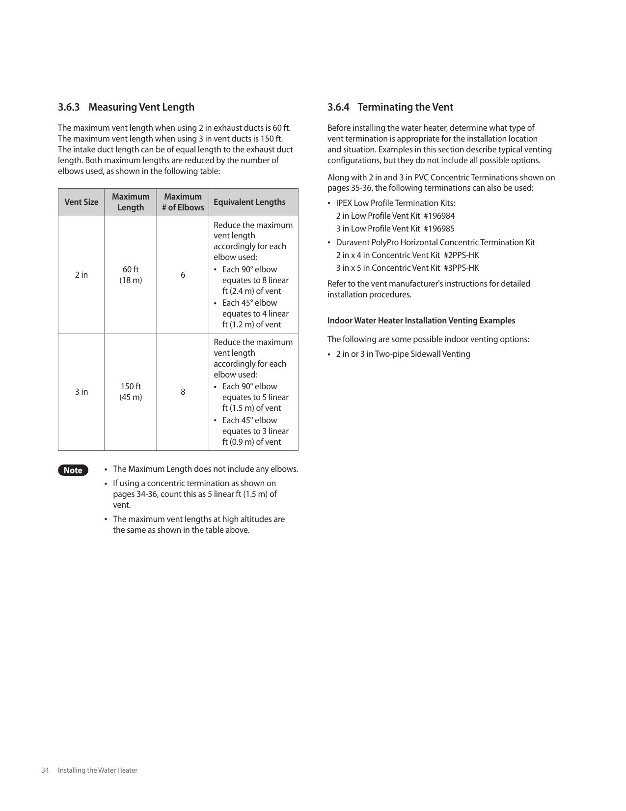
########## 3.8.2 Setting the Front Panel DIP Switches
The two sets of DIP switches on the front panel configure the water heater’s pump & recirculation, display, well pump, storage tank & solar system, lime alarm, high altitude, cascade venting and gas type settings. Some of these configurations are set at the factory and should not be changed. The following tables describe the functions of the DIP switches and their settings:
| | | | |---|---|---| | | | |
| | | |---|---| | | |
| | |---| | |
| | | |---|---| | | |
|1 2 3 4 5 6 7 8 9 10
ON ON| |---|
10-switch Panel:
|Switch|Function|Setting|Setting|Remark| |---|---|---|---|---| |1-3|Recirculation ModeInternal Navien Pump ("A" model only)|No Recirculation|1-OFF; 2-OFF; 3-OFF|*Intelligent Preheating: Learns the user's hot water usage patterns and starts preheating prior to an anticipated draw.
Preheating starts when remote controller is not connected.
When remote controller is connected, preheating starts and operates based on the timer. Set the timer on the remote controller to use hot water at the time of your choice. Intelligent preheating does not function in Cascade Mode (Preheating OFF). Freeze protection is still available with preheating OFF.
External Pump: These settings are to be used when an external pump is wired to the water heater.
*Lime Alarm: Displays a "760" error when the set time period has been reached to indicate a flush or service is necessary.
****High Altitude Above 2,000 ft (610 m), the water heater will de-rate by 4% for each 1,000 ft (305 m) of altitude gain.| |1-3|Recirculation ModeInternal Navien Pump ("A" model only)|Internal Recirculation|1-ON; 2-OFF; 3-OFF|*Intelligent Preheating: Learns the user's hot water usage patterns and starts preheating prior to an anticipated draw.
Preheating starts when remote controller is not connected.
When remote controller is connected, preheating starts and operates based on the timer. Set the timer on the remote controller to use hot water at the time of your choice. Intelligent preheating does not function in Cascade Mode (Preheating OFF). Freeze protection is still available with preheating OFF.
External Pump: These settings are to be used when an external pump is wired to the water heater.
*Lime Alarm: Displays a "760" error when the set time period has been reached to indicate a flush or service is necessary.
****High Altitude Above 2,000 ft (610 m), the water heater will de-rate by 4% for each 1,000 ft (305 m) of altitude gain.| |1-3|Recirculation ModeInternal Navien Pump ("A" model only)|External Recirculation|1-OFF; 2-ON; 3-OFF|*Intelligent Preheating: Learns the user's hot water usage patterns and starts preheating prior to an anticipated draw.
Preheating starts when remote controller is not connected.
When remote controller is connected, preheating starts and operates based on the timer. Set the timer on the remote controller to use hot water at the time of your choice. Intelligent preheating does not function in Cascade Mode (Preheating OFF). Freeze protection is still available with preheating OFF.
External Pump: These settings are to be used when an external pump is wired to the water heater.
*Lime Alarm: Displays a "760" error when the set time period has been reached to indicate a flush or service is necessary.
****High Altitude Above 2,000 ft (610 m), the water heater will de-rate by 4% for each 1,000 ft (305 m) of altitude gain.| |1-3|Recirculation ModeInternal Navien Pump ("A" model only)|Intelligent Preheating*|1-ON; 2-ON; 3-OFF|*Intelligent Preheating: Learns the user's hot water usage patterns and starts preheating prior to an anticipated draw.
Preheating starts when remote controller is not connected.
When remote controller is connected, preheating starts and operates based on the timer. Set the timer on the remote controller to use hot water at the time of your choice. Intelligent preheating does not function in Cascade Mode (Preheating OFF). Freeze protection is still available with preheating OFF.
External Pump: These settings are to be used when an external pump is wired to the water heater.
*Lime Alarm: Displays a "760" error when the set time period has been reached to indicate a flush or service is necessary.
****High Altitude Above 2,000 ft (610 m), the water heater will de-rate by 4% for each 1,000 ft (305 m) of altitude gain.| |1-3|Recirculation ModeExternal Pump Connected|External Pump Only|1-OFF; 2-OFF; 3-ON|*Intelligent Preheating: Learns the user's hot water usage patterns and starts preheating prior to an anticipated draw.
Preheating starts when remote controller is not connected.
When remote controller is connected, preheating starts and operates based on the timer. Set the timer on the remote controller to use hot water at the time of your choice. Intelligent preheating does not function in Cascade Mode (Preheating OFF). Freeze protection is still available with preheating OFF.
External Pump: These settings are to be used when an external pump is wired to the water heater.
*Lime Alarm: Displays a "760" error when the set time period has been reached to indicate a flush or service is necessary.
**High Altitude Above 2,000 ft (610 m), the water heater will de-rate by 4% for each 1,000 ft (305 m) of altitude gain.| |1-3|Recirculation ModeExternal Pump Connected|Internal Recirculation ("A" model only)|1-ON; 2-OFF; 3-ON|*Intelligent Preheating: Learns the user's hot water usage patterns and starts preheating prior to an anticipated draw.
Preheating starts when remote controller is not connected.
When remote controller is connected, preheating starts and operates based on the timer. Set the timer on the remote controller to use hot water at the time of your choice. Intelligent preheating does not function in Cascade Mode (Preheating OFF). Freeze protection is still available with preheating OFF.
External Pump: These settings are to be used when an external pump is wired to the water heater.
*Lime Alarm: Displays a "760" error when the set time period has been reached to indicate a flush or service is necessary.
**High Altitude Above 2,000 ft (610 m), the water heater will de-rate by 4% for each 1,000 ft (305 m) of altitude gain.| |1-3|Recirculation ModeExternal Pump Connected|External Recirculation ("A" model only)|1-OFF; 2-ON; 3-ON|*Intelligent Preheating: Learns the user's hot water usage patterns and starts preheating prior to an anticipated draw.
Preheating starts when remote controller is not connected.
When remote controller is connected, preheating starts and operates based on the timer. Set the timer on the remote controller to use hot water at the time of your choice. Intelligent preheating does not function in Cascade Mode (Preheating OFF). Freeze protection is still available with preheating OFF.
External Pump: These settings are to be used when an external pump is wired to the water heater.
*Lime Alarm: Displays a "760" error when the set time period has been reached to indicate a flush or service is necessary.
**High Altitude Above 2,000 ft (610 m), the water heater will de-rate by 4% for each 1,000 ft (305 m) of altitude gain.| |1-3|Recirculation ModeExternal Pump Connected|Intelligent Preheating*|1-ON; 2-ON; 3-ON|*Intelligent Preheating: Learns the user's hot water usage patterns and starts preheating prior to an anticipated draw.
Preheating starts when remote controller is not connected.
When remote controller is connected, preheating starts and operates based on the timer. Set the timer on the remote controller to use hot water at the time of your choice. Intelligent preheating does not function in Cascade Mode (Preheating OFF). Freeze protection is still available with preheating OFF.
External Pump: These settings are to be used when an external pump is wired to the water heater.
*Lime Alarm: Displays a "760" error when the set time period has been reached to indicate a flush or service is necessary.
**High Altitude Above 2,000 ft (610 m), the water heater will de-rate by 4% for each 1,000 ft (305 m) of altitude gain.| |4|Display Temperature Unit|Celsius|4-ON|*Intelligent Preheating: Learns the user's hot water usage patterns and starts preheating prior to an anticipated draw.
Preheating starts when remote controller is not connected.
When remote controller is connected, preheating starts and operates based on the timer. Set the timer on the remote controller to use hot water at the time of your choice. Intelligent preheating does not function in Cascade Mode (Preheating OFF). Freeze protection is still available with preheating OFF.
External Pump: These settings are to be used when an external pump is wired to the water heater.
*Lime Alarm: Displays a "760" error when the set time period has been reached to indicate a flush or service is necessary.
****High Altitude Above 2,000 ft (610 m), the water heater will de-rate by 4% for each 1,000 ft (305 m) of altitude gain.| |4|Display Temperature Unit|Fahrenheit|4-OFF|*Intelligent Preheating: Learns the user's hot water usage patterns and starts preheating prior to an anticipated draw.
Preheating starts when remote controller is not connected.
When remote controller is connected, preheating starts and operates based on the timer. Set the timer on the remote controller to use hot water at the time of your choice. Intelligent preheating does not function in Cascade Mode (Preheating OFF). Freeze protection is still available with preheating OFF.
External Pump: These settings are to be used when an external pump is wired to the water heater.
*Lime Alarm: Displays a "760" error when the set time period has been reached to indicate a flush or service is necessary.
****High Altitude Above 2,000 ft (610 m), the water heater will de-rate by 4% for each 1,000 ft (305 m) of altitude gain.| |5|Well Pump|Well Pump Operation|5-ON|*Intelligent Preheating: Learns the user's hot water usage patterns and starts preheating prior to an anticipated draw.
Preheating starts when remote controller is not connected.
When remote controller is connected, preheating starts and operates based on the timer. Set the timer on the remote controller to use hot water at the time of your choice. Intelligent preheating does not function in Cascade Mode (Preheating OFF). Freeze protection is still available with preheating OFF.
External Pump: These settings are to be used when an external pump is wired to the water heater.
*Lime Alarm: Displays a "760" error when the set time period has been reached to indicate a flush or service is necessary.
****High Altitude Above 2,000 ft (610 m), the water heater will de-rate by 4% for each 1,000 ft (305 m) of altitude gain.| |5|Well Pump|Do Not Use Well Pump|5-OFF|*Intelligent Preheating: Learns the user's hot water usage patterns and starts preheating prior to an anticipated draw.
Preheating starts when remote controller is not connected.
When remote controller is connected, preheating starts and operates based on the timer. Set the timer on the remote controller to use hot water at the time of your choice. Intelligent preheating does not function in Cascade Mode (Preheating OFF). Freeze protection is still available with preheating OFF.
External Pump: These settings are to be used when an external pump is wired to the water heater.
*Lime Alarm: Displays a "760" error when the set time period has been reached to indicate a flush or service is necessary.
****High Altitude Above 2,000 ft (610 m), the water heater will de-rate by 4% for each 1,000 ft (305 m) of altitude gain.| |6|DHW Storage Tank/ Solar System|Storage Tank/Solar System Operation|6-ON|*Intelligent Preheating: Learns the user's hot water usage patterns and starts preheating prior to an anticipated draw.
Preheating starts when remote controller is not connected.
When remote controller is connected, preheating starts and operates based on the timer. Set the timer on the remote controller to use hot water at the time of your choice. Intelligent preheating does not function in Cascade Mode (Preheating OFF). Freeze protection is still available with preheating OFF.
External Pump: These settings are to be used when an external pump is wired to the water heater.
*Lime Alarm: Displays a "760" error when the set time period has been reached to indicate a flush or service is necessary.
****High Altitude Above 2,000 ft (610 m), the water heater will de-rate by 4% for each 1,000 ft (305 m) of altitude gain.| |6|DHW Storage Tank/ Solar System|Do Not Use Storage Tank/Solar System|6-OFF|*Intelligent Preheating: Learns the user's hot water usage patterns and starts preheating prior to an anticipated draw.
Preheating starts when remote controller is not connected.
When remote controller is connected, preheating starts and operates based on the timer. Set the timer on the remote controller to use hot water at the time of your choice. Intelligent preheating does not function in Cascade Mode (Preheating OFF). Freeze protection is still available with preheating OFF.
External Pump: These settings are to be used when an external pump is wired to the water heater.
*Lime Alarm: Displays a "760" error when the set time period has been reached to indicate a flush or service is necessary.
****High Altitude Above 2,000 ft (610 m), the water heater will de-rate by 4% for each 1,000 ft (305 m) of altitude gain.| |7 & 8|Lime Alarm*|6 Months Alert|7-ON; 8-OFF|*Intelligent Preheating: Learns the user's hot water usage patterns and starts preheating prior to an anticipated draw.
Preheating starts when remote controller is not connected.
When remote controller is connected, preheating starts and operates based on the timer. Set the timer on the remote controller to use hot water at the time of your choice. Intelligent preheating does not function in Cascade Mode (Preheating OFF). Freeze protection is still available with preheating OFF.
External Pump: These settings are to be used when an external pump is wired to the water heater.
*Lime Alarm: Displays a "760" error when the set time period has been reached to indicate a flush or service is necessary.
**High Altitude Above 2,000 ft (610 m), the water heater will de-rate by 4% for each 1,000 ft (305 m) of altitude gain.| |7 & 8|Lime Alarm*|12 Months Alert|7-OFF; 8-ON|*Intelligent Preheating: Learns the user's hot water usage patterns and starts preheating prior to an anticipated draw.
Preheating starts when remote controller is not connected.
When remote controller is connected, preheating starts and operates based on the timer. Set the timer on the remote controller to use hot water at the time of your choice. Intelligent preheating does not function in Cascade Mode (Preheating OFF). Freeze protection is still available with preheating OFF.
External Pump: These settings are to be used when an external pump is wired to the water heater.
*Lime Alarm: Displays a "760" error when the set time period has been reached to indicate a flush or service is necessary.
**High Altitude Above 2,000 ft (610 m), the water heater will de-rate by 4% for each 1,000 ft (305 m) of altitude gain.| |7 & 8|Lime Alarm*|24 Months Alert|7-ON; 8-ON|*Intelligent Preheating: Learns the user's hot water usage patterns and starts preheating prior to an anticipated draw.
Preheating starts when remote controller is not connected.
When remote controller is connected, preheating starts and operates based on the timer. Set the timer on the remote controller to use hot water at the time of your choice. Intelligent preheating does not function in Cascade Mode (Preheating OFF). Freeze protection is still available with preheating OFF.
External Pump: These settings are to be used when an external pump is wired to the water heater.
*Lime Alarm: Displays a "760" error when the set time period has been reached to indicate a flush or service is necessary.
**High Altitude Above 2,000 ft (610 m), the water heater will de-rate by 4% for each 1,000 ft (305 m) of altitude gain.| |9 & 10|High Altitude **|0–1,999 ft (0–609 m)|9-OFF, 10-OFF|*Intelligent Preheating: Learns the user's hot water usage patterns and starts preheating prior to an anticipated draw.
Preheating starts when remote controller is not connected.
When remote controller is connected, preheating starts and operates based on the timer. Set the timer on the remote controller to use hot water at the time of your choice. Intelligent preheating does not function in Cascade Mode (Preheating OFF). Freeze protection is still available with preheating OFF.
External Pump: These settings are to be used when an external pump is wired to the water heater.
*Lime Alarm: Displays a "760" error when the set time period has been reached to indicate a flush or service is necessary.
**High Altitude Above 2,000 ft (610 m), the water heater will de-rate by 4% for each 1,000 ft (305 m) of altitude gain.| |9 & 10|High Altitude **|2,000–5,399 ft (610–1,645 m)|9-ON, 10-OFF|*Intelligent Preheating: Learns the user's hot water usage patterns and starts preheating prior to an anticipated draw.
Preheating starts when remote controller is not connected.
When remote controller is connected, preheating starts and operates based on the timer. Set the timer on the remote controller to use hot water at the time of your choice. Intelligent preheating does not function in Cascade Mode (Preheating OFF). Freeze protection is still available with preheating OFF.
External Pump: These settings are to be used when an external pump is wired to the water heater.
*Lime Alarm: Displays a "760" error when the set time period has been reached to indicate a flush or service is necessary.
**High Altitude Above 2,000 ft (610 m), the water heater will de-rate by 4% for each 1,000 ft (305 m) of altitude gain.| |9 & 10|High Altitude **|5,400–7,699 ft (1,646–2,346 m)|9-OFF, 10-ON|*Intelligent Preheating: Learns the user's hot water usage patterns and starts preheating prior to an anticipated draw.
Preheating starts when remote controller is not connected.
When remote controller is connected, preheating starts and operates based on the timer. Set the timer on the remote controller to use hot water at the time of your choice. Intelligent preheating does not function in Cascade Mode (Preheating OFF). Freeze protection is still available with preheating OFF.
External Pump: These settings are to be used when an external pump is wired to the water heater.
*Lime Alarm: Displays a "760" error when the set time period has been reached to indicate a flush or service is necessary.
**High Altitude Above 2,000 ft (610 m), the water heater will de-rate by 4% for each 1,000 ft (305 m) of altitude gain.| |9 & 10|High Altitude **|7,700–10,100 ft (2,347–3,078 m)|9-ON, 10-ON|*Intelligent Preheating: Learns the user's hot water usage patterns and starts preheating prior to an anticipated draw.
Preheating starts when remote controller is not connected.
When remote controller is connected, preheating starts and operates based on the timer. Set the timer on the remote controller to use hot water at the time of your choice. Intelligent preheating does not function in Cascade Mode (Preheating OFF). Freeze protection is still available with preheating OFF.
External Pump: These settings are to be used when an external pump is wired to the water heater.
*Lime Alarm: Displays a "760" error when the set time period has been reached to indicate a flush or service is necessary.
**High Altitude Above 2,000 ft (610 m), the water heater will de-rate by 4% for each 1,000 ft (305 m) of altitude gain.|
Note This water heater may be installed at elevations up to 10,100 ft (3,078 m) for use with Natural Gas and 4,500 ft (1,370 m) for use
with Propane. To use the water heater at a specific altitude, the DIP switches should be set as described above.
|CAUTION
Do not configure the system for DHW recirculation when it is configured to run an air handler using the H2Air controller. DHW recirculation and Navien H2Air configurations cannot be used at the same time.| |---|
2-switch Panel:
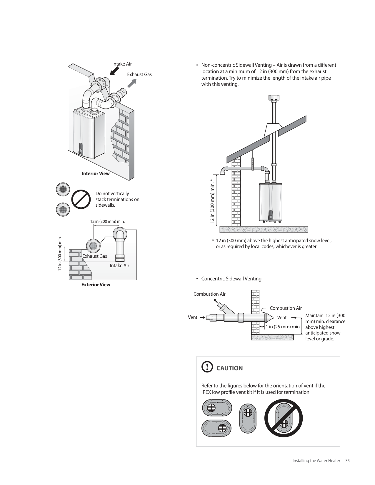
|Switch|Function|Setting|Setting| |---|---|---|---| |1|Cascade Vent|Common Vent|1-OFF| |1|Cascade Vent|Individual Vent|1-ON| |2|Gas Type|Natural Gas|OFF| |2|Gas Type|Propane Gas|ON|
#### 4. Installing a Cascade System
When installing a cascade system, carefully consider the design of the system and the features of the installation location. Follow all local codes and regulations, as well as all guidelines for installing the water heater. The following sections describe additional considerations that are specific to installing cascade systems. Read them carefully before designing or installing the system.
###### 4.1 Connecting Water Supplies
Several options are available for plumbing a cascade system of water heaters. The options shown here are only examples. The setup you choose will vary based on the installation location, local building codes, and other factors. Follow all applicable regulations when installing a cascade system.
You can connect up to 16 water heaters to meet high-volume hot water demands. Some possible connection options include the following: Recirculation via Internal Pumps (“A” model only):
| | | | | |---|---|---|---| | | | | |
| | | | | |---|---|---|---| | | | | |
Communication Cable
| | | | | |---|---|---|---| | | | | |
Union Ball Valve Check Valve Faucet Expansion Tank Pressure Relief Valve
DHW Supply Line
Recirculation Line
| | | | |---|---|---| | | | |
Gas Supply Line
Cold Water Supply Line
############### [NPE-180A/ 210A/ 240A]
Note The recommended minimum recirculation flow rate for each water heater is 2 GPM. Depending on the number of water heaters and the diameter of the recirculation line, it may not be necessary to connect all water heaters to the recirculation line. If this is the case, set the unconnected water heaters to internal recirculation mode. The master water heater must always be connected to the recirculation line and set to external recirculation mode.
Multiple NPE-S Units:
| | | | | |---|---|---|---| | | | | |
| | | | | |---|---|---|---|
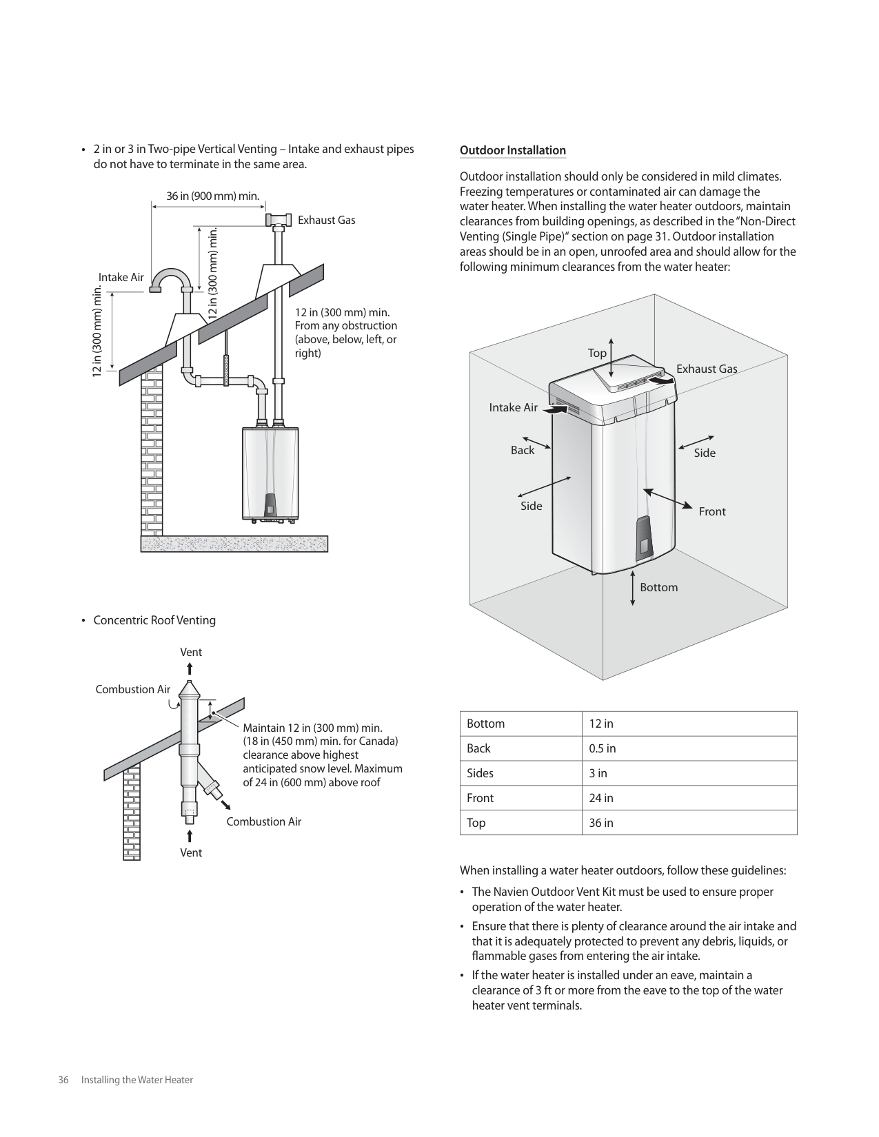
| | | | |
Communication Cable
| | | | | |---|---|---|---| | | | | |
Union Ball Valve Check Valve Faucet Expansion Tank Pressure Relief Valve
DHW Supply Line
Gas Supply Line
| | | |---|---| | | |
Cold Water Supply Line
[NPE-150S/ 180S/ 210S/ 240S]
########## 4.1.1 Piping Sizes and Considerations
When plumbing a cascade system, consider the following pipe diameters and flow rates. Note that flow rates above 6.6 ft/s may cause pipe erosion. These specifications may vary depending on installation conditions.
|Qty|ΔT=54ºF Flow rate (GPM)|Water Velocity (ft/s)|Pipe Diameter (mm/in)|Pipe Diameter (mm/in)| |---|---|---|---|---| |1|7.19|4.78|20A|3/4 in| |2|14.38|5.61|25A|1 in| |3|21.57|5.54|30A|1 1/4 in| |4|28.77|5.21|40A|1 1/2 in| |5|35.96|6.53|40A|11/2 in| |6|43.15|4.49|50A|2 in| |7|50.34|5.24|50A|2 in| |8|57.5|6.00|50A|2 in| |9|64.72|4.39|65A|2 1/2 in| |10|71.92|4.75|65A|2 1/2 in| |11|79.11|5.34|65A|2 1/2 in| |12|86.30|5.84|65A|2 1/2 in| |13|93.49|6.33|65A|2 1/2 in| |14|100.68|6.79|65A|2 1/2 in| |15|107.87|5.11|80A|3 in| |16|115.07|5.44|80A|3 in| |17|122.26|5.81|80A|3 in| |18|129.45|6.14|80A|3 in| |19|136.64|6.46|80A|3 in| |20|143.83|6.83|80A|3 in| |21|151.02|4.06|100A|4 in| |22|158.21|4.25|100A|4 in| |23|165.41|4.45|100A|4 in| |24|172.60|4.65|100A|4 in| |25|179.79|4.85|100A|4 in| |26|186.98|5.05|100A|4 in| |27|194.17|5.24|100A|4 in| |28|201.36|5.44|100A|4 in| |29|208.56|5.61|100A|4 in| |30|215.75|5.81|100A|4 in|
Note The table above is based on model NPE-240A.
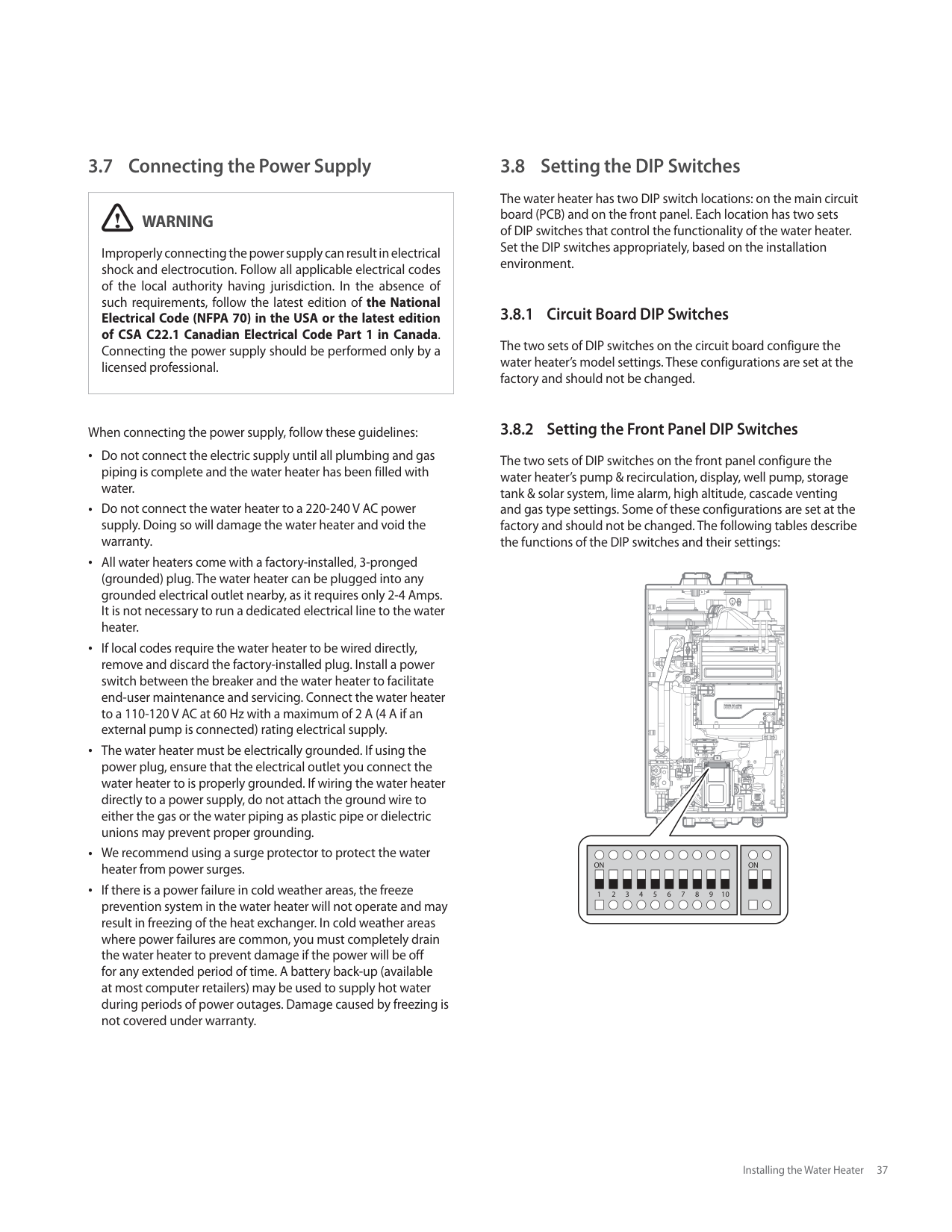
40 Installing a Cascade System
###### 4.2 Connecting the Communication Cables
Up to 16 water heaters can be connected with Navien Ready-Link communication cables. Select one of the water heaters in the cascade system as the master water heater, and then connect the other water heaters to it as slaves. Before making any connections, ensure that the power is turned off to all water heaters.
Connect the Ready-Link cables to the J6 ports on the right side of the front panel:
########## 4.2.1 Configuring the Communication Settings
After connecting the Ready-Link communication cables, restore power to the water heater and turn on all water heaters using the Power button.
To configure the communication settings:
Note To add additional slaves at a later time, repeat step
#### 5. Installing a Common Vent System
###### About the Common Vent System
The Navien Common Vent System* provides an easy way to install the vent system for up to 8 Navien NPE water heater units. By sharing the main intake and exhaust vent pipes, effective system venting is available with less venting materials and minimal number of penetrations on the walls or roofing.
Read all safety messages and carefully follow the guidelines in this manual when installing a common vent system for the Navien NPE water heater units.
|WARNING
Improper venting of the water heater units can result in excessive levels of carbon monoxide, which can lead to severe personal injury or death. The water heater units must be vented in accordance with the “Venting of Equipment“ section of the latest edition of the ANSI Z223.1/NFPA 54 Natural Fuel Gas Code in the USA, as well as all applicable local building codes and regulations. Follow all instructions and guidelines when venting the water heater units. Venting should be performed only by a licensed professional.| |---|
Guidelines for a Common Vent System
|CAUTION
To ensure the correct operation of the common vent system,
- a cascade communication cable MUST be installed between all units in the common vent system by the installer.
- backflow vent dampers must be installed in the exhaust duct of each water heater unit.
- use direct vent systems (with separate intake and exhaust lines).
This section covers the installation of a common vent system for NPE water heaters only.| |---|
To ensure the safe and correct installation of the common vent system, carefully follow the instructions and guidelines.
Check to see if all contents are included in the package (refer to the “Included Items” on page 46). A maximum of 8 NPE water heaters may be connected to one common vent system. In a cascade system that has more than 8 water heaters, use 2 common vent systems, or consult Navien. Use only the PVC cements specified in this manual when connecting pipes, joints, or elbows. Position the water heater units as close as possible to the vent termination. Install a new vent system with this appliance. If an existing vent system is reused, thoroughly inspect it for punctures, cracks, or blockages prior to connecting it to the water heater unit. The common vent system covered in this manual is approved only for direct venting applications. Horizontal vent pipe runs must be supported every 4 feet (1.2 m) (minimum). All vertical vent pipe runs must be supported every 6 feet (1.8 m) (minimum). Support the vent pipe with hangers at regular intervals or as required by local codes. Install a backflow damper for each water heater unit. Use only the damper specified in this manual. To avoid moisture and frost build-up and to maintain clearances to openings on adjacent homes, 45° elbows, 90° elbows, or tees may be attached to the end of the termination vent pipe to direct the exhaust plumes away from buildings, as long as the total allowable vent lengths, maximum number of elbows, and distances to air intake restrictions are observed. If the water heater units will be installed in areas where snow is known to accumulate, protect the vent termination from blockage. Provide a minimum of 1 foot (30 cm) clearance from the bottom of the exhaust of the expected snow accumulation level. Snow removal may be necessary to maintain clearance. Ensure that the vent termination is at least 12 in (305 mm) above ground, 12 in (305 mm) above the highest anticipated snow level, or as required by local codes, whichever is greater. Support the vent pipe with hangers at regular intervals or as required by local codes. The vent for this appliance shall not terminate over public walkways; or near soffit vents or crawl space vents or where condensate or vapor could create a nuisance or hazard or cause property damage; or where condensate or vapor could cause damage or could be detrimental to the operation of regulators, relief valves, or other equipment.
######### Clearances Between Multiple Units
Ensure that the installed water heaters satisfy all installation clearances provided in the manual. It is essential that there is sufficient clearance space for the common vent system to work properly.
The water heater units can be mounted either IN-LINE or BACK TO BACK.
Navien Modular Configuration with Rack System
In-line Setup Back to Back Setup
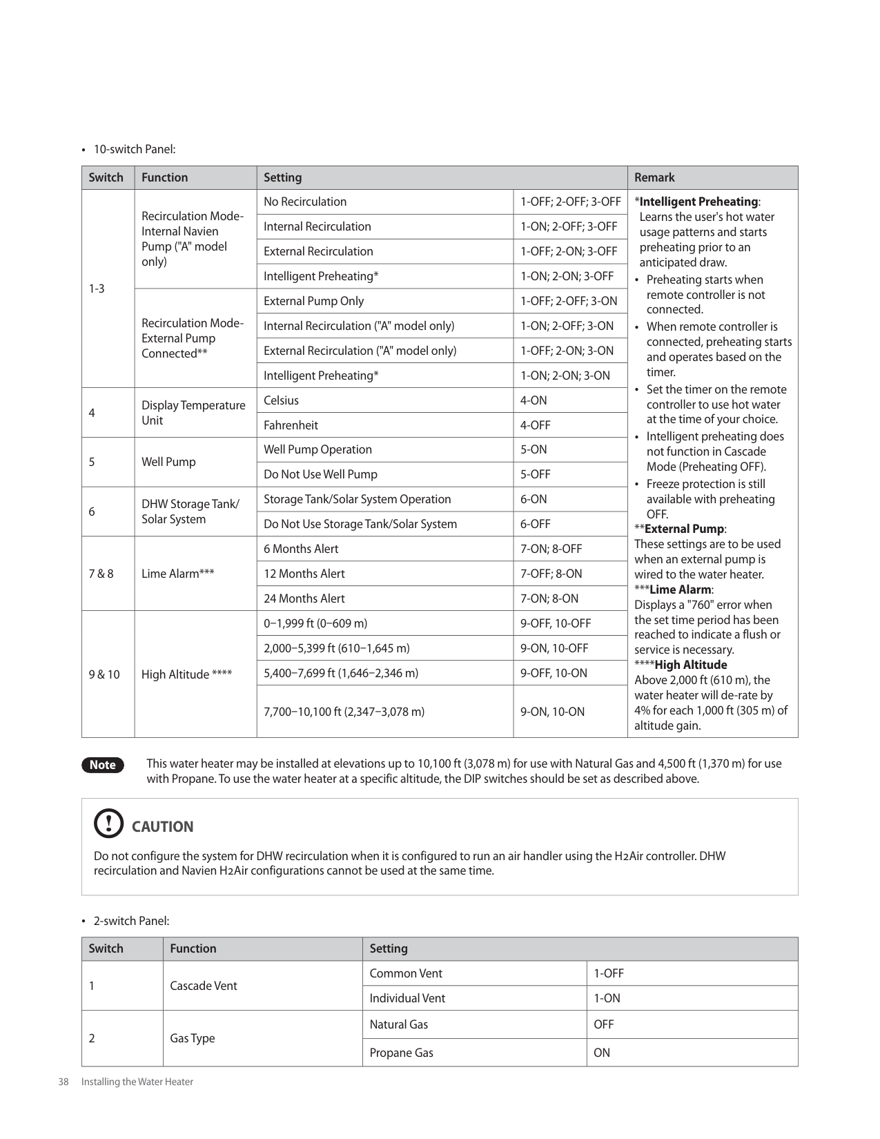

|Bottom|12” (300 mm)| |---|---| |Back|0.5” (13 mm)| |Side|3” (76 mm)| |Front|24” (609 mm)| |Top|36” (914 mm)|
######### General and Local Standards Information
When installing and operating the common vent system, the following standards and regulations must be complied with and adhered to:
Local codes or, in the absence of local codes, the National Fuel Gas Code, ANSI Z223.1/NFPA 54. Appliance manufacturer’s Installation Instructions. Regulations on the supervision of construction. Statutory provisions. Installation and service work must be carried out by licensed professionals only.
######### Risk Guidelines
Ensure that all common vent system components are manufactured and installed in accordance with valid standards, regulations, and safety engineering rules. To avoid risk, the common vent system must be installed and used only for the original purpose described in this manual. Defects or damages found in a common vent system must be addressed and repaired immediately. For roof or chimney modifications, refer to the relevant industrial safety regulations. Works on roofs and facades are dangerous. Comply with all relevant regulations.
######### Cutting and Assembling Common Vent System Components
Standard tools are suitable for the cutting and assembly of common vent system components. Follow the guidelines listed below when working with the components.
When cutting vent components, ensure that the cuts are straight. Chamfer and deburr all edges before installing the components. All vent joints must be fully tightened. Before operating the system, ensure that the Installed vent system is clean and free of debris. Ensure that the vent system is rigidly supported according to the manual’s instructions.
######### Selecting Vent Pipe Materials
Consult the following chart or the most recent edition of ANSI Z223.1/NFPA 54, as well as all applicable local codes and regulations when selecting vent pipe materials. This appliance should be vented with materials approved for Category IV gas appliances. Do not use cellular core PVC (ASTM F891), cellular core CPVC, or Radel® (polyphenolsulfone) for the exhaust vent. See below for recommended vent materials.
|Locale|Recommended Vent Materials| |---|---| |USA|PVC Schedule 40 (Solid Core) CPVC Schedule 40 or 80 (Solid Core)|
######### Vent Pipe Pitch and Supports
For horizontal runs, slope the horizontal section upward toward the vent termination at a rate of 1/4” per foot (2% slope).
######### Connecting Pipes with Cement
|CAUTION
The vapors from primers and solvent cements can make you dizzy and are dangerous to your health. Ensure that the work area is well ventilated, or wear an approved organic vapour respirator when working with primers and solvent cements.| |---|
To connect the vent pipes using cement:
Note Use approved solvent type cement for the proper vent materials. Use solvent type cement only. Check the date of manufacture before using the cement. Ensure that cement was not manufactured more than 2 years prior to using it. Ensure that the inside of the pipe fitting and the outside of the pipe, where cement will be applied, is clean. Apply an even layer of cement over all mating surfaces. Use solvent cement in room temperatures higher than 32 (0 ). Installing vent pipe with cement in cold ambient temperatures can result in longer cure times.
|DANGER
Be careful not to apply force or impact to pipes after making connections. An impact may break the bond and harmful gas might leak inside the room.| |---|
Determining the Length of a Common Vent System Follow the instructions listed below to determine the length of a common vent.
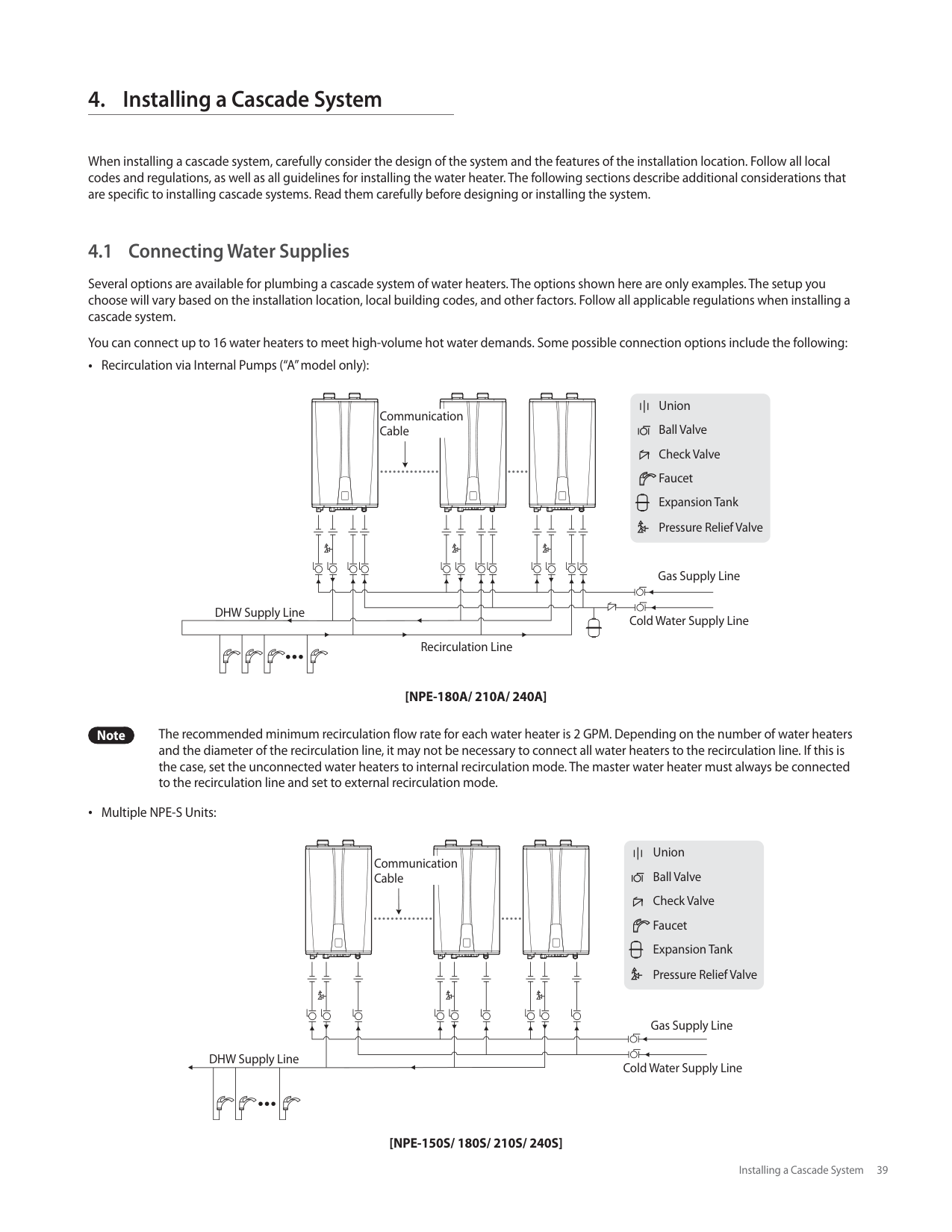
Exhaust
D W
H
Intake
######### Common Vent Length Table [Total Length (L) = W + H]
########### Vent Length for NPE Water Heater Units
|Required Load (Total BTU/H)|Model|Total Length (ft)|Total Length (ft)|Total Length (ft)|Total Length (ft)| |---|---|---|---|---|---| |Required Load (Total BTU/H)|NPE-240A/S|D=3”|D=4”|D=6”|D=8”| |399,800|2|60|106|200| | |599,700|3|40|71|160| | |799,600|4|30|53|120| | |999,500|5| | |96|150| |1,199,400|6| | |80|142| |1,393,300|7| | |68|121| |1,599,200|8| | |60|106|
Note Every 90° elbow used is equivalent to 8 linear feet (2.4
m) of vent length.
######### Example of a Typical Installation (Direct Vent Only)
The following illustration depicts an example of a common vent system installed for a cascade system of 8 Navien NPE heater units.
Note The illustration is intended for reference purposes
only.
###### Navien Backflow Damper (Back-draft Damper)
The Navien backflow damper prevents backflow (back-draft) at the exhaust vent while the water heater unit operates.
By closing the exhaust vent as soon as the combustion cycle ends, the Navien backflow damper retains heat in the system for longer periods. This improves the system’s thermal efficiency.
Note When using a common vent in a cascade system, backflow devices are required to prevent exhaust from entering the building.
Included Items
|Backflow Damper| | |---|---| |Installation Manual|ndensin
g Water Heater
Common Vent SystemInstallation Manual For NPE Series Water Heate

WARNI

| |Ready-Link communication cable| | |Screw (4 ea)||
Specifications
5.9” (150 mm)
1.1” (28 mm)
|Part Name|Backflow Damper| |---|---|
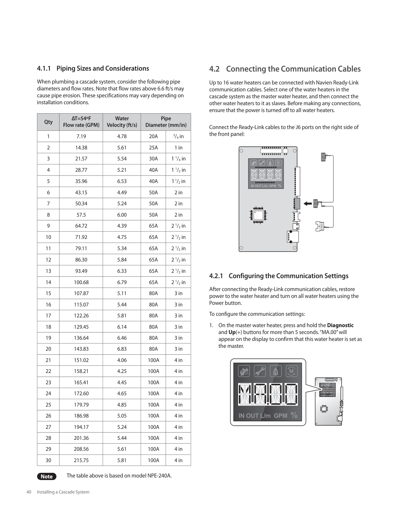
|Part No.|30014367A| |Material|PP (Polypropylene)|
######### Maintenance Port
Navien Backflow Damper has a maintenance port to allow you to easily inspect the operating condition of the damper plate.
Damper plate
Maintenance port
Maintenance port
Gasket Maintenance port cover Fix screw
Refer to < Maintenance> for detailed inspection procedures. Navien Backflow Damper (Back-draft Damper)
Note When using a common vent in a cascade system, backflow devices are required to prevent exhaust from entering the building.
###### Starting the Common Vent System
########## Backflow Damper Assembly
Follow the instructions below to assemble the backflow damper on the NPE water heater units:
########## Connecting the Pipe to the Damper


########## Assembling the T Joint
Apply Cement
8”-to-2” reducer
Note Multiple reducers can be used to allow proper connection of 2" vent pipe to the common vent system.
############## Apply Cement
###### Connecting and Terminating the Vent Pipe
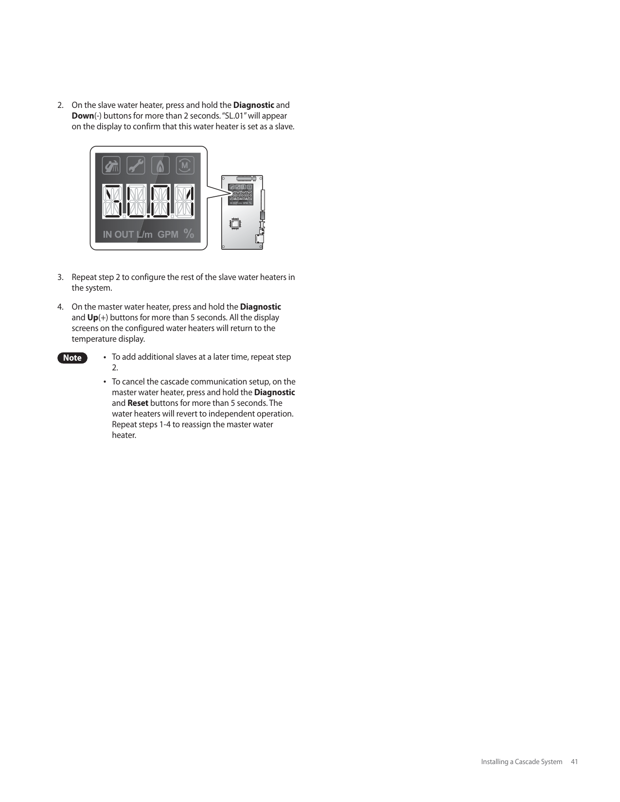
Refer to the following example to install the common vent system. The installation area should be measured to ensure that sufficient space is available to install the water heater units and the common vent system. Ensure that the common vent system is installed near the water heater units while satisfying all clearance requirements that are specified in this manual as well as the Installation Manuals supplied with the water heater units.
########## Connecting the Main Pipe Runs to T Joint
After connecting the tee joint to the 8”-to-2” reducer, connect the main trunk pipe to each side of the tee. Each trunk pipe is connected to the other tee joint. Refer to <”Connecting Pipes with Cement”> on page 44 for more information.
########## Installing the System Termination
End caps, pipe elbows or tee joints can be used at the open ends of the intake and exhaust vent pipes. Refer to the following installation examples that depict how the parts are fitted at the end of the common vent system piping.

Note The illustration is intended for reference purposes only.
###### Setting Up the Common Vent System
|DANGER
Incorrect DIP switch settings may lead to severe personal injury, death, or property damage.| |---|
################# Refer to the following figures when setting DIP switches.
| | | |---|---| | | |
| | | | |---|---|---| | | | |

| | | |---|---| | | |
| | | | | | |---|---|---|---|---| | | | | | |
ON ON
1 2 3 4 5 6 7 8 9 10
|Switch (2–Switch DIP)|Function|Setting|Setting| |---|---|---|---| |1|Cascade Vent Settings|Common Vent|1-OFF| |1|Cascade Vent Settings|Individual Vent|1-ON|
| | | |---|---| | | |
| | | | |---|---|---| | | | |

| | | |---|---| | | |
| | | | | | |---|---|---|---|---| | | | | | |
ON ON
1 2 3 4 5 6 7 8 9 10
|Switch (10–Switch DIP)|Function|Setting|Setting| |---|---|---|---| |9 & 10|High Altitude Settings|0 – 1,999 ft (0 – 609 m)|9-OFF,
10-OFF
| |9 & 10|High Altitude Settings|2,000 – 4,500 ft (610 – 1,372 m)|9-ON,
10-OFF
|
Note The NPE series water heaters may be installed at elevations up to 4,500 ft (1,372 m) for use with Natural Gas and Propane. To use the water heaters in the common vent system at a specific altitude, the DIP switches should be set as described above.
###### Common Vent Termination Clearances
########## Direct Vent Application – Vertical Installation
36" (91cm) min.
Exhaust
Intake
12" (30cm) min.
12" (30 cm) min.
End Cap
########## Venting Intake and Exhaust to Different Locations
Exhaust
End Cap
Intake
########## Direct Vent Application – Horizontal Installation
Exhaust
Maximum length 20’ (6 m)
Minimum length 36” (91 m)
Intake
Note The illustration is intended for reference purposes only. Direct the exhaust away from any building openings.
During cold weather situations, the temperature of the exhaust will be much warmer than the ambient air. Therefore, you will see water vapor being produced at the termination.
###### Exhaust Vent Termination Clearances (For Direct Vent)
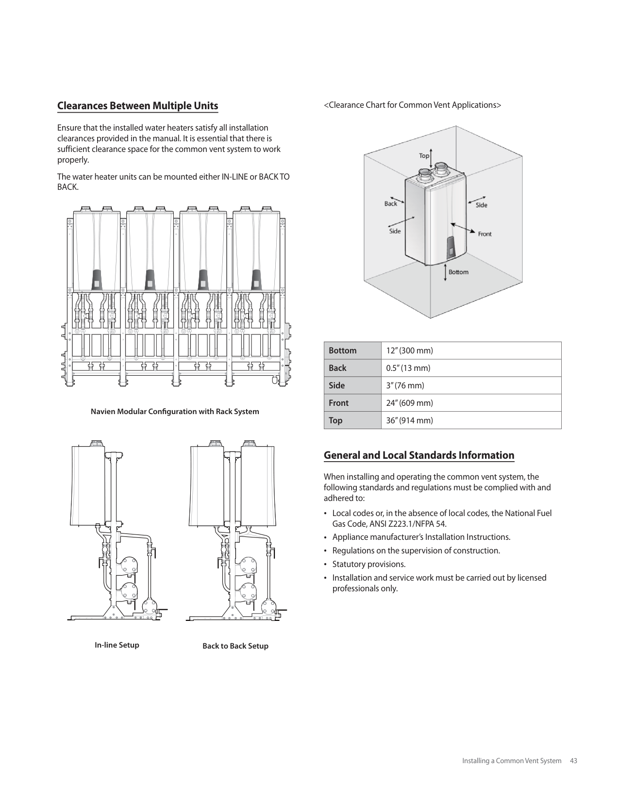

|Ref|Description|Canadian Direct Vent Installations1|U.S. Direct Vent Installations2| |---|---|---|---| |A|Clearance above grade, veranda, porch, deck, or balcony|12 in (30 cm)|12 in (30 cm)| |B|Clearance to window or door that may be opened|12 in (30 cm)|12 in (30 cm)| |C|Clearance to permanently closed window|*|*| |D|Vertical clearance to ventilated soffit located above the terminal within a horizontal distance of 2 feet (61 cm) from the center line of the terminal|*|*| |E|Clearance to unventilated soffit|*|*| |F|Clearance to outside corner|*|*| |G|Clearance to inside corner|*|*| |H|Clearance to each side of center line extended above meter/regulator assembly|3 ft (91 cm) within a height 15 ft above the meter/regulator assembly|*| |I|Clearance to service regulator vent outlet|3 ft (91 cm)|*| |J|Clearance to nonmechanical air supply inlet to building or the combustion air inlet to any other appliance|36 in (91 cm)|12 in (30 cm)| |K|Clearance to a mechanical air supply inlet|6 ft (1.83 m)|3 ft (91 cm) above if within10 ft (3 m) horizontally| |L|Clearance above paved sidewalk or paved driveway located on public property|7 ft (2.13 m)†|*| |M|Clearance under veranda, porch deck, or balcony|12 in (30 cm)‡|*|
###### Maintenance
Periodically check the damper condition inside the backflow damper through the maintenance port to ensure optimal performance of the system. Follow the instructions to check the damper condition and replace the backflow damper if necessary.
Maintenance port
Gasket Maintenance port cover Fix screw
| | | |---|---| | | |
Damper plate is CLOSED.
|WARNING
Ensure that the gasket is properly installed under the maintenance port cover, after checking the operating condition of the damper plate through the maintenance port. Harmful exhaust gas may leak if the gasket is not installed, or if it is not installed properly.
Gasket| |---|
Damper plate is OPEN
#### 6. Appendixes
###### 6.1 Gas Conversion
This water heater is configured for Natural Gas from the factory. If conversion to Propane Gas is required, the conversion kit supplied with the water heater must be used.
|WARNING
This conversion kit shall be installed by a qualified service agency* in accordance with Navien’s instructions and all applicable codes and requirements of the authority having jurisdiction. The information in these instructions must be followed to minimize the risk of fire or explosion or to prevent property damage, personal injury or death. The qualified service agency is responsible for the proper installation of this kit. The installation is not proper and complete until the operation of the converted appliance is checked as specified in the manufacturer’s instructions supplied with the kit.| |---|
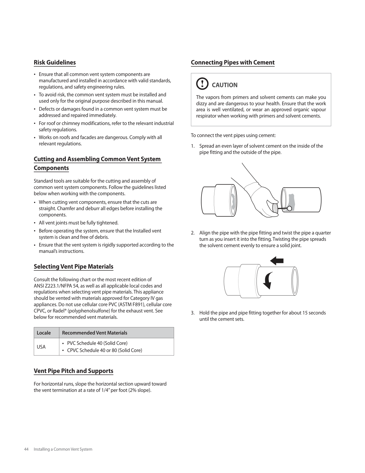
In Canada: The conversion shall be carried out in accordance with
the requirements of the provincial authorities having jurisdiction and in accordance with the requirements of the CAN‐B149.1 and CAN1‐B149.2 Installation Code.
Tools Required: Phillips Screwdriver Flathead Screwdriver 5/32 in or 4 mm Allen Wrench Combustion Analyzer or Dual Port Manometer Gas Leak Detector
########### Included Items:
Gas Orifice (refer to below table)
|Water Heater|NG|LP| |---|---|---| |NPE-150S|Ø6.30|Ø5.10|
|Water Heater|NG|NG|LP|LP| |---|---|---|---|---| |Water Heater|1STAGE|2STAGE|1STAGE|2STAGE| |NPE-180A NPE-180S|Ø4.80|Ø5.95|Ø3.80|Ø4.70| |NPE-210A NPE-210S|Ø6.10|Ø6.30|Ø4.50|Ø4.80|
|Water Heater|NG|NG|LP|LP| |---|---|---|---|---| |Water Heater|1STAGE|2STAGE|1STAGE|2STAGE| |NPE-240A NPE-240S|Ø6.10|Ø6.30|Ø4.50|Ø4.80|
Table 1. Orifice size
Gas Pressure and Conversion Kit Number Labels Procedure:
| | | | | | | | |---|---|---|---|---|---|---| | | | | | | | |
Figure 1. NPE Series Front cover
| | | |---|---| | | | | | | | | | | | | | | | | | | | | | | | | | | |
Gas Inlet Pipe
Gas Valve
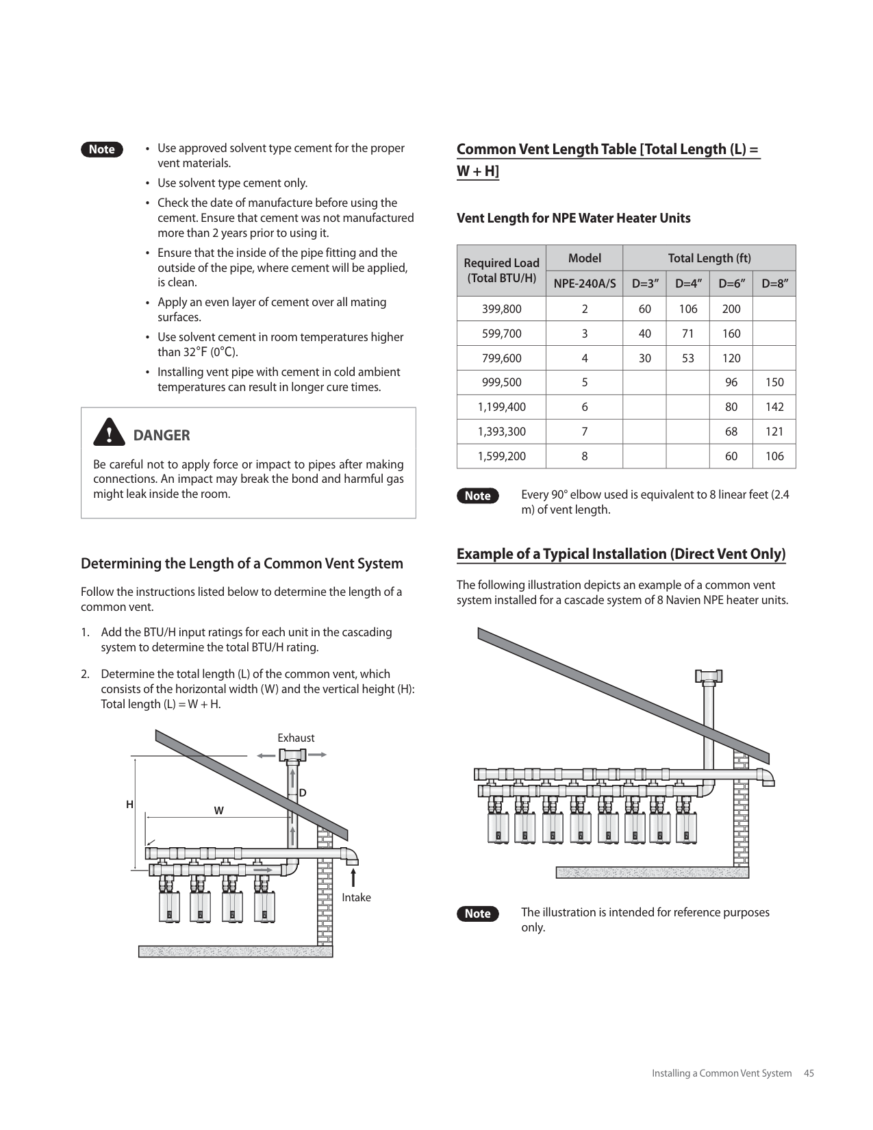
Figure 2. NPE Series Internal Components
Location B: Remove four
| | | |---|---| | | |
| | | |---|---| | | |
(4) screws here
| | | | |---|---|---| | | | |
| | | |---|---| | | |
| | | |---|---| | | |
| | | |---|---| | | |
| | |---| | |
Location A: Remove two (2)
screws here
| | | |---|---| | | |
Figure 3. Detaching Gas Valve from Gas Inlet Pipe and Fan Motor Assembly
| | | | |---|---|---| | | | |
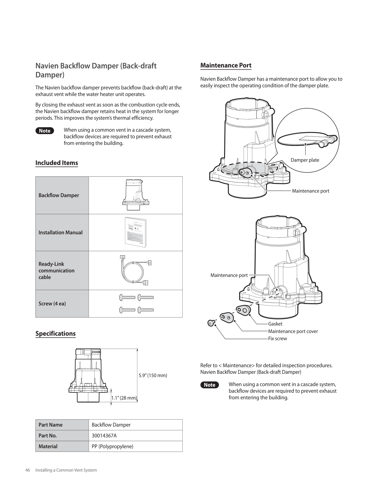
Remove two (2) screws here
| | | |---|---| | | |
| | |---| | |
| | | |---|---| | | |
Figure 4. Access to Gas Orifice in Fan Assembly
|WARNING
DO NOT adjust or attempt to measure gas valve outlet pressure. The gas valve is factory-set for the correct outlet pressure. This setting is suitable for natural gas and propane, requiring no field adjustment.
Attempting to alter or measure the gas valve outlet pressure could result in damage to the valve, causing potential severe personal injury, death or substantial property damage. Navien water heaters are shipped ready to fire natural gas ONLY.| |---|
Packing
Gas Orifice
O-ring
#################
Packing
Gas Orifice
O-ring
|DANGER
See Figure 5. Inspect the O-ring between the gas valve and gas valve inlet adapter whenever they are disassembled. The O-ring must be in good condition and must be installed. Failure to comply will cause a gas leak, resulting in severe personal injury or death.| |---|
LP
NG
NPE-150S NPE-180A/ 210A/ 240A/ 180S/ 210S/ 240S
Figure 6. Orifice identification
Packings Packing
Note Do not overtighten as this may damage or crack
the components.
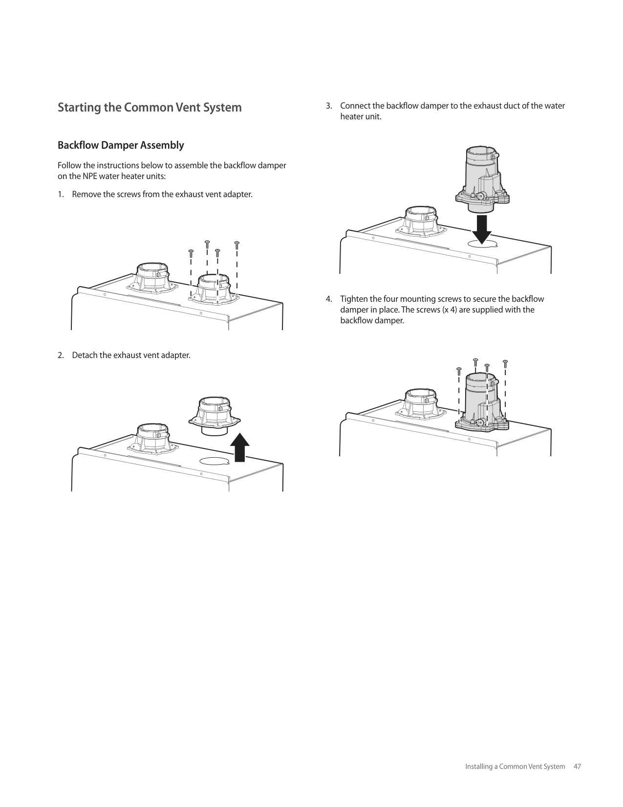
|WARNING
Be sure to turn off the power before changing the DIP switch setting.| |---|
|1 2 3 1 24 5 6 7 8 9 10
ON ON| |---|
#################### NG
LP
| | |---| | |
| | |---| | |
| | |---| | |
| | |---| | |
| | | |---|---| | | |
1 2
1 2
| | | |---|---|
|DANGER
When conversion is required, be sure to set the Front Panel DIP switches according to the supply gas type.
Failure to properly set the DIP switches could cause carbon monoxide poisoning, resulting in severe personal injury or death.| |---|
| | | | |---|---|---| | | | |
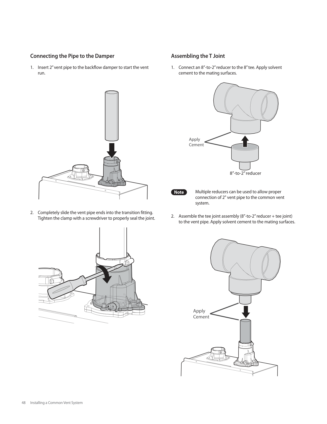


| | | |---|---| | | |
| | |---| | |
| | | |---|---| | | |
Figure 7
|Water Heater|Fuel|High fire|Low fire| |---|---|---|---| |Water Heater|Fuel|%CO2|%CO2| |NPE-150S|NG|8.9|9.5| |NPE-150S|LP|10.2|10.8| |NPE-180A NPE-180S|NG|8.9|9.5| |NPE-180A NPE-180S|LP|10.2|10.8| |NPE-210A NPE-210S|NG|8.9|9.5| |NPE-210A NPE-210S|LP|10.2|10.8| |NPE-240A NPE-240S|NG|8.9|9.5| |NPE-240A NPE-240S|LP|10.2|10.8|
Table 2. CO2 and CO value (CO2 values must be within 0.5% of the values listed.)
c. Fully open several hot water fixtures and set the water heater to operate at 1-stage MIN mode (refer to page 59). Measure the CO2 value at low fire. If the CO2 value is not within 0.5% of the value listed in Table 2, the gas valve set screw will need to be adjusted. If adjustment is necessary, locate the set screw as shown in Figure 8. Using a 5/32 in or 4 mm Allen wrench, turn the set screw no more than 1/4 turn clockwise to raise or counterclockwise to lower the CO2 value.
| | | | | | | | | |---|---|---|---|---|---|---|---| | | | | | | | | |
| | | | |---|---|---| | | | |
| | |---| | |
| | | |---|---| | | |
| | | |---|---|
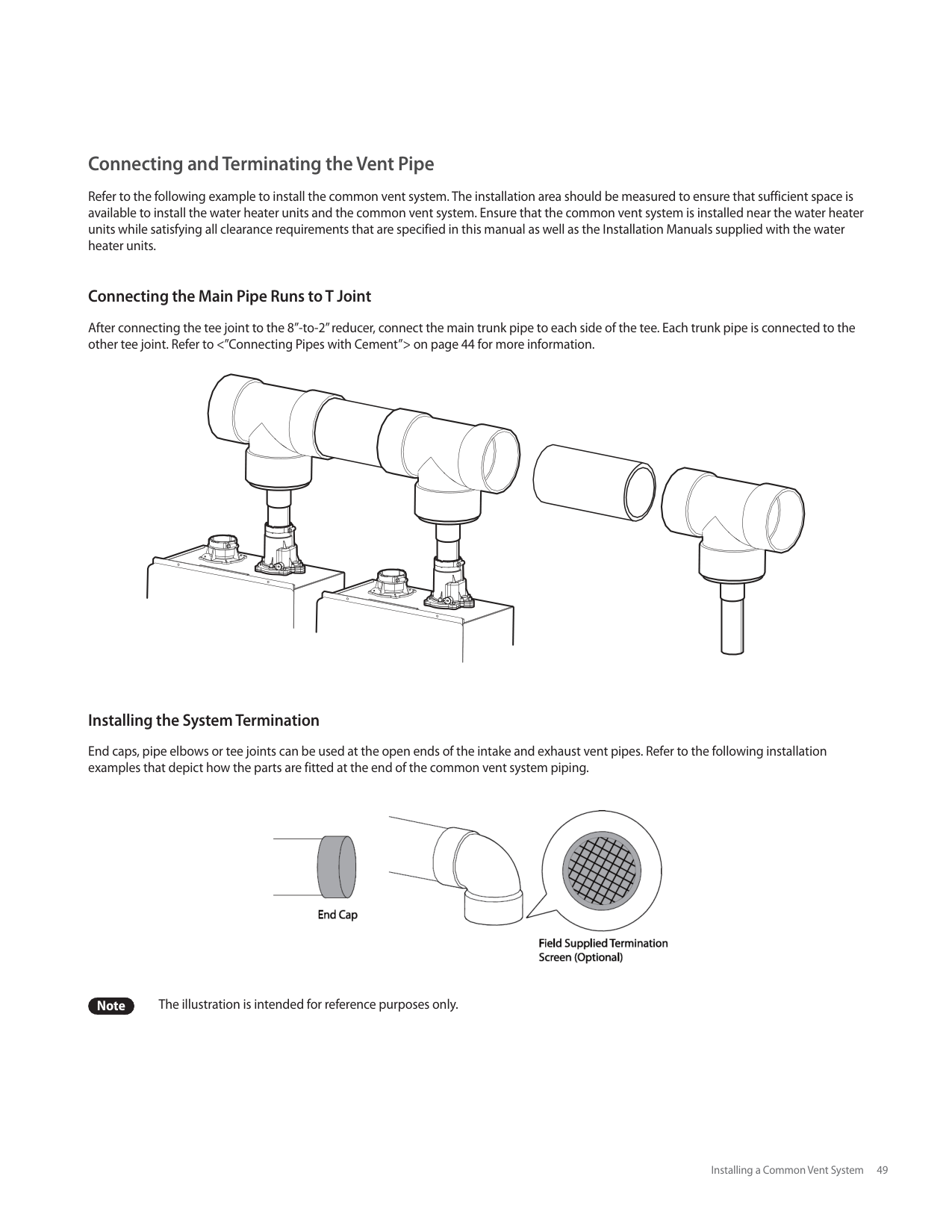
Figure 8. Set Screw Location
Note The set screw is located behind the screw-on cover. This must be removed first.
d. Fully open several hot water fixtures and set the water heater to operate at 2-stage MAX mode (refer to page 59). Measure the CO2 value at high fire. If the CO2 values do not match Table 2 at high fire, do not adjust the gas valve. Check for the proper Gas Orifice.
|DANGER
Improper gas valve settings can cause severe personal injury, death or substantial property damage.| |---|
| | | | | | | | | |---|---|---|---|---|---|---|---| | | | | | | | | |
| | | | | |---|---|---|---| | | | | | | | | | | | | | | | | | | | | | | | | | | | | | | | | | | | | | | | | | | | | |
| | | |---|---|
Figure 9
|Model|Kit Part No.|Gas Type|Offset| |---|---|---|---| |NPE-150S|NAC-N6|LP|-0.03 in ± 0.01 in| |NPE-150S|NAC-L6|NG|-0.04 in ± 0.01 in| |NPE-180A NPE-180S|NAC-01|LP|-0.03 in ± 0.01 in| |NPE-180A NPE-180S|NAC-100|NG|-0.04 in ± 0.01 in| |NPE-210A NPE-210S|NAC-02|LP|-0.02 in ± 0.01 in| |NPE-210A NPE-210S|NAC-200|NG|-0.04 in ± 0.01 in| |NPE-240A NPE-240S|NAC-03|LP|-0.02 in ± 0.01 in| |NPE-240A NPE-240S|NAC-300|NG|-0.04 in ± 0.01 in|
Table 3. Offset value for low fire
c. Fully open a hot water fixture and set the water heater to operate at 1-stage MIN mode (refer to page 59). Measure the offset value at low fire and compare it to the values in Table 3. If the offset value is out of range, the gas valve set screw will need to be adjusted. If adjustment is necessary, locate the set screw as shown in Figure 10. Using a 5/32 in or 4 mm Allen wrench, turn the set screw no more than 1/4 turn clockwise to raise or counterclockwise to lower the offset value.
| | | | | | | | | |---|---|---|---|---|---|---|---| | | | | | | | | |
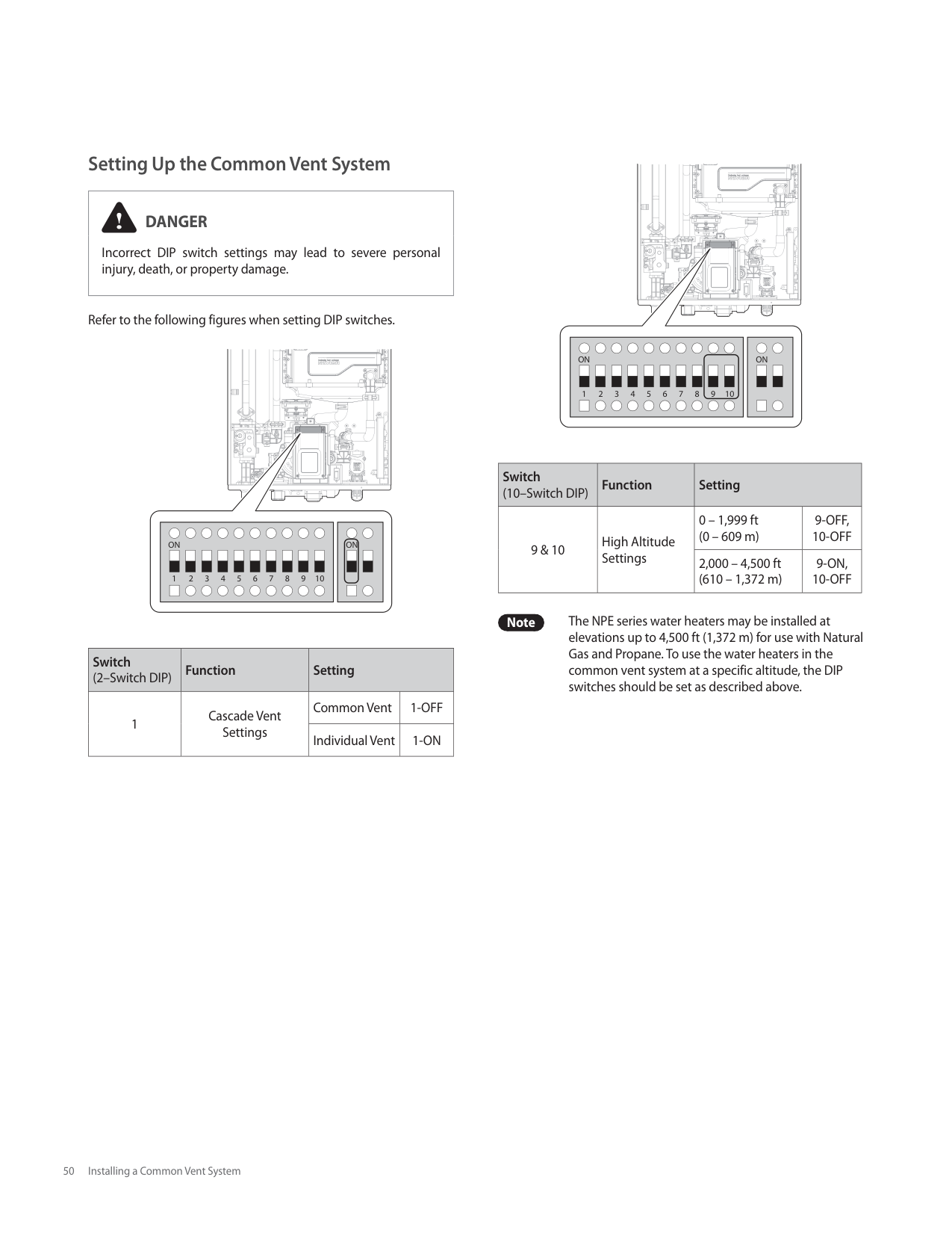
| | | | |---|---|---| | | | |
| | | |---|---| | | |
| | |---| | |
| | | |---|---| | | |
| | | |---|---|
Figure 10
Note The set screw is located behind the screw-on cover. This must be removed first.
d. At high fire, do not check the offset value and never adjust the gas valve.
|DANGER
Improper gas valve settings can cause severe personal injury, death or substantial property damage.| |---|
This unit has been converted to Propane fuel Cet appareil a ete converti au Propane
Orifice Size / Injecteur: Min. 4.5 mm to Max. 4.8 mm
Inlet Gas Pressure / Pression d'entrée du gaz: Min. 8.0 to Max. 13.0 inches
Manifold Gas Pressure / Pression à la tubulure d’alimentation: Min. -0.02 to Max. -0.66 inches WC
BTU Input / Debit calorifique: Max. 180,000 - Min. 19,900 BTUh
Conversion Kit No.: NAC-02
This water heater was converted on
______/______/______ to ____________ gas
with Kit No. ________________________
by _________________________________
(name and address of organization making this conversion, who accepts responsibility for the correctness of this conversion)
Figure 11. Proper Placement of Gas Conversion Labels
########## 6.1.1 Setting the Operation Mode
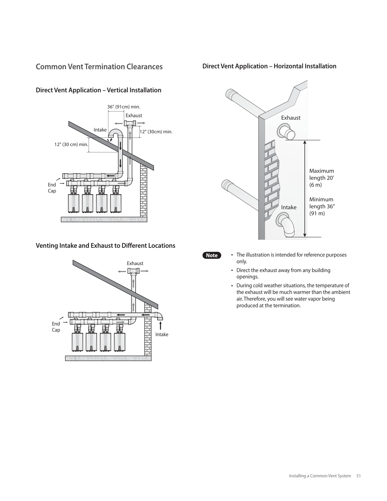
Diagnostics Information
Reset
###### 6.2 Technical Data
Pressure Drop Curve
| | | | | | | | | | | | | | | | | | | | | | | | | | | | | | | | | | | | | | | | | | | | | | | | | | | | |---|---|---|---|---|---|---|---|---|---|---|---|---|---|---|---|---|---|---|---|---|---|---|---|---|---|---|---|---|---|---|---|---|---|---|---|---|---|---|---|---|---|---|---|---|---|---|---|---|---|---| | | | | | | | | | | | | | | | | | | | | | | | | | | | | | | | | | | | | | | | | | | | | | | | | | | | | | | | | | | | | | | | | | | | | | | | | | | | | | | | | | | | | | | | | | | | | | | | | | | | | | | | | | | | | | | | | | | | | | | | | | | | | | | | | | | | | | | | | | | | | | | | | | | | | | | | | | | | | | | | | | | | | | | | | | | | | | | | | | | | | | | | | | | | | | | | | | | | | | | | | | | | | | | | | | | | | | | | | | | | | | | | | | | | | | | | | | | | | | | | | | | | | | | | | | | | | | | | | | | | | | | | | | | | | | | | | | | | | | | | | | | | | | | | | | | | | | | | | | | | | | | | | | | | | | | | | | | | | | | | | | | | | | | | | | | | | | | | | | | | | | | | | | | | | | | | | | | | | | | | | | | | | | | | | | | | | | | | | | | | | | | | | | | | | | | | | | | | | | | | | | | | | | | | | | | | | | | | | | | | | | | | | | | | | | | | | | | | | | | | | | | | | | | | | | | | | | | | | | | | | | | | | | | | | | | | | | | | | | | | | | | | | | | | | | | | | | | | | | | | | | | | | | | | | | | | | | | | | | | | | | | | | | | | | | | | | | | | | | | | | | | | | | | | | | | | | | | | | | | | | | | | | | | | | | | | | | | | | | | | | | | | | | | | | | | | | | | | | | | | | | | | | | | | | | | | | | | | | | | | | | | | | | | | | | | | | | | | | | | | | | | | | | | | | | | | | | | | | | | | | | | | | | | | | | | | | | | | | | | | | | | | | | | | | | | | | | | | | | | | | | | | | | | | | | | | | | | | | | | | | | | | | | | | | | | | | | | | | | | | | | | | | | | | | | | | | | | | | | | | | | | | | | | | | | | | | | | | | | | | | | | | | | | | | | | | | | | | | | | | | | | | | | | | | | | | | | | | | | | | | | | | | | | | | | | | | | | | | | | | | | | | | | | | | | | | | | | | | | | | | | | | | | | | | | | | | | | | | | | | | | | | | | | | | | | | | | | | | | | | | | | | | | | | | | | | | | | | | | | | | | | | | | | | | | | | | | | | | | | | | | | | | | | | | | | | | | | | | | | | | | | | | | | | | | | | | | | | | | | | | | | | | | | | | | | | | | | | | | | | | | | | | | | | | | | | | | | | | | | | | | | | | | | | | | | | | | | | | | | | | | | | | | | | | | | | | | | | | | | | | | | | | | | | | | | | | | | | | | | | | | | | | | | | | | | | | | | | | | | | | | | | | | | | | | | | | | | | | | | | | | | | | | | | | | | | | | | | | | | | | | | | | | | | | | | | | | | | | | | | | | | | | | | | | | | | | | | | | | | | | | | | | | | | | | | | | | | | | | | | | | | | | | | | | | | | | | | | | | | | | | | | | | | | | | | | | | | | | | | | | | | | | | | | | | | | | | | | | | | | | | | | | | | | | | | | | | | | | | | | | | | | | | | | | | | | | | | | | | | | | | | | | | | | | | | | | | | | | | | | | | | | | | | | | | | | | | | | | | | | | | | | | | | | | | | | | | | | | | | | | | | | | | | | | | | | | | | | | | | | | | | | | | | | | | | | | | | | | | | | | | | | | | | | | | | | | | | | | | | | | | | | | | | | | | | | | | | | | | | | | | | | | | | | | | | | | | | | | | | | | | | | | | | | | | | | | | | | | | | | | | | | | | | | | | | | | | | | | | | | | | | | | | | | | | | | | | | | | | | | | | | | | | | | | | | | | | | | | | | | | | | | | | | | | | | | | | | | | | | | | | | | | | | | | | | | | | | | | | | | | | | | | | | | | | | | | | | | | | | | | | | | | | | | | | | | | | | | | | | | | | | | | | | | | | | | | | | | | | | | | | | | | | | | | | | | | | | | | | | | | | | | | | | | | | | | | | | | | | | | | | | | | | | | | | | | | | | | | | | | | | | | | | | | | | | | | | | | | | | | | | | | | | | | | | | | | | | | | | | | | | | | | | | | | | | | | | | | | | | | | | | | | | | | | | | | | | | | | | | | | | | | | | | | | | | | | | | | | | | | | | | | | | | | | | | | | | | | | | | | | | | | | | | | | | | | | | | | | | | | | | | | | | | | | | | | | | | | | | | | | | | | | | | | | | | | | | | | | | | | | | | | | | | | | | | | | | | | | | | | | | | | | | | | | | | | | | | | | | | | | | | | | | | | | | | | | | | | | | | | | | | | | | | | | | | | | | | | | | | | | | | | | | | | | | | | | | | | | | | | | | | | | | | | | | | | | | | | | | | | | | | | | | | | | | | | | | | | | | | | | | | | | | | | | | | | | | | | | | | | | | | | | | | | | | | | | | | | | | | | | | | | | | | | | | | | | | | | | | | | | | | | | | | | | | | | | | | | | | | | | | | | | | | | | | | | | | | | | | | | | | | | | | | | | | | | | | | | | | | | | | | | | | | | | | | | | | | | | | | | | | | | | | | | | | | | | | | | | | | | | | | | | | | | | | | | | | | | | | | | | | | | | | | | | | | | | | | | | | | | | | | | | | | | | | | | | | | | | | | | | | | | | | | | | | | | | | | | | | | | | | | | | | | | | | | | | | | | | | | | | | | | | | | | | | | | | | | | | | | | | | | | | | | | | | | | | | | | | | | | | | | | | | | | | | | | | | | | | | | | | | | | | | | | | | | | | | | | | | | | | | | | | | | | | | | | | | | | | | | | | | | | | | | | | | | | | | | | | | | | | | | | | | | | | | | | | | | | | | | | | | | | | | | | | | | | | | | | | | | | | | | | | | | | | | | | | | | | | | | | | | | | | | | | | | | | | | | | | | | | | | | | | | | | | | | | | | | | |
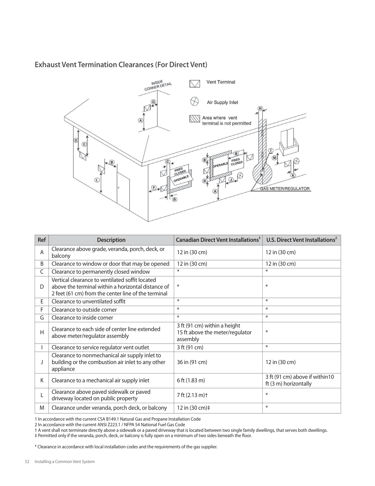
| | | | | | | | | | | | | | | | | | | | | | | | | | | | | | | | | | | | | | | | | | | | | | | | | | | |
[NPE-240A/ 240S]
| | | | | | | | | | | | | | | | | | | | | | | | | | | | | | | | | | | | | | | | | | | | | | | | | | | | |---|---|---|---|---|---|---|---|---|---|---|---|---|---|---|---|---|---|---|---|---|---|---|---|---|---|---|---|---|---|---|---|---|---|---|---|---|---|---|---|---|---|---|---|---|---|---|---|---|---|---| | | | | | | | | | | | | | | | | | | | | | | | | | | | | | | | | | | | | | | | | | | | | | | | | | | | | | | | | | | | | | | | | | | | | | | | | | | | | | | | | | | | | | | | | | | | | | | | | | | | | | | | | | | | | | | | | | | | | | | | | | | | | | | | | | | | | | | | | | | | | | | | | | | | | | | | | | | | | | | | | | | | | | | | | | | | | | | | | | | | | | | | | | | | | | | | | | | | | | | | | | | | | | | | | | | | | | | | | | | | | | | | | | | | | | | | | | | | | | | | | | | | | | | | | | | | | | | | | | | | | | | | | | | | | | | | | | | | | | | | | | | | | | | | | | | | | | | | | | | | | | | | | | | | | | | | | | | | | | | | | | | | | | | | | | | | | | | | | | | | | | | | | | | | | | | | | | | | | | | | | | | | | | | | | | | | | | | | | | | | | | | | | | | | | | | | | | | | | | | | | | | | | | | | | | | | | | | | | | | | | | | | | | | | | | | | | | | | | | | | | | | | | | | | | | | | | | | | | | | | | | | | | | | | | | | | | | | | | | | | | | | | | | | | | | | | | | | | | | | | | | | | | | | | | | | | | | | | | | | | | | | | | | | | | | | | | | | | | | | | | | | | | | | | | | | | | | | | | | | | | | | | | | | | | | | | | | | | | | | | | | | | | | | | | | | | | | | | | | | | | | | | | | | | | | | | | | | | | | | | | | | | | | | | | | | | | | | | | | | | | | | | | | | | | | | | | | | | | | | | | | | | | | | | | | | | | | | | | | | | | | | | | | | | | | | | | | | | | | | | | | | | | | | | | | | | | | | | | | | | | | | | | | | | | | | | | | | | | | | | | | | | | | | | | | | | | | | | | | | | | | | | | | | | | | | | | | | | | | | | | | | | | | | | | | | | | | | | | | | | | | | | | | | | | | | | | | | | | | | | | | | | | | | | | | | | | | | | | | | | | | | | | | | | | | | | | | | | | | | | | | | | | | | | | | | | | | | | | | | | | | | | | | | | | | | | | | | | | | | | | | | | | | | | | | | | | | | | | | | | | | | | | | | | | | | | | | | | | | | | | | | | | | | | | | | | | | | | | | | | | | | | | | | | | | | | | | | | | | | | | | | | | | | | | | | | | | | | | | | | | | | | | | | | | | | | | | | | | | | | | | | | | | | | | | | | | | | | | | | | | | | | | | | | | | | | | | | | | | | | | | | | | | | | | | | | | | | | | | | | | | | | | | | | | | | | | | | | | | | | | | | | | | | | | | | | | | | | | | | | | | | | | | | | | | | | | | | | | | | | | | | | | | | | | | | | | | | | | | | | | | | | | | | | | | | | | | | | | | | | | | | | | | | | | | | | | | | | | | | | | | | | | | | | | | | | | | | | | | | | | | | | | | | | | | | | | | | | | | | | | | | | | | | | | | | | | | | | | | | | | | | | | | | | | | | | | | | | | | | | | | | | | | | | | | | | | | | | | | | | | | | | | | | | | | | | | | | | | | | | | | | | | | | | | | | | | | | | | | | | | | | | | | | | | | | | | | | | | | | | | | | | | | | | | | | | | | | | | | | | | | | | | | | | | | | | | | | | | | | | | | | | | | | | | | | | | | | | | | | | | | | | | | | | | | | | | | | | | | | | | | | | | | | | | | | | | | | | | | | | | | | | | | | | | | | | | | | | | | | | | | | | | | | | | | | | | | | | | | | | | | | | | | | | | | | | | | | | | | | | | | | | | | | | | | | | | | | | | | | | | | | | | | | | | | | | | | | | | | | | | | | | | | | | | | | | | | | | | | | | | | | | | | | | | | | | | | | | | | | | | | | | | | | | | | | | | | | | | | | | | | | | | | | | | | | | | | | | | | | | | | | | | | | | | | | | | | | | | | | | | | | | | | | | | | | | | | | | | | | | | | | | | | | | | | | | | | | | | | | | | | | | | | | | | | | | | | | | | | | | | | | | | | | | | | | | | | | | | | | | | | | | | | | | | | | | | | | | | | | | | | | | | | | | | | | | | | | | | | | | | | | | | | | | | | | | | | | | | | | | | | | | | | | | | | | | | | | | | | | | | | | | | | | | | | | | | | | | | | | | | | | | | | | | | | | | | | | | | | | | | | | | | | | | | | | | | | | | | | | | | | | | | | | | | | | | | | | | | | | | | | | | | | | | | | | | | | | | | | | | | | | | | | | | | | | | | | | | | | | | | | | | | | | | | | | | | | | | | | | | | | | | | | | | | | | | | | | | | | | | | | | | | | | | | | | | | | | | | | | | | | | | | | | | | | | | | | | | | | | | | | | | | | | | | | | | | | | | | | | | | | | | | | | | | | | | | | | | | | | | | | | | | | | | | | | | | | | | | | | | | | | | | | | | | | | | | | | | | | | | | | | | | | | | | | | | | | | | | | | | | | | | | | | | | | | | | | | | | | | | | | | | | | | | | | | | | | | | | | | | | | | | | | | | | | | | | | | | | | | | | | | | | | | | | | | | | | | | | | | | | | | | | | | | | | | | | | | | | | | | | | | | | | | | | | | | | | | | | | | | | | | | | | | | | | | | | | | | | | | | | | | | | | | | | | | | | | | | | | | | | | | | | | | | | | | | | | | | | | | | | | | | | | | | | | | | | | | | | | | | | | | | | | | | | | | | | | | | | | | | | | | | | | | | | | | | | | | | | | | | | | | | | | | | | | | | | | | | | | | | | | | | | | | | | | | | | | | | | | | | | | | | | | | | | | | | | | | | | | | | | | | | | | | | | | | | | | | | | | | | | | | | | | | | | | | | | | | | | | | | | | | | | | | | | | | | | | | | | | | | | | | | | | | | | | | | | | | | | | | | | | | | | | | | | | | | | | | | | | | | | | | | | | | | | | | | | | | | | | | | | | | | | | | | |
[NPE-210A/ 210S]
| | | | | | | | | | | | | | | | | | | | | | | | | | | | | | | | | | | | | | | | | | | | | | | | | | | | |---|---|---|---|---|---|---|---|---|---|---|---|---|---|---|---|---|---|---|---|---|---|---|---|---|---|---|---|---|---|---|---|---|---|---|---|---|---|---|---|---|---|---|---|---|---|---|---|---|---|---| | | | | | | | | | | | | | | | | | | | | | | | | | | | | | | | | | | | | | | | | | | | | | | | | | | | | | | | | | | | | | | | | | | | | | | | | | | | | | | | | | | | | | | | | | | | | | | | | | | | | | | | |
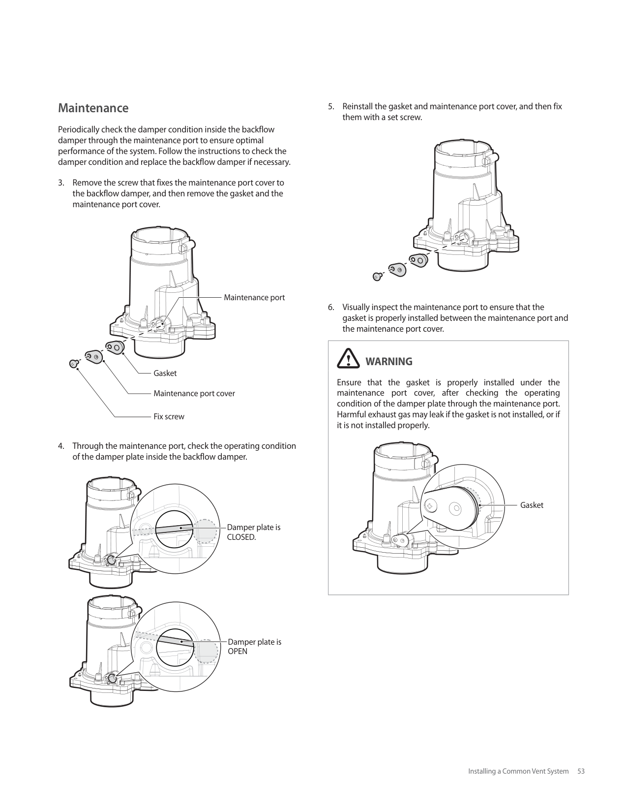
| | | | | | | | | | | | | | | | | | | | | | | | | | | | | | | | | | | | | | | | | | | | | | | | | | | | | | | | | | | | | | | | | | | | | | | | | | | | | | | | | | | | | | | | | | | | | | | | | | | | | | | | | | | | | | | | | | | | | | | | | | | | | | | | | | | | | | | | | | | | | | | | | | | | | | | | | | | | | | | | | | | | | | | | | | | | | | | | | | | | | | | | | | | | | | | | | | | | | | | | | | | | | | | | | | | | | | | | | | | | | | | | | | | | | | | | | | | | | | | | | | | | | | | | | | | | | | | | | | | | | | | | | | | | | | | | | | | | | | | | | | | | | | | | | | | | | | | | | | | | | | | | | | | | | | | | | | | | | | | | | | | | | | | | | | | | | | | | | | | | | | | | | | | | | | | | | | | | | | | | | | | | | | | | | | | | | | | | | | | | | | | | | | | | | | | | | | | | | | | | | | | | | | | | | | | | | | | | | | | | | | | | | | | | | | | | | | | | | | | | | | | | | | | | | | | | | | | | | | | | | | | | | | | | | | | | | | | | | | | | | | | | | | | | | | | | | | | | | | | | | | | | | | | | | | | | | | | | | | | | | | | | | | | | | | | | | | | | | | | | | | | | | | | | | | | | | | | | | | | | | | | | | | | | | | | | | | | | | | | | | | | | | | | | | | | | | | | | | | | | | | | | | | | | | | | | | | | | | | | | | | | | | | | | | | | | | | | | | | | | | | | | | | | | | | | | | | | | | | | | | | | | | | | | | | | | | | | | | | | | | | | | | | | | | | | | | | | | | | | | | | | | | | | | | | | | | | | | | | | | | | | | | | | | | | | | | | | | | | | | | | | | | | | | | | | | | | | | | | | | | | | | | | | | | | | | | | | | | | | | | | | | | | | | | | | | | | | | | | | | | | | | | | | | | | | | | | | | | | | | | | | | | | | | | | | | | | | | | | | | | | | | | | | | | | | | | | | | | | | | | | | | | | | | | | | | | | | | | | | | | | | | | | | | | | | | | | | | | | | | | | | | | | | | | | | | | | | | | | | | | | | | | | | | | | | | | | | | | | | | | | | | | | | | | | | | | | | | | | | | | | | | | | | | | | | | | | | | | | | | | | | | | | | | | | | | | | | | | | | | | | | | | | | | | | | | | | | | | | | | | | | | | | | | | | | | | | | | | | | | | | | | | | | | | | | | | | | | | | | | | | | | | | | | | | | | | | | | | | | | | | | | | | | | | | | | | | | | | | | | | | | | | | | | | | | | | | | | | | | | | | | | | | | | | | | | | | | | | | | | | | | | | | | | | | | | | | | | | | | | | | | | | | | | | | | | | | | | | | | | | | | | | | | | | | | | | | | | | | | | | | | | | | | | | | | | | | | | | | | | | | | | | | | | | | | | | | | | | | | | | | | | | | | | | | | | | | | | | | | | | | | | | | | | | | | | | | | | | | | | | | | | | | | | | | | | | | | | | | | | | | | | | | | | | | | | | | | | | | | | | | | | | | | | | | | | | | | | | | | | | | | | | | | | | | | | | | | | | | | | | | | | | | | | | | | | | | | | | | | | | | | | | | | | | | | | | | | | | | | | | | | | | | | | | | | | | | | | | | | | | | | | | | | | | | | | | | | | | | | | | | | | | | | | | | | | | | | | | | | | | | | | | | | | | | | | | | | | | | | | | | | | | | | | | | | | | | | | | | | | | | | | | | | | | | | | | | | | | | | | | | | | | | | | | | | | | | | | | | | | | | | | | | | | | | | | | | | | | | | | | | | | | | | | | | | | | | | | | | | | | | | | | | | | | | | | | | | | | | | | | | | | | | | | | | | | | | | | | | | | | | | | | | | | | | | | | | | | | | | | | | | | | | | | | | | | | | | | | | | | | | | | | | | | | | | | | | | | | | | | | | | | | | | | | | | | | | | | | | | | | | | | | | | | | | | | | | | | | | | | | | | | | | | | | | | | | | | | | | | | | | | | | | | | | | | | | | | | | | | | | | | | | | | | | | | | | | | | | | | | | | | | | | | | | | | | | | | | | | | | | | | | | | | | | | | | | | | | | | | | | | | | | | | | | | | | | | | | | | | | | | | | | | | | | | | | | | | | | | | | | | | | | | | | | | | | | | | | | | | | | | | | | | | | | | | | | | | | | | | | | | | | | | | | | | | | | | | | | | | | | | | | | | | | | | | | | | | | | | | | | | | | | | | | | | | | | | | | | | | | | | | | | | | | | | | | | | | | | | | | | | | | | | | | | | | | | | | | | | | | | | | | | | | | | | | | | | | | | | | | | | | | | | | | | | | | | | | | | | | | | | | | | | | | | | | | | | | | | | | | | | | | | | | | | | | | | | | | | | | | | | | | | | | | | | | | | | | | | | | | | | | | | | | | | | | | | | | | | | | | | | | | | | | | | | | | | | | | | | | | | | | | | | | | | | | | | | | | | | | | | | | | | | | | | | | | | | | | | | | | | | | | | | | | | | | | | | | | | | | | | | | | | | | | | | | | | | | | | | | | | | | | | | | | | | | | | | | | | | | | | | | | | | | | | | | | | | | | | | | | | | | | | | | | | | | | | | | | | | | | | | | | | | | | | | | | | | | | | | | | | | | | | | | | | | | | | | | | | | | | | | | | | | | | | | | | | | | | | | | | | | | | | | | | | | | | | | | | | | | | | | | | | | | | | | | | | | | | | | | | | | | | | | | | | | | | | | | | | | | | | | | | | | | | | | | | | | | | | | | | | | | | | | | | | | | | | | | | | | | | | | | |
[NPE-180A/ 180S]
| | | | | | | | | | | | | | | | | | | | | | | | | | | | | | | | | | | | | | | | | | | | | | | | | | | | |---|---|---|---|---|---|---|---|---|---|---|---|---|---|---|---|---|---|---|---|---|---|---|---|---|---|---|---|---|---|---|---|---|---|---|---|---|---|---|---|---|---|---|---|---|---|---|---|---|---|---| | | | | | | | | | | | | | | | | | | | | | | | | | | | | | | | | | | | | | | | | | | | | | | | | | | | | | | | | | | | | | | | | | | | | | | | | | | | | | | | | | | | | | | | | | | | | | | | | | | | | | | | | | | | | | | | | | | | | | | | | | | | | | | | | | | | | | | | | | | | | | | | | | | | | | | | | | | | | | | | | | | | | | | | | | | | | | | | | | | | | | | | | | | | | | | | | | | | | | | | | | | | | | | | | | | | | | | | | | | | | | | | | | | | | | | | | | | | | | | | | | | | | | | | | | | | | | | | | | | | | | | | | | | | | | | | | | | | | | | | | | | | | | | | | | | | | | | | | | | | | | | | | | | | | | | | | | | | | | | | | | | | | | | | | | | | | | | | | | | | | | | | | | | | | | | | | | | | | | | | | | | | | | | | | | | | | | | | | | | | | | | | | | | | | | | | | | | | | | | | | | | | | | | | | | | | | | | | | | | | | | | | | | | | | | | | | | | | | | | | | | | | | | | | | | | | | | | | | | | | | | | | | | | | | | | | | | | | | | | | | | | | | | | | | | | | | | | | | | | | | | | | | | | | | | | | | | | | | | | | | | | | | | | | | | | | | | | | | | | | | | | | | | | | | | | | | | | | | | | | | | | | | | | | | | | | |
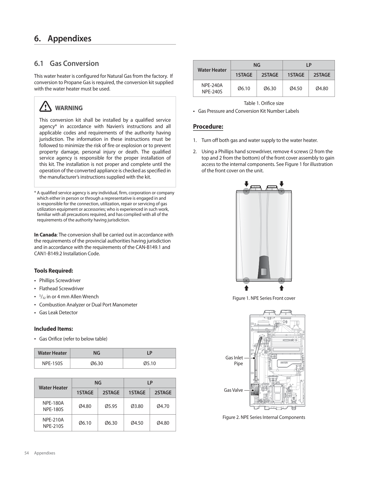
| | | | | | | | | | | | | | | | | | | | | | | | | | | | | | | | | | | | | | | | | | | | | | | | | | | | | | | | | | | | | | | | | | | | | | | | | | | | | | | | | | | | | | | | | | | | | | | | | | | | | | | | | | | | | | | | | | | | | | | | | | | | | | | | | | | | | | | | | | | | | | | | | | | | | | | | | | | | | | | | | | | | | | | | | | | | | | | | | | | | | | | | | | | | | | | | | | | | | | | | | | | | | | | | | | | | | | | | | | | | | | | | | | | | | | | | | | | | | | | | | | | | | | | | | | | | | | | | | | | | | | | | | | | | | | | | | | | | | | | | | | | | | | | | | | | | | | | | | | | | | | | | | | | | | | | | | | | | | | | | | | | | | | | | | | | | | | | | | | | | | | | | | | | | | | | | | | | | | | | | | | | | | | | | | | | | | | | | | | | | | | | | | | | | | | | | | | | | | | | | | | | | | | | | | | | | | | | | | | | | | | | | | | | | | | | | | | | | | | | | | | | | | | | | | | | | | | | | | | | | | | | | | | | | | | | | | | | | | | | | | | | | | | | | | | | | | | | | | | | | | | | | | | | | | | | | | | | | | | | | | | | | | | | | | | | | | | | | | | | | | | | | | | | | | | | | | | | | | | | | | | | | | | | | | | | | | | | | | | | | | | | | | | | | | | | | | | | | | | | | | | | | | | | | | | | | | | | | | | | | | | | | | | | | | | | | | | | | | | | | | | | | | | | | | | | | | | | | | | | | | | | | | | | | | | | | | | | | | | | | | | | | | | | | | | | | | | | | | | | | | | | | | | | | | | | | | | | | | | | | | | | | | | | | | | | | | | | | | | | | | | | | | | | | | | | | | | | | | | | | | | | | | | | | | | | | | | | | | | | | | | | | | | | | | | | | | | | | | | | | | | | | | | | | | | | | | | | | | | | | | | | | | | | | | | | | | | | | | | | | | | | | | | | | | | | | | | | | | | | | | | | | | | | | | | | | | | | | | | | | | | | | | | | | | | | | | | | | | | | | | | | | | | | | | | | | | | | | | | | | | | | | | | | | | | | | | | | | | | | | | | | | | | | | | | | | | | | | | | | | | | | | | | | | | | | | | | | | | | | | | | | | | | | | | | | | | | | | | | | | | | | | | | | | | | | | | | | | | | | | | | | | | | | | | | | | | | | | | | | | | | | | | | | | | | | | | | | | | | | | | | | | | | | | | | | | | | | | | | | | | | | | | | | | | | | | | | | | | | | | | | | | | | | | | | | | | | | | | | | | | | | | | | | | | | | | | | | | | | | | | | | | | | | | | | | | | | | | | | | | | | | | | | | | | | | | | | | | | | | | | | | | | | | | | | | | | | | | | | | | | | | | | | | | | | | | | | | | | | | | | | | | | | | | | | | | | | | | | | | | | | | | | | | | | | | | | | | | | | | | | | | | | | | | | | | | | | | | | | | | | | | | | | | | | | | | | | | | | | | | | | | | | | | | | | | | | | | | | | | | | | | | | | | | | | | | | | | | | | | | | | | | | | | | | | | | | | | | | | | | | | | | | | | | | | | | | | | | | | | | | | | | | | | | | | | | | | | | | | | | | | | | | | | | | | | | | | | | | | | | | | | | | | | | | | | | | | | | | | | | | | | | | | | | | | | | | | | | | | | | | | | | | | | | | | | | | | | | | | | | | | | | | | | | | | | | | | | | | | | | | | | | | | | | | | | | | | | | | | | | | | | | | | | | | | | | | | | | | | | | | | | | | | | | | | | | | | | | | | | | | | | | | | | | | | | | | | | | | | | | | | | | | | | | | | | | | | | | | | | | | | | | | | | | | | | | | | | | | | | | | | | | | | | | | | | | | | | | | | | | | | | | | | | | | | | | | | | | | | | | | | | | | | | | | | | | | | | | | | | | | | | | | | | | | | | | | | | | | | | | | | | | | | | | | | | | | | | | | | | | | | | | | | | | | | | | | | | | | | | | | | | | | | | | | | | | | | | | | | | | | | | | | | | | | | | | | | | | | | | | | | | | | | | | | | | | | | | | | | | | | | | | | | | | | | | | | | | | | | | | | | | | | | | | | | | | | | | | | | | | | | | | | | | | | | | | | | | | | | | | | | | | | | | | | | | | | | | | | | | | | | | | | | | | | | | | | | | | | | | | | | | | | | | | | | | | | | | | | | | | | | | | | | | | | | | | | | | | | | | | | | | | | | | | | | | | | | | | | | | | | | | | | | | | | | | | | | | |
[NPE-150S]
| | | | | | | | | | | | | | | | | | | | | | | | | | | | | | | | |---|---|---|---|---|---|---|---|---|---|---|---|---|---|---|---|---|---|---|---|---|---|---|---|---|---|---|---|---|---|---| | | | | | | | | | | | | | | | | | | | | | | | | | | | | | | | | | | | | | | | | | | | | | | | | | | | | | | | | | | | | | | | | | | | | | | | | | | | | | | | | | | | | | | | | | | | | | | | | | | | | | | | | | | | | | | | | | | | | | | | | | | | | | | | | | | | | | | | | | | | | | | | | | | | | | | | | | | | | | | | | | | | | | | | | | | | | | | | | | | | | | | | | | | | | | | | | | | | | | | | | | | | | | | | | | | | | | | | | | | | | | | | | | | | | | | | | | | | | | | | | | | | | | | | | | | | | | | | | | | | | | | | | | | | | | | | | | | | | | | | | | | | | | | | | | | | | | | | | | | | | | | | | | | | | | | | | | | | | | | | | | | | | | | | | | | | | | | | | | | | | | | | | | | | | | | | | | | | | | | | | | | | | | | | | | | | | | | | | | | | | | | | | | | | | | | | | | | | | | | | | | | | | | | | | | | | | | | | | | | | | | | | | | | | | | | | | | | | | | | | | | | | | | | | | | | | | | | | | | | | | | | | | | | | | | | | | | | | | | | | | | | | | | | | | | | | | | | | | | | | | | | | | | | | | | | | | | | | | | | | | | | | | | | | | | | | | | | | | | | | | | | | | | | | | | | | | | | | | | | | | | | | | | | | | | | | | | | | | | | | | | | | | | | | | | | | | | | | | | | | | | | | | | | | | | | | | | | | | | | | | | | | | | | | | | | | | | | | | | | | |
| | | | | | | | | | | | | | | | | | | | | | | | | | | | | | | | | | | | | | | | | | | | | | | | | | | | | | | | | | | | | | | | | | | | | | | | | | | | | | | | | | | | | | | | | | | | | | | | | | | | | | | | | | | | | | | | | | | | | | | | | | | | | | | | | | | | | | | | | | | | | | | | | | | | | | | | | | | | | | | | | | | | | | | | | | | | | | | | | | | | | | | | | | | | | | | | | | | | | | | | | | | | | | | | | | | | | | | | | | | | | | | | | | | | | | | | | | | | | | | | | | | | | | | | | | | | | | | | | | | | | | | | | | | | | | | | | | | | | | | | | | | | | | | | | | | | | | | | | | | | | | | | | | | | | | | | | | | | | | | | | | | | | | | | | | | | | | | | | | | | | | | | | | | | | | | | | | | | | | | | | | | | | | | | | | | | | | | | | | | | | | | | | | | | | | | | | | | | | | | | | | | | | | | | | | | | | | | | | | | | | | | | | | | | | | | | | | | | | | | | | | | | | | | | | | | | | | | | | | | | | | | | | | | | | | | | | | | | | | | | | | | | | | | | | | | | | | | | | | | | | | | | | | | | | | | | | | | | | | | | | | | | | | | | | | | | | | | | | | | | | | | | | | | | | | | | | | | | | | | | | | | | | | | | | | | | | | | | | | | | | | | | | | | | | | | | | | | | | | | | | | | | | | | | | | | | | | | | | | | | | | | | | | | | | | | | | | | | | | | | | | | | | | | | | | | | | | | | | | | | | | | | | | | | | | | | | | | | | | | | | | | | | | | | | | | | | | | | | | | | | | | | | | | | | | | | | | | | | | | | | | | | | | | | | | | | | | | | | | | | | | | | | | | | | | | | | | | | | | | | | | | | | | | | | | | | | | | | | | | | | | | | | | | | | | | | | | | | | | | | | | | | | | | | | | | | | | | | | | | | | | | | | | | | | | | | | | | | | | | | | | | | | | | | | | | | | | | | | | | | | | | | | | | | | | | | | | | | | | | | | | | | | | | | | | | | | | | | | | | | | | | | | | | | | | | | | | | | | | | | | | | | | | | | | | | | | | | | | | | | | | | | | | | | | | | | | | | | | | | | | | | | | | | | | | | | | | | | | | | | | | | | | | | | | | | | | | | | | | | | | | | | | | | | | | | | | | | | | | | | | | | | | | | | | | | | | | | | | | | | | | | | | | | | | | | | | | | | | | | | | | | | | | | | | | | | | | | | | | | | | | | | | | | | | | | | | | | | | | | | | | | | | | | | | | | | | | | | | | | | | | | | | | | | | | | | | | | | | | | | | | | | | | | | | | | |
[NPE-240A]
| | | | | | | | | | | | | | | | | | | | | | | | | | | | | | | | |---|---|---|---|---|---|---|---|---|---|---|---|---|---|---|---|---|---|---|---|---|---|---|---|---|---|---|---|---|---|---| | | | | | | | | | | | | | | | | | | | | | | | | | | | | | | | | | | | | | | | | | | | | | | | | | | | | | | | | | | | | | | | | | | | | | | | | | | | | | | | | | | | | | | | | | | | | | | | | | | | | | | | | | | | | | | | | | | | | | | | | | | | | | | | | | | | | | | | | | | | | | | | | | | | | | | | | | | | | | | | | | | | | | | | | | | | | | | | | | | | | | | | | | | | | | | | | | | | | | | | | | | | | | | | | | | | | | | | | | | | | | | | | | | | | | | | | | | | | | | | | | | | | | | | | | | | | | | | | | | | | | | | | | | | | | | | | | | | | | | | | | | | | | | | | | | | | | | | | | | | | | | | | | | | | | | | | | | | | | | | | | | | | | | | | | | | | | | | | | | | | | | | | | | | | | | | | | | | | | | | | | | | | | | | | | | | | | | | | | | | | | | | | | | | | | | | | | | | | | | | | | | | | | | | | | | | | | | | | | | | | | | | | | | | | | | | | | | | | | | | | | | | | | | | | | | | | | | | | | | | | | | | | | | | | | | | | | | | | | | | | | | | | | | | | | | | | | | | | | | | | | | | | | | | | | | | | | | | | | | | | | | | | | | | | | | | | | | | | | | | | | | | | | | | | | | | | | | | | | | | | | | | | | | | | | | | | | | | | | | | | | | | | | | | | | | | | | | | | | | | | | | | | | | | | | | | | | | | | | | | | | | | | | | | | | | | | | | | | | | | | | | | | | | | | | | | | | | | | | | | | | | | | | | | | | | | | | | | | | | | | | | | | | | | | | | | | | | | | | | | | | | | |
| | | | | | | | | | | | | | | | | | | | | | | | | | | | | | | | | | | | | | | | | | | | | | | | | | | | | | | | | | | | | | | | | | | | | | | | | | | | | | | | | | | | | | | | | | | | | | | | | | | | | | | | | | | | | | | | | | | | | | | | | | | | | | | | | | | | | | | | | | | | | | | | | | | | | | | | | | | | | | | | | | | | | | | | | | | | | | | | | | | | | | | | | | | | | | | | | | | | | | | | | | | | | | | | | | | | | | | | | | | | | | | | | | | | | | | | | | | | | | | | | | | | | | | | | | | | | | | | | | | | | | | | | | | | | | | | | | | | | | | | | | | | | | | | | | | | | | | | | | | | | | | | | | | | | | | | | | | | | | | | | | | | | | | | | | | | | | | | | | | | | | | | | | | | | | | | | | | | | | | | | | | | | | | | | | | | | | | | | | | | | | | | | | | | | | | | | | | | | | | | | | | | | | | | | | | | | | | | | | | | | | | | | | | | | | | | | | | | | | | | | | | | | | | | | | | | | | | | | | | | | | | | | | | | | | | | | | | | | | | | | | | | | | | | | | | | | | | | | | | | | | | | | | | | | | | | | | | | | | | | | | | | | | | | | | | | | | | | | | | | | | | | | | | | | | | | | | | | | | | | | | | | | | | | | | | | | | | | | | | | | | | | | | | | | | | | | | | | | | | | | | | | | | | | | | | | | | | | | | | | | | | | | | | | | | | | | | | | | | | | | | | | | | | | | | | | | | | | | | | | | | | | | | | | | | | | | | | | | | | | | | | | | | | | | | | | | | | | | | | | | | | | | | | | | | | | | | | | | | | | | | | | | | | | | | | | | | | | | | | | | | | | | | | | | | | | | | | | | | | | | | | | | | | | | | | | | | | | | | | | | | | | | | | | | | | | | | | | | | | | | | | | | | | | | | | | | | | | | | | | | | | | | | | | | | | | | | | | | | | | | | | | | | | | | | | | | | | | | | | | | | | | | | | | | | | | | | | | | | | | | | | | | | | | | | | | | | | | | | | | | | | | | | | | | | | | | | | | | | | | | | | | | | | | | | | | | | | | | | | | | | | | | | | | | | | | | | | | | | | | | | | | | | | | | | | | | | | | | | | | | | | | | | | | | | | | | | | | | | | | | | | | | | | | | | | | | | | | | | | | | | | |
[NPE-210A]
| | | | | | | | | | | | | | | | | | | | | | | | | | | | | | | | |---|---|---|---|---|---|---|---|---|---|---|---|---|---|---|---|---|---|---|---|---|---|---|---|---|---|---|---|---|---|---| | | | | | | | | | | | | | | | | | | | | | | | | | | | | | | | | | | | | | | | | | | | | | | | | | | | | | | | | | | | | | | | | | | | | | | | | | | | | | | | | | | | | | | | | | | | | | | | | | | | | | | | | | | | | | | | | | | | | | | | | | | | | | | | | | | | | | | | | | | | | | | | | | | | | | | | | | | | | | | | | | | | | | | | | | | | | | | | | | | | | | | | | | | | | | | | | | | | | | | | | | | | | | | | | | | | | | | | | | | | | | | | | | | | | | | | | | | | | | | | | | | | | | | | | | | | | | | | | | | | | | | | | | | | | | | | | | | | | | | | | | | | | | | | | | | | | | | | | | | | | | | | | | | | | | | | | | | | | | | | | | | | | | | | | | | | | | | | | | | | | | | | | | | | | | | | | | | | | | | | | | | | | | | | | | | | | | | | | | | | | | | | | | | | | | | | | | | | | | | | | | | | | | | | | | | | | | | | | | | | | | | | | | | | | | | | | | | | | | | | | | | | | | | | | | | | | | | | | | | | | | | | | | | | | | | | | | | | | | | | | | | | | | | | | | | | | | | | | | | | | | | | | | | | | | | | | | | | | | | | | | | | | | | | | | | | | | | | | | | | | | | | | | | | | | | | | | | | | | | | | | | | | | | | | | | | | | | | | | | | | | | | | | | | | | | | | | | | | | | | | | | | | | | | | | | | | | | | | | | | | | | | | | | | | | | | | | | | | | | | | | | | | | | | | | | | | | | | | | | | | | | | | | | | | | | | | | | | | | | | | | | | | | | | | | | | | | | | | | | | | | | | | | | | | | | | | | | | | | | | | | | | | | | | | | | | | | | | | | | | | | | | | | | | | | | | | | | | | | | | | | | | | | | | | | | | | | | | | | | | | | | | | | | | | | | | | | | | | | | | | | | | | | | | | | | | | | | | | | | | | | | | | | | | | | | | |
| | | | | | | | | | | | | | | | | | | | | | | | | | | | | | | | | | | | | | | | | | | | | | | | | | | | | | | | | | | | | | | | | | | | | | | | | | | | | | | | | | | | | | | | | | | | | | | | | | | | | | | | | | | | | | | | | | | | | | | | | | | | | | | | | | | | | | | | | | | | | | | | | | | | | | | | | | | | | | | | | | | | | | | | | | | | | | | | | | | | | | | | | | | | | | | | | | | | | | | | | | | | | | | | | | | | | | | | | | | | | | | | | | | | | | | | | | | | | | | | | | | | | | | | | | | | | | | | | | | | | | | | | | | | | | | | | | | | | | | | | | | | | | | | | | | | | | | | | | | | | | | | | | | | | | | | | | | | | | | | | | | | | | | | | | | | | | | | | | | | | | | | | | | | | | | | | | | | | | | | | | | | | | | | | | | | | | | | | | | | | | | | | | | | | | | | | | | | | | | | | | | | | | | | | | | | | | | | | | | | | | | | | | | | | | | | | | | | | | | | | | | | | | | | | | | | | | | | | | | | | | | | | | | | | | | | | | | | | | | | | | | | | | | | | | | | | | | | | | | | | | | | | | | | | | | | | | | | | | | | | | | | | | | | | | | | | | | | | | | | | | | | | | | | | | | | | | | | | | | | | | | | | | | | | | | | | | | | | | | | | | | | | | | | | | | | | | | | | | | | | | | | | | | | | | | | | | | | | | | | | | | | | | | | | | | | | | | | | | | | | | | | | | | | | | | | | | | | | | | | | | | | | | | | | | | | | | | | | | | | | | | | | | | | | | | | | | | | | | | | | | | |
[NPE-180A]
Note At altitudes above 2,000 ft (610m), the outlet flow will be reduced by 4% for each 1,000 ft (305 m) of altitude gain.
| | | | | | | | | | | | | | | | | | | | | | | | | | |---|---|---|---|---|---|---|---|---|---|---|---|---|---|---|---|---|---|---|---|---|---|---|---|---| | | | | | | | | | | | | | | | | | | | | | | | | | | | | | | | | | | | | | | | | | | | | | | | | | | | | | | | | | | | | | | | | | | | | | | | | | | | | | | | | | | | | | | | | | | | | | | | | | | | | | | | | | | | | | | | | | | | | | | | | | | | | | | | | | | | | | | | | | | | | | | | | | | | | | | | | | | | | | | | | | | | | | | | | | | | | | | | | | | | | | | | | | | | | | | | | | | | | | | | | | | | | | | | | | | | | | | | | | | | | | | | | | | | | | | | | | | | | | | | | | | | | | | | | | | | | | | | | | | | | | | | | | | | | | | | | | | | | | | | | | | | | | | | | | | | | | | | | | | | | | | | | | | | | | | | | | | | | | | | | | | | | | | | | | | | | | | | | | | | | | | | | | | | | | | | | | | | | | | | | | | | | | | | | | | | | | | | | | | | | | | | | | | | | | | | | | | | | | | | | | | | | | | | | | | | | | | | | | | | | | | | | | | | | | | | | | | | | | | | | | | | | | | | | | | | | | | | | | | | | | | | | | | | | | | | | | | | | | | | | | | | | | | | | | | | | | | | | | | | | | | | | | | | | | | | | | | | | | | | | | | | | | | | | | | | | | | | | | | | | | | | | | | | | | | | | | | | | | | | | | | | | | | | | | | | | | | | | | | | | | | | | | | | | | | | | | | | | | | | | | | | | | | | | | | | | | | | | | | | | | | | | | | | | | | | | | | | | | | | | | | | | | | | | | | | | | | | | | | | | | | | | | | | | | | | | | | | | | | | | | | | | | | | | | | | | | | | | | | | | | | | | | | | | | | | | | | | | | | | | | | | | | | | | | | | | | | | | | | | | | | | | | | | | | | | | | | | | | | | | | | | | | | | | | | | | | | | | | | | | | | | | | | | | | | | | | | | | | | | | | | | | | | | | | | | | | | | | | | | | | | | | | | | | | | | | | | | | | | | | | | | | | | | | | | | | | | | | | | | | | | | | | | | | | | | | | | | | | | | | | | | |
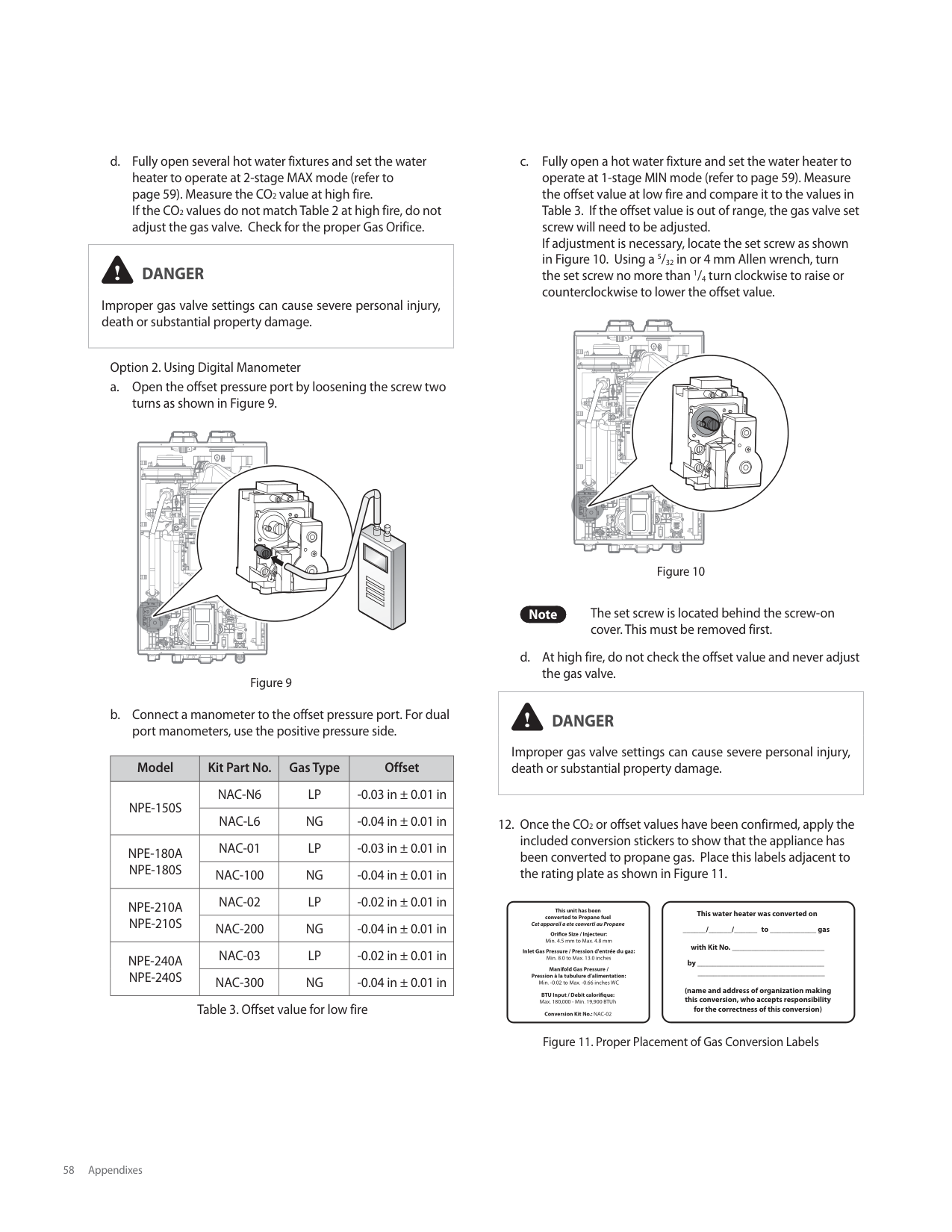
| | | | | | | | | | | | | | | | | | | | | | | | | | | | | | | | | | | | | | | | | | | | | | | | | | | | | | | | | | | | | | | | | | | | | | | | | | | | | | | | | | | | | | | | | | | | | | | | | | | | | | | | | | | | | | | | | | | | | | | | | | | | | | | | | | | | | | | | | | | | | | | | | | | | | | | | | | | | | | | | | | | | | | | | | | | | | | | | | | | | | | | | | | | | | | | | | | | | | | | | | | | | | | | | | | | | | | | | | | | | | | | | | | | | | | | | | | | | | | | | | | | | | | | | | | | | | | | | | | | | | | | | | | | | | | | | | | | | | | | | | | | | | | | | | | | | | | | | | | | | | | | | | | | | | | | | | | | | | | | | | | | | | | | | | | | | | | | | | | | | | | | | | | | | | | | | | | | | | | | | | | | | | | | | | | | | | | | | | | | | | | | | | | | | | | | | | | | | | | | | | | | | | | | | | | | | | | | | | | | | | | | | | | | | | | | | | | | | | | | | | | | | | | | | | | | | | | | | | | | | | | | | | | | | | | | | | | | | | | | | | | | | | | | | | | | | | | | | | | | | | | | | | | | | | | | | | | | | | | | | | | | | | | | | | | | | | | | | | | | | | | | | | | | | | | | | | | | | | | | | | | | | | | | | | | | | | | | | | | | | | | | | | | | | | | | | | | | | | | | | | | | | | | | | | | | | | | | | | | | | | | | | | | | | | | | | | | | | | | | | | | | | | | | | | | | | | | | | | | | | | | | | | | | | | | | | | | | | | | | | | | | | | | | | | | | | | | | | | | | | | | | | | | | | | | | | | | | | | | | | | | | | | | | | | | | | | | | | | | | | | | | | | | | | | | | | | |
[NPE-240S]
| | | | | | | | | | | | | | | | | | | | | | | | | | |---|---|---|---|---|---|---|---|---|---|---|---|---|---|---|---|---|---|---|---|---|---|---|---|---| | | | | | | | | | | | | | | | | | | | | | | | | | | | | | | | | | | | | | | | | | | | | | | | | | | | | | | | | | | | | | | | | | | | | | | | | | | | | | | | | | | | | | | | | | | | | | | | | | | | | | | | | | | | | | | | | | | | | | | | | | | | | | | | | | | | | | | | | | | | | | | | | | | | | | | | | | | | | | | | | | | | | | | | | | | | | | | | | | | | | | | | | | | | | | | | | | | | | | | | | | | | | | | | | | | | | | | | | | | | | | | | | | | | | | | | | | | | | | | | | | | | | | | | | | | | | | | | | | | | | | | | | | | | | | | | | | | | | | | | | | | | | | | | | | | | | | | | | | | | | | | | | | | | | | | | | | | | | | | | | | | | | | | | | | | | | | | | | | | | | | | | | | | | | | | | | | | | | | | | | | | | | | | | | | | | | | | | | | | | | | | | | | | | | | | | | | | | | | | | | | | | | | | | | | | | | | | | | | | | | | | | | | | | | | | | | | | | | | | | | | | | | | | | | | | | | | | | | | | | | | | | | | | | | | | | | | | | | | | | | | | | | | | | | | | | | | | | | | | | | | | | | | | | | | | | | | | | | | | | | | | | | | | | | | | | | | | | | | | | | | | | | | | | | | | | | | | | | | | | | | | | | | | | | | | | | | | | | | | | | | | | | | | | | | | | | | | | | | | | | | | | | | | | | | | | | | | | | | | | | | | | | | | | | | | | | | | | | | | | | | | | | | | | | | | | | | | | | | | | | | | | | | | | | | | | | | | | | | | | | | | | | | | | | | | | | | | | | | | | | | | | | | | | | | | | | | | | | | | | | | | | | | | | | | | | | | | | | | | | | | | | | | | | | | | | | | |
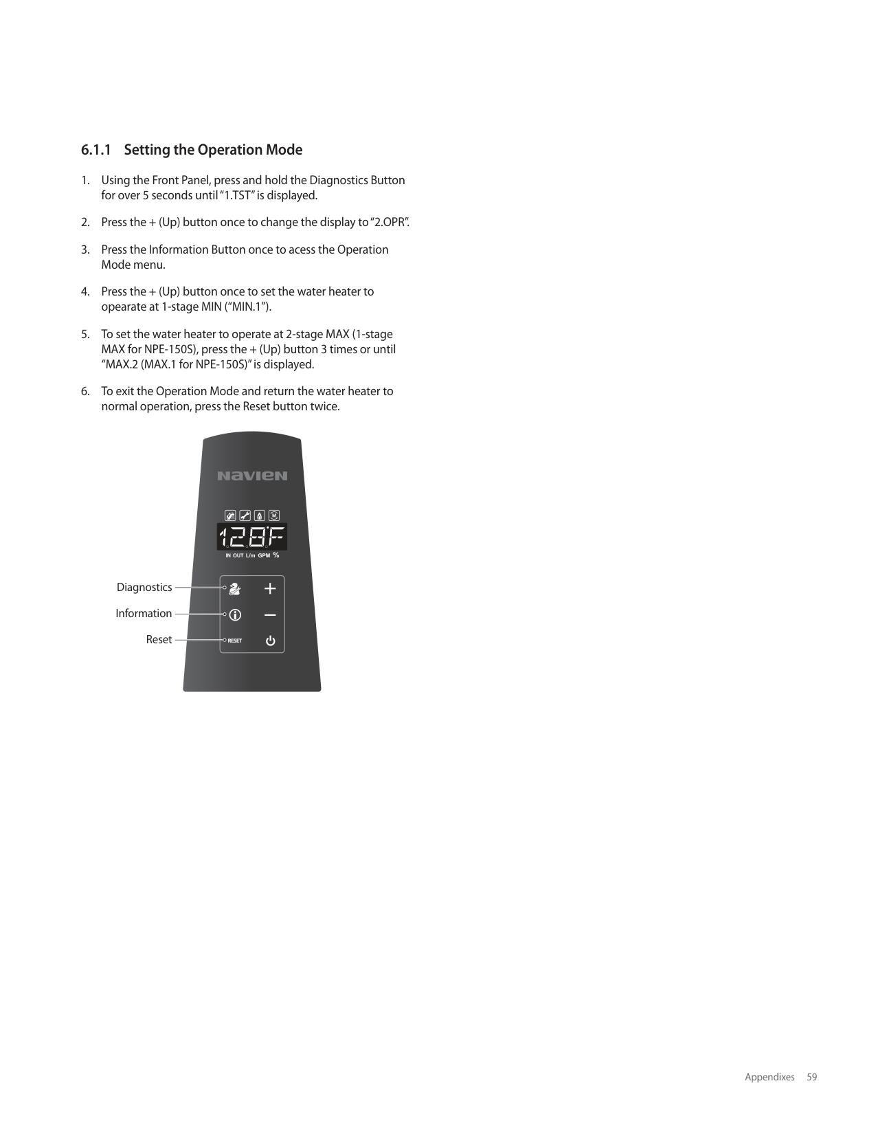
| | | | | | | | | | | | | | | | | | | | | | | | | | | | | | | | | | | | | | | | | | | | | | | | | | | | | | | | | | | | | | | | | | | | | | | | | | | | | | | | | | | | | | | | | | | | | | | | | | | | | | | | | | | | | | | | | | | | | | | | | | | | | | | | | | | | | | | | | | | | | | | | | | | | | | | | | | | | | | | | | | | | | | | | | | | | | | | | | | | | | | | | | | | | | | | | | | | | | | | | | | | | | | | | | | | | | | | | | | | | | | | | | | | | | | | | | | | | | | | | | | | | | | | | | | | | | | | | | | | | | | | | | | | | | | | | | | | | | | | | | | | | | | | | | | | | | | | | | | | | | | | | | | | | | | | | | | | | | | | | | | | | | | | | | | | | | | | | | | | | | | | | | | | | | | | | | | | | | | | | | | | | | | | | | | | | | | | | | | | | | | | | | | | | | | | | | | | | | | | | | | | | | | | | | | | | | | | | | | | | | | | | | | | | | | | | | | | | | | | | | | | | | | | | | | | | | | | | | | | | | | | | | | | | | | | | | | | | | | | | | | | | | | | | | | | | | | | | | | | | | | | | | | | | | | | | | | | | | | | | | | | | | | | | | | | | | | | | | | | | | | | | | | | | | | | | | | | | | | | | | | | | | | | | | | | | | | | | | | | | | | | | | | | | | | | | | | | | | | | | | | | | | | | | | | | | | | | | | | | | | | | | | | | | | | | | | | | | | | | | | | | | | | | | | | | | | | | | | | | | | | | | | | | | | | | | | | | | | | | | | | | | | | | | | | | | | | | | | | | | | | | | | | | | | | | | | | | | | | | | | | | | | | | | | | | | | | | | | | | | | | | | | | | | | | | | | |
[NPE-210S]
| | | | | | | | | | | | | | | | | | | | | | | | | | |---|---|---|---|---|---|---|---|---|---|---|---|---|---|---|---|---|---|---|---|---|---|---|---|---| | | | | | | | | | | | | | | | | | | | | | | | | | | | | | | | | | | | | | | | | | | | | | | | | | | | | | | | | | | | | | | | | | | | | | | | | | | | | | | | | | | | | | | | | | | | | | | | | | | | | | | | | | | | | | | | | | | | | | | | | | | | | | | | | | | | | | | | | | | | | | | | | | | | | | | | | | | | | | | | | | | | | | | | | | | | | | | | | | | | | | | | | | | | | | | | | | | | | | | | | | | | | | | | | | | | | | | | | | | | | | | | | | | | | | | | | | | | | | | | | | | | | | | | | | | | | | | | | | | | | | | | | | | | | | | | | | | | | | | | | | | | | | | | | | | | | | | | | | | | | | | | | | | | | | | | | | | | | | | | | | | | | | | | | | | | | | | | | | | | | | | | | | | | | | | | | | | | | | | | | | | | | | | | | | | | | | | | | | | | | | | | | | | | | | | | | | | | | | | | | | | | | | | | | | | | | | | | | | | | | | | | | | | | | | | | | | | | | | | | | | | | | | | | | | | | | | | | | | | | | | | | | | | | | | | | | | | | | | | | | | | | | | | | | | | | | | | | | | | | | | | | | | | | | | | | | | | | | | | | | | | | | | | | | | | | | | | | | | | | | | | | | | | | | | | | | | | | | | | | | | | | | | | | | | | | | | | | | | | | | | | | | | | | | | | | | | | | | | | | | | | | | | | | | | | | | | | | | | | | | | | | | | | | | | | | | | | | | | | | | | | | | | | | | | | | | | | | | | | | | | | | | | | | | | | | | | | | | | | | | | | | | | | | | | | | | | | | | | | | | | | | | | | | | | | | | | | | | | | | | | | | | | | | | | | | | | | | | | | | | | | | | | | | | | | | | | |
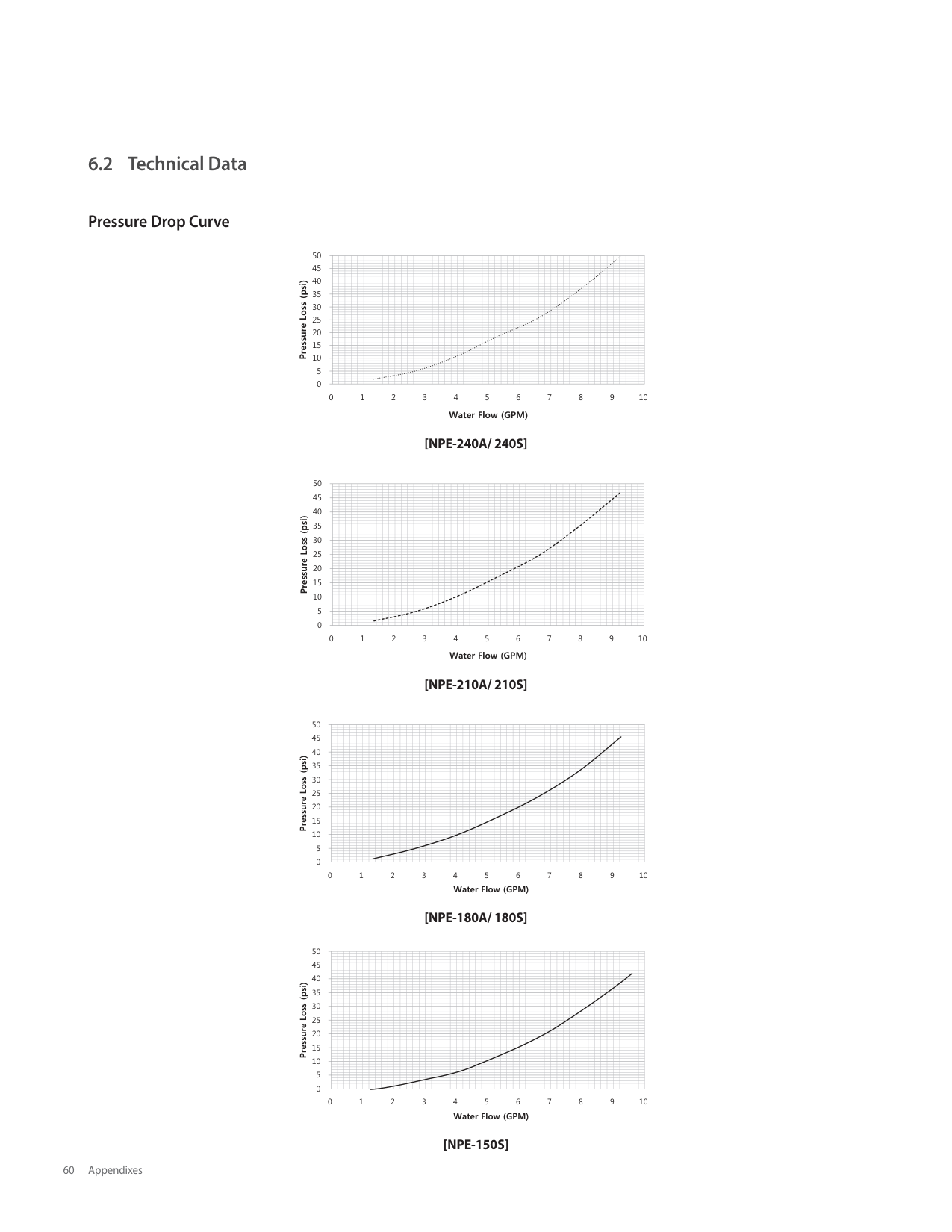
| | | | | | | | | | | | | | | | | | | | | | | | | | | | | | | | | | | | | | | | | | | | | | | | | | | | | | | | | | | | | | | | | | | | | | | | | | | | | | | | | | | | | | | | | | | | | | | | | | | | | | | | | | | | | | | | | | | | | | | | | | | | | | | | | | | | | | | | | | | | | | | | | | | | | | | | | | | | | | | | | | | | | | | | | | | | | | | | | | | | | | | | | | | | | | | | | | | | | | | | | | | | | | | | | | | | | | | | | | | | | | | | | | | | | | | | | | | | | | | | | | | | | | | | | | | | | | | | | | | | | | | | | | | | | | | | | | | | | | | | | | | | | | | | | | | | | | | | | | | | | | | | | | | | | | | | | | | | | | | | | | | | | | | | | | | | | | | | | | | | | | | | | | | | | | | | | | | | | | | | | | | | | | | | | | | | | | | | | | | | | | | | | | | | | | | | | | | | | | | | | | | | | | | | | | | | | | | | | | | | | | | | | | | | | | | | | | | | | | | | | | | | | | | | | | | | | | | | | | | | | | | | | | | | | | | | | | | | | | | | | | | | | | | | | | | | | |
[NPE-180S]
| | | | | | | | | | | | | | | | | | | | | | | | | | | | | | | | |---|---|---|---|---|---|---|---|---|---|---|---|---|---|---|---|---|---|---|---|---|---|---|---|---|---|---|---|---|---|---| | | | | | | | | | | | | | | | | | | | | | | | | | | | | | | | | | | | | | | | | | | | | | | | | | | | | | | | | | | | | | | | | | | | | | | | | | | | | | | | | | | | | | | | | | | | | | | | | | | | | | | | | | | | | | | | | | | | | | | | | | | | | | | | | | | | | | | | | | | | | | | | | | | | | | | | | | | | | | | | | | | | | | | | | | | | | | | | | | | | | | | | | | | | | | | | | | | | | | | | | | | | | | | | | | | | | | | | | | | | | | | | | | | | | | | | | | | | | | | | | | | | | | | | | | | | | | | | | | | | | | | | | | | | | | | | | | | | | | | | | | | | | | | | | | | | | | | | | | | | | | | | | | | | | | | | | | | | | | | | | | | | | | | | | | | | | | | | | | | | | | | | | | | | | | | | | | | | | | | | | | | | | | | | | | | | | | | | | | | | | | | | | | | | | | | | | | | | | | | | | | | | | | | | | | | | | | | | | | | | | | | | | | | | | | | | | | | | | | | | | | | | | | | | | | | | | | | | | | | | | | | | | | | | | | | | | | | | | | | | | | | | | | | | | | | | | | | | | | | | | | | | | | | | | | | | | | | | | | | | | | | | | | | | | | | | | | | | | | | | | | | | | | | | | | | | | | | | | | | | | | | | | | | | | | | | | | | | | | | | | | | | | | | | | | | | | | | | | | | | | | | | | | | | | | | | | | | | | | | | | | | | | | | | | | | | | | | | | | | | | | | | | | | | | | | | | | | | | | | | | | | | | | | | | | | | | | | | | | | | | | | | | | | | | | | | | | | | | | | | | | | | | | | | | | | | | | | | | | | | | | | | | | | | | | | | | | | | | | | | | | | | | | | | | | | | | | | | | | | | | | | | | | | | | | | | | | | | | | | | | | | | | | | | | | | | | | | | | | | | | | | | | | | | | | | | | | | | | | | | | | | | | | | | | | | | | | | | | | | | | | | | | | | | | | | | | | | | | | | | | | | | | | | | | | | | | | | | | | | | | | | | | | | | | | | | | | | | | | | | | | | | | | | | | | | | | | | | | | | | | | | | | | | | | | | | | | | | | | | | | | | | | | | | | | | | | | | | | | | | | | | | | | | | | | | | | | | | | | | | | | | | | | | | | | | | | | | | | | | | | | | | | | | | | | | | | | | | | | | | | | | | | | | | | | | | | | | | | | | | | | | | | | | | | | | | | | | | | | | | | | | | | | | | | | | | | | | | | | | | | | | | | | | | | | | | | | | | | | | | | | | | | | | | | | | | | | | | | | | | | | | | | | | | | | | | | | | | | | | | | | | | | | | | | | | | | | | | | | | | | | | | | | | | | | | | | | | | | | | | | | | | | | | | | | | | | | | | | | | | | | | | | | | | | | | | | | | | | | | | | | | | | | | | | | | | | | | | | | | | | | | | | | | | |
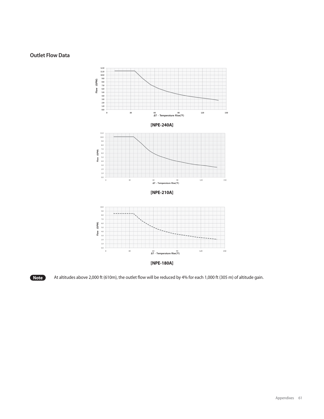
| | | | | | | | | | | | | | | | | | | | | | | | | | | | | | | | | | | | | | | | | | | | | | | | | | | | | | | | | | | | | | | | | | | | | | | | | | | | | | | | | | | | | | | | | | | | | | | | | | | | | | | | | | | | | | | | | | | | | | | | | | | | | | | | | | | | | | | | | | | | | | | | | | | | | | | | | | | | | | | | | | | | | | | | | | | | | | | | | | | | | | | | | | | | | | | | | | | | | | | | | | | | | | | | | | | | | | | | | | | | | | | | | | | | | | | | | | | | | | | | | | | | | | | | | | | | | | | | | | | | | | | | | | | | | | | | | | | | | | | | | | | | | | | |
[NPE-150S]
Note At altitudes above 2,000 ft (610m), the outlet flow will be reduced by 4% for each 1,000 ft (305 m) of altitude gain.
###### 6.3 Wiring Diagram
BKNeutral(W)Hot(BK)
ExternalA
Pump Y
Power Cord
Main Gas Valve
Flame Rod
Fan Motor
Electrode
Ground(GY)
Ground
Dual Venturi
FM
Spark
MGV
BK
Pump
M
ROW Y
Optional
| | | | |---|---|---| | | | |
GY
W
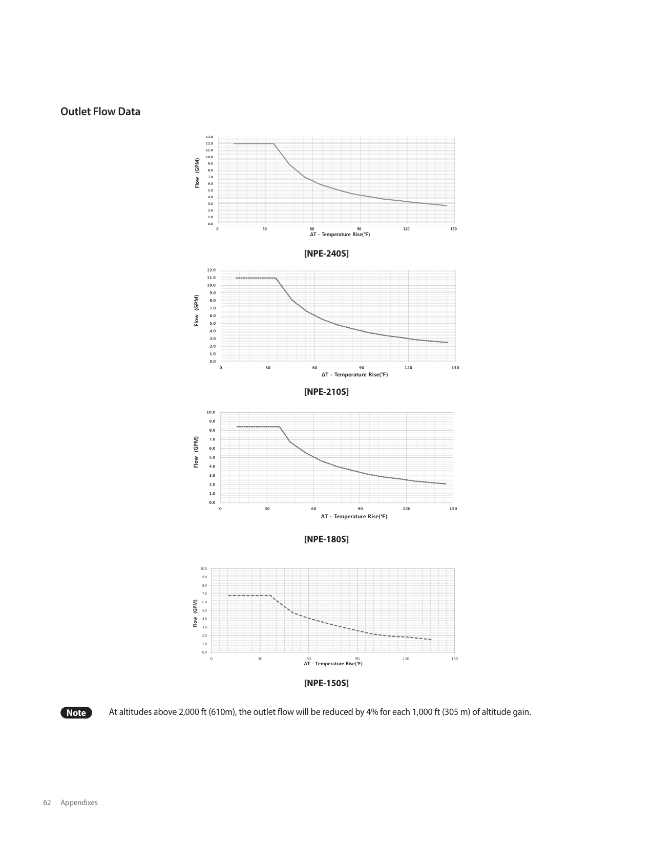
Y
R
BR
W
BK
BR B
W
W
B
Y
| | | |---|---| | | |
IG
Fuse(5A)Power SwitchGY
W
I
CON1
CON11
CON3
CON4CON2
TB1
H
K
J
|Front Panel| | |---|---| |Front Panel| | |Front Panel| | |Front Panel| | |Front Panel| | |Front Panel| | |Front Panel| | |Front Panel| | |Front Panel| | |Front Panel| |
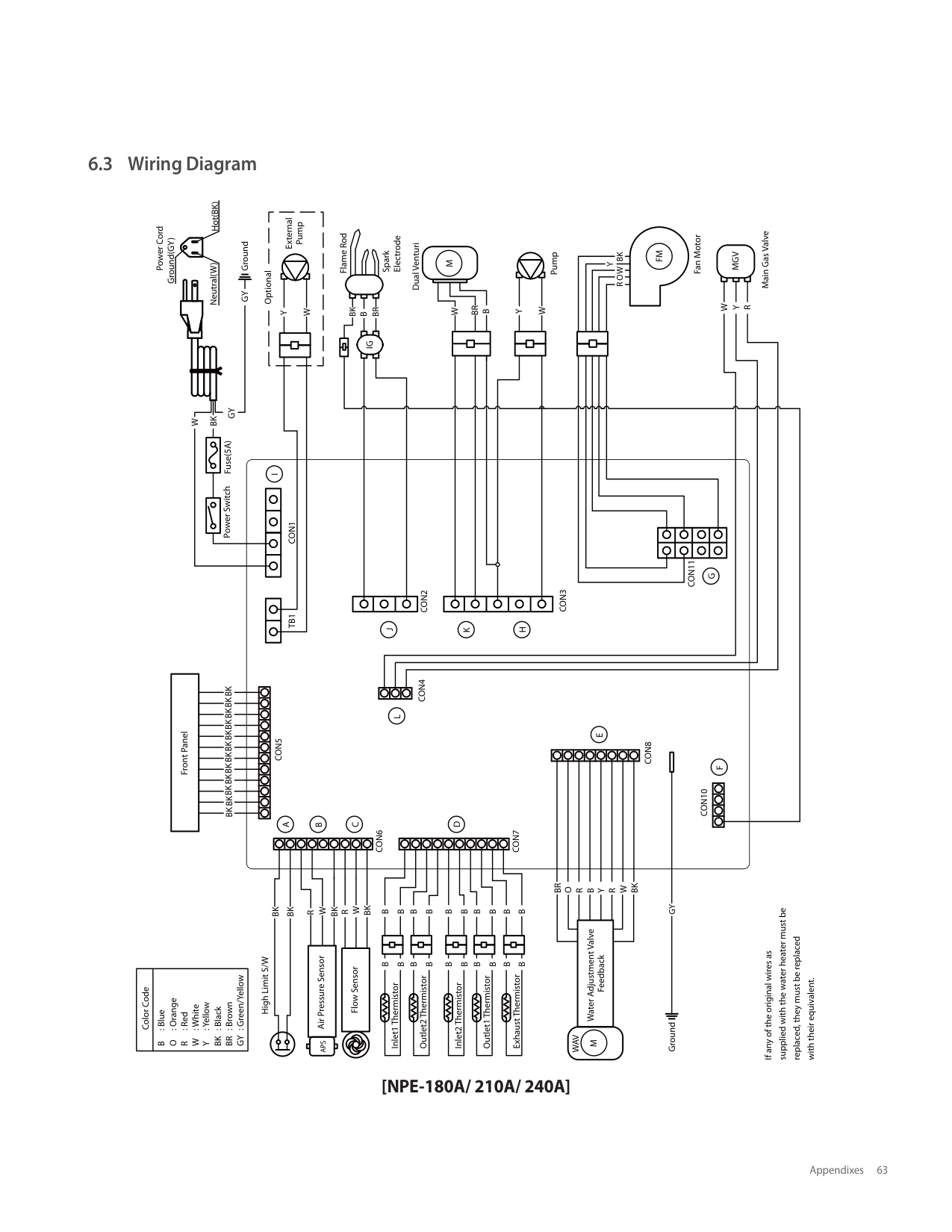
|Front Panel| | |Front Panel| | |Front Panel| |
BKBKBKBKBKBKBKBKBKBKBKBK
L
E
CON5
CON8
CON10
D
C
B
CON6
CON7
|Color Code|B
O
R
W
Y
BK
BR
GY
: Blue
: Orange
: Red
: White
: Yellow
: Black
: Brown
: Green/Yellow| |---|---|
BK
BK
High Limit S/W
BK
W
BK
W
B
B Outlet2 Thermistor
B
B Inlet1 Thermistor
R
APS R
| | | |---|---| |Air Pressure Sensor|Air Pressure Sensor|
| | | |---|---|
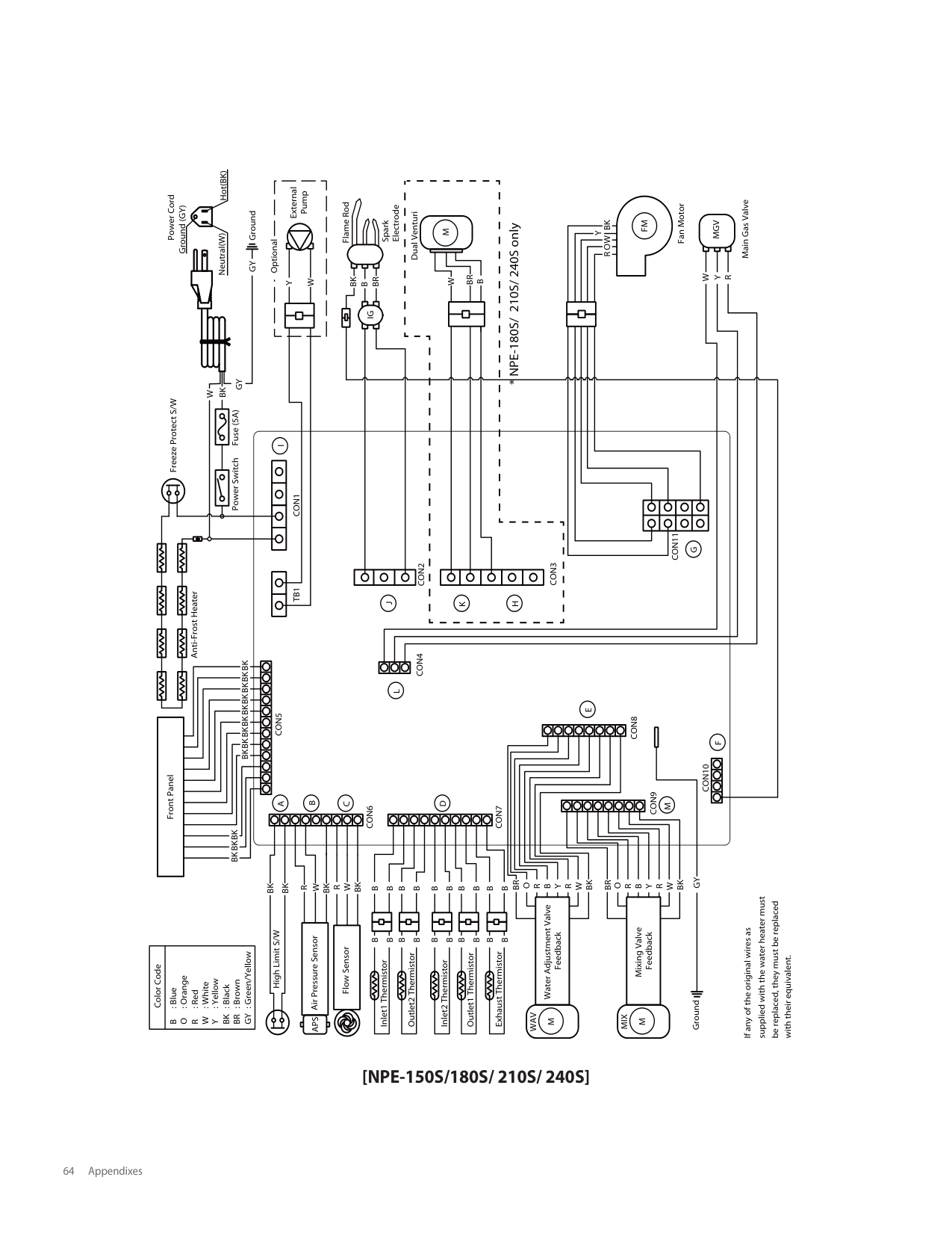
|Flow Sensor|Flow Sensor|
B
B
B
B
B
B Inlet2 Thermistor
B
B Outlet1 Thermistor
B
B Exhaust Thermistor
B
B
B
B
B
B
BK
WAV BR
W
O
B
Y
R
R
Water Adjustment Valve
Feedback M
GYGround
supplied with the water heater must be
replaced, they must be replaced
If any of the original wires as
with their equivalent.
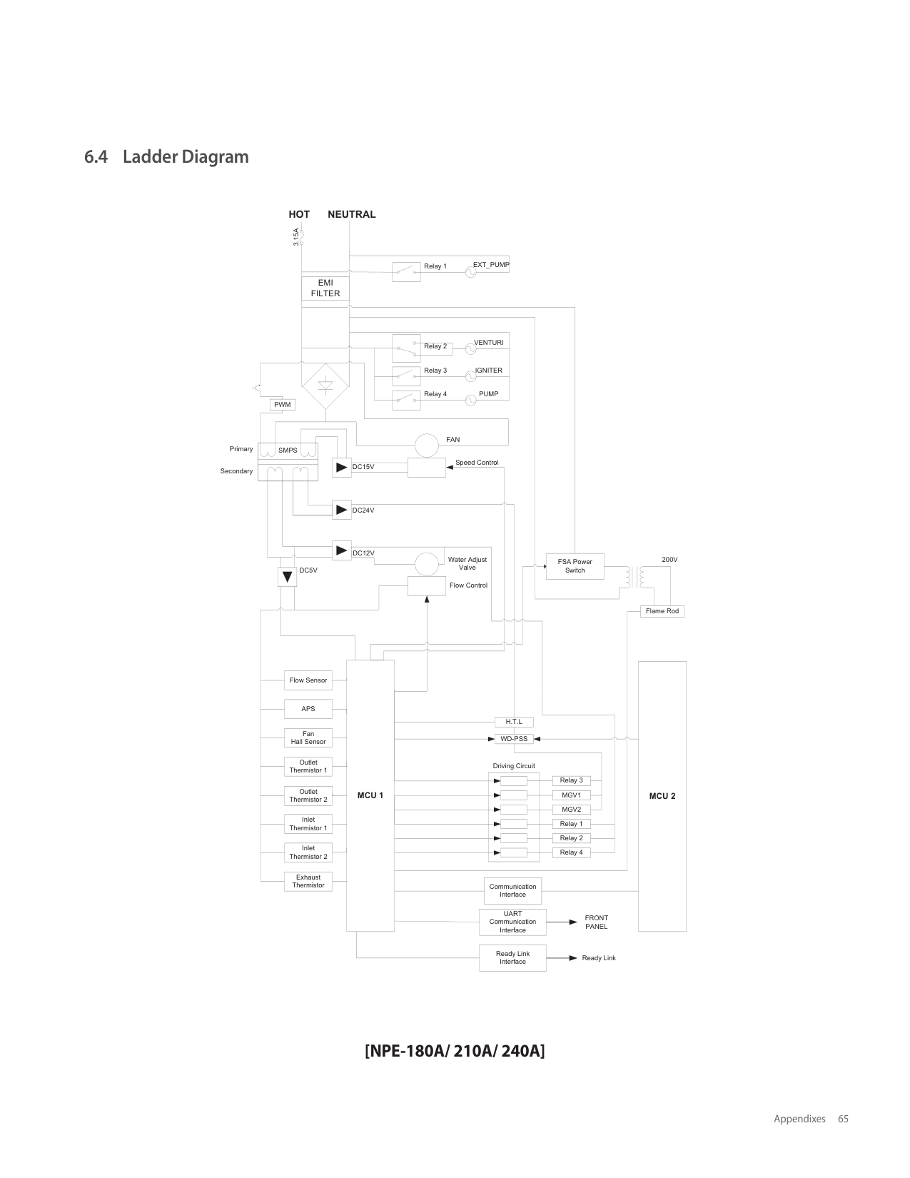
BKNeutral(W)Hot(BK)
External A
Pump Y
Power Cord
Main Gas Valve
Flame Rod
Fan Motor
Electrode
Ground (GY)
Ground
Dual Venturi
FM
BK
MGV
Spark
M
ROW Y
I Optional
GY
W
BR
Y
R
BK
BR B
W
W
B
| | | |---|---| | | |
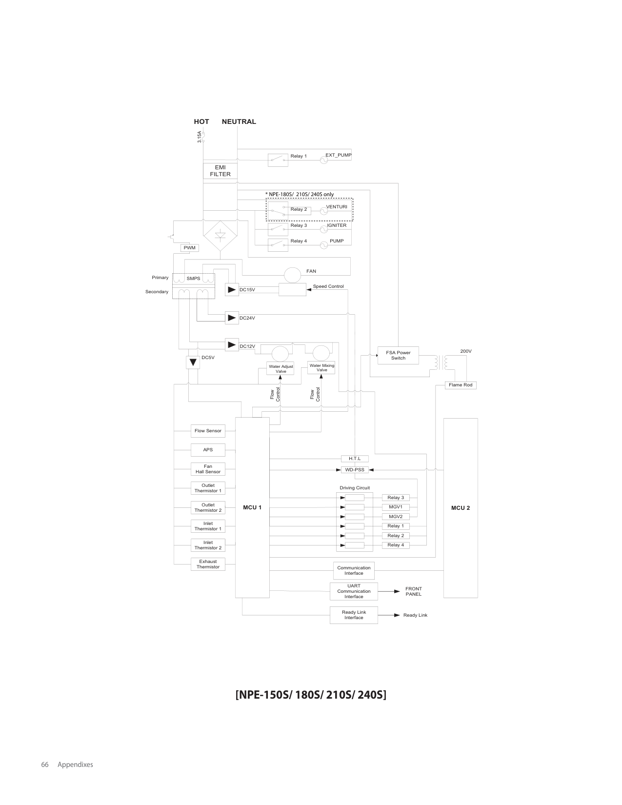
IG
Fuse (5A)GY
W
Freeze Protect S/W
Power Switch
CON1
CON11
G
CON3
CON4CON2
TB1
Anti-Frost Heater
H
J
K
BKBKBKBKBKBKBKBKBK
L
E
CON5
CON8
F
CON10
Front Panel
CON9 Mixing Valve
B
D
C
M
CON6
CON7
BKBKBK
GYGround
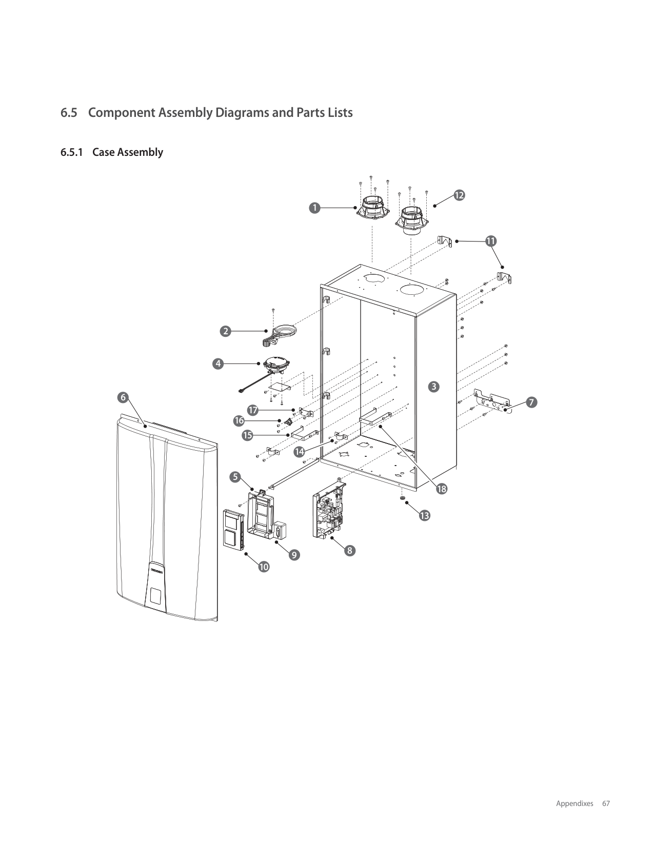
BK
BK
MIX BR
WAV BR
BK
O
O
W
W
W
BK
BK
BK High Limit S/W
W
B
B
Y
Y
R
R
R
R
R
APS R
B
B Inlet1 Thermistor
B
B Outlet2 Thermistor
B
B Inlet2 Thermistor
B
B Outlet1 Thermistor
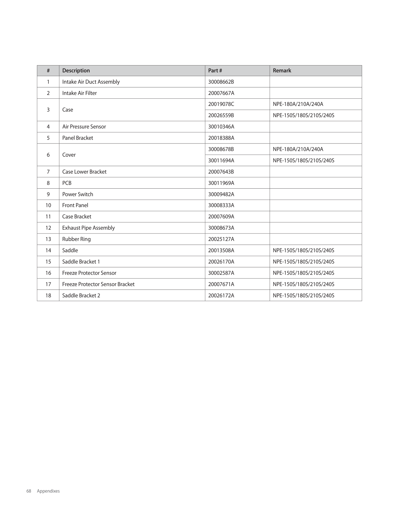
B
B Exhaust Thermistor
| | | |---|---| |Air Pressure Sensor|Air Pressure Sensor|
| | | |---|---| |Flow Sensor|Flow Sensor|
supplied with the water heater must
be replaced, they must be replaced
Water Adjustment Valve
If any of the original wires as
Feedback M
Feedback M
B
B
B
B
B
B
B
B
B
B
|Color Code|B
O
R
W
Y
BK
BR
GY
: Blue
: Orange
: Red
: White
: Yellow
: Black
: Brown
: Green/Yellow| |---|---|
with their equivalent.
####### [NPE-150S/180S/ 210S/ 240S]
##################### HOT NEUTRAL
3.15A
EXT_PUMP
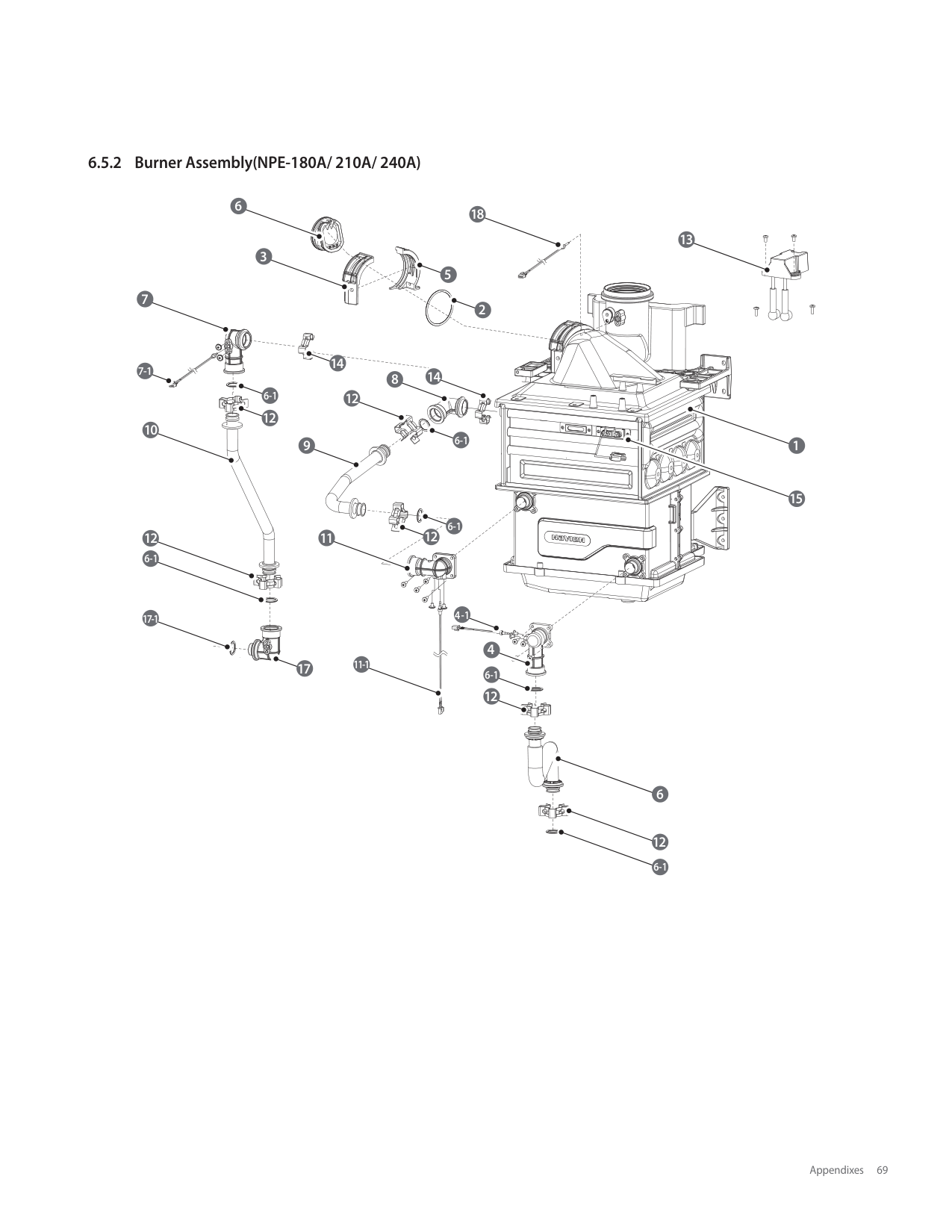
EMI FILTER
VENTURI
IGNITER
PUMP
PWM
FAN
Primary
SMPSPrimary
Speed Control
DC15V
Secondary
DC24V
DC12V
Water Adjust Valve
200V
FSA Power Switch
DC5V
Flow Control
Flame Rod
Flow Sensor
APS
H.T.L
Fan Hall Sensor
WD-PSS
Outlet Thermistor 1
Driving Circuit
Relay 2
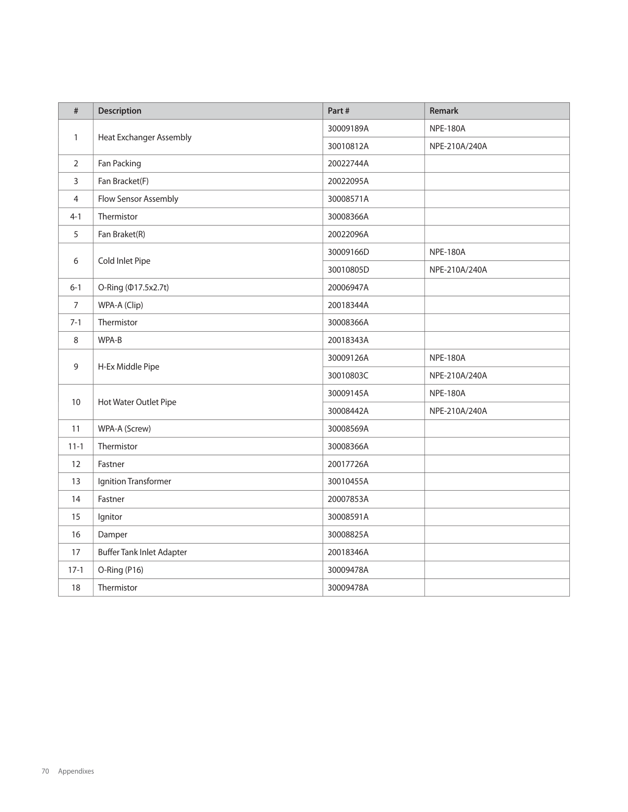
Outlet Thermistor 2
MCU 1 MCU 2
MGV1 MGV2 Relay 1
Inlet
Inlet
Exhaust Thermistor
Communication Interface
|UART Communication Interface| | |---|---| |UART Communication Interface| |
FRONT PANEL
Ready Link Interface
Ready Link
###################### HOT NEUTRAL
######################## 3.15A
EXT_PUMP
EMI FILTER
VENTURI
IGNITER
PUMP
PWM
FAN
Primary
SMPSPrimary
Speed Control
DC15V
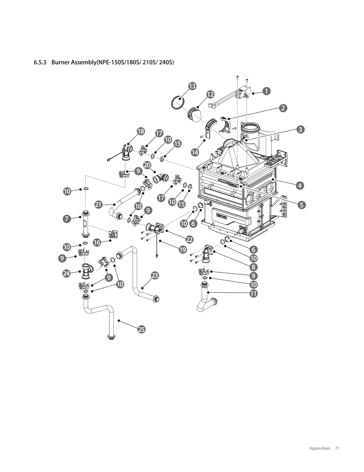
Secondary
DC24V
DC12V
200V
FSA Power Switch
DC5V
Water Mixing Valve
Water Adjust Valve
Flame Rod
Control
Control
Flow
Flow
Flow Sensor
APS
H.T.L
Fan Hall Sensor
WD-PSS
Outlet Thermistor 1
Driving Circuit
Relay 2
Outlet Thermistor 2
MCU 1 MCU 2
MGV1 MGV2 Relay 1
Inlet
Inlet
Exhaust Thermistor
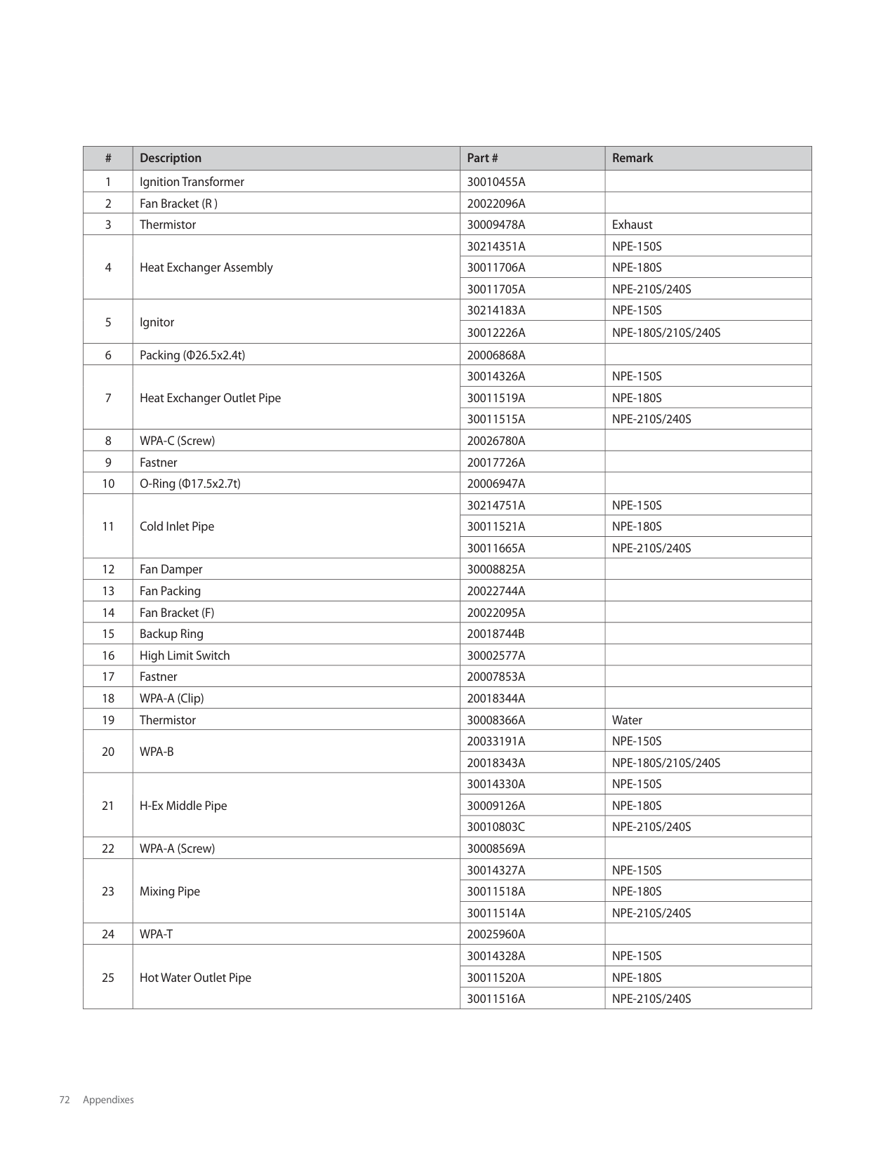
Communication Interface
|UART Communication Interface| | |---|---| |UART Communication Interface| |
FRONT PANEL
Ready Link Interface
Ready Link
####### [NPE-150S/ 180S/ 210S/ 240S]
###### 6.5 Component Assembly Diagrams and Parts Lists
########## 6.5.1 Case Assembly
1
12
11
6
2
4
17 16
15
14
5
89 10
3
18
13
7
|#|Description|Part #|Remark| |---|---|---|---| |1|Intake Air Duct Assembly|30008662B| | |2|Intake Air Filter|20007667A| | |3|Case|20019078C|NPE-180A/210A/240A| |3|Case|20026559B|NPE-150S/180S/210S/240S| |4|Air Pressure Sensor|30010346A| | |5|Panel Bracket|20018388A| | |6|Cover|30008678B|NPE-180A/210A/240A| |6|Cover|30011694A|NPE-150S/180S/210S/240S| |7|Case Lower Bracket|20007643B| | |8|PCB|30011969A| | |9|Power Switch|30009482A| | |10|Front Panel|30008333A| | |11|Case Bracket|20007609A| |
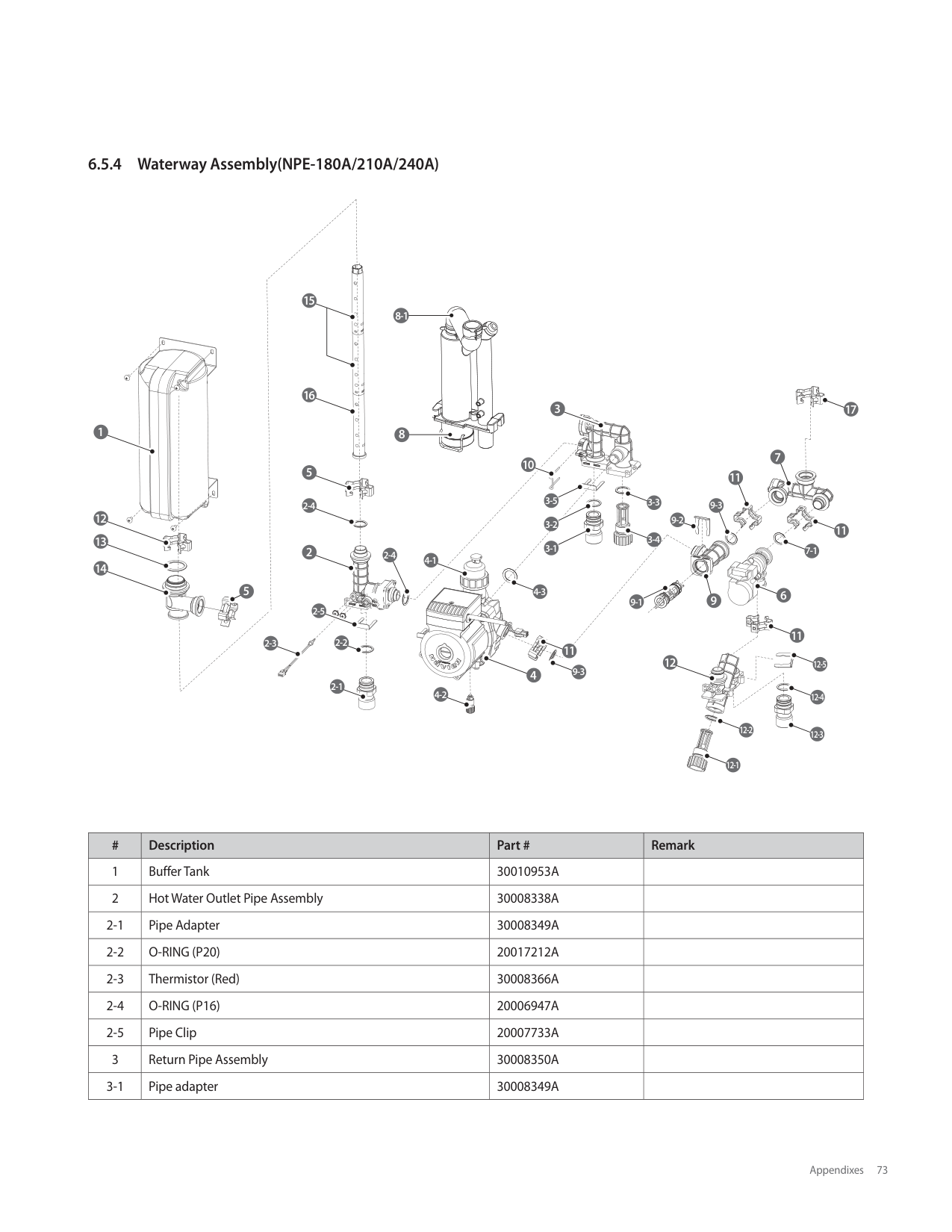
|12|Exhaust Pipe Assembly|30008673A| | |13|Rubber Ring|20025127A| | |14|Saddle|20013508A|NPE-150S/180S/210S/240S| |15|Saddle Bracket 1|20026170A|NPE-150S/180S/210S/240S| |16|Freeze Protector Sensor|30002587A|NPE-150S/180S/210S/240S| |17|Freeze Protector Sensor Bracket|20007671A|NPE-150S/180S/210S/240S| |18|Saddle Bracket 2|20026172A|NPE-150S/180S/210S/240S|
########## 6.5.2 Burner Assembly(NPE-180A/ 210A/ 240A)
7
6
18
13 3
5
2
14
7-1
8 14
6-1
12
12
10
6-1
1
9
15
6-1
12
1112
6-1
4-1
17-1
4
11-1
17
6-1 12
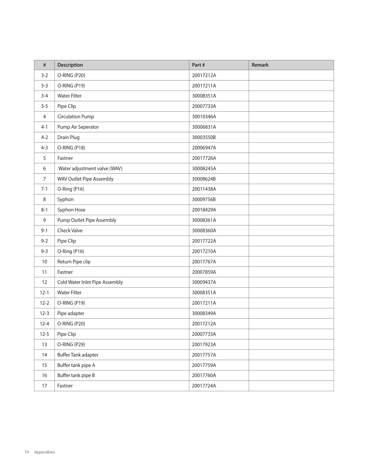
############# 6
12 6-1
|#|Description|Part #|Remark| |---|---|---|---| |1|Heat Exchanger Assembly|30009189A|NPE-180A| |1|Heat Exchanger Assembly|30010812A|NPE-210A/240A| |2|Fan Packing|20022744A| | |3|Fan Bracket(F)|20022095A| | |4|Flow Sensor Assembly|30008571A| | |4-1|Thermistor|30008366A| | |5|Fan Braket(R)|20022096A| | |6|Cold Inlet Pipe|30009166D|NPE-180A| |6|Cold Inlet Pipe|30010805D|NPE-210A/240A| |6-1|O-Ring (Φ17.5x2.7t)|20006947A| | |7|WPA-A (Clip)|20018344A| | |7-1|Thermistor|30008366A| | |8|WPA-B|20018343A| | |9|H-Ex Middle Pipe|30009126A|NPE-180A| |9|H-Ex Middle Pipe|30010803C|NPE-210A/240A| |10|Hot Water Outlet Pipe|30009145A|NPE-180A| |10|Hot Water Outlet Pipe|30008442A|NPE-210A/240A| |11|WPA-A (Screw)|30008569A| | |11-1|Thermistor|30008366A| | |12|Fastner|20017726A| | |13|Ignition Transformer|30010455A| | |14|Fastner|20007853A| | |15|Ignitor|30008591A| | |16|Damper|30008825A| | |17|Buffer Tank Inlet Adapter|20018346A| | |17-1|O-Ring (P16)|30009478A| | |18|Thermistor|30009478A| |
13
12 1
2
18 17
10
15
20 9
14
10
17
21 10
15
10 7
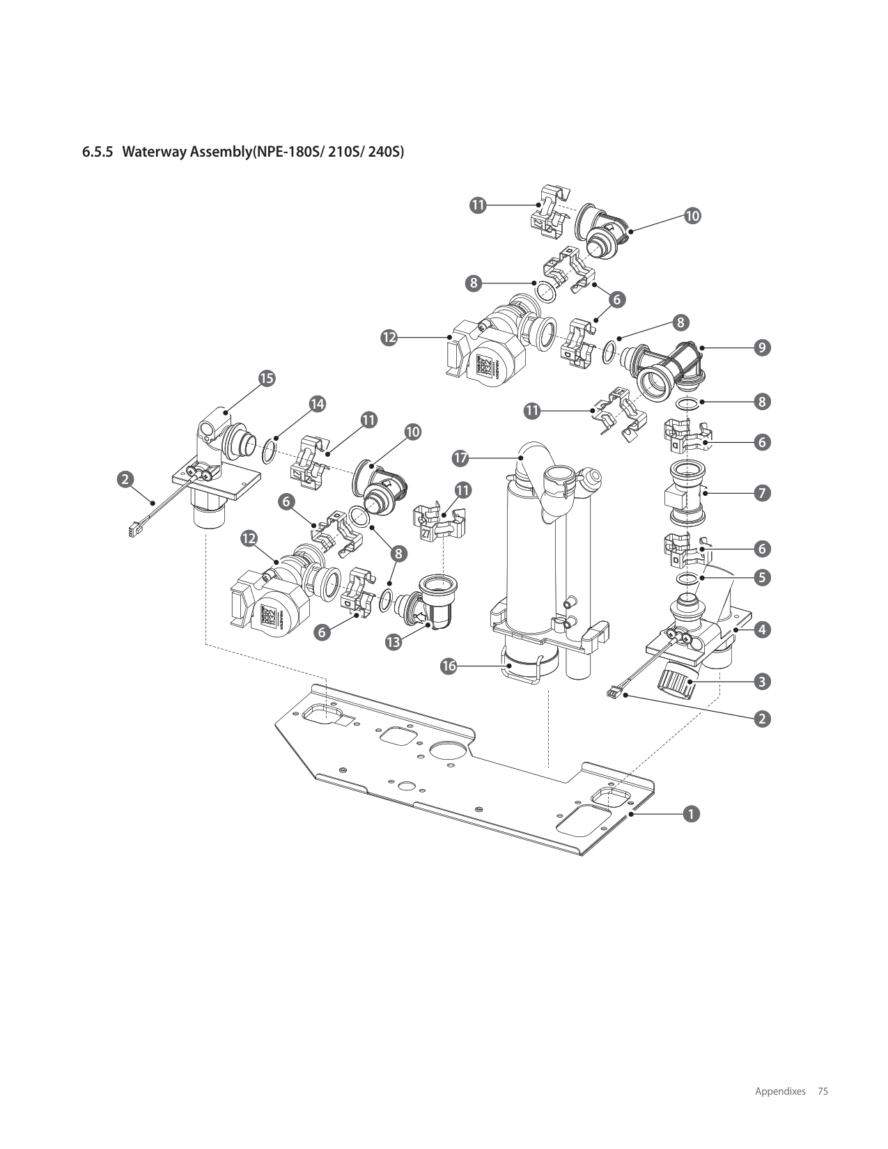
9
10
6
22
16
10 9
19
24
23
9
10
3
6
10
25
|#|Description|Part #|Remark| |---|---|---|---| |1|Ignition Transformer|30010455A| | |2|Fan Bracket (R )|20022096A| | |3|Thermistor|30009478A|Exhaust| |4|Heat Exchanger Assembly|30214351A|NPE-150S| |4|Heat Exchanger Assembly|30011706A|NPE-180S| |4|Heat Exchanger Assembly|30011705A|NPE-210S/240S| |5|Ignitor|30214183A|NPE-150S| |5|Ignitor|30012226A|NPE-180S/210S/240S| |6|Packing (Φ26.5x2.4t)|20006868A| | |7|Heat Exchanger Outlet Pipe|30014326A|NPE-150S| |7|Heat Exchanger Outlet Pipe|30011519A|NPE-180S| |7|Heat Exchanger Outlet Pipe|30011515A|NPE-210S/240S| |8|WPA-C (Screw)|20026780A| | |9|Fastner|20017726A| | |10|O-Ring (Φ17.5x2.7t)|20006947A| | |11|Cold Inlet Pipe|30214751A|NPE-150S| |11|Cold Inlet Pipe|30011521A|NPE-180S|
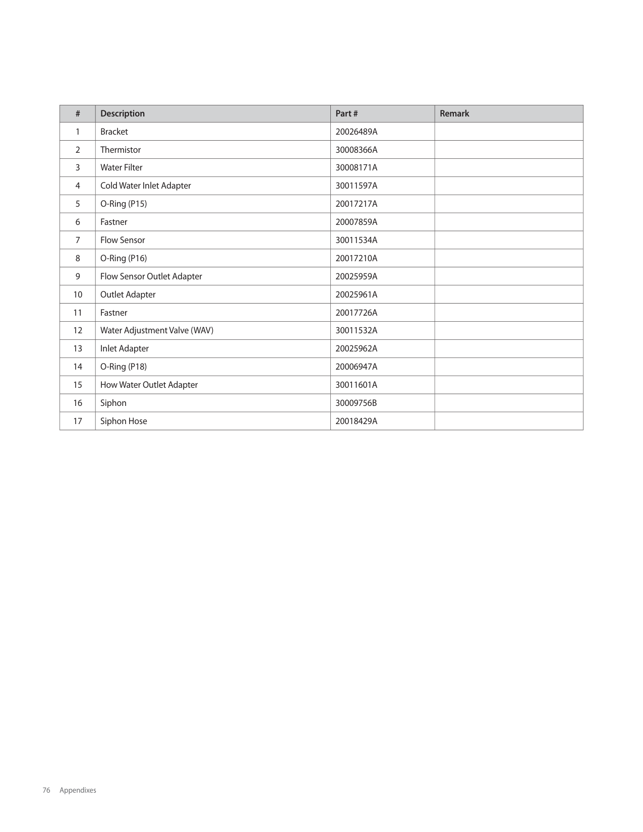
|11|Cold Inlet Pipe|30011665A|NPE-210S/240S| |12|Fan Damper|30008825A| | |13|Fan Packing|20022744A| | |14|Fan Bracket (F)|20022095A| | |15|Backup Ring|20018744B| | |16|High Limit Switch|30002577A| | |17|Fastner|20007853A| | |18|WPA-A (Clip)|20018344A| | |19|Thermistor|30008366A|Water| |20|WPA-B|20033191A|NPE-150S| |20|WPA-B|20018343A|NPE-180S/210S/240S| |21|H-Ex Middle Pipe|30014330A|NPE-150S| |21|H-Ex Middle Pipe|30009126A|NPE-180S| |21|H-Ex Middle Pipe|30010803C|NPE-210S/240S| |22|WPA-A (Screw)|30008569A| | |23|Mixing Pipe|30014327A|NPE-150S| |23|Mixing Pipe|30011518A|NPE-180S| |23|Mixing Pipe|30011514A|NPE-210S/240S| |24|WPA-T|20025960A| | |25|Hot Water Outlet Pipe|30014328A|NPE-150S| |25|Hot Water Outlet Pipe|30011520A|NPE-180S| |25|Hot Water Outlet Pipe|30011516A|NPE-210S/240S|
########## 6.5.4 Waterway Assembly(NPE-180A/210A/240A)
8-1
1
################## 8
10
5
3-5
2-3
2-1
4-2
3-2 3-1
2
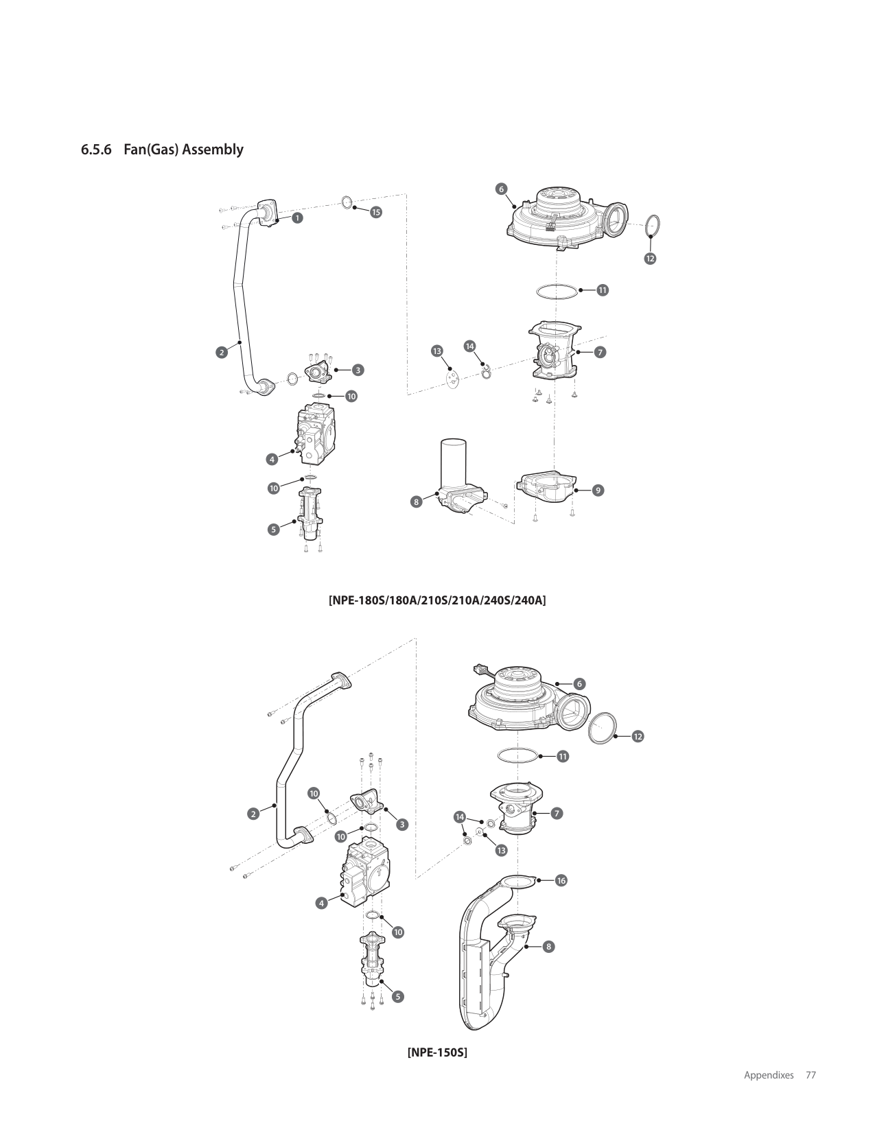
2-4
4-1
5
4-3
2-2
11 4
9-3
17
9-2
11
9-3
7
11
7-1
9-1
69
12
11
12-2 12-3
12-1
|#|Description|Part #|Remark| |---|---|---|---| |1|Buffer Tank|30010953A| | |2|Hot Water Outlet Pipe Assembly|30008338A| | |2-1|Pipe Adapter|30008349A| | |2-2|O-RING (P20)|20017212A| | |2-3|Thermistor (Red)|30008366A| | |2-4|O-RING (P16)|20006947A| | |2-5|Pipe Clip|20007733A| | |3|Return Pipe Assembly|30008350A| | |3-1|Pipe adapter|30008349A| |
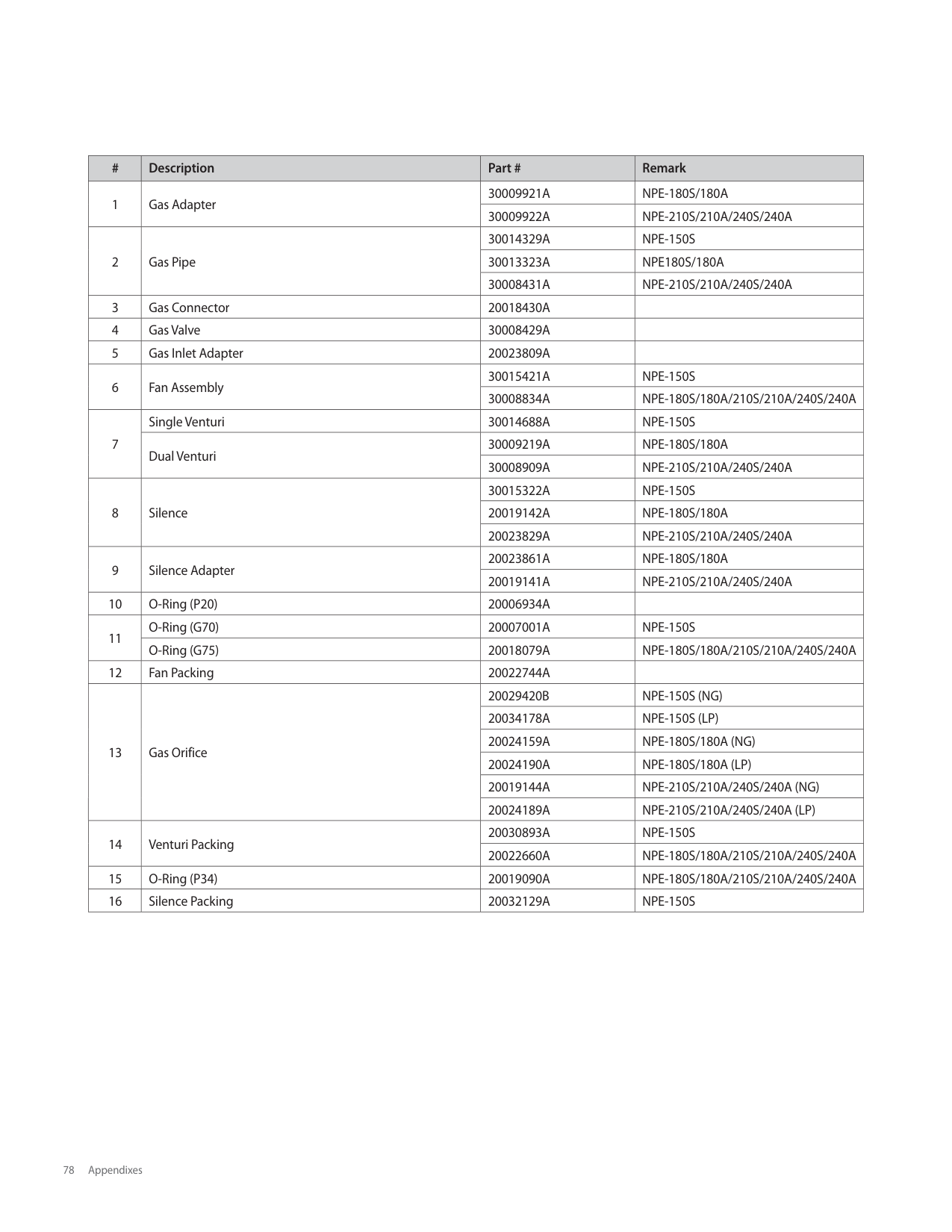
|#|Description|Part #|Remark| |---|---|---|---| |3-2|O-RING (P20)|20017212A| | |3-3|O-RING (P19)|20017211A| | |3-4|Water Filter|30008351A| | |3-5|Pipe Clip|20007733A| | |4|Circulation Pump|30010346A| | |4-1|Pump Air Seperator|30006831A| | |4-2|Drain Plug|30003550B| | |4-3|O-RING (P18)|20006947A| | |5|Fastner|20017726A| | |6|Water adjustment valve (WAV)|30008245A| | |7|WAV Outlet Pipe Assembly|30008624B| | |7-1|O-Ring (P16)|20011438A| | |8|Syphon|30009756B| | |8-1|Syphon Hose|20018429A| | |9|Pump Outlet Pipe Assembly|30008361A| | |9-1|Check Valve|30008360A| | |9-2|Pipe Clip|20017722A| | |9-3|O-Ring (P16)|20017210A| | |10|Return Pipe clip|20017767A| | |11|Fastner|20007859A| | |12|Cold Water Inlet Pipe Assembly|30009437A| | |12-1|Water Filter|30008351A| | |12-2|O-RING (P19)|20017211A| | |12-3|Pipe adapter|30008349A| | |12-4|O-RING (P20)|20017212A| | |12-5|Pipe Clip|20007733A| | |13|O-RING (P29)|20017923A| | |14|Buffer Tank adapter|20017757A| | |15|Buffer tank pipe A|20017759A| | |16|Buffer tank pipe B|20017760A| | |17|Fastner|20017724A| |
########## 6.5.5 Waterway Assembly(NPE-180S/ 210S/ 240S)
11
11
10
10
2
2
8
8
12
12
6
6
8
8
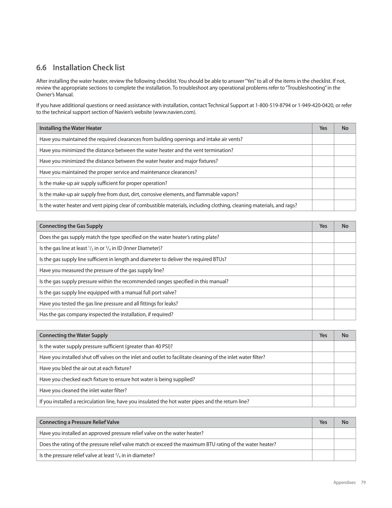
9
15
14
11
11
10
10
6
6
12
12
8
8
11
11
17
11
11
8
8
6
6
6 5
6
6
13
16
4
3
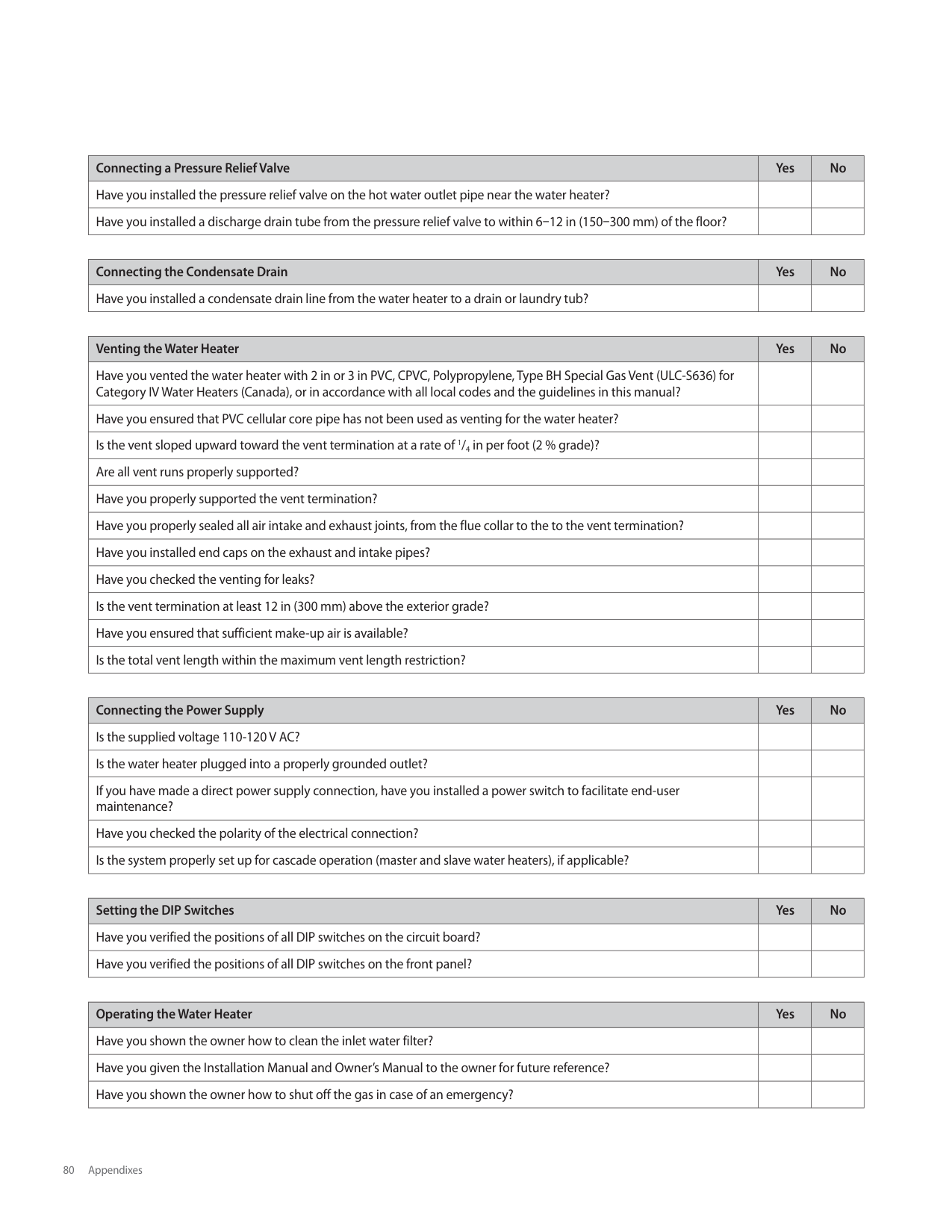
2
2
1
|#|Description|Part #|Remark| |---|---|---|---| |1|Bracket|20026489A| | |2|Thermistor|30008366A| | |3|Water Filter|30008171A| | |4|Cold Water Inlet Adapter|30011597A| | |5|O-Ring (P15)|20017217A| | |6|Fastner|20007859A| | |7|Flow Sensor|30011534A| | |8|O-Ring (P16)|20017210A| | |9|Flow Sensor Outlet Adapter|20025959A| | |10|Outlet Adapter|20025961A| | |11|Fastner|20017726A| | |12|Water Adjustment Valve (WAV)|30011532A| | |13|Inlet Adapter|20025962A| | |14|O-Ring (P18)|20006947A| | |15|How Water Outlet Adapter|30011601A| | |16|Siphon|30009756B| | |17|Siphon Hose|20018429A| |
########## 6.5.6 Fan(Gas) Assembly
96
9
15
91
12
911
914
913
97
92
93
910
94
910
9
98
95
############### [NPE-180S/180A/210S/210A/240S/240A]
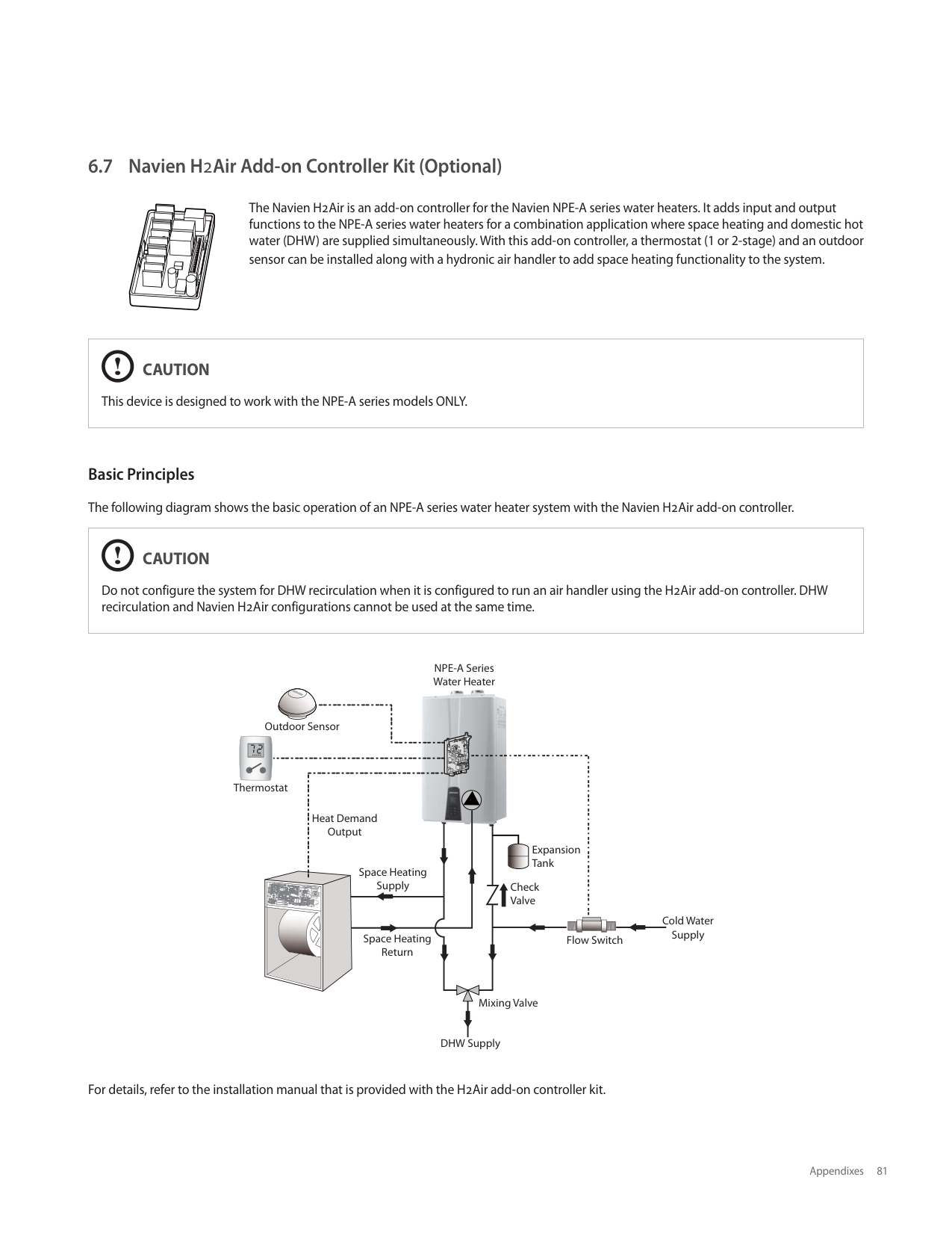
6
| | | |---|---| | | |
12 11
| | | |---|---| | | |
10
7
2
14
3
10
13
16
4
10
8
5
############### [NPE-150S]
|#|Description|Part #|Remark| |---|---|---|---| |1|Gas Adapter|30009921A|NPE-180S/180A| |1|Gas Adapter|30009922A|NPE-210S/210A/240S/240A| |2|Gas Pipe|30014329A|NPE-150S| |2|Gas Pipe|30013323A|NPE180S/180A| |2|Gas Pipe|30008431A|NPE-210S/210A/240S/240A| |3|Gas Connector|20018430A| | |4|Gas Valve|30008429A| | |5|Gas Inlet Adapter|20023809A| | |6|Fan Assembly|30015421A|NPE-150S| |6|Fan Assembly|30008834A|NPE-180S/180A/210S/210A/240S/240A| |7|Single Venturi|30014688A|NPE-150S| |7|Dual Venturi|30009219A|NPE-180S/180A| |7|Dual Venturi|30008909A|NPE-210S/210A/240S/240A| |8|Silence|30015322A|NPE-150S| |8|Silence|20019142A|NPE-180S/180A| |8|Silence|20023829A|NPE-210S/210A/240S/240A| |9|Silence Adapter|20023861A|NPE-180S/180A| |9|Silence Adapter|20019141A|NPE-210S/210A/240S/240A| |10|O-Ring (P20)|20006934A| | |11|O-Ring (G70)|20007001A|NPE-150S| |11|O-Ring (G75)|20018079A|NPE-180S/180A/210S/210A/240S/240A|
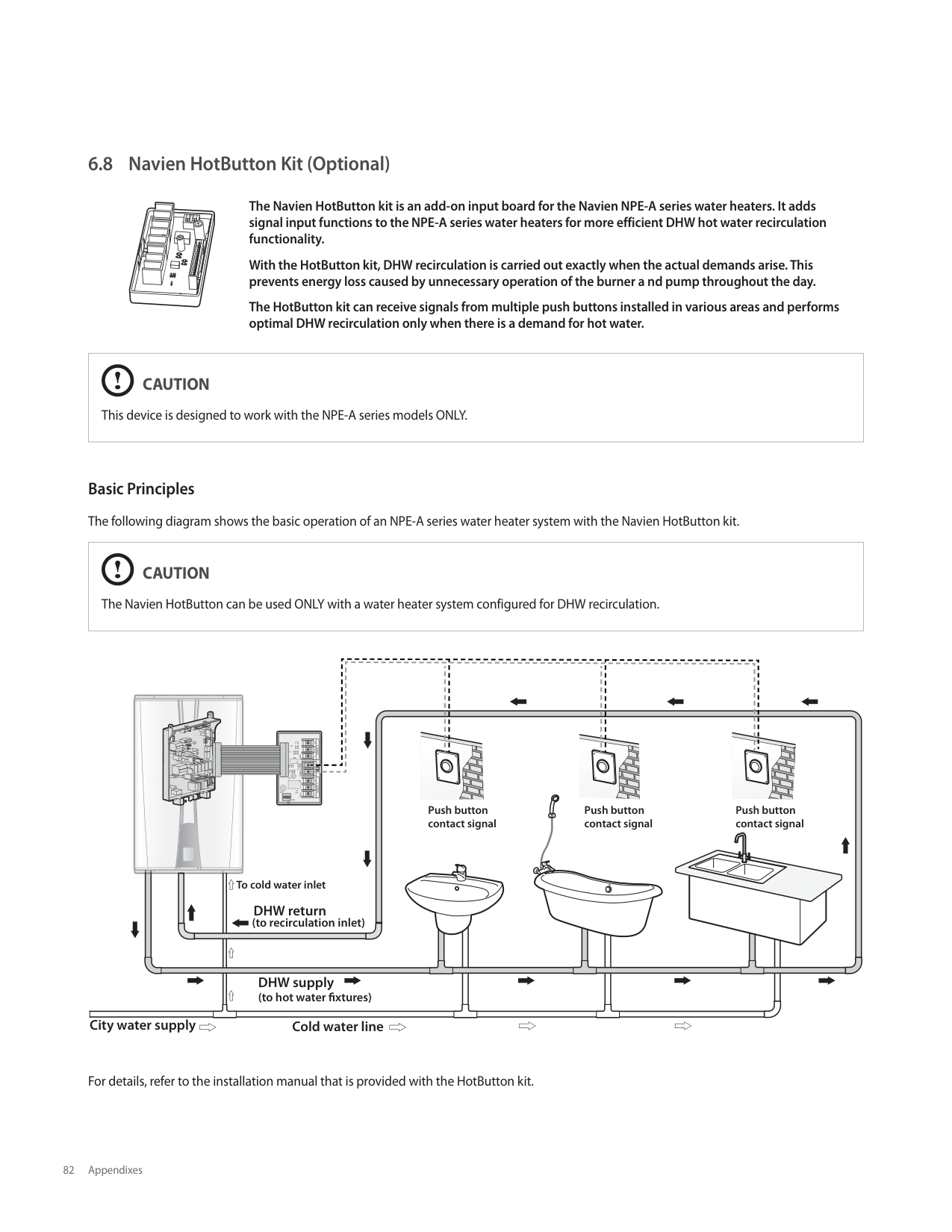
|12|Fan Packing|20022744A| | |13|Gas Orifice|20029420B|NPE-150S (NG)| |13|Gas Orifice|20034178A|NPE-150S (LP)| |13|Gas Orifice|20024159A|NPE-180S/180A (NG)| |13|Gas Orifice|20024190A|NPE-180S/180A (LP)| |13|Gas Orifice|20019144A|NPE-210S/210A/240S/240A (NG)| |13|Gas Orifice|20024189A|NPE-210S/210A/240S/240A (LP)| |14|Venturi Packing|20030893A|NPE-150S| |14|Venturi Packing|20022660A|NPE-180S/180A/210S/210A/240S/240A| |15|O-Ring (P34)|20019090A|NPE-180S/180A/210S/210A/240S/240A| |16|Silence Packing|20032129A|NPE-150S|
###### 6.6 Installation Check list
After installing the water heater, review the following checklist. You should be able to answer “Yes” to all of the items in the checklist. If not, review the appropriate sections to complete the installation. To troubleshoot any operational problems refer to “Troubleshooting” in the Owner’s Manual.
If you have additional questions or need assistance with installation, contact Technical Support at 1-800-519-8794 or 1-949-420-0420, or refer to the technical support section of Navien’s website (www.navien.com).
|Installing the Water Heater|Yes|No| |---|---|---| |Have you maintained the required clearances from building openings and intake air vents?| | | |Have you minimized the distance between the water heater and the vent termination?| | | |Have you minimized the distance between the water heater and major fixtures?| | | |Have you maintained the proper service and maintenance clearances?| | | |Is the make-up air supply sufficient for proper operation?| | | |Is the make-up air supply free from dust, dirt, corrosive elements, and flammable vapors?| | | |Is the water heater and vent piping clear of combustible materials, including clothing, cleaning materials, and rags?| | |
|Connecting the Gas Supply|Yes|No| |---|---|---| |Does the gas supply match the type specified on the water heater’s rating plate?| | | |Is the gas line at least 1/2 in or 3/4 in ID (Inner Diameter)?| | | |Is the gas supply line sufficient in length and diameter to deliver the required BTUs?| | | |Have you measured the pressure of the gas supply line?| | | |Is the gas supply pressure within the recommended ranges specified in this manual?| | | |Is the gas supply line equipped with a manual full port valve?| | | |Have you tested the gas line pressure and all fittings for leaks?| | | |Has the gas company inspected the installation, if required?| | |
|Connecting the Water Supply|Yes|No| |---|---|---| |Is the water supply pressure sufficient (greater than 40 PSI)?| | | |Have you installed shut off valves on the inlet and outlet to facilitate cleaning of the inlet water filter?| | | |Have you bled the air out at each fixture?| | | |Have you checked each fixture to ensure hot water is being supplied?| | | |Have you cleaned the inlet water filter?| | | |If you installed a recirculation line, have you insulated the hot water pipes and the return line?| | |
|Connecting a Pressure Relief Valve|Yes|No| |---|---|---| |Have you installed an approved pressure relief valve on the water heater?| | | |Does the rating of the pressure relief valve match or exceed the maximum BTU rating of the water heater?| | | |Is the pressure relief valve at least 3/4 in in diameter?| | |
|Connecting a Pressure Relief Valve|Yes|No| |---|---|---| |Have you installed the pressure relief valve on the hot water outlet pipe near the water heater?| | | |Have you installed a discharge drain tube from the pressure relief valve to within 6–12 in (150–300 mm) of the floor?| | |
|Connecting the Condensate Drain|Yes|No| |---|---|---| |Have you installed a condensate drain line from the water heater to a drain or laundry tub?| | |
|Venting the Water Heater|Yes|No| |---|---|---| |Have you vented the water heater with 2 in or 3 in PVC, CPVC, Polypropylene, Type BH Special Gas Vent (ULC-S636) for Category IV Water Heaters (Canada), or in accordance with all local codes and the guidelines in this manual?| | | |Have you ensured that PVC cellular core pipe has not been used as venting for the water heater?| | | |Is the vent sloped upward toward the vent termination at a rate of 1/4 in per foot (2 % grade)?| | | |Are all vent runs properly supported?| | | |Have you properly supported the vent termination?| | | |Have you properly sealed all air intake and exhaust joints, from the flue collar to the to the vent termination?| | | |Have you installed end caps on the exhaust and intake pipes?| | | |Have you checked the venting for leaks?| | | |Is the vent termination at least 12 in (300 mm) above the exterior grade?| | | |Have you ensured that sufficient make-up air is available?| | | |Is the total vent length within the maximum vent length restriction?| | |
|Connecting the Power Supply|Yes|No| |---|---|---| |Is the supplied voltage 110-120 V AC?| | | |Is the water heater plugged into a properly grounded outlet?| | | |If you have made a direct power supply connection, have you installed a power switch to facilitate end-user maintenance?| | | |Have you checked the polarity of the electrical connection?| | | |Is the system properly set up for cascade operation (master and slave water heaters), if applicable?| | |
|Setting the DIP Switches|Yes|No| |---|---|---| |Have you verified the positions of all DIP switches on the circuit board?| | | |Have you verified the positions of all DIP switches on the front panel?| | |
|Operating the Water Heater|Yes|No| |---|---|---| |Have you shown the owner how to clean the inlet water filter?| | | |Have you given the Installation Manual and Owner’s Manual to the owner for future reference?| | | |Have you shown the owner how to shut off the gas in case of an emergency?| | |
###### 6.7 Navien H2Air Add-on Controller Kit (Optional)
The Navien H2Air is an add-on controller for the Navien NPE-A series water heaters. It adds input and output functions to the NPE-A series water heaters for a combination application where space heating and domestic hot water (DHW) are supplied simultaneously. With this add-on controller, a thermostat (1 or 2-stage) and an outdoor sensor can be installed along with a hydronic air handler to add space heating functionality to the system.
|CAUTION
This device is designed to work with the NPE-A series models ONLY.| |---|
Basic Principles The following diagram shows the basic operation of an NPE-A series water heater system with the Navien H2Air add-on controller.
|CAUTION
Do not configure the system for DHW recirculation when it is configured to run an air handler using the H2Air add-on controller. DHW recirculation and Navien H2Air configurations cannot be used at the same time.| |---|
NPE-A Series Water Heater


Outdoor Sensor


Thermostat
Heat Demand Output
| | | |---|---| | | |
Expansion Tank


Space Heating Supply
Check Valve
| | | | | |---|---|---|---| | | | | | | | | | |


Cold Water Supply


Space Heating Return
Flow Switch


Mixing Valve
DHW Supply
For details, refer to the installation manual that is provided with the H2Air add-on controller kit.
###### 6.8 Navien HotButton Kit (Optional)
The Navien HotButton kit is an add-on input board for the Navien NPE-A series water heaters. It adds signal input functions to the NPE-A series water heaters for more efficient DHW hot water recirculation functionality.
With the HotButton kit, DHW recirculation is carried out exactly when the actual demands arise. This prevents energy loss caused by unnecessary operation of the burner a nd pump throughout the day.
The HotButton kit can receive signals from multiple push buttons installed in various areas and performs optimal DHW recirculation only when there is a demand for hot water.
|CAUTION
This device is designed to work with the NPE-A series models ONLY.| |---|
Basic Principles The following diagram shows the basic operation of an NPE-A series water heater system with the Navien HotButton kit.
|CAUTION
The Navien HotButton can be used ONLY with a water heater system configured for DHW recirculation.| |---|
SIGNAL 3 GNDSIGNAL 2
ZD1R7
C4
Q1
SIGNAL
SW1
R6
C7
D1CON2
CE1
SIGNAL 1
12 V SIGNAL
U1
CE1 RA1
SW1
To cold water inlet
DHW return (to recirculation inlet)
Push button contact signal
Push button contact signal
DHW supply
(to hot water fixtures)
Cold water lineCity water supply
For details, refer to the installation manual that is provided with the HotButton kit.
Push button contact signal
########### NOTICE BEFORE INSTALLATION
This appliance must be installed by a licensed plumber or gas fitter in accordance with the Massachusetts Plumbing and Fuel Gas Code 248 CMR Sections 4.00 and 5.00.
IMPORTANT: In the State of Massachusetts (248 CMR 4.00 & 5.00) For all side wall horizontally vented gas fueled equipment installed in every dwelling, building or structure used in whole or in part for residential purposes, including those owned or operated by the Commonwealth and where the side wall exhaust vent termination is less than seven (7) feet above finished grade in the area of the venting, including but not limited to decks and porches, the following requirements shall be satisfied:
Memo
Installation Manual
NPE Condensing Water Heaters
Getting Service If your water heater requires service, you have several options for getting service:
Contact Technical Support at 1-800-519-8794 or on the website: www.navien.com. For warranty service, always contact Technical Support first. Contact the technician or professional who installed your water heater. Contact a licensed professional for the affected system (for example, a plumber or electrician).
When you contact Technical Support, please have the following information at hand: Model number Serial number Date purchased Installation location and type Error code, if any appears on the front panel display
Version: 5.3 (Feb. 25, 2016)
Navien, Inc. 800.519.8794 www.Navien.com 20 Goodyear, Irvine, CA 92618
THE LEADER IN CONDENSING TECHNOLOGY