
Ask AI
— answers from the official manualAnswers from the official manual.
Common questions
Common Questions
8 totalWhat travel dimensions does the GENOS M560-V have?
The X-axis travel is 1,050 mm, Y-axis is 560 mm, and Z-axis is 460 mm. These specifications allow for a large work area.
What are the machining capacities with the ø80 face mill at 895 rpm?
The table includes examples such as an ø80 face mill cutting width of 56 mm, depth of 3 mm, and feedrate of 3,000 mm/min. Actual data may vary due to differences in specifications.
What is the dimension of the table travel for GENOS M560-V?
The Y-axis travel is 560 mm, making it suitable for large workpieces with ample operational space. Table dimensions are designed to fit industry requirements.
What maintenance does the collision avoidance system require and when should inspections be done?
The Maintenance Monitor displays inspection items before daily operation and regular intervals. Touch [INFO] button for detailed PDF instructions on relevant maintenance activities.
How can I check the operational status from a remote location with Okuma's Connect Plan?
Installation of Connect Plan software on your PC allows monitoring and control of machine operation status remotely, including tracking from an office or any internet-enabled location.
What are the spindle specifications of the GENOS M560-V?
The GENOS M560-V has a spindle speed range of up to 15,000 min^-1 with spindle motor output capabilities at 22/18.5 kW (10 min/continuous). The tapered bore is 7/24 taper No. 40.
Full Manual
11 pages


########## Vertical Machining Centers


####### Vertical Machining Centers


Thermo-Friendly Concept
Collision Avoidance System
Machining Navi
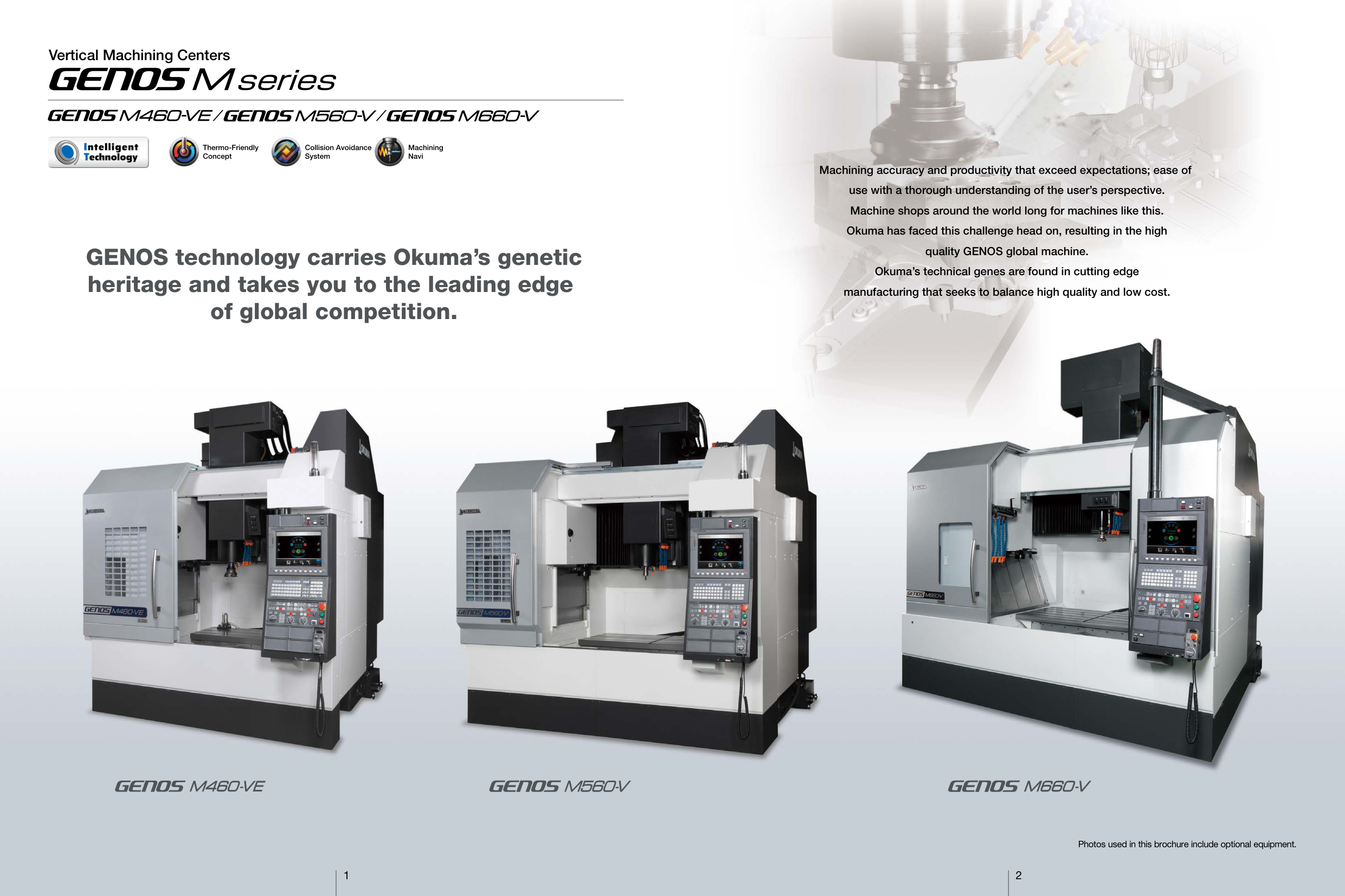
Machining accuracy and productivity that exceed expectations; ease of use with a thorough understanding of the user’s perspective. Machine shops around the world long for machines like this. Okuma has faced this challenge head on, resulting in the high quality GENOS global machine. Okuma’s technical genes are found in cutting edge manufacturing that seeks to balance high quality and low cost.
GENOS technology carries Okuma’s genetic heritage and takes you to the leading edge of global competition.
Photos used in this brochure include optional equipment.
1 2
Highly rigid construction for productivity that exceeds expectations
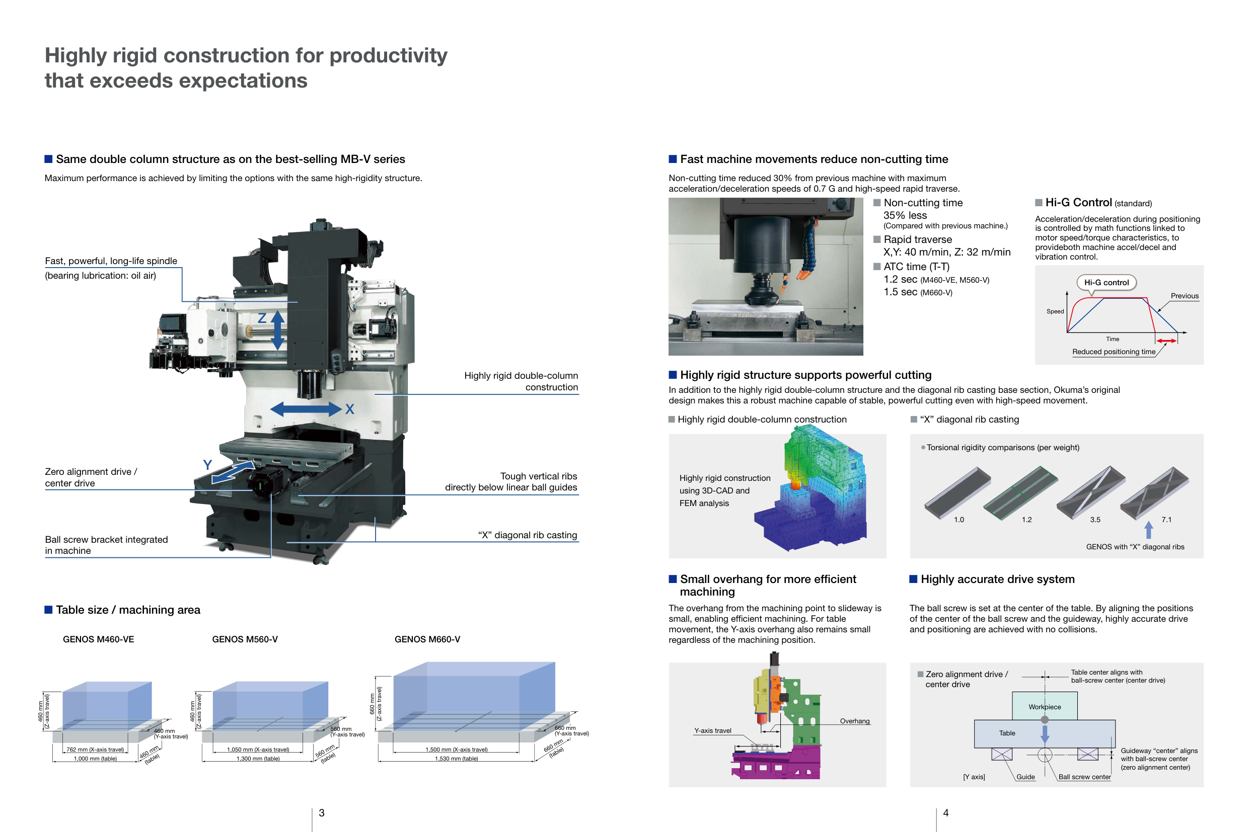
Same double column structure as on the best-selling MB-V series
Maximum performance is achieved by limiting the options with the same high-rigidity structure.

Fast, powerful, long-life spindle (bearing lubrication: oil air)
##### Z
Highly rigid double-column construction
X
Y
Zero alignment drive / center drive
Tough vertical ribs directly below linear ball guides
“X” diagonal rib casting
Ball screw bracket integrated in machine
Table size / machining area
GENOS M560-V GENOS M660-VGENOS M460-VE
(Z-axis travel)
660 mm
(Z-axis travel)
(Z-axis travel)
460 mm
460 mm
660 mm (Y-axis travel)
560 mm (Y-axis travel)
460 mm (Y-axis travel)
660 mm
560 mm (table)
460 mm (table)
(table) 1,530 mm (table) 1,500 mm (X-axis travel)
762 mm (X-axis travel)
1,050 mm (X-axis travel)
1,000 mm (table)
1,300 mm (table)
########### Fast machine movements reduce non-cutting time
Non-cutting time reduced 30% from previous machine with maximum acceleration/deceleration speeds of 0.7 G and high-speed rapid traverse.
########### Hi-G Control (standard)

Non-cutting time 35% less (Compared with previous machine.)
Acceleration/deceleration during positioning is controlled by math functions linked to motor speed/torque characteristics, to provideboth machine accel/decel and vibration control.
Rapid traverse X,Y: 40 m/min, Z: 32 m/min ATC time (T-T) 1.2 sec (M460-VE, M560-V) 1.5 sec (M660-V)
Hi-G control
Previous
| | | | |---|---|---| |Time| | |
Speed
Reduced positioning time
########### Highly rigid structure supports powerful cutting
In addition to the highly rigid double-column structure and the diagonal rib casting base section, Okuma’s original design makes this a robust machine capable of stable, powerful cutting even with high-speed movement.
Highly rigid double-column construction “X” diagonal rib casting

Torsional rigidity comparisons (per weight)


Highly rigid construction using 3D-CAD and FEM analysis
1.0 1.2 3.5 7.1
GENOS with “X” diagonal ribs
Small overhang for more efficient machining
The overhang from the machining point to slideway is small, enabling efficient machining. For table movement, the Y-axis overhang also remains small regardless of the machining position.

Overhang Y-axis travel
Highly accurate drive system
The ball screw is set at the center of the table. By aligning the positions of the center of the ball screw and the guideway, highly accurate drive and positioning are achieved with no collisions.
Table center aligns with ball-screw center (center drive)
Zero alignment drive / center drive
Workpiece
Table
Guideway “center” aligns with ball-screw center (zero alignment center)
Guide[Y axis]
Ball screw center
3 4
Improved productivity with powerful machiningHigh dimensional stability

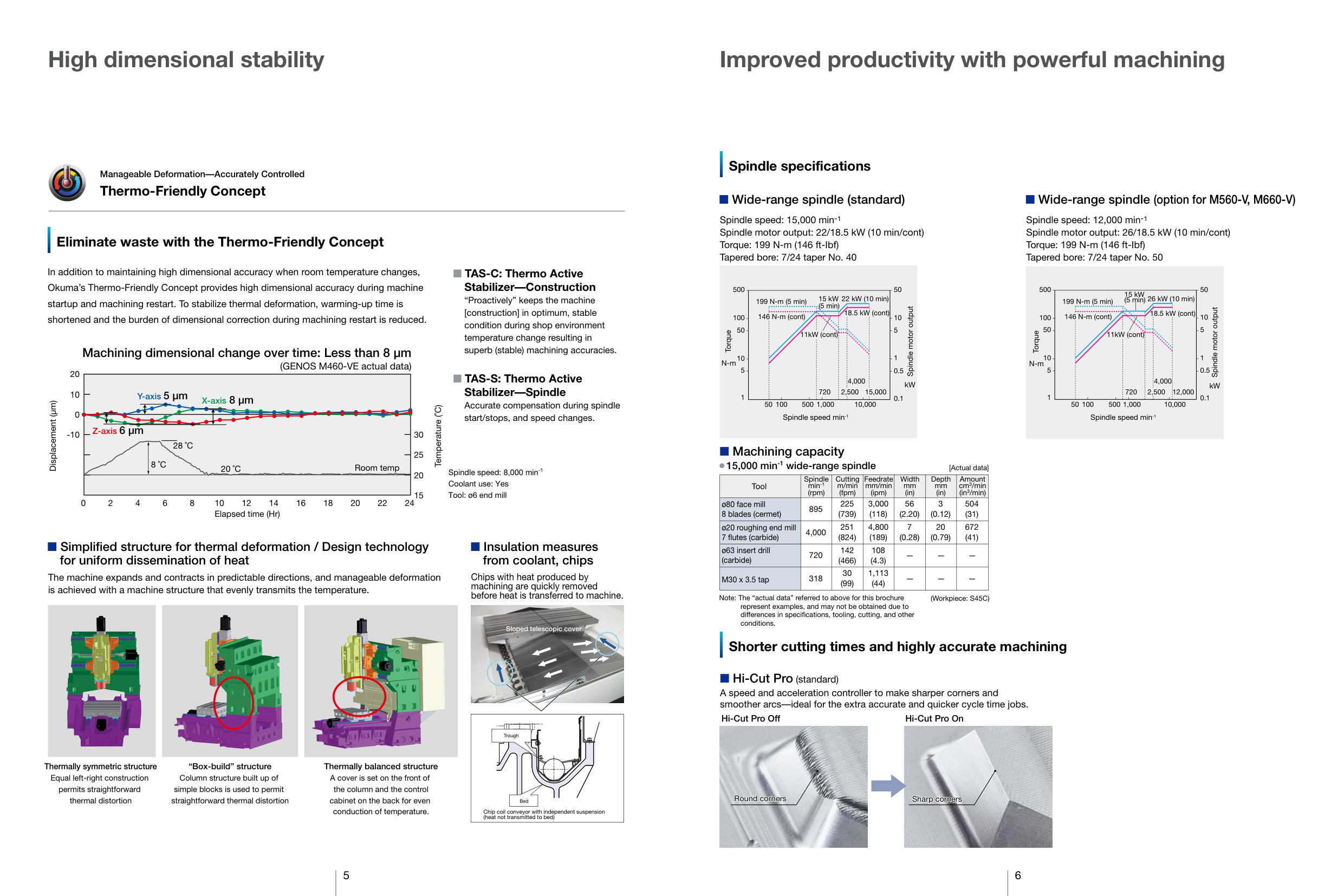
Manageable Deformation—Accurately Controlled
Thermo-Friendly Concept
Spindle specifications
########### Wide-range spindle (standard)
########### Wide-range spindle (option for M560-V, M660-V)
Spindle speed: 15,000 min-1 Spindle motor output: 22/18.5 kW (10 min/cont) Torque: 199 N-m (146 ft-Ibf) Tapered bore: 7/24 taper No. 40
Spindle speed: 12,000 min-1 Spindle motor output: 26/18.5 kW (10 min/cont) Torque: 199 N-m (146 ft-Ibf) Tapered bore: 7/24 taper No. 50
Eliminate waste with the Thermo-Friendly Concept
In addition to maintaining high dimensional accuracy when room temperature changes, Okuma’s Thermo-Friendly Concept provides high dimensional accuracy during machine startup and machining restart. To stabilize thermal deformation, warming-up time is shortened and the burden of dimensional correction during machining restart is reduced.
TAS-C: Thermo Active Stabilizer—Construction “Proactively” keeps the machine [construction] in optimum, stable condition during shop environment temperature change resulting in superb (stable) machining accuracies.
500
50
500
50
15 kW (5 min)
26 kW (10 min)
199 N-m (5 min) 22 kW (10 min)15 kW (5 min)
199 N-m (5 min)
Spindle motor output
Spindle motor output
18.5 kW (cont)
146 N-m (cont) 18.5 kW (cont)
146 N-m (cont)
10
10
100
100
50
5
50
5
Torque
11kW (cont)
11kW (cont)
Torque
########### Machining dimensional change over time: Less than 8 µm (GENOS M460-VE actual data)
1
1
10
10
N-m
N-m
5
5
0.5
0.5
20
TAS-S: Thermo Active Stabilizer—Spindle Accurate compensation during spindle start/stops, and speed changes.
4,000 720
4,000
kW
kW
12,000
720
2,500
15,0002,500
################ X-axis 8 µmY-axis5 µm
10
1 0.1
1
0.1
50 100 500 1,000 10,000
50 100 500 1,000
10,000
Displacement (µm)
Temperature (˚C)
0
Spindle speed min-1
Spindle speed min-1
################ Z-axis 6 µm
-10
30
28 ˚C 8 ˚C
Machining capacity
25
15,000 min-1 wide-range spindle
Room temp20 ˚C
[Actual data]
Spindle speed: 8,000 min-1 Coolant use: Yes Tool: ø6 end mill
20
|Tool|Spindle min-1 (rpm)|Cutting m/min (fpm)|Feedrate mm/min (ipm)|Width mm (in)|Depth mm (in)|Amount cm3/min (in3/min)| |---|---|---|---|---|---|---| |ø80 face mill 8 blades (cermet)|895|225 (739)|3,000 (118)|56 (2.20)|3 (0.12)|504 (31)| |ø20 roughing end mill 7 flutes (carbide)|4,000|251 (824)|4,800 (189)|7 (0.28)|20 (0.79)|672 (41)| |ø63 insert drill (carbide)|720|142 (466)|108 (4.3)| | | | |M30 x 3.5 tap|318|30 (99)|1,113 (44)| | | |
15
0 2 4 6 8 10 12 14 16 18 20 22 24
Elapsed time (Hr)
Simplified structure for thermal deformation / Design technology for uniform dissemination of heat
Insulation measures from coolant, chips
Chips with heat produced by machining are quickly removed before heat is transferred to machine.
The machine expands and contracts in predictable directions, and manageable deformation is achieved with a machine structure that evenly transmits the temperature.

Note: The “actual data” referred to above for this brochure represent examples, and may not be obtained due to differences in specifications, tooling, cutting, and other conditions.
(Workpiece: S45C)


Sloped telescopic cover
Shorter cutting times and highly accurate machining

Hi-Cut Pro (standard) A speed and acceleration controller to make sharper corners and smoother arcs—ideal for the extra accurate and quicker cycle time jobs.

Hi-Cut Pro Off Hi-Cut Pro On
|Bed
Chip coil conveyor with independent suspension (heat not transmitted to bed)
Trough| |---|
Thermally symmetric structure Equal left-right construction permits straightforward thermal distortion
“Box-build” structure Column structure built up of simple blocks is used to permit straightforward thermal distortion
################# Thermally balanced structure A cover is set on the front of
the column and the control cabinet on the back for even
Round corners
Sharp corners
conduction of temperature.
5 6
Truly machinist oriented, superb ease-of-use machine operation


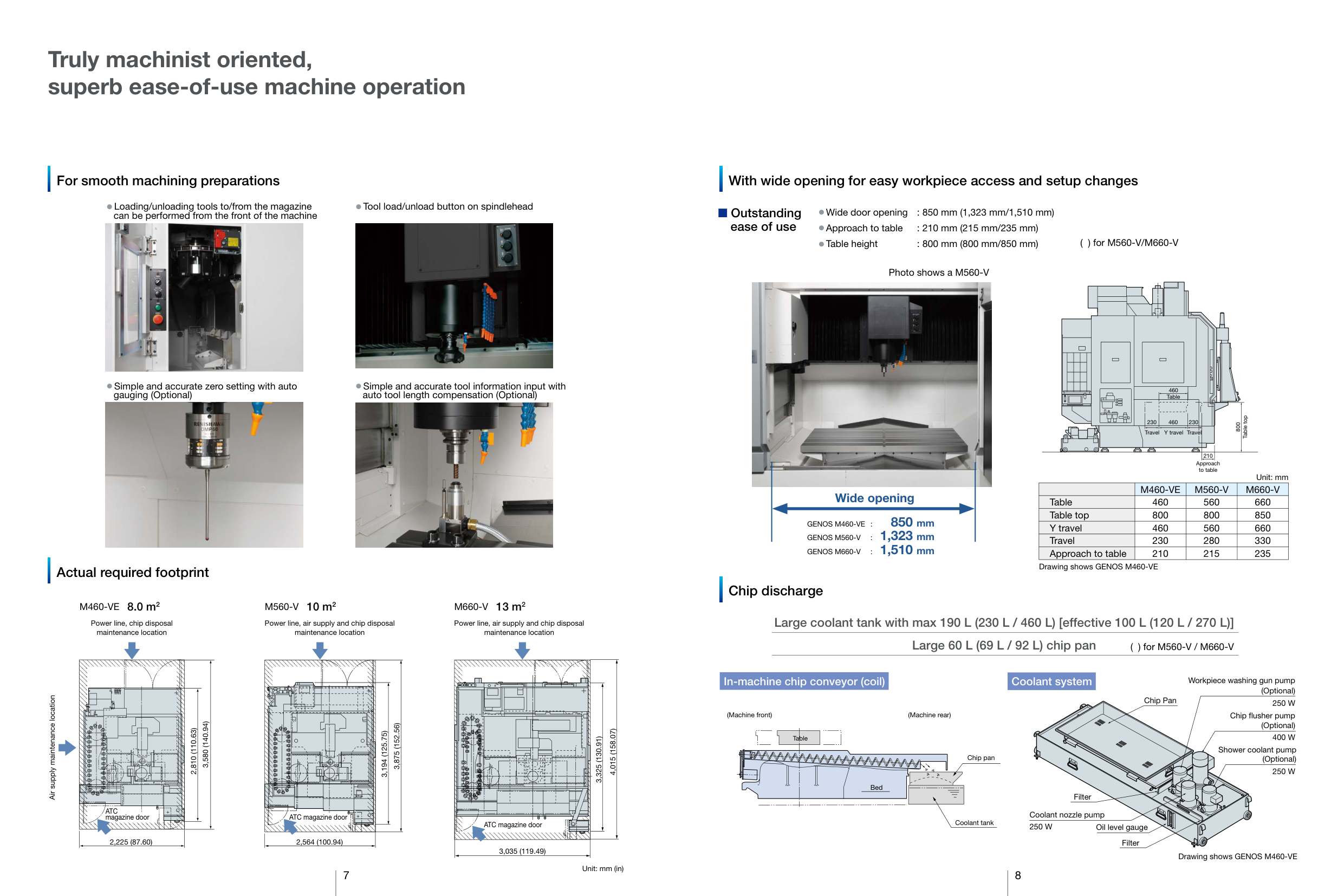
######### For smooth machining preparations With wide opening for easy workpiece access and setup changes
Loading/unloading tools to/from the magazine can be performed from the front of the machine
Tool load/unload button on spindlehead
########### Outstanding ease of use
Wide door opening : 850 mm (1,323 mm/1,510 mm) Approach to table : 210 mm (215 mm/235 mm) Table height : 800 mm (800 mm/850 mm)
( ) for M560-V/M660-V
Photo shows a M560-V


Simple and accurate zero setting with auto gauging (Optional)
Simple and accurate tool information input with auto tool length compensation (Optional)
460
Table
| | | | |---|---|---| | | | |
Table top
230 460 230
800
Travel Y travel Travel
210 Approach to table
Unit: mm
| |M460-VE|M560-V|M660-V| |---|---|---|---| |Table|460|560|660| |Table top|800|800
|850| |Y travel|460|560|660| |Travel|230|280|330| |Approach to table|210|215|235|
############ Wide opening
GENOS M460-VE : 850 mm GENOS M560-V : 1,323 mm GENOS M660-V : 1,510 mm
Drawing shows GENOS M460-VE
######### Actual required footprint
######### Chip discharge
M460-VE 8.0 m2 M560-V 10 m2 M660-V 13 m2
########### Large coolant tank with max 190 L (230 L / 460 L) [effective 100 L (120 L / 270 L)] Large 60 L (69 L / 92 L) chip pan
Power line, chip disposal maintenance location
Power line, air supply and chip disposal maintenance location
Power line, air supply and chip disposal maintenance location
( ) for M560-V / M660-V
############### In-machine chip conveyor (coil)
############### Coolant system
Workpiece washing gun pump (Optional) 250 W
Air supply maintenance location
Chip Pan
Chip flusher pump (Optional) 400 W
(Machine rear)
(Machine front)
3,580 (140.94) 2,810 (110.63)
3,875 (152.56)
3,194 (125.75)
Table
Shower coolant pump (Optional) 250 W
Chip pan
Bed
Filter
ATC magazine door
Coolant nozzle pump 250 W
ATC magazine door
Coolant tank
ATC magazine door
Oil level gauge
2,564 (100.94)2,225 (87.60)
Filter
3,035 (119.49)
Drawing shows GENOS M460-VE
Unit: mm (in)
7 8
Hi-tech Okuma mechatronics for advanced machining applications
With a variety of eco-friendly features

Cutting condition search for milling
###### Machining Navi M-g + (Optional)
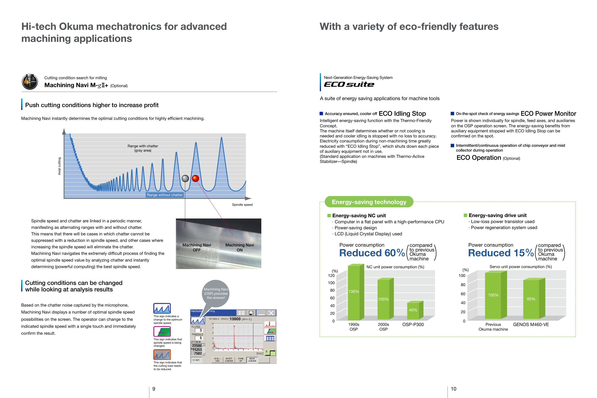
######### Push cutting conditions higher to increase profit
Machining Navi instantly determines the optimal cutting conditions for highly efficient machining.
| | | | | | |---|---|---|---|---| | | | | | | | | | | | | |Range with chatter|Range with chatter|Range with chatter|Range with chatter|Range with chatter| |(gray area)|(gray area)|(gray area)|(gray area)|(gray area)| | | | | | | | | | | | | | | | | | | | | | | | | | | | | | | | | | | | | | | | | | | | | | | | | | | | | | | |Range without chatter|Range without chatter|Range without chatter|Range without chatter| | |Spindle speed and chatter are linked in a periodic manner,|Spindle speed and chatter are linked in a periodic manner,|Spindle speed and chatter are linked in a periodic manner,|Spindle speed and chatter are linked in a periodic manner,|Spindle speed|
Axial cutting

manifesting as alternating ranges with and without chatter. This means that there will be cases in which chatter cannot be suppressed with a reduction in spindle speed, and other cases where increasing the spindle speed will eliminate the chatter. Machining Navi navigates the extremely difficult process of finding the optimal spindle speed value by analyzing chatter and instantly determining (powerful computing) the best spindle speed.
Machining Navi OFF
Machining Navi ON
######### Cutting conditions can be changed while looking at analysis results
Based on the chatter noise captured by the microphone, Machining Navi displays a number of optimal spindle speed possibilities on the screen. The operator can change to the indicated spindle speed with a single touch and immediately confirm the result.

This sign indicates a change to the optimum spindle speed.

This sign indicates that spindle speed is being changed.

This sign indicates that the cutting load needs to be reduced.
Machining Navi (OSP) provides the answer!

Next-Generation Energy-Saving System
A suite of energy saving applications for machine tools
Accuracy ensured, cooler off ECO Idling Stop
Intelligent energy-saving function with the Thermo-Friendly Concept. The machine itself determines whether or not cooling is needed and cooler idling is stopped with no loss to accuracy. Electricity consumption during non-machining time greatly reduced with “ECO Idling Stop”, which shuts down each piece of auxiliary equipment not in use. (Standard application on machines with Thermo-Active Stabilizer—Spindle)
On-the-spot check of energy savings ECO Power Monitor Power is shown individually for spindle, feed axes, and auxiliaries on the OSP operation screen. The energy-saving benefits from auxiliary equipment stopped with ECO Idling Stop can be confirmed on the spot.
Intermittent/continuous operation of chip conveyor and mist collector during operation
ECO Operation (Optional)
Energy-saving technology
|Energy-saving drive unit · Low-loss power transistor used · Power regeneration system used
NC unit power consumption (%) Servo unit power consumption (%)
0
20
40
60
80
100
120
(%)
0
20
40
60
80
100
(%)
136%
100% 100% 85%
40%
1990s OSP
2000s OSP
OSP-P300 Previous
Okuma machine
GENOS M460-VE
Energy-saving NC unit · Computer in a flat panel with a high-performance CPU · Power-saving design · LCD (Liquid Crystal Display) used
Power consumption
Reduced 60 Reduced 15
Power consumptioncompared to previous Okuma machine
compared to previous Okuma machine
| |---|
9 10
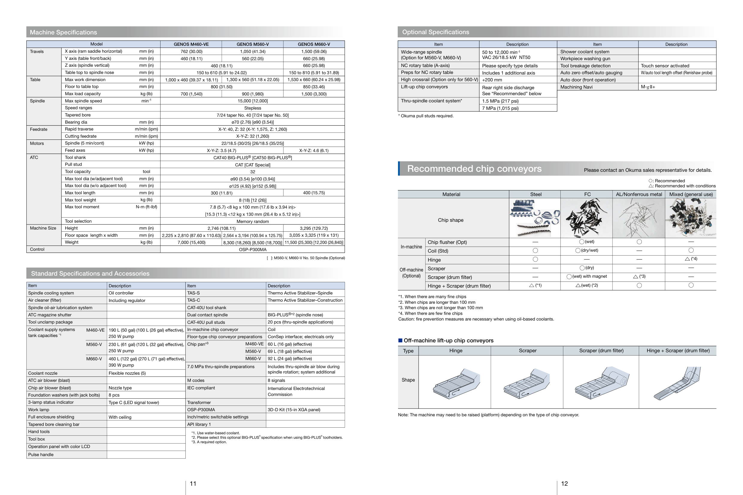
############## Machine Specifications Optional Specifications
|Model|Model|GENOS M460-VE|GENOS M560-V|GENOS M660-V| |---|---|---|---|---| |Travels|X axis (ram saddle horizontal) mm (in)|762 (30.00)|1,050 (41.34)|1,500 (59.06)| |Travels|Y axis (table front/back) mm (in)|460 (18.11)|560 (22.05)|660 (25.98)| |Travels|Z axis (spindle vertical) mm (in)|460 (18.11)|460 (18.11)|660 (25.98)| |Travels|Table top to spindle nose mm (in)|150 to 610 (5.91 to 24.02)|150 to 610 (5.91 to 24.02)|150 to 810 (5.91 to 31.89)| |Table|Max work dimension mm (in)|1,000 x 460 (39.37 x 18.11)|1,300 x 560 (51.18 x 22.05)|1,530 x 660 (60.24 x 25.98)| |Table|Floor to table top mm (in)|800 (31.50)|800 (31.50)|850 (33.46)| |Table|Max load capacity kg (lb)|700 (1,540)|900 (1,980)|1,500 (3,300)| |Spindle|Max spindle speed min-1|15,000 [12,000]|15,000 [12,000]|15,000 [12,000]| |Spindle|Speed ranges|Stepless|Stepless|Stepless| |Spindle|Tapered bore|7/24 taper No. 40 [7/24 taper No. 50]|7/24 taper No. 40 [7/24 taper No. 50]|7/24 taper No. 40 [7/24 taper No. 50]| |Spindle|Bearing dia mm (in)|ø70 (2.76) [ø90 (3.54)]|ø70 (2.76) [ø90 (3.54)]|ø70 (2.76) [ø90 (3.54)]| |Feedrate|Rapid traverse m/min (ipm)|X-Y: 40, Z: 32 (X-Y: 1,575, Z: 1,260)|X-Y: 40, Z: 32 (X-Y: 1,575, Z: 1,260)|X-Y: 40, Z: 32 (X-Y: 1,575, Z: 1,260)| |Feedrate|Cutting feedrate m/min (ipm)|X-Y-Z: 32 (1,260)|X-Y-Z: 32 (1,260)|X-Y-Z: 32 (1,260)| |Motors|Spindle (5 min/cont) kW (hp)|22/18.5 (30/25) [26/18.5 (35/25)]|22/18.5 (30/25) [26/18.5 (35/25)]|22/18.5 (30/25) [26/18.5 (35/25)]| |Motors|Feed axes kW (hp)|X-Y-Z: 3.5 (4.7)|X-Y-Z: 3.5 (4.7)|X-Y-Z: 4.6 (6.1)| |ATC|Tool shank|CAT40 BIG-PLUS® [CAT50 BIG-PLUS®]|CAT40 BIG-PLUS® [CAT50 BIG-PLUS®]|CAT40 BIG-PLUS® [CAT50 BIG-PLUS®]| |ATC|Pull stud|CAT [CAT Special]|CAT [CAT Special]|CAT [CAT Special]| |ATC|Tool capacity tool|32|32|32| |ATC|Max tool dia (w/adjacent tool) mm (in)|ø90 (3.54) [ø100 (3.94)]|ø90 (3.54) [ø100 (3.94)]|ø90 (3.54) [ø100 (3.94)]| |ATC|Max tool dia (w/o adjacent tool) mm (in)|ø125 (4.92) [ø152 (5.98)]|ø125 (4.92) [ø152 (5.98)]|ø125 (4.92) [ø152 (5.98)]| |ATC|Max tool length mm (in)|300 (11.81)|300 (11.81)|400 (15.75)| |ATC|Max tool weight kg (lb)|8 (18) [12 (26)]|8 (18) [12 (26)]|8 (18) [12 (26)]|
|ATC|Max tool moment N-m (ft-lbf)|7.8 (5.7) <8 kg x 100 mm (17.6 lb x 3.94 in)> [15.3 (11.3) <12 kg x 130 mm (26.4 lb x 5.12 in)>]|7.8 (5.7) <8 kg x 100 mm (17.6 lb x 3.94 in)> [15.3 (11.3) <12 kg x 130 mm (26.4 lb x 5.12 in)>]|7.8 (5.7) <8 kg x 100 mm (17.6 lb x 3.94 in)> [15.3 (11.3) <12 kg x 130 mm (26.4 lb x 5.12 in)>]| |ATC|Tool selection|Memory random|Memory random|Memory random| |Machine Size|Height mm (in)|2,746 (108.11)|2,746 (108.11)|3,295 (129.72)| |Machine Size|Floor space length x width mm (in)|2,225 x 2,810 (87.60 x 110.63)|2,564 x 3,194 (100.94 x 125.75)|3,035 x 3,325 (119 x 131)| |Machine Size|Weight kg (lb)|7,000 (15,400)|8,300 (18,260) [8,500 (18,700)]|11,500 (25,300) [12,200 (26,840)]| |Control|Control|OSP-P300MA|OSP-P300MA|OSP-P300MA|
[ ]: M560-V, M660-V No. 50 Spindle (Optional)
############## Standard Specifications and Accessories
Item Spindle cooling system Air cleaner (filter) Spindle oil-air lubrication system ATC magazine shutter Tool unclamp package Coolant supply systems tank capacities *1
M460-VE
M560-V
M660-V
Coolant nozzle ATC air blower (blast) Chip air blower (blast) Foundation washers (with jack bolts) 3-lamp status indicator Work lamp Full enclosure shielding Tapered bore cleaning bar Hand tools Tool box Operation panel with color LCD Pulse handle
Item TAS-S TAS-C CAT-40U tool shank Dual contact spindle CAT-40U pull studs In-machine chip conveyor Floor-type chip conveyor preparations Chip pan*3
Description Oil controller Including regulator
190 L (50 gal) (100 L (26 gal) effective), 250 W pump 230 L (61 gal) (120 L (32 gal) effective), 250 W pump 460 L (122 gal) (270 L (71 gal) effective), 390 W pump
M460-VE M560-V M660-V
7.0 MPa thru-spindle preparations
Flexible nozzles (5)
M codes IEC compliant
Nozzle type 8 pcs Type C (LED signal tower)
Transformer OSP-P300MA Inch/metric switchable settings API library 1
With ceiling
Description Thermo Active Stabilizer–Spindle Thermo Active Stabilizer–Construction
BIG-PLUS®*2 (spindle nose) 20 pcs (thru-spindle applications) Coil ConSep interface; electricals only 60 L (16 gal) (effective) 69 L (18 gal) (effective) 92 L (24 gal) (effective) Includes thru-spindle air blow during spindle rotation; system additional 8 signals International Electrotechnical Commission
3D-D Kit (15-in XGA panel)
R R
|Item|Description|Item|Description| |---|---|---|---| |Wide-range spindle (Option for M560-V, M660-V)|50 to 12,000 min-1 VAC 26/18.5 kW NT50|Shower coolant system| | |Wide-range spindle (Option for M560-V, M660-V)|50 to 12,000 min-1 VAC 26/18.5 kW NT50|Workpiece washing gun| | |NC rotary table (A-axis)|Please specify type details|Tool breakage detection|Touch sensor activated| |Preps for NC rotary table|Includes 1 additional axis|Auto zero offset/auto gauging|W/auto tool length offset (Renishaw probe)| |High crossrail (Option only for 560-V)|+200 mm|Auto door (front operation)| | |Lift-up chip conveyors|Rear right side discharge See “Recommended” below|Machining Navi|M-gII+| |Lift-up chip conveyors|Rear right side discharge See “Recommended” below| | | |Thru-spindle coolant system*|1.5 MPa (217 psi)| | | |Thru-spindle coolant system*|7 MPa (1,015 psi)| | |
#### Recommended chip conveyors Please contact an Okuma sales representative for details.
: Recommended
: Recommended with conditions
|Material|Material|Steel|FC|AL/Nonferrous metal|Mixed (general use)| |---|---|---|---|---|---| |Chip shape|Chip shape|


||| | |In-machine|Chip flusher (Opt)|—|(wet)| |—| |In-machine|Coil (Std)| |(dry/wet)|—| | |Off-machine (Optional)|Hinge| |—|—|(*4)| |Off-machine (Optional)|Scraper|—|(dry)|—|—| |Off-machine (Optional)|Scraper (drum filter)|—|(wet) with magnet|(*3)|—| |Off-machine (Optional)|Hinge + Scraper (drum filter)|(*1)|(wet) (*2)| | |
Caution: fire prevention measures are necessary when using oil-based coolants.
Off-machine lift-up chip conveyors
|Type|Hinge|Scraper|Scraper (drum filter)|Hinge + Scraper (drum filter)| |---|---|---|---|---| |Shape| | | | |
Note: The machine may need to be raised (platform) depending on the type of chip conveyor.
11 12
############## The Next-Generation Intelligent CNC
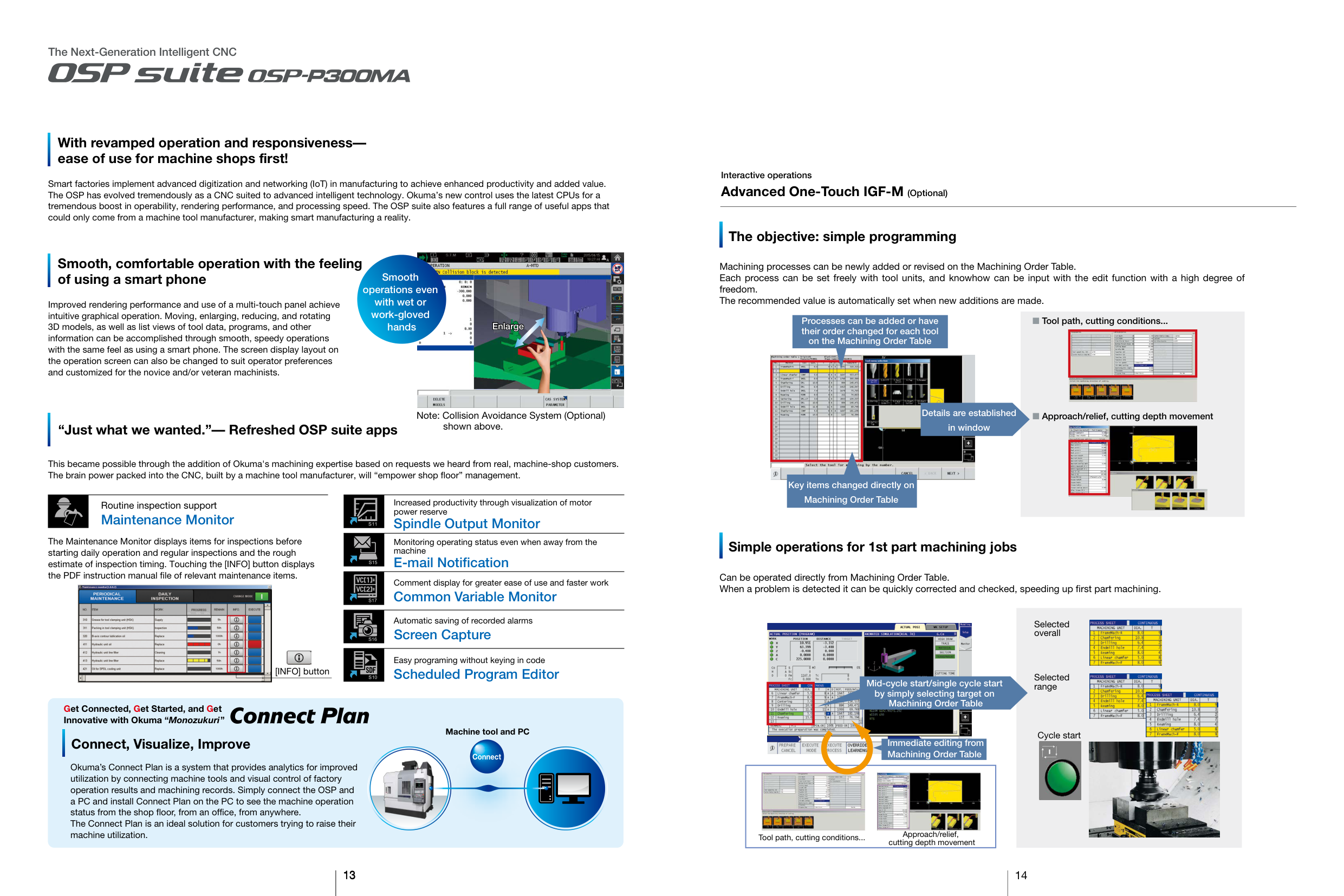
With revamped operation and responsivenessease of use for machine shops first!
Smart factories implement advanced digitization and networking (IoT) in manufacturing to achieve enhanced productivity and added value. The OSP has evolved tremendously as a CNC suited to advanced intelligent technology. Okuma’s new control uses the latest CPUs for a tremendous boost in operability, rendering performance, and processing speed. The OSP suite also features a full range of useful apps that could only come from a machine tool manufacturer, making smart manufacturing a reality.
Interactive operations
Advanced One-Touch IGF-M (Optional)
The objective: simple programming

Smooth, comfortable operation with the feeling of using a smart phone
Machining processes can be newly added or revised on the Machining Order Table. Each process can be set freely with tool units, and knowhow can be input with the edit function with a high degree of freedom. The recommended value is automatically set when new additions are made.
Smooth operations even with wet or work-gloved hands

Improved rendering performance and use of a multi-touch panel achieve intuitive graphical operation. Moving, enlarging, reducing, and rotating 3D models, as well as list views of tool data, programs, and other information can be accomplished through smooth, speedy operations with the same feel as using a smart phone. The screen display layout on the operation screen can also be changed to suit operator preferences and customized for the novice and/or veteran machinists.
Processes can be added or have their order changed for each tool on the Machining Order Table
Tool path, cutting conditions...
Enlarge

|| |---|

Approach/relief, cutting depth movementDetails are established in window
Note: Collision Avoidance System (Optional) shown above.
“Just what we wanted.”— Refreshed OSP suite apps

This became possible through the addition of Okuma's machining expertise based on requests we heard from real, machine-shop customers. The brain power packed into the CNC, built by a machine tool manufacturer, will “empower shop floor” management.
Key items changed directly on Machining Order Table

Increased productivity through visualization of motor power reserve
Routine inspection support
Maintenance Monitor
######### Spindle Output Monitor
The Maintenance Monitor displays items for inspections before starting daily operation and regular inspections and the rough estimate of inspection timing. Touching the [INFO] button displays the PDF instruction manual file of relevant maintenance items.
Monitoring operating status even when away from the machine
######## Simple operations for 1st part machining jobs
######### E-mail Notification
Can be operated directly from Machining Order Table. When a problem is detected it can be quickly corrected and checked, speeding up first part machining.
Comment display for greater ease of use and faster work

######### Common Variable Monitor

Automatic saving of recorded alarms
Selected overall

######### Screen Capture

Easy programing without keying in code
[INFO] button
######### Scheduled Program Editor
Selected range

Mid-cycle start/single cycle start by simply selecting target on Machining Order Table

Get Connected, Get Started, and Get Innovative with Okuma “Monozukuri”
Machine tool and PC
Cycle start
######## Connect, Visualize, Improve
Immediate editing from Machining Order Table


Connect

Okuma’s Connect Plan is a system that provides analytics for improved utilization by connecting machine tools and visual control of factory operation results and machining records. Simply connect the OSP and a PC and install Connect Plan on the PC to see the machine operation status from the shop floor, from an office, from anywhere. The Connect Plan is an ideal solution for customers trying to raise their machine utilization.
|

Tool path, cutting conditions... Approach/relief, cutting depth movement| |---|
13
14
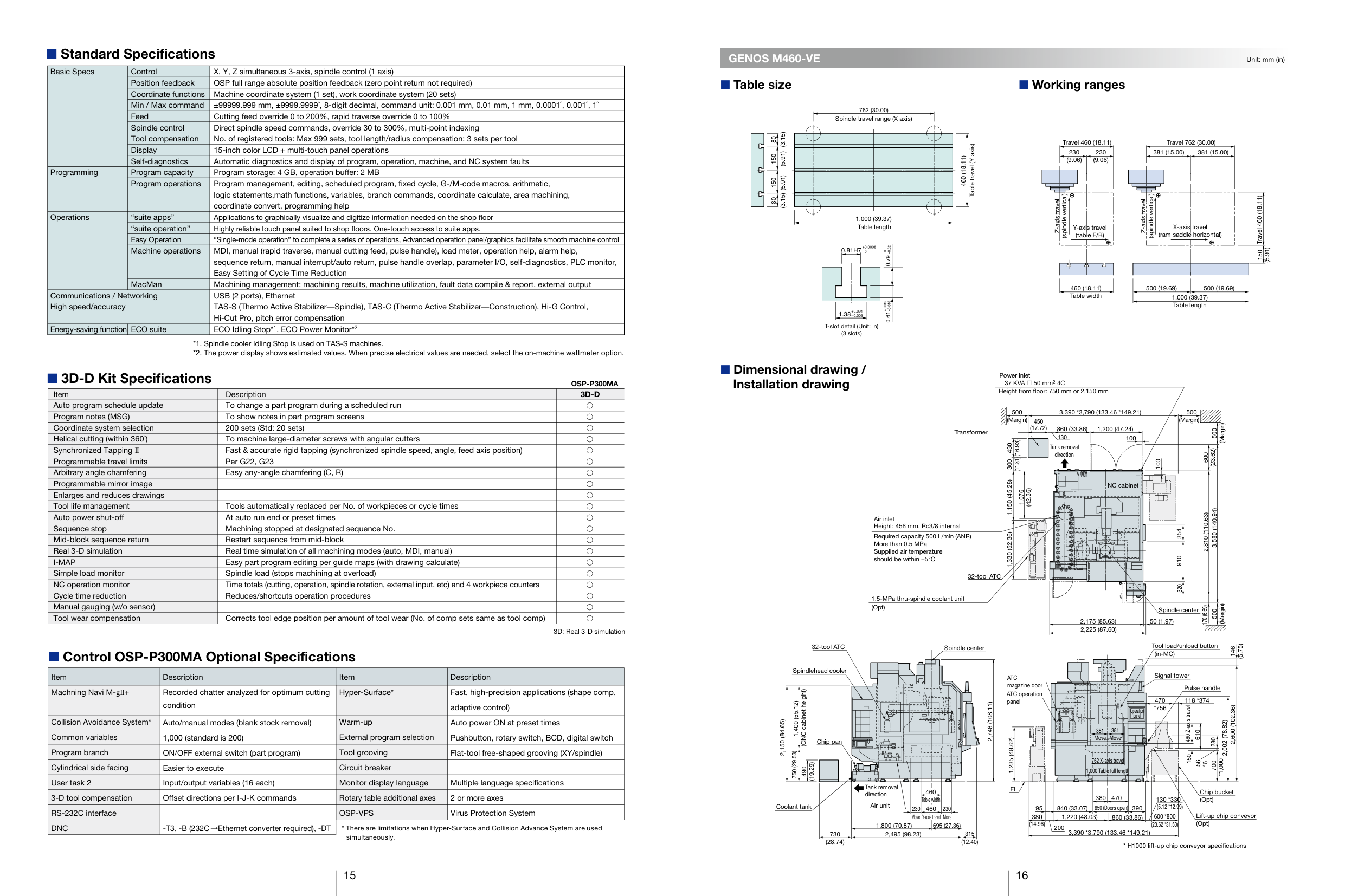
######## Standard Specifications
|Basic Specs|Control|X, Y, Z simultaneous 3-axis, spindle control (1 axis)| |---|---|---| |Basic Specs|Position feedback|OSP full range absolute position feedback (zero point return not required)| |Basic Specs|Coordinate functions|Machine coordinate system (1 set), work coordinate system (20 sets)| |Basic Specs|Min / Max command|±99999.999 mm, ±9999.9999˚, 8-digit decimal, command unit: 0.001 mm, 0.01 mm, 1 mm, 0.0001˚, 0.001˚, 1˚| |Basic Specs|Feed|Cutting feed override 0 to 200%, rapid traverse override 0 to 100%| |Basic Specs|Spindle control|Direct spindle speed commands, override 30 to 300%, multi-point indexing| |Basic Specs|Tool compensation|No. of registered tools: Max 999 sets, tool length/radius compensation: 3 sets per tool| |Basic Specs|Display|15-inch color LCD + multi-touch panel operations| |Basic Specs|Self-diagnostics|Automatic diagnostics and display of program, operation, machine, and NC system faults| |Programming|Program capacity|Program storage: 4 GB, operation buffer: 2 MB| |Programming|Program operations|Program management, editing, scheduled program, fixed cycle, G-/M-code macros, arithmetic, logic statements,math functions, variables, branch commands, coordinate calculate, area machining, coordinate convert, programming help| |Operations|“suite apps”|Applications to graphically visualize and digitize information needed on the shop floor| |Operations|“suite operation”|Highly reliable touch panel suited to shop floors. One-touch access to suite apps.| |Operations|Easy Operation|“Single-mode operation” to complete a series of operations, Advanced operation panel/graphics facilitate smooth machine control| |Operations|Machine operations|MDI, manual (rapid traverse, manual cutting feed, pulse handle), load meter, operation help, alarm help, sequence return, manual interrupt/auto return, pulse handle overlap, parameter I/O, self-diagnostics, PLC monitor, Easy Setting of Cycle Time Reduction| |Operations|MacMan|Machining management: machining results, machine utilization, fault data compile & report, external output| |Communications / Networking|Communications / Networking|USB (2 ports), Ethernet| |High speed/accuracy|High speed/accuracy|TAS-S (Thermo Active Stabilizer––Spindle), TAS-C (Thermo Active Stabilizer––Construction), Hi-G Control, Hi-Cut Pro, pitch error compensation| |Energy-saving function|ECO suite|ECO Idling Stop*1, ECO Power Monitor*2|
######## 3D-D Kit Specifications OSP-P300MA
|Item|Description|3D-D| |---|---|---| |Auto program schedule update|To change a part program during a scheduled run| | |Program notes (MSG)|To show notes in part program screens| | |Coordinate system selection|200 sets (Std: 20 sets)| | |Helical cutting (within 360˚)|To machine large-diameter screws with angular cutters| | |Synchronized Tapping II|Fast & accurate rigid tapping (synchronized spindle speed, angle, feed axis position)| | |Programmable travel limits|Per G22, G23| | |Arbitrary angle chamfering|Easy any-angle chamfering (C, R)| | |Programmable mirror image| | | |Enlarges and reduces drawings| | | |Tool life management|Tools automatically replaced per No. of workpieces or cycle times| | |Auto power shut-off|At auto run end or preset times| | |Sequence stop|Machining stopped at designated sequence No.| | |Mid-block sequence return|Restart sequence from mid-block| | |Real 3-D simulation|Real time simulation of all machining modes (auto, MDI, manual)| | |I-MAP|Easy part program editing per guide maps (with drawing calculate)| | |Simple load monitor|Spindle load (stops machining at overload)| | |NC operation monitor|Time totals (cutting, operation, spindle rotation, external input, etc) and 4 workpiece counters| | |Cycle time reduction|Reduces/shortcuts operation procedures| | |Manual gauging (w/o sensor)| | | |Tool wear compensation|Corrects tool edge position per amount of tool wear (No. of comp sets same as tool comp)| |
3D: Real 3-D simulation
######## Control OSP-P300MA Optional Specifications
|Item|Description|Item|Description| |---|---|---|---| |Machning Navi M-gII+|Recorded chatter analyzed for optimum cutting condition|Hyper-Surface*|Fast, high-precision applications (shape comp, adaptive control)| |Collision Avoidance System*|Auto/manual modes (blank stock removal)|Warm-up|Auto power ON at preset times| |Common variables|1,000 (standard is 200)|External program selection|Pushbutton, rotary switch, BCD, digital switch| |Program branch|ON/OFF external switch (part program)|Tool grooving|Flat-tool free-shaped grooving (XY/spindle)| |Cylindrical side facing|Easier to execute|Circuit breaker| | |User task 2|Input/output variables (16 each)|Monitor display language|Multiple language specifications| |3-D tool compensation|Offset directions per I-J-K commands|Rotary table additional axes|2 or more axes| |RS-232C interface| |OSP-VPS|Virus Protection System| |DNC|-T3, -B (232C Ethernet converter required), -DT
|* There are limitations when Hyper-Surface and Collision Advance System are used|* There are limitations when Hyper-Surface and Collision Advance System are used|
simultaneously.
15
GENOS M460-VE
Table size Working ranges
Unit: mm (in)
(3.15)
(5.91) 80
(3.15) 150
(5.91) 80
150
762 (30.00) Spindle travel range (X axis)
1,000 (39.37) Table length
+0.0008 0
0.61+0.015–0.0160.790–0.02
+0.091 –0.003
T-slot detail (Unit: in) (3 slots)
Table travel (Y axis)
460 (18.11)
Travel 460 (18.11)
230 (9.06)
230 (9.06)
Travel 762 (30.00) 381 (15.00) 381 (15.00)
(spindle vertical)
Z-axis travel
Y-axis travel (table F/B)
460 (18.11) Table width
(spindle vertical)
Z-axis travel
X-axis travel (ram saddle horizontal)
Travel 460 (18.11)150
(5.91)
500 (19.69)
500 (19.69)
1,000 (39.37) Table length
Dimensional drawing / Installation drawing
Power inlet 37 KVA 50 mm2 4C
| | |---|
Height from floor: 750 mm or 2,150 mm
3,390 *3,790 (133.46 *149.21) (Margin) 500
500
(Margin)
450 (17.72)
(Margin) 500
1,200 (47.24)860 (33.86) 130
Transformer
100
(16.93) 300
430
Tank removal direction
(23.62)
600
(11.81) 1,330 (52.36)1,150 (45.28)
100
NC cabinet
(42.36)
1,076
(Margin) 5003,580 (140.94)
2,810 (110.63)
Air inlet Height: 456 mm, Rc3/8 internal
354910
Required capacity 500 L/min (ANR) More than 0.5 MPa Supplied air temperature should be within +5°C
| | |---| | |
32-tool ATC
320
1.5-MPa thru-spindle coolant unit (Opt)
170 (6.69)
Spindle center
50 (1.97)2,175 (85.63) 2,225 (87.60)
Tool load/unload button (in-MC)
32-tool ATC
(5.75) 2,600 (102.36)
Spindle center
146
Spindlehead cooler
Signal tower
ATC magazine door
Pulse handle
(CNC cabinet height)
ATC operation panel
118 *374
470
1,400 (55.12)
2,746 (108.11)
*756
460 Z-axis travel
||Operation panel| |---| | |---| | |
2,150 (84.65)
2,002 (78.82)
381 Move
381 Move
610 150
1,235 (48.62)
280
Chip pan
| | | | |---|---|---|
750 (29.53)
762 X-axis travel
*1,000
56
700
*6
(19.29)
490
1,000 Table full length
Tank removal direction
FL
460 Table width
Chip bucket (Opt)
470380 840 (33.07)95
130 *330
Air unitCoolant tank
(5.12 *12.99)
850 (Doors open)
390
460230 230
Lift-up chip conveyor (Opt)
600 *800
Move 860 (33.86)1,220 (48.03)380 (14.96)
Move Y-axis travel
(23.62 *31.50)
1,800 (70.87) 695 (27.36)
200
3,390 *3,790 (133.46 *149.21)
315 (12.40)
730 (28.74)
2,495 (98.23)
16
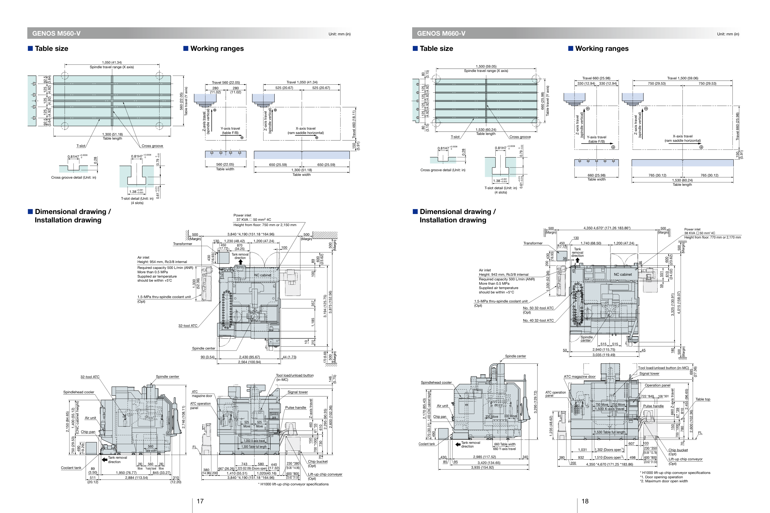
GENOS M560-V
Table size Working ranges
############# GENOS M660-V
Unit: mm (in) Unit: mm (in)
Table size Working ranges
1,050 (41.34) Spindle travel range (X axis)
(3.64) 92.5
(4.92) 92.5
(4.92) 125
125
(4.92) 125
(3.64)
1,300 (51.18) Table length
T-slot Cross groove
Table travel (Y axis)
560 (22.05)
Travel 560 (22.05)
280 (11.02)
280 (11.02)
(spindle vertical)
Z-axis travel
Y-axis travel (table F/B)
Travel 1,050 (41.34) 525 (20.67) 525 (20.67)
(spindle vertical)
Z-axis travel
X-axis travel (ram saddle horizontal)
0.81H7+0.00080
0.28
Cross groove detail (Unit: in)
Dimensional drawing / Installation drawing
0.61+0.015–0.0160.790–0.02
T-slot detail (Unit: in) (4 slots)
560 (22.05) Table width
650 (25.59)
1,300 (51.18) Table width
650 (25.59)
Power inlet 37 KVA 50 mm2 4C
| | |---|
Height from floor: 750 mm or 2,150 mm
3,840 *4,190 (151.18 *164.96)500 (Margin)
500 (Margin)
130 Transformer
1,230 (48.42) 1,200 (47.24)
(Margin)
500
450 (17.72)
870 (34.25)
100 Tank removal direction
(16.93)
(23.62)
430
Air inlet Height: 954 mm, Rc3/8 internal
600
89100
Required capacity 500 L/min (ANR) More than 0.5 MPa Supplied air temperature should be within +5˚C
NC cabinet
| | |---| | |
(52.36)
1,330
3,875 (152.56) 3,194 (125.75)
1.5-MPa thru-spindle coolant unit (Opt)
3101,185357 10
32-tool ATC
Spindle center
170 (6.69)
(Margin)
500
90 (3.54) 44 (1.73)
2,430 (95.67) 2,564 (100.94)
ool load/unload button
T
Spindle center32-tool A
TC
(5.75)
146
(in-MC)
ATC magazine door
Signal tower
Spindlehead cooler
Z-axis travel
(CNC cabinet height)
ATC operation panel
| | | |---|---| | | | | | |
Pulse handle
2,600 (102.36)
2,746 (108.11)
1,400 (55.12)
2,295 (90.35)
2,150 (84.65)
|Operation panel| |---|
Air unit
| | | |---|---| | | |
525 Move
525 Move
460
| | | |---|---| | | | | | |
610 700 *100061 *33
Chip pan
750 (29.53)
150
1,050 X-axis travel
730
(19.29)
560 able width
1,300 Table full length
FL
490
T
70
emoval di ection
Tank r r
Chip bucket (Opt)
230 *380 (9.06 *14.96)(17.32)
743 580 380 (14.96)
280 Move
280 Move
560
440
Coolant tank
Y
-axis travel
1,323 (52.09) (Doors open) 1,410 (55.51) 1,020(40.16)
667 (26.26)
89 (3.50)
845 (33.27)1,950 (76.77) 511
200
600 *800 (23.62 *31.50)
Lift-up chip conveyer (Opt)
2,884 (113.54) 310 (12.20)
3,840 *4,190 (151.18 *164.96)
(20.12)
Travel 460 (18.11)150
(5.91)
(3.15) 80
(4.92) 80
(4.92) 125
125
(4.92) 125
(4.92) 125
(3.15)
1,500 (59.05) Spindle travel range (X axis)
1,530 (60.24) Table length
T-slot Cross groove
0.81H7+0.00080
0.28
Cross groove detail (Unit: in)
0.61+0.015–0.0160.790–0.02
T-slot detail (Unit: in) (4 slots)
Table travel (Y axis)
660 (25.98)
Travel 660 (25.98)
330 (12.94)
330 (12.94)
Travel 1,500 (59.06)
750 (29.53) 750 (29.53)
(spindle vertical)
Z-axis travel
Y-axis travel (table F/B)
660 (25.98) Table width
(spindle vertical)
Z-axis travel
X-axis travel (ram saddle horizontal)
765 (30.12) 765 (30.12)
1,530 (60.24) Table length
Travel 660 (25.98)150
(5.91)
Dimensional drawing / Installation drawing
4,350 4,670* (171.26 183.86*)
500 (Margin)
130
Transformer
450 (17.72)
1,740 (68.50)
1,200 (47.24)
| | | |---|---| | | | | | |
Tank removal direction
|56|56| | |---|---|---| | | | |
(16.93) 1,330 (52.36)200
430
Air inlet Height: 943 mm, Rc3/8 internal
45
NC cabinet
Required capacity 500 L/min (ANR) More than 0.5 MPa Supplied air temperature should be within +5°C
86
1.5-MPa thru-spindle coolant unit (Opt)
No. 50 32-tool ATC (Opt)
No. 40 32-tool ATC
500 (Margin)
610
600
551
Power inlet 38 KVA 50 mm24C Height from floor: 770 mm or 2,170 mm
(Margin)
500
59
Spindle center
Spindlehead cooler
1,400 (CNC cabinet height)
2,170 (85.43)
Air unit
Chip pan
490 770 (30.31)
Coolant tank
330 Move 330 Move
660 Table widthTank removal direction
660 Y-axis travel
2,985 (117.52)430 9585
3,420 (134.65)
3,935 (154.92)
3,295 (129.72)
340
50
Spindle center
| | | | |---|---|---| | | | | | | | |
515 515
2,940 (115.75) 45
3,035 (119.49)
(Margin)
500 180
ATC magazine door
Tool load/unload button (in-MC)
(27.36)
695
Signal tower
ATC operation panel
1,235 (48.62)
380
750 Move750 Move 1,500 X-axis travel
1,530 Table full length
Operation panel
660 Z-axis travel
2,455 (96.65) 810780
108 *301722 *849
Table top
Pulse handle
700 *100067 *39
2,600 (102.36)
150
FL
607 1,302 (Doors open*1)
1,031
1,510 (Doors open*2)
932
498
200
4,350 *4,670 (171.25 *183.86)
103
230 *350 (9.06 *13.78)
600 *800 (23.62 *31.50)
70
Chip bucket (Opt)
Lift-up chip conveyor (Opt)
17 18
GENOS
The origin of gene, from Greek genos meaning race, offspring, origin (pronounced “ ” as in “generous”)
Global Efficient No.1 Standard
Oguchi-cho, Niwa-gun, Aichi 480-0193, Japan TEL: +81-587-95-7825 FAX: +81-587-95-6074
|This product is subject to the Japanese government Foreign Exchange and Foreign Trade Control Act with regard to security controlled items; whereby Okuma Corporation should be notified prior to its shipment to another country.| |---|
When using Okuma products, always read the safety precautions mentioned in the instruction manual and attached to the product.
Pub.No.GENOS-M-E-(A)-(17)-300 (Mar 2020)
The specifications, illustrations, and descriptions in this brochure vary in different markets and are subject to change without notice.
