
Ask AI
— answers from the official manualAnswers from the official manual.
Common questions
Common Questions
10 totalWhat should I do if the treadmill does not turn on?
Check that the power cord is plugged into an earthed outlet, confirm the key is inserted and press reset switch. Wait five minutes to allow capacitors to discharge before attempting again.
How do I calibrate the incline system if it's not working correctly?
Press Stop, Incline increase buttons, insert the key, release all buttons. Press Stop again and then press Incline increase or decrease repeatedly until calibrated. Remove the key when calibration is complete.
What should I do if the walking belt slows down while in use?
Check that the extension cable meets specifications, ensure the belt is not overtightened by turning idler roller screws counterclockwise one quarter turn. Lift each end of the belt 2-3 inches and reposition until centering.
How do I measure my heart rate using the treadmill?
Remove protective sheets from hand contacts, hold hands firmly on pulse bar to begin monitoring. Heart rate measurement requires clean hands for accuracy. Monitor for at least 15 seconds for accurate reading.
What safety precautions should I follow while using the treadmill?
Wear appropriate exercise clothing and athletic shoes, keep children under 13 away from use area. Ensure it is positioned on a flat surface with adequate clearance behind and sides. Do not leave treadmill unattended during operation.
How do I connect my smart device to the treadmill console?
Download iFit app, enable BLE on your device, open iFit and follow setup instructions. Connect by pressing Bluetooth button on console until LED turns solid blue.
Full Manual
36 pages
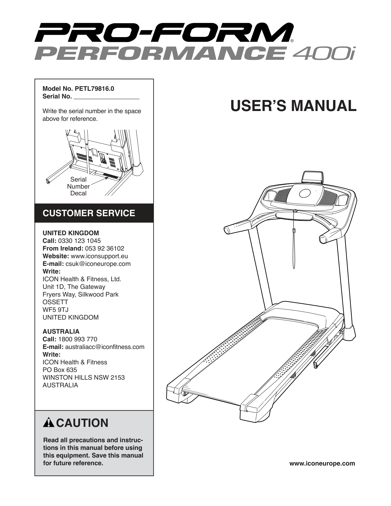
|Model No. PETL79816.0 Serial No.
Write the serial number in the space above for reference.
CUSTOMER SERVICE
UNITED KINGDOM Call: 0330 123 1045 From Ireland: 053 92 36102 Website: www.iconsupport.eu E-mail: csuk@iconeurope.com Write: ICON Health & Fitness, Ltd. Unit 1D, The Gateway Fryers Way, Silkwood Park OSSETT WF5 9TJ UNITED KINGDOM
AUSTRALIA Call: 1800 993 770 E-mail: australiacc@iconfitness.com Write: ICON Health & Fitness PO Box 635 WINSTON HILLS NSW 2153 AUSTRALIA
Serial Number Decal
| |---| |CAUTION
Read all precautions and instructions in this manual before using this equipment. Save this manual for future reference.
|
USER’S MANUAL
www.iconeurope.com
#### TABLE OF CONTENTS
WARNING DECAL PLACEMENT . . . . . . . . . . . . . . . . . . . . . . . . . . . . . . . . . . . . . . . . . . . . . . . . . . . . . . . . . . . . . . .2 IMPORTANT PRECAUTIONS ..................................................................3 BEFORE YOU BEGIN. . . . . . . . . . . . . . . . . . . . . . . . . . . . . . . . . . . . . . . . . . . . . . . . . . . . . . . . . . . . . . . . . . . . . . . .5 PART IDENTIFICATION CHART. . . . . . . . . . . . . . . . . . . . . . . . . . . . . . . . . . . . . . . . . . . . . . . . . . . . . . . . . . . . . . . .6 ASSEMBLY . . . . . . . . . . . . . . . . . . . . . . . . . . . . . . . . . . . . . . . . . . . . . . . . . . . . . . . . . . . . . . . . . . . . . . . . . . . . . . . .7 HOW TO USE THE TREADMILL ..............................................................17 HOW TO FOLD AND MOVE THE TREADMILL ...................................................25 MAINTENANCE AND TROUBLESHOOTING .....................................................26 EXERCISE GUIDELINES ....................................................................29 PART LIST. . . . . . . . . . . . . . . . . . . . . . . . . . . . . . . . . . . . . . . . . . . . . . . . . . . . . . . . . . . . . . . . . . . . . . . . . . . . . . . .30 EXPLODED DRAWING. . . . . . . . . . . . . . . . . . . . . . . . . . . . . . . . . . . . . . . . . . . . . . . . . . . . . . . . . . . . . . . . . . . . . .32 ORDERING REPLACEMENT PARTS. . . . . . . . . . . . . . . . . . . . . . . . . . . . . . . . . . . . . . . . . . . . . . . . . . . Back Cover RECYCLING INFORMATION ......................................................... Back Cover
#### WARNING DECAL PLACEMENT
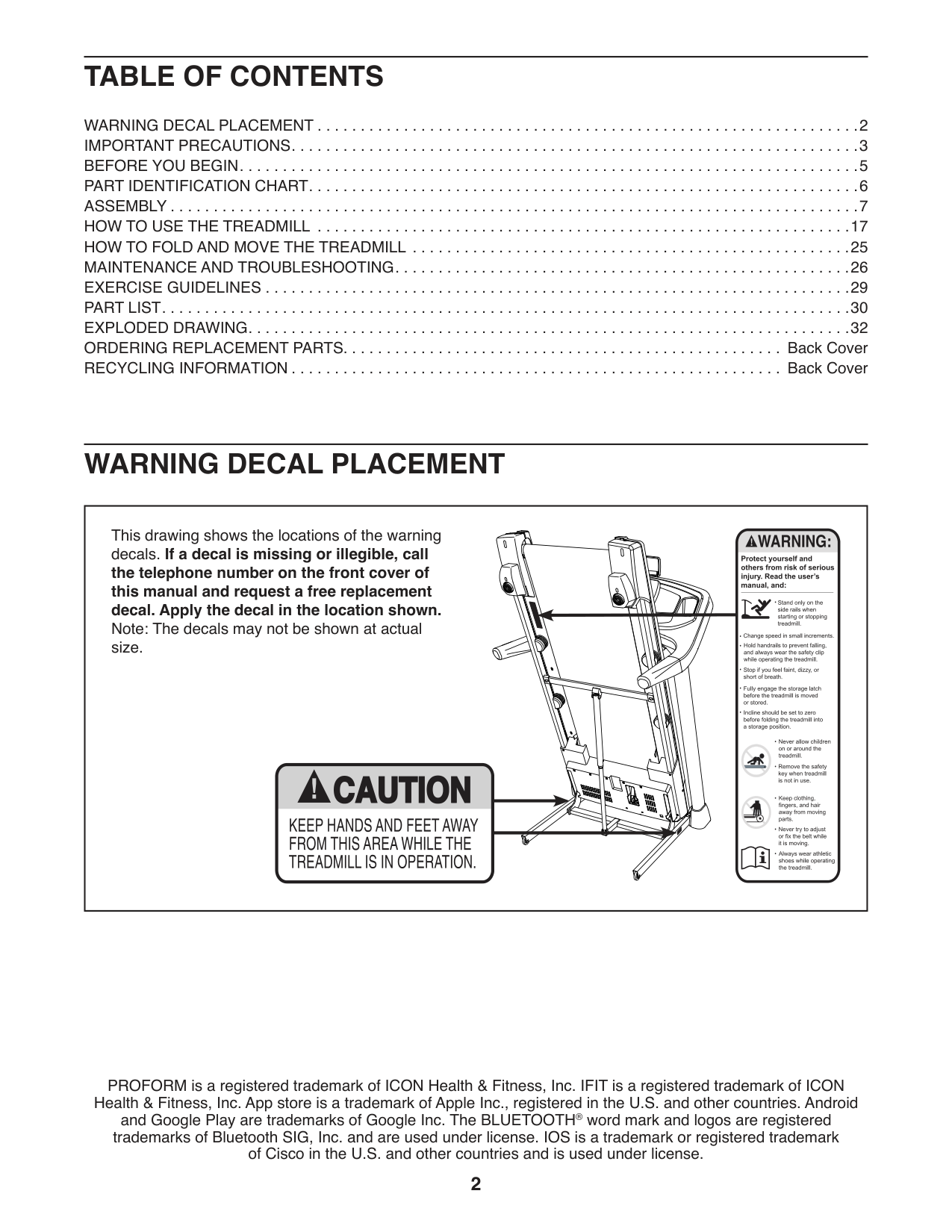
|This drawing shows the locations of the warning decals. If a decal is missing or illegible, call the telephone number on the front cover of this manual and request a free replacement decal. Apply the decal in the location shown. Note: The decals may not be shown at actual size.
| |---|
PROFORM is a registered trademark of ICON Health & Fitness, Inc. IFIT is a registered trademark of ICON Health & Fitness, Inc. App store is a trademark of Apple Inc., registered in the U.S. and other countries. Android and Google Play are trademarks of Google Inc. The BLUETOOTH® word mark and logos are registered trademarks of Bluetooth SIG, Inc. and are used under license. IOS is a trademark or registered trademark of Cisco in the U.S. and other countries and is used under license.
#### IMPORTANT PRECAUTIONS
WARNING: To reduce the risk of burns, fire, electric shock, or injury to persons, read all important precautions and instructions in this manual and all warnings on your treadmill before using your treadmill. ICON assumes no responsibility for personal injury or property damage sustained by or through the use of this product.
cord immediately after use, before cleaning the treadmill, and before performing the maintenance and adjustment procedures described in this manual. Never remove the motor hood unless instructed to do so by an authorized service representative. Servicing other than the procedures in this manual should be performed by an authorized service representative only.
#### SAVE THESE INSTRUCTIONS
#### BEFORE YOU BEGIN
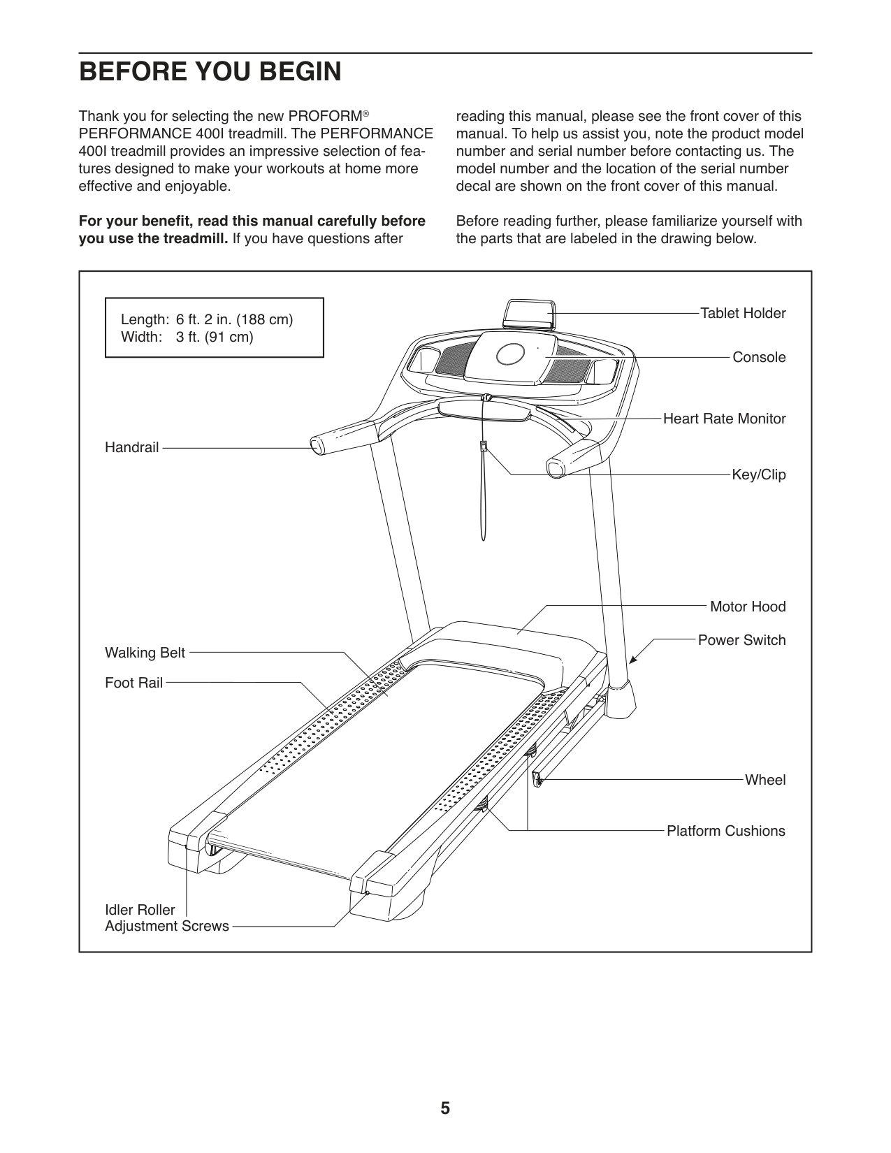
Thank you for selecting the new PROFORM® PERFORMANCE 400I treadmill. The PERFORMANCE 400I treadmill provides an impressive selection of features designed to make your workouts at home more effective and enjoyable.
For your benefit, read this manual carefully before you use the treadmill. If you have questions after
reading this manual, please see the front cover of this manual. To help us assist you, note the product model number and serial number before contacting us. The model number and the location of the serial number decal are shown on the front cover of this manual.
Before reading further, please familiarize yourself with the parts that are labeled in the drawing below.
|Handrail
Console
Key/Clip
Power Switch Walking Belt
Motor Hood
Wheel
Foot Rail
Idler Roller Adjustment Screws
Platform Cushions
Heart Rate Monitor
|Length: 6 ft. 2 in. (188 cm) Width: 3 ft. (91 cm)| |---|
Tablet Holder| |---|
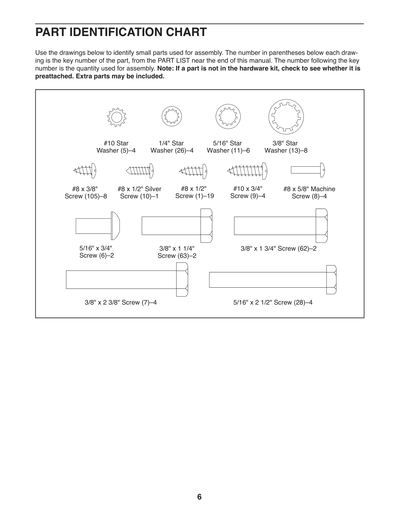
#### PART IDENTIFICATION CHART
Use the drawings below to identify small parts used for assembly. The number in parentheses below each drawing is the key number of the part, from the PART LIST near the end of this manual. The number following the key number is the quantity used for assembly. Note: If a part is not in the hardware kit, check to see whether it is preattached. Extra parts may be included.
|| | | |---|---| | | | | | |
5/16" x 3/4" Screw (6)–2
5/16" Star Washer (11)–6
3/8" Star Washer (13)–8
#8 x 1/2" Silver Screw (10)–1
1/4" Star Washer (26)–4
#8 x 1/2" Screw (1)–19
#8 x 3/8" Screw (105)–8
| | | |---|---| | | | | | |
#10 x 3/4" Screw (9)–4
#10 Star Washer (5)–4
3/8" x 2 3/8" Screw (7)–4
| | | |---|---| | | | | | |
3/8" x 1 3/4" Screw (62)–2
| | | |---|---| | | | | | |
3/8" x 1 1/4" Screw (63)–2
#8 x 5/8" Machine Screw (8)–4
5/16" x 2 1/2" Screw (28)–4
| | | |---|---| | | | | | | | |---|
#### ASSEMBLY
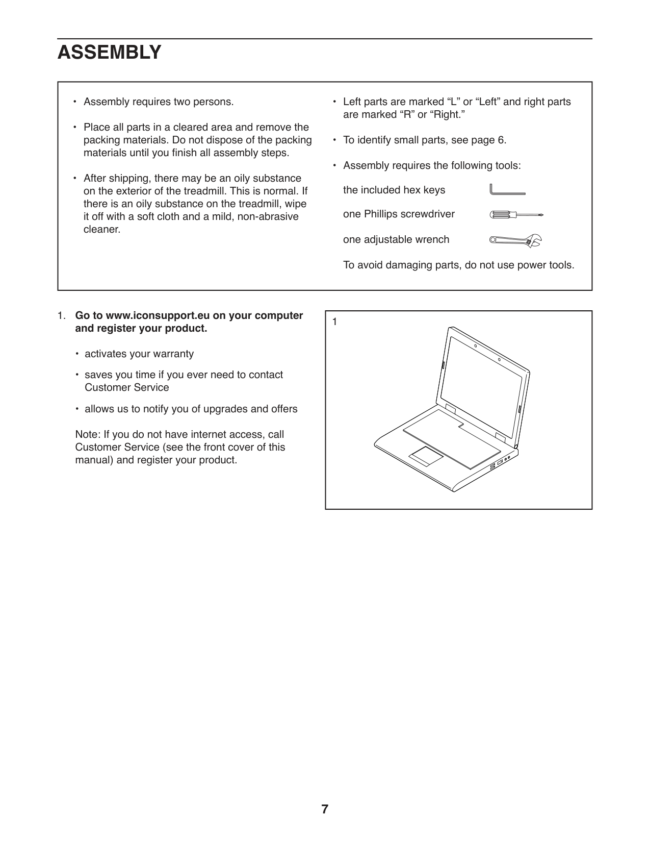
####### 1. Go to www.iconsupport.eu on your computerand register your product.
Note: If you do not have internet access, call Customer Service (see the front cover of this manual) and register your product.
1
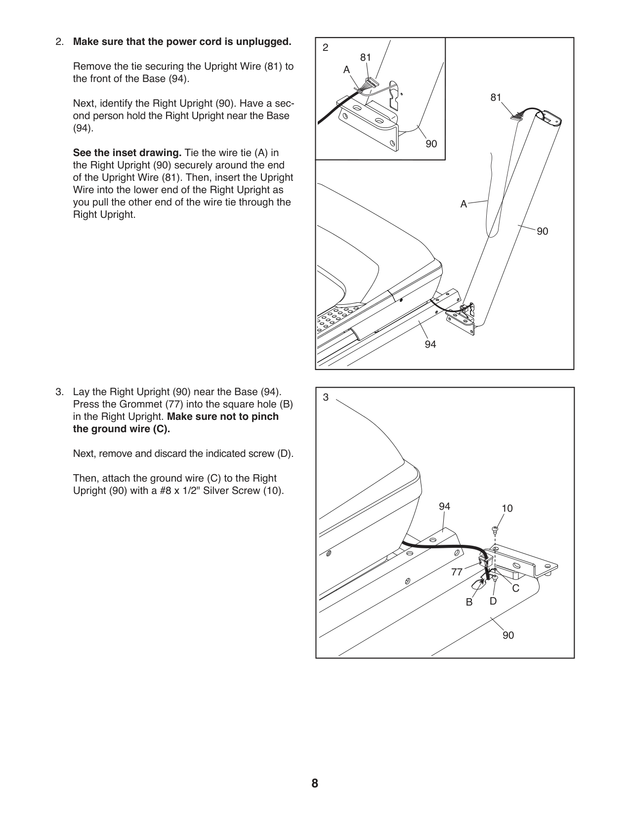
####### 2. Make sure that the power cord is unplugged.
Remove the tie securing the Upright Wire (81) to the front of the Base (94).
Next, identify the Right Upright (90). Have a second person hold the Right Upright near the Base
(94). See the inset drawing. Tie the wire tie (A) in the Right Upright (90) securely around the end of the Upright Wire (81). Then, insert the Upright Wire into the lower end of the Right Upright as you pull the other end of the wire tie through the Right Upright.
######## 3. Lay the Right Upright (90) near the Base (94).Press the Grommet (77) into the square hole (B)in the Right Upright. Make sure not to pinchthe ground wire (C).Next, remove and discard the indicated screw (D).
Then, attach the ground wire (C) to the Right Upright (90) with a #8 x 1/2" Silver Screw (10).
|2
90
81 A
|81
| |---|---| |94
90
A|94
90
A|
|94
90
10
77
DB
C
3| |---|
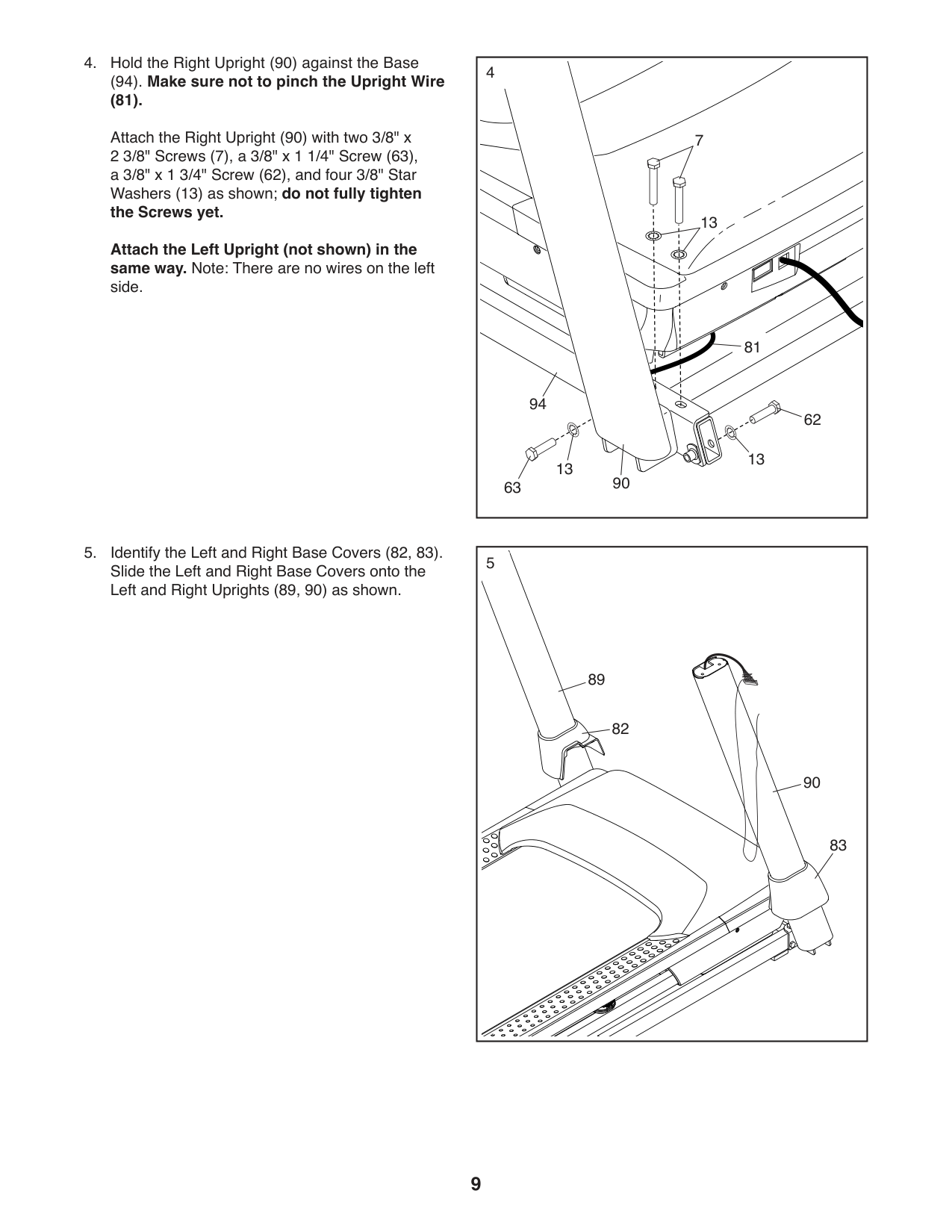
####### (94). Make sure not to pinch the Upright Wire
(81). Attach the Right Upright (90) with two 3/8" x 2 3/8" Screws (7), a 3/8" x 1 1/4" Screw (63), a 3/8" x 1 3/4" Screw (62), and four 3/8" Star Washers (13) as shown; do not fully tighten the Screws yet. Attach the Left Upright (not shown) in the same way. Note: There are no wires on the left side.
|4
63
62
94
13
90
13
7
13
81
| |---|
|83
90
82
89
5| |---|
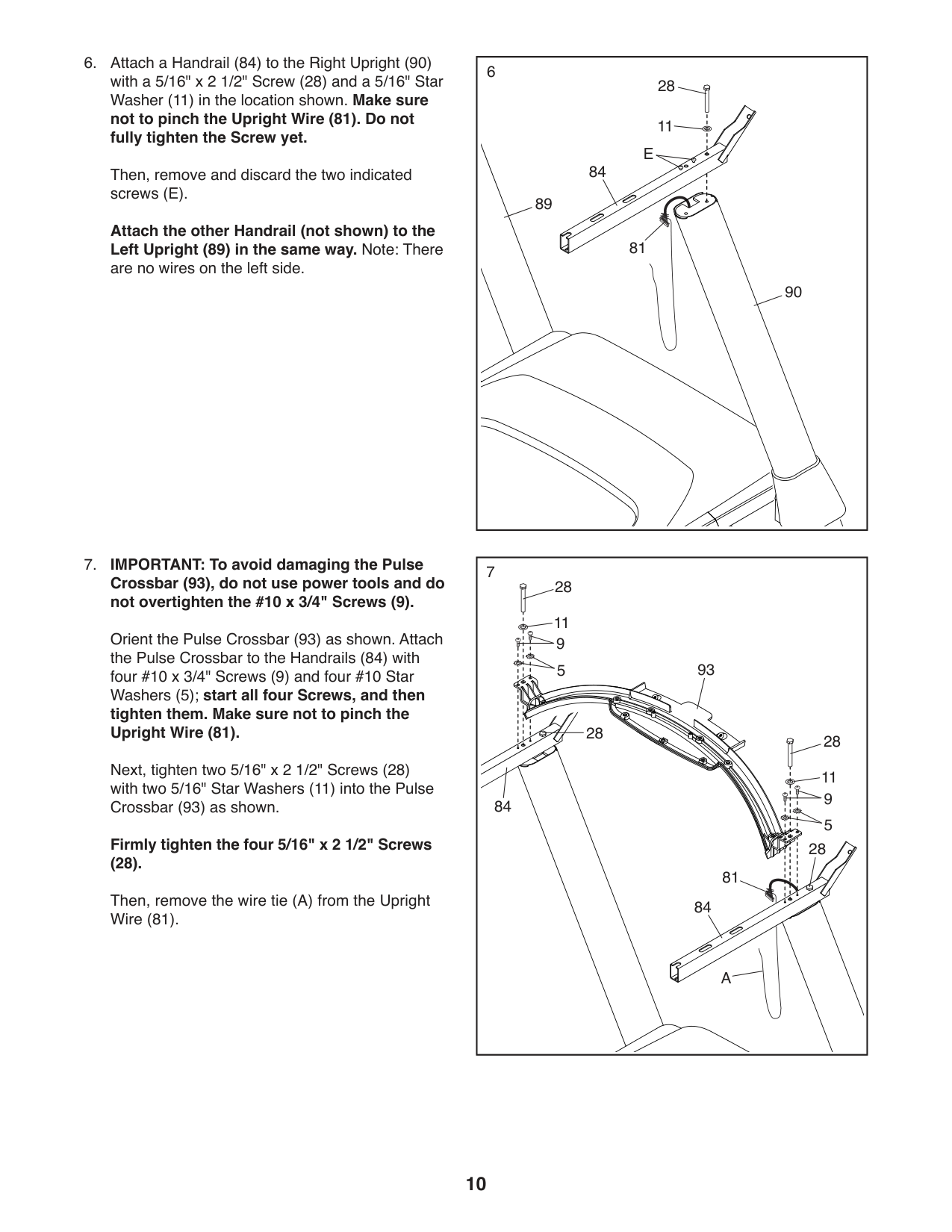
Then, remove and discard the two indicated screws (E).
Attach the other Handrail (not shown) to the Left Upright (89) in the same way. Note: There are no wires on the left side.
11
81
84
E
28
6
90
|93
84
84
7
81
A
28 11 9 5
28
28
28 11 9 5
|
|---|
Orient the Pulse Crossbar (93) as shown. Attach the Pulse Crossbar to the Handrails (84) with four #10 x 3/4" Screws (9) and four #10 Star Washers (5); start all four Screws, and then tighten them. Make sure not to pinch the Upright Wire (81).
Next, tighten two 5/16" x 2 1/2" Screws (28) with two 5/16" Star Washers (11) into the Pulse Crossbar (93) as shown.
Firmly tighten the four 5/16" x 2 1/2" Screws
(28).
Then, remove the wire tie (A) from the Upright Wire (81).
89
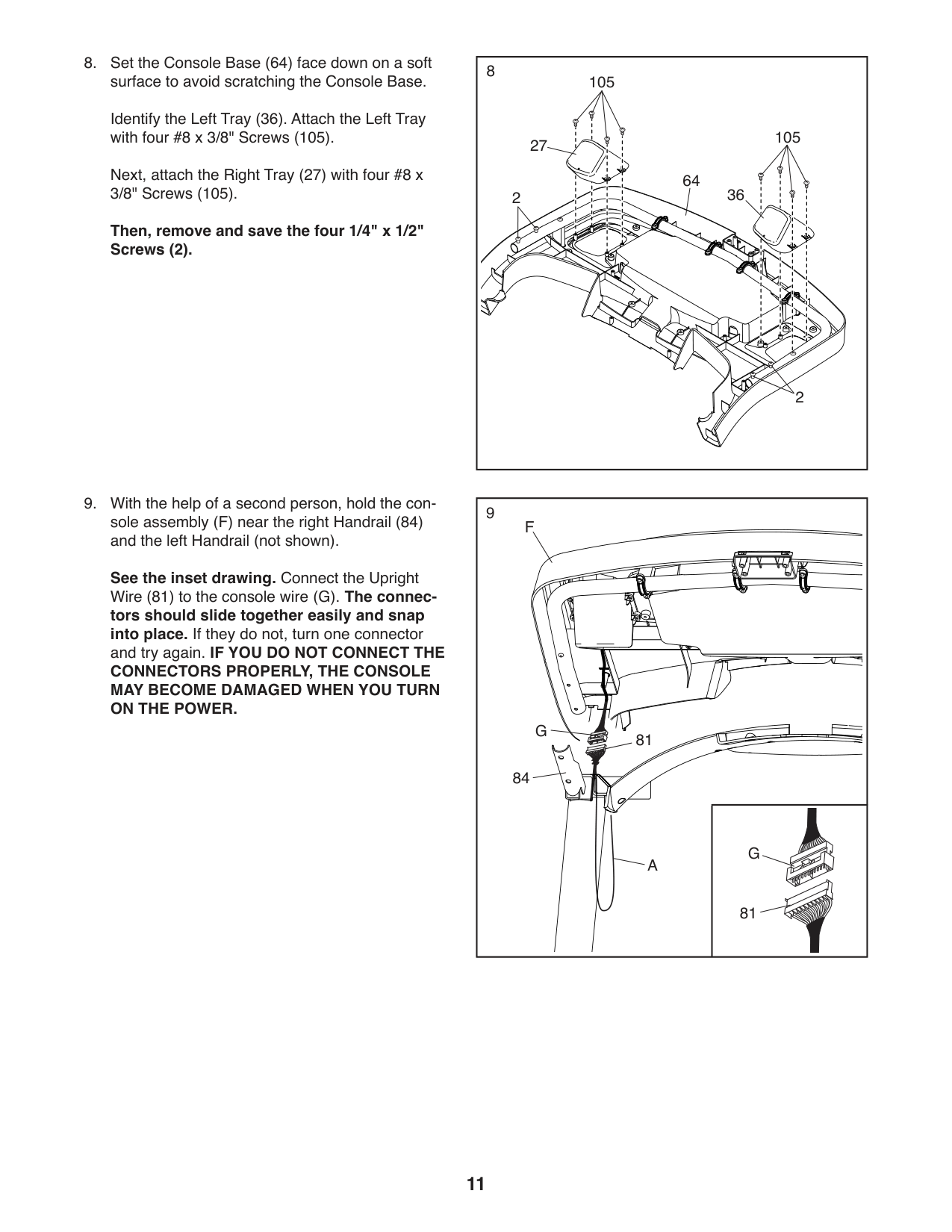
Identify the Left Tray (36). Attach the Left Tray with four #8 x 3/8" Screws (105).
Next, attach the Right Tray (27) with four #8 x 3/8" Screws (105).
Then, remove and save the four 1/4" x 1/2" Screws (2).
See the inset drawing. Connect the Upright Wire (81) to the console wire (G). The connec-
tors should slide together easily and snap into place. If they do not, turn one connector and try again. IF YOU DO NOT CONNECT THE
CONNECTORS PROPERLY, THE CONSOLE MAY BECOME DAMAGED WHEN YOU TURN ON THE POWER.
|64 362
8
2
27
105
105| |---|
9
F
G
81 84
G A
81
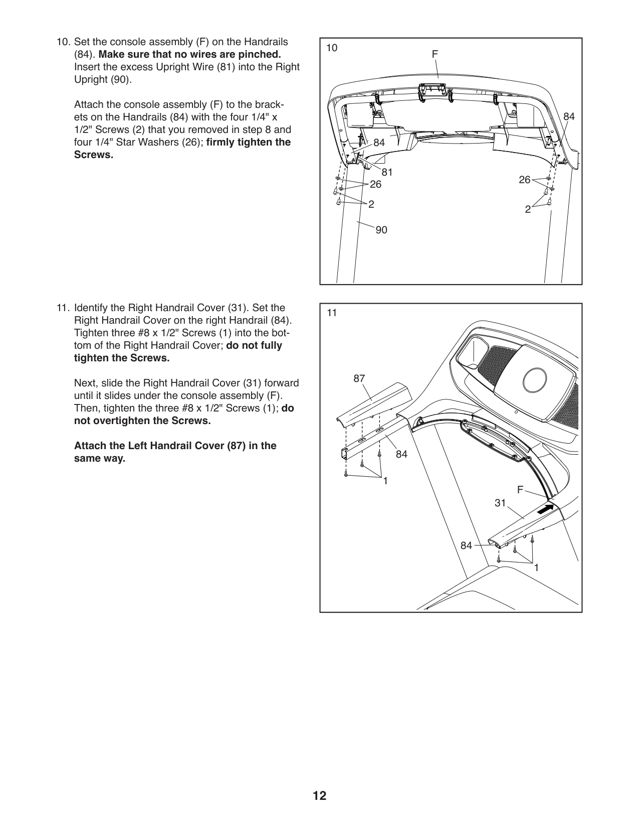
(84). Make sure that no wires are pinched. Insert the excess Upright Wire (81) into the Right Upright (90).
Attach the console assembly (F) to the brackets on the Handrails (84) with the four 1/4" x 1/2" Screws (2) that you removed in step 8 and four 1/4" Star Washers (26); firmly tighten the Screws.
10
90
22
84
F
2626
Next, slide the Right Handrail Cover (31) forward until it slides under the console assembly (F). Then, tighten the three #8 x 1/2" Screws (1); do not overtighten the Screws. Attach the Left Handrail Cover (87) in the same way.
84
81
|11
87
F 31
84
84
1
1| |---|
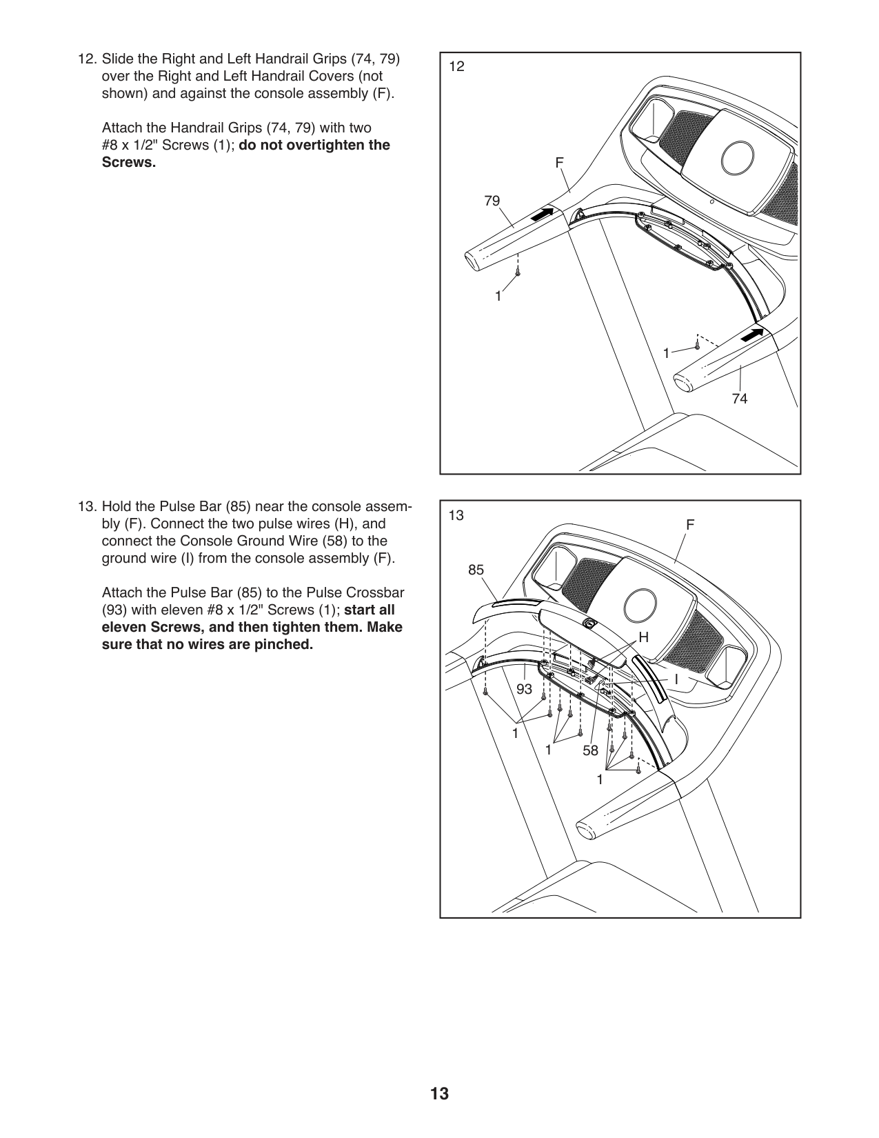
Attach the Handrail Grips (74, 79) with two #8 x 1/2" Screws (1); do not overtighten the Screws.
Attach the Pulse Bar (85) to the Pulse Crossbar
(93) with eleven #8 x 1/2" Screws (1); start all eleven Screws, and then tighten them. Make sure that no wires are pinched.
|12
79
F
74
1
1| |---|
|13
1
85
H
I 93
1
1
58
F
| |---|
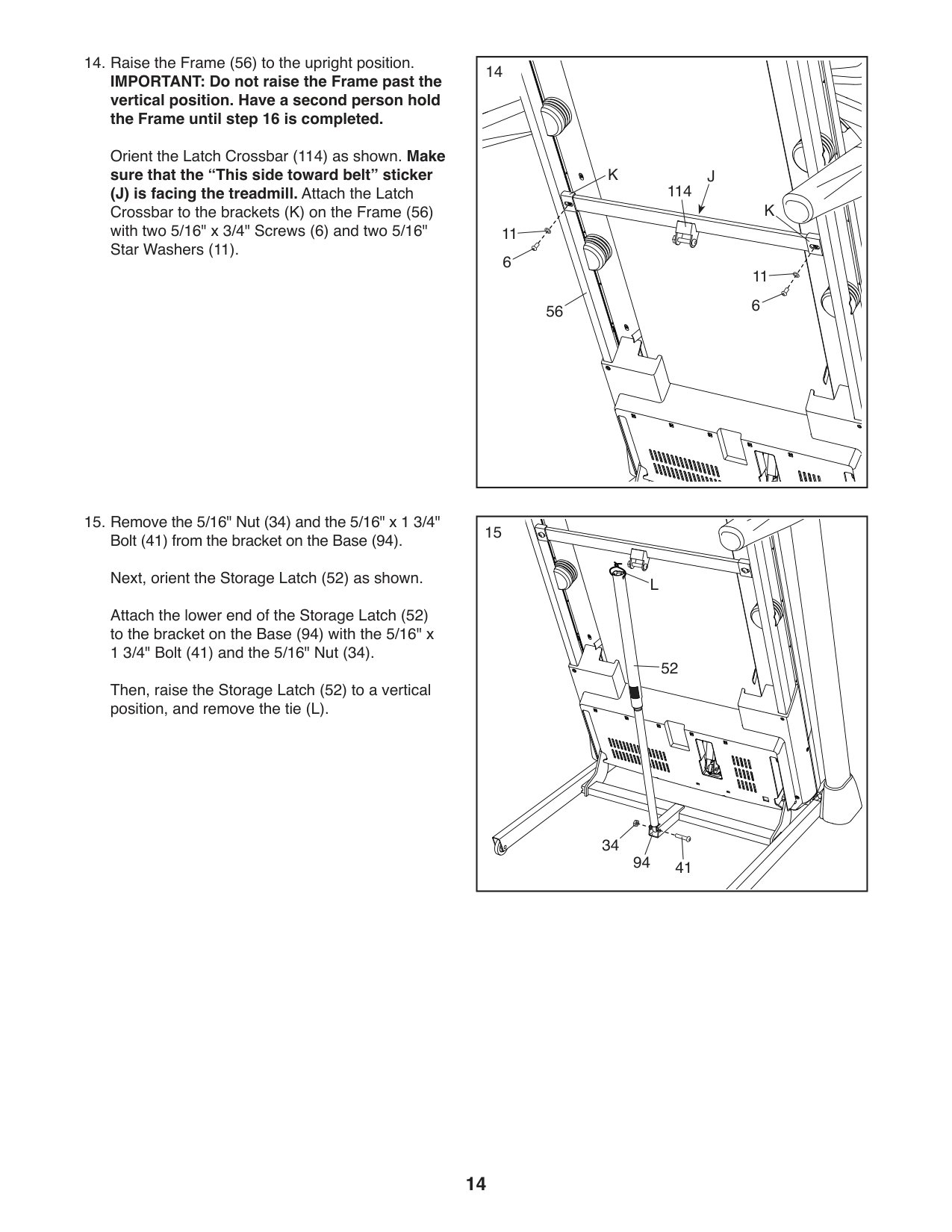
####### 14. Raise the Frame (56) to the upright position.IMPORTANT: Do not raise the Frame past thevertical position. Have a second person holdthe Frame until step 16 is completed.
Orient the Latch Crossbar (114) as shown. Make sure that the “This side toward belt” sticker (J) is facing the treadmill. Attach the Latch Crossbar to the brackets (K) on the Frame (56) with two 5/16" x 3/4" Screws (6) and two 5/16" Star Washers (11).
######## 15. Remove the 5/16" Nut (34) and the 5/16" x 1 3/4"Bolt (41) from the bracket on the Base (94).Next, orient the Storage Latch (52) as shown.
Attach the lower end of the Storage Latch (52) to the bracket on the Base (94) with the 5/16" x 1 3/4" Bolt (41) and the 5/16" Nut (34).
Then, raise the Storage Latch (52) to a vertical position, and remove the tie (L).
|56
114
JK
K
11
11 6
6
14| |---|
|94
52
41
34
L
15|
|---|
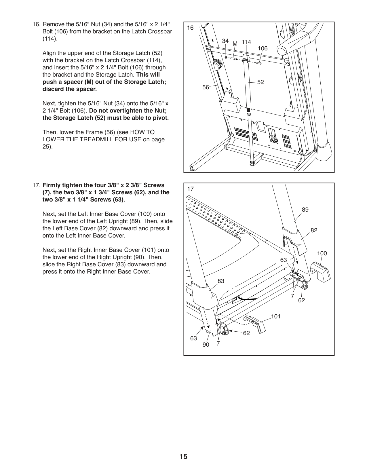
(114).
Align the upper end of the Storage Latch (52) with the bracket on the Latch Crossbar (114), and insert the 5/16" x 2 1/4" Bolt (106) through the bracket and the Storage Latch. This will push a spacer (M) out of the Storage Latch; discard the spacer.
Next, tighten the 5/16" Nut (34) onto the 5/16" x 2 1/4" Bolt (106). Do not overtighten the Nut; the Storage Latch (52) must be able to pivot.
Then, lower the Frame (56) (see HOW TO LOWER THE TREADMILL FOR USE on page 25).
|114
106
56
34 M
52
16
| |---|
####### (7), the two 3/8" x 1 3/4" Screws (62), and the two 3/8" x 1 1/4" Screws (63).
Next, set the Left Inner Base Cover (100) onto the lower end of the Left Upright (89). Then, slide the Left Base Cover (82) downward and press it onto the Left Inner Base Cover.
Next, set the Right Inner Base Cover (101) onto the lower end of the Right Upright (90). Then, slide the Right Base Cover (83) downward and press it onto the Right Inner Base Cover.
|100
83
82
62
89
7
7
63
62
101
63
17
90
| |---|
|18
8
F 8
25
| |---|
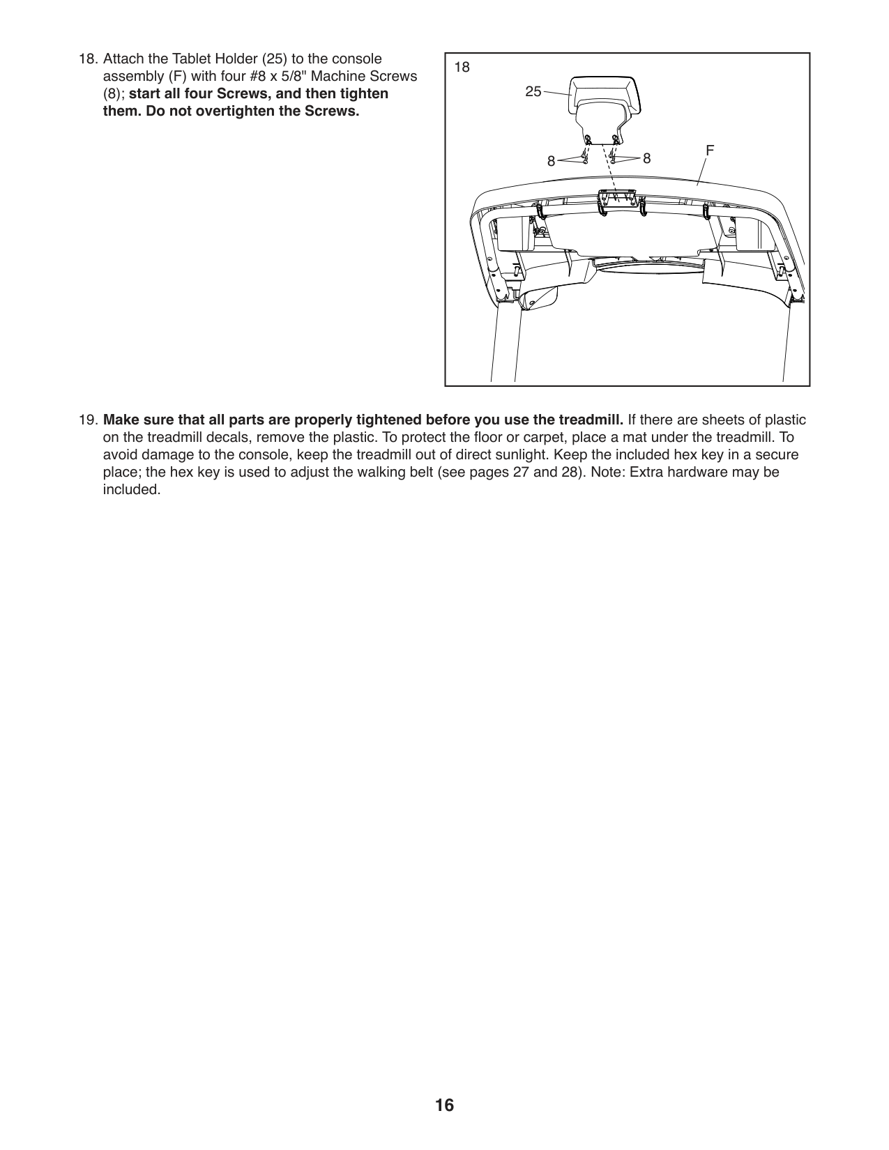
####### (8); start all four Screws, and then tighten them. Do not overtighten the Screws.
#### HOW TO USE THE TREADMILL
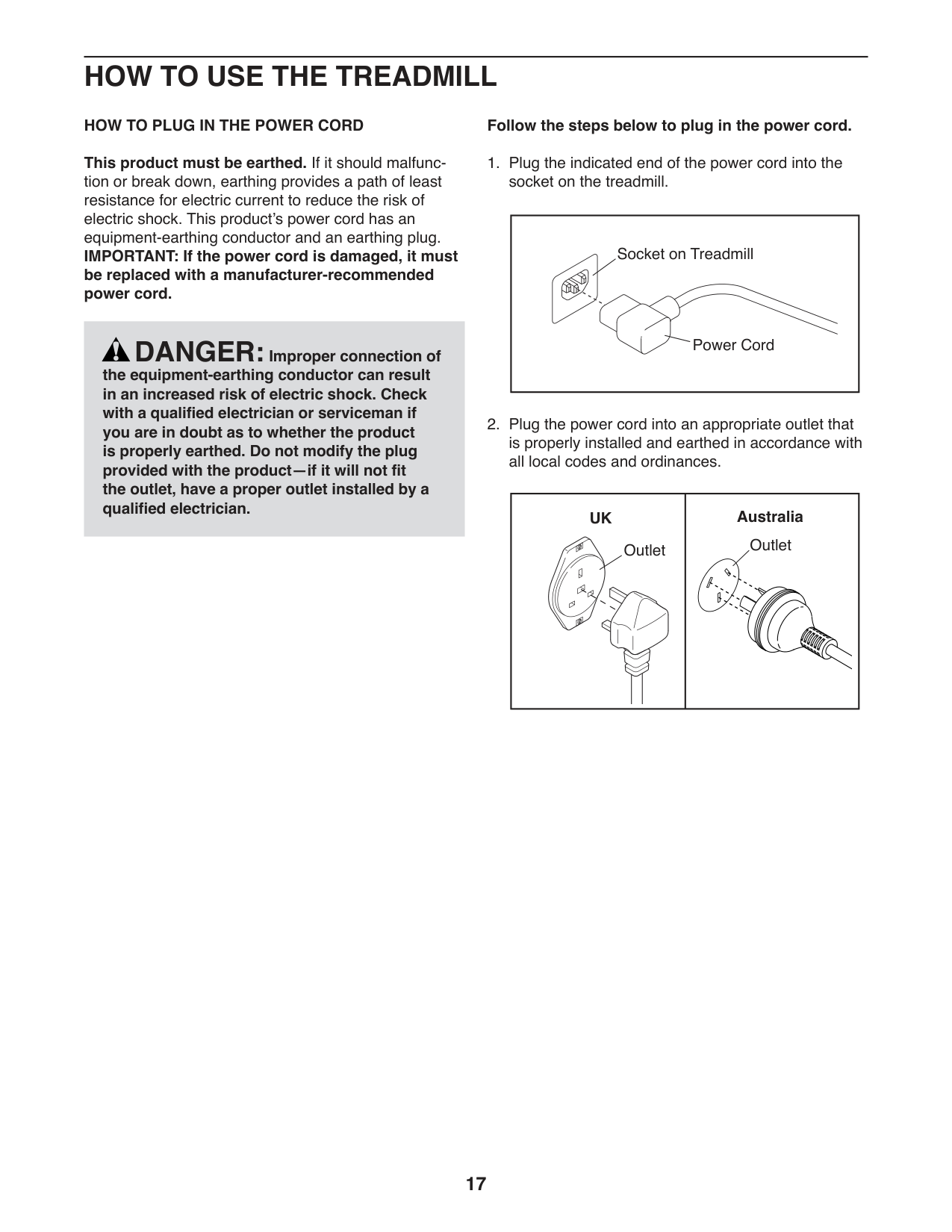
HOW TO PLUG IN THE POWER CORD This product must be earthed. If it should malfunction or break down, earthing provides a path of least resistance for electric current to reduce the risk of electric shock. This product’s power cord has an equipment-earthing conductor and an earthing plug. IMPORTANT: If the power cord is damaged, it must be replaced with a manufacturer-recommended power cord.
####### Follow the steps below to plug in the power cord.
|Socket on Treadmill
AUS
Power Cord| |---|
DANGER:Improper connection of the equipment-earthing conductor can result in an increased risk of electric shock. Check with a qualified electrician or serviceman if you are in doubt as to whether the product is properly earthed. Do not modify the plug provided with the product—if it will not fit the outlet, have a proper outlet installed by a qualified electrician.
####### UK Australia
Outlet
Outlet
UK
HU
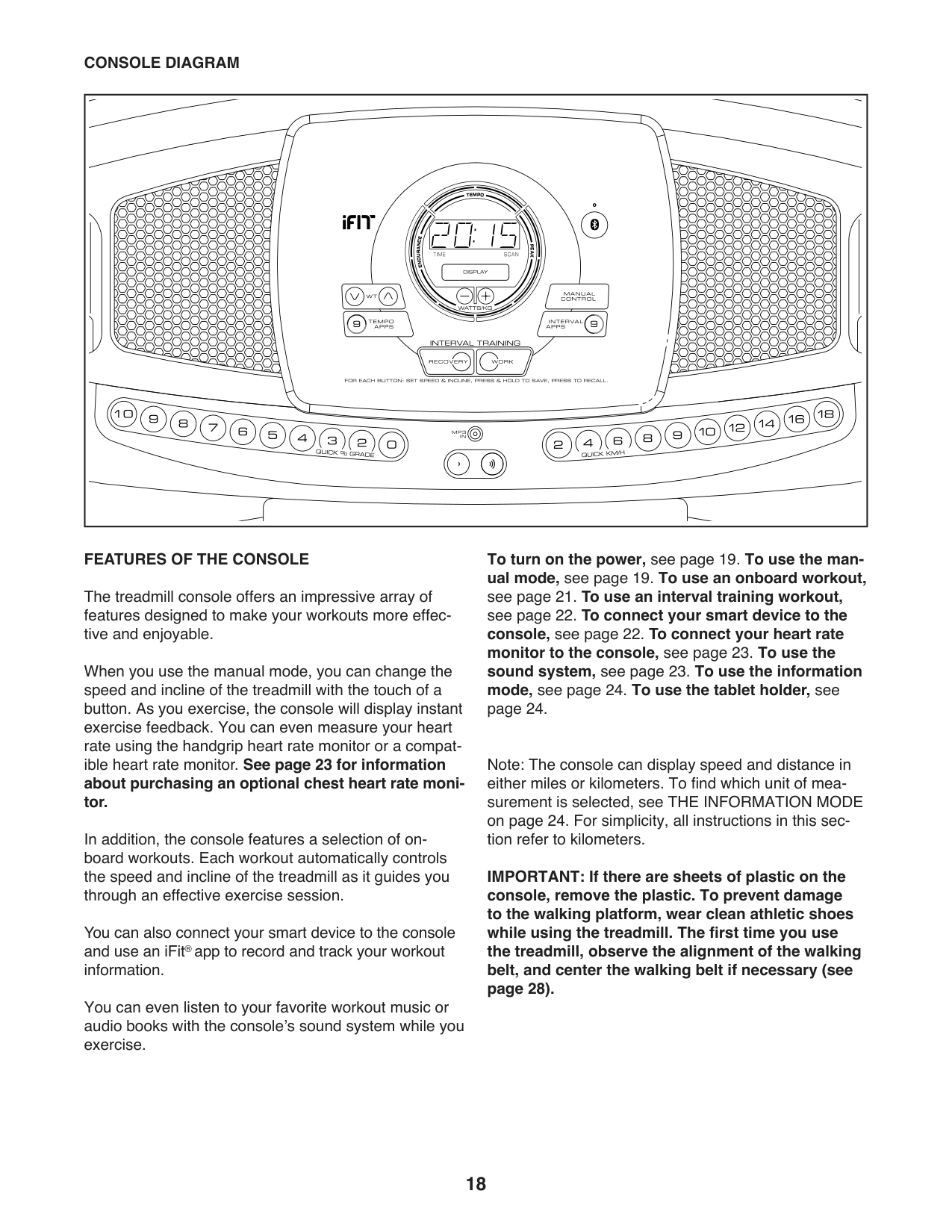
CONSOLE DIAGRAM
####### FEATURES OF THE CONSOLE
The treadmill console offers an impressive array of features designed to make your workouts more effective and enjoyable.
When you use the manual mode, you can change the speed and incline of the treadmill with the touch of a button. As you exercise, the console will display instant exercise feedback. You can even measure your heart rate using the handgrip heart rate monitor or a compatible heart rate monitor. See page 23 for information about purchasing an optional chest heart rate monitor.
In addition, the console features a selection of onboard workouts. Each workout automatically controls the speed and incline of the treadmill as it guides you through an effective exercise session.
You can also connect your smart device to the console and use an iFit®app to record and track your workout information.
ETPE79816
You can even listen to your favorite workout music or audio books with the console’s sound system while you exercise.
To turn on the power, see page 19. To use the manual mode, see page 19. To use an onboard workout,
Note: The console can display speed and distance in either miles or kilometers. To find which unit of measurement is selected, see THE INFORMATION MODE on page 24. For simplicity, all instructions in this section refer to kilometers.
IMPORTANT: If there are sheets of plastic on the console, remove the plastic. To prevent damage to the walking platform, wear clean athletic shoes while using the treadmill. The first time you use the treadmill, observe the alignment of the walking belt, and center the walking belt if necessary (see page 28).
HOW TO TURN ON THE POWER IMPORTANT: If the treadmill has been exposed to cold temperatures, allow it to warm to room temperature before you turn on the power. If you do not do this, you may damage the console displays or other electrical components.
| | | |---|---| | | |
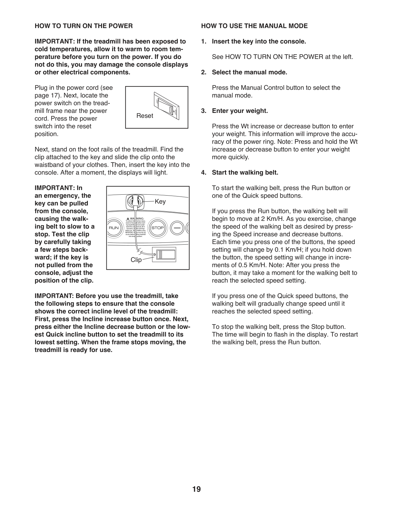
Plug in the power cord (see page 17). Next, locate the power switch on the treadmill frame near the power cord. Press the power switch into the reset position.
Reset
Next, stand on the foot rails of the treadmill. Find the clip attached to the key and slide the clip onto the waistband of your clothes. Then, insert the key into the console. After a moment, the displays will light.
IMPORTANT: In an emergency, the key can be pulled from the console, causing the walking belt to slow to a stop. Test the clip by carefully taking a few steps backward; if the key is not pulled from the console, adjust the position of the clip.
|Key
Clip
| |---|
IMPORTANT: Before you use the treadmill, take the following steps to ensure that the console shows the correct incline level of the treadmill: First, press the Incline increase button once. Next, press either the Incline decrease button or the lowest Quick incline button to set the treadmill to its lowest setting. When the frame stops moving, the treadmill is ready for use.
HOW TO USE THE MANUAL MODE
Press the Manual Control button to select the manual mode.
Press the Wt increase or decrease button to enter your weight. This information will improve the accuracy of the power ring. Note: Press and hold the Wt increase or decrease button to enter your weight more quickly.
To start the walking belt, press the Run button or one of the Quick speed buttons.
If you press the Run button, the walking belt will begin to move at 2 Km/H. As you exercise, change the speed of the walking belt as desired by pressing the Speed increase and decrease buttons. Each time you press one of the buttons, the speed setting will change by 0.1 Km/H; if you hold down the button, the speed setting will change in increments of 0.5 Km/H. Note: After you press the button, it may take a moment for the walking belt to reach the selected speed setting.
If you press one of the Quick speed buttons, the walking belt will gradually change speed until it reaches the selected speed setting.
To stop the walking belt, press the Stop button. The time will begin to flash in the display. To restart the walking belt, press the Run button.
####### 5. Change the incline of the treadmill as desired.
To change the incline of the treadmill, press the Incline increase and decrease buttons or one of the Quick incline buttons. Each time you press one of the buttons, the treadmill will gradually adjust to the selected incline setting.
####### 6. Follow your progress with the display.
As you walk or run on the treadmill, the display can show the following workout information:
Press the Display button to view the desired information in the display.
As you exercise, the power ring will indicate the approximate intensity level of your exercise. To adjust the intensity level, press the Watts/Kg increase or decrease button. The speed and/or incline settings of the treadmill will automatically increase or decrease to reach the desired intensity level.
To reset the display, press the Stop button repeatedly, or remove the key and then reinsert the key.
####### 7. Measure your heart rate if desired.
You can measure your heart rate using either the handgrip heart rate monitor or a compatible heart rate monitor. For information about purchasing an optional chest heart rate monitor, see page 23.
The console is compatible with all BLUETOOTH® Smart heart rate monitors. To connect your heart rate monitor to the console, see page 23.
Note: If you use both heart rate monitors at the same time, the BLUETOOTH Smart heart rate monitor will have priority.
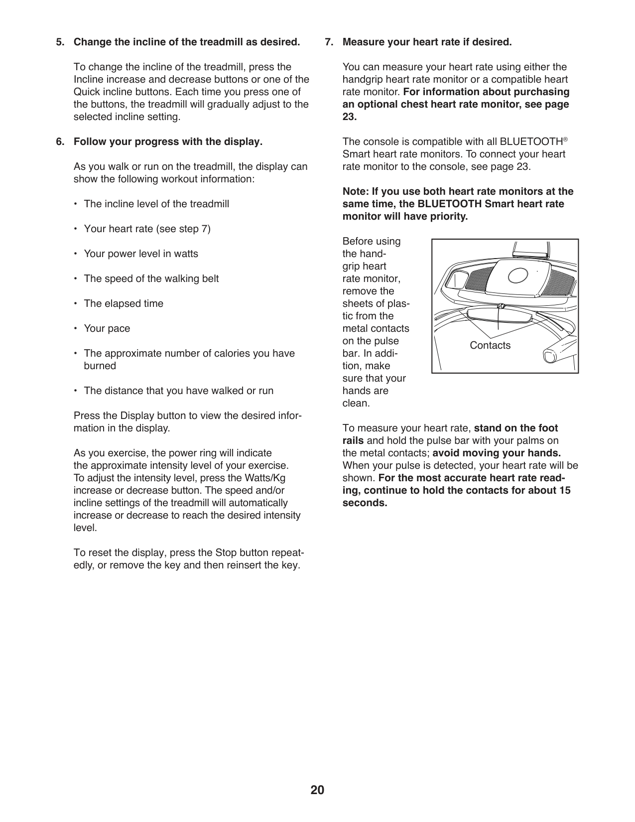
Before using the handgrip heart rate monitor, remove the sheets of plastic from the metal contacts on the pulse bar. In addition, make sure that your hands are clean.
|Contacts
| |---|
To measure your heart rate, stand on the foot rails and hold the pulse bar with your palms on the metal contacts; avoid moving your hands. When your pulse is detected, your heart rate will be shown. For the most accurate heart rate reading, continue to hold the contacts for about 15 seconds.
Step onto the foot rails, press the Stop button repeatedly, and adjust the incline of the treadmill to zero. The incline must be at zero or you may damage the treadmill when you fold it to the storage position. Next, remove the key from the console and put it in a secure place.
When you are finished using the treadmill, press the power switch into the off position and unplug the power cord. IMPORTANT: If you do not do this, the treadmill’s electrical components may wear prematurely.
####### HOW TO USE AN ONBOARD WORKOUT
To select an onboard workout, press the Tempo Apps button or the Interval Apps button repeatedly until the desired workout appears in the display.
Press the Run button to start the workout. A moment after you press the button, the treadmill will automatically adjust to the first speed and incline settings of the workout. Hold the handrails and begin walking.
Each workout is divided into segments. One speed setting and one incline setting are programmed for each segment. Note: The same speed setting and/ or incline setting may be programmed for consecutive segments.
If the speed or incline setting is too high or too low at any time during the workout, you can manually override the setting by pressing the Speed or Incline buttons; however, when the next segment of the workout begins, the treadmill will automatically adjust to the speed and incline settings for the next segment.
To stop the workout at any time, press the Stop button. To resume the workout, press the Run button. The walking belt will begin to move at 2 Km/H. When the next segment of the workout begins, the treadmill will automatically adjust to the speed and incline settings for the next segment.
####### 5. Follow your progress with the display.
See step 6 on page 20. The display will show the time remaining instead of the elapsed time.
####### 6. Measure your heart rate if desired.
HOW TO USE AN INTERVAL TRAINING WORKOUT During an interval training workout, you will repeatedly alternate between intervals of low-intensity “recovery” exercise and intervals of high-intensity “work” exercise.
Press the speed and incline buttons to select the desired speed setting and the desired incline setting for the recovery intervals. Then, press and hold the Recovery button until the console beeps twice.
Press the speed and incline buttons to select the desired speed setting and the desired incline setting for the work intervals. Then, press and hold the Work button until the console beeps twice.
As you exercise, press the Recovery button to select the speed and incline settings that you selected for recovery intervals. Press the Work button to select the speed and incline settings that you selected for work intervals. Alternate between the settings as many times as desired.
To change the settings at any time, repeat steps 3 and 4.
See step 6 on page 20. The display will show the time remaining instad of the elapsed time.
HOW TO CONNECT YOUR SMART DEVICE TO THE CONSOLE
The console supports BLUETOOTH connections to smart devices via the iFit app and to compatible heart rate monitors. Note: Other BLUETOOTH connections are not supported.
####### 1. Download and install the iFit app on your smartdevice.
On your IOS® or AndroidTM smart device, open the App StoreSM or the Google PlayTM store, search for the free iFit app, and then install the app on your smart device. Make sure that the BLE option is enabled on your smart device.
Then, open the iFit app and follow the instructions to set up an iFit account and customize settings.
####### 2. Connect your smart device to the console.
Follow the instructions in the iFit app to connect your smart device to the console.
When a connection is established, the LED on the console will flash blue. Press the Bluetooth button on the console to confirm the connection; the LED on the console will then turn solid blue.
####### 3. Record and track your workout information.
Follow the instructions in the iFit app to record and track your workout information.
####### 4. Diconnect your smart device from the consoleif desired.
To disconnect your smart device from the console, press and hold the Bluetooth button on the console for 5 seconds.
Note: All BLUETOOTH connections between the console and other devices (including any smart devices, heart rate monitors, and so forth) will be disconnected.
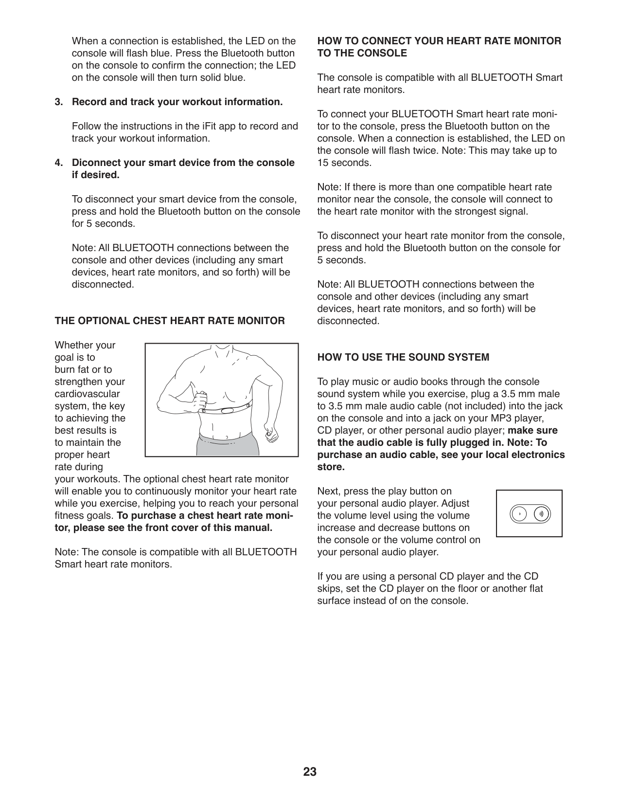
####### THE OPTIONAL CHEST HEART RATE MONITOR
Whether your goal is to burn fat or to strengthen your cardiovascular system, the key to achieving the best results is to maintain the proper heart rate during your workouts. The optional chest heart rate monitor will enable you to continuously monitor your heart rate while you exercise, helping you to reach your personal fitness goals. To purchase a chest heart rate monitor, please see the front cover of this manual.
Note: The console is compatible with all BLUETOOTH Smart heart rate monitors.
####### HOW TO CONNECT YOUR HEART RATE MONITOR TO THE CONSOLE
The console is compatible with all BLUETOOTH Smart heart rate monitors.
To connect your BLUETOOTH Smart heart rate monitor to the console, press the Bluetooth button on the console. When a connection is established, the LED on the console will flash twice. Note: This may take up to 15 seconds.
Note: If there is more than one compatible heart rate monitor near the console, the console will connect to the heart rate monitor with the strongest signal.
To disconnect your heart rate monitor from the console, press and hold the Bluetooth button on the console for 5 seconds.
Note: All BLUETOOTH connections between the console and other devices (including any smart devices, heart rate monitors, and so forth) will be disconnected.
####### HOW TO USE THE SOUND SYSTEM
To play music or audio books through the console sound system while you exercise, plug a 3.5 mm male to 3.5 mm male audio cable (not included) into the jack on the console and into a jack on your MP3 player, CD player, or other personal audio player; make sure that the audio cable is fully plugged in. Note: To purchase an audio cable, see your local electronics store.
Next, press the play button on your personal audio player. Adjust the volume level using the volume increase and decrease buttons on the console or the volume control on your personal audio player.
| | |---|
If you are using a personal CD player and the CD skips, set the CD player on the floor or another flat surface instead of on the console.
####### THE INFORMATION MODE
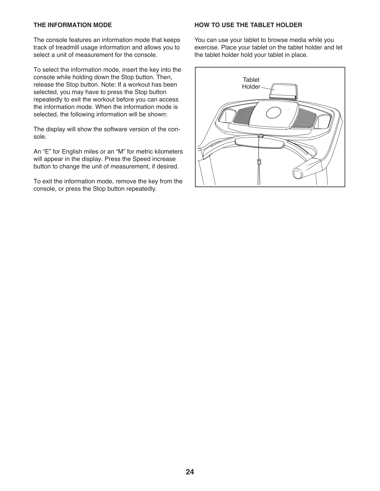
####### HOW TO USE THE TABLET HOLDER
The console features an information mode that keeps track of treadmill usage information and allows you to select a unit of measurement for the console.
You can use your tablet to browse media while you exercise. Place your tablet on the tablet holder and let the tablet holder hold your tablet in place.
To select the information mode, insert the key into the console while holding down the Stop button. Then, release the Stop button. Note: If a workout has been selected, you may have to press the Stop button repeatedly to exit the workout before you can access the information mode. When the information mode is selected, the following information will be shown:
|Tablet Holder
| |---|
The display will show the software version of the console.
An “E” for English miles or an “M” for metric kilometers will appear in the display. Press the Speed increase button to change the unit of measurement, if desired.
To exit the information mode, remove the key from the console, or press the Stop button repeatedly.
#### HOW TO FOLD AND MOVE THE TREADMILL
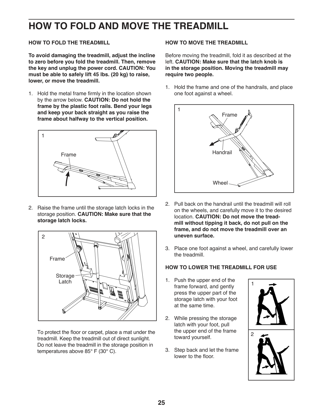
HOW TO FOLD THE TREADMILL
To avoid damaging the treadmill, adjust the incline to zero before you fold the treadmill. Then, remove the key and unplug the power cord. CAUTION: You must be able to safely lift 45 lbs. (20 kg) to raise, lower, or move the treadmill.
|Frame
1| |---|
|2
Frame
Storage Latch
| |---|
To protect the floor or carpet, place a mat under the treadmill. Keep the treadmill out of direct sunlight. Do not leave the treadmill in the storage position in temperatures above 85° F (30° C).
HOW TO MOVE THE TREADMILL
Before moving the treadmill, fold it as described at the left. CAUTION: Make sure that the latch knob is in the storage position. Moving the treadmill may require two people.
|Handrail
Frame
Wheel
1| |---|
####### HOW TO LOWER THE TREADMILL FOR USE
|1| |---| |2|
#### MAINTENANCE AND TROUBLESHOOTING
####### MAINTENANCE
Regular maintenance is important for optimal performance and to reduce wear. Inspect and properly tighten all parts each time the treadmill is used.
Regularly clean the treadmill and keep the walking belt clean and dry. First, press the power switch into the off position and unplug the power cord. Wipe exterior parts of the treadmill with a damp cloth and a small amount of mild soap. IMPORTANT: Do not spray
liquids directly onto the treadmill. To avoid damage to the console, keep liquids away from the console. Then, thoroughly dry the treadmill with a soft towel.
TROUBLESHOOTING SYMPTOM: The power does not turn on
c
ResetTripped
.
SYMPTOM: The power turns off during use
####### SYMPTOM: The incline of the treadmill does not change correctly
a. Hold down the Stop button and the Speed increase button, insert the key into the console, and then release the Stop button and the Speed increase button. Next, press the Stop button, and then press the Incline increase or decrease button. The treadmill will automatically rise to the maximum incline level and then return to the minimum level. This will recalibrate the incline system. If the incline system does not begin calibrating, press the Stop button again, and then press the Incline increase or decrease button again. When the incline system is calibrated, remove the key from the console.
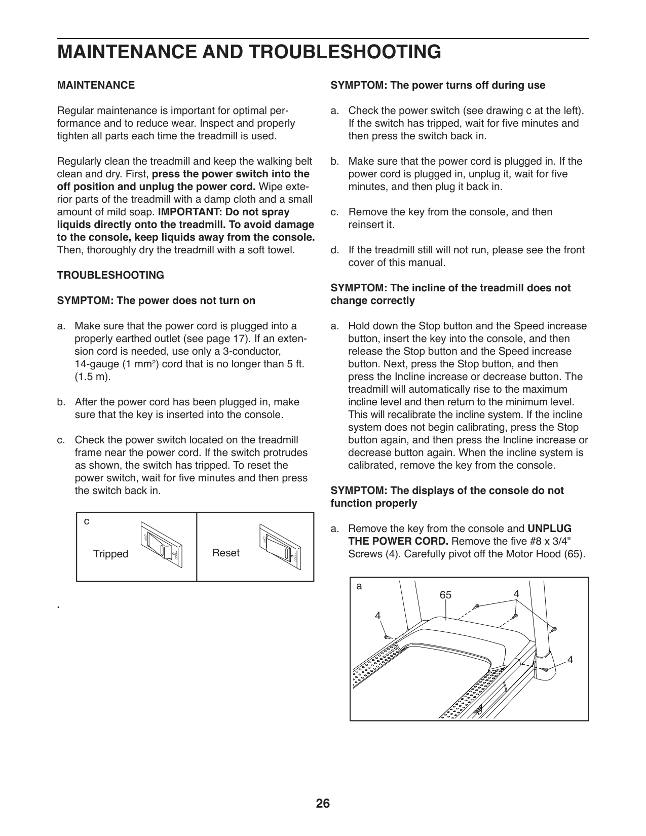
####### SYMPTOM: The displays of the console do not function properly
a. Remove the key from the console and UNPLUG THE POWER CORD. Remove the five #8 x 3/4" Screws (4). Carefully pivot off the Motor Hood (65).
|65 4
a
4
4
| |---|
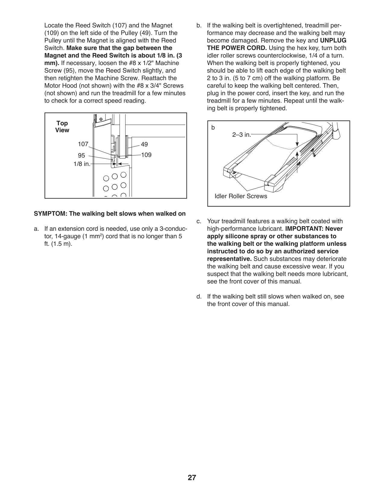
Locate the Reed Switch (107) and the Magnet
(109) on the left side of the Pulley (49). Turn the Pulley until the Magnet is aligned with the Reed Switch. Make sure that the gap between the Magnet and the Reed Switch is about 1/8 in. (3 mm). If necessary, loosen the #8 x 1/2" Machine Screw (95), move the Reed Switch slightly, and then retighten the Machine Screw. Reattach the Motor Hood (not shown) with the #8 x 3/4" Screws (not shown) and run the treadmill for a few minutes to check for a correct speed reading.
####### Top View
107
49
10995
1/8 in.
SYMPTOM: The walking belt slows when walked on a. If an extension cord is needed, use only a 3-conduc-
tor, 14-gauge (1 mm2) cord that is no longer than 5 ft. (1.5 m).
b
| | | | |---|---|---| | | | |
2–3 in.
Idler Roller Screws
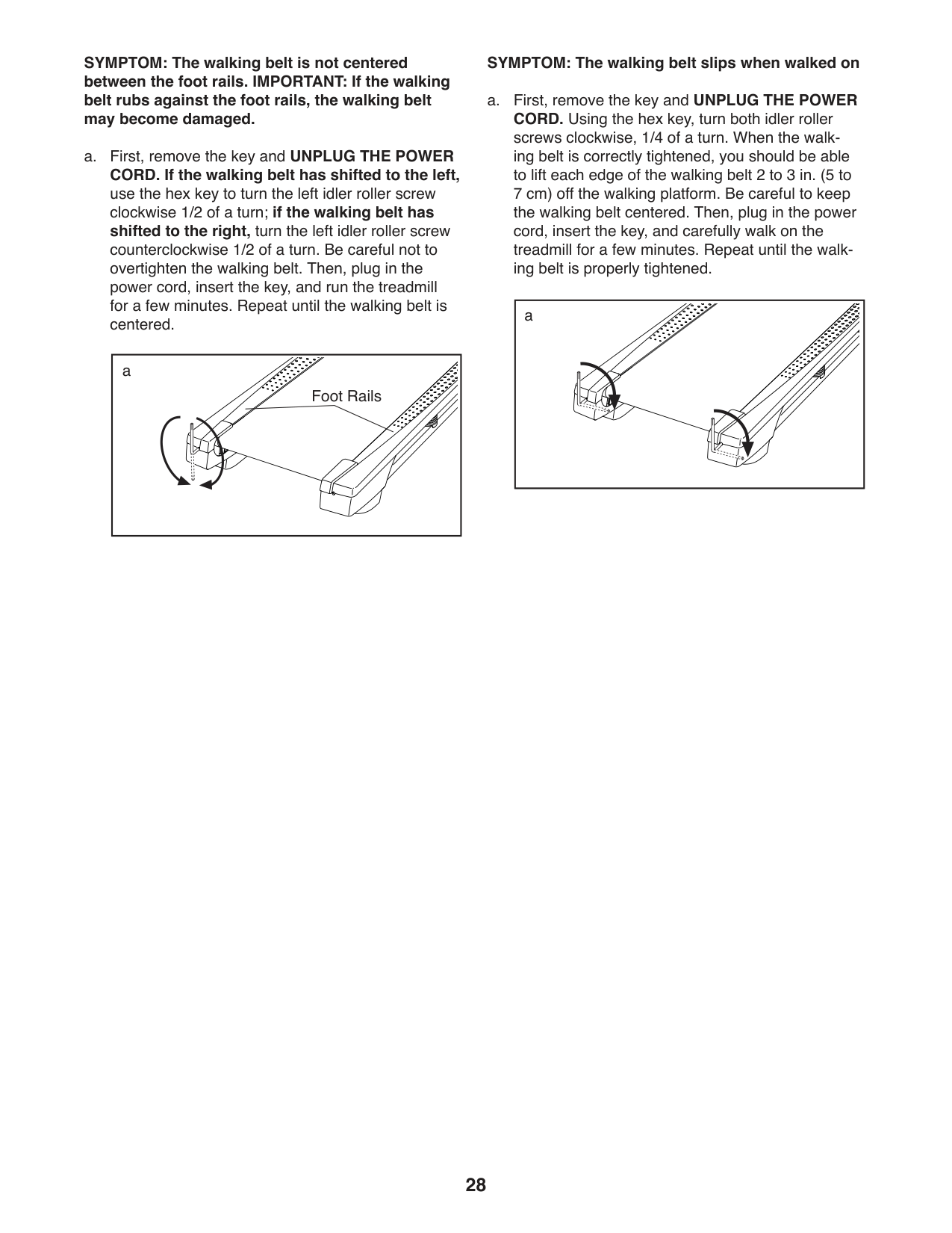
SYMPTOM: The walking belt is not centered between the foot rails. IMPORTANT: If the walking belt rubs against the foot rails, the walking belt may become damaged.
a. First, remove the key and UNPLUG THE POWER
####### CORD. If the walking belt has shifted to the left,
use the hex key to turn the left idler roller screw clockwise 1/2 of a turn; if the walking belt has shifted to the right, turn the left idler roller screw
counterclockwise 1/2 of a turn. Be careful not to overtighten the walking belt. Then, plug in the power cord, insert the key, and run the treadmill for a few minutes. Repeat until the walking belt is centered.
|a
Foot Rails
| |---|
SYMPTOM: The walking belt slips when walked on a. First, remove the key and UNPLUG THE POWER CORD. Using the hex key, turn both idler roller screws clockwise, 1/4 of a turn. When the walking belt is correctly tightened, you should be able to lift each edge of the walking belt 2 to 3 in. (5 to 7 cm) off the walking platform. Be careful to keep the walking belt centered. Then, plug in the power cord, insert the key, and carefully walk on the treadmill for a few minutes. Repeat until the walking belt is properly tightened.
|a| |---|
#### EXERCISE GUIDELINES
WARNING:Before beginning this or any exercise program, consult your physician. This is especially important for persons over age 35 or persons with pre-existing health problems.
The heart rate monitor is not a medical device. Various factors may affect the accuracy of heart rate readings. The heart rate monitor is intended only as an exercise aid in determining heart rate trends in general.
These guidelines will help you to plan your exercise program. For detailed exercise information, obtain a reputable book or consult your physician. Remember, proper nutrition and adequate rest are essential for successful results.
####### EXERCISE INTENSITY
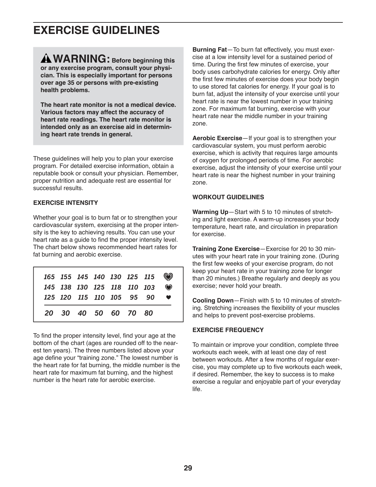
Whether your goal is to burn fat or to strengthen your cardiovascular system, exercising at the proper intensity is the key to achieving results. You can use your heart rate as a guide to find the proper intensity level. The chart below shows recommended heart rates for fat burning and aerobic exercise.
| | |---|
To find the proper intensity level, find your age at the bottom of the chart (ages are rounded off to the nearest ten years). The three numbers listed above your age define your “training zone.” The lowest number is the heart rate for fat burning, the middle number is the heart rate for maximum fat burning, and the highest number is the heart rate for aerobic exercise.
Burning Fat—To burn fat effectively, you must exercise at a low intensity level for a sustained period of time. During the first few minutes of exercise, your body uses carbohydrate calories for energy. Only after the first few minutes of exercise does your body begin to use stored fat calories for energy. If your goal is to burn fat, adjust the intensity of your exercise until your heart rate is near the lowest number in your training zone. For maximum fat burning, exercise with your heart rate near the middle number in your training zone.
Aerobic Exercise—If your goal is to strengthen your cardiovascular system, you must perform aerobic exercise, which is activity that requires large amounts of oxygen for prolonged periods of time. For aerobic exercise, adjust the intensity of your exercise until your heart rate is near the highest number in your training zone.
WORKOUT GUIDELINES Warming Up—Start with 5 to 10 minutes of stretching and light exercise. A warm-up increases your body temperature, heart rate, and circulation in preparation for exercise. Training Zone Exercise—Exercise for 20 to 30 minutes with your heart rate in your training zone. (During the first few weeks of your exercise program, do not keep your heart rate in your training zone for longer than 20 minutes.) Breathe regularly and deeply as you exercise; never hold your breath. Cooling Down—Finish with 5 to 10 minutes of stretching. Stretching increases the flexibility of your muscles and helps to prevent post-exercise problems. EXERCISE FREQUENCY
To maintain or improve your condition, complete three workouts each week, with at least one day of rest between workouts. After a few months of regular exercise, you may complete up to five workouts each week, if desired. Remember, the key to success is to make exercise a regular and enjoyable part of your everyday life.
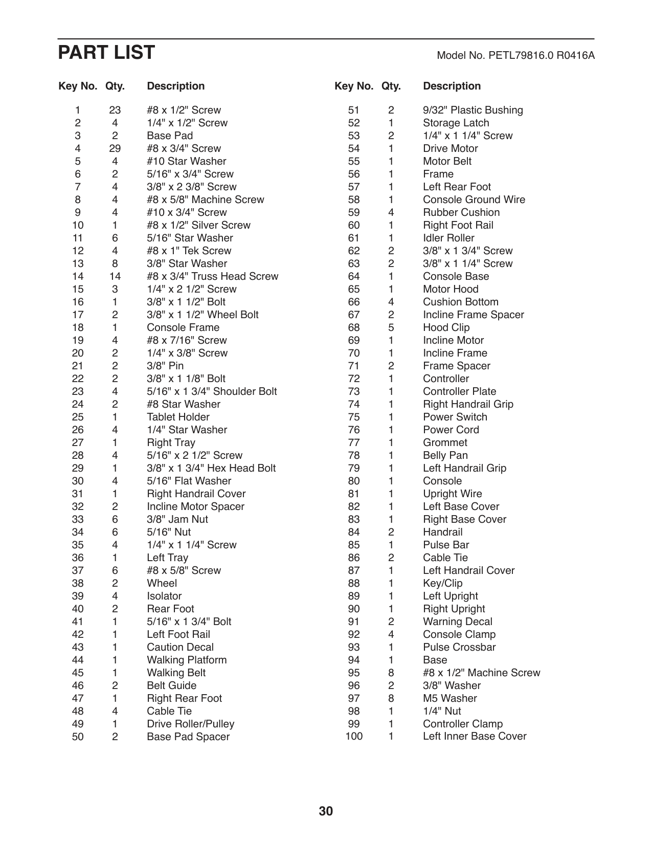
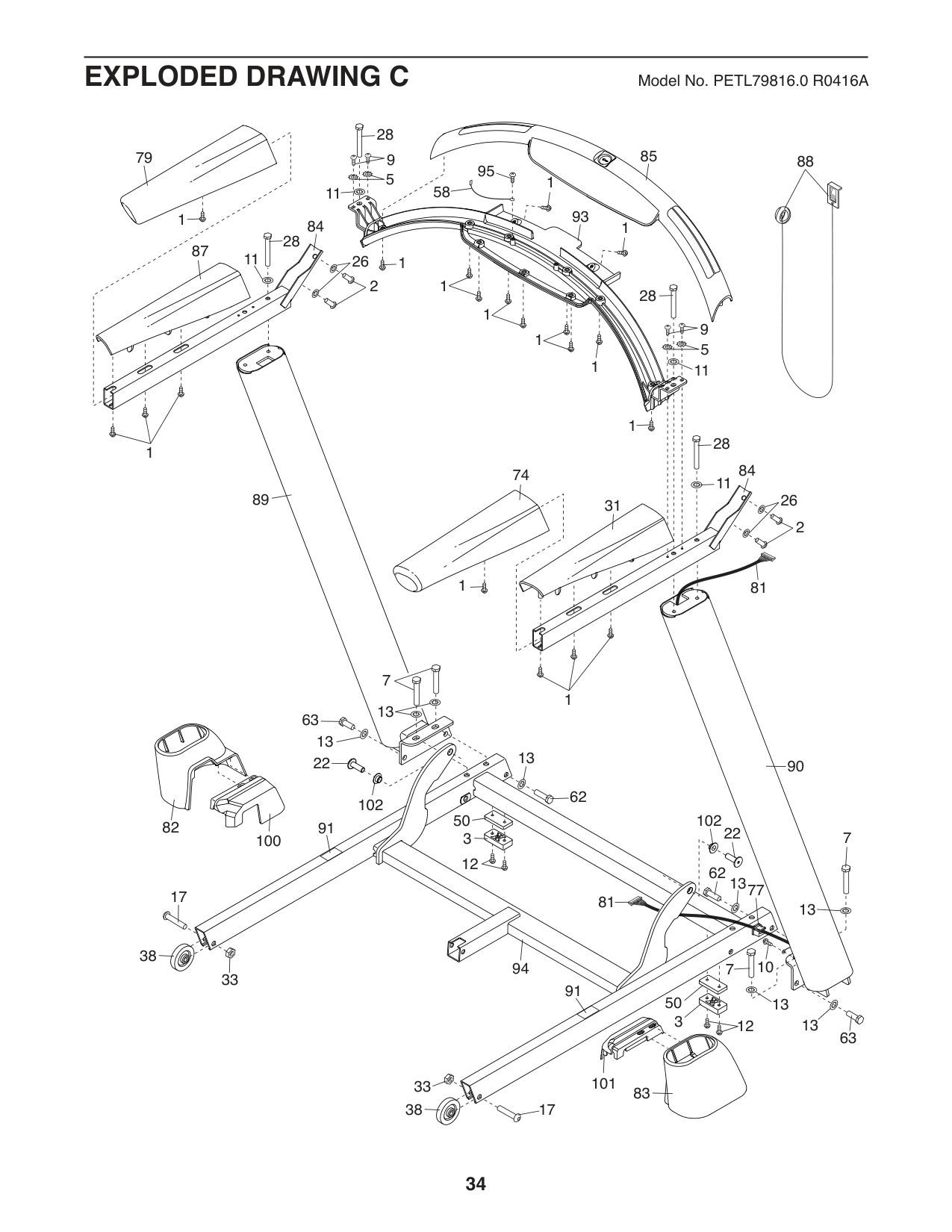
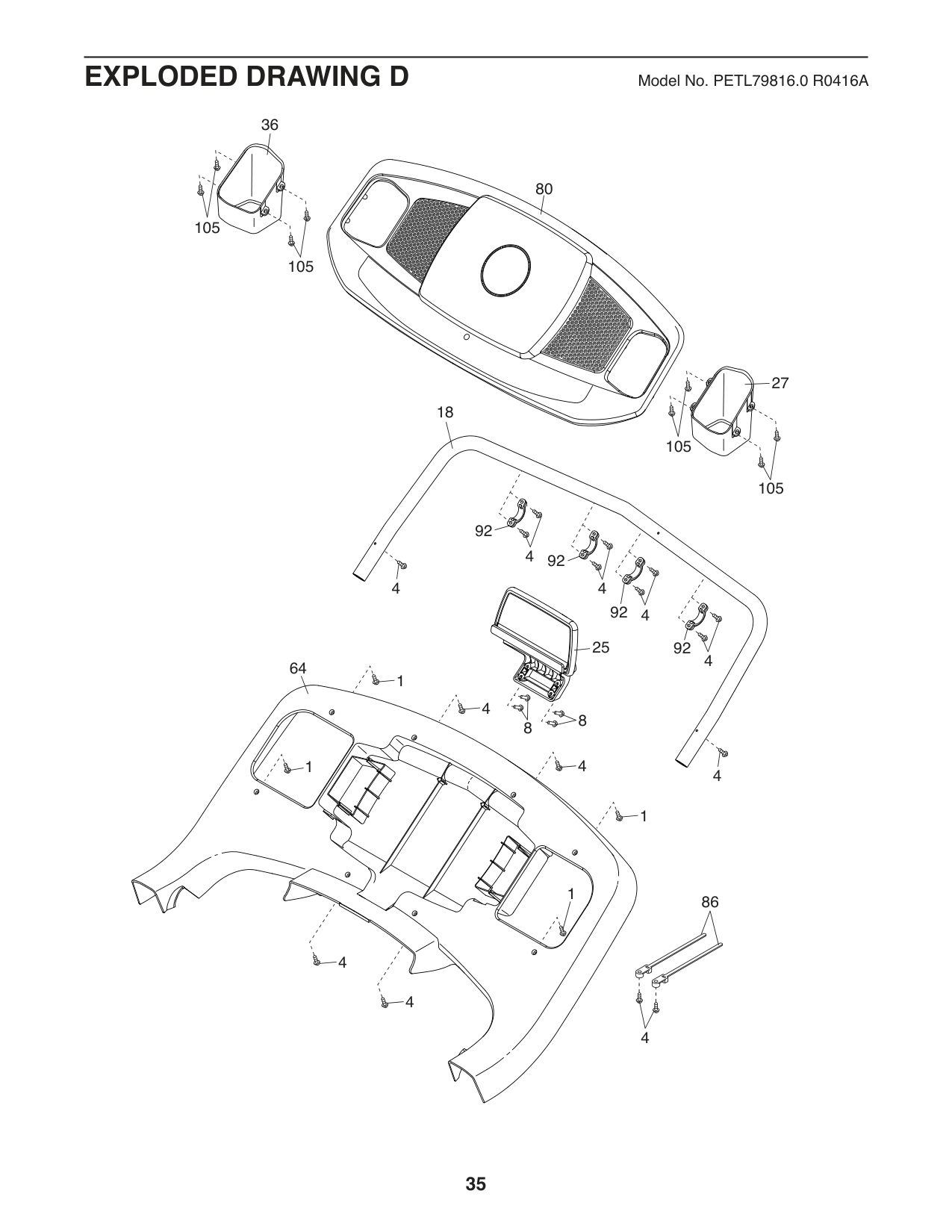
PART LIST Model No. PETL79816.0 R0416A
Key No. Qty. Description Key No. Qty. Description
####### Key No. Qty. Description Key No. Qty. Description
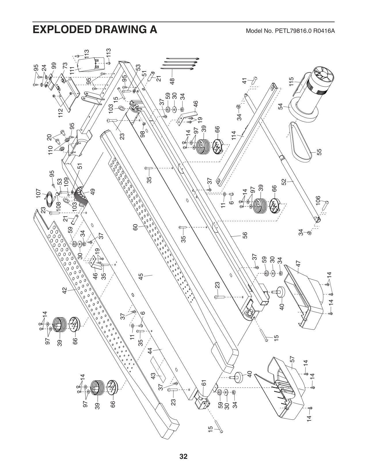
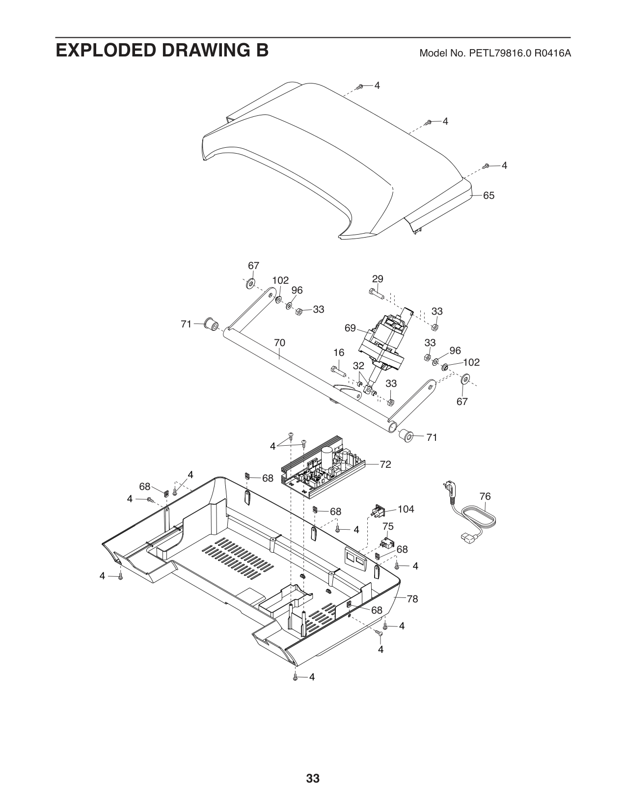
Note: Specifications are subject to change without notice. For information about ordering replacement parts, see the back cover of this manual. *These parts are not illustrated.
113
113
99
73
53
95
24
111
51
21
2395
41
115
95
48
34 30
59
15
3737
46
54
103
112
34
19
95
66 39
97
14
98
114
11020
55
51
95
35
109
37
53
52
66 39
97
49
107
14
106
6 11
108
103
23
21
60
3430 59
34
56
37
35
1946
37
34 30
59
47
1414
35
45
23
42
40
1497
6 11
37
15
66
35
39
57
14
40
14
1497
61
23
66
34 59
39
30
14
15
4
4
4
65
67
29
102
96
33
33
71
69 70
33
96
16
102
32
33
67
71
4
72
4
68
68 4
76

104
68
75
4
68
4
4
78
68
4
4
4
28
85
79
9 5
88 58
95
1
11
93
1
84
1
28
87
11
26
1
2 1
28
1
9 5
1
1
11
1
28
1
84
74
11
89
26
31
2
1
81
7
1
13
63
13 22
13
90
62
102
50 102
82
91
22
7
3
100
12
62
13
77 81
17
13
38
10
94
7
33
91
50
13
3
13
12
63
101
33
83
38
17
105
36
80
105
18
105
64
4
1
1
4
4
92
4
92
4
92
4
25
92
4
4
88
4
4
1
1
86
4
27
105
#### ORDERING REPLACEMENT PARTS
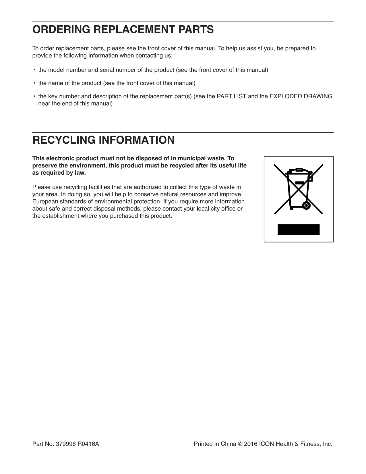
To order replacement parts, please see the front cover of this manual. To help us assist you, be prepared to provide the following information when contacting us:
#### RECYCLING INFORMATION
This electronic product must not be disposed of in municipal waste. To preserve the environment, this product must be recycled after its useful life as required by law.
Please use recycling facilities that are authorized to collect this type of waste in your area. In doing so, you will help to conserve natural resources and improve European standards of environmental protection. If you require more information about safe and correct disposal methods, please contact your local city office or the establishment where you purchased this product.
| | |---|
Part No. 379996 R0416A Printed in China © 2016 ICON Health & Fitness, Inc.