
Solix Sx Tws9 Pinnacle True Wireless Earphones
Ask AI
— answers from the official manualAnswers from the official manual.
Common questions
Common Questions
18 totalCan I use these earphones near water?
No, you should not use these earphones near water. The manual explicitly states 'Do not use this apparatus near water' as part of the safety instructions.
What is the Bluetooth version and operating range of these earphones?
The Solix Sx TWS9 Pinnacle uses Bluetooth version 5.3 with a frequency range of 2402-2480 MHz and an operation range of 10 meters. The maximum transmitted power is 4 dBm.
What should I do if my GPS signal is weak?
Check the Signal Strength in the GPS tool under Satellites. Adjust positioning of the control head or move to a location with better reception as indicated by higher satellite strength levels.
How do I change the wallpaper on my SOLIX Home screen?
Access the Images tool via the Home screen, then select Wallpaper and choose from internal storage or SD/microSD cards. Tap an image to set it as your new Home screen background.
How do I manage my navigation data such as waypoints and routes?
From the Home screen, select Nav Data tool to access saved or create new navigation data. Use this menu to add, edit or delete waypoints, track progress on routes, and more.
What is the process for changing system settings like backlighting?
Open Settings tool from Home screen's Settings option. Here you can adjust various system settings such as backlight brightness, key sounds, units of measurement and time format.
Show 12 more questions
How do I display a chart with certain navigation data overlays?
How do I edit a specific data box in a standard data bar?
How do I set up an instrument view for my dashboard?
How do I set up my radar transmission?
How do I open the X-Press Menu for Sonar views?
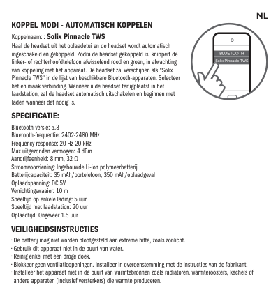
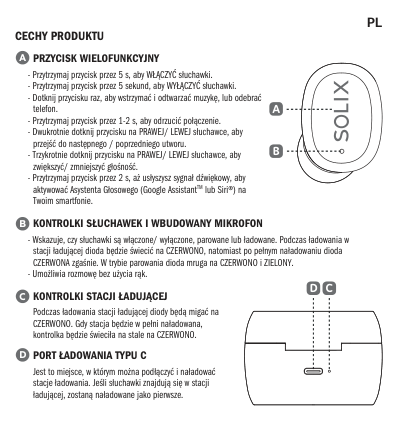
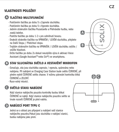
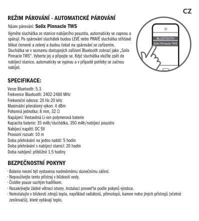
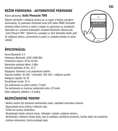
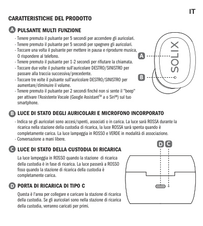
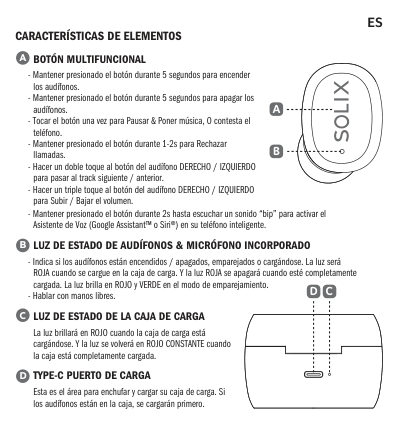
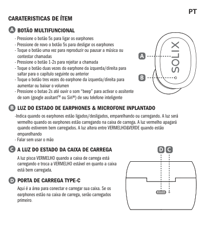
How do I turn on the Solix Sx TWS9 Pinnacle earphones?
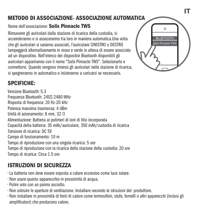
How do I pair the earphones to my smartphone?
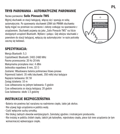
What does the red and green flashing light mean on the earphones?
How long do the earphones last on a single charge?
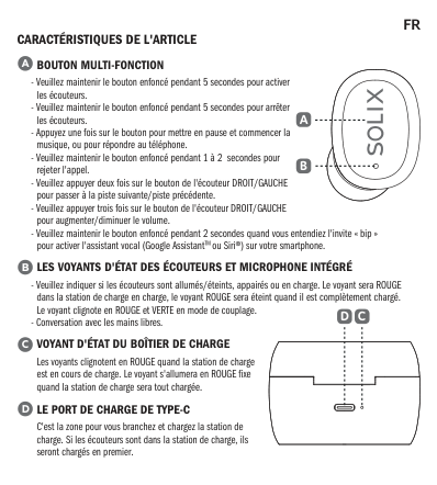
How do I skip to the next or previous track?
How do I adjust the volume?
How do I activate voice assistant on the earphones?
Full Manual
288 pages


SOLIX
Operations Manual
532566-3EN_A
| | |---| | |
| | | |---|---| | | | | | | | | |
THANK YOU!
Thank you for choosing Humminbird®, the #1 name in marine electronics. Humminbird has built its reputation by designing and manufacturing top quality, thoroughly reliable marine equipment. Your Humminbird is designed for trouble-free use in even the harshest marine environment. In the unlikely event that your Humminbird does require repairs, we offer an exclusive Service Policy. For complete details, see the separate warranty card included with your unit. We encourage you to read this operations manual carefully in order to get the full benefit from all the features and applications of your Humminbird product.
Contact Humminbird Customer Service at humminbird.com or call 1-800-633-1468.
WARNING! This device should not be used as a navigational aid to prevent collision, grounding, boat damage, or personal injury. When the boat is moving, water depth may change too quickly to allow time for you to react. Always operate the boat at very slow speeds if you suspect shallow water or submerged objects.
WARNING! The electronic chart in your Humminbird unit is an aid to navigation designed to facilitate the use of authorized government charts, not to replace them. Only official government charts and notices to mariners contain all of the current information needed for the safety of navigation, and the captain is responsible for their prudent use.
WARNING! Compass Safe Distance: The control head must be installed at least 4 feet (1.2 meters) from the compass or other magnetic equipment on the boat. Also, see your compass installation guide for details.
WARNING! This device is granted for use in Mobile only configurations in which the antennas used for this transmitter must be installed to provide a separation distance of at least 8 inches (20 cm) from all person and not be co-located with any other transmitters except in accordance with FCC and Industry Canada multi-transmitter product procedures.
WARNING! Humminbird is not responsible for the loss of data files (waypoints, routes, tracks, groups, recordings, etc.) that may occur due to direct or indirect damage to the unit’s hardware or software. It is important to back up your control head’s data files periodically. Data files should also be saved to your PC before restoring the unit’s defaults or updating the software. Review the information in this manual for details.
WARNING! Disassembly and repair of this electronic unit should only be performed by authorized service personnel. Any modification of the serial number or attempt to repair the original equipment or accessories by unauthorized individuals will void the warranty.
WARNING! Do not travel at high speed with the unit cover installed. Remove the unit cover before traveling at speeds above 20 mph.
NOTE: Some features discussed in this manual require a separate purchase, and some features are only available on international models. Every effort has been made to clearly identify those features. Please read the manual carefully in order to understand the full capabilities of your model.
NOTE: The illustrations in this manual may not look the same as your product, but your unit will function in a similar way.
NOTE: To purchase accessories or any additional equipment for your control head configuration, visit our Web site at humminbird.com or contact Humminbird Customer Service at 1-800-633-1468.
NOTE: The procedures and features described in this manual are subject to change without notice. This manual was written in English and may have been translated to another language. Humminbird is not responsible for incorrect translations or discrepancies between documents.
NOTE: Product specifications and features are subject to change without notice.
NOTE: Humminbird verifies maximum stated depth in saltwater conditions, however actual depth performance may vary due to transducer installation, water type, thermal layers, bottom composition, and slope.
ROHS STATEMENT: Product designed and intended as a fixed installation or part of a system in a vessel may be considered beyond the scope of Directive 2002/95/EC of the European Parliament and of the Council of 27 January 2003 on the restriction of the use of certain hazardous substances in electrical and electronic equipment.
ATTENTION INTERNATIONAL CUSTOMERS: Products sold in the U.S. are not intended for use in the international market. Humminbird international units provide international features and are designed to meet country and regional regulations. Languages, maps, time zones, units of measurement, and warranty are examples of features that are customized for Humminbird international units purchased through our authorized international distributors.
To obtain a list of authorized international distributors, please visit our Web site at humminbird.com or contact Humminbird Customer Service at (334) 687-6613.
360 Imaging®, AUTOCHART®, AutoChart® LIVE, ChartSelect®, Cross Touch®, Down Imaging®, DualBeam PLUS™, Dual Spectrum™, Fish ID+™, FishSmart™, Humminbird®, Humminbird Basemap™, i-Pilot® Link™, LakeMaster®, MEGA Imaging™, MEGA Down Imaging™, MEGA Down Imaging+™, MEGA Side Imaging™, MEGA Side Imaging+™, Real Time Sonar™, RTS Window™, SI™, Side Imaging®, SmartStrike™, SOLIX®, Structure ID™, SwitchFire®, WhiteLine™, X-Press™ Menu, and ZeroLine Map Card™ are trademarked by or registered trademarks of Johnson Outdoors Marine Electronics, Inc.
Airmar is a registered trademark of Airmar Technology Corp. Adobe, Acrobat, Adobe PDF, and Reader are either registered trademarks or trademarks of Adobe Systems Incorporated in the United States and/or other countries. Baekmuk Batang, Baekmuk Dotum, Baekmuk Gulim, and Baekmuk Headline are registered trademarks owned by Kim Jeong-Hwan. The Bluetooth® word mark and logos are registered trademarks owned by the Bluetooth SIG, Inc. and any use of such marks by Johnson Outdoors, Inc. is under license. Other trademarks and trade names are those of their respective owners. Gentoo™ is a trademark of Gentoo Foundation, Inc. microSD and SD are trademarks or registered trademarks of SD-3C, LLC in the United States, other countries or both. Navionics® is a registered trademark of Navionics S.p.A.

NMEA 2000® is a registered trademark of the National Marine Electronics Association.
© 2019 Johnson Outdoors Marine Electronics, Inc. All rights reserved.
Warnings 2 Introduction 6
Using Humminbird Manuals on your Mobile Device or Computer . .7
The SOLIX Control Head 8 SOLIX Touch Screen and Keypad . . . . . . . . . . . . . . . . . . . . . . . . . . .9 SD Card Slots . . . . . . . . . . . . . . . . . . . . . . . . . . . . . . . . . . . . . . . . . . .14
Power On/Off 15 Getting Started 16 The Home Screen 24 The Menu System 32 Views 38
Edit the On-Screen View . . . . . . . . . . . . . . . . . . . . . . . . . . . . . . . . .41 The View Options Menu . . . . . . . . . . . . . . . . . . . . . . . . . . . . . . . . . .50 Create a New View . . . . . . . . . . . . . . . . . . . . . . . . . . . . . . . . . . . . . . .53 Set up an Instrument View . . . . . . . . . . . . . . . . . . . . . . . . . . . . . . .57
Chart Overview 59 Map Source Overview . . . . . . . . . . . . . . . . . . . . . . . . . . . . . . . . . . . .60 Navigation Alarms Overview . . . . . . . . . . . . . . . . . . . . . . . . . . . . . .70 Man Overboard (MOB) Navigation . . . . . . . . . . . . . . . . . . . . . . . . .74 Customize the Chart View . . . . . . . . . . . . . . . . . . . . . . . . . . . . . . . .75 Change the Chart View Data Overlays . . . . . . . . . . . . . . . . . . . . . .84 Chart and Radar . . . . . . . . . . . . . . . . . . . . . . . . . . . . . . . . . . . . . . . .85
############### Introduction to Navigation 86
Navigation Menu Overview 87 Navigation X-Press Menu . . . . . . . . . . . . . . . . . . . . . . . . . . . . . . . . .87 Mark Menu . . . . . . . . . . . . . . . . . . . . . . . . . . . . . . . . . . . . . . . . . . . . . .88 Go To Menu . . . . . . . . . . . . . . . . . . . . . . . . . . . . . . . . . . . . . . . . . . . . .88 Info Menu . . . . . . . . . . . . . . . . . . . . . . . . . . . . . . . . . . . . . . . . . . . . . . .90 Cursor Menu . . . . . . . . . . . . . . . . . . . . . . . . . . . . . . . . . . . . . . . . . . . .92
Waypoints 93 Routes 98 Search 105 Tracks 107
Manage your Navigation Data 110 Manage Waypoints . . . . . . . . . . . . . . . . . . . . . . . . . . . . . . . . . . . . .111 Manage Routes . . . . . . . . . . . . . . . . . . . . . . . . . . . . . . . . . . . . . . . .114 Manage Tracks . . . . . . . . . . . . . . . . . . . . . . . . . . . . . . . . . . . . . . . . .116 Manage Groups . . . . . . . . . . . . . . . . . . . . . . . . . . . . . . . . . . . . . . . .119 Delete All Navigation Data . . . . . . . . . . . . . . . . . . . . . . . . . . . . . . .120 Import/Export Navigation Data . . . . . . . . . . . . . . . . . . . . . . . . . .120
AutoChart LIVE Overview 121 Plan your Map . . . . . . . . . . . . . . . . . . . . . . . . . . . . . . . . . . . . . . . . . .121 Prepare the Control Head for Mapping . . . . . . . . . . . . . . . . . . . .122 Record your Custom Map . . . . . . . . . . . . . . . . . . . . . . . . . . . . . . .125 Stop Recording . . . . . . . . . . . . . . . . . . . . . . . . . . . . . . . . . . . . . . . .126 Correct Data . . . . . . . . . . . . . . . . . . . . . . . . . . . . . . . . . . . . . . . . . . .127 Display the AutoChart Live Map . . . . . . . . . . . . . . . . . . . . . . . . . .128 Adjust the Map Display Settings . . . . . . . . . . . . . . . . . . . . . . . . .130 Customize the Bottom Hardness Display Settings . . . . . . . . .134 Customize the Vegetation Display Settings . . . . . . . . . . . . . . .137
Mosaic Live Overview 140 For Best Performance . . . . . . . . . . . . . . . . . . . . . . . . . . . . . . . . . .140 Open the Mosaic Live Menu . . . . . . . . . . . . . . . . . . . . . . . . . . . . .141 Customize the Mosaic Live Display . . . . . . . . . . . . . . . . . . . . . . .143
Autopilot Overview 147 Radar Overview 149
Radar Transmission Settings . . . . . . . . . . . . . . . . . . . . . . . . . . . .150 Adjust the Transmission Range . . . . . . . . . . . . . . . . . . . . . . . . . .153 Radar Alarms . . . . . . . . . . . . . . . . . . . . . . . . . . . . . . . . . . . . . . . . . .154 Customize the Radar View . . . . . . . . . . . . . . . . . . . . . . . . . . . . . .157 Open the Radar Preferences Menu . . . . . . . . . . . . . . . . . . . . . . .157 Change the Radar View Data Overlays . . . . . . . . . . . . . . . . . . . .159 Adjust Radar Signal Settings . . . . . . . . . . . . . . . . . . . . . . . . . . . .161 EBL/VRM . . . . . . . . . . . . . . . . . . . . . . . . . . . . . . . . . . . . . . . . . . . . . .164 Navigation in Radar View . . . . . . . . . . . . . . . . . . . . . . . . . . . . . . . .166
AIS and MARPA 168 AIS and MARPA Alarms . . . . . . . . . . . . . . . . . . . . . . . . . . . . . . . . . .168 AIS and MARPA Display Settings . . . . . . . . . . . . . . . . . . . . . . . . .170
AIS Overview 172 MARPA Targets 179
Sonar Overview 184 Sonar Setup . . . . . . . . . . . . . . . . . . . . . . . . . . . . . . . . . . . . . . . . . . .190 Sonar Alarms . . . . . . . . . . . . . . . . . . . . . . . . . . . . . . . . . . . . . . . . . .191
2D Sonar Overview 192 Customize the 2D Sonar View . . . . . . . . . . . . . . . . . . . . . . . . . . .193 Open the 2D Sonar Preferences Menu . . . . . . . . . . . . . . . . . . . .193 Change the 2D Sonar View Overlays . . . . . . . . . . . . . . . . . . . . . .199 Adjust 2D Sonar Display Settings . . . . . . . . . . . . . . . . . . . . . . . .200
Side Imaging Overview 205 Customize the Side Imaging View . . . . . . . . . . . . . . . . . . . . . . . .207 Open the Side Imaging Preferences Menu . . . . . . . . . . . . . . . .207 Change the Side Imaging View Overlays . . . . . . . . . . . . . . . . . .209 Adjust Side Imaging Display Settings . . . . . . . . . . . . . . . . . . . . .210
Down Imaging Overview 213 Customize the Down Imaging View . . . . . . . . . . . . . . . . . . . . . . .214 Open the Down Imaging Preferences Menu . . . . . . . . . . . . . . .214 Change the Down Imaging View Overlays . . . . . . . . . . . . . . . . .216 Adjust Down Imaging Display Settings . . . . . . . . . . . . . . . . . . . .217
Use Cursor and Zoom in Sonar Views (2D, SI, DI) 220 Navigation in Sonar Views (2D, SI, DI) 222 Sonar Recording 224 Images Tool 225 Installation Information 231
Set up or Change Transducer Settings (advanced settings) . . .232 Configure Humminbird Radar (Installation and Repair only) . .240 Configure the Control Head . . . . . . . . . . . . . . . . . . . . . . . . . . . . .243 Set up a NMEA 2000 Network . . . . . . . . . . . . . . . . . . . . . . . . . . .247 Set up your Humminbird Network . . . . . . . . . . . . . . . . . . . . . . . .256 Change the Network Name . . . . . . . . . . . . . . . . . . . . . . . . . . . . . .262
Manage your Control Head 264 Update Software 266 Specifications 270 Statements and Acknowledgements 282 Contact Humminbird 288
INTRODUCTION
The instructions in this manual describe the SOLIX control head operations. For an overview of functions, see the Quick Start Guide included with your product.
Build your Network: Some of the features shown in this manual require a separate purchase. Radar, Talon, AIS, Compass/Heading Sensor, Ethernet Switch, i-Pilot Link, etc. require a separate purchase. To install each accessory, use the installation guide provided with it, or download the guide from our Web site at humminbird.com.
Register and Update: As you build your Humminbird network, it is important to register your products and keep your software up to date. Visit our Web site at humminbird.com to register your Humminbird products, update control head and accessory software, and purchase additional equipment. Also, see Update Software in this manual for more information.
6Introduction
USING HUMMINBIRD MANUALS ON YOUR MOBILE DEVICE OR COMPUTER
The Humminbird manuals for your control head and accessories can be downloaded to your mobile device or computer. If you prefer to use a hard copy for reference, this manual may be printed.
######### Download the Manual to your Mobile Device
######### Download the Manual to your Computer
Jump to a Section: Click a section name in the Bookmarks panel. Bookmarks can be expanded and collapsed by clicking on the plus (+) or minus (-) icons.
Search for Words or Phrases: Press and hold the Ctrl F keys on your keyboard. Type the word(s) into the text box. Print: To print, confirm the page sizing is 8.5 x 11" and set to Fit. Set the page orientation to Portrait.
Using the Manual
| || | |---|---|---| | || | | || |
search for key words
bookmarks panel
(Ctrl + F)
7 Introduction
THE SOLIX CONTROL HEAD
The SOLIX control head includes CrossTouch, which allows you to use both the touch screen and keypad to make selections. Review this section for an overview of touch and keypad functions.
| | |---| | |
| | | |---|---| | | | | | |
keypad
| | | |---|---| | | | | | |
| | | |---|---| | | |
| | | |---|---| | | | | | | | | |
| | | |---|---|
| | | | | | | | | | | |
| | | |---|---| | | | | | | | | | | | |
touch screen SD or microSD card slots
Keypad Functions The functions for each key are described here. To apply the key functions, see each section of this manual. Joystick
############ Move Functions
############ (Down) Press Functions
Move to select a view, tool, widget, or menu. Move to activate and/or move the cursor across the displayed view.
Open your selected view, tool, widget, menu, or submenu.
Mark a route point.
Rotary Dial
Turn Functions Turn to adjust menu settings. Turn to adjust the sensitivity in Sonar Views. Turn to zoom in and out in Chart View. Turn to adjust in Radar View.
############ (Down) Press Function
Press the Rotary dial to open the Favorite Views widget.
|Key|Name
|Key Press Function(s)|Key Press Function(s)| |---|---|---|---| | |POWER key|Powers on the control head. During operation, this key opens the Power X-Press Menu.|Powers off the control head.
| | |ENTER key
|Starts a command. Selects, or turns on, a setting. Opens menus. Opens the Info menu and the Cursor menu.|Adjusts menu settings. May vary with the displayed view.
| | |EXIT key|Closes an open menu or dialog box. Turns off an alarm. Exits Cursor mode. Returns to the last displayed view from the Home screen.|Closes all open submenus and menus.| | |GO TO & Screen Snapshot key|Opens the Go To menu for navigation functions (see Routes for details).
|Screen Snapshot: Saves the on-screen view (image). See Images Tool.| | |PANE key
|Activates the Side Bar (the side bar is highlighted in yellow). Use the Joystick to scroll through the side bar widgets.
Selects a pane in a multi-pane view (the selected pane is highlighted in yellow. See Views.)| | | |MARK & Man Overboard key|Press TWICE to mark waypoints.
|Man Overboard: Starts Man Overboard (MOB) Navigation. See Man Overboard (MOB) and Introduction to Navigation).| | |HOME key|Displays the Home screen. See The Home Screen.| | | |ZOOM In key
|Changes the scale of the view to show a closer perspective.| | | |ZOOM Out key|Changes the scale of the view to show a wider view.|Zoom out all the way.| | |MENU key|Opens the X-Press Menu for the on-screen view and operation mode.
Press TWICE to open the Settings tool.|Returns to the last-used Settings tool tab. See The Menu System.|
####### Touch Screen Functions
The touch screen actions are also determined by the view displayed on the screen.
Using the Touch Screen
|
| |---|
Swipe Functions
One Finger Swipe (vertical) Browse Menus: Scroll through a menu or list (up or down).
############ Two Finger Swipe


With a view displayed on-screen, touch the screen with two fingers and swipe down to return to the Home screen.


One Finger Swipe (horizontal) Adjust Menu Slider: Drag the slider to adjust the setting.


With a Chart View displayed on the screen, drag one finger across the screen to see more of the chart that is displayed off-screen.
With a 2D Sonar View displayed on the screen, drag one finger across the screen to see more of the sonar history.
######## Tap Functions
One Tap Select (Open): Tap to select (or open) a view, tool, widget, menu, or icon. Activate the Cursor: Tap a position on the view once.
############ Two Taps


Tap the screen twice to zoom in on the current display.
######## Press and Hold Functions
############ Pinch
############ Press and Hold


Zoom In: Touch the screen with two fingers and move them apart to zoom in on the display.
Press and hold a position on the view with one finger to open the Cursor Menu.

Zoom Out: Touch the screen with two fingers and bring them closer together to zoom out.
####### Basic Touch Screen and Keypad Operations
Select (Open) a Tool, Widget, or View Touch Screen Keypad

tap to open
OpenSelect
Adjust a Menu Setting Touch Screen Keypad
|| |---|
Tap
Press

OR
Turn Press and Hold
Press and Hold OR Slide
Close a Tool or Menu Touch Screen Keypad

tap to close
Select Close
Open a View from the Views Tool Touch Screen Keypad

tap to open
DisplaySelect
Open a View from the Favorite Views Widget Touch Screen Keypad

tap to open
Open Select
Display
####### SD Card Slots
Your control head may be compatible with an SD or microSD card (separate purchase required). Use it to update software, add detailed charts to your control head, import/export navigation data, and save sonar recordings and screen snapshots. Use the instructions in this section to install the card.
CAUTION!Before the control head software is updated or restored to system defaults, export your menu settings, radar settings, and navigation data (see Update Software).
WARNING! Do not leave the card slot cover open. The slot cover should always be closed to prevent water damage to the unit.
######### Insert an SD Card
The left slot is displayed as SD Card (1) in the menu system, and the right slot is displayed as SD Card (2).
Insert a microSD Card The top slot is displayed as SD Card (1) in the menu system, and the bottom slot is displayed
Load an SD Card
| | | |---|---| | | |
| | | |---|---| | | |
| | | | |---|---|---| | | | |
| | | |---|---| | | |
| | | |---|---| | | |
Insert the SD card with the label facing left
POWER ON/OFF
####### Power On

| | | |---|---| | | |
| | | |---|---| | | | | | | | | | | | |
| | | |---|---| | | |
| | | |---|---| | | | | | | | | | | | |
| | | |---|---| | | |
####### Use Standby Mode to Conserve Power
To conserve power while the control head is not in-use, start Standby mode from the Power X-Press Menu.
####### Power Off
Additional Keypad Option Press and hold the POWER key.
15 Power On/Off
GETTING STARTED
The procedures in this section describe how to get started with your control head:
See the control head installation guide and the quick start guide included with your SOLIX control head to configure the unit for first time setup. Also, see Installation Information in this manual for control head configuration and network configuration details.
NOTE: When the SOLIX control head equipment and accessories are first installed, the Setup Guide provides the prompts to guide you through configuring the unit. The Setup Guide includes important steps to configure the control head with the equipment, including vessel dimensions, map source selection, and offset menus. See your control head installation guide to configure the unit for the first time.
################# The Home Screen
Bluetooth notifications (with paired mobile phone)(from left to right): call notifications, text notifications, phone battery power percentage, and phone carrier signal strength.

status bar
side bar
tools
view additional toolscustomizable Home screen wallpaper (background)
1 | Review GPS Reception
Use the GPS tool to check the GPS reception. The GPS tool provides two ways to view the satellites communicating with the GPS Receiver. Yellow indicates that the satellite is being used to determine your current position. Teal indicates that the satellite is being monitored but not used. The following data is also displayed:
Open the GPS Tool If there is more than one control head installed on the network, select the control head that is connected directly to the GPS receiver.
######### Review Satellites and Signal Strength
################# GPS (1) Satellite Sky Chart
selected GPS source GPS status iconfix type

status bar
satellites communicating
to GPS (1)
used satellite (yellow)
monitored satellite (teal)
digital readouts
GPS (1) Satellites shows a sky chart and numerical data from the selected GPS receiver
################# Signal Strength (bar graph)
selected GPS source
fix type
GPS status icon
status bar

boat position (latitude/ longitude)
satellites signal strength GPS (1)
monitored satellite (teal) and strength level
used satellite (yellow) and strength level
digital readouts
Signal Strength (GPS 1/GPS 2): displays vertical bar graphs indicating the satellite signal strengths with the respecting CNO (Carrier-to-Noise) value (0 to 60).
GPS (1) and GPS (2) Sources You can also manually change which GPS receiver is the selected source for GPS (1) or GPS (2). To change the GPS sources, see Set up your Humminbird Network.
2 | Check Sensor Reception and Connections
If you’ve connected other separate-purchase equipment to the control head network, such as AIS, Compass/Heading Sensor, Radar, i-Pilot Link, 360 Imaging, and more, use these instructions to confirm the equipment is detected and communicating with the control head.
Connected but not Detected or Active: If a sensor is not detected on the network, or not transmitting/receiving, it will be completely gray.
Connected but not Transmitting/Receiving: If a sensor is detected, but is not transmitting/receiving, the icon will be partially gray. In this illustration, the GPS receiver is detected, but it doesn’t have a GPS fix. This feature will vary with the type of icon represented.


|Active Status Icon
|Sensor|Icon Description| |---|---|---| ||AIS|AIS is on and receiving targets.
| |
|Wireless Remote|The Bluetooth wireless remote is connected.| ||Compass
|The selected compass/heading sensor is on and heading data is being received.| |
|GPS|The GPS receiver is detected and a GPS fix has been obtained.| |
|i-Pilot Link|i-Pilot Link is connected, enabled, and actively navigating.| |
|Bluetooth Talon
|The Talon is connected and stowed. Download the Bluetooth Talon Accessory Manual from our Web site at humminbird.com for additional Talon status icons.| ||Radar|The selected radar source is detected and transmitting.
| |
|2D Sonar|The selected 2D sonar source is detected and pinging.| ||360 Imaging Sonar|The 360 Imaging transducer is pinging data.|
If you have connected an accessory to the control head, and the icon is not displaying in the system status bar, check the installation of the accessory and the cable connection to the control head.
To change the NMEA 2000 network or multi-control head network sources, see Set up a NMEA 2000 Network and Set up your Humminbird Network.
3 | Start Radar Transmission (connected Radar source required)
For more information about Humminbird CHIRP Radar and Humminbird Radar, see Radar Overview.
WARNING! The radar should be configured by a qualified radar technician after installation or equipment repair. See Installation Information: Configure Humminbird Radar.
Use the following instructions to pair a mobile device (phone or tablet) to the control head using Bluetooth wireless technology.
NOTE: If you have a Bluetooth Talon or the Bluetooth Wireless Remote (separate purchases required), see the accessory operations manual for each product for pairing instructions. Operations manuals can be downloaded from our Web site at humminbird.com.
NOTE: WiFi or cellular data must be enabled on your device.
######### Enable Bluetooth on your Device
######### Pair the Phone with the Control Head
Pairing a Mobile Phone to the SOLIX

Turn paired phone connection on/off.
Bluetooth settings
device list
The status bar indicates the SOLIX is actively searching for Bluetooth devices.
Change the Phone Bluetooth Notification Settings Use the following instructions to select an alert format on the control head or turn off alerts.
Review Phone Bluetooth Notifications View phone notifications on the Home screen.
5 | Set Alarms
When an alarm is turned on, an alert will sound or display on the control head to indicate the threshold has been exceeded.
If the control head is connected to the Humminbird network, select Local Alarms (control head only) or Networked Alarms (alarms shared across control heads). See Set up your Humminbird Network for more information.
################# Setting an Alarm
status barselected categoryhomeclose
| | | | | | | |---|---|---|---|---|---| |||||| | |||||| | |||||| |

menu options
NOTE: See The Menu System: Tips for Using the Status Bar for more details.
The available alarms are determined by the connected equipment, so your control head may provide more or less options than the information shown here.
|System
|Voltage, Lost Heading (compass/heading sensor required), etc.| |---|---| |Vessel|Drift Limit, SOG (Speed over Ground), STW (Speed through Water), etc. Also, see Views: Understand the Data Box Digital Readouts for more information.
| |Navigation
|See Chart Overview: Navigation Alarms Overview for details.| |Sonar
|See Sonar Overview: Sonar Alarms for details.| |Radar
|See Radar Overview: Radar Alarms for details.| |Temperature
|Temp (High) or Temp (Low). To change the Temperature sources, see Installation Information: Set up your Humminbird Network.| |Engine|Low Fuel, Engine Temp, Oil Level, Coolant Level, Check Engine, etc. To change Engine and Fuel sources, see Installation Information: Set up a NMEA 2000 Network.|
####### Change System Settings
Your control head was configured during the installation setup. To change the system settings such as the backlight, key sounds, units of measurement, and the time and date format (including Daylight Saving Time), select Settings from the Home screen. See Manage your Control Head for more information.
NOTE: To reconfigure the control head with the Setup Guide, select the Setup Guide tool from the Home screen.
####### Set up Sonar
Proceed to the Sonar Overview section.
####### Select the Map Source
Proceed to the Chart Overview section.
THE HOME SCREEN
The Home screen is the main control center for your control head. Use the Home screen to access the control head settings, navigation data, views, alarms, and other tools.
######## Open the Home Screen Touch Screen
############ Keypad
################# The SOLIX Home Screen
STATUS BARfavorite views widgetBluetooth notifications (with paired mobile device)

time and date
SIDE BAR widgets
TOOLS
customizable Home screen wallpaper (background)
select to view additional tools


Swipe down to open from any view
#### OR
Press the HOME key
Navigate the Home Screen See the instructions and screenshot below to better understand the Home screen layout. Touch Screen Open a Tool: Tap the tool icon. Open a Widget: Tap the widget icon (in the side bar). View Additional Tools: Tap All Tools. Close (return to the previous view): Tap the X icon in the status bar.
Keypad Select (Open): Use the Joystick to select a menu, tool, or widget. Press the ENTER key to open it. Open a Widget:Press the PANE key. Use the Joystick to select the widget icon and press the ENTER key to open it. View Additional Tools: Use the Joystick to select All Tools. Press the ENTER key. Close (return to the previous view): Press the EXIT key.
Opening a Tool
|
| |---|
#### OR
Tap to Select (Open) Select Open
####### Tools
Tools allow you to manage the control head network operations and saved data. When you connect an accessory to the control head, a related tool may also be displayed.
|Settings|Select Settings to change general system settings such as the backlight, units of measurement, and the time and date format. You can also use this menu to change the main settings for each application (Sonar, Chart, Radar, etc.). See each related section of this manual for details.
| |---|---| |Nav Data|Select Nav Data to manage your saved waypoints, routes, tracks, and groups. You can create new navigation data from this screen, edit your saved navigation data, or start navigation (see Manage your Navigation Data).
Required Equipment: GPS receiver (internal or external)
| |Views|Select Views to access the complete set of views available on your control head. You can edit views, create your own views, and save your favorite views. See Views for more information.
| |Alarms|Select Alarms to view the alarm log, mute alarm sounds, and set the alarms for the individual applications. To set up individual alarms for navigation, sonar, radar, AIS, etc., see each related section of this manual for details. For example, for radar alarm settings, see Radar Alarms.
| |GPS|Select GPS to review the signal strength of the GPS receivers (“sensors”) connected to the system. The tool shows the satellites in the area, the positions, and the signal strength for each one. You can also designate a primary and secondary GPS source from this tool. See Getting Started, Installation Information, and Set up your Humminbird Network.
Required Equipment: GPS receiver (internal or external)
| |Targets
|Select Targets to manage AIS and MARPA targets. See AIS and MARPA for more information. Required Equipment: AIS or Radar, GPS receiver (internal or external), and compass/heading sensor| |Trip Log|Select Trip Log to display Speed over Ground (SOG), timer for elapsed time, distance traveled since last reset, average speed, and trip fuel. You can also reset the trip log to zero and review trend data from this tool.
Required Equipment: GPS receiver (internal or external)
| |Timer
|Select Timer to set an alarm clock for a selected time of day, use the countdown timer, or use the stopwatch. You can set more than one alarm clock.| |Fuel*|Select Fuel to review the fuel log for NMEA 2000 fuel sensors connected to the network. This tool provides refuel alerts and displays the fuel level in graphical form. See Set up a NMEA 2000 Network for details.
*Required Equipment: NMEA 2000 tank sensor and/or fuel flow rate sensor|
|Audio*|Select Audio to listen to AM/FM radio or audio files saved to a USB stick, iPod, etc.
*Required Equipment: compatible audio system
| |---|---| |Bluetooth|Select Bluetooth to pair your mobile phone and/or Bluetooth wireless remote (separate purchase required) to the control head. You can also assign key functions for the Bluetooth remote from this tool. See your installation guide for details. To pair your mobile phone to the control head, see Getting Started.
Required Equipment: mobile phone (with Bluetooth), Bluetooth remote
| |Images
|Select Images to manage your screen snapshots. When a screen snapshot is taken, a waypoint can also be saved at the current position. You can also choose to save the image on the control head or to an SD or microSD card. Also, screen snapshots and pictures from your camera’s SD card (JPG Files) can be displayed as the Home screen wallpaper and in a slideshow from this tool. See Getting Started and Images Tool for more information.| |Record|Select Record to start a sonar recording or select a save location. You can also watch a sonar recording from the perspective of a 2D, SI, or DI View, depending on the capabilities of your model. See Sonar Recording for more information.
Required Equipment: transducer, black box sonar
| |Sun + Moon
|Select Sun + Moon to review the sunrise and sunset for today or the date you select. The Moon data provides the rise and set of the moon and moon phases.| |Files
|Select Files to update the software for the control head or connected accessories. You can also import and export navigation data from this tool, and you can import and export menu settings. Radar installation settings can be managed from this tool, but only authorized radar technicians should use this menu. See the following sections: Manage your Navigation Data and Manage your Control Head.
Required Equipment: SD or microSD card (depending on your control head model)| |Setup Guide|Select Setup Guide, and the control head will guide you through the basic configuration settings for your control head, including units of measurement, language, transducer source, map source, and vessel settings. See your installation guide for details. To change the settings after setup, select Home > Settings.
| |Tides|Select Tides to review information for the nearest tide station to your present position. The tool includes the position of the station and the times of the high and low tides for today’s date. A tide graph is also displayed showing the rise and fall of the tides for the 24 hour time period encompassing the date. You can also search data for a selected date.
Required Map Source: Navionics
|
|Currents|Select Currents to review information for the nearest current station to your present position. Two graphs are also presented that show the time, direction, and flow speed of the current changes for the 24 hour time period of today’s date. You can also search data for a selected date.
Required Map Source: Navionics|
####### Side Bar Widgets
The side bar includes widgets that allow you to quickly access your favorite views, data bars, and digital remotes for networked accessories, like i-Pilot Link and Talon.
The side bar is set to always display on the Home screen, but it can be hidden in other views. See Edit the On-Screen View: Turn the Side Bar On/Off.
################# Opening a Widget
engine data widget

selected data box
(highlighted in yellow)
submenu with
additional data boxes
selected widget
#### OR
Tap to Select (Open) Select a Widget Open
Select the Side Bar
Available Side Bar Widgets When you connect an accessory to the control head, a related widget may also be displayed in the side bar. If you have connected an accessory to the control head, and the icon is not displaying in the system status bar, check the installation of the accessory and the cable connection to the control head.
|Widget Icon|Name|Widget Function
| |---|---|---| ||Favorite Views|Allows you to create a list of your favorite views. There are two tabs, which allow you save up to 10 views. Use the widget to quickly display your favorite views (see Views).
| |
|Data Bar|Displays the standard Data Bar with data box readouts. There are two tabs and each data box can be customized (see Views: Understand the Data Box Digital Readouts).| ||Navigation Data Bar
|Displays the Nav (Navigation) Data Bar with digital readout boxes for navigation. There are two tabs and each data box can be customized (see Views: Understand the Data Box Digital Readouts).
*With a connected i-Pilot Link, this selection will display the i-Pilot Link Navigation Data Bar.| |
|i-Pilot Link*|Displays the i-Pilot Link digital remote.| ||Engine Data*|Displays engine data from the connected NMEA 2000 network. Some data boxes include built-in submenus to view additional data.
| ||Digital Switching*
|Displays the digital switch panel for your boat. Use this widget to quickly access settings for your boat’s electrical and connected systems, such as lights, fans, horns, bilge, etc.
See our Web site for compatibility information.| ||Talon*|Displays the Talon digital remote, which includes quick access menus to deploy and retract the Talon, change the anchor mode, turn the work light on/off, etc.
| ||Audio*|Displays the audio settings for a connected audio accessory.|
*separate purchase accessory
####### Status Bar
The status bar is located at the top of the screen. It changes to match the on-screen view and operation mode.
In the following illustration, the information in the status bar corresponds with the Chart View displayed on-screen. You can tap the icon in the status bar to open a menu, return to the Home screen, close a menu, or make a selection. You can also use the corresponding keys.
################# Status Bar
touch menus change to match the on-screen view and status
sensor status

Tap, or press the MENU key, to open the X-Press Menu for the on-screen view.
Tap, or press the POWER key, to open the Power X-Press Menu
Chart View Status Bar Menus
################# Chart View Status Bar Menus
chart orientation AutoChart Live center vesselchart mode show cursor
||| |---|---| | | |
Tap, or press the MENU key, to open the X-Press Menu.
Sonar View Status Bar Menus
################# Sonar View Status Bar Menus
sonar display frequency zoomsonar colorsSwitchFire™
||| |---|---| | | |
Tap, or press the MENU key, to open the X-Press Menu.
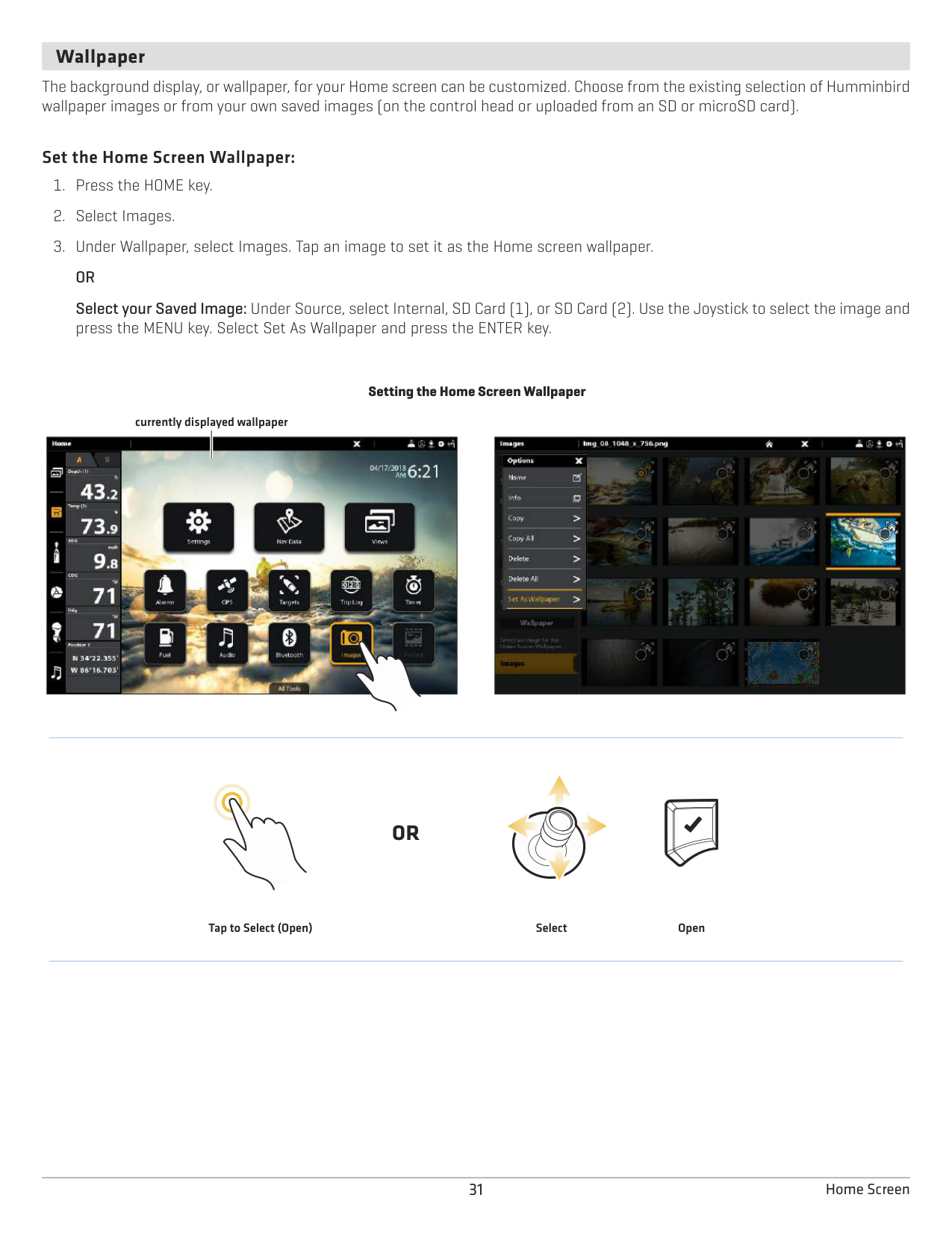
####### Wallpaper
The background display, or wallpaper, for your Home screen can be customized. Choose from the existing selection of Humminbird wallpaper images or from your own saved images (on the control head or uploaded from an SD or microSD card).
######### Set the Home Screen Wallpaper:
Setting the Home Screen Wallpaper currently displayed wallpaper
|| |---|

#### OR
Tap to Select (Open) Select Open
THE MENU SYSTEM
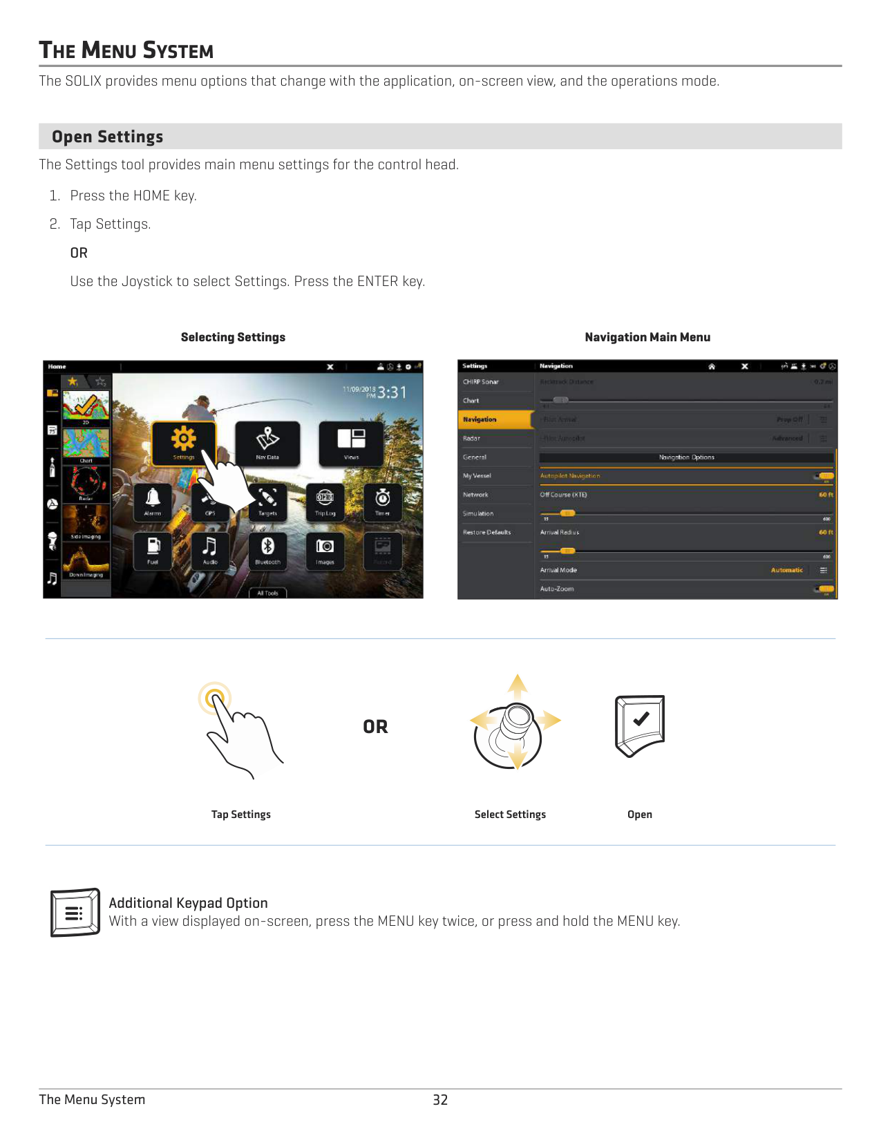
The SOLIX provides menu options that change with the application, on-screen view, and the operations mode.
####### Open Settings
The Settings tool provides main menu settings for the control head.
Selecting Settings
|
| |---|
Navigation Main Menu
|| |---|
#### OR
Tap Settings Select Settings Open
Additional Keypad Option With a view displayed on-screen, press the MENU key twice, or press and hold the MENU key.
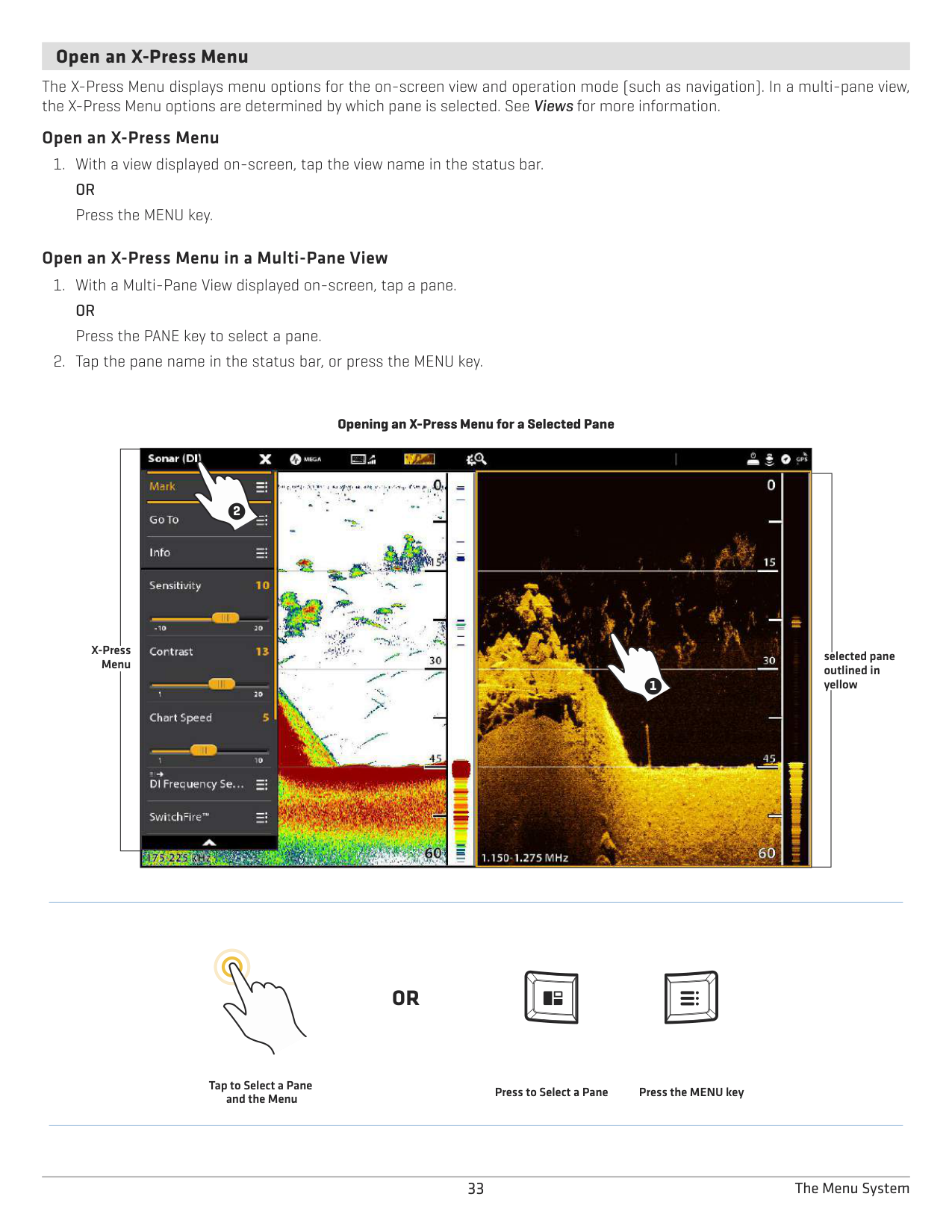
####### Open an X-Press Menu
The X-Press Menu displays menu options for the on-screen view and operation mode (such as navigation). In a multi-pane view, the X-Press Menu options are determined by which pane is selected. See Views for more information.
######### Open an X-Press Menu
######### Open an X-Press Menu in a Multi-Pane View
Opening an X-Press Menu for a Selected Pane
| |
2
1| | |---|---|---| | |
2
1| | | |
2
1| |
X-Press Menu
selected pane outlined in yellow
#### OR
Tap to Select a Pane and the Menu
Press to Select a Pane Press the MENU key
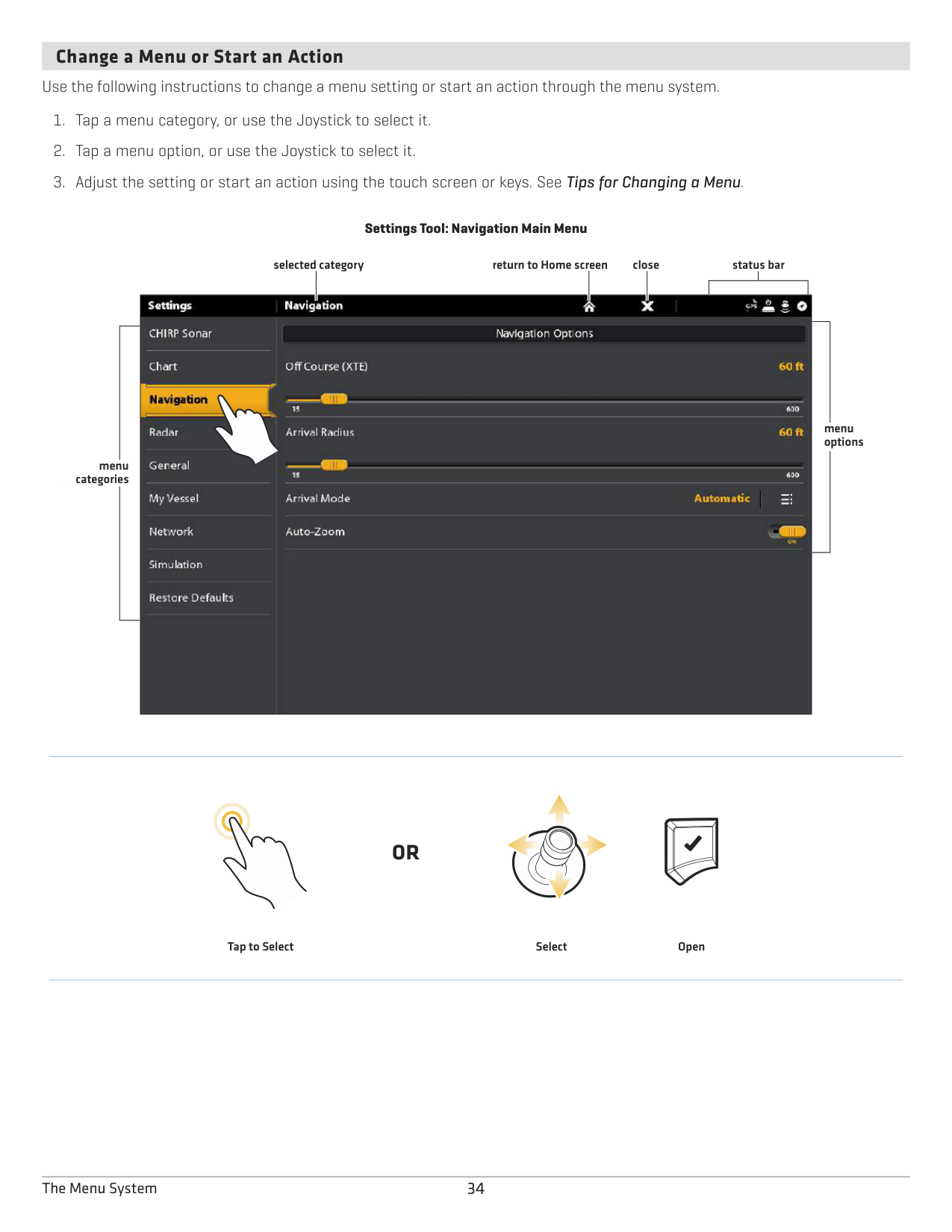
####### Change a Menu or Start an Action
Use the following instructions to change a menu setting or start an action through the menu system.
################# Settings Tool: Navigation Main Menu
selected category return to Home screen close
status bar

menu options
menu categories
#### OR
Tap to Select Select Open
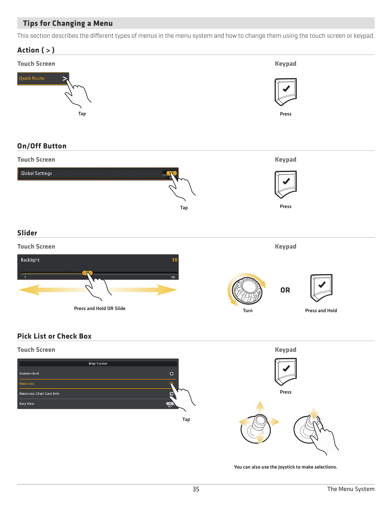
Tips for Changing a Menu This section describes the different types of menus in the menu system and how to change them using the touch screen or keypad. Action ( > ) Touch Screen Keypad

PressTap
On/Off Button Touch Screen Keypad

PressTap
Slider Touch Screen Keypad

######## OR
Press and Hold OR Slide
Turn Press and Hold
Pick List or Check Box Touch Screen Keypad

Tap
Press
You can also use the Joystick to make selections.
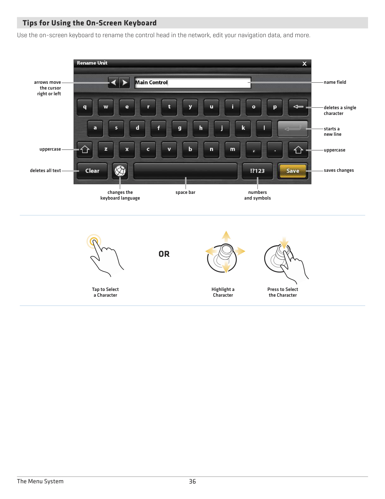
####### Tips for Using the On-Screen Keyboard
Use the on-screen keyboard to rename the control head in the network, edit your navigation data, and more.

name field
arrows move the cursor right or left
deletes a single character
starts a new line
uppercase
uppercase
saves changes
deletes all text
changes the keyboard language
space bar
numbers and symbols
Tap to Select a Character
#### OR
Highlight a Character
Press to Select the Character
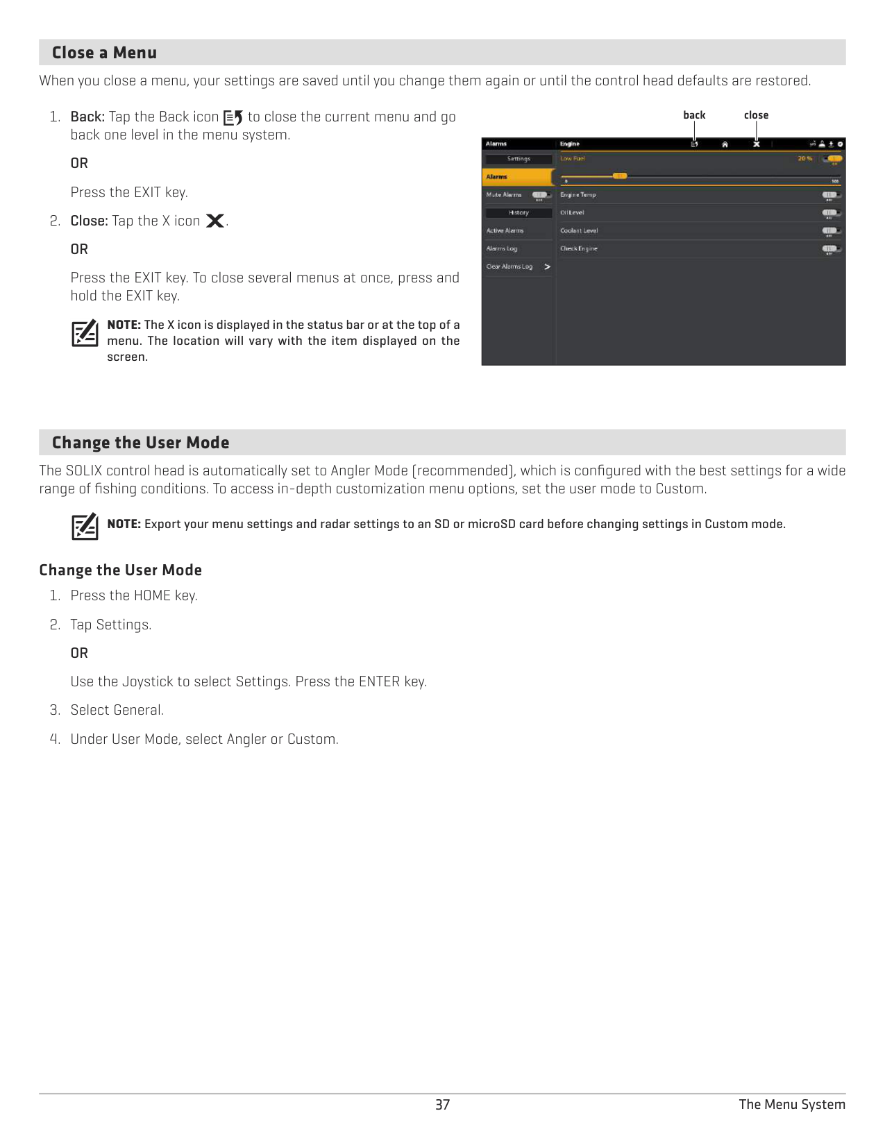
####### Close a Menu
When you close a menu, your settings are saved until you change them again or until the control head defaults are restored.
Press the EXIT key. To close several menus at once, press and hold the EXIT key.
NOTE: The X icon is displayed in the status bar or at the top of a menu. The location will vary with the item displayed on the screen.
closeback
| | | | |---|---|---| ||||
####### Change the User Mode
The SOLIX control head is automatically set to Angler Mode (recommended), which is configured with the best settings for a wide range of fishing conditions. To access in-depth customization menu options, set the user mode to Custom.
NOTE: Export your menu settings and radar settings to an SD or microSD card before changing settings in Custom mode.
######### Change the User Mode
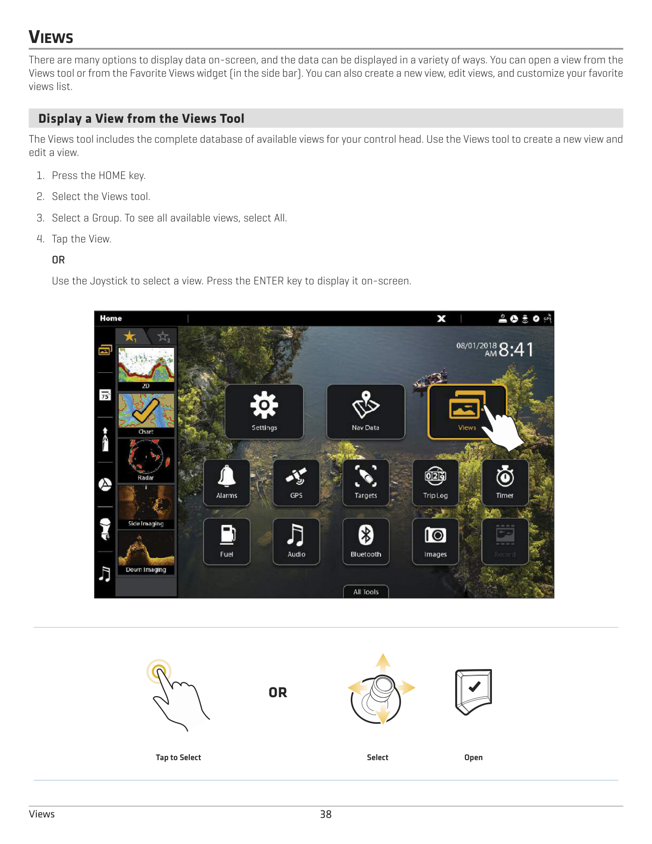
VIEWS
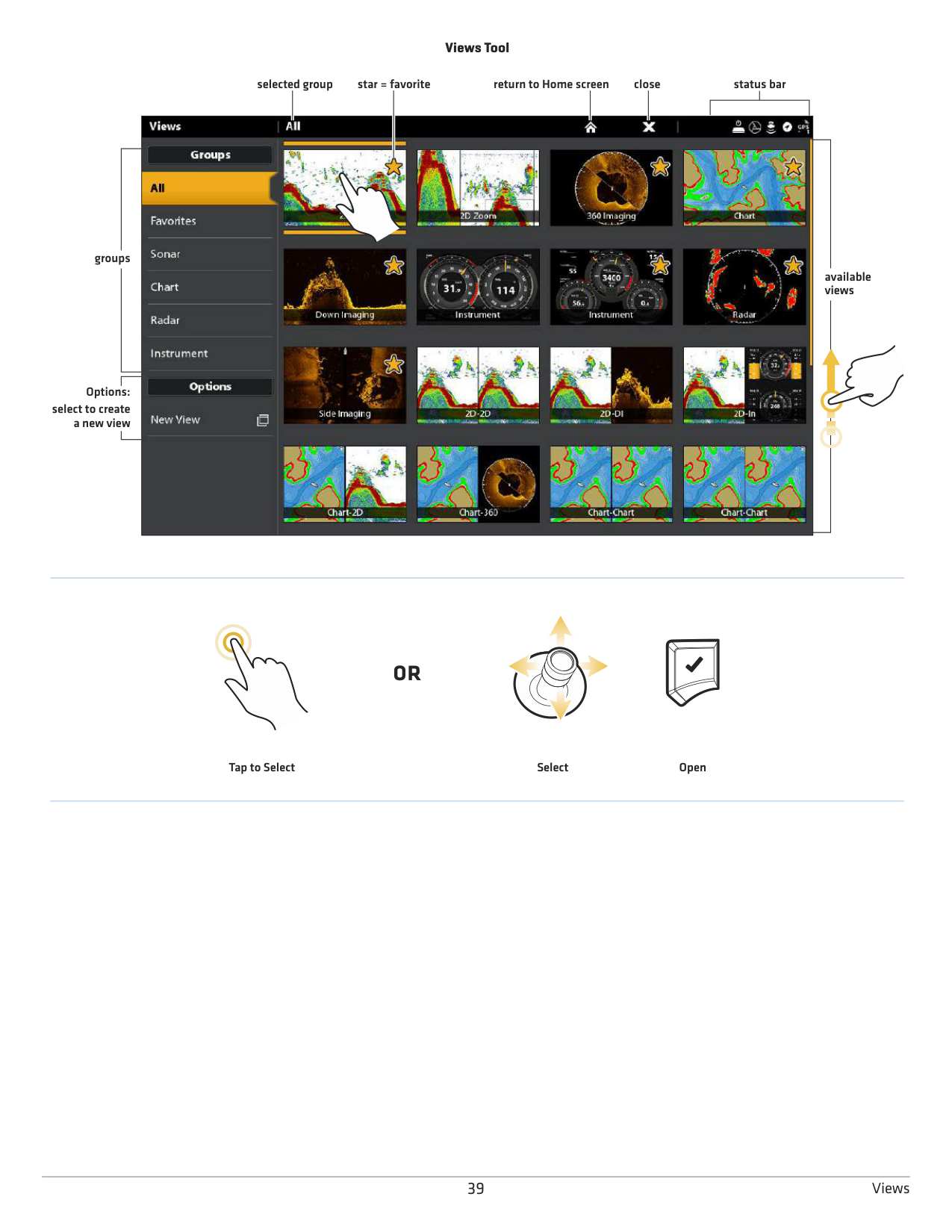
There are many options to display data on-screen, and the data can be displayed in a variety of ways. You can open a view from the Views tool or from the Favorite Views widget (in the side bar). You can also create a new view, edit views, and customize your favorite views list.
####### Display a View from the Views Tool
The Views tool includes the complete database of available views for your control head. Use the Views tool to create a new view and edit a view.
|
| |---|
#### OR
Tap to Select Select Open
################# Views Tool
selected group return to Home screen close
status bar
star = favorite
| | | |---|---| | | |

groups
available views
Options: select to create a new view
#### OR
Tap to Select Select Open
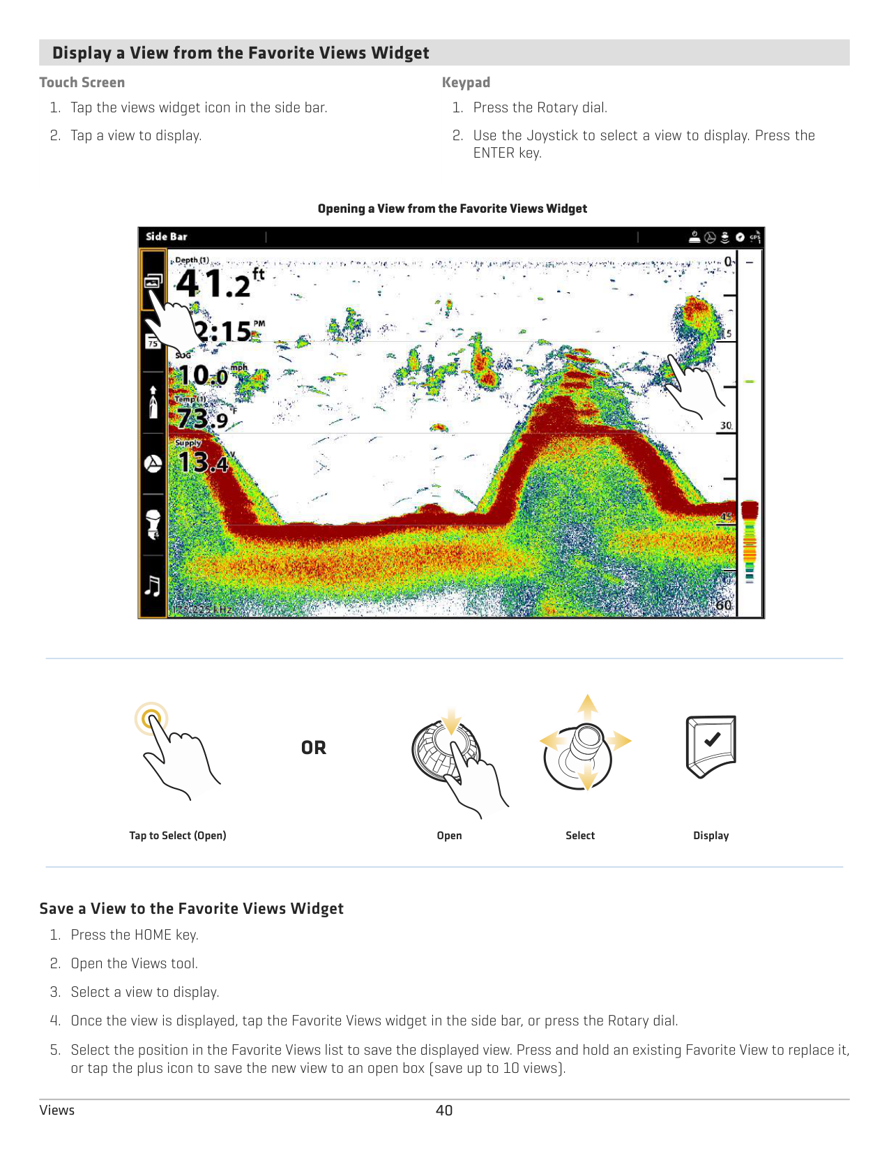
####### Display a View from the Favorite Views Widget
############ Touch Screen
############ Keypad
################# Opening a View from the Favorite Views Widget
|
| |---|
#### OR
Tap to Select (Open) Select Display
Open
######### Save a View to the Favorite Views Widget
EDIT THE ON-SCREEN VIEW
You can edit a view from the Views tool or from the view that is displayed on the screen. When you edit a view from on-screen, the View Options menu provides additional editing options.
Global: To appy changes to all views in the same category, turn on Global. To apply changes to the on-screen view exclusively, turn off Global.

The menu options in Data bar, Options, Preferences, and Overlays change to match the on-screen view. The menu options are described in detail in each section. For example, for Sonar Overlay settings, see Sonar Overview.
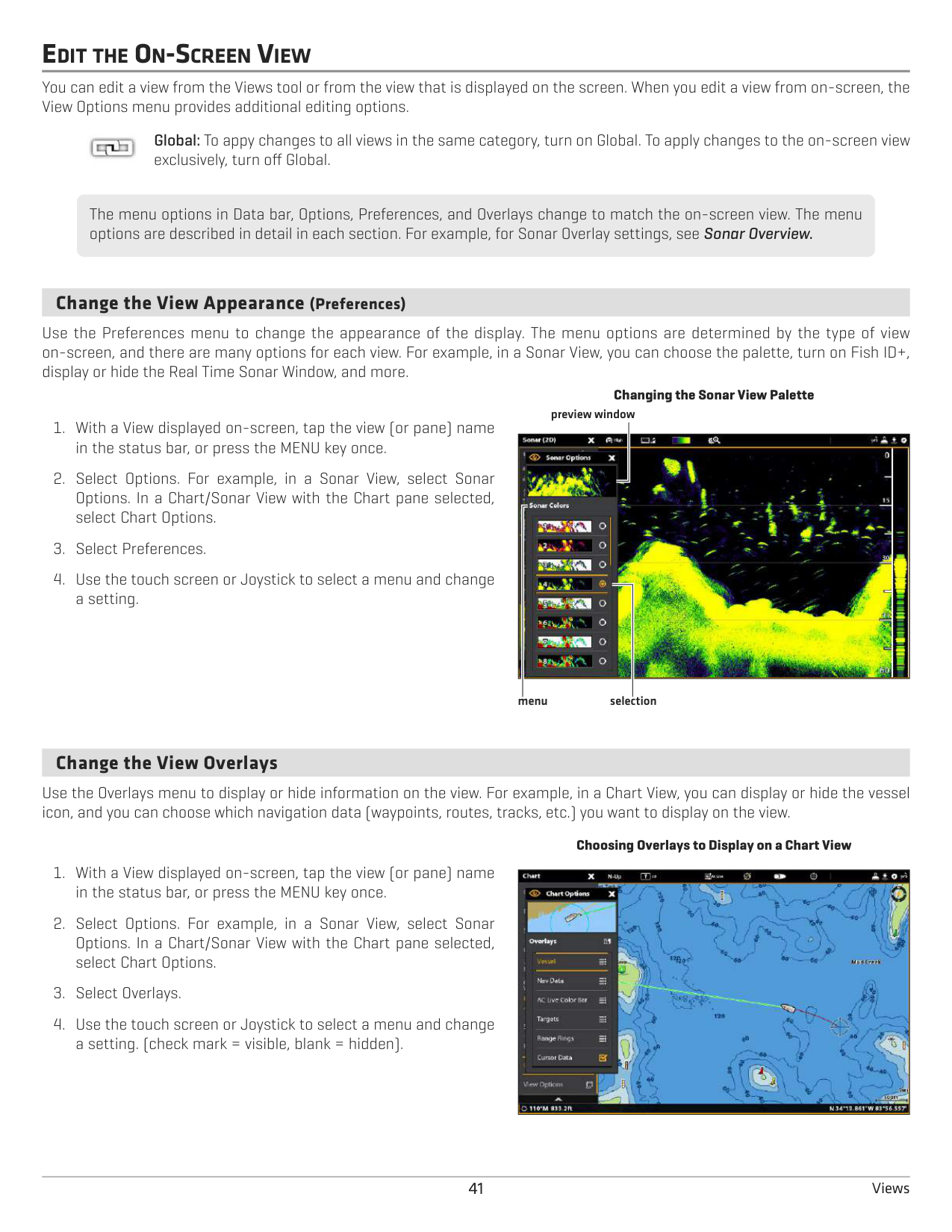
####### Change the View Appearance (Preferences)
Use the Preferences menu to change the appearance of the display. The menu options are determined by the type of view on-screen, and there are many options for each view. For example, in a Sonar View, you can choose the palette, turn on Fish ID+, display or hide the Real Time Sonar Window, and more.
Changing the Sonar View Palette
preview window

selectionmenu
####### Change the View Overlays
Use the Overlays menu to display or hide information on the view. For example, in a Chart View, you can display or hide the vessel icon, and you can choose which navigation data (waypoints, routes, tracks, etc.) you want to display on the view.
################# Choosing Overlays to Display on a Chart View
|| |---|
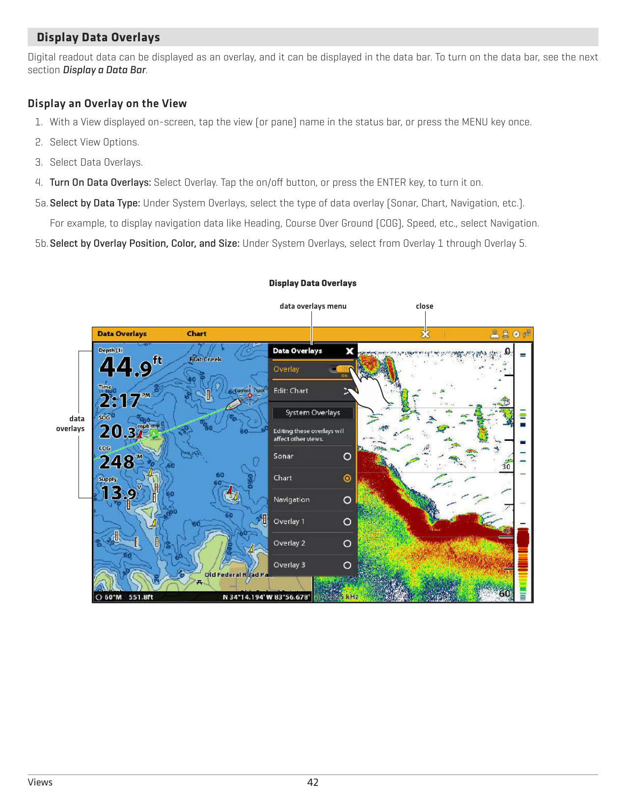
####### Display Data Overlays
Digital readout data can be displayed as an overlay, and it can be displayed in the data bar. To turn on the data bar, see the next section Display a Data Bar.
######### Display an Overlay on the View
5b.Select by Overlay Position, Color, and Size: Under System Overlays, select from Overlay 1 through Overlay 5.
################# Display Data Overlays
data overlays menu
close

data overlays
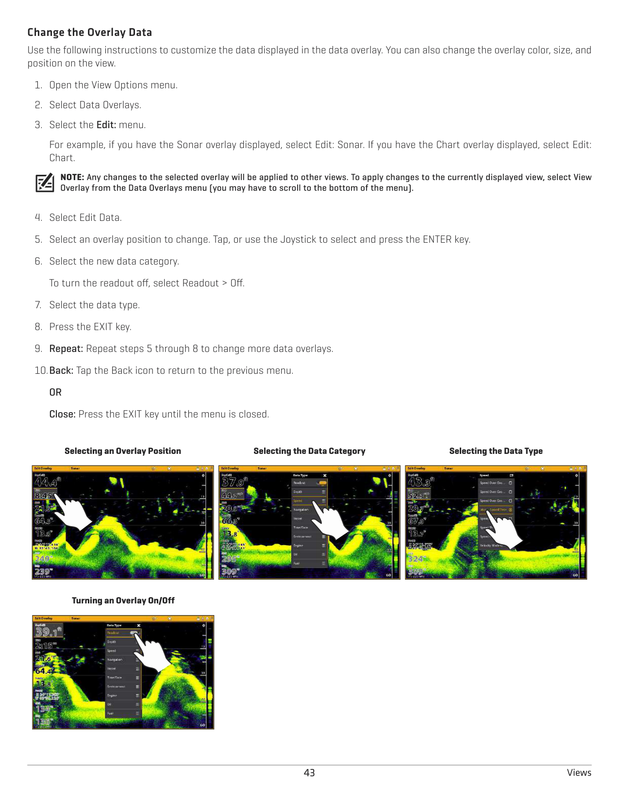
######### Change the Overlay Data
Use the following instructions to customize the data displayed in the data overlay. You can also change the overlay color, size, and position on the view.
For example, if you have the Sonar overlay displayed, select Edit: Sonar. If you have the Chart overlay displayed, select Edit: Chart.
NOTE: Any changes to the selected overlay will be applied to other views. To apply changes to the currently displayed view, select View Overlay from the Data Overlays menu (you may have to scroll to the bottom of the menu).
Selecting an Overlay Position
Selecting the Data Category
Selecting the Data Type
|
| |---|
|
| |---|
|
| |---|
Turning an Overlay On/Off
|
| |---|
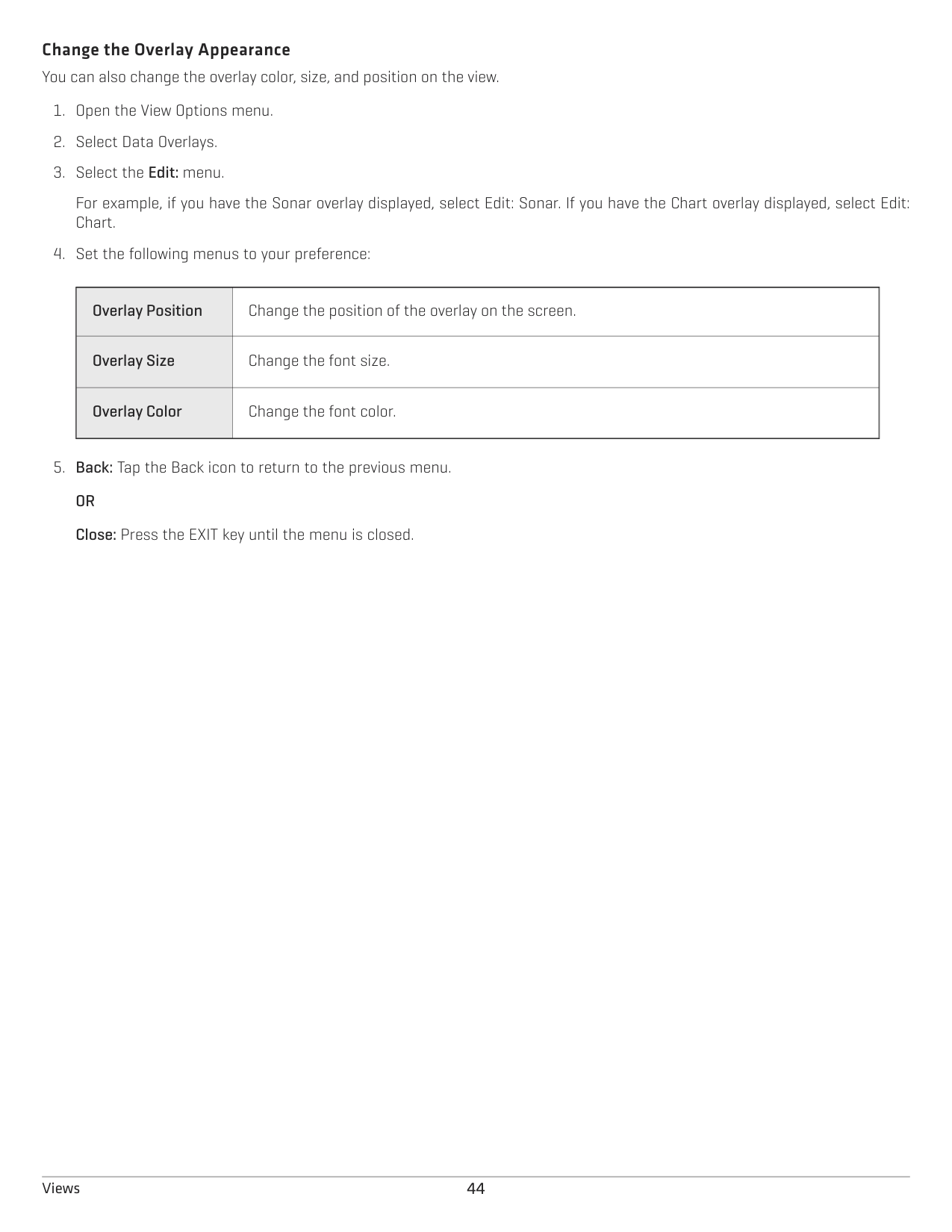
Change the Overlay Appearance You can also change the overlay color, size, and position on the view.
For example, if you have the Sonar overlay displayed, select Edit: Sonar. If you have the Chart overlay displayed, select Edit: Chart.
|Overlay Position|Change the position of the overlay on the screen.
| |---|---| |Overlay Size
|Change the font size.| |Overlay Color|Change the font color.|
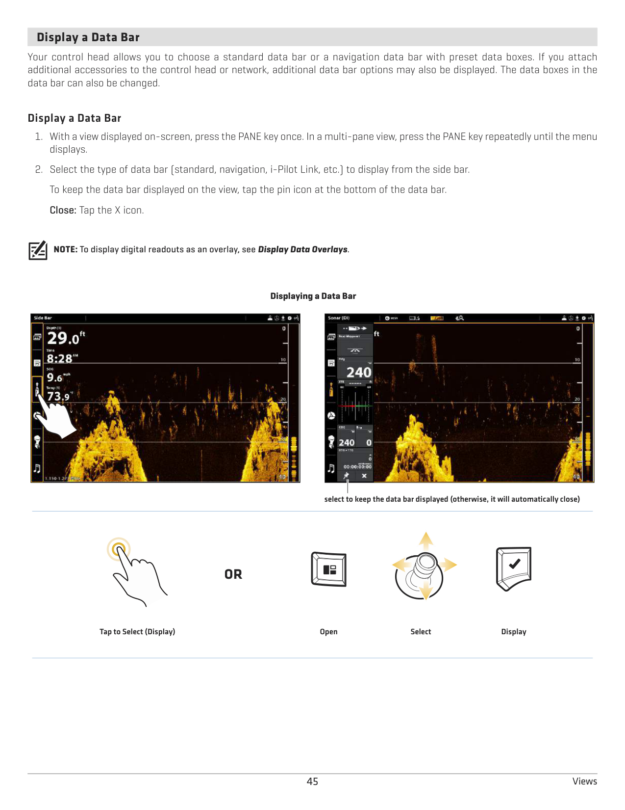
####### Display a Data Bar
Your control head allows you to choose a standard data bar or a navigation data bar with preset data boxes. If you attach additional accessories to the control head or network, additional data bar options may also be displayed. The data boxes in the data bar can also be changed.
######### Display a Data Bar
NOTE: To display digital readouts as an overlay, see Display Data Overlays.
################# Displaying a Data Bar
|
| |---|
||| |---|---| | | |
select to keep the data bar displayed (otherwise, it will automatically close)
#### OR
DisplaySelectOpenTap to Select (Display)
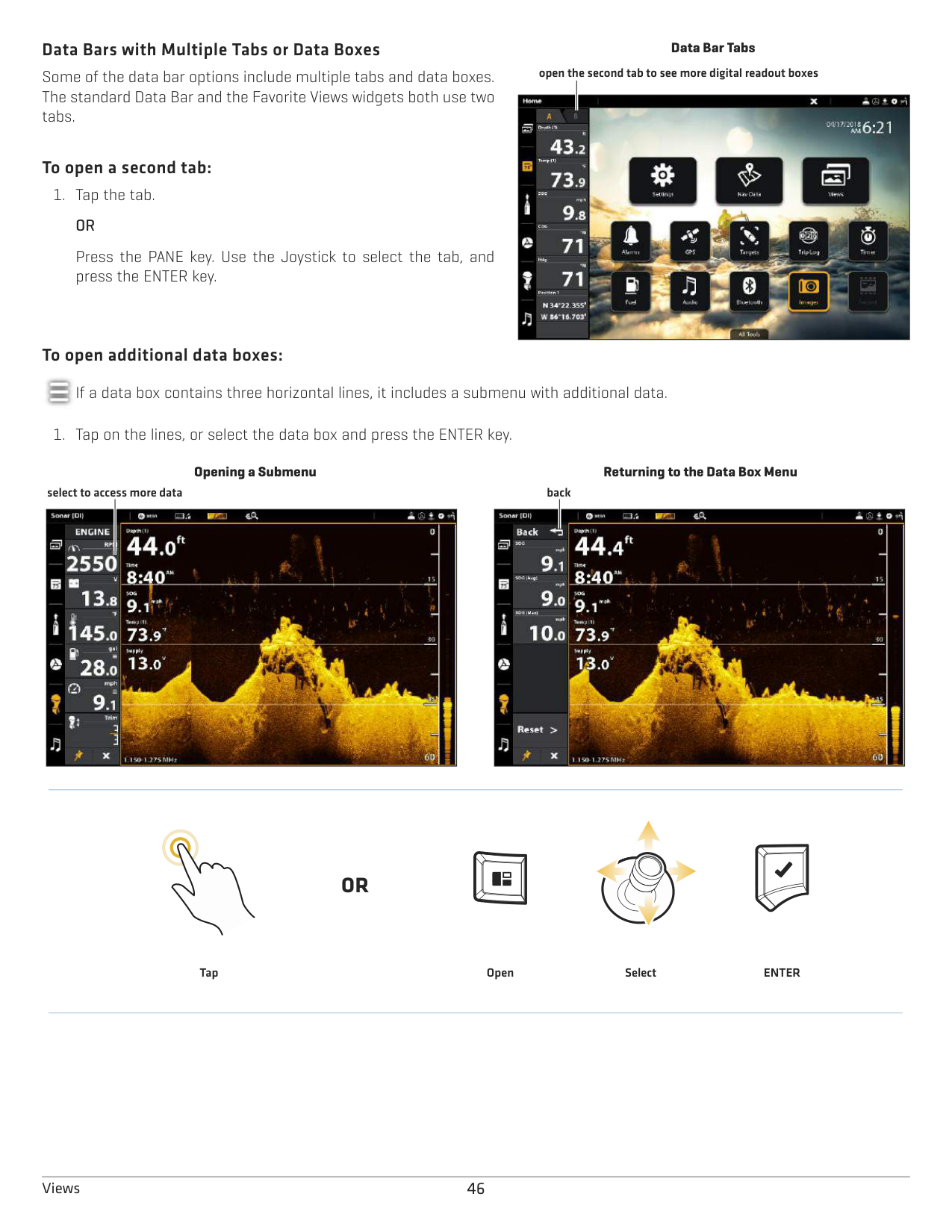
######### Data Bars with Multiple Tabs or Data Boxes
Some of the data bar options include multiple tabs and data boxes. The standard Data Bar and the Favorite Views widgets both use two tabs.
######### To open a second tab:
############# OR
Press the PANE key. Use the Joystick to select the tab, and press the ENTER key.
######### To open additional data boxes:
Data Bar Tabs
open the second tab to see more digital readout boxes


If a data box contains three horizontal lines, it includes a submenu with additional data.
Opening a Submenu Returning to the Data Box Menu backselect to access more data


#### OR
ENTERSelectOpenTap
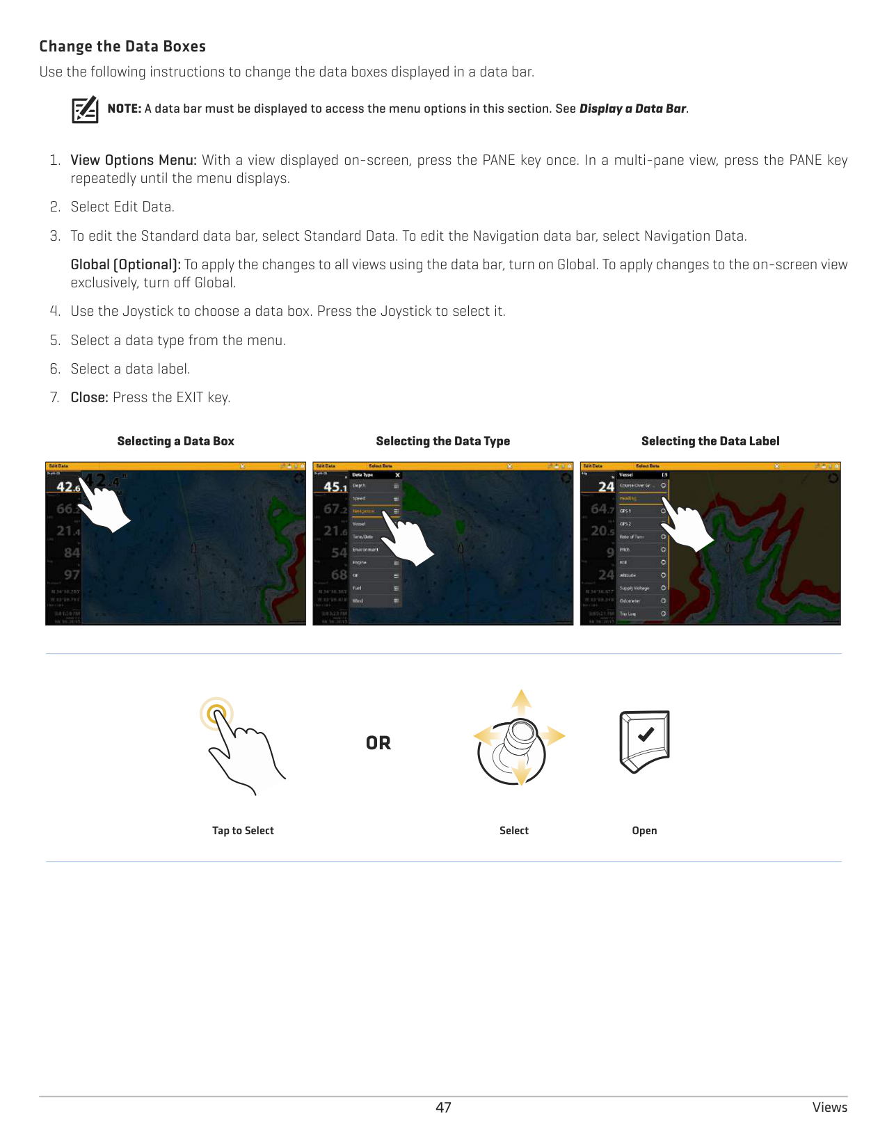
Change the Data Boxes Use the following instructions to change the data boxes displayed in a data bar.
NOTE: A data bar must be displayed to access the menu options in this section. See Display a Data Bar.
Global (Optional): To apply the changes to all views using the data bar, turn on Global. To apply changes to the on-screen view exclusively, turn off Global.
Selecting a Data Box
Selecting the Data Type
Selecting the Data Label
|
| |---|
|
| |---|
|
| |---|
#### OR
Tap to Select Select Open
######### Understand Data Box Digital Readouts
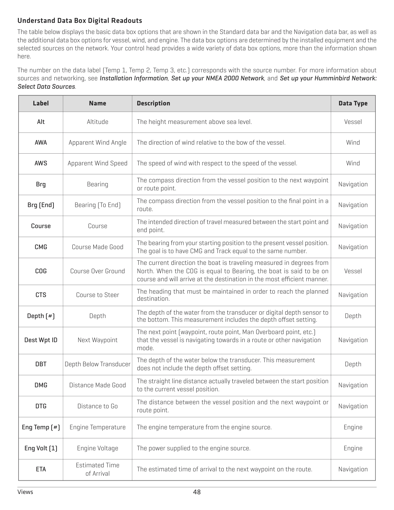
The table below displays the basic data box options that are shown in the Standard data bar and the Navigation data bar, as well as the additional data box options for vessel, wind, and engine. The data box options are determined by the installed equipment and the selected sources on the network. Your control head provides a wide variety of data box options, more than the information shown here.
The number on the data label (Temp 1, Temp 2, Temp 3, etc.) corresponds with the source number. For more information about sources and networking, see Installation Information, Set up your NMEA 2000 Network, and Set up your Humminbird Network: Select Data Sources.
|Label|Name|Description|Data Type
| |---|---|---|---| |Alt
|Altitude|The height measurement above sea level.|Vessel| |AWA|Apparent Wind Angle
|The direction of wind relative to the bow of the vessel.|Wind| |AWS|Apparent Wind Speed
|The speed of wind with respect to the speed of the vessel.|Wind| |Brg|Bearing|The compass direction from the vessel position to the next waypoint or route point.|Navigation
| |Brg (End)|Bearing (To End)|The compass direction from the vessel position to the final point in a route.
|Navigation| |Course
|Course|The intended direction of travel measured between the start point and end point.|Navigation| |CMG|Course Made Good
|The bearing from your starting position to the present vessel position. The goal is to have CMG and Track equal to the same number.|Navigation| |COG
|Course Over Ground|The current direction the boat is traveling measured in degrees from North. When the COG is equal to Bearing, the boat is said to be on course and will arrive at the destination in the most efficient manner.|Vessel| |CTS|Course to Steer|The heading that must be maintained in order to reach the planned destination.|Navigation
| |Depth (#)|Depth|The depth of the water from the transducer or digital depth sensor to the bottom. This measurement includes the depth offset setting.|Depth
| |Dest Wpt ID|Next Waypoint
|The next point (waypoint, route point, Man Overboard point, etc.) that the vessel is navigating towards in a route or other navigation mode.|Navigation
| |DBT
|Depth Below Transducer|The depth of the water below the transducer. This measurement does not include the depth offset setting.|Depth|
|DMG
|Distance Made Good|The straight line distance actually traveled between the start position to the current vessel position.|Navigation| |DTG|Distance to Go|The distance between the vessel position and the next waypoint or route point.|Navigation
| |Eng Temp (#)|Engine Temperature|The engine temperature from the engine source.
|Engine| |Eng Volt (1)|Engine Voltage
|The power supplied to the engine source.|Engine| |ETA|Estimated Time of Arrival|The estimated time of arrival to the next waypoint on the route.|Navigation|
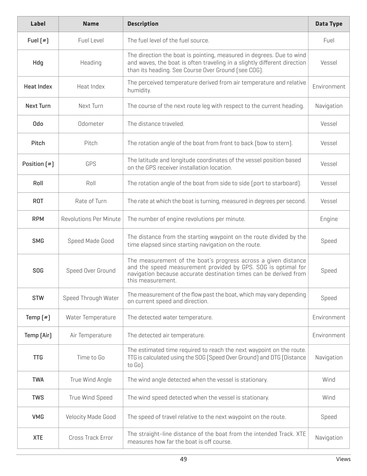
|Label
|Name|Description|Data Type| |---|---|---|---| |Fuel (#)|Fuel Level|The fuel level of the fuel source.
|Fuel| |Hdg|Heading|The direction the boat is pointing, measured in degrees. Due to wind and waves, the boat is often traveling in a slightly different direction than its heading. See Course Over Ground (see COG).
|Vessel| |Heat Index
|Heat Index|The perceived temperature derived from air temperature and relative humidity.|Environment| |Next Turn|Next Turn|The course of the next route leg with respect to the current heading.
|Navigation| |Odo|Odometer
|The distance traveled.|Vessel| |Pitch|Pitch
|The rotation angle of the boat from front to back (bow to stern).|Vessel| |Position (#)
|GPS|The latitude and longitude coordinates of the vessel position based on the GPS receiver installation location.|Vessel| |Roll
|Roll|The rotation angle of the boat from side to side (port to starboard).|Vessel| |ROT|Rate of Turn|The rate at which the boat is turning, measured in degrees per second.
|Vessel| |RPM|Revolutions Per Minute|The number of engine revolutions per minute.
|Engine| |SMG|Speed Made Good
|The distance from the starting waypoint on the route divided by the time elapsed since starting navigation on the route.|Speed| |SOG|Speed Over Ground
|The measurement of the boat’s progress across a given distance and the speed measurement provided by GPS. SOG is optimal for navigation because accurate destination times can be derived from this measurement.
|Speed| |STW
|Speed Through Water|The measurement of the flow past the boat, which may vary depending on current speed and direction.|Speed| |Temp (#)|Water Temperature
|The detected water temperature.|Environment| |Temp (Air)|Air Temperature
|The detected air temperature.|Environment| |TTG|Time to Go
|The estimated time required to reach the next waypoint on the route. TTG is calculated using the SOG (Speed Over Ground) and DTG (Distance to Go).|Navigation| |TWA
|True Wind Angle|The wind angle detected when the vessel is stationary.|Wind| |TWS|True Wind Speed|The wind speed detected when the vessel is stationary.
|Wind| |VMG
|Velocity Made Good|The speed of travel relative to the next waypoint on the route.|Speed| |XTE|Cross Track Error|The straight-line distance of the boat from the intended Track. XTE measures how far the boat is off course.|Navigation|
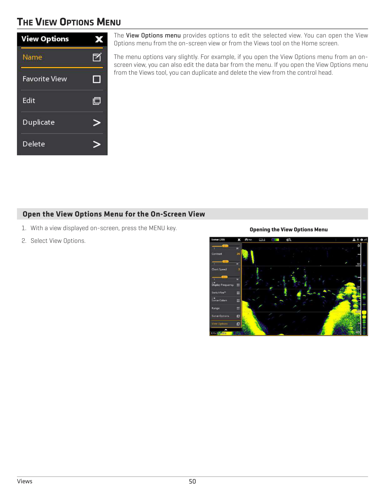
THE VIEW OPTIONS MENU
The View Options menu provides options to edit the selected view. You can open the View Options menu from the on-screen view or from the Views tool on the Home screen.
|| |---|
The menu options vary slightly. For example, if you open the View Options menu from an onscreen view, you can also edit the data bar from the menu. If you open the View Options menu from the Views tool, you can duplicate and delete the view from the control head.
####### Open the View Options Menu for the On-Screen View
Opening the View Options Menu
|| |---|
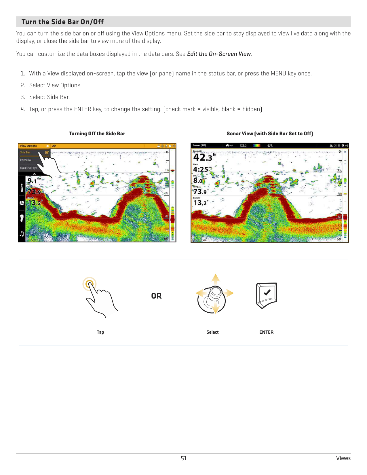
####### Turn the Side Bar On/Off
You can turn the side bar on or off using the View Options menu. Set the side bar to stay displayed to view live data along with the display, or close the side bar to view more of the display.
You can customize the data boxes displayed in the data bars. See Edit the On-Screen View.
Turning Off the Side Bar
|
| |---|
Sonar View (with Side Bar Set to Off)
|| |---|
#### OR
Tap Select ENTER
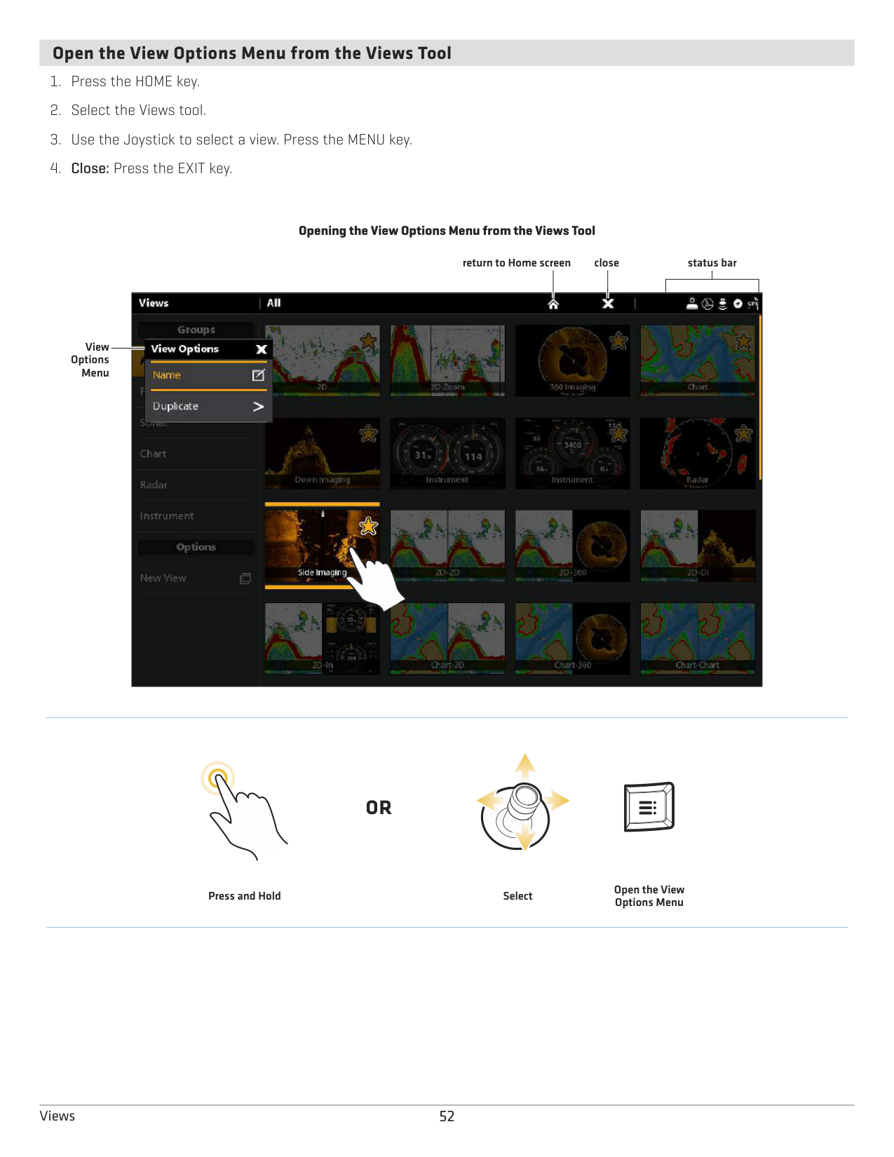
####### Open the View Options Menu from the Views Tool
################# Opening the View Options Menu from the Views Tool
return to Home screen close status bar

View Options
Menu
#### OR
Press and Hold Select
Open the View Options Menu
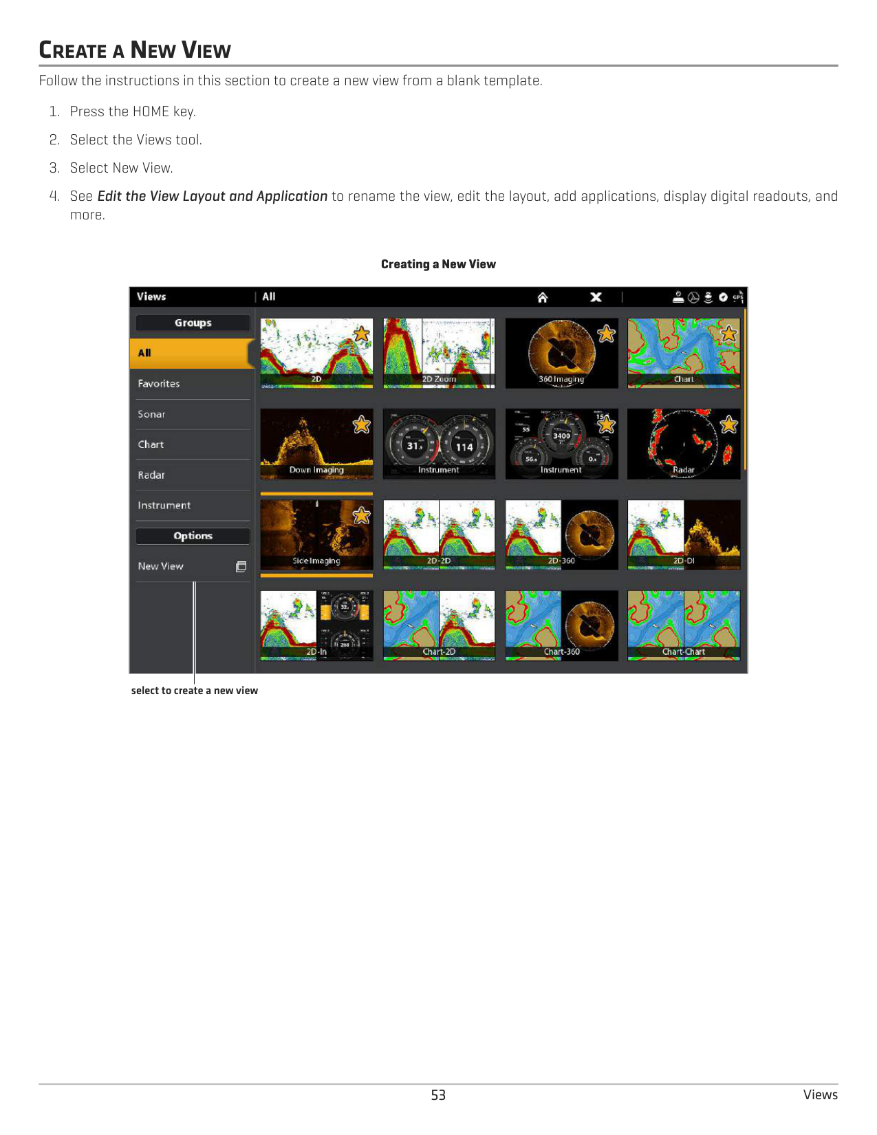
CREATE A NEW VIEW
Follow the instructions in this section to create a new view from a blank template.
Creating a New View

select to create a new view
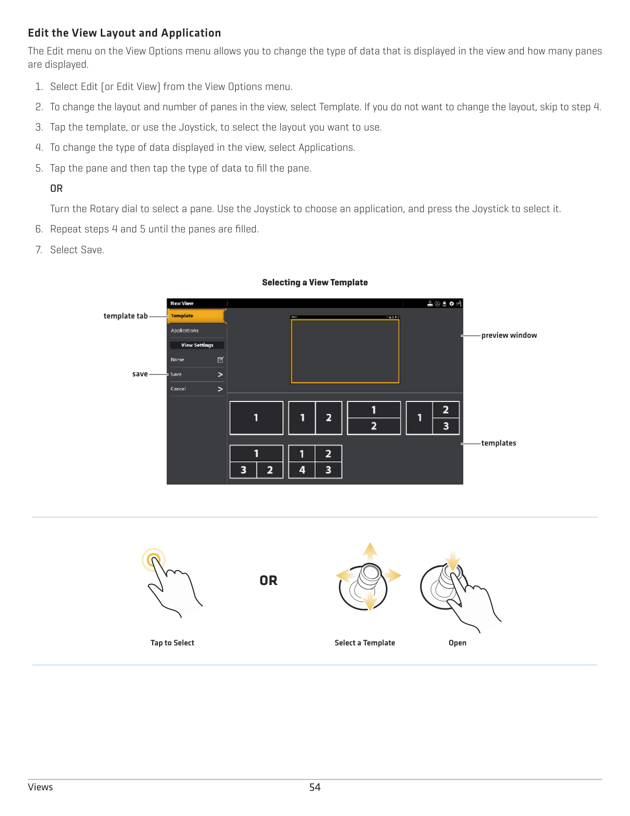
######### Edit the View Layout and Application
The Edit menu on the View Options menu allows you to change the type of data that is displayed in the view and how many panes are displayed.
################# Selecting a View Template
| || | |---|---|---| | || | | || | | || | | || |
template tab
preview window
save
templates
#### OR
OpenSelect a TemplateTap to Select
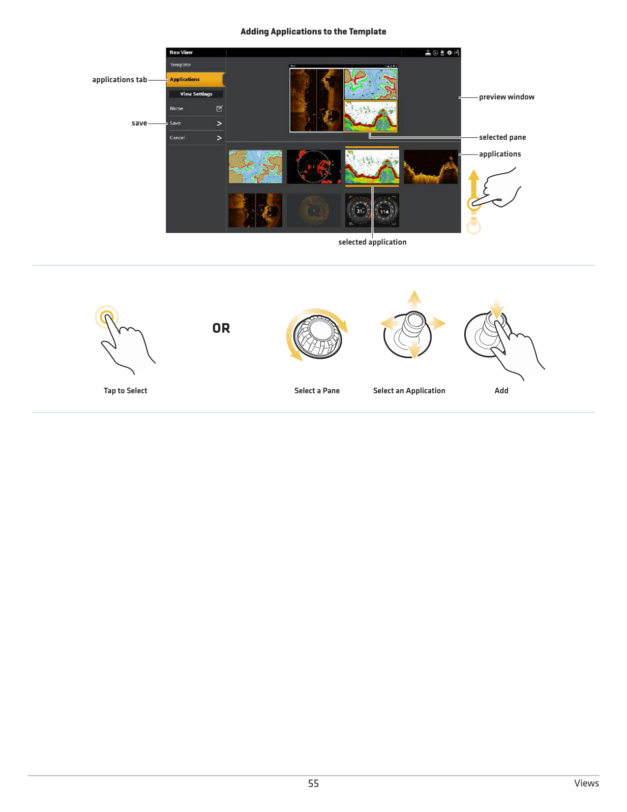
################# Adding Applications to the Template

applications tab
preview window
save
selected pane
applications
selected application
#### OR
Tap to Select Select a Pane Select an Application Add
######### Change the View Name (Views Tool)
Duplicate the Selected View (Views Tool) When you duplicate a view, the control head creates a copy. You can rename the new view, edit it, and change the layout.
######### Delete the Selected View (Views Tool)
SET UP AN INSTRUMENT VIEW
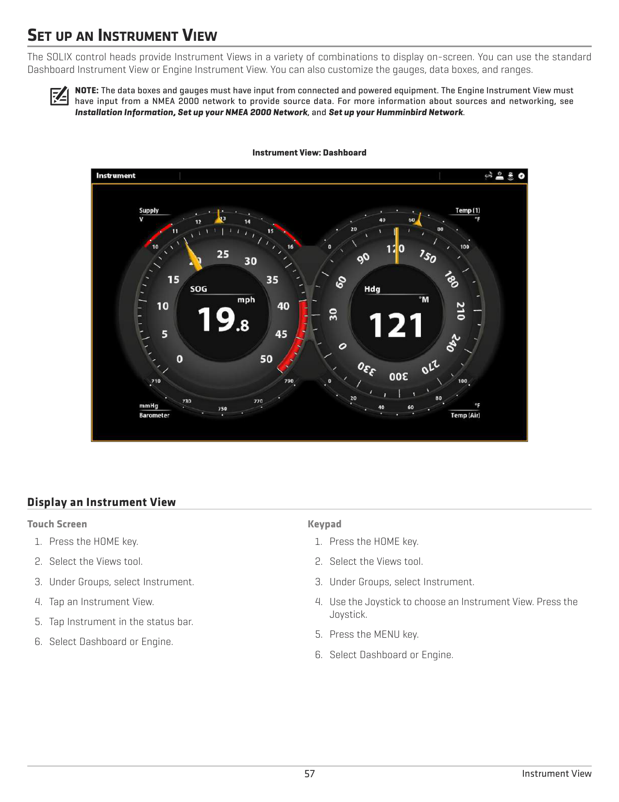
The SOLIX control heads provide Instrument Views in a variety of combinations to display on-screen. You can use the standard Dashboard Instrument View or Engine Instrument View. You can also customize the gauges, data boxes, and ranges.
NOTE: The data boxes and gauges must have input from connected and powered equipment. The Engine Instrument View must have input from a NMEA 2000 network to provide source data. For more information about sources and networking, see Installation Information, Set up your NMEA 2000 Network, and Set up your Humminbird Network.
Instrument View: Dashboard
||
|---|
Display an Instrument View
############ Touch Screen
############ Keypad
57 Instrument View
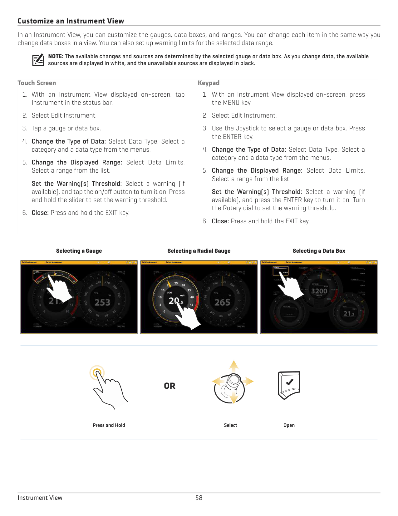
######## Customize an Instrument View
In an Instrument View, you can customize the gauges, data boxes, and ranges. You can change each item in the same way you change data boxes in a view. You can also set up warning limits for the selected data range.
NOTE: The available changes and sources are determined by the selected gauge or data box. As you change data, the available sources are displayed in white, and the unavailable sources are displayed in black.
############ Touch Screen
############ Keypad
Set the Warning(s) Threshold: Select a warning (if available), and tap the on/off button to turn it on. Press and hold the slider to set the warning threshold.
Set the Warning(s) Threshold: Select a warning (if available), and press the ENTER key to turn it on. Turn the Rotary dial to set the warning threshold.
Selecting a Gauge
Selecting a Radial Gauge
Selecting a Data Box
|
| |---|
|
| |---|
|
| |---|
#### OR
Press and Hold Select Open
58Instrument View
CHART OVERVIEW
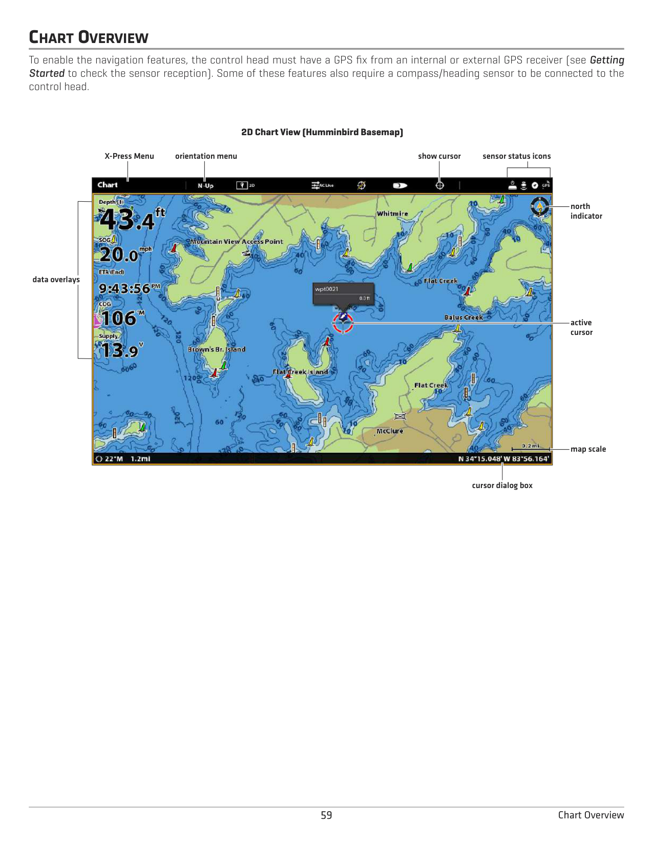
To enable the navigation features, the control head must have a GPS fix from an internal or external GPS receiver (see Getting Started to check the sensor reception). Some of these features also require a compass/heading sensor to be connected to the control head.
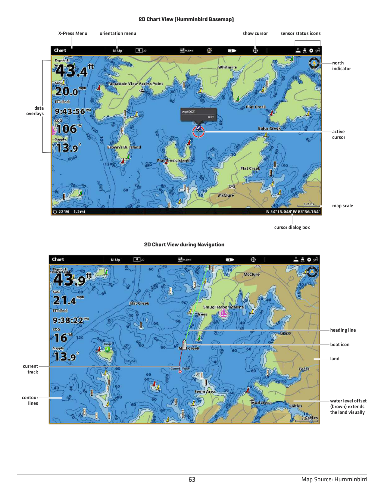
2D Chart View (Humminbird Basemap)
X-Press Menu
orientation menu show cursor sensor status icons

north indicator
data overlays
active cursor
map scale
cursor dialog box
59 Chart Overview
####### Map Source Overview
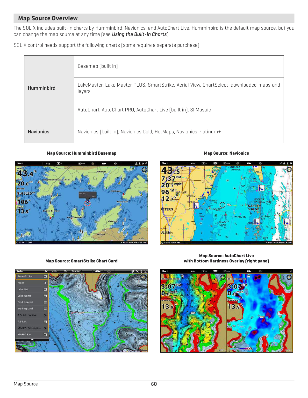
The SOLIX includes built-in charts by Humminbird, Navionics, and AutoChart Live. Humminbird is the default map source, but you can change the map source at any time (see Using the Built-in Charts).
SOLIX control heads support the following charts (some require a separate purchase):
|Humminbird|Basemap (built in)
| |---|---| |Humminbird|LakeMaster, Lake Master PLUS, SmartStrike, Aerial View, ChartSelect-downloaded maps and layers
|
|Humminbird|AutoChart, AutoChart PRO, AutoChart Live (built in), SI Mosaic
| |Navionics|Navionics (built in), Navionics Gold, HotMaps, Navionics Platinum+|
Map Source: Humminbird Basemap
|| |---|
Map Source: Navionics
|| |---|
Map Source: SmartStrike Chart Card
|| |---|
Map Source: AutoChart Live with Bottom Hardness Overlay (right pane)
|| |---|
60Map Source
######### How the Map Source Affects your Chart View Operations
The selected map source influences the menu system. When you change the map source, the menu options for the Chart Views change, allowing you to add navigation data, shading, or alarms.
Install an SD or microSD chart card (separate purchase required) with specific maps or chart layers to add more detail to your Chart views (see Using Chart Cards).
NOTE: Visit our Web site at humminbird.com for the latest compatibility information.
####### Using Built-in Charts
The SOLIX includes built-in charts by Humminbird and Navionics. Display the built-in charts and add data overlays and map layers to customize your Chart view.
######### Humminbird Charts
When Humminbird is selected as the map source, you can use the system defaults, or you can set the menu settings to your preference. You can use the built-in Humminbird Basemap or a Humminbird SD Chart Card (see Using Chart Cards).
|Humminbird Chart Cards*|Select the Humminbird Chart Card to display the map data from the installed chart card.
*Required Equipment: Humminbird chart card. See Using Chart Cards for more information.
| |---|---| |Humminbird Basemap|Select the Humminbird Basemap to display contour data and navigation aids, including hazards, buoys, daymarkers, marinas, and other points of interest. The Basemap also shows depth markings and spot soundings (for coastal areas).|
Chart Cards: Set the following menus to your preference:
|Humminbird: Chart Card Info|Select this menu to review the information about the installed Humminbird chart card.
|
|---|---| |Water Level Offset
|Adjust the setting to change the water level read by the control head. For example, if the lake is down 5 feet, set the Water Level Offset setting to -5. The displayed numbers on the Contour Lines will adjust from the Water Level Offset setting, and the water level offset will be highlighted in brown to extend the land visually on the display.
To apply depth colors, depth highlight range, etc., go to the Chart X-Press Menu > Chart Options > Humminbird Settings. See Customize the Humminbird Chart Display for more information.|
Humminbird Basemap: Set the following menus to your preference:
|Text Size|Adjust the setting to change the size of font used in the Basemap.
| |---|---| |Symbol Size|Adjust the setting to change the size of the symbols used in the Basemap.|
62Map Source: Humminbird
################# 2D Chart View (Humminbird Basemap)
X-Press Menu
orientation menu show cursor sensor status icons

north indicator
data overlays
active cursor
map scale
cursor dialog box
################# 2D Chart View during Navigation

heading line
boat icon
land
current track
contour lines
water level offset (brown) extends the land visually
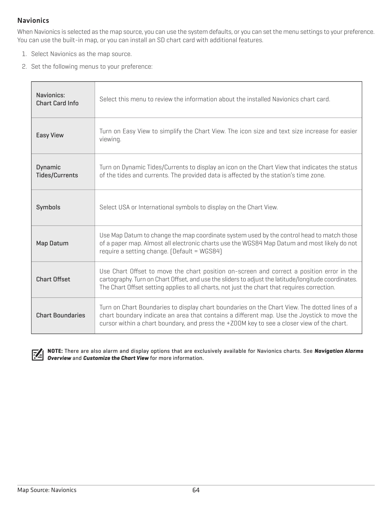
######### Navionics
When Navionics is selected as the map source, you can use the system defaults, or you can set the menu settings to your preference. You can use the built-in map, or you can install an SD chart card with additional features.
|Navionics: Chart Card Info|Select this menu to review the information about the installed Navionics chart card.
|
|---|---| |Easy View
|Turn on Easy View to simplify the Chart View. The icon size and text size increase for easier viewing.| |Dynamic Tides/Currents|Turn on Dynamic Tides/Currents to display an icon on the Chart View that indicates the status of the tides and currents. The provided data is affected by the station’s time zone.
| |Symbols|Select USA or International symbols to display on the Chart View.
| |Map Datum
|Use Map Datum to change the map coordinate system used by the control head to match those of a paper map. Almost all electronic charts use the WGS84 Map Datum and most likely do not require a setting change. (Default = WGS84)| |Chart Offset
|Use Chart Offset to move the chart position on-screen and correct a position error in the cartography. Turn on Chart Offset, and use the sliders to adjust the latitude/longitude coordinates. The Chart Offset setting applies to all charts, not just the chart that requires correction.| |Chart Boundaries
|Turn on Chart Boundaries to display chart boundaries on the Chart View. The dotted lines of a chart boundary indicate an area that contains a different map. Use the Joystick to move the cursor within a chart boundary, and press the +ZOOM key to see a closer view of the chart.|
NOTE: There are also alarm and display options that are exclusively available for Navionics charts. See Navigation Alarms Overview and Customize the Chart View for more information.
64Map Source: Navionics
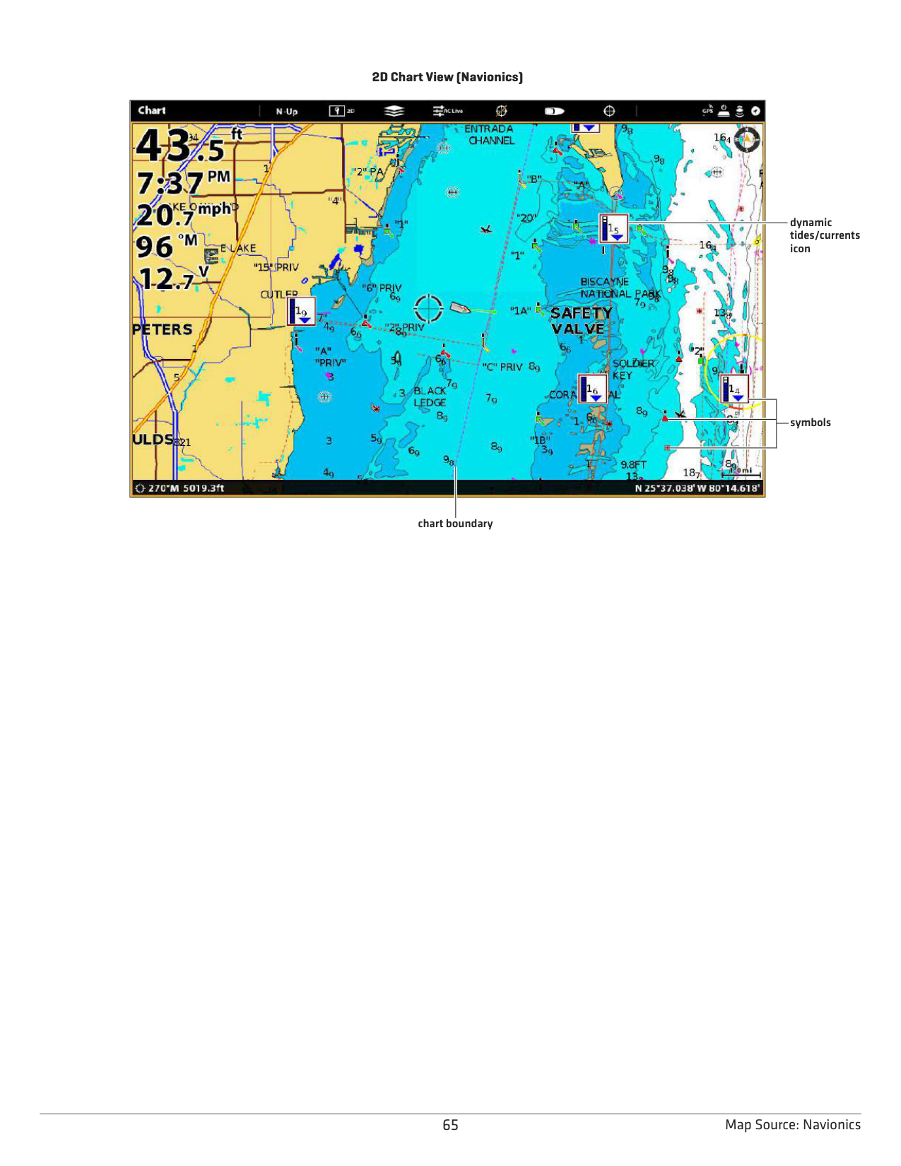
2D Chart View (Navionics)

dynamic tides/currents icon
symbols
chart boundary
65 Map Source: Navionics
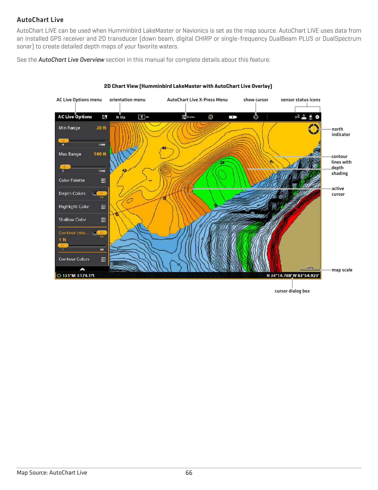
######### AutoChart Live
AutoChart LIVE can be used when Humminbird LakeMaster or Navionics is set as the map source. AutoChart LIVE uses data from an installed GPS receiver and 2D transducer (down beam, digital CHIRP or single-frequency DualBeam PLUS or DualSpectrum sonar) to create detailed depth maps of your favorite waters.
See the AutoChart Live Overview section in this manual for complete details about this feature.
2D Chart View (Humminbird LakeMaster with AutoChart Live Overlay)
AutoChart Live X-Press MenuAC Live Options menu
orientation menu show cursor sensor status icons

north indicator
contour lines with depth shading
active cursor
map scale
cursor dialog box
66Map Source: AutoChart Live
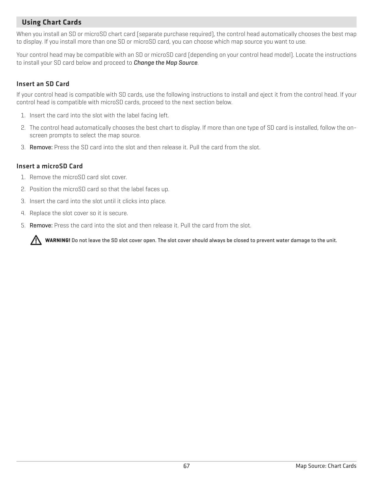
####### Using Chart Cards
When you install an SD or microSD chart card (separate purchase required), the control head automatically chooses the best map to display. If you install more than one SD or microSD card, you can choose which map source you want to use.
Your control head may be compatible with an SD or microSD card (depending on your control head model). Locate the instructions to install your SD card below and proceed to Change the Map Source.
######### Insert an SD Card
If your control head is compatible with SD cards, use the following instructions to install and eject it from the control head. If your control head is compatible with microSD cards, proceed to the next section below.
######### Insert a microSD Card
WARNING! Do not leave the SD slot cover open. The slot cover should always be closed to prevent water damage to the unit.
67 Map Source: Chart Cards
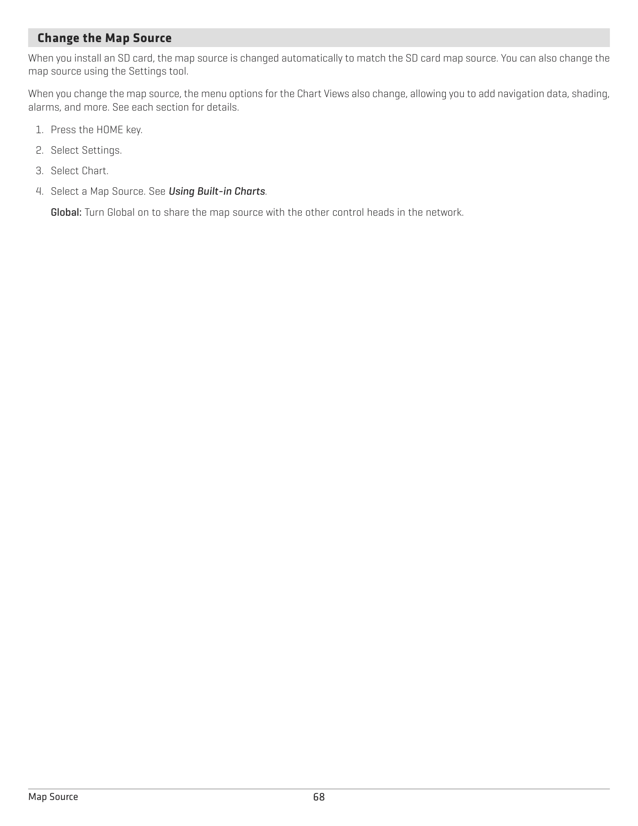
####### Change the Map Source
When you install an SD card, the map source is changed automatically to match the SD card map source. You can also change the map source using the Settings tool.
When you change the map source, the menu options for the Chart Views also change, allowing you to add navigation data, shading, alarms, and more. See each section for details.
68Map Source
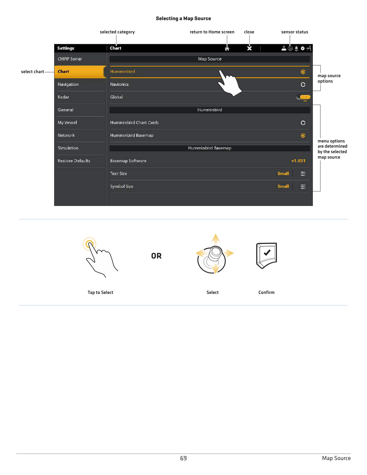
Selecting a Map Source
selected category return to Home screen close sensor status

select chart
map source options
menu options are determined by the selected map source
#### OR
ConfirmSelectTap to Select
69 Map Source
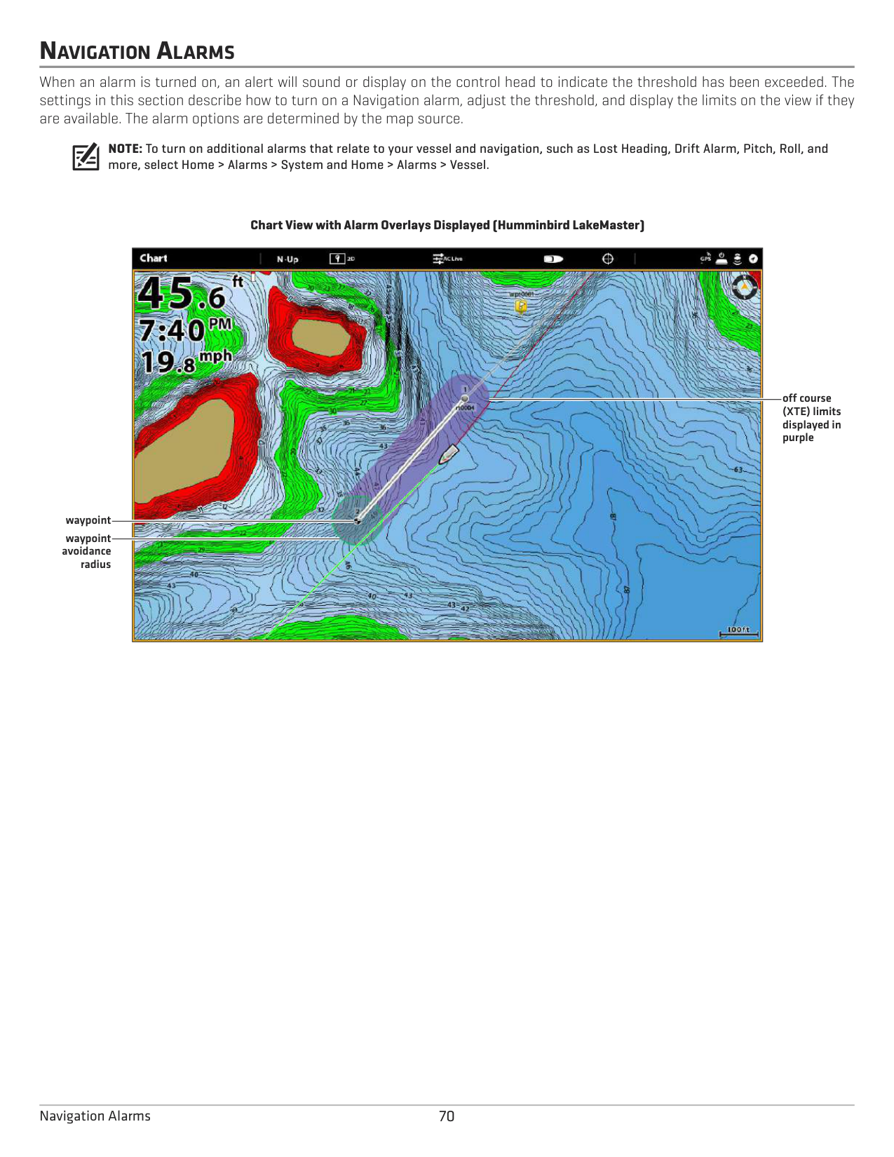
NAVIGATION ALARMS
When an alarm is turned on, an alert will sound or display on the control head to indicate the threshold has been exceeded. The settings in this section describe how to turn on a Navigation alarm, adjust the threshold, and display the limits on the view if they are available. The alarm options are determined by the map source.
NOTE: To turn on additional alarms that relate to your vessel and navigation, such as Lost Heading, Drift Alarm, Pitch, Roll, and more, select Home > Alarms > System and Home > Alarms > Vessel.
################# Chart View with Alarm Overlays Displayed (Humminbird LakeMaster)

off course (XTE) limits displayed in purple
waypoint
waypoint avoidance
radius
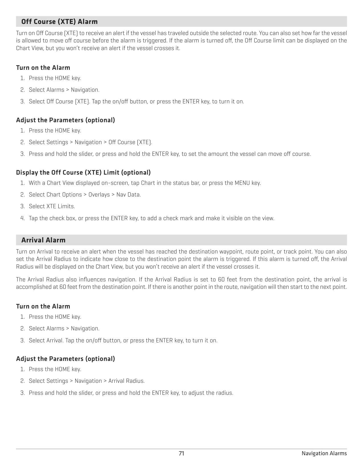
####### Off Course (XTE) Alarm
Turn on Off Course (XTE) to receive an alert if the vessel has traveled outside the selected route. You can also set how far the vessel is allowed to move off course before the alarm is triggered. If the alarm is turned off, the Off Course limit can be displayed on the Chart View, but you won’t receive an alert if the vessel crosses it.
######### Turn on the Alarm
######### Adjust the Parameters (optional)
######### Display the Off Course (XTE) Limit (optional)
####### Arrival Alarm
Turn on Arrival to receive an alert when the vessel has reached the destination waypoint, route point, or track point. You can also set the Arrival Radius to indicate how close to the destination point the alarm is triggered. If this alarm is turned off, the Arrival Radius will be displayed on the Chart View, but you won’t receive an alert if the vessel crosses it.
The Arrival Radius also influences navigation. If the Arrival Radius is set to 60 feet from the destination point, the arrival is accomplished at 60 feet from the destination point. If there is another point in the route, navigation will then start to the next point.
######### Turn on the Alarm
######### Adjust the Parameters (optional)
####### Waypoint Avoidance Alarm
Turn on Waypoint Avoidance to receive an alert if the vessel has crossed the Waypoint Avoidance Radius. If the alarm is turned off, the Waypoint Avoidance Radius can be set for a waypoint, and it will be displayed on the Chart View, but you won’t receive an alert if the radius is crossed.
######### Turn on the Alarm
######### Create an Avoidance Waypoint
####### Anti-Collision Alarm
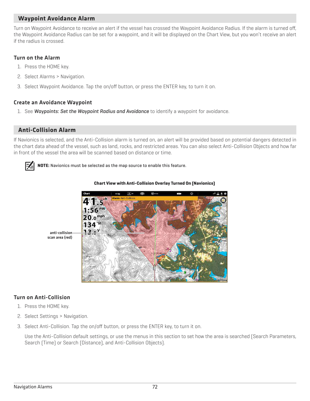
If Navionics is selected, and the Anti-Collision alarm is turned on, an alert will be provided based on potential dangers detected in the chart data ahead of the vessel, such as land, rocks, and restricted areas. You can also select Anti-Collision Objects and how far in front of the vessel the area will be scanned based on distance or time.
NOTE: Navionics must be selected as the map source to enable this feature.
Chart View with Anti-Collision Overlay Turned On (Navionics)

anti-collision scan area (red)
######### Turn on Anti-Collision
Use the Anti-Collision default settings, or use the menus in this section to set how the area is searched (Search Parameters, Search (Time) or Search (Distance), and Anti-Collision Objects).
######### Turn on the Alarm
Display the Anti-Collision Overlay When the overlay is turned off, the scan area is shown only when a danger is detected. When the overlay is turned on, the scan area is displayed at all times. When a potential danger is detected, the scan area will turn red.
MAN OVERBOARD (MOB) NAVIGATION
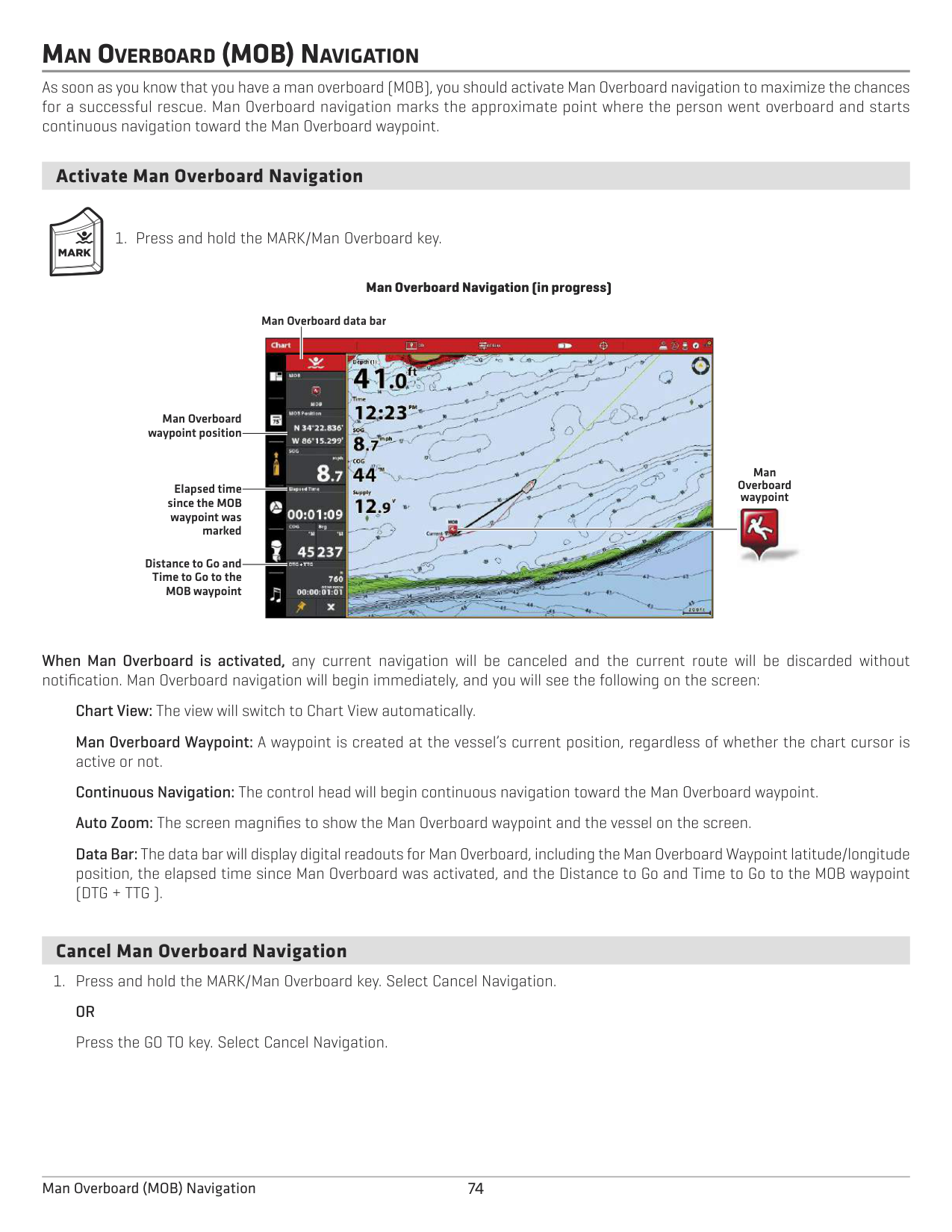
As soon as you know that you have a man overboard (MOB), you should activate Man Overboard navigation to maximize the chances for a successful rescue. Man Overboard navigation marks the approximate point where the person went overboard and starts continuous navigation toward the Man Overboard waypoint.
####### Activate Man Overboard Navigation
################# Man Overboard Navigation (in progress)
Man Overboard data bar

Man Overboard waypoint position
Man Overboard waypoint
Elapsed time since the MOB
waypoint was marked

Distance to Go and Time to Go to the MOB waypoint
When Man Overboard is activated, any current navigation will be canceled and the current route will be discarded without notification. Man Overboard navigation will begin immediately, and you will see the following on the screen:
Chart View: The view will switch to Chart View automatically. Man Overboard Waypoint: A waypoint is created at the vessel’s current position, regardless of whether the chart cursor is active or not. Continuous Navigation: The control head will begin continuous navigation toward the Man Overboard waypoint. Auto Zoom: The screen magnifies to show the Man Overboard waypoint and the vessel on the screen.
Data Bar: The data bar will display digital readouts for Man Overboard, including the Man Overboard Waypoint latitude/longitude position, the elapsed time since Man Overboard was activated, and the Distance to Go and Time to Go to the MOB waypoint (DTG + TTG ).
####### Cancel Man Overboard Navigation
74Man Overboard (MOB) Navigation
CUSTOMIZE THE CHART VIEW
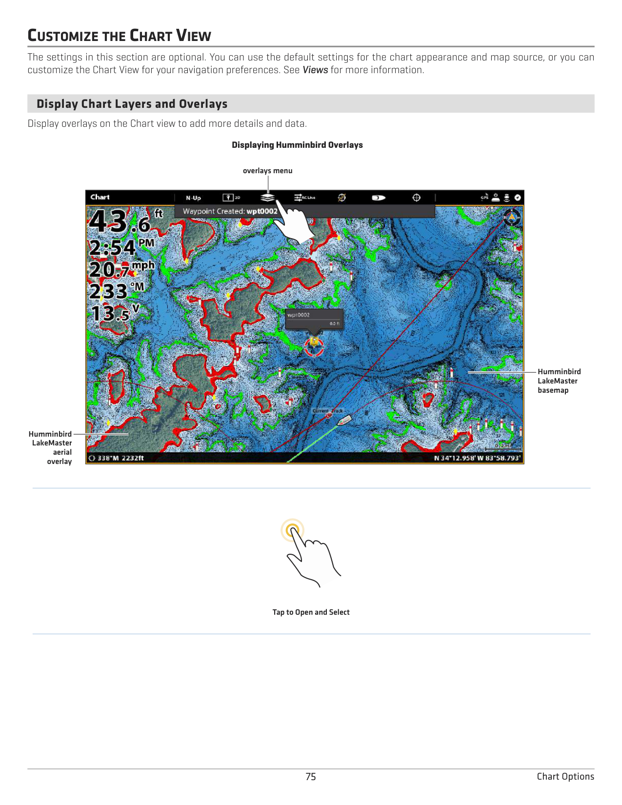
The settings in this section are optional. You can use the default settings for the chart appearance and map source, or you can customize the Chart View for your navigation preferences. See Views for more information.
####### Display Chart Layers and Overlays
Display overlays on the Chart view to add more details and data.
################# Displaying Humminbird Overlays
overlays menu

Humminbird LakeMaster basemap
Humminbird LakeMaster
aerial overlay
Tap to Open and Select
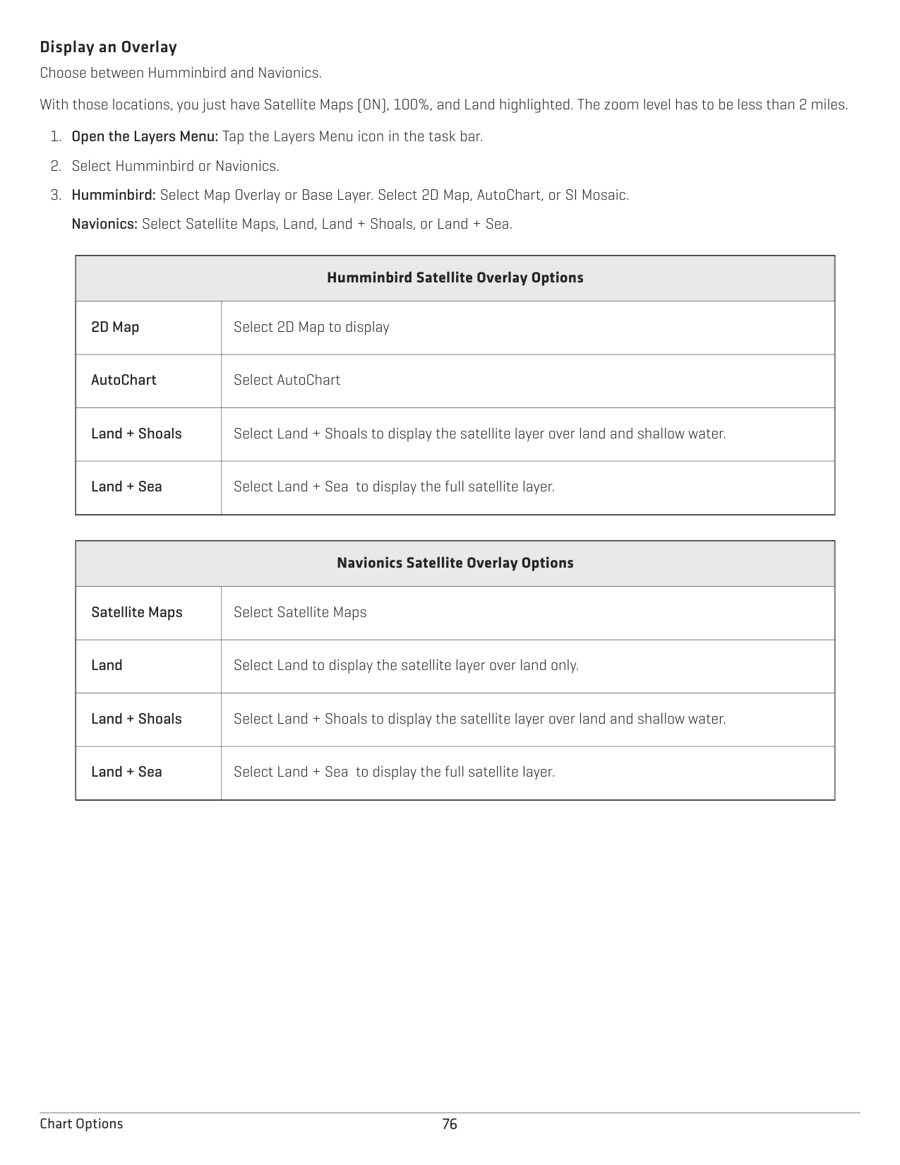
Display an Overlay Choose between Humminbird and Navionics. With those locations, you just have Satellite Maps (ON), 100%, and Land highlighted. The zoom level has to be less than 2 miles.
Navionics: Select Satellite Maps, Land, Land + Shoals, or Land + Sea.
|Humminbird Satellite Overlay Options
|Humminbird Satellite Overlay Options
| |---|---| |2D Map|Select 2D Map to display
| |AutoChart
|Select AutoChart| |Land + Shoals|Select Land + Shoals to display the satellite layer over land and shallow water.
| |Land + Sea
|Select Land + Sea to display the full satellite layer.|
|Navionics Satellite Overlay Options
|Navionics Satellite Overlay Options
| |---|---| |Satellite Maps|Select Satellite Maps
| |Land|Select Land to display the satellite layer over land only.
| |Land + Shoals|Select Land + Shoals to display the satellite layer over land and shallow water.
| |Land + Sea|Select Land + Sea to display the full satellite layer.
|
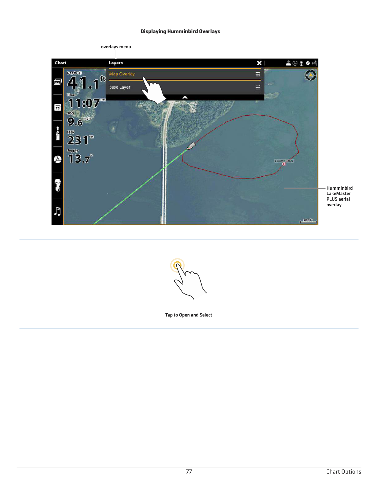
################# Displaying Humminbird Overlays
overlays menu

Humminbird LakeMaster PLUS aerial overlay
Tap to Open and Select
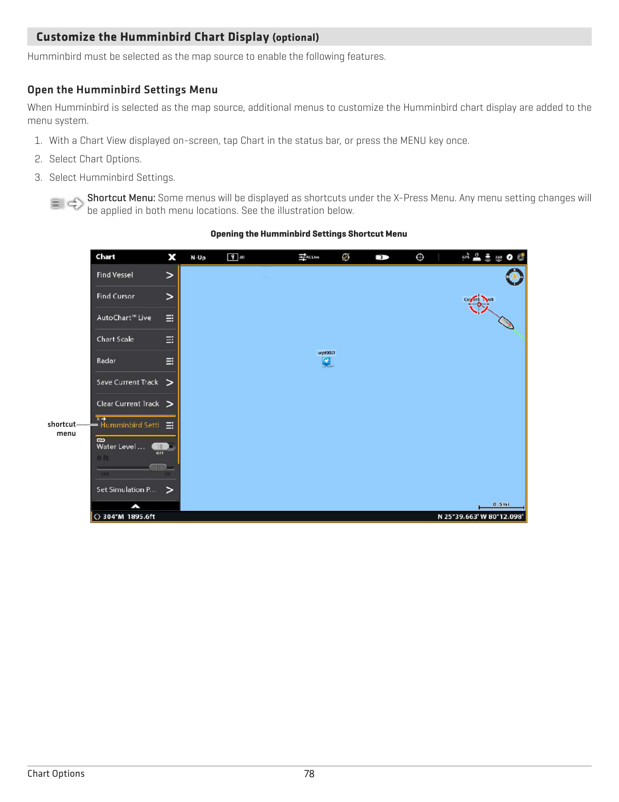
####### Customize the Humminbird Chart Display (optional)
Humminbird must be selected as the map source to enable the following features.
######### Open the Humminbird Settings Menu
When Humminbird is selected as the map source, additional menus to customize the Humminbird chart display are added to the menu system.
Shortcut Menu: Some menus will be displayed as shortcuts under the X-Press Menu. Any menu setting changes will be applied in both menu locations. See the illustration below.

################# Opening the Humminbird Settings Shortcut Menu

shortcut menu
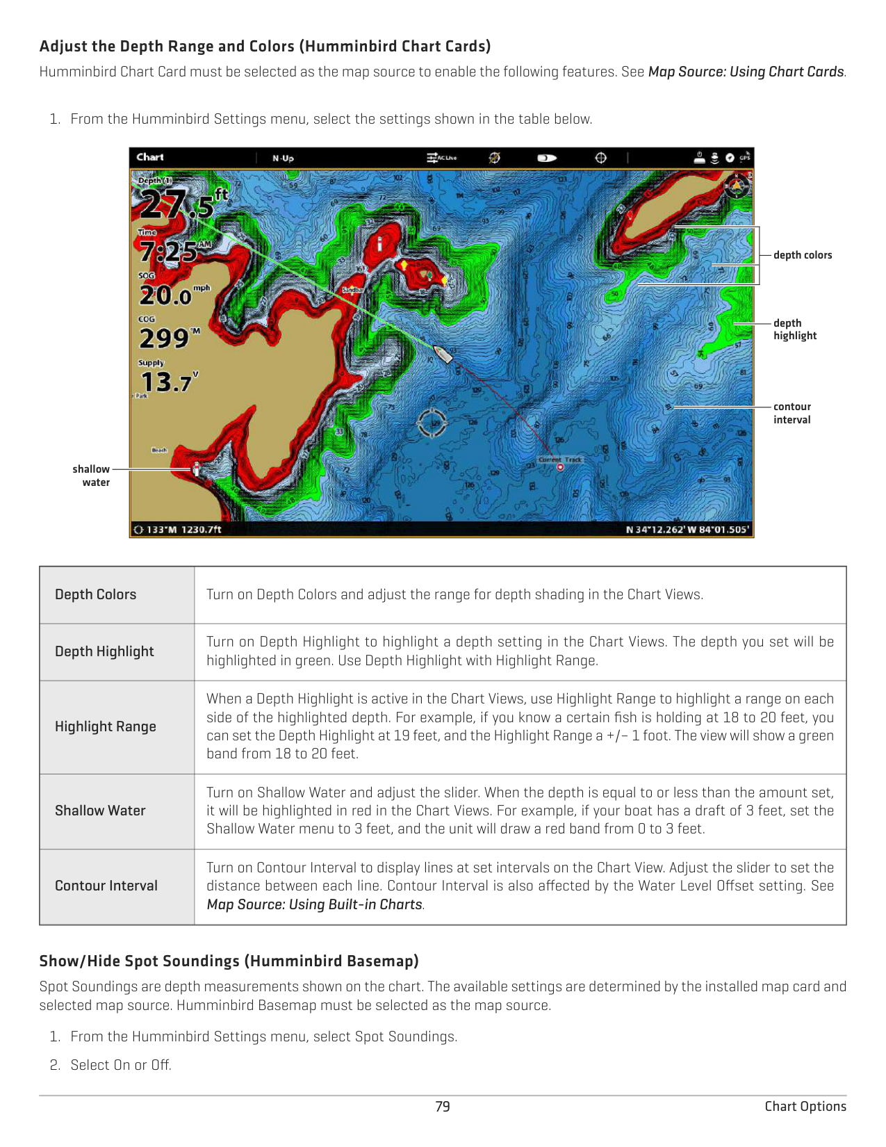
######### Adjust the Depth Range and Colors (Humminbird Chart Cards) Humminbird Chart Card must be selected as the map source to enable the following features. See Map Source: Using Chart Cards.

depth colors
depth highlight
contour interval
shallow water
|Depth Colors|Turn on Depth Colors and adjust the range for depth shading in the Chart Views.
| |---|---| |Depth Highlight|Turn on Depth Highlight to highlight a depth setting in the Chart Views. The depth you set will be highlighted in green. Use Depth Highlight with Highlight Range.
| |Highlight Range
|When a Depth Highlight is active in the Chart Views, use Highlight Range to highlight a range on each side of the highlighted depth. For example, if you know a certain fish is holding at 18 to 20 feet, you can set the Depth Highlight at 19 feet, and the Highlight Range a +/– 1 foot. The view will show a green band from 18 to 20 feet.| |Shallow Water|Turn on Shallow Water and adjust the slider. When the depth is equal to or less than the amount set, it will be highlighted in red in the Chart Views. For example, if your boat has a draft of 3 feet, set the Shallow Water menu to 3 feet, and the unit will draw a red band from 0 to 3 feet.
| |Contour Interval|Turn on Contour Interval to display lines at set intervals on the Chart View. Adjust the slider to set the distance between each line. Contour Interval is also affected by the Water Level Offset setting. See Map Source: Using Built-in Charts.|
######### Show/Hide Spot Soundings (Humminbird Basemap)
Spot Soundings are depth measurements shown on the chart. The available settings are determined by the installed map card and selected map source. Humminbird Basemap must be selected as the map source.
####### Set the Chart Orientation
Use the Preferences menu to change the chart orientation.
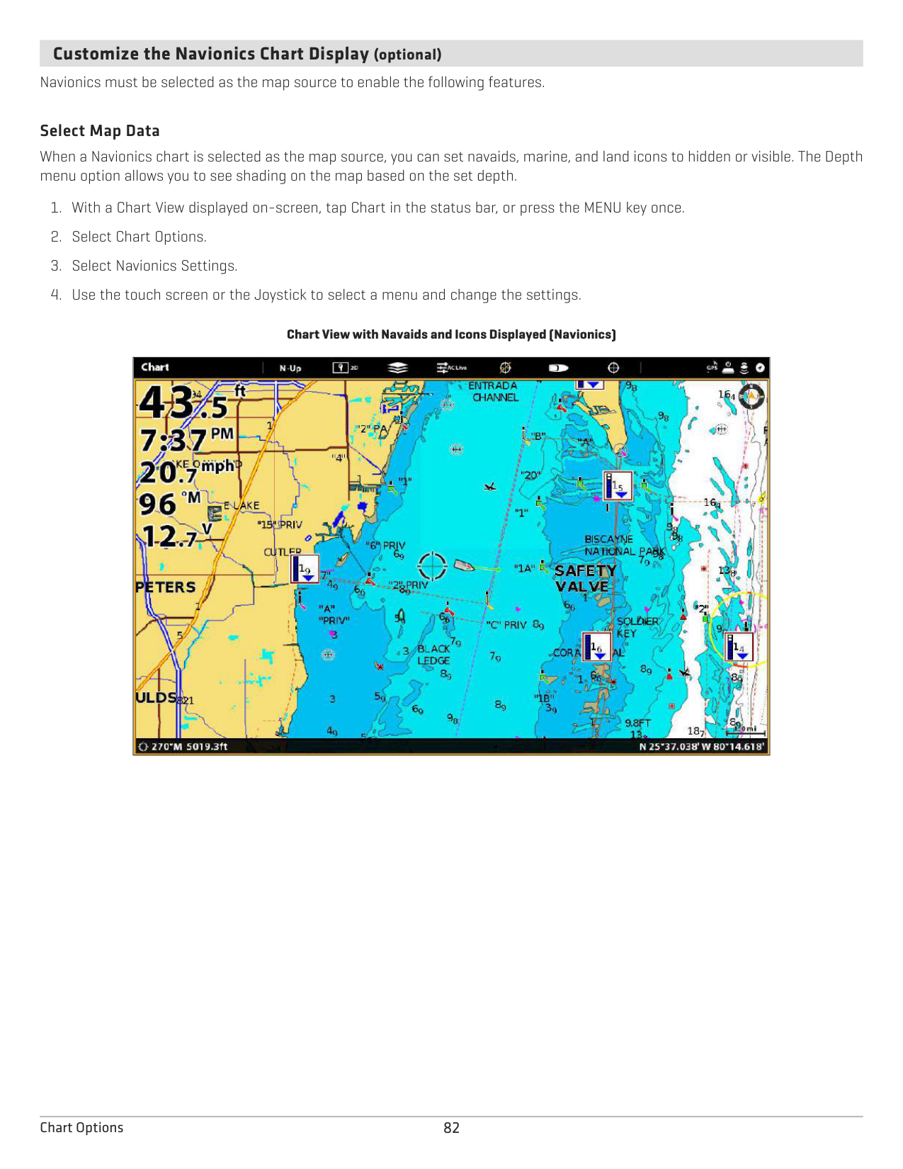
QUICK TIP! You can also select the Chart Orientation Menu on the status bar. See the illustration below.
chart orientation setting

preview window
menu selection
|Head Up (compass or GPS required)|The vessel’s current heading points up, and the chart rotates around the vessel icon so that it always points up on the view. The heading is provided by the connected compass/heading sensor. If a compass is not connected, the vessel will be oriented according to the COG (Course Over Ground).
| |---|---| |North Up
|The chart is oriented with North up on the display, and the vessel rotates according to its heading or COG (Course Over Ground).| |COG Up|The chart is displayed with the vessel oriented in a fixed position pointing up, and the chart rotates according to the vessel COG (Course over Ground).
| |Course Up|During navigation, the intended course or route leg is shown at the top of the view. Objects ahead of the vessel are drawn above the vessel. When the vessel is not navigating, the current heading is displayed.|
####### Set the Motion Mode
Motion Mode controls how the chart moves on the view. This menu is available in Custom Mode (see The Menu System: Change the User Mode).
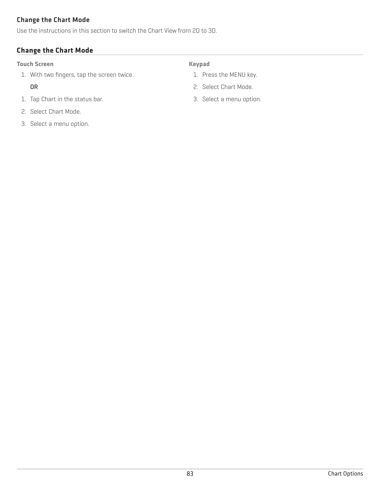
|Relative|The position of the vessel is fixed on the view and the chart moves with the vessel.
| |---|---| |True|The chart is fixed and the vessel moves towards chart objects on the view.
|
####### Turn on/off Vessel Offset
Vessel Offset allows you to see more of the view based on the speed of the vessel. Vessel Offset works with Auto Shift Speed.
|Off|The vessel is displayed in the center of the Chart View.
| |---|---| |On|The vessel is displayed on the lower part of the Chart View.
| |Auto
|When the vessel is moving below the Auto Shift Speed setting, the vessel icon will be displayed in the center of the view. When the vessel is moving at or above the Auto Shift Speed setting, the vessel icon will move to the edge of the view so that more of the view is shown on-screen.|
####### Turn on Auto Zoom
Auto Zoom focuses the view on the current route leg as it is being navigated. As the vessel’s speed increases, the chart range will increase. If you press the ZOOM keys to see more or less of the view, Auto Zoom will pause.
NOTE: The Auto Zoom setting does not apply to the 3D Views.
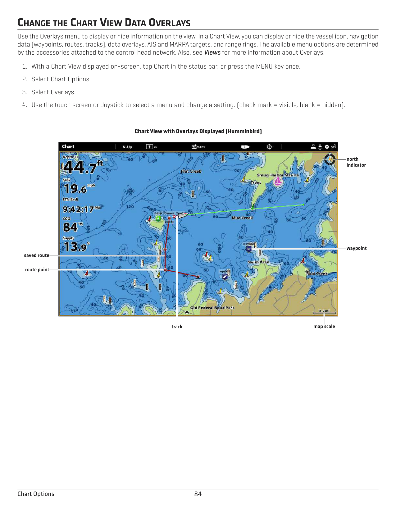
####### Customize the Navionics Chart Display (optional)
Navionics must be selected as the map source to enable the following features.
######### Select Map Data
When a Navionics chart is selected as the map source, you can set navaids, marine, and land icons to hidden or visible. The Depth menu option allows you to see shading on the map based on the set depth.
Chart View with Navaids and Icons Displayed (Navionics)
|| |---|
Change the Chart Mode Use the instructions in this section to switch the Chart View from 2D to 3D.
######## Change the Chart Mode Touch Screen
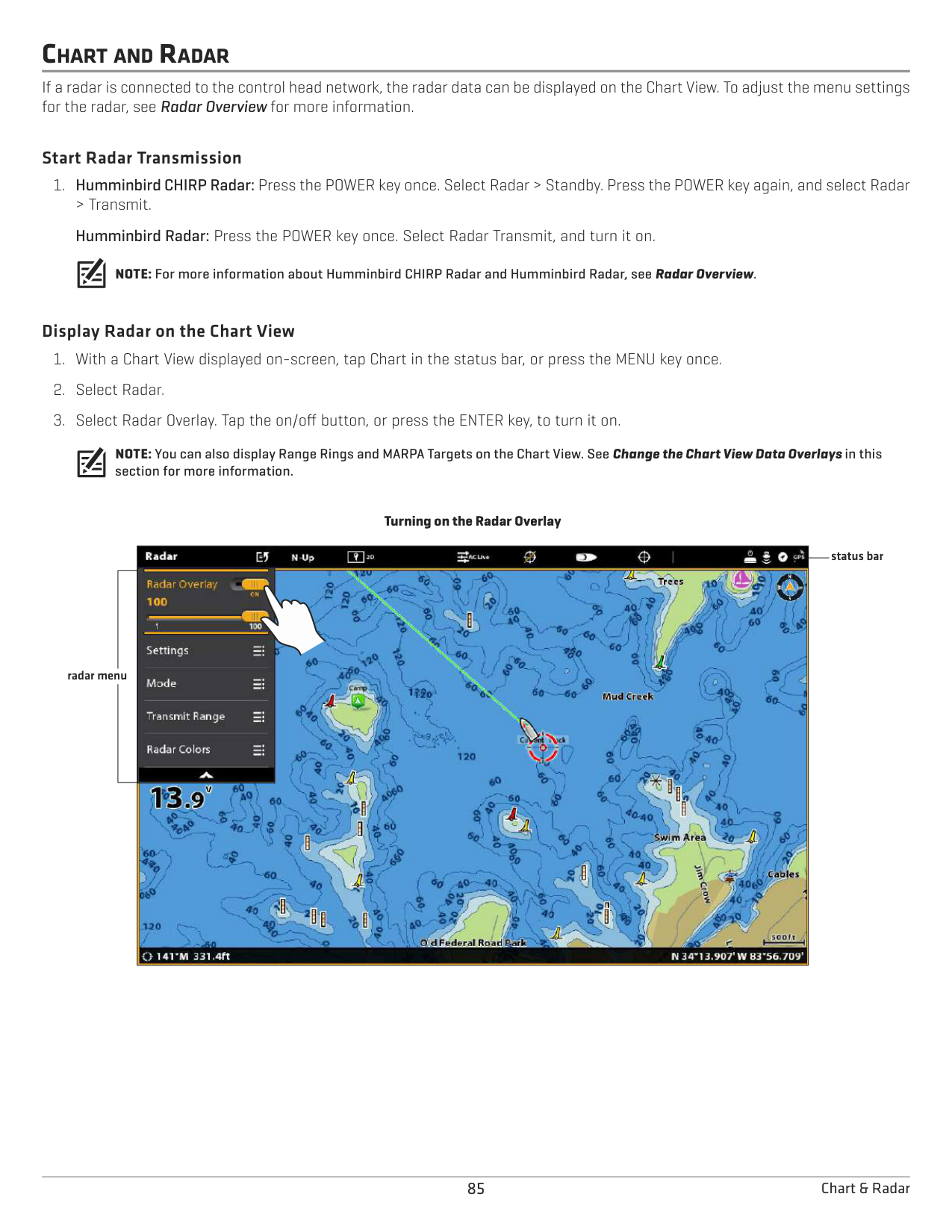
############ Keypad
############# OR
CHANGE THE CHART VIEW DATA OVERLAYS
Use the Overlays menu to display or hide information on the view. In a Chart View, you can display or hide the vessel icon, navigation data (waypoints, routes, tracks), data overlays, AIS and MARPA targets, and range rings. The available menu options are determined by the accessories attached to the control head network. Also, see Views for more information about Overlays.
################# Chart View with Overlays Displayed (Humminbird)
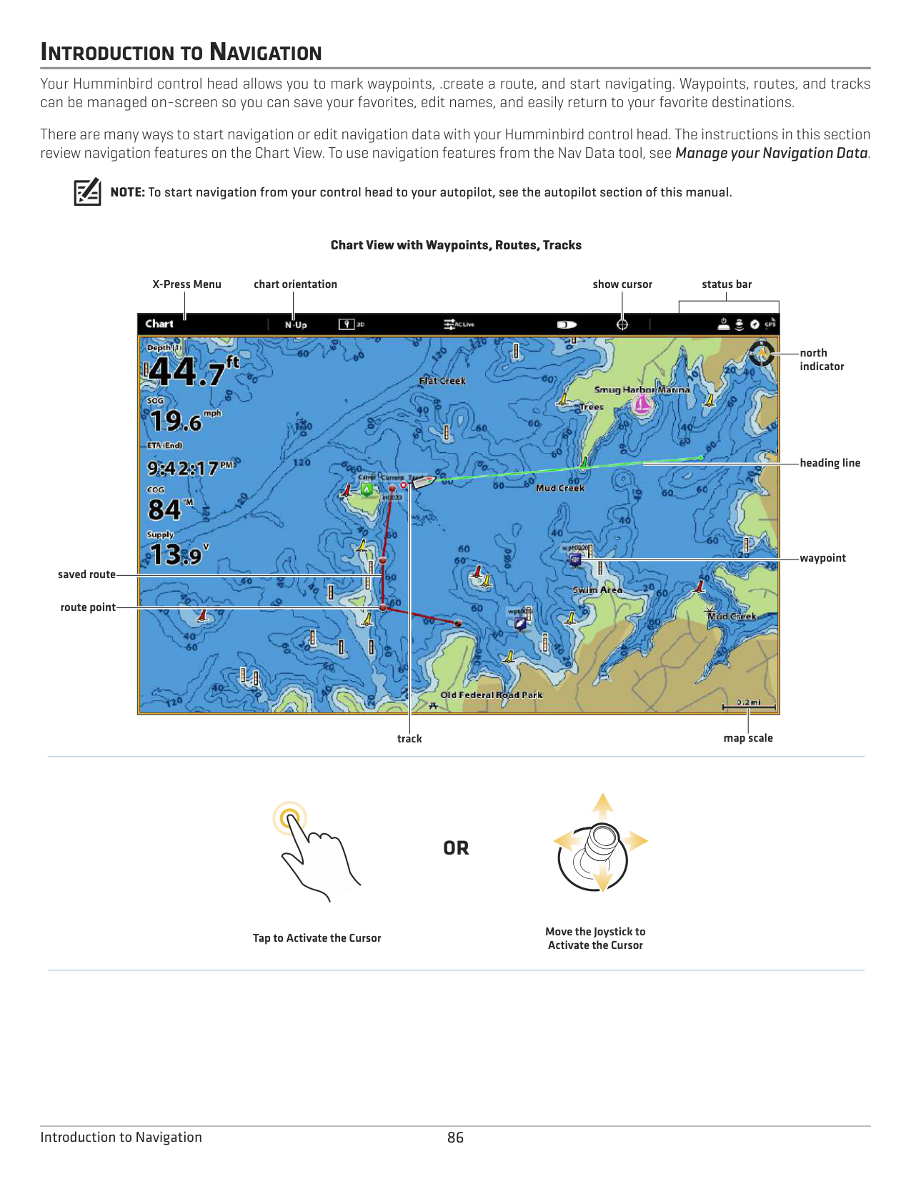

north indicator
waypoint
saved route
route point
map scaletrack
CHART AND RADAR
If a radar is connected to the control head network, the radar data can be displayed on the Chart View. To adjust the menu settings for the radar, see Radar Overview for more information.
######### Start Radar Transmission
NOTE: For more information about Humminbird CHIRP Radar and Humminbird Radar, see Radar Overview.
######### Display Radar on the Chart View
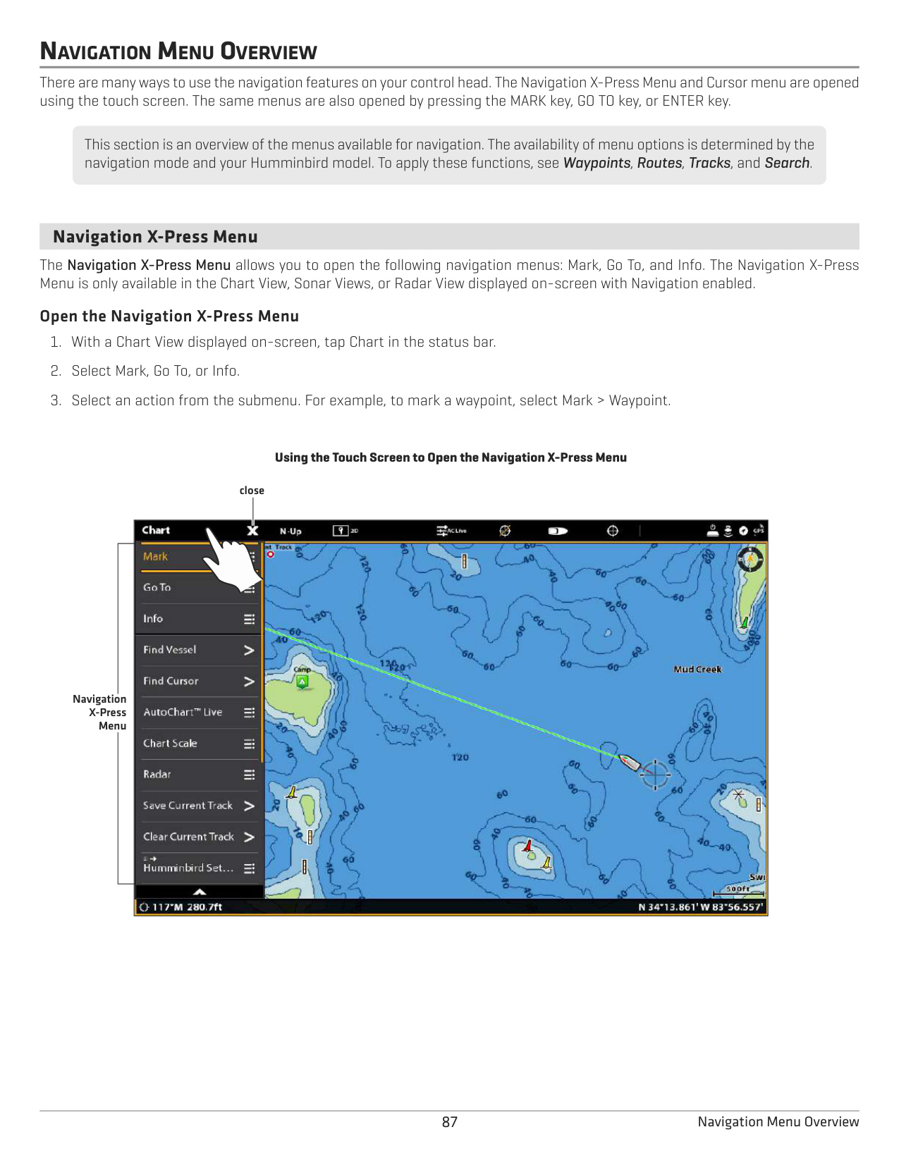
NOTE: You can also display Range Rings and MARPA Targets on the Chart View. See Change the Chart View Data Overlays in this section for more information.
################# Turning on the Radar Overlay
| |
| | |---|---|---| | |
| | | |
| | | |
| |
status bar
radar menu
85 Chart & Radar
INTRODUCTION TO NAVIGATION
Your Humminbird control head allows you to mark waypoints, .create a route, and start navigating. Waypoints, routes, and tracks can be managed on-screen so you can save your favorites, edit names, and easily return to your favorite destinations.
There are many ways to start navigation or edit navigation data with your Humminbird control head. The instructions in this section review navigation features on the Chart View. To use navigation features from the Nav Data tool, see Manage your Navigation Data.
NOTE: To start navigation from your control head to your autopilot, see the autopilot section of this manual.
################# Chart View with Waypoints, Routes, Tracks
chart orientation show cursor status barX-Press Menu
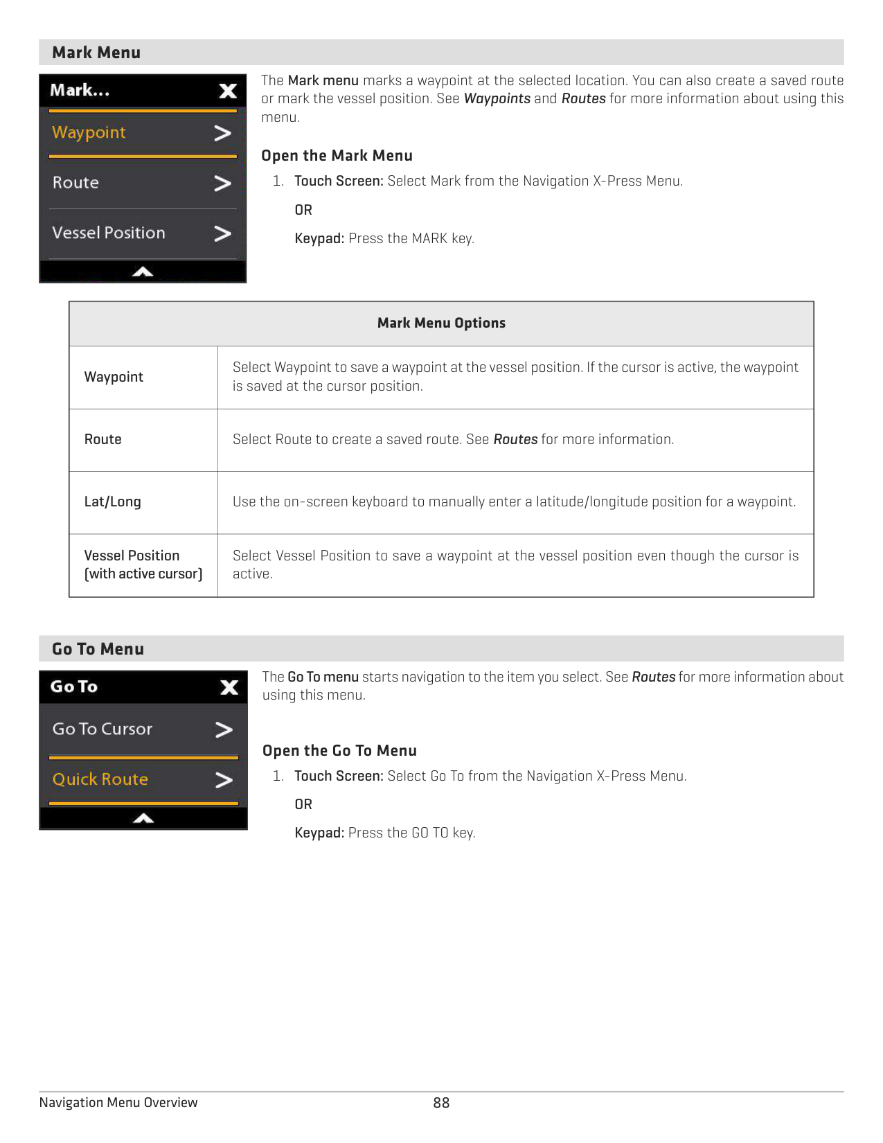

north indicator
heading line
waypoint
saved route
route point
map scaletrack
#### OR
Tap to Activate the Cursor
Move the Joystick to Activate the Cursor
86Introduction to Navigation
NAVIGATION MENU OVERVIEW
There are many ways to use the navigation features on your control head. The Navigation X-Press Menu and Cursor menu are opened using the touch screen. The same menus are also opened by pressing the MARK key, GO TO key, or ENTER key.
This section is an overview of the menus available for navigation. The availability of menu options is determined by the navigation mode and your Humminbird model. To apply these functions, see Waypoints, Routes, Tracks, and Search.
####### Navigation X-Press Menu
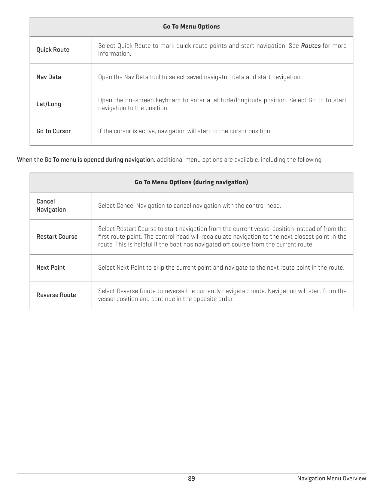
The Navigation X-Press Menu allows you to open the following navigation menus: Mark, Go To, and Info. The Navigation X-Press Menu is only available in the Chart View, Sonar Views, or Radar View displayed on-screen with Navigation enabled.
######### Open the Navigation X-Press Menu
################# Using the Touch Screen to Open the Navigation X-Press Menu
close

Navigation X-Press Menu
####### Mark Menu
The Mark menu marks a waypoint at the selected location. You can also create a saved route or mark the vessel position. See Waypoints and Routes for more information about using this menu.
|| |---|
######### Open the Mark Menu
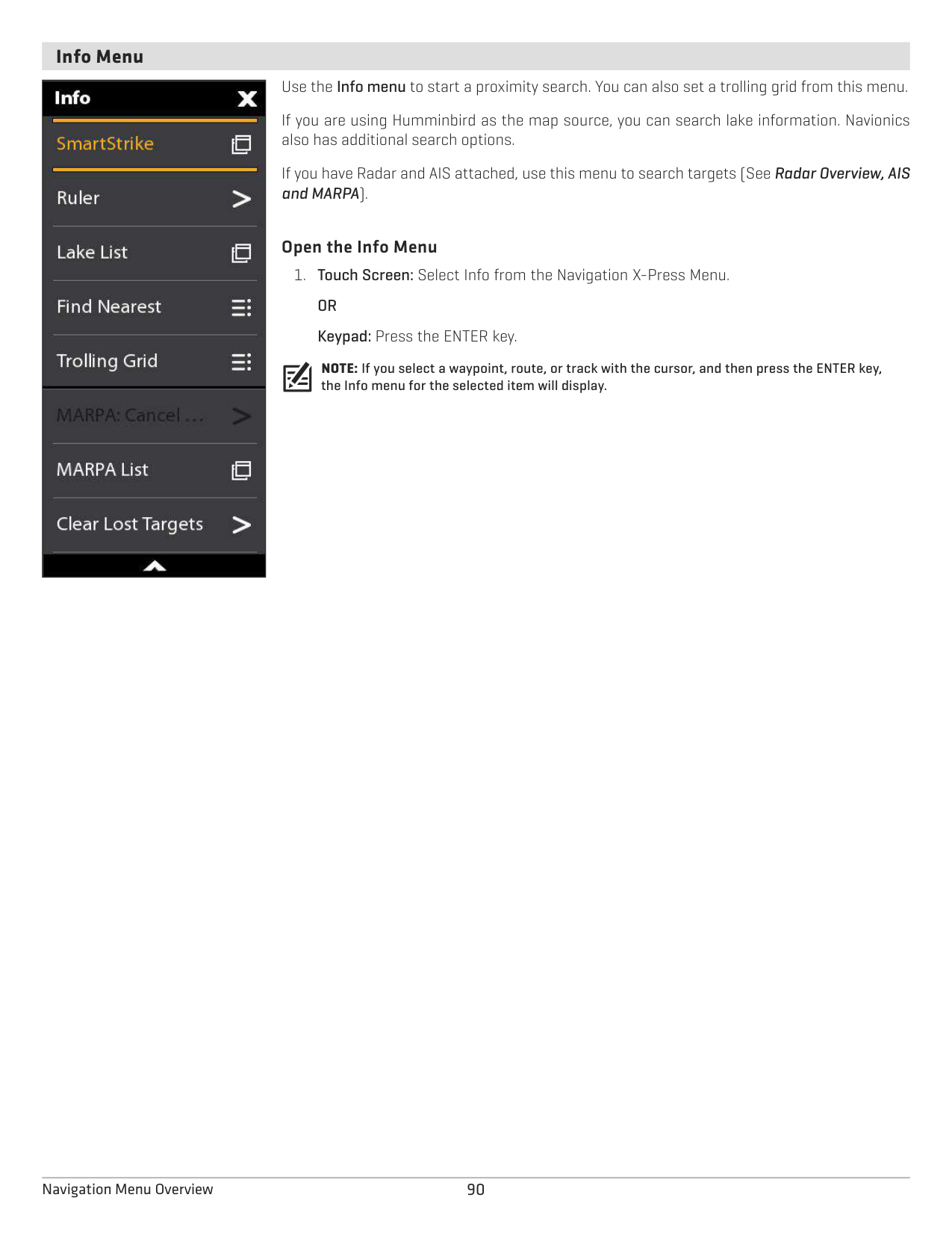
|Mark Menu Options
|Mark Menu Options
| |---|---| |Waypoint|Select Waypoint to save a waypoint at the vessel position. If the cursor is active, the waypoint is saved at the cursor position.
| |Route|Select Route to create a saved route. See Routes for more information.
| |Lat/Long|Use the on-screen keyboard to manually enter a latitude/longitude position for a waypoint.
| |Vessel Position (with active cursor)|Select Vessel Position to save a waypoint at the vessel position even though the cursor is active.
|
####### Go To Menu
The Go To menu starts navigation to the item you select. See Routes for more information about using this menu.
|| |---|
######### Open the Go To Menu
|Go To Menu Options
|Go To Menu Options
| |---|---| |Quick Route|Select Quick Route to mark quick route points and start navigation. See Routes for more information.
| |Nav Data
|Open the Nav Data tool to select saved navigaton data and start navigation.| |Lat/Long
|Open the on-screen keyboard to enter a latitude/longitude position. Select Go To to start navigation to the position.| |Go To Cursor|If the cursor is active, navigation will start to the cursor position.
|
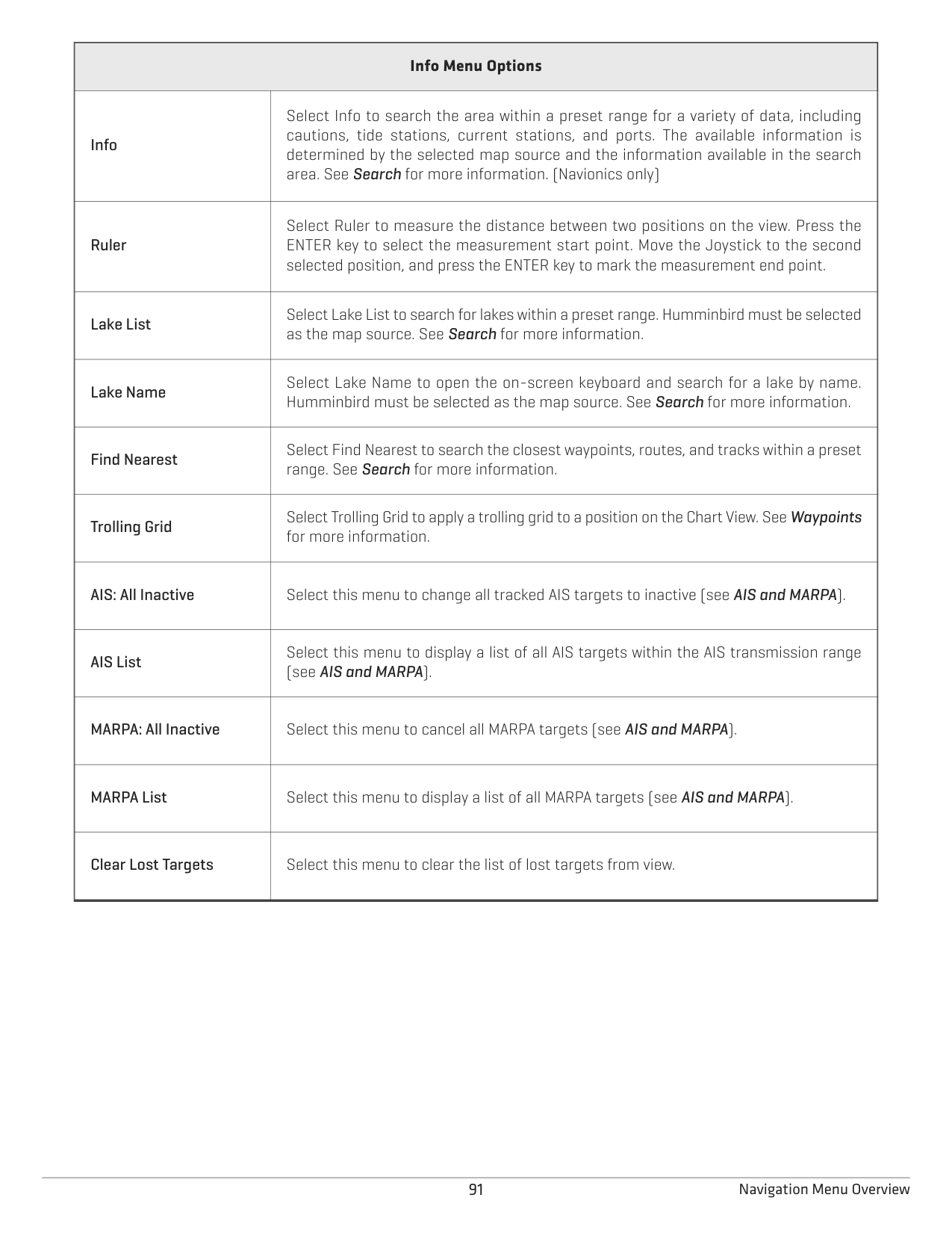
############## When the Go To menu is opened during navigation, additional menu options are available, including the following:
|Go To Menu Options (during navigation)
|Go To Menu Options (during navigation)
| |---|---| |Cancel Navigation
|Select Cancel Navigation to cancel navigation with the control head.| |Restart Course
|Select Restart Course to start navigation from the current vessel position instead of from the first route point. The control head will recalculate navigation to the next closest point in the route. This is helpful if the boat has navigated off course from the current route.| |Next Point|Select Next Point to skip the current point and navigate to the next route point in the route.
| |Reverse Route|Select Reverse Route to reverse the currently navigated route. Navigation will start from the vessel position and continue in the opposite order.|
####### Info Menu
Use the Info menu to start a proximity search. You can also set a trolling grid from this menu. If you are using Humminbird as the map source, you can search lake information. Navionics also has additional search options. If you have Radar and AIS attached, use this menu to search targets (See Radar Overview, AIS and MARPA).
|| |---|
######### Open the Info Menu
NOTE: If you select a waypoint, route, or track with the cursor, and then press the ENTER key, the Info menu for the selected item will display.
|Info Menu Options
|Info Menu Options
| |---|---| |Info
|Select Info to search the area within a preset range for a variety of data, including cautions, tide stations, current stations, and ports. The available information is determined by the selected map source and the information available in the search area. See Search for more information. (Navionics only)| |Ruler|Select Ruler to measure the distance between two positions on the view. Press the ENTER key to select the measurement start point. Move the Joystick to the second selected position, and press the ENTER key to mark the measurement end point.
| |Lake List|Select Lake List to search for lakes within a preset range. Humminbird must be selected as the map source. See Search for more information.
|
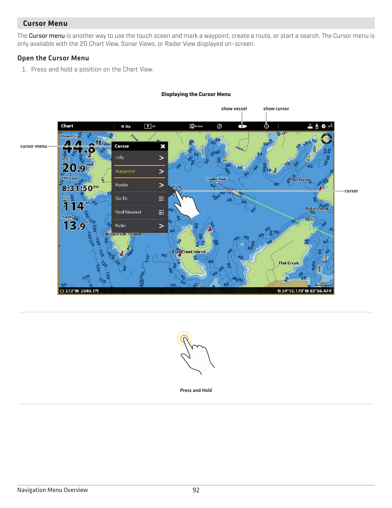
|Lake Name|Select Lake Name to open the on-screen keyboard and search for a lake by name. Humminbird must be selected as the map source. See Search for more information.
| |Find Nearest
|Select Find Nearest to search the closest waypoints, routes, and tracks within a preset range. See Search for more information.| |Trolling Grid|Select Trolling Grid to apply a trolling grid to a position on the Chart View. See Waypoints for more information.
| |AIS: All Inactive|Select this menu to change all tracked AIS targets to inactive (see AIS and MARPA).
| |AIS List
|Select this menu to display a list of all AIS targets within the AIS transmission range (see AIS and MARPA).| |MARPA: All Inactive
|Select this menu to cancel all MARPA targets (see AIS and MARPA).| |MARPA List|Select this menu to display a list of all MARPA targets (see AIS and MARPA).
| |Clear Lost Targets|Select this menu to clear the list of lost targets from view.|
####### Cursor Menu
The Cursor menu is another way to use the touch sceen and mark a waypoint, create a route, or start a search. The Cursor menu is only available with the 2D Chart View, Sonar Views, or Radar View displayed on-screen.
######### Open the Cursor Menu
Displaying the Cursor Menu
show vessel show cursor

cursor menu
cursor
Press and Hold
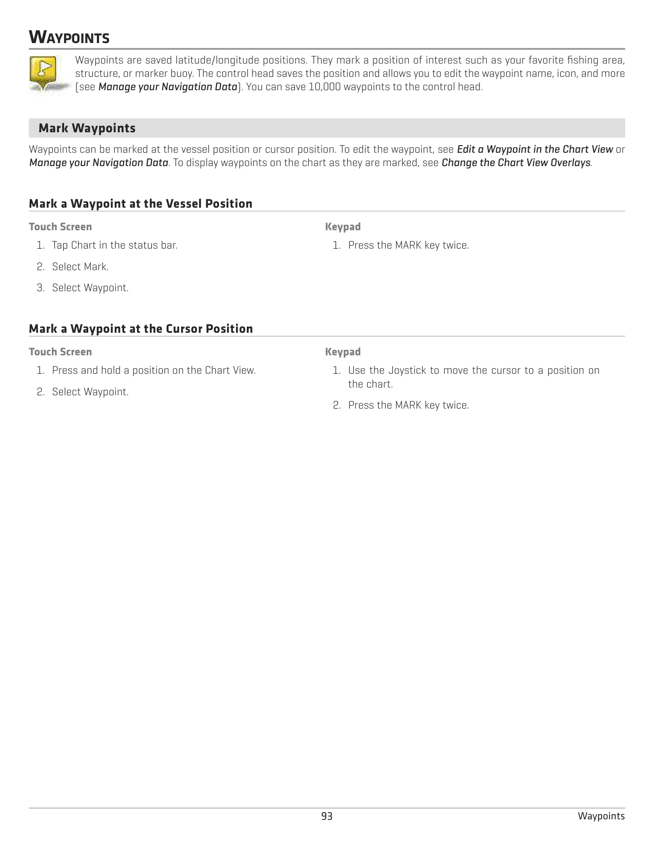
WAYPOINTS
Waypoints are saved latitude/longitude positions. They mark a position of interest such as your favorite fishing area, structure, or marker buoy. The control head saves the position and allows you to edit the waypoint name, icon, and more (see Manage your Navigation Data). You can save 10,000 waypoints to the control head.

####### Mark Waypoints
Waypoints can be marked at the vessel position or cursor position. To edit the waypoint, see Edit a Waypoint in the Chart View or Manage your Navigation Data. To display waypoints on the chart as they are marked, see Change the Chart View Overlays.
Mark a Waypoint at the Vessel Position
Touch Screen
############ Keypad
Mark a Waypoint at the Cursor Position
############ Touch Screen
############ Keypad
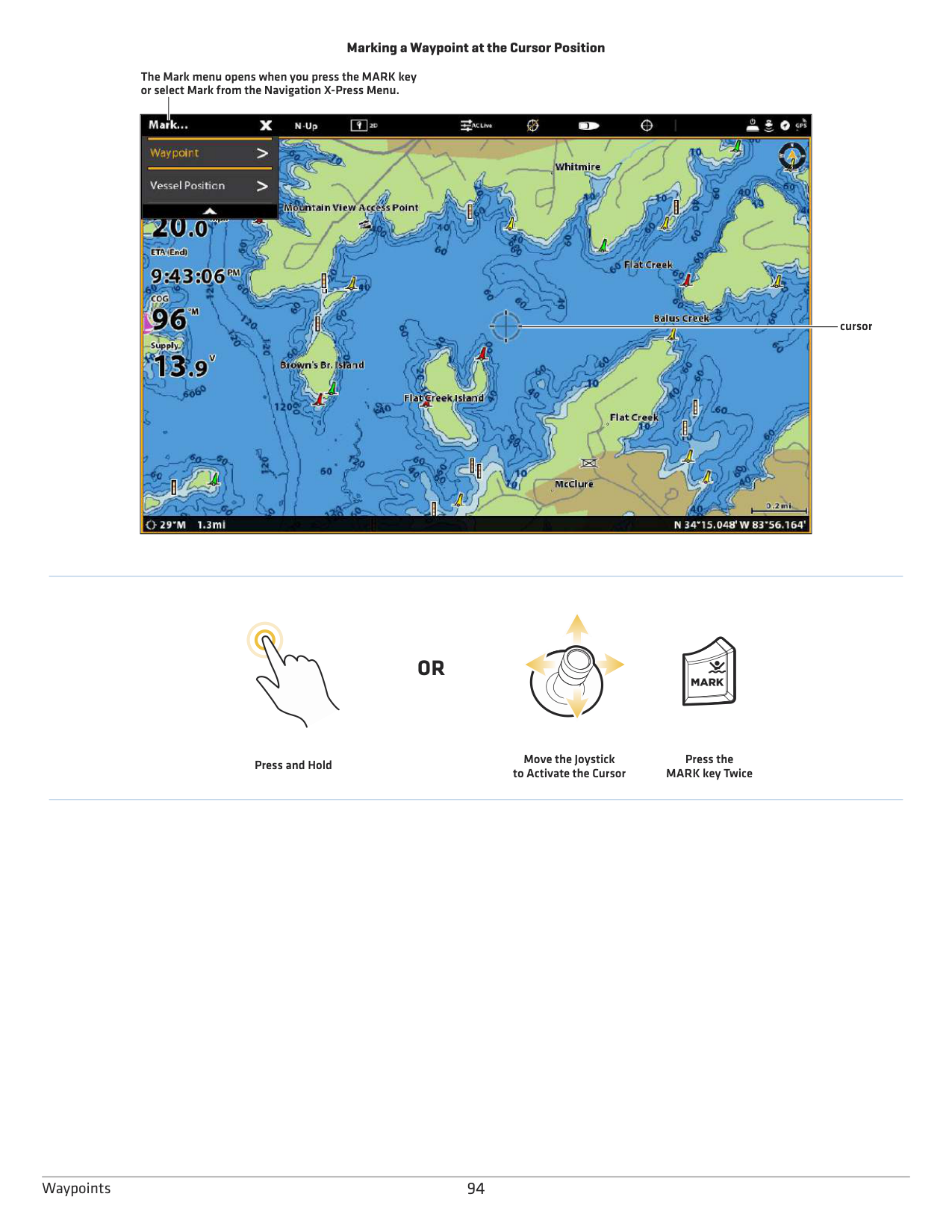
################# Marking a Waypoint at the Cursor Position
The Mark menu opens when you press the MARK key or select Mark from the Navigation X-Press Menu.

cursor
#### OR
Press and Hold
Move the Joystick to Activate the Cursor
Press the MARK key Twice
Mark + Edit Waypoints (on the go) If you set the Mark Mode to Mark + Edit, you can edit a waypoint immediately when you mark it in the Chart View. See Manage your Navigation Data for more information.
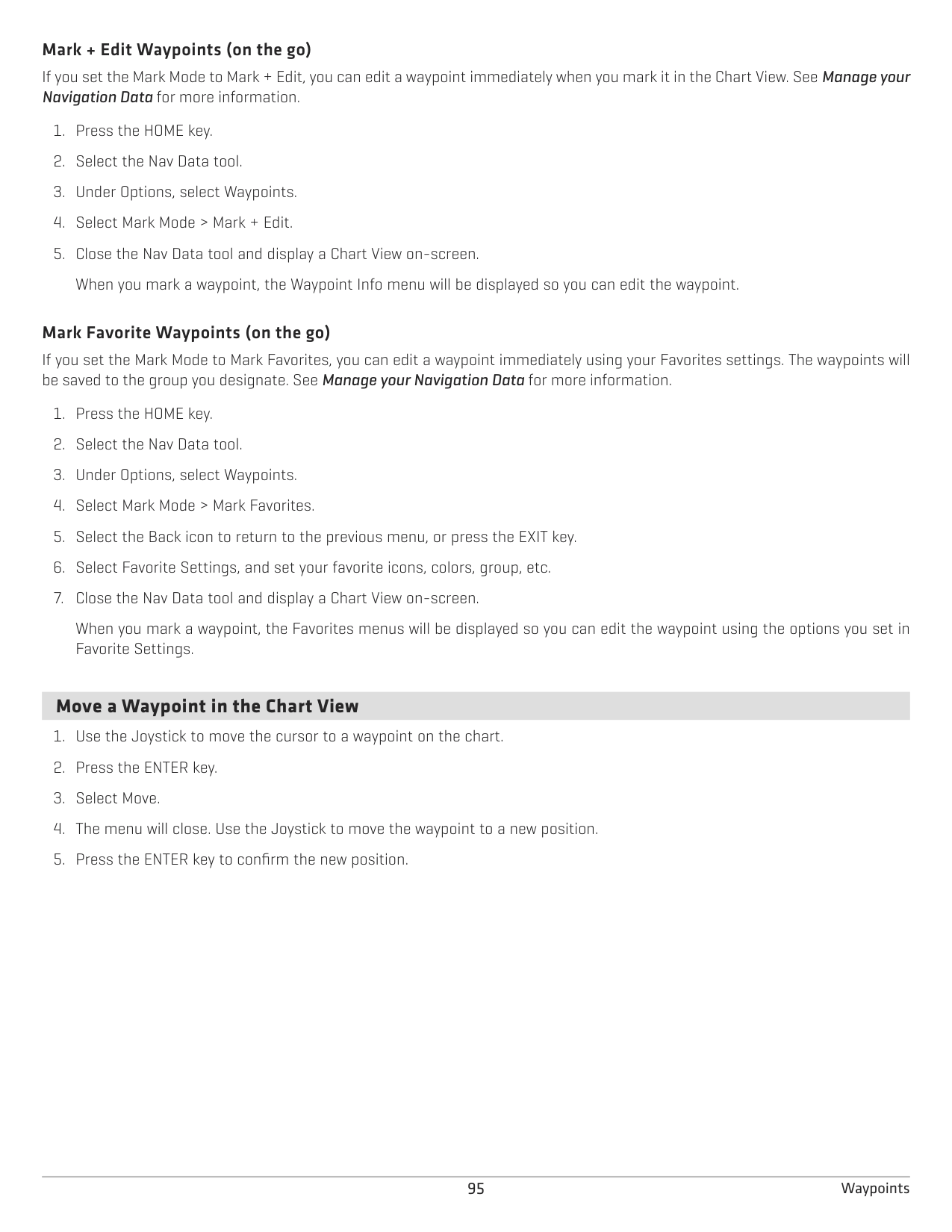
######### Mark Favorite Waypoints (on the go)
If you set the Mark Mode to Mark Favorites, you can edit a waypoint immediately using your Favorites settings. The waypoints will be saved to the group you designate. See Manage your Navigation Data for more information.
When you mark a waypoint, the Favorites menus will be displayed so you can edit the waypoint using the options you set in Favorite Settings.
####### Move a Waypoint in the Chart View
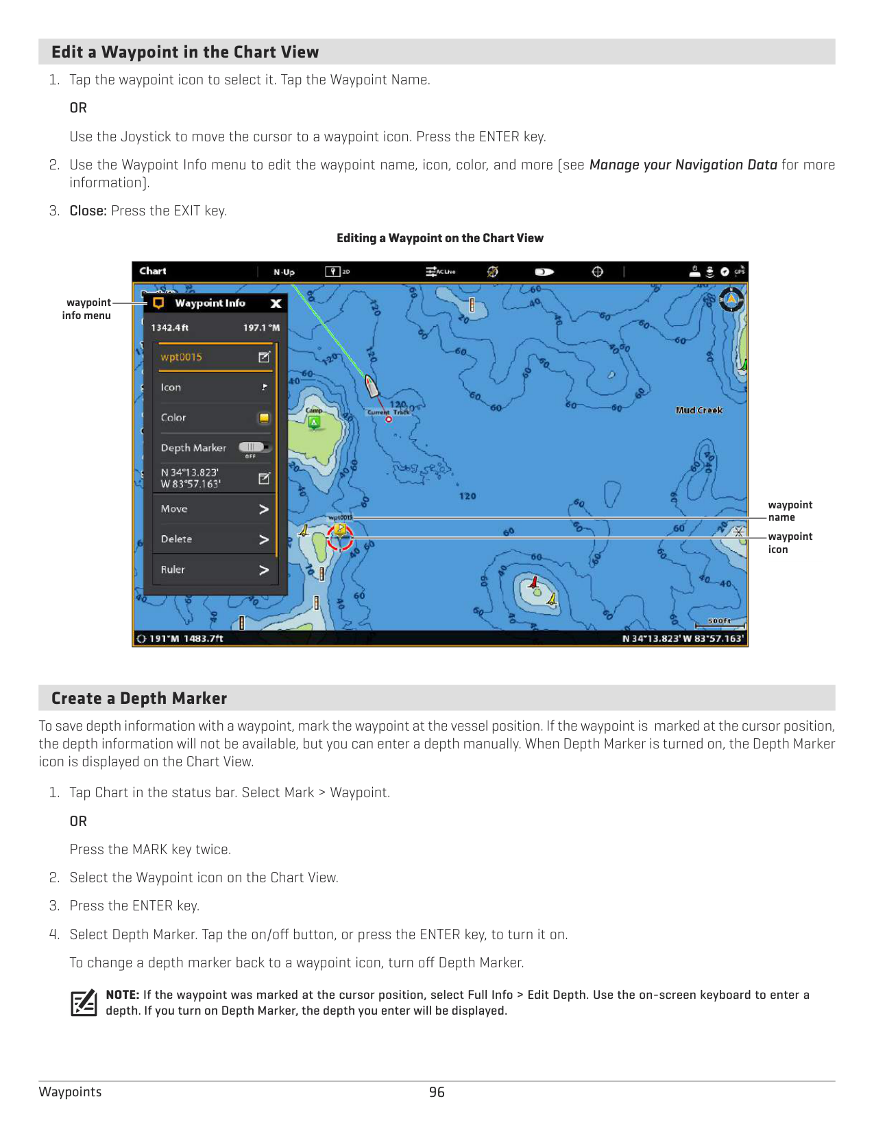
####### Edit a Waypoint in the Chart View
################# Editing a Waypoint on the Chart View

waypoint info menu
waypoint name
waypoint icon
####### Create a Depth Marker
To save depth information with a waypoint, mark the waypoint at the vessel position. If the waypoint is marked at the cursor position, the depth information will not be available, but you can enter a depth manually. When Depth Marker is turned on, the Depth Marker icon is displayed on the Chart View.
NOTE: If the waypoint was marked at the cursor position, select Full Info > Edit Depth. Use the on-screen keyboard to enter a depth. If you turn on Depth Marker, the depth you enter will be displayed.
####### Set the Waypoint Radius and Avoidance
A radius can be set around a selected waypoint. If you select Avoidance, the radius will be highlighted around the waypoint. To receive an alarm when the waypoint avoidance radius has been crossed, turn on the Waypoint Avoidance Alarm (see Navigation Alarms Overview).
####### Display/Hide a Trolling Grid
The Trolling Grid applies a grid to the Chart View that can be used as a guide when trolling around a specific position. The trolling grid can be applied to any positon on the chart.
####### Delete a Waypoint in the Chart View
ROUTES
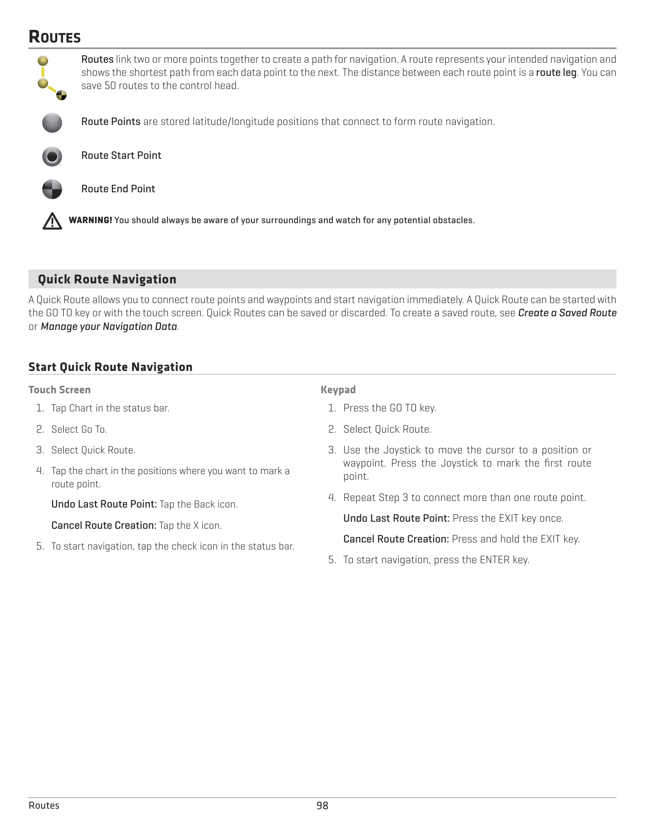
Routes link two or more points together to create a path for navigation. A route represents your intended navigation and shows the shortest path from each data point to the next. The distance between each route point is a route leg. You can save 50 routes to the control head.


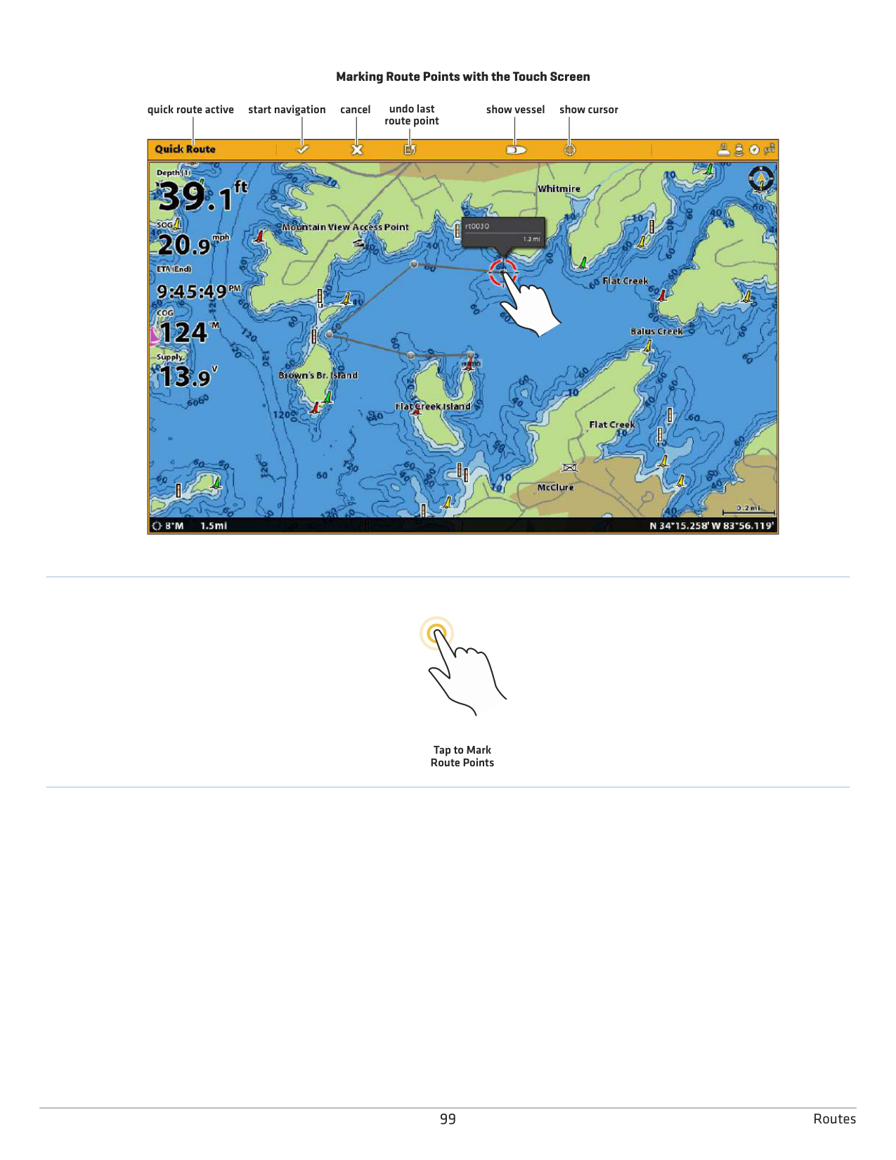


Route Points are stored latitude/longitude positions that connect to form route navigation.


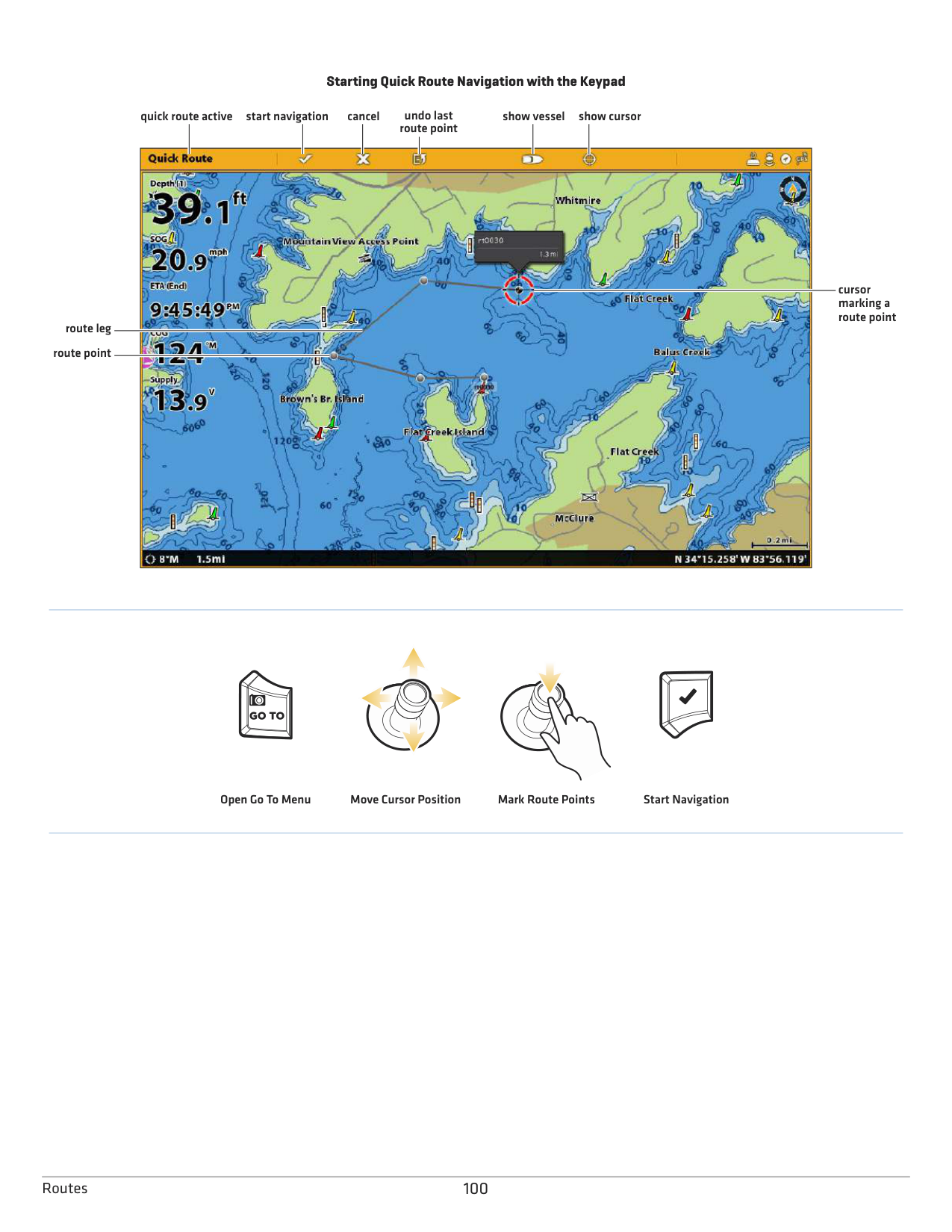


Route Start Point
Route End Point
WARNING! You should always be aware of your surroundings and watch for any potential obstacles.
####### Quick Route Navigation
A Quick Route allows you to connect route points and waypoints and start navigation immediately. A Quick Route can be started with the GO TO key or with the touch screen. Quick Routes can be saved or discarded. To create a saved route, see Create a Saved Route or Manage your Navigation Data.
######## Start Quick Route Navigation Touch Screen
############ Keypad
################# Marking Route Points with the Touch Screen
start navigationquick route active cancel undo last route point
show vessel show cursor

Tap to Mark Route Points
################# Starting Quick Route Navigation with the Keypad
start navigationquick route active cancel undo last route point
show vessel show cursor

cursor marking a route point
route leg
route point
Start NavigationMark Route PointsMove Cursor PositionOpen Go To Menu
######### Change Route Order During Navigation
Reverse Route: Reverses the currently navigated route. Navigation will start from the vessel position and continue in the opposite order.
######### Cancel Quick Route Navigation
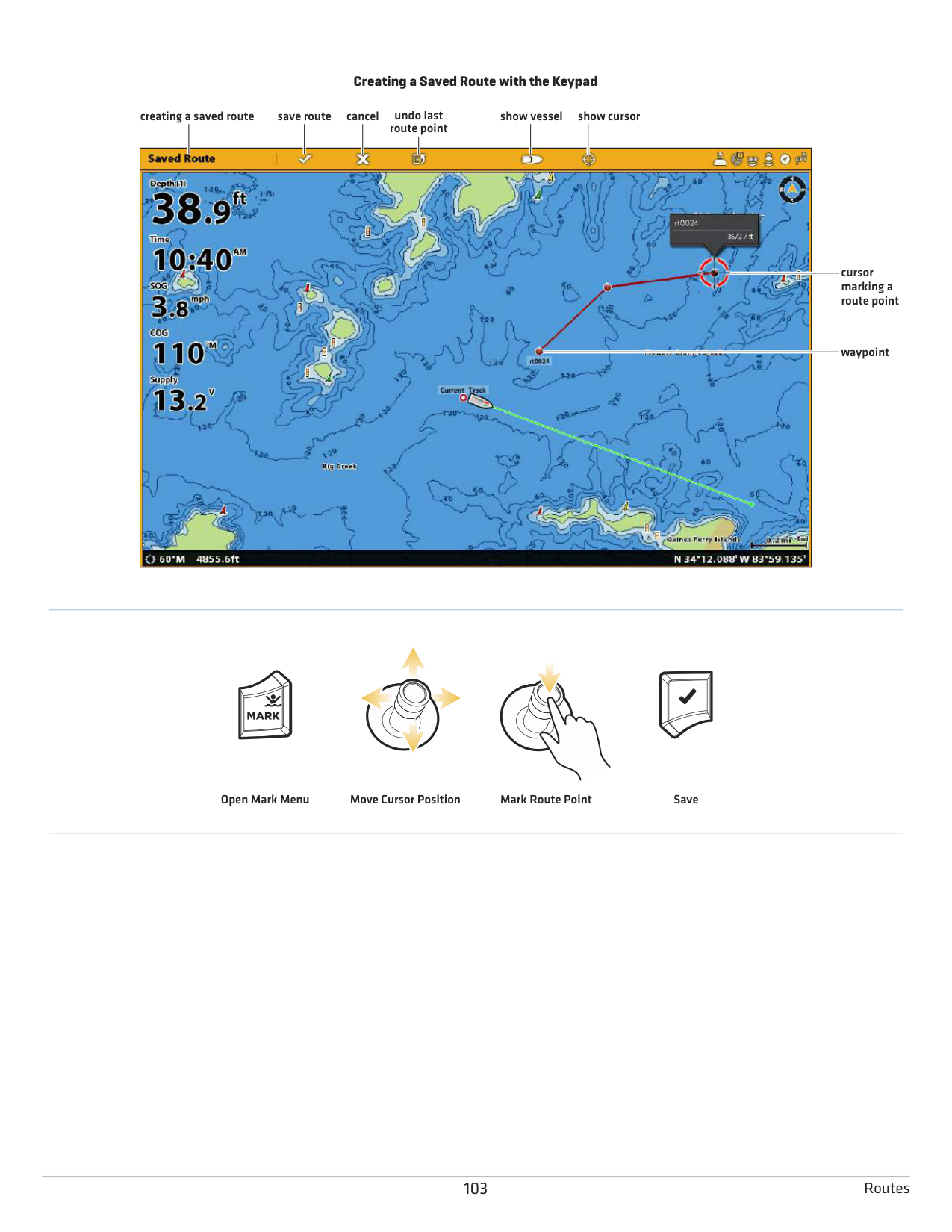
####### Start Navigation to a Saved Waypoint or Route
Use the cursor to select a saved waypoint or route point on the Chart View, and you can start navigation to it. If you select a route point, you can also choose a navigation order for the selected route.
######## Start Navigation Touch Screen
############ Keypad
Cancel Navigation: Press the GO TO key. Select Cancel Navigation.
Cancel Navigation: Tap Chart in the status bar. Select Go To > Cancel Navigation.
####### Program a Position and Start Navigation
Use the instructions in this section to enter a latitude/longitude position and start navigation to it.
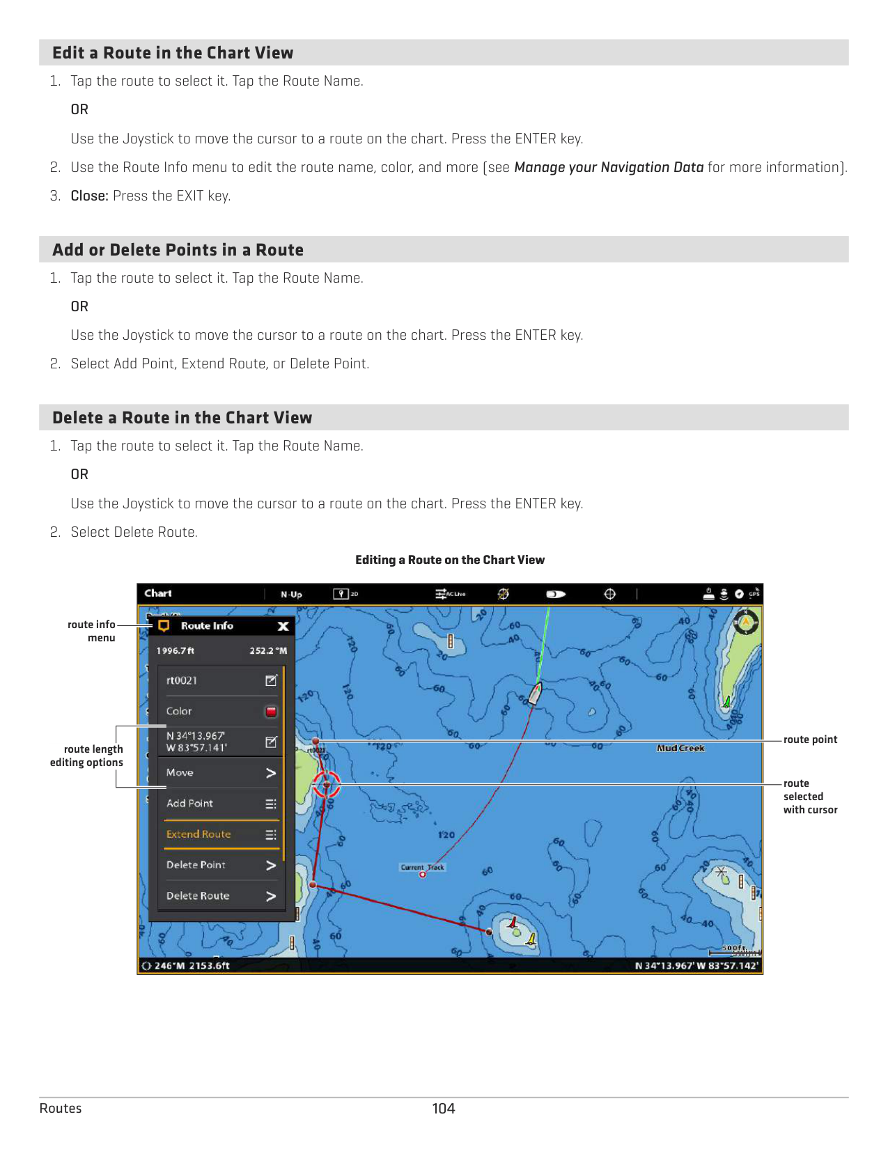
######### Start Navigation to a Latitude/Longitude Position
####### Create a Saved Route
The instructions in this section allow you to create a route in the Chart View and save it for navigation later. The steps are similar to creating a Quick Route, but you will use the Mark menu to start.
Save Location: The route is saved to the Nav Data tool. Navigation: To start navigation on the route, see Start Navigation to a Saved Waypoint or Route. Overlay: To display saved routes on the Chart View, press the MENU key once. Select Chart Options > Overlays > Nav Data > Routes (Saved).
######## Create a Saved Route Touch Screen
############ Keypad
################# Creating a Saved Route with the Keypad
save routecreating a saved route cancel undo last route point
show vessel show cursor

cursor marking a route point
waypoint
Open Mark Menu Move Cursor Position Mark Route Point Save
####### Edit a Route in the Chart View
####### Add or Delete Points in a Route
####### Delete a Route in the Chart View

route info menu
route point
route length editing options
route selected with cursor
SEARCH
There are many ways to search the area for ports, services, tide stations, current stations, and other points of interest. You can also search the nearest waypoints, routes, and tracks. In many cases, you can also use the Go To menu to start navigation to your selection. The search options and the search area distance are determined by the selected map source.
NOTE: For more information about the ENTER key and the Info menu, see Navigation Menu Overview.
Search by Vessel Position If Navionics is selected as the map source, you can run a search based on the vessel position.
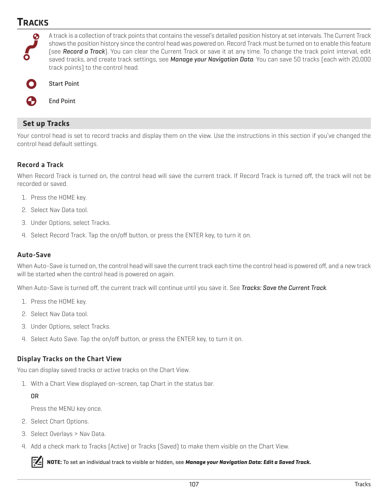
Search by Cursor Position If Navionics is selected as the map source, you can run a search based on the cursor position.
Search for a Lake If Humminbird is selected as the map source, you can search for lakes in the area.
105 Search
Find the Nearest Navigation Data Use the Find Nearest menu to search for the closest waypoints, routes, and tracks.
106Search
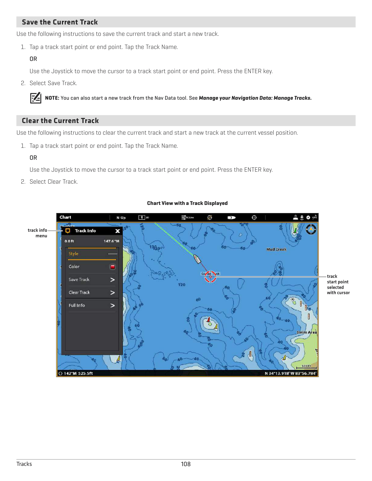
TRACKS
A track is a collection of track points that contains the vessel’s detailed position history at set intervals. The Current Track shows the position history since the control head was powered on. Record Track must be turned on to enable this feature (see Record a Track). You can clear the Current Track or save it at any time. To change the track point interval, edit saved tracks, and create track settings, see Manage your Navigation Data. You can save 50 tracks (each with 20,000 track points) to the control head.
Start Point
End Point
####### Set up Tracks
Your control head is set to record tracks and display them on the view. Use the instructions in this section if you’ve changed the control head default settings.
######### Record a Track
When Record Track is turned on, the control head will save the current track. If Record Track is turned off, the track will not be recorded or saved.
######### Auto-Save
When Auto-Save is turned on, the control head will save the current track each time the control head is powered off, and a new track will be started when the control head is powered on again.
When Auto-Save is turned off, the current track will continue until you save it. See Tracks: Save the Current Track.
Display Tracks on the Chart View You can display saved tracks or active tracks on the Chart View.
NOTE: To set an individual track to visible or hidden, see Manage your Navigation Data: Edit a Saved Track.
####### Save the Current Track
Use the following instructions to save the current track and start a new track.
NOTE: You can also start a new track from the Nav Data tool. See Manage your Navigation Data: Manage Tracks.
####### Clear the Current Track
Use the following instructions to clear the current track and start a new track at the current vessel position.
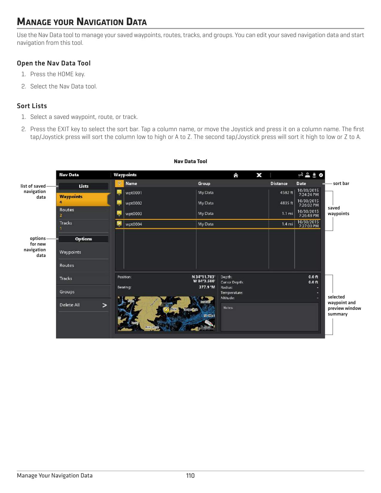
Chart View with a Track Displayed

track info menu
track start point selected with cursor
108Tracks
####### Edit a Track in the Chart View
NOTE: To change the default appearance for new tracks, or to change the Track Point Interval, see Manage your Navigation Data: Manage Tracks.
####### Delete a Saved Track
When you delete a saved track, it is permanently deleted from the control head.
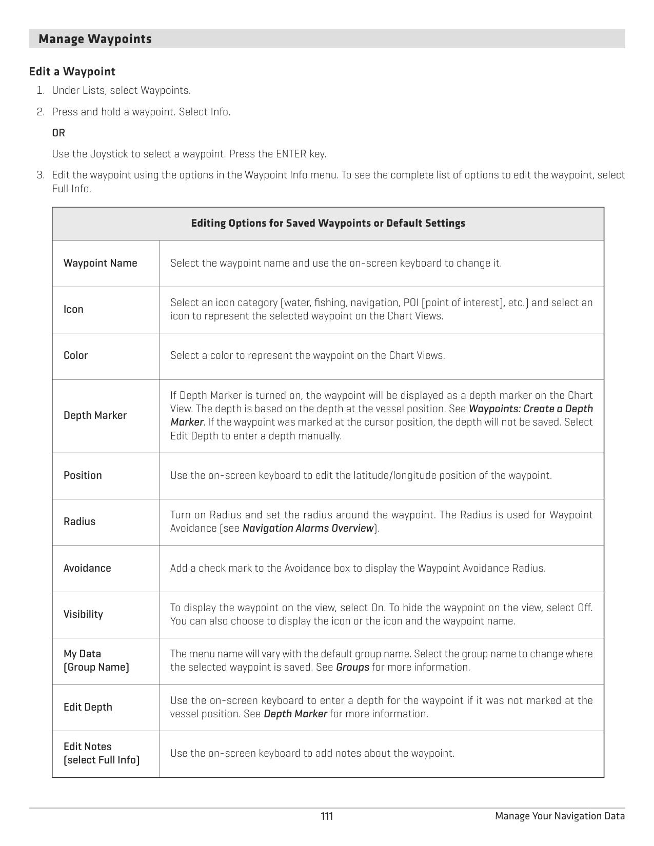
MANAGE YOUR NAVIGATION DATA
Use the Nav Data tool to manage your saved waypoints, routes, tracks, and groups. You can edit your saved navigation data and start navigation from this tool.
######### Open the Nav Data Tool
######### Sort Lists
Nav Data Tool
| || | |---|---|---| | || | | || | | || | | || | | || | | || |
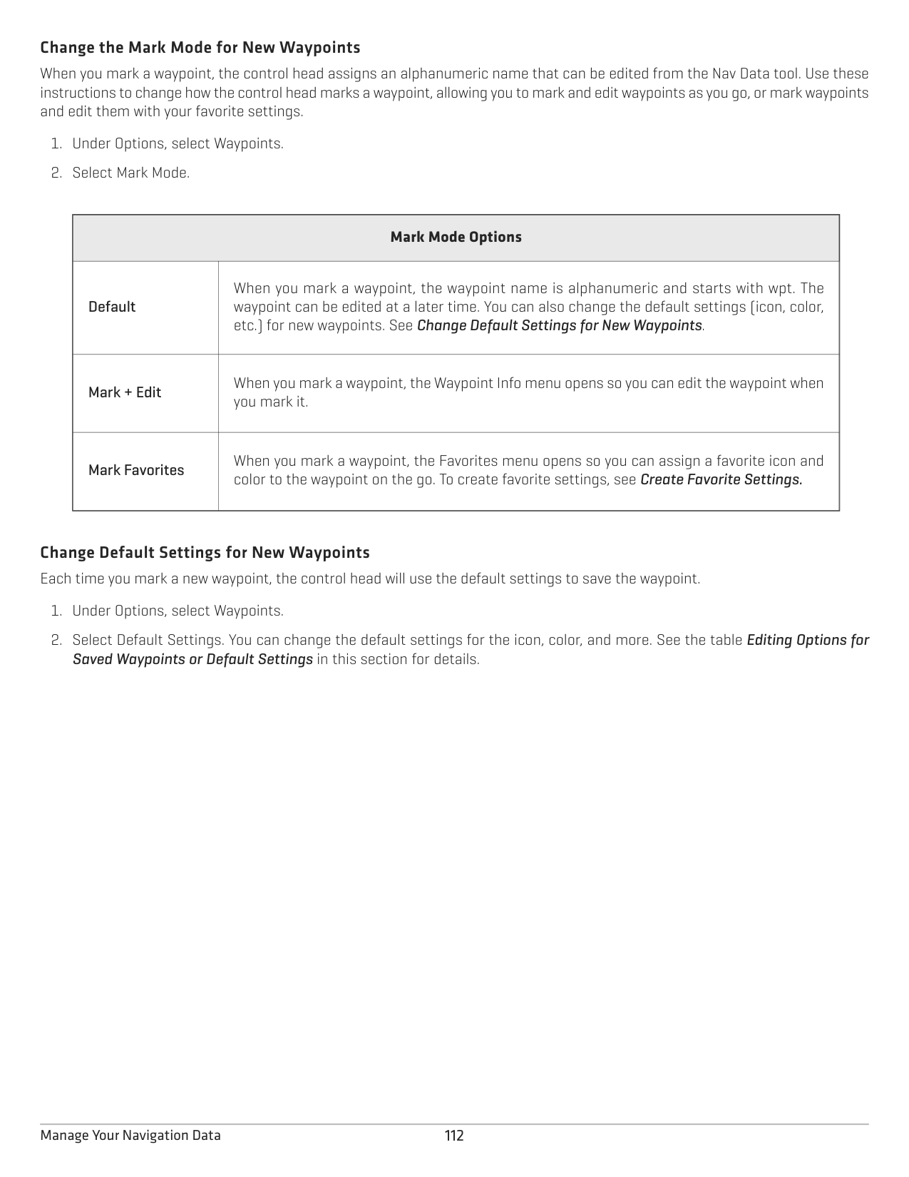
sort bar
list of saved navigation data
saved waypoints
options for new
navigation data
selected waypoint and preview window summary
####### Manage Waypoints
######### Edit a Waypoint
|Editing Options for Saved Waypoints or Default Settings
|Editing Options for Saved Waypoints or Default Settings
| |---|---| |Waypoint Name
|Select the waypoint name and use the on-screen keyboard to change it.| |Icon|Select an icon category (water, fishing, navigation, POI [point of interest], etc.) and select an icon to represent the selected waypoint on the Chart Views.
| |Color|Select a color to represent the waypoint on the Chart Views.
| |Depth Marker|If Depth Marker is turned on, the waypoint will be displayed as a depth marker on the Chart View. The depth is based on the depth at the vessel position. See Waypoints: Create a Depth Marker. If the waypoint was marked at the cursor position, the depth will not be saved. Select Edit Depth to enter a depth manually.
| |Position
|Use the on-screen keyboard to edit the latitude/longitude position of the waypoint.|
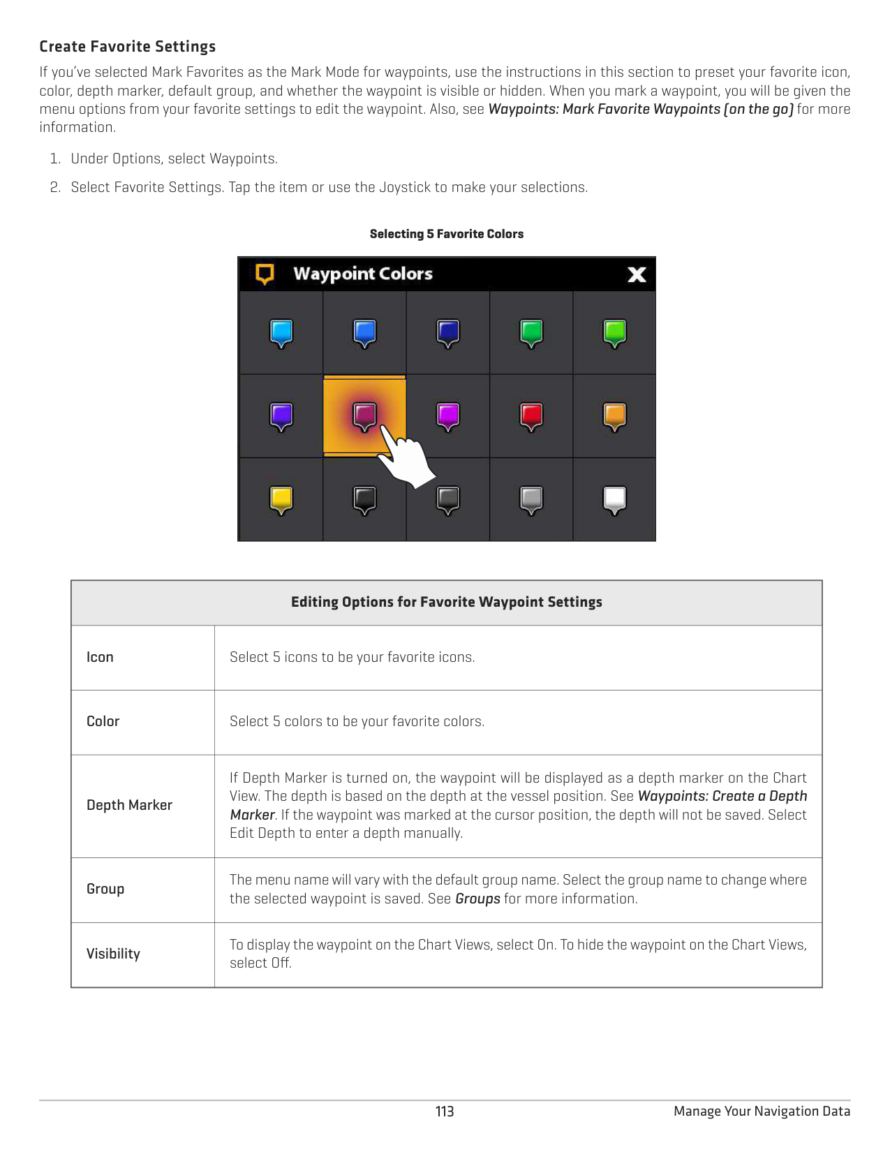
|Radius|Turn on Radius and set the radius around the waypoint. The Radius is used for Waypoint Avoidance (see Navigation Alarms Overview).
| |Avoidance
|Add a check mark to the Avoidance box to display the Waypoint Avoidance Radius.| |Visibility
|To display the waypoint on the view, select On. To hide the waypoint on the view, select Off. You can also choose to display the icon or the icon and the waypoint name.| |My Data (Group Name)|The menu name will vary with the default group name. Select the group name to change where the selected waypoint is saved. See Groups for more information.
| |Edit Depth|Use the on-screen keyboard to enter a depth for the waypoint if it was not marked at the vessel position. See Depth Marker for more information.
| |Edit Notes (select Full Info)|Use the on-screen keyboard to add notes about the waypoint.|
######### Change the Mark Mode for New Waypoints
When you mark a waypoint, the control head assigns an alphanumeric name that can be edited from the Nav Data tool. Use these instructions to change how the control head marks a waypoint, allowing you to mark and edit waypoints as you go, or mark waypoints and edit them with your favorite settings.
|Mark Mode Options
|Mark Mode Options
| |---|---| |Default|When you mark a waypoint, the waypoint name is alphanumeric and starts with wpt. The waypoint can be edited at a later time. You can also change the default settings (icon, color, etc.) for new waypoints. See Change Default Settings for New Waypoints.
| |Mark + Edit|When you mark a waypoint, the Waypoint Info menu opens so you can edit the waypoint when you mark it.
| |Mark Favorites|When you mark a waypoint, the Favorites menu opens so you can assign a favorite icon and color to the waypoint on the go. To create favorite settings, see Create Favorite Settings.|
Change Default Settings for New Waypoints Each time you mark a new waypoint, the control head will use the default settings to save the waypoint.
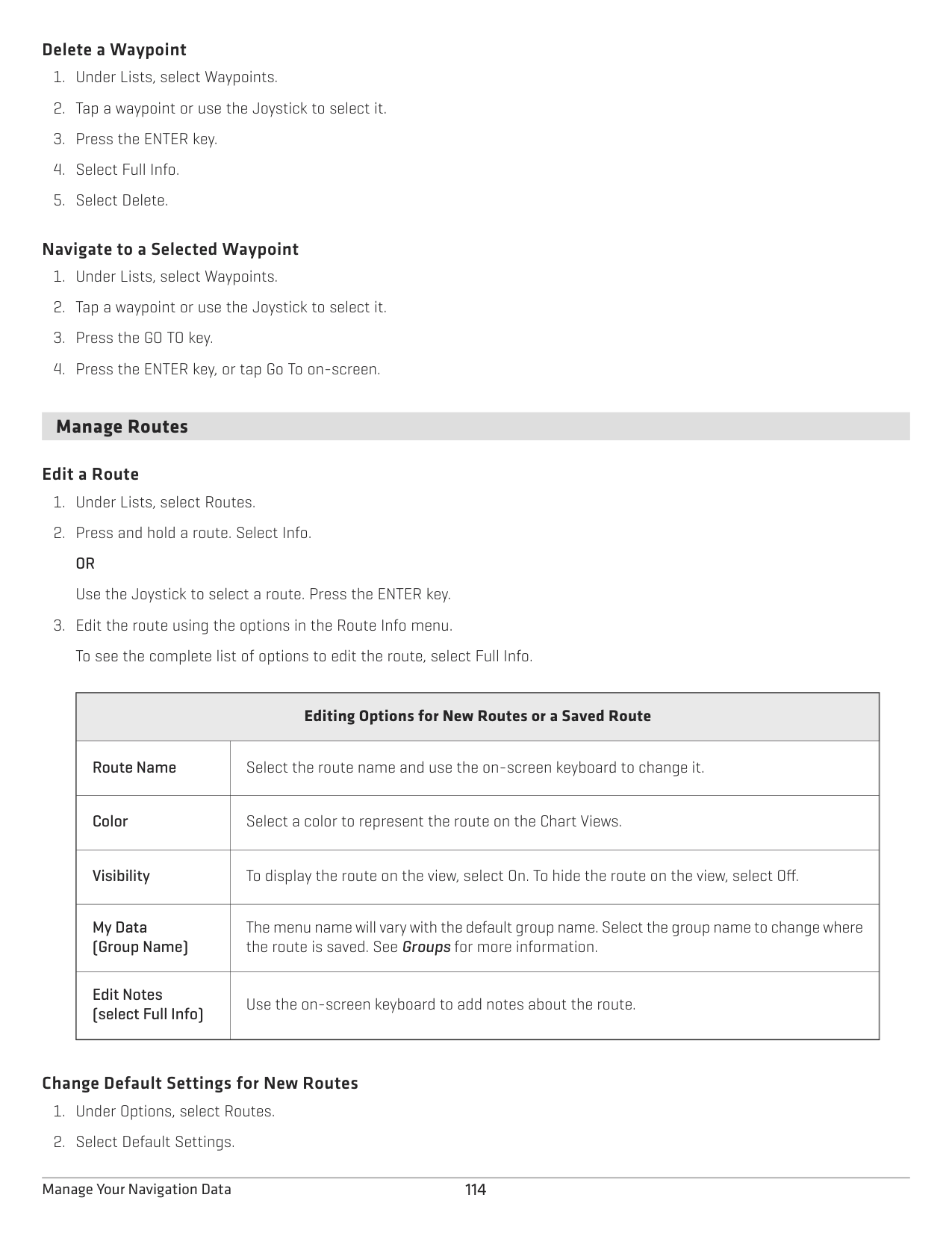
############# Saved Waypoints or Default Settings in this section for details.
######### Create Favorite Settings
If you’ve selected Mark Favorites as the Mark Mode for waypoints, use the instructions in this section to preset your favorite icon, color, depth marker, default group, and whether the waypoint is visible or hidden. When you mark a waypoint, you will be given the menu options from your favorite settings to edit the waypoint. Also, see Waypoints: Mark Favorite Waypoints (on the go) for more information.
Selecting 5 Favorite Colors
|
| |---|
|Editing Options for Favorite Waypoint Settings
|Editing Options for Favorite Waypoint Settings
| |---|---| |Icon|Select 5 icons to be your favorite icons.
| |Color|Select 5 colors to be your favorite colors.
| |Depth Marker
|If Depth Marker is turned on, the waypoint will be displayed as a depth marker on the Chart View. The depth is based on the depth at the vessel position. See Waypoints: Create a Depth Marker. If the waypoint was marked at the cursor position, the depth will not be saved. Select Edit Depth to enter a depth manually.| |Group
|The menu name will vary with the default group name. Select the group name to change where the selected waypoint is saved. See Groups for more information.| |Visibility|To display the waypoint on the Chart Views, select On. To hide the waypoint on the Chart Views, select Off.|
######### Delete a Waypoint
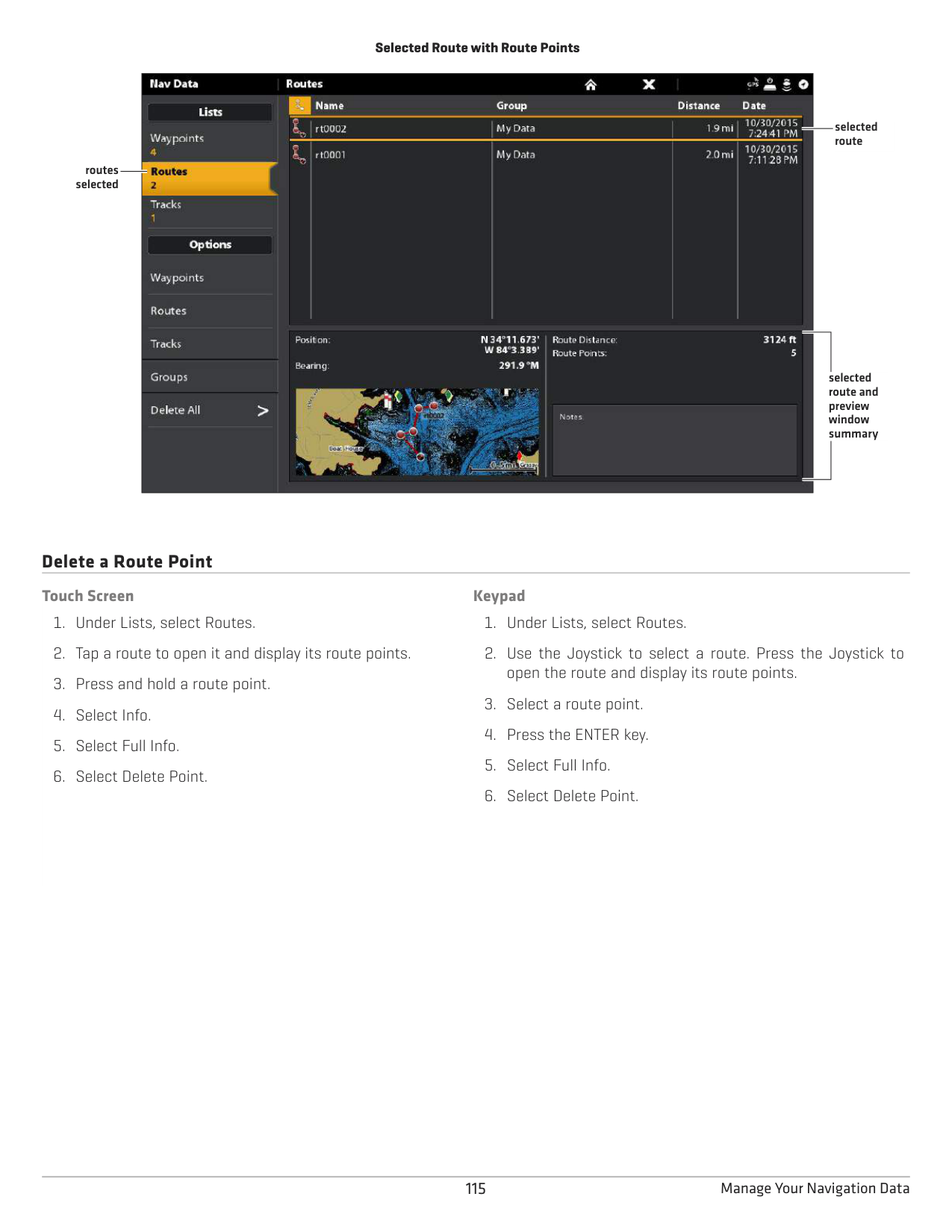
######### Navigate to a Selected Waypoint
####### Manage Routes
######### Edit a Route
|Editing Options for New Routes or a Saved Route
|Editing Options for New Routes or a Saved Route
| |---|---| |Route Name
|Select the route name and use the on-screen keyboard to change it.| |Color
|Select a color to represent the route on the Chart Views.| |Visibility|To display the route on the view, select On. To hide the route on the view, select Off.
| |My Data (Group Name)
|The menu name will vary with the default group name. Select the group name to change where the route is saved. See Groups for more information.| |Edit Notes (select Full Info)
|Use the on-screen keyboard to add notes about the route.|
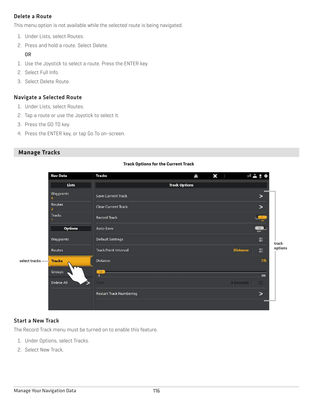
######### Change Default Settings for New Routes
################# Selected Route with Route Points

selected route
routes selected
selected route and preview window summary
######## Delete a Route Point
############ Touch Screen
############ Keypad
Delete a Route This menu option is not available while the selected route is being navigated.
######### Navigate a Selected Route
####### Manage Tracks
Track Options for the Current Track

track options
select tracks
Start a New Track The Record Track menu must be turned on to enable this feature.
######### Record a Track
When Record Track is turned on, the control head will save the current track. If you power off the control head and then power on the control head at a different position, there might be gaps in the track.
If Record Track is turned off, the track will not be displayed on the Chart View, and the track will not be recorded or saved.
######### Auto-Save
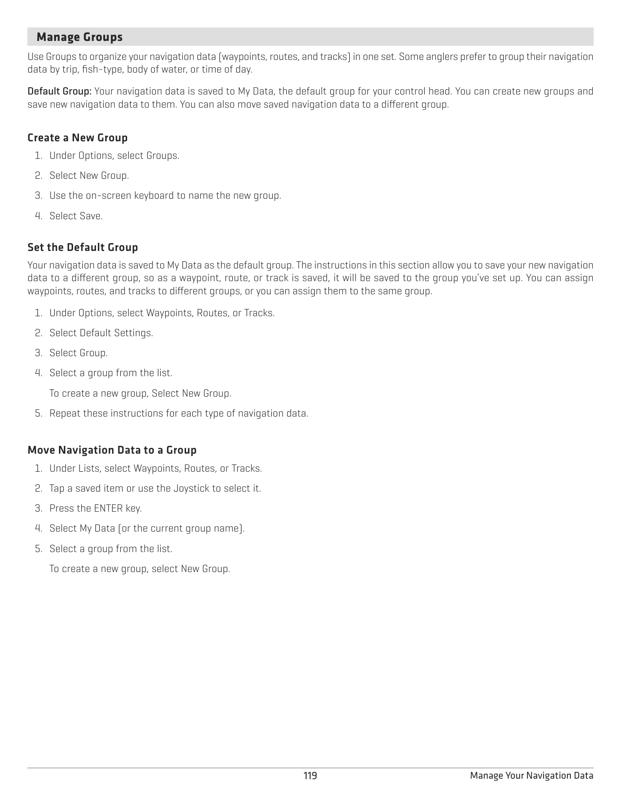
When Auto-Save is turned on, the control head will save the current track each time the control head is powered off, and a new track will be started when the control head is powered on again.
When Auto-Save is turned off, the current track will continue until you save it (see Tracks: Save the Current Track).
######### Change Default Settings for New Tracks
|Changing the Default Settings for New Tracks
|Changing the Default Settings for New Tracks
| |---|---| |Style
|Select a line style.| |Color
|Select a color.| |Group|Select the group name to change where tracks will be saved. You can also open a new group from this menu. See Groups for more information.
|
######### Change the Track Point Interval
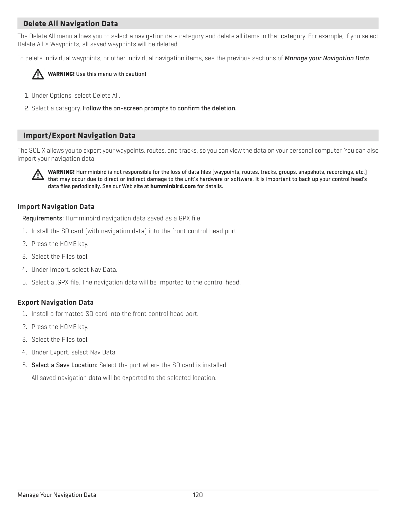
######### Edit a Saved Track
|Editing Options for a Saved Track
|Editing Options for a Saved Track
| |---|---| |Track Name
|Select the track name and use the on-screen keyboard to change it.| |Style|Select a line style.
| |Color
|Select a color.| |Visibility|To display the track on the Chart Views, select On. To hide the track on the Chart Views, select Off.
| |My Data (Group Name)|The menu name will vary with the default group name. Select the group name to change where the selected track is saved. See Groups for more information.
| |Edit Notes (select Full Info)|Use the on-screen keyboard to add notes about the selected track.
|
######### Delete a Track
############# OR
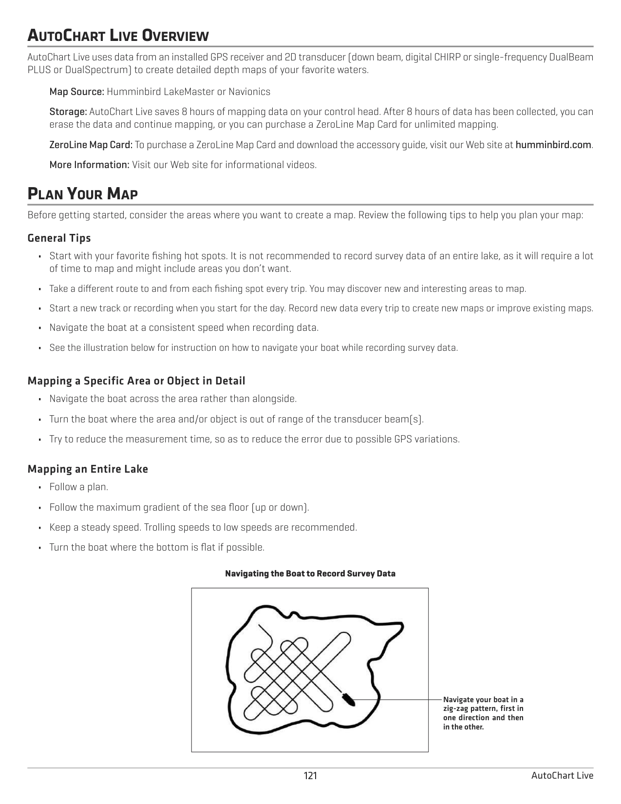
####### Manage Groups
Use Groups to organize your navigation data (waypoints, routes, and tracks) in one set. Some anglers prefer to group their navigation data by trip, fish-type, body of water, or time of day.
Default Group: Your navigation data is saved to My Data, the default group for your control head. You can create new groups and save new navigation data to them. You can also move saved navigation data to a different group.
######### Create a New Group
######### Set the Default Group
Your navigation data is saved to My Data as the default group. The instructions in this section allow you to save your new navigation data to a different group, so as a waypoint, route, or track is saved, it will be saved to the group you’ve set up. You can assign waypoints, routes, and tracks to different groups, or you can assign them to the same group.
######### Move Navigation Data to a Group
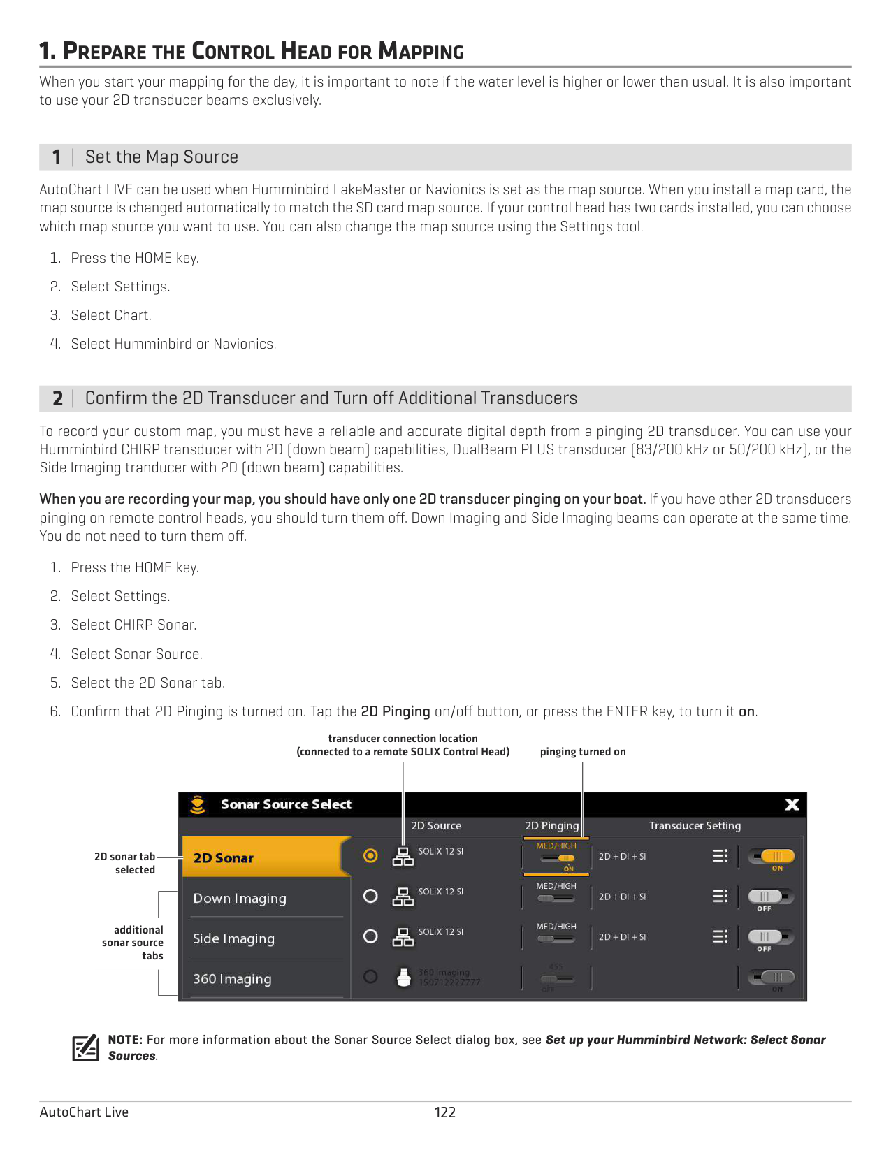
####### Delete All Navigation Data
The Delete All menu allows you to select a navigation data category and delete all items in that category. For example, if you select Delete All > Waypoints, all saved waypoints will be deleted.
To delete individual waypoints, or other individual navigation items, see the previous sections of Manage your Navigation Data.
WARNING! Use this menu with caution!
####### Import/Export Navigation Data
The SOLIX allows you to export your waypoints, routes, and tracks, so you can view the data on your personal computer. You can also import your navigation data.
WARNING! Humminbird is not responsible for the loss of data files (waypoints, routes, tracks, groups, snapshots, recordings, etc.) that may occur due to direct or indirect damage to the unit’s hardware or software. It is important to back up your control head’s data files periodically. See our Web site at humminbird.com for details.
######### Import Navigation Data
Requirements: Humminbird navigation data saved as a GPX file.
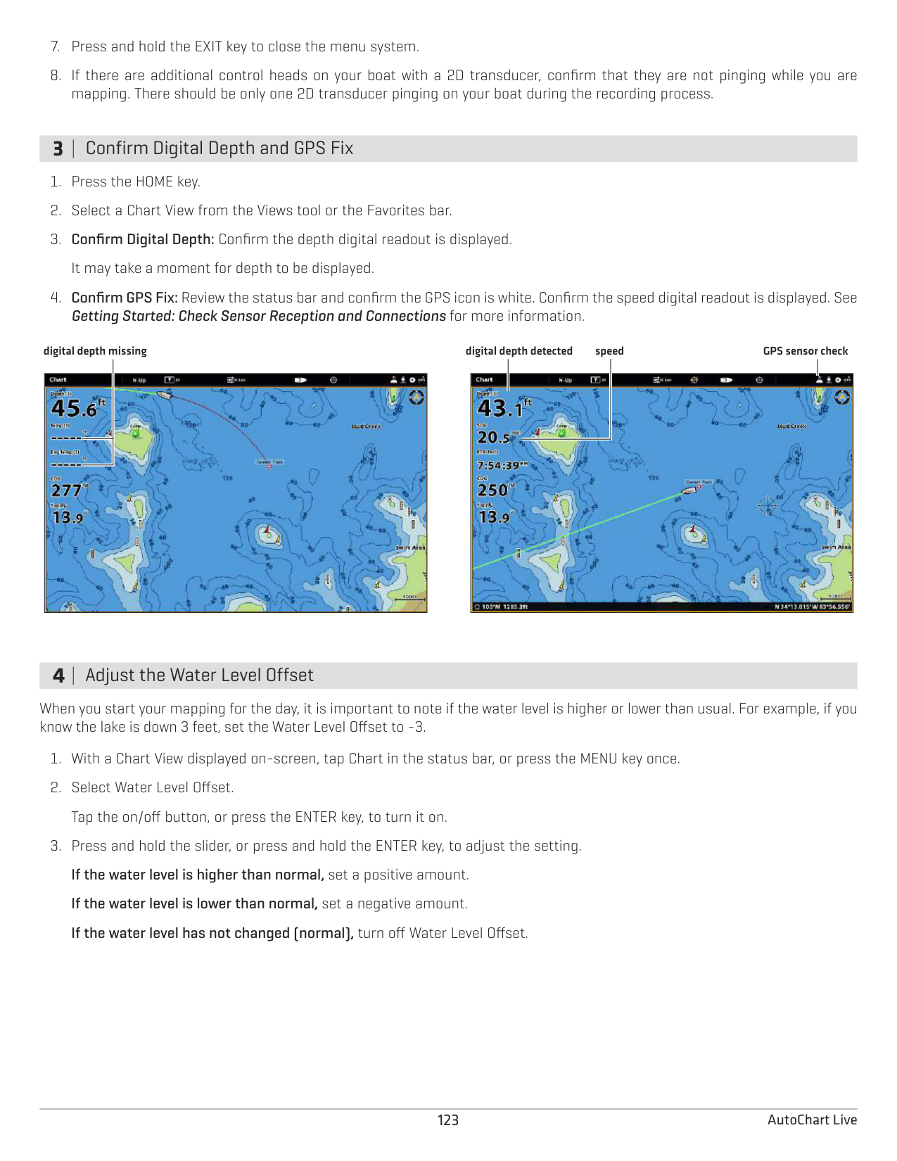
######### Export Navigation Data
AUTOCHART LIVE OVERVIEW
AutoChart Live uses data from an installed GPS receiver and 2D transducer (down beam, digital CHIRP or single-frequency DualBeam PLUS or DualSpectrum) to create detailed depth maps of your favorite waters.
Map Source: Humminbird LakeMaster or Navionics Storage: AutoChart Live saves 8 hours of mapping data on your control head. After 8 hours of data has been collected, you can erase the data and continue mapping, or you can purchase a ZeroLine Map Card for unlimited mapping. ZeroLine Map Card: To purchase a ZeroLine Map Card and download the accessory guide, visit our Web site at humminbird.com. More Information: Visit our Web site for informational videos.
PLAN YOUR MAP Before getting started, consider the areas where you want to create a map. Review the following tips to help you plan your map: General Tips
######### Mapping a Specific Area or Object in Detail
######### Mapping an Entire Lake
Navigating the Boat to Record Survey Data

Navigate your boat in a zig-zag pattern, first in one direction and then in the other.
1. PREPARE THE CONTROL HEAD FOR MAPPING
When you start your mapping for the day, it is important to note if the water level is higher or lower than usual. It is also important to use your 2D transducer beams exclusively.
1 | Set the Map Source
AutoChart LIVE can be used when Humminbird LakeMaster or Navionics is set as the map source. When you install a map card, the map source is changed automatically to match the SD card map source. If your control head has two cards installed, you can choose which map source you want to use. You can also change the map source using the Settings tool.
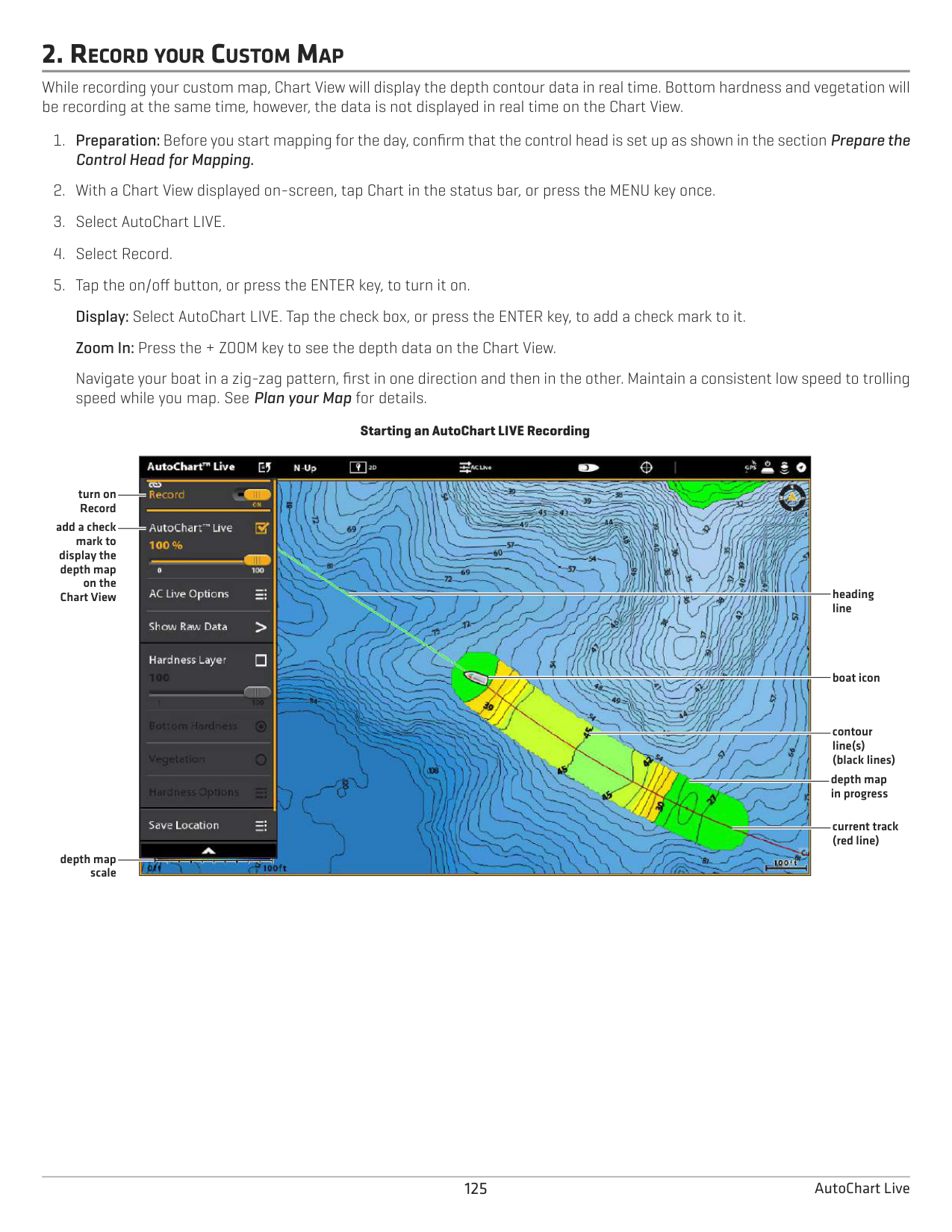
2 | Confirm the 2D Transducer and Turn off Additional Transducers
To record your custom map, you must have a reliable and accurate digital depth from a pinging 2D transducer. You can use your Humminbird CHIRP transducer with 2D (down beam) capabilities, DualBeam PLUS transducer (83/200 kHz or 50/200 kHz), or the Side Imaging tranducer with 2D (down beam) capabilities.
When you are recording your map, you should have only one 2D transducer pinging on your boat. If you have other 2D transducers pinging on remote control heads, you should turn them off. Down Imaging and Side Imaging beams can operate at the same time. You do not need to turn them off.
transducer connection location (connected to a remote SOLIX Control Head) pinging turned on

2D sonar tab selected
additional sonar source
tabs
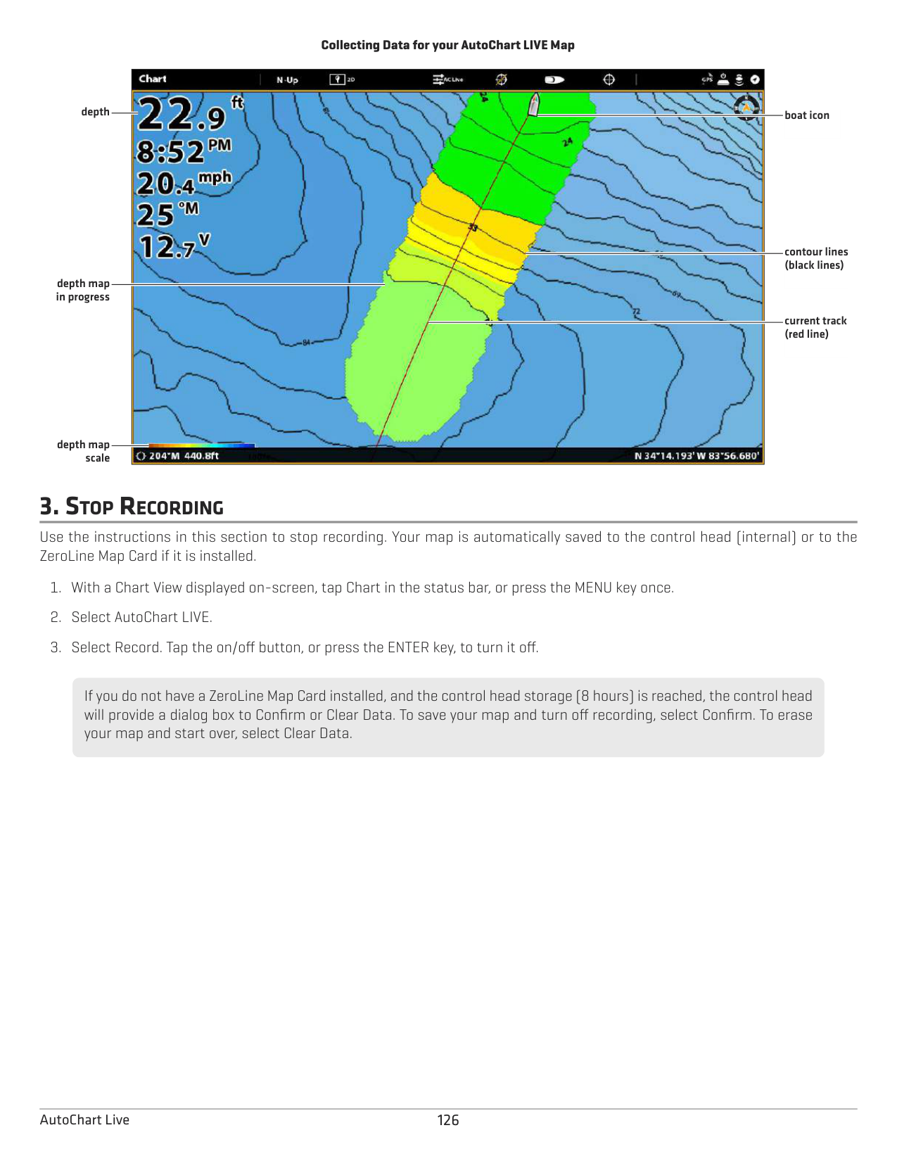
NOTE: For more information about the Sonar Source Select dialog box, see Set up your Humminbird Network: Select Sonar Sources.
3 | Confirm Digital Depth and GPS Fix
digital depth detected GPS sensor checkdigital depth missingspeed


4 | Adjust the Water Level Offset
When you start your mapping for the day, it is important to note if the water level is higher or lower than usual. For example, if you know the lake is down 3 feet, set the Water Level Offset to -3.
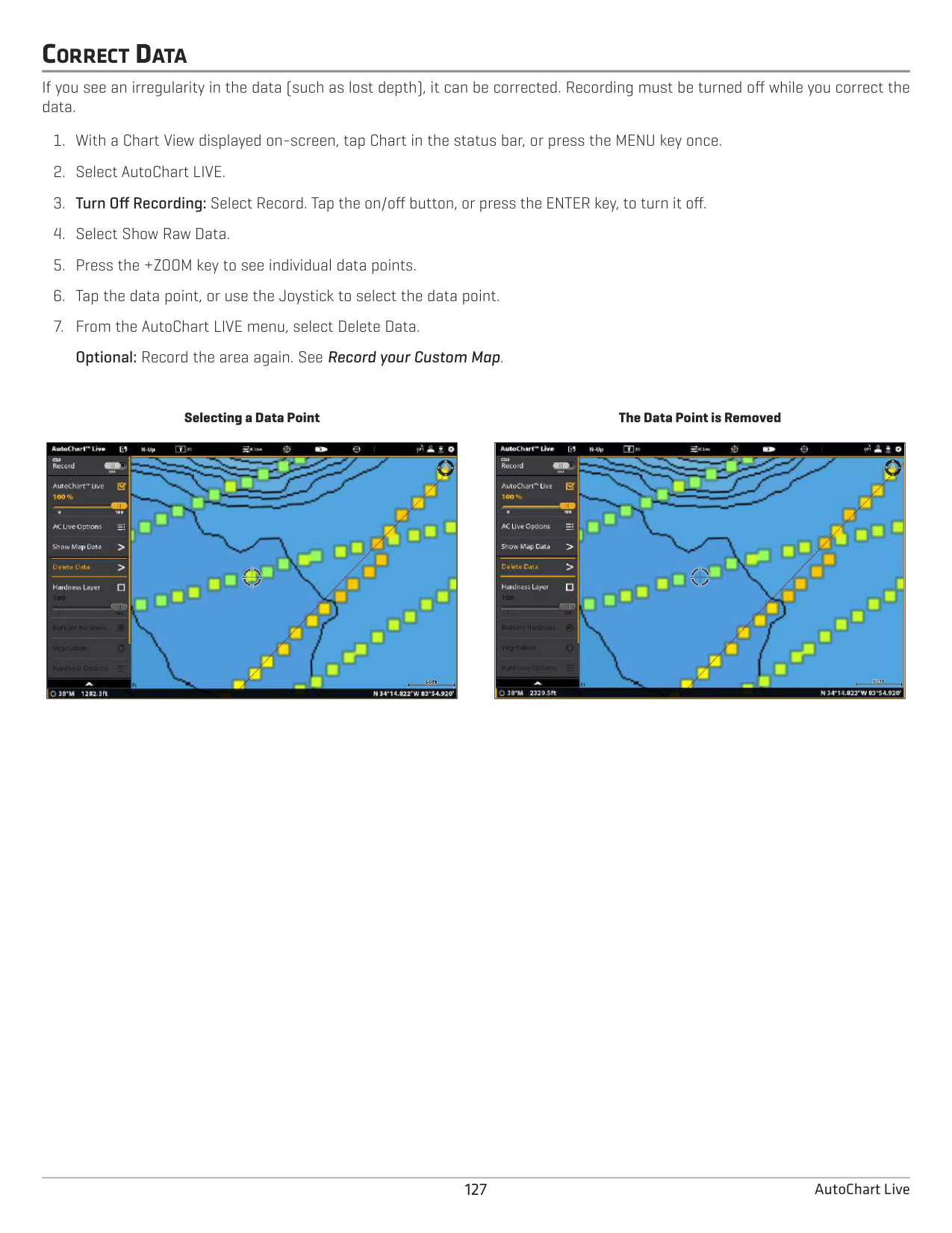
5 | Display the Current Track (optional)
It is helpful to display the current track so you can see where the boat has already traveled while you’re recording the map.
6 | Start a Sonar Recording for AutoChart PC (optional)
If you are planning to use AutoChart PC, start a sonar recording before you start recording your custom map. Sonar Recording can be started from the Recordings tool or from the X-Press Menu in a Sonar View. The instructions for the Recordings tool are shown here.
NOTE: For more information, see Sonar Recording. Also, visit our Web site at humminbird.com to purchase AutoChart PC and download the manual.
2. RECORD YOUR CUSTOM MAP
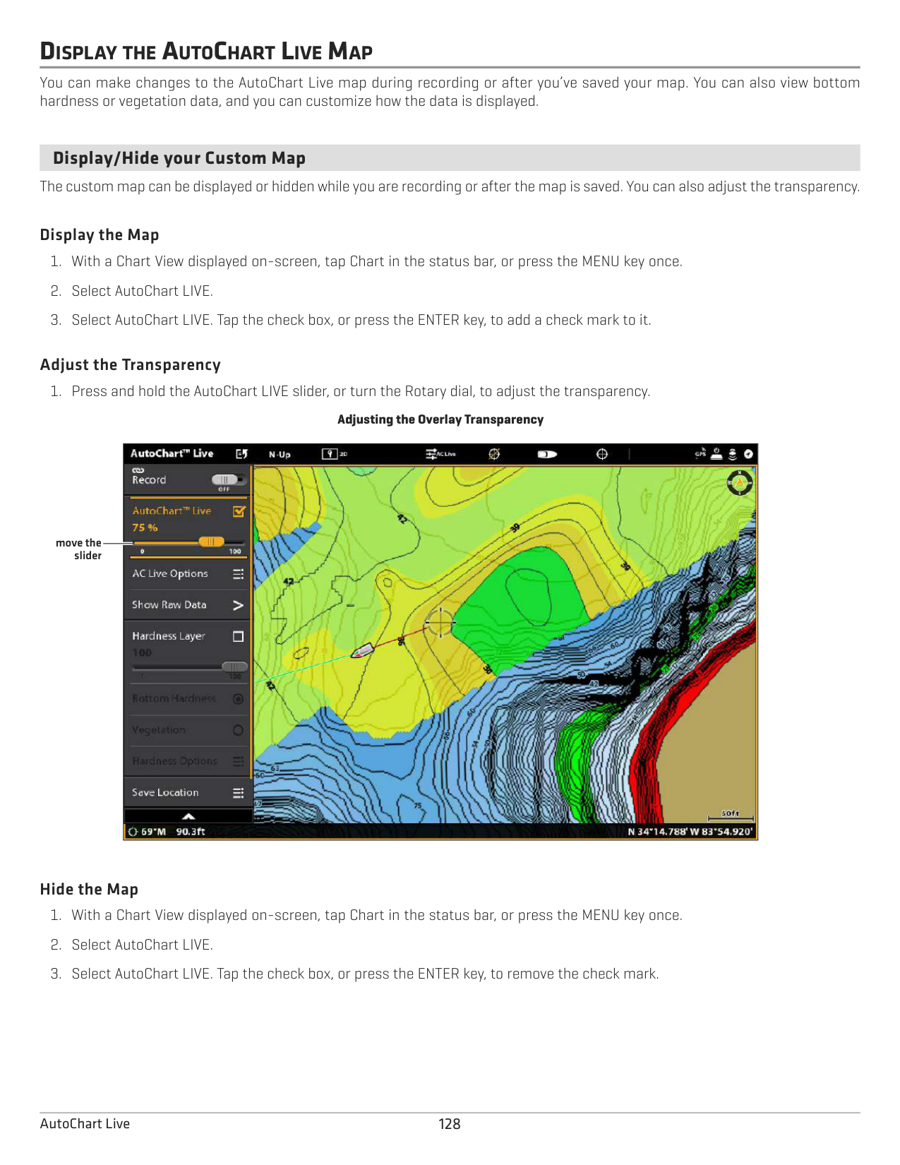
While recording your custom map, Chart View will display the depth contour data in real time. Bottom hardness and vegetation will be recording at the same time, however, the data is not displayed in real time on the Chart View.
Navigate your boat in a zig-zag pattern, first in one direction and then in the other. Maintain a consistent low speed to trolling speed while you map. See Plan your Map for details.
Starting an AutoChart LIVE Recording

turn on Record
add a check
mark to display the depth map
on the Chart View
heading line
boat icon
contour line(s) (black lines)
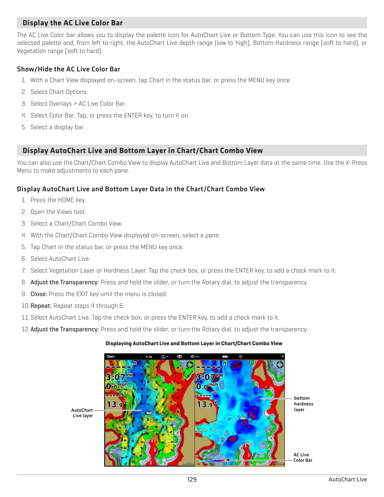
depth map in progress
current track (red line)
depth map scale
Collecting Data for your AutoChart LIVE Map

depth boat icon
contour lines (black lines)
depth map in progress
current track (red line)
depth map scale
3. STOP RECORDING
Use the instructions in this section to stop recording. Your map is automatically saved to the control head (internal) or to the ZeroLine Map Card if it is installed.
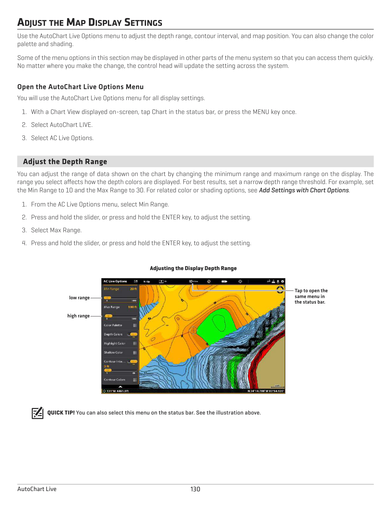
If you do not have a ZeroLine Map Card installed, and the control head storage (8 hours) is reached, the control head will provide a dialog box to Confirm or Clear Data. To save your map and turn off recording, select Confirm. To erase your map and start over, select Clear Data.
CORRECT DATA
If you see an irregularity in the data (such as lost depth), it can be corrected. Recording must be turned off while you correct the data.
Selecting a Data Point
|| |---|
The Data Point is Removed
|| |---|
DISPLAY THE AUTOCHART LIVE MAP
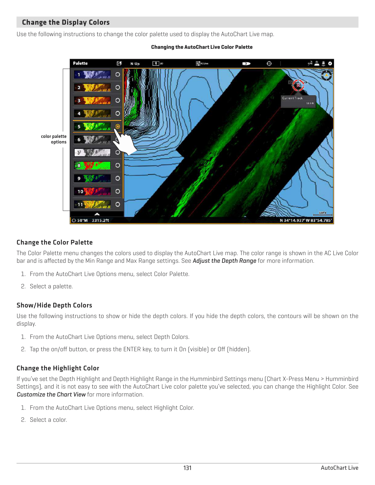
You can make changes to the AutoChart Live map during recording or after you’ve saved your map. You can also view bottom hardness or vegetation data, and you can customize how the data is displayed.
####### Display/Hide your Custom Map
The custom map can be displayed or hidden while you are recording or after the map is saved. You can also adjust the transparency.
######### Display the Map
######### Adjust the Transparency
Adjusting the Overlay Transparency
| || |---|---| | ||
move the slider
######### Hide the Map
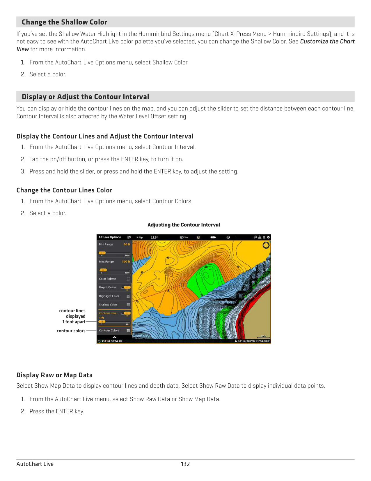
####### Display the AC Live Color Bar
The AC Live Color bar allows you to display the palette icon for AutoChart Live or Bottom Type. You can use this icon to see the selected palette and, from left to right, the AutoChart Live depth range (low to high), Bottom Hardness range (soft to hard), or Vegetation range (soft to hard).
######### Show/Hide the AC Live Color Bar
####### Display AutoChart Live and Bottom Layer in Chart/Chart Combo View
You can also use the Chart/Chart Combo View to display AutoChart Live and Bottom Layer data at the same time. Use the X-Press Menu to make adjustments to each pane.
######### Display AutoChart Live and Bottom Layer Data in the Chart/Chart Combo View
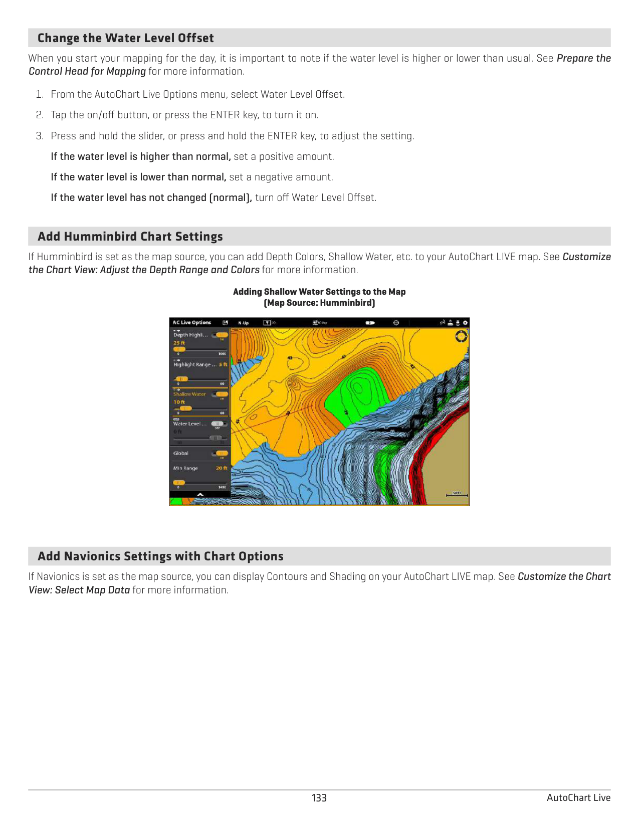

bottom hardness layer
AutoChart Live layer
AC Live Color Bar
ADJUST THE MAP DISPLAY SETTINGS
Use the AutoChart Live Options menu to adjust the depth range, contour interval, and map position. You can also change the color palette and shading.
Some of the menu options in this section may be displayed in other parts of the menu system so that you can access them quickly. No matter where you make the change, the control head will update the setting across the system.
Open the AutoChart Live Options Menu You will use the AutoChart Live Options menu for all display settings.
####### Adjust the Depth Range
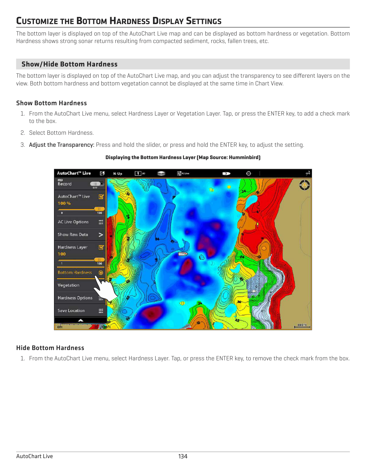
You can adjust the range of data shown on the chart by changing the minimum range and maximum range on the display. The range you select affects how the depth colors are displayed. For best results, set a narrow depth range threshold. For example, set the Min Range to 10 and the Max Range to 30. For related color or shading options, see Add Settings with Chart Options.
################# Adjusting the Display Depth Range

Tap to open the same menu in the status bar.
low range
high range
QUICK TIP! You can also select this menu on the status bar. See the illustration above.
####### Change the Display Colors
Use the following instructions to change the color palette used to display the AutoChart Live map.
################# Changing the AutoChart Live Color Palette
| |
| |---|---|
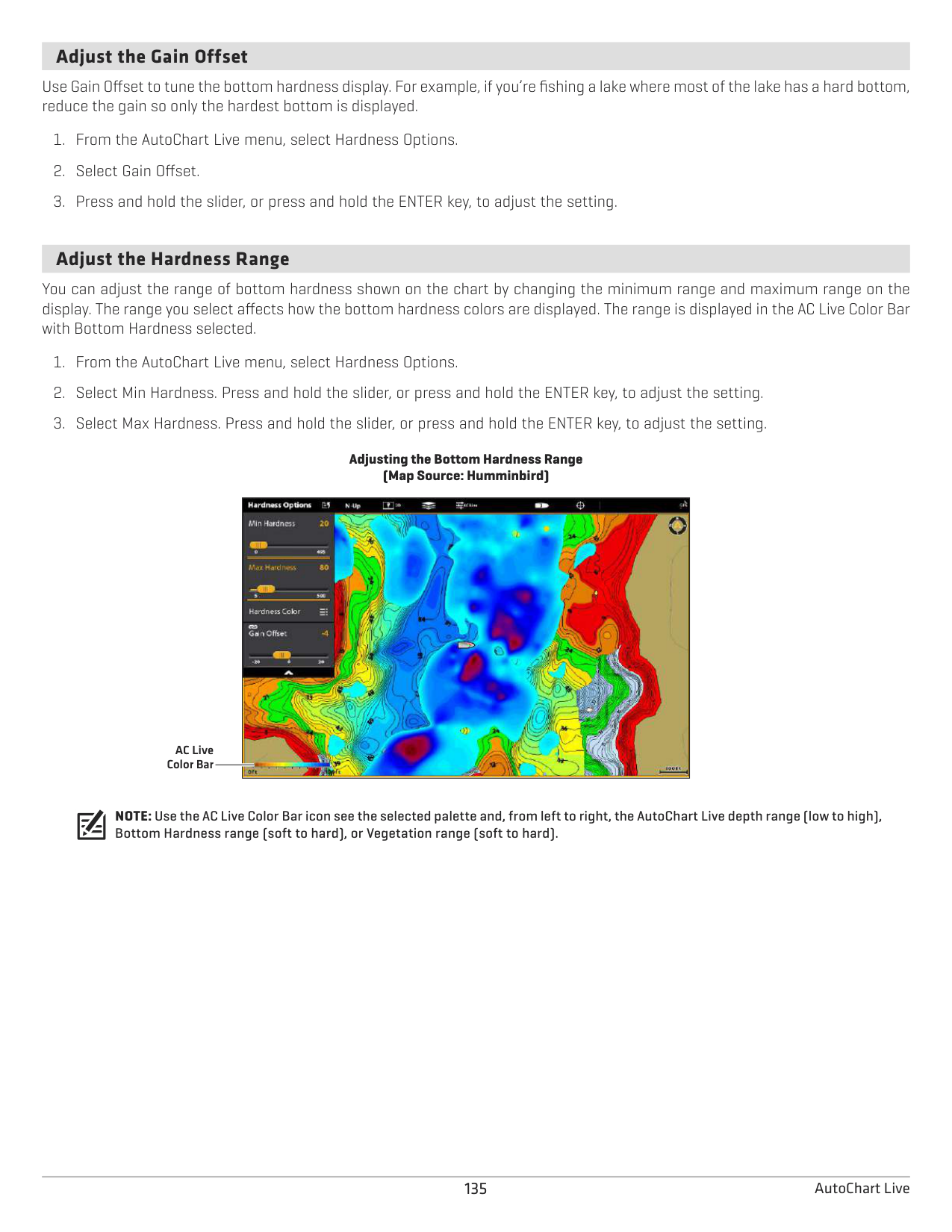
| |
| | |
|
color palette options
######### Change the Color Palette
The Color Palette menu changes the colors used to display the AutoChart Live map. The color range is shown in the AC Live Color bar and is affected by the Min Range and Max Range settings. See Adjust the Depth Range for more information.
######### Show/Hide Depth Colors
Use the following instructions to show or hide the depth colors. If you hide the depth colors, the contours will be shown on the display.
######### Change the Highlight Color
If you’ve set the Depth Highlight and Depth Highlight Range in the Humminbird Settings menu (Chart X-Press Menu > Humminbird Settings), and it is not easy to see with the AutoChart Live color palette you’ve selected, you can change the Highlight Color. See Customize the Chart View for more information.
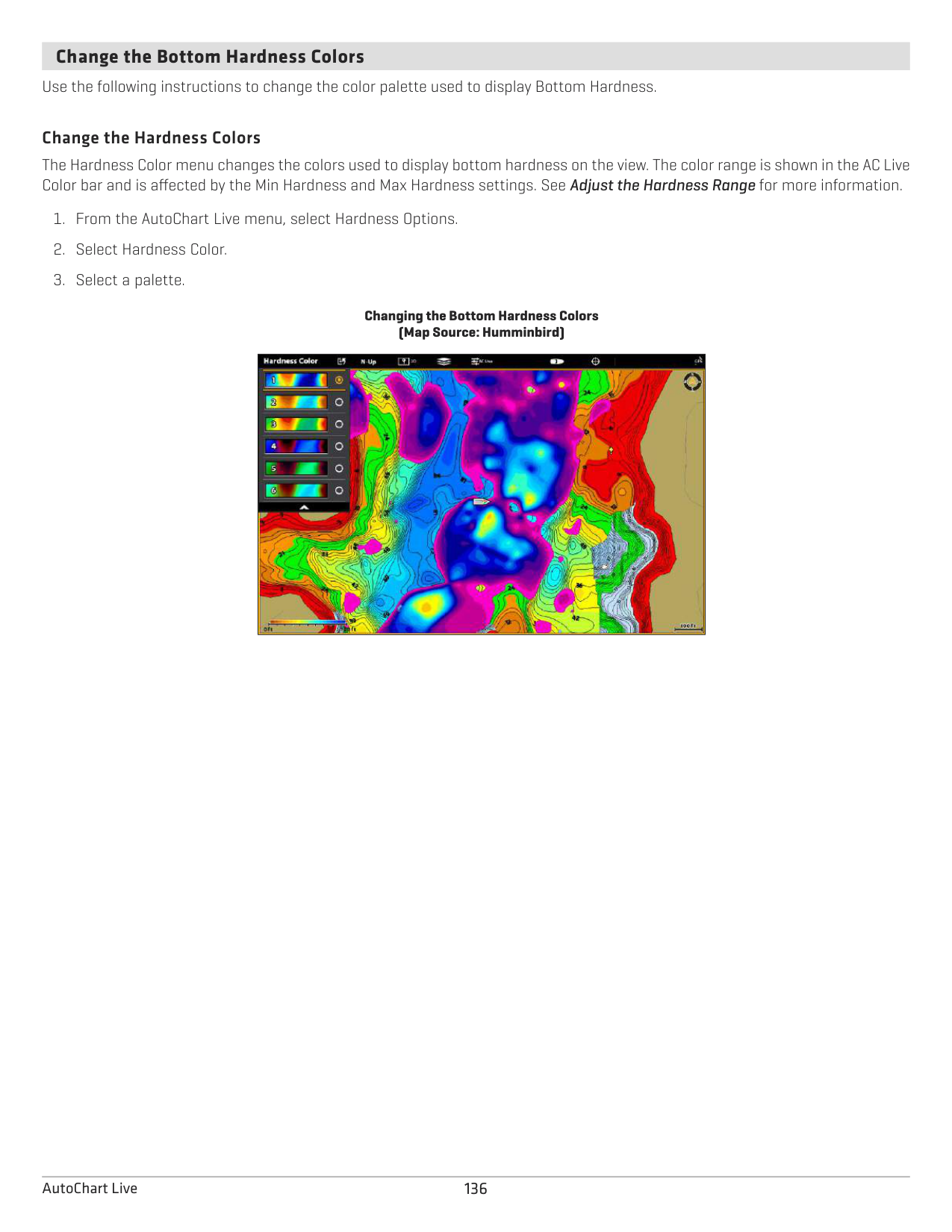
####### Change the Shallow Color
If you’ve set the Shallow Water Highlight in the Humminbird Settings menu (Chart X-Press Menu > Humminbird Settings), and it is not easy to see with the AutoChart Live color palette you’ve selected, you can change the Shallow Color. See Customize the Chart View for more information.
####### Display or Adjust the Contour Interval
You can display or hide the contour lines on the map, and you can adjust the slider to set the distance between each contour line. Contour Interval is also affected by the Water Level Offset setting.
######### Display the Contour Lines and Adjust the Contour Interval
######### Change the Contour Lines Color
Adjusting the Contour Interval
| ||
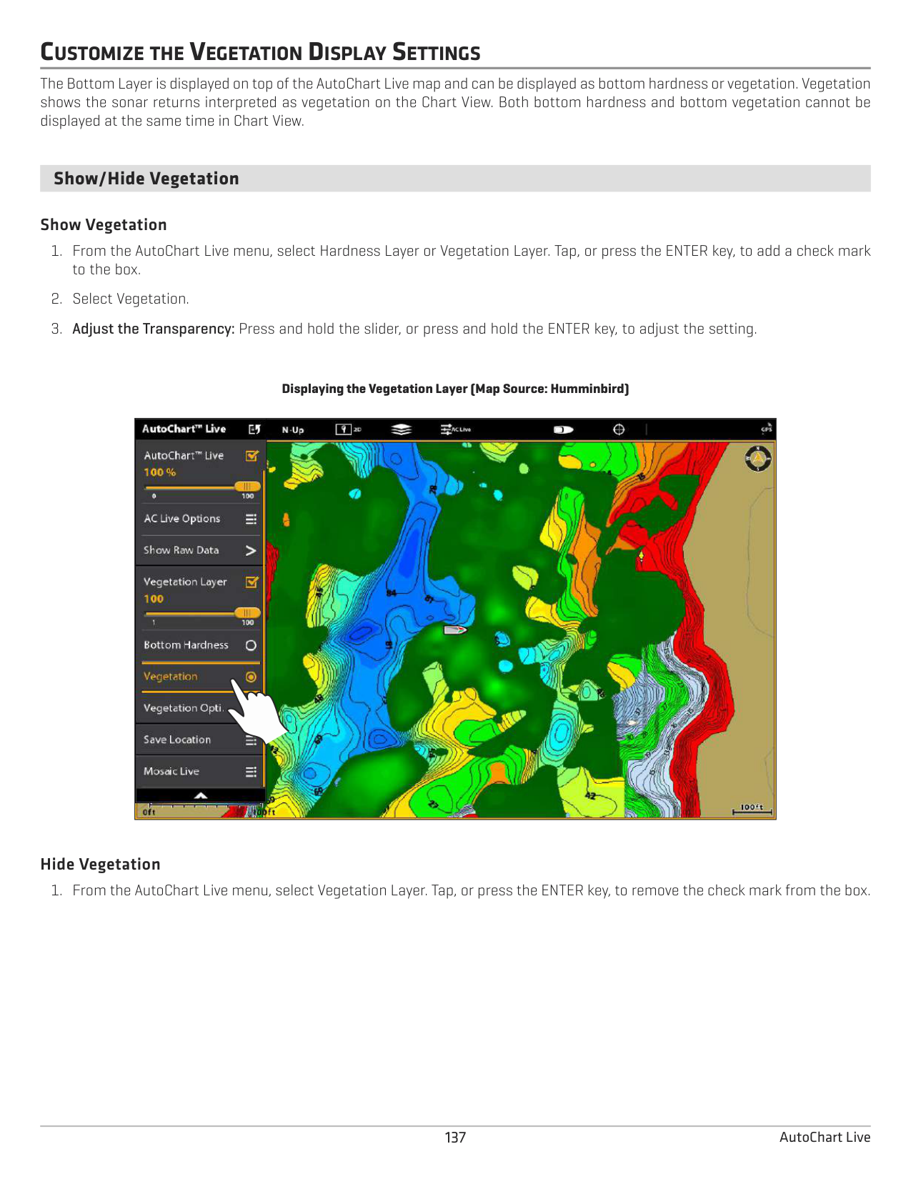
|---|---| | || | ||
contour lines displayed
1 foot apart contour colors
Display Raw or Map Data Select Show Map Data to display contour lines and depth data. Select Show Raw Data to display individual data points.
####### Change the Water Level Offset
When you start your mapping for the day, it is important to note if the water level is higher or lower than usual. See Prepare the Control Head for Mapping for more information.
If the water level is higher than normal, set a positive amount. If the water level is lower than normal, set a negative amount. If the water level has not changed (normal), turn off Water Level Offset.
####### Add Humminbird Chart Settings
If Humminbird is set as the map source, you can add Depth Colors, Shallow Water, etc. to your AutoChart LIVE map. See Customize the Chart View: Adjust the Depth Range and Colors for more information.
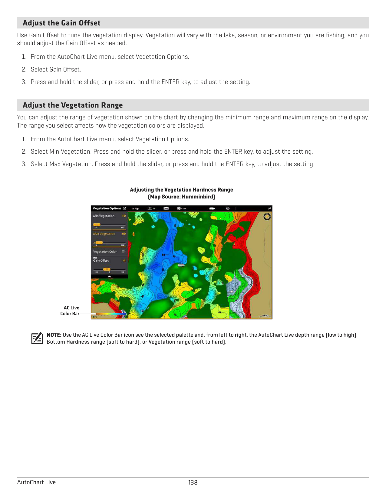
Adding Shallow Water Settings to the Map (Map Source: Humminbird)
|| |---|
####### Add Navionics Settings with Chart Options
If Navionics is set as the map source, you can display Contours and Shading on your AutoChart LIVE map. See Customize the Chart View: Select Map Data for more information.
CUSTOMIZE THE BOTTOM HARDNESS DISPLAY SETTINGS
The bottom layer is displayed on top of the AutoChart Live map and can be displayed as bottom hardness or vegetation. Bottom Hardness shows strong sonar returns resulting from compacted sediment, rocks, fallen trees, etc.
####### Show/Hide Bottom Hardness
The bottom layer is displayed on top of the AutoChart Live map, and you can adjust the transparency to see different layers on the view. Both bottom hardness and bottom vegetation cannot be displayed at the same time in Chart View.
######### Show Bottom Hardness
Displaying the Bottom Hardness Layer (Map Source: Humminbird)
|
|
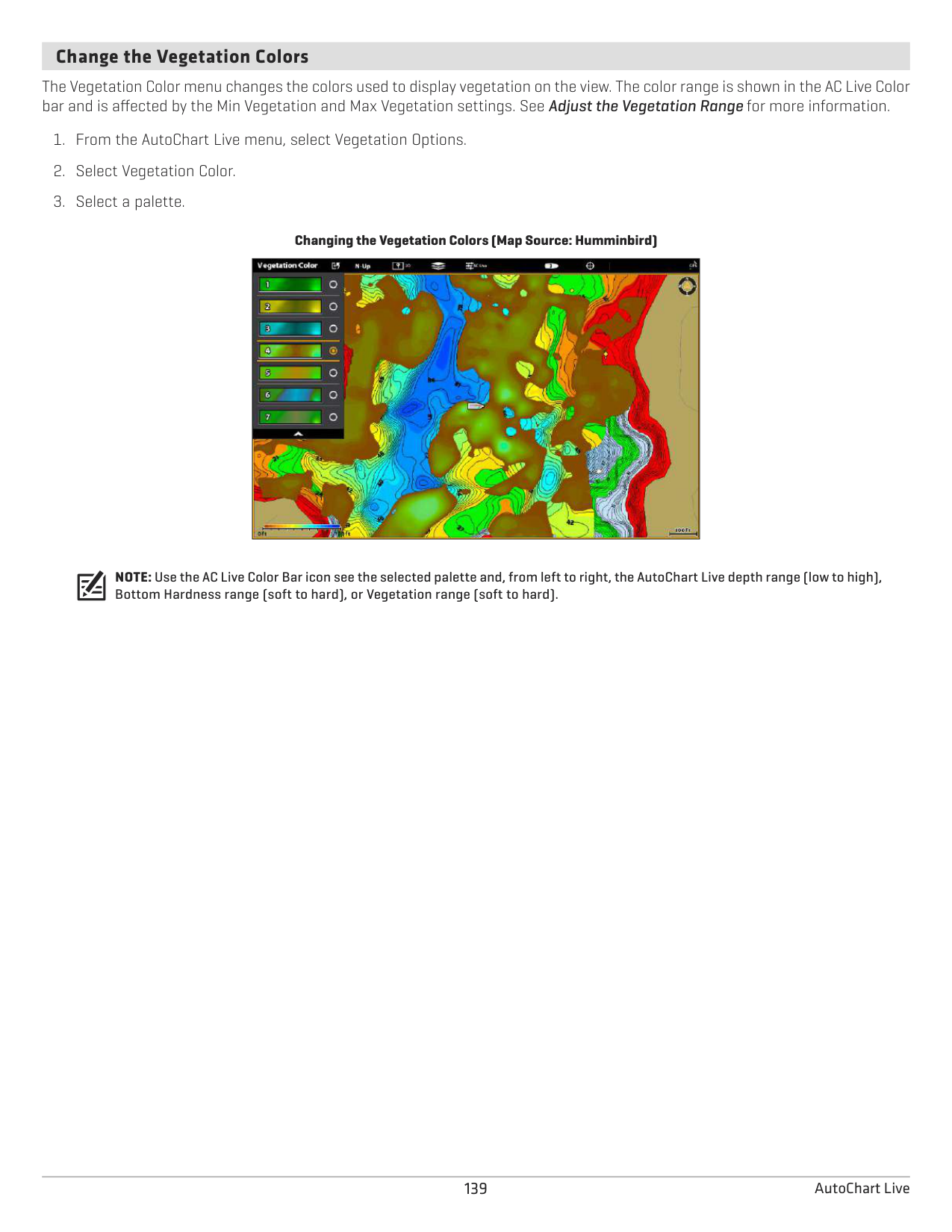
|---|
######### Hide Bottom Hardness
####### Adjust the Gain Offset
Use Gain Offset to tune the bottom hardness display. For example, if you’re fishing a lake where most of the lake has a hard bottom, reduce the gain so only the hardest bottom is displayed.
####### Adjust the Hardness Range
You can adjust the range of bottom hardness shown on the chart by changing the minimum range and maximum range on the display. The range you select affects how the bottom hardness colors are displayed. The range is displayed in the AC Live Color Bar with Bottom Hardness selected.
################# Adjusting the Bottom Hardness Range (Map Source: Humminbird)

AC Live Color Bar
NOTE: Use the AC Live Color Bar icon see the selected palette and, from left to right, the AutoChart Live depth range (low to high), Bottom Hardness range (soft to hard), or Vegetation range (soft to hard).
####### Change the Bottom Hardness Colors
Use the following instructions to change the color palette used to display Bottom Hardness.
######### Change the Hardness Colors
The Hardness Color menu changes the colors used to display bottom hardness on the view. The color range is shown in the AC Live Color bar and is affected by the Min Hardness and Max Hardness settings. See Adjust the Hardness Range for more information.
Changing the Bottom Hardness Colors (Map Source: Humminbird)
|| |---|
CUSTOMIZE THE VEGETATION DISPLAY SETTINGS
The Bottom Layer is displayed on top of the AutoChart Live map and can be displayed as bottom hardness or vegetation. Vegetation shows the sonar returns interpreted as vegetation on the Chart View. Both bottom hardness and bottom vegetation cannot be displayed at the same time in Chart View.
####### Show/Hide Vegetation
######### Show Vegetation
Displaying the Vegetation Layer (Map Source: Humminbird)
|
| |---|
######### Hide Vegetation
####### Adjust the Gain Offset
Use Gain Offset to tune the vegetation display. Vegetation will vary with the lake, season, or environment you are fishing, and you should adjust the Gain Offset as needed.
####### Adjust the Vegetation Range
You can adjust the range of vegetation shown on the chart by changing the minimum range and maximum range on the display. The range you select affects how the vegetation colors are displayed.
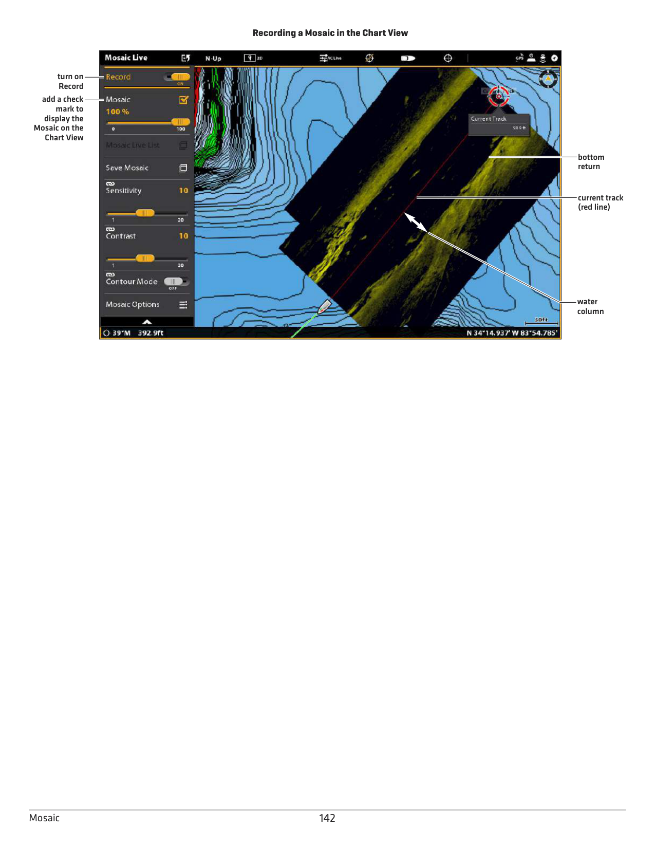
################# Adjusting the Vegetation Hardness Range (Map Source: Humminbird)

AC Live Color Bar
NOTE: Use the AC Live Color Bar icon see the selected palette and, from left to right, the AutoChart Live depth range (low to high), Bottom Hardness range (soft to hard), or Vegetation range (soft to hard).
####### Change the Vegetation Colors
The Vegetation Color menu changes the colors used to display vegetation on the view. The color range is shown in the AC Live Color bar and is affected by the Min Vegetation and Max Vegetation settings. See Adjust the Vegetation Range for more information.
################# Changing the Vegetation Colors (Map Source: Humminbird)
|| |---|
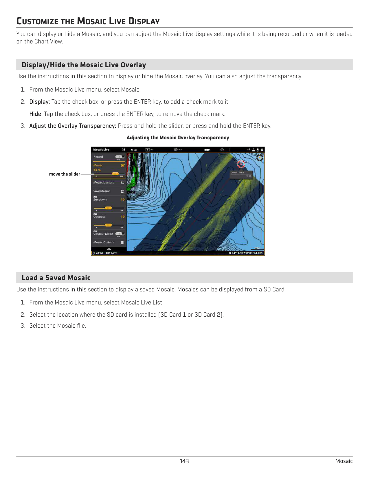
NOTE: Use the AC Live Color Bar icon see the selected palette and, from left to right, the AutoChart Live depth range (low to high), Bottom Hardness range (soft to hard), or Vegetation range (soft to hard).
MOSAIC LIVE OVERVIEW
The Mosaic Live feature allows you to display Side Imaging data on the Chart View. A Mosaic can be displayed as an overlay while it is being recorded, and you can display saved Mosaics on the Chart View. Mosaic can also be used with a 360 Imaging transducer (separate purchase required).
Required Equipment: A Side Imaging transducer or a 360 Imaging transducer, and an SD Card to save recordings. Map Source: Humminbird LakeMaster or Navionics AutoChart PC: To dispay Mosaic Live data in AutoChart PC, use Sonar Recording. See the Sonar Recording section of this manual and the AutoChart PC Installation and Operations Guide for details (separate purchase required).
Accessories: To purchase a 360 Imaging transducer, AutoChart PC, or other related equipment, visit our Web site at humminbird.com.
FOR BEST PERFORMANCE
Many of the features that are available on the Side Imaging View or 360 Imaging View are available when a Mosaic is displayed on the Chart View.
If you are using a Side Imaging transducer or 360 Imaging transducer to display Mosaic Live data, it is important to consider the following tips for best performance:
######### Side Imaging Transducer
######### 360 Imaging Transducer
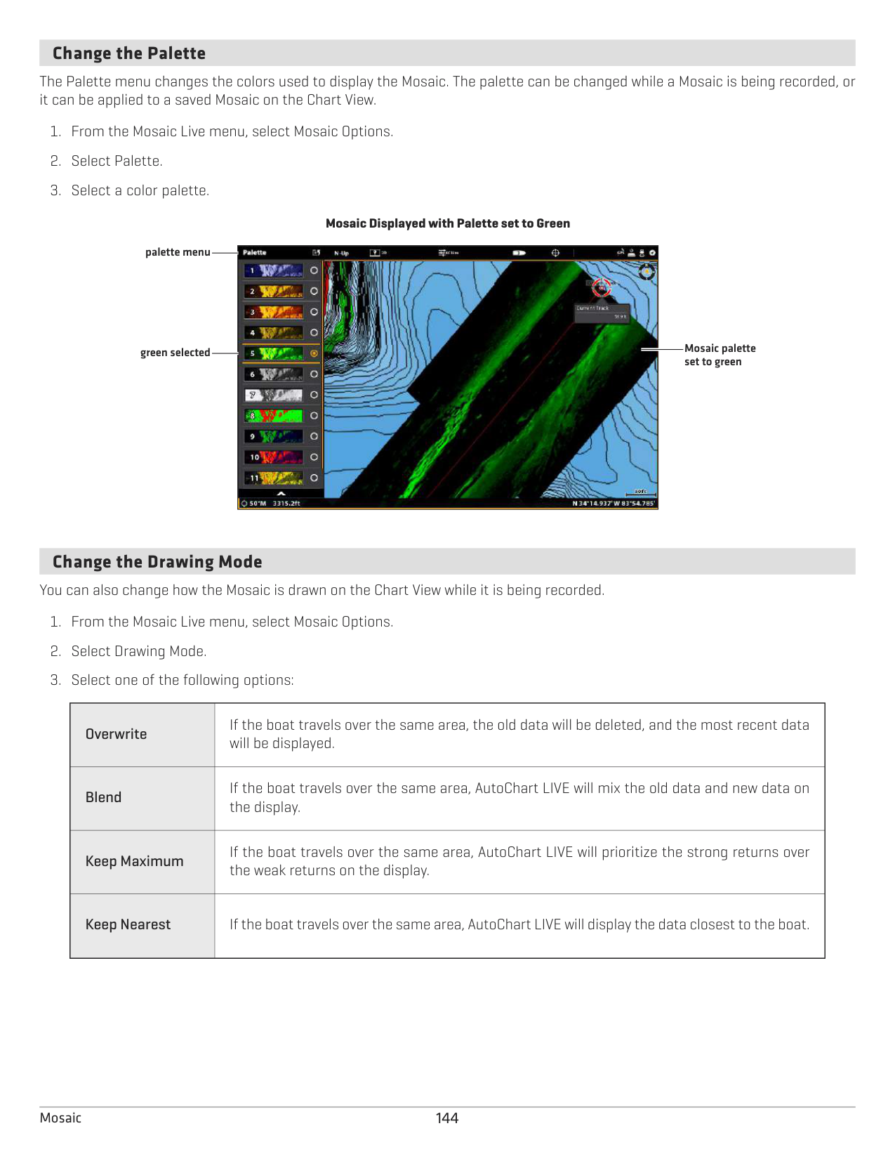
When recording the Mosaic, you should have only one Side Imaging sonar source pinging on your boat. To select a Side Imaging sonar source or confirm pinging, see Set up your Humminbird Network: Select Sonar Sources.
OPEN THE MOSAIC LIVE MENU
####### Record and Save a Mosaic
When you record a Mosaic, the control head displays the data as an overlay on the Chart View. If you are planning to use AutoChart PC, start a sonar recording before you start recording your Mosaic (see Sonar Recording).
The Mosaic must be saved when you are finished recording or before you power off the control head, or the data will be lost. See the instructions below.
WARNING! A Mosaic must be saved when you are finished recording or before you power off the control head, or the data will be lost. Save the recording before you turn off the Record menu.
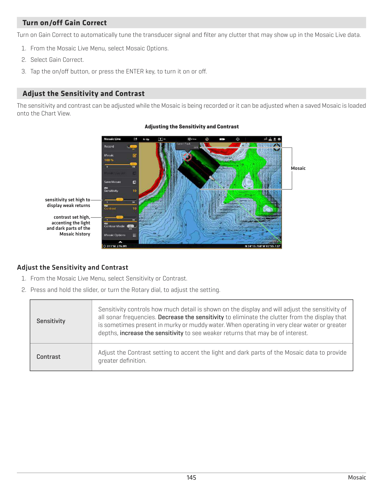
################# Recording a Mosaic in the Chart View

turn on Record
add a check mark to
display the Mosaic on the
Chart View
bottom return
current track (red line)
water column
CUSTOMIZE THE MOSAIC LIVE DISPLAY
You can display or hide a Mosaic, and you can adjust the Mosaic Live display settings while it is being recorded or when it is loaded on the Chart View.
####### Display/Hide the Mosaic Live Overlay
Use the instructions in this section to display or hide the Mosaic overlay. You can also adjust the transparency.
Adjusting the Mosaic Overlay Transparency
| || |---|---| | ||
move the slider
####### Load a Saved Mosaic
Use the instructions in this section to display a saved Mosaic. Mosaics can be displayed from a SD Card.
####### Change the Palette
The Palette menu changes the colors used to display the Mosaic. The palette can be changed while a Mosaic is being recorded, or it can be applied to a saved Mosaic on the Chart View.
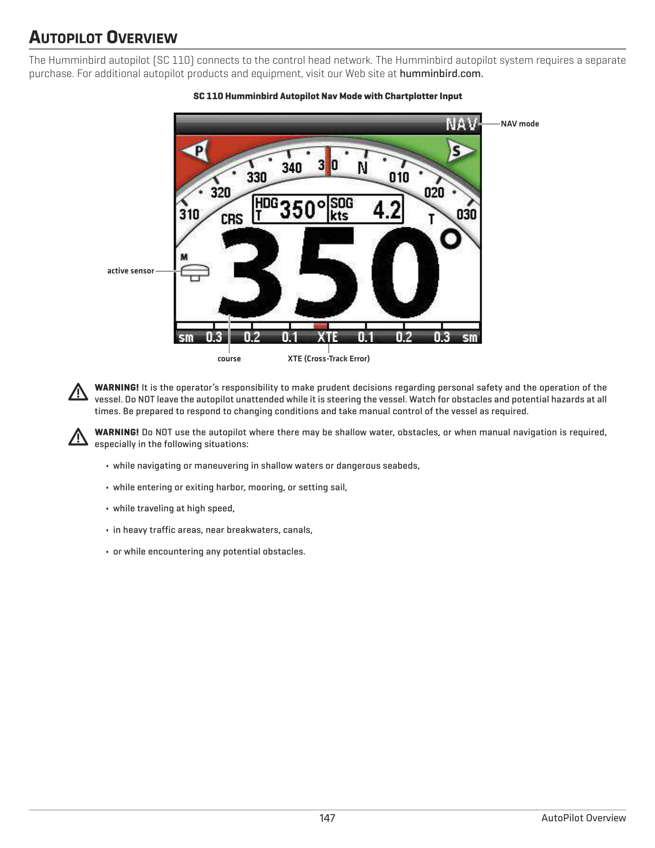
Mosaic Displayed with Palette set to Green palette menu

green selected Mosaic palette
set to green
####### Change the Drawing Mode
You can also change how the Mosaic is drawn on the Chart View while it is being recorded.
|Overwrite
|If the boat travels over the same area, the old data will be deleted, and the most recent data will be displayed.| |---|---| |Blend
|If the boat travels over the same area, AutoChart LIVE will mix the old data and new data on the display.| |Keep Maximum
|If the boat travels over the same area, AutoChart LIVE will prioritize the strong returns over the weak returns on the display.| |Keep Nearest|If the boat travels over the same area, AutoChart LIVE will display the data closest to the boat.
|
####### Turn on/off Gain Correct
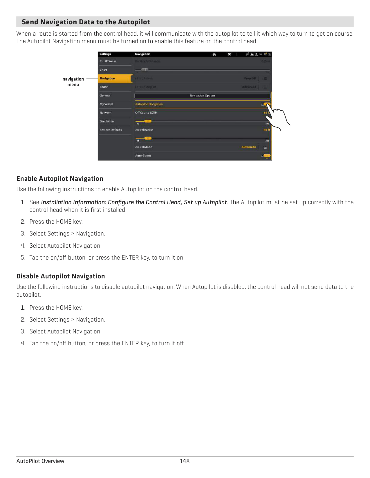
Turn on Gain Correct to automatically tune the transducer signal and filter any clutter that may show up in the Mosaic Live data.
####### Adjust the Sensitivity and Contrast
The sensitivity and contrast can be adjusted while the Mosaic is being recorded or it can be adjusted when a saved Mosaic is loaded onto the Chart View.
################# Adjusting the Sensitivity and Contrast

Mosaic
sensitivity set high to display weak returns
contrast set high, accenting the light and dark parts of the Mosaic history
######### Adjust the Sensitivity and Contrast
|Sensitivity|Sensitivity controls how much detail is shown on the display and will adjust the sensitivity of all sonar frequencies. Decrease the sensitivity to eliminate the clutter from the display that is sometimes present in murky or muddy water. When operating in very clear water or greater depths, increase the sensitivity to see weaker returns that may be of interest.
| |---|---|
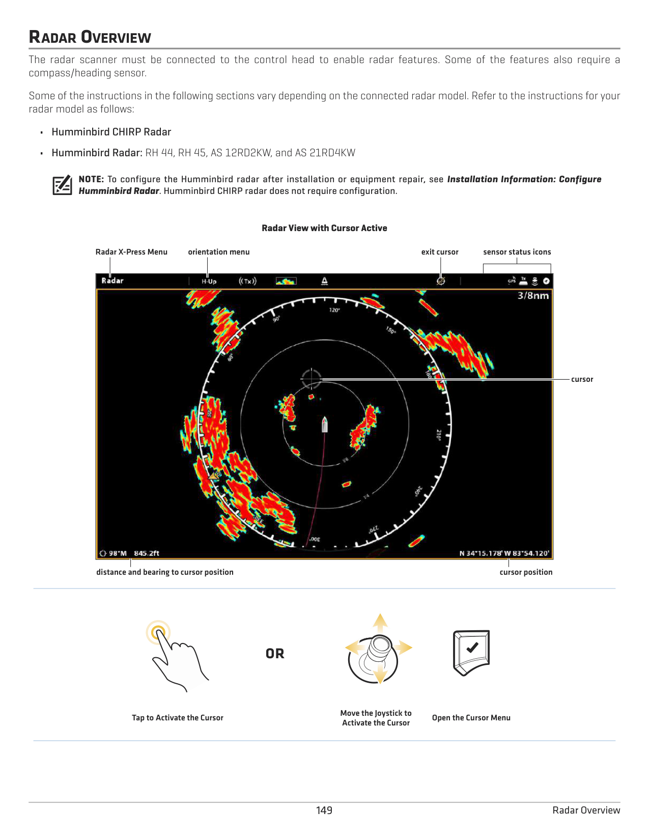
|Contrast|Adjust the Contrast setting to accent the light and dark parts of the Mosaic data to provide greater definition.|
####### Turn on/off Contour Mode
Contour Mode controls how the water column is displayed in the Mosaic. The location of a target in the Mosaic is influenced by the Contour Mode setting. For more information, see Customize the Side Imaging View: Turn on/off Contour Mode.
When Contour Mode turned off, the water column is displayed on the view. The location of a target on the display is based on the slant range to the target.
When Contour Mode is turned on, the bottom is graphed at a constant point on the display, regardless of changes in depth. The Side Imaging beams are divided by a vertical line. The water column is removed from the view, which allows the display to show targets
######### Turn on/off Contour Mode
AUTOPILOT OVERVIEW
The Humminbird autopilot (SC 110) connects to the control head network. The Humminbird autopilot system requires a separate purchase. For additional autopilot products and equipment, visit our Web site at humminbird.com.
################# SC 110 Humminbird Autopilot Nav Mode with Chartplotter Input

NAV mode
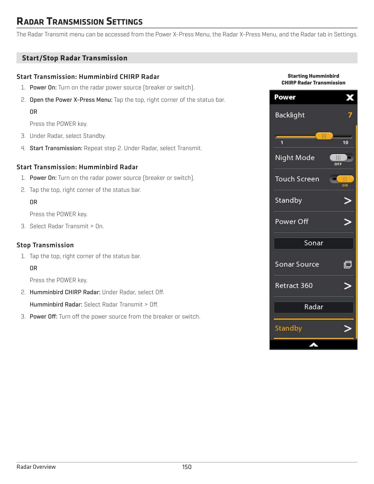
active sensor
XTE (Cross-Track Error)course
WARNING! It is the operator’s responsibility to make prudent decisions regarding personal safety and the operation of the vessel. Do NOT leave the autopilot unattended while it is steering the vessel. Watch for obstacles and potential hazards at all times. Be prepared to respond to changing conditions and take manual control of the vessel as required.
WARNING! Do NOT use the autopilot where there may be shallow water, obstacles, or when manual navigation is required, especially in the following situations:
147 AutoPilot Overview
####### Send Navigation Data to the Autopilot
When a route is started from the control head, it will communicate with the autopilot to tell it which way to turn to get on course. The Autopilot Navigation menu must be turned on to enable this feature on the control head.
| || |---|---| | ||
navigation menu
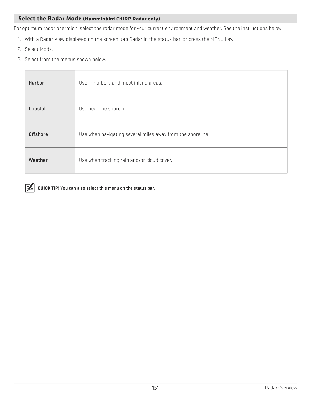
Enable Autopilot Navigation Use the following instructions to enable Autopilot on the control head.
######### Disable Autopilot Navigation
Use the following instructions to disable autopilot navigation. When Autopilot is disabled, the control head will not send data to the autopilot.
148AutoPilot Overview
RADAR OVERVIEW
The radar scanner must be connected to the control head to enable radar features. Some of the features also require a compass/heading sensor.
Some of the instructions in the following sections vary depending on the connected radar model. Refer to the instructions for your radar model as follows:
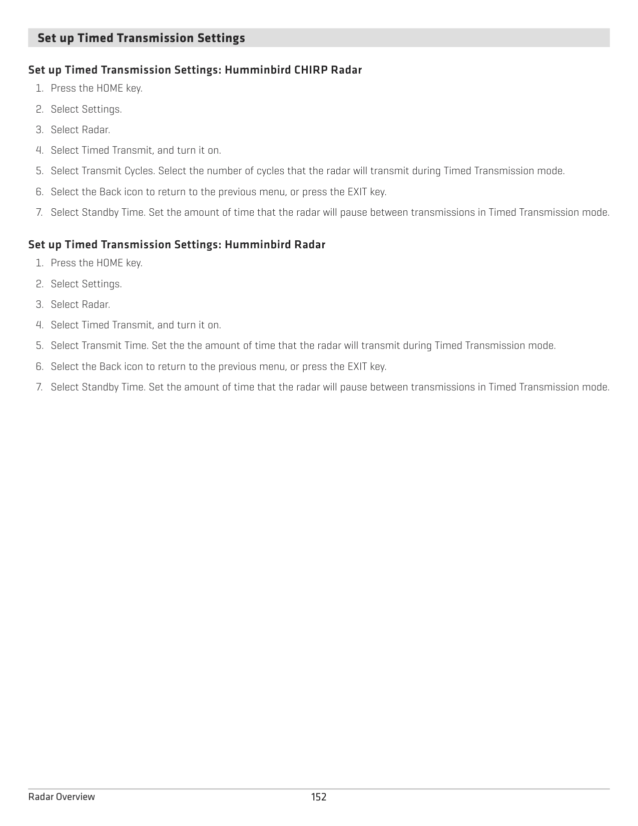
NOTE: To configure the Humminbird radar after installation or equipment repair, see Installation Information: Configure Humminbird Radar. Humminbird CHIRP radar does not require configuration.
Radar View with Cursor Active
orientation menuRadar X-Press Menu exit cursor sensor status icons

cursor
distance and bearing to cursor position
cursor position
#### OR
Move the Joystick to Activate the Cursor
Tap to Activate the Cursor
Open the Cursor Menu
RADAR TRANSMISSION SETTINGS
The Radar Transmit menu can be accessed from the Power X-Press Menu, the Radar X-Press Menu, and the Radar tab in Settings.
####### Start/Stop Radar Transmission
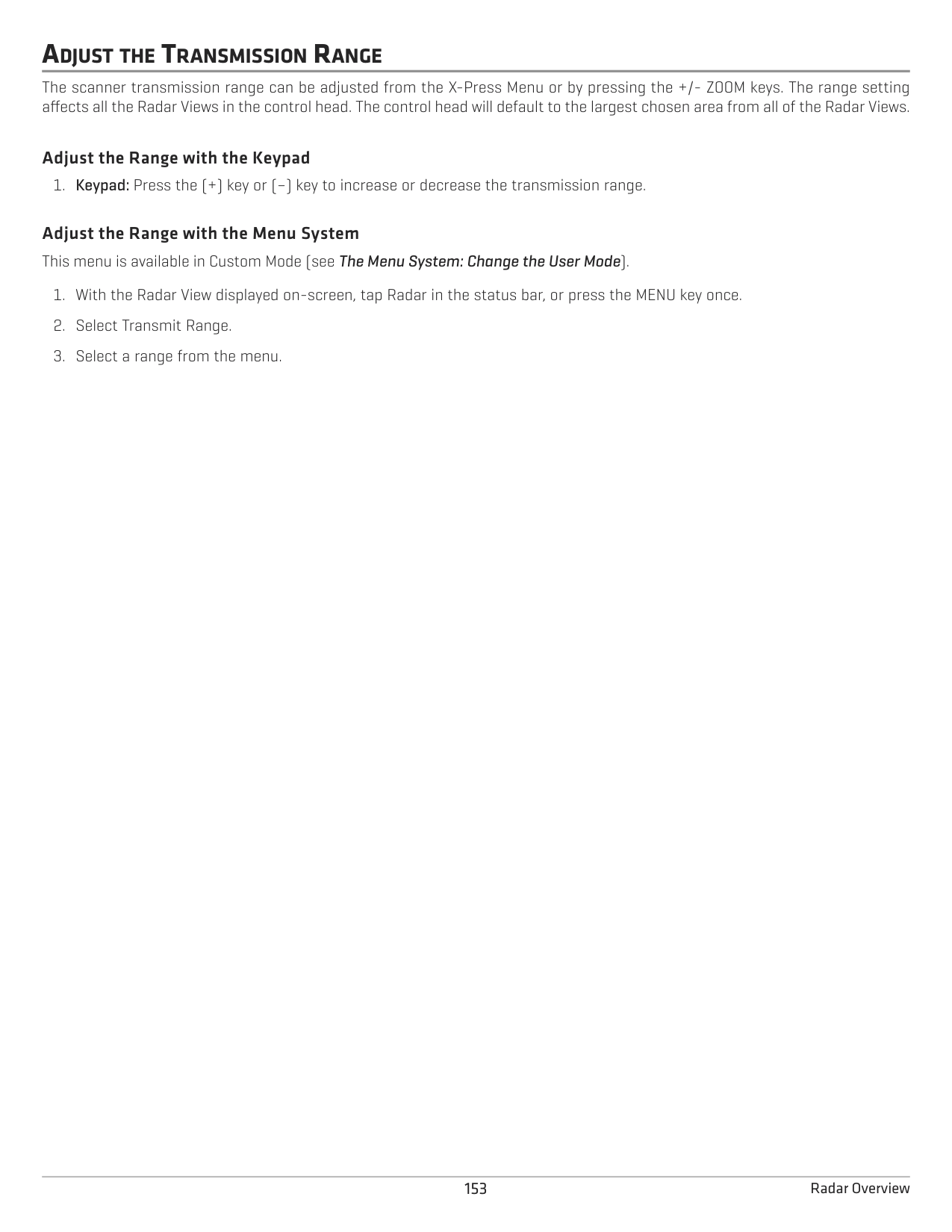
######### Start Transmission: Humminbird CHIRP Radar
######### Start Transmission: Humminbird Radar
######### Stop Transmission
Starting Humminbird CHIRP Radar Transmission
|| |---|
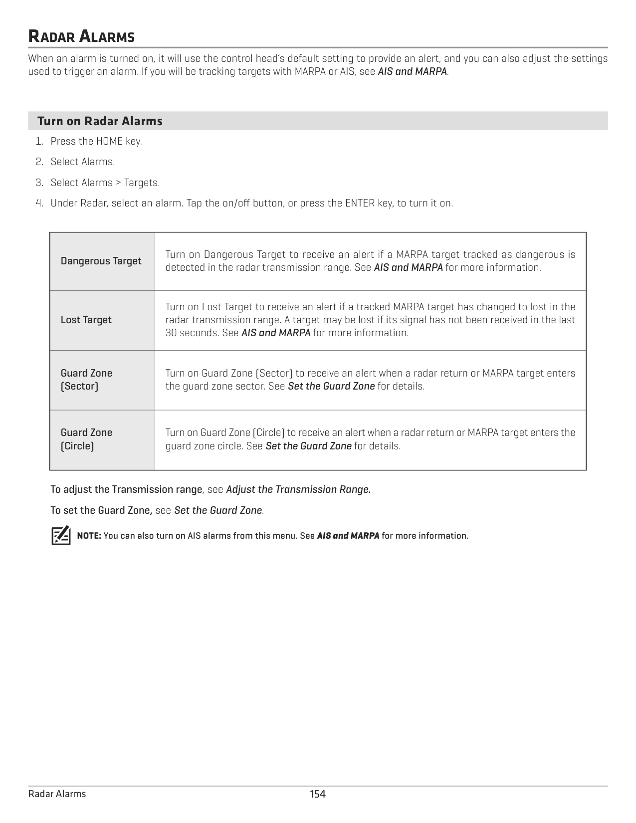
####### Select the Radar Mode (Humminbird CHIRP Radar only)
For optimum radar operation, select the radar mode for your current environment and weather. See the instructions below.
|Harbor
|Use in harbors and most inland areas.| |---|---| |Coastal
|Use near the shoreline.| |Offshore
|Use when navigating several miles away from the shoreline.| |Weather|Use when tracking rain and/or cloud cover.
|
QUICK TIP! You can also select this menu on the status bar.
####### Set up Timed Transmission Settings
######### Set up Timed Transmission Settings: Humminbird CHIRP Radar
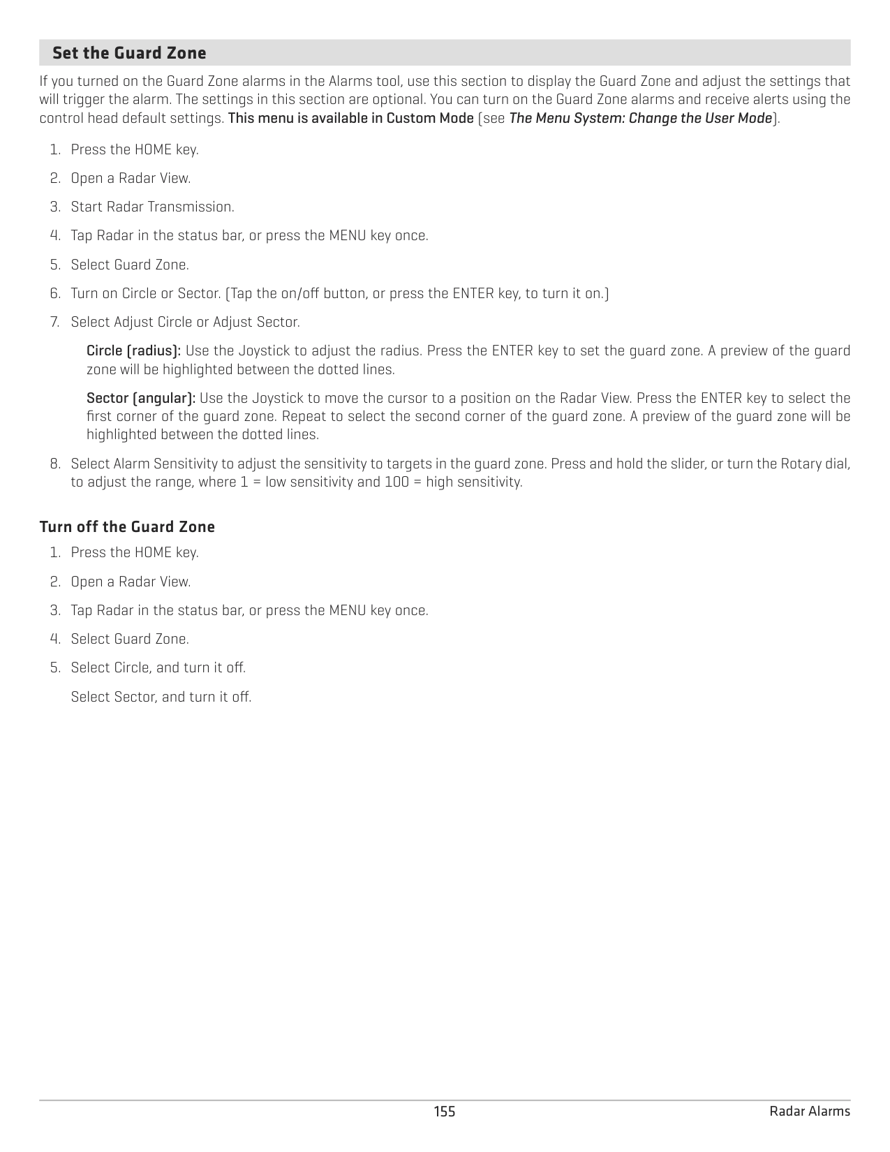
######### Set up Timed Transmission Settings: Humminbird Radar
ADJUST THE TRANSMISSION RANGE
The scanner transmission range can be adjusted from the X-Press Menu or by pressing the +/- ZOOM keys. The range setting affects all the Radar Views in the control head. The control head will default to the largest chosen area from all of the Radar Views.
######### Adjust the Range with the Keypad
Adjust the Range with the Menu System This menu is available in Custom Mode (see The Menu System: Change the User Mode).
RADAR ALARMS
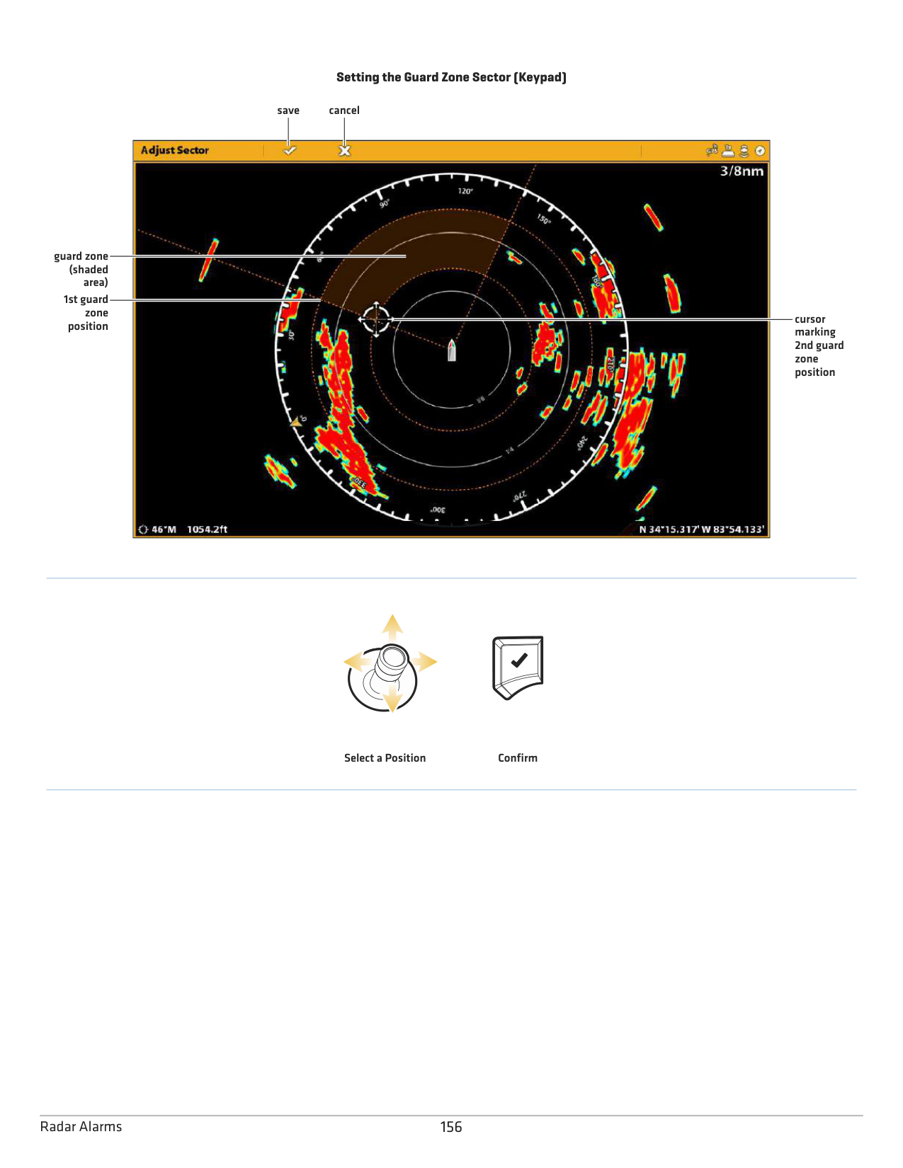
When an alarm is turned on, it will use the control head’s default setting to provide an alert, and you can also adjust the settings used to trigger an alarm. If you will be tracking targets with MARPA or AIS, see AIS and MARPA.
####### Turn on Radar Alarms
|Dangerous Target|Turn on Dangerous Target to receive an alert if a MARPA target tracked as dangerous is detected in the radar transmission range. See AIS and MARPA for more information.
| |---|---| |Lost Target
|Turn on Lost Target to receive an alert if a tracked MARPA target has changed to lost in the radar transmission range. A target may be lost if its signal has not been received in the last 30 seconds. See AIS and MARPA for more information.| |Guard Zone (Sector)
|Turn on Guard Zone (Sector) to receive an alert when a radar return or MARPA target enters the guard zone sector. See Set the Guard Zone for details.| |Guard Zone (Circle)|Turn on Guard Zone (Circle) to receive an alert when a radar return or MARPA target enters the guard zone circle. See Set the Guard Zone for details.
|
To adjust the Transmission range, see Adjust the Transmission Range. To set the Guard Zone, see Set the Guard Zone.
NOTE: You can also turn on AIS alarms from this menu. See AIS and MARPA for more information.
####### Set the Guard Zone
If you turned on the Guard Zone alarms in the Alarms tool, use this section to display the Guard Zone and adjust the settings that will trigger the alarm. The settings in this section are optional. You can turn on the Guard Zone alarms and receive alerts using the control head default settings. This menu is available in Custom Mode (see The Menu System: Change the User Mode).
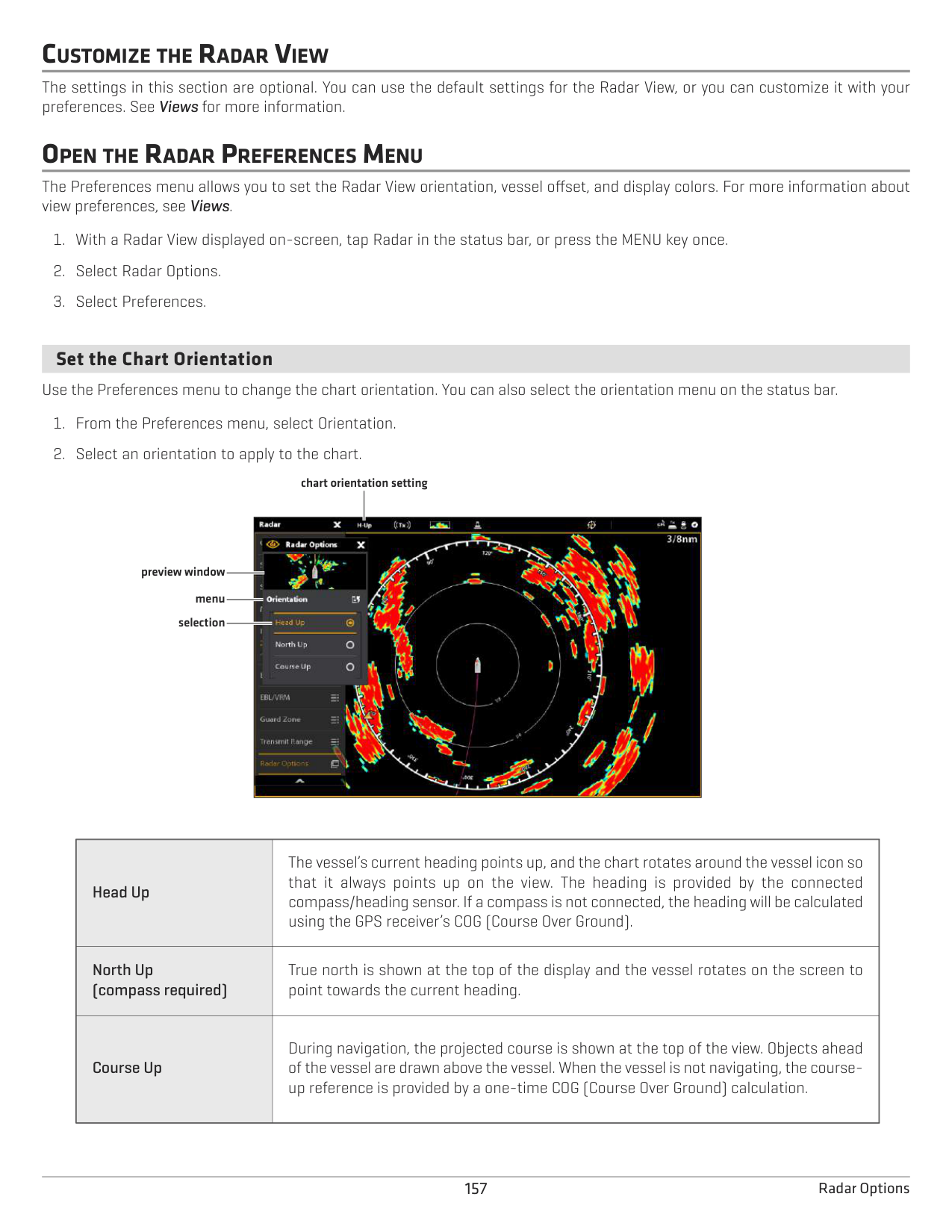
Circle (radius): Use the Joystick to adjust the radius. Press the ENTER key to set the guard zone. A preview of the guard zone will be highlighted between the dotted lines.
Sector (angular): Use the Joystick to move the cursor to a position on the Radar View. Press the ENTER key to select the first corner of the guard zone. Repeat to select the second corner of the guard zone. A preview of the guard zone will be highlighted between the dotted lines.
######### Turn off the Guard Zone
155 Radar Alarms
################# Setting the Guard Zone Sector (Keypad)
save cancel

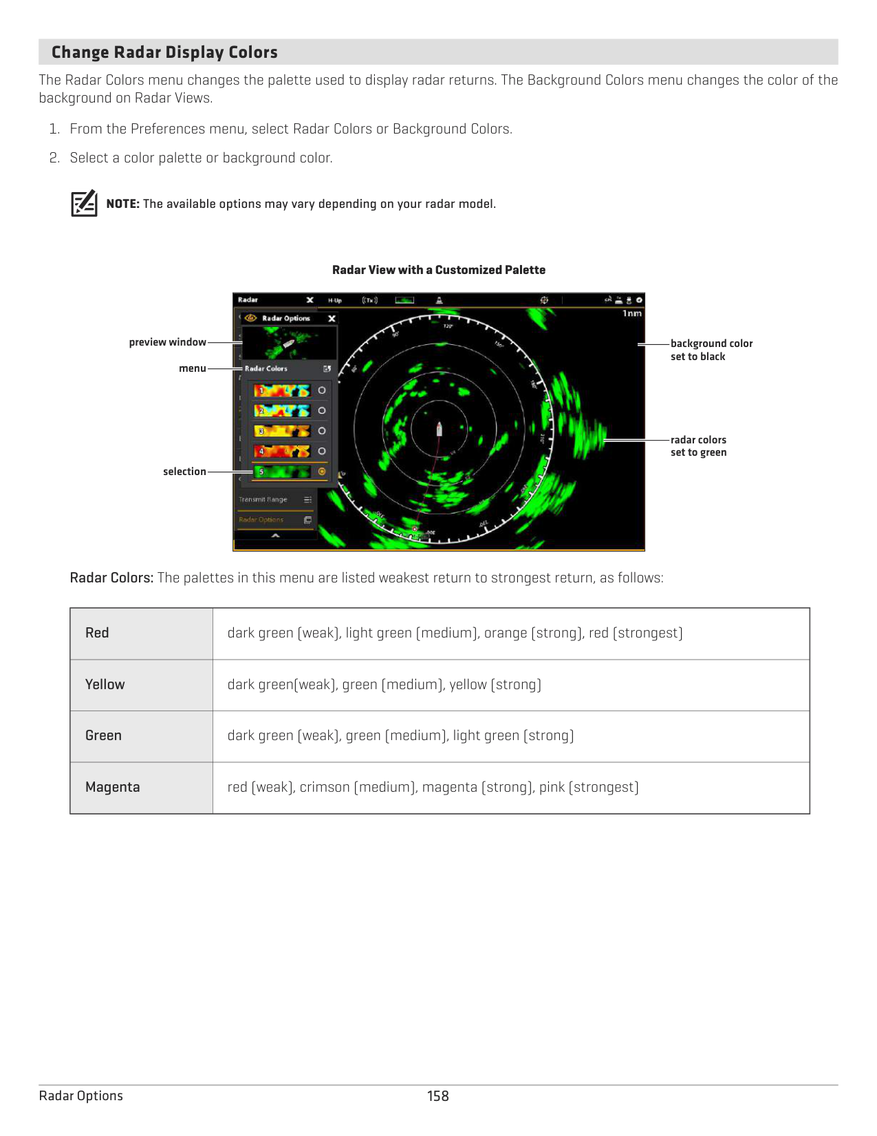
guard zone (shaded area)
1st guard
zone position
cursor marking 2nd guard zone position
Select a Position Confirm
CUSTOMIZE THE RADAR VIEW
The settings in this section are optional. You can use the default settings for the Radar View, or you can customize it with your preferences. See Views for more information.
OPEN THE RADAR PREFERENCES MENU
The Preferences menu allows you to set the Radar View orientation, vessel offset, and display colors. For more information about view preferences, see Views.
####### Set the Chart Orientation
Use the Preferences menu to change the chart orientation. You can also select the orientation menu on the status bar.
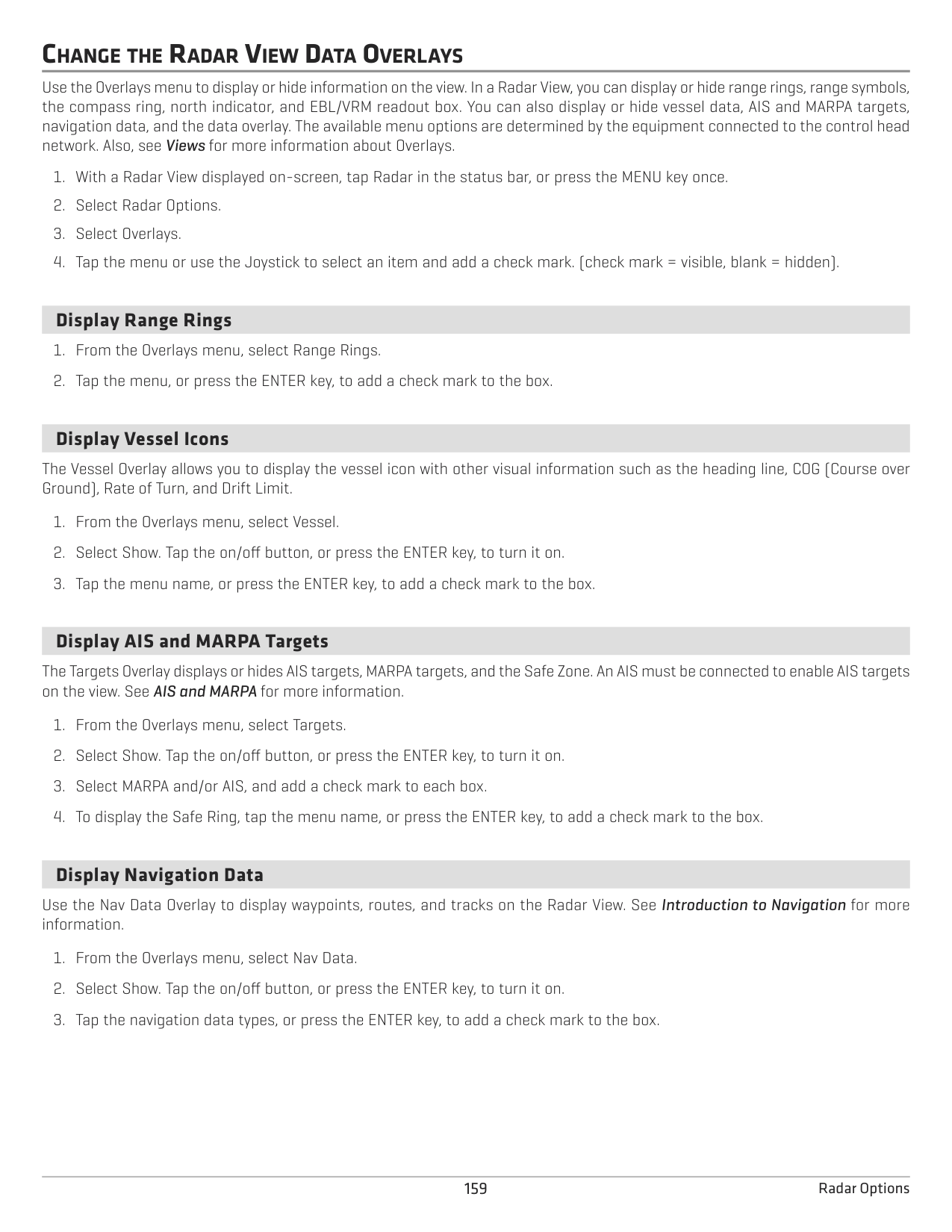
chart orientation setting

preview window
menu selection
|Head Up
|The vessel’s current heading points up, and the chart rotates around the vessel icon so that it always points up on the view. The heading is provided by the connected compass/heading sensor. If a compass is not connected, the heading will be calculated using the GPS receiver’s COG (Course Over Ground).| |---|---| |North Up (compass required)
|True north is shown at the top of the display and the vessel rotates on the screen to point towards the current heading.| |Course Up|During navigation, the projected course is shown at the top of the view. Objects ahead of the vessel are drawn above the vessel. When the vessel is not navigating, the courseup reference is provided by a one-time COG (Course Over Ground) calculation.|
####### Change Radar Display Colors
The Radar Colors menu changes the palette used to display radar returns. The Background Colors menu changes the color of the background on Radar Views.
NOTE: The available options may vary depending on your radar model.
################# Radar View with a Customized Palette

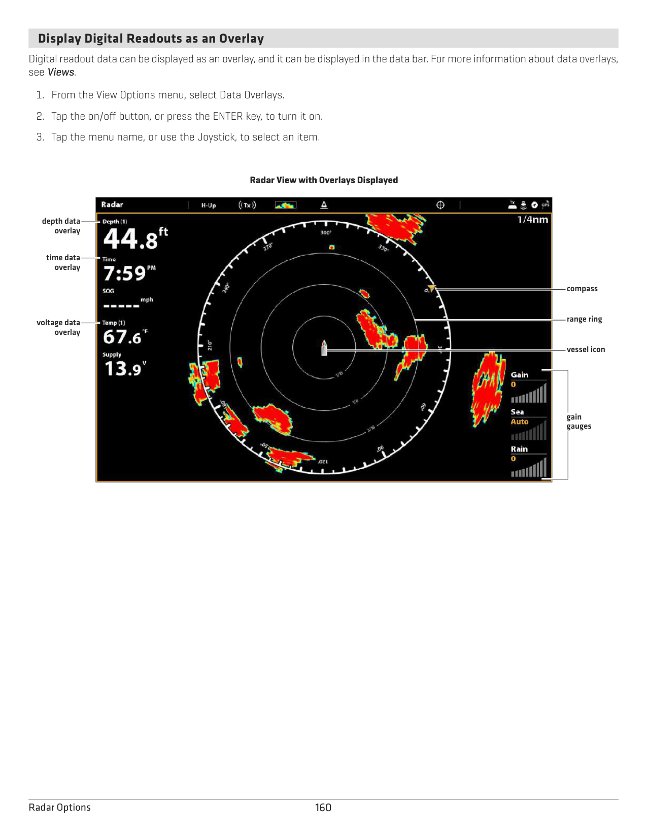
preview window
background color set to black
menu
radar colors set to green
selection
Radar Colors: The palettes in this menu are listed weakest return to strongest return, as follows:
|Red|dark green (weak), light green (medium), orange (strong), red (strongest)
| |---|---| |Yellow
|dark green(weak), green (medium), yellow (strong)| |Green|dark green (weak), green (medium), light green (strong)
| |Magenta|red (weak), crimson (medium), magenta (strong), pink (strongest)|
CHANGE THE RADAR VIEW DATA OVERLAYS
Use the Overlays menu to display or hide information on the view. In a Radar View, you can display or hide range rings, range symbols, the compass ring, north indicator, and EBL/VRM readout box. You can also display or hide vessel data, AIS and MARPA targets, navigation data, and the data overlay. The available menu options are determined by the equipment connected to the control head network. Also, see Views for more information about Overlays.
####### Display Range Rings
####### Display Vessel Icons
The Vessel Overlay allows you to display the vessel icon with other visual information such as the heading line, COG (Course over Ground), Rate of Turn, and Drift Limit.
####### Display AIS and MARPA Targets
The Targets Overlay displays or hides AIS targets, MARPA targets, and the Safe Zone. An AIS must be connected to enable AIS targets on the view. See AIS and MARPA for more information.
####### Display Navigation Data
Use the Nav Data Overlay to display waypoints, routes, and tracks on the Radar View. See Introduction to Navigation for more information.
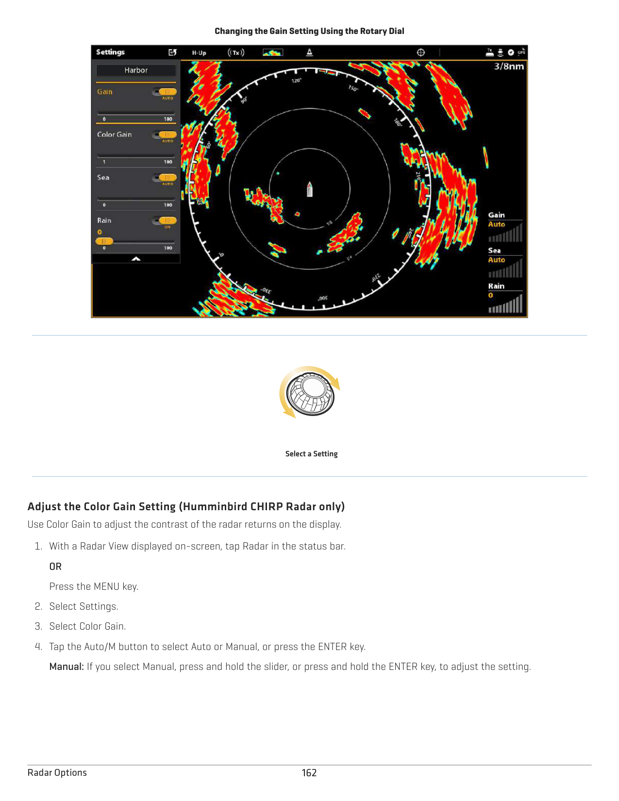
####### Display Digital Readouts as an Overlay
Digital readout data can be displayed as an overlay, and it can be displayed in the data bar. For more information about data overlays, see Views.
Radar View with Overlays Displayed

depth data overlay
time data overlay
compass
range ring
voltage data overlay
vessel icon
gain gauges
ADJUST RADAR SIGNAL SETTINGS Use the settings in this section to filter the returns on the display or increase the amount of returns on the display. Adjust the Gain Setting
Use the Gain setting to adjust the sensitivity of the radar. Increase the gain to see more targets on the view, and decrease the gain to reduce the clutter caused by rain or snow.
QUICK TIP! You can also change this setting by turning the Rotary dial. See the illustration below.
Changing the Gain Setting Using the Rotary Dial
|| |---|
Select a Setting
######### Adjust the Color Gain Setting (Humminbird CHIRP Radar only) Use Color Gain to adjust the contrast of the radar returns on the display.
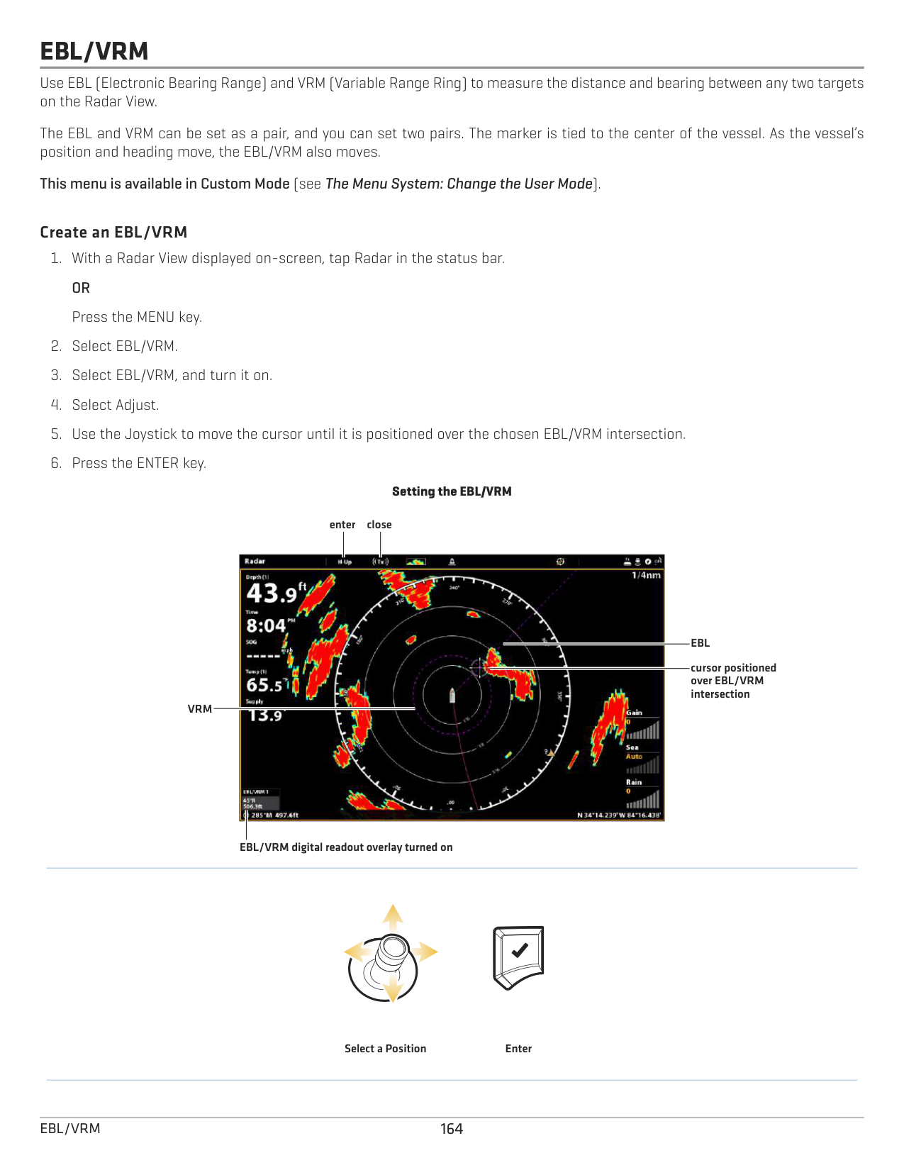
Adjust the Sea Clutter Setting Use the Sea Clutter setting to reduce the clutter that may appear on the view during rough sea conditions.
Manual: If you select Manual, press and hold the slider, or press and hold the ENTER key, to adjust the setting.
Adjust Rain Clutter Settings Use the Rain Clutter setting to reduce the clutter on the view caused by rain or snow.
Adjust Interference Rejection Use the Interference Rejection setting to reduce the noise or interference from other transmitting radars in the area.
EBL/VRM
Use EBL (Electronic Bearing Range) and VRM (Variable Range Ring) to measure the distance and bearing between any two targets on the Radar View.
The EBL and VRM can be set as a pair, and you can set two pairs. The marker is tied to the center of the vessel. As the vessel’s position and heading move, the EBL/VRM also moves.
This menu is available in Custom Mode (see The Menu System: Change the User Mode).
######### Create an EBL/VRM
################# Setting the EBL/VRM
closeenter

EBL
cursor positioned over EBL/VRM intersection
VRM
EBL/VRM digital readout overlay turned on
Select a Position Enter
164EBL/VRM
######### Edit an EBL/VRM
######### Turn off an EBL/VRM
165 EBL/VRM
NAVIGATION IN RADAR VIEW
You can mark waypoints and start navigation from the Radar View. See Introduction to Navigation for more features and information.
NOTE: To display navigation data on the Radar View, see Change the Radar View Data Overlays: Display Navigation Data.
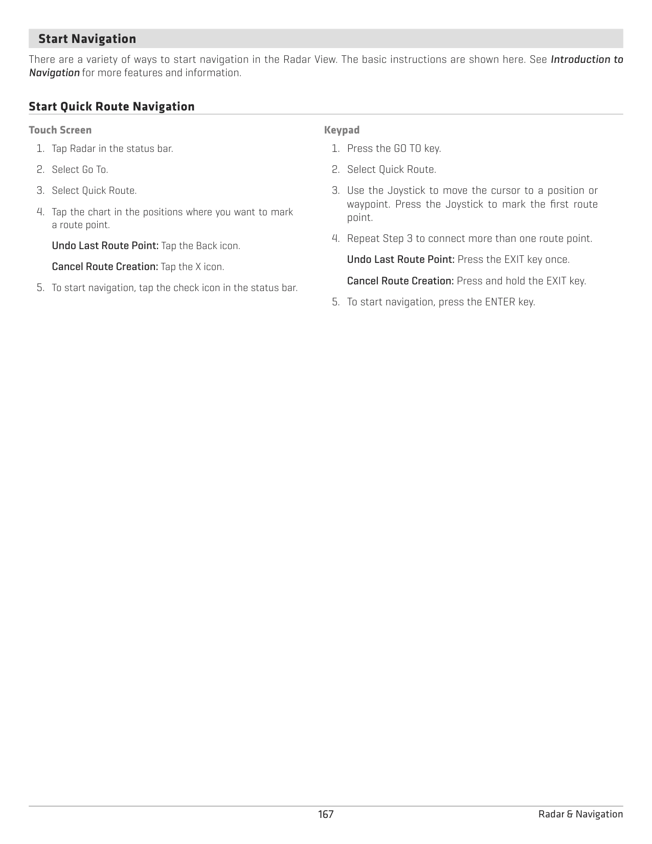
####### Mark a Waypoint
There are a variety of ways to mark a waypoint in the Radar View. The basic instructions are shown here. See Introduction to Navigation for more features and information.
Mark a Waypoint at the Vessel Position
Touch Screen
############ Keypad
Mark a Waypoint at the Cursor Position
############ Touch Screen
############ Keypad
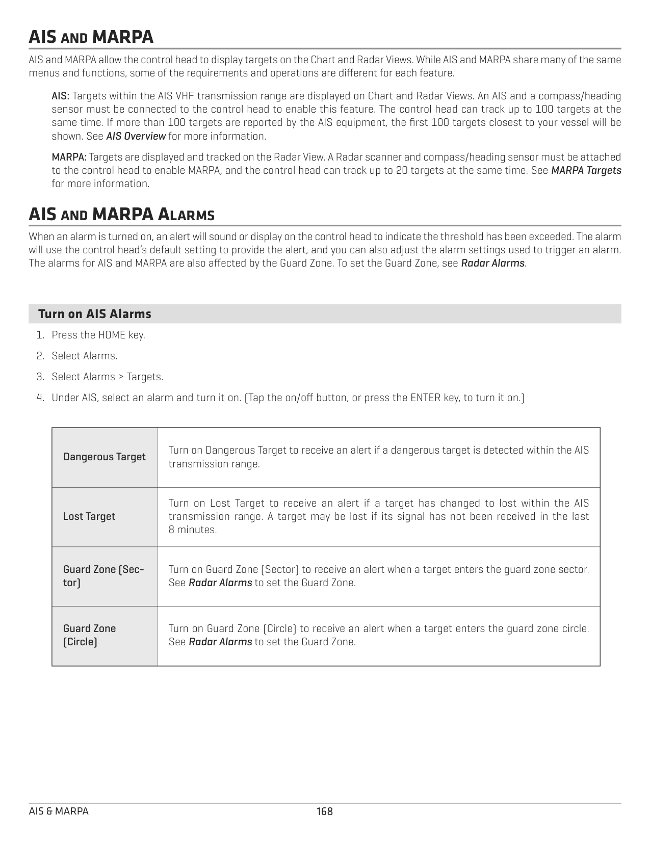
166Radar & Navigation
####### Start Navigation
There are a variety of ways to start navigation in the Radar View. The basic instructions are shown here. See Introduction to Navigation for more features and information.
######## Start Quick Route Navigation Touch Screen
############ Keypad
167 Radar & Navigation
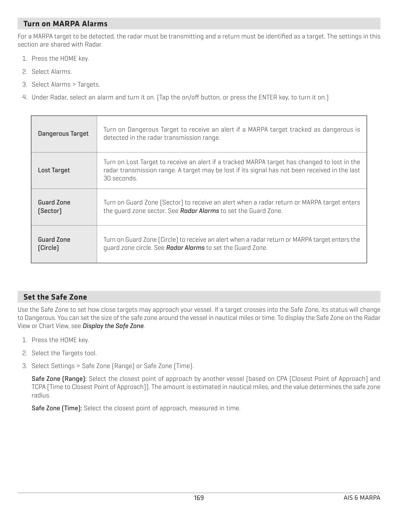
AIS AND MARPA
AIS and MARPA allow the control head to display targets on the Chart and Radar Views. While AIS and MARPA share many of the same menus and functions, some of the requirements and operations are different for each feature.
AIS: Targets within the AIS VHF transmission range are displayed on Chart and Radar Views. An AIS and a compass/heading sensor must be connected to the control head to enable this feature. The control head can track up to 100 targets at the same time. If more than 100 targets are reported by the AIS equipment, the first 100 targets closest to your vessel will be shown. See AIS Overview for more information.
MARPA: Targets are displayed and tracked on the Radar View. A Radar scanner and compass/heading sensor must be attached to the control head to enable MARPA, and the control head can track up to 20 targets at the same time. See MARPA Targets for more information.
AIS AND MARPA ALARMS
When an alarm is turned on, an alert will sound or display on the control head to indicate the threshold has been exceeded. The alarm will use the control head’s default setting to provide the alert, and you can also adjust the alarm settings used to trigger an alarm. The alarms for AIS and MARPA are also affected by the Guard Zone. To set the Guard Zone, see Radar Alarms.
####### Turn on AIS Alarms
|Dangerous Target|Turn on Dangerous Target to receive an alert if a dangerous target is detected within the AIS transmission range.
| |---|---| |Lost Target
|Turn on Lost Target to receive an alert if a target has changed to lost within the AIS transmission range. A target may be lost if its signal has not been received in the last 8 minutes.| |Guard Zone (Sector)
|Turn on Guard Zone (Sector) to receive an alert when a target enters the guard zone sector. See Radar Alarms to set the Guard Zone.| |Guard Zone (Circle)|Turn on Guard Zone (Circle) to receive an alert when a target enters the guard zone circle. See Radar Alarms to set the Guard Zone.|
####### Turn on MARPA Alarms
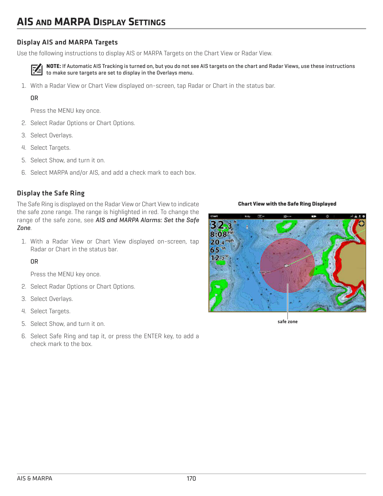
For a MARPA target to be detected, the radar must be transmitting and a return must be identified as a target. The settings in this section are shared with Radar.
|Dangerous Target|Turn on Dangerous Target to receive an alert if a MARPA target tracked as dangerous is detected in the radar transmission range.
| |---|---| |Lost Target|Turn on Lost Target to receive an alert if a tracked MARPA target has changed to lost in the radar transmission range. A target may be lost if its signal has not been received in the last 30 seconds.
| |Guard Zone (Sector)|Turn on Guard Zone (Sector) to receive an alert when a radar return or MARPA target enters the guard zone sector. See Radar Alarms to set the Guard Zone.
| |Guard Zone (Circle)
|Turn on Guard Zone (Circle) to receive an alert when a radar return or MARPA target enters the guard zone circle. See Radar Alarms to set the Guard Zone.|
####### Set the Safe Zone
Use the Safe Zone to set how close targets may approach your vessel. If a target crosses into the Safe Zone, its status will change to Dangerous. You can set the size of the safe zone around the vessel in nautical miles or time. To display the Safe Zone on the Radar View or Chart View, see Display the Safe Zone.
Safe Zone (Range): Select the closest point of approach by another vessel (based on CPA [Closest Point of Approach] and TCPA [Time to Closest Point of Approach]). The amount is estimated in nautical miles, and the value determines the safe zone radius.
Safe Zone (Time): Select the closest point of approach, measured in time.
AIS AND MARPA DISPLAY SETTINGS
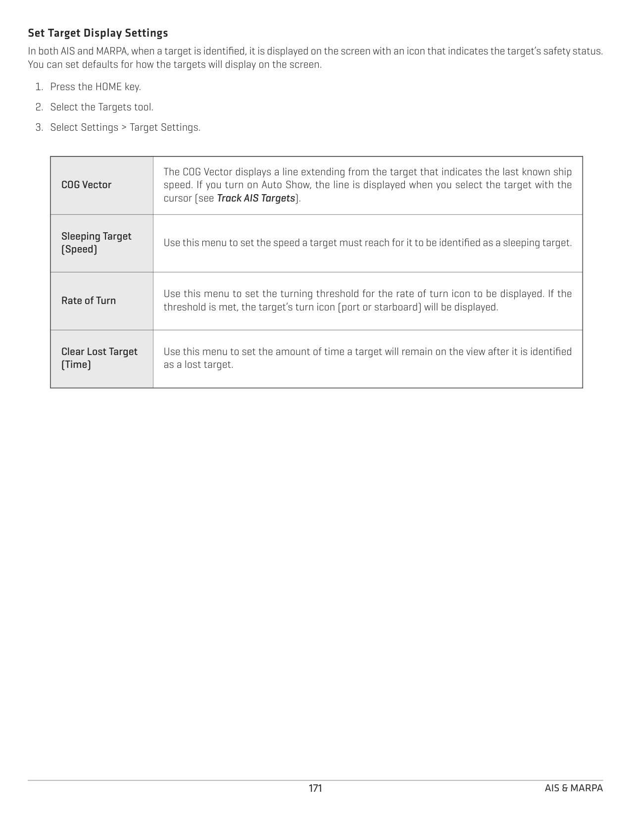
Display AIS and MARPA Targets Use the following instructions to display AIS or MARPA Targets on the Chart View or Radar View.
NOTE: If Automatic AIS Tracking is turned on, but you do not see AIS targets on the chart and Radar Views, use these instructions to make sure targets are set to display in the Overlays menu.
######### Display the Safe Ring
The Safe Ring is displayed on the Radar View or Chart View to indicate the safe zone range. The range is highlighted in red. To change the range of the safe zone, see AIS and MARPA Alarms: Set the Safe Zone.
################# Chart View with the Safe Ring Displayed

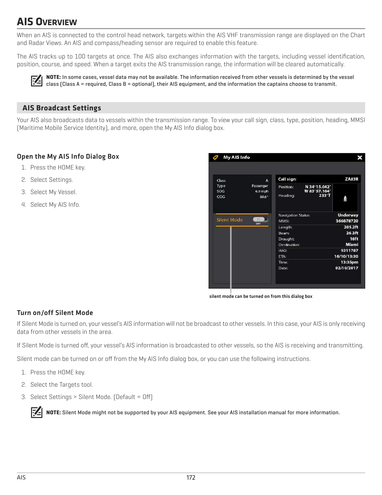
safe zone
######### Set Target Display Settings
In both AIS and MARPA, when a target is identified, it is displayed on the screen with an icon that indicates the target’s safety status. You can set defaults for how the targets will display on the screen.
|COG Vector|The COG Vector displays a line extending from the target that indicates the last known ship speed. If you turn on Auto Show, the line is displayed when you select the target with the cursor (see Track AIS Targets).
| |---|---| |Sleeping Target (Speed)|Use this menu to set the speed a target must reach for it to be identified as a sleeping target.
| |Rate of Turn
|Use this menu to set the turning threshold for the rate of turn icon to be displayed. If the threshold is met, the target’s turn icon (port or starboard) will be displayed.| |Clear Lost Target (Time)|Use this menu to set the amount of time a target will remain on the view after it is identified as a lost target.
|
AIS OVERVIEW
When an AIS is connected to the control head network, targets within the AIS VHF transmission range are displayed on the Chart and Radar Views. An AIS and compass/heading sensor are required to enable this feature.
The AIS tracks up to 100 targets at once. The AIS also exchanges information with the targets, including vessel identification, position, course, and speed. When a target exits the AIS transmission range, the information will be cleared automatically.
NOTE: In some cases, vessel data may not be available. The information received from other vessels is determined by the vessel class (Class A = required, Class B = optional), their AIS equipment, and the information the captains choose to transmit.
####### AIS Broadcast Settings
Your AIS also broadcasts data to vessels within the transmission range. To view your call sign, class, type, position, heading, MMSI (Maritime Mobile Service Identity), and more, open the My AIS Info dialog box.
######### Open the My AIS Info Dialog Box

silent mode can be turned on from this dialog box
######### Turn on/off Silent Mode
If Silent Mode is turned on, your vessel’s AIS information will not be broadcast to other vessels. In this case, your AIS is only receiving data from other vessels in the area.
If Silent Mode is turned off, your vessel’s AIS information is broadcasted to other vessels, so the AIS is receiving and transmitting. Silent mode can be turned on or off from the My AIS Info dialog box, or you can use the following instructions.
NOTE: Silent Mode might not be supported by your AIS equipment. See your AIS installation manual for more information.
####### AIS Filter Settings
You can also control how many AIS targets are shown on the view by adjusting the filter settings.
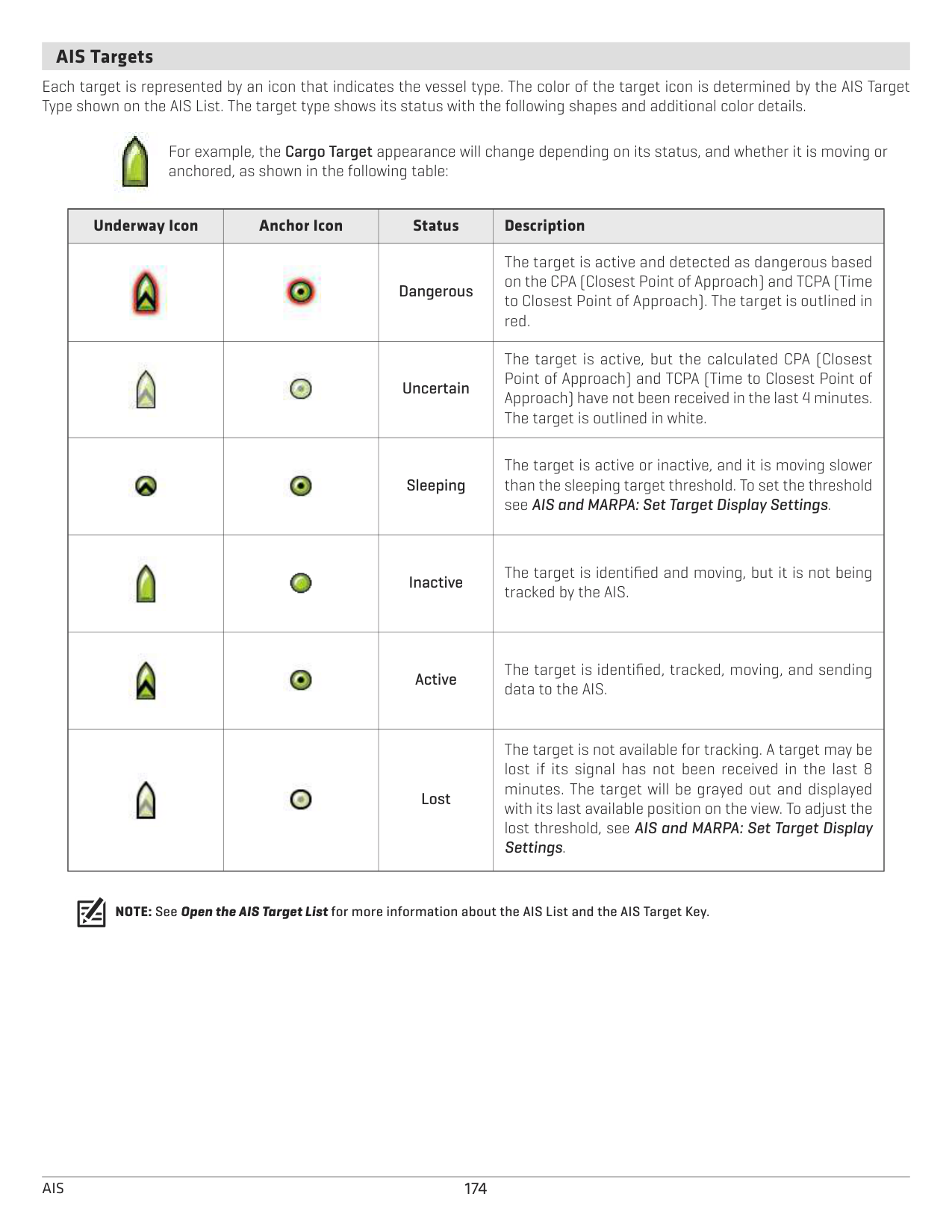
######### Turn on/off Range Filter
If Range Filter is turned on, targets are displayed from your vessel to the distance you set. Targets outside of the range will not be displayed.
If Range Filter is turned off, targets will be displayed within the full range of the AIS equipment’s transmission capabilities.
Turn on/off Class B Filter If Class B Filter is turned on, Class B targets will not be shown. If Class B filter is turned off, all available AIS targets will be shown.
####### AIS Targets
Each target is represented by an icon that indicates the vessel type. The color of the target icon is determined by the AIS Target Type shown on the AIS List. The target type shows its status with the following shapes and additional color details.

For example, the Cargo Target appearance will change depending on its status, and whether it is moving or anchored, as shown in the following table:
|Underway Icon|Anchor Icon
|Status|Description|
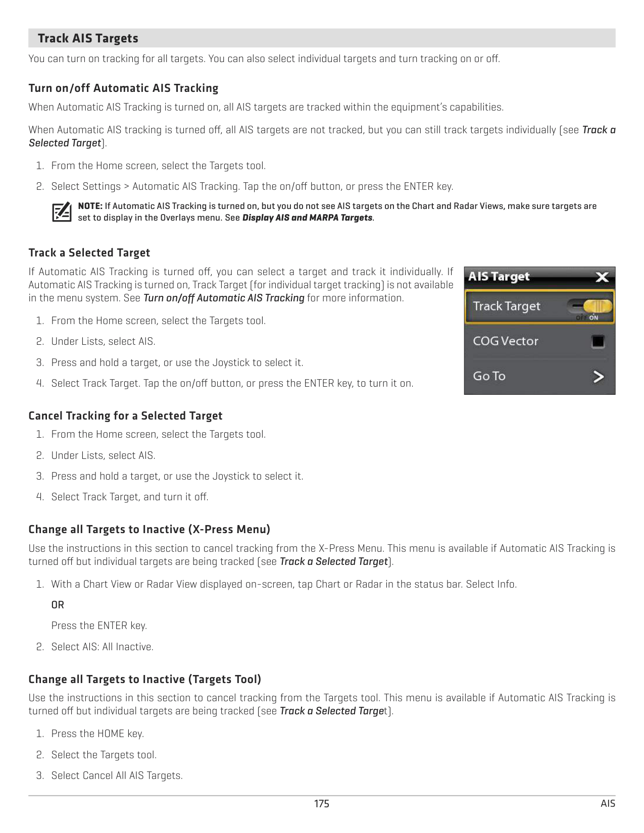
|---|---|---|---| |
||Dangerous|The target is active and detected as dangerous based on the CPA (Closest Point of Approach) and TCPA (Time to Closest Point of Approach). The target is outlined in red.| |
||Uncertain|The target is active, but the calculated CPA (Closest Point of Approach) and TCPA (Time to Closest Point of Approach) have not been received in the last 4 minutes. The target is outlined in white.| ||
|Sleeping|The target is active or inactive, and it is moving slower than the sleeping target threshold. To set the threshold see AIS and MARPA: Set Target Display Settings.| |||Inactive|The target is identified and moving, but it is not being tracked by the AIS.
| |||Active|The target is identified, tracked, moving, and sending data to the AIS.
| ||
|Lost|The target is not available for tracking. A target may be lost if its signal has not been received in the last 8 minutes. The target will be grayed out and displayed with its last available position on the view. To adjust the lost threshold, see AIS and MARPA: Set Target Display Settings.
|
NOTE: See Open the AIS Target List for more information about the AIS List and the AIS Target Key.
####### Track AIS Targets
You can turn on tracking for all targets. You can also select individual targets and turn tracking on or off.
Turn on/off Automatic AIS Tracking When Automatic AIS Tracking is turned on, all AIS targets are tracked within the equipment’s capabilities. When Automatic AIS tracking is turned off, all AIS targets are not tracked, but you can still track targets individually (see Track a Selected Target).
NOTE: If Automatic AIS Tracking is turned on, but you do not see AIS targets on the Chart and Radar Views, make sure targets are set to display in the Overlays menu. See Display AIS and MARPA Targets.
######### Track a Selected Target
If Automatic AIS Tracking is turned off, you can select a target and track it individually. If Automatic AIS Tracking is turned on, Track Target (for individual target tracking) is not available in the menu system. See Turn on/off Automatic AIS Tracking for more information.
|| |---|
######### Cancel Tracking for a Selected Target
######### Change all Targets to Inactive (X-Press Menu)
Use the instructions in this section to cancel tracking from the X-Press Menu. This menu is available if Automatic AIS Tracking is turned off but individual targets are being tracked (see Track a Selected Target).
######### Change all Targets to Inactive (Targets Tool)
Use the instructions in this section to cancel tracking from the Targets tool. This menu is available if Automatic AIS Tracking is turned off but individual targets are being tracked (see Track a Selected Target).
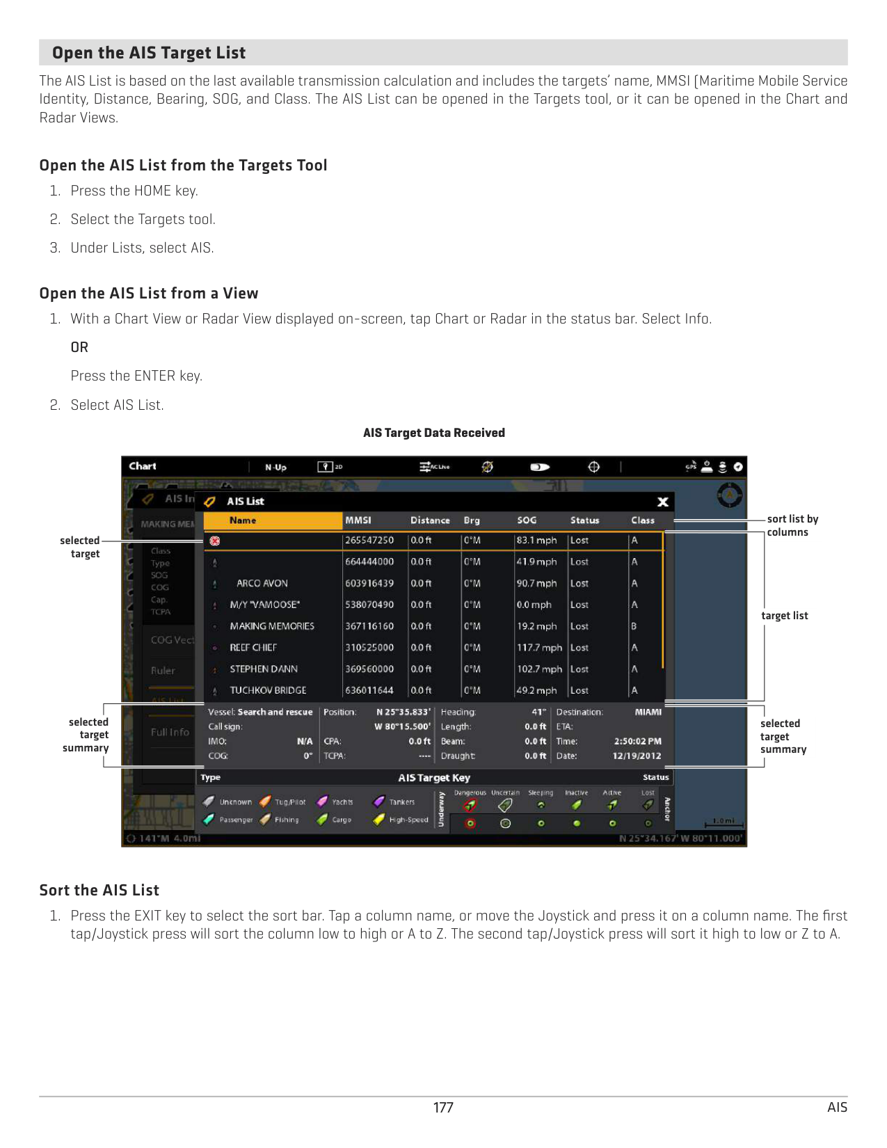
####### Start Navigation to a Selected Target
Start navigation to a selected target using the following instructions. See Introduction to Navigation for more features and information.
######## Start Navigation to a Selected Target
############ Touch Screen
############ Keypad
NOTE: You can also start navigation from the AIS List in the Targets tool. Select a target and press the MENU key, or press and hold the target name. Select Go To.
####### Open the AIS Target List
The AIS List is based on the last available transmission calculation and includes the targets’ name, MMSI (Maritime Mobile Service Identity, Distance, Bearing, SOG, and Class. The AIS List can be opened in the Targets tool, or it can be opened in the Chart and Radar Views.
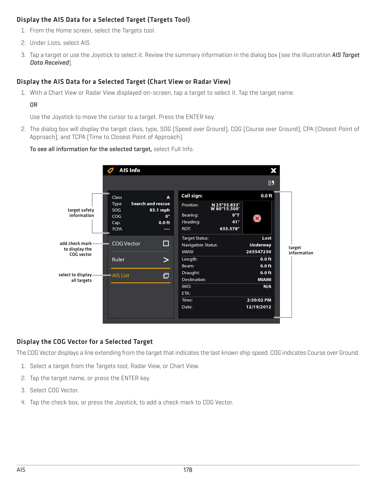
######### Open the AIS List from the Targets Tool
######### Open the AIS List from a View
AIS Target Data Received

sort list by columns
selected target
target list
selected
selected target summary
target summary
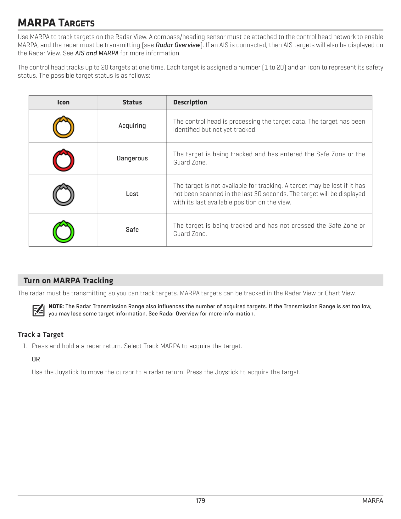
######### Sort the AIS List
######### Display the AIS Data for a Selected Target (Targets Tool)
Data Received).
######### Display the AIS Data for a Selected Target (Chart View or Radar View)

target safety information
add check mark to display the COG vector
target information
select to display all targets

Display the COG Vector for a Selected Target The COG Vector displays a line extending from the target that indicates the last known ship speed. COG indicates Course over Ground.
MARPA TARGETS
Use MARPA to track targets on the Radar View. A compass/heading sensor must be attached to the control head network to enable MARPA, and the radar must be transmitting (see Radar Overview). If an AIS is connected, then AIS targets will also be displayed on the Radar View. See AIS and MARPA for more information.
The control head tracks up to 20 targets at one time. Each target is assigned a number (1 to 20) and an icon to represent its safety status. The possible target status is as follows:
|Icon
|Status|Description| |---|---|---| |
|Acquiring|The control head is processing the target data. The target has been identified but not yet tracked.| |
|Dangerous|The target is being tracked and has entered the Safe Zone or the Guard Zone.| ||Lost
|The target is not available for tracking. A target may be lost if it has not been scanned in the last 30 seconds. The target will be displayed with its last available position on the view.| ||Safe|The target is being tracked and has not crossed the Safe Zone or Guard Zone.|
####### Turn on MARPA Tracking
The radar must be transmitting so you can track targets. MARPA targets can be tracked in the Radar View or Chart View.
NOTE: The Radar Transmission Range also influences the number of acquired targets. If the Transmission Range is set too low, you may lose some target information. See Radar Overview for more information.
######### Track a Target
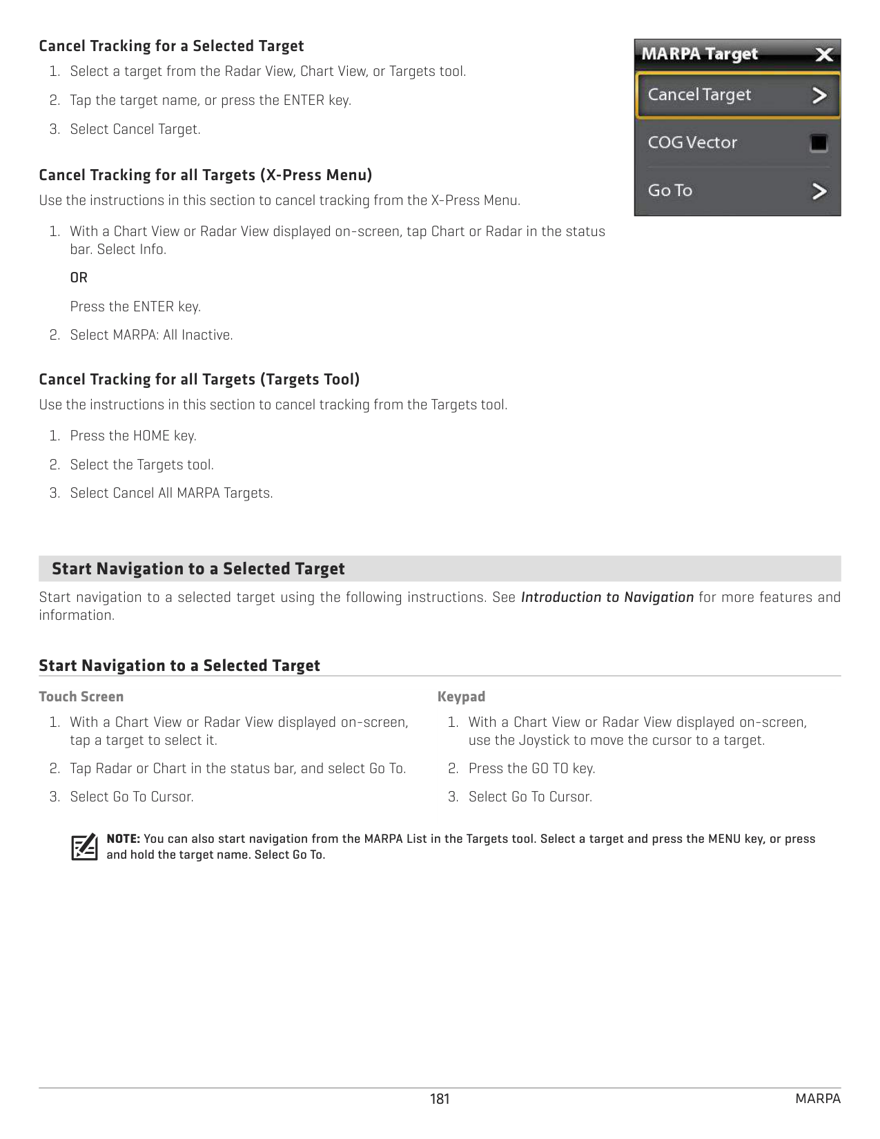
Radar View with MARPA Targets Displayed
orientation menu close cursor sensor status icons

MARPA target
MARPA target
Press and Hold a Radar Return
#### OR
Move the Cursor to a Radar Return
Press the Joystick to Acquire Target
######### Cancel Tracking for a Selected Target
Cancel Tracking for all Targets (X-Press Menu) Use the instructions in this section to cancel tracking from the X-Press Menu.
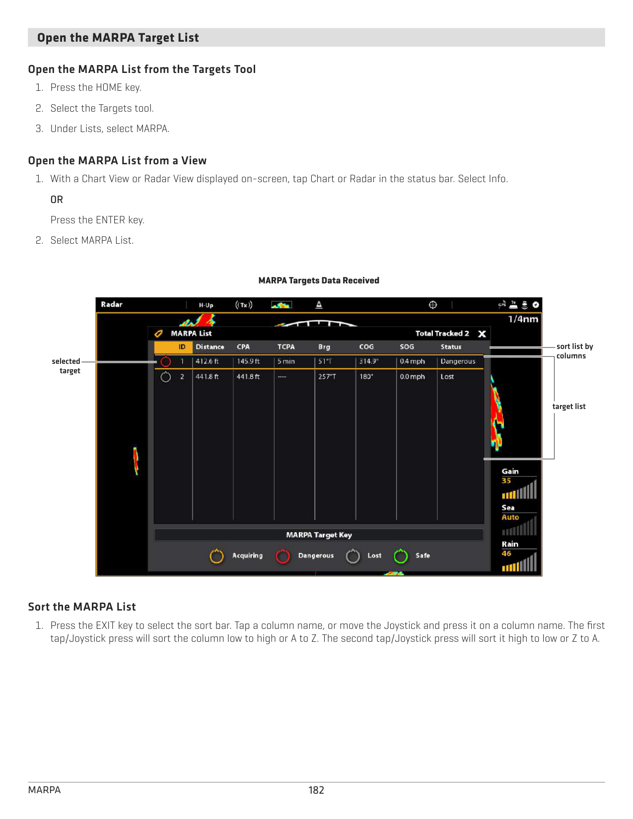
Cancel Tracking for all Targets (Targets Tool) Use the instructions in this section to cancel tracking from the Targets tool.
|| |---|
####### Start Navigation to a Selected Target
Start navigation to a selected target using the following instructions. See Introduction to Navigation for more features and information.
######## Start Navigation to a Selected Target
############ Touch Screen
############ Keypad
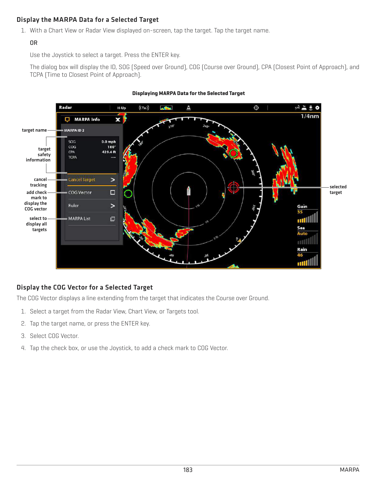
NOTE: You can also start navigation from the MARPA List in the Targets tool. Select a target and press the MENU key, or press and hold the target name. Select Go To.
####### Open the MARPA Target List
######### Open the MARPA List from the Targets Tool
######### Open the MARPA List from a View
MARPA Targets Data Received

sort list by columns
selected target
target list
######### Sort the MARPA List
######### Display the MARPA Data for a Selected Target
Displaying MARPA Data for the Selected Target

target name
target safety
information
cancel
tracking add check
selected target
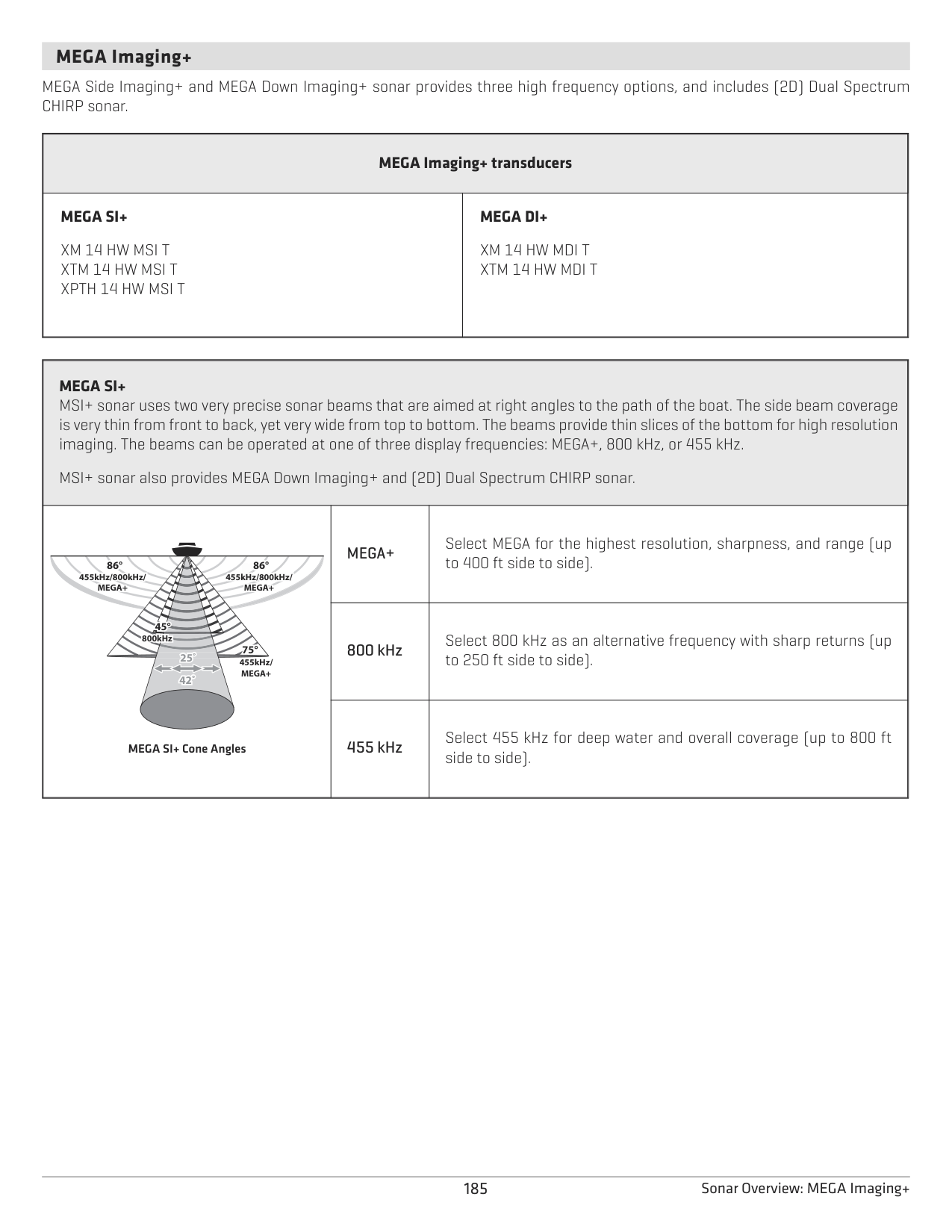
mark to display the COG vector
select to display all targets
Display the COG Vector for a Selected Target The COG Vector displays a line extending from the target that indicates the Course over Ground.
SONAR OVERVIEW
A functioning transducer must be attached to the control head or selected as the transducer source on the Ethernet network to enable sonar functions. To purchase transducers and black box sonar equipment, visit our Web site at humminbird.com.
The SOLIX control head supports the following sonar:
NOTE: Depth capability is affected by such factors as boat speed, wave action, bottom hardness, water conditions, and transducer installation. See the Specifications section for details.
184Sonar Overview
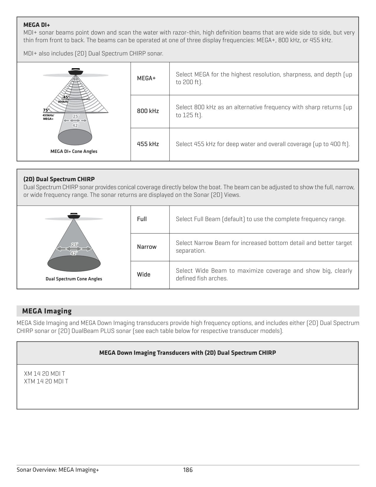
####### MEGA Imaging+
MEGA Side Imaging+ and MEGA Down Imaging+ sonar provides three high frequency options, and includes (2D) Dual Spectrum CHIRP sonar.
|MEGA Imaging+ transducers
|MEGA Imaging+ transducers
| |---|---| |MEGA SI+
XM 14 HW MSI T XTM 14 HW MSI T XPTH 14 HW MSI T|MEGA DI+
XM 14 HW MDI T XTM 14 HW MDI T
|
|MEGA SI+
MSI+ sonar uses two very precise sonar beams that are aimed at right angles to the path of the boat. The side beam coverage is very thin from front to back, yet very wide from top to bottom. The beams provide thin slices of the bottom for high resolution imaging. The beams can be operated at one of three display frequencies: MEGA+, 800 kHz, or 455 kHz.
MSI+ sonar also provides MEGA Down Imaging+ and (2D) Dual Spectrum CHIRP sonar.
| |---|---|---| |8°88°
25˚ 42˚
886° 86°°°86°
445
86° 86°
45°45° 800kHz
75°
455kHz/ MEGA+
455kHz/800kHz/ MEGA+
455kHz/800kHz/ MEGA+
86° 86°
MEGA SI+ Cone Angles
|66°
MEGA+|Select MEGA for the highest resolution, sharpness, and range (up to 400 ft side to side).
| |8°88°
25˚ 42˚
886° 86°°°86°
445
86° 86°
45°45° 800kHz
75°
455kHz/ MEGA+
455kHz/800kHz/ MEGA+
455kHz/800kHz/ MEGA+
86° 86°
MEGA SI+ Cone Angles
|800 kHz
|Select 800 kHz as an alternative frequency with sharp returns (up to 250 ft side to side).| |8°88°
25˚ 42˚
886° 86°°°86°
445
86° 86°
45°45° 800kHz
75°
455kHz/ MEGA+
455kHz/800kHz/ MEGA+
455kHz/800kHz/ MEGA+
86° 86°
MEGA SI+ Cone Angles
|455 kHz|Select 455 kHz for deep water and overall coverage (up to 800 ft side to side).|
185 Sonar Overview: MEGA Imaging+
|MEGA DI+ MDI+ sonar beams point down and scan the water with razor-thin, high definition beams that are wide side to side, but very thin from front to back. The beams can be operated at one of three display frequencies: MEGA+, 800 kHz, or 455 kHz.
MDI+ also includes (2D) Dual Spectrum CHIRP sonar.
|MEGA DI+ MDI+ sonar beams point down and scan the water with razor-thin, high definition beams that are wide side to side, but very thin from front to back. The beams can be operated at one of three display frequencies: MEGA+, 800 kHz, or 455 kHz.
MDI+ also includes (2D) Dual Spectrum CHIRP sonar.
|MEGA DI+ MDI+ sonar beams point down and scan the water with razor-thin, high definition beams that are wide side to side, but very thin from front to back. The beams can be operated at one of three display frequencies: MEGA+, 800 kHz, or 455 kHz.
MDI+ also includes (2D) Dual Spectrum CHIRP sonar.
| |---|---|---| |455kHz/ MEGA+ 25˚
42˚
44545°
5°77575°
800kHz
MEGA DI+ Cone Angles|MEGA+
|Select MEGA for the highest resolution, sharpness, and depth (up to 200 ft).| |455kHz/ MEGA+ 25˚
42˚
44545°
5°77575°
800kHz
MEGA DI+ Cone Angles|800 kHz|Select 800 kHz as an alternative frequency with sharp returns (up to 125 ft).
| |455kHz/ MEGA+ 25˚
42˚
44545°
5°77575°
800kHz
MEGA DI+ Cone Angles|455 kHz|Select 455 kHz for deep water and overall coverage (up to 400 ft).|
|(2D) Dual Spectrum CHIRP Dual Spectrum CHIRP sonar provides conical coverage directly below the boat. The beam can be adjusted to show the full, narrow, or wide frequency range. The sonar returns are displayed on the Sonar (2D) Views.
|(2D) Dual Spectrum CHIRP Dual Spectrum CHIRP sonar provides conical coverage directly below the boat. The beam can be adjusted to show the full, narrow, or wide frequency range. The sonar returns are displayed on the Sonar (2D) Views.
|(2D) Dual Spectrum CHIRP Dual Spectrum CHIRP sonar provides conical coverage directly below the boat. The beam can be adjusted to show the full, narrow, or wide frequency range. The sonar returns are displayed on the Sonar (2D) Views.
| |---|---|---| |25˚ 42˚
Dual Spectrum Cone Angles
|Full|Select Full Beam (default) to use the complete frequency range.
| |25˚ 42˚
Dual Spectrum Cone Angles
|Narrow
|Select Narrow Beam for increased bottom detail and better target separation.|
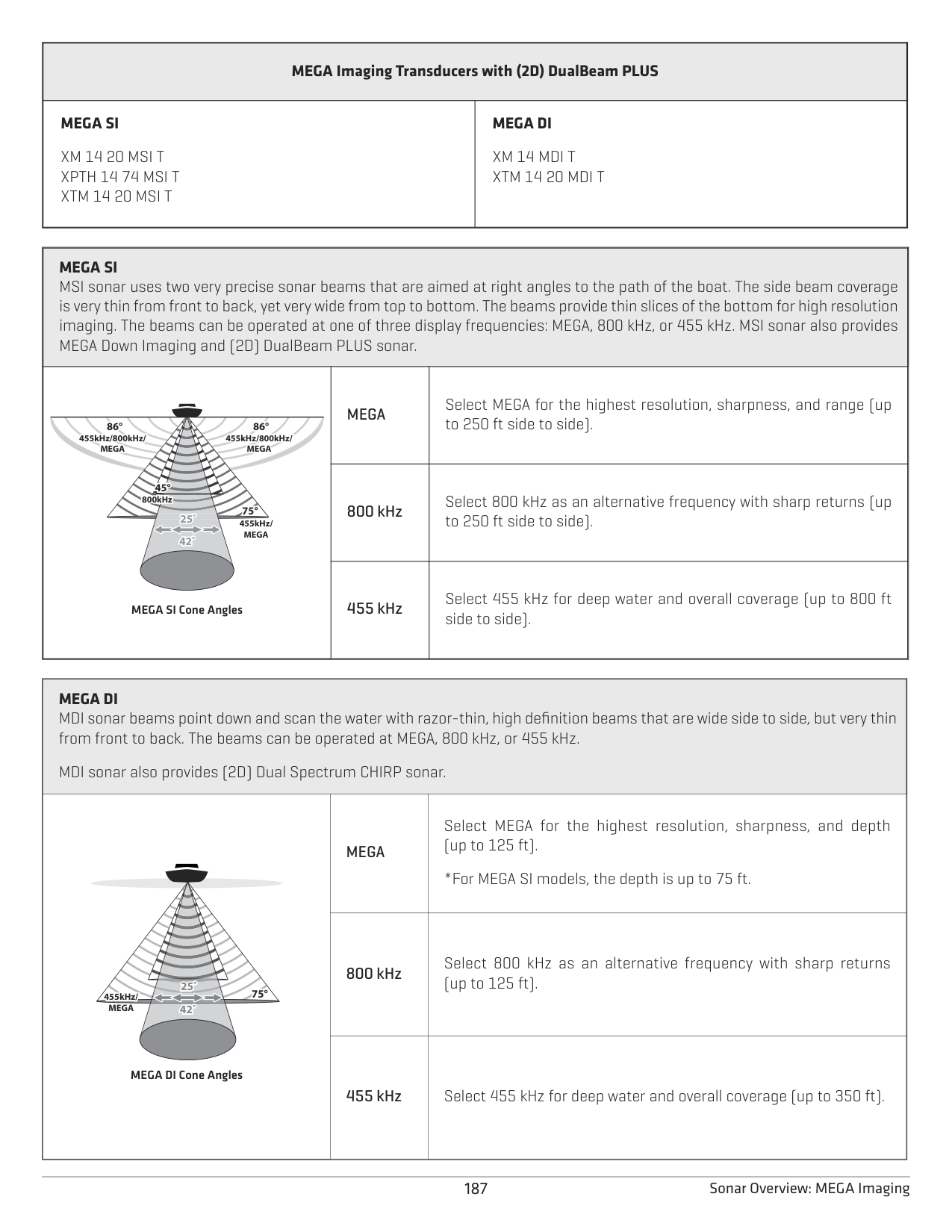
|25˚ 42˚
Dual Spectrum Cone Angles
|Wide|Select Wide Beam to maximize coverage and show big, clearly defined fish arches.|
####### MEGA Imaging
MEGA Side Imaging and MEGA Down Imaging transducers provide high frequency options, and includes either (2D) Dual Spectrum CHIRP sonar or (2D) DualBeam PLUS sonar (see each table below for respective transducer models).
|MEGA Down Imaging Transducers with (2D) Dual Spectrum CHIRP
| |---| |XM 14 20 MDI T XTM 14 20 MDI T|
186Sonar Overview: MEGA Imaging+
|MEGA Imaging Transducers with (2D) DualBeam PLUS
|MEGA Imaging Transducers with (2D) DualBeam PLUS
| |---|---| |MEGA SI
XM 14 20 MSI T XPTH 14 74 MSI T XTM 14 20 MSI T
|MEGA DI
XM 14 MDI T XTM 14 20 MDI T|
|MEGA SI
MSI sonar uses two very precise sonar beams that are aimed at right angles to the path of the boat. The side beam coverage is very thin from front to back, yet very wide from top to bottom. The beams provide thin slices of the bottom for high resolution imaging. The beams can be operated at one of three display frequencies: MEGA, 800 kHz, or 455 kHz. MSI sonar also provides MEGA Down Imaging and (2D) DualBeam PLUS sonar.
| |---|---|---| |8°88°
25˚ 42˚
886° 86°°°86°
445
86° 86°
45°45° 800kHz
75°
455kHz/ MEGA
455kHz/800kHz/ MEGA
455kHz/800kHz/ MEGA
86° 86°
MEGA SI Cone Angles
|66°
MEGA|Select MEGA for the highest resolution, sharpness, and range (up to 250 ft side to side).
| |8°88°
25˚ 42˚
886° 86°°°86°
445
86° 86°
45°45° 800kHz
75°
455kHz/ MEGA
455kHz/800kHz/ MEGA
455kHz/800kHz/ MEGA
86° 86°
MEGA SI Cone Angles
|800 kHz
|Select 800 kHz as an alternative frequency with sharp returns (up to 250 ft side to side).| |8°88°
25˚ 42˚
886° 86°°°86°
445
86° 86°
45°45° 800kHz
75°
455kHz/ MEGA
455kHz/800kHz/ MEGA
455kHz/800kHz/ MEGA
86° 86°
MEGA SI Cone Angles
|455 kHz|Select 455 kHz for deep water and overall coverage (up to 800 ft side to side).|
|MEGA DI MDI sonar beams point down and scan the water with razor-thin, high definition beams that are wide side to side, but very thin from front to back. The beams can be operated at MEGA, 800 kHz, or 455 kHz.
MDI sonar also provides (2D) Dual Spectrum CHIRP sonar.
|MEGA DI MDI sonar beams point down and scan the water with razor-thin, high definition beams that are wide side to side, but very thin from front to back. The beams can be operated at MEGA, 800 kHz, or 455 kHz.
MDI sonar also provides (2D) Dual Spectrum CHIRP sonar.
|MEGA DI MDI sonar beams point down and scan the water with razor-thin, high definition beams that are wide side to side, but very thin from front to back. The beams can be operated at MEGA, 800 kHz, or 455 kHz.
MDI sonar also provides (2D) Dual Spectrum CHIRP sonar.
| |---|---|---| |25˚ 42˚ 75°455kHz/
MEGA
MEGA DI Cone Angles
|MEGA|Select MEGA for the highest resolution, sharpness, and depth (up to 125 ft).
*For MEGA SI models, the depth is up to 75 ft.
|
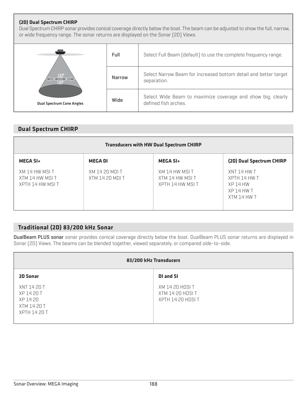
|25˚ 42˚ 75°455kHz/
MEGA
MEGA DI Cone Angles
|800 kHz
|Select 800 kHz as an alternative frequency with sharp returns (up to 125 ft).| |25˚ 42˚ 75°455kHz/
MEGA
MEGA DI Cone Angles
|455 kHz|Select 455 kHz for deep water and overall coverage (up to 350 ft).|
########### 187 Sonar Overview: MEGA Imaging
|(2D) Dual Spectrum CHIRP Dual Spectrum CHIRP sonar provides conical coverage directly below the boat. The beam can be adjusted to show the full, narrow, or wide frequency range. The sonar returns are displayed on the Sonar (2D) Views.
|(2D) Dual Spectrum CHIRP Dual Spectrum CHIRP sonar provides conical coverage directly below the boat. The beam can be adjusted to show the full, narrow, or wide frequency range. The sonar returns are displayed on the Sonar (2D) Views.
|(2D) Dual Spectrum CHIRP Dual Spectrum CHIRP sonar provides conical coverage directly below the boat. The beam can be adjusted to show the full, narrow, or wide frequency range. The sonar returns are displayed on the Sonar (2D) Views.
| |---|---|---| |25˚ 42˚
Dual Spectrum Cone Angles
|Full|Select Full Beam (default) to use the complete frequency range.
| |25˚ 42˚
Dual Spectrum Cone Angles
|Narrow|Select Narrow Beam for increased bottom detail and better target separation.
| |25˚ 42˚
Dual Spectrum Cone Angles
|Wide|Select Wide Beam to maximize coverage and show big, clearly defined fish arches.|
Dual Spectrum CHIRP
|Transducers with HW Dual Spectrum CHIRP
|Transducers with HW Dual Spectrum CHIRP
|Transducers with HW Dual Spectrum CHIRP
|Transducers with HW Dual Spectrum CHIRP
| |---|---|---|---| |MEGA SI+
XM 14 HW MSI T XTM 14 HW MSI T XPTH 14 HW MSI T|MEGA DI
XM 14 20 MDI T XTM 14 20 MDI T
|MEGA SI+
XM 14 HW MSI T XTM 14 HW MSI T XPTH 14 HW MSI T|(2D) Dual Spectrum CHIRP
XNT 14 HW T XPTH 14 HW T XP 14 HW XP 14 HW T XTM 14 HW T
|
Traditional (2D) 83/200 kHz Sonar
DualBeam PLUS sonar sonar provides conical coverage directly below the boat. DualBeam PLUS sonar returns are displayed in Sonar (2D) Views. The beams can be blended together, viewed separately, or compared side-to-side.
|83/200 kHz Transducers
|83/200 kHz Transducers
| |---|---| |2D Sonar
XNT 14 20 T XP 14 20 T XP 14 20 XTM 14 20 T XPTH 14 20 T|DI and SI
XM 14 20 HDSI T XTM 14 20 HDSI T XPTH 14 20 HDSI T
|
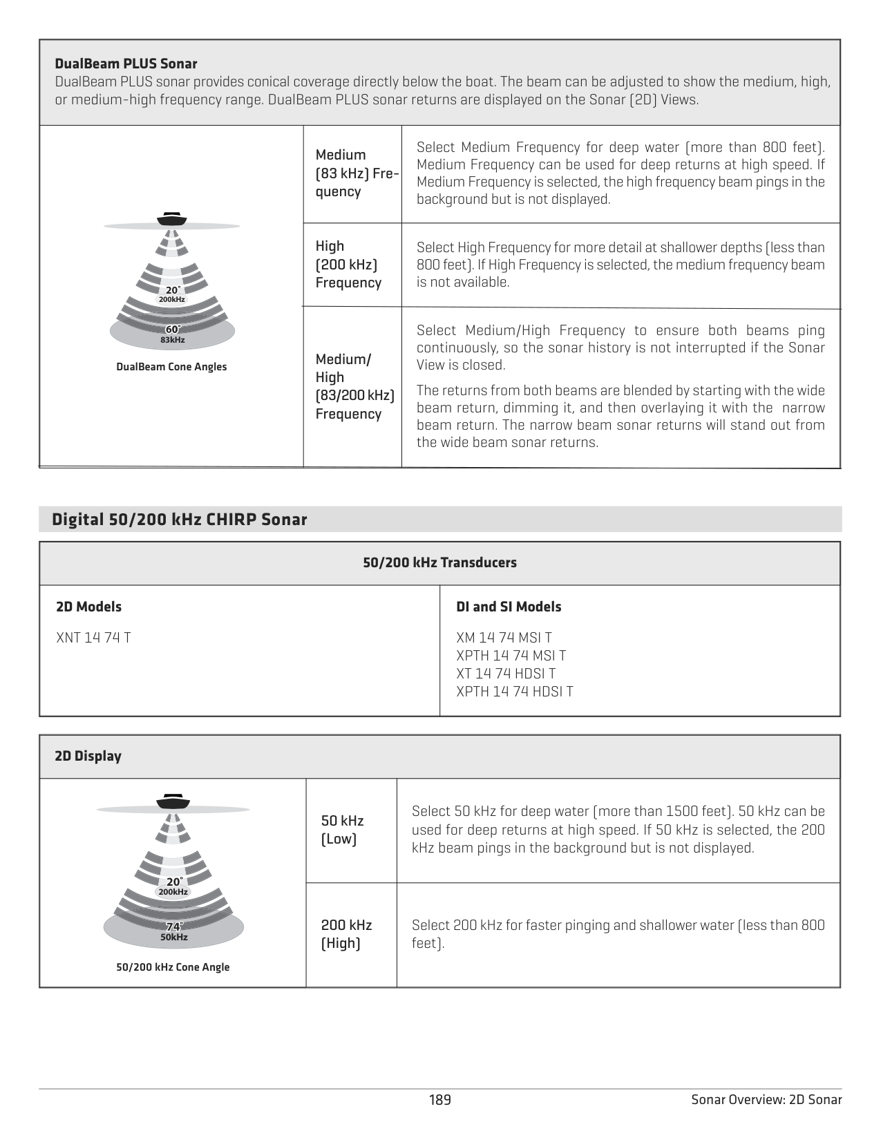
188Sonar Overview: MEGA Imaging
|DualBeam PLUS Sonar DualBeam PLUS sonar provides conical coverage directly below the boat. The beam can be adjusted to show the medium, high, or medium-high frequency range. DualBeam PLUS sonar returns are displayed on the Sonar (2D) Views.
|DualBeam PLUS Sonar DualBeam PLUS sonar provides conical coverage directly below the boat. The beam can be adjusted to show the medium, high, or medium-high frequency range. DualBeam PLUS sonar returns are displayed on the Sonar (2D) Views.
|DualBeam PLUS Sonar DualBeam PLUS sonar provides conical coverage directly below the boat. The beam can be adjusted to show the medium, high, or medium-high frequency range. DualBeam PLUS sonar returns are displayed on the Sonar (2D) Views.
| |---|---|---| |200kHz
83kHz
20˚
DualBeam Cone Angles|Medium (83 kHz) Frequency
|Select Medium Frequency for deep water (more than 800 feet). Medium Frequency can be used for deep returns at high speed. If Medium Frequency is selected, the high frequency beam pings in the background but is not displayed.| |200kHz
83kHz
20˚
DualBeam Cone Angles|High (200 kHz) Frequency
|Select High Frequency for more detail at shallower depths (less than 800 feet). If High Frequency is selected, the medium frequency beam is not available.| |200kHz
83kHz
20˚
DualBeam Cone Angles|Medium/ High (83/200 kHz) Frequency|Select Medium/High Frequency to ensure both beams ping continuously, so the sonar history is not interrupted if the Sonar View is closed.
The returns from both beams are blended by starting with the wide beam return, dimming it, and then overlaying it with the narrow beam return. The narrow beam sonar returns will stand out from the wide beam sonar returns.|
####### Digital 50/200 kHz CHIRP Sonar
|50/200 kHz Transducers
|50/200 kHz Transducers
| |---|---| |2D Models XNT 14 74 T|DI and SI Models
XM 14 74 MSI T XPTH 14 74 MSI T XT 14 74 HDSI T XPTH 14 74 HDSI T
|
|2D Display
|2D Display
|2D Display
| |---|---|---| |200kHz
774 50kHz
20˚
74˚
50/200 kHz Cone Angle|50 kHz (Low)
|Select 50 kHz for deep water (more than 1500 feet). 50 kHz can be used for deep returns at high speed. If 50 kHz is selected, the 200 kHz beam pings in the background but is not displayed.| |200kHz
774 50kHz
20˚
74˚
50/200 kHz Cone Angle|200 kHz (High)|Select 200 kHz for faster pinging and shallower water (less than 800 feet).|
189 Sonar Overview: 2D Sonar
SONAR SETUP
The available sonar views and menus on the control head are determined by the connected transducer and the selected transducer source. The selected transducer must be pinging to enable the views.

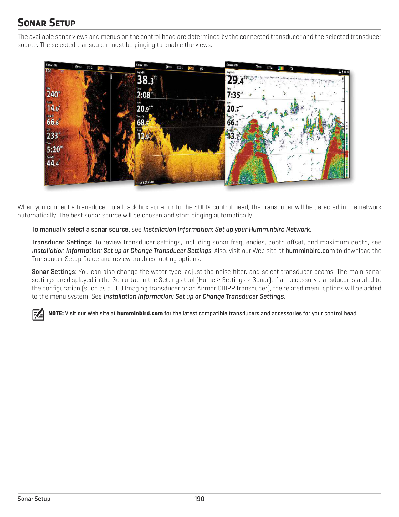


When you connect a transducer to a black box sonar or to the SOLIX control head, the transducer will be detected in the network automatically. The best sonar source will be chosen and start pinging automatically.
############# To manually select a sonar source, see Installation Information: Set up your Humminbird Network.
Transducer Settings: To review transducer settings, including sonar frequencies, depth offset, and maximum depth, see Installation Information: Set up or Change Transducer Settings. Also, visit our Web site at humminbird.com to download the Transducer Setup Guide and review troubleshooting options.
Sonar Settings: You can also change the water type, adjust the noise filter, and select transducer beams. The main sonar settings are displayed in the Sonar tab in the Settings tool (Home > Settings > Sonar). If an accessory transducer is added to the configuration (such as a 360 Imaging transducer or an Airmar CHIRP transducer), the related menu options will be added to the menu system. See Installation Information: Set up or Change Transducer Settings.
NOTE: Visit our Web site at humminbird.com for the latest compatible transducers and accessories for your control head.
190Sonar Setup
SONAR ALARMS
Before you start navigating and fishing with your control head, set up sonar alarms. A functioning transducer must be attached to the control head or selected as the transducer source on the network to enable all sonar functions.
####### Turn on Sonar Alarms
|Fish (Shallow)|Turn on Fish (Shallow) to receive an alarm if fish are detected in shallow water. You can also adjust the shallow water range with the slider.
| |---|---| |Fish (Deep)|Turn on Fish (Deep) to receive an alarm if fish are detected in deep water. You can also adjust the deep water range with the slider.
| |Shallow Water|If the bottom depth is less than the amount you set, the control head will provide an alarm.
| |Deep Water|If the bottom depth is more than the amount you set, the control head will provide an alarm.|
191 Sonar Alarms
2D SONAR OVERVIEW
As the boat moves, the unit charts the changes in depth on the display to create a profile of the bottom contour. The 2D Sonar View displays the sonar return intensity with different colors.
Strong returns often result from rocky or hard bottoms (compacted sediment, rocks, fallen trees), while weaker returns often result from soft bottoms (sand, mud), vegetation, and small fish.
The colors used to represent high, medium, to low intensity returns are determined by the palette you choose in the Preferences menu (see Open the 2D Sonar Preferences Menu: Change the Palette and Background).
The control head displays the return intensity based on the Palette and Bottom View menu settings. You can display the RTS Window (Real Time Sonar), turn on/off fish symbols (Fish ID+), change the SwitchFire mode, adjust sensitivity, and more.
################# 2D Sonar View: Original Palette
Color Bar weak strong

strong returns (possibly rocks, tree limbs, or other structure)
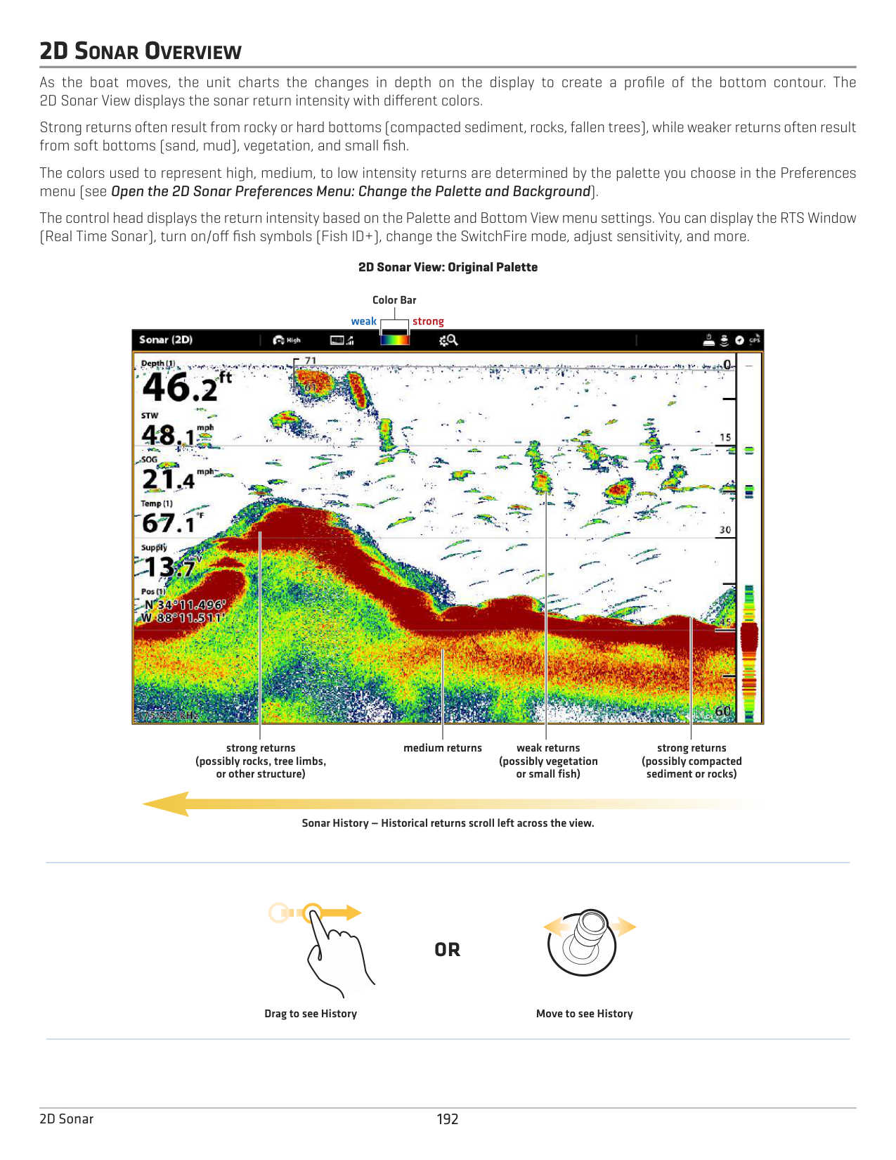
medium returns weak returns
strong returns (possibly compacted sediment or rocks)
(possibly vegetation or small fish)
Sonar History — Historical returns scroll left across the view.
#### OR
Drag to see History Move to see History
1922D Sonar
CUSTOMIZE THE 2D SONAR VIEW
The settings in this section are optional. You can use the default settings for the 2D Sonar View, or you can customize it with your preferences. See Views for more information.
OPEN THE 2D SONAR PREFERENCES MENU
The Preferences menu allows you to set the sonar mode, zoom mode, return palette, background color, bottom view, and RTS Window. For more information about view preferences, see Views.
####### Change the Sonar Mode
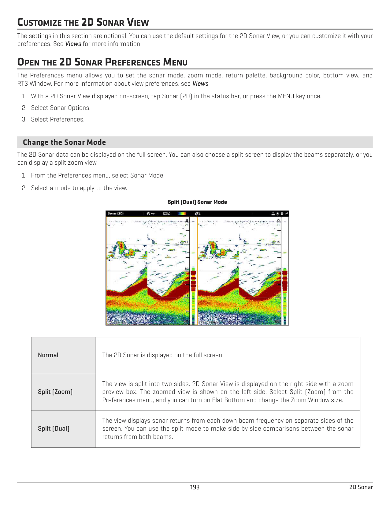
The 2D Sonar data can be displayed on the full screen. You can also choose a split screen to display the beams separately, or you can display a split zoom view.
Split (Dual) Sonar Mode
|| |---|
|Normal
|The 2D Sonar is displayed on the full screen.| |---|---| |Split (Zoom)|The view is split into two sides. 2D Sonar View is displayed on the right side with a zoom preview box. The zoomed view is shown on the left side. Select Split (Zoom) from the Preferences menu, and you can turn on Flat Bottom and change the Zoom Window size.
| |Split (Dual)|The view displays sonar returns from each down beam frequency on separate sides of the screen. You can use the split mode to make side by side comparisons between the sonar returns from both beams.|
####### Set the Zoom Mode
The Zoom Mode sets the zoom commands to magnify the full pane or the cursor selection. See Use Cursor and Zoom in Sonar Views to apply the zoom features.
|Pane Zoom
|When you use pinch out/in (touch screen) to zoom, or press the +/– ZOOM keys, the view will be magnified.| |---|---|
|Cursor Zoom
|When you use pinch out/in (touch screen) to zoom, or press the +/– ZOOM keys, the cursor selection will be magnified.|
####### Change the Color Palette
The Sonar Colors menu changes the colors used to display sonar returns on the view.
QUICK TIP! This setting can also be changed in the status bar menu
1942D Sonar
Sonar View with a Customized Palette and Background

preview window
menu
selection
Weak
Strong
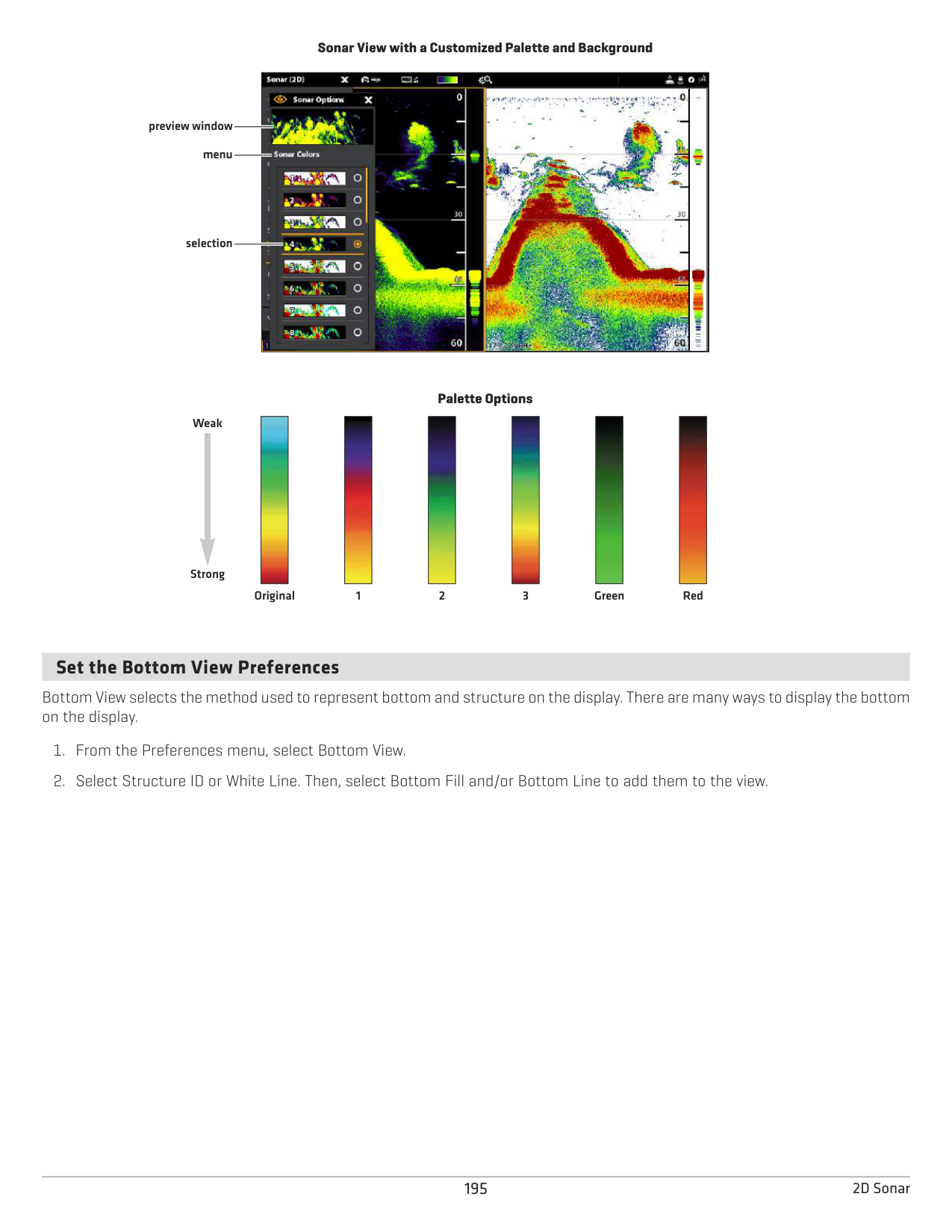
|| |---|
Original
|| |---|
1
################# Palette Options
|| |---|
2
|| |---|
3
|| |---|
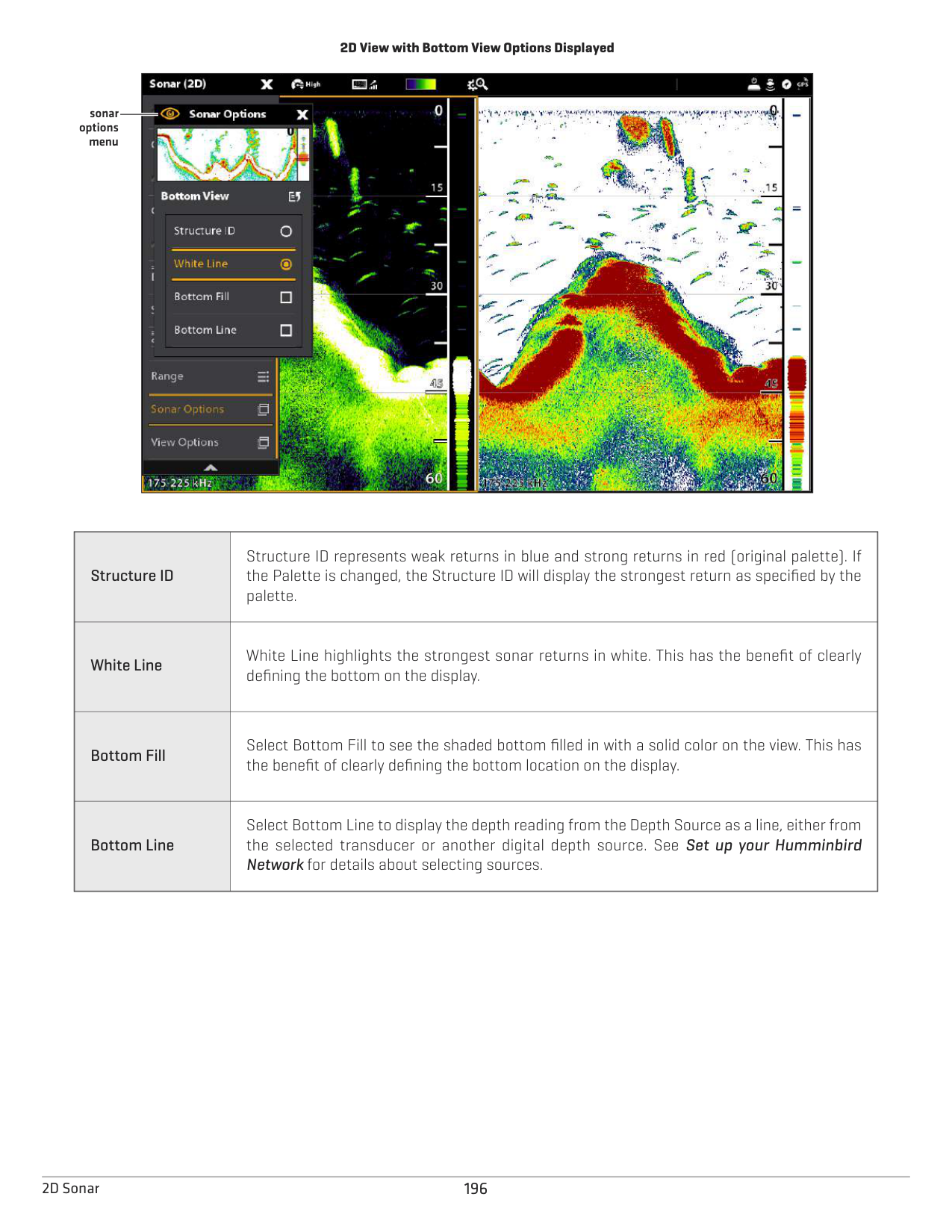
Green
|| |---|
Red
####### Set the Bottom View Preferences
Bottom View selects the method used to represent bottom and structure on the display. There are many ways to display the bottom on the display.
2D View with Bottom View Options Displayed

sonar options
menu
|Structure ID
|Structure ID represents weak returns in blue and strong returns in red (original palette). If the Palette is changed, the Structure ID will display the strongest return as specified by the palette.| |---|---| |White Line
|White Line highlights the strongest sonar returns in white. This has the benefit of clearly defining the bottom on the display.| |Bottom Fill|Select Bottom Fill to see the shaded bottom filled in with a solid color on the view. This has the benefit of clearly defining the bottom location on the display.
|
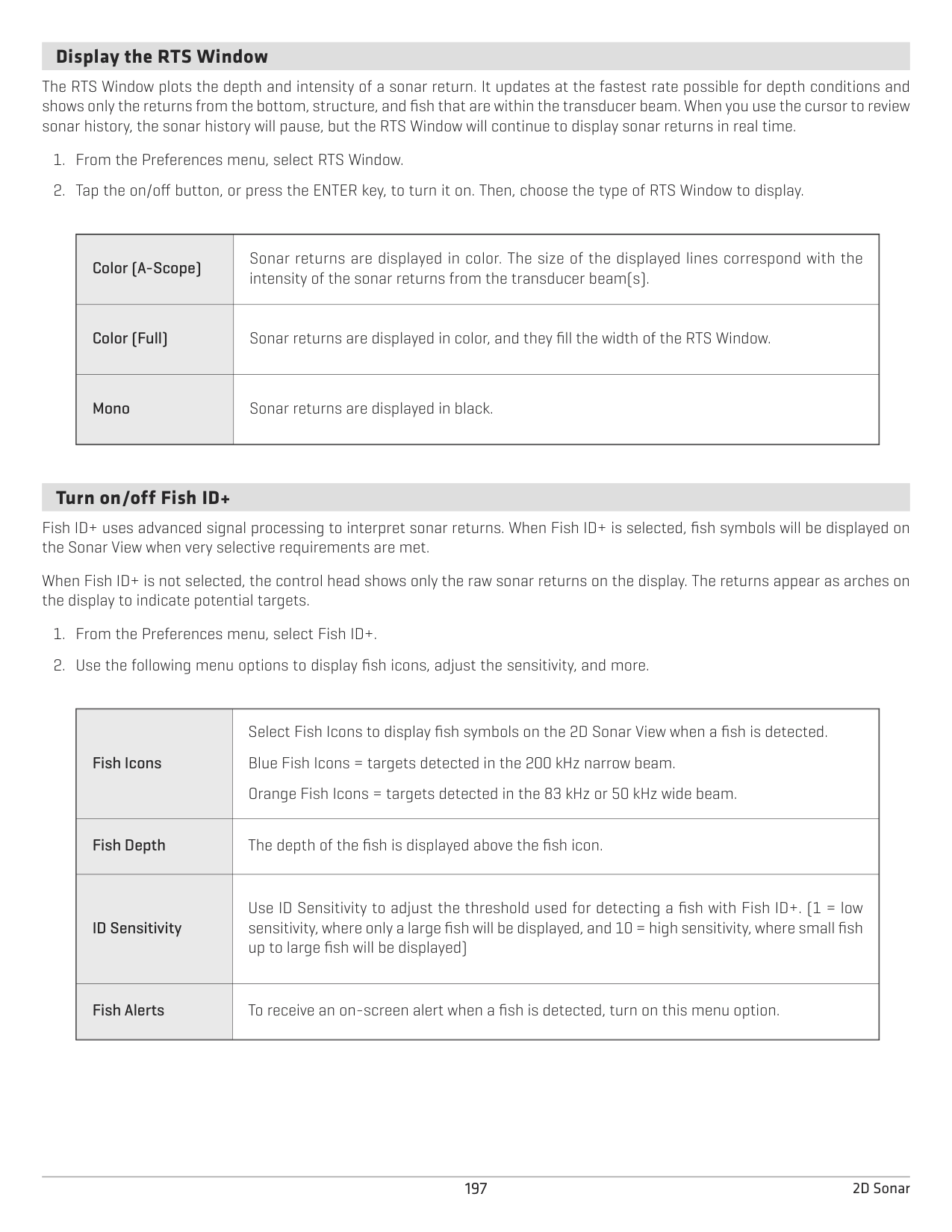
|Bottom Line|Select Bottom Line to display the depth reading from the Depth Source as a line, either from the selected transducer or another digital depth source. See Set up your Humminbird Network for details about selecting sources.|
1962D Sonar
####### Display the RTS Window
The RTS Window plots the depth and intensity of a sonar return. It updates at the fastest rate possible for depth conditions and shows only the returns from the bottom, structure, and fish that are within the transducer beam. When you use the cursor to review sonar history, the sonar history will pause, but the RTS Window will continue to display sonar returns in real time.
|Color (A-Scope)
|Sonar returns are displayed in color. The size of the displayed lines correspond with the intensity of the sonar returns from the transducer beam(s).| |---|---| |Color (Full)|Sonar returns are displayed in color, and they fill the width of the RTS Window.
| |Mono|Sonar returns are displayed in black.|
####### Turn on/off Fish ID+
Fish ID+ uses advanced signal processing to interpret sonar returns. When Fish ID+ is selected, fish symbols will be displayed on the Sonar View when very selective requirements are met.
When Fish ID+ is not selected, the control head shows only the raw sonar returns on the display. The returns appear as arches on the display to indicate potential targets.
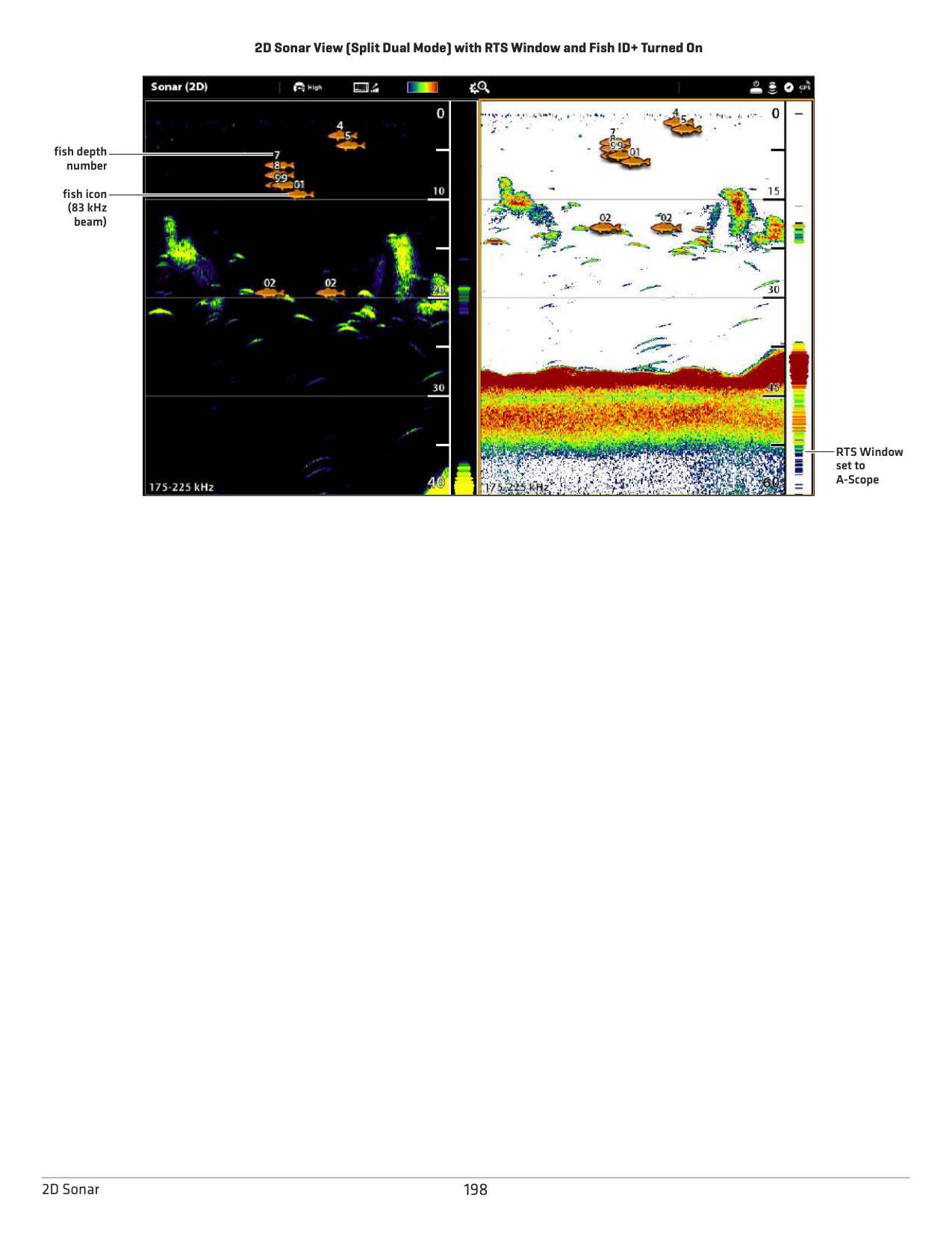
|Fish Icons|Select Fish Icons to display fish symbols on the 2D Sonar View when a fish is detected. Blue Fish Icons = targets detected in the 200 kHz narrow beam. Orange Fish Icons = targets detected in the 83 kHz or 50 kHz wide beam.
| |---|---| |Fish Depth
|The depth of the fish is displayed above the fish icon.| |ID Sensitivity
|Use ID Sensitivity to adjust the threshold used for detecting a fish with Fish ID+. (1 = low sensitivity, where only a large fish will be displayed, and 10 = high sensitivity, where small fish up to large fish will be displayed)| |Fish Alerts|To receive an on-screen alert when a fish is detected, turn on this menu option.|
2D Sonar View (Split Dual Mode) with RTS Window and Fish ID+ Turned On

fish depth number
fish icon (83 kHz beam)
RTS Window set to A-Scope
1982D Sonar
CHANGE THE 2D SONAR VIEW OVERLAYS
Use the Overlays menu to display or hide information on the view. In the 2D Sonar View, you can display the following: depth lines, depth range, a color bar for the selected palette, temperature graph, beam frequency label, and data overlays.
Digital readout data can be displayed as an overlay, and it can be displayed in the data bar. To turn on the data overlay or data bar, see Views: Edit the On-Screen View. For more information about data overlays, see Views.
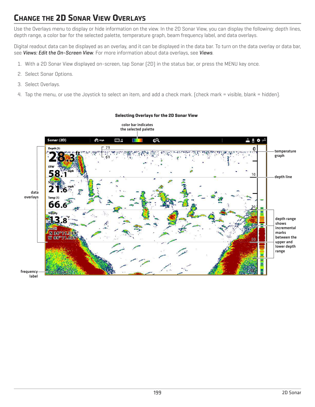
################# Selecting Overlays for the 2D Sonar View
color bar indicates the selected palette

temperature graph
depth line
data overlays
depth range shows incremental marks between the upper and lower depth range
frequency label
ADJUST 2D SONAR DISPLAY SETTINGS
The X-Press Menu provides menu options to adjust the sensitivity and range as you fish. You can also mark a particular depth and control how fast the sonar history scrolls across the screen. The menu options allow you to see more or less of the sonar returns from the transducer beams as you adjust each setting.
################# Adjusting Sonar Display Settings

Sonar X-Press
upper range
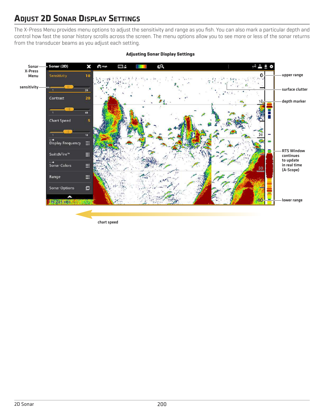
Menu
sensitivity
surface clutter
depth marker
RTS Window continues to update in real time (A-Scope)
lower range
chart speed
2002D Sonar
######### Adjust Display Settings
|Sensitivity
|Sensitivity controls how much detail is shown on the display and will adjust the sensitivity of all sonar frequencies. Decrease the sensitivity to eliminate the clutter from the display that is sometimes present in murky or muddy water. When operating in very clear water or greater depths, increase the sensitivity to see weaker returns that may be of interest.
QUICK TIP! This setting can also be changed by turning the Rotary dial.
| |---|---| |Contrast
|Contrast allows you to choose a range of the Sonar Colors palette to display sonar returns.
When Contrast is set to 20 (default), the entire Sonar Colors palette (represented by the Color Bar) is used to display weak and strong sonar returns. As you increase the Contrast, the top range of the Color Bar is used to display all sonar returns (whether weak or strong). As you decrease the Contrast, the bottom range of the Color Bar is used to display all sonar returns (whether weak or strong).| |Chart Speed|Chart Speed determines how fast the sonar history moves across the display and how much detail is shown. Select a faster speed to see more detail. Select a slower speed to keep the sonar history on the display longer.|
######### Filter Surface Clutter
Use Surface Clutter to reduce the noise that may appear at the top of the view caused by algae and aeration. The lower the setting, the less surface clutter will be displayed. A higher setting allows more surface clutter to be displayed.
Change the SwitchFire Mode SwitchFire controls how the sonar returns are displayed in the view.
SwitchFire: Clear Mode
SwitchFire: Max Mode
Tap to open the SwitchFire menu in the status bar. Tap to open the SwitchFire menu in the status bar.
| | | |---|---| |||
| | |
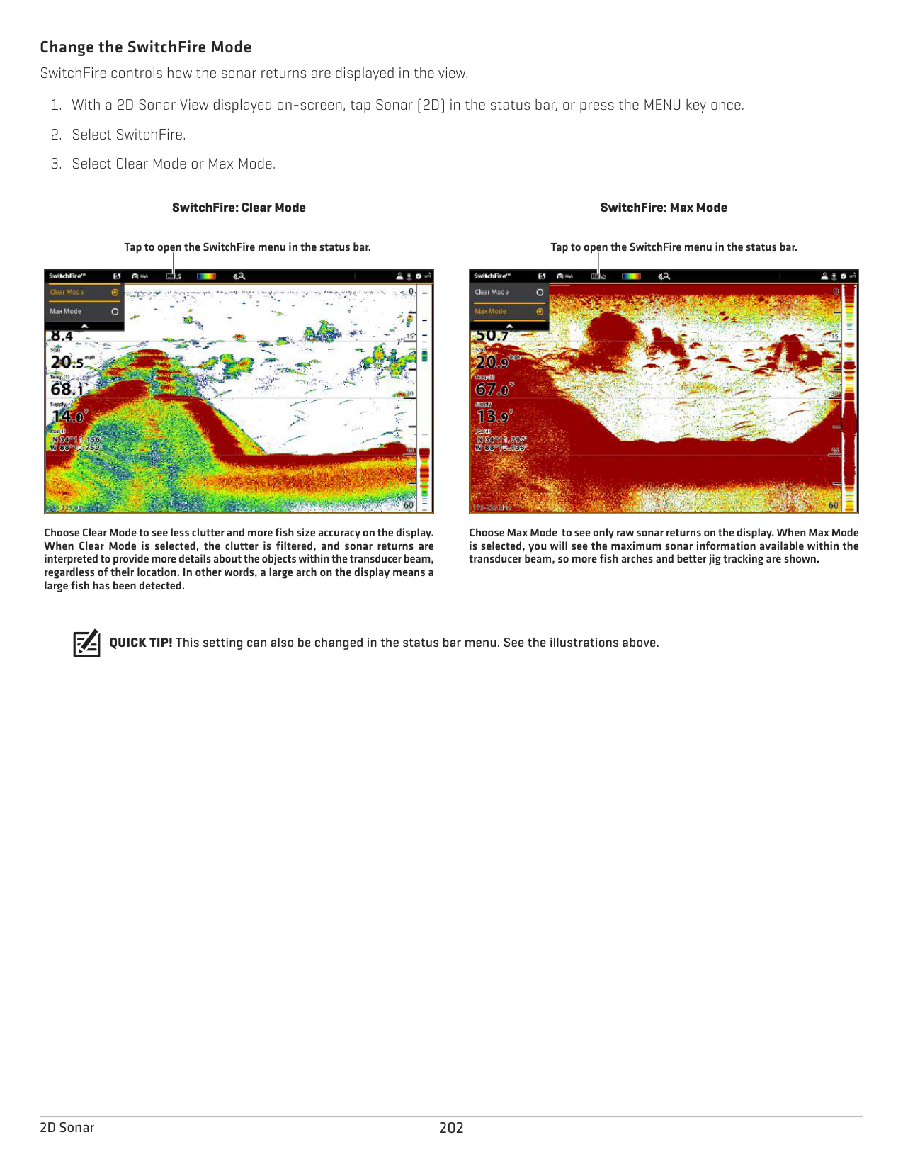
|---|---| |||
Choose Clear Mode to see less clutter and more fish size accuracy on the display. When Clear Mode is selected, the clutter is filtered, and sonar returns are interpreted to provide more details about the objects within the transducer beam, regardless of their location. In other words, a large arch on the display means a large fish has been detected.
Choose Max Mode to see only raw sonar returns on the display. When Max Mode is selected, you will see the maximum sonar information available within the transducer beam, so more fish arches and better jig tracking are shown.
QUICK TIP! This setting can also be changed in the status bar menu. See the illustrations above.
2022D Sonar
######### Set the Range
Range controls how much of the water column is displayed on the view. For example, if you are only interested in the area between 20 and 50 feet deep, set the Upper Range to 20 and the Lower Range to 50. The view will not display sonar returns outside of the set ranges, and greater detail for the selected range will be displayed.
Display the Depth Marker To mark a specific depth on the view, turn on Depth Marker. This menu is available in Custom Mode (see The Menu System: Change the User Mode).
######### Select Frequencies If there are multiple beams available in a transducer, you can display individual frequencies on the 2D Sonar View. See Installation Information: Set up your Humminbird Network, Select Sonar Sources and Set up or Change Transducer Settings for details.
NOTE: If the control head is using a sonar source with only one beam frequency, the frequency list will not offer additional options.
QUICK TIP! This setting can also be changed by pressing and holding the ENTER key.
2D Sonar View
Tap to open the SwitchFire menu in the status bar.

frequency menu
#### OR
Press and Hold to Change the Setting
Tap to Select
######### Adjust Beam Sensitivity
Your control head model may allow you to adjust the sensitivity of individual frequencies. The available frequencies are determined by your control head model and the installed transducer. Use the following instructions to adjust a single beam.
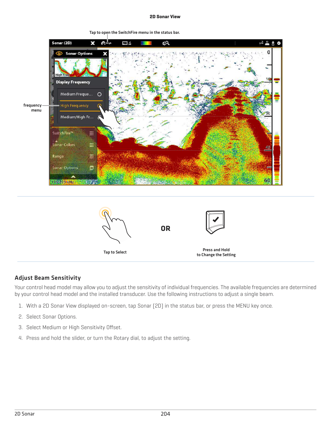
2042D Sonar
SIDE IMAGING OVERVIEW (SIDEIMAGINGTRANSDUCERREQUIRED)
Side Imaging beams “illuminate” the bottom contour, structure, and fish. The side beam coverage is very thin from front to back, yet very wide from top to bottom. The bottom composition determines the intensity of the sonar return, and upward slopes that face the transducer reflect sonar better than downward slopes that face away from the transducer.
Side Imaging View

boat icon
bottom return

Side Imaging sonar returns are first displayed at the top of the screen, and historical data scrolls down the display as new information is received.
water column
light shades
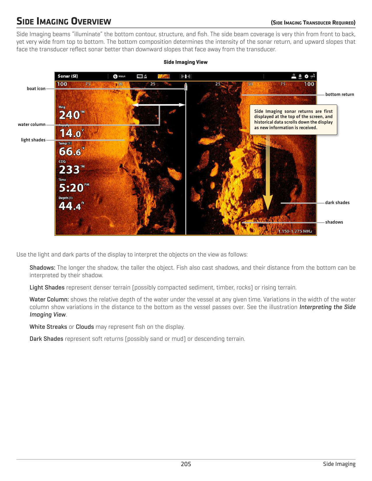
dark shades
shadows
Use the light and dark parts of the display to interpret the objects on the view as follows:
Shadows: The longer the shadow, the taller the object. Fish also cast shadows, and their distance from the bottom can be interpreted by their shadow.
Light Shades represent denser terrain (possibly compacted sediment, timber, rocks) or rising terrain.
Water Column: shows the relative depth of the water under the vessel at any given time. Variations in the width of the water column show variations in the distance to the bottom as the vessel passes over. See the illustration Interpreting the Side Imaging View.
White Streaks or Clouds may represent fish on the display. Dark Shades represent soft returns (possibly sand or mud) or descending terrain.
Interpreting the Side Imaging View

To visualize how Side Imaging works, the Side Imaging View illustration can be folded down the middle and then folded again at the lowest point of the water column. The raised area reveals the water column with its relative depth of the water under the vessel. In the Side Imaging View, variations in the width of the water column show variations in the distance to the bottom as the vessel passes over.

######### For Best Side Imaging Performance
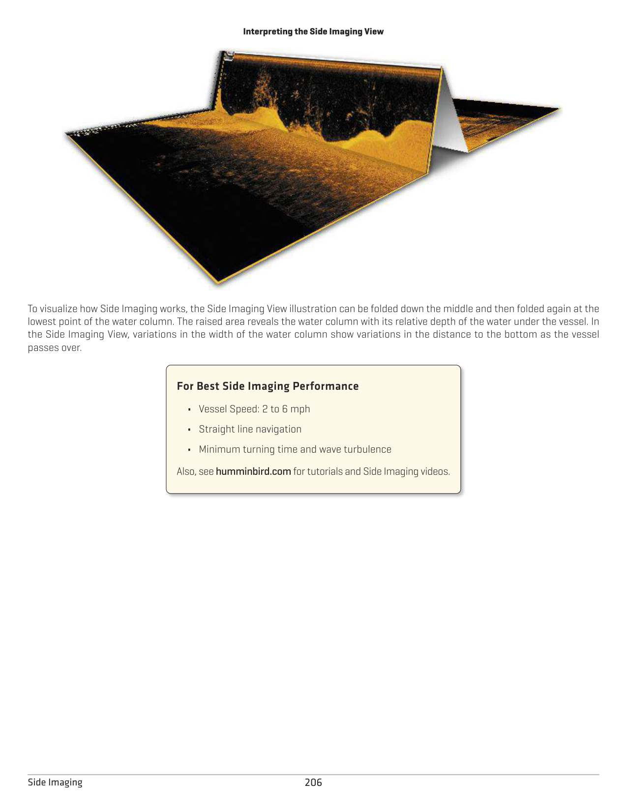
Also, see humminbird.com for tutorials and Side Imaging videos.
CUSTOMIZE THE SIDE IMAGING VIEW
The settings in this section are optional. You can use the default settings for the view, or you can customize it with your preferences. See Views for more information.
OPEN THE SIDE IMAGING PREFERENCES MENU
The Preferences menu allows you to select a beam to display, set the zoom mode, return palette, and turn on Contour Mode and SI Navigation. For more information about view preferences, see Views.
####### Select Beams to Display
The Side Imaging View displays both beams on the view. You can also choose to display the left side or the right side of the Side Imaging transducer beams.
####### Change the Color Palette
The Sonar Colors menu changes the colors used to display sonar returns on the view.
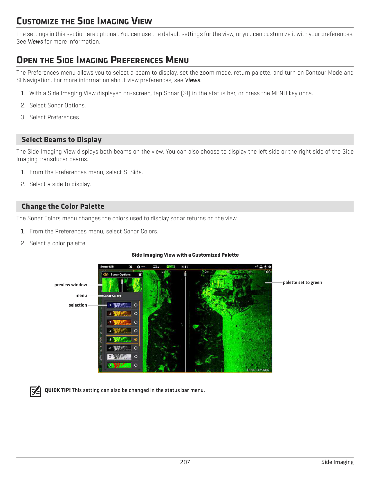
################# Side Imaging View with a Customized Palette

palette set to green
preview window menu selection
QUICK TIP! This setting can also be changed in the status bar menu.
####### Turn on/off Contour Mode
Contour Mode controls how the water column is displayed in the Side Imaging Views. When Contour Mode turned off, the water column is displayed on the view. The location of a target on the display is based on the slant range to the target.
When Contour Mode is turned on, the bottom is graphed at a constant point on the display, regardless of changes in depth. The Side Imaging beams are divided by a vertical line. The water column is removed from the view, which allows the display to show targets at their linear horizontal distance. The location of a target may be easier to interpret when the water column is removed.
Contour Mode Off
Contour Mode On
|| |---|
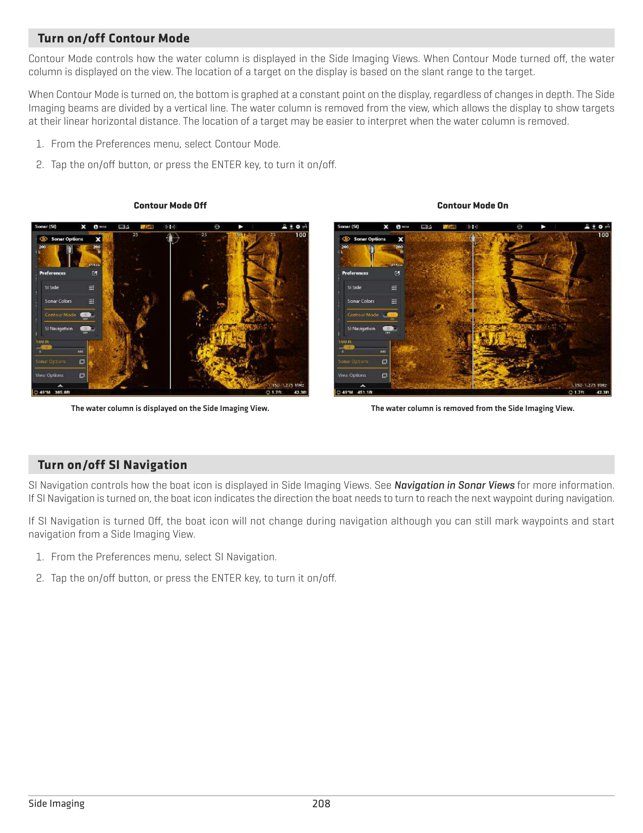
|| |---|
The water column is displayed on the Side Imaging View. The water column is removed from the Side Imaging View.
####### Turn on/off SI Navigation
SI Navigation controls how the boat icon is displayed in Side Imaging Views. See Navigation in Sonar Views for more information. If SI Navigation is turned on, the boat icon indicates the direction the boat needs to turn to reach the next waypoint during navigation.
If SI Navigation is turned Off, the boat icon will not change during navigation although you can still mark waypoints and start navigation from a Side Imaging View.
CHANGE THE SIDE IMAGING VIEW OVERLAYS
Use the Overlays menu to display or hide information on the view. In the Side Imaging View, you can display the following: boat icon, range lines, range intervals, side label, frequency label, and data overlays. To turn on the data overlay or data bar, see Views: Edit the On-Screen View. For more information about data overlays, see Views.
Selecting Overlays for the Side Imaging View
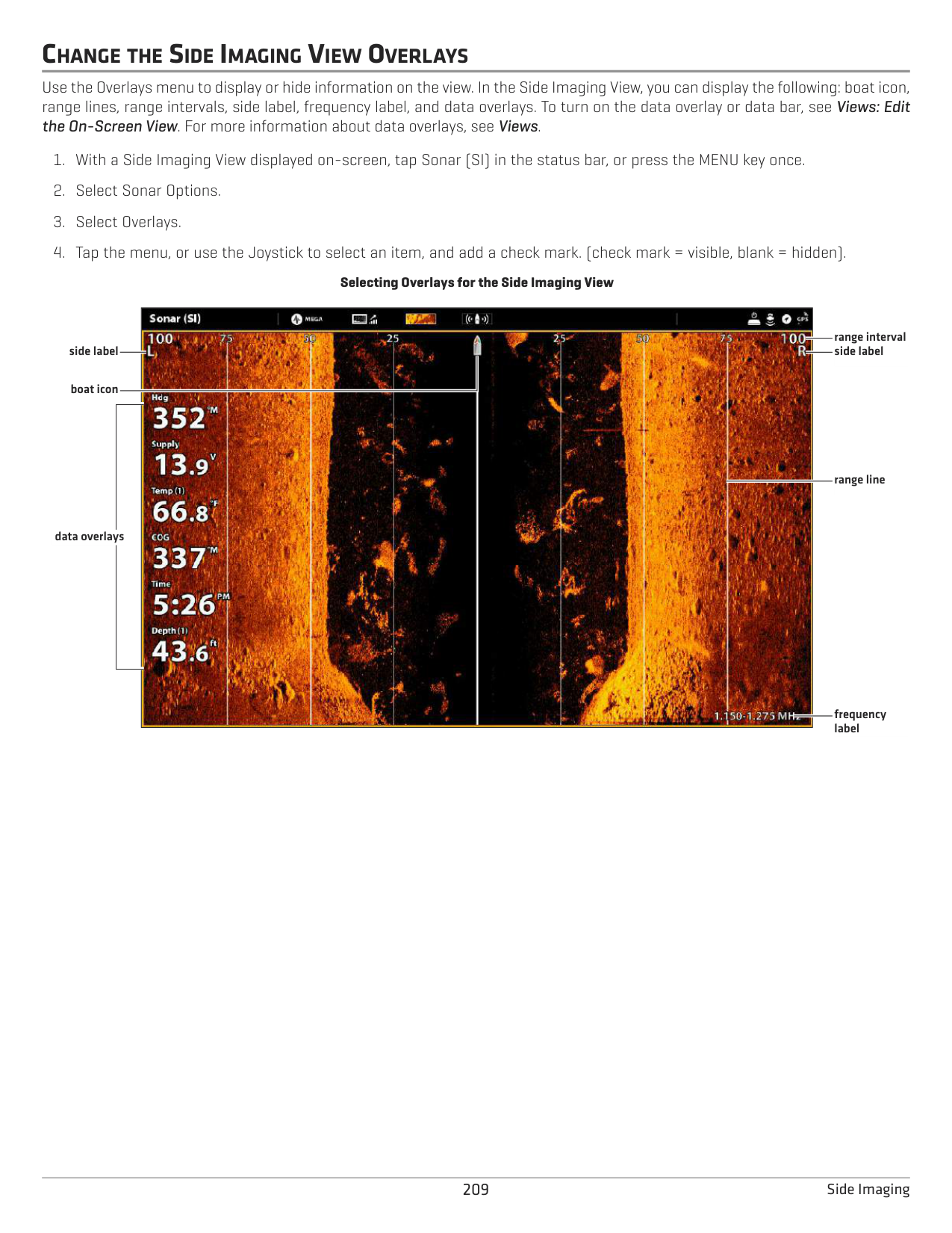

range interval side label
side label
boat icon
range line
data overlays
frequency label
ADJUST SIDE IMAGING DISPLAY SETTINGS
The X-Press Menu provides menu options to adjust the sensitivity, contrast, sharpness, and range as you fish. You can also mark a particular range, and you can control how fast the sonar history scrolls across the screen. The menu options allow you to see more or less of the sonar returns from the transducer beams as you adjust each setting.
######### Adjust Display Settings
Adjusting Side Imaging Display Settings
| || |---|---|
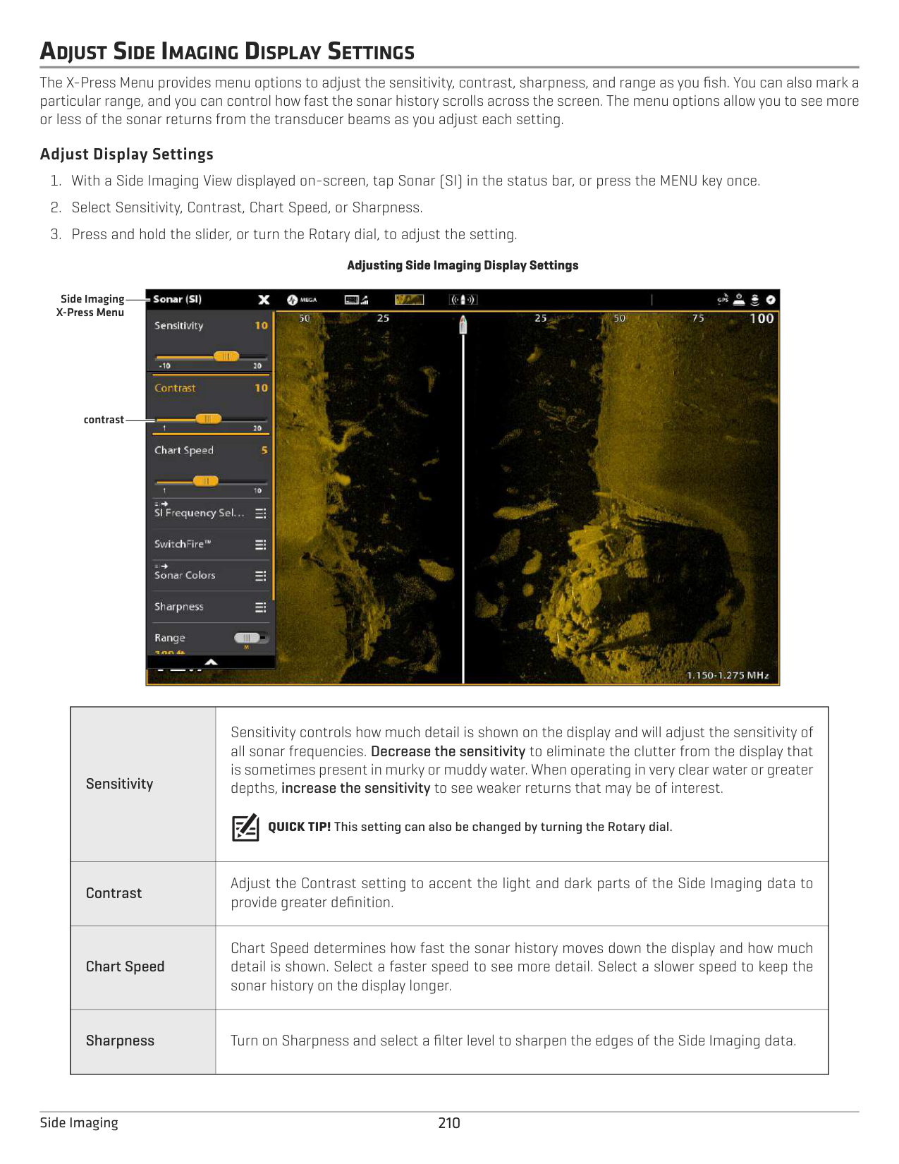
| || | ||
Side Imaging X-Press Menu
contrast
|Sensitivity
|Sensitivity controls how much detail is shown on the display and will adjust the sensitivity of all sonar frequencies. Decrease the sensitivity to eliminate the clutter from the display that is sometimes present in murky or muddy water. When operating in very clear water or greater depths, increase the sensitivity to see weaker returns that may be of interest.
QUICK TIP! This setting can also be changed by turning the Rotary dial.
| |---|---| |Contrast
|Adjust the Contrast setting to accent the light and dark parts of the Side Imaging data to provide greater definition.| |Chart Speed
|Chart Speed determines how fast the sonar history moves down the display and how much detail is shown. Select a faster speed to see more detail. Select a slower speed to keep the sonar history on the display longer.| |Sharpness|Turn on Sharpness and select a filter level to sharpen the edges of the Side Imaging data.|
Change the SwitchFire Mode SwitchFire controls how the sonar returns are displayed in the view.
|Clear Mode
|Choose Clear Mode to see less clutter and more fish size accuracy on the display. When Clear Mode is selected, the clutter is filtered, and sonar returns are interpreted to provide more details about the objects within the transducer beam, regardless of their location. In other words, a large arch on the display means a large fish has been detected.| |---|---| |Max Mode|Choose Max Mode to see only raw sonar returns on the display. When Max Mode is selected, you will see the maximum sonar information available within the transducer beam, so more fish arches and better jig tracking are shown.|
QUICK TIP! This setting can also be changed in the status bar menu.
Set the Range Range controls how much of the water column is displayed on the view.
|Auto
|The Range will be adjusted by the control head to follow the bottom automatically.| |---|---| |Man (Manual)
|To adjust the display range, press and hold the slider, or press and hold the ENTER key. Select a low range number to focus on a shorter distance of the water column and see greater detail on the screen. Select a higher range number to view farther into the water and see an overview of details on the screen.|
######### Display Range Markers
To mark a specific range on the view, turn on Range Marker. This menu is available in Custom Mode (see The Menu System: Change the User Mode).
range markers

Select Frequencies If there are multiple beams available in a transducer, you can display individual frequencies on the view. See Installation Information: Set up your Humminbird Network, Select Sonar Sources and Set up or Change Transducer Settings for details.
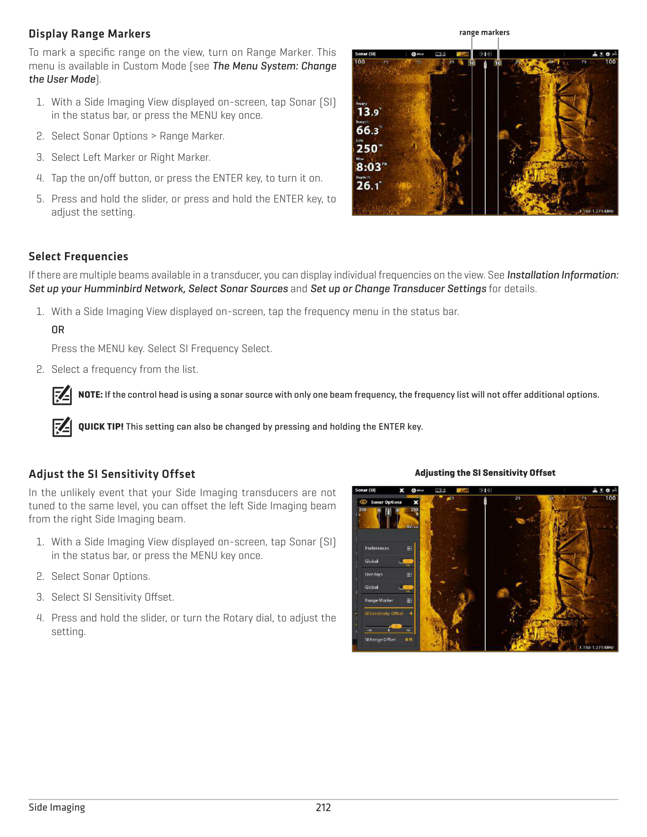
NOTE: If the control head is using a sonar source with only one beam frequency, the frequency list will not offer additional options.
QUICK TIP! This setting can also be changed by pressing and holding the ENTER key.
######### Adjust the SI Sensitivity Offset
In the unlikely event that your Side Imaging transducers are not tuned to the same level, you can offset the left Side Imaging beam from the right Side Imaging beam.
################# Adjusting the SI Sensitivity Offset
|| |---|
DOWN IMAGING OVERVIEW (DOWNIMAGINGTRANSDUCERORSIDEIMAGINGTRANSDUCERREQUIRED)
The images you see on the Down Imaging display are produced using sonar technology. Each time the unit pings, a strip of data representing all the echoes received by the transducer are put together on the display to form the image that you see. Like traditional 2D Sonar, the sonar history scrolls left across the screen.
Down Imaging beams “illuminate” the bottom contour, structure, and fish. The beams are wide (side to side) but very thin from front to back.
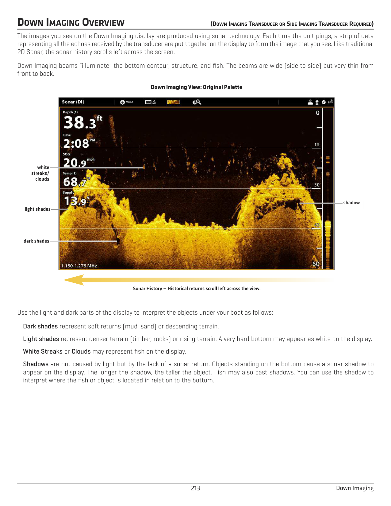
################# Down Imaging View: Original Palette

white streaks/
clouds
shadow
light shades
dark shades
Sonar History — Historical returns scroll left across the view.
Use the light and dark parts of the display to interpret the objects under your boat as follows: Dark shades represent soft returns (mud, sand) or descending terrain. Light shades represent denser terrain (timber, rocks) or rising terrain. A very hard bottom may appear as white on the display. White Streaks or Clouds may represent fish on the display.
Shadows are not caused by light but by the lack of a sonar return. Objects standing on the bottom cause a sonar shadow to appear on the display. The longer the shadow, the taller the object. Fish may also cast shadows. You can use the shadow to interpret where the fish or object is located in relation to the bottom.
CUSTOMIZE THE DOWN IMAGING VIEW
The settings in this section are optional. You can use the default settings for the view, or you can customize it with your preferences. See Views for more information.
OPEN THE DOWN IMAGING PREFERENCES MENU
The Preferences menu allows you to set the palette, zoom mode, and bottom line. For more information about view preferences, see Views.
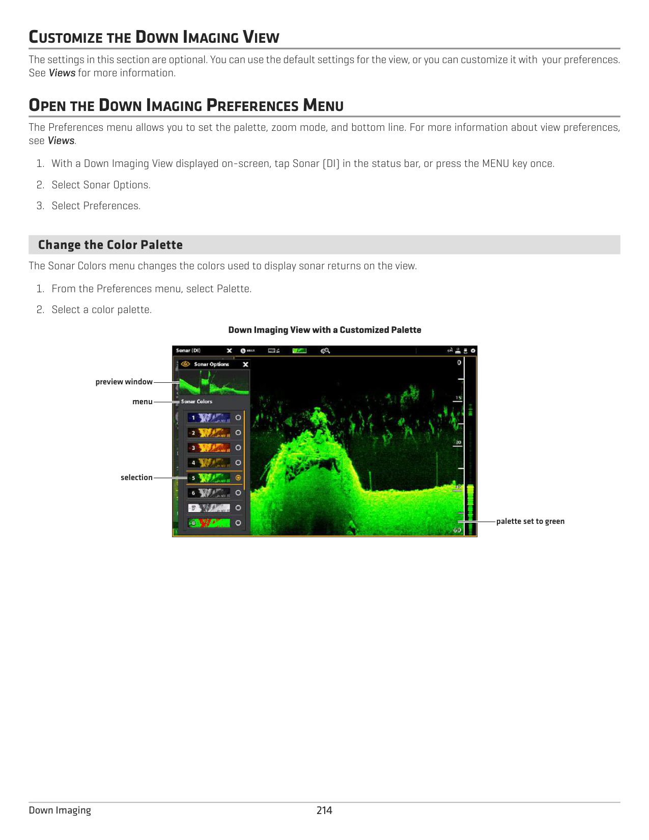
####### Change the Color Palette
The Sonar Colors menu changes the colors used to display sonar returns on the view.
Down Imaging View with a Customized Palette

preview window menu
selection
palette set to green
####### Set the Zoom Mode
The Zoom Mode sets the zoom commands to magnify the full pane or the cursor selection. See Use Cursor and Zoom in Sonar Views to apply the zoom features.
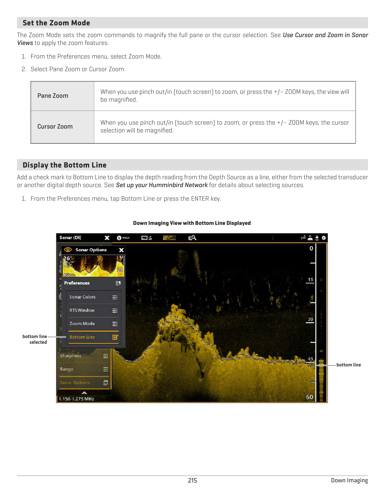
|Pane Zoom
|When you use pinch out/in (touch screen) to zoom, or press the +/– ZOOM keys, the view will be magnified.| |---|---| |Cursor Zoom
|When you use pinch out/in (touch screen) to zoom, or press the +/– ZOOM keys, the cursor selection will be magnified.|
####### Display the Bottom Line
Add a check mark to Bottom Line to display the depth reading from the Depth Source as a line, either from the selected transducer or another digital depth source. See Set up your Humminbird Network for details about selecting sources.
Down Imaging View with Bottom Line Displayed

bottom line selected
bottom line
CHANGE THE DOWN IMAGING VIEW OVERLAYS
Use the Overlays menu to display or hide information on the view. In the Down Imaging View, you can display the following: depth range, beam frequency label, and data overlays. Digital readout data can be displayed as an overlay, and it can be displayed in the data bar. To turn on the data bar, see Views: Display a Data Bar. For more information about data overlays, see Views.
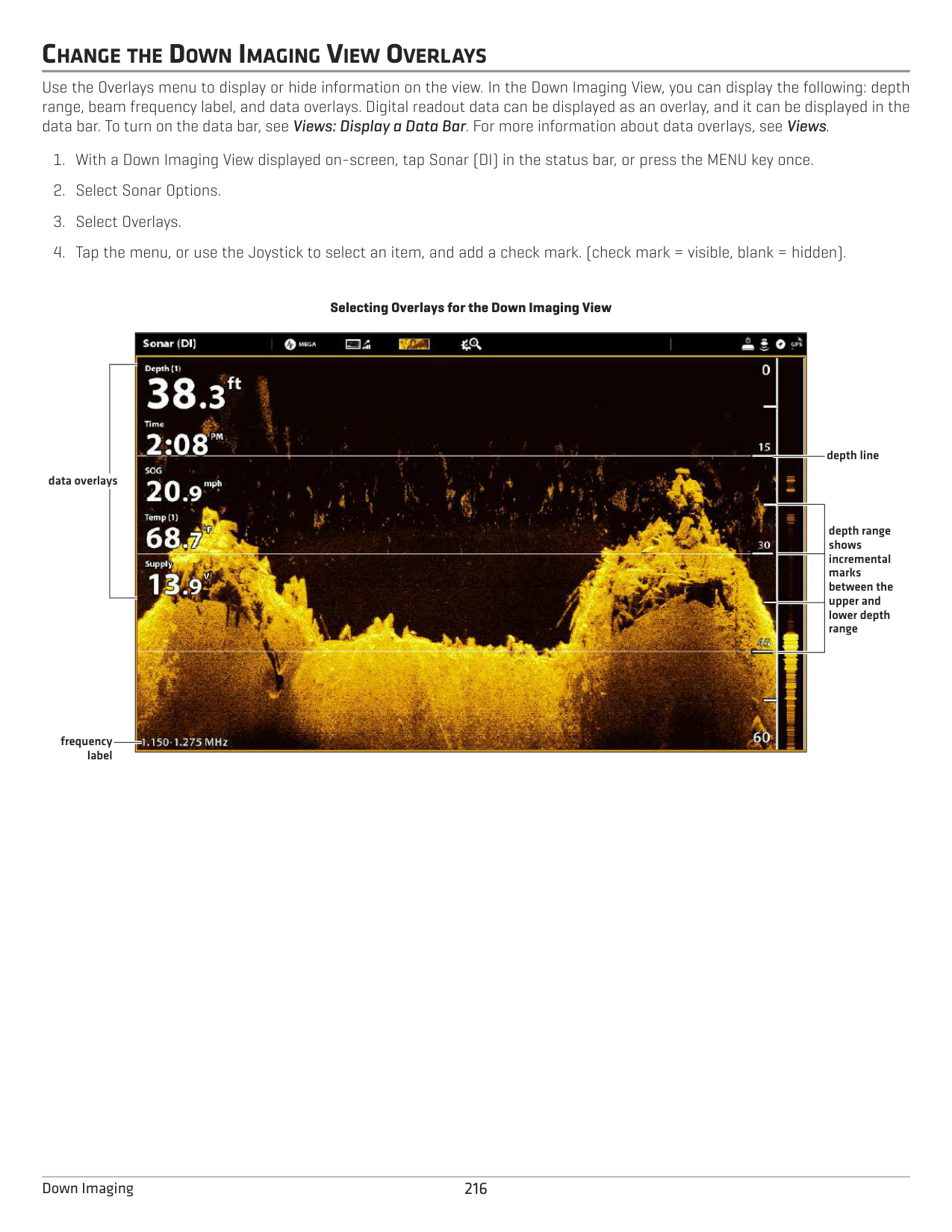
Selecting Overlays for the Down Imaging View

depth line
data overlays
depth range shows incremental marks between the upper and lower depth range
frequency label
ADJUST DOWN IMAGING DISPLAY SETTINGS
The X-Press Menu provides menu options to adjust the sensitivity and range as you fish. You can also mark a particular depth, and you can control how fast the sonar history scrolls across the screen. The menu options allow you to see more or less of the sonar returns from the transducer beams as you adjust each setting.
################# Adjusting Down Imaging Display Settings

Down Imaging X-Press Menu
upper range
sensitivity
lower range
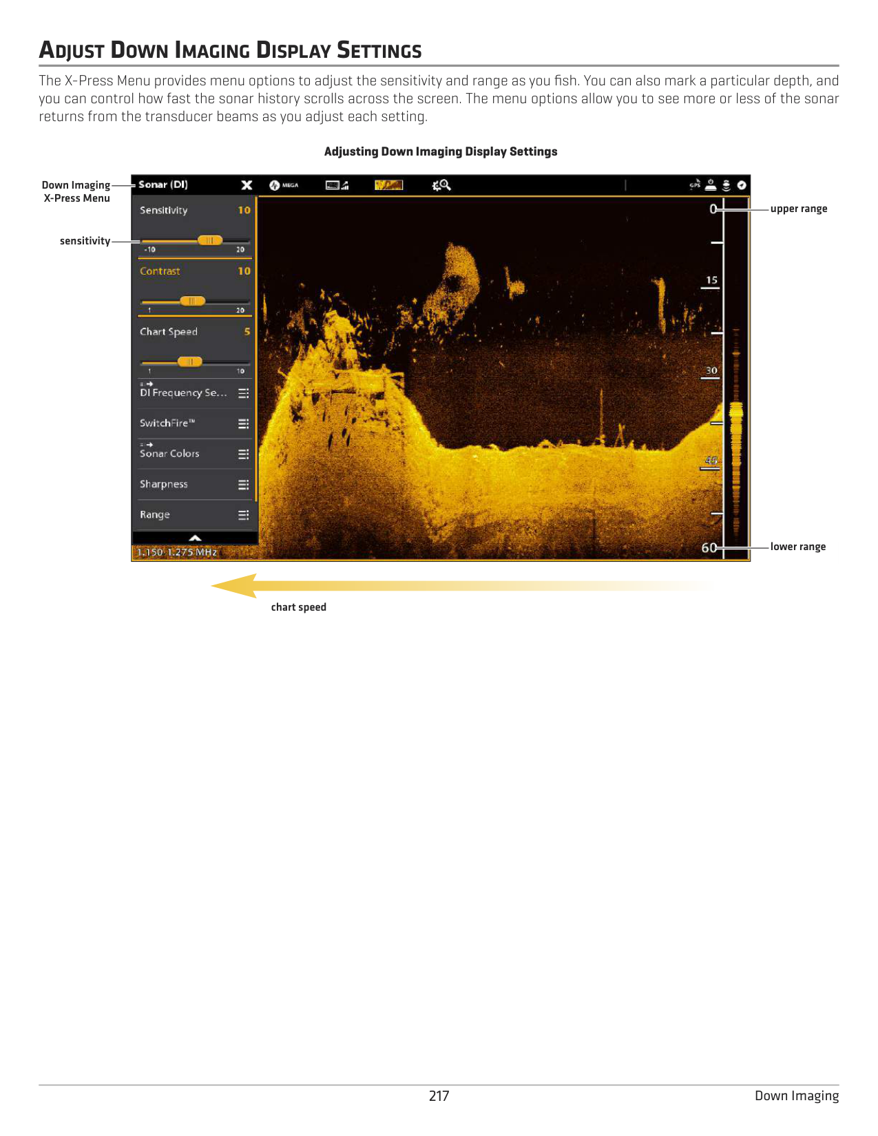
chart speed
######### Adjust Display Settings
|Sensitivity
|Sensitivity controls how much detail is shown on the display and will adjust the sensitivity of all sonar frequencies. Decrease the sensitivity to eliminate the clutter from the display that is sometimes present in murky or muddy water. When operating in very clear water or greater depths, increase the sensitivity to see weaker returns that may be of interest.| |---|---| |Contrast
|Adjust the Contrast setting to accent the light and dark parts of the Down Imaging data to provide greater definition.| |Chart Speed|Chart Speed determines how fast the sonar history moves across the display and how much detail is shown. Select a faster speed to see more detail. Select a slower speed to keep the sonar history on the display longer.
| |Sharpness|Turn on sharpness and select a filter level to sharpen the edges of the Down Imaging data.|
Change the SwitchFire Mode SwitchFire controls how the sonar returns are displayed in the view.
|Clear Mode|Choose Clear Mode to see less clutter and more fish size accuracy on the display. When Clear Mode is selected, the clutter is filtered, and sonar returns are interpreted to provide more details about the objects within the transducer beam, regardless of their location. In other words, a large arch on the display means a large fish has been detected.
| |---|---| |Max Mode|Choose Max Mode to see only raw sonar returns on the display. When Max Mode is selected, you will see the maximum sonar information available within the transducer beam, so more fish arches and better jig tracking are shown.|
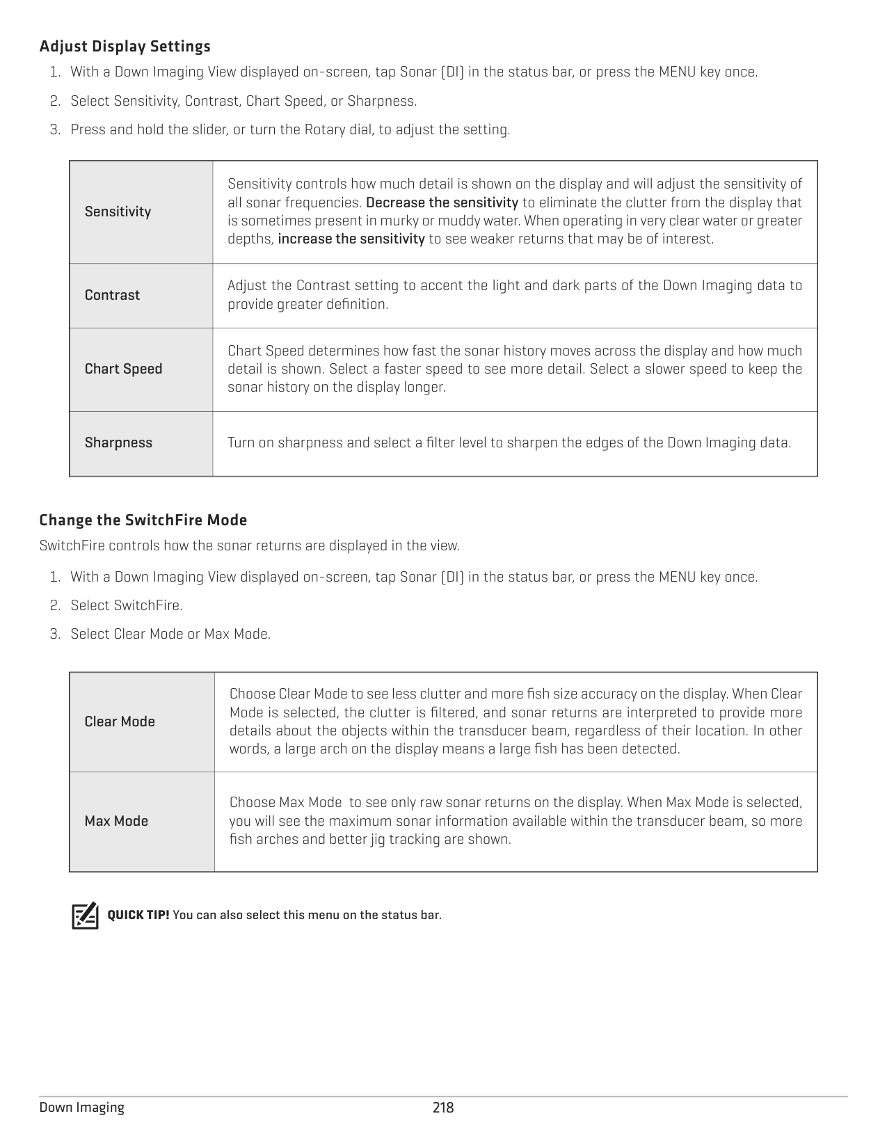
QUICK TIP! You can also select this menu on the status bar.
######### Set the Range
Range controls how much of the water column is displayed on the view. For example, if you are only interesed in the area between 20 and 50 feet deep, set the Upper Range to 20 and the Lower Range to 50. The view will not display sonar returns outside of the set ranges, and greater detail for the selected range will be displayed.
Display the Depth Marker To mark a specific depth on the view, turn on Depth Marker. This menu is available in Custom Mode (see The Menu System: Change the User Mode).
Select Frequencies If there are multiple beams available in a transducer, you can display individual frequencies on the view. See Installation Information: Set up your Humminbird Network, Select Sonar Sources and Set up or Change Transducer Settings for details.
NOTE: If the control head is using a sonar source with only one beam frequency, the frequency list will not offer additional options.
QUICK TIP! This setting can also be changed by pressing and holding the ENTER key.
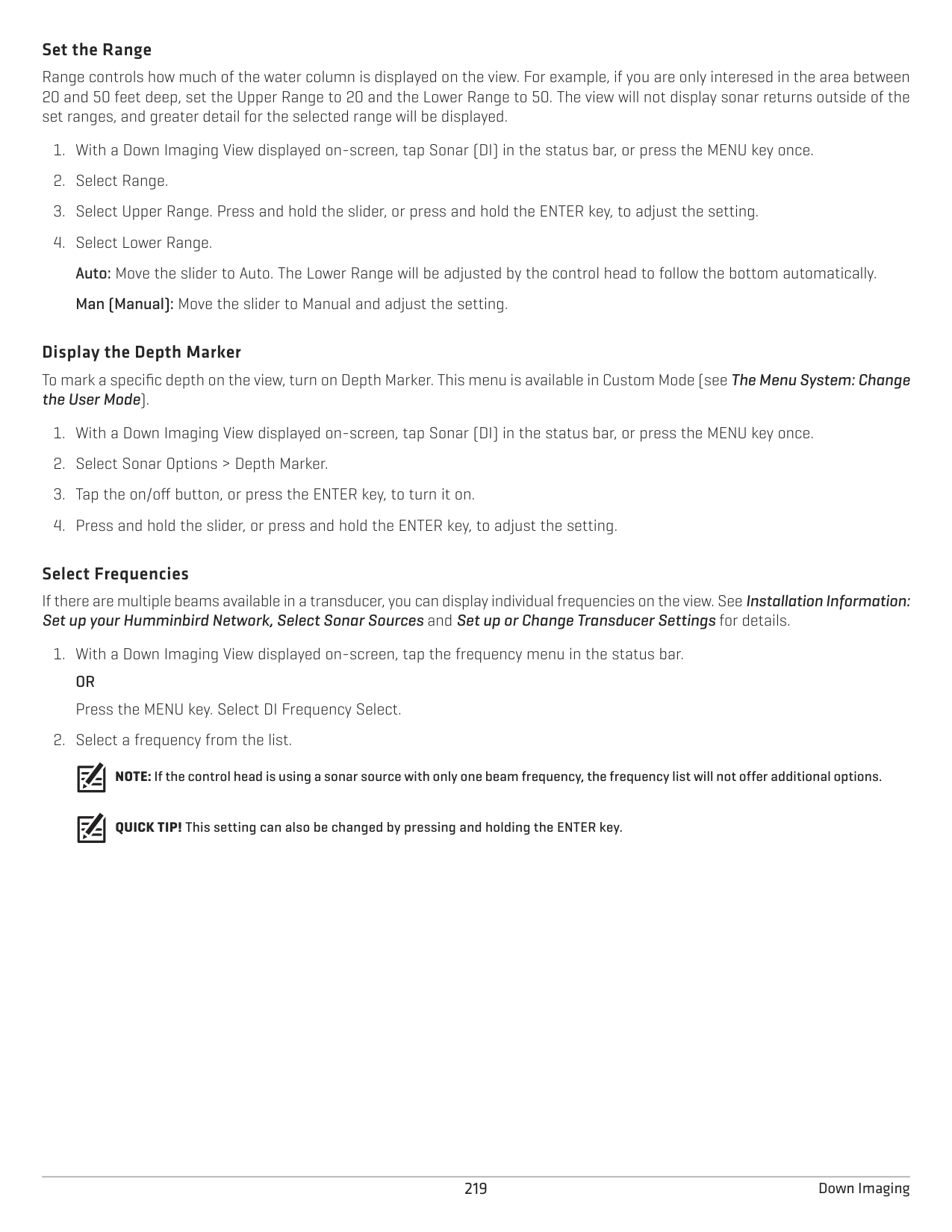
USE CURSOR AND ZOOM IN SONAR VIEWS (2D, SI, DI)
You can use the cursor in the 2D Sonar, Side Imaging, and Down Imaging Views. With the cursor activated, you can magnify sonar returns on the view to get a closer look.
NOTE: To display the 2D Sonar View in Split Zoom mode, see Customize the 2D Sonar View: Change the Sonar Mode.
######## Change the Zoom Mode
In 2D Sonar View and Down Imaging View, the sonar returns will be magnified based on the Zoom Mode setting. You can magnify the full view (Pane Zoom) or a selected area of the view (Cursor Zoom). See Customize the 2D Sonar View or Customize the Down Imaging View for more information.
QUICK TIP! You can also select this menu on the status bar.
Touch Screen
############ Keypad
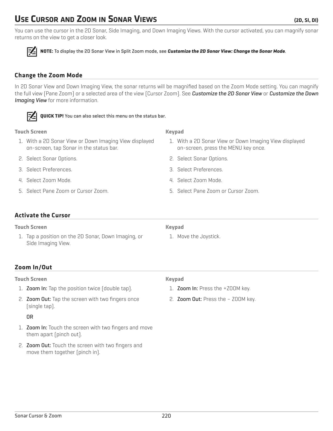
Activate the Cursor
############ Touch Screen
############ Keypad
Zoom In/Out
############ Touch Screen
############ Keypad
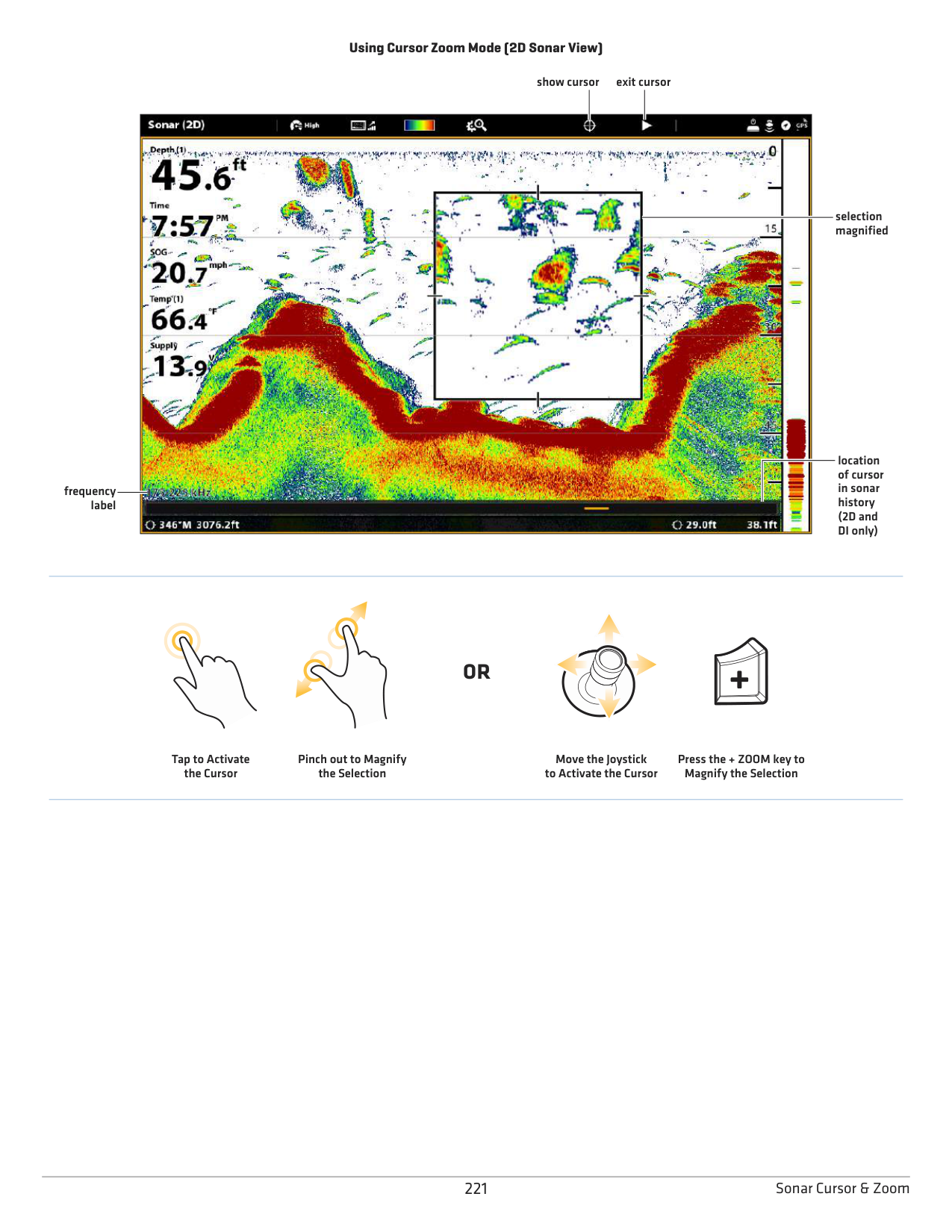
220Sonar Cursor & Zoom
Using Cursor Zoom Mode (2D Sonar View)
show cursor exit cursor

selection magnified
location of cursor in sonar history (2D and DI only)
frequency label
#### OR
Tap to Activate the Cursor
Pinch out to Magnify the Selection
Move the Joystick to Activate the Cursor
Press the + ZOOM key to Magnify the Selection
221 Sonar Cursor & Zoom
NAVIGATION IN SONAR VIEWS (2D, SI, DI)
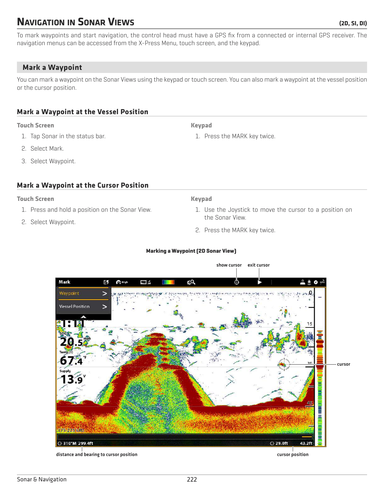
To mark waypoints and start navigation, the control head must have a GPS fix from a connected or internal GPS receiver. The navigation menus can be accessed from the X-Press Menu, touch screen, and the keypad.
####### Mark a Waypoint
You can mark a waypoint on the Sonar Views using the keypad or touch screen. You can also mark a waypoint at the vessel position or the cursor position.
Mark a Waypoint at the Vessel Position
Touch Screen
############ Keypad
Mark a Waypoint at the Cursor Position
############ Touch Screen
############ Keypad
################# Marking a Waypoint (2D Sonar View)
show cursor
exit cursor

cursor
distance and bearing to cursor position
cursor position
222Sonar & Navigation
####### Navigate to a Position
Use the instructions in this section to start navigation to a position in the Sonar Views. See Introduction to Navigation for more information about these features.
######## Start Navigation
############ Touch Screen
############ Keypad
NOTE: In Side Imaging Views, if SI Navigation is turned on, the boat icon will turn to indicate the direction the boat needs to turn to reach the next waypoint during navigation (see Customize the Side Imaging View: Turn on/off SI Navigation).
######### Cancel Navigation
223 Sonar & Navigation
SONAR RECORDING
Use the Sonar Recording menu to record active sonar information. Sonar recordings are saved to an installed SD card, and you can play your saved sonar recordings from the Recordings tool. When the recording is played back, the views that were active during the recording are available. You can also adjust the view settings and mark waypoints during playback.
######### Start Recording
When you start a sonar recording, you can select which beams will be recorded and where the sonar recording will be saved. Sonar Recording can be started from the Sonar X-Press Menu or the Recordings tool. The instructions for the Sonar X-Press Menu are shown here.
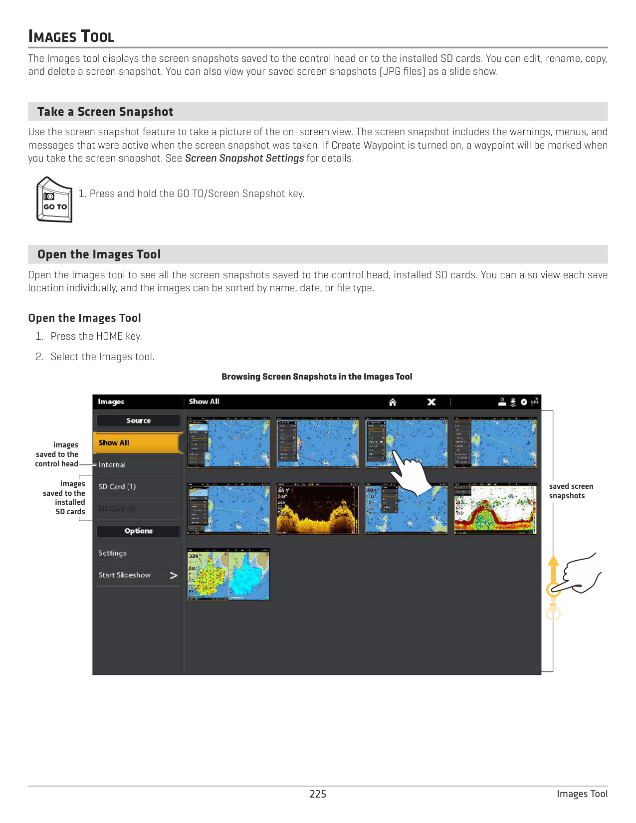
######### Stop Recording
######### Play a Sonar Recording 1. Press the HOME key.
Open the Playback Control Menu The Playback Control menu includes stop, pause, forward or reverse for the recording played on the screen.
224Sonar Recording
IMAGES TOOL
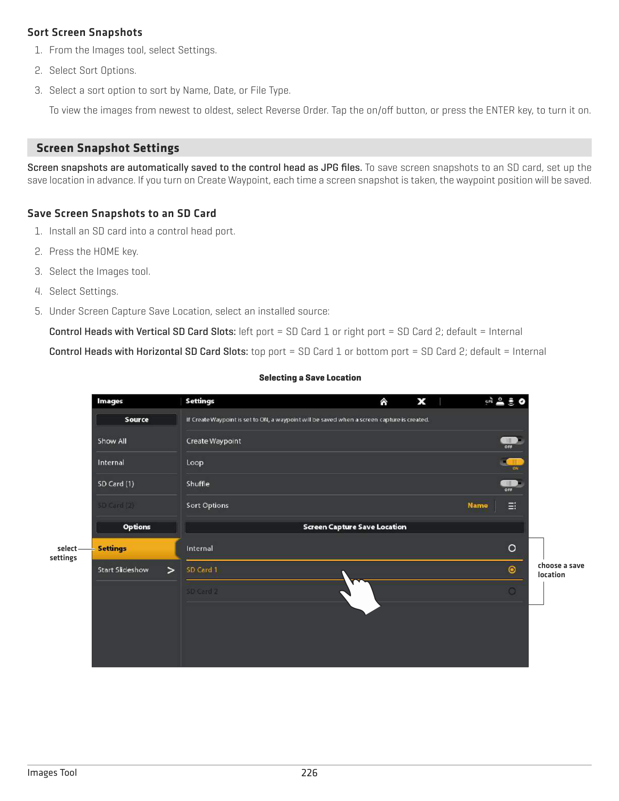
The Images tool displays the screen snapshots saved to the control head or to the installed SD cards. You can edit, rename, copy, and delete a screen snapshot. You can also view your saved screen snapshots (JPG files) as a slide show.
####### Take a Screen Snapshot
Use the screen snapshot feature to take a picture of the on-screen view. The screen snapshot includes the warnings, menus, and messages that were active when the screen snapshot was taken. If Create Waypoint is turned on, a waypoint will be marked when you take the screen snapshot. See Screen Snapshot Settings for details.
####### Open the Images Tool
Open the Images tool to see all the screen snapshots saved to the control head, installed SD cards. You can also view each save location individually, and the images can be sorted by name, date, or file type.
######### Open the Images Tool 1. Press the HOME key.
Browsing Screen Snapshots in the Images Tool
| |
| | |---|---|---| | |
| | | |
| | | |
| | | |
| | | |
| |
images saved to the control head
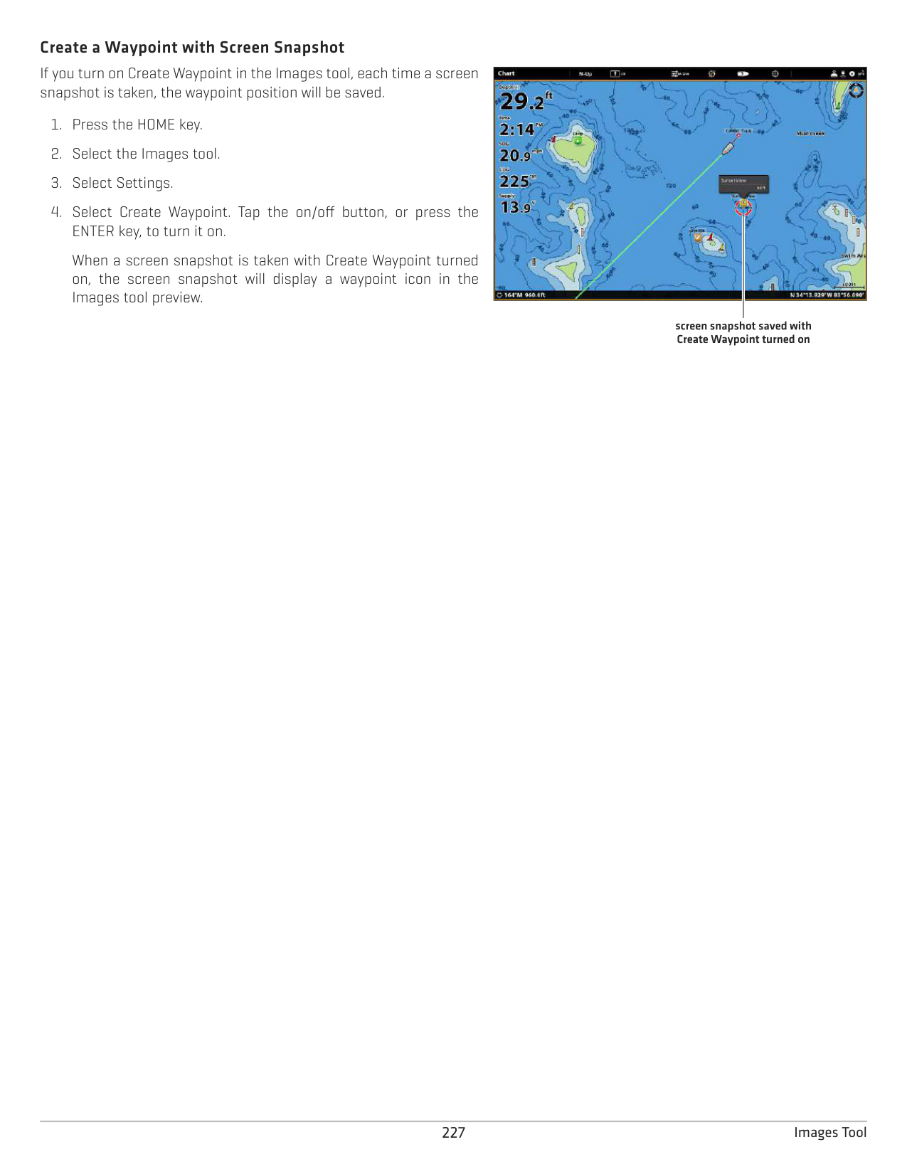
images
saved screen snapshots
saved to the installed SD cards
######### Sort Screen Snapshots
####### Screen Snapshot Settings
Screen snapshots are automatically saved to the control head as JPG files. To save screen snapshots to an SD card, set up the save location in advance. If you turn on Create Waypoint, each time a screen snapshot is taken, the waypoint position will be saved.
######### Save Screen Snapshots to an SD Card
Selecting a Save Location
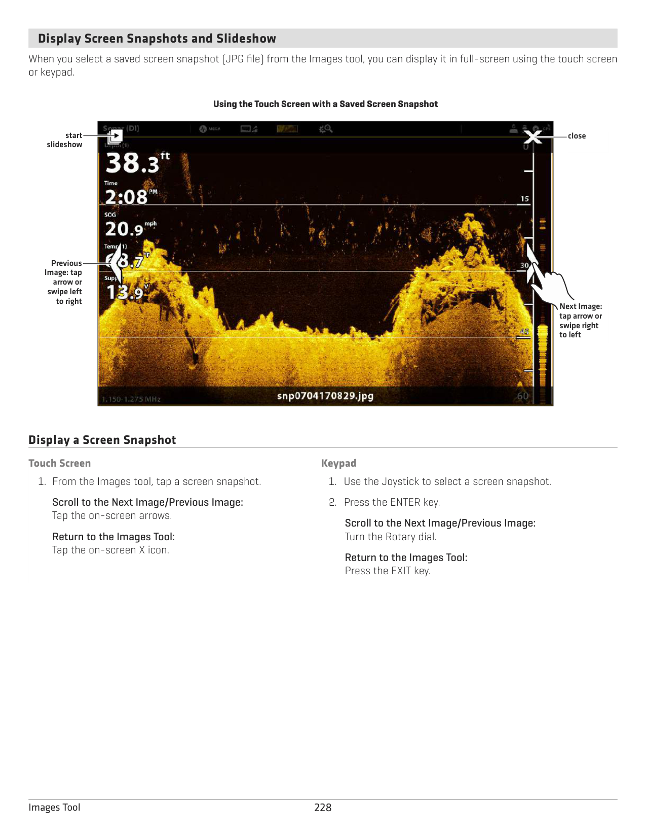

select settings
choose a save location
######### Create a Waypoint with Screen Snapshot
If you turn on Create Waypoint in the Images tool, each time a screen snapshot is taken, the waypoint position will be saved.
When a screen snapshot is taken with Create Waypoint turned on, the screen snapshot will display a waypoint icon in the Images tool preview.

screen snapshot saved with Create Waypoint turned on
####### Display Screen Snapshots and Slideshow
When you select a saved screen snapshot (JPG file) from the Images tool, you can display it in full-screen using the touch screen or keypad.
Using the Touch Screen with a Saved Screen Snapshot

start slideshow
close
Previous Image: tap
arrow or swipe left
to right
Next Image: tap arrow or swipe right to left
Display a Screen Snapshot
############ Touch Screen
############ Keypad
Scroll to the Next Image/Previous Image: Tap the on-screen arrows.
Scroll to the Next Image/Previous Image: Turn the Rotary dial.
Return to the Images Tool: Tap the on-screen X icon.
Return to the Images Tool: Press the EXIT key.
######### Set up the Slideshow
Screen snapshots and pictures from your camera’s SD card can be displayed in a slideshow. You can use the control head default settings to play the slide show, or you can set the slideshow to loop or shuffle.
######### Play the Slideshow
####### Edit Screen Snapshots
The Images Options menu allows you to edit the name and review the file information for the selected screen snapshot. You can also copy screen snapshots to another save location or delete them.
######### Change a Screen Snapshot Name
######### Review Screen Snapshot Information
When you save a screen snapshot, the date and time the screen snapshot was taken is saved. If Create Waypoint is turned on, the position and waypoint name are also saved with the screen snapshot. Use these instructions to review the saved information.
######### Copy a Screen Snapshot
######### Delete a Screen Snapshot
INSTALLATION INFORMATION
This section includes information that may be required to connect new equipment or a new accessory to the control head. There are several configurations available for your SOLIX control head. You can network control heads, connect accessories to an Ethernet network, connect to a NMEA 2000 network, and add transducers to your system through black box sonar. For configuration options and the latest Humminbird accessories, visit our Web site at humminbird.com.
Installation guides are included with each hardware component to install equipment purchased separately (transducer, heading sensor, radar, AIS, autopilot, and accessories). See your installation guides for details.
Unused Ports: Any unused ports should be covered with the port covers to prevent potential damage to the control head. Cables: We also recommend that you label the cables with waterproof tags for future reference.
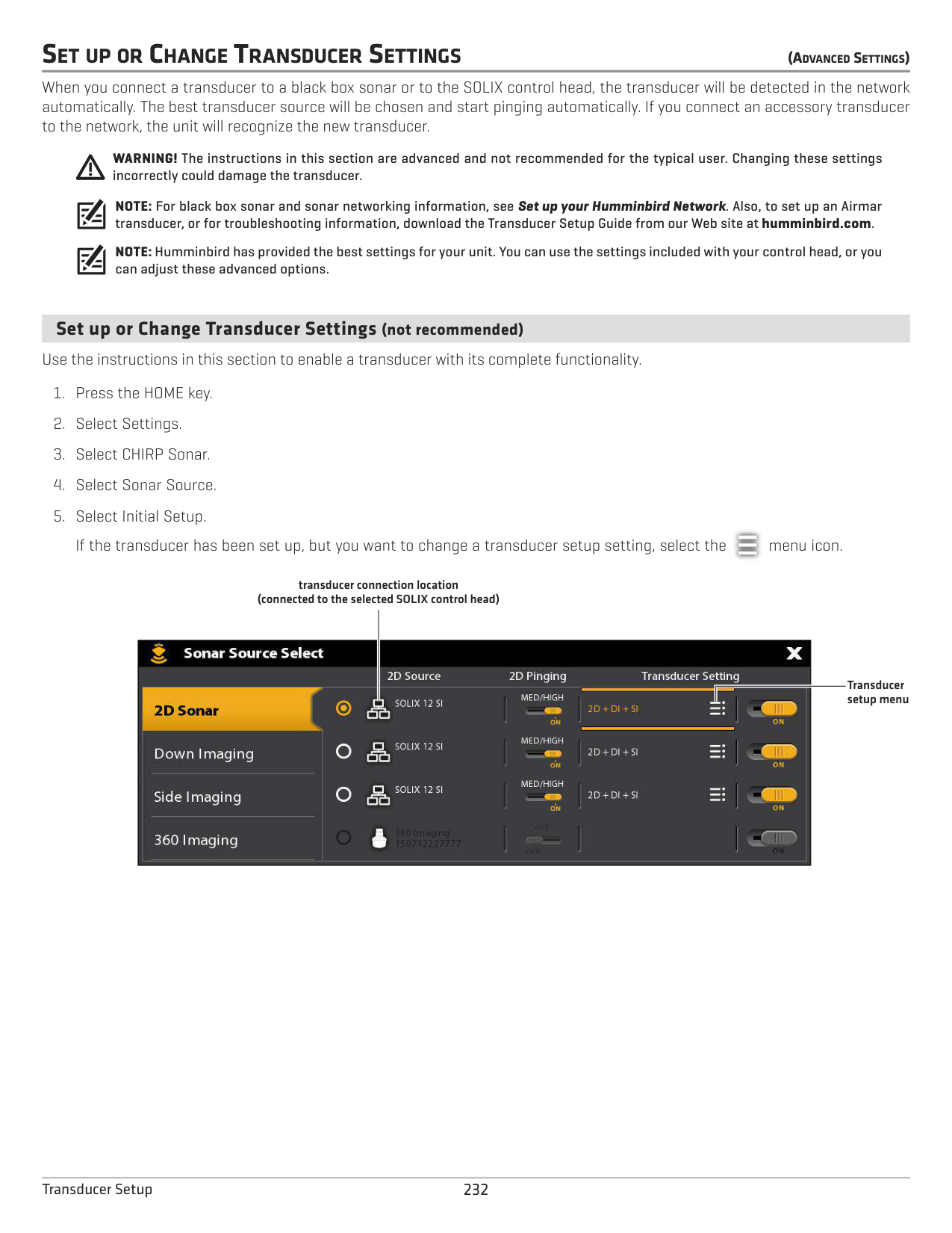
WARNING! Before you connect cables to the control head, or disconnect cables, the control head power and equipment power sources must be turned off.
CAUTION! Before you update the control head software, synchronize units on the network, or restore system defaults, export your control head menu settings to an SD card. It is also recommended to export your navigation data to an SD card. See Update Software for details.
NOTE: If you have questions about the installation or troubleshooting, see your control head installation guide. Also, contact Humminbird Customer Service at humminbird.com.
231 Installation
SET UP OR CHANGE TRANSDUCER SETTINGS (ADVANCEDSETTINGS)
When you connect a transducer to a black box sonar or to the SOLIX control head, the transducer will be detected in the network automatically. The best transducer source will be chosen and start pinging automatically. If you connect an accessory transducer to the network, the unit will recognize the new transducer.
WARNING! The instructions in this section are advanced and not recommended for the typical user. Changing these settings incorrectly could damage the transducer.
NOTE: For black box sonar and sonar networking information, see Set up your Humminbird Network. Also, to set up an Airmar transducer, or for troubleshooting information, download the Transducer Setup Guide from our Web site at humminbird.com.
NOTE: Humminbird has provided the best settings for your unit. You can use the settings included with your control head, or you can adjust these advanced options.
####### Set up or Change Transducer Settings (not recommended)
Use the instructions in this section to enable a transducer with its complete functionality.
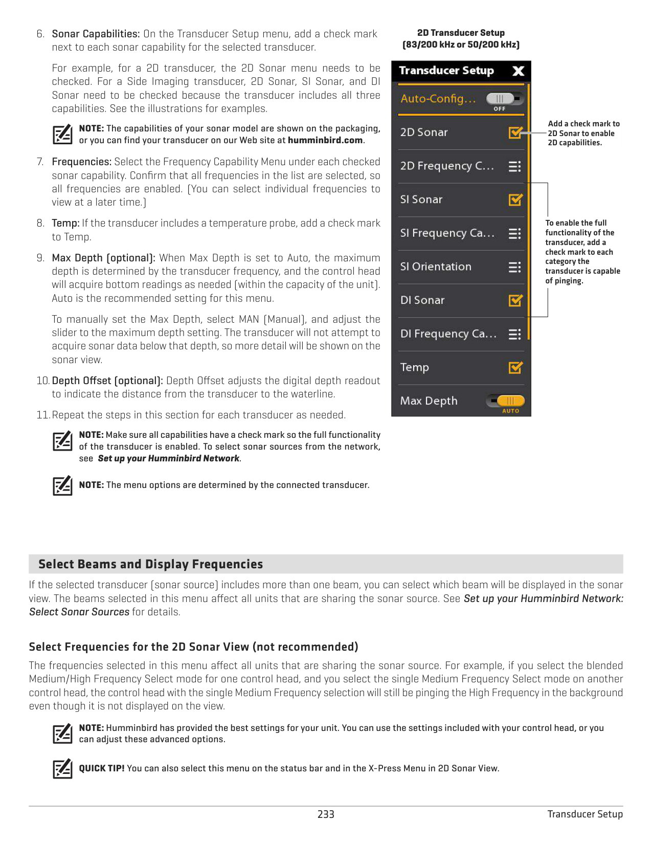

transducer connection location (connected to the selected SOLIX control head)

Transducer setup menu
For example, for a 2D transducer, the 2D Sonar menu needs to be checked. For a Side Imaging transducer, 2D Sonar, SI Sonar, and DI Sonar need to be checked because the transducer includes all three capabilities. See the illustrations for examples.
NOTE: The capabilities of your sonar model are shown on the packaging, or you can find your transducer on our Web site at humminbird.com.
To manually set the Max Depth, select MAN (Manual), and adjust the slider to the maximum depth setting. The transducer will not attempt to acquire sonar data below that depth, so more detail will be shown on the sonar view.
NOTE: Make sure all capabilities have a check mark so the full functionality of the transducer is enabled. To select sonar sources from the network, see Set up your Humminbird Network.
NOTE: The menu options are determined by the connected transducer.
################# 2D Transducer Setup (83/200 kHz or 50/200 kHz)
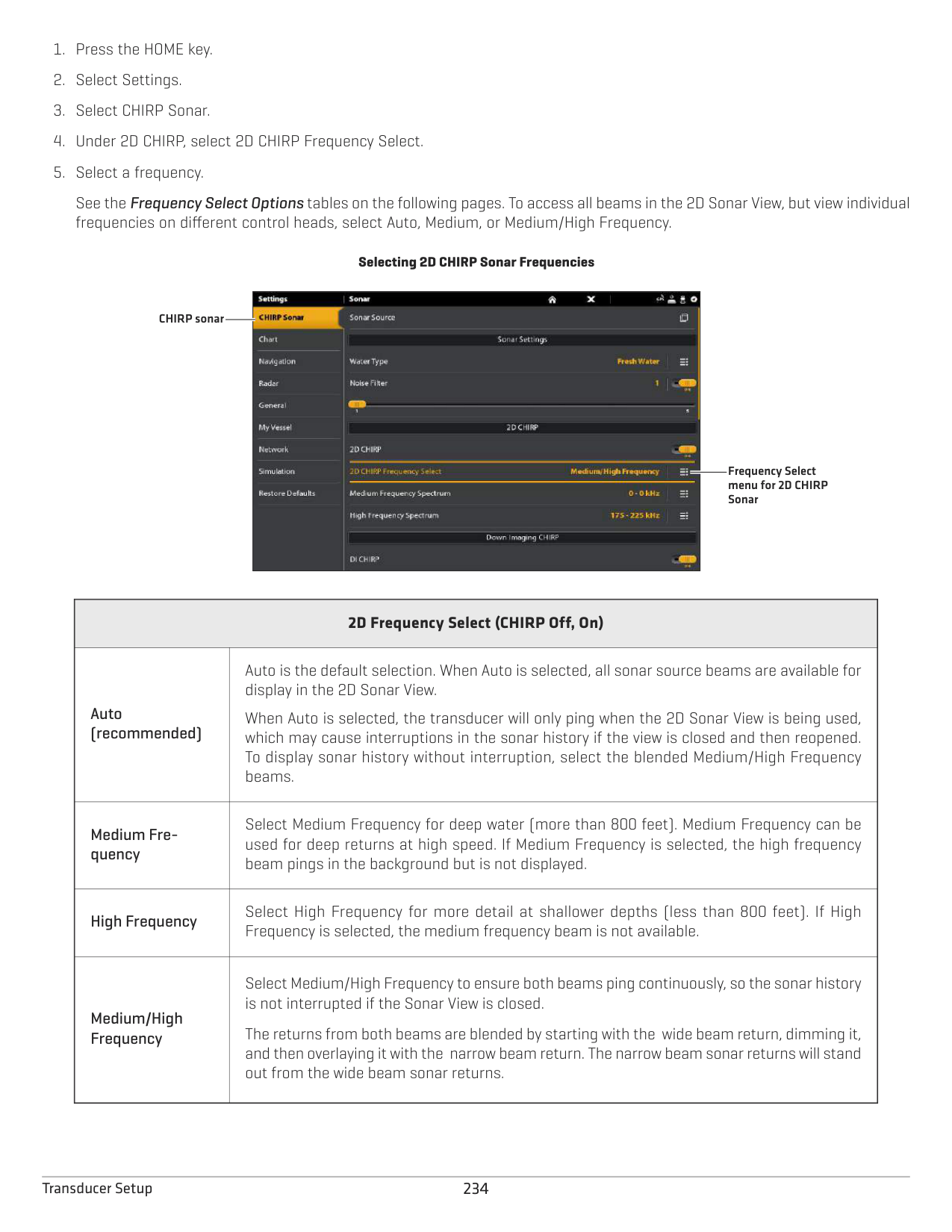

Add a check mark to 2D Sonar to enable 2D capabilities.
To enable the full functionality of the transducer, add a check mark to each category the transducer is capable of pinging.
####### Select Beams and Display Frequencies
If the selected transducer (sonar source) includes more than one beam, you can select which beam will be displayed in the sonar view. The beams selected in this menu affect all units that are sharing the sonar source. See Set up your Humminbird Network: Select Sonar Sources for details.
######### Select Frequencies for the 2D Sonar View (not recommended)
The frequencies selected in this menu affect all units that are sharing the sonar source. For example, if you select the blended Medium/High Frequency Select mode for one control head, and you select the single Medium Frequency Select mode on another control head, the control head with the single Medium Frequency selection will still be pinging the High Frequency in the background even though it is not displayed on the view.
NOTE: Humminbird has provided the best settings for your unit. You can use the settings included with your control head, or you can adjust these advanced options.
QUICK TIP! You can also select this menu on the status bar and in the X-Press Menu in 2D Sonar View.
See the Frequency Select Options tables on the following pages. To access all beams in the 2D Sonar View, but view individual frequencies on different control heads, select Auto, Medium, or Medium/High Frequency.
Selecting 2D CHIRP Sonar Frequencies
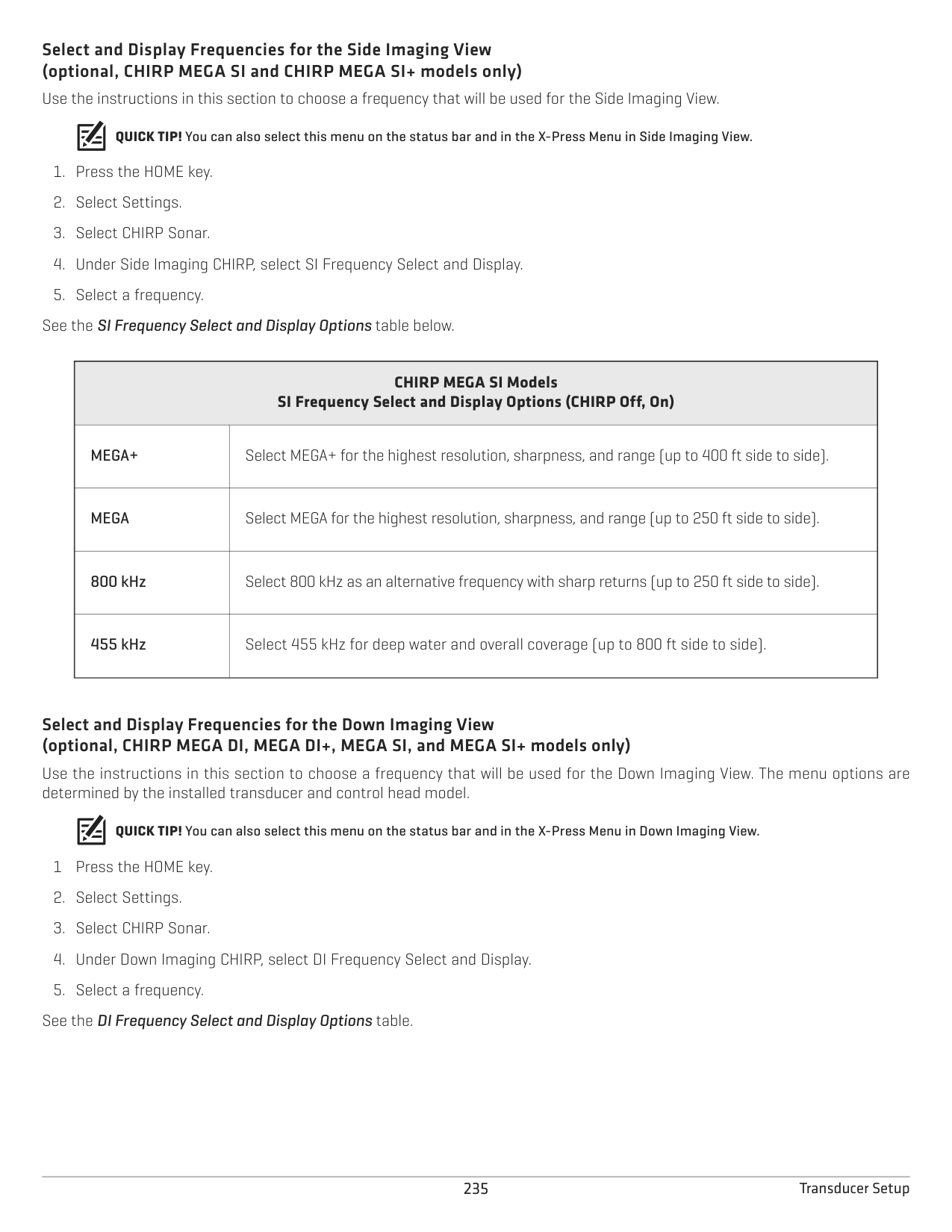
| || | |---|---|---| | || | | || |
CHIRP sonar
Frequency Select menu for 2D CHIRP Sonar
|2D Frequency Select (CHIRP Off, On)
|2D Frequency Select (CHIRP Off, On)
| |---|---| |Auto (recommended)
|Auto is the default selection. When Auto is selected, all sonar source beams are available for display in the 2D Sonar View.
When Auto is selected, the transducer will only ping when the 2D Sonar View is being used, which may cause interruptions in the sonar history if the view is closed and then reopened. To display sonar history without interruption, select the blended Medium/High Frequency beams.| |Medium Frequency|Select Medium Frequency for deep water (more than 800 feet). Medium Frequency can be used for deep returns at high speed. If Medium Frequency is selected, the high frequency beam pings in the background but is not displayed.
| |High Frequency|Select High Frequency for more detail at shallower depths (less than 800 feet). If High Frequency is selected, the medium frequency beam is not available.
| |Medium/High Frequency|Select Medium/High Frequency to ensure both beams ping continuously, so the sonar history is not interrupted if the Sonar View is closed.
The returns from both beams are blended by starting with the wide beam return, dimming it, and then overlaying it with the narrow beam return. The narrow beam sonar returns will stand out from the wide beam sonar returns.|
######### Select and Display Frequencies for the Side Imaging View (optional, CHIRP MEGA SI and CHIRP MEGA SI+ models only) Use the instructions in this section to choose a frequency that will be used for the Side Imaging View.
QUICK TIP! You can also select this menu on the status bar and in the X-Press Menu in Side Imaging View.
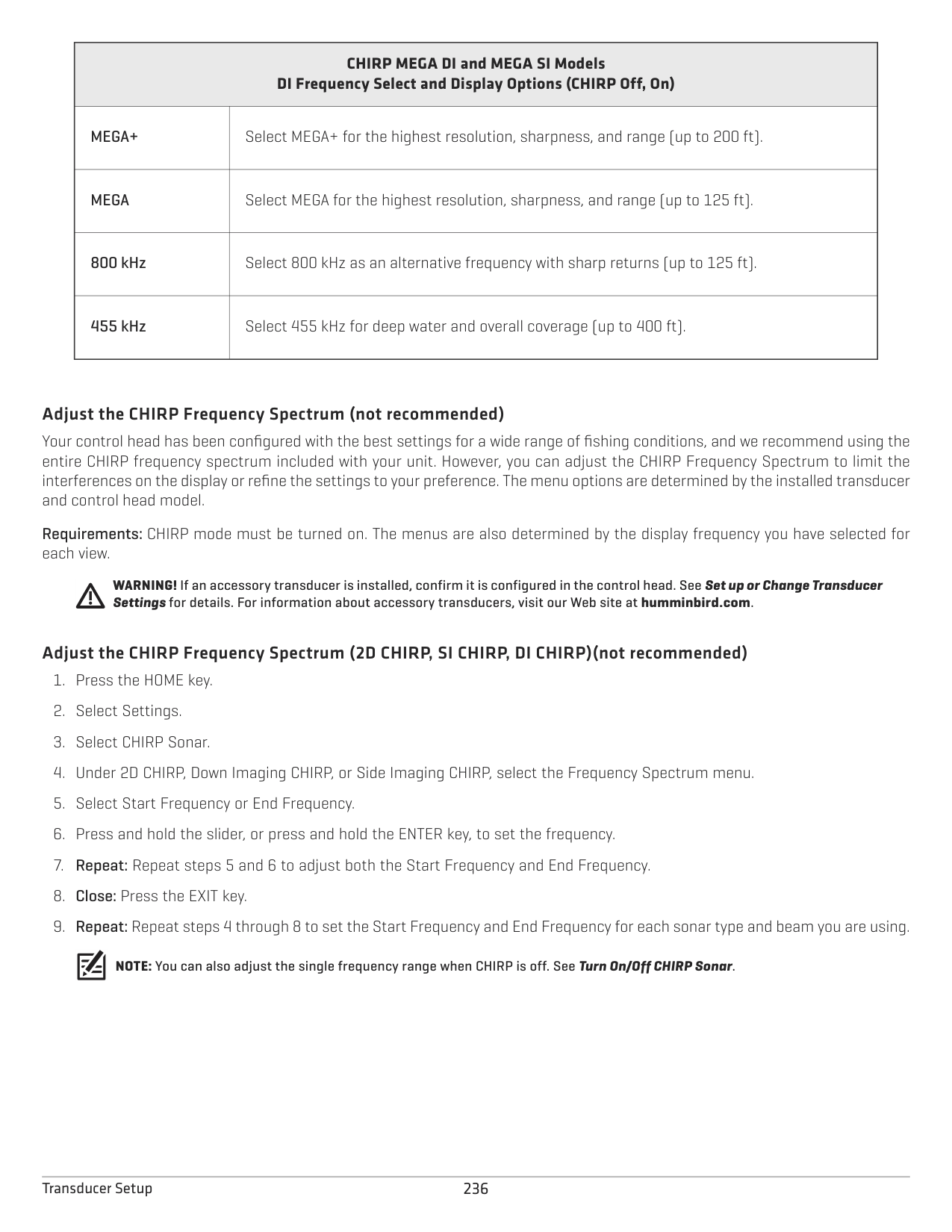
See the SI Frequency Select and Display Options table below.
|CHIRP MEGA SI Models SI Frequency Select and Display Options (CHIRP Off, On)
|CHIRP MEGA SI Models SI Frequency Select and Display Options (CHIRP Off, On)
| |---|---| |MEGA+|Select MEGA+ for the highest resolution, sharpness, and range (up to 400 ft side to side).
| |MEGA
|Select MEGA for the highest resolution, sharpness, and range (up to 250 ft side to side).| |800 kHz|Select 800 kHz as an alternative frequency with sharp returns (up to 250 ft side to side).
| |455 kHz
|Select 455 kHz for deep water and overall coverage (up to 800 ft side to side).|
######### Select and Display Frequencies for the Down Imaging View (optional, CHIRP MEGA DI, MEGA DI+, MEGA SI, and MEGA SI+ models only)
Use the instructions in this section to choose a frequency that will be used for the Down Imaging View. The menu options are determined by the installed transducer and control head model.
QUICK TIP! You can also select this menu on the status bar and in the X-Press Menu in Down Imaging View. 1 Press the HOME key.
|CHIRP MEGA DI and MEGA SI Models DI Frequency Select and Display Options (CHIRP Off, On)
|CHIRP MEGA DI and MEGA SI Models DI Frequency Select and Display Options (CHIRP Off, On)
| |---|---| |MEGA+|Select MEGA+ for the highest resolution, sharpness, and range (up to 200 ft).
| |MEGA
|Select MEGA for the highest resolution, sharpness, and range (up to 125 ft).| |800 kHz
|Select 800 kHz as an alternative frequency with sharp returns (up to 125 ft).| |455 kHz|Select 455 kHz for deep water and overall coverage (up to 400 ft).
|
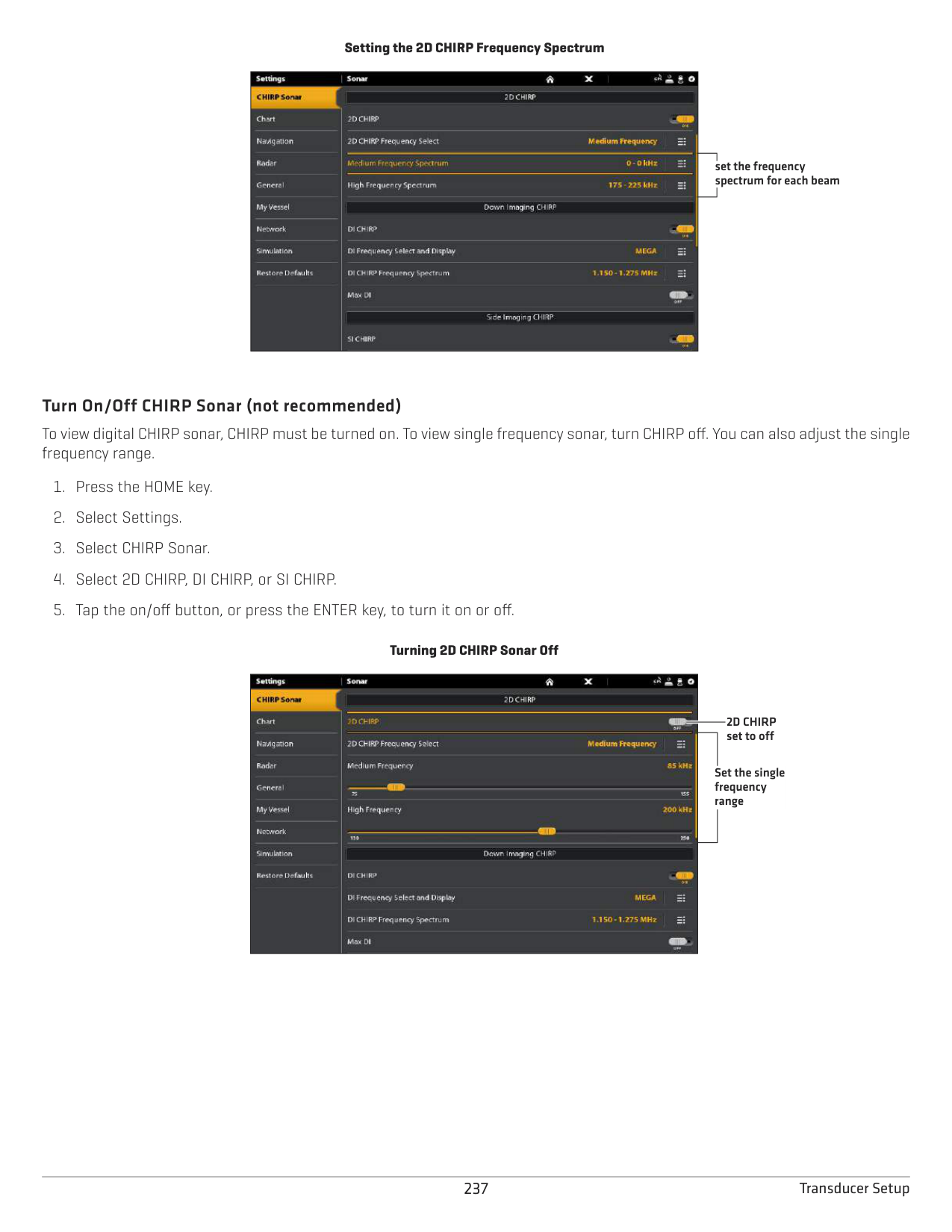
######### Adjust the CHIRP Frequency Spectrum (not recommended)
Your control head has been configured with the best settings for a wide range of fishing conditions, and we recommend using the entire CHIRP frequency spectrum included with your unit. However, you can adjust the CHIRP Frequency Spectrum to limit the interferences on the display or refine the settings to your preference. The menu options are determined by the installed transducer and control head model.
Requirements: CHIRP mode must be turned on. The menus are also determined by the display frequency you have selected for each view.
WARNING! If an accessory transducer is installed, confirm it is configured in the control head. See Set up or Change Transducer Settings for details. For information about accessory transducers, visit our Web site at humminbird.com.
######### Adjust the CHIRP Frequency Spectrum (2D CHIRP, SI CHIRP, DI CHIRP)(not recommended)
NOTE: You can also adjust the single frequency range when CHIRP is off. See Turn On/Off CHIRP Sonar.
Setting the 2D CHIRP Frequency Spectrum
|| | |---|---|
|| | || |
set the frequency spectrum for each beam
######### Turn On/Off CHIRP Sonar (not recommended)
To view digital CHIRP sonar, CHIRP must be turned on. To view single frequency sonar, turn CHIRP off. You can also adjust the single frequency range.
################# Turning 2D CHIRP Sonar Off

2D CHIRP set to off
Set the single frequency range
####### Change the Water Type
Use the instructions in this section to change the Water Type setting.
####### Adjust the Noise Filter (not recommended)
Use Noise Filter to limit the interference that may appear on the sonar views from sources such as your boat engine, turbulence, or other sonar devices.
####### Change the Side Imaging Orientation (CHIRP MEGA SI models only)
Use SI Orientation to switch how the Side Imaging beams are displayed on the Side Imaging View. This menu option can be used if the port and starboard beams are reversed during installation, which might be the case if a transducer is installed incorrectly. For further assistance, contact Humminbird Customer Service.
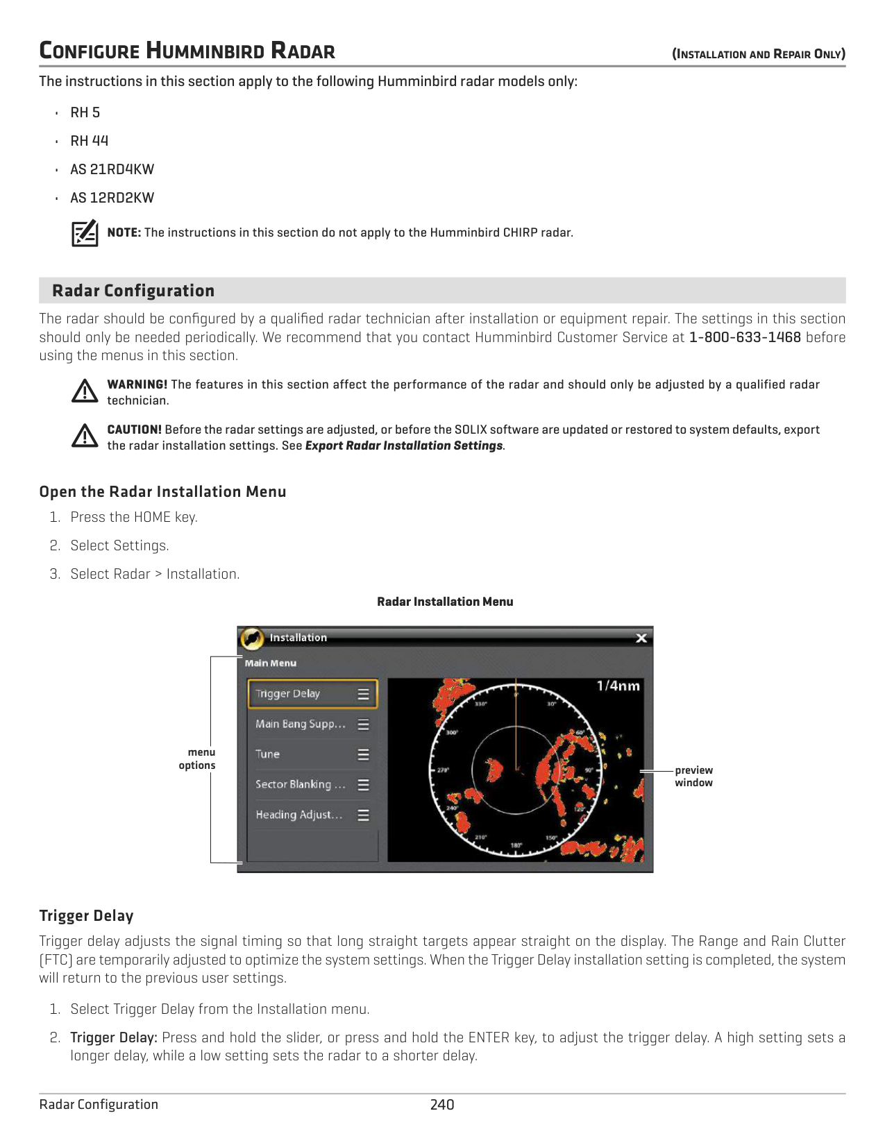
####### Turn on Max DI (CHIRP MEGA SI models only)
Max DI (On) is typically used for deep water to provide the maximum strength for the Down Imaging signal. Max DI (Off) typically provides the best resolution in shallow water.
####### Change Imaging+ Presets (MEGA SI+ and DI+ models only)
Use one of the Imaging+ Presets to change your frequency for maximum detail or maximum coverage.
CONFIGURE HUMMINBIRD RADAR (INSTALLATIONANDREPAIRONLY)
The instructions in this section apply to the following Humminbird radar models only:
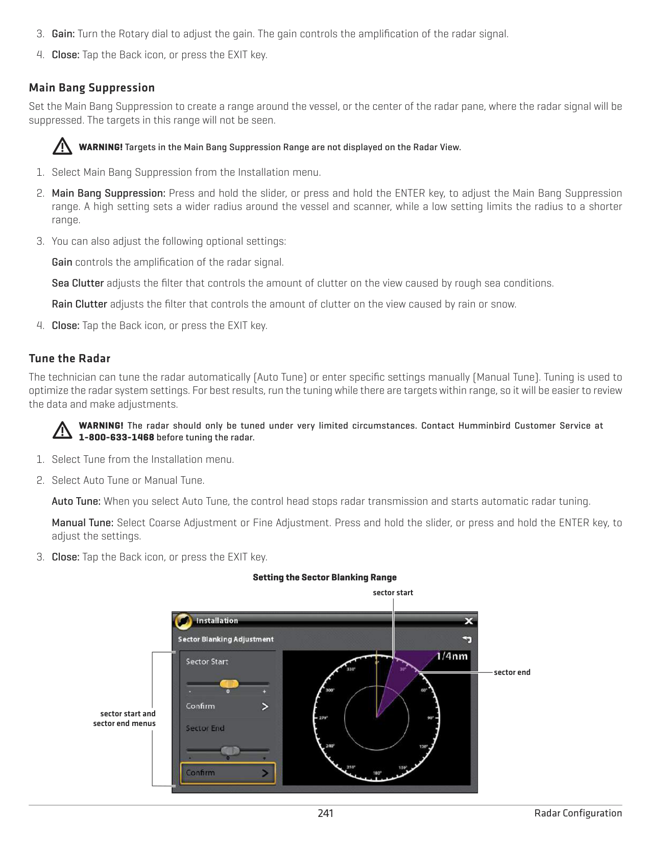
NOTE: The instructions in this section do not apply to the Humminbird CHIRP radar.
####### Radar Configuration
The radar should be configured by a qualified radar technician after installation or equipment repair. The settings in this section should only be needed periodically. We recommend that you contact Humminbird Customer Service at 1-800-633-1468 before using the menus in this section.
WARNING! The features in this section affect the performance of the radar and should only be adjusted by a qualified radar technician.
CAUTION! Before the radar settings are adjusted, or before the SOLIX software are updated or restored to system defaults, export the radar installation settings. See Export Radar Installation Settings.
######### Open the Radar Installation Menu
Radar Installation Menu

menu options
preview window
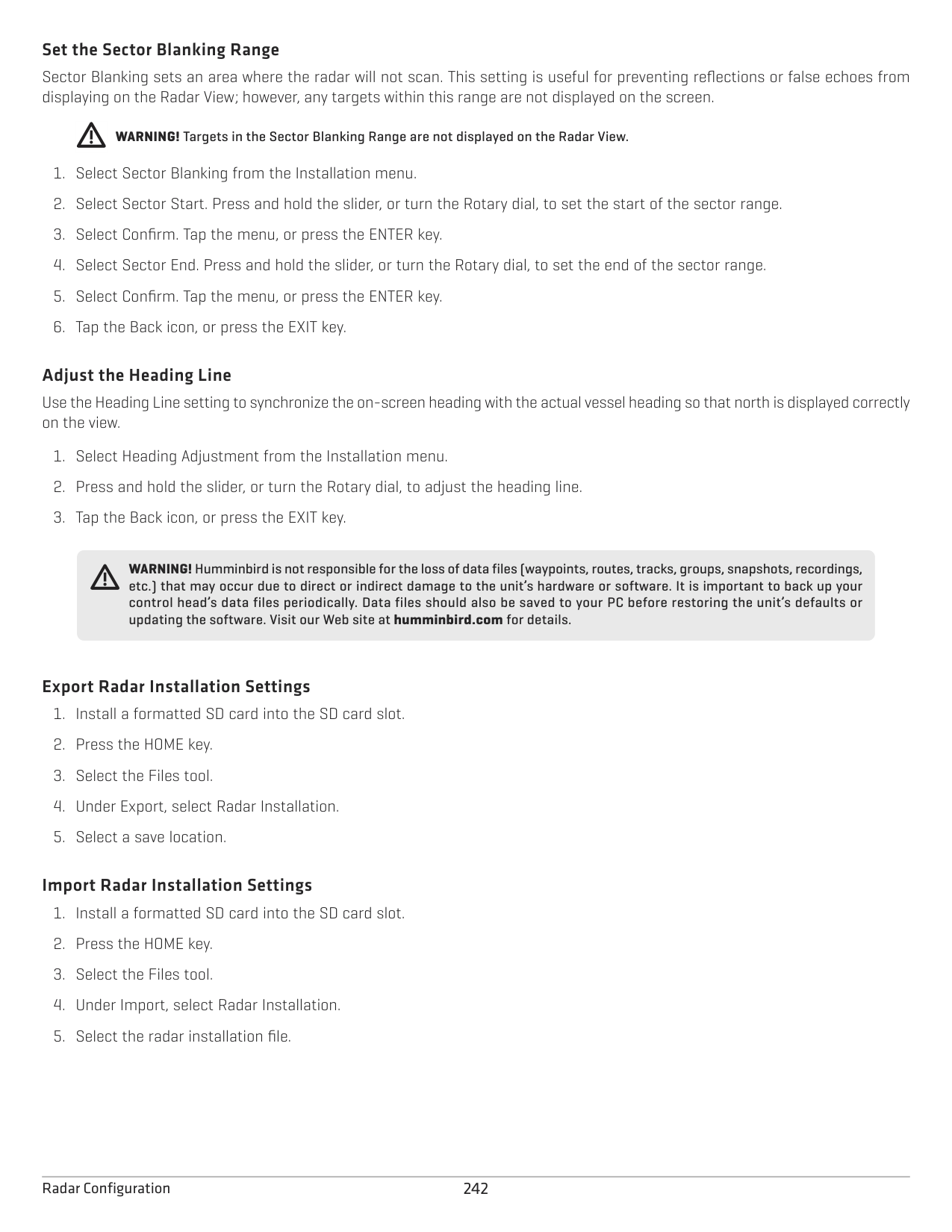
######### Trigger Delay
Trigger delay adjusts the signal timing so that long straight targets appear straight on the display. The Range and Rain Clutter (FTC) are temporarily adjusted to optimize the system settings. When the Trigger Delay installation setting is completed, the system will return to the previous user settings.
######### Main Bang Suppression
Set the Main Bang Suppression to create a range around the vessel, or the center of the radar pane, where the radar signal will be suppressed. The targets in this range will not be seen.
WARNING! Targets in the Main Bang Suppression Range are not displayed on the Radar View.
######### Tune the Radar
The technician can tune the radar automatically (Auto Tune) or enter specific settings manually (Manual Tune). Tuning is used to optimize the radar system settings. For best results, run the tuning while there are targets within range, so it will be easier to review the data and make adjustments.
WARNING! The radar should only be tuned under very limited circumstances. Contact Humminbird Customer Service at 1-800-633-1468 before tuning the radar.
Manual Tune: Select Coarse Adjustment or Fine Adjustment. Press and hold the slider, or press and hold the ENTER key, to adjust the settings.
sector start

sector end
sector start and sector end menus
241 Radar Configuration
######### Set the Sector Blanking Range
Sector Blanking sets an area where the radar will not scan. This setting is useful for preventing reflections or false echoes from displaying on the Radar View; however, any targets within this range are not displayed on the screen.
WARNING! Targets in the Sector Blanking Range are not displayed on the Radar View.
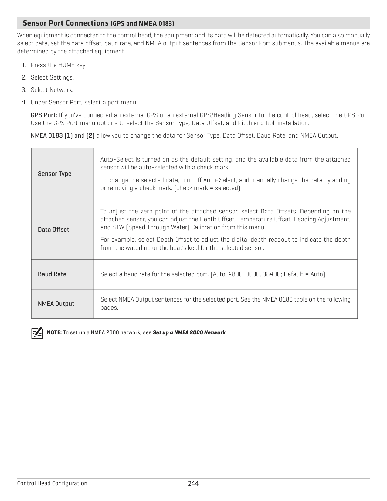
######### Adjust the Heading Line
Use the Heading Line setting to synchronize the on-screen heading with the actual vessel heading so that north is displayed correctly on the view.
WARNING! Humminbird is not responsible for the loss of data files (waypoints, routes, tracks, groups, snapshots, recordings, etc.) that may occur due to direct or indirect damage to the unit’s hardware or software. It is important to back up your control head’s data files periodically. Data files should also be saved to your PC before restoring the unit’s defaults or updating the software. Visit our Web site at humminbird.com for details.
######### Export Radar Installation Settings
######### Import Radar Installation Settings
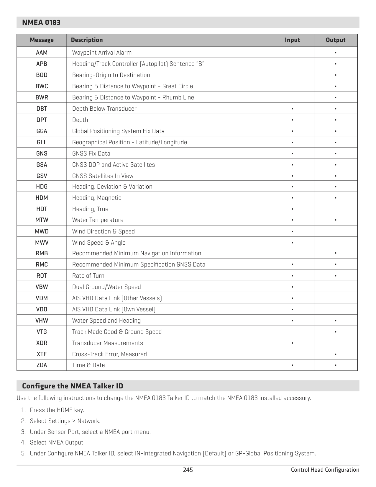
CONFIGURE THE CONTROL HEAD
Use the instructions in this section to review control head and network connections, select baud rates and NMEA 0183 Output sentences, and name the control heads and networks.
When the SOLIX control head equipment and accessories are installed, the Setup Guide provides the prompts to guide you through configuring the unit. When you attach new hardware to the control head after it has been configured, the unit will detect the new hardware and provide additional prompts to add the equipment to the system.
####### System Info
######### Review System Connections
Use the System Info dialog box to review control head information such as the software version and serial number. You can also review connection information for the equipment connected to the control head ports, and you can change the control head name.
|| | |---|---| || | || | || | || | || | || |
control head information
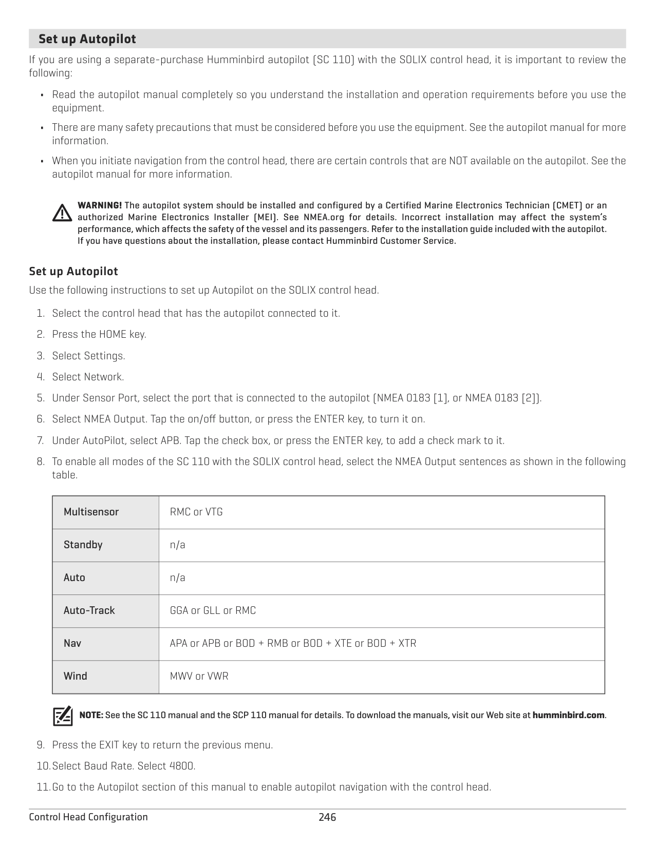
network name
control head ports and connection information
rename the control head
Change the Control Head Name When a control head is part of a network, you can change its name so it is easy to identify as a source on the network.
####### Sensor Port Connections (GPS and NMEA 0183)
When equipment is connected to the control head, the equipment and its data will be detected automatically. You can also manually select data, set the data offset, baud rate, and NMEA output sentences from the Sensor Port submenus. The available menus are determined by the attached equipment.
GPS Port: If you’ve connected an external GPS or an external GPS/Heading Sensor to the control head, select the GPS Port. Use the GPS Port menu options to select the Sensor Type, Data Offset, and Pitch and Roll installation.
NMEA 0183 (1) and (2) allow you to change the data for Sensor Type, Data Offset, Baud Rate, and NMEA Output.
|Sensor Type|Auto-Select is turned on as the default setting, and the available data from the attached sensor will be auto-selected with a check mark.
To change the selected data, turn off Auto-Select, and manually change the data by adding or removing a check mark. (check mark = selected)
| |---|---| |Data Offset|To adjust the zero point of the attached sensor, select Data Offsets. Depending on the attached sensor, you can adjust the Depth Offset, Temperature Offset, Heading Adjustment, and STW (Speed Through Water) Calibration from this menu.
For example, select Depth Offset to adjust the digital depth readout to indicate the depth from the waterline or the boat’s keel for the selected sensor.
| |Baud Rate
|Select a baud rate for the selected port. (Auto, 4800, 9600, 38400; Default = Auto)|
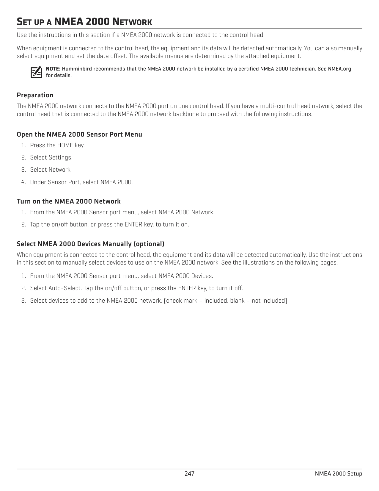
|NMEA Output|Select NMEA Output sentences for the selected port. See the NMEA 0183 table on the following pages.|
NOTE: To set up a NMEA 2000 network, see Set up a NMEA 2000 Network.
####### NMEA 0183
|Message|Description
|Input
|Output| |---|---|---|---| |AAM
|Waypoint Arrival Alarm| |•| |APB|Heading/Track Controller (Autopilot) Sentence “B”
| |•| |BOD|Bearing-Origin to Destination| |•
| |BWC|Bearing & Distance to Waypoint - Great Circle| |•
| |BWR|Bearing & Distance to Waypoint - Rhumb Line
| |•| |DBT
|Depth Below Transducer|•|•| |DPT
|Depth|•|•| |GGA
|Global Positioning System Fix Data|•|•| |GLL|Geographical Position - Latitude/Longitude
|•|•| |GNS
|GNSS Fix Data|•|•| |GSA
|GNSS DOP and Active Satellites|•|•| |GSV|GNSS Satellites In View
|•|•| |HDG|Heading, Deviation & Variation
|•|•| |HDM
|Heading, Magnetic|•|•| |HDT
|Heading, True|•| | |MTW|Water Temperature|•
|•| |MWD|Wind Direction & Speed
|•| | |MWV
|Wind Speed & Angle|•| | |RMB|Recommended Minimum Navigation Information| |•
| |RMC
|Recommended Minimum Specification GNSS Data|•|•|
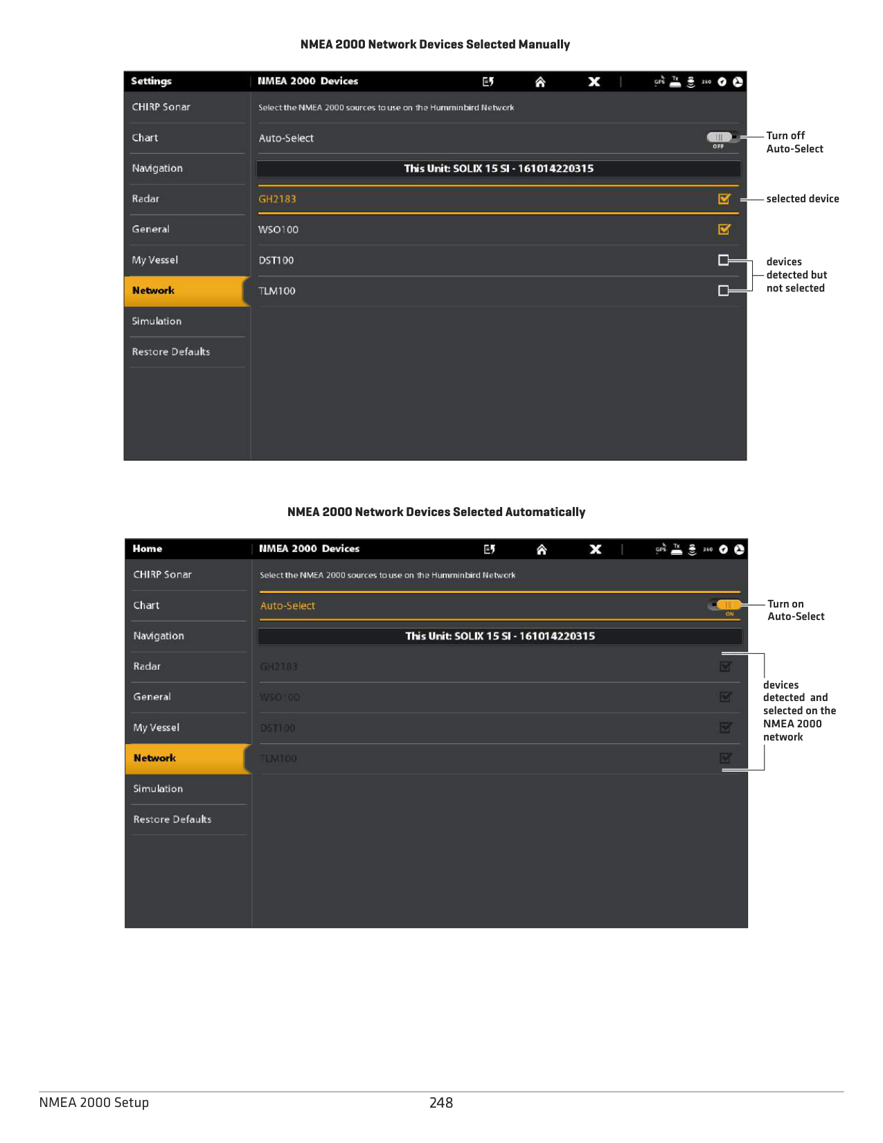
|ROT|Rate of Turn|•
|•| |VBW|Dual Ground/Water Speed|•
| | |VDM|AIS VHD Data Link (Other Vessels)|•
| | |VDO|AIS VHD Data Link (Own Vessel)|•
| | |VHW|Water Speed and Heading|•
|•| |VTG|Track Made Good & Ground Speed| |•
| |XDR|Transducer Measurements|•| | |XTE|Cross-Track Error, Measured| |•
| |ZDA|Time & Date|•|•|
####### Configure the NMEA Talker ID
Use the following instructions to change the NMEA 0183 Talker ID to match the NMEA 0183 installed accessory.
####### Set up Autopilot
If you are using a separate-purchase Humminbird autopilot (SC 110) with the SOLIX control head, it is important to review the following:
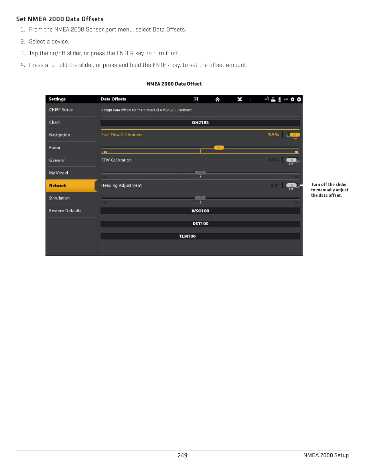
WARNING! The autopilot system should be installed and configured by a Certified Marine Electronics Technician (CMET) or an authorized Marine Electronics Installer (MEI). See NMEA.org for details. Incorrect installation may affect the system’s performance, which affects the safety of the vessel and its passengers. Refer to the installation guide included with the autopilot. If you have questions about the installation, please contact Humminbird Customer Service.
Set up Autopilot Use the following instructions to set up Autopilot on the SOLIX control head.
NOTE:See the SC 110 manual and the SCP 110 manual for details. To download the manuals, visit our Web site at humminbird.com.
|Multisensor
|RMC or VTG| |---|---| |Standby
|n/a| |Auto
|n/a| |Auto-Track
|GGA or GLL or RMC| |Nav
|APA or APB or BOD + RMB or BOD + XTE or BOD + XTR| |Wind|MWV or VWR|
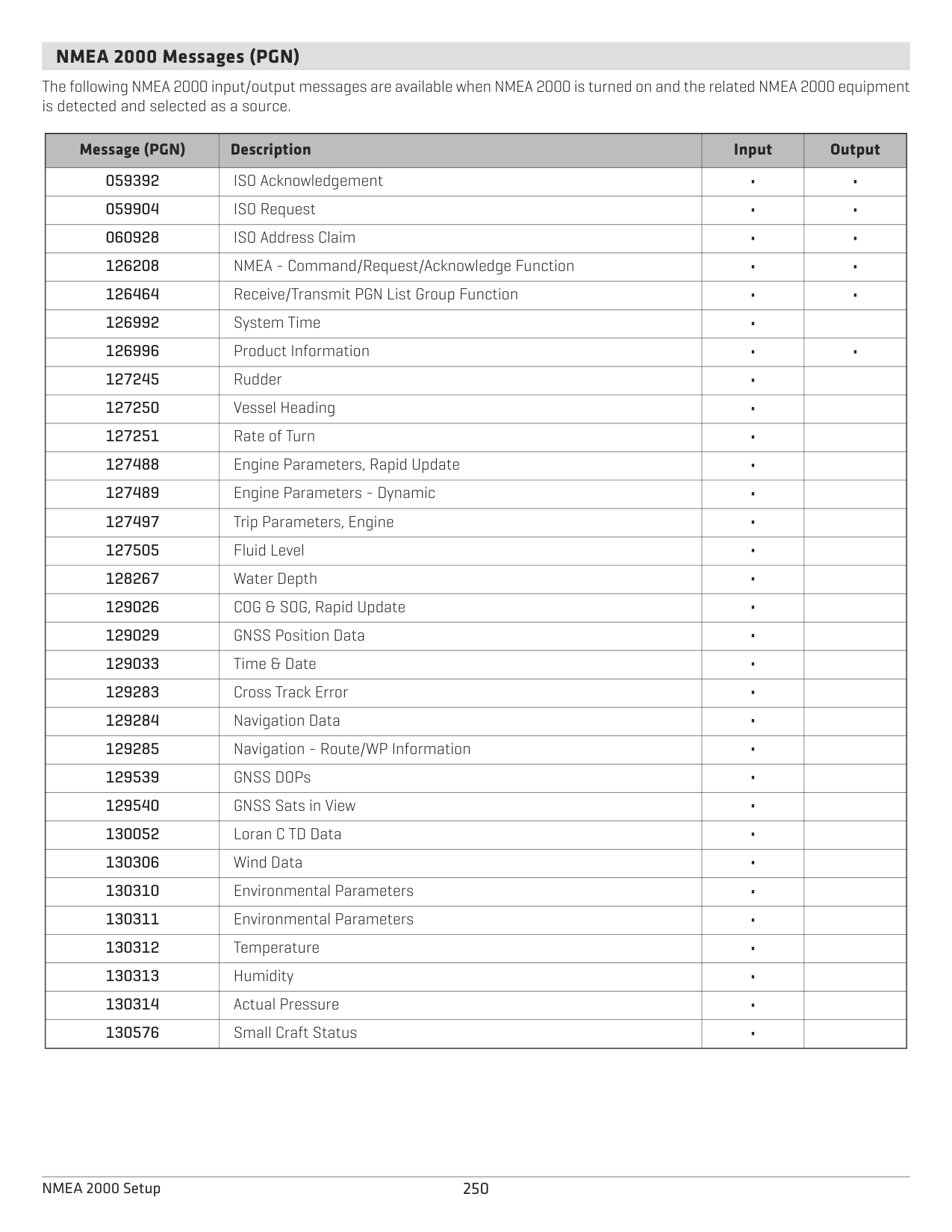
SET UP A NMEA 2000 NETWORK Use the instructions in this section if a NMEA 2000 network is connected to the control head. When equipment is connected to the control head, the equipment and its data will be detected automatically. You can also manually select equipment and set the data offset. The available menus are determined by the attached equipment.
NOTE: Humminbird recommends that the NMEA 2000 network be installed by a certified NMEA 2000 technician. See NMEA.org for details.
######### Preparation
The NMEA 2000 network connects to the NMEA 2000 port on one control head. If you have a multi-control head network, select the control head that is connected to the NMEA 2000 network backbone to proceed with the following instructions.
######### Open the NMEA 2000 Sensor Port Menu
######### Turn on the NMEA 2000 Network
######### Select NMEA 2000 Devices Manually (optional)
When equipment is connected to the control head, the equipment and its data will be detected automatically. Use the instructions in this section to manually select devices to use on the NMEA 2000 network. See the illustrations on the following pages.
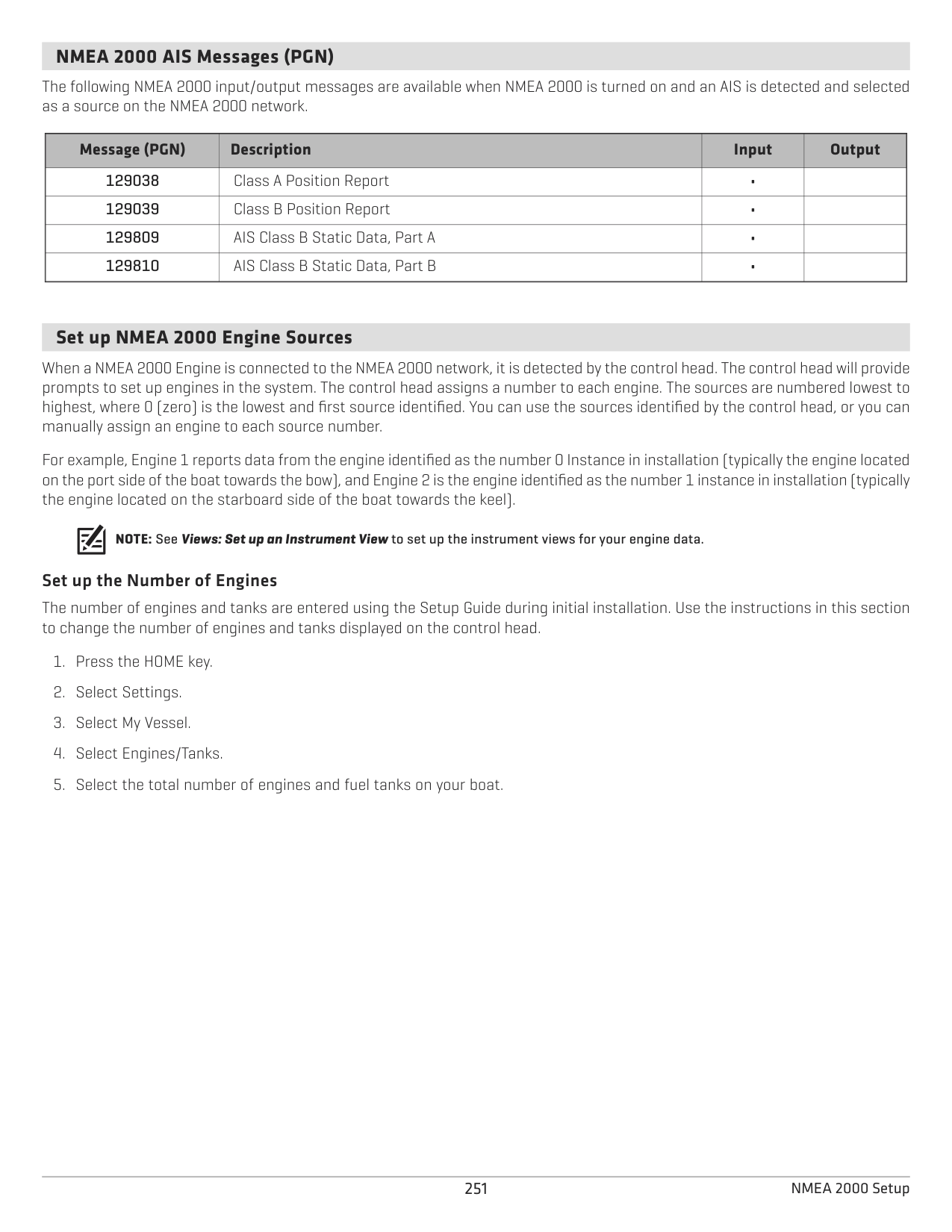
################# NMEA 2000 Network Devices Selected Manually

Turn off Auto-Select
selected device
devices detected but not selected
################# NMEA 2000 Network Devices Selected Automatically

Turn on Auto-Select
devices detected and selected on the NMEA 2000 network
######### Set NMEA 2000 Data Offsets
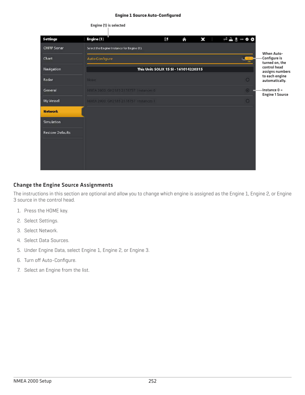
NMEA 2000 Data Offset
|| | |---|---| || |
Turn off the slider to manually adjust the data offset.
####### NMEA 2000 Messages (PGN)
The following NMEA 2000 input/output messages are available when NMEA 2000 is turned on and the related NMEA 2000 equipment is detected and selected as a source.
|Message (PGN)
|Description
|Input|Output
| |---|---|---|---| |059392
|ISO Acknowledgement|•|•| |059904|ISO Request|•
|•| |060928
|ISO Address Claim|•|•| |126208|NMEA - Command/Request/Acknowledge Function|•
|•| |126464
|Receive/Transmit PGN List Group Function|•|•| |126992
|System Time|•| | |126996|Product Information|•
|•| |127245|Rudder
|•| | |127250
|Vessel Heading|•| | |127251|Rate of Turn|•
| | |127488|Engine Parameters, Rapid Update|•
| | |127489|Engine Parameters - Dynamic
|•| | |127497
|Trip Parameters, Engine|•| |
|127505|Fluid Level
|•| | |128267|Water Depth
|•| | |129026|COG & SOG, Rapid Update
|•| | |129029|GNSS Position Data|•
| | |129033|Time & Date
|•| | |129283|Cross Track Error
|•| | |129284|Navigation Data
|•| | |129285|Navigation - Route/WP Information|•| | |129539
|GNSS DOPs|•| | |129540|GNSS Sats in View
|•| | |130052
|Loran C TD Data|•| | |130306|Wind Data
|•| | |130310|Environmental Parameters|•| | |130311|Environmental Parameters|•| | |130312|Temperature
|•| | |130313
|Humidity|•| | |130314|Actual Pressure
|•| | |130576|Small Craft Status|•| |
####### NMEA 2000 AIS Messages (PGN)
The following NMEA 2000 input/output messages are available when NMEA 2000 is turned on and an AIS is detected and selected as a source on the NMEA 2000 network.
|Message (PGN)
|Description
|Input|Output
| |---|---|---|---| |129038
|Class A Position Report|•| | |129039|Class B Position Report|•
| | |129809
|AIS Class B Static Data, Part A|•| |
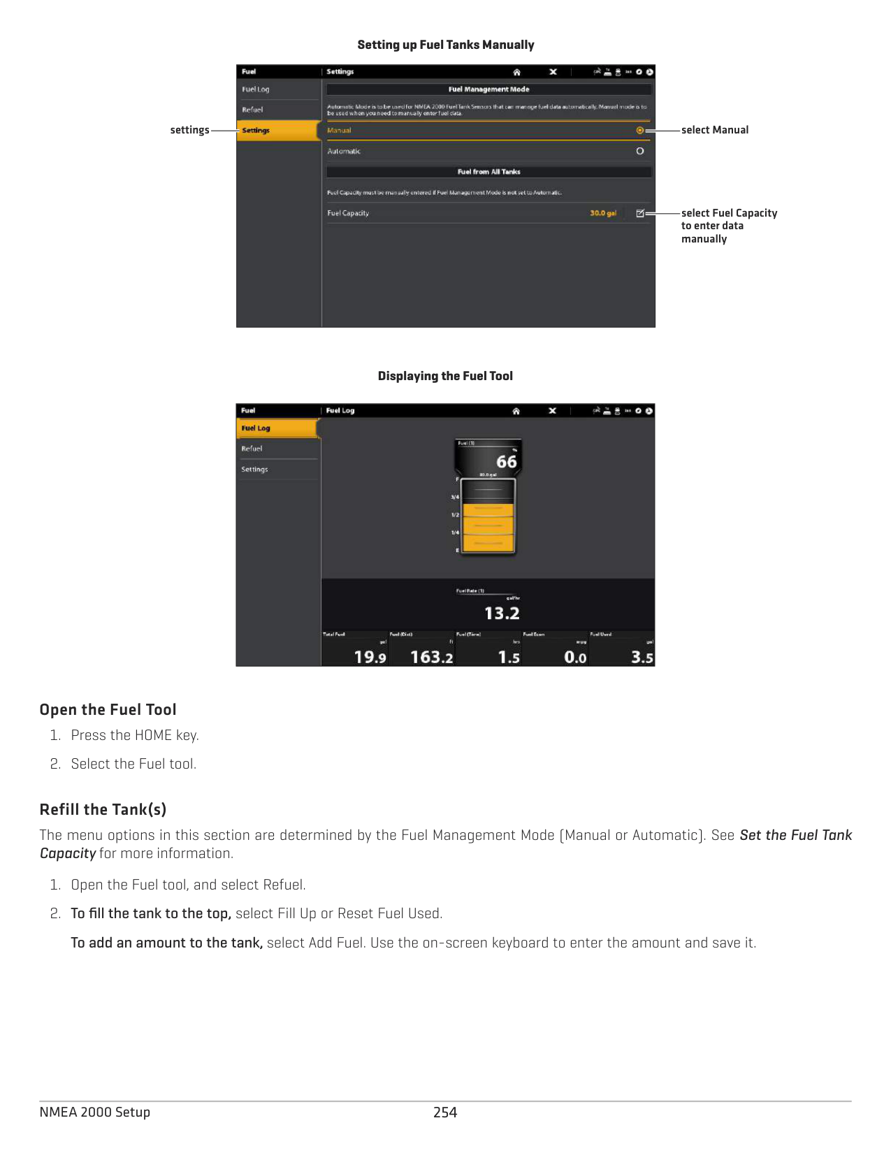
|129810|AIS Class B Static Data, Part B|•| |
####### Set up NMEA 2000 Engine Sources
When a NMEA 2000 Engine is connected to the NMEA 2000 network, it is detected by the control head. The control head will provide prompts to set up engines in the system. The control head assigns a number to each engine. The sources are numbered lowest to highest, where 0 (zero) is the lowest and first source identified. You can use the sources identified by the control head, or you can manually assign an engine to each source number.
For example, Engine 1 reports data from the engine identified as the number 0 Instance in installation (typically the engine located on the port side of the boat towards the bow), and Engine 2 is the engine identified as the number 1 instance in installation (typically the engine located on the starboard side of the boat towards the keel).
NOTE: See Views: Set up an Instrument View to set up the instrument views for your engine data. Set up the Number of Engines
The number of engines and tanks are entered using the Setup Guide during initial installation. Use the instructions in this section to change the number of engines and tanks displayed on the control head.
################# Engine 1 Source Auto-Configured
Engine (1) is selected

When AutoConfigure is turned on, the control head assigns numbers to each engine automatically.
Instance 0 = Engine 1 Source
Change the Engine Source Assignments The instructions in this section are optional and allow you to change which engine is assigned as the Engine 1, Engine 2, or Engine
####### Set up Fuel Tanks
The Setup Guide provides prompts to set up the fuel tanks in the system, and it assigns a source number to each fuel tank. If a NMEA 2000 fuel tank sensor and a fuel flow rate sensor are installed, the control head can display fuel levels automatically. If only a fuel flow rate sensor is installed, you need to set up the fuel tanks manually to manage fuel levels.
######### Set up the Number of Tanks
The number of engines and tanks are entered using the Setup Guide during initial installation. Use the instructions in this section to change the number of engines and tanks displayed on the control head.
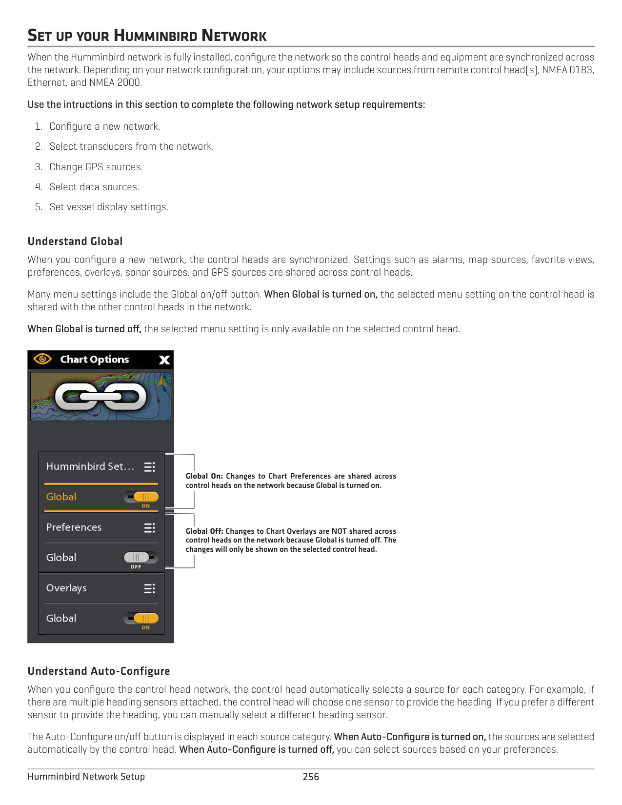
######### Set the Fuel Tank Capacity
If there is a fuel flow rate sensor installed, but not a NMEA 2000 fuel tank sensor, use the instructions in this section to set up fuel tank data manually. You can also use these instructions to confirm Automatic Fuel Management Mode if you have a NMEA 2000 fuel tank sensor and a fuel flow rate sensor installed.
NOTE: If NMEA 2000 fuel tank sensor and a fuel flow rate sensor are installed, select Auto to automatically detect the tank capacity.
Setting up Fuel Tanks Manually
| || | |---|---|---| | || | | || |
settings select Manual
select Fuel Capacity to enter data manually
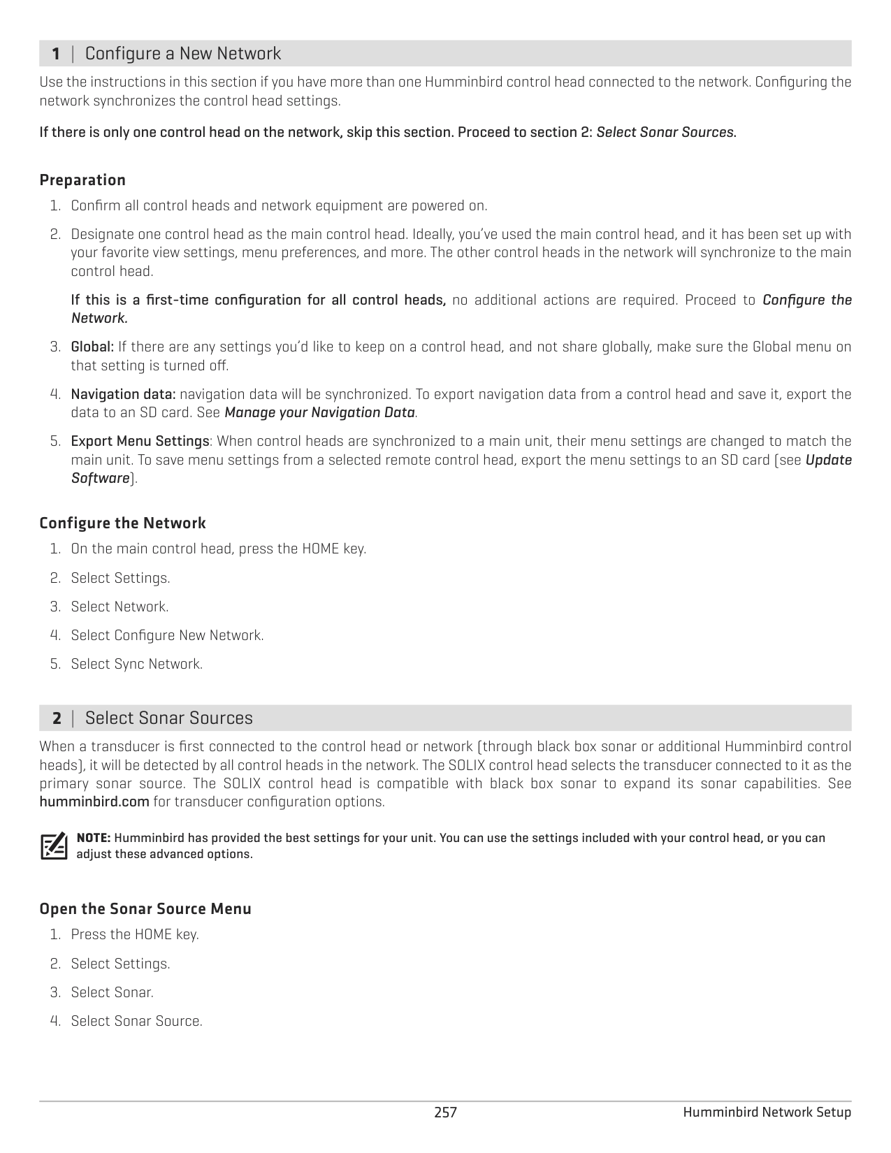
################# Displaying the Fuel Tool
|| |---|
######### Open the Fuel Tool
Refill the Tank(s) The menu options in this section are determined by the Fuel Management Mode (Manual or Automatic). See Set the Fuel Tank Capacity for more information.
To add an amount to the tank, select Add Fuel. Use the on-screen keyboard to enter the amount and save it.
######### Change the Fuel Tank or Fuel Flow Source Assignments
The instructions in this section are optional and allow you to change which fuel tank is assigned as the Tank 1, Tank 2, or Tank 3 source in the control head. You can also use these instructions to change the fuel flow rate Sensors (Fuel Flow) assignments. The menu options are determined by the type of sensors installed.
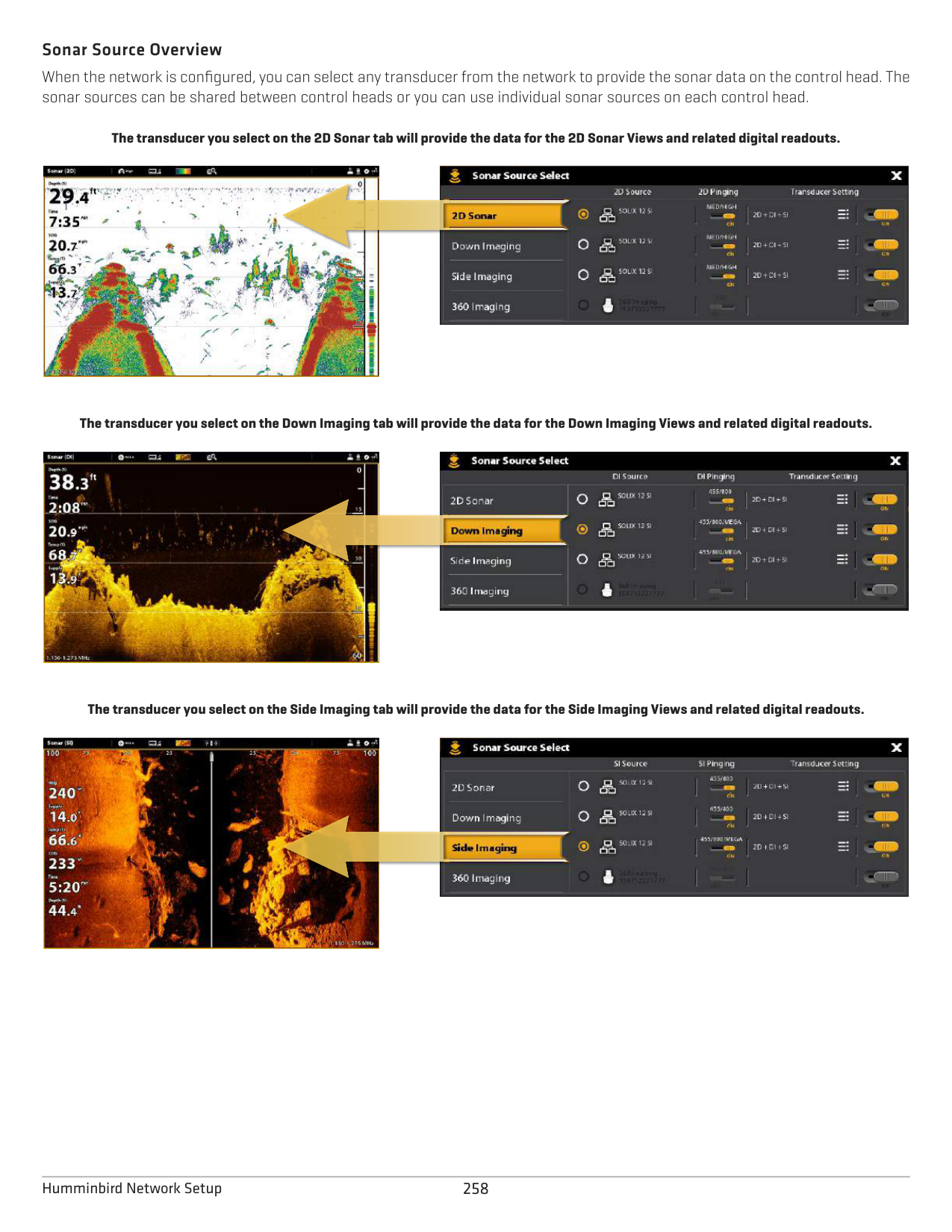
SET UP YOUR HUMMINBIRD NETWORK
When the Humminbird network is fully installed, configure the network so the control heads and equipment are synchronized across the network. Depending on your network configuration, your options may include sources from remote control head(s), NMEA 0183, Ethernet, and NMEA 2000.
############# Use the intructions in this section to complete the following network setup requirements:
######### Understand Global
When you configure a new network, the control heads are synchronized. Settings such as alarms, map sources, favorite views, preferences, overlays, sonar sources, and GPS sources are shared across control heads.
Many menu settings include the Global on/off button. When Global is turned on, the selected menu setting on the control head is shared with the other control heads in the network.
When Global is turned off, the selected menu setting is only available on the selected control head.

Global On: Changes to Chart Preferences are shared across control heads on the network because Global is turned on.
Global Off: Changes to Chart Overlays are NOT shared across control heads on the network because Global is turned off. The changes will only be shown on the selected control head.
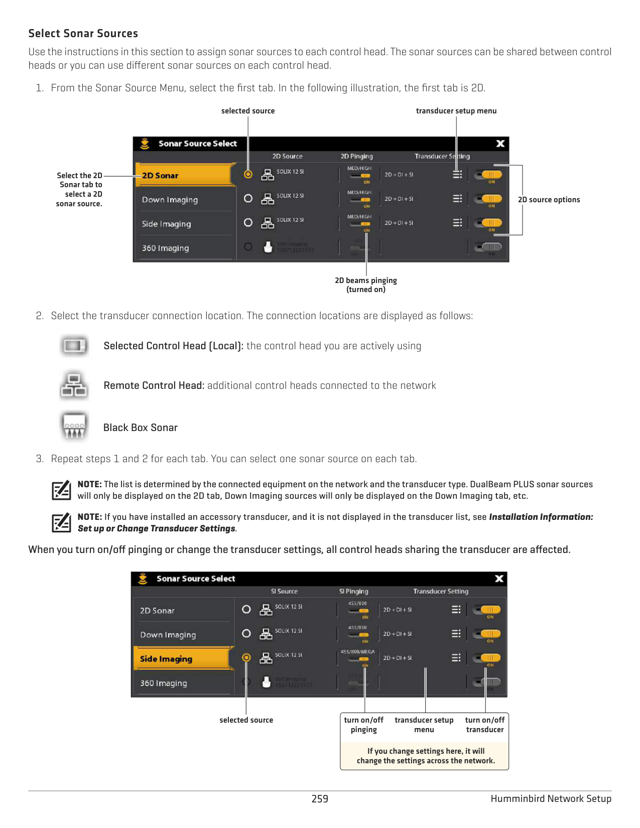
######### Understand Auto-Configure
When you configure the control head network, the control head automatically selects a source for each category. For example, if there are multiple heading sensors attached, the control head will choose one sensor to provide the heading. If you prefer a different sensor to provide the heading, you can manually select a different heading sensor.
The Auto-Configure on/off button is displayed in each source category. When Auto-Configure is turned on, the sources are selected automatically by the control head. When Auto-Configure is turned off, you can select sources based on your preferences.
###### 1 | Configure a New Network
Use the instructions in this section if you have more than one Humminbird control head connected to the network. Configuring the network synchronizes the control head settings.
If there is only one control head on the network, skip this section. Proceed to section 2: Select Sonar Sources.
######### Preparation
If this is a first-time configuration for all control heads, no additional actions are required. Proceed to Configure the Network.
######### Configure the Network
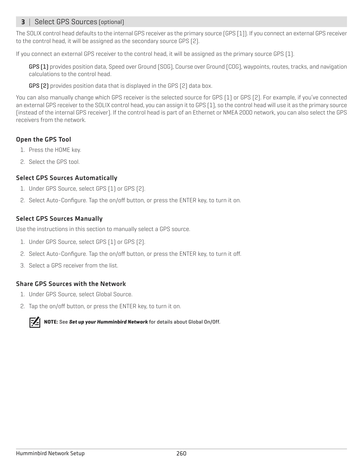
###### 2 | Select Sonar Sources
When a transducer is first connected to the control head or network (through black box sonar or additional Humminbird control heads), it will be detected by all control heads in the network. The SOLIX control head selects the transducer connected to it as the primary sonar source. The SOLIX control head is compatible with black box sonar to expand its sonar capabilities. See humminbird.com for transducer configuration options.
NOTE: Humminbird has provided the best settings for your unit. You can use the settings included with your control head, or you can adjust these advanced options.
######### Open the Sonar Source Menu
######### Sonar Source Overview
When the network is configured, you can select any transducer from the network to provide the sonar data on the control head. The sonar sources can be shared between control heads or you can use individual sonar sources on each control head.
The transducer you select on the 2D Sonar tab will provide the data for the 2D Sonar Views and related digital readouts.


The transducer you select on the Down Imaging tab will provide the data for the Down Imaging Views and related digital readouts.


The transducer you select on the Side Imaging tab will provide the data for the Side Imaging Views and related digital readouts.


######### Select Sonar Sources
Use the instructions in this section to assign sonar sources to each control head. The sonar sources can be shared between control heads or you can use different sonar sources on each control head.
Selected Control Head (Local): the control head you are actively using
Remote Control Head: additional control heads connected to the network
Black Box Sonar
selected source transducer setup menu

Select the 2D Sonar tab to
select a 2D sonar source.
2D source options
2D beams pinging (turned on)


NOTE: The list is determined by the connected equipment on the network and the transducer type. DualBeam PLUS sonar sources will only be displayed on the 2D tab, Down Imaging sources will only be displayed on the Down Imaging tab, etc.
NOTE: If you have installed an accessory transducer, and it is not displayed in the transducer list, see Installation Information: Set up or Change Transducer Settings.
When you turn on/off pinging or change the transducer settings, all control heads sharing the transducer are affected.
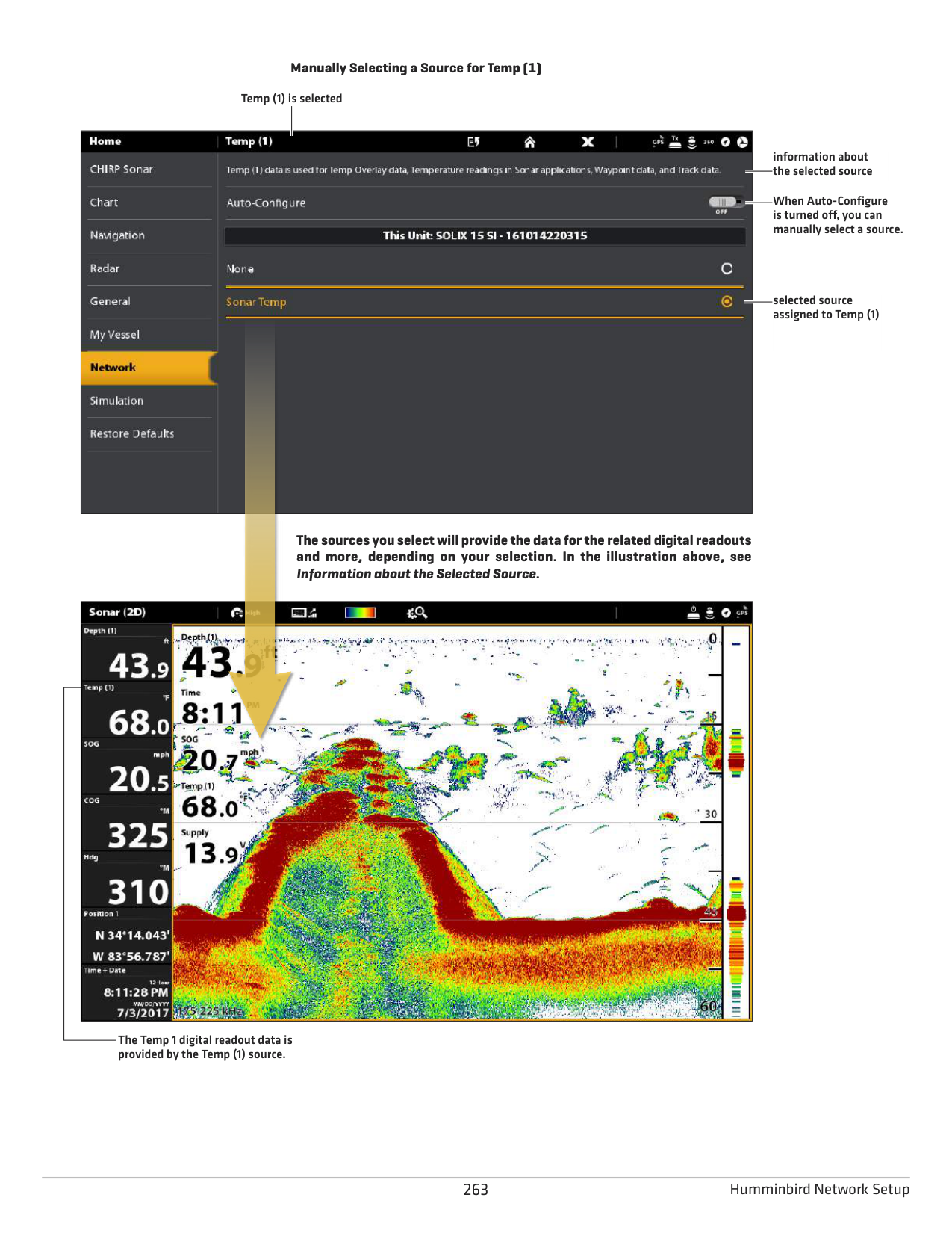

selected source transducer setup menu
turn on/off pinging
turn on/off transducer
If you change settings here, it will change the settings across the network.
###### 3 | Select GPS Sources (optional)
The SOLIX control head defaults to the internal GPS receiver as the primary source (GPS [1]). If you connect an external GPS receiver to the control head, it will be assigned as the secondary source GPS (2).
If you connect an external GPS receiver to the control head, it will be assigned as the primary source GPS (1).
You can also manually change which GPS receiver is the selected source for GPS (1) or GPS (2). For example, if you’ve connected an external GPS receiver to the SOLIX control head, you can assign it to GPS (1), so the control head will use it as the primary source (instead of the internal GPS receiver). If the control head is part of an Ethernet or NMEA 2000 network, you can also select the GPS receivers from the network.
######### Open the GPS Tool
######### Select GPS Sources Automatically
Select GPS Sources Manually Use the instructions in this section to manually select a GPS source.
######### Share GPS Sources with the Network
NOTE: See Set up your Humminbird Network for details about Global On/Off.
###### 4 | Select Data Sources (optional)
When the network has been configured, you can choose sources from the entire network. Depending on your network configuration, your options may include sources from remote control head(s), NMEA 0183, Ethernet, and NMEA 2000. Sources are shared across the network. In some situations, sources can be individualized for each control head. For example, Control Head A can use one transducer and Control Head B can use a different transducer.
Auto-Configure: The Auto-Configure on/off button is displayed in each source category. When Auto-Configure is turned on, the sources are selected automatically by the control head. When Auto-Configure is turned off, you can select sources based on your preferences.
For example, if there are multiple heading sensors attached, the control head network will choose one sensor to provide the heading. If you prefer a different sensor to provide the heading, you can manually assign a different heading sensor as the selected source.
######### Select Sources Automatically (default)
Auto-Configure is turned on by default, so the instructions in this section are only necessary if you’ve manually changed the source selection and want to return to a source being chosen automatically.
Select Sources Manually (optional) Use the instructions in this section to manually select a source.
CHANGE THE NETWORK NAME
The Network Info menu allows you to name each network so it is easy to identify in the system. You can also review network information from the dialog box.
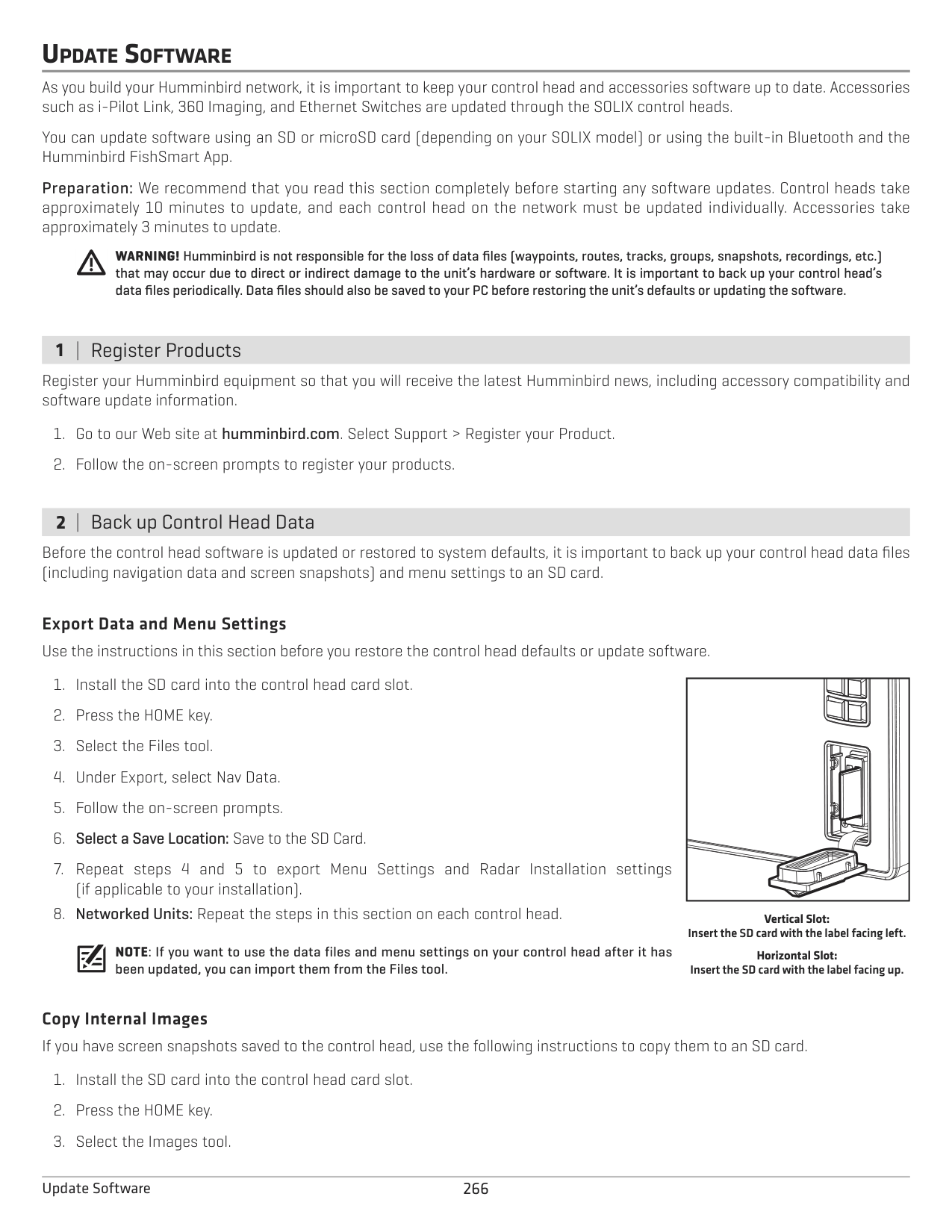
################# Manually Selecting a Source for Temp (1)
Temp (1) is selected

information about the selected source
When Auto-Configure is turned off, you can manually select a source.
selected source assigned to Temp (1)

################# The sources you select will provide the data for the related digital readouts and more, depending on your selection. In the illustration above, see Information about the Selected Source.

The Temp 1 digital readout data is provided by the Temp (1) source.
MANAGE YOUR CONTROL HEAD
Many of the control head settings can be accessed from the Settings tool (General Menu) or from the Power X-Press Menu in the status bar.
######### Open the Settings Tool 1. Press the HOME key.
######### Open the Power X-Press Menu
Many of the control head settings can be accessed quickly from the Power X-Press Menu. You can also turn off Radar transmission or change the transducer source from this menu.
####### Adjust Lighting
The lighting menus can be accessed from the Settings tool (General Menu) or the Power X-Press Menu. The following instructions use the Power X-Press Menu.
######### Adjust the Backlight
######### Turn on/off Night Mode
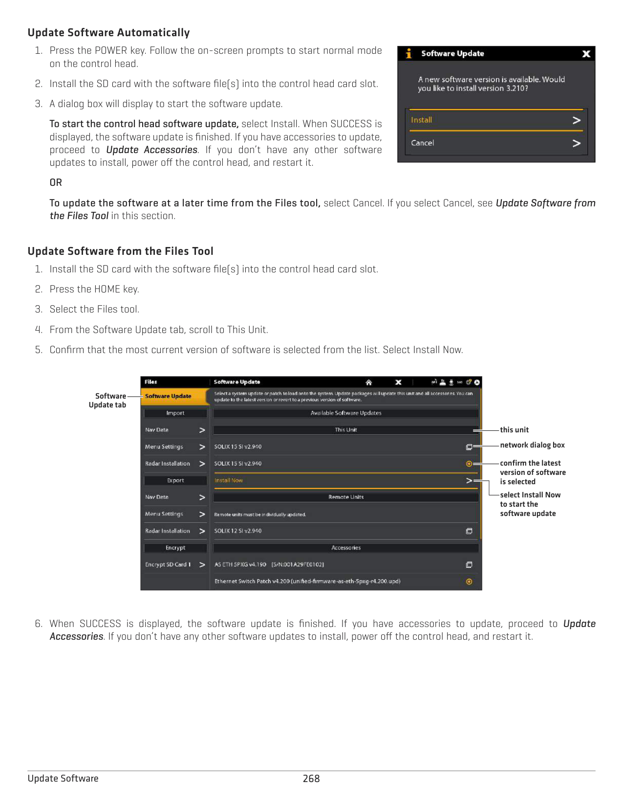
####### Change Touch Screen and Key Sounds
######### Turn on/off Touch Screen
############# OR
264Manage your Control Head
######### Turn on/off Key Sounds 1. Press the HOME key.
####### Import/Export Files
It is important to back up your data files periodically. Data files should also be saved to your PC before restoring the unit’s defaults or updating software.
WARNING! Humminbird is not responsible for the loss of data files (waypoints, routes, tracks, groups, snapshots, recordings, etc.) that may occur due to direct or indirect damage to the unit’s hardware or software. It is important to back up your control head’s data files periodically. Data files should also be saved to your PC before restoring the unit’s defaults or updating the software. Visit our Web site at humminbird.com for more information.
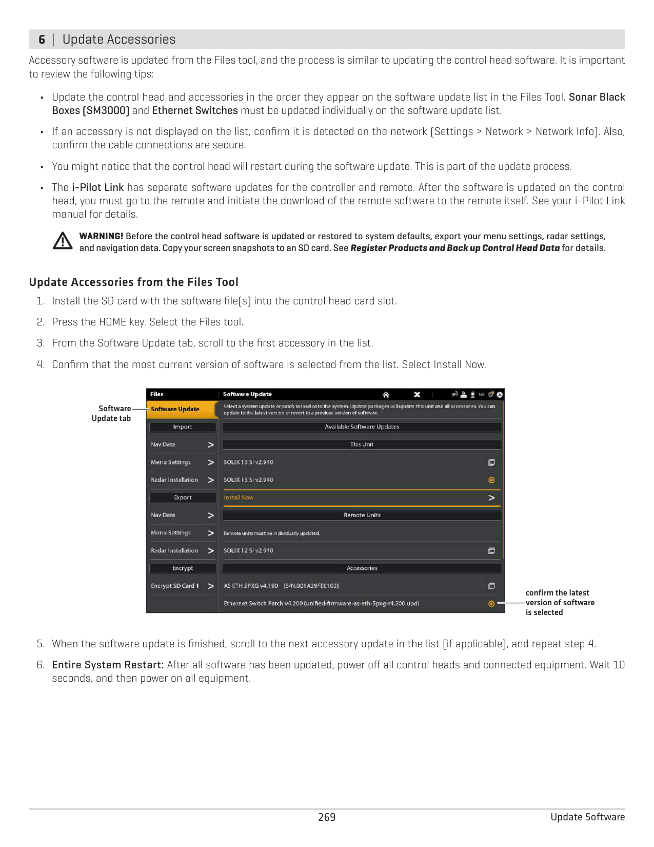
Use the following instructions to save your menu settings. To import or export navigation data, see Manage your Navigation Data. To export your Radar installation settings, see Installation Information: Configure Humminbird Radar.
######### Import Files
######### Export Files
265 Manage your Control Head
UPDATE SOFTWARE
As you build your Humminbird network, it is important to keep your control head and accessories software up to date. Accessories such as i-Pilot Link, 360 Imaging, and Ethernet Switches are updated through the SOLIX control heads.
You can update software using an SD or microSD card (depending on your SOLIX model) or using the built-in Bluetooth and the Humminbird FishSmart App.
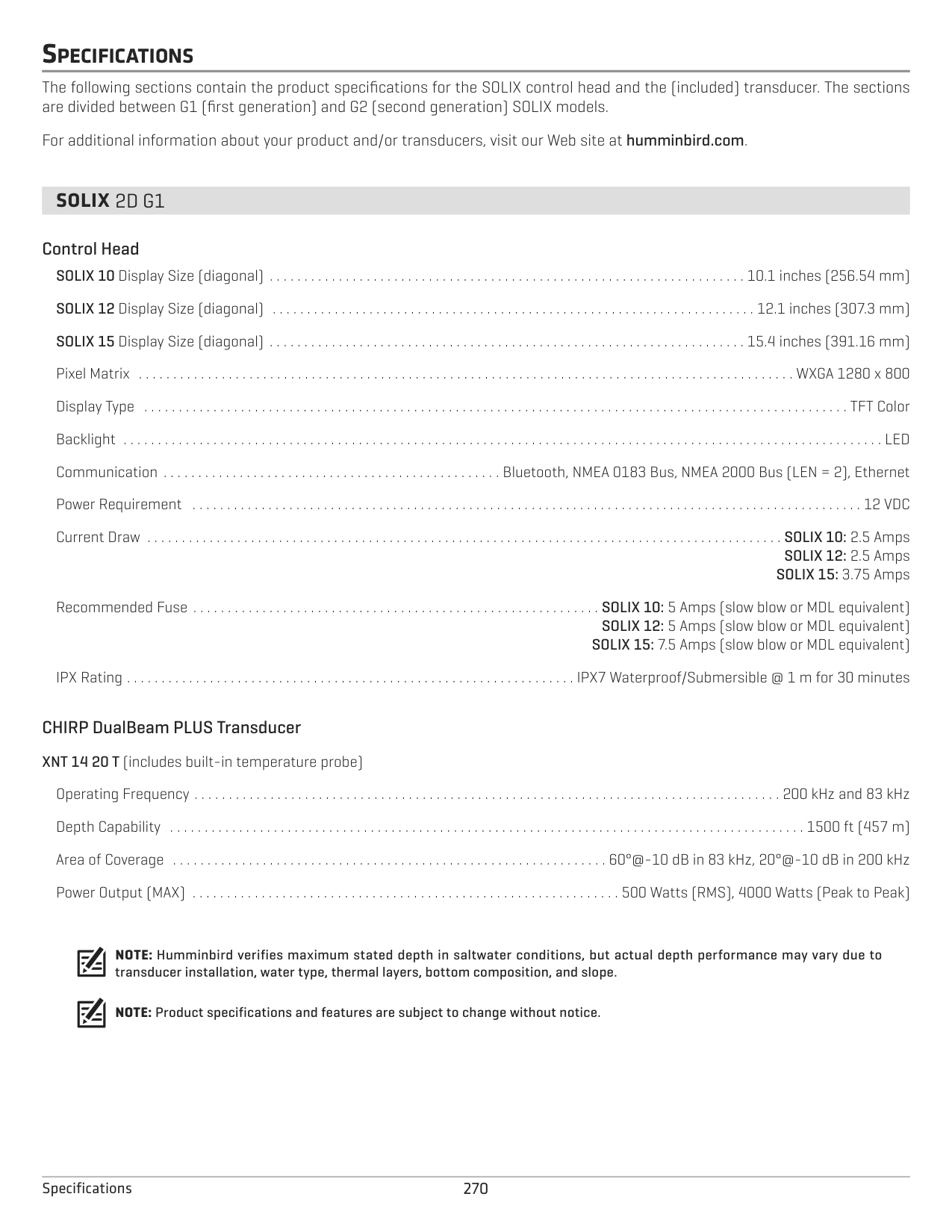
Preparation: We recommend that you read this section completely before starting any software updates. Control heads take approximately 10 minutes to update, and each control head on the network must be updated individually. Accessories take approximately 3 minutes to update.
WARNING! Humminbird is not responsible for the loss of data files (waypoints, routes, tracks, groups, snapshots, recordings, etc.) that may occur due to direct or indirect damage to the unit’s hardware or software. It is important to back up your control head’s data files periodically. Data files should also be saved to your PC before restoring the unit’s defaults or updating the software.
Register your Humminbird equipment so that you will receive the latest Humminbird news, including accessory compatibility and software update information.
###### 2 | Back up Control Head Data
Before the control head software is updated or restored to system defaults, it is important to back up your control head data files (including navigation data and screen snapshots) and menu settings to an SD card.
Export Data and Menu Settings Use the instructions in this section before you restore the control head defaults or update software.
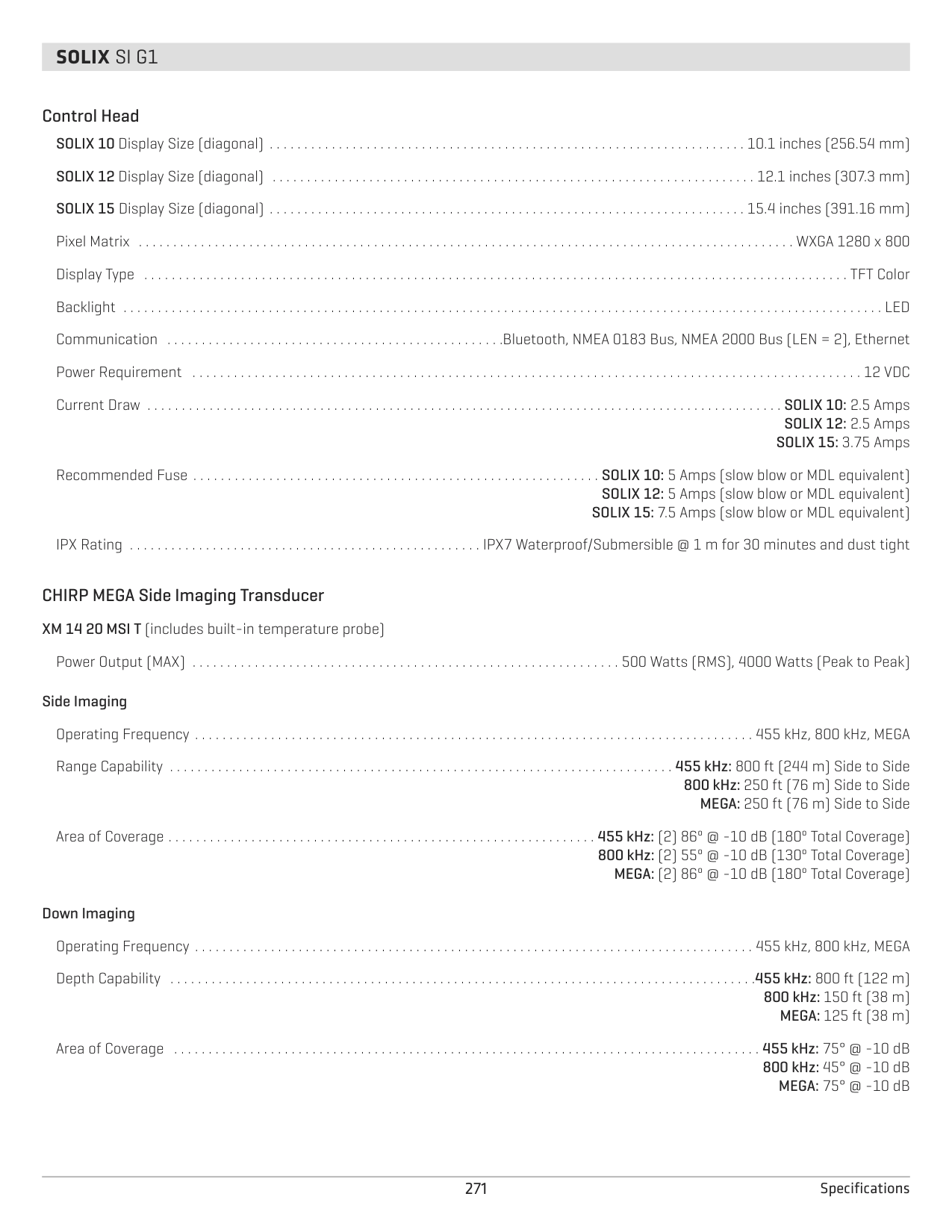
NOTE: If you want to use the data files and menu settings on your control head after it has been updated, you can import them from the Files tool.
| | | | |---|---|---| | | | |
| | | |---|---| | | |
| | | |---|---| | | |
Vertical Slot: Insert the SD card with the label facing left.
Horizontal Slot: Insert the SD card with the label facing up.
Copy Internal Images If you have screen snapshots saved to the control head, use the following instructions to copy them to an SD card.
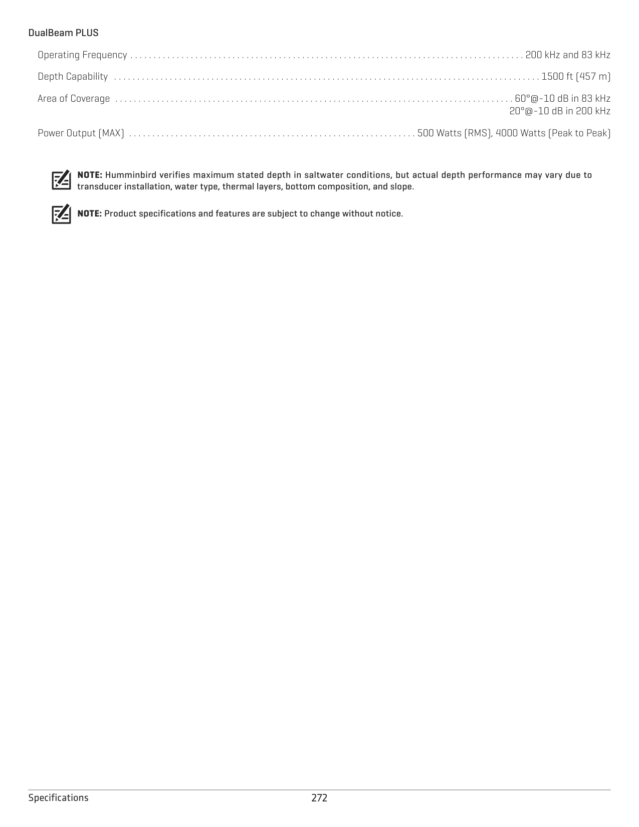
###### 3 | Check the Current Software Version
It is helpful to review the software version number that is currently installed on the control head and each accessory.
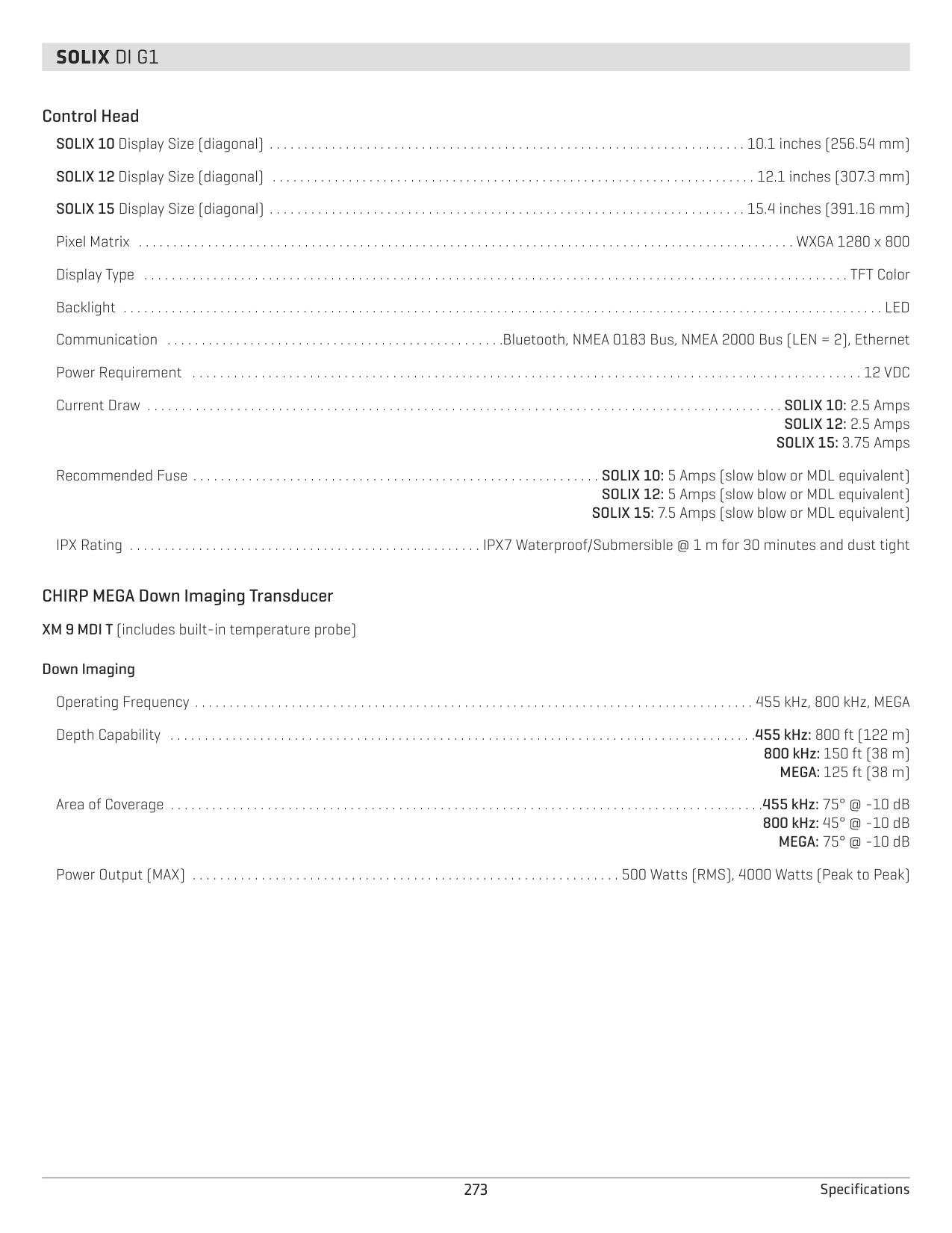
Supplies: In addition to your Humminbird equipment, you will need a PC with Internet access and a blank SD or microSD card (depending on your control head model).
When you install the SD card with the software file, the control head will detect the update and provide an automatic prompt to install the software. You can follow the prompts or choose to install the software at a later time through the Files tool. It is important to review the following tips:
WARNING! Before the control head software is updated or restored to system defaults, export your menu settings, radar settings, and navigation data. Copy your screen snapshots to an SD card. See Register Products and Back up Control Head Data for details.
######### Update Software Automatically
To start the control head software update, select Install. When SUCCESS is displayed, the software update is finished. If you have accessories to update, proceed to Update Accessories. If you don’t have any other software updates to install, power off the control head, and restart it.
|| |---|
OR To update the software at a later time from the Files tool, select Cancel. If you select Cancel, see Update Software from the Files Tool in this section.
######### Update Software from the Files Tool


Software Update tab
this unit
network dialog box
confirm the latest version of software is selected
select Install Now to start the software update
Accessories. If you don’t have any other software updates to install, power off the control head, and restart it.
###### 6 | Update Accessories
Accessory software is updated from the Files tool, and the process is similar to updating the control head software. It is important to review the following tips:
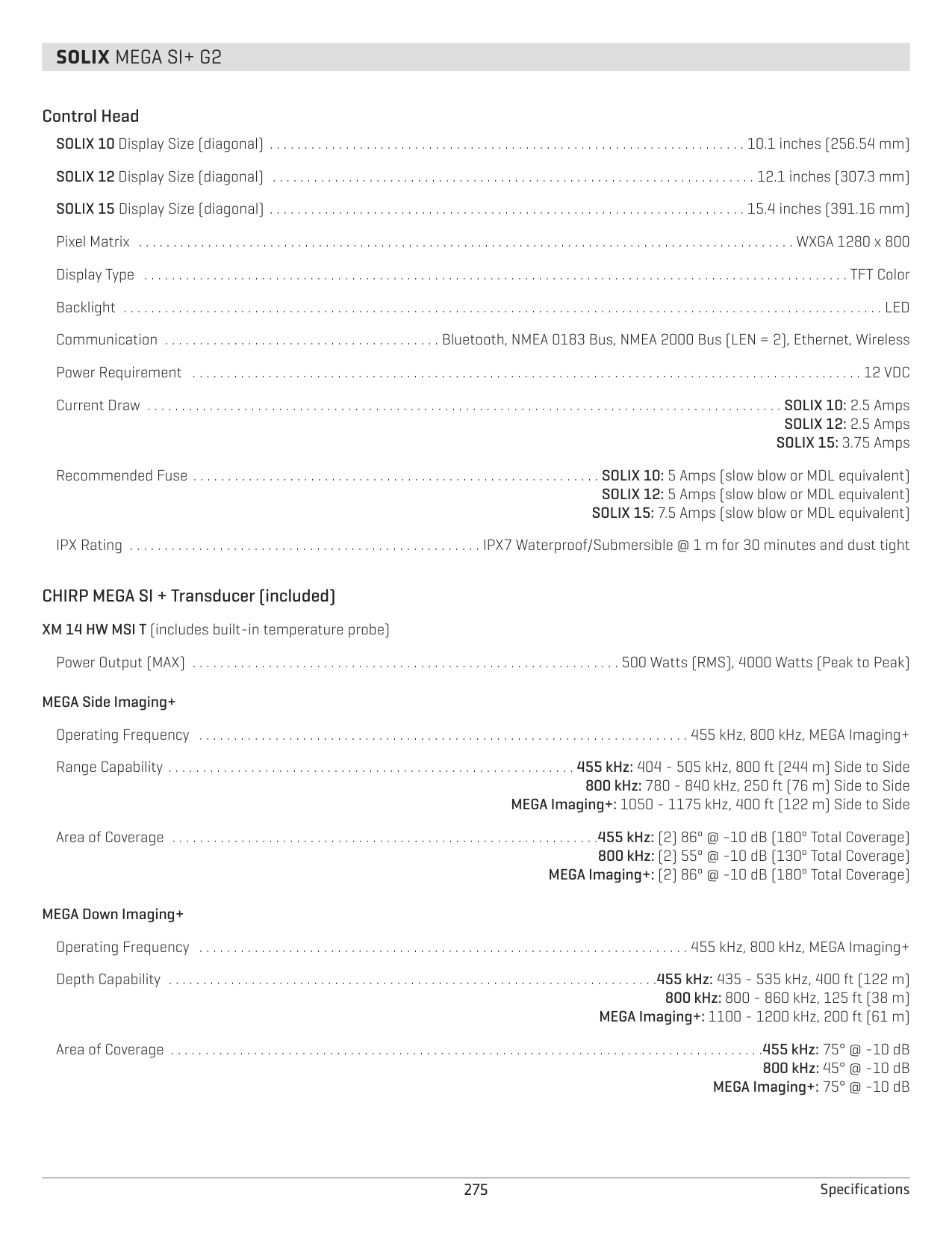
WARNING! Before the control head software is updated or restored to system defaults, export your menu settings, radar settings, and navigation data. Copy your screen snapshots to an SD card. See Register Products and Back up Control Head Data for details.
######### Update Accessories from the Files Tool
| || | |---|---|---| | || | | || |
Software Update tab
confirm the latest version of software is selected
SPECIFICATIONS
The following sections contain the product specifications for the SOLIX control head and the (included) transducer. The sections are divided between G1 (first generation) and G2 (second generation) SOLIX models.
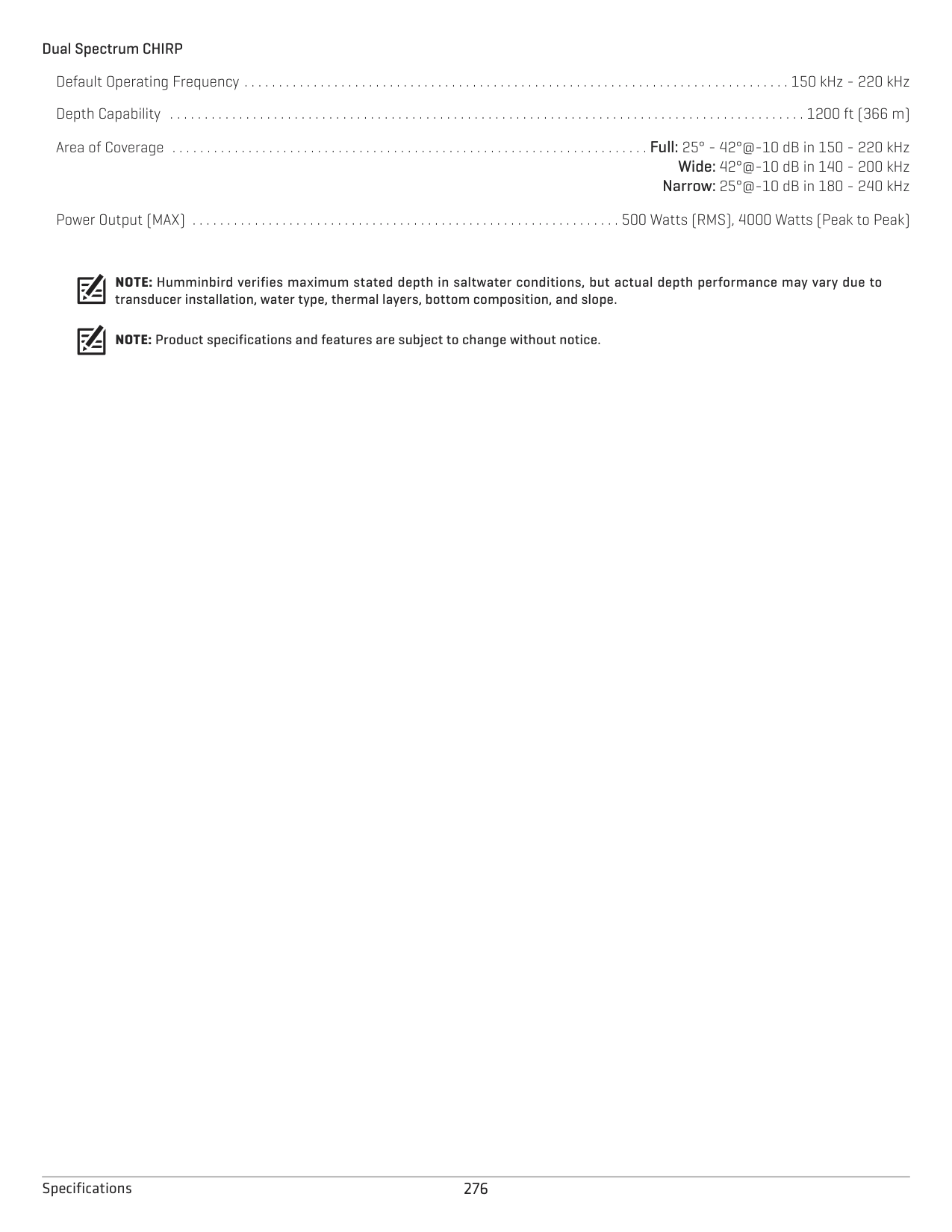
For additional information about your product and/or transducers, visit our Web site at humminbird.com.
##### SOLIX 2D G1
######### Control Head
SOLIX 10 Display Size (diagonal) . . . . . . . . . . . . . . . . . . . . . . . . . . . . . . . . . . . . . . . . . . . . . . . . . . . . . . . . . . . . . . . . . . . . . 10.1 inches (256.54 mm) SOLIX 12 Display Size (diagonal) . . . . . . . . . . . . . . . . . . . . . . . . . . . . . . . . . . . . . . . . . . . . . . . . . . . . . . . . . . . . . . . . . . . . . . 12.1 inches (307.3 mm) SOLIX 15 Display Size (diagonal) . . . . . . . . . . . . . . . . . . . . . . . . . . . . . . . . . . . . . . . . . . . . . . . . . . . . . . . . . . . . . . . . . . . . . 15.4 inches (391.16 mm) Pixel Matrix . . . . . . . . . . . . . . . . . . . . . . . . . . . . . . . . . . . . . . . . . . . . . . . . . . . . . . . . . . . . . . . . . . . . . . . . . . . . . . . . . . . . . . . . . . . . . . . WXGA 1280 x 800 Display Type . . . . . . . . . . . . . . . . . . . . . . . . . . . . . . . . . . . . . . . . . . . . . . . . . . . . . . . . . . . . . . . . . . . . . . . . . . . . . . . . . . . . . . . . . . . . . . . . . . . . . . TFT Color Backlight . . . . . . . . . . . . . . . . . . . . . . . . . . . . . . . . . . . . . . . . . . . . . . . . . . . . . . . . . . . . . . . . . . . . . . . . . . . . . . . . . . . . . . . . . . . . . . . . . . . . . . . . . . . . . . LED Communication . . . . . . . . . . . . . . . . . . . . . . . . . . . . . . . . . . . . . . . . . . . . . . . . . Bluetooth, NMEA 0183 Bus, NMEA 2000 Bus (LEN = 2), Ethernet Power Requirement . . . . . . . . . . . . . . . . . . . . . . . . . . . . . . . . . . . . . . . . . . . . . . . . . . . . . . . . . . . . . . . . . . . . . . . . . . . . . . . . . . . . . . . . . . . . . . . . . 12 VDC Current Draw . . . . . . . . . . . . . . . . . . . . . . . . . . . . . . . . . . . . . . . . . . . . . . . . . . . . . . . . . . . . . . . . . . . . . . . . . . . . . . . . . . . . . . . . . . . . SOLIX 10: 2.5 Amps
SOLIX 12: 2.5 Amps SOLIX 15: 3.75 Amps
Recommended Fuse . . . . . . . . . . . . . . . . . . . . . . . . . . . . . . . . . . . . . . . . . . . . . . . . . . . . . . . . . . . SOLIX 10: 5 Amps (slow blow or MDL equivalent) SOLIX 12: 5 Amps (slow blow or MDL equivalent) SOLIX 15: 7.5 Amps (slow blow or MDL equivalent)
IPX Rating . . . . . . . . . . . . . . . . . . . . . . . . . . . . . . . . . . . . . . . . . . . . . . . . . . . . . . . . . . . . . . . . . IPX7 Waterproof/Submersible @ 1 m for 30 minutes
CHIRP DualBeam PLUS Transducer XNT 14 20 T (includes built-in temperature probe)
Operating Frequency . . . . . . . . . . . . . . . . . . . . . . . . . . . . . . . . . . . . . . . . . . . . . . . . . . . . . . . . . . . . . . . . . . . . . . . . . . . . . . . . . . . . . 200 kHz and 83 kHz Depth Capability . . . . . . . . . . . . . . . . . . . . . . . . . . . . . . . . . . . . . . . . . . . . . . . . . . . . . . . . . . . . . . . . . . . . . . . . . . . . . . . . . . . . . . . . . . . . 1500 ft (457 m) Area of Coverage . . . . . . . . . . . . . . . . . . . . . . . . . . . . . . . . . . . . . . . . . . . . . . . . . . . . . . . . . . . . . . . 60°@-10 dB in 83 kHz, 20°@-10 dB in 200 kHz Power Output (MAX) . . . . . . . . . . . . . . . . . . . . . . . . . . . . . . . . . . . . . . . . . . . . . . . . . . . . . . . . . . . . . . 500 Watts (RMS), 4000 Watts (Peak to Peak)
NOTE: Humminbird verifies maximum stated depth in saltwater conditions, but actual depth performance may vary due to transducer installation, water type, thermal layers, bottom composition, and slope.
NOTE: Product specifications and features are subject to change without notice.
##### SOLIX SI G1
######### Control Head
SOLIX 10 Display Size (diagonal) . . . . . . . . . . . . . . . . . . . . . . . . . . . . . . . . . . . . . . . . . . . . . . . . . . . . . . . . . . . . . . . . . . . . . 10.1 inches (256.54 mm) SOLIX 12 Display Size (diagonal) . . . . . . . . . . . . . . . . . . . . . . . . . . . . . . . . . . . . . . . . . . . . . . . . . . . . . . . . . . . . . . . . . . . . . . 12.1 inches (307.3 mm) SOLIX 15 Display Size (diagonal) . . . . . . . . . . . . . . . . . . . . . . . . . . . . . . . . . . . . . . . . . . . . . . . . . . . . . . . . . . . . . . . . . . . . . 15.4 inches (391.16 mm) Pixel Matrix . . . . . . . . . . . . . . . . . . . . . . . . . . . . . . . . . . . . . . . . . . . . . . . . . . . . . . . . . . . . . . . . . . . . . . . . . . . . . . . . . . . . . . . . . . . . . . . WXGA 1280 x 800 Display Type . . . . . . . . . . . . . . . . . . . . . . . . . . . . . . . . . . . . . . . . . . . . . . . . . . . . . . . . . . . . . . . . . . . . . . . . . . . . . . . . . . . . . . . . . . . . . . . . . . . . . . TFT Color Backlight . . . . . . . . . . . . . . . . . . . . . . . . . . . . . . . . . . . . . . . . . . . . . . . . . . . . . . . . . . . . . . . . . . . . . . . . . . . . . . . . . . . . . . . . . . . . . . . . . . . . . . . . . . . . . . LED Communication . . . . . . . . . . . . . . . . . . . . . . . . . . . . . . . . . . . . . . . . . . . . . . . . .Bluetooth, NMEA 0183 Bus, NMEA 2000 Bus (LEN = 2), Ethernet Power Requirement . . . . . . . . . . . . . . . . . . . . . . . . . . . . . . . . . . . . . . . . . . . . . . . . . . . . . . . . . . . . . . . . . . . . . . . . . . . . . . . . . . . . . . . . . . . . . . . . . 12 VDC Current Draw . . . . . . . . . . . . . . . . . . . . . . . . . . . . . . . . . . . . . . . . . . . . . . . . . . . . . . . . . . . . . . . . . . . . . . . . . . . . . . . . . . . . . . . . . . . . SOLIX 10: 2.5 Amps
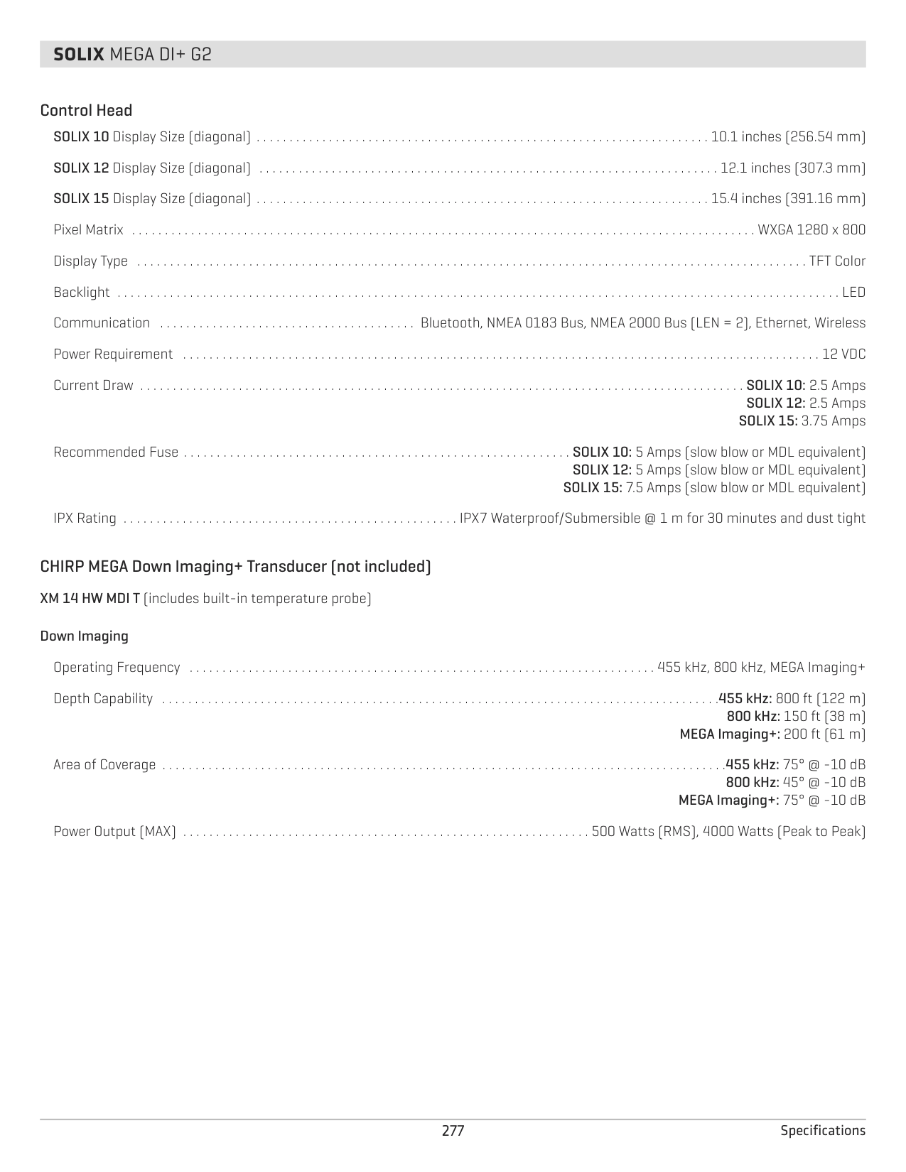
SOLIX 12: 2.5 Amps SOLIX 15: 3.75 Amps
Recommended Fuse . . . . . . . . . . . . . . . . . . . . . . . . . . . . . . . . . . . . . . . . . . . . . . . . . . . . . . . . . . . SOLIX 10: 5 Amps (slow blow or MDL equivalent) SOLIX 12: 5 Amps (slow blow or MDL equivalent) SOLIX 15: 7.5 Amps (slow blow or MDL equivalent)
IPX Rating . . . . . . . . . . . . . . . . . . . . . . . . . . . . . . . . . . . . . . . . . . . . . . . . . . . IPX7 Waterproof/Submersible @ 1 m for 30 minutes and dust tight
CHIRP MEGA Side Imaging Transducer XM 14 20 MSI T (includes built-in temperature probe)
Power Output (MAX) . . . . . . . . . . . . . . . . . . . . . . . . . . . . . . . . . . . . . . . . . . . . . . . . . . . . . . . . . . . . . . 500 Watts (RMS), 4000 Watts (Peak to Peak)
################ Side Imaging
Operating Frequency . . . . . . . . . . . . . . . . . . . . . . . . . . . . . . . . . . . . . . . . . . . . . . . . . . . . . . . . . . . . . . . . . . . . . . . . . . . . . . . . . 455 kHz, 800 kHz, MEGA Range Capability . . . . . . . . . . . . . . . . . . . . . . . . . . . . . . . . . . . . . . . . . . . . . . . . . . . . . . . . . . . . . . . . . . . . . . . . . 455 kHz: 800 ft (244 m) Side to Side
800 kHz: 250 ft (76 m) Side to Side MEGA: 250 ft (76 m) Side to Side
Area of Coverage . . . . . . . . . . . . . . . . . . . . . . . . . . . . . . . . . . . . . . . . . . . . . . . . . . . . . . . . . . . . . . 455 kHz: (2) 86º @ -10 dB (180º Total Coverage) 800 kHz: (2) 55º @ -10 dB (130º Total Coverage) MEGA: (2) 86º @ -10 dB (180º Total Coverage)
################ Down Imaging
Operating Frequency . . . . . . . . . . . . . . . . . . . . . . . . . . . . . . . . . . . . . . . . . . . . . . . . . . . . . . . . . . . . . . . . . . . . . . . . . . . . . . . . . 455 kHz, 800 kHz, MEGA Depth Capability . . . . . . . . . . . . . . . . . . . . . . . . . . . . . . . . . . . . . . . . . . . . . . . . . . . . . . . . . . . . . . . . . . . . . . . . . . . . . . . . . . . . .455 kHz: 800 ft (122 m)
800 kHz: 150 ft (38 m) MEGA: 125 ft (38 m)
Area of Coverage . . . . . . . . . . . . . . . . . . . . . . . . . . . . . . . . . . . . . . . . . . . . . . . . . . . . . . . . . . . . . . . . . . . . . . . . . . . . . . . . . . . . . 455 kHz: 75° @ -10 dB 800 kHz: 45° @ -10 dB MEGA: 75° @ -10 dB
################ DualBeam PLUS
Operating Frequency . . . . . . . . . . . . . . . . . . . . . . . . . . . . . . . . . . . . . . . . . . . . . . . . . . . . . . . . . . . . . . . . . . . . . . . . . . . . . . . . . . . . . 200 kHz and 83 kHz Depth Capability . . . . . . . . . . . . . . . . . . . . . . . . . . . . . . . . . . . . . . . . . . . . . . . . . . . . . . . . . . . . . . . . . . . . . . . . . . . . . . . . . . . . . . . . . . . . 1500 ft (457 m) Area of Coverage . . . . . . . . . . . . . . . . . . . . . . . . . . . . . . . . . . . . . . . . . . . . . . . . . . . . . . . . . . . . . . . . . . . . . . . . . . . . . . . . . . . . . . 60°@-10 dB in 83 kHz
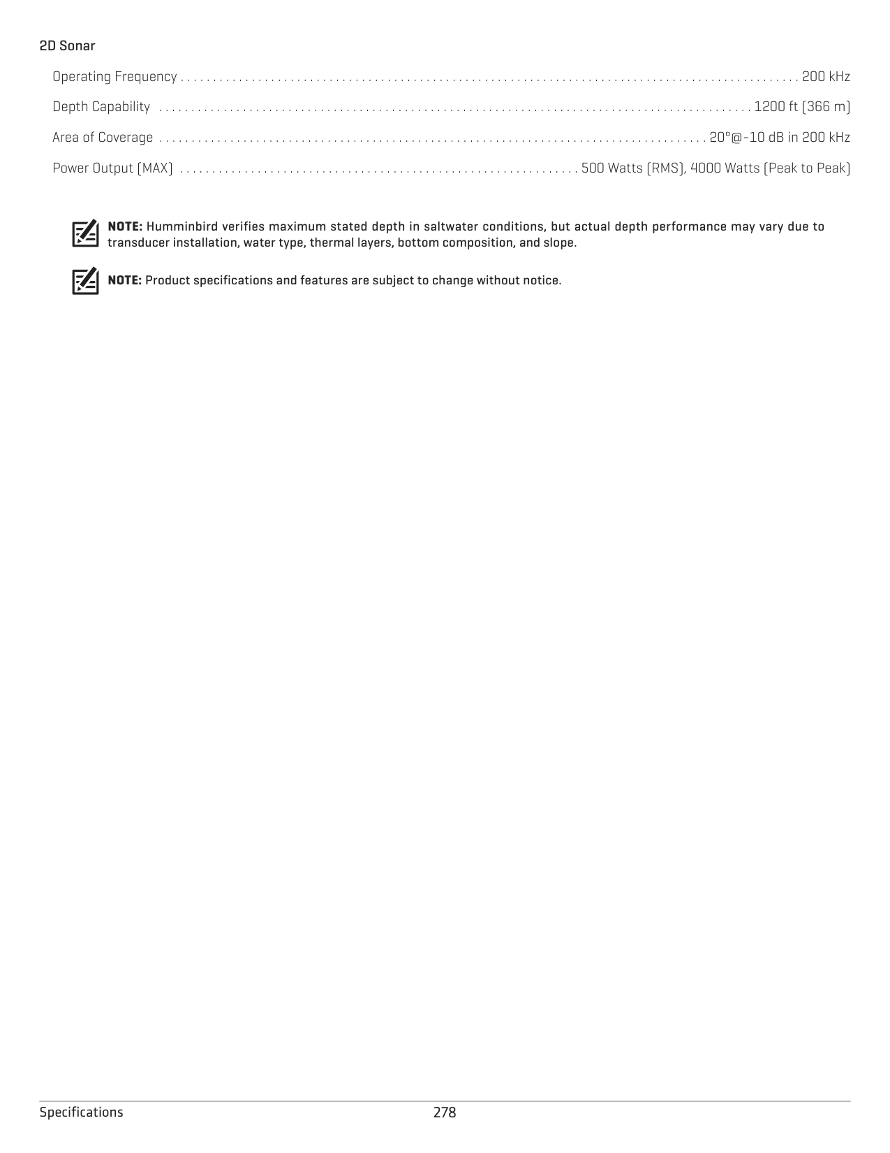
20°@-10 dB in 200 kHz Power Output (MAX) . . . . . . . . . . . . . . . . . . . . . . . . . . . . . . . . . . . . . . . . . . . . . . . . . . . . . . . . . . . . . . 500 Watts (RMS), 4000 Watts (Peak to Peak)
NOTE: Humminbird verifies maximum stated depth in saltwater conditions, but actual depth performance may vary due to transducer installation, water type, thermal layers, bottom composition, and slope.
NOTE: Product specifications and features are subject to change without notice.
##### SOLIX DI G1
######### Control Head
SOLIX 10 Display Size (diagonal) . . . . . . . . . . . . . . . . . . . . . . . . . . . . . . . . . . . . . . . . . . . . . . . . . . . . . . . . . . . . . . . . . . . . . 10.1 inches (256.54 mm) SOLIX 12 Display Size (diagonal) . . . . . . . . . . . . . . . . . . . . . . . . . . . . . . . . . . . . . . . . . . . . . . . . . . . . . . . . . . . . . . . . . . . . . . 12.1 inches (307.3 mm) SOLIX 15 Display Size (diagonal) . . . . . . . . . . . . . . . . . . . . . . . . . . . . . . . . . . . . . . . . . . . . . . . . . . . . . . . . . . . . . . . . . . . . . 15.4 inches (391.16 mm) Pixel Matrix . . . . . . . . . . . . . . . . . . . . . . . . . . . . . . . . . . . . . . . . . . . . . . . . . . . . . . . . . . . . . . . . . . . . . . . . . . . . . . . . . . . . . . . . . . . . . . . WXGA 1280 x 800 Display Type . . . . . . . . . . . . . . . . . . . . . . . . . . . . . . . . . . . . . . . . . . . . . . . . . . . . . . . . . . . . . . . . . . . . . . . . . . . . . . . . . . . . . . . . . . . . . . . . . . . . . . TFT Color Backlight . . . . . . . . . . . . . . . . . . . . . . . . . . . . . . . . . . . . . . . . . . . . . . . . . . . . . . . . . . . . . . . . . . . . . . . . . . . . . . . . . . . . . . . . . . . . . . . . . . . . . . . . . . . . . . LED Communication . . . . . . . . . . . . . . . . . . . . . . . . . . . . . . . . . . . . . . . . . . . . . . . . .Bluetooth, NMEA 0183 Bus, NMEA 2000 Bus (LEN = 2), Ethernet Power Requirement . . . . . . . . . . . . . . . . . . . . . . . . . . . . . . . . . . . . . . . . . . . . . . . . . . . . . . . . . . . . . . . . . . . . . . . . . . . . . . . . . . . . . . . . . . . . . . . . . 12 VDC Current Draw . . . . . . . . . . . . . . . . . . . . . . . . . . . . . . . . . . . . . . . . . . . . . . . . . . . . . . . . . . . . . . . . . . . . . . . . . . . . . . . . . . . . . . . . . . . . SOLIX 10: 2.5 Amps
SOLIX 12: 2.5 Amps SOLIX 15: 3.75 Amps
Recommended Fuse . . . . . . . . . . . . . . . . . . . . . . . . . . . . . . . . . . . . . . . . . . . . . . . . . . . . . . . . . . . SOLIX 10: 5 Amps (slow blow or MDL equivalent) SOLIX 12: 5 Amps (slow blow or MDL equivalent) SOLIX 15: 7.5 Amps (slow blow or MDL equivalent)
IPX Rating . . . . . . . . . . . . . . . . . . . . . . . . . . . . . . . . . . . . . . . . . . . . . . . . . . . IPX7 Waterproof/Submersible @ 1 m for 30 minutes and dust tight
CHIRP MEGA Down Imaging Transducer XM 9 MDI T (includes built-in temperature probe) Down Imaging
Operating Frequency . . . . . . . . . . . . . . . . . . . . . . . . . . . . . . . . . . . . . . . . . . . . . . . . . . . . . . . . . . . . . . . . . . . . . . . . . . . . . . . . . 455 kHz, 800 kHz, MEGA Depth Capability . . . . . . . . . . . . . . . . . . . . . . . . . . . . . . . . . . . . . . . . . . . . . . . . . . . . . . . . . . . . . . . . . . . . . . . . . . . . . . . . . . . . .455 kHz: 800 ft (122 m)
800 kHz: 150 ft (38 m) MEGA: 125 ft (38 m)
Area of Coverage . . . . . . . . . . . . . . . . . . . . . . . . . . . . . . . . . . . . . . . . . . . . . . . . . . . . . . . . . . . . . . . . . . . . . . . . . . . . . . . . . . . . . .455 kHz: 75° @ -10 dB 800 kHz: 45° @ -10 dB MEGA: 75° @ -10 dB
Power Output (MAX) . . . . . . . . . . . . . . . . . . . . . . . . . . . . . . . . . . . . . . . . . . . . . . . . . . . . . . . . . . . . . . 500 Watts (RMS), 4000 Watts (Peak to Peak)
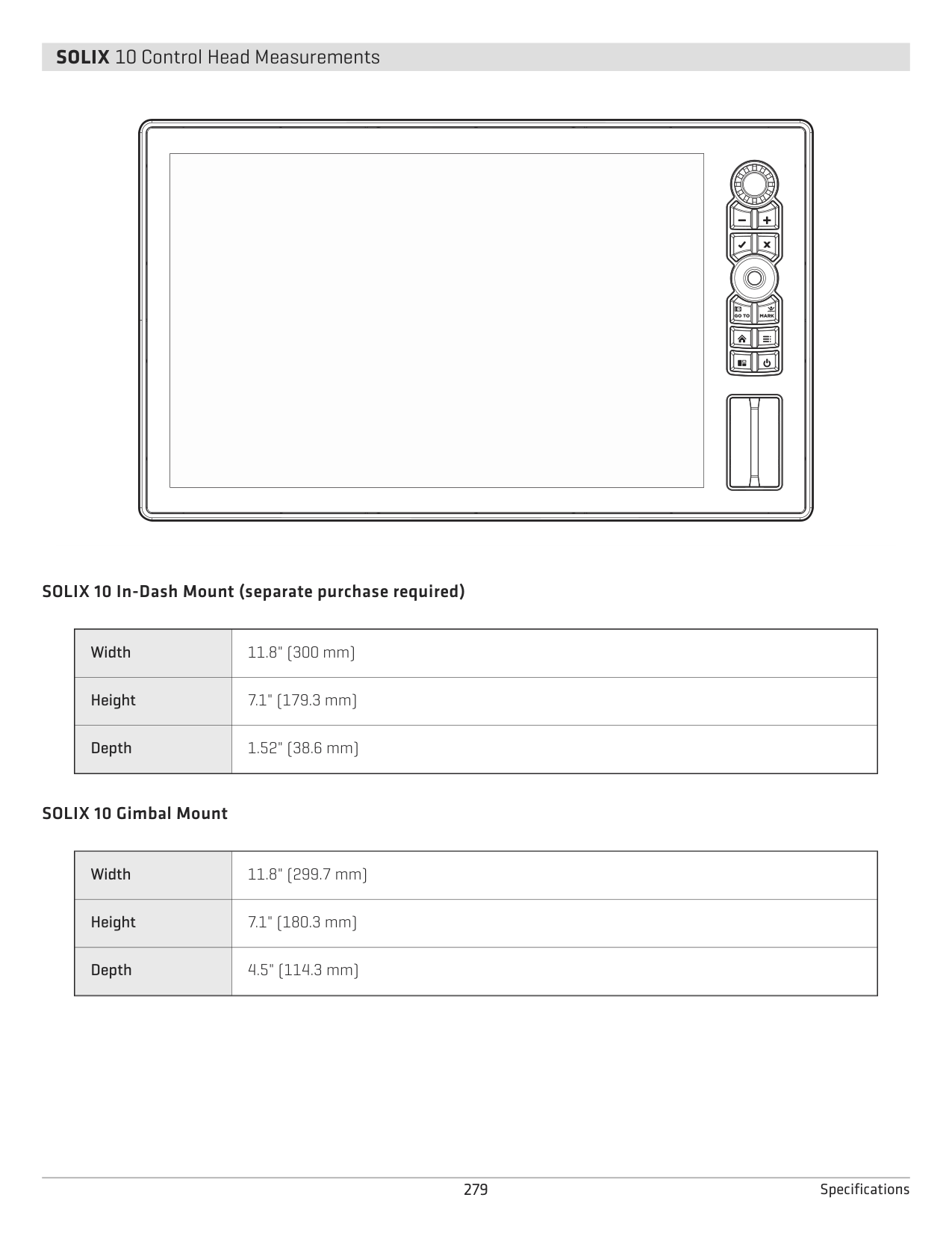
NOTE: Humminbird verifies maximum stated depth in saltwater conditions, but actual depth performance may vary due to transducer installation, water type, thermal layers, bottom composition, and slope.
NOTE: Product specifications and features are subject to change without notice.
###### SOLIX MEGA SI+ G2
######### Control Head
SOLIX 10 Display Size (diagonal) . . . . . . . . . . . . . . . . . . . . . . . . . . . . . . . . . . . . . . . . . . . . . . . . . . . . . . . . . . . . . . . . . . . . . 10.1 inches (256.54 mm) SOLIX 12 Display Size (diagonal) . . . . . . . . . . . . . . . . . . . . . . . . . . . . . . . . . . . . . . . . . . . . . . . . . . . . . . . . . . . . . . . . . . . . . . 12.1 inches (307.3 mm) SOLIX 15 Display Size (diagonal) . . . . . . . . . . . . . . . . . . . . . . . . . . . . . . . . . . . . . . . . . . . . . . . . . . . . . . . . . . . . . . . . . . . . . 15.4 inches (391.16 mm) Pixel Matrix . . . . . . . . . . . . . . . . . . . . . . . . . . . . . . . . . . . . . . . . . . . . . . . . . . . . . . . . . . . . . . . . . . . . . . . . . . . . . . . . . . . . . . . . . . . . . . . WXGA 1280 x 800 Display Type . . . . . . . . . . . . . . . . . . . . . . . . . . . . . . . . . . . . . . . . . . . . . . . . . . . . . . . . . . . . . . . . . . . . . . . . . . . . . . . . . . . . . . . . . . . . . . . . . . . . . . TFT Color Backlight . . . . . . . . . . . . . . . . . . . . . . . . . . . . . . . . . . . . . . . . . . . . . . . . . . . . . . . . . . . . . . . . . . . . . . . . . . . . . . . . . . . . . . . . . . . . . . . . . . . . . . . . . . . . . . LED Communication . . . . . . . . . . . . . . . . . . . . . . . . . . . . . . . . . . . . . . . . Bluetooth, NMEA 0183 Bus, NMEA 2000 Bus (LEN = 2), Ethernet, Wireless Power Requirement . . . . . . . . . . . . . . . . . . . . . . . . . . . . . . . . . . . . . . . . . . . . . . . . . . . . . . . . . . . . . . . . . . . . . . . . . . . . . . . . . . . . . . . . . . . . . . . . . 12 VDC Current Draw . . . . . . . . . . . . . . . . . . . . . . . . . . . . . . . . . . . . . . . . . . . . . . . . . . . . . . . . . . . . . . . . . . . . . . . . . . . . . . . . . . . . . . . . . . . . SOLIX 10: 2.5 Amps
SOLIX 12: 2.5 Amps SOLIX 15: 3.75 Amps
Recommended Fuse . . . . . . . . . . . . . . . . . . . . . . . . . . . . . . . . . . . . . . . . . . . . . . . . . . . . . . . . . . . SOLIX 10: 5 Amps (slow blow or MDL equivalent) SOLIX 12: 5 Amps (slow blow or MDL equivalent) SOLIX 15: 7.5 Amps (slow blow or MDL equivalent)
IPX Rating . . . . . . . . . . . . . . . . . . . . . . . . . . . . . . . . . . . . . . . . . . . . . . . . . . . IPX7 Waterproof/Submersible @ 1 m for 30 minutes and dust tight
CHIRP MEGA SI + Transducer (included) XM 14 HW MSI T (includes built-in temperature probe)
Power Output (MAX) . . . . . . . . . . . . . . . . . . . . . . . . . . . . . . . . . . . . . . . . . . . . . . . . . . . . . . . . . . . . . . 500 Watts (RMS), 4000 Watts (Peak to Peak)
################ MEGA Side Imaging+
Operating Frequency . . . . . . . . . . . . . . . . . . . . . . . . . . . . . . . . . . . . . . . . . . . . . . . . . . . . . . . . . . . . . . . . . . . . . . . 455 kHz, 800 kHz, MEGA Imaging+ Range Capability . . . . . . . . . . . . . . . . . . . . . . . . . . . . . . . . . . . . . . . . . . . . . . . . . . . . . . . . . . . 455 kHz: 404 - 505 kHz, 800 ft (244 m) Side to Side
800 kHz: 780 - 840 kHz, 250 ft (76 m) Side to Side

MEGA Imaging+: 1050 - 1175 kHz, 400 ft (122 m) Side to Side Area of Coverage . . . . . . . . . . . . . . . . . . . . . . . . . . . . . . . . . . . . . . . . . . . . . . . . . . . . . . . . . . . . . .455 kHz: (2) 86º @ -10 dB (180º Total Coverage)
800 kHz: (2) 55º @ -10 dB (130º Total Coverage) MEGA Imaging+: (2) 86º @ -10 dB (180º Total Coverage)
################ MEGA Down Imaging+
Operating Frequency . . . . . . . . . . . . . . . . . . . . . . . . . . . . . . . . . . . . . . . . . . . . . . . . . . . . . . . . . . . . . . . . . . . . . . . 455 kHz, 800 kHz, MEGA Imaging+ Depth Capability . . . . . . . . . . . . . . . . . . . . . . . . . . . . . . . . . . . . . . . . . . . . . . . . . . . . . . . . . . . . . . . . . . . . . . .455 kHz: 435 - 535 kHz, 400 ft (122 m)
800 kHz: 800 - 860 kHz, 125 ft (38 m) MEGA Imaging+: 1100 - 1200 kHz, 200 ft (61 m)
Area of Coverage . . . . . . . . . . . . . . . . . . . . . . . . . . . . . . . . . . . . . . . . . . . . . . . . . . . . . . . . . . . . . . . . . . . . . . . . . . . . . . . . . . . . . .455 kHz: 75° @ -10 dB 800 kHz: 45° @ -10 dB MEGA Imaging+: 75° @ -10 dB
################ Dual Spectrum CHIRP
Default Operating Frequency . . . . . . . . . . . . . . . . . . . . . . . . . . . . . . . . . . . . . . . . . . . . . . . . . . . . . . . . . . . . . . . . . . . . . . . . . . . . . . . 150 kHz - 220 kHz Depth Capability . . . . . . . . . . . . . . . . . . . . . . . . . . . . . . . . . . . . . . . . . . . . . . . . . . . . . . . . . . . . . . . . . . . . . . . . . . . . . . . . . . . . . . . . . . . . 1200 ft (366 m) Area of Coverage . . . . . . . . . . . . . . . . . . . . . . . . . . . . . . . . . . . . . . . . . . . . . . . . . . . . . . . . . . . . . . . . . . . . . Full: 25° - 42°@-10 dB in 150 - 220 kHz
Wide: 42°@-10 dB in 140 - 200 kHz Narrow: 25°@-10 dB in 180 - 240 kHz
Power Output (MAX) . . . . . . . . . . . . . . . . . . . . . . . . . . . . . . . . . . . . . . . . . . . . . . . . . . . . . . . . . . . . . . 500 Watts (RMS), 4000 Watts (Peak to Peak)
NOTE: Humminbird verifies maximum stated depth in saltwater conditions, but actual depth performance may vary due to transducer installation, water type, thermal layers, bottom composition, and slope.
NOTE: Product specifications and features are subject to change without notice.
###### SOLIX MEGA DI+ G2
######### Control Head
SOLIX 10 Display Size (diagonal) . . . . . . . . . . . . . . . . . . . . . . . . . . . . . . . . . . . . . . . . . . . . . . . . . . . . . . . . . . . . . . . . . . . . . 10.1 inches (256.54 mm) SOLIX 12 Display Size (diagonal) . . . . . . . . . . . . . . . . . . . . . . . . . . . . . . . . . . . . . . . . . . . . . . . . . . . . . . . . . . . . . . . . . . . . . . 12.1 inches (307.3 mm) SOLIX 15 Display Size (diagonal) . . . . . . . . . . . . . . . . . . . . . . . . . . . . . . . . . . . . . . . . . . . . . . . . . . . . . . . . . . . . . . . . . . . . . 15.4 inches (391.16 mm) Pixel Matrix . . . . . . . . . . . . . . . . . . . . . . . . . . . . . . . . . . . . . . . . . . . . . . . . . . . . . . . . . . . . . . . . . . . . . . . . . . . . . . . . . . . . . . . . . . . . . . . WXGA 1280 x 800 Display Type . . . . . . . . . . . . . . . . . . . . . . . . . . . . . . . . . . . . . . . . . . . . . . . . . . . . . . . . . . . . . . . . . . . . . . . . . . . . . . . . . . . . . . . . . . . . . . . . . . . . . . TFT Color Backlight . . . . . . . . . . . . . . . . . . . . . . . . . . . . . . . . . . . . . . . . . . . . . . . . . . . . . . . . . . . . . . . . . . . . . . . . . . . . . . . . . . . . . . . . . . . . . . . . . . . . . . . . . . . . . . LED Communication . . . . . . . . . . . . . . . . . . . . . . . . . . . . . . . . . . . . . . . Bluetooth, NMEA 0183 Bus, NMEA 2000 Bus (LEN = 2), Ethernet, Wireless Power Requirement . . . . . . . . . . . . . . . . . . . . . . . . . . . . . . . . . . . . . . . . . . . . . . . . . . . . . . . . . . . . . . . . . . . . . . . . . . . . . . . . . . . . . . . . . . . . . . . . . 12 VDC Current Draw . . . . . . . . . . . . . . . . . . . . . . . . . . . . . . . . . . . . . . . . . . . . . . . . . . . . . . . . . . . . . . . . . . . . . . . . . . . . . . . . . . . . . . . . . . . . SOLIX 10: 2.5 Amps
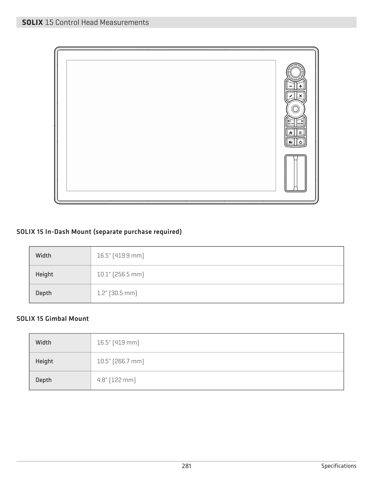
SOLIX 12: 2.5 Amps SOLIX 15: 3.75 Amps
Recommended Fuse . . . . . . . . . . . . . . . . . . . . . . . . . . . . . . . . . . . . . . . . . . . . . . . . . . . . . . . . . . . SOLIX 10: 5 Amps (slow blow or MDL equivalent) SOLIX 12: 5 Amps (slow blow or MDL equivalent) SOLIX 15: 7.5 Amps (slow blow or MDL equivalent)
IPX Rating . . . . . . . . . . . . . . . . . . . . . . . . . . . . . . . . . . . . . . . . . . . . . . . . . . . IPX7 Waterproof/Submersible @ 1 m for 30 minutes and dust tight
CHIRP MEGA Down Imaging+ Transducer (not included) XM 14 HW MDI T (includes built-in temperature probe) Down Imaging
Operating Frequency . . . . . . . . . . . . . . . . . . . . . . . . . . . . . . . . . . . . . . . . . . . . . . . . . . . . . . . . . . . . . . . . . . . . . . . 455 kHz, 800 kHz, MEGA Imaging+ Depth Capability . . . . . . . . . . . . . . . . . . . . . . . . . . . . . . . . . . . . . . . . . . . . . . . . . . . . . . . . . . . . . . . . . . . . . . . . . . . . . . . . . . . . .455 kHz: 800 ft (122 m)
800 kHz: 150 ft (38 m) MEGA Imaging+: 200 ft (61 m)
Area of Coverage . . . . . . . . . . . . . . . . . . . . . . . . . . . . . . . . . . . . . . . . . . . . . . . . . . . . . . . . . . . . . . . . . . . . . . . . . . . . . . . . . . . . . .455 kHz: 75° @ -10 dB 800 kHz: 45° @ -10 dB MEGA Imaging+: 75° @ -10 dB
Power Output (MAX) . . . . . . . . . . . . . . . . . . . . . . . . . . . . . . . . . . . . . . . . . . . . . . . . . . . . . . . . . . . . . . 500 Watts (RMS), 4000 Watts (Peak to Peak)
NOTE: Humminbird verifies maximum stated depth in saltwater conditions, but actual depth performance may vary due to transducer installation, water type, thermal layers, bottom composition, and slope.
NOTE: Product specifications and features are subject to change without notice.
###### SOLIX 10 Control Head Measurements
| | |---| | |
| | | | |---|---|---| | | | |
| | | |---|---| | | | | | |
| | | |---|---| | | | | | | | | |
| | | |---|---| | | | | | | | | |
| | | |---|---|
| | | | | |
| | | |---|---| | | | | | |
SOLIX 10 In-Dash Mount (separate purchase required)
|Width
|11.8" (300 mm)| |---|---| |Height|7.1" (179.3 mm)
| |Depth|1.52" (38.6 mm)|
SOLIX 10 Gimbal Mount
###### SOLIX 12 Control Head Measurements
| | |---| | |
| | | |---|---|
| | | | | |
| | | |---|---| | | | | | | | | |
| | | |---|---| | | | | | | | | |
| | | |---|---| | | | | | |
| | | |---|---| | | | | | |
SOLIX 12 In-Dash Mount (separate purchase required)
|Width
|13.8" (350.5 mm)| |---|---| |Height|8.2" (208.5 mm)
| |Depth|1.2" (30.5 mm)|
SOLIX 12 Gimbal Mount
|Width
|13.8" (350.5 mm)| |---|---| |Height|8.7" (221 mm)
| |Depth|4.8" (122 mm)|
###### SOLIX 15 Control Head Measurements
| | |---| | |
| | | | |---|---|---| | | | |
| | | |---|---| | | | | | |
| | | |---|---| | | | | | | | | |
| | | |---|---| | | | | | | | | |
| | | |---|---| | | | | | |
| | | |---|---| | | |
| | |
SOLIX 15 In-Dash Mount (separate purchase required)
|Width
|16.5" (419.9 mm)| |---|---| |Height|10.1" (256.5 mm)
| |Depth|1.2" (30.5 mm)|
SOLIX 15 Gimbal Mount
STATEMENTS AND ACKNOWLEDGEMENTS
ENVIRONMENTAL COMPLIANCE STATEMENT: It is the intention of Johnson Outdoors Marine Electronics, Inc. to be a responsible corporate citizen, operating in compliance with known and applicable environmental regulations, and a good neighbor in the communities where we make or sell our products.
WEEE DIRECTIVE: EU Directive 2002/96/EC “Waste of Electrical and Electronic Equipment Directive (WEEE)” impacts most distributors, sellers, and manufacturers of consumer electronics in the European Union. The WEEE Directive requires the producer of consumer electronics to take responsibility for the management of waste from their products to achieve environmentally responsible disposal during the product life cycle.
WEEE compliance may not be required in your location for electrical & electronic equipment (EEE), nor may it be required for EEE designed and intended as fixed or temporary installation in transportation vehicles such as automobiles, aircraft, and boats. In some European Union member states, these vehicles are considered outside of the scope of the Directive, and EEE for those applications can be considered excluded from the WEEE Directive requirement.
This symbol (WEEE wheelie bin) on product indicates the product must not be disposed of with other household refuse. It must be disposed of and collected for recycling and recovery of waste EEE. Johnson Outdoors Marine Electronics, Inc. will mark all EEE products in accordance with the WEEE Directive. It is our goal to comply in the collection, treatment, recovery, and environmentally sound disposal of those products; however, these requirements do vary within European Union member states. For more information about where you should

dispose of your waste equipment for recycling and recovery and/or your European Union member state requirements, please contact your dealer or distributor from which your product was purchased.
Caldera Systems, Inc. The following copyright and license is applicable to the OpenSLP project: Copyright © 2000 Caldera Systems, Inc. All rights reserved. Redistribution and use in source and binary forms, with or without modification, are permitted provided that the following conditions are met:

THIS SOFTWARE IS PROVIDED BY THE COPYRIGHT HOLDERS AND CONTRIBUTORS ``AS IS'' AND ANY EXPRESS OR IMPLIED WARRANTIES, INCLUDING, BUT NOT LIMITED TO, THE IMPLIED WARRANTIES OF MERCHANTABILITY AND FITNESS FOR A PARTICULAR PURPOSE ARE DISCLAIMED. IN NO EVENT SHALL THE CALDERA SYSTEMS OR CONTRIBUTORS BE LIABLE FOR ANY DIRECT, INDIRECT, INCIDENTAL, SPECIAL, EXEMPLARY, OR CONSEQUENTIAL DAMAGES (INCLUDING, BUT NOT LIMITED TO, PROCUREMENT OF SUBSTITUTE GOODS OR SERVICES; LOSS OF USE, DATA, OR PROFITS; OR BUSINESS INTERRUPTION) HOWEVER CAUSED AND ON ANY THEORY OF LIABILITY, WHETHER IN CONTRACT, STRICT LIABILITY, OR TORT (INCLUDING NEGLIGENCE OR OTHERWISE) ARISING IN ANY WAY OUT OF THE USE OF THIS SOFTWARE, EVEN IF ADVISED OF THE POSSIBILITY OF SUCH DAMAGE.
####### libxml++
NOTE: This product uses libxml++ software. This portion of the software is free software; you can redistribute it and/or modify it under the terms of the GNU Lesser General Public License as published by the Free Software Foundation; either version 2 of the License, or (at your option) any later version. This program is distributed in the hope that it will be useful, but WITHOUT ANY WARRANTY; without even the implied warranty of MERCHANTABILITY or FITNESS FOR A PARTICULAR PURPOSE. See the GNU Lesser General Public License for more details.
You may receive a copy of the GNU Lesser General Public License along with this program; if not, write to the Free Software Foundation, Inc., 51 Franklin Street, Fifth Floor, Boston, MA 02110-1301 USA.
To receive a free copy of the libxml++ software used in this system, please send a letter of request* with the following information: Name (First & Last) Phone Number E-mail Address Mailing Address Humminbird serial number (Your Humminbird unit must be registered at humminbird.com/support/productregistration.aspx.)
Shipping and Handling: We can only accept requests that include a money order in the amount of $9.99 to cover shipping and handling. Please allow 4-6 weeks for processing.
Send the letter of request* to the following address: Software Request Humminbird 678 Humminbird Lane Eufaula, AL 36027
*NOTE: A copy of the libxml++ software is not required to upgrade your fishing system. The Humminbird application software and control head include a separate service warranty. Please see humminbird.com and the separate warranty card included with your unit for details. libxml12 (The MIT License)
Except where otherwise noted in the source code (e.g. the files hash.c, list.c and the trio files, which are covered by a similar license but with different Copyright notices) all the files are:
Copyright © 1998-2003 Daniel Veillard. All Rights Reserved.
Permission is hereby granted, free of charge, to any person obtaining a copy of this software and associated documentation files (the "Software"), to deal in the Software without restriction, including without limitation the rights to use, copy, modify, merge, publish, distribute, sublicense, and/or sell copies of the Software, and to permit persons to whom the Software is furnished to do so, subject to the following conditions:
The above copyright notice and this permission notice shall be included in all copies or substantial portions of the Software.
THE SOFTWARE IS PROVIDED "AS IS", WITHOUT WARRANTY OF ANY KIND, EXPRESS OR IMPLIED, INCLUDING BUT NOT LIMITED TO THE WARRANTIES OF MERCHANTABILITY, FITNESS FOR A PARTICULAR PURPOSE AND NONINFRINGEMENT. IN NO EVENT SHALL THE DANIEL VEILLARD BE LIABLE FOR ANY CLAIM, DAMAGES OR OTHER LIABILITY, WHETHER IN AN ACTION OF CONTRACT, TORT OR OTHERWISE, ARISING FROM, OUT OF OR IN CONNECTION WITH THE SOFTWARE OR THE USE OR OTHER DEALINGS IN THE SOFTWARE.
Except as contained in this notice, the name of Daniel Veillard shall not be used in advertising or otherwise to promote the sale, use or other dealings in this Software without prior written authorization from him.
####### Linux Operating System
NOTE: This product uses the Linux operating system. This portion of the software is free software; you can redistribute it and/or modify it under the terms of the GNU General Public License as published by the Free Software Foundation; either version 2 of the License, or (at your option) any later version. This program is distributed in the hope that it will be useful, but WITHOUT ANY WARRANTY; without even the implied warranty of MERCHANTABILITY or FITNESS FOR A PARTICULAR PURPOSE. See the GNU General Public License for more details.
You may receive a copy of the GNU General Public License along with this program; if not, write to the Free Software Foundation, Inc., 51 Franklin Street, Fifth Floor, Boston, MA 02110-1301 USA.
To receive a free copy of the Linux software used in this system, please send a letter of request* with the following information: Name (First & Last) Phone Number E-mail Address Mailing Address Humminbird serial number (Your Humminbird unit must be registered at humminbird.com/support/productregistration.aspx.)
Shipping and Handling: We can only accept requests that include a money order in the amount of $9.99 to cover shipping and handling. Please allow 4-6 weeks for processing.
Send the letter of request* to the following address: Software Request Humminbird 678 Humminbird Lane Eufaula, AL 36027
*NOTE: A copy of the Linux operating system is not required to upgrade your fishing system. The Humminbird application software and control head include a separate service warranty. Please see humminbird.com and the separate warranty card included with your unit for details. Macho (C++ Machine Objects) (The MIT License)
The Machine Objects class library (in short Macho) allows the creation of state machines based on the "State" design pattern in straight C++. It extends the pattern with the option to create hierarchical state machines, making it possible to convert the popular UML statechart notation to working code in a straightforward way. Other features are entry and exit actions, state histories and state variables.
Copyright © 2005 by Eduard Hiti (feedback to reverse:de.ehiti@macho)
Permission is hereby granted, free of charge, to any person obtaining a copy of this software and associated documentation files (the "Software"), to deal in the Software without restriction, including without limitation the rights to use, copy, modify, merge, publish, distribute, sublicense, and/or sell copies of the Software, and to permit persons to whom the Software is furnished to do so, subject to the following conditions:
The above copyright notice and this permission notice shall be included in all copies or substantial portions of the Software.
THE SOFTWARE IS PROVIDED "AS IS", WITHOUT WARRANTY OF ANY KIND, EXPRESS OR IMPLIED, INCLUDING BUT NOT LIMITED TO THE WARRANTIES OF MERCHANTABILITY, FITNESS FOR A PARTICULAR PURPOSE AND NONINFRINGEMENT. IN NO EVENT SHALL THE AUTHORS OR COPYRIGHT HOLDERS BE LIABLE FOR ANY CLAIM, DAMAGES OR OTHER LIABILITY, WHETHER IN AN ACTION OF CONTRACT, TORT OR OTHERWISE, ARISING FROM, OUT OF OR IN CONNECTION WITH THE SOFTWARE OR THE USE OR OTHER DEALINGS IN THE SOFTWARE.
You are encouraged to provide any changes, extensions and corrections for this software to the author at the above-mentioned email address for inclusion into future versions.
####### Navionics
WARNINGS: The electronic chart is an aid to navigation designed to facilitate the use of authorized government charts, not to replace them. Only official government charts and notices to mariners contain all information needed for the safety of navigation, and as always, the captain is responsible for their prudent use.
ACKNOWLEDGEMENT OF THIRD PARTY NOTICES AND COPYRIGHT LICENSES: This product may contain cartography and other data from one or more of the following Third Party sources; to the extent that any such source is used, the relevant provisions below shall apply:
“National Oceanic and Atmospheric Administration (NOAA)”, “National Imagery Mapping Agency (NIMA)”, “National Geospatial-Intelligence Agency (NGA)”, “National Agriculture Imagery Program (NAIP)”, “United States Army Corps of Engineers (USACE)”, “United States Geological Survey (USGS), Digital Line Graphic (DLG), Digital Raster Graphic (DRG)”, “Department of Natural Resources (DNR)”, “United States Department of Defense”, “United States Department of Commerce, Bureau of Public Roads & State’s Highway Commission”, “Department of Environmental Protection (DEP)”, “Department of Fish and Wildlife”, “Department of Game and Fishing”, “Ocean Mapping Group, Department of Geodesy and Geomatics Engineering, University of New Brunswick”, “Pennsylvania Fish and Boat Commission (PFBC)”, “Florida Natural Areas Inventory (FNAI)”, “North Carolina Wildlife Resources Commission (NCWRC)”, “New York State, Department of Environmental Conservation”, “National Geophysical Data Center & Great Lakes Environmental Research Laboratory - Great Lakes Information Network”, “Imray Charts”, “Wavey Line Charts Publishing”, “Angler Atlas”, “Fish-n-Map Company”, “Track Map Data”, “Servicio de Hidrografia Naval (SHN), Argentina”, “Western Australia Department of Planning and Infrastructure (DPIWA)”, “Australian Hydrographic Service (AHS)”, “Maritime Safety Agency of State of Queensland (MSQ)”, “©The State of Queensland (Department of the Environment and Resource Management) (DERM)”, “I-Cubed”, “GeoContent”, “DigitalGlobe”, “European Environment Agency (Corine)”, “Algemene Nederlandsche Wielsrijders Bond (ANWB)”, “© Dutch Ministry of Infrastructure and Environment”, “Dienst Der Hydrografie, Netherlands”, “Vlaamse Hidrografie, Belgium”, “Belgium National Oceanographic Data Centre (BMDC)”, “Management Unit of the North Sea Mathematical Models (MUMM)”, “Landesvermessungsamt Baden-Wurttemberg”, “Bundesamt für Seeschiffahrt und Hydrographie (BSH)”, “Bundesministerium fur Verkehr, Bau und Stadtentwicklung – Die Wasser-und Schifffahrtsverwaltung des Bundes (WSW), Germany”, “Geodatastyrelsen (GST)”, “Delius Klasing Verlag (DKV)”, “Estonian Maritime Administration (EMA)”, “Finnish Maritime Administration (FMA)”, “National Land Survey (NLS)”, “Service Hydrographique et Oceanographique de la Marine (SHOM)”, “Hellenic Navy Hydrographic Service (HNHS)”, “Hvratski Hidrografski Institute (HHI), Croatia”, “Icelandic Coast Guard (ICG)”, “Istituto Idrografico della Marina, Italia”, “Ministero dello Sviluppo Economico, Italia”, “Japan Hydrographic Department”, “Norvegian Hydrographic Service (Statens Kartverk Interreg Geovekst)”, “Nordeca SA”, “Myosa Boating Union”, “State Hydrographic Service Ukraine (SHSU)”, “United Kingdom Hydrographic Office (UKHO), ©British Crown Copyright, [2013]”, “British Oceanographic Data Centre (BODC) and the Environment Agency”, “Channel Coastal Observatory”, “IHO-IOC GEBCO Gazetteer of Undersea Feature Names, Bathymetric Contours derived from the GEBCO¬_08 Grid and GEBCO One Minute Grid; www.gebco.net”, “United Kingdom Department of Energy and Climate Control”, “The database of British and Irish Hills by Graham Jackson and Chris Crocker”, “Swedish Maritime Administration (SMA)”, “Hydrographica AB”, “Instituto Hidrográfico, Portugal (IHPT)”, “Instituto Hidrográfico de la Marina, España (IHM)”, “Ministerio de Agricultura, Alimentacio y Medio Ambiente, España (MAGRAMA)”, “Departamento de Medio Ambiente, Planificacion Territorial, Agricultura y Pesca, Gobierno Vasco”, “National Hydrographic Office, Sultanate of Oman (NHOSO)”, “South Africa Navy Hydrographic Office (SAN)”, “© Swisstopo”, “Swiss Lakes Charts with the permission from Cap.Jean DeBosset”, “Abris LLC “, “GeoNames”, “Claymoreclan Design”, “Reliance Globalcom”, “Kingfisher Information Services by Seafish.Org”, “Land Information New Zealand (LINZ)”
This Navionics electronic marine chart incorporates Data which is © “Commonwealth of Australia (“Great Barrier Reef Marine Park Authority”)” 2009. The Data has been used in this Navionics electronic marine chart with the permission of the Commonwealth. The Commonwealth has not evaluated the Data as altered and incorporated within this Navionics electronic marine chart, and therefore gives no warranty regarding its accuracy, completeness, currency or suitability for any particular purpose.
The “Crown in Right of the State of Western Australia” accepts no liability for the accuracy of copying of information contained in this product and does not warrant that this product meets any regulations as an appropriate product for navigation.
This product has been produced by Navionics S.p.A. based on “Canadian Hydrographic Service (CHS)” data, following any minimum standards/guidelines that may have been established by CHS, pursuant to CHS Digital Value-Added Reseller Agreement No. 2012-0605-1260-N. The incorporation of data sourced from CHS in this product shall not be construed as constituting an endorsement by CHS of this product. This product does not meet the requirements of the Charts and Nautical publications Regulations under the Canada Shipping Act, 2001. Certified charts and publications, corrected and up-to-date, must be used to meet the requirements of those regulations.
All above Companies, Institutions and Hydrographic Offices have not verified the product and do not accept liability for its accuracy. Copyright © 2013 Navionics S.p.A.
####### Qt Project
NOTE: This product uses Qt software. Qt is licensed under commercial and open source licenses (GNU General Public License version 3 and GNU Lesser General Public License version 2.1). This portion of the software is free software; you can redistribute it and/or modify it under the terms of the GNU General Public License and GNU Lesser General Public License as published by the Free Software Foundation; either version 3 of the GNU General Public License and version 2.1 of the GNU Lesser General Public License, or (at your option) any later version.
This program is distributed in the hope that it will be useful, but WITHOUT ANY WARRANTY; without even the implied warranty of MERCHANTABILITY or FITNESS FOR A PARTICULAR PURPOSE. See the GNU General Public License and GNU Lesser General Public License for more details.
You may receive a copy of the GNU General Public License and GNU Lesser General Public License along with this program; if not, write to the Free Software Foundation, Inc., 51 Franklin Street, Fifth Floor, Boston, MA 02110-1301 USA.
To receive a free copy of the Qt software used in this system, please send a letter of request* with the following information: Name (First & Last) Phone Number E-mail Address Mailing Address Humminbird serial number (Your Humminbird unit must be registered at humminbird.com/support/productregistration.aspx.)
Shipping and Handling: We can only accept requests that include a money order in the amount of $9.99 to cover shipping and handling. Please allow 4-6 weeks for processing.
Send the letter of request* to the following address: Software Request Humminbird 678 Humminbird Lane Eufaula, AL 36027
*NOTE: A copy of the Qt software is not required to upgrade your fishing system. The Humminbird application software and control head
include a separate service warranty. Please see humminbird.com and the separate warranty card included with your unit for details.
##### FCC Notice
This device complies with Part 15 of the FCC Rules. Operation is subject to the following two conditions: (1) this device may not cause harmful interference, and (2) this device must accept any interference received, including interference that may cause undesired operation.
CAUTION! This equipment has been tested and found to comply with the limits for a Class B digital device, pursuant to Part 15 of the FCC Rules. These limits are designed to provide reasonable protection against harmful interference in a residential installation. This equipment generates, uses and can radiate radio frequency energy and, if not installed and used in accordance with the instructions, may cause harmful interference to radio communications. However, there is no guarantee that interference will not occur in a particular installation. If this equipment does cause harmful interference to radio or television reception, which can be determined by turning the equipment off and on, the user is encouraged to try to correct the interference by one or more of the following measures:
RF EXPOSURE COMPLIANCE: This device has been evaluated and found compliant in accordance with EU EN 62479:2010 and EN 62311:2008 for human RF exposure. This product has been so constructed that the product complies with the requirement of Article 10(2) as it can be operated in at least one Member State as examined and the product is compliant with Article 10(10) as it has no restrictions on putting into service in all EU member states.
EU DECLARATION OF CONFORMITY: Hereby, Humminbird declares that this device is in compliance with the essential requirements and other relevant provisions of Directive 2014/53/EU. The declaration of conformity may be consulted at https://www.humminbird.com/EU-DOC.

##### Class B Device (Broadcasting and communication equipment for home)
This equipment is home use (Class B) electromagnetic wave suitability equipment and to be used at home and it can be used in all areas.
##### End User License Agreement
This Hydrographic Database is the proprietary and confidential property of Johnson Outdoors Marine Electronics. Unauthorized use, including the copying of this Hydrographic Database, is expressly prohibited. BY USING THE PRODUCT YOU ARE AGREEING TO BE BOUND BY ALL THE TERMS AND CONDITIONS OF THE JOHNSON OUTDOORS (“LICENSOR”) LICENSE AGREEMENT (“AGREEMENT”) WHICH IS PROVIDED WITH THIS LAKEMASTER DIGITAL MAP PRODUCT (“LICENSED PRODUCT”) INCLUDING, WITHOUT LIMITATION, THE USE RESTRICTIONS, WARRANTY DISCLAIMER AND LIMITATIONS OF LIABILITY SET FORTH HEREIN. Under the Agreement, you have a limited, non-exclusive, personal license to use the data contained on the media in this package, on a GPS mapping device for supplemental navigation reference purposes. Licensor and its third-party suppliers retain all rights to the Licensed Product not expressly granted by the Agreement. You are responsible for using official government charts and prudent navigation for safe travel. The Licensed Product and the accompanying documentation are copyrighted works of authorship and contain valuable secret and confidential information proprietary to Licensor and its third-party suppliers who retain the ownership of the information and all copyrights and other proprietary rights therein. You agree to exercise reasonable efforts to protect their proprietary interests. You may NOT modify, adapt, translate, reverse engineer, decompile, disassemble, sub license, rent, lease, or sell any portion of the Data. You may NOT create derivative works based upon the Data. You may NOT place the Data onto a server so that it is accessible via a public network such as the Internet.
LICENSOR AND ITS THIRD-PARTY SUPPLIERS DO NOT WARRANT THE LICENSED PRODUCT WILL MEET YOUR REQUIREMENTS OR THAT ITS OPERATION WILL BE UNINTERRUPTED OR ERROR-FREE. IN NO EVENT WILL LAKEMASTER OR ITS SUPPLIERS BE LIABLE TO YOU FOR ANY CONSEQUENTIAL OR INCIDENTAL DAMAGES. Some states or jurisdictions do not allow the exclusion or limitation of consequential or incidental damages, so the above limitations may not apply to you.
Portions of Humminbird Basemap© OpenStreetMap contributors. Portions of Humminbird Basemap sourced from GeoBase®.
Portions of Humminbird Basemap contains information licensed under the Open Government Licence Canada. Portions of Humminbird Basemap copyright 2001 Her Majesty the Queen in Right of Manitoba, as represented by the Minister of Conservation. All rights reserved. Portions of Humminbird Basemap contains information licenced under the GeoNB Open Data Licence. Portions of Humminbird Basemap contains information licenced under the Open Government Licence Ontario.
CONTACT HUMMINBIRD
Contact Humminbird Customer Service in any of the following ways:
Web site: humminbird.com
E-mail: service@humminbird.com
Telephone: 1-800-633-1468
########## Direct Shipping:
Humminbird Service Department 678 Humminbird Lane Eufaula, AL 36027 USA
Hours of Operation: Monday - Friday 8:00 a.m. to 4:30 p.m. (Central Standard Time)
########## Social Media Resources:
Facebook.com/HumminbirdElectronics
Twitter.com (@humminbirdfish)


Instagram.com/humminbird
YouTube.com/humminbirdtv
288Contact Humminbird