
Ask AI
— answers from the official manualAnswers from the official manual.
Common questions
Common Questions
10 totalHow do I pair my Programmer/Receiver with the Room Thermostat?
In the Installer menu, under Radio settings, select 'Pair'. Press and hold until advancement bars appear. When pairing is complete, a number will display showing that the connection succeeded (Page 14).
How do I set the time and date on the Programmer/Receiver?
Hold the menu button for more than three seconds to enter Settings. Select 'Time/date', then proceed through hours, minutes, days, months, and years until all settings are completed correctly (Page 12).
How do I replace the batteries in my Room Thermostat?
Remove the unit from the wall plate by inserting a flat-head screwdriver into the bottom slot and turning until catches release. Replace AAA 1.5V alkaline batteries correctly with positive terminals facing up (Page 20).
What are the Holiday function settings on the Programmer/Receiver?
Select ‘Holiday’ in Settings mode, turn knob to select ON and set dates for start and end of holiday period. This enables frost protection when away without full heat (Page 13).
How do I adjust the signal strength at the Room Thermostat?
Navigate to 'S2 RF Signal Strength' in Settings, press to enter and note displayed number indicating current strength: [0] no signal, [1-3] weak, [4-6] acceptable, [7-10] very good (Page 18).
How do I unpair my Programmer/Receiver and Room Thermostat?
In the Installer menu, under Radio settings, select 'Pair', then turn knob to ‘d’ for disconnect. Press button to start unpairing process until zero confirms disconnection (Page 14).
Full Manual
24 pages

Installation and operating instructions
Radio Frequency Twin Channel Programmer/Receiver and Room Thermostat
Greenstar Comfort I RF
##### For EMS compatible Worcester Greenstar condensing boilers
6 720 810 964 (2014/07)
select
select
advance
menu
advance
6720810964-00.1Wo
UK/IE
Contents
###### Contents
######## 1 Key to symbols and safety instructions . . . . . . . . . . . 3
######## 2 Comfort I RF . . . . . . . . . . . . . . . . . . . . . . . . . . . . . . . . . . 4
######## 3 Installation . . . . . . . . . . . . . . . . . . . . . . . . . . . . . . . . . . . 6
######## 4 Operation . . . . . . . . . . . . . . . . . . . . . . . . . . . . . . . . . . . 10
5 Programmer/Receiver settings . . . . . . . . . . . . . . . . 11
######## 6 Room thermostat . . . . . . . . . . . . . . . . . . . . . . . . . . . . . 16
######## 7 Troubleshooting . . . . . . . . . . . . . . . . . . . . . . . . . . . . . 19
Key to symbols and safety instructions
###### 1 Key to symbols and safety instructions 1.1 Key to symbols Warnings
|Warnings in this document are identified by a warning triangle printed against a grey background. Keywords at the start of a warning indicate the type and seriousness of the ensuing risk if measures to prevent the risk are not taken.| |---|
The following keywords are defined and can be used in this document:
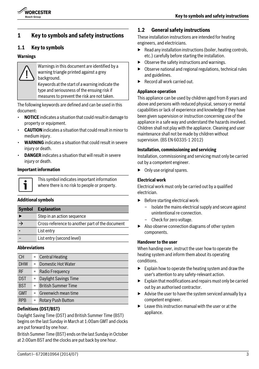
Important information
This symbol indicates important information where there is no risk to people or property.
Additional symbols
######## Symbol Explanation
▶ Step in an action sequence
Cross-reference to another part of the document
• List entry
– List entry (second level)
Abbreviations
CH = Central Heating DHW = Domestic Hot Water RF = Radio Frequency DST = Daylight Savings Time BST = British Summer Time GMT = Greenwich mean time RPB = Rotary Push Button
Definitions (DST/BST) Daylight Saving Time (DST) and British Summer Time (BST) begins on the last Sunday in March at 1:00am GMT and clocks are put forward by one hour. British Summer Time (BST) ends on the last Sunday in October at 2:00am BST and the clocks are put back by one hour.
1.2 General safety instructions These installation instructions are intended for heating engineers, and electricians.
▶ Read any installation instructions (boiler, heating controls, etc.) carefully before starting the installation.
▶ Observe the safety instructions and warnings.
▶ Observe national and regional regulations, technical rules and guidelines.
▶ Record all work carried out. Appliance operation
This appliance can be used by children aged from 8 years and above and persons with reduced physical, sensory or mental capabilities or lack of experience and knowledge if they have been given supervision or instruction concerning use of the appliance in a safe way and understand the hazards involved. Children shall not play with the appliance. Cleaning and user maintenance shall not be made by children without supervision. (BS EN 60335-1 2012)
Installation, commissioning and servicing Installation, commissioning and servicing must only be carried out by a competent engineer.
▶ Only use original spares. Electrical work
Electrical work must only be carried out by a qualified electrician.
▶ Before starting electrical work:
▶ Also observe connection diagrams of other system components.
Handover to the user When handing over, instruct the user how to operate the heating system and inform them about its operating conditions.
▶ Explain how to operate the heating system and draw the user's attention to any safety-relevant action.
▶ Explain that modifications and repairs must only be carried out by an authorised contractor.
▶ Advise the user to have the system serviced annually by a competent engineer.
▶ Leave this instruction manual with the user or at the appliance.
######## Comfort I RF
2Comfort I RF The Comfort I RF comprises a boiler or wall mounted twin channel Programmer/Receiver and wall mounted Room thermostat.
1
2
6
select
select
pmam
advance
advance
menu
5 3
4
Comfort I RF
6720810964-01.1Wo
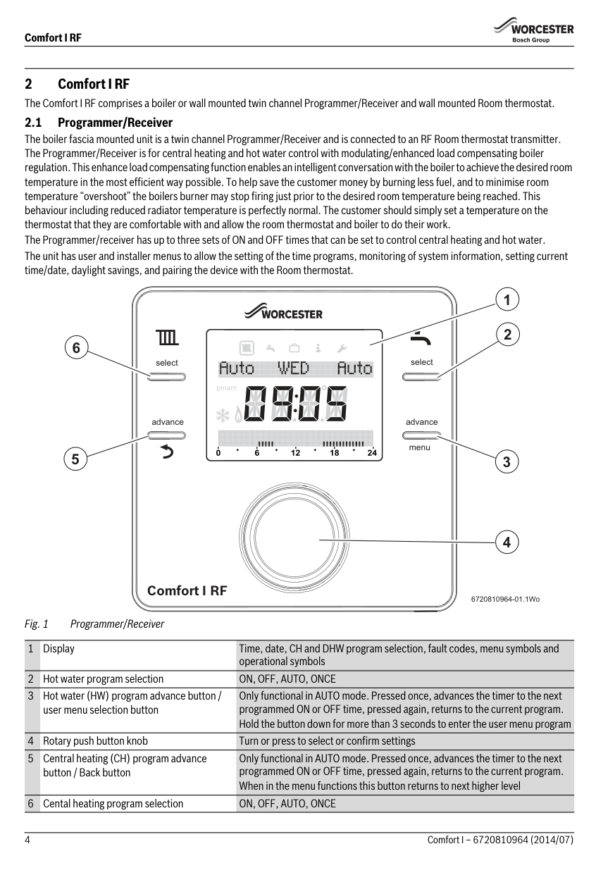
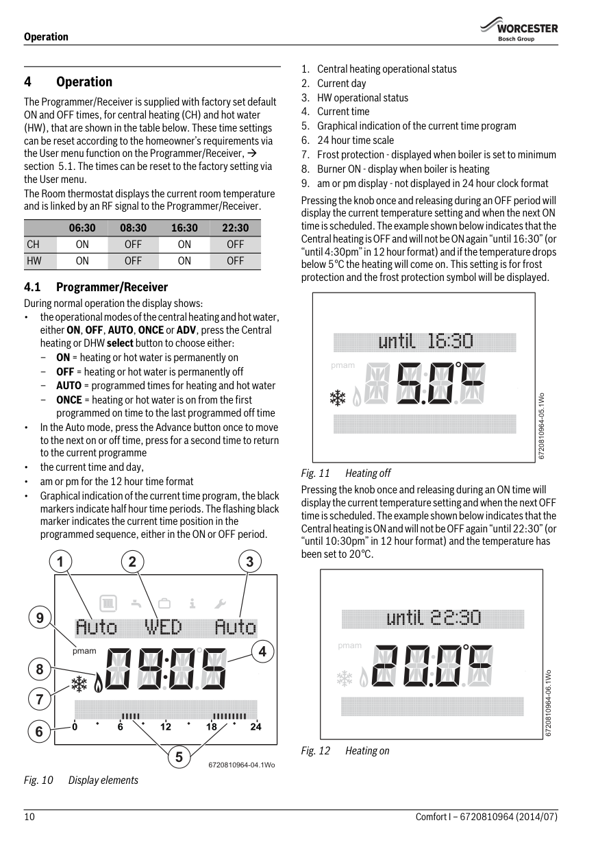
Fig. 1 Programmer/Receiver 1Display Time, date, CH and DHW program selection, fault codes, menu symbols and operational symbols
Only functional in AUTO mode. Pressed once, advances the timer to the next programmed ON or OFF time, pressed again, returns to the current program. Hold the button down for more than 3 seconds to enter the user menu program
Only functional in AUTO mode. Pressed once, advances the timer to the next programmed ON or OFF time, pressed again, returns to the current program. When in the menu functions this button returns to next higher level
######## Comfort I RF
2.2 RF Room thermostat The Room thermostat can only be used in conjunction with the Programmer/Receiver. The Room thermostat displays the current room temperature and is also used to set a new temperature set point. This information is transmitted back to the Programmer/Receiver to control the boiler output to maintain the desired room temperature. Setting a new temperature will not have any effect when the Programmer/Receiver is in an OFF time period, but will be stored and take effect during the next ON period.
The display is not backlit, this will reduce the drain on battery power which will maximise the life of the batteries.
1
2
5
3
4
Comfort I RF
6720810964-02.1Wo
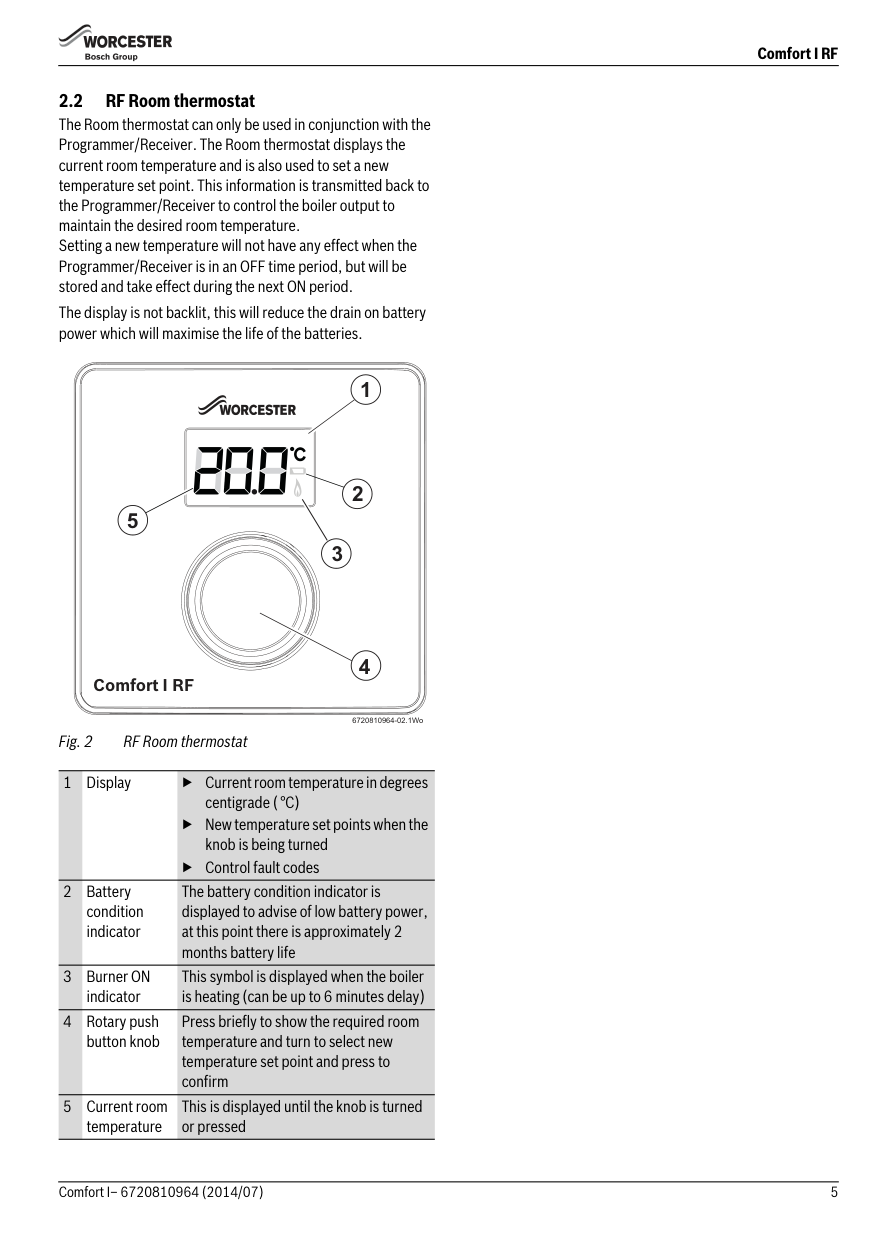
Fig. 2 RF Room thermostat
1Display ▶ Current room temperature in degrees centigrade ( °C)
▶ New temperature set points when the knob is being turned
▶ Control fault codes
The battery condition indicator is displayed to advise of low battery power, at this point there is approximately 2 months battery life
This symbol is displayed when the boiler is heating (can be up to 6 minutes delay)
4Rotary push button knob
Press briefly to show the required room temperature and turn to select new temperature set point and press to confirm
5 Current room temperature
This is displayed until the knob is turned or pressed
######## Programmer/boiler connection
###### 3 Installation
|NOTICE: EMS Connections
▶ The Programmer must NOT be connected to the boiler’s 230 volt supply or an external 230 volt supply.| |---|
|CAUTION: Mains supplies
▶ Isolate the mains supplies to the boiler before starting any work, and follow all relevant safety precautions| |---|
▶ Ensure that the EMS cable is at least 100mm away from any power cables to eliminate any mains interference
Refer to the boiler’s Installation, Commissioning and Servicing instruction manual for information on the boiler. Refer to this manual for detailed information on installing and using the Comfort I RF. A brief overview of the Comfort I RF installation procedure is listed below:
▶ EMS connections are not polarity sensitive
The Comfort I RF connects to your boiler’s EMS BUS connections. Run a two core cable from the boiler to the Programmer. Use an electrical cable with a minimum rating of H05VV-F. For cable runs up to:
▶ Isolate the boiler
▶ Remove any panels or casings required to gain access to the control panel
▶ 100 metres, use 0.50mm2 conductor cross sectional area
▶ 300 metres, use 1.5mm2 conductor cross sectional area Connect the cable to the EMS bus point connections on the boiler control circuit board, refer to the Installation, Commissioning and Servicing instruction manual for your boiler to locate the EMS connections. Optional wall mounting kit
▶ Mount the Programmer/Receiver (boiler fascia or a suitable wall location using the optional Wall Mounting Plate Kit, this will require wiring between the boiler EMS BUS connections and Wall Mounting Plate)
▶Turn the boiler on
▶ Set time and date on the Programmer/Receiver
The Comfort I RF connects to your boiler’s EMS BUS connections only, on an edge connector identified either with B B or .
▶ Insert batteries in the Room thermostat
▶ The units will automatically connect to each other
| | |---|
▶ Ensure that the signal strength is adequate at the Room thermostat before mounting in a suitable reference room
Using the wall plate as a template, mark the position of the mounting screws. The optional wall mounting kit contains:
Section 6.7
▶ Drill two holes to suit the size and depth of the wall plugs
▶ Fit the wall plugs
▶ Feed the two core cable through the back of the wall plate ▶ Fit the wall plate [1], ensuring that it is level and tighten the
screws to secure
▶ Connect the two core cable to the terminal block, one core to each outer connection, ignore the middle connection
######## Boiler fascia mounted Programmer/Receiver
Refer to your boiler’s Installation, Commissioning and Servicing instruction manual for mounting the Programmer/Receiver into the boiler fascia.
Wall mounted Programmer/Receiver Choose a convenient wall location, approximately 1.2 metres from the floor, to mount the Programmer/Receiver.
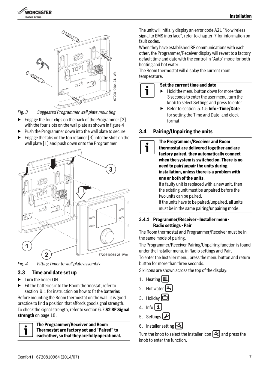
6720810964-24.1Wo
▶ Engage the four clips on the back of the Programmer [2] with the four slots on the wall plate as shown in figure 4
▶ Push the Programmer down into the wall plate to secure
▶ Engage the tabs on the top retainer [3] into the slots on the wall plate [1] and push down onto the Programmer
3
1
2
6720810964-25.1Wo
####### 3.3 Time and date set up
▶Turn the boiler ON
▶ Fit the batteries into the Room thermostat, refer to
section 9.1 for instruction on how to fit the batteries Before mounting the Room thermostat on the wall, it is good practice to find a position that affords good signal strength. To check the signal strength, refer to section 6.7S2 RF Signal strength on page 18.
The Programmer/Receiver and Room Thermostat are factory set and “Paired” to each other, so that they are fully operational.
The unit will initially display an error code A21 “No wireless signal to EMS interface”, refer to chapter 7 for information on fault codes. When they have established RF communications with each other, the Programmer/Receiver display will revert to a factory default time and date with the control in “Auto” mode for both heating and hot water. The Room thermostat will display the current room temperature.
Set the current time and date
▶ Hold the menu button down for more than 3 seconds to enter the user menu, turn the knob to select Settings and press to enter
▶ Refer to section 5.1.5 Info - Time/Date for setting the Time and Date, and clock format
####### 3.4 Pairing/Unpairing the units
The Programmer/Receiver and Room thermostat are delivered together and are factory paired, they automatically connect when the system is switched on. There is no need to pair/unpair the units during installation, unless there is a problem with one or both of the units. If a faulty unit is replaced with a new unit, then the existing unit must be unpaired before the two units can be paired. If the units have to be paired/unpaired, all units must be in the same pairing/unpairing mode.
######## 3.4.1 Programmer/Receiver - Installer menu -
Radio settings - Pair The Room thermostat and Programmer/Receiver must be in the same mode of pairing. The Programmer/Receiver Pairing/Unpairing function is found under the Installer menu, in Radio settings and Pair. To enter the Installer menu, press the menu button and return button for more than three seconds. Six icons are shown across the top of the display:
Turn the knob to select the Installer icon and press the knob to enter the function.
▶ Turn the knob to select Radio settings
▶ Press the knob to display Pairing, that is RF pairing of the devices in the system
▶ Turn the knob to display Unpairing or Pairing
▶IfPairingis chosen, press the knob and pairing is displayed with advancing bars. When the pairing between the devices has been made the number 1 is displayed confirming the Room thermostat is connected
▶IfUnpairing is chosen, press the knob and Unpairing is displayed with advancing bars, when the unpairing between the devices has been made the number 0 is displayed confirming that the Room thermostat has been disconnected
If a fault code is displayed the user must first press the knob to return to the main display then the user can hold the knob to enter the Settings menu
| | |---|
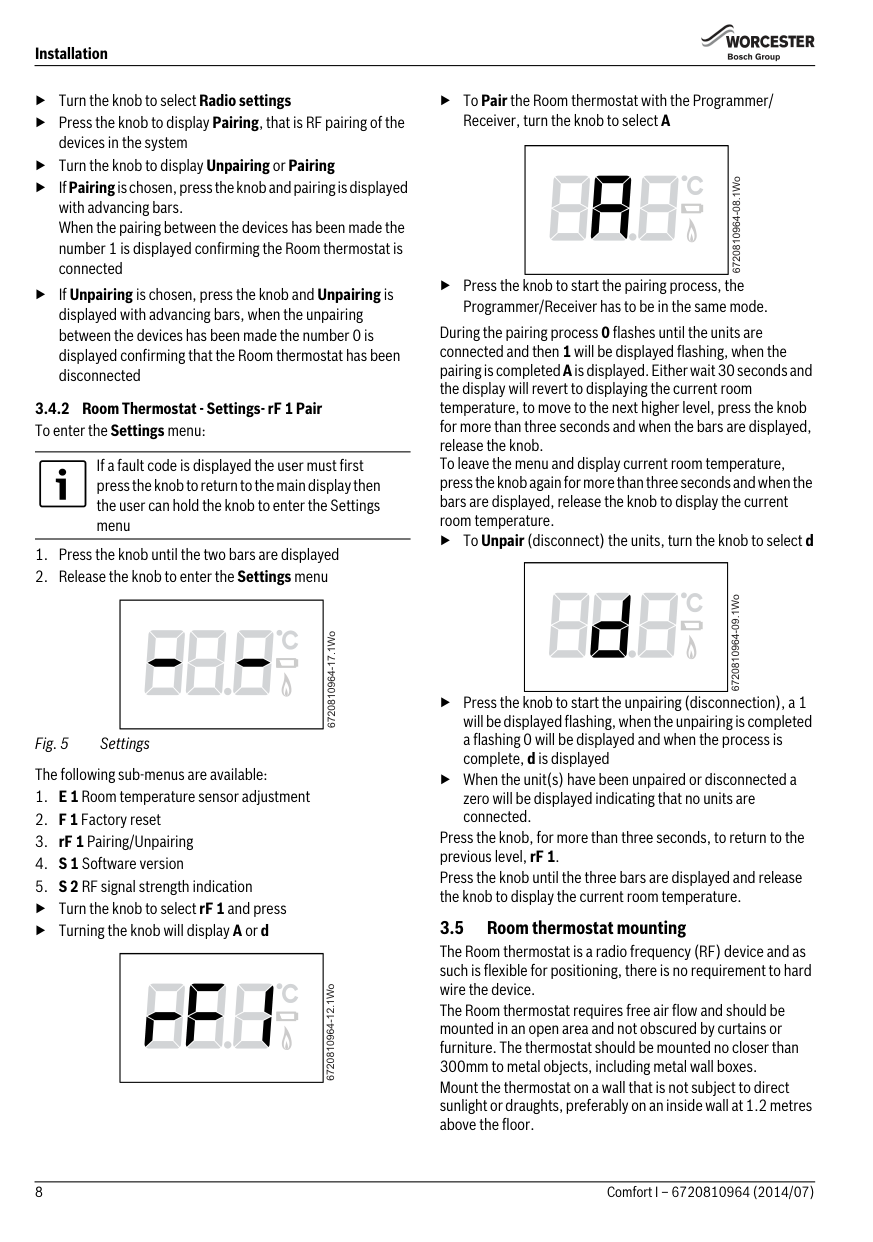
6720810964-17.1Wo
Fig. 5 Settings The following sub-menus are available:
▶ Turn the knob to select rF 1 and press
▶ Turning the knob will display A or d
| | |---|
6720810964-12.1Wo
▶ToPair the Room thermostat with the Programmer/ Receiver, turn the knob to select A
| | |---|
| | |---|
▶ Press the knob to start the pairing process, the Programmer/Receiver has to be in the same mode.
During the pairing process 0 flashes until the units are connected and then 1 will be displayed flashing, when the pairing is completedAis displayed. Either wait 30 seconds and the display will revert to displaying the current room temperature, to move to the next higher level, press the knob for more than three seconds and when the bars are displayed, release the knob. To leave the menu and display current room temperature, press the knob again for more than three seconds and when the bars are displayed, release the knob to display the current room temperature.
▶ToUnpair(disconnect) the units, turn the knob to select d
▶ Press the knob to start the unpairing (disconnection), a 1 will be displayed flashing, when the unpairing is completed a flashing 0 will be displayed and when the process is complete, d is displayed
▶ When the unit(s) have been unpaired or disconnected a zero will be displayed indicating that no units are connected.
Press the knob, for more than three seconds, to return to the previous level, rF 1. Press the knob until the three bars are displayed and release the knob to display the current room temperature.
3.5 Room thermostat mounting The Room thermostat is a radio frequency (RF) device and as such is flexible for positioning, there is no requirement to hard wire the device. The Room thermostat requires free air flow and should be mounted in an open area and not obscured by curtains or furniture. The thermostat should be mounted no closer than 300mm to metal objects, including metal wall boxes. Mount the thermostat on a wall that is not subject to direct sunlight or draughts, preferably on an inside wall at 1.2 metres above the floor.
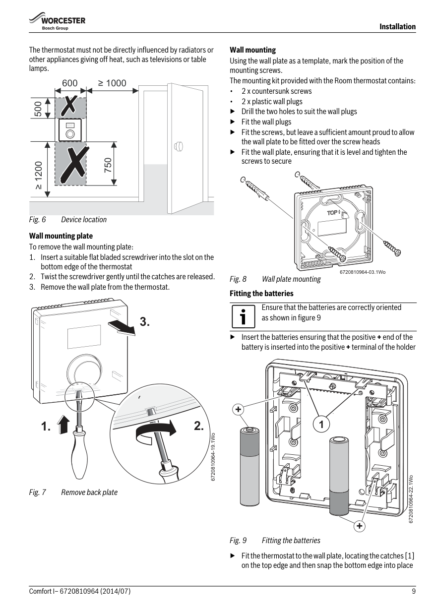
The thermostat must not be directly influenced by radiators or other appliances giving off heat, such as televisions or table lamps.
600
≥ 1000
500
||°F| |---| | |---|
750
≥ 1200
Wall mounting plate To remove the wall mounting plate:
Wall mounting Using the wall plate as a template, mark the position of the mounting screws. The mounting kit provided with the Room thermostat contains:
▶ Drill the two holes to suit the wall plugs
▶ Fit the wall plugs
▶ Fit the screws, but leave a sufficient amount proud to allow the wall plate to be fitted over the screw heads
▶ Fit the wall plate, ensuring that it is level and tighten the screws to secure
6720810964-03.1Wo
▶ Insert the batteries ensuring that the positive + end of the battery is inserted into the positive+terminal of the holder
Ensure that the batteries are correctly oriented as shown in figure 9
+
1
6720810964-22.1Wo
+
▶ Fit the thermostat to the wall plate, locating the catches [1] on the top edge and then snap the bottom edge into place
Operation
###### 4Operation
The Programmer/Receiver is supplied with factory set default ON and OFF times, for central heating (CH) and hot water (HW), that are shown in the table below. These time settings can be reset according to the homeowner’s requirements via the User menu function on the Programmer/Receiver, section 5.1. The times can be reset to the factory setting via the User menu. The Room thermostat displays the current room temperature and is linked by an RF signal to the Programmer/Receiver.
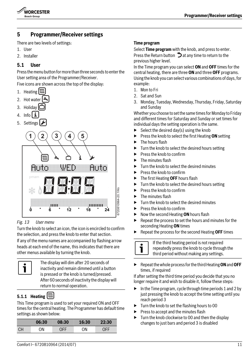
Pressing the knob once and releasing during an OFF period will display the current temperature setting and when the next ON time is scheduled. The example shown below indicates that the Central heating is OFF and will not be ON again “until 16:30” (or “until 4:30pm” in 12 hour format) and if the temperature drops below 5°C the heating will come on. This setting is for frost protection and the frost protection symbol will be displayed.
06:30 08:30 16:30 22:30
CH ON OFF ON OFF HW ON OFF ON OFF
|pmam
| |---|
|pmam
| |---|
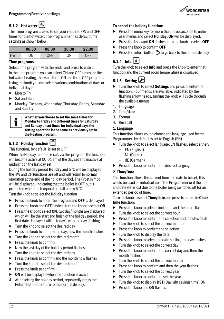
Pressing the knob once and releasing during an ON time will display the current temperature setting and when the next OFF time is scheduled. The example shown below indicates that the Central heating is ON and will not be OFF again “until 22:30” (or “until 10:30pm” in 12 hour format) and the temperature has been set to 20°C.
2 3
1
|4pmam
| |---|
9
5
6720810964-04.1Wo
Fig. 10 Display elements
###### 5 Programmer/Receiver settings There are two levels of settings:
Time program Select Time program with the knob, and press to enter. Press the Return button at any time to return to the previous higher level. In the Time program you can select ON and OFF times for the central heating, there are three ON and three OFF programs. Using the knob you can select various combinations of days, for example:
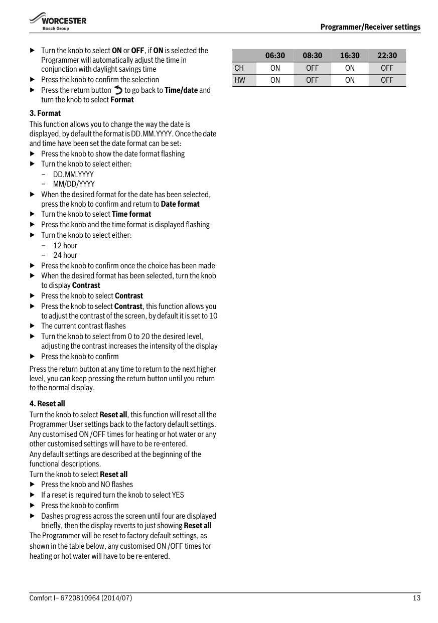
5.1 User Press the menu button for more than three seconds to enter the User setting area of the Programmer/Receiver. Five icons are shown across the top of the display:
Whether you choose to set the same times for Monday to Friday and different times for Saturday and Sunday or set times for individual days the setting operation is the same.
▶ Select the desired day(s) using the knob
#### 2 3 4 51
▶Press the knob to select the first Heating ON setting
▶ The hours flash
▶ Turn the knob to select the desired hours setting
|pmam| |---|
▶Press the knob to confirm
▶The minutes flash
▶ Turn the knob to select the desired minutes
▶Press the knob to confirm
▶The first HeatingOFF hours flash
▶ Turn the knob to select the desired hours setting
▶Press the knob to confirm
6720810964-20.1Wo
▶The minutes flash
▶ Turn the knob to select the desired minutes
▶Press the knob to confirm
▶ Now the second Heating ON hours flash
▶ Repeat the process to set the hours and minutes for the seconding Heating ON times
Fig. 13 User menu Turn the knob to select an icon, the icon is encircled to confirm the selection, and press the knob to enter that section. If any of the menu names are accompanied by flashing arrow heads at each end of the name, this indicates that there are other menus available by turning the knob.
▶ Repeat the process for the second Heating OFF times
If the third heating period is not required repeatedly press the knob to cycle through the third period without making any settings.
The display will dim after 20 seconds of inactivity and remain dimmed until a button is pressed or the knob is turned/pressed. After 60 seconds of inactivity the display will return to normal operation.
▶ Repeat the whole process for the third HeatingONandOFF
times, if required If after setting the third time period you decide that you no longer require it and wish to disable it, follow these steps:
▶ In the Time program, cycle through time periods 1 and 2 by just pressing the knob to accept the time setting until you reach period 3
5.1.1 Heating This Time program is used to set your required ON and OFF times for the central heating. The Programmer has default time settings as shown below:
▶ Turn the knob to set the flashing hours to 00
▶ Press to accept and the minutes flash
▶ Turn the knob clockwise to 00 and then the display changes to just bars and period 3 is disabled
06:30 08:30 16:30 22:30 CH ON OFF ON OFF
06:30 08:30 16:30 22:30 HW ON OFF ON OFF
Time programs Select time program with the knob, and press to enter. In the time program you can select ON and OFF times for the hot water heating, there are three ON and three OFF programs. Using the knob you can select various combinations of days or individual days: ▶Mon to Fri ▶ Sat and Sun ▶ Monday, Tuesday, Wednesday, Thursday, Friday, Saturday
and Sunday
Whether you choose to set the same times for Monday to Friday and different times for Saturday and Sunday or set times for individual days the setting operation is the same as previously set in the Heating program.
▶ Press the knob to enter the program and OFF is displayed
▶Press the knob andOFFflashes, turn the knob to selectON ▶ Press the knob to selectON, two day/months are displayed
which will be the start and finish of the holiday period, the first date displayed will be today’s with the day flashing
▶ Turn the knob to select the desired day
▶ Press the knob to confirm the day, now the month flashes
▶ Turn the knob to select the desired month
▶ Press the knob to confirm
▶ Now the last day of the holiday period flashes
▶ Turn the knob to select the desired day
▶ Press the knob to confirm and the month now flashes
▶ Turn the knob to select the desired month
▶ Press the knob to confirm
▶ ON will be displayed when the function is active
######## To cancel the holiday function:
▶ Press the menu key for more than three seconds to enter user menus and select Holiday, ON will be displayed.
▶Press the knob andONflashes, turn the knob to selectOFF
▶ Press the knob to confirm OFF
▶ Press the return button to go back to the normal display
▶ Turn the knob to select Settings and press to enter the function. Four menus are available, indicated by the flashing arrow heads, turning the knob will cycle through the available menus:
▶ Turn the knob to select language, EN flashes, select either:
▶ Press the knob to confirm the desired language
▶ Press the knob to select clock time and the hours flash
▶Turn the knob to select the correct hour
▶ Press the knob to confirm the selection and minutes flash
▶ Turn the knob to select the correct minutes
▶ Press the knob to confirm the selection
▶ Turn the knob to display the date
▶ Press the knob to select the date setting, the day flashes
▶Turn the knob to select the correct day
▶ Press the knob to confirm the correct day and then the month flashes
▶ Turn the knob to select the correct month
▶ Press the knob to confirm and then the year flashes
▶Turn the knob to select the correct year
▶ Press the knob to confirm to set the year
▶ Turn the knob to display DST (Daylight savings time) ON
▶Press the knob andON flashes
▶ Turn the knob to select ON or OFF, if ON is selected the Programmer will automatically adjust the time in conjunction with daylight savings time
▶ Press the knob to confirm the selection
▶ Press the return button to go back to Time/date and turn the knob to select Format
▶ Press the knob to show the date format flashing
▶ Turn the knob to select either:
▶ When the desired format for the date has been selected, press the knob to confirm and return to Date format
▶ Turn the knob to select Time format
▶ Press the knob and the time format is displayed flashing
▶ Turn the knob to select either:
▶ Press the knob to confirm once the choice has been made ▶ When the desired format has been selected, turn the knob
to display Contrast
▶ Press the knob to select Contrast
▶ Press the knob to selectContrast, this function allows you to adjust the contrast of the screen, by default it is set to 10
▶ The current contrast flashes
▶ Turn the knob to select from 0 to 20 the desired level, adjusting the contrast increases the intensity of the display
▶ Press the knob to confirm
Press the return button at any time to return to the next higher level, you can keep pressing the return button until you return to the normal display.
▶ Press the knob and NO flashes
▶ If a reset is required turn the knob to select YES
▶ Press the knob to confirm
▶ Dashes progress across the screen until four are displayed
briefly, then the display reverts to just showing Reset all The Programmer will be reset to factory default settings, as shown in the table below, any customised ON /OFF times for heating or hot water will have to be re-entered.
06:30 08:30 16:30 22:30
CH ON OFF ON OFF HW ON OFF ON OFF
####### 5.2 Installer
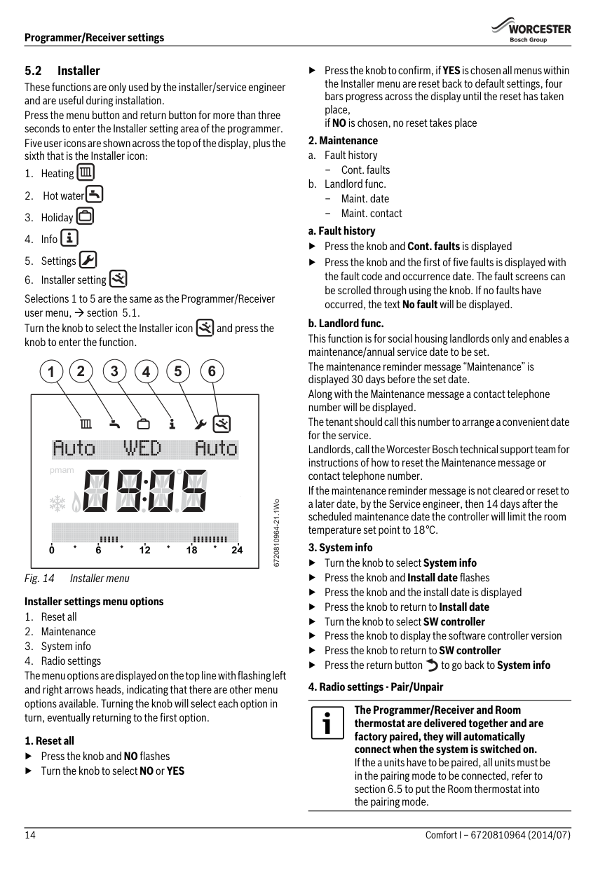
These functions are only used by the installer/service engineer and are useful during installation. Press the menu button and return button for more than three seconds to enter the Installer setting area of the programmer. Five user icons are shown across the top of the display, plus the sixth that is the Installer icon:
Selections 1 to 5 are the same as the Programmer/Receiver user menu, section 5.1. Turn the knob to select the Installer icon and press the knob to enter the function.
#### 2 3 4 5 61
|pmam
| |---|
6720810964-21.1Wo
######## 1. Reset all
▶Press the knob andNO flashes
▶ Turn the knob to select NO or YES
▶ Press the knob to confirm, if YESis chosen all menus within the Installer menu are reset back to default settings, four bars progress across the display until the reset has taken place, if NO is chosen, no reset takes place
######## 2. Maintenance
–Cont. faults
▶Press the knob andCont. faults is displayed
▶ Press the knob and the first of five faults is displayed with the fault code and occurrence date. The fault screens can be scrolled through using the knob. If no faults have occurred, the text No fault will be displayed.
######## 3. System info
▶ Turn the knob to select System info
▶Press the knob andInstall date flashes
▶Press the knob and the install date is displayed
▶ Press the knob to return to Install date
▶ Turn the knob to select SW controller
▶ Press the knob to display the software controller version
▶ Press the knob to return to SW controller
▶ Press the return button to go back to System info
######## 4. Radio settings - Pair/Unpair
The Programmer/Receiver and Room thermostat are delivered together and are factory paired, they will automatically connect when the system is switched on. If the a units have to be paired, all units must be in the pairing mode to be connected, refer to section 6.5 to put the Room thermostat into the pairing mode.
When the devices are being paired, the Room thermostat and Programmer/Receiver must be in the same mode of pairing. Refer to section 6.5 for pairing of the Room thermostat.
Ensure that the Room thermostat is positioned as suggested in Section 3.2 and away from metal objects that might attenuate the RF signal.
Before mounting the Room thermostat on the wall, it is good practice to find a position that affords good signal strength.
When the units have been paired, check the signal strength at the Room thermostat. If the signal strength is low, try another position in that room until the best possible signal strength is obtained, refer to section 6.7 for the Signal strength at the Room thermostat.
▶ Turn the knob to select Radio settings
▶ Press the knob to display Pairing, that is RF pairing of the devices in the system
▶ Turn the knob to display Unpairing or Pairing
▶IfPairingis chosen, press the knob and pairing is displayed with advancing bars, when the pairing between the devices has been made a number is displayed confirming the number of Room thermostats connected
▶IfUnpairing is chosen, press the knob and Unpairing is displayed with advancing bars, when the unpairing between the devices has been made the number 0 is displayed confirming that the Room thermostat(s) have been disconnected
5.3 Key lock When the Key lock is active, no user interaction with the units is possible, if a button is pressed or the knob turned/pressed the word Key lock is displayed. Key lock ON To activate the Keylock:
▶ Hold down the CH Select button and the knob at the same
time for more than three seconds and theKeylockis active Key lock OFF To de-activate the Key lock:
▶ Hold down the CH Select button and the knob at the same time for more than three seconds and the Key lock is deactivated and the normal display is shown
Turn the knob anti-clockwise to decrease the temperature or clockwise to increase. The new temperature setting will flash for three seconds.
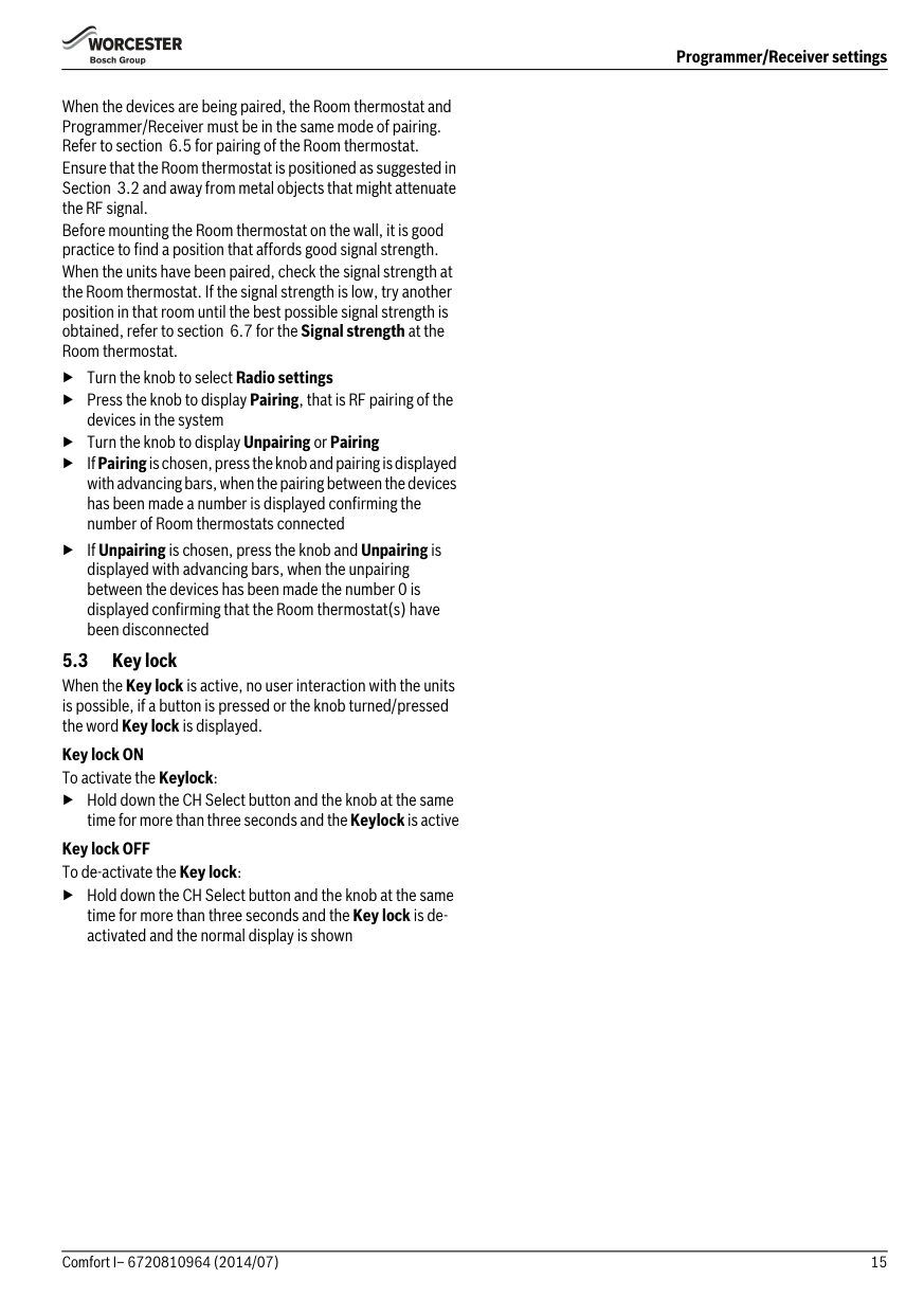
###### 6 Room thermostat
After 30 seconds of inactivity the display reverts to the showing the current room temperature.
| | |---|
1 2
6720810964-07.1Wo
3
Press the knob briefly to display the required room temperature.
6720810964-26.1Wo
Fig. 17
If the Programmer/Receiver is in an OFF period, the Room thermostat will display the new temperature setting flashing for three seconds and then OFF flashing for three seconds.
Low battery The battery symbol indicates the batteries require replacing within two months refer to section 9.1 Burner ON indicator
The symbol is shown when the boiler is firing (there may be up to a six minute delay between the boiler firing and the symbol being displayed).
######## Low RF signal strength
The A21 fault code will be displayed at initial switch on until the two units have established an RF communication link
The A21fault code indicates no RF signal, refer to section 6.7 for the signal strength indication on the Room Thermostat.
6720810964-27.1Wo
######## Room thermostat
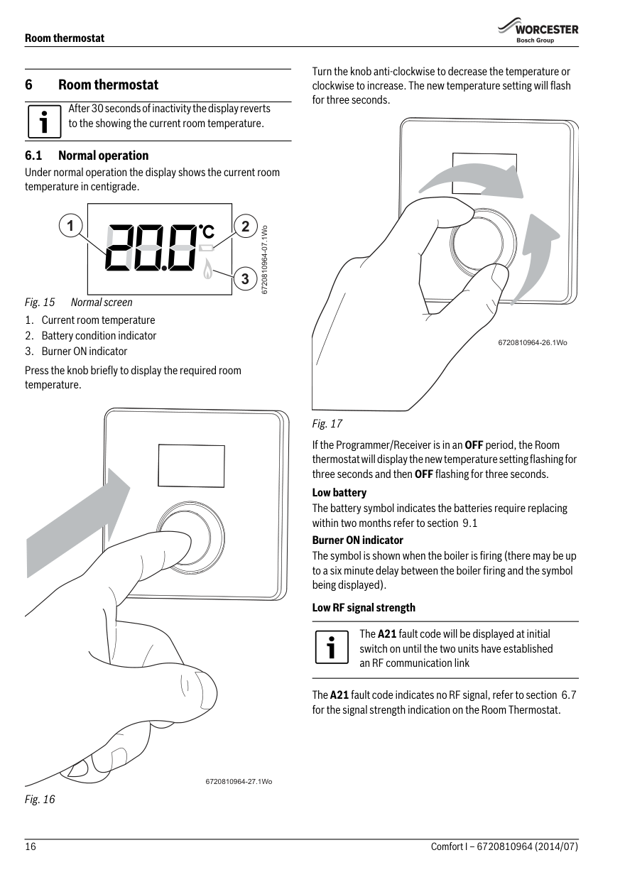
6.2 Settings These functions are only used by the installer/service engineer and are useful during installation. To enter the Settings menu:
If a fault code is displayed the user must first press the knob to return to the main display then the user can hold the knob to enter the Settings menu
| | |---|
6720810964-17.1Wo 6720810964-28.1Wo
| | |---|
▶ Turn the knob to selectE 1
| | |---|
6720810964-11.1Wo 6720810964-16.1Wo
▶ Press the knob to enter the temperature offset function, the offset value is displayed, by default it is 0.0 °C.
▶Press the knob andthe display flashes.
▶ Turn the knob to adjust the temperature offset, between
-5 and +5 °C.
▶ Press the knob to confirm the desired setting
▶ Press the knob for more than three seconds to return to the previous level
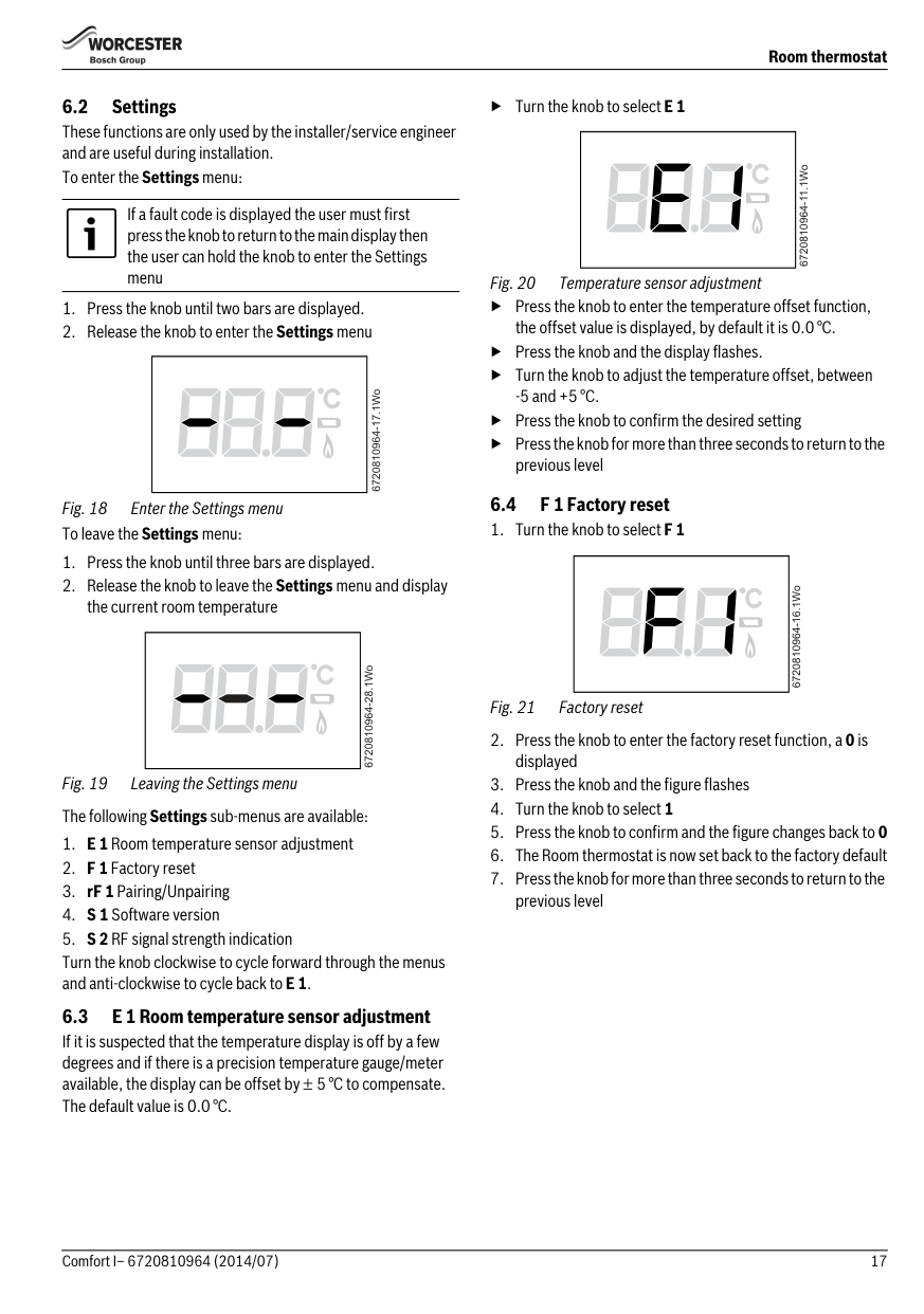
6.4 F 1 Factory reset
Fig. 21 Factory reset
| | |---|
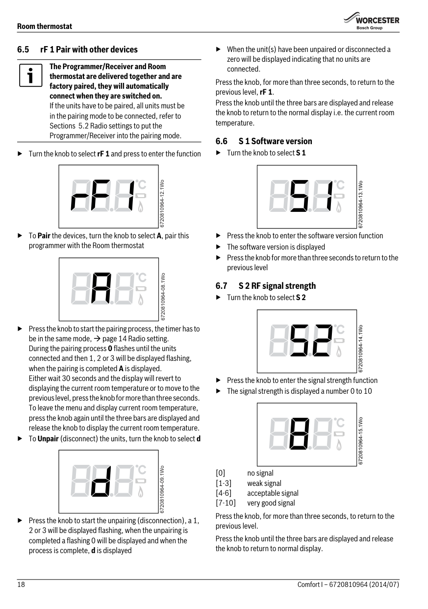
####### 6.5 rF 1 Pair with other devices
The Programmer/Receiver and Room thermostat are delivered together and are factory paired, they will automatically connect when they are switched on. If the units have to be paired, all units must be in the pairing mode to be connected, refer to Sections 5.2 Radio settings to put the Programmer/Receiver into the pairing mode.
▶ Turn the knob to select rF 1 and press to enter the function
| | |---|
6720810964-12.1Wo
▶ToPair the devices, turn the knob to select A, pair this programmer with the Room thermostat
| | |---|
| | |---|
▶ Press the knob to start the pairing process, the timer has to be in the same mode, page 14 Radio setting. During the pairing process 0 flashes until the units connected and then 1, 2 or 3 will be displayed flashing, when the pairing is completed A is displayed. Either wait 30 seconds and the display will revert to displaying the current room temperature or to move to the previous level, press the knob for more than three seconds. To leave the menu and display current room temperature, press the knob again until the three bars are displayed and release the knob to display the current room temperature.
▶ToUnpair (disconnect) the units, turn the knob to select d
▶ Press the knob to start the unpairing (disconnection), a 1, 2 or 3 will be displayed flashing, when the unpairing is completed a flashing 0 will be displayed and when the process is complete, d is displayed
▶ When the unit(s) have been unpaired or disconnected a zero will be displayed indicating that no units are connected.
Press the knob, for more than three seconds, to return to the previous level, rF 1.
Press the knob until the three bars are displayed and release the knob to return to the normal display i.e. the current room temperature.
####### 6.6 S 1 Software version
▶ Press the knob to enter the software version function
▶ The software version is displayed
▶ Press the knob for more than three seconds to return to the previous level
6.7 S 2 RF signal strength
| | |---|
| | |---|
| | |---|
▶ Press the knob to enter the signal strength function
▶ The signal strength is displayed a number 0 to 10
[0] no signal [1-3] weak signal [4-6] acceptable signal [7-10] very good signal
Press the knob, for more than three seconds, to return to the previous level.

Press the knob until the three bars are displayed and release the knob to return to normal display.
Troubleshooting
###### 7Troubleshooting
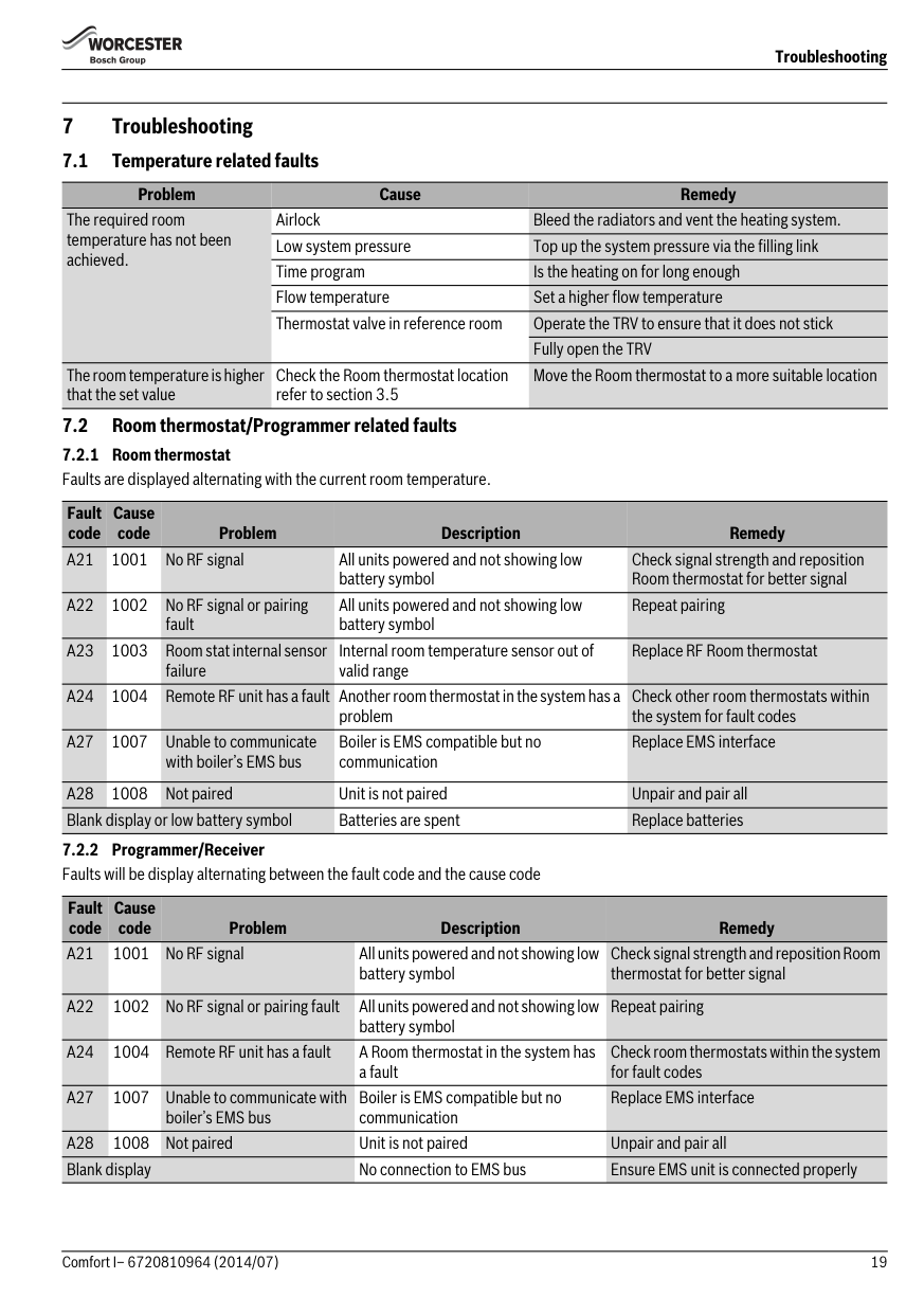
Problem Cause Remedy The required room temperature has not been achieved.
Airlock Bleed the radiators and vent the heating system. Low system pressure Top up the system pressure via the filling link Time program Is the heating on for long enough Flow temperature Set a higher flow temperature Thermostat valve in reference room Operate the TRV to ensure that it does not stick
Fully open the TRV
The room temperature is higher that the set value
Check the Room thermostat location refer to section 3.5
Move the Room thermostat to a more suitable location
Fault code
Cause code Problem Description Remedy
battery symbol
Check signal strength and reposition Room thermostat for better signal
All units powered and not showing low battery symbol
Repeat pairing
Internal room temperature sensor out of valid range
Replace RF Room thermostat
Check other room thermostats within the system for fault codes
problem
Boiler is EMS compatible but no communication

Replace EMS interface
Fault code
Cause code Problem Description Remedy
battery symbol
Check signal strength and reposition Room thermostat for better signal
Repeat pairing
battery symbol
A24 1004 Remote RF unit has a fault A Room thermostat in the system has
Check room thermostats within the system for fault codes
a fault
Boiler is EMS compatible but no communication
Replace EMS interface
######## Servicing
▶ RF signal link between the units is set up correctly, sections 6.5 and page 14 Radio settings
▶ Room thermostat batteries are the correct type, fitted correctly and are not exhausted.If in doubt, fit new batteries section 9.1.
2.
6720810964-19.1Wo

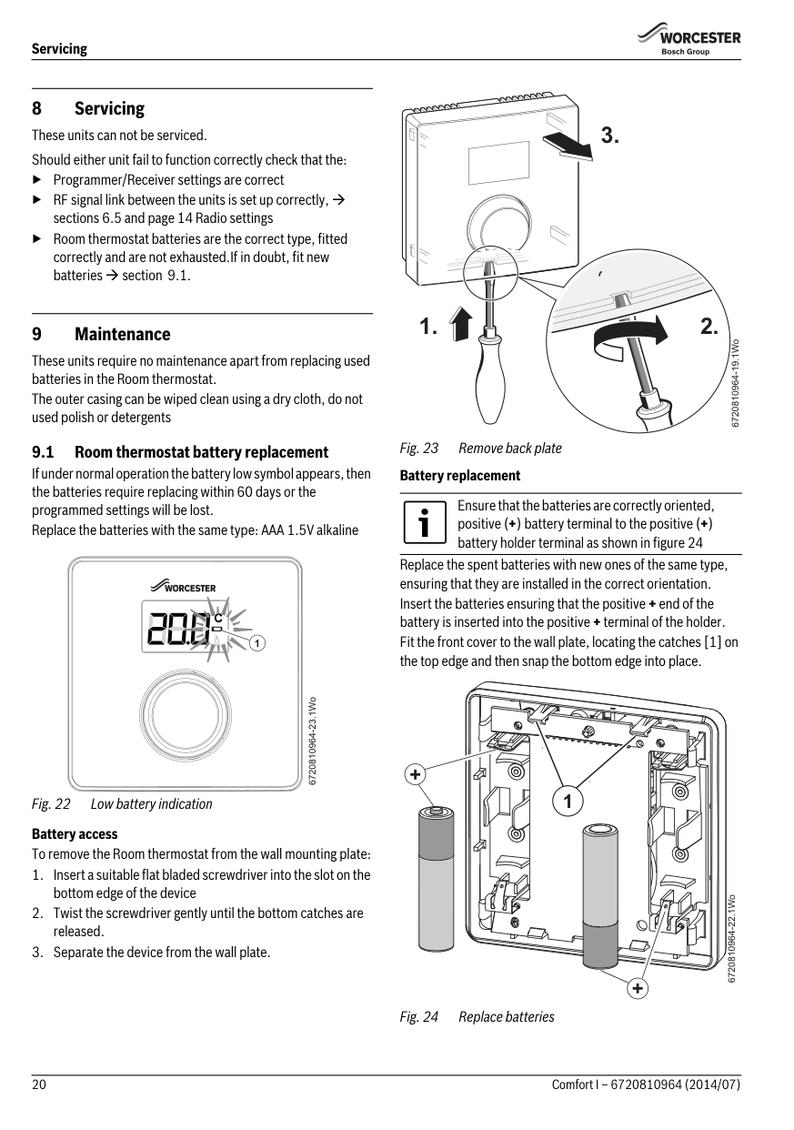
These units require no maintenance apart from replacing used batteries in the Room thermostat. The outer casing can be wiped clean using a dry cloth, do not used polish or detergents
Replace the spent batteries with new ones of the same type, ensuring that they are installed in the correct orientation. Insert the batteries ensuring that the positive + end of the battery is inserted into the positive + terminal of the holder. Fit the front cover to the wall plate, locating the catches [1] on the top edge and then snap the bottom edge into place.
9.1 Room thermostat battery replacement If under normal operation the battery low symbol appears, then the batteries require replacing within 60 days or the programmed settings will be lost. Replace the batteries with the same type: AAA 1.5V alkaline
Ensure that the batteries are correctly oriented, positive (+) battery terminal to the positive (+) battery holder terminal as shown in figure 24
1
6720810964-23.1Wo
+
1
Fig. 22 Low battery indication Battery access To remove the Room thermostat from the wall mounting plate:
6720810964-22.1Wo
+
ErP Class
###### 10 ErP Class
The data represented in the table below is required for the completion of Energy Related Product (ErP) Directive System Package fiche and, subsequently, the ErP system data label. ERP Labelling obligation applicable from 26th September 2015.
Supplier Worcester Bosch Group Model Comfort I ErP Class V Function and ERP description
Load compensation Modulating room thermostat, for use with modulating heaters: An electronic room thermostat that varies the flow temperature of the water leaving the heater dependant upon measured room temperature deviation from room thermostat set point. Control is achieved by modulating the output of the heater.
+3%
Additional seasonal space heating efficiency gain
Battery recycling Batteries, rechargeable or not, must not be disposed of into ordinary household waste. Instead, they must be recycled properly to protect the environment and cut down on the waste of precious resources. Your local waste management authority can supply details concerning the proper disposal of batteries.
###### 11 Environment / disposal
Environmental protection is a fundamental corporate strategy of the Bosch Group. The quality of our products, their economy and environmental safety are all of equal importance to us and all environmental protection legislation and regulations are strictly observed. We use the best possible technology and materials for protecting the environment taking account of economic considerations.
Packaging We participate in the recycling programmes of the countries in which our products are sold to ensure optimum recycling. All of our packaging materials are environmentally compatible and can be recycled.
Electrical and electronic equipment Scrap electrical and electronic equipment must be collected separately and returned to an environmentally compatible recycling facility (European Directive on waste electrical and electronic equipment).
Use the country specific return and collection system for the disposal of electrical and electronic equipment.
########## 22 Comfort I – 6720810964 (2014/07)
########## 23Comfort I– 6720810964 (2014/07)
Worcester, Bosch Group Cotswold Way, Warndon, Worcester WR4 9SW. Tel. 0330 123 9559 Worcester, Bosch Group is a brand name of Bosch Thermotechnology Ltd.
worcester-bosch.co.uk
6 720 810 964 (2014/07)

######### WORCESTER, BOSCH GROUP:
TECHNICAL SUPPORT: 0330 123 3366 APPOINTMENTS: 0330 123 9339 SPARES: 0330 123 9779 LITERATURE: 0330 123 9119 TRAINING: 0330 123 0166 SALES: 0330 123 9669