
Bebe Stars 821 Freedom 3 IN 1 Petrol Tricycle
Ask AI
— answers from the official manualAnswers from the official manual.
Common questions
Common Questions
10 totalHow can I properly adjust and maintain the brake system of the Bebe Stars 821 Freedom 3 IN 1 Petrol Tricycle?
To ensure proper functioning, check and clean your brakes regularly. Apply light oil to the pivot points every three months to prevent wear. Major adjustments like cable length can be made using pliers or an adjusting barrel as detailed in the manual.
What steps should I take if my Bebe Stars trike’s brakes squeal when applying them?
If your brakes are squealing, check and clean the brake blocks and rim to remove any grease or dirt. Adjust cables for binding and replace worn down block material (Page 54)
How do I assemble the front and rear wheels of my Bebe Stars tricycle?
To install the front wheel, remove the retaining nuts and slip the wheel onto the forks, securing with axle retainers. Tighten the nuts securely on both sides (Page 14). For the rear wheel installation, follow similar steps including installing axle retainers properly.
How do I inflate the tires of my Bebe Stars tricycle?
Before inflating, check for correct sizes and pressure ranges marked on tire sidewall. Use a high-quality dial gauge to fill your tires with the proper level indicated by the maximum pressure rating (Page 31).
What should I do if my Bebe Stars tricycle’s chain slips or jumps off?
Adjust the derailleur alignment according to your bike model, check for any worn down teeth on gears, and consider replacing stretched chains as needed. Refer also to troubleshooting section (Page 52).
How do I properly adjust the front fork of my tricycle?
To adjust the front fork, secure it facing forward and ensure that the handlebar stem is aligned correctly. Tighten expander bolts securely to avoid over-tightening which could damage the assembly (Page 17).
Show 4 more questions
How can I adjust the seat of my Bebe Stars tricycle for optimal comfort?
What are the maintenance tasks I need to perform weekly on my tricycle, according to the manual?
How do I properly secure the quick-release lever for my Bebe Stars tricycle?
How do I replace a flat tire on my Bebe Stars tricycle?
Full Manual
56 pages

| | |---| |ADULT TRICYCLE ASSEMBLY|
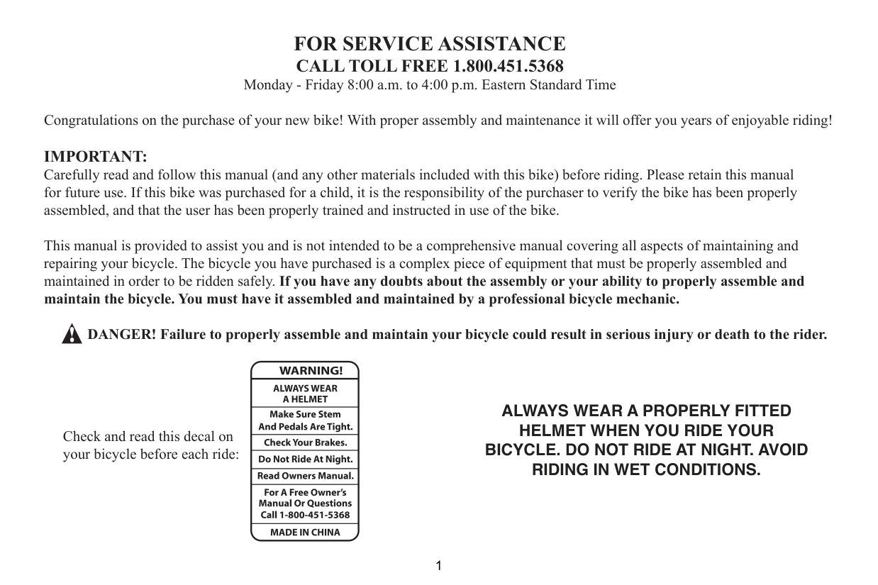
FOR SERVICE ASSISTANCE CALL TOLL FREE 1.800.451.5368 Monday - Friday 8:00 a.m. to 4:00 p.m. Eastern Standard Time Congratulations on the purchase of your new bike! With proper assembly and maintenance it will offer you years of enjoyable riding! IMPORTANT: Carefully read and follow this manual (and any other materials included with this bike) before riding. Please retain this manual for future use. If this bike was purchased for a child, it is the responsibility of the purchaser to verify the bike has been properly assembled, and that the user has been properly trained and instructed in use of the bike.
This manual is provided to assist you and is not intended to be a comprehensive manual covering all aspects of maintaining and repairing your bicycle. The bicycle you have purchased is a complex piece of equipment that must be properly assembled and maintained in order to be ridden safely. If you have any doubts about the assembly or your ability to properly assemble and maintain the bicycle. You must have it assembled and maintained by a professional bicycle mechanic.
DANGER! Failure to properly assemble and maintain your bicycle could result in serious injury or death to the rider.
Check and read this decal on your bicycle before each ride:
ALWAYS WEAR A PROPERLY FITTED HELMET WHEN YOU RIDE YOUR BICYCLE. DO NOT RIDE AT NIGHT. AVOID RIDING IN WET CONDITIONS.
RESPONSIBILITY OF THE OWNER! IMPORTANT: Reading and following the information and instructions in this manual are essential to your ability to ride safely.
and which make sense as rider safety precautions at all times.
how to properly and safely use the bike as well.
below, including size of the unit that is proper for the rider to insure good control during use. Do not overload a unit with a rider that is too heavy or too large, and do not attempt to carry extra passengers, packages or loads on the bicycle. Do not attempt to use street bikes for off road riding.
Adult Tricycles. (Max weight of rider+luggage+bike = 275lbs/125kg). These bikes are intended for use on public roads,
paths or tracks that are in good condition. These bikes are NOT intended for off-road use. Wear a helmet at all times.
Check your bike regularly and do required maintenance.
Condition 1—This is a set of conditions for the operation of a bicycle on a regular paved surface or smooth unpaved surface where the tires may unintentionally lose ground contact.
OWNER’S RESPONSIBILITY continued
NOTE. Carefully read this manual and follow instructions. Your bicycle may come with additional instruction sheets that cover features unique to your bike. Please ensure that you read and become familiar with their contents. Always wear a CPSC approved helmet when riding your
laws. Keep all materials which come with the bike for future reference.
Any major service or adjustments on your bike should be carried out by a competent adult or professional bike mechanic. If you wish to make adjustments yourself, this manual contains important tips on how to do it. CAUTION: Any adjustments you make are entirely at your own risk. Do NOT use your bike for freestyle and stunt riding, jumping or competitive events. Even if you are riding a mountain bike, you should know that off-road use or any similar activities can be dangerous, and you are warned that you assume the risk for personal injury, damages
##### or losses incurred from such use. Do not ride your bike when any part is damaged or not working properly. If you are unsure how to carry out repairs or maintenance on your bike, it is vital that you consult a local bike mechanic for professional assistance and support.
WARNING: AS WITH ALL MECHANICAL COMPONENTS, THE BICYCLE IS SUBJECTED TO WEAR AND HIGH STRESSES. DIFFERENT MATERIALS AND COMPONENTS MAY REACT TO WEAR OR STRESS FATIGUE IN DIFFERENT WAYS. IF THE DESIGN LIFE OF A COMPONENT HAS BEEN EXCEEDED, IT MAY SUDDENLY FAIL, POSSIBLY CAUSING INJURIES TO THE RIDER. ANY FORM OF CRACK, SCRATCHES OR CHANGE OF COLORING IN HIGHLY STRESSED AREAS INDICATE THAT THE LIFE OF THE COMPONENT HAS BEEN REACHED AND SHOULD BE REPLACED.
Forehead covered Forehead exposed
ALWAYS WEAR A HELMETIT COULD SAVE YOUR LIFE!
should be worn at all times when riding your bicycle. In addition, if you are carrying a passenger (only use an approved child safety seat), and remember, the passenger must also be wearing a helmet
The correct helmet should:
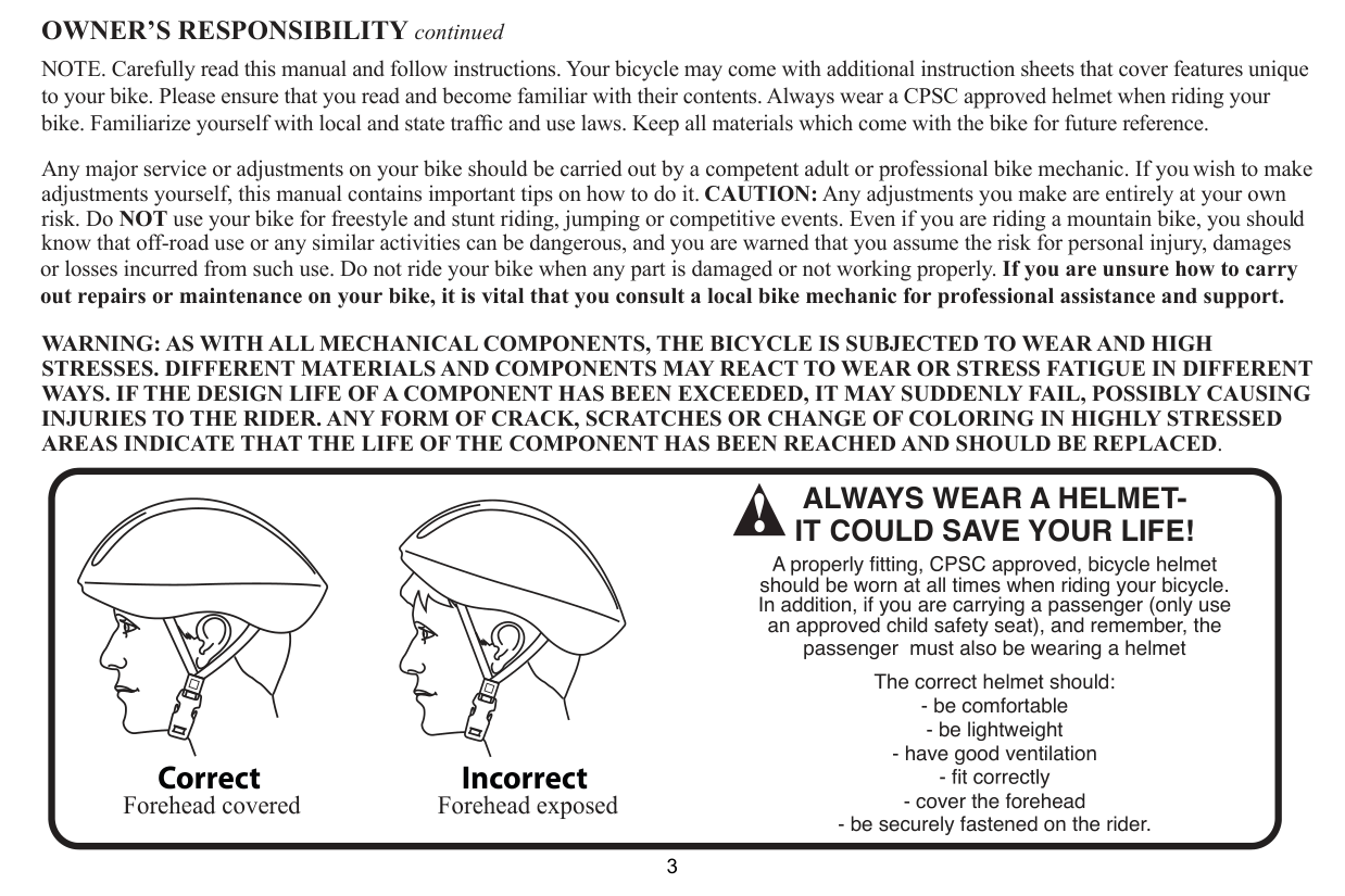
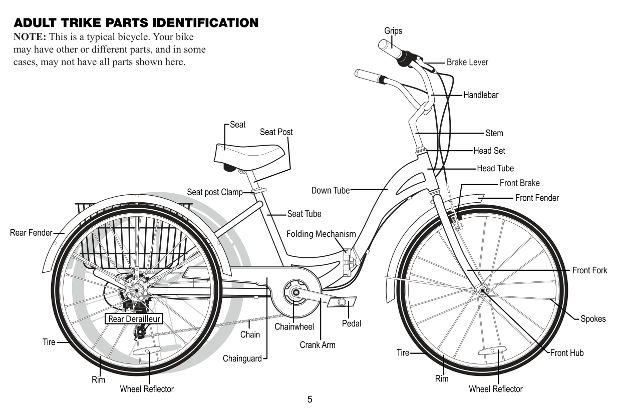
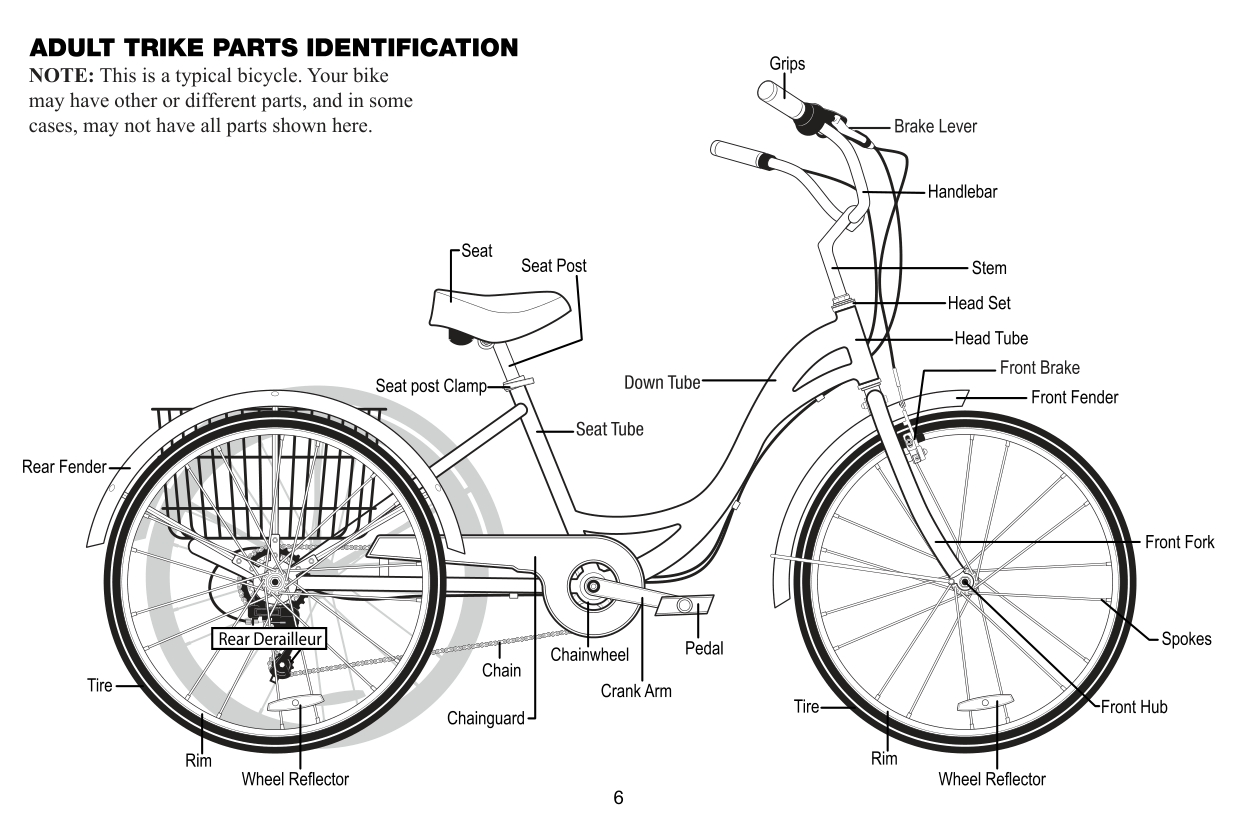
TABLE OF CONTENT Parts Identification Graphics........................5-6 Before Riding ...............................................7-12 Assembly Instructions..................................13-36 Maintenance................................................37-54 Warranty......................................................55
|WARNING / CAUTION Throughout this manual you will see the words WARNING and CAUTION. Please pay special attention to this information, as it could affect your safety as you assemble and ride your bike.
| |---|
ALWAYS WEAR A PROPERLY FITTED HELMET WHEN YOU RIDE YOUR BICYCLE. DO NOT RIDE AT NIGHT. AVOID RIDING IN WET CONDITIONS.
######## Folding Mechanism
RULES OF THE ROAD In the interest of safe cycling, make sure you read and understand the owner’s manual.
DANGER, WARNING , CAUTION, IMPORTANT, and NOTE or NOTICE. These are important signal words telling you to pay special attention to that text as rider safety is involved. DANGER and WARNING: Pay special attention to these since failure to do so could result in serious injury or death to the rider or others. CAUTION: If not followed these instructions could result in injury or mechanical failure or damage to the bicycle. NOTE or NOTICE or IMPORTANT: These specify something that is of special interest.
IMPORTANT Before you ride this bicycle, read this RULES OF THE ROAD section and check that all parts are installed and working as per this manual. If you understand how the bicycle operates, you will get the best performance. When you read this instruction book, compare the illustrations to the bicycle. Learn the location of all the parts and how they work. Keep this book for future reference. CAUTION Before you ride the bicycle, check the brake and other parts of the bike. Make sure all parts are tightened, assembled
##### and follow the maintenance procedures in this book. If you do not feel comfortable with your skills in assembling or adjusting the bike, please take it to a professional bike repairman.
caught in the chain wheel. Long sleeves, long pants, gloves, eye protection, a good helmet, elbow and knee pads are recommended. Helmet use is required by law in many states and is always a good idea.
other debris on the road can also affect stopping distance. If at all possible, do not ride in wet weather. Vision and control are impaired, creating a greater risk of accidents and injury.
your bike.
or control of the bike or exceeds the max weight limit.
BEFORE RIDING:
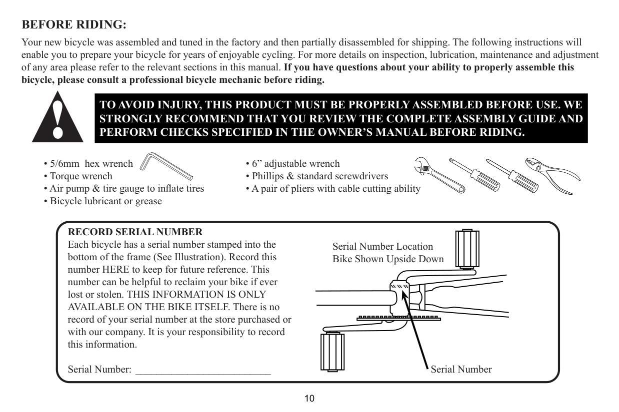
Your new bicycle was assembled and tuned in the factory and then partially disassembled for shipping. The following instructions will enable you to prepare your bicycle for years of enjoyable cycling. For more details on inspection, lubrication, maintenance and adjustment of any area please refer to the relevant sections in this manual. If you have questions about your ability to properly assemble this bicycle, please consult a professional bicycle mechanic before riding.
TO AVOID INJURY, THIS PRODUCT MUST BE PROPERLY ASSEMBLED BEFORE USE. WE STRONGLY RECOMMEND THAT YOU REVIEW THE COMPLETE ASSEMBLY GUIDE AND PERFORM CHECKS SPECIFIED IN THE OWNER’S MANUAL BEFORE RIDING.
RECORD SERIAL NUMBER Each bicycle has a serial number stamped into the bottom of the frame (See Illustration). Record this number HERE to keep for future reference. This number can be helpful to reclaim your bike if ever lost or stolen. THIS INFORMATION IS ONLY AVAILABLE ON THE BIKE ITSELF. There is no record of your serial number at the store purchased or with our company. It is your responsibility to record this information.
Serial Number: __________________________
Serial Number Location Bike Shown Upside Down
###
Serial Number
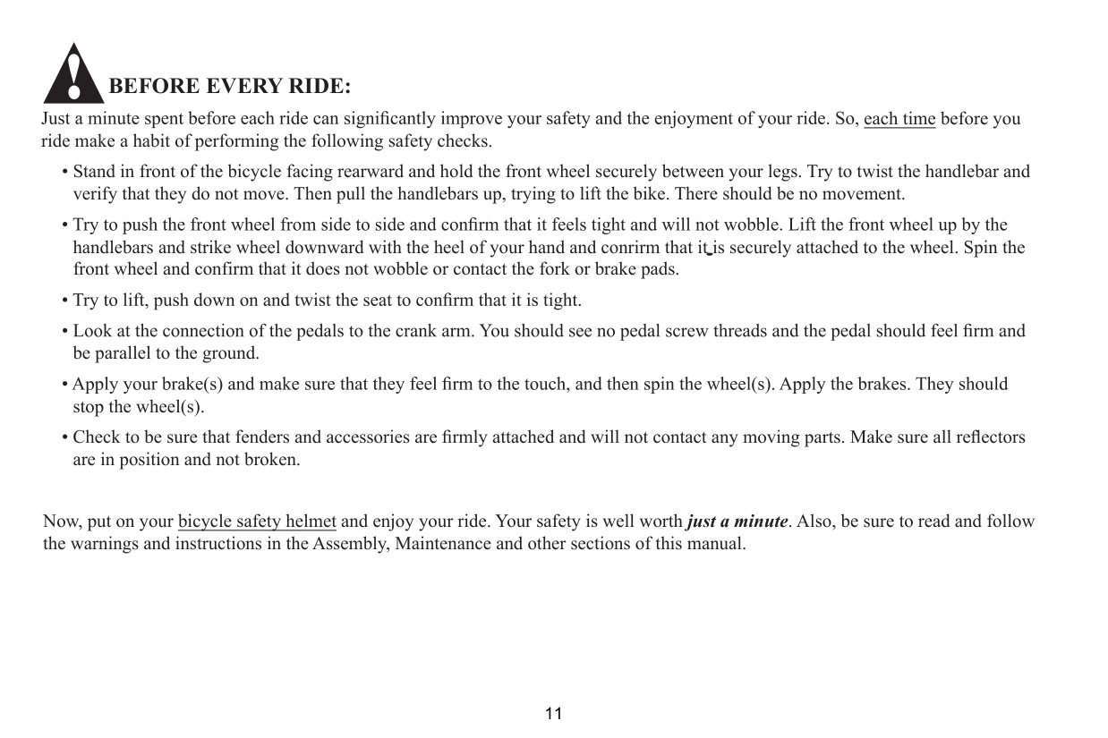
BEFORE EVERY RIDE:
each time before you ride make a habit of performing the following safety checks.
• Stand in front of the bicycle facing rearward and hold the front wheel securely between your legs. Try to twist the handlebar and verify that they do not move. Then pull the handlebars up, trying to lift the bike. There should be no movement.
handlebars and strike wheel downward with the heel of your hand and conrirm that it is securely attached to the wheel. Spin the
front wheel and confirm that it does not wobble or contact the fork or brake pads.
be parallel to the ground.
stop the wheel(s).
are in position and not broken.
Now, put on your bicycle safety helmet and enjoy your ride. Your safety is well worth just a minute. Also, be sure to read and follow the warnings and instructions in the Assembly, Maintenance and other sections of this manual.
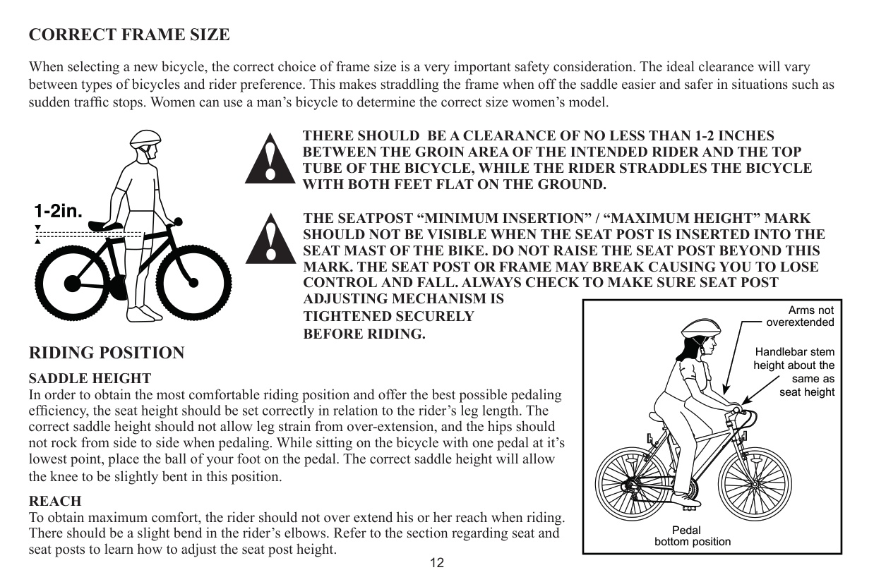
CORRECT FRAME SIZE
When selecting a new bicycle, the correct choice of frame size is a very important safety consideration. The ideal clearance will vary between types of bicycles and rider preference. This makes straddling the frame when off the saddle easier and safer in situations such as
##### THERE SHOULD BE A CLEARANCE OF NO LESS THAN 1-2 INCHES BETWEEN THE GROIN AREA OF THE INTENDED RIDER AND THE TOP TUBE OF THE BICYCLE, WHILE THE RIDER STRADDLES THE BICYCLE WITH BOTH FEET FLAT ON THE GROUND.
Handlebar stem height about the
THE SEATPOST “MINIMUM INSERTION” / “MAXIMUM HEIGHT” MARK SHOULD NOT BE VISIBLE WHEN THE SEAT POST IS INSERTED INTO THE SEAT MAST OF THE BIKE. DO NOT RAISE THE SEAT POST BEYOND THIS MARK. THE SEAT POST OR FRAME MAY BREAK CAUSING YOU TO LOSE CONTROL AND FALL. ALWAYS CHECK TO MAKE SURE SEAT POST ADJUSTING MECHANISM IS TIGHTENED SECURELY BEFORE RIDING.
|Arms not overextended
Handlebar stem height about the
same as seat height
Pedal bottom position| |---|
RIDING POSITION SADDLE HEIGHT In order to obtain the most comfortable riding position and offer the best possible pedaling correct saddle height should not allow leg strain from over-extension, and the hips should not rock from side to side when pedaling. While sitting on the bicycle with one pedal at it’s lowest point, place the ball of your foot on the pedal. The correct saddle height will allow the knee to be slightly bent in this position. REACH To obtain maximum comfort, the rider should not over extend his or her reach when riding. There should be a slight bend in the rider’s elbows. Refer to the section regarding seat and seat posts to learn how to adjust the seat post height.
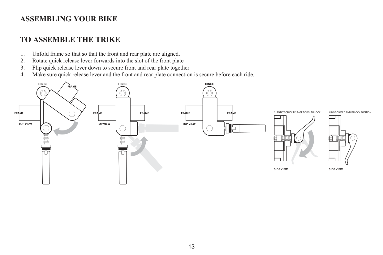
TO ASSEMBLE THE TRIKE
HINGEHINGE
FRAME
HINGE
FRAME FRAMEFRAMEFRAMEFRAME
TOP VIEWTOP VIEW
TOP VIEW
HINGE CLOSED AND IN LOCK POSITION
SIDE VIEWSIDE VIEW
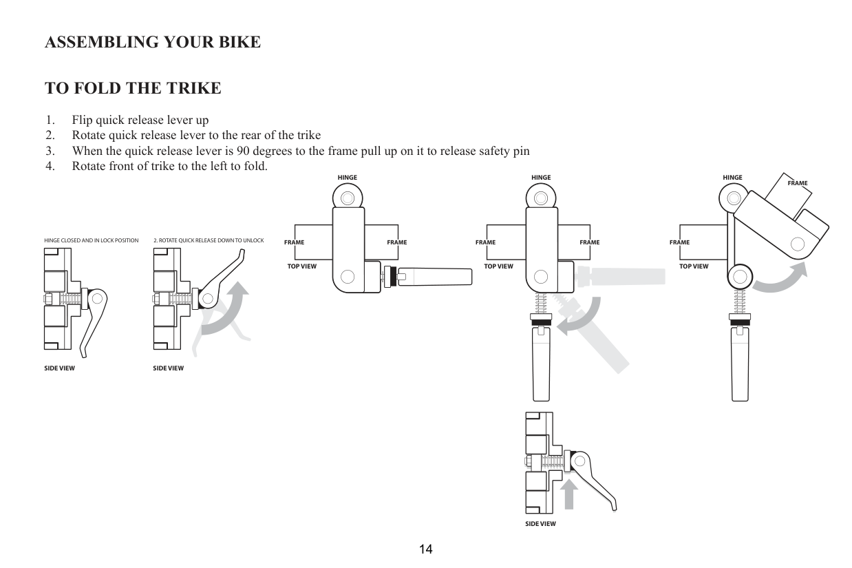
TO FOLD THE TRIKE
HINGE
HINGE HINGE
FRAME
HINGE CLOSED AND IN LOCK POSITION
FRAME FRAME FRAME FRAME FRAME
TOP VIEW
TOP VIEW TOP VIEW
SIDE VIEW SIDE VIEW
SIDE VIEW
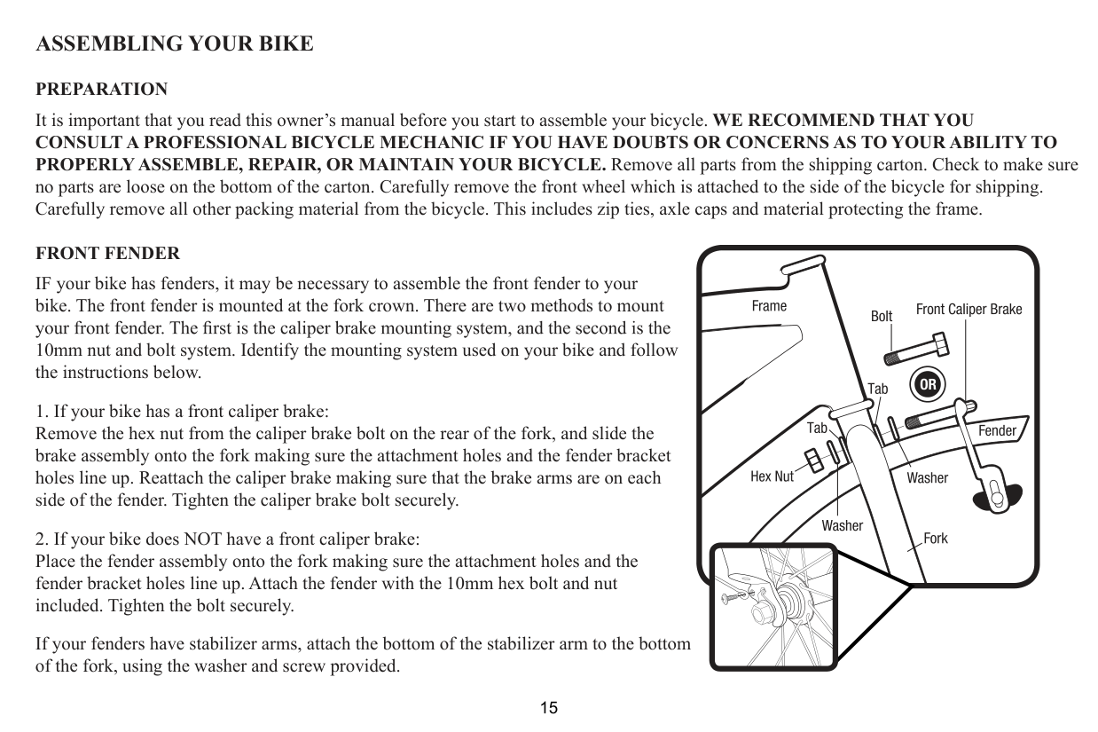
PROPERLY ASSEMBLE, REPAIR, OR MAINTAIN YOUR BICYCLE. Remove all parts from the shipping carton. Check to make sure no parts are loose on the bottom of the carton. Carefully remove the front wheel which is attached to the side of the bicycle for shipping. Carefully remove all other packing material from the bicycle. This includes zip ties, axle caps and material protecting the frame.
##### FRONT FENDER
IF your bike has fenders, it may be necessary to assemble the front fender to your bike. The front fender is mounted at the fork crown. There are two methods to mount
10mm nut and bolt system. Identify the mounting system used on your bike and follow the instructions below.
If your fenders have stabilizer arms, attach the bottom of the stabilizer arm to the bottom of the fork, using the washer and screw provided.
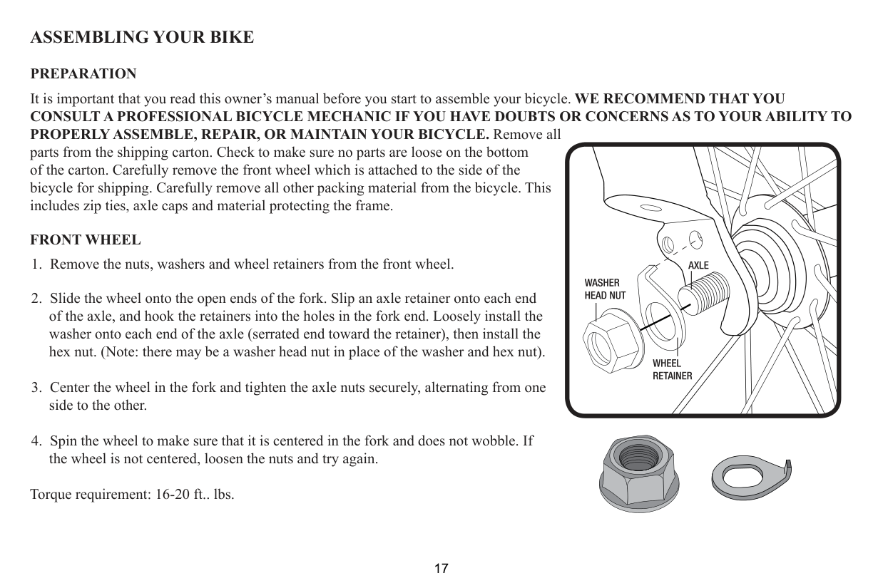
includes zip ties, axle caps and material protecting the frame. FRONT WHEEL
includes zip ties, axle caps and material protecting the frame. FRONT WHEEL
of the axle, and hook the retainers into the holes in the fork end. Loosely install the washer onto each end of the axle (serrated end toward the retainer), then install the hex nut. (Note: there may be a washer head nut in place of the washer and hex nut).
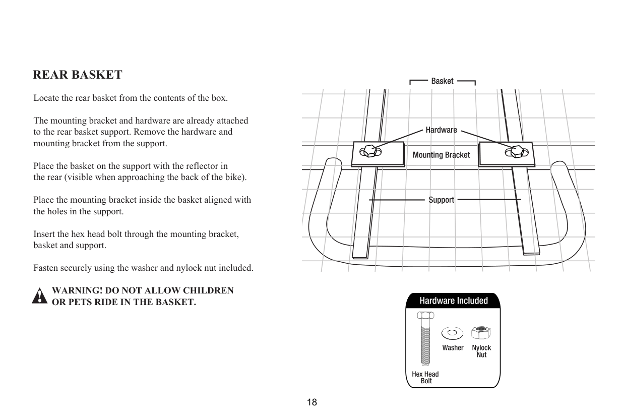
REAR BASKET Locate the rear basket from the contents of the box. The mounting bracket and hardware are already attached to the rear basket support. Remove the hardware and mounting bracket from the support. Place the basket on the support with the reflector in the rear (visible when approaching the back of the bike). Place the mounting bracket inside the basket aligned with the holes in the support. Insert the hex head bolt through the mounting bracket, basket and support. Fasten securely using the washer and nylock nut included.
####### WARNING! DO NOT ALLOW CHILDREN OR PETS RIDE IN THE BASKET.
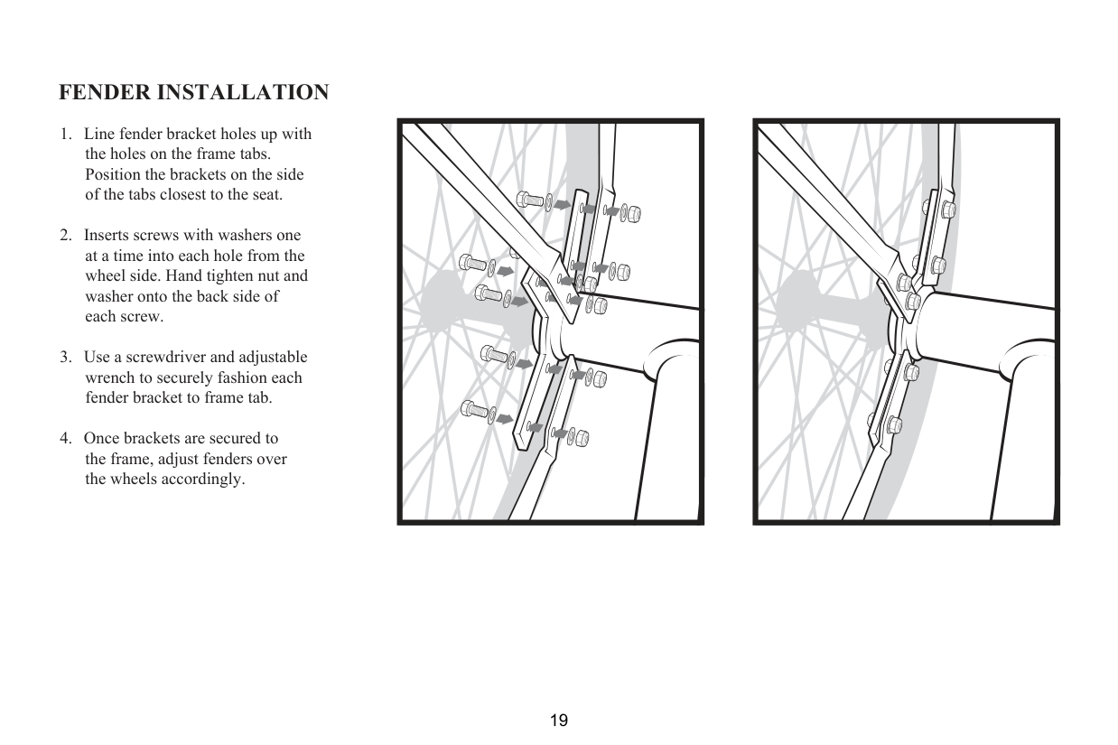
FENDER INSTALLATION
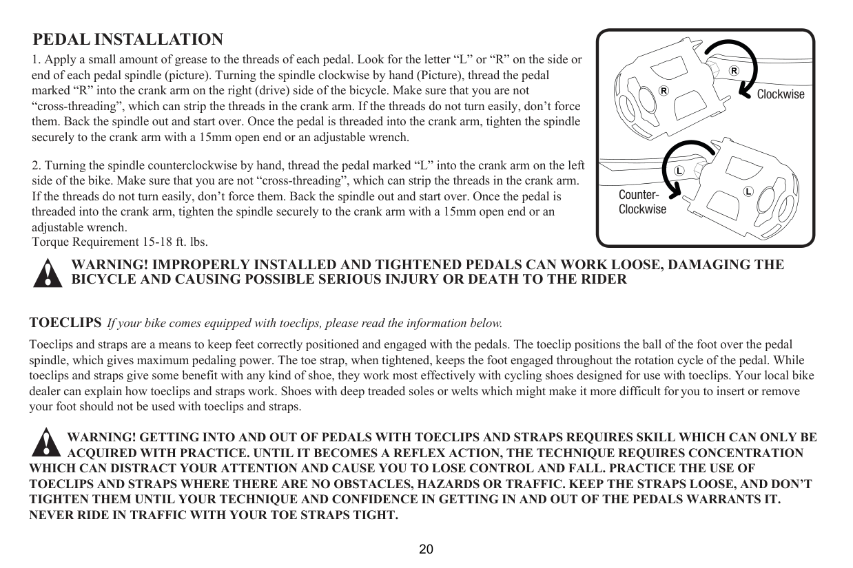
PEDAL INSTALLATION
Torque Requirement 15-18 ft. lbs.
CounterClockwise
Clockwise
WARNING! IMPROPERLY INSTALLED AND TIGHTENED PEDALS CAN WORK LOOSE, DAMAGING THE BICYCLE AND CAUSING POSSIBLE SERIOUS INJURY OR DEATH TO THE RIDER
##### TOECLIPS
If your bike comes equipped with toeclips, please read the information below.
Toeclips and straps are a means to keep feet correctly positioned and engaged with the pedals. The toeclip positions the ball of the foot over the pedal spindle, which gives maximum pedaling power. The toe strap, when tightened, keeps the foot engaged throughout the rotation cycle of the pedal. While toeclips and straps give some benefit with any kind of shoe, they work most effectively with cycling shoes designed for use with toeclips. Your local bike dealer can explain how toeclips and straps work. Shoes with deep treaded soles or welts which might make it more difficult for you to insert or remove your foot should not be used with toeclips and straps.
WARNING! GETTING INTO AND OUT OF PEDALS WITH TOECLIPS AND STRAPS REQUIRES SKILL WHICH CAN ONLY BE ACQUIRED WITH PRACTICE. UNTIL IT BECOMES A REFLEX ACTION, THE TECHNIQUE REQUIRES CONCENTRATION
WHICH CAN DISTRACT YOUR ATTENTION AND CAUSE YOU TO LOSE CONTROL AND FALL. PRACTICE THE USE OF TOECLIPS AND STRAPS WHERE THERE ARE NO OBSTACLES, HAZARDS OR TRAFFIC. KEEP THE STRAPS LOOSE, AND DON’T TIGHTEN THEM UNTIL YOUR TECHNIQUE AND CONFIDENCE IN GETTING IN AND OUT OF THE PEDALS WARRANTS IT. NEVER RIDE IN TRAFFIC WITH YOUR TOE STRAPS TIGHT.

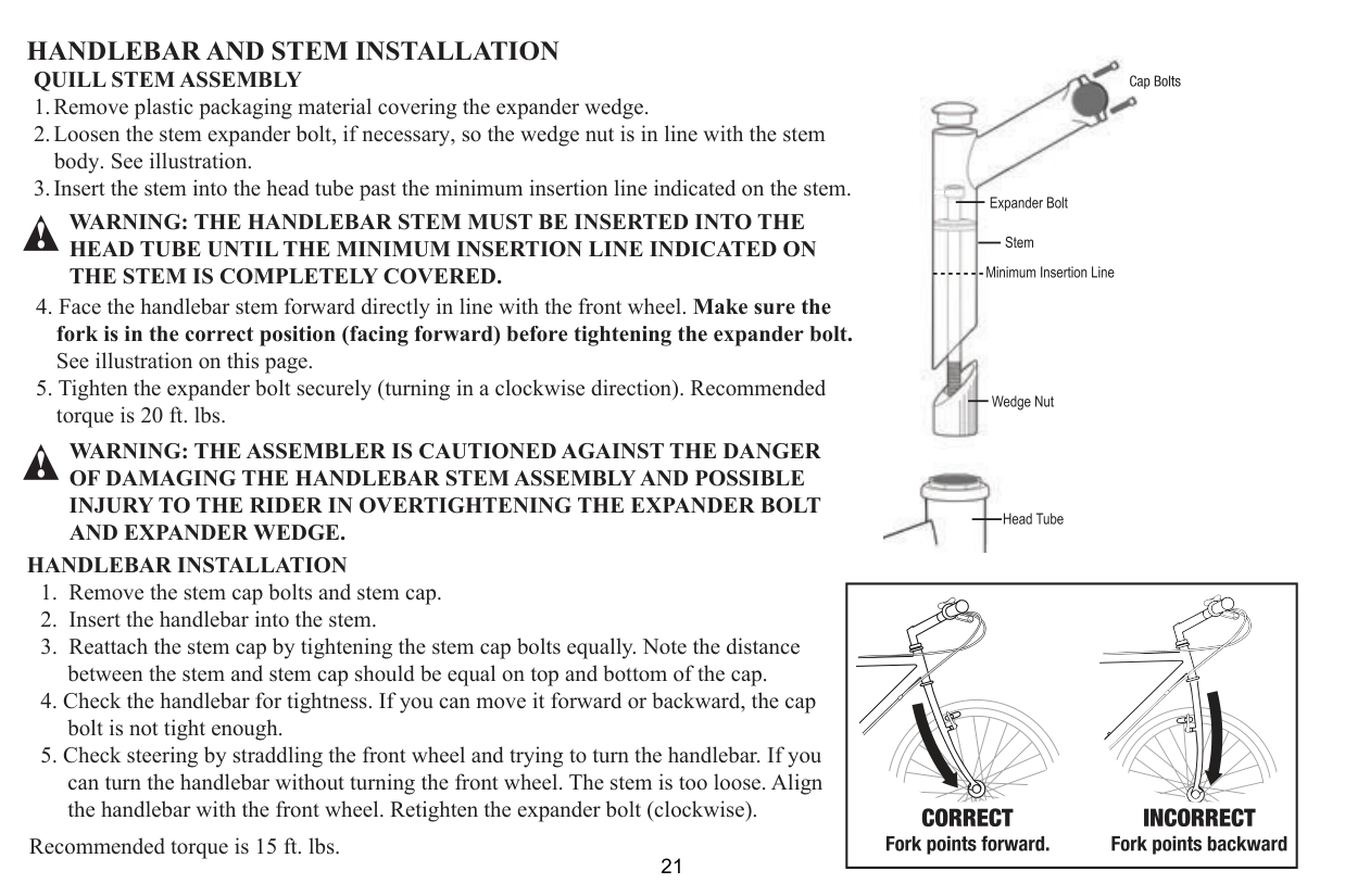
##### QUILL STEM ASSEMBLY
WARNING: THE HANDLEBAR STEM MUST BE INSERTED INTO THE HEAD TUBE UNTIL THE MINIMUM INSERTION LINE INDICATED ON THE STEM IS COMPLETELY COVERED.
WARNING: THE ASSEMBLER IS CAUTIONED AGAINST THE DANGER OF DAMAGING THE HANDLEBAR STEM ASSEMBLY AND POSSIBLE INJURY TO THE RIDER IN OVERTIGHTENING THE EXPANDER BOLT AND EXPANDER WEDGE.

HANDLEBAR INSTALLATION
Recommended torque is 15 ft. lbs.
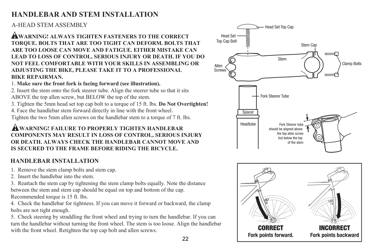
A-HEAD STEM ASSEMBLY
WARNING! ALWAYS TIGHTEN FASTENERS TO THE CORRECT TORQUE. BOLTS THAT ARE TOO TIGHT CAN DEFORM. BOLTS THAT ARE TOO LOOSE CAN MOVE AND FATIGUE. EITHER MISTAKE CAN LEAD TO LOSS OF CONTROL, SERIOUS INJURY OR DEATH. IF YOU DO NOT FEEL COMFORTABLE WITH YOUR SKILLS IN ASSEMBLING OR ADJUSTING THE BIKE, PLEASE TAKE IT TO A PROFESSIONAL BIKE REPAIRMAN.
WARNING! FAILURE TO PROPERLY TIGHTEN HANDLEBAR COMPONENTS MAY RESULT IN LOSS OF CONTROL, SERIOUS INJURY OR DEATH. ALWAYS CHECK THE HANDLEBAR CANNOT MOVE AND IS SECURED TO THE FRAME BEFORE RIDING THE BICYCLE.
Fork Steerer tube should be aligned above


the top allen screw but below the top


of the stem
##### HANDLEBAR INSTALLATION
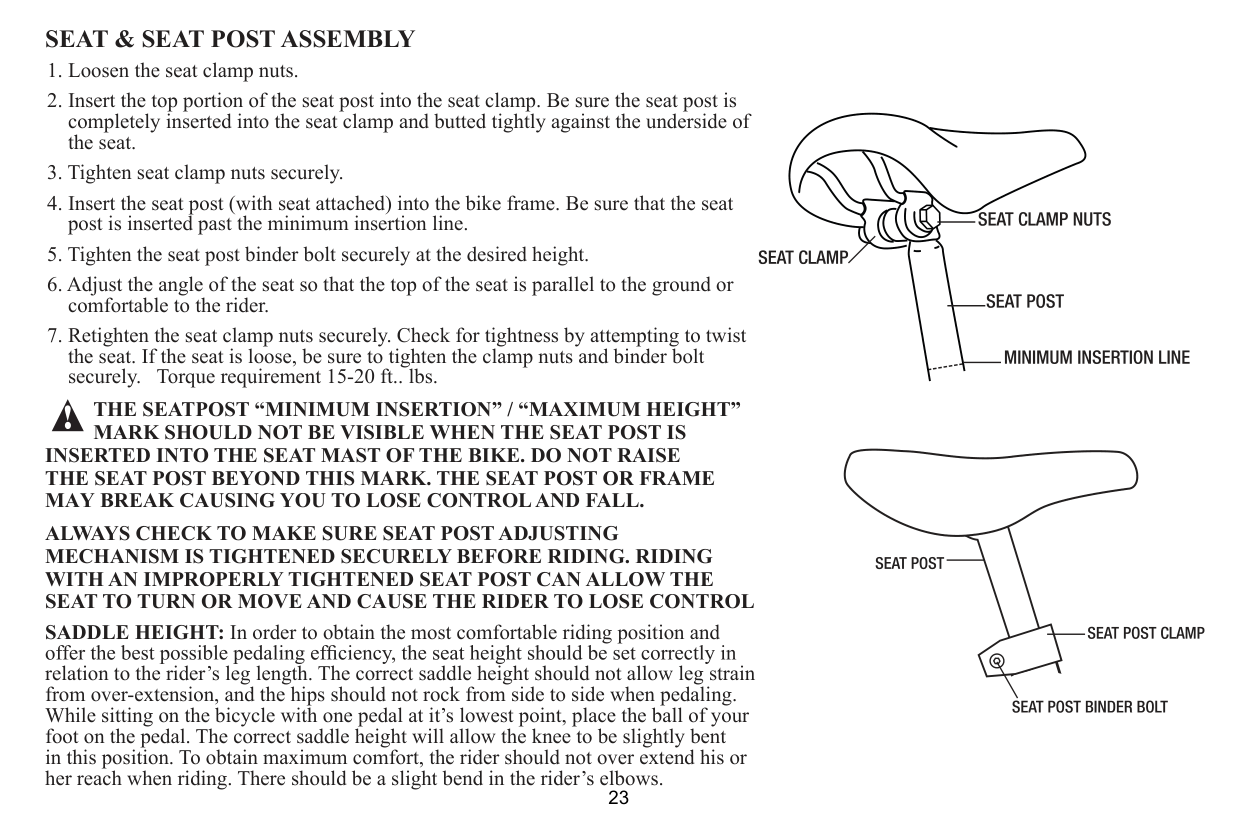
SEAT & SEAT POST ASSEMBLY
THE SEATPOST “MINIMUM INSERTION” / “MAXIMUM HEIGHT” MARK SHOULD NOT BE VISIBLE WHEN THE SEAT POST IS
INSERTED INTO THE SEAT MAST OF THE BIKE. DO NOT RAISE THE SEAT POST BEYOND THIS MARK. THE SEAT POST OR FRAME MAY BREAK CAUSING YOU TO LOSE CONTROL AND FALL.
ALWAYS CHECK TO MAKE SURE SEAT POST ADJUSTING MECHANISM IS TIGHTENED SECURELY BEFORE RIDING. RIDING WITH AN IMPROPERLY TIGHTENED SEAT POST CAN ALLOW THE SEAT TO TURN OR MOVE AND CAUSE THE RIDER TO LOSE CONTROL
SADDLE HEIGHT: In order to obtain the most comfortable riding position and
relation to the rider’s leg length. The correct saddle height should not allow leg strain from over-extension, and the hips should not rock from side to side when pedaling. While sitting on the bicycle with one pedal at it’s lowest point, place the ball of your foot on the pedal. The correct saddle height will allow the knee to be slightly bent in this position. To obtain maximum comfort, the rider should not over extend his or her reach when riding. There should be a slight bend in the rider’s elbows.
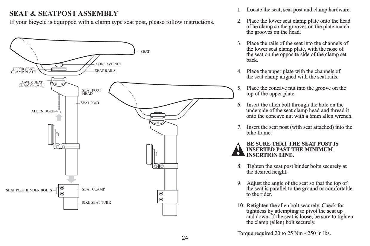
SEAT & SEATPOST ASSEMBLY
If your bicycle is equipped with a clamp type seat post, please follow instructions.
SEAT
CONCAVE NUT
UPPER SEAT CLAMP PLATE SEAT RAILS
| | | | | |---|---|---|---| | | | | |
LOWER SEAT CLAMP PLATE
SEAT POST HEAD
SEAT POST
ALLEN BOLT
| | |---| | |
| | |---| | |
SEAT CLAMPSEAT POST BINDER BOLTS
BIKE SEAT TUBE
Torque required 20 to 25 Nm - 250 in lbs.
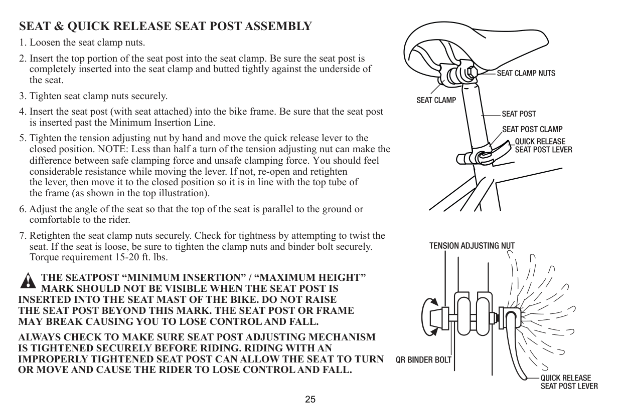
SEAT & QUICK RELEASE SEAT POST ASSEMBLY
THE SEATPOST “MINIMUM INSERTION” / “MAXIMUM HEIGHT” MARK SHOULD NOT BE VISIBLE WHEN THE SEAT POST IS
INSERTED INTO THE SEAT MAST OF THE BIKE. DO NOT RAISE THE SEAT POST BEYOND THIS MARK. THE SEAT POST OR FRAME MAY BREAK CAUSING YOU TO LOSE CONTROL AND FALL.
ALWAYS CHECK TO MAKE SURE SEAT POST ADJUSTING MECHANISM IS TIGHTENED SECURELY BEFORE RIDING. RIDING WITH AN IMPROPERLY TIGHTENED SEAT POST CAN ALLOW THE SEAT TO TURN OR MOVE AND CAUSE THE RIDER TO LOSE CONTROL AND FALL.
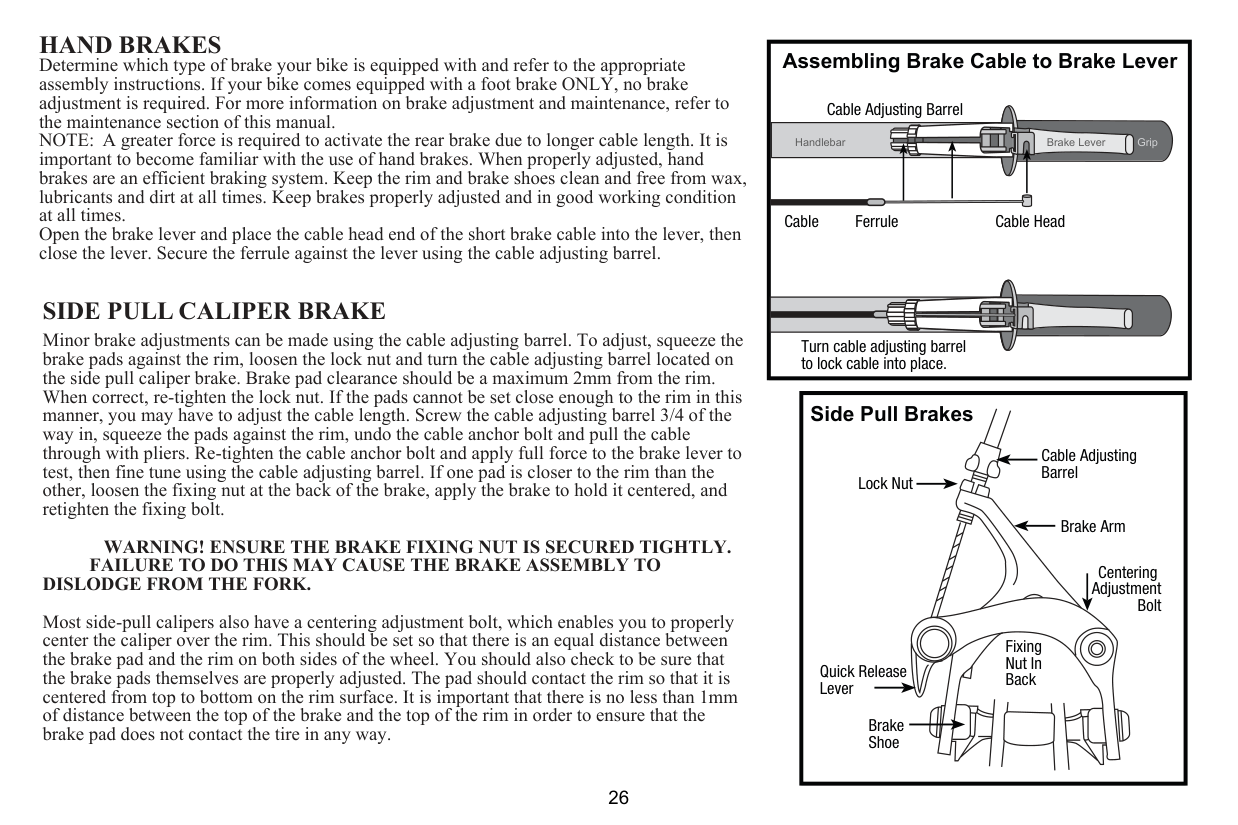
HAND BRAKES Determine which type of brake your bike is equipped with and refer to the appropriate assembly instructions. If your bike comes equipped with a foot brake ONLY, no brake adjustment is required. For more information on brake adjustment and maintenance, refer to the maintenance section of this manual. NOTE: A greater force is required to activate the rear brake due to longer cable length. It is important to become familiar with the use of hand brakes. When properly adjusted, hand brakes are an efficient braking system. Keep the rim and brake shoes clean and free from wax, lubricants and dirt at all times. Keep brakes properly adjusted and in good working condition at all times. Open the brake lever and place the cable head end of the short brake cable into the lever, then close the lever. Secure the ferrule against the lever using the cable adjusting barrel.
SIDE PULL CALIPER BRAKE
Minor brake adjustments can be made using the cable adjusting barrel. To adjust, squeeze the brake pads against the rim, loosen the lock nut and turn the cable adjusting barrel located on the side pull caliper brake. Brake pad clearance should be a maximum 2mm from the rim. When correct, re-tighten the lock nut. If the pads cannot be set close enough to the rim in this manner, you may have to adjust the cable length. Screw the cable adjusting barrel 3/4 of the way in, squeeze the pads against the rim, undo the cable anchor bolt and pull the cable through with pliers. Re-tighten the cable anchor bolt and apply full force to the brake lever to test, then fine tune using the cable adjusting barrel. If one pad is closer to the rim than the other, loosen the fixing nut at the back of the brake, apply the brake to hold it centered, and retighten the fixing bolt.
WARNING! ENSURE THE BRAKE FIXING NUT IS SECURED TIGHTLY. FAILURE TO DO THIS MAY CAUSE THE BRAKE ASSEMBLY TO
DISLODGE FROM THE FORK.
Most side-pull calipers also have a centering adjustment bolt, which enables you to properly center the caliper over the rim. This should be set so that there is an equal distance between the brake pad and the rim on both sides of the wheel. You should also check to be sure that the brake pads themselves are properly adjusted. The pad should contact the rim so that it is centered from top to bottom on the rim surface. It is important that there is no less than 1mm of distance between the top of the brake and the top of the rim in order to ensure that the brake pad does not contact the tire in any way.
Assembling Brake Cable to Brake Lever
######### Cable Adjusting Barrel
Handlebar Grip
Brake Lever
Cable HeadCable Ferrule
Turn cable adjusting barrel to lock cable into place.
|Side Pull Brakes
Cable Adjusting Barrel
Brake Shoe
Fixing Nut In Back
Brake Arm
Lock Nut
Quick Release Lever
Centering Adjustment
Bolt
| |---|
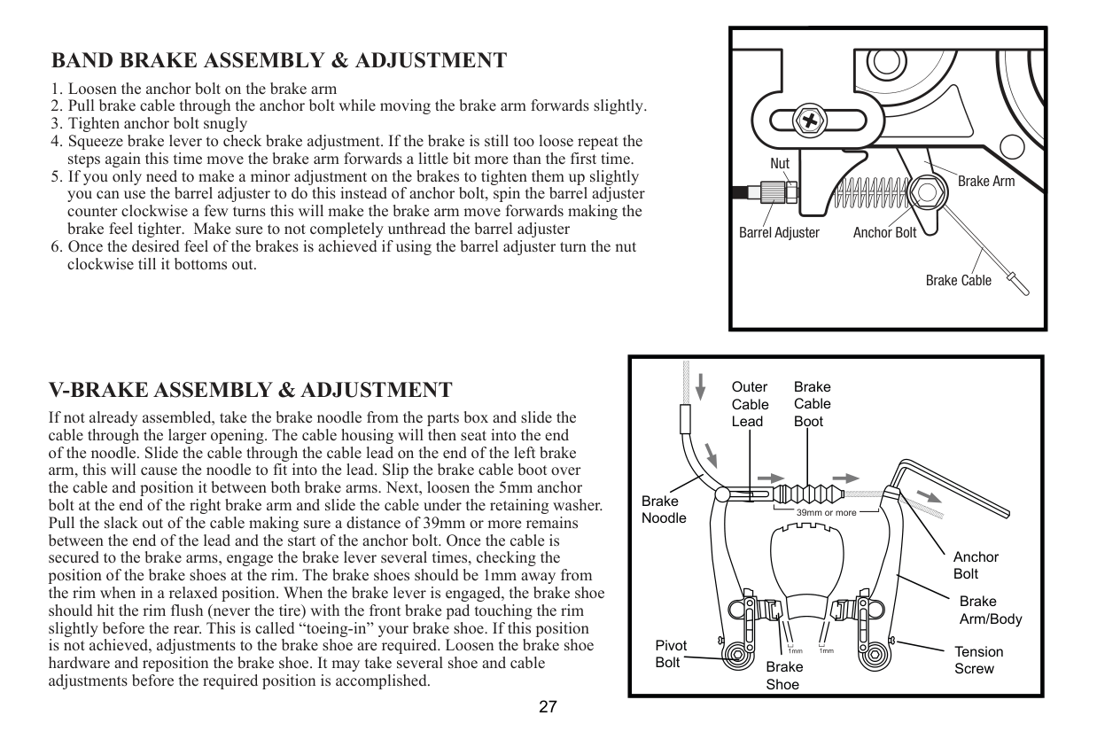
BAND BRAKE ASSEMBLY & ADJUSTMENT
Nut
Brake Arm
| | | |---|---| | | |
Barrel Adjuster
Anchor Bolt
Brake Cable
V-BRAKE ASSEMBLY & ADJUSTMENT
If not already assembled, take the brake noodle from the parts box and slide the cable through the larger opening. The cable housing will then seat into the end of the noodle. Slide the cable through the cable lead on the end of the left brake arm, this will cause the noodle to fit into the lead. Slip the brake cable boot over the cable and position it between both brake arms. Next, loosen the 5mm anchor bolt at the end of the right brake arm and slide the cable under the retaining washer. Pull the slack out of the cable making sure a distance of 39mm or more remains between the end of the lead and the start of the anchor bolt. Once the cable is secured to the brake arms, engage the brake lever several times, checking the position of the brake shoes at the rim. The brake shoes should be 1mm away from the rim when in a relaxed position. When the brake lever is engaged, the brake shoe should hit the rim flush (never the tire) with the front brake pad touching the rim slightly before the rear. This is called “toeing-in” your brake shoe. If this position is not achieved, adjustments to the brake shoe are required. Loosen the brake shoe hardware and reposition the brake shoe. It may take several shoe and cable adjustments before the required position is accomplished.
|Brake Noodle
Outer Cable Lead
Brake Cable Boot
Anchor Bolt
Brake Arm/Body
Tension ScrewBrake Shoe
Pivot Bolt
39mm or more| |---|
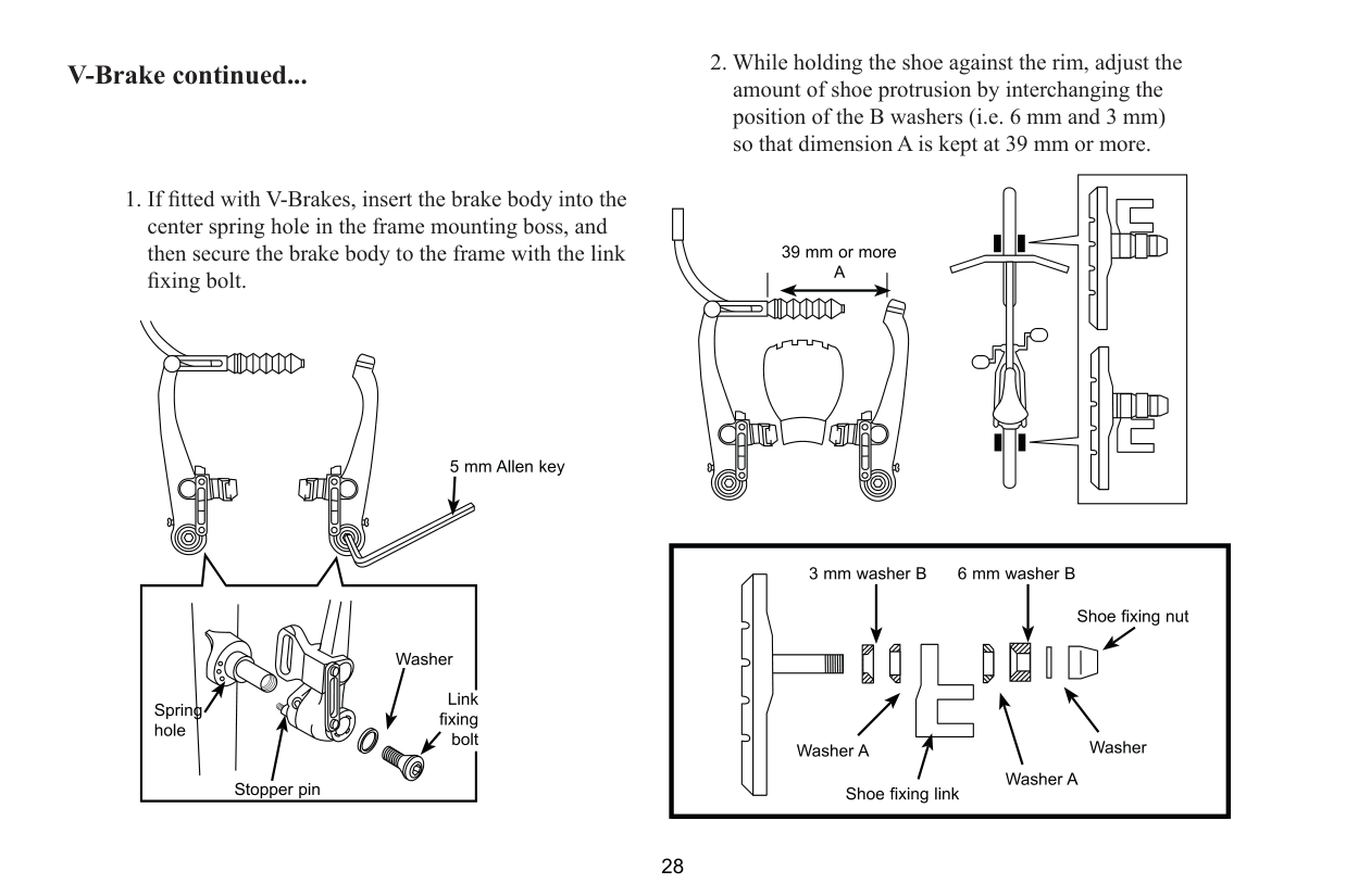
V-Brake continued...
center spring hole in the frame mounting boss, and then secure the brake body to the frame with the link
| | | |---|---| | | |
| | | |---|---|
| | | |---|---|
shoe fixing nut
5 mm Allen key
1 mm 1 mm
1mm
Spring tension adjustment screw
Spring tension adjustment screw
Allow 1mm clearance below tire edge and brake pad.
1mm 1mm
5 mm Allen key
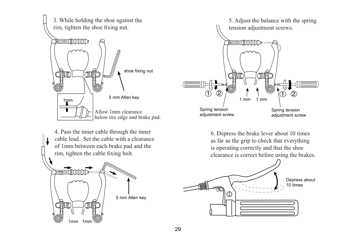
Depress about 10 times
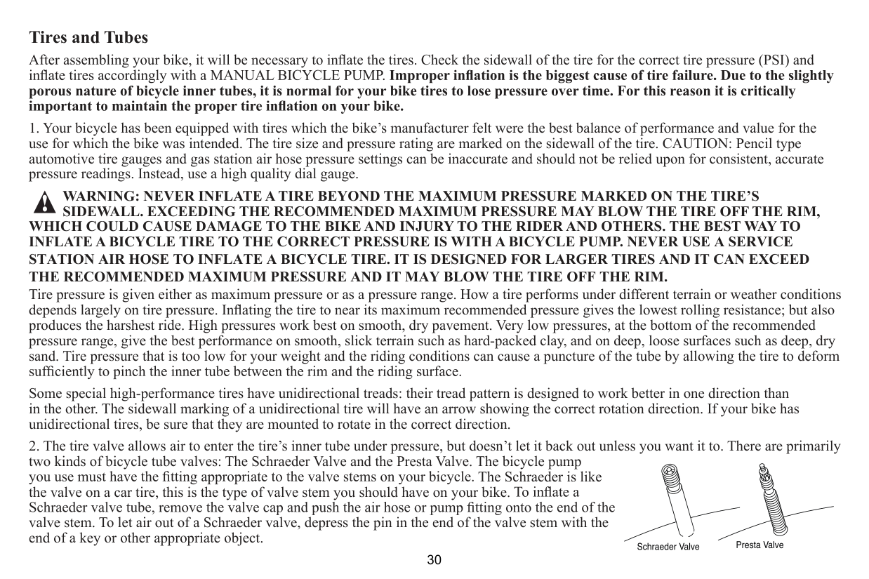
Tires and Tubes
##### porous nature of bicycle inner tubes, it is normal for your bike tires to lose pressure over time. For this reason it is critically
WARNING: NEVER INFLATE A TIRE BEYOND THE MAXIMUM PRESSURE MARKED ON THE TIRE’S SIDEWALL. EXCEEDING THE RECOMMENDED MAXIMUM PRESSURE MAY BLOW THE TIRE OFF THE RIM,
WHICH COULD CAUSE DAMAGE TO THE BIKE AND INJURY TO THE RIDER AND OTHERS. THE BEST WAY TO INFLATE A BICYCLE TIRE TO THE CORRECT PRESSURE IS WITH A BICYCLE PUMP. NEVER USE A SERVICE STATION AIR HOSE TO INFLATE A BICYCLE TIRE. IT IS DESIGNED FOR LARGER TIRES AND IT CAN EXCEED THE RECOMMENDED MAXIMUM PRESSURE AND IT MAY BLOW THE TIRE OFF THE RIM. Tire pressure is given either as maximum pressure or as a pressure range. How a tire performs under different terrain or weather conditions produces the harshest ride. High pressures work best on smooth, dry pavement. Very low pressures, at the bottom of the recommended pressure range, give the best performance on smooth, slick terrain such as hard-packed clay, and on deep, loose surfaces such as deep, dry sand. Tire pressure that is too low for your weight and the riding conditions can cause a puncture of the tube by allowing the tire to deform Some special high-performance tires have unidirectional treads: their tread pattern is designed to work better in one direction than in the other. The sidewall marking of a unidirectional tire will have an arrow showing the correct rotation direction. If your bike has unidirectional tires, be sure that they are mounted to rotate in the correct direction.
The Schraeder is like the valve on a car tire, this is the type of valve stem you should have on your bike. valve stem. To let air out of a Schraeder valve, depress the pin in the end of the valve stem with the end of a key or other appropriate object.
REFLECTORS
, inspect
onto your bicycle. Please refer to the following section for instructions on all types of
WARNING! REFLECTORS ARE IMPORTANT SAFETY DEVICES WHICH ARE DESIGNED AS AN INTEGRAL PART OF YOUR BICYCLE. FEDERAL
REGULATIONS REQUIRE EVERY BICYCLE TO BE EQUIPPED WITH FRONT, REAR, WHEEL, AND PEDAL REFLECTORS. THESE REFLECTORS ARE DESIGNED TO PICK UP AND REFLECT STREET LIGHTS AND CAR LIGHTS IN A WAY THAT HELPS YOU TO BE SEEN AND RECOGNIZED AS A MOVING BICYCLIST. CHECK REFLECTORS AND THEIR MOUNTING BRACKETS REGULARLY TO MAKE SURE THEY ARE CLEAN, STRAIGHT, UNBROKEN AND SECURELY MOUNTED. HAVE YOUR DEALER REPLACE DAMAGED REFLECTORS AND STRAIGHTEN OR TIGHTEN ANY THAT ARE BENT OR LOOSE.
FORK MOUNT REFLECTORS and then through the fork. Next, insert a second washer onto the bolt and thread a hex nut upright position.
Re ector
Screw
Re ector Bracket
Washer
Hex Bolt
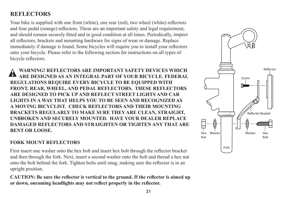
WasherHex Nut
Fork
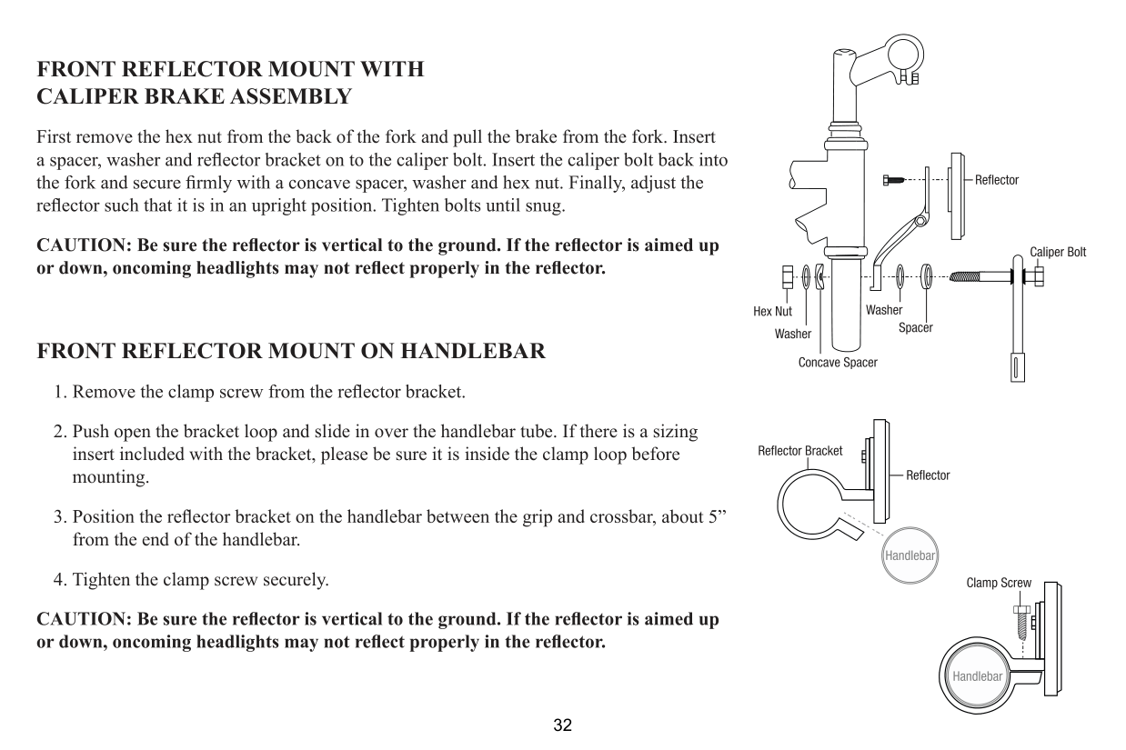
FRONT REFLECTOR MOUNT WITH CALIPER BRAKE ASSEMBLY
First remove the hex nut from the back of the fork and pull the brake from the fork. Insert
FRONT REFLECTOR MOUNT ON HANDLEBAR
, about 5” from the end of the handlebar.
| | | | |---|---|---| | | | |
| | | |---|---| | | | | | |
REAR REFLECTOR MOUNT ON SEAT POST
, see the top diagram.
facing away from the bike.
| | | |---|---| | | |
REAR REFLECTOR MOUNT ON SEAT STAY BRACKET
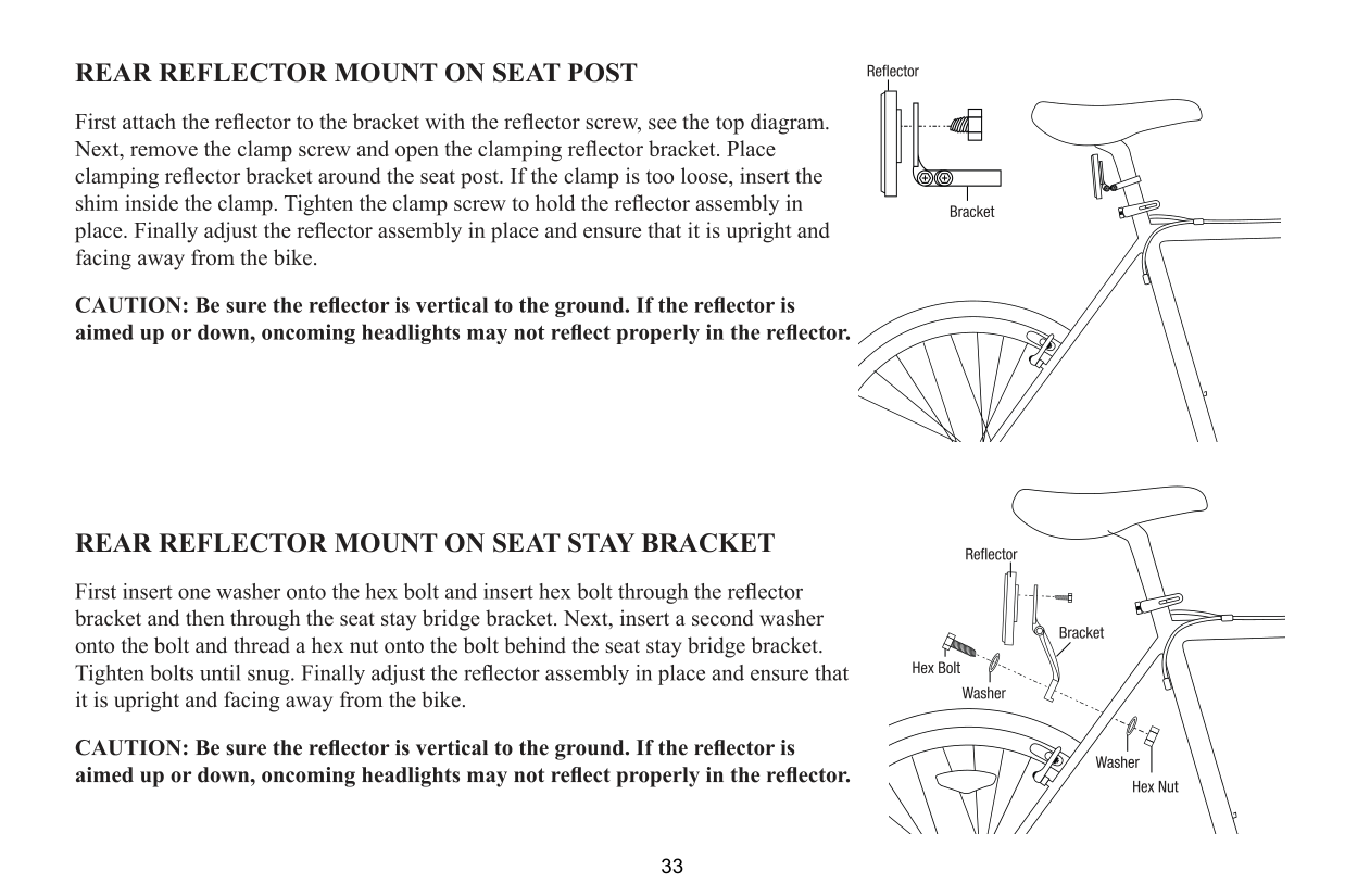
bracket and then through the seat stay bridge bracket. Next, insert a second washer onto the bolt and thread a hex nut onto the bolt behind the seat stay bridge bracket.
it is upright and facing away from the bike.
SHIFTING GEARS If your bike is a multi speed bike, please read the information below to familiarize yourself with the basics of shifting gears. Your multi-speed bicycle will have a derailleur drivetrain (see 1. below), an internal gear hub drivetrain (see 2. below) or, in some special cases, a combination of the two.
a. A Brief Note About Shifting Gears There are several different types and styles of shifting controls: levers, twist grips, triggers, combination shift/brake controls, pushbuttons, and so on. If you are not comfortable shifting gears, ask your local bike mechanic to explain the type of shifting controls that are on your bike, and to show you how they work. The vocabulary of shifting can be pretty confusing. A downshift is a shift to
CAUTION: Never move the shifter while pedaling backward, nor pedal backward immediately after having moved the shifter. This could jam the chain and cause damage to the bicycle.
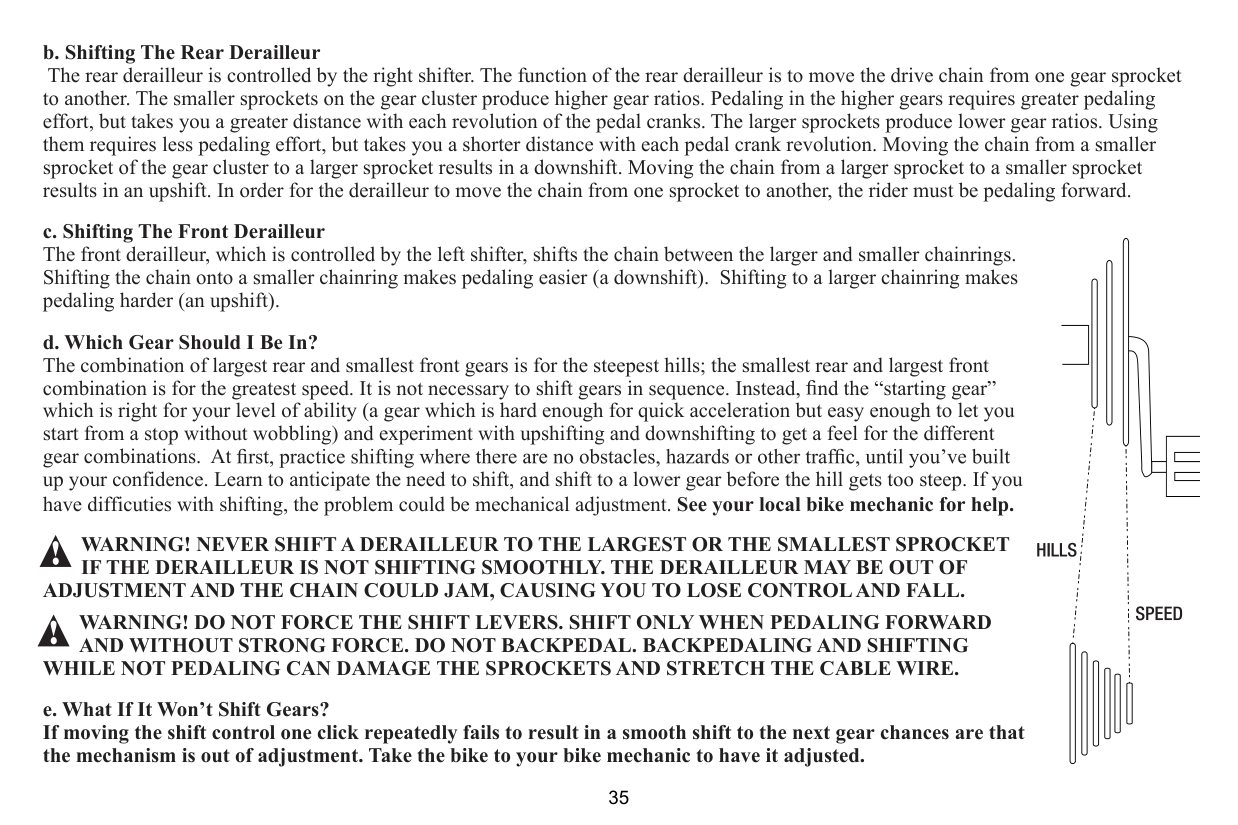
to another. The smaller sprockets on the gear cluster produce higher gear ratios. Pedaling in the higher gears requires greater pedaling effort, but takes you a greater distance with each revolution of the pedal cranks. The larger sprockets produce lower gear ratios. Using them requires less pedaling effort, but takes you a shorter distance with each pedal crank revolution. Moving the chain from a smaller sprocket of the gear cluster to a larger sprocket results in a downshift. Moving the chain from a larger sprocket to a smaller sprocket results in an upshift. In order for the derailleur to move the chain from one sprocket to another, the rider must be pedaling forward.
WARNING! NEVER SHIFT A DERAILLEUR TO THE LARGEST OR THE SMALLEST SPROCKET IF THE DERAILLEUR IS NOT SHIFTING SMOOTHLY. THE DERAILLEUR MAY BE OUT OF
ADJUSTMENT AND THE CHAIN COULD JAM, CAUSING YOU TO LOSE CONTROL AND FALL.
WARNING! DO NOT FORCE THE SHIFT LEVERS. SHIFT ONLY WHEN PEDALING FORWARD AND WITHOUT STRONG FORCE. DO NOT BACKPEDAL. BACKPEDALING AND SHIFTING
WHILE NOT PEDALING CAN DAMAGE THE SPROCKETS AND STRETCH THE CABLE WIRE.
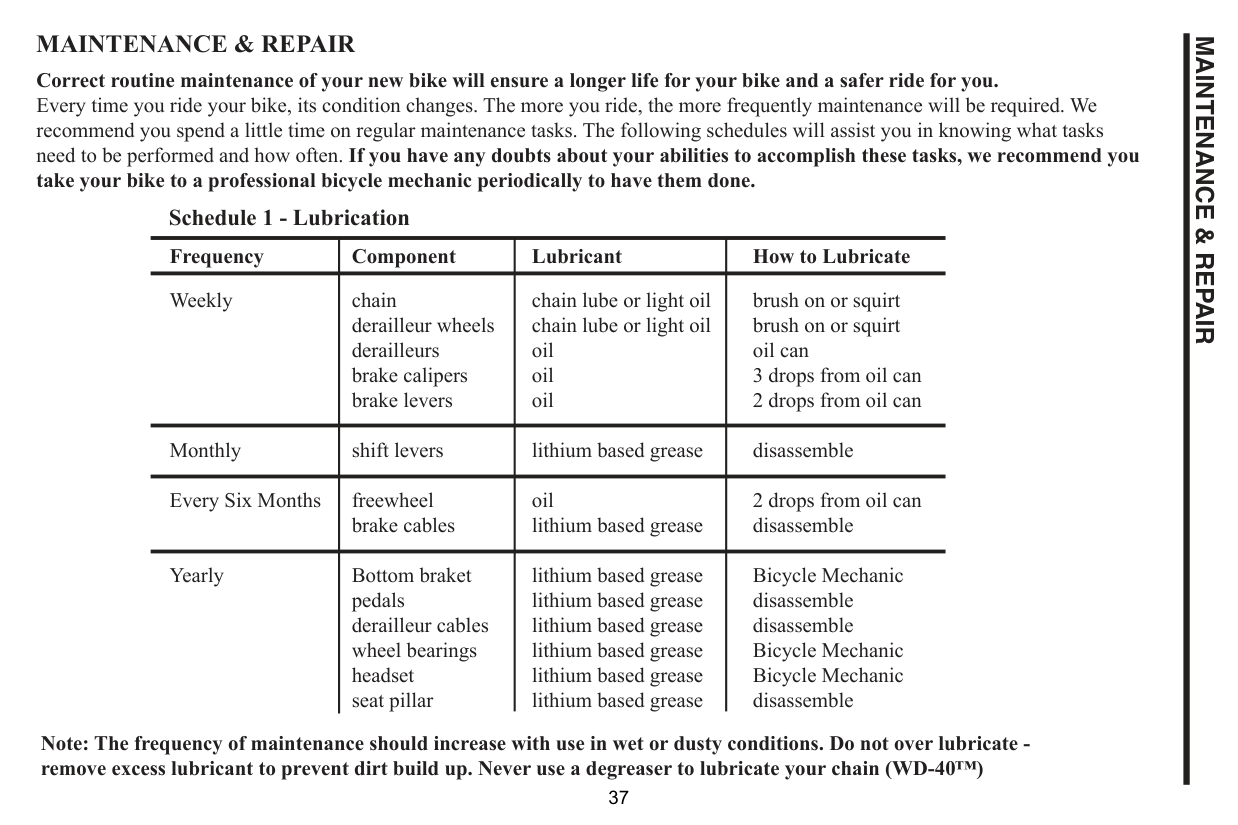
MAINTENANCE & REPAIR Correct routine maintenance of your new bike will ensure a longer life for your bike and a safer ride for you. Every time you ride your bike, its condition changes. The more you ride, the more frequently maintenance will be required. We recommend you spend a little time on regular maintenance tasks. The following schedules will assist you in knowing what tasks need to be performed and how often. If you have any doubts about your abilities to accomplish these tasks, we recommend you take your bike to a professional bicycle mechanic periodically to have them done.
Schedule 1 - Lubrication
|Frequency|Component|Lubricant|How to Lubricate| |---|---|---|---| |Weekly|chain derailleur wheels derailleurs brake calipers brake levers|chain lube or light oil chain lube or light oil oil oil oil|brush on or squirt brush on or squirt oil can 3 drops from oil can 2 drops from oil can| |Monthly|shift levers|lithium based grease|disassemble| |Every Six Months|freewheel brake cables|oil lithium based grease|2 drops from oil can disassemble| |Yearly|Bottom braket pedals derailleur cables wheel bearings headset seat pillar|lithium based grease lithium based grease lithium based grease lithium based grease lithium based grease lithium based grease|Bicycle Mechanic disassemble disassemble Bicycle Mechanic Bicycle Mechanic disassemble|
Note: The frequency of maintenance should increase with use in wet or dusty conditions. Do not over lubricate remove excess lubricant to prevent dirt build up. Never use a degreaser to lubricate your chain (WD-40™)
MAINTENANCE & REPAIR
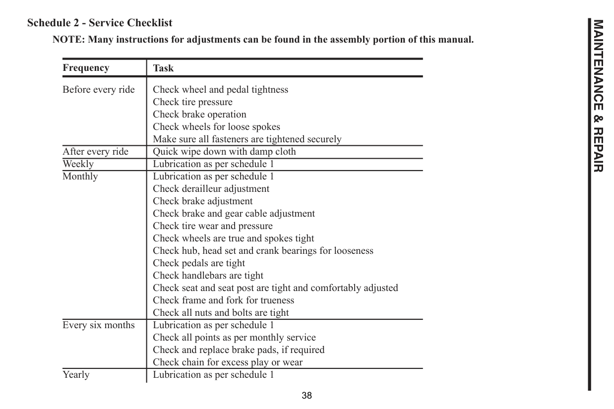
Schedule 2 - Service Checklist
NOTE: Many instructions for adjustments can be found in the assembly portion of this manual.
|Frequency|Task| |---|---| |Before every ride|Check wheel and pedal tightness Check tire pressure Check brake operation Check wheels for loose spokes Make sure all fasteners are tightened securely| |After every ride|Quick wipe down with damp cloth|
|Weekly|Lubrication as per schedule 1| |Monthly|Lubrication as per schedule 1 Check derailleur adjustment Check brake adjustment Check brake and gear cable adjustment Check tire wear and pressure Check wheels are true and spokes tight Check hub, head set and crank bearings for looseness Check pedals are tight Check handlebars are tight Check seat and seat post are tight and comfortably adjusted Check frame and fork for trueness Check all nuts and bolts are tight| |Every six months|Lubrication as per schedule 1 Check all points as per monthly service Check and replace brake pads, if required Check chain for excess play or wear| |Yearly|Lubrication as per schedule 1|
MAINTENANCE & REPAIR
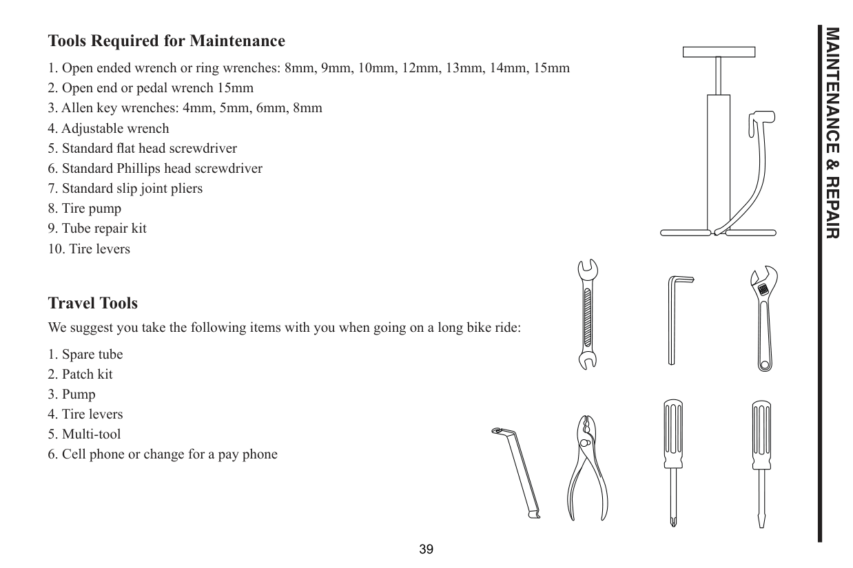
Tools Required for Maintenance
Travel Tools We suggest you take the following items with you when going on a long bike ride:
MAINTENANCE & REPAIR
WHEELS AND TIRES Wheel Inspection It is most important that wheels are kept in top condition. Properly maintaining your bicycle’s wheels will help braking performance and stability when riding. Be aware of the following potential problems:
MAINTENANCE & REPAIR
Tire Inspection Tires must be maintained properly to ensure road holding and stability. Check the following areas:
cause of tire failure. Due to the slightly porous nature of bicycle inner tubes, it is normal for your tires to lose
Bead Seating: Tread: Caution: Excessively worn or damaged tires should be replaced. Valves: A slow leak caused by the entry of the dirt can
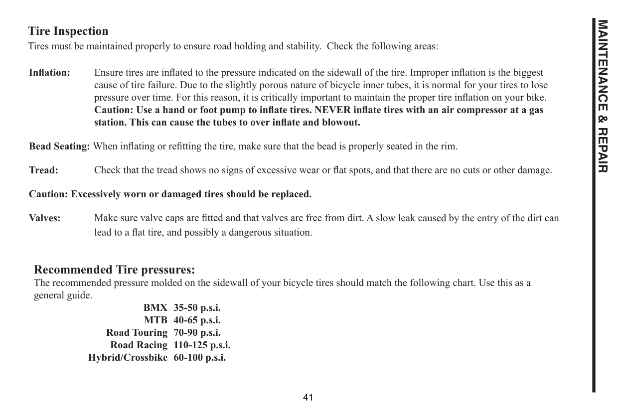
Recommended Tire pressures: The recommended pressure molded on the sidewall of your bicycle tires should match the following chart. Use this as a general guide.
BMX MTB
35-50 p.s.i. 40-65 p.s.i. 70-90 p.s.i. 110-125 p.s.i. 60-100 p.s.i.
Road Touring Road Racing Hybrid/Crossbike
MAINTENANCE & REPAIR
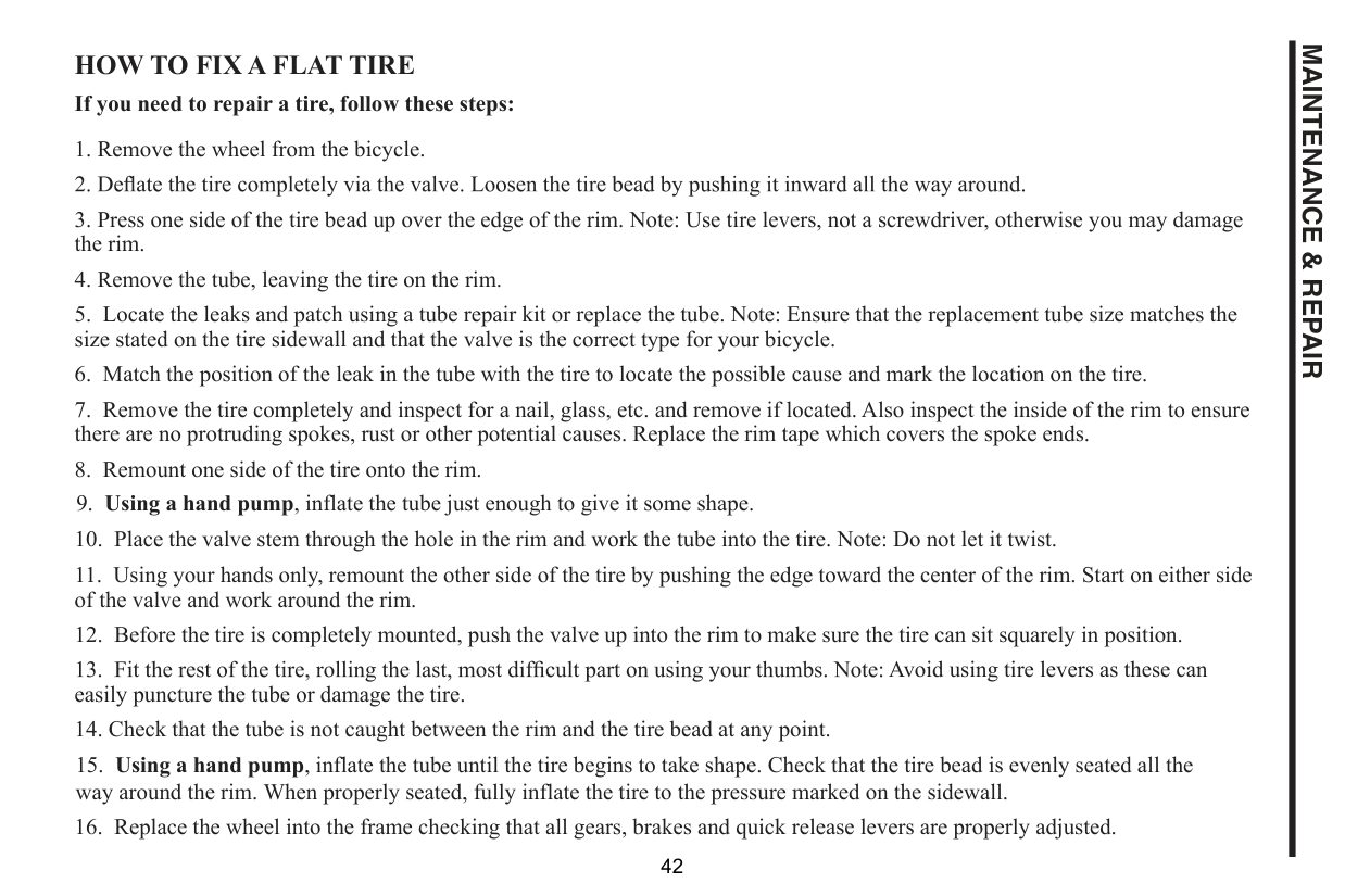
HOW TO FIX A FLAT TIRE If you need to repair a tire, follow these steps:
Avoid using tire levers as these can easily puncture the tube or damage the tire.
MAINTENANCE & REPAIR
HUB BEARING ADJUSTMENT When checked, the hub bearings of either wheel will require adjustment if there is any more than slight side play.
|Axle Lock Nut
Hub Body
Ball Bearings Bearing Cone
Washer Axle Nut| |---|
HEADSET INSPECTION The headset bearing adjustment should be checked every month. This is important as it is the headset which locks the fork into the frame, and if loose, can cause damage or result in an accident. While standing over the frame top tube with both feet on the
|Lock Nut
Lock Washer
Adjusting Cup/Cone
Ball Retainer
Top Head Cup
Standard Headset| |---|
any looseness in the headset, it will need adjustment. Check that the headset is not over tight by slowly rotating the fork to the right and left. If the fork tends to stick or bind at any point, the bearings are too tight.
Note: for repairs and adjustments.
##### ADJUSTMENT
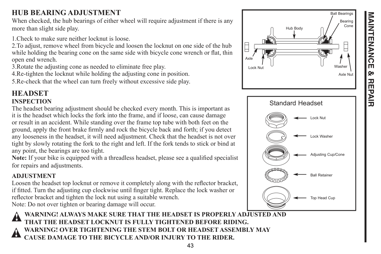
Note: Do not over tighten or bearing damage will occur.
##### WARNING! ALWAYS MAKE SURE THAT THE HEADSET IS PROPERLY ADJUSTED AND THAT THE HEADSET LOCKNUT IS FULLY TIGHTENED BEFORE RIDING. WARNING! OVER TIGHTENING THE STEM BOLT OR HEADSET ASSEMBLY MAY CAUSE DAMAGE TO THE BICYCLE AND/OR INJURY TO THE RIDER.
MAINTENANCE & REPAIR
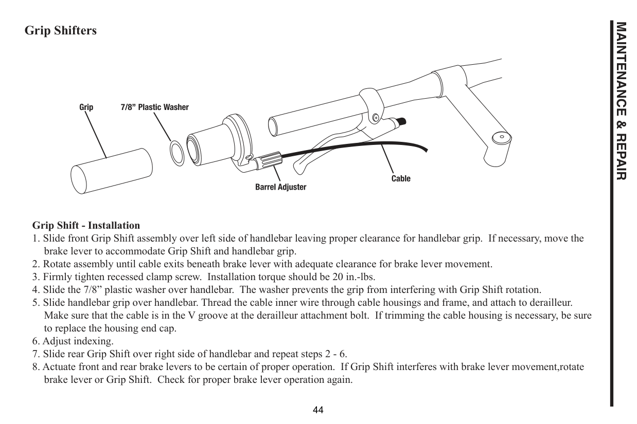
Grip Shifters
##### Grip Shift - Installation
MAINTENANCE & REPAIR
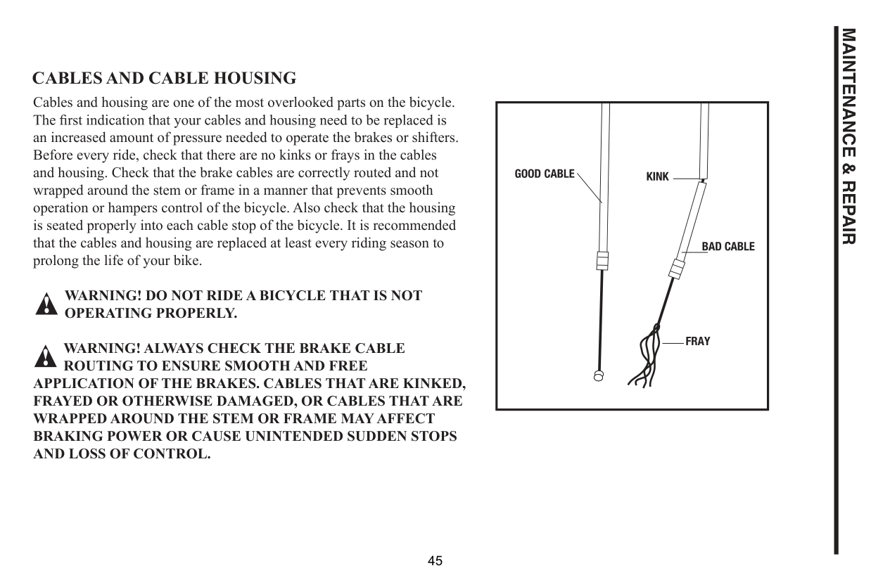
CABLES AND CABLE HOUSING Cables and housing are one of the most overlooked parts on the bicycle. an increased amount of pressure needed to operate the brakes or shifters. Before every ride, check that there are no kinks or frays in the cables and housing. Check that the brake cables are correctly routed and not wrapped around the stem or frame in a manner that prevents smooth operation or hampers control of the bicycle. Also check that the housing is seated properly into each cable stop of the bicycle. It is recommended that the cables and housing are replaced at least every riding season to prolong the life of your bike.
WARNING! DO NOT RIDE A BICYCLE THAT IS NOT OPERATING PROPERLY.
WARNING! ALWAYS CHECK THE BRAKE CABLE ROUTING TO ENSURE SMOOTH AND FREE
APPLICATION OF THE BRAKES. CABLES THAT ARE KINKED, FRAYED OR OTHERWISE DAMAGED, OR CABLES THAT ARE WRAPPED AROUND THE STEM OR FRAME MAY AFFECT BRAKING POWER OR CAUSE UNINTENDED SUDDEN STOPS AND LOSS OF CONTROL.
MAINTENANCE & REPAIR
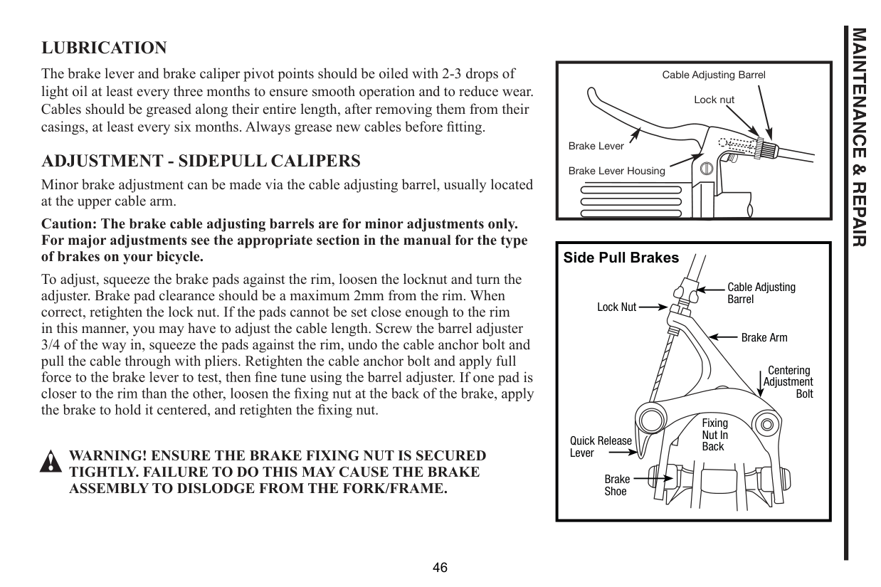
LUBRICATION
The brake lever and brake caliper pivot points should be oiled with 2-3 drops of light oil at least every three months to ensure smooth operation and to reduce wear. Cables should be greased along their entire length, after removing them from their
ADJUSTMENT - SIDEPULL CALIPERS
Minor brake adjustment can be made via the cable adjusting barrel, usually located at the upper cable arm.
Caution: The brake cable adjusting barrels are for minor adjustments only. For major adjustments see the appropriate section in the manual for the type of brakes on your bicycle.
To adjust, squeeze the brake pads against the rim, loosen the locknut and turn the adjuster. Brake pad clearance should be a maximum 2mm from the rim. When correct, retighten the lock nut. If the pads cannot be set close enough to the rim in this manner, you may have to adjust the cable length. Screw the barrel adjuster 3/4 of the way in, squeeze the pads against the rim, undo the cable anchor bolt and pull the cable through with pliers. Retighten the cable anchor bolt and apply full
. If one pad is
WARNING! ENSURE THE BRAKE FIXING NUT IS SECURED TIGHTLY. FAILURE TO DO THIS MAY CAUSE THE BRAKE ASSEMBLY TO DISLODGE FROM THE FORK/FRAME.
Cable Adjusting Barrel Lock nut
Brake Lever Brake Lever Housing
|Side Pull Brakes
Cable Adjusting Barrel
Brake Shoe
Fixing Nut In Back
Brake Arm
Lock Nut
Quick Release Lever
Centering Adjustment
Bolt
| |---|
MAINTENANCE & REPAIR
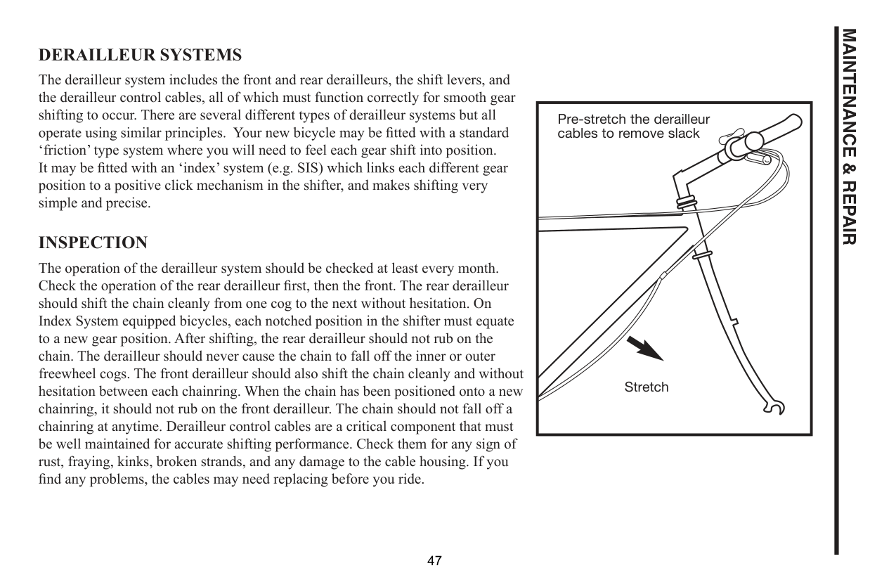
DERAILLEUR SYSTEMS The derailleur system includes the front and rear derailleurs, the shift levers, and the derailleur control cables, all of which must function correctly for smooth gear shifting to occur. There are several different types of derailleur systems but all ‘friction’ type system where you will need to feel each gear shift into position. position to a positive click mechanism in the shifter, and makes shifting very simple and precise. INSPECTION The operation of the derailleur system should be checked at least every month.
The rear derailleur should shift the chain cleanly from one cog to the next without hesitation. On Index System equipped bicycles, each notched position in the shifter must equate to a new gear position. After shifting, the rear derailleur should not rub on the chain. The derailleur should never cause the chain to fall off the inner or outer freewheel cogs. The front derailleur should also shift the chain cleanly and without hesitation between each chainring. When the chain has been positioned onto a new chainring, it should not rub on the front derailleur. The chain should not fall off a chainring at anytime. Derailleur control cables are a critical component that must be well maintained for accurate shifting performance. Check them for any sign of rust, fraying, kinks, broken strands, and any damage to the cable housing. If you
|Pre-stretch the derailleur cables to remove slack
Stretch| |---|
MAINTENANCE & REPAIR
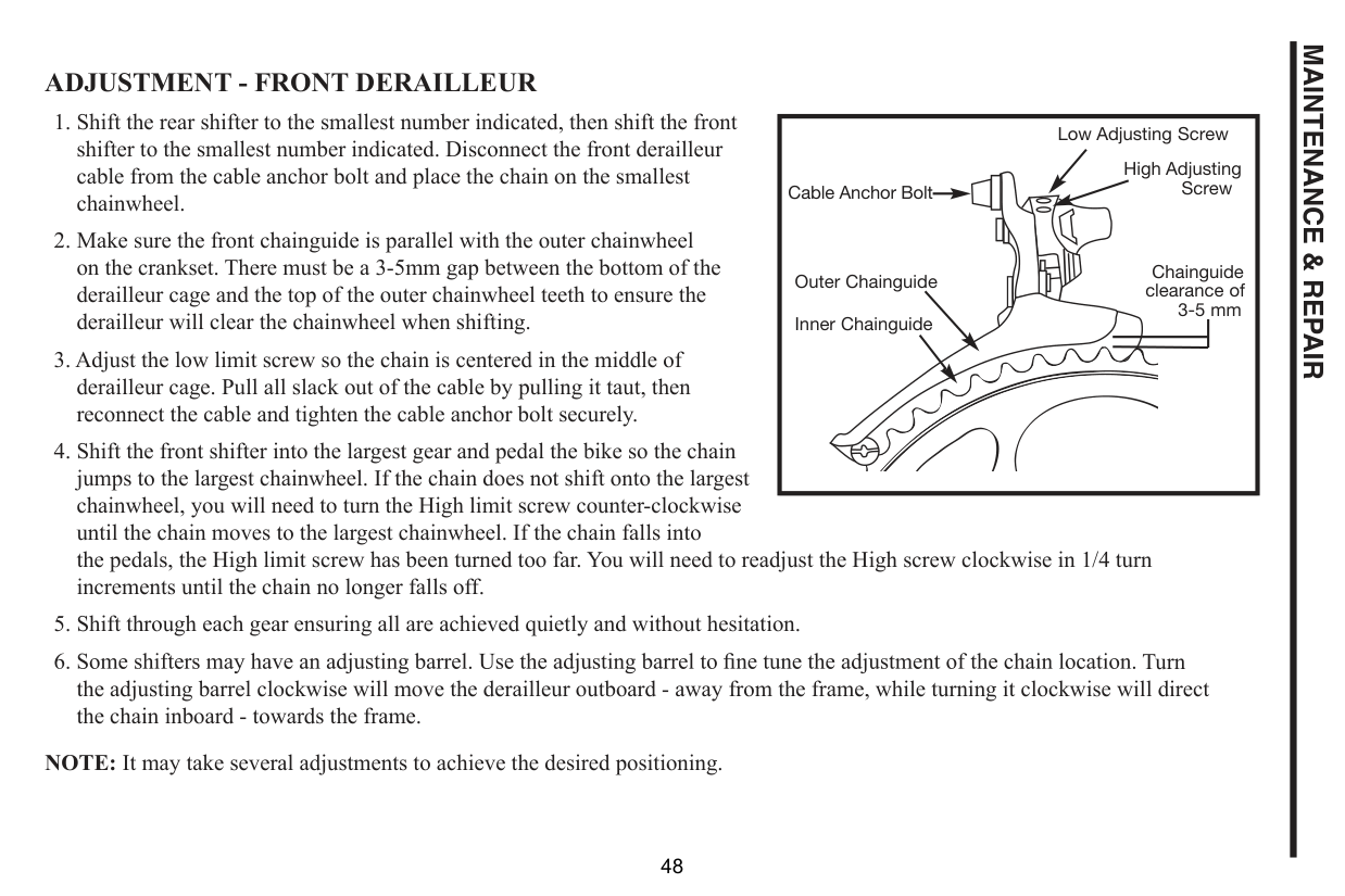
ADJUSTMENT - FRONT DERAILLEUR
|Cable Anchor Bolt
Outer Chainguide Inner Chainguide
Low Adjusting Screw High Adjusting Screw
Chainguide clearance of 3-5 mm
| |---|
Turn the adjusting barrel clockwise will move the derailleur outboard - away from the frame, while turning it clockwise will direct the chain inboard - towards the frame.
NOTE: It may take several adjustments to achieve the desired positioning.
MAINTENANCE & REPAIR
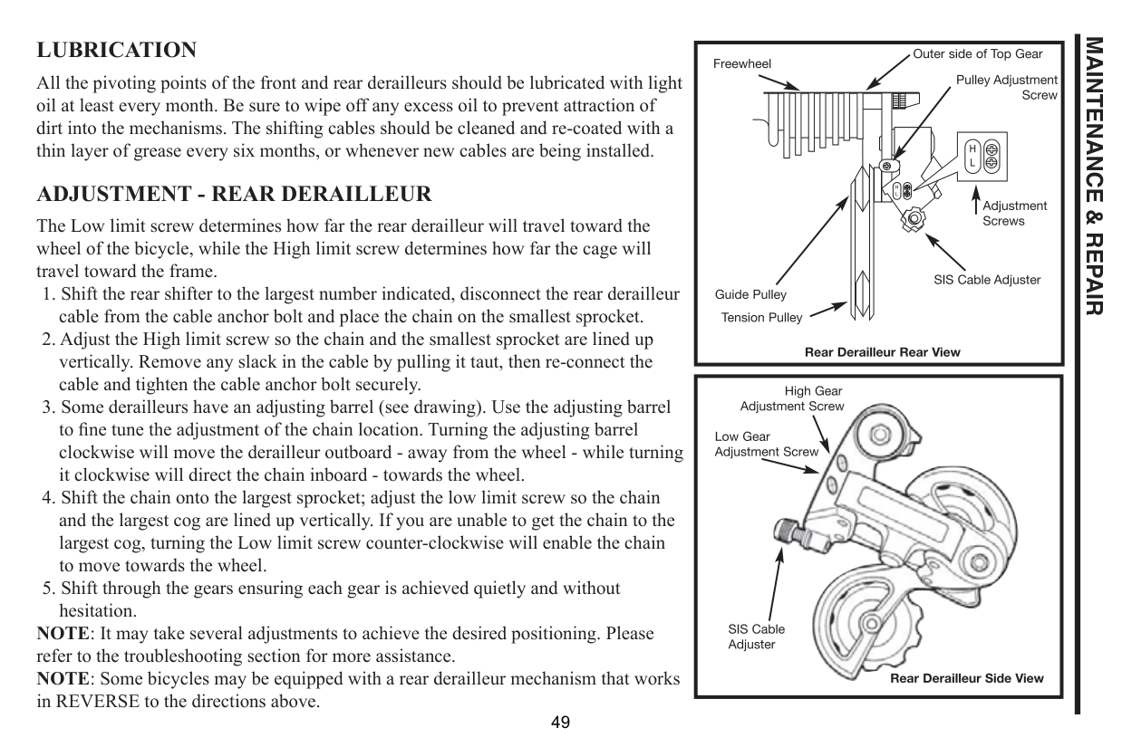
LUBRICATION
All the pivoting points of the front and rear derailleurs should be lubricated with light oil at least every month. Be sure to wipe off any excess oil to prevent attraction of dirt into the mechanisms. The shifting cables should be cleaned and re-coated with a thin layer of grease every six months, or whenever new cables are being installed.
ADJUSTMENT - REAR DERAILLEUR
The Low limit screw determines how far the rear derailleur will travel toward the wheel of the bicycle, while the High limit screw determines how far the cage will travel toward the frame.
clockwise will move the derailleur outboard - away from the wheel - while turning it clockwise will direct the chain inboard - towards the wheel.
NOTE: It may take several adjustments to achieve the desired positioning. Please refer to the troubleshooting section for more assistance. NOTE: Some bicycles may be equipped with a rear derailleur mechanism that works in REVERSE to the directions above.
| | |---|
|| |---|
MAINTENANCE & REPAIR
MAINTENANCE & REPAIR
PEDALS Pedals are available in a variety of shapes, sizes and materials, and each are designed with a particular purpose in mind. Some pedals as downward pressure, on the pedals. Use of toe clips with straps requires practice to acquire the necessary skill to operate them safely. Inspection: Pedals should be inspected every month, taking note of the following areas:
WARNING! Never ride with loose pedals. Always wear shoes. Lubrication and Adjustment: Many pedals cannot be disassembled to allow access to the internal bearings and axle. However, it is usually possible to inject a little oil onto the inside bearings, and this should be done every six months. If the pedal is the type that can be fully disassembled, then the bearings should be removed, cleaned and greased every six to twelve months. Because of the wide variety of pedal types and their internal complexity, disassembly procedures are beyond the scope of this manual and further assistance should be sought from a professional bicycle mechanic.
Attachment Note: The right and left pedals of a bicycle each have a different thread and are not interchangeable. Never force a pedal into the incorrect crank arm. Check for the right (R) and left (L) letters on each pedal and crank arm. Match the appropriate pedal to each crank only. When the axle is screwed all the way in, securely tighten using a 15mm narrow open-ended wrench so that the shoulder of the pedal spindle is securely tightened against the crank arm. If removing a pedal, remember that the right pedal axle must be turned counter compatible with the cranks on your bicycle. Bicycles use one of two types of cranks and these use different axle threads. Your bike may be equipped with cranks that are a one piece design with no separate axle. These operate with pedals that have a 1/2”(12.7mm) thread. Bikes equipped with three piece crank sets with a separate axle, left crank and right crank, use a slightly larger 9/16”(14mm) thread. Note: Never try and force a pedal with the wrong thread size into a bicycle crank.
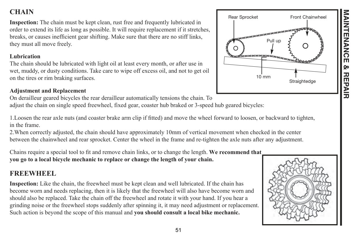
CHAIN Inspection: The chain must be kept clean, rust free and frequently lubricated in order to extend its life as long as possible. It will require replacement if it stretches,
MAINTENANCE & REPAIR
f links,
they must all move freely. Lubrication The chain should be lubricated with light oil at least every month, or after use in wet, muddy, or dusty conditions. Take care to wipe off excess oil, and not to get oil on the tires or rim braking surfaces. Adjustment and Replacement On derailleur geared bicycles the rear derailleur automatically tensions the chain. To adjust the chain on single speed freewheel, fixed gear, coaster hub braked or 3-speed hub geared bicycles:
in the frame. 2.When correctly adjusted, the chain should have approximately 10mm of vertical movement when checked in the center between the chainwheel and rear sprocket. Center the wheel in the frame and re-tighten the axle nuts after any adjustment.
We recommend that you go to a local bicycle mechanic to replace or change the length of your chain. FREEWHEEL Inspection: Like the chain, the freewheel must be kept clean and well lubricated. If the chain has become worn and needs replacing, then it is likely that the freewheel will also have become worn and should also be replaced. Take the chain off the freewheel and rotate it with your hand. If you hear a grinding noise or the freewheel stops suddenly after spinning it, it may need adjustment or replacement. Such action is beyond the scope of this manual and you should consult a local bike mechanic.
|| |---|
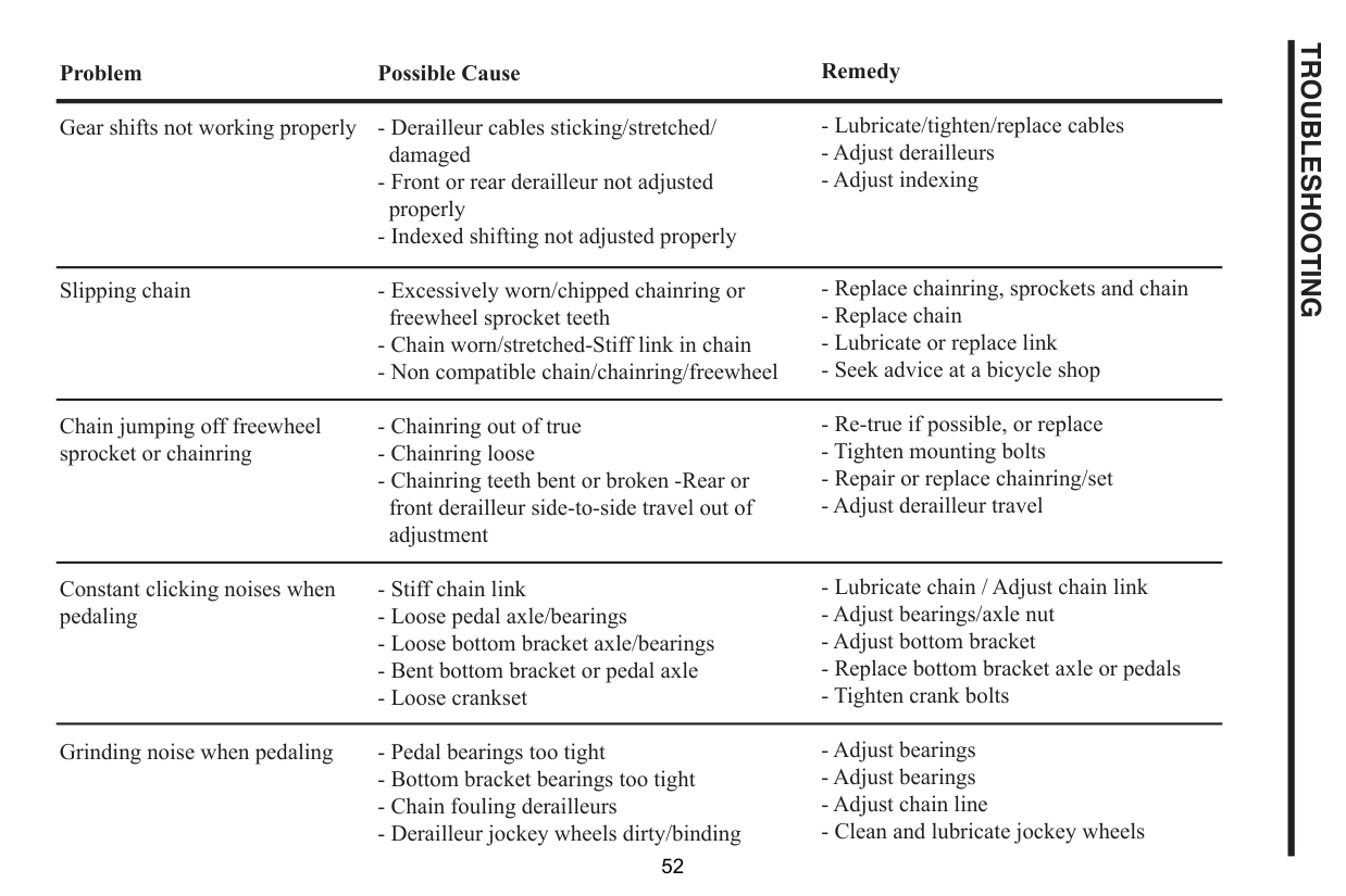
Gear shifts not working properly
Slipping chain
Chain jumping off freewheel sprocket or chainring
Constant clicking noises when pedaling
Grinding noise when pedaling
TROUBLESHOOTING
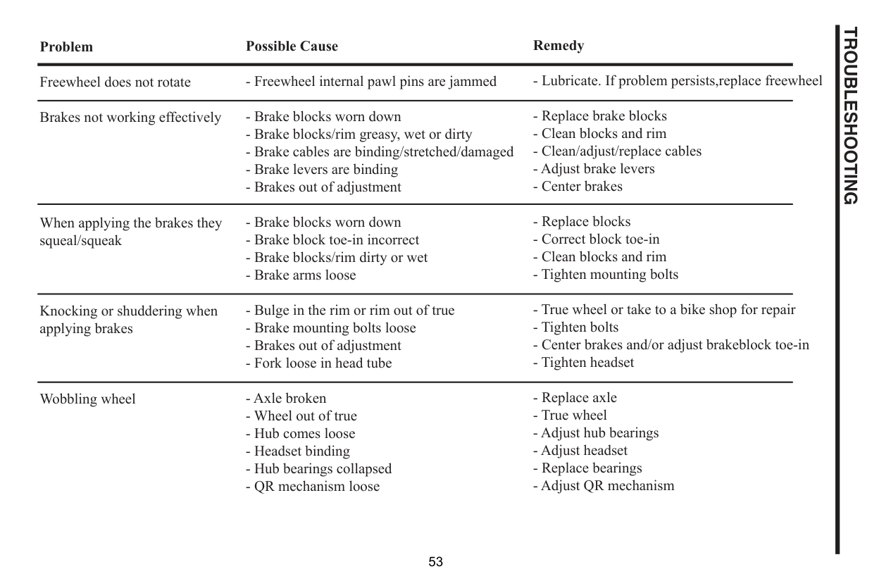
Freewheel does not rotate Brakes not working effectively
When applying the brakes they squeal/squeak
Knocking or shuddering when applying brakes
Wobbling wheel
TROUBLESHOOTING
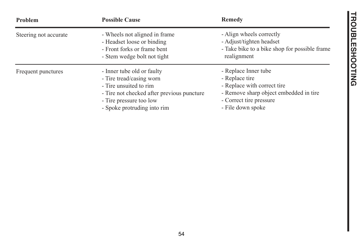
Steering not accurate
Frequent punctures
TROUBLESHOOTING
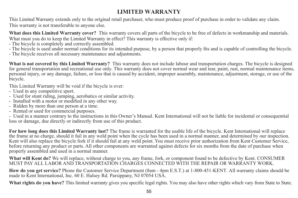
What is not covered by this Limited Warranty? This warranty does not include labour and transportation charges. The bicycle is designed for general transportation and recreational use only. This warranty does not cover normal wear and tear, paint, rust, normal maintenance items, personal injury, or any damage, failure, or loss that is caused by accident, improper assembly, maintenance, adjustment, storage, or use of the bicycle.
This Limited Warranty will be void if the bicycle is ever:
For how long does this Limited Warranty last? The frame is warranted for the usable life of the bicycle. Kent International will replace the frame at no charge, should it fail in any weld point when the cycle has been used in a normal manner, and determined by our inspection. Kent will also replace the bicycle fork if it should fail at any weld point. You must receive prior authorization from Kent Customer Service, before returning any product or parts. All other components are warranted against defects for six months from the date of purchase when properly assembled and used in a normal manner.
What will Kent do? We will replace, without charge to you, any frame, fork, or component found to be defective by Kent. CONSUMER MUST PAY ALL LABOR AND TRANSPORTATION CHARGES CONNECTED WITH THE REPAIR OR WARRANTY WORK.
How do you get service? Phone the Customer Service Department (8am - 4pm E.S.T.) at 1-800-451-KENT. All warranty claims should be made to Kent International, Inc. 60 E. Halsey Rd. Parsippany, NJ 07054 USA.
What rights do you have? This limited warranty gives you specific legal rights. You may also have other rights which vary from State to State.