
Ask AI
— answers from the official manualAnswers from the official manual.
Common questions
Common Questions
19 totalWhy is my meter showing a random, changing reading when the test leads are not connected to anything?
On some low AC and DC voltage ranges, the display may show a random, changing reading when the test leads are not connected to a device — this is normal and is caused by the high-input sensitivity. The reading will stabilize and give a proper measurement when connected to a circuit. (Page 10)
What should I do if the meter does not operate at all?
First check to be sure the batteries are properly installed and that they are good. If the battery is good and the meter still does not operate, check to be sure that both ends of the fuse are properly installed. For further assistance, call the Customer Service Line at 1-888-326-1006. (Page 18)
What is the maximum voltage the 82141 can safely measure?
The maximum input for both VDC and VAC is 600V DC/AC. Additionally, the voltage on the COM input jack must never exceed 500V above earth ground. (Pages 4, 5)
How do I determine if a 9V battery is good, weak, or bad using the battery test function?
Set the function switch to the 9V BAT position and connect the test leads to the battery. A reading above 8.2V indicates a good battery, 7.2V to 8.2V indicates a weak battery, and below 7.2V indicates a bad battery. (Page 15)
How do I factory reset the Craftsman 82141?
There is no specific procedure mentioned for a factory reset in this manual. The closest related action would be troubleshooting steps, such as checking batteries and installing new ones to resolve non-operation issues.
What steps should I follow if the meter displays an overrange warning?
If an '1' appears in the display during a measurement indicating that the value exceeds the selected range, change to a higher range. The meter will indicate the proper decimal point and value once you reset to a suitable range.
Show 13 more questions
How do I properly install the batteries?
What safety measures should be taken before performing resistance measurements?
What steps are involved in replacing a blown fuse?
How do I perform a resistance measurement?
How do I measure AC voltage?
What does it mean when '1' appears on the display during a measurement?
How do I know when the battery needs to be replaced?
How long can I use the 10A current measurement range before damaging the meter?
What type and size of battery does the Craftsman 82141 require?
What fuses does the 82141 use and where can I get replacements?
How do I safely replace the fuse in the 82141?
What should I do if '1_1' appears on my display?
How do I perform battery testing?
Full Manual
36 pages
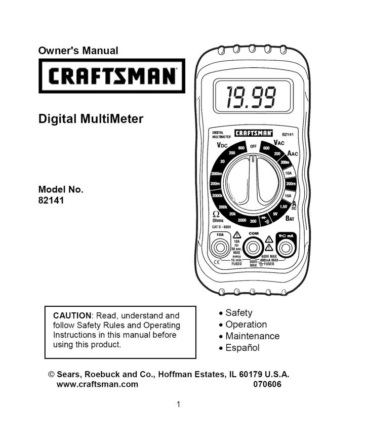
Owner's Manual Digital MultiMeter Model No. 82141
Caution:
Read, understand and follow Safety Rules and Operating Instructions in this manual before using this product.Il 60179 U.S.A.
www.craftsman.com 070606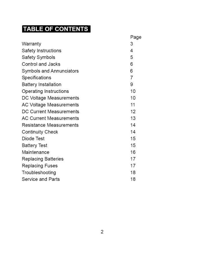
r:_ :] i :[o] |o[o] _/ / _ _/ 1_ Warranty Safety Instructions Safety Symbols Control and Jacks Symbols and Annunciators Specifications Battery Installation Operating Instructions DC Voltage Measurements AC Voltage Measurements DC Current Measurements AC Current Measurements Resistance Measurements Continuity Check Diode Test Battery Test Maintenance Replacing Batteries Replacing Fuses Troubleshooting Service and Parts Page 3 4 5 6 6 7 9 10 10 11 12 13 14 14 15 15 16 17 17 18 18
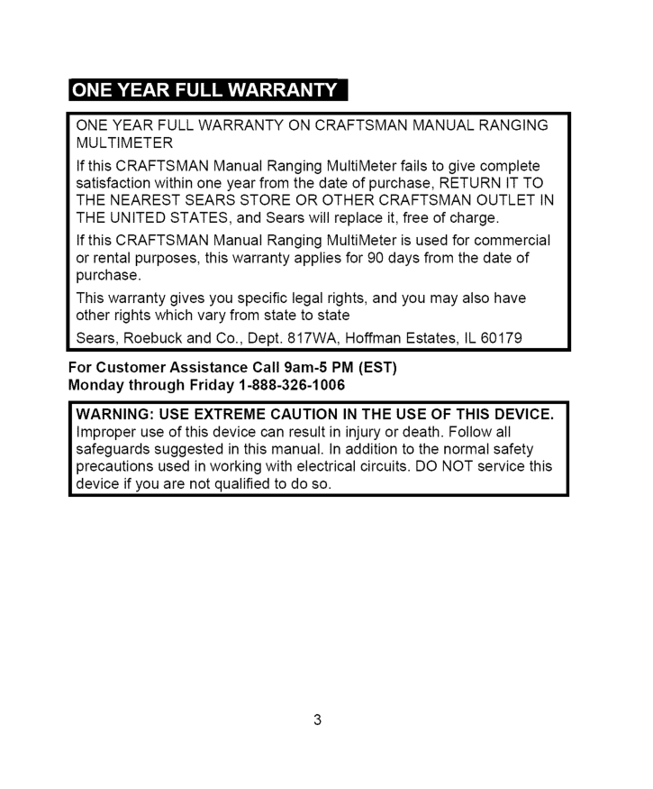
Oneyearfullwarranty
Oncraftsman
Manual
Ranging
Multimeter
IfthisCRAFTSMAN Manual Ranging MultiMeter failstogivecomplete satisfaction withinoneyearfromthedateofpurchase,Return
Itto
Thenearest
Sears
Store
Orother
Craftsman
Outlet
In
Theunited
States,
andSearswillreplace it,freeofcharge. IfthisCRAFTSMAN Manual Ranging MultiMeter isusedforcommercial orrentalpurposes, thiswarranty applies for90daysfromthedateof purchase. Thiswarranty givesyouspecific legalrights, andyoumayalsohave otherrightswhichvaryfromstatetostate Sears, Roebuck andCo.,Dept.817WA, Hoffman Estates,Il60179
For Customer Assistance Call 9am-5Pm (Est)
Monday through Friday 1-888-326-1006Warning:
Use Extreme
Caution
In The Use Of This Device.
Improper use of this device can result in injury or death. Follow all safeguards suggested in this manual. In addition to the normal safety precautions used in working with electrical circuits. DO NOT service this device if you are not qualified to do so.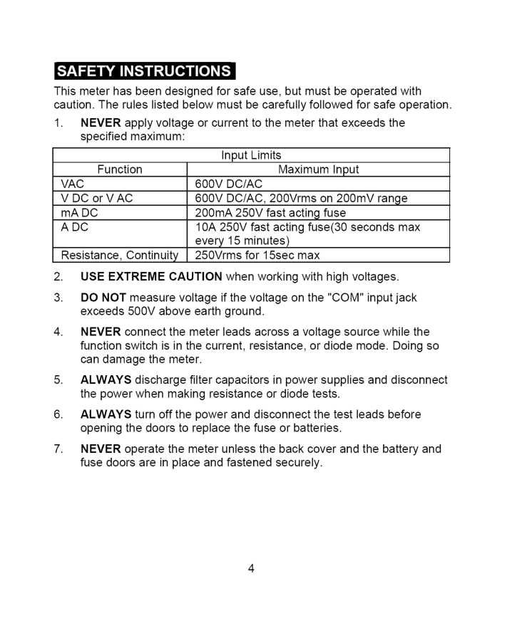
Thismeterhasbeendesigned forsafeuse,butmustbeoperated with caution. Theruleslistedbelowmustbecarefully followed forsafeoperation.
1. Never
applyvoltage orcurrent tothemeterthatexceeds the specified maximum: InputLimits Function Maximum InputVac
600Vdc/Ac
VDCorVAC600Vdc/Ac,
200Vrms on200mV range mADC 200mA 250VfastactingfuseAdc
10A250Vfastactingfuse(30 seconds max every 15 minutes) Resistance, Continuity 250Vrms for 15sec maxUse Extreme
Caution
when working with high voltages.Never
Always
Always
Never
3_'I_I=IIli'db_'d;4 :[o]l
Lwarn,Ng
I
IcAut'°NI 'sMAX00V
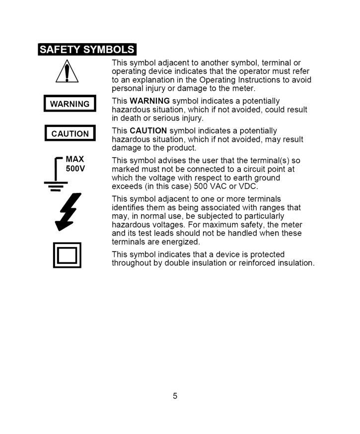
i m This symbol adjacent to another symbol, terminal or operating device indicates that the operator must refer to an explanation in the Operating Instructions to avoid personal injury or damage to the meter. This WARNING symbol indicates a potentially hazardous situation, which if not avoided, could result in death or serious injury. This CAUTION symbol indicates a potentially hazardous situation, which if not avoided, may result damage to the product. This symbol advises the user that the terminal(s) so marked must not be connected to a circuit point at which the voltage with respect to earth ground exceeds (in this case) 500 VAC or VDC. This symbol adjacent to one or more terminals identifies them as being associated with ranges that may, in normal use, be subjected to particularly hazardous voltages. For maximum safety, the meter and its test leads should not be handled when these terminals are energized. This symbol indicates that a device is protected throughout by double insulation or reinforced insulation.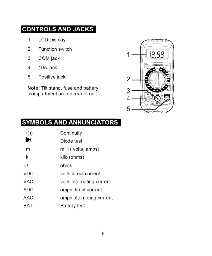
o_o]_IIII_,To]L',]F:I _Ie]LnlT:T_[(_
H =O
__k, | __k, k, k, __O_
•))) Continuity {1_ Diode test m milli ( volts, amps) k kilo (ohms) £_ ohmsVdc
volts direct currentVac
volts alternating currentAdc
amps direct currentAac
amps alternating currentBat
Battery test m 2_ 3_ 4_ 5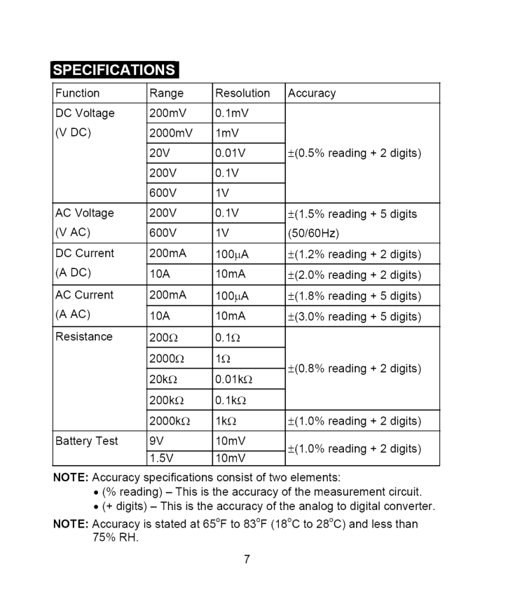
Function DC Voltage
(V Dc)
AC Voltage(V Ac)
DC Current(A Dc)
AC Current(A Ac)
Resistance Battery Test Range 200mV 2000mV20V
200V
600V
200V
600V
200mA10A
200mA10A
200£2 2000£! 20k£_ 200k£_ 2000k£_9V
1.5V
Resolution 0.1mV lmV0.01V
0.1V
1V
0.1V
1V
100pA 10mA 100pA 10mA0.1E_
1£2 0.01 k£_ 0.1k£_ lk£_ lOmV lOmV Accuracy +(0.5% reading + 2 digits) +(1.5% reading + 5 digits (50/60Hz) +(1.2% reading + 2 digits) +(2.0% reading + 2 digits) +(1.8% reading + 5 digits) +(3.0% reading + 5 digits) +(0.8% reading + 2 digits) +(1.0% reading + 2 digits) +(1.0% reading + 2 digits)Note:
Accuracy specifications consist of two elements:Note:
Accuracy is stated at 65°F to 83°F (18°C to 28°C) and less than75% Rh.
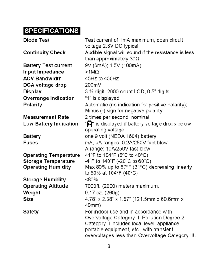
DiodeTest Continuity Check Battery Test current Input Impedance ACV Bandwidth DCA voltage drop Display Overrange indication Polarity Measurement Rate Low Battery Indication Battery Fuses Operating Temperature Storage Temperature Operating Humidity Storage Humidity Operating Altitude Weight Size Safety Test current of 1 mA maximum, open circuit voltage 2.8V DC typical Audible signal will sound if the resistance is less than approximately 30£2 9V (6mA); 1.5V (100mA)
>1M£2
45Hz to 450Hz 200mV 3 ½ digit, 2000 count LCD, 0.5" digits "1" is displayed Automatic (no indication for positive polarity); Minus (-) sign for negative polarity. 2 times per second, nominal "_" is displayed if battery voltage drops below operating voltage one 9 volt (NEDA 1604) battery mA, IJA ranges; 0.2A/250V fast blow A range; 10A/250V fast blow 41°F to 104°F (5°C to 40°C) -4°F to 140°F (-20°C to 60°C) Max 80% up to 87°F (31°C) decreasing linearly to 50% at 104°F (40°C) <80% 7000ft. (2000) meters maximum. 9.17 oz. (260g). 4.78" x 2.38" x 1.57" (121.5mm x 60.6mm x 40mm) For indoor use and in accordance with Overvoltage Category II, Pollution Degree 2. Category II includes local level, appliance, portable equipment, etc., with transient overvoltages less than Overvoltage CategoryIii.
I Warning:
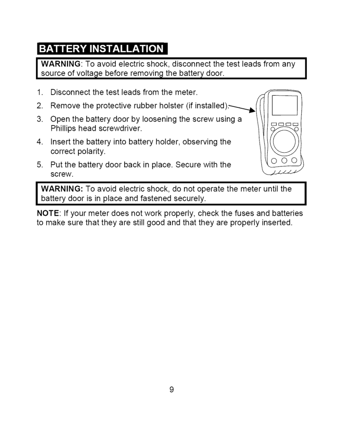
To avoid electric shock, disconnect the test leads from anyI
source of voltage before removing the battery door.I
I Warning:
To avoid electric shock, do not operate the meter until theI
battery door is in place and fastened securely.I
Note:
If your meter does not work properly, check the fuses and batteries to make sure that they are still good and that they are properly inserted.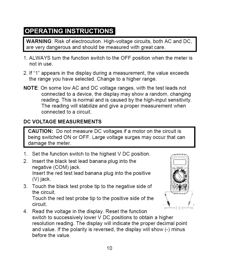
J Warning:
Risk of electrocution. High-voltage circuits, both AC and DC,J
are very dangerous and should be measured with great care.I
1. Always
turn the function switch to the OFF position when the meter is not in use.Note:
On some low AC and DC voltage ranges, with the test leads not connected to a device, the display may show a random, changing reading. This is normal and is caused by the high-input sensitivity. The reading will stabilize and give a proper measurement when connected to a circuit.Dc Voltage
Measurements
J
Aution:
Do not measure DC voltages if a motor on the circuit is being switched ON or OFF. Large voltage surges may occur that can damage the meter.I
10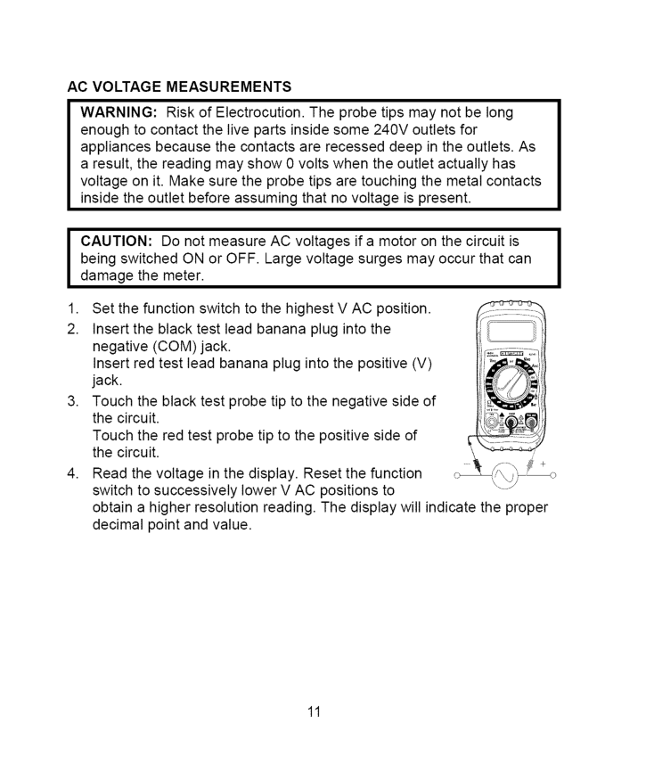
Ac Voltage
Measurements
Warning:
Risk of Electrocution. The probe tips may not be long enough to contact the live parts inside some 240V outlets for appliances because the contacts are recessed deep in the outlets. As a result, the reading may show 0 volts when the outlet actually has voltage on it. Make sure the probe tips are touching the metal contacts inside the outlet before assuming that no voltage is present.I Caution:
Do not measure AC voltages if a motor on the circuit is being switched ON or OFF. Large voltage surges may occur that can I damage the meter.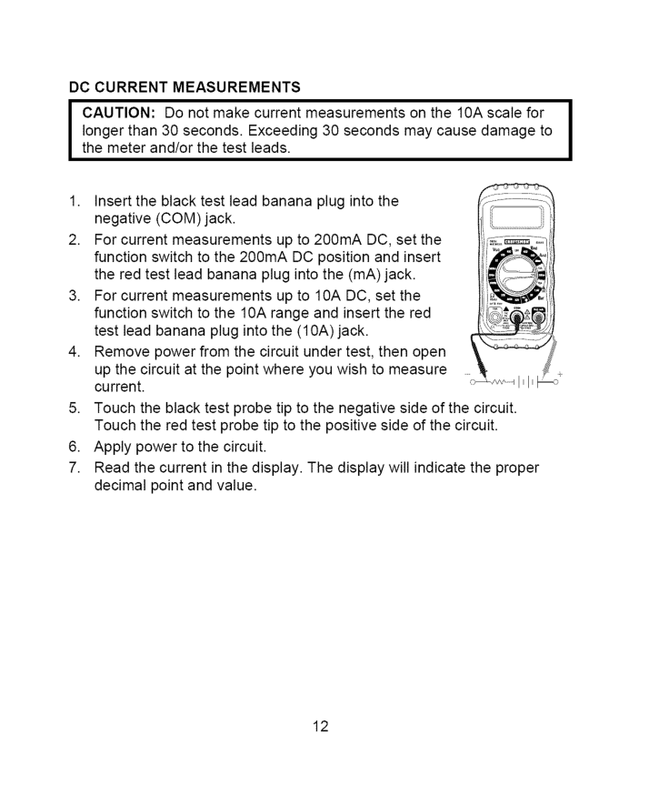
Dc Current
Measurements
I Caution:
Do not make current measurements on the 10A scale for I longer than 30 seconds. Exceeding 30 seconds may cause damage to the meter and/or the test leads.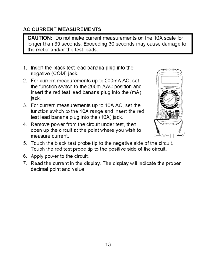
Ac Current
Measurements
I Caution:
Do not make current measurements on the 10A scale for I longer than 30 seconds. Exceeding 30 seconds may cause damage to the meter and/or the test leads.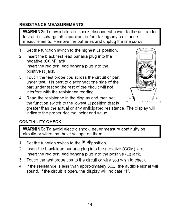
Resistance
Measurements
I
Arning:
To avoid electric shock, disconnect power to the unit under test and discharge all capacitors before taking any resistance measurements. Remove the batteries and unplug the line cords.Continuity
Check
I
Arning:
To avoid electric shock, never measure continuity on circuits or wires that have voltage on them.I
I
14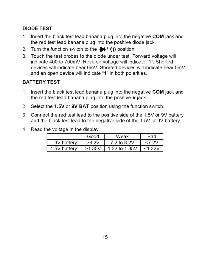
Diode
Test
Battery
Test
>8.2V
7.2 to 8.2V<7.2V
1.5V battery:>1.35V
1.22 to 1.35V<1.22V
15
Iwarning:
Toavoidelectric shock, disconnect thetestleadsfromany source ofvoltage beforeremoving thebackcoverorthebattery orfuse doors.Iwarning:
Toavoidelectric shock, donotoperate yourmeteruntilthe battery andfusedoorsareinplaceandfastened securely. ThisMultiMeter isdesigned toprovide yearsofdependable service, ifthe following careinstructions areperformed:Use And Store The Meter In Normal
Temperatures.
Temperature extremes can shorten the life of the electronic parts and distort or melt plastic parts.Handle
The Meter Gently
And Carefully.
Dropping it can damage the electronic parts or the case.Keep The Meter Clean.
Use Only Fresh Batteries
Of The Recommended
Size
And Type.
Remove old or weak batteries so they do not leak and damage the unit.If The Meter
Is To Be Stored
For A Long Period Of Time,
the batteries should be removed to prevent damage to the unit.I
I
16
Replacing
Batteries
Warning:
To avoid electric shock, disconnect the test leads from any source of voltage before removing the battery door.I
[ Warning:
To avoid electric shock, do not operate your meter until theJ
battery door is in place and fastened securely.Replacing
Fuses
I Warning:
To avoid electric shock, disconnect the test leads from any | source of voltage before removing the fuse door.I
J
fuse door is in place and fastened securely.Ul Listed
The UL mark does not indicate that this product has been evaluated for the accuracy of its readings. 17
/ _,(olUJ:] III:[_."]:[olo]l i I _ [€ There may be times when your meter does not operate properly. Here are some common problems that you may have and some easy solutions to them. Meter Does Not Operate:
82141 -Db
Replacement battery door82141-Df
Replacement fuse door82141 -Cs
Rear cover screws For replacement parts shipped directly to your home Call 9 am - 5 pm Eastern Time, M - F 1-888-326-1006 18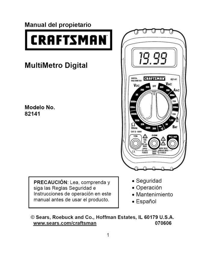
Manual del propietario MultiMetro Digital Modelo No. 82141
Precaucion:
Lea, comprenda y siga las Reglas Seguridad e Instrucciones de operaci6n en este manual antes de usar el producto.Il 60179 U.S.A.
www.sears.com/craftsman 070606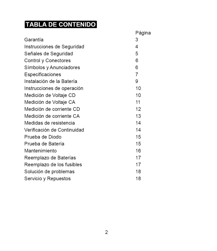
r.'1:] IF.'1e]:[e[e] _/ / :1_IIe]_ Garantia Instrucciones de Seguridad Se_ales de Seguridad Control y Conectores Simbolos y Anunciadores Especificaciones Instalaci6n de la Bateria Instrucciones de operaci6n Medici6n de Voltaje
Cd
Medici6n de VoltajeCa
Medici6n de corrienteCd
Medici6n de corrienteCa
Medidas de resistencia Verificaci6n de Continuidad Prueba de Diodo Prueba de Bateria Mantenimiento Reemplazo de Baterias Reemplazo de los fusibles Soluci6n de problemas Servicio y Repuestos Pagina 3 4 5 6 6 7 9 10 10 11 12 13 14 14 15 15 16 17 17 18 18
_____ _ __ oH" __ "o _ __ h. o GARANTiA TOTAL POR UN ANO PARA EL MULTiMETRO
Con
Escala
Manual
De Craftsman
Si este Multimetro de escala manual CRAFTSMAN no le satisface totalmente dentro de un a_o a partir de la fecha de compra,Regr#:Selo
A La Tienda
Sears O Distribuidor
Craftsman
Ma,S Cercano
En Los Estados
Unidos,
y Sears Io reemplazara, sin cargos. Si este Multimetro de escala manual CRAFTSMAN es utilizado de manera comercial o para renta, esta garantia se aplica a los primeros 90 dias a partir de la fecha de compra. Esta garantia la otorga derechos legales especificos, ademas de que usted pueda tener otros derechos variables entre estados Sears, Roebuck and Co., Dept. 817WA, Hoffman Estates,Il 60179
Para ayuda al cliente Llame entre 9 a.m. y 5 PM (Hora est_ndar del este). Lunes a viernes 1-888-326-1006Advertencia:
Extreme
Sus Precauciones
Al Usar Este
Dispositivo.
El uso inapropiado de este dispositivo puede causar lesiones o la muerte. Siga todas las salvaguardas sugeridas en este manual. Ademas de las precauciones de seguridad normales usadas al trabajar con circuitos electricos. NO de servicio a este dispositivo si usted no esta calificado para hacerlo.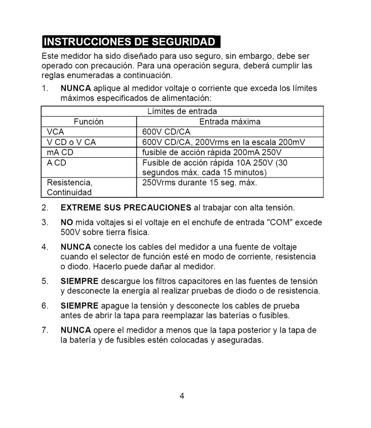
Estemedidor hasidodisefiado parausoseguro, sinembargo, debeser operado conprecauci6n. Paraunaoperaci6n segura, deberacumplir las reglasenumeradas acontinuaci6n.
1. Nunca
aplique almedidor voltaje ocorriente queexceda loslimites maximos especificados dealimentaci6n: Limites deentrada Funci6n Entrada maximaVca
600Vcd/Ca
VCDoVCA600Vcd/Ca,
200Vrms enlaescala200mV mACD fusibledeacci6nrapida200mA250V
Acd
Fusible deacci6n rapida10A250V(30 segundos max.cada15minutos) Resistencia, 250Vrms durante 15seg.max. Continuidad2. Extreme
Susprecauciones
altrabajar conaltatensi6n."Com"
excede 500Vsobretierrafisica.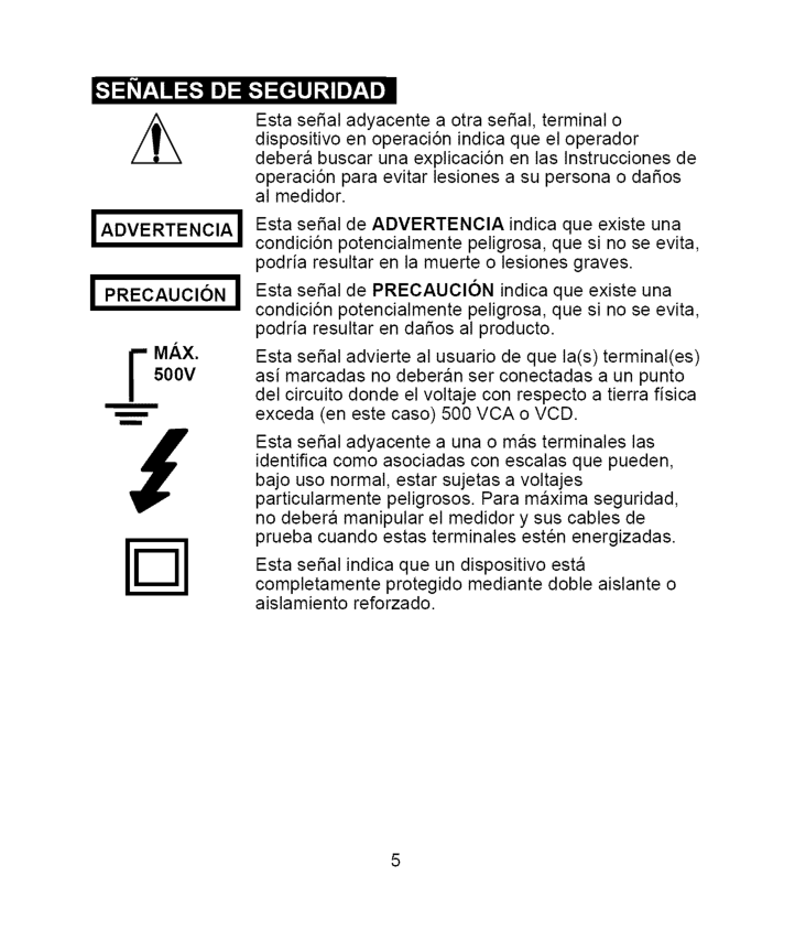
•"t:1_r:_I :_1 J]:1_"]:[rllJ _IIJT:_! ±
I Advertencia
I
! Precaucion
]F
Ax.
500V
nm Esta seSal adyacente a otra seSal, terminal o dispositivo en operaci6n indica que el operador debera buscar una explicaci6n en las Instrucciones de operaci6n para evitar lesiones a su persona o daSos al medidor. Esta seSal de ADVERTENClA indica que existe una condici6n potencialmente peligrosa, que si no se evita, podria resultar en la muerte o lesiones graves. Esta seSal de PRECAUClON indica que existe una condici6n potencialmente peligrosa, que si no se evita, podria resultar en daSos al producto. Esta seSal advierte al usuario de que la(s) terminal(es) asi marcadas no deberan ser conectadas a un punto del circuito donde el voltaje con respecto a tierra fisica exceda (en este caso) 500 VCA o VCD. Esta seSal adyacente a una o mas terminales las identifica como asociadas con escalas que pueden, bajo uso normal, estar sujetas a voltajes particularmente peligrosos. Para maxima seguridad, no debera manipular el medidor y sus cables de prueba cuando estas terminales esten energizadas. Esta seSal indica que un dispositivo esta completamente protegido mediante doble aislante o aislamiento reforzado.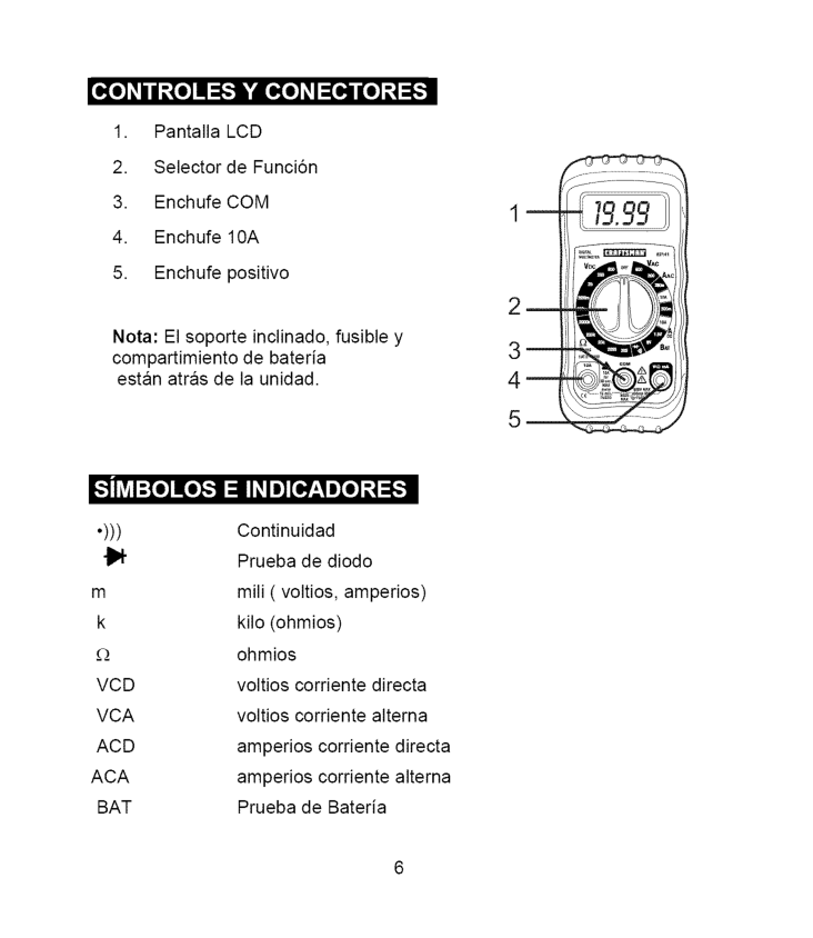
_o] _/ / _._[o]I :F."]k'|o[o]_I:[O,]lI[o]_._]:F:
Lcd
Vcd
voltios corriente directaVca
voltios corriente alternaAcd
amperios corriente directaAca
amperios corriente alternaBat
Prueba de Bateria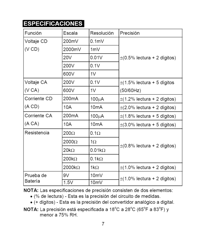
_,..-'.) -..,1 =[e,]I_1[___[e,][e] _I_ Funci6n Voltaje
Cd
(V Cd)
VoltajeCa
(V Ca)
CorrienteCd
(A Cd)
CorrienteCa
(A Ca)
Resistencia Prueba de Bateria Escala 200mY 2000mY20V
200V
600V
200V
600V
200mA10A
200mA10A
200_ 2000_ 20k_ 200k_ 2000k_9V
1.5V
Resoluci6n 0.1mY 1mY0.01V
0.1V
1V
0.1V
1V
100pA 10 mA 100pA 10 mA 0.1£_ 1£_ 0.01k£_ 0.1k£_ lk£_ 10mV 10 mV Precisi6n +(0.5% lectura + 2 digitos) +(1.5% lectura + 5 digitos (50/60Hz) +(1.2% lectura + 2 digitos) +(2.0% lectura + 2 digitos) +(1.8% lectura + 5 digitos) +(3.0% lectura + 5 digitos) _+(0.8%lectura + 2 digitos) ±(1.0%lectura + 2 digitos) ±(1.0%lectura + 2 digitos)Nota:
Las especificaciones de precisi6n consisten de dos elementos:Nota:
La precisi6n esta especificada a 18°C a 28°C (65°F a 83°F) y menor a 75% RH.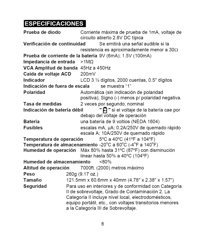
_,,,-,,) _ =[e,]I_1[e,7'__[e,] [e]ZI=[_ Prueba de diodo Corriente maxima de prueba de 1mA, voltaje de circuito abierto 2.8V DC tipica Verificaci6n de continuidad Se emitira una seSal audible si la resistencia es aproximadamente menor a 30£_ Prueba de corriente de la bateria 9V (6mA); 1.5V (100mA) Impedancia de entrada
>1M£2
VCA Amplitud de banda 45Hz a 450Hz Caida de voltajeAcd
200mV Indicador LCD 3 ½ digitos, 2000 cuentas, 0.5" digitos Indicaci6n de fuera de escala se muestra "1" Polaridad Automatica (sin indicaciSn de polaridad positiva); Signo (-) menos p/polaridad negativa. Tasa de medidas 2 veces por segundo, nominal Indicaci6n de bateria d6bil "_" si el voltaje de la bateria cae por debajo del voltaje de operaciSn Bateria una bateria de 9 voltios (NEDA 1604) Fusibles escalas mA, pA; 0.2A/250V de quemado rapido escala A; 10A/250V de quemado rapido Temperatura de operaci6n 5°C a 40°C (41°F a 104°F) Temperatura de almacenamiento -20°C a 60°C (-4°F a 140°F) Humedad de operaci6n Max 80% hasta 31°C (87°F) con disminuciSn linear hasta 50% a 40°C (104°F) Humedad de almacenamiento <80% Altitud de operaci6n 7000ft. (2000) metros maximo Peso 260g (9.17 oz.) TamaSo 121.5mm x 60.6mm x 40mm (4.78" x 2.38" x 1.57") Seguridad Para uso en interiores y de conformidad con Categoria II de sobrevoltaje, Grado de ContaminaciSn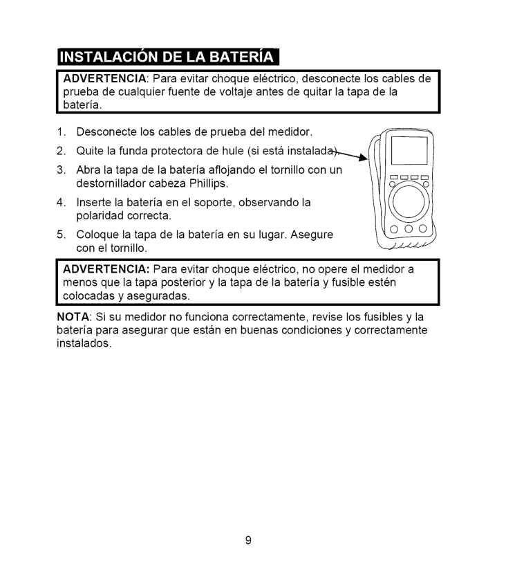
I__1 Ir_,q IF_,Te,] [_ _IIe):11IF_,1:T_,_I
I1:1_,_
I ADVERTENClA: Para evitar choque electrico, desconecte los cables de prueba de cualquier fuente de voltaje antes de quitar la tapa de laI
bateria.I
menos que la tapa posterior y la tapa de la bateria y fusible estenI
colocadas y aseguradas.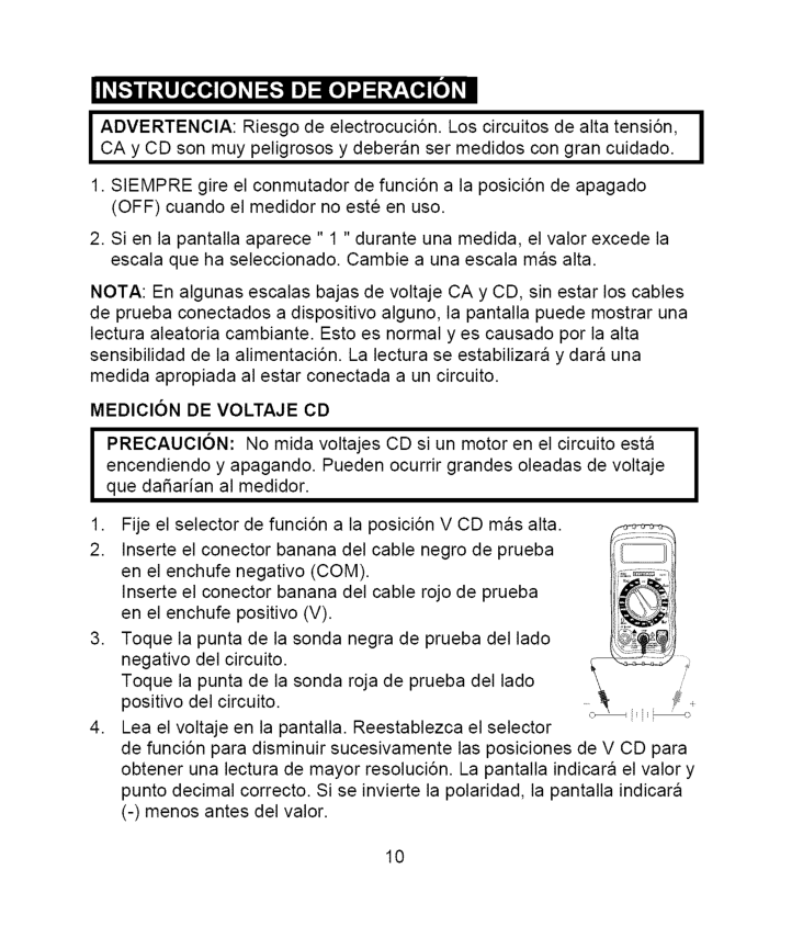
k, _ Ok, |
O"
___ Ok,I Advertencia:
Riesgo de electrocuci6n. Los circuitos de alta tensi6n,I
CA y CD son muy peligrosos y deberan ser medidos con gran cuidado.1. Siempre
gire el conmutador de funci6n a la posici6n de apagado (OFF) cuando el medidor no este en uso.Nota:
En algunas escalas bajas de voltaje CA y CD, sin estar los cables de prueba conectados a dispositivo alguno, la pantalla puede mostrar una lectura aleatoria cambiante. Esto es normal yes causado pot la alta sensibilidad de la alimentaci6n. La lectura se estabilizara y dara una medida apropiada al estar conectada a un circuito. MEDIClONDe Voltaje
Cd
I
PRECAUCl6N: No mida voltajes CD si un motor en el circuito estaI
encendiendo y apagando. Pueden ocurrir grandes oleadas de voltaje I que daSarian al medidor.(Com).
Inserte el conector banana del cable rojo de prueba en el enchufe positivo(V).
Medicion
De Voltaje
Ca
Advertencia:
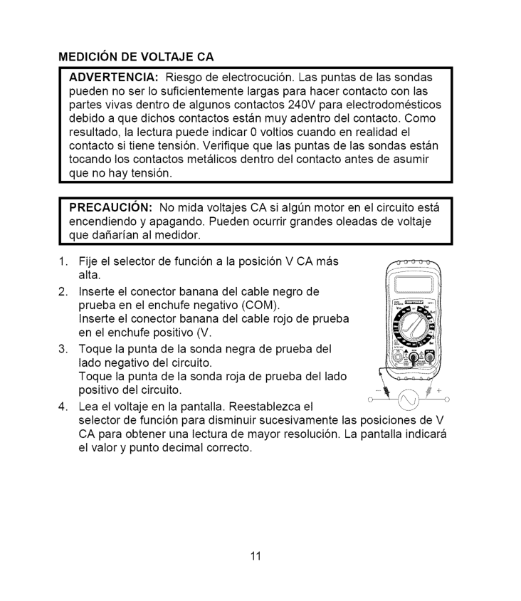
Riesgo de electrocuci6n. Las puntas de las sondas pueden no ser Io suficientemente largas para hacer contacto con las partes vivas dentro de algunos contactos 240V para electrodomesticos debido a que dichos contactos estan muy adentro del contacto. Como resultado, la lectura puede indicar 0 voltios cuando en realidad el contacto si tiene tensi6n. Verifique que las puntas de las sondas estan tocando los contactos metalicos dentro del contacto antes de asumir que no hay tensi6n.I
Recaucion:
No mida voltajes CA si algen motor en el circuito estaI
encendiendo y apagando. Pueden ocurrir grandes oleadas de voltaje I que daSarian al medidor.(V.
Toque la punta de la sonda negra de prueba del lado negativo del circuito. Toque la punta de la sonda roja de prueba del lado positivo del circuito. Lea el voltaje en la pantalla. Reestablezca el selector de funci6n para disminuir sucesivamente las posiciones de V CA para obtener una lectura de mayor resoluci6n. La pantalla indicara el valor y punto decimal correcto. 11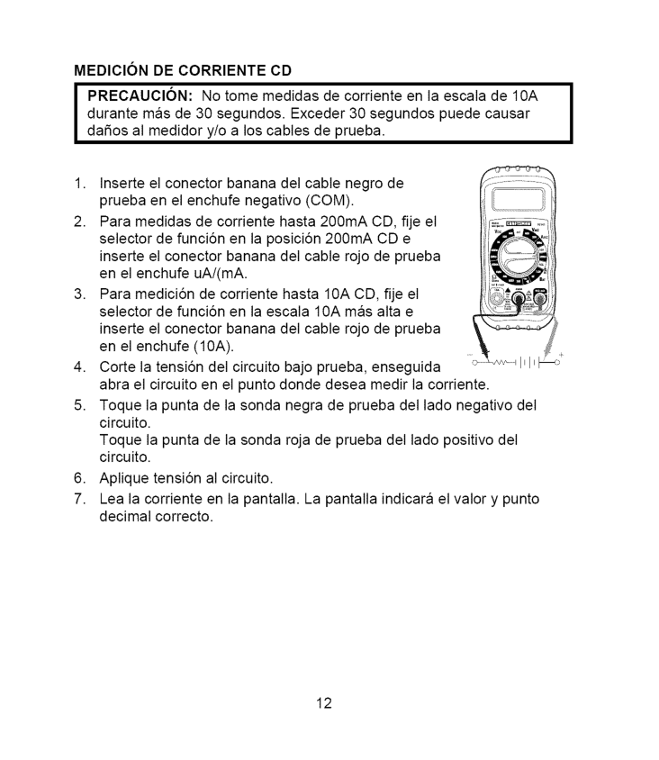
Medicion
De Corriente
Cd
I
Precaucion:
No tome medidas de corriente en la escala de 10A durante mas de 30 segundos. Exceder 30 segundos puede causarI
dafios al medidor y/o a los cables de prueba.(10A).
Corte la tensi6n del circuito bajo prueba, enseguida abra el circuito en el punto donde desea medir la corriente. Toque la punta de la sonda negra de prueba del lado negativo del circuito. Toque la punta de la sonda roja de prueba del lado positivo del circuito. Aplique tensi6n al circuito. Lea la corriente en la pantalla. La pantalla indicara el valor y punto decimal correcto. 12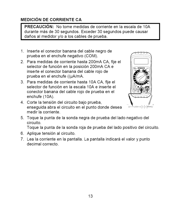
Medicion
De Corriente
Ca
I
Precaucion:
No tome medidas de corriente en la escala de 10A durante mas de 30 segundos. Exceder 30 segundos puede causarI
dafios al medidor y/o a los cables de prueba.(10A).
Medidas
De Resistencia
Advertencia:
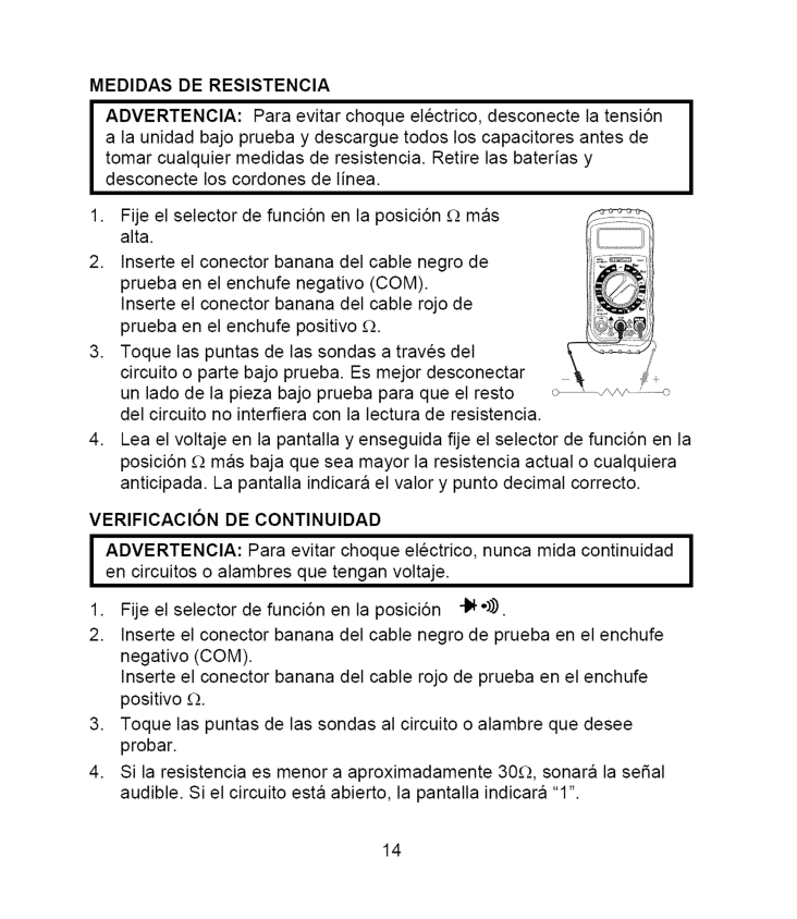
Para evitar choque electrico, desconecte la tensi6n a la unidad bajo prueba y descargue todos los capacitores antes de tomar cualquier medidas de resistencia. Retire las baterias y desconecte los cordones de linea.I Advertenoia:
Para evitar choque electrico, nunca mida continuidadI
en circuitos o alambres que tengan voltaje.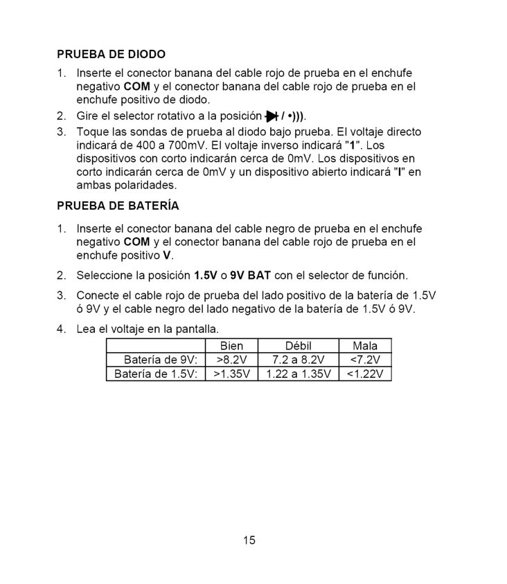
Prueba
De Diodo
1, Inserte el conector banana del cable rojo de prueba en el enchufe negativo COM y el conector banana del cable rojo de prueba en el enchufe positivo de diodo.Prueba
DE BATERiA>8.2V
7.2 a 8.2V<7.2V
Bateria de 1.5V:>1.35V
1.22 a 1.35V<1.22V
15
ADVERTENClA: Paraevitarchoque electrico, desconecte loscables de prueba decualquier fuentedevoltaje antesdequitarlatapaposterior o ladelabateria ofusibles. ADVERTENClA: Paraevitarchoque electrico, noopereelmedidor a menos quelatapaposterior ylatapadelabateria yfusibles esten colocadas yaseguradas. EsteMultimetro estadiseSado paraproveer muchos aSosdeservicio confiable, siseIlevan acabolassiguientes instrucciones decuidado del manual:
1. Mantenga
Seco El Medidor.
Si se moja, sequelo.Use Y Almacene
El Medidor
Bajo
Temperatura
Normal.
Los extremos de temperatura pueden acortar la vida de las partes electrSnicas y distorsionar o fundir las piezas de plastico.Manipule
El Medidor
CON SUAVlDAD Y CUlDADO. Dejarlo caer puede daSar las partes electrSnicas o la caja.Mantenga
Limpio El Medidor.
Ocasionalmente limpie la caja con un paso hQmedo. NO use quimicos, solventes para limpieza o detergentes.Use Solo Baterias
Nuevas
Del Tamano
Y Tipo
Recomendado.
Retire las baterias viejas o debiles de manera que no se derramen y daSen la unidad.El Medidor
Durante
Un Largo
Periodo
De Tiempo,
debera retirar la bateria para prevenir daSos a la unidad.Inscrito
En Ul
La marca UL no indica que este producto ha sido evaluado en cuanto a la precisiSn de sus lecturas. 16
Reemplazo
DE BATERiASAdvertencia:
Para evitar choque electrico, desconecte los cables de prueba de cualquier fuente de voltaje antes de quitar la tapa de la bater{a, Cuando las baterias se agoten o caigan bajo el voltaje de operaciSn, aparecera "1_1"del lado derecho de la pantalla LCD. Debera reemplazar las baterias.I
menos que la tapa posterior y la tapa de la bateria y de fusibles esten I colocadas y aseguradas.Reemplazo
DE LOS FUSlBLESI Advertencia:
Para evitar choque electrico, desconecte los cables deI
prueba de cualquier fuente de voltaje antes de quitar la tapa de fusibles.(0.2A/250V
de quemado rapido para la escala 200mA,10A/250V
de quemado rapido para la escala10A).
I Advertencia:
Para evitar choque electrico, no opere el medidorI
hasta que la tapa de fusibles este colocada y asegurada, 17
Habra ocasiones enquesumedidor nofuncione correctamente. En seguida encontrara algunos problemas comunes quepuedeIlegaratenet yalgunas soluciones faciles. Elmedidornofunciona: 1.Siempre leatodaslasinstrucciones enestemanual antesdeusar. 2.Verifique quelabateria estabieninstalada. 3.Verifique quelabateria estaenbuenas condiciones. 4.Silabateria estaenbuenestadoyelmedidor aunnofunciona, reviseel fusibleparaasegurar queambos extremos estenbieninsertados. SiustedNOcomprende c6mofunciona elmedidor: 1.Compre ellibrodeinstrucci6n Multimetros ysuusoenlaspruebas electricas ("Multitesters and Their Use for Electrical Testing") (Articulo No. 82303) en la tienda Sears de su Iocalidad.