
Ask AI
— answers from the official manualAnswers from the official manual.
Common questions
Common Questions
30 totalHow often should I replace the air filter on the RER 1000?
The air filter should be replaced every 100 operating hours or more frequently in dusty conditions. Never use gasoline or low flash point solvents for cleaning the air filter element, as this can cause damage. (Page 2)
What is the maximum slope I can safely operate the Craftsman RER 1000 on?
Do not operate this machine on a slope greater than 12 degrees. On slopes, the weight of towed equipment may cause loss of traction and loss of control. If turning on a slope is necessary, turn slowly and gradually. (Page 2)
How do I engage the mower blades on the RER 1000?
To engage the blades, move the throttle/choke control lever to the FAST position before engaging the PTO (Blade Engage) lever. Keep all bystanders, helpers, children, and pets at least 75 feet away from the machine while the blades are in operation. Never operate without the discharge chute or grass collector in place. (Page 2)
How should I safely store the Craftsman RER 1000?
Never store a gasoline-powered lawn tractor with fuel in the tank in an enclosed or poorly ventilated area, where gasoline fumes can reach fire, sparks, or pilot lights. This applies to indoor storage as well as poorly ventilated outdoor structures. (Page 2)
How do I perform basic maintenance on the battery?
The battery is sealed and maintenance-free, but ensure the cables and terminals are clean and free of corrosive build-up. Avoid charging the battery in areas with explosive gases. When reconnecting, connect the negative cable end to the tractor's engine block away from the battery, attaching it to a non-painted area for a good connection. (Page 2)
What safety precautions should I follow before performing maintenance on the RER 1000?
Before starting any maintenance, ensure the engine is shut off and cool, and disengage all controls. Allow the engine to cool for at least 30 minutes before cleaning or servicing, and be careful not to touch the muffler, as it can cause severe burns or death. Never attempt adjustments while the engine is running, except disengaging the PTO lever and moving the shift lever into neutral. (Page 2)
Show 24 more questions
How do I assemble the seat and deck chute on the RER 1000?
How often should I replace the air filter?
What is the maximum slope for safe operation of the RER 1000?
How do I engage the PTO (Blade Engage) lever correctly?
Can I assemble the riding mower according to the manual instructions?
Is it safe to charge the battery indoors?
How often should I maintain my Craftsman RER 1000?
How do I adjust the seat on my RER 1000?
Are there any specific safety standards my Craftsman RER 1000 adheres to?
Why won't my Craftsman RER 1000 engine start?
What type of fuel should I use in the Craftsman RER 1000?
What type of oil is recommended for cold weather use?
What should I do if the engine won't start?
How can I safely refuel my Craftsman RER 1000?
How do I start the engine when my battery is dead?
How do I factory reset the Craftsman Rer 1000 settings?
How often should I replace the spark plugs?
What do I do if my engine is hard to start?
How can I level the mower deck side-to-side?
How should I store the tractor for winter?
How do I adjust the blade cutting height?
What should I check if my mower blades won't rotate?
How do I remove my battery during maintenance?
Why is my engine losing power while mowing?
Full Manual
60 pages


Owner's Manual
##### [CRAFTSMAN'[
16.5 HP ELECTRIC START
42" MOWER AUTOMATIC LAWN TRACTOR
Model No. 917.271643
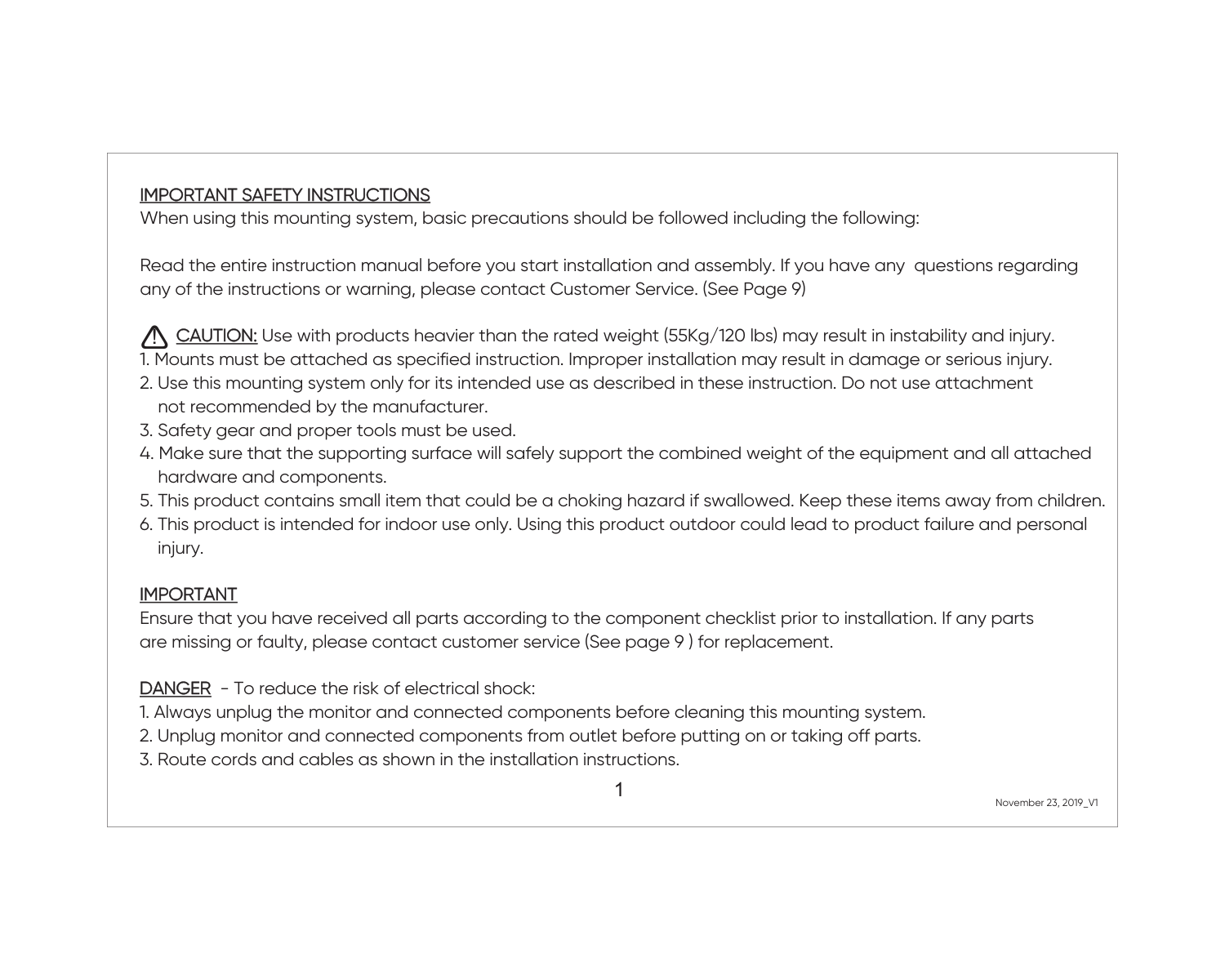
CAUTION: Read and follow all Safety Rules and Instructions before operating this equipment.
Foranswers to your questions about thisproduct,Call: 1-800-659-5917
Sear= Craftsman Help Line 5 am 5 pm, Mort - Sat
############## Sears, Roebuck and Co., Hoffman Estates, I160179 Visit our Craftsman website:www.sears.com/craftsman

Maintenance Schedule ...................... 18 Service and Adjustments .................... 22 Storable ............................................... 29 Troubleshooting ................................. 30 Repair Parts ........................................ 34 Parts Ordering ..................... Back Cover
Warranty............................................... 2
Safety Rules ......................................... 3 Product Specifications .......................... 6 Assembly .............................................. 8 Operation ............................................ 11 Maintenance ....................................... 18
LIMITED TWO YEAR WARRANTY ON CRAFTSMAN RIDING EQUIPMENT PARTS For two (2) years from the date of purchase, if this Craftsman Riding Equipment is maintained, lubdcatad and tuned up according to the instructions in the owner's manual, Sears will repair or replace, free of charge, any parts found to be defective in matadal or workmanship. Warranty service is available free of charge by returning your Craftsman dding equipment to your nearest Sears Service Center. In-home warranty service is available but a trip charge will apply. This warranty applies only while this product is in the United States.
This Warranty does not cover:.
LIMITED 90 DAYWARRANTY ON BA'I-]'ERY For ninety (90) days from date of purchase, if any battery includedwith this dding equipment proves defective in matedai or workmanship and our testing determines the
battery will not hold a charge, Sears will replace the battery at no charge. Warranty service is available free of charge by returning your Craftsman dding equipment to your nearest Sears Service Center. In-home warranty service is available but a tdp
charge will apply. This warranty applies only while this product is in the United States. TO LOCATE THE NEAREST SEARS SERVICE CENTER OR TO SCHEDULE IN-HOME WARRANTY SERVICE, SIMPLY CONTACT SEARS AT 1-800-4-MY-HOME
This Warranty gives you specific legal rights, and you may also have other dghts which may vary from state to state.
Seam, Roebuck and Co., [3/817 WA, Hoffman Estates, IL 60179
2

MPORTANT: This cuttingmachine is capable of amputating hands and feet and throwing objects. Failure to observe the tallowing sarsty instructionscould resultin safious injury or death.
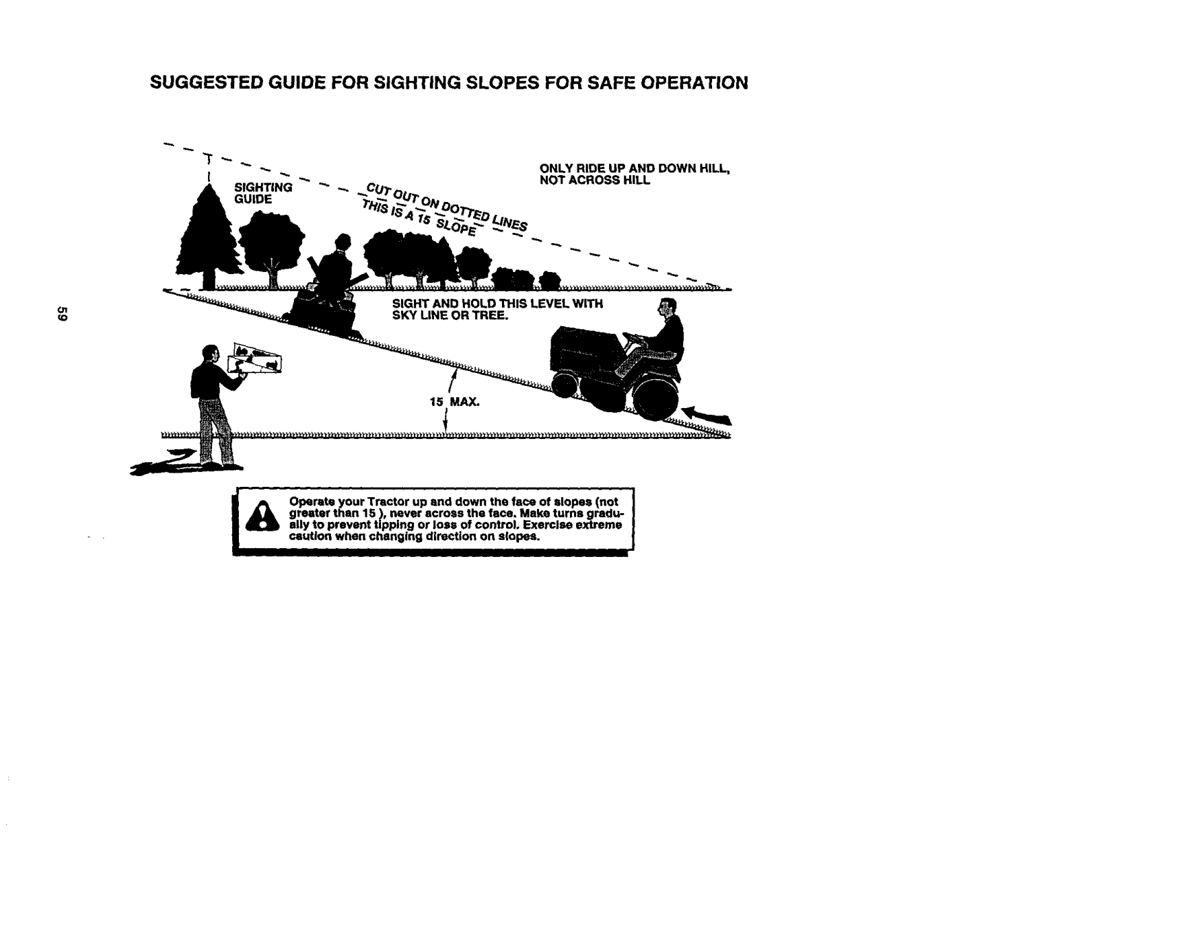
I1oSLOPE OPERATION Slopes are a majorfactor related to loss-ofcontrol and tipover accidents, which can rasult in severe in ury or death. All slopes requireextra caution, fyou cannot back up the slope or if you feel uneasy on it, do not mow it. DO:
I. GENERAL OPERATION
before mowing. Stop machine if anyone enters the area.
machine. Tall grass can hide obstacles.
down the slope. DO NOT:
suddenly turn over if a wheel is over the edge of a cliff or ditch, or if an edge caves in.

IILCHILDREN Tragcaccidentscanoccuriftheoperator isnotaledtothepresenceofchitdren. Childrenareoftenattractedtothe machineandthemowingactivity.Never assume that chitdren witi remain where you last saw
Wrap the blade(s) or wear gloves, use extra caution when servicing
IV. SERVICE
Use extra care in handting gasoline and other fuels. They are flammable and vapors are explosive.
lutely necessary. Always look and behind before and while backing.
and be seriously injured or interfere with safe machine operation.

CAUTION: Tow only the attachments that are recommended by and comply with specifications of the manufacturer your tractor. Use common sense when towing. Operate only at the lowest possible speed when on a slope. Too heavy of a load, while on a slope, is dangerous. "i3rescan lose traction with the ground and cause you to lose control o! your tractor. _I_WARNING: Engine exhaust, some its constituents, and certain vehicle components contain or emit chemicals known to the State of Caiifomla to cause cancer and birth defects or other reproductive harm. _I_WARNING: Battery posts, terminals and related accessories contain lead and lead compounds, chemicals known to the State of California to cause cancer and birthdefects or other reproductive harm. Wash hands after handling,
_J-ook for this symbol to point out importantsafety precautions. It means CAUTIONll! BECOMEALERT!II YOUR SAFETY IS INVOLVED. _ CAUTION: In order to prevent
accidental starting when setting up, transporting, adjusting or making repairs, always disconnect spark plug wire and place wire where It cannot contact spark plug.
• l_CAUTION: Do not coast down a hill in neutral, you may lose control of the tractor.

PRODUCTSPECIFICATIONS
Please read and retainthis manual. The instructionswill enable you to assemble and maintain your tractor propedy. Always observe the =SAFETY RULES!. REPAIR AGREEMENT A Repair Agreement is available on this product. Contact your nearest Sears store for details. CUSTOMER RESPONSIBILITIES
GASOLINE 1.25GALLONS CAPACITY UNLEADED ANDTYPE: REGULAR OILTYPE ShE30(ABOVE32°F (API-SF-SJ): SAE5W-30
(BELOW32°F) DILCAPACITY:3.0PINTS ;PARKPLUG: CHAMPIONRC12YC SAP:.030") SROUND SPEED FORWARD:5.2 (MPH): REVERSE: 2.7
nance" and =Storage" sections of this owner's manual
TIRE PRESSURE: FRONT: 14 PSI REAR: 12PSI
,_WARNING: This tractor is equipped with an internal combustion engine and should not be used on or near any unimproved forest-covered, brushcovered or grass-covered land unless the engine's exhaust system is equipped with a spark arrester meeting applicable local or state laws (if any). If a spark arrester is used, it should be maintained in effective working order by the operator. In the state of California the above is required by law (Section 4442 of the California Public Resources Code). Other states may have similarlaws. Federal laws apply on federal lands. A spark arrester for the muffler is availabte through your nearest Sears service center (See REPAIR PARTS section of this manual).
CHARGING 3 AMPS BA'I-['ERY SYSTEM: 5 AMPS HEADLIGHTS
BA'I-I'ERY: AMP/HR: 25 MIN. CCA: 190 CASE SIZE: U1R
BLADE BOLT 27-35 FT. LBS. TORQUE:
CONGRATULATIONS on your purchase of a new tractor. It has been designed, engineered and manufactured to give you the best possible dependability and pedormance. Should you experience any problem you cannot easily remedy, please contact a Sears or other qualified service center. We have competent, well-trained technicians and the proper tools to service or repair this tractor.

Steering Wheel
Steering Wheel Insert
(1) Large Flat Washer
1) Hex Bolt 3/6-16 x 1
/1) Hex Bolt
1) Lockwasher3/8
############### 16-18 x 1-1/4
(1) Locknut5/16-18
Extension Shaft
Steering Boot
=_ SteeringWheelAdapter
t
(1) Washer 17/32 x 1-3/16 x 12 Gauge
_(1) Knob
For Future Use
Keys
Slope Sheet
Video Cassette

Your new tractor has been assembled at the factorywith exception of those parts left unasssmb{ed for shipping purposes. To ensure safe and proper operation of your tractor all parts and hardware you assemble must be tightened securely. Use the correct tools as necessary to insure proper tightness. Review the video cassette before you begin. TOOLS REQUIRED FOR ASSEMBLY A socket wrench set will make assembly easier. Standard wrench sizes you need are listed below.
IMPORTANT: Check for and remove any staples in skid that may puncture tires where tractor is to roll off skid.
(1) Tire pressure gauge When right or left hand is mentioned in this manual, it means, from your point of view, when you are in the operating position (seated behind the steering wheel). TO REMOVE TRACTOR FROM CARTON UNPACK CARTON
-_ _ insert 3/8 HexBolt
3/8 LockWasher _Large Rat
Shaft
############### BEFORE REMOVING TRACTOR FROM SKID ATTACHSTEERINGWHEEL
5/16 ex Bolt
ASSEMBLE EXTENSION SHAFT AND BOOT
Lower Steering Shaft
steedng shaft. Align mounting holes in extension and lower shafts and instaU5/16 hex boltand Iocknut. Tighten securely.
IMPORTANT: "Rghtanbolt and nut securely to 18-22 ft, Ibs torque.
slotsin dash and push down to secure.
INSTALL STEERING WHEEL
Slots
HOW TO SET UPYOUR TRACTOR CHECK BATTERY
open battery box door. NOTE: Ifthis battery isput intoservice after month and year indicated on label (label located between terminals) charge battery for minimum of one hourat 6-10 amps. (See "BATTERY" in Maintenance section of this manual for charging instructions).

NOTE: You may now roll or drive your tractor off the skid. Follow the appropriate instruction below to remove the tractor from the skid.
Labe_
Battery Door
TO ROLL TRACTOR OFF SKID (See Operation section for location end function of controls)
INSTALL SEAT Adjust seat before tightening adjustment knob.
shield up against tractor. TO DRIVE TRACTOR OFF SKID (See Operation section for location and function of controls) _k WARNING: Before starting, road, understand and follow all instructionsin the Operation section of this manual. Be sure tractor is in a well-ventilated area. Be sure the area in front of tractor is clear of other people and objects.
9, Raise seat and tighten adjustment knob securely.
_%ulder

CHECK BRAKE SYSTEM Afteryou leam how to operate your tractor, check to see that the brake is properly adjusted. See "TO ADJUST BRAKE" in the Service and Adjustments section of this manual.
INSTALL MULCHER PLATE (If previously removed)
CHECKLIST Before you operate and enjoy your new tractor, we wish to assure that you receive the best performance and satisfaction from this qualityproduct. Please review the following checklist: / All assembly instructionshave been
Plate Shield
completed. / No remaining loose pads in carton. / Battery is propedy prepared and
charged. (Minimum 1 hour at 6 amps). 4" Seat is adjusted comfortablyand
Latch
tightened securely.
/ All tires are properly inflated. (For shipping purposes, the tires were overinflated at the factory).
CAUTION: Do not remove deflector shield from mower. Raise and hold shield when attaching mulcher plate and allow it to rest on plate while in operation. TO CONVERT TO BAGGING OR DISCHARGING
,/Be sure mower deck is properly leveled side-to-side/front-to-raar for best cutting results. (13res must be properly inflated for leveling).
,/Check mower and drive belts. Be sum they are routed properly around pulleys and inside all belt keepers.
Simply remove mulcher plate and store in e safe place. Your mower is now ready for discharging or installation of optional grass catcher accessory. NOTE; It is not necessary to change blades. The mulcher blades are designed for discharging and bagging also.
J Check widng. See that all connections are stillsecure and wires are propedy clamped.
,/Before ddving tractor, be sure freewheel control is in drive position. While learning how to use your tractor, pay extra attention to the following importantitems: / Engine oil is at proper level. ,/Fuel tank is filledwith fresh, clean,
CHECK TIRE PRESSURE
Thetiresonyourtractorwereovednflated at thefactory for shippingpurposes. Correcttirepressureisimportantforbest cuttingperformance.
regular unleaded gasoline.
/ Become familiar with all controls - their locationand function. Operate them before you start the engine.
• Reducetirepressureto PSishownin
=PRODUCTSPECIFICATIONS"section ofthismanual.
,/Be sure brake system is in safe operating condition.
CHECK DECK LEVELNESS For best cutting resultS, mower housing shoutdbe propedy leveled. See "TO LEVEL MOWER HOUSING" in the Service and Adjustments section of this manual. CHECK FOR PROPER POSITION OF ALL BELTS See the figuresthat are shown for replacing motion and mower blade drive
,/It isimportant to purge the transmission before operating your tractor for the first time. Follow proper starting and transmission purging instructions(See
"TO START ENGINE" and "PURGE TRANSMISSION" in the Operation section of this manual).
belts in the Service and Adjustments sectionof this manual. Verify that the belts are muted correctly.

################# These symbols may appear on your tractor or in literature supplied with the product. Learn and understand their meaning.
BATi'E RY CAUTION OR REVERSE FORWARD FAST SLOW WARNING
!
ENGINE ON ENGINE OFF OIL PRESSURE LIGHTS ON OVER TEMP

LIGHT
FUEL CHOKE MOWER HEIGHT PARKING BRAKE UNLOCKED LOCKED
MOWER LIFT
®5I
#### _r_'l R N H L
ATTACHMENT REVERSE NEUTRAL HIGH LOW CLUTCH ENGAGED
PARKING BRAKE
@@@@@
KEEP
IGHmON CLUTCH DISENGAGED (SEE SAFETY RULES SECTION)
FREEWHEEL (A_omaEc Models only)
DANGER, KEEP HANDSANDFEETAWAY

KNOWYOURTRACTOR READ THIS OWNER'S MANUAL AND SAFETY RULES BEFORE OPERATING YOUR TRACTOR Compare the illustrations with your tractor to familiarize yourself with the locations of various controls and adjustments. Save this manual for future reference.
Ught Switch
Attachment Ignition Switch Clutch
I_iR
Ammeter .... -..
J LeverPlunger
################# Throttle/Choke Attachment Control Uft Lever
ClutcWBrake Height Pedal Adjustment
Indicator
Freewheel Control Parking Brake Lever
Motion Control Lever
############### Our tractorsconform tothe safety standards oftheAmerican National Standards Institute.
AMMETER - indicates charging (+) or discharging (-) of battery. ATTACHMENT CLUTCH LEVER - Used to engage the mower blades, or other attachments mounted to your tractor. A'rrACHMENT LIFT LEVER - Used to raise, lower, and adjust the mower deck or other attachments mounted to your tractor. CLUTCH/BRAKE PEDAL - Used for declutching and braking the tractor and starting the engine. MOTION CONTROL LEVER - Selects the speed and direction of tractor.
IGNrrlON SWITCH - Used for startingand stopping the engine. LIFT LEVER PLUNGER - Used to release attachment liftlever when changing its position. LIGHT SWITCH -Turns the headlights on and off. PARKING BRAKE LEVER - Locks clutch/ brake pedal intothe brake position, THRO'I'FLE/CHOKE CONTROL - Used for starting and controlling engine speed. FREEWHEEL CONTROLDissngagages transmission for pushing

The operation of any tractor can result in foreign objects thrown into the eyes, which can result in severe eye damage. Always wear safety glasses or eye shields while operating your tractor or performing any adjustments or repairs. We recommend a wide vision safety mask over spectacles or standard safety glasses.
HOWTO USEYOURTRACTOR TO SET PARKING BRAKE Your tractor is equipped with an operator presence sensing switch. When engine is running, any attempt by the operator to leave the seat without first setting the parking brake will shut off the engine.
in any position other than =OFF" will cause the battery to be discharged, (dead). NOTE: Under certain conditions when tractor is standing idle with the engine running, hot engine exhaust gases may cause =browning" of grass. To eliminate this possibility,always stop engine when stopping tractor on grass areas. A CAUTION: Always stop tractor completely, as described above, before leaving the operator's position;to empty TO USE THRO'I'FLE CONTROL Always operate engine at full throttle.
=BRAKE" position and hold.
position. Make sure parking brake will hold tractor secure.
AttachmentClutchLever IgniUon "Engaged"Position Kay
Position
Choke Control Brake
Clu_lY pos_on BmkE
TO MOVE FORWARD AND BACKWARD The direction and speed of movement is controlled by the motioncontrol lever.
Motion Control
"Disengaged' "Brake"_ever Pos_on Position
STOPPING MOWER BLADES -
TO ADJUST MOWER CUTI'ING HEIGHT The position of the attachment lift lever determines the cutting height.
• To stop mower blades,move attachment clutch lever to "DISENGAGED" position.
GROUND DRIVE -
The cuffing height range is approximately 1-1/2 to 4". The heights are measured from the ground to the blade tip with the engine not running. These heights are approximate end may vary depending upon soil conditions, height of grass and types of grass being mowed.
position. IMPORTANT: The motion control lever does not return to neutral (N) position when the clutch/brake pedal is depressed. ENGINE -
• Move throttle controlto slow position.
NOTE: Failure to move throttle control to slow position end allowing engine to idle before stopping may cause engine to
=backfire".

IMPORTANT: The motioncontrol does not returnto neutral (N) position when the clutch/brake pedal is depressed,
approximately 2-1/2 inches dudno the cool season and to over 3 inches
dudng hot months. For healthier better looking lawns, mow often after moderate growth.
When pushing or towing your tractor, sure to disengage transmission by placing freewheel control in freewheeling position. Free wheel control is located the rear drawbar of treotor.
TO OPERATE MOWER
Your tractor is equipped with an operator presence sensing switch. Any attempt by the operator to leave the seat with the
engine running and the attachment crutch engaged will shut off the engine. 1, Select desired height of
attachment clutch control. TO STOP MOWER BLADES disengage attachment clutch control.
• Do not push or tow tractor at more
two (2) MPH.
_kCAUTION: Do not operate the mower without either the entire grass catcher, on mowers so equipped, or the defied,or
above procedure. NOTE: To protect hoodfrom damage when transportingyour tractor on a or a trailer, be sure hood is closed secured to tractor. Use an appropriate means of tying hood to tractor (rope, etc.).
shield in place.
Attachemnt
"Engaged" Posi_on
TO OPERATE ON
TOWING CARTS AND OTHER AI"rACHMENTS
_3AUTION: Do not ddve upor dowse hillswith slopes greater than "15 not drive across any
Tow only the attachments that recommended by and comply spe_t'w..ationsof the manufacturer tractor. Use common sense when towing. Too heavy of a load, while on a slope, dangerous. "Rrescan lose traction with ground and cause you to lose control yourtractor,

BEFORE STARTING THE ENGINE CHECK ENGINE OIL LEVEL The engine in your tractor has been shipped, from the factory, already filled with summer weight oil.
TO START ENGINE When starting the engine for the first time or if the engine has run out of fuel, it will take extra cranking time to move fuel from the tank to the engine.
WARM WEA'rI-IER STARTING (50 ° F and above)
cap tight, wait for a few seconds, remove and read oil level. If necessary, add oil until =FULL" mark on dipstick is reached. Do not overfill.
ADD GASOLINE
• FUlfuel tank. Use fresh, clean, regular
unleaded gasoline with a minimum of
87 octane. (Use of leaded gasoline will increase carbon and lead oxide
deposits and reduce valve life). Do not mix oil with gasoline. Purchase fuel in quantities that can be used within 30 days to assure fuel freshness.
IMPORTANT: When operating in temperatures below 32°F(0°C), use fresh, clean winter grade gasoline to help insure good cold weather starting.
• The attachments and ground drive can now be used. If the engine does not accept the load, restart the engine and allow it to warm up for one minute using the choke as dascribed above.
a, WARNING: Experience indicates that alcohol blended fuels (called gasohol or
using ethanol or methanol) can attract moisture which leads to separation and formation of acids duringstorage. Acidic gas can damage the fuel system of an engine while in storage. To avoid engine problems, the fuel system should be emptied before storage of 30 days or longer. Drain the gas tank, start the engine and let it run untilthe fuel lines and carburetor are empty. Use fresh fuel next season. See Storage Instructionsfor additional information. Never usa engine or carburetor cleaner products in the fuel tank or permanent damage may occur. _11CAUTION: Fill to bottom of gas tank filler neck. Do not overfill. Wipe off any spilled oil or fuel. Do not store, spillor use gasoline near an open flame.
COLD WEATHER STARTING ( 50° F and below)
engine warm-up period from several seconds to several minutes, depending on the temperature.

AUTOMATIC TRANSMISSION WARM UP Before drivingthe unit in cold weather, the transmission should be warmed up as follows:
NOTE: Duringthis procedure there will be nomovement of drivewheels. The air is being removed from hydraulicdrive
system.
warm up. This can be done during the engine warm up period.
• The attachments can also be used
during the engine warm-up period alter the transmissionhas been warmed up.
NOTE: Ifat a high altitude (above 3000 feet) or in cold temperatures (below 32 F) the carburetor fuel mixture may need to be adjusted for best engine performance. See "TO ADJUST CARBURETOR" in the Service and Adjustments section of this manual. PURGE TRANSMISSION r_eCAUTION: Never engage or disengage
8, Slowly move motion control lever forward, after the tractor moves approximately five (5) feet, slowly move motion control lever to reverse position.After the tractor moves approximately five (5) feet returnthe motion control lever to the neutral (N) position. Repeat this procedure with the motion control lever three (3) times.
ewheel lever while the engine is running. To ensure proper operation and performance, it is recommendedthat the transmissionbe purged before operating tractorfor the firsttime. This procedurewill remove any trapped air inside the transmission which may have developed during shippingof your tractor. IMPORTANT: Should your transmission requireremoval for service or replacement, it should be purged alter reinstallation before operatingthe tractor.
Your tractor is now purged and now ready for normal operation.
forward position and hold for five (5) seconds. Move lever to full reverse
positionand hold for five (5) seconds. Repeat this procedure three (3) times.

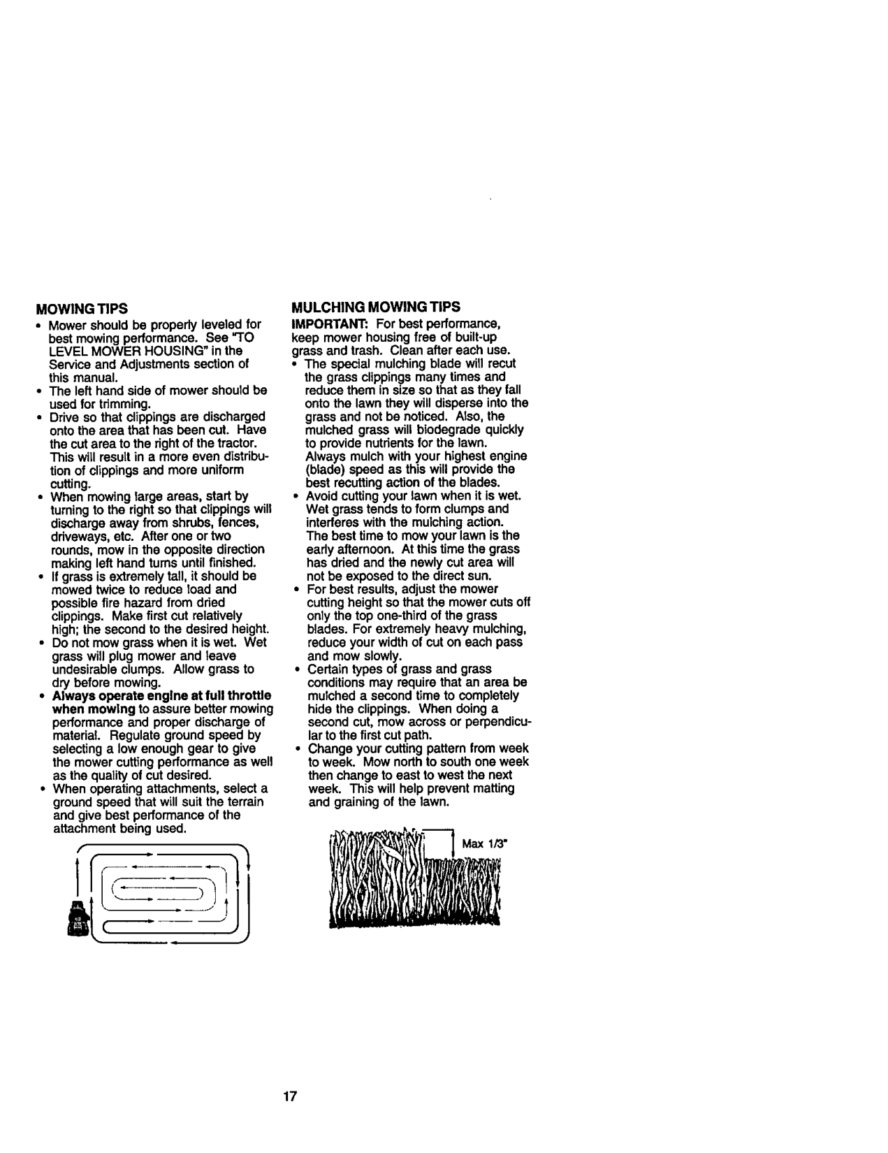
MULCHING MOWING TIPS IMPORTANT: For best performance, keep mower housing free of built-up grass and trash. Clean after each use.
MOWING TIPS
best mowing performance. See "TO LEVEL MOWER HOUSING" in the
Service and Adjustments section of this manual.
the cut area to the rightof the tractor. This will resutt in a more even distribu-
tion of clippings and more uniform cutting.
possible fire hazard from dried clippings. Make first cut relatively high; the second to the desired height.
then change to east to west the next week. This will help prevent matting and graining of the lawn.

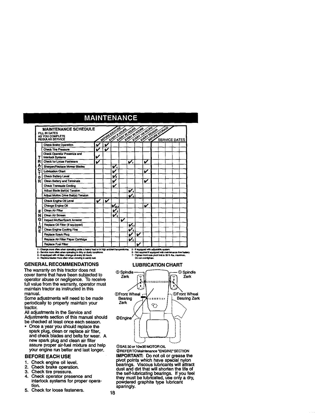
GENERAL RECOMMENDATIONS The warranty onthis tractordoes not cover items that have been subjected to operator abuse or negligence. To r_ive faltvalue from the warranty, operator must maln_in tractor as instructedin this manual. Some adjustments will need to be made periodicallyto property maintain your tractor. All adjustments in the Se_ce and Adjustmentssection of this manual should be checked at least once each season.
LUBRICATION CHART _) Spindle_
-- _)Spindle
####### .............
_
_Front Wheel
FrontWheel
Beadng ====--=,
_ ,;..,
ng
_Engine ..--Y
• Once a year you should replace the spark plug, clean or replace air filter, and check blades and beltsfor wear. A
1
new spark plug and clean air filter assure proper air-fuel mixture and help your engine run better and last longer.
_)SAE30o¢10w30MOTOROIL
• )REFERTO Maintenance "ENGINE'SECTION IMPORTANT: Do not oil or grease the pivot points which have special nylon bearings. Viscous lubricantswill attract dust and dirt that will shodan the life of
BEFORE EACH USE
the self-lubdc_tin_ beadngs. If you feal they must be lubncated, use only a dry, powdered graphite type lubricant
sparingly.

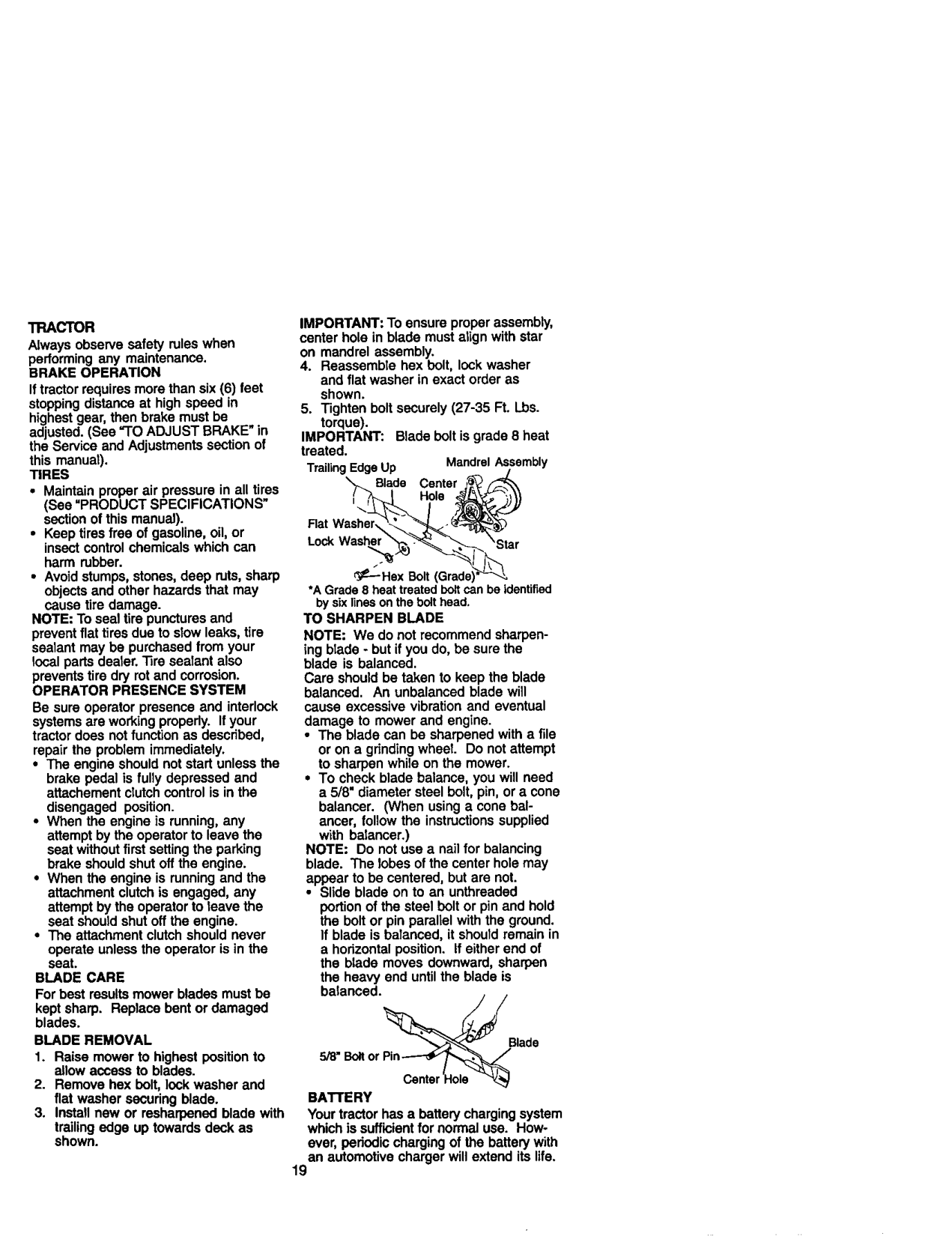
IMPORTANT: To ensure proper assembly, center hole in blade must align with star on mandrel assembly.
TRACTOR Always observe safety rules when performing any maintenance. BRAKE OPERATION Iftractor requires more than six (6) feet stopping distance at high speed in highest gear, then brake must be ad usted. (See "TO ADJUST BRAKE" in the Service and Ad ustmants section of this manuat). TIRES
IMPORTANT: Blade bolt isgrade 8 heat treated.
TrailingEdgeUp MandrelAssembly Blade Center Hole
Rat Washer, LockWashe
Ge---Hsx Boltq
*AGrade8 heattreatedboltcanbe identified
bysixlinesonthebolt head. TO SHARPEN BLADE NOTE: We do not recommend sharpening blade - but if you do, be sure the blade is balanced. Care should be taken to keep the blade balanced. An unbalanced blade will cause excessive vibration and eventual damage to mower and engine.
NOTE: To seal tire punctures and prevent flat tires due to slow leaks, tire sealant may be purchased from your local parts dealer. 33rosealant also prevents tire dry rot and corrosion. OPERATOR PRESENCE SYSTEM Be sure operator presence and interlock systems are working properly. If your tractor does not function as described, repair the problem immediately.
NOTE: Do not use a nail for balancing blade. The lobes of the center hole may
appear to be centered, but are not. • Slide blade on to an unthreaded
portion of the steel bolt or pin and hold the bolt or pin parallel with the ground. If blade is balanced, it should remain in a horizontal position. If either end of the blade moves downward, sharpen the heavy end untilthe blade is balanced.
BLADE CARE For best results mower blades must be kept sharp. Replace bent or damaged blades. BLADE REMOVAL
Blade
BATTERY Your tractor has a battery charging system which is sufficientfor normal use. However, periodic charging of the battery with an automotive charger will extend its life.
trailingedge up towards deck as shown.
19

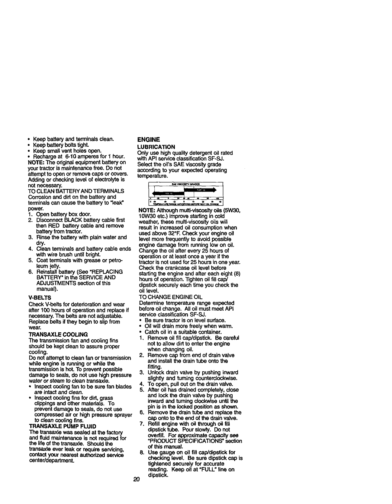
ENGINE LUBRICATION Only use high qualitydetergent oil rated withAPI service classification SF-SJ.
Select the oil'sSAE viscositygrade according to your expected operating temperature.
P_IEwn<_lrt_ _l
NOTE: Althoughmulti-viscoaityoils (5W301 10W30 etc.) improve startingin cold weather, these mulfi-viscosity oilswilt resultin increased oil consumptionwhen used above 32°E Check your engine oil
level mere frequentlyto avoid possible engine damage from runninglow on oil. Change the oil after every 25 hours of operationor at least once a year if the tractorisnot usedfor 25 hoursin one year. Check the crankcase oil level before startingthe engine and after each eight (8) hours of operation."lightenoilfill cap/ dipsticksecurely each time you checkthe oil levai, TO CHANGE ENGINE OIL Determine temperature range expected before oil change. All oil mustmeet API service clessification SF-SJ.
4, Clean terminals and battery cable ends with wire brush untilbright.
V-BELTS Check V-beltsfor deterioration and wear after 100 hours of operation and replace if necessary.The beltsare not adjustable. Replace baits ifthey begin to slipfrom wear. TRANSAXLE COOLING The transmissionfan and cooling fins shouldbe kept clean to assure proper cooling. Do not attempt to clean fan or transmission while engine is running or while the transmissionis hoLTo prevent possible damage to seals, do not use high pressure water or steam to clean transaxle.
TRANSAXLE PUMP FLUID
The transex_ewas sealed at the factory and fluid maintenance is not required for the life of the transexle. Should the
transexle ever leak or require servicing, contact your nearest authorized service center/department.
dipstick.2O

NOTE: If very dirty or damaged, replace pre-cleaner.
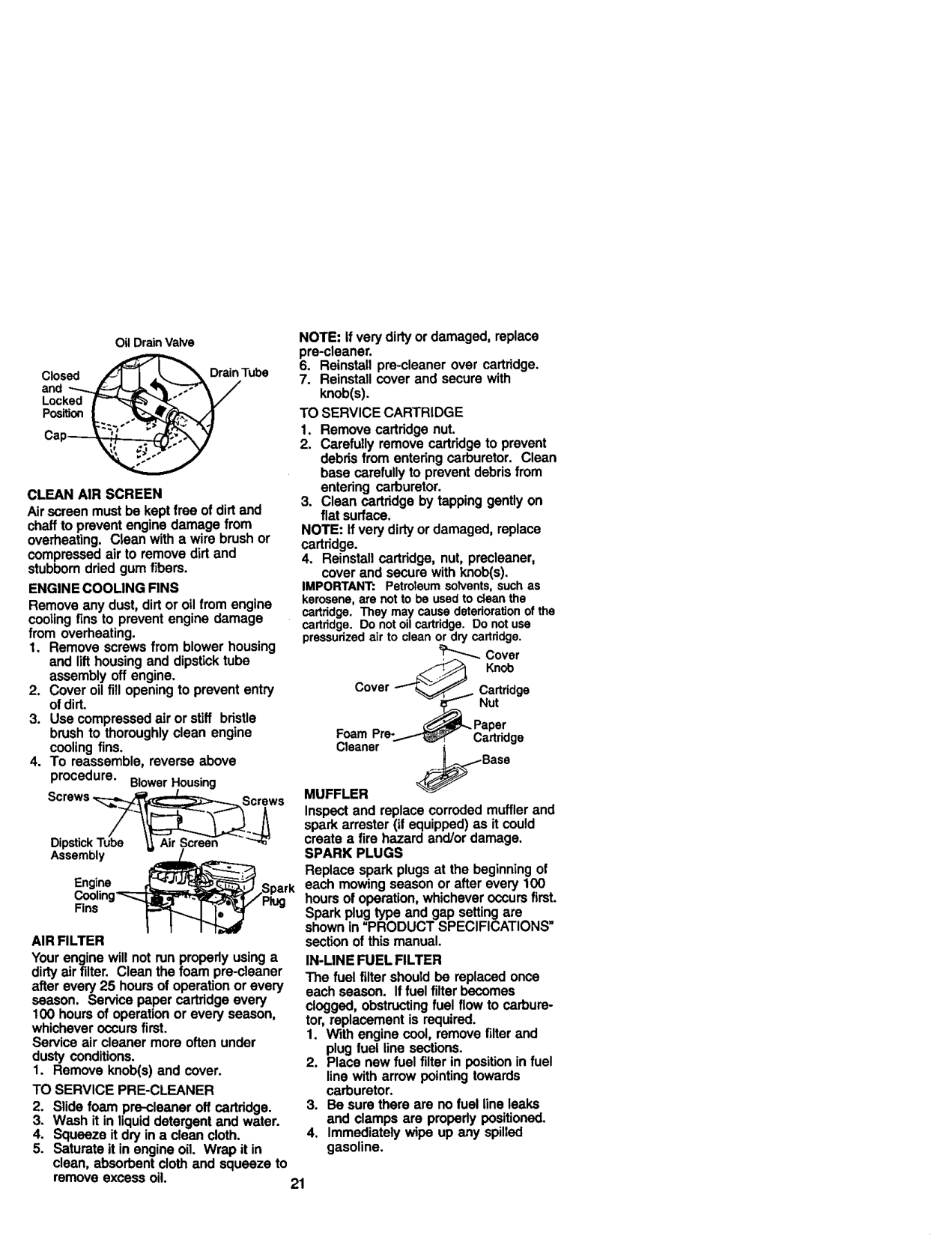
Oil DrainValve Closed _ DrainTube
TO SERVICE CARTRIDGE
NOTE: If very dirty or damaged, replace cartridge.
CLEAN AIR SCREEN Air screen must be kept free of dirt and chaff to prevent engine damage from overheating. Clean with a wire brush or compressed air to remove dirt and stubborndried gum f]bem. ENGINE COOLING FINS Remove any dust, dirt or oil from engine cooling fins to prevent engine damage from overheating.
IMPORTANT: PstroTeumsolvents,suchas kerosene,are notto be usedto deanthe cartridge.Tipsymay causedeteriorationof the osrtddge. Donotoilcartridge.Donotuse pressurizedair to cleanor dryosrtridgs.
Cover Knob
Cover _// Cartridge
-___ Nut Paper Foam Pre-_Y_"_ Cartridge
_Bass
MUFFLER Inspect and replace corroded muffler and spark arrester (if equipped) as it could create a fire hazard and/or damage. SPARK PLUGS Replace spark plugs at the beginning of each mowing season or after every 100 hours of operation, whichever occurs first. Spark plug type and gap setting are shown in "PRODUCT SPECIFICATIONS" section of this manual. IN-LINE FUEL FILTER The fuel filter should be replaced once each season. Iffuel filter becomes clogged, obstructingfuel flow to carburetor, replacement is required.
_Screws
EngineJi_2_ - ark
AIR FILTER Your engine will not run propedy using a dirty air filter. Clean the foam pre-cleaner after every 25 hours of operation or every season, Service paper cartridge every 100 hours of operation or every season, whichever occurs first. Service air cleaner more often under dusty conditions.
line with arrow pointing towards carburetor.
I. Remove knob(s) and cover. TO SERVICE PRE-CLEANER
remove excess oil. 21

• Protect painted surfaces with automo-
tive type wax. We do not recommend using a garden hose to clean your tractor unless the electrical system, muffler, air filter and
Clam_clamp
FuelFilter CLEANING
carburetor are covered to keep water out. Water in engine Can resutt in a shortened engine life.
Clean engine, battery, seat, finish, etc.ofallforeignmatter. Keep finished surfaces and wheels free
of all gasoline, oil, etc.
• 1_CAUTION: BEFORE PERFORMING ANY SERVICE OR ADJUSTMENTS:
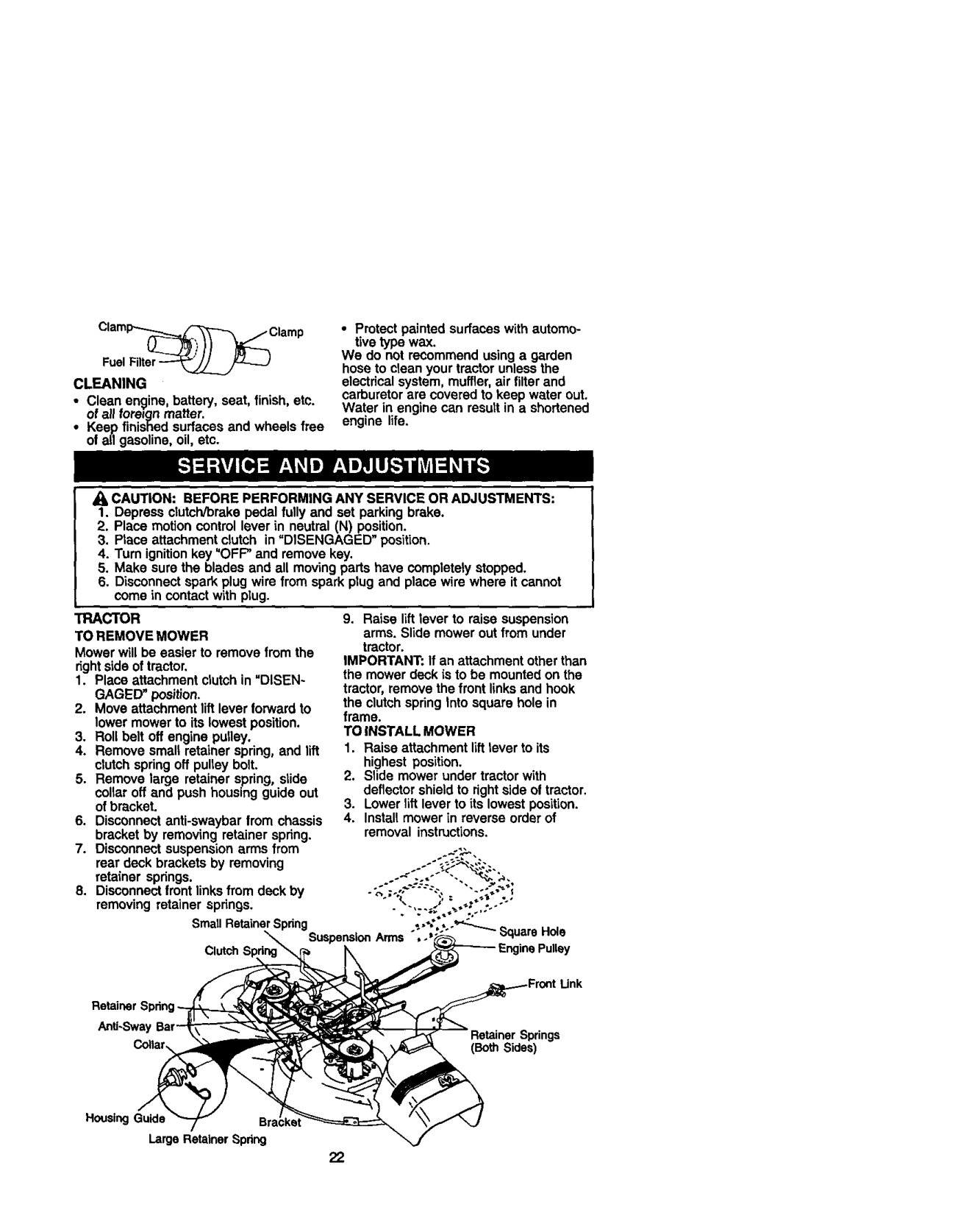
TRACTOR TO REMOVE MOWER Mower will be easier to remove from the right side of tractor,
IMPORTANT: If an attachment other than the mower deck is to be mounted on the tractor, remove the front linksand hook the clutch spring Into square hole in frame. TO INSTALL MOWER
SmaURetainerSpring
Clutch
Link
################# Anti-Swa
Springs (Both Sides)
HousingGuide La_e RetainerSpring
22

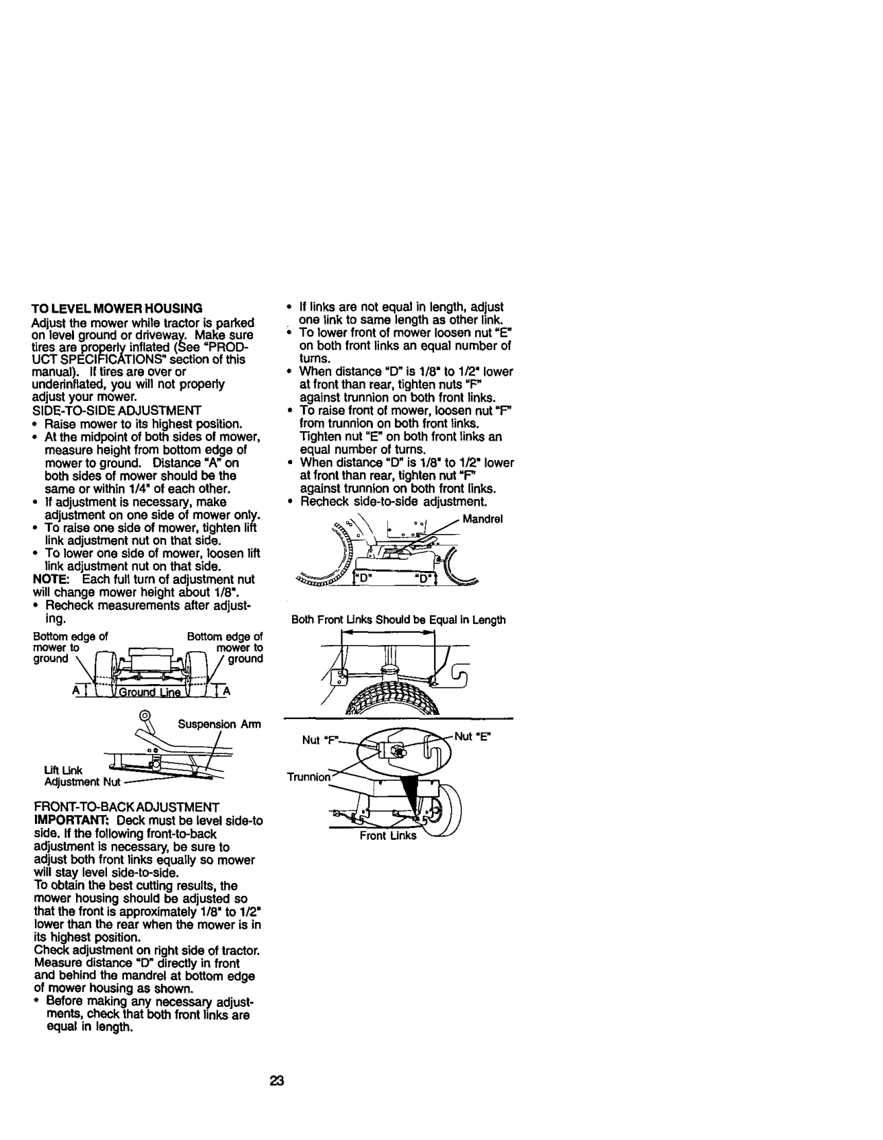
TOLEVELMOWERHOUSING Adjustthemowerwhiletractoris parked
• If links are not equal in length, adjust
one link to same length as other link. ;, To lower front of mower loosen nut =E"
on level ground or ddveway. Make sure
on both front links an equal number of turns.
tires are properly inflated (See =PRODUCT SPECIFICATIONS" section of this
Tighten nut "E"on both front links an equal number of turns.
at front than rear, tightennut =F" against trunnion on both front links.
manual). Iftires are over or undednflated, you will not property adjust your mower. SIDE-TO-SIDE ADJUSTMENT
NOTE: Each full turn of adjustment nut will change mower height about 1/8".
• Recheck measurements after adjust-
ing. Bottomedgeof Bottomedgeof
BothFrontUnksShouldbe EqualinLength
Arm
Uft _°n
Adjustment Nut
FRONT-TO-BACK ADJUSTMENT IMPORTANT: Deck must be level side-to side. Ifthe followingfront-to-back adjustment is necessary, be sure to adjust beth front links equally so mower will stay level side-to-side. To obtainthe best cutting results, the mower housing should be adjusted so that the front isapproximately 1/8" to 1/2" lower than the rear when the mower is in its highest position. Check adjustmenton rightside of tractor. Measure distance "[_' directly in front and behind the mandrel at bottom edge of mower housing as shown.
Trunnion_
Front Links
• Before making any necessary adjustments, check that both front links are equal in length.

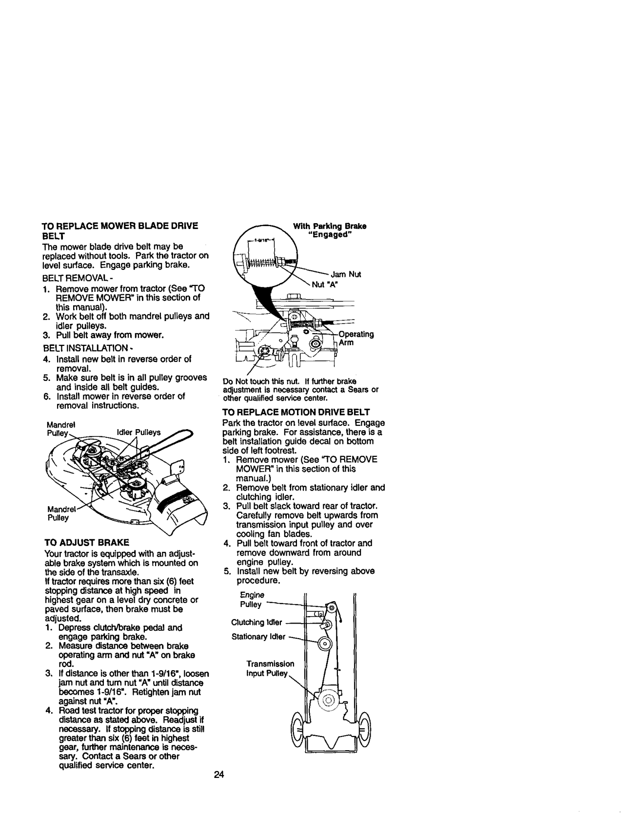
TO REPLACE MOWER BLADE DRIVE BELT
With Perking Brake
"Engaged"
The mower blade drive belt may be replaced without tools. Park the tractor on level surface. Engage parking brake.
BELTREMOVAL-
Do Not touch this nut. If further brake adjustment is necessary contact a Sears or other qualified service center.
TO REPLACE MOTION DRIVE BELT Park the tractor on level surface. Engage parking brake. For assistance, there is a belt installation guide decal on bottom side of leftfootrest. 1, Remove mower (See "TO REMOVE
Mandrel
MOWER" in this section of this manual.)
MandreP Pulley
TO ADJUST BRAKE Your tractor is equipped with an adjust° able brake system which ismounted on the side of the transaxle. If tractorrequires more than six (6) feet stoppingdistance at high speed in highest gear on a level dry concrete or paved surface, then brake must be adjusted.
Engine Pulley
Clutching Ioler -Stationary Idter
operating arm and nut =A"on brake rod.
Transmission Input PuNey _
3, If distance is other than 1-9/16", loosen
jam nut and turn nut "A" untildistance becomes 1-9/16". Retightee jam nut against nut ",6,'.
24

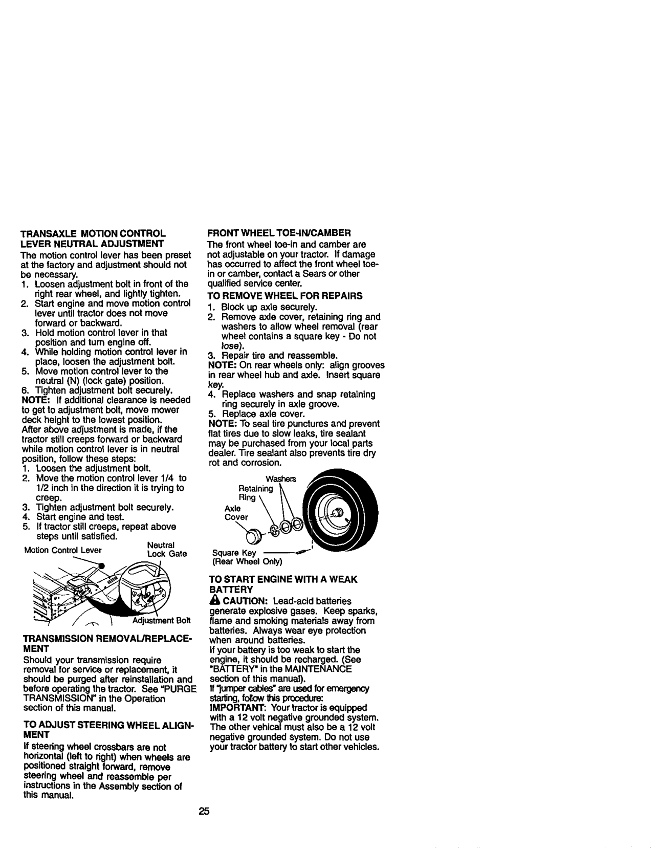
FRONT WHEEL TOE-IN/CAMBER The front wheel toe-in and camber are not adjustable on your tractor. If damage has occurred to affect the front wheel toein or camber, contact a Sears or other qualifiedservice center. TO REMOVE WHEEL FOR REPAIRS
TRANSAXLE MOTION CONTROL LEVER NEUTRAL ADJUSTMENT
The motion control lever has been preset at the factory and adjustmentshould not be necessary.
1/2 inch in the direction it istrying to creep.
steps until satisfied.
Neutral MotionControlLever LockGate
(Rear Wheel Only)
TO START ENGINE WITH A WEAK BATTERY
CAUTION: Leed-acid batteries generate explosive gases. Keep sparks, flame and smoking materials away from batteries. Always wear eye protection when around batteries.
Adjustment Bolt
TRANSMISSION REMOVAL/REPLACEMENT
ifyour battery istoo weak to start the engine, it should be recharged. (See "BA'I-I'ERY"in the MAINTENANCE
Should your transmission require removal for service or replacement, it should be purged after rainstailation and before operating the tractor. See =PURGE TRANSMISSION" in the Operation section of this manual.
section of this manual). ff"jumper cable_' are usedloteme_ starUng,followthisproceduce: IMPORTANT: Yourtractor is equipped with a 12 volt negative grounded system. The other vehical must also be a 12 volt
TO ADJUST STEERING WHEEL ALIGNMENT
negative grounded system. Do not use your tractor batteryto start other vehicles.
If steering wheel crossbars are not horizontal (leftto right) when wheels are positioned straight forward, remove steedng wheel and reassemble per instructionsin the Assembly section of this manual.

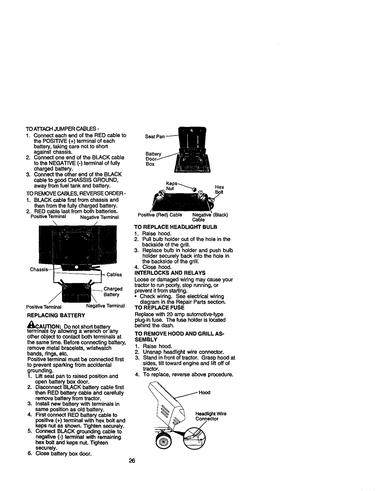
TOA'I-rACHJUMPER CABLES-
Ba_ew Box
Keps_ Nut Hex
TO REMOVE CABLES,REVERSE ORDER -
than from the fully charged battery. 2. RED cable last from both batteries.
Positive (Red) Cable
PositiveTerminal NegativeTerminal
TO REPLACE HEADLIGHT BULB
Loose or damaged wiring may cause your tractorto run peorly, stop running,or prevent itfrom starting.
• Check w_ring. See electrical wiring
diagram in the Repair Parts section. TO REPLACE FUSE Replace with 20 amp automotive-type plug-infuss. The fuss holder islocated behind the dash. TO REMOVE HOOD AND GRILL ASSEMBLY
PositiveTerminal Negative Terminal REPLACING BATrERY
te_C.AU._ON: Do not shortb.attery
na_soy a owing a wrencn or any other object to contact both terminals at the same time. Before connecting battery, remove metal bracelets, wristwatch bands, rings,etc. Positiveterminal must be connected first to prevent sparking from accidental grounding.
then RED battery cable and carefully remove battery from tractor.
Headlight Wire Connector

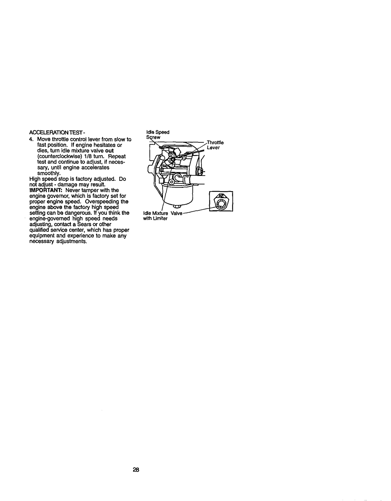
TO ADJUST CARBURETOR NOTE: The carburetor on this engine is low emission. It is equipped with an idle fuel adjusting needle with a limiter cap, which altows some adjustment within the limitsallowed by the cap. Do net attempt to remove the limitercap. The limitercap cannot be removed without breeking the adjusting needle. The carburetor has been preset at the factory and adjustment should not be necessary. However, minor adjustment may be required to compensate for differences in fuel, temperature, altitude or load. If the carburetor does need adjustment, proceed as follows: Ingeneral,turningidlemixture valve in
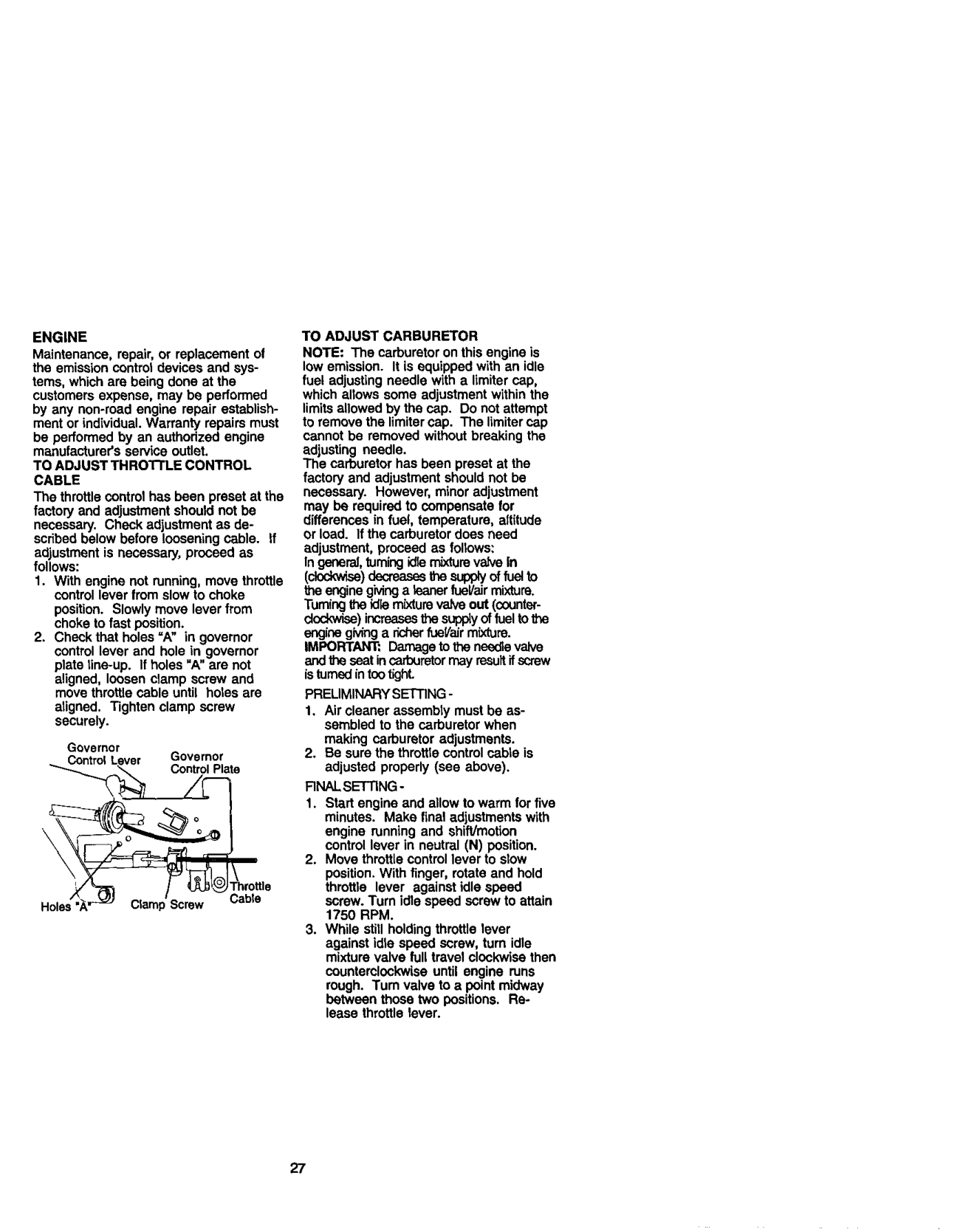
ENGINE Maintenance, repair, or replacement of the emission centrol devices and systems, which are being done at the customers expense, may be performed by any non-road engine repair establishment or individual. Warranty repairs must be performed by an authodzed engine manufacturer's service outlet. TO ADJUST THRO'I-FLE CONTROL CABLE The throttle control has been preset at the factory and adjustment should not be necessary. Chock adjustment as described below before loosening cable. If adjustment is necessary, proceed as follows:
(ck_v, Lse)docreasssthe sup_y of fu_ to theenginegivinga tearierfuel/airmixture. Turningtheidle m{xturevedveout (counterdockwiss)increasesthe supplyof fuelto _e engine giving a richer fueVair mixture. IMPORTANT: Damage to the needle valve and the ssat in cerbut_tor rnay rssult ifscrew isturned in tootighL
PRELIMINARY SETTING-
aligned. Tighten clamp screw securely.
Governor Control Governor
Control Plate
RNAL SETTING-
Clamp Screw Cabte

ACCELERATION TEST -
Idle Speed
High speed stop is factory adjusted. Do not adjust - damage may result. IMPORTANT= Never tamper with the
######### ro ,e
engine governor, which is factory set for proper engine speed, Overspeeding the engine above the factory high speed setting can be dangerous. If you think the engine-governed high speed needs adjusting, contact a Sears or other qualified se_ce center, which has proper equipment and experience to make any necessary adjustments.
IdleMixtureValve--/_ with Umiter

Also, expodance indicates that alcohol blended fuels (called gasohol or using ethanol or methanol) can attract moisture which leads to separation and formation of acids during storage. Acidic gas can damage the fuel system of and engine while in storage.
Immediately prepare your tractor for storage at the end of the season or ifthe tractor will not be used for 30 days or more,
CAUTION: Never store the tractor with gasoline in the tank inside a building where fumes may reach an open flame or spark. Allow the engine to cool before storing in any enclosure.
TRACTOR Remove mower from tractor for winter storage. When mower is to be stored for a period of time, clean it thoroughly, remove all dirt, grease, leaves, etc. Store in a clean, dry area.
(See belt replacement instructionsin the Service and Adjustments section of this manual).
engine at least 10 minutes after adding stabilizer to allow the stabilizerto reach
the carburetor. Do not drain the gas tank and carburetor if using fuel stabilizer. ENGINEOIL
Drain oil (with engine warm) and replace with clean engine oil. (See "ENGINE" in the Maintenance section of this manual). CYLiNDER(S)
BATI'ERY
Fully charge the batteryfor storage. After a period of time in storage, battery
may require recharging.

and battery cleaned thoroughly (see "TO CLEAN BATI-ERY AND TERMI-
NALS" in the Maintenance section of this manual).
sation to form and will cause your tractorto rust.
ENGINE FUEL SYSTEM IMPORTANT: it Isimpartant to prevent gum deposites from forming in essential fuel system parts such as carburetor, fuel hose, or tank during storage.
IMPORTANT: Never caver tractor while engine and exhaust areas are stillwarm.

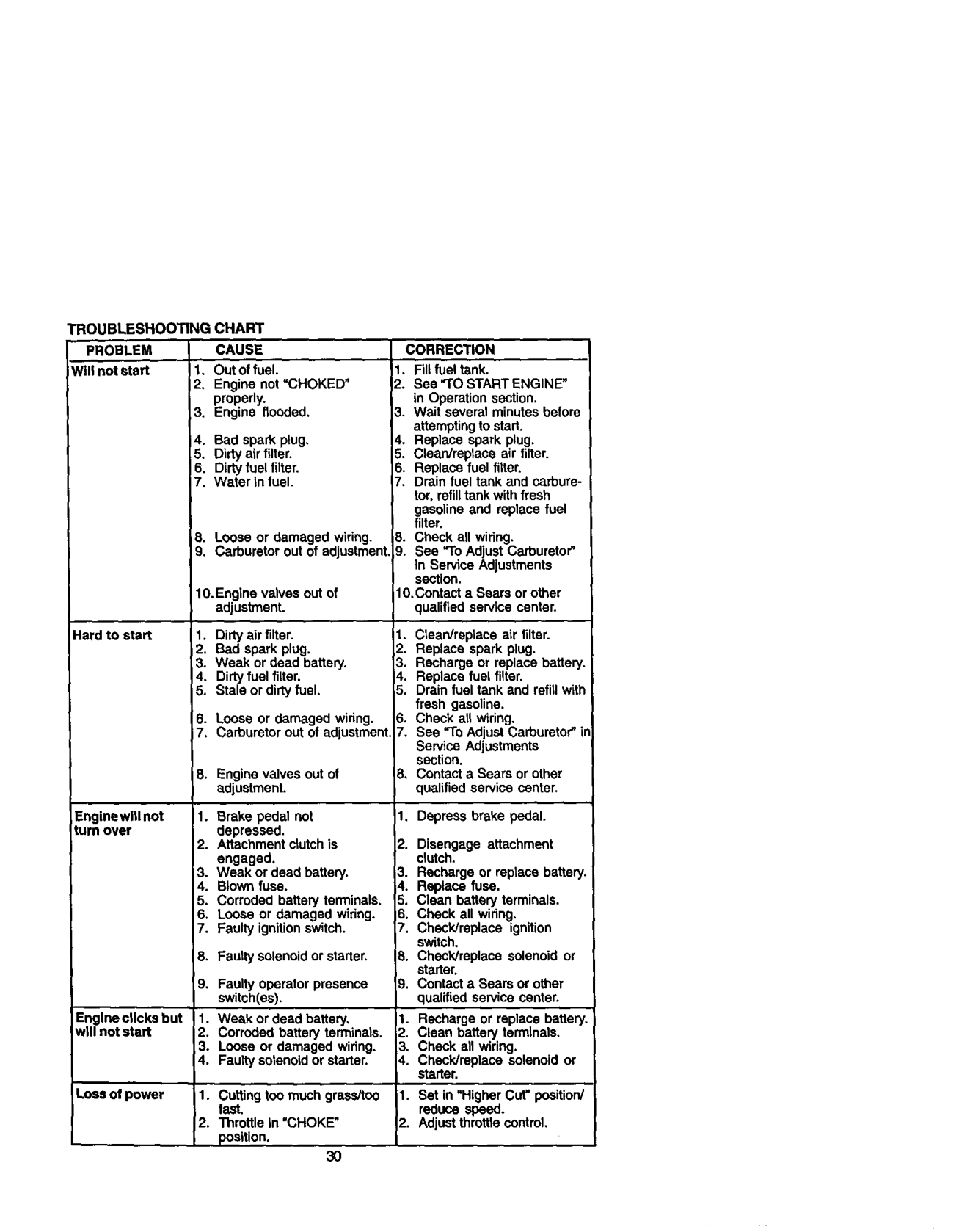
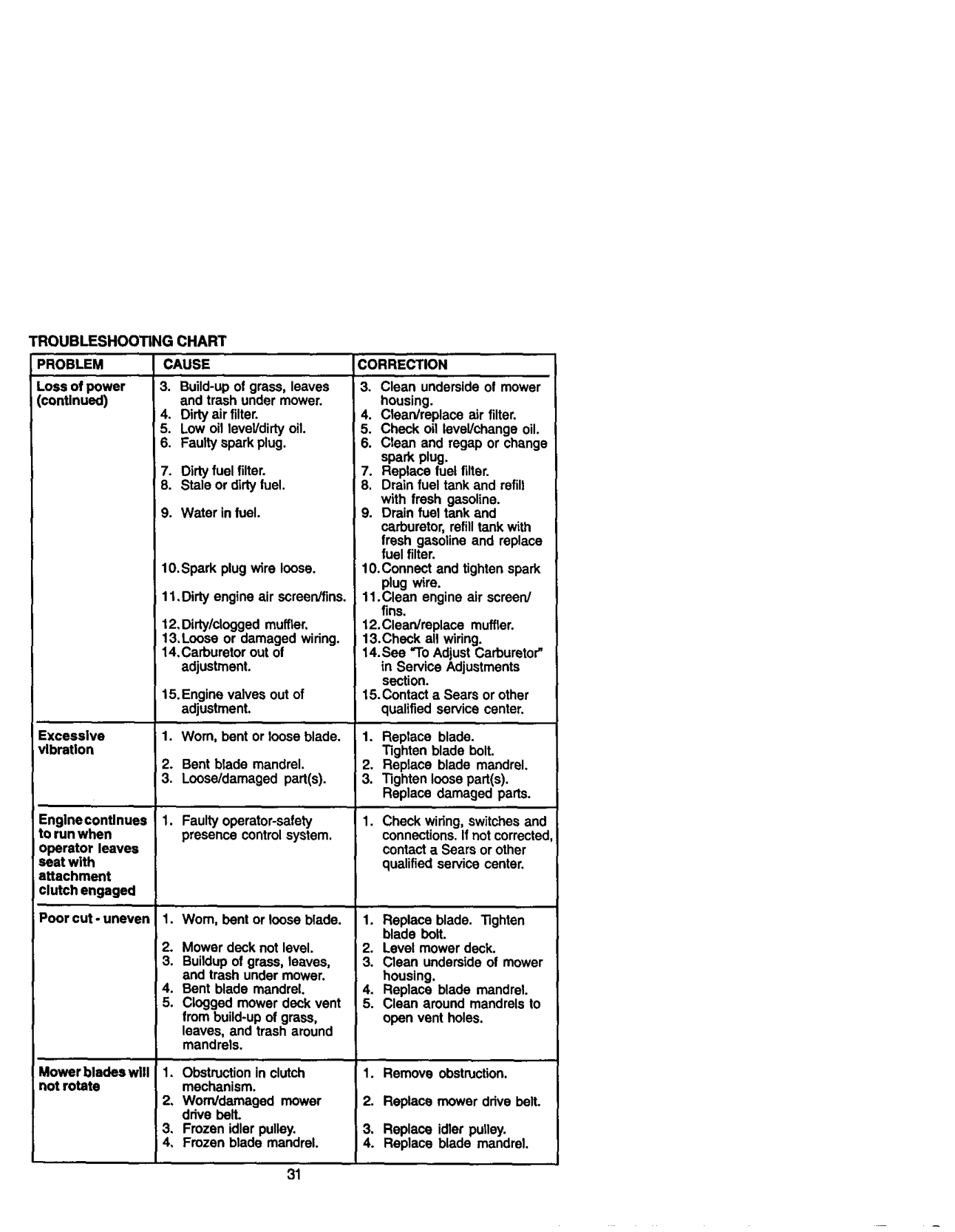
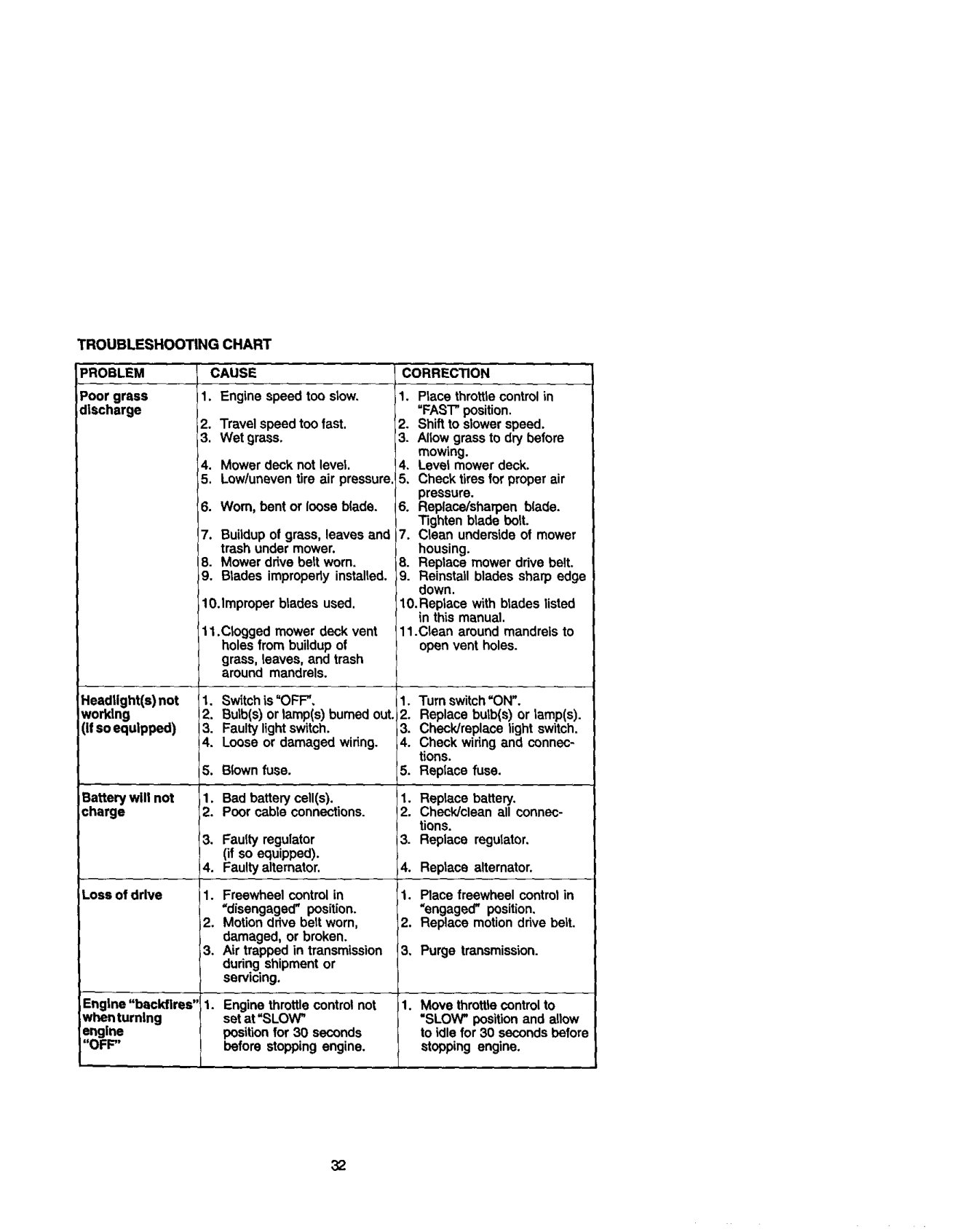
TROUBLESHOOTINGCHART
CAUSE
CORRECTION
PROBLEM Will n_ sta_ 1,
Outoffuel. Enginenot=CHOKED" properly. Engineflooded,
I1. Fillfuel tank. 12.See "TO START ENGINE"
in Operation section.
attempting to start. a,. Replace spark plug. _. Clean/replace air filter.
gasoline and replace fuel filter.
Looseor damagedwiring, Carburetoroutofadjustment,
lO.Contact a Sears or other qualified service center.
1O.Enginevalvesoutof adjustment.
Hard to start

8, Contact a Sears or other qualified service center,
Englnewlllnot turnover
Engine clicks but will not start
I1. Recharge or replace battery, _2. Clean battery terminals,
Loss of power
3O

TROUBLESHOOTINGCHART PROBLEM Lossofpower (continued)
CAUSE
CORRECTION
and trash under mower.
spark plug.
I 7. Dirtyfuel filter.

10.Spark plug wire loose.
Excessive vlbratlon
############### 1. Faultyoperator-safety presencecontrolsystem.
Englnecontlnues to run when
connections. If not corrected
operator leaves seat with attachment clutch engaged
contact a Sears or other qualified service center,
Poor cut-uneven
from build*up of grass, leaves, and trash around mandrels.
Mower blades will not rotate

TROUBLESHOOT_GCHART PROBLEM Poor grass discharge
CAUSE
CORRECTION
Travelspeedtoofast. Wetgrass.
Mowerdeck notlevel. Low/uneventire air pressure,
Worn,bentor looseb(ade.
Buildup of grass, leaves and trash under mower. Mower drive belt worn. Btades improperty instalted.
grass, leaves, and trash around mandrels.
Headlight(s)not working (ifsoequipped)
i2. Replace butb(s) or Ismp(s). 13. Check/replace light switch. _4. Check wiring and connec-
tions.
Batterywillnot charge
. Rep_ece battery.•Check/cleanallconnections.
Loss of drive
=disengaged" position.
Engine "backfires' when turning engine "OFF"
Engine throttle control not set at "SLOW"
position for 30 seconds before stopping engine.
I
############### 32

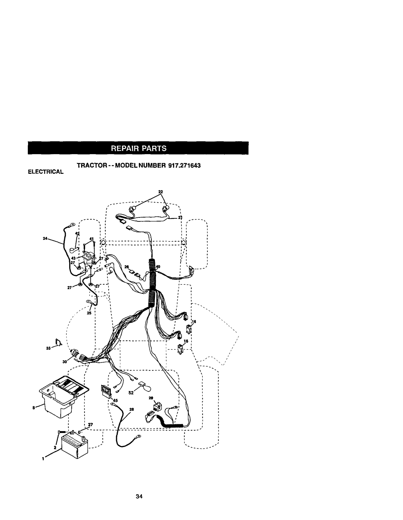
TRACTOR-- MODEL NUMBER 917.271643
SCHEMATIC
I
BATTERY
FUSE : _ STARTER
.... i _ gu°<
################### (NOTOCCUPIED)
,_,
i i t.
L_ ------
,_ IGNITION GAP I_UNITPLUGSON TWINCYL ENGINES) ,
NOTE YOUR TRACTOR _S EQUIPPED WITH ASPECIAL ALTERNATOR SYSTEM. THE LIGHTS ARE NOT CONNECTED TO THE BATTERY, BUT HAVE THEIR OWN ELECTRICALSOURCE. BECAUSE OF THIS, THE BRIGHTNESS OF THE LIGHTS WILL CHANGE WITH ENGINE SPEED. AT IDLE THE LIGHTS WILL DIM. AS THE ENGINE IS SPEEDED UP. THE LIGHTS WiLL BECOME THEIR BRIGHTEST.
HFJ_DUGHTS
################# F)
+
################### NON-REMOVABLE CONNECTIONS
o
IGNmON swrrcH
REMOVABLE CONNECTIONS
WIRING INSULATED CUPS NOTE: IF WIRING INSULATED CLIPS WERE REMOVED FOR SERVICING OF UNIT, THEY SHOULD BE REPLACED TO PROPERLY SECURE YOUR W_R_NQ.
################# 33

########### ELECTRICALTRACTOR -- MODEL NUMBER 917.271643
i
25
################# 34

############### TRACTOR -- MODELNUMBER 917.271643
ELECTRICAL
################## KEY PART NO. NO. DESCRIPTION

40 178437 Hamess Ign 41 71110408 Bolt BIk, Fin Hex 1/4-20 Unc x 1/2 42 131563 Cover Terminal Red 43 178861 Balenoid 45 121433X Ammeter Rectangular 6Amp 52 141940 Proteclton Wire Loop
NOTE: All component dimensions given inU.S. inches 1 inch = 25.4 mm

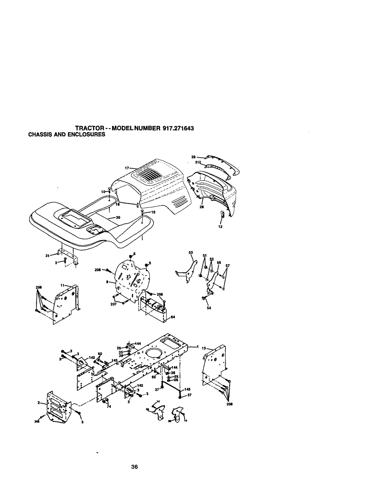
############### TRACTOR - - MODEL NUMBER 917.271643 CHASSISAND ENCLOSURES
2|
12
53
54
2O6
################# 36

############### TRACTOR-- MODELNUMBER 917.271643 CHASSISAND ENCLOSURES
################## KEY PART NO. NO. DESCRIPTION
29 155217X599 Lens, Griile 30 174738X558 Fend/Ftrest
31 139976 Bracket, Fender Support
60 72140606 Bolt Rdhd Sqnk 3/8-16 UNC x 3,_4 64 154798 Dash Lower STLT 74 S'RTo41437 Nut Crownlock 3/8016 UNC

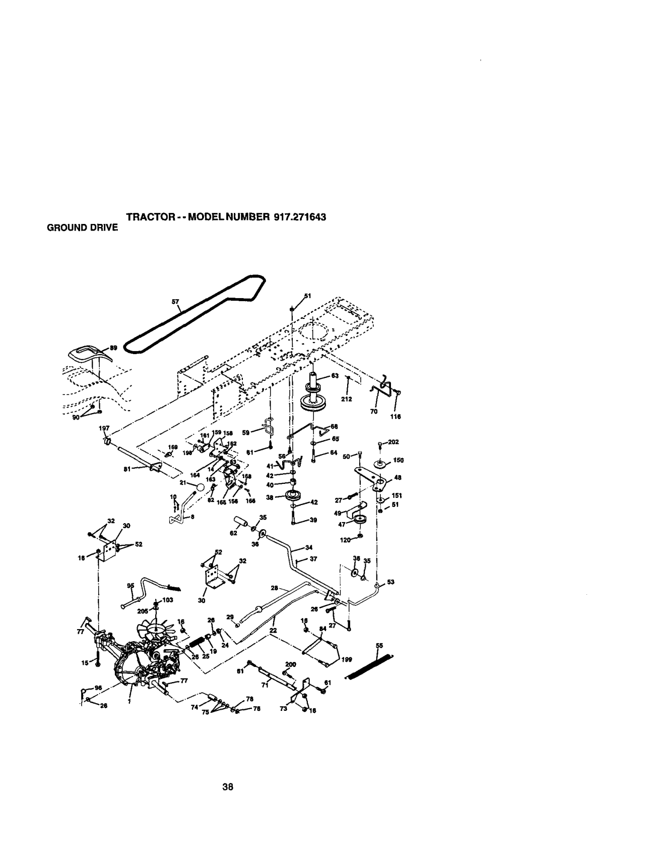
############### TRACTOR - - MODEL NUMBER 917.271643 GROUNDDRIVE
212
70
2
22 l_t.,6 84
61
############### 38

############### TRACTOR -- MODELNUMBER 917.271643 GROUNDDRIVE
################## KEY PART KEY PART NO. NO. DESCRIPTION NO. NO. DESCRIPTION
Keeper, Bolt Engine Hydro Guide, Belt, Mower Drive RH Strap, Torque, Lh Strap, Torque. Rh Spacer, Axle Washer 25/32 x 1-1/4 x 16 Ga. Ring, E Key, Square Washer 25/32 x 1-5/8 x 16 Ga. Shaft Asm Cross Spring,Tor_K_'_ Washer 17/82 x 3/4 x 16 Ga.
1 ...... Transmission (See Breakdown) 66 154778
Hydro Gear Mede1322-.0510 70 134683 8 165866 Rod, Sh_t 71 169t83 10 STD561210 Pin, Cotter 1/8 x 1 73 169182
Link Transaxle Console, Shift Nut Selt-Thd Wshd 1/4
Control Asm Bypass Hydro Spdng, Retainer 1" Nut, Hex Jam Toplock 1/2-20
Bolt Rdhd Sq Neck 3/8-16 x 1 Nut Lock F_J3/8-16 Specer Retainer Washer 13/32 x 2 x 10 Washer 5/16 x 1.0 x 1.25 Bracket Shift Mount Hub Tapered Flange Shift Bolt Rdhd Sqnk lj4-20 x 3/4 G_ 5 NUt Cmwnlock 1/4-20 Uric Bolt Hex Fin 1/4-20 x 1 Washer 5i8 x .281 x 10 Ga. Bracket Pivot Lever Screw 5/16 x 1.0 x .125 Bolt Shoulder 5/16-18 x .561 plate Fastener Cross Shaft Nyliner Snap-In Washer Nyliner Bolt Sheu_der5/16-18 Unc Bolt RdHd Sqnk 5/16-18 Unc x 1 Bolt Carr. Sh 3/8-16 x 1-1/2 Gr. 5 Washer 17/32 x 1 x 16Ga. Nut Hex Flange Lock
8883R Cover,Pedal 2_ 7211G612
NOTE: All component dimensions given inU.S. inches 1 inch = 25.4 mm
############### 39

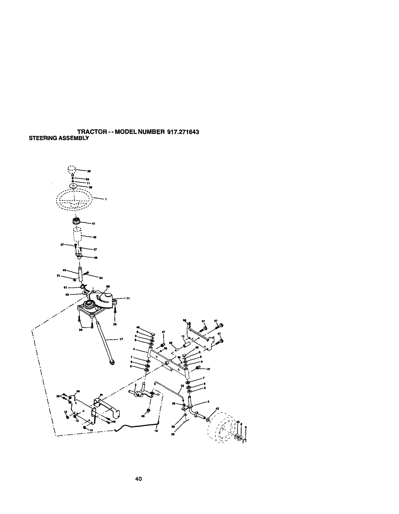
############ TRACTOR--MODELNUMBER917.271643 STEERINGASSEMBLY
./ /

################# 4O

############### TRACTOR -- MODEL NUMBER 917.271643 STEERING ASSEMBLY
################## KEY PART NO. NO. DESCRIPTION
e2 16S_35 Bracket Susp. Chassis Front 85 133835 Fastener Christmas Tree 88 175118 Bolt Shoulder 7/16-20 91 175553 Clip Steedng
NO'I_:NI componentdirnensionsgiveninU.S._ctt_ 1_'tch= 25A mm
################# 41

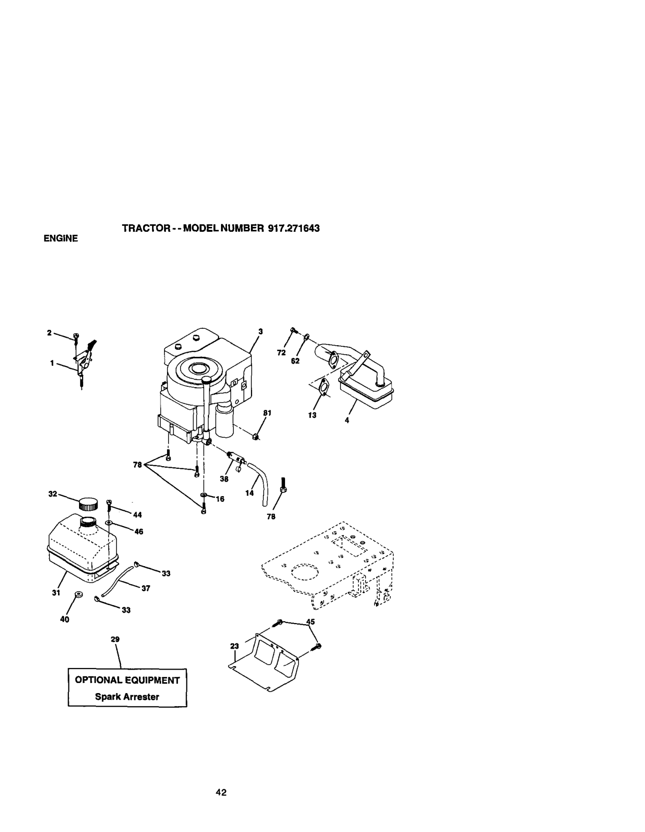
########### ENGINE TRACTOR - -MODEL NUMBER 917.271643
B1 13
14
37
################# 4O
2g
OPTIONAL EQUIPMENTSparkArrester
################# 42

############### TRACTOR-- MODEL NUMBER 917.271643
ENGINE
KEY PART NO. NO. DESCRIPTION
17{To45 Controll'hrot/Ch 17720410 Screw Hex Thd Cut 1/4-20x_'8 T
........ Engine(See Breakdown)
Bdggs MOdel 310707-01 3/-E1 137352 Muffler Exhaust B&S Lt 165291 GaSket 1 313 Id T=n Plated 148456 Tube Drain oil easy ST[_5123/ Washer Lock Ext Tooth 3/8 16ge37 Shield Br0wning/Debris Guard 137180 Arrestor Spark 109202X Tank Fuel 1 25 Fr 158990 Cap Asm Fuel Sears Vented 123487X Clarnp Hose BIk 13/040 Line Fuel 20" 148315 Plug drain oileasy 124028X Bushing Snap Nyl BIk Fuel Line 17490412 Screw Hexwsh Thdrol 1/4-20x3/4 17060612 Screw 3/8-16 x 3/4 19091416 Washer 9/32 X 7/8 X 16ga ST1_551131 Washer Lock Hvy Hid Spr 5/16 71070512 Screw Hexhd Cap 5/16-18x5/4 17060620 Screw 3,'8-16xl -1/4 73510400 Nut Range 1/4-20 Starter Nut
4 13 14 16 23 29
NOTE: Ancomponent dirnen_ns given tn U.S. inches 1 inch= 25.4 mm
############### 43

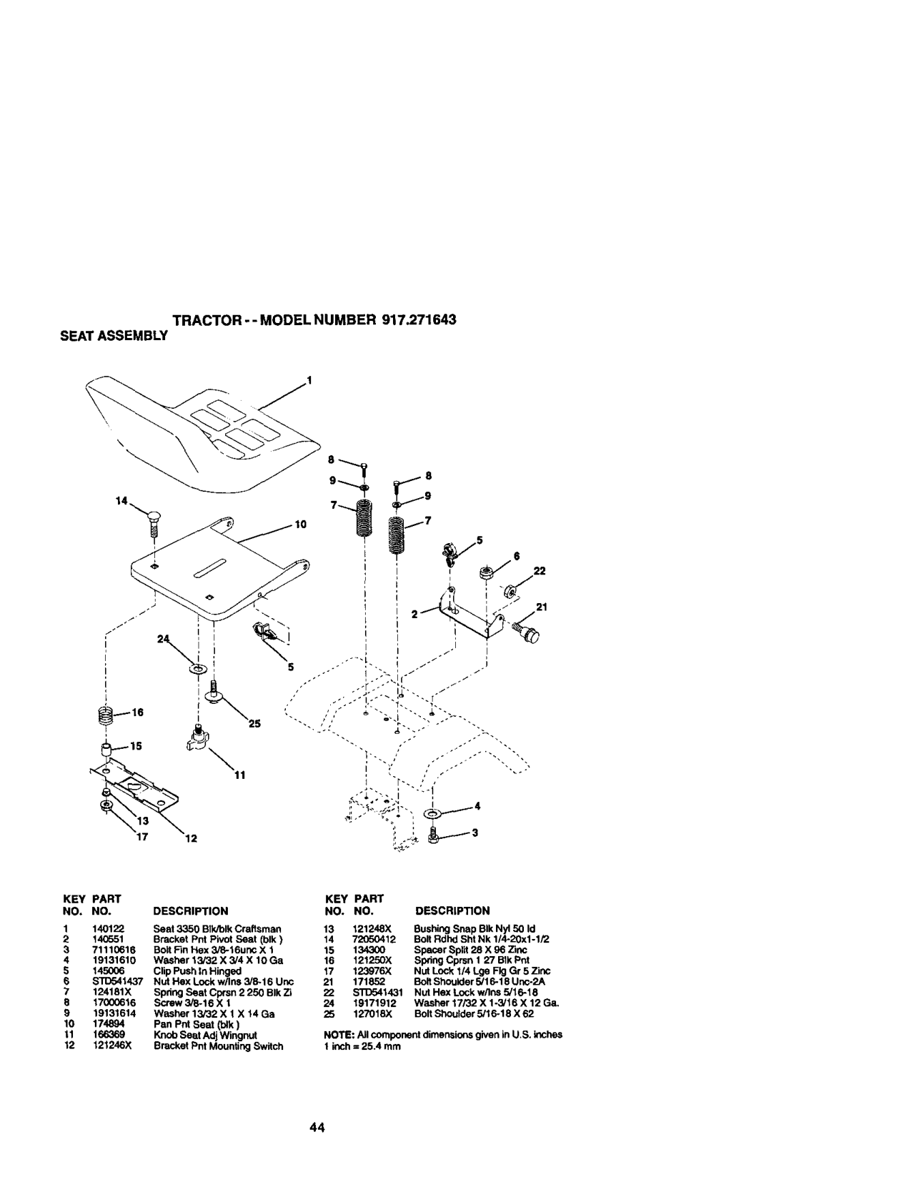
########### TRACTOR--MODEL NUMBER 917.271643 SEATASSEMBLY
################## KEY PART KEY PART NO+ NO. DESCRIPTION NO. NO, DESCRIPTION
############### 44

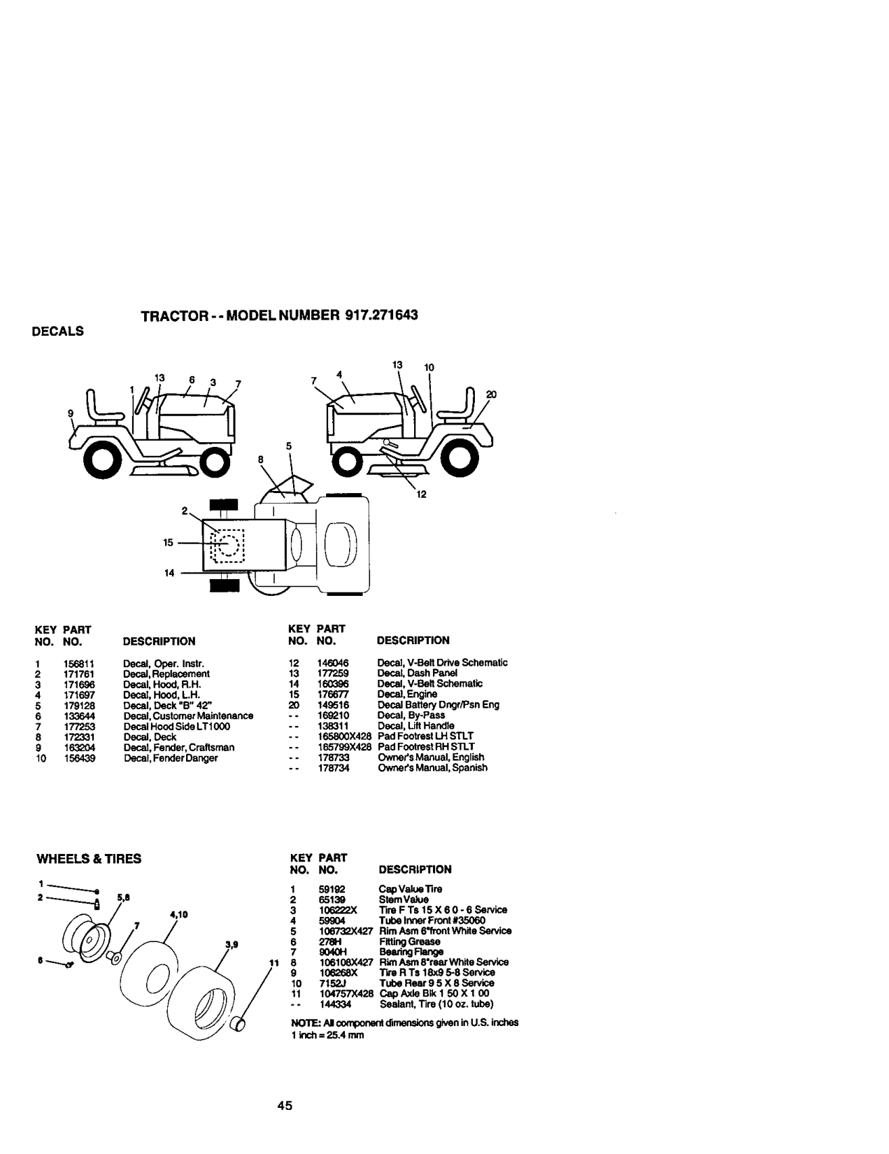
############### TRACTOR - - MODEL NUMBER 917.271643
DECALS
13 10
\
12
################## KEY PART NO. NO.
KEY PART DESCRIPTION NO. NO.
DESCRIPTION
Decal, V-Belt Drive Schematic Decal, Dash panel Decal, V-Belt Schematic Decal, Engine Decal Battery Dngr/Psn Eng Decal, By-Pass Decal, LiftHandle Pad Footrest I.H SILT Pad Footrest RH STLT Owners Manual, English Owner's Manual, Spanish
Decal, Oper. Instr. 12 146046 Decal, Replacement 13 177259 Oecal, Hood, R,H. 14 160356 Decat, Hood, L,H. 15 176677 Decal, Deck "B" 42' 20 149516 Decal, Customer Maintenance - - 16_10 Decal Hood Side LT1000 -- 138311 Decal, Deck - - 165800X428 Decal, Fender, Craftsman -- 165799X428 Decal, Fender Danger - - 178733
################## KEY PART NO. NO. DESCRIPTION
4,10
11
################# 45

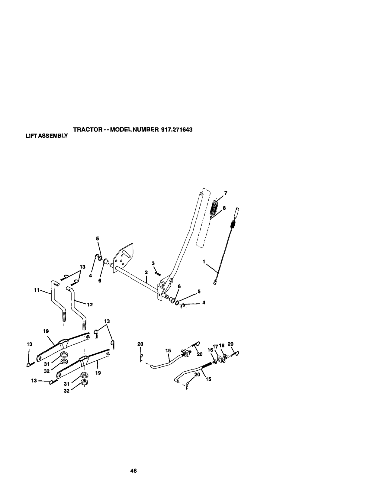
############### TRACTOR -- MODELNUMBER 917.271643 LIFTASSEMBLY

TRACTOR--MODELNUMBER917.271643 UFTASSEMBLY
KEY PART NO. NO. DESCRIPTION
NO'I1E:Allcomponentdirnen_or_ givenin U.S.inches 1inch=25,4 mm
############### 47

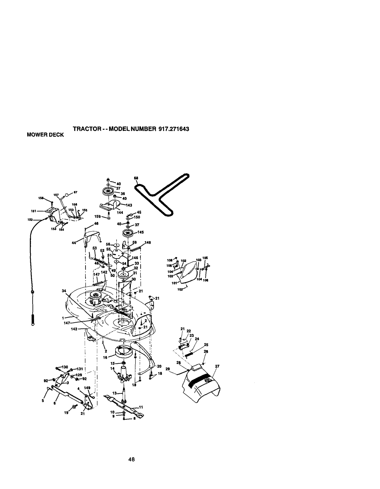
########### TRACTOR--MODEL NUMBER 917,271643 MOWERDECK
34
>21
27

############### TRACTOR-- MODELNUMBER 917.271643 MOWERDECK
KEY PART KEY PART NO, NO, DESCRiPTiON NO, NO.
DESCRIPTION Boil, Shoulder 5/16-18 UNC Ann Assembly, Pad, Brake Washer, Ha,-dened Arm, Idler Spacer, Retainer Guard, TUV Idler Knob Custom Oval V-Bait Nut Mulchor Cover Scow Washer #10 Washer, Lock Latch Assembly, Bagger Nut,Weld Washer 13/32 x 13/16 x 12 Ga. Bolt, Fin Hex 5/6-16 UNC x 1Gr. 5 Bolt, Rdhd Sqnk 3/6-16UNC x 1 Ann Swing Brake Mower Bracket Ann Idtar 42" Keeper Bolt 42" Clutch Cable Pulley idler Rat BoltCarriage Idler Spring Exteneion Spring Return Idler RetaJnet Swing Yellew Zidc Washer 9/32 x 3/4 x 16 Ga. Bracket Clutch Cable Clutch 42 In Washer Rat _ Type B Spring Retainer Swing Retention Lever Spacer Rod Clutch Screw Hex Thd Cut 1/4-20 x 5/8 BoIl Rdhd Sqn 3/6-16 Uric x 3/4 Mandrel Assembly (Includes Key Numbers 8-10,13-15, 31 and 32) Replacement Mower, Compldta
15,3535 Putley, Mandrel 154 169675 33 178342 Nut, Topleck, Rangnd 34 STD533717 Bolt 155 169671
Ga 158 17720410 40 S]_541437 NutU_rownlock3/8-16UNC 159 7214C614 44 14_088 Guard, Mandrel, L.H. - - 130794 45 STD624903 Retainer 46 137729 Screw, Thd. Roll 1/4-20 x 5/8
NOTE: AI com4xx_t dimensldf_ given in U.S.inches 1 inch= 25.4 mm

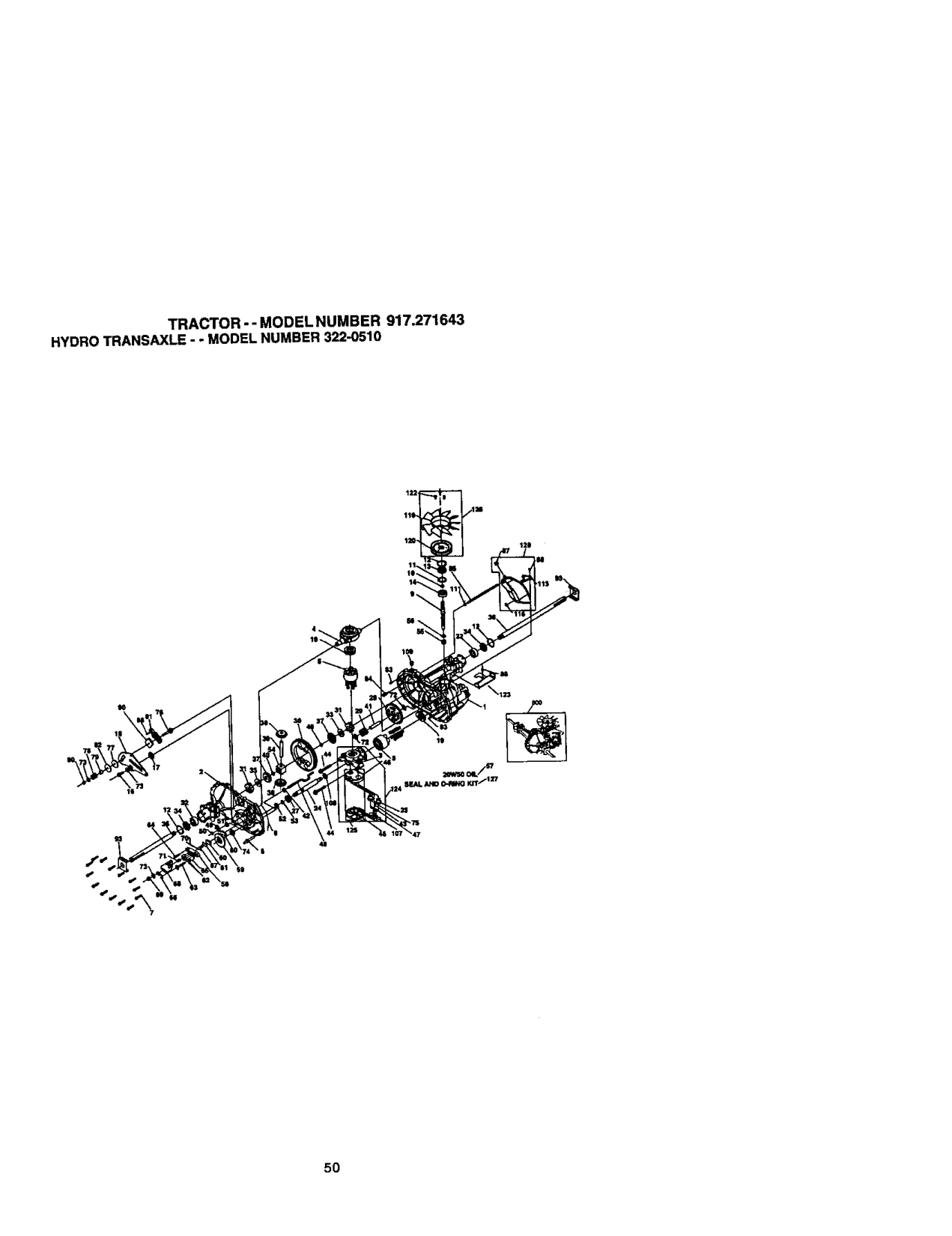
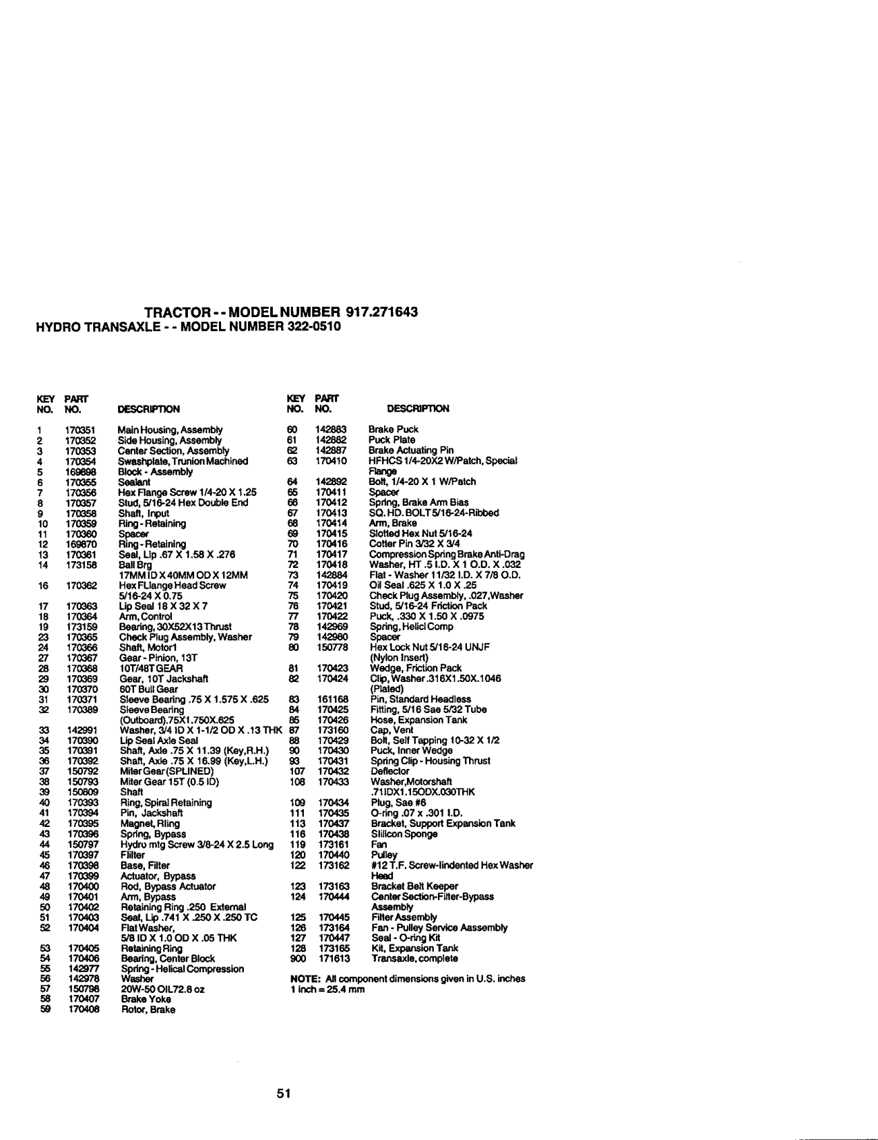
############### TRACTOR -- MODELNUMBER 917.271643 HYDROTRANSAXLE- - MODELNUMBER322-0510
5O

############### TRACTOR-- MODEL NUMBER 917.271643 HYDROTRANSAXLE- - MODELNUMBER322-0510
PARr KEY PARr NO. NO. DESCRg:TION NO. NO. DESCRIFRON

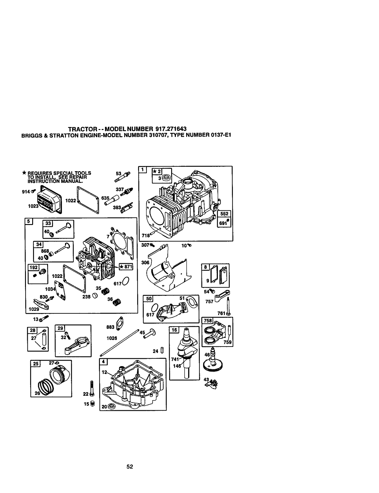
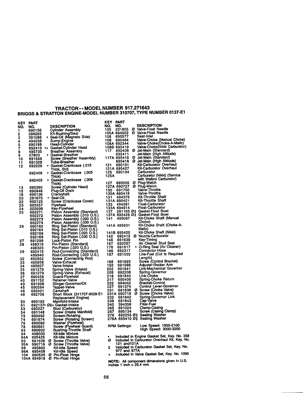
############### TRACTOR - - MODEL NUMBER 917.271643 BRIGGS&STRATTONENGINE-MODELNUMBER310707,TYPE NUMBER0137-E1
_r REQUIRES SPECIALTOOLS 53_ TO INSTALL. SEE REPAIR INSTRUCTION MANUAL.
o_ o,,_,,3°_
761q
180_26_45_24
41

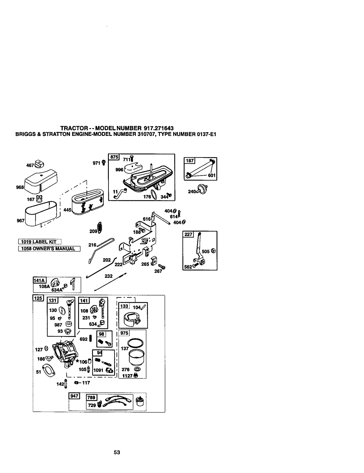
############### TRACTOR -- MODELNUMBER 917.271643 BRIGGS& STRAI-I'ONENGINE-MODELNUMBER310707,TYPE NUMBER0137-E1
968 /" / ' 176
I 1019 LABEL KIT 1 I 1058OWNER'S MANUAL 1
########### 1141AIK:_
L,o9.,A_ "U
108A_
################## 276511127_ 142_ Q-117

############### BRIGGS& STRATrON ENGINE-MODELNUMBER310707,TYPE NUMBER0137-E1
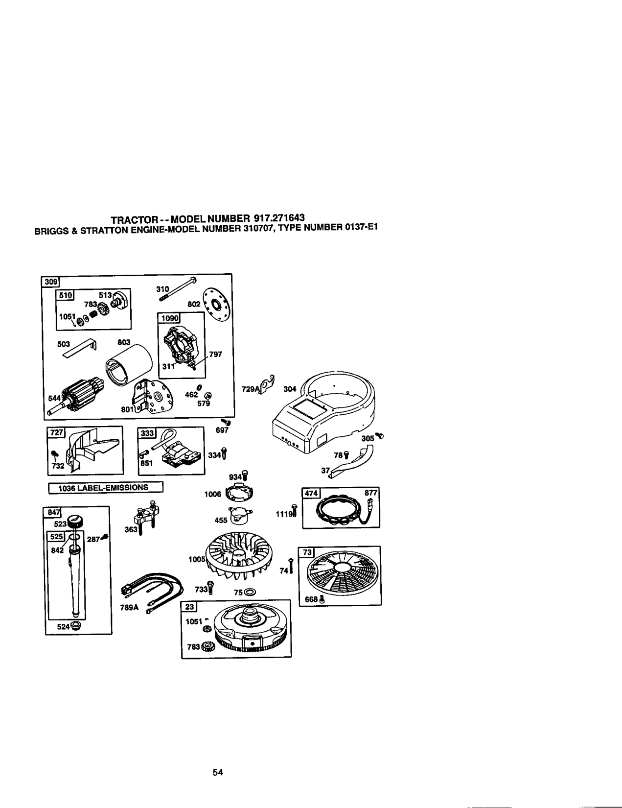
O 462
729A_ 304 •
579 801
697
I 1036 LABEL-EMISSIONS I 1006
287 J_
789A
524_

TRACTOR-- MODELNUMBER 917.271643 BRIGGS& STRATrON ENGINE-MODELNUMBER310707,TYPE NUMBER0137-E1
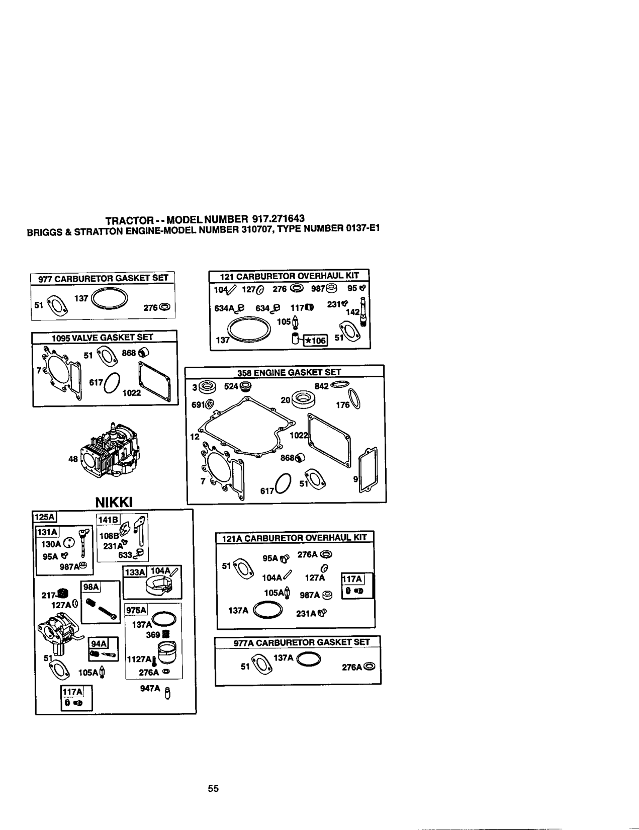
########## 9. CA._____.RRUR_ORGASKETs_r-I
121 CARBURETOR OVERHAUL KIT 104_ 12"/_ 276 _ 987_ 95 19
51% 276_
634A_ 634€_ 1170 231_142_
1095 VALVE GASKET SET

137_ _ 51_'_
E.GtHEGASK_SET
.,,o .w
NIKKI
######## 130AO_11;;;A"_1
121A CARBURETOR OVERHAUL KIT SSA_ 276A_
987A_ ] 133A ,
137A O 231A_
977A CARBURE[OR GASKET S_ __
###### %'AO /
51 276A_
_ _A _

############### BRIGGS&STRA'I'rON ENGINE-MODELNUMBER310707,TYPE NUMBER0137-E1
KEY PART KEY PART NO, NO, DESCRIPTION NO. NO. DESCRIPTION

692406 • Gasket-Crankcase (.005 125 690194 Carburetor
Thick) 125A Carburetor(Nikki)(Sauce 692405 • Gasket-Crankcase (.009 withWalbro Carburetor) Thick) 127 695005 _ Plug-Welch
493320 Pin-Piston (.020 O.S.) 176 691917 ° O-Ring Seal (Air Cleaner) 29 692419 Rod*Connasting (Standard) 186 692317 Connector-Hose
499940 Rod-Conne_Jng (,020 U.S.) 187 691050 Line-Fuel (Cut 1oRequired
Replacement Engine) 232 691842 Spring-Governor Link
60 690193 Manifold-Intake 238 691843 Cap-Valve 51 692137. O1+ Gasket-Intake 240 394358 Filter-Fuel
NOTE: All componentdimensionsgiven in U.S. inches1_ch = 25.4 mm

############### TRACTOR-- MODEL NUMBER 917.271643 BRIGGS&STRATFONENGINE-MODELNUMBER310707,TYPE NUMBER0137-E1
KEY PART KEY PART NO, NO. DESCRIPTION NO, NO, DESCRIPTION
297 691002 Screw (DipstickTube) 789 692037 Hamess-Widng 304 690844 Housln9-Bldwer 789A 695050 Hamess-Wirlng 305 690960 Screw (13tower Housing) 797 693167 NUt (Brush Retainer)
Shiald-C finder 801 691429306690499-uyn Cap-Ddve 307 691003 Screw_Cyllnder Shield) 802 691286 Cap-End
333 495859 Armature-Magneto Screw (Armature Magneto) Spark Plug
334 691061 851 692424 Terminal-SparkPlug 337 491055 868 690968 ,+ Seal-Valve
344 693675 Screw (Cable Clamp) 871 690969 Bushin_l-Gulde 358 690189 Engine Gasket Set 875 694842 Base-Air Cleaner 363 19203 Flywheel Puller 877 593458 Wlre-Connoctor/Altamator 368 695422 _pSring-Float Bowl 883 692236 ° Gasket-Exhaust
053 89838 Wr Screw (RockerCover)ench-SpsrkPlug914690960 404 691691 Washer (GovernorCrank) 934 691055 Screw (Fan Retainer) 448 496894 Filtar-AirCleaner Ca_idge 947 497672 Solenold-Fual 455 891173 Cup-Flywheal 947A 895423 Solenoid-Fuel 462 691261 Washer (Brush Retainer) 967 272043 Fllter-Pre Cleaner 467 691668 Knob-Air Cleaner 968 691916 Cover-AirCleaner 474 691063 Alternator 971 692129 Screw (Air Cleaner Base) 503 591532 Strap-Starter 975 495933 BowI-Fldat 505 691251 Nut (Govemor Control Lever) 975A 695417 Bowl-Float 510 693699 Drive-Starter 977 690192 Sat-Carburetor Gasket 513 692024 Clutch-Drive 977A 695428 Set-Carburetor Gasket
761 691096 Screw ICounterweight) NOTE: All componentdimensionsgiven in U.S. 783 693713 Gear-Pmldn inches 1 inch = 25.4 mm

############### SERVICENOTE

############# SUGGESTED GUIDE FOR SIGHTING SLOPES FOR SAFE OPERATION
################# ONLY RIDE UP AND DOWN HILL, NOT ACROSS HILL
¢n €o
! greater than 15), never across the face, Make turns gradu-
Iallytopreventtippingorlossofcontrol.Exerciseextreme
I_ Operate yourTractor up and down the face ]
caution when changing direction on slopes.

Forrepairofmajorbrand appliancesinyour own home... no matterwhomadeit,no matterwhosold
1-SOO-4-MY-HOME_ tu_rne,c_c_r_ht
(14_oo48946_) (u.sAandCanada)
Forrepairof cany-in productslikevacuums,lawnequipment,and
ek_tronica, callforthe nearestSears Parts and Repair Center. 1-800-488-1222 Any'_e,dayorr_ght(USJ_uty)
www,searsJ:ofn
Forthereplacementparts,accessoriesand owner'smanuals thatyou needtodo-it-yourself,canSearsPadsDirect'_!
1-600-366-PART (1-80o_6-7278)
6a.m,-11 #m., 7daysaweek
############### Cu.sAon_,) wv,w.sear_com_oadsdln_t
To purchaseor inquireabouta SearsServiceAgreement or SearsMaintenanceAgreement
1-800-827-6655 (us_.) 1-800-361-6665 (_)
7 &m. - 5p.m., CST, Mot_ - Sat 9&rn. - 8p.m.EST, M - F, 4p.m.Sat.
Parapeoltsewiciode re_ a Au Canadapour seevt_ en fran_:
doWciio, yparao_z piezas: I.SOO.LE4=OYERMC 1-888-SU-HOGAR (14y304;334_7)
©Sea& Roebu_ ardC&
® Registered Trademark / TM Trademark / suService Mark of Sears, Roebuck and Co. ® Marca Registrada / "ruMama de Fdbrica / suMarca de Servicio de 8ears, Roebuck and Co. u<:Marque de commerce I uo MaTque d_pos_e de Seam, Roebuck ==ndCo.
################# 78733 04.11.01 RH Printed in U.S,A,