
Ask AI
— answers from the official manualAnswers from the official manual.
Common questions
Common Questions
10 totalHow do I mount an indoor sensor?
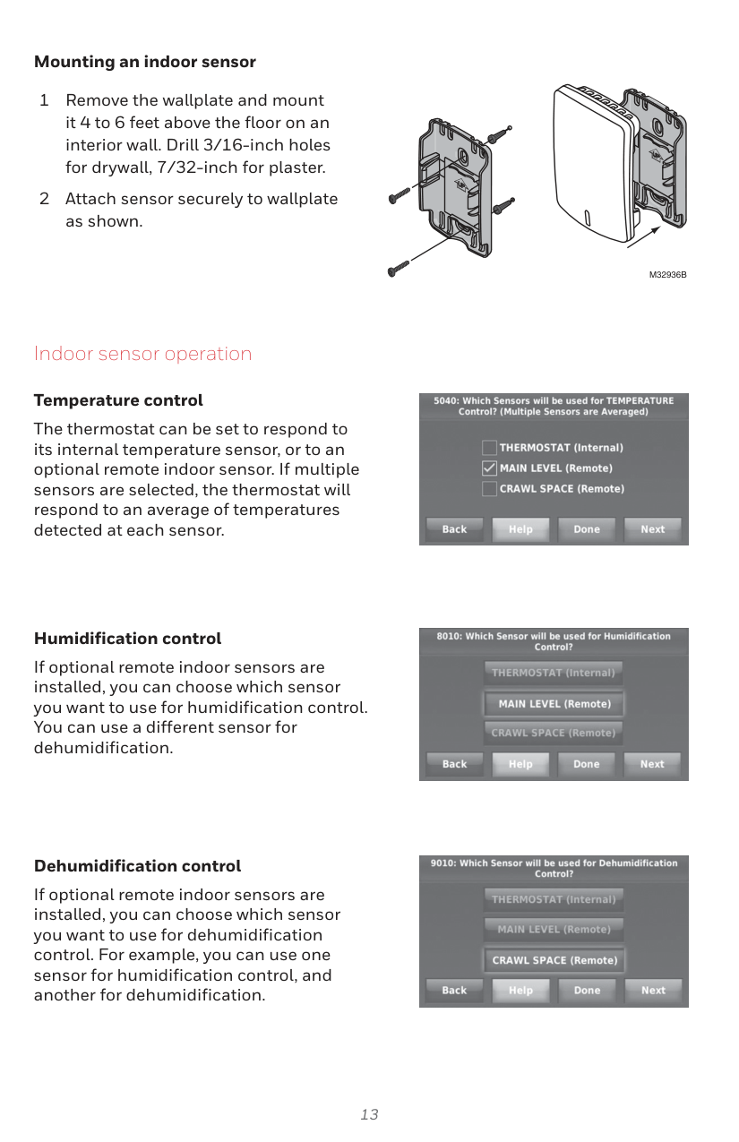
Remove the wallplate and mount it on an interior wall 4 to 6 feet above the floor, drill 3/16-inch holes for drywall or 7/32-inch holes for plaster. Attach the sensor securely to the wallplate (page 15).
How do I factory reset the thermostat?
Press and hold the Power button for 10 seconds until the LED flashes red. This clears all settings and returns the device to factory defaults. You will need to re-pair all connected devices after the reset.
What is the password needed to access installer options?
The password required to enter Installer Options is the date code, which you can find on the back of the thermostat or by touching Menu -> Dealer Information as per page 12.
How do I link the EIM and thermostat?
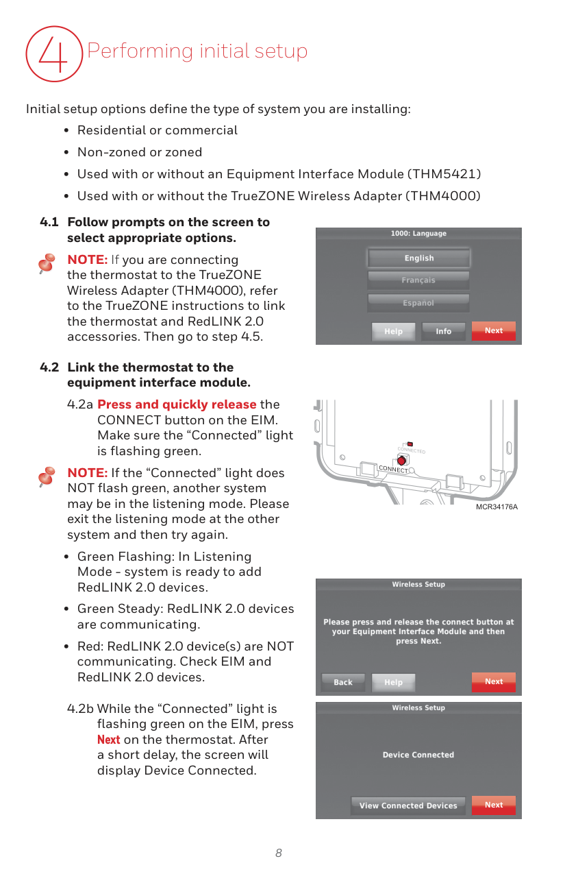
Press and quickly release the CONNECT button on the EIM; ensure that the “Connected” light is flashing green, then press Next on the thermostat. The screen will display Device Connected after a short delay (page 10).
How do I connect RedLINK 2.0 accessories?
Press and quickly release the CONNECT button on each new RedLINK 2.0 accessory while the Add Device screen is displayed (listening mode); after a short delay, check the thermostat to confirm connection of each accessory (page 11).
What is the operating temperature range?
Operating Ambient Temperature ranges are: Thermostat - 32°F to 120°F, Portable Comfort Control - 32°F to 120°F, Wireless Outdoor Sensor - -40°F to 140°F, RedLINK 2.0 Internet Gateway - 32°F to 120°F (Table at page 15).
Full Manual
16 pages
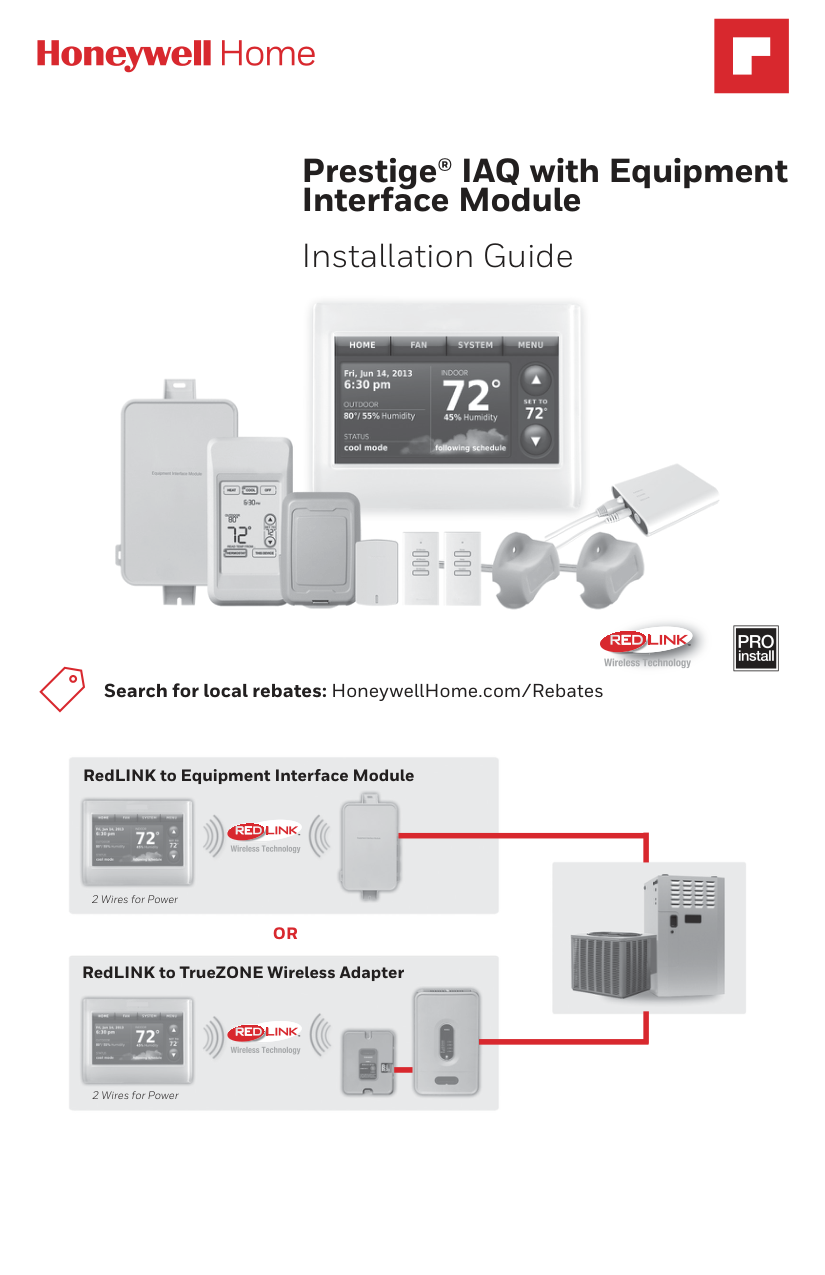
Prestige® IAQ with Equipment Interface Module
Installation Guide


| | |---|


Search for local rebates: HoneywellHome.com/Rebates

RedLINK to Equipment Interface Module


TM

2 Wires for Power
######## OR
RedLINK to TrueZONE Wireless Adapter


TM

2 Wires for Power
Reference to key features

| | | |---|---| | | |
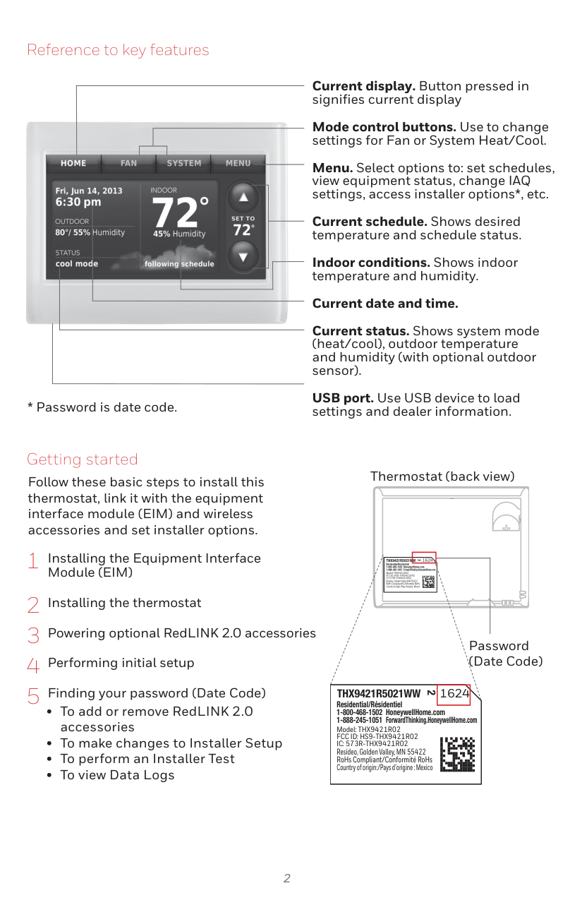
###### * Password is date code.
Current display. Button pressed in signifies current display
Mode control buttons. Use to change settings for Fan or System Heat/Cool.
Menu. Select options to: set schedules, view equipment status, change IAQ settings, access installer options*, etc.
Current schedule. Shows desired temperature and schedule status.
Indoor conditions. Shows indoor temperature and humidity.
Current date and time. Current status. Shows system mode (heat/cool), outdoor temperature and humidity (with optional outdoor sensor). USB port. Use USB device to load settings and dealer information.
Getting started
Follow these basic steps to install this thermostat, link it with the equipment interface module (EIM) and wireless accessories and set installer options.
Thermostat (back view)
1624THX9421R5021WW
2
Residential/Résidentiel 1-800-468-1502 HoneywellHome.com 1-888-245-1051 ForwardThinking.HoneywellHome.com
Model: THX9421R02 FCC ID: HS9-THX9421R02 IC: 573R-THX9421R02
Resideo, Golden Valley, MN 55422 RoHs Compliant/Conformité RoHs Country of origin:/Pays d’origine : Mexico
Password (Date Code)
1624THX9421R5021WW
2
Residential/Résidentiel 1-800-468-1502 HoneywellHome.com 1-888-245-1051 ForwardThinking.HoneywellHome.com
Model: THX9421R02 FCC ID: HS9-THX9421R02 IC: 573R-THX9421R02
Resideo, Golden Valley, MN 55422 RoHs Compliant/Conformité RoHs Country of origin:/Pays d’origine : Mexico
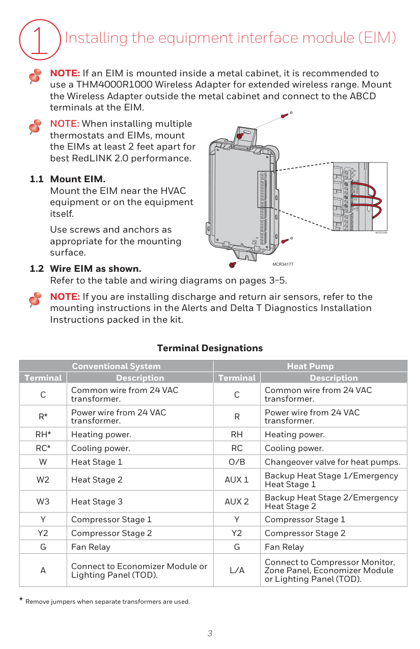
1 Installing the equipment interface module (EIM)
NOTE: If an EIM is mounted inside a metal cabinet, it is recommended to use a THM4000R1000 Wireless Adapter for extended wireless range. Mount the Wireless Adapter outside the metal cabinet and connect to the ABCD terminals at the EIM.
NOTE: When installing multiple thermostats and EIMs, mount the EIMs at least 2 feet apart for best RedLINK 2.0 performance.
R C
Use screws and anchors as appropriate for the mounting surface.
B
WO/
Y Y2 G
A
AL/
MCR32389B
############ MCR34177
NOTE: If you are installing discharge and return air sensors, refer to the mounting instructions in the Alerts and Delta T Diagnostics Installation Instructions packed in the kit.
##### Terminal Designations
|Conventional System|Conventional System|Heat Pump|Heat Pump| |---|---|---|---| |Terminal|Description|Terminal|Description| |C|Common wire from 24 VAC transformer.|C|Common wire from 24 VAC transformer.| |R*|Power wire from 24 VAC transformer.|R|Power wire from 24 VAC transformer.| |RH*|Heating power.|RH|Heating power.| |RC*|Cooling power.|RC|Cooling power.| |W|Heat Stage 1|O/B|Changeover valve for heat pumps.| |W2|Heat Stage 2|AUX 1|Backup Heat Stage 1/Emergency Heat Stage 1| |W3|Heat Stage 3|AUX 2|Backup Heat Stage 2/Emergency Heat Stage 2| |Y|Compressor Stage 1|Y|Compressor Stage 1| |Y2|Compressor Stage 2|Y2|Compressor Stage 2| |G|Fan Relay|G|Fan Relay| |A|Connect to Economizer Module or Lighting Panel (TOD).|L/A|Connect to Compressor Monitor, Zone Panel, Economizer Module or Lighting Panel (TOD).|
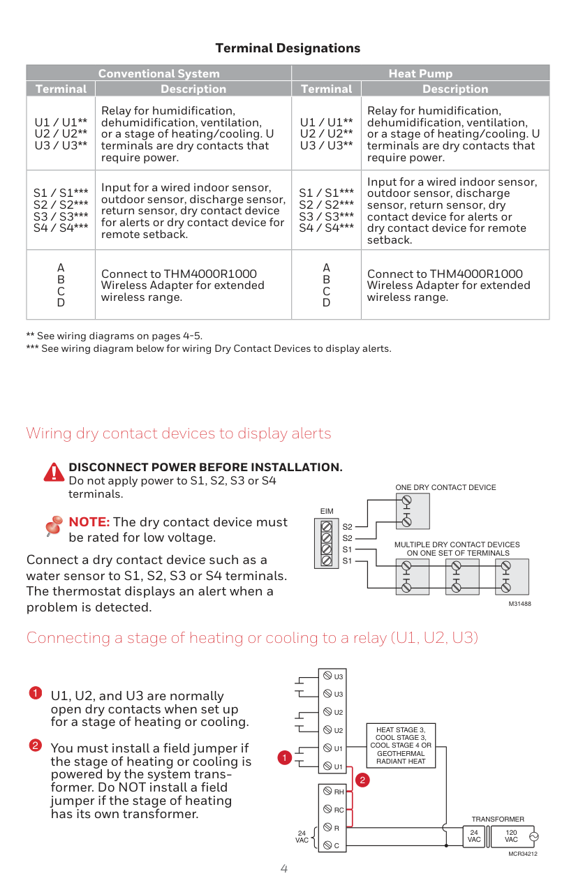
##### Terminal Designations
|Conventional System|Conventional System|Heat Pump|Heat Pump| |---|---|---|---| |Terminal|Description|Terminal|Description| |U1 / U1
U2 / U2
U3 / U3
|Relay for humidification, dehumidification, ventilation, or a stage of heating/cooling. U terminals are dry contacts that require power.|U1 / U1
U2 / U2
U3 / U3
|Relay for humidification, dehumidification, ventilation, or a stage of heating/cooling. U terminals are dry contacts that require power.| |S1 / S1*
S2 / S2*
S3 / S3*
S4 / S4*
|Input for a wired indoor sensor, outdoor sensor, discharge sensor, return sensor, dry contact device for alerts or dry contact device for remote setback.|S1 / S1*
S2 / S2*
S3 / S3*
S4 / S4*
|Input for a wired indoor sensor, outdoor sensor, discharge sensor, return sensor, dry contact device for alerts or dry contact device for remote setback.| |A
B
C
D
|Connect to THM4000R1000 Wireless Adapter for extended wireless range.|A
B
C
D
|Connect to THM4000R1000 Wireless Adapter for extended wireless range.|
*** See wiring diagram below for wiring Dry Contact Devices to display alerts.
Wiring dry contact devices to display alerts
DISCONNECT POWER BEFORE INSTALLATION. Do not apply power to S1, S2, S3 or S4 terminals.
EIM
NOTE: The dry contact device must be rated for low voltage.
| | |---|
Connect a dry contact device such as a water sensor to S1, S2, S3 or S4 terminals. The thermostat displays an alert when a problem is detected.
ONE DRY CONTACT DEVICE
MULTIPLE DRY CONTACT DEVICES ON ONE SET OF TERMINALS
M31488
Connecting a stage of heating or cooling to a relay (U1, U2, U3)
U1, U2, and U3 are normally open dry contacts when set up for a stage of heating or cooling. You must install a field jumper if the stage of heating or cooling is powered by the system transformer. Do NOT install a field jumper if the stage of heating has its own transformer.
U3
U3
U2
HEAT STAGE 3, COOL STAGE 3, COOL STAGE 4 OR GEOTHERMAL RADIANT HEAT
U2
U1
1
U1
2
RH
RC
TRANSFORMER
R
24 VAC
120 VAC
24 VAC
C
MCR34212
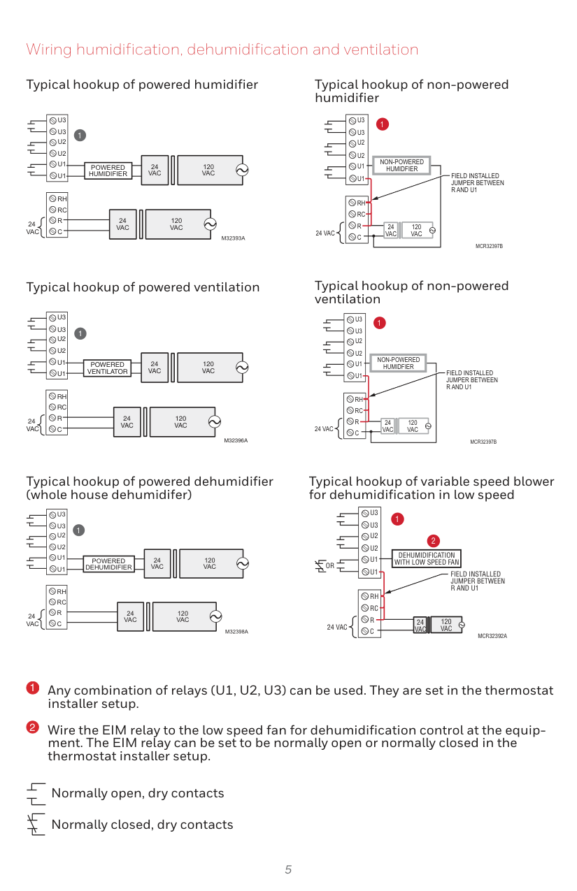
Wiring humidification, dehumidification and ventilation
Typical hookup of powered humidifier Typical hookup of non-powered humidifier
U3 U3 U2 U2 U1 U1
1
24 VAC
120 VAC
POWERED HUMIDIFIER
RH RC R C
|120 VAC| |---|
24 VAC
24 VAC
M32393A
U3 U3 U2 U2 U1 U1
1
NON-POWERED HUMIDFIER
FIELD INSTALLED JUMPER BETWEEN R AND U1
RH RC R C
120 VAC
24 VAC
24 VAC
MCR32397B
Typical hookup of powered ventilation
U3 U3
M32396A
24 VAC
120 VAC
24 VAC
120 VAC
1
POWERED DEHUMIDIFIER
RH RC R C
U3 U3
POWERED VENTILATOR
RH RC R C
24 VAC
Typical hookup of non-powered ventilation
U3 U3 U2 U2 U1 U1
1
NON-POWERED HUMIDFIER
FIELD INSTALLED JUMPER BETWEEN R AND U1
RH RC R C
120 VAC
24 VAC
24 VAC
MCR32397B
Typical hookup of powered dehumidifier (whole house dehumidifer)
24 VAC
120 VAC
24 VAC
24 VAC
|120 VAC| |---|
M32398A
Typical hookup of variable speed blower for dehumidification in low speed
U3 U3 U2 U2 U1 U1
1
2
DEHUMIDIFICATION WITH LOW SPEED FAN
OR
FIELD INSTALLED JUMPER BETWEEN R AND U1
RH RC R C
120 VAC
24 VAC
24 VAC
MCR32392A
Any combination of relays (U1, U2, U3) can be used. They are set in the thermostat installer setup.
Wire the EIM relay to the low speed fan for dehumidification control at the equipment. The EIM relay can be set to be normally open or normally closed in the thermostat installer setup.
Normally open, dry contacts Normally closed, dry contacts
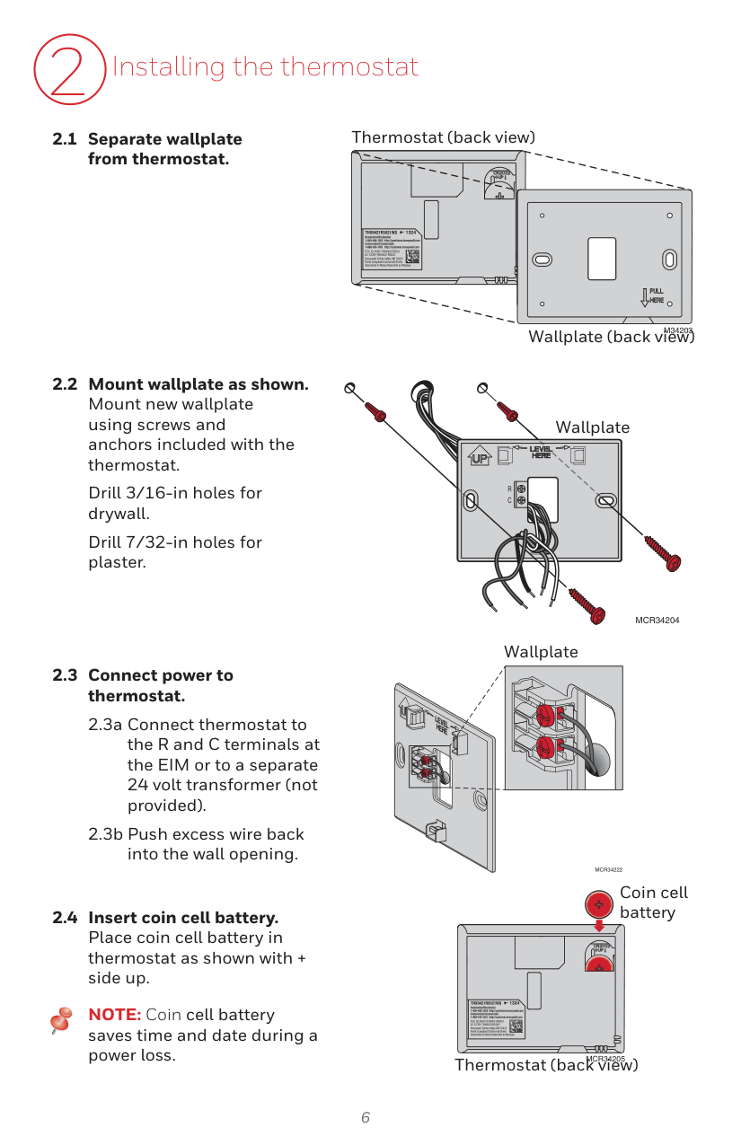
2 Installing the thermostat
Drill 3/16-in holes for drywall.
Drill 7/32-in holes for plaster.
NOTE: Coin cell battery saves time and date during a power loss.
Thermostat (back view)
1324
M34203
Wallplate (back view)
Wallplate
R C
MCR34204
Wallplate
MCR34222
Coin cell battery
1324
########### MCR34205
Thermostat (back view)
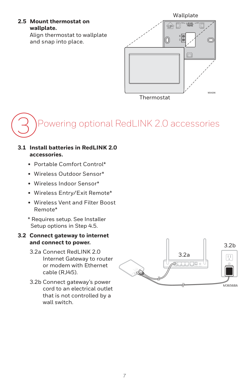
2.5 Mount thermostat on wallplate. Align thermostat to wallplate and snap into place.
Wallplate
R C
M34206
Thermostat
3.2b
3.2a
| | |---|
M36568A
4 Performing initial setup
Initial setup options define the type of system you are installing:
4.1 Follow prompts on the screen to select appropriate options. NOTE: If you are connecting the thermostat to the TrueZONE Wireless Adapter (THM4000), refer to the TrueZONE instructions to link the thermostat and RedLINK 2.0 accessories. Then go to step 4.5. Next

NOTE: If the “Connected” light does NOT flash green, another system may be in the listening mode. Please exit the listening mode at the other system and then try again.
CONNECTED
CONNECT
MCR34176A

Next

Next
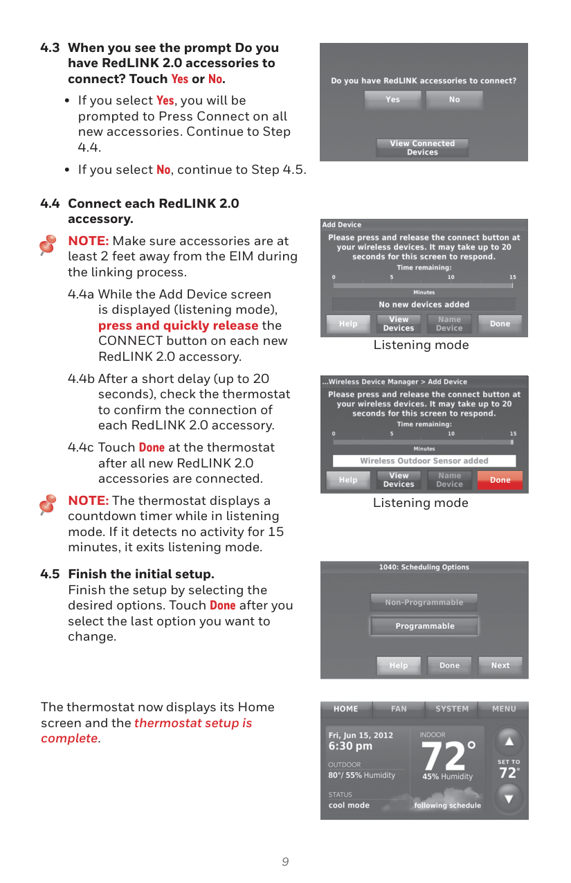
##### 4.3 When you see the prompt Do youhave RedLINK 2.0 accessories toconnect? Touch Yes or No.

##### 4.4 Connect each RedLINK 2.0accessory.
NOTE: Make sure accessories are at least 2 feet away from the EIM during the linking process.
NOTE: The thermostat displays a countdown timer while in listening mode. If it detects no activity for 15 minutes, it exits listening mode.
###### 4.5 Finish the initial setup.Finish the setup by selecting thedesired options. Touch Done after youselect the last option you want tochange.

Listening mode


Done
Listening mode

The thermostat now displays its Home screen and the thermostat setup is complete.

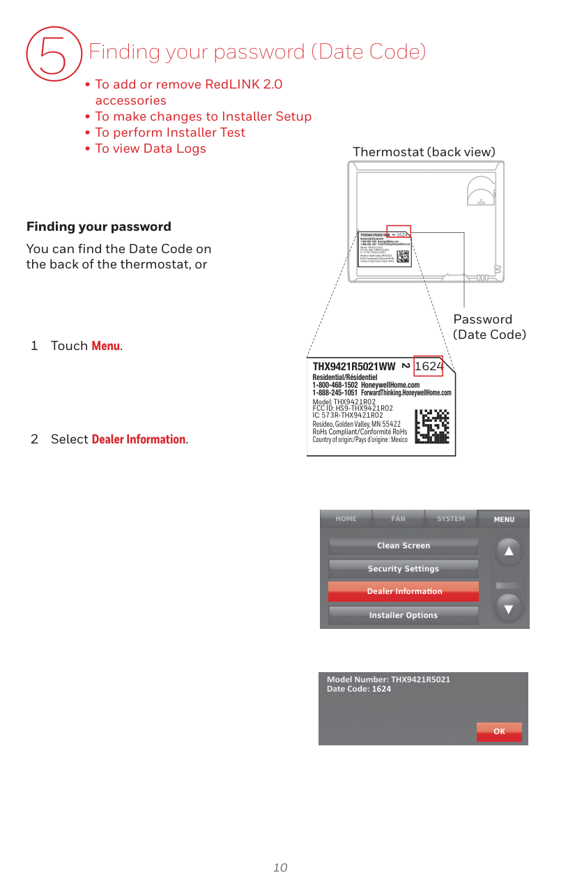
5 Finding your password (Date Code)
Thermostat (back view)
##### Finding your password
1624THX9421R5021WW
2
Residential/Résidentiel 1-800-468-1502 HoneywellHome.com 1-888-245-1051 ForwardThinking.HoneywellHome.com
You can find the Date Code on the back of the thermostat, or
Model: THX9421R02 FCC ID: HS9-THX9421R02 IC: 573R-THX9421R02
Resideo, Golden Valley, MN 55422 RoHs Compliant/Conformité RoHs Country of origin:/Pays d’origine : Mexico
Password (Date Code)
1624THX9421R5021WW
2
Residential/Résidentiel 1-800-468-1502 HoneywellHome.com 1-888-245-1051 ForwardThinking.HoneywellHome.com
Model: THX9421R02 FCC ID: HS9-THX9421R02 IC: 573R-THX9421R02
Resideo, Golden Valley, MN 55422 RoHs Compliant/Conformité RoHs Country of origin:/Pays d’origine : Mexico

Dealer Informa on

1624
OK
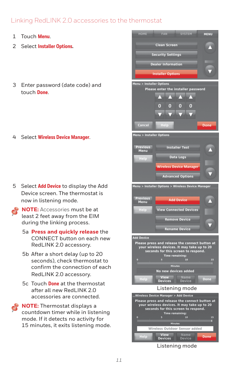
Linking RedLINK 2.0 accessories to the thermostat
NOTE: Accessories must be at least 2 feet away from the EIM during the linking process.
NOTE: Thermostat displays a countdown timer while in listening mode. If it detects no activity for 15 minutes, it exits listening mode.

Installer Op ons

######### Done

Wireless Device Manager

Add Device

Listening mode


########## Done
Listening mode
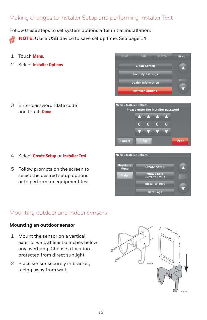
Making changes to Installer Setup and performing Installer Test
Follow these steps to set system options after initial installation.
NOTE: Use a USB device to save set up time. See page 14.

Installer Op ons

Done

Mounting outdoor and indoor sensors
##### Mounting an outdoor sensor
M28491B
M28849A
##### Mounting an indoor sensor
M32936B
Indoor sensor operation
##### Temperature control
The thermostat can be set to respond to its internal temperature sensor, or to an optional remote indoor sensor. If multiple sensors are selected, the thermostat will respond to an average of temperatures detected at each sensor.

##### Humidification control
If optional remote indoor sensors are installed, you can choose which sensor you want to use for humidification control. You can use a different sensor for dehumidification.

##### Dehumidification control
If optional remote indoor sensors are installed, you can choose which sensor you want to use for dehumidification control. For example, you can use one sensor for humidification control, and another for dehumidification.

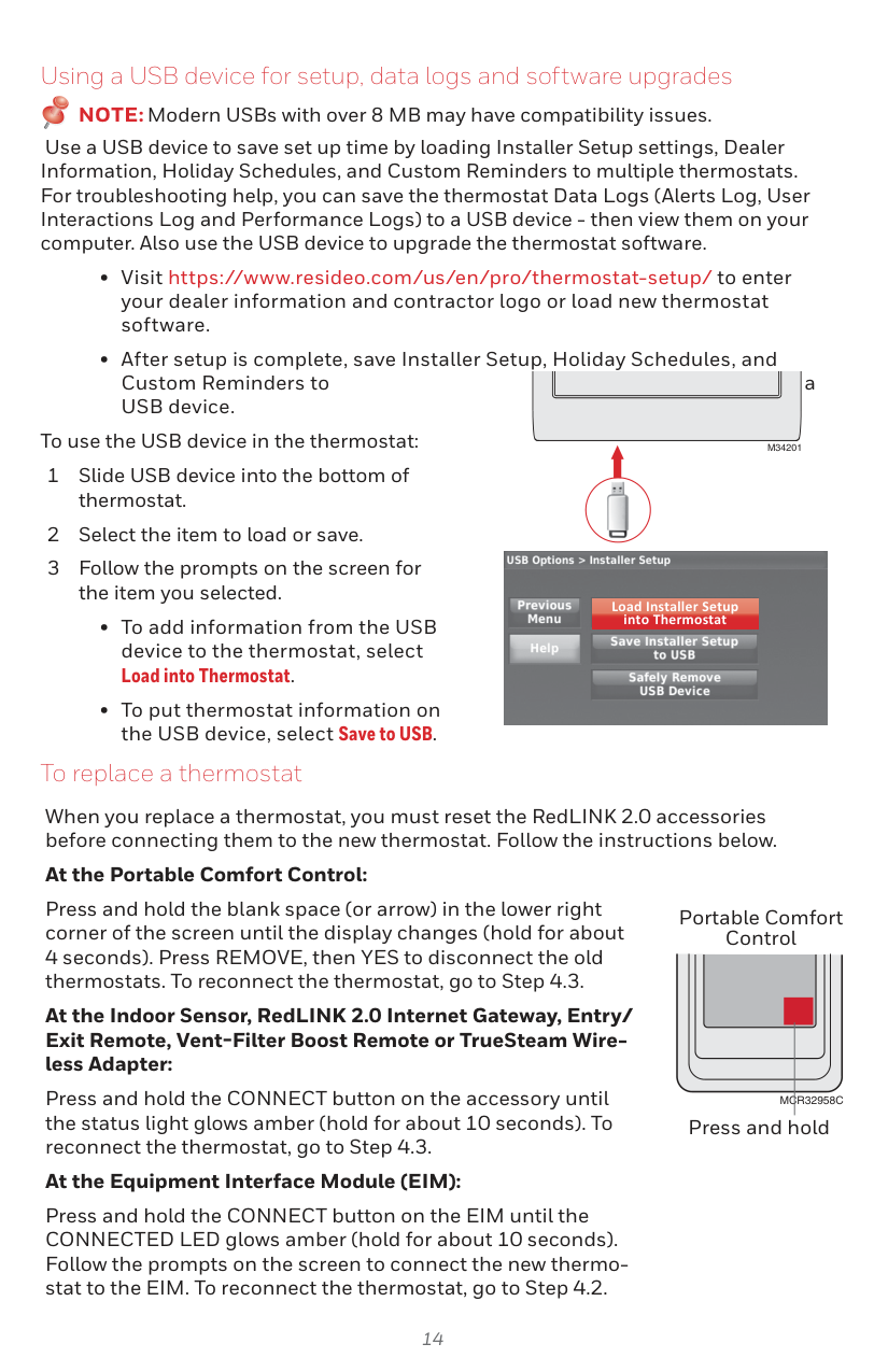
Using a USB device for setup, data logs and software upgrades
NOTE:Modern USBs with over 8 MB may have compatibility issues.
Use a USB device to save set up time by loading Installer Setup settings, Dealer Information, Holiday Schedules, and Custom Reminders to multiple thermostats. For troubleshooting help, you can save the thermostat Data Logs (Alerts Log, User Interactions Log and Performance Logs) to a USB device - then view them on your computer. Also use the USB device to upgrade the thermostat software.
To use the USB device in the thermostat:
M34201
When you replace a thermostat, you must reset the RedLINK 2.0 accessories before connecting them to the new thermostat. Follow the instructions below.
At the Portable Comfort Control:
Press and hold the blank space (or arrow) in the lower right corner of the screen until the display changes (hold for about


Load Installer Setup into Thermostat
To replace a thermostat
Portable Comfort Control
At the Indoor Sensor, RedLINK 2.0 Internet Gateway, Entry/ Exit Remote, Vent-Filter Boost Remote or TrueSteam Wireless Adapter:
Press and hold the CONNECT button on the accessory until the status light glows amber (hold for about 10 seconds). To reconnect the thermostat, go to Step 4.3.
MCR32958C
Press and hold
##### At the Equipment Interface Module (EIM):
Press and hold the CONNECT button on the EIM until the CONNECTED LED glows amber (hold for about 10 seconds). Follow the prompts on the screen to connect the new thermostat to the EIM. To reconnect the thermostat, go to Step 4.2.
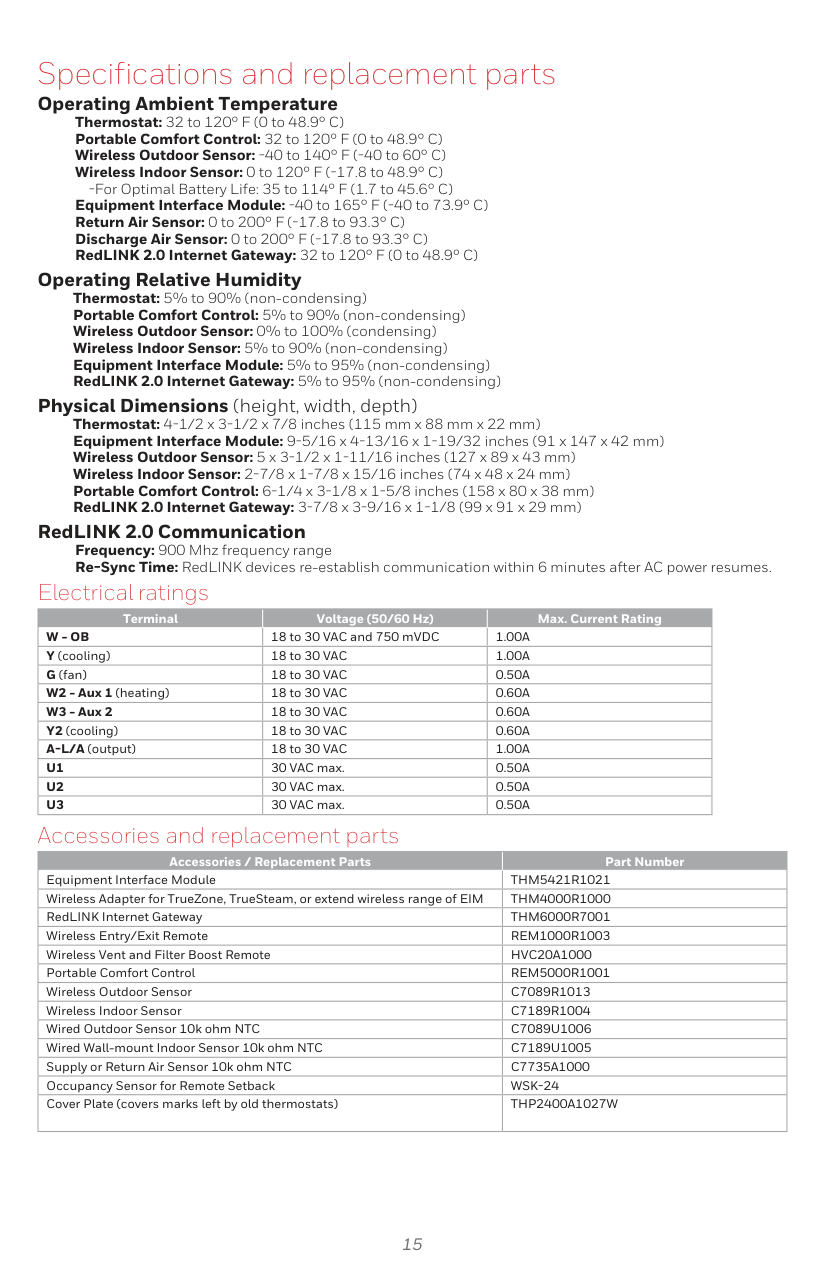
#### Specifications and replacement parts
Operating Ambient Temperature Thermostat: 32 to 120° F (0 to 48.9° C) Portable Comfort Control: 32 to 120° F (0 to 48.9° C) Wireless Outdoor Sensor: -40 to 140° F (-40 to 60° C) Wireless Indoor Sensor: 0 to 120° F (-17.8 to 48.9° C)
-For Optimal Battery Life: 35 to 114° F (1.7 to 45.6° C) Equipment Interface Module: -40 to 165° F (-40 to 73.9° C) Return Air Sensor: 0 to 200° F (-17.8 to 93.3° C) Discharge Air Sensor: 0 to 200° F (-17.8 to 93.3° C) RedLINK 2.0 Internet Gateway: 32 to 120° F (0 to 48.9° C)
Operating Relative Humidity Thermostat: 5% to 90% (non-condensing) Portable Comfort Control: 5% to 90% (non-condensing) Wireless Outdoor Sensor: 0% to 100% (condensing) Wireless Indoor Sensor: 5% to 90% (non-condensing) Equipment Interface Module: 5% to 95% (non-condensing) RedLINK 2.0 Internet Gateway: 5% to 95% (non-condensing)
Physical Dimensions (height, width, depth) Thermostat: 4-1/2 x 3-1/2 x 7/8 inches (115 mm x 88 mm x 22 mm) Equipment Interface Module: 9-5/16 x 4-13/16 x 1-19/32 inches (91 x 147 x 42 mm) Wireless Outdoor Sensor: 5 x 3-1/2 x 1-11/16 inches (127 x 89 x 43 mm) Wireless Indoor Sensor: 2-7/8 x 1-7/8 x 15/16 inches (74 x 48 x 24 mm) Portable Comfort Control: 6-1/4 x 3-1/8 x 1-5/8 inches (158 x 80 x 38 mm) RedLINK 2.0 Internet Gateway: 3-7/8 x 3-9/16 x 1-1/8 (99 x 91 x 29 mm)
RedLINK 2.0 Communication Frequency: 900 Mhz frequency range Re-Sync Time: RedLINK devices re-establish communication within 6 minutes after AC power resumes.
Electrical ratings
|Terminal|Voltage (50/60 Hz)|Max. Current Rating| |---|---|---| |W - OB|18 to 30 VAC and 750 mVDC|1.00A| |Y (cooling)|18 to 30 VAC|1.00A| |G (fan)|18 to 30 VAC|0.50A| |W2 - Aux 1 (heating)|18 to 30 VAC|0.60A| |W3 - Aux 2|18 to 30 VAC|0.60A| |Y2 (cooling)|18 to 30 VAC|0.60A| |A-L/A (output)|18 to 30 VAC|1.00A| |U1|30 VAC max.|0.50A| |U2|30 VAC max.|0.50A|
|U3|30 VAC max.|0.50A|
Accessories and replacement parts
|Accessories / Replacement Parts|Part Number| |---|---| |Equipment Interface Module|THM5421R1021| |Wireless Adapter for TrueZone, TrueSteam, or extend wireless range of EIM|THM4000R1000| |RedLINK Internet Gateway|THM6000R7001| |Wireless Entry/Exit Remote|REM1000R1003| |Wireless Vent and Filter Boost Remote|HVC20A1000| |Portable Comfort Control|REM5000R1001| |Wireless Outdoor Sensor|C7089R1013| |Wireless Indoor Sensor|C7189R1004| |Wired Outdoor Sensor 10k ohm NTC|C7089U1006| |Wired Wall-mount Indoor Sensor 10k ohm NTC|C7189U1005| |Supply or Return Air Sensor 10k ohm NTC|C7735A1000| |Occupancy Sensor for Remote Setback|WSK-24| |Cover Plate (covers marks left by old thermostats)|THP2400A1027W|
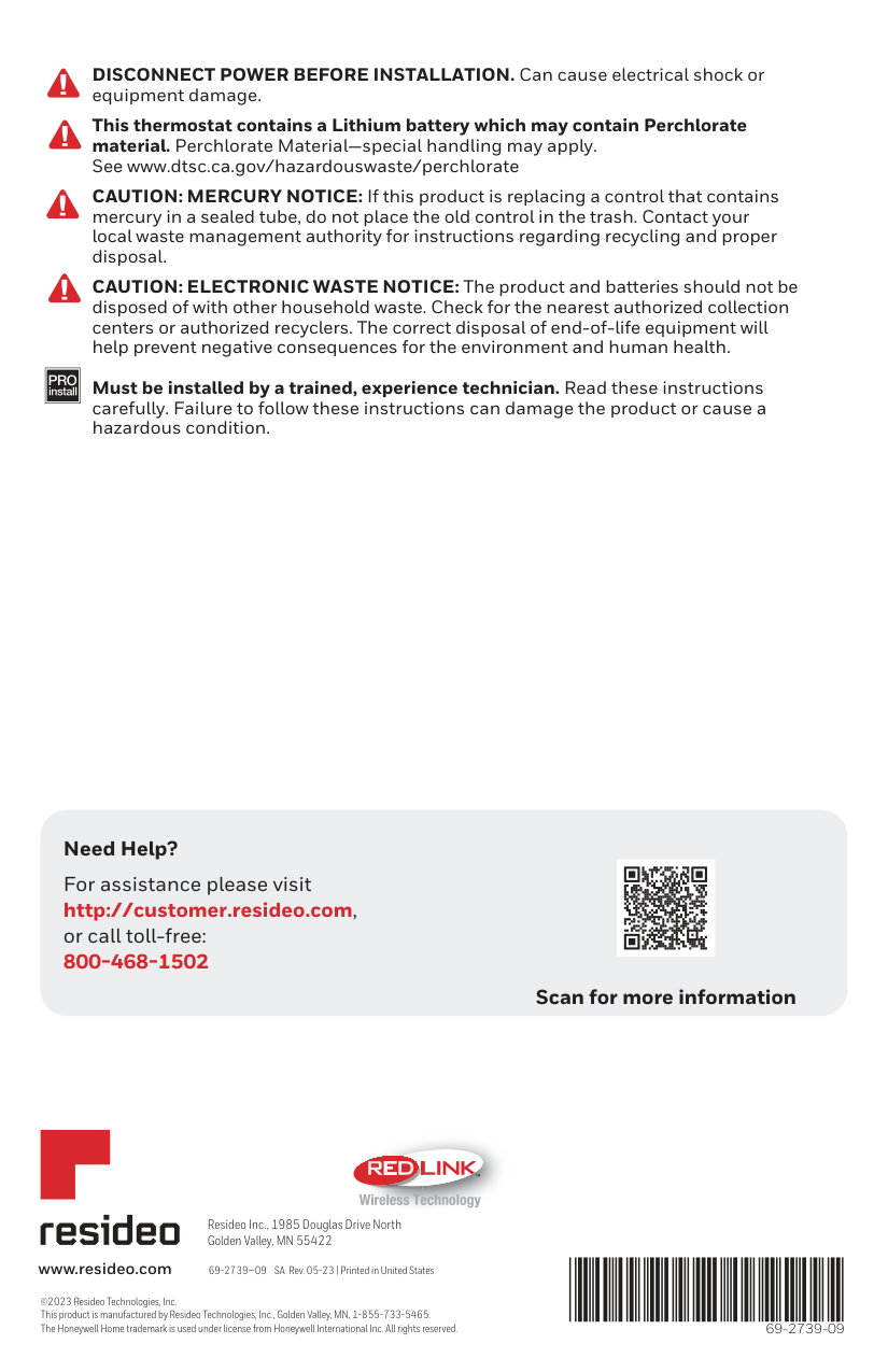
DISCONNECT POWER BEFORE INSTALLATION. Can cause electrical shock or equipment damage.
This thermostat contains a Lithium battery which may contain Perchlorate material. Perchlorate Material—special handling may apply. See www.dtsc.ca.gov/hazardouswaste/perchlorate
CAUTION: MERCURY NOTICE: If this product is replacing a control that contains mercury in a sealed tube, do not place the old control in the trash. Contact your local waste management authority for instructions regarding recycling and proper disposal.
CAUTION: ELECTRONIC WASTE NOTICE: The product and batteries should not be disposed of with other household waste. Check for the nearest authorized collection centers or authorized recyclers. The correct disposal of end-of-life equipment will help prevent negative consequences for the environment and human health.
| | |---|
Must be installed by a trained, experience technician. Read these instructions carefully. Failure to follow these instructions can damage the product or cause a hazardous condition.
Need Help? For assistance please visit http://customer.resideo.com,
or call toll-free: 800-468-1502
Scan for more information


############# TM
Resideo Inc., 1985 Douglas Drive North Golden Valley, MN 55422
www.resideo.com 69-2739—09 SA Rev. 05-23 | Printed in United States
©2023 Resideo Technologies, Inc. This product is manufactured by Resideo Technologies, Inc., Golden Valley, MN, 1-855-733-5465. The Honeywell Home trademark is used under license from Honeywell International Inc. All rights reserved. 69-2739-09