
Honeywell RM7895A1014 Flame Safeguard
Ask AI
— answers from the official manualAnswers from the official manual.
Common questions
Common Questions
12 totalWhat is the FFRT (Flame Failure Response Time) for Ra890E models with 120V 60Hz configuration?
For Ra890E models with 120V 60Hz configuration and 30 second safety switch timing, the FFRT is 0.8 seconds. The specific model number is Ra890F1338 with RM7890A1031 amplifier. (Page 4)
Which models use the RA890F detector?
Several models use the RA890F detector including R177A, R180A, R180B, R187A, R190B, Ra190B, and R887A. All of these require the Q270A Subbase with the RA890F detector.
What terminal configurations does the R190B model use?
The R190B model has the same terminal configuration as R180B: power at 1-2, main valve limit at 5, pilot valve motor at 3, ignition at 4, controller at R/W/B, and detector at F/G. Remove the Series 10 Controller and rewire before installation.
Is there a 'proof of flame' terminal on the RM7890A1015?
No, the RM7890A1015 does not have a 'proof of flame' terminal, unlike the RA890E or RA890F which have this feature at terminal 5. This is an important difference when replacing older models.
Do I need to rewire when replacing a Series 10 Controller with RM7890A1015?
Yes, you must remove the Series 10 Controller and rewire when upgrading to RM7890A1015. This rewiring requirement is noted for multiple device models including R180A, R180B, and R187A. (Page 3)
Is rewiring required for R887A when converting to RM7890A1015?
Yes, R887A requires rewiring when upgrading to the RM7890A1015 controller. Additionally, you must use the Q7800F1004 Subbase with this configuration. (Page 4)
Show 6 more questions
What subbase is required when using RA890F?
What does it mean when a device requires JR2 to be clipped?
What is the difference between RA890F and Ra890E regarding flame detection?
What are the terminal designations for R180A power and detection?
What voltage and frequency options are available for the R7847A1025 amplifier?
Which models use the same wiring as R180B?
Full Manual
39 pages
Honeywell Primary Control Cross Reference 95-6855-15 Page 1
R177, R180, R187, R190B, Ra190B, R190C, R887, R890B
Ra890B, R890C, Ra890C, Ra890Xb,Xc, Ra890D
Pages 2–4Ra890E
Pages 5–7Ra890F
Pages 8–9Ra890G
Page 10Ra890H,J,K
Page 11R485
Pages 12–13R4075
Pages 14–15R4138
Pages 16–17R4795
Pages 18–19R7023
Page 20R7795
Pages 21–24 7800 SERIES Primary Controls Pages 25–26 FIREYETM TFM1,2,3 and UVM1,2,3,5 Pages 27–28Mii
Pages 29–35 MicroM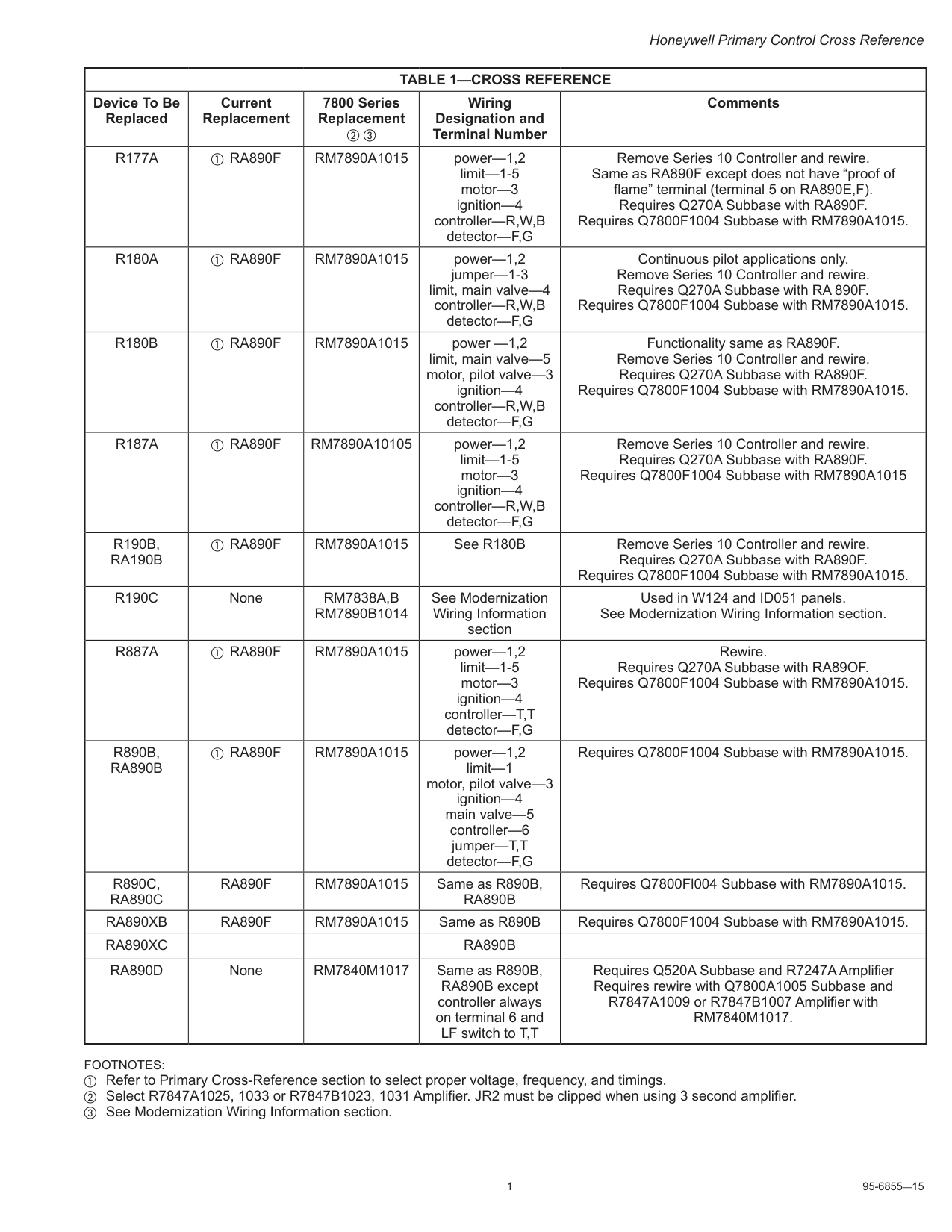
1 95-6855—15 Honeywell Primary Control Cross Reference
Table 1—Cross Reference
Device To Be Replaced Current Replacement 7800 Series Replacement b c Wiring Designation and Terminal Number CommentsR177A
a RA890FRm7890A1015
power—1,2 limit—1-5 motor—3 ignition—4 controller—R,W,B detector—F,G Remove Series 10 Controller and rewire. Same as RA890F except does not have “proof of flame” terminal (terminal 5 on RA890E,F). Requires Q270A Subbase with RA890F. Requires Q7800F1004 Subbase with RM7890A1015.R180A
a RA890FRm7890A1015
power—1,2 jumper—1-3 limit, main valve—4 controller—R,W,B detector—F,G Continuous pilot applications only. Remove Series 10 Controller and rewire. Requires Q270A Subbase with RA 890F. Requires Q7800F1004 Subbase with RM7890A1015.R180B
a RA890FRm7890A1015
power —1,2 limit, main valve—5 motor, pilot valve—3 ignition—4 controller—R,W,B detector—F,G Functionality same as RA890F. Remove Series 10 Controller and rewire. Requires Q270A Subbase with RA890F. Requires Q7800F1004 Subbase with RM7890A1015.R187A
a RA890FRm7890A10105
power—1,2 limit—1-5 motor—3 ignition—4 controller—R,W,B detector—F,G Remove Series 10 Controller and rewire. Requires Q270A Subbase with RA890F. Requires Q7800F1004 Subbase with RM7890A1015R190B,
Ra190B
a RA890FRm7890A1015
See R180B Remove Series 10 Controller and rewire. Requires Q270A Subbase with RA890F. Requires Q7800F1004 Subbase with RM7890A1015.R190C
NoneRm7838A,B
Rm7890B1014
See Modernization Wiring Information section Used in W124 and ID051 panels. See Modernization Wiring Information section.R887A
a RA890FRm7890A1015
power—1,2 limit—1-5 motor—3 ignition—4 controller—T,T detector—F,G Rewire. Requires Q270A Subbase with RA89OF. Requires Q7800F1004 Subbase with RM7890A1015.R890B,
Ra890B
a RA890FRm7890A1015
power—1,2 limit—1 motor, pilot valve—3 ignition—4 main valve—5 controller—6 jumper—T,T detector—F,G Requires Q7800F1004 Subbase with RM7890A1015.R890C,
Ra890C
Ra890F
Rm7890A1015
Same as R890B,Ra890B
Requires Q7800Fl004 Subbase with RM7890A1015.Ra890Xb
Ra890F
Rm7890A1015
Same as R890B Requires Q7800F1004 Subbase with RM7890A1015.Ra890Xc
Ra890B
Ra890D
NoneRm7840M1017
Same as R890B, RA890B except controller always on terminal 6 and LF switch to T,T Requires Q520A Subbase and R7247A Amplifier Requires rewire with Q7800A1005 Subbase and R7847A1009 or R7847B1007 Amplifier withRm7840M1017.
Footnotes:
a Refer to Primary Cross-Reference section to select proper voltage, frequency, and timings. b Select R7847A1025, 1033 or R7847B1023, 1031 Amplifier. JR2 must be clipped when using 3 second amplifier. c See Modernization Wiring Information section.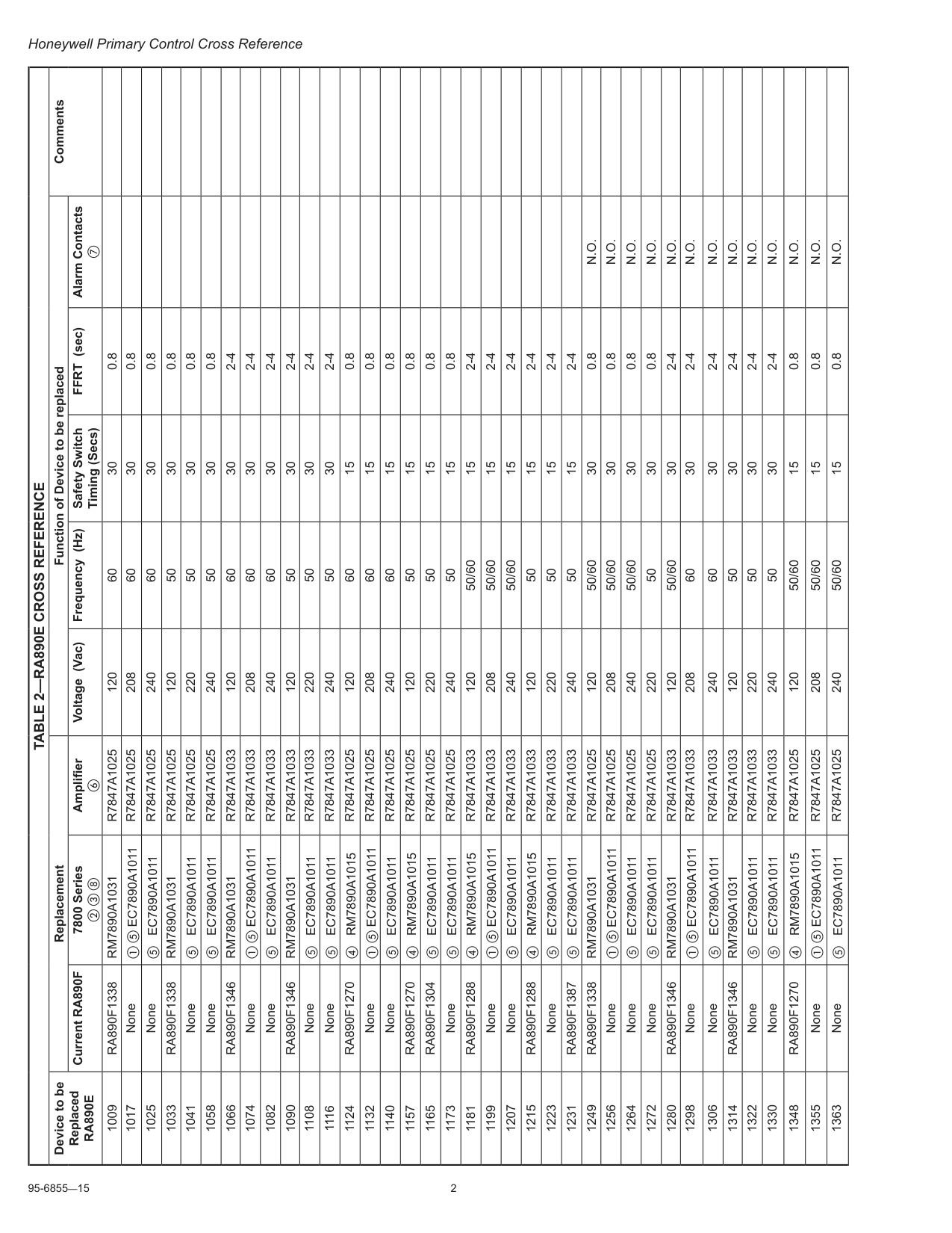
95-6855—15 2 Honeywell Primary Control Cross Reference
Table 2—Ra890E Cross Reference
Device to be ReplacedRa890E
Replacement Function of Device to be replaced Comments Current RA890F 7800 Series b c h Amplifier f Voltage (Vac) Frequency (Hz) Safety Switch Timing (Secs) FFRT (sec) Alarm Contacts g 1009Ra890F1338
Rm7890A1031
R7847A1025
120 60 30 0.8 1017 None a e EC7890A1011R7847A1025
208 60 30 0.8 1025 None e EC7890A1011R7847A1025
240 60 30 0.8 1033Ra890F1338
Rm7890A1031
R7847A1025
120 50 30 0.8 1041 None e EC7890A1011R7847A1025
220 50 30 0.8 1058 None e EC7890A1011R7847A1025
240 50 30 0.8 1066Ra890F1346
Rm7890A1031
R7847A1033
120 60 30 2-4 1074 None a e EC7890A1011R7847A1033
208 60 30 2-4 1082 None e EC7890A1011R7847A1033
240 60 30 2-4 1090Ra890F1346
Rm7890A1031
R7847A1033
120 50 30 2-4 1108 None e EC7890A1011R7847A1033
220 50 30 2-4 1116 None e EC7890A1011R7847A1033
240 50 30 2-4 1124Ra890F1270
d RM7890A1015R7847A1025
120 60 15 0.8 1132 None a e EC7890A1011R7847A1025
208 60 15 0.8 1140 None e EC7890A1011R7847A1025
240 60 15 0.8 1157Ra890F1270
d RM7890A1015R7847A1025
120 50 15 0.8 1165Ra890F1304
e EC7890A1011R7847A1025
220 50 15 0.8 1173 None e EC7890A1011R7847A1025
240 50 15 0.8 1181Ra890F1288
d RM7890A1015R7847A1033
120 50/60 15 2-4 1199 None a e EC7890A1011R7847A1033
208 50/60 15 2-4 1207 None e EC7890A1011R7847A1033
240 50/60 15 2-4 1215Ra890F1288
d RM7890A1015R7847A1033
120 50 15 2-4 1223 None e EC7890A1011R7847A1033
220 50 15 2-4 1231Ra890F1387
e EC7890A1011R7847A1033
240 50 15 2-4 1249Ra890F1338
Rm7890A1031
R7847A1025
120 50/60 30 0.8N.O.
1256 None a e EC7890A1011R7847A1025
208 50/60 30 0.8N.O.
1264 None e EC7890A1011R7847A1025
240 50/60 30 0.8N.O.
1272 None e EC7890A1011R7847A1025
220 50 30 0.8N.O.
1280Ra890F1346
Rm7890A1031
R7847A1033
120 50/60 30 2-4N.O.
1298 None a e EC7890A1011R7847A1033
208 60 30 2-4N.O.
1306 None e EC7890A1011R7847A1033
240 60 30 2-4N.O.
1314Ra890F1346
Rm7890A1031
R7847A1033
120 50 30 2-4N.O.
1322 None e EC7890A1011R7847A1033
220 50 30 2-4N.O.
1330 None e EC7890A1011R7847A1033
240 50 30 2-4N.O.
1348Ra890F1270
d RM7890A1015R7847A1025
120 50/60 15 0.8N.O.
1355 None a e EC7890A1011R7847A1025
208 50/60 15 0.8N.O.
1363 None e EC7890A1011R7847A1025
240 50/60 15 0.8N.O.
3 95-6855—15 Honeywell Primary Control Cross Reference
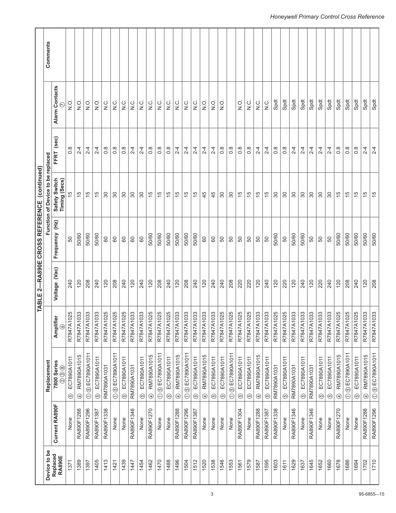
Table 2—Ra890E Cross Reference
Device to be ReplacedRa890E
Replacement Function of Device to be replaced Comments Current RA890F 7800 Series b c h Amplifier f Voltage (Vac) Frequency (Hz) Safety Switch Timing (Secs) FFRT (sec) Alarm Contacts g 1371 None e EC7890A1011R7847A1025
240 50 15 0.8N.O.
1389Ra890F1288
d RM7890A1015R7847A1033
120 50/60 15 2-4N.O.
1397Ra890F1296
a e EC7890A1011R7847A1033
208 50/60 15 2-4N.O.
1405Ra890F1387
e EC7890A1011R7847A1033
240 50/60 15 2-4N.O.
1413Ra890F1338
Rm7890A1031
R7847A1025
120 60 30 0.8N.C.
1421 None a e EC7890A1011R7847A1025
208 60 30 0.8N.C.
1439 None e EC7890A1011R7847A1025
240 60 30 0.8N.C.
1447Ra890F1346
Rm7890A1031
R7847A1033
120 60 30 2-4N.C.
1454 None e EC7890A1011R7847A1033
240 60 30 2-4N.C.
1462Ra890F1270
d RM7890A1015R7847A1025
120 50/60 15 0.8N.C.
1470 None a e EC7890A1011R7847A1025
208 50/60 15 0.8N.C.
1488 None e EC7890A1011R7847A1025
240 50/60 15 0.8N.C.
1496Ra890F1288
d RM7890A1015R7847A1033
120 50/60 15 2-4N.C.
1504Ra890F1296
a e EC7890A1011R7847A1033
208 50/60 15 2-4N.C.
1512Ra890F1387
e EC7890A1011R7847A1033
240 50/60 15 2-4N.C.
1520 None d RM7890A1015R7847A1033
120 60 45 2-4N.O.
1538 None e EC7890A1011R7847A1033
240 60 45 2-4N.O.
1546 None e EC7890A1011R7847A1025
240 50 30 0.8N.O.
1553 None a e EC7890A1011R7847A1025
208 50 30 0.8 1561Ra890F1304
e EC7890A1011R7847A1025
220 50 15 0.8N.O.
1579 None e EC7890A1011R7847A1025
220 50 15 0.8N.C.
1587Ra890F1288
d RM7890A1015R7847A1033
120 50 15 2-4N.C.
1595Ra890F1387
e EC7890A1011R7847A1033
240 50 15 2-4N.C.
1603Ra890F1338
Rm7890A1031
R7847A1025
120 50/60 30 0.8 Spdt 1611 None e EC7890A1011R7847A1025
220 50 30 0.8 Spdt 1629Ra890F1346
Rm7890A1031
R7847A1033
120 50/60 30 2-4 Spdt 1637 None e EC7890A1011R7847A1033
240 50/60 30 2-4 Spdt 1645Ra890F1346
Rm7890A1031
R7847A1033
120 50 30 2-4 Spdt 1652 None e EC7890A1011R7847A1033
220 50 30 2-4 Spdt 1660 None e EC7890A1011R7847A1033
240 50 30 2-4 Spdt 1678Ra890F1270
d RM7890A1015R7847A1025
120 50/60 15 0.8 Spdt 1686 None a e EC7890A1011R7847A1025
208 50/60 15 0.8 Spdt 1694 None e EC7890A1011R7847A1025
240 50/60 15 0.8 Spdt 1702Ra890F1288
d RM7890A1015R7847A1033
120 50/60 15 2-4 Spdt 1710Ra890F1296
a e EC7890A1011R7847A1033
208 50/60 15 2-4 Spdt (continued)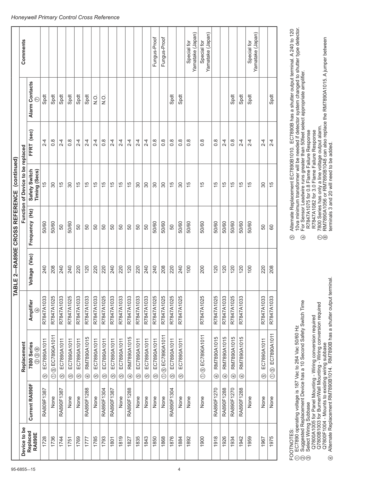
95-6855—15 4 Honeywell Primary Control Cross Reference
Footnotes:
a EC7890 operating voltage is 187 Vac to 264 Vac 50/60 Hz b Suggested Replacement Device has a 10 Second Safety Switch Time c Select Wiring Subbase Q7800A1005 for Panel Mounting - Wiring conversion required Q7800B1003 for Burner/Wall Mounting - Wiring conversion required Q7800F1004 - Mounts to existing wiring subbase d Alternate Replacement RM7890B1014. RM7890B has a shutter output terminal. e Alternate Replacement EC7890B1010. EC7890B has a shutter output terminal. A 240 to 120 10va minimum transformer will be needed if detector system changed to shutter type detector. f For Sensor Leadwire runs greater than 50feet select appropriate amplifier. R7847A1075 for 0.8 Flame Failure Response R7847A1082 for 3.0 Flame Failure Response g 7800 Series has only a line voltage output alarm. h RM7890A1056 or RM7890B1048 can also replace the RM7890A1015. A jumper between terminals 3 and 20 will need to be added.Table 2—Ra890E Cross Reference
Device to be ReplacedRa890E
Replacement Function of Device to be replaced Comments Current RA890F 7800 Series b c h Amplifier f Voltage (Vac) Frequency (Hz) Safety Switch Timing (Secs) FFRT (sec) Alarm Contacts g 1728Ra809F1387
e EC7890A1011R7847A1033
240 50/60 15 2-4 Spdt 1736 None a e EC7890A1011R7847A1025
208 50/60 30 0.8 Spdt 1744Ra890F1387
e EC7890A1011R7847A1033
240 50 15 2-4 Spdt 1751 None e EC7890A1011R7847A1025
240 50/60 30 0.8 Spdt 1769 None e EC7890A1011R7847A1033
220 50 15 2-4 Spdt 1777Ra890F1288
d RM7890A1015R7847A1033
120 50 15 2-4 Spdt 1785 None e EC7890A1011R7847A1033
220 50 15 2-4N.O.
1793Ra890F1304
e EC7890A1011R7847A1025
220 50 15 0.8N.O.
1801Ra890F1387
e EC7890A1011R7847A1033
240 50 15 2-4 1819 None e EC7890A1011R7847A1033
220 50 15 2-4 1827Ra890F1288
d RM7890A1015R7847A1033
120 50 15 2-4 1835 None e EC7890A1011R7847A1033
220 50 30 2-4 1843 None e EC7890A1011R7847A1033
240 50 30 2-4 1850 None e EC7890A1011R7847A1025
240 50/60 30 0.8 Fungus-Proof 1868 None a e EC7890A1011R7847A1025
208 50/60 30 0.8 Fungus-Proof 1876Ra890F1304
e EC7890A1011R7847A1025
220 50 15 0.8 Spdt 1884 None e EC7890A1011R7847A1025
240 50/60 30 0.8 Spdt 1892 None 100 50/60 15 0.8 Special for Yamatake (Japan) 1900 None a e EC7890A1011R7847A1025
200 50/60 15 0.8 Special for Yamatake (Japan) 1918Ra890F1270
d RM7890A1015R7847A1025
120 50/60 15 0.8 1926Ra890F1288
d RM7890A1015R7847A1033
120 50/60 15 2-4 1934Ra890F1270
d RM7890A1015R7847A1025
120 50/60 15 0.8 Spdt 1942Ra890F1288
d RM7890A1015R7847A1033
120 50/60 15 2-4 Spdt 1959 None 100 50/60 15 2-4 Spdt Special for Yamatake (Japan) 1967 None e EC7890A1011R7847A1033
220 50 30 2-4 1975 None a e EC7890A1011R7847A1033
208 60 15 2-4 Spdt (continued)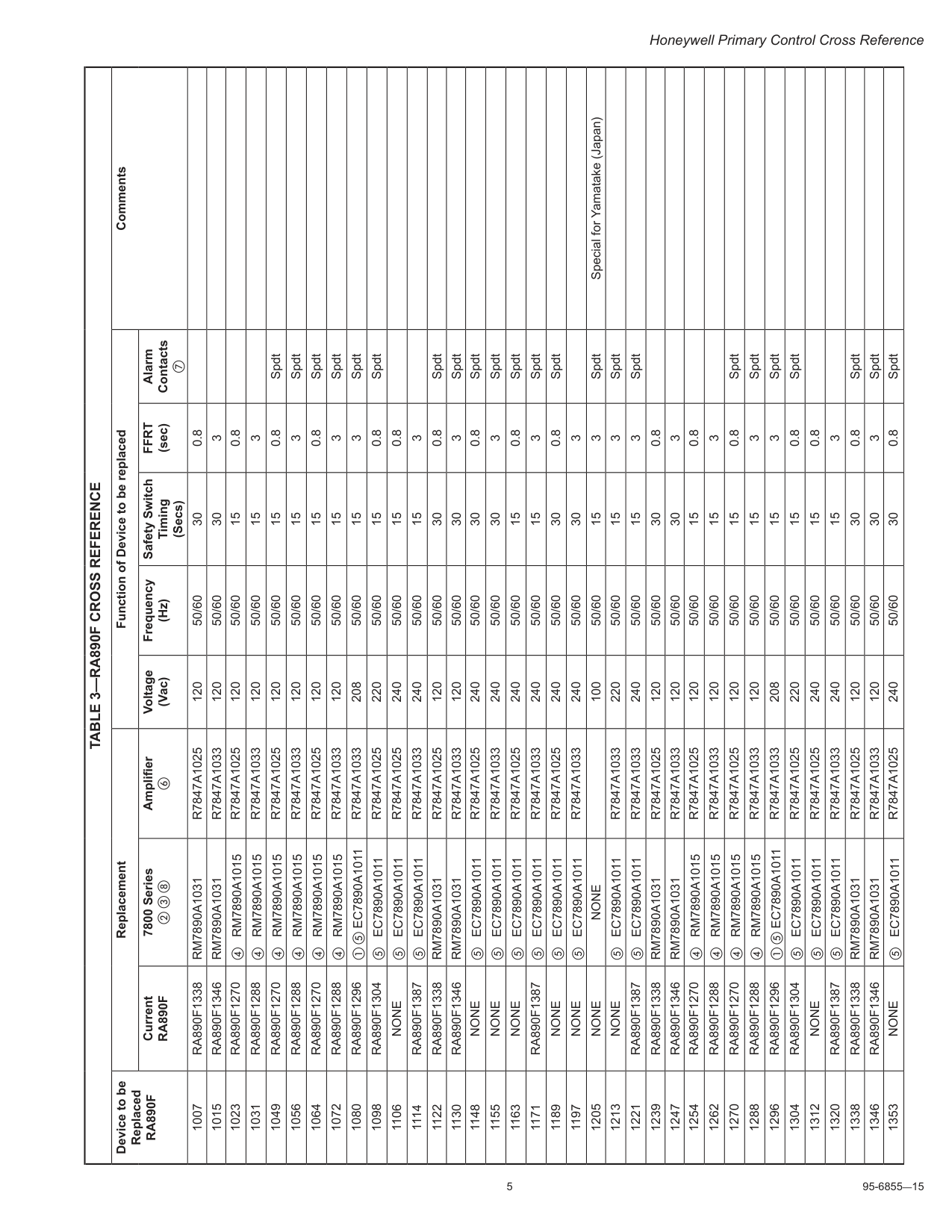
5 95-6855—15 Honeywell Primary Control Cross Reference
Table 3—Ra890F Cross Reference
Device to be ReplacedRa890F
Replacement Function of Device to be replaced Comments CurrentRa890F
7800 Series b c h Amplifier f Voltage (Vac) Frequency (Hz) Safety Switch Timing (Secs)Ffrt
(sec) Alarm Contacts g 1007Ra890F1338
Rm7890A1031
R7847A1025
120 50/60 30 0.8 1015Ra890F1346
Rm7890A1031
R7847A1033
120 50/60 30 3 1023Ra890F1270
d RM7890A1015R7847A1025
120 50/60 15 0.8 1031Ra890F1288
d RM7890A1015R7847A1033
120 50/60 15 3 1049Ra890F1270
d RM7890A1015R7847A1025
120 50/60 15 0.8 Spdt 1056Ra890F1288
d RM7890A1015R7847A1033
120 50/60 15 3 Spdt 1064Ra890F1270
d RM7890A1015R7847A1025
120 50/60 15 0.8 Spdt 1072Ra890F1288
d RM7890A1015R7847A1033
120 50/60 15 3 Spdt 1080Ra890F1296
a e EC7890A1011R7847A1033
208 50/60 15 3 Spdt 1098Ra890F1304
e EC7890A1011R7847A1025
220 50/60 15 0.8 Spdt 1106None
e EC7890A1011R7847A1025
240 50/60 15 0.8 1114Ra890F1387
e EC7890A1011R7847A1033
240 50/60 15 3 1122Ra890F1338
Rm7890A1031
R7847A1025
120 50/60 30 0.8 Spdt 1130Ra890F1346
Rm7890A1031
R7847A1033
120 50/60 30 3 Spdt 1148None
e EC7890A1011R7847A1025
240 50/60 30 0.8 Spdt 1155None
e EC7890A1011R7847A1033
240 50/60 30 3 Spdt 1163None
e EC7890A1011R7847A1025
240 50/60 15 0.8 Spdt 1171Ra890F1387
e EC7890A1011R7847A1033
240 50/60 15 3 Spdt 1189None
e EC7890A1011R7847A1025
240 50/60 30 0.8 Spdt 1197None
e EC7890A1011R7847A1033
240 50/60 30 3 1205None
None
100 50/60 15 3 Spdt Special for Yamatake (Japan) 1213None
e EC7890A1011R7847A1033
220 50/60 15 3 Spdt 1221Ra890F1387
e EC7890A1011R7847A1033
240 50/60 15 3 Spdt 1239Ra890F1338
Rm7890A1031
R7847A1025
120 50/60 30 0.8 1247Ra890F1346
Rm7890A1031
R7847A1033
120 50/60 30 3 1254Ra890F1270
d RM7890A1015R7847A1025
120 50/60 15 0.8 1262Ra890F1288
d RM7890A1015R7847A1033
120 50/60 15 3 1270Ra890F1270
d RM7890A1015R7847A1025
120 50/60 15 0.8 Spdt 1288Ra890F1288
d RM7890A1015R7847A1033
120 50/60 15 3 Spdt 1296Ra890F1296
a e EC7890A1011R7847A1033
208 50/60 15 3 Spdt 1304Ra890F1304
e EC7890A1011R7847A1025
220 50/60 15 0.8 Spdt 1312None
e EC7890A1011R7847A1025
240 50/60 15 0.8 1320Ra890F1387
e EC7890A1011R7847A1033
240 50/60 15 3 1338Ra890F1338
Rm7890A1031
R7847A1025
120 50/60 30 0.8 Spdt 1346Ra890F1346
Rm7890A1031
R7847A1033
120 50/60 30 3 Spdt 1353None
e EC7890A1011R7847A1025
240 50/60 30 0.8 Spdt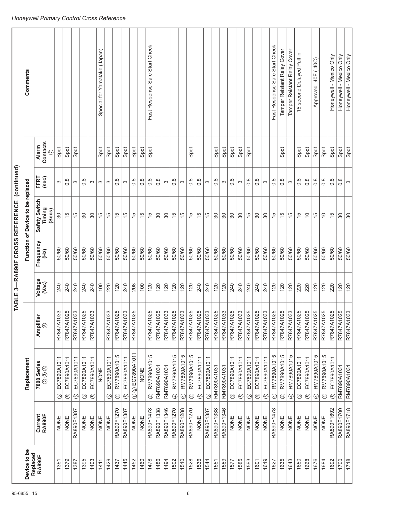
95-6855—15 6 Honeywell Primary Control Cross Reference
Table 3—Ra890F Cross Reference
Device to be ReplacedRa890F
Replacement Function of Device to be replaced Comments CurrentRa890F
7800 Series b c h Amplifier f Voltage (Vac) Frequency (Hz) Safety Switch Timing (Secs)Ffrt
(sec) Alarm Contacts g 1361None
e EC7890A1011R7847A1033
240 50/60 30 3 Spdt 1379None
e EC7890A1011R7847A1025
240 50/60 15 0.8 Spdt 1387Ra890F1387
e EC7890A1011R7847A1033
240 50/60 15 3 Spdt 1395None
e EC7890A1011R7847A1025
240 50/60 30 0.8 1403None
e EC7890A1011R7847A1033
240 50/60 30 3 1411None
None
100 50/60 15 3 Spdt Special for Yamatake (Japan) 1429None
e EC7890A1011R7847A1033
220 50/60 15 3 Spdt 1437Ra890F1270
d RM7890A1015R7847A1025
120 50/60 15 0.8 Spdt 1445Ra890F1387
e EC7890A1011R7847A1033
240 50/60 15 3 Spdt 1452None
a e EC7890A1011R7847A1025
208 50/60 15 0.8 Spdt 1460None
None
100 50/60 15 0.8 Spdt 1478Ra890F1478
d RM7890A1015R7847A1025
120 50/60 15 0.8 Spdt Fast Response Safe Start Check 1486Ra890F1338
Rm7890A1031
R7847A1025
120 50/60 30 0.8 1494Ra890F1346
Rm7890A1031
R7847A1033
120 50/60 30 3 1502Ra890F1270
d RM7890A1015R7847A1025
120 50/60 15 0.8 1510Ra890F1288
d RM7890A1015R7847A1033
120 50/60 15 3 1528Ra890F1270
d RM7890A1015R7847A1025
120 50/60 15 0.8 Spdt 1536None
e EC7890A1011R7847A1025
240 50/60 15 0.8 1544Ra890F1387
e EC7890A1011R7847A1033
240 50/60 15 3 1551Ra890F1338
Rm7890A1031
R7847A1025
120 50/60 30 0.8 Spdt 1569Ra890F1346
Rm7890A1031
R7847A1033
120 50/60 30 3 Spdt 1577None
e EC7890A1011R7847A1025
240 50/60 30 0.8 Spdt 1585None
e EC7890A1011R7847A1033
240 50/60 30 3 Spdt 1593None
e EC7890A1011R7847A1025
240 50/60 15 0.8 Spdt 1601None
e EC7890A1011R7847A1025
240 50/60 30 0.8 1619None
e EC7890A1011R7847A1033
240 50/60 30 3 1627Ra890F1478
d RM7890A1015R7847A1025
120 50/60 15 0.8 Fast Response Safe Start Check 1635None
d RM7890A1015R7847A1025
120 50/60 15 0.8 Spdt Tamper Reistant Relay Cover 1643None
d RM7890A1015R7847A1033
120 50/60 15 3 Tamper Reistant Relay Cover 1650None
e EC7890A1011R7847A1025
220 50/60 15 0.8 Spdt 15 second Delayed Pull in 1668None
e EC7890A1011R7847A1025
220 50/60 10 0.8 Spdt 1676None
d RM7890A1015R7847A1025
120 50/60 15 0.8 Spdt Approved -40F (-40C) 1684None
d RM7890A1015R7847A1025
120 50/60 10 0.8 Spdt 1692Ra890F1692
e EC7890A1011R7847A1025
220 50/60 15 0.8 Spdt Honeywell - Mexico Only 1700Ra890F1700
Rm7890A1031
R7847A1025
120 50/60 30 0.8 Spdt Honeywell - Mexico Only 1718Ra890F1718
Rm7890A1031
R7847A1033
120 50/60 30 3 Spdt Honeywell - Mexico Only (continued)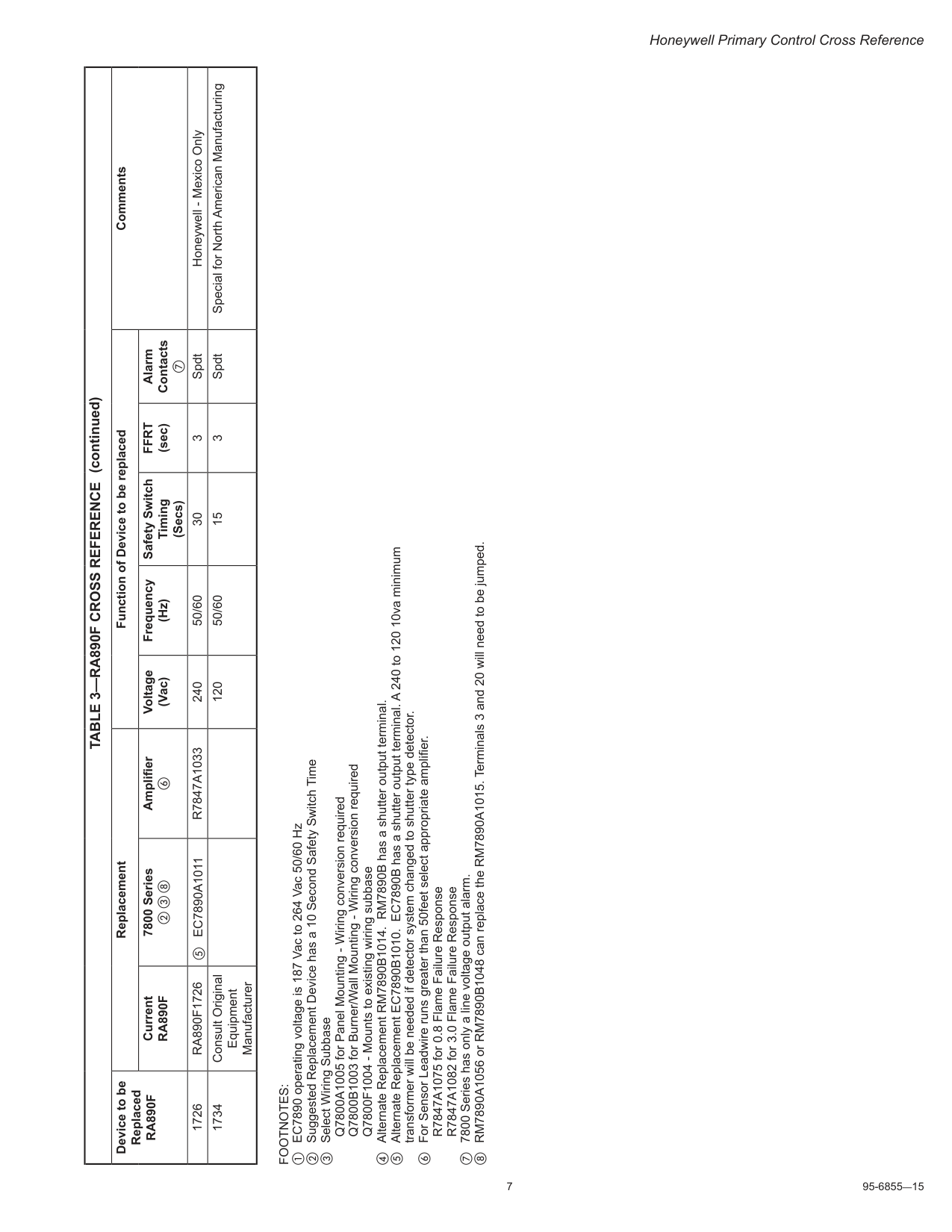
7 95-6855—15 Honeywell Primary Control Cross Reference
Footnotes:
a EC7890 operating voltage is 187 Vac to 264 Vac 50/60 Hz b Suggested Replacement Device has a 10 Second Safety Switch Time c Select Wiring Subbase Q7800A1005 for Panel Mounting - Wiring conversion required Q7800B1003 for Burner/Wall Mounting - Wiring conversion required Q7800F1004 - Mounts to existing wiring subbase d Alternate Replacement RM7890B1014. RM7890B has a shutter output terminal. e Alternate Replacement EC7890B1010. EC7890B has a shutter output terminal. A 240 to 120 10va minimum transformer will be needed if detector system changed to shutter type detector. f For Sensor Leadwire runs greater than 50feet select appropriate amplifier. R7847A1075 for 0.8 Flame Failure Response R7847A1082 for 3.0 Flame Failure Response g 7800 Series has only a line voltage output alarm. h RM7890A1056 or RM7890B1048 can replace the RM7890A1015. Terminals 3 and 20 will need to be jumped.Table 3—Ra890F Cross Reference
Device to be ReplacedRa890F
Replacement Function of Device to be replaced Comments CurrentRa890F
7800 Series b c h Amplifier f Voltage (Vac) Frequency (Hz) Safety Switch Timing (Secs)Ffrt
(sec) Alarm Contacts g 1726Ra890F1726
e EC7890A1011R7847A1033
240 50/60 30 3 Spdt Honeywell - Mexico Only 1734 Consult Original Equipment Manufacturer 120 50/60 15 3 Spdt Special for North American Manufacturing (continued)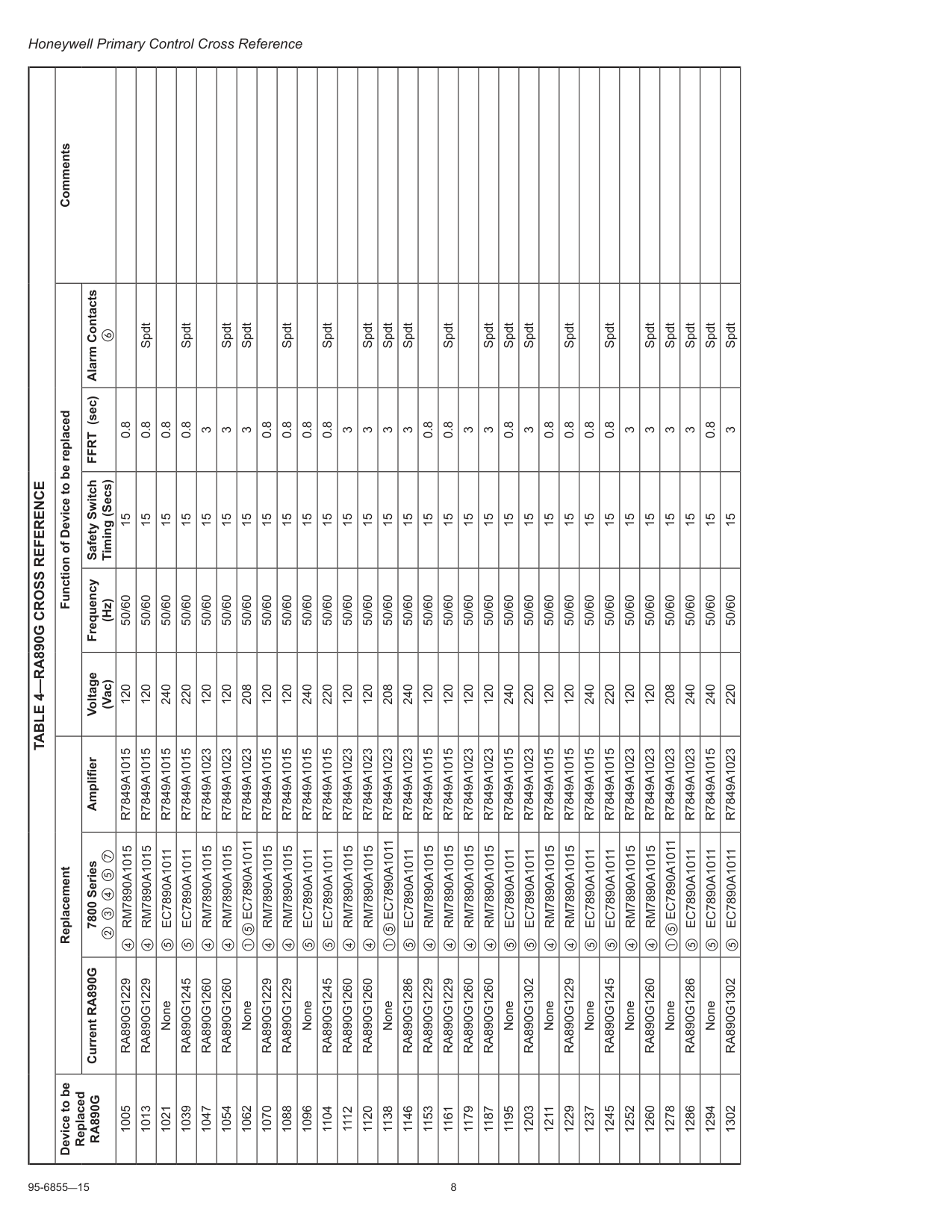
95-6855—15 8 Honeywell Primary Control Cross Reference
Table 4—Ra890G Cross Reference
Device to be ReplacedRa890G
Replacement Function of Device to be replaced Comments Current RA890G 7800 Series b c d e g Amplifier Voltage (Vac) Frequency (Hz) Safety Switch Timing (Secs) FFRT (sec) Alarm Contacts f 1005Ra890G1229
d RM7890A1015R7849A1015
120 50/60 15 0.8 1013Ra890G1229
d RM7890A1015R7849A1015
120 50/60 15 0.8 Spdt 1021 None e EC7890A1011R7849A1015
240 50/60 15 0.8 1039Ra890G1245
e EC7890A1011R7849A1015
220 50/60 15 0.8 Spdt 1047Ra890G1260
d RM7890A1015R7849A1023
120 50/60 15 3 1054Ra890G1260
d RM7890A1015R7849A1023
120 50/60 15 3 Spdt 1062 None a e EC7890A1011R7849A1023
208 50/60 15 3 Spdt 1070Ra890G1229
d RM7890A1015R7849A1015
120 50/60 15 0.8 1088Ra890G1229
d RM7890A1015R7849A1015
120 50/60 15 0.8 Spdt 1096 None e EC7890A1011R7849A1015
240 50/60 15 0.8 1104Ra890G1245
e EC7890A1011R7849A1015
220 50/60 15 0.8 Spdt 1112Ra890G1260
d RM7890A1015R7849A1023
120 50/60 15 3 1120Ra890G1260
d RM7890A1015R7849A1023
120 50/60 15 3 Spdt 1138 None a e EC7890A1011R7849A1023
208 50/60 15 3 Spdt 1146Ra890G1286
e EC7890A1011R7849A1023
240 50/60 15 3 Spdt 1153Ra890G1229
d RM7890A1015R7849A1015
120 50/60 15 0.8 1161Ra890G1229
d RM7890A1015R7849A1015
120 50/60 15 0.8 Spdt 1179Ra890G1260
d RM7890A1015R7849A1023
120 50/60 15 3 1187Ra890G1260
d RM7890A1015R7849A1023
120 50/60 15 3 Spdt 1195 None e EC7890A1011R7849A1015
240 50/60 15 0.8 Spdt 1203Ra890G1302
e EC7890A1011R7849A1023
220 50/60 15 3 Spdt 1211 None d RM7890A1015R7849A1015
120 50/60 15 0.8 1229Ra890G1229
d RM7890A1015R7849A1015
120 50/60 15 0.8 Spdt 1237 None e EC7890A1011R7849A1015
240 50/60 15 0.8 1245Ra890G1245
e EC7890A1011R7849A1015
220 50/60 15 0.8 Spdt 1252 None d RM7890A1015R7849A1023
120 50/60 15 3 1260Ra890G1260
d RM7890A1015R7849A1023
120 50/60 15 3 Spdt 1278 None a e EC7890A1011R7849A1023
208 50/60 15 3 Spdt 1286Ra890G1286
e EC7890A1011R7849A1023
240 50/60 15 3 Spdt 1294 None e EC7890A1011R7849A1015
240 50/60 15 0.8 Spdt 1302Ra890G1302
e EC7890A1011R7849A1023
220 50/60 15 3 Spdt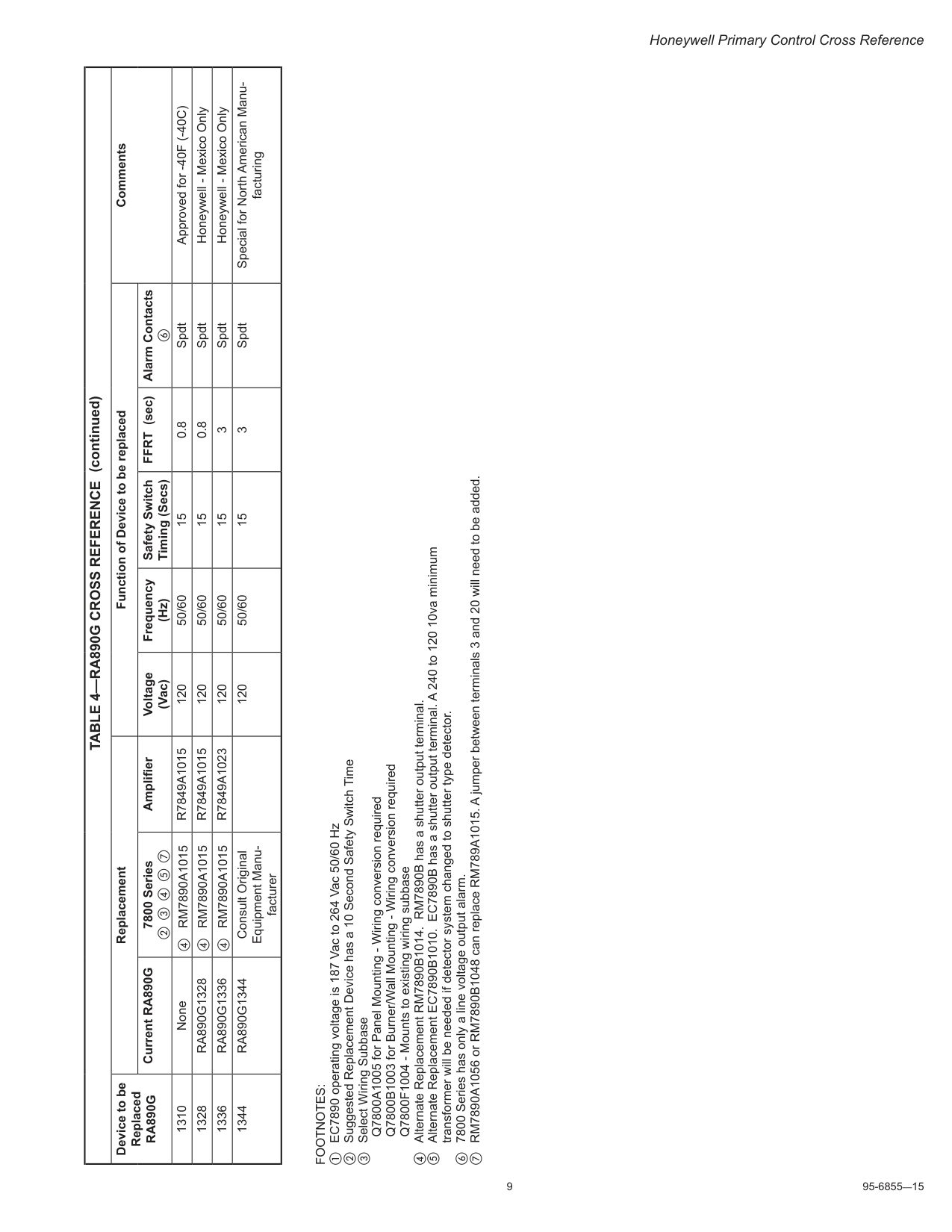
9 95-6855—15 Honeywell Primary Control Cross Reference
Footnotes:
a EC7890 operating voltage is 187 Vac to 264 Vac 50/60 Hz b Suggested Replacement Device has a 10 Second Safety Switch Time c Select Wiring Subbase Q7800A1005 for Panel Mounting - Wiring conversion required Q7800B1003 for Burner/Wall Mounting - Wiring conversion required Q7800F1004 - Mounts to existing wiring subbase d Alternate Replacement RM7890B1014. RM7890B has a shutter output terminal. e Alternate Replacement EC7890B1010. EC7890B has a shutter output terminal. A 240 to 120 10va minimum transformer will be needed if detector system changed to shutter type detector. f 7800 Series has only a line voltage output alarm. g RM7890A1056 or RM7890B1048 can replace RM789A1015. A jumper between terminals 3 and 20 will need to be added.Table 4—Ra890G Cross Reference
Device to be ReplacedRa890G
Replacement Function of Device to be replaced Comments Current RA890G 7800 Series b c d e g Amplifier Voltage (Vac) Frequency (Hz) Safety Switch Timing (Secs) FFRT (sec) Alarm Contacts f 1310 None d RM7890A1015R7849A1015
120 50/60 15 0.8 Spdt Approved for -40F (-40C) 1328Ra890G1328
d RM7890A1015R7849A1015
120 50/60 15 0.8 Spdt Honeywell - Mexico Only 1336Ra890G1336
d RM7890A1015R7849A1023
120 50/60 15 3 Spdt Honeywell - Mexico Only 1344Ra890G1344
Consult Original Equipment Manu facturer 120 50/60 15 3 Spdt Special for North American Manu facturing (continued)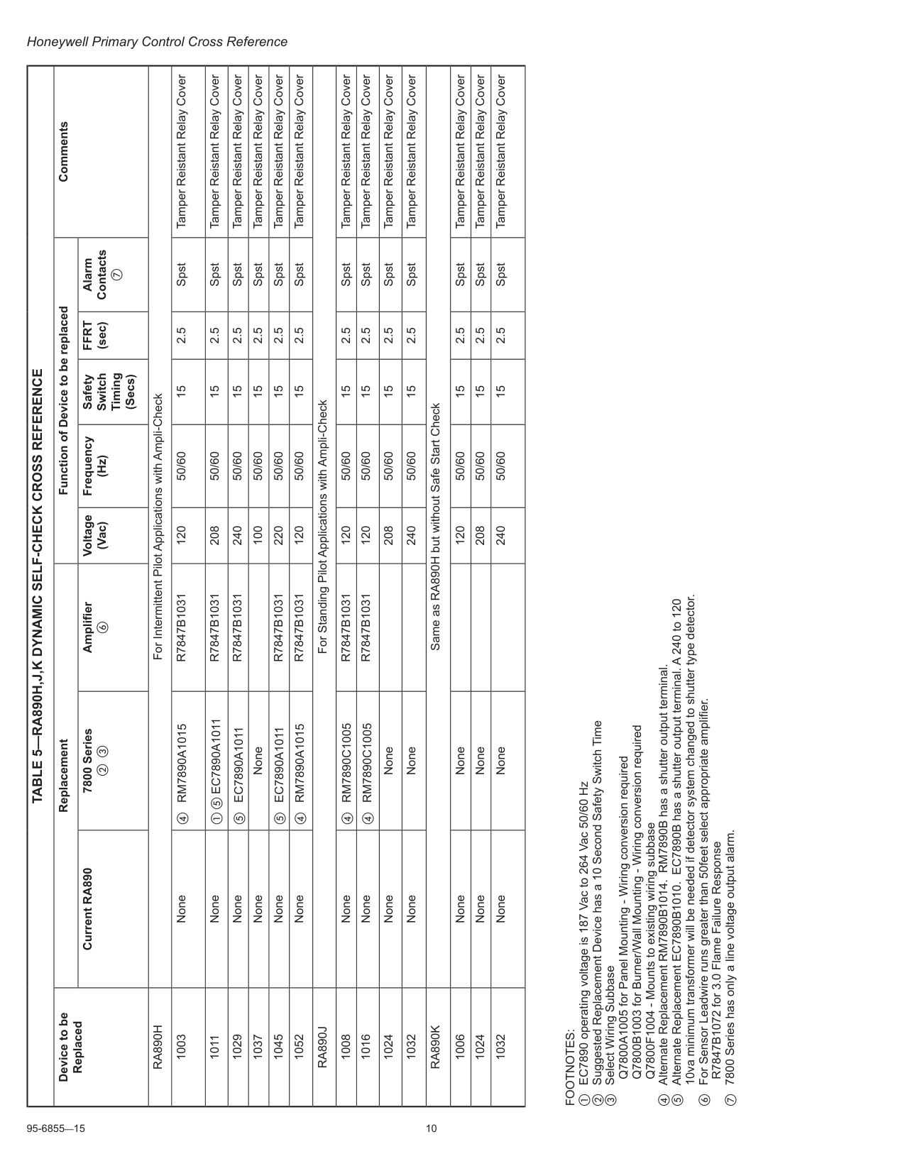
95-6855—15 10 Honeywell Primary Control Cross Reference
Table 5—Ra890H,J,K Dynamic Self-Check Cross Reference
Device to be Replaced Replacement Function of Device to be replaced Comments Current RA890 7800 Series b c Amplifier f Voltage (Vac) Frequency (Hz) Safety Switch Timing (Secs)Ffrt
(sec) Alarm Contacts gRa890H
For Intermittent Pilot Applications with Ampli-Check 1003 None d RM7890A1015R7847B1031
120 50/60 15 2.5 Spst Tamper Reistant Relay Cover 1011 None a e EC7890A1011R7847B1031
208 50/60 15 2.5 Spst Tamper Reistant Relay Cover 1029 None e EC7890A1011R7847B1031
240 50/60 15 2.5 Spst Tamper Reistant Relay Cover 1037 None None 100 50/60 15 2.5 Spst Tamper Reistant Relay Cover 1045 None e EC7890A1011R7847B1031
220 50/60 15 2.5 Spst Tamper Reistant Relay Cover 1052 None d RM7890A1015R7847B1031
120 50/60 15 2.5 Spst Tamper Reistant Relay CoverRa890J
For Standing Pilot Applications with Ampli-Check 1008 None d RM7890C1005R7847B1031
120 50/60 15 2.5 Spst Tamper Reistant Relay Cover 1016 None d RM7890C1005R7847B1031
120 50/60 15 2.5 Spst Tamper Reistant Relay Cover 1024 None None 208 50/60 15 2.5 Spst Tamper Reistant Relay Cover 1032 None None 240 50/60 15 2.5 Spst Tamper Reistant Relay CoverRa890K
Same as RA890H but without Safe Start Check 1006 None None 120 50/60 15 2.5 Spst Tamper Reistant Relay Cover 1024 None None 208 50/60 15 2.5 Spst Tamper Reistant Relay Cover 1032 None None 240 50/60 15 2.5 Spst Tamper Reistant Relay CoverFootnotes:
a EC7890 operating voltage is 187 Vac to 264 Vac 50/60 Hz b Suggested Replacement Device has a 10 Second Safety Switch Time c Select Wiring Subbase Q7800A1005 for Panel Mounting - Wiring conversion required Q7800B1003 for Burner/Wall Mounting - Wiring conversion required Q7800F1004 - Mounts to existing wiring subbase d Alternate Replacement RM7890B1014. RM7890B has a shutter output terminal. e Alternate Replacement EC7890B1010. EC7890B has a shutter output terminal. A 240 to 120 10va minimum transformer will be needed if detector system changed to shutter type detector. f For Sensor Leadwire runs greater than 50feet select appropriate amplifier. R7847B1072 for 3.0 Flame Failure Response g 7800 Series has only a line voltage output alarm.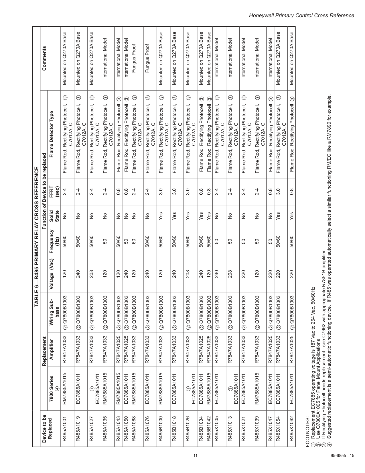
11 95-6855—15 Honeywell Primary Control Cross Reference
Table 6—R485 Primary Relay Cross Reference
Device to be Replaced Replacement Function of Device to be replaced Comments 7800 Series d Amplifier Wiring Sub base Voltage (Vac) Frequency (Hz) Solid StateFfrt
(sec) Flame Detector TypeR485A1001
Rm7885A1015
R7847A1033
b Q7800B1003 120 50/60 No 2-4 Flame Rod, Rectifying Photocell, cC7012A, C
Mounted on Q270A BaseR485A1019
Ec7885A1011
R7847A1033
b Q7800B1003 240 50/60 No 2-4 Flame Rod, Rectifying Photocell, cC7012A, C
Mounted on Q270A BaseR485A1027
aEc7885A1011
R7847A1033
b Q7800B1003 208 50/60 No 2-4 Flame Rod, Rectifying Photocell, cC7012A, C
Mounted on Q270A BaseR485A1035
Rm7885A1015
R7847A1033
b Q7800B1003 120 50 No 2-4 Flame Rod, Rectifying Photocell, cC7012A, C
International ModelR485A1043
Rm7885A1015
R7847A1025
b Q7800B1003 120 50/60 No 0.8 Flame Rod, Rectifying Photocell c International ModelR485A1050
Ec7885A1011
R7847A1025
b Q7800B1003 240 50 No 0.8 Flame Rod, Rectifying Photocell c International ModelR485A1068
Rm7885A1015
R7847A1033
b Q7800B1003 120 60 No 2-4 Flame Rod, Rectifying Photocell, cC7012A, C
Fungus ProofR485A1076
Ec7885A1011
R7847A1033
b Q7800B1003 240 50/60 No 2-4 Flame Rod, Rectifying Photocell, cC7012A, C
Fungus ProofR485B1000
Rm7885A1015
R7847A1033
b Q7800B1003 120 50/60 Yes 3.0 Flame Rod, Rectifying Photocell, cC7012A, C
Mounted on Q270A BaseR485B1018
Ec7885A1011
R7847A1033
b Q7800B1003 240 50/60 Yes 3.0 Flame Rod, Rectifying Photocell, cC7012A, C
Mounted on Q270A BaseR485B1026
aEc7885A1011
R7847A1033
b Q7800B1003 208 50/60 Yes 3.0 Flame Rod, Rectifying Photocell, cC7012A, C
Mounted on Q270A BaseR485B1034
Ec7885A1011
R7847A1025
b Q7800B1003 240 50/60 Yes 0.8 Flame Rod, Rectifying Photocell c Mounted on Q270A BaseR485B1042
Rm7885A1015
R7847A1025
b Q7800B1003 120 50/60 Yes 0.8 Flame Rod, Rectifying Photocell c Mounted on Q270A BaseR485X1005
Ec7885A1011
R7847A1033
b Q7800B1003 240 50 No 2-4 Flame Rod, Rectifying Photocell, cC7012A, C
International ModelR485X1013
aEc7885A1011
R7847A1033
b Q7800B1003 208 50 No 2-4 Flame Rod, Rectifying Photocell, cC7012A, C
International ModelR485X1021
Ec7885A1011
R7847A1033
b Q7800B1003 220 50 No 2-4 Flame Rod, Rectifying Photocell, cC7012A, C
International ModelR485X1039
Rm7885A1015
R7847A1033
b Q7800B1003 120 50 No 2-4 Flame Rod, Rectifying Photocell, cC7012A, C
International ModelR485X1047
Ec7885A1011
R7847A1025
b Q7800B1003 220 50 No 0.8 Flame Rod, Rectifying Photocell c International ModelR485X1054
Ec7885A1011
R7847A1033
b Q7800B1003 220 50/60 Yes 3.0 Flame Rod, Rectifying Photocell, cC7012A, C
Mounted on Q270A BaseR485X1062
Ec7885A1011
R7847A1025
b Q7800B1003 220 50/60 Yes 0.8 Flame Rod, Rectifying Photocell c Mounted on Q270A BaseFootnotes:
a Replacement EC7885 operating voltage is 187 Vac to 264 Vac, 50/60Hz b Use Q7800A1005 for Panel Mount Applications c If Rectifying Photocell needs replacement - see C7962 with appropriate R7851B amplifier d Suggested replacement is a semi-automatic functioning device. If R485 was operated automatically select a similar functioning RM/EC like a RM7890 for example.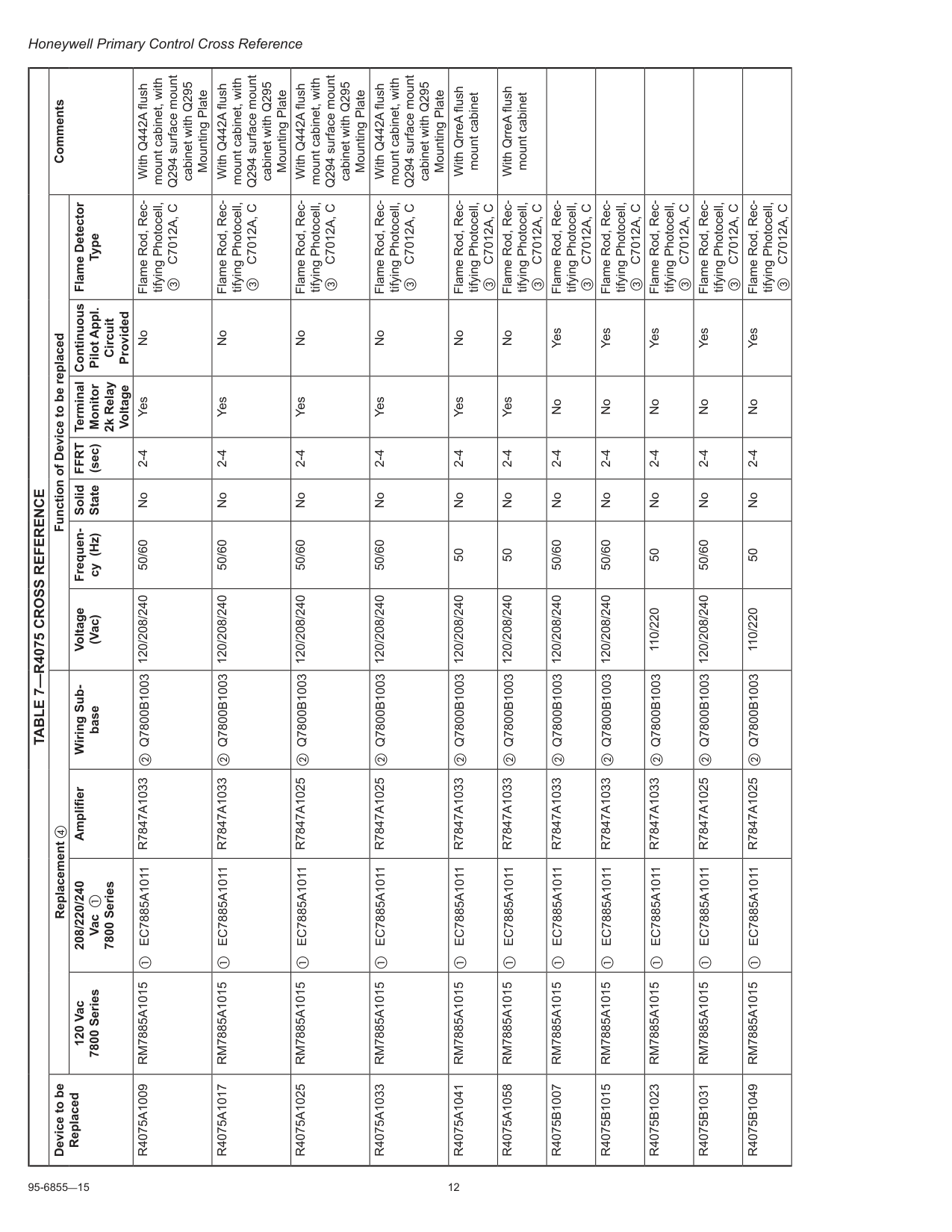
95-6855—15 12 Honeywell Primary Control Cross Reference
Table 7—R4075 Cross Reference
Device to be Replaced Replacement d Function of Device to be replaced Comments 120 Vac 7800 Series 208/220/240 Vac a 7800 Series Amplifier Wiring Sub base Voltage (Vac) Frequen cy (Hz) Solid StateFfrt
(sec) Terminal Monitor 2k Relay Voltage Continuous Pilot Appl. Circuit Provided Flame Detector TypeR4075A1009
Rm7885A1015
a EC7885A1011R7847A1033
b Q7800B1003 120/208/240 50/60 No 2-4 Yes No Flame Rod, Rec tifying Photocell, c C7012A, C With Q442A flush mount cabinet, with Q294 surface mount cabinet with Q295 Mounting PlateR4075A1017
Rm7885A1015
a EC7885A1011R7847A1033
b Q7800B1003 120/208/240 50/60 No 2-4 Yes No Flame Rod, Rec tifying Photocell, c C7012A, C With Q442A flush mount cabinet, with Q294 surface mount cabinet with Q295 Mounting PlateR4075A1025
Rm7885A1015
a EC7885A1011R7847A1025
b Q7800B1003 120/208/240 50/60 No 2-4 Yes No Flame Rod, Rec tifying Photocell, c C7012A, C With Q442A flush mount cabinet, with Q294 surface mount cabinet with Q295 Mounting PlateR4075A1033
Rm7885A1015
a EC7885A1011R7847A1025
b Q7800B1003 120/208/240 50/60 No 2-4 Yes No Flame Rod, Rec tifying Photocell, c C7012A, C With Q442A flush mount cabinet, with Q294 surface mount cabinet with Q295 Mounting PlateR4075A1041
Rm7885A1015
a EC7885A1011R7847A1033
b Q7800B1003 120/208/240 50 No 2-4 Yes No Flame Rod, Rec tifying Photocell, c C7012A, C With QrreA flush mount cabinetR4075A1058
Rm7885A1015
a EC7885A1011R7847A1033
b Q7800B1003 120/208/240 50 No 2-4 Yes No Flame Rod, Rec tifying Photocell, c C7012A, C With QrreA flush mount cabinetR4075B1007
Rm7885A1015
a EC7885A1011R7847A1033
b Q7800B1003 120/208/240 50/60 No 2-4 No Yes Flame Rod, Rec tifying Photocell, c C7012A, CR4075B1015
Rm7885A1015
a EC7885A1011R7847A1033
b Q7800B1003 120/208/240 50/60 No 2-4 No Yes Flame Rod, Rec tifying Photocell, c C7012A, CR4075B1023
Rm7885A1015
a EC7885A1011R7847A1033
b Q7800B1003 110/220 50 No 2-4 No Yes Flame Rod, Rec tifying Photocell, c C7012A, CR4075B1031
Rm7885A1015
a EC7885A1011R7847A1025
b Q7800B1003 120/208/240 50/60 No 2-4 No Yes Flame Rod, Rec tifying Photocell, c C7012A, CR4075B1049
Rm7885A1015
a EC7885A1011R7847A1025
b Q7800B1003 110/220 50 No 2-4 No Yes Flame Rod, Rec tifying Photocell, c C7012A, C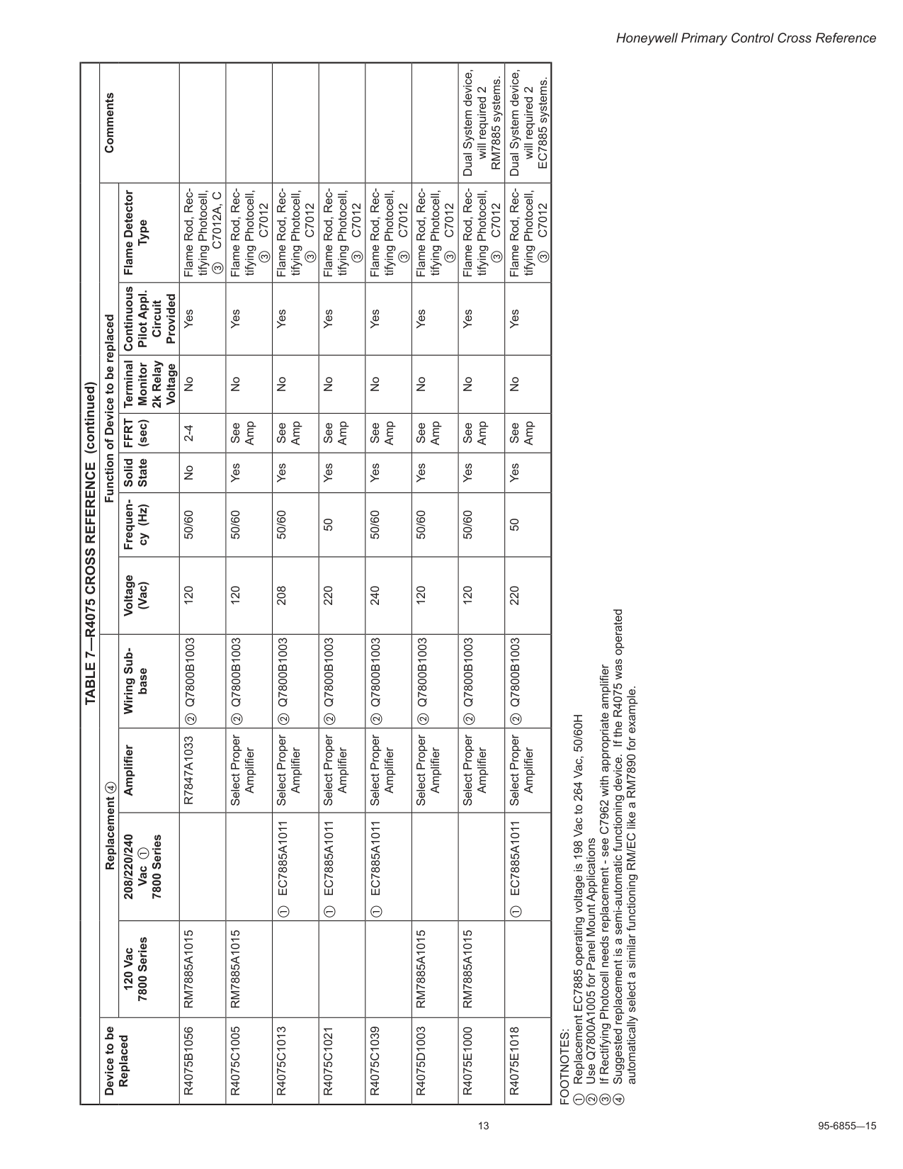
13 95-6855—15 Honeywell Primary Control Cross Reference
Footnotes:
a Replacement EC7885 operating voltage is 198 Vac to 264 Vac, 50/60H b Use Q7800A1005 for Panel Mount Applications c If Rectifying Photocell needs replacement - see C7962 with appropriate amplifier d Suggested replacement is a semi-automatic functioning device. If the R4075 was operated automatically select a similar functioning RM/EC like a RM7890 for example.Table 7—R4075 Cross Reference
Device to be Replaced Replacement d Function of Device to be replaced Comments 120 Vac 7800 Series 208/220/240 Vac a 7800 Series Amplifier Wiring Sub base Voltage (Vac) Frequen cy (Hz) Solid StateFfrt
(sec) Terminal Monitor 2k Relay Voltage Continuous Pilot Appl. Circuit Provided Flame Detector TypeR4075B1056
Rm7885A1015
R7847A1033
b Q7800B1003 120 50/60 No 2-4 No Yes Flame Rod, Rec tifying Photocell, c C7012A, CR4075C1005
Rm7885A1015
Select Proper Amplifier b Q7800B1003 120 50/60 Yes See Amp No Yes Flame Rod, Rec tifying Photocell, c C7012R4075C1013
a EC7885A1011 Select Proper Amplifier b Q7800B1003 208 50/60 Yes See Amp No Yes Flame Rod, Rec tifying Photocell, c C7012R4075C1021
a EC7885A1011 Select Proper Amplifier b Q7800B1003 220 50 Yes See Amp No Yes Flame Rod, Rec tifying Photocell, c C7012R4075C1039
a EC7885A1011 Select Proper Amplifier b Q7800B1003 240 50/60 Yes See Amp No Yes Flame Rod, Rec tifying Photocell, c C7012R4075D1003
Rm7885A1015
Select Proper Amplifier b Q7800B1003 120 50/60 Yes See Amp No Yes Flame Rod, Rec tifying Photocell, c C7012R4075E1000
Rm7885A1015
Select Proper Amplifier b Q7800B1003 120 50/60 Yes See Amp No Yes Flame Rod, Rec tifying Photocell, c C7012 Dual System device, will required 2 RM7885 systems.R4075E1018
a EC7885A1011 Select Proper Amplifier b Q7800B1003 220 50 Yes See Amp No Yes Flame Rod, Rec tifying Photocell, c C7012 Dual System device, will required 2 EC7885 systems. (continued)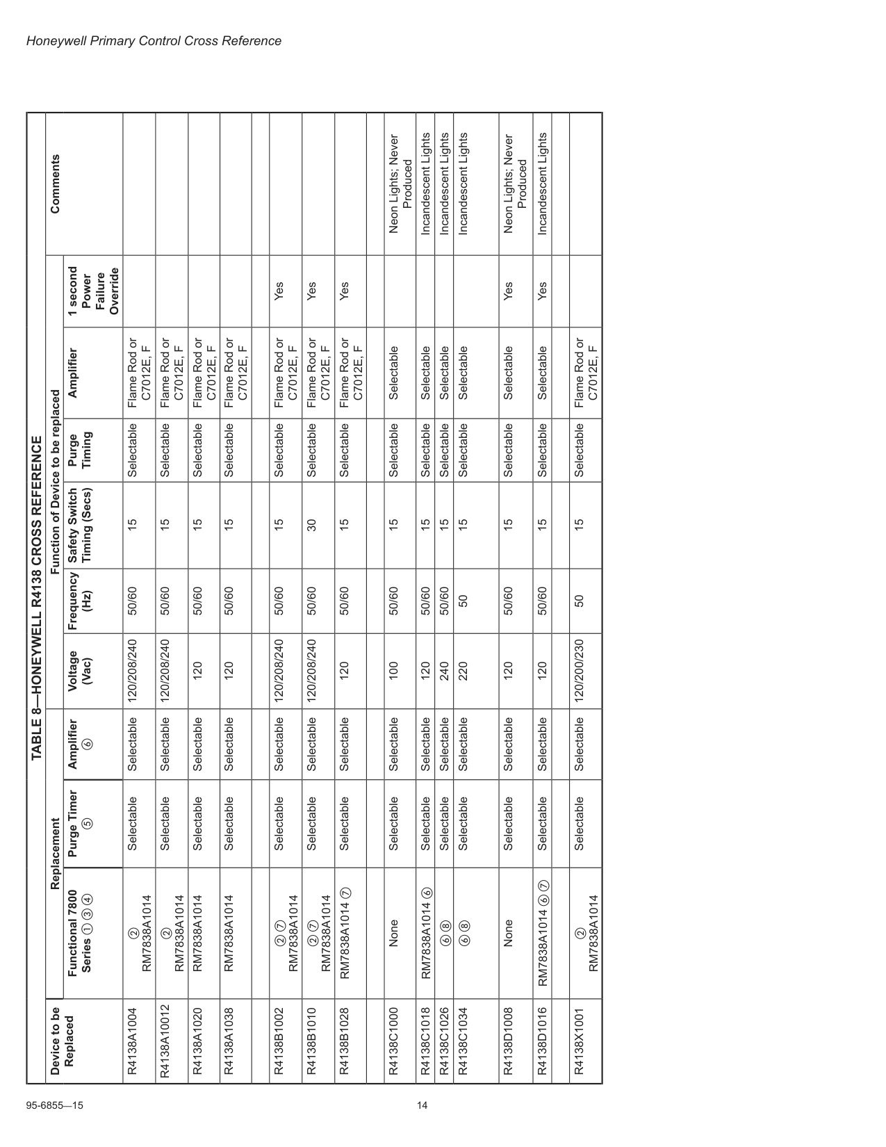
95-6855—15 14 Honeywell Primary Control Cross Reference
Table 8—Honeywell R4138 Cross Reference
Device to be Replaced Replacement Function of Device to be replaced Comments Functional 7800 Series a c d Purge Timer e Amplifier f Voltage (Vac) Frequency (Hz) Safety Switch Timing (Secs) Purge Timing Amplifier 1 second Power Failure OverrideR4138A1004
bRm7838A1014
Selectable Selectable 120/208/240 50/60 15 Selectable Flame Rod orC7012E, F
R4138A10012
bRm7838A1014
Selectable Selectable 120/208/240 50/60 15 Selectable Flame Rod orC7012E, F
R4138A1020
Rm7838A1014
Selectable Selectable 120 50/60 15 Selectable Flame Rod orC7012E, F
R4138A1038
Rm7838A1014
Selectable Selectable 120 50/60 15 Selectable Flame Rod orC7012E, F
R4138B1002
b gRm7838A1014
Selectable Selectable 120/208/240 50/60 15 Selectable Flame Rod orC7012E, F
YesR4138B1010
b gRm7838A1014
Selectable Selectable 120/208/240 50/60 30 Selectable Flame Rod orC7012E, F
YesR4138B1028
RM7838A1014 g Selectable Selectable 120 50/60 15 Selectable Flame Rod orC7012E, F
YesR4138C1000
None Selectable Selectable 100 50/60 15 Selectable Selectable Neon Lights; Never ProducedR4138C1018
RM7838A1014 f Selectable Selectable 120 50/60 15 Selectable Selectable Incandescent LightsR4138C1026
f h Selectable Selectable 240 50/60 15 Selectable Selectable Incandescent LightsR4138C1034
f h Selectable Selectable 220 50 15 Selectable Selectable Incandescent LightsR4138D1008
None Selectable Selectable 120 50/60 15 Selectable Selectable Yes Neon Lights; Never ProducedR4138D1016
RM7838A1014 f g Selectable Selectable 120 50/60 15 Selectable Selectable Yes Incandescent LightsR4138X1001
bRm7838A1014
Selectable Selectable 120/200/230 50 15 Selectable Flame Rod orC7012E, F
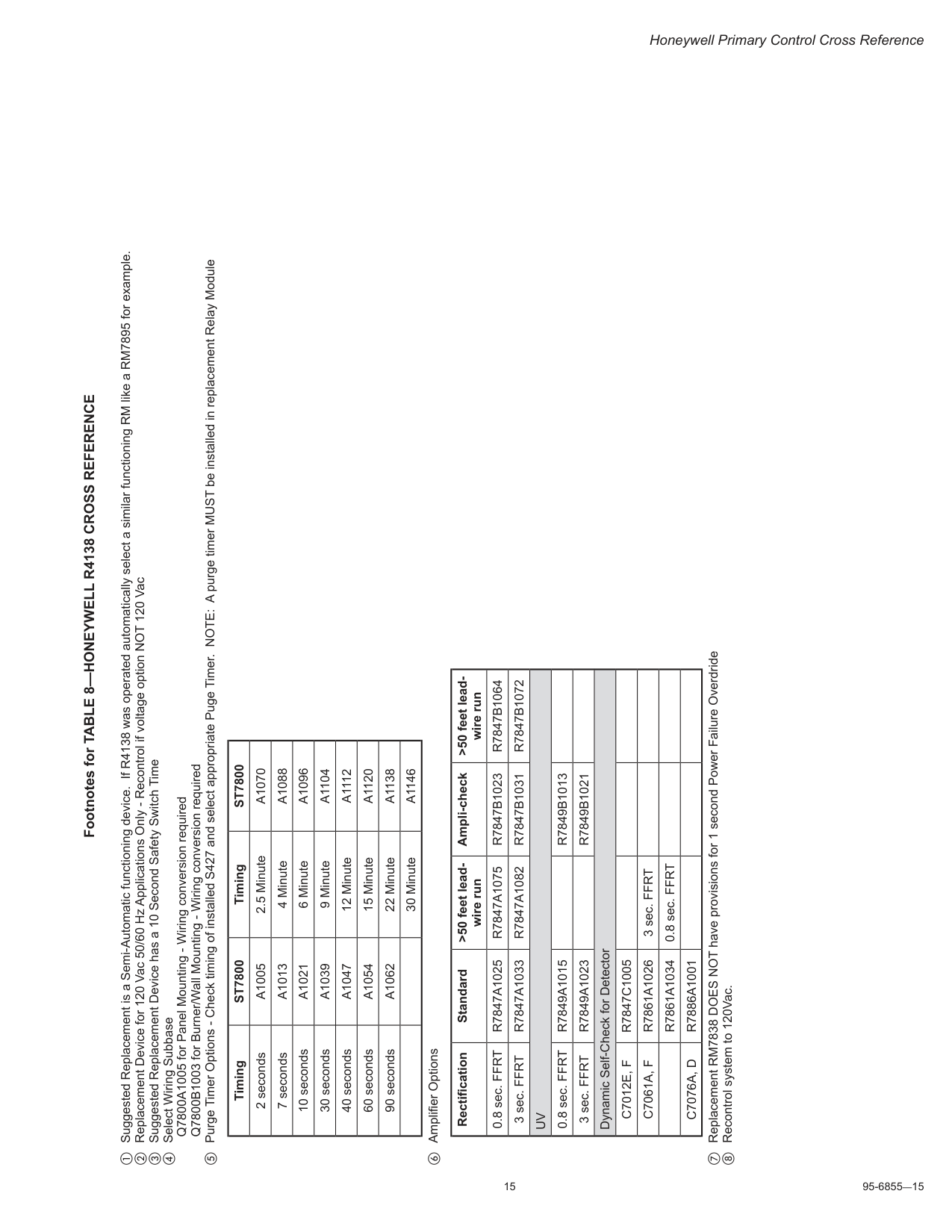
15 95-6855—15 Honeywell Primary Control Cross Reference Footnotes for TABLE 8—HONEYWELL R4138 CROSS REFERENCE a Suggested Replacement is a Semi-Automatic functioning device. If R4138 was operated automatically select a similar functioning RM like a RM7895 for example. b Replacement Device for 120 Vac 50/60 Hz Applications Only - Recontrol if voltage option NOT 120 Vac c Suggested Replacement Device has a 10 Second Safety Switch Time d Select Wiring Subbase Q7800A1005 for Panel Mounting - Wiring conversion required Q7800B1003 for Burner/Wall Mounting - Wiring conversion required e Purge Timer Options - Check timing of installed S427 and select appropriate Puge Timer. NOTE: A purge timer MUST be installed in replacement Relay Module Timing
St7800
TimingSt7800
2 secondsA1005
2.5 MinuteA1070
7 secondsA1013
4 MinuteA1088
10 secondsA1021
6 MinuteA1096
30 secondsA1039
9 MinuteA1104
40 secondsA1047
12 MinuteA1112
60 secondsA1054
15 MinuteA1120
90 secondsA1062
22 MinuteA1138
30 MinuteA1146
f Amplifier Options Rectification Standard >50 feet lead wire run Ampli-check >50 feet lead wire run 0.8 sec. FFRTR7847A1025
R7847A1075
R7847B1023
R7847B1064
3 sec. FFRTR7847A1033
R7847A1082
R7847B1031
R7847B1072
Uv
0.8 sec. FFRTR7849A1015
R7849B1013
3 sec. FFRTR7849A1023
R7849B1021
Dynamic Self-Check for DetectorC7012E, F
R7847C1005
C7061A, F
R7861A1026
3 sec. FFRTR7861A1034
0.8 sec. FFRTC7076A, D
R7886A1001
g Replacement RM7838 DOES NOT have provisions for 1 second Power Failure Overdride h Recontrol system to 120Vac.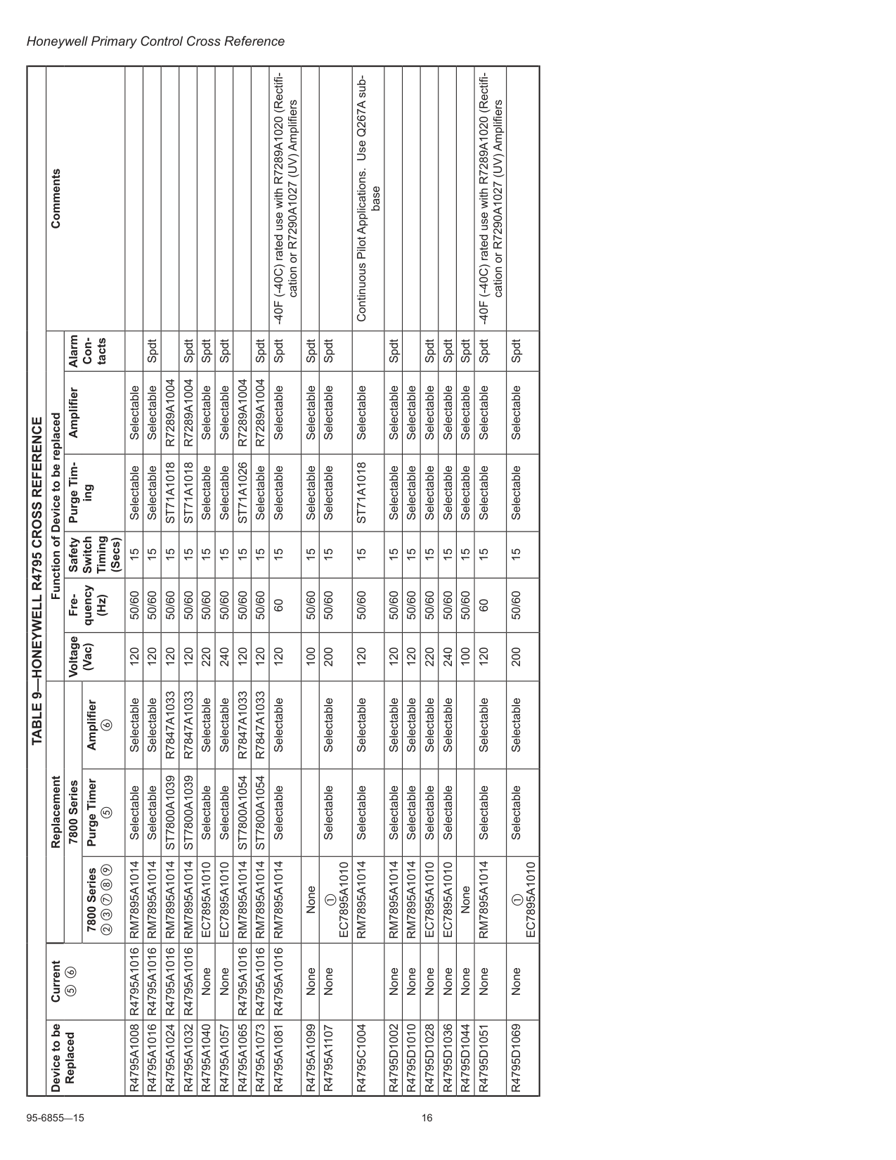
95-6855—15 16 Honeywell Primary Control Cross Reference
Table 9—Honeywell R4795 Cross Reference
Device to be Replaced Current e f Replacement Function of Device to be replaced Comments 7800 Series Voltage (Vac) Fre quency (Hz) Safety Switch Timing (Secs) Purge Tim ing Amplifier Alarm Con tacts 7800 Series b c g h i Purge Timer e Amplifier fR4795A1008 R4795A1016 Rm7895A1014
Selectable Selectable 120 50/60 15 Selectable SelectableR4795A1016 R4795A1016 Rm7895A1014
Selectable Selectable 120 50/60 15 Selectable Selectable SpdtR4795A1024 R4795A1016 Rm7895A1014
St7800A1039
R7847A1033
120 50/60 15St71A1018
R7289A1004
R4795A1032 R4795A1016 Rm7895A1014
St7800A1039
R7847A1033
120 50/60 15St71A1018
R7289A1004
SpdtR4795A1040
NoneEc7895A1010
Selectable Selectable 220 50/60 15 Selectable Selectable SpdtR4795A1057
NoneEc7895A1010
Selectable Selectable 240 50/60 15 Selectable Selectable SpdtR4795A1065 R4795A1016 Rm7895A1014
St7800A1054
R7847A1033
120 50/60 15St71A1026
R7289A1004
R4795A1073 R4795A1016 Rm7895A1014
St7800A1054
R7847A1033
120 50/60 15 SelectableR7289A1004
SpdtR4795A1081 R4795A1016 Rm7895A1014
Selectable Selectable 120 60 15 Selectable Selectable Spdt -40F (-40C) rated use with R7289A1020 (Rectifi cation or R7290A1027 (UV) AmplifiersR4795A1099
None None 100 50/60 15 Selectable Selectable SpdtR4795A1107
None aEc7895A1010
Selectable Selectable 200 50/60 15 Selectable Selectable SpdtR4795C1004
Rm7895A1014
Selectable Selectable 120 50/60 15St71A1018
Selectable Continuous Pilot Applications. Use Q267A sub baseR4795D1002
NoneRm7895A1014
Selectable Selectable 120 50/60 15 Selectable Selectable SpdtR4795D1010
NoneRm7895A1014
Selectable Selectable 120 50/60 15 Selectable SelectableR4795D1028
NoneEc7895A1010
Selectable Selectable 220 50/60 15 Selectable Selectable SpdtR4795D1036
NoneEc7895A1010
Selectable Selectable 240 50/60 15 Selectable Selectable SpdtR4795D1044
None None 100 50/60 15 Selectable Selectable SpdtR4795D1051
NoneRm7895A1014
Selectable Selectable 120 60 15 Selectable Selectable Spdt -40F (-40C) rated use with R7289A1020 (Rectifi cation or R7290A1027 (UV) AmplifiersR4795D1069
None aEc7895A1010
Selectable Selectable 200 50/60 15 Selectable Selectable Spdt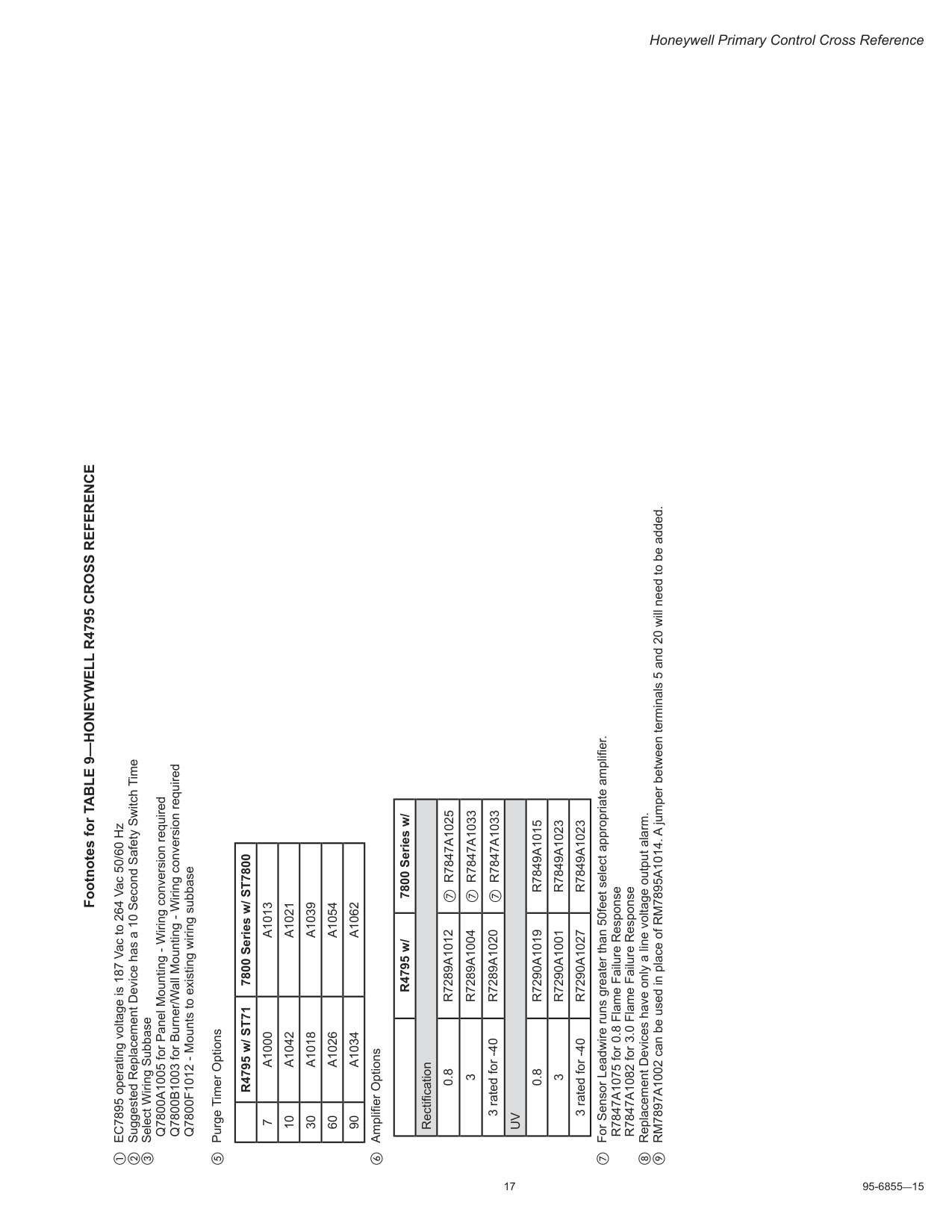
17 95-6855—15 Honeywell Primary Control Cross Reference Footnotes for TABLE 9—HONEYWELL R4795 CROSS REFERENCE a EC7895 operating voltage is 187 Vac to 264 Vac 50/60 Hz b Suggested Replacement Device has a 10 Second Safety Switch Time c Select Wiring Subbase Q7800A1005 for Panel Mounting - Wiring conversion required Q7800B1003 for Burner/Wall Mounting - Wiring conversion required Q7800F1012 - Mounts to existing wiring subbase e Purge Timer Options R4795 w/ ST71 7800 Series w/ ST7800 7
A1000
A1013
10A1042
A1021
30A1018
A1039
60A1026
A1054
90A1034
A1062
f Amplifier Options R4795 w/ 7800 Series w/ Rectification 0.8R7289A1012
g R7847A1025 3R7289A1004
g R7847A1033 3 rated for -40R7289A1020
g R7847A1033Uv
0.8R7290A1019
R7849A1015
3R7290A1001
R7849A1023
3 rated for -40R7290A1027
R7849A1023
g For Sensor Leadwire runs greater than 50feet select appropriate amplifier. R7847A1075 for 0.8 Flame Failure Response R7847A1082 for 3.0 Flame Failure Response h Replacement Devices have only a line voltage output alarm. i RM7897A1002 can be used in place of RM7895A1014. A jumper between terminals 5 and 20 will need to be added.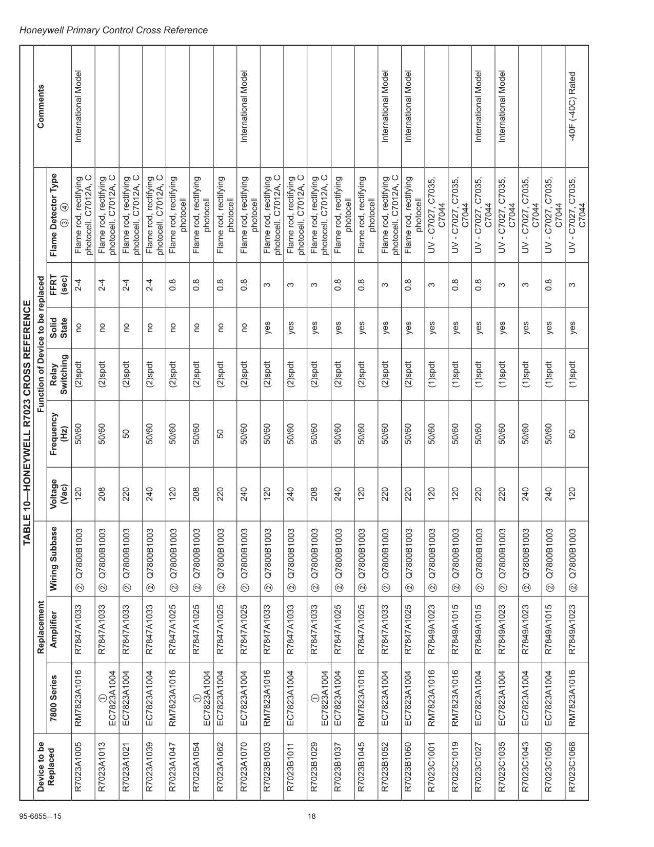
95-6855—15 18 Honeywell Primary Control Cross Reference
Table 10—Honeywell R7023 Cross Reference
Device to be Replaced Replacement Function of Device to be replaced Comments 7800 Series Amplifier Wiring Subbase Voltage (Vac) Frequency (Hz) Relay Switching Solid StateFfrt
(sec) Flame Detector Type c dR7023A1005
Rm7823A1016
R7847A1033
b Q7800B1003 120 50/60 (2)spdt no 2-4 Flame rod, rectifying photocell, C7012A, C International ModelR7023A1013
aEc7823A1004
R7847A1033
b Q7800B1003 208 50/60 (2)spdt no 2-4 Flame rod, rectifying photocell, C7012A, CR7023A1021
Ec7823A1004
R7847A1033
b Q7800B1003 220 50 (2)spdt no 2-4 Flame rod, rectifying photocell, C7012A, CR7023A1039
Ec7823A1004
R7847A1033
b Q7800B1003 240 50/60 (2)spdt no 2-4 Flame rod, rectifying photocell, C7012A, CR7023A1047
Rm7823A1016
R7847A1025
b Q7800B1003 120 50/60 (2)spdt no 0.8 Flame rod, rectifying photocellR7023A1054
aEc7823A1004
R7847A1025
b Q7800B1003 208 50/60 (2)spdt no 0.8 Flame rod, rectifying photocellR7023A1062
Ec7823A1004
R7847A1025
b Q7800B1003 220 50 (2)spdt no 0.8 Flame rod, rectifying photocellR7023A1070
Ec7823A1004
R7847A1025
b Q7800B1003 240 50/60 (2)spdt no 0.8 Flame rod, rectifying photocell International ModelR7023B1003
Rm7823A1016
R7847A1033
b Q7800B1003 120 50/60 (2)spdt yes 3 Flame rod, rectifying photocell, C7012A, CR7023B1011
Ec7823A1004
R7847A1033
b Q7800B1003 240 50/60 (2)spdt yes 3 Flame rod, rectifying photocell, C7012A, CR7023B1029
aEc7823A1004
R7847A1033
b Q7800B1003 208 50/60 (2)spdt yes 3 Flame rod, rectifying photocell, C7012A, CR7023B1037
Ec7823A1004
R7847A1025
b Q7800B1003 240 50/60 (2)spdt yes 0.8 Flame rod, rectifying photocellR7023B1045
Rm7823A1016
R7847A1025
b Q7800B1003 120 50/60 (2)spdt yes 0.8 Flame rod, rectifying photocellR7023B1052
Ec7823A1004
R7847A1033
b Q7800B1003 220 50/60 (2)spdt yes 3 Flame rod, rectifying photocell, C7012A, C International ModelR7023B1060
Ec7823A1004
R7847A1025
b Q7800B1003 220 50/60 (2)spdt yes 0.8 Flame rod, rectifying photocell International ModelR7023C1001
Rm7823A1016
R7849A1023
b Q7800B1003 120 50/60 (1)spdt yes 3Uv - C7027, C7035,
C7044
R7023C1019
Rm7823A1016
R7849A1015
b Q7800B1003 120 50/60 (1)spdt yes 0.8Uv - C7027, C7035,
C7044
R7023C1027
Ec7823A1004
R7849A1015
b Q7800B1003 220 50/60 (1)spdt yes 0.8Uv - C7027, C7035,
C7044
International ModelR7023C1035
Ec7823A1004
R7849A1023
b Q7800B1003 220 50/60 (1)spdt yes 3Uv - C7027, C7035,
C7044
International ModelR7023C1043
Ec7823A1004
R7849A1023
b Q7800B1003 240 50/60 (1)spdt yes 3Uv - C7027, C7035,
C7044
R7023C1050
Ec7823A1004
R7849A1015
b Q7800B1003 240 50/60 (1)spdt yes 0.8Uv - C7027, C7035,
C7044
R7023C1068
Rm7823A1016
R7849A1023
b Q7800B1003 120 60 (1)spdt yes 3Uv - C7027, C7035,
C7044
-40F (-40C) Rated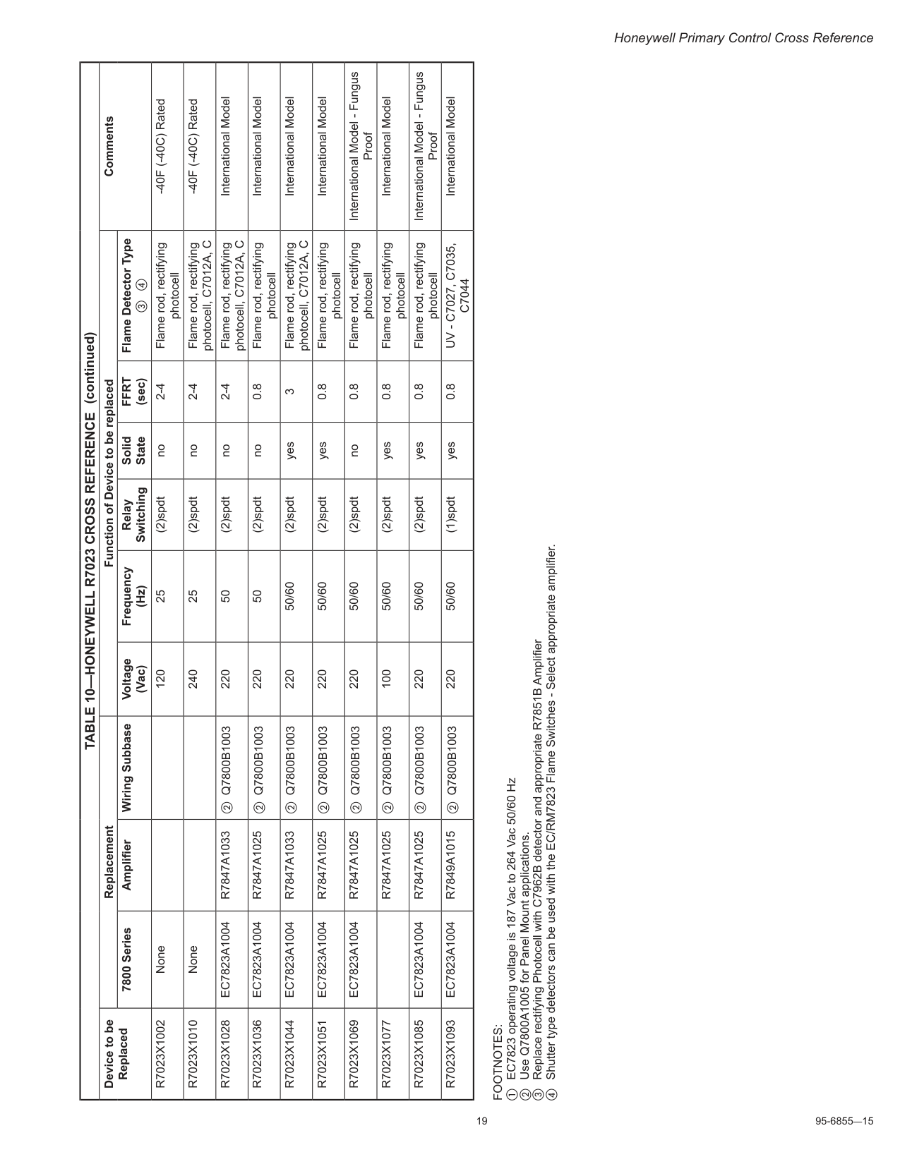
19 95-6855—15 Honeywell Primary Control Cross Reference
Footnotes:
a EC7823 operating voltage is 187 Vac to 264 Vac 50/60 Hz b Use Q7800A1005 for Panel Mount applications. c Replace rectifying Photocell with C7962B detector and appropriate R7851B Amplifier d Shutter type detectors can be used with the EC/RM7823 Flame Switches - Select appropriate amplifier.Table 10—Honeywell R7023 Cross Reference
Device to be Replaced Replacement Function of Device to be replaced Comments 7800 Series Amplifier Wiring Subbase Voltage (Vac) Frequency (Hz) Relay Switching Solid StateFfrt
(sec) Flame Detector Type c dR7023X1002
None 120 25 (2)spdt no 2-4 Flame rod, rectifying photocell -40F (-40C) RatedR7023X1010
None 240 25 (2)spdt no 2-4 Flame rod, rectifying photocell, C7012A, C -40F (-40C) RatedR7023X1028
Ec7823A1004
R7847A1033
b Q7800B1003 220 50 (2)spdt no 2-4 Flame rod, rectifying photocell, C7012A, C International ModelR7023X1036
Ec7823A1004
R7847A1025
b Q7800B1003 220 50 (2)spdt no 0.8 Flame rod, rectifying photocell International ModelR7023X1044
Ec7823A1004
R7847A1033
b Q7800B1003 220 50/60 (2)spdt yes 3 Flame rod, rectifying photocell, C7012A, C International ModelR7023X1051
Ec7823A1004
R7847A1025
b Q7800B1003 220 50/60 (2)spdt yes 0.8 Flame rod, rectifying photocell International ModelR7023X1069
Ec7823A1004
R7847A1025
b Q7800B1003 220 50/60 (2)spdt no 0.8 Flame rod, rectifying photocell International Model - Fungus ProofR7023X1077
R7847A1025
b Q7800B1003 100 50/60 (2)spdt yes 0.8 Flame rod, rectifying photocell International ModelR7023X1085
Ec7823A1004
R7847A1025
b Q7800B1003 220 50/60 (2)spdt yes 0.8 Flame rod, rectifying photocell International Model - Fungus ProofR7023X1093
Ec7823A1004
R7849A1015
b Q7800B1003 220 50/60 (1)spdt yes 0.8Uv - C7027, C7035,
C7044
International Model (continued)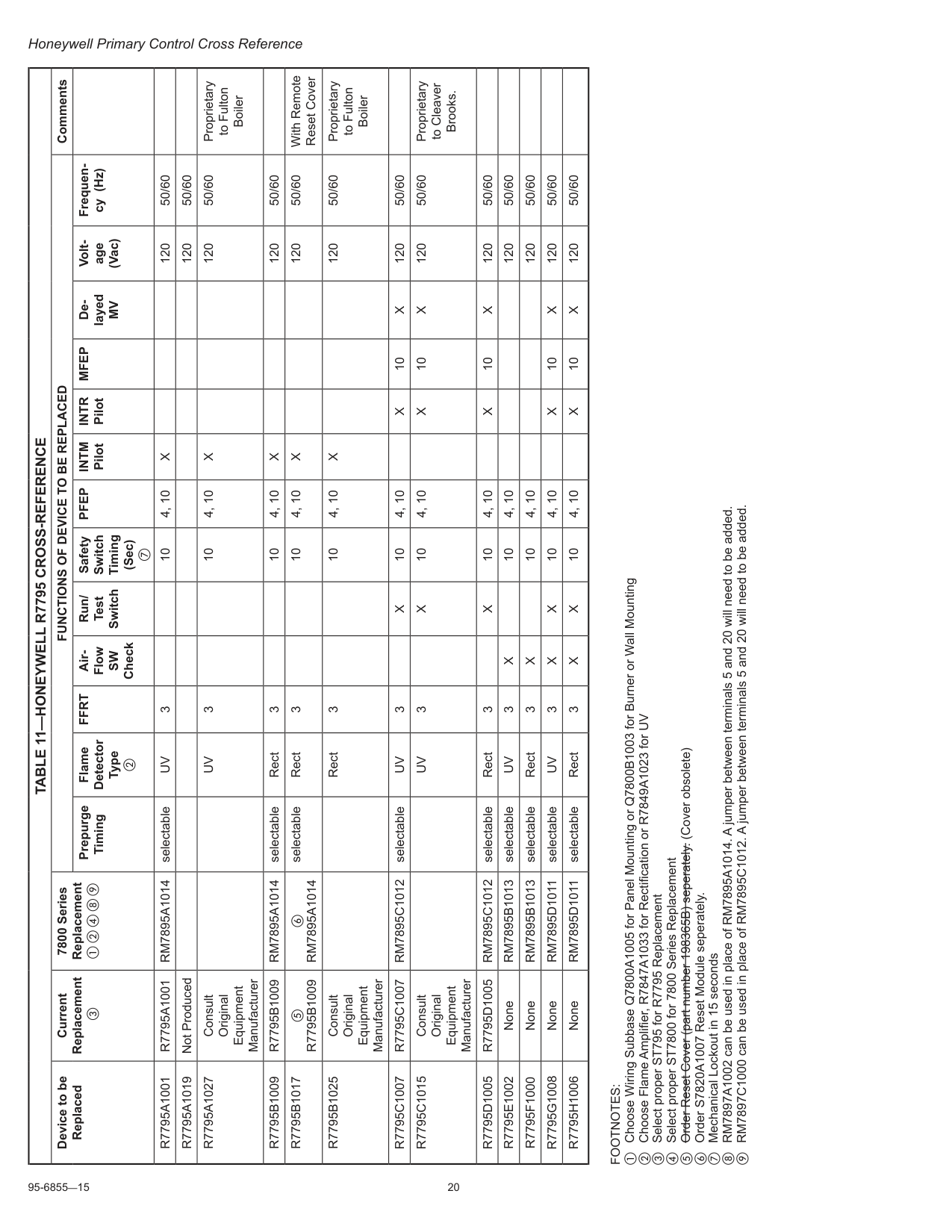
95-6855—15 20 Honeywell Primary Control Cross Reference
Table 11—Honeywell R7795 Cross-Reference
Device to be Replaced Current Replacement c 7800 Series Replacement a b d h iFunctions Of Device To Be Replaced
Comments Prepurge Timing Flame Detector Type bFfrt
Air- FlowSw
Check Run/ Test Switch Safety Switch Timing (Sec) gPfep
Intm
PilotIntr
PilotMfep
De layedMv
Volt age (Vac) Frequen cy (Hz)R7795A1001
R7795A1001
Rm7895A1014
selectableUv
3 10 4, 10X
120 50/60R7795A1019
Not Produced 120 50/60R7795A1027
Consult Original Equipment ManufacturerUv
3 10 4, 10X
120 50/60 Proprietary to Fulton BoilerR7795B1009
R7795B1009
Rm7895A1014
selectable Rect 3 10 4, 10X
120 50/60R7795B1017
eR7795B1009
fRm7895A1014
selectable Rect 3 10 4, 10X
120 50/60 With Remote Reset CoverR7795B1025
Consult Original Equipment Manufacturer Rect 3 10 4, 10X
120 50/60 Proprietary to Fulton BoilerR7795C1007
R7795C1007
Rm7895C1012
selectableUv
3X
10 4, 10X
10X
120 50/60R7795C1015
Consult Original Equipment ManufacturerUv
3X
10 4, 10X
10X
120 50/60 Proprietary to Cleaver Brooks.R7795D1005
R7795D1005
Rm7895C1012
selectable Rect 3X
10 4, 10X
10X
120 50/60R7795E1002
NoneRm7895B1013
selectableUv
3X
10 4, 10 120 50/60R7795F1000
NoneRm7895B1013
selectable Rect 3X
10 4, 10 120 50/60R7795G1008
NoneRm7895D1011
selectableUv
3X
X
10 4, 10X
10X
120 50/60R7795H1006
NoneRm7895D1011
selectable Rect 3X
X
10 4, 10X
10X
120 50/60Footnotes:
a Choose Wiring Subbase Q7800A1005 for Panel Mounting or Q7800B1003 for Burner or Wall Mounting b Choose Flame Amplifier, R7847A1033 for Rectification or R7849A1023 for UV c Select proper ST795 for R7795 Replacement d Select proper ST7800 for 7800 Series Replacement e Order Reset Cover (part number 198365B) seperately. (Cover obsolete) f Order S7820A1007 Reset Module seperately. g Mechanical Lockout in 15 seconds h RM7897A1002 can be used in place of RM7895A1014. A jumper between terminals 5 and 20 will need to be added. i RM7897C1000 can be used in place of RM7895C1012. A jumper between terminals 5 and 20 will need to be added.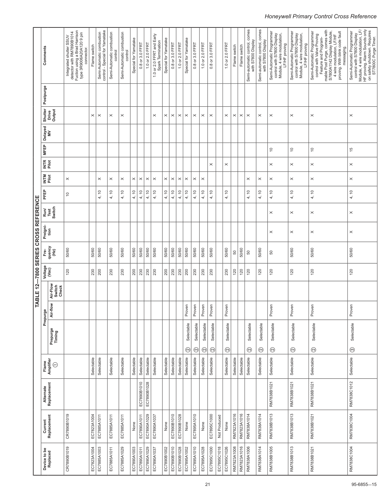
21 95-6855—15 Honeywell Primary Control Cross Reference
Table 12—7800 Series Cross Reference
Device to be Replaced Current Replacement Alternate Replacement Flame Amplifier a Prepurge Voltage (Vac) Fre quency (Hz) Preigni tion Run/ Test SwitchPfep
Intm
PilotIntr
PilotMfep
DelayedMv
Shutter Drive Output Postpurge Comments Prepurge Timing Air-flow Air-Flow Switch CheckCr7890B1019
Cr7890B1019
120 50/60 10X
Integrated shutter SSUV detector with RM7890B1014 Fuction using a Brad Harrison type 3R9006A20A120 9 pin connector.Ec7823A1004
Ec7823A1004
Selectable 230 50/60X
Flame switchEc7885A1003
Ec7885A1011
Selectable 200 50/60 4, 10X
X
Semi-Automatic combustion control - Special for YamatakeEc7885A1011
Ec7885A1011
Selectable 230 50/60 4, 10X
X
Semi-Automatic combustion controlEc7885A1029
Ec7885A1011
Selectable 230 50/60 4, 10X
X
Semi-Automatic combustion controlEc7890A1003
None Selectable 200 50/60 4, 10X
Special for YamatakeEc7890A1011
Ec7890A1011
Ec7890B1010
Selectable 230 50/60 4, 10X
0.8 or 3.0 FFRTEc7890A1029
Ec7890A1029
Ec7890B1028
Selectable 230 50/60 4, 10X
1.0 or 2.0 FFRTEc7890A1037
Ec7890A1037
Selectable 230 50/60 4, 10X
X
1.0 or 2.0 FFRT and Early Spark TerminationEc7890B1002
None Selectable 200 50/60 4, 10X
X
Special for YamatakeEc7890B1010
Ec7890B1010
Selectable 230 50/60 4, 10X
X
0.8 or 3.0 FFRTEc7890B1028
Ec7890B1028
Selectable 230 50/60 4, 10X
X
1.0 or 2.0 FFRTEc7895A1002
None Selectable b Selectable Proven 200 50/60 4, 10X
X
Special for YamatakeEc7895A1010
Ec7895A1010
Selectable b Selectable Proven 230 50/60 4, 10X
X
0.8 or 3.0 FFRTEc7895A1028
None Selectable b Selectable Proven 230 50/60 4, 10X
X
1.0 or 2.0 FFRTEc7895C1000
Ec7895C1000
Selectable b Selectable Proven 230 50/60 4, 10X
X
0.8 or 3.0 FFRTEc7895C1018
Not ProducedEc7895C1026
None Selectable b Selectable Proven 230 50/60 4, 10X
X
1.0 or 2.0 FFRTRm7823A1008
Rm7823A1016
Selectable 120 50X
Flame switchRm7823A1016
Rm7823A1016
Selectable 120 50/60X
Flame switchRm7838A1006
Rm7838A1014
Selectable b Selectable 120 50 4, 10X
X
Semi-automatic control, comes with S7800 DisplayRm7838A1014
Rm7838A1014
Selectable b Selectable 120 50/60 4, 10X
X
Semi-automatic control, comes with S7800 DisplayRm7838B1005
Rm7838B1013
Rm7838B1021
Selectable b Selectable Proven 120 50X
X
4, 10X
X
10X
Semi-Automatic Programmer control with S7800 Display Module, 4 wire modulation, LF/HF provingRm7838B1013
Rm7838B1013
Rm7838B1021
Selectable b Selectable Proven 120 50/60X
X
4, 10X
X
10X
Semi-Automatic Programmer control with S7800 Display Module, 4 wire modulation, LF/HF provingRm7838B1021
Rm7838B1021
Rm7838B1021
Selectable b Selectable Proven 120 50/60X
X
4, 10X
X
10X
Semi-Automatic Programmer control with Valve Proving Feature and Program mable Post Purge, comes with S7800A1142 Display Module, 4 wire modulation, LF/HF proving. With blink code fault messaging.Rm7838C1004
Rm7838C1004
Rm7838C1012
Selectable c Selectable Proven 120 50/60X
X
4, 10X
X
15X
Semi-Automatic Programmer control with S7800 Display Module, 4 wire modulation, LF/ HF proving. Alarm Sounds only on safety shutdown. Requires ST7800C Purge Timer.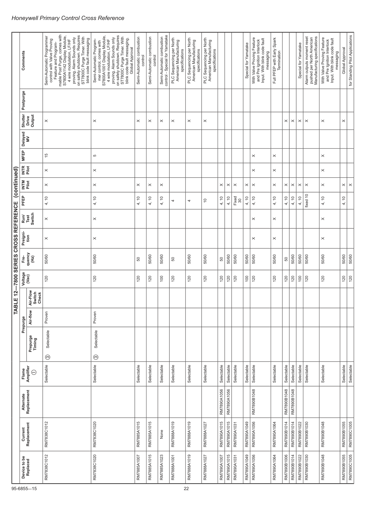
95-6855—15 22 Honeywell Primary Control Cross Reference
Table 12—7800 Series Cross Reference
Device to be Replaced Current Replacement Alternate Replacement Flame Amplifier a Prepurge Voltage (Vac) Fre quency (Hz) Preigni tion Run/ Test SwitchPfep
Intm
PilotIntr
PilotMfep
DelayedMv
Shutter Drive Output Postpurge Comments Prepurge Timing Air-flow Air-Flow Switch CheckRm7838C1012
Rm7838C1012
Selectable c Selectable Proven 120 50/60X
X
4, 10X
X
15X
Semi-Automatic Programmer control with Valve Proving Feature and Program mable Post Purge, comes with S7800A1142 Display Module, 4 wire modulation, LF/HF proving. Alarm Sounds only on safety shutdown. Requires ST7800C Purge Timer. With blink code fault messagingRm7838C1020
Rm7838C1020
Selectable c Selectable Proven 120 50/60X
X
4, 10X
X
5X
Semi-Automatic Program mer control, comes with S7800A1001 Display Module, 4 wire modulation, LF/HF proving. Alarm Sounds only on safety shutdown. Requires ST7800C Purge Timer. With blink code fault messaging. Global ApprovalRm7885A1007
Rm7885A1015
Selectable 120 50 4, 10X
X
Semi-Automatic combustion controlRm7885A1015
Rm7885A1015
Selectable 120 50/60 4, 10X
X
Semi-Automatic combustion controlRm7885A1023
None Selectable 100 50/60 4, 10X
X
Semi-Automatic combustion control - Special for YamatakeRm7888A1001
Rm7888A1019
Selectable 120 50 4X
PLC Sequencing per North American Manufacturing specificationsRm7888A1019
Rm7888A1019
Selectable 120 50/60 4X
PLC Sequencing per North American Manufacturing specificationsRm7888A1027
Rm7888A1027
Selectable 120 50/60 10X
PLC Sequencing per North American Manufacturing specificationsRm7890A1007
Rm7890A1015
Rm7890A1056
Selectable 120 50 4, 10X
Rm7890A1015
Rm7890A1015
Rm7890A1056
Selectable 120 50/60 4, 10X
Rm7890A1031
Rm7890A1031
Selectable 120 50/60 Fixed 30X
Rm7890A1049
Rm7890A1049
Selectable 100 50/60 4, 10X
Special for YamatakeRm7890A1056
Rm7890A1056
Rm7890B1048
Selectable 120 50/60X
X
4, 10X
X
X
With Valve Proving Feature and Pre Ignition Interlock Input. With blink code fault messagingRm7890A1064
Rm7890A1064
Selectable 120 50/60X
X
4, 10X
X
X
Full PFEP with Early Spark TerminationRm7890B1006
Rm7890B1014
Rm7890B1048
Selectable 120 50 4, 10X
X
Rm7890B1014
Rm7890B1014
Rm7890B1048
Selectable 120 50/60 4, 10X
X
Rm7890B1022
Rm7890B1022
Selectable 100 50/60 4, 10X
X
Special for YamatakeRm7890B1030
Rm7890B1030
Selectable 120 50/60 fixed 10X
X
Alarm outputs moment reset pushed per North American Manufacturing specificationsRm7890B1048
Rm7890B1048
Selectable 120 50/60X
X
4, 10X
X
X
X
With Valve Proving Feature and Pre Ignition Interlock Input. With blink code fault messagingRm7890B1055
Rm7890B1055
Selectable 120 50/60 4, 10X
X
Global ApprovalRm7890C1005
Rm7890C1005
Selectable 120 50/60X
for Standing Pilot Applications (continued)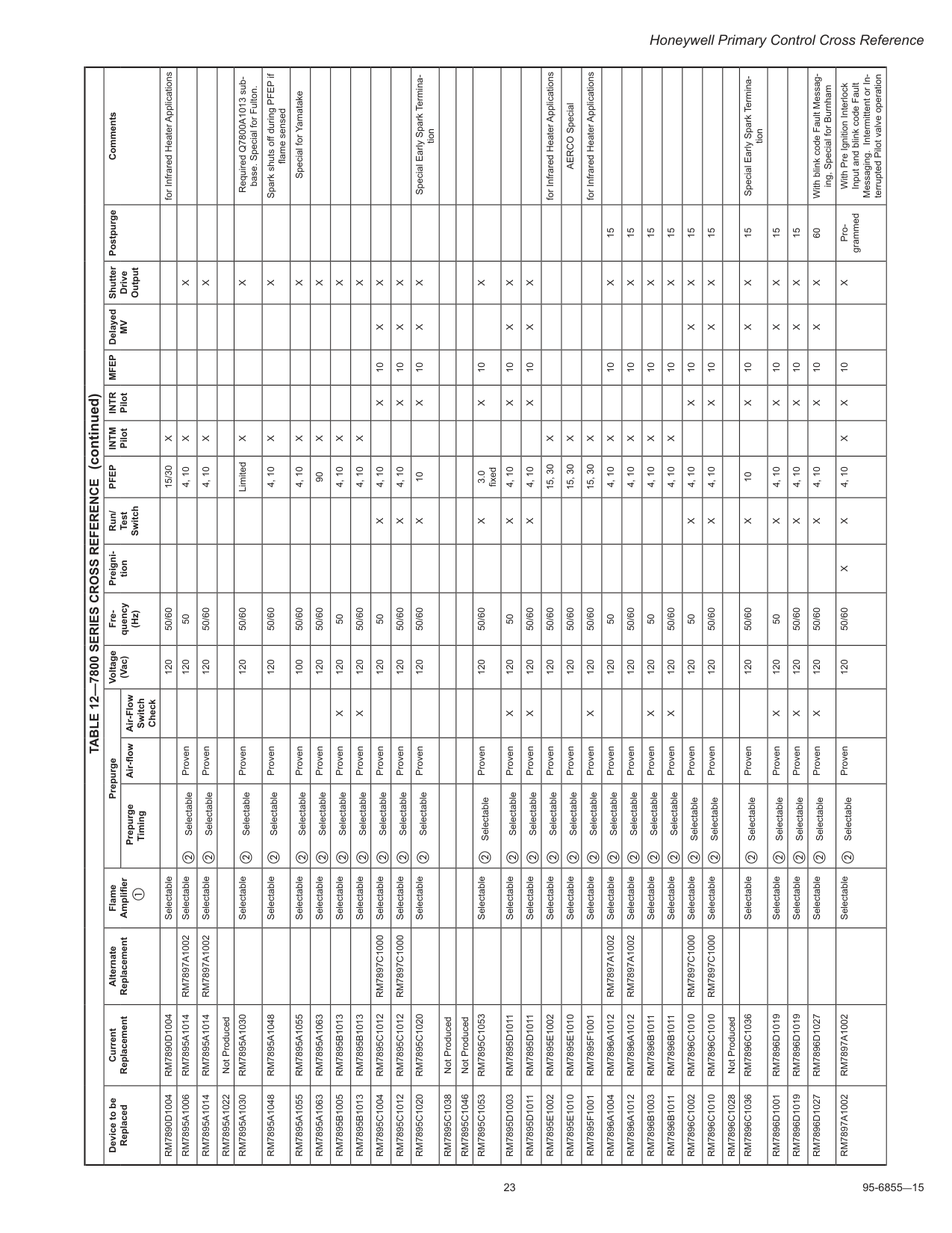
23 95-6855—15 Honeywell Primary Control Cross Reference
Table 12—7800 Series Cross Reference
Device to be Replaced Current Replacement Alternate Replacement Flame Amplifier a Prepurge Voltage (Vac) Fre quency (Hz) Preigni tion Run/ Test SwitchPfep
Intm
PilotIntr
PilotMfep
DelayedMv
Shutter Drive Output Postpurge Comments Prepurge Timing Air-flow Air-Flow Switch CheckRm7890D1004
Rm7890D1004
Selectable 120 50/60 15/30X
for Infrared Heater ApplicationsRm7895A1006
Rm7895A1014
Rm7897A1002
Selectable b Selectable Proven 120 50 4, 10X
X
Rm7895A1014
Rm7895A1014
Rm7897A1002
Selectable b Selectable Proven 120 50/60 4, 10X
X
Rm7895A1022
Not ProducedRm7895A1030
Rm7895A1030
Selectable b Selectable Proven 120 50/60 LimitedX
X
Required Q7800A1013 sub base. Special for Fulton.Rm7895A1048
Rm7895A1048
Selectable b Selectable Proven 120 50/60 4, 10X
X
Spark shuts off during PFEP if flame sensedRm7895A1055
Rm7895A1055
Selectable b Selectable Proven 100 50/60 4, 10X
X
Special for YamatakeRm7895A1063
Rm7895A1063
Selectable b Selectable Proven 120 50/60 90X
X
Rm7895B1005
Rm7895B1013
Selectable b Selectable ProvenX
120 50 4, 10X
X
Rm7895B1013
Rm7895B1013
Selectable b Selectable ProvenX
120 50/60 4, 10X
X
Rm7895C1004
Rm7895C1012
Rm7897C1000
Selectable b Selectable Proven 120 50X
4, 10X
10X
X
Rm7895C1012
Rm7895C1012
Rm7897C1000
Selectable b Selectable Proven 120 50/60X
4, 10X
10X
X
Rm7895C1020
Rm7895C1020
Selectable b Selectable Proven 120 50/60X
10X
10X
X
Special Early Spark Termina tionRm7895C1038
Not ProducedRm7895C1046
Not ProducedRm7895C1053
Rm7895C1053
Selectable b Selectable Proven 120 50/60X
3.0 fixedX
10X
Rm7895D1003
Rm7895D1011
Selectable b Selectable ProvenX
120 50X
4, 10X
10X
X
Rm7895D1011
Rm7895D1011
Selectable b Selectable ProvenX
120 50/60X
4, 10X
10X
X
Rm7895E1002
Rm7895E1002
Selectable b Selectable Proven 120 50/60 15, 30X
for Infrared Heater ApplicationsRm7895E1010
Rm7895E1010
Selectable b Selectable Proven 120 50/60 15, 30X
AERCO SpecialRm7895F1001
Rm7895F1001
Selectable b Selectable ProvenX
120 50/60 15, 30X
for Infrared Heater ApplicationsRm7896A1004
Rm7896A1012
Rm7897A1002
Selectable b Selectable Proven 120 50 4, 10X
10X
15Rm7896A1012
Rm7896A1012
Rm7897A1002
Selectable b Selectable Proven 120 50/60 4, 10X
10X
15Rm7896B1003
Rm7896B1011
Selectable b Selectable ProvenX
120 50 4, 10X
10X
15Rm7896B1011
Rm7896B1011
Selectable b Selectable ProvenX
120 50/60 4, 10X
10X
15Rm7896C1002
Rm7896C1010
Rm7897C1000
Selectable b Selectable Proven 120 50X
4, 10X
10X
X
15Rm7896C1010
Rm7896C1010
Rm7897C1000
Selectable b Selectable Proven 120 50/60X
4, 10X
10X
X
15Rm7896C1028
Not ProducedRm7896C1036
Rm7896C1036
Selectable b Selectable Proven 120 50/60X
10X
10X
X
15 Special Early Spark Termina tionRm7896D1001
Rm7896D1019
Selectable b Selectable ProvenX
120 50X
4, 10X
10X
X
15Rm7896D1019
Rm7896D1019
Selectable b Selectable ProvenX
120 50/60X
4, 10X
10X
X
15Rm7896D1027
Rm7896D1027
Selectable b Selectable ProvenX
120 50/60X
4, 10X
10X
X
60 With blink code Fault Messag ing, Special for BurnhamRm7897A1002
Rm7897A1002
Selectable b Selectable Proven 120 50/60X
X
4, 10X
X
10X
Pro grammed With Pre Ignition Interlock Input and blink code Fault Messaging. Intermittent or In terrupted Pilot valve operation (continued)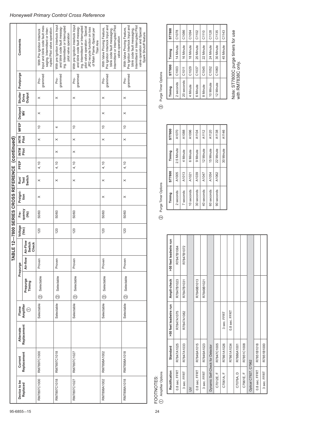
95-6855—15 24 Honeywell Primary Control Cross Reference
Footnotes:
a Amplifier Options Rectification Standard >50 feet leadwire run Ampli-check >50 feet leadwire run 0.8 sec. FFRTR7847A1025
R7847A1075
R7847B1023
R7847B1064
3 sec. FFRTR7847A1033
R7847A1082
R7847B1031
R7847B1072
Uv
0.8 sec. FFRTR7849A1015
R7849B1013
3 sec. FFRTR7849A1023
R7849B1021
Dynamic Self-Check for DetectorC7012E, F
R7847C1005
C7061A, F
R7861A1026
3 sec. FFRTR7861A1034
0.8 sec. FFRTC7076A, D
R7886A1001
C7961E, F
R7851C1008
Optical C7927, C7962 0.8 sec. FFRTR7851B1018
3 sec. FFRTR7851B1000
c Purge Timer Options TimingSt7800
TimingSt7800
2 secondsC1003
14 MinuteC1078
20 secondsC1011
16 MinuteC1086
4 MinuteC1029
18 MinuteC1094
6 MinuteC1037
20 MinuteC1102
8 MinuteC1045
22 MinuteC1110
10 MinuteC1052
24 MinuteC1128
12 MinuteC1060
30 MinuteC1135
45 MinuteC1143
Note: ST7800C purge timers for use with RM7838C only. b Purge Timer Options TimingSt7800
TimingSt7800
2 secondsA1005
2.5 MinuteA1070
7 secondsA1013
4 MinuteA1088
10 secondsA1021
6 MinuteA1096
30 secondsA1039
9 MinuteA1104
40 secondsA1047
12 MinuteA1112
60 secondsA1054
15 MinuteA1120
90 secondsA1062
22 MinuteA1138
30 MinuteA1146
Table 12—7800 Series Cross Reference
Device to be Replaced Current Replacement Alternate Replacement Flame Amplifier a Prepurge Voltage (Vac) Fre quency (Hz) Preigni tion Run/ Test SwitchPfep
Intm
PilotIntr
PilotMfep
DelayedMv
Shutter Drive Output Postpurge Comments Prepurge Timing Air-flow Air-Flow Switch CheckRm7897C1000
Rm7897C1000
Selectable b Selectable Proven 120 50/60X
X
4, 10X
10X
X
Pro grammed With Pre Ignition Interlock Input and blink code fault mes saging. Intermittent or Inter rupted Pilot valve operationRm7897C1018
Rm7897C1018
Selectable b Selectable Proven 120 50/60X
4, 10X
X
4X
Pro grammed With pre Ignition Interlock Input and blink code fault messag ing. Intermittent or Interrupted pilot valve operationRm7897C1027
Rm7897C1027
Selectable b Selectable Proven 120 50/60X
4, 10X
X
10X
Pro grammed With pre Ignition Interlock Input and blink code fault messag ing. Intermittent or Interrupted pilot valve operation - Special JR2 recycle function on loss of Main Flame.-Special per Titan AireRm7898A1002
Rm7898A1002
Selectable b Selectable Proven 120 50/60X
X
4, 10X
10X
X
Pro grammed With Valve Proving Feature, Pre Ignition Interlock Input and blink code fault messaging. Intermittent or Interrupted Pilot valve operationRm7898A1018
Rm7898A1018
Selectable b Selectable Proven 120 50/60X
X
4, 10X
10X
X
Pro grammed With Valve Proving Feature, Pre Ignition Interlock Input and blink code fault messaging. Intermittent or Interrupted Pilot valve operation and Special Spark Shutoff feature. (continued)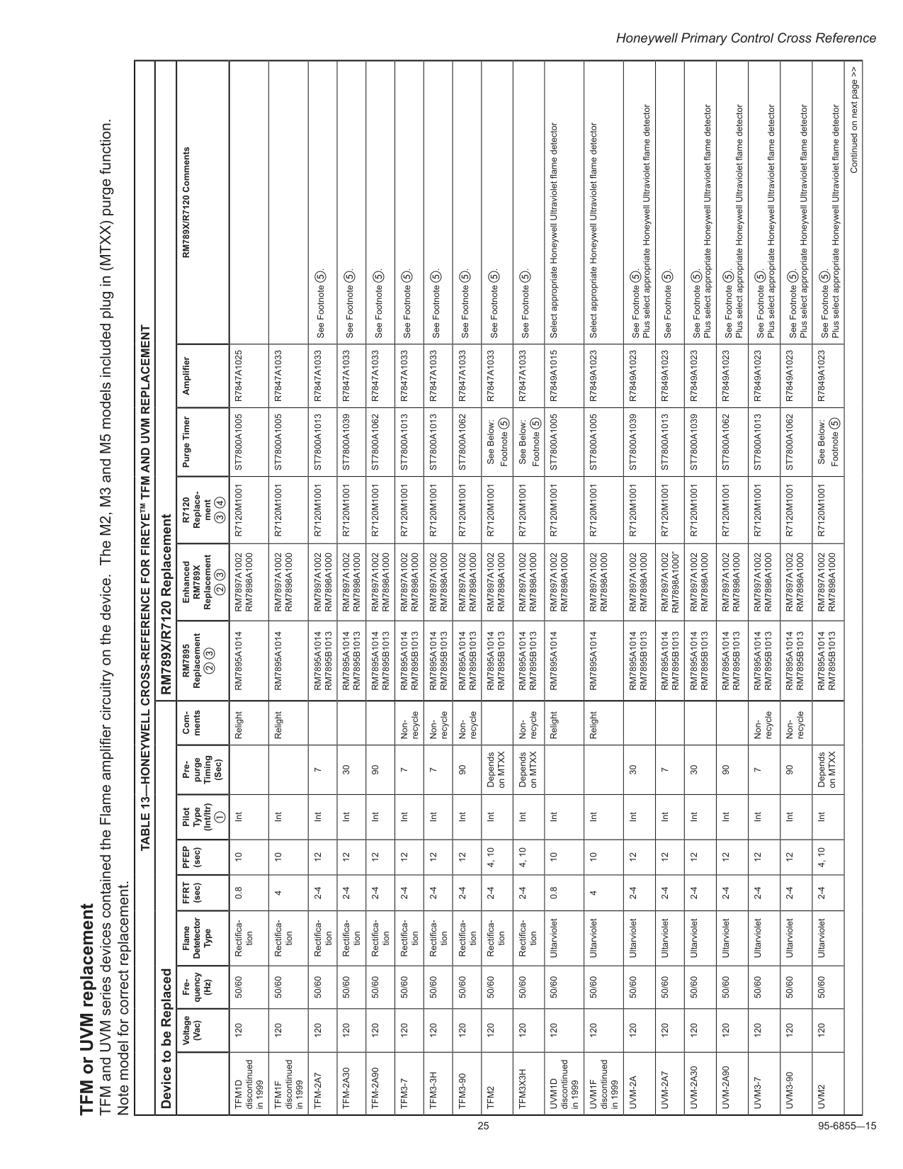
25 95-6855—15 Honeywell Primary Control Cross Reference TFM or UVM replacement TFM and UVM series devices contained the Flame amplifier circuitry on the device. The M2, M3 and M5 models included plug in (MTXX) purge function. Note model for correct replacement.
Table 13—Honeywell Cross-Reference For Fireyetm Tfm And Uvm Replacement
Device to be Replaced RM789X/R7120 Replacement Voltage (Vac) Fre quency (Hz) Flame Detetector TypeFfrt
(sec)Pfep
(sec) Pilot Type (Int/Itr) a Pre purge Timing (Sec) Com mentsRm7895
Replacement b c EnhancedRm789X
Replacement b cR7120
Replace ment c d Purge Timer Amplifier RM789X/R7120 CommentsTfm1D
discontinued in 1999 120 50/60 Rectifica tion 0.8 10 Int RelightRm7895A1014
Rm7897A1002
Rm7898A1000
R7120M1001
St7800A1005
R7847A1025
Tfm1F
discontinued in 1999 120 50/60 Rectifica tion 4 10 Int RelightRm7895A1014
Rm7897A1002
Rm7898A1000
R7120M1001
St7800A1005
R7847A1033
Tfm-2A7
120 50/60 Rectifica tion 2-4 12 Int 7Rm7895A1014
Rm7895B1013
Rm7897A1002
Rm7898A1000
R7120M1001
St7800A1013
R7847A1033
See Footnote e.Tfm-2A30
120 50/60 Rectifica tion 2-4 12 Int 30Rm7895A1014
Rm7895B1013
Rm7897A1002
Rm7898A1000
R7120M1001
St7800A1039
R7847A1033
See Footnote e.Tfm-2A90
120 50/60 Rectifica tion 2-4 12 Int 90Rm7895A1014
Rm7895B1013
Rm7897A1002
Rm7898A1000
R7120M1001
St7800A1062
R7847A1033
See Footnote e.Tfm3-7
120 50/60 Rectifica tion 2-4 12 Int 7 Non- recycleRm7895A1014
Rm7895B1013
Rm7897A1002
Rm7898A1000
R7120M1001
St7800A1013
R7847A1033
See Footnote e.Tfm3-3H
120 50/60 Rectifica tion 2-4 12 Int 7 Non- recycleRm7895A1014
Rm7895B1013
Rm7897A1002
Rm7898A1000
R7120M1001
St7800A1013
R7847A1033
See Footnote e.Tfm3-90
120 50/60 Rectifica tion 2-4 12 Int 90 Non- recycleRm7895A1014
Rm7895B1013
Rm7897A1002
Rm7898A1000
R7120M1001
St7800A1062
R7847A1033
See Footnote e.Tfm2
120 50/60 Rectifica tion 2-4 4, 10 Int Depends on MTXXRm7895A1014
Rm7895B1013
Rm7897A1002
Rm7898A1000
R7120M1001
See Below: Footnote eR7847A1033
See Footnote e.Tfm3X3H
120 50/60 Rectifica tion 2-4 4, 10 Int Depends on MTXX Non- recycleRm7895A1014
Rm7895B1013
Rm7897A1002
Rm7898A1000
R7120M1001
See Below: Footnote eR7847A1033
See Footnote e.Uvm1D
discontinued in 1999 120 50/60 Ultarviolet 0.8 10 Int RelightRm7895A1014
Rm7897A1002
Rm7898A1000
R7120M1001
St7800A1005
R7849A1015
Select appropriate Honeywell Ultraviolet flame detectorUvm1F
discontinued in 1999 120 50/60 Ultarviolet 4 10 Int RelightRm7895A1014
Rm7897A1002
Rm7898A1000
R7120M1001
St7800A1005
R7849A1023
Select appropriate Honeywell Ultraviolet flame detectorUvm-2A
120 50/60 Ultarviolet 2-4 12 Int 30Rm7895A1014
Rm7895B1013
Rm7897A1002
Rm7898A1000
R7120M1001
St7800A1039
R7849A1023
See Footnote e. Plus select appropriate Honeywell Ultraviolet flame detectorUvm-2A7
120 50/60 Ultarviolet 2-4 12 Int 7Rm7895A1014
Rm7895B1013
Rm7897A1002
Rm7898A1000”
R7120M1001
St7800A1013
R7849A1023
See Footnote e.Uvm-2A30
120 50/60 Ultarviolet 2-4 12 Int 30Rm7895A1014
Rm7895B1013
Rm7897A1002
Rm7898A1000
R7120M1001
St7800A1039
R7849A1023
See Footnote e. Plus select appropriate Honeywell Ultraviolet flame detectorUvm-2A90
120 50/60 Ultarviolet 2-4 12 Int 90Rm7895A1014
Rm7895B1013
Rm7897A1002
Rm7898A1000
R7120M1001
St7800A1062
R7849A1023
See Footnote e. Plus select appropriate Honeywell Ultraviolet flame detectorUvm3-7
120 50/60 Ultarviolet 2-4 12 Int 7 Non- recycleRm7895A1014
Rm7895B1013
Rm7897A1002
Rm7898A1000
R7120M1001
St7800A1013
R7849A1023
See Footnote e. Plus select appropriate Honeywell Ultraviolet flame detectorUvm3-90
120 50/60 Ultarviolet 2-4 12 Int 90 Non- recycleRm7895A1014
Rm7895B1013
Rm7897A1002
Rm7898A1000
R7120M1001
St7800A1062
R7849A1023
See Footnote e. Plus select appropriate Honeywell Ultraviolet flame detectorUvm2
120 50/60 Ultarviolet 2-4 4, 10 Int Depends on MTXXRm7895A1014
Rm7895B1013
Rm7897A1002
Rm7898A1000
R7120M1001
See Below: Footnote eR7849A1023
See Footnote e. Plus select appropriate Honeywell Ultraviolet flame detector Continued on next page >>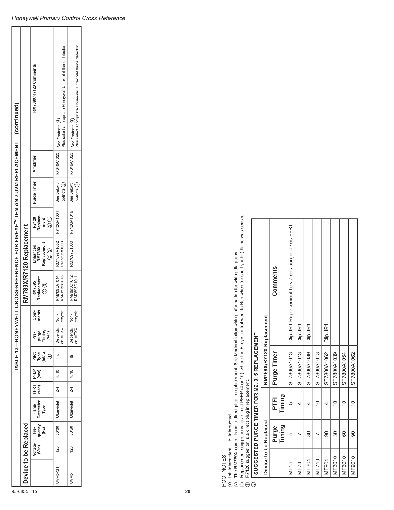
95-6855—15 26 Honeywell Primary Control Cross Reference
Table 13—Honeywell Cross-Reference For Fireyetm Tfm And Uvm Replacement
Device to be Replaced RM789X/R7120 Replacement Voltage (Vac) Fre quency (Hz) Flame Detetector TypeFfrt
(sec)Pfep
(sec) Pilot Type (Int/Itr) a Pre purge Timing (Sec) Com mentsRm7895
Replacement b c EnhancedRm789X
Replacement b cR7120
Replace ment c d Purge Timer Amplifier RM789X/R7120 CommentsUvm3-3H
120 50/60 Ultarviolet 2-4 4, 10 Int Depends on MTXX Non- recycleRm7895A1014
Rm7895B1013
Rm7897A1002
Rm7898A1000
R7120M1001
See Below: Footnote eR7849A1023
See Footnote e. Plus select appropriate Honeywell Ultraviolet flame detectorUvm5
120 50/60 Ultarviolet 2-4 4, 10 Itr Depends on MTXX Non- recycleRm7895C1012
Rm7895D1011
Rm7897C1000
R7120M1019
See Below: Footnote eR7849A1023
See Footnote e. Plus select appropriate Honeywell Ultraviolet flame detector (continued)Footnotes:
a Int: Intermittent, Itr: Interrupted b The RM789X control is not a direct plug in replacement. See Modernization wiring information for wiring diagrams. c Replacement suggestions have fixed PFEP (4 or 10) where the Fireye control went to Run when (or shortly after) flame was sensed. d R7120 suggestion is a direct plug in replacement. eSuggested Purge Timer For M2, 3, 5 Replacement
Device to be Replaced RM789X/R7120 Replacement Purge TimingPtfi
Timing Purge Timer CommentsMt55
5 5St7800A1013
Clip JR1 Replacement has 7 sec purge, 4 sec FFRTMt74
7 4St7800A1013
Clip JR1Mt304
30 4St7800A1039
Clip JR1Mt710
7 10St7800A1013
Mt904
90 4St7800A1062
Clip JR1Mt3010
30 10St7800A1039
Mt6010
60 10St7800A1054
Mt9010
90 10St7800A1062
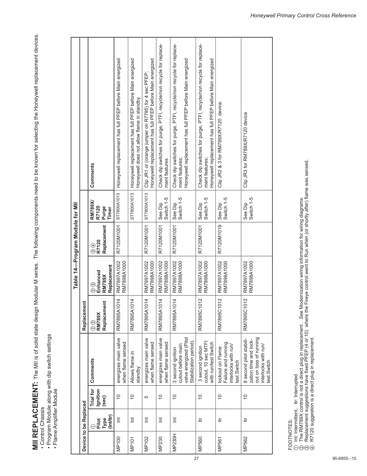
27 95-6855—15 Honeywell Primary Control Cross Reference MII REPLACEMENT: The MII is of solid state design Modular M series. The following components need to be known for selecting the Honeywell replacement devices.
Rm789X
Replacement b c EnhancedRm789X
Replacement c dR7120
ReplacementRm789X/
R7120
Purge Timer CommentsMp100
Int 10 energizes main valve when flame sensedRm7895A1014
Rm7897A1002
Rm7898A1000
R7120M1001
St7800A1013
Honeywell replacement has full PFEP before Main energizedMp101
Int 10 Allows flame in standbyRm7895A1014
St7800A1013
Honeywell replacement has full PFEP before Main energized Honeywell does not allow flame in standbyMp102
Int 5 energizes main valve when flame sensedRm7895A1014
Rm7897A1002
Rm7898A1000
R7120M1001
St7800A1013
Clip JR1 or (orange jumper on R7795) for 4 sec PFEP; Honeywell replacement has full PFEP before Main energizedMp230
Int 10 energizes main valve when flame sensedRm7895A1014
Rm7897A1002
Rm7898A1000
R7120M1001
See Dip Switch 1-5 Check dip switches for purge, PTFI, recycle/non recycle for replace ment featuresMp230H
Int 10 3 second ignition cutout before main valve energized (Pilot Stabilization period).Rm7895A1014
Rm7897A1002
Rm7898A1000
R7120M1001
See Dip Switch 1-5 Check dip switches for purge, PTFI, recycle/non recycle for replace ment features; Honeywell replacement has full PFEP before Main energizedMp560
Itr 10 3 second ignition cutout, 10 sec MTFI with run/test SwitchRm7895C1012
Rm7897A1002
Rm7898A1000
R7120M1001
See Dip Switch 1-5 Check dip switches for purge, PTFI, recycle/non recycle for replace ment features; Honeywell replacement has full PFEP before Main energizedMp561
Itr 10 lockout on Flame Failure and running interlocks with run/ test SwitchRm7895C1012
Rm7897A1002
Rm7898A1000
R7120M1019
See Dip Switch 1-5 Clip JR2 & 3 for RM789X/R7120 device.Mp562
Itr 10 8 second pilot stabili zation time and lock out on loss of running interlocks with run/ test SwitchRm7895C1012
Rm7897A1002
Rm7898A1000
See Dip Switch 1-5 Clip JR3 for RM789X/R7120 deviceFootnotes:
a Int: Intermittent, Itr: Interrupted b The RM789X control is not a direct plug in replacement . See Modernization wiring information for wiring diagrams. c Replacement suggestions have fixed PFEP (4 or 10) where the Fireye control went to Run when (or shortly after) flame was sensed. d R7120 suggestion is a direct plug in replacement.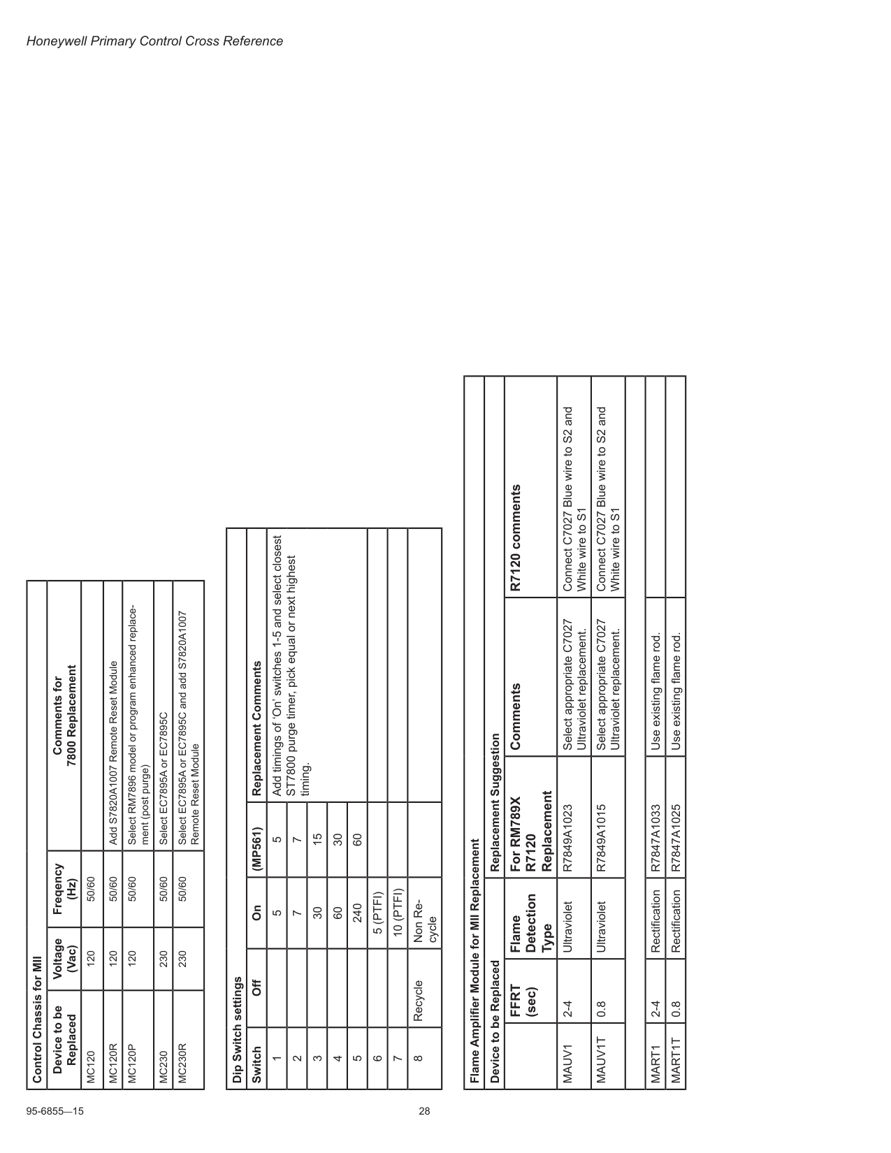
95-6855—15 28 Honeywell Primary Control Cross Reference Control Chassis for MII Device to be Replaced Voltage (Vac) Freqency (Hz) Comments for 7800 Replacement
Mc120
120 50/60Mc120R
120 50/60 Add S7820A1007 Remote Reset ModuleMc120P
120 50/60 Select RM7896 model or program enhanced replace ment (post purge)Mc230
230 50/60 Select EC7895A or EC7895CMc230R
230 50/60 Select EC7895A or EC7895C and add S7820A1007 Remote Reset Module Dip Switch settings Switch Off On(Mp561)
Replacement Comments 1 5 5 Add timings of ‘On’ switches 1-5 and select closest ST7800 purge timer, pick equal or next highest timing. 2 7 7 3 30 15 4 60 30 5 240 60 65 (Ptfi)
710 (Ptfi)
8 Recycle Non Re cycle Flame Amplifier Module for MII Replacement Device to be Replaced Replacement SuggestionFfrt
(sec) Flame Detection Type For RM789XR7120
Replacement Comments R7120 commentsMauv1
2-4 UltravioletR7849A1023
Select appropriate C7027 Ultraviolet replacement. Connect C7027 Blue wire to S2 and White wire to S1Mauv1T
0.8 UltravioletR7849A1015
Select appropriate C7027 Ultraviolet replacement. Connect C7027 Blue wire to S2 and White wire to S1Mart1
2-4 RectificationR7847A1033
Use existing flame rod.Mart1T
0.8 RectificationR7847A1025
Use existing flame rod.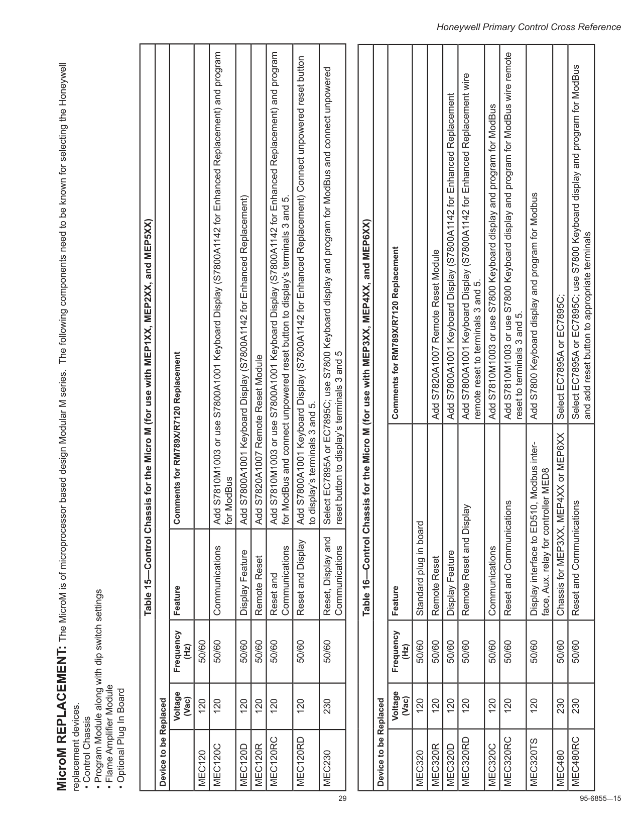
29 95-6855—15 Honeywell Primary Control Cross Reference MicroM REPLACEMENT: The MicroM is of microprocessor based design Modular M series. The following components need to be known for selecting the Honeywell replacement devices.
Mec120
120 50/60Mec120C
120 50/60 Communications Add S7810M1003 or use S7800A1001 Keyboard Display (S7800A1142 for Enhanced Replacement) and program for ModBusMec120D
120 50/60 Display Feature Add S7800A1001 Keyboard Display (S7800A1142 for Enhanced Replacement)Mec120R
120 50/60 Remote Reset Add S7820A1007 Remote Reset ModuleMec120Rc
120 50/60 Reset and Communications Add S7810M1003 or use S7800A1001 Keyboard Display (S7800A1142 for Enhanced Replacement) and program for ModBus and connect unpowered reset button to display’s terminals 3 and 5.Mec120Rd
120 50/60 Reset and Display Add S7800A1001 Keyboard Display (S7800A1142 for Enhanced Replacement) Connect unpowered reset button to display’s terminals 3 and 5.Mec230
230 50/60 Reset, Display and Communications Select EC7895A or EC7895C; use S7800 Keyboard display and program for ModBus and connect unpowered reset button to display’s terminals 3 and 5 Table 16—Control Chassis for the Micro M (for use with MEP3XX, MEP4XX, and MEP6XX) Device to be Replaced Voltage (Vac) Frequency (Hz) Feature Comments for RM789X/R7120 ReplacementMec320
120 50/60 Standard plug in boardMec320R
120 50/60 Remote Reset Add S7820A1007 Remote Reset ModuleMec320D
120 50/60 Display Feature Add S7800A1001 Keyboard Display (S7800A1142 for Enhanced ReplacementMec320Rd
120 50/60 Remote Reset and Display Add S7800A1001 Keyboard Display (S7800A1142 for Enhanced Replacement wire remote reset to terminals 3 and 5.Mec320C
120 50/60 Communications Add S7810M1003 or use S7800 Keyboard display and program for ModBusMec320Rc
120 50/60 Reset and Communications Add S7810M1003 or use S7800 Keyboard display and program for ModBus wire remote reset to terminals 3 and 5.Mec320Ts
120 50/60 Display interface to ED510, Modbus inter face, Aux. relay for controller MED8 Add S7800 Keyboard display and program for ModbusMec480
230 50/60 Chassis for MEP3XX, MEP4XX or MEP6XX Select EC7895A or EC7895C;Mec480Rc
230 50/60 Reset and Communications Select EC7895A or EC7895C; use S7800 Keyboard display and program for ModBus and add reset button to appropriate terminals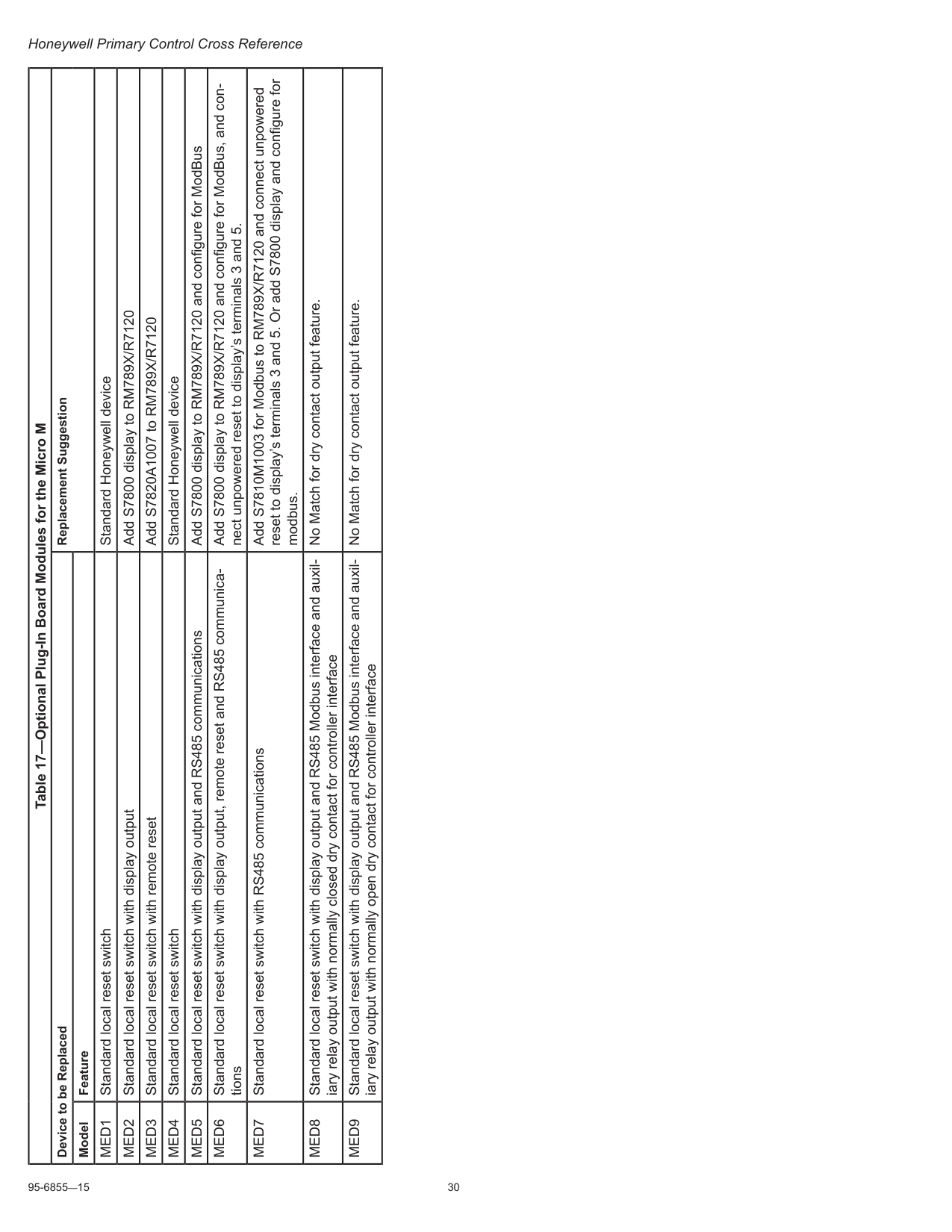
95-6855—15 30 Honeywell Primary Control Cross Reference Table 17—Optional Plug-In Board Modules for the Micro M Device to be Replaced Replacement Suggestion Model Feature
Med1
Standard local reset switch Standard Honeywell deviceMed2
Standard local reset switch with display output Add S7800 display to RM789X/R7120Med3
Standard local reset switch with remote reset Add S7820A1007 to RM789X/R7120Med4
Standard local reset switch Standard Honeywell deviceMed5
Standard local reset switch with display output and RS485 communications Add S7800 display to RM789X/R7120 and configure for ModBusMed6
Standard local reset switch with display output, remote reset and RS485 communica tions Add S7800 display to RM789X/R7120 and configure for ModBus, and con nect unpowered reset to display’s terminals 3 and 5.Med7
Standard local reset switch with RS485 communications Add S7810M1003 for Modbus to RM789X/R7120 and connect unpowered reset to display’s terminals 3 and 5. Or add S7800 display and configure for modbus.Med8
Standard local reset switch with display output and RS485 Modbus interface and auxil iary relay output with normally closed dry contact for controller interface No Match for dry contact output feature.Med9
Standard local reset switch with display output and RS485 Modbus interface and auxil iary relay output with normally open dry contact for controller interface No Match for dry contact output feature.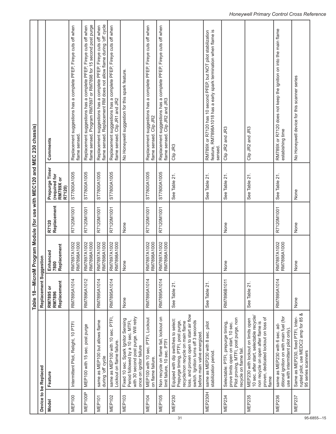
31 95-6855—15 Honeywell Primary Control Cross Reference Table 18—MicroM Program Module (for use with MEC120 and MEC 230 chassis) Device to be Replaced Replacement Suggestion Model Feature RM7895 or
Rm7896
Replacement Enhanced 7800 ReplacementR7120
Replacement Prepurge Timer (required for RM789X orR7120)
CommentsMep100
Intermittent Pilot, Relight, 10 PTFIRm7895A1014
Rm7897A1002
Rm7898A1000
R7120M1001
St7800A1005
Replacement suggestions has a complete PFEP, Fireye cuts off when flame sensed.Mep100P
MEP100 with 15 sec. post purgeRm7896A1012
Rm7897A1002
Rm7898A1000
R7120M1001
St7800A1005
Replacement suggestions has a complete PFEP, Fireye cuts off when flame sensed. Program RM7897 or RM7898 for 15 second post purgeMep101
same as MEP100 but allows flame during ‘off’ cycleRm7895A1014
Rm7897A1002
Rm7898A1000
R7120M1001
St7800A1005
Replacement suggestions has a complete PFEP, Fireye cuts off when flame sensed. Replacement RM does not allow flame during ‘off’ cycleMep102
same as MEP100 with 10 sec. PTFI, Lockout on flame failure.Rm7895A1014
Rm7897A1002
Rm7898A1000
R7120M1001
St7800A1005
Replacement suggestions has a complete PFEP, Fireye cuts off when flame sensed. Clip JR1 and JR2Mep103
Fixed 10 sec. Spark Ignitor Sensing Period followed by a 10 sec. MTFI, with 30 second post purge. Will retry once on ignitor failure None None None No Honeywell suggestion for this spark feature.Mep104
MEP100 with 10 sec. PTFI, Lockout on flame failure.Rm7895A1014
Rm7897A1002
Rm7898A1000
R7120M1001
St7800A1005
Replacement suggestions has a complete PFEP, Fireye cuts off when flame sensed. Clip JR2Mep105
Non recycle on flame fail, lockout on limit failure, 10 sec. PTFIRm7895A1014
Rm7897A1002
Rm7898A1000
R7120M1001
St7800A1005
Replacement suggestions has a complete PFEP, Fireye cuts off when flame sensed. Clip JR2 and JR3Mep230
Equiped with dip switches to select: Prepurge timing, PTFI, post purge, recycle/non recycle on main flame loss, and proven open to start air flow switch. Ignition turns off 3 seconds before main valve energized. See Table 21. See Table 21. Clip JR3Mep230H
same as MEP230 with 8 sec. pilot stabilization period. See Table 21. See Table 21. RM789X or R7120 has 10 second PFEP, but NOT pilot stabilization feature, RM7898A1018 has a early spark termination when flame is sensed.Mep234
Selectable: PTFI, prepurge timing, prove limits open on start, 10 sec. Pilot proving, MTFI, post purge, non recycle on flame fail.Rm7896B1011
None None See Table 21. Clip JR2 and JR3Mep235
MEP230 with lockout on limits open 10 sec. after start, selectable recycle/ non recycle on open after flame is proven, dedicated lockout on loss of flame See Table 21. See Table 21. Clip JR2 and JR3Mep236
same as MEP230 with 6 sec. ad ditional ignition on with main fuel (for use with intermittent pilot only).Rm7895A1014
Rm7897A1002
Rm7898A1000
R7120M1001
See Table 21. RM789X or R7120 does not keep the ignition on into the main flame estabishing timeMep237
Same as MEP230, fixed PTFI, Inter rupted pilot, use MEDC2 amp for 85 & 95 series scanners None None None None No Honeywell device for this scanner series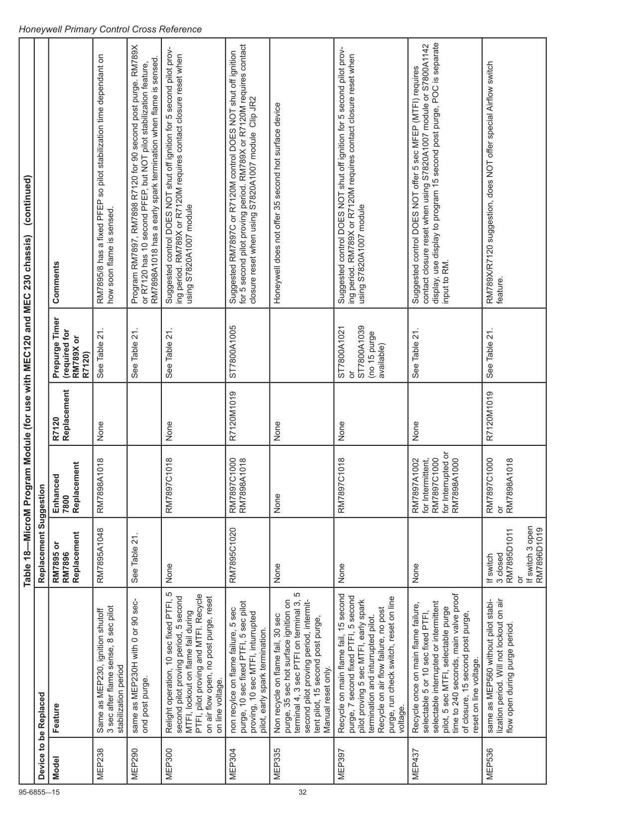
95-6855—15 32 Honeywell Primary Control Cross Reference Table 18—MicroM Program Module (for use with MEC120 and MEC 230 chassis) Device to be Replaced Replacement Suggestion Model Feature RM7895 or
Rm7896
Replacement Enhanced 7800 ReplacementR7120
Replacement Prepurge Timer (required for RM789X orR7120)
CommentsMep238
Same as MEP230, ignition shutoff 3 sec after flame sense, 8 sec pilot stabilization periodRm7895A1048
Rm7898A1018
None See Table 21. RM7895/8 has a fixed PFEP so pilot stabilization time dependant on how soon flame is sensed.Mep290
same as MEP230H with 0 or 90 sec ond post purge. See Table 21. See Table 21. Program RM7897, RM7898 R7120 for 90 second post purge. RM789X or R7120 has 10 second PFEP, but NOT pilot stabilization feature, RM7898A1018 has a early spark termination when flame is sensed.Mep300
Relight operation, 10 sec fixed PTFI, 5 second pilot proving period, 5 second MTFI, lockout on flame fail during PTFI, pilot proving and MTFI. Recycle on air flow open, no post purge, reset on line voltage. NoneRm7897C1018
None See Table 21. Suggested control DOES NOT shut off ignition for 5 second pilot prov ing period. RM789X or R7120M requires contact closure reset when using S7820A1007 moduleMep304
non recylce on flame failure, 5 sec purge, 10 sec fixed PTFI, 5 sec pilot proving, 10 sec MTFI, inturrupted pilot, early spark termination.Rm7895C1020
Rm7897C1000
Rm7898A1018
R7120M1019
St7800A1005
Suggested RM7897C or R7120M control DOES NOT shut off ignition for 5 second pilot proving period. RM789X or R7120M requires contact closure reset when using S7820A1007 module Clip JR2Mep335
Non recycle on flame fail, 30 sec purge, 35 sec hot surface ignition on terminal 4, 3 sec PTFI on terminal 3, 5 second pilot proving period, intermit tent pilot, 15 second post purge, Manual reset only. None None None Honeywell does not offer 35 second hot surface deviceMep397
Recycle on main flame fail, 15 second purge, 7 second fixed PTFI, 5 second pilot proving 5 sec MTFI, early spark termination and inturrupted pilot. Recycle on air flow failure, no post purge, run check switch, reset on line voltage. NoneRm7897C1018
NoneSt7800A1021
orSt7800A1039
(no 15 purge available) Suggested control DOES NOT shut off ignition for 5 second pilot prov ing period. RM789X or R7120M requires contact closure reset when using S7820A1007 moduleMep437
Recycle once on main flame failure, selectable 5 or 10 sec fixed PTFI, selectable interrupted or intermittent pilot, 5 sec MTFI, selectable purge time to 240 seconds, main valve proof of closure, 15 second post purge, reset on line voltage. NoneRm7897A1002
for Intermittent,Rm7897C1000
for Interrupted orRm7898A1000
None See Table 21. Suggested control DOES NOT offer 5 sec MFEP (MTFI) requires contact closure reset when using S7820A1007 module or S7800A1142 display, use display to program 15 second post purge, POC is separate input to RM.Mep536
same as MEP560 without pilot stabi lization period. Will not lockout on air flow open during purge period. If switch 3 closedRm7895D1011
or If switch 3 openRm7896D1019
Rm7897C1000
orRm7898A1018
R7120M1019
See Table 21. RM789X/R7120 suggestion, does NOT offer special Airflow switch feature. (continued)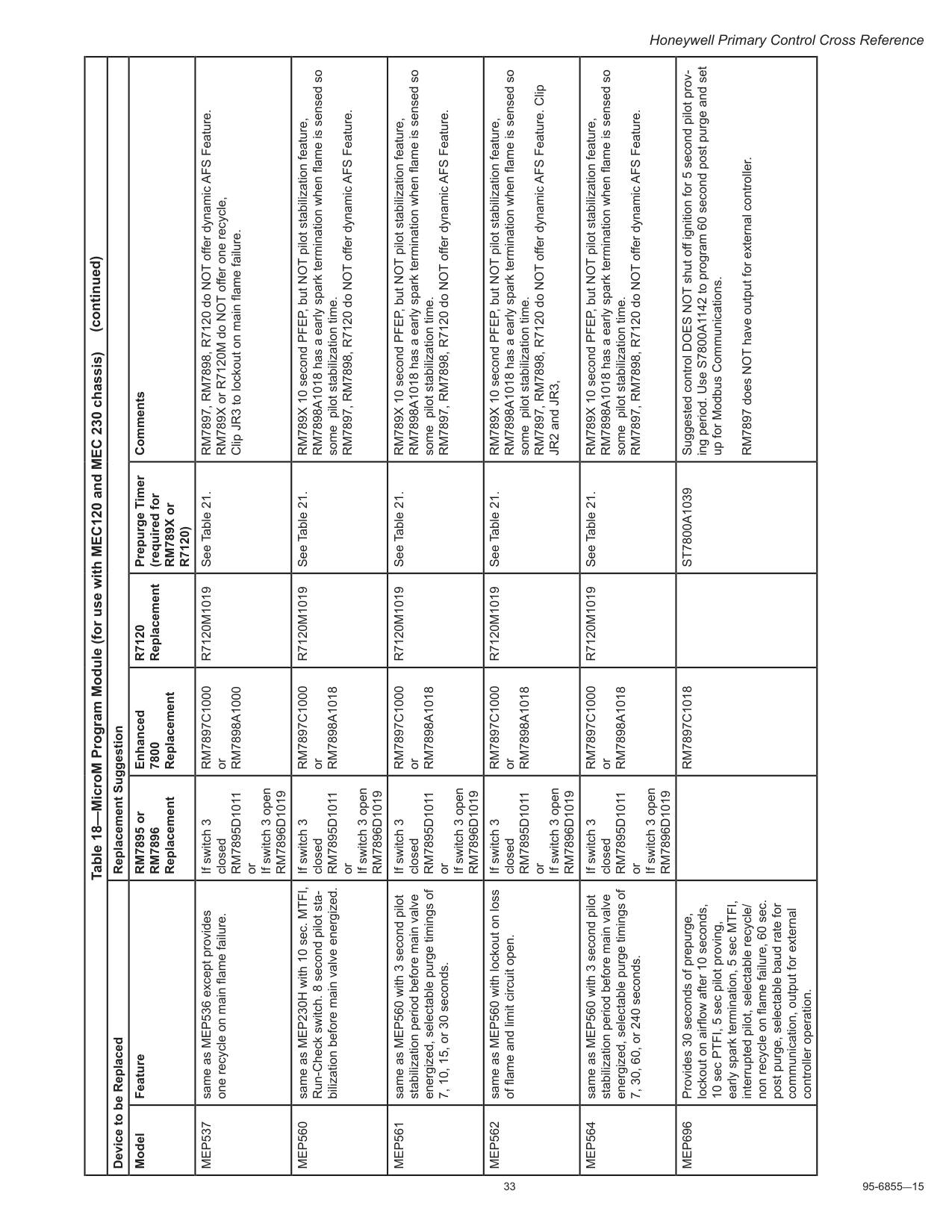
33 95-6855—15 Honeywell Primary Control Cross Reference Table 18—MicroM Program Module (for use with MEC120 and MEC 230 chassis) Device to be Replaced Replacement Suggestion Model Feature RM7895 or
Rm7896
Replacement Enhanced 7800 ReplacementR7120
Replacement Prepurge Timer (required for RM789X orR7120)
CommentsMep537
same as MEP536 except provides one recycle on main flame failure. If switch 3 closedRm7895D1011
or If switch 3 openRm7896D1019
Rm7897C1000
orRm7898A1000
R7120M1019
See Table 21. RM7897, RM7898, R7120 do NOT offer dynamic AFS Feature. RM789X or R7120M do NOT offer one recycle, Clip JR3 to lockout on main flame failure.Mep560
same as MEP230H with 10 sec. MTFI, Run-Check switch. 8 second pilot sta bilization before main valve energized. If switch 3 closedRm7895D1011
or If switch 3 openRm7896D1019
Rm7897C1000
orRm7898A1018
R7120M1019
See Table 21. RM789X 10 second PFEP, but NOT pilot stabilization feature, RM7898A1018 has a early spark termination when flame is sensed so some pilot stabilization time. RM7897, RM7898, R7120 do NOT offer dynamic AFS Feature.Mep561
same as MEP560 with 3 second pilot stabilization period before main valve energized, selectable purge timings of 7, 10, 15, or 30 seconds. If switch 3 closedRm7895D1011
or If switch 3 openRm7896D1019
Rm7897C1000
orRm7898A1018
R7120M1019
See Table 21. RM789X 10 second PFEP, but NOT pilot stabilization feature, RM7898A1018 has a early spark termination when flame is sensed so some pilot stabilization time. RM7897, RM7898, R7120 do NOT offer dynamic AFS Feature.Mep562
same as MEP560 with lockout on loss of flame and limit circuit open. If switch 3 closedRm7895D1011
or If switch 3 openRm7896D1019
Rm7897C1000
orRm7898A1018
R7120M1019
See Table 21. RM789X 10 second PFEP, but NOT pilot stabilization feature, RM7898A1018 has a early spark termination when flame is sensed so some pilot stabilization time. RM7897, RM7898, R7120 do NOT offer dynamic AFS Feature. Clip JR2 and JR3,Mep564
same as MEP560 with 3 second pilot stabilization period before main valve energized, selectable purge timings of 7, 30, 60, or 240 seconds. If switch 3 closedRm7895D1011
or If switch 3 openRm7896D1019
Rm7897C1000
orRm7898A1018
R7120M1019
See Table 21. RM789X 10 second PFEP, but NOT pilot stabilization feature, RM7898A1018 has a early spark termination when flame is sensed so some pilot stabilization time. RM7897, RM7898, R7120 do NOT offer dynamic AFS Feature.Mep696
Provides 30 seconds of prepurge, lockout on airflow after 10 seconds, 10 sec PTFI, 5 sec pilot proving, early spark termination, 5 sec MTFI, interrupted pilot, selectable recycle/ non recycle on flame failure, 60 sec. post purge, selectable baud rate for communication, output for external controller operation.Rm7897C1018
St7800A1039
Suggested control DOES NOT shut off ignition for 5 second pilot prov ing period. Use S7800A1142 to program 60 second post purge and set up for Modbus Communications.RM7897 does NOT have output for external controller. (continued)
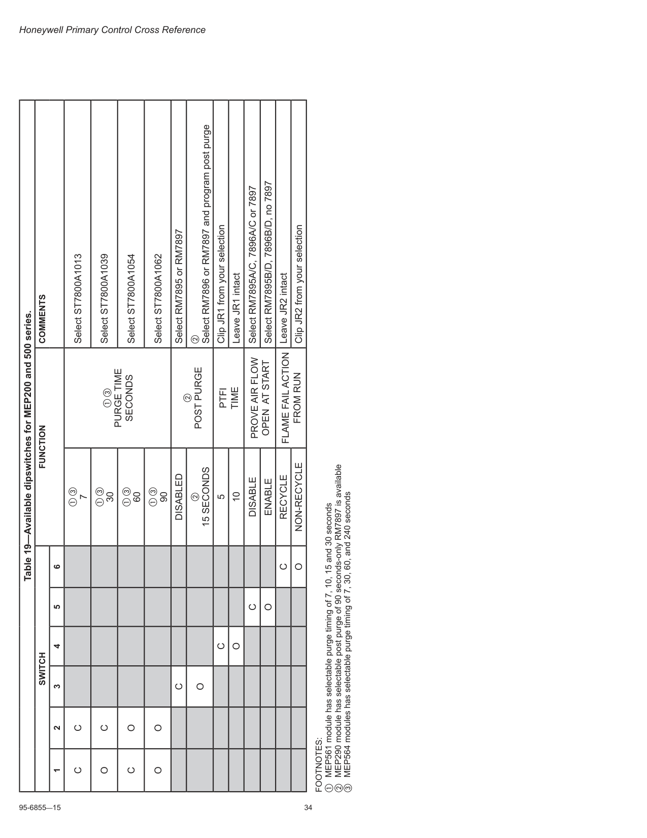
95-6855—15 34 Honeywell Primary Control Cross Reference Table 19—Available dipswitches for MEP200 and 500 series.
Switch
Function
Comments
1 2 3 4 5 6C
C
a c 7 a cPurge Time
Seconds
Select ST7800A1013O
C
a c 30 Select ST7800A1039C
O
a c 60 Select ST7800A1054O
O
a c 90 Select ST7800A1062C
Disabled
bPost Purge
Select RM7895 or RM7897O
b15 Seconds
b Select RM7896 or RM7897 and program post purgeC
5Ptfi
Time
Clip JR1 from your selectionO
10 Leave JR1 intactC
Disable
Prove Air Flow
Open At Start
Select RM7895A/C, 7896A/C or 7897O
Enable
Select RM7895B/D, 7896B/D, no 7897C
Recycle
Flame Fail Action
From Run
Leave JR2 intactO
Non-Recycle
Clip JR2 from your selectionFootnotes:
a MEP561 module has selectable purge timing of 7, 10, 15 and 30 seconds b MEP290 module has selectable post purge of 90 seconds-only RM7897 is available c MEP564 modules has selectable purge timing of 7, 30, 60, and 240 seconds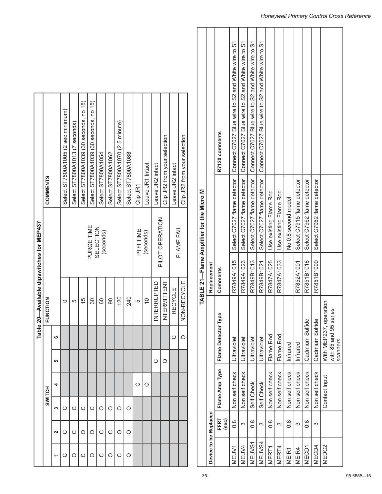
35 95-6855—15 Honeywell Primary Control Cross Reference Table 20—Available dipswitches for MEP437
Switch
Function
Comments
1 2 3 4 5 6C
C
C
0Purge Time
Selection
(seconds) Select ST7800A1005 (2 sec minimum)O
C
C
5 Select ST7800A1013 (7 seconds)C
O
C
15 Select ST7800A1039 (30 seconds, no 15)O
O
C
30 Select ST7800A1039 (30 seconds, no 15)C
C
O
60 Select ST7800A1054O
C
O
90 Select ST7800A1062C
O
O
120 Select ST7800A1070 (2.5 minute)O
O
O
240 Select ST7800A1088C
5Ptfi Time
(seconds) Clip JR1O
10 Leave JR1 IntactC
Interrupted
Pilot Operation
Leave JR2 intactO
Intermittent
Clip JR2 from your selectionC
Recycle
Flame Fail
Leave JR2 intactO
Non-Recycle
Clip JR2 from your selection TABLE 21—Flame Amplifier for the Micro M Device to be Replaced ReplacementFfrt
(sec) Flame Amp Type Flame Detector Type Comments R7120 commentsMeuv1
0.8 Non self check UltravioletR7849A1015
Select C7027 flame detector Connect C7027 Blue wire to S2 and White wire to S1Meuv4
3 Non self check UltravioletR7849A1023
Select C7027 flame detector Connect C7027 Blue wire to S2 and White wire to S1Meuvs1
0.8 Self Check UltravioletR7849B1013
Select C7027 flame detector Connect C7027 Blue wire to S2 and White wire to S1Meuvs4
3 Self Check UltravioletR7849B1021
Select C7027 flame detector Connect C7027 Blue wire to S2 and White wire to S1Mert1
0.8 Non self check Flame RodR7847A1025
Use existing Flame RodMert4
3 Non self check Flame RodR7847A1033
Use existing Flame RodMeir1
0.8 Non self check Infrared No 0.8 second modelMeir4
3 Non self check InfraredR7852A1001
Select C7915 flame detectorMecd1
0.8 Non self check Cadmium SulfideR7851B1018
Select C7962 flame detectorMecd4
3 Non self check Cadmium SulfideR7851B1000
Select C7962 flame detectorMedc2
Contact Input With MEP237, operation with 85 and 95 series scanners.
95-6855—15 36 Honeywell Primary Control Cross Reference

37 95-6855—15 Honeywell Primary Control Cross Reference
Honeywell Primary Control Cross Reference Automation and Control Solutions Honeywell International Inc. 1985 Douglas Drive North Golden Valley, MN 55422 Honeywell Limited-Honeywell Limitée 35 Dynamic Drive Toronto, Ontario M1V 4Z9 http://yourhome.honeywell.com ® U.S. Registered Trademark. © 2010 Honeywell International Inc. Patents pending. All rights reserved. 95-6855—15 M.S. Rev. 05-10 Printed in U.S.A.