
Ask AI
— answers from the official manualAnswers from the official manual.
Common questions
Common Questions
10 totalWhat if I have an unusual system configuration for my T10 Pro?
Consult Table 5 on page 26 in Installer Options to configure the thermostat according to your specific system type and equipment (Page 28).
How do I properly set up a heat pump system?
In Installer Setup, choose 'Heat Pump' under System Type. Configure settings based on ISU names in Table 5 to match your equipment (Page 37).
How do I add an Apple HomeKit setup for my T10 Pro?
From the main menu, go to 'Connect HomeKit', use Honeywell Home app, and follow on-screen instructions to connect your thermostat (Page 30).
How do I check my thermostat's IP address?
From the main menu, go to Thermostat Information where you can find the IP Address among other details about your T10 Pro (Page 32).
Why won't my T10 Pro detect a wired indoor sensor?
Ensure you have selected 'Yes' under Indoor Sensor in Installer Options ISU and connected the C-wire properly (Page 5).
How do I reset my Honeywell T10 Pro Thermostat to factory defaults?
Press and hold the Menu button until you see 'Installer Options'. Enter your date code, then scroll to 'Reset' and select 'Factory Reset'. Confirm when prompted. (Page 32)
Full Manual
42 pages
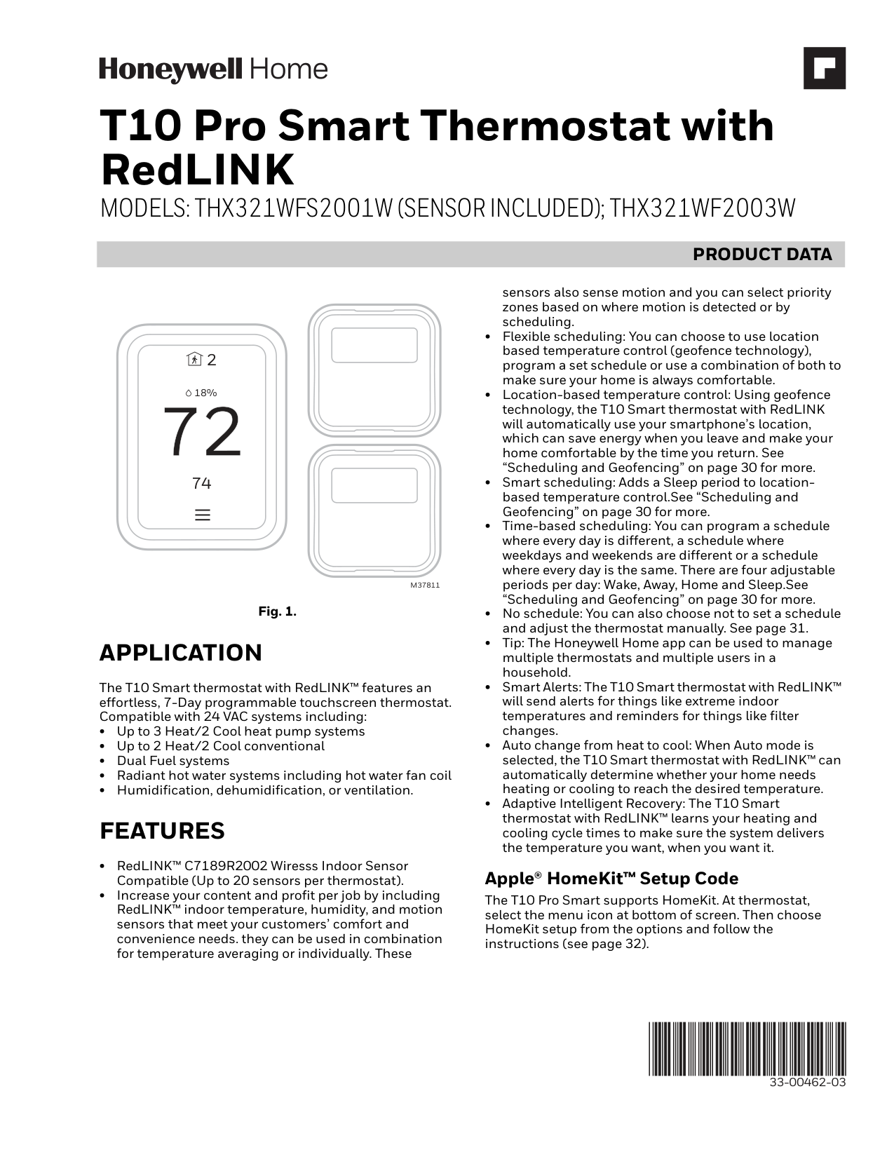
T10 Pro Smart Thermostat with RedLINK MODELS: THX321WFS2001W (SENSOR INCLUDED); THX321WF2003W
|PRODUCT DATA| |---|
2
18%
74
M37811
Fig. 1.
APPLICATION
The T10 Smart thermostat with RedLINK™ features an effortless, 7-Day programmable touchscreen thermostat. Compatible with 24 VAC systems including:
FEATURES
Apple® HomeKit™ Setup Code
The T10 Pro Smart supports HomeKit. At thermostat, select the menu icon at bottom of screen. Then choose HomeKit setup from the options and follow the instructions (see page 32).
33-00462-03
CONTENTS
Application ..................................................................................... 1 Features .......................................................................................... 1 Specifications ............................................................................... 3 Dimensions.....................................................................................3-4 Regulatory information ............................................................ 5
Installation Mounting......................................................................................... 6 Wiring................................................................................................7-13 Installing wireless indoor sensors.........................................13-14 Installing Wired Indoor Sensor .............................................. 14-15 Installing Wired outdoor sensor ............................................ 15-16 Installer setup................................................................................16-28
Wi-Fi Wi-Fi setup ..................................................................................... 29-30 Wi-Fi setup, after initial installation .................................... 30 Scheduling and Geofencing ................................................... 30-31 Main Menu Options ................................................................... 31 Installer Options .......................................................................... 31-32 Getting the most from the T10 Smart Thermostat ........ 32 Setting the Time/Date .............................................................. 33 Setting the Fan ............................................................................. 33 Setting the System mode ......................................................... 33 Using Priority ................................................................................ 34 Alerts and notifications ............................................................ 34-35
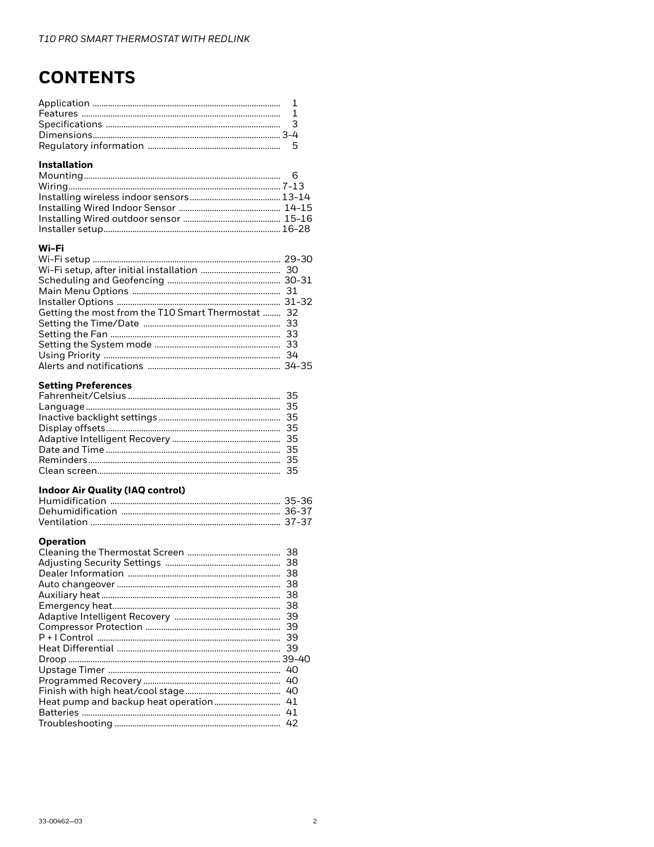
Setting Preferences
Fahrenheit/Celsius ..................................................................... 35 Language........................................................................................ 35 Inactive backlight settings....................................................... 35 Display offsets............................................................................... 35 Adaptive Intelligent Recovery ................................................. 35 Date and Time ............................................................................... 35 Reminders....................................................................................... 35 Clean screen................................................................................... 35
Indoor Air Quality (IAQ control)
Humidification ............................................................................. 35-36 Dehumidification ........................................................................ 36-37 Ventilation ...................................................................................... 37-37
Operation Cleaning the Thermostat Screen .......................................... 38 Adjusting Security Settings .................................................... 38 Dealer Information ..................................................................... 38 Auto changeover .......................................................................... 38 Auxiliary heat................................................................................. 38 Emergency heat............................................................................ 38 Adaptive Intelligent Recovery ................................................ 39 Compressor Protection ............................................................. 39 P + I Control ................................................................................... 39 Heat Differential .......................................................................... 39 Droop ................................................................................................39-40 Upstage Timer .............................................................................. 40 Programmed Recovery .............................................................. 40 Finish with high heat/cool stage........................................... 40 Heat pump and backup heat operation.............................. 41 Batteries .......................................................................................... 41 Troubleshooting ........................................................................... 42
SPECIFICATIONS
Models: THX321WFS2001W (Sensor included) THX321WF2003W
Table 1. Thermostat Description
| | | |---|---| |Feature|Description| |Powering Method|Common wire required| |Stages:
• Up to 3H/2C Heat pump
• Up to 2H/2C conventional
|Equipment type:
• Dual fuel
• Hot water, steam, or hot water coil
• Gas or oil furnace
• High-efficiency or mid-efficiency
• Cool only
• Does not work on Milivolt systems
• Humidifier, Dehumidifier, or Ventilator control
| |Changeover|Manual or Auto Changeover Selectable| |System Setting|Em Heat-Heat-Off-Cool-Auto| |Fan Setting|Auto-On-Circ-Follow Schedule|
Table 2. Electrical Ratings
| | | | |---|---|---| |Terminal|Voltage (50/60Hz)|Running Current| |W (Heat)|20-30 VAC|0.02-1.0 A| |W2 (Aux) Heat|20-30 VAC|0.02-1.0 A| |E (Emergency Heat)|20-30 VAC|0.02-0.5 A| |Y (Compressor Stage 1)|20-30 VAC|0.02-1.0 A| |Y2 (Compressor Stage 2)|20-30 VAC|0.02-1.0 A| |G (Fan)|20-30 VAC|0.02-0.5 A| |O/B (Changeover)|20-30 VAC|0.02-0.5 A| |L/A (Heat Pump Fault)|20-30 VAC|0.02-0.5 A| |U (Hum, Dehum, or Vent)|20-30 VAC|0.02-0.5 A|
Does not work on Milivolt systems Power Consumption: 3VA
RedLINK Communication: Frequency: 900 Mhz frequency range Re-Sync Time: RedLINK devices re-establish communica-
tion within 6 minutes after AC power resumes.
Temperature Setting Range: Heating: 40 to 90 °F (4.5 to 32 °C). Cooling: 50 to 99 °F (10 to 37 °C). Note: Adjustable high and low range-stop settings.
Temperature Sensor Accuracy: ± 1.5 F at 70 F (0.75 C at 21.0 C)
Humidification Setting Range: 10% to 60% RH.
Dehumidification Setting Range: 25% to 80% RH.
Humidity Display Range: 0% to 99%.
Humidity Sensor Accuracy: ± 5% RH from 30% to 50% RH at 75 F.
Cool Indication: Display floods blue and says "cooling to" when cool is on.
Heat or Em Heat Indication: Display floods orange and says "heating to" when heat is
on.
AUX Heat Indication: Display shows “Aux heat on” above the room temperature.
Interstage Differential: Comfort:
The thermostat keeps the indoor temperature within 1 degree of the setpoint (droop less control). Unless the system is dual fuel, or a droop setting is used, the thermostat turns on stage 2 when the capacity on stage 1 reaches 90%.
Clock Accuracy:
1 minute per month at 77 °F (25 °C). ± 2 minutes per month over the operating ambient temperature range. Automatically updates when connected to Wi-Fi router and registered to account.
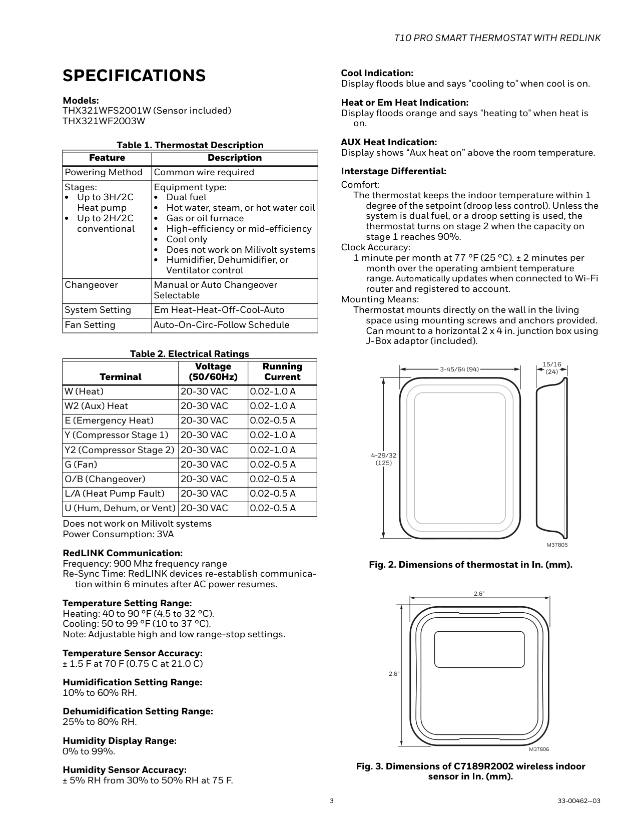
Mounting Means: Thermostat mounts directly on the wall in the living
space using mounting screws and anchors provided. Can mount to a horizontal 2 x 4 in. junction box using J-Box adaptor (included).
3-45/64 (94)
4-29/32 (125)
15/16 (24)
M37805
Fig. 2. Dimensions of thermostat in In. (mm).
2.6”
2.6”
M37806
Fig. 3. Dimensions of C7189R2002 wireless indoor sensor in In. (mm).
3-29/32 (99)
########## UP
3-29/32 (99)
M37807
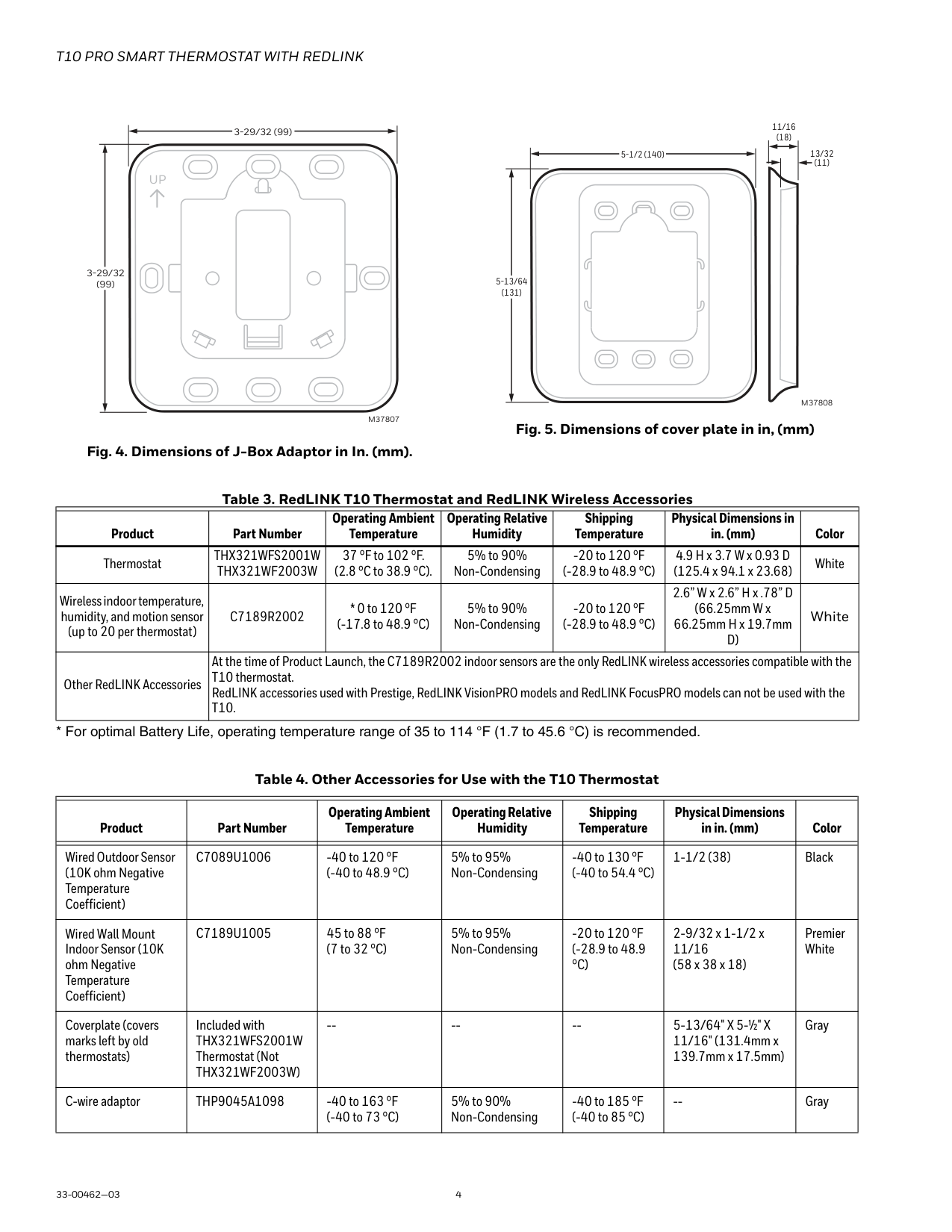
Fig. 4. Dimensions of J-Box Adaptor in In. (mm).
11/16 (18)
5-1/2 (140) 13/32
(11)
5-13/64 (131)
M37808
Fig. 5. Dimensions of cover plate in in, (mm)
Table 3. RedLINK T10 Thermostat and RedLINK Wireless Accessories
| | | | | | | | |---|---|---|---|---|---|---| |Product|Part Number|Operating Ambient Temperature|Operating Relative Humidity|Shipping Temperature|Physical Dimensions in in. (mm)|Color| |Thermostat|THX321WFS2001W THX321WF2003W|37 °F to 102 °F. (2.8 °C to 38.9 °C).|5% to 90% Non-Condensing|-20 to 120 °F (-28.9 to 48.9 °C)|4.9 H x 3.7 W x 0.93 D (125.4 x 94.1 x 23.68)|White| |Wireless indoor temperature, humidity, and motion sensor (up to 20 per thermostat)|C7189R2002|* 0 to 120 °F (-17.8 to 48.9 °C)|5% to 90% Non-Condensing|-20 to 120 °F (-28.9 to 48.9 °C)|2.6” W x 2.6” H x .78” D (66.25mm W x 66.25mm H x 19.7mm D)|White| |Other RedLINK Accessories|At the time of Product Launch, the C7189R2002 indoor sensors are the only RedLINK wireless accessories compatible with the T10 thermostat. RedLINK accessories used with Prestige, RedLINK VisionPRO models and RedLINK FocusPRO models can not be used with the T10.|At the time of Product Launch, the C7189R2002 indoor sensors are the only RedLINK wireless accessories compatible with the T10 thermostat. RedLINK accessories used with Prestige, RedLINK VisionPRO models and RedLINK FocusPRO models can not be used with the T10.|At the time of Product Launch, the C7189R2002 indoor sensors are the only RedLINK wireless accessories compatible with the T10 thermostat. RedLINK accessories used with Prestige, RedLINK VisionPRO models and RedLINK FocusPRO models can not be used with the T10.|At the time of Product Launch, the C7189R2002 indoor sensors are the only RedLINK wireless accessories compatible with the T10 thermostat. RedLINK accessories used with Prestige, RedLINK VisionPRO models and RedLINK FocusPRO models can not be used with the T10.|At the time of Product Launch, the C7189R2002 indoor sensors are the only RedLINK wireless accessories compatible with the T10 thermostat. RedLINK accessories used with Prestige, RedLINK VisionPRO models and RedLINK FocusPRO models can not be used with the T10.|At the time of Product Launch, the C7189R2002 indoor sensors are the only RedLINK wireless accessories compatible with the T10 thermostat. RedLINK accessories used with Prestige, RedLINK VisionPRO models and RedLINK FocusPRO models can not be used with the T10.|
Table 4. Other Accessories for Use with the T10 Thermostat
| | | | | | | | |---|---|---|---|---|---|---| |Product|Part Number|Operating Ambient Temperature|Operating Relative Humidity|Shipping Temperature|Physical Dimensions in in. (mm)|Color| | | | | | | | | |Wired Outdoor Sensor (10K ohm Negative Temperature Coefficient)|C7089U1006|-40 to 120 °F (-40 to 48.9 °C)|5% to 95% Non-Condensing|-40 to 130 °F (-40 to 54.4 °C)|1-1/2 (38)|Black| |Wired Wall Mount Indoor Sensor (10K ohm Negative Temperature Coefficient)|C7189U1005|45 to 88 °F (7 to 32 °C)|5% to 95% Non-Condensing|-20 to 120 °F (-28.9 to 48.9 °C)|2-9/32 x 1-1/2 x 11/16 (58 x 38 x 18)|Premier White| |Coverplate (covers marks left by old thermostats)|Included with THX321WFS2001W Thermostat (Not THX321WF2003W)|--|--|--|5-13/64" X 5-½" X 11/16" (131.4mm x 139.7mm x 17.5mm)|Gray| |C-wire adaptor|THP9045A1098|-40 to 163 °F (-40 to 73 °C)|5% to 90% Non-Condensing|-40 to 185 °F (-40 to 85 °C)|--|Gray|
#### Regulatory information
FCC REGULATIONS 47 CFR § 15.19 (a)(3) This device complies with part 15 of the FCC Rules. Operation is subject to the following two conditions:
47 CFR § 15.21 (USA only) Changes or modifications not expressly approved by the party responsible for compliance could void the user’s authority to operate the equipment.
47 CFR § 15.105 (b) See https://customer.resideo.com/enUS/support/residential/codes-andstandards/FCC15105/Pages/default.aspx for additional FCC information for this product.
IC REGULATIONSRSS-GENThis device complies with Industry Canada’s license-exempt RSSs. Operation is subject to the following two conditions:
SYSTEM INSTALLATION When Installing This Product...
Finding Your Password (Date Code) You will need the thermostat password to:
CAUTION Electrical Hazard. Can cause electrical shock or equipment damage. Disconnect power before wiring.
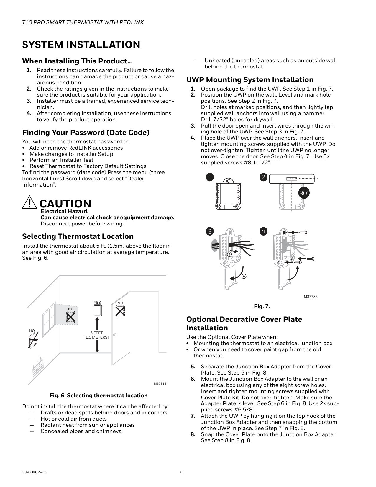
Selecting Thermostat Location
Install the thermostat about 5 ft. (1.5m) above the floor in an area with good air circulation at average temperature. See Fig. 6.
YES NO
NO
NO
5 FEET [1.5 METERS]
M37812
Fig. 6. Selecting thermostat location
Do not install the thermostat where it can be affected by:
— Drafts or dead spots behind doors and in corners
— Hot or cold air from ducts
— Radiant heat from sun or appliances
— Concealed pipes and chimneys
— Unheated (uncooled) areas such as an outside wall behind the thermostat
UWP Mounting System Installation
1 2
3 4
############################ M37786
Fig. 7.
Optional Decorative Cover Plate Installation Use the Optional Cover Plate when:
5
76
8
M37809
Fig. 8.
Terminal Designations
Wiring UWP
Push down on the tabs to put the wires into the inner holes of their corresponding terminals on the UWP (one wire per terminal) until they are firmly in place.
Gently tug on the wires to verify they are secure. If you need to release the wires again, push down the terminal tabs on the sides of the UWP. This wiring is just an example, yours may vary.
#################### M37788
Fig. 9.
| | | | | |---|---|---|---| |Conventional Systems|Conventional Systems|Heat Pump Systems|Heat Pump Systems| |Terminal|Description|Terminal|Description| |S/S|Input for a wired indoor, outdoor sensor|S/S|Input for a wired indoor, outdoor sensor| |Y|Compressor Stage 1|Y|Compressor Stage 1| |Y2|Compressor Stage 2|Y2|Compressor Stage 2| |G|Fan Relay|G|Fan Relay| |C|24VAC Common wire from secondary side of cooling transformer (if 2 transformers)|C|24VAC Common wire from secondary side of cooling transformer| |K*|Connect to K on C-wire adaptor|K*|Connect to K on C-wire adaptor| |U/U|Relay for humidifier, dehumidifier, or ventilator|U/U|Relay for humidifier, dehumidifier, or ventilator| |A| |L/A|Connect to compressor monitor| |W|Heat Stage 1|O/B|Changeover valve for heat pumps| |W2|Heat Stage 2|AUX|Backup Heat| | | |E|Emergency Heat| |R|24 VAC Heating transformer|R|24 VAC Heating transformer| |Rc|24 VAC Cooling transformer|Rc|24 VAC Cooling transformer|
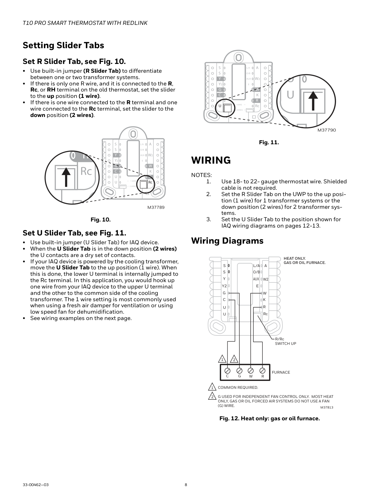
Setting Slider Tabs Set R Slider Tab, see Fig. 10.
M37789
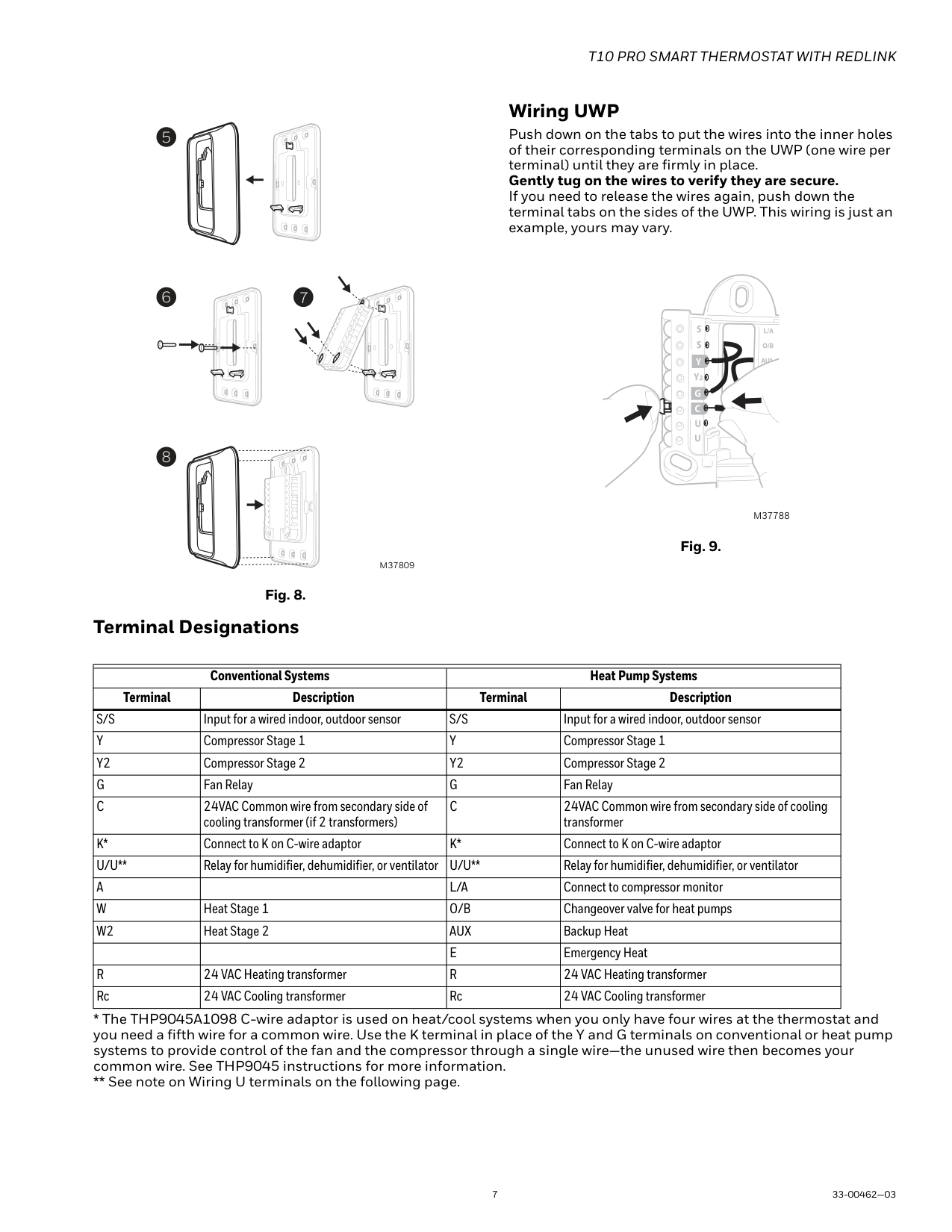
Fig. 10.
Set U Slider Tab, see Fig. 11.
M37790
Fig. 11.
WIRING
NOTES:
#### Wiring Diagrams
HEAT ONLY. GAS OR OIL FURNACE.
S S Y
A
L/A
O/B
AUX
W2
Y2 G C
E
W K
R
U
Rc
U
R/Rc SWITCH UP
1 2
FURNACE
W RGC
G USED FOR INDEPENDENT FAN CONTROL ONLY. MOST HEAT ONLY, GAS OR OIL FORCED AIR SYSTEMS DO NOT USE A FAN (G) WIRE.
M37813
Fig. 12. Heat only: gas or oil furnace.
############## COOL ONLY.
S S Y Y2 G C
A
L/A
############ O/B
AUX
W2
E
W K
R
U
Rc
U
R/Rc SWITCH UP
1
AIR-HANDLER Y RGC
1 COMMON REQUIRED.
M37814
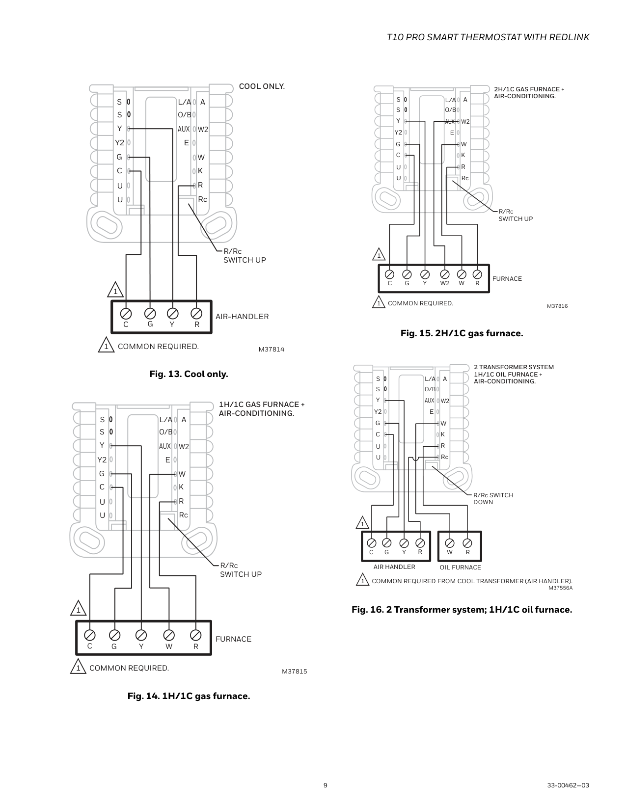
Fig. 13. Cool only.
################ 1H/1C GAS FURNACE + AIR-CONDITIONING.
S S Y
A
L/A
############### O/B
AUX
W2
Y2 G C
E
W K
R
U
Rc
U
R/Rc SWITCH UP
11
C
FURNACE
RWYGC
1 COMMON REQUIRED.
M37815
Fig. 14. 1H/1C gas furnace.
######################### 2H/1C GAS FURNACE + AIR-CONDITIONING.
S S Y
A
L/A
O/B
AUX
W2
Y2 G C
E
W K
R
U
Rc
U
R/Rc SWITCH UP
11
FURNACE
RWYGCW2
1 COMMON REQUIRED.
M37816
Fig. 15. 2H/1C gas furnace.
######################### 2 TRANSFORMER SYSTEM 1H/1C OIL FURNACE + AIR-CONDITIONING.
S S Y
A
L/A
##################### O/B
AUX
W2
Y2 G C
E
W K
R
U
Rc
U
R/Rc SWITCH DOWN
1
RWYGCR
AIR HANDLER

OIL FURNACE
1 COMMON REQUIRED FROM COOL TRANSFORMER (AIR HANDLER).
M37556A
Fig. 16. 2 Transformer system; 1H/1C oil furnace.
######################### 2 TRANSFORMER SYSTEM HOT WATER HEAT + AIR-CONDITIONING (OR HOT WATER COIL).
S S Y
A
L/A
##################### O/B
AUX
W2
Y2 G C
E
W K
R
U
Rc
U
R/Rc SWITCH DOWN
1
RWYGCR
AIR HANDLER
BOILER
1 COMMON REQUIRED FROM COOL TRANSFORMER (AIR-HANDLER).
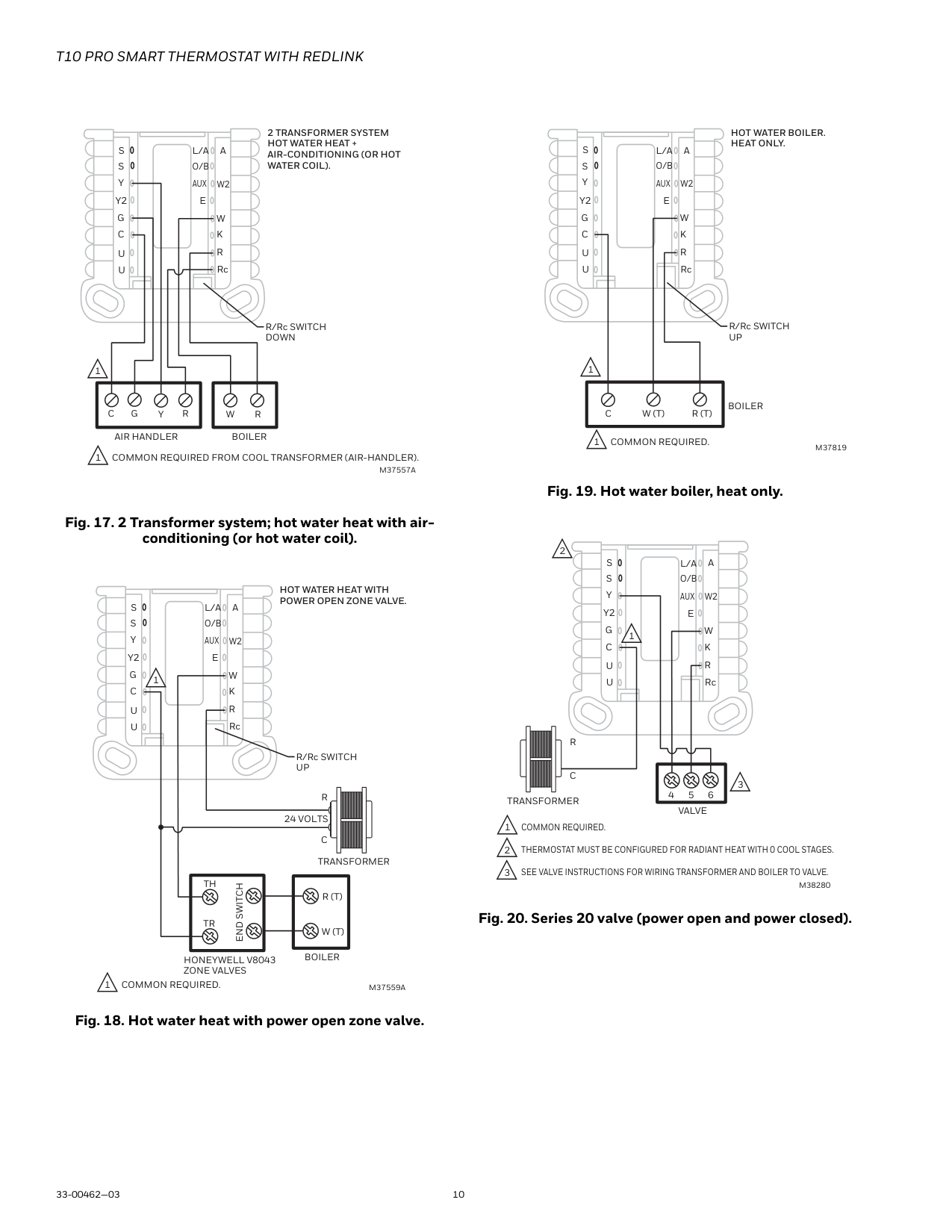
M37557A
######################### HOT WATER HEAT WITH POWER OPEN ZONE VALVE.
S S Y
A
L/A
##################### O/B
AUX
W2
Y2 G C
E
W K
1
R
U
Rc
U
R/Rc SWITCH UP
R 24 VOLTS
C
TRANSFORMER
TH
END SWITCH
R (T)
TR
W (T)
BOILER
HONEYWELL V8043 ZONE VALVES
1 COMMON REQUIRED.
M37559A
########################### HOT WATER BOILER. HEAT ONLY.
S S Y
A
L/A
####################### O/B
AUX
W2
Y2 G C
E
W K
R
U
Rc
U
R/Rc SWITCH UP
11
BOILER
R (T)W (T)
C
1 COMMON REQUIRED.
M37819
Fig. 19. Hot water boiler, heat only.
2
S S Y
A
L/A
O/B
AUX
W2
Y2 G C
E
W K
R
U
Rc
U
3
5 6
VALVE
C
1
4 TRANSFORMER
R
M38280
Fig. 20. Series 20 valve (power open and power closed).
######################### 2H/2C GAS FURNACE + AIR-CONDITIONING.
S S Y
A
L/A
##################### O/B
AUX
W2
Y2 G C
E
W K
R
U
Rc

U
R/Rc SWITCH UP
1
FURNACE
########### RWYGCW2Y2
1 COMMON REQUIRED.
M37560A
Fig. 21. 2H/2C: gas furnace.
######################## 1H/1C HEAT PUMP WITHOUT AUX HEAT.
4
12 13
DO NOT CONNECT ANY WIRE TO W FOR HEAT PUMP APPLICATIONS! THIS CAN CAUSE HEAT TO RUN CONTINUOUSLY.
S S Y
Y2 G C
U
U
A
W2
W K
Rc
R
L/A
E
AUX
HEAT PUMP/ AIR-HANDLER
R/Rc SWITCH UP
O/B
11
ROYGCL
M37561A
Fig. 22. 1H/1C heat pump without aux heat.
######################### 2H/1C HEAT PU ELECTRIC AUX
S S Y
A
L/A
5
###################### O/B
AUX
W2
Y2 G C
E
6
W K
7
R
U
Rc
U
R/Rc SWITCH UP
2 3 4
RAUXLGCOY
HEAT PUMP/ AIR-HANDLER
1 COMMON REQUIRED. L ONLY CONNECTED IF HEAT PUMP HAS A FAULT TERMIN SOME HEAT PUMPS USE B RATHER THAN O FOR REVERS DIFFERENT HEAT PUMP MODELS LABEL THE AUXILIARY H DIFFERENTLY THAN SHOWN. CONSULT HEAT PUMP WIRI
######################### 2H/2C HEAT PUMP WITHOUT AUX HEAT.
4
12 13
Y2
DO NOT CONNECT ANY WIRE TO W FOR HEAT PUMP APPLICATIONS! THIS CAN CAUSE HEAT TO RUN CONTINUOUSLY.
S S Y
Y2 G C
U
U
A
W2
W K
Rc
R
L/A
E
AUX
HEAT PUMP/ AIR-HANDLER
R/Rc SWITCH UP
O/B
11
ROYGCL
M37563A
######################### 3H/2C HEAT PUMP WITH ELECTRIC AUX HEAT.
S S Y
A
L/A
5
###################### O/B
AUX
W2
Y2 G C
E
7
W K
6
R
U
Rc
U
R/Rc SWITCH UP
3 4
2
HEAT PUMP/ AIR-HANDLER
RAUXLYGOCY2
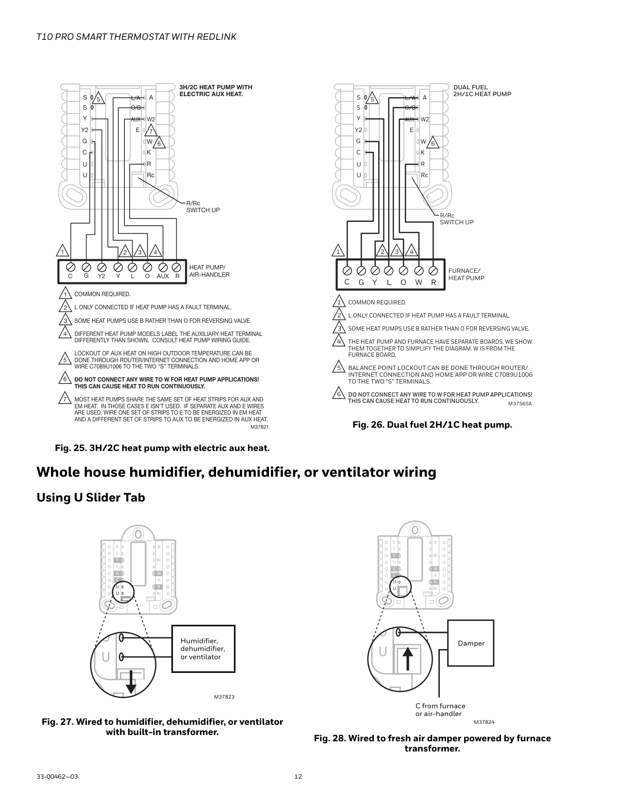
1 COMMON REQUIRED. L ONLY CONNECTED IF HEAT PUMP HAS A FAULT TERMINAL. SOME HEAT PUMPS USE B RATHER THAN O FOR REVERSING VALVE. DIFFERENT HEAT PUMP MODELS LABEL THE AUXILIARY HEAT TERMINAL DIFFERENTLY THAN SHOWN. CONSULT HEAT PUMP WIRING GUIDE. LOCKOUT OF AUX HEAT ON HIGH OUTDOOR TEMPERATURE CAN BE DONE THROUGH ROUTER/INTERNET CONNECTION AND HOME APP OR WIRE C7089U1006 TO THE TWO “S” TERMINALS.
DO NOT CONNECT ANY WIRE TO W FOR HEAT PUMP APPLICATIONS! THIS CAN CAUSE HEAT TO RUN CONTINUOUSLY.
MOST HEAT PUMPS SHARE THE SAME SET OF HEAT STRIPS FOR AUX AND EM HEAT. IN THOSE CASES E ISN’T USED. IF SEPARATE AUX AND E WIRES ARE USED, WIRE ONE SET OF STRIPS TO E TO BE ENERGIZED IN EM HEAT AND A DIFFERENT SET OF STRIPS TO AUX TO BE ENERGIZED IN AUX HEAT.
M37821
######################### DUAL FUEL 2H/1C HEAT PUMP
S S Y
A
L/A
5
##################### O/B
AUX
W2
Y2 G C
E
W K
6
R
U
Rc
U
R/Rc SWITCH UP
2 3 4
RWLGCOY
FURNACE/ HEAT PUMP
1 COMMON REQUIRED. L ONLY CONNECTED IF HEAT PUMP HAS A FAULT TERMINAL. SOME HEAT PUMPS USE B RATHER THAN O FOR REVERSING VALVE. THE HEAT PUMP AND FURNACE HAVE SEPARATE BOARDS. WE SHOW THEM TOGETHER TO SIMPLIFY THE DIAGRAM. W IS FROM THE FURNACE BOARD. BALANCE POINT LOCKOUT CAN BE DONE THROUGH ROUTER/ INTERNET CONNECTION AND HOME APP OR WIRE C7089U1006 TO THE TWO “S” TERMINALS.
DO NOT CONNECT ANY WIRE TO W FOR HEAT PUMP APPLICATIONS! THIS CAN CAUSE HEAT TO RUN CONTINUOUSLY.
M37565A
Fig. 26. Dual fuel 2H/1C heat pump.
Fig. 25. 3H/2C heat pump with electric aux heat.
#### Whole house humidifier, dehumidifier, or ventilator wiring Using U Slider Tab
| |Humidifier, dehumidifier, or ventilator| |---|---| | |Humidifier, dehumidifier, or ventilator| | |Humidifier, dehumidifier, or ventilator|
Damper
M37823
C from furnace or air-handler
Fig. 27. Wired to humidifier, dehumidifier, or ventilator with built-in transformer.
M37824
Fig. 28. Wired to fresh air damper powered by furnace transformer.
Humidifier, dehumidifier, or ventilator
R from 24 volt transformer
C (common) from 24 volt transformer
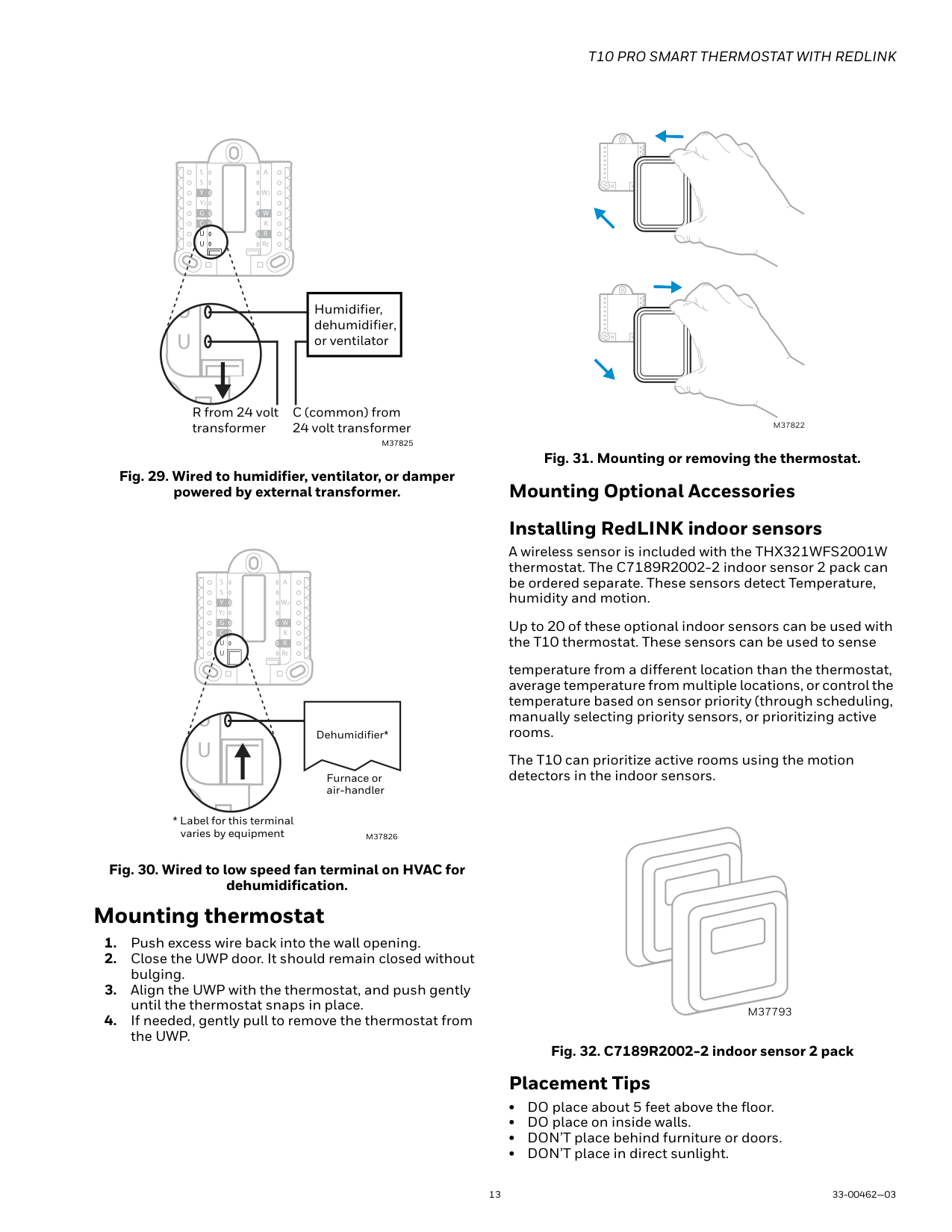
M37825
Fig. 29. Wired to humidifier, ventilator, or damper powered by external transformer.
| |Dehumidifier*| |---|---| | |Dehumidifier*|
Furnace or air-handler
Fig. 30. Wired to low speed fan terminal on HVAC for dehumidification.
#### Mounting thermostat
M37822
Mounting Optional Accessories Installing RedLINK indoor sensors
A wireless sensor is included with the THX321WFS2001W thermostat. The C7189R2002-2 indoor sensor 2 pack can be ordered separate. These sensors detect Temperature, humidity and motion.
Up to 20 of these optional indoor sensors can be used with the T10 thermostat. These sensors can be used to sense
temperature from a different location than the thermostat, average temperature from multiple locations, or control the temperature based on sensor priority (through scheduling, manually selecting priority sensors, or prioritizing active rooms.
The T10 can prioritize active rooms using the motion detectors in the indoor sensors.
################# M37793
Placement Tips
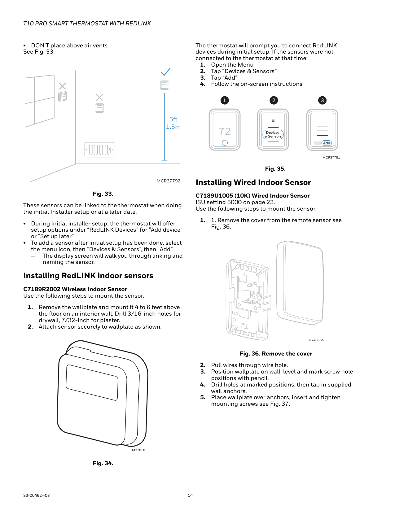
######## • DON’T place above air vents. See Fig. 33.
###### 5ft 1.5m
################## MCR37792
Fig. 33.
These sensors can be linked to the thermostat when doing the initial Installer setup or at a later date.
— The display screen will walk you through linking and
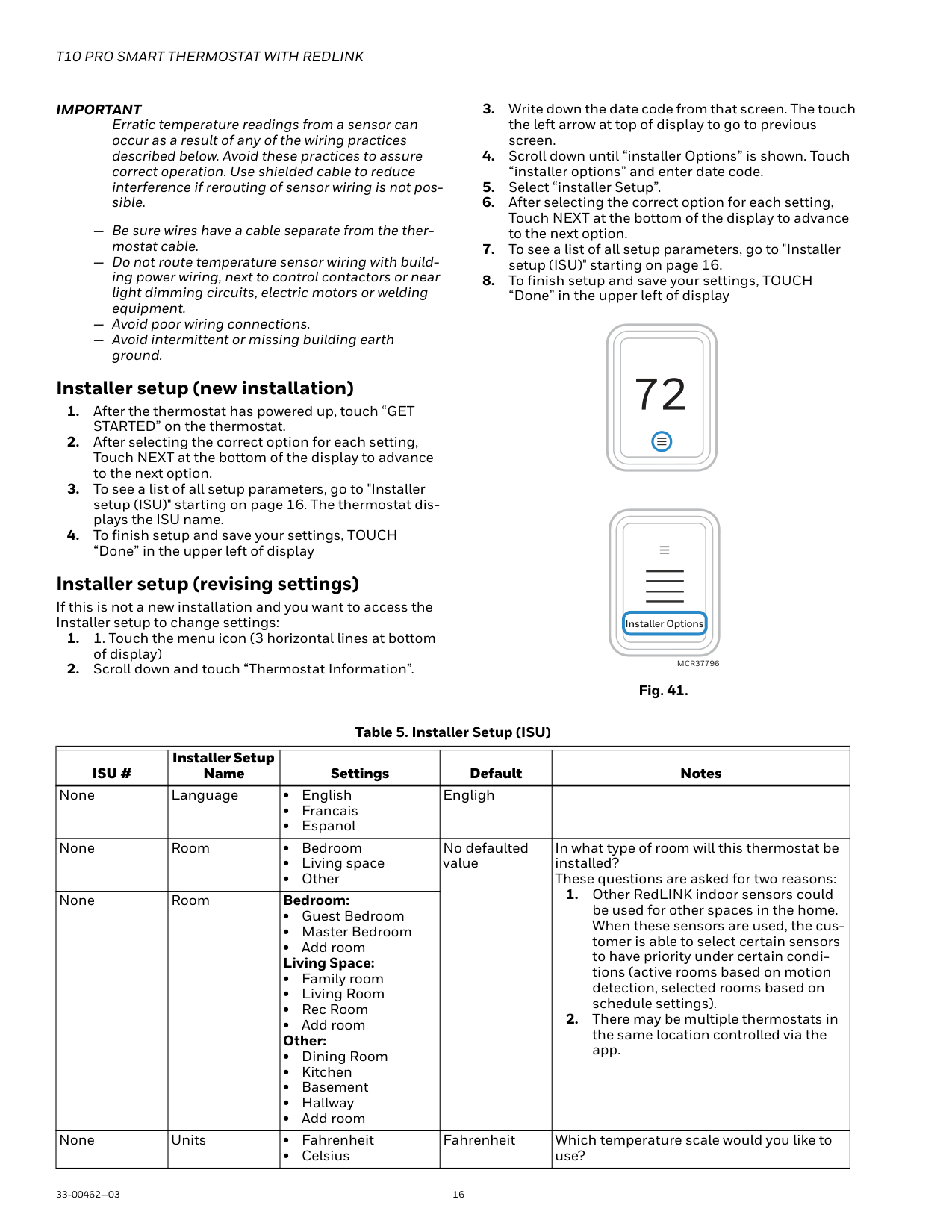
naming the sensor. Installing RedLINK indoor sensors C7189R2002 Wireless Indoor Sensor Use the following steps to mount the sensor.
M37818
Fig. 34.
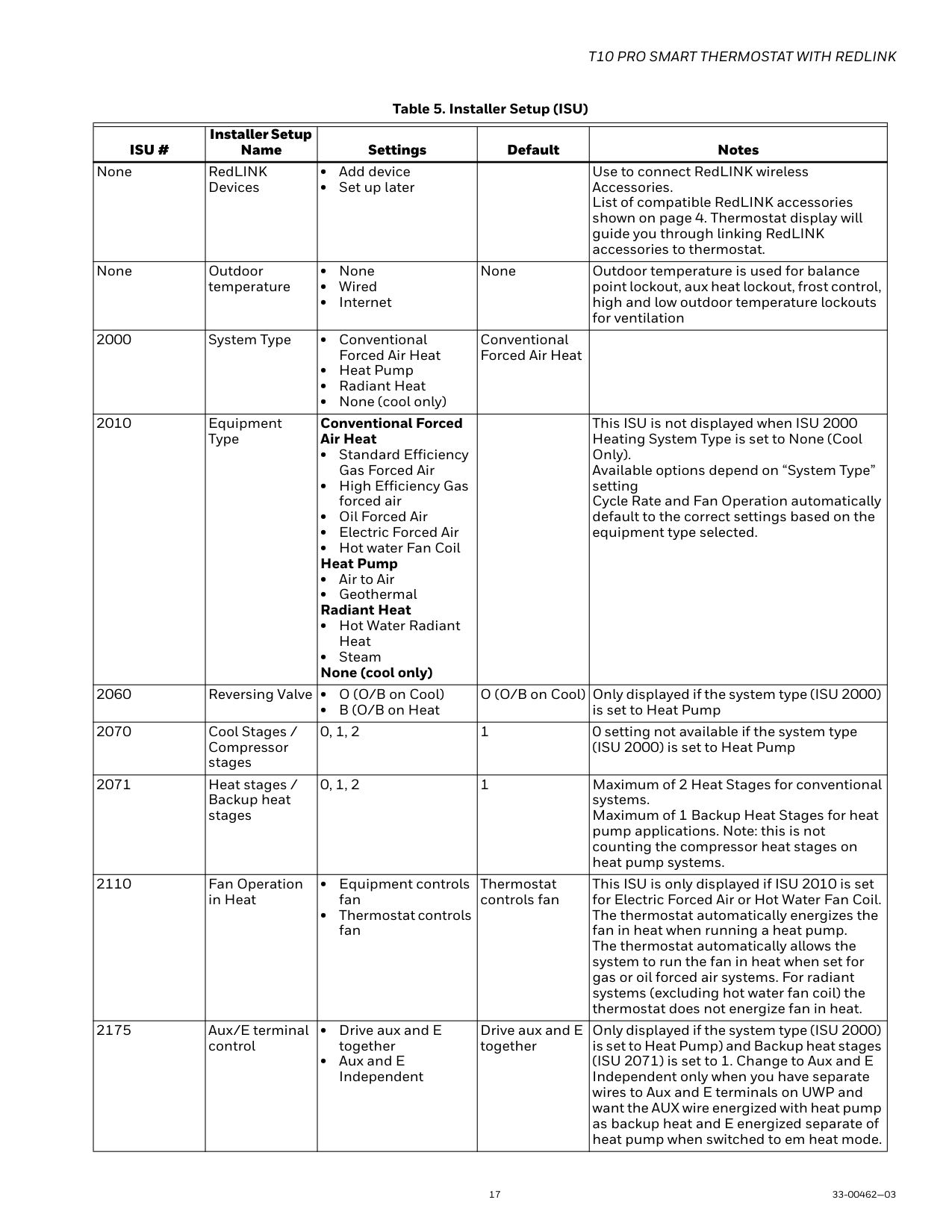
The thermostat will prompt you to connect RedLINK devices during initial setup. If the sensors were not connected to the thermostat at that time:
######### 1 32
Devices & Sensors
Add
MCR37791
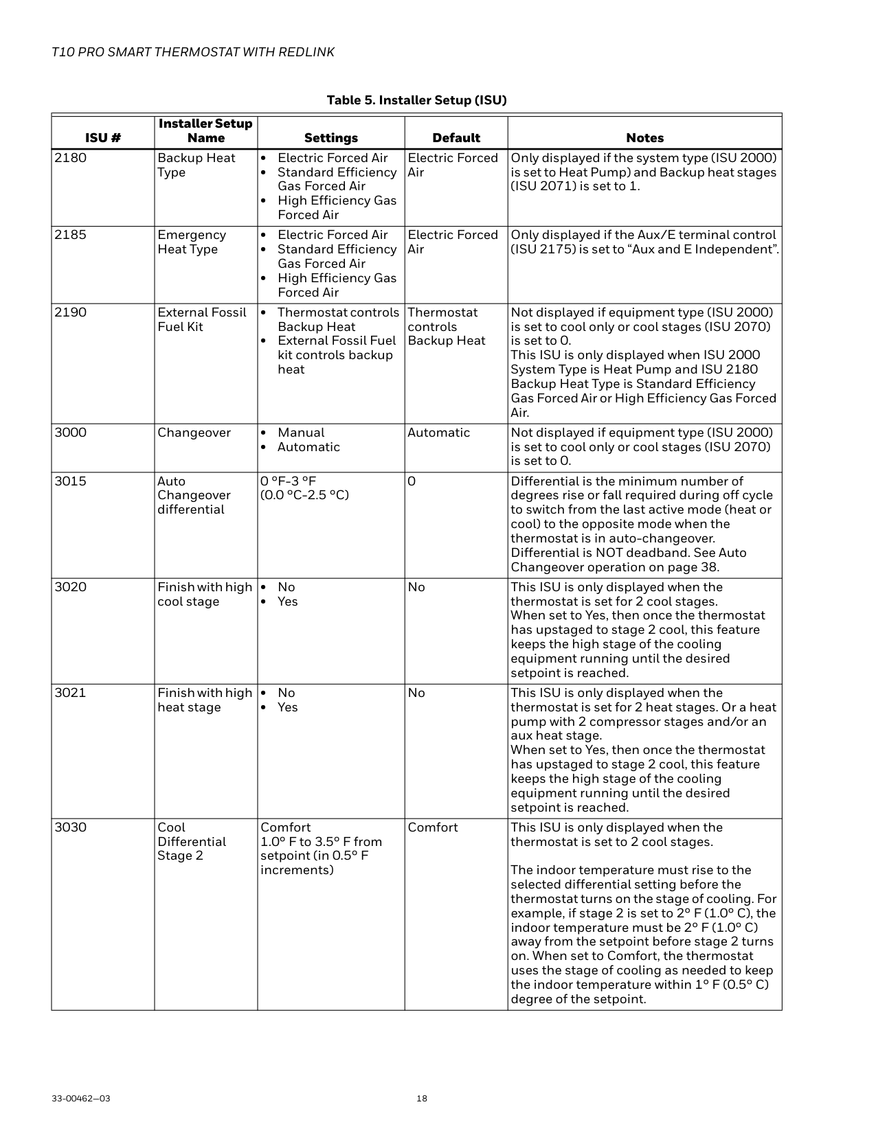
Fig. 35. Installing Wired Indoor Sensor C7189U1005 (10K) Wired Indoor Sensor ISU setting 5000 on page 23. Use the following steps to mount the sensor:
Fig. 36. Remove the cover
UP
M24056A
UP
M24057A
Fig. 37. Mount wallplate to wall 6. Replace the cover on the remote sensor.
CAUTION Electrical Shock Hazard. Can cause electrical shock or equipment damage. Disconnect power supply before connecting wiring.
Wiring 1 C7189U1005 sensor (10k ohm) for temperature control. Select 10K in the Installer Setup (ISU 5030) when using C7189U1005 sensor(s).
C7189
S S
UWP M37794
Wiring 4 C7189U1005 sensors (10k ohm) for temperature averaging network. Select 10K in the Installer Setup (ISU
5030) when using C7189U1005 sensor(s).
1
S S C7189 C7189
UWP
C7189 C7189
1
THE NUMBER OF C7189U SENSORS MUST BE A SQUARE NUMBER (1, 4, 9, 16, ETC.)
M37795
Installing Wired outdoor sensor
See ISU setting “outdoor temperature” on page 17 for correct thermostat configuration.
Follow instructions included with C7089U1006 wired outdoor sensor.
Location and Mounting (Fig. 40) Mount the sensor where:
Do not mount the sensor:
M7514
Fig. 40.
CAUTION Electrical Interference (Noise) Hazard. Can cause erratic system operation. Keep wiring at least one foot away from large inductive loads such as motors, line starters, lighting ballasts and large power distribution panels. Use shielded cable to reduce interference when rerouting is not possible.
IMPORTANT Erratic temperature readings from a sensor can occur as a result of any of the wiring practices described below. Avoid these practices to assure correct operation. Use shielded cable to reduce interference if rerouting of sensor wiring is not possible.
— Be sure wires have a cable separate from the thermostat cable.
— Do not route temperature sensor wiring with building power wiring, next to control contactors or near light dimming circuits, electric motors or welding equipment.
— Avoid poor wiring connections.
— Avoid intermittent or missing building earth ground.
Installer setup (new installation)
Installer setup (revising settings)
If this is not a new installation and you want to access the Installer setup to change settings:
################### Installer Options
############################# MCR37796
Table 5. Installer Setup (ISU)
| | | | | | |---|---|---|---|---| |ISU #|Installer Setup Name|Settings|Default|Notes| |None|Language|• English
• Francais
• Espanol
|Engligh| | |None|Room|• Bedroom
• Living space
• Other
|No defaulted value|In what type of room will this thermostat be installed? These questions are asked for two reasons:
1. Other RedLINK indoor sensors could be used for other spaces in the home. When these sensors are used, the customer is able to select certain sensors to have priority under certain conditions (active rooms based on motion detection, selected rooms based on schedule settings).
2. There may be multiple thermostats in the same location controlled via the app.
| |None|Room|Bedroom:
• Guest Bedroom
• Master Bedroom
• Add room Living Space:
• Family room
• Living Room
• Rec Room
• Add room Other:
• Dining Room
• Kitchen
• Basement
• Hallway
• Add room
|No defaulted value|In what type of room will this thermostat be installed? These questions are asked for two reasons:
1. Other RedLINK indoor sensors could be used for other spaces in the home. When these sensors are used, the customer is able to select certain sensors to have priority under certain conditions (active rooms based on motion detection, selected rooms based on schedule settings).
2. There may be multiple thermostats in the same location controlled via the app.
| |None|Units|• Fahrenheit
• Celsius
|Fahrenheit|Which temperature scale would you like to use?|
| | | | | | |---|---|---|---|---| |ISU #|Installer Setup Name|Settings|Default|Notes| |None|RedLINK Devices|• Add device
• Set up later
| |Use to connect RedLINK wireless Accessories. List of compatible RedLINK accessories shown on page 4. Thermostat display will guide you through linking RedLINK accessories to thermostat.| |None|Outdoor temperature|• None
• Wired
• Internet
|None|Outdoor temperature is used for balance point lockout, aux heat lockout, frost control, high and low outdoor temperature lockouts for ventilation| |2000|System Type|• Conventional Forced Air Heat
• Heat Pump
• Radiant Heat
• None (cool only)
|Conventional Forced Air Heat| | |2010|Equipment Type|Conventional Forced Air Heat
• Standard Efficiency Gas Forced Air
• High Efficiency Gas forced air
• Oil Forced Air
• Electric Forced Air
• Hot water Fan Coil Heat Pump
• Air to Air
• Geothermal Radiant Heat
• Hot Water Radiant Heat
• Steam None (cool only)
| |This ISU is not displayed when ISU 2000 Heating System Type is set to None (Cool Only). Available options depend on “System Type” setting Cycle Rate and Fan Operation automatically default to the correct settings based on the equipment type selected.| |2060|Reversing Valve|• O (O/B on Cool)
• B (O/B on Heat
|O (O/B on Cool)|Only displayed if the system type (ISU 2000) is set to Heat Pump| |2070|Cool Stages / Compressor stages|0, 1, 2|1|0 setting not available if the system type (ISU 2000) is set to Heat Pump| |2071|Heat stages / Backup heat stages|0, 1, 2|1|Maximum of 2 Heat Stages for conventional systems. Maximum of 1 Backup Heat Stages for heat pump applications. Note: this is not counting the compressor heat stages on heat pump systems.| |2110|Fan Operation in Heat|• Equipment controls fan
• Thermostat controls fan
|Thermostat controls fan|This ISU is only displayed if ISU 2010 is set for Electric Forced Air or Hot Water Fan Coil. The thermostat automatically energizes the fan in heat when running a heat pump. The thermostat automatically allows the system to run the fan in heat when set for gas or oil forced air systems. For radiant systems (excluding hot water fan coil) the thermostat does not energize fan in heat.| |2175|Aux/E terminal control|• Drive aux and E together
• Aux and E Independent
|Drive aux and E together|Only displayed if the system type (ISU 2000) is set to Heat Pump) and Backup heat stages (ISU 2071) is set to 1. Change to Aux and E Independent only when you have separate wires to Aux and E terminals on UWP and want the AUX wire energized with heat pump as backup heat and E energized separate of heat pump when switched to em heat mode.|
| | | | | | |---|---|---|---|---| |ISU #|Installer Setup Name|Settings|Default|Notes| |2180|Backup Heat Type|• Electric Forced Air
• Standard Efficiency Gas Forced Air
• High Efficiency Gas Forced Air
|Electric Forced Air|Only displayed if the system type (ISU 2000) is set to Heat Pump) and Backup heat stages (ISU 2071) is set to 1.| |2185|Emergency Heat Type|• Electric Forced Air
• Standard Efficiency Gas Forced Air
• High Efficiency Gas Forced Air
|Electric Forced Air|Only displayed if the Aux/E terminal control (ISU 2175) is set to “Aux and E Independent”.| |2190|External Fossil Fuel Kit|• Thermostat controls Backup Heat
• External Fossil Fuel kit controls backup heat
|Thermostat controls Backup Heat|Not displayed if equipment type (ISU 2000) is set to cool only or cool stages (ISU 2070) is set to 0. This ISU is only displayed when ISU 2000 System Type is Heat Pump and ISU 2180 Backup Heat Type is Standard Efficiency Gas Forced Air or High Efficiency Gas Forced Air.| |3000|Changeover|• Manual
• Automatic
|Automatic|Not displayed if equipment type (ISU 2000) is set to cool only or cool stages (ISU 2070) is set to 0.| |3015|Auto Changeover differential|0 °F-3 °F (0.0 °C-2.5 °C)|0|Differential is the minimum number of degrees rise or fall required during off cycle to switch from the last active mode (heat or cool) to the opposite mode when the thermostat is in auto-changeover. Differential is NOT deadband. See Auto Changeover operation on page 38.| |3020|Finish with high cool stage|• No
• Yes
|No|This ISU is only displayed when the thermostat is set for 2 cool stages. When set to Yes, then once the thermostat has upstaged to stage 2 cool, this feature keeps the high stage of the cooling equipment running until the desired setpoint is reached.| |3021|Finish with high heat stage|• No
• Yes
|No|This ISU is only displayed when the thermostat is set for 2 heat stages. Or a heat pump with 2 compressor stages and/or an aux heat stage. When set to Yes, then once the thermostat has upstaged to stage 2 cool, this feature keeps the high stage of the cooling equipment running until the desired setpoint is reached.| |3030|Cool Differential Stage 2|Comfort 1.0° F to 3.5° F from setpoint (in 0.5° F increments)|Comfort|This ISU is only displayed when the thermostat is set to 2 cool stages.
The indoor temperature must rise to the selected differential setting before the thermostat turns on the stage of cooling. For example, if stage 2 is set to 2° F (1.0° C), the indoor temperature must be 2° F (1.0° C) away from the setpoint before stage 2 turns on. When set to Comfort, the thermostat uses the stage of cooling as needed to keep the indoor temperature within 1° F (0.5° C) degree of the setpoint.|
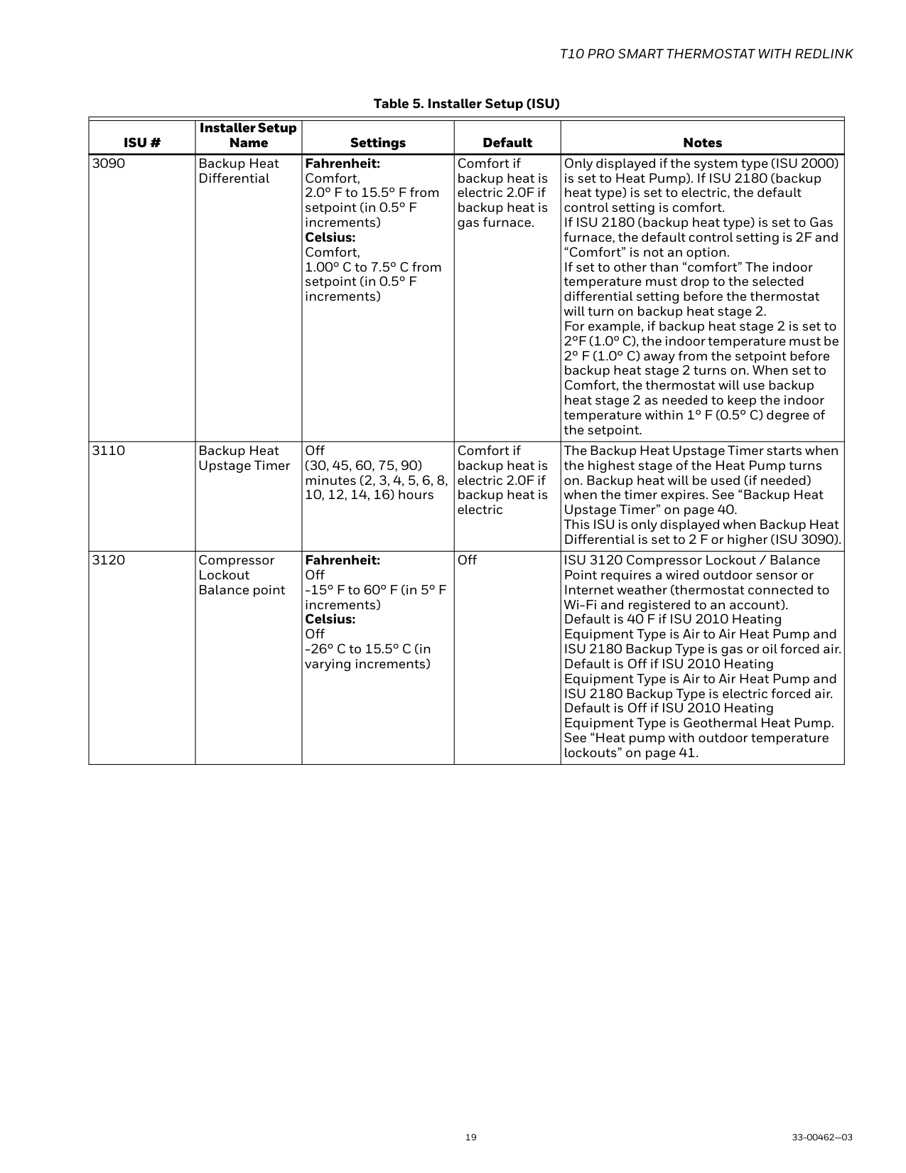
| | | | | | |---|---|---|---|---| |ISU #|Installer Setup Name|Settings|Default|Notes| |3090|Backup Heat Differential|Fahrenheit: Comfort, 2.0° F to 15.5° F from setpoint (in 0.5° F increments) Celsius: Comfort, 1.00° C to 7.5° C from setpoint (in 0.5° F increments)|Comfort if backup heat is electric 2.0F if backup heat is gas furnace.|Only displayed if the system type (ISU 2000) is set to Heat Pump). If ISU 2180 (backup heat type) is set to electric, the default control setting is comfort. If ISU 2180 (backup heat type) is set to Gas furnace, the default control setting is 2F and “Comfort” is not an option. If set to other than “comfort” The indoor temperature must drop to the selected differential setting before the thermostat will turn on backup heat stage 2. For example, if backup heat stage 2 is set to 2°F (1.0° C), the indoor temperature must be 2° F (1.0° C) away from the setpoint before backup heat stage 2 turns on. When set to Comfort, the thermostat will use backup heat stage 2 as needed to keep the indoor temperature within 1° F (0.5° C) degree of the setpoint.| |3110|Backup Heat Upstage Timer|Off (30, 45, 60, 75, 90) minutes (2, 3, 4, 5, 6, 8, 10, 12, 14, 16) hours|Comfort if backup heat is electric 2.0F if backup heat is electric|The Backup Heat Upstage Timer starts when the highest stage of the Heat Pump turns on. Backup heat will be used (if needed) when the timer expires. See “Backup Heat Upstage Timer” on page 40. This ISU is only displayed when Backup Heat Differential is set to 2 F or higher (ISU 3090).| |3120|Compressor Lockout Balance point|Fahrenheit: Off
-15° F to 60° F (in 5° F increments) Celsius: Off
-26° C to 15.5° C (in varying increments)
|Off|ISU 3120 Compressor Lockout / Balance Point requires a wired outdoor sensor or Internet weather (thermostat connected to Wi-Fi and registered to an account). Default is 40 F if ISU 2010 Heating Equipment Type is Air to Air Heat Pump and ISU 2180 Backup Type is gas or oil forced air. Default is Off if ISU 2010 Heating Equipment Type is Air to Air Heat Pump and ISU 2180 Backup Type is electric forced air. Default is Off if ISU 2010 Heating Equipment Type is Geothermal Heat Pump. See “Heat pump with outdoor temperature lockouts” on page 41.|
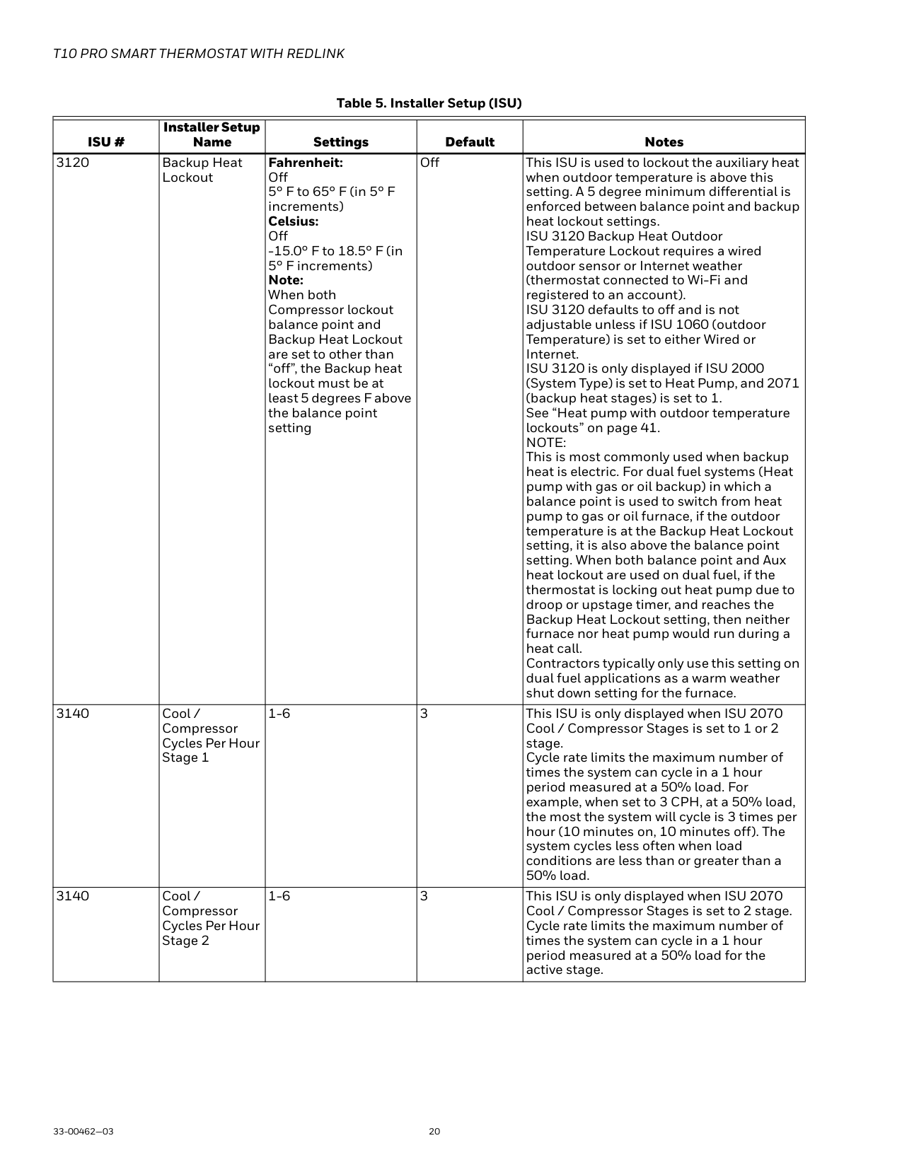
| | | | | | |---|---|---|---|---| |ISU #|Installer Setup Name|Settings|Default|Notes| |3120|Backup Heat Lockout|Fahrenheit: Off 5° F to 65° F (in 5° F increments) Celsius: Off
-15.0° F to 18.5° F (in 5° F increments) Note: When both Compressor lockout balance point and Backup Heat Lockout are set to other than “off”, the Backup heat lockout must be at least 5 degrees F above the balance point setting|Off|This ISU is used to lockout the auxiliary heat when outdoor temperature is above this setting. A 5 degree minimum differential is enforced between balance point and backup heat lockout settings. ISU 3120 Backup Heat Outdoor Temperature Lockout requires a wired outdoor sensor or Internet weather (thermostat connected to Wi-Fi and registered to an account). ISU 3120 defaults to off and is not adjustable unless if ISU 1060 (outdoor Temperature) is set to either Wired or Internet. ISU 3120 is only displayed if ISU 2000 (System Type) is set to Heat Pump, and 2071 (backup heat stages) is set to 1. See “Heat pump with outdoor temperature lockouts” on page 41. NOTE: This is most commonly used when backup heat is electric. For dual fuel systems (Heat pump with gas or oil backup) in which a balance point is used to switch from heat pump to gas or oil furnace, if the outdoor temperature is at the Backup Heat Lockout setting, it is also above the balance point setting. When both balance point and Aux heat lockout are used on dual fuel, if the thermostat is locking out heat pump due to droop or upstage timer, and reaches the Backup Heat Lockout setting, then neither furnace nor heat pump would run during a heat call. Contractors typically only use this setting on dual fuel applications as a warm weather shut down setting for the furnace.| |3140|Cool / Compressor Cycles Per Hour Stage 1|1-6|3|This ISU is only displayed when ISU 2070 Cool / Compressor Stages is set to 1 or 2 stage. Cycle rate limits the maximum number of times the system can cycle in a 1 hour period measured at a 50% load. For example, when set to 3 CPH, at a 50% load, the most the system will cycle is 3 times per hour (10 minutes on, 10 minutes off). The system cycles less often when load conditions are less than or greater than a 50% load.| |3140|Cool / Compressor Cycles Per Hour Stage 2|1-6|3|This ISU is only displayed when ISU 2070 Cool / Compressor Stages is set to 2 stage. Cycle rate limits the maximum number of times the system can cycle in a 1 hour period measured at a 50% load for the active stage.|
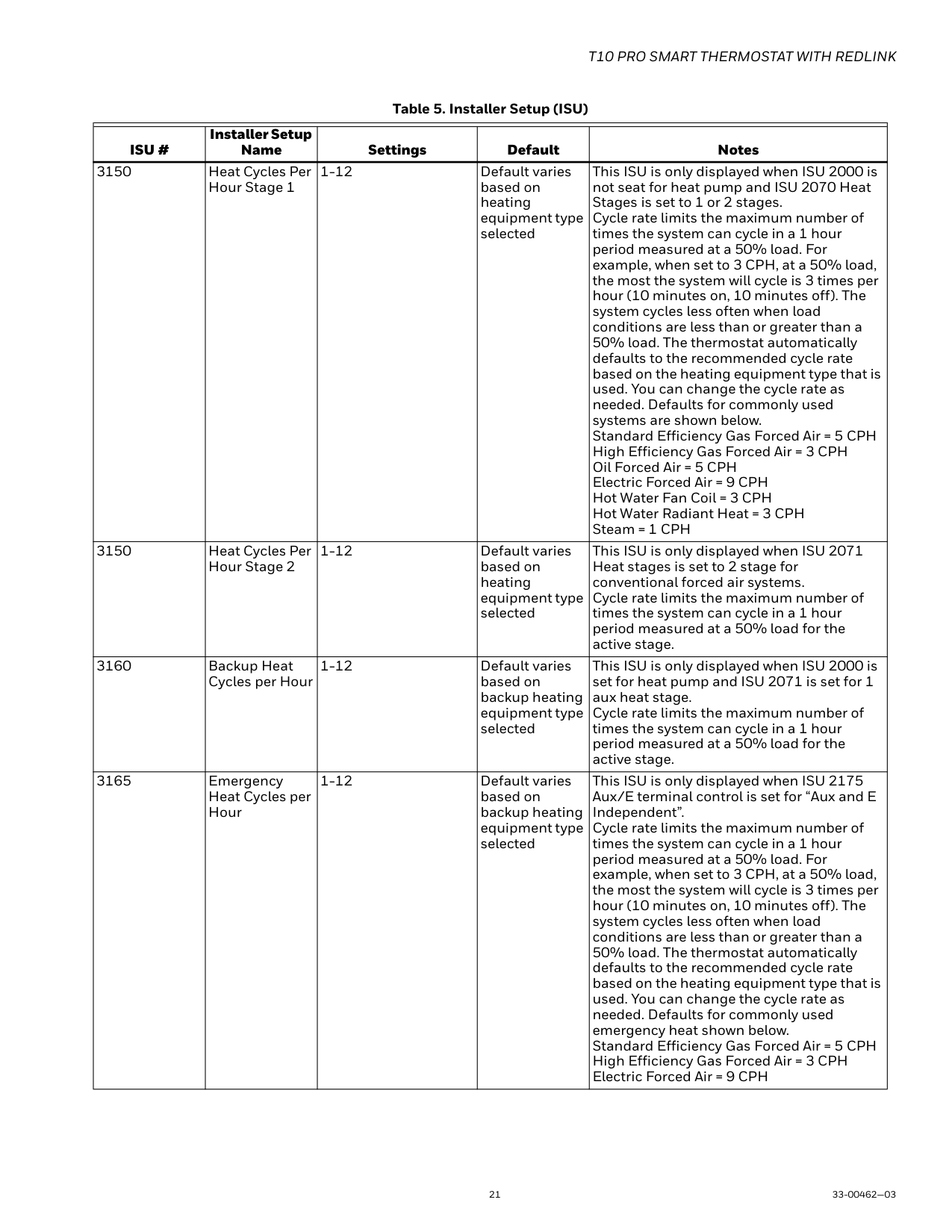
| | | | | | |---|---|---|---|---| |ISU #|Installer Setup Name|Settings|Default|Notes| |3150|Heat Cycles Per Hour Stage 1|1-12|Default varies based on heating equipment type selected|This ISU is only displayed when ISU 2000 is not seat for heat pump and ISU 2070 Heat Stages is set to 1 or 2 stages. Cycle rate limits the maximum number of times the system can cycle in a 1 hour period measured at a 50% load. For example, when set to 3 CPH, at a 50% load, the most the system will cycle is 3 times per hour (10 minutes on, 10 minutes off). The system cycles less often when load conditions are less than or greater than a 50% load. The thermostat automatically defaults to the recommended cycle rate based on the heating equipment type that is used. You can change the cycle rate as needed. Defaults for commonly used systems are shown below. Standard Efficiency Gas Forced Air = 5 CPH High Efficiency Gas Forced Air = 3 CPH Oil Forced Air = 5 CPH Electric Forced Air = 9 CPH Hot Water Fan Coil = 3 CPH Hot Water Radiant Heat = 3 CPH Steam = 1 CPH| |3150|Heat Cycles Per Hour Stage 2|1-12|Default varies based on heating equipment type selected|This ISU is only displayed when ISU 2071 Heat stages is set to 2 stage for conventional forced air systems. Cycle rate limits the maximum number of times the system can cycle in a 1 hour period measured at a 50% load for the active stage.| |3160|Backup Heat Cycles per Hour|1-12|Default varies based on backup heating equipment type selected|This ISU is only displayed when ISU 2000 is set for heat pump and ISU 2071 is set for 1 aux heat stage. Cycle rate limits the maximum number of times the system can cycle in a 1 hour period measured at a 50% load for the active stage.| |3165|Emergency Heat Cycles per Hour|1-12|Default varies based on backup heating equipment type selected|This ISU is only displayed when ISU 2175 Aux/E terminal control is set for “Aux and E Independent”. Cycle rate limits the maximum number of times the system can cycle in a 1 hour period measured at a 50% load. For example, when set to 3 CPH, at a 50% load, the most the system will cycle is 3 times per hour (10 minutes on, 10 minutes off). The system cycles less often when load conditions are less than or greater than a 50% load. The thermostat automatically defaults to the recommended cycle rate based on the heating equipment type that is used. You can change the cycle rate as needed. Defaults for commonly used emergency heat shown below. Standard Efficiency Gas Forced Air = 5 CPH High Efficiency Gas Forced Air = 3 CPH Electric Forced Air = 9 CPH|
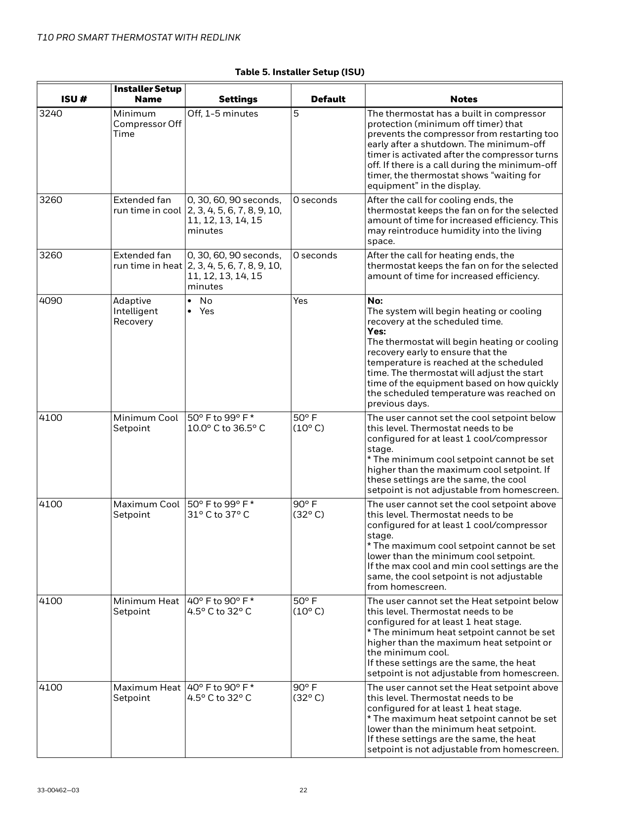
| | | | | | |---|---|---|---|---| |ISU #|Installer Setup Name|Settings|Default|Notes| |3240|Minimum Compressor Off Time|Off, 1-5 minutes|5|The thermostat has a built in compressor protection (minimum off timer) that prevents the compressor from restarting too early after a shutdown. The minimum-off timer is activated after the compressor turns off. If there is a call during the minimum-off timer, the thermostat shows “waiting for equipment” in the display.| |3260|Extended fan run time in cool|0, 30, 60, 90 seconds, 2, 3, 4, 5, 6, 7, 8, 9, 10, 11, 12, 13, 14, 15 minutes|0 seconds|After the call for cooling ends, the thermostat keeps the fan on for the selected amount of time for increased efficiency. This may reintroduce humidity into the living space.| |3260|Extended fan run time in heat|0, 30, 60, 90 seconds, 2, 3, 4, 5, 6, 7, 8, 9, 10, 11, 12, 13, 14, 15 minutes|0 seconds|After the call for heating ends, the thermostat keeps the fan on for the selected amount of time for increased efficiency.| |4090|Adaptive Intelligent Recovery|• No
• Yes
|Yes|No: The system will begin heating or cooling recovery at the scheduled time. Yes: The thermostat will begin heating or cooling recovery early to ensure that the temperature is reached at the scheduled time. The thermostat will adjust the start time of the equipment based on how quickly the scheduled temperature was reached on previous days.| |4100|Minimum Cool Setpoint|50° F to 99° F * 10.0° C to 36.5° C|50° F (10° C)|The user cannot set the cool setpoint below this level. Thermostat needs to be configured for at least 1 cool/compressor stage.
* The minimum cool setpoint cannot be set higher than the maximum cool setpoint. If these settings are the same, the cool setpoint is not adjustable from homescreen.| |4100|Maximum Cool Setpoint|50° F to 99° F * 31° C to 37° C|90° F (32° C)|The user cannot set the cool setpoint above this level. Thermostat needs to be configured for at least 1 cool/compressor stage.
* The maximum cool setpoint cannot be set lower than the minimum cool setpoint. If the max cool and min cool settings are the same, the cool setpoint is not adjustable from homescreen.| |4100|Minimum Heat Setpoint|40° F to 90° F * 4.5° C to 32° C|50° F (10° C)|The user cannot set the Heat setpoint below this level. Thermostat needs to be configured for at least 1 heat stage.
* The minimum heat setpoint cannot be set higher than the maximum heat setpoint or the minimum cool. If these settings are the same, the heat setpoint is not adjustable from homescreen.| |4100|Maximum Heat Setpoint|40° F to 90° F * 4.5° C to 32° C|90° F (32° C)|The user cannot set the Heat setpoint above this level. Thermostat needs to be configured for at least 1 heat stage.
* The maximum heat setpoint cannot be set lower than the minimum heat setpoint. If these settings are the same, the heat setpoint is not adjustable from homescreen.|
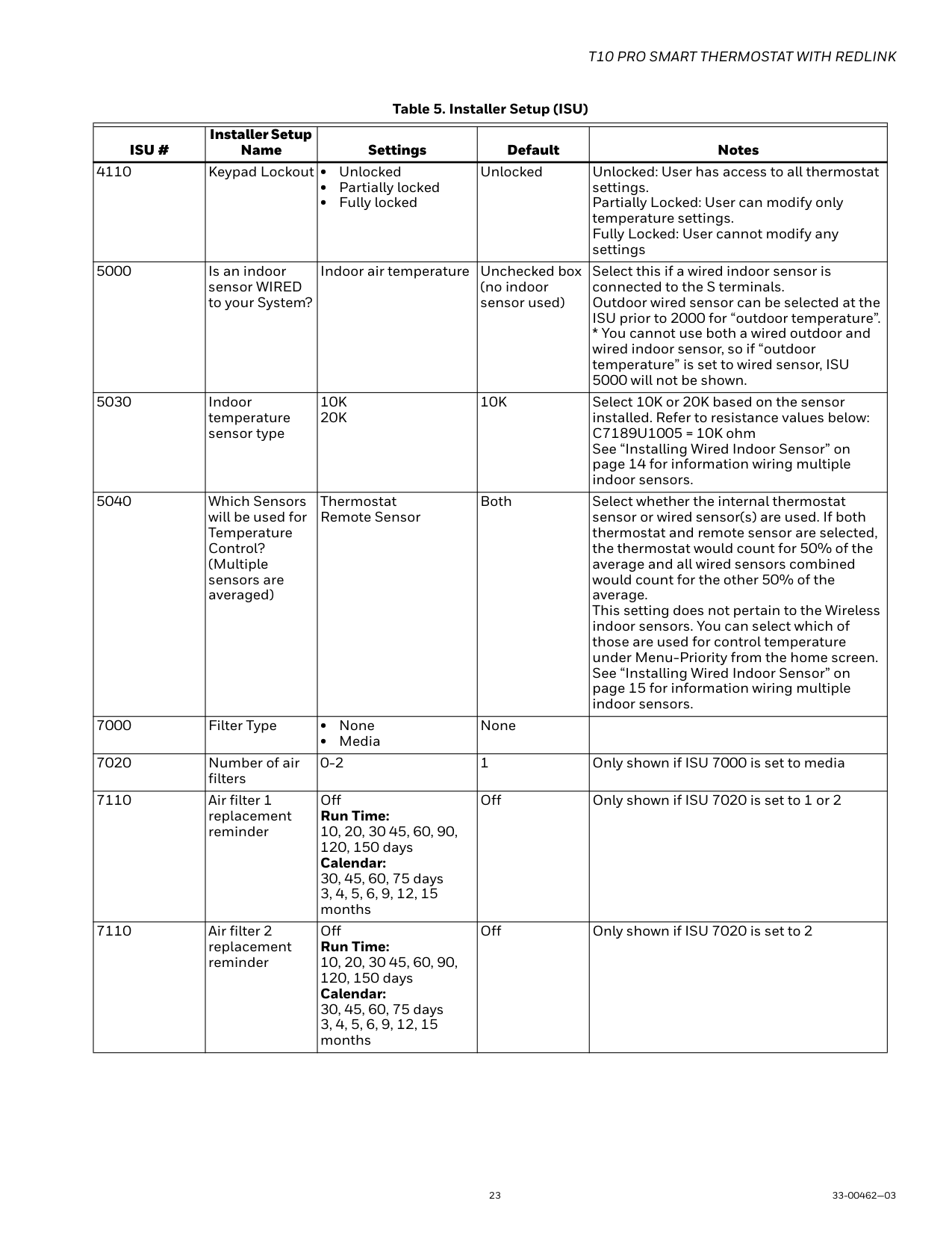
| | | | | | |---|---|---|---|---| |ISU #|Installer Setup Name|Settings|Default|Notes| |4110|Keypad Lockout|• Unlocked
• Partially locked
• Fully locked
|Unlocked|Unlocked: User has access to all thermostat settings. Partially Locked: User can modify only temperature settings. Fully Locked: User cannot modify any settings| |5000|Is an indoor sensor WIRED to your System?|Indoor air temperature|Unchecked box (no indoor sensor used)|Select this if a wired indoor sensor is connected to the S terminals. Outdoor wired sensor can be selected at the ISU prior to 2000 for “outdoor temperature”. * You cannot use both a wired outdoor and wired indoor sensor, so if “outdoor temperature” is set to wired sensor, ISU 5000 will not be shown.| |5030|Indoor temperature sensor type|10K 20K|10K|Select 10K or 20K based on the sensor installed. Refer to resistance values below: C7189U1005 = 10K ohm See “Installing Wired Indoor Sensor” on page 14 for information wiring multiple indoor sensors.|
|5040|Which Sensors will be used for Temperature Control? (Multiple sensors are averaged)|Thermostat Remote Sensor|Both|Select whether the internal thermostat sensor or wired sensor(s) are used. If both thermostat and remote sensor are selected, the thermostat would count for 50% of the average and all wired sensors combined would count for the other 50% of the average. This setting does not pertain to the Wireless indoor sensors. You can select which of those are used for control temperature under Menu-Priority from the home screen. See “Installing Wired Indoor Sensor” on page 15 for information wiring multiple indoor sensors.| |7000|Filter Type|• None
• Media
|None| | |7020|Number of air filters|0-2|1|Only shown if ISU 7000 is set to media| |7110|Air filter 1 replacement reminder|Off Run Time: 10, 20, 30 45, 60, 90, 120, 150 days Calendar: 30, 45, 60, 75 days 3, 4, 5, 6, 9, 12, 15 months|Off|Only shown if ISU 7020 is set to 1 or 2| |7110|Air filter 2 replacement reminder|Off Run Time: 10, 20, 30 45, 60, 90, 120, 150 days Calendar: 30, 45, 60, 75 days 3, 4, 5, 6, 9, 12, 15 months|Off|Only shown if ISU 7020 is set to 2|
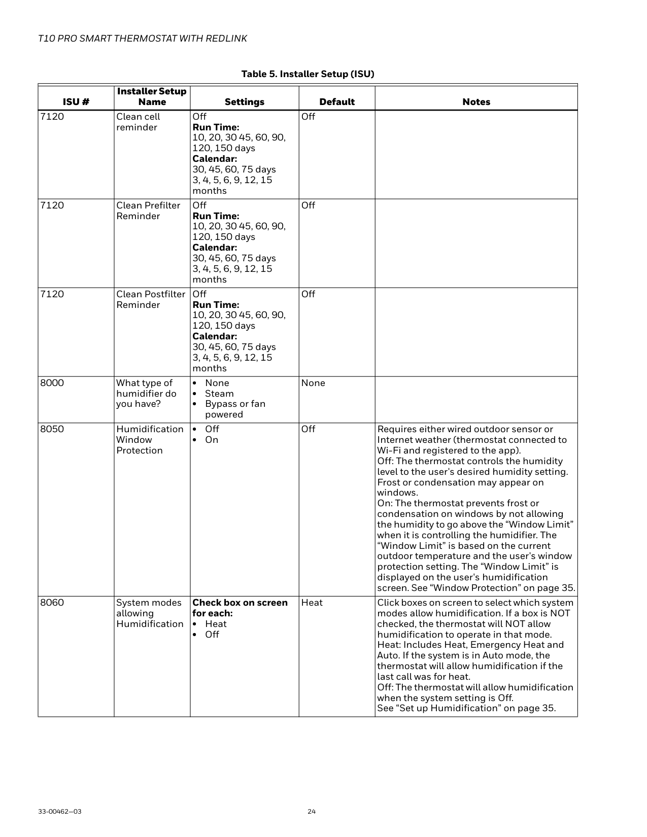
| | | | | | |---|---|---|---|---| |ISU #|Installer Setup Name|Settings|Default|Notes| |7120|Clean cell reminder|Off Run Time: 10, 20, 30 45, 60, 90, 120, 150 days Calendar: 30, 45, 60, 75 days 3, 4, 5, 6, 9, 12, 15 months|Off| | |7120|Clean Prefilter Reminder|Off Run Time: 10, 20, 30 45, 60, 90, 120, 150 days Calendar: 30, 45, 60, 75 days 3, 4, 5, 6, 9, 12, 15 months|Off| | |7120|Clean Postfilter Reminder|Off Run Time: 10, 20, 30 45, 60, 90, 120, 150 days Calendar: 30, 45, 60, 75 days 3, 4, 5, 6, 9, 12, 15 months|Off| | |8000|What type of humidifier do you have?|• None
• Steam
• Bypass or fan powered
|None| | |8050|Humidification Window Protection|• Off
• On
|Off|Requires either wired outdoor sensor or Internet weather (thermostat connected to Wi-Fi and registered to the app). Off: The thermostat controls the humidity level to the user's desired humidity setting. Frost or condensation may appear on windows. On: The thermostat prevents frost or condensation on windows by not allowing the humidity to go above the “Window Limit” when it is controlling the humidifier. The “Window Limit” is based on the current outdoor temperature and the user's window protection setting. The “Window Limit” is displayed on the user's humidification screen. See “Window Protection” on page 35.| |8060|System modes allowing Humidification|Check box on screen for each:
• Heat
• Off
|Heat|Click boxes on screen to select which system modes allow humidification. If a box is NOT checked, the thermostat will NOT allow humidification to operate in that mode. Heat: Includes Heat, Emergency Heat and Auto. If the system is in Auto mode, the thermostat will allow humidification if the last call was for heat. Off: The thermostat will allow humidification when the system setting is Off. See “Set up Humidification” on page 35.|
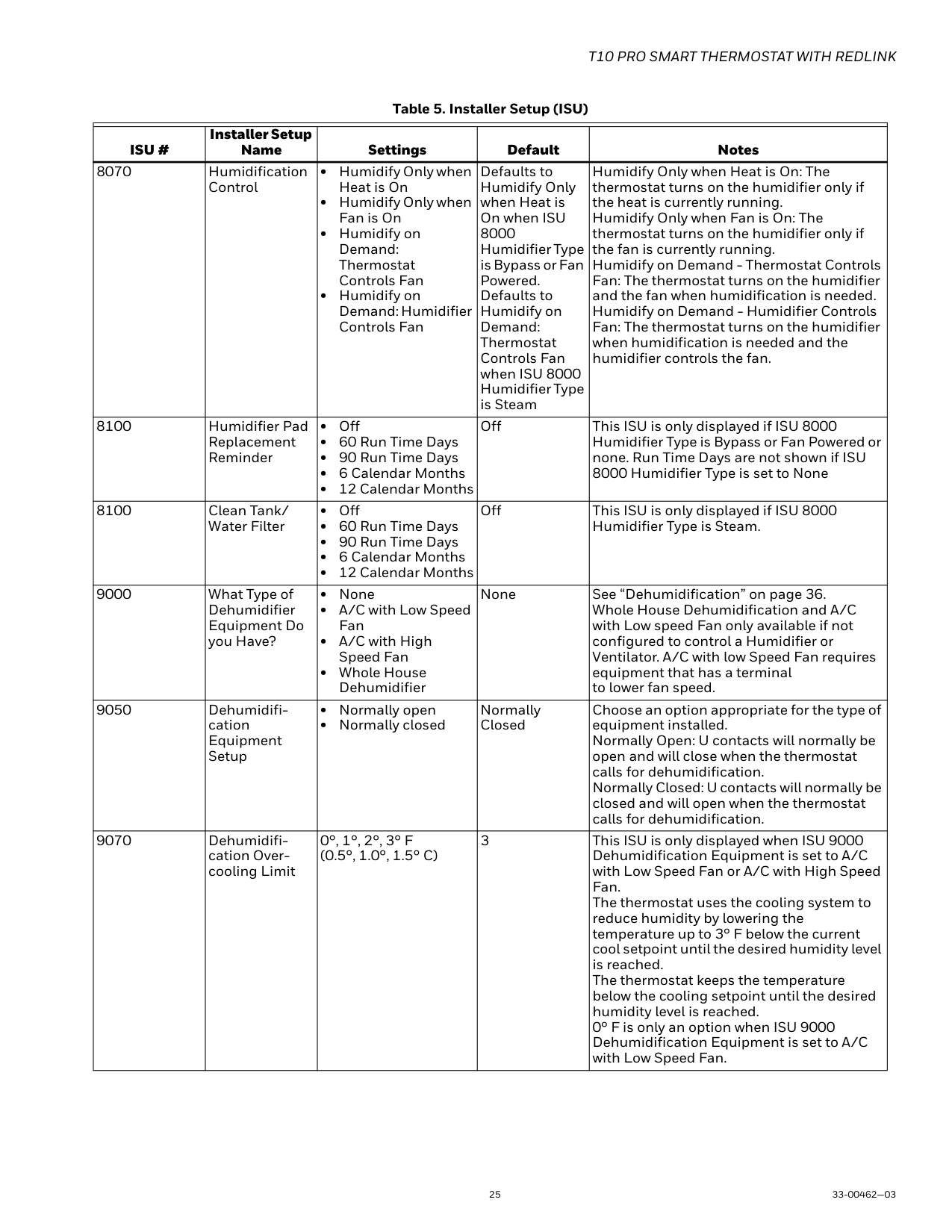
| | | | | | |---|---|---|---|---| |ISU #|Installer Setup Name|Settings|Default|Notes| |8070|Humidification Control|• Humidify Only when Heat is On
• Humidify Only when Fan is On
• Humidify on Demand: Thermostat Controls Fan
• Humidify on Demand: Humidifier Controls Fan
|Defaults to Humidify Only when Heat is On when ISU 8000 Humidifier Type is Bypass or Fan Powered. Defaults to Humidify on Demand: Thermostat Controls Fan when ISU 8000 Humidifier Type is Steam|Humidify Only when Heat is On: The thermostat turns on the humidifier only if the heat is currently running. Humidify Only when Fan is On: The thermostat turns on the humidifier only if the fan is currently running. Humidify on Demand - Thermostat Controls Fan: The thermostat turns on the humidifier and the fan when humidification is needed. Humidify on Demand - Humidifier Controls Fan: The thermostat turns on the humidifier when humidification is needed and the humidifier controls the fan.| |8100|Humidifier Pad Replacement Reminder|• Off
• 60 Run Time Days
• 90 Run Time Days
• 6 Calendar Months
• 12 Calendar Months
|Off|This ISU is only displayed if ISU 8000 Humidifier Type is Bypass or Fan Powered or none. Run Time Days are not shown if ISU 8000 Humidifier Type is set to None| |8100|Clean Tank/ Water Filter|• Off
• 60 Run Time Days
• 90 Run Time Days
• 6 Calendar Months
• 12 Calendar Months
|Off|This ISU is only displayed if ISU 8000 Humidifier Type is Steam.| |9000|What Type of Dehumidifier Equipment Do you Have?|• None
• A/C with Low Speed Fan
• A/C with High Speed Fan
• Whole House Dehumidifier
|None|See “Dehumidification” on page 36. Whole House Dehumidification and A/C with Low speed Fan only available if not configured to control a Humidifier or Ventilator. A/C with low Speed Fan requires equipment that has a terminal to lower fan speed.| |9050|Dehumidification Equipment Setup|• Normally open
• Normally closed
|Normally Closed|Choose an option appropriate for the type of equipment installed. Normally Open: U contacts will normally be open and will close when the thermostat calls for dehumidification. Normally Closed: U contacts will normally be closed and will open when the thermostat calls for dehumidification.| |9070|Dehumidification Overcooling Limit|0°, 1°, 2°, 3° F (0.5°, 1.0°, 1.5° C)|3|This ISU is only displayed when ISU 9000 Dehumidification Equipment is set to A/C with Low Speed Fan or A/C with High Speed Fan. The thermostat uses the cooling system to reduce humidity by lowering the temperature up to 3° F below the current cool setpoint until the desired humidity level is reached. The thermostat keeps the temperature below the cooling setpoint until the desired humidity level is reached. 0° F is only an option when ISU 9000 Dehumidification Equipment is set to A/C with Low Speed Fan.|
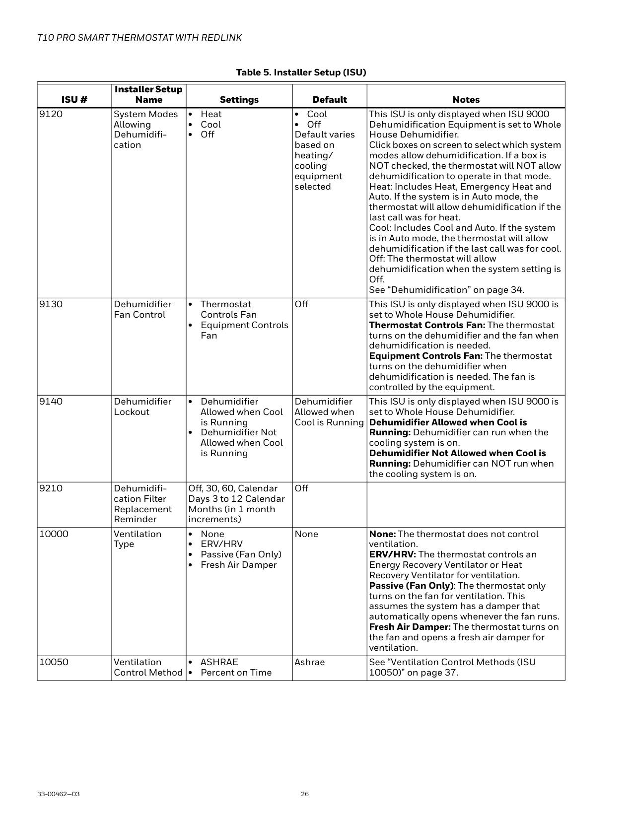
| | | | | | |---|---|---|---|---| |ISU #|Installer Setup Name|Settings|Default|Notes| |9120|System Modes Allowing Dehumidification|• Heat
• Cool
• Off
|• Cool
• Off Default varies based on heating/ cooling equipment selected
|This ISU is only displayed when ISU 9000 Dehumidification Equipment is set to Whole House Dehumidifier. Click boxes on screen to select which system modes allow dehumidification. If a box is NOT checked, the thermostat will NOT allow dehumidification to operate in that mode. Heat: Includes Heat, Emergency Heat and Auto. If the system is in Auto mode, the thermostat will allow dehumidification if the last call was for heat. Cool: Includes Cool and Auto. If the system is in Auto mode, the thermostat will allow dehumidification if the last call was for cool. Off: The thermostat will allow dehumidification when the system setting is Off. See “Dehumidification” on page 34.| |9130|Dehumidifier Fan Control|• Thermostat Controls Fan
• Equipment Controls Fan
|Off|This ISU is only displayed when ISU 9000 is set to Whole House Dehumidifier. Thermostat Controls Fan: The thermostat turns on the dehumidifier and the fan when dehumidification is needed. Equipment Controls Fan: The thermostat turns on the dehumidifier when dehumidification is needed. The fan is controlled by the equipment.| |9140|Dehumidifier Lockout|• Dehumidifier Allowed when Cool is Running
• Dehumidifier Not Allowed when Cool is Running
|Dehumidifier Allowed when Cool is Running|This ISU is only displayed when ISU 9000 is set to Whole House Dehumidifier. Dehumidifier Allowed when Cool is Running: Dehumidifier can run when the cooling system is on. Dehumidifier Not Allowed when Cool is Running: Dehumidifier can NOT run when the cooling system is on.| |9210|Dehumidification Filter Replacement Reminder|Off, 30, 60, Calendar Days 3 to 12 Calendar Months (in 1 month increments)|Off| | |10000|Ventilation Type|• None
• ERV/HRV
• Passive (Fan Only)
• Fresh Air Damper
|None|None: The thermostat does not control ventilation. ERV/HRV: The thermostat controls an Energy Recovery Ventilator or Heat Recovery Ventilator for ventilation. Passive (Fan Only): The thermostat only turns on the fan for ventilation. This assumes the system has a damper that automatically opens whenever the fan runs. Fresh Air Damper: The thermostat turns on the fan and opens a fresh air damper for ventilation.| |10050|Ventilation Control Method|• ASHRAE
• Percent on Time
|Ashrae|See “Ventilation Control Methods (ISU 10050)” on page 37.|
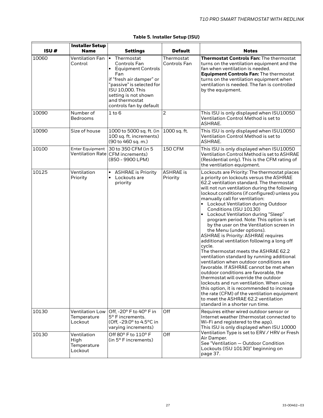
| | | | | | |---|---|---|---|---| |ISU #|Installer Setup Name|Settings|Default|Notes| |10060|Ventilation Fan Control|• Thermostat Controls Fan
• Equipment Controls Fan
if “fresh air damper” or “passive” is selected for ISU 10,000. This setting is not shown and thermostat controls fan by default|Thermostat Controls Fan|Thermostat Controls Fan: The thermostat turns on the ventilation equipment and the fan when ventilation is needed. Equipment Controls Fan: The thermostat turns on the ventilation equipment when ventilation is needed. The fan is controlled by the equipment.| |10090|Number of Bedrooms|1 to 6|2|This ISU is only displayed when ISU10050 Ventilation Control Method is set to ASHRAE.| |10090|Size of house|1000 to 5000 sq. ft. (in 100 sq. ft. increments) (90 to 460 sq. m.)|1000 sq. ft.|This ISU is only displayed when ISU10050 Ventilation Control Method is set to ASHRAE.| |10100|Enter Equipment Ventilation Rate|30 to 350 CFM (in 5 CFM increments) (850 - 9900 LPM)|150 CFM|This ISU is only displayed when ISU10050 Ventilation Control Method is set to ASHRAE (Residential only). This is the CFM rating of the ventilation equipment.| |10125|Ventilation Priority|• ASHRAE is Priority
• Lockouts are priority
|ASHRAE is Priority|Lockouts are Priority: The thermostat places a priority on lockouts versus the ASHRAE 62.2 ventilation standard. The thermostat will not run ventilation during the following lockout conditions (if configured) unless you manually call for ventilation:
• Lockout Ventilation during Outdoor Conditions (ISU 10130)
• Lockout Ventilation during “Sleep” program period. Note: This option is set by the user on the Ventilation screen in the Menu (under options).
ASHRAE is Priority: ASHRAE requires additional ventilation following a long off cycle. The thermostat meets the ASHRAE 62.2 ventilation standard by running additional ventilation when outdoor conditions are favorable. If ASHRAE cannot be met when outdoor conditions are favorable, the thermostat will override the outdoor lockouts and run ventilation. When using this option, it is recommended to increase the rate (CFM) of the ventilation equipment to meet the ASHRAE 62.2 ventilation standard in a shorter run time.| |10130|Ventilation Low Temperature Lockout|Off, -20° F to 40° F in 5° F increments. (Off, -29.0° to 4.5°C in varying increments)|Off|Requires either wired outdoor sensor or Internet weather (thermostat connected to Wi-Fi and registered to the app). This ISU is only displayed when ISU 10000 Ventilation Type is set to ERV / HRV or Fresh Air Damper. See “Ventilation — Outdoor Condition Lockouts (ISU 10130)” beginning on page 37.| |10130|Ventilation High Temperature Lockout|Off 80° F to 110° F (in 5° F increments)|Off|Requires either wired outdoor sensor or Internet weather (thermostat connected to Wi-Fi and registered to the app). This ISU is only displayed when ISU 10000 Ventilation Type is set to ERV / HRV or Fresh Air Damper. See “Ventilation — Outdoor Condition Lockouts (ISU 10130)” beginning on page 37.|
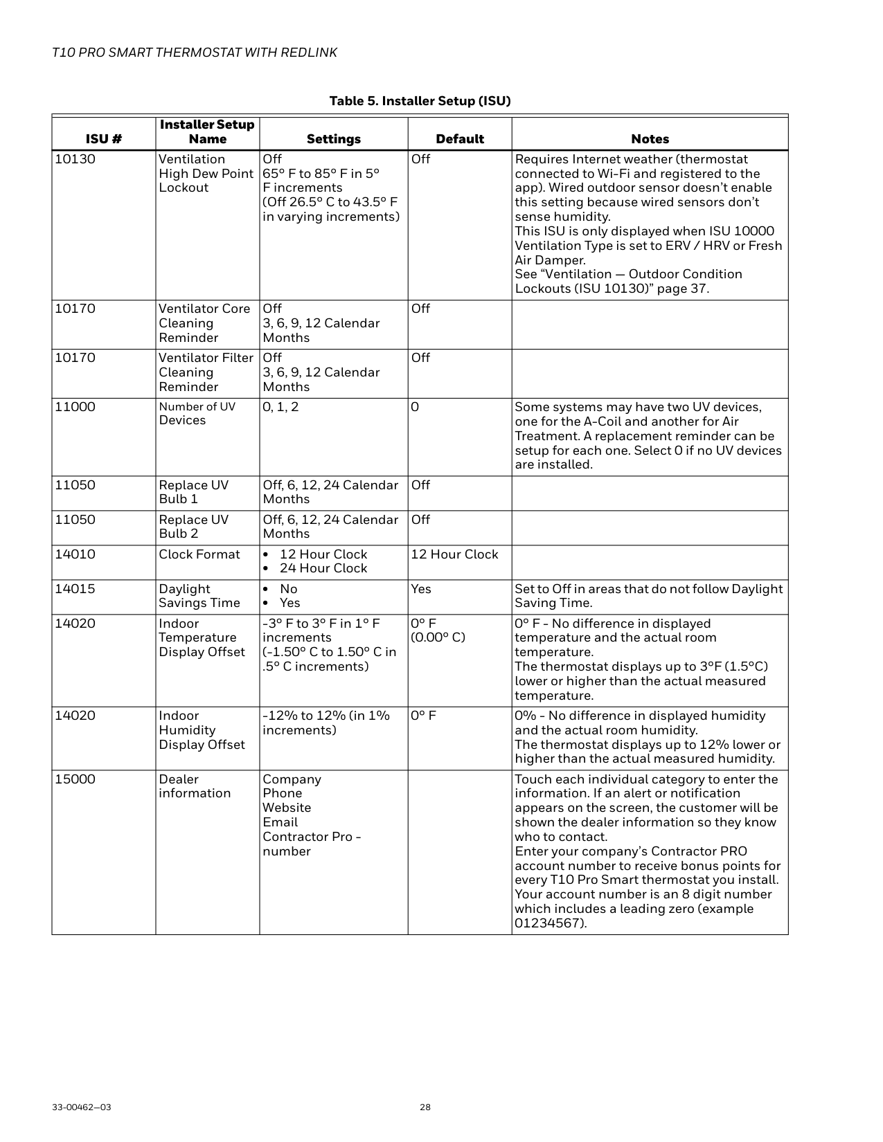
| | | | | | |---|---|---|---|---| |ISU #|Installer Setup Name|Settings|Default|Notes| |10130|Ventilation High Dew Point Lockout|Off 65° F to 85° F in 5° F increments (Off 26.5° C to 43.5° F in varying increments)|Off|Requires Internet weather (thermostat connected to Wi-Fi and registered to the app). Wired outdoor sensor doesn’t enable this setting because wired sensors don’t sense humidity. This ISU is only displayed when ISU 10000 Ventilation Type is set to ERV / HRV or Fresh Air Damper. See “Ventilation — Outdoor Condition Lockouts (ISU 10130)” page 37.| |10170|Ventilator Core Cleaning Reminder|Off 3, 6, 9, 12 Calendar Months|Off| | |10170|Ventilator Filter Cleaning Reminder|Off 3, 6, 9, 12 Calendar Months|Off| |
|11000|Number of UV Devices|0, 1, 2|0|Some systems may have two UV devices, one for the A-Coil and another for Air Treatment. A replacement reminder can be setup for each one. Select 0 if no UV devices are installed.| |11050|Replace UV Bulb 1|Off, 6, 12, 24 Calendar Months|Off| | |11050|Replace UV Bulb 2|Off, 6, 12, 24 Calendar Months|Off| | |14010|Clock Format|• 12 Hour Clock
• 24 Hour Clock
|12 Hour Clock| | |14015|Daylight Savings Time|• No
• Yes
|Yes|Set to Off in areas that do not follow Daylight Saving Time.| |14020|Indoor Temperature Display Offset|-3° F to 3° F in 1° F increments (-1.50° C to 1.50° C in
.5° C increments)|0° F (0.00° C)|0° F - No difference in displayed temperature and the actual room temperature. The thermostat displays up to 3°F (1.5°C) lower or higher than the actual measured temperature.| |14020|Indoor Humidity Display Offset|-12% to 12% (in 1% increments)|0° F|0% - No difference in displayed humidity and the actual room humidity. The thermostat displays up to 12% lower or higher than the actual measured humidity.| |15000|Dealer information|Company Phone Website Email Contractor Pro number| |Touch each individual category to enter the information. If an alert or notification appears on the screen, the customer will be shown the dealer information so they know who to contact. Enter your company’s Contractor PRO account number to receive bonus points for every T10 Pro Smart thermostat you install. Your account number is an 8 digit number which includes a leading zero (example 01234567).|
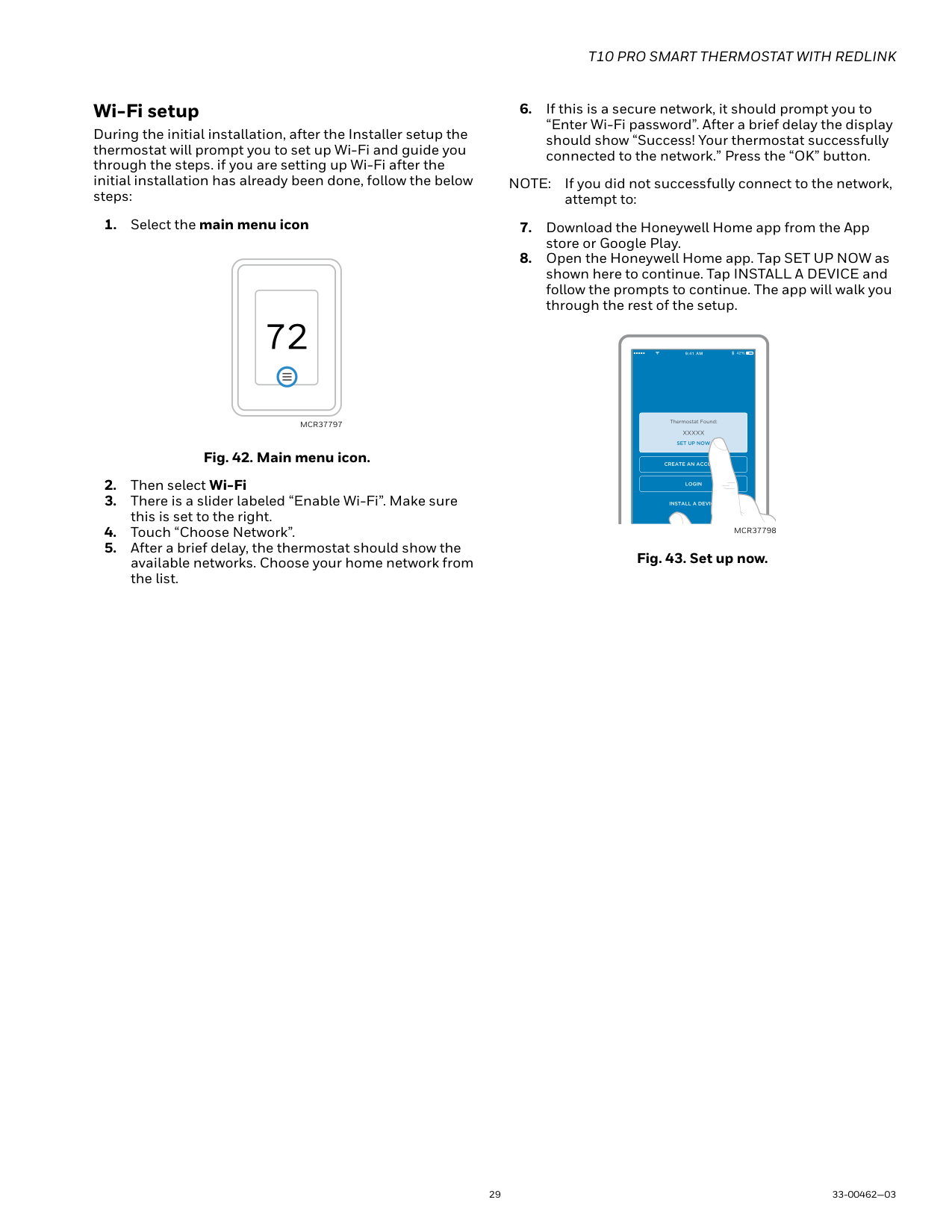
Wi-Fi setup
During the initial installation, after the Installer setup the thermostat will prompt you to set up Wi-Fi and guide you through the steps. if you are setting up Wi-Fi after the initial installation has already been done, follow the below steps:
Fig. 42. Main menu icon.
MCR37797
NOTE: If you did not successfully connect to the network, attempt to:
MCR37798
Fig. 43. Set up now.
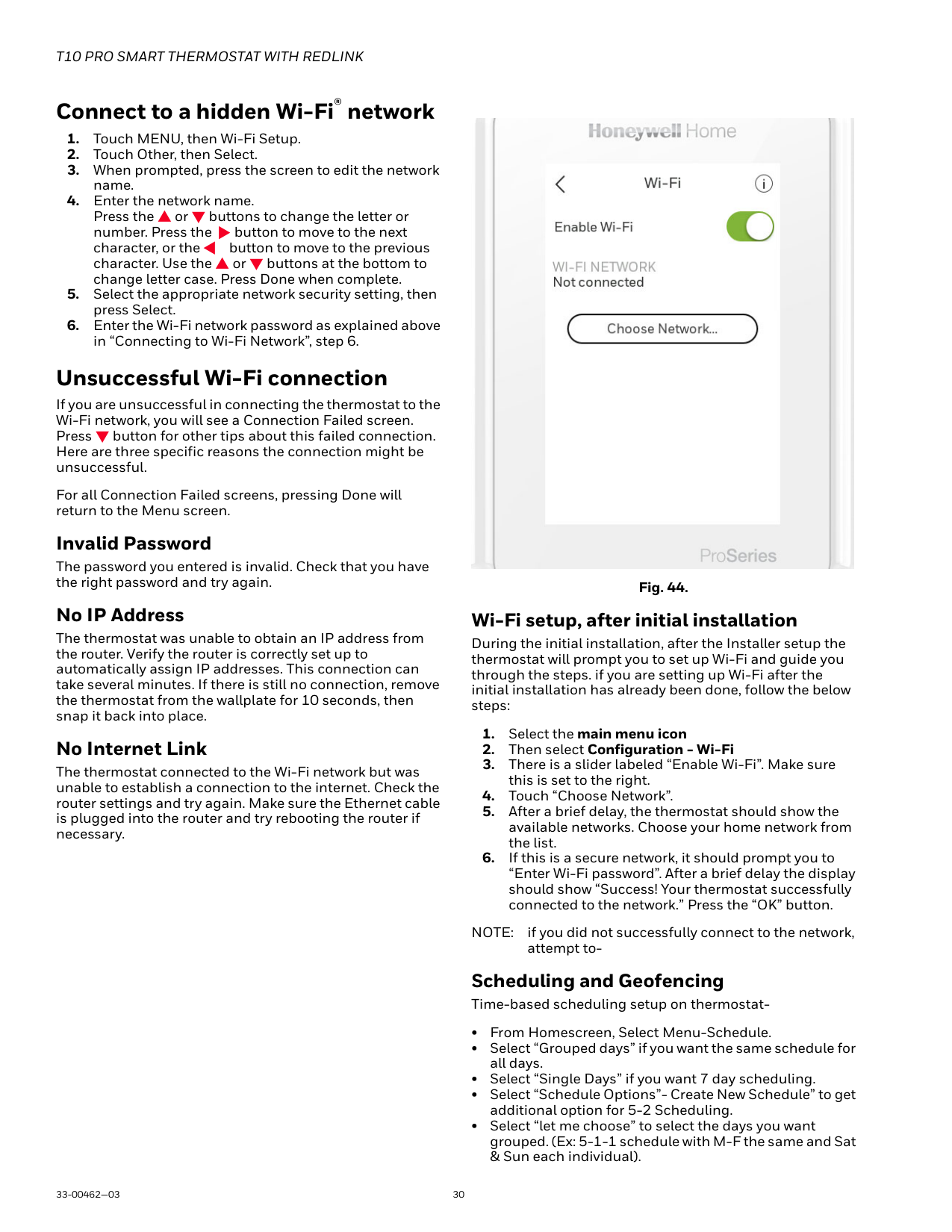
#### Connect to a hidden Wi-Fi® network
#### Unsuccessful Wi-Fi connection
If you are unsuccessful in connecting the thermostat to the Wi-Fi network, you will see a Connection Failed screen. Press button for other tips about this failed connection. Here are three specific reasons the connection might be unsuccessful.
For all Connection Failed screens, pressing Done will return to the Menu screen.
Invalid Password
The password you entered is invalid. Check that you have the right password and try again.
No IP Address The thermostat was unable to obtain an IP address from the router. Verify the router is correctly set up to automatically assign IP addresses. This connection can take several minutes. If there is still no connection, remove the thermostat from the wallplate for 10 seconds, then snap it back into place. No Internet Link The thermostat connected to the Wi-Fi network but was unable to establish a connection to the internet. Check the router settings and try again. Make sure the Ethernet cable is plugged into the router and try rebooting the router if necessary.

Fig. 44.
Wi-Fi setup, after initial installation
During the initial installation, after the Installer setup the thermostat will prompt you to set up Wi-Fi and guide you through the steps. if you are setting up Wi-Fi after the initial installation has already been done, follow the below steps:
NOTE: if you did not successfully connect to the network, attempt to-
Scheduling and Geofencing Time-based scheduling setup on thermostat-
Schedule override With thermostat in heat, cool, auto, or em heat mode, press the up or down arrow to change the setpoint. (if thermostat is in auto mode, you need to press “heat to” or “cool to” first). If scheduling is enabled it will say “Hold until” and show a time at the bottom of the screen. Touch this. Display says “Use current temperature, fan, and comfort priority settings until…”
Options are:
Main Menu
From Home Screen, press the menu icon at bottom of the display (3 horizontal lines). (If this is not shown at home screen, touch screen to wake display first).
Main Menu Options System mode (Available modes vary depending on how the thermostat
was configured)
Fan (Fan setting not available for all system types)
• Circulate (fan runs randomly approx. 33% of the time) Priority If wireless indoor temperature/humidity/motion sensors
are used, select which sensors are used for temperature control. Can choose active sensor (ones detecting motion) or manually select which sensors to use.
Schedule
NOTE: To enable geofencing, us the Honeywell Home
app. Management: Devices & Sensors
Configuration
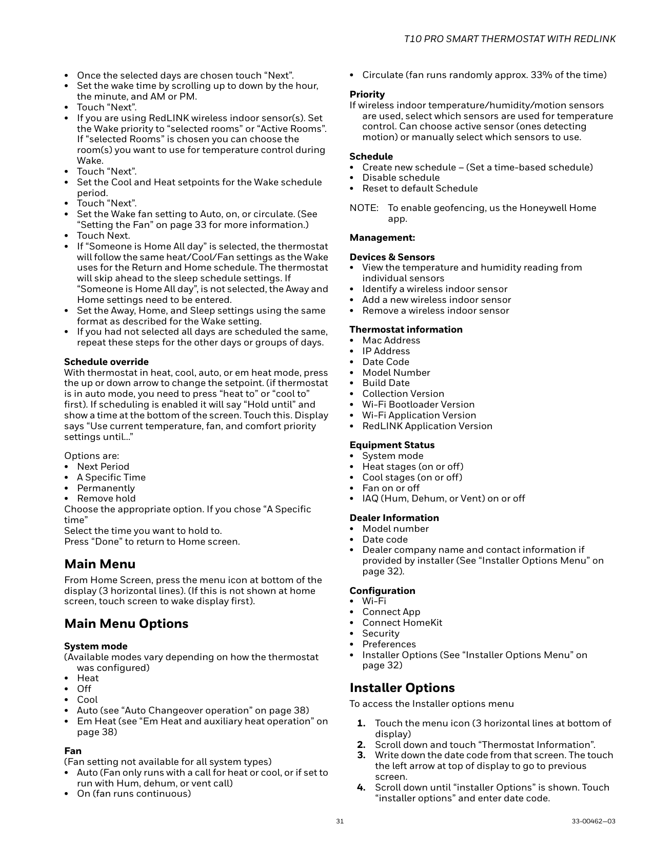
Installer Options To access the Installer options menu
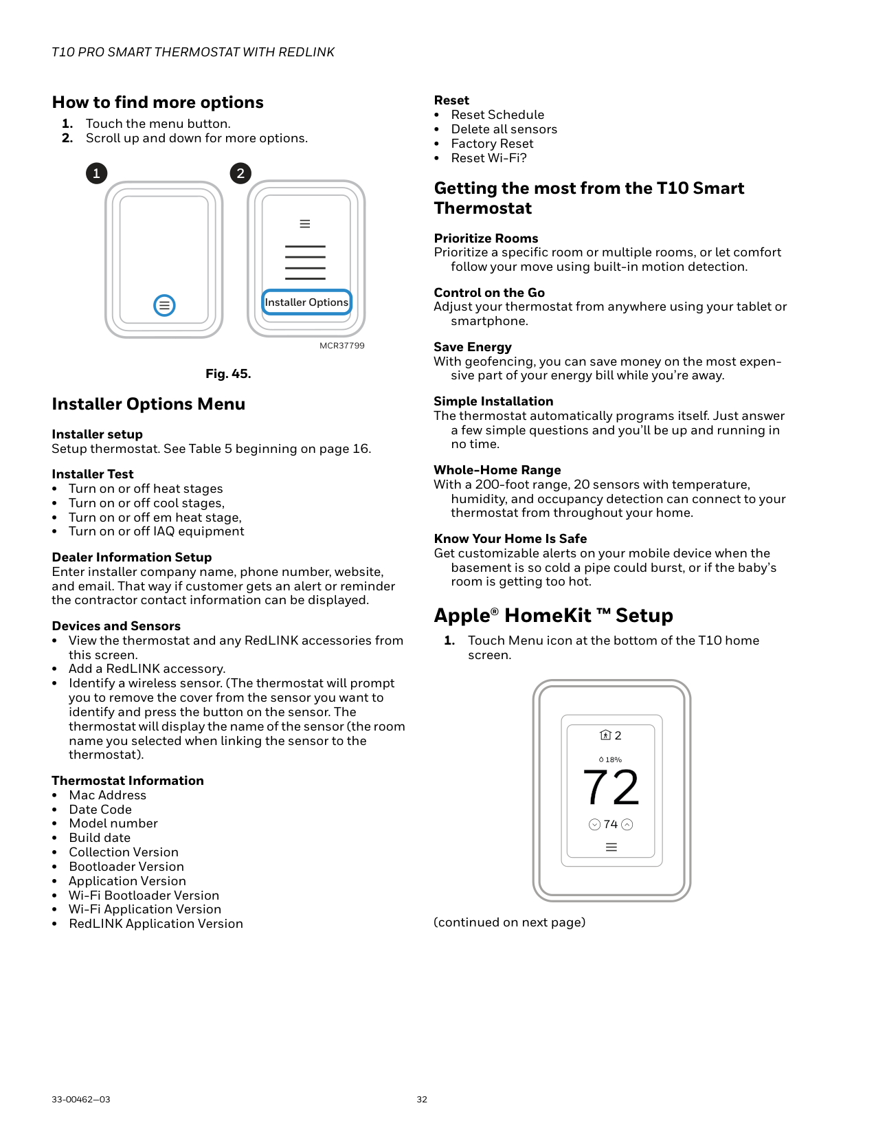
How to find more options
####### 1 2
############# Installer Options
MCR37799
Fig. 45. Installer Options Menu Installer setup Setup thermostat. See Table 5 beginning on page 16. Installer Test
Dealer Information Setup Enter installer company name, phone number, website, and email. That way if customer gets an alert or reminder the contractor contact information can be displayed.
Devices and Sensors
Getting the most from the T10 Smart Thermostat
Prioritize Rooms Prioritize a specific room or multiple rooms, or let comfort
follow your move using built-in motion detection.
Control on the Go Adjust your thermostat from anywhere using your tablet or
smartphone.
Save Energy With geofencing, you can save money on the most expen-
sive part of your energy bill while you’re away.
Simple Installation The thermostat automatically programs itself. Just answer
a few simple questions and you’ll be up and running in no time.
Whole-Home Range With a 200-foot range, 20 sensors with temperature,
humidity, and occupancy detection can connect to your thermostat from throughout your home.
Know Your Home Is Safe Get customizable alerts on your mobile device when the
basement is so cold a pipe could burst, or if the baby’s room is getting too hot.
#### Apple® HomeKit ™ Setup
screen.
2
18%
74
(continued on next page)
|| |---|
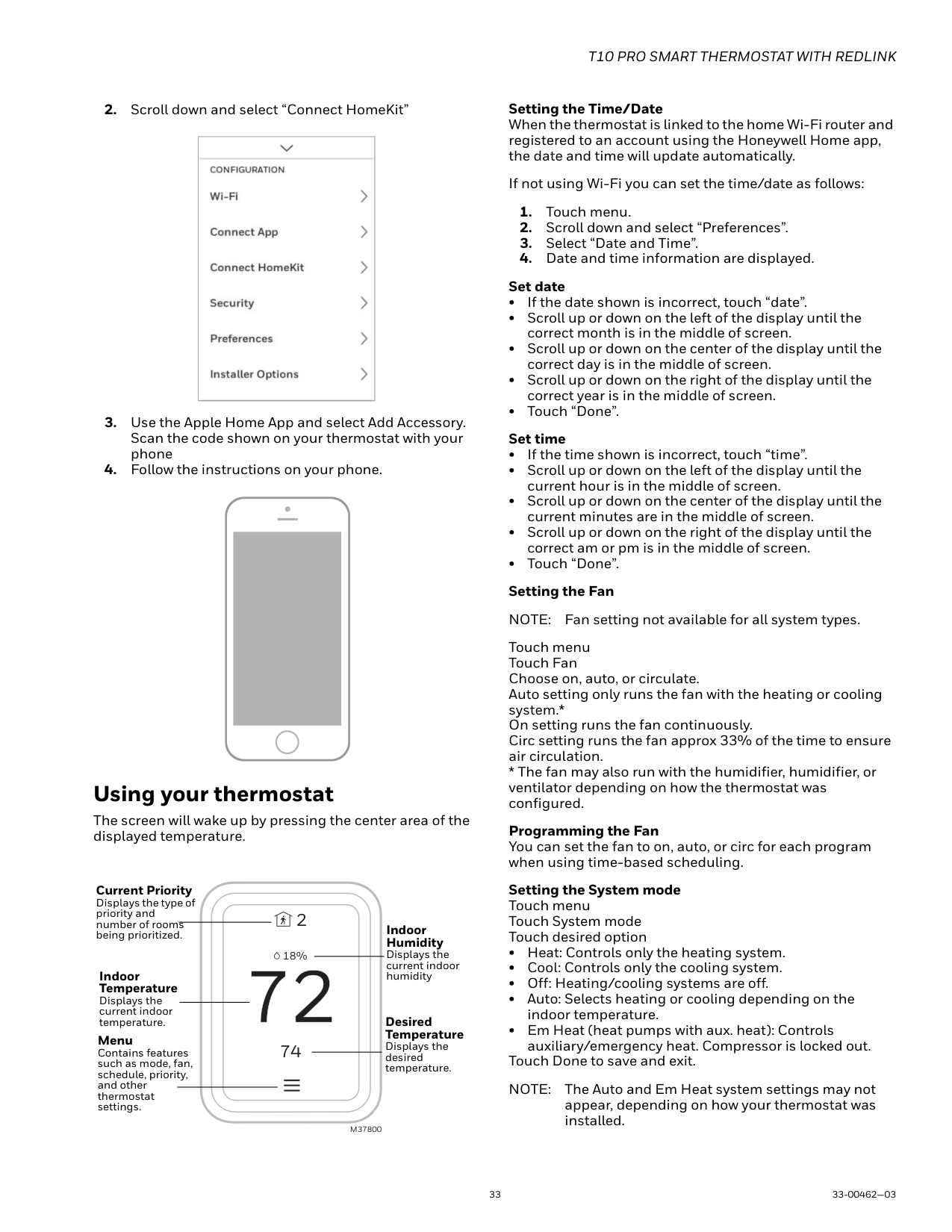
#### Using your thermostat
The screen will wake up by pressing the center area of the displayed temperature.
Current Priority Displays the type of priority and number of rooms being prioritized. Indoor
2
| | | | |---|---|---| | | | | | | | |
Humidity Displays the current indoor humidity
18%
Indoor Temperature
Displays the current indoor temperature.
Desired Temperature Displays the desired temperature.
Menu Contains features such as mode, fan, schedule, priority, and other thermostat settings.
74
M37800
Setting the Time/Date When the thermostat is linked to the home Wi-Fi router and registered to an account using the Honeywell Home app, the date and time will update automatically.
If not using Wi-Fi you can set the time/date as follows:
Touch menu Touch Fan Choose on, auto, or circulate. Auto setting only runs the fan with the heating or cooling system.* On setting runs the fan continuously. Circ setting runs the fan approx 33% of the time to ensure air circulation.
Programming the Fan You can set the fan to on, auto, or circ for each program when using time-based scheduling.
Setting the System mode Touch menu Touch System mode Touch desired option
Touch Done to save and exit. NOTE: The Auto and Em Heat system settings may not
appear, depending on how your thermostat was installed.
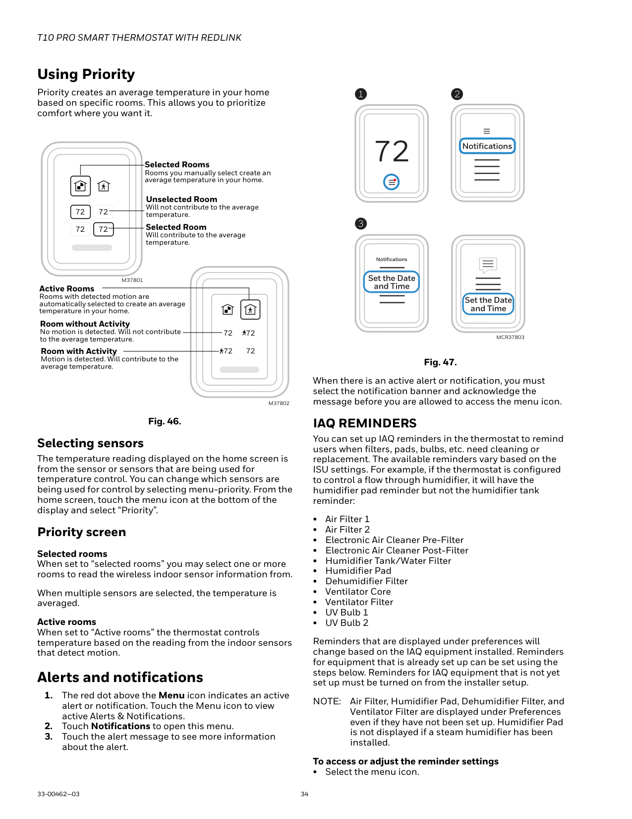
#### Using Priority
Priority creates an average temperature in your home based on specific rooms. This allows you to prioritize comfort where you want it.
Selected Rooms Rooms you manually select create an average temperature in your home.
Unselected Room Will not contribute to the average temperature.
72 72 72 72
Selected Room Will contribute to the average temperature.
M37801
Active Rooms Rooms with detected motion are automatically selected to create an average temperature in your home. Room without Activity No motion is detected. Will not contribute to the average temperature. Room with Activity
72 72

72 72

Motion is detected. Will contribute to the average temperature.
M37802
Fig. 46. Selecting sensors
The temperature reading displayed on the home screen is from the sensor or sensors that are being used for temperature control. You can change which sensors are being used for control by selecting menu-priority. From the home screen, touch the menu icon at the bottom of the display and select “Priority”.
Priority screen Selected rooms When set to “selected rooms” you may select one or more rooms to read the wireless indoor sensor information from.
When multiple sensors are selected, the temperature is averaged.
Active rooms When set to “Active rooms” the thermostat controls temperature based on the reading from the indoor sensors that detect motion.
#### Alerts and notifications
1 2
Notifications
3
Notifications Set the Date and Time
Set the Date and Time
############################# MCR37803
Fig. 47.
When there is an active alert or notification, you must select the notification banner and acknowledge the message before you are allowed to access the menu icon.
IAQ REMINDERS
You can set up IAQ reminders in the thermostat to remind users when filters, pads, bulbs, etc. need cleaning or replacement. The available reminders vary based on the ISU settings. For example, if the thermostat is configured to control a flow through humidifier, it will have the humidifier pad reminder but not the humidifier tank reminder:
Reminders that are displayed under preferences will change based on the IAQ equipment installed. Reminders for equipment that is already set up can be set using the steps below. Reminders for IAQ equipment that is not yet set up must be turned on from the installer setup.
NOTE: Air Filter, Humidifier Pad, Dehumidifier Filter, and Ventilator Filter are displayed under Preferences even if they have not been set up. Humidifier Pad is not displayed if a steam humidifier has been installed.
To access or adjust the reminder settings
• Select the menu icon.
NOTE: When set for run time days, the thermostat tracks the amount of time the fan has run and compares that time against the number of run time days selected. Fan run time is counted when there is a call for forced air heating, cooling, or fan.
Setting Preferences
Preference menu options let you select how the thermostat displays information or responds to certain situations.
To access the Preferences menu:
— Touch menu
— Scroll down and select “preferences”. — Select an option and follow prompts:
— Temperature units (Fahrenheit or Celsius)
— Language (English French or Spanish)
— Inactive backlight setting (0% to 100%)
— Inactive Sleep backlight setting (0% to 100% and inactive sleep time settings. Note: these can be set different than the schedule sleep times)
— Indoor display offsets (temperature and humidity)
— Clean screen (allows you 30 seconds to clean display without accidentally adjusting a setting)
—Set date —Set time — Set to 12 or 24 hour clock
— Set for daylight savings time
— Electronic Air Cleaner Pre-Filter
— Electronic Air Cleaner Post-Filter
— Humidifier Tank/Water Filter
— Humidifier Pad
— Dehumidifier Filter
— Ventilator Core
— Ventilator Filter
—On or Off Touch Done to save your settings. Indoor Air Quality control Humidification
The thermostat reads the indoor humidity level and allows the user to set a humidification setting with or without window protection. The thermostat can be set up to control a humidifier in any system mode in the Installer Setup (ISU 8060).
Window Protection
Window Protection limits the amount of humidity to prevent frost or condensation on windows. Window Protection (ISU 8050) requires either an outdoor sensor or use of Internet weather (Outdoor temperature setting In ISU chart on page 17. The thermostat prevents frost or condensation on windows by not allowing the humidifier to run above a certain level. To prevent frost or condensation, the thermostat may turn off the humidifier before the humidity setting is reached. If Window protection is enabled ((ISU 8050), you can adjust this setting by pressing MENU, then scroll down and select Humidification-Options-Window Protection Level. Window Protection is set on a scale from 1-10. A setting of "1" represents poorly insulated windows and a setting of "10" represents well insulated windows. A lower number automatically reduces the humidity to help prevent frost or condensation on your windows. Use a higher number if indoor air seems too dry. To prevent frost/condensation on your windows during cold outdoor temperatures, poorly insulated windows require a lower Window Protection setting, which will limit how much your humidifier can run. After you set the Window Protection setting, check for frost/condensation on your windows in the morning. If frost/condensation is present, adjust the Window Protection setting to the next lowest number and check for frost/condensation on your windows the next morning. Continue to adjust the Window Protection setting to a lower number until frost/condensation is no longer present If Window Protection is turned Off, the thermostat controls the humidity level to the user's desired humidity setting. Frost or condensation may appear on windows.
Set up Humidification
— The thermostat turns on the humidifier only if the heat is currently running and humidification is needed.
— The thermostat turns on the humidifier only if the fan is currently running and humidification is needed.
— The thermostat turns on the humidifier and the fan when humidification is needed.
— The thermostat turns on the humidifier when humidification is needed and the humidifier controls the fan.
Control Humidification Level
Window Protection is set on a scale from 1–10. A setting of 1 represents poorly insulated windows and a setting of 10 represents well insulated windows. A lower number automatically reduces the humidity to help prevent frost or condensation on your windows. Use a higher number if indoor air seems too dry. To prevent frost/condensation on your windows during cold outdoor temperatures, poorly insulated windows require a lower Window Protection setting, which will limit how much your humidifier can run.
NOTE: The Window Protection option is only available if a wired outdoor sensor or Internet is used to provide outdoor temperature. See ISU setting “Outdoor Temperature” on page 17.
Dehumidification
The thermostat reads the indoor humidity level and allows the user to set a dehumidification setting. The thermostat controls the humidity level using the cooling system or a whole house dehumidifier.
Dehumidification using the Cooling System
When set for A/C with Low Speed Fan or A/C with High Speed Fan, an overcooling limit can be set from 0 °F to 3 °F (ISU 9070). The thermostat uses the cooling system to reduce humidity by lowering the temperature up to 3° F below the current cool setpoint until the desired humidity level is reached. If set for A/C with Low Speed Fan, configure U contacts as normally open or normally closed (ISU 9050) and wire to the Low Speed Fan terminal on the equipment. For example, if the U contacts are normally closed, they will open when the thermostat calls for dehumidification. See “Whole House humidifier, dehumidifier, or ventilator wiring” Fig. 27 to Fig. 30.
If humidification and dehumidification are both setup to operate in the system mode (Off), the thermostat will automatically enforce a 15% deadband between the humidification and dehumidification settings. The thermostat will automatically switch between humidification and dehumidification to maintain the desired humidity level.
Dehumidification using A/C with Low Speed Fan, A/C with High Speed Fan, has the following methods of dehumidification control (ISU 9080):
Dehumidification overcooling limit (ISU 9070): This option uses the cooling system to lower the temperature up to 5° F below the current cool setpoint until the desired humidity is reached. The Dehum Over Cooling Limit range is from 1° to 5° F.
NOTE: The thermostat will not lower the fan speed when the second stage of cooling is on.
Set up Dehumidification With Cooling System Some screens shown in this section may not appear on the thermostat, depending on how you set up dehumidification.
Dehumidification using a Whole House Dehumidifier
The Whole House Dehumidifier option requires a dedicated unit for dehumidification. The thermostat can be set to control dehumidification in all modes (Heat, Off, Cool [ISU 9120]). Set up Dehumidification With Whole House Dehumidifier (Some screens shown in this section may not appear on the thermostat, depending on how you set up dehumidification.)
NOTE: Heat includes Heat, Emergency Heat and Auto. If the system is in Auto mode, the thermostat will allow dehumidification if the last call was for heat.
Cool includes Cool and Auto. If the system is in Auto mode, the thermostat will allow dehumidification if the last call was for cool.
page 26.
page 26.
Control Dehumidification Level
NOTE: If your air conditioner is used to control humidity, the temperature may drop up to 3° F below your temperature setting until humidity reaches the desired level.
NOTE: If humidification and dehumidification are setup to operate in the same system mode (Off) the thermostat will automatically enforce a 15% deadband between the humidification and dehumidification settings. The thermostat will automatically switch between humidification and dehumidification to maintain the desired humidity level.
Dehumidification using the Cooling System
Dehumidification using A/C with Low Speed Fan, A/C with High Speed Fan, has the following methods of dehumidification control (ISU 9080):
Cooling Droop (ISU 9080): This option uses the cooling system to lower the temperature up to 3° F below the current cool setpoint until the desired humidity is reached. The Dehum Over Cooling Limit range is from 0° to 3° F for dehum with low speed fan or 1° to 3° F for dehum with high speed fan.
Ventilation
The thermostat can be set for the following ventilation types: (ISU 10000)
Ventilation Control Methods (ISU 10050) Ventilation can be setup to meet either ASHRAE or Percent On Time settings. To meet these settings, the thermostat will ventilate during calls for heat, cool, and fan. If the required ventilation has not been achieved for ASHRAE or Percent On Time, the thermostat will force the ventilation equipment on.
ASHRAE The thermostat operates ventilation equipment to meet the ASHRAE 62.2 ventilation standard based on CFM, number of bedrooms, and square footage of the house. ASHRAE 62.2 can only be met if the ventilation equipment is running. If the ventilation equipment is off for any reason (outdoor ventilation lockouts, set up to turn Off during Sleep period, turned off by user, etc.), ASHRAE 62.2 is not met during those times. See ISU 1012 to select a Ventilation Priority.
Percent On Time The thermostat operates ventilation equipment based on a percentage entered in the installer setup (ISU 1012). For example if Percent On Time is set to 50%, the ventilation equipment will run at random times during a 1 hour period until it reaches a 50% run time (approximately 30 minutes). Default setting is 30%. Range is 10% to 100% in 10% increments.
Ventilation Fan Control (ISU 10060)
— The thermostat turns on the ventilator and the fan when ventilation is needed.
— The thermostat turns on the ventilator when ventilation is needed. The fan is controlled by the equipment.
Ventilation Priority (ISU 10125) Lockouts are Priority The thermostat places a priority on lockouts versus the ASHRAE 62.2 ventilation standard. The thermostat will not run ventilation during the following lockout conditions (if configured) unless you manually call for ventilation:
— Lockout Ventilation during Outdoor Conditions (ISU 10130)
— Lockout Ventilation during “Sleep” program periods. Note: This option is set by the user on the Ventilation screen. From Home press menu-ventilationoptions-disable during sleep.
ASHRAE is Priority ASHRAE requires additional ventilation following a long off cycle. The thermostat meets the ASHRAE 62.2 ventilation standard by running additional ventilation when outdoor conditions are favorable. If ASHRAE cannot be met when outdoor conditions are favorable, the thermostat will override the outdoor lockouts and run ventilation. When using this option, it is recommended to increase the rate (CFM) of the ventilation equipment to meet the ASHRAE 62.2 ventilation standard in a shorter run time.
NOTE: The ability to lockout ventilation during the “Sleep” program periods is not an option when you select ASHRAE is Priority.
Ventilation — Outdoor Condition Lockouts (ISU 10130) Ventilation will not operate when outdoor conditions exceed the lockout settings unless you manually call for ventilation or Ventilation Priority (ISU 10125) is set to ASHRAE is Priority and ventilation is needed to meet ASHRAE. Lockouts can prevent ventilation during extreme weather conditions to keep humid, hot, and cold air out of the home.
NOTE: This feature requires a wired sensor for outdoor temperature limits, or Internet connection for temperature and humidity lockouts.
Options are:
Control Ventilation Level
ignore changes.
Lockout During Sleep: Under the ventilation menu, touch “options”. Select or deselect “disable during Sleep”. Touch the back arrow in upper left of display to return to previous screen.
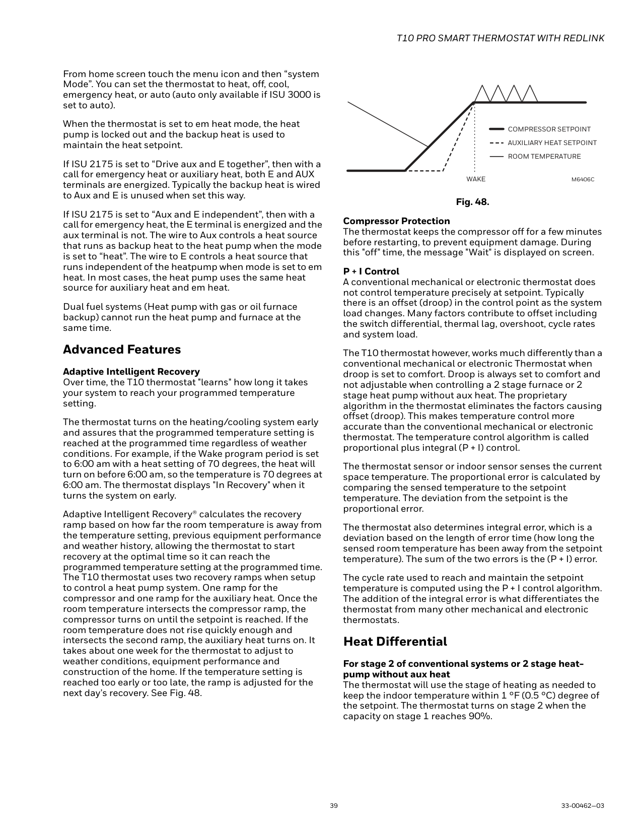
Cleaning the Thermostat Screen When you select the Clean Screen option, the screen is locked to prevent accidental changes to the thermostat while you clean the screen.
NOTE: Do NOT spray any liquid directly on the thermostat. Spray liquids onto cloth, then use the damp cloth to clean the screen. Use water or household glass cleaner. Avoid abrasive cleansers.
Adjusting Security Settings You can adjust security options to prevent unauthorized changes to system settings.
Lock mode options
NOTE: If you choose to create a password for additional security, write it down for reference.
Dealer Information This can be viewed by the homeowner when an alert or reminder message appears on the thermostat display. Entering Dealer Information
—Company
—Phone
—Website
Viewing Dealer Information Check dealer information if you need to contact your installer for maintenance, repairs, or upgrades.
NOTE: This menu option will only appear if the contractor had entered this information.
Auto Changeover operation
Auto changeover is available if the thermostat is configured for at least 1 heat stage and 1 cool stage and ISU 3000 is set to “Auto”.
When configured this way, you can select “Auto” as one of the options under “System mode”.
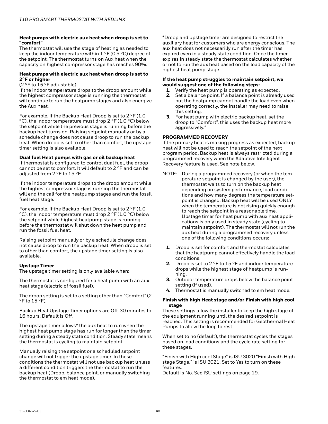
ISU 3015 is the auto changeover differential setting. It can be set from 0-3 °F. (0-2.5 °C) to This is the minimum number of degrees needed between the heat and the cool setpoints when the thermostat is in auto changeover mode. When in auto mode, the customer can always set the heat and cool setpoint to the same temperature, regardless of the differential setting although most customer prefer to have a cool setpoint that is at least 3 degrees above the heat setpoint. When 0 is selected, we enforce a 1.5°F differential behind the scenes to ensure the heat doesn’t come on after cooling shuts off or vice-versa.
The differential is the minimum number of degrees the temperature needs to rise or fall before switching from heat to cool while in auto changeover mode. Example: If heat and cool were both set for 70, and heat had been used last, the temperature would need to rise at least 3 degrees above the heat setpoint before the thermostat would turn on cooling. Then it would cycle cooling on and off to maintain setpoint and the temp would need to drop at least
If the AC is used for dehumidification then we enforce an additional temp drop below the overcooling amount, (ISU
9070) prior to switching back to heat. Em Heat and auxiliary heat operation Auxiliary heat:
Emergency heat: Emergency heat runs when you manually switch the thermostat to the em heat mode. When the thermostat is in emergency heat mode, the heat pump is locked out.
Emergency heat mode is only available when the thermostat is configured for a heat pump (ISU 2000) and Backup heat stages is set to 1 (ISU 2071).
From home screen touch the menu icon and then “system Mode”. You can set the thermostat to heat, off, cool, emergency heat, or auto (auto only available if ISU 3000 is set to auto).
When the thermostat is set to em heat mode, the heat pump is locked out and the backup heat is used to maintain the heat setpoint.
If ISU 2175 is set to “Drive aux and E together”, then with a call for emergency heat or auxiliary heat, both E and AUX terminals are energized. Typically the backup heat is wired to Aux and E is unused when set this way.
If ISU 2175 is set to “Aux and E independent”, then with a call for emergency heat, the E terminal is energized and the aux terminal is not. The wire to Aux controls a heat source that runs as backup heat to the heat pump when the mode is set to “heat”. The wire to E controls a heat source that runs independent of the heatpump when mode is set to em heat. In most cases, the heat pump uses the same heat source for auxiliary heat and em heat.
Dual fuel systems (Heat pump with gas or oil furnace backup) cannot run the heat pump and furnace at the same time.
Advanced Features Adaptive Intelligent Recovery Over time, the T10 thermostat "learns" how long it takes your system to reach your programmed temperature setting.
The thermostat turns on the heating/cooling system early and assures that the programmed temperature setting is reached at the programmed time regardless of weather conditions. For example, if the Wake program period is set to 6:00 am with a heat setting of 70 degrees, the heat will turn on before 6:00 am, so the temperature is 70 degrees at 6:00 am. The thermostat displays "In Recovery" when it turns the system on early.
Adaptive Intelligent Recovery® calculates the recovery ramp based on how far the room temperature is away from the temperature setting, previous equipment performance and weather history, allowing the thermostat to start recovery at the optimal time so it can reach the programmed temperature setting at the programmed time. The T10 thermostat uses two recovery ramps when setup to control a heat pump system. One ramp for the compressor and one ramp for the auxiliary heat. Once the room temperature intersects the compressor ramp, the compressor turns on until the setpoint is reached. If the room temperature does not rise quickly enough and intersects the second ramp, the auxiliary heat turns on. It takes about one week for the thermostat to adjust to weather conditions, equipment performance and construction of the home. If the temperature setting is reached too early or too late, the ramp is adjusted for the next day's recovery. See Fig. 48.
COMPRESSOR SETPOINT AUXILIARY HEAT SETPOINT ROOM TEMPERATURE
WAKE
M6406C
Fig. 48.
Compressor Protection The thermostat keeps the compressor off for a few minutes before restarting, to prevent equipment damage. During this "off" time, the message "Wait" is displayed on screen.
P + I Control A conventional mechanical or electronic thermostat does not control temperature precisely at setpoint. Typically there is an offset (droop) in the control point as the system load changes. Many factors contribute to offset including the switch differential, thermal lag, overshoot, cycle rates and system load.
The T10 thermostat however, works much differently than a conventional mechanical or electronic Thermostat when droop is set to comfort. Droop is always set to comfort and not adjustable when controlling a 2 stage furnace or 2 stage heat pump without aux heat. The proprietary algorithm in the thermostat eliminates the factors causing offset (droop). This makes temperature control more accurate than the conventional mechanical or electronic thermostat. The temperature control algorithm is called proportional plus integral (P + I) control.
The thermostat sensor or indoor sensor senses the current space temperature. The proportional error is calculated by comparing the sensed temperature to the setpoint temperature. The deviation from the setpoint is the proportional error.
The thermostat also determines integral error, which is a deviation based on the length of error time (how long the sensed room temperature has been away from the setpoint temperature). The sum of the two errors is the (P + I) error.
The cycle rate used to reach and maintain the setpoint temperature is computed using the P + I control algorithm. The addition of the integral error is what differentiates the thermostat from many other mechanical and electronic thermostats.
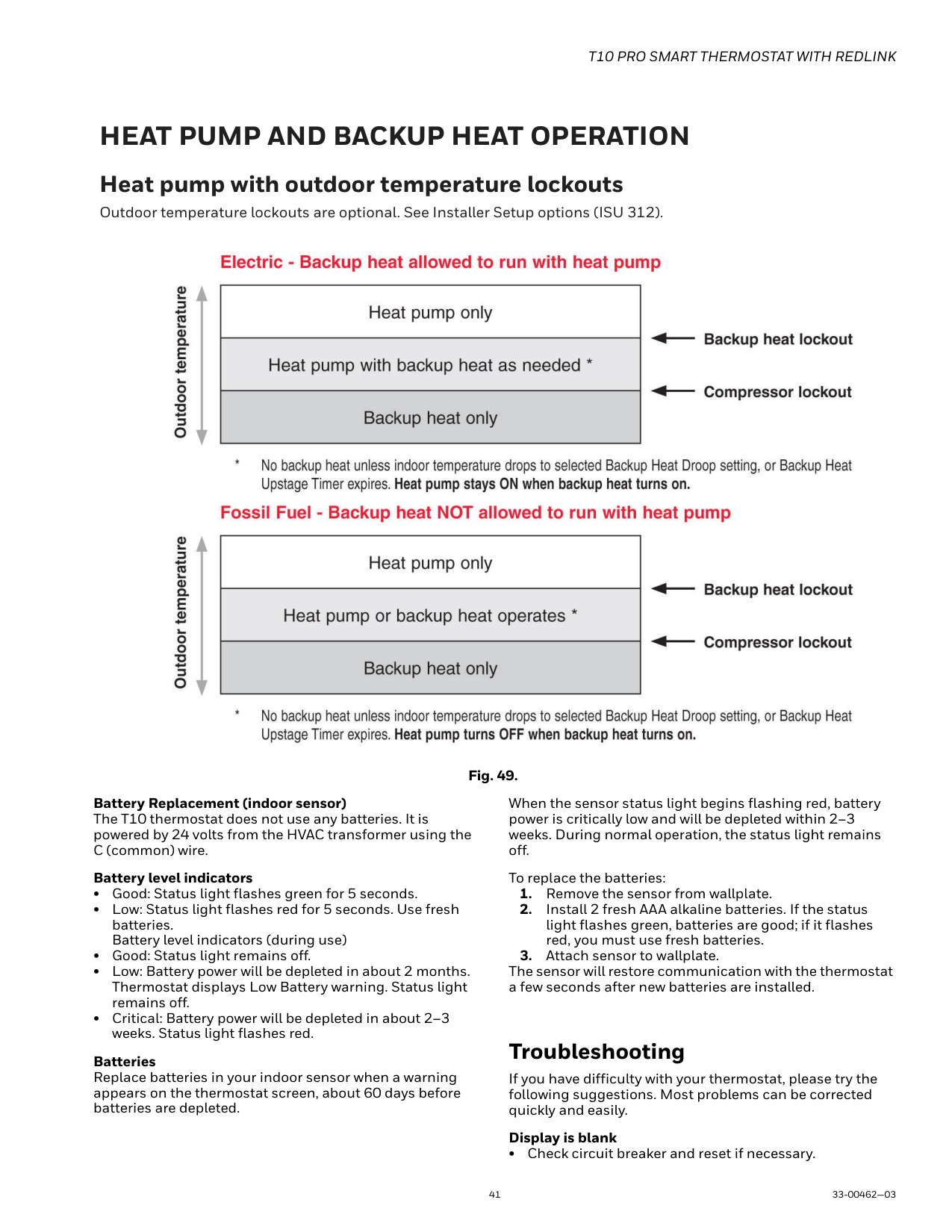
Heat Differential
For stage 2 of conventional systems or 2 stage heatpump without aux heat The thermostat will use the stage of heating as needed to keep the indoor temperature within 1 °F (0.5 °C) degree of the setpoint. The thermostat turns on stage 2 when the capacity on stage 1 reaches 90%.
Heat pumps with electric aux heat when droop is set to “comfort” The thermostat will use the stage of heating as needed to keep the indoor temperature within 1 °F (0.5 °C) degree of the setpoint. The thermostat turns on Aux heat when the capacity on highest compressor stage has reaches 90%.
Heat pumps with electric aux heat when droop is set to 2°F or higher (2 °F to 15 °F adjustable) If the indoor temperature drops to the droop amount while the highest compressor stage is running the thermostat will continue to run the heatpump stages and also energize the Aux heat.
For example, if the Backup Heat Droop is set to 2 °F (1.0 °C), the indoor temperature must drop 2 °F (1.0 °C) below the setpoint while the previous stage is running before the backup heat turns on. Raising setpoint manually or by a schedule change does not cause droop to run the backup heat. When droop is set to other than comfort, the upstage timer setting is also available.
Dual fuel Heat pumps with gas or oil backup heat
If thermostat is configured to control dual fuel, the droop cannot be set to comfort. It will default to 2 °F and can be adjusted from 2 °F to 15 °F.
If the indoor temperature drops to the droop amount while the highest compressor stage is running the thermostat will end the call for the heatpump stages and run the fossil fuel heat stage.
For example, if the Backup Heat Droop is set to 2 °F (1.0 °C), the indoor temperature must drop 2 °F (1.0 °C) below the setpoint while highest heatpump stage is running before the thermostat will shut down the heat pump and run the fossil fuel heat.
Raising setpoint manually or by a schedule change does not cause droop to run the backup heat. When droop is set to other than comfort, the upstage timer setting is also available.
Upstage Timer The upstage timer setting is only available when: The thermostat is configured for a heat pump with an aux heat stage (electric of fossil fuel). The droop setting is set to a setting other than “Comfort” (2 °F to 15 °F). Backup Heat Upstage Timer options are Off, 30 minutes to 16 hours. Default is Off. The upstage timer allows* the aux heat to run when the highest heat pump stage has run for longer than the timer setting during a steady state condition. Steady state means the thermostat is cycling to maintain setpoint. Manually raising the setpoint or a scheduled setpoint change will not trigger the upstage timer. In those conditions the thermostat will not use backup heat unless a different condition triggers the thermostat to run the backup heat (Droop, balance point, or manually switching the thermostat to em heat mode).
*Droop and upstage timer are designed to restrict the auxiliary heat for customers who are energy conscious. The aux heat does not necessarilly run after the timer has expired even in a steady state condition. Once the timer expires in steady state the thermostat calculates whether or not to run the aux heat based on the load capacity of the highest heat pump stage.
If the heat pump struggles to maintain setpoint, we would suggest one of the following steps:
PROGRAMMED RECOVERY If the primary heat is making progress as expected, backup heat will not be used to reach the setpoint of the next program period. Backup heat is always restricted during a programmed recovery when the Adaptive Intelligent Recovery feature is used. See note below.
NOTE: During a programmed recovery (or when the temperature setpoint is changed by the user), the thermostat waits to turn on the backup heat depending on system performance, load conditions and how many degrees the temperature setpoint is changed. Backup heat will be used ONLY when the temperature is not rising quickly enough to reach the setpoint in a reasonable time. Upstage timer for heat pump with aux heat applications is only used in steady state (cycling to maintain setpoint). The thermostat will not run the aux heat during a programmed recovery unless one of the following conditions occurs:
Finish with high Heat stage and/or Finish with high cool
stage These settings allow the installer to keep the high stage of the equipment running until the desired setpoint is reached. This setting is recommended for Geothermal Heat Pumps to allow the loop to rest.
When set to no (default), the thermostat cycles the stages based on load conditions and the cycle rate setting for these stages.
“Finish with High cool Stage” is ISU 3020 “Finish with High stage Stage,” is ISU 3021. Set to Yes to turn on these features. Default is No. See ISU settings on page 19.
HEAT PUMP AND BACKUP HEAT OPERATION Heat pump with outdoor temperature lockouts Outdoor temperature lockouts are optional. See Installer Setup options (ISU 312).

Fig. 49.
Battery Replacement (indoor sensor) The T10 thermostat does not use any batteries. It is powered by 24 volts from the HVAC transformer using the C (common) wire.
When the sensor status light begins flashing red, battery power is critically low and will be depleted within 2–3 weeks. During normal operation, the status light remains off.
Battery level indicators
Batteries Replace batteries in your indoor sensor when a warning appears on the thermostat screen, about 60 days before batteries are depleted.
To replace the batteries:
The sensor will restore communication with the thermostat a few seconds after new batteries are installed.
Troubleshooting
If you have difficulty with your thermostat, please try the following suggestions. Most problems can be corrected quickly and easily.
Display is blank
• Check circuit breaker and reset if necessary.
Default minimum and maximum settings-
Cool runs with a call for heat
• For heat pump systems, verify there is not a wire attached to W on the UWP.
Cooling runs below set-point: Cool should never run unless the display is solid blue and shows “cooling to” rather than “cool to”.
If ISU 9000 is set for AC with low speed fan or AC with high speed fan, the T10 can run cooling up to 3 degrees below set-point when humidity is high. It will cool 1 degree below set-point for approximately every 4% RH above the dehumidity setting.
Use of the Works with Apple badge means that an accessory has been designed to work specifically with the technology identified in the badge and has been certified by the developer to meet Apple performance standards. Apple is not responsible for the operation of this device or its compliance with safety and regulatory standards. AirPlay, iPad, iPad Air, iPad Pro, iPhone and iPod touch are trademarks of Apple Inc., registered in the U.S. and other countries. HomePod is a trademark of Apple Inc.
Resideo Technologies, Inc. 1985 Douglas Drive North, Golden Valley, MN 55422 1-800-468-1502 33-00462—03 M.S. Rev. 10-20 | Printed in United States
www.resideo.com
© 2020 Resideo Technologies, Inc. All rights reserved. The Honeywell Home trademark is used under license from Honeywell International, Inc. This product is manufactured by Resideo Technologies, Inc. and its affiliates.