
Ask AI
— answers from the official manualAnswers from the official manual.
Common questions
Common Questions
29 totalHow do I ensure proper wall receptacles and power cords are installed for my HP Latex 335 printer?
The wall receptacles must be suitable for the input voltage requirements of 200–240 V ±10%. Additionally, they should accommodate the plug type specific to your region (e.g., NEMA 6-20P in USA and Canada). Two HP-approved power cords are required.
How much space is needed around the printer for installation?
A minimum of 3 m (10 ft) should be available in front of the printer. Space permitting, an additional 1 m (3.5 ft) on each side and rear would ease assembly tasks.
What electrical components are required for installation?
Two dedicated power cords according to the single-phase line specifications must be installed, with branch circuit breakers, residual current circuit breaker if necessary, and appropriate grounding. Avoid using a power strip.
What are the environmental requirements for optimal operation?
The printer should not be directly exposed to sunlight or dust. Ensure that the ambient temperature meets ranges: operating temperature is 15 to 30°C (59 to 86°F) and relative humidity range for best print quality is 40-60%. Also, maintain proper ventilation.
What supplies are needed on the day of installation?
You will need six HP 831 ink cartridges (black, cyan, magenta, yellow, light cyan and light magenta), one HP 831 optimizer cartridge, and at least one roll of substrate to perform calibrations and printhead alignment during setup.
How do I check if my network requires a web proxy?
Open Internet Explorer or Safari on any computer within your network, browse to http://hp.com. If you cannot connect because of a web proxy box in the settings being checked, note down the proxy server name and port number.
Show 23 more questions
What are the ventilation requirements for the printing area?
What is the recommended electrical configuration for my country?
How do I handle moving the printer from a cold to warm/humid environment?
What are the printing speed modes available on the HP Latex 335?
What is the maximum print resolution of the HP Latex 335?
What ink cartridge size does the HP Latex 335 use, and what colors are available?
What media types and roll sizes are compatible with the HP Latex 335?
What are the operating environment requirements for the HP Latex 335?
What is the warranty on the HP Latex 335 printer and the HP Latex 64-in Cutter?
What are the cutting specifications for the HP Latex 64-in Cutter included in the Print and Cut Solution?
What is included in the box with the HP Latex 335 Print and Cut Solution?
What connectivity options does the HP Latex 335 printer support?
What are the power requirements for the HP Latex 335?
What is the printing speed of the HP Latex 335 for billboard prints?
What media types are compatible with the HP Latex 335?
How do I reset the HP Latex 335 printer to factory settings?
What is the warranty period for the HP Latex 335 printer?
How do I troubleshoot when there is a paper jam in the HP Latex 335 printer?
What is the maximum width and thickness of media that can be handled by the HP Latex 335?
What safety certifications does the HP Latex 335 printer comply with?
How do I configure the network settings for my HP Latex 335 printer?
Where can I obtain more information about my HP Latex 335 printer and find community support?
What is the power requirement for the HP Latex 335 printer?
Full Manual
20 pages


HP Latex Print and Cut Solution
Site Preparation Guide
© Copyright 2017 HP Development Company, L.P.
Edition 1
Legal notices
The information contained herein is subject to change without notice.
The only warranties for HP Products and services are set forth in the express warranty statement accompanying such products and services. Nothing herein should be construed as constituting an additional warranty. HP shall not be liable for technical or editorial errors or omissions contained herein.
Table of contents
Unloading route .................................................................................................................................................... 3 Environmental specifications ............................................................................................................................. 4 Ventilation and air conditioning ......................................................................................................................... 4
Designing the optimal print production area ....................................................................................................................... 5 RIP workstation characteristics .............................................................................................................................................. 6 Networking ................................................................................................................................................................................ 6 Printing supplies ....................................................................................................................................................................... 7 Return the site preparation checklist .................................................................................................................................... 7 Electrical configuration ............................................................................................................................................................ 7
Single-phase power ............................................................................................................................................ 7 Circuit breakers ..................................................................................................................................................... 7 Wall receptacles and power cords ..................................................................................................................... 8 Powerline disturbances .................................................................................................................................... 13 Grounding ........................................................................................................................................................... 13

ENWW iii
##### iv ENWW
1 Overview
Introduction
Your equipment is supplied ready to use after a few simple installation procedures described in detail in the Assembly instructions. It is important to read the information provided in this guide thoroughly and to ensure complete compliance with all installation and operation requirements, safety procedures, warnings, cautions, and local regulations. A well prepared site helps to provide a smooth and easy installation.
Documentation
The following manuals are provided with your equipment, and can also be downloaded from http://www.hp.com/go/Latex300/manuals/.
Customer responsibility
You are responsible for preparing the physical site for the installation of the equipment.
NOTE: Make sure that a certified electrician reviews the setup and configuration of the electrical system used to power the equipment. See Electrical configuration on page 7.
| | |---|
ENWW Introduction 1
Installation time schedule
Allow a minimum of 4 hours for the installation. The installer may require the help of three people to perform certain tasks during installation.
2 Chapter 1 Overview ENWW
2 Site preparation requirements
Physical space requirements
#### Unloading route

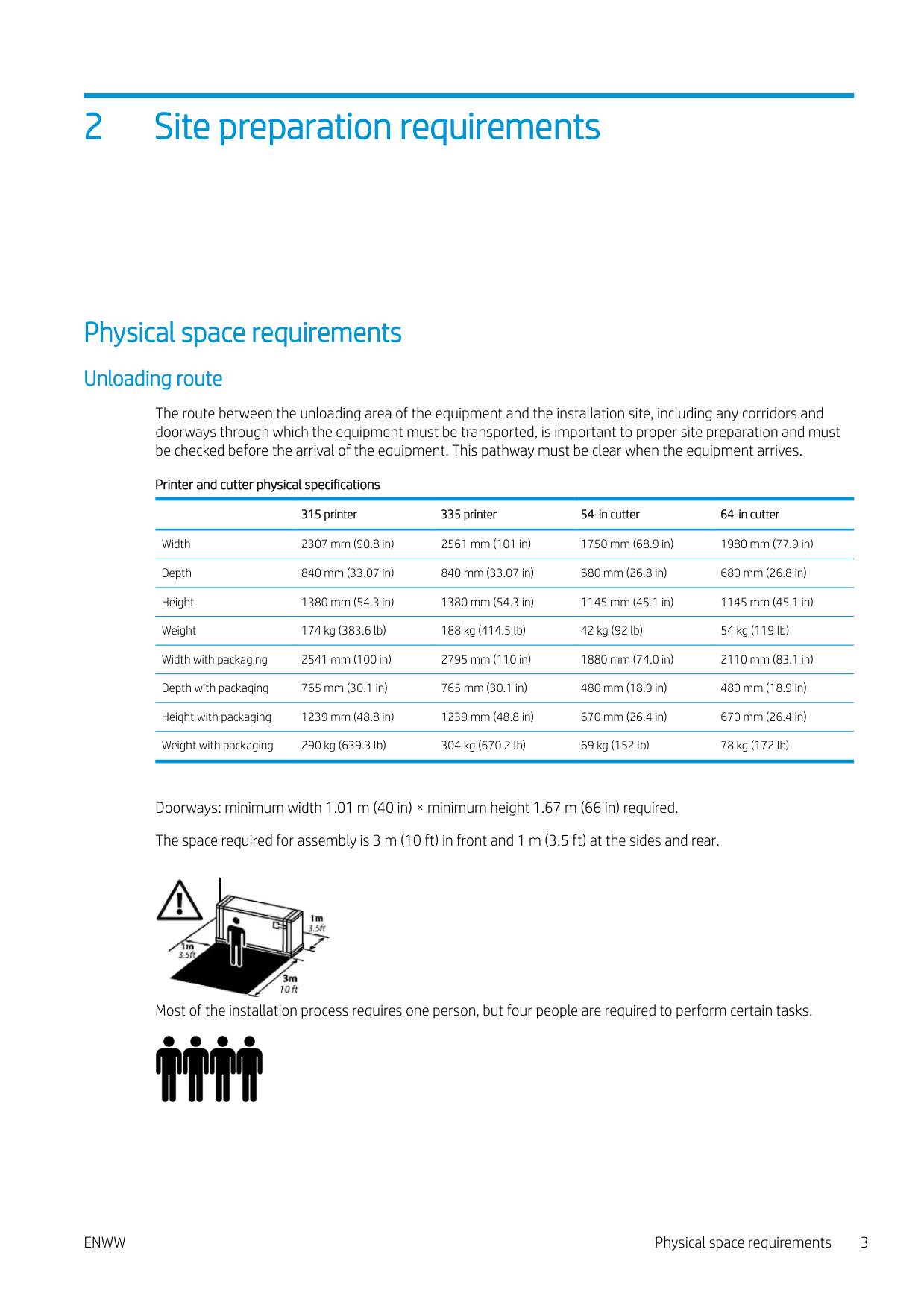
The route between the unloading area of the equipment and the installation site, including any corridors and doorways through which the equipment must be transported, is important to proper site preparation and must be checked before the arrival of the equipment. This pathway must be clear when the equipment arrives.
Printer and cutter physical specifications
315 printer 335 printer 54-in cutter 64-in cutter Width 2307 mm (90.8 in) 2561 mm (101 in) 1750 mm (68.9 in) 1980 mm (77.9 in) Depth 840 mm (33.07 in) 840 mm (33.07 in) 680 mm (26.8 in) 680 mm (26.8 in) Height 1380 mm (54.3 in) 1380 mm (54.3 in) 1145 mm (45.1 in) 1145 mm (45.1 in) Weight 174 kg (383.6 lb) 188 kg (414.5 lb) 42 kg (92 lb) 54 kg (119 lb) Width with packaging 2541 mm (100 in) 2795 mm (110 in) 1880 mm (74.0 in) 2110 mm (83.1 in) Depth with packaging 765 mm (30.1 in) 765 mm (30.1 in) 480 mm (18.9 in) 480 mm (18.9 in) Height with packaging 1239 mm (48.8 in) 1239 mm (48.8 in) 670 mm (26.4 in) 670 mm (26.4 in) Weight with packaging 290 kg (639.3 lb) 304 kg (670.2 lb) 69 kg (152 lb) 78 kg (172 lb)
Doorways: minimum width 1.01 m (40 in) × minimum height 1.67 m (66 in) required. The space required for assembly is 3 m (10 ft) in front and 1 m (3.5 ft) at the sides and rear.

Most of the installation process requires one person, but four people are required to perform certain tasks.

ENWW Physical space requirements 3
#### Environmental specifications
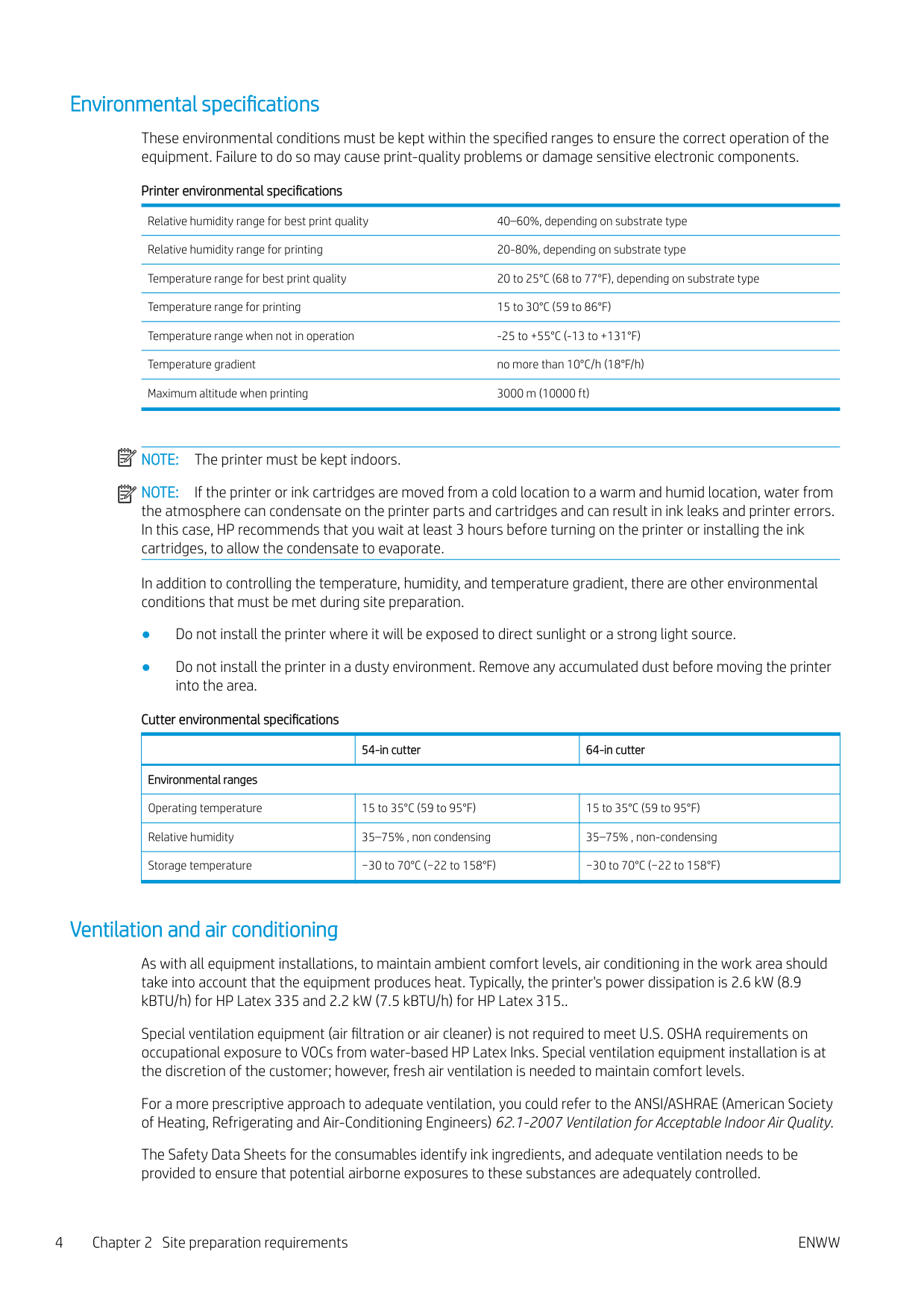
These environmental conditions must be kept within the specified ranges to ensure the correct operation of the equipment. Failure to do so may cause print-quality problems or damage sensitive electronic components.
Printer environmental specifications Relative humidity range for best print quality 40–60%, depending on substrate type Relative humidity range for printing 20-80%, depending on substrate type Temperature range for best print quality 20 to 25°C (68 to 77°F), depending on substrate type Temperature range for printing 15 to 30°C (59 to 86°F) Temperature range when not in operation -25 to +55°C (-13 to +131°F) Temperature gradient no more than 10°C/h (18°F/h) Maximum altitude when printing 3000 m (10000 ft)
| | |---|
NOTE: The printer must be kept indoors.
| | |---|
NOTE: If the printer or ink cartridges are moved from a cold location to a warm and humid location, water from the atmosphere can condensate on the printer parts and cartridges and can result in ink leaks and printer errors. In this case, HP recommends that you wait at least 3 hours before turning on the printer or installing the ink cartridges, to allow the condensate to evaporate.
In addition to controlling the temperature, humidity, and temperature gradient, there are other environmental conditions that must be met during site preparation.
Cutter environmental specifications
| |54-in cutter|64-in cutter| |---|---|---| |Environmental ranges|Environmental ranges|Environmental ranges| |Operating temperature|15 to 35°C (59 to 95°F)|15 to 35°C (59 to 95°F)| |Relative humidity|35–75% , non condensing|35–75% , non-condensing| |Storage temperature|−30 to 70°C (−22 to 158°F)|−30 to 70°C (−22 to 158°F)|
#### Ventilation and air conditioning
As with all equipment installations, to maintain ambient comfort levels, air conditioning in the work area should take into account that the equipment produces heat. Typically, the printer's power dissipation is 2.6 kW (8.9 kBTU/h) for HP Latex 335 and 2.2 kW (7.5 kBTU/h) for HP Latex 315..
Special ventilation equipment (air filtration or air cleaner) is not required to meet U.S. OSHA requirements on occupational exposure to VOCs from water-based HP Latex Inks. Special ventilation equipment installation is at the discretion of the customer; however, fresh air ventilation is needed to maintain comfort levels.

For a more prescriptive approach to adequate ventilation, you could refer to the ANSI/ASHRAE (American Society of Heating, Refrigerating and Air-Conditioning Engineers) 62.1-2007 Ventilation for Acceptable Indoor Air Quality.
The Safety Data Sheets for the consumables identify ink ingredients, and adequate ventilation needs to be provided to ensure that potential airborne exposures to these substances are adequately controlled.
You can obtain current Safety Data Sheets for the ink systems used in the printer from http://www.hp.com/go/ msds.
Air conditioning and ventilation should meet with local environmental, health and safety (EHS) guidelines and regulations.
WARNING! The ventilation and air conditioning units should not blow air directly onto the equipment. TIP: Maintaining positive air pressure in the print production room will help prevent dust from entering the room. TIP: Consider to provide a minimum of 5 ACH* (air changes per hour) of fresh air ventilation and a minimum room volume of 30 m3.
Designing the optimal print production area
You need enough space to perform the following tasks:
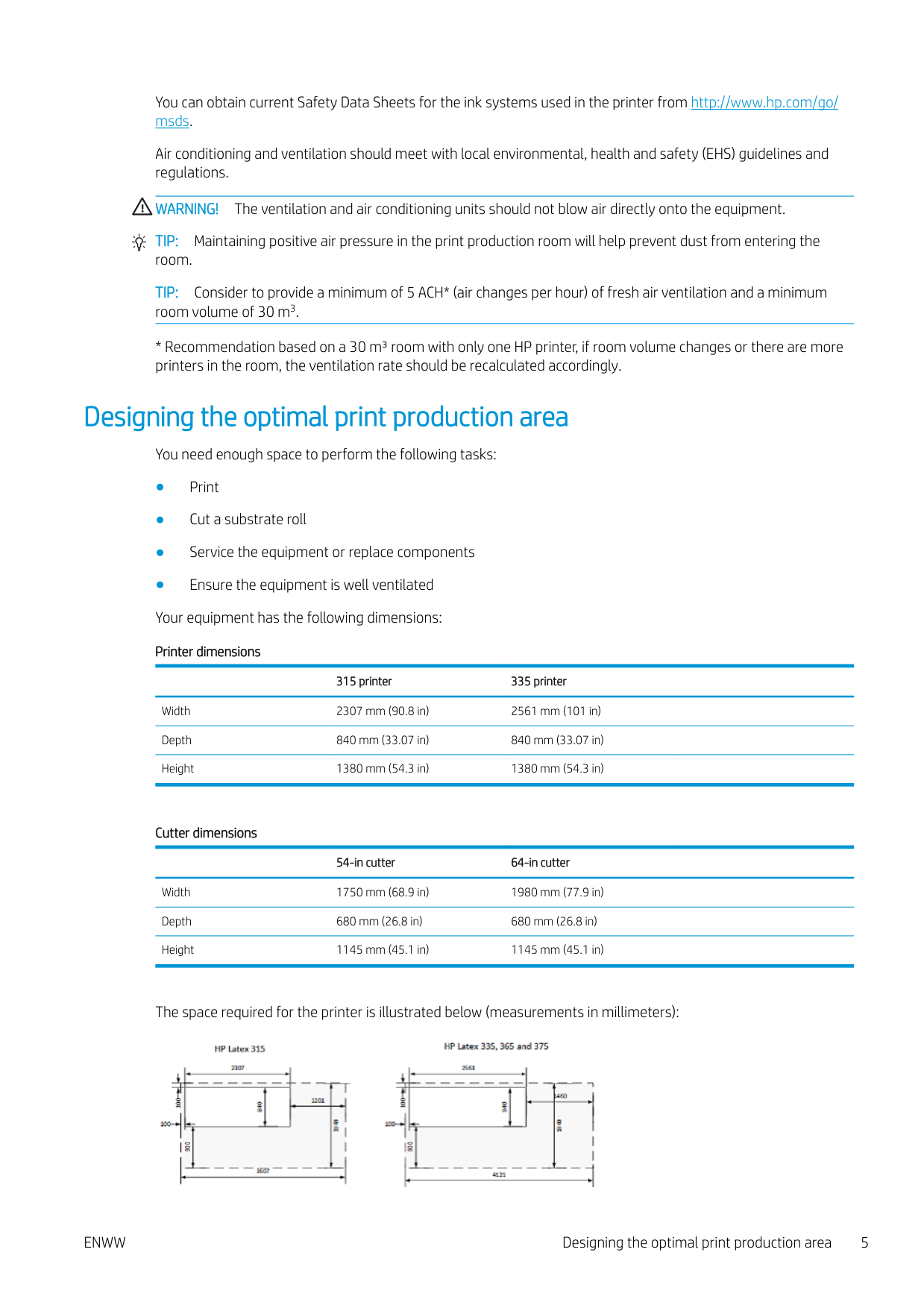
315 printer 335 printer Width 2307 mm (90.8 in) 2561 mm (101 in) Depth 840 mm (33.07 in) 840 mm (33.07 in) Height 1380 mm (54.3 in) 1380 mm (54.3 in)
###### Cutter dimensions
54-in cutter 64-in cutter Width 1750 mm (68.9 in) 1980 mm (77.9 in) Depth 680 mm (26.8 in) 680 mm (26.8 in) Height 1145 mm (45.1 in) 1145 mm (45.1 in)
The space required for the printer is illustrated below (measurements in millimeters):

ENWW Designing the optimal print production area 5
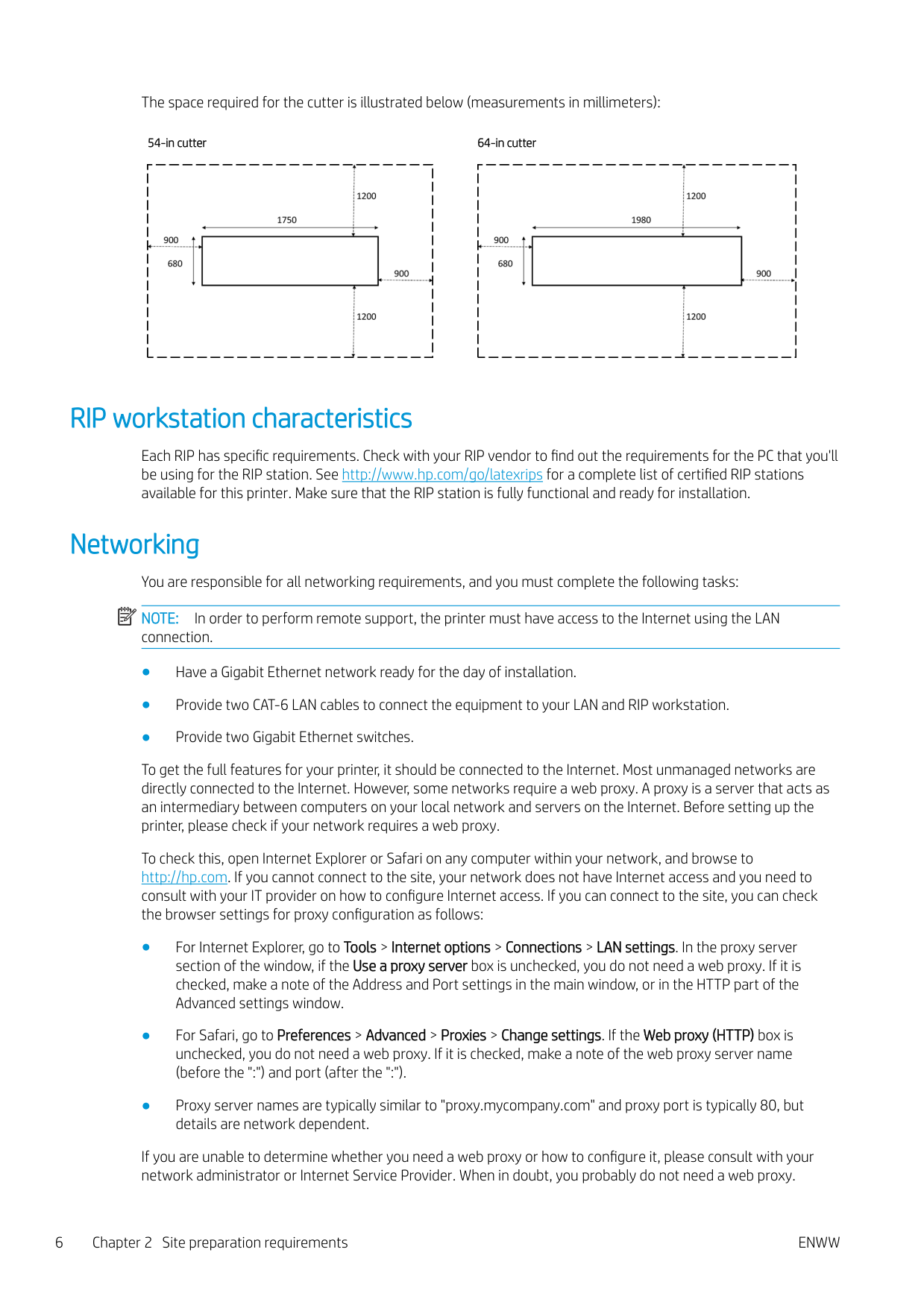
The space required for the cutter is illustrated below (measurements in millimeters):
54-in cutter 64-in cutter


RIP workstation characteristics
Each RIP has specific requirements. Check with your RIP vendor to find out the requirements for the PC that you'll be using for the RIP station. See http://www.hp.com/go/latexrips for a complete list of certified RIP stations available for this printer. Make sure that the RIP station is fully functional and ready for installation.
Networking You are responsible for all networking requirements, and you must complete the following tasks: NOTE: In order to perform remote support, the printer must have access to the Internet using the LAN connection.
| | |---|
To get the full features for your printer, it should be connected to the Internet. Most unmanaged networks are directly connected to the Internet. However, some networks require a web proxy. A proxy is a server that acts as an intermediary between computers on your local network and servers on the Internet. Before setting up the printer, please check if your network requires a web proxy.
To check this, open Internet Explorer or Safari on any computer within your network, and browse to http://hp.com. If you cannot connect to the site, your network does not have Internet access and you need to consult with your IT provider on how to configure Internet access. If you can connect to the site, you can check the browser settings for proxy configuration as follows:
If you are unable to determine whether you need a web proxy or how to configure it, please consult with your network administrator or Internet Service Provider. When in doubt, you probably do not need a web proxy.
Printing supplies
The following supplies should be purchased in addition to the printer and should be available on the day of installation:
Return the site preparation checklist
The checklist must be completed and returned to your reseller or service representative a minimum of two weeks before the day of installation.
| | |---|
NOTE: Any delays during installation that are caused by an unprepared site will be charged to the customer. Take care that your site is properly prepared to ensure a smooth and easy installation.
Electrical configuration
| | |---|
NOTE: If configuration of the building electrical system used to power the equipment needs to be modified to meet equipment requirements, an electrician is required. Make sure that your electrician is appropriately certified according to local regulations and supplied with all the information regarding the electrical configuration.
Your equipment requires the following electrical components to be supplied and installed by the customer, according to the Electrical Code requirements of the local jurisdiction of the country where the equipment is installed.
#### Single-phase power
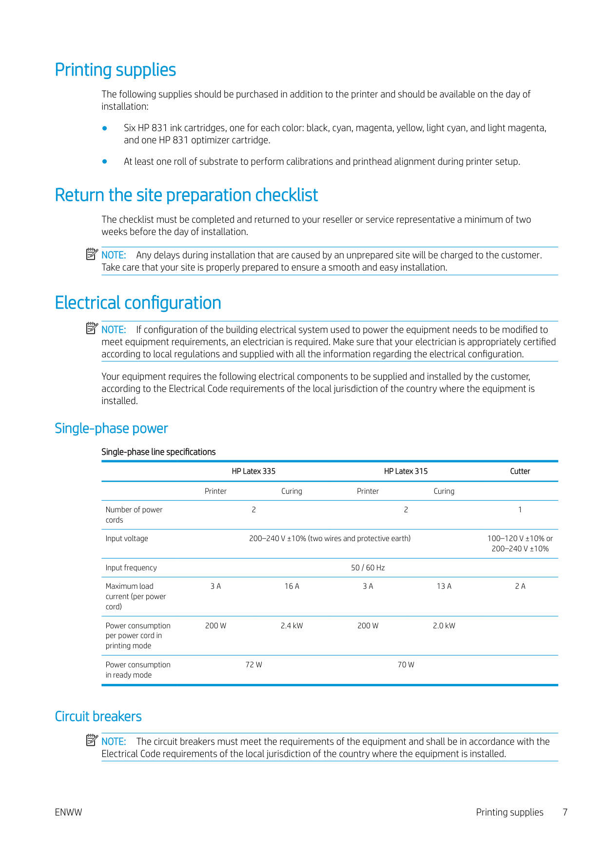
Single-phase line specifications
HP Latex 335 HP Latex 315 Cutter Printer Curing Printer Curing
Number of power cords
2 2 1
Input voltage 200–240 V ±10% (two wires and protective earth) 100–120 V ±10% or 200–240 V ±10%
Input frequency 50 / 60 Hz Maximum load current (per power cord)
3 A 16 A 3 A 13 A 2 A
Power consumption per power cord in printing mode
Power consumption in ready mode
200 W 2.4 kW 200 W 2.0 kW
72 W 70 W
#### Circuit breakers
| | |---|
NOTE: The circuit breakers must meet the requirements of the equipment and shall be in accordance with the Electrical Code requirements of the local jurisdiction of the country where the equipment is installed.
ENWW Printing supplies 7
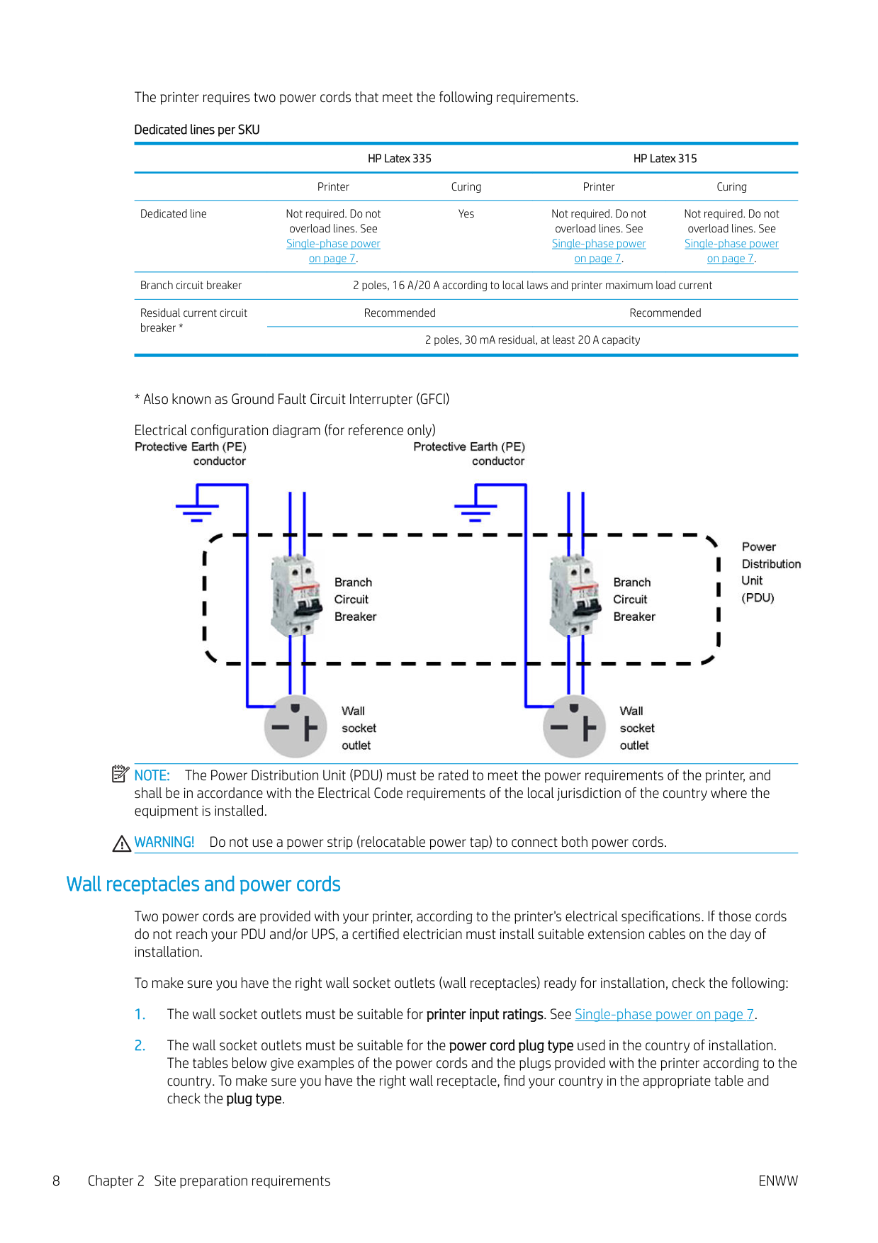
The printer requires two power cords that meet the following requirements. Dedicated lines per SKU
HP Latex 335 HP Latex 315 Printer Curing Printer Curing Dedicated line Not required. Do not
Not required. Do not overload lines. See Single-phase power on page 7. Branch circuit breaker 2 poles, 16 A/20 A according to local laws and printer maximum load current Residual current circuit breaker *
Yes Not required. Do not
overload lines. See Single-phase power on page 7.
overload lines. See Single-phase power on page 7.
Recommended Recommended 2 poles, 30 mA residual, at least 20 A capacity
| | |---|

NOTE: The Power Distribution Unit (PDU) must be rated to meet the power requirements of the printer, and shall be in accordance with the Electrical Code requirements of the local jurisdiction of the country where the equipment is installed.
WARNING! Do not use a power strip (relocatable power tap) to connect both power cords.
#### Wall receptacles and power cords
Two power cords are provided with your printer, according to the printer's electrical specifications. If those cords do not reach your PDU and/or UPS, a certified electrician must install suitable extension cables on the day of installation.
To make sure you have the right wall socket outlets (wall receptacles) ready for installation, check the following:
WARNING! Use only use the power cord supplied by HP with the printer. Do not use a power strip
(relocatable power tap) to connect both power cords. Do not damage, cut, or repair the power cord. With a damaged power cord, there is risk of fire and electric shock. Always replace a damaged power cord with an HP-approved power cord.
HP Latex 335 Printer—Power cord specifications by region
NOTE: You need two power cords. Country HP part number Length Plug type Plug
USA, Canada, Mexico, Japan, Philippines, Thailand
8120-6893 4.5 m NEMA 6-20P, 240 V, 20 A, non-locking

International 8120-6897 4.5 m IEC 60309, 240 V, 16 A, 2L
+PE

HP Latex 315 Printer—Power cord specifications by region
NOTE: You need two power cords. Country HP part number Length Plug type Plug America Argentina 8120-6897 4.5 m IEC 60309, 240V, 16A, 2L

+PE
Brazil 8121-110 2.5 m NBR 14136
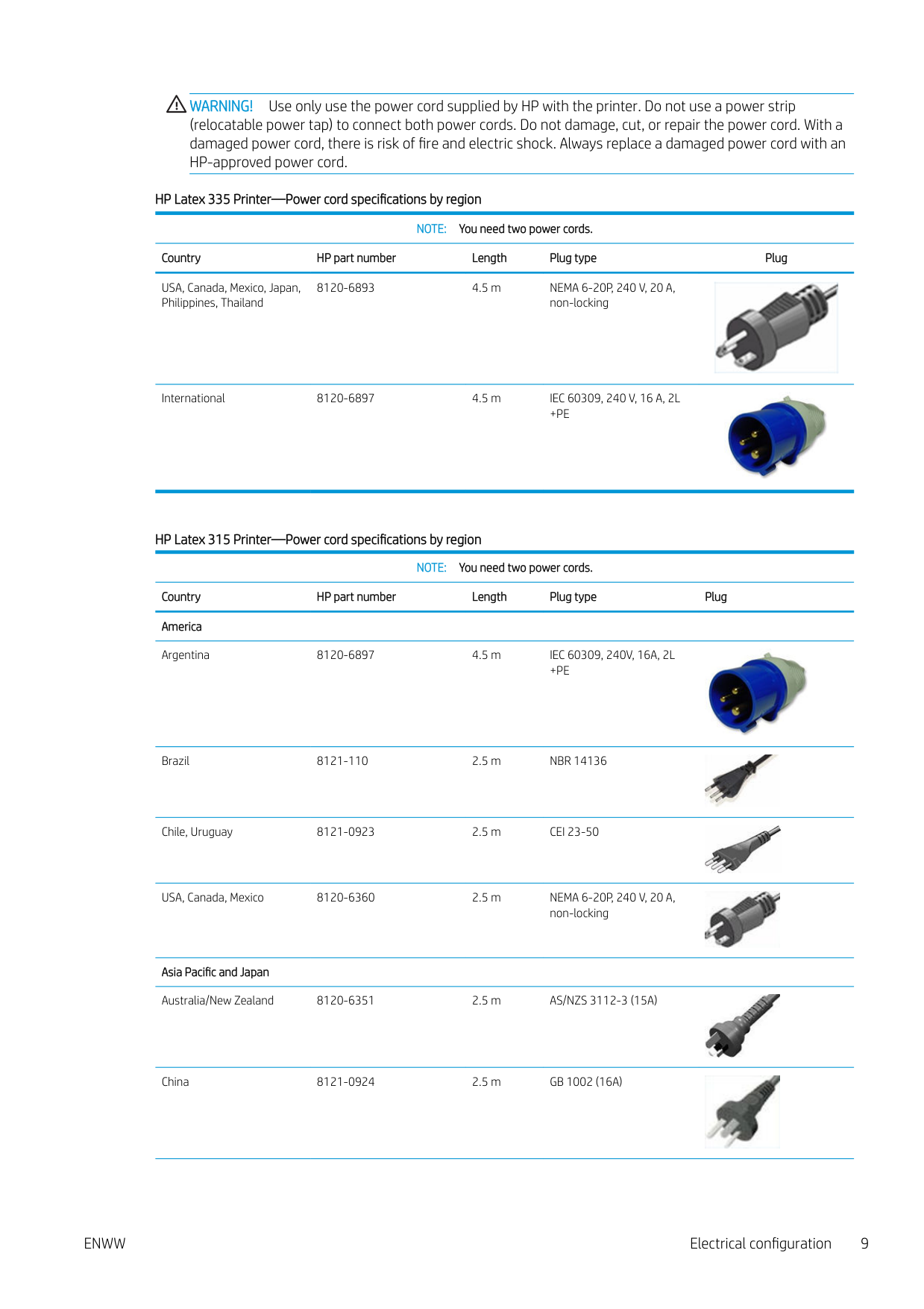

Chile, Uruguay 8121-0923 2.5 m CEI 23-50
USA, Canada, Mexico 8120-6360 2.5 m NEMA 6-20P, 240 V, 20 A, non-locking
Asia Pacific and Japan Australia/New Zealand 8120-6351 2.5 m AS/NZS 3112-3 (15A)
China 8121-0924 2.5 m GB 1002 (16A)


HP Latex 315 Printer—Power cord specifications by region (continued)
NOTE: You need two power cords. Country HP part number Length Plug type Plug Korea, Indonesia 8120-6352 2.5 m CEE 7-VII

India 8121-1074 2.5 m IS 1293
Taiwan 8121-1033 4.5 m CNS 690
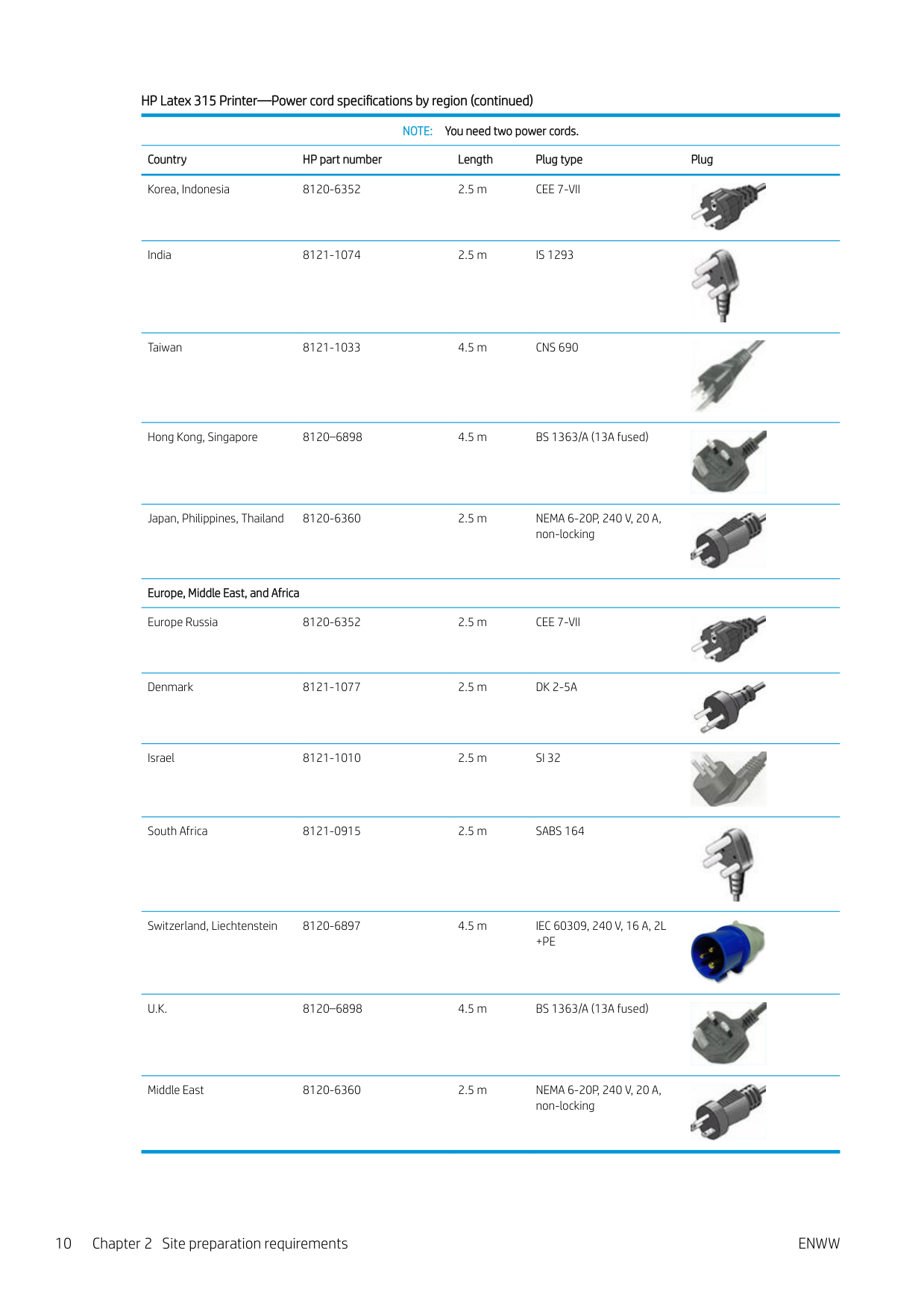
Hong Kong, Singapore 8120–6898 4.5 m BS 1363/A (13A fused)
Japan, Philippines, Thailand 8120-6360 2.5 m NEMA 6-20P, 240 V, 20 A, non-locking


Europe, Middle East, and Africa Europe Russia 8120-6352 2.5 m CEE 7-VII

Denmark 8121-1077 2.5 m DK 2-5A

Israel 8121-1010 2.5 m SI 32
South Africa 8121-0915 2.5 m SABS 164
Switzerland, Liechtenstein 8120-6897 4.5 m IEC 60309, 240 V, 16 A, 2L
+PE
U.K. 8120–6898 4.5 m BS 1363/A (13A fused)
Middle East 8120-6360 2.5 m NEMA 6-20P, 240 V, 20 A, non-locking


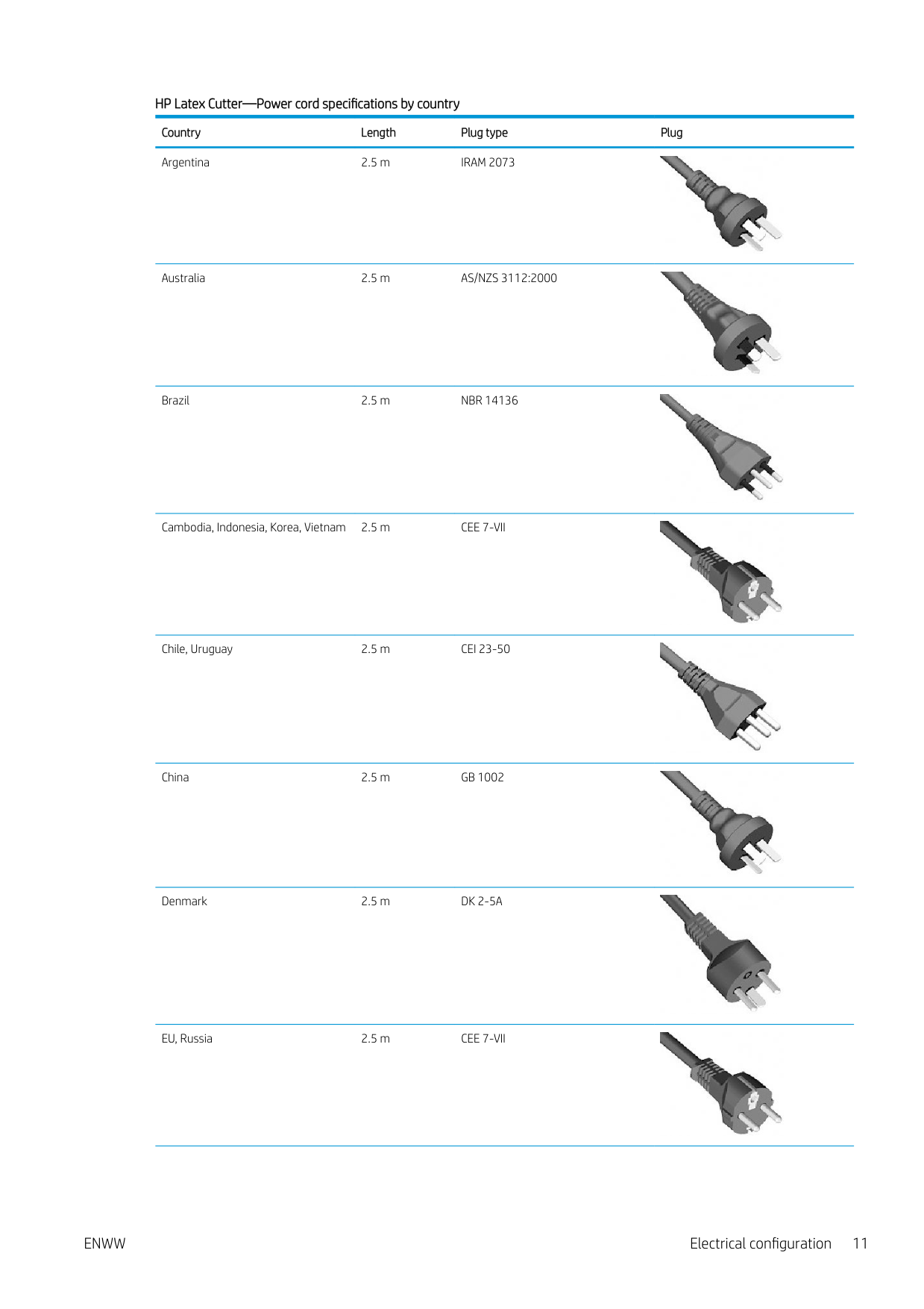
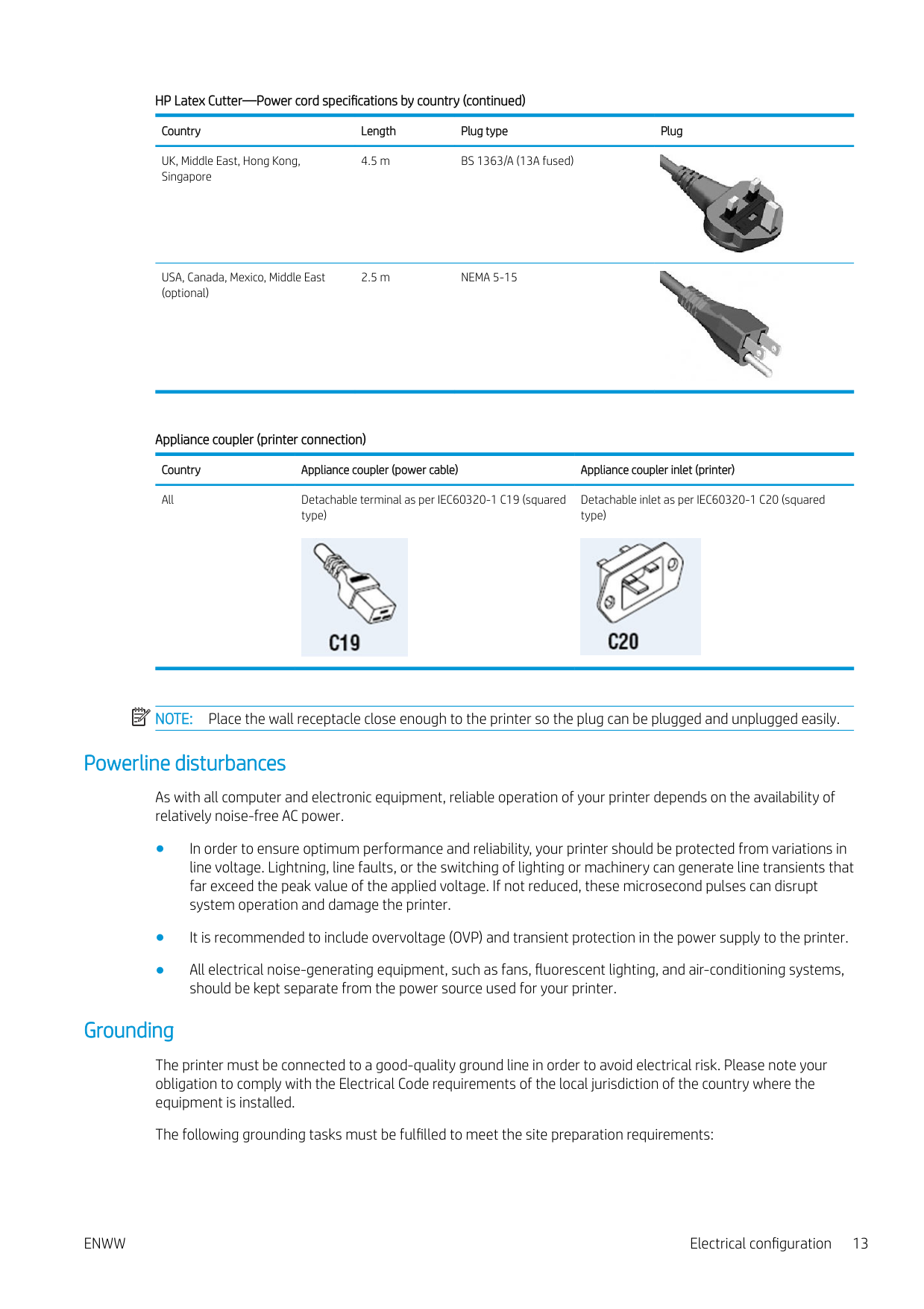
###### HP Latex Cutter—Power cord specifications by country Country Length Plug type Plug Argentina 2.5 m IRAM 2073

Australia 2.5 m AS/NZS 3112:2000
Brazil 2.5 m NBR 14136


Cambodia, Indonesia, Korea, Vietnam 2.5 m CEE 7-VII
Chile, Uruguay 2.5 m CEI 23-50
China 2.5 m GB 1002
Denmark 2.5 m DK 2-5A


EU, Russia 2.5 m CEE 7-VII

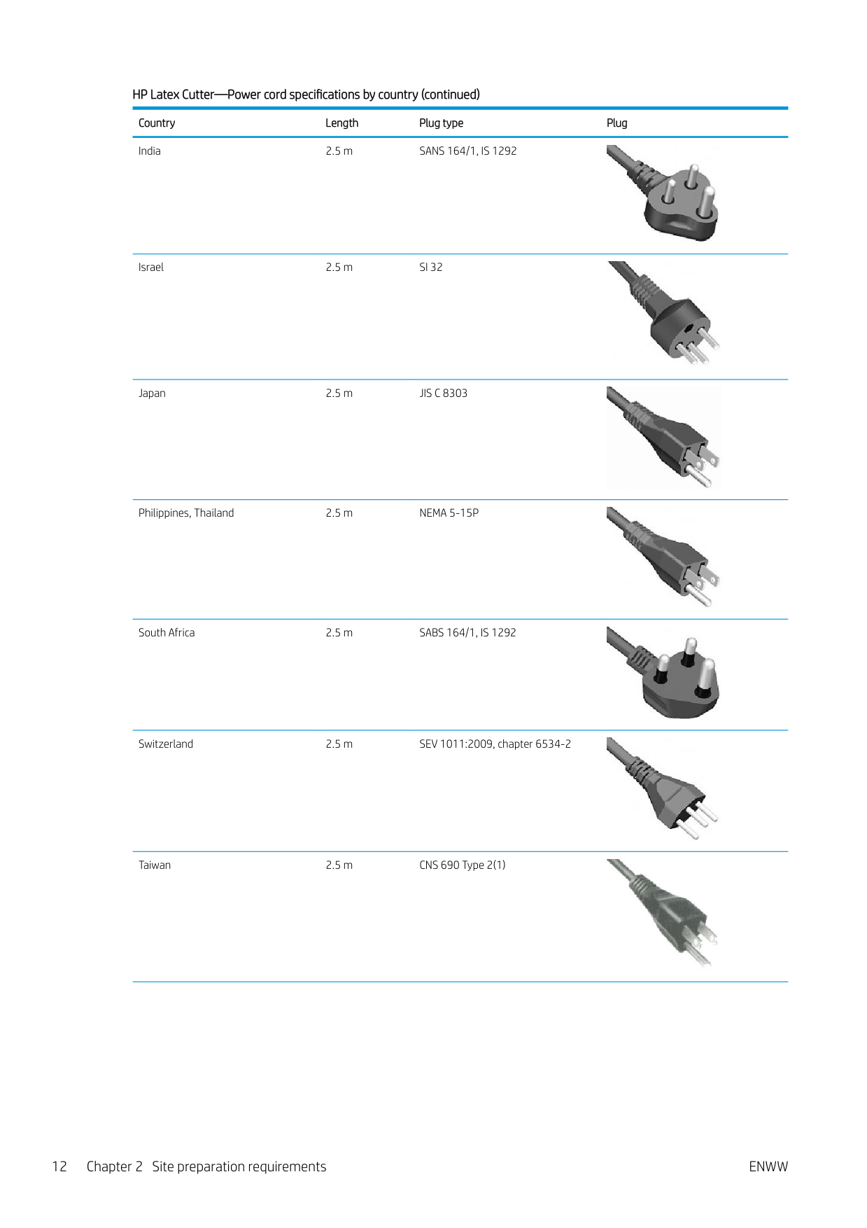
India 2.5 m SANS 164/1, IS 1292

Israel 2.5 m SI 32
Japan 2.5 m JIS C 8303


Philippines, Thailand 2.5 m NEMA 5-15P

South Africa 2.5 m SABS 164/1, IS 1292
Switzerland 2.5 m SEV 1011:2009, chapter 6534-2
Taiwan 2.5 m CNS 690 Type 2(1)


UK, Middle East, Hong Kong, Singapore
4.5 m BS 1363/A (13A fused)

USA, Canada, Mexico, Middle East (optional)
2.5 m NEMA 5-15


Appliance coupler (printer connection) Country Appliance coupler (power cable) Appliance coupler inlet (printer) All Detachable terminal as per IEC60320-1 C19 (squared
Detachable inlet as per IEC60320-1 C20 (squared type)
type)


| | |---|
NOTE: Place the wall receptacle close enough to the printer so the plug can be plugged and unplugged easily.
#### Powerline disturbances
As with all computer and electronic equipment, reliable operation of your printer depends on the availability of relatively noise-free AC power.
#### Grounding
The printer must be connected to a good-quality ground line in order to avoid electrical risk. Please note your obligation to comply with the Electrical Code requirements of the local jurisdiction of the country where the equipment is installed.
The following grounding tasks must be fulfilled to meet the site preparation requirements:
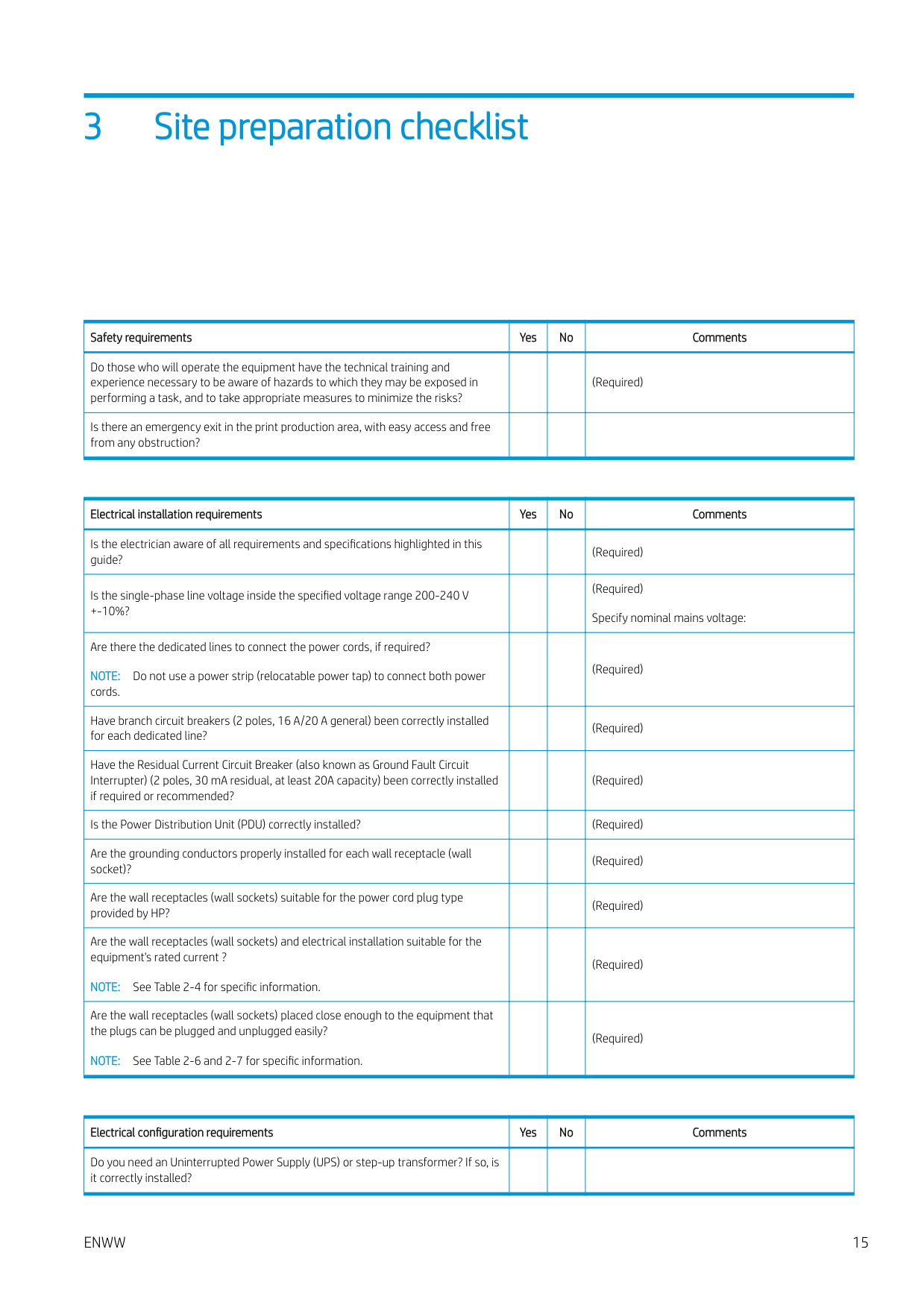
3 Site preparation checklist
|Safety requirements|Yes|No|Comments| |---|---|---|---| |Do those who will operate the equipment have the technical training and experience necessary to be aware of hazards to which they may be exposed in performing a task, and to take appropriate measures to minimize the risks?| | |(Required)| |Is there an emergency exit in the print production area, with easy access and free from any obstruction?| | | |
|Electrical installation requirements|Yes|No|Comments| |---|---|---|---| |Is the electrician aware of all requirements and specifications highlighted in this guide?| | |(Required)| |Is the single-phase line voltage inside the specified voltage range 200-240 V
+-10%?| | |(Required) Specify nominal mains voltage:| |Are there the dedicated lines to connect the power cords, if required? NOTE: Do not use a power strip (relocatable power tap) to connect both power cords.| | |(Required)| |Have branch circuit breakers (2 poles, 16 A/20 A general) been correctly installed for each dedicated line?| | |(Required)| |Have the Residual Current Circuit Breaker (also known as Ground Fault Circuit Interrupter) (2 poles, 30 mA residual, at least 20A capacity) been correctly installed if required or recommended?| | |(Required)| |Is the Power Distribution Unit (PDU) correctly installed?| | |(Required)| |Are the grounding conductors properly installed for each wall receptacle (wall socket)?| | |(Required)| |Are the wall receptacles (wall sockets) suitable for the power cord plug type provided by HP?| | |(Required)|
|Are the wall receptacles (wall sockets) and electrical installation suitable for the equipment's rated current ?
NOTE: See Table 2-4 for specific information.| | |(Required)| |Are the wall receptacles (wall sockets) placed close enough to the equipment that the plugs can be plugged and unplugged easily?
NOTE: See Table 2-6 and 2-7 for specific information.| | |(Required)|
|Electrical configuration requirements|Yes|No|Comments| |---|---|---|---| |Do you need an Uninterrupted Power Supply (UPS) or step-up transformer? If so, is it correctly installed?| | | |
ENWW 15
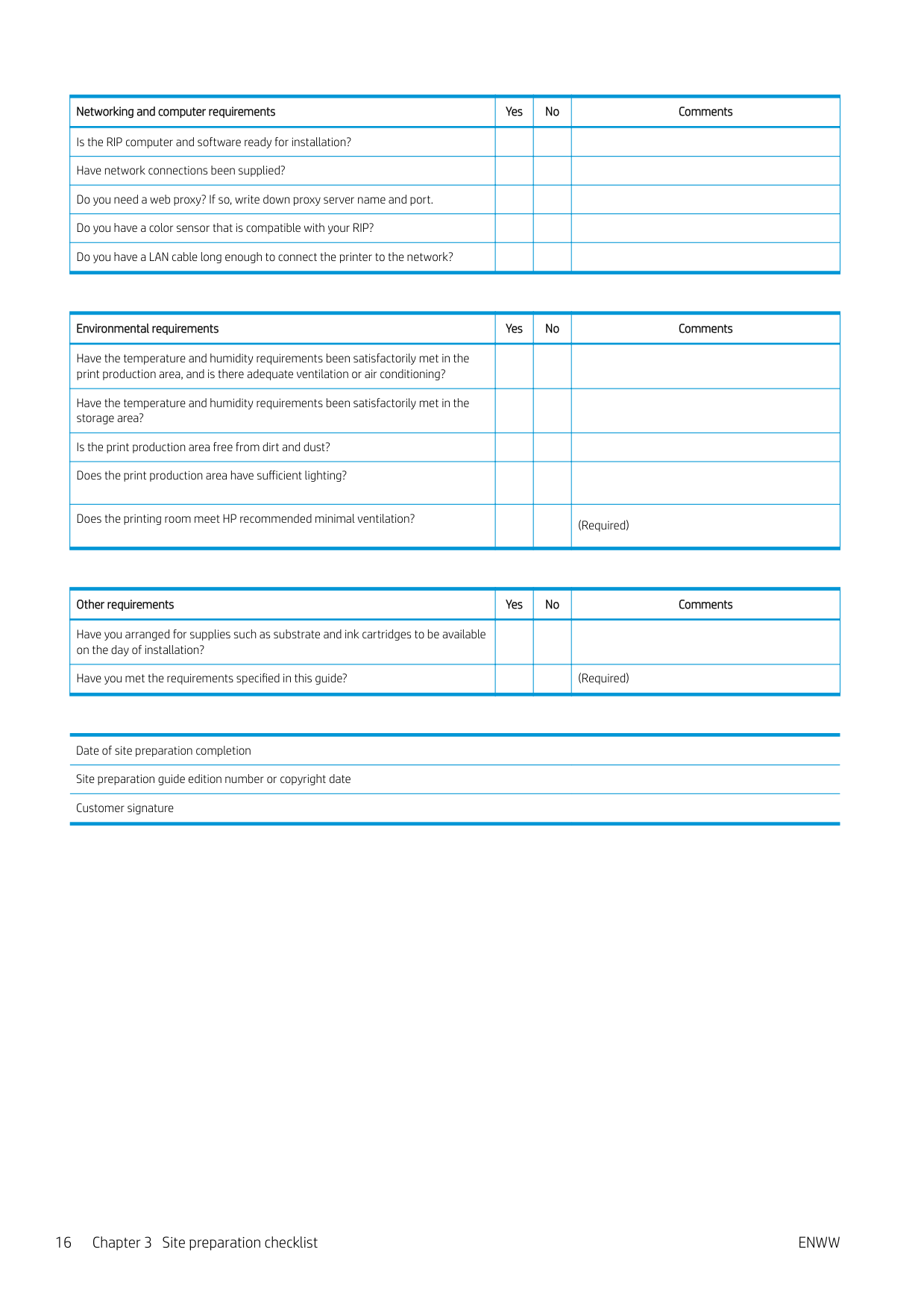
|Networking and computer requirements|Yes|No|Comments| |---|---|---|---| |Is the RIP computer and software ready for installation?| | | | |Have network connections been supplied?| | | | |Do you need a web proxy? If so, write down proxy server name and port.| | | | |Do you have a color sensor that is compatible with your RIP?| | | | |Do you have a LAN cable long enough to connect the printer to the network?| | | |
|Environmental requirements|Yes|No|Comments| |---|---|---|---| |Have the temperature and humidity requirements been satisfactorily met in the print production area, and is there adequate ventilation or air conditioning?| | | | |Have the temperature and humidity requirements been satisfactorily met in the storage area?| | | | |Is the print production area free from dirt and dust?| | | | |Does the print production area have sufficient lighting?| | | | |Does the printing room meet HP recommended minimal ventilation?| | |(Required)|
|Other requirements|Yes|No|Comments| |---|---|---|---| |Have you arranged for supplies such as substrate and ink cartridges to be available on the day of installation?| | | | |Have you met the requirements specified in this guide?| | |(Required)|
Date of site preparation completion Site preparation guide edition number or copyright date Customer signature
16 Chapter 3 Site preparation checklist ENWW