
Ask AI
— answers from the official manualAnswers from the official manual.
Common questions
Common Questions
8 totalWhat should I do if my hard drive or eMMC light keeps blinking?
A blinking white hard drive/eMMC light indicates that the internal storage device is being accessed. If you're concerned about excessive activity, it might be a normal process, but check for system updates or disk errors using Windows tools.
How do I replace the battery in my HP 15 Notebook PC?
To remove and install a battery: Turn off your computer, disconnect all external devices, and unplug the power cord. Then turn the laptop upside down on a flat surface, slide the release latch located at the bottom to unlock the battery, and lift it out using two fingers in the center of the battery. Ensure compatibility before inserting by sliding the new battery straight in until it clicks into place.
Where can I find my computer's specifications?
Refer to chapter 12 Specifications for detailed information on processor, display, memory, hard drive capacities and types available in your HP 15 Notebook PC model.
How do I locate the WLAN antenna cables when swapping a wireless module?
To access and replace the WLAN module, follow steps to remove necessary parts like battery, service door, optical drive. Disconnect the WLAN antenna cables from terminals on the WLAN module; ensure correct placement with protective sleeves if disengaged.
What is the safe operating temperature for my laptop?
To prevent overheating and potential injury, avoid placing the device directly on your lap or any soft surface like pillows which can obstruct airflow and cause hot spots. Use it only on a hard flat surface with ventilation around.
How do I update my BIOS in Windows 10?
Start Setup Utility (BIOS) from the Windows search function, then download an appropriate BIOS update for your model from HP's website and follow installation instructions within the utility.
Full Manual
107 pages

HP 15 Notebook PC
Maintenance and Service Guide
© Copyright 2015 HP Development Company, L.P.
AMD is a trademark of Advanced Micro Devices, Inc. Bluetooth is a trademark owned by its proprietor and used by HP Inc. under license. Intel, Celeron, Centrino, and Pentium are trademarks of Intel Corporation in the U.S. and other countries. Microsoft and Windows are U.S. registered trademarks of the Microsoft group of companies.
The information contained herein is subject to change without notice. The only warranties for HP products and services are set forth in the express warranty statements accompanying such products and services. Nothing herein should be construed as constituting an additional warranty. HP shall not be liable for technical or editorial errors or omissions contained herein.
Second Edition: August 2015 First Edition: November 2014 Document Part Number: 793965-002
######## Product notice
This guide describes features that are common to most models. Some features may not be available on your computer.
Not all features are available in all editions of Windows. This computer may require upgraded and/or separately purchased hardware, drivers, and/or software to take full advantage of Windows functionality. See http://www.microsoft.com for details.
######## Software terms
By installing, copying, downloading, or otherwise using any software product preinstalled on this computer, you agree to be bound by the terms of the HP End User License Agreement (EULA). If you do not accept these license terms, your sole remedy is to return the entire unused product (hardware and software) within 14 days for a refund subject to the refund policy of your place of purchase.
For any further information or to request a full refund of the computer, please contact your local point of sale (the seller).
#### Important Notice about Customer Self-Repair Parts
CAUTION: Your computer includes Customer Self-Repair parts and parts that should only be accessed by an authorized service provider. See Chapter 5, "Removal and replacement procedures for Customer Self-Repair parts," for details. Accessing parts described in Chapter 6, "Removal and replacement procedures for Authorized Service Provider only parts," can damage the computer or void your warranty.
iii
####### iv Important Notice about Customer Self-Repair Parts
#### Safety warning notice
WARNING! To reduce the possibility of heat-related injuries or of overheating the device, do not place the device directly on your lap or obstruct the device air vents. Use the device only on a hard, flat surface. Do not allow another hard surface, such as an adjoining optional printer, or a soft surface, such as pillows or rugs or clothing, to block airflow. Also, do not allow the AC adapter to contact the skin or a soft surface, such as pillows or rugs or clothing, during operation. The device and the AC adapter comply with the user-accessible surface temperature limits defined by the International Standard for Safety of Information Technology Equipment (IEC 60950).
v
####### vi Safety warning notice
Table of contents
TouchPad ............................................................................................................................................. 8 Lights ................................................................................................................................................... 8 Buttons and speakers ....................................................................................................................... 10 Keys ................................................................................................................................................... 11
Bottom ................................................................................................................................................................. 12 Locating system information .............................................................................................................................. 14

Plastic parts ....................................................................................................................................... 22 Cables and connectors ...................................................................................................................... 23 Drive handling ................................................................................................................................... 23
Grounding guidelines ........................................................................................................................................... 24
Electrostatic discharge damage ........................................................................................................ 24 Packaging and transporting guidelines .......................................................................... 25 Workstation guidelines ................................................................................................... 25 Equipment guidelines ..................................................................................................... 26
Battery ............................................................................................................................................... 28 Service door ....................................................................................................................................... 29
vii
Memory module ................................................................................................................................ 30 WLAN module .................................................................................................................................... 31 Optical drive ....................................................................................................................................... 33
###### 6 Removal and replacement procedures for Authorized Service Provider parts ................................................... 35Component replacement procedures .................................................................................................................. 35
Display panel ..................................................................................................................................... 36 Keyboard ........................................................................................................................................... 38 Top cover ........................................................................................................................................... 40 Hard drive .......................................................................................................................................... 44 Power button board .......................................................................................................................... 47 TouchPad button board ..................................................................................................................... 49 Optical drive connector cable ............................................................................................................ 51 System board .................................................................................................................................... 52 RTC battery ........................................................................................................................................ 57 Fan ..................................................................................................................................................... 59 Heat sink assembly ........................................................................................................................... 61 Power connector cable ...................................................................................................................... 63 Speakers ............................................................................................................................................ 64 Display assembly ............................................................................................................................... 65
####### 7 Using Setup Utility (BIOS) in Windows 8.1 ...................................................................................................... 73Starting Setup Utility (BIOS) ................................................................................................................................ 73Updating the BIOS ................................................................................................................................................ 73
Determining the BIOS version ........................................................................................................... 73 Downloading a BIOS update .............................................................................................................. 73

####### 8 Using Setup Utility (BIOS) in Windows 10 ....................................................................................................... 75Starting Setup Utility (BIOS) ................................................................................................................................ 75Updating Setup Utility (BIOS) .............................................................................................................................. 75
Determining the BIOS version ........................................................................................................... 75 Downloading a BIOS update .............................................................................................................. 76
Synchronizing a tablet and keyboard (select products only) .............................................................................. 77
###### 9 Backing up, restoring, and recovering in Windows 8.1 .................................................................................... 78Creating recovery media and backups ................................................................................................................ 78
Creating HP Recovery media (select models only) ........................................................................... 78 Using Windows tools ........................................................................................................................................... 79 Restore and recovery ........................................................................................................................................... 79
Recovering using HP Recovery Manager ........................................................................................... 80
viii
What you need to know before you get started ............................................................. 80 Using the HP Recovery partition (select models only) ................................................... 81 Using HP Recovery media to recover .............................................................................. 81 Changing the computer boot order ................................................................................ 81 Removing the HP Recovery partition (select models only) ............................................ 82
Creating HP Recovery media (select products only) ......................................................................... 83 Using Windows tools ........................................................................................................................................... 84 Restore and recovery ........................................................................................................................................... 85
Recovering using HP Recovery Manager ........................................................................................... 85 What you need to know before you get started ............................................................. 85 Using the HP Recovery partition (select products only) ................................................. 86 Using HP Recovery media to recover .............................................................................. 86 Changing the computer boot order ................................................................................ 87 Removing the HP Recovery partition (select products only) ......................................... 87

Index ............................................................................................................................................................. 95
ix
####### x
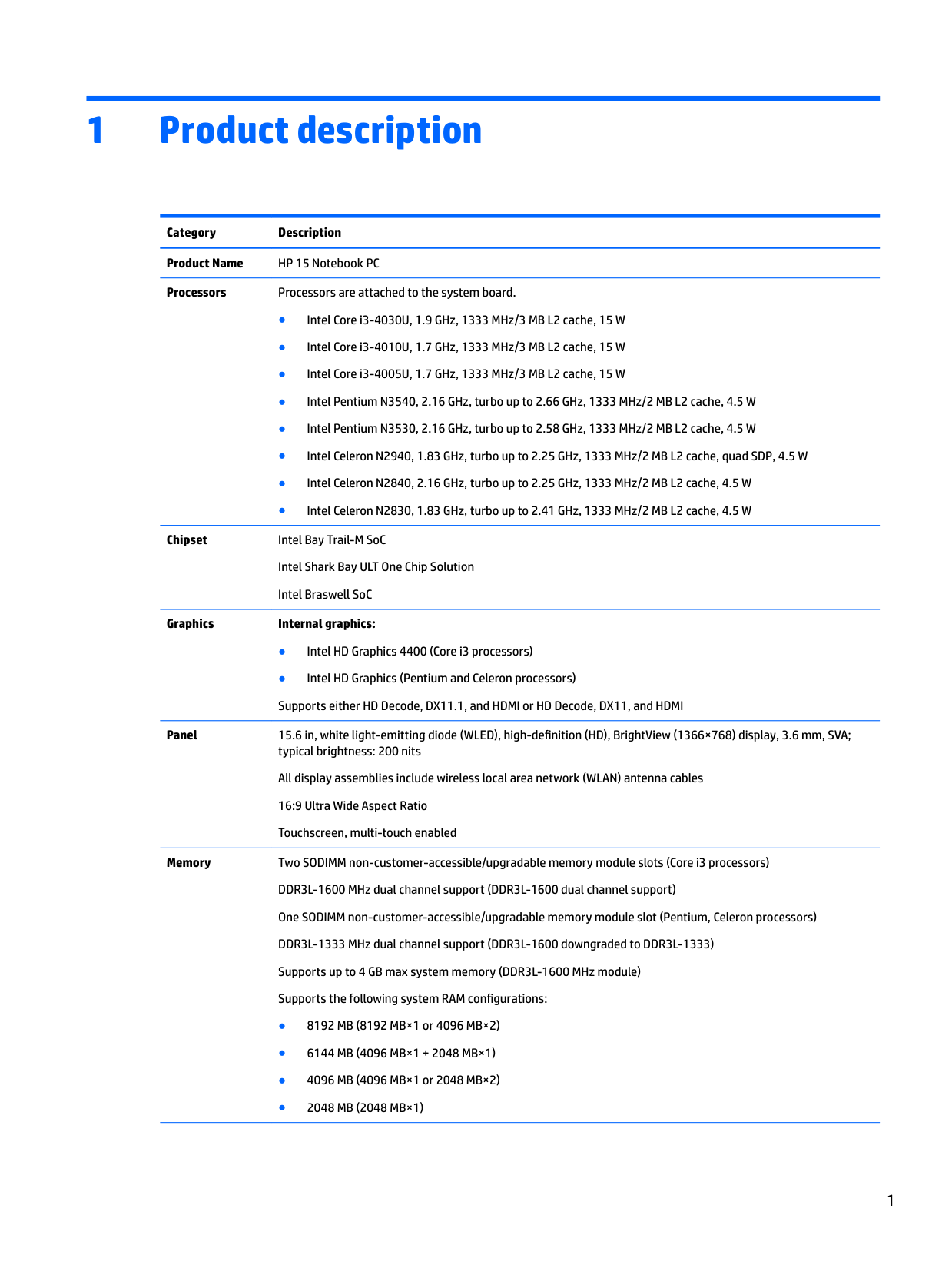
1 Product description
Category Description Product Name HP 15 Notebook PC Processors Processors are attached to the system board.
Chipset Intel Bay Trail-M SoC Intel Shark Bay ULT One Chip Solution Intel Braswell SoC

######## Graphics Internal graphics:
Panel 15.6 in, white light-emitting diode (WLED), high-definition (HD), BrightView (1366×768) display, 3.6 mm, SVA; typical brightness: 200 nits All display assemblies include wireless local area network (WLAN) antenna cables 16:9 Ultra Wide Aspect Ratio Touchscreen, multi-touch enabled
Memory Two SODIMM non-customer-accessible/upgradable memory module slots (Core i3 processors) DDR3L-1600 MHz dual channel support (DDR3L-1600 dual channel support) One SODIMM non-customer-accessible/upgradable memory module slot (Pentium, Celeron processors) DDR3L-1333 MHz dual channel support (DDR3L-1600 downgraded to DDR3L-1333) Supports up to 4 GB max system memory (DDR3L-1600 MHz module) Supports the following system RAM configurations:
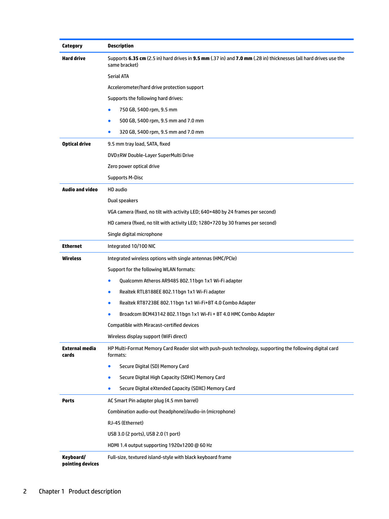
Hard drive Supports 6.35 cm (2.5 in) hard drives in 9.5 mm (.37 in) and 7.0 mm (.28 in) thicknesses (all hard drives use the same bracket) Serial ATA Accelerometer/hard drive protection support Supports the following hard drives:
Optical drive 9.5 mm tray load, SATA, fixed DVD±RW Double-Layer SuperMulti Drive Zero power optical drive Supports M-Disc
Audio and video HD audio Dual speakers VGA camera (fixed, no tilt with activity LED; 640×480 by 24 frames per second) HD camera (fixed, no tilt with activity LED; 1280×720 by 30 frames per second) Single digital microphone
Ethernet Integrated 10/100 NIC Wireless Integrated wireless options with single antennas (HMC/PCIe)
Support for the following WLAN formats:
External media cards
HP Multi-Format Memory Card Reader slot with push-push technology, supporting the following digital card formats:
Ports AC Smart Pin adapter plug (4.5 mm barrel) Combination audio-out (headphone)/audio-in (microphone) RJ-45 (Ethernet) USB 3.0 (2 ports), USB 2.0 (1 port) HDMI 1.4 output supporting 1920x1200 @ 60 Hz
Keyboard/ pointing devices
Full-size, textured island-style with black keyboard frame
2 Chapter 1 Product description
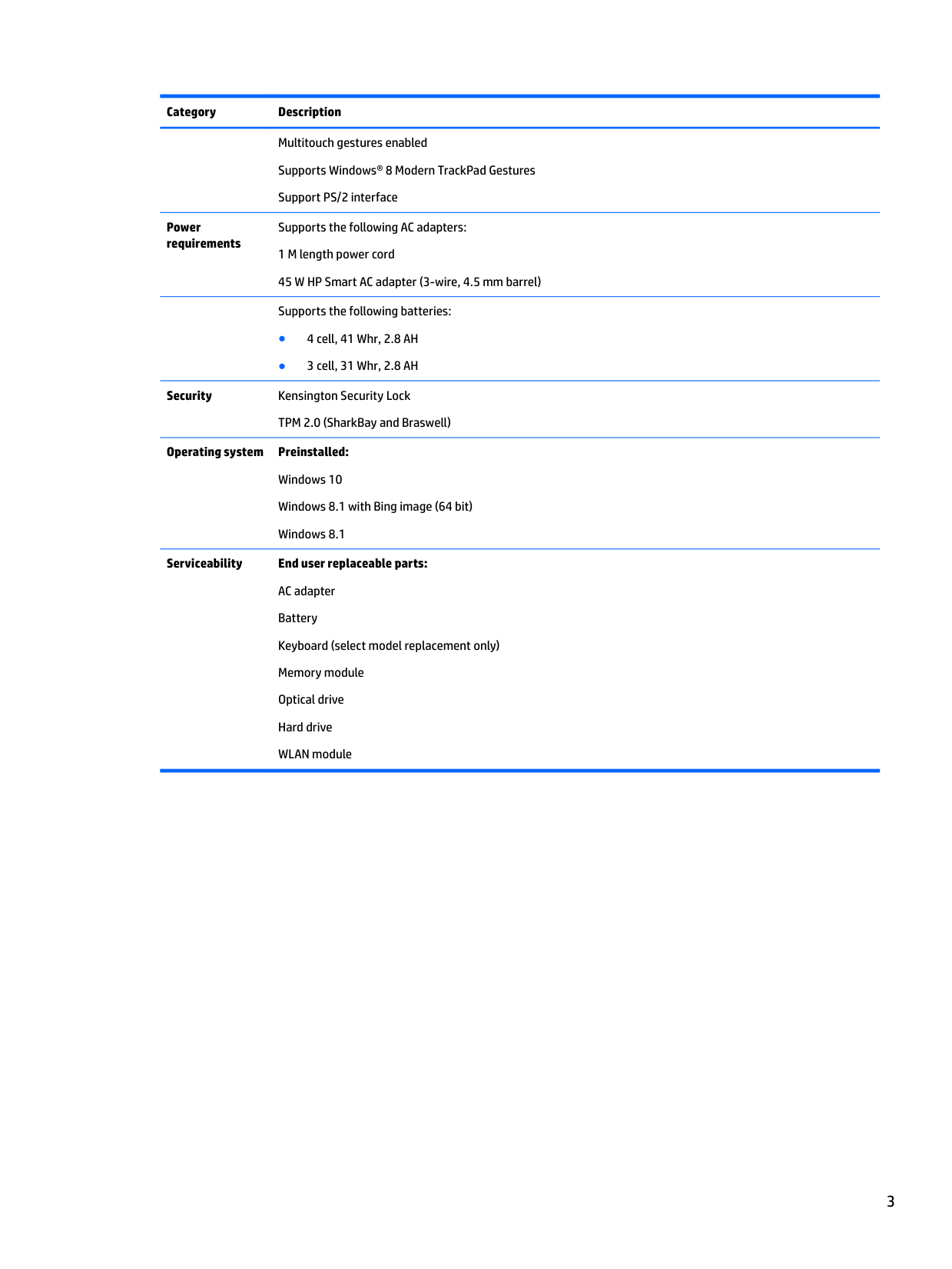
Multitouch gestures enabled Supports Windows® 8 Modern TrackPad Gestures Support PS/2 interface
Power requirements
Supports the following AC adapters: 1 M length power cord 45 W HP Smart AC adapter (3-wire, 4.5 mm barrel) Supports the following batteries:
Security Kensington Security Lock
TPM 2.0 (SharkBay and Braswell)
Operating system Preinstalled: Windows 10 Windows 8.1 with Bing image (64 bit) Windows 8.1
Serviceability End user replaceable parts: AC adapter Battery Keyboard (select model replacement only) Memory module Optical drive Hard drive WLAN module
2 External component identification
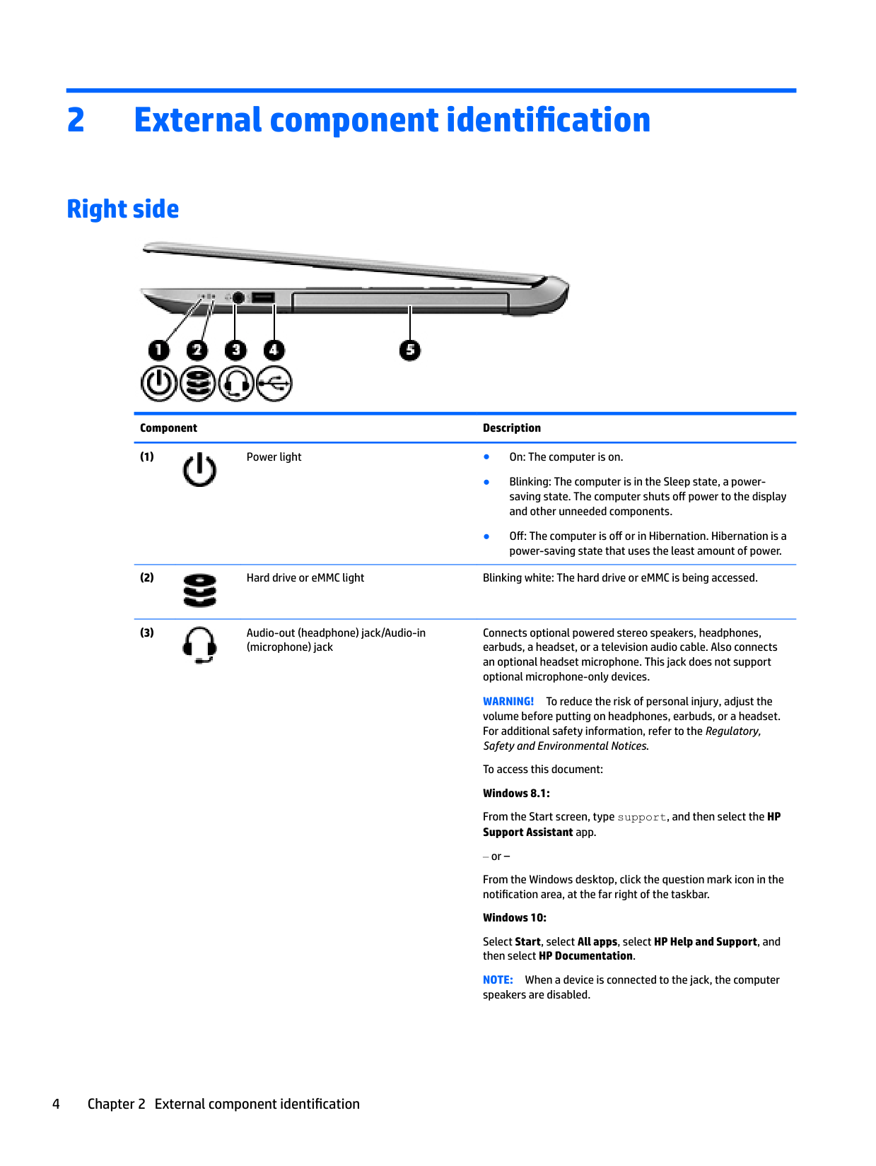
Right side

######## Component Description


Connects optional powered stereo speakers, headphones, earbuds, a headset, or a television audio cable. Also connects an optional headset microphone. This jack does not support optional microphone-only devices.

WARNING! To reduce the risk of personal injury, adjust the volume before putting on headphones, earbuds, or a headset. For additional safety information, refer to the Regulatory, Safety and Environmental Notices.

To access this document: Windows 8.1: From the Start screen, type support, and then select the HP Support Assistant app.
or –
From the Windows desktop, click the question mark icon in the notification area, at the far right of the taskbar.
Windows 10:
Select Start, select All apps, select HP Help and Support, and then select HP Documentation.
NOTE: When a device is connected to the jack, the computer speakers are disabled.
NOTE: Be sure that the device cable has a 4-conductor connector that supports both audio-out (headphone) and audio-in (microphone).

NOTE: For disc compatibility information, go to the Help and
Support web page. Follow the web page instructions to select your computer model. Select Drivers & Downloads, and then follow the on-screen instructions.
In Windows 10, type help in the taskbar search box, select Help and Support, and then type disc compatibility in the search box.
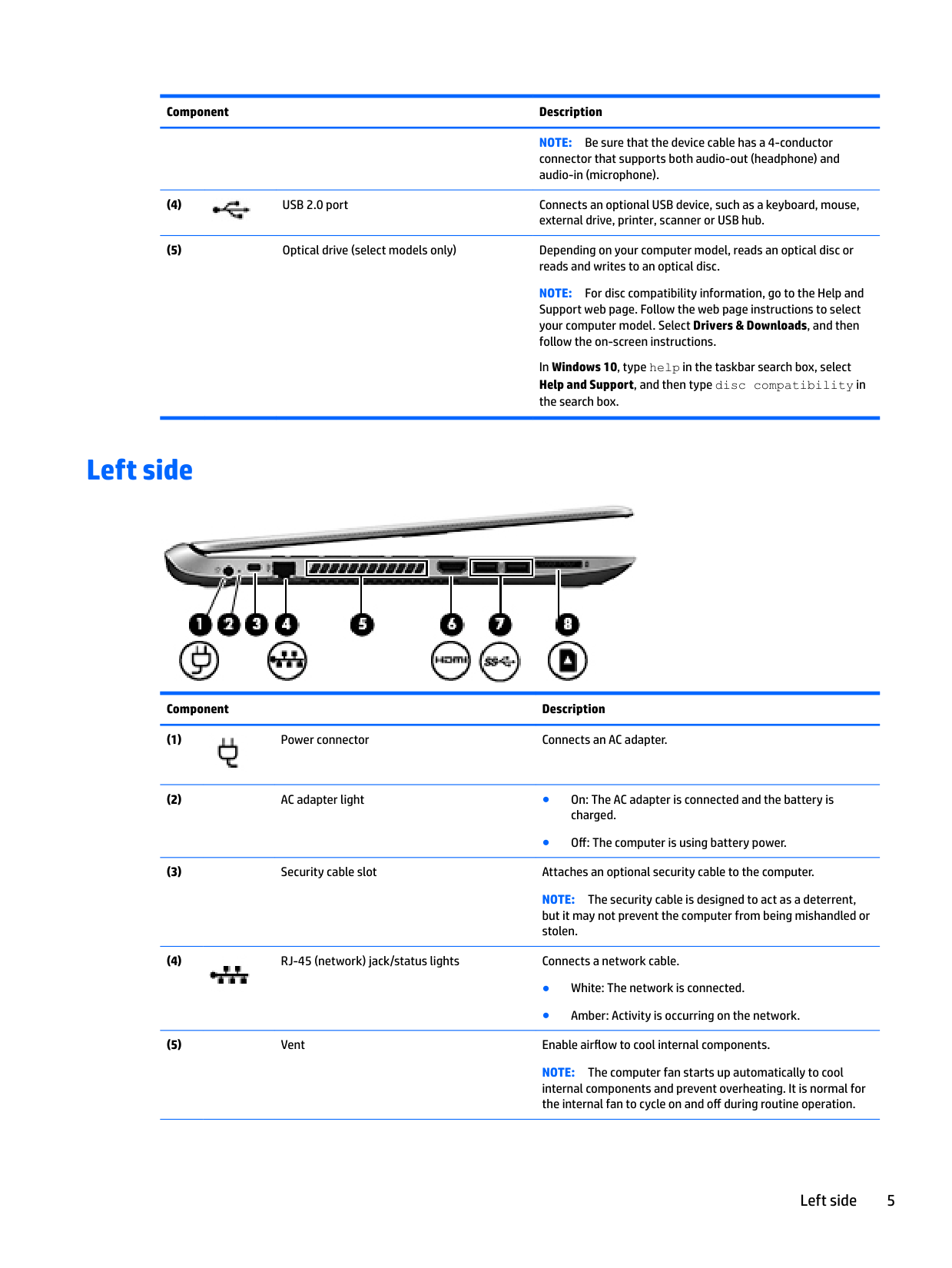
Left side

######## Component Description

● Off: The computer is using battery power.
NOTE: The security cable is designed to act as a deterrent, but it may not prevent the computer from being mishandled or stolen.

NOTE: The computer fan starts up automatically to cool internal components and prevent overheating. It is normal for the internal fan to cycle on and off during routine operation.
Left side 5


● Hold the card label-side up, with connectors facing the slot, insert the card into the slot, and then push in on the card until it is firmly seated.
To remove a card:
● Press in on the card until it pops out.
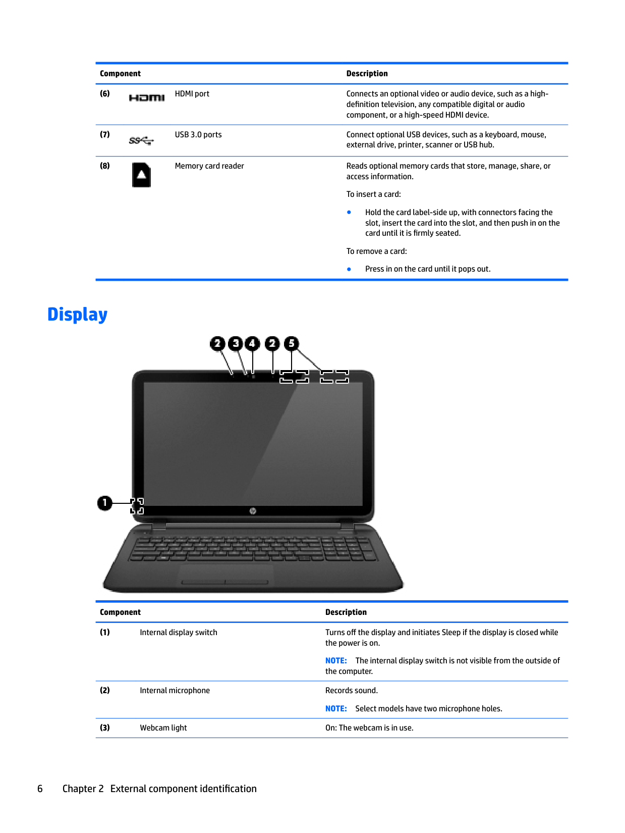
Display

######## Component Description
NOTE: The internal display switch is not visible from the outside of the computer.
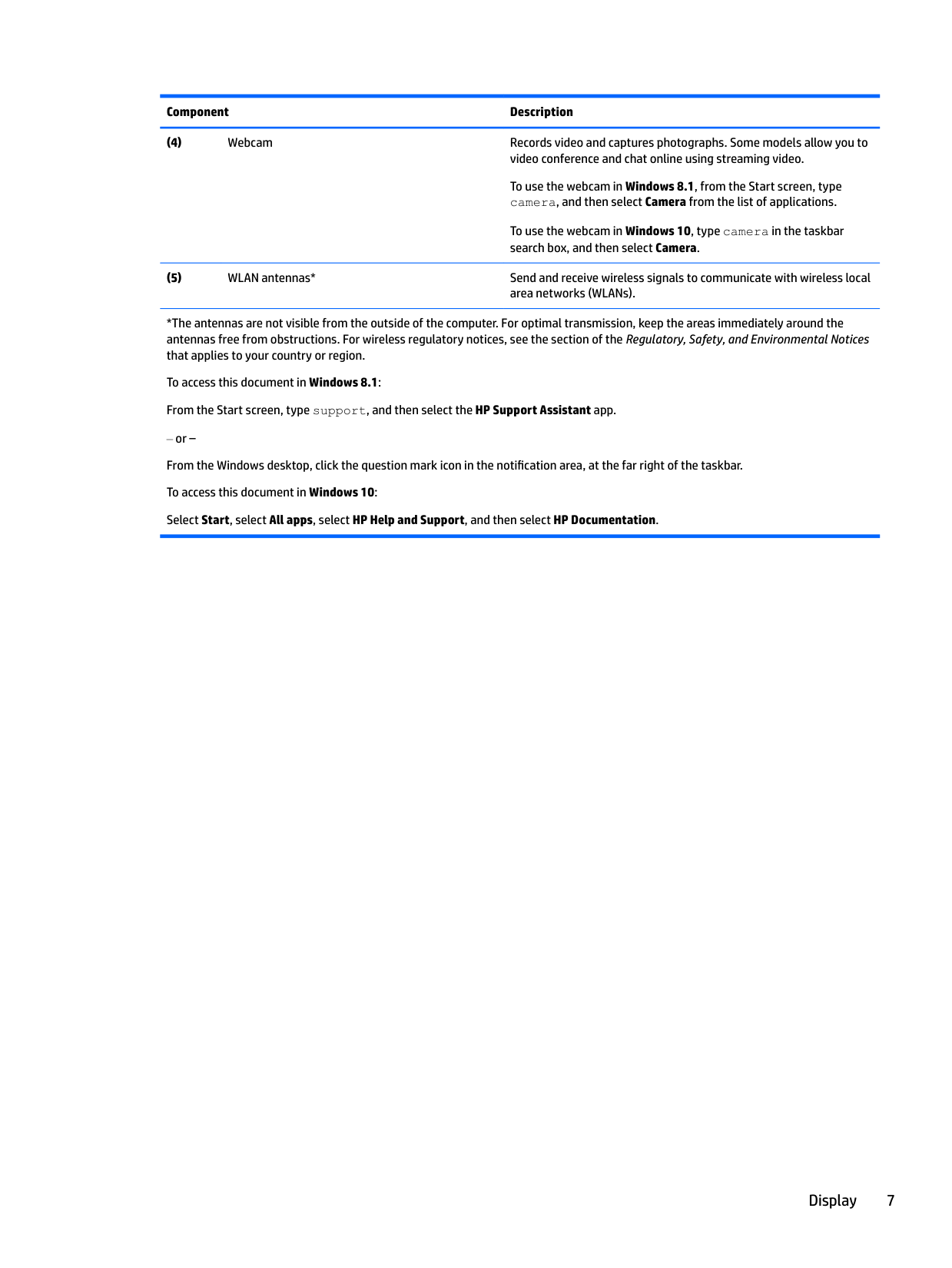
To use the webcam in Windows 8.1, from the Start screen, type camera, and then select Camera from the list of applications.
To use the webcam in Windows 10, type camera in the taskbar search box, and then select Camera.
*The antennas are not visible from the outside of the computer. For optimal transmission, keep the areas immediately around the antennas free from obstructions. For wireless regulatory notices, see the section of the Regulatory, Safety, and Environmental Notices that applies to your country or region.
To access this document in Windows 8.1: From the Start screen, type support, and then select the HP Support Assistant app.
‒ or – From the Windows desktop, click the question mark icon in the notification area, at the far right of the taskbar. To access this document in Windows 10: Select Start, select All apps, select HP Help and Support, and then select HP Documentation.
Display 7
Top
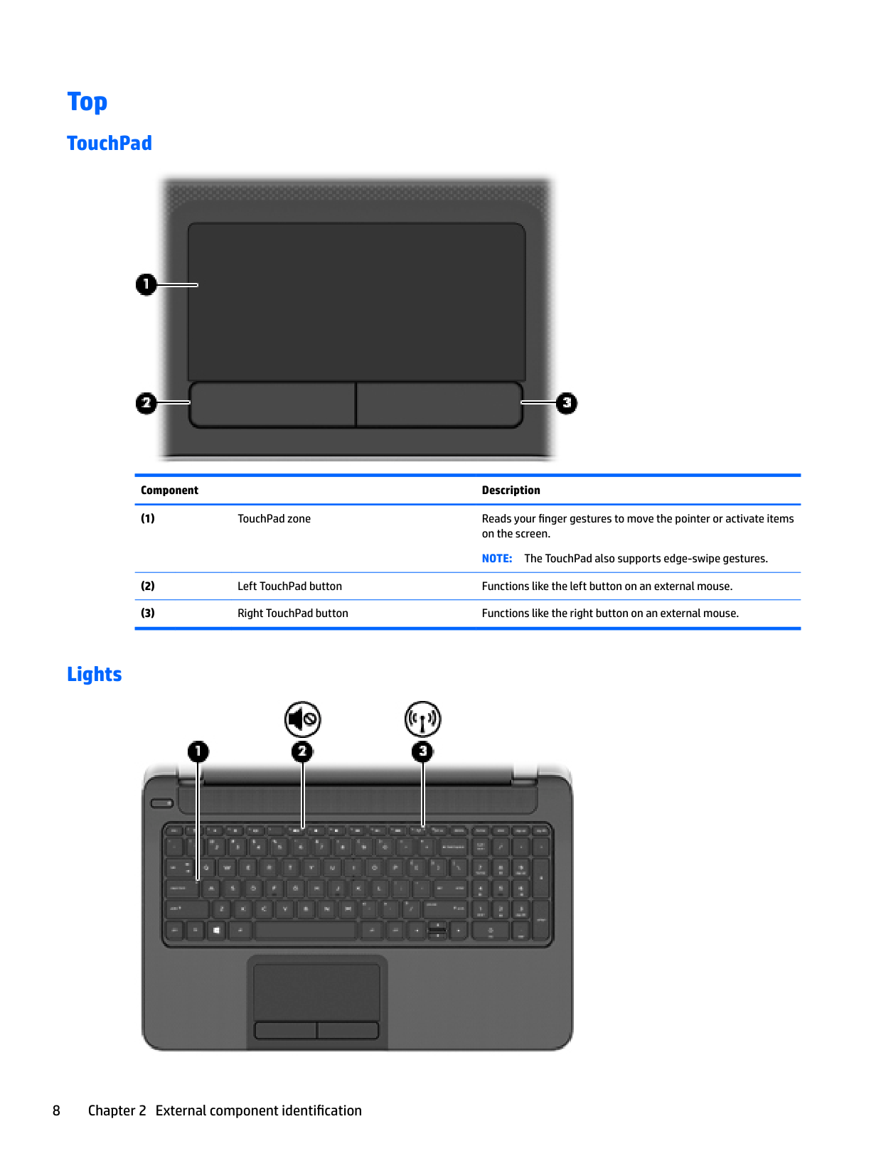
#### TouchPad

######## Component Description
#### Lights


● Off: Computer sound is on.

NOTE: On some models, the wireless light is amber when all wireless devices are off.
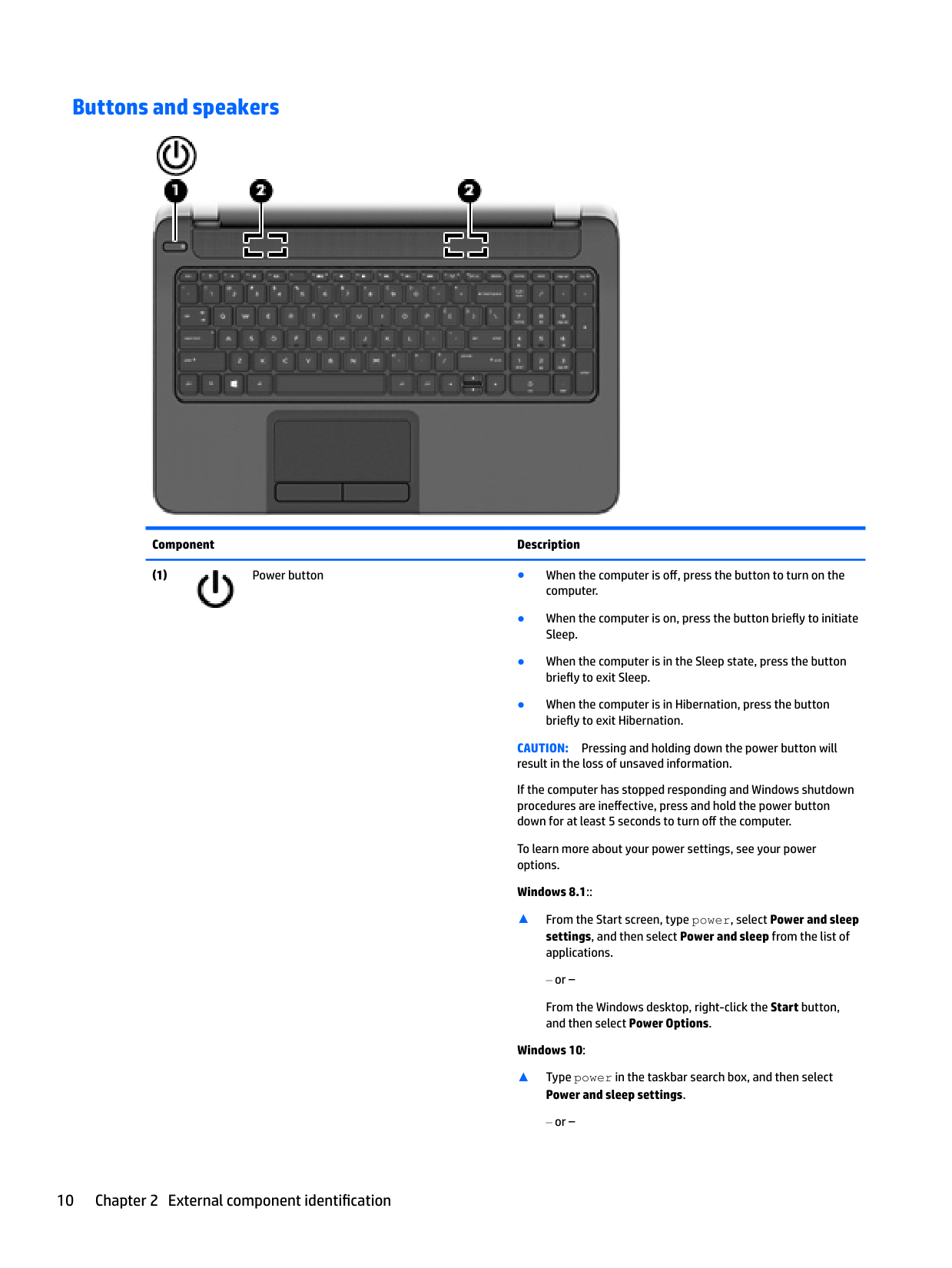
#### Buttons and speakers

######## Component Description

CAUTION: Pressing and holding down the power button will result in the loss of unsaved information. If the computer has stopped responding and Windows shutdown procedures are ineffective, press and hold the power button down for at least 5 seconds to turn off the computer. To learn more about your power settings, see your power options. Windows 8.1::
▲ From the Start screen, type power, select Power and sleep settings, and then select Power and sleep from the list of applications.
or –
From the Windows desktop, right-click the Start button, and then select Power Options.
######## Windows 10:
▲ Type power in the taskbar search box, and then select
######## Power and sleep settings.
‒ or –
Right-click the Start button, and then select Power Options.
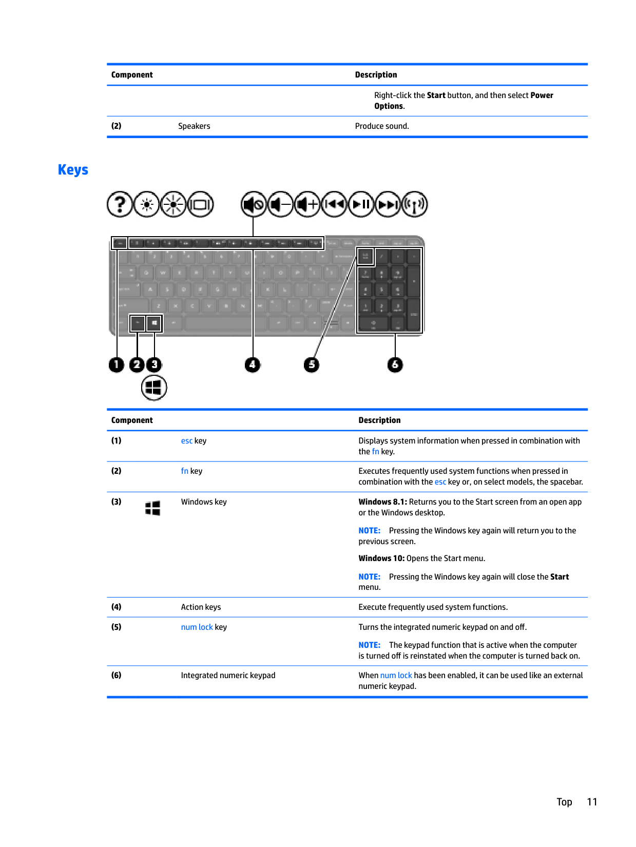
#### Keys

######## Component Description

NOTE: Pressing the Windows key again will return you to the previous screen.
Windows 10: Opens the Start menu. NOTE: Pressing the Windows key again will close the Start menu.
NOTE: The keypad function that is active when the computer is turned off is reinstated when the computer is turned back on.
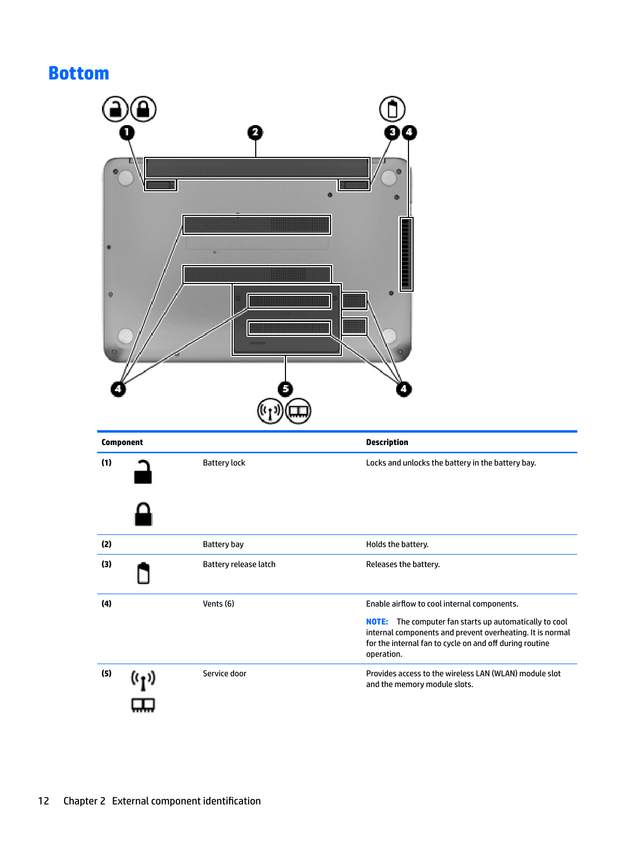
Bottom

######## Component Description


NOTE: The computer fan starts up automatically to cool internal components and prevent overheating. It is normal for the internal fan to cycle on and off during routine operation.


CAUTION: To prevent an unresponsive system, replace the wireless module only with a wireless module authorized for use in the computer by the governmental agency that regulates wireless devices in your country or region. If you replace the module and then receive a warning message, remove the module to restore computer functionality, and then contact support through Help and Support.
In Windows 8.1, from the Start screen, type h, and then select Help and Support.
In Windows 10, type support in the taskbar search box, and then select the HP Support Assistant app.
– or – Click the question mark icon in the taskbar.
Bottom 13
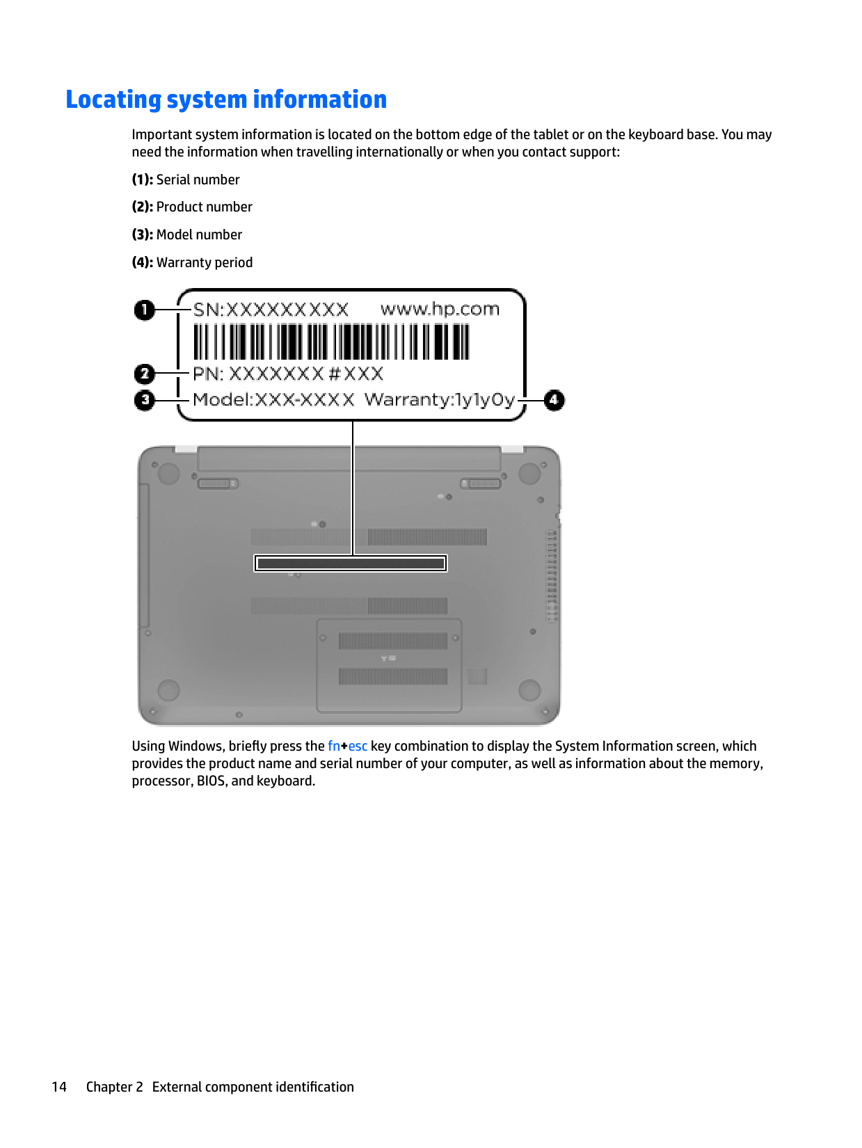
Locating system information
Important system information is located on the bottom edge of the tablet or on the keyboard base. You may need the information when travelling internationally or when you contact support:

Using Windows, briefly press the fn+esc key combination to display the System Information screen, which provides the product name and serial number of your computer, as well as information about the memory, processor, BIOS, and keyboard.
3 Illustrated parts catalog
Computer major components
| | |---|
NOTE: HP continually improves and changes product parts. For complete and current information on supported parts for your computer, go to http://partsurfer.hp.com, select your country or region, and then follow the on-screen instructions.
| | |---|
NOTE: Details about your computer, including model, serial number, product key, and length of warranty, are on the service tag at the bottom of your computer. See Locating system information on page 14 for details.

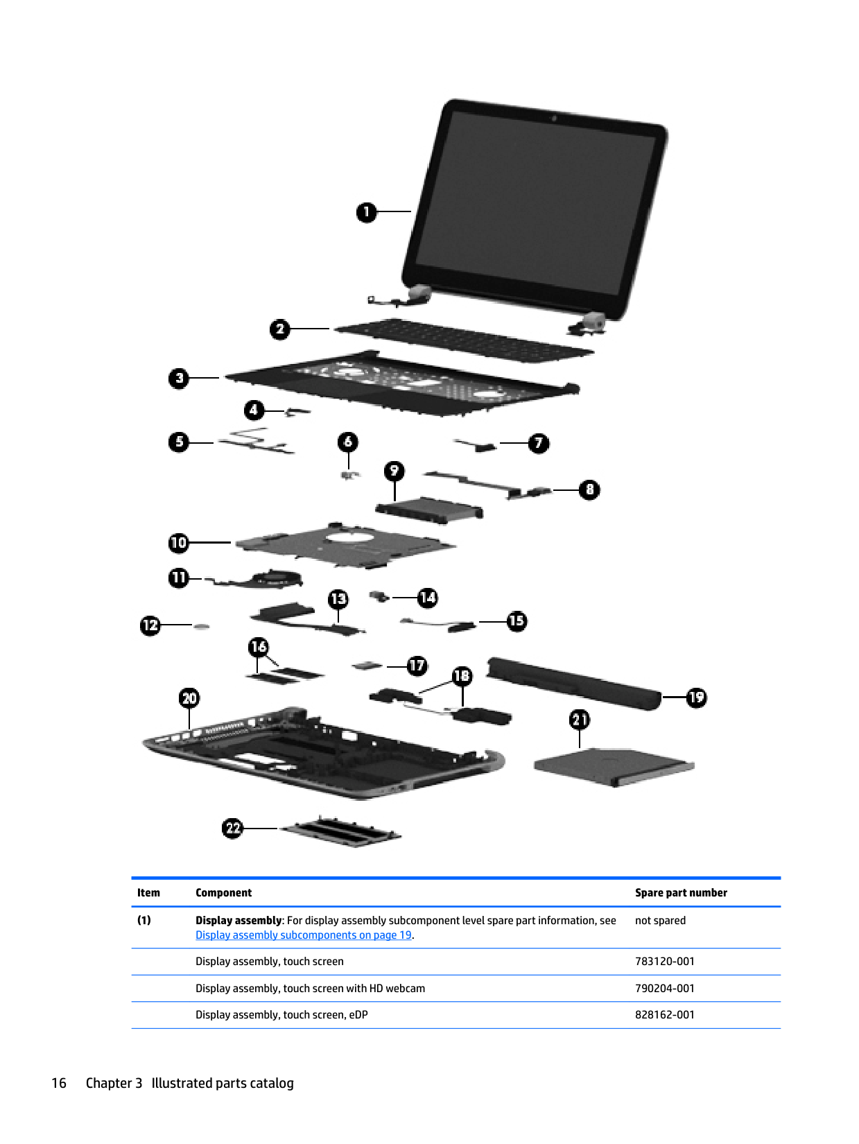
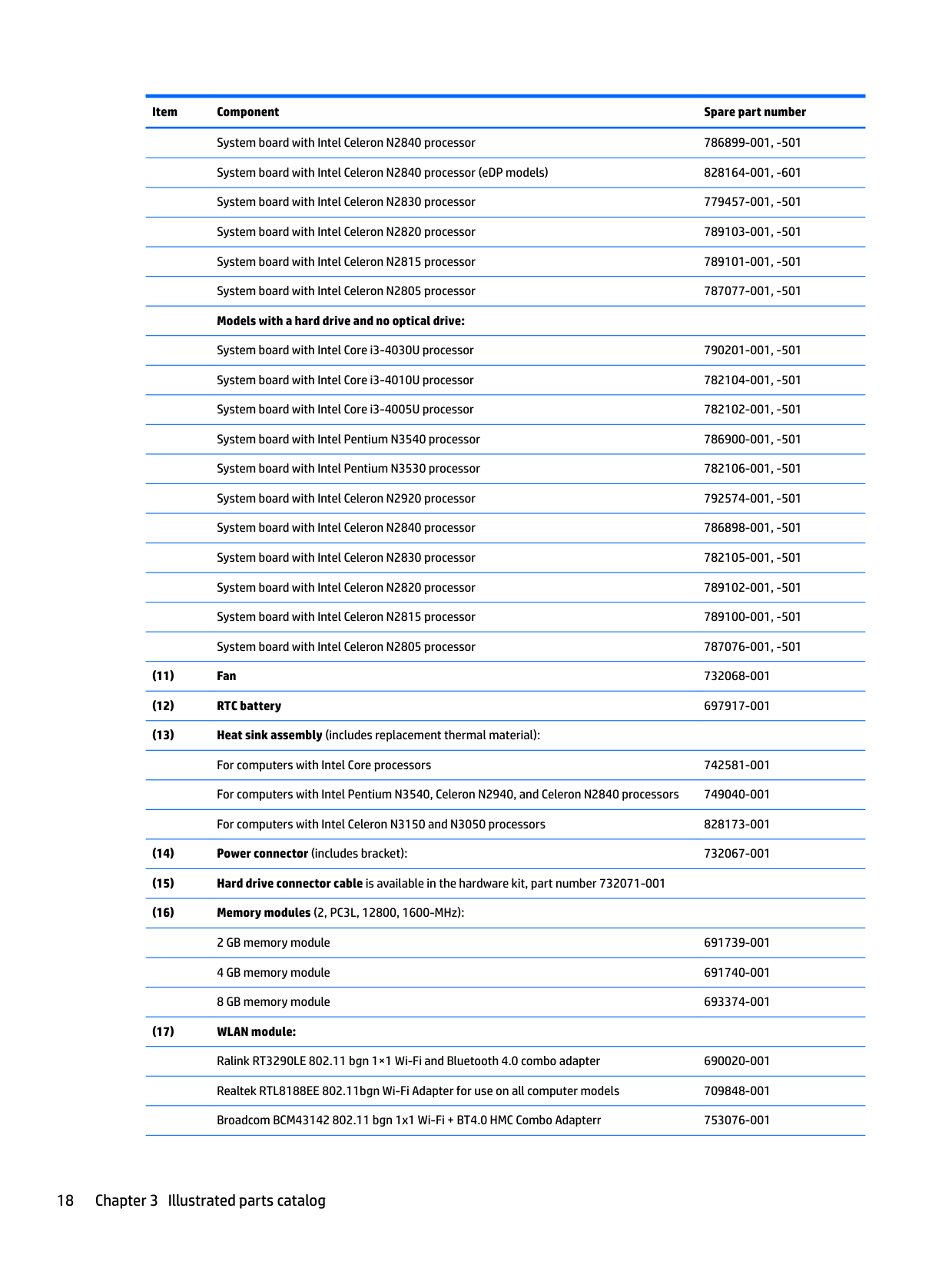
######## Item Component Spare part number
not spared
Display assembly, touch screen 783120-001 Display assembly, touch screen with HD webcam 790204-001 Display assembly, touch screen, eDP 828162-001
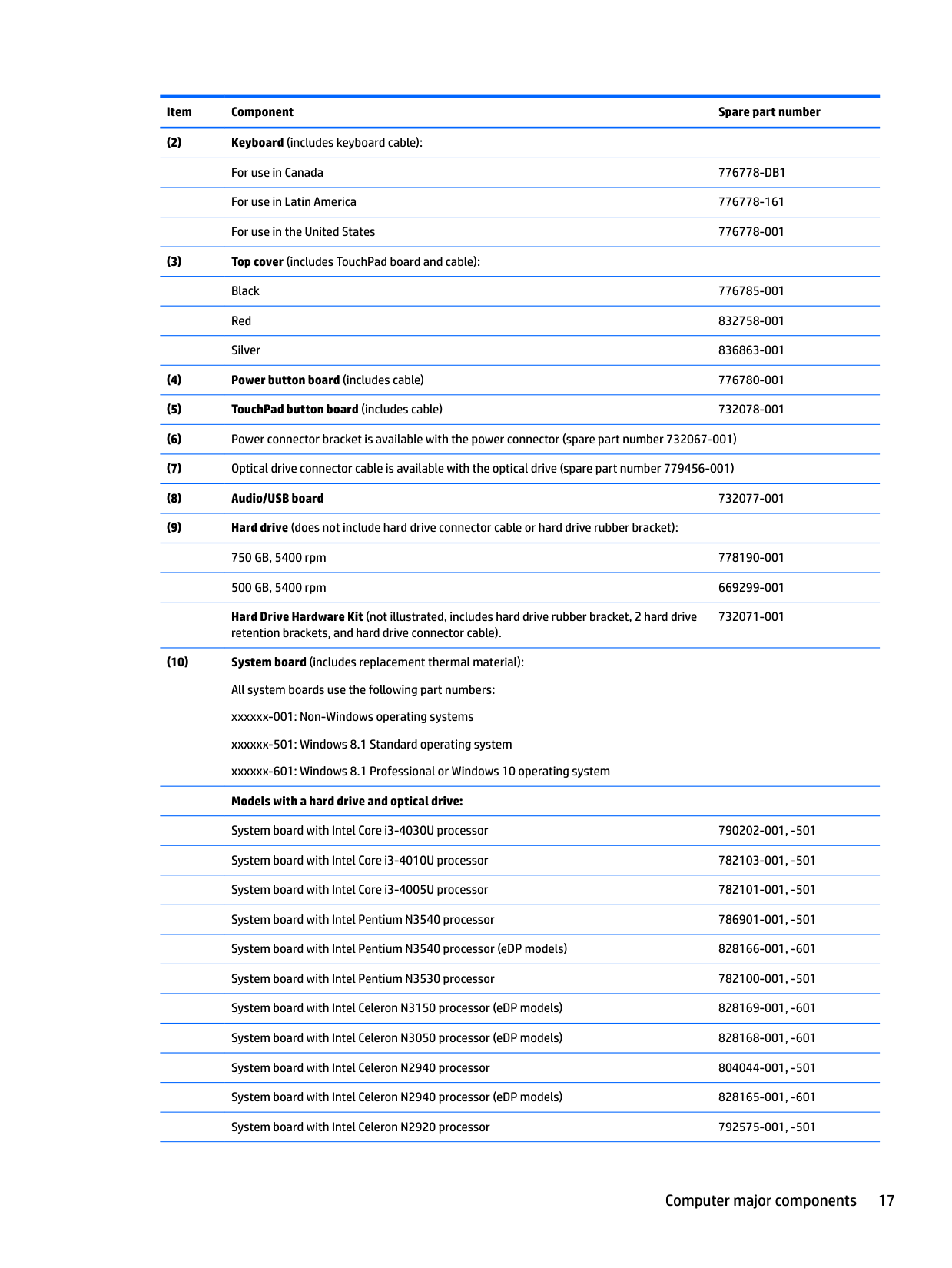
Hard Drive Hardware Kit (not illustrated, includes hard drive rubber bracket, 2 hard drive retention brackets, and hard drive connector cable).
732071-001
System board with Intel Celeron N2840 processor 786899-001, -501 System board with Intel Celeron N2840 processor (eDP models) 828164-001, -601 System board with Intel Celeron N2830 processor 779457-001, -501 System board with Intel Celeron N2820 processor 789103-001, -501 System board with Intel Celeron N2815 processor 789101-001, -501 System board with Intel Celeron N2805 processor 787077-001, -501 Models with a hard drive and no optical drive:
System board with Intel Core i3-4030U processor 790201-001, -501
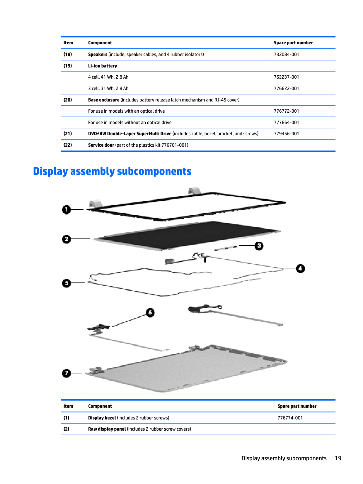
Display assembly subcomponents

######## Item Component Spare part number
Display assembly subcomponents 19
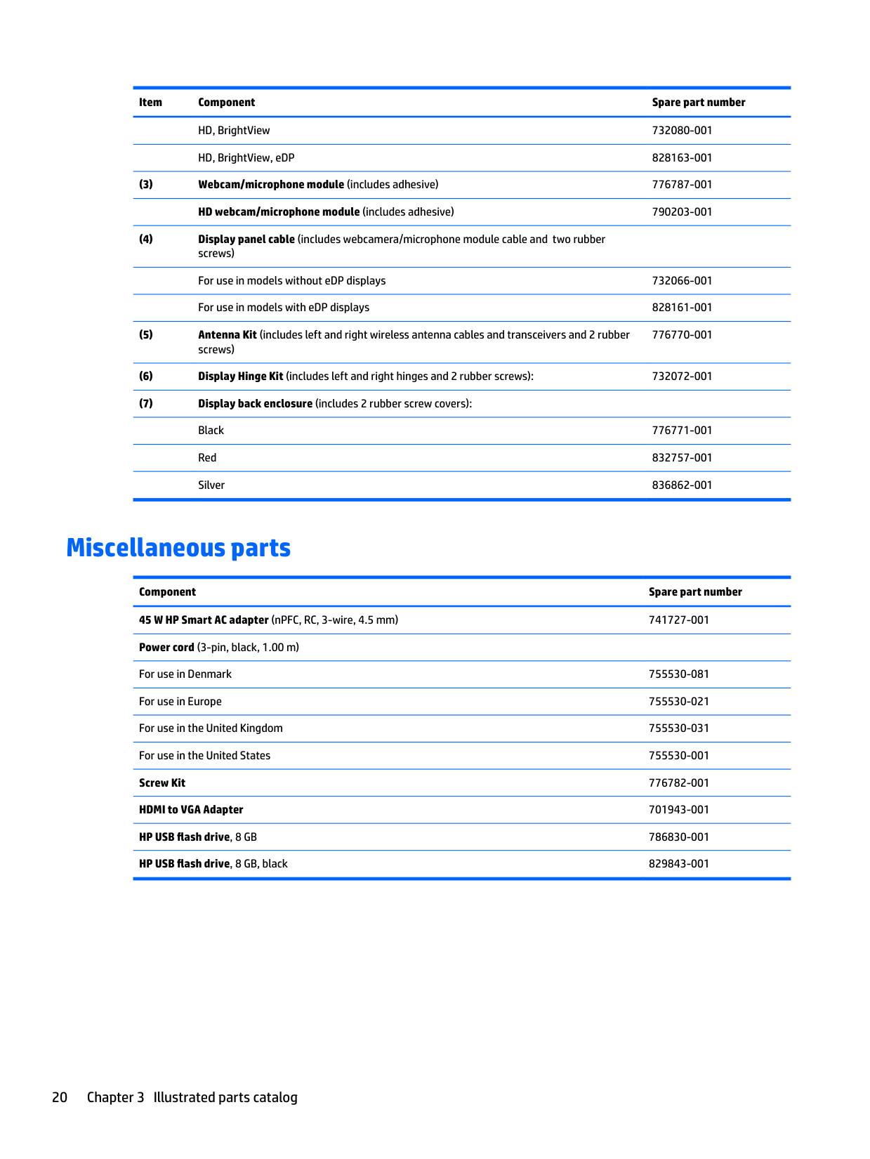
HD, BrightView 732080-001 HD, BrightView, eDP 828163-001
776770-001
Miscellaneous parts
Component Spare part number 45 W HP Smart AC adapter (nPFC, RC, 3-wire, 4.5 mm) 741727-001 Power cord (3-pin, black, 1.00 m)
For use in Denmark 755530-081 For use in Europe 755530-021 For use in the United Kingdom 755530-031 For use in the United States 755530-001 Screw Kit 776782-001 HDMI to VGA Adapter 701943-001 HP USB flash drive, 8 GB 786830-001 HP USB flash drive, 8 GB, black 829843-001
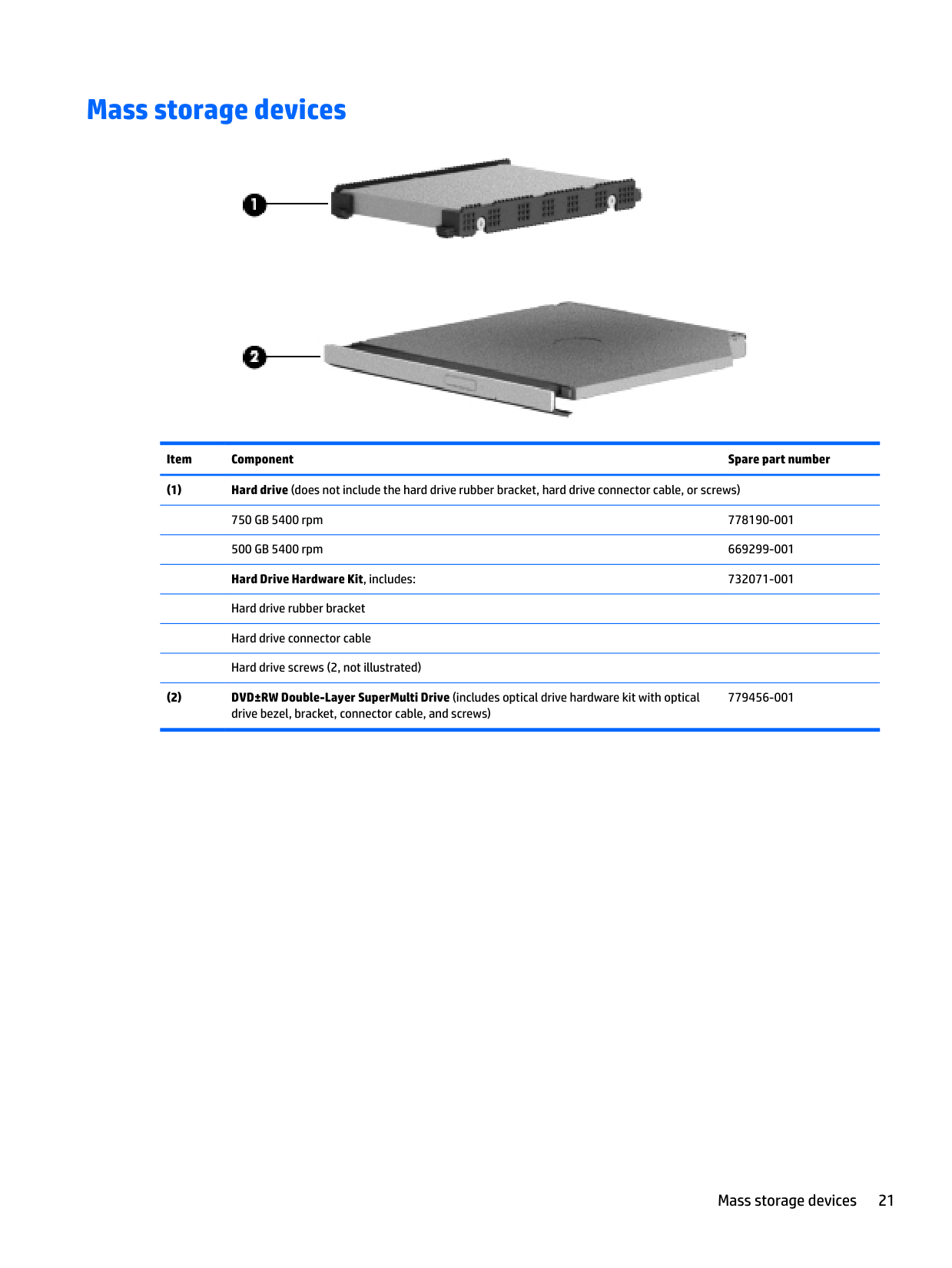
Mass storage devices

######## Item Component Spare part number
779456-001
Mass storage devices 21
4 Removal and replacement procedurespreliminary requirements
Tools required
You will need the following tools to complete the removal and replacement procedures:
Service considerations
The following sections include some of the considerations that you must keep in mind during disassembly and assembly procedures.
| | |---|
NOTE: As you remove each subassembly from the computer, place the subassembly (and all accompanying screws) away from the work area to prevent damage.
#### Plastic parts
CAUTION: Using excessive force during disassembly and reassembly can damage plastic parts. Use care when handling the plastic
#### Cables and connectors
CAUTION: When servicing the computer, be sure that cables are placed in their proper locations during the reassembly process. Improper cable placement can damage the computer.
Cables must be handled with extreme care to avoid damage. Apply only the tension required to unseat or seat the cables during removal and insertion. Handle cables by the connector whenever possible. In all cases, avoid bending, twisting, or tearing cables. Be sure that cables are routed in such a way that they cannot be caught or snagged by parts being removed or replaced. Handle flex cables with extreme care; these cables tear easily.
Drive handling CAUTION: Drives are fragile components that must be handled with care. To prevent damage to the computer, damage to a drive, or loss of information, observe these precautions: Before removing or inserting a hard drive, shut down the computer. If you are unsure whether the computer is off or in Hibernation, turn the computer on, and then shut it down through the operating system. Before handling a drive, be sure that you are discharged of static electricity. While handling a drive, avoid touching the connector. Before removing a diskette drive or optical drive, be sure that a diskette or disc is not in the drive and be sure that the optical drive tray is closed. Handle drives on surfaces covered with at least one inch of shock-proof foam. Avoid dropping drives from any height onto any surface. Avoid exposing an internal hard drive to products that have magnetic fields, such as monitors or speakers. Avoid exposing an internal hard drive to products that have magnetic fields, such as monitors or speakers. Avoid exposing a drive to temperature extremes or liquids. If a drive must be mailed, place the drive in a bubble pack mailer or other suitable form of protective packaging and label the package “FRAGILE.”
Service considerations 23
Grounding guidelines
#### Electrostatic discharge damage
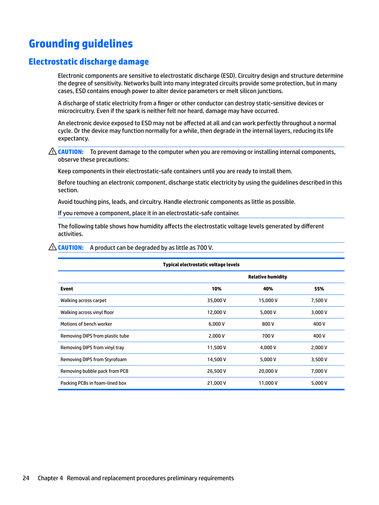
Electronic components are sensitive to electrostatic discharge (ESD). Circuitry design and structure determine the degree of sensitivity. Networks built into many integrated circuits provide some protection, but in many cases, ESD contains enough power to alter device parameters or melt silicon junctions.
A discharge of static electricity from a finger or other conductor can destroy static-sensitive devices or microcircuitry. Even if the spark is neither felt nor heard, damage may have occurred.
An electronic device exposed to ESD may not be affected at all and can work perfectly throughout a normal cycle. Or the device may function normally for a while, then degrade in the internal layers, reducing its life expectancy.
CAUTION: To prevent damage to the computer when you are removing or installing internal components, observe these precautions: Keep components in their electrostatic-safe containers until you are ready to install them. Before touching an electronic component, discharge static electricity by using the guidelines described in this section. Avoid touching pins, leads, and circuitry. Handle electronic components as little as possible. If you remove a component, place it in an electrostatic-safe container. The following table shows how humidity affects the electrostatic voltage levels generated by different activities. CAUTION: A product can be degraded by as little as 700 V.
Typical electrostatic voltage levels
Relative humidity Event 10% 40% 55% Walking across carpet 35,000 V 15,000 V 7,500 V Walking across vinyl floor 12,000 V 5,000 V 3,000 V Motions of bench worker 6,000 V 800 V 400 V Removing DIPS from plastic tube 2,000 V 700 V 400 V Removing DIPS from vinyl tray 11,500 V 4,000 V 2,000 V Removing DIPS from Styrofoam 14,500 V 5,000 V 3,500 V Removing bubble pack from PCB 26,500 V 20,000 V 7,000 V Packing PCBs in foam-lined box 21,000 V 11,000 V 5,000 V
##### Packaging and transporting guidelines
Follow these grounding guidelines when packaging and transporting equipment:
##### Workstation guidelines
Follow these grounding workstation guidelines:
Grounding guidelines 25
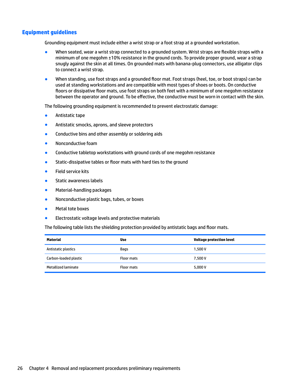
##### Equipment guidelines
Grounding equipment must include either a wrist strap or a foot strap at a grounded workstation.
Material Use Voltage protection level
Antistatic plastics Bags 1,500 V Carbon-loaded plastic Floor mats 7,500 V Metallized laminate Floor mats 5,000 V
5 Removal and replacement procedures for Customer Self-Repair parts
| | |---|
NOTE: The Customer Self-Repair program is not available in all locations. Installing a part not supported by the Customer Self-Repair program may void your warranty. Check your warranty to determine if Customer Self-Repair is supported in your location.
| | |---|
NOTE: HP continually improves and changes product parts. For complete and current information on supported parts for your computer, go to http://partsurfer.hp.com, select your country or region, and then follow the on-screen instructions.
Component replacement procedures
| | |---|
NOTE: Please read and follow the procedures described here to access and replace Customer Self-Repair parts successfully.
| | |---|
NOTE: Details about your computer, including model, serial number, product key, and length of warranty, are on the service tag at the bottom of your computer. See Locating system information on page 14 for details.
This chapter provides removal and replacement procedures for Customer Self-Repair parts. There are as many as 12 screws that must be removed, replaced, and/or loosened when servicing Customer Self-Repair parts. Make special note of each screw size and location during removal and replacement.
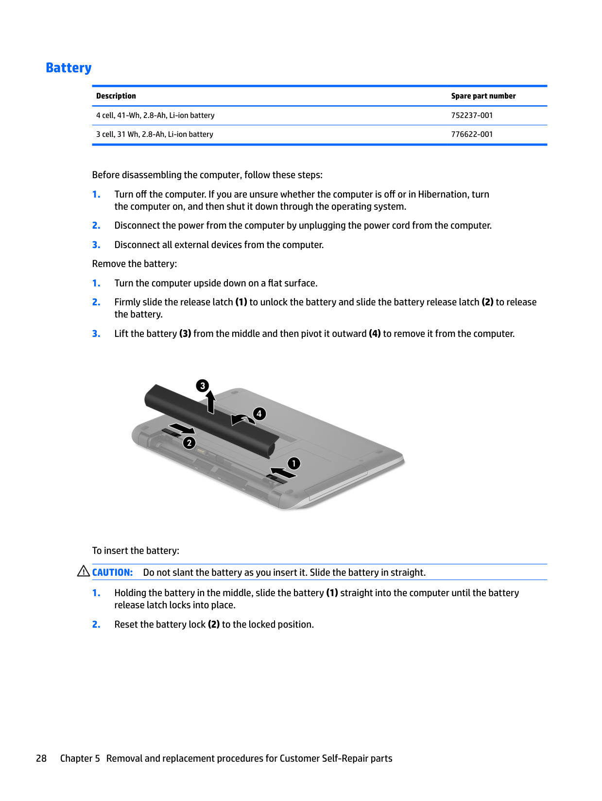
#### Battery
######## Description Spare part number
4 cell, 41-Wh, 2.8-Ah, Li-ion battery 752237-001 3 cell, 31 Wh, 2.8-Ah, Li-ion battery 776622-001
Before disassembling the computer, follow these steps:

To insert the battery: CAUTION: Do not slant the battery as you insert it. Slide the battery in straight.
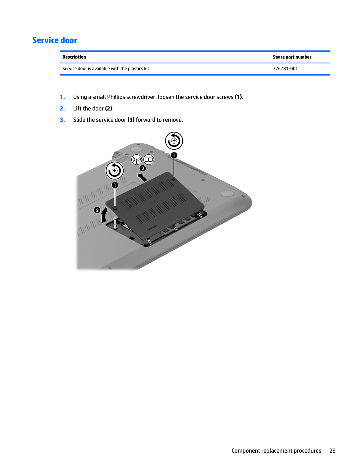
#### Service door
Description Spare part number Service door is available with the plastics kit. 776781-001

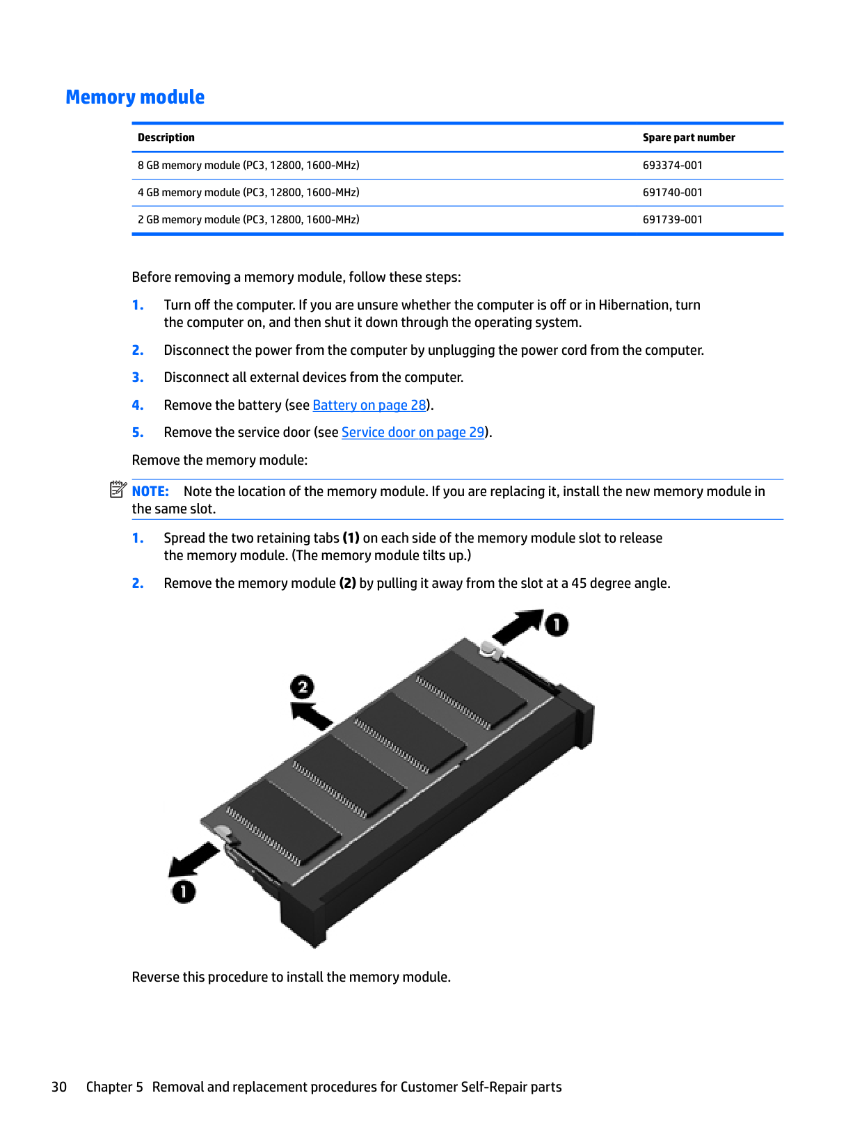
#### Memory module
Description Spare part number 8 GB memory module (PC3, 12800, 1600-MHz) 693374-001
Before removing a memory module, follow these steps:
| | |---|
NOTE: Note the location of the memory module. If you are replacing it, install the new memory module in the same slot.

Reverse this procedure to install the memory module.
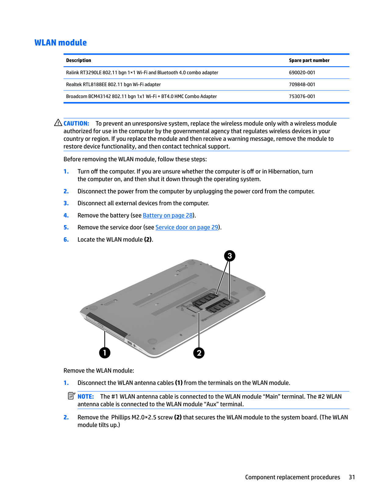
#### WLAN module
######## Description Spare part number
Ralink RT3290LE 802.11 bgn 1×1 Wi-Fi and Bluetooth 4.0 combo adapter 690020-001 Realtek RTL8188EE 802.11 bgn Wi-Fi adapter 709848-001 Broadcom BCM43142 802.11 bgn 1x1 Wi-Fi + BT4.0 HMC Combo Adapter 753076-001
CAUTION: To prevent an unresponsive system, replace the wireless module only with a wireless module authorized for use in the computer by the governmental agency that regulates wireless devices in your country or region. If you replace the module and then receive a warning message, remove the module to restore device functionality, and then contact technical support.
Before removing the WLAN module, follow these steps:

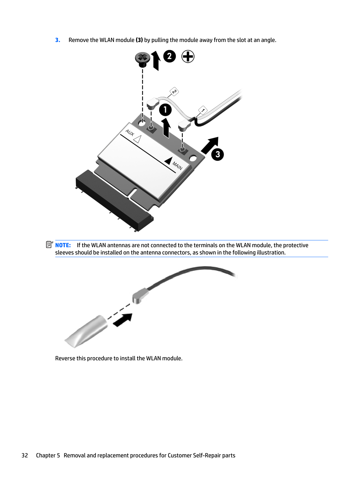
Remove the WLAN module:
NOTE: The #1 WLAN antenna cable is connected to the WLAN module “Main” terminal. The #2 WLAN antenna cable is connected to the WLAN module “Aux” terminal.
| | |---|

| | |---|
NOTE: If the WLAN antennas are not connected to the terminals on the WLAN module, the protective sleeves should be installed on the antenna connectors, as shown in the following illustration.

Reverse this procedure to install the WLAN module.
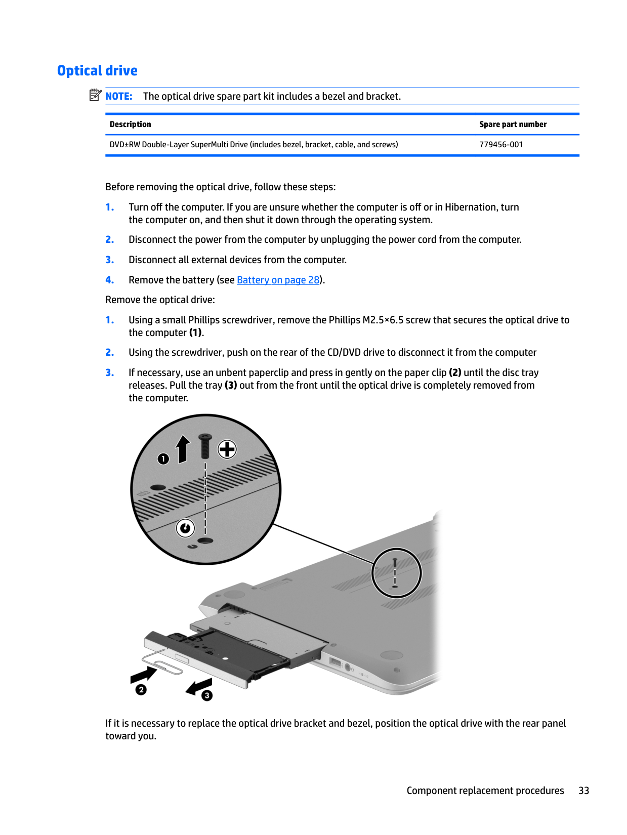
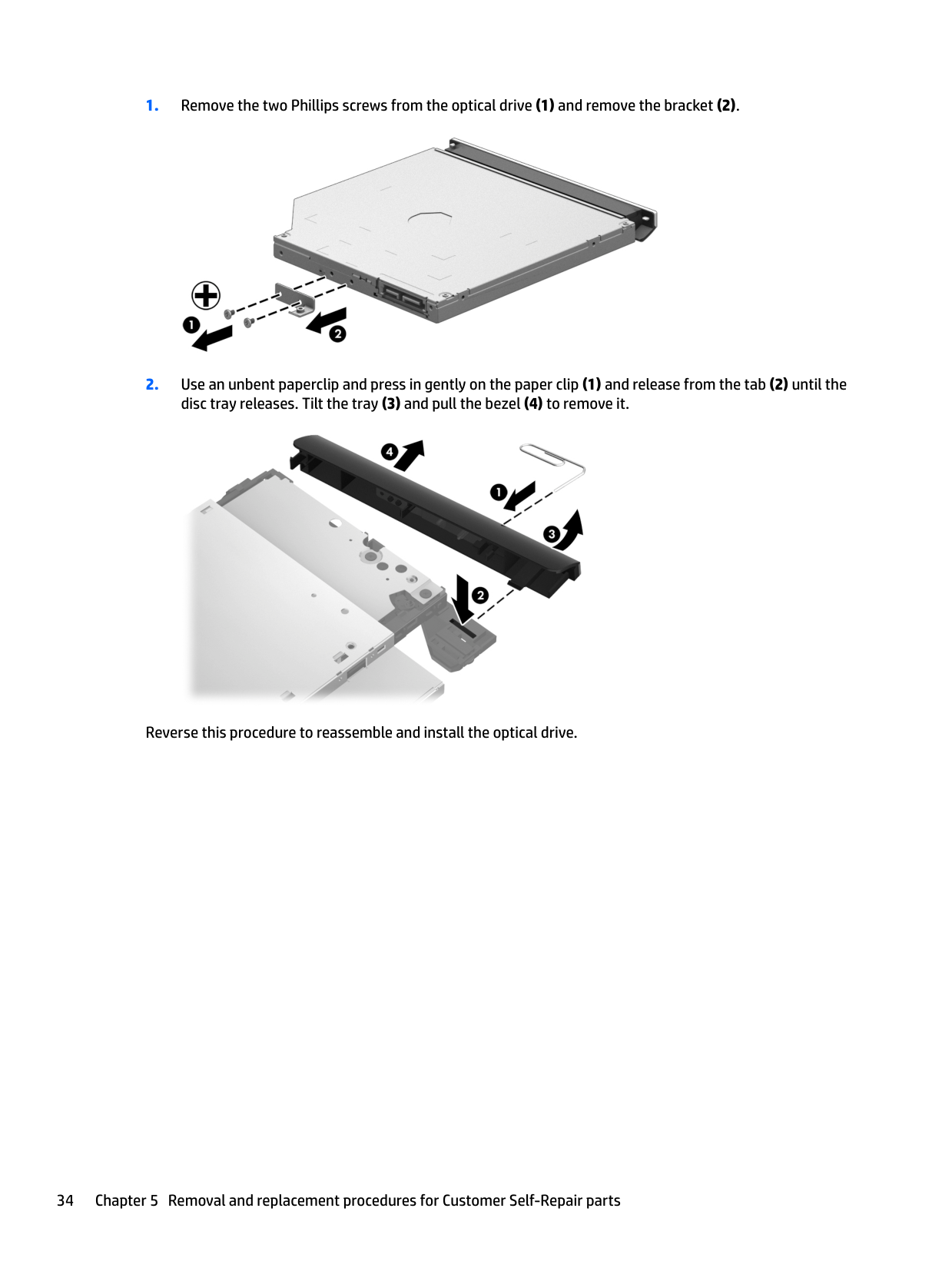
#### Optical drive
| | |---|
NOTE: The optical drive spare part kit includes a bezel and bracket.
Description Spare part number DVD±RW Double-Layer SuperMulti Drive (includes bezel, bracket, cable, and screws) 779456-001
Before removing the optical drive, follow these steps:

If it is necessary to replace the optical drive bracket and bezel, position the optical drive with the rear panel toward you.


Reverse this procedure to reassemble and install the optical drive.
6 Removal and replacement procedures for Authorized Service Provider parts
CAUTION: Components described in this chapter should only be accessed by an authorized service provider. Accessing these parts can damage the computer or void the warranty.
| | |---|
NOTE: HP continually improves and changes product parts. For complete and current information on supported parts for your computer, go to http://partsurfer.hp.com, select your country or region, and then follow the on-screen instructions.
Component replacement procedures
| |
|---|
NOTE: Details about your computer, including model, serial number, product key, and length of warranty, are on the service tag at the bottom of your computer. See Locating system information on page 14 for details.
This chapter provides removal and replacement procedures for Authorized Service Provider only parts. There are as many as 62 screws that must be removed, replaced, and/or loosened when servicing Authorized Service Provider only parts. Make special note of each screw size and location during removal and replacement.
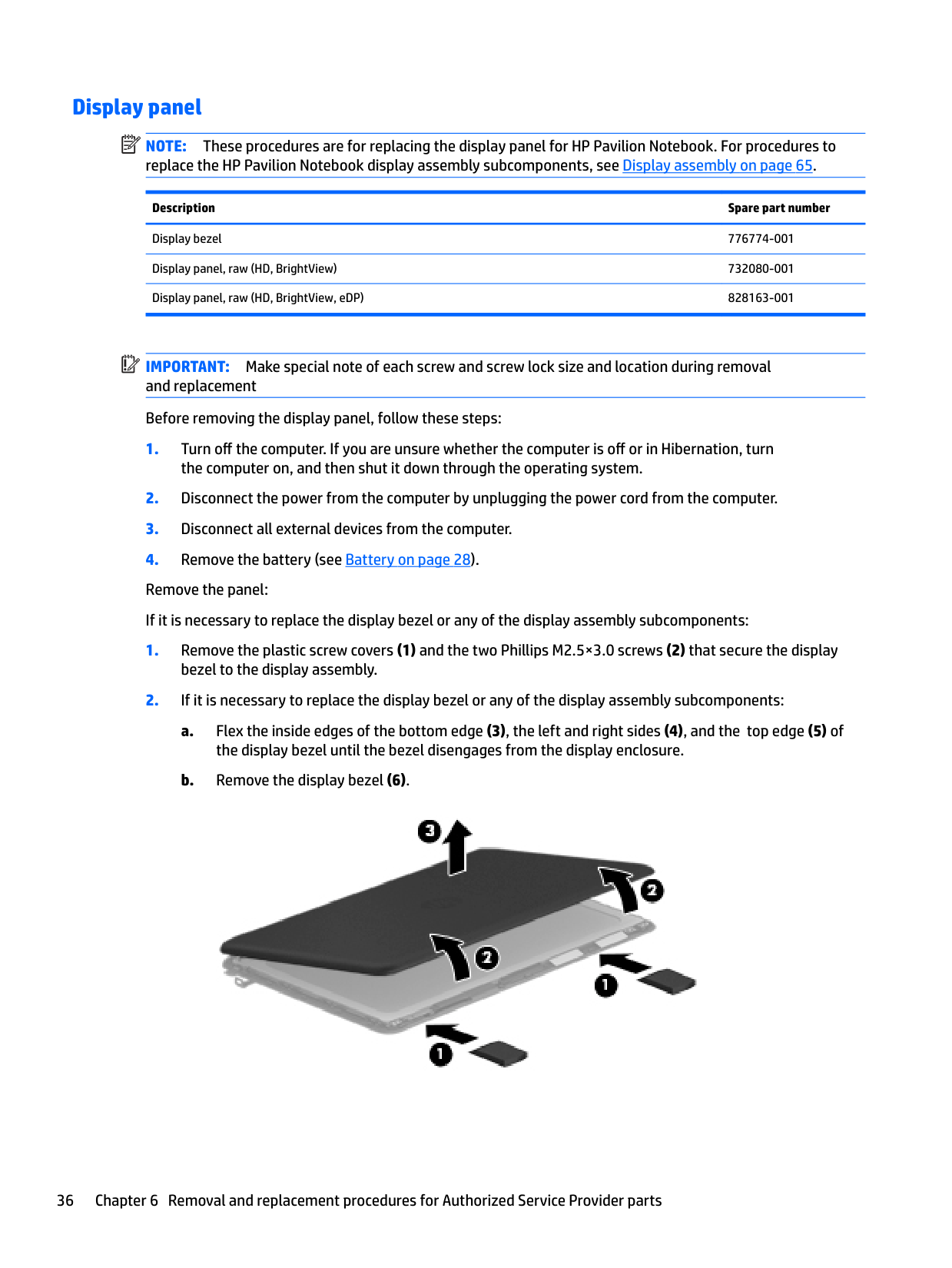
#### Display panel
| | |---|
NOTE: These procedures are for replacing the display panel for HP Pavilion Notebook. For procedures to replace the HP Pavilion Notebook display assembly subcomponents, see Display assembly on page 65.
Description Spare part number
Display bezel 776774-001 Display panel, raw (HD, BrightView) 732080-001 Display panel, raw (HD, BrightView, eDP) 828163-001
| | |---|
IMPORTANT: Make special note of each screw and screw lock size and location during removal and replacement Before removing the display panel, follow these steps:


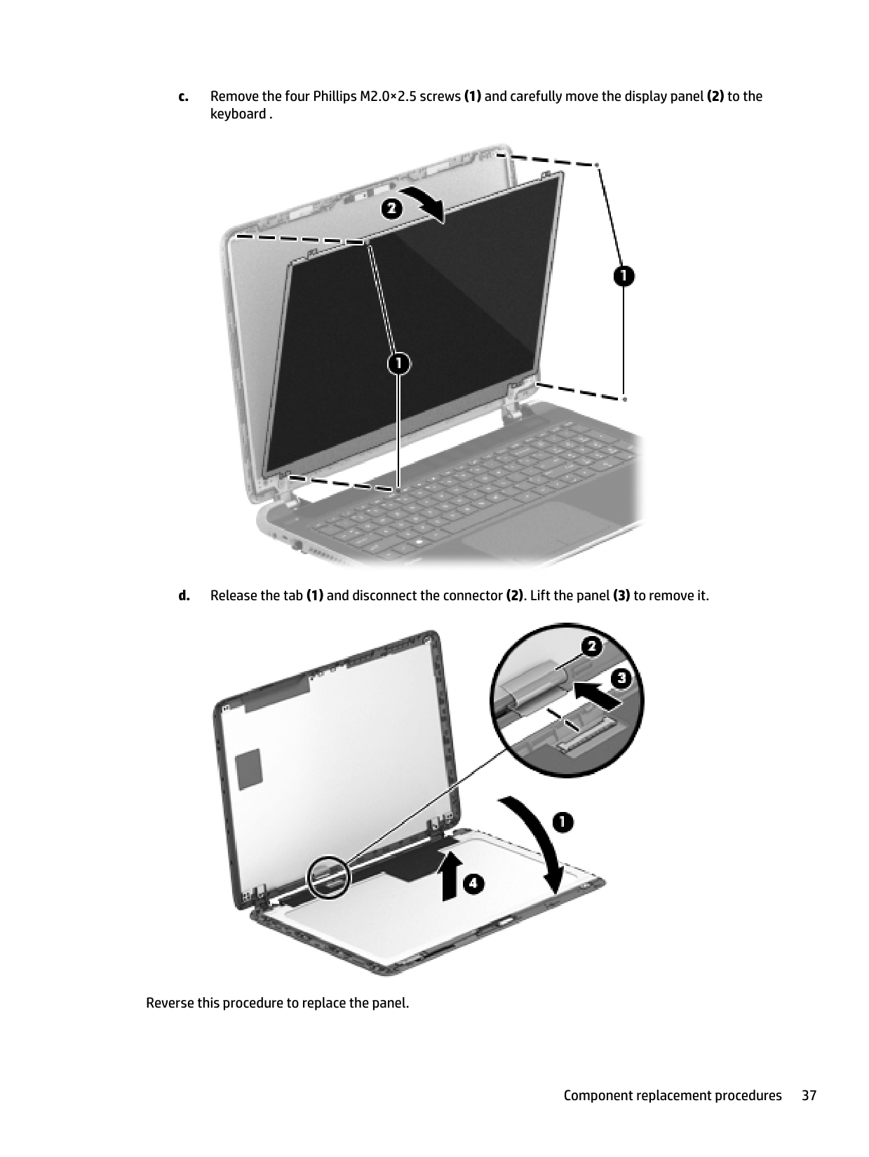
Reverse this procedure to replace the panel.
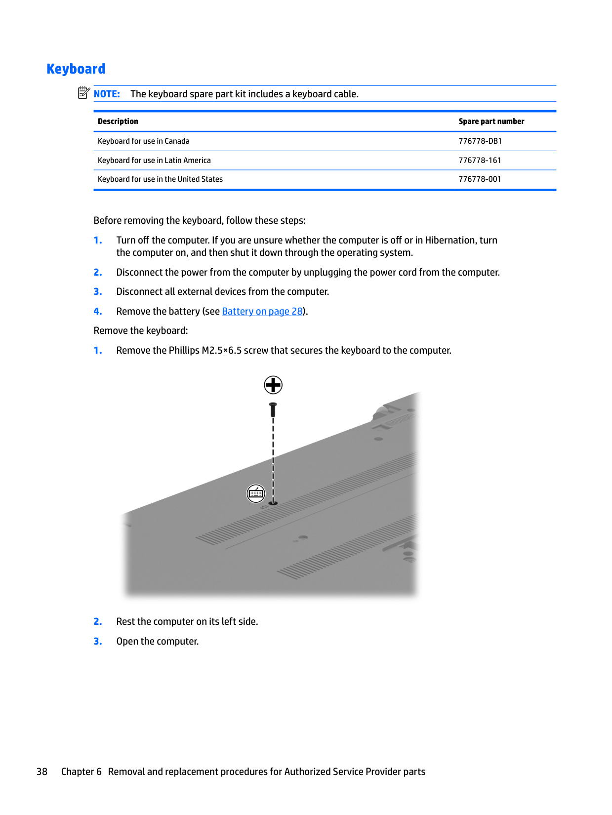
#### Keyboard
| | |---|
NOTE: The keyboard spare part kit includes a keyboard cable.
Description Spare part number
Keyboard for use in Canada 776778-DB1 Keyboard for use in Latin America 776778-161 Keyboard for use in the United States 776778-001
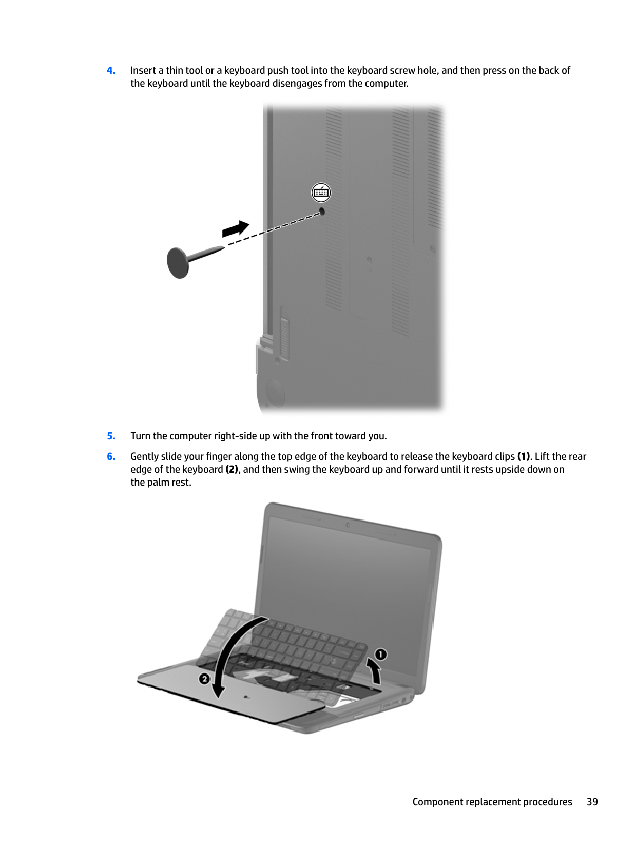
Before removing the keyboard, follow these steps:


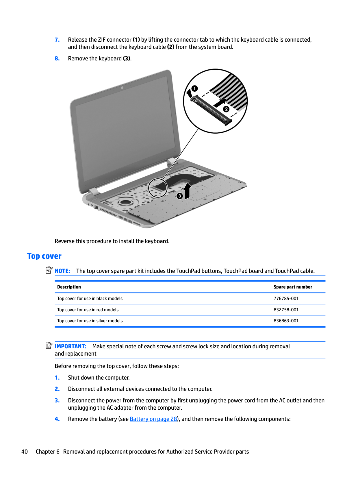
Reverse this procedure to install the keyboard.
#### Top cover
| | |---|
NOTE: The top cover spare part kit includes the TouchPad buttons, TouchPad board and TouchPad cable.
Description Spare part number
Top cover for use in black models 776785-001 Top cover for use in red models 832758-001 Top cover for use in silver models 836863-001
| | |---|
IMPORTANT: Make special note of each screw and screw lock size and location during removal and replacement Before removing the top cover, follow these steps:
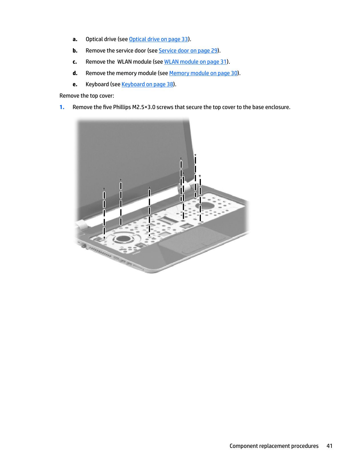
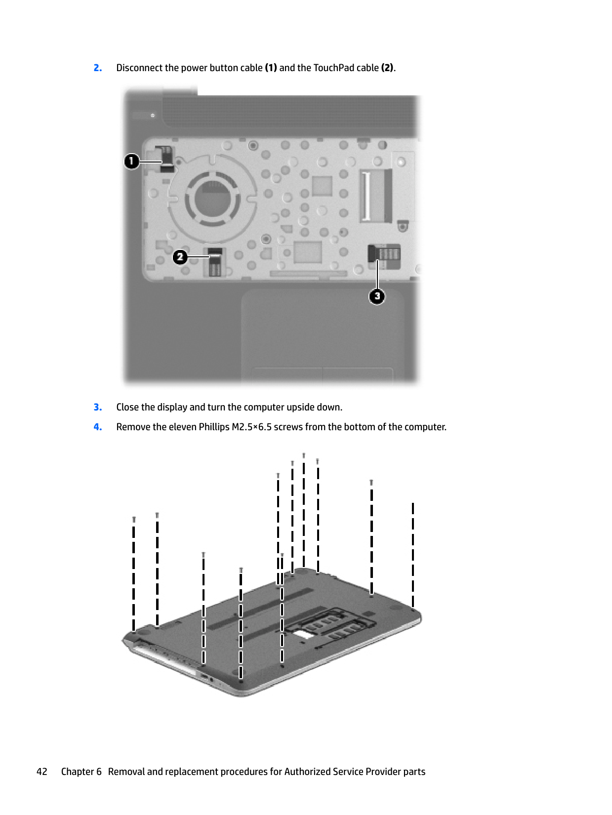
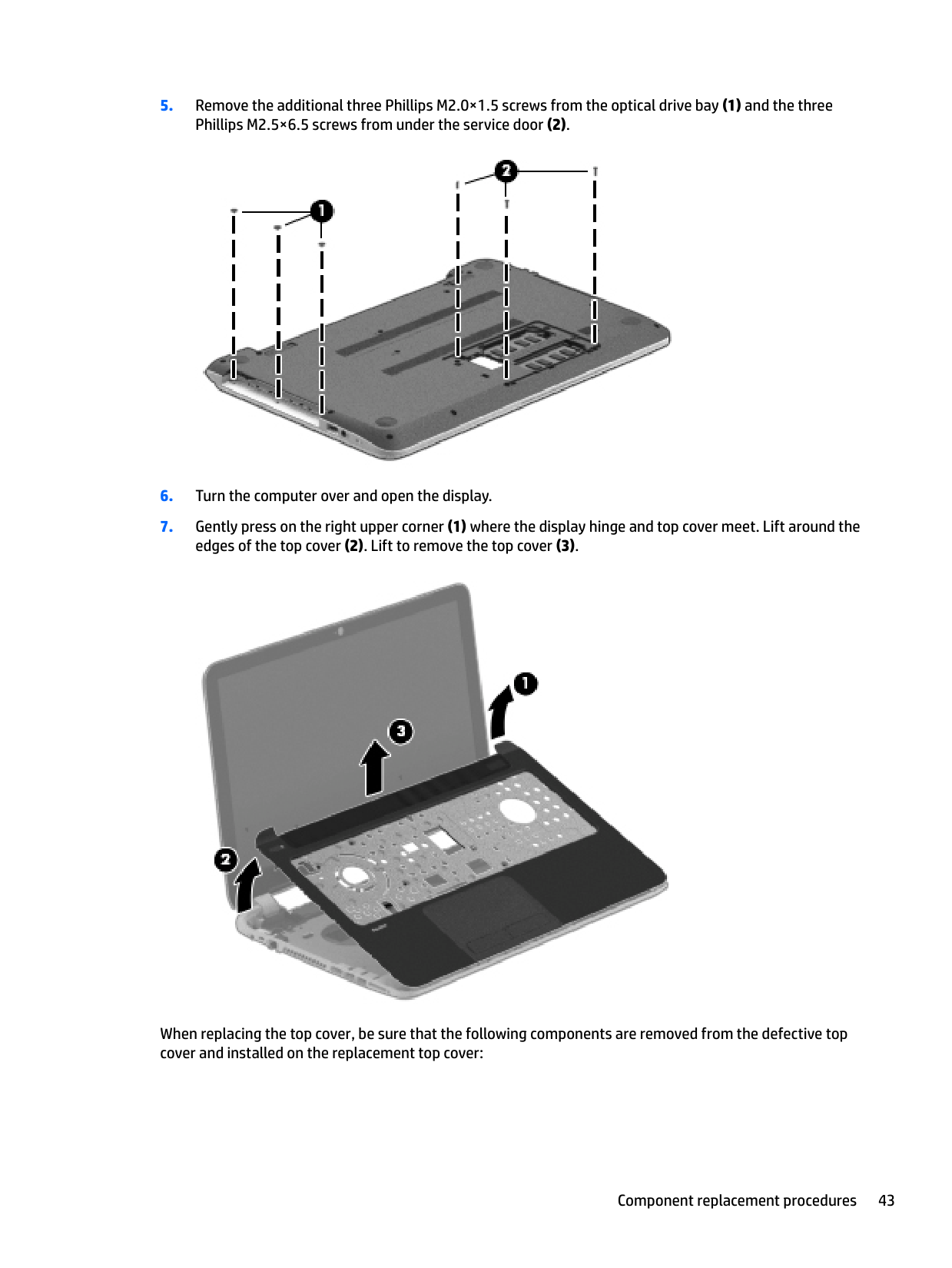
Remove the top cover:


When replacing the top cover, be sure that the following components are removed from the defective top cover and installed on the replacement top cover:
#### Hard drive
| | |---|
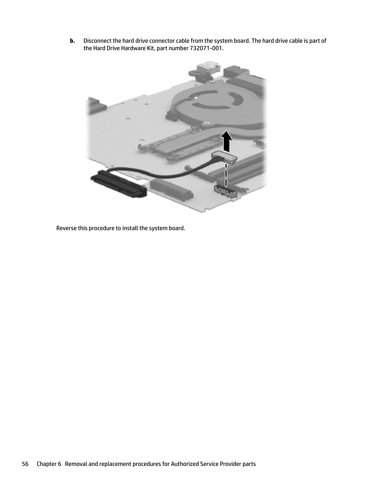
NOTE: The hard drive spare part kit includes the hard drive rubber bracket and screws. These components are included in the Hard Drive Hardware Kit, spare part number 732071-001.
Description Spare part number 750 GB, 5400 rpm 778190-001 500 GB, 5400 rpm 669299-001 Hard Drive Hardware Kit (not illustrated, includes hard drive rubber bracket, 2 hard drive retention brackets, and hard drive connector cable).
732071-001
Before removing the hard drive, follow these steps:
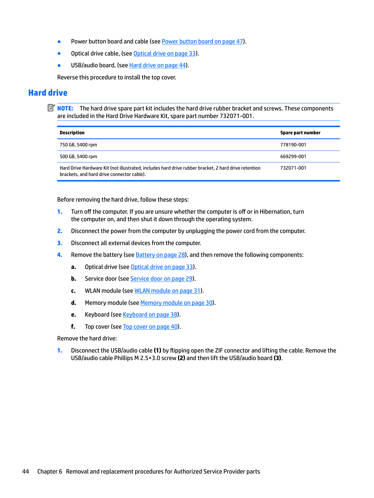
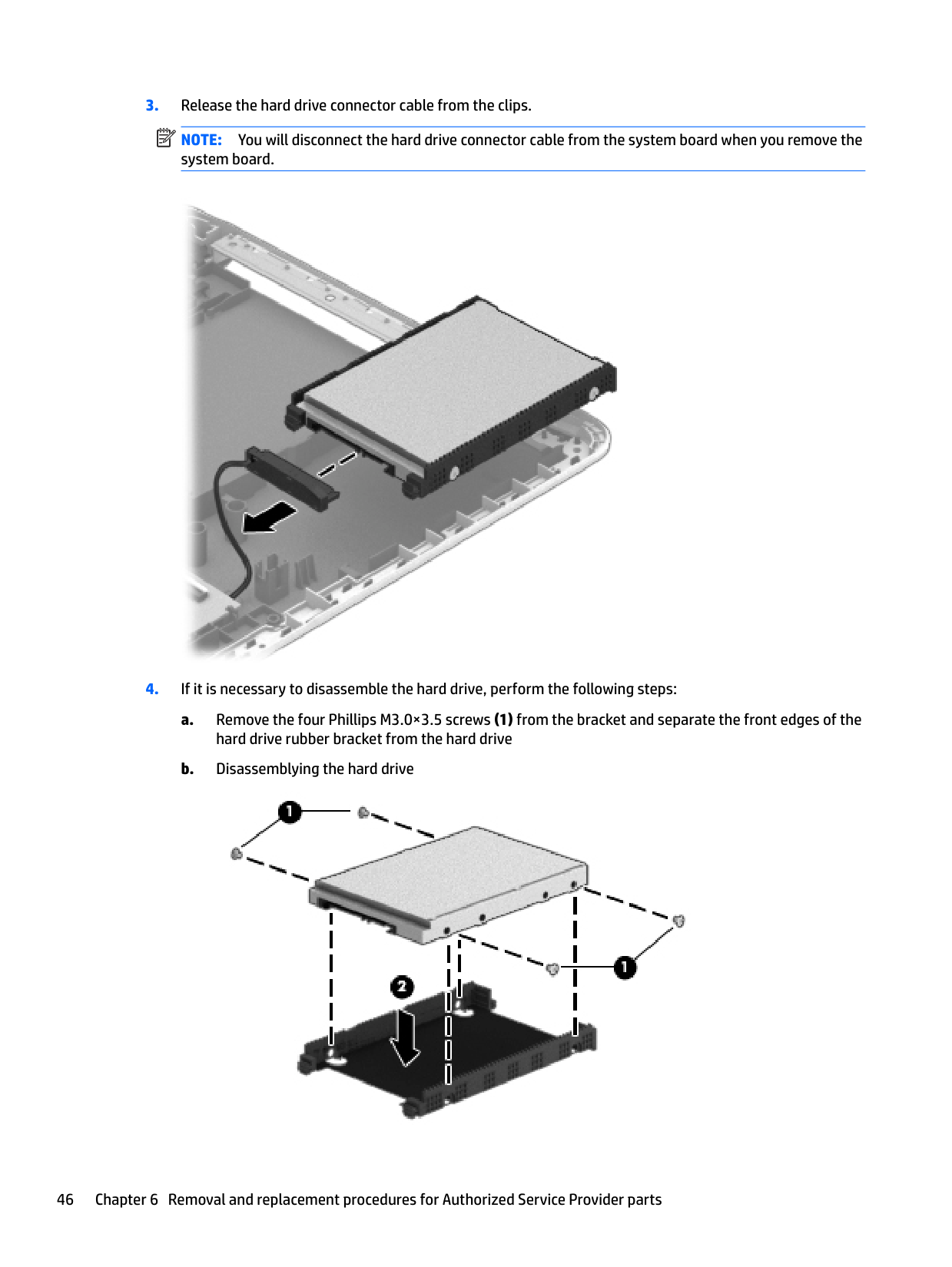
Remove the hard drive:

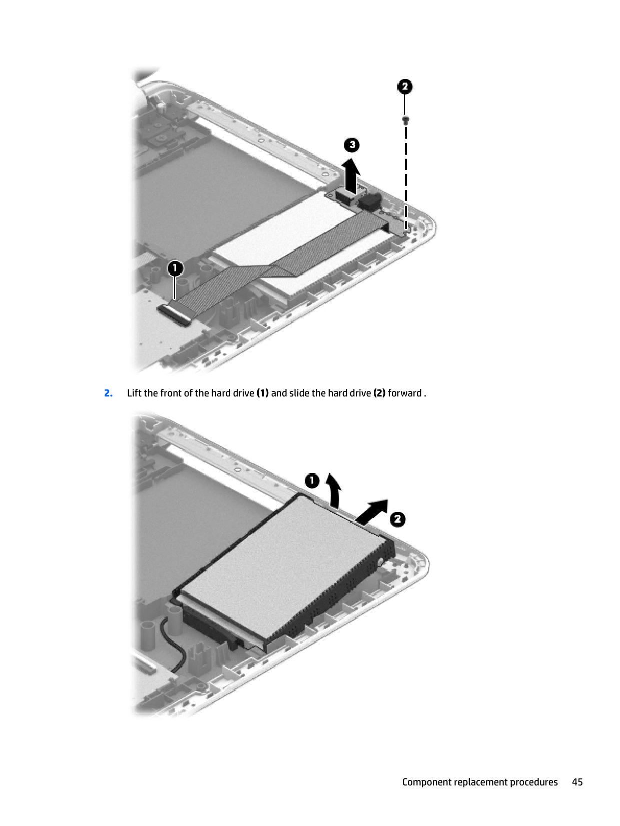
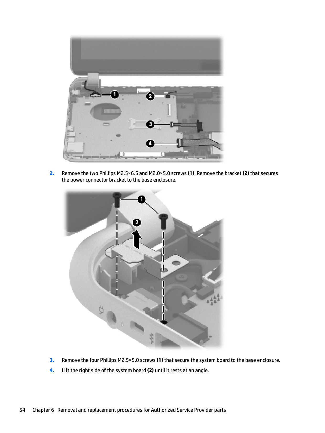
####### 2. Lift the front of the hard drive (1) and slide the hard drive (2) forward .

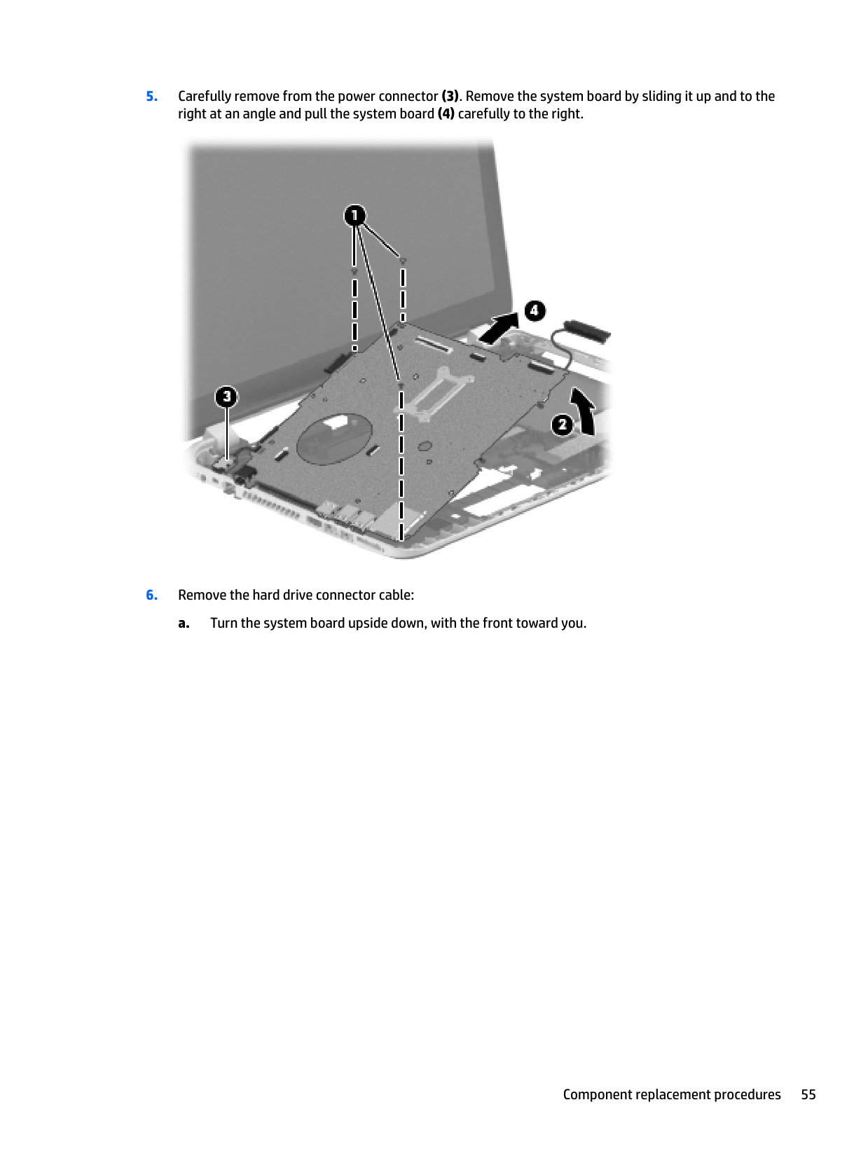
NOTE: You will disconnect the hard drive connector cable from the system board when you remove the system board.

| | |---|

Reverse this procedure to reassemble and install the hard drive.
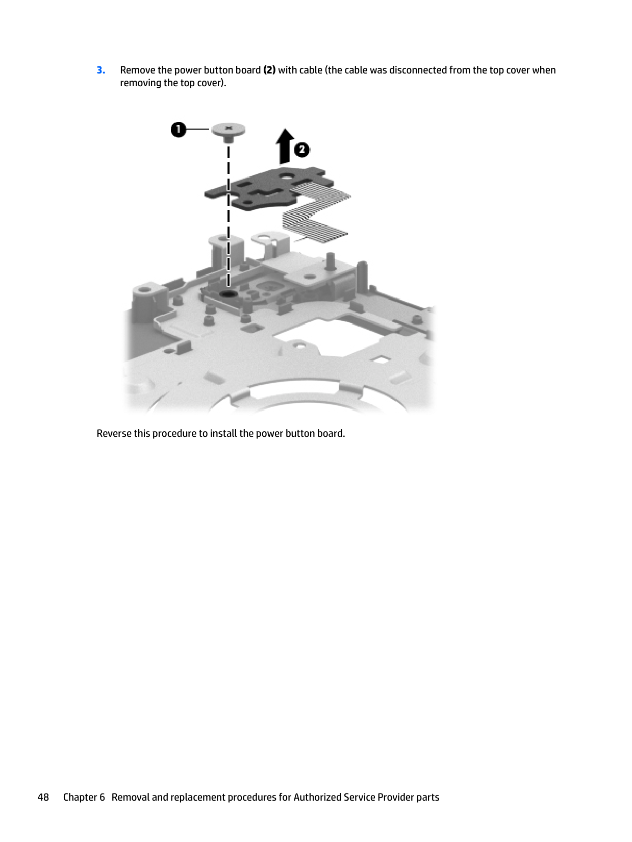
#### Power button board
Description Spare part number Power button board (includes cable) 776780-001
Before removing the power button board, follow these steps:
Remove the power button board:

Reverse this procedure to install the power button board.
#### TouchPad button board
Description Spare part number TouchPad button board (includes cable) 732078-001
Before removing the TouchPad button board, follow these steps:
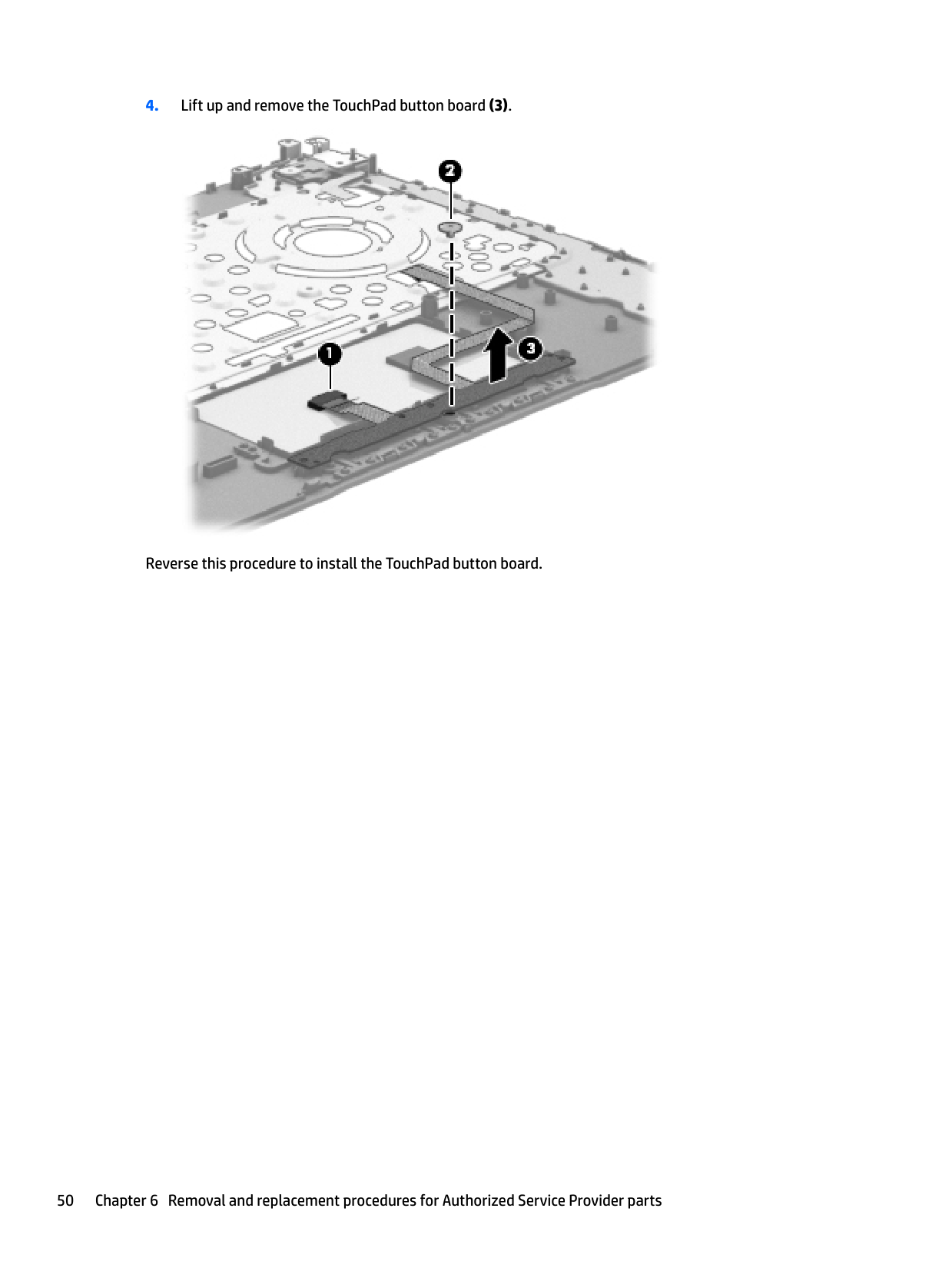
Remove the TouchPad button board:

Reverse this procedure to install the TouchPad button board.
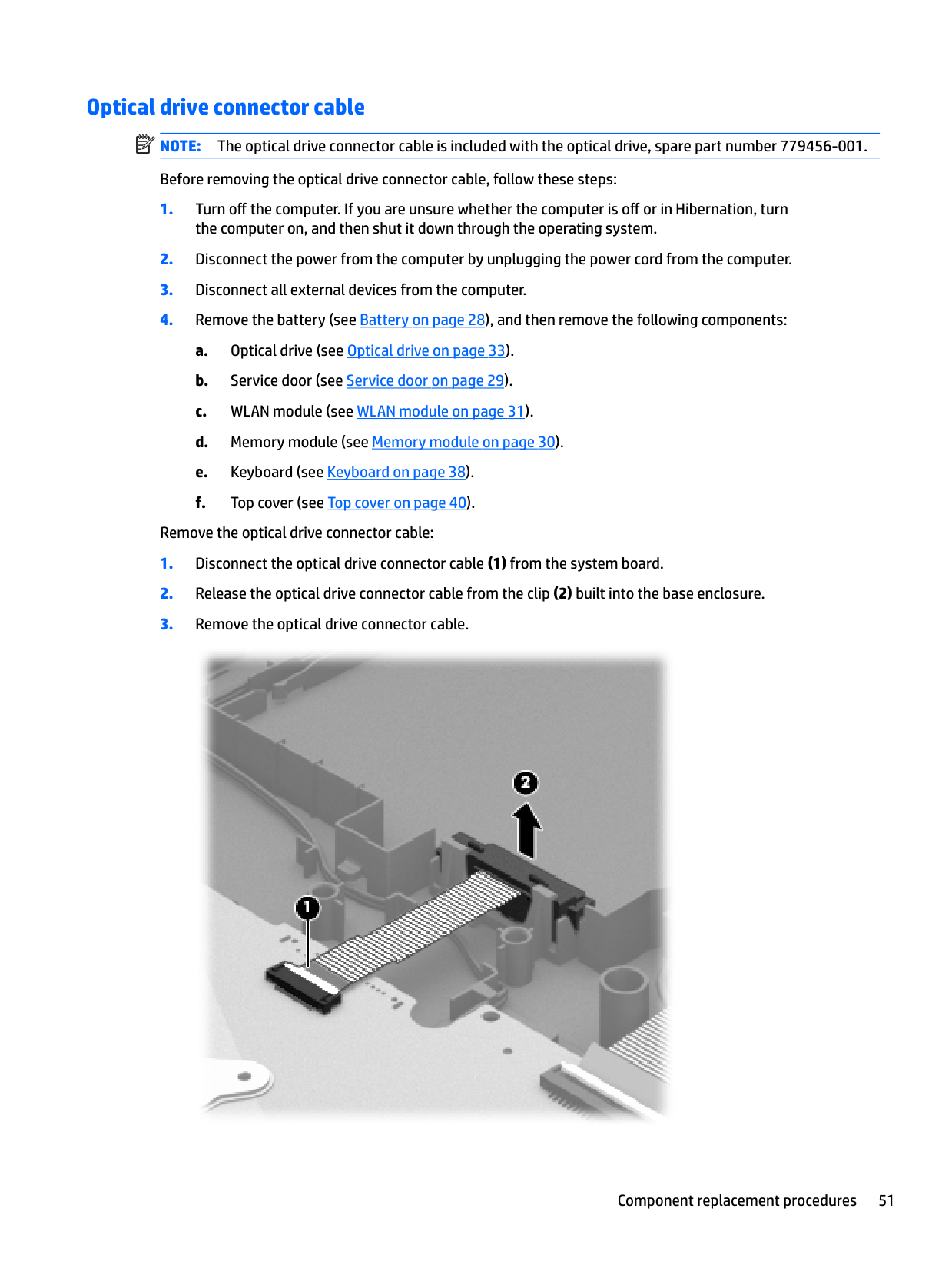
Optical drive connector cable NOTE: The optical drive connector cable is included with the optical drive, spare part number 779456-001. Before removing the optical drive connector cable, follow these steps:
| | |---|
Remove the optical drive connector cable:

Reverse this procedure to install the optical drive connector cable.
#### System board
| |
|---|
NOTE: The system board spare part kit includes replacement thermal material.
Description Spare part number All system boards use the following part numbers: xxxxxx-001: Non-Windows operating systems xxxxxx-501: Windows 8.1 Standard operating system xxxxxx-601: Windows 8.1 Professional or Windows 10 operating system Models with a hard drive and optical drive: System board with Intel Core i3-4030U processor 790202-001, -501
System board with Intel Core i3-4010U processor 782104-001, -501
######## Description Spare part number
System board with Intel Celeron N2830 processor 782105-001, -501 System board with Intel Celeron N2820 processor 789102-001, -501 System board with Intel Celeron N2815 processor 789100-001, -501 System board with Intel Celeron N2805 processor 787076-001, -501
Before removing the system board, follow these steps:
the computer on, and then shut it down through the operating system.
When replacing the system board, be sure that the following components are removed from the defective system board and installed on the replacement system board:


Reverse this procedure to install the system board.
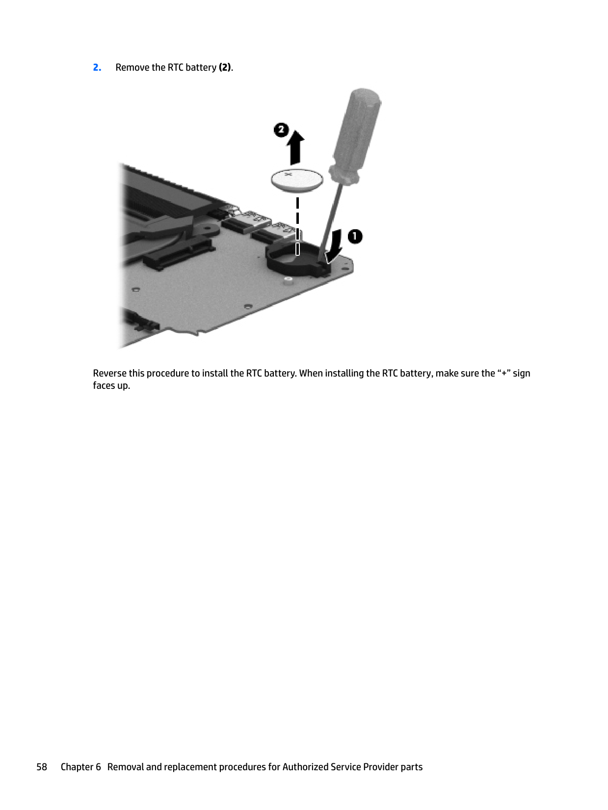
#### RTC battery
Description Spare part number RTC battery 697917-001
Before removing the RTC battery, follow these steps:
the computer on, and then shut it down through the operating system.
Remove the RTC battery:

Reverse this procedure to install the RTC battery. When installing the RTC battery, make sure the “+” sign faces up.
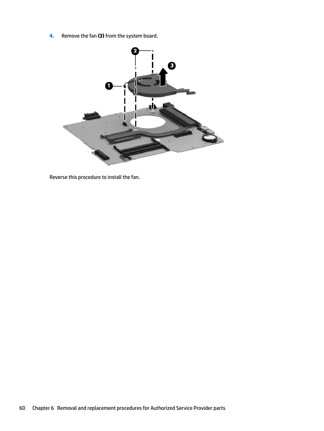
#### Fan
Description Spare part number Fan 732068-001
| | |---|
NOTE: To properly ventilate the computer, allow at least 7.6 cm (3 in) of clearance on the left side of the computer. The computer uses an electric fan for ventilation. The fan is controlled by a temperature sensor and is designed to turn on automatically when high temperature conditions exist. These conditions are affected by high external temperatures, system power consumption, power management/battery conservation configurations, battery fast charging, and software requirements. Exhaust air is displaced through the ventilation grill located on the left side of the computer.
Before removing the fan, follow these steps:
Remove the fan:

Reverse this procedure to install the fan.
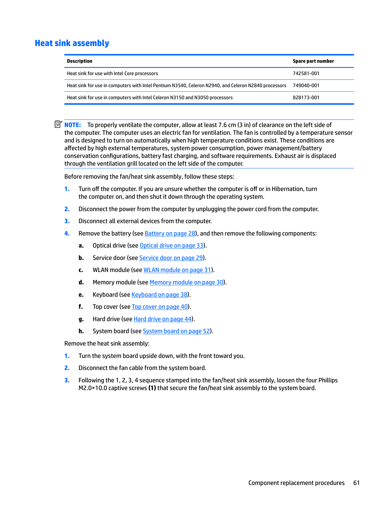
#### Heat sink assembly
######## Description Spare part number
Heat sink for use with Intel Core processors 742581-001 Heat sink for use in computers with Intel Pentium N3540, Celeron N2940, and Celeron N2840 processors 749040-001 Heat sink for use in computers with Intel Celeron N3150 and N3050 processors 828173-001
| | |---|
NOTE: To properly ventilate the computer, allow at least 7.6 cm (3 in) of clearance on the left side of the computer. The computer uses an electric fan for ventilation. The fan is controlled by a temperature sensor and is designed to turn on automatically when high temperature conditions exist. These conditions are affected by high external temperatures, system power consumption, power management/battery conservation configurations, battery fast charging, and software requirements. Exhaust air is displaced through the ventilation grill located on the left side of the computer.
Before removing the fan/heat sink assembly, follow these steps:
Remove the heat sink assembly:
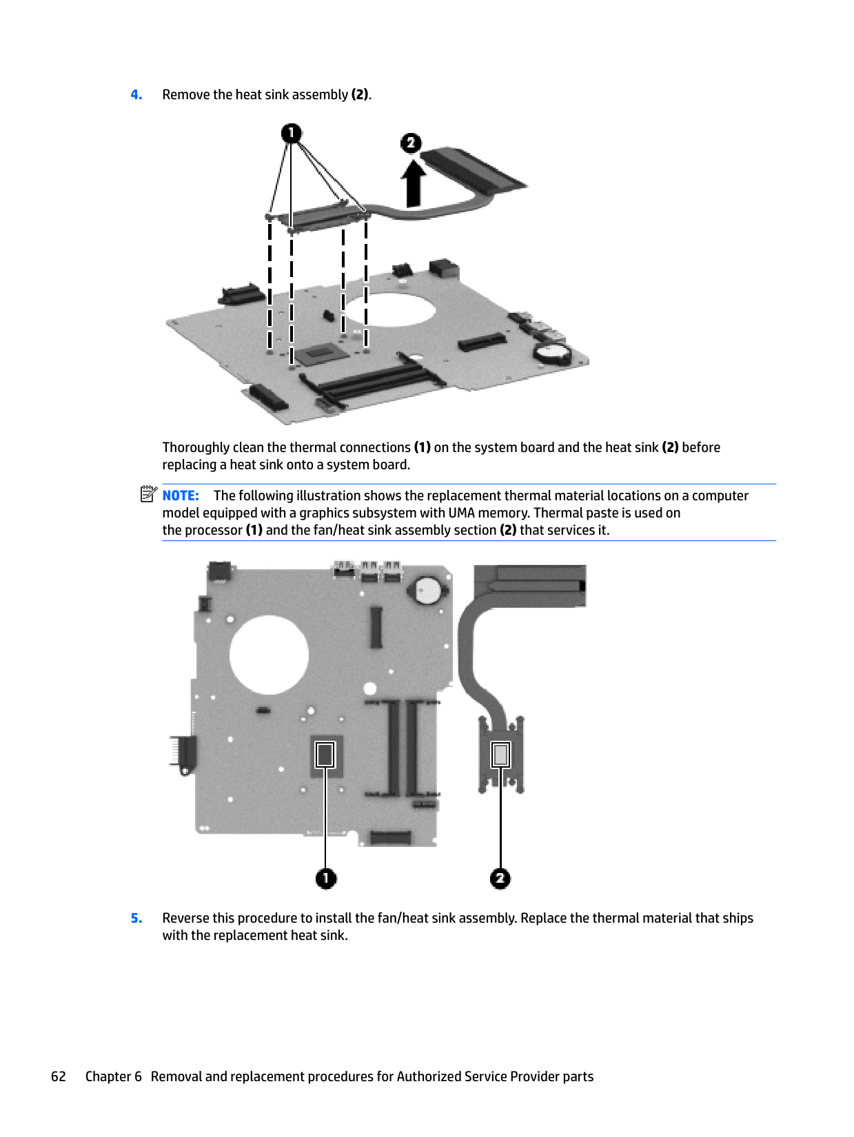
####### 4. Remove the heat sink assembly (2).

Thoroughly clean the thermal connections (1) on the system board and the heat sink (2) before replacing a heat sink onto a system board.
| | |---|
NOTE: The following illustration shows the replacement thermal material locations on a computer model equipped with a graphics subsystem with UMA memory. Thermal paste is used on the processor (1) and the fan/heat sink assembly section (2) that services it.

####### 5. Reverse this procedure to install the fan/heat sink assembly. Replace the thermal material that shipswith the replacement heat sink.
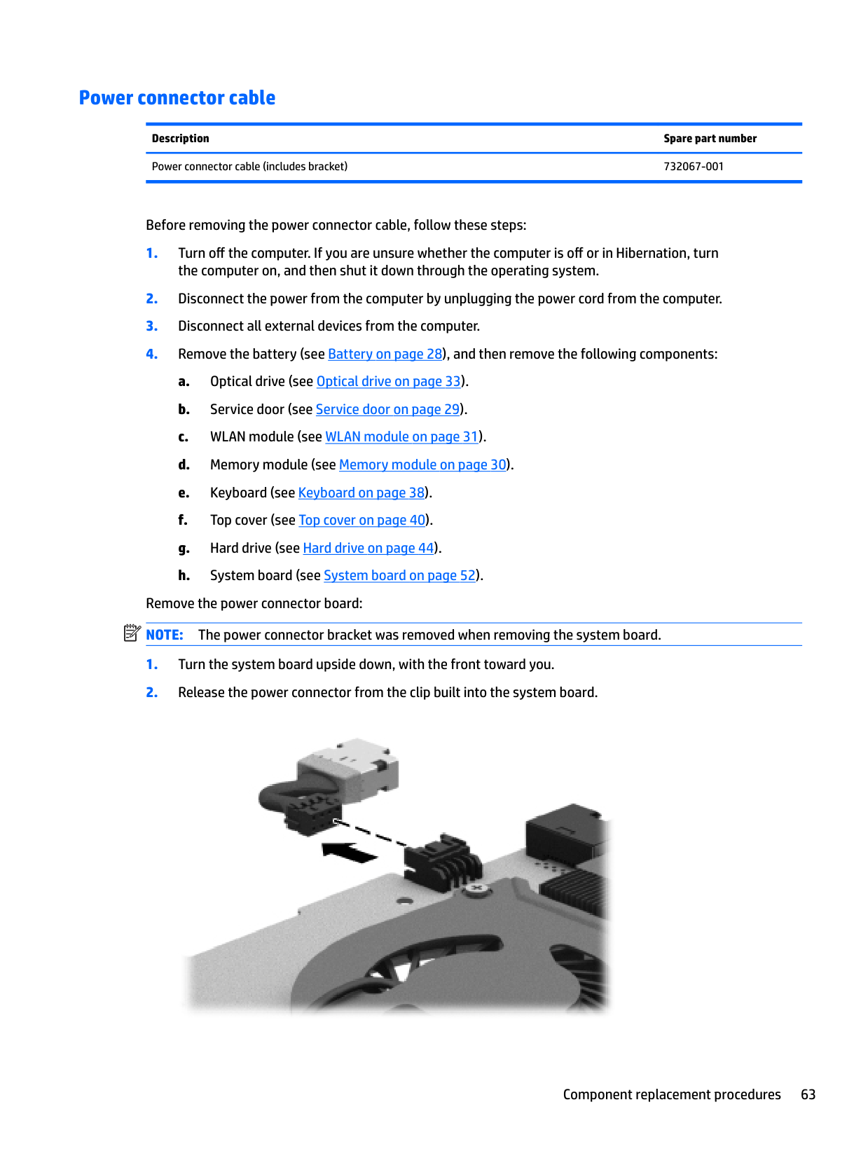
#### Power connector cable
Description Spare part number Power connector cable (includes bracket) 732067-001
Before removing the power connector cable, follow these steps:
the computer on, and then shut it down through the operating system.
| | |---|
Remove the power connector board: NOTE: The power connector bracket was removed when removing the system board.

Reverse this procedure to install the power connector cable.
#### Speakers
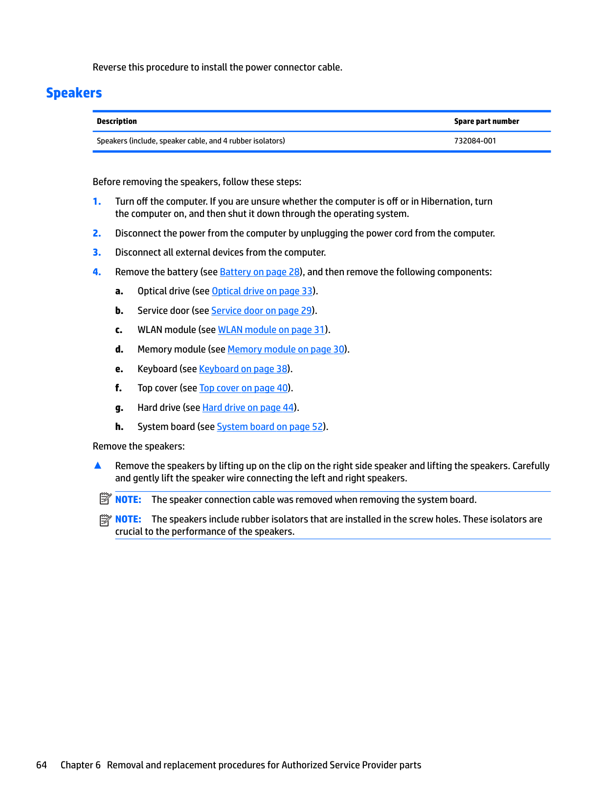
Description Spare part number Speakers (include, speaker cable, and 4 rubber isolators) 732084-001
Before removing the speakers, follow these steps:
the computer on, and then shut it down through the operating system.
Remove the speakers:
▲ Remove the speakers by lifting up on the clip on the right side speaker and lifting the speakers. Carefully and gently lift the speaker wire connecting the left and right speakers. NOTE: The speaker connection cable was removed when removing the system board. NOTE: The speakers include rubber isolators that are installed in the screw holes. These isolators are crucial to the performance of the speakers.
| | |---|
| | |---|

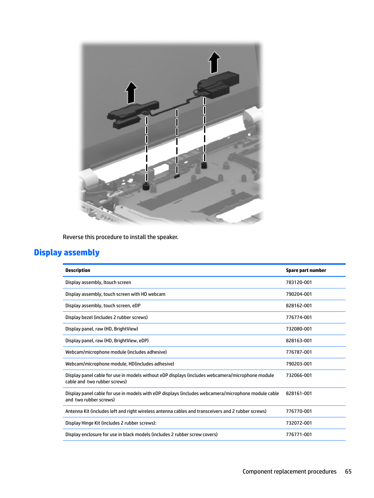
Reverse this procedure to install the speaker.
#### Display assembly
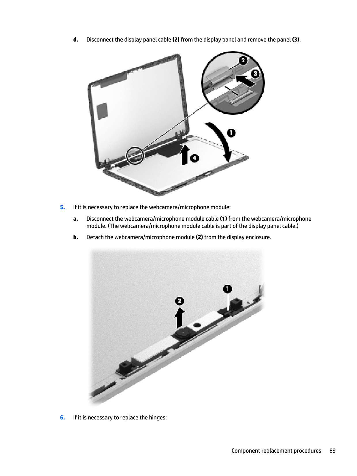
Description Spare part number Display assembly, ltouch screen 783120-001 Display assembly, touch screen with HD webcam 790204-001 Display assembly, touch screen, eDP 828162-001 Display bezel (includes 2 rubber screws) 776774-001 Display panel, raw (HD, BrightView) 732080-001 Display panel, raw (HD, BrightView, eDP) 828163-001 Webcam/microphone module (includes adhesive) 776787-001 Webcam/microphone module, HD(includes adhesive) 790203-001 Display panel cable for use in models without eDP displays (includes webcamera/microphone module cable and two rubber screws)
732066-001
Display panel cable for use in models with eDP displays (includes webcamera/microphone module cable and two rubber screws)
828161-001
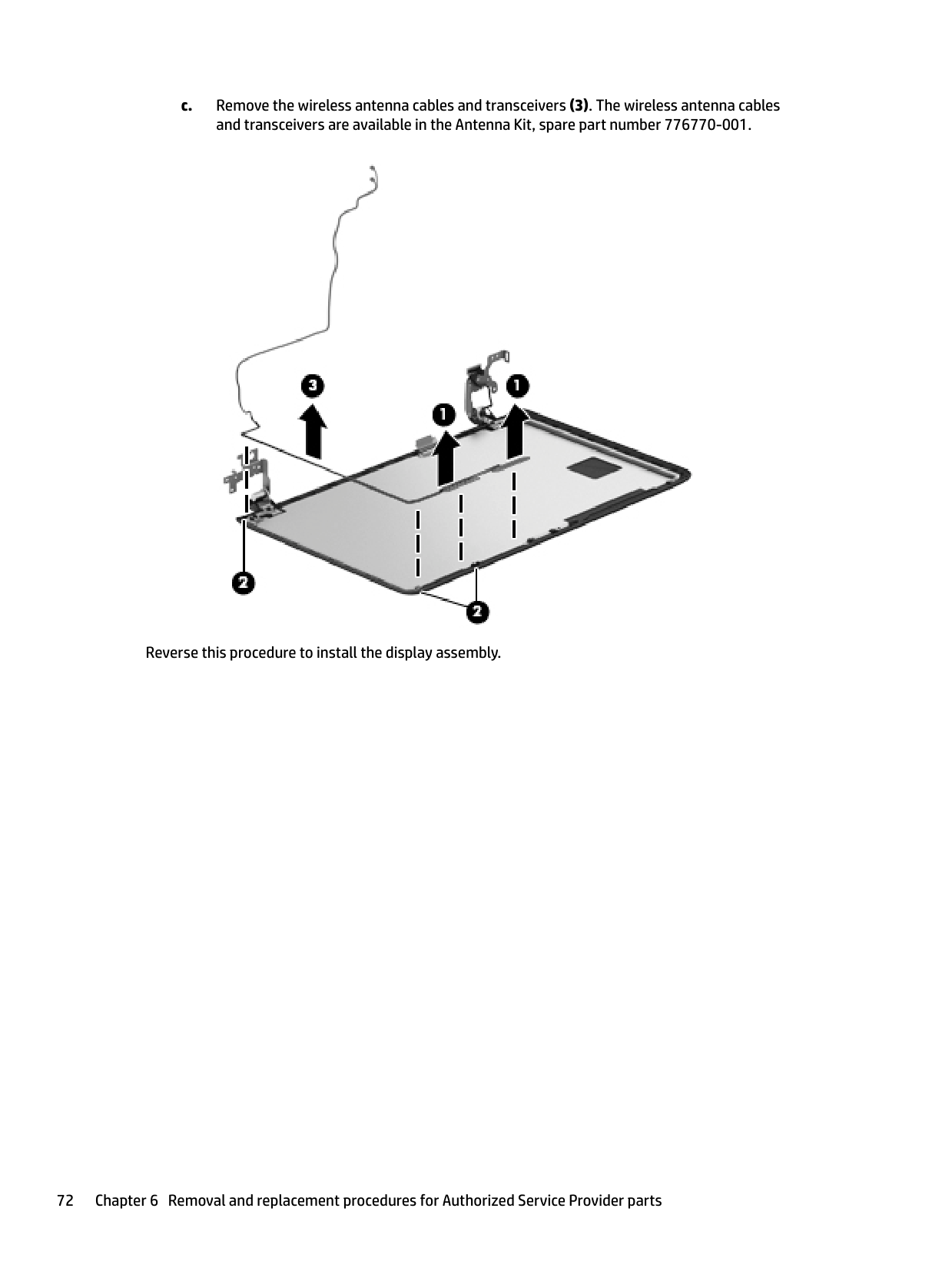
Antenna Kit (includes left and right wireless antenna cables and transceivers and 2 rubber screws) 776770-001 Display Hinge Kit (includes 2 rubber screws): 732072-001 Display enclosure for use in black models (includes 2 rubber screw covers) 776771-001
######## Description Spare part number
Display enclosure for use in red models (includes 2 rubber screw covers) 832757-001 Display enclosure for use in silver models (includes 2 rubber screw covers) 836862-001
| | |---|
NOTE: The display assembly is spared both together and at the subcomponent level. For more display assembly spare part information, see the individual removal subsections. Before removing the display assembly, follow these steps:
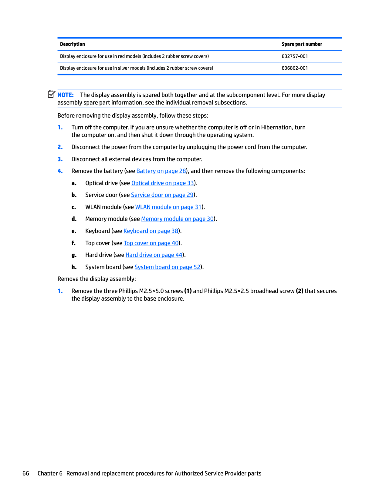
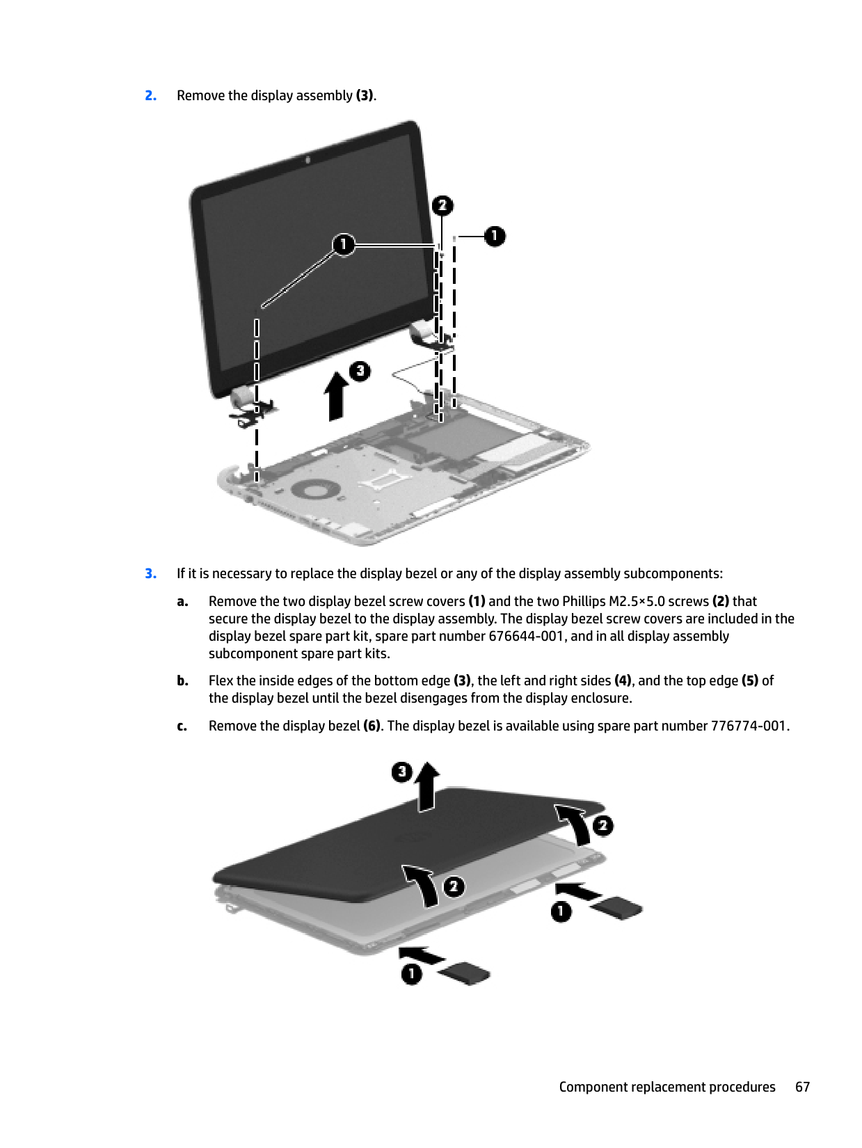
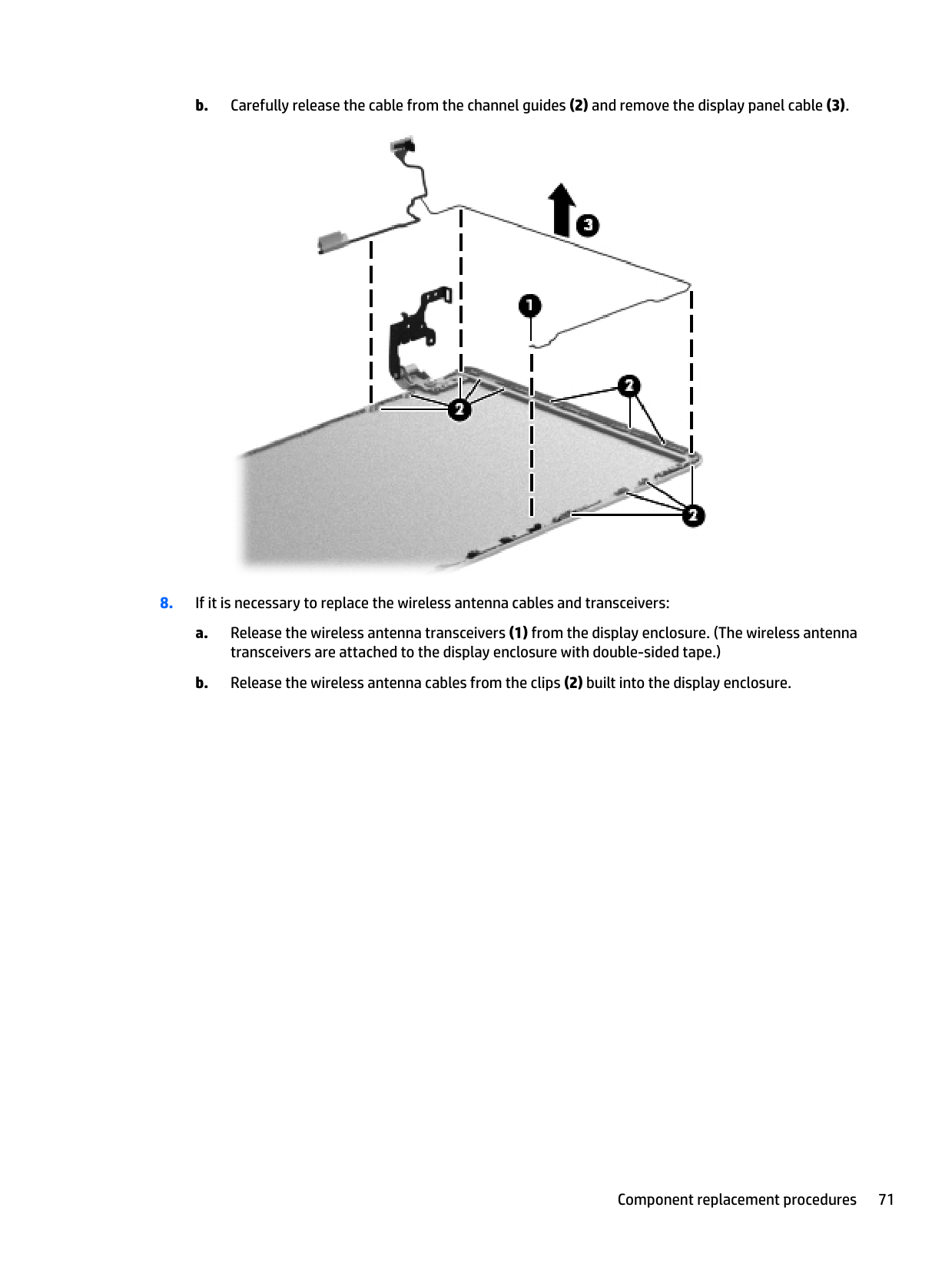
Remove the display assembly:


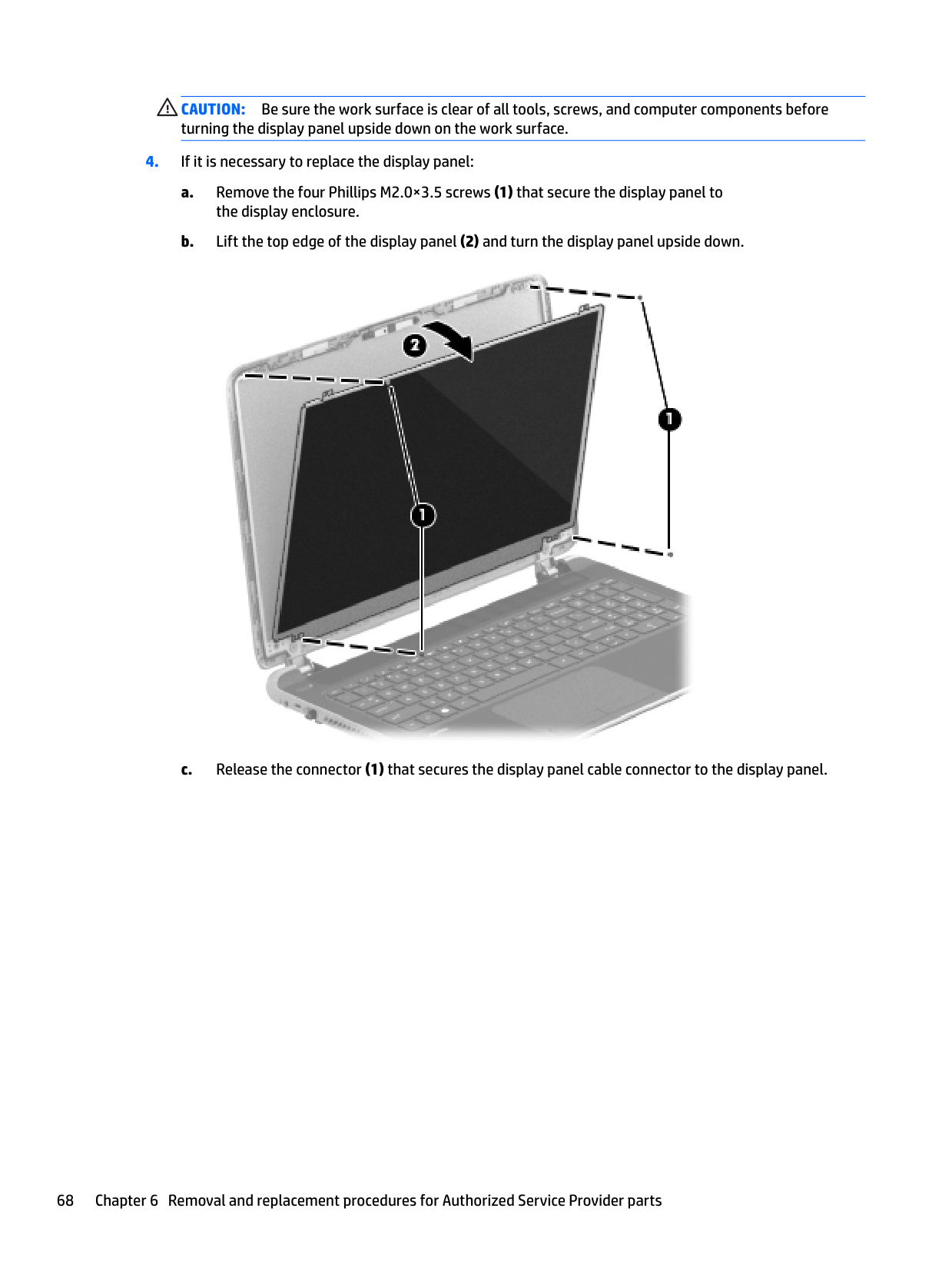
CAUTION: Be sure the work surface is clear of all tools, screws, and computer components before turning the display panel upside down on the work surface.


a. Remove the four Phillips M2.5×4.0 screws (1) and (2) that secure the hinges to
the display enclosure.
b. Remove the hinges and brackets (3) from the display enclosure.


Reverse this procedure to install the display assembly.
7 Using Setup Utility (BIOS) in Windows 8.1
Setup Utility, or Basic Input/Output System (BIOS), controls communication between all the input and output devices on the system (such as disk drives, display, keyboard, mouse, and printer). Setup Utility (BIOS) includes settings for the types of devices installed, the startup sequence of the computer, and the amount of system and extended memory.
Starting Setup Utility (BIOS)
CAUTION: Use extreme care when making changes in Setup Utility (BIOS). Errors can prevent the computer from operating properly.
▲ Turn on or restart the computer, quickly press esc, and then press f10.
Updating the BIOS Updated versions of the BIOS may be available on the HP website. Most BIOS updates on the HP website are packaged in compressed files called SoftPaqs. Some download packages contain a file named Readme.txt, which contains information regarding installing and troubleshooting the file.
#### Determining the BIOS version
To determine whether available BIOS updates contain later BIOS versions than the one currently installed on the computer, you need to know the version of the system BIOS that is installed.
BIOS version information (also known as ROM date and System BIOS) can be revealed from the Start screen by typing support, selecting the HP Support Assistant app, selecting My computer, and then selecting System Information, or by using Setup Utility (BIOS).
#### Downloading a BIOS update
CAUTION: To reduce the risk of damage to the computer or an unsuccessful installation, download and install a BIOS update only when the computer is connected to reliable external power using the AC adapter. Do not download or install a BIOS update while the computer is running on battery power, docked in an optional docking device, or connected to an optional power source. During the download and installation, follow these instructions:
| | |---|
NOTE: If your computer is connected to a network, consult the network administrator before installing any software updates, especially system BIOS updates.
‒ or –
From the Windows desktop, click the question mark icon in the notification area, at the far right of the taskbar.
If the update is more recent than your BIOS, make a note of the path to the location on your hard drive where the BIOS update is downloaded. You will need to access this path when you are ready to install the update.
BIOS installation procedures vary. Follow any instructions that appear on the screen after the download is complete. If no instructions appear, follow these steps:
‒ or – From the Windows desktop, right-click the Start button, and then select File Explorer.
| | |---|
NOTE: After a message on the screen reports a successful installation, you can delete the downloaded file from your hard drive.
74 Chapter 7 Using Setup Utility (BIOS) in Windows 8.1
8 Using Setup Utility (BIOS) in Windows 10
Setup Utility, or Basic Input/Output System (BIOS), controls communication between all the input and output devices on the system (such as disk drives, display, keyboard, mouse, and printer). Setup Utility (BIOS) includes settings for the types of devices installed, the startup sequence of the computer, and the amount of system and extended memory.
| | |---|
NOTE: To start Setup Utility on convertible computers, your computer must be in notebook mode and you must use the keyboard attached to your notebook. The on-screen keyboard, which displays in tablet mode, cannot access Setup Utility.
Starting Setup Utility (BIOS)
CAUTION: Use extreme care when making changes in Setup Utility (BIOS). Errors can prevent the computer from operating properly.
| | |---|
NOTE: To start Setup Utility on convertible computers, your computer must be in notebook mode and you must use the keyboard attached to your notebook. The on-screen keyboard, which displays in tablet mode, cannot access Setup Utility.
▲ Turn on or restart the computer, quickly press esc, and then press f10.
Updating Setup Utility (BIOS) Updated versions of Setup Utility (BIOS) may be available on the HP website. Most BIOS updates on the HP website are packaged in compressed files called SoftPaqs. Some download packages contain a file named Readme.txt, which contains information regarding installing and troubleshooting the file.
Determining the BIOS version To decide whether you need to update Setup Utility (BIOS), first determine the BIOS version on your computer. To reveal the BIOS version information (also known as ROM date and System BIOS):
– or –
Click the question mark icon in the taskbar.
– or –
▲ Use Setup Utility (BIOS). To use Setup Utility (BIOS):
#### Downloading a BIOS update
CAUTION: To reduce the risk of damage to the computer or an unsuccessful installation, download and install a BIOS update only when the computer is connected to reliable external power using the AC adapter. Do not download or install a BIOS update while the computer is running on battery power, docked in an optional docking device, or connected to an optional power source. During the download and installation, follow these instructions:
| | |---|
NOTE: If your computer is connected to a network, consult the network administrator before installing any software updates, especially system BIOS updates.
– or – Click the question mark icon in the taskbar.
Make a note of the path to the location on your hard drive where the BIOS update is downloaded. You will need to access this path when you are ready to install the update.
BIOS installation procedures vary. Follow any instructions that appear on the screen after the download is complete. If no instructions appear, follow these steps:
76 Chapter 8 Using Setup Utility (BIOS) in Windows 10
| | |---|
NOTE: After a message on the screen reports a successful installation, you can delete the downloaded file from your hard drive.
Synchronizing a tablet and keyboard (select products only)
For a tablet with a detachable keyboard, when you attach the tablet to the keyboard and restart the computer, Setup Utility (BIOS) checks to see if the Embedded Controller firmware on the keyboard needs to be synchronized. If so, synchronization begins. If the synchronization is interrupted, a notification screen displays for 10 seconds before the tablet restarts and attempts to synchronize again.
| | |---|
NOTE: The Embedded Controller firmware will synchronize ONLY if the tablet or keyboard battery is more than 50% charged, or if your tablet is connected to AC power.
Synchronizing a tablet and keyboard (select products only) 77
9 Backing up, restoring, and recovering in Windows 8.1
This chapter provides information about the following processes. The information in the chapter is standard procedure for most models.
▲ From the Start screen, type support, and then select the HP Support Assistant app.
Creating recovery media and backups
The following methods of creating recovery media and backups are available on select models only. Choose the available method according to your computer model.
| | |---|
#### Creating HP Recovery media (select models only)
| | |---|
IMPORTANT: If your computer does not list a Recovery Media Creation option, you can obtain recovery media for your system from support. See the Worldwide Telephone Numbers booklet included with the computer. You can also find contact information from the HP website. Go to http://www.hp.com/support, select your country or region, and follow the on-screen instructions.
HP Recovery Manager is a software program that allows you to create recovery media after you successfully set up the computer. HP Recovery media can be used to perform system recovery if the hard drive becomes corrupted. System recovery reinstalls the original operating system and the software programs installed at the factory and then configures the settings for the programs. HP Recovery media can also be used to customize the system or restore the factory image if you replace the hard drive.
To create HP Recovery media:
Using Windows tools You can create system restore points and create backups of personal information using Windows tools. NOTE: If storage is 32 GB or less, Microsoft System Restore is disabled by default.
| |
|---|
▲ From the Start screen, type help, and then select Help and Support. or –
From the Windows desktop, click the question mark icon in the notification area, at the far right of the taskbar.
For more information and steps, see Help and Support.
Restore and recovery
There are several options for recovering your system. Choose the method that best matches your situation and level of expertise:
| | |---|
IMPORTANT: Not all methods are available on all models.
Using Windows tools 79
▲ From the Start screen, type support, and then select the HP Support Assistant app.

▲ From the Start screen, type recovery, select HP Recovery Manager, select Drivers and
Applications Reinstall, and then follow the on-screen instructions.
#### Recovering using HP Recovery Manager
HP Recovery Manager software allows you to recover the computer to its original factory state by using the HP Recovery media that you either created or that you obtained from support, or by using the HP Recovery partition (select models only). If you have not already created recovery media, see Creating HP Recovery
media (select models only) on page 78.
##### What you need to know before you get started
IMPORTANT: Recovery through HP Recovery Manager should be used as a final attempt to correct computer issues.
| | |---|
website. Go to http://www.hp.com/support, select your country or region, and follow the on-screen instructions.
| | |---|
| | |---|
IMPORTANT: HP Recovery Manager does not automatically provide backups of your personal data. Before beginning recovery, back up any personal data you want to retain. Using HP Recovery media, you can choose from one of the following recovery options: NOTE: Only the options available for your computer display when you start the recovery process.
The HP Recovery partition (select models only) allows System Recovery and Minimized Image Recovery (select models only).
##### Using the HP Recovery partition (select models only)
The HP Recovery partition allows you to perform a system recovery or minimized image recovery (select models only) without the need for recovery discs or a recovery USB flash drive. This type of recovery can be used only if the hard drive is still working.
To start HP Recovery Manager from the HP Recovery partition:
##### Using HP Recovery media to recover
You can use HP Recovery media to recover the original system. This method can be used if your system does not have an HP Recovery partition or if the hard drive is not working properly.
NOTE: If the computer does not automatically restart in HP Recovery Manager, change the computer boot order. See Changing the computer boot order on page 81.
| | |---|
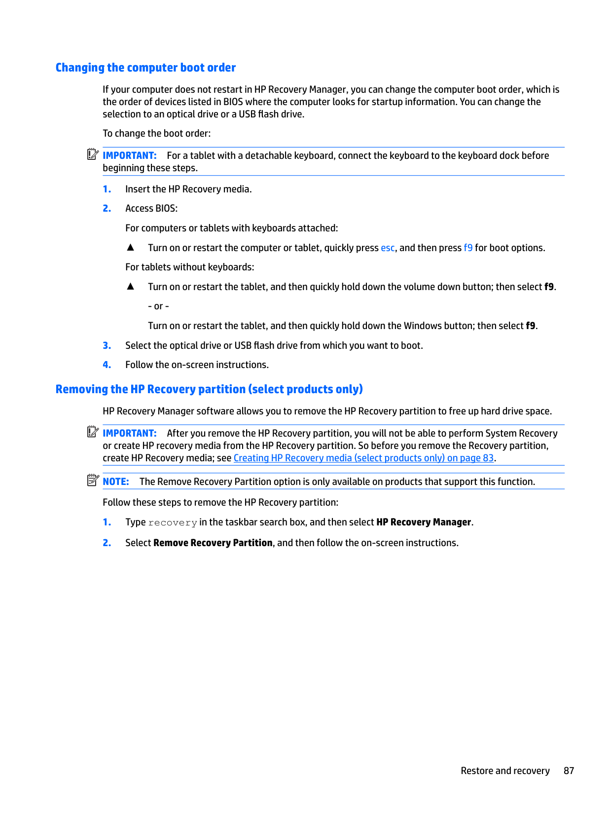
##### Changing the computer boot order
If your computer does not restart in HP Recovery Manager, you can change the computer boot order, which is the order of devices listed in BIOS where the computer looks for startup information. You can change the selection for an optical drive or a USB flash drive.
Restore and recovery 81
To change the boot order:
▲ Turn on or restart the computer, quickly press esc, and then press f9 for boot options.
Removing the HP Recovery partition (select models only) HP Recovery Manager software allows you to remove the HP Recovery partition to free up hard drive space. IMPORTANT: After you remove the HP Recovery partition, you can no longer use the Windows Refresh option or the Windows option to remove everything and reinstall Windows. In addition, you will not be able to perform System Recovery or Minimized Image Recovery from the HP Recovery partition. So before you remove the Recovery partition, create HP Recovery media; see Creating HP Recovery media (select models only) on page 78. Follow these steps to remove the HP Recovery partition:
| | |---|
10 Backing up, restoring, and recovering in Windows 10
This chapter provides information about the following processes. The information in the chapter is standard procedure for most products.
▲ Type support in the taskbar search box, and then select the HP Support Assistant app.
‒ or – Click the question mark icon in the taskbar.
| | |---|
IMPORTANT: If you will be performing recovery procedures on a tablet, the tablet battery must be at least 70% charged before you start the recovery process.
IMPORTANT: For a tablet with a detachable keyboard, connect the keyboard to the keyboard dock before beginning any recovery process.
Creating recovery media and backups
The following methods of creating recovery media and backups are available on select products only. Choose the available method according to your computer model.
| | |---|
#### Creating HP Recovery media (select products only)
If possible, check for the presence of the Recovery partition and the Windows partition. From the Start menu, select File Explorer, and then select This PC.
Creating recovery media and backups 83
You can use Windows tools to create system restore points and create backups of personal information, see Using Windows tools on page 84.
| |
|---|
To create HP Recovery media: IMPORTANT: For a tablet with a detachable keyboard, connect the keyboard to the keyboard dock before beginning these steps.
Using Windows tools
You can create recovery media, system restore points, and backups of personal information using Windows tools.
| | |---|
NOTE: If storage is 32 GB or less, Microsoft System Restore is disabled by default. For more information and steps, see the Get started app.
▲ Select the Start button, and then select the Get started app.
Restore and recovery
There are several options for recovering your system. Choose the method that best matches your situation and level of expertise:
| | |---|
IMPORTANT: Not all methods are available on all products.
▲ Select the Start button, and then select the Get started app.
▲ Type recovery in the taskbar search box, select HP Recovery Manager, select Reinstall drivers
and/or applications, and then follow the on-screen instructions.
#### Recovering using HP Recovery Manager
HP Recovery Manager software allows you to recover the computer to its original factory state by using the HP Recovery media that you either created or that you obtained from HP, or by using the HP Recovery partition (select products only). If you have not already created recovery media, see Creating HP Recovery media (select products only) on page 83.
##### What you need to know before you get started
IMPORTANT: Recovery through HP Recovery Manager should be used as a final attempt to correct computer issues.
| | |---|
website. Go to http://www.hp.com/support, select your country or region, and follow the on-screen instructions.
| | |---|
| | |---|
IMPORTANT: HP Recovery Manager does not automatically provide backups of your personal data. Before beginning recovery, back up any personal data you want to retain. Using HP Recovery media, you can choose from one of the following recovery options: NOTE: Only the options available for your computer display when you start the recovery process.
The HP Recovery partition (select products only) allows System Recovery only. Using the HP Recovery partition (select products only)
The HP Recovery partition allows you to perform a system recovery without the need for recovery discs or a recovery USB flash drive. This type of recovery can be used only if the hard drive is still working.
| | |---|
To start HP Recovery Manager from the HP Recovery partition: IMPORTANT: For a tablet with a detachable keyboard, connect the keyboard to the keyboard dock before beginning these steps (select products only).
For computers or tablets with keyboards attached, press f11 while the computer boots, or press and hold f11 as you press the power button.
For tablets without keyboards: Turn on or restart the tablet, and then quickly hold down the volume down button; then select f11.
##### Using HP Recovery media to recover
You can use HP Recovery media to recover the original system. This method can be used if your system does not have an HP Recovery partition or if the hard drive is not working properly.
NOTE: If the computer does not automatically restart in HP Recovery Manager, change the computer boot order. See Changing the computer boot order on page 87.
| | |---|
##### Changing the computer boot order
If your computer does not restart in HP Recovery Manager, you can change the computer boot order, which is the order of devices listed in BIOS where the computer looks for startup information. You can change the selection to an optical drive or a USB flash drive.
| | |---|
To change the boot order: IMPORTANT: For a tablet with a detachable keyboard, connect the keyboard to the keyboard dock before beginning these steps.
▲ Turn on or restart the computer or tablet, quickly press esc, and then press f9 for boot options. For tablets without keyboards:
▲ Turn on or restart the tablet, and then quickly hold down the volume down button; then select f9.
Removing the HP Recovery partition (select products only) HP Recovery Manager software allows you to remove the HP Recovery partition to free up hard drive space. IMPORTANT: After you remove the HP Recovery partition, you will not be able to perform System Recovery or create HP recovery media from the HP Recovery partition. So before you remove the Recovery partition, create HP Recovery media; see Creating HP Recovery media (select products only) on page 83. NOTE: The Remove Recovery Partition option is only available on products that support this function. Follow these steps to remove the HP Recovery partition:
| | |---|
| | |---|
11 Using HP PC Hardware Diagnostics (UEFI)
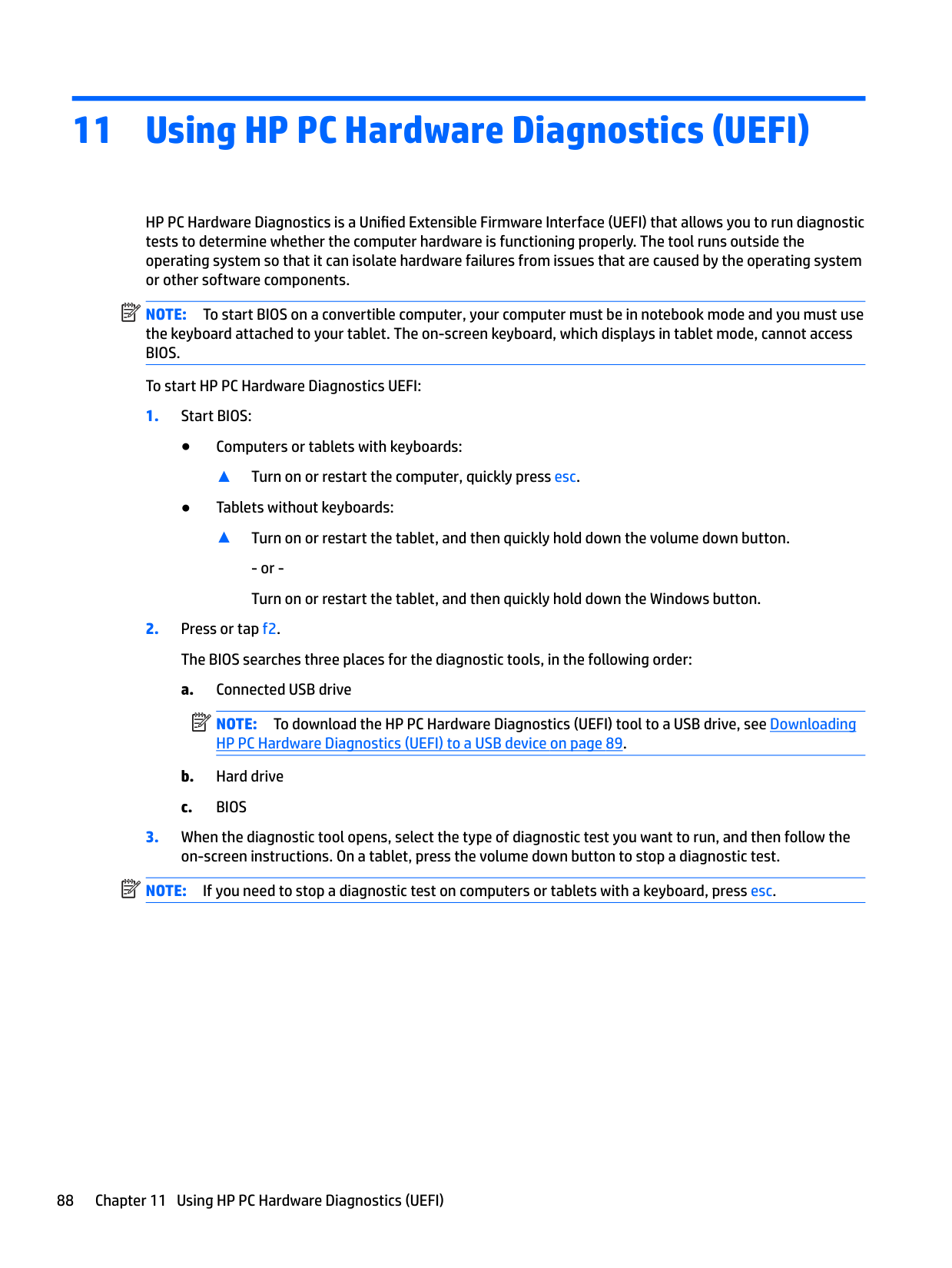
HP PC Hardware Diagnostics is a Unified Extensible Firmware Interface (UEFI) that allows you to run diagnostic tests to determine whether the computer hardware is functioning properly. The tool runs outside the operating system so that it can isolate hardware failures from issues that are caused by the operating system or other software components.
| | |---|
NOTE: To start BIOS on a convertible computer, your computer must be in notebook mode and you must use the keyboard attached to your tablet. The on-screen keyboard, which displays in tablet mode, cannot access BIOS.
To start HP PC Hardware Diagnostics UEFI:
▲ Turn on or restart the computer, quickly press esc.
▲ Turn on or restart the tablet, and then quickly hold down the volume down button.
| |
|---|
| | |---|
NOTE: If you need to stop a diagnostic test on computers or tablets with a keyboard, press esc.
88 Chapter 11 Using HP PC Hardware Diagnostics (UEFI)
Downloading HP PC Hardware Diagnostics (UEFI) to a USB device There are two options to download HP PC Hardware Diagnostics to a USB device: Download the latest UEFI version:
– or – Click Find Now to let HP automatically detect your product.
Downloading HP PC Hardware Diagnostics (UEFI) to a USB device 89
12 Specifications
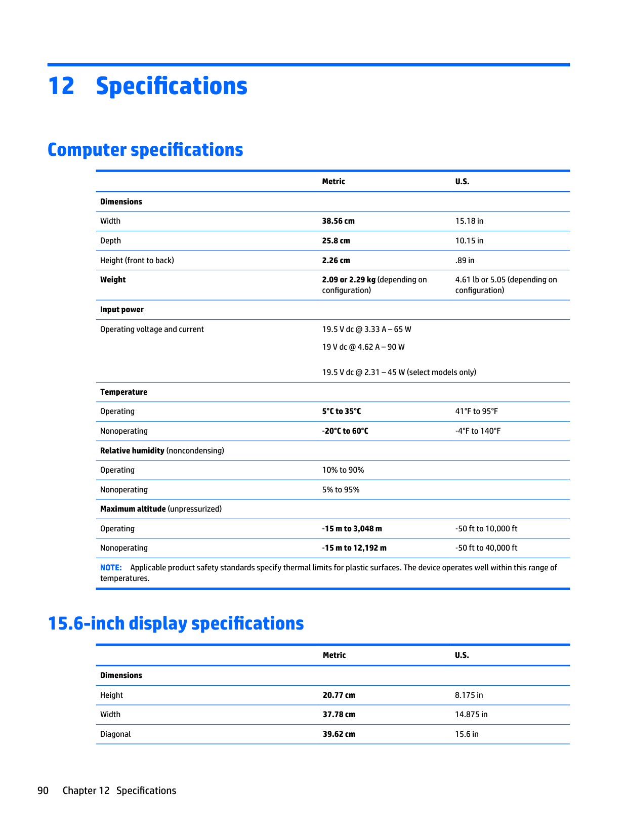
Computer specifications
Metric U.S. Dimensions
Width 38.56 cm 15.18 in Depth 25.8 cm 10.15 in Height (front to back) 2.26 cm .89 in
######## Weight 2.09 or 2.29 kg (depending on
configuration)
Input power Operating voltage and current 19.5 V dc @ 3.33 A – 65 W
19 V dc @ 4.62 A – 90 W
4.61 lb or 5.05 (depending on configuration)
19.5 V dc @ 2.31 – 45 W (select models only)
Temperature Operating 5°C to 35°C 41°F to 95°F Nonoperating ‑20°C to 60°C ‑4°F to 140°F Relative humidity (noncondensing) Operating 10% to 90% Nonoperating 5% to 95% Maximum altitude (unpressurized)
Operating ‑15 m to 3,048 m ‑50 ft to 10,000 ft Nonoperating ‑15 m to 12,192 m ‑50 ft to 40,000 ft NOTE: Applicable product safety standards specify thermal limits for plastic surfaces. The device operates well within this range of
temperatures.
15.6-inch display specifications
######## Metric U.S.
Dimensions Height 20.77 cm 8.175 in Width 37.78 cm 14.875 in Diagonal 39.62 cm 15.6 in
90 Chapter 12 Specifications
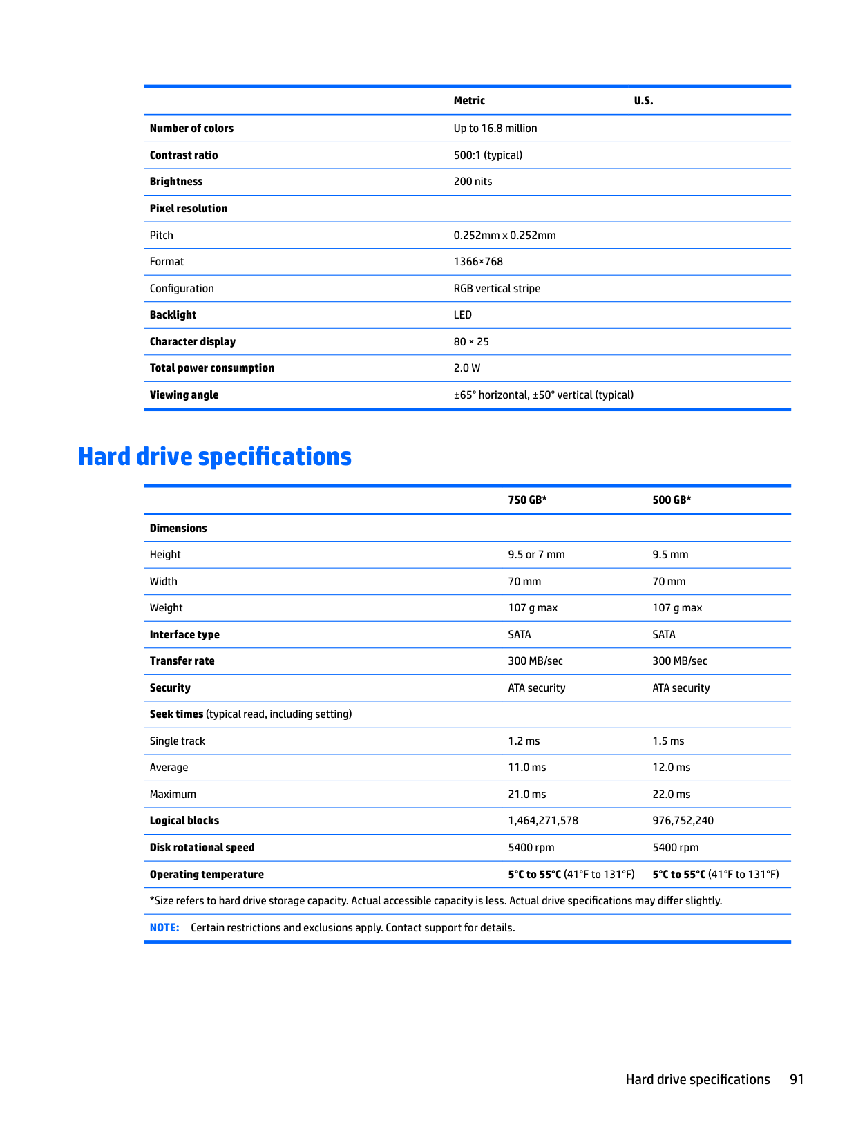
Metric U.S. Number of colors Up to 16.8 million Contrast ratio 500:1 (typical) Brightness 200 nits Pixel resolution Pitch 0.252mm x 0.252mm Format 1366×768 Configuration RGB vertical stripe Backlight LED Character display 80 × 25 Total power consumption 2.0 W Viewing angle ±65° horizontal, ±50° vertical (typical)
Hard drive specifications
######## 750 GB* 500 GB*
Dimensions Height 9.5 or 7 mm 9.5 mm Width 70 mm 70 mm Weight 107 g max 107 g max Interface type SATA SATA Transfer rate 300 MB/sec 300 MB/sec Security ATA security ATA security Seek times (typical read, including setting) Single track 1.2 ms 1.5 ms Average 11.0 ms 12.0 ms Maximum 21.0 ms 22.0 ms Logical blocks 1,464,271,578 976,752,240 Disk rotational speed 5400 rpm 5400 rpm Operating temperature 5°C to 55°C (41°F to 131°F) 5°C to 55°C (41°F to 131°F)
*Size refers to hard drive storage capacity. Actual accessible capacity is less. Actual drive specifications may differ slightly. NOTE: Certain restrictions and exclusions apply. Contact support for details.
Hard drive specifications 91
13 Power cord set requirements
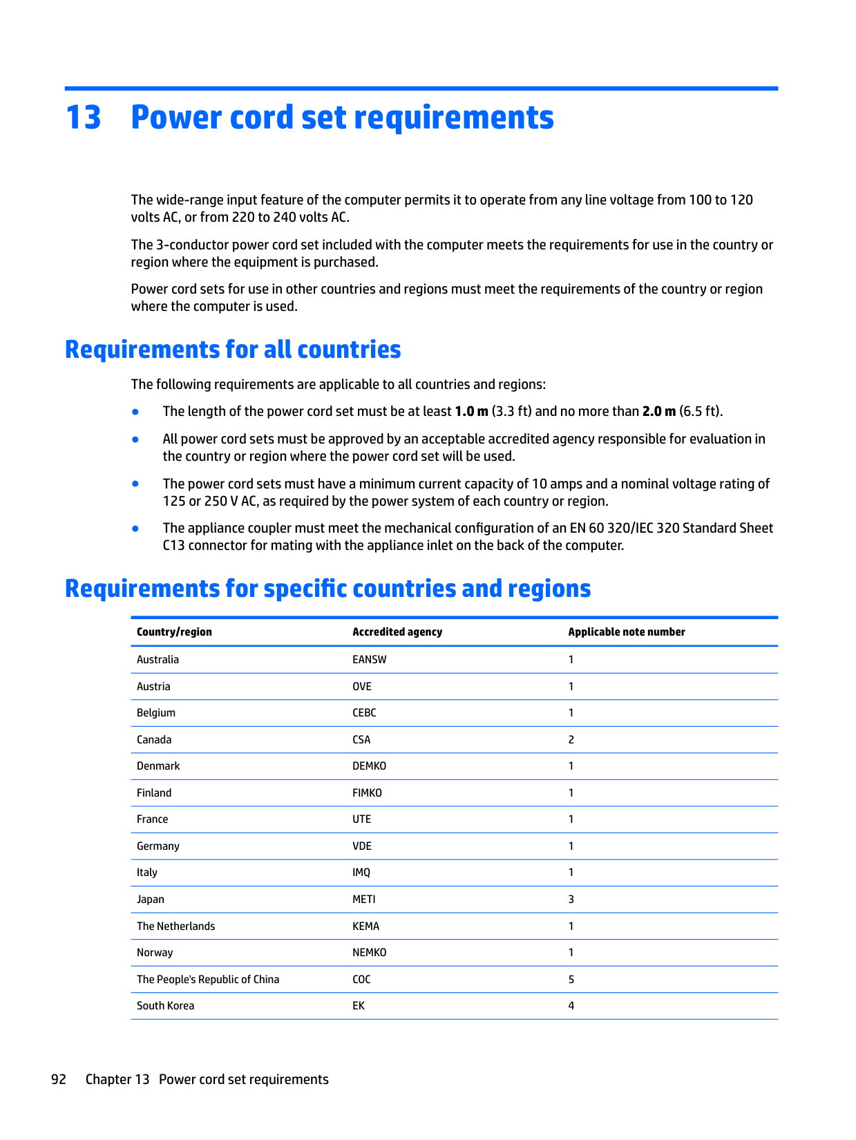
The wide-range input feature of the computer permits it to operate from any line voltage from 100 to 120 volts AC, or from 220 to 240 volts AC.
The 3-conductor power cord set included with the computer meets the requirements for use in the country or region where the equipment is purchased.
Power cord sets for use in other countries and regions must meet the requirements of the country or region where the computer is used.
Requirements for all countries
The following requirements are applicable to all countries and regions:
Requirements for specific countries and regions
######## Country/region Accredited agency Applicable note number
Australia EANSW 1 Austria OVE 1 Belgium CEBC 1 Canada CSA 2 Denmark DEMKO 1 Finland FIMKO 1 France UTE 1 Germany VDE 1 Italy IMQ 1 Japan METI 3 The Netherlands KEMA 1 Norway NEMKO 1 The People's Republic of China COC 5 South Korea EK 4
92 Chapter 13 Power cord set requirements
######## Country/region Accredited agency Applicable note number
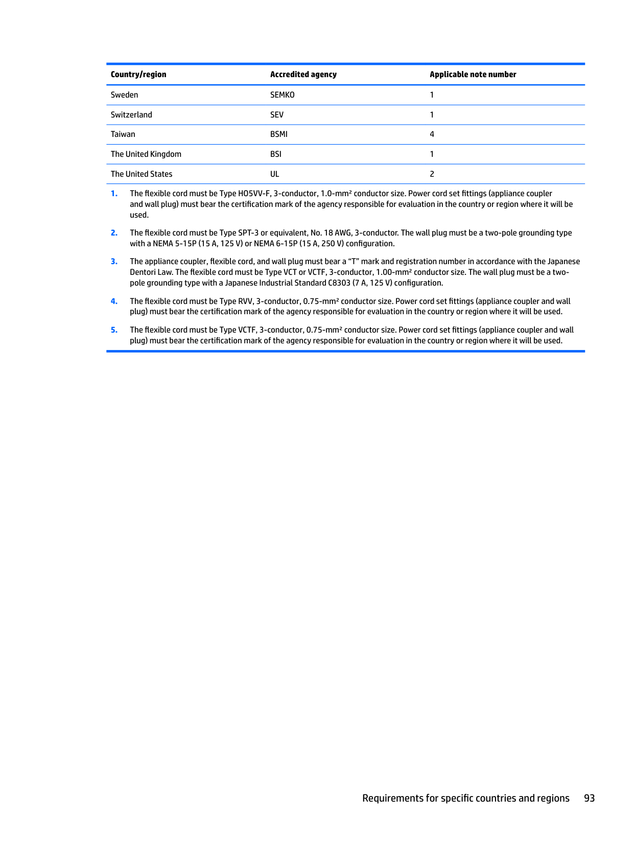
Sweden SEMKO 1 Switzerland SEV 1 Taiwan BSMI 4 The United Kingdom BSI 1 The United States UL 2
Requirements for specific countries and regions 93
14 Recycling
When a non-rechargeable or rechargeable battery has reached the end of its useful life, do not dispose of the battery in general household waste. Follow the local laws and regulations in your area for battery disposal.
HP encourages customers to recycle used electronic hardware, HP original print cartridges, and rechargeable batteries. For more information about recycling programs, see the HP Web site at http://www.hp.com/recycle.
94 Chapter 14 Recycling
Index
identifying 11
antenna removal 71 spare part number 20, 65, 72 Antenna Kit, spare part number 20,
65, 72 audio, product description 2 audio-out (headphone) jacks 4
19
battery removal 28 spare part number 19, 28
battery cover, identifying 12 battery lock, locks and unlocks the
battery 12 battery release latch 12 BIOS
determining version 73, 75 downloading an update 73, 76 starting the Setup Utility 73, 75 updating 73, 75
boot order changing 81, 87
buttons left TouchPad 8 power 10 right TouchPad 8
bottom 12 display 6 left side 5 right side 4 top 8
computer major components 15 computer specifications 90 connector, power 5
specifications 90
display assembly removal 65 spare part numbers 65 subcomponents 19
display bezel removal 36, 67 spare part number 19, 36, 65,
67 display enclosure, spare part numbers 20, 65
display hinge removal 69 spare part number 20, 65, 70
Display Hinge Kit, spare part number 20, 65, 70
display panel product description 1 removal 68
display panel cable removal 70
DVD±RW Double-Layer SuperMulti
Drive removal 33 spare part number 19, 21, 33
removal 59 spare part numbers 59
fan/heat sink assembly removal 61 spare part numbers 18, 61
fn key, identifying 11
product description 2 removal 44 spare part numbers 17, 21, 44 specifications 91 hard drive connector cable
illustrated 21
Hard Drive Hardware Kit contents 21 spare part number 17, 21, 44
hard drive light 4 hard drive rubber bracket
illustrated 21 removal 46
hard drive, identifying 12 HDMI 20 HDMI port
identifying 6 HP PC Hardware Diagnostics (UEFI) using 88
HP Recovery Manager correcting boot problems 81, 87 starting 81, 86
HP Recovery media
creating 78, 83 recovery 81, 86
HP Recovery partition recovery 81, 86 removing 82, 87
identifying 11 internal display switch, identifying 6 internal microphone, identifying 6
audio-out (headphone) 4 network 5 RJ-45 (network) 5
product description 2 removal 38 spare part numbers 17, 38
keypad, integrated numeric 11 keys
action 11 esc 11 fn 11 num lock 11 Windows 11
serial number 14 latches 12 lights
AC adapter 5 caps lock 9 eMMC 4 hard drive 4 mute 9 power 4 wireless 9
identifying 12 product description 1 removal 30 spare part numbers 18, 30
microphone
product description 2 minimized image recovery 81, 86 minimized image, creating 80, 85 model name 1 mute light, identifying 9
description 3
optical drive product description 2 removal 33 spare part numbers 33
optical drive bracket removal 33
optical drive connector cable removal 51 spare part number 51
optical drive, identifying 5 original system recovery 80, 85
description 2
ports charging (powered) 6 HDMI 6 product description 2 USB 3.0 6
power button board removal 47
power button, identifying 10 power connector cable
removal 63
power connector, identifying 5 power cord
set requirements 92 spare part numbers 20
power lights, identifying 4 power requirements, product
description 3 processor
product description 1
product description audio 2 chipset 1 display panel 1 Ethernet 2 external media cards 2 graphics 1 hard drive 2 keyboard 2 memory module 1
microphone 2 operating system 3 optical drive 2 pointing device 2 ports 2 power requirements 3 processors 1 product name 1 security 3 serviceability 3 video 2 wireless 2
product name 1 product name and number,
computer 14
options 79, 85
recovery discs 79, 81, 84, 86 HP Recovery Manager 80, 85 media 81, 86 starting 81, 86 supported discs 79, 84 system 80, 85 USB flash drive 81, 86 using HP Recovery media 79, 84
recovery media creating 78, 83 creating using HP Recovery
Manager 79, 84 recovery partition
removing 82, 87 regulatory information 14 removal/replacement
procedures 27, 35 RJ-45 (network) jack, identifying 5 RTC battery
removal 57 spare part number 18, 57
removal 29
96 Index
service door
spare part number 29 serviceability, product description 3 slots
memory card 6 security cable 5
speakers identifying 11 removal 64 spare part number 19, 64
specifications computer 90 display 90 hard drive 91
supported discs, recovery 79, 84 system board
removal 52 spare part numbers 17, 52
system information locating 14 system recovery 80, 85 system restore point
creating 79, 84 system restore point, creating 78, 83
removal 40 spare part numbers 17, 40
TouchPad buttons 8
TouchPad button board removal 49 spare part number 17, 49
TouchPad zone, identifying 8
identifying 7 webcam light, identifying 6
webcamera/microphone module removal 69 spare part number 20, 65, 69
Windows system restore point 78, 79, 83,
84 Windows key, identifying 11 Windows tools
using 79, 84
wireless antenna removal 71 spare part number 20, 65, 72
wireless light 9 wireless, product description 2 WLAN antennas, identifying 7 WLAN module
removal 31 spare part numbers 18, 31