
Toshiba Satellite L645 S4032 HD Intel Core I3 350m Laptop Specifications And Datasheet
Ask AI
— answers from the official manualAnswers from the official manual.
Common questions
Common Questions
9 totalWhat should I do if the TE2 starter trips due to an overload?
If the starter Overloads (over temperature or thermal capacity exceeded), it must reset itself before operation can begin again. This occurs when the motor cools down; meanwhile, the system will remain inactive.
How do I bypass power around defective components?
Use an integral Bypass Contactor and ensure control wiring goes through to command a bypass if necessary. This is enabled with factory defaults but can be manually operated using dry contact closures depending on installation.
How can I ensure proper motor protection during startup and operation?
Configure thermal model overload settings (Functions F001 to F005), and use dual ramp or jog features if needed, by enabling external control commands.
How do I disable the built-in overload protection function?
To disable Overload Protection use Function F005. This is advised when using external thermal overload relays.
What steps are required when installing and testing a TE2 starter with a motor smaller than specified?
When testing smaller loads, configure the system to disable Phase Loss Protection according to section 5.6.8.a guidelines.
How do I ensure correct setup for using Power Factor Correction Capacitors with a TE2 starter?
Ensure power factor correction capacitors are off-line during ramp up and connect them to the line side of the TE2, not the load side. Use separate capacitor control contactors.
Full Manual
100 pages

DOCUMENT: NBZ0004 Rev.1
INSTRUCTION MANUAL
INSTALLATION – OPERATION - MAINTENANCE
###### TE2 Series
###### Low Voltage Digital Solid State Soft Starter 18 – 1250A
Issued: 3/20 Firmware Version 1.33
############## This Page Intentionally Left Blank
###### Important Notice
The instructions contained in this manual are not intended to cover all details or variations in equipment types nor may it provide for every possible contingency concerning the installation, operations, or maintenance of this equipment. Should additional information be required, contact your Toshiba Customer Support Center.
The contents of this manual shall not become a part of or modify any prior or existing agreement, commitment, or relationship. The sales contract contains the entire obligation of Toshiba International Corporation. The warranty contained in the contract between the parties is the sole warranty of Toshiba International Corporation and any statements contained herein do not create new warranties or modify the existing warranty.
Any electrical or mechanical modifications to this equipment without the prior written consent of Toshiba International Corporation may void all warranties or other safety certifications. Unauthorized modifications may also result in safety hazard or equipment damage.
Misuse of this equipment could result in injury and equipment damage. In no event will Toshiba International Corporation be responsible or liable for direct, indirect, special, or consequential damage or injury that may result from the misuse of this equipment.
###### About This Manual
Every effort has been made to provide accurate and concise information to you, our customer.
At Toshiba International Corporation we are continuously striving for better ways to meet the constantly changing needs of our customers. E-mail your comments, questions, or concerns about this publication to tic-controls@toshiba.com.
###### Purpose and Scope of Manual

This manual provides information on how to safely install, operate, maintain, and dispose of your TE2 solid state starter. The information provided in this manual is applicable to the TE2 starter only.
This manual provides information on the various features and functions of this powerful device, including:
Included is a section on general safety instructions that describe the warning labels and symbols that are used on the device and throughout the manual. Read the manual completely before installing, operating, performing maintenance, or disposing of this equipment.
This manual and the accompanying drawings should be considered a permanent part of the equipment and should be readily available for reference and review. Dimensions shown in the manual are in imperial units and/or the metric equivalent. Connection drawings within this document convey the typical topology of the TE starter.
Because of our commitment to continuous improvement, Toshiba International Corporation reserves the right, without prior notice, to update information, make product changes, or to discontinue any product or service identified in this publication.
#################### Toshiba International Corporation (TIC) shall not be liable for direct, indirect, special, or consequential damages resulting from the use of the information contained within this manual.
This manual is copyrighted. No part of this manual may be photocopied or reproduced in any form without the prior written consent of Toshiba International Corporation.
© Copyright 2020 Toshiba International Corporation. All rights reserved. Printed in the U.S.A.
TOSHIBA® is a registered trademark of Toshiba Corporation. All other product or trade references appearing in this manual are registered trademarks of their respective owners.
###### Contacting TIC’s Customer Support Center
Toshiba International Corporation’s Customer Support Center can be contacted to obtain help in resolving any system problem that you may experience or to provide application information.
The Support Center is open from 8 a.m. to 5 p.m. (CST), Monday through Friday. The Center’s toll free number is US (800) 231-1412/Fax (713) 937-9349 CAN (800) 872-2192 MEX 01 (800) 527-1204. For after-hours support follow the directions of the outgoing message when calling. To contact Toshiba International Corporation, address all correspondence to:
Field Service Department Toshiba International Corporation 13131 West Little York Road Houston, Texas 77041-9990
For further information on Toshiba International Corporation’s products and services, please visit our website at www.toshiba.com/tic.
###### TOSHIBA INTERNATIONAL CORPORATION
########## TE2 Solid State Starter
Please complete the following information for your records and retain this manual. Model Number: _____________________________________________________________________ Serial Number: _____________________________________________________________________ Project Number (if applicable):_________________________________________________________ Date of Installation: _________________________________________________________________ Inspected By: _____________________________________________________________________ Name of Application: ________________________________________________________________
###### General Safety Information
DO NOT attempt to install, operate, maintain, or dispose of this equipment until you have read and understood all of the product safety information and directions that are contained in this manual.
########## Safety Alert Symbol
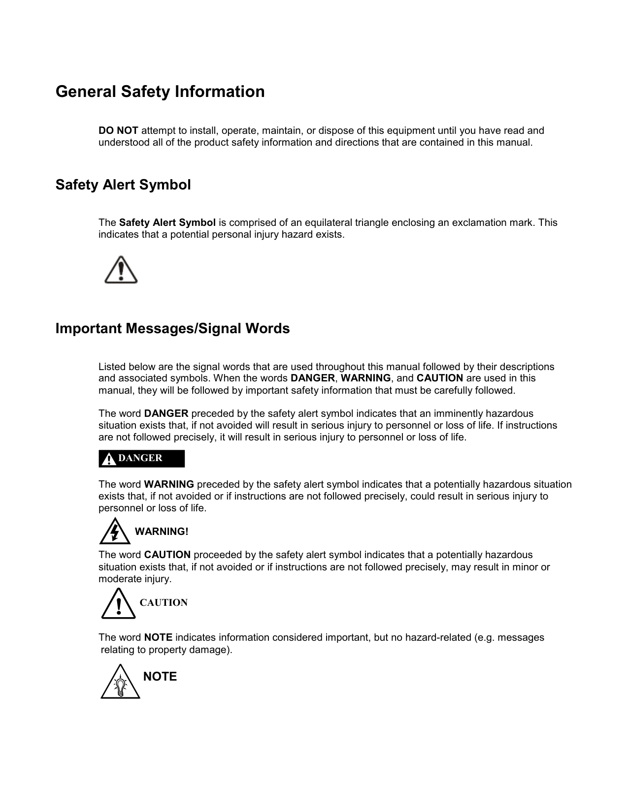
The Safety Alert Symbol is comprised of an equilateral triangle enclosing an exclamation mark. This indicates that a potential personal injury hazard exists.

########## Important Messages/Signal Words
Listed below are the signal words that are used throughout this manual followed by their descriptions and associated symbols. When the words DANGER, WARNING, and CAUTION are used in this manual, they will be followed by important safety information that must be carefully followed.
The word DANGER preceded by the safety alert symbol indicates that an imminently hazardous situation exists that, if not avoided will result in serious injury to personnel or loss of life. If instructions are not followed precisely, it will result in serious injury to personnel or loss of life.
DANGER
The word WARNING preceded by the safety alert symbol indicates that a potentially hazardous situation exists that, if not avoided or if instructions are not followed precisely, could result in serious injury to personnel or loss of life.
#################### WARNING!
The word CAUTION proceeded by the safety alert symbol indicates that a potentially hazardous situation exists that, if not avoided or if instructions are not followed precisely, may result in minor or moderate injury.
#################### CAUTION
The word NOTE indicates information considered important, but no hazard-related (e.g. messages relating to property damage).
NOTE
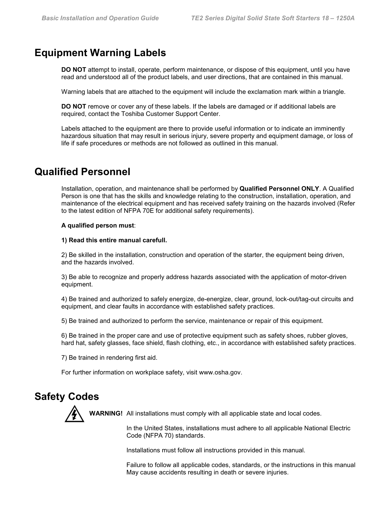
Equipment Warning Labels DO NOT attempt to install, operate, perform maintenance, or dispose of this equipment, until you have read and understood all of the product labels, and user directions, that are contained in this manual. Warning labels that are attached to the equipment will include the exclamation mark within a triangle. DO NOT remove or cover any of these labels. If the labels are damaged or if additional labels are required, contact the Toshiba Customer Support Center. Labels attached to the equipment are there to provide useful information or to indicate an imminently hazardous situation that may result in serious injury, severe property and equipment damage, or loss of life if safe procedures or methods are not followed as outlined in this manual.
###### Qualified Personnel
Installation, operation, and maintenance shall be performed by Qualified Personnel ONLY. A Qualified Person is one that has the skills and knowledge relating to the construction, installation, operation, and maintenance of the electrical equipment and has received safety training on the hazards involved (Refer to the latest edition of NFPA 70E for additional safety requirements).
A qualified person must:
###### Safety Codes
WARNING! All installations must comply with all applicable state and local codes.
In the United States, installations must adhere to all applicable National Electric Code (NFPA 70) standards.
Installations must follow all instructions provided in this manual. Failure to follow all applicable codes, standards, or the instructions in this manual May cause accidents resulting in death or severe injuries.
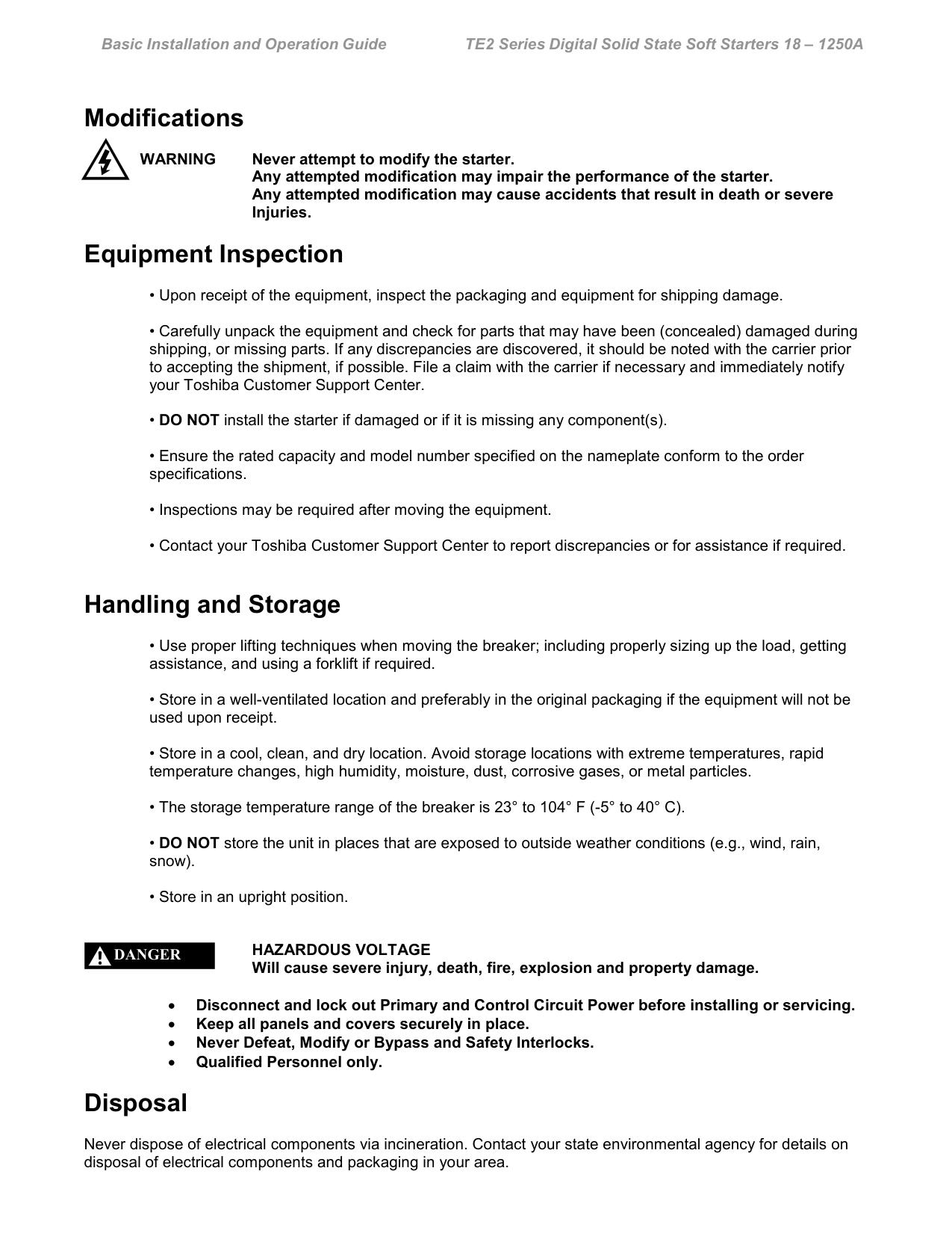
###### Modifications
WARNING Never attempt to modify the starter. Any attempted modification may impair the performance of the starter. Any attempted modification may cause accidents that result in death or severe Injuries.
###### Equipment Inspection

###### Handling and Storage
#################### DANGER
###### Disposal
Never dispose of electrical components via incineration. Contact your state environmental agency for details on disposal of electrical components and packaging in your area.
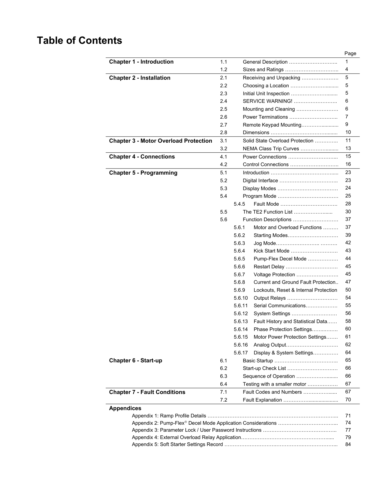
##### Table of Contents
Page
Chapter 2 - Installation 2.1 Receiving and Unpacking …………………. 5
Chapter 4 - Connections 4.1 Power Connections ………………………... 15
Chapter 5 - Programming 5.1 Introduction ………………………………..... 23
###################### Appendices
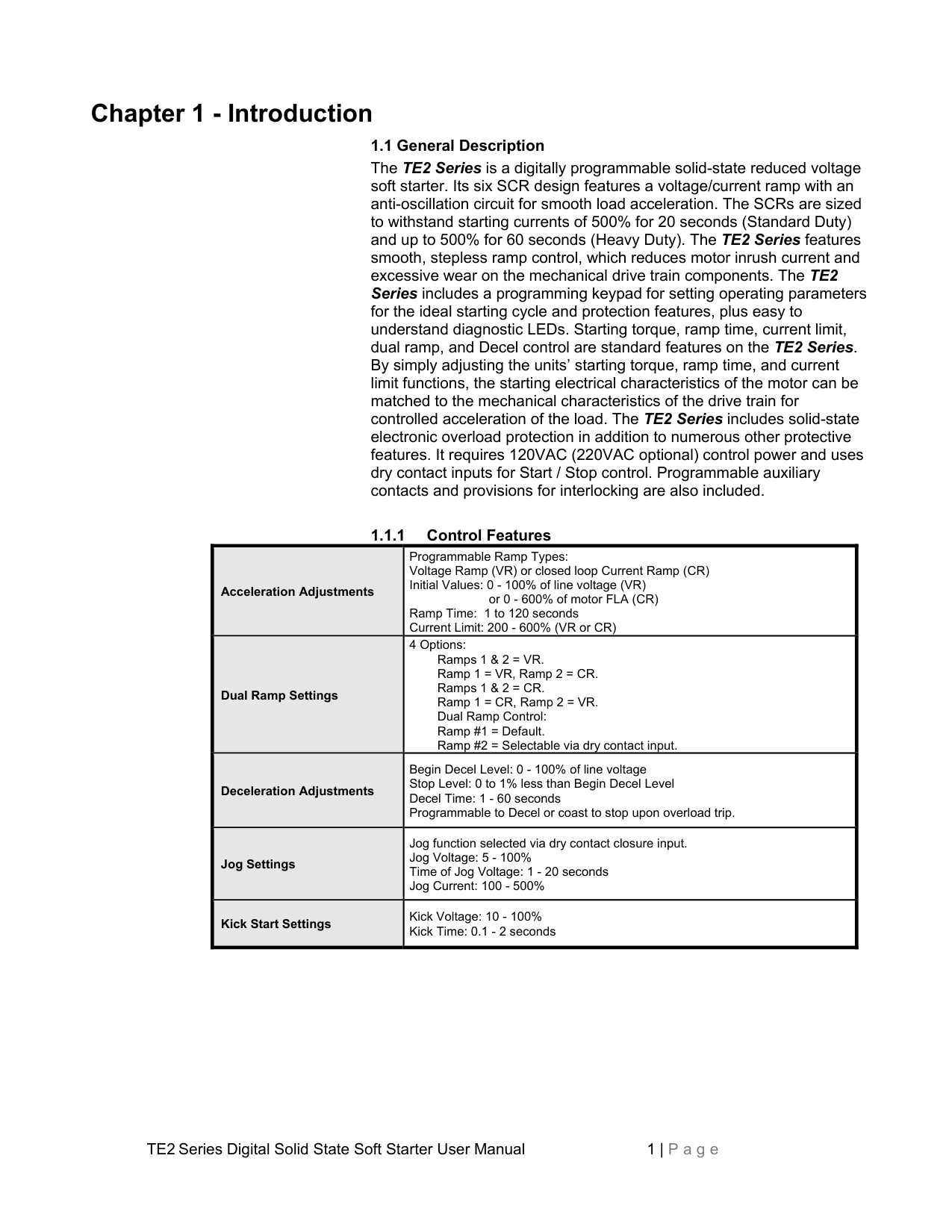
##### Chapter 1 - Introduction
################## 1.1 General Description
The TE2 Series is a digitally programmable solid-state reduced voltage soft starter. Its six SCR design features a voltage/current ramp with an anti-oscillation circuit for smooth load acceleration. The SCRs are sized to withstand starting currents of 500% for 20 seconds (Standard Duty) and up to 500% for 60 seconds (Heavy Duty). The TE2 Series features smooth, stepless ramp control, which reduces motor inrush current and excessive wear on the mechanical drive train components. The TE2 Series includes a programming keypad for setting operating parameters for the ideal starting cycle and protection features, plus easy to understand diagnostic LEDs. Starting torque, ramp time, current limit, dual ramp, and Decel control are standard features on the TE2 Series. By simply adjusting the units’ starting torque, ramp time, and current limit functions, the starting electrical characteristics of the motor can be matched to the mechanical characteristics of the drive train for controlled acceleration of the load. The TE2 Series includes solid-state electronic overload protection in addition to numerous other protective features. It requires 120VAC (220VAC optional) control power and uses dry contact inputs for Start / Stop control. Programmable auxiliary contacts and provisions for interlocking are also included.
################## 1.1.1 Control Features
|Acceleration Adjustments|Programmable Ramp Types: Voltage Ramp (VR) or closed loop Current Ramp (CR) Initial Values: 0 - 100% of line voltage (VR)
or 0 - 600% of motor FLA (CR) Ramp Time: 1 to 120 seconds Current Limit: 200 - 600% (VR or CR)| |---|---| |Dual Ramp Settings|4 Options: Ramps 1 & 2 = VR. Ramp 1 = VR, Ramp 2 = CR. Ramps 1 & 2 = CR. Ramp 1 = CR, Ramp 2 = VR. Dual Ramp Control:
Ramp #1 = Default.
Ramp #2 = Selectable via dry contact input.
| |Deceleration Adjustments|Begin Decel Level: 0 - 100% of line voltage Stop Level: 0 to 1% less than Begin Decel Level Decel Time: 1 - 60 seconds Programmable to Decel or coast to stop upon overload trip.| |Jog Settings|Jog function selected via dry contact closure input. Jog Voltage: 5 - 100% Time of Jog Voltage: 1 - 20 seconds Jog Current: 100 - 500%| |Kick Start Settings|Kick Voltage: 10 - 100% Kick Time: 0.1 - 2 seconds|
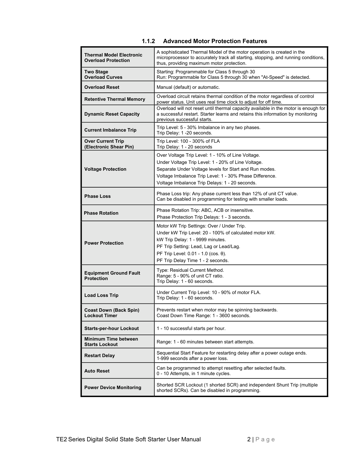
################## 1.1.2 Advanced Motor Protection Features
|Thermal Model Electronic Overload Protection
|A sophisticated Thermal Model of the motor operation is created in the microprocessor to accurately track all starting, stopping, and running conditions, thus, providing maximum motor protection.| |---|---| |Two Stage Overload Curves
|Starting: Programmable for Class 5 through 30 Run: Programmable for Class 5 through 30 when "At-Speed" is detected.| |Overload Reset|Manual (default) or automatic.| |Retentive Thermal Memory|Overload circuit retains thermal condition of the motor regardless of control power status. Unit uses real time clock to adjust for off time.| |Dynamic Reset Capacity|Overload will not reset until thermal capacity available in the motor is enough for a successful restart. Starter learns and retains this information by monitoring previous successful starts.| |Current Imbalance Trip|Trip Level: 5 - 30% Imbalance in any two phases. Trip Delay: 1 -20 seconds.| |Over Current Trip (Electronic Shear Pin)
|Trip Level: 100 - 300% of FLA Trip Delay: 1 - 20 seconds| |Voltage Protection|Over Voltage Trip Level: 1 - 10% of Line Voltage. Under Voltage Trip Level: 1 - 20% of Line Voltage. Separate Under Voltage levels for Start and Run modes. Voltage Imbalance Trip Level: 1 - 30% Phase Difference. Voltage Imbalance Trip Delays: 1 - 20 seconds.| |Phase Loss|Phase Loss trip: Any phase current less than 12% of unit CT value. Can be disabled in programming for testing with smaller loads.| |Phase Rotation|Phase Rotation Trip: ABC, ACB or insensitive. Phase Protection Trip Delays: 1 - 3 seconds.| |Power Protection|Motor kW Trip Settings: Over / Under Trip. Under kW Trip Level: 20 - 100% of calculated motor kW. kW Trip Delay: 1 - 9999 minutes. PF Trip Setting: Lead, Lag or Lead/Lag. PF Trip Level: 0.01 - 1.0 (cos. θ). PF Trip Delay Time 1 - 2 seconds.| |Equipment Ground Fault Protection
|Type: Residual Current Method. Range: 5 - 90% of unit CT ratio. Trip Delay: 1 - 60 seconds.| |Load Loss Trip|Under Current Trip Level: 10 - 90% of motor FLA. Trip Delay: 1 - 60 seconds.|
|Coast Down (Back Spin) Lockout Timer
|Prevents restart when motor may be spinning backwards. Coast Down Time Range: 1 - 3600 seconds.| |Starts-per-hour Lockout|1 - 10 successful starts per hour.| |Minimum Time between Starts Lockout
|Range: 1 - 60 minutes between start attempts.| |Restart Delay|Sequential Start Feature for restarting delay after a power outage ends. 1-999 seconds after a power loss.| |Auto Reset|Can be programmed to attempt resetting after selected faults. 0 - 10 Attempts, in 1 minute cycles.| |Power Device Monitoring|Shorted SCR Lockout (1 shorted SCR) and independent Shunt Trip (multiple shorted SCRs). Can be disabled in programming.|
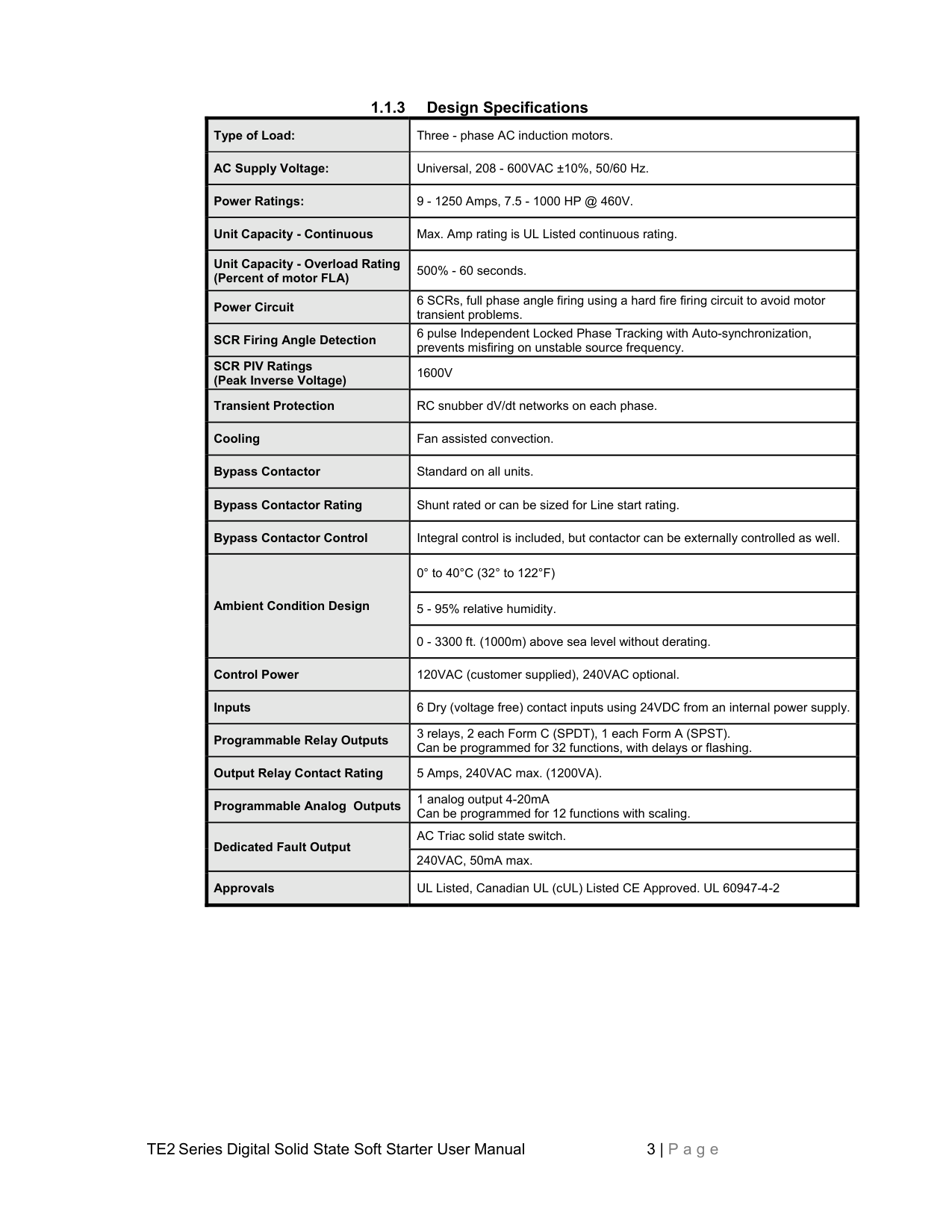
################## 1.1.3 Design Specifications
|Type of Load:|Three - phase AC induction motors.| |---|---| |AC Supply Voltage:|Universal, 208 - 600VAC ±10%, 50/60 Hz.| |Power Ratings:|9 - 1250 Amps, 7.5 - 1000 HP @ 460V.| |Unit Capacity - Continuous|Max. Amp rating is UL Listed continuous rating.| |Unit Capacity - Overload Rating (Percent of motor FLA)
|500% - 60 seconds.| |Power Circuit|6 SCRs, full phase angle firing using a hard fire firing circuit to avoid motor transient problems.| |SCR Firing Angle Detection|6 pulse Independent Locked Phase Tracking with Auto-synchronization, prevents misfiring on unstable source frequency.| |SCR PIV Ratings (Peak Inverse Voltage)
|1600V| |Transient Protection|RC snubber dV/dt networks on each phase.| |Cooling|Fan assisted convection.| |Bypass Contactor|Standard on all units.| |Bypass Contactor Rating|Shunt rated or can be sized for Line start rating.| |Bypass Contactor Control|Integral control is included, but contactor can be externally controlled as well.| |Ambient Condition Design
|0° to 40°C (32° to 122°F)| |Ambient Condition Design
|5 - 95% relative humidity.| |Ambient Condition Design
|0 - 3300 ft. (1000m) above sea level without derating.| |Control Power|120VAC (customer supplied), 240VAC optional.| |Inputs|6 Dry (voltage free) contact inputs using 24VDC from an internal power supply.| |Programmable Relay Outputs|3 relays, 2 each Form C (SPDT), 1 each Form A (SPST). Can be programmed for 32 functions, with delays or flashing.| |Output Relay Contact Rating|5 Amps, 240VAC max. (1200VA).| |Programmable Analog Outputs|1 analog output 4-20mA Can be programmed for 12 functions with scaling.| |Dedicated Fault Output
|AC Triac solid state switch.| |Dedicated Fault Output
|240VAC, 50mA max.|
|Approvals|UL Listed, Canadian UL (cUL) Listed CE Approved. UL 60947-4-2|
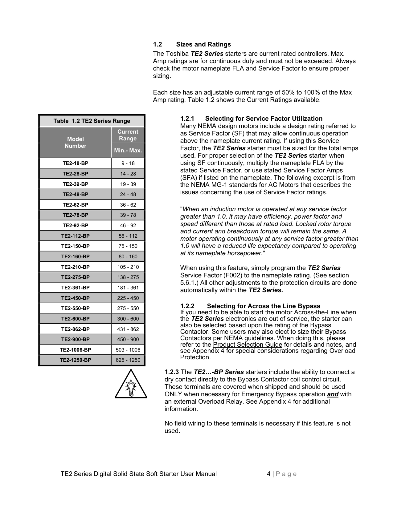
################## 1.2 Sizes and Ratings
The Toshiba TE2 Series starters are current rated controllers. Max. Amp ratings are for continuous duty and must not be exceeded. Always check the motor nameplate FLA and Service Factor to ensure proper sizing.
Each size has an adjustable current range of 50% to 100% of the Max Amp rating. Table 1.2 shows the Current Ratings available.
|Table 1.2 TE2 Series Range|Table 1.2 TE2 Series Range| |---|---| |Model Number
|Current Range
| |Model Number
|Min.- Max.| |TE2-18-BP|9 - 18| |TE2-28-BP|14 - 28| |TE2-39-BP|19 - 39| |TE2-48-BP|24 - 48| |TE2-62-BP|36 - 62| |TE2-78-BP|39 - 78| |TE2-92-BP|46 - 92| |TE2-112-BP|56 - 112| |TE2-150-BP|75 - 150| |TE2-160-BP|80 - 160| |TE2-210-BP|105 - 210| |TE2-275-BP|138 - 275| |TE2-361-BP|181 - 361| |TE2-450-BP|225 - 450| |TE2-550-BP|275 - 550| |TE2-600-BP|300 - 600| |TE2-862-BP|431 - 862| |TE2-900-BP|450 - 900| |TE2-1006-BP|503 - 1006| |TE2-1250-BP|625 - 1250|
"When an induction motor is operated at any service factor greater than 1.0, it may have efficiency, power factor and speed different than those at rated load. Locked rotor torque and current and breakdown torque will remain the same. A motor operating continuously at any service factor greater than 1.0 will have a reduced life expectancy compared to operating
When using this feature, simply program the TE2 Series Service Factor (F002) to the nameplate rating. (See section 5.6.1.) All other adjustments to the protection circuits are done automatically within the TE2 Series.
1.2.3 The TE2…-BP Series starters include the ability to connect a dry contact directly to the Bypass Contactor coil control circuit. These terminals are covered when shipped and should be used ONLY when necessary for Emergency Bypass operation and with an external Overload Relay. See Appendix 4 for additional information.
No field wiring to these terminals is necessary if this feature is not used.
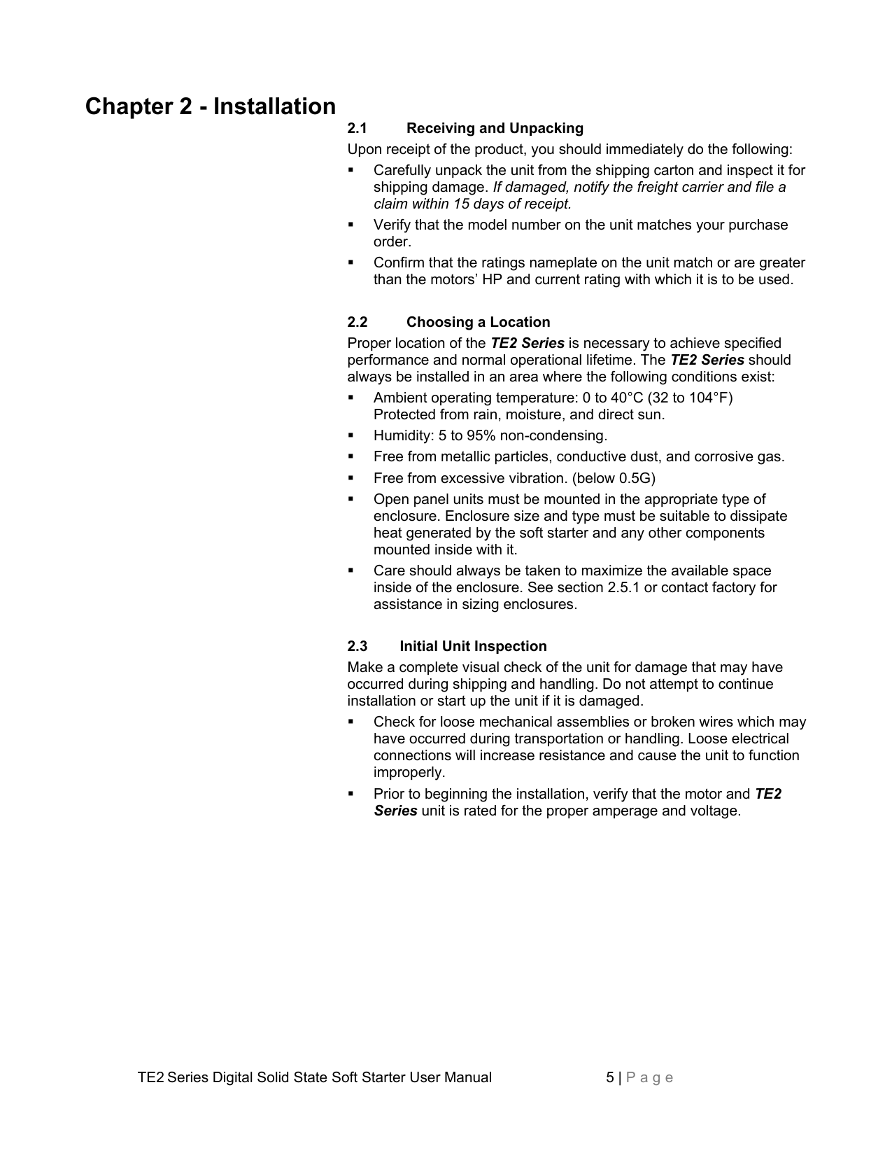
##### Chapter 2 - Installation
Proper location of the TE2 Series is necessary to achieve specified performance and normal operational lifetime. The TE2 Series should always be installed in an area where the following conditions exist:
Make a complete visual check of the unit for damage that may have occurred during shipping and handling. Do not attempt to continue installation or start up the unit if it is damaged.
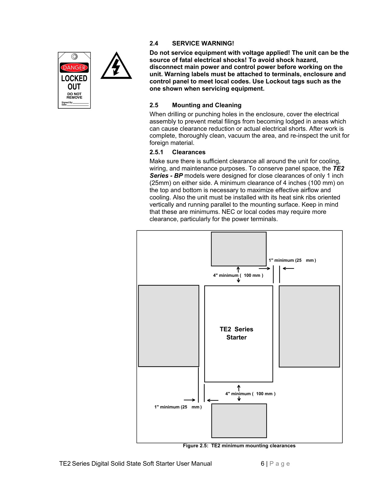
################## 2.4 SERVICE WARNING!
Do not service equipment with voltage applied! The unit can be the source of fatal electrical shocks! To avoid shock hazard, disconnect main power and control power before working on the unit. Warning labels must be attached to terminals, enclosure and control panel to meet local codes. Use Lockout tags such as the one shown when servicing equipment.
################## 2.5 Mounting and Cleaning
When drilling or punching holes in the enclosure, cover the electrical assembly to prevent metal filings from becoming lodged in areas which can cause clearance reduction or actual electrical shorts. After work is complete, thoroughly clean, vacuum the area, and re-inspect the unit for foreign material. 2.5.1 Clearances
Make sure there is sufficient clearance all around the unit for cooling, wiring, and maintenance purposes. To conserve panel space, the TE2 Series - BP models were designed for close clearances of only 1 inch (25mm) on either side. A minimum clearance of 4 inches (100 mm) on the top and bottom is necessary to maximize effective airflow and cooling. Also the unit must be installed with its heat sink ribs oriented vertically and running parallel to the mounting surface. Keep in mind that these are minimums. NEC or local codes may require more clearance, particularly for the power terminals.
1" minimum (25 mm )

4" minimum ( 100 mm )
################## TE2 Series Starter

4" minimum ( 100 mm )
1" minimum (25 mm )
Figure 2.5: TE2 minimum mounting clearances
WARNING! Remove all sources of power before cleaning the unit.
In dirty or contaminated atmospheres, the unit should be cleaned on a regular basis to ensure proper cooling. Do not use any chemicals to clean the unit. To remove surface dust, use clean, dry compressed air only, 80 to 100 psi. A three-inch, high quality, dry paintbrush is helpful to loosen up the dust prior to using compressed air on the unit. Do not use wire brushes or other conductive cleaning materials
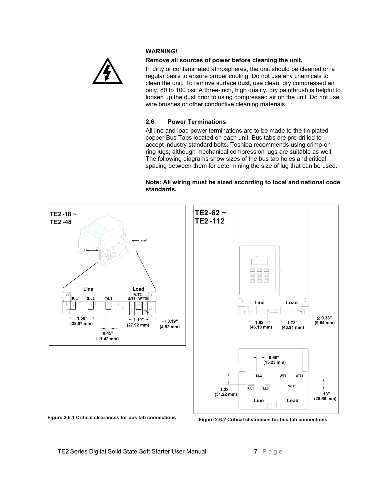
################## 2.6 Power Terminations
All line and load power terminations are to be made to the tin plated copper Bus Tabs located on each unit. Bus tabs are pre-drilled to accept industry standard bolts. Toshiba recommends using crimp-on ring lugs, although mechanical compression lugs are suitable as well. The following diagrams show sizes of the bus tab holes and critical spacing between them for determining the size of lug that can be used.
################## Note: All wiring must be sized according to local and national code standards.
############# TE2-62 ~ TE2 -112
################## TE2 -18 ~ TE2 -48
Load
Line
Line Load
V/T2 U/T1 W/T3/

R/L1 S/L2 T/L3
######################## Line Load
| | | |---|---| | | |
| | | | |---|---|---| | |1.82"| |

0.38" (9.64 mm) (46.19 mm)
1.50" (38.07 mm)
1.10" (27.92 mm)

0.19" (4.82 mm)
1.73" (43.91 mm)


0.45" (11.42 mm)
0.60" (15.23 mm)

S/L2
U/T1 W/T3
V/T2
R/L1 T/L3
1.23" (31.22 mm)
1.13" (28.68 mm)
Line Load
Figure 2.6.1 Critical clearances for bus tab connections Figure 2.6.2 Critical clearances for bus tab connections
|2.81" (71.32 mm)
0.38" (9.64 mm)
Line Load
1.54" (39.09 mm)
1.52" (38.58 mm)
T/L3 R/L1
S/L2
Line Load
U/T1
W/T3
V/T2
0.60" (15.23 mm)
0.14" (3.55 mm)
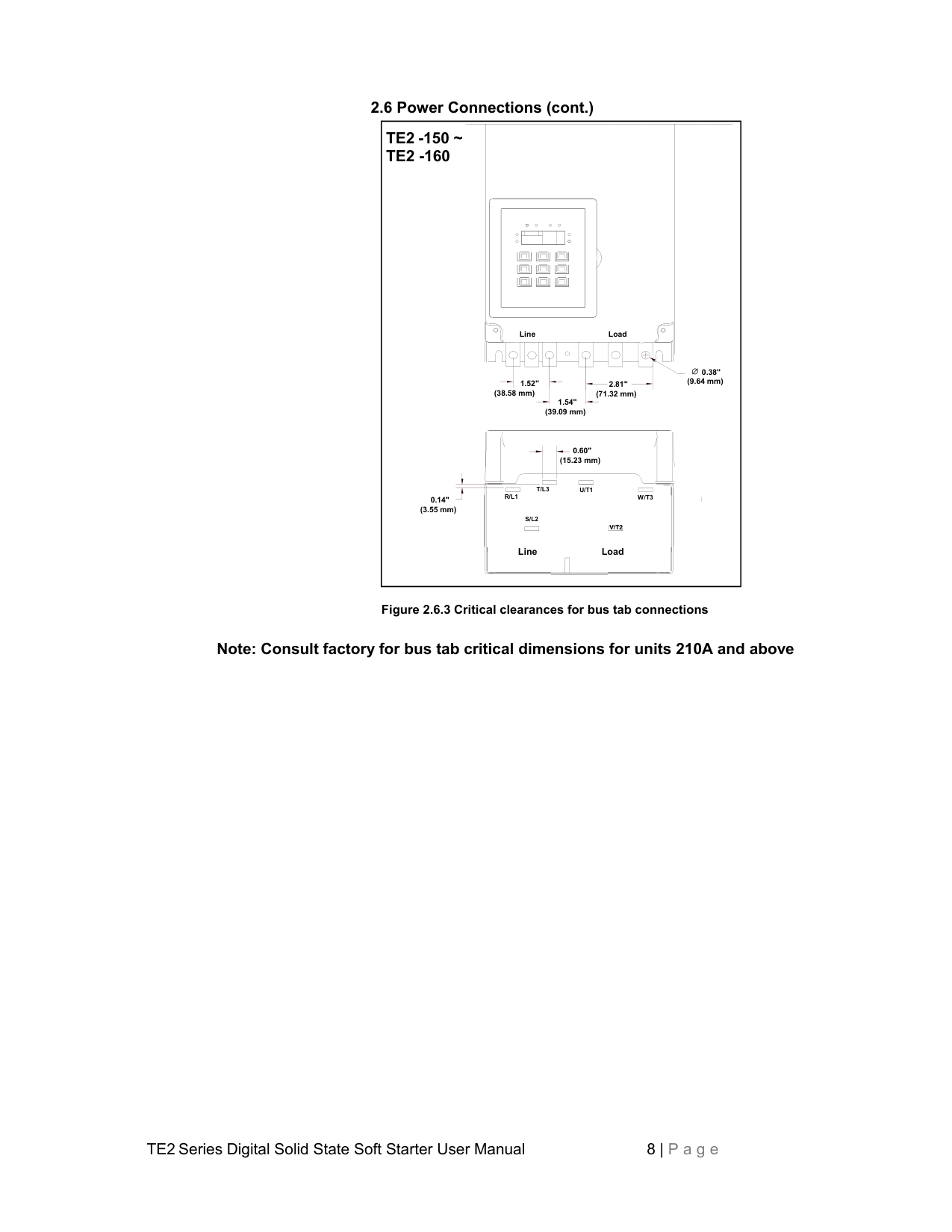
TE2 -150 ~ TE2 -160| |---|
Figure 2.6.3 Critical clearances for bus tab connections
Note: Consult factory for bus tab critical dimensions for units 210A and above
2.6.1 Power Terminals: Connection points are bus tabs with pre-drilled holes (see below). Suggested wire sizes and tightening torques for factory-supplied
connectors using conductors rated for 75C are shown in the chart below. Always consult local and national codes along with industry standard practices for proper wires sizes and terminations to accommodate voltage drop and ambient conditions.
|Table 2.6: TE2 Series Wire Ranges and Torque Specifications|Table 2.6: TE2 Series Wire Ranges and Torque Specifications|Table 2.6: TE2 Series Wire Ranges and Torque Specifications|Table 2.6: TE2 Series Wire Ranges and Torque Specifications|Table 2.6: TE2 Series Wire Ranges and Torque Specifications|Table 2.6: TE2 Series Wire Ranges and Torque Specifications|Table 2.6: TE2 Series Wire Ranges and Torque Specifications| |---|---|---|---|---|---|---| |Model Number
|Current Range Min.- Max.
|Suggested Wire Size AWG
|Tightening Torque in.-lbs.
|Screw / Bolt Size
|Tightening Torque Nm
|Suggested Wire Size ISOmm2
| |TE2-18-BP|9 - 18|10|35
|1 x M5 (included)
|4|6| |TE2-28-BP|14 - 28|8|35
|1 x M5 (included)
|4|10| |TE2-39-BP|19 - 39|8|35
|1 x M5 (included)
|4|10| |TE2-48-BP|24 - 48|6|35
|1 x M5 (included)
|4|16| |TE2-62-BP|36 - 62|4|45|1 x M8 (included)
|5|25| |TE2-78-BP|39 - 78|3|45|1 x M8 (included)
|5|35| |TE2-92-BP|46 - 92|2|45|1 x M8 (included)
|5|35| |TE2-112-BP|56 - 112|1|45|1 x M8 (included)
|5|50| |TE2-150-BP|75 - 150|2/0|80|1 x M8 (included)
|9|70| |TE2-160-BP|80 - 160|3/0|80|1 x M8 (included)
|9|95| |TE2-210-BP|105 - 210|250|200|1 x 0.38" hole (M10) for User supplied lugs
|15|150| |TE2-275-BP|138 - 275|350 kCMIL|200|1 x 0.38" hole (M10) for User supplied lugs
|15|185| |TE2-361-BP|180 - 361|2 x 300 kCMIL|200|1 x 0.38" hole (M10) for User supplied lugs
|15|2 x 150| |TE2-450-BP|225 - 450|2 x 300 kCMIL|200|1 x 0.38" hole (M10) for User supplied lugs
|15|2 x 150| |TE2-550-BP|275 - 550|2 x 400 kCMIL|200|1 x 0.38" hole (M10) for User supplied lugs
|15|2 x 240| |TE2-600-BP|300 - 600|2 x 500 kCMIL|TBD|TBD|TBD|2 x 300| |TE2-862-BP|431 - 862|3 x 400 kCMIL|TBD|TBD|TBD|3 x 240| |TE2-900-BP|450 - 900|3 x 500 kCMIL|TBD|TBD|TBD|3 x 300| |TE2-1006-BP|503 - 1006|4 x 350 kCMIL|TBD|TBD|TBD|4 x 185| |TE2-1250-BP|625 - 1250|4 x 500 kCMIL|TBD|TBD|TBD|4 x 300|
Note: TBD = To Be Determined at a later date
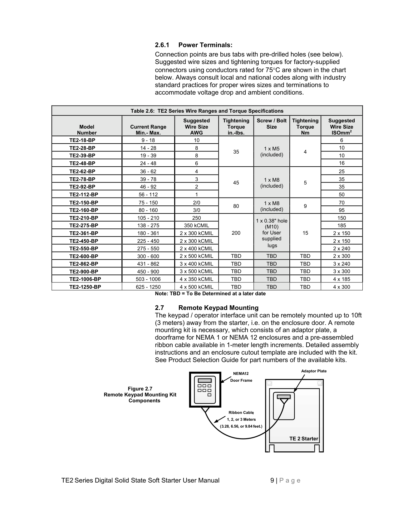
Figure 2.7 Remote Keypad Mounting Kit
Components
Adaptor Plate NEMA12
| | |---|
Door Frame
||TE 2 Starter| |---|
| |---|
Ribbon Cable, 1, 2, or 3 Meters (3.28, 6.56, or 9.84 feet.)
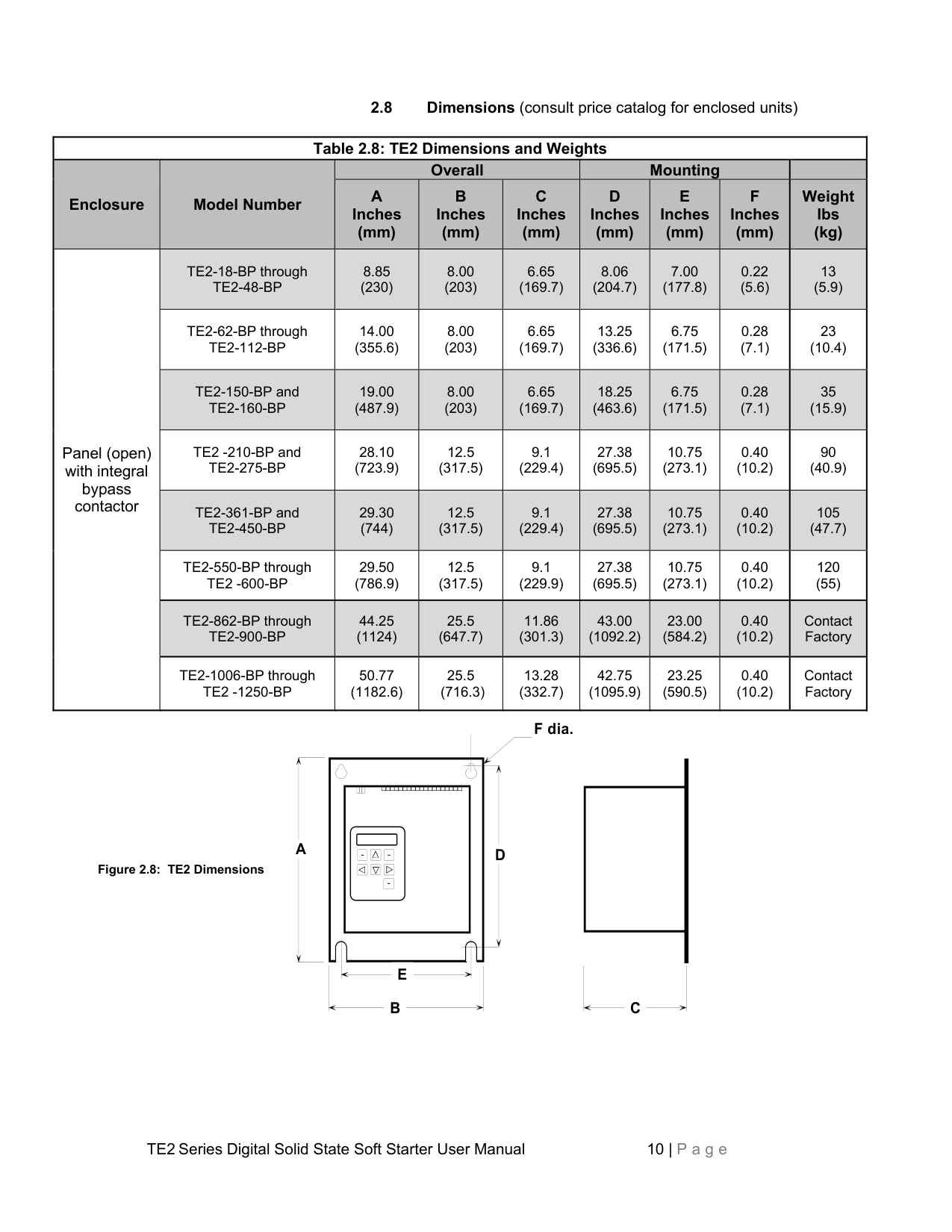
2.8 Dimensions (consult price catalog for enclosed units)
|Table 2.8: TE2 Dimensions and Weights|Table 2.8: TE2 Dimensions and Weights|Table 2.8: TE2 Dimensions and Weights|Table 2.8: TE2 Dimensions and Weights|Table 2.8: TE2 Dimensions and Weights|Table 2.8: TE2 Dimensions and Weights|Table 2.8: TE2 Dimensions and Weights|Table 2.8: TE2 Dimensions and Weights|Table 2.8: TE2 Dimensions and Weights| |---|---|---|---|---|---|---|---|---| |Enclosure|Model Number|Overall|Overall|Overall|Mounting|Mounting|Mounting| | |Enclosure|Model Number|A Inches (mm)
|B Inches (mm)
|C Inches (mm)
|D Inches (mm)
|E Inches (mm)
|F Inches (mm)
|Weight lbs (kg)
| |Panel (open) with integral bypass contactor
|TE2-18-BP through TE2-48-BP
|8.85 (230)
|8.00 (203)
|6.65 (169.7)
|8.06 (204.7)
|7.00 (177.8)
|0.22 (5.6)
|13 (5.9)
| |Panel (open) with integral bypass contactor
|TE2-62-BP through TE2-112-BP|14.00 (355.6)|8.00 (203)|6.65 (169.7)|13.25 (336.6)|6.75 (171.5)|0.28 (7.1)|23 (10.4)| |Panel (open) with integral bypass contactor
|TE2-150-BP and TE2-160-BP
|19.00 (487.9)
|8.00 (203)
|6.65 (169.7)
|18.25 (463.6)
|6.75 (171.5)
|0.28 (7.1)
|35 (15.9)
| |Panel (open) with integral bypass contactor
|TE2 -210-BP and TE2-275-BP|28.10 (723.9)|12.5 (317.5)|9.1 (229.4)|27.38 (695.5)|10.75 (273.1)|0.40 (10.2)|90 (40.9)| |Panel (open) with integral bypass contactor
|TE2-361-BP and TE2-450-BP
|29.30 (744)
|12.5 (317.5)
|9.1 (229.4)
|27.38 (695.5)
|10.75 (273.1)
|0.40 (10.2)
|105 (47.7)
| |Panel (open) with integral bypass contactor
|TE2-550-BP through TE2 -600-BP|29.50 (786.9)|12.5 (317.5)|9.1 (229.9)|27.38 (695.5)|10.75 (273.1)|0.40 (10.2)|120 (55)| |Panel (open) with integral bypass contactor
|TE2-862-BP through TE2-900-BP
|44.25 (1124)
|25.5 (647.7)
|11.86 (301.3)
|43.00 (1092.2)
|23.00 (584.2)
|0.40 (10.2)
|Contact Factory
| |Panel (open) with integral bypass contactor
|TE2-1006-BP through TE2 -1250-BP|50.77 (1182.6)|25.5 (716.3)|13.28 (332.7)|42.75 (1095.9)|23.25 (590.5)|0.40 (10.2)|Contact Factory|
Figure 2.8: TE2 Dimensions
Fdia.
| | | | |---|---|---|
| | | | | | | | | | | | | | | | | | | | |---|---|---|---|---|---|---|---|---|---|---|---|---|---|---|---|---|---|---|
A
D
~ ~
~
E B
C
##### Chapter 3 - Motor Overload Protection
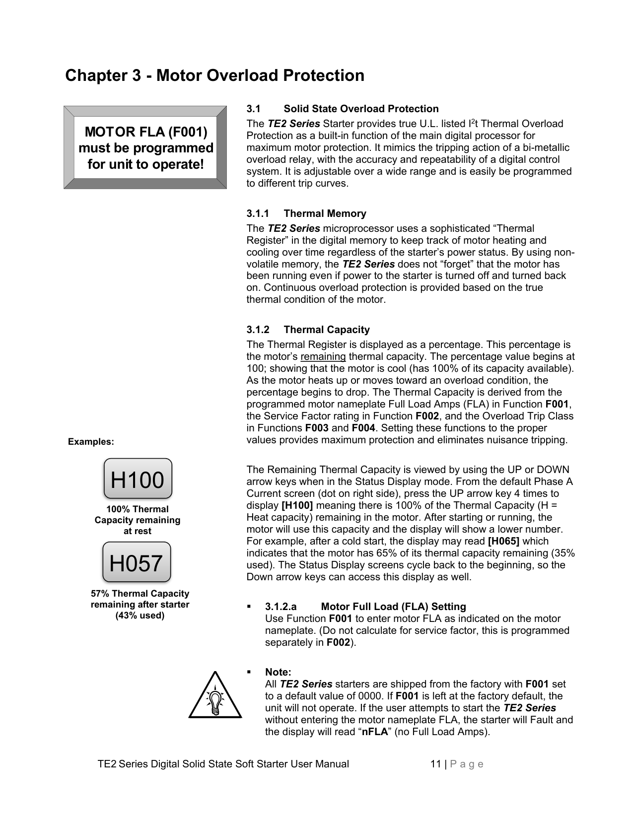
||MOTOR FLA (F001) must be programmed for unit to operate!| |---| | |---|
3.1 Solid State Overload Protection The TE2 Series Starter provides true U.L. listed I2t Thermal Overload Protection as a built-in function of the main digital processor for maximum motor protection. It mimics the tripping action of a bi-metallic overload relay, with the accuracy and repeatability of a digital control system. It is adjustable over a wide range and is easily be programmed to different trip curves.
Examples:


H100
100% Thermal Capacity remaining at rest


H057
57% Thermal Capacity remaining after starter (43% used)
################## 3.1.1 Thermal Memory
The TE2 Series microprocessor uses a sophisticated “Thermal Register” in the digital memory to keep track of motor heating and cooling over time regardless of the starter’s power status. By using nonvolatile memory, the TE2 Series does not “forget” that the motor has been running even if power to the starter is turned off and turned back on. Continuous overload protection is provided based on the true thermal condition of the motor.
################## 3.1.2 Thermal Capacity
The Thermal Register is displayed as a percentage. This percentage is the motor’s remaining thermal capacity. The percentage value begins at 100; showing that the motor is cool (has 100% of its capacity available). As the motor heats up or moves toward an overload condition, the percentage begins to drop. The Thermal Capacity is derived from the programmed motor nameplate Full Load Amps (FLA) in Function F001, the Service Factor rating in Function F002, and the Overload Trip Class in Functions F003 and F004. Setting these functions to the proper values provides maximum protection and eliminates nuisance tripping.
The Remaining Thermal Capacity is viewed by using the UP or DOWN arrow keys when in the Status Display mode. From the default Phase A Current screen (dot on right side), press the UP arrow key 4 times to display [H100] meaning there is 100% of the Thermal Capacity (H = Heat capacity) remaining in the motor. After starting or running, the motor will use this capacity and the display will show a lower number. For example, after a cold start, the display may read [H065] which indicates that the motor has 65% of its thermal capacity remaining (35% used). The Status Display screens cycle back to the beginning, so the Down arrow keys can access this display as well.
3.1.3 Disabling the Overload Protection The Overload Protection feature can be disabled if necessary. When using external devices such as Motor Protection Relays or when the TE2 Series is wired downstream from an existing starter, this feature can be disabled to prevent conflicts with external Overload Protection devices. When the TE2 Series is controlling multiple motors, the built-in Overload Protection must be disabled and individual thermal overload relays must be installed on the motor leads going to each motor (see Appendix 4 for additional details). To disable the Overload Protection function, use F005.
WARNING! Do NOT disable Overload Protection unless another Thermal Overload Protection device exists in the circuit for all three phases. Running a motor without Overload Protection presents serious risk of motor damage or fire.
WARNING! Two-wire control systems may restart without warning when Auto Reset of the Overload Protection is selected. Extreme caution should be exercised. To prevent automatic restarting with 2-wire control systems, use external interlocking to provide sufficient warning and safety to operators. A Warning Label similar to that shown below (and the one provided in the packet with this manual) must be located where visible (on the starter enclosure and/or the driven equipment) as required by local code.
############ WARNING: MOTOR CONNECTED TO THIS EQUIPMENT MAY START AUTOMATICALLY WITHOUT WARNING
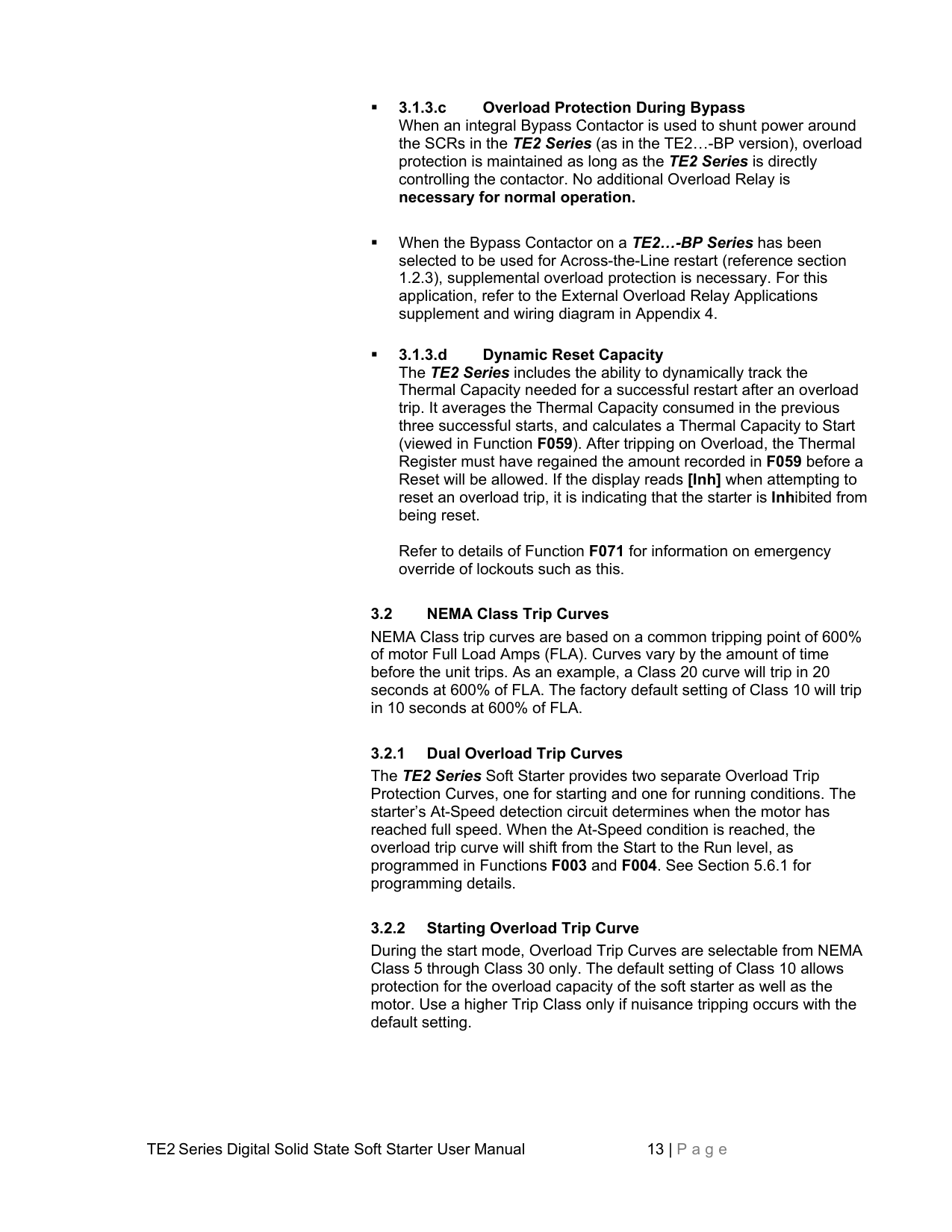
Refer to details of Function F071 for information on emergency override of lockouts such as this.
3.2 NEMA Class Trip Curves NEMA Class trip curves are based on a common tripping point of 600% of motor Full Load Amps (FLA). Curves vary by the amount of time before the unit trips. As an example, a Class 20 curve will trip in 20 seconds at 600% of FLA. The factory default setting of Class 10 will trip in 10 seconds at 600% of FLA.
################## 3.2.1 Dual Overload Trip Curves
The TE2 Series Soft Starter provides two separate Overload Trip Protection Curves, one for starting and one for running conditions. The starter’s At-Speed detection circuit determines when the motor has reached full speed. When the At-Speed condition is reached, the overload trip curve will shift from the Start to the Run level, as programmed in Functions F003 and F004. See Section 5.6.1 for programming details.
################## 3.2.2 Starting Overload Trip Curve
During the start mode, Overload Trip Curves are selectable from NEMA Class 5 through Class 30 only. The default setting of Class 10 allows protection for the overload capacity of the soft starter as well as the motor. Use a higher Trip Class only if nuisance tripping occurs with the default setting.
During the Run mode, Overload Trip curves are selectable from NEMA Class 5, 10, 15, 20, 25, and 30. Program the appropriate curve according to the characteristics of your motor and load.

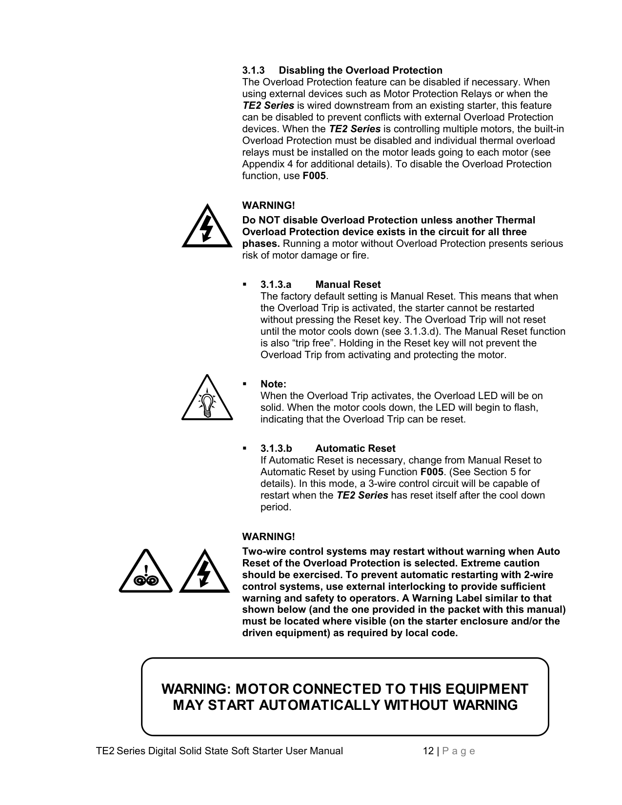


Figure 3.2.4: TE2 Series Overload Trip Curves
##### Chapter 4 - Connections
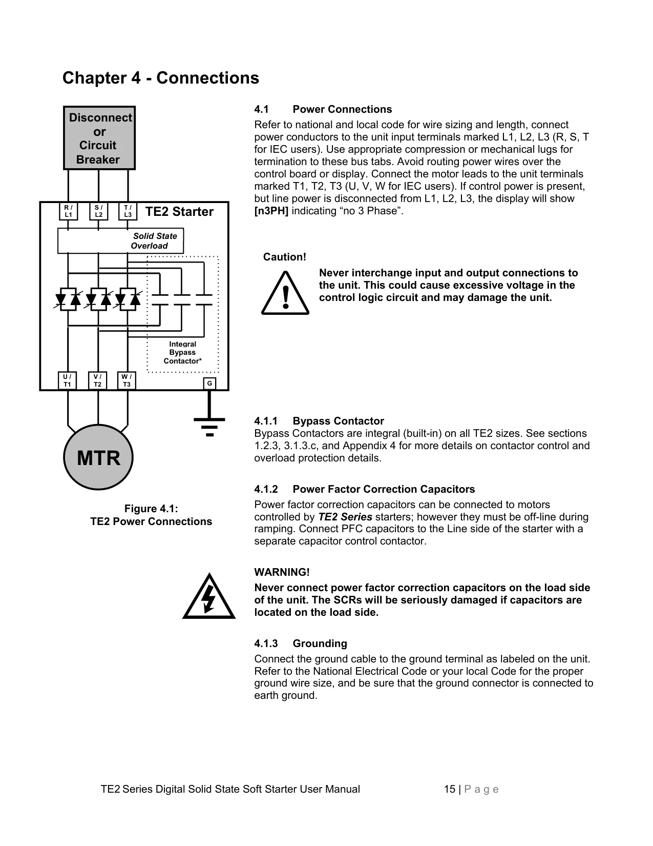
4.1 Power Connections Refer to national and local code for wire sizing and length, connect power conductors to the unit input terminals marked L1, L2, L3 (R, S, T for IEC users). Use appropriate compression or mechanical lugs for termination to these bus tabs. Avoid routing power wires over the control board or display. Connect the motor leads to the unit terminals marked T1, T2, T3 (U, V, W for IEC users). If control power is present, but line power is disconnected from L1, L2, L3, the display will show [n3PH] indicating “no 3 Phase”.

Disconnect or Circuit Breaker


R / L1
S / L2
T / L3
TE2 Starter

Solid State Overload
Caution!
Never interchange input and output connections to the unit. This could cause excessive voltage in the control logic circuit and may damage the unit.
Integral Bypass Contactor*


U / T1
V / T2
W / T3
G
Power factor correction capacitors can be connected to motors controlled by TE2 Series starters; however they must be off-line during ramping. Connect PFC capacitors to the Line side of the starter with a separate capacitor control contactor.
WARNING! Never connect power factor correction capacitors on the load side of the unit. The SCRs will be seriously damaged if capacitors are located on the load side.

MTR
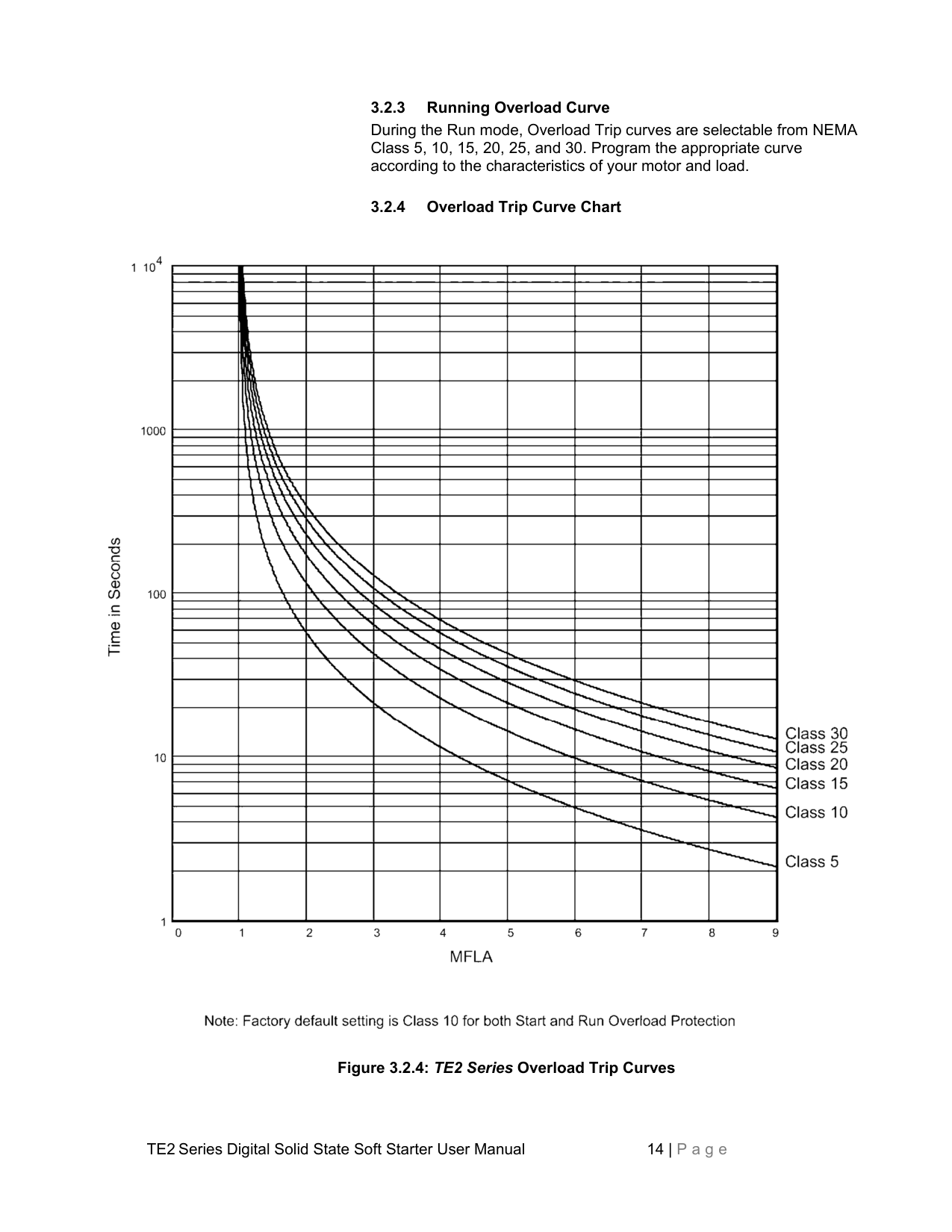
Figure 4.1: TE2 Power Connections
Connect the ground cable to the ground terminal as labeled on the unit. Refer to the National Electrical Code or your local Code for the proper ground wire size, and be sure that the ground connector is connected to earth ground.
################## 4.1.4 Testing
The TE2 Series can be tested with a load smaller than the motor it was originally selected to control, however additional steps must be taken to avoid tripping on Phase Current Loss. See section 5.6.8.a under “Phase Loss Protection” for additional details on performing this task.
################## 4.1.5 Lightning Protection
As with all electronic power controllers, protection from damage by lightning surges is recommended in areas where lightning is a significant problem. Stationary SPDs (Surge Protection Device) should be considered and utilized on the input power source. The best method of protection is to have an Isolation Contactor in front of the starter that is open when the soft starter is not in use. Enclosed versions may be provided with a surge protection device.
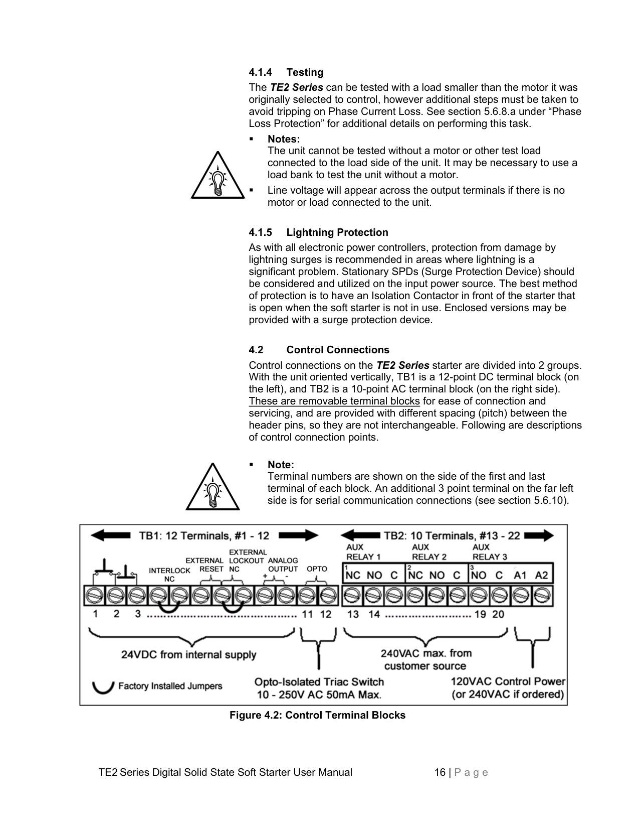
4.2 Control Connections Control connections on the TE2 Series starter are divided into 2 groups. With the unit oriented vertically, TB1 is a 12-point DC terminal block (on the left), and TB2 is a 10-point AC terminal block (on the right side). These are removable terminal blocks for ease of connection and servicing, and are provided with different spacing (pitch) between the header pins, so they are not interchangeable. Following are descriptions of control connection points.
Note: Terminal numbers are shown on the side of the first and last terminal of each block. An additional 3 point terminal on the far left side is for serial communication connections (see section 5.6.10).

################## Figure 4.2: Control Terminal Blocks
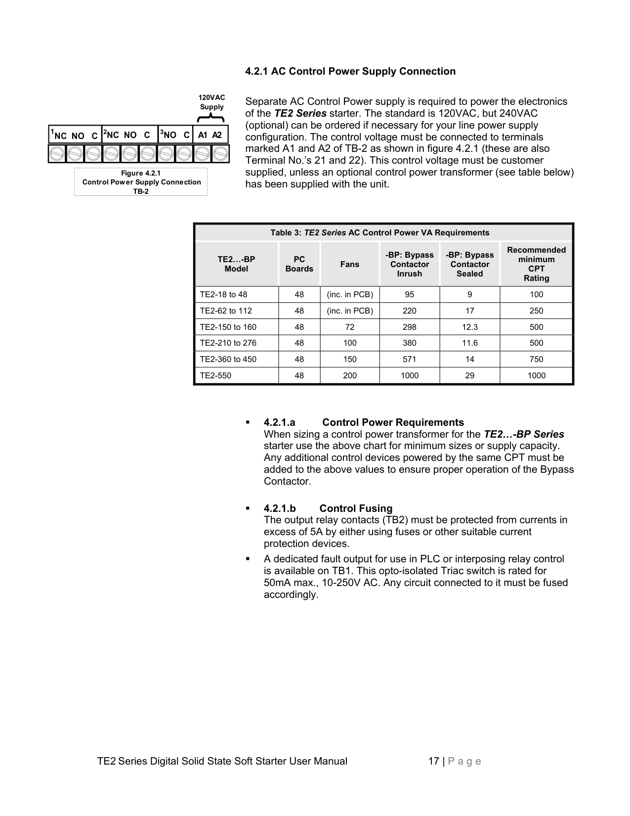
################## 4.2.1 AC Control Power Supply Connection
120VAC Supply
|1NC NO C|2NC NO C|3NO C|A1 A2|A1 A2| |---|---|---|---|---| | | | | | |
|Figure 4.2.1 Control Power Supply Connection TB-2| |---|
Separate AC Control Power supply is required to power the electronics of the TE2 Series starter. The standard is 120VAC, but 240VAC (optional) can be ordered if necessary for your line power supply configuration. The control voltage must be connected to terminals marked A1 and A2 of TB-2 as shown in figure 4.2.1 (these are also Terminal No.’s 21 and 22). This control voltage must be customer supplied, unless an optional control power transformer (see table below) has been supplied with the unit.
|Table 3: TE2 Series AC Control Power VA Requirements|Table 3: TE2 Series AC Control Power VA Requirements|Table 3: TE2 Series AC Control Power VA Requirements|Table 3: TE2 Series AC Control Power VA Requirements|Table 3: TE2 Series AC Control Power VA Requirements|Table 3: TE2 Series AC Control Power VA Requirements| |---|---|---|---|---|---| |TE2…-BP Model
|PC Boards
|Fans|-BP: Bypass Contactor Inrush
|-BP: Bypass Contactor Sealed
|Recommended minimum CPT Rating
| |TE2-18 to 48|48|(inc. in PCB)|95|9|100| |TE2-62 to 112|48|(inc. in PCB)|220|17|250| |TE2-150 to 160|48|72|298|12.3|500| |TE2-210 to 276|48|100|380|11.6|500| |TE2-360 to 450|48|150|571|14|750| |TE2-550|48|200|1000|29|1000|
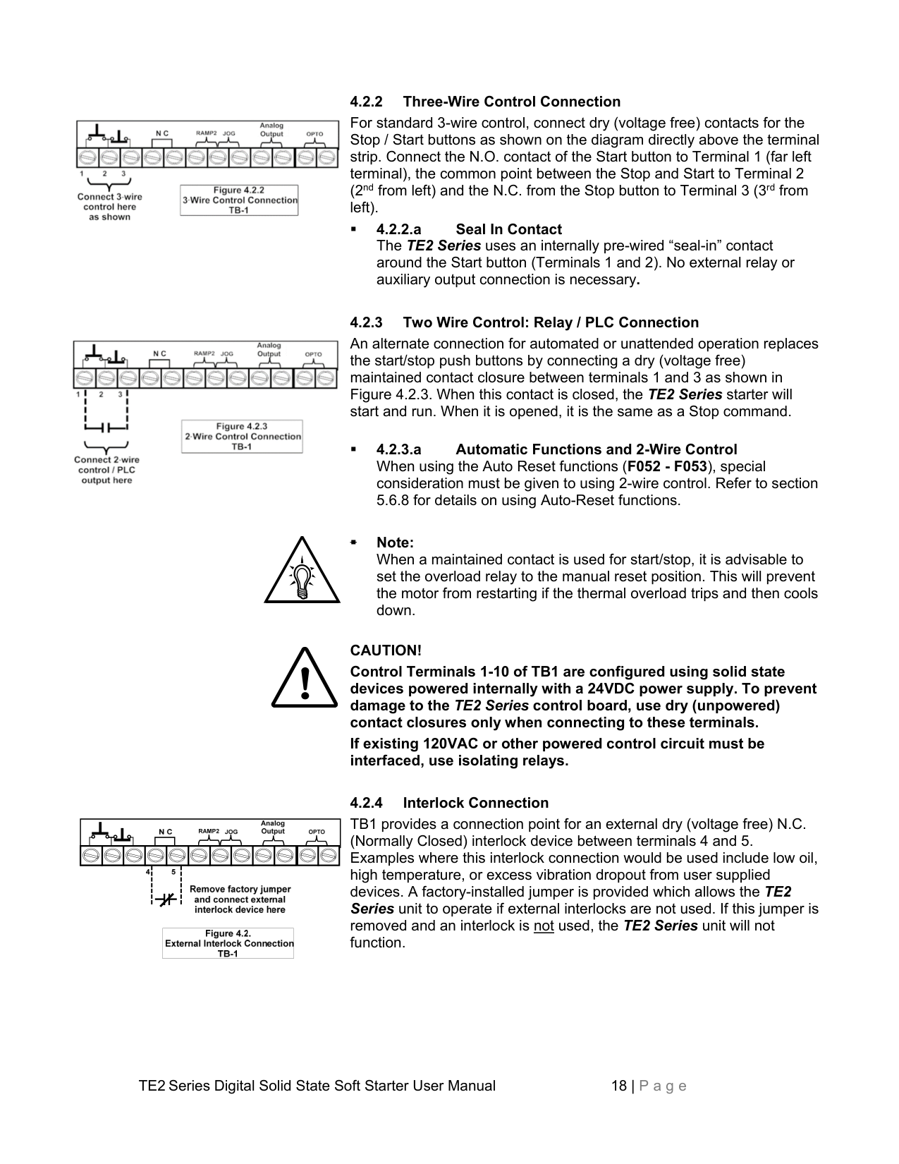
4.2.2 Three-Wire Control Connection For standard 3-wire control, connect dry (voltage free) contacts for the Stop / Start buttons as shown on the diagram directly above the terminal strip. Connect the N.O. contact of the Start button to Terminal 1 (far left terminal), the common point between the Stop and Start to Terminal 2 (2nd from left) and the N.C. from the Stop button to Terminal 3 (3rd from left).

4.2.3 Two Wire Control: Relay / PLC Connection An alternate connection for automated or unattended operation replaces the start/stop push buttons by connecting a dry (voltage free) maintained contact closure between terminals 1 and 3 as shown in Figure 4.2.3. When this contact is closed, the TE2 Series starter will start and run. When it is opened, it is the same as a Stop command.
Note:
When a maintained contact is used for start/stop, it is advisable to set the overload relay to the manual reset position. This will prevent the motor from restarting if the thermal overload trips and then cools down.
CAUTION! Control Terminals 1-10 of TB1 are configured using solid state devices powered internally with a 24VDC power supply. To prevent damage to the TE2 Series control board, use dry (unpowered) contact closures only when connecting to these terminals. If existing 120VAC or other powered control circuit must be interfaced, use isolating relays.

TB1 provides a connection point for an external dry (voltage free) N.C. (Normally Closed) interlock device between terminals 4 and 5. Examples where this interlock connection would be used include low oil, high temperature, or excess vibration dropout from user supplied devices. A factory-installed jumper is provided which allows the TE2 Series unit to operate if external interlocks are not used. If this jumper is removed and an interlock is not used, the TE2 Series unit will not function.


|


| |---|

4.2.5 Enabling the Dual Ramp and Jog Features TB1 includes provisions for enabling the Dual Ramp and Jog functions by using external contact closures. Both features use a common
+24VDC from Terminal 7. However, they can be used independently of each other or together. See sections 5.6.2 and 5.6.3 for full function descriptions and setup.
The Dual Ramp feature is useful in instances where the load changes significantly. Example: a loaded or unloaded conveyor belt. The characteristics for starting an unloaded conveyor can be programmed for Ramp 1. The characteristics for starting a loaded conveyor can be programmed for Ramp 2. Ramp 2 can also be programmed for Full Voltage / Across-the-Line starting by setting the ramp time to 0 and Current to 600%.
Dual Ramp is also useful in 2-speed motor applications. Simply use an auxiliary contact from one of the speed contactors to select Ramp 2 so that separate ramp profiles can be used.
Dual Ramp input can also be configured as a “Remote reset” (See parameter F113 and associated table)
The Jog feature can be used for tasks such as lining up machines for blade or bit changes, or inching belts along to check tracking.
This input is also used to change the function of the Serial Communications port control through F068. For additional information, see instructions of that function in section 5.6.11.
Jog input can be also configured as:


|


| |---|


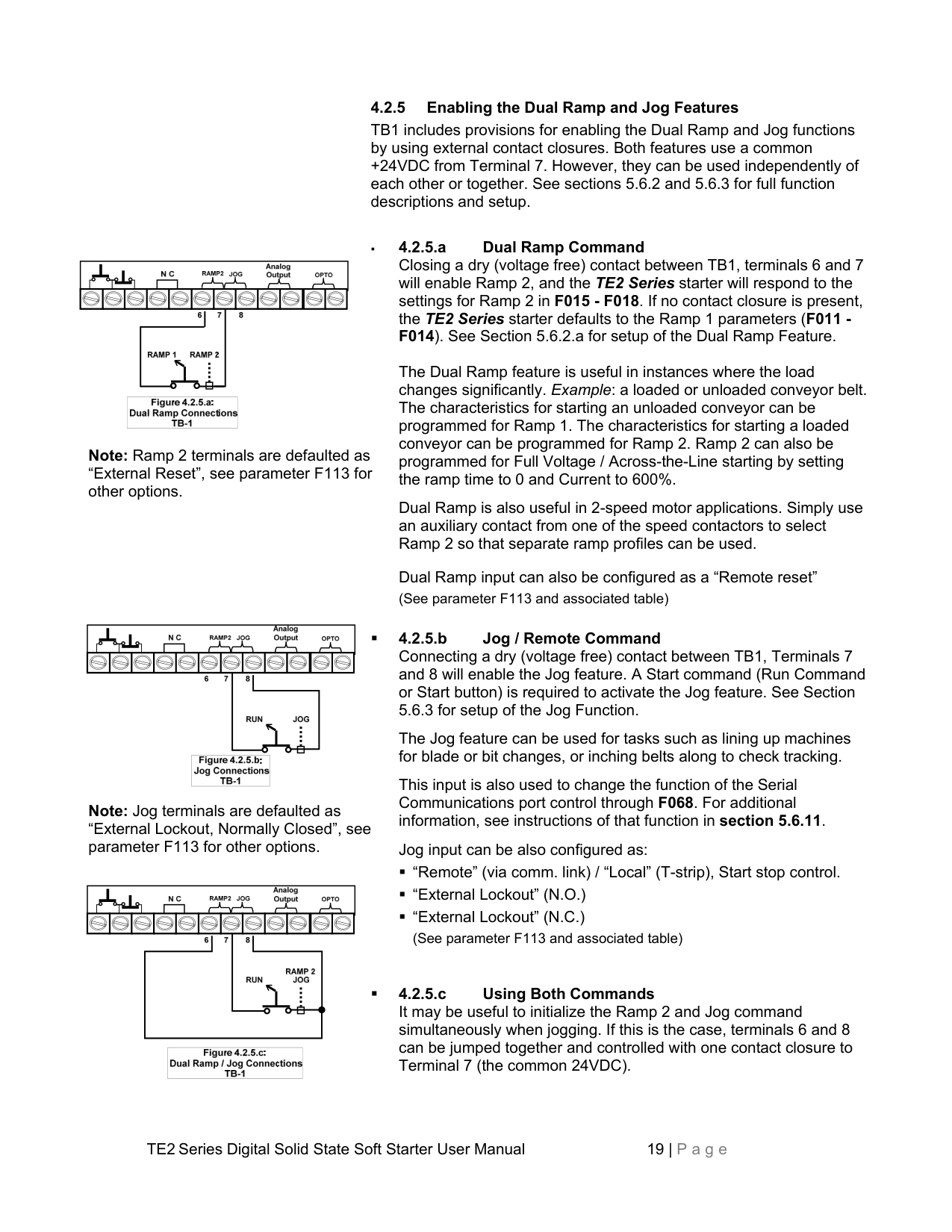

Note: Ramp 2 terminals are defaulted as “External Reset”, see parameter F113 for other options.


|


| |---|


Note: Jog terminals are defaulted as “External Lockout, Normally Closed”, see parameter F113 for other options.


||| |---|---| |
|
|
|


| |---|


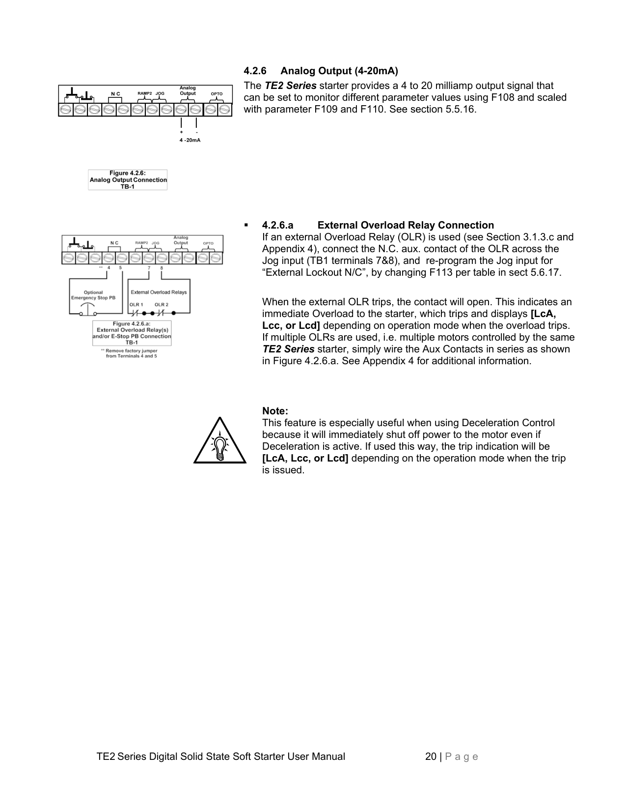
################## 4.2.6 Analog Output (4-20mA)
The TE2 Series starter provides a 4 to 20 milliamp output signal that can be set to monitor different parameter values using F108 and scaled with parameter F109 and F110. See section 5.5.16.


|


| |---|

4.2.6.a External Overload Relay Connection If an external Overload Relay (OLR) is used (see Section 3.1.3.c and Appendix 4), connect the N.C. aux. contact of the OLR across the Jog input (TB1 terminals 7&8), and re-program the Jog input for “External Lockout N/C”, by changing F113 per table in sect 5.6.17.

When the external OLR trips, the contact will open. This indicates an immediate Overload to the starter, which trips and displays [LcA, Lcc, or Lcd] depending on operation mode when the overload trips. If multiple OLRs are used, i.e. multiple motors controlled by the same TE2 Series starter, simply wire the Aux Contacts in series as shown in Figure 4.2.6.a. See Appendix 4 for additional information.
Note: This feature is especially useful when using Deceleration Control because it will immediately shut off power to the motor even if Deceleration is active. If used this way, the trip indication will be [LcA, Lcc, or Lcd] depending on the operation mode when the trip is issued.


|


| |---|


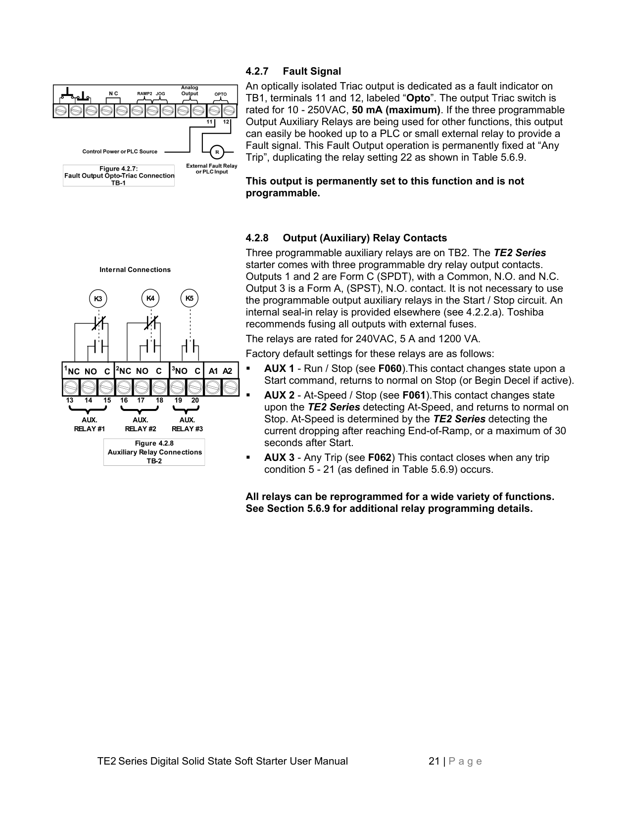
################## 4.2.7 Fault Signal
An optically isolated Triac output is dedicated as a fault indicator on TB1, terminals 11 and 12, labeled “Opto”. The output Triac switch is rated for 10 - 250VAC, 50 mA (maximum). If the three programmable Output Auxiliary Relays are being used for other functions, this output can easily be hooked up to a PLC or small external relay to provide a Fault signal. This Fault Output operation is permanently fixed at “Any Trip”, duplicating the relay setting 22 as shown in Table 5.6.9.
This output is permanently set to this function and is not programmable.
Internal Connections
K5K4
K3
1NC NO C A1 A22NC NOC3NOC
13 14 15 16 17 18 19 20
AUX. RELAY #2
AUX. RELAY #3
AUX. RELAY #1
|Figure 4.2.8 Auxiliary Relay Connections TB-2| |---|
################## 4.2.8 Output (Auxiliary) Relay Contacts
Three programmable auxiliary relays are on TB2. The TE2 Series starter comes with three programmable dry relay output contacts. Outputs 1 and 2 are Form C (SPDT), with a Common, N.O. and N.C. Output 3 is a Form A, (SPST), N.O. contact. It is not necessary to use the programmable output auxiliary relays in the Start / Stop circuit. An internal seal-in relay is provided elsewhere (see 4.2.2.a). Toshiba recommends fusing all outputs with external fuses. The relays are rated for 240VAC, 5 A and 1200 VA. Factory default settings for these relays are as follows:
All relays can be reprogrammed for a wide variety of functions. See Section 5.6.9 for additional relay programming details.
4.2.9 Bypass Contactor Control On TE2…-BP version (and NEMA 12 enclosures) starters, an internal dedicated connection is used at the factory for automatically controlling the Bypass Contactor. Field wiring for Bypass Contactor operation is not required.
4.2.9.a Independent Bypass Contactor Control The TE2…-BP Series starters use standard industrial contactors that can be controlled independently of the starter electronics if necessary. When doing so, it is necessary to size the starter based upon the ATL (Across-the-Line) selection chart so that the contactors are rated for ATL duty instead of normal Shunt Duty. Supplemental overload protection will be required (see section 3.1.3.c).
Units have external terminal blocks marked for this purpose (see Appendix 4 for drawings). A dry (voltage free) contact closure between these terminals will close the bypass contactor immediately. The Bypass Contactor coil voltage is the same as the control voltage (120VAC unless the optional 240VAC control is specified), and the voltage on these terminals is the same as the coil voltage.
################## No field wiring is necessary to these terminals if this feature is not used.
For all other styles of TE2 Series, the At-Speed signaling can be programmed into any of the three Output relays (section 4.2.8 and Table 5.6.9).
##### Chapter 5 - Programming
||MOTOR FLA (F001) must be programmed for unit to operate!| |---| |
|---|

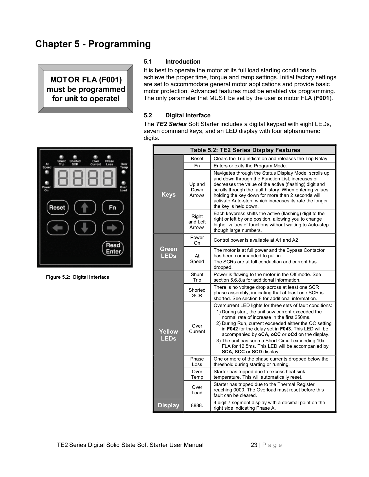
Figure 5.2: Digital Interface
################## 5.1 Introduction
It is best to operate the motor at its full load starting conditions to achieve the proper time, torque and ramp settings. Initial factory settings are set to accommodate general motor applications and provide basic motor protection. Advanced features must be enabled via programming. The only parameter that MUST be set by the user is motor FLA (F001).
################## 5.2 Digital Interface
The TE2 Series Soft Starter includes a digital keypad with eight LEDs, seven command keys, and an LED display with four alphanumeric digits.
|Table 5.2: TE2 Series Display Features|Table 5.2: TE2 Series Display Features|Table 5.2: TE2 Series Display Features| |---|---|---| |Keys
|Reset|Clears the Trip indication and releases the Trip Relay.| |Keys
|Fn|Enters or exits the Program Mode.| |Keys
|Up and Down Arrows|Navigates through the Status Display Mode, scrolls up and down through the Function List, increases or decreases the value of the active (flashing) digit and scrolls through the fault history. When entering values, holding the key down for more than 2 seconds will activate Auto-step, which increases its rate the longer the key is held down.| |Keys
|Right and Left Arrows|Each keypress shifts the active (flashing) digit to the right or left by one position, allowing you to change higher values of functions without waiting to Auto-step though large numbers.| |Green LEDs
|Power On|Control power is available at A1 and A2| |Green LEDs
|At Speed|The motor is at full power and the Bypass Contactor has been commanded to pull in. The SCRs are at full conduction and current has dropped.| |Yellow LEDs
|Shunt Trip|Power is flowing to the motor in the Off mode. See section 5.6.8.a for additional information.| |Yellow LEDs
|Shorted SCR|There is no voltage drop across at least one SCR phase assembly, indicating that at least one SCR is shorted. See section 8 for additional information.| |Yellow LEDs
|Over Current|Overcurrent LED lights for three sets of fault conditions:
1) During start, the unit saw current exceeded the normal rate of increase in the first 250ms.
2) During Run, current exceeded either the OC setting in F042 for the delay set in F043. This LED will be accompanied by oCA, oCC or oCd on the display.
3) The unit has seen a Short Circuit exceeding 10x FLA for 12.5ms. This LED will be accompanied by SCA, SCC or SCD display.
| |Yellow LEDs
|Phase Loss|One or more of the phase currents dropped below the threshold during starting or running.| |Yellow LEDs
|Over Temp|Starter has tripped due to excess heat sink temperature. This will automatically reset.| |Yellow LEDs
|Over Load|Starter has tripped due to the Thermal Register reaching 0000. The Overload must reset before this fault can be cleared.| |Display|8888.|4 digit 7 segment display with a decimal point on the right side indicating Phase A.|
5.3 Display Modes There are three modes of display: The Status Display Mode, the Program Mode, and the Fault Mode.
5.3.1 Status Display Mode (Default Display) The Status Display Mode displays five “screens” of information. Motor Currents (3 phases), Remaining Thermal Capacity and Ground Current. This is also the entry screen for going into the Program Mode. Status mode: [0000.] The initial display on power up is four digits and the decimal. This indicates the motor current for Phase A of the motor. [0000] Scroll UP to display four digits only (no decimal). This indicates the motor current for Phase B. While viewing Phase B, press the UP arrow again to view Phase C current.
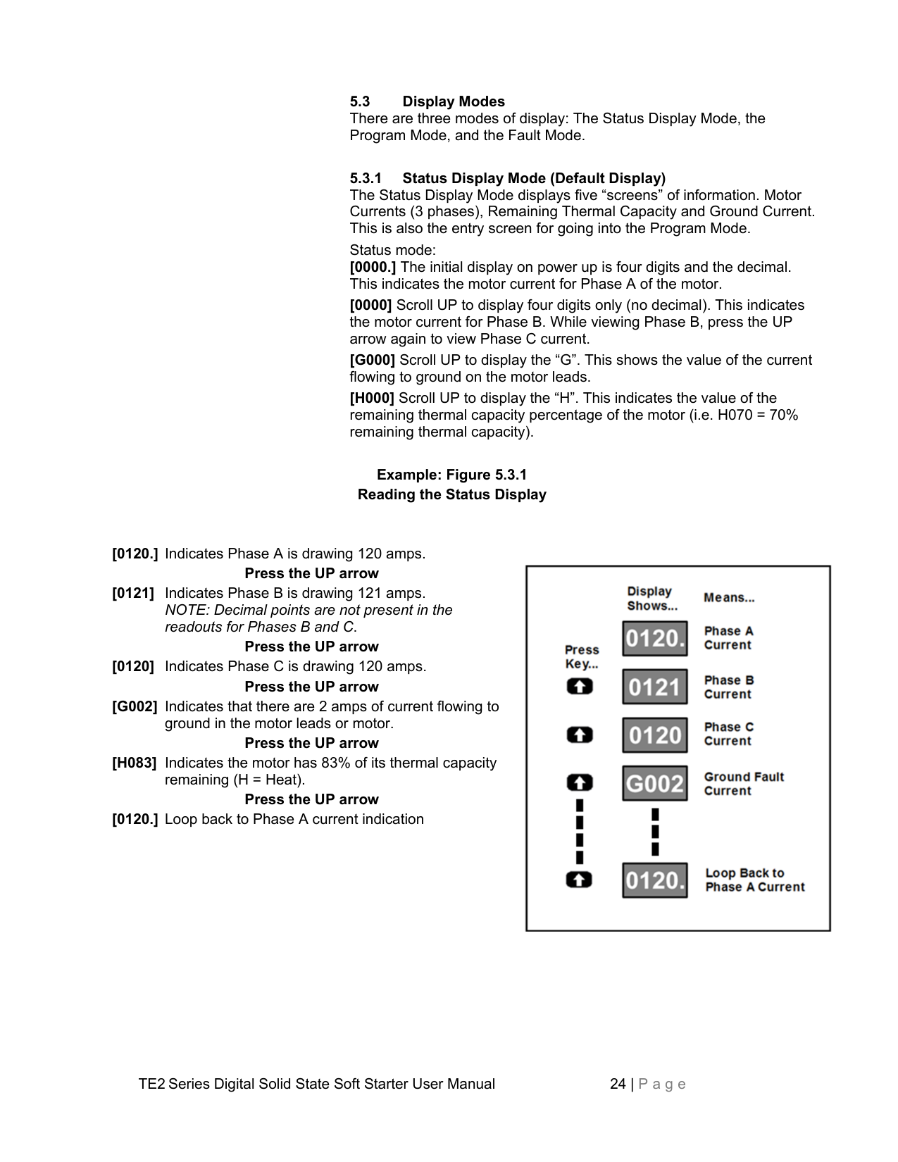
################## Example: Figure 5.3.1 Reading the Status Display
Press the UP arrow [0120] Indicates Phase C is drawing 120 amps. Press the UP arrow
Press the UP arrow
Press the UP arrow [0120.] Loop back to Phase A current indication

5.4 Program Mode The starter must be OFF (Motor Stopped) in order to enter the Program Mode. Use the Program Mode to view or change Function (Fn) settings. To enter the Program Mode, press the [Fn] key once from the Status Screen described in 5.3.1 above. The first time you enter the Program Mode after power has been cycled to the starter, the initial function [F001] should be displayed with the selected digit flashing. If the TE2 Series starter has been programmed and power to the unit has not
been cycled, the readout will display the last function viewed or changed. To change to a different function, use the arrow keys. 5.4.1 Viewing Function Programming and Values
While in the RUN Mode, the programming of each individual function and metering values can be viewed, but no changes are allowed. Each Function is signified by the letter "F" at the beginning of the data. The 4digit value of the function follows after pushing the (READ/ENTER) key.
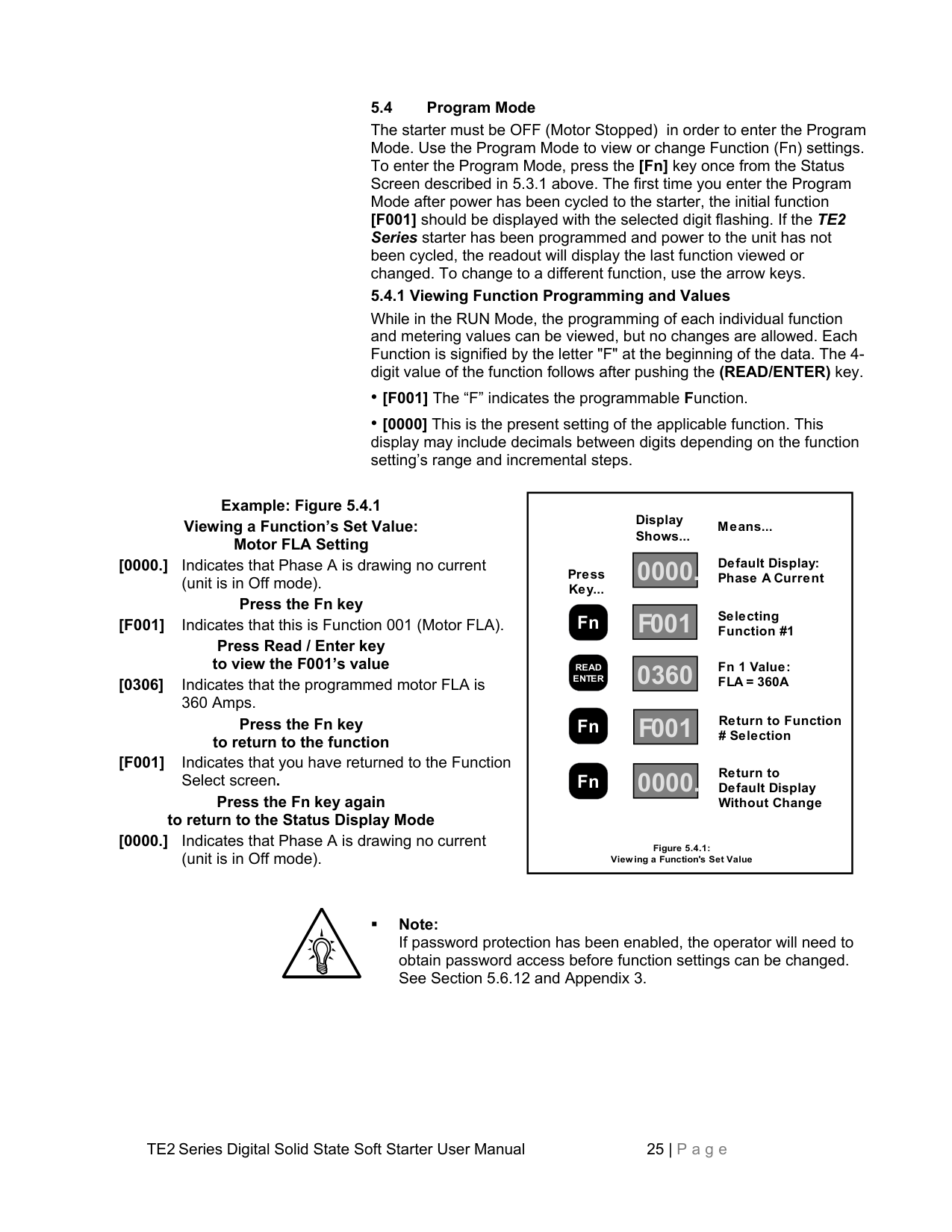
Example: Figure 5.4.1 Viewing a Function’s Set Value: Motor FLA Setting [0000.] Indicates that Phase A is drawing no current
(unit is in Off mode).
Press the Fn key [F001] Indicates that this is Function 001 (Motor FLA).
Press Read / Enter key to view the F001’s value [0306] Indicates that the programmed motor FLA is
360 Amps.
Press the Fn key to return to the function
[F001] Indicates that you have returned to the Function
Select screen.
Press the Fn key again to return to the Status Display Mode [0000.] Indicates that Phase A is drawing no current
(unit is in Off mode).
Display
Means...
Shows...
Default Display: Phase A Current
#### 0000. F001 0360
Press Key...
Selecting Function #1
Fn
Fn 1 Value: FLA = 360A
READ ENTER
Return to Function
SelectionF001
Fn
Return to Default Display Without Change
#### 0000.
Fn
Figure 5.4.1: Viewing a Function's Set Value
Note: If password protection has been enabled, the operator will need to obtain password access before function settings can be changed. See Section 5.6.12 and Appendix 3.
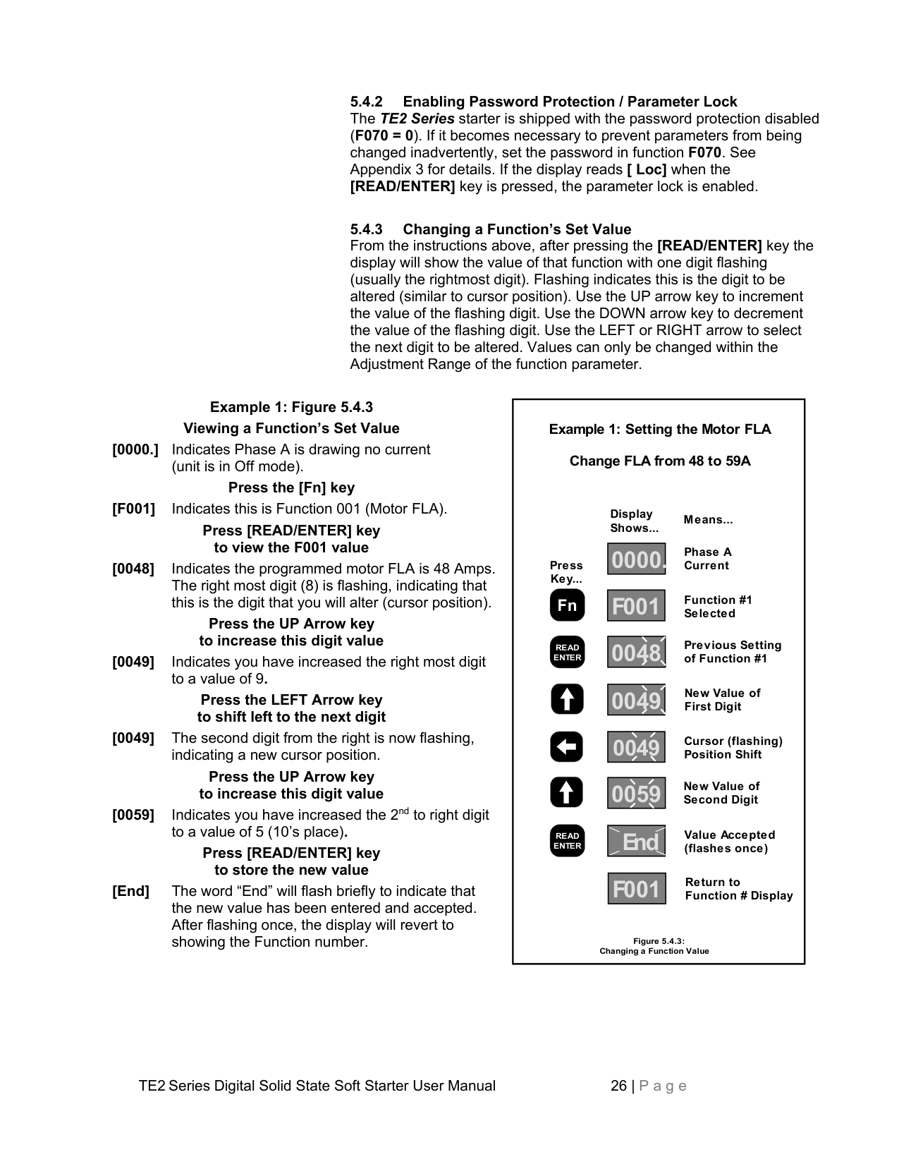
Example 1: Figure 5.4.3 Viewing a Function’s Set Value
[0000.] Indicates Phase A is drawing no current
(unit is in Off mode).
Press the [Fn] key [F001] Indicates this is Function 001 (Motor FLA).
Press [READ/ENTER] key to view the F001 value
Press the UP Arrow key to increase this digit value
Press the LEFT Arrow key to shift left to the next digit [0049] The second digit from the right is now flashing,
indicating a new cursor position.
Press the UP Arrow key to increase this digit value
[0059] Indicates you have increased the 2nd to right digit
to a value of 5 (10’s place).
Press [READ/ENTER] key to store the new value
[End] The word “End” will flash briefly to indicate that the new value has been entered and accepted. After flashing once, the display will revert to showing the Function number.
|Display
Press Key...
Shows...
Means...
Phase A Current
Function #1 Selected
Previous Setting of Function #1
New Value of First Digit
Cursor (flashing) Position Shift
New Value of Second Digit
0000. F001
0048
0049 0049 0059
End Value Accepted(flashes once)
Return to Function # Display
Figure 5.4.3: Changing a Function Value
Example 1: Setting the Motor FLA Change FLA from 48 to 59A
F001
READ ENTER
Fn
READ ENTER
| |---|
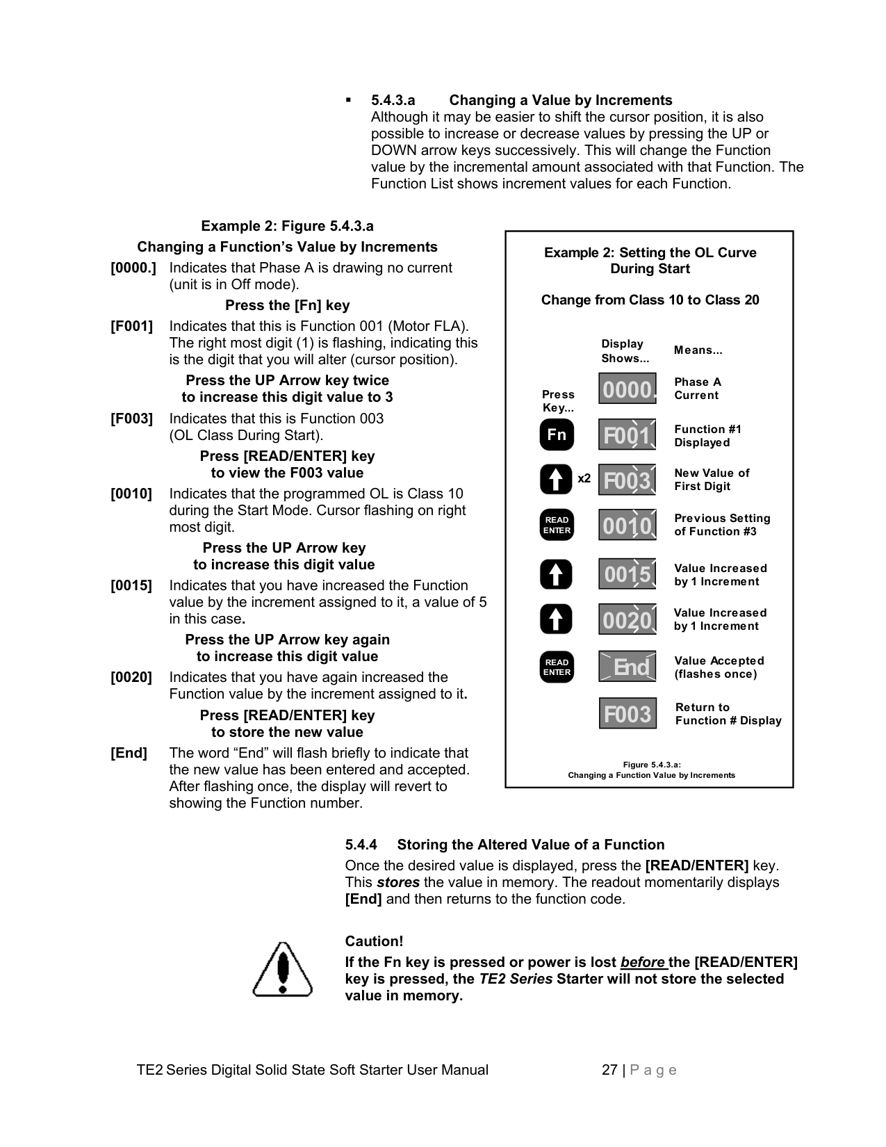
5.4.3.a Changing a Value by Increments Although it may be easier to shift the cursor position, it is also possible to increase or decrease values by pressing the UP or DOWN arrow keys successively. This will change the Function value by the incremental amount associated with that Function. The Function List shows increment values for each Function.
Example 2: Figure 5.4.3.a Changing a Function’s Value by Increments
[0000.] Indicates that Phase A is drawing no current
(unit is in Off mode).
Press the [Fn] key [F001] Indicates that this is Function 001 (Motor FLA). The right most digit (1) is flashing, indicating this is the digit that you will alter (cursor position).
Press the UP Arrow key twice to increase this digit value to 3 [F003] Indicates that this is Function 003 (OL Class During Start).
Press [READ/ENTER] key to view the F003 value
[0010] Indicates that the programmed OL is Class 10 during the Start Mode. Cursor flashing on right most digit.
Press the UP Arrow key to increase this digit value
[0015] Indicates that you have increased the Function value by the increment assigned to it, a value of 5 in this case.
Press the UP Arrow key again to increase this digit value
[0020] Indicates that you have again increased the
Function value by the increment assigned to it.
Press [READ/ENTER] key to store the new value
[End] The word “End” will flash briefly to indicate that the new value has been entered and accepted. After flashing once, the display will revert to showing the Function number.
|Display
Press Key...
Shows...
Means...
Phase A Current
Function #1 Displayed
Previous Setting of Function #3
Value Increased by 1 Increment
Value Increased by 1 Increment
0000. F001
0010 0015 0020
End Value Accepted(flashes once)
Return to Function # Display
Figure 5.4.3.a: Changing a Function Value by Increments
Example 2: Setting the OL Curve During Start
Change from Class 10 to Class 20
F003
New Value of
First DigitF003x2
Fn
READ ENTER
READ ENTER| |---|

################## 5.4.4 Storing the Altered Value of a Function
Once the desired value is displayed, press the [READ/ENTER] key. This stores the value in memory. The readout momentarily displays [End] and then returns to the function code.
Caution! If the Fn key is pressed or power is lost before the [READ/ENTER] key is pressed, the TE2 Series Starter will not store the selected value in memory.
################## 5.4.5 Fault Mode
The Fault Mode Display provides information to the operator when a fault occurs and allows the operator to review fault history. Refer to Section 7 for details. Fault codes are displayed by 3 alpha characters. The first and second characters (reading left to right) are the initials for the applicable English-language fault name. The third or right-most character can be either A, c, or d to denote when the fault occurred. “A” denotes Acceleration. “c” denotes Constant speed. “d” denotes Decel or Stop.
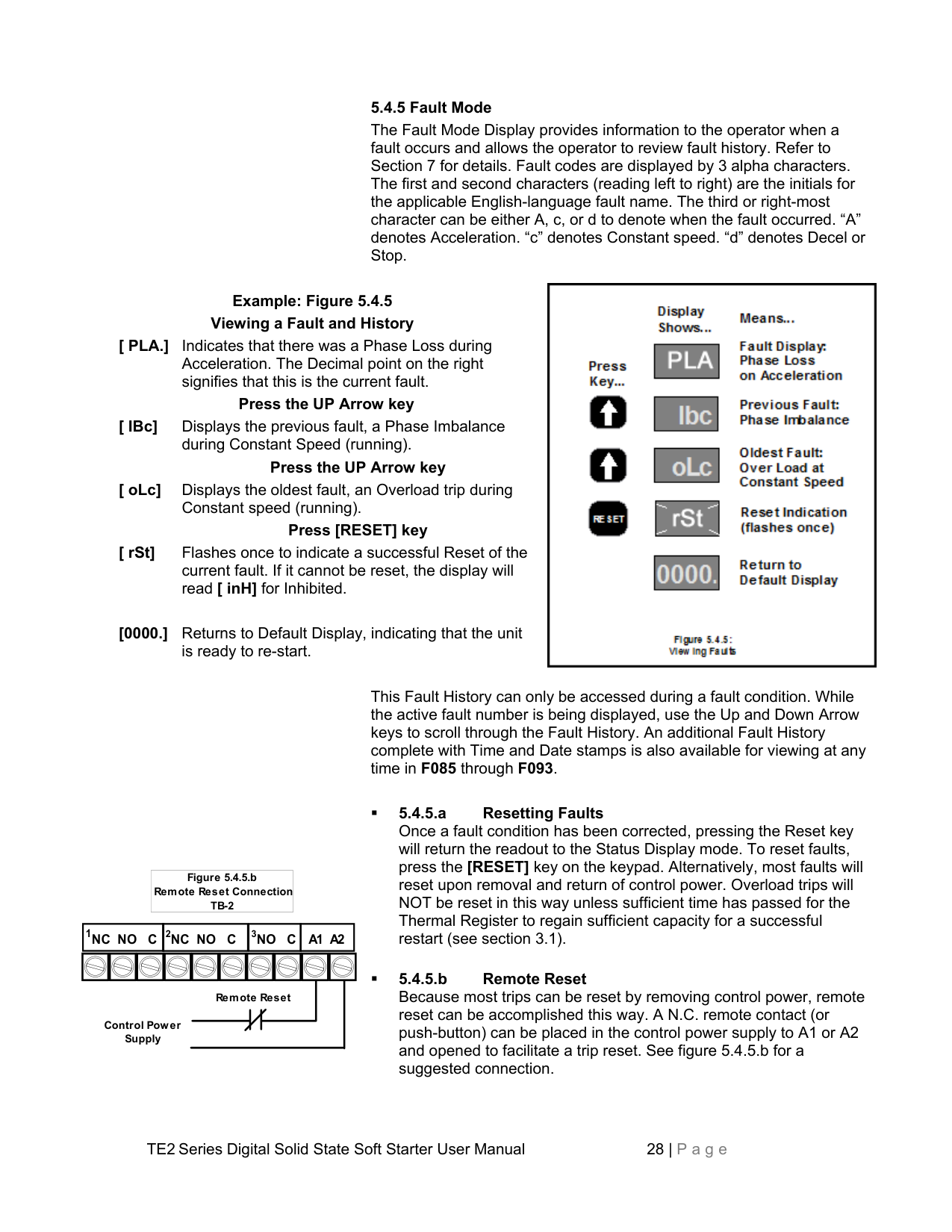
Example: Figure 5.4.5 Viewing a Fault and History
[ PLA.] Indicates that there was a Phase Loss during Acceleration. The Decimal point on the right signifies that this is the current fault.
Press the UP Arrow key [ IBc] Displays the previous fault, a Phase Imbalance
during Constant Speed (running).
Press the UP Arrow key [ oLc] Displays the oldest fault, an Overload trip during
Constant speed (running).
################## Press [RESET] key
[ rSt] Flashes once to indicate a successful Reset of the current fault. If it cannot be reset, the display will read [ inH] for Inhibited.
[0000.] Returns to Default Display, indicating that the unit
is ready to re-start.

This Fault History can only be accessed during a fault condition. While the active fault number is being displayed, use the Up and Down Arrow keys to scroll through the Fault History. An additional Fault History complete with Time and Date stamps is also available for viewing at any time in F085 through F093.
|Figure 5.4.5.b Remote Reset Connection TB-2| |---|
####################### 1NC NO C A1 A22NC NOC3NOC
Remote Reset
Control Power Supply
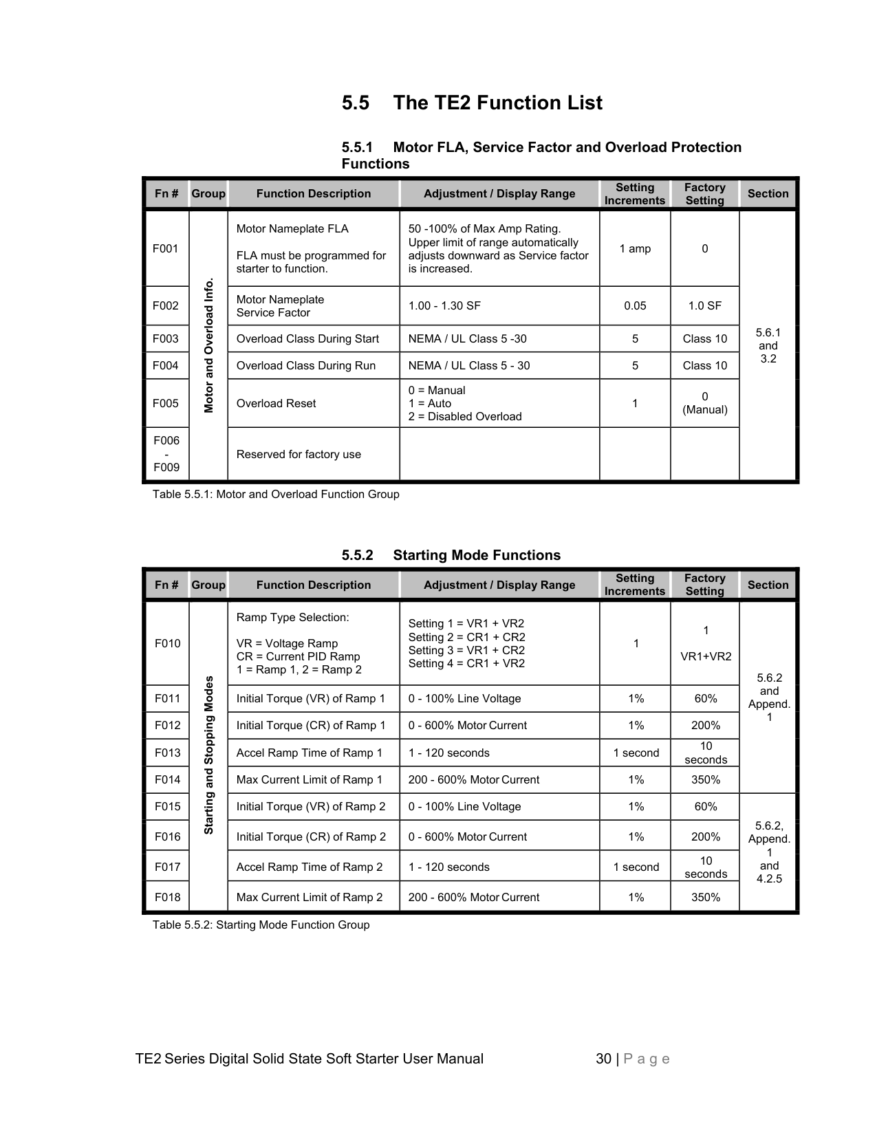
########### 5.5 The TE2 Function List
|Fn #|Group|Function Description|Adjustment / Display Range|Setting Increments
|Factory Setting
|Section| |---|---|---|---|---|---|---| |F001|Motor and Overload Info.|Motor Nameplate FLA FLA must be programmed for starter to function.|50 -100% of Max Amp Rating. Upper limit of range automatically adjusts downward as Service factor is increased.|1 amp|0|5.6.1 and 3.2
| |F002|Motor and Overload Info.|Motor Nameplate Service Factor|1.00 - 1.30 SF|0.05|1.0 SF|5.6.1 and 3.2
| |F003|Motor and Overload Info.|Overload Class During Start|NEMA / UL Class 5 -30|5|Class 10|5.6.1 and 3.2
| |F004|Motor and Overload Info.|Overload Class During Run|NEMA / UL Class 5 - 30|5|Class 10|5.6.1 and 3.2
| |F005|Motor and Overload Info.|Overload Reset|0 = Manual
1 = Auto
2 = Disabled Overload
|1|0 (Manual)|5.6.1 and 3.2
| |F006 F009|Motor and Overload Info.|Reserved for factory use| | | |5.6.1 and 3.2
|
|Fn #|Group|Function Description|Adjustment / Display Range|Setting Increments
|Factory Setting
|Section|
|---|---|---|---|---|---|---| |F010|Starting and Stopping Modes|Ramp Type Selection: VR = Voltage Ramp CR = Current PID Ramp 1 = Ramp 1, 2 = Ramp 2|Setting 1 = VR1 + VR2
Setting 2 = CR1 + CR2
Setting 3 = VR1 + CR2
Setting 4 = CR1 + VR2
|1|1 VR1+VR2|5.6.2 and Append. 1
| |F011|Starting and Stopping Modes|Initial Torque (VR) of Ramp 1|0 - 100% Line Voltage|1%|60%|5.6.2 and Append. 1
| |F012|Starting and Stopping Modes|Initial Torque (CR) of Ramp 1|0 - 600% Motor Current|1%|200%|5.6.2 and Append. 1
| |F013|Starting and Stopping Modes|Accel Ramp Time of Ramp 1|1 - 120 seconds|1 second|10 seconds|5.6.2 and Append. 1
| |F014|Starting and Stopping Modes|Max Current Limit of Ramp 1|200 - 600% Motor Current|1%|350%|5.6.2 and Append. 1
| |F015|Starting and Stopping Modes|Initial Torque (VR) of Ramp 2|0 - 100% Line Voltage|1%|60%|5.6.2, Append. 1 and 4.2.5
| |F016|Starting and Stopping Modes|Initial Torque (CR) of Ramp 2|0 - 600% Motor Current|1%|200%|5.6.2, Append. 1 and 4.2.5
| |F017|Starting and Stopping Modes|Accel Ramp Time of Ramp 2|1 - 120 seconds|1 second|10 seconds|5.6.2, Append. 1 and 4.2.5
| |F018|Starting and Stopping Modes|Max Current Limit of Ramp 2|200 - 600% Motor Current|1%|350%|5.6.2, Append. 1 and 4.2.5
|
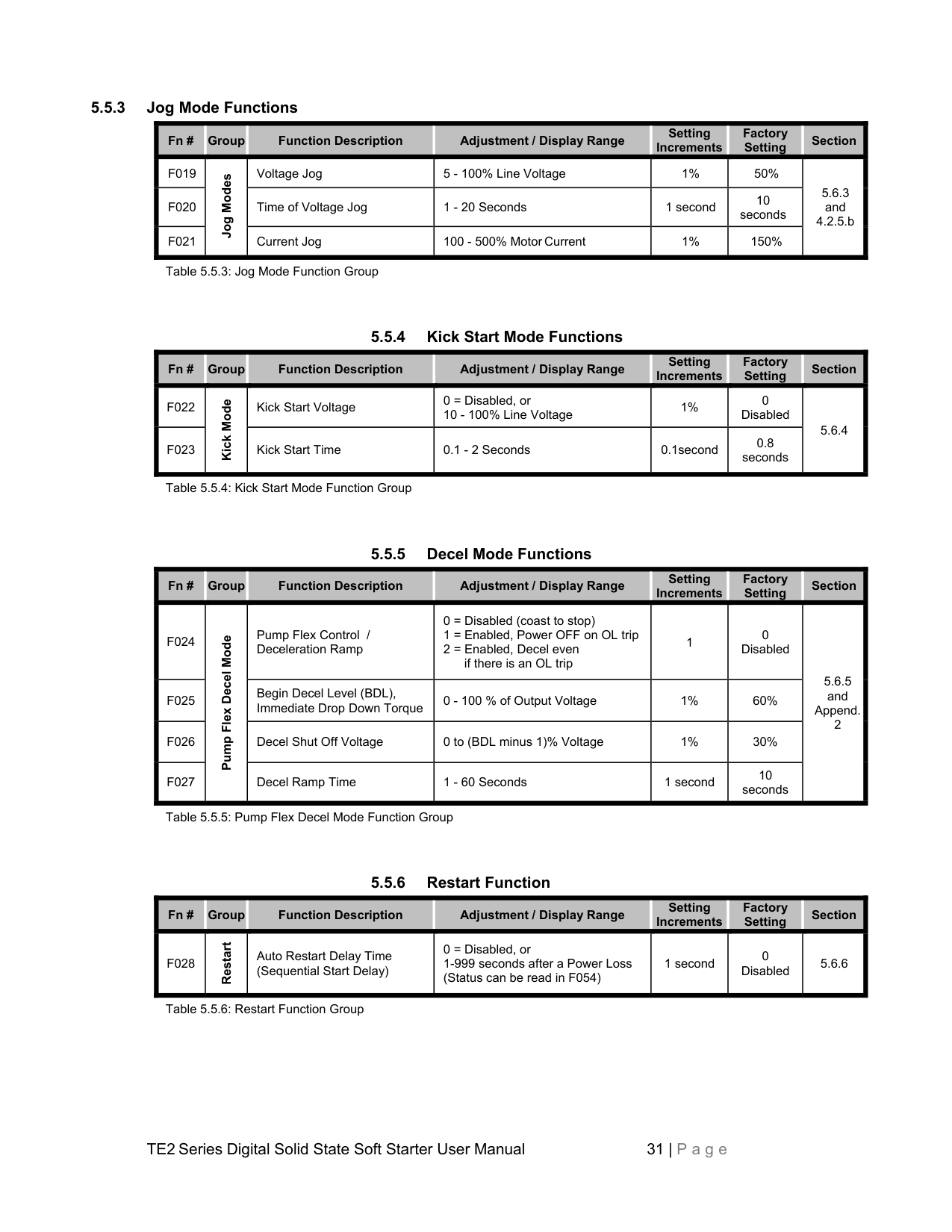
5.5.3 Jog Mode Functions
|Fn #|Group|Function Description|Adjustment / Display Range|Setting Increments
|Factory Setting
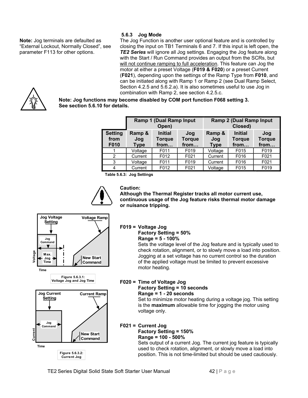
|Section| |---|---|---|---|---|---|---| |F019|Jog Modes|Voltage Jog|5 - 100% Line Voltage|1%|50%|5.6.3 and 4.2.5.b| |F020|Jog Modes|Time of Voltage Jog|1 - 20 Seconds|1 second|10 seconds|5.6.3 and 4.2.5.b| |F021|Jog Modes|Current Jog|100 - 500% Motor Current|1%|150%|5.6.3 and 4.2.5.b|
|Fn #|Group|Function Description|Adjustment / Display Range|Setting Increments
|Factory Setting
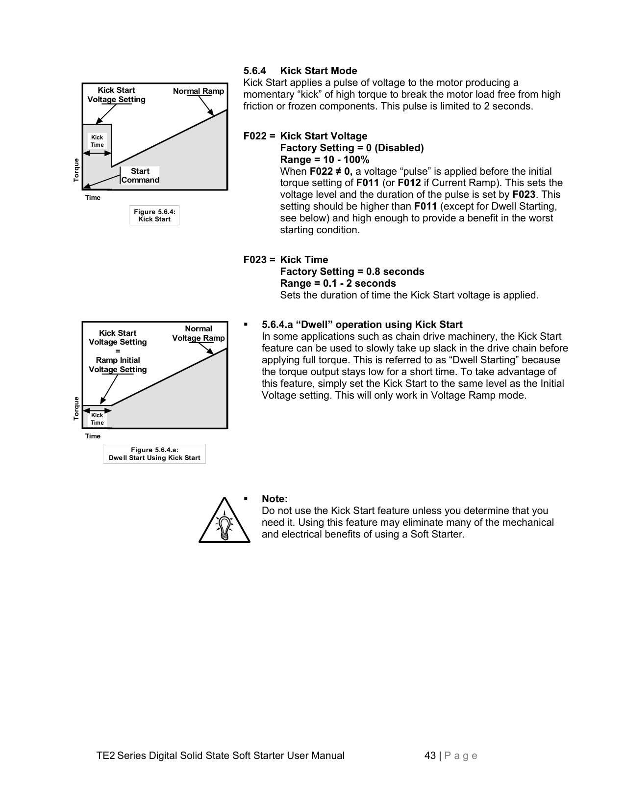
|Section| |---|---|---|---|---|---|---| |F022|Kick Mode
|Kick Start Voltage|0 = Disabled, or 10 - 100% Line Voltage|1%|0 Disabled|5.6.4| |F023|Kick Mode
|Kick Start Time|0.1 - 2 Seconds|0.1second|0.8 seconds|5.6.4|
|Fn #|Group|Function Description|Adjustment / Display Range|Setting Increments
|Factory Setting
|Section| |---|---|---|---|---|---|---| |F024|Pump Flex Decel Mode|Pump Flex Control / Deceleration Ramp|0 = Disabled (coast to stop)
1 = Enabled, Power OFF on OL trip
2 = Enabled, Decel even if there is an OL trip
|1|0 Disabled|5.6.5 and Append. 2| |F025|Pump Flex Decel Mode|Begin Decel Level (BDL), Immediate Drop Down Torque|0 - 100 % of Output Voltage|1%|60%|5.6.5 and Append. 2| |F026|Pump Flex Decel Mode|Decel Shut Off Voltage|0 to (BDL minus 1)% Voltage|1%|30%|5.6.5 and Append. 2| |F027|Pump Flex Decel Mode|Decel Ramp Time|1 - 60 Seconds|1 second|10 seconds|5.6.5 and Append. 2|
|Fn #|Group|Function Description|Adjustment / Display Range|Setting Increments
|Factory Setting
|Section| |---|---|---|---|---|---|---| |F028|Restart|Auto Restart Delay Time (Sequential Start Delay)|0 = Disabled, or 1-999 seconds after a Power Loss (Status can be read in F054)|1 second|0 Disabled|5.6.6|
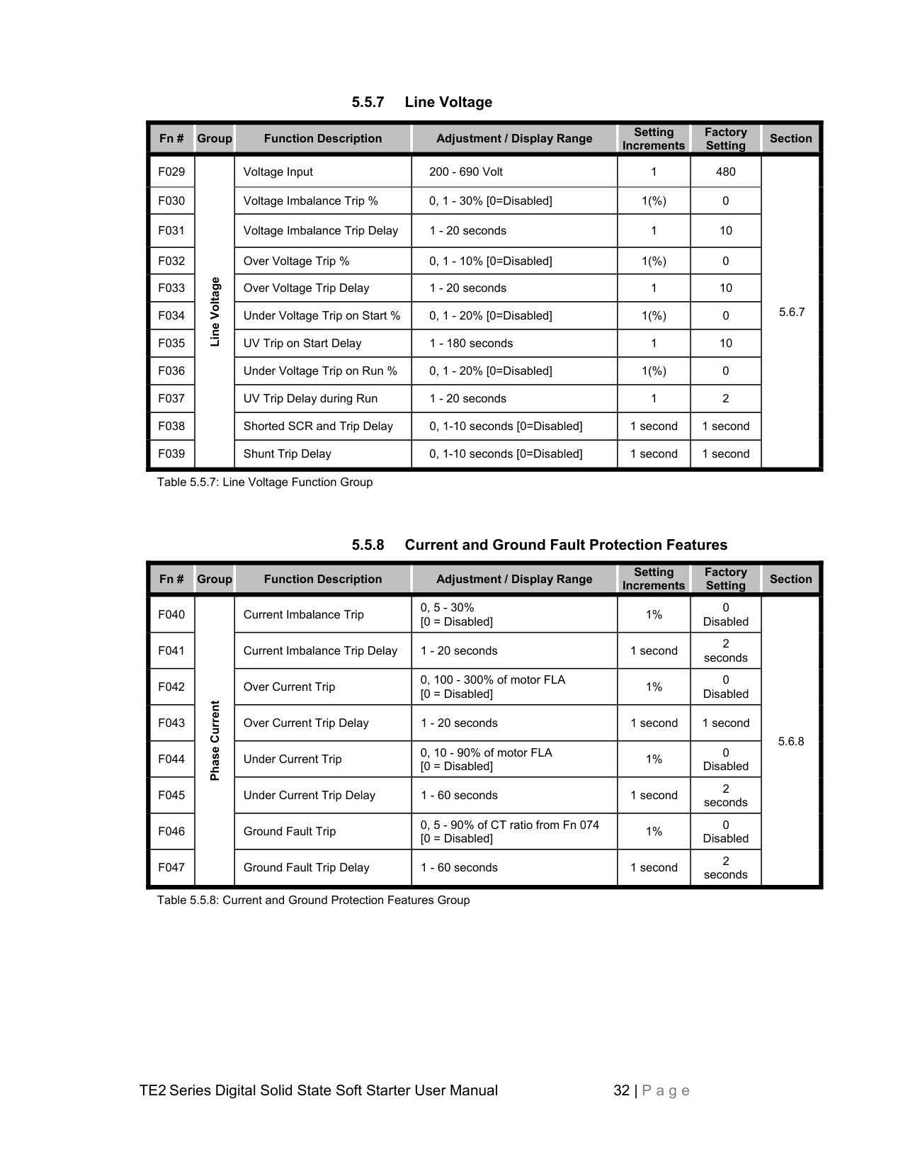
|Fn #|Group|Function Description|Adjustment / Display Range|Setting Increments
|Factory Setting
|Section| |---|---|---|---|---|---|---| |F029|Line Voltage|Voltage Input|200 - 690 Volt|1|480|5.6.7| |F030|Line Voltage|Voltage Imbalance Trip %|0, 1 - 30% [0=Disabled]|1(%)|0|5.6.7| |F031|Line Voltage|Voltage Imbalance Trip Delay|1 - 20 seconds|1|10|5.6.7| |F032|Line Voltage|Over Voltage Trip %|0, 1 - 10% [0=Disabled]|1(%)|0|5.6.7| |F033|Line Voltage|Over Voltage Trip Delay|1 - 20 seconds|1|10|5.6.7|
|F034|Line Voltage|Under Voltage Trip on Start %|0, 1 - 20% [0=Disabled]|1(%)|0|5.6.7| |F035|Line Voltage|UV Trip on Start Delay|1 - 180 seconds|1|10|5.6.7| |F036|Line Voltage|Under Voltage Trip on Run %|0, 1 - 20% [0=Disabled]|1(%)|0|5.6.7| |F037|Line Voltage|UV Trip Delay during Run|1 - 20 seconds|1|2|5.6.7| |F038|Line Voltage|Shorted SCR and Trip Delay|0, 1-10 seconds [0=Disabled]|1 second|1 second|5.6.7| |F039|Line Voltage|Shunt Trip Delay|0, 1-10 seconds [0=Disabled]|1 second|1 second|5.6.7|
|Fn #|Group|Function Description|Adjustment / Display Range|Setting Increments
|Factory Setting
|Section| |---|---|---|---|---|---|---| |F040|Phase Current
|Current Imbalance Trip|0, 5 - 30% [0 = Disabled]|1%|0 Disabled|5.6.8| |F041|Phase Current
|Current Imbalance Trip Delay|1 - 20 seconds|1 second|2 seconds|5.6.8| |F042|Phase Current
|Over Current Trip|0, 100 - 300% of motor FLA [0 = Disabled]|1%|0 Disabled|5.6.8| |F043|Phase Current
|Over Current Trip Delay|1 - 20 seconds|1 second|1 second|5.6.8| |F044|Phase Current
|Under Current Trip|0, 10 - 90% of motor FLA [0 = Disabled]|1%|0 Disabled|5.6.8| |F045|Phase Current
|Under Current Trip Delay|1 - 60 seconds|1 second|2 seconds|5.6.8| |F046|Phase Current
|Ground Fault Trip|0, 5 - 90% of CT ratio from Fn 074 [0 = Disabled]|1%|0 Disabled|5.6.8| |F047|Phase Current
|Ground Fault Trip Delay|1 - 60 seconds|1 second|2 seconds|5.6.8|
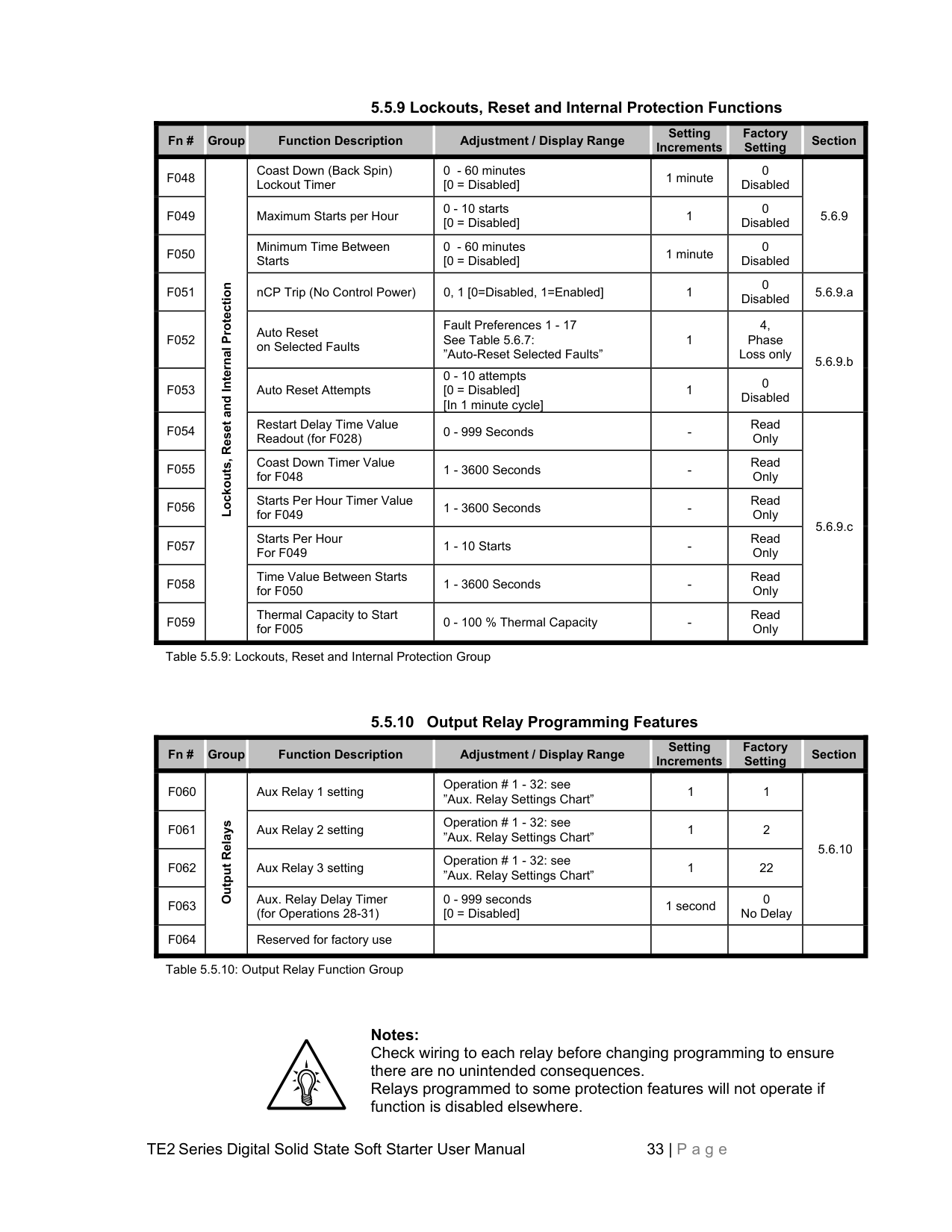
|Fn #|Group|Function Description|Adjustment / Display Range|Setting Increments
|Factory Setting
|Section| |---|---|---|---|---|---|---| |F048|Lockouts, Reset and Internal Protection
|Coast Down (Back Spin) Lockout Timer|0 - 60 minutes [0 = Disabled]|1 minute|0 Disabled|5.6.9| |F049|Lockouts, Reset and Internal Protection
|Maximum Starts per Hour|0 - 10 starts [0 = Disabled]|1|0 Disabled|5.6.9| |F050|Lockouts, Reset and Internal Protection
|Minimum Time Between Starts|0 - 60 minutes [0 = Disabled]|1 minute|0 Disabled|5.6.9|
|F051|Lockouts, Reset and Internal Protection
|nCP Trip (No Control Power)|0, 1 [0=Disabled, 1=Enabled]|1|0 Disabled|5.6.9.a| |F052|Lockouts, Reset and Internal Protection
|Auto Reset on Selected Faults|Fault Preferences 1 - 17 See Table 5.6.7: ”Auto-Reset Selected Faults”|1|4, Phase Loss only|5.6.9.b| |F053|Lockouts, Reset and Internal Protection
|Auto Reset Attempts|0 - 10 attempts [0 = Disabled] [In 1 minute cycle]|1|0 Disabled|5.6.9.b| |F054|Lockouts, Reset and Internal Protection
|Restart Delay Time Value Readout (for F028)|0 - 999 Seconds|-|Read Only|5.6.9.c| |F055|Lockouts, Reset and Internal Protection
|Coast Down Timer Value for F048|1 - 3600 Seconds|-|Read Only|5.6.9.c| |F056|Lockouts, Reset and Internal Protection
|Starts Per Hour Timer Value for F049|1 - 3600 Seconds|-|Read Only|5.6.9.c| |F057|Lockouts, Reset and Internal Protection
|Starts Per Hour For F049|1 - 10 Starts|-|Read Only|5.6.9.c| |F058|Lockouts, Reset and Internal Protection
|Time Value Between Starts for F050|1 - 3600 Seconds|-|Read Only|5.6.9.c| |F059|Lockouts, Reset and Internal Protection
|Thermal Capacity to Start for F005|0 - 100 % Thermal Capacity|-|Read Only|5.6.9.c|
|Fn #|Group|Function Description|Adjustment / Display Range|Setting Increments
|Factory Setting
|Section| |---|---|---|---|---|---|---| |F060|Output Relays|Aux Relay 1 setting|Operation # 1 - 32: see ”Aux. Relay Settings Chart”|1|1|5.6.10| |F061|Output Relays|Aux Relay 2 setting|Operation # 1 - 32: see ”Aux. Relay Settings Chart”|1|2|5.6.10| |F062|Output Relays|Aux Relay 3 setting|Operation # 1 - 32: see ”Aux. Relay Settings Chart”|1|22|5.6.10| |F063|Output Relays|Aux. Relay Delay Timer (for Operations 28-31)|0 - 999 seconds [0 = Disabled]|1 second|0 No Delay|5.6.10| |F064|Output Relays|Reserved for factory use| | | | |
Notes: Check wiring to each relay before changing programming to ensure there are no unintended consequences. Relays programmed to some protection features will not operate if function is disabled elsewhere.
|Fn #|Group|Function Description|Adjustment / Display Range|Setting Increments
|Factory Setting
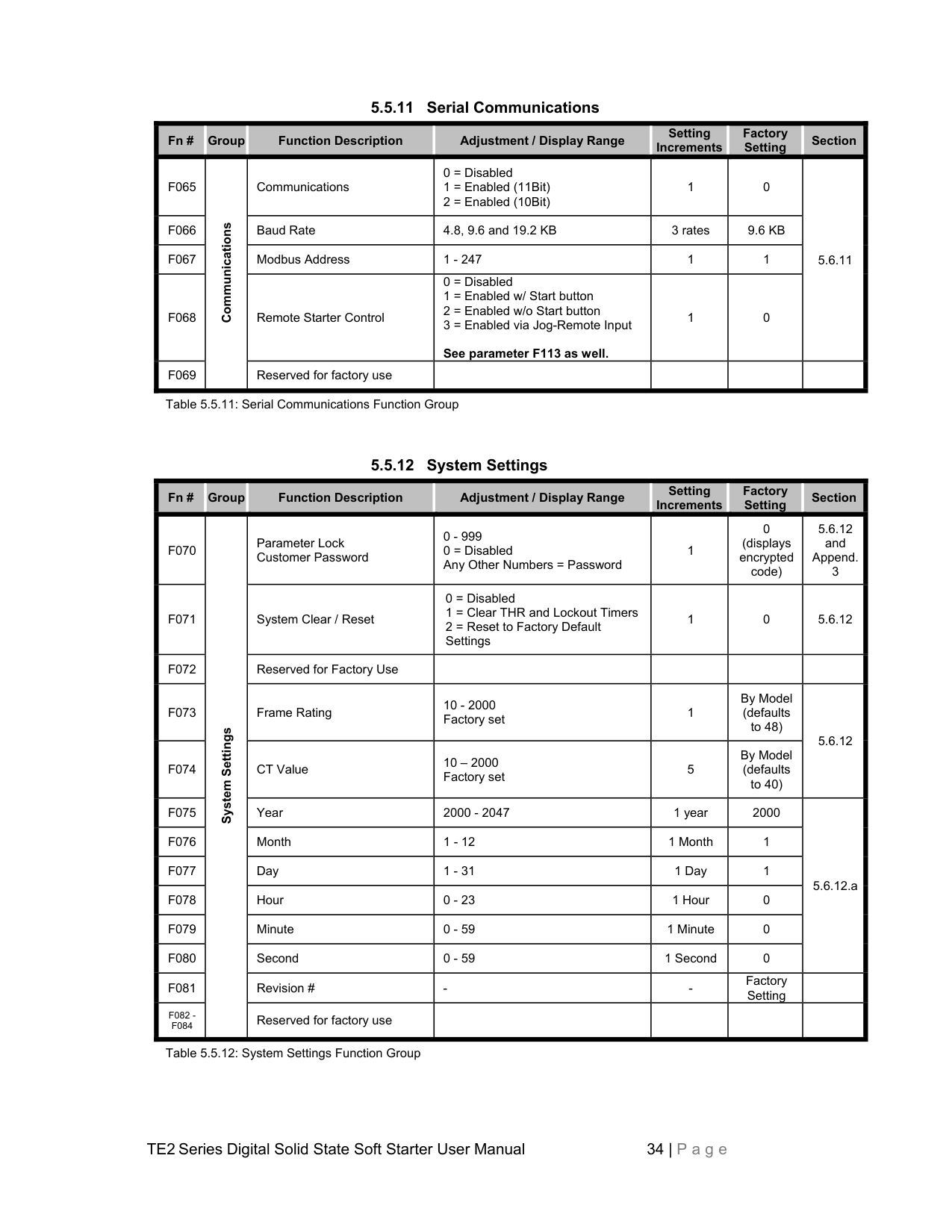
|Section| |---|---|---|---|---|---|---| |F065|Communications
|Communications|0 = Disabled
1 = Enabled (11Bit)
2 = Enabled (10Bit)
|1|0|5.6.11
|
|F066|Communications
|Baud Rate|4.8, 9.6 and 19.2 KB|3 rates|9.6 KB|5.6.11
| |F067|Communications
|Modbus Address|1 - 247|1|1|5.6.11
| |F068|Communications
|Remote Starter Control|0 = Disabled
1 = Enabled w/ Start button
2 = Enabled w/o Start button
3 = Enabled via Jog-Remote Input See parameter F113 as well.
|1|0|5.6.11
| |F069|Communications
|Reserved for factory use| | | | |
|Fn #|Group|Function Description|Adjustment / Display Range|Setting Increments
|Factory Setting
|Section| |---|---|---|---|---|---|---| |F070|System Settings|Parameter Lock Customer Password|0 - 999 0 = Disabled Any Other Numbers = Password|1|0 (displays encrypted code)|5.6.12 and Append. 3| |F071|System Settings|System Clear / Reset|0 = Disabled
1 = Clear THR and Lockout Timers
2 = Reset to Factory Default Settings
|1|0|5.6.12| |F072|System Settings|Reserved for Factory Use| | | | | |F073|System Settings|Frame Rating|10 - 2000 Factory set|1|By Model (defaults to 48)|5.6.12| |F074|System Settings|CT Value|10 – 2000 Factory set|5|By Model (defaults to 40)|5.6.12| |F075|System Settings|Year|2000 - 2047|1 year|2000|5.6.12.a
| |F076|System Settings|Month|1 - 12|1 Month|1|5.6.12.a
| |F077|System Settings|Day|1 - 31|1 Day|1|5.6.12.a
| |F078|System Settings|Hour|0 - 23|1 Hour|0|5.6.12.a
| |F079|System Settings|Minute|0 - 59|1 Minute|0|5.6.12.a
| |F080|System Settings|Second|0 - 59|1 Second|0|5.6.12.a
| |F081|System Settings|Revision #|-|-|Factory Setting| | |F082 F084|System Settings|Reserved for factory use| | | | |
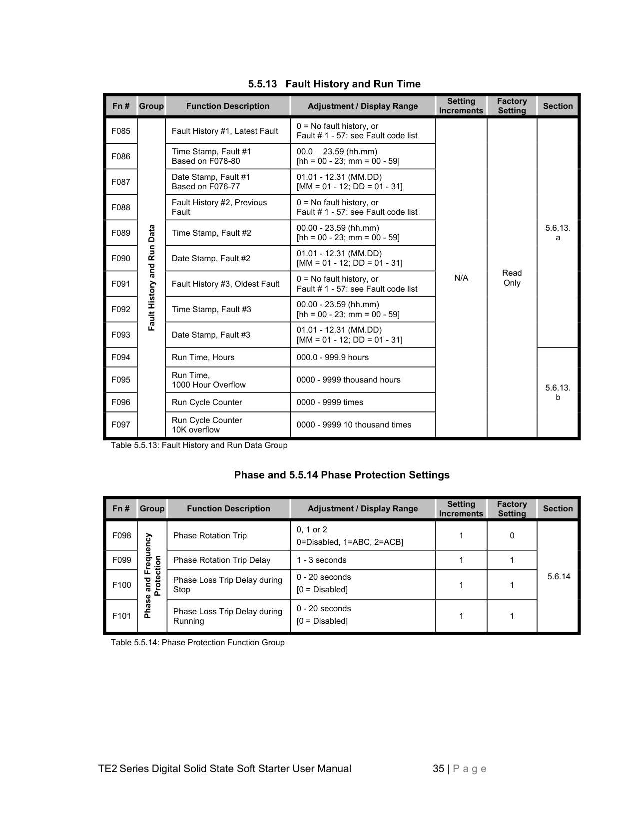
################## 5.5.13 Fault History and Run Time
|Fn #|Group|Function Description|Adjustment / Display Range|Setting Increments
|Factory Setting
|Section| |---|---|---|---|---|---|---| |F085|Fault History and Run Data|Fault History #1, Latest Fault|0 = No fault history, or Fault # 1 - 57: see Fault code list|N/A
|Read Only|5.6.13. a| |F086|Fault History and Run Data|Time Stamp, Fault #1 Based on F078-80|00.0 23.59 (hh.mm) [hh = 00 - 23; mm = 00 - 59]|N/A
|Read Only|5.6.13. a|
|F087|Fault History and Run Data|Date Stamp, Fault #1 Based on F076-77|01.01 - 12.31 (MM.DD) [MM = 01 - 12; DD = 01 - 31]|N/A
|Read Only|5.6.13. a| |F088|Fault History and Run Data|Fault History #2, Previous Fault|0 = No fault history, or Fault # 1 - 57: see Fault code list|N/A
|Read Only|5.6.13. a| |F089|Fault History and Run Data|Time Stamp, Fault #2|00.00 - 23.59 (hh.mm) [hh = 00 - 23; mm = 00 - 59]|N/A
|Read Only|5.6.13. a| |F090|Fault History and Run Data|Date Stamp, Fault #2|01.01 - 12.31 (MM.DD) [MM = 01 - 12; DD = 01 - 31]|N/A
|Read Only|5.6.13. a| |F091|Fault History and Run Data|Fault History #3, Oldest Fault|0 = No fault history, or Fault # 1 - 57: see Fault code list|N/A
|Read Only|5.6.13. a| |F092|Fault History and Run Data|Time Stamp, Fault #3|00.00 - 23.59 (hh.mm) [hh = 00 - 23; mm = 00 - 59]|N/A
|Read Only|5.6.13. a| |F093|Fault History and Run Data|Date Stamp, Fault #3|01.01 - 12.31 (MM.DD) [MM = 01 - 12; DD = 01 - 31]|N/A
|Read Only|5.6.13. a| |F094|Fault History and Run Data|Run Time, Hours|000.0 - 999.9 hours|N/A
|Read Only|5.6.13. b| |F095|Fault History and Run Data|Run Time, 1000 Hour Overflow|0000 - 9999 thousand hours|N/A
|Read Only|5.6.13. b| |F096|Fault History and Run Data|Run Cycle Counter|0000 - 9999 times|N/A
|Read Only|5.6.13. b| |F097|Fault History and Run Data|Run Cycle Counter 10K overflow|0000 - 9999 10 thousand times|N/A
|Read Only|5.6.13. b|
Phase and 5.5.14 Phase Protection Settings
|Fn #|Group|Function Description|Adjustment / Display Range|Setting Increments
|Factory Setting
|Section| |---|---|---|---|---|---|---| |F098|Phase and Frequency
Protection
|Phase Rotation Trip|0, 1 or 2 0=Disabled, 1=ABC, 2=ACB]|1|0|5.6.14| |F099|Phase and Frequency
Protection
|Phase Rotation Trip Delay|1 - 3 seconds|1|1|5.6.14| |F100|Phase and Frequency
Protection
|Phase Loss Trip Delay during Stop|0 - 20 seconds [0 = Disabled]|1|1|5.6.14| |F101|Phase and Frequency
Protection
|Phase Loss Trip Delay during Running|0 - 20 seconds [0 = Disabled]|1|1|5.6.14|
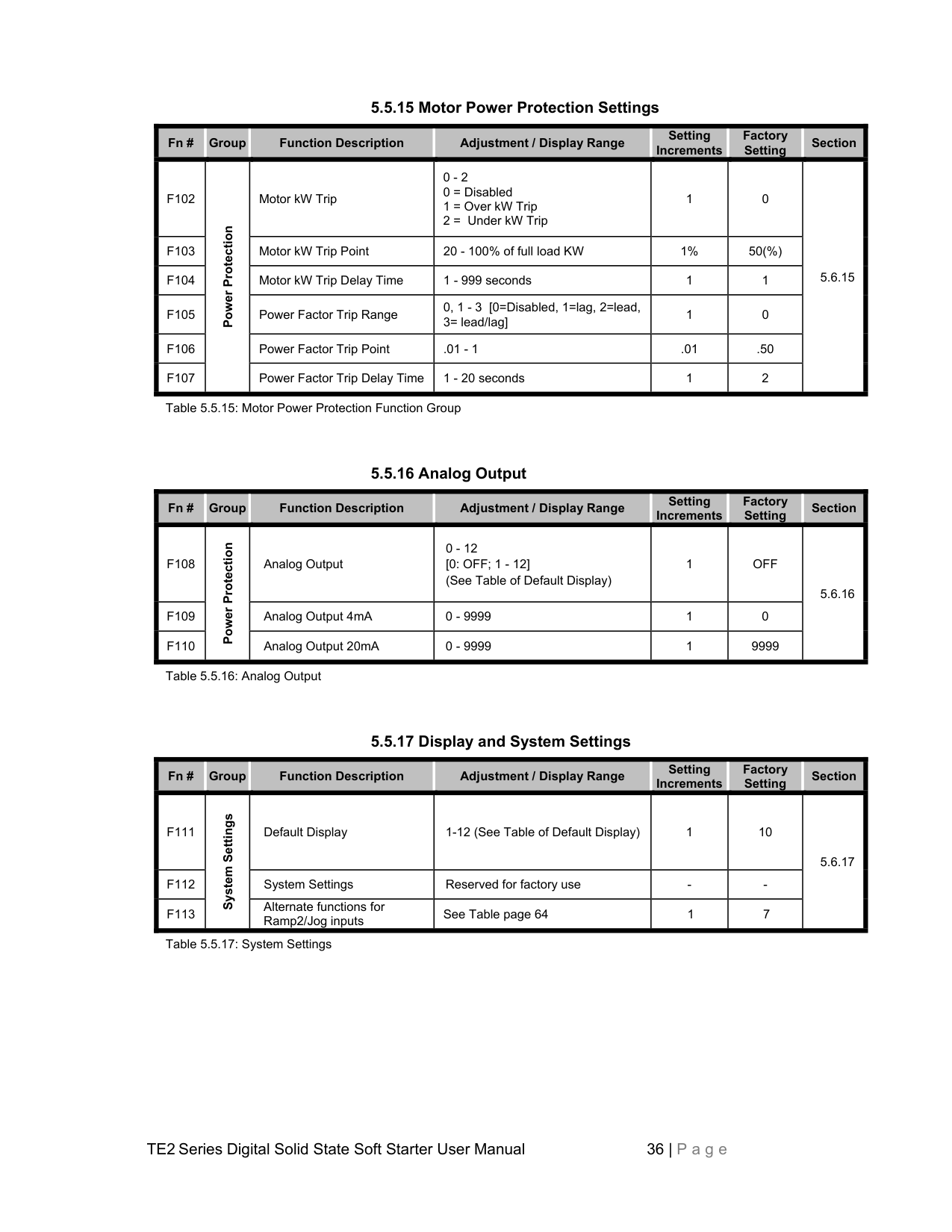
|Fn #|Group|Function Description|Adjustment / Display Range|Setting Increments
|Factory Setting
|Section|
|---|---|---|---|---|---|---| |F102|Power Protection|Motor kW Trip|0 - 2
0 = Disabled
1 = Over kW Trip
2 = Under kW Trip
|1|0|5.6.15| |F103|Power Protection|Motor kW Trip Point|20 - 100% of full load KW|1%|50(%)|5.6.15| |F104|Power Protection|Motor kW Trip Delay Time|1 - 999 seconds|1|1|5.6.15| |F105|Power Protection|Power Factor Trip Range|0, 1 - 3 [0=Disabled, 1=lag, 2=lead, 3= lead/lag]|1|0|5.6.15| |F106|Power Protection|Power Factor Trip Point|.01 - 1|.01|.50|5.6.15| |F107|Power Protection|Power Factor Trip Delay Time|1 - 20 seconds|1|2|5.6.15|
|Fn #|Group|Function Description|Adjustment / Display Range|Setting Increments
|Factory Setting
|Section| |---|---|---|---|---|---|---| |F108|Power Protection|Analog Output|0 - 12 [0: OFF; 1 - 12] (See Table of Default Display)|1|OFF|5.6.16
| |F109|Power Protection|Analog Output 4mA|0 - 9999|1|0|5.6.16
| |F110|Power Protection|Analog Output 20mA|0 - 9999|1|9999|5.6.16
|
|Fn #|Group|Function Description|Adjustment / Display Range|Setting Increments
|Factory Setting
|Section| |---|---|---|---|---|---|---| |F111|System Settings
|Default Display|1-12 (See Table of Default Display)|1|10|5.6.17| |F112|System Settings
|System Settings|Reserved for factory use|-|-|5.6.17| |F113|System Settings
|Alternate functions for Ramp2/Jog inputs|See Table page 64|1|7|5.6.17|
||MOTOR FLA (F001) must be programmed for unit to operate!| |---| | |---|
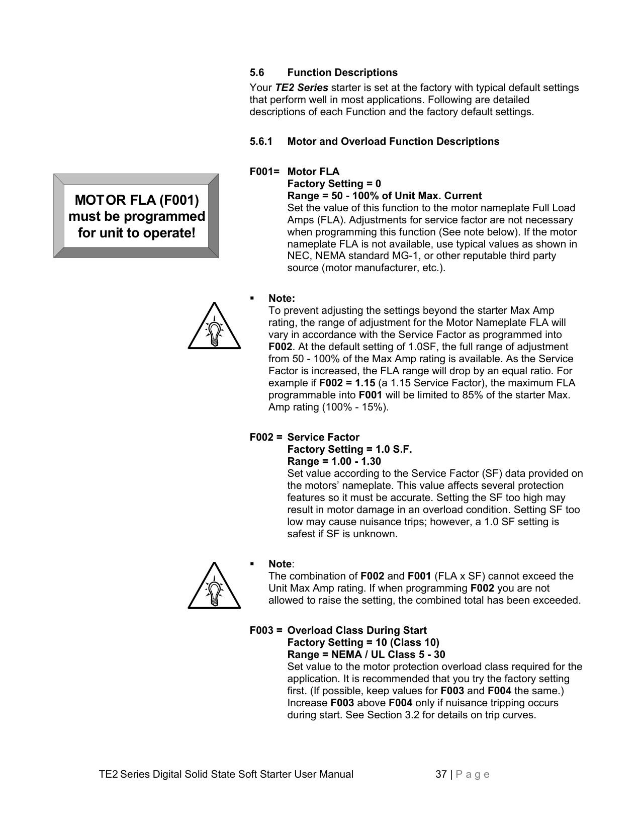
5.6 Function Descriptions Your TE2 Series starter is set at the factory with typical default settings that perform well in most applications. Following are detailed descriptions of each Function and the factory default settings.
################## 5.6.1 Motor and Overload Function Descriptions
Note: To prevent adjusting the settings beyond the starter Max Amp rating, the range of adjustment for the Motor Nameplate FLA will vary in accordance with the Service Factor as programmed into F002. At the default setting of 1.0SF, the full range of adjustment from 50 - 100% of the Max Amp rating is available. As the Service Factor is increased, the FLA range will drop by an equal ratio. For example if F002 = 1.15 (a 1.15 Service Factor), the maximum FLA programmable into F001 will be limited to 85% of the starter Max. Amp rating (100% - 15%).
Note: The combination of F002 and F001 (FLA x SF) cannot exceed the Unit Max Amp rating. If when programming F002 you are not allowed to raise the setting, the combined total has been exceeded.
WARNING: Setting F005 = 1 (Automatic) may present significant operational risk. When F005 = 2 (Disabled Overload), a separate external thermal overload protection device must be in the circuit.
Note: Because of the risk of fire or equipment damage, cycling control power will NOT reset an Overload Trip. If F005 = 2 (Automatic Reset), cycling control power will allow reset ONLY if the Thermal Register has determined that the motor has regained sufficient thermal capacity to allow it to restart successfully.

################## 5.6.2 Starting Modes
The TE2 Series is capable of several different starting modes, but is set from the factory for the most common applications. A second ramp profile is available for use should it be required. Unless wired to do so, the TE2 Series defaults to Ramp 1. This section describes functions for
| |Ramp 1 (Dual Ramp Input Open)
|Ramp 2 (Dual Ramp Input Closed)
| |---|---|---| |F010 Setting
|Ramp Profile|Ramp Profile| |1|Voltage|Voltage| |2|Current|Current| |3|Voltage|Current| |4|Current|Voltage|
Table 5.6.2: Ramp Type selection Settings
Select Voltage Ramp by setting F010 = 1 (factory default) When Voltage Ramp is selected, Set Initial Torque (Voltage) with F011 (see below) Set Ramp Time with F013 (see below) Set Maximum Current Limit with F014 (see below)
Or;
Select Current Ramp by setting F010 = 2 When Current Ramp is selected, Set Initial Torque (Current) with F012 (see below) Set Ramp Time with F013 (see below) Set Maximum Current Limit with F014 (see below)
Note: When either Ramp is set to “Voltage Ramp”, the corresponding “Initial Torque (Current)” setting is ignored. Conversely, when set to “Current Ramp”, the “Initial Torque (Voltage)” is ignored.
Note: Acceleration time is affected by the following conditions:
################## 5.6.2.a Ramp 2 (user-optional ramp)
This ramp is selected by closing the input for Ramp 2, TB1 terminals 5 & 6 (see section 4.2.5). If this input is left open, the TE2 Series will respond only to Ramp 1 settings as listed above. Since ramp 2 is always used as an alternate to the default Ramp 1, different combinations of ramp profiles can be selected in F010. Refer to Appendix 1 for additional information on ramp profiles.
Note: Ramp 2 is often useful as a “bump start” or as a temporary Acrossthe-Line start mode. Consult Appendix 1 for details.
Note: Jog terminals are defaulted as “External Lockout, Normally Closed”, see parameter F113 for other options.
Note: Jog functions may become disabled by COM port function F068 setting 3. See section 5.6.10 for details.
| |Ramp 1 (Dual Ramp Input Open)
|Ramp 1 (Dual Ramp Input Open)
|Ramp 1 (Dual Ramp Input Open)
|Ramp 2 (Dual Ramp Input Closed)
|Ramp 2 (Dual Ramp Input Closed)
|Ramp 2 (Dual Ramp Input Closed)
| |---|---|---|---|---|---|---| |Setting from F010
|Ramp & Jog Type
|Initial Torque from…
|Jog Torque from…
|Ramp & Jog Type
|Initial Torque from…
|Jog Torque from…
| |1|Voltage|F011|F019|Voltage|F015|F019| |2|Current|F012|F021|Current|F016|F021| |3|Voltage|F011|F019|Current|F016|F021|
|4|Current|F012|F021|Voltage|F015|F019|
Table 5.6.3: Jog Settings

|Jog Voltage Setting
Voltage Ramp
New Start Command
Max. Jog
Time
Jog Command| |---|
Voltage
Time
|Figure 5.6.3.1: Voltage Jog and Jog Time| |---|
|Jog Current Setting
Current Ramp
New Start Command
Jog Command| |---|
Current
Time
|Figure 5.6.3.2: Current Jog| |---|
Caution: Although the Thermal Register tracks all motor current use, continuous usage of the Jog feature risks thermal motor damage or nuisance tripping.
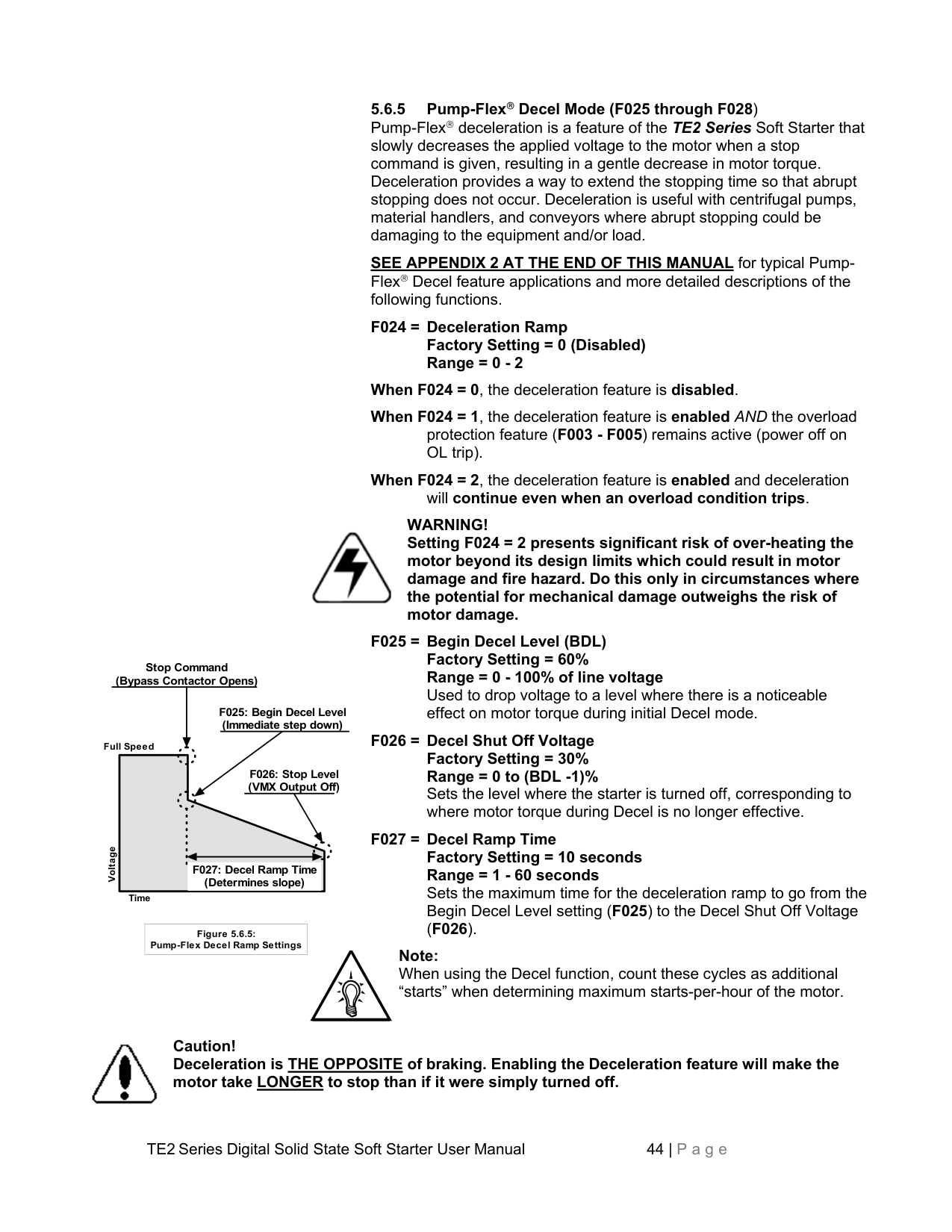
5.6.4 Kick Start Mode Kick Start applies a pulse of voltage to the motor producing a momentary “kick” of high torque to break the motor load free from high friction or frozen components. This pulse is limited to 2 seconds.
|Kick Start Voltage Setting
Normal Ramp
Start Command
Kick Time| |---|
Torque
Time
|Figure 5.6.4: Kick Start| |---|
|Kick Start Voltage Setting = Ramp Initial Voltage Setting
Normal Voltage Ramp
Kick Time
| |---|
Torque
Time
|Figure 5.6.4.a: Dwell Start Using Kick Start| |---|
5.6.5 Pump-Flex Decel Mode (F025 through F028) Pump-Flex deceleration is a feature of the TE2 Series Soft Starter that slowly decreases the applied voltage to the motor when a stop command is given, resulting in a gentle decrease in motor torque. Deceleration provides a way to extend the stopping time so that abrupt stopping does not occur. Deceleration is useful with centrifugal pumps, material handlers, and conveyors where abrupt stopping could be damaging to the equipment and/or load.
SEE APPENDIX 2 AT THE END OF THIS MANUAL for typical PumpFlex Decel feature applications and more detailed descriptions of the following functions.
WARNING! Setting F024 = 2 presents significant risk of over-heating the motor beyond its design limits which could result in motor damage and fire hazard. Do this only in circumstances where the potential for mechanical damage outweighs the risk of motor damage.

Stop Command (Bypass Contactor Opens)
F025: Begin Decel Level (Immediate step down)
Full Speed
F026: Stop Level (VMX Output Off)
Voltage
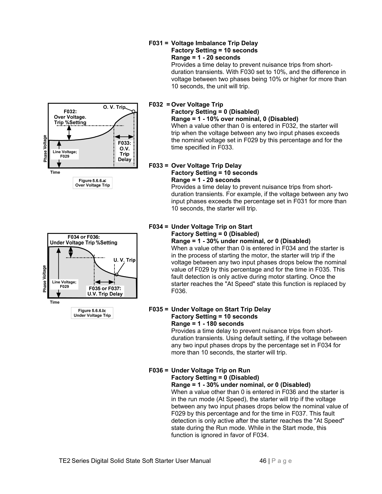
########################## F027: Decel Ramp Time (Determines slope)
Time
|Figure 5.6.5: Pump-Flex Decel Ramp Settings| |---|
Note: When using the Decel function, count these cycles as additional “starts” when determining maximum starts-per-hour of the motor.

Caution! Deceleration is THE OPPOSITE of braking. Enabling the Deceleration feature will make the motor take LONGER to stop than if it were simply turned off.
Note: This is similar to the Coast Down Lockout Timer in F048, however it only activates on Power Loss.
5.6.7 Voltage Protection Features
################## Note: All of these features are disabled upon shipping from the factory and must be enabled via user programming as follows:
|


|
|---|


|


| |---|


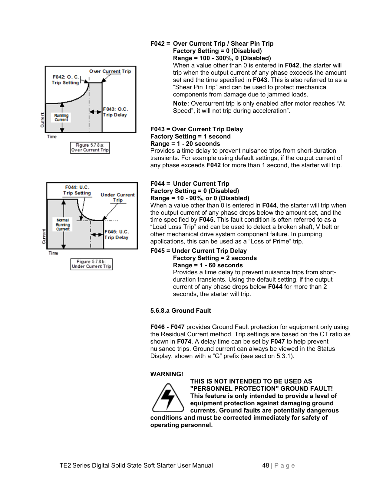

| | | |---|---| | | |


|


| |---|


Note: Under Voltage and Over Voltage Trip settings may conflict with Voltage Imbalance Trip settings set in F030 and F031. If a voltage anomaly occurs that is out of range of any feature, the one with the lowest settings and fastest trip time will take precedence.
5.6.8 Current and Ground Fault Protection Features
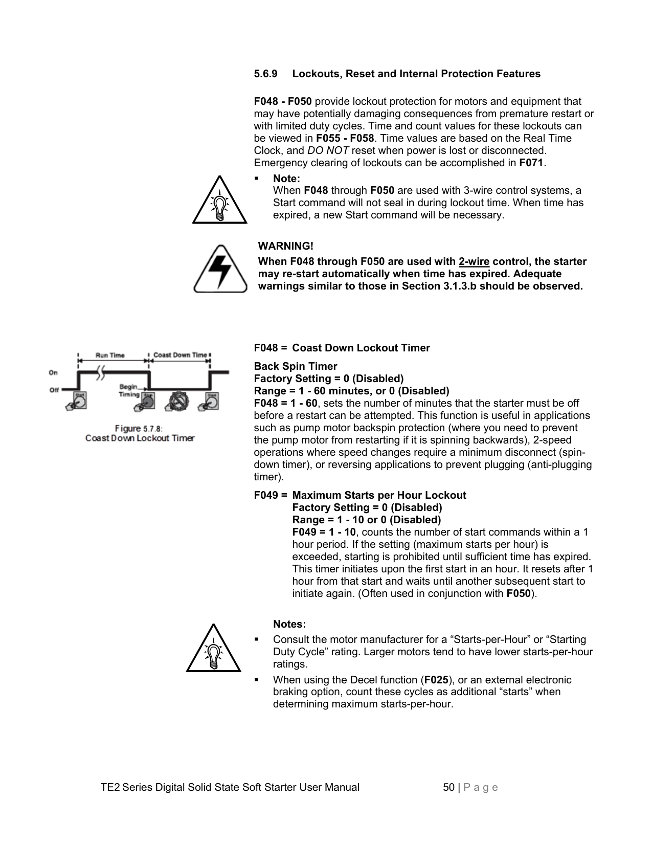
Note: All of these features are disabled at the factory and must be enabled via user programming as follows:


Note: Overcurrent trip is only enabled after motor reaches “At Speed”, it will not trip during acceleration”.
WARNING!
THIS IS NOT INTENDED TO BE USED AS "PERSONNEL PROTECTION" GROUND FAULT! This feature is only intended to provide a level of equipment protection against damaging ground currents. Ground faults are potentially dangerous

conditions and must be corrected immediately for safety of operating personnel.
F046 = Ground Fault Trip Factory Setting = 0 (Disabled) Range = 5 - 90% of CT value, or 0 (Disabled) When a value other than 0 is entered in F046, the starter will trip if current to ground exceeds this percentage of the unit CT value. The CT value is shown in F074, (see section 5.6.12). This value is different from the Unit Rating or FLA setting. Following are two examples of Ground Fault current settings.
Example: To calculate the ground current trip value in amps, divide the setting of
If you have a desired trip value in amps and need to determine the percentage value for F046, simply divide the desired trip ampere value by 100, then multiply that times the value in F074.
Example: 210A starter desired Ground Fault Trip Level is 8A, The CT value is F074 is 250. Then, 8 ÷ 100 = 0.08 then x 250 = 20% in F046.

CAUTION: This method of Ground Fault sensing may not provide adequate equipment protection in resistance-grounded systems. We recommend providing external GF protection using a core balanced Zero Sequence CT for those types of applications. Consult factory for additional assistance.
################## 5.6.9 Lockouts, Reset and Internal Protection Features
Note: When F048 through F050 are used with 3-wire control systems, a Start command will not seal in during lockout time. When time has expired, a new Start command will be necessary.

WARNING! When F048 through F050 are used with 2-wire control, the starter may re-start automatically when time has expired. Adequate warnings similar to those in Section 3.1.3.b should be observed.

F048 = Coast Down Lockout Timer Back Spin Timer Factory Setting = 0 (Disabled) Range = 1 - 60 minutes, or 0 (Disabled)
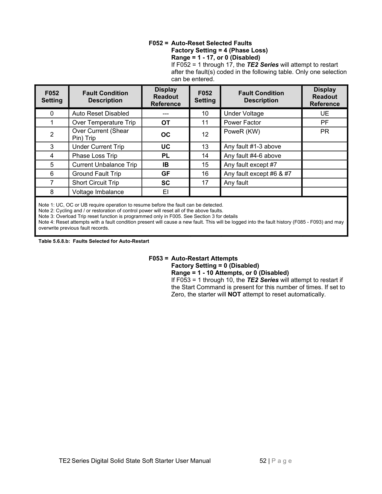
################## Notes:
Example: If F050 = 15, motor will not be allowed to re-start within 15 minutes of the first start.
This function is useful as a “Short-Cycle Timer” to prevent excessive motor wear when automatic demand control may occasionally cycle on and off too quickly. e.g. compressors or sump pumps.
5.6.9.a Control Power Trip (F051)
5.6.9.b Auto-Reset Programming (F052 - F054) The TE2 Series can be programmed to automatically attempt a reset based on the selected “Auto-Reset” faults (F52), provided a Start Command is present (see Section 4.2), and no fault condition is active. Function F52 selects the “Auto-Reset” faults and function F53 sets the number of reset attempts. If F053 is set to 0 (default setting), the TE2 Series auto-reset function is disabled.
Note: When using 3-wire control: For safety reasons, the TE2 Series will not attempt restarting unless the Start Command is reinitiated and maintained during a restart attempt.
|F052 Setting
|Fault Condition Description
|Display Readout Reference
|F052 Setting
|Fault Condition Description
|Display Readout Reference
| |---|---|---|---|---|---| |0|Auto Reset Disabled|---|10|Under Voltage|UE| |1|Over Temperature Trip|OT|11|Power Factor|PF| |2|Over Current (Shear Pin) Trip|OC|12|PoweR (KW)|PR| |3|Under Current Trip|UC|13|Any fault #1-3 above| | |4|Phase Loss Trip|PL|14|Any fault #4-6 above| |
|5|Current Unbalance Trip|IB|15|Any fault except #7| | |6|Ground Fault Trip|GF|16|Any fault except #6 & #7| | |7|Short Circuit Trip|SC|17|Any fault| | |8|Voltage Imbalance|EI| | | | |Note 1: UC, OC or UB require operation to resume before the fault can be detected.
Note 2: Cycling and / or restoration of control power will reset all of the above faults.
Note 3: Overload Trip reset function is programmed only in F005. See Section 3 for details
Note 4: Reset attempts with a fault condition present will cause a new fault. This will be logged into the fault history (F085 - F093) and may overwrite previous fault records.
|Note 1: UC, OC or UB require operation to resume before the fault can be detected.
Note 2: Cycling and / or restoration of control power will reset all of the above faults.
Note 3: Overload Trip reset function is programmed only in F005. See Section 3 for details
Note 4: Reset attempts with a fault condition present will cause a new fault. This will be logged into the fault history (F085 - F093) and may overwrite previous fault records.
|
Table 5.6.8.b: Faults Selected for Auto-Restart
################## 5.6.9.c Timer Value Readouts for Protection Features
################## 5.6.10 Output Relays
There are three programmable relays (rated 240VAC, 5A, 1200 VA) in the TE2 Series. They can be programmed for change of state indication for any one of the 32 conditions identified in the following chart.
F061 = Aux Relay 2: Form C (SPDT) Factory Setting = 2 (At Speed / Stop) Range = 1 - 32 (See list)
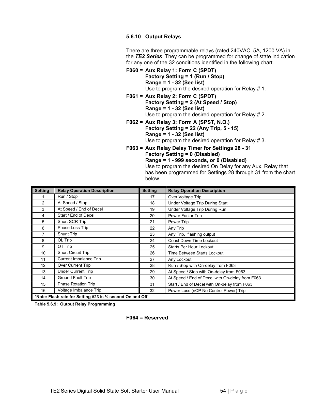
F062 = Aux Relay 3: Form A (SPST, N.O.) Factory Setting = 22 (Any Trip, 5 - 15) Range = 1 - 32 (See list)
Setting Relay Operation Description Setting Relay Operation Description
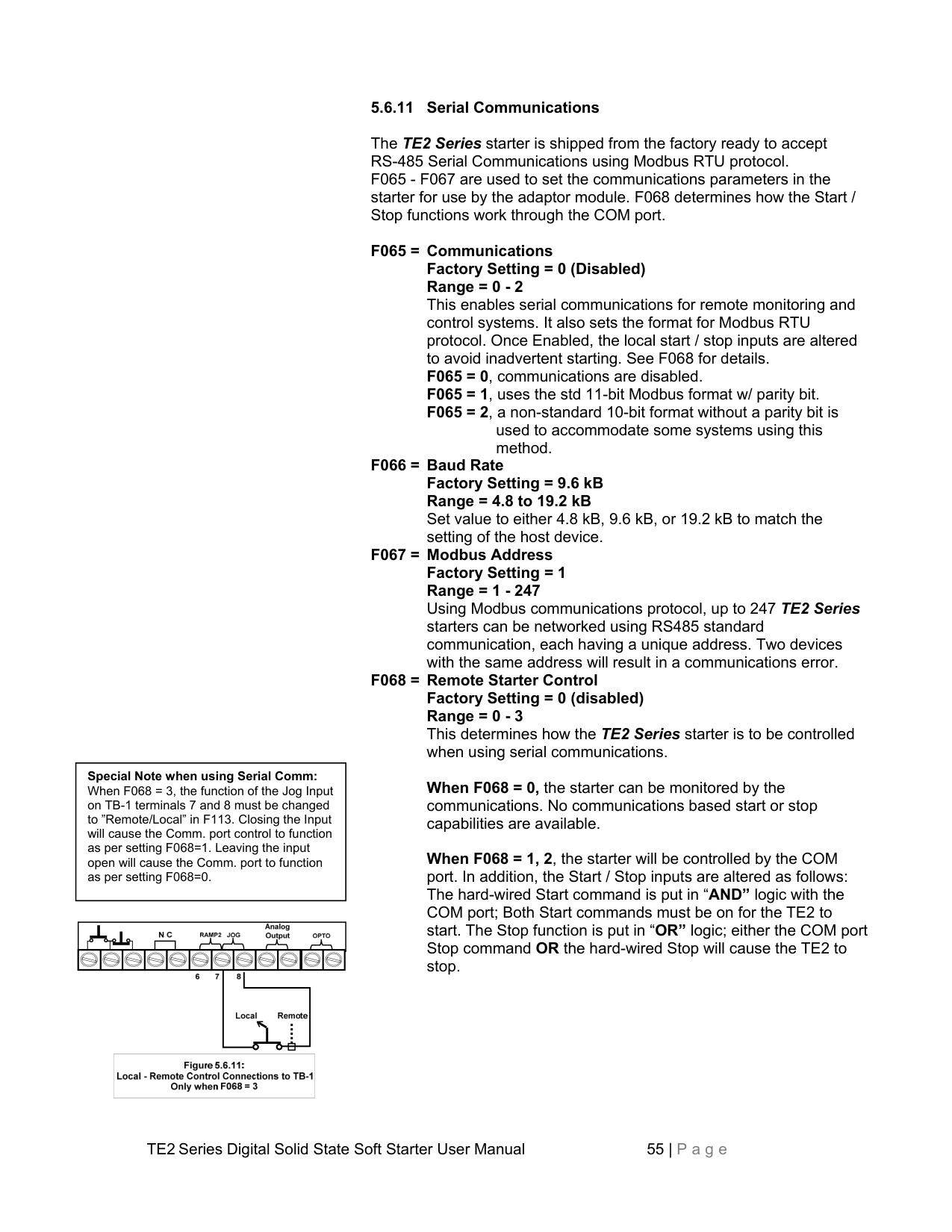
######################## *Note: Flash rate for Setting #23 is ½ second On and Off Table 5.6.9: Output Relay Programming
################## 5.6.11 Serial Communications
The TE2 Series starter is shipped from the factory ready to accept RS-485 Serial Communications using Modbus RTU protocol. F065 - F067 are used to set the communications parameters in the starter for use by the adaptor module. F068 determines how the Start / Stop functions work through the COM port.
Special Note when using Serial Comm: When F068 = 3, the function of the Jog Input on TB-1 terminals 7 and 8 must be changed to ”Remote/Local” in F113. Closing the Input will cause the Comm. port control to function as per setting F068=1. Leaving the input open will cause the Comm. port to function as per setting F068=0.


|


| |---|


When F068 = 3, and the jog input is set to “Remote/Local” in F113 the TE2 starter will change the function of the Jog Input to cause a switch between the functions of setting 0 and setting 1 as listed above. When the input is open, the starter will respond to the COM port as per setting F068=0. When the Jog Input is closed, the starter will respond as per setting F068=1. Use this function if it is necessary to have a return to local start/stop control should the communications system fail or become disconnected. NOTE: There is no jog function available, due to the reconfiguration of the jog input port. The jog input must be manually changed to “Remote/Local” in parameter F113.
################## F069= Reserved
The following functions set operator interface controls and unit programming. Also contained here are the Clock settings used for history functions. Change the Clock settings to local time zone if accurate time values are needed.
################### F070 = Parameter Lock / User PasswordFactory Setting = 0 (disabled)Range = 0 - 999Use only when necessary to prevent unauthorized access.Provides users with the ability to prevent unauthorizedoperators from making changes to the programmed functions.If you do NOT need to take advantage of this feature, do notenter anything into this function. The factory default is disabled,and no Password is necessary to make changes to theprogram.
See Appendix 3 at the end of this manual for detailed instructions on using and altering the Parameter Lock / User Password feature.
################### F071 = Emergency Clear / ResetFactory Setting = 0 (disabled)Range = 0 - 2This Function serves two purposes. It can clear the memoryvalues used for lockouts and overload protection, and it canreset all functions to the factory default settings. This is a “One-Shot” feature, so when another value is entered as shownbelow, this function automatically returns to the default state.
WARNING! Clearing the Thermal Register to allow restarting without proper cool-down time after an Overload Trip can result in motor damage and fire. Use only where emergency restart is necessary with knowledge of these potential hazards.
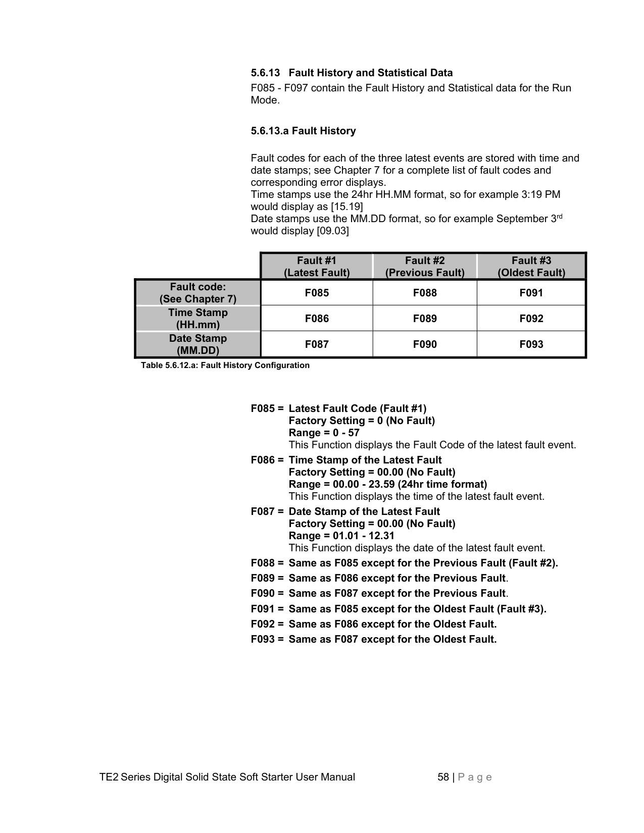
Note: The time clock does not automatically adjust for daylight savings time.
################## 5.6.13 Fault History and Statistical Data
F085 - F097 contain the Fault History and Statistical data for the Run Mode.
################## 5.6.13.a Fault History
Fault codes for each of the three latest events are stored with time and date stamps; see Chapter 7 for a complete list of fault codes and corresponding error displays. Time stamps use the 24hr HH.MM format, so for example 3:19 PM would display as [15.19] Date stamps use the MM.DD format, so for example September 3rd would display [09.03]
| |Fault #1 (Latest Fault)
|Fault #2 (Previous Fault)
|Fault #3 (Oldest Fault)
| |---|---|---|---| |Fault code: (See Chapter 7)
|F085|F088|F091| |Time Stamp (HH.mm)
|F086|F089|F092| |Date Stamp (MM.DD)
|F087|F090|F093|
Table 5.6.12.a: Fault History Configuration
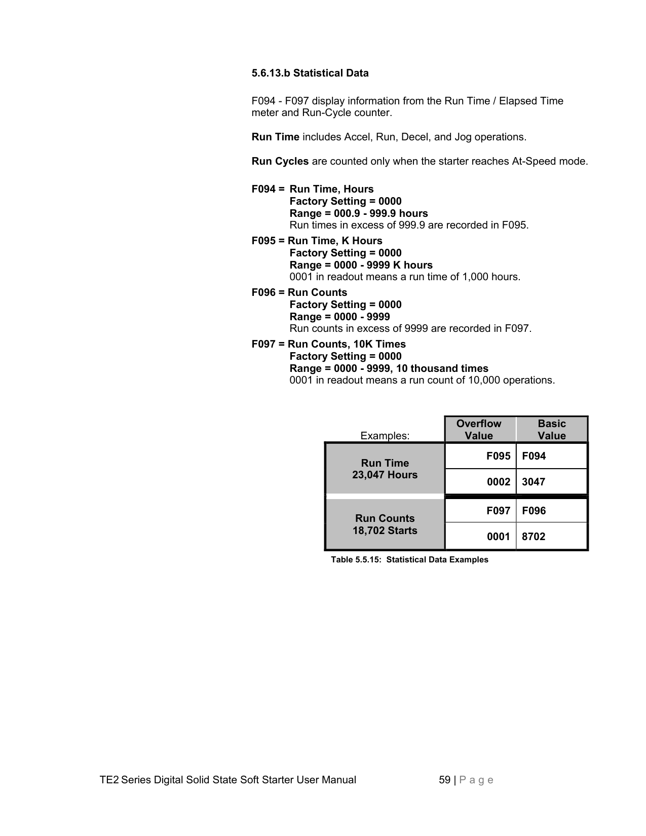
|Examples:|Overflow Value
|Basic Value
| |---|---|---| |Run Time 23,047 Hours
|F095|F094| |Run Time 23,047 Hours
|0002|3047| |Run Counts 18,702 Starts
|F097|F096| |Run Counts 18,702 Starts
|0001|8702|
Table 5.5.15: Statistical Data Examples
Factory Setting = 0 (Disabled) Range = 0 (Disabled), 1 (A-B-C), or 2 (B-A-C)
The TE2 Series is set up to monitor an expected Phase Rotation and trip if it changes. Control of this is divided into two categories: Enable or Disabled and Expected Sequence. The default setting is disabled.
Setting this function to disabled (setting 0) is useful in applications where the TE2 Series is going to be used downstream from an existing reversing contactor or to avoid conflicts with other protection devices.
On large motors where large multiple conductors are used, it may be easier to change the Expected Sequence in the TE2 Series starter rather than swap the conductors.
Note: Based on loss of input voltage on one phase while decelerating or stopped.
Note: Based on current in one phase dropping below 20% of FLA (F001), while starting or running.
################## 5.6.15 Motor Power & Power Factor Protection Settings
PF
0.5
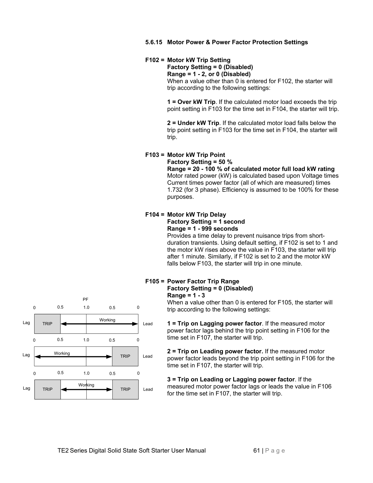
00.51.0 0
Working
LeadLag
TRIP
0.5
00.51.0 0
Working
LeadLag
TRIP
0.5
00.51.0 0
Working
LeadLag
TRIP
TRIP
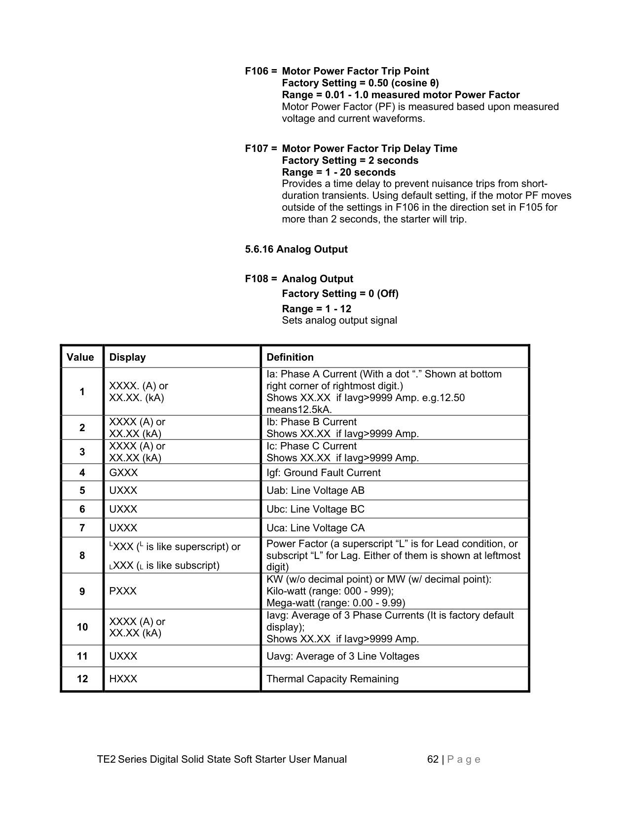
Range = 1 - 12 Sets analog output signal
|Value|Display|Definition| |---|---|---| |1|XXXX. (A) or XX.XX. (kA)|Ia: Phase A Current (With a dot “.” Shown at bottom right corner of rightmost digit.) Shows XX.XX if Iavg>9999 Amp. e.g.12.50 means12.5kA.| |2|XXXX (A) or XX.XX (kA)|Ib: Phase B Current Shows XX.XX if Iavg>9999 Amp.| |3|XXXX (A) or XX.XX (kA)|Ic: Phase C Current Shows XX.XX if Iavg>9999 Amp.| |4|GXXX|Igf: Ground Fault Current| |5|UXXX|Uab: Line Voltage AB| |6|UXXX|Ubc: Line Voltage BC| |7|UXXX|Uca: Line Voltage CA| |8|LXXX (L is like superscript) or LXXX (L is like subscript)|Power Factor (a superscript “L” is for Lead condition, or subscript “L” for Lag. Either of them is shown at leftmost digit)| |9|PXXX|KW (w/o decimal point) or MW (w/ decimal point): Kilo-watt (range: 000 - 999); Mega-watt (range: 0.00 - 9.99)| |10|XXXX (A) or XX.XX (kA)|Iavg: Average of 3 Phase Currents (It is factory default display); Shows XX.XX if Iavg>9999 Amp.| |11|UXXX|Uavg: Average of 3 Line Voltages| |12|HXXX|Thermal Capacity Remaining|
################## F109 = Analog Output 4mAFactory Setting = 0Range = 0 - 9999
Enter a value that the 4mA level will represent for the selected function; typically this value should be 0.
################## F110 = Analog Output 20mAFactory Setting = 9999Range = 0 - 9999
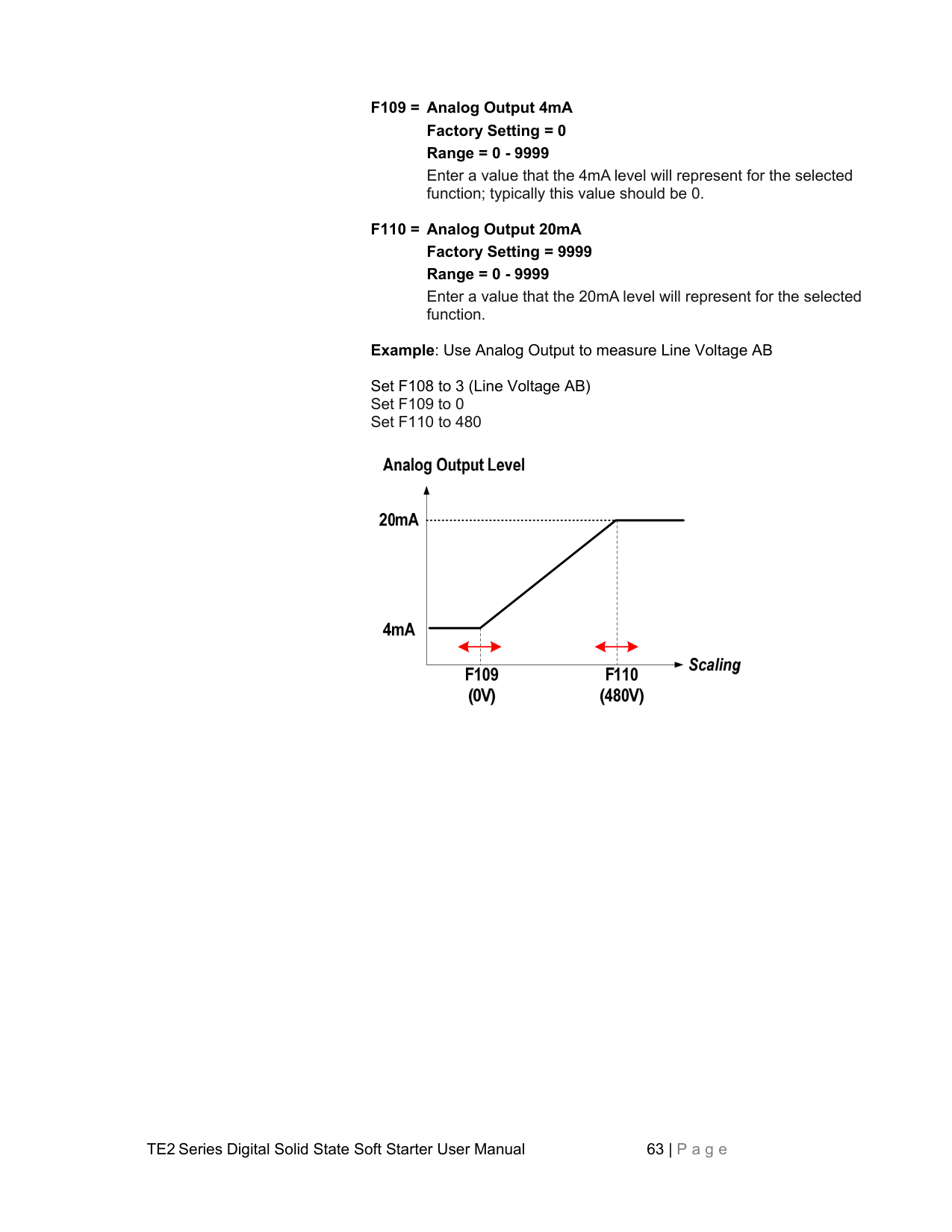
Enter a value that the 20mA level will represent for the selected function.
Example: Use Analog Output to measure Line Voltage AB


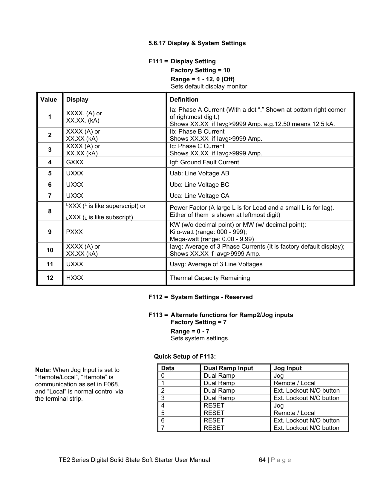


Note: When Jog Input is set to “Remote/Local”, “Remote” is communication as set in F068, and “Local” is normal control via the terminal strip.
Range = 1 - 12, 0 (Off) Sets default display monitor
|Value|Display|Definition| |---|---|---| |1|XXXX. (A) or XX.XX. (kA)|Ia: Phase A Current (With a dot “.” Shown at bottom right corner of rightmost digit.) Shows XX.XX if Iavg>9999 Amp. e.g.12.50 means 12.5 kA.| |2|XXXX (A) or XX.XX (kA)|Ib: Phase B Current Shows XX.XX if Iavg>9999 Amp.|
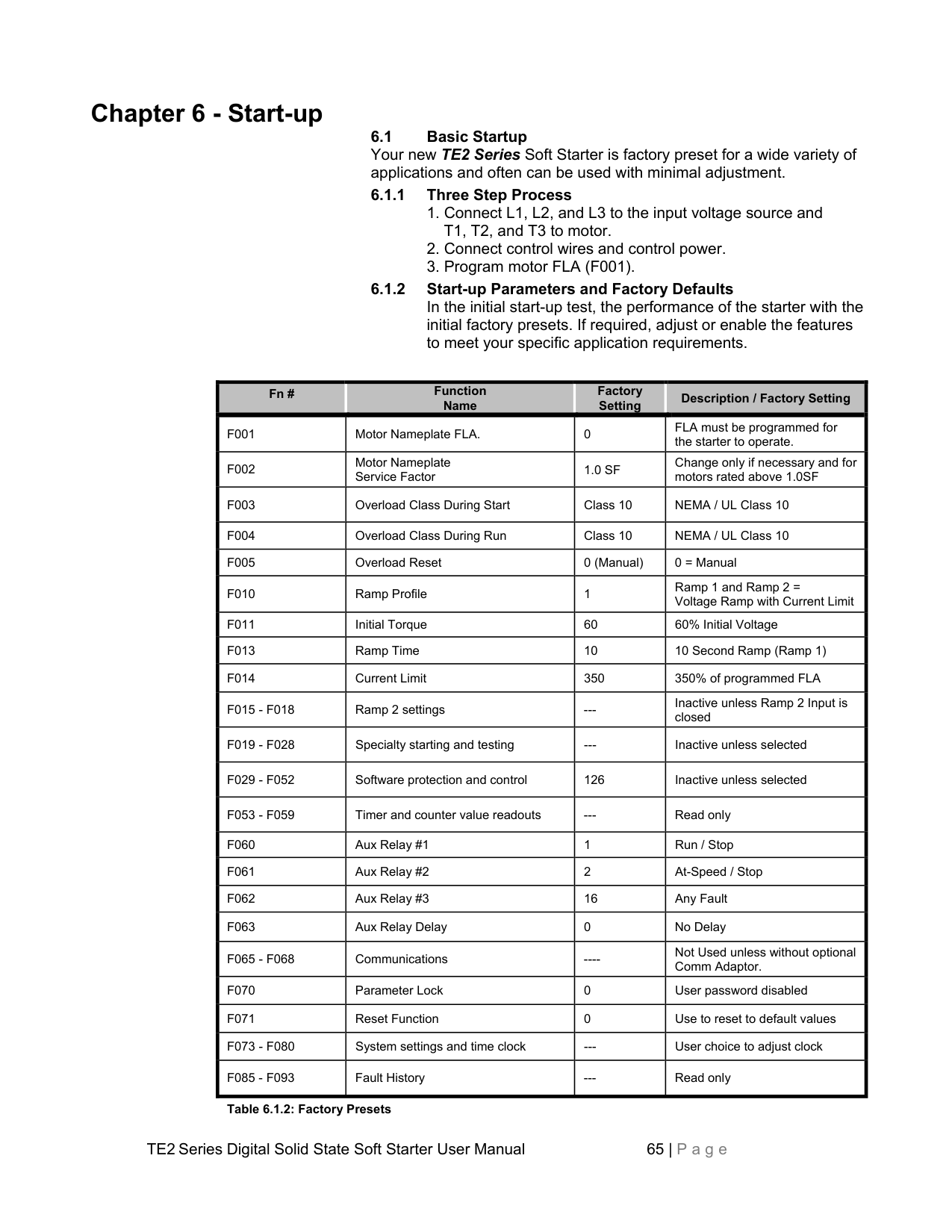
|3|XXXX (A) or XX.XX (kA)|Ic: Phase C Current Shows XX.XX if Iavg>9999 Amp.| |4|GXXX|Igf: Ground Fault Current| |5|UXXX|Uab: Line Voltage AB| |6|UXXX|Ubc: Line Voltage BC| |7|UXXX|Uca: Line Voltage CA| |8|LXXX (L is like superscript) or LXXX (L is like subscript)|Power Factor (A large L is for Lead and a small L is for lag). Either of them is shown at leftmost digit)| |9|PXXX|KW (w/o decimal point) or MW (w/ decimal point): Kilo-watt (range: 000 - 999); Mega-watt (range: 0.00 - 9.99)| |10|XXXX (A) or XX.XX (kA)|Iavg: Average of 3 Phase Currents (It is factory default display); Shows XX.XX if Iavg>9999 Amp.| |11|UXXX|Uavg: Average of 3 Line Voltages| |12|HXXX|Thermal Capacity Remaining|
Range = 0 - 7 Sets system settings.
################## Quick Setup of F113:
|Data|Dual Ramp Input|Jog Input| |---|---|---| |0|Dual Ramp|Jog| |1|Dual Ramp|Remote / Local| |2|Dual Ramp|Ext. Lockout N/O button| |3|Dual Ramp|Ext. Lockout N/C button| |4|RESET|Jog| |5|RESET|Remote / Local| |6|RESET|Ext. Lockout N/O button| |7|RESET|Ext. Lockout N/C button|
##### Chapter 6 - Start-up
6.1 Basic Startup Your new TE2 Series Soft Starter is factory preset for a wide variety of applications and often can be used with minimal adjustment.
################## 6.1.1 Three Step Process
################### 6.1.2 Start-up Parameters and Factory DefaultsIn the initial start-up test, the performance of the starter with theinitial factory presets. If required, adjust or enable the featuresto meet your specific application requirements.
|Fn #|Function Name
|Factory Setting
|Description / Factory Setting| |---|---|---|---| |F001|Motor Nameplate FLA.|0|FLA must be programmed for the starter to operate.| |F002|Motor Nameplate Service Factor|1.0 SF|Change only if necessary and for motors rated above 1.0SF| |F003|Overload Class During Start|Class 10|NEMA / UL Class 10| |F004|Overload Class During Run|Class 10|NEMA / UL Class 10| |F005|Overload Reset|0 (Manual)|0 = Manual| |F010|Ramp Profile|1|Ramp 1 and Ramp 2 = Voltage Ramp with Current Limit| |F011|Initial Torque|60|60% Initial Voltage| |F013|Ramp Time|10|10 Second Ramp (Ramp 1)| |F014|Current Limit|350|350% of programmed FLA| |F015 - F018|Ramp 2 settings|---|Inactive unless Ramp 2 Input is closed| |F019 - F028|Specialty starting and testing|---|Inactive unless selected| |F029 - F052|Software protection and control|126|Inactive unless selected| |F053 - F059|Timer and counter value readouts|---|Read only| |F060|Aux Relay #1|1|Run / Stop| |F061|Aux Relay #2|2|At-Speed / Stop| |F062|Aux Relay #3|16|Any Fault| |F063|Aux Relay Delay|0|No Delay| |F065 - F068|Communications|----|Not Used unless without optional Comm Adaptor.| |F070|Parameter Lock|0|User password disabled| |F071|Reset Function|0|Use to reset to default values| |F073 - F080|System settings and time clock|---|User choice to adjust clock|
|F085 - F093|Fault History|---|Read only|
Table 6.1.2: Factory Presets
################## 6.2 Start-up Check List
################## 6.3 Sequence of Operation
################## If Pump-Flex Decel is programmed in F025:
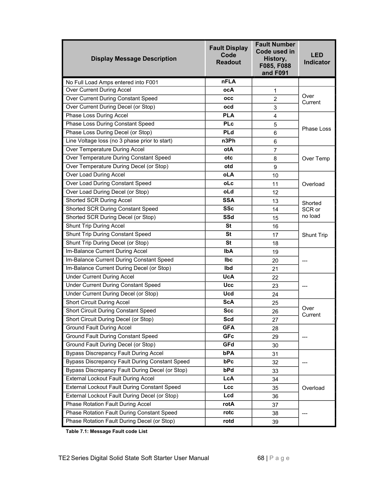
If the unit does not follow this operational sequence, please refer to the Service and Troubleshooting Guide section.
################## 6.4 Testing with a smaller motor
To test the TE2 Series starter in combination with a motor that draws less than Less than 20% of the FLA setting in F001, the Phase Current Loss (Running) protection must be disabled as per instructions in section 5.6.14 (F101). If this feature is not disabled, the TE2 Series will trip on a Phase Loss fault after running for 3 seconds at low current levels.
##### Chapter 7 - Fault Conditions
7.1 Fault Codes and Numbers (in History) A two or three character fault code is displayed in the LED display at the time of the trip event. For three character codes, the first two characters indicate the trip condition (see Table 7.1). The third digit is a suffix showing the TE2 Series operating mode when the trip occurred. Operating modes are as follows:
Code suffix “A”: Acceleration, meaning that the TE2 Series was ramping up, but had not yet achieved “At-Speed” status (see table 5.2 for a brief description of At-Speed indication).
################## IMPORTANT NOTE: Fault code SSd may display if there is no output load (motor) connection when control power is applied!
In addition to these fault display codes, each trip condition has a corresponding numeric code that is stored in the Fault History. The numeric codes follow the display codes exactly. Table 7.1 shows the Fault Display Codes, Fault Number Codes, and LED indicators for each fault condition. Additional details are available in the Service and Troubleshooting Guide.
Example: If Function F003 (starting overload protection) is set too low for the size of the load and causes a trip, the fault code “oLA” will be displayed. Its corresponding number will be entered into the fault history. In this case, the number 0010 will be shown on the display in
|Display Message Description|Fault Display Code Readout
|Fault Number Code used in History, F085, F088 and F091
|LED Indicator
| |---|---|---|---|
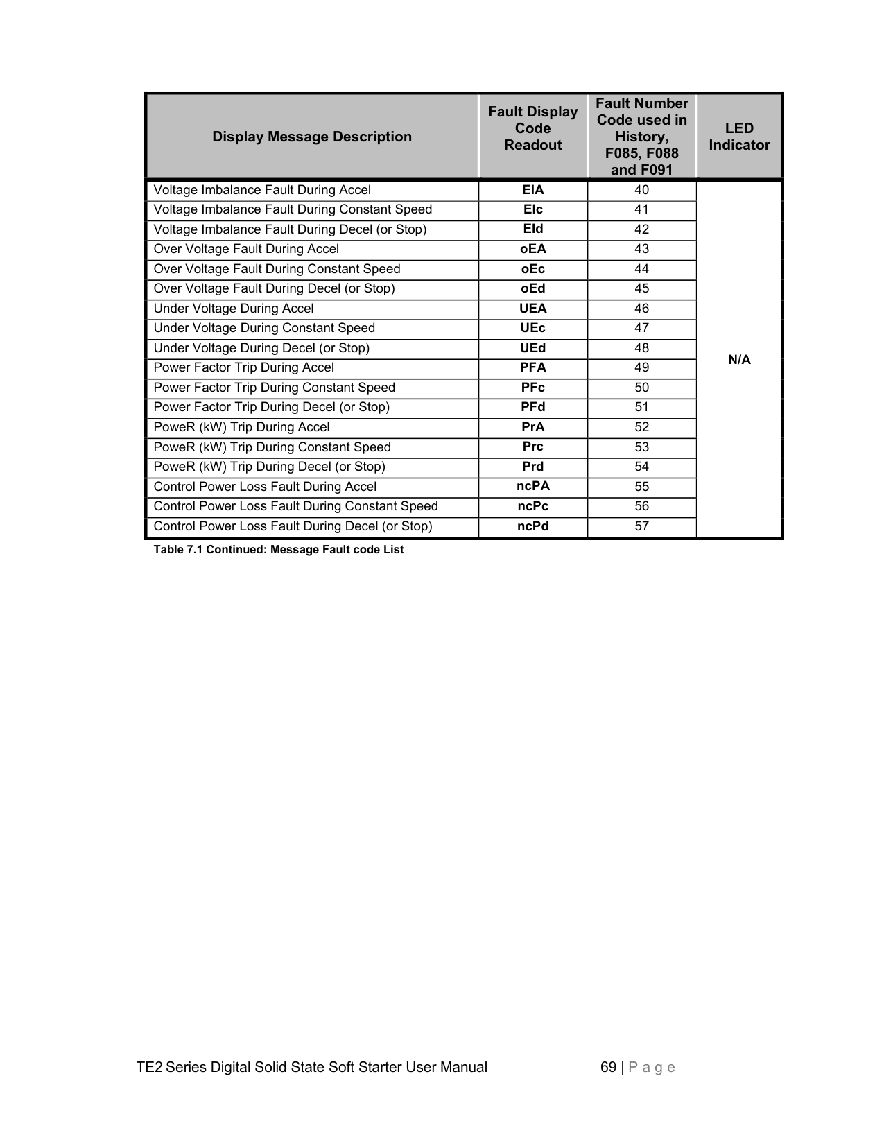
|No Full Load Amps entered into F001|nFLA| | | |Over Current During Accel|ocA|1|Over Current| |Over Current During Constant Speed|occ|2|Over Current| |Over Current During Decel (or Stop)|ocd|3|Over Current| |Phase Loss During Accel|PLA|4|Phase Loss
| |Phase Loss During Constant Speed|PLc|5|Phase Loss
| |Phase Loss During Decel (or Stop)|PLd|6|Phase Loss
| |Line Voltage loss (no 3 phase prior to start)|n3Ph|6|Phase Loss
| |Over Temperature During Accel|otA|7|Over Temp| |Over Temperature During Constant Speed|otc|8|Over Temp| |Over Temperature During Decel (or Stop)|otd|9|Over Temp| |Over Load During Accel|oLA|10|Overload
| |Over Load During Constant Speed|oLc|11|Overload
| |Over Load During Decel (or Stop)|oLd|12|Overload
| |Shorted SCR During Accel|SSA|13|Shorted SCR or no load| |Shorted SCR During Constant Speed|SSc|14|Shorted SCR or no load| |Shorted SCR During Decel (or Stop)|SSd|15|Shorted SCR or no load| |Shunt Trip During Accel|St|16|Shunt Trip| |Shunt Trip During Constant Speed|St|17|Shunt Trip| |Shunt Trip During Decel (or Stop)|St|18|Shunt Trip| |Im-Balance Current During Accel|IbA|19|---
| |Im-Balance Current During Constant Speed|Ibc|20|---
| |Im-Balance Current During Decel (or Stop)|Ibd|21|---
| |Under Current During Accel|UcA|22|---
| |Under Current During Constant Speed|Ucc|23|---
| |Under Current During Decel (or Stop)|Ucd|24|---
| |Short Circuit During Accel|ScA|25|Over Current| |Short Circuit During Constant Speed|Scc|26|Over Current| |Short Circuit During Decel (or Stop)|Scd|27|Over Current| |Ground Fault During Accel|GFA|28|---
| |Ground Fault During Constant Speed|GFc|29|---
| |Ground Fault During Decel (or Stop)|GFd|30|---
| |Bypass Discrepancy Fault During Accel|bPA|31|---
| |Bypass Discrepancy Fault During Constant Speed|bPc|32|---
|
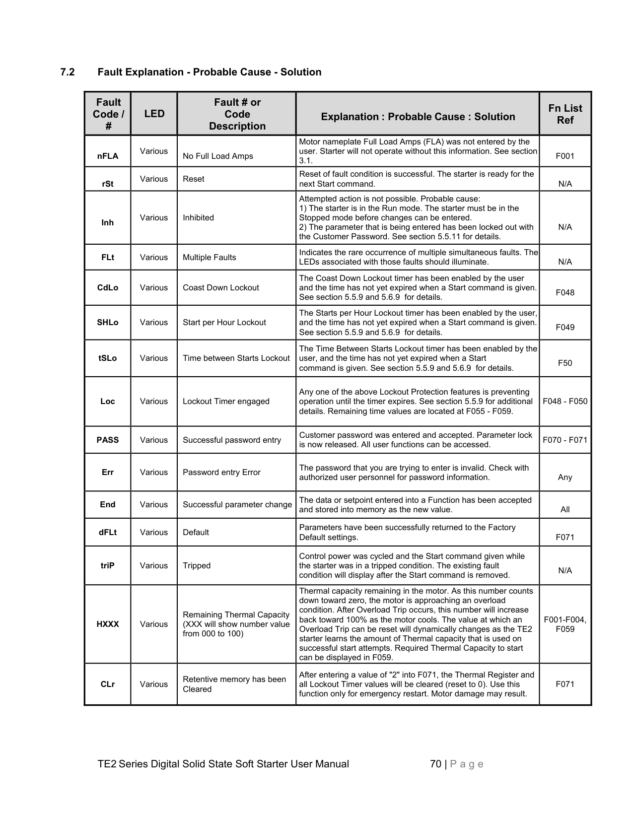
|Bypass Discrepancy Fault During Decel (or Stop)|bPd|33|---
| |External Lockout Fault During Accel|LcA|34|Overload
| |External Lockout Fault During Constant Speed|Lcc|35|Overload
| |External Lockout Fault During Decel (or Stop)|Lcd|36|Overload
| |Phase Rotation Fault During Accel|rotA|37|---| |Phase Rotation Fault During Constant Speed|rotc|38|---| |Phase Rotation Fault During Decel (or Stop)|rotd|39|---|
######################## Table 7.1: Message Fault code List
|Display Message Description|Fault Display Code Readout
|Fault Number Code used in History, F085, F088 and F091
|LED Indicator
| |---|---|---|---| |Voltage Imbalance Fault During Accel|EIA|40|N/A
| |Voltage Imbalance Fault During Constant Speed|EIc|41|N/A
| |Voltage Imbalance Fault During Decel (or Stop)|EId|42|N/A
| |Over Voltage Fault During Accel|oEA|43|N/A
| |Over Voltage Fault During Constant Speed|oEc|44|N/A
| |Over Voltage Fault During Decel (or Stop)|oEd|45|N/A
| |Under Voltage During Accel|UEA|46|N/A
| |Under Voltage During Constant Speed|UEc|47|N/A
| |Under Voltage During Decel (or Stop)|UEd|48|N/A
| |Power Factor Trip During Accel|PFA|49|N/A
| |Power Factor Trip During Constant Speed|PFc|50|N/A
| |Power Factor Trip During Decel (or Stop)|PFd|51|N/A
| |PoweR (kW) Trip During Accel|PrA|52|N/A
| |PoweR (kW) Trip During Constant Speed|Prc|53|N/A
| |PoweR (kW) Trip During Decel (or Stop)|Prd|54|N/A
| |Control Power Loss Fault During Accel|ncPA|55|N/A
| |Control Power Loss Fault During Constant Speed|ncPc|56|N/A
| |Control Power Loss Fault During Decel (or Stop)|ncPd|57|N/A
|
######################## Table 7.1 Continued: Message Fault code List
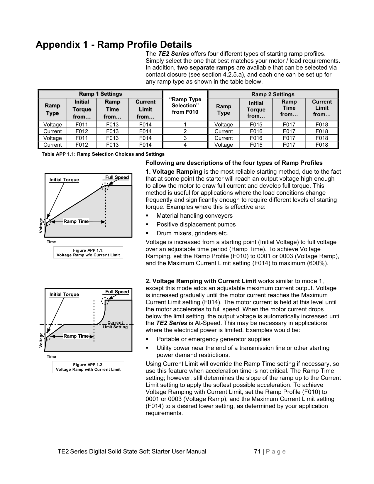
################## 7.2 Fault Explanation - Probable Cause - Solution
|Fault Code / #
|LED|Fault # or Code Description
|Explanation : Probable Cause : Solution|Fn List Ref
| |---|---|---|---|---| |nFLA|Various|No Full Load Amps|Motor nameplate Full Load Amps (FLA) was not entered by the user. Starter will not operate without this information. See section 3.1.|F001| |rSt|Various|Reset|Reset of fault condition is successful. The starter is ready for the next Start command.|N/A| |Inh|Various|Inhibited|Attempted action is not possible. Probable cause:
1) The starter is in the Run mode. The starter must be in the Stopped mode before changes can be entered.
2) The parameter that is being entered has been locked out with the Customer Password. See section 5.5.11 for details.
|N/A| |FLt|Various|Multiple Faults|Indicates the rare occurrence of multiple simultaneous faults. The LEDs associated with those faults should illuminate.|N/A| |CdLo|Various|Coast Down Lockout|The Coast Down Lockout timer has been enabled by the user and the time has not yet expired when a Start command is given. See section 5.5.9 and 5.6.9 for details.|F048| |SHLo|Various|Start per Hour Lockout|The Starts per Hour Lockout timer has been enabled by the user, and the time has not yet expired when a Start command is given. See section 5.5.9 and 5.6.9 for details.|F049| |tSLo|Various|Time between Starts Lockout|The Time Between Starts Lockout timer has been enabled by the user, and the time has not yet expired when a Start command is given. See section 5.5.9 and 5.6.9 for details.|F50| |Loc|Various|Lockout Timer engaged|Any one of the above Lockout Protection features is preventing operation until the timer expires. See section 5.5.9 for additional details. Remaining time values are located at F055 - F059.|F048 - F050| |PASS|Various|Successful password entry|Customer password was entered and accepted. Parameter lock is now released. All user functions can be accessed.|F070 - F071| |Err|Various|Password entry Error|The password that you are trying to enter is invalid. Check with authorized user personnel for password information.|Any| |End|Various|Successful parameter change|The data or setpoint entered into a Function has been accepted and stored into memory as the new value.|All| |dFLt|Various|Default|Parameters have been successfully returned to the Factory Default settings.|F071| |triP|Various|Tripped|Control power was cycled and the Start command given while the starter was in a tripped condition. The existing fault condition will display after the Start command is removed.|N/A| |HXXX|Various|Remaining Thermal Capacity (XXX will show number value from 000 to 100)|Thermal capacity remaining in the motor. As this number counts down toward zero, the motor is approaching an overload condition. After Overload Trip occurs, this number will increase back toward 100% as the motor cools. The value at which an Overload Trip can be reset will dynamically changes as the TE2 starter learns the amount of Thermal capacity that is used on successful start attempts. Required Thermal Capacity to start can be displayed in F059.|F001-F004, F059| |CLr|Various|Retentive memory has been Cleared|After entering a value of "2" into F071, the Thermal Register and all Lockout Timer values will be cleared (reset to 0). Use this function only for emergency restart. Motor damage may result.|F071|
##### Appendix 1 - Ramp Profile Details
The TE2 Series offers four different types of starting ramp profiles. Simply select the one that best matches your motor / load requirements. In addition, two separate ramps are available that can be selected via contact closure (see section 4.2.5.a), and each one can be set up for any ramp type as shown in the table below.
|
Ramp 1 Settings|
Ramp 1 Settings|
Ramp 1 Settings|
Ramp 1 Settings|“Ramp Type Selection” from F010|Ramp 2 Settings|Ramp 2 Settings|Ramp 2 Settings|Ramp 2 Settings| |---|---|---|---|---|---|---|---|---| |
Ramp Type
|
Initial Torque from…

|
Ramp Time from…

|
Current Limit from…

|“Ramp Type Selection” from F010|Ramp Type
|Initial Torque from…
|Ramp Time from…
|Current Limit from…
| |Voltage|F011|F013|F014|1|Voltage|F015|F017|F018| |Current|F012|F013|F014|2|Current|F016|F017|F018| |Voltage|F011|F013|F014|3|Current|F016|F017|F018| |Current|F012|F013|F014|4|Voltage|F015|F017|F018|
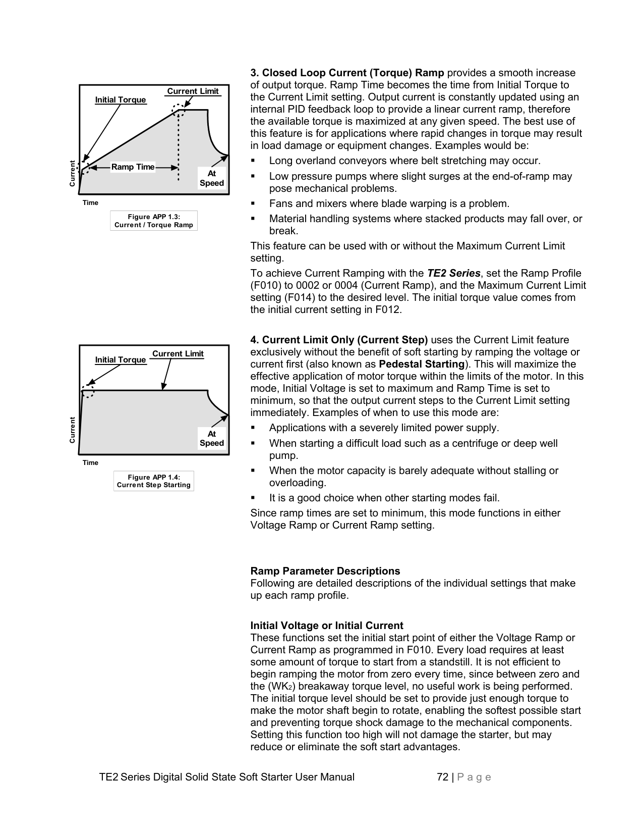
Table APP 1.1: Ramp Selection Choices and Settings
################## Following are descriptions of the four types of Ramp Profiles
Full Speed
Initial Torque
Voltage
######################### Ramp Time
Time
|Figure APP 1.1: Voltage Ramp w/o Current Limit| |---|
Full Speed
Initial Torque
Current Limit Setting
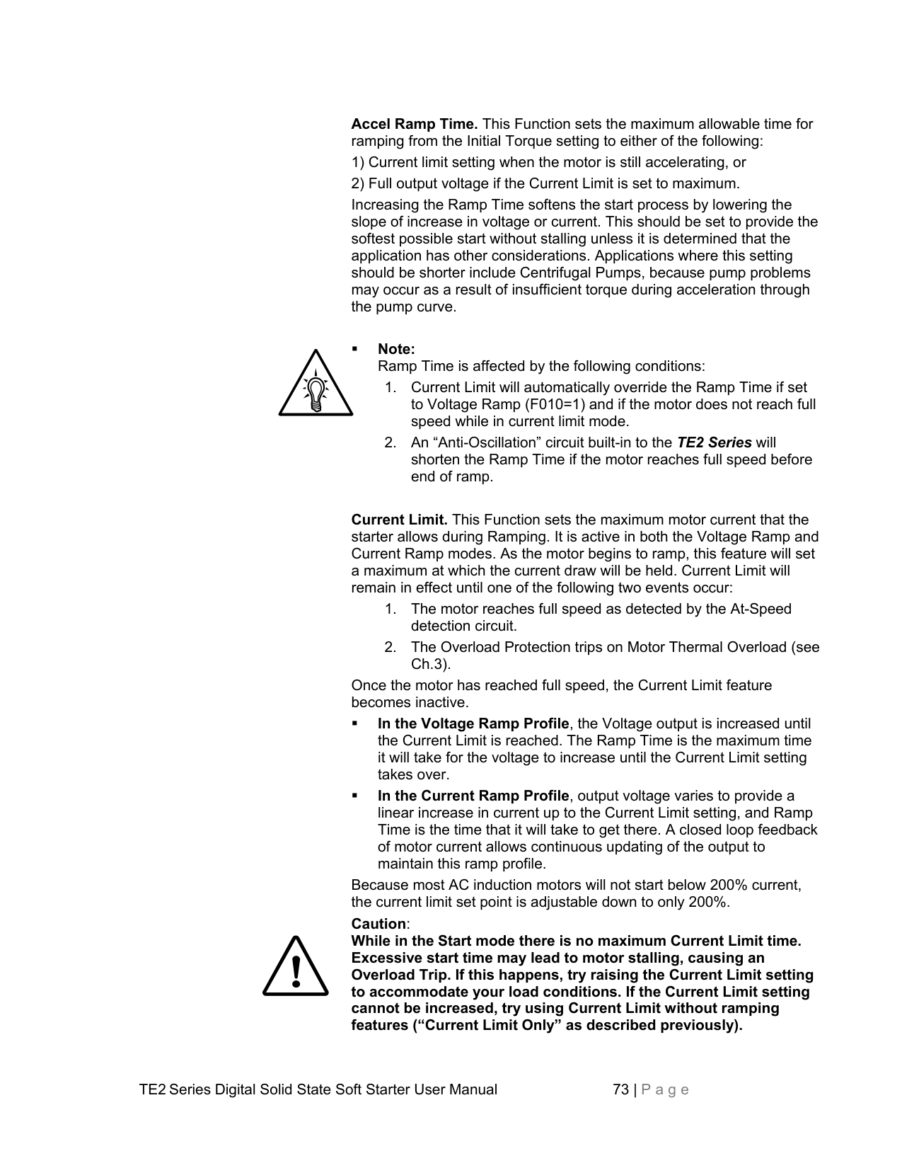
Voltage
Ramp Time
Time
Using Current Limit will override the Ramp Time setting if necessary, so use this feature when acceleration time is not critical. The Ramp Time setting; however, still determines the slope of the ramp up to the Current Limit setting to apply the softest possible acceleration. To achieve Voltage Ramping with Current Limit, set the Ramp Profile (F010) to 0001 or 0003 (Voltage Ramp), and the Maximum Current Limit setting (F014) to a desired lower setting, as determined by your application requirements.
|Figure APP 1.2: Voltage Ramp with Current Limit| |---|
Current Limit
Initial Torque
Current
Ramp Time
At Speed
Time
|Figure APP 1.3: Current / Torque Ramp| |---|
|Initial Torque
Current Limit
At Speed
|
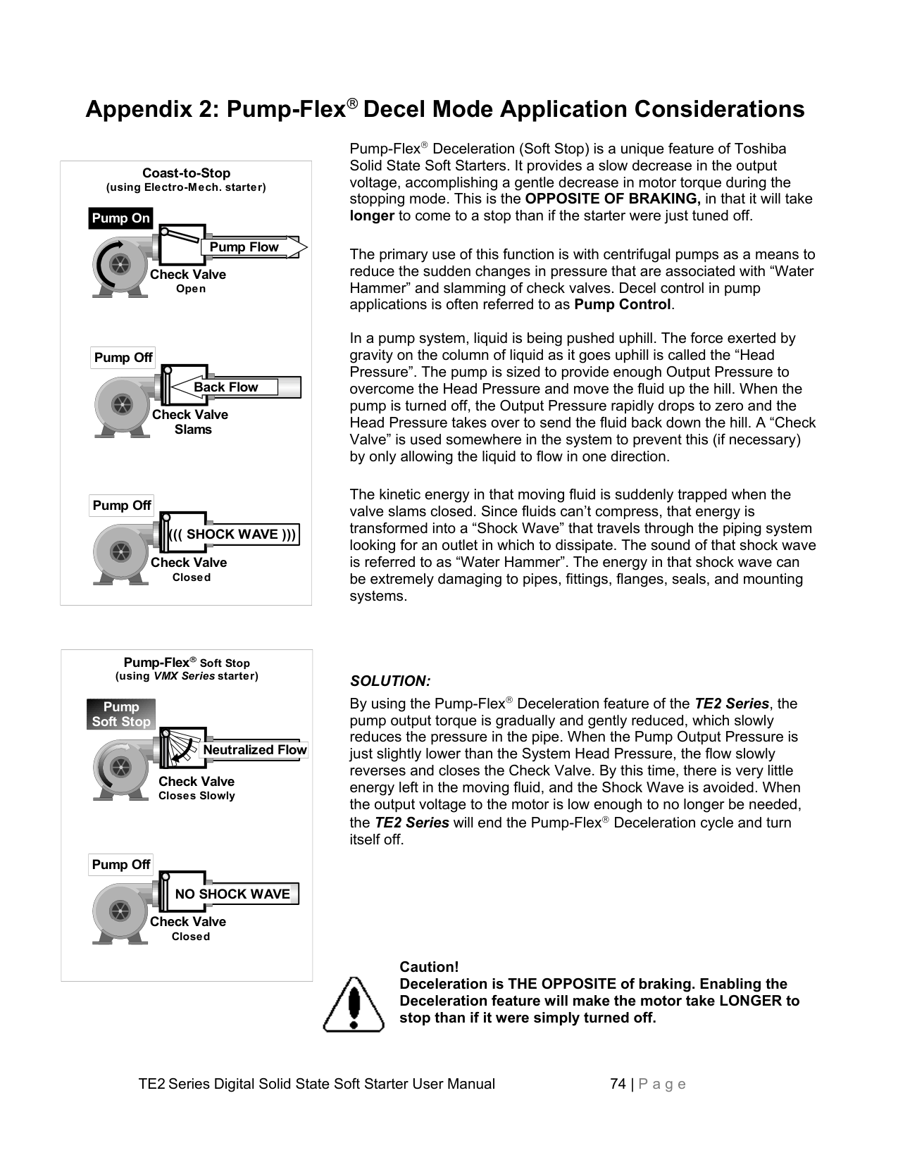
|---|
Current
Time
|Figure APP 1.4: Current Step Starting| |---|
This feature can be used with or without the Maximum Current Limit setting. To achieve Current Ramping with the TE2 Series, set the Ramp Profile (F010) to 0002 or 0004 (Current Ramp), and the Maximum Current Limit setting (F014) to the desired level. The initial torque value comes from the initial current setting in F012.
Since ramp times are set to minimum, this mode functions in either Voltage Ramp or Current Ramp setting.
Ramp Parameter Descriptions Following are detailed descriptions of the individual settings that make up each ramp profile.
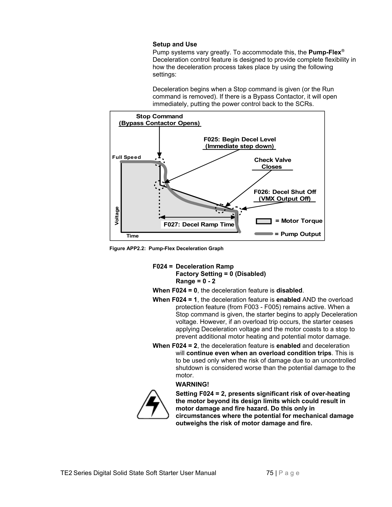
Initial Voltage or Initial Current These functions set the initial start point of either the Voltage Ramp or Current Ramp as programmed in F010. Every load requires at least some amount of torque to start from a standstill. It is not efficient to begin ramping the motor from zero every time, since between zero and the (WK2) breakaway torque level, no useful work is being performed. The initial torque level should be set to provide just enough torque to make the motor shaft begin to rotate, enabling the softest possible start and preventing torque shock damage to the mechanical components. Setting this function too high will not damage the starter, but may reduce or eliminate the soft start advantages.
Accel Ramp Time. This Function sets the maximum allowable time for ramping from the Initial Torque setting to either of the following:
Increasing the Ramp Time softens the start process by lowering the slope of increase in voltage or current. This should be set to provide the softest possible start without stalling unless it is determined that the application has other considerations. Applications where this setting should be shorter include Centrifugal Pumps, because pump problems may occur as a result of insufficient torque during acceleration through the pump curve.
Note: Ramp Time is affected by the following conditions:
Current Limit. This Function sets the maximum motor current that the starter allows during Ramping. It is active in both the Voltage Ramp and Current Ramp modes. As the motor begins to ramp, this feature will set a maximum at which the current draw will be held. Current Limit will remain in effect until one of the following two events occur:
Ch.3). Once the motor has reached full speed, the Current Limit feature becomes inactive.
Because most AC induction motors will not start below 200% current, the current limit set point is adjustable down to only 200%.
Caution: While in the Start mode there is no maximum Current Limit time. Excessive start time may lead to motor stalling, causing an Overload Trip. If this happens, try raising the Current Limit setting to accommodate your load conditions. If the Current Limit setting cannot be increased, try using Current Limit without ramping features (“Current Limit Only” as described previously).
##### Appendix 2: Pump-Flex Decel Mode Application Considerations
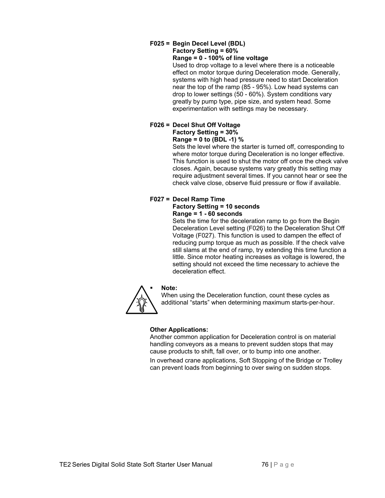
|Pump On
Check Valve
Open
|Pump Off| |---|
Check Valve Slams
Pump Off
Check Valve
Closed
((( SHOCK WAVE )))
Coast-to-Stop (using Electro-Mech. starter)
Pump Flow
Back Flow| |---|
Pump-Flex Deceleration (Soft Stop) is a unique feature of Toshiba Solid State Soft Starters. It provides a slow decrease in the output voltage, accomplishing a gentle decrease in motor torque during the stopping mode. This is the OPPOSITE OF BRAKING, in that it will take longer to come to a stop than if the starter were just tuned off.
The primary use of this function is with centrifugal pumps as a means to reduce the sudden changes in pressure that are associated with “Water Hammer” and slamming of check valves. Decel control in pump applications is often referred to as Pump Control.
In a pump system, liquid is being pushed uphill. The force exerted by gravity on the column of liquid as it goes uphill is called the “Head Pressure”. The pump is sized to provide enough Output Pressure to overcome the Head Pressure and move the fluid up the hill. When the pump is turned off, the Output Pressure rapidly drops to zero and the Head Pressure takes over to send the fluid back down the hill. A “Check Valve” is used somewhere in the system to prevent this (if necessary) by only allowing the liquid to flow in one direction.
The kinetic energy in that moving fluid is suddenly trapped when the valve slams closed. Since fluids can’t compress, that energy is transformed into a “Shock Wave” that travels through the piping system looking for an outlet in which to dissipate. The sound of that shock wave is referred to as “Water Hammer”. The energy in that shock wave can be extremely damaging to pipes, fittings, flanges, seals, and mounting systems.
|Pump Soft Stop
Check Valve Closes Slowly
Neutralized Flow
Pump-Flex Soft Stop (using VMX Series starter)
|Pump Off| |---|
Check Valve
Closed
NO SHOCK WAVE| |---|
SOLUTION: By using the Pump-Flex Deceleration feature of the TE2 Series, the pump output torque is gradually and gently reduced, which slowly reduces the pressure in the pipe. When the Pump Output Pressure is just slightly lower than the System Head Pressure, the flow slowly reverses and closes the Check Valve. By this time, there is very little energy left in the moving fluid, and the Shock Wave is avoided. When the output voltage to the motor is low enough to no longer be needed, the TE2 Series will end the Pump-Flex Deceleration cycle and turn itself off.

################## Caution! Deceleration is THE OPPOSITE of braking. Enabling the Deceleration feature will make the motor take LONGER to stop than if it were simply turned off.
Setup and Use Pump systems vary greatly. To accommodate this, the Pump-Flex Deceleration control feature is designed to provide complete flexibility in how the deceleration process takes place by using the following settings:
Deceleration begins when a Stop command is given (or the Run command is removed). If there is a Bypass Contactor, it will open immediately, putting the power control back to the SCRs.
|Stop Command (Bypass Contactor Opens)
F025: Begin Decel Level (Immediate step down)
F026: Decel Shut Off (VMX Output Off)
Voltage
Time
F027: Decel Ramp Time
Full Speed Check Valve Closes
= Motor Torque
= Pump Output| |---|
Figure APP2.2: Pump-Flex Deceleration Graph

Setting F024 = 2, presents significant risk of over-heating the motor beyond its design limits which could result in motor damage and fire hazard. Do this only in circumstances where the potential for mechanical damage outweighs the risk of motor damage and fire.
Note: When using the Deceleration function, count these cycles as additional “starts” when determining maximum starts-per-hour.
Other Applications: Another common application for Deceleration control is on material handling conveyors as a means to prevent sudden stops that may cause products to shift, fall over, or to bump into one another. In overhead crane applications, Soft Stopping of the Bridge or Trolley can prevent loads from beginning to over swing on sudden stops.
##### Appendix 3: Parameter Lock / User Password Instructions
Provides users with the ability to prevent unauthorized operators from making changes to the programmed functions. If you do not need to take advantage of this feature, do not enter anything into this function. The factory default is disabled, and no Password is necessary to make changes to the program.
When any value other than 0000 is entered into this Function, the Parameter Lock is enabled and that number becomes the User Password. From that point forward, it will be necessary to enter the User Password in this Function prior to making changes in any programmed function, including this one. When the Parameter Lock has been enabled, attempts to alter the program will result in the display reading [Err ] whenever the [READ/ENTER] key is pressed. To alter the program after the Parameter Lock has been enabled, go to Function F070 and enter the correct user Password. The display will read an encoded value representing the existing password. As soon as you press the first Arrow key, the display will change to [0000] and start showing the actual value of your password entry. When the [READ/ ENTER] button is pressed, the display will read [PASS], indicating that the User Password is correct and the system is unlocked. You will have 5 minutes in which to make a change in the program. This 5-minute window resets whenever any key is pressed, so it floats to give you 5 minutes after the last entry. After 5 minutes of no keypad activity, the Parameter Lock is reinstated with the current user Password. Subsequent changes will require re-entering the User Password. To change the User Password or to disable the Parameter Lock function, enter the programmed User Password first, and then set Function F070 to 0, disabling the Parameter Lock. If you do not re-enter the Password or enter a new user password, the Parameter Lock feature will remain disabled. If you enter a different number into this Function, the new number becomes your new User Password. Existing passwords are encoded to “hide” them in the display.

Caution: DO NOT LOSE YOUR PASSWORD. If the password has been lost or forgotten, contact Toshiba for assistance.
|Display
Press Key...
Shows...
Means...
Phase A Current
Select Function #70
Default Setting of Function #70
New Value of First Digit
Cursor (flashing) Position Shift
New Value of Second Digit
0000. F070 3552 0003 0003 0023
End Value Accepted(flashes once)
Return to Function # Display
Figure App 3: Entering a Password
Example: Setting a Password Using Password 123
F070
READ ENTER
Fn
READ ENTER
x 3
x 2
Cursor (flashing) Position Shift
New Value of Second Digit
0023 0123
|
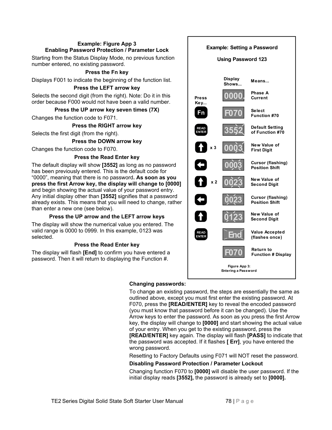
|---|
Example: Figure App 3 Enabling Password Protection / Parameter Lock Starting from the Status Display Mode, no previous function number entered, no existing password.
################## Press the Fn key
Displays F001 to indicate the beginning of the function list.
################## Press the LEFT arrow key
Selects the second digit (from the right). Note: Do it in this order because F000 would not have been a valid number.
Press the UP arrow key seven times (7X) Changes the function code to F071.
Press the RIGHT arrow key Selects the first digit (from the right).
Press the DOWN arrow key Changes the function code to F070.
Press the Read Enter key The default display will show [3552] as long as no password has been previously entered. This is the default code for “0000”, meaning that there is no password. As soon as you press the first Arrow key, the display will change to [0000] and begin showing the actual value of your password entry. Any initial display other than [3552] signifies that a password already exists. This means that you will need to change, rather than enter a new one (see below).
Press the UP arrow and the LEFT arrow keys The display will show the numerical value you entered. The valid range is 0000 to 0999. In this example, 0123 was selected.
Press the Read Enter key The display will flash [End] to confirm you have entered a password. Then it will return to displaying the Function #.
Changing passwords: To change an existing password, the steps are essentially the same as outlined above, except you must first enter the existing password. At F070, press the [READ/ENTER] key to reveal the encoded password (you must know that password before it can be changed). Use the Arrow keys to enter the password. As soon as you press the first Arrow key, the display will change to [0000] and start showing the actual value of your entry. When you get to the existing password, press the [READ/ENTER] key again. The display will flash [PASS] to indicate that the password was accepted. If it flashes [ Err], you have entered the wrong password. Resetting to Factory Defaults using F071 will NOT reset the password. Disabling Password Protection / Parameter Lockout
Changing function F070 to [0000] will disable the user password. If the initial display reads [3552], the password is already set to [0000].
##### Appendix 4 - External Overload Relay Applications
Your TE2 Series starter comes equipped with a very intelligent internal electronic overload protection system, and does not need an external Overload Relay (OLR). There are instances; however, where external OLRs are needed or desired because of the application. These fall into three categories: Higher Level Protection systems, Redundant Backup applications, and Special Motor applications.
Note: If the Deceleration Function is activated (F024), additional consideration must be put into determining how the starter is to operate in the event of an Overload Trip. See Section 5.6.5 for issues regarding this application.
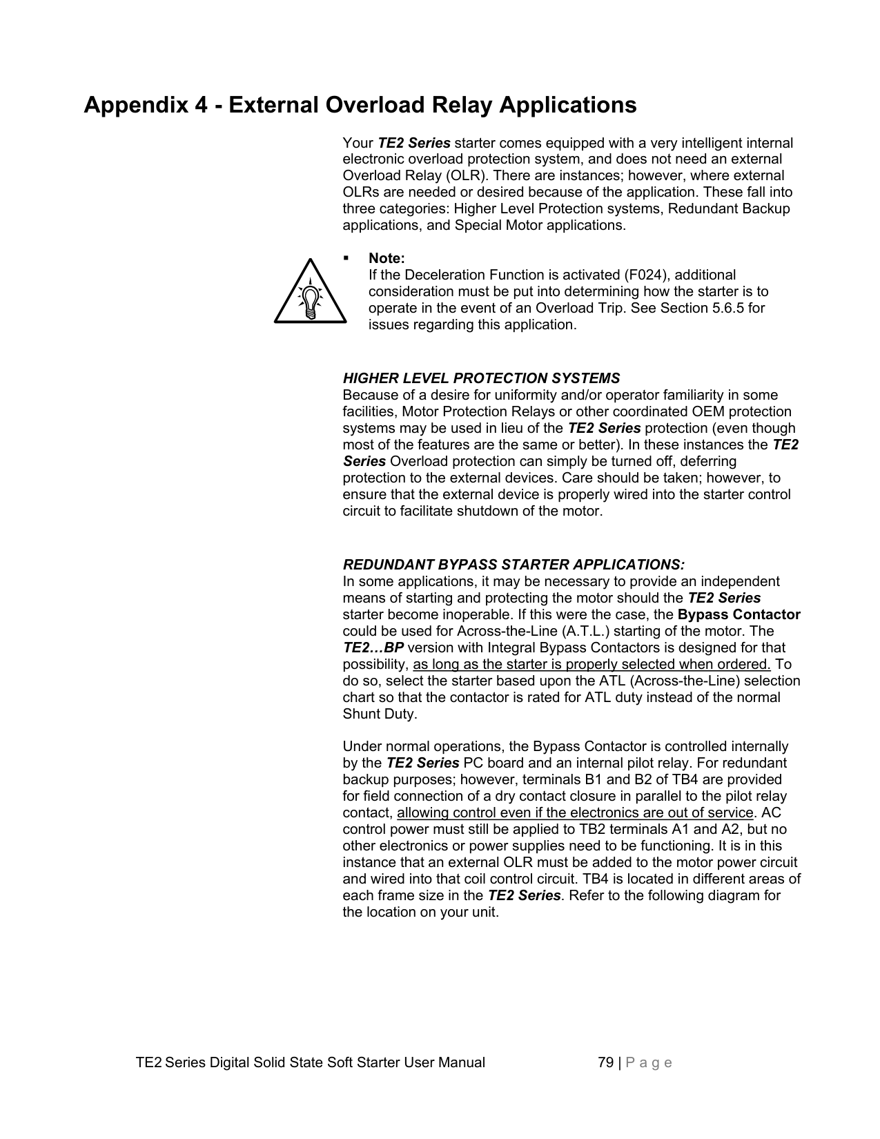
HIGHER LEVEL PROTECTION SYSTEMS Because of a desire for uniformity and/or operator familiarity in some facilities, Motor Protection Relays or other coordinated OEM protection systems may be used in lieu of the TE2 Series protection (even though most of the features are the same or better). In these instances the TE2 Series Overload protection can simply be turned off, deferring protection to the external devices. Care should be taken; however, to ensure that the external device is properly wired into the starter control circuit to facilitate shutdown of the motor.
REDUNDANT BYPASS STARTER APPLICATIONS: In some applications, it may be necessary to provide an independent means of starting and protecting the motor should the TE2 Series starter become inoperable. If this were the case, the Bypass Contactor could be used for Across-the-Line (A.T.L.) starting of the motor. The TE2…BP version with Integral Bypass Contactors is designed for that possibility, as long as the starter is properly selected when ordered. To do so, select the starter based upon the ATL (Across-the-Line) selection chart so that the contactor is rated for ATL duty instead of the normal Shunt Duty.
Under normal operations, the Bypass Contactor is controlled internally by the TE2 Series PC board and an internal pilot relay. For redundant backup purposes; however, terminals B1 and B2 of TB4 are provided for field connection of a dry contact closure in parallel to the pilot relay contact, allowing control even if the electronics are out of service. AC control power must still be applied to TB2 terminals A1 and A2, but no other electronics or power supplies need to be functioning. It is in this instance that an external OLR must be added to the motor power circuit and wired into that coil control circuit. TB4 is located in different areas of each frame size in the TE2 Series. Refer to the following diagram for the location on your unit.
################# TE2 Bypass Control Terminal Location Diagrams
Bypass Control* Terminals 18 - 48A Units with integral bypass
Bypass Control* Terminals 62 - 160A Units with integral bypass
Note: Use these terminals only when separate control of the Bypass Contactor is necessary.
To BP Aux. Contact N.C.
To BP Coil.
| | | |---|---| | | |
Bypass Control Terminals 210 - 600A with integral bypass
|1|2|3|4|5|6|7|7|8|8| |---|---|---|---|---|---|---|---|---|---| | | | | | | | | | | |
120V Supply from A1 & A2 on TB2
| | |
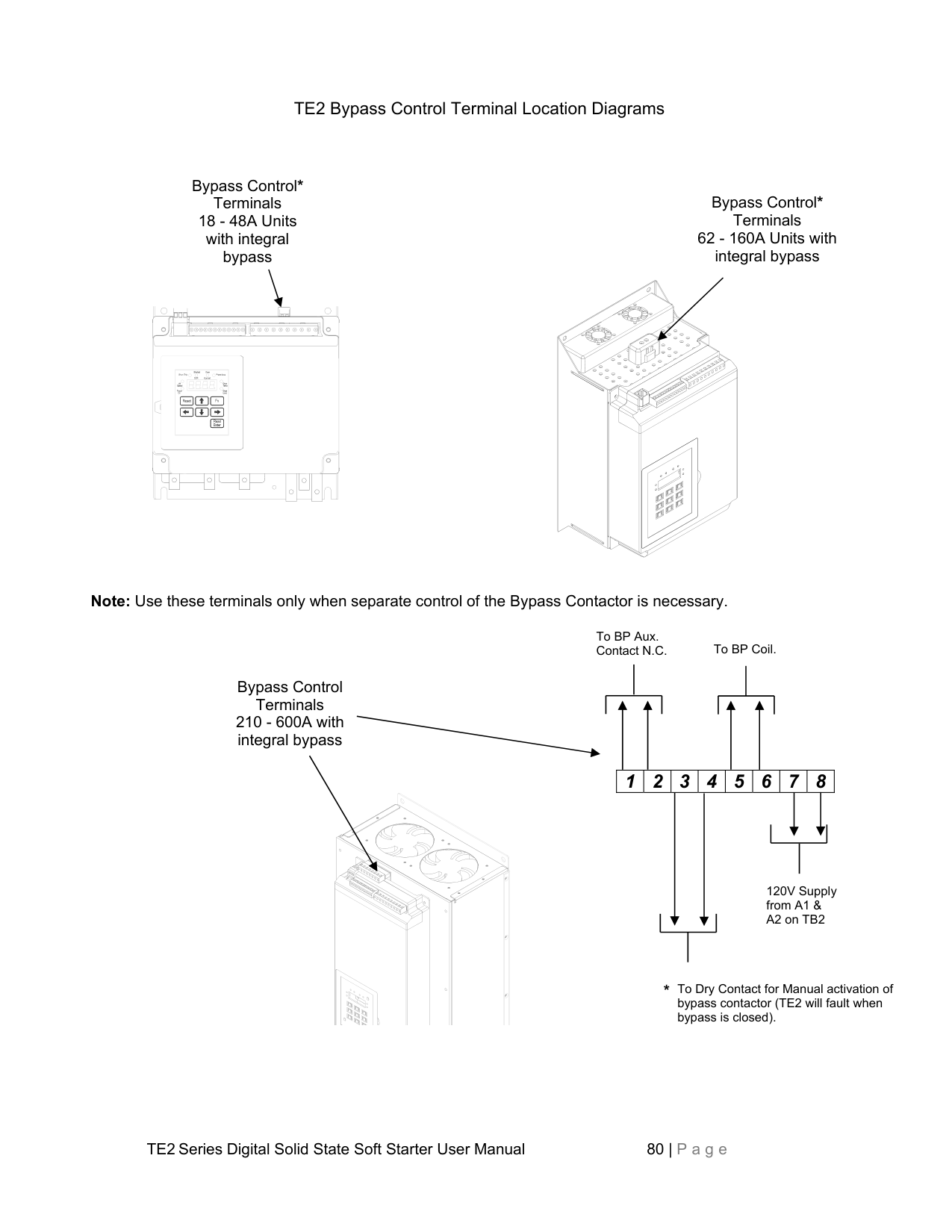
|---|---| | | |
################## *
To Dry Contact for Manual activation of bypass contactor (TE2 will fault when bypass is closed).
Across-the-Line (Direct-on-Line) Bypass A suggested control schematic is shown below for using the TE2 …-BP Series rated for Across-the-Line Bypass with an External Overload:

AC CONTROL POWER
Start / Run Command

Disconnect or Circuit Breaker
CR

############################ (2-wire or 3-wire)


97 98
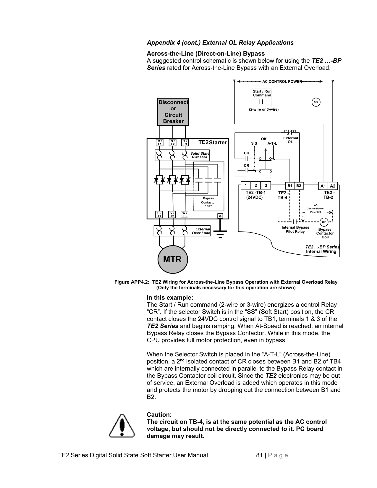
External OL
Off S S A-T-L
TE2Starter.

R / L1
S / L2
T / L3
| | | |---|---| | | |
CR
Solid State. Over Load

############################ CR
1 2 3 A1 A2
B1 B2

TE2 -TB-1 (24VDC)
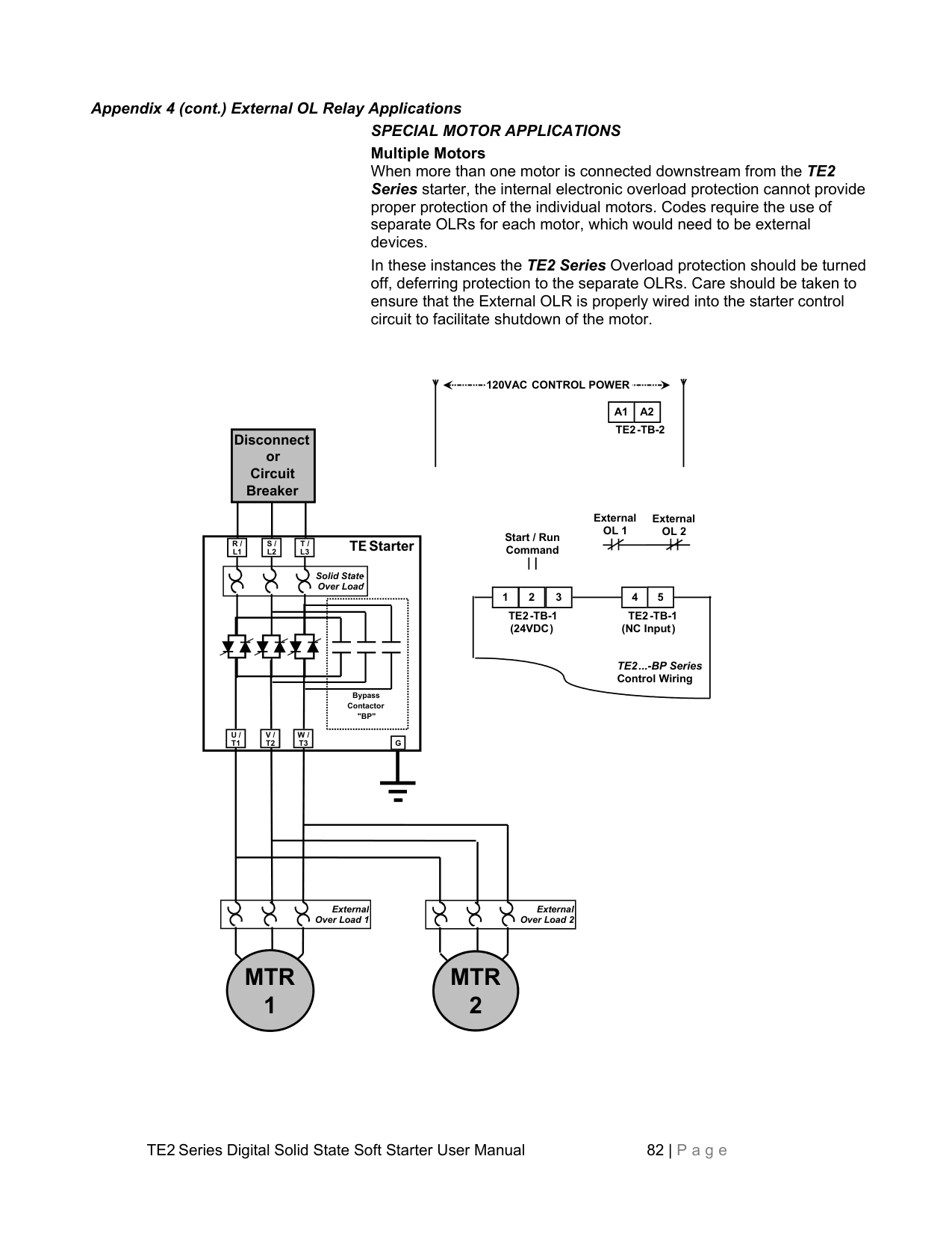
TE2 TB-2
########################### TE2 TB-4
Bypass Contactor "BP"
AC
Control Power Potential
U / T1
V / T2
W / T3
G
BP
Internal Bypass Pilot Relay
External Over Load
Bypass Contactor Coil


TE2 ...-BP Series Internal Wiring
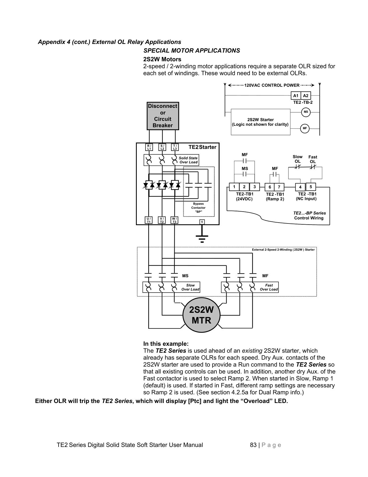

########### MTR
Figure APP4.2: TE2 Wiring for Across-the-Line Bypass Operation with External Overload Relay (Only the terminals necessary for this operation are shown)
In this example: The Start / Run command (2-wire or 3-wire) energizes a control Relay “CR”. If the selector Switch is in the “SS” (Soft Start) position, the CR contact closes the 24VDC control signal to TB1, terminals 1 & 3 of the TE2 Series and begins ramping. When At-Speed is reached, an internal Bypass Relay closes the Bypass Contactor. While in this mode, the CPU provides full motor protection, even in bypass.
When the Selector Switch is placed in the “A-T-L” (Across-the-Line) position, a 2nd isolated contact of CR closes between B1 and B2 of TB4 which are internally connected in parallel to the Bypass Relay contact in the Bypass Contactor coil circuit. Since the TE2 electronics may be out of service, an External Overload is added which operates in this mode and protects the motor by dropping out the connection between B1 and B2.

Caution: The circuit on TB-4, is at the same potential as the AC control voltage, but should not be directly connected to it. PC board damage may result.
Multiple Motors When more than one motor is connected downstream from the TE2 Series starter, the internal electronic overload protection cannot provide proper protection of the individual motors. Codes require the use of separate OLRs for each motor, which would need to be external devices. In these instances the TE2 Series Overload protection should be turned off, deferring protection to the separate OLRs. Care should be taken to ensure that the External OLR is properly wired into the starter control circuit to facilitate shutdown of the motor.

120VAC CONTROL POWER
A1 A2
TE2-TB-2

Disconnect or Circuit Breaker


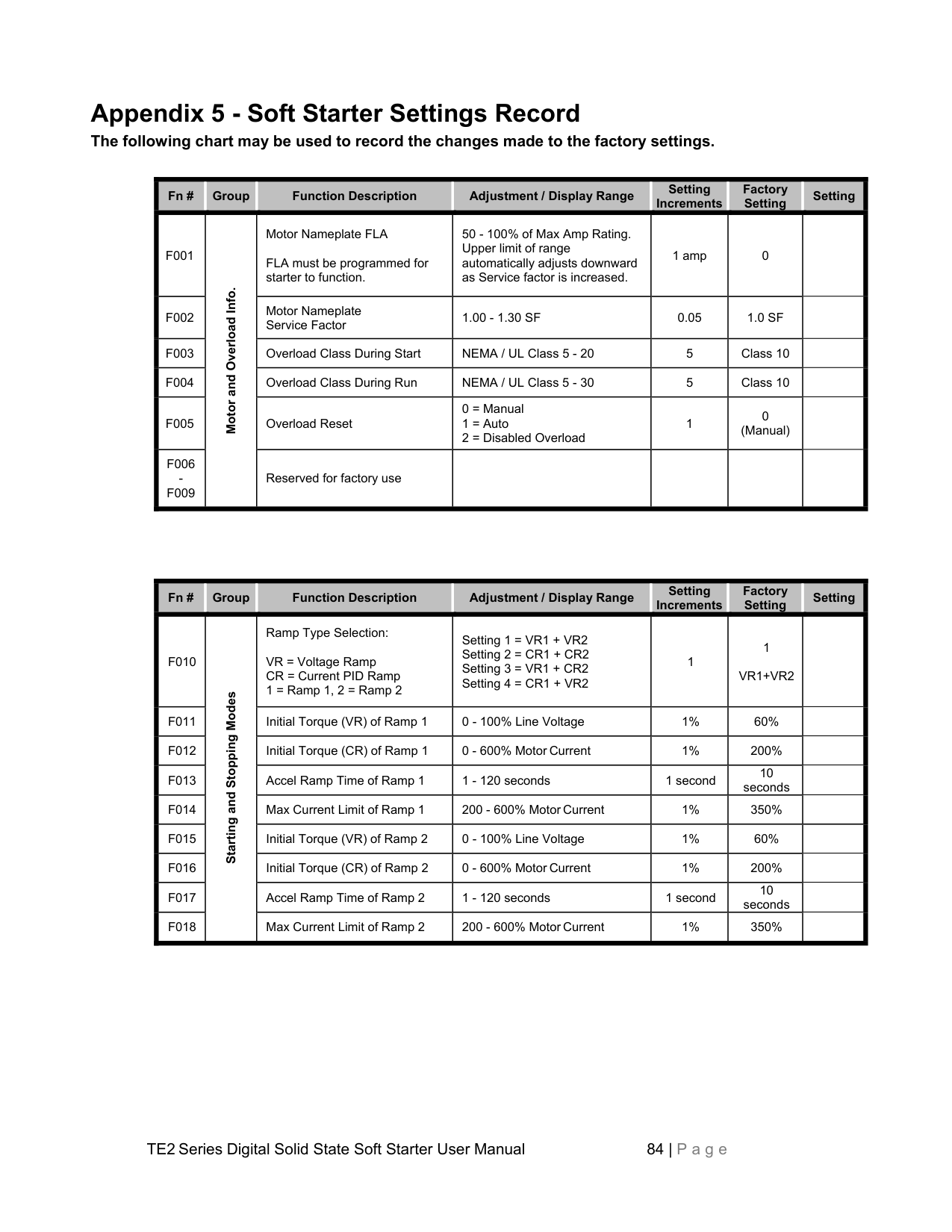
External OL 1
External OL 2
Start / Run Command

TEStarter
R / L1
S / L2
T / L3
Solid State. Over Load.


4 5
1 2 3
TE2-TB-1 (NC Input)
TE2-TB-1 (24VDC)
TE2...-BP Series Control Wiring
Bypass Contactor "BP"
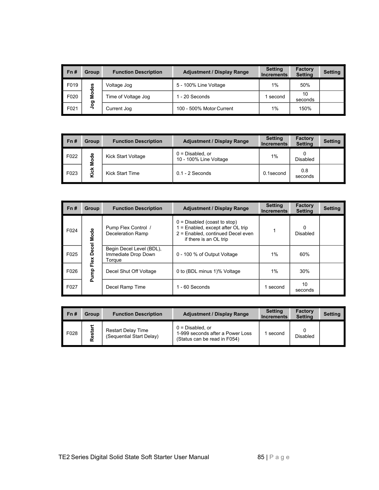
U / T1
V / T2
W / T3
G
External Over Load 1
External Over Load 2


######### MTR 1
######### MTR 2


2S2W Motors 2-speed / 2-winding motor applications require a separate OLR sized for each set of windings. These would need to be external OLRs.

120VAC CONTROL POWER
A1 A2
TE2 -TB-2
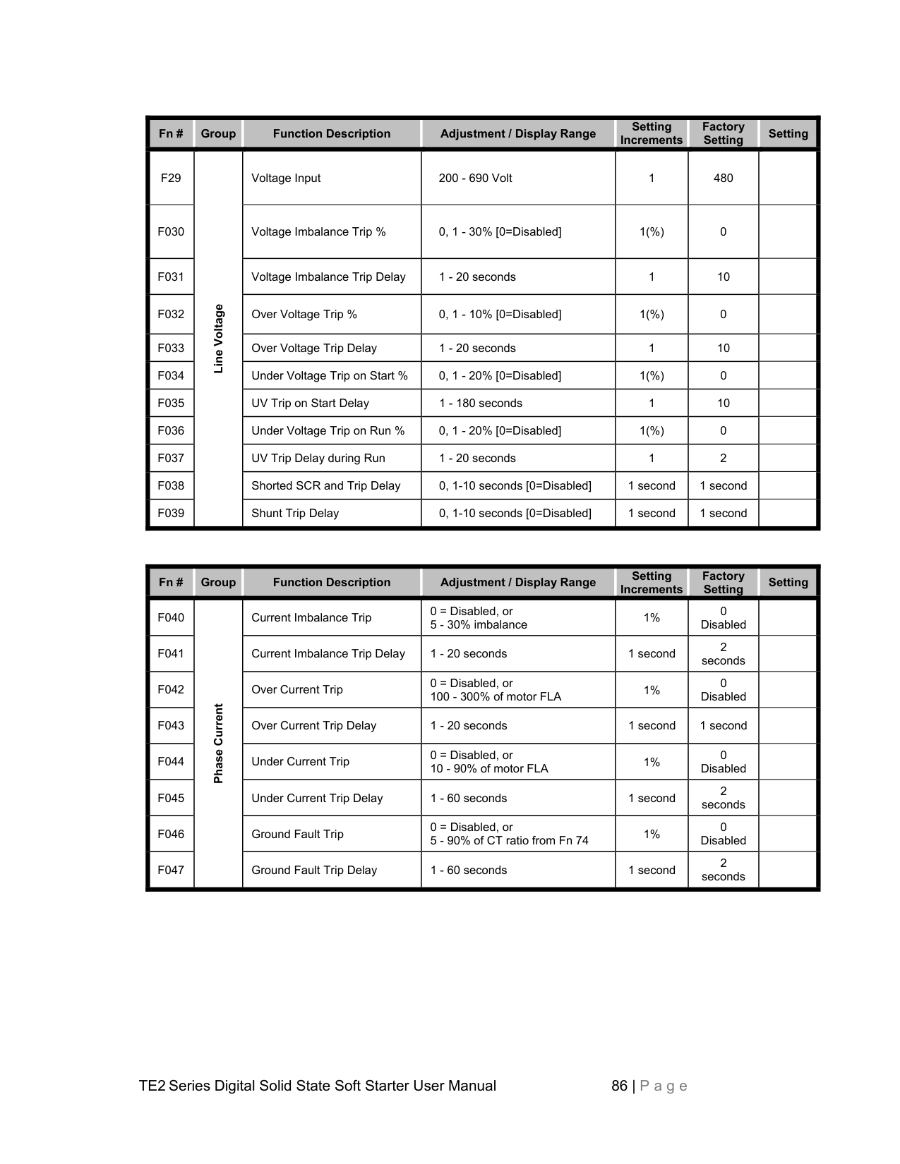

Disconnect or Circuit Breaker

MS

2S2W Starter (Logic not shown for clarity)

MF

R / L1
S / L2
T / L3
TE2Starter
MF
Slow OL
Fast OL
Solid State. Over Load.
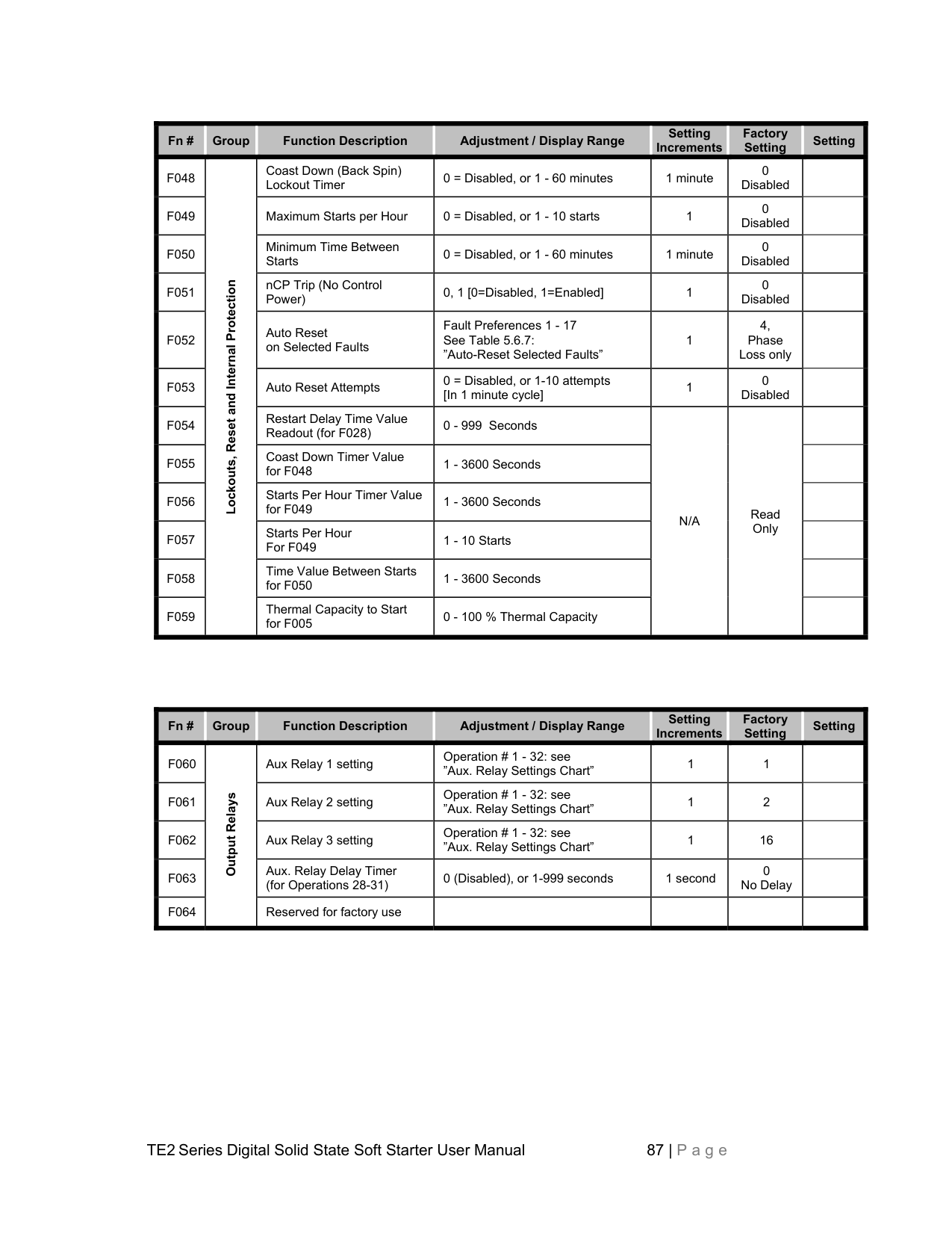


MS
MF
4 5
1 2 3
6 7


TE2 -TB1 (NC Input)

TE2-TB1 (24VDC)
TE2 -TB1 (Ramp 2)
Bypass Contactor "BP"
TE2...-BP Series Control Wiring
U / T1
V / T2
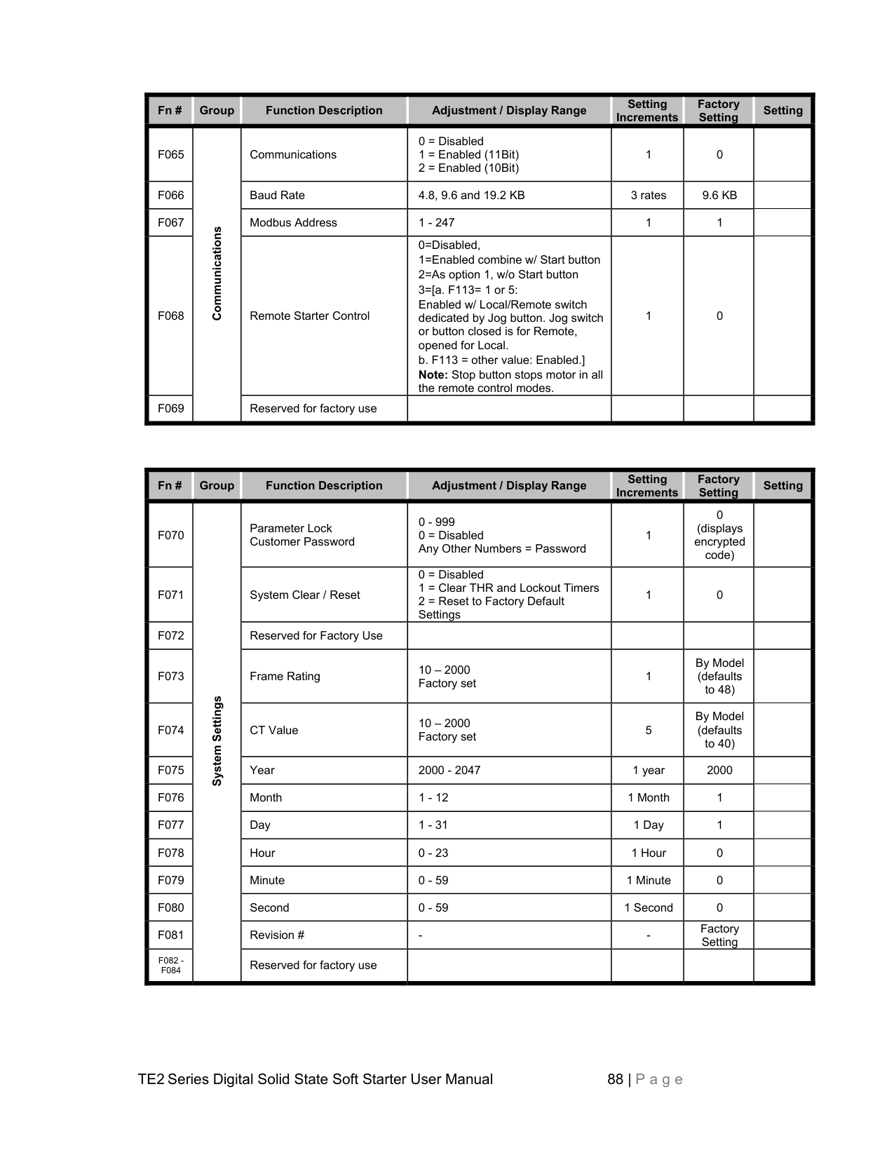
W / T3
G
External 2-Speed 2-Winding ( 2S2W ) Starter
MS MF


Slow Over Load
Fast Over Load

######### 2S2W MTR

In this example: The TE2 Series is used ahead of an existing 2S2W starter, which already has separate OLRs for each speed. Dry Aux. contacts of the 2S2W starter are used to provide a Run command to the TE2 Series so that all existing controls can be used. In addition, another dry Aux. of the Fast contactor is used to select Ramp 2. When started in Slow, Ramp 1 (default) is used. If started in Fast, different ramp settings are necessary so Ramp 2 is used. (See section 4.2.5a for Dual Ramp info.)
Either OLR will trip the TE2 Series, which will display [Ptc] and light the “Overload” LED.
##### Appendix 5 - Soft Starter Settings Record
The following chart may be used to record the changes made to the factory settings.
|Fn #|Group|Function Description|Adjustment / Display Range|Setting Increments
|Factory Setting
|Setting| |---|---|---|---|---|---|---| |F001|Motor and Overload Info.|Motor Nameplate FLA FLA must be programmed for starter to function.|50 - 100% of Max Amp Rating. Upper limit of range automatically adjusts downward as Service factor is increased.|1 amp|0| |
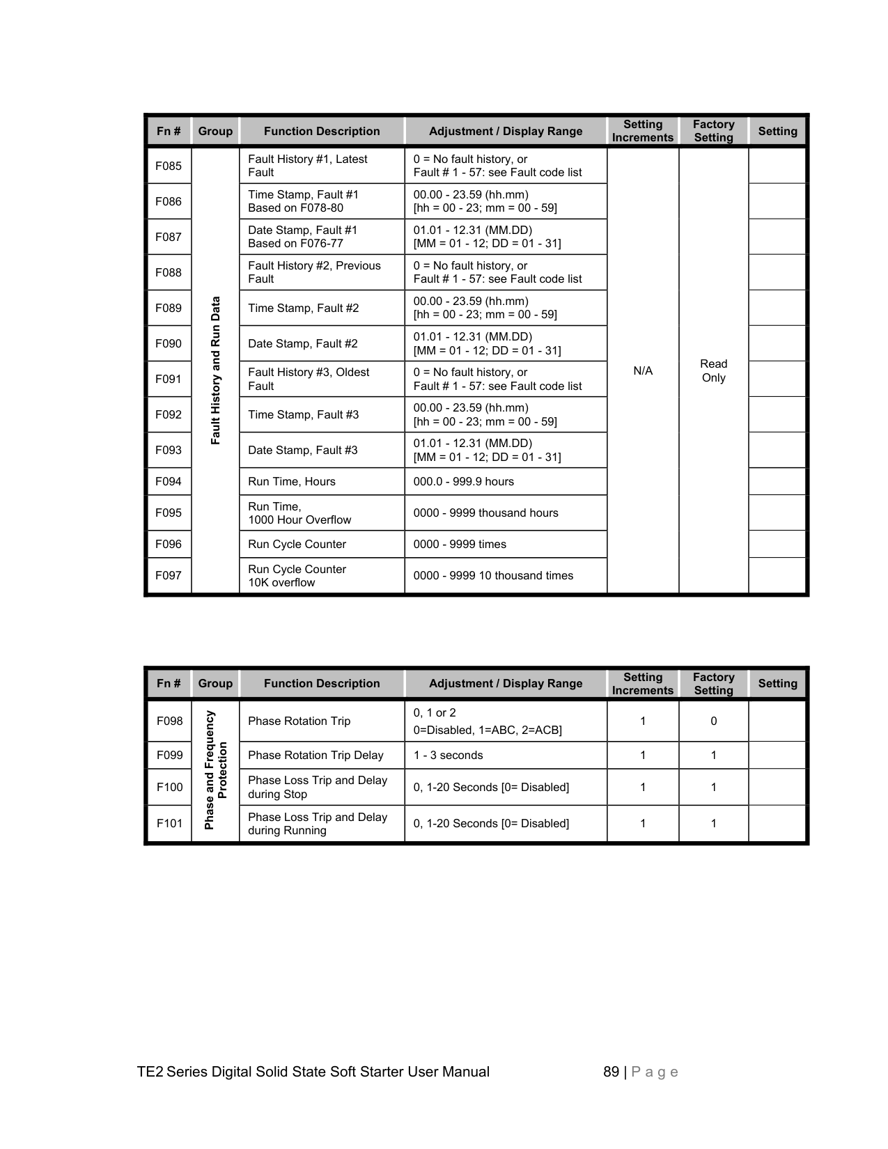
|F002|Motor and Overload Info.|Motor Nameplate Service Factor|1.00 - 1.30 SF|0.05|1.0 SF| | |F003|Motor and Overload Info.|Overload Class During Start|NEMA / UL Class 5 - 20|5|Class 10| | |F004|Motor and Overload Info.|Overload Class During Run|NEMA / UL Class 5 - 30|5|Class 10| | |F005|Motor and Overload Info.|Overload Reset|0 = Manual
1 = Auto
2 = Disabled Overload
|1|0 (Manual)| | |F006 F009|Motor and Overload Info.|Reserved for factory use| | | | |
|Fn #|Group|Function Description|Adjustment / Display Range|Setting Increments
|Factory Setting
|Setting| |---|---|---|---|---|---|---| |F010|Starting and Stopping Modes|Ramp Type Selection: VR = Voltage Ramp CR = Current PID Ramp 1 = Ramp 1, 2 = Ramp 2|Setting 1 = VR1 + VR2
Setting 2 = CR1 + CR2
Setting 3 = VR1 + CR2
Setting 4 = CR1 + VR2
|1|1 VR1+VR2| | |F011|Starting and Stopping Modes|Initial Torque (VR) of Ramp 1|0 - 100% Line Voltage|1%|60%| | |F012|Starting and Stopping Modes|Initial Torque (CR) of Ramp 1|0 - 600% Motor Current|1%|200%| | |F013|Starting and Stopping Modes|Accel Ramp Time of Ramp 1|1 - 120 seconds|1 second|10 seconds| | |F014|Starting and Stopping Modes|Max Current Limit of Ramp 1|200 - 600% Motor Current|1%|350%| | |F015|Starting and Stopping Modes|Initial Torque (VR) of Ramp 2|0 - 100% Line Voltage|1%|60%| | |F016|Starting and Stopping Modes|Initial Torque (CR) of Ramp 2|0 - 600% Motor Current|1%|200%| | |F017|Starting and Stopping Modes|Accel Ramp Time of Ramp 2|1 - 120 seconds|1 second|10 seconds| | |F018|Starting and Stopping Modes|Max Current Limit of Ramp 2|200 - 600% Motor Current|1%|350%| |
|Fn #|Group|Function Description|Adjustment / Display Range|Setting Increments
|Factory Setting
|Setting| |---|---|---|---|---|---|---| |F019|Jog Modes
|Voltage Jog|5 - 100% Line Voltage|1%|50%| | |F020|Jog Modes
|Time of Voltage Jog|1 - 20 Seconds|1 second|10 seconds| | |F021|Jog Modes
|Current Jog|100 - 500% Motor Current|1%|150%| |
|Fn #|Group|Function Description|Adjustment / Display Range|Setting Increments
|Factory Setting
|Setting| |---|---|---|---|---|---|---| |F022|Kick Mode|Kick Start Voltage|0 = Disabled, or 10 - 100% Line Voltage|1%|0 Disabled| | |F023|Kick Mode|Kick Start Time|0.1 - 2 Seconds|0.1second|0.8 seconds| |
|Fn #|Group|Function Description|Adjustment / Display Range|Setting Increments
|Factory Setting
|Setting|
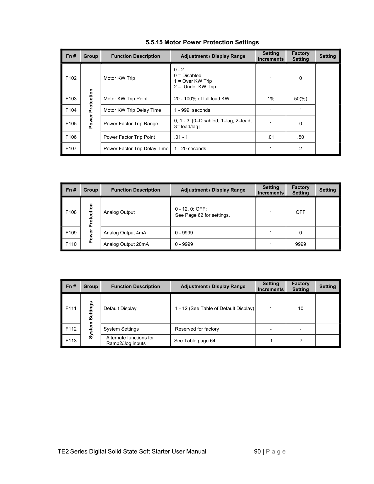
|---|---|---|---|---|---|---| |F024|Pump Flex Decel Mode|Pump Flex Control / Deceleration Ramp|0 = Disabled (coast to stop)
1 = Enabled, except after OL trip
2 = Enabled, continued Decel even if there is an OL trip
|1|0 Disabled| | |F025|Pump Flex Decel Mode|Begin Decel Level (BDL), Immediate Drop Down Torque|0 - 100 % of Output Voltage|1%|60%| | |F026|Pump Flex Decel Mode|Decel Shut Off Voltage|0 to (BDL minus 1)% Voltage|1%|30%| | |F027|Pump Flex Decel Mode|Decel Ramp Time|1 - 60 Seconds|1 second|10 seconds| |
|Fn #|Group|Function Description|Adjustment / Display Range|Setting Increments
|Factory Setting
|Setting| |---|---|---|---|---|---|---| |F028|Restart|Restart Delay Time (Sequential Start Delay)|0 = Disabled, or 1-999 seconds after a Power Loss (Status can be read in F054)|1 second|0 Disabled| |
|Fn #|Group|Function Description|Adjustment / Display Range|Setting Increments
|Factory Setting
|Setting| |---|---|---|---|---|---|---| |F29|Line Voltage|Voltage Input|200 - 690 Volt|1|480| | |F030|Line Voltage|Voltage Imbalance Trip %|0, 1 - 30% [0=Disabled]|1(%)|0| | |F031|Line Voltage|Voltage Imbalance Trip Delay|1 - 20 seconds|1|10| | |F032|Line Voltage|Over Voltage Trip %|0, 1 - 10% [0=Disabled]|1(%)|0| | |F033|Line Voltage|Over Voltage Trip Delay|1 - 20 seconds|1|10| | |F034|Line Voltage|Under Voltage Trip on Start %|0, 1 - 20% [0=Disabled]|1(%)|0| | |F035|Line Voltage|UV Trip on Start Delay|1 - 180 seconds|1|10| | |F036|Line Voltage|Under Voltage Trip on Run %|0, 1 - 20% [0=Disabled]|1(%)|0| | |F037|Line Voltage|UV Trip Delay during Run|1 - 20 seconds|1|2| | |F038|Line Voltage|Shorted SCR and Trip Delay|0, 1-10 seconds [0=Disabled]|1 second|1 second| | |F039|Line Voltage|Shunt Trip Delay|0, 1-10 seconds [0=Disabled]|1 second|1 second| |
|Fn #|Group|Function Description|Adjustment / Display Range|Setting Increments
|Factory Setting
|Setting| |---|---|---|---|---|---|---| |F040|Phase Current
|Current Imbalance Trip|0 = Disabled, or 5 - 30% imbalance|1%|0 Disabled| | |F041|Phase Current
|Current Imbalance Trip Delay|1 - 20 seconds|1 second|2 seconds| | |F042|Phase Current
|Over Current Trip|0 = Disabled, or 100 - 300% of motor FLA|1%|0 Disabled| | |F043|Phase Current
|Over Current Trip Delay|1 - 20 seconds|1 second|1 second| | |F044|Phase Current
|Under Current Trip|0 = Disabled, or 10 - 90% of motor FLA|1%|0 Disabled| |

|F045|Phase Current
|Under Current Trip Delay|1 - 60 seconds|1 second|2 seconds| | |F046|Phase Current
|Ground Fault Trip|0 = Disabled, or 5 - 90% of CT ratio from Fn 74|1%|0 Disabled| | |F047|Phase Current
|Ground Fault Trip Delay|1 - 60 seconds|1 second|2 seconds| |
|Fn #|Group|Function Description|Adjustment / Display Range|Setting Increments
|Factory Setting
|Setting| |---|---|---|---|---|---|---| |F048|Lockouts, Reset and Internal Protection
|Coast Down (Back Spin) Lockout Timer|0 = Disabled, or 1 - 60 minutes|1 minute|0 Disabled| | |F049|Lockouts, Reset and Internal Protection
|Maximum Starts per Hour|0 = Disabled, or 1 - 10 starts|1|0 Disabled| | |F050|Lockouts, Reset and Internal Protection
|Minimum Time Between Starts|0 = Disabled, or 1 - 60 minutes|1 minute|0 Disabled| | |F051|Lockouts, Reset and Internal Protection
|nCP Trip (No Control Power)|0, 1 [0=Disabled, 1=Enabled]|1|0 Disabled| | |F052|Lockouts, Reset and Internal Protection
|Auto Reset on Selected Faults|Fault Preferences 1 - 17 See Table 5.6.7: ”Auto-Reset Selected Faults”|1|4, Phase Loss only| | |F053|Lockouts, Reset and Internal Protection
|Auto Reset Attempts|0 = Disabled, or 1-10 attempts [In 1 minute cycle]|1|0 Disabled| | |F054|Lockouts, Reset and Internal Protection
|Restart Delay Time Value Readout (for F028)|0 - 999 Seconds|N/A|Read Only| | |F055|Lockouts, Reset and Internal Protection
|Coast Down Timer Value for F048|1 - 3600 Seconds|N/A|Read Only| | |F056|Lockouts, Reset and Internal Protection
|Starts Per Hour Timer Value for F049|1 - 3600 Seconds|N/A|Read Only| | |F057|Lockouts, Reset and Internal Protection
|Starts Per Hour For F049|1 - 10 Starts|N/A|Read Only| | |F058|Lockouts, Reset and Internal Protection
|Time Value Between Starts for F050|1 - 3600 Seconds|N/A|Read Only| | |F059|Lockouts, Reset and Internal Protection
|Thermal Capacity to Start for F005|0 - 100 % Thermal Capacity|N/A|Read Only| |
|Fn #|Group|Function Description|Adjustment / Display Range|Setting Increments
|Factory Setting
|Setting| |---|---|---|---|---|---|---| |F060|Output Relays|Aux Relay 1 setting|Operation # 1 - 32: see ”Aux. Relay Settings Chart”|1|1| | |F061|Output Relays|Aux Relay 2 setting|Operation # 1 - 32: see ”Aux. Relay Settings Chart”|1|2| | |F062|Output Relays|Aux Relay 3 setting|Operation # 1 - 32: see ”Aux. Relay Settings Chart”|1|16| | |F063|Output Relays|Aux. Relay Delay Timer (for Operations 28-31)|0 (Disabled), or 1-999 seconds|1 second|0 No Delay| | |F064|Output Relays|Reserved for factory use| | | | |
|Fn #|Group|Function Description|Adjustment / Display Range|Setting Increments
|Factory Setting
|Setting| |---|---|---|---|---|---|---| |F065|Communications
|Communications|0 = Disabled
1 = Enabled (11Bit)
2 = Enabled (10Bit)
|1|0| | |F066|Communications
|Baud Rate|4.8, 9.6 and 19.2 KB|3 rates|9.6 KB| | |F067|Communications
|Modbus Address|1 - 247|1|1| | |F068|Communications
|Remote Starter Control|0=Disabled,
1=Enabled combine w/ Start button
2=As option 1, w/o Start button
3=[a. F113= 1 or 5: Enabled w/ Local/Remote switch dedicated by Jog button. Jog switch or button closed is for Remote, opened for Local. b. F113 = other value: Enabled.] Note: Stop button stops motor in all the remote control modes.
|1|0| | |F069|Communications
|Reserved for factory use| | | | |
|Fn #|Group|Function Description|Adjustment / Display Range|Setting Increments
|Factory Setting
|Setting| |---|---|---|---|---|---|---| |F070|System Settings|Parameter Lock Customer Password|0 - 999 0 = Disabled Any Other Numbers = Password|1|0 (displays encrypted code)| | |F071|System Settings|System Clear / Reset|0 = Disabled
1 = Clear THR and Lockout Timers
2 = Reset to Factory Default Settings
|1|0| | |F072|System Settings|Reserved for Factory Use| | | | | |F073|System Settings|Frame Rating|10 – 2000 Factory set|1|By Model (defaults to 48)| | |F074|System Settings|CT Value|10 – 2000 Factory set|5|By Model (defaults to 40)| | |F075|System Settings|Year|2000 - 2047|1 year|2000| | |F076|System Settings|Month|1 - 12|1 Month|1| | |F077|System Settings|Day|1 - 31|1 Day|1| | |F078|System Settings|Hour|0 - 23|1 Hour|0| | |F079|System Settings|Minute|0 - 59|1 Minute|0| | |F080|System Settings|Second|0 - 59|1 Second|0| | |F081|System Settings|Revision #|-|-|Factory Setting| | |F082 F084|System Settings|Reserved for factory use| | | | |
|Fn #|Group|Function Description|Adjustment / Display Range|Setting Increments
|Factory Setting
|Setting| |---|---|---|---|---|---|---| |F085|Fault History and Run Data
|Fault History #1, Latest Fault|0 = No fault history, or Fault # 1 - 57: see Fault code list|N/A|Read Only| | |F086|Fault History and Run Data
|Time Stamp, Fault #1 Based on F078-80|00.00 - 23.59 (hh.mm) [hh = 00 - 23; mm = 00 - 59]|N/A|Read Only| | |F087|Fault History and Run Data
|Date Stamp, Fault #1 Based on F076-77|01.01 - 12.31 (MM.DD) [MM = 01 - 12; DD = 01 - 31]|N/A|Read Only| | |F088|Fault History and Run Data
|Fault History #2, Previous Fault|0 = No fault history, or Fault # 1 - 57: see Fault code list|N/A|Read Only| | |F089|Fault History and Run Data
|Time Stamp, Fault #2|00.00 - 23.59 (hh.mm) [hh = 00 - 23; mm = 00 - 59]|N/A|Read Only| | |F090|Fault History and Run Data
|Date Stamp, Fault #2|01.01 - 12.31 (MM.DD) [MM = 01 - 12; DD = 01 - 31]|N/A|Read Only| | |F091|Fault History and Run Data
|Fault History #3, Oldest Fault|0 = No fault history, or Fault # 1 - 57: see Fault code list|N/A|Read Only| | |F092|Fault History and Run Data
|Time Stamp, Fault #3|00.00 - 23.59 (hh.mm) [hh = 00 - 23; mm = 00 - 59]|N/A|Read Only| | |F093|Fault History and Run Data
|Date Stamp, Fault #3|01.01 - 12.31 (MM.DD) [MM = 01 - 12; DD = 01 - 31]|N/A|Read Only| | |F094|Fault History and Run Data
|Run Time, Hours|000.0 - 999.9 hours|N/A|Read Only| | |F095|Fault History and Run Data
|Run Time, 1000 Hour Overflow|0000 - 9999 thousand hours|N/A|Read Only| | |F096|Fault History and Run Data
|Run Cycle Counter|0000 - 9999 times|N/A|Read Only| | |F097|Fault History and Run Data
|Run Cycle Counter 10K overflow|0000 - 9999 10 thousand times|N/A|Read Only| |
|Fn #|Group|Function Description|Adjustment / Display Range|Setting Increments
|Factory Setting
|Setting| |---|---|---|---|---|---|---| |F098|Phase and Frequency
Protection|Phase Rotation Trip|0, 1 or 2 0=Disabled, 1=ABC, 2=ACB]|1|0| | |F099|Phase and Frequency
Protection|Phase Rotation Trip Delay|1 - 3 seconds|1|1| | |F100|Phase and Frequency
Protection|Phase Loss Trip and Delay during Stop|0, 1-20 Seconds [0= Disabled]|1|1| | |F101|Phase and Frequency
Protection|Phase Loss Trip and Delay during Running|0, 1-20 Seconds [0= Disabled]|1|1| |
################## 5.5.15 Motor Power Protection Settings
|Fn #|Group|Function Description|Adjustment / Display Range|Setting Increments
|Factory Setting
|Setting| |---|---|---|---|---|---|---| |F102|Power Protection|Motor KW Trip|0 - 2
0 = Disabled
1 = Over KW Trip
2 = Under KW Trip
|1|0| | |F103|Power Protection|Motor KW Trip Point|20 - 100% of full load KW|1%|50(%)| | |F104|Power Protection|Motor KW Trip Delay Time|1 - 999 seconds|1|1| | |F105|Power Protection|Power Factor Trip Range|0, 1 - 3 [0=Disabled, 1=lag, 2=lead, 3= lead/lag]|1|0| | |F106|Power Protection|Power Factor Trip Point|.01 - 1|.01|.50| | |F107|Power Protection|Power Factor Trip Delay Time|1 - 20 seconds|1|2| |
|Fn #|Group|Function Description|Adjustment / Display Range|Setting Increments
|Factory Setting
|Setting| |---|---|---|---|---|---|---| |F108|Power Protection|Analog Output|0 - 12, 0: OFF; See Page 62 for settings.|1|OFF| | |F109|Power Protection|Analog Output 4mA|0 - 9999|1|0| | |F110|Power Protection|Analog Output 20mA|0 - 9999|1|9999| |
|Fn #|Group|Function Description|Adjustment / Display Range|Setting Increments
|Factory Setting
|Setting| |---|---|---|---|---|---|---| |F111|System Settings
|Default Display|1 - 12 (See Table of Default Display)|1|10| | |F112|System Settings
|System Settings|Reserved for factory|-|-| | |F113|System Settings
|Alternate functions for Ramp2/Jog inputs|See Table page 64|1|7| |