
Ask AI
— answers from the official manualAnswers from the official manual.
Common questions
Common Questions
9 totalHow can I reset the HP t520 to its factory default settings?
Press and hold the Power button for 10 seconds until the LED flashes red, which clears all settings and returns the device to factory defaults. You will need to re-pair all connected devices after resetting. (Page 23)
What should I do if my HP t520 shows error code E01?
The manual does not provide specific guidance for the error code E01, though it mentions standard troubleshooting steps and recommends contacting customer service with detailed information. (Page 23)
How do I secure the power cord to avoid accidental disconnection?
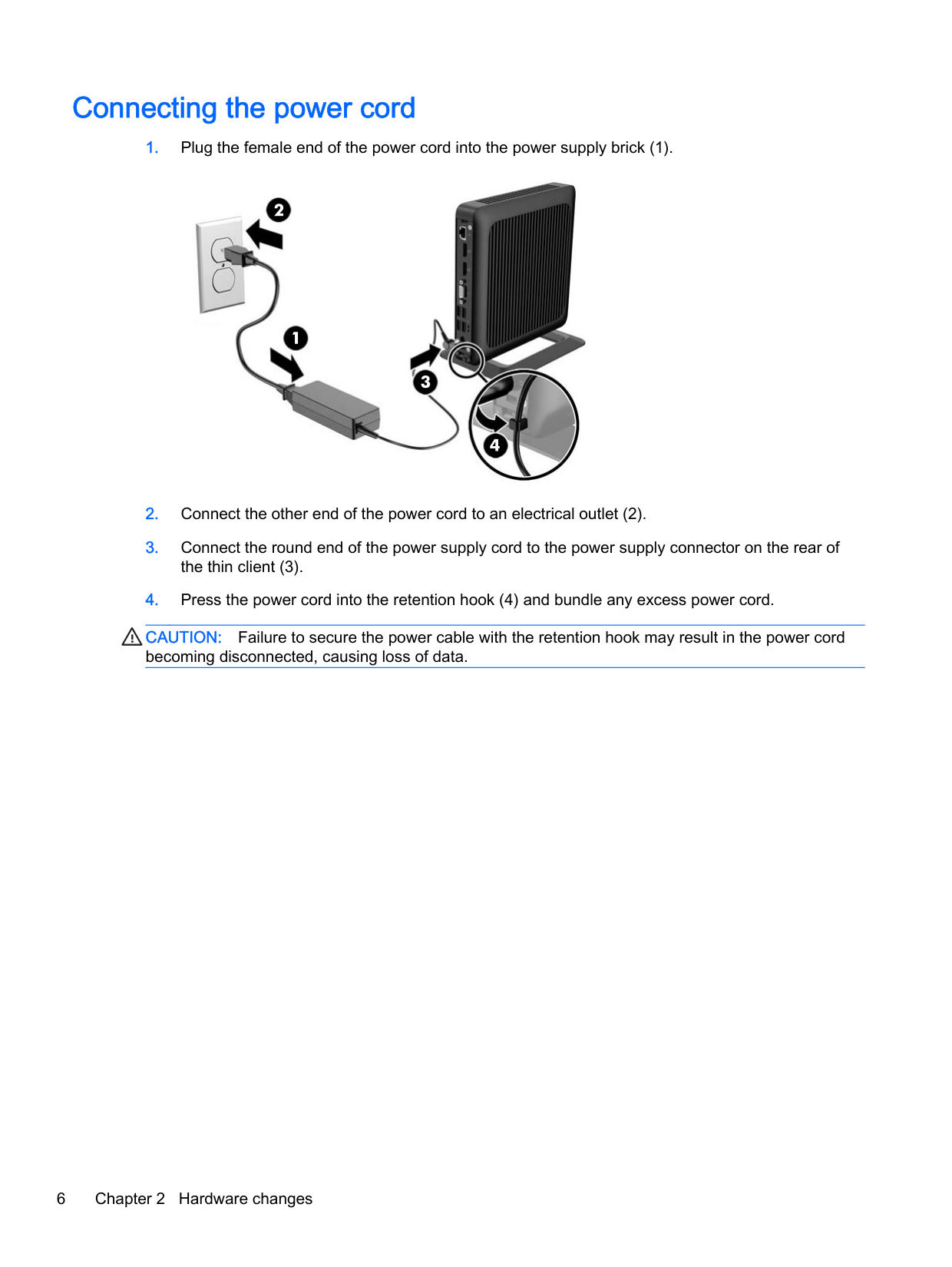
Secure the power cable by pressing its rounded end into the retention hook located on the back of the thin client and bundle any excess power cord. Failure to secure it may result in loss of data. (Page 6)
Where is the serial number located on my HP t520 thin client?
The serial number is located under a label or decal affixed underneath the device, as indicated in an illustration near Serial Number Location. (Page 4)
How do I attach the stand to my HP t520?
Attach the stand by removing any security devices, turning off the device properly through the operating system or BIOS, disconnecting power and external devices. Adjust the stand if necessary and then align screw holes on the bottom of the thin client with those on the stand before tightening captive screws securely. (Page 7)
How do I replace the memory module in my HP t520?
To install or remove a DDR3-SDRAM SODIMM, follow these steps: Remove and disconnect any security devices, media, external devices. Disconnect power and wait 30 seconds before handling the modules. Carefully move the thin client out of stand and lay flat on surface facing up. Follow instructions under Install SODIMM section for insertion or removal procedures while ensuring correct orientation noted by gold notches aligned with memory connector tabs (Page 7, Page 10)
Full Manual
39 pages

Hardware Reference Guide
HP Thin Clients
© Copyright 2014 Hewlett-Packard Development Company, L.P. The information contained herein is subject to change without notice.
The only warranties for HP products and services are set forth in the express warranty statements accompanying such products and services. Nothing herein should be construed as constituting an additional warranty. HP shall not be liable for technical or editorial errors or omissions contained herein.
This document contains proprietary information that is protected by copyright. No part of this document may be photocopied, reproduced, or translated to another language without the prior written consent of Hewlett-Packard Company.
Hardware Reference Guide HP t520 Flexible Series Thin Client First Edition: June 2014 Document Part Number: 759673-001
#### About This Book
WARNING! Text set off in this manner indicates that failure to follow directions could result in bodily harm or loss of life.
CAUTION: Text set off in this manner indicates that failure to follow directions could result in damage to equipment or loss of information.
| | |---|
NOTE: Text set off in this manner provides important supplemental information.
iii
###### iv About This Book
Table of contents
Adjusting the stand .............................................................................................................. 7 Installing the stand ............................................................................................................... 7
Removing and replacing the access panel ........................................................................................... 9 Removing the access panel ................................................................................................. 9 Replacing the access panel ............................................................................................... 11
Replacing the memory module ........................................................................................................... 11 SODIMM ............................................................................................................................ 11 DDR3-SDRAM SODIMM ................................................................................................... 11 Populating the SODIMM socket ......................................................................................... 12 Installing SODIMM ............................................................................................................. 12
Security .............................................................................................................................................. 15

Cable lock .......................................................................................................................... 15 Mounting the thin client ...................................................................................................................... 16
Supported mounting options .............................................................................................. 18
v
Supported orientations ....................................................................................................................... 24 Non-supported orientations ................................................................................................................ 25
Removing the solid state drive (flash memory) .................................................................. 28 Installing the solid state drive (flash memory) .................................................................... 29
##### Index ................................................................................................................................................................... 32

vi
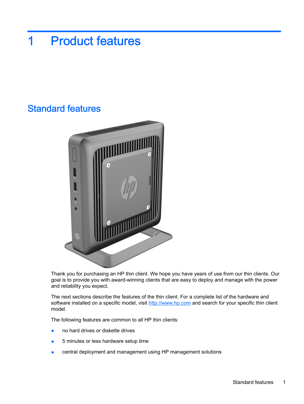
1 Product features
Standard features

Thank you for purchasing an HP thin client. We hope you have years of use from our thin clients. Our goal is to provide you with award-winning clients that are easy to deploy and manage with the power and reliability you expect.
The next sections describe the features of the thin client. For a complete list of the hardware and software installed on a specific model, visit http://www.hp.com and search for your specific thin client model.
The following features are common to all HP thin clients:
Standard features 1
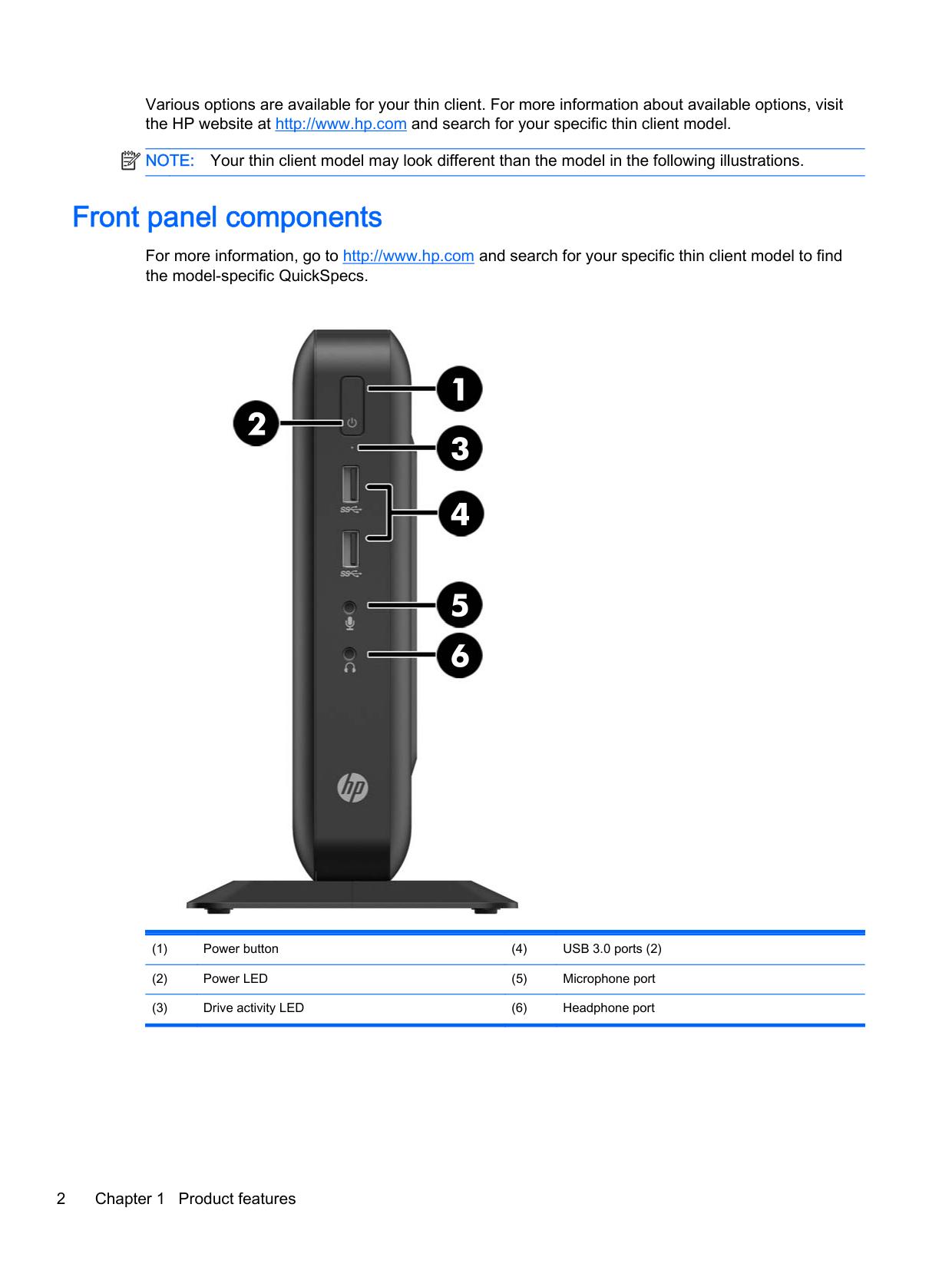
Various options are available for your thin client. For more information about available options, visit the HP website at http://www.hp.com and search for your specific thin client model.
| | |---|
NOTE: Your thin client model may look different than the model in the following illustrations.
Front panel components
For more information, go to http://www.hp.com and search for your specific thin client model to find the model-specific QuickSpecs.


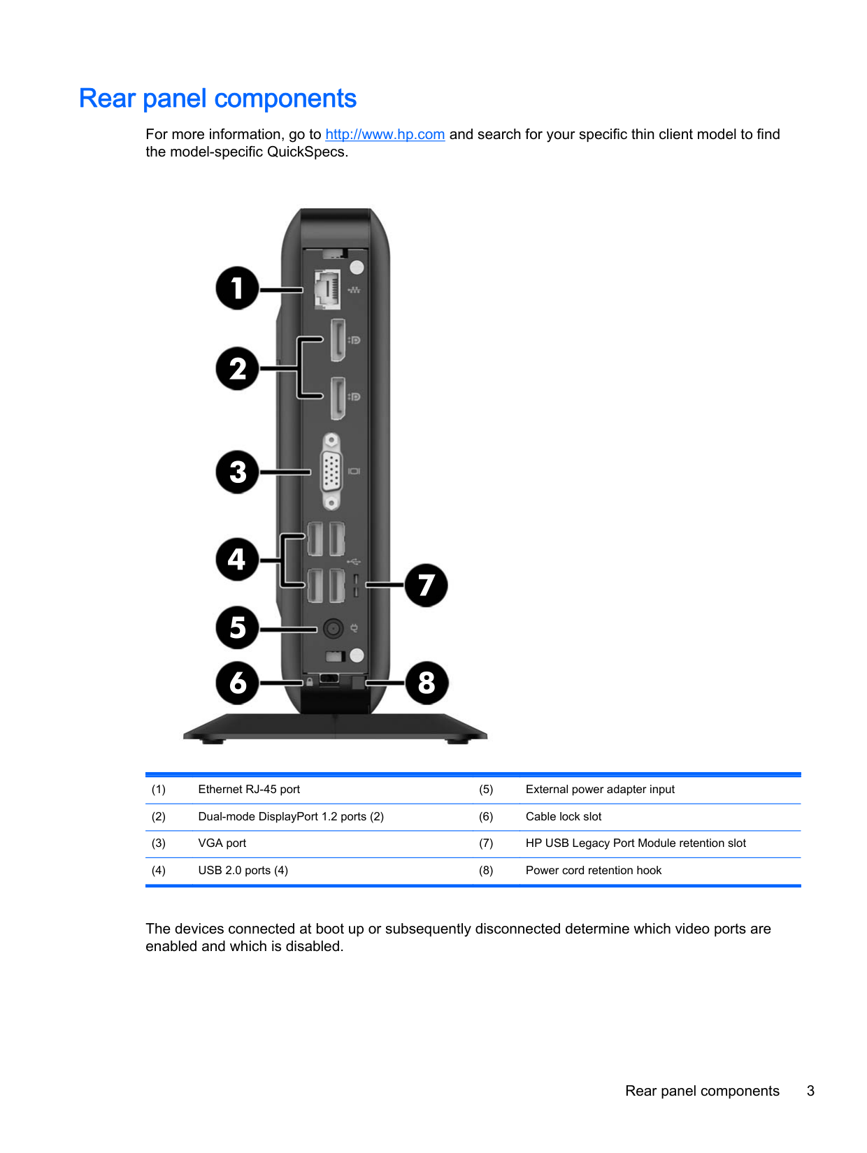
Rear panel components
For more information, go to http://www.hp.com and search for your specific thin client model to find the model-specific QuickSpecs.


The devices connected at boot up or subsequently disconnected determine which video ports are enabled and which is disabled.
Rear panel components 3
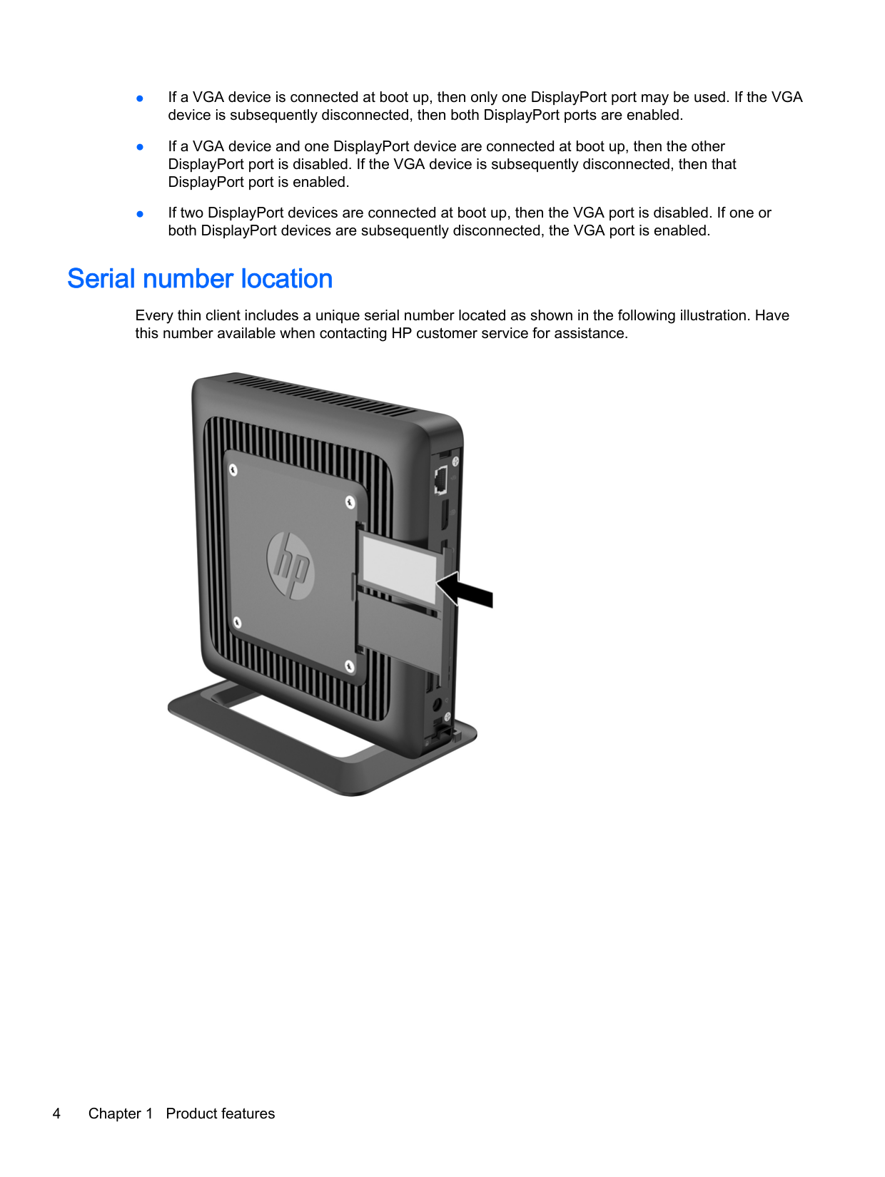
Serial number location
Every thin client includes a unique serial number located as shown in the following illustration. Have this number available when contacting HP customer service for assistance.

2 Hardware changes
Warnings and cautions
Before performing upgrades be sure to carefully read all of the applicable instructions, cautions, and warnings in this guide.
WARNING! To reduce the risk of personal injury or equipment damage from electric shock, hot surfaces, or fire: Disconnect the power cord from the power outlet and allow the internal system components to cool before you touch them. Do not plug telecommunications or telephone connectors into the network interface controller (NIC) receptacles. Do not disable the power cord grounding plug. The grounding plug is an important safety feature. Plug the power cord into a grounded (earthed) outlet that is easily accessible at all times.
To reduce the risk of serious injury, read the Safety & Comfort Guide. It describes proper workstation setup, posture, and health and work habits for computer users, and provides important electrical and mechanical safety information. The Safety & Comfort Guideis located on the HP website at
http://www.hp.com/ergo.
WARNING! Energized parts inside. Disconnect power to the equipment before removing the enclosure. Replace and secure the enclosure before re-energizing the equipment.
CAUTION: Static electricity can damage the electrical components of the thin client or optional equipment. Before beginning the following procedures, be sure that you are discharged of static electricity by briefly touching a grounded metal object. See Electrostatic discharge on page 26 for more information.
When the thin client is plugged into an AC power source, voltage is always applied to the system board. To prevent damage to internal components, you must disconnect the power cord from the power source before opening the thin client.
Warnings and cautions 5
Connecting the power cord


CAUTION: Failure to secure the power cable with the retention hook may result in the power cord becoming disconnected, causing loss of data.
Attaching the stand
CAUTION: Unless the thin client is mounted with the HP Quick Release, it must be operated with the stand attached to ensure proper airflow around the thin client.
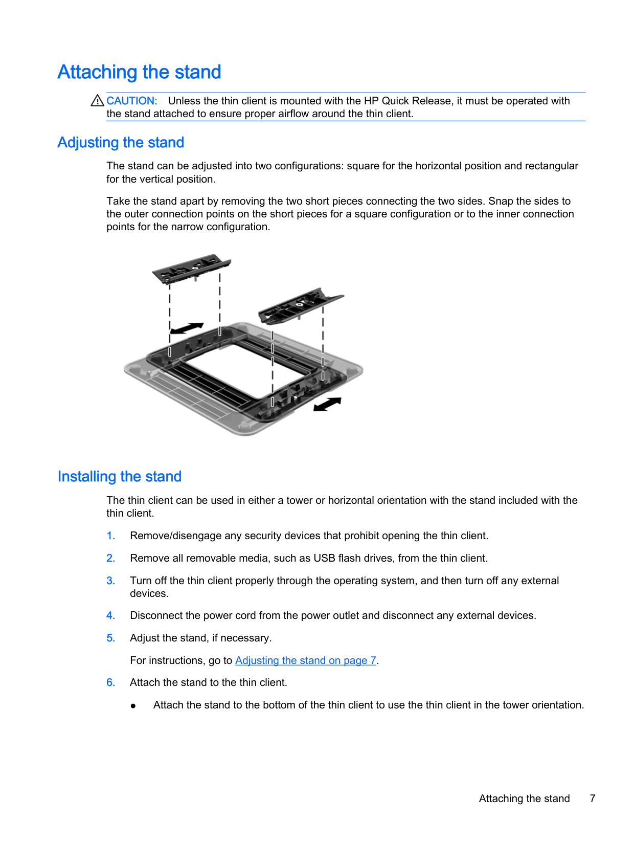
#### Adjusting the stand
The stand can be adjusted into two configurations: square for the horizontal position and rectangular for the vertical position.
Take the stand apart by removing the two short pieces connecting the two sides. Snap the sides to the outer connection points on the short pieces for a square configuration or to the inner connection points for the narrow configuration.

#### Installing the stand
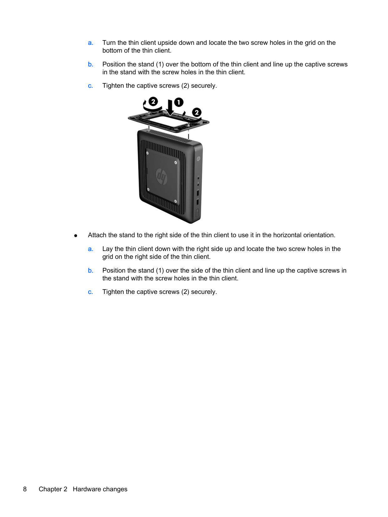
The thin client can be used in either a tower or horizontal orientation with the stand included with the thin client.
Attaching the stand 7


| | |---|
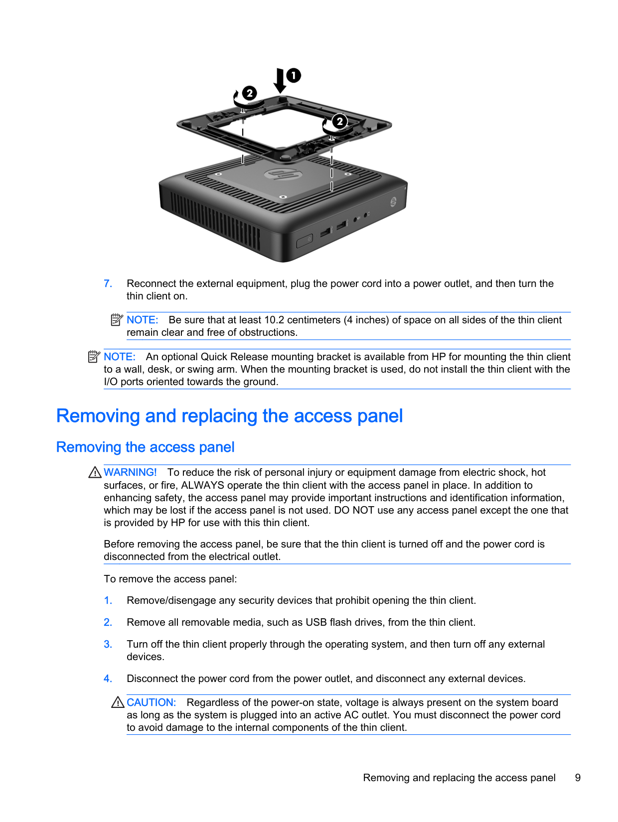
NOTE: Be sure that at least 10.2 centimeters (4 inches) of space on all sides of the thin client remain clear and free of obstructions.
| | |---|
NOTE: An optional Quick Release mounting bracket is available from HP for mounting the thin client to a wall, desk, or swing arm. When the mounting bracket is used, do not install the thin client with the I/O ports oriented towards the ground.
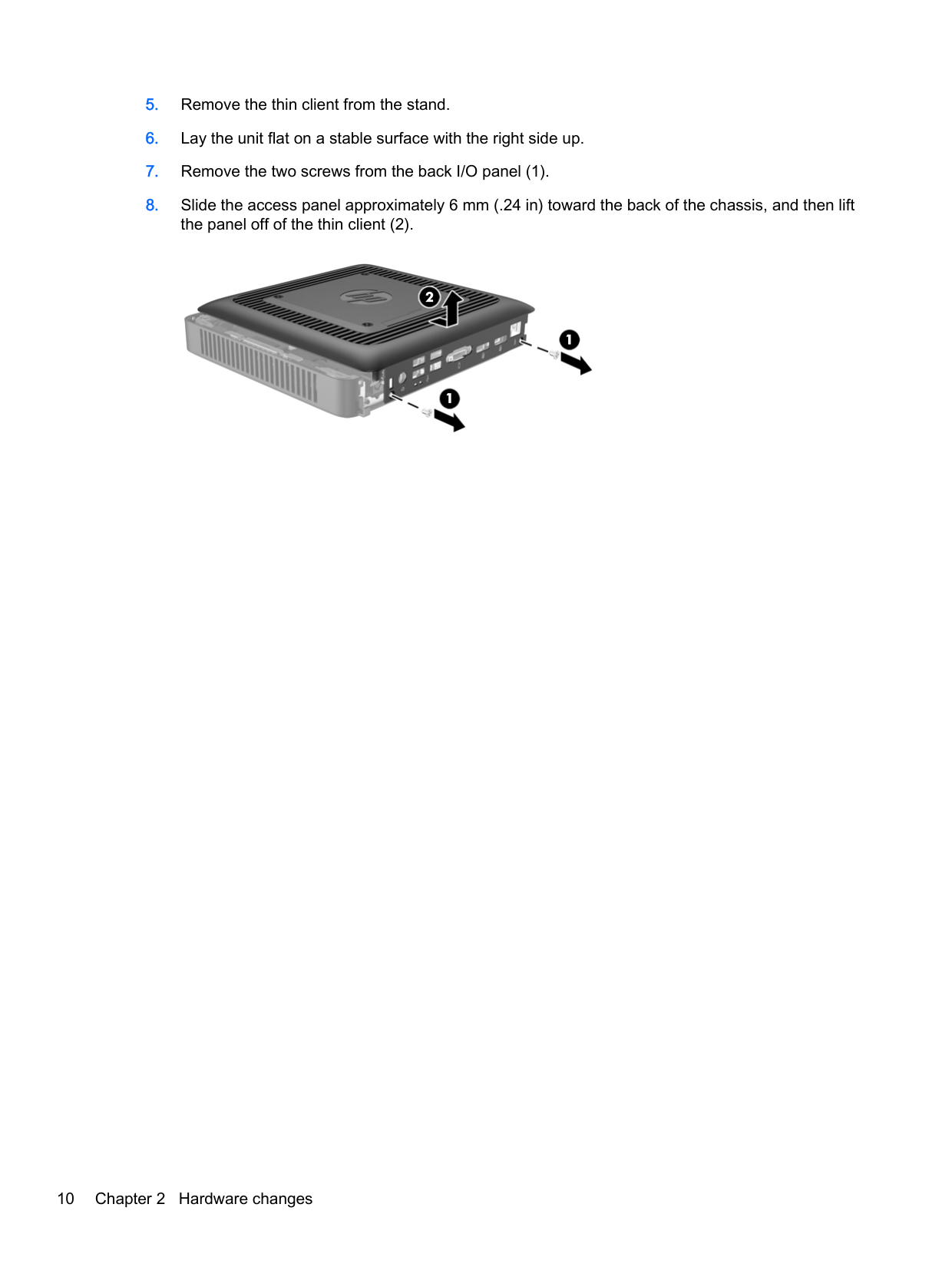
Removing and replacing the access panel
#### Removing the access panel
WARNING! To reduce the risk of personal injury or equipment damage from electric shock, hot surfaces, or fire, ALWAYS operate the thin client with the access panel in place. In addition to enhancing safety, the access panel may provide important instructions and identification information, which may be lost if the access panel is not used. DO NOT use any access panel except the one that is provided by HP for use with this thin client.
Before removing the access panel, be sure that the thin client is turned off and the power cord is disconnected from the electrical outlet.
To remove the access panel:
CAUTION: Regardless of the power-on state, voltage is always present on the system board as long as the system is plugged into an active AC outlet. You must disconnect the power cord to avoid damage to the internal components of the thin client.
Removing and replacing the access panel 9


#### Replacing the access panel
To replace the access panel:
Replacing the memory module
The thin client comes with one double data rate 3 synchronous dynamic random access memory (DDR3L-SDRAM) small outline dual inline memory module (SODIMM).
#### SODIMM
The memory socket is populated with one industry-standard SODIMM.
#### DDR3-SDRAM SODIMM
For proper system operation, the SODIMM must adhere to the following specifications:

| | |---|
NOTE: The system does not operate properly when unsupported SODIMMs are installed.
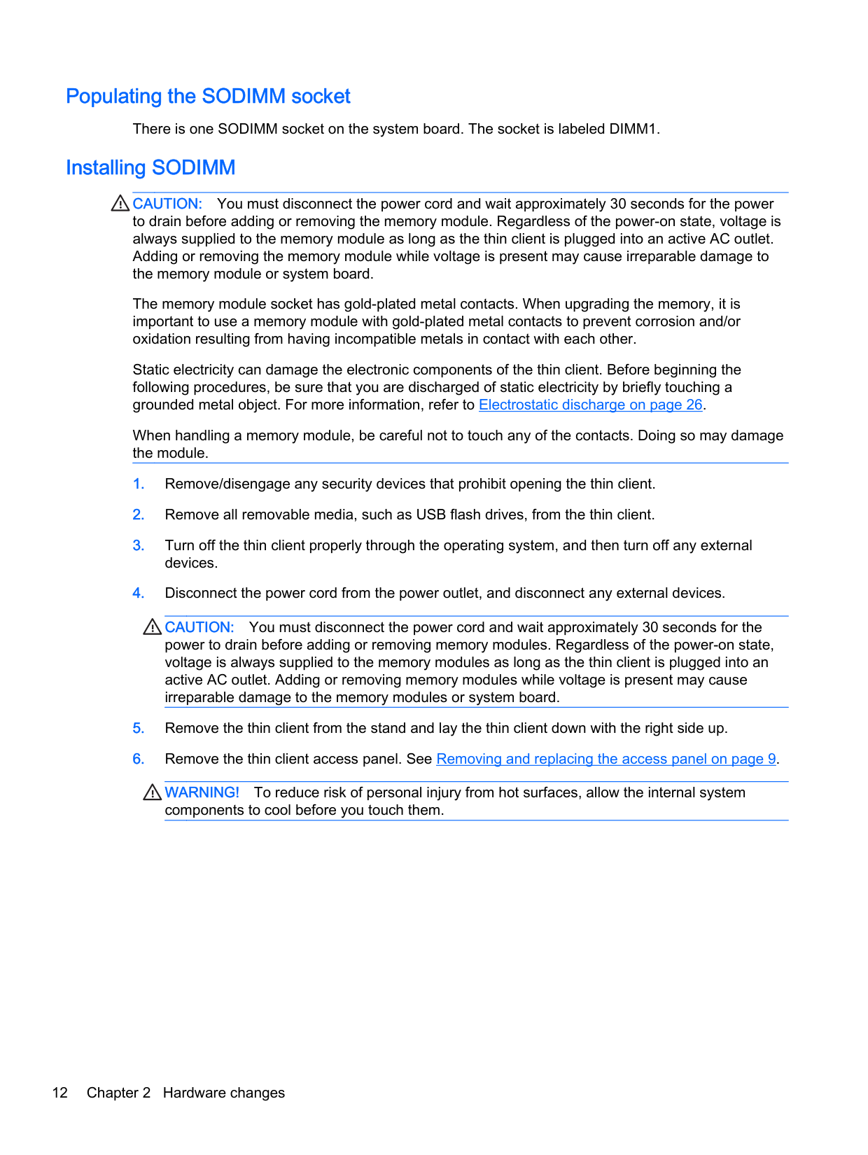
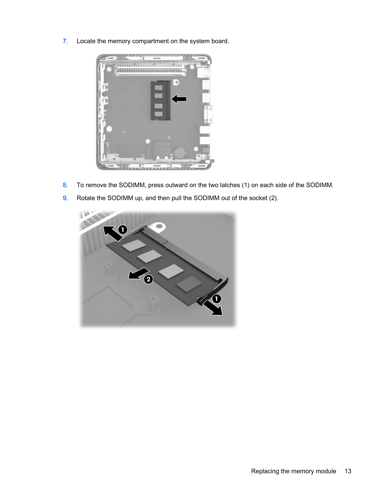
#### Populating the SODIMM socket
There is one SODIMM socket on the system board. The socket is labeled DIMM1.
#### Installing SODIMM
CAUTION: You must disconnect the power cord and wait approximately 30 seconds for the power to drain before adding or removing the memory module. Regardless of the power-on state, voltage is always supplied to the memory module as long as the thin client is plugged into an active AC outlet. Adding or removing the memory module while voltage is present may cause irreparable damage to the memory module or system board.
The memory module socket has gold-plated metal contacts. When upgrading the memory, it is important to use a memory module with gold-plated metal contacts to prevent corrosion and/or oxidation resulting from having incompatible metals in contact with each other.
Static electricity can damage the electronic components of the thin client. Before beginning the following procedures, be sure that you are discharged of static electricity by briefly touching a grounded metal object. For more information, refer to Electrostatic discharge on page 26.
When handling a memory module, be careful not to touch any of the contacts. Doing so may damage the module.
CAUTION: You must disconnect the power cord and wait approximately 30 seconds for the power to drain before adding or removing memory modules. Regardless of the power-on state, voltage is always supplied to the memory modules as long as the thin client is plugged into an active AC outlet. Adding or removing memory modules while voltage is present may cause irreparable damage to the memory modules or system board.
WARNING! To reduce risk of personal injury from hot surfaces, allow the internal system components to cool before you touch them.


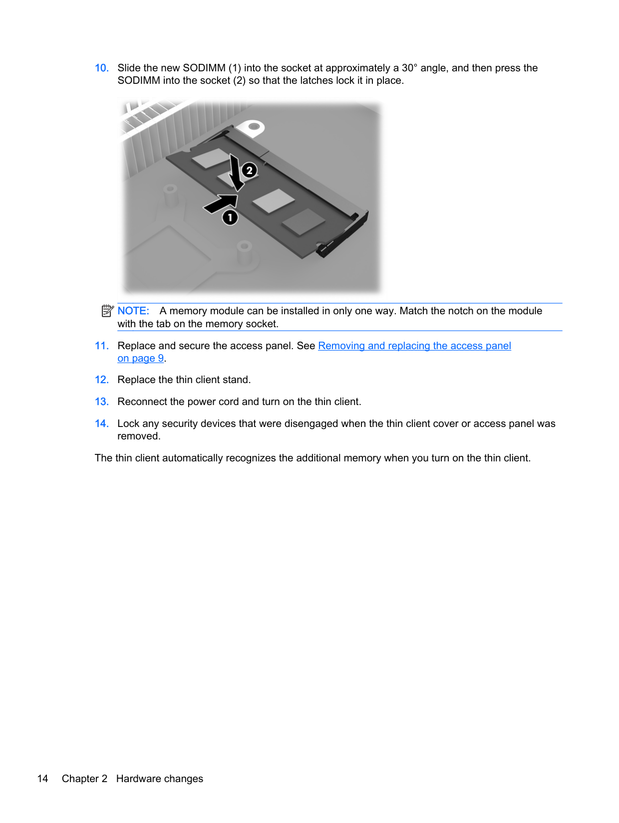
| | |---|
NOTE: A memory module can be installed in only one way. Match the notch on the module with the tab on the memory socket.
The thin client automatically recognizes the additional memory when you turn on the thin client.
Security
These thin clients are designed to accept a security cable lock. The cable lock prevents unauthorized removal of the thin client.
You may also purchase a port cover to help secure the rear ports. To order either option, visit the HP website at http://www.hp.com and search for your specific thin client model.
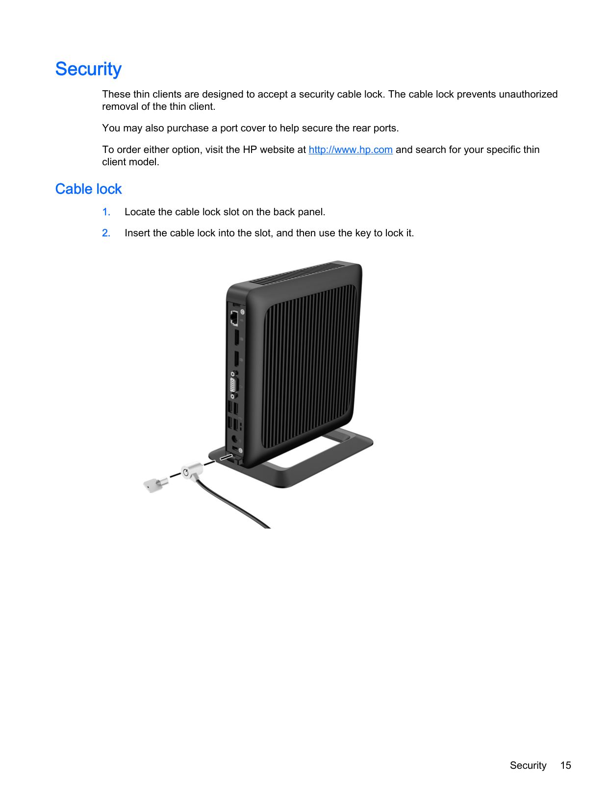
#### Cable lock

Security 15
Mounting the thin client
HP recommends mounting the thin client in the vertical (tower) orientation, with the HP logo right-side up. Mounting in other orientations may result in decreased performance under certain conditions; operating the thin client with limited power to prevent overheating is one such condition.
This thin client incorporates four mounting points on the right side of the unit. These mounting points follow the Video Electronics Standards Association (VESA) standard, which provides industrystandard mounting interfaces for Flat Displays (FDs), such as flat-panel monitors, flat displays, and flat TVs. The HP Quick Release connects to the VESA-standard mounting points, allowing you to mount the thin client in a variety of orientations.
| | |---|
NOTE: When mounting to a thin client, use the 15 mm screws supplied with the HP Quick Release.
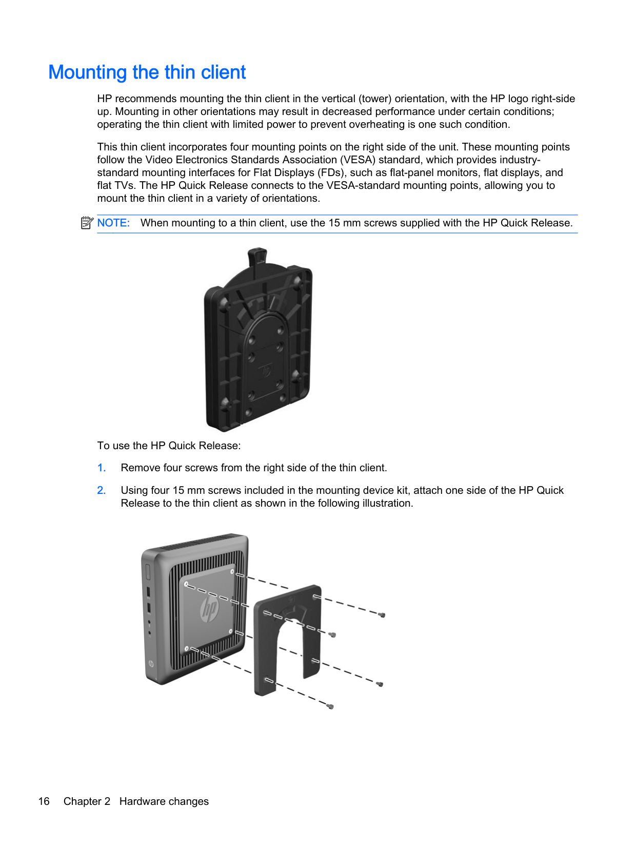

To use the HP Quick Release:


When attached, the HP Quick Release automatically locks in position. You only need to slide the lever to one side to remove the thin client.
CAUTION: For proper function of the HP Quick Release and a secure connection of all components, both the release lever on one side of the mounting device and the rounded opening on the other side must face upward.
Mounting the thin client 17
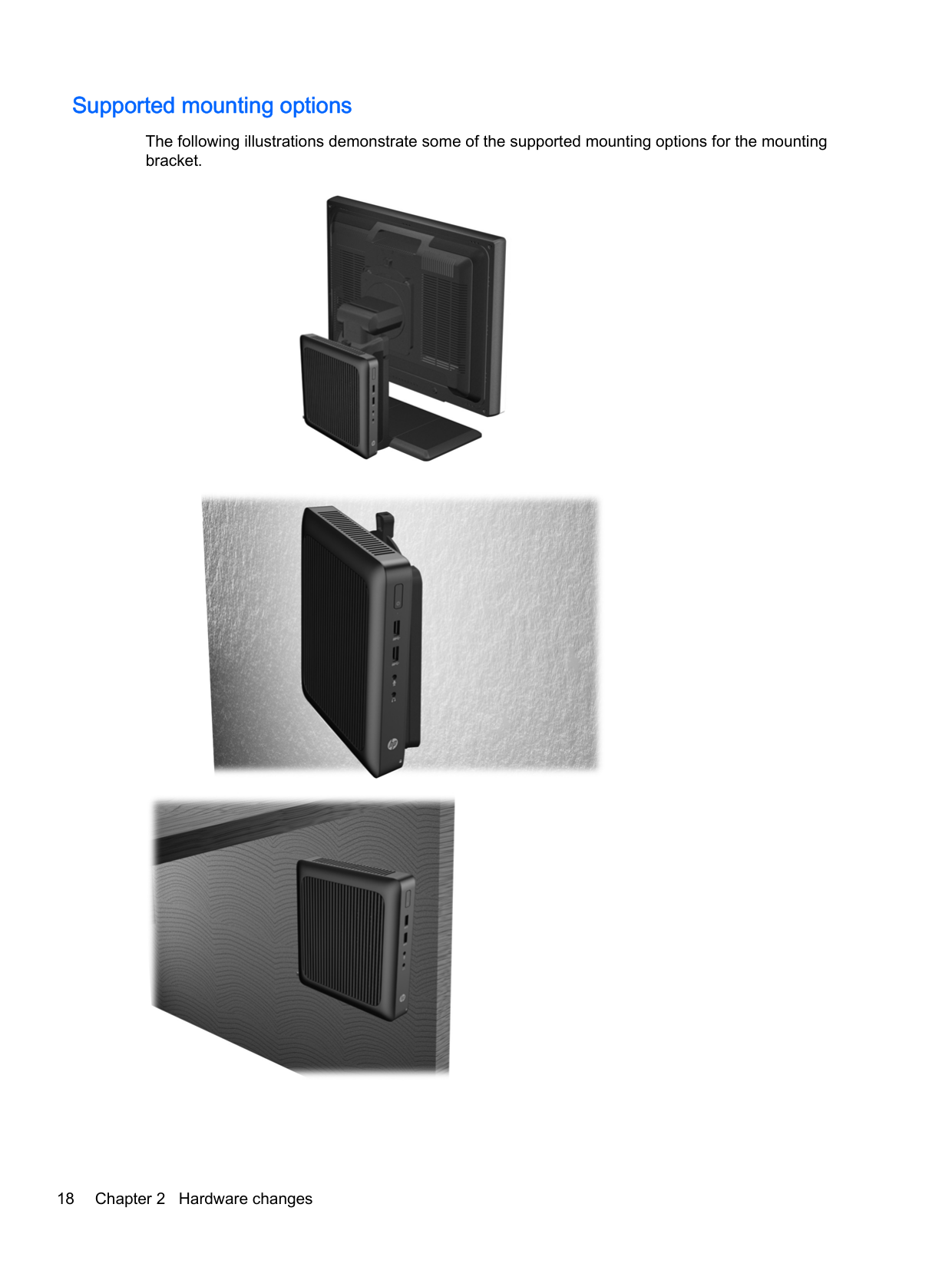
#### Supported mounting options
The following illustrations demonstrate some of the supported mounting options for the mounting bracket.


A Specifications
For the latest specifications or additional specifications on the thin client, go to http://www.hp.com/go/ quickspecs/ and search for your specific model to find the model-specific QuickSpecs.
Dimensions Width Depth Height (without stand) Height (with stand)
45.1 mm 200 mm 200.1 mm 210.5 mm
1.78 in. 7.87 in 7.88 In 8.29 in.
Approximate Weight 1,037.1 g 36.59 oz Temperature Range (fanless design)* Operating** (max. rate of change is 10°C per hour or 18°F per hour) Nonoperating (max. rate of change is 20°C per hour or 36°F per hour)
10°C to 40°C
50°F to 104°F
-30°C to 60°C
-22°F to 140°F
*Specifications are at sea level with altitude derating of 1°C/300 m (1.8°F/1000 ft) to a maximum of 3 Km (10,000 ft), with no direct, sustained sunlight. Upper limit may be limited by the type and number of options installed.
Relative Humidity (non-condensing) Operating (max. wet bulb temperature is 28°C or 84.2°F) Nonoperating (max. wet bulb temperature is 38.7°C or 101.6°F)
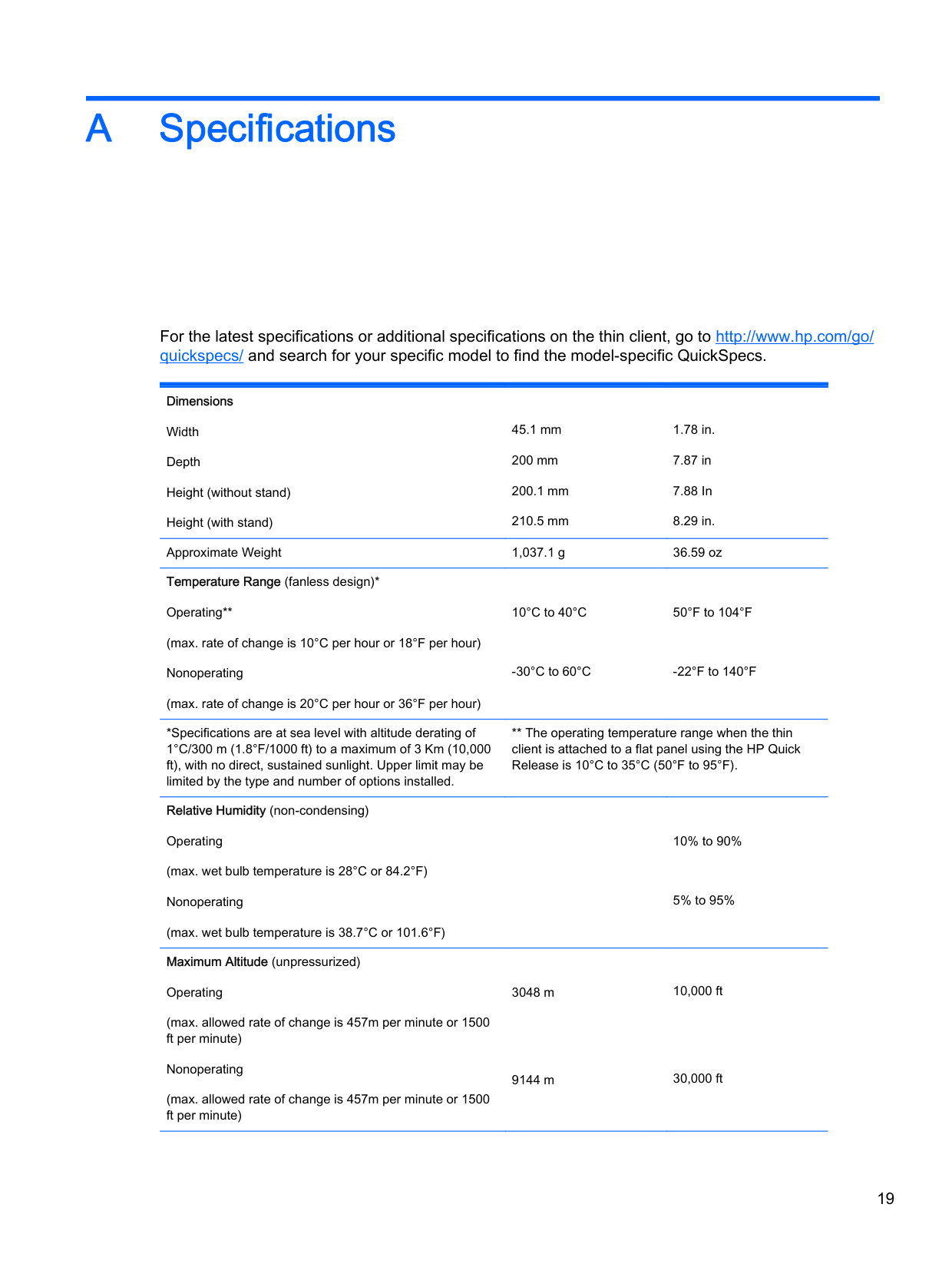
Maximum Altitude (unpressurized) Operating (max. allowed rate of change is 457m per minute or 1500 ft per minute) Nonoperating (max. allowed rate of change is 457m per minute or 1500 ft per minute)
** The operating temperature range when the thin client is attached to a flat panel using the HP Quick Release is 10°C to 35°C (50°F to 95°F).
10% to 90%
5% to 95%
3048 m
9144 m
10,000 ft
30,000 ft
Power Supply Operating Voltage Range Rated Line Frequency
100 VAC to 240 VAC 50 Hz to 60 Hz
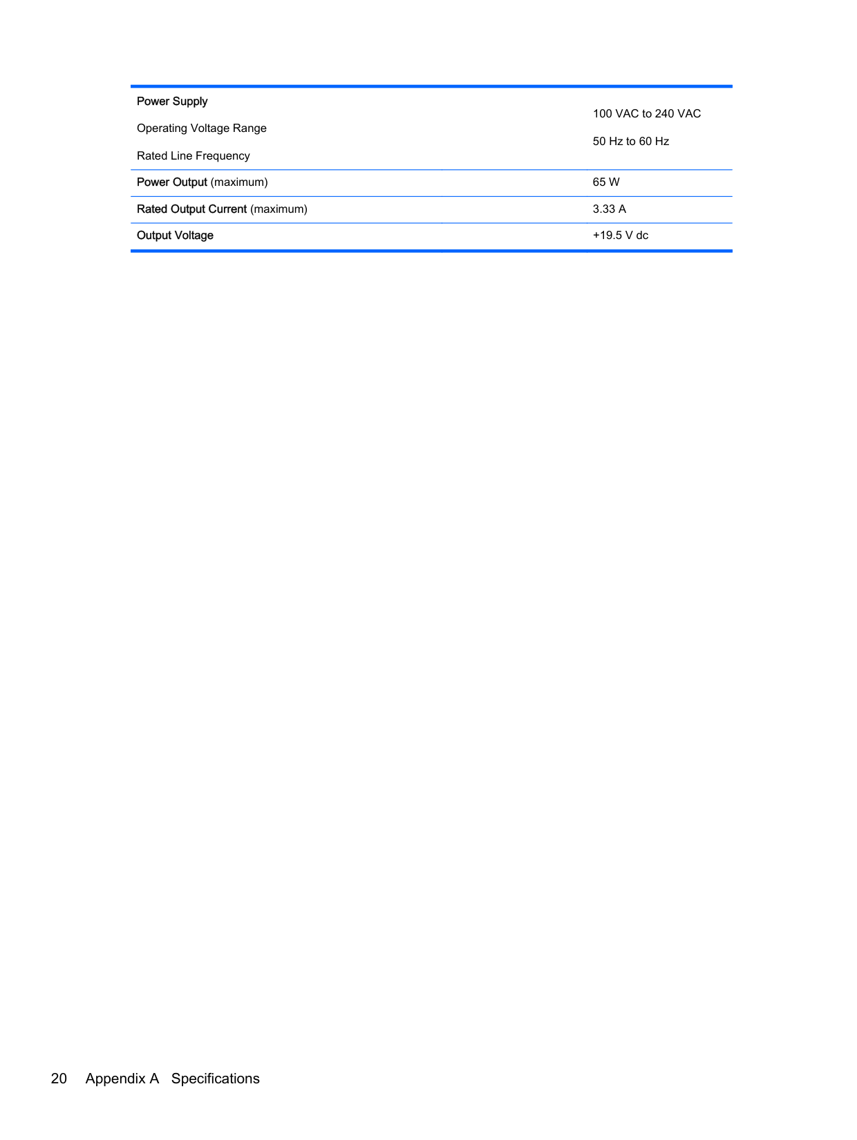
Power Output (maximum) 65 W Rated Output Current (maximum) 3.33 A Output Voltage +19.5 V dc
20 Appendix A Specifications
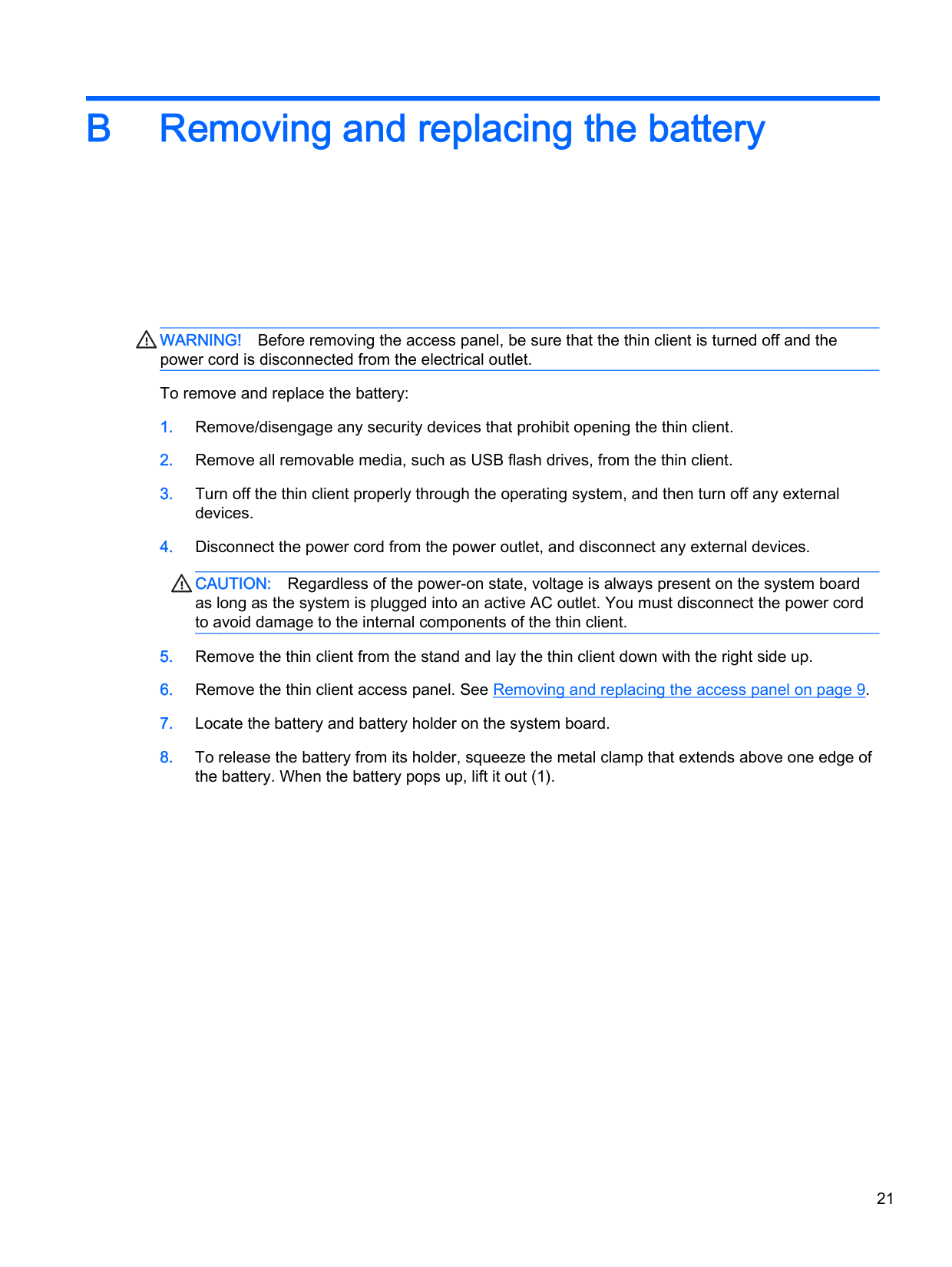
B Removing and replacing the battery
WARNING! Before removing the access panel, be sure that the thin client is turned off and the power cord is disconnected from the electrical outlet. To remove and replace the battery:
CAUTION: Regardless of the power-on state, voltage is always present on the system board as long as the system is plugged into an active AC outlet. You must disconnect the power cord to avoid damage to the internal components of the thin client.

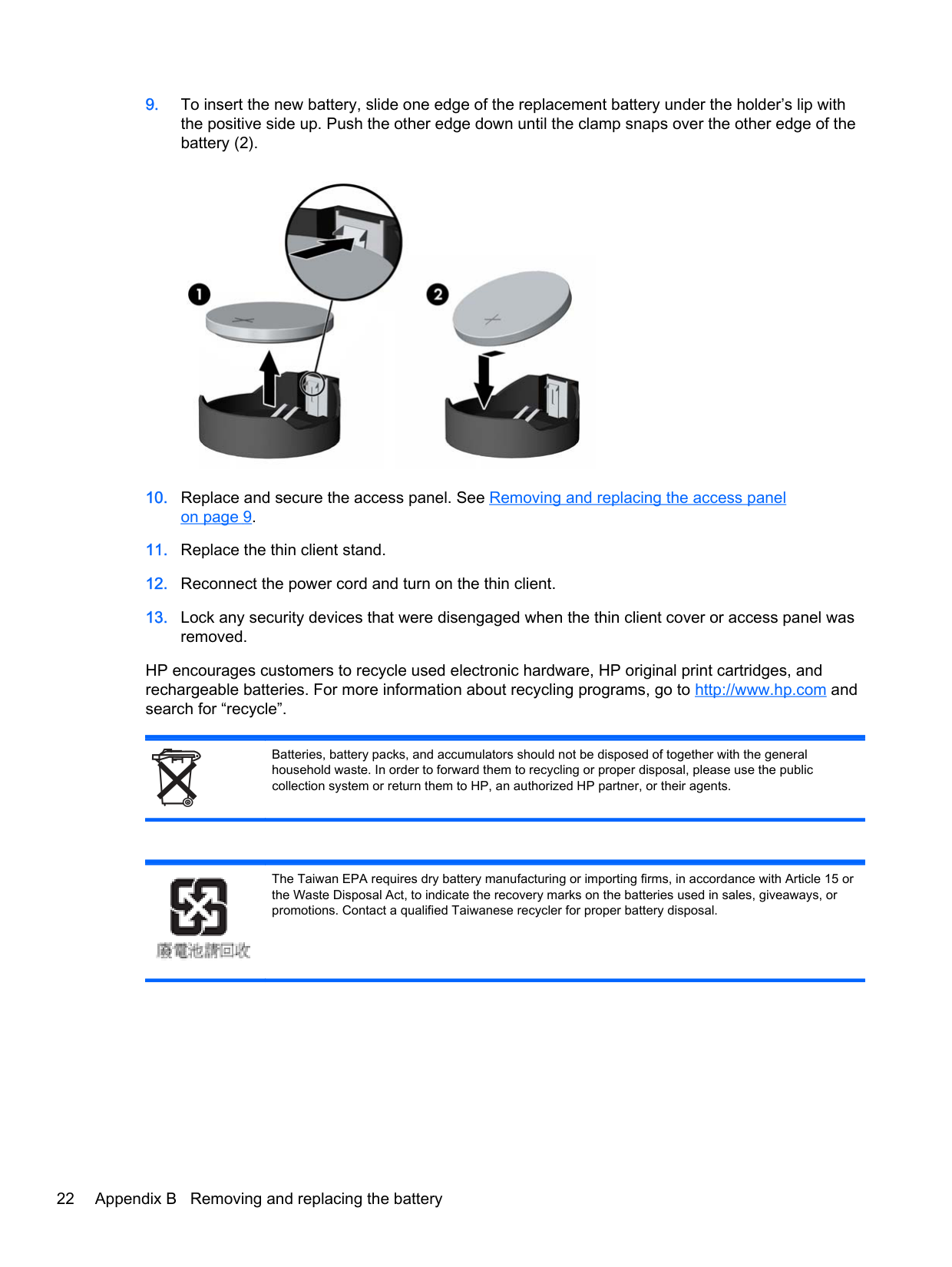
HP encourages customers to recycle used electronic hardware, HP original print cartridges, and rechargeable batteries. For more information about recycling programs, go to http://www.hp.com and search for “recycle”.
Batteries, battery packs, and accumulators should not be disposed of together with the general household waste. In order to forward them to recycling or proper disposal, please use the public collection system or return them to HP, an authorized HP partner, or their agents.
The Taiwan EPA requires dry battery manufacturing or importing firms, in accordance with Article 15 or the Waste Disposal Act, to indicate the recovery marks on the batteries used in sales, giveaways, or promotions. Contact a qualified Taiwanese recycler for proper battery disposal.

22 Appendix B Removing and replacing the battery
C Thin client operation
Routine thin client care
Use the following information to properly care for your thin client:
Routine thin client care 23
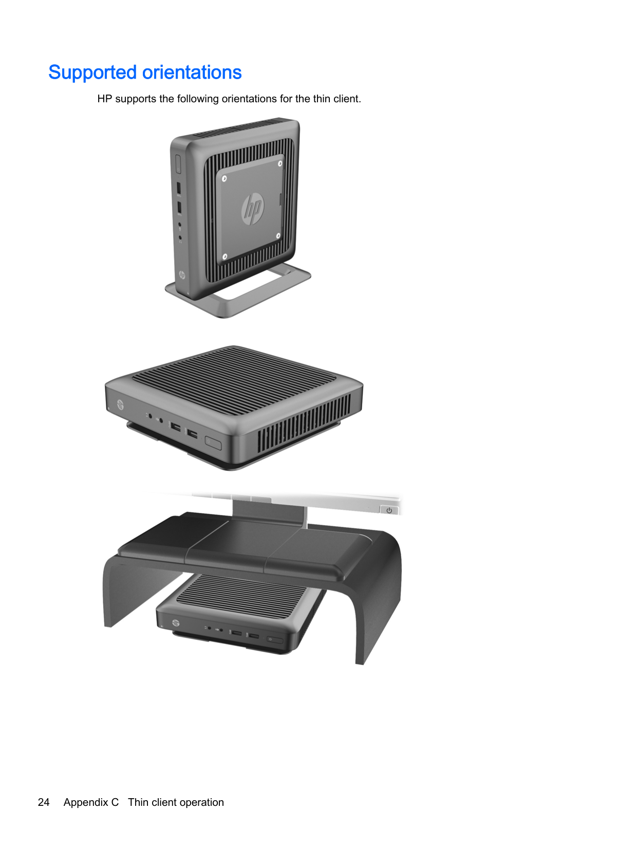
Supported orientations
HP supports the following orientations for the thin client.


24 Appendix C Thin client operation
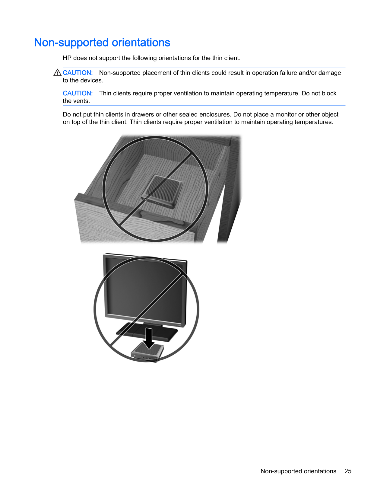
Non-supported orientations
HP does not support the following orientations for the thin client.
CAUTION: Non-supported placement of thin clients could result in operation failure and/or damage to the devices.
CAUTION: Thin clients require proper ventilation to maintain operating temperature. Do not block the vents. Do not put thin clients in drawers or other sealed enclosures. Do not place a monitor or other object on top of the thin client. Thin clients require proper ventilation to maintain operating temperatures.


Non-supported orientations 25
D Electrostatic discharge
A discharge of static electricity from a finger or other conductor may damage system boards or other static-sensitive devices. This type of damage may reduce the life expectancy of the device.
Preventing electrostatic damage
To prevent electrostatic damage, observe the following precautions:
Grounding methods
There are several methods for grounding. Use one or more of the following methods when handling or installing electrostatic-sensitive parts:
If you do not have any of the suggested equipment for proper grounding, contact an HP authorized dealer, reseller, or service provider.
| | |---|
NOTE: For more information about static electricity, contact an HP authorized dealer, reseller, or service provider.
26 Appendix D Electrostatic discharge
E Shipping information
Shipping preparation
Follow these suggestions when preparing to ship the thin client:
| | |---|
Important service repair information
In all cases, remove and safeguard all external options before returning the thin client to HP for repair or exchange.
In countries that support customer mail-in repair by returning the same unit to the customer, HP makes every effort to return the repaired unit with the same internal memory and flash modules that were sent.
In countries that do not support customer mail-in repair by returning the same unit to the customer, all internal options should be removed and safeguarded in addition to the external options. The thin client should be restored to the original configuration before returning it to HP for repair.
Shipping preparation 27
Removing and replacing the solid state drive (flash memory)
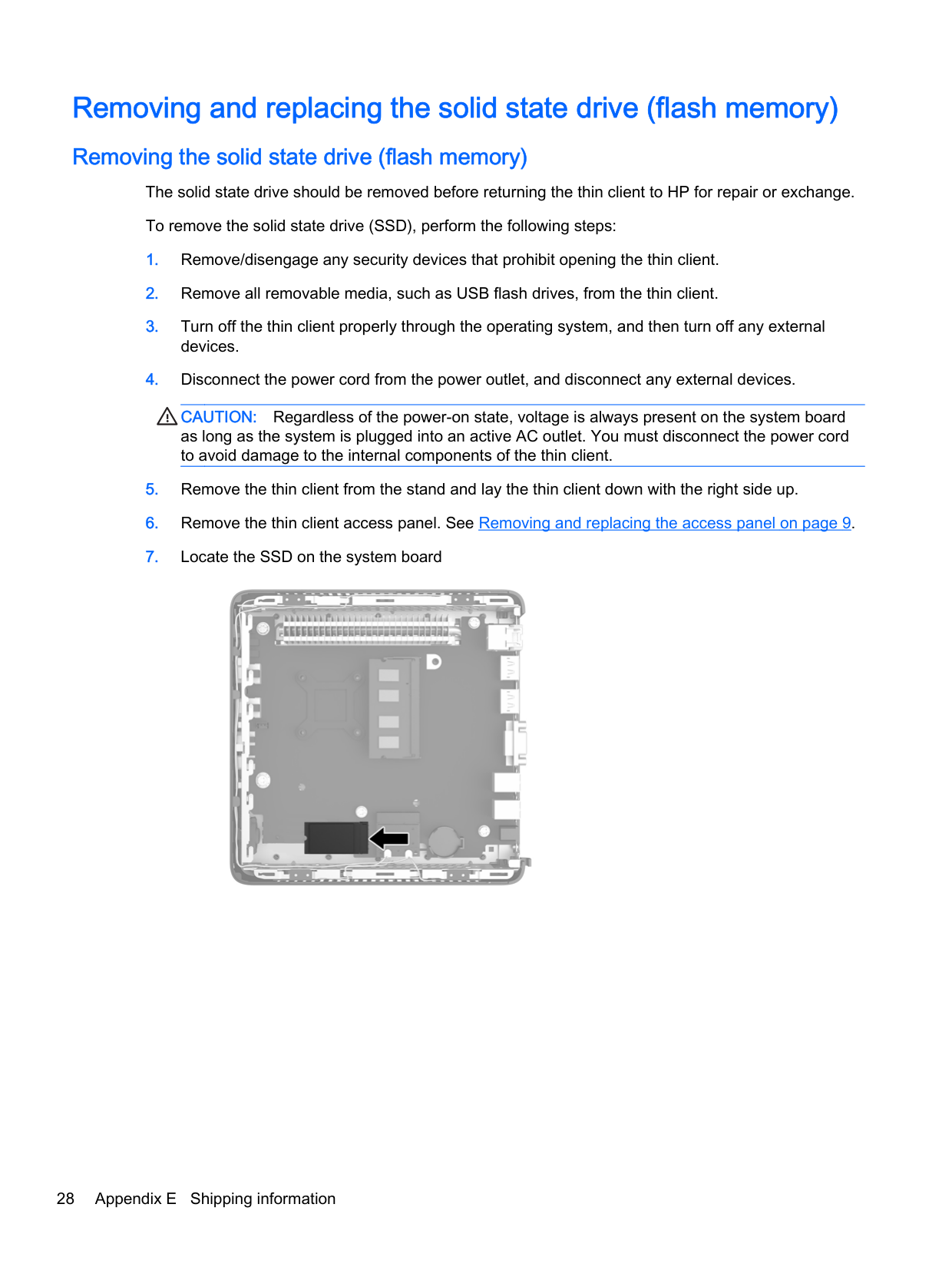
Removing the solid state drive (flash memory) The solid state drive should be removed before returning the thin client to HP for repair or exchange. To remove the solid state drive (SSD), perform the following steps:
CAUTION: Regardless of the power-on state, voltage is always present on the system board as long as the system is plugged into an active AC outlet. You must disconnect the power cord to avoid damage to the internal components of the thin client.


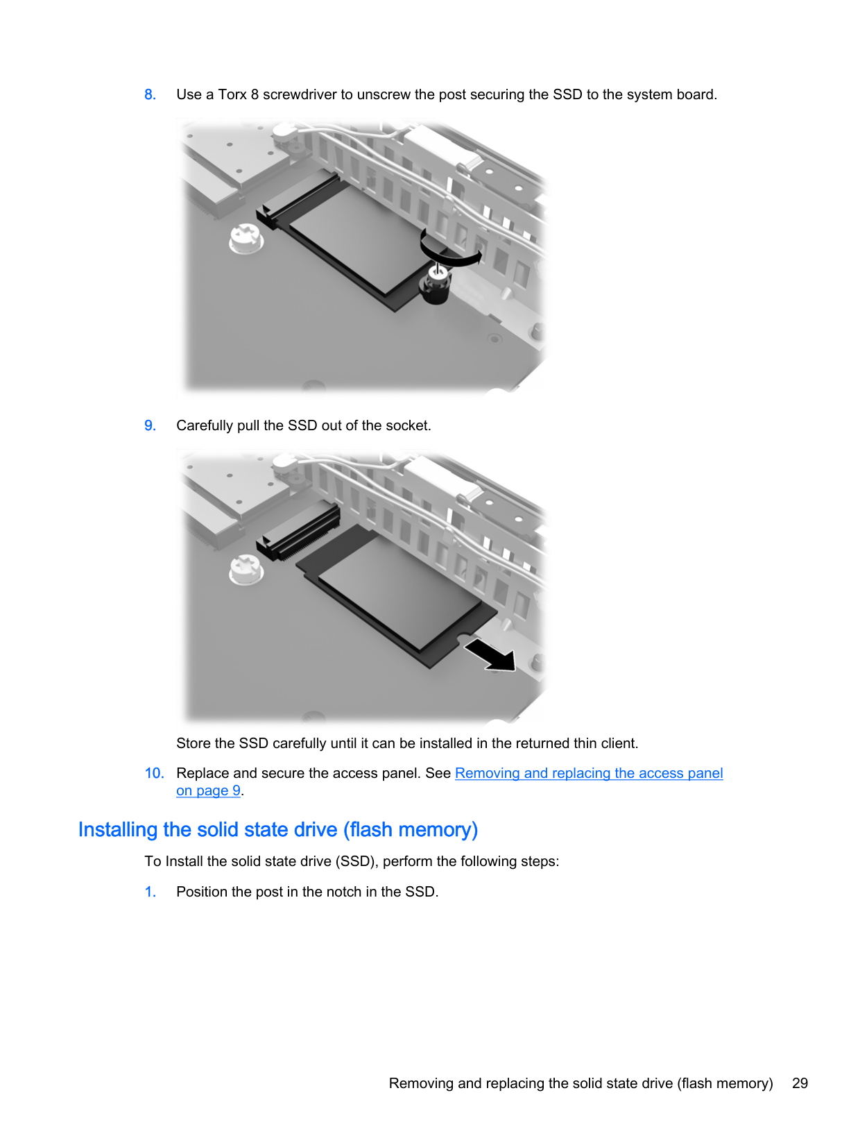
Store the SSD carefully until it can be installed in the returned thin client.
#### Installing the solid state drive (flash memory)
To Install the solid state drive (SSD), perform the following steps:

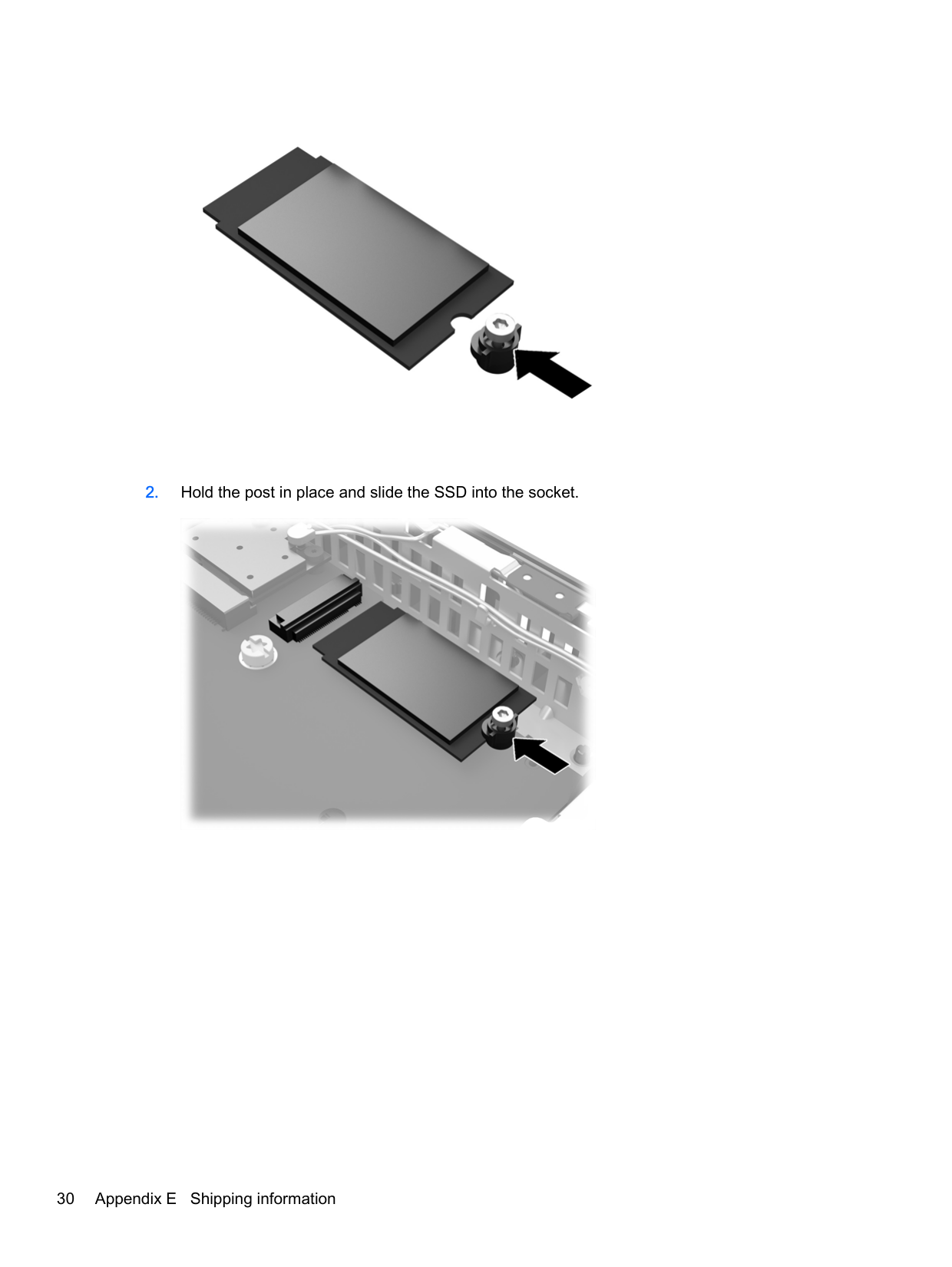
###### 2. Hold the post in place and slide the SSD into the socket.

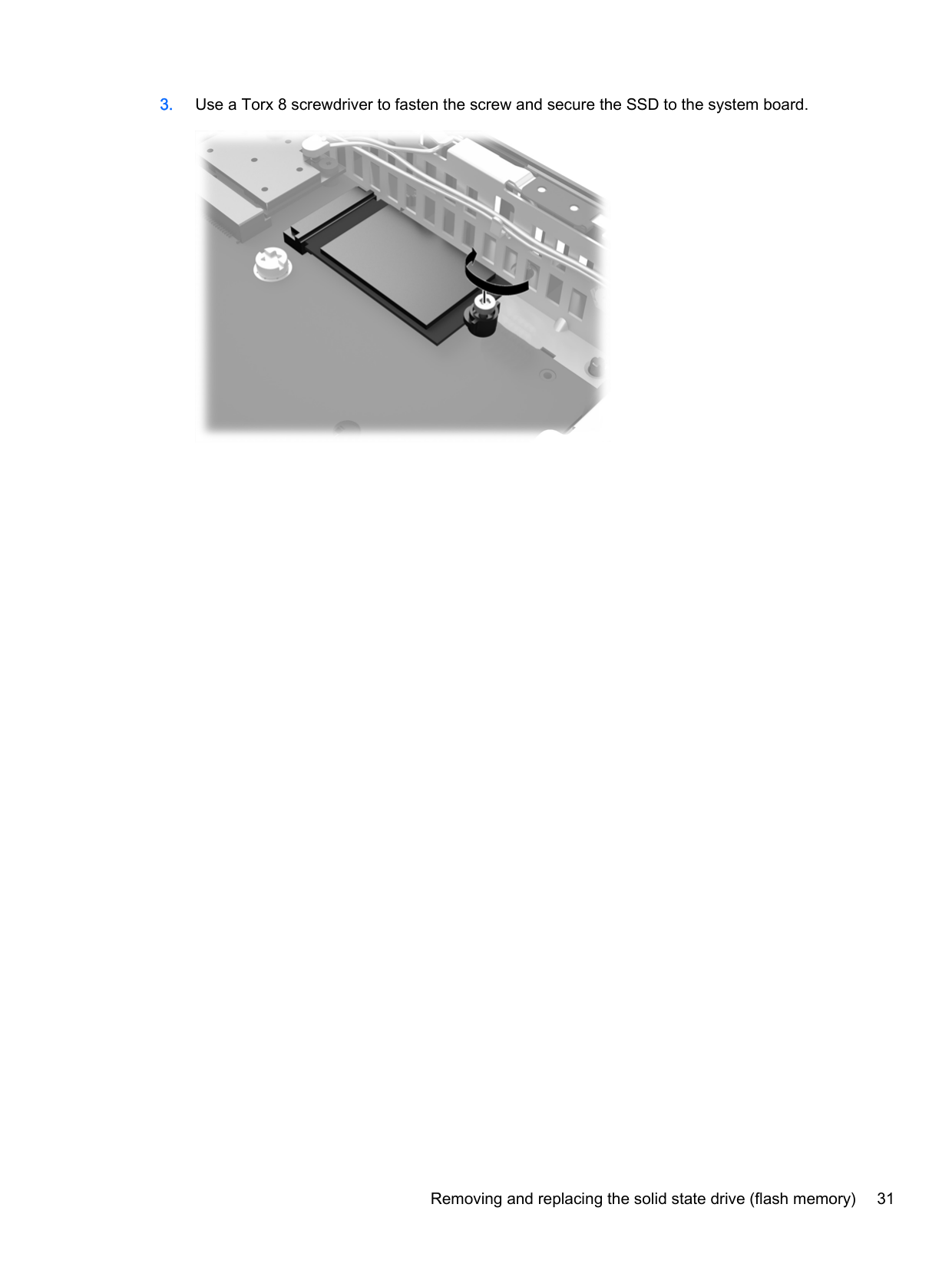
###### 3. Use a Torx 8 screwdriver to fasten the screw and secure the SSD to the system board.

Index
removing 9 replacing 11
altitude specifications 19
attaching the stand 7 electric shock 5, 9, 12 HP Quick Release 17 installing SODIMM 12 removing the battery 21 securing the power cable 6 static electricity 5 thin client orientation 25 ventilation 25
components front panel 2 rear panel 3
3
installing 29 removing 28
front panel components 2
32 Index
flash memory 29 memory (SODIMM) 11 SODIMM 11 solid state drive 29 SSD 29
installation 11 socket population 12 specifications 11
microphone port location 2 mounting options
on back of monitor stand 18 on wall 18 under desk 18
mounting thin client 16
in a drawer 25 under a monitor 25
power button location 2 power cord connection 6 power cord retention hook 3 power output specifications 20 power supply specifications 20 preventing electrostatic damage
26
19
removing access panel 9 battery 21 flash memory 28 solid state drive 28 SSD 28
replacing access panel 11 battery 21 retention hook 3 RJ-45 connector 3 routine care 23
cable lock 15 serial number location 4 service repair 27 shipping preparation 27 SODIMM
installation 11 socket population 12
solid state drive installing 29 removing 28
specifications altitude 19 dimensions 19 hardware 19 humidity 19 power output 20 power supply 20 rated output current 20 relative humidity 19 temperature 19 thin client 19
specifications, memory 11 SSD
installing 29 removing 28
stand, attaching 7 supported mounting options 18 supported orientations 24
horizontal 24 under monitor stand 24 vertical 24
slot 3 USB ports
burn 5, 12 electric shock 5, 9, 21 grounding plug 5 NIC receptacles 5
websites HP 1 options 1
Index 33