Ask AI
— answers from the official manualAnswers from the official manual.
Common questions
Common Questions
10 totalWhat should I do when the Red Power LED flashes four times indicating power failure?
Check if a device is causing overload by removing all attached devices, powering on to enter POST, then adding one device at a time until you identify and resolve issue. If not resolved, replace the power supply or system board. (Page 37 Table B-3)
How do I set up Wake-on LAN on my HP t630 Thin Client?
To enable WOL, turn on the computer and press F10 during boot to access Computer Setup. Navigate to Power > Hardware Power Management > S5 Maximum Power Savings setting and disable it for enabling WOL feature; save changes then exit. (Page 34)
How do I adjust the stand orientation for the t630 Thin Client?
The stand can be adjusted into two configurations: square for the horizontal position (align short pieces with outer connection points) or rectangular for the vertical position (align short pieces with inner connection points). Follow steps to attach the stand based on desired placement. Make sure at least 4 inches of space remains clear around the thin client once installed. (Page 6)
How do I reset my HP t630 Thin Client to factory defaults?
Press and hold the Power button for 10 seconds until the LED flashes red to clear all settings and return it to factory defaults. You will need to re-pair all connected devices after performing a factory reset. (Page A-2 Computer Setup—File)
What should I do if my HP t630 Thin Client displays the 'Out of Memory Space for Option ROMs' error?
If encountering this issue, remove any recently added PCI expansion cards to see if problem persists. In Computer Setup under Advanced > Device Options set NIC PXE Option ROM Download to Disable to conserve memory space; save changes and exit setup to prevent the internal NIC's option ROM from being downloaded during POST (Page A-3 BIOS setting).
How do I reseat memory modules if there is a pre-video memory error?
To resolve, ensure proper installation: power off unit, unplug cord, reseat memory modules by firmly pressing them back into sockets; check connections and try again. Replace faulty module if required (Page 37 Table B-3).
Show 4 more questions
Full Manual
61 pages


Troubleshooting Guide
HP t630 Thin Client
© Copyright 2016 HP Development Company, L.P.
Windows is a registered trademark or trademark of Microsoft Corporation in the United States and/or other countries.
The information contained herein is subject to change without notice. The only warranties for HP products and services are set forth in the express warranty statements accompanying such products and services. Nothing herein should be construed as constituting an additional warranty. HP shall not be liable for technical or editorial errors or omissions contained herein.
Second Edition: December 2016 First Edition: July 2016 Document Part Number: 839089-002
######## Product notice
This user guide describes features that are common to most models. Some features may not be available on your computer.
Not all features are available in all editions of Windows. This computer may require upgraded and/or separately purchased hardware, drivers and/or software to take full advantage of Windows functionality. Go to http://www.microsoft.com for details.
To access the latest user guides or manuals for your product, go to http://www.hp.com/
support, and select your country. Select Find your product, and then follow the on-screen instructions.
######## Software terms
By installing, copying, downloading, or otherwise using any software product preinstalled on this computer, you agree to be bound by the terms of the HP End User License Agreement (EULA). If you do not accept these license terms, your sole remedy is to return the entire unused product (hardware and software) within 14 days for a full refund subject to the refund policy of your seller.

For any further information or to request a full refund of the price of the computer, please contact your seller.
#### About this book
WARNING! Text set off in this manner indicates that failure to follow directions could result in bodily harm or loss of life.
CAUTION: Text set off in this manner indicates that failure to follow directions could result in damage to equipment or loss of information.
| | |---|
NOTE: Text set off in this manner provides important supplemental information.
iii
###### iv About this book
Table of contents
Adjusting the stand ............................................................................................................................. 6 Installing the stand .............................................................................................................................. 6
Connecting the AC power cord ............................................................................................................................... 8 Securing the thin client .......................................................................................................................................... 9 Routine thin client care .......................................................................................................................................... 9

Removing the access panel ............................................................................................................... 10 Replacing the access panel ............................................................................................................... 12
Locating internal components ............................................................................................................................ 13 Replacing an M.2 storage module ....................................................................................................................... 14 Removing and replacing the battery ................................................................................................................... 16 Installing an internal USB flash drive .................................................................................................................. 18 Upgrading system memory ................................................................................................................................. 19
Installing a memory module ............................................................................................................. 19
Configuring the serial port .................................................................................................................................. 21 Locating configurable serial port jumpers ....................................................................................... 21 Serial port functionality .................................................................................................................... 22 Configuring the serial port ................................................................................................................ 23
##### Appendix A Computer Setup (F10) Utility, BIOS Settings .................................................................................... 24Computer Setup (F10) Utilities ............................................................................................................................ 24
Using Computer Setup (F10) Utilities ................................................................................................ 24 Computer Setup—File ....................................................................................................................... 26 Computer Setup—Storage ................................................................................................................ 27 Computer Setup—Security ............................................................................................................... 28
v
Computer Setup—Power .................................................................................................................. 29 Computer Setup—Advanced ............................................................................................................. 30
Changing BIOS Settings from the HP BIOS Configuration Utility (HPBCU) .......................................................... 31
Basic troubleshooting ....................................................................................................................... 40 Diskless (No-Flash) unit troubleshooting ......................................................................................... 41
Configuring a PXE server ..................................................................................................................................... 42

##### Index ............................................................................................................................................................. 54
vi
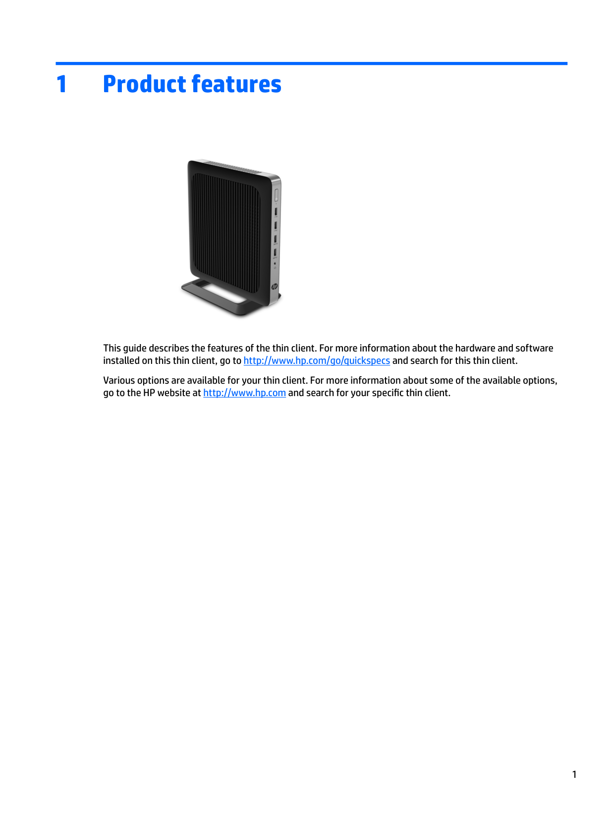
1 Product features

This guide describes the features of the thin client. For more information about the hardware and software installed on this thin client, go to http://www.hp.com/go/quickspecs and search for this thin client.
Various options are available for your thin client. For more information about some of the available options, go to the HP website at http://www.hp.com and search for your specific thin client.
1
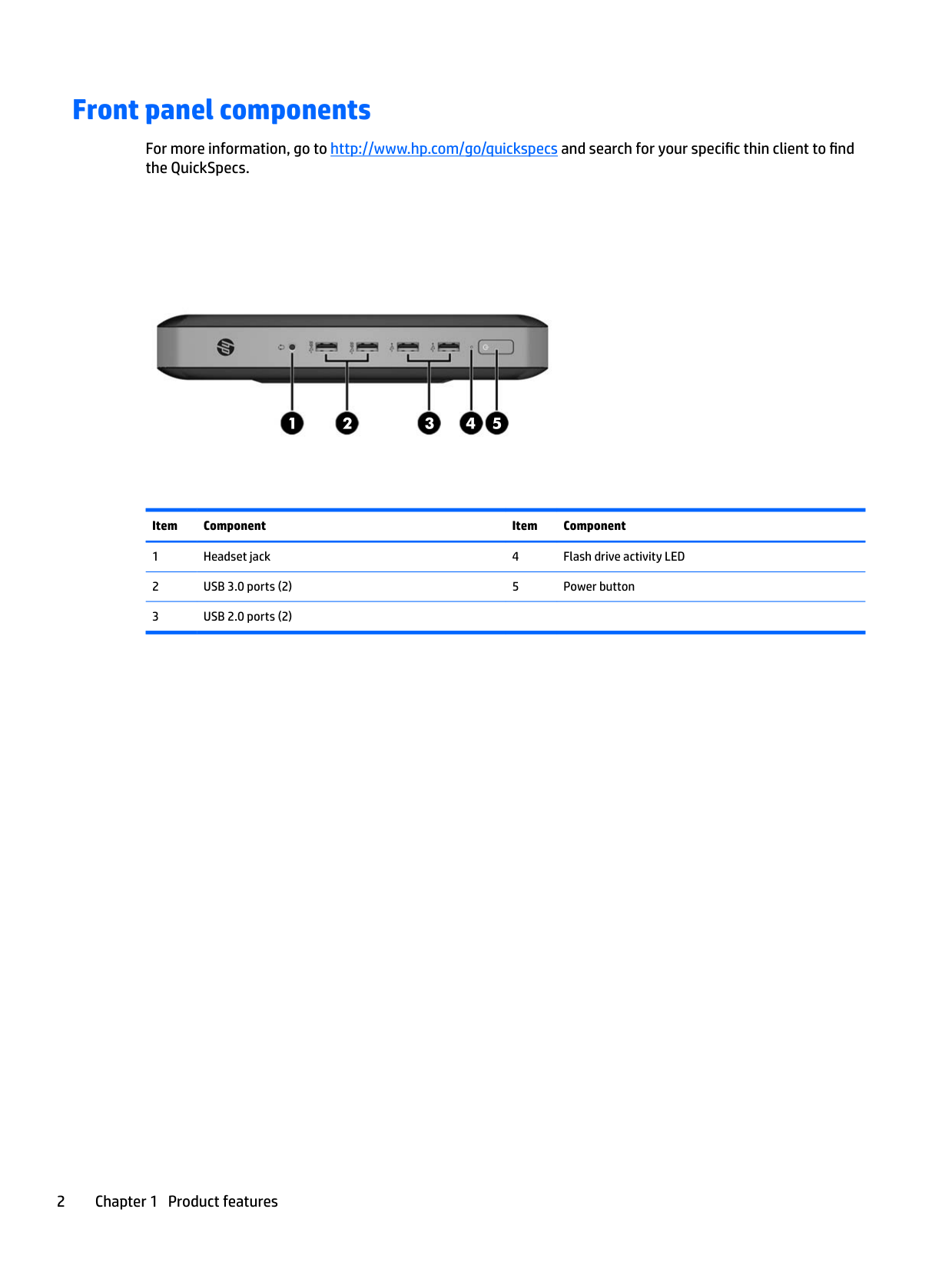
Front panel components
For more information, go to http://www.hp.com/go/quickspecs and search for your specific thin client to find the QuickSpecs.


Item Component Item Component
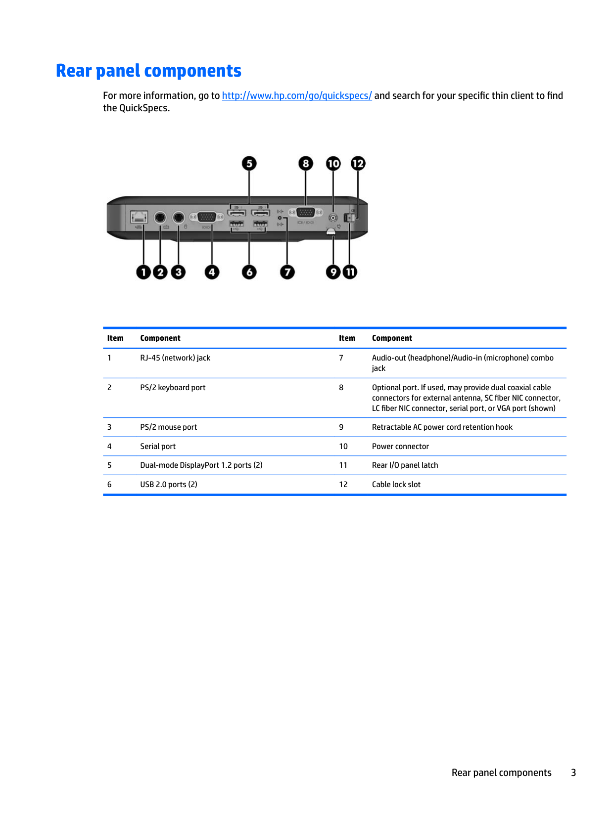
Rear panel components
For more information, go to http://www.hp.com/go/quickspecs/ and search for your specific thin client to find the QuickSpecs.

Item Component Item Component
Rear panel components 3
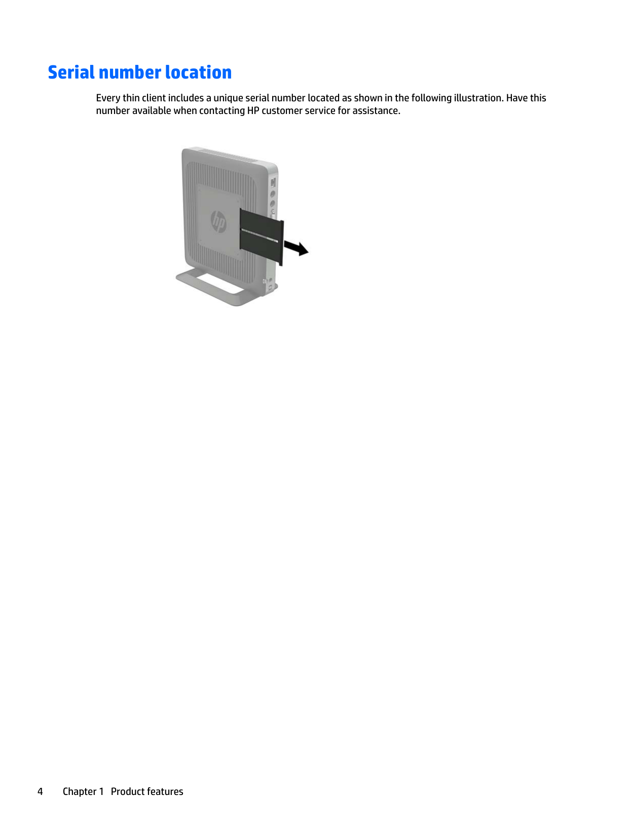
Serial number location
Every thin client includes a unique serial number located as shown in the following illustration. Have this number available when contacting HP customer service for assistance.

2 Setup
Warnings and cautions
Before performing upgrades be sure to carefully read all of the applicable instructions, cautions, and warnings in this guide.
WARNING! To reduce the risk of personal injury or equipment damage from electric shock, hot surfaces, or fire: Disconnect the AC power cord from the AC outlet and allow the internal system components to cool before you touch them. Do not plug telecommunications or telephone connectors into the network interface controller (NIC) receptacles. Do not disable the AC power cord grounding plug. The grounding plug is an important safety feature. Plug the AC power cord into a grounded (earthed) AC outlet that is easily accessible at all times.
To reduce the risk of serious injury, read the Safety & Comfort Guide. It describes proper workstation setup, posture, and health and work habits for thin client users, and provides important electrical and mechanical safety information. The Safety & Comfort Guide is located on the HP website at http://www.hp.com/ergo.
WARNING! Energized parts inside. Disconnect power to the equipment before removing the enclosure. Replace and secure the enclosure before re-energizing the equipment. CAUTION: Static electricity can damage the electrical components of the thin client or optional equipment. Before beginning the following procedures, be sure that you are discharged of static electricity by briefly touching a grounded metal object.
When the thin client is plugged into an AC power source, voltage is always applied to the system board. To prevent damage to internal components, you must disconnect the AC power cord from the power source before opening the thin client.
Warnings and cautions 5
Attaching the stand
CAUTION: Unless the thin client is mounted with the HP Quick Release, it must be operated with the stand attached to ensure proper airflow around the thin client.
#### Adjusting the stand
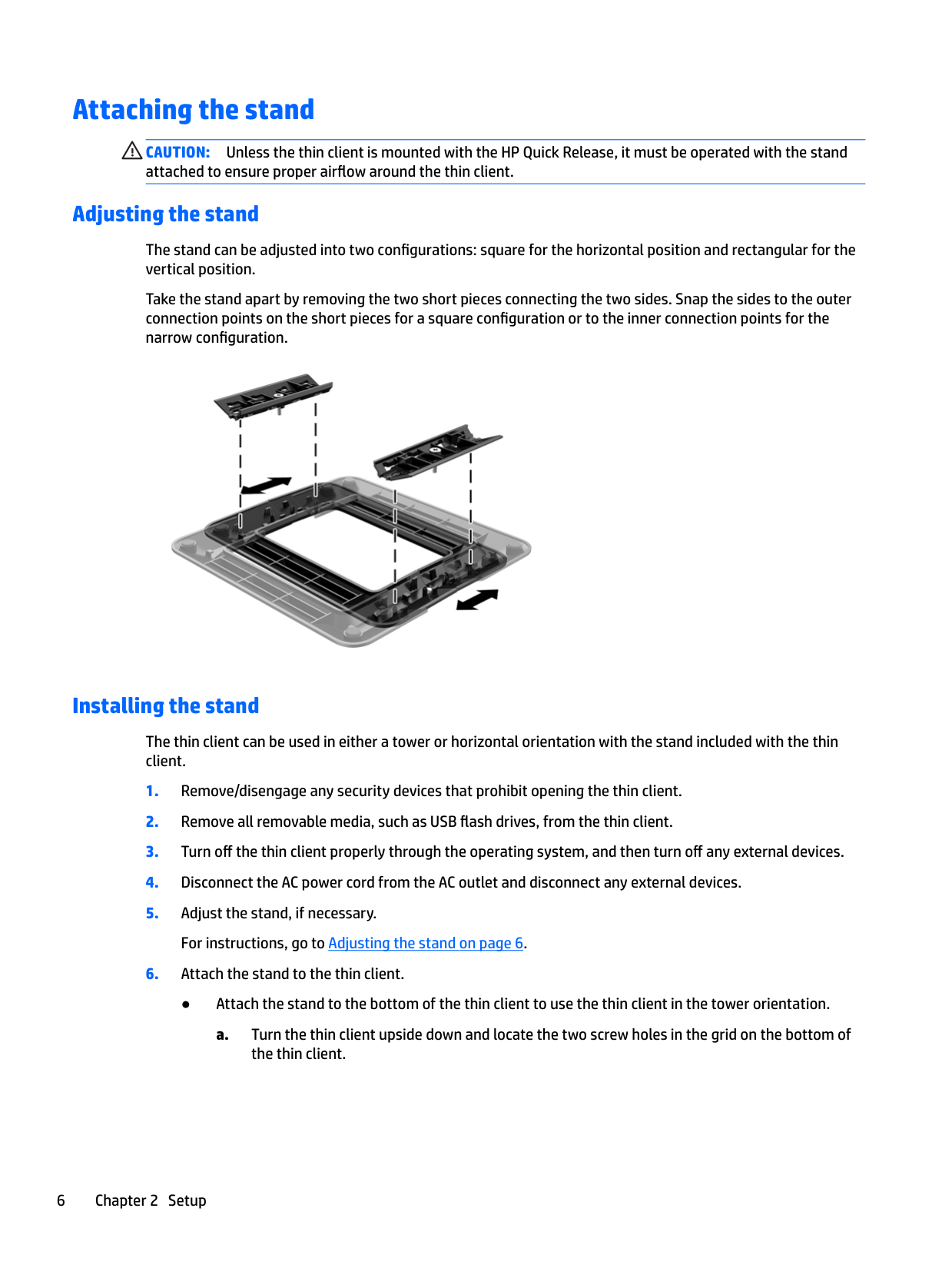
The stand can be adjusted into two configurations: square for the horizontal position and rectangular for the vertical position.
Take the stand apart by removing the two short pieces connecting the two sides. Snap the sides to the outer connection points on the short pieces for a square configuration or to the inner connection points for the narrow configuration.

#### Installing the stand
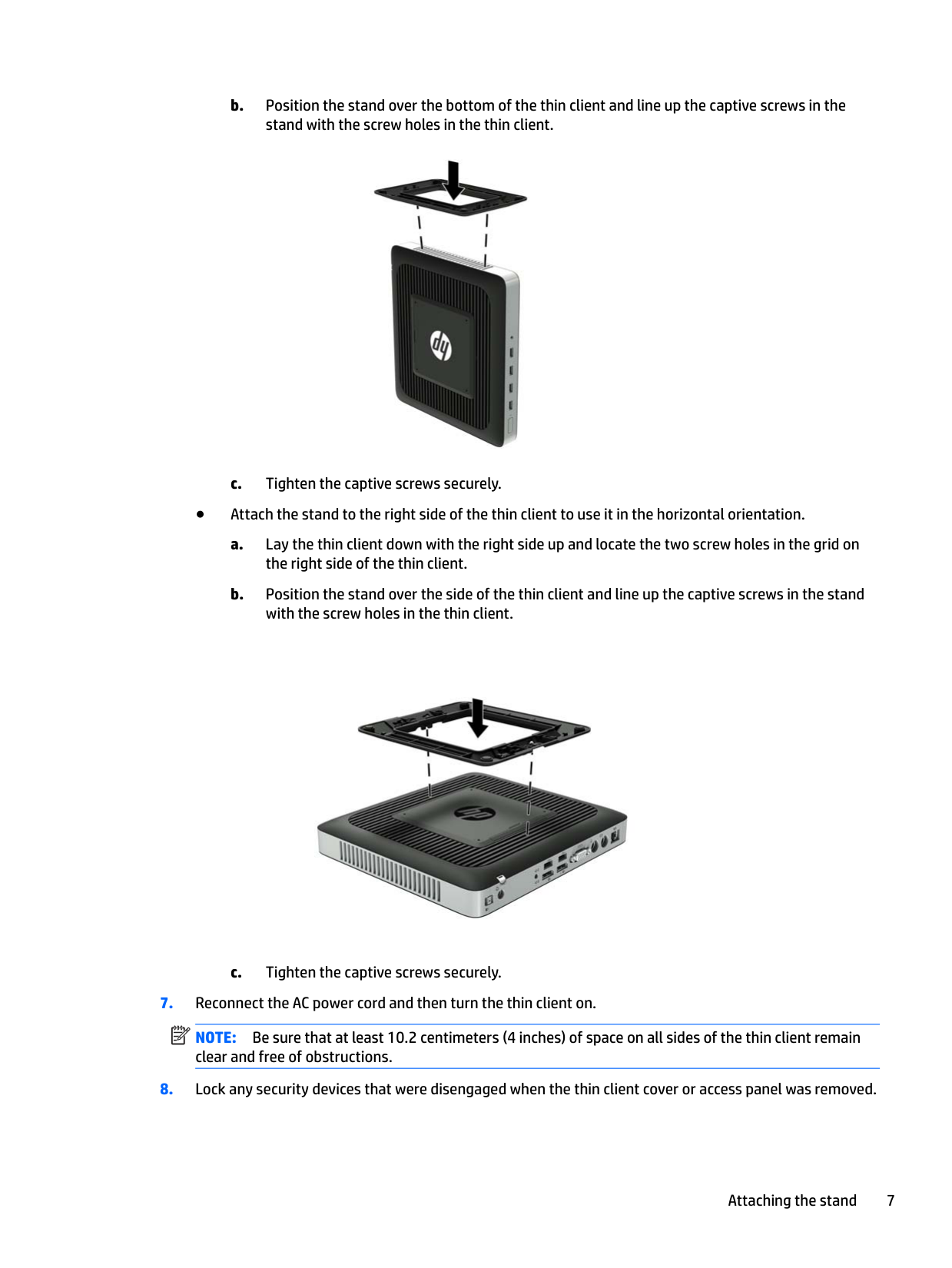
The thin client can be used in either a tower or horizontal orientation with the stand included with the thin client.


NOTE: Be sure that at least 10.2 centimeters (4 inches) of space on all sides of the thin client remain clear and free of obstructions.
| | |---|
Attaching the stand 7
| | |---|
NOTE: An optional Quick Release mounting bracket is available from HP for mounting the thin client to a wall, desk, or swing arm. When the mounting bracket is used, do not install the thin client with the I/O ports oriented towards the ground.
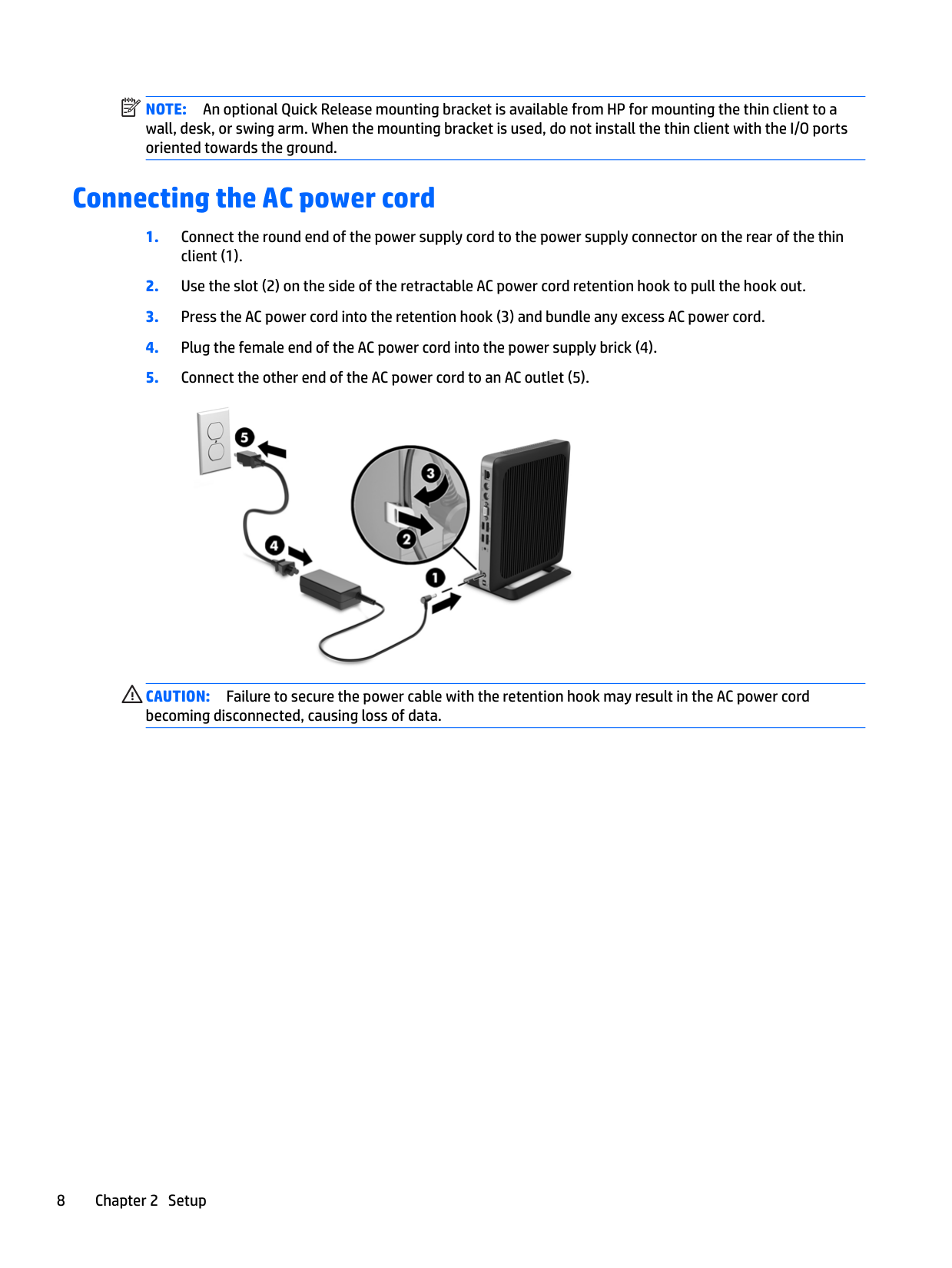
Connecting the AC power cord

CAUTION: Failure to secure the power cable with the retention hook may result in the AC power cord becoming disconnected, causing loss of data.
Securing the thin client
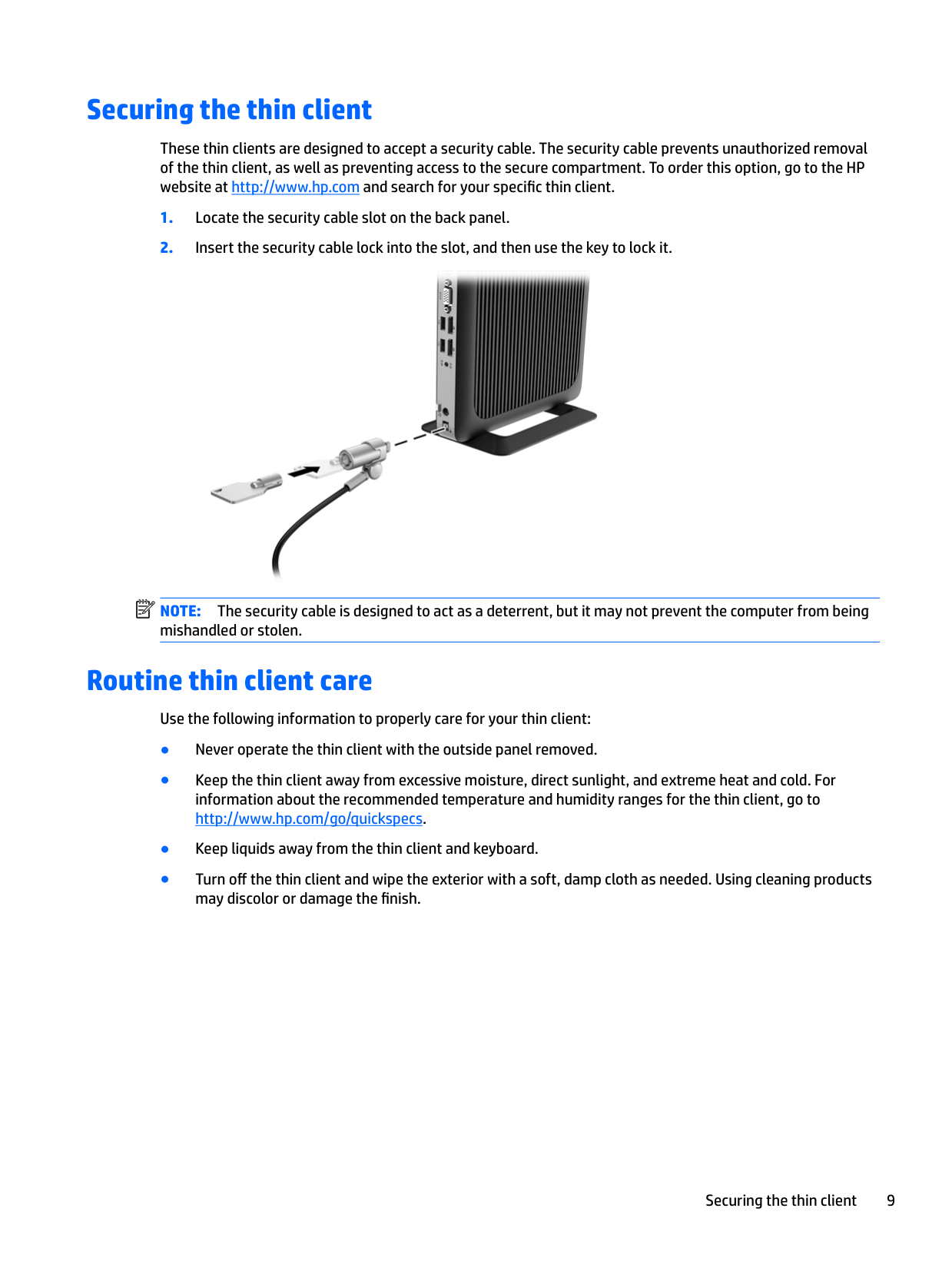
These thin clients are designed to accept a security cable. The security cable prevents unauthorized removal of the thin client, as well as preventing access to the secure compartment. To order this option, go to the HP website at http://www.hp.com and search for your specific thin client.

| | |---|
NOTE: The security cable is designed to act as a deterrent, but it may not prevent the computer from being mishandled or stolen.
Routine thin client care
Use the following information to properly care for your thin client:
Securing the thin client 9
3 Hardware changes
Warnings and cautions
Before performing upgrades be sure to carefully read all of the applicable instructions, cautions, and warnings in this guide.
WARNING! To reduce the risk of personal injury or equipment damage from electric shock, hot surfaces, or fire: Energized and moving parts are inside. Disconnect power to the equipment before removing the enclosure. Allow the internal system components to cool before you touch them. Replace and secure the enclosure before re-energizing the equipment. Do not plug telecommunications or telephone connectors into the network interface controller (NIC) receptacles. Do not disable the AC power cord grounding plug. The grounding plug is an important safety feature. Plug the AC power cord into a grounded (earthed) AC outlet that is easily accessible at all times. To reduce the risk of serious injury, read the Safety & Comfort Guide. It describes proper workstation setup and provides guidelines for posture and work habits that increase your comfort and decrease your risk of injury. It also provides electrical and mechanical safety information. This guide is located on the web at http://www.hp.com/ergo. CAUTION: Static electricity can damage the electrical components of the thin client or optional equipment. Before beginning the following procedures, be sure that you are discharged of static electricity by briefly touching a grounded metal object.
When the thin client is plugged into an AC power source, voltage is always applied to the system board. You must disconnect the power cord from the power source before opening the thin client to prevent damage to internal components.
Removing and replacing the access panel
#### Removing the access panel
WARNING! To reduce the risk of personal injury or equipment damage from electric shock, hot surfaces, or fire, ALWAYS operate the thin client with the access panel in place. In addition to enhancing safety, the access panel may provide important instructions and identification information, which may be lost if the access panel is not used. DO NOT use any access panel except the one that is provided by HP for use with this thin client.
Before removing the access panel, be sure that the thin client is turned off and the AC power cord is disconnected from the AC outlet.
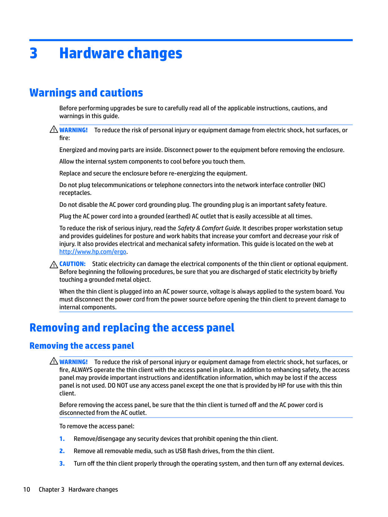
To remove the access panel:
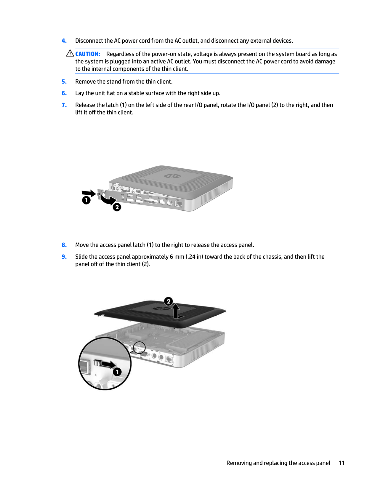
CAUTION: Regardless of the power-on state, voltage is always present on the system board as long as the system is plugged into an active AC outlet. You must disconnect the AC power cord to avoid damage to the internal components of the thin client.


Removing and replacing the access panel 11
#### Replacing the access panel
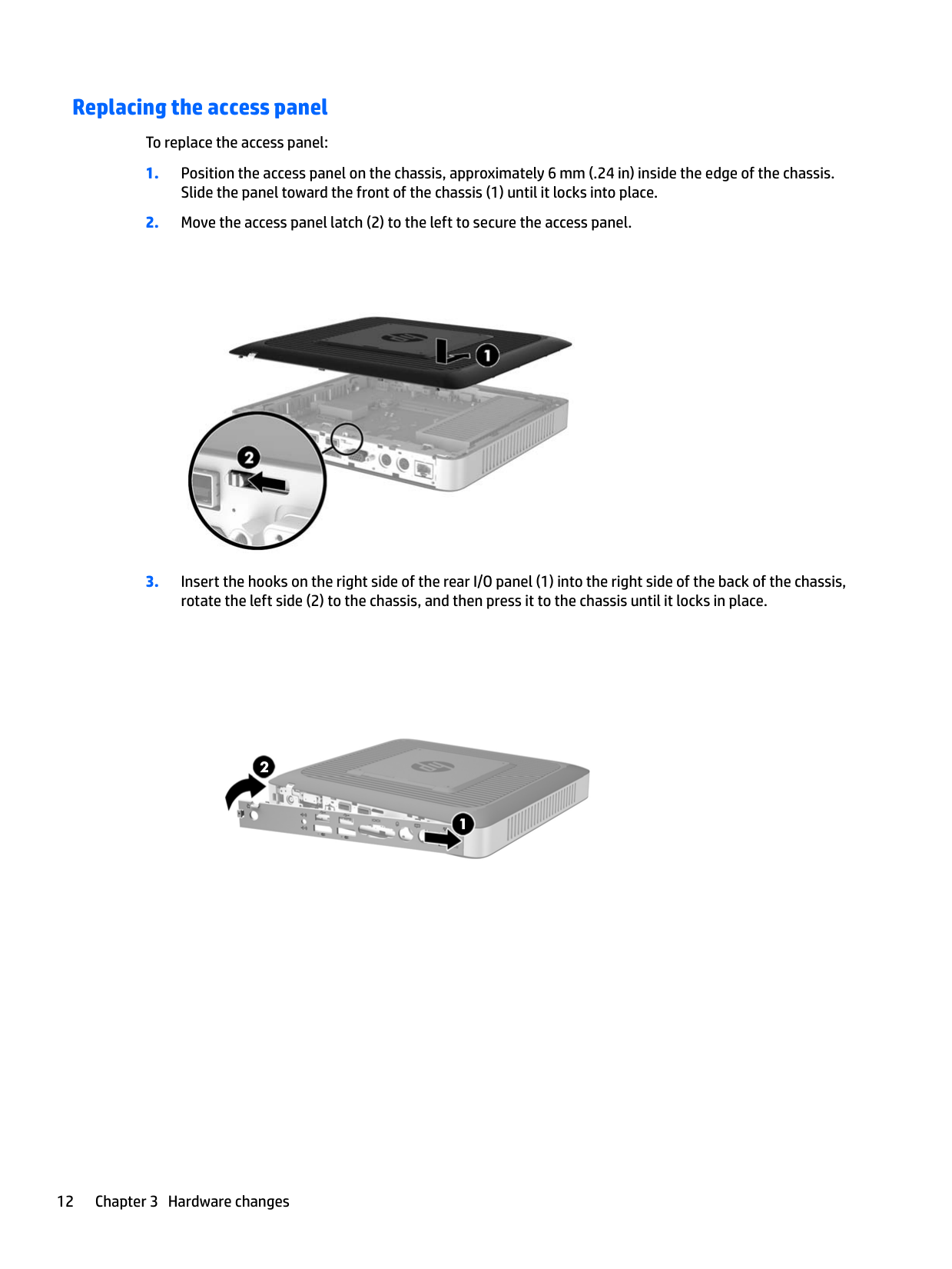
To replace the access panel:


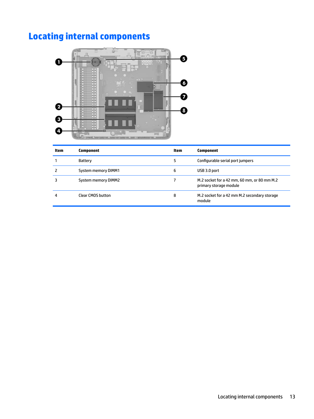
Locating internal components

######## Item Component Item Component
Locating internal components 13
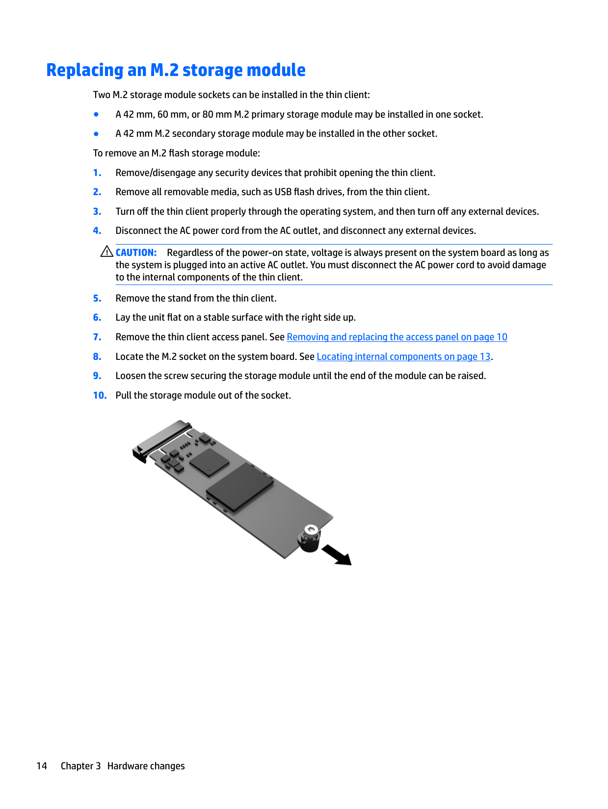
Replacing an M.2 storage module
Two M.2 storage module sockets can be installed in the thin client:
CAUTION: Regardless of the power-on state, voltage is always present on the system board as long as the system is plugged into an active AC outlet. You must disconnect the AC power cord to avoid damage to the internal components of the thin client.


| |
|---|

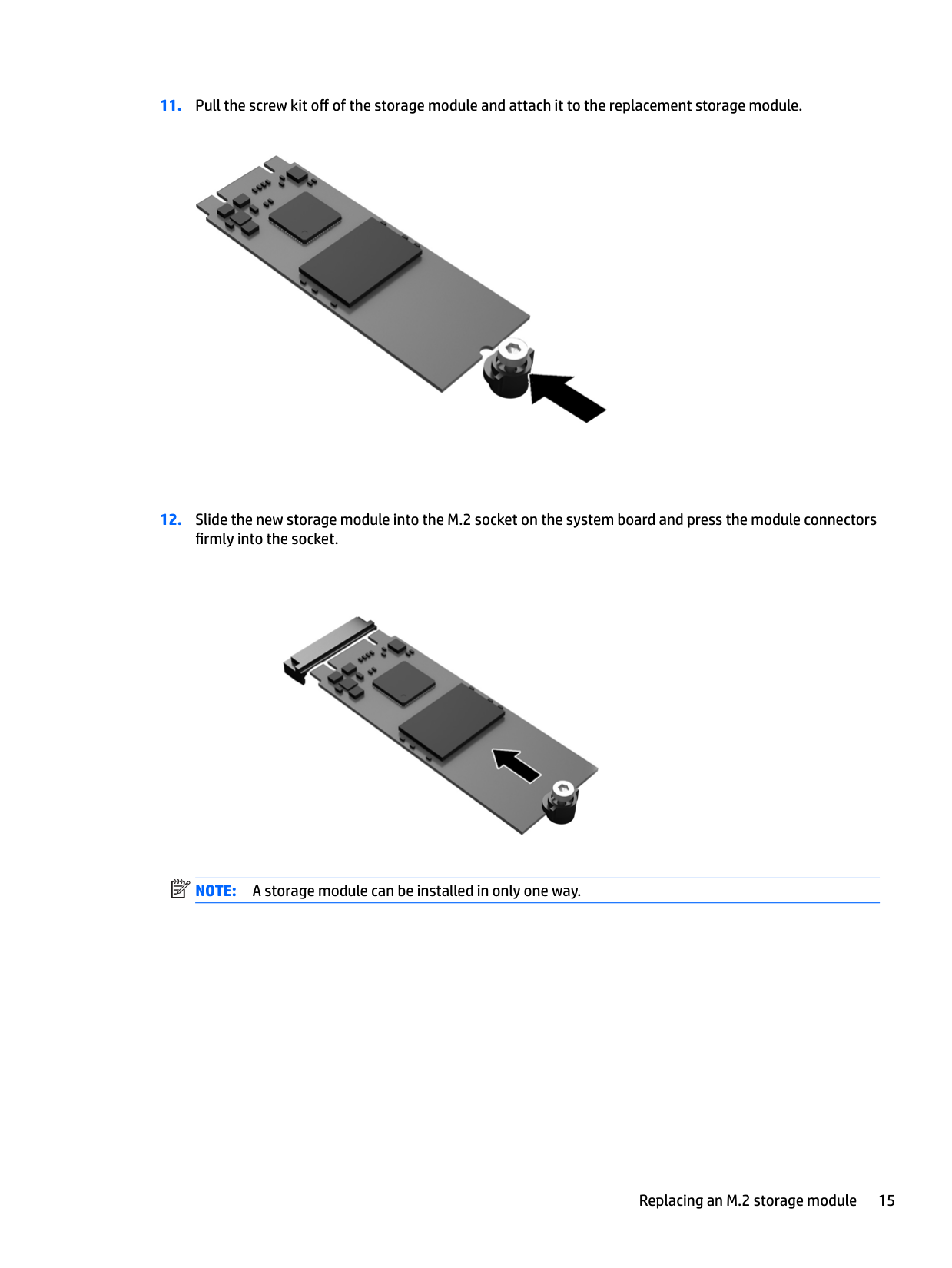
NOTE: A storage module can be installed in only one way.
Replacing an M.2 storage module 15

Removing and replacing the battery
WARNING! Before removing the access panel, be sure that the thin client is turned off and the AC power cord
is disconnected from the AC outlet. To remove and replace the battery:
CAUTION: Regardless of the power-on state, voltage is always present on the system board as long as the system is plugged into an active AC outlet. You must disconnect the AC power cord to avoid damage to the internal components of the thin client.

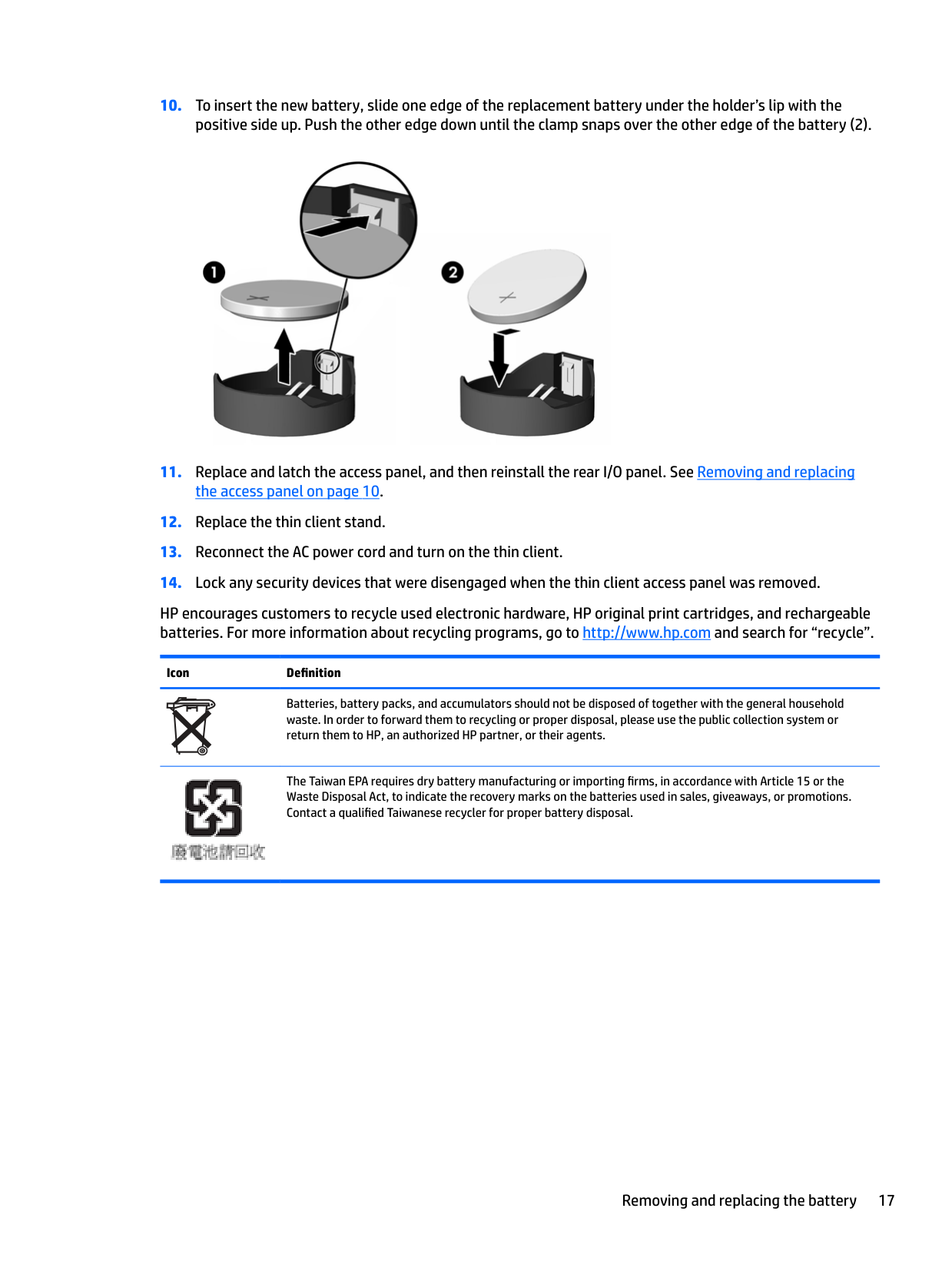
HP encourages customers to recycle used electronic hardware, HP original print cartridges, and rechargeable batteries. For more information about recycling programs, go to http://www.hp.com and search for “recycle”.
Icon Definition
Batteries, battery packs, and accumulators should not be disposed of together with the general household waste. In order to forward them to recycling or proper disposal, please use the public collection system or return them to HP, an authorized HP partner, or their agents.

The Taiwan EPA requires dry battery manufacturing or importing firms, in accordance with Article 15 or the Waste Disposal Act, to indicate the recovery marks on the batteries used in sales, giveaways, or promotions. Contact a qualified Taiwanese recycler for proper battery disposal.
Removing and replacing the battery 17
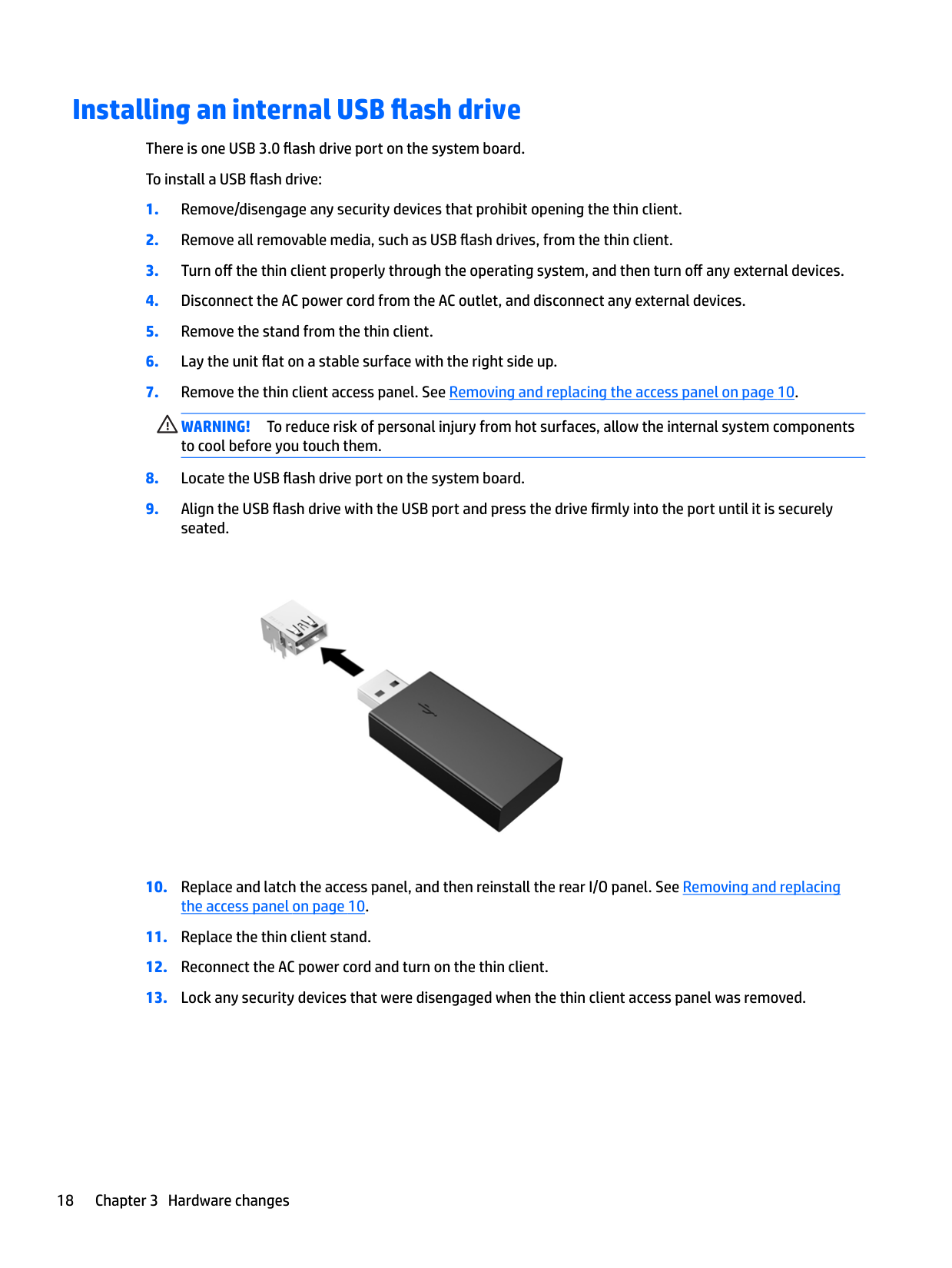
Installing an internal USB flash drive There is one USB 3.0 flash drive port on the system board. To install a USB flash drive:
WARNING! To reduce risk of personal injury from hot surfaces, allow the internal system components to cool before you touch them.

Upgrading system memory
The memory socket on the system board is populated with one memory module. To achieve the maximum memory support, you can populate each memory socket with up to 16 GB of memory each (32 GB total).
For proper system operation, the memory module must adhere to the following specifications:
Higher-speed DDR4 SODIMM modules will actually operate at a maximum system memory speed of 1866 MHz.
| | |---|
NOTE: The system does not operate properly when a nonsupported memory module is installed.
#### Installing a memory module
CAUTION: You must unplug the power cord and wait approximately 30 seconds for the power to drain before adding or removing memory modules. Regardless of the power-on state, voltage is always supplied to the memory modules as long as the thin client is plugged into an active AC outlet. Adding or removing memory modules while voltage is present may cause irreparable damage to the memory modules or system board.
The memory module socket has gold-plated metal contacts. When upgrading the memory, it is important to use a memory module with gold-plated metal contacts to prevent corrosion and/or oxidation resulting from having incompatible metals in contact with each other.
Static electricity can damage the electronic components of the thin client or optional cards. Before beginning the following procedures, be sure that you are discharged of static electricity by briefly touching a grounded metal object.
When handling a memory module, be careful not to touch any of the contacts. Doing so may damage the module.
CAUTION: You must unplug the power cord and wait approximately 30 seconds for the power to drain before adding or removing a memory module. Regardless of the power-on state, voltage is always supplied to the memory module as long as the thin client is plugged into an active AC outlet. Adding or removing a memory module while voltage is present may cause irreparable damage to the memory module or system board.
Upgrading system memory 19
WARNING! To reduce risk of personal injury from hot surfaces, allow the internal system components to cool before you touch them.


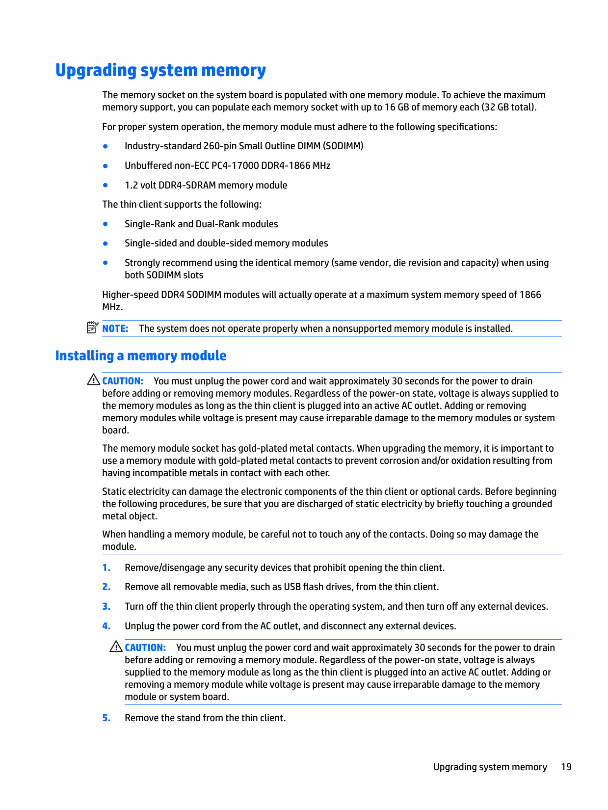
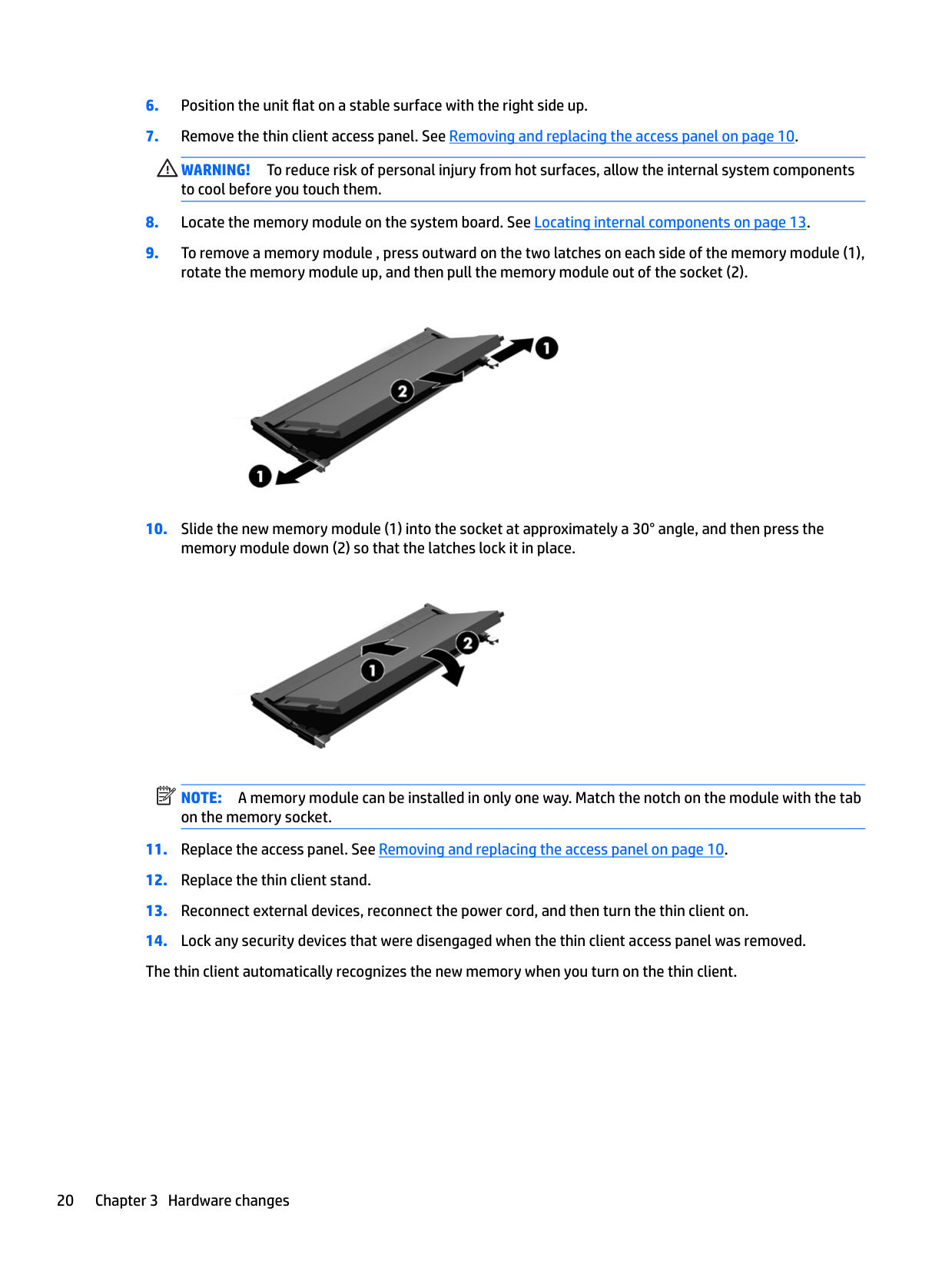
NOTE: A memory module can be installed in only one way. Match the notch on the module with the tab on the memory socket.
| | |---|
Configuring the serial port
One configurable powered serial port is standard on the thin client. Devices that support a powered serial interface do not require an external power source. To determine which serial port pin powered a specific device, refer to the specification for that device. The default setting for the powered serial port is not powered.
Two system board jumpers control which pins are powered (5V) on the serial port, as follows:
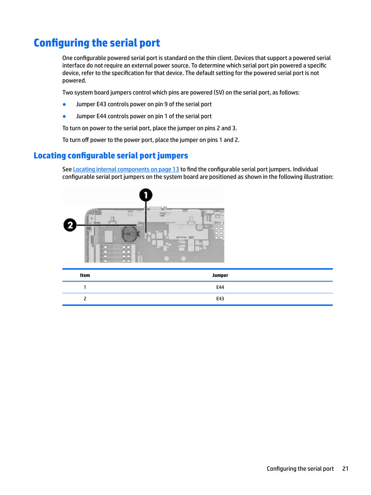
#### Locating configurable serial port jumpers
See Locating internal components on page 13 to find the configurable serial port jumpers. Individual configurable serial port jumpers on the system board are positioned as shown in the following illustration:

Item Jumper
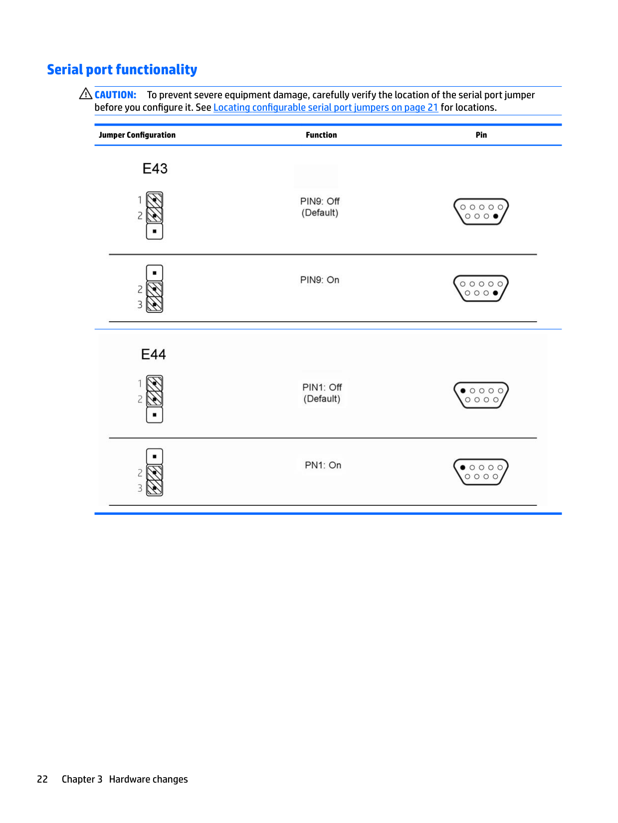
#### Serial port functionality
CAUTION: To prevent severe equipment damage, carefully verify the location of the serial port jumper before you configure it. See Locating configurable serial port jumpers on page 21 for locations.
Jumper Configuration Function Pin


#### Configuring the serial port
CAUTION: Regardless of the power-on state, voltage is always present on the system board as long as the system is plugged into an active AC outlet. You must unplug the power cord to avoid damage to the internal components of the thin client.
CAUTION: An unsupported configuration can cause severe equipment damage. Carefully verify serial port jumper locations and supported configurations before you configure a serial port. See Locating configurable serial port jumpers on page 21 for jumper locations. See Serial port functionality on page 22 for supported configurations.
A Computer Setup (F10) Utility, BIOS Settings
Computer Setup (F10) Utilities
Use Computer Setup (F10) Utility to do the following:
#### Using Computer Setup (F10) Utilities
Computer Setup can be accessed only by turning the computer on or restarting the system. To access the Computer Setup Utilities menu, complete the following steps:
NOTE: If you do not press esc or F10 at the appropriate time, you must restart the computer and again press esc or F10 when the monitor light turns green to access the utility.
NOTE: You can select the language for most menus, settings, and messages using the Language Selection option using the F8 key in Computer Setup.
| | |---|
| | |---|
CAUTION: Do NOT turn the computer power OFF while the BIOS is saving the Computer Setup (F10) changes because the CMOS could become corrupted. It is safe to turn off the computer only after exiting the F10 Setup screen.
Heading Table File Computer Setup—File on page 26 Storage Computer Setup—Storage on page 27 Security Computer Setup—Security on page 28 Power Computer Setup—Power on page 29 Advanced Computer Setup—Advanced on page 30
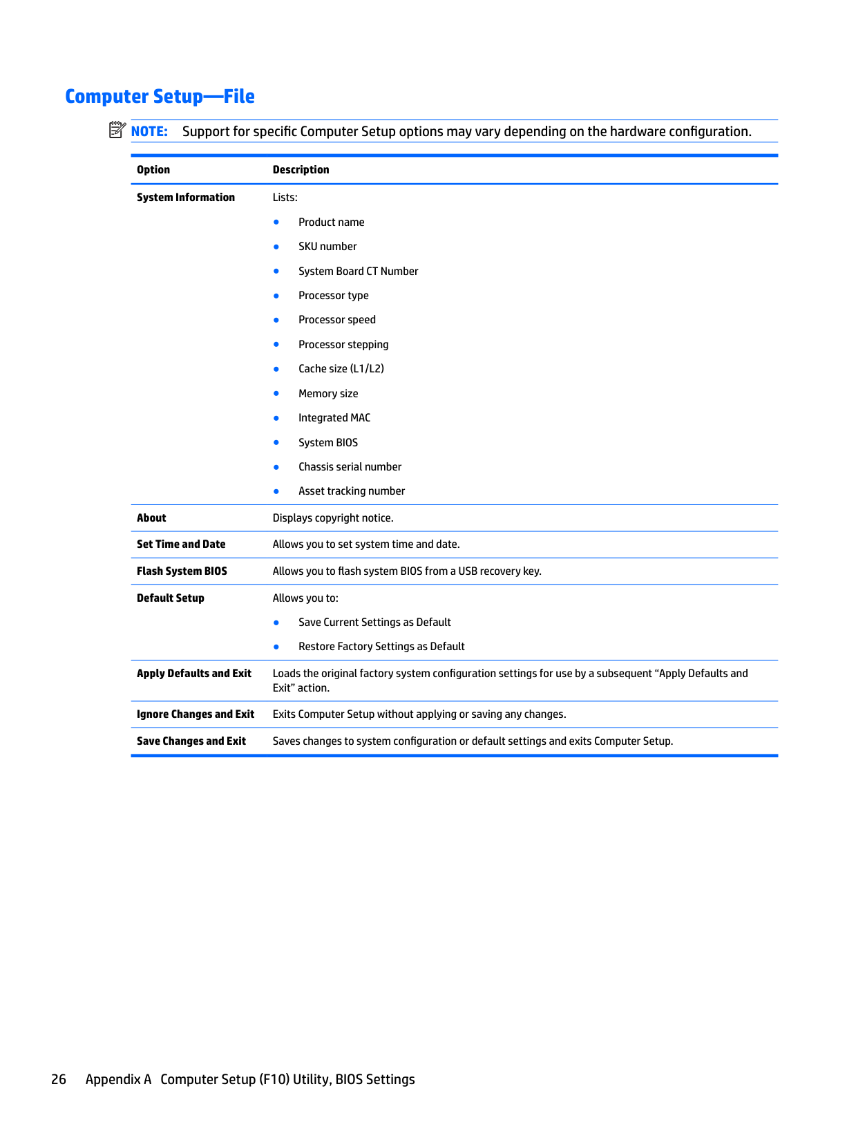
#### Computer Setup—File
| | |---|
NOTE: Support for specific Computer Setup options may vary depending on the hardware configuration.
Option Description System Information Lists:
About Displays copyright notice. Set Time and Date Allows you to set system time and date. Flash System BIOS Allows you to flash system BIOS from a USB recovery key. Default Setup Allows you to:
Apply Defaults and Exit Loads the original factory system configuration settings for use by a subsequent “Apply Defaults and
Exit” action. Ignore Changes and Exit Exits Computer Setup without applying or saving any changes. Save Changes and Exit Saves changes to system configuration or default settings and exits Computer Setup.
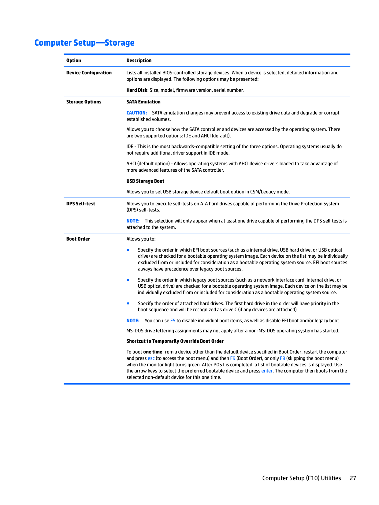
#### Computer Setup—Storage
Option Description Device Configuration Lists all installed BIOS-controlled storage devices. When a device is selected, detailed information and
options are displayed. The following options may be presented: Hard Disk: Size, model, firmware version, serial number.
Storage Options SATA Emulation CAUTION: SATA emulation changes may prevent access to existing drive data and degrade or corrupt established volumes. Allows you to choose how the SATA controller and devices are accessed by the operating system. There are two supported options: IDE and AHCI (default). IDE - This is the most backwards-compatible setting of the three options. Operating systems usually do not require additional driver support in IDE mode. AHCI (default option) - Allows operating systems with AHCI device drivers loaded to take advantage of more advanced features of the SATA controller. USB Storage Boot Allows you to set USB storage device default boot option in CSM/Legacy mode.
DPS Self-test Allows you to execute self-tests on ATA hard drives capable of performing the Drive Protection System (DPS) self-tests. NOTE: This selection will only appear when at least one drive capable of performing the DPS self tests is attached to the system.
Boot Order Allows you to:
NOTE: You can use F5 to disable individual boot items, as well as disable EFI boot and/or legacy boot. MS-DOS drive lettering assignments may not apply after a non-MS-DOS operating system has started. Shortcut to Temporarily Override Boot Order
To boot one time from a device other than the default device specified in Boot Order, restart the computer and press esc (to access the boot menu) and then F9 (Boot Order), or only F9 (skipping the boot menu) when the monitor light turns green. After POST is completed, a list of bootable devices is displayed. Use the arrow keys to select the preferred bootable device and press enter. The computer then boots from the selected non-default device for this one time.
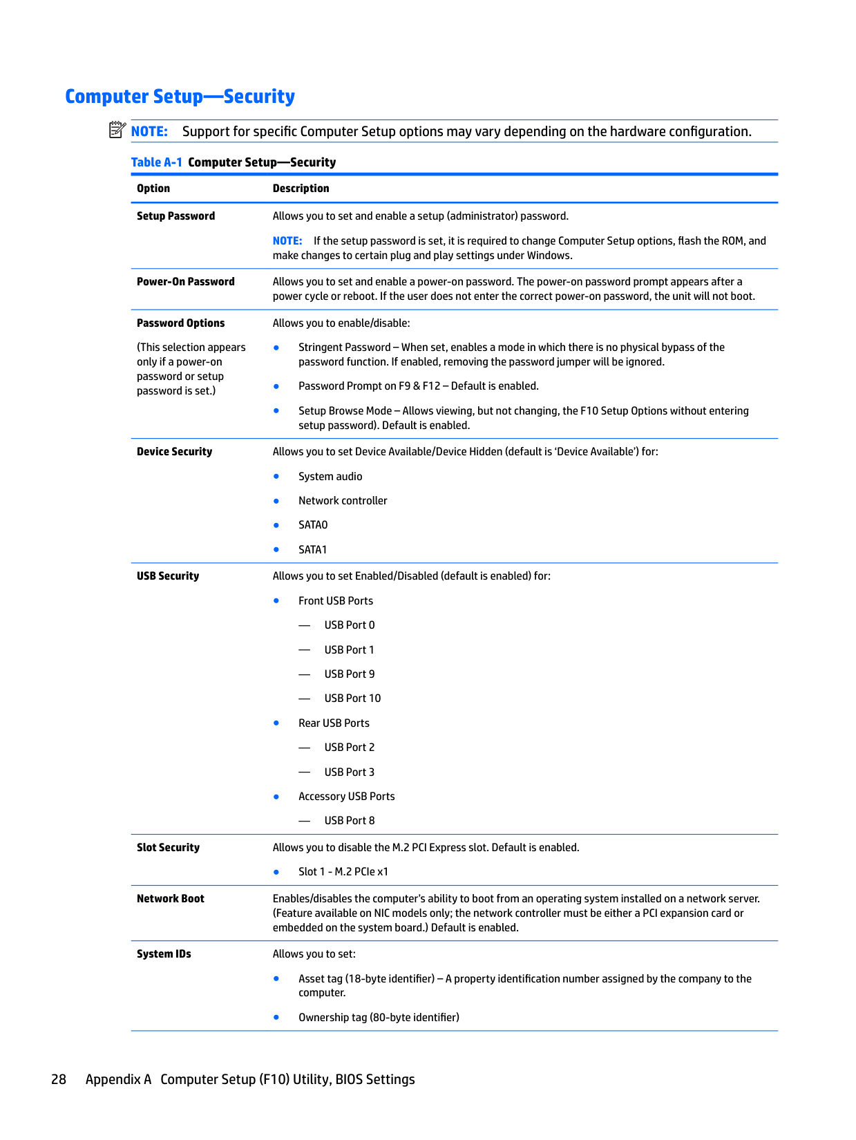
Computer Setup—Security NOTE: Support for specific Computer Setup options may vary depending on the hardware configuration. Table A-1 Computer Setup—Security Option Description Setup Password Allows you to set and enable a setup (administrator) password.
| | |---|
NOTE: If the setup password is set, it is required to change Computer Setup options, flash the ROM, and make changes to certain plug and play settings under Windows.
Power-On Password Allows you to set and enable a power-on password. The power-on password prompt appears after a
power cycle or reboot. If the user does not enter the correct power-on password, the unit will not boot. Password Options
Allows you to enable/disable:
(This selection appears only if a power-on password or setup password is set.)
Device Security Allows you to set Device Available/Device Hidden (default is ‘Device Available’) for:
USB Security Allows you to set Enabled/Disabled (default is enabled) for:
— USB Port 8
Slot Security Allows you to disable the M.2 PCI Express slot. Default is enabled.
● Slot 1 - M.2 PCIe x1
Network Boot Enables/disables the computer’s ability to boot from an operating system installed on a network server. (Feature available on NIC models only; the network controller must be either a PCI expansion card or embedded on the system board.) Default is enabled.
System IDs Allows you to set:
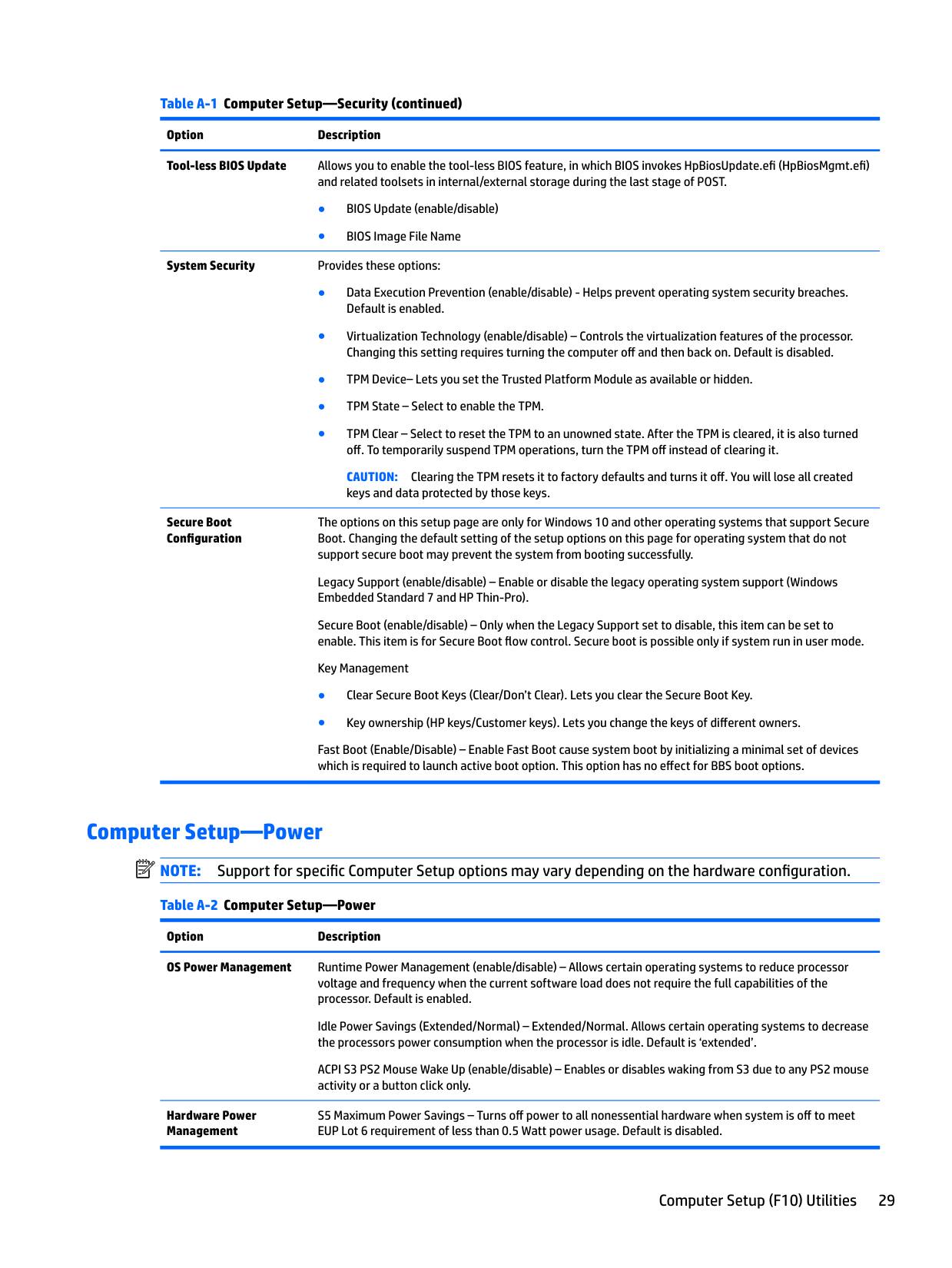
Table A-1 Computer Setup—Security (continued) Option Description Tool-less BIOS Update Allows you to enable the tool-less BIOS feature, in which BIOS invokes HpBiosUpdate.efi (HpBiosMgmt.efi)
and related toolsets in internal/external storage during the last stage of POST.

CAUTION: Clearing the TPM resets it to factory defaults and turns it off. You will lose all created keys and data protected by those keys.
Secure Boot Configuration
The options on this setup page are only for Windows 10 and other operating systems that support Secure Boot. Changing the default setting of the setup options on this page for operating system that do not support secure boot may prevent the system from booting successfully.
Legacy Support (enable/disable) – Enable or disable the legacy operating system support (Windows Embedded Standard 7 and HP Thin-Pro).
Secure Boot (enable/disable) – Only when the Legacy Support set to disable, this item can be set to enable. This item is for Secure Boot flow control. Secure boot is possible only if system run in user mode.
Key Management
Fast Boot (Enable/Disable) – Enable Fast Boot cause system boot by initializing a minimal set of devices which is required to launch active boot option. This option has no effect for BBS boot options.

Computer Setup—Power NOTE: Support for specific Computer Setup options may vary depending on the hardware configuration. Table A-2 Computer Setup—Power
| | |---|
Option Description OS Power Management Runtime Power Management (enable/disable) – Allows certain operating systems to reduce processor
voltage and frequency when the current software load does not require the full capabilities of the processor. Default is enabled.
Idle Power Savings (Extended/Normal) – Extended/Normal. Allows certain operating systems to decrease the processors power consumption when the processor is idle. Default is ‘extended’.
ACPI S3 PS2 Mouse Wake Up (enable/disable) – Enables or disables waking from S3 due to any PS2 mouse activity or a button click only.
Hardware Power Management
S5 Maximum Power Savings – Turns off power to all nonessential hardware when system is off to meet EUP Lot 6 requirement of less than 0.5 Watt power usage. Default is disabled.
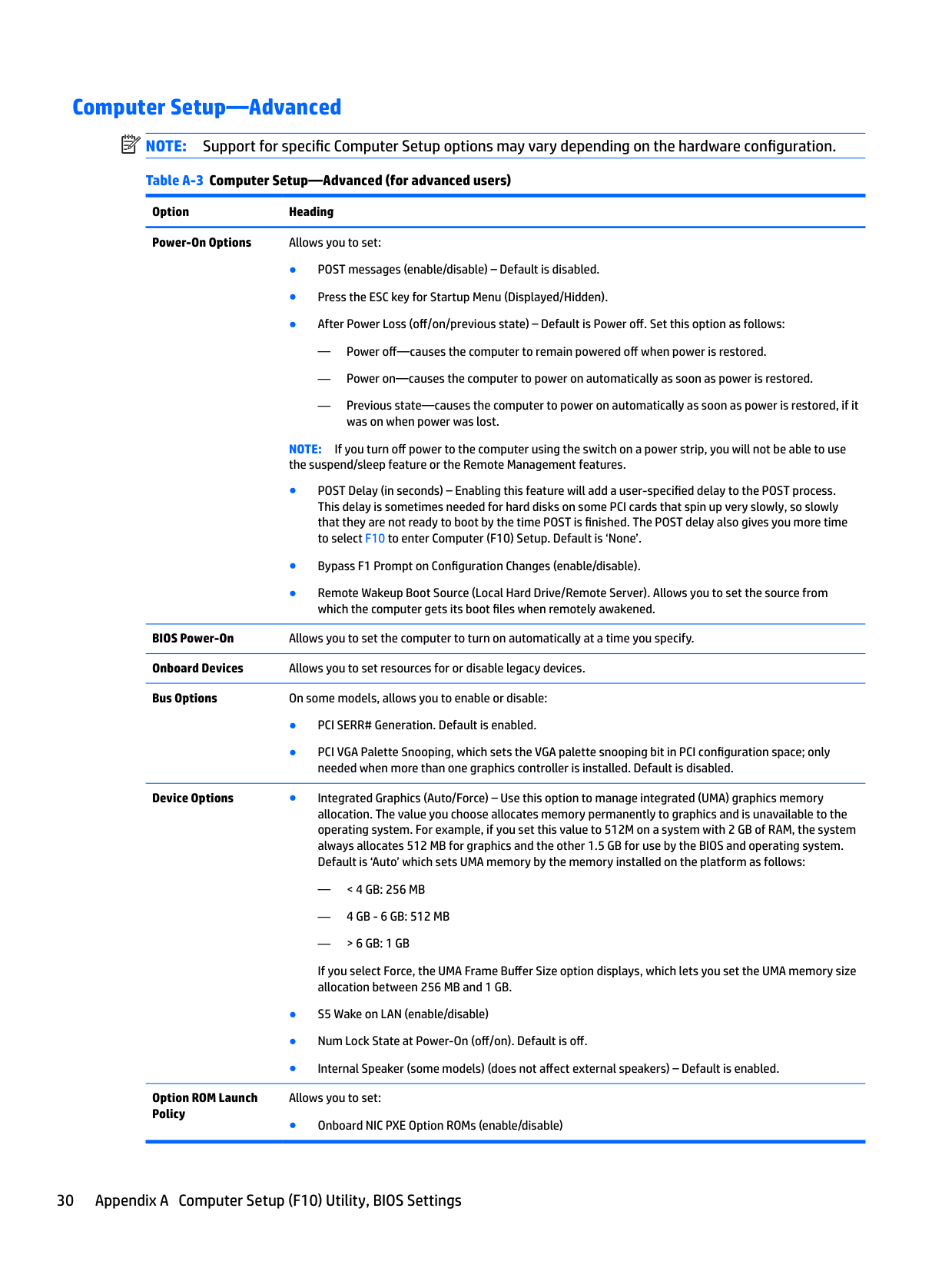
#### Computer Setup—Advanced NOTE: Support for specific Computer Setup options may vary depending on the hardware configuration. Table A-3 Computer Setup—Advanced (for advanced users)
| | |---|
Option Heading Power-On Options Allows you to set:

— Power off—causes the computer to remain powered off when power is restored.
— Power on—causes the computer to power on automatically as soon as power is restored.
— Previous state—causes the computer to power on automatically as soon as power is restored, if it was on when power was lost.
NOTE: If you turn off power to the computer using the switch on a power strip, you will not be able to use the suspend/sleep feature or the Remote Management features.
BIOS Power-On Allows you to set the computer to turn on automatically at a time you specify. Onboard Devices Allows you to set resources for or disable legacy devices. Bus Options On some models, allows you to enable or disable:
Device Options ● Integrated Graphics (Auto/Force) – Use this option to manage integrated (UMA) graphics memory allocation. The value you choose allocates memory permanently to graphics and is unavailable to the operating system. For example, if you set this value to 512M on a system with 2 GB of RAM, the system always allocates 512 MB for graphics and the other 1.5 GB for use by the BIOS and operating system. Default is ‘Auto’ which sets UMA memory by the memory installed on the platform as follows:
— < 4 GB: 256 MB
— 4 GB - 6 GB: 512 MB
— > 6 GB: 1 GB
If you select Force, the UMA Frame Buffer Size option displays, which lets you set the UMA memory size allocation between 256 MB and 1 GB.
Option ROM Launch Policy
Allows you to set:
● Onboard NIC PXE Option ROMs (enable/disable)
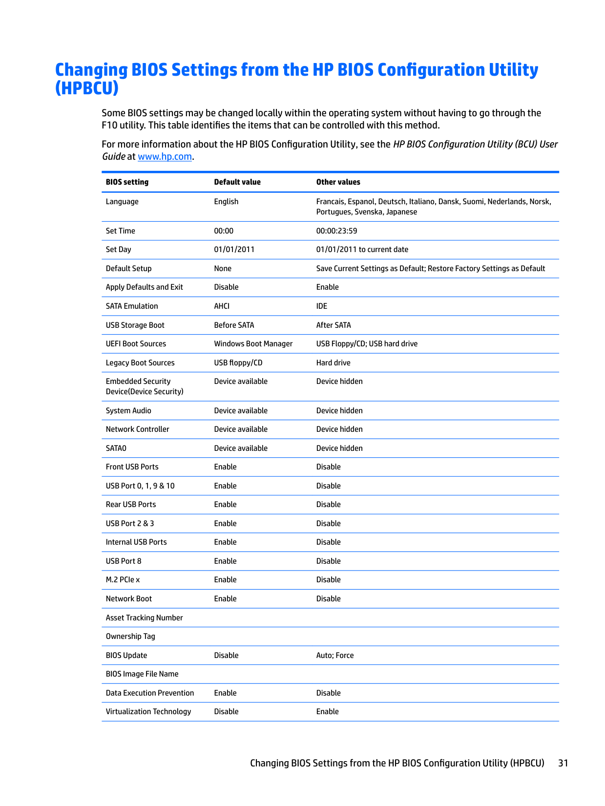
Changing BIOS Settings from the HP BIOS Configuration Utility (HPBCU)
Some BIOS settings may be changed locally within the operating system without having to go through the F10 utility. This table identifies the items that can be controlled with this method.
For more information about the HP BIOS Configuration Utility, see the HP BIOS Configuration Utility (BCU) User Guide at www.hp.com.
BIOS setting Default value Other values Language English Francais, Espanol, Deutsch, Italiano, Dansk, Suomi, Nederlands, Norsk,
Portugues, Svenska, Japanese Set Time 00:00 00:00:23:59 Set Day 01/01/2011 01/01/2011 to current date Default Setup None Save Current Settings as Default; Restore Factory Settings as Default Apply Defaults and Exit Disable Enable SATA Emulation AHCI IDE USB Storage Boot Before SATA After SATA UEFI Boot Sources Windows Boot Manager USB Floppy/CD; USB hard drive Legacy Boot Sources USB floppy/CD Hard drive Embedded Security Device(Device Security)
Device available Device hidden
System Audio Device available Device hidden Network Controller Device available Device hidden SATA0 Device available Device hidden Front USB Ports Enable Disable USB Port 0, 1, 9 & 10 Enable Disable Rear USB Ports Enable Disable USB Port 2 & 3 Enable Disable Internal USB Ports Enable Disable USB Port 8 Enable Disable M.2 PCIe x Enable Disable Network Boot Enable Disable Asset Tracking Number Ownership Tag BIOS Update Disable Auto; Force BIOS Image File Name Data Execution Prevention Enable Disable Virtualization Technology Disable Enable
Changing BIOS Settings from the HP BIOS Configuration Utility (HPBCU) 31
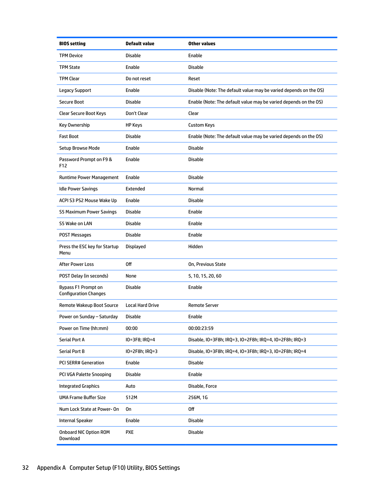
BIOS setting Default value Other values TPM Device Disable Enable TPM State Enable Disable TPM Clear Do not reset Reset Legacy Support Enable Disable (Note: The default value may be varied depends on the OS) Secure Boot Disable Enable (Note: The default value may be varied depends on the OS) Clear Secure Boot Keys Don’t Clear Clear Key Ownership HP Keys Custom Keys Fast Boot Disable Enable (Note: The default value may be varied depends on the OS) Setup Browse Mode Enable Disable Password Prompt on F9 & F12
Enable Disable
Runtime Power Management Enable Disable Idle Power Savings Extended Normal ACPI S3 PS2 Mouse Wake Up Enable Disable S5 Maximum Power Savings Disable Enable S5 Wake on LAN Disable Enable POST Messages Disable Enable Press the ESC key for Startup Menu
Displayed Hidden
After Power Loss Off On, Previous State POST Delay (in seconds) None 5, 10, 15, 20, 60 Bypass F1 Prompt on Configuration Changes
Disable Enable
Remote Wakeup Boot Source Local Hard Drive Remote Server Power on Sunday – Saturday Disable Enable Power on Time (hh:mm) 00:00 00:00:23:59 Serial Port A IO=3F8; IRQ=4 Disable, IO=3F8h; IRQ=3, IO=2F8h; IRQ=4, IO=2F8h; IRQ=3 Serial Port B IO=2F8h; IRQ=3 Disable, IO=3F8h; IRQ=4, IO=3F8h; IRQ=3, IO=2F8h; IRQ=4 PCI SERR# Generation Enable Disable PCI VGA Palette Snooping Disable Enable Integrated Graphics Auto Disable, Force UMA Frame Buffer Size 512M 256M, 1G Num Lock State at Power- On On Off Internal Speaker Enable Disable Onboard NIC Option ROM Download
PXE Disable
B Diagnostics and troubleshooting
LEDs
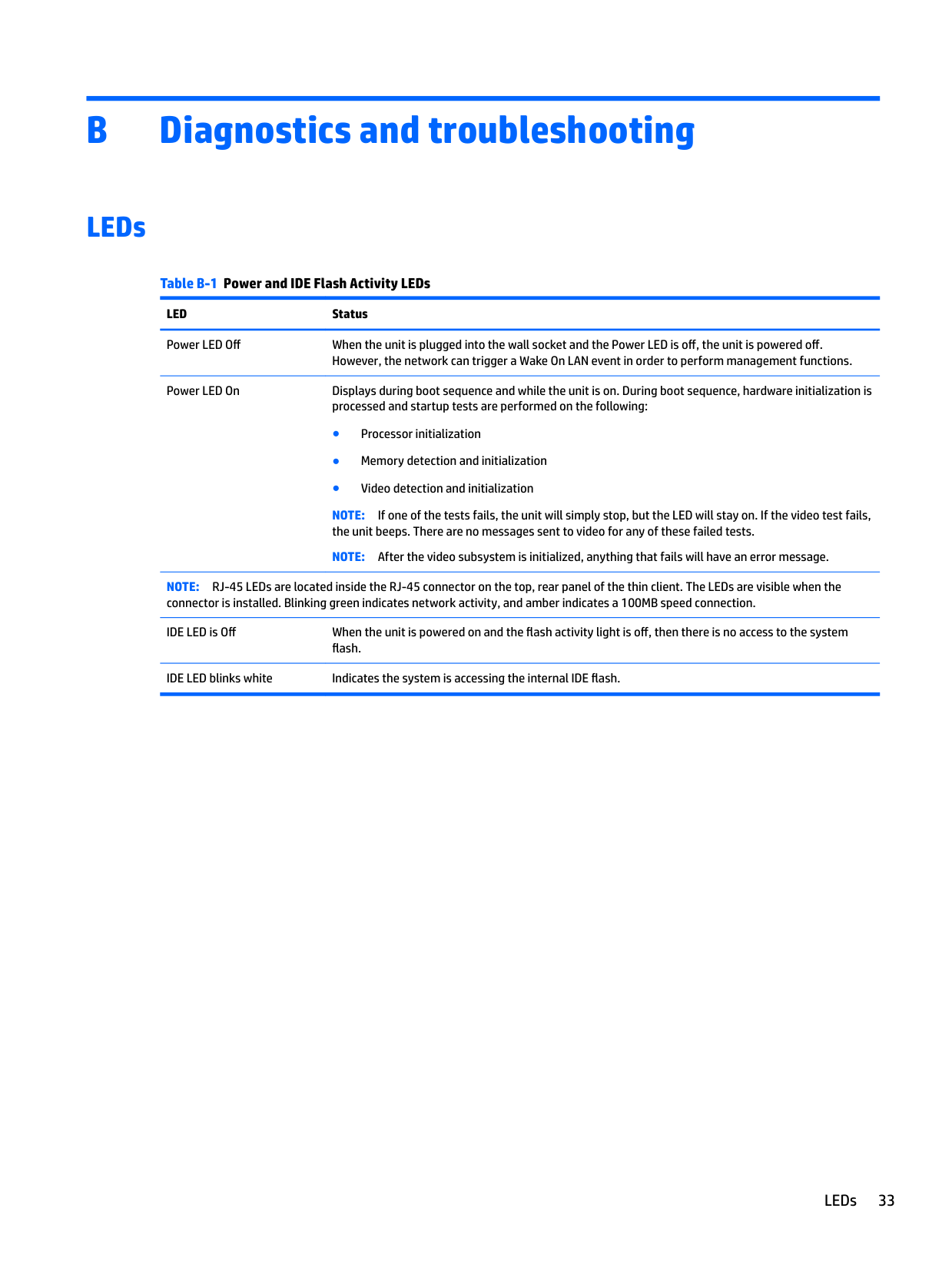
Table B-1 Power and IDE Flash Activity LEDs LED Status Power LED Off When the unit is plugged into the wall socket and the Power LED is off, the unit is powered off.
However, the network can trigger a Wake On LAN event in order to perform management functions. Power LED On Displays during boot sequence and while the unit is on. During boot sequence, hardware initialization is processed and startup tests are performed on the following:
NOTE: If one of the tests fails, the unit will simply stop, but the LED will stay on. If the video test fails, the unit beeps. There are no messages sent to video for any of these failed tests.
NOTE: After the video subsystem is initialized, anything that fails will have an error message. NOTE: RJ-45 LEDs are located inside the RJ-45 connector on the top, rear panel of the thin client. The LEDs are visible when the connector is installed. Blinking green indicates network activity, and amber indicates a 100MB speed connection. IDE LED is Off When the unit is powered on and the flash activity light is off, then there is no access to the system
flash. IDE LED blinks white Indicates the system is accessing the internal IDE flash.
LEDs 33
Wake-on LAN
Wake-on LAN (WOL) allows a computer to be turned on or resumed from sleep or hibernation state by a network message. You can enable or disable WOL in Computer Setup using the S5 Maximum Power Savings setting.
To enable or disable WOL:
NOTE: If you do not press esc or F10 at the appropriate time, you must restart the computer and again press esc or F10 when the monitor light turns green to access the utility.
| | |---|
Power-On Sequence
At power-on, the flash boot block code initializes the hardware to a known state, then performs basic poweron diagnostic tests to determine the integrity of the hardware. Initialization performs the following functions:
Resetting the Setup and Power-on passwords
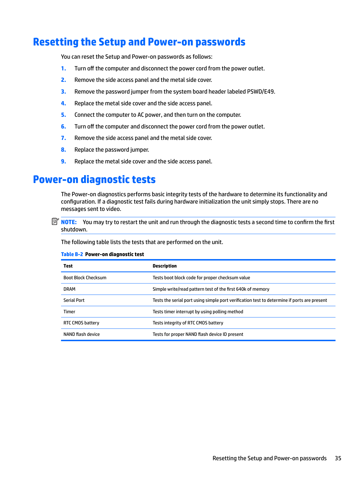
You can reset the Setup and Power-on passwords as follows:
Power-on diagnostic tests
The Power-on diagnostics performs basic integrity tests of the hardware to determine its functionality and configuration. If a diagnostic test fails during hardware initialization the unit simply stops. There are no messages sent to video.
| | |---|
NOTE: You may try to restart the unit and run through the diagnostic tests a second time to confirm the first shutdown. The following table lists the tests that are performed on the unit. Table B-2 Power-on diagnostic test
Test Description Boot Block Checksum Tests boot block code for proper checksum value DRAM Simple write/read pattern test of the first 640k of memory Serial Port Tests the serial port using simple port verification test to determine if ports are present Timer Tests timer interrupt by using polling method RTC CMOS battery Tests integrity of RTC CMOS battery NAND flash device Tests for proper NAND flash device ID present
Resetting the Setup and Power-on passwords 35
Interpreting POST diagnostic front panel LEDs and audible codes
This section covers the front panel LED codes as well as the audible codes that may occur before or during POST that do not necessarily have an error code or text message associated with them.
WARNING! When the computer is plugged into an AC power source, voltage is always applied to the system board. To reduce the risk of personal injury from electrical shock and/or hot surfaces, be sure to disconnect the power cord from the wall outlet and allow the internal system components to cool before touching.
| | |---|
NOTE: Recommended actions in the following table are listed in the order in which they should be performed. Not all diagnostic lights and audible codes are available on all models.
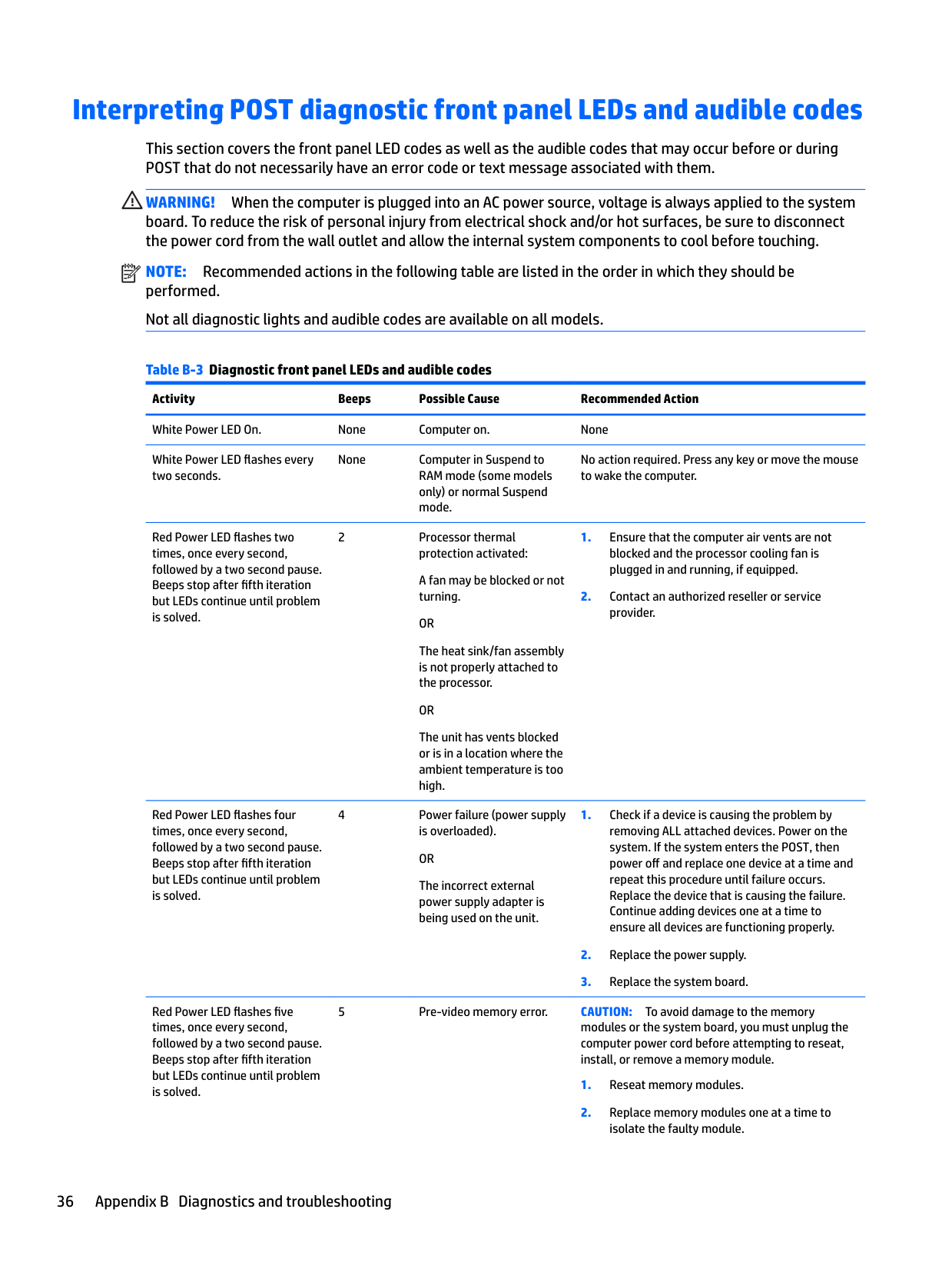
Table B-3 Diagnostic front panel LEDs and audible codes Activity Beeps Possible Cause Recommended Action White Power LED On. None Computer on. None White Power LED flashes every two seconds.
None Computer in Suspend to RAM mode (some models only) or normal Suspend mode.
No action required. Press any key or move the mouse to wake the computer.
Red Power LED flashes two times, once every second, followed by a two second pause. Beeps stop after fifth iteration but LEDs continue until problem is solved.
Red Power LED flashes four times, once every second, followed by a two second pause. Beeps stop after fifth iteration but LEDs continue until problem is solved.
Red Power LED flashes five times, once every second, followed by a two second pause. Beeps stop after fifth iteration but LEDs continue until problem is solved.
2 Processor thermal protection activated: A fan may be blocked or not turning. OR The heat sink/fan assembly is not properly attached to the processor. OR The unit has vents blocked or is in a location where the ambient temperature is too high.
4 Power failure (power supply is overloaded). OR The incorrect external power supply adapter is being used on the unit.
5 Pre-video memory error. CAUTION: To avoid damage to the memory modules or the system board, you must unplug the computer power cord before attempting to reseat, install, or remove a memory module.
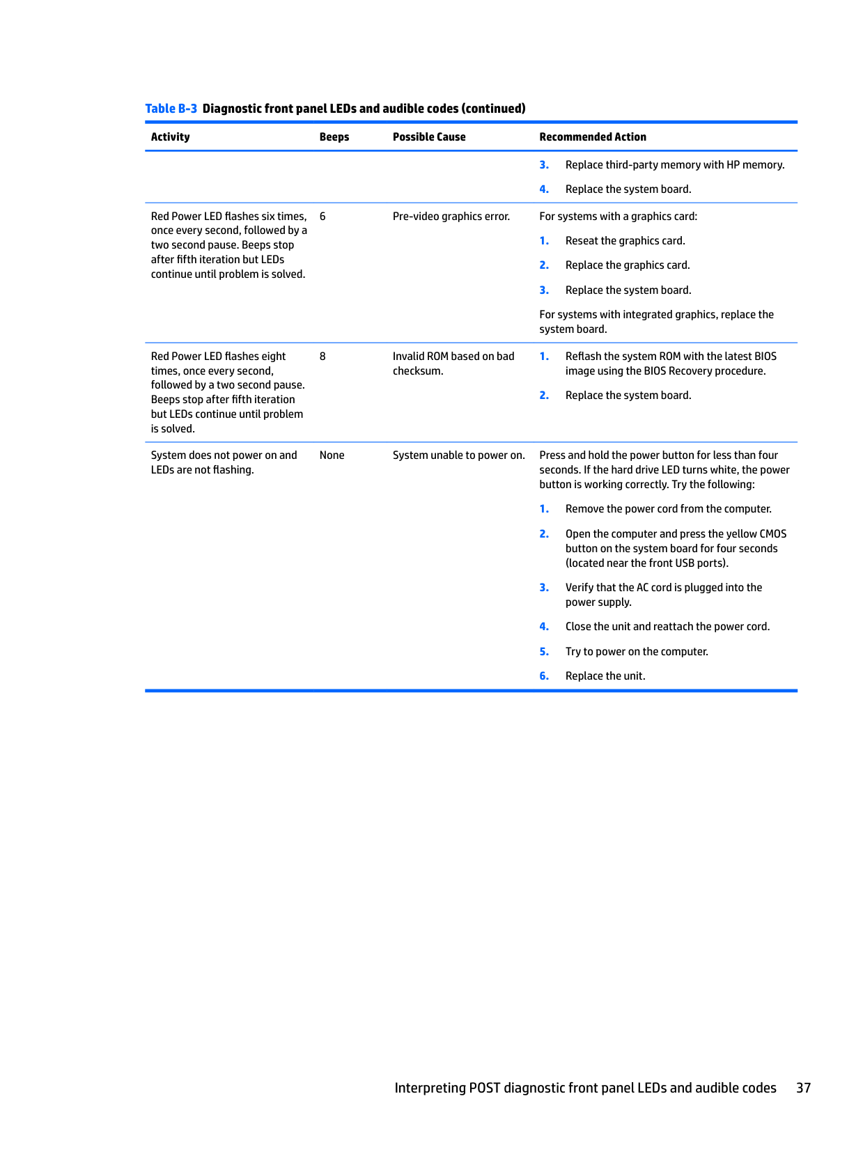
####### Table B-3 Diagnostic front panel LEDs and audible codes (continued)
######## Activity Beeps Possible Cause Recommended Action
Red Power LED flashes six times, once every second, followed by a two second pause. Beeps stop after fifth iteration but LEDs continue until problem is solved.
6 Pre-video graphics error. For systems with a graphics card:
For systems with integrated graphics, replace the system board.
Red Power LED flashes eight times, once every second, followed by a two second pause. Beeps stop after fifth iteration but LEDs continue until problem is solved.
System does not power on and LEDs are not flashing.
8 Invalid ROM based on bad checksum.
None System unable to power on. Press and hold the power button for less than four seconds. If the hard drive LED turns white, the power button is working correctly. Try the following:
Interpreting POST diagnostic front panel LEDs and audible codes 37
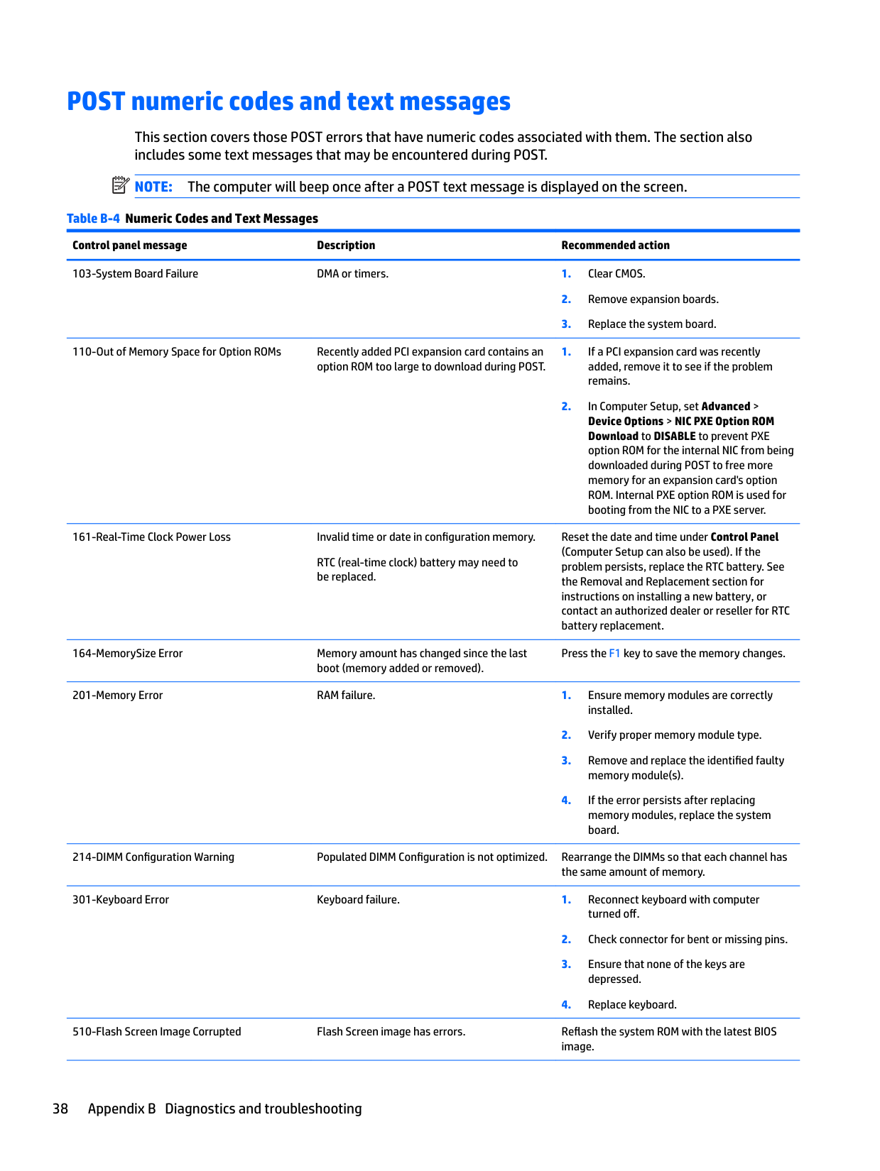
POST numeric codes and text messages
This section covers those POST errors that have numeric codes associated with them. The section also includes some text messages that may be encountered during POST.

| | |---|
NOTE: The computer will beep once after a POST text message is displayed on the screen.
Table B-4 Numeric Codes and Text Messages Control panel message Description Recommended action 103-System Board Failure DMA or timers. 1. Clear CMOS.
110-Out of Memory Space for Option ROMs Recently added PCI expansion card contains an option ROM too large to download during POST.
161-Real-Time Clock Power Loss Invalid time or date in configuration memory.
RTC (real-time clock) battery may need to be replaced.
Reset the date and time under Control Panel (Computer Setup can also be used). If the problem persists, replace the RTC battery. See the Removal and Replacement section for instructions on installing a new battery, or contact an authorized dealer or reseller for RTC battery replacement.
164-MemorySize Error Memory amount has changed since the last boot (memory added or removed).
Press the F1 key to save the memory changes.
201-Memory Error RAM failure. 1. Ensure memory modules are correctly installed.
214-DIMM Configuration Warning Populated DIMM Configuration is not optimized. Rearrange the DIMMs so that each channel has the same amount of memory.
301-Keyboard Error Keyboard failure. 1. Reconnect keyboard with computer turned off.
510-Flash Screen Image Corrupted Flash Screen image has errors. Reflash the system ROM with the latest BIOS image.
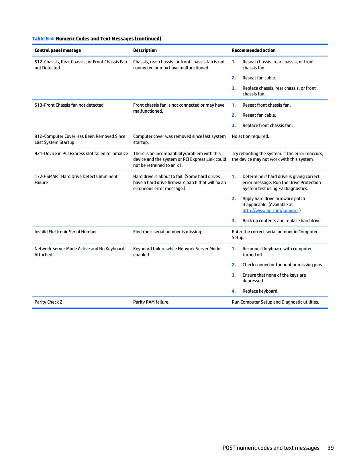
####### Table B-4 Numeric Codes and Text Messages (continued)
######## Control panel message Description Recommended action
Chassis, rear chassis, or front chassis fan is not connected or may have malfunctioned.
912-Computer Cover Has Been Removed Since Last System Startup
Computer cover was removed since last system startup.
No action required.
921-Device in PCI Express slot failed to initialize There is an incompatibility/problem with this device and the system or PCI Express Link could not be retrained to an x1.
Try rebooting the system. If the error reoccurs, the device may not work with this system
1720-SMART Hard Drive Detects Imminent Failure
Hard drive is about to fail. (Some hard drives have a hard drive firmware patch that will fix an erroneous error message.)
Invalid Electronic Serial Number Electronic serial number is missing. Enter the correct serial number in Computer Setup.
Network Server Mode Active and No Keyboard Attached
Keyboard failure while Network Server Mode enabled.
Parity Check 2 Parity RAM failure. Run Computer Setup and Diagnostic utilities.
POST numeric codes and text messages 39
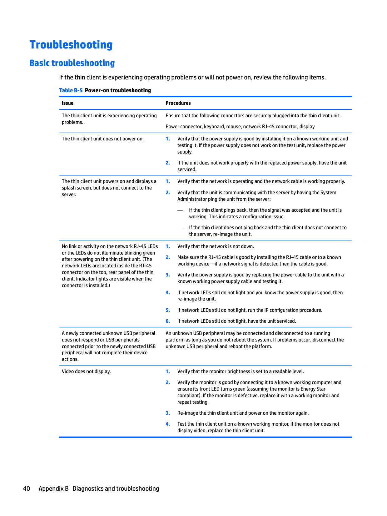
Troubleshooting
Basic troubleshooting If the thin client is experiencing operating problems or will not power on, review the following items. Table B-5 Power-on troubleshooting
Issue Procedures
The thin client unit is experiencing operating problems.
Ensure that the following connectors are securely plugged into the thin client unit: Power connector, keyboard, mouse, network RJ-45 connector, display
The thin client unit does not power on. 1. Verify that the power supply is good by installing it on a known working unit and testing it. If the power supply does not work on the test unit, replace the power supply.
serviced.
The thin client unit powers on and displays a splash screen, but does not connect to the server.
— If the thin client pings back, then the signal was accepted and the unit is working. This indicates a configuration issue.
— If the thin client does not ping back and the thin client does not connect to the server, re-image the unit.
No link or activity on the network RJ-45 LEDs or the LEDs do not illuminate blinking green after powering on the thin client unit. (The network LEDs are located inside the RJ-45 connector on the top, rear panel of the thin client. Indicator lights are visible when the connector is installed.)
A newly connected unknown USB peripheral does not respond or USB peripherals connected prior to the newly connected USB peripheral will not complete their device actions.
An unknown USB peripheral may be connected and disconnected to a running platform as long as you do not reboot the system. If problems occur, disconnect the unknown USB peripheral and reboot the platform.
Video does not display. 1. Verify that the monitor brightness is set to a readable level.
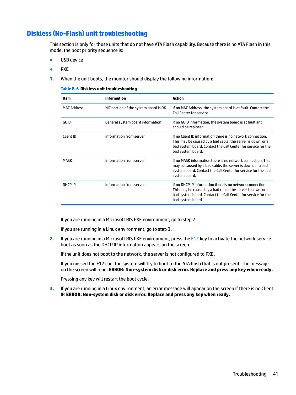
#### Diskless (No-Flash) unit troubleshooting
This section is only for those units that do not have ATA Flash capability. Because there is no ATA Flash in this model the boot priority sequence is:
Item Information Action MAC Address NIC portion of the system board is OK If no MAC Address, the system board is at fault. Contact the
Call Center for service. GUID General system board information If no GUID information, the system board is at fault and should be replaced.
Client ID Information from server If no Client ID information there is no network connection. This may be caused by a bad cable, the server is down, or a bad system board. Contact the Call Center for service for the bad system board.
MASK Information from server If no MASK information there is no network connection. This may be caused by a bad cable, the server is down, or a bad system board. Contact the Call Center for service for the bad system board.
DHCP IP Information from server If no DHCP IP information there is no network connection. This may be caused by a bad cable, the server is down, or a bad system board. Contact the Call Center for service for the bad system board.
If you are running in a Microsoft RIS PXE environment, go to step 2. If you are running in a Linux environment, go to step 3.
If you missed the F12 cue, the system will try to boot to the ATA flash that is not present. The message on the screen will read: ERROR: Non-system disk or disk error. Replace and press any key when ready.
Pressing any key will restart the boot cycle.
Troubleshooting 41
Configuring a PXE server
| | |---|
NOTE: All PXE software is supported by authorized service providers on a warranty or service contract basis. Customers who call the HP Customer Service Center with PXE issues and questions should be referred to their PXE provider for assistance.
Additionally, refer to the following:
| | |---|
C Using HP ThinUpdate to restore the image
HP ThinUpdate allows you to download images and add-ons from HP, capture an HP thin client image, and create bootable USB flash drives for image deployment.
HP ThinUpdate is preinstalled on some HP thin clients, and it is also available as an add-on at http://www.hp.com/support (search for the thin client model and see the Drivers & software section of the support page for that model).
— Create a bootable USB flash drive from an image file on local storage
— Copy an .ibr image file from a USB flash drive to local storage
— Restore a USB flash drive layout
You can use a bootable USB flash drive created with HP ThinUpdate to deploy an HP thin client image to another HP thin client of the same model with the same operating system.
##### System requirements
To create a recovery device for the purpose of reflashing or restoring the software image on the flash, you will need the following:
— ThinPro: 8 GB
| | |---|
— Windows 10 IoT (if using the USB format): 32 GB NOTE: Optionally, you can use the tool on a Windows computer. This restore method will not work with all USB flash devices. USB flash devices that do not show up as removable drive in Windows do not support this restore method. USB flash devices with multiple partitions generally do not support this restore method. The range of USB flash devices available on the market is constantly changing. Not all USB flash devices have been tested with the HP Thin Client Imaging Tool.
43
D Device management
The t630 includes a license for HP Device Manager and has a Device Manager agent pre-installed. HP Device Manager is a thin client optimized management tool used to manage the full life cycle of HP thin clients to include Discover, Asset Management, Deployment and Configuration. For more information on HP Device Manager, please visit www.hp.com/go/hpdm.
If you wish to manage the t630 with other management tools such as Microsoft SCCM or LANDesk, go to www.hp.com/go/clientmanagement for more information.
44 Appendix D Device management
E System BIOS
Updating or restoring a BIOS
##### HP Device Manager
HP Device Manager can be used to update the BIOS of a thin client. Customers can use a pre-built BIOS add-on or can use the standard BIOS upgrade package along with an HP Device Manager File and Registry template. For more information on HP Device Manager File and Registry templates, review the HP Device Manager User Guide found at www.hp.com/go/hpdm.
##### Windows BIOS Flashing
You can use the BIOS Flash Update SoftPaq to restore or upgrade the system BIOS. Several methods for changing the BIOS firmware stored on your computer are available.
The BIOS executable is a utility designed to flash the System BIOS within a Microsoft Windows environment. To display the available options for this utility, launch the executable file under the Microsoft Windows environment.
You can run the BIOS executable with or without the USB storage device. If the system does not have a USB storage device installed, the BIOS update will perform under the Microsoft Windows environment and followed by system reboot.
Linux BIOS Flashing All BIOS flashing under ThinPro 6.x and later utilizes tool-less BIOS updates, in which the BIOS updates itself. Use the following comments to flash a Linux BIOS:
Prepares the system to update the BIOS during the next restart. This command automatically copies the files into the correct location and prompts you to restart the thin client. This command requires that the tool-less update option in the BIOS settings is set to Auto. You can use hpt-bios-cfg to set the toolless update option in the BIOS.
##### BitLocker Drive Encryption / BIOS Measurements
If you have Windows BitLocker Drive Encryption (BDE) enabled on your system, we recommend that you temporarily suspend BDE before updating the BIOS. You should also obtain your BDE recovery password or recovery PIN before suspending BDE. After you flash the BIOS, you can resume BDE.
To make a change to BDE, select Start > Control Panel > BitLocker Drive Encryption, click Suspend Protection or Resume Protection and then click Yes.
As a general rule, updating the BIOS will modify measurement values stored in the Platform Configuration Registers (PCRs) of the system's security module. Temporarily disable technologies that use these PCR values to ascertain platform health (BDE is one such example) prior to flashing the BIOS. Once you update the BIOS, re-enable the functions and restart the system so that you can take new measurements.
##### BootBlock Emergency Recovery Mode
Updating or restoring a BIOS 45
In the event of a failed BIOS update (for example if power is lost while updating), the System BIOS may become corrupted. BootBlock Emergency Recovery Mode detects this condition and automatically searches the root directory of the hard drive and any USB media sources for a compatible binary image. Copy the binary (.bin) file in the DOS Flash folder to the root of the desired storage device, and then power on the system. Once the recovery process locates the binary image, it attempts the recovery process. The automatic recovery continues until it successfully restores or updates the BIOS. If the system has a BIOS Setup password, you may need to use the Startup Menu / Utilities submenu to flash the BIOS manually after providing the password. Sometimes there are restrictions on which BIOS versions are allowed to be installed on a platform. If the BIOS that was on the system had restrictions, then only allowable BIOS versions may be used for recovery.
46 Appendix E System BIOS
F Using HP PC Hardware Diagnostics (UEFI)
HP PC Hardware Diagnostics is a Unified Extensible Firmware Interface (UEFI) that allows you to run diagnostic tests to determine whether the computer hardware is functioning properly. The tool runs outside the operating system so that it can isolate hardware failures from issues that are caused by the operating system or other software components.
When HP PC Hardware Diagnostics (UEFI) detects a failure that requires hardware replacement, a 24-digit Failure ID code is generated. This ID code can then be provided to support to help determine how to correct the problem.
| | |---|
NOTE: To start diagnostics on a convertible computer, your computer must be in notebook mode and you must use the keyboard attached. To start HP PC Hardware Diagnostics (UEFI), follow these steps:
| | |---|
| | |---|
NOTE: If you need to stop a diagnostic test, press esc.
Downloading HP PC Hardware Diagnostics (UEFI) to a USB device
| | |---|
NOTE: The HP PC Hardware Diagnostics (UEFI) download instructions are provided in English only, and you must use a Windows computer to download and create the HP UEFI support environment because only .exe files are offered.

There are two options to download HP PC Hardware Diagnostics to a USB device. Download the latest UEFI version
Downloading HP PC Hardware Diagnostics (UEFI) to a USB device 47
– or – Select Identify now to let HP automatically detect your product.
48 Appendix F Using HP PC Hardware Diagnostics (UEFI)
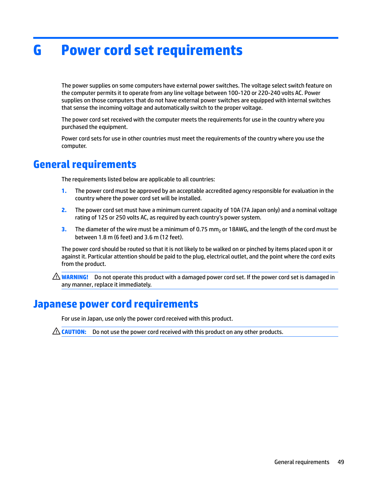
G Power cord set requirements
The power supplies on some computers have external power switches. The voltage select switch feature on the computer permits it to operate from any line voltage between 100-120 or 220-240 volts AC. Power supplies on those computers that do not have external power switches are equipped with internal switches that sense the incoming voltage and automatically switch to the proper voltage.

The power cord set received with the computer meets the requirements for use in the country where you purchased the equipment.
Power cord sets for use in other countries must meet the requirements of the country where you use the computer.
General requirements
The requirements listed below are applicable to all countries:
The power cord should be routed so that it is not likely to be walked on or pinched by items placed upon it or against it. Particular attention should be paid to the plug, electrical outlet, and the point where the cord exits from the product.
WARNING! Do not operate this product with a damaged power cord set. If the power cord set is damaged in any manner, replace it immediately.
Japanese power cord requirements For use in Japan, use only the power cord received with this product. CAUTION: Do not use the power cord received with this product on any other products.
General requirements 49
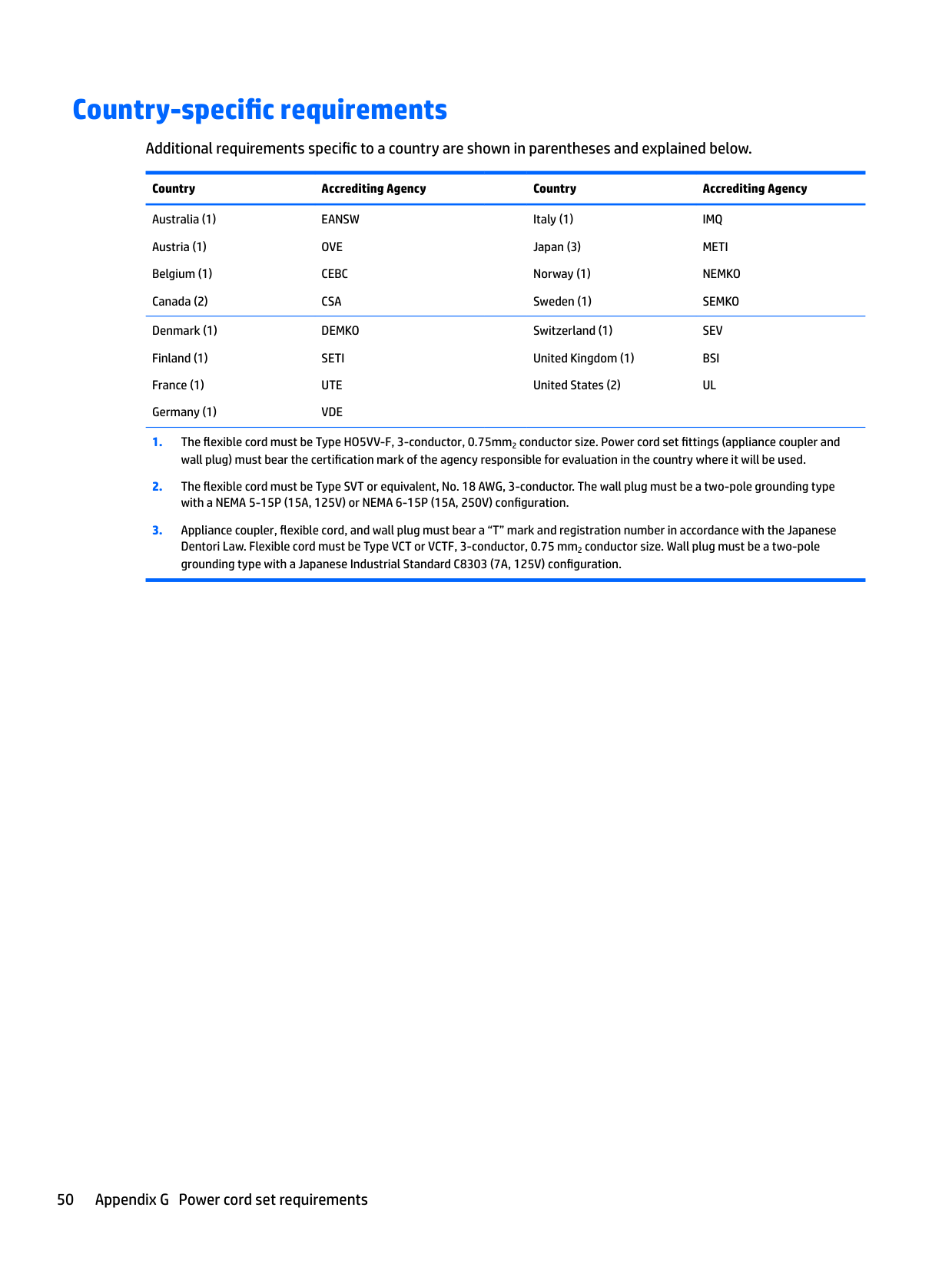
Country-specific requirements
Additional requirements specific to a country are shown in parentheses and explained below. Country Accrediting Agency Country Accrediting Agency Australia (1) Austria (1) Belgium (1) Canada (2)
EANSW OVE CEBC CSA
Italy (1) Japan (3) Norway (1) Sweden (1)

IMQ METI NEMKO SEMKO
Denmark (1) Finland (1) France (1) Germany (1)
DEMKO SETI UTE VDE
Switzerland (1) United Kingdom (1) United States (2)
SEV BSI UL
Dentori Law. Flexible cord must be Type VCT or VCTF, 3-conductor, 0.75 mm2 conductor size. Wall plug must be a two-pole grounding type with a Japanese Industrial Standard C8303 (7A, 125V) configuration.
50 Appendix G Power cord set requirements
H Statement of Volatility
Thin Client products typically have three types of memory devices namely, RAM, ROM, and Flash memory devices. Data stored in the RAM memory device will be lost once the power is removed from the device. RAM devices could be powered by main, aux, or battery power (power states are explained below). Therefore, even when the unit is not connected to an AC outlet, some of the RAM devices could be powered by battery power. Data stored in the ROM or Flash memory devices will retain its data even if the power is removed to the device. Manufacturers of Flash device usually specify a period of time (in the order of ten years) for data retention.
Definition of power states: Main Power: Power available when the unit is turned on. Aux or Standby power: Power available when the unit is in off state when the power supply is connected to an active AC outlet. Battery Power: Power from a coin battery present in the Thin Client systems.
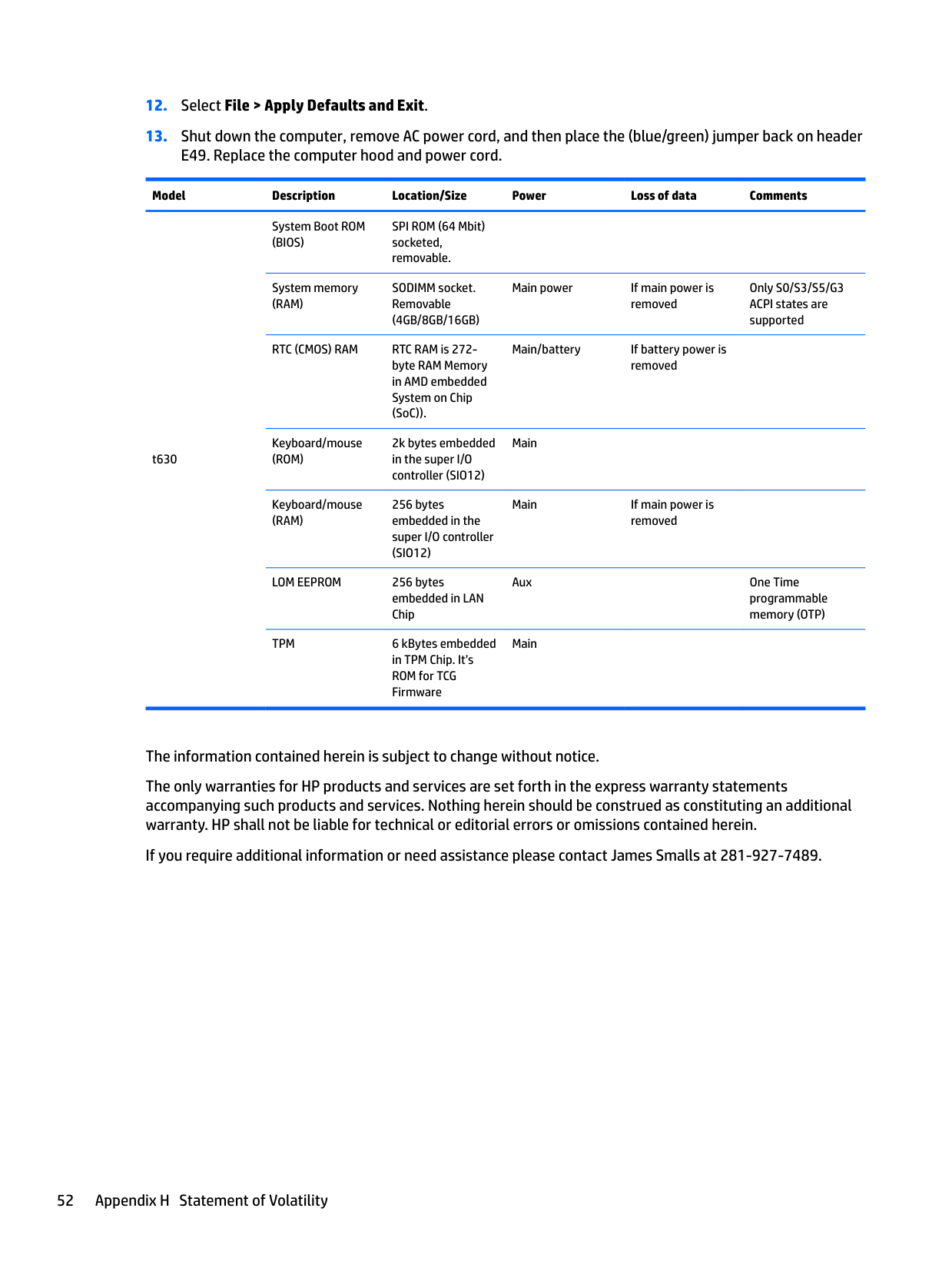
The table below lists the available memory devices and their types per the models. Please note that the Thin Client systems do not use traditional hard drives with moving parts. Instead, they use flash memory devices with an IDE/ SATA front-end interface. Hence, the operating systems interface with these flash devices similar to a regular IDE/ SATA hard drive. This IDE/ SATA flash device contains the image of the operating system. The flash device can only be written by an administrator. A special software tool is required to format the flash devices and clear the data stored in them.
Please find below a list of steps that should be taken to update BIOS and use it to set the BIOS settings to factory default settings.
######## Model Description Location/Size Power Loss of data Comments
t630
System Boot ROM (BIOS)
SPI ROM (64 Mbit) socketed, removable.
System memory (RAM)
SODIMM socket. Removable (4GB/8GB/16GB)
RTC (CMOS) RAM RTC RAM is 272byte RAM Memory in AMD embedded System on Chip (SoC)).
Keyboard/mouse (ROM)
2k bytes embedded in the super I/O controller (SIO12)
Keyboard/mouse (RAM)
256 bytes embedded in the super I/O controller (SIO12)
LOM EEPROM 256 bytes embedded in LAN Chip
TPM 6 kBytes embedded in TPM Chip. It’s ROM for TCG Firmware
Main power If main power is removed
Main/battery If battery power is removed
Only S0/S3/S5/G3 ACPI states are supported
Main
Main If main power is removed
Aux One Time programmable memory (OTP)

Main
The information contained herein is subject to change without notice. The only warranties for HP products and services are set forth in the express warranty statements accompanying such products and services. Nothing herein should be construed as constituting an additional warranty. HP shall not be liable for technical or editorial errors or omissions contained herein. If you require additional information or need assistance please contact James Smalls at 281-927-7489.
52 Appendix H Statement of Volatility
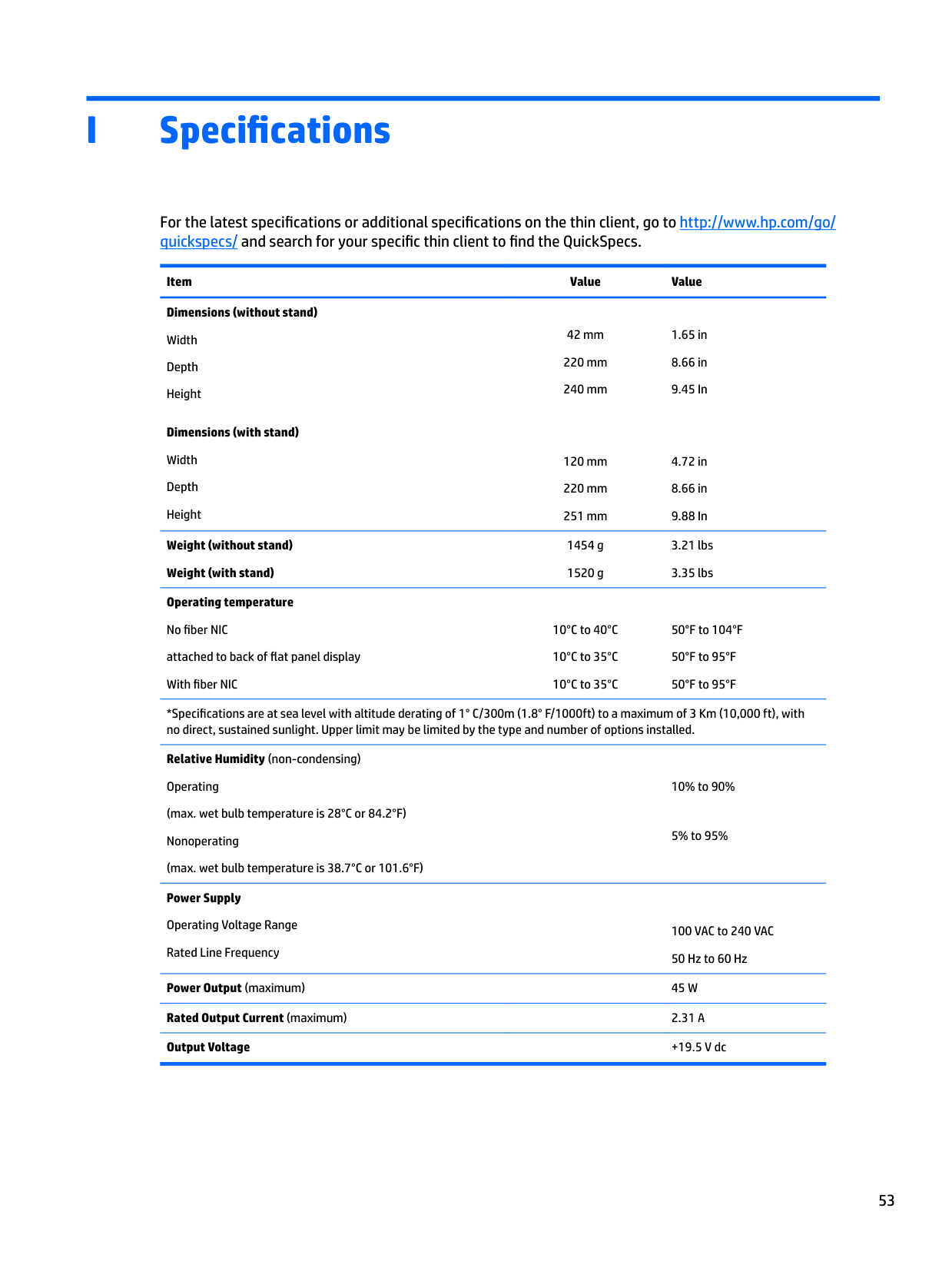
I Specifications
For the latest specifications or additional specifications on the thin client, go to http://www.hp.com/go/ quickspecs/ and search for your specific thin client to find the QuickSpecs.
Item Value Value Dimensions (without stand)
42 mm 220 mm 240 mm
1.65 in
Width Depth Height
######## Dimensions (with stand)
Width Depth Height
120 mm 220 mm 251 mm
4.72 in
Weight (without stand) Weight (with stand)
1454 g 1520 g
3.21 lbs 3.35 lbs
Operating temperature No fiber NIC attached to back of flat panel display With fiber NIC
10°C to 40°C 10°C to 35°C 10°C to 35°C
50°F to 104°F 50°F to 95°F 50°F to 95°F
*Specifications are at sea level with altitude derating of 1° C/300m (1.8° F/1000ft) to a maximum of 3 Km (10,000 ft), with no direct, sustained sunlight. Upper limit may be limited by the type and number of options installed.
Relative Humidity (non-condensing) Operating (max. wet bulb temperature is 28°C or 84.2°F) Nonoperating (max. wet bulb temperature is 38.7°C or 101.6°F)
Power Supply Operating Voltage Range Rated Line Frequency
10% to 90%
5% to 95%
100 VAC to 240 VAC 50 Hz to 60 Hz
Power Output (maximum) 45 W Rated Output Current (maximum) 2.31 A Output Voltage +19.5 V dc
Index
removing 10 replacing 12
audible codes 36
updating 45
attaching the stand 6 electric shock 5, 10, 19 installing memory modules 19 removing the battery 16 securing the power cable 8 static electricity 5, 10
changing BIOS settings in the REPSETUP utility 31
COM ports 21 functionality 22 identifying 21 locations 23
components front panel 2 internal 13 rear panel 3
configurable serial ports configuring 23 functionality 22 identifying 21 system board jumpers 21

country power cord set requirements 50
(WOL) 34
diskless troubleshooting 41
codes 36 messages 38
using 47 humidity specifications 53
security cable 9 USB flash drive 18
internal components 13
L LEDs 33
blinking power 36
##### M
33 power cord set requirements country specific 50
power output specifications 53 power supply specifications 53
power-on diagnostic tests 35 power-on sequence 34
access panel 10 battery 16
replacing access panel 12 battery 16 M.2 storage module 14 storage module 14 resetting the Administrator
password 35 routine care 9
configuring 23 functionality 22 identifying 21 locations 21 system board jumpers 21
specifications dimensions 53 hardware 53 humidity 53 power output 53 power supply 53 rated output current 53 relative humidity 53 temperature 53 thin client 53
stand, attaching 6 storage module, replacing 14
54 Index
tower stand 6 troubleshooting 40
U updating a BIOS 45 upgrading system memory 19 USB flash drive, installing 18 USB ports
size 18 USB ports, internal location 18
W Wake-on LAN (WOL) 34 warnings
burn 5, 10, 18, 20 electric shock 5, 10, 16 grounding plug 5, 10 NIC receptacles 5, 10
websites HP 1
Index 55