
Ask AI
— answers from the official manualAnswers from the official manual.
Common questions
Common Questions
10 totalHow do I install the boiler flue?
To install the boiler flue, follow these steps: Measure wall thickness, place two small location marks on the flue with appropriate spacing. Fit both internal and external seals correctly to ensure proper seal. Push the flue through the wall from inside or outside depending on wall type. Ensure it fits securely per the manufacturer's instructions located in Section 2.12 of the manual.
What is the maximum permissible concentric flue length for a boiler?
The total maximum permissible horizontal concentric flue length can range between 6 to 9 meters, depending on the boiler model's heating output (24 kW, 30 kW or 35 kW), subtracting any bends and attachment kit lengths from this limit.
What are the dimensions of the Ideal Boilers Atlantic 24 model?
The boiler casing dimensions for the Ideal Boilers Atlantic 24 variant include: Height - 700mm, Width - 395mm, Depth - 285mm. Refer to Section 2.18 Wall Mounting Template of this manual for precise measurements and layout.
What should I do if the boiler displays error code 'F7'?
Error code 'F7' indicates low mains voltage, which may prevent proper operation of the boiler. Check and ensure a stable electrical supply with sufficient voltage; contact a professional technician for further diagnosis or repairs.
How do I drain the boiler before servicing?
Drain the boiler by loosening the bottom valve located below the heating exchanger, allowing water to flow out until the boiler is drained. Follow safety and operational guidelines for draining as described in Section 3.21 of this manual.
How do I factory reset the boiler settings?
To perform a factory reset on your Ideal Boilers Atlantic 24, press the 'Reset' button located on the control panel for approximately 10 seconds until the LED indicates ready mode. This will revert all current configurations to their default state.
Full Manual
72 pages
#### combination boilers
#### INSTALLATION & SERVICING INSTRUCTIONS
######## For User Guide see reverse of book
June 2022 UIN 223483 A05
THESE INSTRUCTIONS TO BE RETAINED BY USER
###################### ERP DATA
| | | |MODEL|MODEL|MODEL| |---|---|---|---|---|---| | |SYMBOL|UNITS|24|30|35| |Condensing Boiler|n/a|n/a|yes|yes|yes| |Low Temperature Boiler|n/a|n/a|no|no|no| |B1 Boiler|n/a|n/a|no|no|no| |Cogeneration Space Heater|n/a|n/a|no|no|no| |Equipped with a Supplementary Heater|n/a|n/a|no|no|no| |Combination Heater|n/a|n/a|yes|yes|yes| |Nominal Heat Output for Space Heating|Nominal Heat Output for Space Heating|Nominal Heat Output for Space Heating|Nominal Heat Output for Space Heating|Nominal Heat Output for Space Heating|Nominal Heat Output for Space Heating| |Full Load|P4|kW|24.3|24.3|24.3| |Part Load|P1|kW|8.0|8.0|8.0| |Auxiliary Electricity Consumption|Auxiliary Electricity Consumption|Auxiliary Electricity Consumption|Auxiliary Electricity Consumption|Auxiliary Electricity Consumption|Auxiliary Electricity Consumption| |Full Load|elmax|kW|0.044|0.028|0.025| |Part Load|elmin|kW|0.012|0.011|0.011| |Standby|PSB|kW|0.003|0.003|0.003| |Seasonal Space Heating Energy Efficiency|Seasonal Space Heating Energy Efficiency|Seasonal Space Heating Energy Efficiency|Seasonal Space Heating Energy Efficiency|Seasonal Space Heating Energy Efficiency|Seasonal Space Heating Energy Efficiency| |Full Load|ƞ4|%|90.0|90.0|90.0| |Part Load|ƞ1|%|98.6|98.6|98.6| |Standby Loss|Pstby|kW|0.050|0.050|0.050| |Ignition|Pign|kW|0|0|0| | | | | | | | |Emissions NOx (Gross)|NOx, pond Hs|mg/kWh|28|25|30|
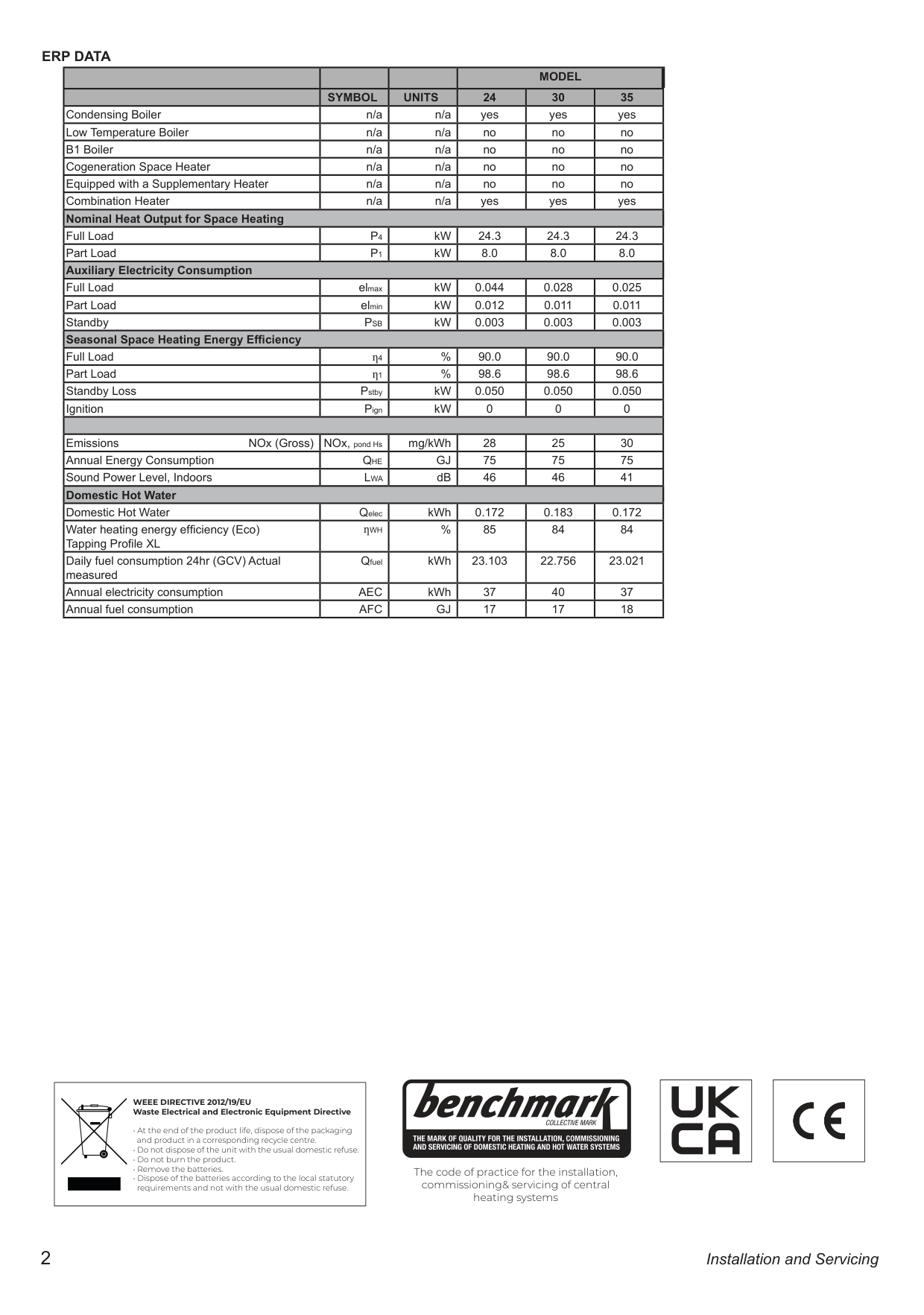
|Annual Energy Consumption|QHE|GJ|75|75|75| |Sound Power Level, Indoors|LWA|dB|46|46|41| |Domestic Hot Water|Domestic Hot Water|Domestic Hot Water|Domestic Hot Water|Domestic Hot Water|Domestic Hot Water| |Domestic Hot Water|Qelec|kWh|0.172|0.183|0.172| |Water heating energy efficiency (Eco) Tapping Profile XL|ƞWH|%|85|84|84| |Daily fuel consumption 24hr (GCV) Actual measured|Qfuel|kWh|23.103|22.756|23.021| |Annual electricity consumption|AEC|kWh|37|40|37| |Annual fuel consumption|AFC|GJ|17|17|18|
|WEEE DIRECTIVE 2012/19/EU Waste Electrical and Electronic Equipment Directive
• At the end of the product life, dispose of the packaging and product in a corresponding recycle centre.
• Do not dispose of the unit with the usual domestic refuse.
• Do not burn the product.
• Remove the batteries.
• Dispose of the batteries according to the local statutory requirements and not with the usual domestic refuse.
| |---|
The code of practice for the installation, commissioning& servicing of central heating systems
| | |---|
| | |---|
|PRODUCT FICHE| |---|
###################### ATLANTIC COMBI COMBINATION BOILER Ideal Heating ERP DATA
| |SYMBOL|UNITS|MODEL|MODEL|MODEL| |---|---|---|---|---|---| | | | |24|30|35|
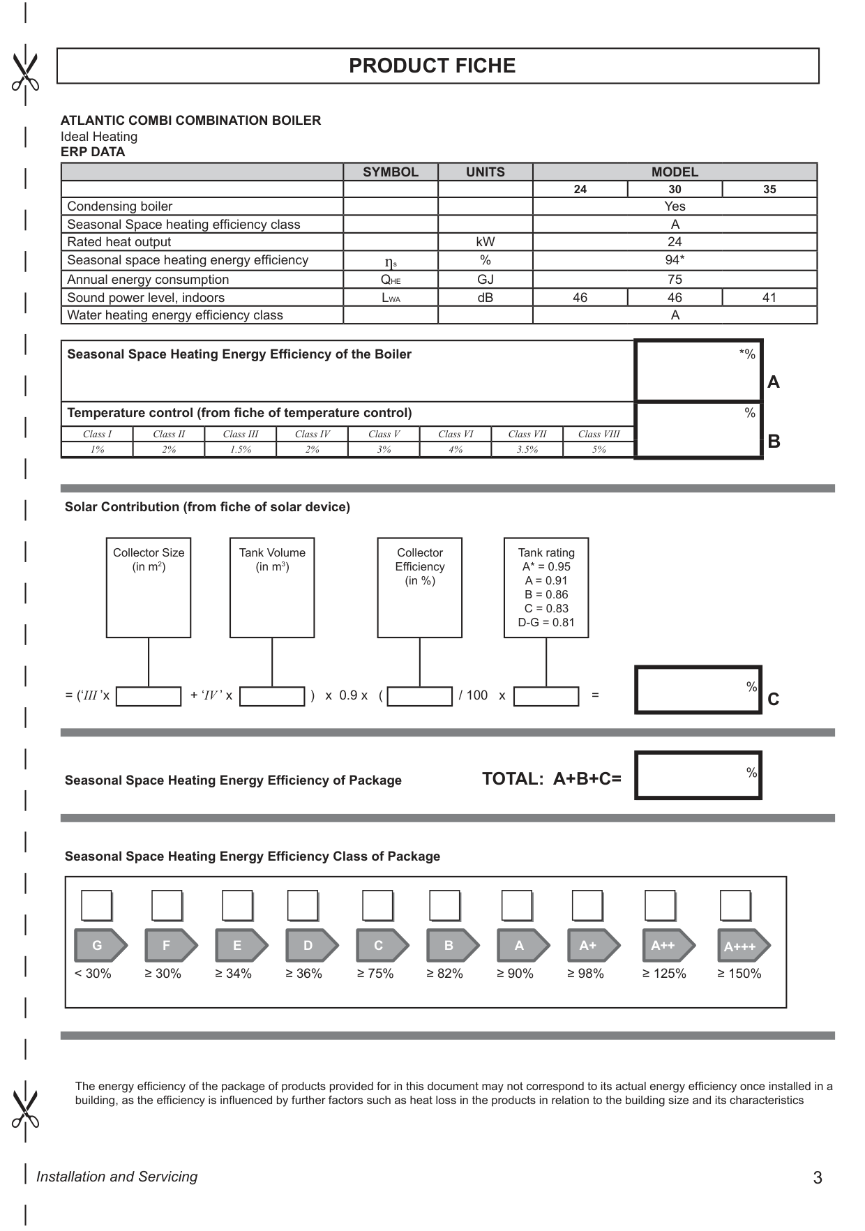
|Condensing boiler| | |Yes|Yes|Yes| |Seasonal Space heating efficiency class| | |A|A|A| |Rated heat output| |kW|24|24|24| |Seasonal space heating energy efficiency|ƞs|%|94*|94*|94*| |Annual energy consumption|QHE|GJ|75|75|75| |Sound power level, indoors|LWA|dB|46|46|41| |Water heating energy efficiency class| | |A|A|A|
|Seasonal Space Heating Energy Efficiency of the Boiler|*%| |---|---| |Temperature control (from fiche of temperature control)|%|
Class I Class II Class III Class IV Class V Class VI Class VII Class VIII 1% 2% 1.5% 2% 3% 4% 3.5% 5%
Solar Contribution (from fiche of solar device)
Tank Volume (in m3)
Collector Efficiency (in %)
Collector Size (in m2)
Tank rating A* = 0.95

D-G = 0.81
|%| |---|
= (‘III ’x + ‘IV ’ x ) x 0.9 x ( / 100 x =
|%| |---|
Seasonal Space Heating Energy Efficiency of Package TOTAL: A+B+C=
Seasonal Space Heating Energy Efficiency Class of Package
|G F E D C B A A+ A++ A+++
< 30% ≥ 30% ≥ 34% ≥ 36% ≥ 75% ≥ 82% ≥ 90% ≥ 98% ≥ 125% ≥ 150%| |---|
The energy efficiency of the package of products provided for in this document may not correspond to its actual energy efficiency once installed in a building, as the efficiency is influenced by further factors such as heat loss in the products in relation to the building size and its characteristics
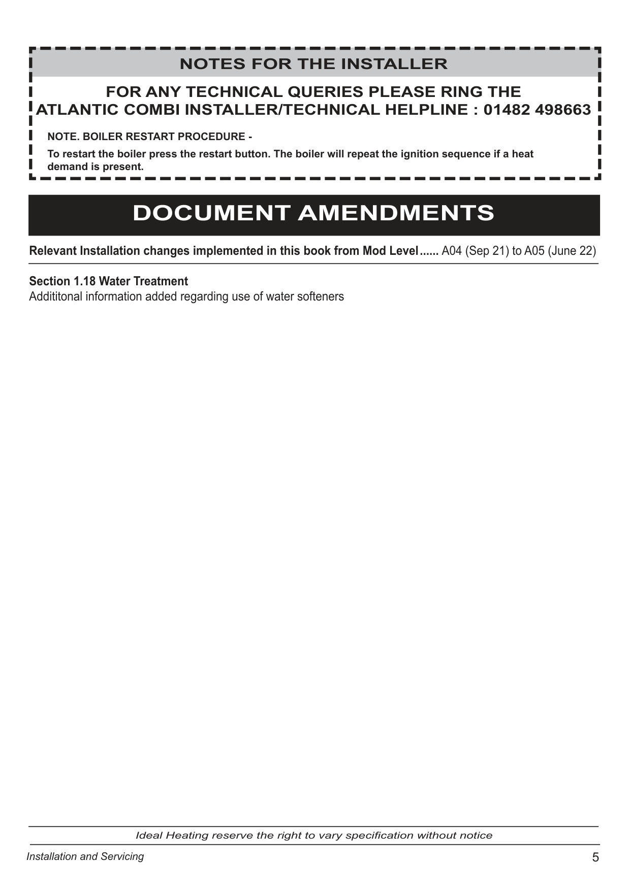
######### NOTES FOR THE INSTALLER
######### FOR ANY TECHNICAL QUERIES PLEASE RING THE ATLANTIC COMBI INSTALLER/TECHNICAL HELPLINE : 01482 498663
NOTE. BOILER RESTART PROCEDURE To restart the boiler press the restart button. The boiler will repeat the ignition sequence if a heat demand is present.
DOCUMENT AMENDMENTS Relevant Installation changes implemented in this book from Mod Level ...... A04 (Sep 21) to A05 (June 22) Section 1.18 Water Treatment Addititonal information added regarding use of water softeners
Ideal Heating reserve the right to vary specification without notice
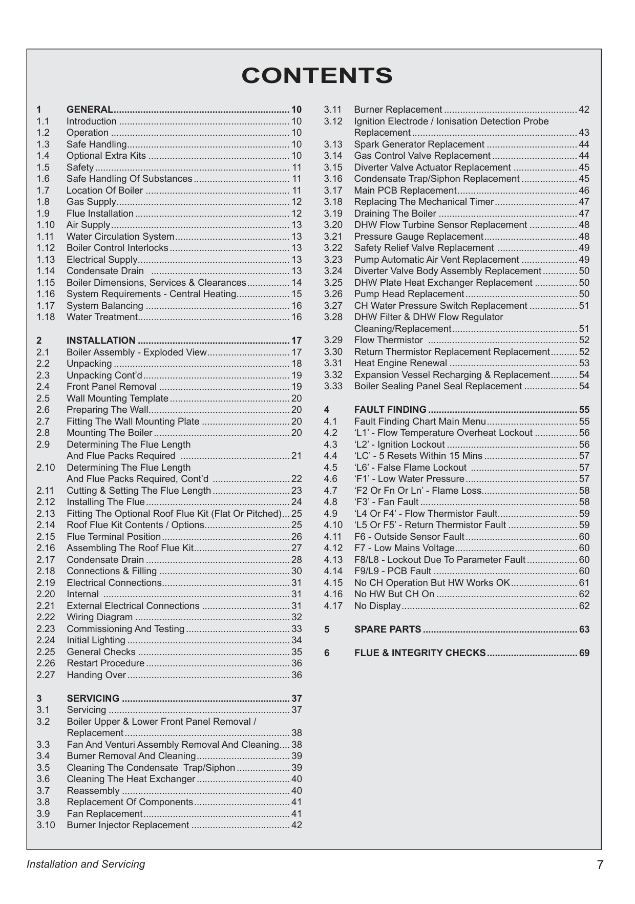
|CONTENTS
1 GENERAL ..................................................................10
1.1 Introduction ................................................................10
1.2 Operation ...................................................................10
1.3 Safe Handling .............................................................10
1.4 Optional Extra Kits .....................................................10
1.5 Safety ......................................................................... 11
1.6 Safe Handling Of Substances .................................... 11
1.7 Location Of Boiler ...................................................... 11
1.8 Gas Supply .................................................................12
1.9 Flue Installation ..........................................................12
1.10 Air Supply ...................................................................13
1.11 Water Circulation System ...........................................13
1.12 Boiler Control Interlocks .............................................13
1.13 Electrical Supply .........................................................13
1.14 Condensate Drain ....................................................13
1.15 Boiler Dimensions, Services & Clearances ................14
1.16 System Requirements - Central Heating ....................15
1.17 System Balancing ......................................................16
1.18 Water Treatment.........................................................16
2 INSTALLATION .........................................................17
2.1 Boiler Assembly - Exploded View ...............................17
2.2 Unpacking ..................................................................18
2.3 Unpacking Cont’d .......................................................19
2.4 Front Panel Removal .................................................19
2.5 Wall Mounting Template .............................................20
2.6 Preparing The Wall .....................................................20
2.7 Fitting The Wall Mounting Plate .................................20
2.8 Mounting The Boiler ...................................................20
2.9 Determining The Flue Length And Flue Packs Required .........................................21
2.10 Determining The Flue Length And Flue Packs Required, Cont’d .............................22
2.11 Cutting & Setting The Flue Length .............................23
2.12 Installing The Flue ......................................................24
2.13 Fitting The Optional Roof Flue Kit (Flat Or Pitched) ...25
2.14 Roof Flue Kit Contents / Options ................................25
2.15 Flue Terminal Position ................................................26
2.16 Assembling The Roof Flue Kit ....................................27
2.17 Condensate Drain ......................................................28
2.18 Connections & Filling .................................................30
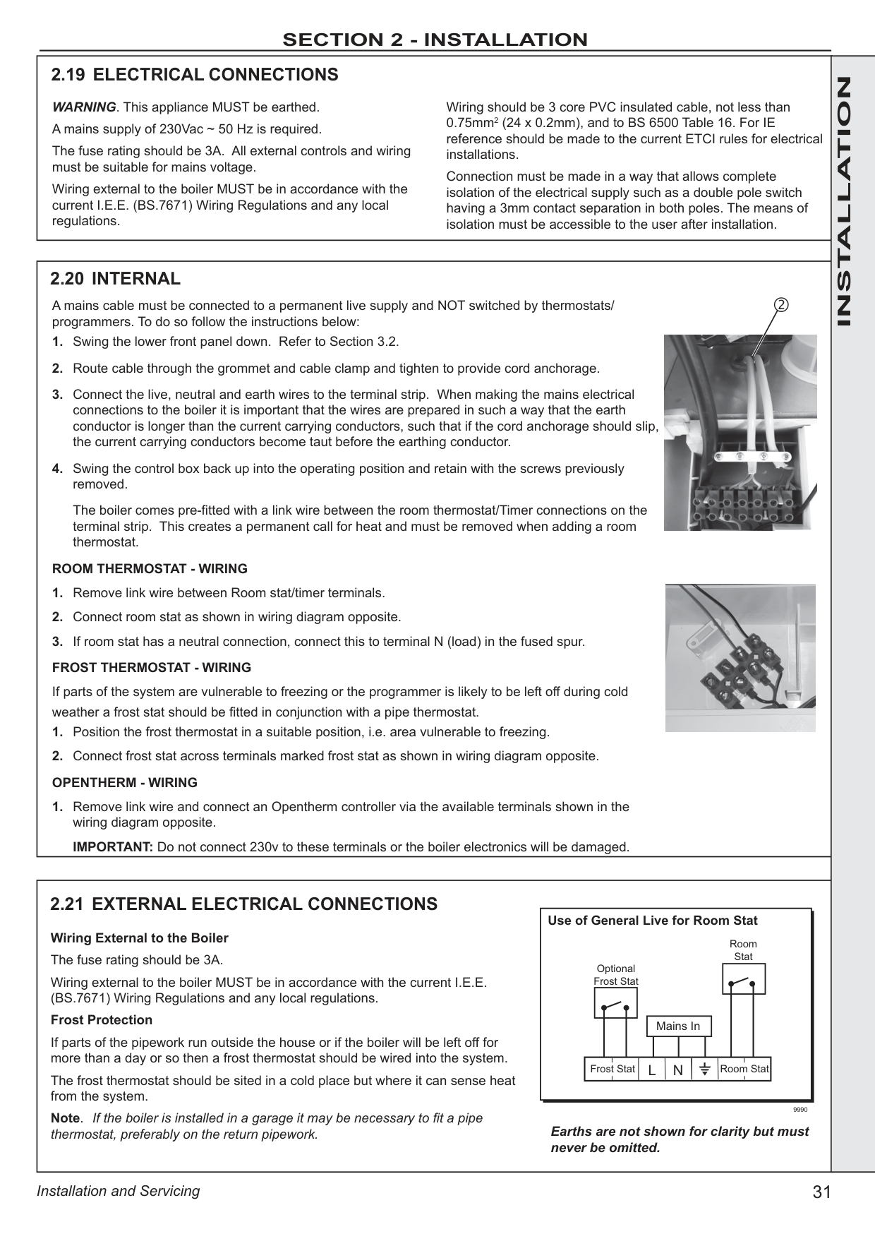
2.19 Electrical Connections ................................................31
2.20 Internal ......................................................................31
2.21 External Electrical Connections .................................31
2.22 Wiring Diagram ..........................................................32
2.23 Commissioning And Testing .......................................33
2.24 Initial Lighting .............................................................34
2.25 General Checks .........................................................35
2.26 Restart Procedure ......................................................36
2.27 Handing Over .............................................................36
3 SERVICING ...............................................................37
3.1 Servicing ....................................................................37
3.2 Boiler Upper & Lower Front Panel Removal / Replacement ..............................................................38
3.3 Fan And Venturi Assembly Removal And Cleaning ....38
3.4 Burner Removal And Cleaning ...................................39
3.5 Cleaning The Condensate Trap/Siphon ....................39
3.6 Cleaning The Heat Exchanger ...................................40
3.7 Reassembly ...............................................................40
3.8 Replacement Of Components ....................................41
3.9 Fan Replacement .......................................................41
3.10 Burner Injector Replacement .....................................42
3.11 Burner Replacement ..................................................42
3.12 Ignition Electrode / Ionisation Detection Probe Replacement ..............................................................43
3.13 Spark Generator Replacement ..................................44
3.14 Gas Control Valve Replacement ................................44
3.15 Diverter Valve Actuator Replacement ........................45
3.16 Condensate Trap/Siphon Replacement .....................45
3.17 Main PCB Replacement .............................................46
3.18 Replacing The Mechanical Timer ...............................47
3.19 Draining The Boiler ....................................................47
3.20 DHW Flow Turbine Sensor Replacement ..................48
3.21 Pressure Gauge Replacement ...................................48
3.22 Safety Relief Valve Replacement ..............................49
3.23 Pump Automatic Air Vent Replacement .....................49
3.24 Diverter Valve Body Assembly Replacement .............50
3.25 DHW Plate Heat Exchanger Replacement ................50
3.26 Pump Head Replacement ..........................................50
3.27 CH Water Pressure Switch Replacement ..................51
3.28 DHW Filter & DHW Flow Regulator Cleaning/Replacement ...............................................51
3.29 Flow Thermistor ........................................................52
3.30 Return Thermistor Replacement Replacement ..........52
3.31 Heat Engine Renewal ................................................53
3.32 Expansion Vessel Recharging & Replacement ..........54
3.33 Boiler Sealing Panel Seal Replacement ....................54
4 FAULT FINDING ........................................................55
4.1 Fault Finding Chart Main Menu ..................................55
4.2 ‘L1’ - Flow Temperature Overheat Lockout ................56
4.3 ‘L2’ - Ignition Lockout .................................................56
4.4 ‘LC’ - 5 Resets Within 15 Mins ...................................57
4.5 ‘L6’ - False Flame Lockout ........................................57
4.6 ‘F1’ - Low Water Pressure ..........................................57
4.7 ‘F2 Or Fn Or Ln’ - Flame Loss....................................58
4.8 ‘F3’ - Fan Fault ...........................................................58
4.9 ‘L4 Or F4’ - Flow Thermistor Fault ..............................59
4.10 ‘L5 Or F5’ - Return Thermistor Fault ..........................59
4.11 F6 - Outside Sensor Fault ..........................................60
4.12 F7 - Low Mains Voltage ..............................................60
4.13 F8/L8 - Lockout Due To Parameter Fault ...................60
4.14 F9/L9 - PCB Fault ......................................................60
4.15 No CH Operation But HW Works OK .........................61
4.16 No HW But CH On .....................................................62
4.17 No Display ..................................................................62
5 SPARE PARTS ..........................................................63
6 FLUE & INTEGRITY CHECKS ..................................69
| |---|
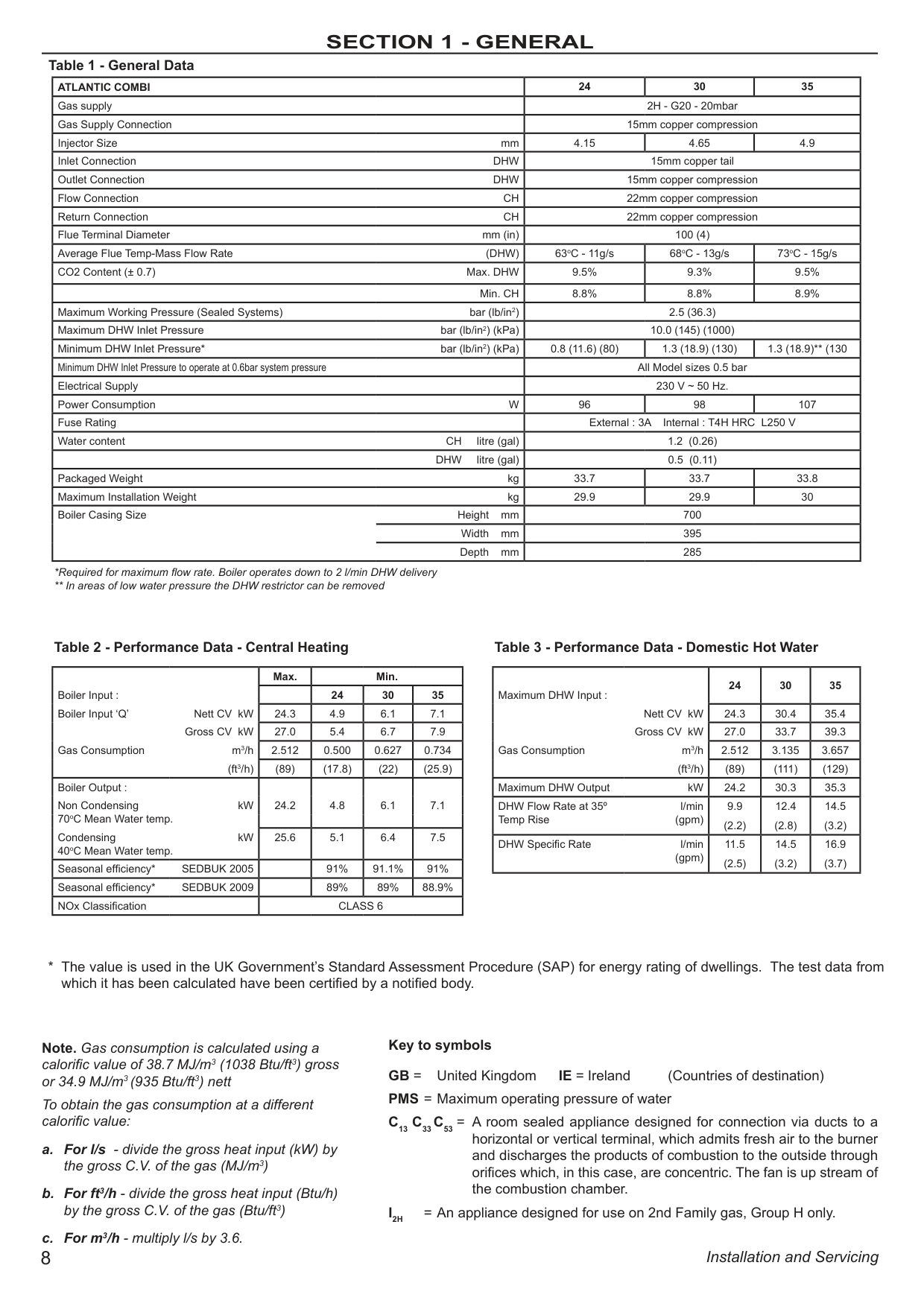
###################### Table 1 - General Data
ATLANTIC COMBI 24 30 35 Gas supply 2H - G20 - 20mbar Gas Supply Connection 15mm copper compression Injector Size mm 4.15 4.65 4.9 Inlet Connection DHW 15mm copper tail Outlet Connection DHW 15mm copper compression Flow Connection CH 22mm copper compression Return Connection CH 22mm copper compression Flue Terminal Diameter mm (in) 100 (4) Average Flue Temp-Mass Flow Rate (DHW) 63oC - 11g/s 68oC - 13g/s 73oC - 15g/s CO2 Content (± 0.7) Max. DHW 9.5% 9.3% 9.5%
Min. CH 8.8% 8.8% 8.9% Maximum Working Pressure (Sealed Systems) bar (lb/in2) 2.5 (36.3) Maximum DHW Inlet Pressure bar (lb/in2) (kPa) 10.0 (145) (1000) Minimum DHW Inlet Pressure* bar (lb/in2) (kPa) 0.8 (11.6) (80) 1.3 (18.9) (130) 1.3 (18.9)** (130 Minimum DHW Inlet Pressure to operate at 0.6bar system pressure All Model sizes 0.5 bar Electrical Supply 230 V ~ 50 Hz. Power Consumption W 96 98 107 Fuse Rating External : 3A Internal : T4H HRC L250 V Water content CH litre (gal) 1.2 (0.26)
DHW litre (gal) 0.5 (0.11) Packaged Weight kg 33.7 33.7 33.8 Maximum Installation Weight kg 29.9 29.9 30 Boiler Casing Size Height mm 700 Width mm 395 Depth mm 285
###################### Table 2 - Performance Data - Central Heating Table 3 - Performance Data - Domestic Hot Water
|Boiler Input : Boiler Input ‘Q’ Nett CV kW
Gross CV kW Gas Consumption m3/h
(ft3/h)|Max.|Min.|Min.|Min.| |---|---|---|---|---| |Boiler Input : Boiler Input ‘Q’ Nett CV kW
Gross CV kW Gas Consumption m3/h
(ft3/h)| |24|30|35| |Boiler Input : Boiler Input ‘Q’ Nett CV kW
Gross CV kW Gas Consumption m3/h
(ft3/h)|24.3|4.9|6.1|7.1| |Boiler Input : Boiler Input ‘Q’ Nett CV kW
Gross CV kW Gas Consumption m3/h
(ft3/h)|27.0|5.4|6.7|7.9| |Boiler Input : Boiler Input ‘Q’ Nett CV kW
Gross CV kW Gas Consumption m3/h
(ft3/h)|2.512|0.500|0.627|0.734| |Boiler Input : Boiler Input ‘Q’ Nett CV kW
Gross CV kW Gas Consumption m3/h
(ft3/h)|(89)|(17.8)|(22)|(25.9)| |Boiler Output : Non Condensing kW 70oC Mean Water temp. Condensing kW 40oC Mean Water temp.|24.2|4.8|6.1|7.1| |Boiler Output : Non Condensing kW 70oC Mean Water temp. Condensing kW 40oC Mean Water temp.|25.6|5.1|6.4|7.5| |Seasonal efficiency* SEDBUK 2005| |91%|91.1%|91%| |Seasonal efficiency* SEDBUK 2009| |89%|89%|88.9%| |NOx Classification|CLASS 6|CLASS 6|CLASS 6|CLASS 6|
|Maximum DHW Input :
Nett CV kW Gross CV kW
Gas Consumption m3/h (ft3/h)|24|30|35| |---|---|---|---| |Maximum DHW Input :
Nett CV kW Gross CV kW
Gas Consumption m3/h (ft3/h)|24.3|30.4|35.4| |Maximum DHW Input :
Nett CV kW Gross CV kW
Gas Consumption m3/h (ft3/h)|27.0|33.7|39.3| |Maximum DHW Input :
Nett CV kW Gross CV kW
Gas Consumption m3/h (ft3/h)|2.512|3.135|3.657|

|Maximum DHW Input :
Nett CV kW Gross CV kW
Gas Consumption m3/h (ft3/h)|(89)|(111)|(129)| |Maximum DHW Output kW|24.2|30.3|35.3| |DHW Flow Rate at 35º Temp Rise
l/min (gpm)|9.9 (2.2)|12.4 (2.8)|14.5 (3.2)| |DHW Specific Rate l/min (gpm)|11.5 (2.5)|14.5 (3.2)|16.9 (3.7)|
Key to symbols GB = United Kingdom IE = Ireland (Countries of destination) PMS = Maximum operating pressure of water
Note. Gas consumption is calculated using a calorific value of 38.7 MJ/m3 (1038 Btu/ft3) gross or 34.9 MJ/m3(935 Btu/ft3) nett
To obtain the gas consumption at a different calorific value:
C13 C33C53 = A room sealed appliance designed for connection via ducts to a horizontal or vertical terminal, which admits fresh air to the burner and discharges the products of combustion to the outside through orifices which, in this case, are concentric. The fan is up stream of the combustion chamber.
I2H = An appliance designed for use on 2nd Family gas, Group H only.
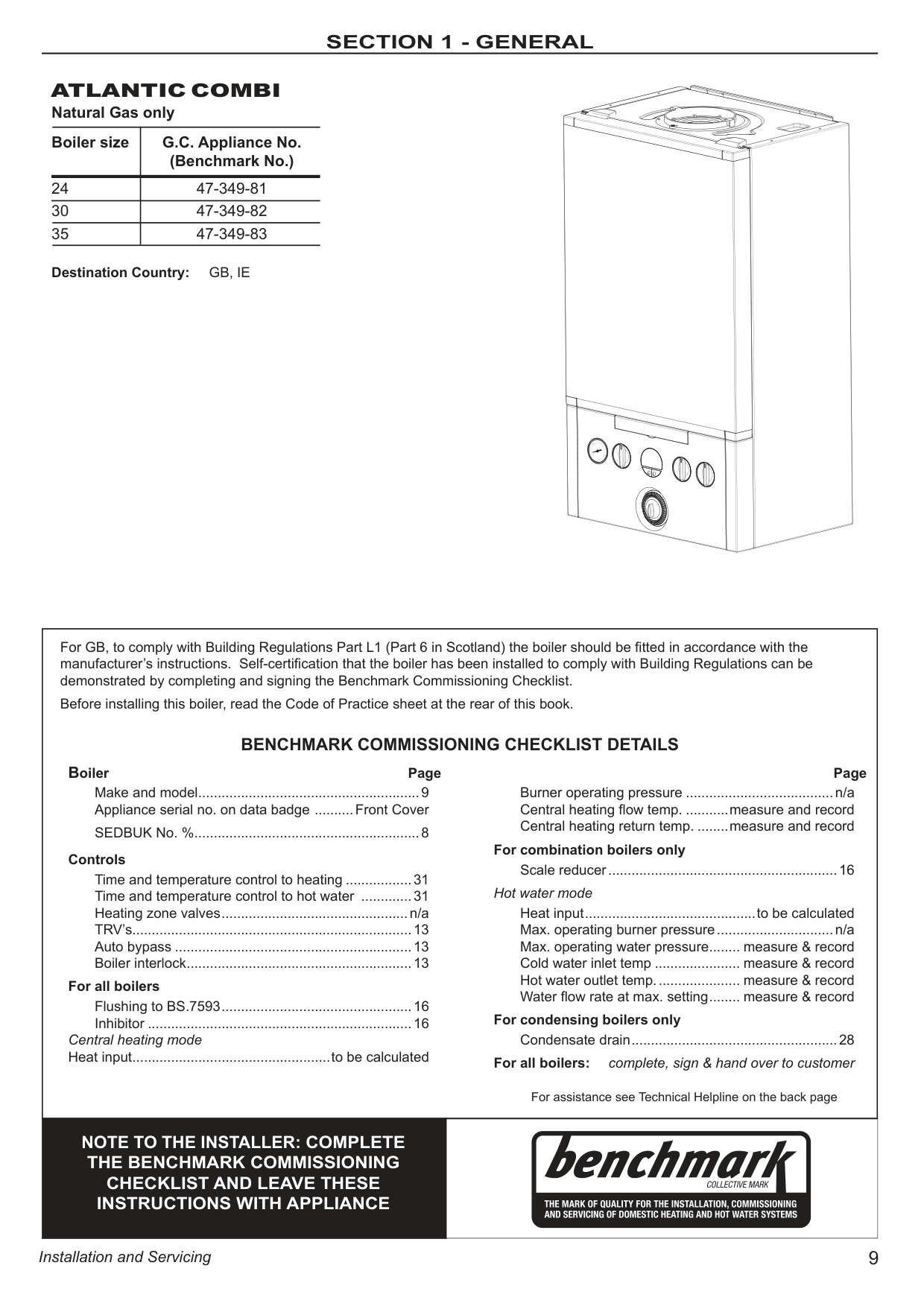
############ ATLANTIC COMBI
################# Natural Gas only
|Boiler size|G.C. Appliance No. (Benchmark No.)| |---|---| |4|47-349-81| |0|47-349-82| |5|47-349-83|
Destination Country: GB, IE
|Boiler Page
Make and model .........................................................9 Appliance serial no. on data badge ..........Front Cover
SEDBUK No. % ..........................................................8 Controls
Time and temperature control to heating .................31 Time and temperature control to hot water .............31 Heating zone valves ................................................n/a TRV’s........................................................................13 Auto bypass .............................................................13 Boiler interlock ..........................................................13
For all boilers
Flushing to BS.7593 .................................................16 Inhibitor ....................................................................16
Central heating mode Heat input ...................................................to be calculated
For assistance see Technical Helpline on the back page
Page
Burner operating pressure ......................................n/a Central heating flow temp. ...........measure and record Central heating return temp. ........measure and record
For combination boilers only
Scale reducer ...........................................................16 Hot water mode
Heat input ............................................to be calculated Max. operating burner pressure ..............................n/a Max. operating water pressure ........ measure & record Cold water inlet temp ...................... measure & record Hot water outlet temp. ..................... measure & record Water flow rate at max. setting ........ measure & record
For condensing boilers only
Condensate drain .....................................................28 For all boilers: complete, sign & hand over to customer
For GB, to comply with Building Regulations Part L1 (Part 6 in Scotland) the boiler should be fitted in accordance with the manufacturer’s instructions. Self-certification that the boiler has been installed to comply with Building Regulations can be demonstrated by completing and signing the Benchmark Commissioning Checklist. Before installing this boiler, read the Code of Practice sheet at the rear of this book.
BENCHMARK COMMISSIONING CHECKLIST DETAILS|Boiler Page
Make and model .........................................................9 Appliance serial no. on data badge ..........Front Cover
SEDBUK No. % ..........................................................8 Controls
Time and temperature control to heating .................31 Time and temperature control to hot water .............31 Heating zone valves ................................................n/a TRV’s........................................................................13 Auto bypass .............................................................13 Boiler interlock ..........................................................13
For all boilers
Flushing to BS.7593 .................................................16 Inhibitor ....................................................................16
Central heating mode Heat input ...................................................to be calculated
For assistance see Technical Helpline on the back page
Page
Burner operating pressure ......................................n/a Central heating flow temp. ...........measure and record Central heating return temp. ........measure and record
For combination boilers only
Scale reducer ...........................................................16 Hot water mode
Heat input ............................................to be calculated Max. operating burner pressure ..............................n/a Max. operating water pressure ........ measure & record Cold water inlet temp ...................... measure & record Hot water outlet temp. ..................... measure & record Water flow rate at max. setting ........ measure & record
For condensing boilers only
Condensate drain .....................................................28 For all boilers: complete, sign & hand over to customer
For GB, to comply with Building Regulations Part L1 (Part 6 in Scotland) the boiler should be fitted in accordance with the manufacturer’s instructions. Self-certification that the boiler has been installed to comply with Building Regulations can be demonstrated by completing and signing the Benchmark Commissioning Checklist. Before installing this boiler, read the Code of Practice sheet at the rear of this book.
BENCHMARK COMMISSIONING CHECKLIST DETAILS| |---|---| |NOTE TO THE INSTALLER: COMPLETE THE BENCHMARK COMMISSIONING CHECKLIST AND LEAVE THESE INSTRUCTIONS WITH APPLIANCE| |
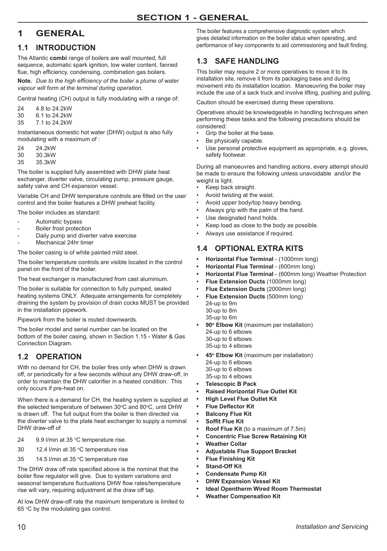
########### 1 GENERAL
############# 1.1 INTRODUCTION
The Atlantic combi range of boilers are wall mounted, full sequence, automatic spark ignition, low water content, fanned flue, high efficiency, condensing, combination gas boilers. Note. Due to the high efficiency of the boiler a plume of water vapour will form at the terminal during operation. Central heating (CH) output is fully modulating with a range of:
24 4.8 to 24.2kW 30 6.1 to 24.2kW 35 7.1 to 24.2kW
Instantaneous domestic hot water (DHW) output is also fully modulating with a maximum of :
24 24.2kW 30 30.3kW 35 35.3kW
The boiler is supplied fully assembled with DHW plate heat exchanger, diverter valve, circulating pump, pressure gauge, safety valve and CH expansion vessel.
Variable CH and DHW temperature controls are fitted on the user control and the boiler features a DHW preheat facility.
The boiler includes as standard:
The boiler temperature controls are visible located in the control panel on the front of the boiler.
The heat exchanger is manufactured from cast aluminium. The boiler is suitable for connection to fully pumped, sealed heating systems ONLY. Adequate arrangements for completely draining the system by provision of drain cocks MUST be provided in the installation pipework. Pipework from the boiler is routed downwards. The boiler model and serial number can be located on the bottom of the boiler casing, shown in Section 1.15 - Water & Gas Connection Diagram.
############# 1.2 OPERATION
With no demand for CH, the boiler fires only when DHW is drawn off, or periodically for a few seconds without any DHW draw-off, in order to maintain the DHW calorifier in a heated condition. This only occurs if pre-heat on.
When there is a demand for CH, the heating system is supplied at the selected temperature of between 30oC and 80oC, until DHW is drawn off. The full output from the boiler is then directed via the diverter valve to the plate heat exchanger to supply a nominal DHW draw-off of
24 9.9 l/min at 35 oC temperature rise. 30 12.4 l/min at 35 oC temperature rise 35 14.5 l/min at 35 oC temperature rise The DHW draw off rate specified above is the nominal that the boiler flow regulator will give. Due to system variations and seasonal temperature fluctuations DHW flow rates/temperature rise will vary, requiring adjustment at the draw off tap. At low DHW draw-off rate the maximum temperature is limited to 65 oC by the modulating gas control.
The boiler features a comprehensive diagnostic system which gives detailed information on the boiler status when operating, and performance of key components to aid commissioning and fault finding.
############# 1.3 SAFE HANDLING
This boiler may require 2 or more operatives to move it to its installation site, remove it from its packaging base and during movement into its installation location. Manoeuvring the boiler may include the use of a sack truck and involve lifting, pushing and pulling.
Caution should be exercised during these operations. Operatives should be knowledgeable in handling techniques when performing these tasks and the following precautions should be considered:
############# 1.4 OPTIONAL EXTRA KITS
############# 1.5 SAFETY
Current Gas Safety (installation and use) regulations or rules in force:
The appliance is suitable only for installation in GB and IE and should be installed in accordance with the rules in force. In GB, the installation must be carried out by a Gas Safe Registered Engineer. It must be carried out in accordance with the relevant requirements of the:
Where no specific instructions are given, reference should be made to the relevant British Standard Code of Practice.
In IE, the installation must be carried out by a Registered Gas Installer (RGII) and installed in accordance with the current edition of I.S.813 “Domestic Gas Installations”, the current Building Regulations and reference should be made to the current ETCI rules for electrical installation.
Detailed recommendations are contained in the following British Standard Codes of Practice:
BSEN. 12828 Heating Systems in buildings: Design for water
based heating systems.
BSEN 12831 Heating Systems in buildings: Method for
calculation of the design heat load.
BSEN 14336 Heating Systems in buildings: Installation and
commissioning of water based heating systems.
BS. 5546 Installation of gas hot water supplies for domestic
purposes (2nd Family Gases)
BS. 6798 Installation of gas fired hot water boilers of rated
input not exceeding 70 kW. BS. 6891 Low pressure installation pipes. Health & Safety Document No. 635. The Electricity at Work Regulations, 1989.
The manufacturer’s notes must NOT be taken, in any way, as overriding statutory obligations.
IMPORTANT. These appliances are CE certificated for safety and performance. It is, therefore, important that no external control devices, e.g. flue dampers, economisers etc., are directly connected to these appliances unless covered by these Installation and Servicing Instructions or as otherwise recommended by Ideal Heating in writing. If in doubt please enquire.
Any direct connection of a control device not approved by Ideal Heating could invalidate the certification and the normal appliance warranty. It could also infringe the Gas Safety Regulations and the above regulations.
############# 1.6 SAFE HANDLING OF SUBSTANCES
No asbestos, mercury or CFCs are included in any part of the boiler or its manufacture.
############# 1.7 LOCATION OF BOILER
The boiler must be installed on a flat and vertical internal wall, capable of adequately supporting the weight of the boiler and any ancillary equipment.
The boiler may be fitted on a combustible wall and insulation between the wall and the boiler is not necessary, unless required by the local authority.
For electrical safety reasons there must be no access available from the back of the boiler.
The boiler must not be fitted outside. Timber Framed Buildings
If the boiler is to be fitted in a timber Framed building it should be fitted in accordance with the Institute of Gas Engineering document IGE/UP/7:2006 - Edition 2.
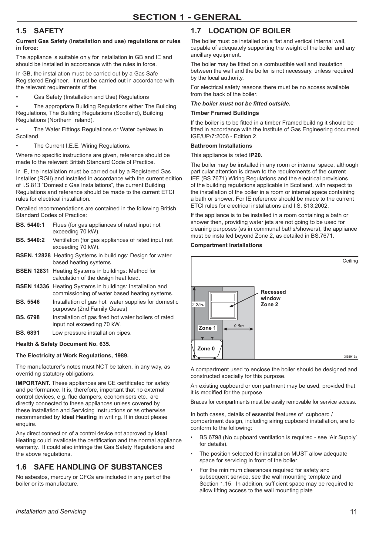
Bathroom Installations This appliance is rated IP20. The boiler may be installed in any room or internal space, although particular attention is drawn to the requirements of the current IEE (BS.7671) Wiring Regulations and the electrical provisions of the building regulations applicable in Scotland, with respect to the installation of the boiler in a room or internal space containing a bath or shower. For IE reference should be made to the current ETCI rules for electrical installations and I.S. 813:2002. If the appliance is to be installed in a room containing a bath or shower then, providing water jets are not going to be used for cleaning purposes (as in communal baths/showers), the appliance must be installed beyond Zone 2, as detailed in BS.7671. Compartment Installations
Ceiling
Recessed window Zone 2
########################## 2.25m
0.6m
Zone 1
Zone 0
3G8913a
A compartment used to enclose the boiler should be designed and constructed specially for this purpose.
An existing cupboard or compartment may be used, provided that it is modified for the purpose.
Braces for compartments must be easily removable for service access. In both cases, details of essential features of cupboard / compartment design, including airing cupboard installation, are to conform to the following:
############# 1.8 GAS SUPPLY
The local gas supplier should be consulted, at the installation planning stage, in order to establish the availability of an adequate supply of gas. An existing service pipe must NOT be used without prior consultation with the local gas supplier.
The boiler MUST be installed on a gas supply with a governed meter only.
A gas meter can only be connected by the local gas supplier or by a Gas Safe Registered Engineer. In IE by a Registered Gas Installer (RGII).
An existing meter should be checked, preferably by the gas supplier, to ensure that the meter is adequate to deal with the rate of gas supply required.
It is the responsibility of the Gas Installer to size the gas Installer to size the gas installation pipework in accordance with BS6891. Whilst the principle of the 1:1 gas valve ensures the boiler range is able to deliver it’s full output at inlet pressures as low as 14mb, other gas appliances in the property may not be as tolerant. When operating pressures are found to be below the minimum meter outlet of 19mb these should be checked to ensure this is adequate for correct and safe operation.
Allowing for the acceptable pressure loss of 1mb across the installation pipework, it can be assumed that a minimum permitted operating pressure of 18mb will be delivered to the inlet of the appliance. (Reference BS 6400-1 Clause 6.2 Pressure Absorption).
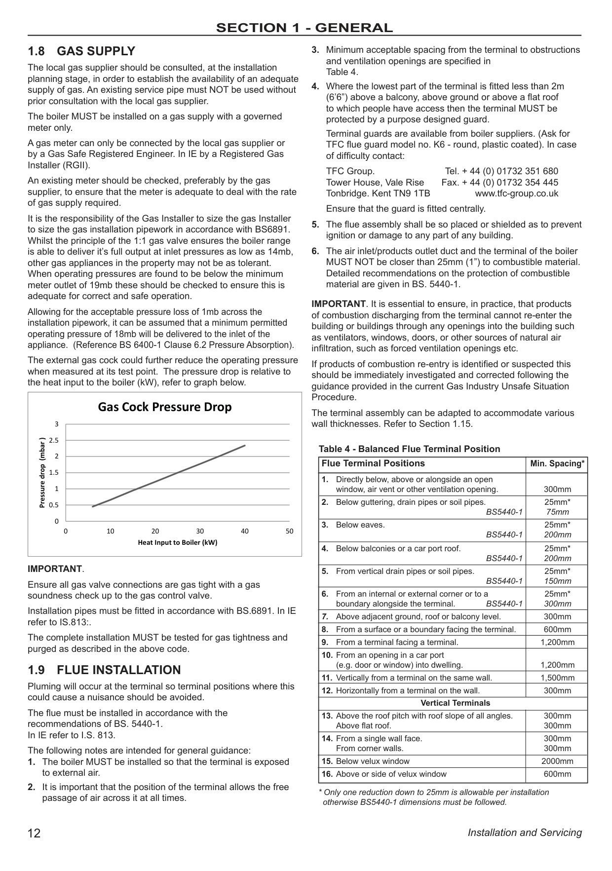
The external gas cock could further reduce the operating pressure when measured at its test point. The pressure drop is relative to the heat input to the boiler (kW), refer to graph below.
|0
0.5
1
1.5
2
2.5
3
0 10 20 30 40 50
Pressure drop (mbar )
Heat Input to Boiler (kW)
Gas Cock Pressure Drop| |---|
IMPORTANT.
Ensure all gas valve connections are gas tight with a gas soundness check up to the gas control valve.
Installation pipes must be fitted in accordance with BS.6891. In IE refer to IS.813:.
The complete installation MUST be tested for gas tightness and purged as described in the above code.
############# 1.9 FLUE INSTALLATION
Pluming will occur at the terminal so terminal positions where this could cause a nuisance should be avoided.
The flue must be installed in accordance with the recommendations of BS. 5440-1. In IE refer to I.S. 813.
The following notes are intended for general guidance:
Terminal guards are available from boiler suppliers. (Ask for TFC flue guard model no. K6 - round, plastic coated). In case of difficulty contact:
TFC Group. Tel. + 44 (0) 01732 351 680 Tower House, Vale Rise Fax. + 44 (0) 01732 354 445 Tonbridge. Kent TN9 1TB www.tfc-group.co.uk
Ensure that the guard is fitted centrally.
IMPORTANT. It is essential to ensure, in practice, that products of combustion discharging from the terminal cannot re-enter the building or buildings through any openings into the building such as ventilators, windows, doors, or other sources of natural air infiltration, such as forced ventilation openings etc.
If products of combustion re-entry is identified or suspected this should be immediately investigated and corrected following the guidance provided in the current Gas Industry Unsafe Situation Procedure.
The terminal assembly can be adapted to accommodate various wall thicknesses. Refer to Section 1.15.
###################### Table 4 - Balanced Flue Terminal Position
|Flue Terminal Positions|Min. Spacing*| |---|---| |1. Directly below, above or alongside an open
window, air vent or other ventilation opening.|300mm|
|2. Below guttering, drain pipes or soil pipes.
BS5440-1|25mm* 75mm| |3. Below eaves.
BS5440-1|25mm* 200mm| |4. Below balconies or a car port roof.
BS5440-1|25mm* 200mm| |5. From vertical drain pipes or soil pipes.
BS5440-1|25mm* 150mm| |6. From an internal or external corner or to a
boundary alongside the terminal. BS5440-1|25mm* 300mm| |7. Above adjacent ground, roof or balcony level.|300mm| |8. From a surface or a boundary facing the terminal.|600mm| |9. From a terminal facing a terminal.|1,200mm| |10. From an opening in a car port
(e.g. door or window) into dwelling.|1,200mm| |11. Vertically from a terminal on the same wall.|1,500mm| |12. Horizontally from a terminal on the wall.|300mm| |Vertical Terminals|Vertical Terminals| |13. Above the roof pitch with roof slope of all angles.
Above flat roof.|300mm 300mm| |14. From a single wall face.
From corner walls.|300mm 300mm| |15. Below velux window|2000mm| |16. Above or side of velux window|600mm|
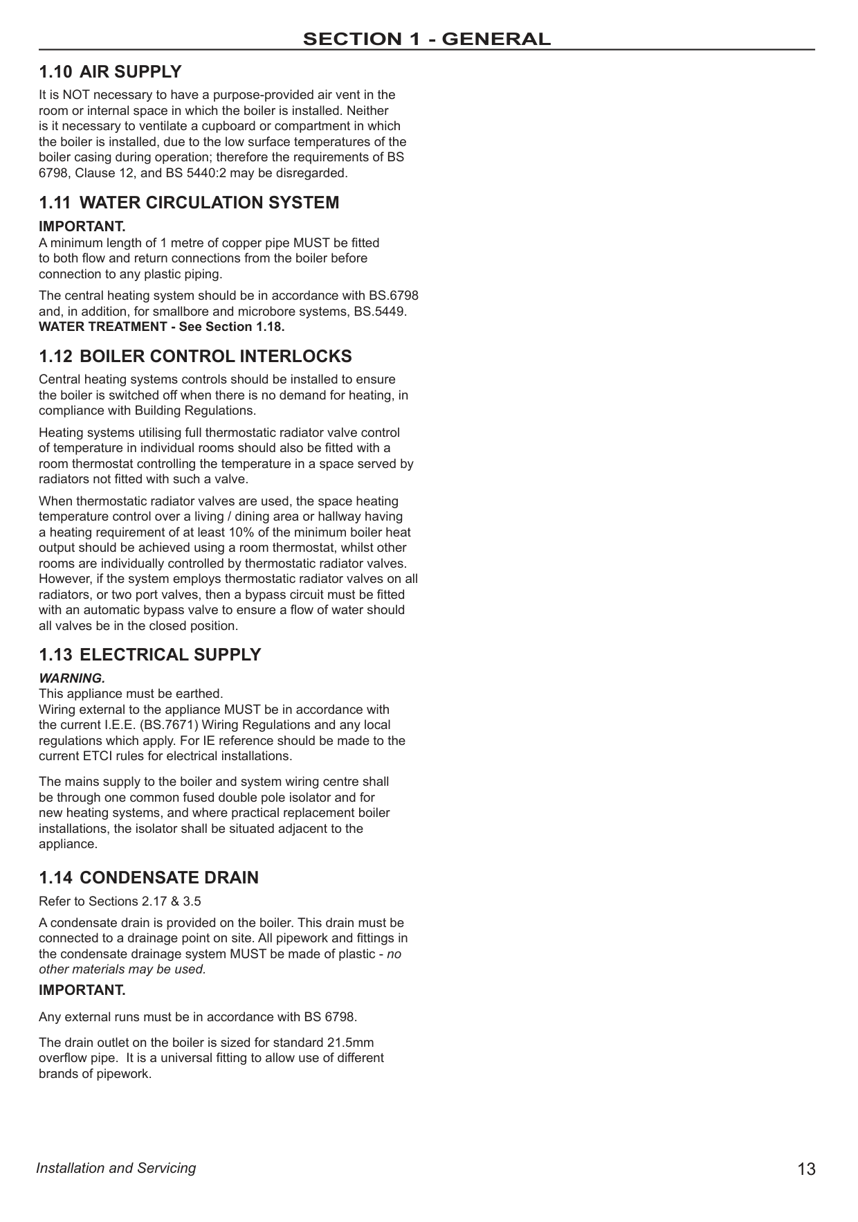
############# 1.10 AIR SUPPLY
It is NOT necessary to have a purpose-provided air vent in the room or internal space in which the boiler is installed. Neither is it necessary to ventilate a cupboard or compartment in which the boiler is installed, due to the low surface temperatures of the boiler casing during operation; therefore the requirements of BS 6798, Clause 12, and BS 5440:2 may be disregarded.
############# 1.11 WATER CIRCULATION SYSTEM
IMPORTANT. A minimum length of 1 metre of copper pipe MUST be fitted to both flow and return connections from the boiler before connection to any plastic piping.
The central heating system should be in accordance with BS.6798 and, in addition, for smallbore and microbore systems, BS.5449. WATER TREATMENT - See Section 1.18.
############# 1.12 BOILER CONTROL INTERLOCKS
Central heating systems controls should be installed to ensure the boiler is switched off when there is no demand for heating, in compliance with Building Regulations.
Heating systems utilising full thermostatic radiator valve control of temperature in individual rooms should also be fitted with a room thermostat controlling the temperature in a space served by radiators not fitted with such a valve.
When thermostatic radiator valves are used, the space heating temperature control over a living / dining area or hallway having a heating requirement of at least 10% of the minimum boiler heat output should be achieved using a room thermostat, whilst other rooms are individually controlled by thermostatic radiator valves. However, if the system employs thermostatic radiator valves on all radiators, or two port valves, then a bypass circuit must be fitted with an automatic bypass valve to ensure a flow of water should all valves be in the closed position.
############# 1.13 ELECTRICAL SUPPLY
WARNING. This appliance must be earthed. Wiring external to the appliance MUST be in accordance with the current I.E.E. (BS.7671) Wiring Regulations and any local regulations which apply. For IE reference should be made to the current ETCI rules for electrical installations.
The mains supply to the boiler and system wiring centre shall be through one common fused double pole isolator and for new heating systems, and where practical replacement boiler installations, the isolator shall be situated adjacent to the appliance.
############# 1.14 CONDENSATE DRAINRefer to Sections 2.17 & 3.5
A condensate drain is provided on the boiler. This drain must be connected to a drainage point on site. All pipework and fittings in the condensate drainage system MUST be made of plastic - no other materials may be used.
IMPORTANT. Any external runs must be in accordance with BS 6798. The drain outlet on the boiler is sized for standard 21.5mm overflow pipe. It is a universal fitting to allow use of different brands of pipework.
|3952.5 2.5 from case
700
Side flue dim. A
285
155
DATA PLATE
CH FLOW
DHW OUTLET
COND. DRAIN
GAS INLET
DHW INLET
CH RETURN
PRV
Underside View - Dimensions to Wall
43.5 65 28.528.5 60.5 75 39.554.5
99 99
34
103
103103
WALL
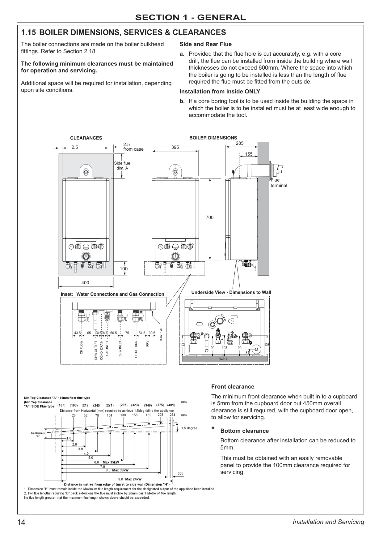
1.15 BOILER DIMENSIONS, SERVICES & CLEARANCES
The boiler connections are made on the boiler bulkhead fittings. Refer to Section 2.18.
The following minimum clearances must be maintained for operation and servicing.
Additional space will be required for installation, depending upon site conditions.
Side and Rear Flue
a. Provided that the flue hole is cut accurately, e.g. with a core drill, the flue can be installed from inside the building where wall thicknesses do not exceed 600mm. Where the space into which the boiler is going to be installed is less than the length of flue required the flue must be fitted from the outside.
Installation from inside ONLY
b. If a core boring tool is to be used inside the building the space in which the boiler is to be installed must be at least wide enough to accommodate the tool.

Front clearance
The minimum front clearance when built in to a cupboard is 5mm from the cupboard door but 450mm overall clearance is still required, with the cupboard door open, to allow for servicing.
* Bottom clearance
Bottom clearance after installation can be reduced to 5mm.
This must be obtained with an easily removable panel to provide the 100mm clearance required for servicing.| |---|
|General
1. The installation must comply with all relevant national and local regulations.
2. The installation should be designed to work with flow temperatures of up to 84 oC.
3. All components of the system must be suitable for a working pressure of 3 bar and temperature of 110 oC. Extra care should be taken in making all connections so that the risk of leakage is minimised.
The following components are incorporated within the appliance:
a. Circulating pump.
b. Safety valve, with a non-adjustable preset lift pressure of 3 bar.
c. Pressure gauge, covering a range of 0 to 4 bar.
d. An 8-litre expansion vessel, with an initial charge pressure of 0.75 bar.
4. ‘Make-up’ Water. Provision must be made for replacing water loss from the system, either :
a. From a manually filled ‘make-up’ vessel with a readily visible water level. The vessel should be mounted at least 150mm above the highest point of the system and be connected through a non-return valve to the system, fitted at least 150mm below the ‘make-up’ vessel on the return side of the radiators. or
b. Where access to a ‘make-up’ vessel would be difficult, by pre-pressurisation of the system.
The maximum cold water capacity of the system should not exceed 143 litres, if not pressurized. However, if the system is to be pressurized, the efficiency of the expansion vessel will be reduced and a larger vessel (or smaller system volume) may be necessary. If the capacity of the vessel is not considered sufficient for this, or for any other reason, an additional vessel MUST be installed on the return to the boiler.
Guidance on vessel sizing is given in table above.
5. Filling The system may be filled by the following method:
Where the mains pressure is excessive a pressure reducing valve must be used to facilitate filling.
a. Thoroughly flush out the whole system with cold water.
b. Fill and vent the system until the pressure gauge registers 1bar and examine for leaks.
c. Check the operation of the safety valve by raising the water pressure until the valve lifts. This should occur within 0.3bar of the preset lift pressure.
d. Release water from the system until the minimum system design pressure is reached; 1.0 bar if the system is to be pre-pressurised.
Notes
a. The method of filling, refilling, topping up or flushing sealed primary hot water circuits from the mains via a temporary hose connection is only allowed if acceptable to the local water authority.
b. Antifreeze fluid, corrosion and scale inhibitor fluids suitable for use with boilers having aluminium heat exchangers may be used in the central heating system.
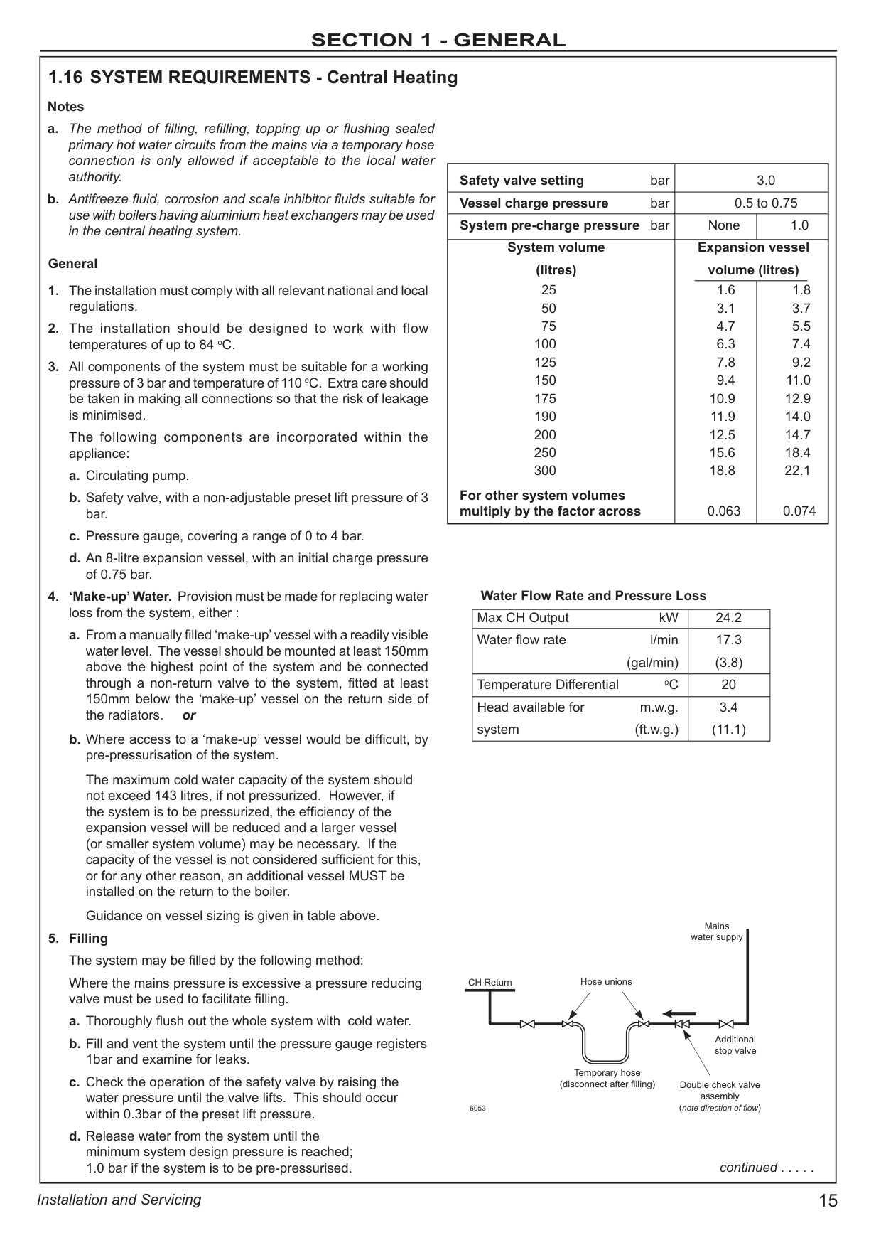
1.16 SYSTEM REQUIREMENTS - Central Heating
Water Flow Rate and Pressure Loss
|Max CH Output kW|24.2| |---|---| |Water flow rate l/min (gal/min)|17.3 (3.8)| |Temperature Differential oC|20| |Head available for m.w.g. system (ft.w.g.)|3.4 (11.1)|
Safety valve setting bar 3.0 Vessel charge pressure bar 0.5 to 0.75 System pre-charge pressure bar None 1.0
System volume Expansion vessel (litres) volume (litres)
25 1.6 1.8 50 3.1 3.7 75 4.7 5.5
100 6.3 7.4 125 7.8 9.2 150 9.4 11.0 175 10.9 12.9 190 11.9 14.0 200 12.5 14.7 250 15.6 18.4 300 18.8 22.1
For other system volumes multiply by the factor across 0.063 0.074
continued . . . . .
CH Return
6053
Hose unions
Mains water supply
Temporary hose (disconnect after filling)
Additional stop valve
Double check valve assembly (note direction of flow)| |---|
|........ SYSTEM REQUIREMENTS - CONT Domestic Hot Water
1. The DHW service must be in accordance with BS.5546 & BS.6700.
2. Refer to Table 1 for minimum and maximum working pressures. In areas of low mains water pressures the domestic hot water regulator may be removed from the DHW flow turbine cartridge. Refer to Section 3.20. The boiler will require the flow rate to be set to obtain a temperature rise of 35oC at the tap furthest from the boiler.
3. The boilers are suitable for connection to most types of washing machine and dishwasher appliances.
4. If the shower/mixer valve does not incorporate non-return valves the following must be followed: a. The cold inlet to the boiler is fitted with an approved anti-
vacuum or syphon non-return valve.
b. Hot and cold water supplies to the shower are of equal
pressure. 5. Hard Water Areas Where the water hardness exceeds 200mg/litre (200 ppm), it is recommended that a proprietary scale reducing device is fitted into the boiler cold supply within the requirements of the local water company.
IMPORTANT. Provision must be made to accommodate the expansion of DHW contained within the appliance. If the DHW inlet contains a back flow prevention device or non-return valve, e.g. a water meter, then a mini expansion vessel should be fitted between the device and the boiler in the cold inlet pipe.
Cold water, rising main and pipework in exposed areas need to be suitably lagged to prevent freezing.| |---|
|The boiler does not normally need a bypass but at least some radiators on the heating circuit, of load of at least 10% of the minimum boiler output, must be provided with twin lockshield valves so that this minimum heating load is always available. See note regarding thermostatic radiator valves on page 13.
Note. Systems incorporating zone valves which could completely cut off the flow through the system must also include a bypass.
BALANCING
1. Set the programmer to ON. Close the manual or thermostatic
valves on all radiators, leaving the twin lockshield valves (on
the radiators referred to above) in the OPEN position. Turn up the room thermostat and adjust the lockshield valve to give an uninterrupted flow through the radiator. These valves should now be left as set.
2. Open all manual or thermostatic radiator valves and adjust the lockshield valves on the remaining radiators, to give around 20oC temperature drop at each radiator.
3. Adjust the room thermostat and programmer to NORMAL settings.
1.17 SYSTEM BALANCING| |---|
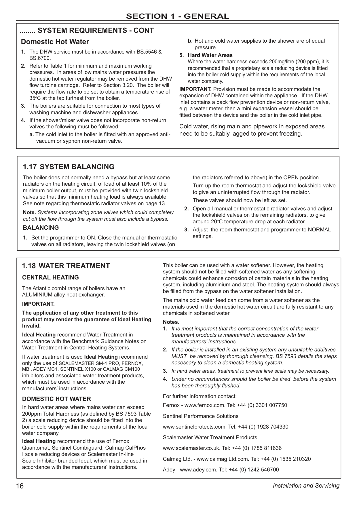
|CENTRAL HEATING
The Atlantic combi range of boilers have an ALUMINIUM alloy heat exchanger.
IMPORTANT. The application of any other treatment to this product may render the guarantee of Ideal Heating Invalid. Ideal Heating recommend Water Treatment in accordance with the Benchmark Guidance Notes on Water Treatment in Central Heating Systems.
If water treatment is used Ideal Heating recommend only the use of SCALEMASTER SM-1 PRO, FERNOX, MBI, ADEY MC1, SENTINEL X100 or CALMAG CM100 inhibitors and associated water treatment products, which must be used in accordance with the manufacturers’ instructions.
DOMESTIC HOT WATER In hard water areas where mains water can exceed 200ppm Total Hardness (as defined by BS 7593 Table
2) a scale reducing device should be fitted into the boiler cold supply within the requirements of the local water company. Ideal Heating recommend the use of Fernox Quantomat, Sentinel Combiguard, Calmag CalPhos I scale reducing devices or Scalemaster In-line Scale Inhibitor branded Ideal, which must be used in accordance with the manufacturers’ instructions.
This boiler can be used with a water softener. However, the heating system should not be filled with softened water as any softening chemicals could enhance corrosion of certain materials in the heating system, including aluminium and steel. The heating system should always be filled from the bypass on the water softener installation.
The mains cold water feed can come from a water softener as the materials used in the domestic hot water circuit are fully resistant to any chemicals in softened water.
Notes.
1. It is most important that the correct concentration of the water treatment products is maintained in accordance with the manufacturers’ instructions.
2. If the boiler is installed in an existing system any unsuitable additives MUST be removed by thorough cleansing. BS 7593 details the steps necessary to clean a domestic heating system.
3. In hard water areas, treatment to prevent lime scale may be necessary.
4. Under no circumstances should the boiler be fired before the system has been thoroughly flushed.
For further information contact: Fernox - www.fernox.com. Tel: +44 (0) 3301 007750 Sentinel Performance Solutions www.sentinelprotects.com. Tel: +44 (0) 1928 704330 Scalemaster Water Treatment Products www.scalemaster.co.uk. Tel: +44 (0) 1785 811636 Calmag Ltd. - www.calmag Ltd.com. Tel: +44 (0) 1535 210320 Adey - www.adey.com. Tel: +44 (0) 1242 546700
1.18 WATER TREATMENT| |---|
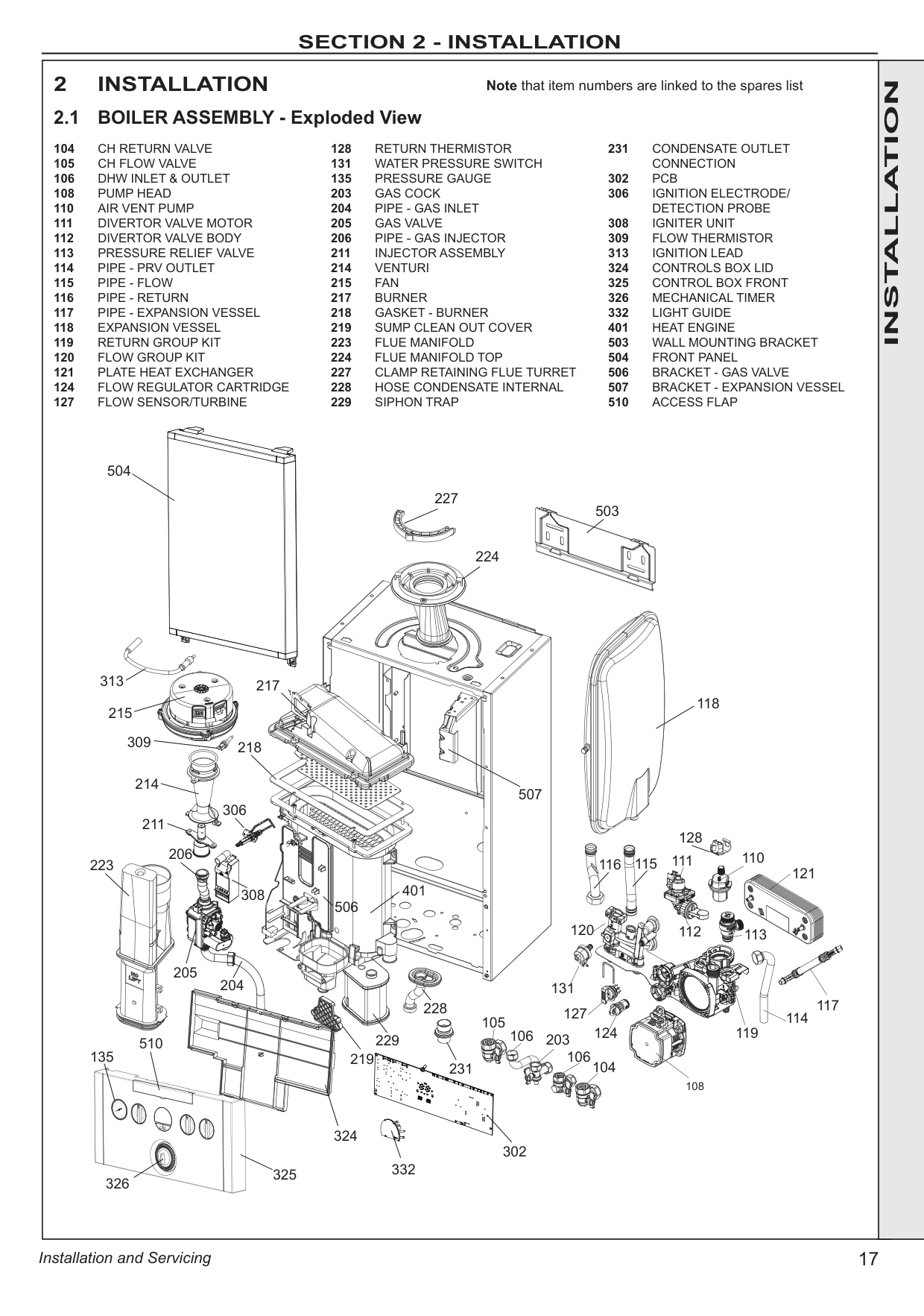
|2 INSTALLATION 2.1 BOILER ASSEMBLY - Exploded View
Note that item numbers are linked to the spares list
104 CH RETURN VALVE
105 CH FLOW VALVE
106 DHW INLET & OUTLET 108 PUMP HEAD
110 AIR VENT PUMP
111 DIVERTOR VALVE MOTOR
112 DIVERTOR VALVE BODY
113 PRESSURE RELIEF VALVE
114 PIPE - PRV OUTLET
115 PIPE - FLOW
116 PIPE - RETURN
117 PIPE - EXPANSION VESSEL
118 EXPANSION VESSEL
119 RETURN GROUP KIT
120 FLOW GROUP KIT
121 PLATE HEAT EXCHANGER 124 FLOW REGULATOR CARTRIDGE 127 FLOW SENSOR/TURBINE
128 RETURN THERMISTOR 131 WATER PRESSURE SWITCH 135 PRESSURE GAUGE
203 GAS COCK
204 PIPE - GAS INLET
205 GAS VALVE
206 PIPE - GAS INJECTOR 211 INJECTOR ASSEMBLY
214 VENTURI
215 FAN
217 BURNER
218 GASKET - BURNER
219 SUMP CLEAN OUT COVER
223 FLUE MANIFOLD
224 FLUE MANIFOLD TOP
227 CLAMP RETAINING FLUE TURRET
228 HOSE CONDENSATE INTERNAL
229 SIPHON TRAP
231 CONDENSATE OUTLET
CONNECTION 302 PCB 306 IGNITION ELECTRODE/
DETECTION PROBE
308 IGNITER UNIT
309 FLOW THERMISTOR 313 IGNITION LEAD
324 CONTROLS BOX LID
325 CONTROL BOX FRONT
326 MECHANICAL TIMER 332 LIGHT GUIDE 401 HEAT ENGINE
503 WALL MOUNTING BRACKET
504 FRONT PANEL
506 BRACKET - GAS VALVE
507 BRACKET - EXPANSION VESSEL 510 ACCESS FLAP
504
313 215 309 214
206 223
205
510 135
326
325
324
204
229
231
302 332
118
507
224
503
228
308
306
218
217
506
401
211
219
227
110
114
113
121
131 127
124
120
119
117
112
115116
108
111
128
104
106
203106
105
| | | |---|---|---|
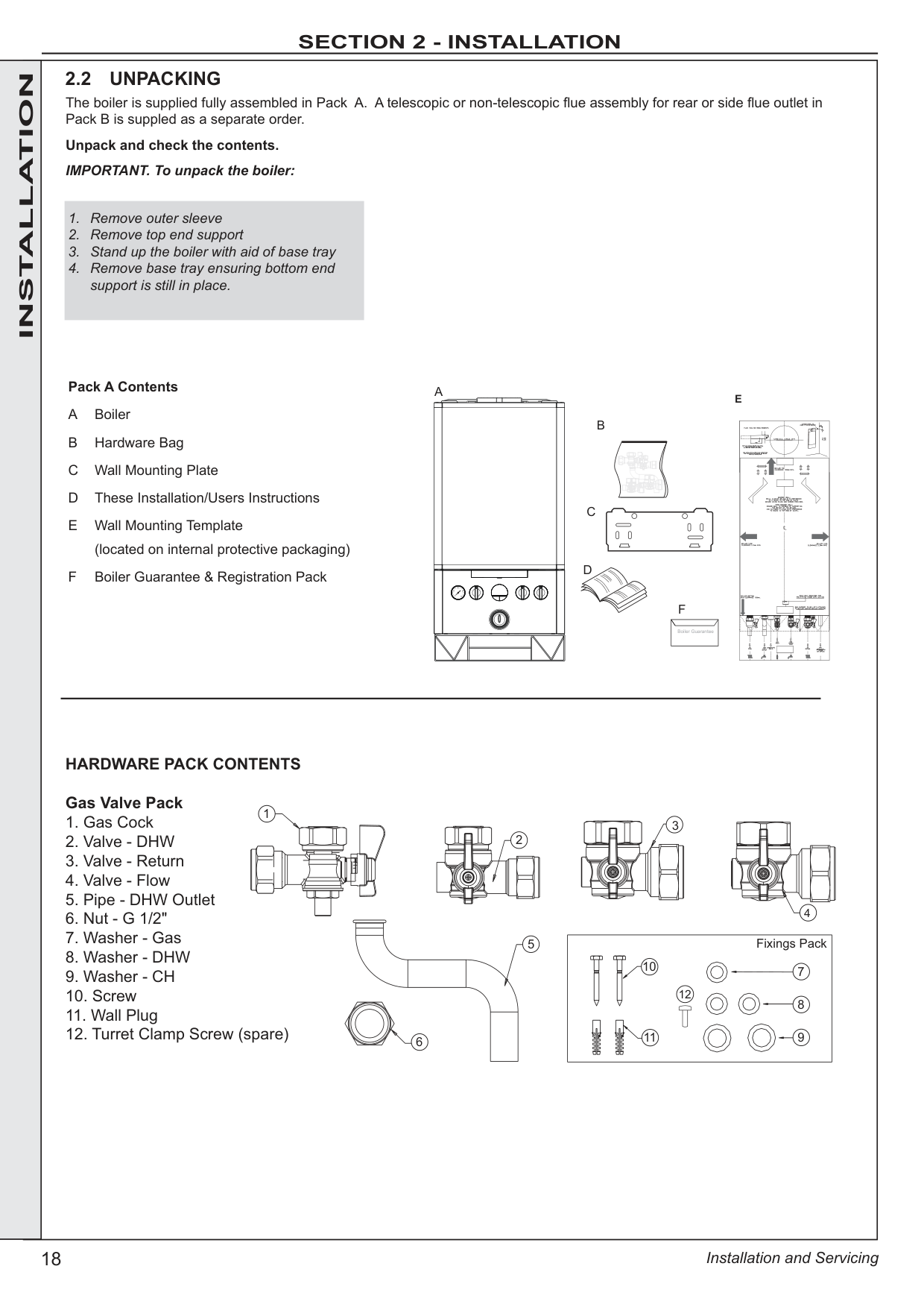
| | |HARDWARE PACK CONTENTS
Gas Valve Pack
1. Gas Cock
2. Valve - DHW
3. Valve - Return
4. Valve - Flow
5. Pipe - DHW Outlet
6. Nut - G 1/2"
7. Washer - Gas
8. Washer - DHW
9. Washer - CH
10. Screw
11. Wall Plug
12. Turret Clamp Screw (spare)
|Fixings Pack 710
11
8
9
12
| |---|
3
4
2
6
5
1
2.2 UNPACKING
The boiler is supplied fully assembled in Pack A. A telescopic or non-telescopic flue assembly for rear or side flue outlet in Pack B is suppled as a separate order.
Unpack and check the contents. IMPORTANT. To unpack the boiler:
Pack A Contents
A Boiler
B Hardware Bag
C Wall Mounting Plate
D These Installation/Users Instructions
E Wall Mounting Template (located on internal protective packaging)
F Boiler Guarantee & Registration Pack
C
D
B
E
|Boiler Guarantee| |---|
A
F
1. Remove outer sleeve
2. Remove top end support
3. Stand up the boiler with aid of base tray
4. Remove base tray ensuring bottom end support is still in place.
| |---|---|---|
and remove.
2
1
3
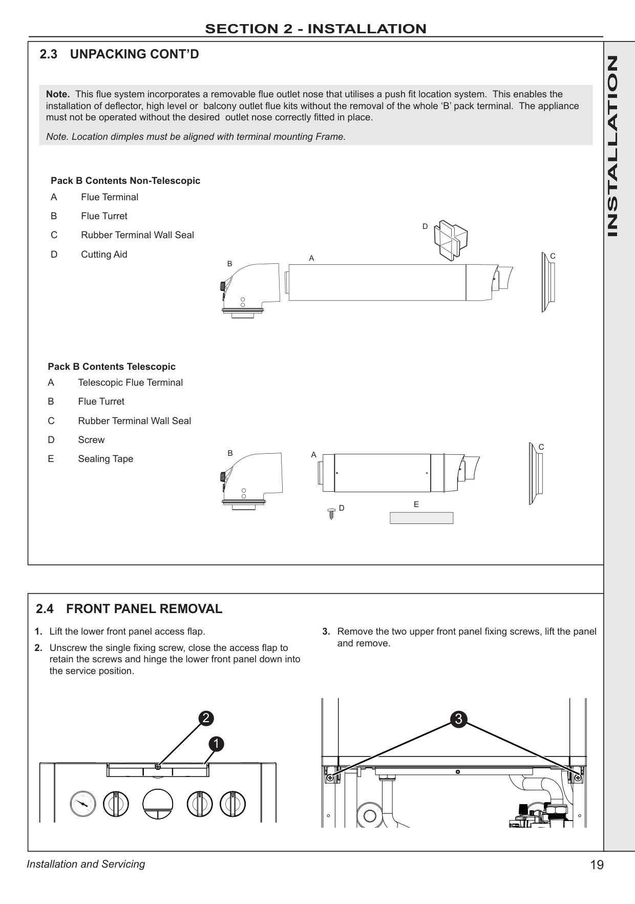
Pack B Contents Telescopic
Pack B Contents Non-Telescopic
Note. This flue system incorporates a removable flue outlet nose that utilises a push fit location system. This enables the installation of deflector, high level or balcony outlet flue kits without the removal of the whole ‘B’ pack terminal. The appliance must not be operated without the desired outlet nose correctly fitted in place.
Note. Location dimples must be aligned with terminal mounting Frame.
D
CA B
| | | | |---|---|---| | | | |
C
B
A
E
| | | | |---|---|---| | | | |
D
INSTALLATION
IMPORTANT.
Ensure that, during the cutting operation, masonry falling outside of the building does not cause damage or personal injury.
############# INSTALLATION
Extended centre line
155 (200)
The wall mounting template is located on the internal protective packaging. The template shows the position of the fixing and rear flue centre holes for a standard installation Care MUST be taken to ensure the correct holes are drilled.
“A” - See Diagram in Frame 1
| | | | |---|---|---| | | | | | | | |
Rear flue only 5" diameter hole
Side flue only 5" diameter hole
X
Section through wall
Note. Check all of the hole positions before drilling.
3G9495
|2.8 MOUNTING THE BOILER NOTE. ENSURE BOTTOM END SUPPORT IS LEFT IN PLACE
1. Lift the boiler onto the wall mounting plate (refer to the Introduction section for safe handling advice), locating it over the two tabs.
2. Remove the bottom end support packaging.
3. Ensure the plastic plugs are removed from both the CH and DHW connections.
| |---|
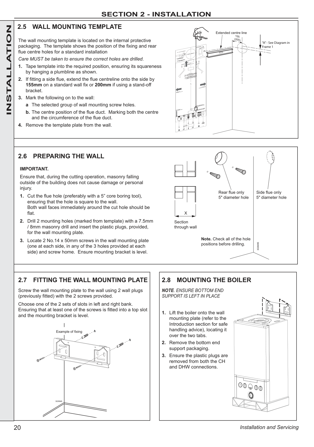
Screw the wall mounting plate to the wall using 2 wall plugs (previously fitted) with the 2 screws provided.
Choose one of the 2 sets of slots in left and right bank. Ensuring that at least one of the screws is fitted into a top slot and the mounting bracket is level.
Example of fixing
3G9948
|2.9 DETERMINING THE FLUE LENGTH AND FLUE PACKS REQUIRED IMPORTANT. The boiler must be installed in a vertical position in accordance to the installation instructions.
FLUE KITS Telescopic Flue‘B’ Pack - contains: Flue turret, telescopic flue incorporating a terminal and rubber wall seals.
Horizontal Flue Terminal (600mm long) ‘B’ Pack - contains: Flue turret, non telescopic single piece flue incorporating a terminal and rubber wall seals.
Horizontal Flue Terminal (1000mm long) ‘B’ Pack - Flue turret, telescopic flue incorporating a terminal, rubber wall seals and instructions.
Note. If ‘B’ packs are used on their own (either 1 piece or telescopic), then they can be fitted horizontally as the flue inside is designed to slope 1.5 degrees.
Flue Kit 203129 - D Pack Flue Extension 100mm DIA 1000mm long
Flue Kit 211037 - D Pack Flue Extension 100mm DIA 500mm long
Flue Kit 211038 - D Pack Flue Extension 100mm Dia 2000mm long
Flue Kit 211039 - Roof Flue Kit with Vertical Connector
When extension ‘D’ Packs are used the flue duct must incline 1.5 degrees away from the appliance, to allow the condensate to drain back to the boiler and out of the condensate drain. It is recommended that a support bracket is fitted on every 1 metre of pipe work used
and the bracket is located as close to the collar as possible. The bracketing must ensure a 1.5 degree fall back to the appliance.
Optional Flue Finishing Kit - UIN 155988 & Concentric Flue Screw Retaining Kit (Optional Kit of mechanical fixing of flue joints) Only use water as a lubricant during assembly. The ‘B’ pack terminal is classed as part of the maximum flue length. These flue systems incorporates a removable flue outlet nose that utilises a push fit location system. This enables the installation of deflector, high level or balcony flue kits without the removal of the whole ‘B’ pack terminal. The appliance must not be operated without the desired outlet nose correctly fitted in place, ensuring the side location dimples are in line with the mounting face allowing the correct sealing of the components. It is IMPORTANT that all attachments are fitted in accordance to the installation instructions provided with them.
The TURRET supplied in the ‘B’ Pack has an upper combustion sample point with a screw cap seal and a lower air sample point with an air stopper seal. Ensure all caps & seals are in place.
Additional Termination Kits available for use with these ‘B’ packs.
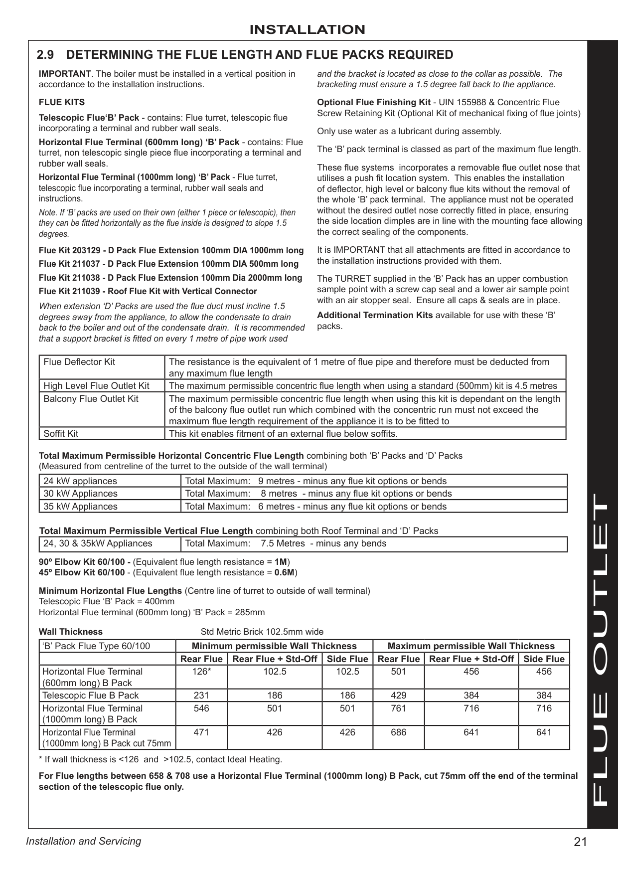
|Flue Deflector Kit|The resistance is the equivalent of 1 metre of flue pipe and therefore must be deducted from any maximum flue length| |---|---| |High Level Flue Outlet Kit|The maximum permissible concentric flue length when using a standard (500mm) kit is 4.5 metres| |Balcony Flue Outlet Kit|The maximum permissible concentric flue length when using this kit is dependant on the length of the balcony flue outlet run which combined with the concentric run must not exceed the maximum flue length requirement of the appliance it is to be fitted to| |Soffit Kit|This kit enables fitment of an external flue below soffits.|
Total Maximum Permissible Horizontal Concentric Flue Length combining both ‘B’ Packs and ‘D’ Packs (Measured from centreline of the turret to the outside of the wall terminal)
|24 kW appliances|Total Maximum: 9 metres - minus any flue kit options or bends| |---|---| |30 kW Appliances|Total Maximum: 8 metres - minus any flue kit options or bends| |35 kW Appliances|Total Maximum: 6 metres - minus any flue kit options or bends|
Total Maximum Permissible Vertical Flue Length combining both Roof Terminal and ‘D’ Packs
|24, 30 & 35kW Appliances|Total Maximum: 7.5 Metres - minus any bends| |---|---|
90º Elbow Kit 60/100 - (Equivalent flue length resistance = 1M) 45º Elbow Kit 60/100 - (Equivalent flue length resistance = 0.6M)
Minimum Horizontal Flue Lengths (Centre line of turret to outside of wall terminal) Telescopic Flue ‘B’ Pack = 400mm Horizontal Flue terminal (600mm long) ‘B’ Pack = 285mm
Wall Thickness Std Metric Brick 102.5mm wide
|‘B’ Pack Flue Type 60/100|Minimum permissible Wall Thickness|Minimum permissible Wall Thickness|Minimum permissible Wall Thickness|Maximum permissible Wall Thickness|Maximum permissible Wall Thickness|Maximum permissible Wall Thickness| |---|---|---|---|---|---|---| | |Rear Flue|Rear Flue + Std-Off|Side Flue|Rear Flue|Rear Flue + Std-Off|Side Flue| |Horizontal Flue Terminal (600mm long) B Pack|126*|102.5|102.5|501|456|456| |Telescopic Flue B Pack|231|186|186|429|384|384| |Horizontal Flue Terminal (1000mm long) B Pack|546|501|501|761|716|716| |Horizontal Flue Terminal (1000mm long) B Pack cut 75mm|471|426|426|686|641|641|
* If wall thickness is <126 and >102.5, contact Ideal Heating.
For Flue lengths between 658 & 708 use a Horizontal Flue Terminal (1000mm long) B Pack, cut 75mm off the end of the terminal section of the telescopic flue only.| |FLUE OUTLET| |---|---|---|
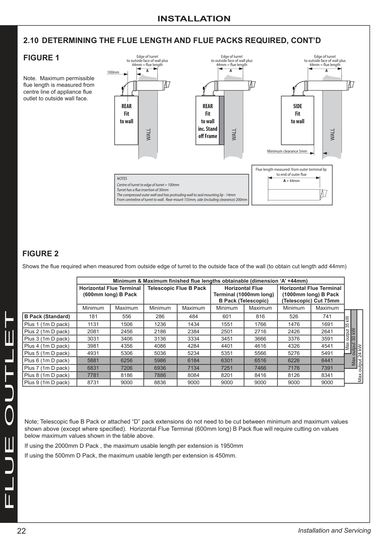
|FLUE OUTLET|| |Minimum & Maximum finished flue lengths obtainable (dimension ‘A’ +44mm)|Minimum & Maximum finished flue lengths obtainable (dimension ‘A’ +44mm)|Minimum & Maximum finished flue lengths obtainable (dimension ‘A’ +44mm)|Minimum & Maximum finished flue lengths obtainable (dimension ‘A’ +44mm)|Minimum & Maximum finished flue lengths obtainable (dimension ‘A’ +44mm)|Minimum & Maximum finished flue lengths obtainable (dimension ‘A’ +44mm)|Minimum & Maximum finished flue lengths obtainable (dimension ‘A’ +44mm)|Minimum & Maximum finished flue lengths obtainable (dimension ‘A’ +44mm)| | | | |---|---|---|---|---|---|---|---|---|---|---|---| | |Horizontal Flue Terminal (600mm long) B Pack|Horizontal Flue Terminal (600mm long) B Pack|Telescopic Flue B Pack|Telescopic Flue B Pack|Horizontal Flue Terminal (1000mm long) B Pack (Telescopic)|Horizontal Flue Terminal (1000mm long) B Pack (Telescopic)|Horizontal Flue Terminal (1000mm long) B Pack (Telescopic) Cut 75mm|Horizontal Flue Terminal (1000mm long) B Pack (Telescopic) Cut 75mm| | | | | |Minimum|Maximum|Minimum|Maximum|Minimum|Maximum|Minimum|Maximum| | | |
| |Minimum|Maximum|Minimum|Maximum|Minimum|Maximum|Minimum|Maximum|Max output 35 kW| |Max output 24 kW| |B Pack (Standard)|181|556|286|484|601|816|526|741|Max output 35 kW| |Max output 24 kW| |Plus 1 (1m D pack)|1131|1506|1236|1434|1551|1766|1476|1691|Max output 35 kW| |Max output 24 kW| |Plus 2 (1m D pack)|2081|2456|2186|2384|2501|2716|2426|2641|Max output 35 kW| |Max output 24 kW| |Plus 3 (1m D pack)|3031|3406|3136|3334|3451|3666|3376|3591|Max output 35 kW| |Max output 24 kW| |Plus 4 (1m D pack)|3981|4356|4086|4284|4401|4616|4326|4541|Max output 35 kW| |Max output 24 kW| |Plus 5 (1m D pack)|4931|5306|5036|5234|5351|5566|5276|5491|Max output 35 kW| |Max output 24 kW| |Plus 5 (1m D pack)|4931|5306|5036|5234|5351|5566|5276|5491|Max output 30 kW|Max output 30 kW|Max output 24 kW| |Plus 6 (1m D pack)|5881|6256|5986|6184|6301|6516|6226|6441|Max output 30 kW|Max output 30 kW|Max output 24 kW| |Plus 7 (1m D pack)|6831|7206|6936|7134|7251|7466|7176|7391|Max output 30 kW|Max output 30 kW|Max output 24 kW| |Plus 7 (1m D pack)|6831|7206|6936|7134|7251|7466|7176|7391| | | | |Plus 8 (1m D pack)|7781|8186|7886|8084|8201|8416|8126|8341| | | | |Plus 9 (1m D pack)|8731|9000|8836|9000|9000|9000|9000|9000| | | | |Plus 9 (1m D pack)|8731|9000|8836|9000|9000|9000|9000|9000| | | |
100mm
Edge of turret to outside face of wall plus 44mm = ue length
|Centre of turret to edge of turret = 100mm Turret has a ue insertion of 30mm The compressed outer wall seal has protruding wall to seal mounting lip - 14mm From centreline of turret to wall. Rear mount 155mm, side (including clearance) 200mm
NOTES| |---|
REAR Fit to wall
A
WALL
Edge of turret to outside face of wall plus 44mm = ue length
|Flue length measured from outer terminal lip to end of outer ue A + 44mm
| |---|
| | | | |---|---|---| |REAR Fit to wall inc. Stand o Frame|REAR Fit to wall inc. Stand o Frame|REAR Fit to wall inc. Stand o Frame|
A
WALL
Edge of turret to outside face of wall plus 44mm = ue length
| | | | |---|---|---| |SIDE Fit to wall|SIDE Fit to wall|SIDE Fit to wall| |Minimum clearance 5mm|Minimum clearance 5mm|Minimum clearance 5mm|
A
WALL
2.10 DETERMINING THE FLUE LENGTH AND FLUE PACKS REQUIRED, CONT’D
Shows the flue required when measured from outside edge of turret to the outside face of the wall (to obtain cut length add 44mm)
FIGURE 1
FIGURE 2
Note. Maximum permissible flue length is measured from centre line of appliance flue outlet to outside wall face.
Note; Telescopic flue B Pack or attached “D” pack extensions do not need to be cut between minimum and maximum values shown above (except where specified). Horizontal Flue Terminal (600mm long) B Pack flue will require cutting on values below maximum values shown in the table above.
If using the 2000mm D Pack , the maximum usable length per extension is 1950mm If using the 500mm D Pack, the maximum usable length per extension is 450mm.| |---|---|
|2.11 CUTTING & SETTING THE FLUE LENGTH
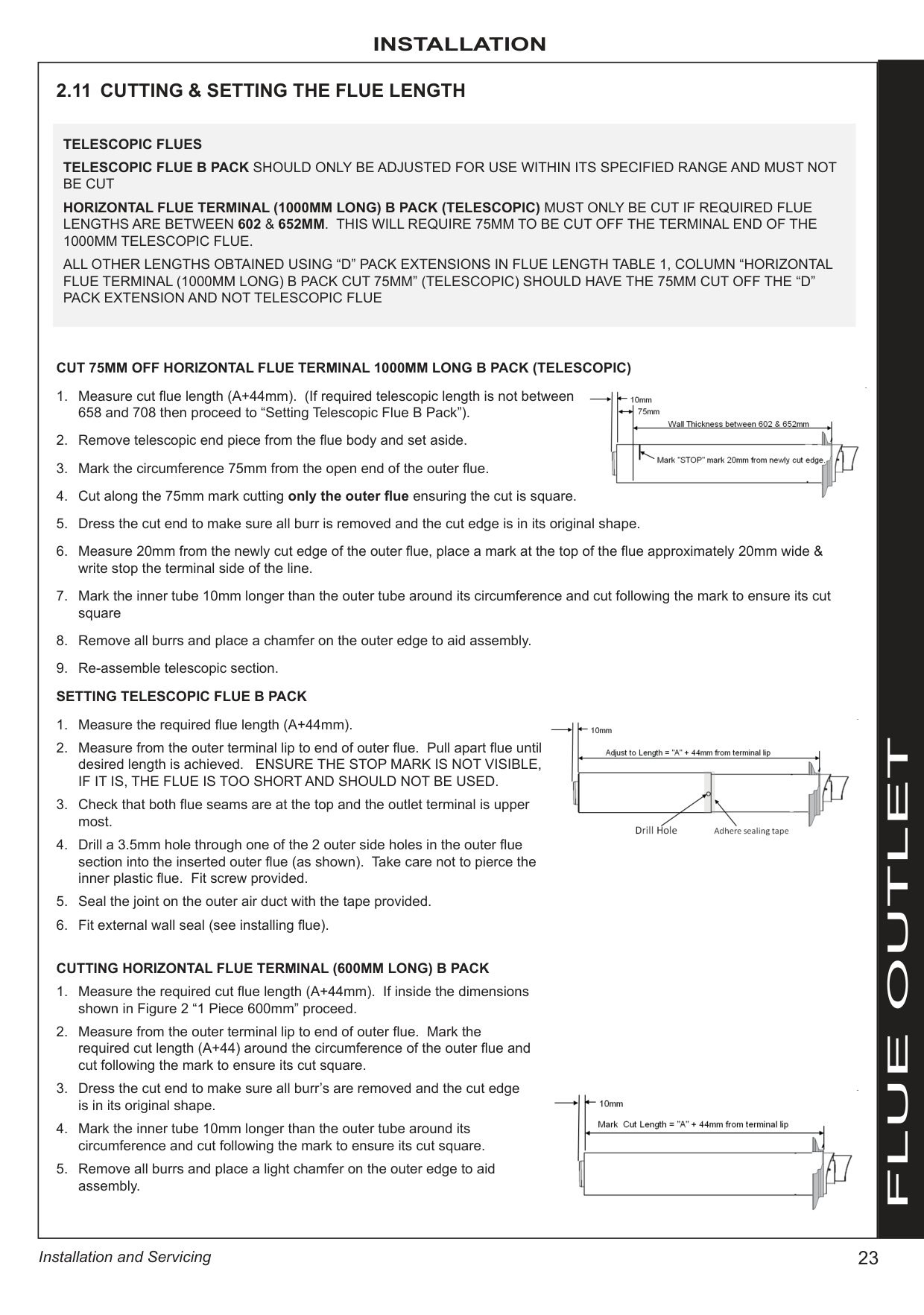
CUT 75MM OFF HORIZONTAL FLUE TERMINAL 1000MM LONG B PACK (TELESCOPIC)
1. Measure cut flue length (A+44mm). (If required telescopic length is not between 658 and 708 then proceed to “Setting Telescopic Flue B Pack”).
2. Remove telescopic end piece from the flue body and set aside.
3. Mark the circumference 75mm from the open end of the outer flue.
4. Cut along the 75mm mark cutting only the outer flue ensuring the cut is square.
5. Dress the cut end to make sure all burr is removed and the cut edge is in its original shape.
6. Measure 20mm from the newly cut edge of the outer flue, place a mark at the top of the flue approximately 20mm wide & write stop the terminal side of the line.
7. Mark the inner tube 10mm longer than the outer tube around its circumference and cut following the mark to ensure its cut square
8. Remove all burrs and place a chamfer on the outer edge to aid assembly.
9. Re-assemble telescopic section. SETTING TELESCOPIC FLUE B PACK
1. Measure the required flue length (A+44mm).
2. Measure from the outer terminal lip to end of outer flue. Pull apart flue until desired length is achieved. ENSURE THE STOP MARK IS NOT VISIBLE, IF IT IS, THE FLUE IS TOO SHORT AND SHOULD NOT BE USED.
3. Check that both flue seams are at the top and the outlet terminal is upper most.
4. Drill a 3.5mm hole through one of the 2 outer side holes in the outer flue section into the inserted outer flue (as shown). Take care not to pierce the inner plastic flue. Fit screw provided.
5. Seal the joint on the outer air duct with the tape provided.
6. Fit external wall seal (see installing flue).
CUTTING HORIZONTAL FLUE TERMINAL (600MM LONG) B PACK
1. Measure the required cut flue length (A+44mm). If inside the dimensions shown in Figure 2 “1 Piece 600mm” proceed.
2. Measure from the outer terminal lip to end of outer flue. Mark the required cut length (A+44) around the circumference of the outer flue and cut following the mark to ensure its cut square.
3. Dress the cut end to make sure all burr’s are removed and the cut edge is in its original shape.
4. Mark the inner tube 10mm longer than the outer tube around its circumference and cut following the mark to ensure its cut square.
5. Remove all burrs and place a light chamfer on the outer edge to aid assembly.
TELESCOPIC FLUES TELESCOPIC FLUE B PACK SHOULD ONLY BE ADJUSTED FOR USE WITHIN ITS SPECIFIED RANGE AND MUST NOT BE CUT HORIZONTAL FLUE TERMINAL (1000MM LONG) B PACK (TELESCOPIC) MUST ONLY BE CUT IF REQUIRED FLUE LENGTHS ARE BETWEEN 602 & 652MM. THIS WILL REQUIRE 75MM TO BE CUT OFF THE TERMINAL END OF THE 1000MM TELESCOPIC FLUE.
ALL OTHER LENGTHS OBTAINED USING “D” PACK EXTENSIONS IN FLUE LENGTH TABLE 1, COLUMN “HORIZONTAL FLUE TERMINAL (1000MM LONG) B PACK CUT 75MM” (TELESCOPIC) SHOULD HAVE THE 75MM CUT OFF THE “D” PACK EXTENSION AND NOT TELESCOPIC FLUE


|FLUE OUTLET| |---|---|
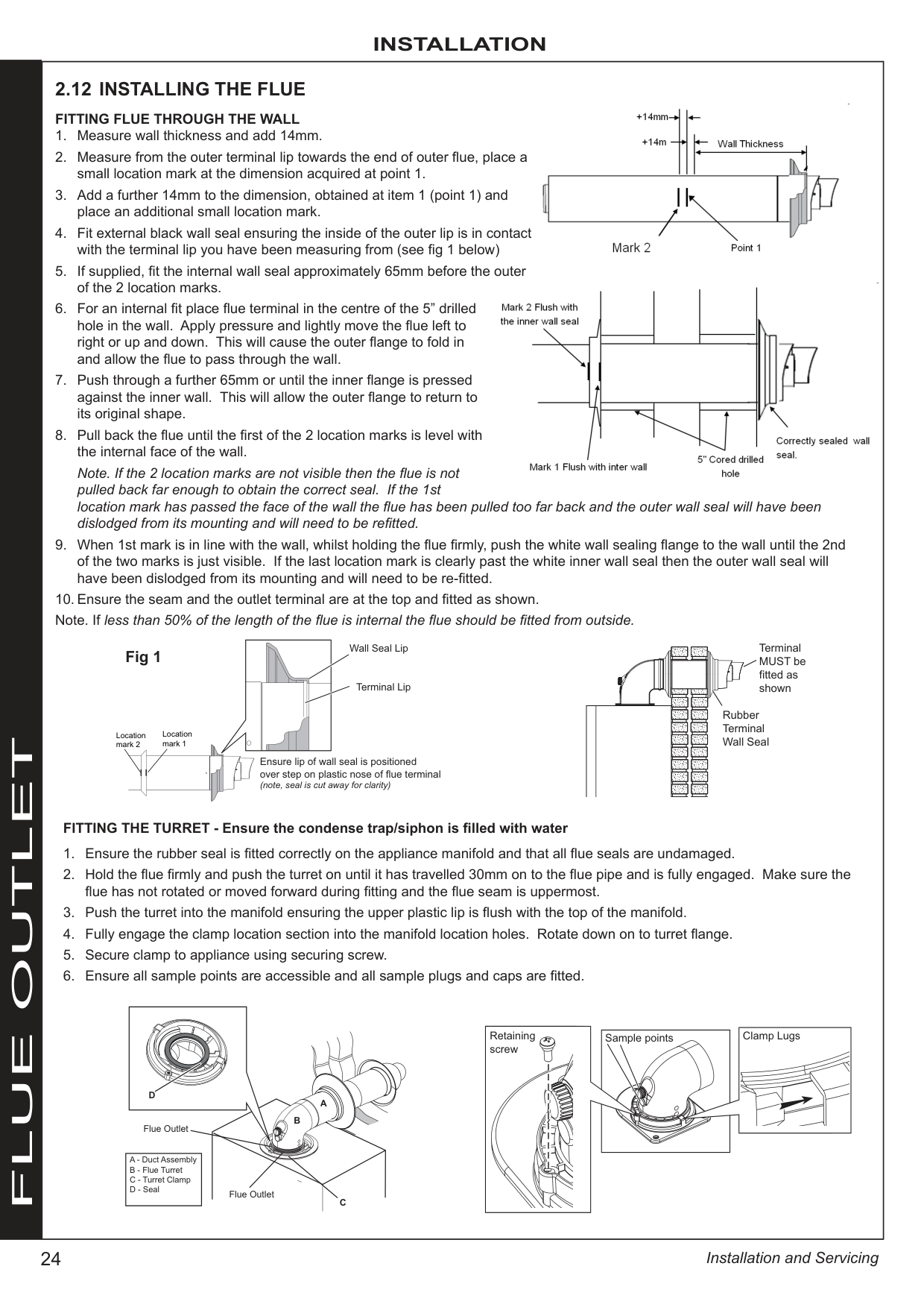
############# 2.12 INSTALLING THE FLUEFITTING FLUE THROUGH THE WALL

Note. If the 2 location marks are not visible then the flue is not pulled back far enough to obtain the correct seal. If the 1st location mark has passed the face of the wall the flue has been pulled too far back and the outer wall seal will have been dislodged from its mounting and will need to be refitted.

Wall Seal Lip
Terminal MUST be fitted as shown
################# Fig 1
Terminal Lip
Rubber Terminal Wall Seal
Location mark 1
Location mark 2
##### FLUE OUTLET
Ensure lip of wall seal is positioned over step on plastic nose of flue terminal (note, seal is cut away for clarity)
###################### FITTING THE TURRET - Ensure the condense trap/siphon is filled with water
Retaining screw
Clamp Lugs
|Sample points
| |---|
| | | |---|---| | | |
D
A
B
Flue Outlet
|A - Duct Assembly
B - Flue Turret
C - Turret Clamp
D - Seal
| |---|
| | | |---|---| | | |
Flue Outlet
C
Note.
A flat or pitched roof flashing plate (not supplied) is required before proceeding with the installation of this kit.
This kit is suitable for both flat and pitched roof terminations, using a concentric flue to run vertically from the top of the boiler and terminating above roof level.
Connection to the top of the boiler is made using a separately supplied vertical connector.
###################### WEATHER PROOFING
Where the flue passes through the roof line an adequate seal must be made. This is achieved by using either:
###################### ACCESSORIES
Flue Duct Extension Kits are available for flue lengths extending beyond 1m. These packs contain 1m extension ducts and may be cut to the desired length.
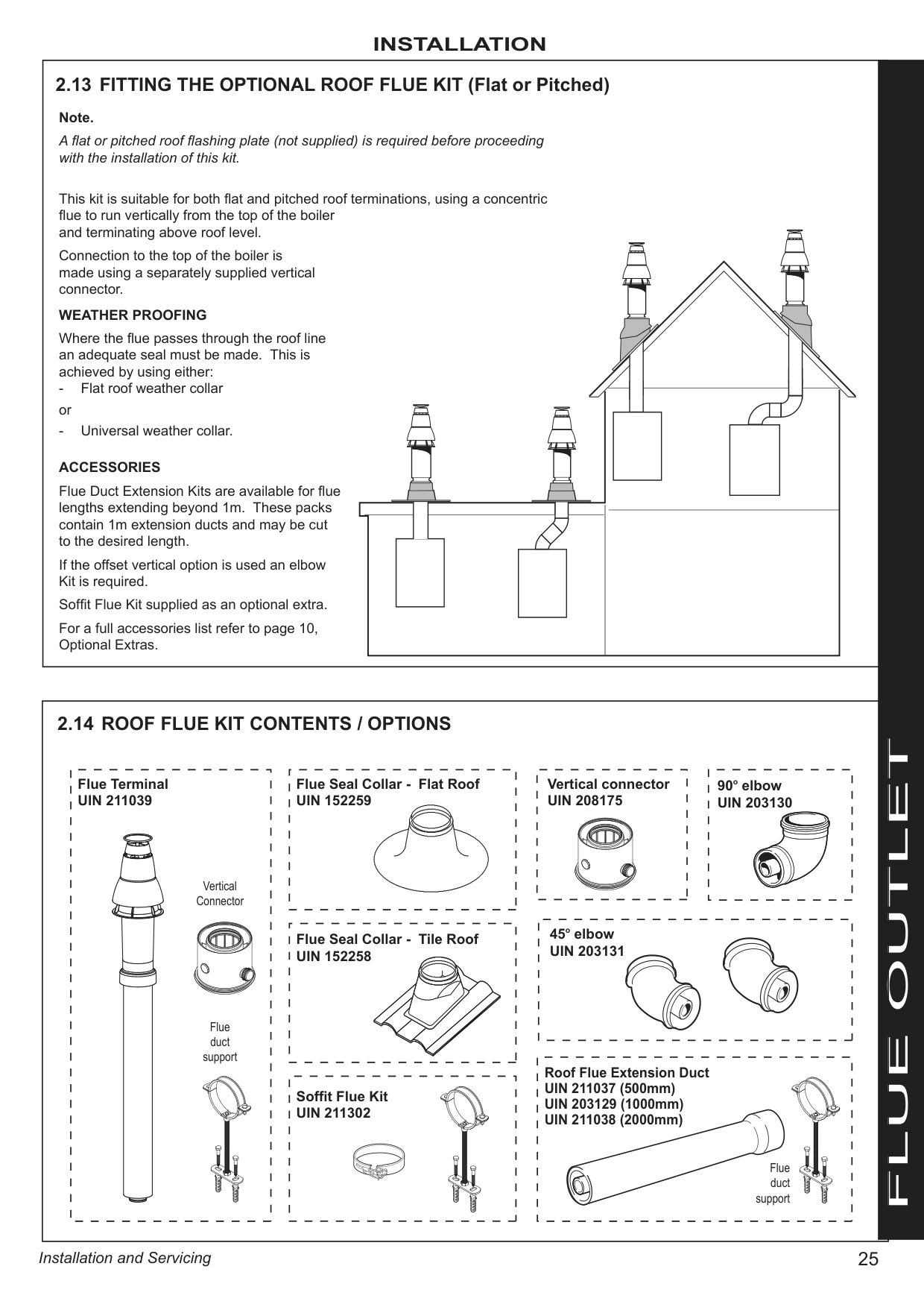
If the offset vertical option is used an elbow Kit is required.
Soffit Flue Kit supplied as an optional extra. For a full accessories list refer to page 10, Optional Extras.
|Flue duct support
Vertical Connector
Flue Terminal UIN 211039| |---|
|Flue Seal Collar - Flat Roof UIN 152259| |---|
|Flue Seal Collar - Tile Roof UIN 152258| |---|
|Soffit Flue Kit UIN 211302
| |---|
|Vertical connector UIN 208175| |---|
|90o elbow UIN 203130| |---|
|45o elbow UIN 203131| |---|
|Flue duct
support
Roof Flue Extension Duct
UIN 211037 (500mm) UIN 203129 (1000mm)
UIN 211038 (2000mm)
| |---|
FLUE OUTLET
|FLUE OUTLET| |rf8394-1
690mm Fixed
300mm min
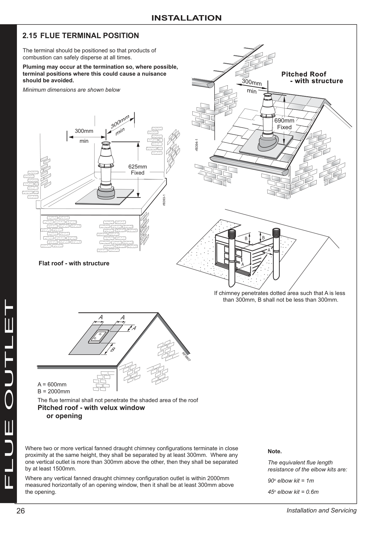
2.15 FLUE TERMINAL POSITION
rf8393-1
300mm min
300mm min
|625|m| |---|---| |Fi|ed|
Flat roof - with structure
The terminal should be positioned so that products of combustion can safely disperse at all times.
Pluming may occur at the termination so, where possible, terminal positions where this could cause a nuisance should be avoided.
Minimum dimensions are shown below
RF9807
A A
B
A
A = 600mm
B = 2000mm The flue terminal shall not penetrate the shaded area of the roof
Note.
The equivalent flue length resistance of the elbow kits are:
90o elbow kit = 1m 45o elbow kit = 0.6m

If chimney penetrates dotted area such that A is less than 300mm, B shall not be less than 300mm.
Where two or more vertical fanned draught chimney configurations terminate in close proximity at the same height, they shall be separated by at least 300mm. Where any one vertical outlet is more than 300mm above the other, then they shall be separated by at least 1500mm.
Where any vertical fanned draught chimney configuration outlet is within 2000mm measured horizontally of an opening window, then it shall be at least 300mm above the opening.
Pitched roof - with velux window or opening| |---|---|---|
############# 2.16 ASSEMBLING THE ROOF FLUE KIT
| | | |---|---| |AX L 7.|NGTH: m|
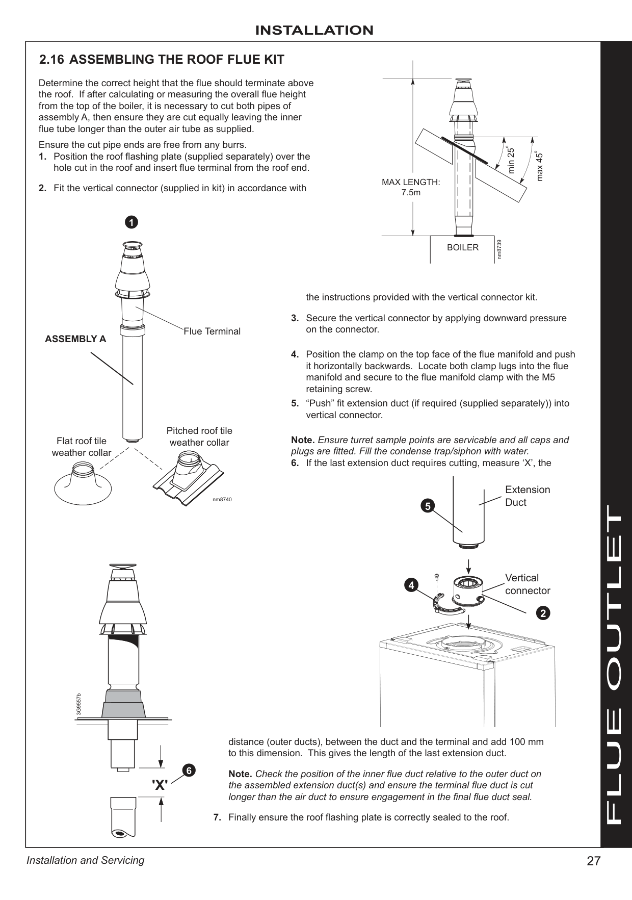
Determine the correct height that the flue should terminate above the roof. If after calculating or measuring the overall flue height from the top of the boiler, it is necessary to cut both pipes of assembly A, then ensure they are cut equally leaving the inner flue tube longer than the outer air tube as supplied.
| | | | | | | |---|---|---|---|---|---| | | | | |o| | | | | | |o| |
Ensure the cut pipe ends are free from any burrs.
min 25
max 45o
##################### 1
| | | | | |---|---|---|---| | |BOILER|BOILER|BOILER|
nm8739
the instructions provided with the vertical connector kit.
Note. Ensure turret sample points are servicable and all caps and plugs are fitted. Fill the condense trap/siphon with water.
Flue Terminal
ASSEMBLY A
Pitched roof tile weather collarFlat roof tile
weather collar
Extension Duct
nm8740
5
FLUE OUTLET
Vertical connector
4
2
3G9557b
distance (outer ducts), between the duct and the terminal and add 100 mm to this dimension. This gives the length of the last extension duct.
6
Note. Check the position of the inner flue duct relative to the outer duct on
the assembled extension duct(s) and ensure the terminal flue duct is cut longer than the air duct to ensure engagement in the final flue duct seal.
'X'
############# 2.17 CONDENSATE DRAIN
############# INSTALLATION
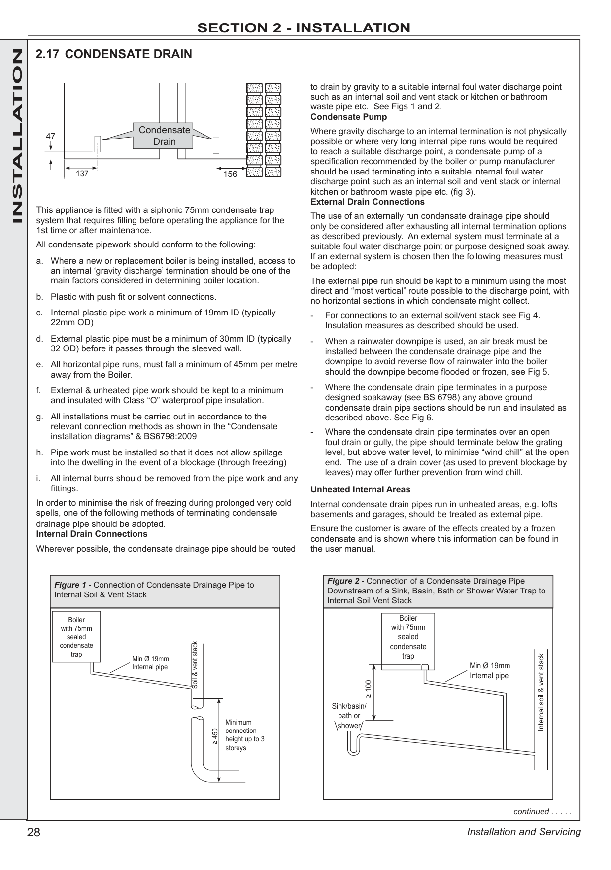
to drain by gravity to a suitable internal foul water discharge point such as an internal soil and vent stack or kitchen or bathroom waste pipe etc. See Figs 1 and 2. Condensate Pump
Condensate Drain
Where gravity discharge to an internal termination is not physically possible or where very long internal pipe runs would be required to reach a suitable discharge point, a condensate pump of a specification recommended by the boiler or pump manufacturer should be used terminating into a suitable internal foul water discharge point such as an internal soil and vent stack or internal kitchen or bathroom waste pipe etc. (fig 3). External Drain Connections
47
137
156
This appliance is fitted with a siphonic 75mm condensate trap system that requires filling before operating the appliance for the 1st time or after maintenance.
The use of an externally run condensate drainage pipe should only be considered after exhausting all internal termination options as described previously. An external system must terminate at a suitable foul water discharge point or purpose designed soak away. If an external system is chosen then the following measures must be adopted:
All condensate pipework should conform to the following:
The external pipe run should be kept to a minimum using the most direct and “most vertical” route possible to the discharge point, with no horizontal sections in which condensate might collect.
######################## Unheated Internal Areas
In order to minimise the risk of freezing during prolonged very cold spells, one of the following methods of terminating condensate drainage pipe should be adopted. Internal Drain Connections
Internal condensate drain pipes run in unheated areas, e.g. lofts basements and garages, should be treated as external pipe.
Ensure the customer is aware of the effects created by a frozen condensate and is shown where this information can be found in the user manual.
Wherever possible, the condensate drainage pipe should be routed
|Figure 1 - Connection of Condensate Drainage Pipe to Internal Soil & Vent Stack| |---| ||Boiler with 75mm sealed condensate trap| |---|
Min Ø 19mm Internal pipe
Minimum connection height up to 3 storeys
Soil & vent stack
≥ 450
|
|Figure 2 - Connection of a Condensate Drainage Pipe Downstream of a Sink, Basin, Bath or Shower Water Trap to Internal Soil Vent Stack| |---| |Sink/basin/ bath or shower
Boiler with 75mm sealed condensate trap
Min Ø 19mm Internal pipe
Internal soil & vent stack
≥ 100
|
continued . . . . .
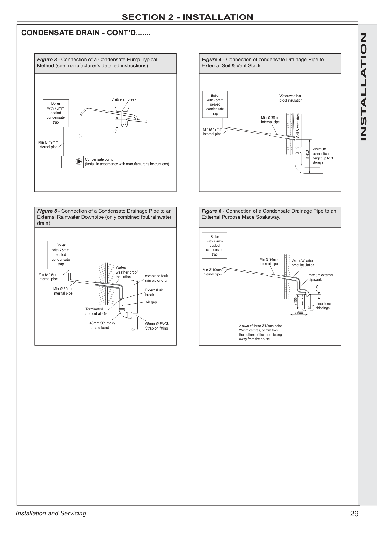
|CONDENSATE DRAIN - CONT’D.......
|Figure 3 - Connection of a Condensate Pump Typical Method (see manufacturer’s detailed instructions)| |---| |Visible air break
| | | |---|---| | | |
Condensate pump (Install in accordance with manufacturer’s instructions)
Min Ø 19mm Internal pipe
|Boiler with 75mm sealed condensate trap| |---|
75|
|Figure 5 - Connection of a Condensate Drainage Pipe to an External Rainwater Downpipe (only combined foul/rainwater drain)| |---| |Min Ø 19mm Internal pipe
|Boiler with 75mm sealed condensate trap| |---|
Min Ø 30mm Internal pipe
Air gap
External air break
combined foul/ rain water drain
Terminated and cut at 45º
43mm 90º male/ female bend
Water/ weather proof insulation
68mm Ø PVCU Strap on fitting
|
|Figure 6 - Connection of a Condensate Drainage Pipe to an External Purpose Made Soakaway.| |---| ||Boiler with 75mm sealed condensate trap| |---|
Min Ø 19mm Internal pipe
Min Ø 30mm Internal pipe
Water/Weather proof insulation
Max 3m external pipework
Limestone chippings
≥ 500
≥ 300
≥ 25
2 rows of three Ø12mm holes 25mm centres, 50mm from the bottom of the tube, facing away from the house|
|Figure 4 - Connection of condensate Drainage Pipe to External Soil & Vent Stack|
|---| |Minimum connection height up to 3 storeys
Soil & vent stack
≥ 450
|Boiler with 75mm sealed condensate trap| |---|
Min Ø 19mm Internal pipe
Min Ø 30mm Internal pipe
Water/weather proof insulation
|
|INSTALLATION| |---|---|
|INSTALLATION|Safety Drain Valve
Black Handle Yellow
Handle
Black Handle
Blue Handle
DHW Outlet
Gas Supply
CH Return
DHW Inlet
Gas Pressure Test Point
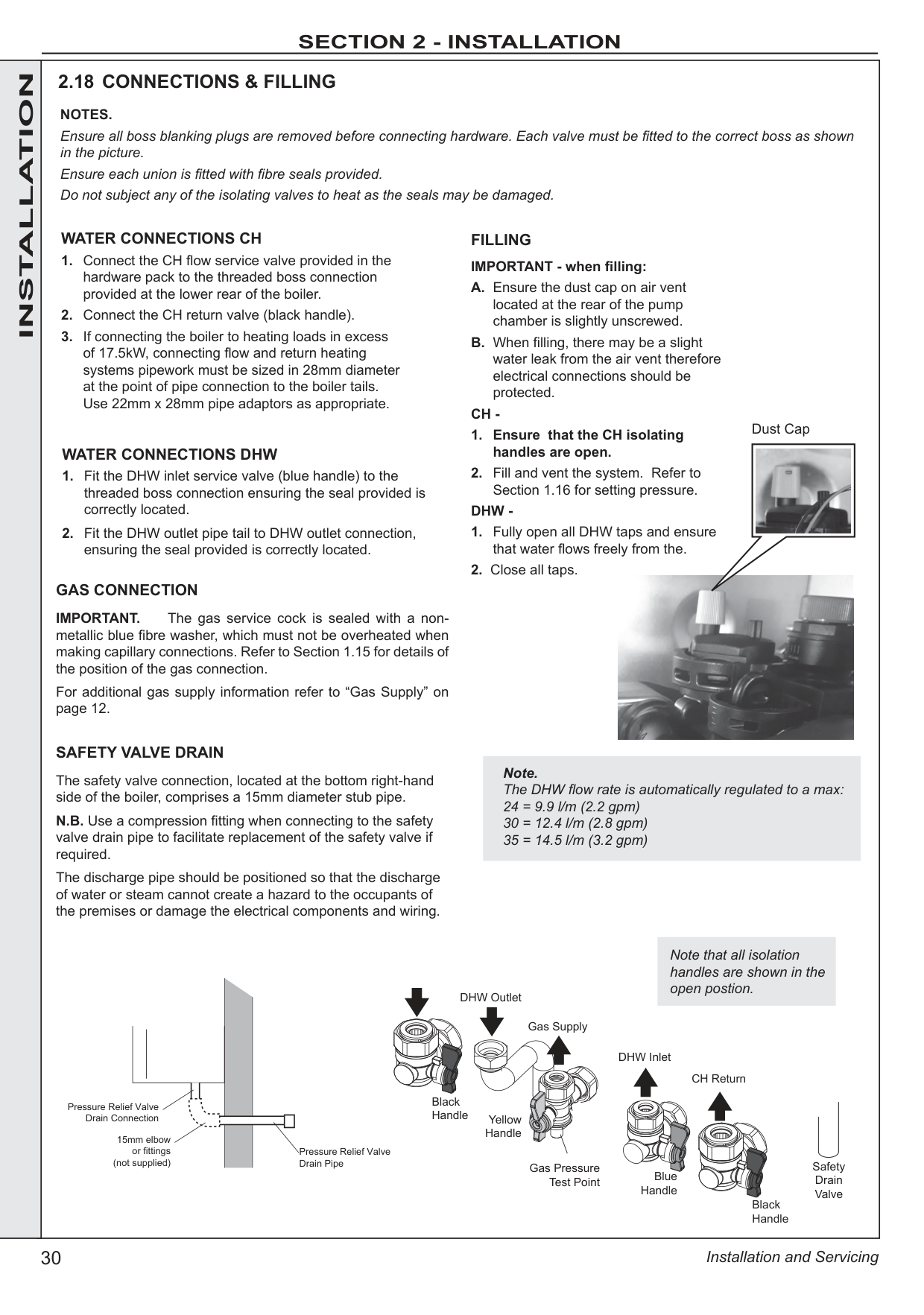
2.18 CONNECTIONS & FILLING NOTES. Ensure all boss blanking plugs are removed before connecting hardware. Each valve must be fitted to the correct boss as shown in the picture. Ensure each union is fitted with fibre seals provided. Do not subject any of the isolating valves to heat as the seals may be damaged.
WATER CONNECTIONS CH
1. Connect the CH flow service valve provided in the hardware pack to the threaded boss connection provided at the lower rear of the boiler.
2. Connect the CH return valve (black handle).
3. If connecting the boiler to heating loads in excess of 17.5kW, connecting flow and return heating systems pipework must be sized in 28mm diameter at the point of pipe connection to the boiler tails. Use 22mm x 28mm pipe adaptors as appropriate.
GAS CONNECTION
IMPORTANT. The gas service cock is sealed with a nonmetallic blue fibre washer, which must not be overheated when making capillary connections. Refer to Section 1.15 for details of the position of the gas connection.
For additional gas supply information refer to “Gas Supply” on page 12.
SAFETY VALVE DRAIN
The safety valve connection, located at the bottom right-hand side of the boiler, comprises a 15mm diameter stub pipe.
N.B. Use a compression fitting when connecting to the safety valve drain pipe to facilitate replacement of the safety valve if required.
The discharge pipe should be positioned so that the discharge of water or steam cannot create a hazard to the occupants of the premises or damage the electrical components and wiring.
FILLING IMPORTANT - when filling:
A. Ensure the dust cap on air vent located at the rear of the pump chamber is slightly unscrewed.
B. When filling, there may be a slight water leak from the air vent therefore electrical connections should be protected.
CH -
1. Ensure that the CH isolating handles are open.
2. Fill and vent the system. Refer to Section 1.16 for setting pressure.
DHW -
1. Fully open all DHW taps and ensure that water flows freely from the.
2. Close all taps.
WATER CONNECTIONS DHW
1. Fit the DHW inlet service valve (blue handle) to the threaded boss connection ensuring the seal provided is correctly located.
2. Fit the DHW outlet pipe tail to DHW outlet connection, ensuring the seal provided is correctly located.
Note. The DHW flow rate is automatically regulated to a max: 24 = 9.9 l/m (2.2 gpm) 30 = 12.4 l/m (2.8 gpm) 35 = 14.5 l/m (3.2 gpm)
Note that all isolation handles are shown in the open postion.
Pressure Relief Valve Drain Connection
15mm elbow
or fittings (not supplied)
Pressure Relief Valve Drain Pipe

Dust Cap
| |---|---|
|2.19 ELECTRICAL CONNECTIONS
WARNING. This appliance MUST be earthed. A mains supply of 230Vac ~ 50 Hz is required. The fuse rating should be 3A. All external controls and wiring must be suitable for mains voltage. Wiring external to the boiler MUST be in accordance with the current I.E.E. (BS.7671) Wiring Regulations and any local regulations.
Wiring should be 3 core PVC insulated cable, not less than 0.75mm2 (24 x 0.2mm), and to BS 6500 Table 16. For IE reference should be made to the current ETCI rules for electrical installations.
Connection must be made in a way that allows complete isolation of the electrical supply such as a double pole switch having a 3mm contact separation in both poles. The means of isolation must be accessible to the user after installation.|INSTALLATION| |---|---| | |INSTALLATION| |
2.20 INTERNAL
A mains cable must be connected to a permanent live supply and NOT switched by thermostats/

programmers. To do so follow the instructions below:
1. Swing the lower front panel down. Refer to Section 3.2.
2. Route cable through the grommet and cable clamp and tighten to provide cord anchorage.
3. Connect the live, neutral and earth wires to the terminal strip. When making the mains electrical connections to the boiler it is important that the wires are prepared in such a way that the earth conductor is longer than the current carrying conductors, such that if the cord anchorage should slip, the current carrying conductors become taut before the earthing conductor.
4. Swing the control box back up into the operating position and retain with the screws previously removed.
The boiler comes pre-fitted with a link wire between the room thermostat/Timer connections on the terminal strip. This creates a permanent call for heat and must be removed when adding a room thermostat.
ROOM THERMOSTAT - WIRING
1. Remove link wire between Room stat/timer terminals.
2. Connect room stat as shown in wiring diagram opposite.
3. If room stat has a neutral connection, connect this to terminal N (load) in the fused spur. FROST THERMOSTAT - WIRING
If parts of the system are vulnerable to freezing or the programmer is likely to be left off during cold weather a frost stat should be fitted in conjunction with a pipe thermostat.
1. Position the frost thermostat in a suitable position, i.e. area vulnerable to freezing.
2. Connect frost stat across terminals marked frost stat as shown in wiring diagram opposite. OPENTHERM - WIRING
1. Remove link wire and connect an Opentherm controller via the available terminals shown in the wiring diagram opposite. IMPORTANT: Do not connect 230v to these terminals or the boiler electronics will be damaged.|INSTALLATION| | |INSTALLATION| |Wiring External to the Boiler The fuse rating should be 3A. Wiring external to the boiler MUST be in accordance with the current I.E.E. (BS.7671) Wiring Regulations and any local regulations. Frost Protection
If parts of the pipework run outside the house or if the boiler will be left off for more than a day or so then a frost thermostat should be wired into the system.
The frost thermostat should be sited in a cold place but where it can sense heat from the system.
Note. If the boiler is installed in a garage it may be necessary to fit a pipe thermostat, preferably on the return pipework. Earths are not shown for clarity but must
never be omitted.
2.21 EXTERNAL ELECTRICAL CONNECTIONS
9990
|LN Room StatFrost Stat
|Mains In|Mains In|Mains In|Mains In| |---|---|---|---| | | | | |
Use of General Live for Room Stat
Room Stat Optional Frost Stat| |---| |INSTALLATION|
| | |2.22 WIRING DIAGRAM
321654321321654321654321654321876543215432154321
SERVICE
CONNECTOR
2
3
4
1
2
3
4
5
12
Chasss
Earth
TIMER
12
321
234
1
2
3
321
1
2
3
|PELV| |---|
|X4| |---|
|230V 50Hz Mans| |---|
NO. 2 B2 24V
NO. 5 A2 24V
NO. 6 B1
NO. 4 B3
NO. 3 A3
NO. 1 A1
|X6| |---|
WPS 5V
|X5| |---|
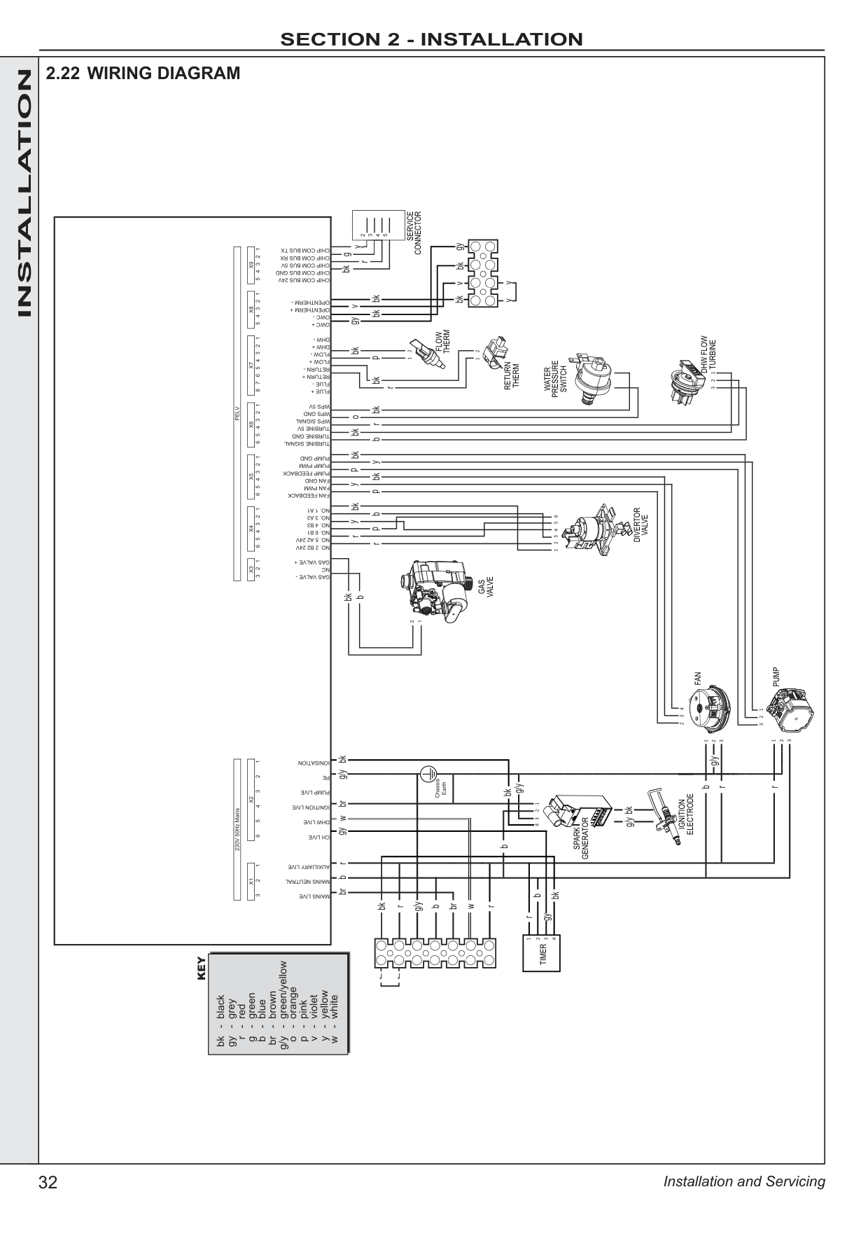
FLOW +
FAN FEEDBACK
FAN PWM
FAN GND
PUMP FEEDBACK
PUMP PWM
NC GAS VALVE -
GAS VALVE +
TURBINE SIGNAL
TURBINE GND
|X1| |---|
TURBINE 5V
CH LIVE
IGNITION LIVE
PE
|X2| |---|
PUMP LIVE
DHW LIVE
|X3| |---|
PUMP GND
|X9| |---|
|X8| |---|
OWC +
OWC -
OPENTHERM +
OPENTHERM -
CHIP COM BUS TX
CHIP COM BUS 24V
CHIP COM BUS GND
CHIP COM BUS 5V
CHIP COM BUS RX
MAINS LIVE
MAINS NEUTRAL
AUXILIARY LIVE
IONISATION
FLOW -
DHW +
DHW -
|X7| |---|
3421
123456
2
WPS SIGNAL
WPS GND
FLUE +
FLUE -
RETURN +
RETURN -
1
|black
grey
red
green
blue
brown
green/yellow
orange
pink
violet
yellow
white
-
-
-
-
-
-
-
-
-
-
-
-
bk
gy
r
g
b
br
g/y
o
p
v
y
w| |---|
KEY
DIVERTOR
VALVE
FAN
PUMP
DHW FLOW
TURBINE
WATER
PRESSURE
SWITCH
RETURN
THERM
FLOW
THERM
GAS
VALVE
SPARK
GENERATOR
IGNITION
ELECTRODE
br
g/y
g/y
g/y b
r
r
bk
bk
b g/y
b
b
bk b
gy r
r
g/y
bk
rgybk
bk
wbrbbr
w
r r
r
pbpbky ybkypbk
b bk
rp
r
o
bkbkbkbk
bk
yv
vbkgy
bk
r bkgy
g
vv
r r
| |---|---|---|
|2.23 COMMISSIONING AND TESTING
GENERAL
Please Note: The combustion for this appliance has been checked, adjusted and preset at the factory for operation on the gas type defined on the appliance data plate. DO NOT adjust the air/gas ratio valve.
Having checked:
- That the boiler has been installed in accordance with these instructions.
- The integrity of the flue system and the flue seals, as described in the Flue Installation section.
Proceed to put the boiler into operation as follows: CHECK THE OPERATIONAL (WORKING) GAS INLET PRESSURE
Set up the boiler to operate at maximum rate by opening hot tap to maximum flow.
With the boiler operating in the maximum rate condition check that the operational (working) gas pressure at the inlet gas pressure test point complies with the requirements - refer to “Gas Supply” on page 12.
Ensure that this inlet pressure can be obtained with all other gas appliances in the property working.
Black Handle Yellow
Handle
CH Flow
DHW Outlet
Gas Supply
Gas Pressure Test Point
WARNING. Whilst effecting the required gas tightness test and purging air from the gas installation, open all windows and doors, extinguish naked lights and DO NOT SMOKE.
A. Electrical Installation
1. Checks to ensure electrical safety should be carried out by a competent person.
2. ALWAYS carry out the preliminary electrical system checks, i.e. earth continuity, polarity, resistance to earth and short circuit, using a suitable test meter.
3. After wiring the boiler, all grommets in the bottom panel MUST be in place to ensure that the boiler case sealing is maintained.
B. Gas Installation
1. The whole of the gas installation, including the meter, should be inspected and tested for tightness and purged in accordance with the recommendations of IGEM/UP/1B. In IE refer to IS.813:2002.
2. Purge air from the gas installation by the approved methods only.
|ATTENTION ! IT IS A CONDITION OF THE MANUFACTURERS WARRANTY THAT THE BENCHMARK COMMISSIONING CHECKLIST IS FULLY COMPLETED AND LEFT WITH THE APPLIANCE| |---|
As part of the commissioning process, the combustion of this appliance must be checked and the Benchmark Checklist completed. A flow chart to assist is provided on page 69.| | | |---|---|---|
|INSTALLATION|2.24 INITIAL LIGHTING
THE DISPLAY
The user control has two LEDs and two 7 segment displays to inform the user about the status. The display will show the status of the boiler. The LED will show the status of the flame. If no flame is detected the LED is off. When the flame is detected the LED will be lit permanently.
Below is a list with display function in normal operation.


Standby, no demand for heat present. CH Boiler is active for central heating.

H Boiler is active for domestic hot water. FP Boiler is active for boiler frost protection. L[-] Boiler is in lockout for a specific error. F[-] Boiler has a fault for a specific error. Note: Boiler frost protection - boiler fires if temperature is below 5 degrees C.
1. Check that the system has been filled to the required pressure and that the boiler is not airlocked. Ensure the automatic air vent cap is open.
Note. It is important the burner is not operated before the system is fully vented of air. If it is necessary to operate the appliance pump to assist venting of the air this must be done with the gas service cock turned off.
2. Refit the boiler upper and lower front panels. Refer to Section 3.2.
3. Check that the drain cock is closed and that the CH and DHW isolating valves (M, L and G) are OPEN.
4. Check that the electrical supply is OFF.
5. Check that the boiler mode control knob (A) is off.
6. Check that the gas service cock (K) is OPEN.
7. Slacken the screw in the inlet pressure test point (J) and connect a gas pressure gauge via a flexible tube.
8. Switch electricity supply ON & check mechanical timer is in “Permanently On” position.
CENTRAL HEATING
9. Set the CH temp control (C) to max and turn the mode control knob (A) to . The boiler control should now go through its ignition sequence until the burner is established.
10. If the boiler does not light code L 2 will be displayed. After 5 attempts the boiler will lock out and display fault code L 2constantly. Restart the boiler (Refer to Section 2.26). The boiler will repeat its ignition sequence. If reset occurs 5 times within 15 minutes then L C will be shown. If power is removed this will be reset.
When the burner is established the BLUE ‘Burner On’ LED (E) will be illuminated, the LED display (D) will show status C H & [temp].
DOMESTIC HOT WATER
11. With the boiler firing, set the DHW Temp Control knob (B) to maximum and fully open a DHW tap.
The boiler should continue to run and the LED display (D) should show status H & [temp].
12. Ensure that with the boiler operating the dynamic gas pressure is able to obtain maximum output. Refer to Table 2.
IMPORTANT - The gas input to the burner is regulated by the gas valve according to the air flow produced by the fan. It is NOT useradjustable. Any interference to sealed settings on the gas valve will adversely affect operation and render our warranty void. For additional gas supply info refer to “Gas Supply” on page 12.
13. Turn off the DHW tap.
14. To turn on the preheat, push “preheat” button (G). A blue LED will illuminate. Press the “preheat” button again to turn off.
Note. The boiler incorporates a fan overrun cycle which MUST NOT be prematurely interrupted by isolation of the mains electricity supply.
MECHANICAL TIMER
19
20 21
22
23
24
1
2
3
4
5
6
7
8
9
10
11
1
2
1
3
1
4
15
16
17
18
Permanently ON
Permanently OFF
Timer Control
Legend
A. Domestic Hot Water Temperature Knob
B. Central Heating Temperature Knob
C. Mode Knob
D. Boiler Status Display
E. Preheat Indicator
F. Burner ‘on’ Indicator
G. Preheat On Off button
H. Restart button
J. Central Heating Economy Setting
K. Pressure Gauge
L. CH Flow Isolating Valve
M. DHW Outlet
N. Gas Inlet Pressure Test Point
O. Gas Service Cock
P. DHW Inlet Valve
Q. CH Return Isolating Valve
88
AK
L M
P
Q
ON
BDFEGH CJ
Safety Drain Valve
Black Handle
Yellow Handle
Black Handle
Blue Handle
| |---|---|
|WATER TEMPERATURES
Temperatures can be selected using the CH and DHW thermostats.
|Knob Setting|CH Flow Temp oC|DHW Outlet Temp oC| |---|---|---| |Max|80|65| |Min|30|40|
2.25 GENERAL CHECKS
DOMESTIC HOT WATER (DHW) MODE
1. Fully open all DHW taps in turn and ensure that water flows freely from them.
The display should read: H then the burner LED will illuminate when the burner lights.

2. Close all taps except the furthest one from the boiler and check that the boiler is firing at maximum rate.
This is factory set to give a DHW temperature rise of approximately 35oC at the flow rate stated on page 10 under “operation”.
3. Reduce the DHW draw-off rate to about 3 l/min (0.7gpm) and check that the boiler modulates to deliver DHW at approximately 64oC.
4. Close the DHW tap and check that the main burner extinguishes. The pump should overrun for 60 seconds and the display sequence should read: 00 When the pump stops the display sequence should read: 00
Note. On systems in excess of 2 bar inlet pressure a water pressure governor may be required to prevent water noise.
CENTRAL HEATING (CH) & DOMESTIC HOT WATER (DHW) MODE.
1. Ensure that the CH external controls are calling for heat.
The display should read: CH after first satisfying DHW preheat if necessary.
2. Fully open a DHW tap and check that hot water is delivered. The display should read: H and the burner on LED will be illuminated.

3. Gas Rate
Check the boiler gas rate when the boiler is at full DHW output.
Check at the gas meter, with no other appliance in use. Refer to Tables 2 & 3 for gas rates.
4. Close the DHW tap. The burner should go off and the pump continue to run.
5. Set the central heating external controls to OFF. The burner should go off and the pump continue to run for four minutes The display should read: 00
6. Check the correct operation of the timer and all other system controls. Operate each control separately and check that the main burner responds.
Make the following checks for correct operation in:
Due to system variations and seasonal temperature fluctuations DHW flow rates/temperature rise will vary, requiring adjustment at the draw off tap : the lower the rate the higher the temperature, and vice versa.
WATER CIRCULATION SYSTEM
1. With the system COLD, check that the initial pressure is correct to the system design requirements. For pre-pressurised systems, this should be 1.0 bar.
2. With the system HOT, examine all water connections for soundness. The system pressure will increase with temperature rise but should not exceed 2.5 bar.
3. With the system still hot, turn off the gas, water and electricity supplies to the boiler and drain down to complete the flushing process.
Note: A flushing solution should be used during the flushing procedure. Flushing solutions: Fernox Superfloc, Sentinel X300 (new systems) or X400 (existing systems). Refer to Section 1.18.
4. Refill and vent the system, add inhibitor (see Section 1.18), clear all air locks and again check for water soundness.
5. Reset the system initial pressure to the design requirement.
6. Balance the system. Refer to Section 1.17.
7. Check the condensate drain for leaks and check that it is discharging correctly.
8. Finally, set the controls to the User’s requirements.
Note: The pump will operate briefly as a self-check once every
24 hours in the absence of any system demand.| | | |---|---|---|
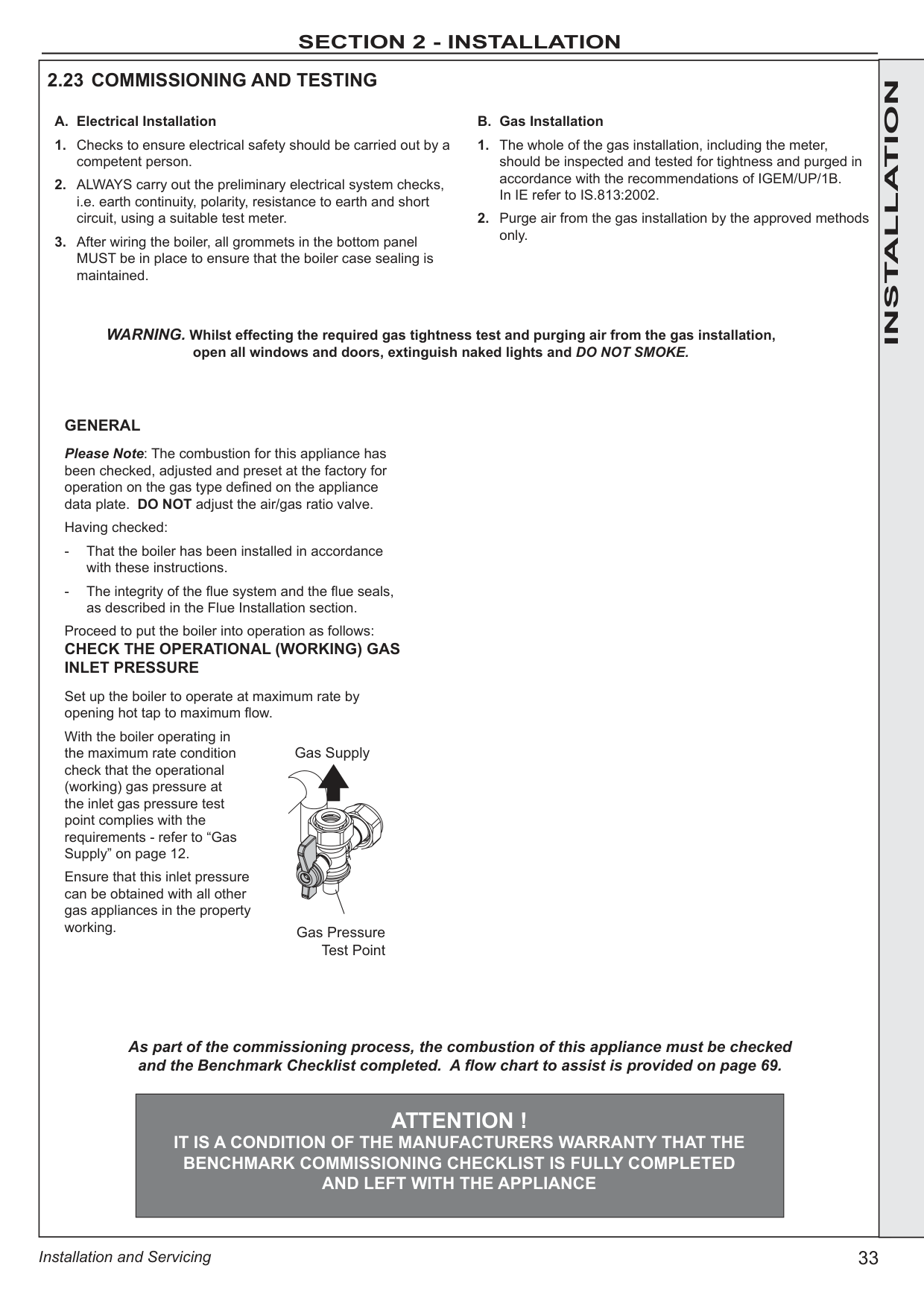
############# INSTALLATION
To restart the boiler press the restart button.
88
Restart button
After completing the installation and commissioning of the system the installer should hand over to the householder by the following actions:
Advise the User of the precautions necessary to prevent damage to the system and to the building, in the event of the system remaining inoperative during frosty conditions.
Explain that due to system variations and seasonal temperature fluctuations DHW flow rates/temperature rise will vary, requiring adjustment at the draw off tap. It is therefore necessary to draw the users attention to the section in the Users Instructions titled “Control of Water Temperature” and the following statement:
“Additionally, the temperature can be controlled by the user via the draw-off tap: the lower the rate the higher the temperature, and vice versa”.
Emphasise that if a fault is indicated refer to “Fault Codes” in the User Guide.
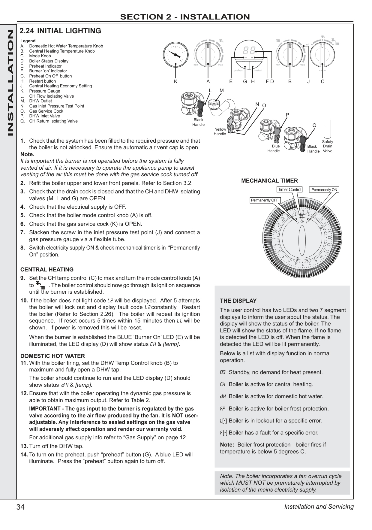
Explain that the dial underneath the boiler indicates the central heating system pressure and that if the normal COLD pressure of the system is seen to decrease over a period of time then a water leak is indicated. Explain the re-pressurising procedure and if unable to re-pressurise or if the pressure continues to drop a registered local heating installer should be consulted.
the Commissioning Checklist before handover to the customer. For IE, its is necessary to complete a “Declaration of Conformity” to indicate compliance to I.S. 813:2002.
IMPORTANT
Stress the importance of regular servicing by a Gas Safe Registered Engineer. In IE servicing work must be carried out by a Registered Gas Installer (RGII).
|3 SERVICING 3.1 SERVICING
For the very latest copy of literature for specification & maintenance practices, visit our website idealheating.com, where you will be able to download the relevant information. WARNING. Always turn OFF the gas supply at the gas service cock, and switch OFF and disconnect the electricity supply to the appliance before servicing. Combustion testing must be carried out by a competent person using a combustion analyser conforming to BS7927. To ensure the continued safe and efficient operation of the appliance it is recommended that it is checked at regular intervals and serviced as necessary. The frequency of servicing will depend upon the installation condition and usage but should be carried out at least annually. It is the law that any service work must be carried out by a Gas Safe Registered Engineer. In IE service work must be carried out by a Registered Gas Installer (RGII).
Note. In order to carry out either servicing or replacement of components the boiler front panel must be removed. Refer to Section 3.2.
PRELIMINARY INSPECTION
1. Light the boiler and carry out a pre-service check, noting any operational faults (refer to appropriate fault finding chart as necessary).
2. Check the flue terminal (and terminal guard if fitted) is undamaged and clear of any obstruction.
3. Check combustion by connecting the flue gas analyser to the flue gas sampling point as shown in the diagram and measure CO and CO2 at maximum rate. To set the boiler to Maximum and Minimum heat inputs see page 68.
If the CO / CO2 ratio is greater than 0.004 please proceed to “Cleaning Procedure”.
If the CO / CO2 ratio is less than 0.004 please proceed to “Check Procedure”.
CHECK PROCEDURE
1. Check all water and gas joints for signs of leakage. Remake any suspect joints ensuring a gas tightness check is carried out if applicable and the water system is correctly refilled, vented and re-pressurised.
2. Proceed to “IMPORTANT”. CLEANING PROCEDURE
1. Clean the main burner. Refer to Section 3.4.
2. Clean the heat exchanger & condensate trap/siphon. Refer to Section 3.5 & 3.6.
3. Check the main injector for blockage or damage. Refer to Section 3.3. ALSO IF THE DHW FLOW RATE IS IN QUESTION:
4. Check the DHW filter for blockage.
5. The cleaning procedures are covered more fully in Sections 3.3 3.7 and MUST be carried out in sequence.
6. Proceed to “IMPORTANT”. Do not operate the boiler if the front panel is not fitted. IMPORTANT
1. If, for any reason, the condensate trap/siphon has been removed, ensure the trap is refilled with water before re-assembling.
2. After completing the servicing or exchange of components always ensure all gas valve connections are gas tight with a gas soundness check up to the gas control valve.
3. When work is complete the front panel MUST be correctly refitted, ensuring that a good seal is made.
4. Complete the service section in the Benchmark Commissioning Checklist.
GENERAL Please Note: During Servicing, and after any maintenance or change of part of the combustion circuit, the following must be checked:
- The integrity of the flue system and the flue seals.
- The integrity of the boiler combustion circuit and the relevant seals.
- The operational (working) gas inlet pressure at maximum rate.
- The gas rate.
- The combustion performance.
COMPETENCE TO CARRY OUT THE CHECK OF COMBUSTION PERFORMANCE
Please Note: BS 6798:2009 Specification for installation and maintenance of gas-fired boilers of rated input not exceeding 70kW net advises that:
- The person carrying out a combustion measurement should have been assessed as competent in the use of a flue gas analyser and the interpretation of the results.
- The flue gas analyser used should be one meeting the requirements of BS7927 or BS-EN50379-3 and be calibrated in accordance with the analyser manufacturer’s requirements.
Flue Sampling Point
Air Sample Point
Ensure all caps and seals are re-fitted after use|SERVICING| |---|---|
############# 3.2 BOILER UPPER & LOWER FRONT PANEL REMOVAL / REPLACEMENT
REPLACEMENT
REMOVAL
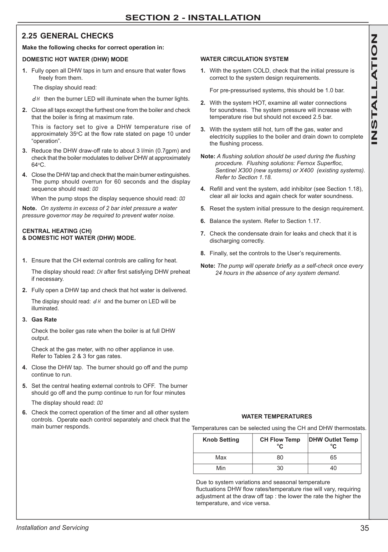
1&72&6 3&5
############# SERVICING
############# 3.3 FAN AND VENTURI ASSEMBLY REMOVAL AND CLEANING


Injector
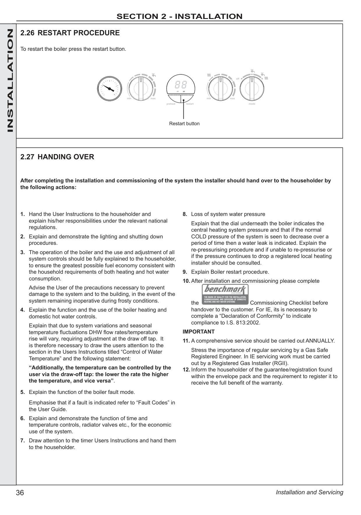

############# 3.4 BURNER REMOVAL AND CLEANING
IMPORTANT The burner head is a ceramic plaque construction. Care must be taken to ensure that the burner is not placed down upon its face as this may cause damage to the ceramic.
3

######
######


SERVICING
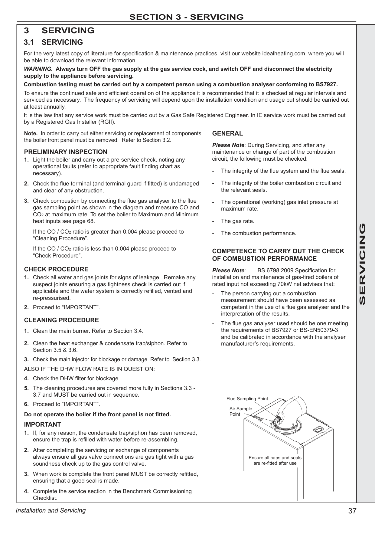
############# 3.5 CLEANING THE CONDENSATE TRAP/SIPHON
Note: Ensure condensate trap is fully drained before removal.
######

############# 3.6 CLEANING THE HEAT EXCHANGER
|
Ignition/Flame Electrode
| |---|
Note: Ensure the condensate trap/siphon is fully drained before cleaning. Refer to Section 3.19.
Earth Wire
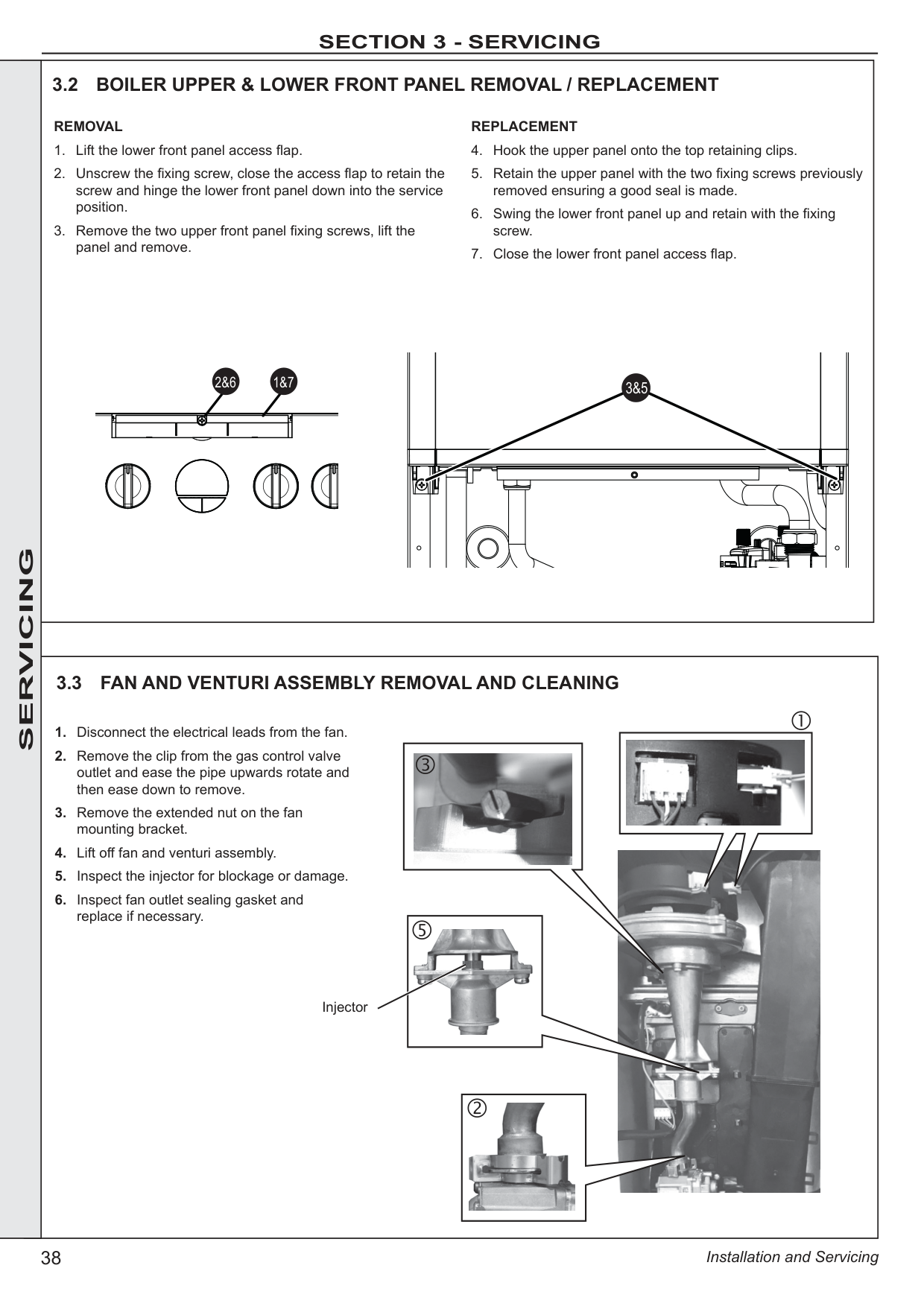

######
SERVICING
############# 3.7 REASSEMBLY
Reassemble the boiler in the following order:
IMPORTANT. Ensure that the boiler upper front panel is correctly fitted and that a good seal is made.
D
B


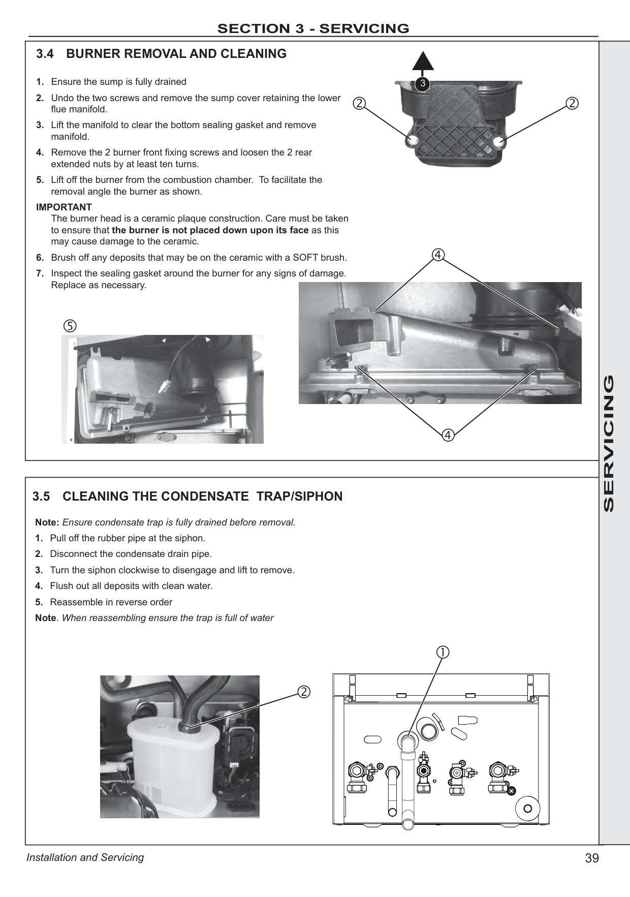
A
C
|3.8 REPLACEMENT OF COMPONENTS
GENERAL When replacing ANY component
1. Isolate the electricity supply.
2. Turn off the gas supply.
3. Remove the lower front panel fixing screws, swing the panel into the servicing position and remove the upper front panel. Refer to Section 3.2.
After replacing ANY component check operation of the boiler, including gas soundness, gas rate and combustion test.
IMPORTANT.
Ensure all gas valve connections are gas tight with a gas soundness check up to the gas control valve.
When work is complete, the front panels must be correctly refitted - ensuring that a good seal is made.
Notes.
1. In order to assist fault finding, the control panel has an LED diagnostic display.
2. In order to replace components in Sections 3.20 - 3.32 it is necessary to drain the boiler. Refer to Section 3.19.
THE BOILER MUST NOT BE OPERATED WITHOUT THE FRONT PANEL FITTED|SERVICING| |---|---| | |SERVICING| |
3.9 FAN REPLACEMENT

1. Refer to Section 3.8.
2. Disconnect the electrical leads from the fan.
3. Remove the clip from the gas control valve outlet.
4. Remove the extended nut retaining the fan mounting bracket.
5. Lift and remove the fan and venturi assembly.
6. Remove the screw and twist venturi anticlockwise to remove venturi assembly, noting the orientation of the venturi in relation to the fan body.
7. Transfer the venturi assembly to the new fan, replacing the ‘o’ ring if evidence of damage or deterioration is visible.
8. Fit the new fan / venturi assembly ensuring the retaining tabs are correctly positioned and the fan outlet sealing gasket is correctly positioned and free from damage. Refit the extended nut.
9. Reassemble the boiler in reverse order, taking care not to overtighten the screw on the fan mounting bracket and ensure all gas ‘o’ rings are in place
10. Check the operation of the boiler. Refer to Sections 2.24 & 2.25.


Retaining Tabs

|SERVICING|
|SERVICING|
3.10 BURNER INJECTOR REPLACEMENT
1. Refer to Section 3.8.
2. Disconnect the electrical leads from the fan.
3. Remove the clip from the gas valve to venturi pipe and ease the pipe upwards, rotate and ease down to remove.
4. Loosen the screw retaining the fan mounting bracket.
5. Lift and remove the fan and venturi assembly.
6. Remove the 2 injector housing screws.
7. Withdraw the injector housing.
8. Fit the new injector housing complete with injector.
9. Reassemble in reverse order, ensuring that the new gas seal supplied is located correctly in the injector housing.
10. Check operation of the boiler. Refer to Sections 2.24 & 2.25.


| |---|---| |SERVICING| | |SERVICING|
4
3.11 BURNER REPLACEMENT
1. Refer to Section 3.8.
2. Refer to Section 3.9.
3. Undo the two screws and remove the sump cover.
4. Lift the manifold to clear the bottom sealing gasket and remove manifold.
5. Remove the 2 front fixing screws and loosen the 2 rear extended nuts.
6. Lift off the burner from the combustion chamber. To facilitate the removal angle the burner as shown.
7. Fit the new burner, replacing any damaged or deteriorating sealing gasket.
8. Reassemble in reverse order.
9. Check the operation of the boiler. Refer to Sections 2.24 & 2.25.


|
|
3.12 IGNITION ELECTRODE / IONISATION DETECTION PROBE REPLACEMENT
1. Refer to Section 3.8.
2. Remove the burner. Refer to Section 3.11.
3. Unplug the ignition lead from the electrode.
4. Remove the earth lead from the ignition electrode/ionisation detection probe.
5. Remove the 2 screws holding the ignition electrode to the combustion chamber.
6. Remove the electrode.
7. Fit the new ignition electrode, using the new gasket supplied. Check dimensions as shown.
8. Reassemble in reverse order.
9. Check the operation of the boiler. Refer to Sections 2.24 & 2.25.
Ignition /IonisationElectrode
3mm
Straight edge Spark Gap
3.5mm
| |SERVICING| |---|---|---| | | | |

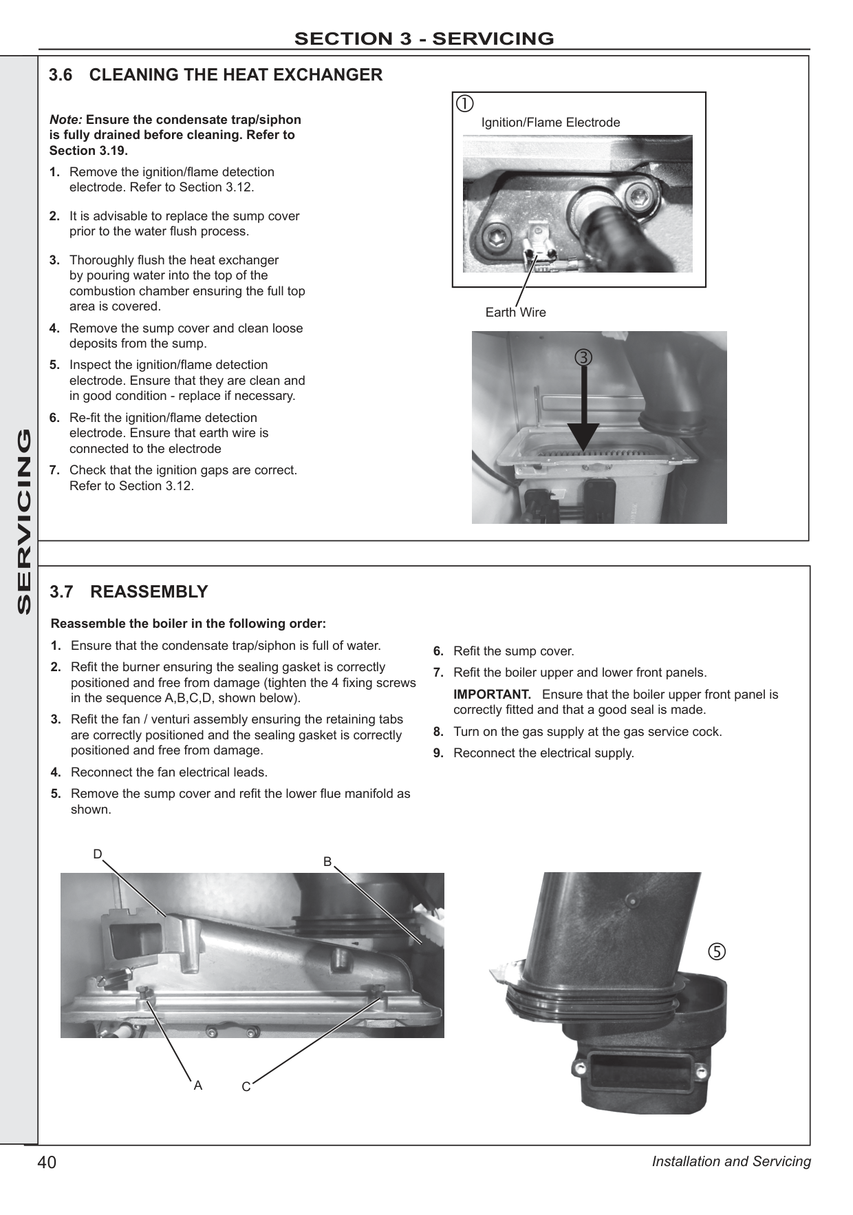
Spark Generator
######

SERVICING

######

############# 3.15 DIVERTER VALVE ACTUATOR REPLACEMENT
Refer to Section 3.8. To remove the motor:
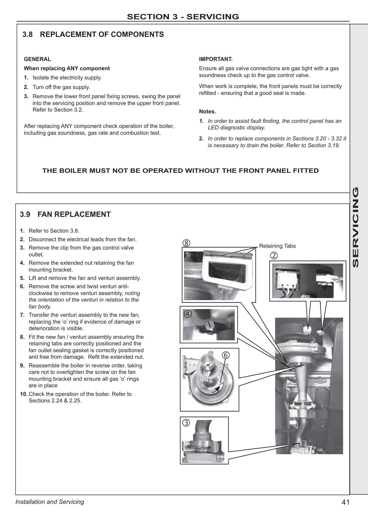


############# SERVICING
Note. All spares will be delivered in mid-position therefore ignore point 3 and proceed to point 4.
############# 3.16 CONDENSATE TRAP/SIPHON REPLACEMENT
|
| |---|
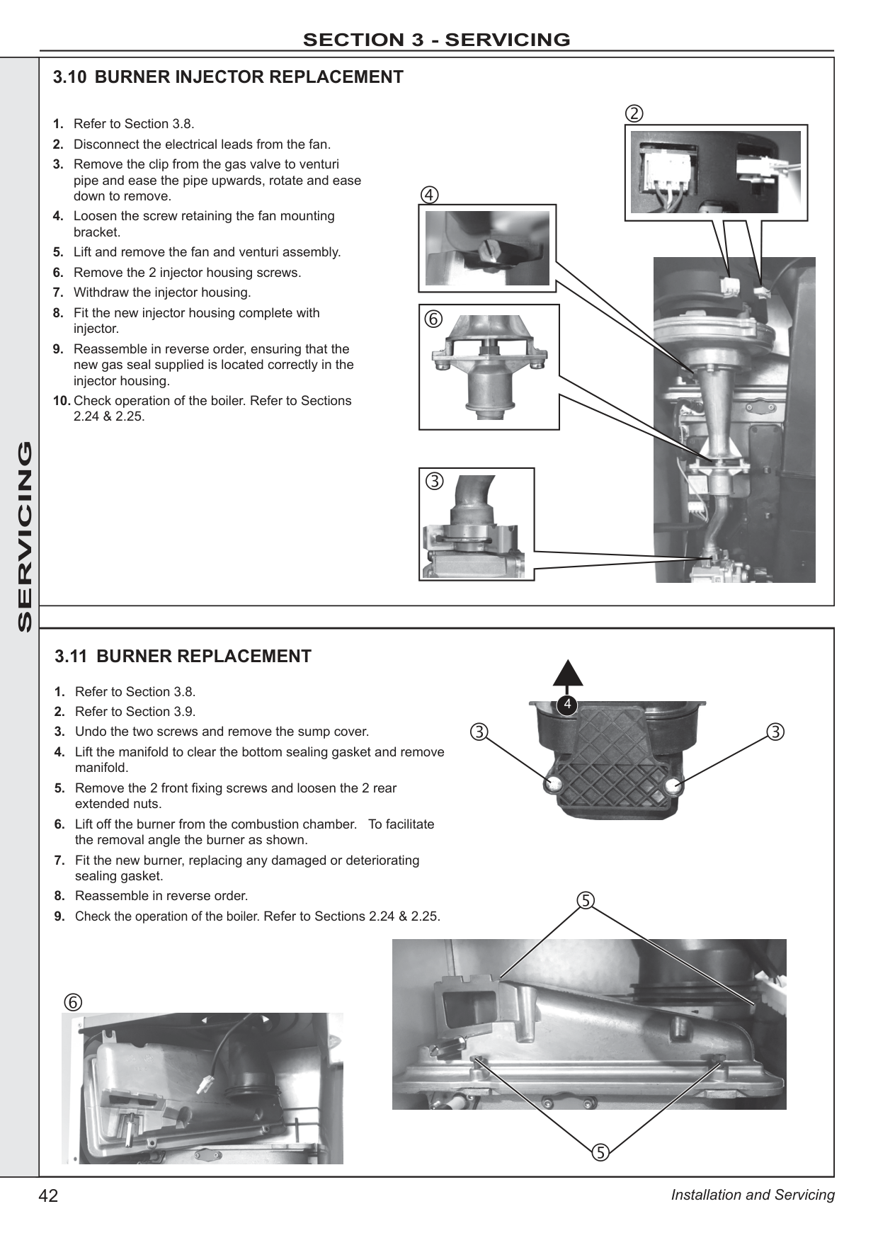
Note: Ensure condensate trap is fully drained before removal.

|SERVICING|

3.17 MAIN PCB REPLACEMENT
* Note. that production boiler PCB’s are factory pre-set to operate for boiler range and output, but when ordering PCB as a spare Note. Fit the earth strap provided with the PCB to your wrist and secure to a suitable earth on the boiler chassis.
1. Refer to Section 3.8.
2. Rotate all control knobs into the upright position.
3. Remove the 2 screws retaining the control box cover.
4. Carefully lift the cover at the front & pull forward to remove.
5. Unplug all connections to the PCB.
6. Remove the two screws that secure the PCB
7. Spring out the four side retaining clips and pull the PCB upwards to clear the retaining posts.
8. Unclip the light guide and secure this to the new PCB
9. Insert the new PCB and secure all electrical connections. Ensure control knobs are correctly aligned with PCB.
10. Reassemble in reverse order.
11. a. Turn power on, display shows uP. Rotate all three dials fully anti-clockwise.
b. Press RESTART, display shows oF
c. Turn power off
d. Turn power on, display shows F9
e. Using central heating knob, rotate clockwise to select between “C” (combi with preheat) or “ES” (combi without preheat).
f. Using central heating knob, rotate clockwise or anticlockwise to show “n” for Natural Gas, then press restart button.
g. Using central heating knob rotate clockwise or anticlockwise to show boiler size, select correct 24, 30 or 35 then press restart button.
h. Display shows “C”, “n”, Boiler size, internal number. j. Press restart. New PCB is now programmed.
12. Check operation of the boiler.
|
| |---|
| |---|---|
|
1. Refer to Section 3.8.
2. Swing the boiler lower front panel into the service position. Refer to Section 3.2.
3. Remove the 4 fixing screws.
4. Disconnect the 4 push on connectors.
5. Remove programmer, earth cable and cover.
6. Re-fit 4 push on connectors to new programmer.
7. Fit programmer and retain with 4 screws previously removed.
8. Replace the lower front panel.
9. Check operation of the boiler. Refer to Sections 2.24 & 2.25.
Note. To program refer to user guide at rear of this book.
3.18 REPLACING THE MECHANICAL TIMER
| | | |---|---|---| | | | | |3.19 DRAINING THE BOILER
DOMESTIC HOT WATER CIRCUIT
1. Refer to Section 3.8.
2. Close the DHW water isolating valve on the boiler inlet.
3. To drain the domestic hot water circuit: As there is no direct drain for the domestic hot water circuit, depending on the location of the boiler, opening the lowest hot water tap may drain this circuit. However it must be noted that some residual water will be experienced during replacement of components.
4. After replacing any component on the boiler, close tap, close the drain valve and open all system isolating valves (repressurise as appropriate)
5. Check operation of the boiler. Refer to Sections 2.24 & 2.25.
CENTRAL HEATING CIRCUIT
1. Refer to Section 3.8.
2. Close all the CH water isolating valves on the boiler inlet.
3. To drain the primary heat exchanger circuit: Open the drain valve and attach a length of hose to the CH drain point.
4. After replacing any component on the boiler, remove the hose, close the drain valve and open all system isolating valves (repressurise as appropriate).
5. Check operation of the boiler. Refer to Sections 2.24 & 2.25.
CH Return
CH Flow
DHW
InletDHW Outlet
Gas
CH Circuit Drain| | |
############# 3.20 DHW FLOW TURBINE SENSOR REPLACEMENT
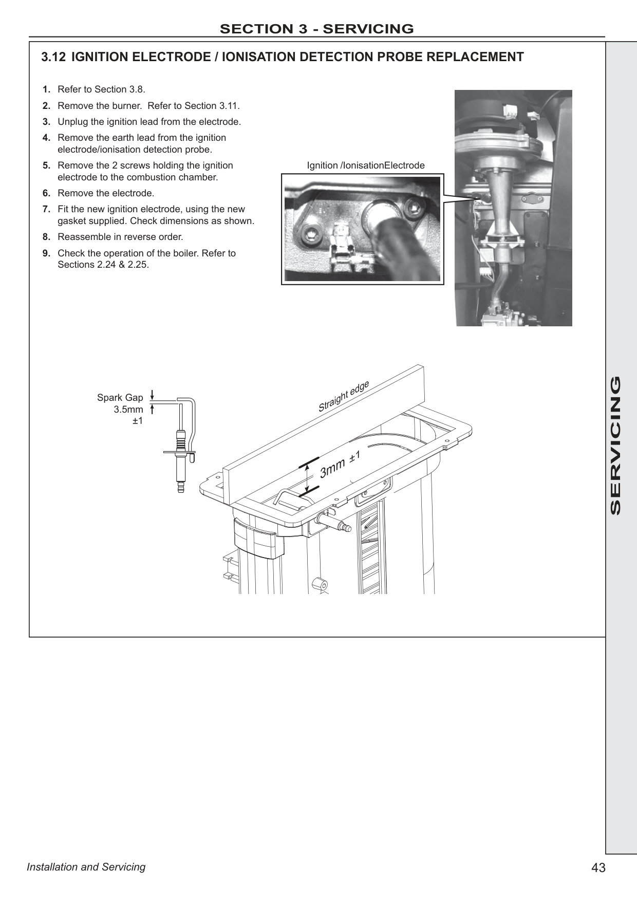
|| |---|
|
| |---|
######
######
############# SERVICING
############# 3.21 PRESSURE GAUGE REPLACEMENT
|| |---|
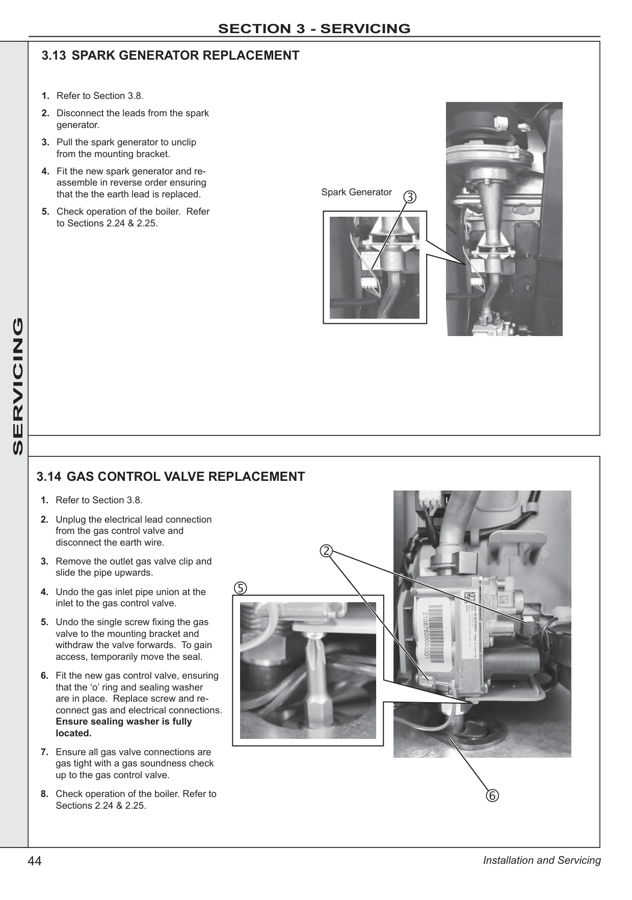
######
|| |---|
############# 3.22 SAFETY RELIEF VALVE REPLACEMENT


############# SERVICING
############# 3.23 PUMP AUTOMATIC AIR VENT REPLACEMENT
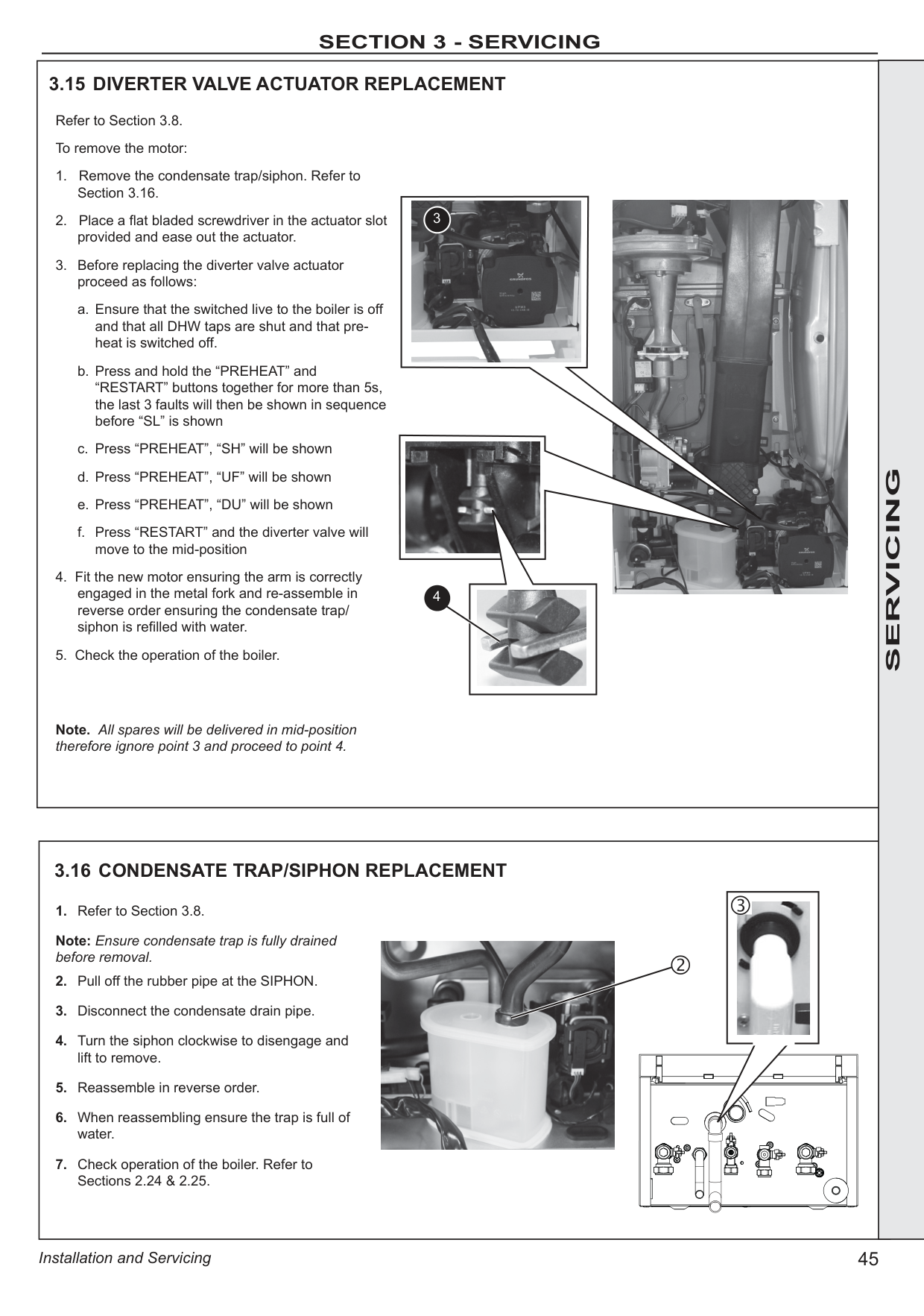

Dust Cap

############# 3.24 DIVERTER VALVE BODY ASSEMBLY REPLACEMENT
To remove the valve body assembly:
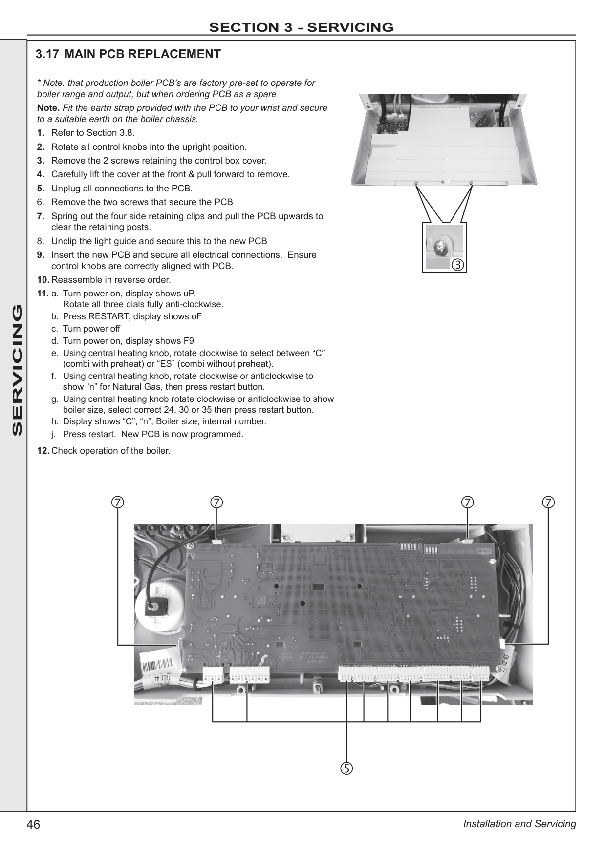
18 17
12
11
############# SERVICING
14
16
13
############# 3.25 DHW PLATE HEAT EXCHANGER REPLACEMENT
######
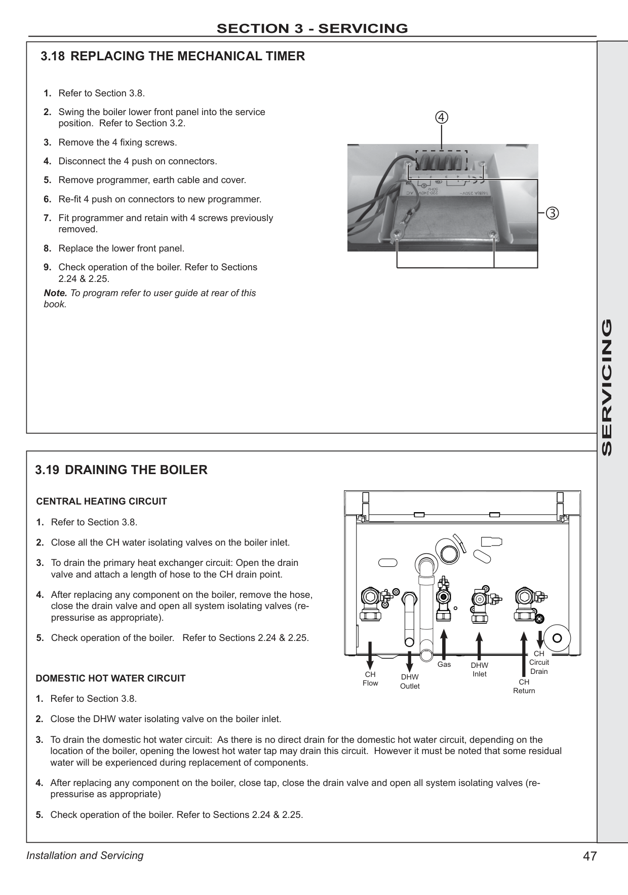
Note. Ensure dimples and “bottom” are lower most.


############# 3.26 PUMP HEAD REPLACEMENT
######
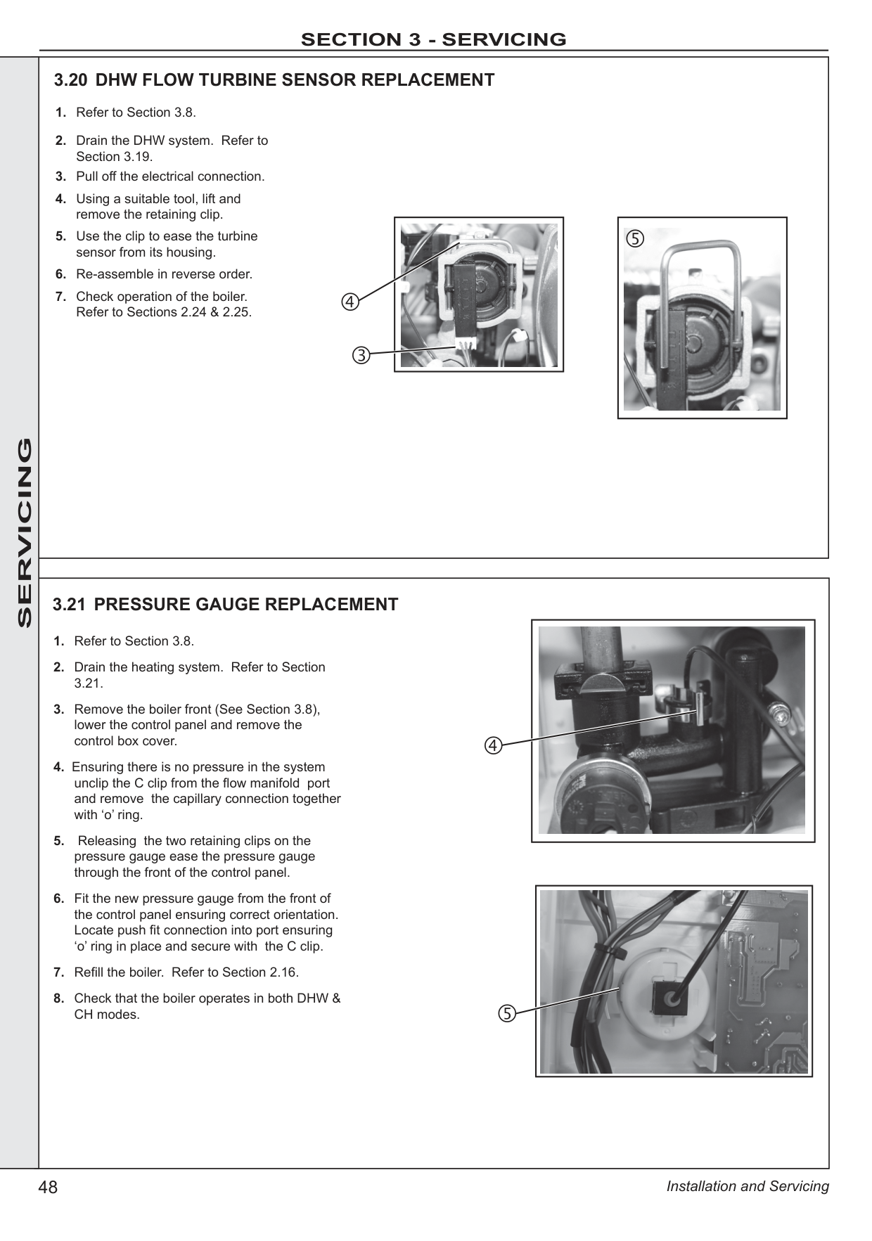

######

######

|| |---|
######

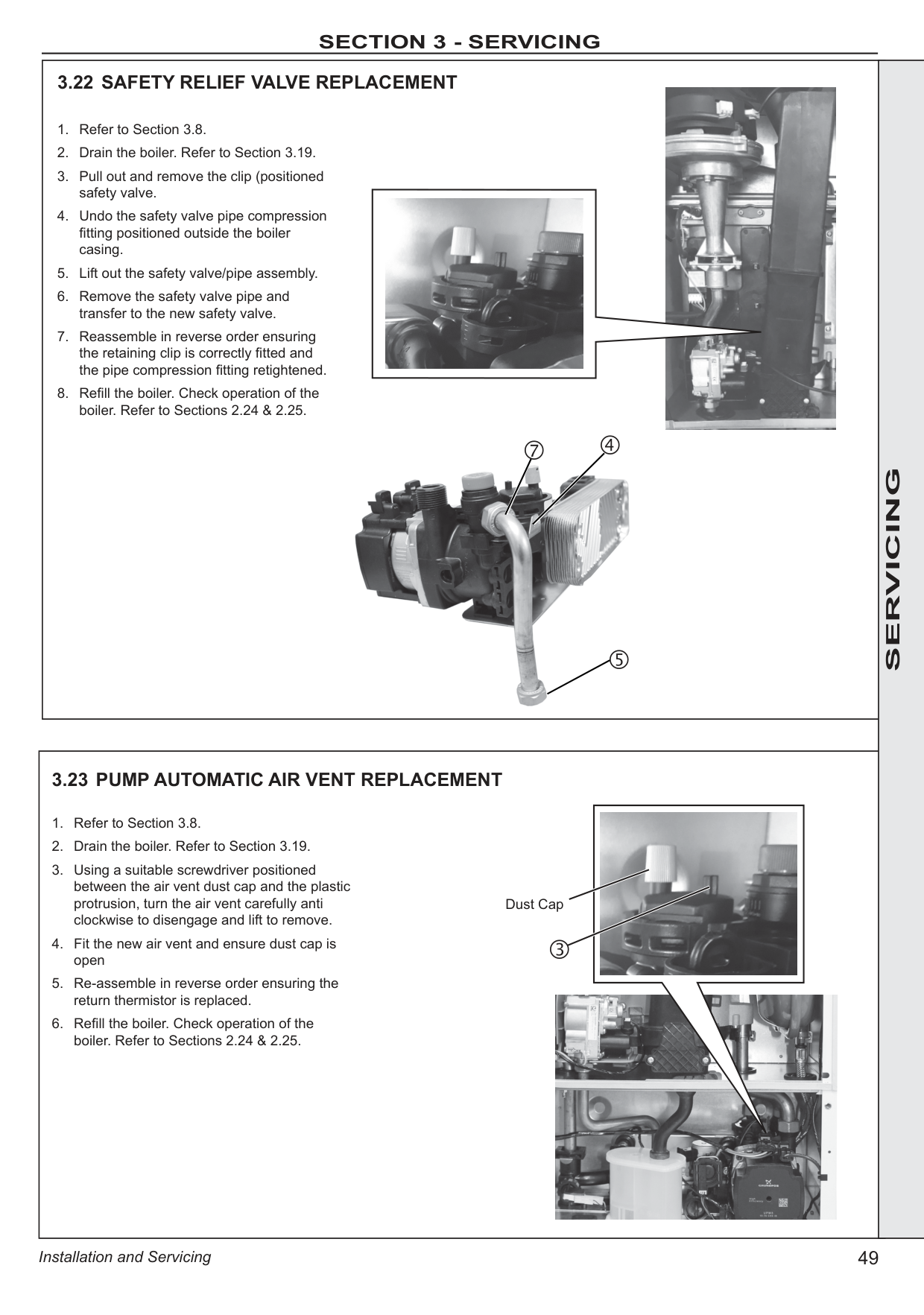
############# 3.29 FLOW THERMISTOR

######

############# SERVICING
############# 3.30 RETURN THERMISTOR REPLACEMENT REPLACEMENT
|
Thermistor Locator Tab (with thermistor fitted)
| |---|

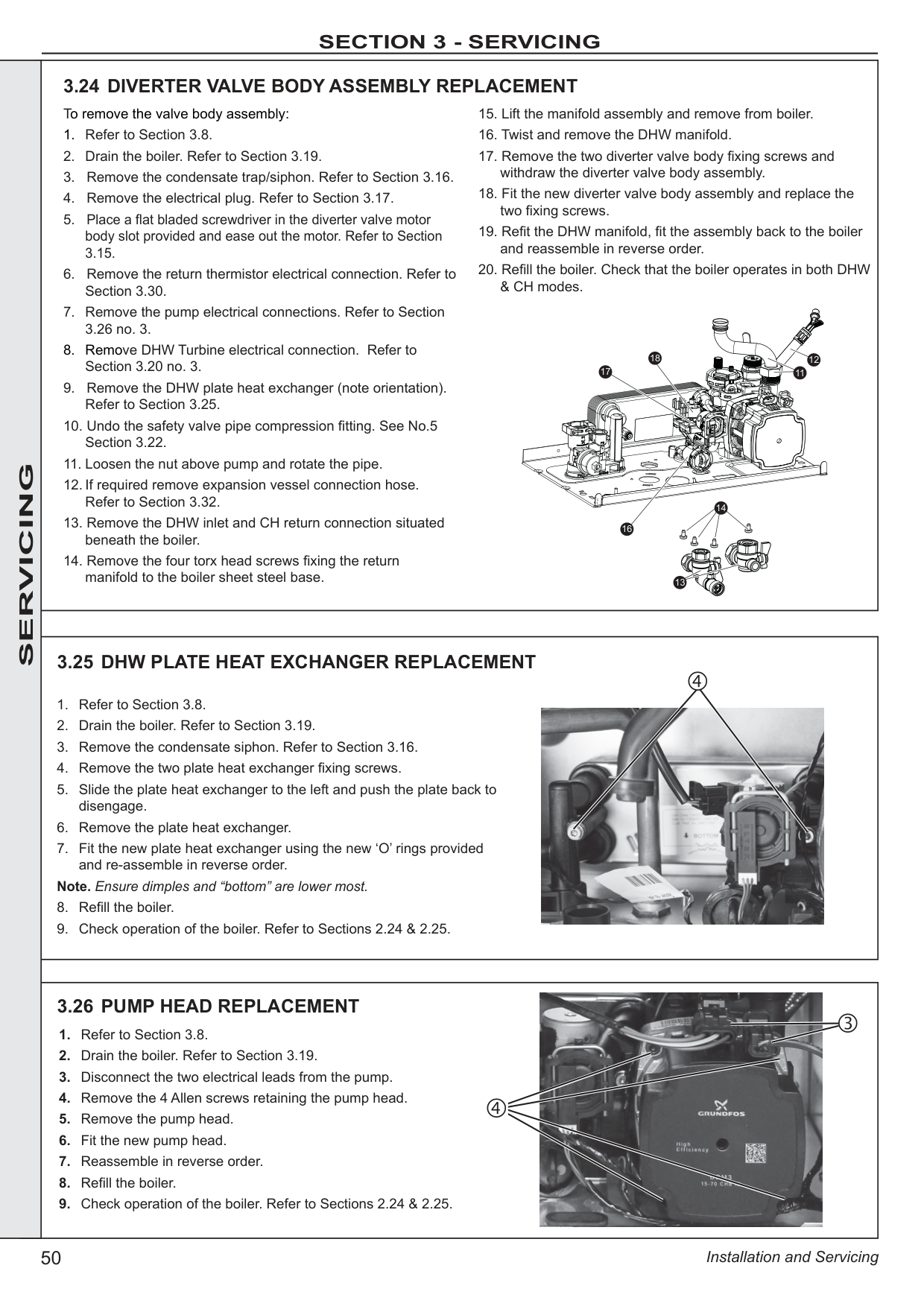

|3.31 HEAT ENGINE RENEWAL Refer also to Section 2.1 - ‘Boiler Exploded View’
IMPORTANT - Before starting the removal procedure, protect the gas and electrical controls with a waterproof sheet or plastic bag.1.Refer to Section 3.8.
2. Drain the boiler. Refer to Section 3.19.
3. Remove the fan / venturi assembly and place on one side. Refer to Section 3.9.
4. Remove burner and place on one side. Refer to Section 3.11.
5. Remove the ignition electrode. Refer to Section 3.12.
6. Remove the spark generator. Refer to Section 3.13.
7. Remove the gas valve. Refer to Section 3.14.
8. Remove the expansion vessel. Refer to Section 3.32.
9. Remove the flow thermistor. Refer to Section 3.29.
10. Remove the 2 M5 screws retaining the gas valve mounting bracket and transfer bracket to the new heat exchanger.
11. Undo the inlet pipe union nut, swing the pipe and pull down to remove from heat exchanger.
12. Pull out the flow pipe spring clip, pull the pipe down to remove from heat exchanger.
13. Remove the condensate rubber pipe from the sump.
14. Remove the two heat exchanger fixing screws.
15. To remove the Heat exchanger slide out of location bracket.
16. If replacement sump required: Rotate heat exchanger assembly 180º. Place new sump onto heat exchanger, ensuring correct orientation and seal is in place. Then gently apply pressure to the base of the sump at each tab fixing point and engage tabs onto the heat exchanger.
17. Reassemble in reverse order, ensuring the heat exchanger LH retaining bracket is correctly positioned. Replace any new ‘o’ rings supplied with new heat exchanger and replacing gaskets or seals if any sign of damage is evident. When replacing the spring clips located on the return pipe connection, ensure clip is oriented to correctly match connecting pipe diameters.
18. Ensure the trap/siphon is filled with water. Refer to Section 3.15.
19. Refill the boiler.
20. Ensure all gas valve connections are gas tight with a gas soundness check up to the gas control valve.
21. Check operation of the boiler. Refer to Sections 2.24 & 2.25.

Shown as 180º position

10
13
12
11
16
14| | | |---|---|---|
###################### RECHARGING
REPLACEMENT
Recharge Point
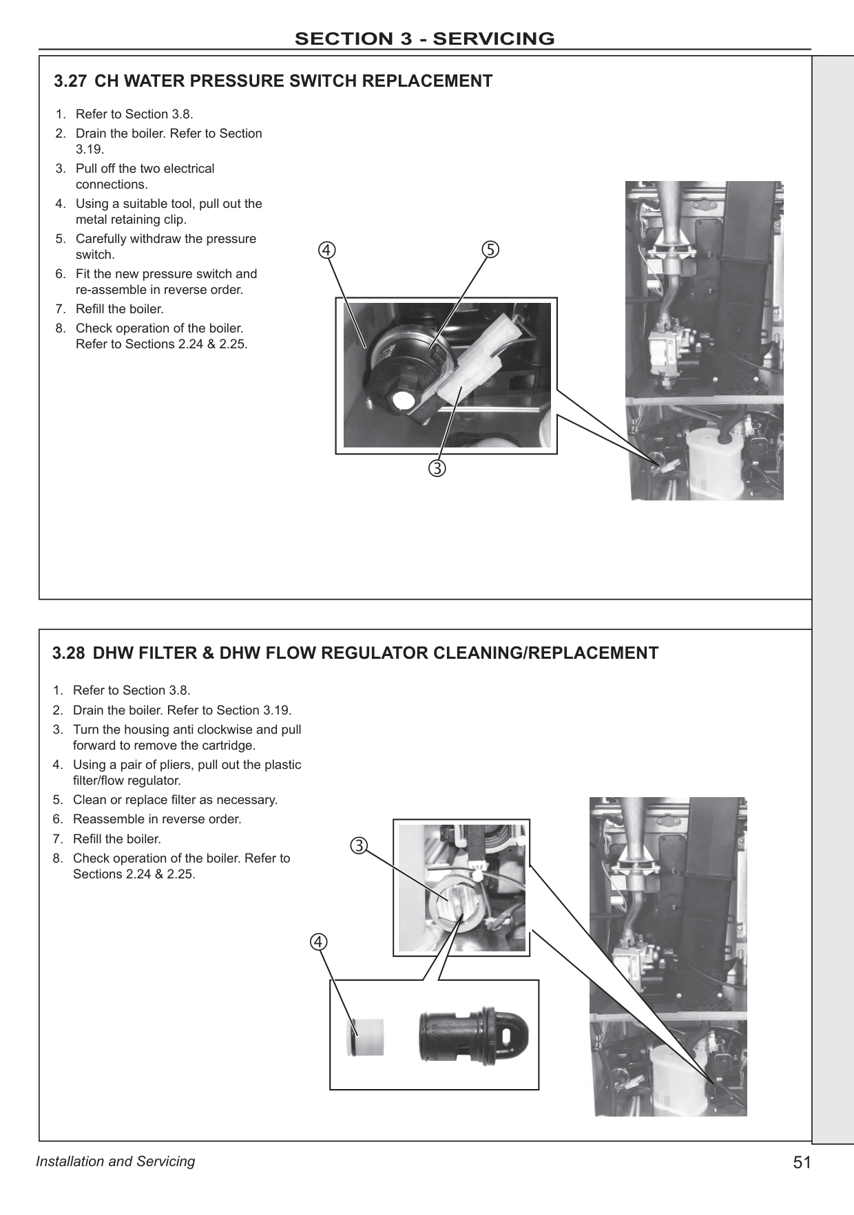

######

######
|
| |---|
SERVICING


Note. Ensure that the boiler front panel is correctly sealed, compressing the seal to make an airtight joint.
|4 FAULT FINDING 4.1 FAULT FINDING CHART MAIN MENU
|‘L1’| |---|
|GO TO SECTION 4.2 FLOW TEMPERATURE OVERHEAT LOCKOUT| |---|
|‘L2’| |---|
|‘L6’|
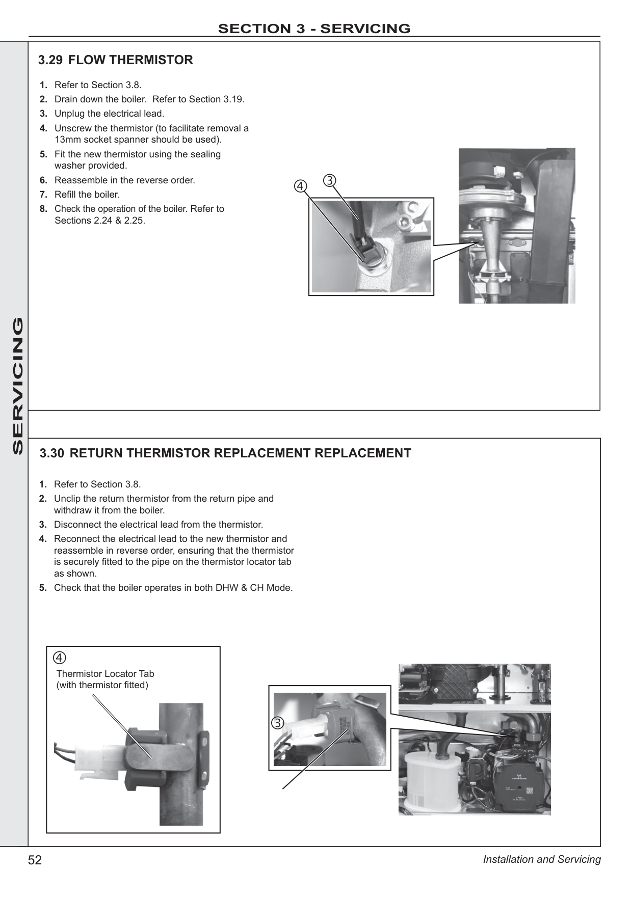
|---|
|‘F1’| |---|
|‘F2 or Fn or Ln’| |---|
|‘F3’| |---|
|‘L4 or F4’| |---|
|‘L5 or F5’| |---|
|‘F6’| |---|
|‘F7’| |---|
|‘FA’| |---|
|‘F9 or L9’| |---|
|REPLACE PCB| |---|
|GO TO SECTION 4.3 IGNITION LOCKOUT| |---|
|GO TO SECTION 4.5 FALSE FLAME LOCKOUT| |---|
|GO TO SECTION 4.6 LOW WATER PRESSURE| |---|
|GO TO SECTION 4.7 FLAME LOSS| |---|
|GO TO SECTION 4.8 FAN FAULT| |---|
|GO TO SECTION 4.9 FLOW THERMISTOR FAULT| |---|
|GO TO SECTION 4.10 RETURN THERMISTOR FAULT| |---|
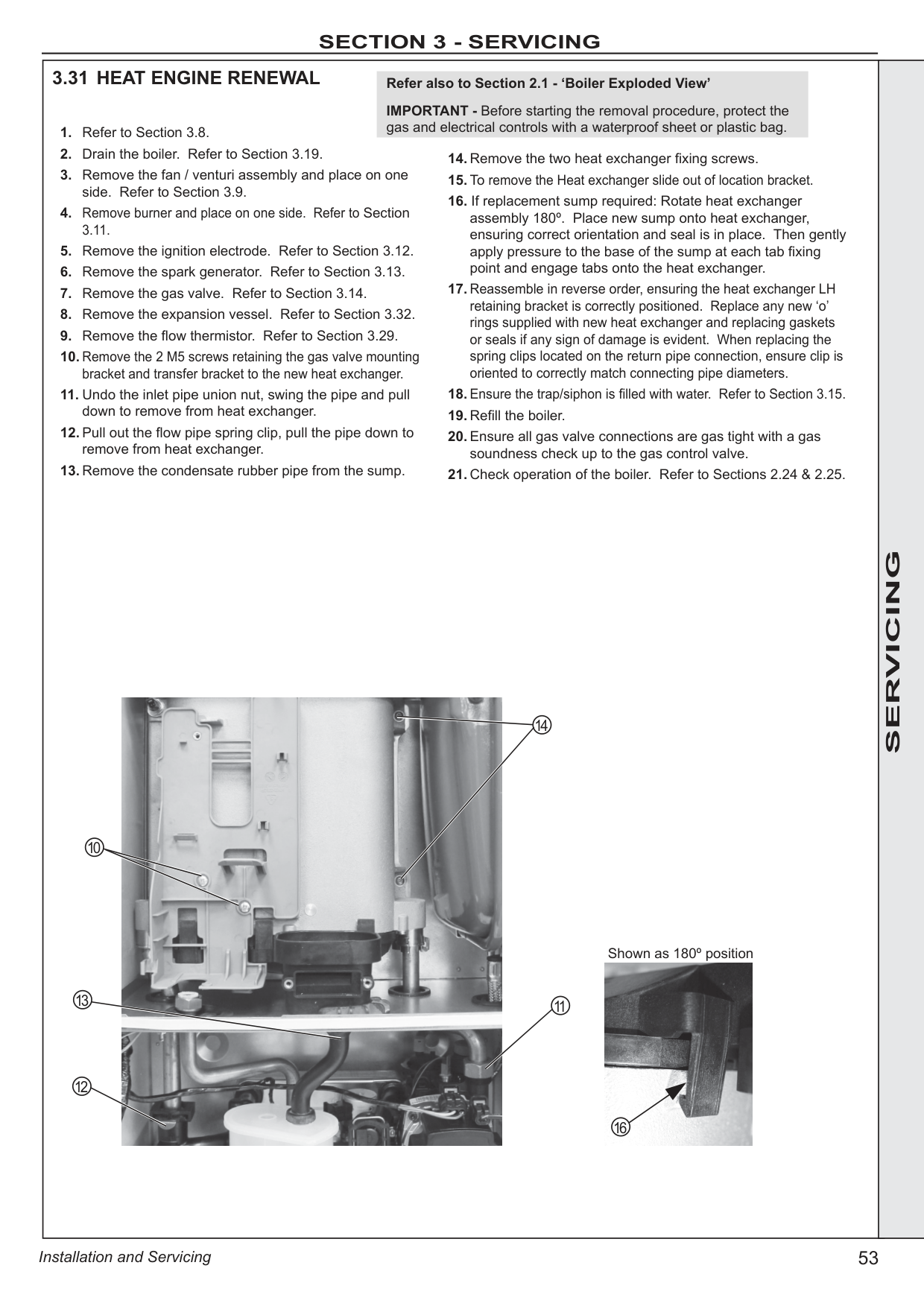
|GO TO SECTION 4.11 OUTSIDE SENSOR FAULT| |---|
|LOW MAINS VOLTAGE CONTACT ELECTRICITY PROVIDER| |---|
|NEGATIVE DIFFERENTIAL FLOW OR RETURN THERMISTOR FAULT| |---|
|NO CH BUT HW OK| |---|
|NO HW BUT CH OK| |---|
|NO DISPLAY| |---|
|GO TO SECTION 4.17| |---|
|GO TO SECTION 4.15| |---|
|GO TO SECTION 4.16| |---|
|‘LC’| |---|
|5 RESETS WITHIN 15 MINS TURN POWER OFF AND ON| |---|
RESTART PROCEDURE: To restart boiler press the restart button.
|‘FU’| |---|
|DIFF GREATER THAN 50°C CHECK ISOLATION VALVES ARE OPEN CHECK PUMP CHECK RAD VALVES OPEN CHECK SYSTEM BLOCKAGES| |---|
|‘F8 or L8’| |---|
|PCB UNCONFIGURED/FAULTY OR GAS VALVE SHORT CIRCUIT. SEE SECTION 3.14 IF FAULT PERSISTS REPLACE PCB| |---| |I|DI| |---|---|---|
|FAULT FINDING FAULT FINDING FAULT FINDING FAULT FINDING FAULT FINDING|4.2 ‘L1’ - FLOW TEMPERATURE OVERHEAT LOCKOUT
Is the Boiler and CH System filled with water and all isolation and radiator valves open?
YES
|Fill and vent the system and open all isolation valves, then restart boiler|
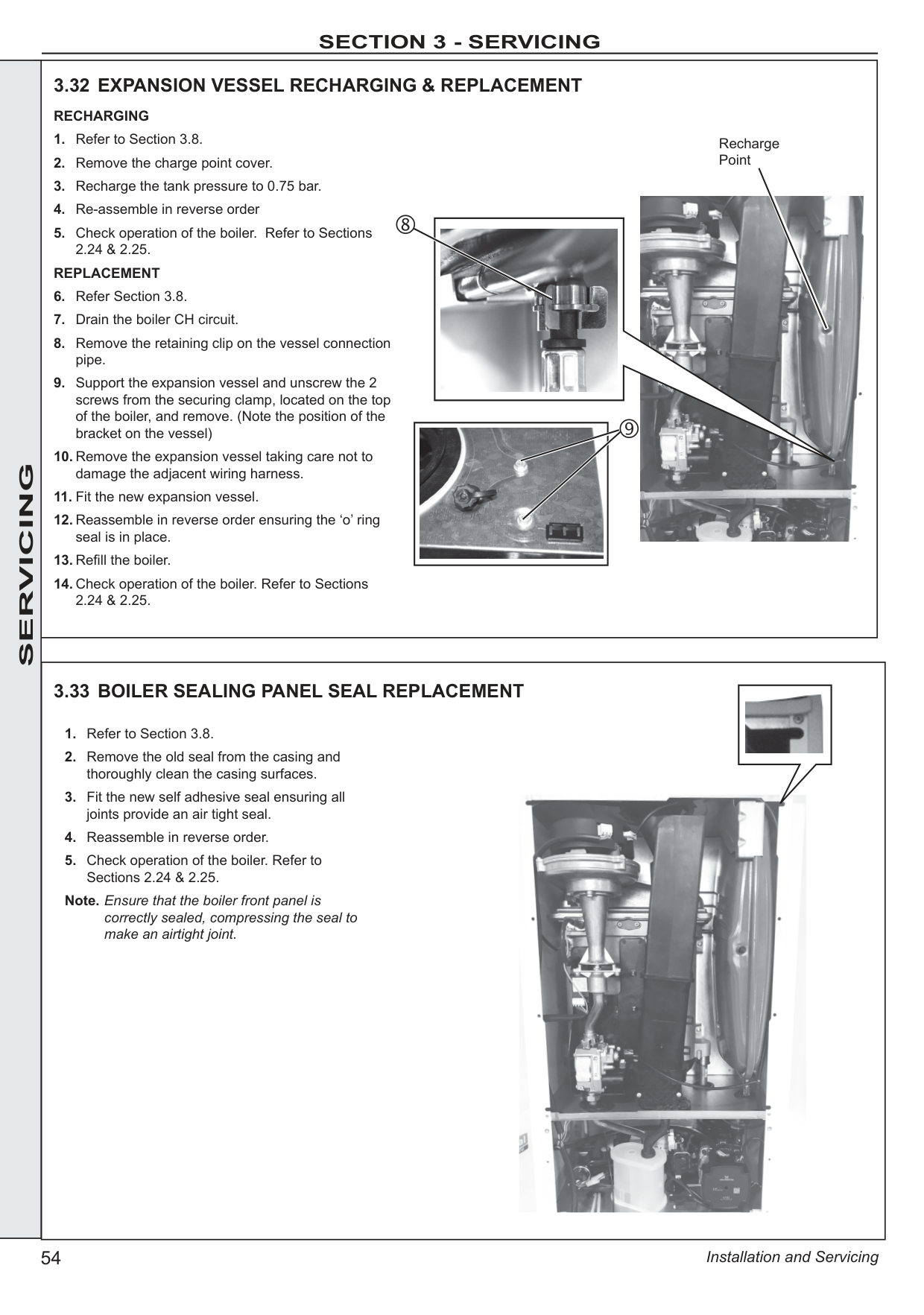
|---|
Is the Flow/Return Differential across the Boiler in excess of 30°C?
NO
Check that the Pump is rotating freely. Is the Differential now below 20°C?
YES
NO
|Replace the Pump, then restart boiler| |---|
NO
|OK, now restart boiler| |---|
YES
RESTART PROCEDURE: To restart boiler press the restart button.
|Check the Return Thermistors (Refer to Section 3.12) Check resistance using a suitable multimeter connected across the thermistor’s terminal pins At 25 oC expect 9,700 - 10,300 Ohms At 60 oC expect 2,400 - 2,600 Ohms At 85 oC expect 1,000 - 1,100 Ohms| |---| | |---|---| |FAULT FINDING FAULT FINDING FAULT FINDING FAULT FINDING FAULT FINDING| | |FAULT FINDING FAULT FINDING FAULT FINDING FAULT FINDING FAULT FINDING|4.3 ‘L2’ - IGNITION LOCKOUT
If the boiler is restarted does the boiler ignite for a short time and then extinguish?
YES
Is the Gas Pressure available at the Boiler Inlet (>18 mbar)?
|Check the detection electrode and associated harness for: continuity, visual condition and position (Refer to Section 3.14). Check if the condensate pipe is blocked.
Check flue is installed correctly. Replace as necessary.| |---|
NO
|Check gas supply and rectify fault| |---|
NO
YES
Is 24Vdc supply available at the Gas Valve?
YES
Check spark generator and associated harness for: continuity and visual condition. (Refer to Section 3.15) Are these functioning correctly?
YES
Check ignition electrode and associated harness for: continuity, visual condition and position. (Refer to Section 3.13) Are these functioning correctly?
|Check siphon and condensate drain pipework for blockage and rectify if necessary. Boiler now working OK?|Check siphon and condensate drain pipework for blockage and rectify if necessary. Boiler now working OK?| |---|---| | |NO|
|Check wiring connection from gas valve to PCB for continuity. If the wiring is OK then replace the PCB| |---|
NO
|Replace Spark Generator and harness as necessary| |---|
NO
|Replace Ignition Electrode and associated harness as necessary| |---|
NO YES
|Replace Gas Valve| |---|
Unplug gas valve. Is resistance between outside pins between 4k Ω (± 2)?
YES
|Replace Gas Valve| |---|
NO
RESTART PROCEDURE: To restart boiler press the restart button.|
|4.4 ‘LC’ - 5 RESETS WITHIN 15 MINS
|Turn power off and on| |---| |FAULT FINDING FAULT FINDING FAULT FINDING FAULT FINDING FAULT FINDING| |---|---| | |FAULT FINDING FAULT FINDING FAULT FINDING FAULT FINDING FAULT FINDING|
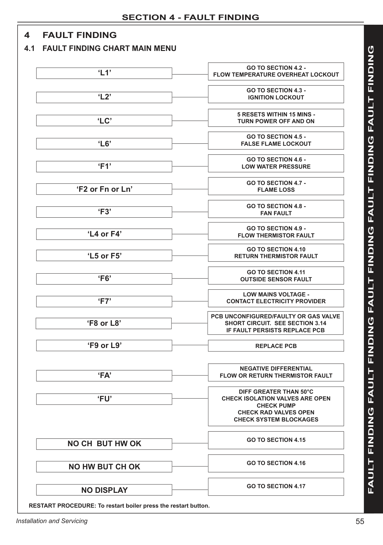
|Restart the boiler, does Boiler Work OK?
NO
|Check condition of ignitor and spark generator. Replace if required. Check routing and integrity of internal boiler wiring is OK.| |---|
|Replace ignitor, if fault persists replace spark generator.| |---|
YES
RESTART PROCEDURE: To restart boiler press the restart button.
4.5 ‘L6’ - FALSE FLAME LOCKOUT|FAULT FINDING FAULT FINDING FAULT FINDING FAULT FINDING FAULT FINDING| | |FAULT FINDING FAULT FINDING FAULT FINDING FAULT FINDING FAULT FINDING| |Are the Boiler and CH System filled with water and all isolation and radiator valves open (check pressure gauge is between 1 to 1.5 bar)?
NO
NO
YES
|Fill and vent the system and open all isolation valves| |---|
YES Are connections on water pressure sensor secure?
|Re-fit connections| |---|
|Replace water pressure switch| |---|
4.6 ‘F1’ - LOW WATER PRESSURE|FAULT FINDING FAULT FINDING FAULT FINDING FAULT FINDING FAULT FINDING|
|FAULT FINDING FAULT FINDING FAULT FINDING FAULT FINDING FAULT FINDING|4.7 ‘F2 OR FN OR LN’ - FLAME LOSS
Does the boiler ignite for a short time and then extinguish?
YES
YES
|Is the Gas Pressure available at the Boiler Inlet (18 mbar)?| |---|
|Check if condensate pipe is blocked. Check if flue is blocked.
Replace as necessary.| |---|
|Is the top flue manifold seal present and correctly fitted. ?| |---|
NO
NO
|Check gas supply and rectify fault| |---|
NO
YES
|Is 24Vdc supply available at the Gas Valve while the flame is on?| |---|
YES
|Check spark generator and associated harness for: continuity and visual condition. (Refer to Section 3.15) Are these functioning correctly?| |---|
YES
|Check ignition electrode and associated harness for: continuity, visual condition and position. (Refer to Section 3.13) Are these functioning correctly?|Check ignition electrode and associated harness for: continuity, visual condition and position. (Refer to Section 3.13) Are these functioning correctly?| |---|---| | |YES|
|Check siphon and condensate drain pipe work for blockage and rectify if necessary. Boiler now working OK?| |---|
|Check wiring from gas valve to PCB for continuity. If the wiring is OK then replace the PCB| |---|
NO
|Replace Spark Generator and Harness as necessary.|
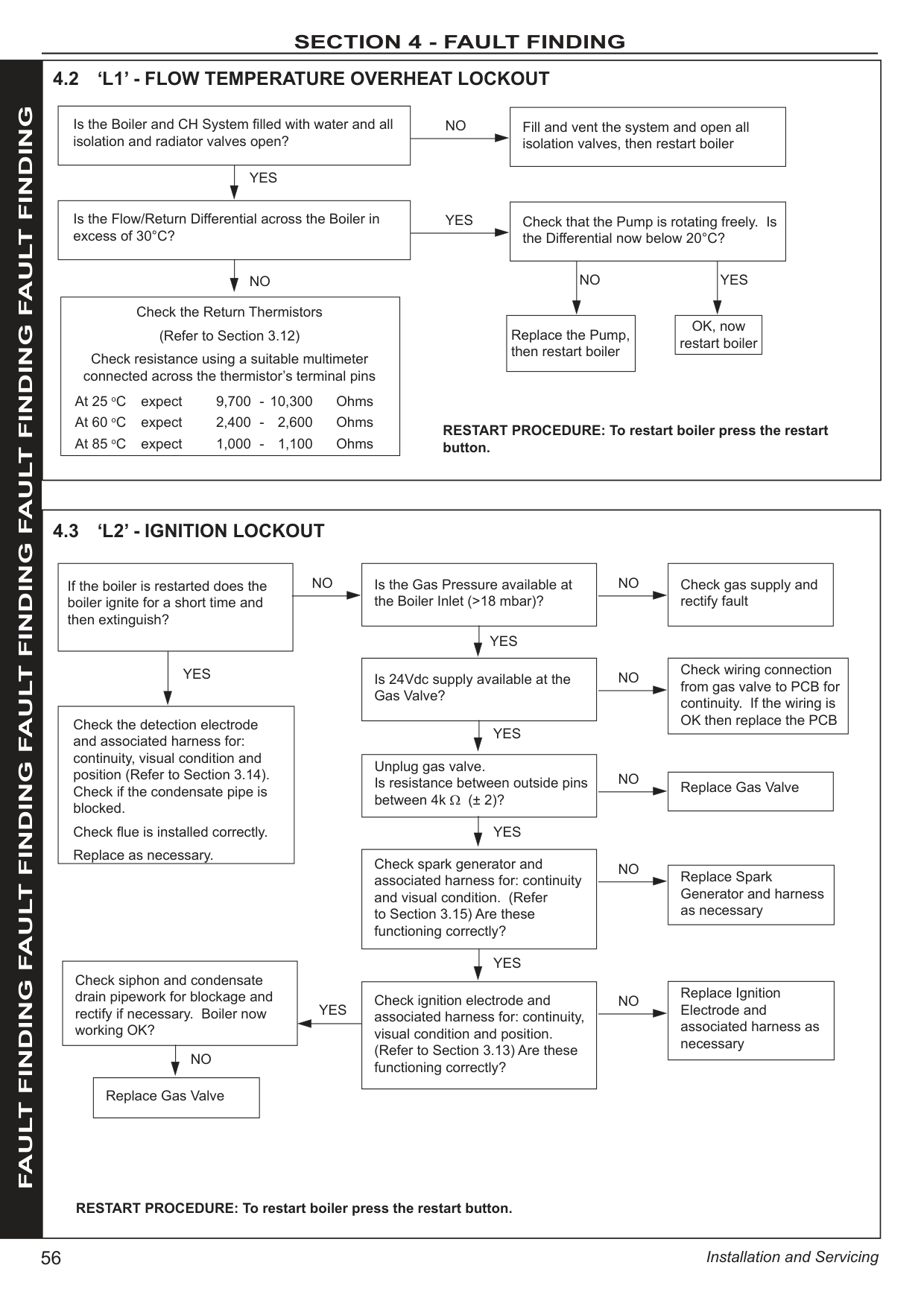
|---|
NO
|Replace Ignition Electrode and associated harness as necessary| |---|
NO
|Replace Gas Valve| |---|
Re-fit correctly or replace
NO| |---|---| |FAULT FINDING FAULT FINDING FAULT FINDING FAULT FINDING FAULT FINDING| | |FAULT FINDING FAULT FINDING FAULT FINDING FAULT FINDING FAULT FINDING|4.8 ‘F3’ - FAN FAULT
Does the wiring from the Fan to the PCB have secure connections at both ends and has not deteriorated? Does the wiring have continuity?
YES
|Rectify Wiring & connections| |---|
Is there 230Vac at the Blue and Brown connections to the 3 way connection on the Fan?
NO
|Replace PCB| |---|
|Replace Fan| |---|
NO
YES|
|4.9 ‘L4 OR F4’ - FLOW THERMISTOR FAULT
Disconnect the wiring from the Flow Thermistor Check the resistance using a suitable multimeter connected across the Thermistor’s terminal pins.
At 25 oC expect 9,700 - 10,300 Ohms At 60 oC expect 2,400 - 2,600 Ohms At 85 oC expect 1,000 - 1,100 Ohms
Is the Thermistor value correct? YES
Is the wiring securely connected to the low voltage 6 way connector at the front left hand side of the PCB?
YES
|Replace PCB| |---|
|Fit a new Thermistor| |---|
NO
|Securely connect the wiring to the PCB| |---|
Is the wiring securely connected to the Flow Thermistor (located in the top of the Heat Exchanger?)
YES
NO
|Securely connect the wiring to the Flow Thermistor| |---|
NO| |---|
|FAULT FINDING FAULT FINDING FAULT FINDING FAULT FINDING FAULT FINDING| |---|
|4.10 ‘L5 OR F5’ - RETURN THERMISTOR FAULT
Remove the Return Thermistor from the CH Return Pipe and disconnect the wires.
Check the resistance using a suitable multimeter connected across the thermistor’s terminal pins.
At 25 oC expect 9,700 - 10,300 Ohms At 60 oC expect 2,400 - 2,600 Ohms At 85 oC expect 1,000 - 1,100 Ohms
Is the Thermistor value correct? YES Is there continuity between the PCB and the Thermistor? YES
|Replace PCB| |---|
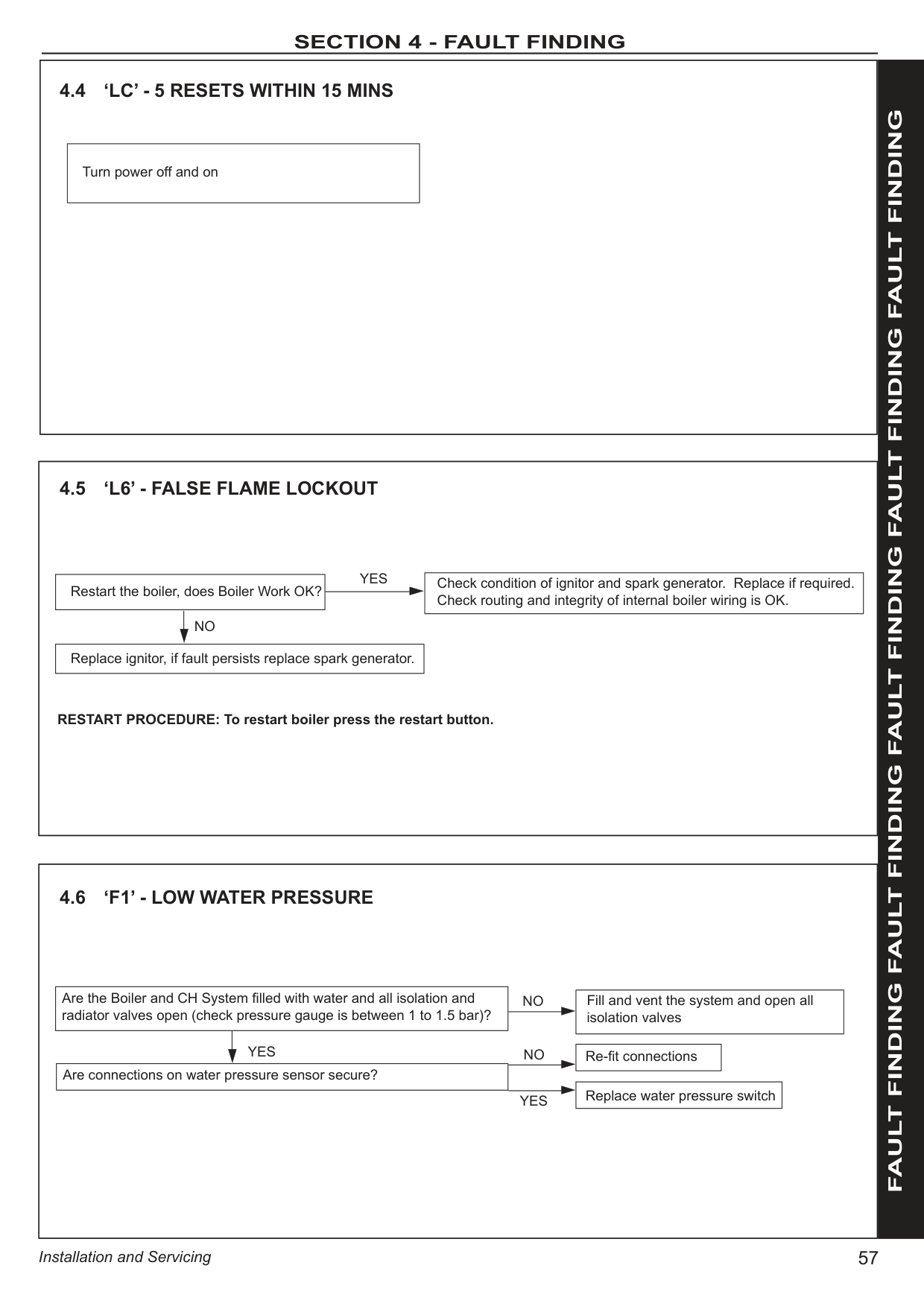
|Fit a new Thermistor| |---|
NO
|Check and replace wiring as necessary| |---|
NO| |---|
|FAULT FINDING FAULT FINDING FAULT FINDING FAULT FINDING FAULT FINDING|Disconnect the wires to the outside sensor. Check the resistance using a suitable multimeter connected across the Outside Sensor’s terminal pins.
At 0 oC expect 31,000 - 35,000 Ohms At 15 oC expect 15,000 - 16,500 Ohms At 30 oC expect 7,700 - 8,500 Ohms
Is the Outside Sensor value correct?
YES
Is the wiring securely connected between the incoming terminal block boiler connection of the Outside Sensor and the PCB?
|Replace PCB| |---|
|Fit a new Outside Sensor| |---|
NO
|Securely connect the wiring at the Terminal Block and the PCB| |---|
Is the wiring securely connected at both the boiler and Outside Sensor?
YES
NO
|Securely connect the wiring at both the boiler and Outside Sensor| |---|
NO
YES
4.11 F6 - OUTSIDE SENSOR FAULT| |---|---| |FAULT FINDING FAULT FINDING FAULT FINDING FAULT FINDING FAULT FINDING| | |FAULT FINDING FAULT FINDING FAULT FINDING FAULT FINDING FAULT FINDING||Contact electricity provider| |---|
4.12 F7 - LOW MAINS VOLTAGE| |FAULT FINDING FAULT FINDING FAULT FINDING FAULT FINDING FAULT FINDING| | |FAULT FINDING FAULT FINDING FAULT FINDING FAULT FINDING FAULT FINDING||Reprogram PCB as described in Section 3.17.| |---|
4.13 F8/L8 - LOCKOUT DUE TO PARAMETER FAULT| |FAULT FINDING FAULT FINDING FAULT FINDING FAULT FINDING FAULT FINDING| | |FAULT FINDING FAULT FINDING FAULT FINDING FAULT FINDING FAULT FINDING||Replace PCB Reprogram PCB as described in Section 3.17.| |---|
If fault persists replace PCB
4.14 F9/L9 - PCB FAULT|
|Is the mode knob in the Winter position? YES
YES
YES
YES
NO
NO
NO
NO
|Move the mode knob to the Winter position| |---|
|Switch the Timer and Room Thermostat On|
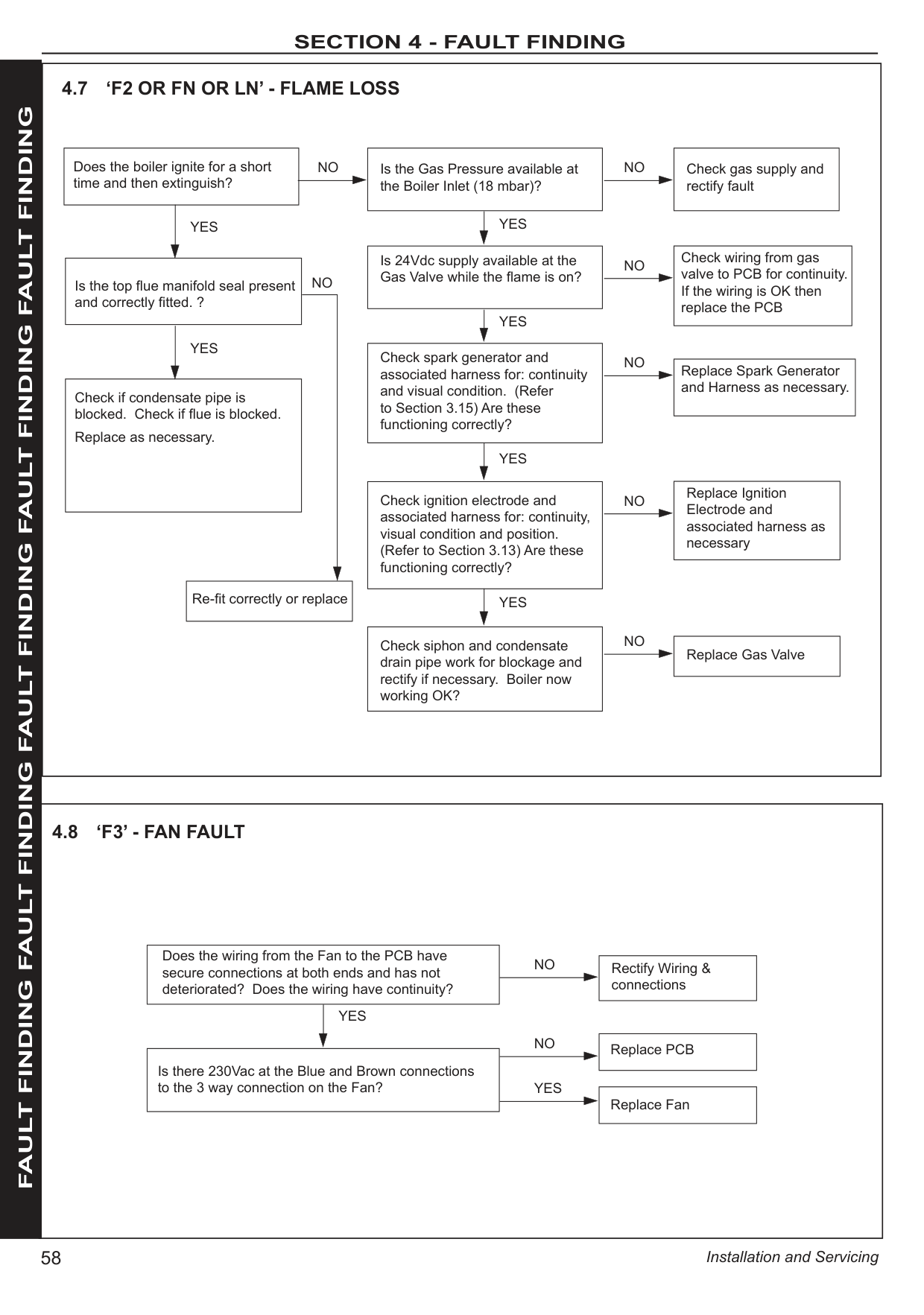
|---|
|Open the Radiator Valves| |---|
|There is no Voltage from the Timer/Room Stat. This is not boiler fault. Ensure Voltage is supplied to boiler by rectifying external wiring.| |---|
Are the Timer and the Room Thermostat switched on?
Are the Radiator Valves Open?
Is there 230Vac at (A)?
|Replace the Diverter Valve Motor| |---|

4.15 NO CH OPERATION BUT HW WORKS OK
A| |FAULT FINDING FAULT FINDING FAULT FINDING FAULT FINDING FAULT FINDING| |---|---|---| | | | |
Does the display show “dH” when a tap is on?
NO
YES
Are the flow rates correct as per Section 1.16.
Is the wiring between the PCB and the diverter valve actuator connected?
YES
YES
Check diverter head fully engaged onto waterset body
YES
Is diverter stuck in the CH position YES
Check and replace diverter valve actuator head. Is Boiler DHW OK?
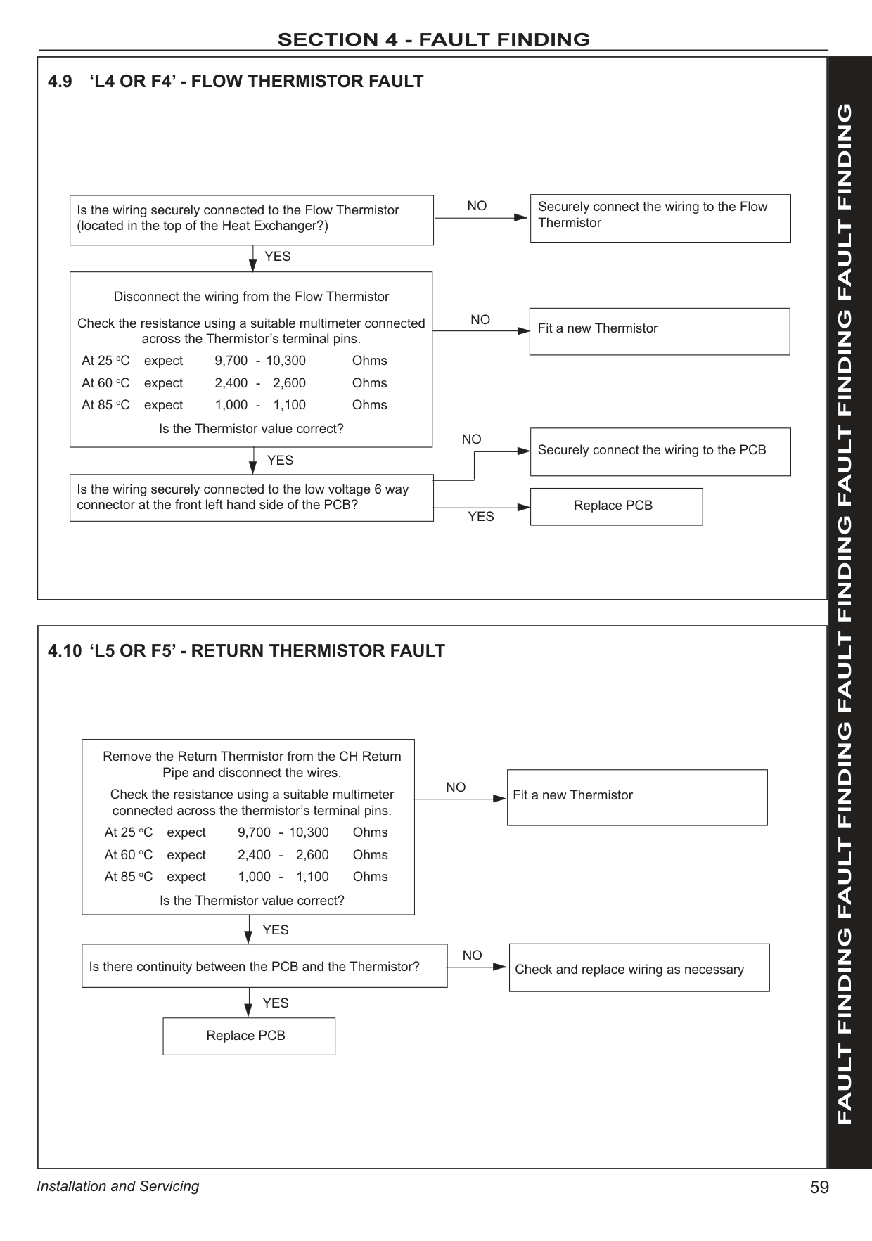
NO
|Change diverter valve assembly.| |---|
NO
|Adjust flow rates to achieve 35º temp rise and check filter fitted in turbine is not blocked with debris.| |---|
NO
|Reconnect wiring or replace wiring harness if no continuity.| |---|
NO
|Re-engage diverter head.| |---|
NO
|Replace PCB| |---|
Is hot and cold pipework crossed?
NO
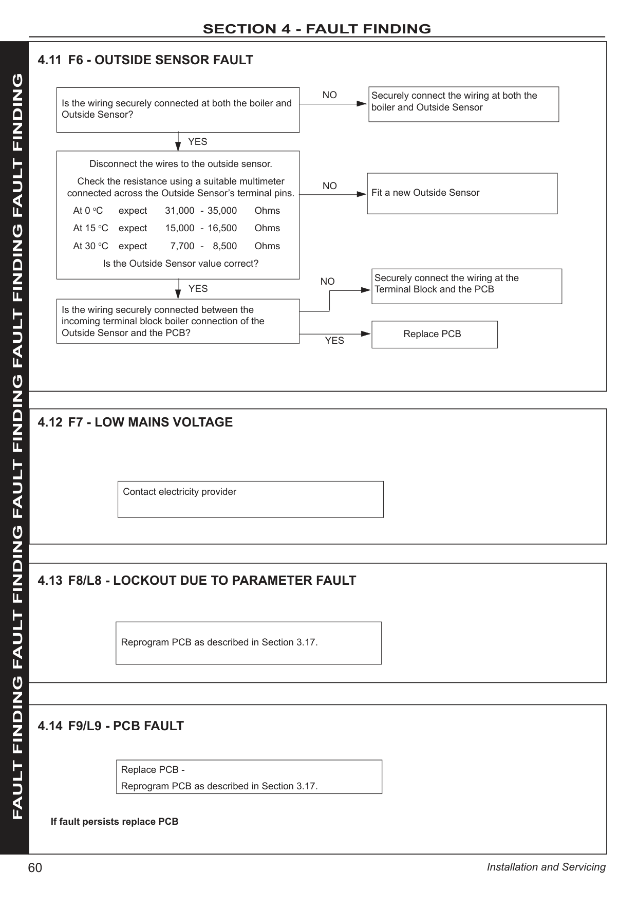
Is the wiring connected between PCB and DHW sensor?
Remove the turbine, and check for debris in the turbine. Replace turbine if necessary. Is DHW OK?
YES
NO
|Re-connect wiring| |---|
NO
|Replace turbine sensor| |---|
FAULT FINDING FAULT FINDING FAULT FINDING FAULT FINDING FAULT FINDING
|Supply power to the boiler| |---|
NO
Is there 230Vac to the boiler at L and N? YES
|Connect the wiring from the terminal block to the Main PCB securely.| |---|
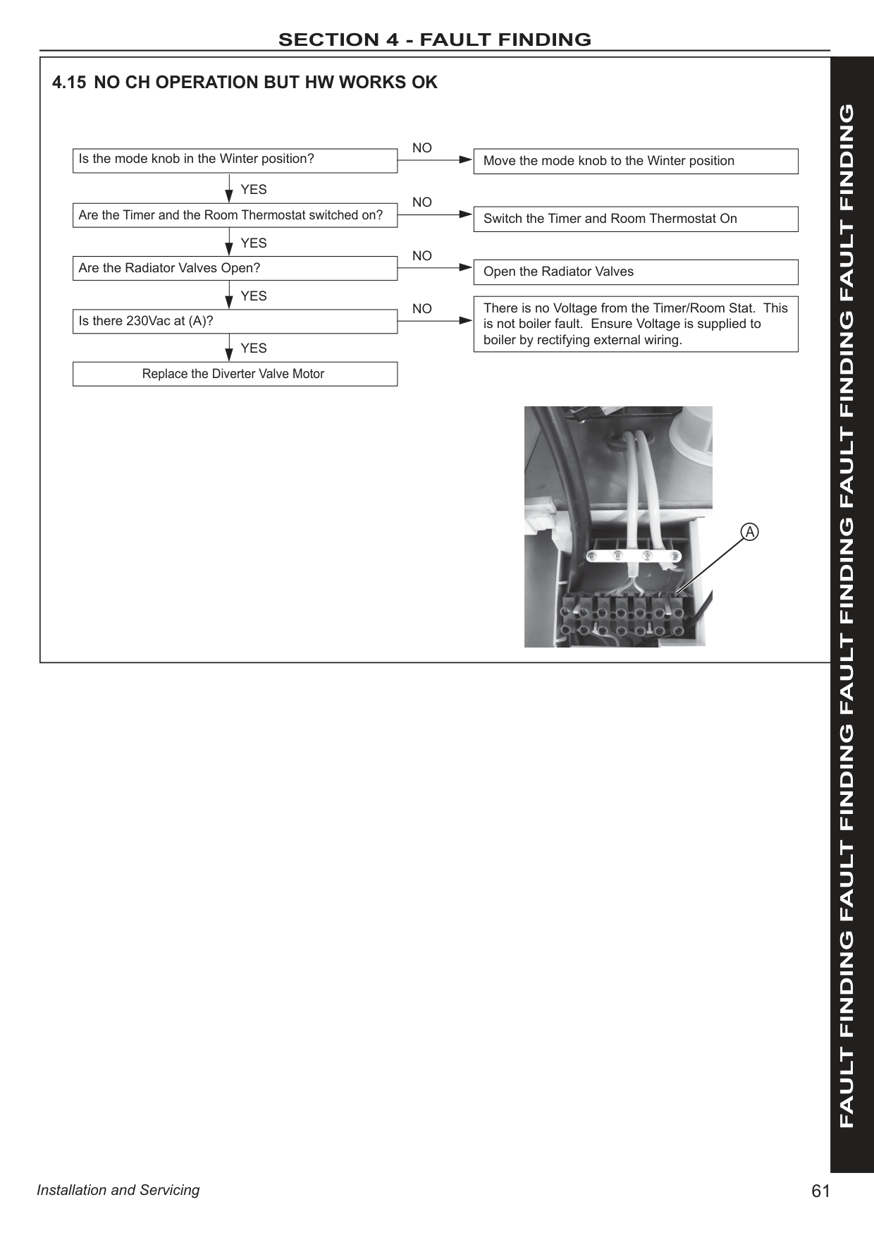
NO
Is the wiring from the terminal block to the Main PCB connected securely?
YES
|Replace PCB| |---|

###################### NL
########### SECTION 5 - SPARE PARTS 5 SPARE PARTS
When replacing any part on this appliance use only spare parts that you can be assured conform to the safety and performance specification that we require. Do not use reconditioned or copy parts that have not been clearly authorised by Ideal Heating. Failure to do so could affect safety or performance of this appliance.
###################### Our Parts team are also available to help with your Spare Parts enquiries on 01482 498665.
When calling, and to ensure we can provide you with the most accurate parts information, please ensure you have the following to hand;


Benchmark Commissioning & Warranty Validation Service Record
It is a requirement that the boiler is installed and commissioned to the manufacturers’ instructions and the data fields on the commissioning checklist completed in full.
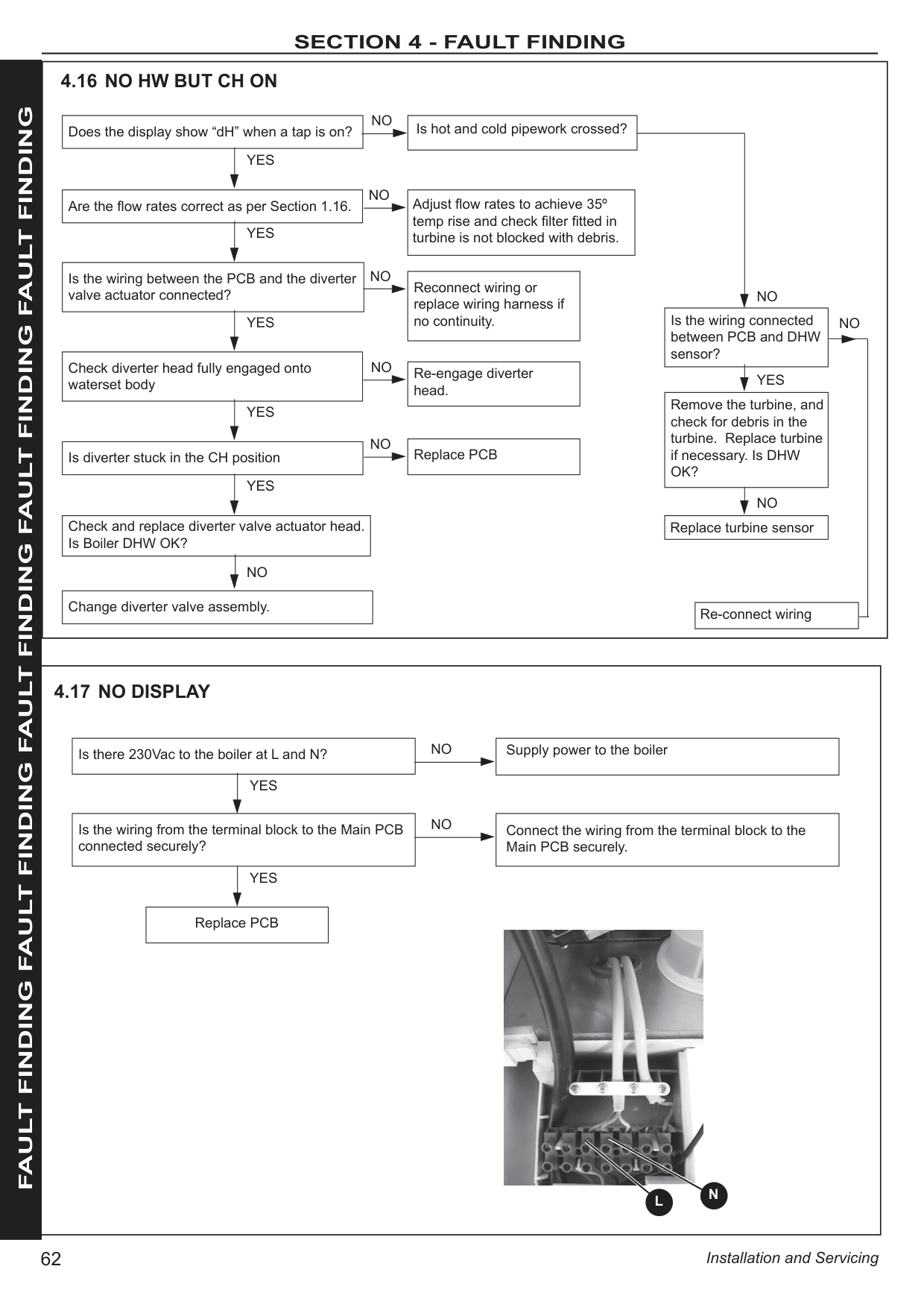
To instigate the boiler warranty the boiler needs to be registered with the manufacturer within one month of the installation. The warranty rests with the end-user (consumer), and they should be made aware it is ultimately their responsibility to register with the manufacturer, within the allotted time period.
It is essential that the boiler is serviced in line with the manufacturers’ recommendations, at least annually. This must be carried out by a competent Gas Safe registered engineer. The service details should be recorded on the Benchmark Service and Interim Boiler Work Record and left with the householder. Failure to comply with the manufacturers’ servicing instructions and requirements will invalidate the warranty.
www.hhic.co.uk
This Commissioning Checklist is to be completed in full by the competent person who commissioned the boiler as a means of demonstrating compliance with the appropriate Building Regulations and then handed to the customer to keep for future reference.
Failure to install and commission according to the manufacturers’ instructions and complete this Benchmark Commissioning Checklist will invalidate the warranty. This does not affect the customer’s statutory rights.
© Heating and Hotwater Industry Council (HHIC)
www.centralheating.co.uk
#################### GAS BOILER SYSTEM COMMISSIONING CHECKLIST & WARRANTY VALIDATION RECORD
|Address:|Address:|Address:|Address:|Address:|Address:|Address:|Address:|Address:|Address:|Address:|Address:|Address:|Address:|Address:|Address:|Address:|Address:|Address:|Address:|Address:|Address:|Address:|Address:|Address:|Address:|Address:|Address:|Address:|Address:|Address:|Address:|Address:|Address:|Address:|Address:|Address:| |---|---|---|---|---|---|---|---|---|---|---|---|---|---|---|---|---|---|---|---|---|---|---|---|---|---|---|---|---|---|---|---|---|---|---|---|---| |Boiler make and model:|Boiler make and model:|Boiler make and model:|Boiler make and model:|Boiler make and model:|Boiler make and model:|Boiler make and model:|Boiler make and model:|Boiler make and model:|Boiler make and model:|Boiler make and model:|Boiler make and model:|Boiler make and model:|Boiler make and model:|Boiler make and model:|Boiler make and model:|Boiler make and model:|Boiler make and model:|Boiler make and model:|Boiler make and model:|Boiler make and model:|Boiler make and model:|Boiler make and model:|Boiler make and model:|Boiler make and model:|Boiler make and model:|Boiler make and model:|Boiler make and model:|Boiler make and model:|Boiler make and model:|Boiler make and model:|Boiler make and model:|Boiler make and model:|Boiler make and model:|Boiler make and model:|Boiler make and model:|Boiler make and model:| |Boiler serial number:|Boiler serial number:|Boiler serial number:|Boiler serial number:| | | | | | | | | | | | | | | | | | | | | | | | | | | | | | | | | | |Commissioned by (PRINT NAME):|Commissioned by (PRINT NAME):|Commissioned by (PRINT NAME):|Commissioned by (PRINT NAME):|Commissioned by (PRINT NAME):|Commissioned by (PRINT NAME):|Commissioned by (PRINT NAME):|Commissioned by (PRINT NAME):|Commissioned by (PRINT NAME):|Commissioned by (PRINT NAME):|Gas Safe registration number:|Gas Safe registration number:|Gas Safe registration number:|Gas Safe registration number:|Gas Safe registration number:|Gas Safe registration number:|Gas Safe registration number:|Gas Safe registration number:|Gas Safe registration number:|Gas Safe registration number:|Gas Safe registration number:|Gas Safe registration number:|Gas Safe registration number:|Gas Safe registration number:|Gas Safe registration number:|Gas Safe registration number:|Gas Safe registration number:|Gas Safe registration number:|Gas Safe registration number:|Gas Safe registration number:|Gas Safe registration number:|Gas Safe registration number:|Gas Safe registration number:|Gas Safe registration number:|Gas Safe registration number:|Gas Safe registration number:|Gas Safe registration number:| |Company name:|Company name:|Company name:|Company name:|Company name:|Company name:|Company name:|Company name:|Company name:|Company name:|Telephone number:|Telephone number:|Telephone number:|Telephone number:|Telephone number:|Telephone number:|Telephone number:|Telephone number:|Telephone number:|Telephone number:|Telephone number:|Telephone number:|Telephone number:|Telephone number:|Telephone number:|Telephone number:|Telephone number:|Telephone number:|Telephone number:|Telephone number:|Telephone number:|Telephone number:|Telephone number:|Telephone number:|Telephone number:|Telephone number:|Telephone number:| |Company email:|Company email:|Company email:|Company email:|Company email:|Company email:|Company email:|Company email:|Company email:|Company email:|Company address:|Company address:|Company address:|Company address:|Company address:|Company address:|Company address:|Company address:|Company address:|Company address:|Company address:|Company address:|Company address:|Company address:|Company address:|Company address:|Company address:|Company address:|Company address:|Company address:|Company address:|Company address:|Company address:|Company address:|Company address:|Company address:|Company address:| | | | | | | | | | | | | | | | | | | | | | | | | | |Commissioning date:|Commissioning date:|Commissioning date:|Commissioning date:|Commissioning date:|Commissioning date:|Commissioning date:|Commissioning date:|Commissioning date:|Commissioning date:|Commissioning date:|Commissioning date:| |Heating and hot water system complies with the appropriate Building Regulations? Yes|Heating and hot water system complies with the appropriate Building Regulations? Yes|Heating and hot water system complies with the appropriate Building Regulations? Yes|Heating and hot water system complies with the appropriate Building Regulations? Yes|Heating and hot water system complies with the appropriate Building Regulations? Yes|Heating and hot water system complies with the appropriate Building Regulations? Yes|Heating and hot water system complies with the appropriate Building Regulations? Yes|Heating and hot water system complies with the appropriate Building Regulations? Yes|Heating and hot water system complies with the appropriate Building Regulations? Yes|Heating and hot water system complies with the appropriate Building Regulations? Yes|Heating and hot water system complies with the appropriate Building Regulations? Yes|Heating and hot water system complies with the appropriate Building Regulations? Yes|Heating and hot water system complies with the appropriate Building Regulations? Yes|Heating and hot water system complies with the appropriate Building Regulations? Yes|Heating and hot water system complies with the appropriate Building Regulations? Yes|Heating and hot water system complies with the appropriate Building Regulations? Yes|Heating and hot water system complies with the appropriate Building Regulations? Yes|Heating and hot water system complies with the appropriate Building Regulations? Yes|Heating and hot water system complies with the appropriate Building Regulations? Yes|Heating and hot water system complies with the appropriate Building Regulations? Yes|Heating and hot water system complies with the appropriate Building Regulations? Yes|Heating and hot water system complies with the appropriate Building Regulations? Yes|Heating and hot water system complies with the appropriate Building Regulations? Yes|Heating and hot water system complies with the appropriate Building Regulations? Yes|Heating and hot water system complies with the appropriate Building Regulations? Yes|Heating and hot water system complies with the appropriate Building Regulations? Yes|Heating and hot water system complies with the appropriate Building Regulations? Yes|Heating and hot water system complies with the appropriate Building Regulations? Yes|Heating and hot water system complies with the appropriate Building Regulations? Yes|Heating and hot water system complies with the appropriate Building Regulations? Yes|Heating and hot water system complies with the appropriate Building Regulations? Yes|Heating and hot water system complies with the appropriate Building Regulations? Yes|Heating and hot water system complies with the appropriate Building Regulations? Yes|Heating and hot water system complies with the appropriate Building Regulations? Yes|Heating and hot water system complies with the appropriate Building Regulations? Yes|Heating and hot water system complies with the appropriate Building Regulations? Yes| | |Optional: Building Regulations Notification Number (if applicable):|Optional: Building Regulations Notification Number (if applicable):|Optional: Building Regulations Notification Number (if applicable):|Optional: Building Regulations Notification Number (if applicable):|Optional: Building Regulations Notification Number (if applicable):|Optional: Building Regulations Notification Number (if applicable):|Optional: Building Regulations Notification Number (if applicable):|Optional: Building Regulations Notification Number (if applicable):|Optional: Building Regulations Notification Number (if applicable):|Optional: Building Regulations Notification Number (if applicable):| | | | | | | | | | | | | | | | | | | | | | | | | | | | |Time, temperature control and boiler interlock provided for central heating and hot water|Time, temperature control and boiler interlock provided for central heating and hot water|Time, temperature control and boiler interlock provided for central heating and hot water|Time, temperature control and boiler interlock provided for central heating and hot water|Time, temperature control and boiler interlock provided for central heating and hot water|Time, temperature control and boiler interlock provided for central heating and hot water|Time, temperature control and boiler interlock provided for central heating and hot water|Time, temperature control and boiler interlock provided for central heating and hot water|Time, temperature control and boiler interlock provided for central heating and hot water|Time, temperature control and boiler interlock provided for central heating and hot water|Yes|Yes|Yes|Yes|Yes|Yes|Yes|Yes|Yes|Yes|Yes|Yes|Yes|Yes|Yes|Yes|Yes|Yes|Yes|Yes|Yes|Yes|Yes|Yes|Yes|Yes| | |Boiler Plus requirements (tick the appropriate box(s))|Boiler Plus requirements (tick the appropriate box(s))|Boiler Plus requirements (tick the appropriate box(s))|Boiler Plus requirements (tick the appropriate box(s))|Boiler Plus requirements (tick the appropriate box(s))|Boiler Plus requirements (tick the appropriate box(s))|Boiler Plus requirements (tick the appropriate box(s))|Boiler Plus requirements (tick the appropriate box(s))|Boiler Plus requirements (tick the appropriate box(s))|Boiler Plus requirements (tick the appropriate box(s))|Boiler Plus requirements (tick the appropriate box(s))|Boiler Plus requirements (tick the appropriate box(s))|Boiler Plus requirements (tick the appropriate box(s))|Boiler Plus requirements (tick the appropriate box(s))|Boiler Plus requirements (tick the appropriate box(s))|Boiler Plus requirements (tick the appropriate box(s))|Boiler Plus requirements (tick the appropriate box(s))|Boiler Plus requirements (tick the appropriate box(s))|Boiler Plus requirements (tick the appropriate box(s))|Boiler Plus requirements (tick the appropriate box(s))|Boiler Plus requirements (tick the appropriate box(s))|Boiler Plus requirements (tick the appropriate box(s))|Boiler Plus requirements (tick the appropriate box(s))|Boiler Plus requirements (tick the appropriate box(s))|Boiler Plus requirements (tick the appropriate box(s))|Boiler Plus requirements (tick the appropriate box(s))|Boiler Plus requirements (tick the appropriate box(s))|Boiler Plus requirements (tick the appropriate box(s))|Boiler Plus requirements (tick the appropriate box(s))|Boiler Plus requirements (tick the appropriate box(s))|Boiler Plus requirements (tick the appropriate box(s))|Boiler Plus requirements (tick the appropriate box(s))|Boiler Plus requirements (tick the appropriate box(s))|Boiler Plus requirements (tick the appropriate box(s))|Boiler Plus requirements (tick the appropriate box(s))|Boiler Plus requirements (tick the appropriate box(s))|Boiler Plus requirements (tick the appropriate box(s))| |Boiler Plus option chosen for combination boiler in ENGLAND|Boiler Plus option chosen for combination boiler in ENGLAND|Boiler Plus option chosen for combination boiler in ENGLAND|Boiler Plus option chosen for combination boiler in ENGLAND|Boiler Plus option chosen for combination boiler in ENGLAND|Boiler Plus option chosen for combination boiler in ENGLAND|Boiler Plus option chosen for combination boiler in ENGLAND|Boiler Plus option chosen for combination boiler in ENGLAND|Boiler Plus option chosen for combination boiler in ENGLAND|Boiler Plus option chosen for combination boiler in ENGLAND|Weather compensation|Weather compensation|Weather compensation|Weather compensation|Weather compensation|Weather compensation| | | |Smart thermostat with automisation and optimisation|Smart thermostat with automisation and optimisation|Smart thermostat with automisation and optimisation|Smart thermostat with automisation and optimisation|Smart thermostat with automisation and optimisation|Smart thermostat with automisation and optimisation|Smart thermostat with automisation and optimisation|Smart thermostat with automisation and optimisation|Smart thermostat with automisation and optimisation|Smart thermostat with automisation and optimisation|Smart thermostat with automisation and optimisation|Smart thermostat with automisation and optimisation|Smart thermostat with automisation and optimisation|Smart thermostat with automisation and optimisation|Smart thermostat with automisation and optimisation|Smart thermostat with automisation and optimisation|Smart thermostat with automisation and optimisation| | |Boiler Plus option chosen for combination boiler in ENGLAND|Boiler Plus option chosen for combination boiler in ENGLAND|Boiler Plus option chosen for combination boiler in ENGLAND|Boiler Plus option chosen for combination boiler in ENGLAND|Boiler Plus option chosen for combination boiler in ENGLAND|Boiler Plus option chosen for combination boiler in ENGLAND|Boiler Plus option chosen for combination boiler in ENGLAND|Boiler Plus option chosen for combination boiler in ENGLAND|Boiler Plus option chosen for combination boiler in ENGLAND|Boiler Plus option chosen for combination boiler in ENGLAND|Load compensation|Load compensation|Load compensation|Load compensation|Load compensation|Load compensation| | | |Flue Gas Heat Recovery|Flue Gas Heat Recovery|Flue Gas Heat Recovery|Flue Gas Heat Recovery|Flue Gas Heat Recovery|Flue Gas Heat Recovery|Flue Gas Heat Recovery|Flue Gas Heat Recovery|Flue Gas Heat Recovery|Flue Gas Heat Recovery|Flue Gas Heat Recovery|Flue Gas Heat Recovery|Flue Gas Heat Recovery|Flue Gas Heat Recovery|Flue Gas Heat Recovery|Flue Gas Heat Recovery|Flue Gas Heat Recovery| | |Time and temperature control to hot water|Time and temperature control to hot water|Cylinder thermostat and programmer/timer|Cylinder thermostat and programmer/timer|Cylinder thermostat and programmer/timer|Cylinder thermostat and programmer/timer|Cylinder thermostat and programmer/timer|Cylinder thermostat and programmer/timer|Cylinder thermostat and programmer/timer|Cylinder thermostat and programmer/timer|Cylinder thermostat and programmer/timer|Cylinder thermostat and programmer/timer|Cylinder thermostat and programmer/timer|Cylinder thermostat and programmer/timer|Cylinder thermostat and programmer/timer|Cylinder thermostat and programmer/timer| | | |Combination boiler|Combination boiler|Combination boiler|Combination boiler|Combination boiler|Combination boiler|Combination boiler|Combination boiler|Combination boiler|Combination boiler|Combination boiler|Combination boiler|Combination boiler|Combination boiler|Combination boiler|Combination boiler|Combination boiler| | |Zone valves|Zone valves|pre-existing|pre-existing|pre-existing| | | |Fitted|Fitted|Fitted|Fitted|Fitted|Fitted|Fitted|Fitted| | | |Not required|Not required|Not required|Not required|Not required|Not required|Not required|Not required|Not required|Not required|Not required|Not required|Not required|Not required|Not required|Not required|Not required| | |Thermostatic radiator valves|Thermostatic radiator valves|pre-existing|pre-existing|pre-existing| | | |Fitted|Fitted|Fitted|Fitted|Fitted|Fitted|Fitted|Fitted| | | |Not required|Not required|Not required|Not required|Not required|Not required|Not required|Not required|Not required|Not required|Not required|Not required|Not required|Not required|Not required|Not required|Not required| |
|Automatic bypass to system|Automatic bypass to system|pre-existing|pre-existing|pre-existing| | | |Fitted|Fitted|Fitted|Fitted|Fitted|Fitted|Fitted|Fitted| | | |Not required|Not required|Not required|Not required|Not required|Not required|Not required|Not required|Not required|Not required|Not required|Not required|Not required|Not required|Not required|Not required|Not required| | |Underfloor heating|Underfloor heating|pre-existing|pre-existing|pre-existing| | | |Fitted|Fitted|Fitted|Fitted|Fitted|Fitted|Fitted|Fitted| | | |Not required|Not required|Not required|Not required|Not required|Not required|Not required|Not required|Not required|Not required|Not required|Not required|Not required|Not required|Not required|Not required|Not required| | |Water quality|Water quality|Water quality|Water quality|Water quality|Water quality|Water quality|Water quality|Water quality|Water quality|Water quality|Water quality|Water quality|Water quality|Water quality|Water quality|Water quality|Water quality|Water quality|Water quality|Water quality|Water quality|Water quality|Water quality|Water quality|Water quality|Water quality|Water quality|Water quality|Water quality|Water quality|Water quality|Water quality|Water quality|Water quality|Water quality|Water quality| |The system has been flushed, cleaned and a suitable inhibitor applied upon final fill, in accordance with BS7593 and boiler manufacturers’ instructions|The system has been flushed, cleaned and a suitable inhibitor applied upon final fill, in accordance with BS7593 and boiler manufacturers’ instructions|The system has been flushed, cleaned and a suitable inhibitor applied upon final fill, in accordance with BS7593 and boiler manufacturers’ instructions|The system has been flushed, cleaned and a suitable inhibitor applied upon final fill, in accordance with BS7593 and boiler manufacturers’ instructions|The system has been flushed, cleaned and a suitable inhibitor applied upon final fill, in accordance with BS7593 and boiler manufacturers’ instructions|The system has been flushed, cleaned and a suitable inhibitor applied upon final fill, in accordance with BS7593 and boiler manufacturers’ instructions|The system has been flushed, cleaned and a suitable inhibitor applied upon final fill, in accordance with BS7593 and boiler manufacturers’ instructions|The system has been flushed, cleaned and a suitable inhibitor applied upon final fill, in accordance with BS7593 and boiler manufacturers’ instructions|The system has been flushed, cleaned and a suitable inhibitor applied upon final fill, in accordance with BS7593 and boiler manufacturers’ instructions|The system has been flushed, cleaned and a suitable inhibitor applied upon final fill, in accordance with BS7593 and boiler manufacturers’ instructions|The system has been flushed, cleaned and a suitable inhibitor applied upon final fill, in accordance with BS7593 and boiler manufacturers’ instructions|The system has been flushed, cleaned and a suitable inhibitor applied upon final fill, in accordance with BS7593 and boiler manufacturers’ instructions|The system has been flushed, cleaned and a suitable inhibitor applied upon final fill, in accordance with BS7593 and boiler manufacturers’ instructions|The system has been flushed, cleaned and a suitable inhibitor applied upon final fill, in accordance with BS7593 and boiler manufacturers’ instructions|The system has been flushed, cleaned and a suitable inhibitor applied upon final fill, in accordance with BS7593 and boiler manufacturers’ instructions|The system has been flushed, cleaned and a suitable inhibitor applied upon final fill, in accordance with BS7593 and boiler manufacturers’ instructions|The system has been flushed, cleaned and a suitable inhibitor applied upon final fill, in accordance with BS7593 and boiler manufacturers’ instructions|The system has been flushed, cleaned and a suitable inhibitor applied upon final fill, in accordance with BS7593 and boiler manufacturers’ instructions|The system has been flushed, cleaned and a suitable inhibitor applied upon final fill, in accordance with BS7593 and boiler manufacturers’ instructions|The system has been flushed, cleaned and a suitable inhibitor applied upon final fill, in accordance with BS7593 and boiler manufacturers’ instructions|The system has been flushed, cleaned and a suitable inhibitor applied upon final fill, in accordance with BS7593 and boiler manufacturers’ instructions|The system has been flushed, cleaned and a suitable inhibitor applied upon final fill, in accordance with BS7593 and boiler manufacturers’ instructions|The system has been flushed, cleaned and a suitable inhibitor applied upon final fill, in accordance with BS7593 and boiler manufacturers’ instructions|The system has been flushed, cleaned and a suitable inhibitor applied upon final fill, in accordance with BS7593 and boiler manufacturers’ instructions|The system has been flushed, cleaned and a suitable inhibitor applied upon final fill, in accordance with BS7593 and boiler manufacturers’ instructions|The system has been flushed, cleaned and a suitable inhibitor applied upon final fill, in accordance with BS7593 and boiler manufacturers’ instructions|The system has been flushed, cleaned and a suitable inhibitor applied upon final fill, in accordance with BS7593 and boiler manufacturers’ instructions|The system has been flushed, cleaned and a suitable inhibitor applied upon final fill, in accordance with BS7593 and boiler manufacturers’ instructions|Yes|Yes|Yes|Yes|Yes|Yes|Yes|Yes| | |What system cleaner was used?|What system cleaner was used?|What system cleaner was used?|What system cleaner was used?|What system cleaner was used?|What system cleaner was used?|What system cleaner was used?|What system cleaner was used?|What system cleaner was used?|What system cleaner was used?|Brand:|Brand:|Brand:|Brand:|Brand:|Brand:|Brand:|Brand:|Brand:|Brand:|Brand:|Brand:|Brand:|Brand:|Brand:|Product:|Product:|Product:|Product:|Product:|Product:|Product:|Product:|Product:|Product:|Product:|Product:| |What inhibitor was used?|What inhibitor was used?|What inhibitor was used?|What inhibitor was used?|What inhibitor was used?|What inhibitor was used?|What inhibitor was used?|What inhibitor was used?|What inhibitor was used?|What inhibitor was used?|Brand:|Brand:|Brand:|Brand:|Brand:|Brand:|Brand:|Brand:|Brand:|Brand:|Brand:|Brand:|Brand:|Brand:|Brand:|Product:|Product:|Product:|Product:|Product:|Product:|Product:|Product:|Product:|Product:|Product:|Product:| |Primary water system filter|Primary water system filter|pre-existing|pre-existing|pre-existing| | | |Fitted|Fitted|Fitted|Fitted|Fitted|Fitted|Fitted|Fitted| | | |Not required|Not required|Not required|Not required|Not required|Not required|Not required|Not required|Not required|Not required|Not required|Not required|Not required|Not required|Not required|Not required|Not required| | |CENTRAL HEATING MODE measure and record (as appropriate)|CENTRAL HEATING MODE measure and record (as appropriate)|CENTRAL HEATING MODE measure and record (as appropriate)|CENTRAL HEATING MODE measure and record (as appropriate)|CENTRAL HEATING MODE measure and record (as appropriate)|CENTRAL HEATING MODE measure and record (as appropriate)|CENTRAL HEATING MODE measure and record (as appropriate)|CENTRAL HEATING MODE measure and record (as appropriate)|CENTRAL HEATING MODE measure and record (as appropriate)|CENTRAL HEATING MODE measure and record (as appropriate)|CENTRAL HEATING MODE measure and record (as appropriate)|CENTRAL HEATING MODE measure and record (as appropriate)|CENTRAL HEATING MODE measure and record (as appropriate)|CENTRAL HEATING MODE measure and record (as appropriate)|CENTRAL HEATING MODE measure and record (as appropriate)|CENTRAL HEATING MODE measure and record (as appropriate)|CENTRAL HEATING MODE measure and record (as appropriate)|CENTRAL HEATING MODE measure and record (as appropriate)|CENTRAL HEATING MODE measure and record (as appropriate)|CENTRAL HEATING MODE measure and record (as appropriate)|CENTRAL HEATING MODE measure and record (as appropriate)|CENTRAL HEATING MODE measure and record (as appropriate)|CENTRAL HEATING MODE measure and record (as appropriate)|CENTRAL HEATING MODE measure and record (as appropriate)|CENTRAL HEATING MODE measure and record (as appropriate)|CENTRAL HEATING MODE measure and record (as appropriate)|CENTRAL HEATING MODE measure and record (as appropriate)|CENTRAL HEATING MODE measure and record (as appropriate)|CENTRAL HEATING MODE measure and record (as appropriate)|CENTRAL HEATING MODE measure and record (as appropriate)|CENTRAL HEATING MODE measure and record (as appropriate)|CENTRAL HEATING MODE measure and record (as appropriate)|CENTRAL HEATING MODE measure and record (as appropriate)|CENTRAL HEATING MODE measure and record (as appropriate)|CENTRAL HEATING MODE measure and record (as appropriate)|CENTRAL HEATING MODE measure and record (as appropriate)|CENTRAL HEATING MODE measure and record (as appropriate)| |Gas rate (for combination boilers complete DHW mode gas rate)|Gas rate (for combination boilers complete DHW mode gas rate)|Gas rate (for combination boilers complete DHW mode gas rate)|Gas rate (for combination boilers complete DHW mode gas rate)|Gas rate (for combination boilers complete DHW mode gas rate)|Gas rate (for combination boilers complete DHW mode gas rate)|Gas rate (for combination boilers complete DHW mode gas rate)|Gas rate (for combination boilers complete DHW mode gas rate)|m3/hr|m3/hr|m3/hr|m3/hr|m3/hr|m3/hr|m3/hr|m3/hr|or|or|or|or|or|or|or|or|or|or|or|or|ft3/hr|ft3/hr|ft3/hr|ft3/hr|ft3/hr|ft3/hr|ft3/hr|ft3/hr|ft3/hr| |Central heating output left at factory settings?|Central heating output left at factory settings?|Central heating output left at factory settings?|Central heating output left at factory settings?|Central heating output left at factory settings?|Central heating output left at factory settings?|Central heating output left at factory settings?|Central heating output left at factory settings?|Yes|Yes|Yes|Yes|Yes|Yes|Yes|Yes|Yes|Yes|Yes|Yes| | |No|No|No|No|No|No|No|No|No|No|No|No|No| | | |If no, what is the maximum central heating output selected?|If no, what is the maximum central heating output selected?|If no, what is the maximum central heating output selected?|If no, what is the maximum central heating output selected?|If no, what is the maximum central heating output selected?|If no, what is the maximum central heating output selected?|If no, what is the maximum central heating output selected?|If no, what is the maximum central heating output selected?|kW|kW|kW|kW|kW|kW|kW|kW|kW|kW|kW|kW|kW|kW|kW|kW|kW|kW|kW|kW|kW|kW|kW|kW|kW|kW|kW|kW|kW| |Dynamic gas inlet pressure|Dynamic gas inlet pressure|Dynamic gas inlet pressure|Dynamic gas inlet pressure|Dynamic gas inlet pressure|Dynamic gas inlet pressure|Dynamic gas inlet pressure|Dynamic gas inlet pressure|mbar|mbar|mbar|mbar|mbar|mbar|mbar|mbar|mbar|mbar|mbar|mbar|mbar|mbar|mbar|mbar|mbar|mbar|mbar|mbar|mbar|mbar|mbar|mbar|mbar|mbar|mbar|mbar|mbar| |Central heating flow temperature|Central heating flow temperature|Central heating flow temperature|Central heating flow temperature|Central heating flow temperature|Central heating flow temperature|Central heating flow temperature|Central heating flow temperature|°C|°C|°C|°C|°C|°C|°C|°C|°C|°C|°C|°C|°C|°C|°C|°C|°C|°C|°C|°C|°C|°C|°C|°C|°C|°C|°C|°C|°C| |Central heating return temperature|Central heating return temperature|Central heating return temperature|Central heating return temperature|Central heating return temperature|Central heating return temperature|Central heating return temperature|Central heating return temperature|°C|°C|°C|°C|°C|°C|°C|°C|°C|°C|°C|°C|°C|°C|°C|°C|°C|°C|°C|°C|°C|°C|°C|°C|°C|°C|°C|°C|°C| |System correctly balanced/rebalanced?|System correctly balanced/rebalanced?|System correctly balanced/rebalanced?|System correctly balanced/rebalanced?|System correctly balanced/rebalanced?|System correctly balanced/rebalanced?|System correctly balanced/rebalanced?|System correctly balanced/rebalanced?|Yes|Yes|Yes|Yes|Yes|Yes|Yes|Yes|Yes|Yes|Yes|Yes|Yes|Yes|Yes|Yes|Yes|Yes|Yes|Yes|Yes|Yes|Yes|Yes|Yes|Yes|Yes| | | |COMBINATION BOILERS ONLY|COMBINATION BOILERS ONLY|COMBINATION BOILERS ONLY|COMBINATION BOILERS ONLY|COMBINATION BOILERS ONLY|COMBINATION BOILERS ONLY|COMBINATION BOILERS ONLY|COMBINATION BOILERS ONLY|COMBINATION BOILERS ONLY|COMBINATION BOILERS ONLY|COMBINATION BOILERS ONLY|COMBINATION BOILERS ONLY|COMBINATION BOILERS ONLY|COMBINATION BOILERS ONLY|COMBINATION BOILERS ONLY|COMBINATION BOILERS ONLY|COMBINATION BOILERS ONLY|COMBINATION BOILERS ONLY|COMBINATION BOILERS ONLY|COMBINATION BOILERS ONLY|COMBINATION BOILERS ONLY|COMBINATION BOILERS ONLY|COMBINATION BOILERS ONLY|COMBINATION BOILERS ONLY|COMBINATION BOILERS ONLY|COMBINATION BOILERS ONLY|COMBINATION BOILERS ONLY|COMBINATION BOILERS ONLY|COMBINATION BOILERS ONLY|COMBINATION BOILERS ONLY|COMBINATION BOILERS ONLY|COMBINATION BOILERS ONLY|COMBINATION BOILERS ONLY|COMBINATION BOILERS ONLY|COMBINATION BOILERS ONLY|COMBINATION BOILERS ONLY|COMBINATION BOILERS ONLY| |Is the installation in a hard water area (above 200ppm)?|Is the installation in a hard water area (above 200ppm)?|Is the installation in a hard water area (above 200ppm)?|Is the installation in a hard water area (above 200ppm)?|Is the installation in a hard water area (above 200ppm)?|Is the installation in a hard water area (above 200ppm)?|Is the installation in a hard water area (above 200ppm)?|Is the installation in a hard water area (above 200ppm)?|Yes|Yes|Yes|Yes|Yes|Yes|Yes|Yes|Yes|Yes|Yes|Yes| | |No|No|No|No|No|No|No|No|No|No|No|No|No| | | |Water scale reducer/softener|Water scale reducer/softener|pre-existing|pre-existing|pre-existing| | | |Fitted|Fitted|Fitted|Fitted|Fitted|Fitted|Fitted|Fitted|Fitted|Fitted|Fitted|Fitted| | |Not required|Not required|Not required|Not required|Not required|Not required|Not required|Not required|Not required|Not required|Not required|Not required|Not required| | | |What type of scale reducer/softener has been fitted?|What type of scale reducer/softener has been fitted?|What type of scale reducer/softener has been fitted?|What type of scale reducer/softener has been fitted?|What type of scale reducer/softener has been fitted?|What type of scale reducer/softener has been fitted?|What type of scale reducer/softener has been fitted?|What type of scale reducer/softener has been fitted?|Brand:|Brand:|Brand:|Brand:|Brand:|Brand:|Brand:|Brand:|Brand:|Brand:|Brand:|Brand:|Brand:|Brand:|Product:|Product:|Product:|Product:|Product:|Product:|Product:|Product:|Product:|Product:|Product:|Product:|Product:|Product:|Product:| |Water meter fitted?|Water meter fitted?|Water meter fitted?|Water meter fitted?|Water meter fitted?|Water meter fitted?|Water meter fitted?|Water meter fitted?|Yes|Yes|Yes|Yes|Yes|Yes|Yes|Yes|Yes|Yes|Yes|Yes| | |No|No|No|No|No|No|No|No|No|No|No|No|No| | | |If yes- DHW expansion vessel|If yes- DHW expansion vessel|pre-existing|pre-existing|pre-existing| | | |Fitted|Fitted|Fitted|Fitted|Fitted|Fitted|Fitted|Fitted|Fitted|Fitted|Fitted|Fitted| | |Not required|Not required|Not required|Not required|Not required|Not required|Not required|Not required|Not required|Not required|Not required|Not required|Not required| | | |Pressure reducing valve|Pressure reducing valve|pre-existing|pre-existing|pre-existing| | | |Fitted|Fitted|Fitted|Fitted|Fitted|Fitted|Fitted|Fitted|Fitted|Fitted|Fitted|Fitted| | |Not required|Not required|Not required|Not required|Not required|Not required|Not required|Not required|Not required|Not required|Not required|Not required|Not required| | | |DOMESTIC HOT WATER MODE Measure and record|DOMESTIC HOT WATER MODE Measure and record|DOMESTIC HOT WATER MODE Measure and record|DOMESTIC HOT WATER MODE Measure and record|DOMESTIC HOT WATER MODE Measure and record|DOMESTIC HOT WATER MODE Measure and record|DOMESTIC HOT WATER MODE Measure and record|DOMESTIC HOT WATER MODE Measure and record|DOMESTIC HOT WATER MODE Measure and record|DOMESTIC HOT WATER MODE Measure and record|DOMESTIC HOT WATER MODE Measure and record|DOMESTIC HOT WATER MODE Measure and record|DOMESTIC HOT WATER MODE Measure and record|DOMESTIC HOT WATER MODE Measure and record|DOMESTIC HOT WATER MODE Measure and record|DOMESTIC HOT WATER MODE Measure and record|DOMESTIC HOT WATER MODE Measure and record|DOMESTIC HOT WATER MODE Measure and record|DOMESTIC HOT WATER MODE Measure and record|DOMESTIC HOT WATER MODE Measure and record|DOMESTIC HOT WATER MODE Measure and record|DOMESTIC HOT WATER MODE Measure and record|DOMESTIC HOT WATER MODE Measure and record|DOMESTIC HOT WATER MODE Measure and record|DOMESTIC HOT WATER MODE Measure and record|DOMESTIC HOT WATER MODE Measure and record|DOMESTIC HOT WATER MODE Measure and record|DOMESTIC HOT WATER MODE Measure and record|DOMESTIC HOT WATER MODE Measure and record|DOMESTIC HOT WATER MODE Measure and record|DOMESTIC HOT WATER MODE Measure and record|DOMESTIC HOT WATER MODE Measure and record|DOMESTIC HOT WATER MODE Measure and record|DOMESTIC HOT WATER MODE Measure and record|DOMESTIC HOT WATER MODE Measure and record|DOMESTIC HOT WATER MODE Measure and record|DOMESTIC HOT WATER MODE Measure and record| |Gas rate|Gas rate|Gas rate|Gas rate|Gas rate|Gas rate|Gas rate|Gas rate|m3/hr|m3/hr|m3/hr|m3/hr|m3/hr|m3/hr|m3/hr|m3/hr|or|or|or|or|or|or|or|or|or|or|or|or|ft3/hr|ft3/hr|ft3/hr|ft3/hr|ft3/hr|ft3/hr|ft3/hr|ft3/hr|ft3/hr| |Dynamic gas inlet pressure at maximum rate|Dynamic gas inlet pressure at maximum rate|Dynamic gas inlet pressure at maximum rate|Dynamic gas inlet pressure at maximum rate|Dynamic gas inlet pressure at maximum rate|Dynamic gas inlet pressure at maximum rate|Dynamic gas inlet pressure at maximum rate|Dynamic gas inlet pressure at maximum rate|mbar|mbar|mbar|mbar|mbar|mbar|mbar|mbar|mbar|mbar|mbar|mbar|mbar|mbar|mbar|mbar|mbar|mbar|mbar|mbar|mbar|mbar|mbar|mbar|mbar|mbar|mbar|mbar|mbar| |Cold water inlet temperature|Cold water inlet temperature|Cold water inlet temperature|Cold water inlet temperature|Cold water inlet temperature|Cold water inlet temperature|Cold water inlet temperature|Cold water inlet temperature|°C|°C|°C|°C|°C|°C|°C|°C|°C|°C|°C|°C|°C|°C|°C|°C|°C|°C|°C|°C|°C|°C|°C|°C|°C|°C|°C|°C|°C| |Hot water has been checked at all outlets|Hot water has been checked at all outlets|Hot water has been checked at all outlets|Hot water has been checked at all outlets|Hot water has been checked at all outlets|Hot water has been checked at all outlets|Hot water has been checked at all outlets|Hot water has been checked at all outlets|Yes|Yes|Yes|Yes|Yes|Yes|Yes|Yes| | | |Temperature °C|Temperature °C|Temperature °C|Temperature °C|Temperature °C|Temperature °C|Temperature °C|Temperature °C|Temperature °C|Temperature °C|Temperature °C|Temperature °C|Temperature °C|Temperature °C|Temperature °C|Temperature °C|Temperature °C|Temperature °C| |CONDENSATE DISPOSAL|CONDENSATE DISPOSAL|CONDENSATE DISPOSAL|CONDENSATE DISPOSAL|CONDENSATE DISPOSAL|CONDENSATE DISPOSAL|CONDENSATE DISPOSAL|CONDENSATE DISPOSAL|CONDENSATE DISPOSAL|CONDENSATE DISPOSAL|CONDENSATE DISPOSAL|CONDENSATE DISPOSAL|CONDENSATE DISPOSAL|CONDENSATE DISPOSAL|CONDENSATE DISPOSAL|CONDENSATE DISPOSAL|CONDENSATE DISPOSAL|CONDENSATE DISPOSAL|CONDENSATE DISPOSAL|CONDENSATE DISPOSAL|CONDENSATE DISPOSAL|CONDENSATE DISPOSAL|CONDENSATE DISPOSAL|CONDENSATE DISPOSAL|CONDENSATE DISPOSAL|CONDENSATE DISPOSAL|CONDENSATE DISPOSAL|CONDENSATE DISPOSAL|CONDENSATE DISPOSAL|CONDENSATE DISPOSAL|CONDENSATE DISPOSAL|CONDENSATE DISPOSAL|CONDENSATE DISPOSAL|CONDENSATE DISPOSAL|CONDENSATE DISPOSAL|CONDENSATE DISPOSAL|CONDENSATE DISPOSAL| |The condensate drain has been installed in accordance with the manufacturers’ instructions and/or BS5546/BS6798|The condensate drain has been installed in accordance with the manufacturers’ instructions and/or BS5546/BS6798|The condensate drain has been installed in accordance with the manufacturers’ instructions and/or BS5546/BS6798|The condensate drain has been installed in accordance with the manufacturers’ instructions and/or BS5546/BS6798|The condensate drain has been installed in accordance with the manufacturers’ instructions and/or BS5546/BS6798|The condensate drain has been installed in accordance with the manufacturers’ instructions and/or BS5546/BS6798|The condensate drain has been installed in accordance with the manufacturers’ instructions and/or BS5546/BS6798|The condensate drain has been installed in accordance with the manufacturers’ instructions and/or BS5546/BS6798|The condensate drain has been installed in accordance with the manufacturers’ instructions and/or BS5546/BS6798|The condensate drain has been installed in accordance with the manufacturers’ instructions and/or BS5546/BS6798|The condensate drain has been installed in accordance with the manufacturers’ instructions and/or BS5546/BS6798|The condensate drain has been installed in accordance with the manufacturers’ instructions and/or BS5546/BS6798|The condensate drain has been installed in accordance with the manufacturers’ instructions and/or BS5546/BS6798|The condensate drain has been installed in accordance with the manufacturers’ instructions and/or BS5546/BS6798|The condensate drain has been installed in accordance with the manufacturers’ instructions and/or BS5546/BS6798|The condensate drain has been installed in accordance with the manufacturers’ instructions and/or BS5546/BS6798|The condensate drain has been installed in accordance with the manufacturers’ instructions and/or BS5546/BS6798|The condensate drain has been installed in accordance with the manufacturers’ instructions and/or BS5546/BS6798|The condensate drain has been installed in accordance with the manufacturers’ instructions and/or BS5546/BS6798|The condensate drain has been installed in accordance with the manufacturers’ instructions and/or BS5546/BS6798|The condensate drain has been installed in accordance with the manufacturers’ instructions and/or BS5546/BS6798|The condensate drain has been installed in accordance with the manufacturers’ instructions and/or BS5546/BS6798|The condensate drain has been installed in accordance with the manufacturers’ instructions and/or BS5546/BS6798|The condensate drain has been installed in accordance with the manufacturers’ instructions and/or BS5546/BS6798|The condensate drain has been installed in accordance with the manufacturers’ instructions and/or BS5546/BS6798|Yes|Yes|Yes|Yes|Yes|Yes|Yes|Yes|Yes|Yes|Yes|Yes| |Point of termination|Point of termination|Point of termination|Point of termination|Point of termination|Point of termination|Point of termination|Internal|Internal|Internal|Internal|Internal|Internal|Internal|Internal| | | |External (only where internal termination impractical)|External (only where internal termination impractical)|External (only where internal termination impractical)|External (only where internal termination impractical)|External (only where internal termination impractical)|External (only where internal termination impractical)|External (only where internal termination impractical)|External (only where internal termination impractical)|External (only where internal termination impractical)|External (only where internal termination impractical)|External (only where internal termination impractical)|External (only where internal termination impractical)|External (only where internal termination impractical)|External (only where internal termination impractical)|External (only where internal termination impractical)|External (only where internal termination impractical)| | | | |Method of disposal|Method of disposal|Method of disposal|Method of disposal|Method of disposal|Method of disposal|Method of disposal|Gravity|Gravity|Gravity|Gravity|Gravity|Gravity|Gravity|Gravity| | | |Pumped|Pumped|Pumped|Pumped|Pumped|Pumped|Pumped|Pumped|Pumped|Pumped|Pumped|Pumped|Pumped|Pumped|Pumped|Pumped| | | | |ALL INSTALLATIONS|ALL INSTALLATIONS|ALL INSTALLATIONS|ALL INSTALLATIONS|ALL INSTALLATIONS|ALL INSTALLATIONS|ALL INSTALLATIONS|ALL INSTALLATIONS|ALL INSTALLATIONS|ALL INSTALLATIONS|ALL INSTALLATIONS|ALL INSTALLATIONS|ALL INSTALLATIONS|ALL INSTALLATIONS|ALL INSTALLATIONS|ALL INSTALLATIONS|ALL INSTALLATIONS|ALL INSTALLATIONS|ALL INSTALLATIONS|ALL INSTALLATIONS|ALL INSTALLATIONS|ALL INSTALLATIONS|ALL INSTALLATIONS|ALL INSTALLATIONS|ALL INSTALLATIONS|ALL INSTALLATIONS|ALL INSTALLATIONS|ALL INSTALLATIONS|ALL INSTALLATIONS|ALL INSTALLATIONS|ALL INSTALLATIONS|ALL INSTALLATIONS|ALL INSTALLATIONS|ALL INSTALLATIONS|ALL INSTALLATIONS|ALL INSTALLATIONS|ALL INSTALLATIONS| |Record the following|At max rate:|At max rate:|CO ppm|CO ppm|CO ppm|CO ppm|CO ppm|CO ppm|CO ppm|CO ppm|CO ppm|CO2 %|CO2 %|CO2 %|CO2 %|CO2 %|CO2 %|CO2 %|CO2 %|CO2 %|CO2 %|CO2 %|CO/CO2 Ratio|CO/CO2 Ratio|CO/CO2 Ratio|CO/CO2 Ratio|CO/CO2 Ratio|CO/CO2 Ratio|CO/CO2 Ratio|CO/CO2 Ratio|CO/CO2 Ratio|CO/CO2 Ratio|CO/CO2 Ratio|CO/CO2 Ratio|CO/CO2 Ratio|CO/CO2 Ratio| |Record the following|At min rate (where possible)|At min rate (where possible)|CO ppm|CO ppm|CO ppm|CO ppm|CO ppm|CO ppm|CO ppm|CO ppm|CO ppm|CO2 %|CO2 %|CO2 %|CO2 %|CO2 %|CO2 %|CO2 %|CO2 %|CO2 %|CO2 %|CO2 %|CO/CO2 Ratio|CO/CO2 Ratio|CO/CO2 Ratio|CO/CO2 Ratio|CO/CO2 Ratio|CO/CO2 Ratio|CO/CO2 Ratio|CO/CO2 Ratio|CO/CO2 Ratio|CO/CO2 Ratio|CO/CO2 Ratio|CO/CO2 Ratio|CO/CO2 Ratio|CO/CO2 Ratio| |Where possible, has a flue integrity check been undertaken in accordance with manufacturers’ instructions, and readings are correct?|Where possible, has a flue integrity check been undertaken in accordance with manufacturers’ instructions, and readings are correct?|Where possible, has a flue integrity check been undertaken in accordance with manufacturers’ instructions, and readings are correct?|Where possible, has a flue integrity check been undertaken in accordance with manufacturers’ instructions, and readings are correct?|Where possible, has a flue integrity check been undertaken in accordance with manufacturers’ instructions, and readings are correct?|Where possible, has a flue integrity check been undertaken in accordance with manufacturers’ instructions, and readings are correct?|Where possible, has a flue integrity check been undertaken in accordance with manufacturers’ instructions, and readings are correct?|Where possible, has a flue integrity check been undertaken in accordance with manufacturers’ instructions, and readings are correct?|Where possible, has a flue integrity check been undertaken in accordance with manufacturers’ instructions, and readings are correct?|Where possible, has a flue integrity check been undertaken in accordance with manufacturers’ instructions, and readings are correct?|Where possible, has a flue integrity check been undertaken in accordance with manufacturers’ instructions, and readings are correct?|Where possible, has a flue integrity check been undertaken in accordance with manufacturers’ instructions, and readings are correct?|Where possible, has a flue integrity check been undertaken in accordance with manufacturers’ instructions, and readings are correct?|Where possible, has a flue integrity check been undertaken in accordance with manufacturers’ instructions, and readings are correct?|Where possible, has a flue integrity check been undertaken in accordance with manufacturers’ instructions, and readings are correct?|Where possible, has a flue integrity check been undertaken in accordance with manufacturers’ instructions, and readings are correct?|Where possible, has a flue integrity check been undertaken in accordance with manufacturers’ instructions, and readings are correct?|Where possible, has a flue integrity check been undertaken in accordance with manufacturers’ instructions, and readings are correct?|Where possible, has a flue integrity check been undertaken in accordance with manufacturers’ instructions, and readings are correct?|Where possible, has a flue integrity check been undertaken in accordance with manufacturers’ instructions, and readings are correct?|Where possible, has a flue integrity check been undertaken in accordance with manufacturers’ instructions, and readings are correct?|Where possible, has a flue integrity check been undertaken in accordance with manufacturers’ instructions, and readings are correct?|Where possible, has a flue integrity check been undertaken in accordance with manufacturers’ instructions, and readings are correct?|Where possible, has a flue integrity check been undertaken in accordance with manufacturers’ instructions, and readings are correct?|Yes|Yes|Yes|Yes|Yes|Yes|Yes|Yes| | | | | |
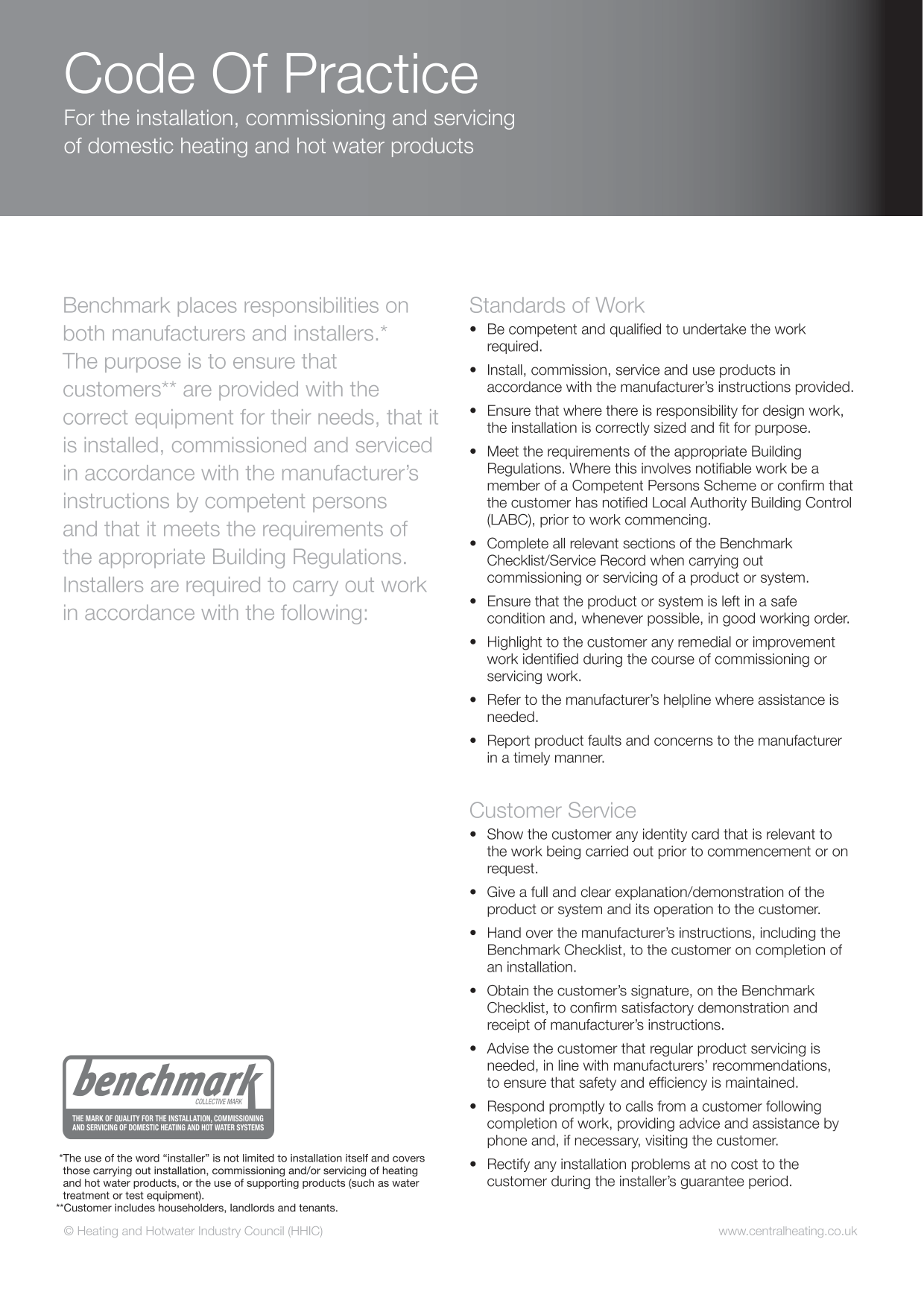
|The operation of the boiler and system controls have been demonstrated to and understood by the customer|The operation of the boiler and system controls have been demonstrated to and understood by the customer|The operation of the boiler and system controls have been demonstrated to and understood by the customer|The operation of the boiler and system controls have been demonstrated to and understood by the customer|The operation of the boiler and system controls have been demonstrated to and understood by the customer|The operation of the boiler and system controls have been demonstrated to and understood by the customer|The operation of the boiler and system controls have been demonstrated to and understood by the customer|The operation of the boiler and system controls have been demonstrated to and understood by the customer|The operation of the boiler and system controls have been demonstrated to and understood by the customer|The operation of the boiler and system controls have been demonstrated to and understood by the customer|The operation of the boiler and system controls have been demonstrated to and understood by the customer|The operation of the boiler and system controls have been demonstrated to and understood by the customer|The operation of the boiler and system controls have been demonstrated to and understood by the customer|The operation of the boiler and system controls have been demonstrated to and understood by the customer|The operation of the boiler and system controls have been demonstrated to and understood by the customer|The operation of the boiler and system controls have been demonstrated to and understood by the customer|The operation of the boiler and system controls have been demonstrated to and understood by the customer|The operation of the boiler and system controls have been demonstrated to and understood by the customer|The operation of the boiler and system controls have been demonstrated to and understood by the customer|The operation of the boiler and system controls have been demonstrated to and understood by the customer|The operation of the boiler and system controls have been demonstrated to and understood by the customer|The operation of the boiler and system controls have been demonstrated to and understood by the customer|The operation of the boiler and system controls have been demonstrated to and understood by the customer|The operation of the boiler and system controls have been demonstrated to and understood by the customer|Yes|Yes|Yes|Yes|Yes|Yes|Yes|Yes| | | | | | |The manufacturers’ literature, including Benchmark Checklist and Service Record, has been explained and left with the customer|The manufacturers’ literature, including Benchmark Checklist and Service Record, has been explained and left with the customer|The manufacturers’ literature, including Benchmark Checklist and Service Record, has been explained and left with the customer|The manufacturers’ literature, including Benchmark Checklist and Service Record, has been explained and left with the customer|The manufacturers’ literature, including Benchmark Checklist and Service Record, has been explained and left with the customer|The manufacturers’ literature, including Benchmark Checklist and Service Record, has been explained and left with the customer|The manufacturers’ literature, including Benchmark Checklist and Service Record, has been explained and left with the customer|The manufacturers’ literature, including Benchmark Checklist and Service Record, has been explained and left with the customer|The manufacturers’ literature, including Benchmark Checklist and Service Record, has been explained and left with the customer|The manufacturers’ literature, including Benchmark Checklist and Service Record, has been explained and left with the customer|The manufacturers’ literature, including Benchmark Checklist and Service Record, has been explained and left with the customer|The manufacturers’ literature, including Benchmark Checklist and Service Record, has been explained and left with the customer|The manufacturers’ literature, including Benchmark Checklist and Service Record, has been explained and left with the customer|The manufacturers’ literature, including Benchmark Checklist and Service Record, has been explained and left with the customer|The manufacturers’ literature, including Benchmark Checklist and Service Record, has been explained and left with the customer|The manufacturers’ literature, including Benchmark Checklist and Service Record, has been explained and left with the customer|The manufacturers’ literature, including Benchmark Checklist and Service Record, has been explained and left with the customer|The manufacturers’ literature, including Benchmark Checklist and Service Record, has been explained and left with the customer|The manufacturers’ literature, including Benchmark Checklist and Service Record, has been explained and left with the customer|The manufacturers’ literature, including Benchmark Checklist and Service Record, has been explained and left with the customer|The manufacturers’ literature, including Benchmark Checklist and Service Record, has been explained and left with the customer|The manufacturers’ literature, including Benchmark Checklist and Service Record, has been explained and left with the customer|The manufacturers’ literature, including Benchmark Checklist and Service Record, has been explained and left with the customer|The manufacturers’ literature, including Benchmark Checklist and Service Record, has been explained and left with the customer|Yes|Yes|Yes|Yes|Yes|Yes|Yes|Yes| | | | | | |Commissioning Engineer’s signature|Commissioning Engineer’s signature|Commissioning Engineer’s signature|Commissioning Engineer’s signature|Commissioning Engineer’s signature|Commissioning Engineer’s signature|Commissioning Engineer’s signature|Commissioning Engineer’s signature|Commissioning Engineer’s signature|Commissioning Engineer’s signature|Commissioning Engineer’s signature|Commissioning Engineer’s signature|Commissioning Engineer’s signature|Commissioning Engineer’s signature|Commissioning Engineer’s signature|Commissioning Engineer’s signature|Commissioning Engineer’s signature|Commissioning Engineer’s signature|Commissioning Engineer’s signature|Commissioning Engineer’s signature|Commissioning Engineer’s signature|Commissioning Engineer’s signature|Commissioning Engineer’s signature|Commissioning Engineer’s signature|Commissioning Engineer’s signature|Commissioning Engineer’s signature|Commissioning Engineer’s signature|Commissioning Engineer’s signature|Commissioning Engineer’s signature|Commissioning Engineer’s signature|Commissioning Engineer’s signature|Commissioning Engineer’s signature|Commissioning Engineer’s signature|Commissioning Engineer’s signature|Commissioning Engineer’s signature|Commissioning Engineer’s signature|Commissioning Engineer’s signature| |Customer’s signature (To confirm satisfactory demonstration and receipt of manufacturers’ literature)|Customer’s signature (To confirm satisfactory demonstration and receipt of manufacturers’ literature)|Customer’s signature (To confirm satisfactory demonstration and receipt of manufacturers’ literature)|Customer’s signature (To confirm satisfactory demonstration and receipt of manufacturers’ literature)|Customer’s signature (To confirm satisfactory demonstration and receipt of manufacturers’ literature)|Customer’s signature (To confirm satisfactory demonstration and receipt of manufacturers’ literature)|Customer’s signature (To confirm satisfactory demonstration and receipt of manufacturers’ literature)|Customer’s signature (To confirm satisfactory demonstration and receipt of manufacturers’ literature)|Customer’s signature (To confirm satisfactory demonstration and receipt of manufacturers’ literature)|Customer’s signature (To confirm satisfactory demonstration and receipt of manufacturers’ literature)|Customer’s signature (To confirm satisfactory demonstration and receipt of manufacturers’ literature)|Customer’s signature (To confirm satisfactory demonstration and receipt of manufacturers’ literature)|Customer’s signature (To confirm satisfactory demonstration and receipt of manufacturers’ literature)|Customer’s signature (To confirm satisfactory demonstration and receipt of manufacturers’ literature)|Customer’s signature (To confirm satisfactory demonstration and receipt of manufacturers’ literature)|Customer’s signature (To confirm satisfactory demonstration and receipt of manufacturers’ literature)|Customer’s signature (To confirm satisfactory demonstration and receipt of manufacturers’ literature)|Customer’s signature (To confirm satisfactory demonstration and receipt of manufacturers’ literature)|Customer’s signature (To confirm satisfactory demonstration and receipt of manufacturers’ literature)|Customer’s signature (To confirm satisfactory demonstration and receipt of manufacturers’ literature)|Customer’s signature (To confirm satisfactory demonstration and receipt of manufacturers’ literature)|Customer’s signature (To confirm satisfactory demonstration and receipt of manufacturers’ literature)|Customer’s signature (To confirm satisfactory demonstration and receipt of manufacturers’ literature)|Customer’s signature (To confirm satisfactory demonstration and receipt of manufacturers’ literature)|Customer’s signature (To confirm satisfactory demonstration and receipt of manufacturers’ literature)|Customer’s signature (To confirm satisfactory demonstration and receipt of manufacturers’ literature)|Customer’s signature (To confirm satisfactory demonstration and receipt of manufacturers’ literature)|Customer’s signature (To confirm satisfactory demonstration and receipt of manufacturers’ literature)|Customer’s signature (To confirm satisfactory demonstration and receipt of manufacturers’ literature)|Customer’s signature (To confirm satisfactory demonstration and receipt of manufacturers’ literature)|Customer’s signature (To confirm satisfactory demonstration and receipt of manufacturers’ literature)|Customer’s signature (To confirm satisfactory demonstration and receipt of manufacturers’ literature)|Customer’s signature (To confirm satisfactory demonstration and receipt of manufacturers’ literature)|Customer’s signature (To confirm satisfactory demonstration and receipt of manufacturers’ literature)|Customer’s signature (To confirm satisfactory demonstration and receipt of manufacturers’ literature)|Customer’s signature (To confirm satisfactory demonstration and receipt of manufacturers’ literature)|Customer’s signature (To confirm satisfactory demonstration and receipt of manufacturers’ literature)|
© Heating and Hotwater Industry Council (HHIC)
www.centralheating.co.uk
manufacturers’ specified spare parts.
|SERVICE/INTERIM WORK ON BOILER delete as appropriate|SERVICE/INTERIM WORK ON BOILER delete as appropriate|SERVICE/INTERIM WORK ON BOILER delete as appropriate|SERVICE/INTERIM WORK ON BOILER delete as appropriate|SERVICE/INTERIM WORK ON BOILER delete as appropriate|Date:|Date:| |---|---|---|---|---|---|---| |Engineer name:|Engineer name:|Engineer name:|Company name:|Company name:|Company name:|Company name:| |Telephone No:|Telephone No:|Telephone No:|Gas Safe registration No:|Gas Safe registration No:|Gas Safe registration No:|Gas Safe registration No:| |Max rate|CO ppm|CO ppm|CO² %|CO/CO²|CO/CO²|CO/CO²| |Min rate|CO ppm|CO ppm|CO² %|CO/CO²|CO/CO²|CO/CO²| |Where possible, has a flue integrity check been undertaken in accordance with manufacturers’ instructions, and readings are correct?”|Where possible, has a flue integrity check been undertaken in accordance with manufacturers’ instructions, and readings are correct?”|Where possible, has a flue integrity check been undertaken in accordance with manufacturers’ instructions, and readings are correct?”|Where possible, has a flue integrity check been undertaken in accordance with manufacturers’ instructions, and readings are correct?”|yes|yes|yes| |Gas rate:|Gas rate:|m3/h|OR|ft3/h|ft3/h|ft3/h| |Were parts fitted?delete as appropriate|Were parts fitted?delete as appropriate|Were parts fitted?delete as appropriate|Yes|No|No|No| |Parts fitted:|Parts fitted:|Parts fitted:|Parts fitted:|Parts fitted:|Parts fitted:|Parts fitted:| |System inhibitor concentration has been checked and appropriate action taken, in accordance with BS 7593 and boiler manufacturers’ instructions. *|System inhibitor concentration has been checked and appropriate action taken, in accordance with BS 7593 and boiler manufacturers’ instructions. *|System inhibitor concentration has been checked and appropriate action taken, in accordance with BS 7593 and boiler manufacturers’ instructions. *|System inhibitor concentration has been checked and appropriate action taken, in accordance with BS 7593 and boiler manufacturers’ instructions. *|yes|yes|n/a| |Comments:|Comments:|Comments:|Comments:|Comments:|Comments:|Comments:| | | | | | | | | |Signature:|Signature:|Signature:|Signature:|Signature:|Signature:|Signature:|
|SERVICE/INTERIM WORK ON BOILER delete as appropriate|SERVICE/INTERIM WORK ON BOILER delete as appropriate|SERVICE/INTERIM WORK ON BOILER delete as appropriate|SERVICE/INTERIM WORK ON BOILER delete as appropriate|SERVICE/INTERIM WORK ON BOILER delete as appropriate|Date:|Date:| |---|---|---|---|---|---|---| |Engineer name:|Engineer name:|Engineer name:|Company name:|Company name:|Company name:|Company name:| |Telephone No:|Telephone No:|Telephone No:|Gas Safe registration No:|Gas Safe registration No:|Gas Safe registration No:|Gas Safe registration No:| |Max rate|CO ppm|CO ppm|CO² %|CO/CO²|CO/CO²|CO/CO²|
|Min rate|CO ppm|CO ppm|CO² %|CO/CO²|CO/CO²|CO/CO²| |Where possible, has a flue integrity check been undertaken in accordance with manufacturers’ instructions, and readings are correct?”|Where possible, has a flue integrity check been undertaken in accordance with manufacturers’ instructions, and readings are correct?”|Where possible, has a flue integrity check been undertaken in accordance with manufacturers’ instructions, and readings are correct?”|Where possible, has a flue integrity check been undertaken in accordance with manufacturers’ instructions, and readings are correct?”|yes|yes|yes| |Gas rate:|Gas rate:|m3/h|OR|ft3/h|ft3/h|ft3/h| |Were parts fitted?delete as appropriate|Were parts fitted?delete as appropriate|Were parts fitted?delete as appropriate|Yes|No|No|No| |Parts fitted:|Parts fitted:|Parts fitted:|Parts fitted:|Parts fitted:|Parts fitted:|Parts fitted:| |System inhibitor concentration has been checked and appropriate action taken, in accordance with BS 7593 and boiler manufacturers’ instructions. *|System inhibitor concentration has been checked and appropriate action taken, in accordance with BS 7593 and boiler manufacturers’ instructions. *|System inhibitor concentration has been checked and appropriate action taken, in accordance with BS 7593 and boiler manufacturers’ instructions. *|System inhibitor concentration has been checked and appropriate action taken, in accordance with BS 7593 and boiler manufacturers’ instructions. *|yes|yes|n/a| |Comments:|Comments:|Comments:|Comments:|Comments:|Comments:|Comments:| | | | | | | | | |Signature:|Signature:|Signature:|Signature:|Signature:|Signature:|Signature:|
*A System inhibitor efficacy test is required on every annual service in accordance with the manufacturers’ instructions and BS 7593. It is only acceptable to not have undertaken this if the service engineers attendance visit was in between annual services to attend a non-water facing component.
|SERVICE/INTERIM WORK ON BOILER delete as appropriate|SERVICE/INTERIM WORK ON BOILER delete as appropriate|SERVICE/INTERIM WORK ON BOILER delete as appropriate|SERVICE/INTERIM WORK ON BOILER delete as appropriate|SERVICE/INTERIM WORK ON BOILER delete as appropriate|Date:|Date:| |---|---|---|---|---|---|---| |Engineer name:|Engineer name:|Engineer name:|Company name:|Company name:|Company name:|Company name:| |Telephone No:|Telephone No:|Telephone No:|Gas Safe registration No:|Gas Safe registration No:|Gas Safe registration No:|Gas Safe registration No:| |Max rate|CO ppm|CO ppm|CO² %|CO/CO²|CO/CO²|CO/CO²| |Min rate|CO ppm|CO ppm|CO² %|CO/CO²|CO/CO²|CO/CO²| |Where possible, has a flue integrity check been undertaken in accordance with manufacturers’ instructions, and readings are correct?”|Where possible, has a flue integrity check been undertaken in accordance with manufacturers’ instructions, and readings are correct?”|Where possible, has a flue integrity check been undertaken in accordance with manufacturers’ instructions, and readings are correct?”|Where possible, has a flue integrity check been undertaken in accordance with manufacturers’ instructions, and readings are correct?”|yes|yes|yes| |Gas rate:|Gas rate:|m3/h|OR|ft3/h|ft3/h|ft3/h| |Were parts fitted?delete as appropriate|Were parts fitted?delete as appropriate|Were parts fitted?delete as appropriate|Yes|No|No|No| |Parts fitted:|Parts fitted:|Parts fitted:|Parts fitted:|Parts fitted:|Parts fitted:|Parts fitted:| |System inhibitor concentration has been checked and appropriate action taken, in accordance with BS 7593 and boiler manufacturers’ instructions. *|System inhibitor concentration has been checked and appropriate action taken, in accordance with BS 7593 and boiler manufacturers’ instructions. *|System inhibitor concentration has been checked and appropriate action taken, in accordance with BS 7593 and boiler manufacturers’ instructions. *|System inhibitor concentration has been checked and appropriate action taken, in accordance with BS 7593 and boiler manufacturers’ instructions. *|yes|yes|n/a| |Comments:|Comments:|Comments:|Comments:|Comments:|Comments:|Comments:| | | | | | | | | |Signature:|Signature:|Signature:|Signature:|Signature:|Signature:|Signature:|
|SERVICE/INTERIM WORK ON BOILER delete as appropriate|SERVICE/INTERIM WORK ON BOILER delete as appropriate|SERVICE/INTERIM WORK ON BOILER delete as appropriate|SERVICE/INTERIM WORK ON BOILER delete as appropriate|SERVICE/INTERIM WORK ON BOILER delete as appropriate|Date:|Date:|
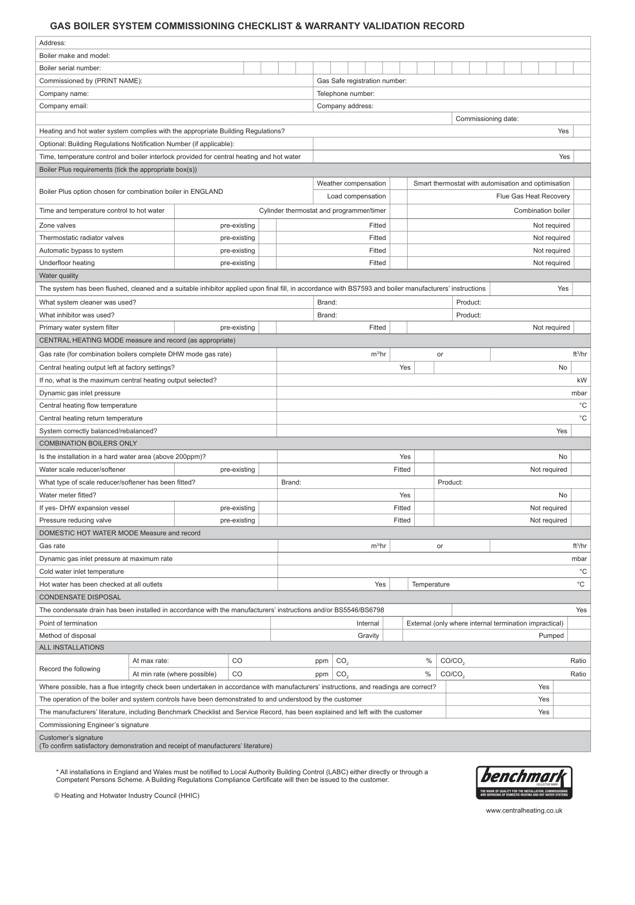
|---|---|---|---|---|---|---| |Engineer name:|Engineer name:|Engineer name:|Company name:|Company name:|Company name:|Company name:| |Telephone No:|Telephone No:|Telephone No:|Gas Safe registration No:|Gas Safe registration No:|Gas Safe registration No:|Gas Safe registration No:| |Max rate|CO ppm|CO ppm|CO² %|CO/CO²|CO/CO²|CO/CO²| |Min rate|CO ppm|CO ppm|CO² %|CO/CO²|CO/CO²|CO/CO²| |Where possible, has a flue integrity check been undertaken in accordance with manufacturers’ instructions, and readings are correct?”|Where possible, has a flue integrity check been undertaken in accordance with manufacturers’ instructions, and readings are correct?”|Where possible, has a flue integrity check been undertaken in accordance with manufacturers’ instructions, and readings are correct?”|Where possible, has a flue integrity check been undertaken in accordance with manufacturers’ instructions, and readings are correct?”|yes|yes|yes| |Gas rate:|Gas rate:|m3/h|OR|ft3/h|ft3/h|ft3/h| |Were parts fitted?delete as appropriate|Were parts fitted?delete as appropriate|Were parts fitted?delete as appropriate|Yes|No|No|No| |Parts fitted:|Parts fitted:|Parts fitted:|Parts fitted:|Parts fitted:|Parts fitted:|Parts fitted:| |System inhibitor concentration has been checked and appropriate action taken, in accordance with BS 7593 and boiler manufacturers’ instructions. *|System inhibitor concentration has been checked and appropriate action taken, in accordance with BS 7593 and boiler manufacturers’ instructions. *|System inhibitor concentration has been checked and appropriate action taken, in accordance with BS 7593 and boiler manufacturers’ instructions. *|System inhibitor concentration has been checked and appropriate action taken, in accordance with BS 7593 and boiler manufacturers’ instructions. *|yes|yes|n/a| |Comments:|Comments:|Comments:|Comments:|Comments:|Comments:|Comments:| | | | | | | | | |Signature:|Signature:|Signature:|Signature:|Signature:|Signature:|Signature:|
*A System inhibitor efficacy test is required on every annual service in accordance with the manufacturers’ instructions and BS 7593. It is only acceptable to not have undertaken this if the service engineers attendance visit was in between annual services to attend a non-water facing component.
|SERVICE/INTERIM WORK ON BOILER delete as appropriate|SERVICE/INTERIM WORK ON BOILER delete as appropriate|SERVICE/INTERIM WORK ON BOILER delete as appropriate|SERVICE/INTERIM WORK ON BOILER delete as appropriate|SERVICE/INTERIM WORK ON BOILER delete as appropriate|Date:|Date:| |---|---|---|---|---|---|---| |Engineer name:|Engineer name:|Engineer name:|Company name:|Company name:|Company name:|Company name:| |Telephone No:|Telephone No:|Telephone No:|Gas Safe registration No:|Gas Safe registration No:|Gas Safe registration No:|Gas Safe registration No:| |Max rate|CO ppm|CO ppm|CO² %|CO/CO²|CO/CO²|CO/CO²| |Min rate|CO ppm|CO ppm|CO² %|CO/CO²|CO/CO²|CO/CO²| |Where possible, has a flue integrity check been undertaken in accordance with manufacturers’ instructions, and readings are correct?”|Where possible, has a flue integrity check been undertaken in accordance with manufacturers’ instructions, and readings are correct?”|Where possible, has a flue integrity check been undertaken in accordance with manufacturers’ instructions, and readings are correct?”|Where possible, has a flue integrity check been undertaken in accordance with manufacturers’ instructions, and readings are correct?”|yes|yes|yes| |Gas rate:|Gas rate:|m3/h|OR|ft3/h|ft3/h|ft3/h| |Were parts fitted?delete as appropriate|Were parts fitted?delete as appropriate|Were parts fitted?delete as appropriate|Yes|No|No|No| |Parts fitted:|Parts fitted:|Parts fitted:|Parts fitted:|Parts fitted:|Parts fitted:|Parts fitted:| |System inhibitor concentration has been checked and appropriate action taken, in accordance with BS 7593 and boiler manufacturers’ instructions. *|System inhibitor concentration has been checked and appropriate action taken, in accordance with BS 7593 and boiler manufacturers’ instructions. *|System inhibitor concentration has been checked and appropriate action taken, in accordance with BS 7593 and boiler manufacturers’ instructions. *|System inhibitor concentration has been checked and appropriate action taken, in accordance with BS 7593 and boiler manufacturers’ instructions. *|yes|yes|n/a| |Comments:|Comments:|Comments:|Comments:|Comments:|Comments:|Comments:| | | | | | | | | |Signature:|Signature:|Signature:|Signature:|Signature:|Signature:|Signature:|
|SERVICE/INTERIM WORK ON BOILER delete as appropriate|SERVICE/INTERIM WORK ON BOILER delete as appropriate|SERVICE/INTERIM WORK ON BOILER delete as appropriate|SERVICE/INTERIM WORK ON BOILER delete as appropriate|SERVICE/INTERIM WORK ON BOILER delete as appropriate|Date:|Date:| |---|---|---|---|---|---|---|

|Engineer name:|Engineer name:|Engineer name:|Company name:|Company name:|Company name:|Company name:| |Telephone No:|Telephone No:|Telephone No:|Gas Safe registration No:|Gas Safe registration No:|Gas Safe registration No:|Gas Safe registration No:| |Max rate|CO ppm|CO ppm|CO² %|CO/CO²|CO/CO²|CO/CO²| |Min rate|CO ppm|CO ppm|CO² %|CO/CO²|CO/CO²|CO/CO²| |Where possible, has a flue integrity check been undertaken in accordance with manufacturers’ instructions, and readings are correct?”|Where possible, has a flue integrity check been undertaken in accordance with manufacturers’ instructions, and readings are correct?”|Where possible, has a flue integrity check been undertaken in accordance with manufacturers’ instructions, and readings are correct?”|Where possible, has a flue integrity check been undertaken in accordance with manufacturers’ instructions, and readings are correct?”|yes|yes|yes| |Gas rate:|Gas rate:|m3/h|OR|ft3/h|ft3/h|ft3/h| |Were parts fitted?delete as appropriate|Were parts fitted?delete as appropriate|Were parts fitted?delete as appropriate|Yes|No|No|No| |Parts fitted:|Parts fitted:|Parts fitted:|Parts fitted:|Parts fitted:|Parts fitted:|Parts fitted:| |System inhibitor concentration has been checked and appropriate action taken, in accordance with BS 7593 and boiler manufacturers’ instructions. *|System inhibitor concentration has been checked and appropriate action taken, in accordance with BS 7593 and boiler manufacturers’ instructions. *|System inhibitor concentration has been checked and appropriate action taken, in accordance with BS 7593 and boiler manufacturers’ instructions. *|System inhibitor concentration has been checked and appropriate action taken, in accordance with BS 7593 and boiler manufacturers’ instructions. *|yes|yes|n/a| |Comments:|Comments:|Comments:|Comments:|Comments:|Comments:|Comments:| | | | | | | | | |Signature:|Signature:|Signature:|Signature:|Signature:|Signature:|Signature:|
manufacturers specified spare parts.
|SERVICE/INTERIM WORK ON BOILER delete as appropriate|SERVICE/INTERIM WORK ON BOILER delete as appropriate|SERVICE/INTERIM WORK ON BOILER delete as appropriate|SERVICE/INTERIM WORK ON BOILER delete as appropriate|SERVICE/INTERIM WORK ON BOILER delete as appropriate|Date:|Date:| |---|---|---|---|---|---|---| |Engineer name:|Engineer name:|Engineer name:|Company name:|Company name:|Company name:|Company name:| |Telephone No:|Telephone No:|Telephone No:|Gas Safe registration No:|Gas Safe registration No:|Gas Safe registration No:|Gas Safe registration No:| |Max rate|CO ppm|CO ppm|CO² %|CO/CO²|CO/CO²|CO/CO²| |Min rate|CO ppm|CO ppm|CO² %|CO/CO²|CO/CO²|CO/CO²| |Where possible, has a flue integrity check been undertaken in accordance with manufacturers’ instructions, and readings are correct?”|Where possible, has a flue integrity check been undertaken in accordance with manufacturers’ instructions, and readings are correct?”|Where possible, has a flue integrity check been undertaken in accordance with manufacturers’ instructions, and readings are correct?”|Where possible, has a flue integrity check been undertaken in accordance with manufacturers’ instructions, and readings are correct?”|yes|yes|yes| |Gas rate:|Gas rate:|m3/h|OR|ft3/h|ft3/h|ft3/h| |Were parts fitted?delete as appropriate|Were parts fitted?delete as appropriate|Were parts fitted?delete as appropriate|Yes|No|No|No| |Parts fitted:|Parts fitted:|Parts fitted:|Parts fitted:|Parts fitted:|Parts fitted:|Parts fitted:| |System inhibitor concentration has been checked and appropriate action taken, in accordance with BS 7593 and boiler manufacturers’ instructions. *|System inhibitor concentration has been checked and appropriate action taken, in accordance with BS 7593 and boiler manufacturers’ instructions. *|System inhibitor concentration has been checked and appropriate action taken, in accordance with BS 7593 and boiler manufacturers’ instructions. *|System inhibitor concentration has been checked and appropriate action taken, in accordance with BS 7593 and boiler manufacturers’ instructions. *|yes|yes|n/a| |Comments:|Comments:|Comments:|Comments:|Comments:|Comments:|Comments:| | | | | | | | | |Signature:|Signature:|Signature:|Signature:|Signature:|Signature:|Signature:|
|SERVICE/INTERIM WORK ON BOILER delete as appropriate|SERVICE/INTERIM WORK ON BOILER delete as appropriate|SERVICE/INTERIM WORK ON BOILER delete as appropriate|SERVICE/INTERIM WORK ON BOILER delete as appropriate|SERVICE/INTERIM WORK ON BOILER delete as appropriate|Date:|Date:| |---|---|---|---|---|---|---| |Engineer name:|Engineer name:|Engineer name:|Company name:|Company name:|Company name:|Company name:|
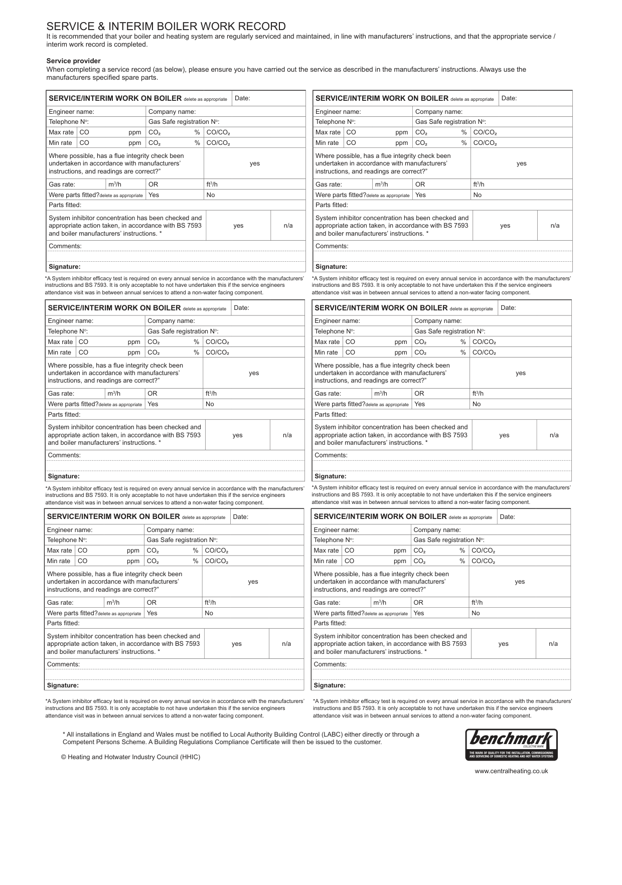
|Telephone No:|Telephone No:|Telephone No:|Gas Safe registration No:|Gas Safe registration No:|Gas Safe registration No:|Gas Safe registration No:| |Max rate|CO ppm|CO ppm|CO² %|CO/CO²|CO/CO²|CO/CO²| |Min rate|CO ppm|CO ppm|CO² %|CO/CO²|CO/CO²|CO/CO²| |Where possible, has a flue integrity check been undertaken in accordance with manufacturers’ instructions, and readings are correct?”|Where possible, has a flue integrity check been undertaken in accordance with manufacturers’ instructions, and readings are correct?”|Where possible, has a flue integrity check been undertaken in accordance with manufacturers’ instructions, and readings are correct?”|Where possible, has a flue integrity check been undertaken in accordance with manufacturers’ instructions, and readings are correct?”|yes|yes|yes| |Gas rate:|Gas rate:|m3/h|OR|ft3/h|ft3/h|ft3/h| |Were parts fitted?delete as appropriate|Were parts fitted?delete as appropriate|Were parts fitted?delete as appropriate|Yes|No|No|No| |Parts fitted:|Parts fitted:|Parts fitted:|Parts fitted:|Parts fitted:|Parts fitted:|Parts fitted:| |System inhibitor concentration has been checked and appropriate action taken, in accordance with BS 7593 and boiler manufacturers’ instructions. *|System inhibitor concentration has been checked and appropriate action taken, in accordance with BS 7593 and boiler manufacturers’ instructions. *|System inhibitor concentration has been checked and appropriate action taken, in accordance with BS 7593 and boiler manufacturers’ instructions. *|System inhibitor concentration has been checked and appropriate action taken, in accordance with BS 7593 and boiler manufacturers’ instructions. *|yes|yes|n/a| |Comments:|Comments:|Comments:|Comments:|Comments:|Comments:|Comments:| | | | | | | | | |Signature:|Signature:|Signature:|Signature:|Signature:|Signature:|Signature:|
*A System inhibitor efficacy test is required on every annual service in accordance with the manufacturers’ instructions and BS 7593. It is only acceptable to not have undertaken this if the service engineers attendance visit was in between annual services to attend a non-water facing component.
*A System inhibitor efficacy test is required on every annual service in accordance with the manufacturers’ instructions and BS 7593. It is only acceptable to not have undertaken this if the service engineers attendance visit was in between annual services to attend a non-water facing component.
|SERVICE/INTERIM WORK ON BOILER delete as appropriate|SERVICE/INTERIM WORK ON BOILER delete as appropriate|SERVICE/INTERIM WORK ON BOILER delete as appropriate|SERVICE/INTERIM WORK ON BOILER delete as appropriate|SERVICE/INTERIM WORK ON BOILER delete as appropriate|Date:|Date:| |---|---|---|---|---|---|---| |Engineer name:|Engineer name:|Engineer name:|Company name:|Company name:|Company name:|Company name:| |Telephone No:|Telephone No:|Telephone No:|Gas Safe registration No:|Gas Safe registration No:|Gas Safe registration No:|Gas Safe registration No:| |Max rate|CO ppm|CO ppm|CO² %|CO/CO²|CO/CO²|CO/CO²| |Min rate|CO ppm|CO ppm|CO² %|CO/CO²|CO/CO²|CO/CO²| |Where possible, has a flue integrity check been undertaken in accordance with manufacturers’ instructions, and readings are correct?”|Where possible, has a flue integrity check been undertaken in accordance with manufacturers’ instructions, and readings are correct?”|Where possible, has a flue integrity check been undertaken in accordance with manufacturers’ instructions, and readings are correct?”|Where possible, has a flue integrity check been undertaken in accordance with manufacturers’ instructions, and readings are correct?”|yes|yes|yes| |Gas rate:|Gas rate:|m3/h|OR|ft3/h|ft3/h|ft3/h| |Were parts fitted?delete as appropriate|Were parts fitted?delete as appropriate|Were parts fitted?delete as appropriate|Yes|No|No|No| |Parts fitted:|Parts fitted:|Parts fitted:|Parts fitted:|Parts fitted:|Parts fitted:|Parts fitted:| |System inhibitor concentration has been checked and appropriate action taken, in accordance with BS 7593 and boiler manufacturers’ instructions. *|System inhibitor concentration has been checked and appropriate action taken, in accordance with BS 7593 and boiler manufacturers’ instructions. *|System inhibitor concentration has been checked and appropriate action taken, in accordance with BS 7593 and boiler manufacturers’ instructions. *|System inhibitor concentration has been checked and appropriate action taken, in accordance with BS 7593 and boiler manufacturers’ instructions. *|yes|yes|n/a| |Comments:|Comments:|Comments:|Comments:|Comments:|Comments:|Comments:| | | | | | | | | |Signature:|Signature:|Signature:|Signature:|Signature:|Signature:|Signature:|
|SERVICE/INTERIM WORK ON BOILER delete as appropriate|SERVICE/INTERIM WORK ON BOILER delete as appropriate|SERVICE/INTERIM WORK ON BOILER delete as appropriate|SERVICE/INTERIM WORK ON BOILER delete as appropriate|SERVICE/INTERIM WORK ON BOILER delete as appropriate|Date:|Date:| |---|---|---|---|---|---|---|
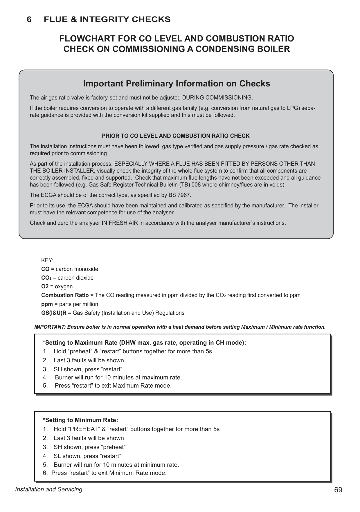
|Engineer name:|Engineer name:|Engineer name:|Company name:|Company name:|Company name:|Company name:| |Telephone No:|Telephone No:|Telephone No:|Gas Safe registration No:|Gas Safe registration No:|Gas Safe registration No:|Gas Safe registration No:| |Max rate|CO ppm|CO ppm|CO² %|CO/CO²|CO/CO²|CO/CO²| |Min rate|CO ppm|CO ppm|CO² %|CO/CO²|CO/CO²|CO/CO²| |Where possible, has a flue integrity check been undertaken in accordance with manufacturers’ instructions, and readings are correct?”|Where possible, has a flue integrity check been undertaken in accordance with manufacturers’ instructions, and readings are correct?”|Where possible, has a flue integrity check been undertaken in accordance with manufacturers’ instructions, and readings are correct?”|Where possible, has a flue integrity check been undertaken in accordance with manufacturers’ instructions, and readings are correct?”|yes|yes|yes| |Gas rate:|Gas rate:|m3/h|OR|ft3/h|ft3/h|ft3/h| |Were parts fitted?delete as appropriate|Were parts fitted?delete as appropriate|Were parts fitted?delete as appropriate|Yes|No|No|No| |Parts fitted:|Parts fitted:|Parts fitted:|Parts fitted:|Parts fitted:|Parts fitted:|Parts fitted:| |System inhibitor concentration has been checked and appropriate action taken, in accordance with BS 7593 and boiler manufacturers’ instructions. *|System inhibitor concentration has been checked and appropriate action taken, in accordance with BS 7593 and boiler manufacturers’ instructions. *|System inhibitor concentration has been checked and appropriate action taken, in accordance with BS 7593 and boiler manufacturers’ instructions. *|System inhibitor concentration has been checked and appropriate action taken, in accordance with BS 7593 and boiler manufacturers’ instructions. *|yes|yes|n/a| |Comments:|Comments:|Comments:|Comments:|Comments:|Comments:|Comments:| | | | | | | | | |Signature:|Signature:|Signature:|Signature:|Signature:|Signature:|Signature:|
*A System inhibitor efficacy test is required on every annual service in accordance with the manufacturers’ instructions and BS 7593. It is only acceptable to not have undertaken this if the service engineers attendance visit was in between annual services to attend a non-water facing component.
*A System inhibitor efficacy test is required on every annual service in accordance with the manufacturers’ instructions and BS 7593. It is only acceptable to not have undertaken this if the service engineers attendance visit was in between annual services to attend a non-water facing component.
|SERVICE/INTERIM WORK ON BOILER delete as appropriate|SERVICE/INTERIM WORK ON BOILER delete as appropriate|SERVICE/INTERIM WORK ON BOILER delete as appropriate|SERVICE/INTERIM WORK ON BOILER delete as appropriate|SERVICE/INTERIM WORK ON BOILER delete as appropriate|Date:|Date:| |---|---|---|---|---|---|---| |Engineer name:|Engineer name:|Engineer name:|Company name:|Company name:|Company name:|Company name:| |Telephone No:|Telephone No:|Telephone No:|Gas Safe registration No:|Gas Safe registration No:|Gas Safe registration No:|Gas Safe registration No:| |Max rate|CO ppm|CO ppm|CO² %|CO/CO²|CO/CO²|CO/CO²| |Min rate|CO ppm|CO ppm|CO² %|CO/CO²|CO/CO²|CO/CO²| |Where possible, has a flue integrity check been undertaken in accordance with manufacturers’ instructions, and readings are correct?”|Where possible, has a flue integrity check been undertaken in accordance with manufacturers’ instructions, and readings are correct?”|Where possible, has a flue integrity check been undertaken in accordance with manufacturers’ instructions, and readings are correct?”|Where possible, has a flue integrity check been undertaken in accordance with manufacturers’ instructions, and readings are correct?”|yes|yes|yes| |Gas rate:|Gas rate:|m3/h|OR|ft3/h|ft3/h|ft3/h| |Were parts fitted?delete as appropriate|Were parts fitted?delete as appropriate|Were parts fitted?delete as appropriate|Yes|No|No|No| |Parts fitted:|Parts fitted:|Parts fitted:|Parts fitted:|Parts fitted:|Parts fitted:|Parts fitted:| |System inhibitor concentration has been checked and appropriate action taken, in accordance with BS 7593 and boiler manufacturers’ instructions. *|System inhibitor concentration has been checked and appropriate action taken, in accordance with BS 7593 and boiler manufacturers’ instructions. *|System inhibitor concentration has been checked and appropriate action taken, in accordance with BS 7593 and boiler manufacturers’ instructions. *|System inhibitor concentration has been checked and appropriate action taken, in accordance with BS 7593 and boiler manufacturers’ instructions. *|yes|yes|n/a| |Comments:|Comments:|Comments:|Comments:|Comments:|Comments:|Comments:| | | | | | | | | |Signature:|Signature:|Signature:|Signature:|Signature:|Signature:|Signature:|
|SERVICE/INTERIM WORK ON BOILER delete as appropriate|SERVICE/INTERIM WORK ON BOILER delete as appropriate|SERVICE/INTERIM WORK ON BOILER delete as appropriate|SERVICE/INTERIM WORK ON BOILER delete as appropriate|SERVICE/INTERIM WORK ON BOILER delete as appropriate|Date:|Date:|
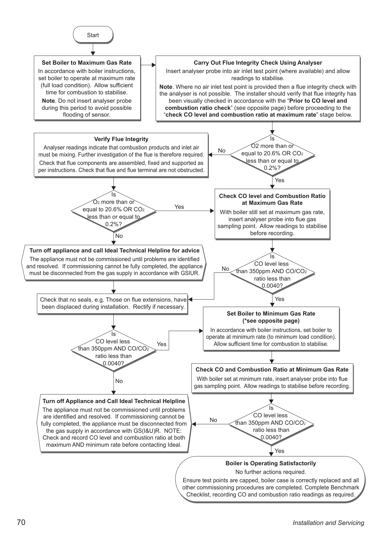
|---|---|---|---|---|---|---| |Engineer name:|Engineer name:|Engineer name:|Company name:|Company name:|Company name:|Company name:| |Telephone No:|Telephone No:|Telephone No:|Gas Safe registration No:|Gas Safe registration No:|Gas Safe registration No:|Gas Safe registration No:| |Max rate|CO ppm|CO ppm|CO² %|CO/CO²|CO/CO²|CO/CO²| |Min rate|CO ppm|CO ppm|CO² %|CO/CO²|CO/CO²|CO/CO²| |Where possible, has a flue integrity check been undertaken in accordance with manufacturers’ instructions, and readings are correct?”|Where possible, has a flue integrity check been undertaken in accordance with manufacturers’ instructions, and readings are correct?”|Where possible, has a flue integrity check been undertaken in accordance with manufacturers’ instructions, and readings are correct?”|Where possible, has a flue integrity check been undertaken in accordance with manufacturers’ instructions, and readings are correct?”|yes|yes|yes| |Gas rate:|Gas rate:|m3/h|OR|ft3/h|ft3/h|ft3/h| |Were parts fitted?delete as appropriate|Were parts fitted?delete as appropriate|Were parts fitted?delete as appropriate|Yes|No|No|No| |Parts fitted:|Parts fitted:|Parts fitted:|Parts fitted:|Parts fitted:|Parts fitted:|Parts fitted:| |System inhibitor concentration has been checked and appropriate action taken, in accordance with BS 7593 and boiler manufacturers’ instructions. *|System inhibitor concentration has been checked and appropriate action taken, in accordance with BS 7593 and boiler manufacturers’ instructions. *|System inhibitor concentration has been checked and appropriate action taken, in accordance with BS 7593 and boiler manufacturers’ instructions. *|System inhibitor concentration has been checked and appropriate action taken, in accordance with BS 7593 and boiler manufacturers’ instructions. *|yes|yes|n/a| |Comments:|Comments:|Comments:|Comments:|Comments:|Comments:|Comments:| | | | | | | | | |Signature:|Signature:|Signature:|Signature:|Signature:|Signature:|Signature:|
########### 6 FLUE & INTEGRITY CHECKS
####### FLOWCHART FOR CO LEVEL AND COMBUSTION RATIO CHECK ON COMMISSIONING A CONDENSING BOILER
Important Preliminary Information on Checks The air gas ratio valve is factory-set and must not be adjusted DURING COMMISSIONING. If the boiler requires conversion to operate with a different gas family (e.g. conversion from natural gas to LPG) separate guidance is provided with the conversion kit supplied and this must be followed.
################## PRIOR TO CO LEVEL AND COMBUSTION RATIO CHECK
The installation instructions must have been followed, gas type verified and gas supply pressure / gas rate checked as required prior to commissioning.
As part of the installation process, ESPECIALLY WHERE A FLUE HAS BEEN FITTED BY PERSONS OTHER THAN THE BOILER INSTALLER, visually check the integrity of the whole flue system to confirm that all components are correctly assembled, fixed and supported. Check that maximum flue lengths have not been exceeded and all guidance has been followed (e.g. Gas Safe Register Technical Bulletin (TB) 008 where chimney/flues are in voids).
The ECGA should be of the correct type, as specified by BS 7967. Prior to its use, the ECGA should have been maintained and calibrated as specified by the manufacturer. The installer must have the relevant competence for use of the analyser. Check and zero the analyser IN FRESH AIR in accordance with the analyser manufacturer’s instructions.
KEY: CO = carbon monoxide CO2 = carbon dioxide O2 = oxygen Combustion Ratio = The CO reading measured in ppm divided by the CO2 reading first converted to ppm ppm = parts per million GS(I&U)R = Gas Safety (Installation and Use) Regulations
IMPORTANT: Ensure boiler is in normal operation with a heat demand before setting Maximum / Minimum rate function.
|*Setting to Maximum Rate (DHW max. gas rate, operating in CH mode):
1. Hold “preheat” & “restart” buttons together for more than 5s
2. Last 3 faults will be shown
3. SH shown, press “restart”
4. Burner will run for 10 minutes at maximum rate.
5. Press “restart” to exit Maximum Rate mode.
| |---|

|*Setting to Minimum Rate:
1. Hold “PREHEAT” & “restart” buttons together for more than 5s
2. Last 3 faults will be shown
3. SH shown, press “preheat”
4. SL shown, press “restart”
5. Burner will run for 10 minutes at minimum rate.
6. Press “restart” to exit Minimum Rate mode.
| |---|
Start
|Carry Out Flue Integrity Check Using Analyser Insert analyser probe into air inlet test point (where available) and allow readings to stabilise.
Note. Where no air inlet test point is provided then a flue integrity check with the analyser is not possible. The installer should verify that flue integrity has been visually checked in accordance with the “Prior to CO level and combustion ratio check” (see opposite page) before proceeding to the “check CO level and combustion ratio at maximum rate” stage below.|Carry Out Flue Integrity Check Using Analyser Insert analyser probe into air inlet test point (where available) and allow readings to stabilise.
Note. Where no air inlet test point is provided then a flue integrity check with the analyser is not possible. The installer should verify that flue integrity has been visually checked in accordance with the “Prior to CO level and combustion ratio check” (see opposite page) before proceeding to the “check CO level and combustion ratio at maximum rate” stage below.| |---|---| | | |
|Set Boiler to Maximum Gas Rate In accordance with boiler instructions, set boiler to operate at maximum rate (full load condition). Allow sufficient time for combustion to stabilise.
Note. Do not insert analyser probe during this period to avoid possible flooding of sensor.| | |---|---| |Set Boiler to Maximum Gas Rate In accordance with boiler instructions, set boiler to operate at maximum rate (full load condition). Allow sufficient time for combustion to stabilise.
Note. Do not insert analyser probe during this period to avoid possible flooding of sensor.| |
|Verify Flue Integrity Analyser readings indicate that combustion products and inlet air must be mixing. Further investigation of the flue is therefore required. Check that flue components are assembled, fixed and supported as per instructions. Check that flue and flue terminal are not obstructed.| |---|
Is O2 more than or equal to 20.6% OR CO2 less than or equal to 0.2%?
No
Yes
|Check CO level and Combustion Ratio at Maximum Gas Rate
With boiler still set at maximum gas rate, insert analyser probe into flue gas sampling point. Allow readings to stabilise before recording.|Check CO level and Combustion Ratio at Maximum Gas Rate
With boiler still set at maximum gas rate, insert analyser probe into flue gas sampling point. Allow readings to stabilise before recording.| |---|---| | | |
Is O2 more than or equal to 20.6% OR CO2 less than or equal to 0.2%?
Yes
No
Turn off appliance and call Ideal Technical Helpline for advice The appliance must not be commissioned until problems are identified and resolved. If commissioning cannot be fully completed, the appliance must be disconnected from the gas supply in accordance with GSIUR.
Is CO level less than 350ppm AND CO/CO2 ratio less than 0.0040?
No
Yes
Check that no seals, e.g. Those on flue extensions, have been displaced during installation. Rectify if necessary.
|Set Boiler to Minimum Gas Rate (*see opposite page)
In accordance with boiler instructions, set boiler to operate at minimum rate (to minimum load condition). Allow sufficient time for combustion to stabilise.|Set Boiler to Minimum Gas Rate (*see opposite page)
In accordance with boiler instructions, set boiler to operate at minimum rate (to minimum load condition). Allow sufficient time for combustion to stabilise.| |---|---| | | |
Is CO level less than 350ppm AND CO/CO2 ratio less than 0.0040?
Yes
Check CO and Combustion Ratio at Minimum Gas Rate With boiler set at minimum rate, insert analyser probe into flue gas sampling point. Allow readings to stabilise before recording.
No
Turn off Appliance and Call Ideal Technical Helpline The appliance must not be commissioned until problems are identified and resolved. If commissioning cannot be fully completed, the appliance must be disconnected from the gas supply in accordance with GS(I&U)R. NOTE: Check and record CO level and combustion ratio at both maximum AND minimum rate before contacting Ideal.
Is CO level less than 350ppm AND CO/CO2 ratio less than 0.0040?
No
Yes
Boiler is Operating Satisfactorily No further actions required.
Ensure test points are capped, boiler case is correctly replaced and all other commissioning procedures are completed. Complete Benchmark Checklist, recording CO and combustion ratio readings as required.
############# NOTES
Installation and Servicing
71
|At Ideal Heating we take our environmental impact seriously, therefore when installing any Ideal Heating product please make sure to dispose of any previous appliance in an environmentally conscious manner. Households can contact their local authority to find out how. See https://www.gov.uk/managing-your-waste-an-overview for guidance on how to efficiently recycle your business waste.
| |---|
Ideal Boilers Ltd., pursues a policy of continuing improvement in the design and performance of its products. The right is therefore reserved to vary specification without notice.
Ideal is a trademark of Ideal Boilers. Registered Office Ideal Boilers Ltd., National Avenue, Hull, East Yorkshire, HU5 4JB Tel 01482 492251 Fax 01482 448858 Registration No. London 322 137
EU Authorised Representative: Atlantic SFDT 44 Boulevard des Etats-Unis, 85 000 La Roche-Sur-Yon, France +33 (0)2 51 44 34 34
############### Ideal Heating provides after-sales assistance and Technical advice for Atlantic combi boilers
Ideal Technical Helpline: 01482 498663