
Ask AI
— answers from the official manualAnswers from the official manual.
Common questions
Common Questions
29 totalHow do I reset the Ideal Boilers I 24 after a fault?
To reset the boiler, turn the mode knob to the reset position and immediately turn the knob back to the required setting. The boiler will repeat the ignition sequence if a heat demand is present. This reset procedure is noted in the document amendments section. (Page 5)
What is the maximum working pressure for the I 24 boiler?
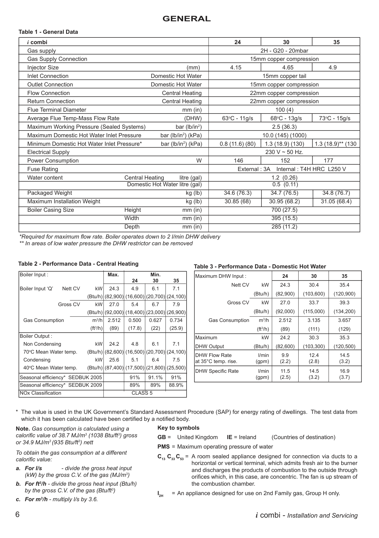
The maximum working pressure for sealed systems is 2.5 bar (36.3 lb/in²). The safety valve has a non-adjustable preset lift pressure of 3 bar. The system should be filled until the pressure gauge registers 1 bar, then checked for leaks. (Page 6)
What is the domestic hot water flow rate for the I 24 at 35°C temperature rise?
The I 24 delivers a nominal DHW flow rate of 9.9 litres per minute at a 35°C temperature rise. The DHW flow rate is automatically regulated to a maximum of 9.9 l/min (2.2 gpm). Due to system variations and seasonal temperature fluctuations, DHW flow rates and temperature rise will vary, requiring adjustment at the draw-off tap. (Page 8)
Does the I 24 boiler require a purpose-provided air vent in the room where it is installed?
It is NOT necessary to have a purpose-provided air vent in the room or internal space in which the boiler is installed. Neither is it necessary to ventilate a cupboard or compartment in which the boiler is installed, due to the low surface temperatures of the boiler casing during operation. Therefore, the requirements of BS 6798, Clause 12, and BS 5440:2 may be disregarded. (Page 11)
What type of pipework must be used for the condensate drain on the I 24?
All pipework and fittings in the condensate drainage system MUST be made of plastic — no other materials may be used. Internal plastic pipework must be a minimum of 19mm internal diameter (typically 22mm OD), and external plastic pipe must be a minimum of 30mm internal diameter (typically 32mm OD) before it passes through the sleeved wall. All horizontal pipe runs must fall a minimum of 45mm per metre away from the boiler. (Page 11)
What water treatment products does Ideal Boilers recommend for the I 24?
Ideal Boilers recommend only the use of Scalemaster Gold 100, FERNOX-MB-1, ADEY MC1, SENTINEL-X100, or CALMAG CM100 inhibitors and associated water treatment products. These must be used in accordance with the manufacturers' instructions. The application of any other treatment to this product may render the guarantee of the i combi invalid. (Page 14)
Show 23 more questions
What is the maximum horizontal flue length for the I 24 boiler?
What electrical supply does the I 24 boiler require, and what fuse rating should be used?
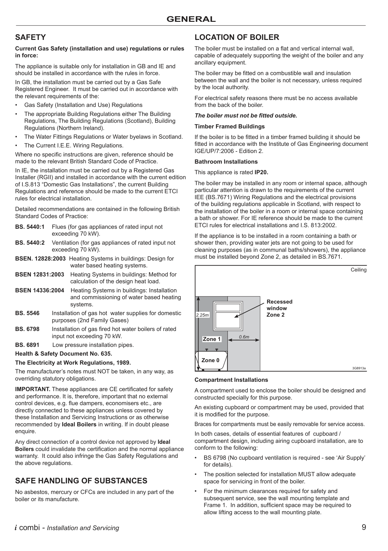
Can the I 24 boiler be installed in a bathroom or room containing a bath or shower?
How do I flush out the system before installing a new Ideal i24 boiler?
What are the dimensions required for mounting and clearances of an i24 Ideal Boiler?
How do I set the boiler for commissioning and initial operation before use?
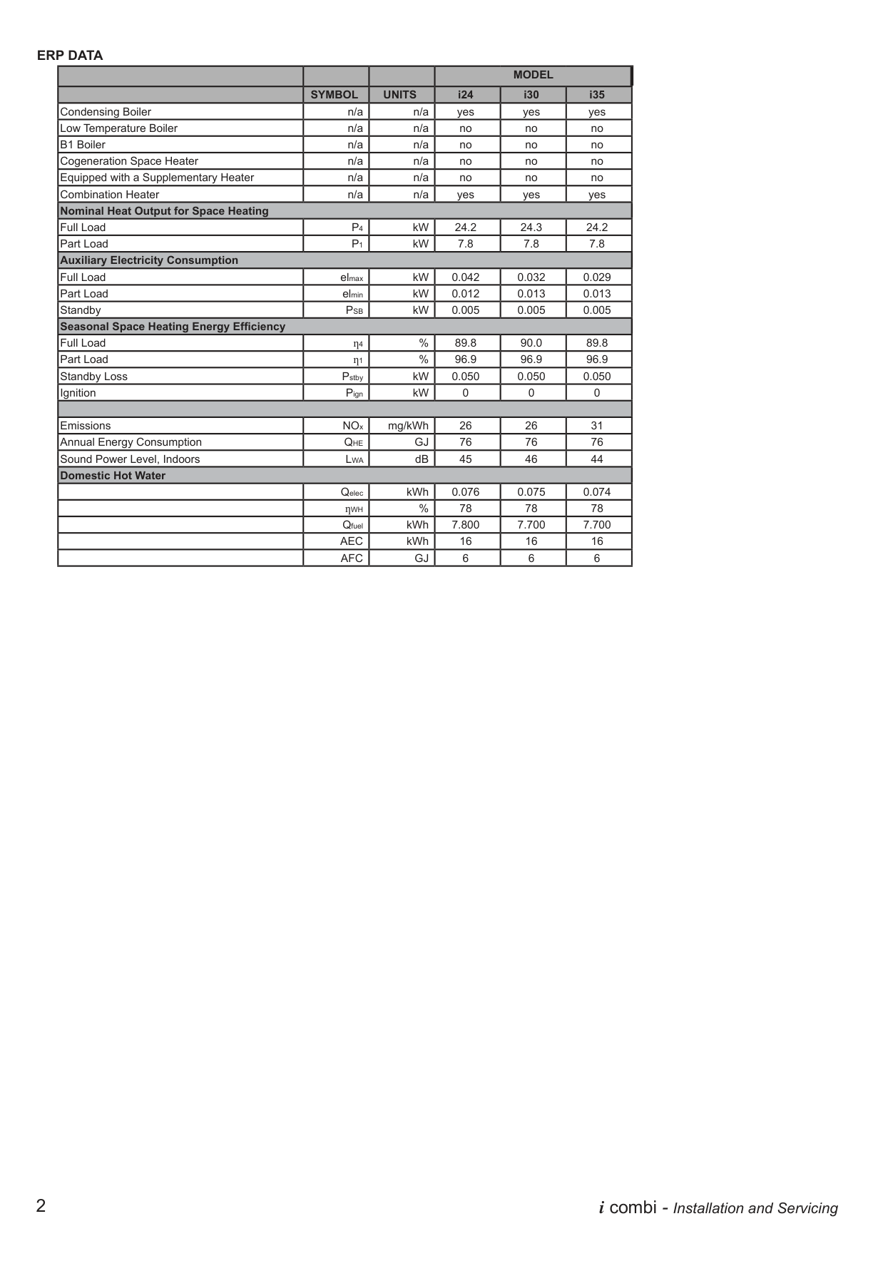
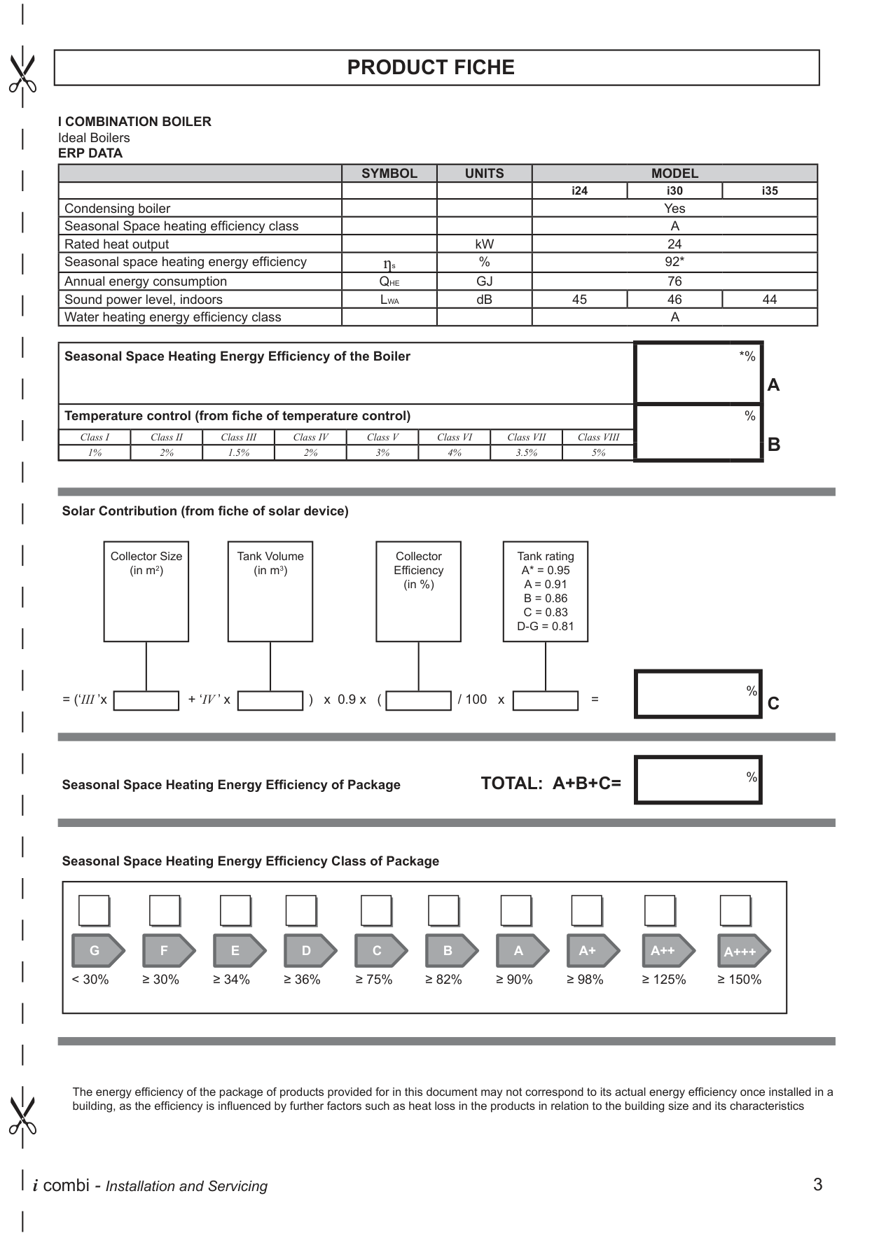
Where can I find the specifications like heat output and efficiency ratings for the i24 Ideal Boiler?
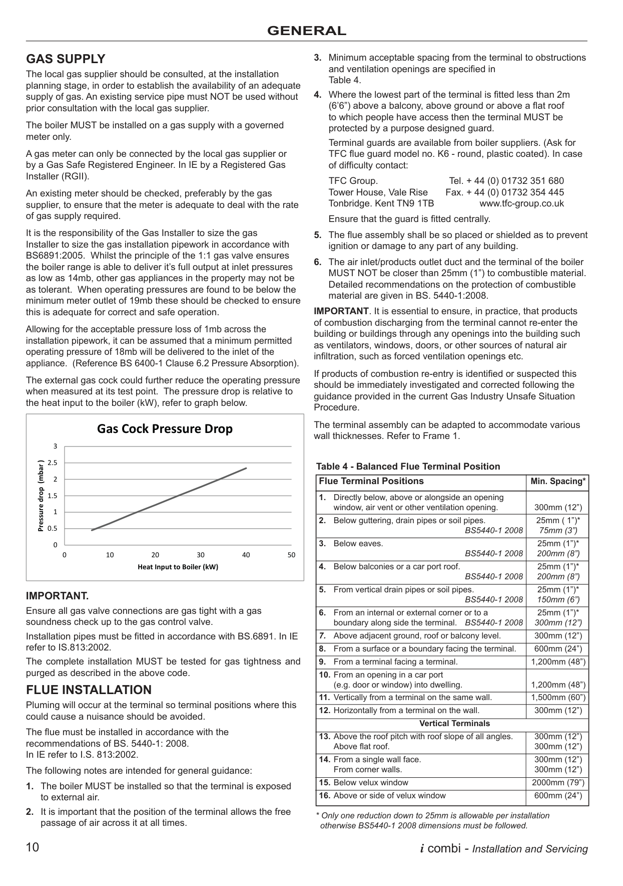
How much clearance is needed around the flue terminal of an i24 Ideal Boiler during installation?
What steps should be followed for electrical wiring of the i24 Ideal Boiler?
What are the water treatment recommendations for maintaining an i24 Ideal Boiler?
What should be done before firing the I 24 boiler for the first time regarding the condensate trap?
What should I do when my boiler displays an F2 code?
How can I reset my boiler after a fault code appears?
What action should I take when my boiler displays an L2 error?
Why does my boiler repeatedly show the L1 code?
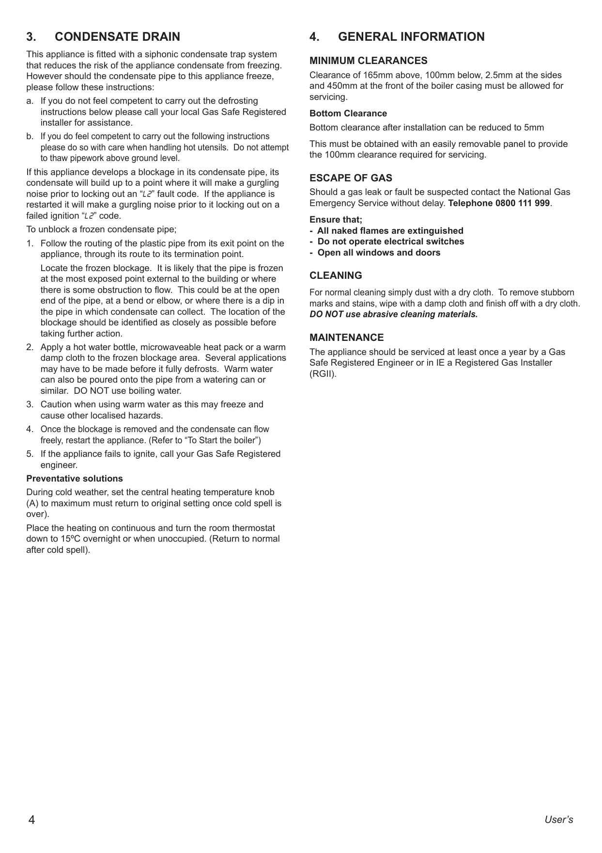
How can I defrost my condensate pipe?
How do I ensure proper operation of my heating system?
What should I do if my central heating is not working?
How can I perform regular maintenance on my boiler?
What is the recommended clearances for my boiler installation?
How can I prevent my heating system from freezing?
What specific electrical equipment should be used for powering the i24 Ideal Boiler?
What are the requirements for condensate drainage when installing an i24 Ideal Boiler?
Full Manual
10 pages
USER GUIDE
LOGIC HEAT H12IE H15IE H18IE H24IE H30IE
When replacing any part on this appliance, use only spare parts that you can be assured conform to the safety and performance specification that we require. Do not use reconditioned or copy parts that have not been clearly authorised by Ideal Boilers. For the very latest copy of literature for specification and maintenance practices visit our website www.idealboilers.com where you can download the relevant information in PDF format.
August 2018 UIN 218170 A03
|CONTENTS
1. Introduction .............................................................. 2 Safety ......................................................................... 2 Electricity Supply ........................................................ 2 Important Notes .......................................................... 2
2. Boiler Operation ....................................................... 3 Controls Diagram........................................................ 3 To Start the Boiler ....................................................... 3 Control of Water Temperature .................................... 3 Efficient Heating System Operation............................ 3 Weather Compensation .............................................. 3 Boiler Frost Protection ................................................ 3 Boiler Restart .............................................................. 3 Mains Power Off ......................................................... 3
3. Condensate Drain ..................................................... 4
4. General Information ................................................. 4 Minimum Clearances .................................................. 4 Escape of Gas ............................................................ 4 Cleaning ..................................................................... 4 Maintenance ............................................................... 4
5. Points for the Boiler User ........................................ 5 Troubleshooting .......................................................... 5
6. Normal Operation Display Codes ........................... 5
7. Fault Codes ............................................................... 6
| |---|
###### SAFETY Current Gas Safety (Installation & Use) Regulations or rules in force.
In your own interest, and that of safety, it is the law that this boiler must be installed by a Gas Safe Registered Engineer, in accordance with the above regulations.
In IE, the installation must be carried out by a Registered Gas Installer (RGII) and installed in accordance with the current edition of I.S. 813 “Domestic Gas Installations”, the current Building Regulations and reference should be made to the current ETCI rules for electrical installation.
It is essential that the instructions in this booklet are strictly followed, for safe and economical operation of the boiler.
ELECTRICITY SUPPLY This appliance must be earthed. Supply: 230 V ~ 50 Hz. The fusing should be 3A.
###### IMPORTANT NOTES
All Gas Safe Register installers carry a Gas Safe Register ID card, and have a registration number. Both should be recorded in the Benchmark Commissioning Checklist. You can check your installer by calling Gas Safe Register direct on 0800 4085500.
|THE BENCHMARK SERVICE INTERVAL RECORD MUST BE COMPLETED AFTER EACH SERVICE
Ideal Boilers is a member of the Benchmark scheme and fully supports the aims of the programme. Benchmark has been introduced to improve the standards of installation and commissioning of central heating systems in the UK and to encourage the regular servicing of all central heating systems to ensure safety and efficiency.| | |---|---|
#### 2. BOILER OPERATION
||ºC
ON
MIN
e
RESTART
MAX
BOILER OFF
BOILER ON| |---|
A EBCDFG
Legend
A. Central Heating Temperature Knob
B. Mode Knob
C. Boiler Status
D. Burner ‘on’ Indicator
E. Central Heating Economy Setting
F. RESTART Button
G. Function Button
| |---|
TO START THE BOILER If a programmer is fitted refer to separate instructions for the programmer before continuing. Start the boiler as follows:
The boiler will commence ignition sequence, supplying heat to the central heating, if required. Note. In normal operation the boiler status display (C) will show codes:
Central Heating being supplied FP Boiler frost protection
To Turn Off Set the mode knob (B) to ‘BOILER OFF’.
###### CONTROL OF WATER TEMPERATURE
The boiler controls the central heating radiator temperature to a maximum of 80oC, adjustable via the central heating temperature knob (A).
Approximate temperatures for central heating:
|Knob Setting|Central Heating Radiator Temperature (approx.)| |---|---| |Minimum|30ºC|
|Maximum|80ºC|
For economy setting ‘ ’ refer to Efficient Heating System Operation.
EFFICIENT HEATING SYSTEM OPERATION The boiler is a high efficiency, condensing appliance which will automatically adjust its output to match the demand for heat. Therefore gas consumption is reduced as the heat demand is reduced.
The boiler condenses water from the flue gases when operating most efficiently. To operate your boiler efficiently (using less gas) turn the central heating temperature knob (A) to the ‘ ‘ position or lower. In winter periods it may be necessary to turn the knob towards the ‘MAX’ position to meet heating requirements. This will depend on the house and radiators used.
Reducing the room thermostat setting by 1ºC can reduce gas consumption by up to 10%.
WEATHER COMPENSATION When the Weather Compensation option is fitted to the system then the central heating temperature knob (A) becomes a method of controlling room temperature. Turn the knob clockwise to increase room temperature and anti-clockwise to decrease room temperature. Once the desired setting has been achieved, leave the knob in this position and the system will automatically achieve the desired room temperature for all outside weather conditions. BOILER FROST PROTECTION
If the system includes a frost thermostat then, during cold weather, the boiler should be turned OFF at the programmer (if fitted) ONLY. The mains supply should be left switched ON, with the boiler thermostat left in the normal running position.
If no system frost protection is provided and frost is likely during a short absence from home it is recommended to leave the heating controls (if fitted) at a reduced temperature setting. For longer periods, the entire system should be drained.
BOILER RESTART To restart the boiler, when directed in the listed fault codes (see section 7) press the “RESTART” button (F). The boiler will repeat its ignition sequence. If the boiler still fails to start consult a Gas Safe Registered Engineer or an IE Registered Gas Installer (RGII). MAINS POWER OFF
To remove all power to the boiler the mains power switch must be turned off.
#### 3. CONDENSATE DRAIN
This appliance is fitted with a siphonic condensate trap system that reduces the risk of the appliance condensate from freezing. However should the condensate pipe to this appliance freeze, please follow these instructions:
If this appliance develops a blockage in its condensate pipe, its condensate will build up to a point where it will make a gurgling noise prior to locking out an “L 2” fault code. If the appliance is restarted it will make a gurgling noise prior to it locking out on a failed ignition “L 2” code. To unblock a frozen condensate pipe;
Locate the frozen blockage. It is likely that the pipe is frozen at the most exposed point external to the building or where there is some obstruction to flow. This could be at the open end of the pipe, at a bend or elbow, or where there is a dip in the pipe in which condensate can collect. The location of the blockage should be identified as closely as possible before taking further action.
Preventative solutions During cold weather, set the central heating temperature knob (A) to maximum must return to original setting once cold spell is over). Place the heating on continuous and turn the room thermostat down to 15ºC overnight or when unoccupied. (Return to normal after cold spell).
#### 4. GENERAL INFORMATION MINIMUM CLEARANCES
Clearance of 165mm above, 100mm below, 2.5mm at the sides and 450mm at the front of the boiler casing must be allowed for servicing.
Bottom Clearance Bottom clearance after installation can be reduced to 5mm This must be obtained with an easily removable panel to provide the 100mm clearance required for servicing.
ESCAPE OF GAS Should a gas leak or fault be suspected contact the National Gas Emergency Service without delay. Telephone 0800 111 999. Ensure that;
###### CLEANING
For normal cleaning simply dust with a dry cloth. To remove stubborn marks and stains, wipe with a damp cloth and finish off with a dry cloth. DO NOT use abrasive cleaning materials.
MAINTENANCE The appliance should be serviced at least once a year by a Gas Safe Registered Engineer or in IE a Registered Gas Installer (RGII).
#### 5. POINTS FOR THE BOILER USER
Note. In line with our current warranty policy we would ask that you check through the following guide to identify any problems external to the boiler prior to requesting a service engineers visit. Should the problem be found to be other than with the appliance we reserve the right to levy a charge for the visit, or for any pre-arranged visit where access is not gained by the engineer.
TROUBLESHOOTING
Check the mains power is turned on and ensure mode knob (B) is in the “BOILER ON” position
NO CENTRAL HEATING OR HOT WATER
Check the Programmer (external to the boiler) is in an “ON” position, and the room thermostat is turned up
NO See boiler “Operation Modes”
Does the boiler operate and provide central heating?
and “Fault Codes” section. If “0 0” is displayed then contact a Gas Safe Registered Engineer or in IE a Registered Gas Installer (RGII)
YES
Check the time settings on the programmer are as you require and adjust if necessary
FOR ANY QUERIES PLEASE RING THE IDEAL CONSUMER HELPLINE : 01482 498660
NOTE. BOILER RESTART PROCEDURE To restart boiler, press the “RESTART” button
#### 6. NORMAL OPERATION DISPLAY CODES
|DISPLAY CODE ON BOILER|DESCRIPTION| |---|---| |
00|The boiler is in standby operation awaiting either a central heating call or hot water demand.| |54oC
ON|The boiler has a call for central heating but the appliance has reached the desired temperature set on the boiler.| |54oC
ON|The boiler is operating in central heating / hot water mode.|
|FP
|The boiler is operating in frost protection.| |- -|The boiler mode knob (B) is in the off position, rotate fully clockwise for hot water and central heating operation.|
#### 7 . FAULT CODES
|DISPLAY CODE ON BOILER|DESCRIPTION|ACTION| |---|---|---| |F 2|Flame Loss|1. Check other gas appliances in the house are working to confirm a supply is present in the property.
2. If other appliances do not work or there are no other appliances, check the gas supply is on at the meter and/or pre payment meter has credit. If the boiler fails to operate then please contact Ideal (if under warranty) or alternatively a Gas Safe Registered Engineer if outside of the warranty period. In IE contact a Registered Gas Installer (RGII).
| |F 3|Fan Fault|Restart the appliance - if the boiler fails to operate then please contact Ideal (if under warranty) or alternatively a Gas Safe Registered Engineer if outside of the warranty period. In IE contact a Registered Gas Installer (RGII).| |F 4 L 4|Flow Thermistor|Restart the appliance - if the boiler fails to operate then please contact Ideal (if under warranty) or alternatively a Gas Safe Registered Engineer if outside of the warranty period. In IE contact a Registered Gas Installer (RGII).| |F 5 L 5|Return Thermistor|Restart the appliance - if the boiler fails to operate then please contact Ideal (if under warranty) or alternatively a Gas Safe Registered Engineer if outside of the warranty period. In IE contact a Registered Gas Installer (RGII).| |F 6|Outside Sensor Failure|Restart the appliance - if the boiler fails to operate then please contact Ideal (if under warranty) or alternatively a Gas Safe Registered Engineer if outside of the warranty period. In IE contact a Registered Gas Installer (RGII).| |F 7|Low Mains Voltage|Contact a qualified electrician or your electricity provider.| |F 9 L 9|Unconfigured PCB|Unconfigured PCB or gas valve short circuit. Please contact Ideal (if under warranty) or alternatively a Gas Safe Registered Engineer if outside of the warranty period. In IE contact a Registered Gas Installer (RGII).| |F 8 L 8|Unconfigured PCB|Unconfigured PCB or gas valve short circuit. Please contact Ideal (if under warranty) or alternatively a Gas Safe Registered Engineer if outside of the warranty period. In IE contact a Registered Gas Installer (RGII).| |F A|Flow / Return Reversed|Please contact a Gas Safe Registered Engineer. In IE contact a Registered Gas Installer (RGII).| |F 8|No Water Flow|Please contact Ideal (if under warranty) or alternatively a Gas Safe Registered Engineer if outside of the warranty period. In IE contact a Registered Gas Installer (RGII).| |L 1|Flow Temperature Overheat or No Water Flow|Check system water pressure is between 1 & 1.5bar on the system pressure gauge. To re-pressurise the system see Section 4. If the boiler fails to operate then please contact Ideal (if under warranty) or alternatively a Gas Safe Registered Engineer if outside of the warranty period. In IE contact a Registered Gas Installer (RGII).| |L 2|Ignition Lockout|1. Check condensate Pipe for blockages (refer to Section 3)
2. Check other gas appliances in the house are working to confirm a supply is present in the property.
3. If other appliances do not work or there are no other appliances, check the gas supply is on at the meter and/or pre payment meter has credit. If the boiler fails to operate then please contact Ideal (if under warranty) or alternatively a Gas Safe Registered Engineer if outside of the warranty period. In IE contact a Registered Gas Installer (RGII).
| |L 6|False Flame Lockout|Restart the appliance - if the boiler fails to operate then please contact Ideal (if under warranty) or alternatively a Gas Safe Registered Engineer if outside of the warranty period. In IE contact a Registered Gas Installer (RGII).| |L C|5 Boiler Resets in 15 minutes|1. Turn electrical supply to boiler off and on.
2. If the boiler fails to operate please contact Ideal (if under warranty) or alternatively a Gas Safe Registered Engineer if outside of the warranty period. In IE contact a Registered Gas Installer (RGII).
| |F U|Flow/Return Differential > 50°C|If the boiler fails to operate then please contact Ideal (if under warranty) or alternatively a Gas Safe Registered Engineer if outside of the warranty period. In IE contact a Registered Gas Installer (RGII).|