
Ask AI
— answers from the official manualAnswers from the official manual.
Common questions
Common Questions
8 totalWhere is the Data Link Connector (DLC) of my vehicle?
The DLC is usually located under the instrument panel (dash), within 12 inches (300 mm) of center on the driver’s side, or behind the ashtray or at far left corner on some Asian and European vehicles. Consult your vehicle's service manual if you cannot locate it.
How do I retrieve diagnostic trouble codes?
Connect the Innova 3011 to the DLC, turn the ignition on without starting the engine, and wait for the Car Reader to link with the vehicle's computer. The LCD will display any DTCs present in the vehicle's memory.
How do I erase diagnostic trouble codes from my vehicle?
Press and release the ERASE button when connected to the DLC; confirm by pressing again once more. The Car Reader will re-link after erasing DTCs, showing 'rEAd' on its display.
What does a solid yellow LED indicate?
A solid yellow LED indicates there is a pending fault code present and/or some of the vehicle's emission monitors have not yet run their diagnostic testing, which can be confirmed by one or more blinking Monitor icons on the LCD display.
How do I verify if my vehicle is OBD 2 compliant?
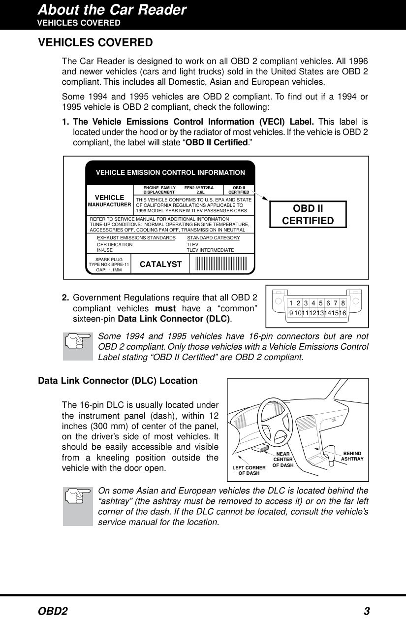
Check for a Vehicle Emissions Control Information (VECI) label stating 'OBD II Certified' or look for a sixteen-pin Data Link Connector (DLC). Vehicles from 1996 onwards are typically compliant. Some earlier models comply only if labeled as such.
How do I read and interpret error codes like P0508, P0420, or P0715?
Refer to the DTC definitions starting from page 14 in the manual, match your code with them for a detailed description of what each specific number represents (e.g., P0508 Idle Control System Circuit High).
Full Manual
31 pages

CAR READER

Table of Contents
Title Page No. YOU CAN DO IT! . . . . . . . . . . . . . . . . . . . . . . . . . . . . . . . . . . . . . . . . . . . . . 1 SAFETY PRECAUTIONS
Safety First . . . . . . . . . . . . . . . . . . . . . . . . . . . . . . . . . . . . . . . . . . . . . 2 ABOUT THE CAR READER
Vehicles Covered . . . . . . . . . . . . . . . . . . . . . . . . . . . . . . . . . . . . . . . . 3 Controls and Indicators . . . . . . . . . . . . . . . . . . . . . . . . . . . . . . . . . . . . 4 Display Functions . . . . . . . . . . . . . . . . . . . . . . . . . . . . . . . . . . . . . . . . 5
######### PREPARATION FOR TESTING
Before You Begin . . . . . . . . . . . . . . . . . . . . . . . . . . . . . . . . . . . . . . . . . 7 Vehicle Service Manuals . . . . . . . . . . . . . . . . . . . . . . . . . . . . . . . . . . . 7
USING THE CODE READER Code Retrieval Procedure . . . . . . . . . . . . . . . . . . . . . . . . . . . . . . . . . . 8 Erasing Diagnostic Trouble Codes (DTCs) . . . . . . . . . . . . . . . . . . . . . . 10
######### DTC DEFINITIONS
Diagnostic Trouble Code Definitions . . . . . . . . . . . . . . . . . . . . . . . . . . . 12
LIMITED WARRANTY AND SERVICE PROCEDURES The Manufacturer warrants to the original purchaser that this unit is free of defects in materials and workmanship under normal use and maintenance for a period of one (1) year from the date of original purchase. If the unit fails within the one (1) year period, it will be repaired or replaced, at the Manufacturer's option, at no charge, when returned prepaid to the Technical Service Center with Proof of Purchase. The sales receipt may be used for this purpose. Installation labor is not covered under this warranty.
All replacement parts, whether new or re-manufactured, assume as their warranty period for only the remaining time of this warranty.This warranty does not apply to damage caused by improper use, accident, abuse, improper voltage, service, fire, flood, lightning, or other acts of God, or if the product was altered or repaired by anyone other than the Manufacturer's Technical Service Center. Consequential and incidental damages are not recoverable under this warranty. Some states do not allow the exclusion or limitation of incidental or consequential damages, so the above limitation or exclusion may not apply to you.
This warranty gives you specific legal rights, and you may also have other rights, which vary from state to state. No portion of this warranty may be copied or duplicated without the expressed written permission from the Manufacturer.
i OBD2
You Can Do It!
EASY TO USE - EASY TO VIEW - EASY TO DEFINE
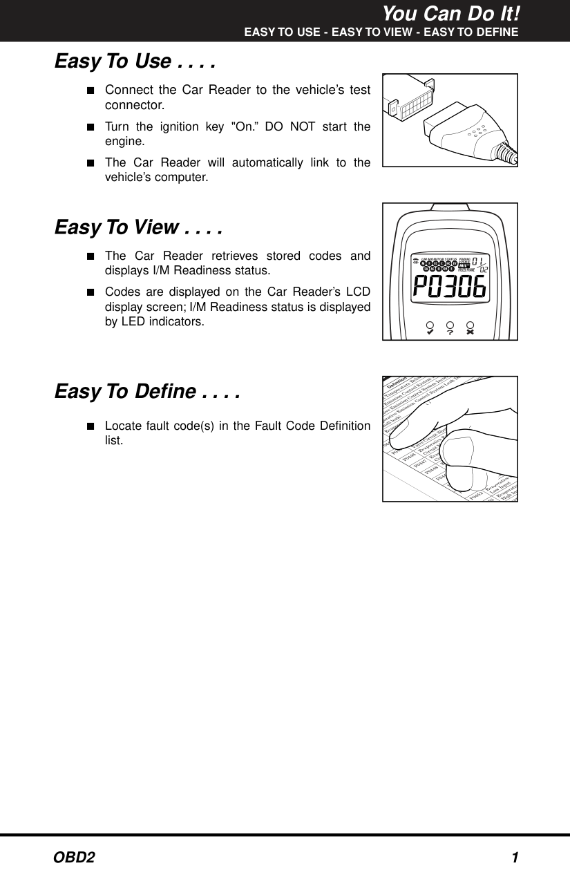
Easy To Use . . . .
| | |---|
Easy To View . . . .
########### tr
|Definition
Temperature B
elow
E
mission C
ontrol System
M
ve Em
ission C
ontrol System
Incorr
po
rative E
Leak
Det
all leak)Evaporative E
mission Control System
Purge C
ontrol
Valve C
ircuit Malfunction
P0
444 Evaporative E
mission C
ontrol System
Purge Control
Valve C
ircuit O
pen P0445 Evaporative E
mission C
ontrol S
ystem Purge Control
Valve C
ircuit Sh
orted
P0446 Evaporative E
mission C
ontrol System
Vent Control
Circuit Malfunction
P0447 Evapora
tive Emission Control S
Vent Cont
Circuit OP0448 Evaporative E
mission C
ontrol System
en
Circuit Shorted P0449 Evaporative E
ontrol Syste
Solenoid Circuit M P0450 Evaporative E
ontrol
MalfunctionP0451 Evaporative E
missionC Range/Perform
ance P0452 Evaporative Emis Low Input
45
3 Evaporati High I
np ap| |---|
Easy To Define . . . .
yst e ati
■ Locate fault code(s) in the Fault Code Definition
sm
list.
ve
Ev
Safety Precautions SAFETY FIRST SAFETY FIRST!
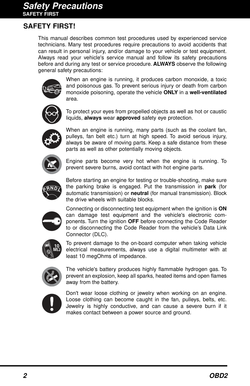
This manual describes common test procedures used by experienced service technicians. Many test procedures require precautions to avoid accidents that can result in personal injury, and/or damage to your vehicle or test equipment. Always read your vehicle's service manual and follow its safety precautions before and during any test or service procedure. ALWAYS observe the following general safety precautions:
When an engine is running, it produces carbon monoxide, a toxic and poisonous gas. To prevent serious injury or death from carbon monoxide poisoning, operate the vehicle ONLY in a well-ventilated area.
To protect your eyes from propelled objects as well as hot or caustic liquids, always wear approved safety eye protection.
When an engine is running, many parts (such as the coolant fan, pulleys, fan belt etc.) turn at high speed. To avoid serious injury, always be aware of moving parts. Keep a safe distance from these parts as well as other potentially moving objects.
Engine parts become very hot when the engine is running. To prevent severe burns, avoid contact with hot engine parts.
Before starting an engine for testing or trouble-shooting, make sure the parking brake is engaged. Put the transmission in park (for automatic transmission) or neutral (for manual transmission). Block the drive wheels with suitable blocks.
N
R
D
P
L
Connecting or disconnecting test equipment when the ignition is ON can damage test equipment and the vehicle's electronic components. Turn the ignition OFF before connecting the Code Reader to or disconnecting the Code Reader from the vehicle’s Data Link Connector (DLC).
To prevent damage to the on-board computer when taking vehicle electrical measurements, always use a digital multimeter with at least 10 megOhms of impedance.
The vehicle's battery produces highly flammable hydrogen gas. To prevent an explosion, keep all sparks, heated items and open flames away from the battery.
Don't wear loose clothing or jewelry when working on an engine. Loose clothing can become caught in the fan, pulleys, belts, etc. Jewelry is highly conductive, and can cause a severe burn if it makes contact between a power source and ground.
#### VEHICLES COVERED VEHICLES COVERED
The Car Reader is designed to work on all OBD 2 compliant vehicles. All 1996 and newer vehicles (cars and light trucks) sold in the United States are OBD 2 compliant. This includes all Domestic, Asian and European vehicles.
Some 1994 and 1995 vehicles are OBD 2 compliant. To find out if a 1994 or 1995 vehicle is OBD 2 compliant, check the following:
||VEHICLE MANUFACTURER|VEHICLE MANUFACTURER|ENGINE FAMILY EFN2.6YBT2BA DISPLACEMENT 2.6L|ENGINE FAMILY EFN2.6YBT2BA DISPLACEMENT 2.6L|OBD II CERTIFIED| |---|---|---|---|---| |VEHICLE MANUFACTURER|VEHICLE MANUFACTURER|THIS VEHICLE CONFORMS TO U.S. EPA AND STATE OF CALIFORNIA REGULATIONS APPLICABLE TO 1999 MODEL YEAR NEW TLEV PASSENGER CARS.|THIS VEHICLE CONFORMS TO U.S. EPA AND STATE OF CALIFORNIA REGULATIONS APPLICABLE TO 1999 MODEL YEAR NEW TLEV PASSENGER CARS.|THIS VEHICLE CONFORMS TO U.S. EPA AND STATE OF CALIFORNIA REGULATIONS APPLICABLE TO 1999 MODEL YEAR NEW TLEV PASSENGER CARS.| |REFER TO SERVICE MANUAL FOR ADDITIONAL INFORMATION TUNE-UP CONDITIONS: NORMAL OPERATING ENGINE TEMPERATURE, ACCESSORIES OFF, COOLING FAN OFF, TRANSMISSION IN NEUTRAL|REFER TO SERVICE MANUAL FOR ADDITIONAL INFORMATION TUNE-UP CONDITIONS: NORMAL OPERATING ENGINE TEMPERATURE, ACCESSORIES OFF, COOLING FAN OFF, TRANSMISSION IN NEUTRAL|REFER TO SERVICE MANUAL FOR ADDITIONAL INFORMATION TUNE-UP CONDITIONS: NORMAL OPERATING ENGINE TEMPERATURE, ACCESSORIES OFF, COOLING FAN OFF, TRANSMISSION IN NEUTRAL|REFER TO SERVICE MANUAL FOR ADDITIONAL INFORMATION TUNE-UP CONDITIONS: NORMAL OPERATING ENGINE TEMPERATURE, ACCESSORIES OFF, COOLING FAN OFF, TRANSMISSION IN NEUTRAL|REFER TO SERVICE MANUAL FOR ADDITIONAL INFORMATION TUNE-UP CONDITIONS: NORMAL OPERATING ENGINE TEMPERATURE, ACCESSORIES OFF, COOLING FAN OFF, TRANSMISSION IN NEUTRAL| |EXHAUST EMISSIONS STANDARDS STANDARD CATEGORY CERTIFICATION IN-USE
TLEV TLEV INTERMEDIATE|EXHAUST EMISSIONS STANDARDS STANDARD CATEGORY CERTIFICATION IN-USE
TLEV TLEV INTERMEDIATE|EXHAUST EMISSIONS STANDARDS STANDARD CATEGORY CERTIFICATION IN-USE
TLEV TLEV INTERMEDIATE|EXHAUST EMISSIONS STANDARDS STANDARD CATEGORY CERTIFICATION IN-USE
TLEV TLEV INTERMEDIATE|EXHAUST EMISSIONS STANDARDS STANDARD CATEGORY CERTIFICATION IN-USE
TLEV TLEV INTERMEDIATE| |SPARK PLUG TYPE NGK BPRE-11 GAP: 1.1MM|CATALYST|CATALYST| | |
VEHICLE EMISSION CONTROL INFORMATION
|OBD II CERTIFIED| |---| | |---|
||1|2|3|4|5|6|7|8| |---|---|---|---|---|---|---|---| |9|0|1|2|3|4|5|6| | |---|
Some 1994 and 1995 vehicles have 16-pin connectors but are not OBD 2 compliant. Only those vehicles with a Vehicle Emissions Control Label stating “OBD II Certified” are OBD 2 compliant.
####### Data Link Connector (DLC) Location
|NEAR CENTER OF DASH
BEHIND ASHTRAY LEFT CORNER OF DASH
| |---|
The 16-pin DLC is usually located under the instrument panel (dash), within 12 inches (300 mm) of center of the panel, on the driver’s side of most vehicles. It should be easily accessible and visible from a kneeling position outside the vehicle with the door open.
On some Asian and European vehicles the DLC is located behind the “ashtray” (the ashtray must be removed to access it) or on the far left corner of the dash. If the DLC cannot be located, consult the vehicle’s service manual for the location.
#### CONTROLS AND INDICATORS CONTROLS AND INDICATORS
|7
4
1
5
2
3
6
8| |---|
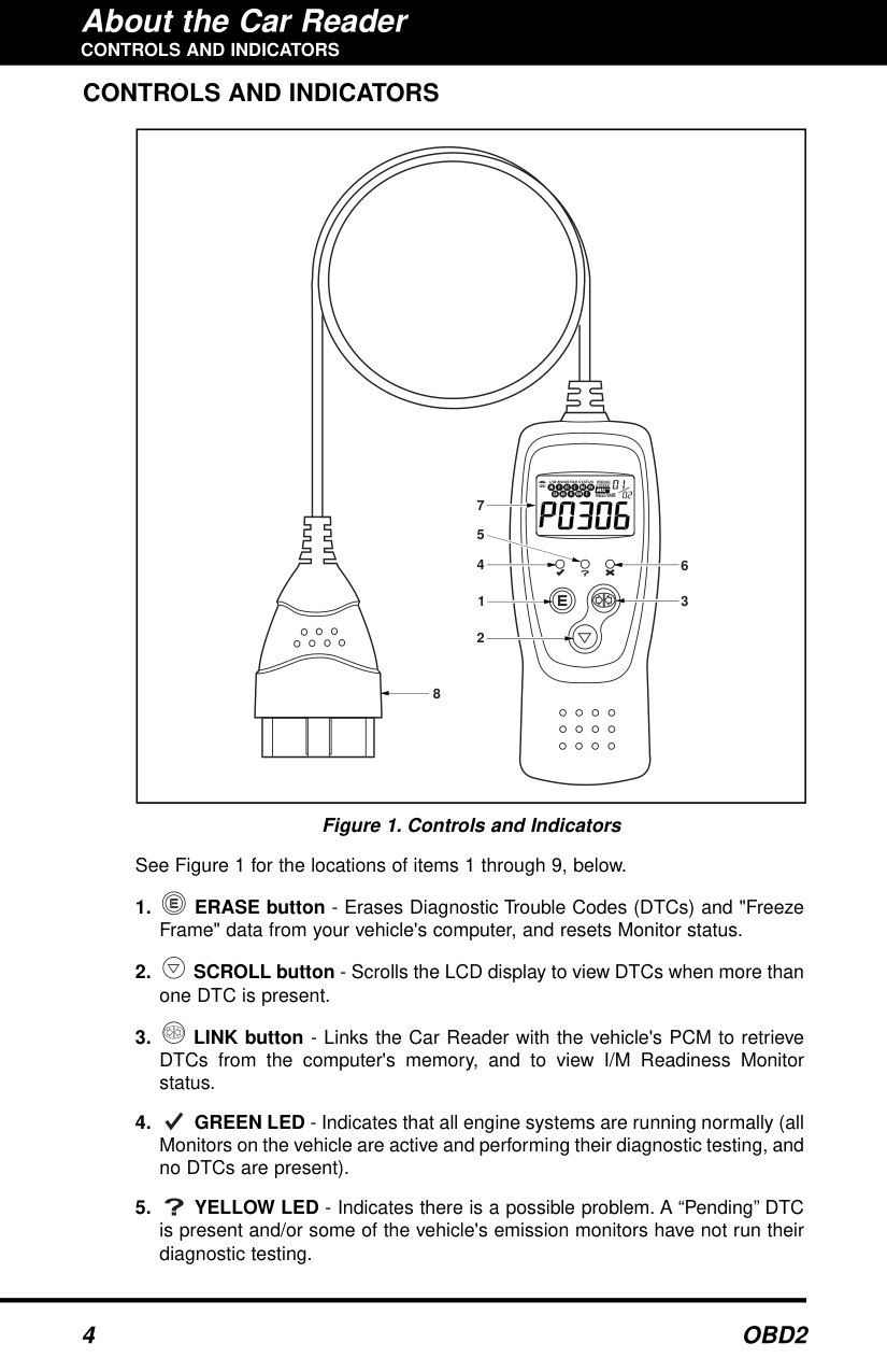
######## Figure 1. Controls and Indicators
See Figure 1 for the locations of items 1 through 9, below.
About the Car Reader
########## DISPLAY FUNCTIONS
#### DISPLAY FUNCTIONS
|2
3
7
9
8
10
| | | |
|---|---|---| | | | |
465
1| |---|
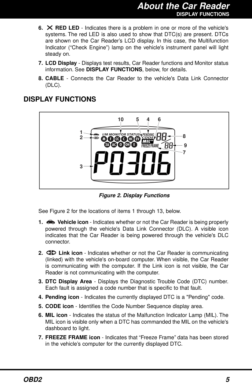
######## Figure 2. Display Functions
See Figure 2 for the locations of items 1 through 13, below.
########## DISPLAY FUNCTIONS
The I/M Monitor Status icons are associated with INSPECTION and MAINTENANCE (I/M) READINESS STATUS. Some states require that all vehicle Monitors have run and completed their diagnostic testing before a vehicle can be tested for Emissions (Smog Check). A maximum of eleven Monitors are used on OBD 2 systems. Not all vehicles support all eleven Monitors. When the Car Reader is linked to a vehicle, only the icons for Monitors that are supported by the vehicle under test are visible on the display.
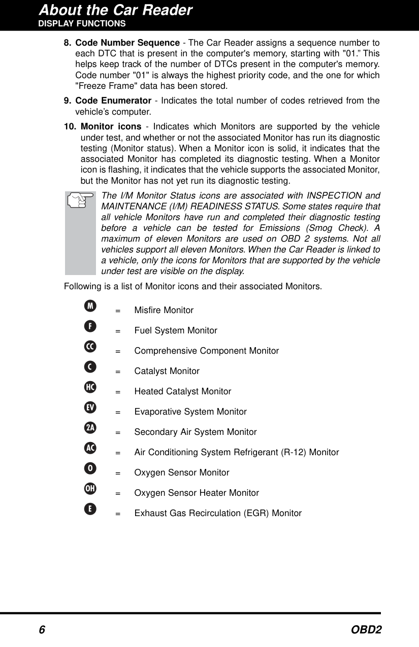
Following is a list of Monitor icons and their associated Monitors.
= Misfire Monitor
= Fuel System Monitor
= Comprehensive Component Monitor
= Catalyst Monitor
= Heated Catalyst Monitor
= Evaporative System Monitor
= Secondary Air System Monitor
= Air Conditioning System Refrigerant (R-12) Monitor
= Oxygen Sensor Monitor
= Oxygen Sensor Heater Monitor
= Exhaust Gas Recirculation (EGR) Monitor
Preparation for Testing BEFORE YOU BEGIN / VEHICLE SERVICE MANUALS BEFORE YOU BEGIN
Fix any known mechanical problems before performing any test. See your vehicle's service manual or a mechanic for more information. Check the following areas before starting any test:
#### VEHICLE SERVICE MANUALS
Always refer to the manufacturer's service manual for your vehicle before performing any test or repair procedures. Contact your local car dealership, auto parts store or bookstore for availability of these manuals.
#### CODE RETRIEVAL PROCEDURE
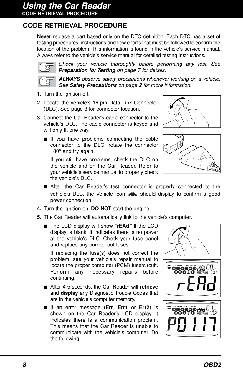
Never replace a part based only on the DTC definition. Each DTC has a set of testing procedures, instructions and flow charts that must be followed to confirm the location of the problem. This information is found in the vehicle's service manual. Always refer to the vehicle's service manual for detailed testing instructions.
Check your vehicle thoroughly before performing any test. See Preparation for Testingon page 7 for details. ALWAYSobserve safety precautions whenever working on a vehicle. SeeSafety Precautionson page 2 for more information.
If you still have problems, check the DLC on the vehicle and on the Car Reader. Refer to your vehicle's service manual to properly check the vehicle's DLC.
| | |---|
| | |---|
If replacing the fuse(s) does not correct the problem, see your vehicle's repair manual to locate the proper computer (PCM) fuse/circuit. Perform any necessary repairs before continuing.
| | |---|
| | |---|
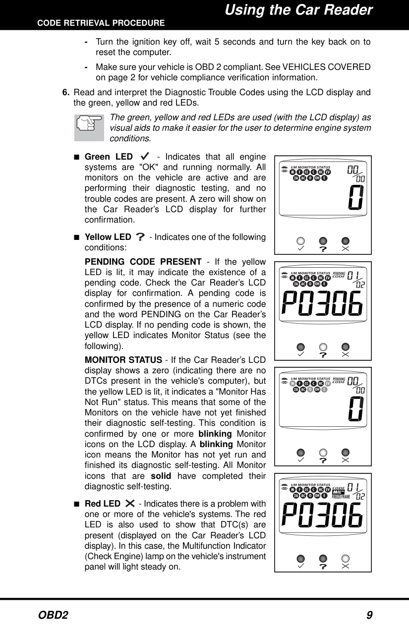
The green, yellow and red LEDs are used (with the LCD display) as visual aids to make it easier for the user to determine engine system conditions.
PENDING CODE PRESENT - If the yellow LED is lit, it may indicate the existence of a pending code. Check the Car Reader’s LCD display for confirmation. A pending code is confirmed by the presence of a numeric code and the word PENDING on the Car Reader’s LCD display. If no pending code is shown, the yellow LED indicates Monitor Status (see the following).
MONITOR STATUS - If the Car Reader’s LCD display shows a zero (indicating there are no DTCs present in the vehicle's computer), but the yellow LED is lit, it indicates a "Monitor Has Not Run" status. This means that some of the Monitors on the vehicle have not yet finished their diagnostic self-testing. This condition is confirmed by one or more blinking Monitor icons on the LCD display. A blinking Monitor icon means the Monitor has not yet run and finished its diagnostic self-testing. All Monitor icons that are solid have completed their diagnostic self-testing.
| | |---|
| |
|---|
| | |---|
| | |---|
The Car Reader will automatically re-link to the vehicle's computer every 15 seconds to refresh the data being retrieved. When data is being refreshed, a single beep will sound, and "rEAd" will be shown on the LCD display for 5-6 seconds. The Car Reader will then beep twice and return to displaying codes. This action repeats as long as the Car Reader is in communication with the vehicle's computer.
The Car Reader will display a code only if codes are present in the vehicle's computer memory. If no codes are present, a "0" will be displayed.
■ Whenever the SCROLL function is used to view additional codes, the Car Reader’s communication link with the vehicle's computer disconnects. To re-establish communication, press the LINK button again.
Refer to page 14 for Diagnostic Trouble Code definitions. Match the retrieved DTC(s) with those listed. Read the associated definition(s), and see the vehicle's service manual for further evaluation.
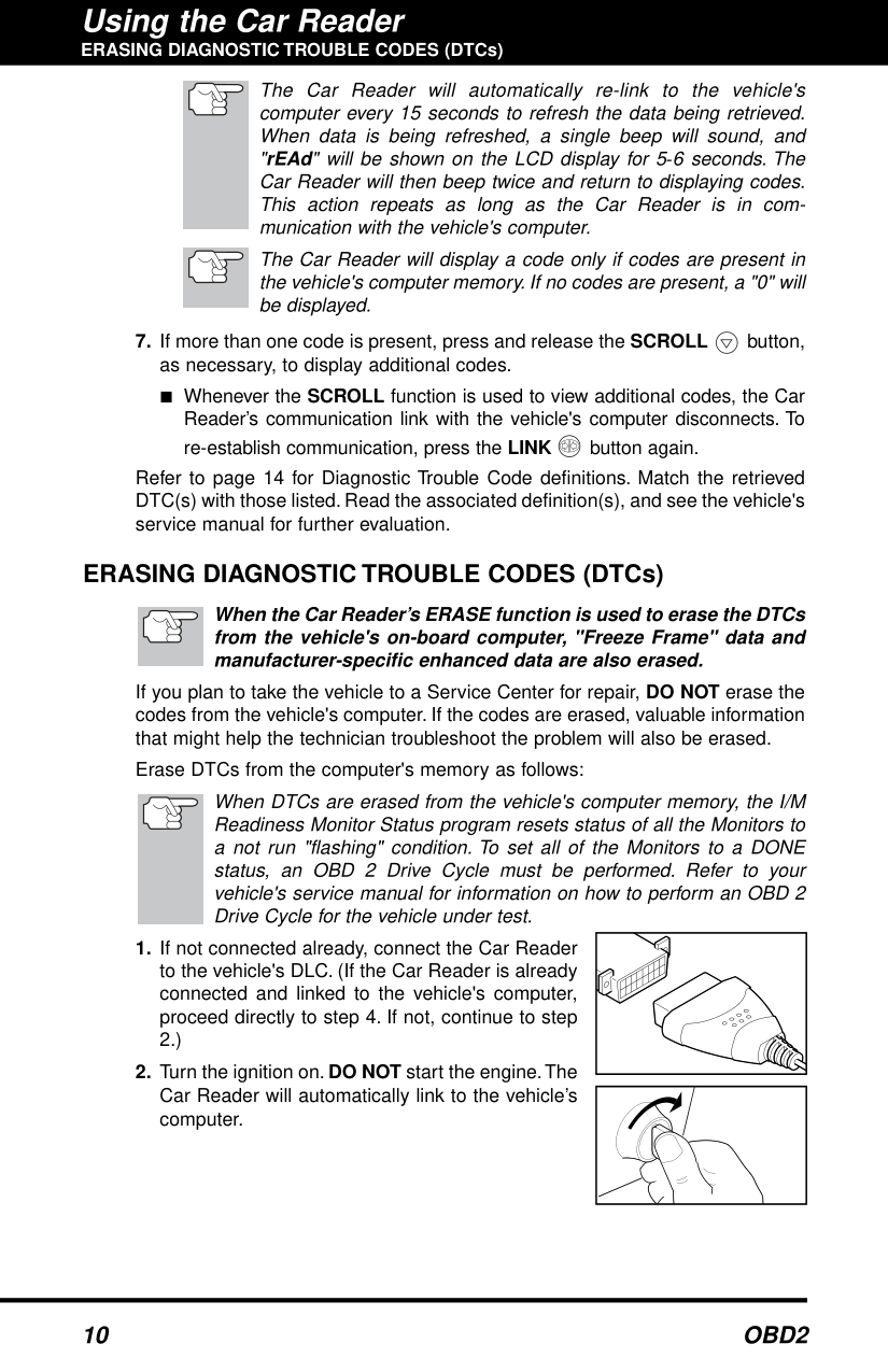
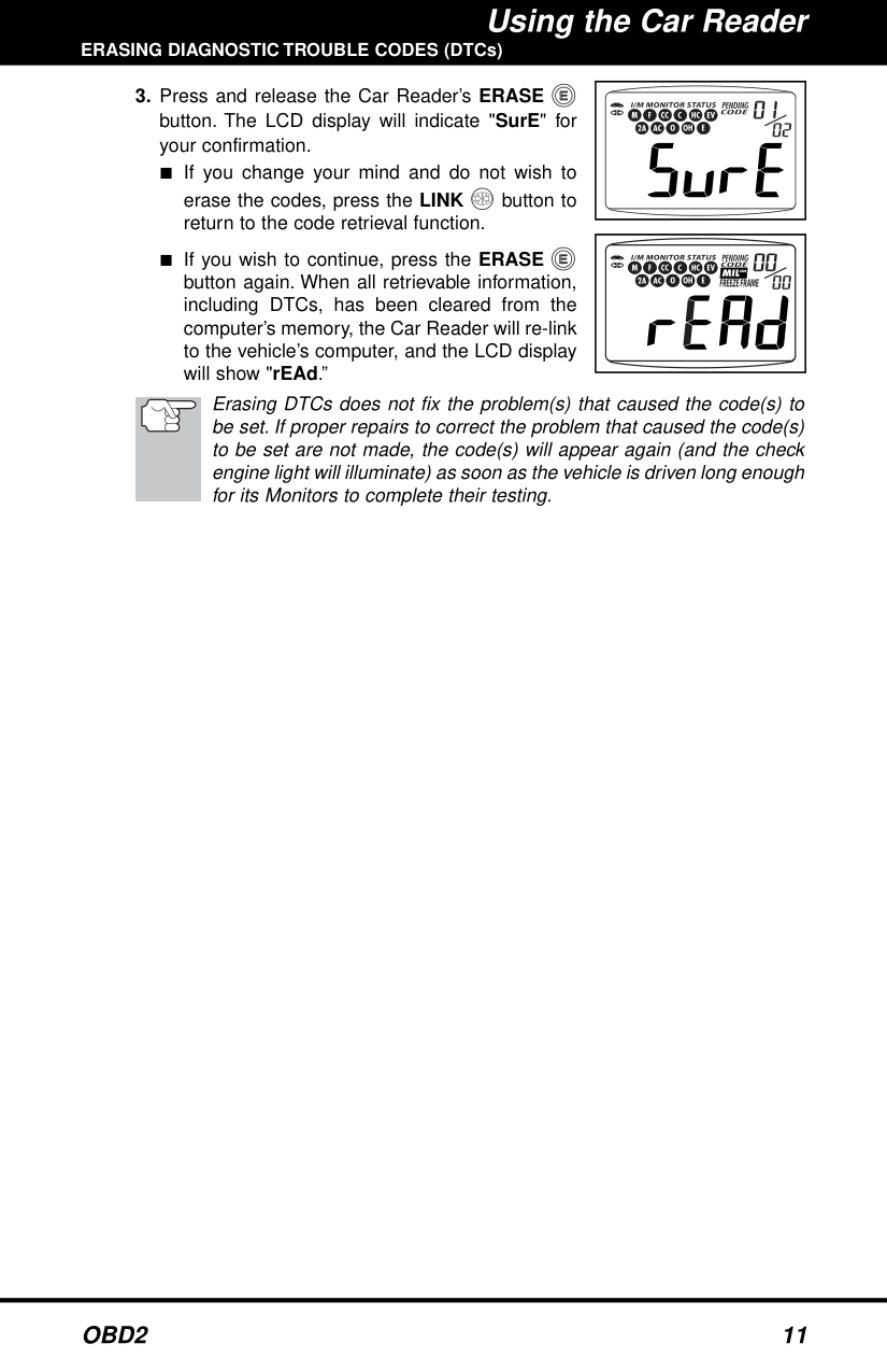
#### ERASING DIAGNOSTIC TROUBLE CODES (DTCs)
######## When the Car Reader’s ERASE function is used to erase the DTCs from the vehicle's on-board computer, "Freeze Frame" data and manufacturer-specific enhanced data are also erased.
If you plan to take the vehicle to a Service Center for repair, DO NOT erase the codes from the vehicle's computer. If the codes are erased, valuable information that might help the technician troubleshoot the problem will also be erased.
Erase DTCs from the computer's memory as follows:
When DTCs are erased from the vehicle's computer memory, the I/M Readiness Monitor Status program resets status of all the Monitors to a not run "flashing" condition. To set all of the Monitors to a DONE status, an OBD 2 Drive Cycle must be performed. Refer to your vehicle's service manual for information on how to perform an OBD 2 Drive Cycle for the vehicle under test.
| | |---|
| | |---|
| | |---|
erase the codes, press the LINK button to return to the code retrieval function.
| | |---|
Erasing DTCs does not fix the problem(s) that caused the code(s) to be set. If proper repairs to correct the problem that caused the code(s) to be set are not made, the code(s) will appear again (and the check engine light will illuminate) as soon as the vehicle is driven long enough for its Monitors to complete their testing.
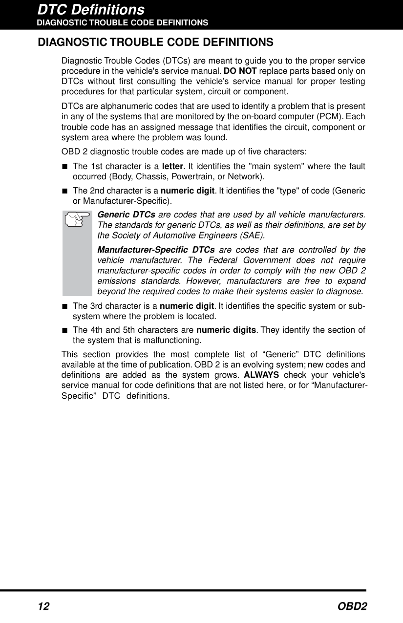
#### DIAGNOSTIC TROUBLE CODE DEFINITIONS
Diagnostic Trouble Codes (DTCs) are meant to guide you to the proper service procedure in the vehicle's service manual. DO NOT replace parts based only on DTCs without first consulting the vehicle's service manual for proper testing procedures for that particular system, circuit or component.
DTCs are alphanumeric codes that are used to identify a problem that is present in any of the systems that are monitored by the on-board computer (PCM). Each trouble code has an assigned message that identifies the circuit, component or system area where the problem was found.
OBD 2 diagnostic trouble codes are made up of five characters:
Generic DTCsare codes that are used by all vehicle manufacturers. The standards for generic DTCs, as well as their definitions, are set by the Society of Automotive Engineers (SAE).
Manufacturer-Specific DTCs are codes that are controlled by the vehicle manufacturer. The Federal Government does not require manufacturer-specific codes in order to comply with the new OBD 2 emissions standards. However, manufacturers are free to expand beyond the required codes to make their systems easier to diagnose.
This section provides the most complete list of “Generic” DTC definitions available at the time of publication. OBD 2 is an evolving system; new codes and definitions are added as the system grows. ALWAYS check your vehicle's service manual for code definitions that are not listed here, or for “ManufacturerSpecific” DTC definitions.
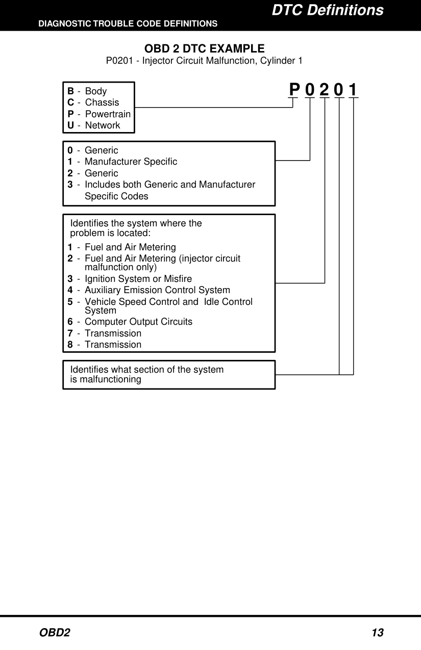
OBD 2 DTC EXAMPLE P0201 - Injector Circuit Malfunction, Cylinder 1
P 0 2 0 1B
Body Chassis Powertrain Network
Generic Manufacturer Specific Generic Includes both Generic and Manufacturer Specific Codes
-
Identifies the system where the problem is located:
Fuel and Air Metering Fuel and Air Metering (injector circuit malfunction only) Ignition System or Misfire Auxiliary Emission Control System Vehicle Speed Control and Idle Control System Computer Output Circuits Transmission Transmission
Identifies what section of the system is malfunctioning
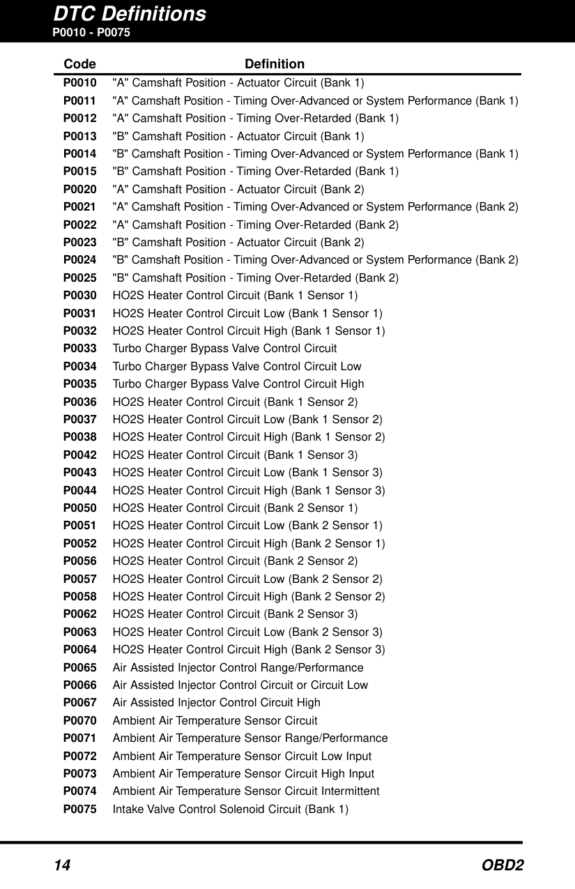
P0010 - P0075
####### Code Definition
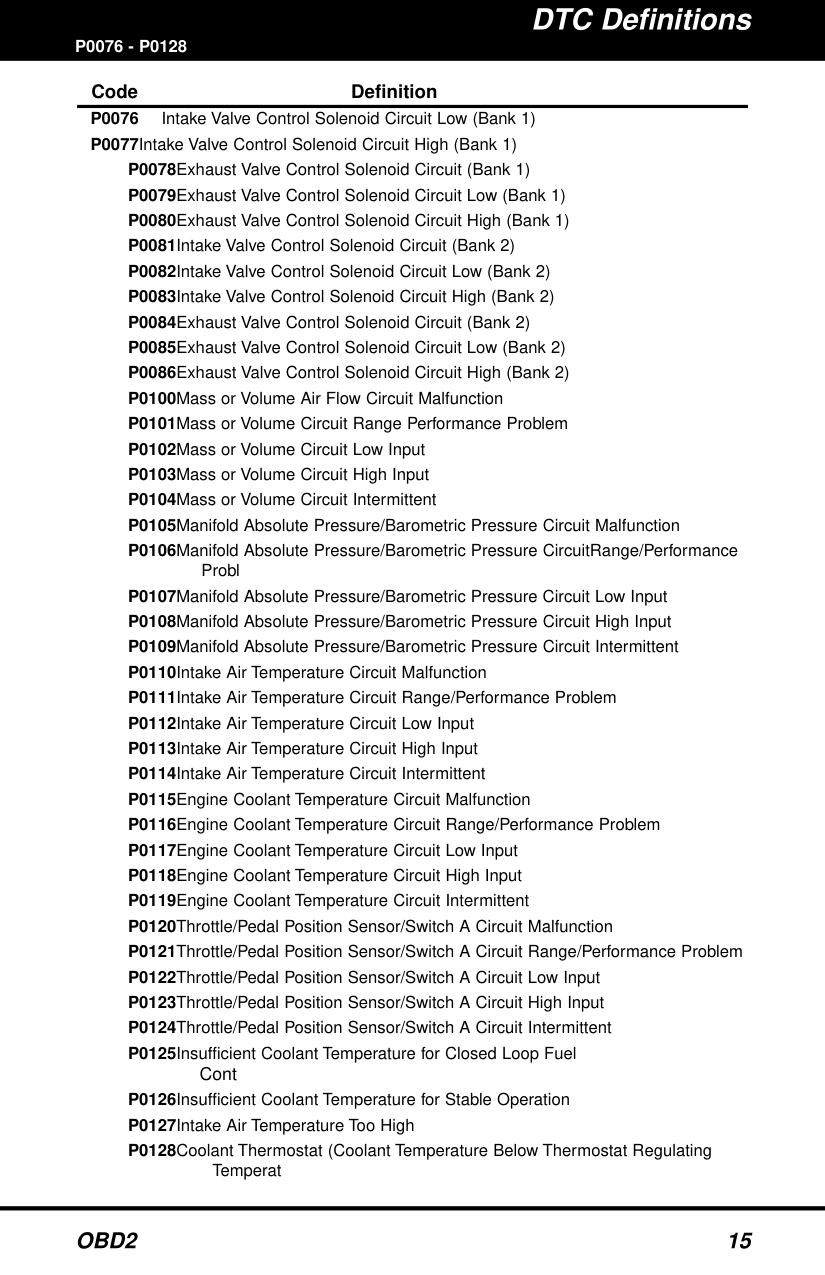
####### P0076 - P0128Code Definition
P0128Coolant Thermostat (Coolant Temperature Below Thermostat Regulating
Temperat
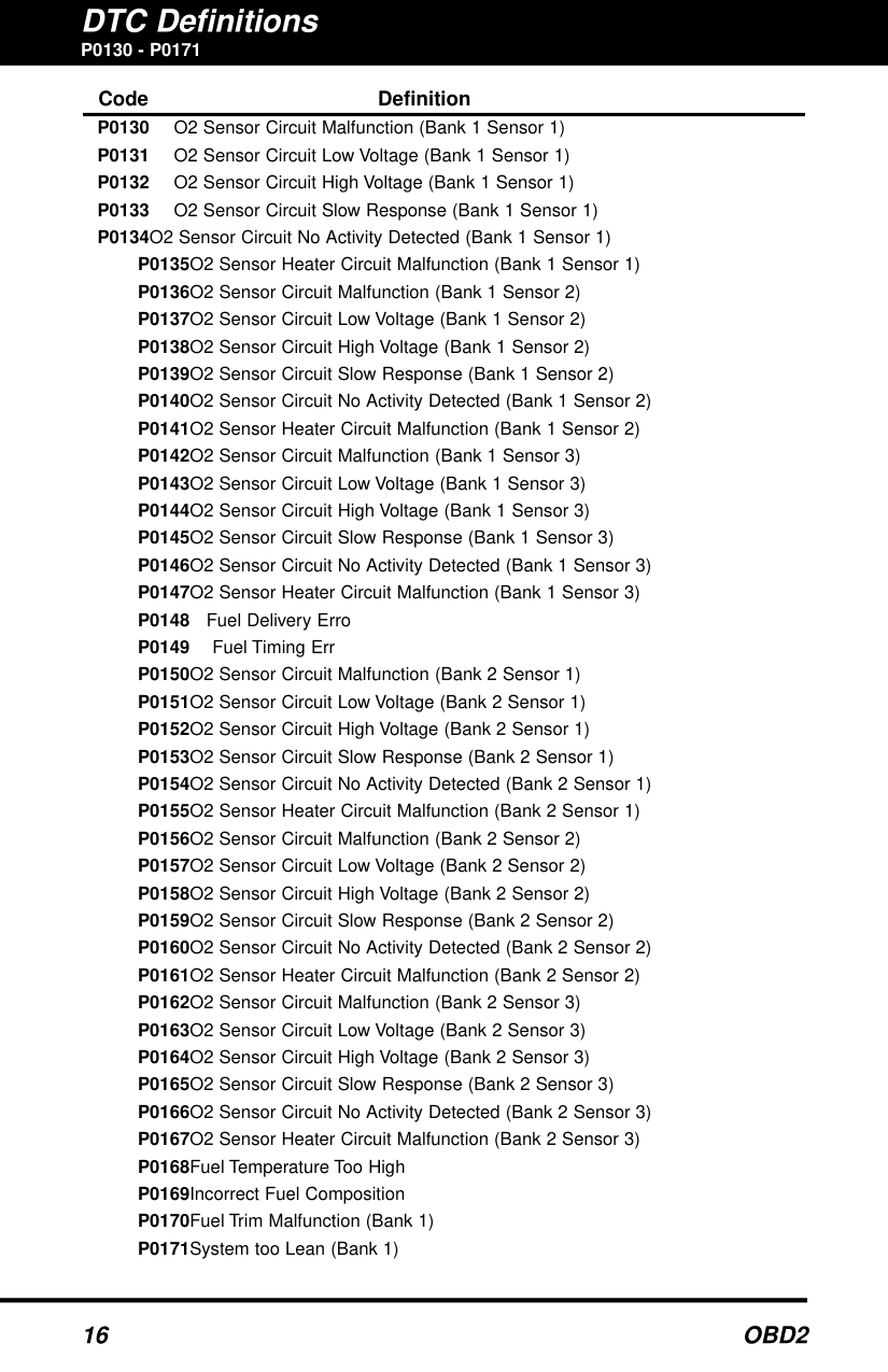
P0130 - P0171
####### Code Definition
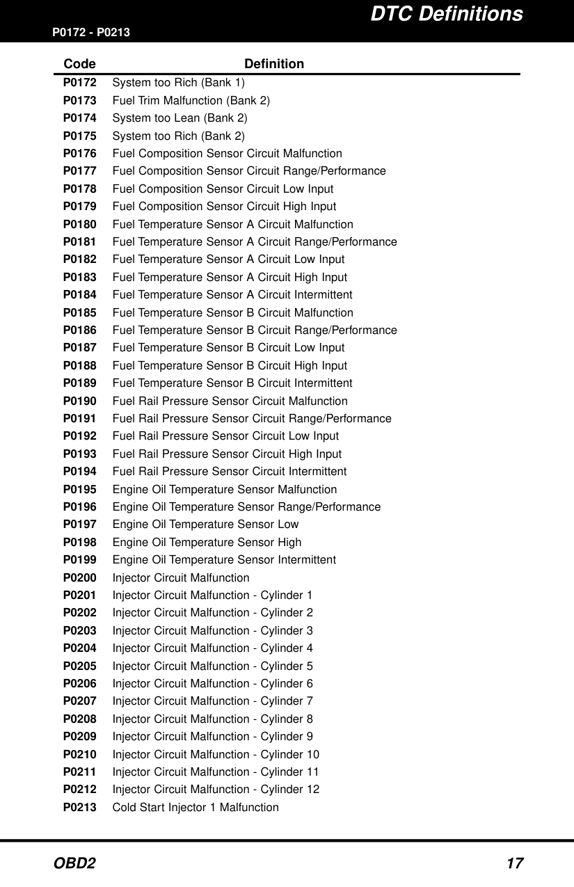
P0172 - P0213
####### Code Definition
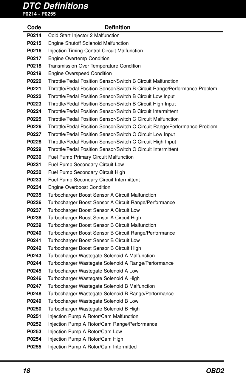
########## P0214 - P0255
Code Definition P0214 Cold Start Injector 2 Malfunction P0215 Engine Shutoff Solenoid Malfunction P0216 Injection Timing Control Circuit Malfunction P0217 Engine Overtemp Condition P0218 Transmission Over Temperature Condition P0219 Engine Overspeed Condition P0220 Throttle/Pedal Position Sensor/Switch B Circuit Malfunction P0221 Throttle/Pedal Position Sensor/Switch B Circuit Range/Performance Problem P0222 Throttle/Pedal Position Sensor/Switch B Circuit Low Input P0223 Throttle/Pedal Position Sensor/Switch B Circuit High Input P0224 Throttle/Pedal Position Sensor/Switch B Circuit Intermittent P0225 Throttle/Pedal Position Sensor/Switch C Circuit Malfunction P0226 Throttle/Pedal Position Sensor/Switch C Circuit Range/Performance Problem P0227 Throttle/Pedal Position Sensor/Switch C Circuit Low Input P0228 Throttle/Pedal Position Sensor/Switch C Circuit High Input P0229 Throttle/Pedal Position Sensor/Switch C Circuit Intermittent P0230 Fuel Pump Primary Circuit Malfunction P0231 Fuel Pump Secondary Circuit Low P0232 Fuel Pump Secondary Circuit High P0233 Fuel Pump Secondary Circuit Intermittent P0234 Engine Overboost Condition P0235 Turbocharger Boost Sensor A Circuit Malfunction P0236 Turbocharger Boost Sensor A Circuit Range/Performance P0237 Turbocharger Boost Sensor A Circuit Low P0238 Turbocharger Boost Sensor A Circuit High P0239 Turbocharger Boost Sensor B Circuit Malfunction P0240 Turbocharger Boost Sensor B Circuit Range/Performance P0241 Turbocharger Boost Sensor B Circuit Low P0242 Turbocharger Boost Sensor B Circuit High P0243 Turbocharger Wastegate Solenoid A Malfunction P0244 Turbocharger Wastegate Solenoid A Range/Performance P0245 Turbocharger Wastegate Solenoid A Low P0246 Turbocharger Wastegate Solenoid A High P0247 Turbocharger Wastegate Solenoid B Malfunction P0248 Turbocharger Wastegate Solenoid B Range/Performance P0249 Turbocharger Wastegate Solenoid B Low P0250 Turbocharger Wastegate Solenoid B High P0251 Injection Pump A Rotor/Cam Malfunction P0252 Injection Pump A Rotor/Cam Range/Performance P0253 Injection Pump A Rotor/Cam Low P0254 Injection Pump A Rotor/Cam High P0255 Injection Pump A Rotor/Cam Intermitted
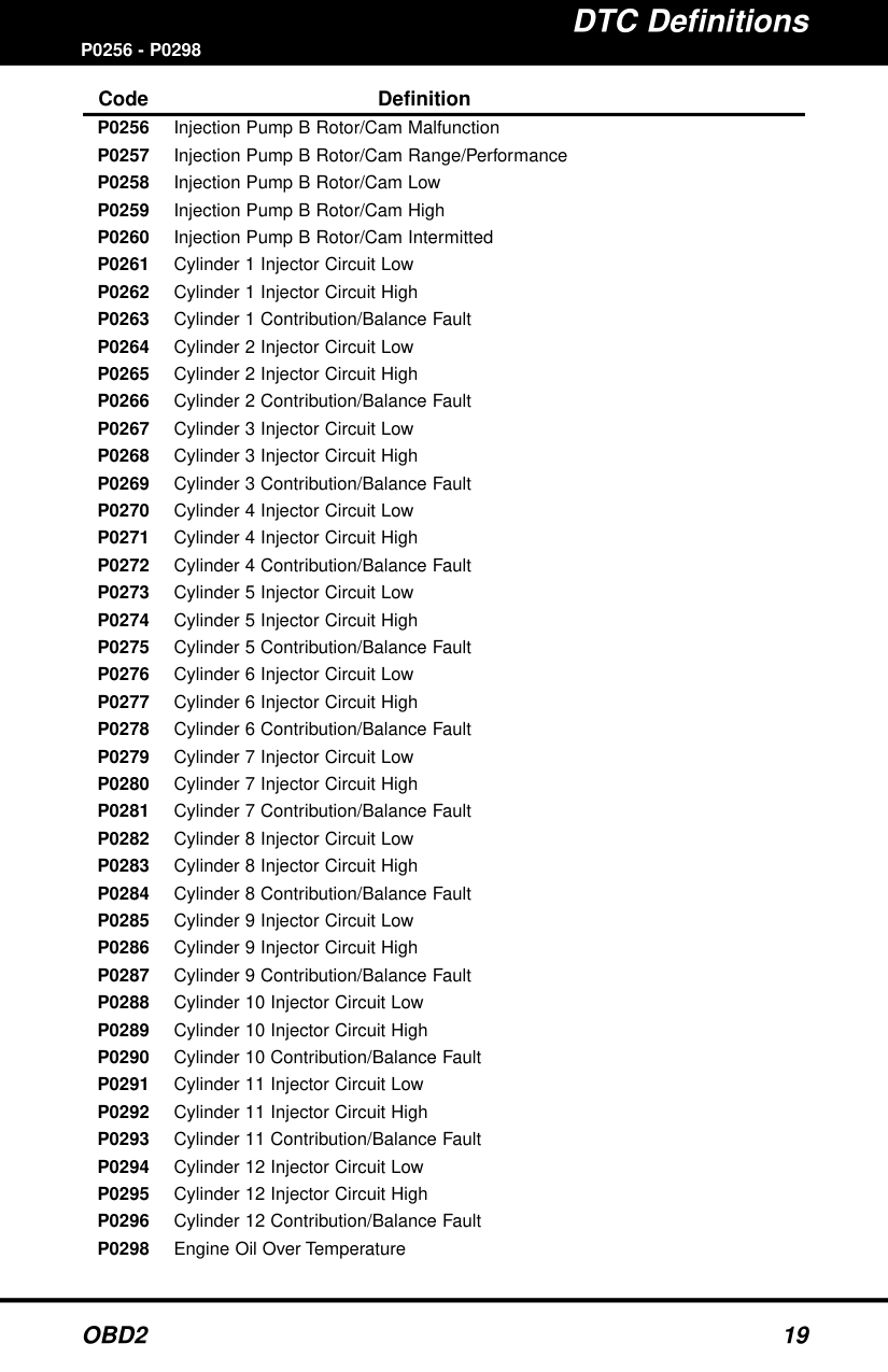
P0256 - P0298
####### Code Definition
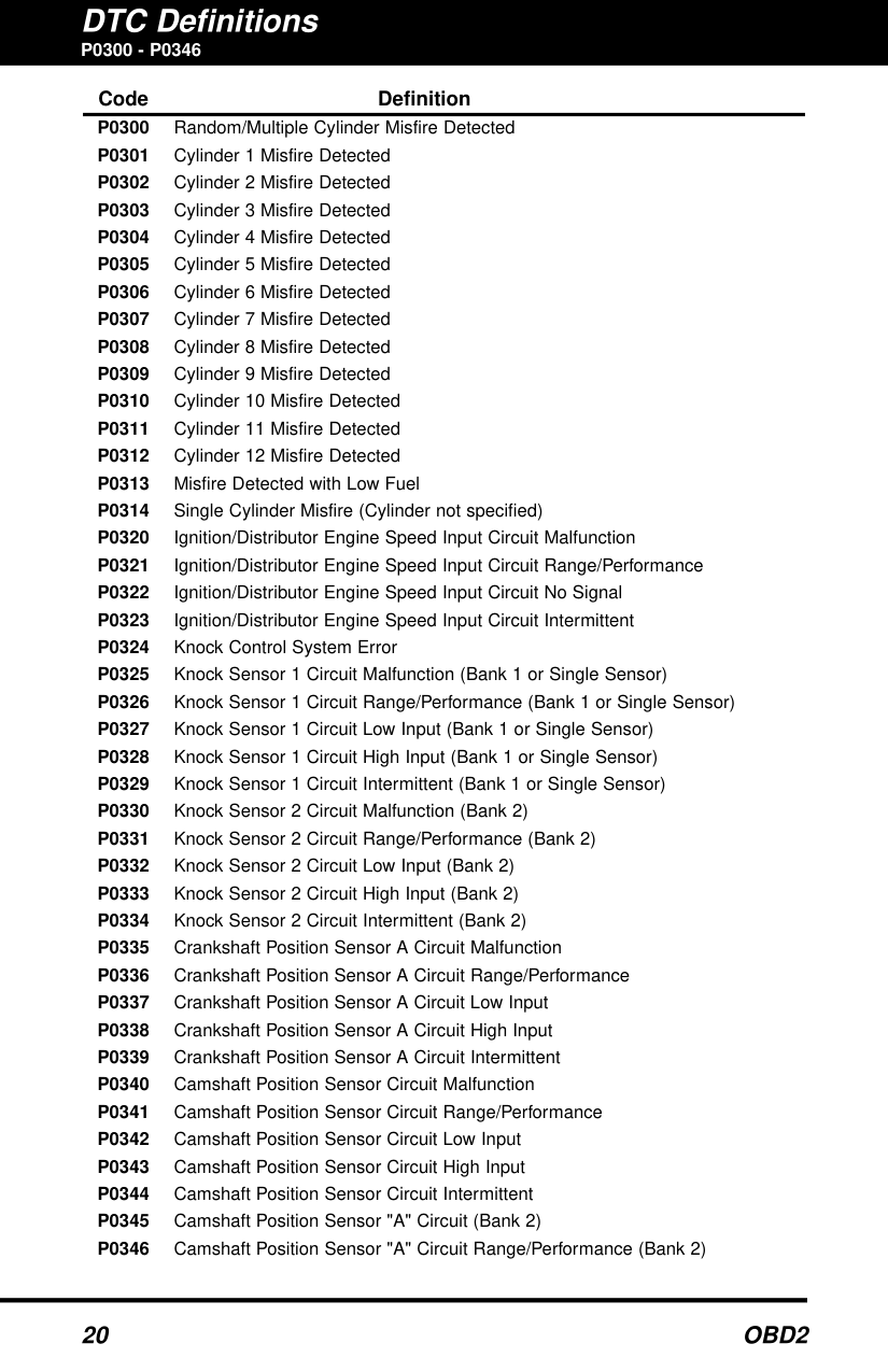
P0300 - P0346
####### Code Definition
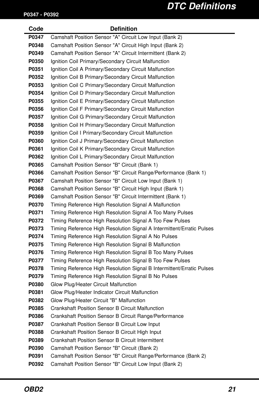
####### P0347 - P0392Code Definition
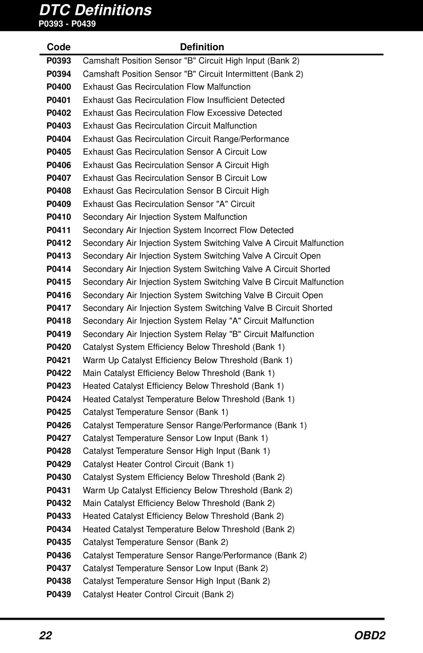
########## P0393 - P0439
Code Definition P0393 Camshaft Position Sensor "B" Circuit High Input (Bank 2) P0394 Camshaft Position Sensor "B" Circuit Intermittent (Bank 2)
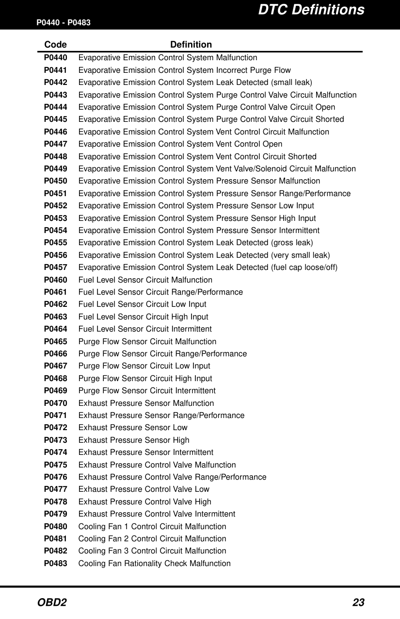
####### P0440 - P0483Code Definition
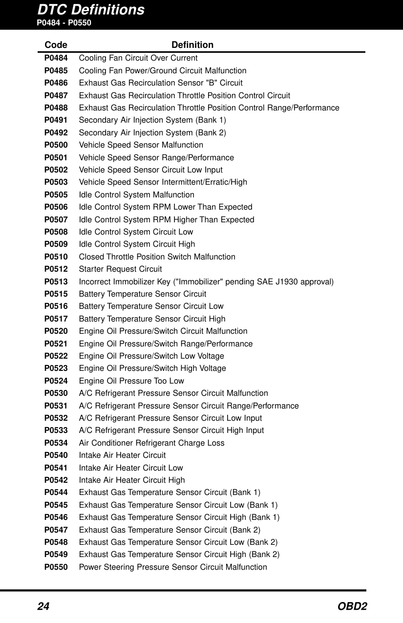
########## P0484 - P0550
Code Definition P0484 Cooling Fan Circuit Over Current P0485 Cooling Fan Power/Ground Circuit Malfunction P0486 Exhaust Gas Recirculation Sensor "B" Circuit P0487 Exhaust Gas Recirculation Throttle Position Control Circuit P0488 Exhaust Gas Recirculation Throttle Position Control Range/Performance
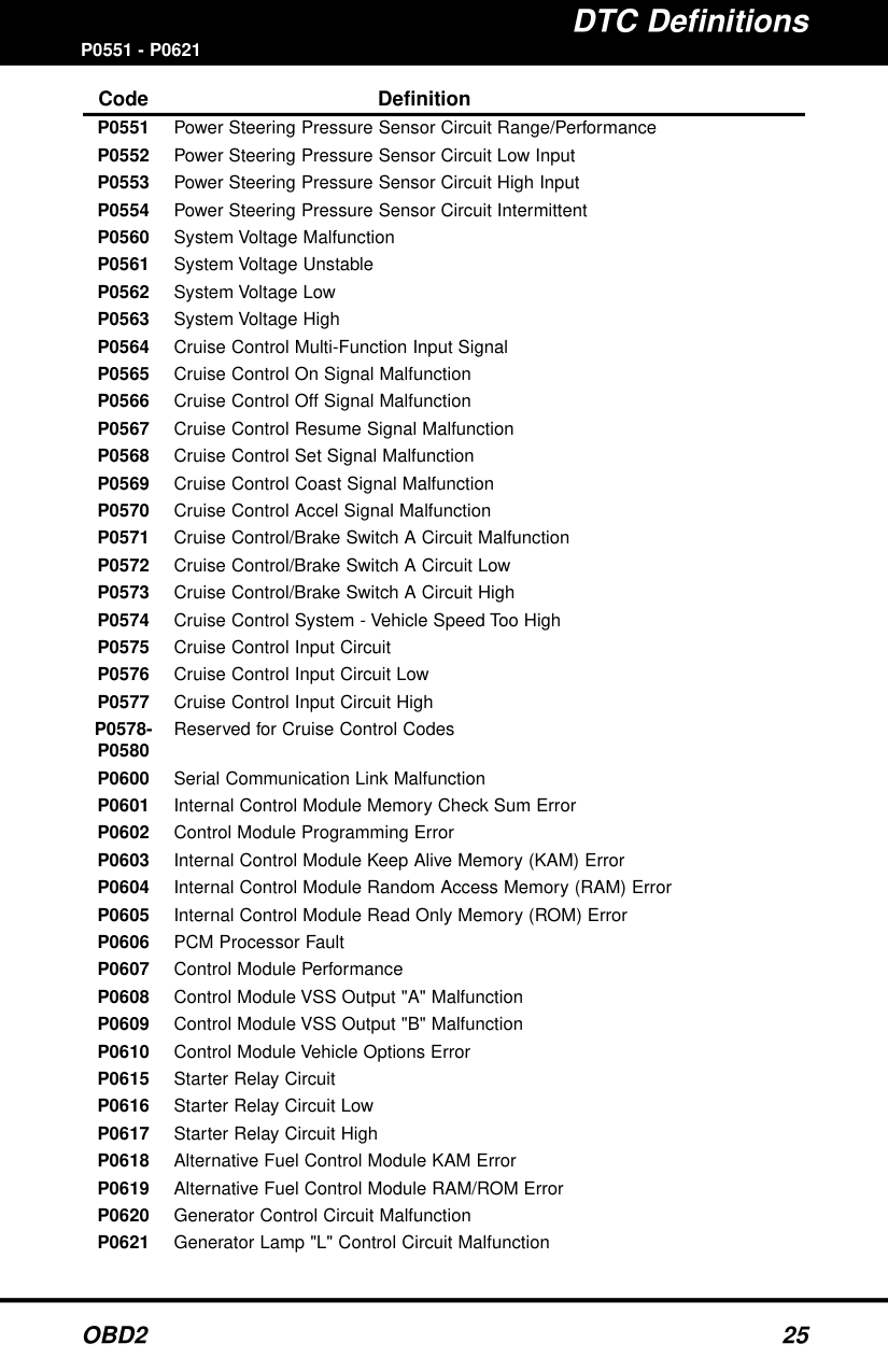
####### P0551 - P0621Code Definition
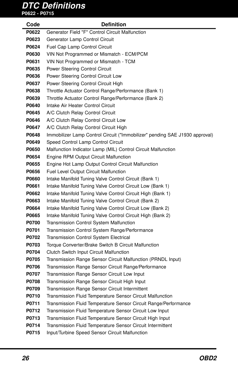
P0622 - P0715
####### Code Definition
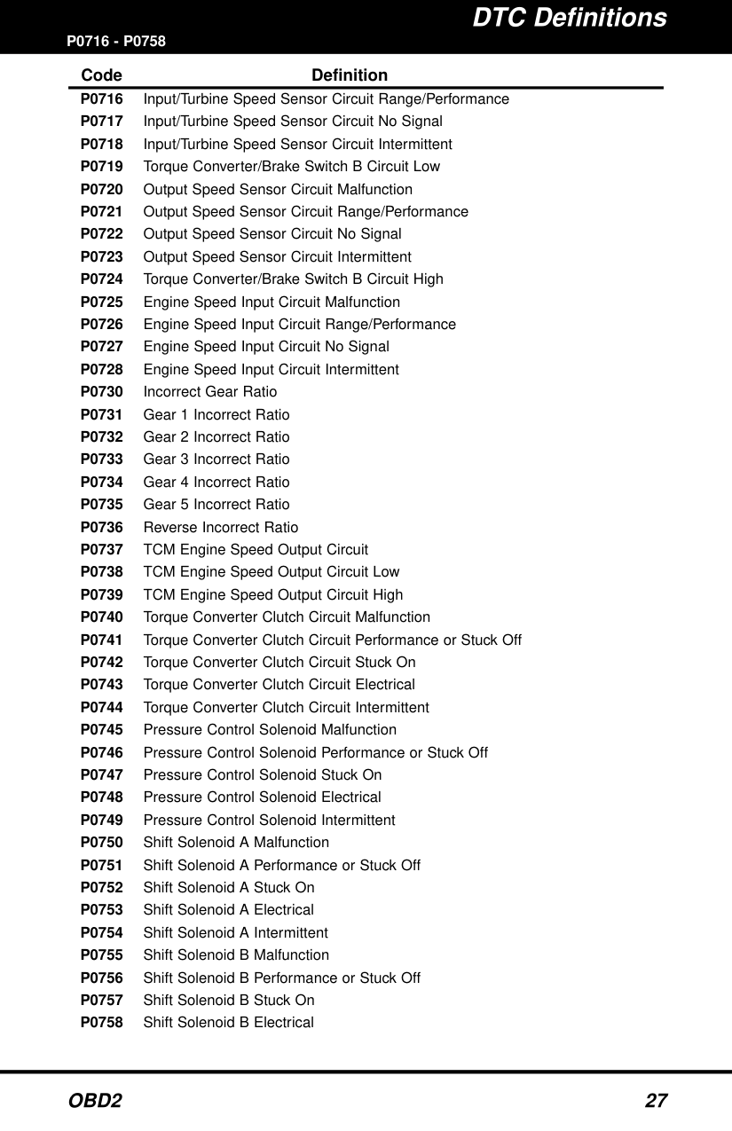
####### P0716 - P0758Code Definition
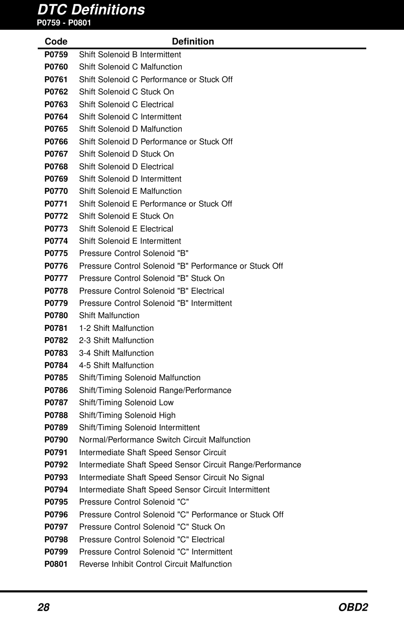
########## P0759 - P0801
Code Definition P0759 Shift Solenoid B Intermittent P0760 Shift Solenoid C Malfunction P0761 Shift Solenoid C Performance or Stuck Off P0762 Shift Solenoid C Stuck On P0763 Shift Solenoid C Electrical P0764 Shift Solenoid C Intermittent P0765 Shift Solenoid D Malfunction P0766 Shift Solenoid D Performance or Stuck Off P0767 Shift Solenoid D Stuck On P0768 Shift Solenoid D Electrical P0769 Shift Solenoid D Intermittent P0770 Shift Solenoid E Malfunction P0771 Shift Solenoid E Performance or Stuck Off P0772 Shift Solenoid E Stuck On P0773 Shift Solenoid E Electrical P0774 Shift Solenoid E Intermittent P0775 Pressure Control Solenoid "B" P0776 Pressure Control Solenoid "B" Performance or Stuck Off P0777 Pressure Control Solenoid "B" Stuck On P0778 Pressure Control Solenoid "B" Electrical P0779 Pressure Control Solenoid "B" Intermittent P0780 Shift Malfunction P0781 1-2 Shift Malfunction P0782 2-3 Shift Malfunction P0783 3-4 Shift Malfunction P0784 4-5 Shift Malfunction P0785 Shift/Timing Solenoid Malfunction P0786 Shift/Timing Solenoid Range/Performance P0787 Shift/Timing Solenoid Low P0788 Shift/Timing Solenoid High P0789 Shift/Timing Solenoid Intermittent P0790 Normal/Performance Switch Circuit Malfunction P0791 Intermediate Shaft Speed Sensor Circuit P0792 Intermediate Shaft Speed Sensor Circuit Range/Performance P0793 Intermediate Shaft Speed Sensor Circuit No Signal P0794 Intermediate Shaft Speed Sensor Circuit Intermittent P0795 Pressure Control Solenoid "C" P0796 Pressure Control Solenoid "C" Performance or Stuck Off P0797 Pressure Control Solenoid "C" Stuck On P0798 Pressure Control Solenoid "C" Electrical P0799 Pressure Control Solenoid "C" Intermittent P0801 Reverse Inhibit Control Circuit Malfunction
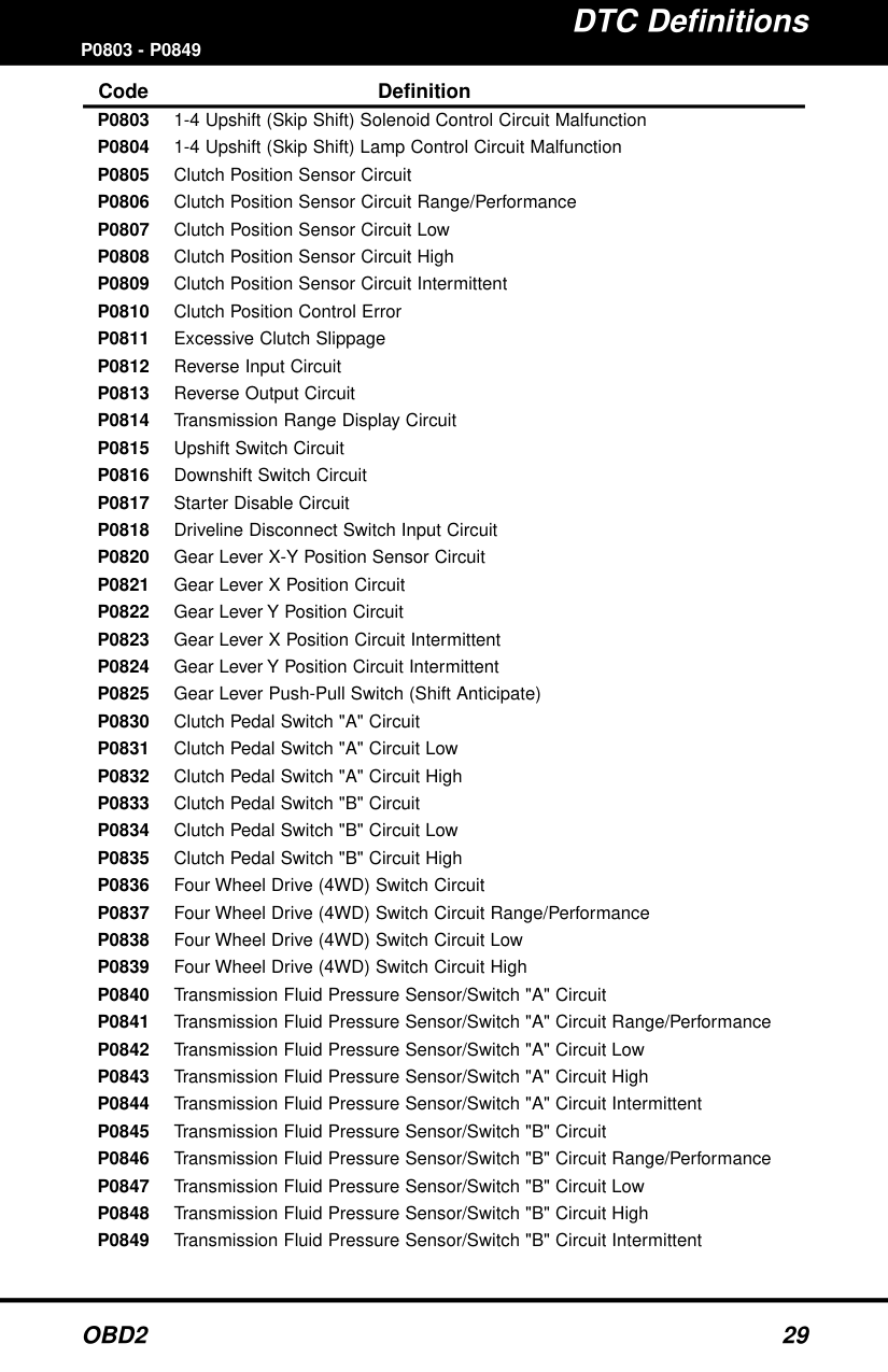
########## P0803 - P0849
Code Definition P0803 1-4 Upshift (Skip Shift) Solenoid Control Circuit Malfunction P0804 1-4 Upshift (Skip Shift) Lamp Control Circuit Malfunction P0805 Clutch Position Sensor Circuit P0806 Clutch Position Sensor Circuit Range/Performance P0807 Clutch Position Sensor Circuit Low P0808 Clutch Position Sensor Circuit High P0809 Clutch Position Sensor Circuit Intermittent P0810 Clutch Position Control Error P0811 Excessive Clutch Slippage P0812 Reverse Input Circuit P0813 Reverse Output Circuit P0814 Transmission Range Display Circuit P0815 Upshift Switch Circuit P0816 Downshift Switch Circuit P0817 Starter Disable Circuit P0818 Driveline Disconnect Switch Input Circuit