
Ask AI
— answers from the official manualAnswers from the official manual.
Common questions
Common Questions
10 totalWhat are the safety precautions for using the Innova 3306 Multimeter?
The multimeter must be used indoors only and not in excess of its rated voltage to avoid electric shock. Ensure equipment is de-energized before testing resistance or diodes to prevent personal injury. Only use provided test leads, and inspect them for damage prior to each use.
How do I measure AC/DC voltage with the Innova 3306?
Plug the black lead into 'COM' and red into 'V'. Set switch to ACV or DCV and place the red lead on the positive side of the circuit being tested, black lead on negative. Ensure not to touch energized conductors.
What do I do if the multimeter battery shows low?
Replace the battery immediately when the low battery indicator appears as false readings can happen which may cause electric shock or personal injury. Use only specified battery type for replacement.
How should I maintain my Innova 3306 Multimeter?
Keep the meter clean and dry, avoid using solvents to clean it. A damp cloth can be used but must be fully dried after cleaning.
What are the dimensions of the Innova 3306?
The size is 5.50 inches high, 3.50 inches wide and 1.25 inches deep (139mm x 89 mm x 32 mm).
How do I replace the battery in my Innova 3306?
Remove rear panel and access battery compartment to remove only one 9V alkaline battery. Reassemble the case using the screws, without touching or disassembling circuit boards.
Full Manual
2 pages
OWNER’S MANUAL DIGITAL MULTIMETER MRP #93-0187 Rev. A


SAFETY PRECAUTIONS/ WARNINGS
To prevent electrical shock and/or damage to the tester or the equipment under test, observe the following safety precautions:
SPECIFICATIONS
GENERAL SPECIFICATIONS AND FEATURES
Temperature - 32° to 104° F. (0° C to 40° C) Humidity - Less than 80% relative humidity (non-condensing) Altitude - up to 6562 ft (2000 meters)
Temperature - 4° to 140° F (- 20° to 60° C) Humidity - Less than 90% relative humidity (non-condensing)
Height - 5.50 in. (139 mm) Width - 3.50 in. (89 mm) Depth - 1.25 in. (32 mm)
| | |---|
ELECTRICAL SPECIFICATIONS
Accuracy of specifications in the following tables are based on an operating temperature of 64°F to 82°F (18°C to 28°C) and a relative humidity of less than 75%.
Maximum voltage from V ma socket to COM socket is 500V AC/DC; from COM socket to ground is 300V AC/DC.
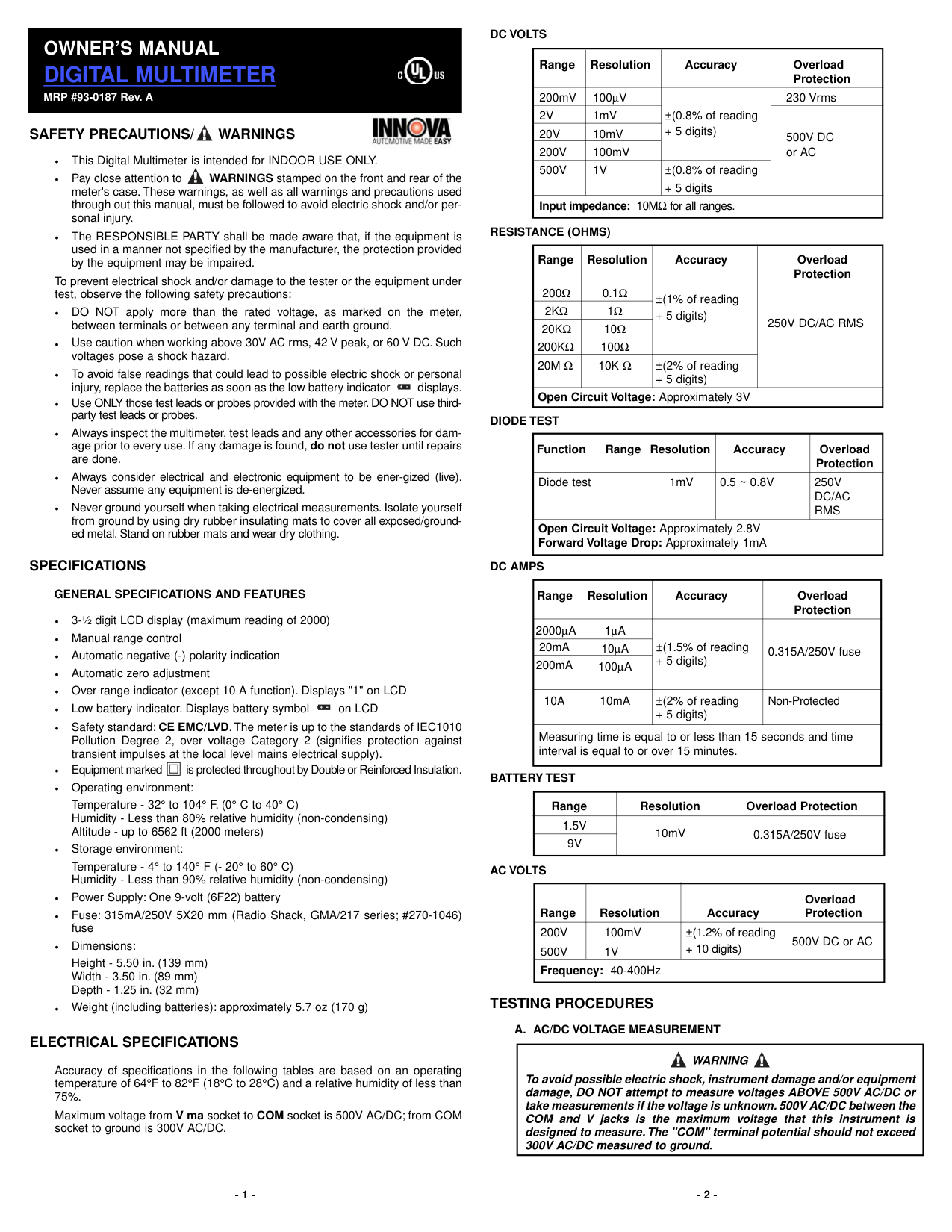
DC VOLTS
|Range|Resolution|Accuracy|Overload Protection| |---|---|---|---| |200mV|100μV|±(0.8% of reading
+ 5 digits)|230 Vrms| |2V|1mV|±(0.8% of reading
+ 5 digits)|500V DC or AC| |20V|10mV|±(0.8% of reading
+ 5 digits)|500V DC or AC| |200V|100mV|±(0.8% of reading
+ 5 digits)|500V DC or AC| |500V|1V|±(0.8% of reading
+ 5 digits|500V DC or AC| |Input impedance: 10MΩ for all ranges.|Input impedance: 10MΩ for all ranges.|Input impedance: 10MΩ for all ranges.|Input impedance: 10MΩ for all ranges.|
RESISTANCE (OHMS)
|Range|Resolution|Accuracy|Overload Protection| |---|---|---|---| |200Ω|0.1Ω|±(1% of reading
+ 5 digits)|250V DC/AC RMS| |2KΩ|1Ω|±(1% of reading
+ 5 digits)|250V DC/AC RMS| |20KΩ|10Ω|±(1% of reading
+ 5 digits)|250V DC/AC RMS| |200KΩ|100Ω|±(1% of reading
+ 5 digits)|250V DC/AC RMS| |20M Ω|10K Ω|±(2% of reading
+ 5 digits)|250V DC/AC RMS| |Open Circuit Voltage: Approximately 3V|Open Circuit Voltage: Approximately 3V|Open Circuit Voltage: Approximately 3V|Open Circuit Voltage: Approximately 3V|
DIODE TEST
|Function|Range|Resolution|Accuracy|Overload Protection| |---|---|---|---|---| |Diode test| |1mV|0.5 ~ 0.8V|250V DC/AC RMS| |Open Circuit Voltage: Approximately 2.8V Forward Voltage Drop: Approximately 1mA|Open Circuit Voltage: Approximately 2.8V Forward Voltage Drop: Approximately 1mA|Open Circuit Voltage: Approximately 2.8V Forward Voltage Drop: Approximately 1mA|Open Circuit Voltage: Approximately 2.8V Forward Voltage Drop: Approximately 1mA|Open Circuit Voltage: Approximately 2.8V Forward Voltage Drop: Approximately 1mA|
DC AMPS
|Range|Resolution|Accuracy|Overload Protection| |---|---|---|---| |2000μA|1μA|±(1.5% of reading
+ 5 digits)|0.315A/250V fuse| |20mA|10μA|±(1.5% of reading
+ 5 digits)|0.315A/250V fuse| |200mA|100μA|±(1.5% of reading
+ 5 digits)|0.315A/250V fuse| |10A|10mA|±(2% of reading
+ 5 digits)|Non-Protected| |Measuring time is equal to or less than 15 seconds and time interval is equal to or over 15 minutes.|Measuring time is equal to or less than 15 seconds and time interval is equal to or over 15 minutes.|Measuring time is equal to or less than 15 seconds and time interval is equal to or over 15 minutes.|Measuring time is equal to or less than 15 seconds and time interval is equal to or over 15 minutes.|
BATTERY TEST
|Range|Resolution|Overload Protection| |---|---|---| |1.5V|10mV|0.315A/250V fuse| |9V|10mV|0.315A/250V fuse|
AC VOLTS
|Range|Resolution|Accuracy|Overload Protection| |---|---|---|---| |200V|100mV|±(1.2% of reading
+ 10 digits)|500V DC or AC| |500V|1V|±(1.2% of reading
+ 10 digits)|500V DC or AC| |Frequency: 40-400Hz|Frequency: 40-400Hz|Frequency: 40-400Hz|Frequency: 40-400Hz|
TESTING PROCEDURES
A. AC/DC VOLTAGE MEASUREMENT
|WARNING
To avoid possible electric shock, instrument damage and/or equipment damage, DO NOT attempt to measure voltages ABOVE 500V AC/DC or take measurements if the voltage is unknown. 500V AC/DC between the COM and V jacks is the maximum voltage that this instrument is designed to measure.The "COM" terminal potential should not exceed 300V AC/DC measured to ground.
| |---|
E. BATTERY TEST
B. RESISTANCE MEASUREMENT Ω (OHMS)
|WARNING
Resistance measurements must be made on "de-energized" (dead) circuits ONLY. Impressing a voltage across the multimeter's terminals while set to any resistance range may result in electric shock, instrument damage and/or damage to equipment under test. MAKE SURE equipment is completely de-energized before taking any resistance measurements.
| |---|
MAINTENANCE
BATTERY AND FUSE REPLACEMENT
|WARNING
When replacing the battery or the fuse, remove only the rear panel. Do not remove or disassemble the circuit board or the front panel, these items are not serviceable and if disassembled there is the possibility of loose metal parts shorting the circuit board and causing an electrocution danger to the user.
| |---|
C. DIODE TEST
NOTE:Use a0.315A/250V, 5x20mmtype fuse ONLY - Bussmann, GMA Type (Radio Shack #270-1046 or similar). Using anincorrect fuse may result in serious injury and/or damage to the unit.
|WARNING
To avoid electrical shock and/or damage to the multimeter, ensure the power is removed from the circuit before any DIODE testing procedure is conducted.Test diodes on de-energized (dead) circuits only, never on live circuits.
| |---|
LIMITED ONE YEAR WARRANTY
The Manufacturer warrants to the original purchaser that this unit is free of defects in materials and workmanship under normal use and maintenance for a period of one (1) year from the date of original purchase. If the unit fails within the one (1) year period, it will be repaired or replaced, at the Manufacturer’s option, at no charge, when returned prepaid to the Service Center with Proof of Purchase. The sales receipt may be used for this purpose. Installation labor is not covered under this warranty. All replacement parts, whether new or remanufactured, assume as their warranty period only the remaining time of this warranty. This warranty does not apply to damage caused by improper use, accident, abuse, improper voltage, service, fire, flood, lightning, or other acts of God, or if the product was altered or repaired by anyone other than the Manufacturer’s Service Center. The Manufacturer, under no circumstances shall be liable for any consequential damages for breach of any written warranty of this unit. This warranty gives you specific legal rights, and you may also have rights, which vary from state to state.This manual is copyrighted with all rights reserved. No portion of this document may be copied or reproduced by any means without the express written permission of the Manufacturer. THIS WARRANTY IS NOT TRANSFERABLE. For service, send via U.P.S. (if possible) prepaid to Manufacturer. Allow 3-4 weeks for service/repair.
D. DC CURRENT MEASUREMENT (AMPS)
|WARNING
To prevent electrical shock when performing current measurements, follow all steps as indicated below DO NOT skip any steps or take any short cuts.
The DC10A range is not fused.To avoid current hazard and/or damage to the tester, DO NOT try to take measurements on circuits that have more than 10 amps. DO NOT take more than 15 seconds to take the reading. A waiting period of AT LEAST 15 MINUTES is necessary between every 15 second testing period.
| |---|
CAUTION: After the test is completed, shut the power off to the circuit before removing the test leads and before reconnecting any disconnected wires or devices.
Copyright © 2013 IEC. All Rights Reserved.