
Ask AI
— answers from the official manualAnswers from the official manual.
Common questions
Common Questions
18 totalHow do I erase Diagnostic Trouble Codes (DTCs) from my vehicle's computer?
Connect the Scan Tool to the vehicle's DLC, turn the ignition ON, and perform the Code Retrieval procedure. Once codes are displayed, press and release the ERASE button, select YES when the confirmation message appears, and press ENTER. Note that 'Permanent' DTCs cannot be erased using the ERASE function, and erasing will also clear Freeze Frame data and reset all Monitor statuses. (Page 15)
What do the green, yellow, and red LEDs mean on the Innova 5210?
The green LED indicates all engine systems are running normally with no DTCs present and all Monitors have completed diagnostic testing. The yellow LED indicates a possible problem, such as a pending DTC or some Monitors not having completed their diagnostic testing. The red LED indicates a confirmed problem with one or more vehicle systems, with DTCs present and the Check Engine lamp illuminated on the dashboard. (Page 5)
How do I connect the Innova 5210 to the RepairSolutions 2 app via Bluetooth or WiFi?
Launch the RepairSolutions 2 app and select WiFi Tools Settings from the menu, power on your Code Reader, then select it from the list of available devices. Once Bluetooth pairing is complete, follow the on-screen prompts to connect to an available WiFi network, noting that only 2.4GHz networks are supported. The RepairSolutions 2 app will store a maximum of two WiFi configurations. (Page 17)
What safety precautions should I follow when using the Innova 5210 on a running vehicle?
Always operate the vehicle in a well-ventilated area to avoid carbon monoxide poisoning, and wear approved safety eye protection at all times. Keep a safe distance from moving engine parts such as the coolant fan, pulleys, and fan belt, and avoid contact with hot engine parts. Before starting an engine for testing, ensure the parking brake is engaged and the transmission is in park or neutral with drive wheels blocked. (Page 1)
How do I perform a battery and alternator check using the Innova 5210?
From the Main Menu, select Battery/Alternator Test and choose either Battery Test or Alternator Monitor. For the battery test, turn the engine off, turn the ignition on without starting the engine, turn on the headlights, and follow the on-screen prompts including three engine start/stop cycles. Results are displayed with LED indicators: Green = Good, Yellow = Normal, Red = Warning/Bad. (Pages 26-27)
How do I set up the display language and unit of measurement when using the scan tool for the first time?
The first time the unit is connected to a vehicle, you will be prompted to select a display language from English, French, or Spanish, then press ENTER. Next, select the desired unit of measurement (USA or Metric) and press ENTER to confirm. After initial setup, these settings can be changed at any time through the Adjustments and Settings menu. (Page 5)
Show 12 more questions
What is Freeze Frame data and how do I view it on the Innova 5210?
How do I view and customize Live Data (PIDs) on the Innova 5210?
How do I erase Diagnostic Trouble Codes (DTCs) from my Innova 5210?
What should I do if the Innova 5210 fails to link to my vehicle?
How can I perform an EVAP leak test using the Innova 5210?
How do I view OEM enhanced codes on my Innova 5210 except from Ford/Mazda?
How do I check my vehicle battery condition using the Innova 5210?
How do I customize live data on the Innova 5210?
How do I set up language and measurement units on my Innova 5210?
What should I do if my Innova 5210 LED displays yellow?
How do I conduct an O2 Sensor Test with my Innova 5210?
What is covered under the Innova 5210 warranty and how do I get service?
Full Manual
34 pages
Table of Contents i
About The Scan Tool
SAFETY FIRST! ....................................................................... 1Controls And Indicators ..............................................
2Display Functions ............................................................
3Initial Adjustments ..........................................................
5Using The Scan Tool
Code Retrieval Procedure ..........................................
6 THE SYSTEM MENU ............................................................... 10 VIEWING OEM ENHANCED DTCs (except Ford/Mazda)........ 11 VIEWING OEM ENHANCED DTCs (Ford/Mazda only) ........... 12 VIEWING ABS DTCs ................................................................ 13 ERASING DIAGNOSTIC TROUBLE CODES (DTCs).............. 15About Repairsolutions 2® ............................................ 16
Connecting To Bluetooth / Wifi ................................. 17
Live Data Mode
VIEWING LIVE DATA .............................................................. 18 CUSTOMIZING LIVE DATA (PIDs) ......................................... 19Additional Functions
SYSTEM TEST MENU ............................................................. 21Viewing Vehicle Information ....................................... 24
Battery/Alternator Test ............................................. 26
Viewing The Firmware Version .................................... 28
THE TOOL LIBRARY ............................................................... 28Adjustments And Settings ........................................... 30
Warranty And Servicing
Limited One Year Warranty .......................................... 33
Service Procedures ....................................................... 33
About the Scan Tool
Safety First
1Safety First!
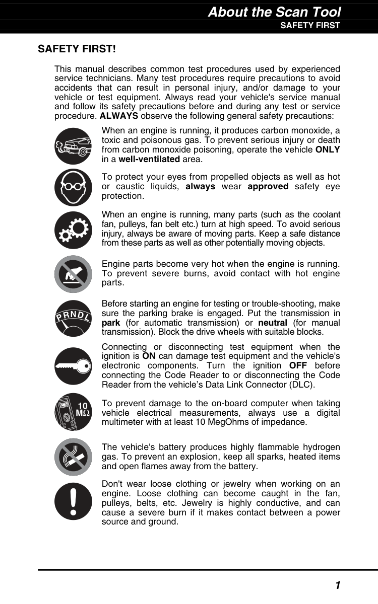
This manual describes common test procedures used by experienced service technicians. Many test procedures require precautions to avoid accidents that can result in personal injury, and/or damage to your vehicle or test equipment. Always read your vehicle's service manual and follow its safety precautions before and during any test or service procedure. ALWAYS observe the following general safety precautions: When an engine is running, it produces carbon monoxide, a toxic and poisonous gas. To prevent serious injury or death from carbon monoxide poisoning, operate the vehicle ONLY in a well-ventilated area. To protect your eyes from propelled objects as well as hot or caustic liquids, always wear approved safety eye protection. When an engine is running, many parts (such as the coolant fan, pulleys, fan belt etc.) turn at high speed. To avoid serious injury, always be aware of moving parts. Keep a safe distance from these parts as well as other potentially moving objects. Engine parts become very hot when the engine is running. To prevent severe burns, avoid contact with hot engine parts. Before starting an engine for testing or trouble-shooting, make sure the parking brake is engaged. Put the transmission in park (for automatic transmission) or neutral (for manual transmission). Block the drive wheels with suitable blocks. Connecting or disconnecting test equipment when the ignition is ON can damage test equipment and the vehicle's electronic components. Turn the ignition OFF before connecting the Code Reader to or disconnecting the Code Reader from the vehicle’s Data Link Connector (DLC). To prevent damage to the on-board computer when taking vehicle electrical measurements, always use a digital multimeter with at least 10 MegOhms of impedance. The vehicle's battery produces highly flammable hydrogen gas. To prevent an explosion, keep all sparks, heated items and open flames away from the battery. Don't wear loose clothing or jewelry when working on an engine. Loose clothing can become caught in the fan, pulleys, belts, etc. Jewelry is highly conductive, and can cause a severe burn if it makes contact between a power source and ground.N
L
D
R
P
About the Scan Tool
Controls And Indicators
2Controls And Indicators
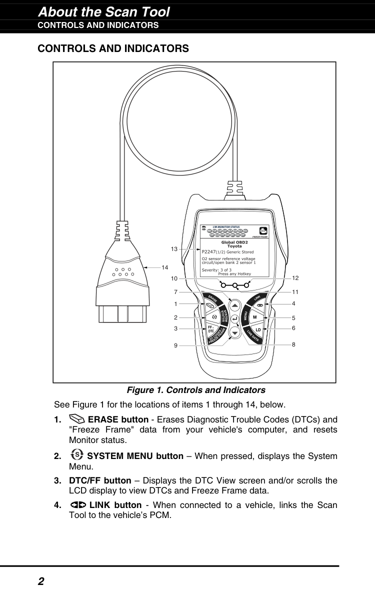
Figure 1. Controls and Indicators See Figure 1 for the locations of items 1 through 14, below.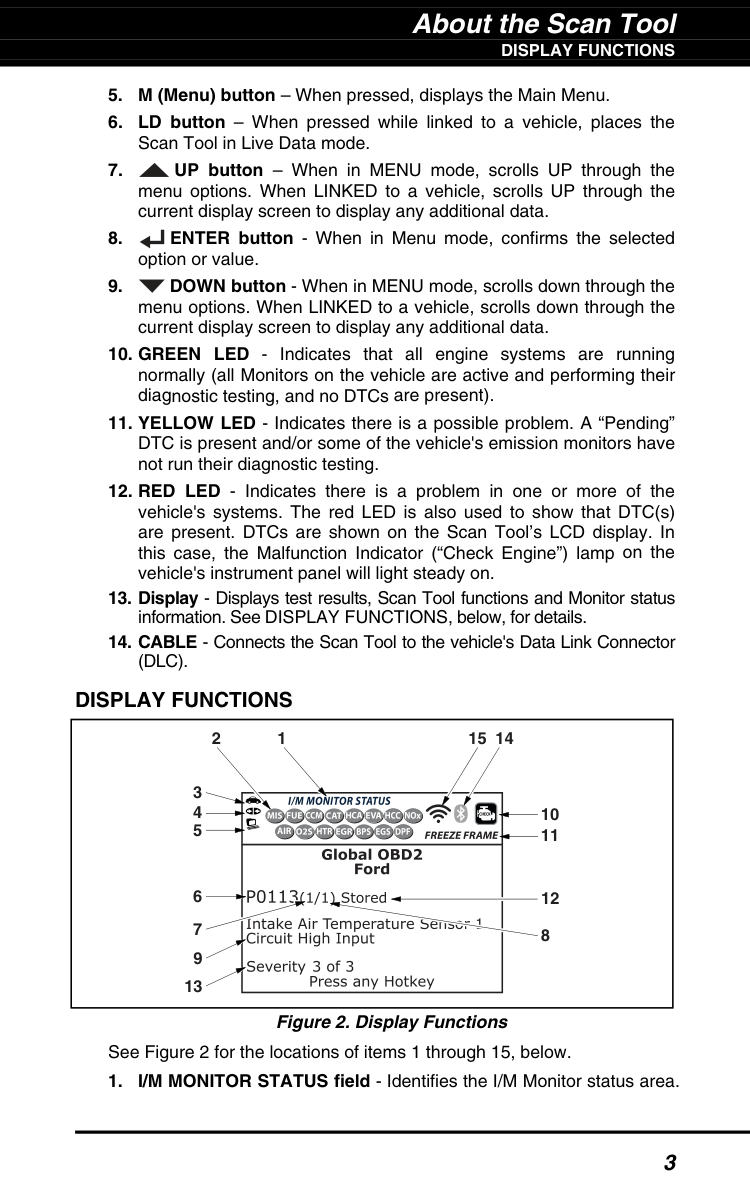
About the Scan Tool
Display Functions
3(Dlc).
Display Functions
Figure 2. Display Functions See Figure 2 for the locations of items 1 through 15, below.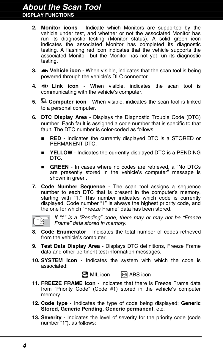
About the Scan Tool
Display Functions
4Permanent Dtc.
YELLOW - Indicates the currently displayed DTC is a PENDINGDtc.
GREEN - In cases where no codes are retrieved, a “No DTCs are presently stored in the vehicle’s computer” message is shown in green.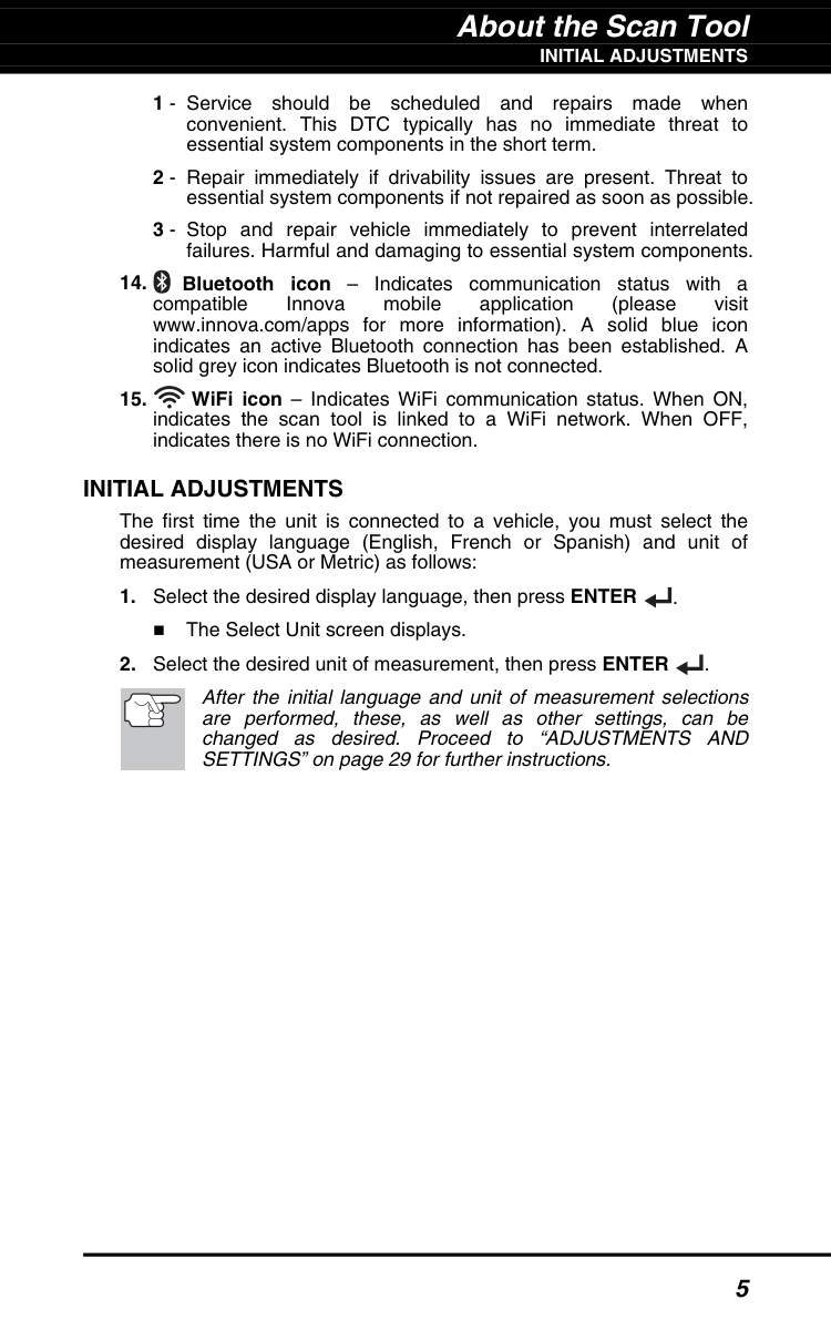
About the Scan Tool
Initial Adjustments
5 1 - Service should be scheduled and repairs made when convenient. This DTC typically has no immediate threat to essential system components in the short term. 2 - Repair immediately if drivability issues are present. Threat to essential system components if not repaired as soon as possible. 3 - Stop and repair vehicle immediately to prevent interrelated failures. Harmful and damaging to essential system components.Initial Adjustments
The first time the unit is connected to a vehicle, you must select the desired display language (English, French or Spanish) and unit of measurement (USA or Metric) as follows: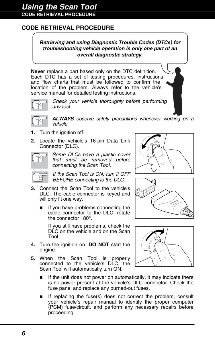
Using the Scan Tool
Code Retrieval Procedure
6Code Retrieval Procedure
Never replace a part based only on the DTC definition. Each DTC has a set of testing procedures, instructions and flow charts that must be followed to confirm the location of the problem. Always refer to the vehicle's service manual for detailed testing instructions. Check your vehicle thoroughly before performing any test. ALWAYS observe safety precautions whenever working on a vehicle.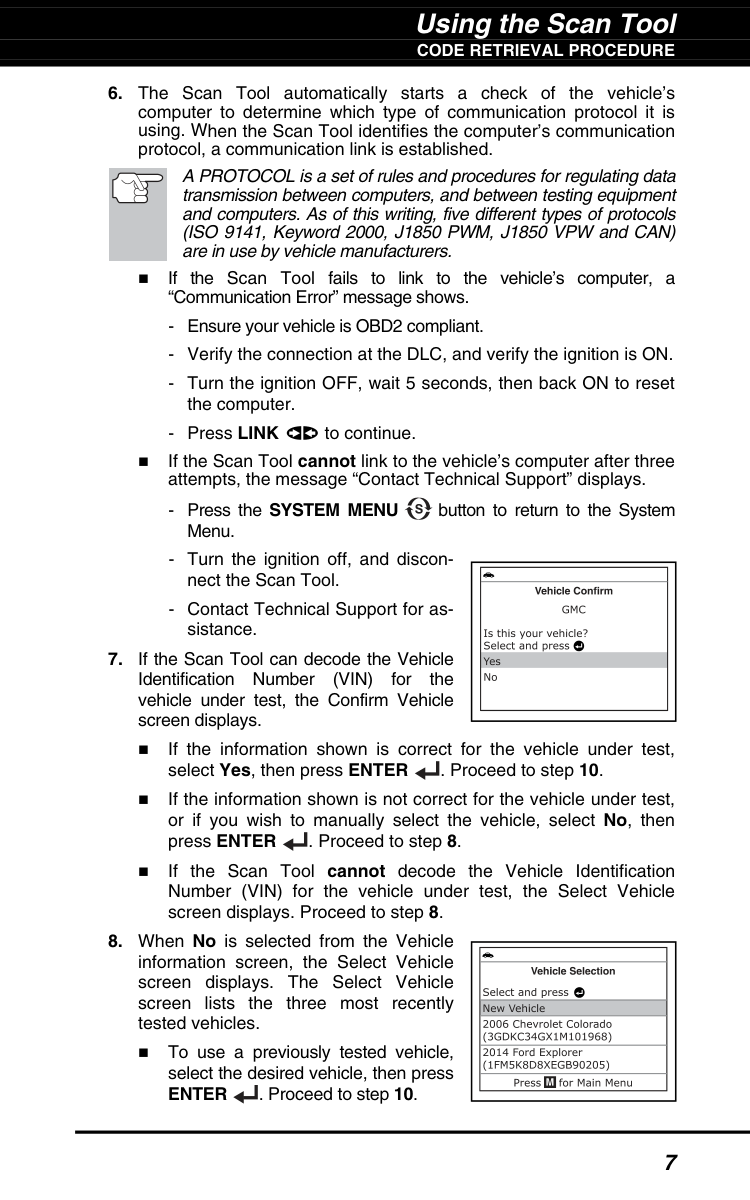
Using the Scan Tool
Code Retrieval Procedure
7Enter
. Proceed to step 10.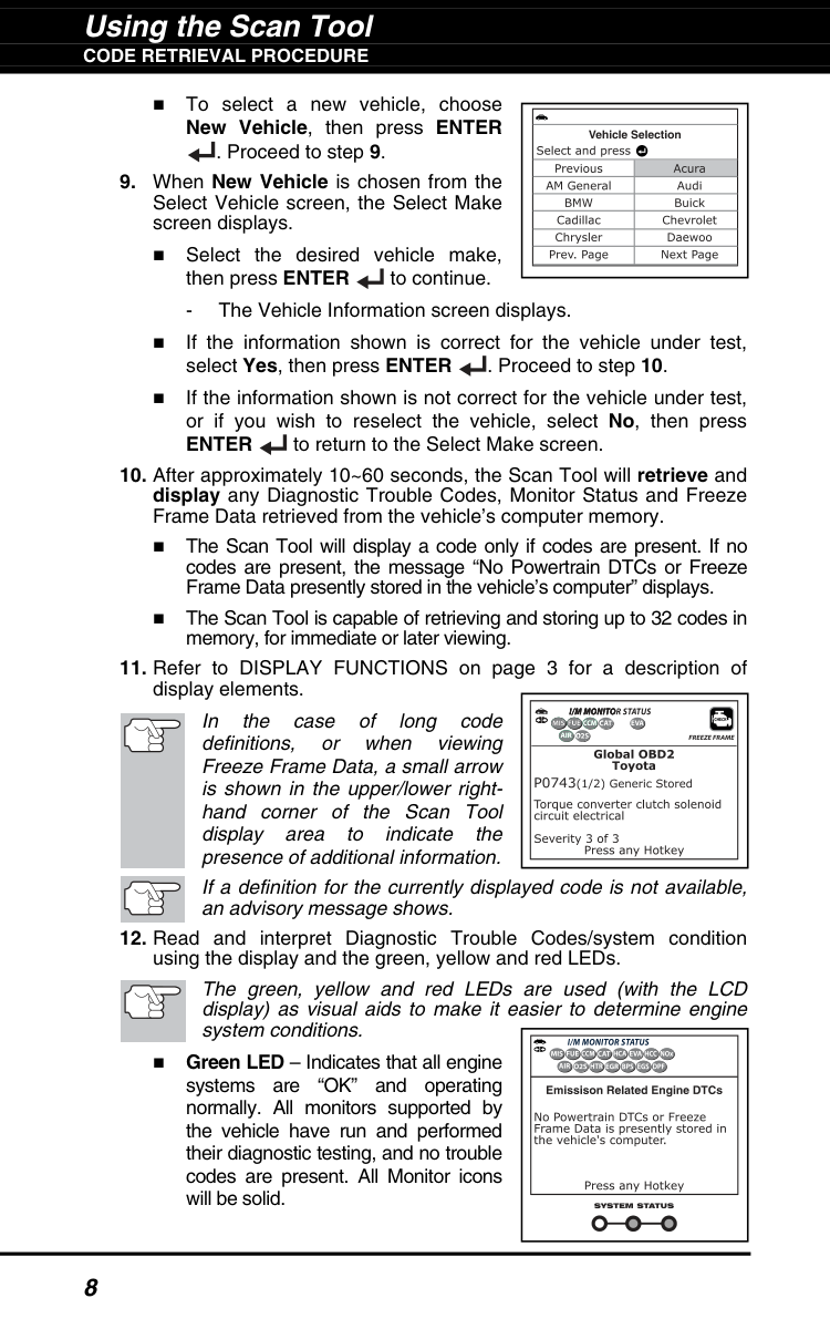
Using the Scan Tool
Code Retrieval Procedure
8 To select a new vehicle, choose New Vehicle, then press ENTER . Proceed to step 9.Enter
to return to the Select Make screen.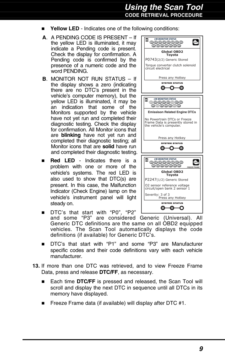
Using the Scan Tool
Code Retrieval Procedure
9 Yellow LED - Indicates one of the following conditions: A. A PENDING CODE IS PRESENT – If the yellow LED is illuminated, it may indicate a Pending code is present. Check the display for confirmation. A Pending code is confirmed by the presence of a numeric code and the word PENDING. B. MONITOR NOT RUN STATUS – If the display shows a zero (indicating there are no DTC’s present in the vehicle’s computer memory), but the yellow LED is illuminated, it may be an indication that some of the Monitors supported by the vehicle have not yet run and completed their diagnostic testing. Check the display for confirmation. All Monitor icons that are blinking have not yet run and completed their diagnostic testing; all Monitor icons that are solid have run and completed their diagnostic testing. Red LED - Indicates there is a problem with one or more of the vehicle's systems. The red LED is also used to show that DTC(s) are present. In this case, the Malfunction Indicator (Check Engine) lamp on the vehicle's instrument panel will light steady on. DTC’s that start with “P0”, “P2” and some “P3” are considered Generic (Universal). All Generic DTC definitions are the same on all OBD2 equipped vehicles. The Scan Tool automatically displays the code definitions (if available) for Generic DTC’s. DTC’s that start with “P1” and some “P3” are Manufacturer specific codes and their code definitions vary with each vehicle manufacturer.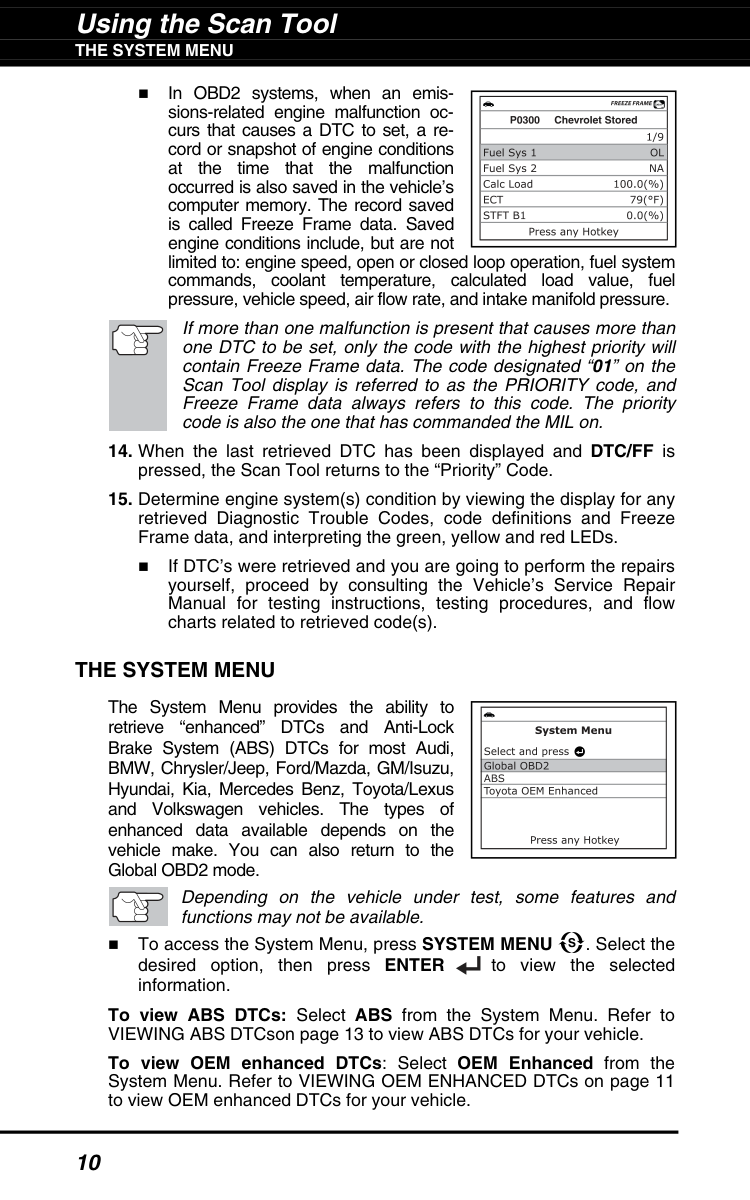
Using the Scan Tool
The System Menu
10 In OBD2 systems, when an emis- sions-related engine malfunction oc- curs that causes a DTC to set, a re- cord or snapshot of engine conditions at the time that the malfunction occurred is also saved in the vehicle’s computer memory. The record saved is called Freeze Frame data. Saved engine conditions include, but are not limited to: engine speed, open or closed loop operation, fuel system commands, coolant temperature, calculated load value, fuel pressure, vehicle speed, air flow rate, and intake manifold pressure. If more than one malfunction is present that causes more than one DTC to be set, only the code with the highest priority will contain Freeze Frame data. The code designated “01” on the Scan Tool display is referred to as the PRIORITY code, and Freeze Frame data always refers to this code. The priority code is also the one that has commanded the MIL on.The System Menu
The System Menu provides the ability to retrieve “enhanced” DTCs and Anti-Lock Brake System (ABS) DTCs for most Audi, BMW, Chrysler/Jeep, Ford/Mazda, GM/Isuzu, Hyundai, Kia, Mercedes Benz, Toyota/Lexus and Volkswagen vehicles. The types of enhanced data available depends on the vehicle make. You can also return to the Global OBD2 mode. Depending on the vehicle under test, some features and functions may not be available. To access the System Menu, press SYSTEM MENU . Select the desired option, then press ENTER to view the selected information. To view ABS DTCs: Select ABS from the System Menu. Refer to VIEWING ABS DTCson page 13 to view ABS DTCs for your vehicle. To view OEM enhanced DTCs: Select OEM Enhanced from the System Menu. Refer to VIEWING OEM ENHANCED DTCs on page 11 to view OEM enhanced DTCs for your vehicle.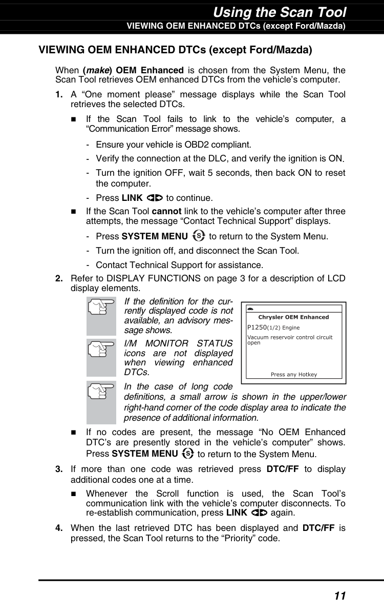
Using the Scan Tool VIEWING OEM ENHANCED DTCs (except Ford/Mazda) 11 VIEWING OEM ENHANCED DTCs (except Ford/Mazda) When (make) OEM Enhanced is chosen from the System Menu, the Scan Tool retrieves OEM enhanced DTCs from the vehicle’s computer.
I/M Monitor Status
icons are not displayed when viewing enhanced DTCs. In the case of long code definitions, a small arrow is shown in the upper/lower right-hand corner of the code display area to indicate the presence of additional information. If no codes are present, the message “No OEM Enhanced DTC’s are presently stored in the vehicle’s computer” shows. Press SYSTEM MENU to return to the System Menu.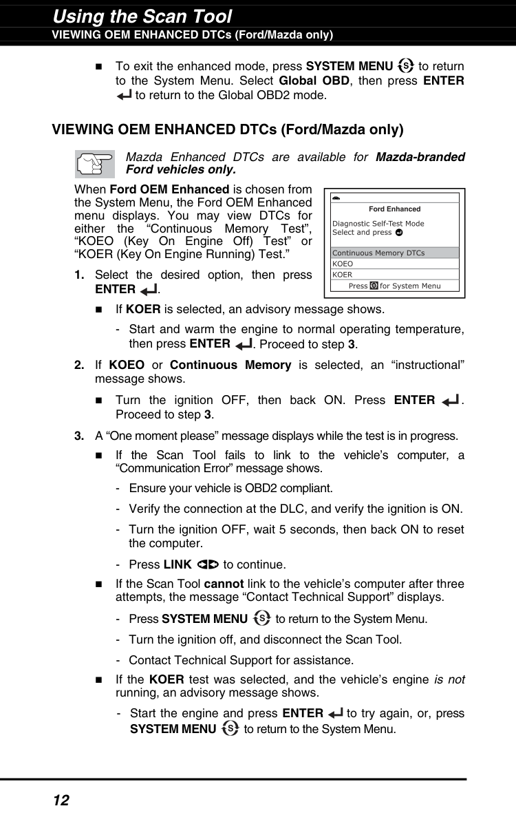
Using the Scan Tool VIEWING OEM ENHANCED DTCs (Ford/Mazda only) 12 To exit the enhanced mode, press SYSTEM MENU to return to the System Menu. Select Global OBD, then press ENTER to return to the Global OBD2 mode. VIEWING OEM ENHANCED DTCs (Ford/Mazda only) Mazda Enhanced DTCs are available for Mazda-branded Ford vehicles only. When Ford OEM Enhanced is chosen from the System Menu, the Ford OEM Enhanced menu displays. You may view DTCs for either the “Continuous Memory Test”, “KOEO (Key On Engine Off) Test” or “KOER (Key On Engine Running) Test.”
Enter
. If KOER is selected, an advisory message shows.System Menu
to return to the System Menu.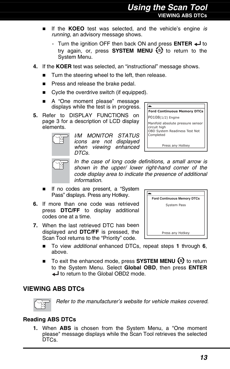
Using the Scan Tool VIEWING ABS DTCs 13 If the KOEO test was selected, and the vehicle’s engine is running, an advisory message shows.
I/M Monitor Status
icons are not displayed when viewing enhanced DTCs. In the case of long code definitions, a small arrow is shown in the upper/ lower right-hand corner of the code display area to indicate the presence of additional information. If no codes are present, a “System Pass” displays. Press any Hotkey.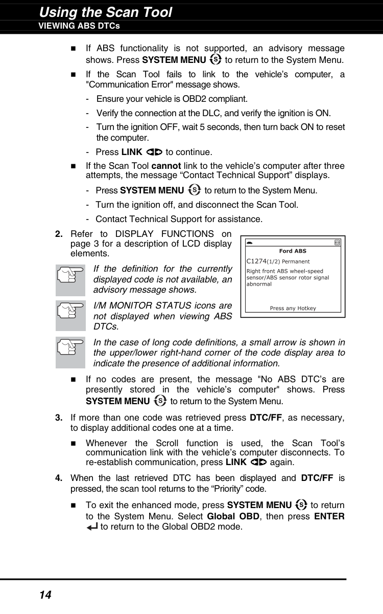
Using the Scan Tool VIEWING ABS DTCs 14 If ABS functionality is not supported, an advisory message shows. Press SYSTEM MENU to return to the System Menu. If the Scan Tool fails to link to the vehicle’s computer, a "Communication Error" message shows.
System Menu
to return to the System Menu.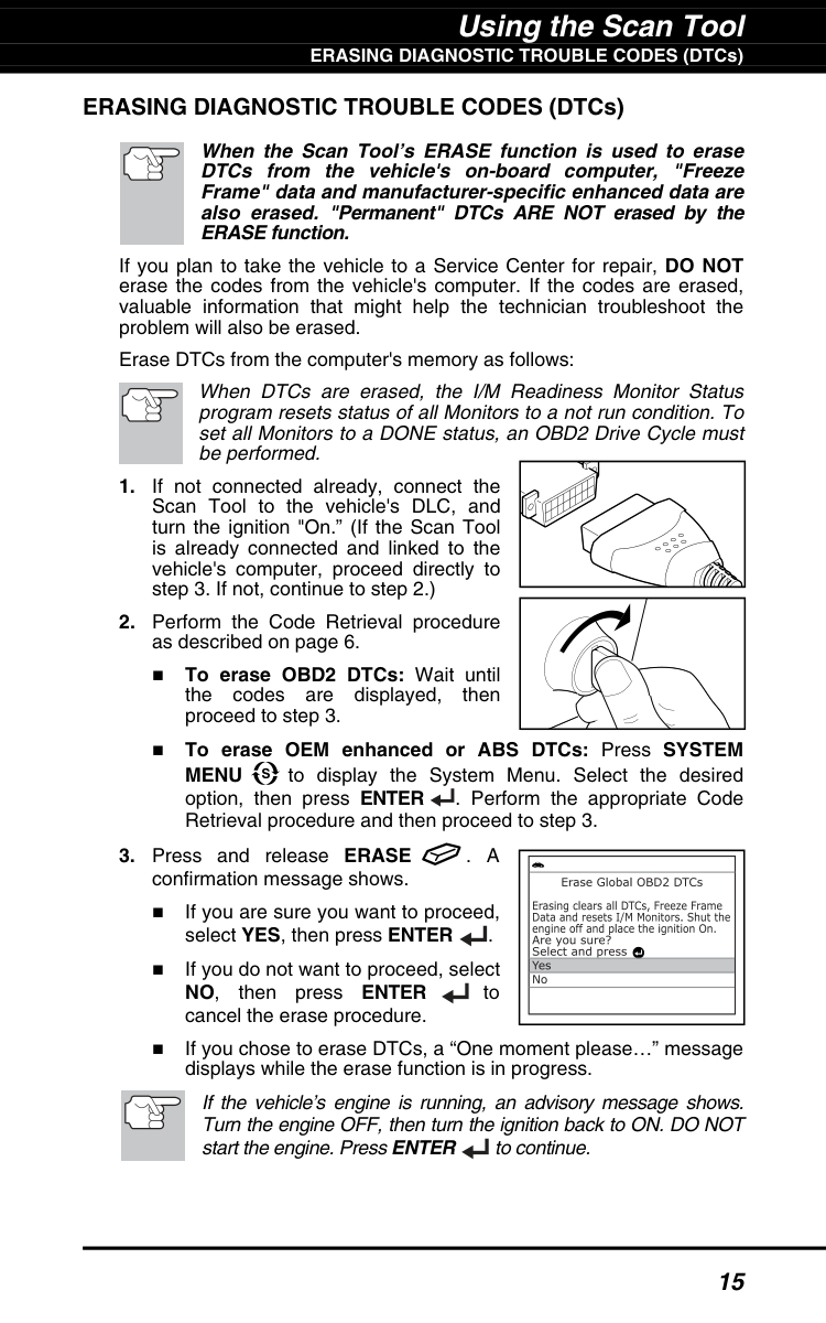
Using the Scan Tool ERASING DIAGNOSTIC TROUBLE CODES (DTCs) 15 ERASING DIAGNOSTIC TROUBLE CODES (DTCs) When the Scan Tool’s ERASE function is used to erase DTCs from the vehicle's on-board computer, "Freeze Frame" data and manufacturer-specific enhanced data are also erased. "Permanent" DTCs ARE NOT erased by the ERASE function. If you plan to take the vehicle to a Service Center for repair, DO NOT erase the codes from the vehicle's computer. If the codes are erased, valuable information that might help the technician troubleshoot the problem will also be erased. Erase DTCs from the computer's memory as follows: When DTCs are erased, the I/M Readiness Monitor Status program resets status of all Monitors to a not run condition. To set all Monitors to a DONE status, an OBD2 Drive Cycle must be performed.
Menu
to display the System Menu. Select the desired option, then press ENTER . Perform the appropriate Code Retrieval procedure and then proceed to step 3.. A
confirmation message shows. If you are sure you want to proceed, select YES, then press ENTER . If you do not want to proceed, select NO, then press ENTER to cancel the erase procedure. If you chose to erase DTCs, a “One moment please…” message displays while the erase function is in progress. If the vehicle’s engine is running, an advisory message shows. Turn the engine OFF, then turn the ignition back to ON. DO NOT start the engine. Press ENTER to continue.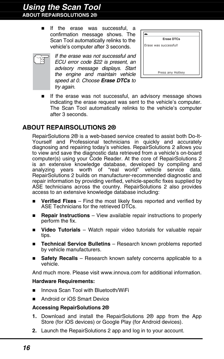
Using the Scan Tool
About Repairsolutions 2®
16 If the erase was successful, a confirmation message shows. The Scan Tool automatically relinks to the vehicle’s computer after 3 seconds. If the erase was not successful and ECU error code $22 is present, an advisory message displays. Start the engine and maintain vehicle speed at 0. Choose Erase DTCs to try again. If the erase was not successful, an advisory message shows indicating the erase request was sent to the vehicle’s computer. The Scan Tool automatically relinks to the vehicle’s computer after 3 seconds.About Repairsolutions 2®
RepairSolutions 2® is a web-based service created to assist both Do-It- Yourself and Professional technicians in quickly and accurately diagnosing and repairing today’s vehicles. RepairSolutions 2 allows you to view and save the diagnostic data retrieved from a vehicle’s on-board computer(s) using your Code Reader. At the core of RepairSolutions 2 is an extensive knowledge database, developed by compiling and analyzing years worth of “real world” vehicle service data. RepairSolutions 2 builds on manufacturer-recommended diagnostic and repair information by providing verified, vehicle-specific fixes supplied by ASE technicians across the country. RepairSolutions 2 also provides access to an extensive knowledge database including: Verified Fixes – Find the most likely fixes reported and verified by ASE Technicians for the retrieved DTCs. Repair Instructions – View available repair instructions to properly perform the fix. Video Tutorials – Watch repair video tutorials for valuable repair tips. Technical Service Bulletins – Research known problems reported by vehicle manufacturers. Safety Recalls – Research known safety concerns applicable to a vehicle. And much more. Please visit www.innova.com for additional information. Hardware Requirements: Innova Scan Tool with Bluetooth/WiFi Android or iOS Smart Device Accessing RepairSolutions 2®
Using the Scan Tool
Connecting To Bluetooth / Wifi
17 If you have not yet established an account, you must register for a FREE RepairSolutions 2 account before proceeding.Connecting To Bluetooth / Wifi
Launch the RepairSolutions 2 app an follow the prompts to establish Bluetooth and (optionally) WiFi connections, as follows:Skip.
Live Data Mode
Viewing Live Data
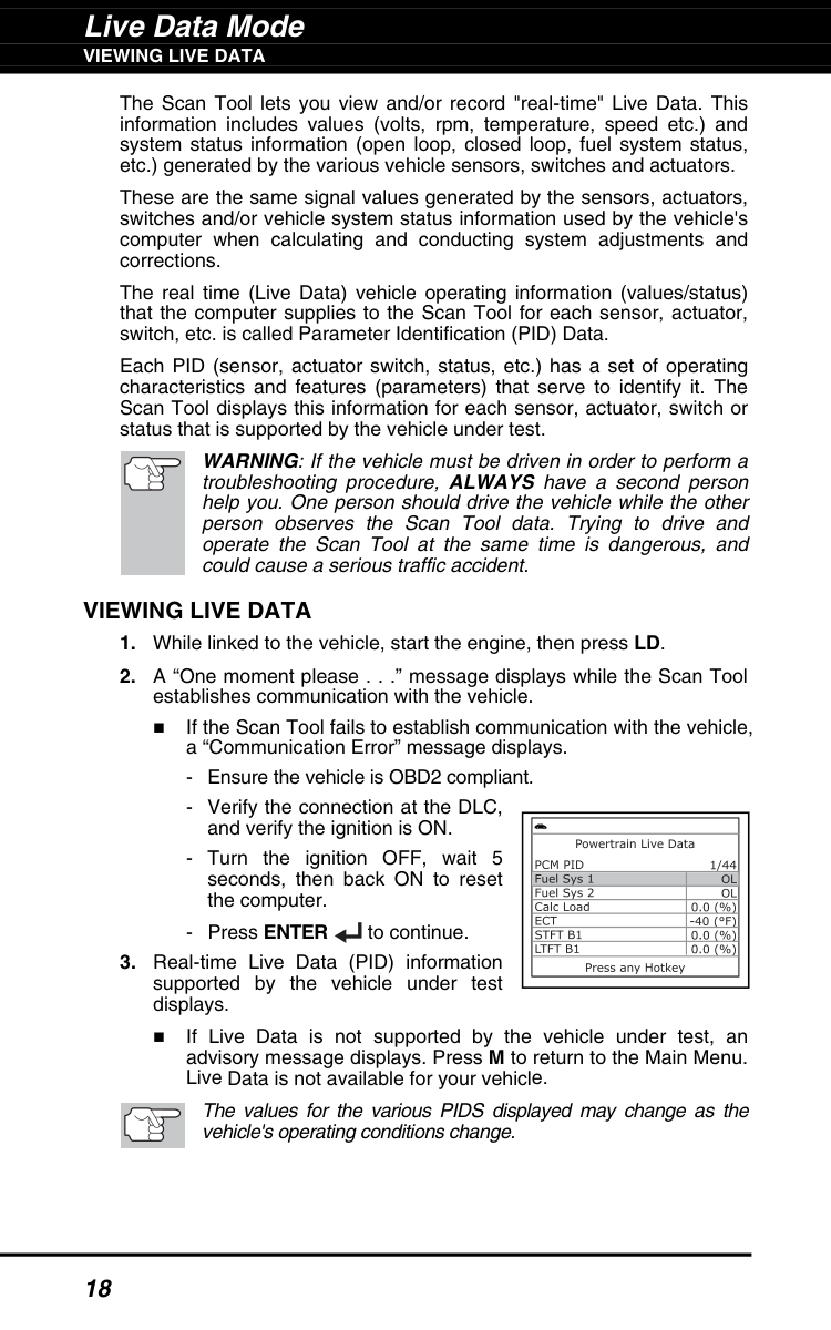
18 The Scan Tool lets you view and/or record "real-time" Live Data. This information includes values (volts, rpm, temperature, speed etc.) and system status information (open loop, closed loop, fuel system status, etc.) generated by the various vehicle sensors, switches and actuators. These are the same signal values generated by the sensors, actuators, switches and/or vehicle system status information used by the vehicle's computer when calculating and conducting system adjustments and corrections. The real time (Live Data) vehicle operating information (values/status) that the computer supplies to the Scan Tool for each sensor, actuator, switch, etc. is called Parameter Identification (PID) Data. Each PID (sensor, actuator switch, status, etc.) has a set of operating characteristics and features (parameters) that serve to identify it. The Scan Tool displays this information for each sensor, actuator, switch or status that is supported by the vehicle under test. WARNING: If the vehicle must be driven in order to perform a troubleshooting procedure, ALWAYS have a second person help you. One person should drive the vehicle while the other person observes the Scan Tool data. Trying to drive and operate the Scan Tool at the same time is dangerous, and could cause a serious traffic accident.Viewing Live Data
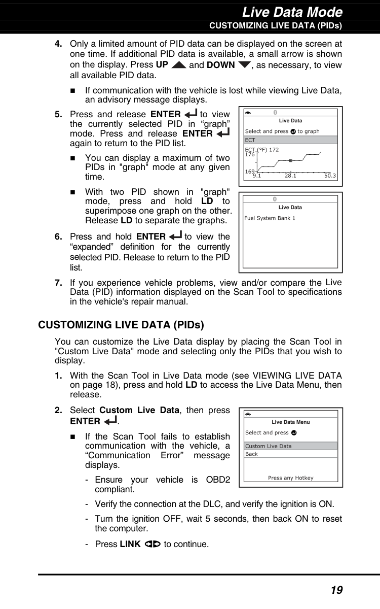
Live Data Mode CUSTOMIZING LIVE DATA (PIDs) 19
Enter
. If the Scan Tool fails to establish communication with the vehicle, a “Communication Error” message displays.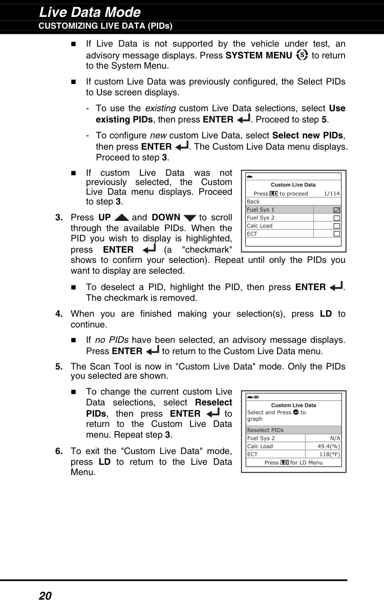
Live Data Mode CUSTOMIZING LIVE DATA (PIDs) 20 If Live Data is not supported by the vehicle under test, an advisory message displays. Press SYSTEM MENU to return to the System Menu. If custom Live Data was previously configured, the Select PIDs to Use screen displays.
Enter
(a "checkmark" shows to confirm your selection). Repeat until only the PIDs you want to display are selected. To deselect a PID, highlight the PID, then press ENTER . The checkmark is removed.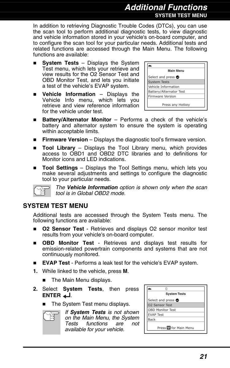
Additional Functions
System Test Menu
21 In addition to retrieving Diagnostic Trouble Codes (DTCs), you can use the scan tool to perform additional diagnostic tests, to view diagnostic and vehicle information stored in your vehicle's on-board computer, and to configure the scan tool for your particular needs. Additional tests and related functions are accessed through the Main Menu. The following functions are available: System Tests – Displays the System Test menu, which lets your retrieve and view results for the O2 Sensor Test and OBD Monitor Test, and lets you initiate a test of the vehicle’s EVAP system. Vehicle Information – Displays the Vehicle Info menu, which lets you retrieve and view reference information for the vehicle under test. Battery/Alternator Monitor – Performs a check of the vehicle’s battery and alternator system to ensure the system is operating within acceptable limits. Firmware Version – Displays the diagnostic tool’s firmware version. Tool Library – Displays the Tool Library menu, which provides access to OBD1 and OBD2 DTC libraries and to definitions for Monitor icons and LED indications. Tool Settings – Displays the Tool Settings menu, which lets you make several adjustments and settings to configure the diagnostic tool to your particular needs. The Vehicle Information option is shown only when the scan tool is in Global OBD2 mode.System Test Menu
Additional tests are accessed through the System Tests menu. The following functions are available: O2 Sensor Test - Retrieves and displays O2 sensor monitor test results from your vehicle's on-board computer. OBD Monitor Test - Retrieves and displays test results for emission-related powertrain components and systems that are not continuously monitored. EVAP Test - Performs a leak test for the vehicle's EVAP system.Enter
. The System Test menu displays. If System Tests is not shown on the Main Menu, the System Tests functions are not available for your vehicle.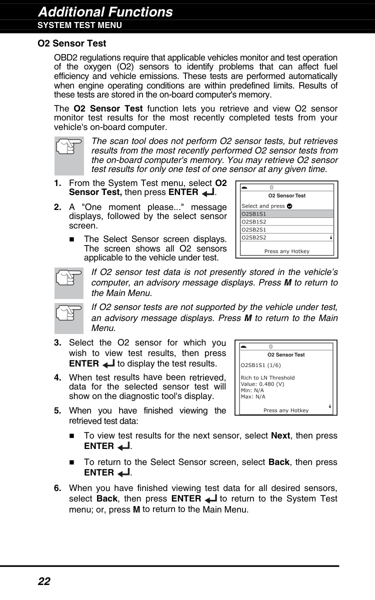
Additional Functions
System Test Menu
22 O2 Sensor Test OBD2 regulations require that applicable vehicles monitor and test operation of the oxygen (O2) sensors to identify problems that can affect fuel efficiency and vehicle emissions. These tests are performed automatically when engine operating conditions are within predefined limits. Results of these tests are stored in the on-board computer's memory. The O2 Sensor Test function lets you retrieve and view O2 sensor monitor test results for the most recently completed tests from your vehicle's on-board computer. The scan tool does not perform O2 sensor tests, but retrieves results from the most recently performed O2 sensor tests from the on-board computer's memory. You may retrieve O2 sensor test results for only one test of one sensor at any given time.Enter
to display the test results.Enter
. To return to the Select Sensor screen, select Back, then pressEnter
.
Additional Functions
System Test Menu
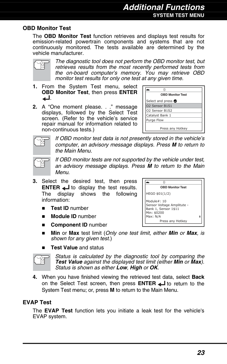
23 OBD Monitor Test The OBD Monitor Test function retrieves and displays test results for emission-related powertrain components and systems that are not continuously monitored. The tests available are determined by the vehicle manufacturer. The diagnostic tool does not perform the OBD monitor test, but retrieves results from the most recently performed tests from the on-board computer’s memory. You may retrieve OBD monitor test results for only one test at any given time.Enter
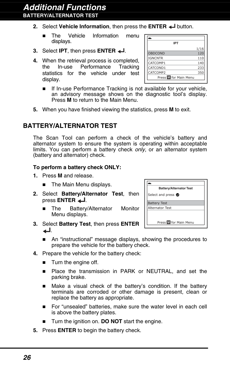
to display the test results. The display shows the following information: Test ID number Module ID number Component ID number Min or Max test limit (Only one test limit, either Min or Max, is shown for any given test.) Test Value and status Status is calculated by the diagnostic tool by comparing the Test Value against the displayed test limit (either Min or Max). Status is shown as either Low, High or OK.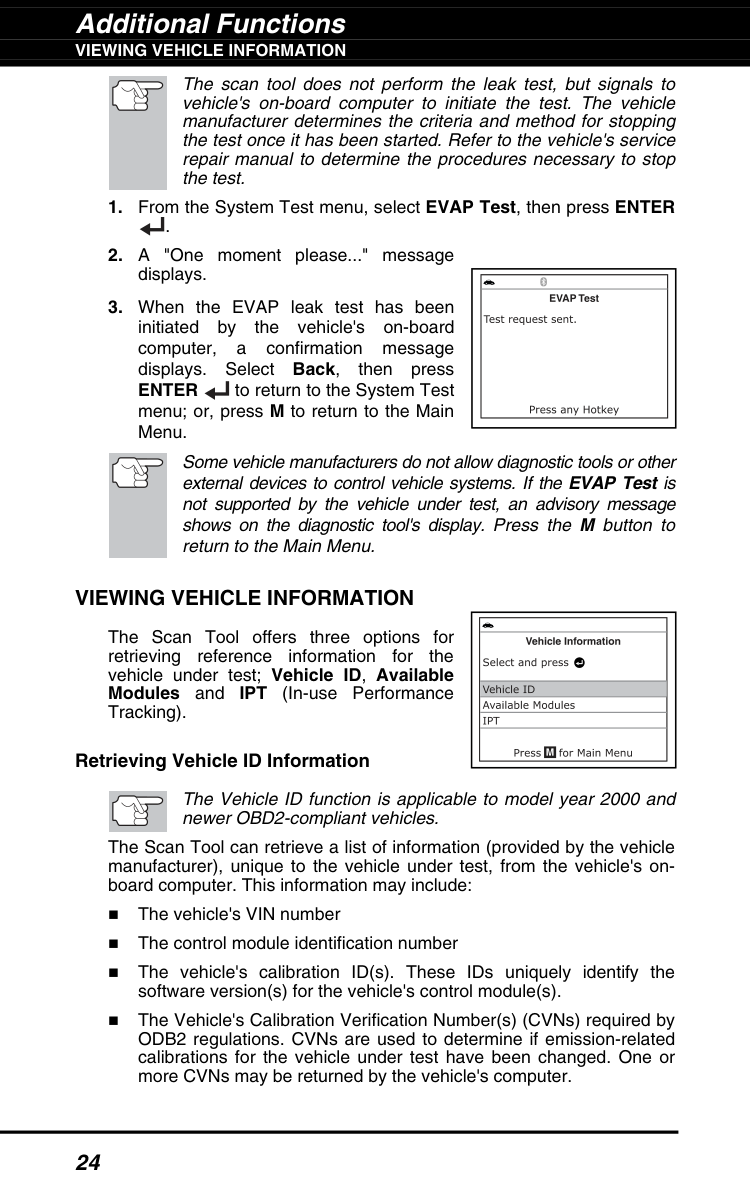
Additional Functions
Viewing Vehicle Information
24 The scan tool does not perform the leak test, but signals to vehicle's on-board computer to initiate the test. The vehicle manufacturer determines the criteria and method for stopping the test once it has been started. Refer to the vehicle's service repair manual to determine the procedures necessary to stop the test.Enter
to return to the System Test menu; or, press M to return to the Main Menu. Some vehicle manufacturers do not allow diagnostic tools or other external devices to control vehicle systems. If the EVAP Test is not supported by the vehicle under test, an advisory message shows on the diagnostic tool's display. Press the M button to return to the Main Menu.Viewing Vehicle Information
The Scan Tool offers three options for retrieving reference information for the vehicle under test; Vehicle ID, Available Modules and IPT (In-use Performance Tracking). Retrieving Vehicle ID Information The Vehicle ID function is applicable to model year 2000 and newer OBD2-compliant vehicles. The Scan Tool can retrieve a list of information (provided by the vehicle manufacturer), unique to the vehicle under test, from the vehicle's on- board computer. This information may include: The vehicle's VIN number The control module identification number The vehicle's calibration ID(s). These IDs uniquely identify the software version(s) for the vehicle's control module(s). The Vehicle's Calibration Verification Number(s) (CVNs) required by ODB2 regulations. CVNs are used to determine if emission-related calibrations for the vehicle under test have been changed. One or more CVNs may be returned by the vehicle's computer.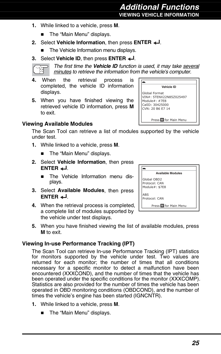
Additional Functions
Viewing Vehicle Information
25Enter
. The Vehicle Information menu dis- plays.Enter
.
Additional Functions
Battery/Alternator Test
26Battery/Alternator Test
The Scan Tool can perform a check of the vehicle’s battery and alternator system to ensure the system is operating within acceptable limits. You can perform a battery check only, or an alternator system (battery and alternator) check. To perform a battery check ONLY: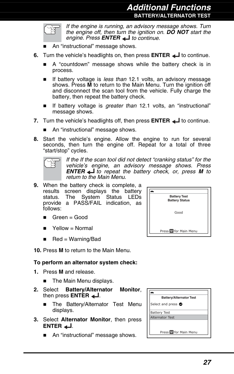
Additional Functions
Battery/Alternator Test
27 If the engine is running, an advisory message shows. Turn the engine off, then turn the ignition on. DO NOT start the engine. Press ENTER to continue. An “instructional” message shows.Enter
to repeat the battery check, or, press M to return to the Main Menu.Enter
. An “instructional” message shows.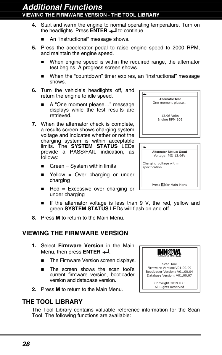
Additional Functions
Viewing The Firmware Version - The Tool Library
28Viewing The Firmware Version
The Tool Library
The Tool Library contains valuable reference information for the Scan Tool. The following functions are available: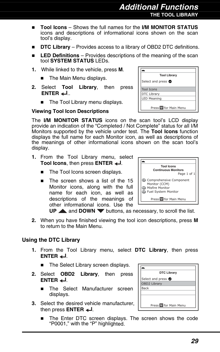
Additional Functions
The Tool Library
29 Tool Icons – Shows the full names for the I/M MONITOR STATUS icons and descriptions of informational icons shown on the scan tool’s display. DTC Library – Provides access to a library of OBD2 DTC definitions. LED Definitions – Provides descriptions of the meaning of the scan tool SYSTEM STATUS LEDs.Enter
.. The Tool Library menu displays. Viewing Tool Icon Descriptions The I/M MONITOR STATUS icons on the scan tool’s LCD display provide an indication of the “Completed / Not Complete” status for all I/M Monitors supported by the vehicle under test. The Tool Icons function displays the full name for each Monitor icon, as well as descriptions of the meanings of other informational icons shown on the scan tool’s display.Up
and DOWN buttons, as necessary, to scroll the list.Enter
. The Select Library screen displays.Obd2
Library, then pressEnter
. The Select Manufacturer screen displays.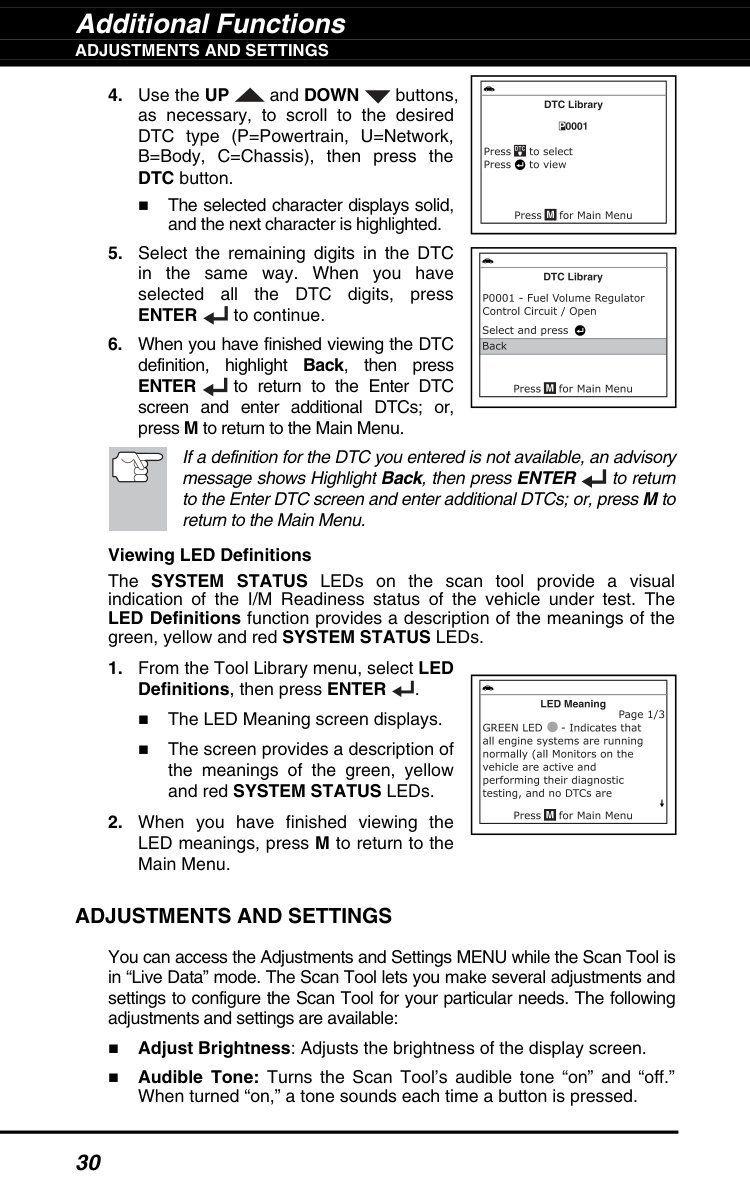
Additional Functions
Adjustments And Settings
30
Enter
to continue.Enter
to return to the Enter DTC screen and enter additional DTCs; or, press M to return to the Main Menu. If a definition for the DTC you entered is not available, an advisory message shows Highlight Back, then press ENTER to return to the Enter DTC screen and enter additional DTCs; or, press M to return to the Main Menu. Viewing LED Definitions The SYSTEM STATUS LEDs on the scan tool provide a visual indication of the I/M Readiness status of the vehicle under test. The LED Definitions function provides a description of the meanings of the green, yellow and red SYSTEM STATUS LEDs.Adjustments And Settings
You can access the Adjustments and Settings MENU while the Scan Tool is in “Live Data” mode. The Scan Tool lets you make several adjustments and settings to configure the Scan Tool for your particular needs. The following adjustments and settings are available: Adjust Brightness: Adjusts the brightness of the display screen. Audible Tone: Turns the Scan Tool’s audible tone “on” and “off.” When turned “on,” a tone sounds each time a button is pressed.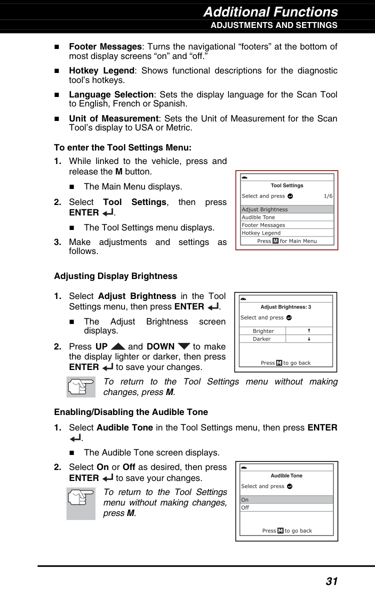
Additional Functions
Adjustments And Settings
31 Footer Messages: Turns the navigational “footers” at the bottom of most display screens “on” and “off.” Hotkey Legend: Shows functional descriptions for the diagnostic tool’s hotkeys. Language Selection: Sets the display language for the Scan Tool to English, French or Spanish. Unit of Measurement: Sets the Unit of Measurement for the Scan Tool’s display to USA or Metric. To enter the Tool Settings Menu:Enter
. The Tool Settings menu displays.Enter
to save your changes. To return to the Tool Settings menu without making changes, press M. Enabling/Disabling the Audible ToneEnter
to save your changes. To return to the Tool Settings menu without making changes, press M.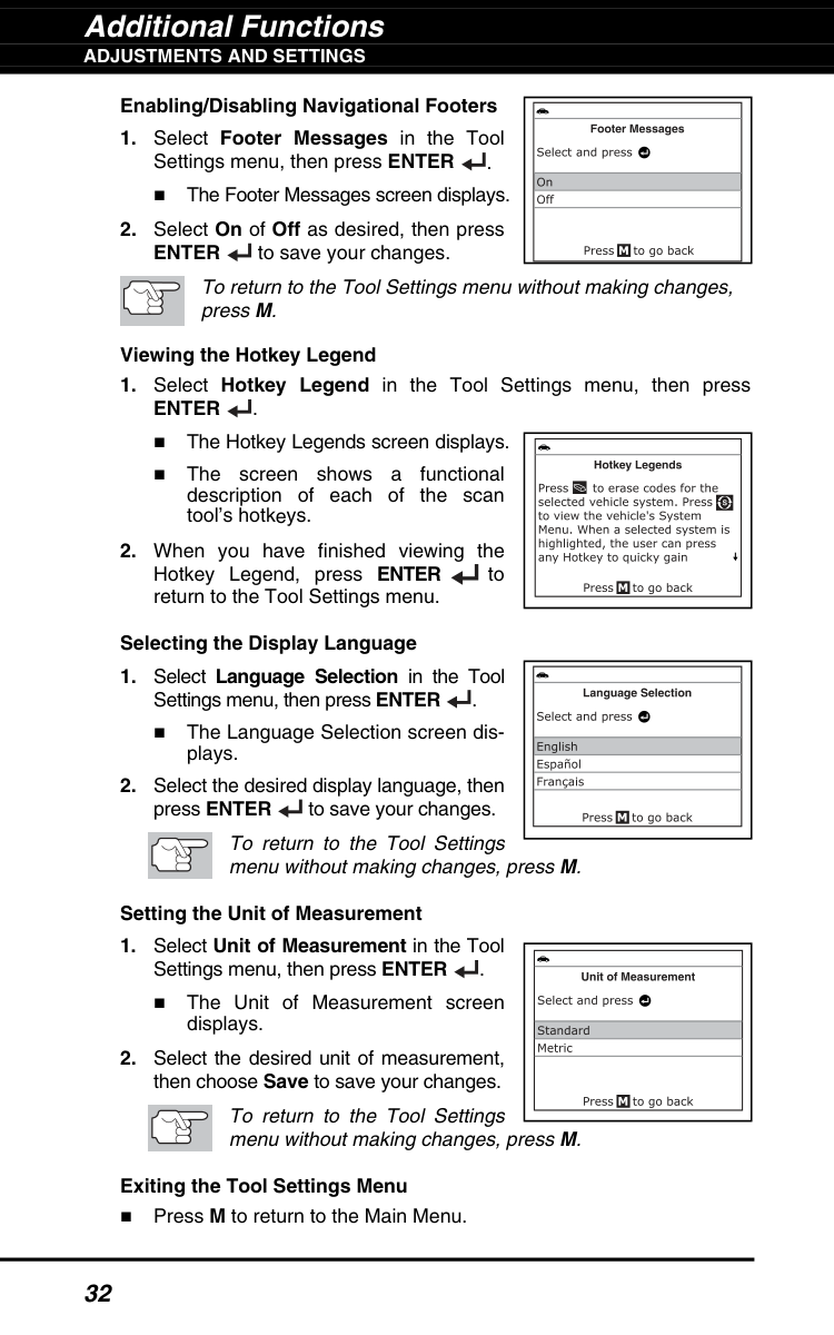
Additional Functions
Adjustments And Settings
32 Enabling/Disabling Navigational FootersEnter
to save your changes. To return to the Tool Settings menu without making changes, press M. Viewing the Hotkey LegendEnter
. The Hotkey Legends screen displays. The screen shows a functional description of each of the scan tool’s hotkeys.
Warranty and Servicing 33