
Ask AI
— answers from the official manualAnswers from the official manual.
Common questions
Common Questions
10 totalHow can I resolve the 'Water Inlet Error' on my Kenmore washing machine?
A Water Inlet Error indicates issues with water supply, and requires checking if the correct water level of 246 is reached within 25 minutes of starting a cycle. Ensure the filter is not clogged and reconnect or repair any loose/defective connectors between the main PCB and inlet valve assembly. Replace faulty parts such as the INLET VALVE ASSEMBLY, MAIN PWB ASSEMBLY, or SENSOR if required. (Page 26)
What causes an 'Unbalance Error' in my Kenmore washing machine?
An Unbalance Error occurs when the laundry is too small, improperly distributed, or contains non-distributable items leading to uneven weight distribution. Adjust your load by ensuring clothes are evenly spread and check if the machine is level on a firm surface without tilting (Page 27).
How can I handle an 'Over Flow Error' notification on my Kenmore washing machine?
An Over Flow Error typically suggests the water level exceeds normal limits, indicated by a frequency over 213. Check for excessive suds or leakage; clean or unblock any components involved in managing water levels such as valves and sensors, and ensure proper drainage (Page 27).
What should I do if my Kenmore washing machine is showing a 'Heating Error'?
A Heating Error means the heating mechanism isn't functioning correctly. You should check for issues with the THERMISTOR, as it measures water temperature accurately and may need replacement (Page 28).
How can I resolve a 'Locked Motor Error' on my Kenmore washing machine?
A Locked Motor Error indicates issues with motor connections or components. Reconnect loose connectors at the main PCB and stator assembly, repair faulty wiring between these parts, confirm hall sensor functionality by ohm checks (if defective, replace), and inspect rotor magnets for cracks. Repairing or replacing any defective parts is crucial to restore motor operation (Page 29).
Why would my Kenmore washing machine display a 'Door Open Error' during an active cycle?
A Door Open Error signals that the door might not be securely closed. Ensure the closing mechanism works properly, with no obstructions or damaged gaskets interfering (Page 31). Fixing this typically requires replacing the DOOR SWITCH ASSEMBLY if mechanical issues are found.
Show 4 more questions
Full Manual
61 pages
http://www.managemyhome.com
WASHING MACHINE SERVICE MANUAL CAUTION
READ THIS MANUAL CAREFULLY TO DIAGNOSE PROBLEMS CORRECTLY BEFORE SERVICING THE UNIT.
##### MODEL : 796.4219#90# , 796.4102#90#
################### P/No.: MFL30599143
CONTENTS

1. SPECIFICATIONS
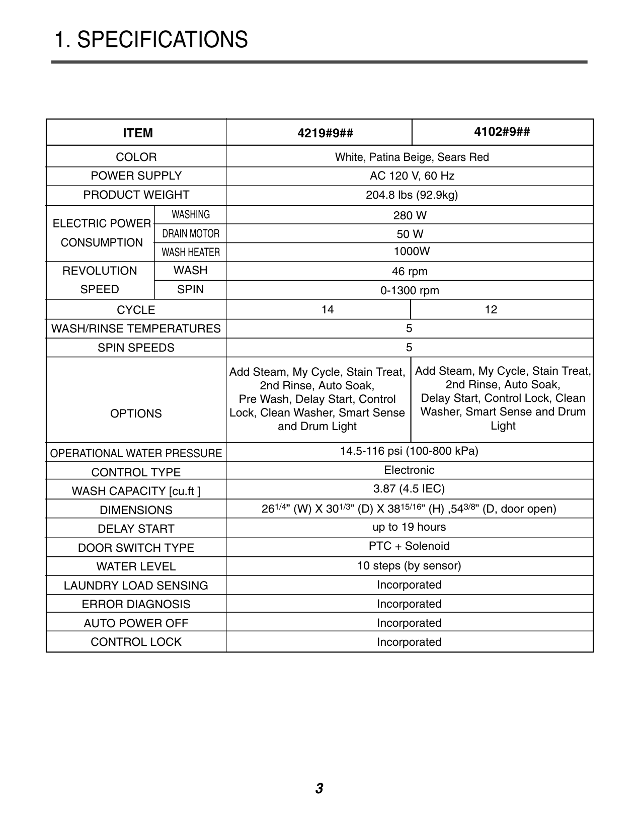
|ITEM|ITEM|4219#9##|4102#9##| |---|---|---|---| |COLOR|COLOR|White, Patina Beige, Sears Red|White, Patina Beige, Sears Red| |POWER SUPPLY|POWER SUPPLY|AC 120 V, 60 Hz|AC 120 V, 60 Hz| |PRODUCT WEIGHT|PRODUCT WEIGHT|204.8 lbs (92.9kg)|204.8 lbs (92.9kg)| |ELECTRIC POWER CONSUMPTION|WASHING|280 W|280 W| |ELECTRIC POWER CONSUMPTION|DRAIN MOTOR|50 W|50 W| |ELECTRIC POWER CONSUMPTION|WASH HEATER|1000W|1000W| |REVOLUTION SPEED|WASH|46 rpm|46 rpm| |REVOLUTION SPEED|SPIN|0-1300 rpm|0-1300 rpm|
|CYCLE|CYCLE|14|12| |WASH/RINSE TEMPERATURES|WASH/RINSE TEMPERATURES|5|5| |SPIN SPEEDS|SPIN SPEEDS|5|5| |OPTIONS|OPTIONS|Add Steam, My Cycle, Stain Treat, 2nd Rinse, Auto Soak, Pre Wash, Delay Start, Control Lock, Clean Washer, Smart Sense and Drum Light|Add Steam, My Cycle, Stain Treat, 2nd Rinse, Auto Soak, Delay Start, Control Lock, Clean Washer, Smart Sense and Drum Light| |OPERATIONAL WATER PRESSURE|OPERATIONAL WATER PRESSURE|14.5-116 psi (100-800 kPa)|14.5-116 psi (100-800 kPa)| |CONTROL TYPE|CONTROL TYPE|Electronic|Electronic| |WASH CAPACITY [cu.ft ]|WASH CAPACITY [cu.ft ]|3.87 (4.5 IEC)|3.87 (4.5 IEC)| |DIMENSIONS|DIMENSIONS|261/4” (W) X 301/3” (D) X 3815/16” (H) ,543/8” (D, door open)|261/4” (W) X 301/3” (D) X 3815/16” (H) ,543/8” (D, door open)| |DELAY START|DELAY START|up to 19 hours|up to 19 hours| |DOOR SWITCH TYPE|DOOR SWITCH TYPE|PTC + Solenoid|PTC + Solenoid| |WATER LEVEL|WATER LEVEL|10 steps (by sensor)|10 steps (by sensor)| |LAUNDRY LOAD SENSING|LAUNDRY LOAD SENSING|Incorporated|Incorporated| |ERROR DIAGNOSIS|ERROR DIAGNOSIS|Incorporated|Incorporated| |AUTO POWER OFF|AUTO POWER OFF|Incorporated|Incorporated| |CONTROL LOCK|CONTROL LOCK|Incorporated|Incorporated|
2. FEATURES & TECHNICAL EXPLANATION
###### 2-1. FEATURES
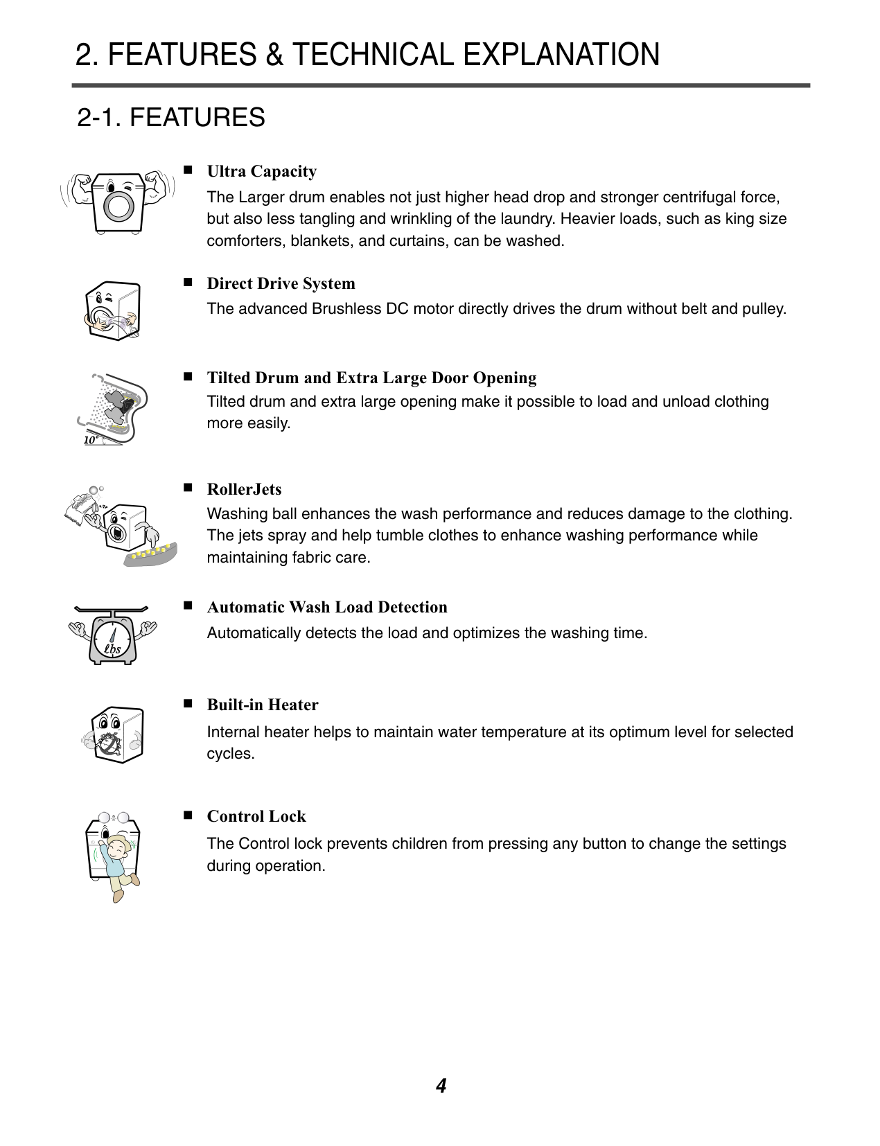
Ultra Capacity The Larger drum enables not just higher head drop and stronger centrifugal force, but also less tangling and wrinkling of the laundry. Heavier loads, such as king size comforters, blankets, and curtains, can be washed.
Direct Drive System The advanced Brushless DC motor directly drives the drum without belt and pulley.
Tilted Drum and Extra Large Door Opening Tilted drum and extra large opening make it possible to load and unload clothing more easily.


RollerJets Washing ball enhances the wash performance and reduces damage to the clothing. The jets spray and help tumble clothes to enhance washing performance while maintaining fabric care.
Automatic Wash Load Detection Automatically detects the load and optimizes the washing time.
Built-in Heater Internal heater helps to maintain water temperature at its optimum level for selected cycles.
Control Lock The Control lock prevents children from pressing any button to change the settings during operation.
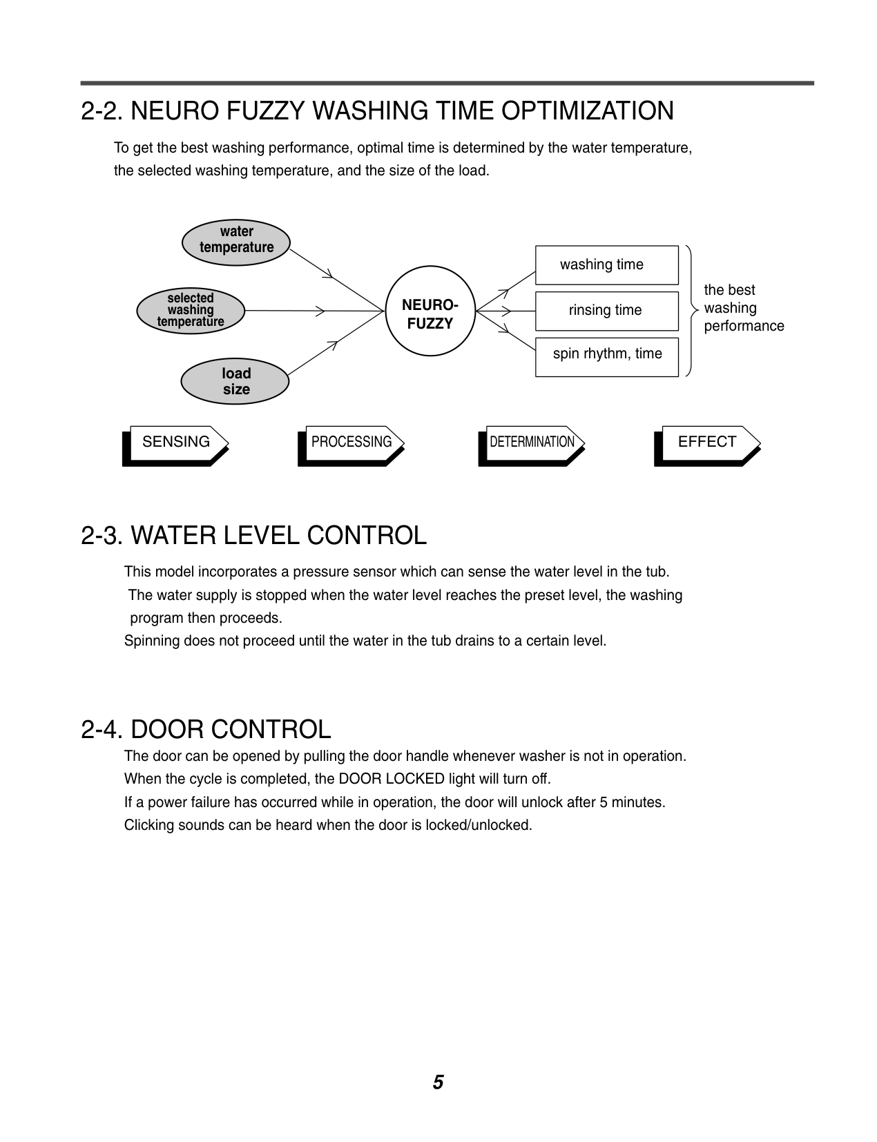
###### 2-2. NEURO FUZZY WASHING TIME OPTIMIZATION
To get the best washing performance, optimal time is determined by the water temperature, the selected washing temperature, and the size of the load.
water temperature
selected washing temperature
load size
NEUROFUZZY
washing time
rinsing time
spin rhythm, time
the best washing performance
SENSING PROCESSING DETERMINATION EFFECT
###### 2-3. WATER LEVEL CONTROL
This model incorporates a pressure sensor which can sense the water level in the tub. The water supply is stopped when the water level reaches the preset level, the washing program then proceeds.
Spinning does not proceed until the water in the tub drains to a certain level.
###### 2-4. DOOR CONTROL
The door can be opened by pulling the door handle whenever washer is not in operation. When the cycle is completed, the DOOR LOCKED light will turn off. If a power failure has occurred while in operation, the door will unlock after 5 minutes. Clicking sounds can be heard when the door is locked/unlocked.
###### 2-5. THE DOOR CAN NOT BE OPENED
While program is operating. When a power failed and power plug is taken out in operation While Door Lock lights turn on. White the motor is in the process of intertial rotating, through the operation is paused.
###### 2-6. CONTROL LOCK
Use this option to prevent unwanted use of the washer. Press and hold CONTROL LOCK button for 5 seconds to lock/unlock control. When CONTROL LOCK is set, CONTROL LOCK lights and all buttons are disabled. You can lock the controls of the washer while washing.
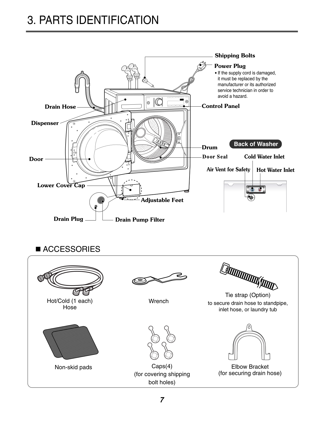
3. PARTS IDENTIFICATION
| | | | |---|---|---| | | | |
########### ACCESSORIES
Hot/Cold (1 each) Hose
Wrench
Non-skid pads Caps(4)
(for covering shipping bolt holes)
Tie strap (Option) to secure drain hose to standpipe, inlet hose, or laundry tub
Elbow Bracket (for securing drain hose)
#### 4. INSTALLATION & TEST
|1| |---|
|2| |---|
|3|
|---|
|4| |---|
|5| |---|
|6| |---|
Before servicing, ask the customer what the trouble is. Check the setup (power supply is 120V, remove the transit bolts, level the washer...) Check with the troubleshooting guide. Plan your service method by referring to the disassembly instructions. Service the unit. After servicing, operate the appliance to see whether it functions correctly.
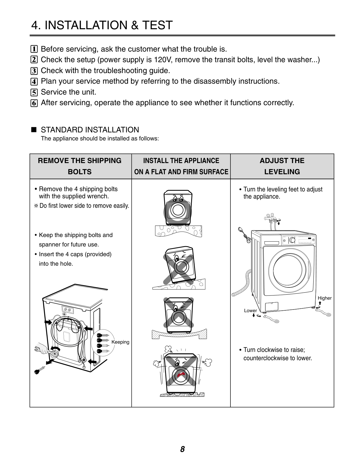
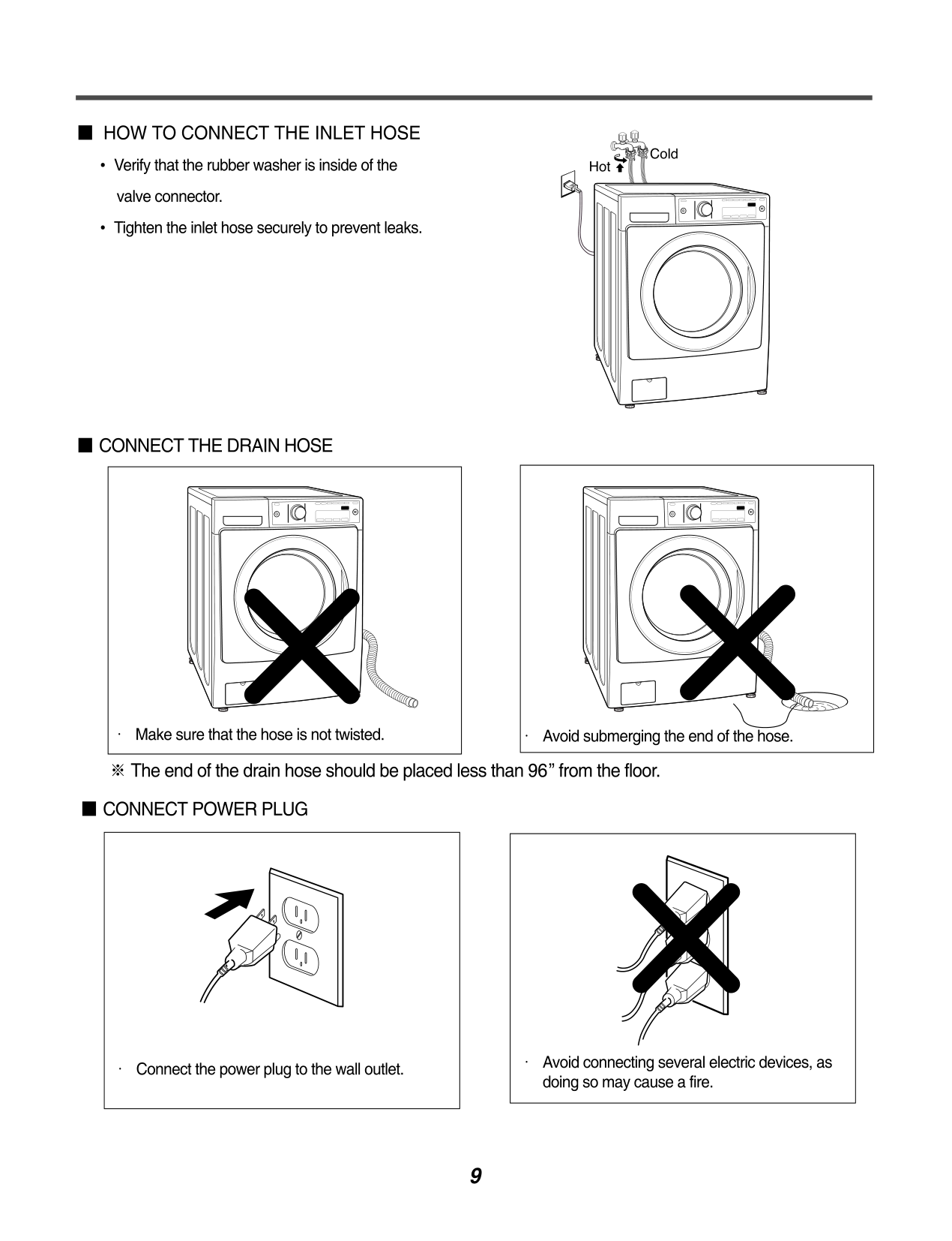
STANDARD INSTALLATION The appliance should be installed as follows:
|| | |---|
REMOVE THE SHIPPING BOLTS|INSTALL THE APPLIANCE ON A FLAT AND FIRM SURFACE|ADJUST THE LEVELING| |---|---|---| |• Remove the 4 shipping bolts with the supplied wrench. Do first lower side to remove easily.
• Keep the shipping bolts and spanner for future use.
• Insert the 4 caps (provided) into the hole.
| |• Turn the leveling feet to adjust the appliance.
• Turn clockwise to raise; counterclockwise to lower.
|
############### 7
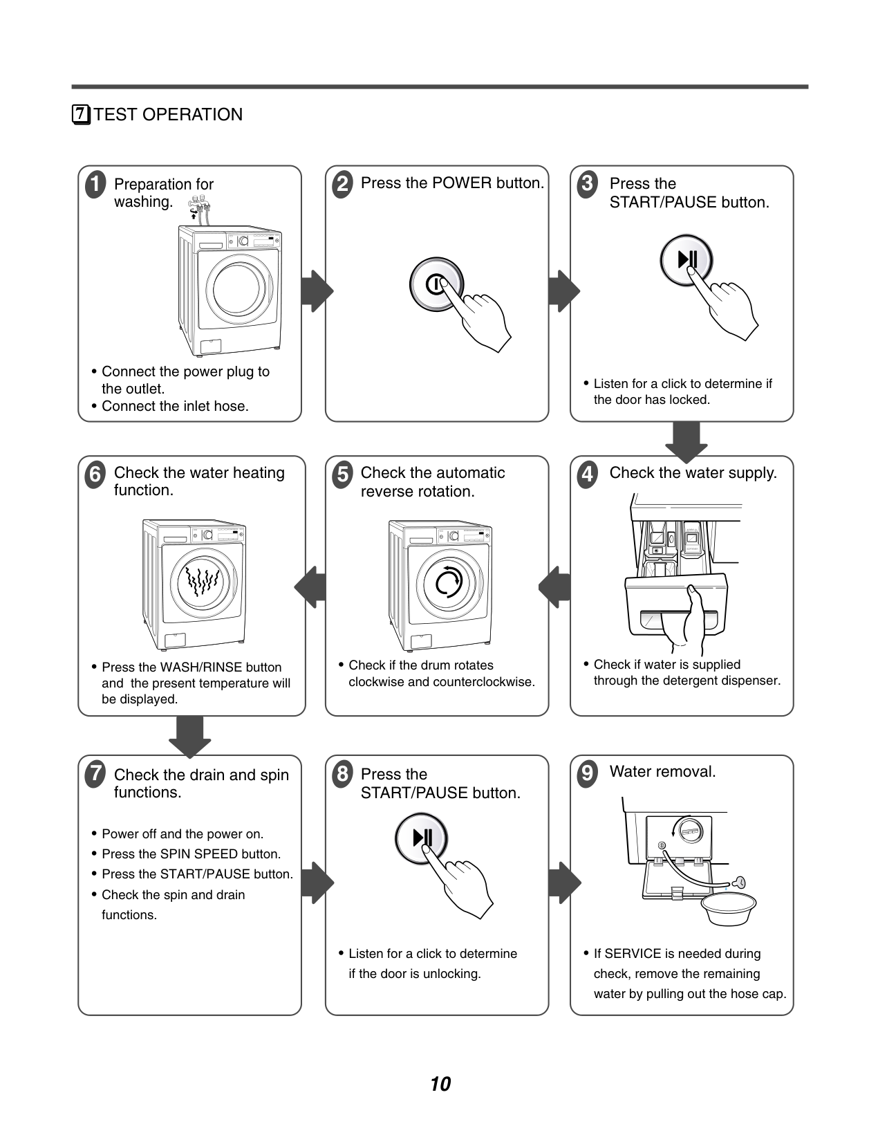
################# TEST OPERATION
3 Press the
1 Preparation for
########### 2 Press the POWER button.
washing.
START/PAUSE button.
• Listen for a click to determine if
the door has locked.
function.
• Press the WASH/RINSE button and the present temperature will be displayed.
5 Check the automatic
reverse rotation.
4 Check the water supply.
• Check if water is supplied
through the detergent dispenser.
• Check if the drum rotates
clockwise and counterclockwise.
9 Water removal.
8 Press the
functions.
START/PAUSE button.
• Listen for a click to determine
• If SERVICE is needed during check, remove the remaining water by pulling out the hose cap.
if the door is unlocking.
5. OPERATION
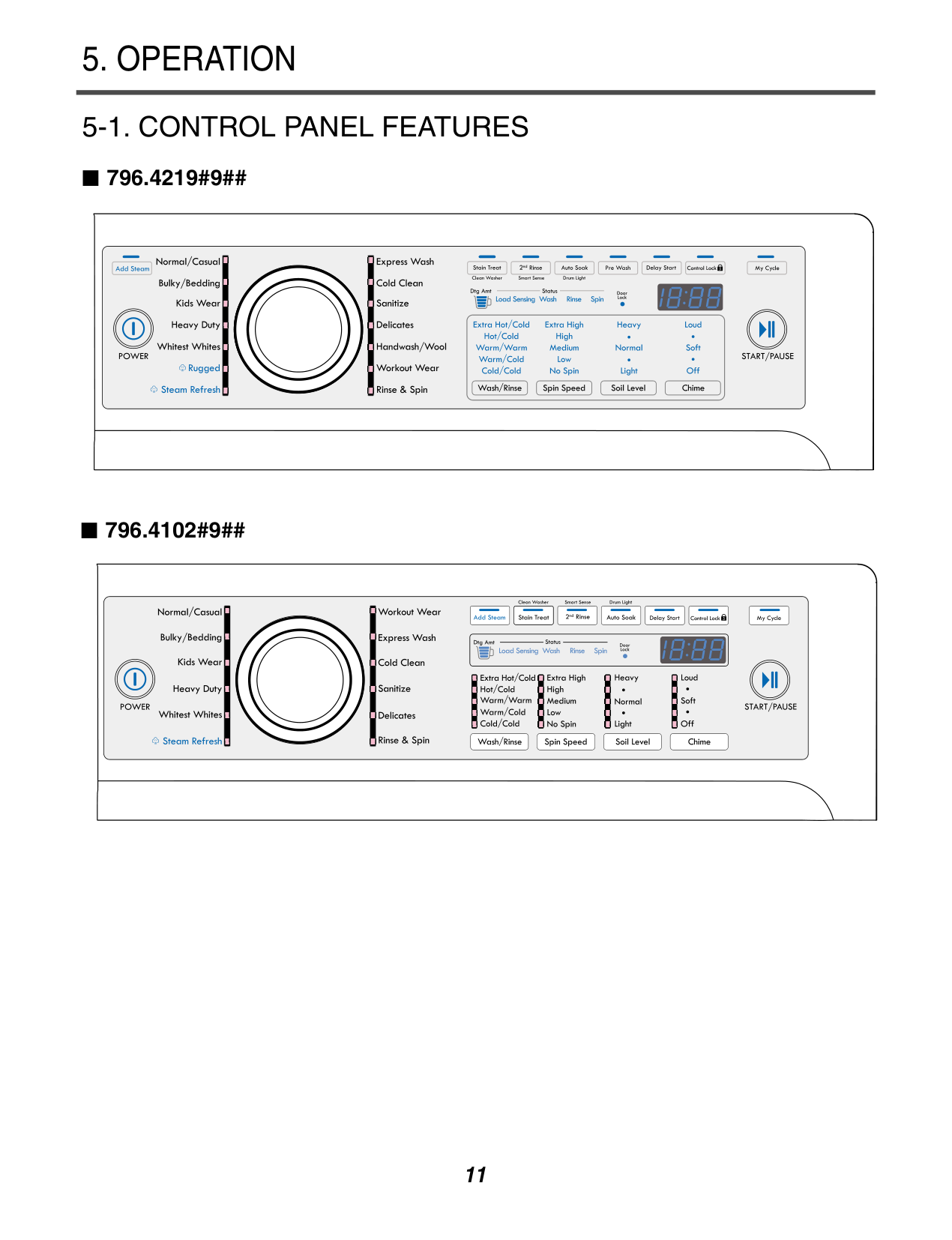
###### 5-1. CONTROL PANEL FEATURES
796.4219#9##
############ 796.4102#9##
################ H
################ F E G


################ I A
################ B CD
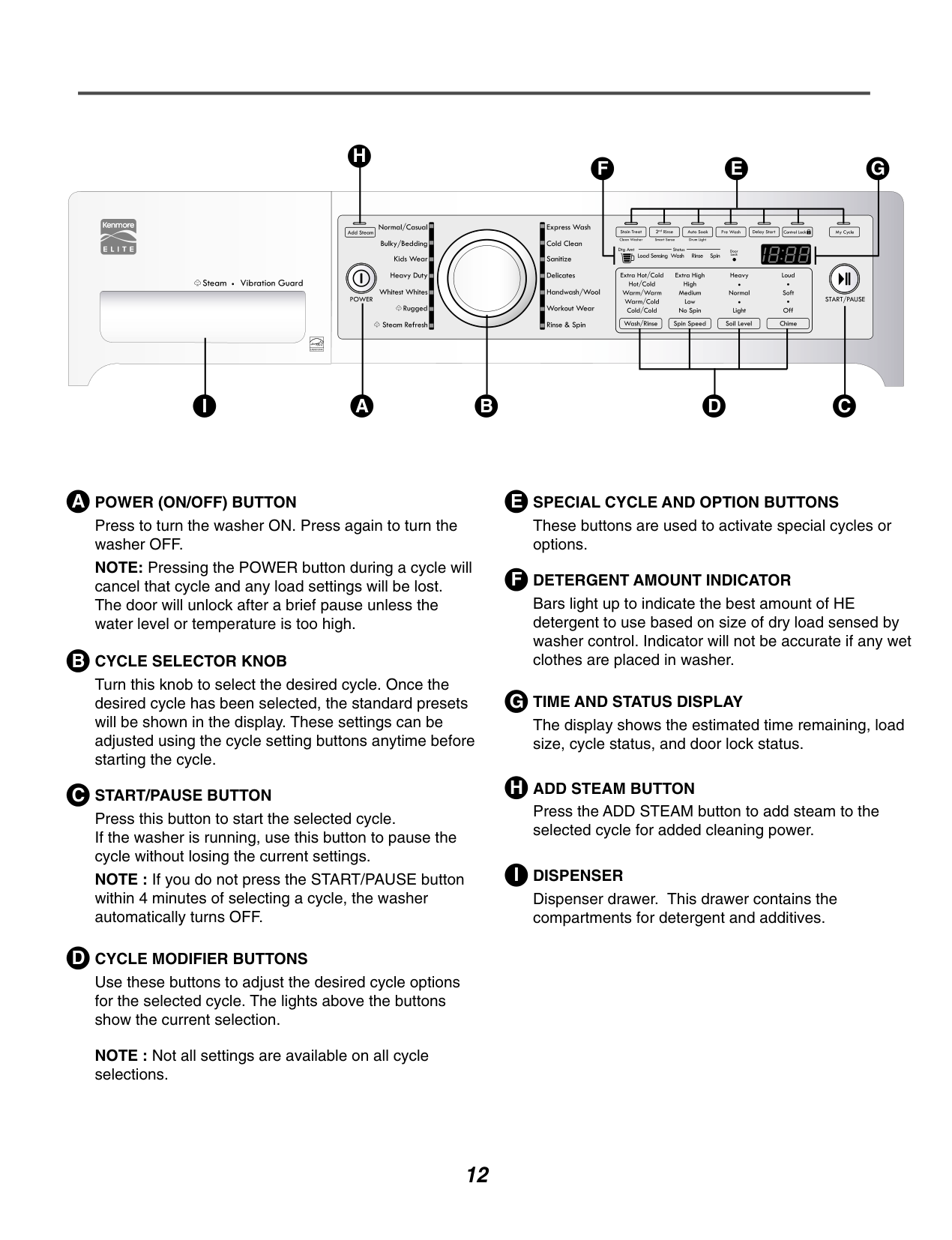
################ A POWER (ON/OFF) BUTTON
Press to turn the washer ON. Press again to turn the washer OFF. NOTE: Pressing the POWER button during a cycle will cancel that cycle and any load settings will be lost. The door will unlock after a brief pause unless the water level or temperature is too high.
################ B CYCLE SELECTOR KNOB
Turn this knob to select the desired cycle. Once the desired cycle has been selected, the standard presets will be shown in the display. These settings can be adjusted using the cycle setting buttons anytime before starting the cycle.
################ C START/PAUSE BUTTON
Press this button to start the selected cycle. If the washer is running, use this button to pause the cycle without losing the current settings. NOTE : If you do not press the START/PAUSE button within 4 minutes of selecting a cycle, the washer automatically turns OFF.
################ D CYCLE MODIFIER BUTTONS
Use these buttons to adjust the desired cycle options for the selected cycle. The lights above the buttons show the current selection.
NOTE : Not all settings are available on all cycle selections.
These buttons are used to activate special cycles or options.
The display shows the estimated time remaining, load size, cycle status, and door lock status.
F DETERGENT AMOUNT INDICATOR Bars light up to indicate the best amount of HE detergent to use based on size of dry load sensed by washer control. Indicator will not be accurate if any wet clothes are placed in washer.
Press the ADD STEAM button to add steam to the selected cycle for added cleaning power.
I DISPENSER Dispenser drawer. This drawer contains the compartments for detergent and additives.
############ 4219#9##
############ 4102#9##
######### 5-3. CYCLE OPTIONS
###################### ADD STEAM
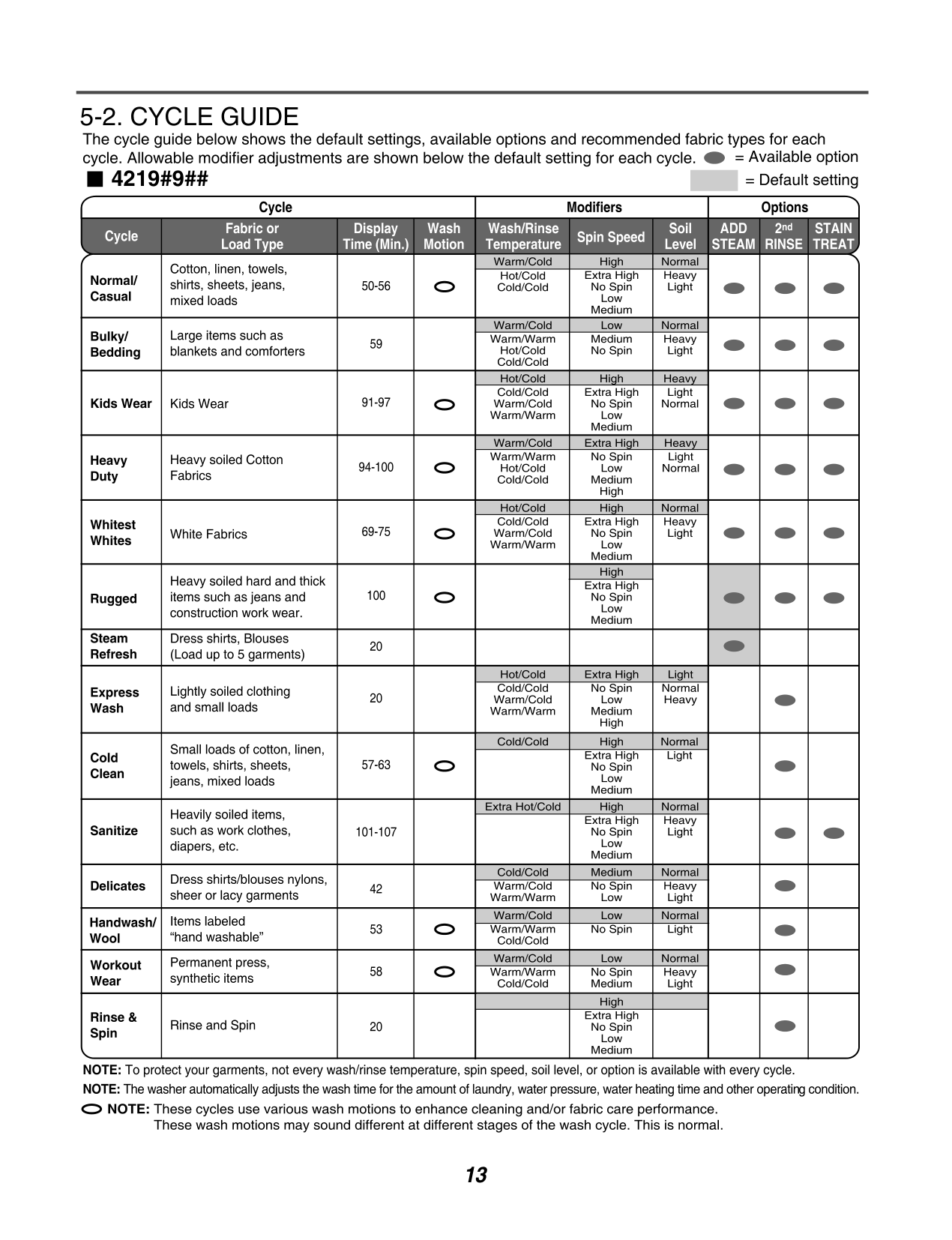
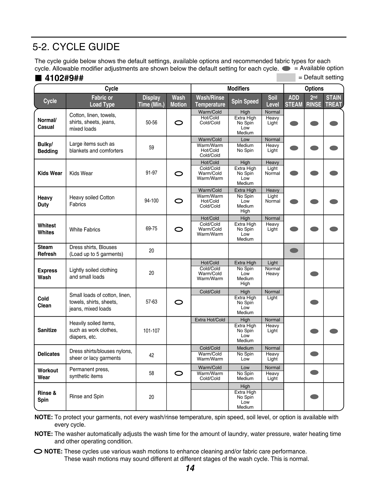
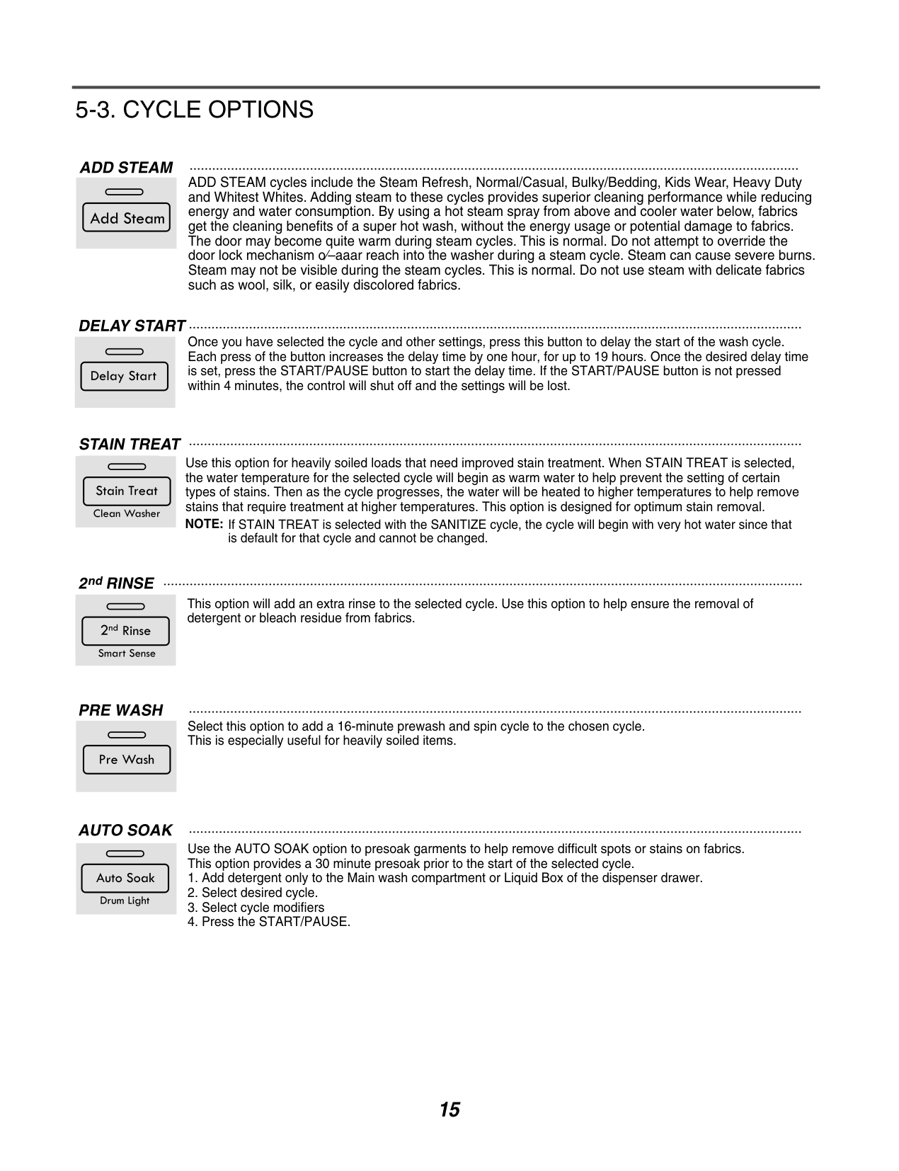
ADD STEAM cycles include the Steam Refresh, Normal/Casual, Bulky/Bedding, Kids Wear, Heavy Duty and Whitest Whites. Adding steam to these cycles provides superior cleaning performance while reducing energy and water consumption. By using a hot steam spray from above and cooler water below, fabrics get the cleaning benefits of a super hot wash, without the energy usage or potential damage to fabrics. The door may become quite warm during steam cycles. This is normal. Do not attempt to override the door lock mechanism o⁄–aaar reach into the washer during a steam cycle. Steam can cause severe burns. Steam may not be visible during the steam cycles. This is normal. Do not use steam with delicate fabrics such as wool, silk, or easily discolored fabrics.
##################### DELAY START
Once you have selected the cycle and other settings, press this button to delay the start of the wash cycle. Each press of the button increases the delay time by one hour, for up to 19 hours. Once the desired delay time is set, press the START/PAUSE button to start the delay time. If the START/PAUSE button is not pressed within 4 minutes, the control will shut off and the settings will be lost.
#################### STAIN TREAT
Use this option for heavily soiled loads that need improved stain treatment. When STAIN TREAT is selected, the water temperature for the selected cycle will begin as warm water to help prevent the setting of certain types of stains. Then as the cycle progresses, the water will be heated to higher temperatures to help remove stains that require treatment at higher temperatures. This option is designed for optimum stain removal. NOTE: If STAIN TREAT is selected with the SANITIZE cycle, the cycle will begin with very hot water since that
is default for that cycle and cannot be changed.
##################### 2ndRINSE
This option will add an extra rinse to the selected cycle. Use this option to help ensure the removal of detergent or bleach residue from fabrics.
##################### PRE WASH
Select this option to add a 16-minute prewash and spin cycle to the chosen cycle. This is especially useful for heavily soiled items.
##################### AUTO SOAK
Use the AUTO SOAK option to presoak garments to help remove difficult spots or stains on fabrics. This option provides a 30 minute presoak prior to the start of the selected cycle.
######### 5-4. SPECIAL FUNCTION
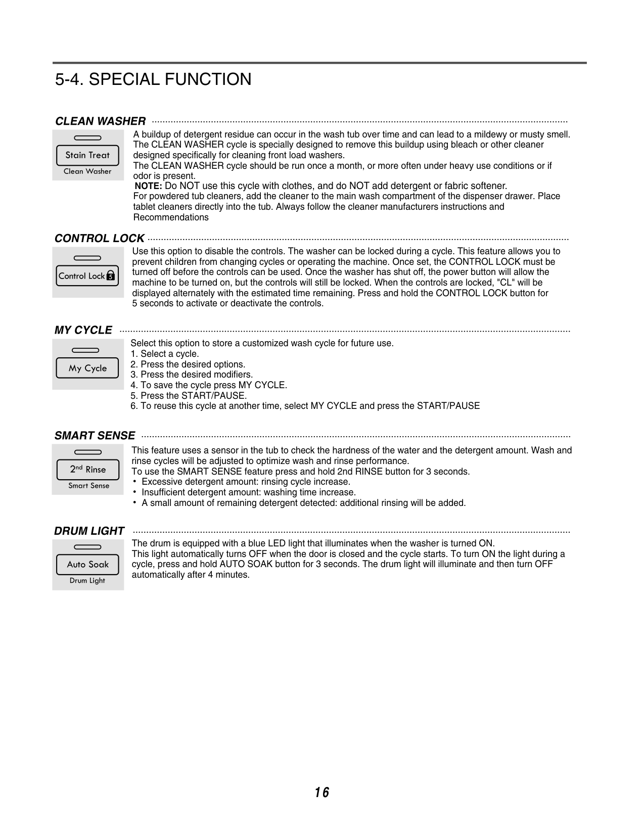
CLEAN WASHER A buildup of detergent residue can occur in the wash tub over time and can lead to a mildewy or musty smell. The CLEAN WASHER cycle is specially designed to remove this buildup using bleach or other cleaner designed specifically for cleaning front load washers. The CLEAN WASHER cycle should be run once a month, or more often under heavy use conditions or if odor is present.
NOTE: Do NOT use this cycle with clothes, and do NOT add detergent or fabric softener.
For powdered tub cleaners, add the cleaner to the main wash compartment of the dispenser drawer. Place tablet cleaners directly into the tub. Always follow the cleaner manufacturers instructions and Recommendations
CONTROL LOCK Use this option to disable the controls. The washer can be locked during a cycle. This feature allows you to prevent children from changing cycles or operating the machine. Once set, the CONTROL LOCK must be turned off before the controls can be used. Once the washer has shut off, the power button will allow the machine to be turned on, but the controls will still be locked. When the controls are locked, "CL" will be displayed alternately with the estimated time remaining. Press and hold the CONTROL LOCK button for 5 seconds to activate or deactivate the controls.
MY CYCLE
Select this option to store a customized wash cycle for future use.
SMART SENSE
This feature uses a sensor in the tub to check the hardness of the water and the detergent amount. Wash and rinse cycles will be adjusted to optimize wash and rinse performance. To use the SMART SENSE feature press and hold 2nd RINSE button for 3 seconds.
Excessive detergent amount: rinsing cycle increase. Insufficient detergent amount: washing time increase. A small amount of remaining detergent detected: additional rinsing will be added.
DRUM LIGHT
The drum is equipped with a blue LED light that illuminates when the washer is turned ON. This light automatically turns OFF when the door is closed and the cycle starts. To turn ON the light during a cycle, press and hold AUTO SOAK button for 3 seconds. The drum light will illuminate and then turn OFF automatically after 4 minutes.
16
######### 5-5. EXPLANATION OF EACH PROCESS
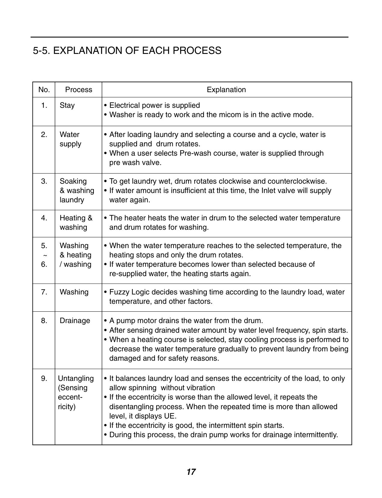
|No.|Process|Explanation| |---|---|---| |1.|Stay|• Electrical power is supplied
•Washer is ready to work and the micom is in the active mode.
| |2.|Water supply|• After loading laundry and selecting a course and a cycle, water is supplied and drum rotates.
• When a user selects Pre-wash course, water is supplied through pre wash valve.
| |3.|Soaking & washing laundry|•To get laundry wet, drum rotates clockwise and counterclockwise.
• If water amount is insufficient at this time, the Inlet valve will supply water again.
| |4.
|Heating & washing|• The heater heats the water in drum to the selected water temperature and drum rotates for washing.| |5. ~
6.
|Washing & heating / washing|• When the water temperature reaches to the selected temperature, the heating stops and only the drum rotates.
• If water temperature becomes lower than selected because of re-supplied water, the heating starts again.
| |7.|Washing|• Fuzzy Logic decides washing time according to the laundry load, water temperature, and other factors.| |8.
|Drainage|• A pump motor drains the water from the drum.
•After sensing drained water amount by water level frequency, spin starts.
• When a heating course is selected, stay cooling process is performed to decrease the water temperature gradually to prevent laundry from being damaged and for safety reasons.
| |9.|Untangling (Sensing eccentricity)|• It balances laundry load and senses the eccentricity of the load, to only allow spinning without vibration
• If the eccentricity is worse than the allowed level, it repeats the disentangling process. When the repeated time is more than allowed level, it displays UE.
• If the eccentricity is good, the intermittent spin starts.
• During this process, the drain pump works for drainage intermittently.
|
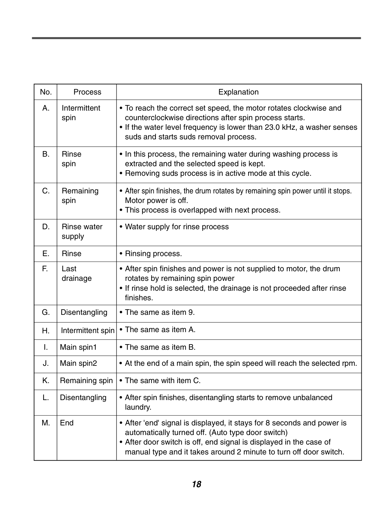
|No.|Process|Explanation| |---|---|---| |A.|Intermittent spin|•To reach the correct set speed, the motor rotates clockwise and counterclockwise directions after spin process starts.
• If the water level frequency is lower than 23.0 kHz, a washer senses suds and starts suds removal process.
| |B.|Rinse spin|• In this process, the remaining water during washing process is extracted and the selected speed is kept.
• Removing suds process is in active mode at this cycle.
| |C.
|Remaining spin|• After spin finishes, the drum rotates by remaining spin power until it stops. Motor power is off.
• This process is overlapped with next process.
| |D.|Rinse water supply|•Water supply for rinse process| |E.|Rinse|• Rinsing process.
| |F.|Last drainage|• After spin finishes and power is not supplied to motor, the drum rotates by remaining spin power
• If rinse hold is selected, the drainage is not proceeded after rinse finishes.
| |G.
|Disentangling|• The same as item 9.| |H.|Intermittent spin|• The same as item A.| |I.|Main spin1
|• The same as item B.| |J.|Main spin2|• At the end of a main spin, the spin speed will reach the selected rpm.
| |K.|Remaining spin|• The same with item C.| |L.|Disentangling|• After spin finishes, disentangling starts to remove unbalanced laundry.| |M.|End|• After 'end' signal is displayed, it stays for 8 seconds and power is automatically turned off. (Auto type door switch)
• After door switch is off, end signal is displayed in the case of manual type and it takes around 2 minute to turn off door switch.
|
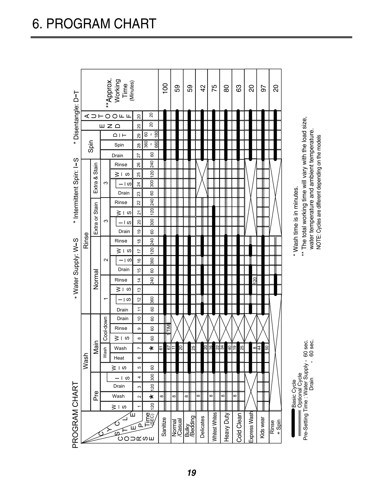
6. PROGRAM CHART
100
59 59
75
80
63
20
97
20
120120 120 120120
61
11
Sanitize
/Bedding
/Casual
Normal
Bulky
20
22
34
16
40
19
25
44
50
Whitest Whites
######################## Heavy Duty
Cold Clean
Express Wash
Kids wear
########################## NOTE: Cycles are different depending on the models
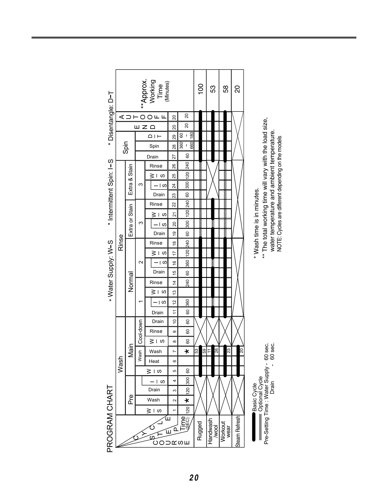
53 100
58
20
120120 120 120120
26
53
59
11
23
20
Rugged
Steam Refresh
Handwash
Workout
/wool
wear
############## 20
NOTE: Cycles are different depending on the models
#### 7. TEST MODE
####### 7-1. SAFETY CAUTION
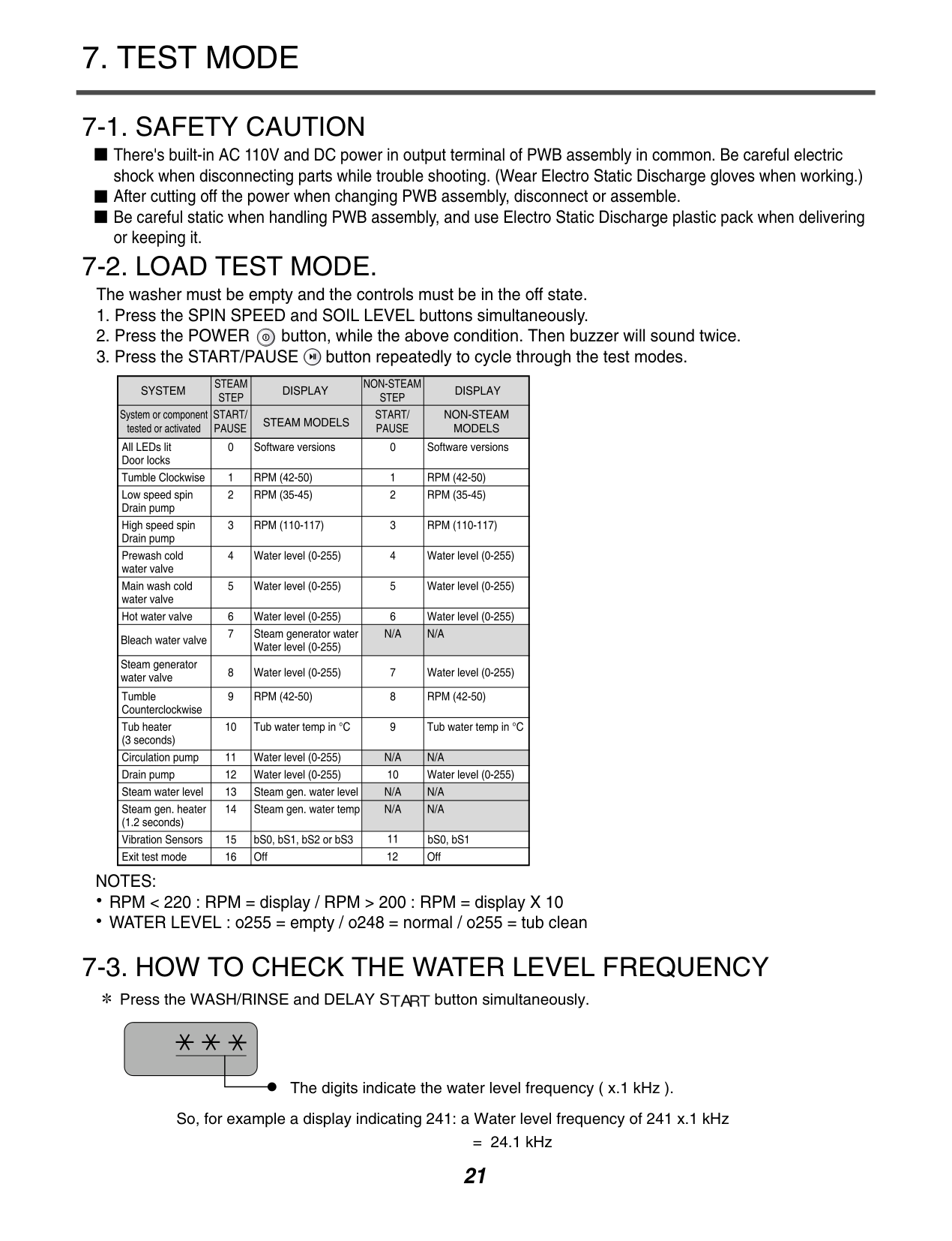
There's built-in AC 110V and DC power in output terminal of PWB assembly in common. Be careful electric shock when disconnecting parts while trouble shooting. (Wear Electro Static Discharge gloves when working.) After cutting off the power when changing PWB assembly, disconnect or assemble. Be careful static when handling PWB assembly, and use Electro Static Discharge plastic pack when delivering or keeping it.
####### 7-2. LOAD TEST MODE.
The washer must be empty and the controls must be in the off state.
Number of times the Start/Pause button is pressed
Check Point
None
Turns on all lamps and locks the door. Tumble clockwise. Low speed Spin. High speed Spin.

It will be take about 2minits to be high speed spin
Inlet valve for prewash turns on. Inlet valve for main wash turns on. Inlet valve for hot water turns on. Inlet valve for bleach turns on. Tumble counterclockwise. Heater turns on for 3 seconds. Drain pump turns on. off
NOTES: RPM < 220 : RPM = display / RPM > 200 : RPM = display X 10 WATER LEVEL : o255 = empty / o248 = normal / o255 = tub clean
####### 7-3. HOW TO CHECK THE WATER LEVEL FREQUENCY


Press the WASH/RINSE and DELAY S button simultaneously.
The digits indicate the water level frequency ( x.1 kHz ). So, for example a display indicating 241: a Water level frequency of 241 x.1 kHz
= 24.1 kHz
#### 8. TROUBLESHOOTING
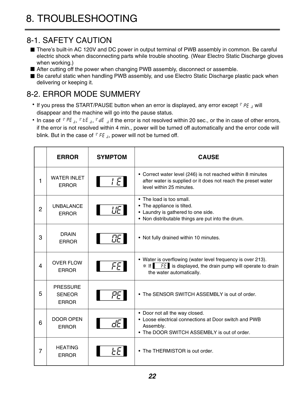
There’s built-in AC 120V and DC power in output terminal of PWB assembly in common. Be careful electric shock when disconnecting parts while trouble shooting. (Wear Electro Static Discharge gloves when working.) After cutting off the power when changing PWB assembly, disconnect or assemble. Be careful static when handling PWB assembly, and use Electro Static Discharge plastic pack when delivering or keeping it.

If you press the START/PAUSE button when an error is displayed, any error except will disappear and the machine will go into the pause status. In case of , , if the error is not resolved within 20 sec., or the in case of other errors, if the error is not resolved within 4 min., power will be turned off automatically and the error code will blink. But in the case of , power will not be turned off.


| |ERROR|SYMPTOM|CAUSE| |---|---|---|---| |1|WATER INLET ERROR| |• Correct water level (246) is not reached within 8 minutes after water is supplied or it does not reach the preset water level within 25 minutes.| |2|UNBALANCE ERROR| |• The load is too small.
• The appliance is tilted.
• Laundry is gathered to one side.
• Non distributable things are put into the drum.
| |3|DRAIN ERROR| |• Not fully drained within 10 minutes.| |4|OVER FLOW ERROR| |•Water is overflowing (water level frequency is over 213). If is displayed, the drain pump will operate to drain the water automatically.
| |5|PRESSURE SENEOR ERROR| |• The SENSOR SWITCH ASSEMBLY is out of order.| |6|DOOR OPEN ERROR| |• Door not all the way closed.
• Loose electrical connections at Door switch and PWB Assembly.
• The DOOR SWITCH ASSEMBLY is out of order.
| |7|HEATING ERROR| |• The THERMISTOR is out order.|
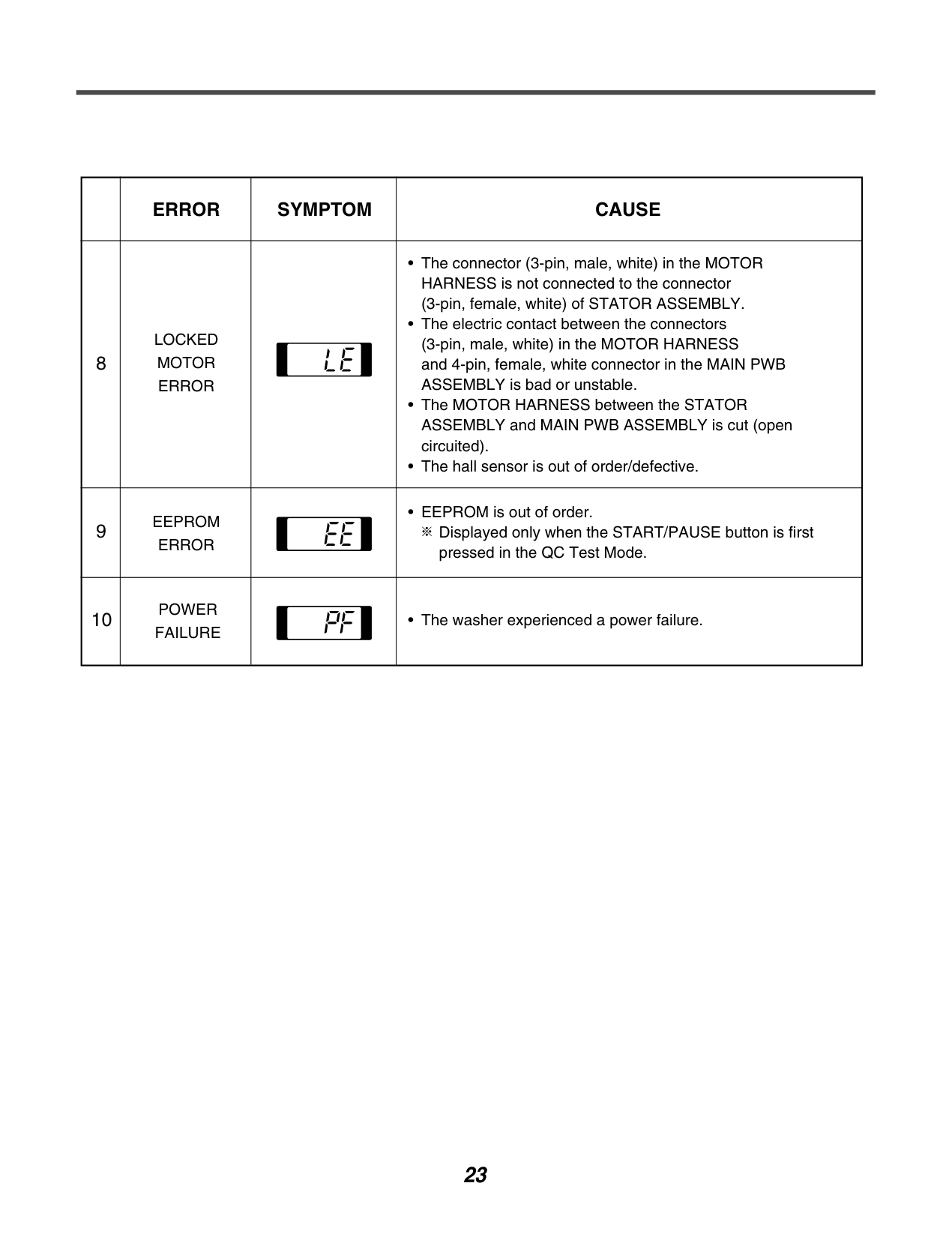
| |ERROR|SYMPTOM|CAUSE| |---|---|---|---| |8|LOCKED MOTOR ERROR| |• The connector (3-pin, male, white) in the MOTOR HARNESS is not connected to the connector (3-pin, female, white) of STATOR ASSEMBLY.
• The electric contact between the connectors (3-pin, male, white) in the MOTOR HARNESS and 4-pin, female, white connector in the MAIN PWB ASSEMBLY is bad or unstable.
• The MOTOR HARNESS between the STATOR ASSEMBLY and MAIN PWB ASSEMBLY is cut (open circuited).
• The hall sensor is out of order/defective.
| |9|EEPROM ERROR| |• EEPROM is out of order. Displayed only when the START/PAUSE button is first pressed in the QC Test Mode.
| |10|POWER FAILURE| |• The washer experienced a power failure.|
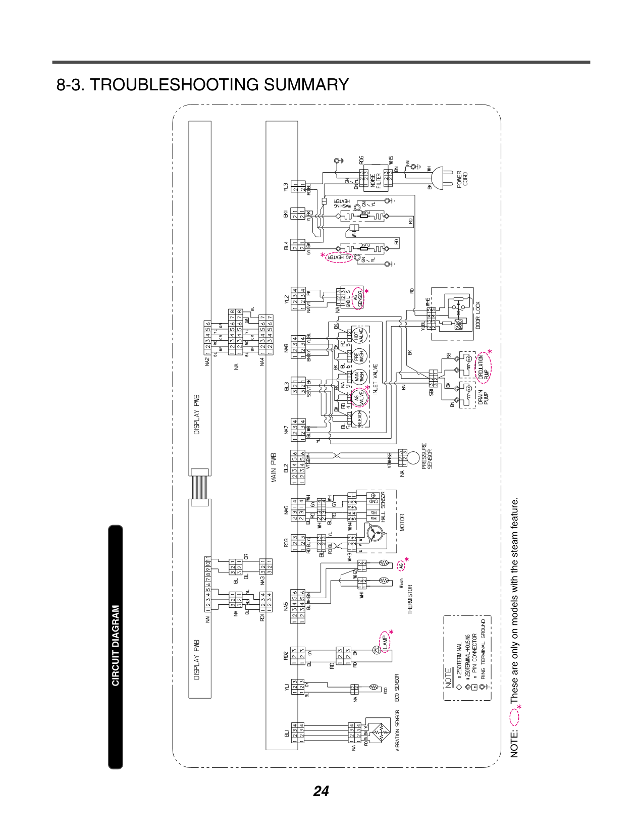
######### 8-3. TROUBLESHOOTING SUMMARY
| | | |---|---| | | |
CIRCUIT DIAGRAM
| | | |---|---| | | |
| | | |---|---| | | |
| | | | | | | | | | | | | | | | | | | | | | | | | | | | | | | | |---|---|---|---|---|---|---|---|---|---|---|---|---|---|---|---|---|---|---|---|---|---|---|---|---|---|---|---|---|---|---| | | | | | | | | | | | | | | | | | | | | | | | | | | | | | | | | | | | | | | | | | | | | | | | | | | | | | | | | | | | | | | | | | | | | | | | | | | | | | | | | | | | | | | | | | | | | | | | | | | | | | | | | | | | | | | | | | | | | | | | | | | | | | | | | | | | | | | | | | | | | | | | | | | | | | | | | | | | | | | | | | | | | | | | | | | | | | | | | | | | | | | | | | | | | | | | |
| | | | | | | | | | | | | | | | | | | | | | | | | | | | | | | | | | |---|---|---|---|---|---|---|---|---|---|---|---|---|---|---|---|---|---|---|---|---|---|---|---|---|---|---|---|---|---|---|---|---| | | | | | | | | | | | | | | | | | | | | | | | | | | | | | | | | | | | | | | | | | | | | | | | | | | | | | | | | | | | | | | | | | | | | | | | | | | | | | | | | | | | | | | | | | | | | | | | | | | | | | | | | | | | | | | | | | | | | | | | | | | | | | | | | | | | | | | | | | | | | | | | | | | | | | | | | | | | | | | | | | | | | | | | | | | | | | | | | | | | | | | | | | | | | | | | | | | | | | | | | | | | | | | | | | | | | | | | | | | | | | | | | | | | | | | | | | | | | | | | | | | | | | | | | | | | | | | | | | | | | | | | | | | | | | | | |
| | | | | | | | | | | | | | | | | | | | | | | | | | | | | | | | | | | | | | |---|---|---|---|---|---|---|---|---|---|---|---|---|---|---|---|---|---|---|---|---|---|---|---|---|---|---|---|---|---|---|---|---|---|---|---|---|
| | | | | | | | | | | | | | | | | | | | | | | | | | | | | | | | | | | | | | | | | | | | | | | | | | | | | | | | | | | | | | | | | | | | | | | | | | | | | | | | | | | | | | | | | | | | | | | | | | | | | | | | | | | | | | | | | | | | | | | | | | | | | | | | | | | | | | | | | | | | | | | | | | | | | | | | | | | | | | | | | | | | | | | | | | | | | | | | | | | | | | | | | | | | | |
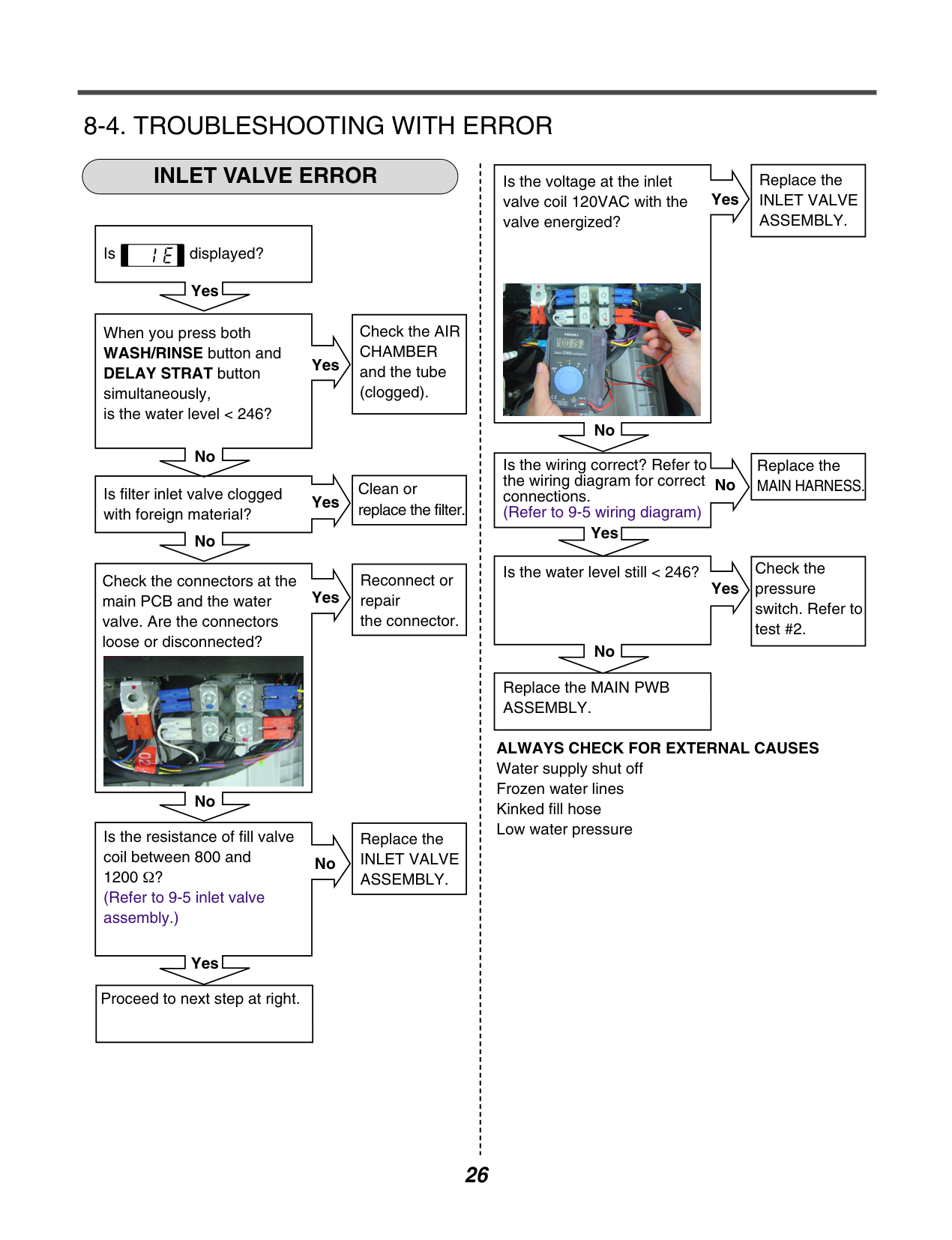
######### 8-4. TROUBLESHOOTING WITH ERRORINLET VALVE ERROR
|Replace the INLET VALVE ASSEMBLY.| |---|
Is the voltage at the inlet valve coil 120VAC with the valve energized?
Yes
| | | |---|---| | | |
Is displayed?

Yes
|Check the AIR CHAMBER and the tube (clogged).| |---|
When you press both WASH/RINSE button and DELAY STRAT button simultaneously, is the water level < 246?
Yes
| | |
|---|---| | | |
No
No
|Replace the MAIN HARNESS.| |---|
Is the wiring correct? Refer to the wiring diagram for correct connections.
|Clean or replace the filter.| |---|
No
Is filter inlet valve clogged with foreign material?
Yes
| | | |---|---| | | |
(Refer to 9-5 wiring diagram)
| | | |---|---| | | |
Yes
No
|Check the pressure switch. Refer to test #2.| |---|
Is the water level still < 246?
|Reconnect or repair the connector.| |---|
Check the connectors at the main PCB and the water valve. Are the connectors loose or disconnected?
Yes
Yes
| | | |---|---| | | |
| | | |---|---| | | |
No

|Replace the MAIN PWB ASSEMBLY.| |---|
ALWAYS CHECK FOR EXTERNAL CAUSES Water supply shut off Frozen water lines Kinked fill hose Low water pressure
No
|Replace the INLET VALVE ASSEMBLY.| |---|
Is the resistance of fill valve coil between 800 and 1200 Ω? (Refer to 9-5 inlet valve assembly.)
No
| | | |---|---| | | |
Yes
|Proceed to next step at right.| |---|
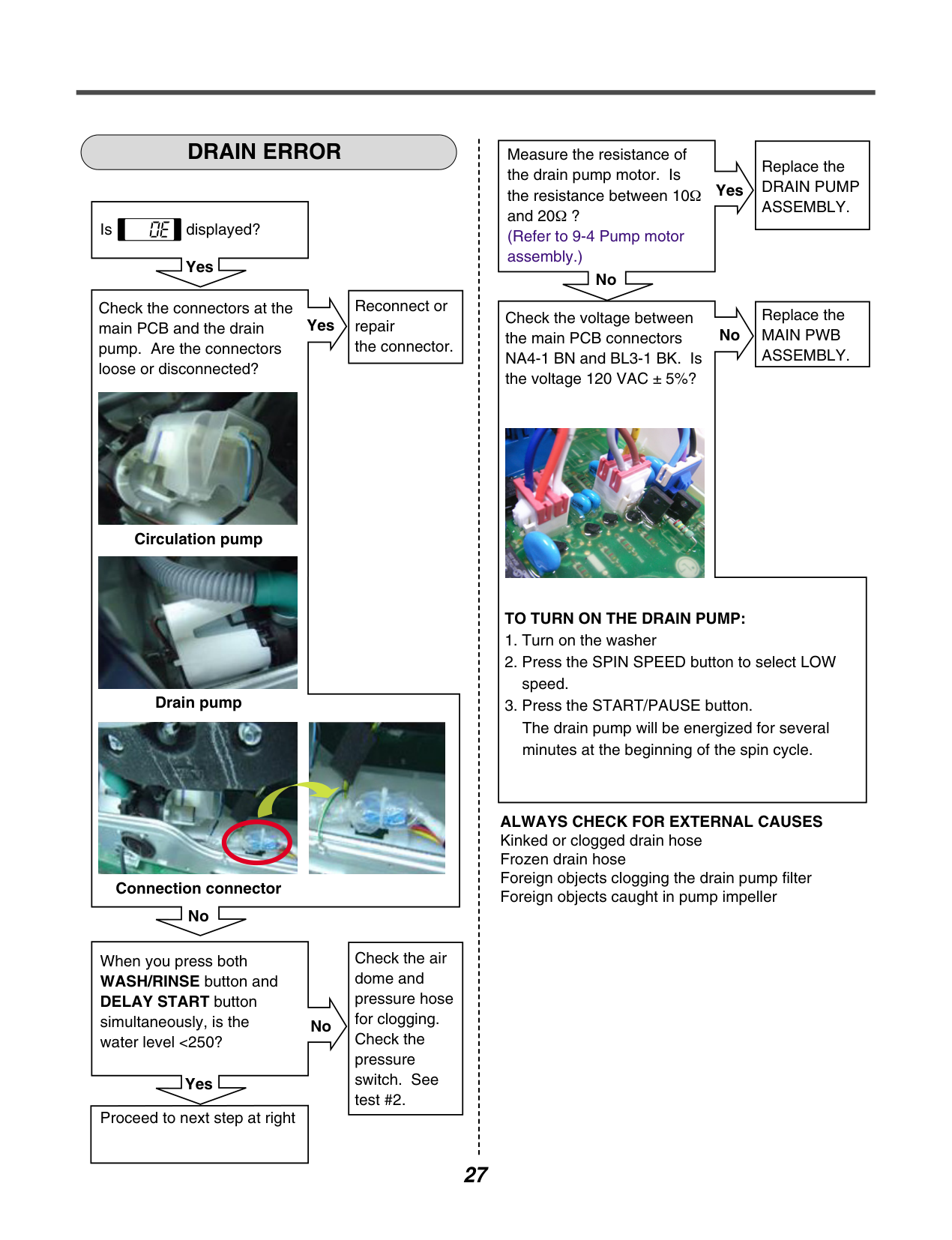
############ DRAIN ERROR
Is displayed?
Yes
|Reconnect or repair the connector.| |---|
Check the connectors at the main PCB and the drain pump. Are the connectors loose or disconnected?
Yes

Circulation pump

Drain pump


Connection connector No
|Check the air dome and pressure hose for clogging. Check the pressure switch. See test #2.| |---|
When you press both WASH/RINSE button and DELAY START button simultaneously, is the water level <250?
No
| | | |---|---| | | |
Yes
|Proceed to next step at right| |---|
Measure the resistance of the drain pump motor. Is the resistance between 10Ω and 20Ω ? (Refer to 9-4 Pump motor assembly.)
Yes
| | | |---|---| | | |
No
|Replace the DRAIN PUMP ASSEMBLY.| |---|
Check the voltage between the main PCB connectors NA4-1 BN and BL3-1 BK. Is the voltage 120 VAC ± 5%?
No
|Replace the MAIN PWB ASSEMBLY.| |---|

####################### TO TURN ON THE DRAIN PUMP:
ALWAYS CHECK FOR EXTERNAL CAUSES Kinked or clogged drain hose Frozen drain hose Foreign objects clogging the drain pump filter Foreign objects caught in pump impeller
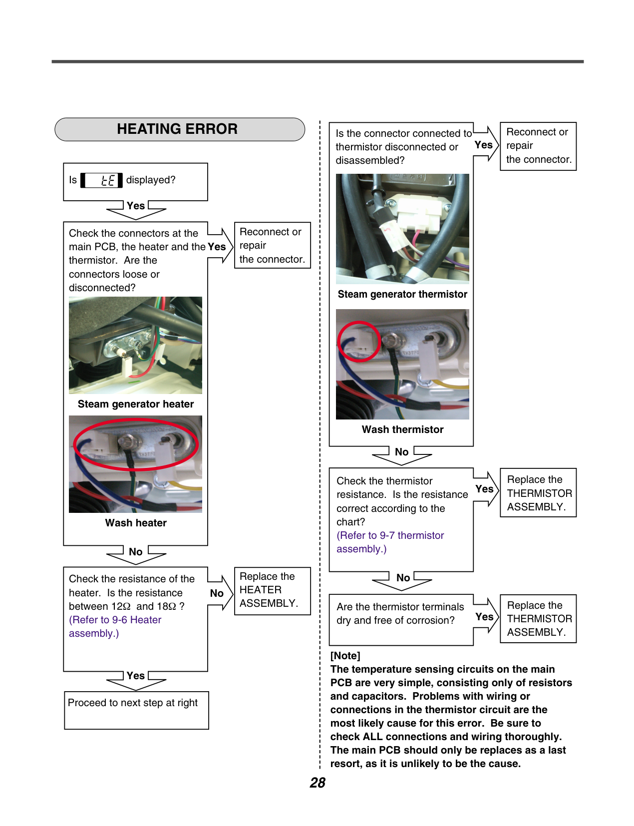
############ HEATING ERROR
|Reconnect or repair the connector.| |---|
Is the connector connected to thermistor disconnected or disassembled?
Yes
| | | |---|---| | | |

Is displayed?
Yes
|Reconnect or repair the connector.| |---|
Check the connectors at the main PCB, the heater and the thermistor. Are the connectors loose or disconnected?
Yes
| | | |---|---| | | |
Steam generator thermistor


Steam generator heater

Wash thermistor
No
|Replace the THERMISTOR ASSEMBLY.| |---|
Check the thermistor resistance. Is the resistance correct according to the chart? (Refer to 9-7 thermistor assembly.)
Yes
| | | |---|---| | | |
Wash heater
No
|Replace the HEATER ASSEMBLY.| |---|
No
Check the resistance of the heater. Is the resistance between 12Ω and 18 (Refer to 9-6 Heater assembly.)
No
|Replace the THERMISTOR ASSEMBLY.| |---|
Are the thermistor terminals dry and free of corrosion?
|Ω ?| | |---|---| | | |
Yes
[Note] The temperature sensing circuits on the main PCB are very simple, consisting only of resistors and capacitors. Problems with wiring or connections in the thermistor circuit are the most likely cause for this error. Be sure to check ALL connections and wiring thoroughly. The main PCB should only be replaces as a last resort, as it is unlikely to be the cause.
Yes
|Proceed to next step at right| |---|
############ LOCKED MOTOR ERROR
Is displayed?
Yes
|Reconnect the connector. (connector / wire / motor )| |---|
Check the connectors at the main PCB and the main motor. Are the connectors loose or disconnected? Main PCB connectors RD3 and NA4 Motor connectors to stator and hall sensor
Yes

Motor Drive

####################### Hall sensor

Motor Drive Hall Sensor

Motor Yes
Check the resistance of the stator winding from the main PCB connector RD3. Is the resistance between each pair or wires between 5 and 15 ? (Measure pins 1-2, 1-3 and 2-3.)
####################### No
| | | |---|---| | | |

Yes
|Replace the STATOR.| |---|
Is hall sensor out of order? (Refer to 9-3 Stator assembly/Hall sensor.)
Yes
| | | |---|---| | | |
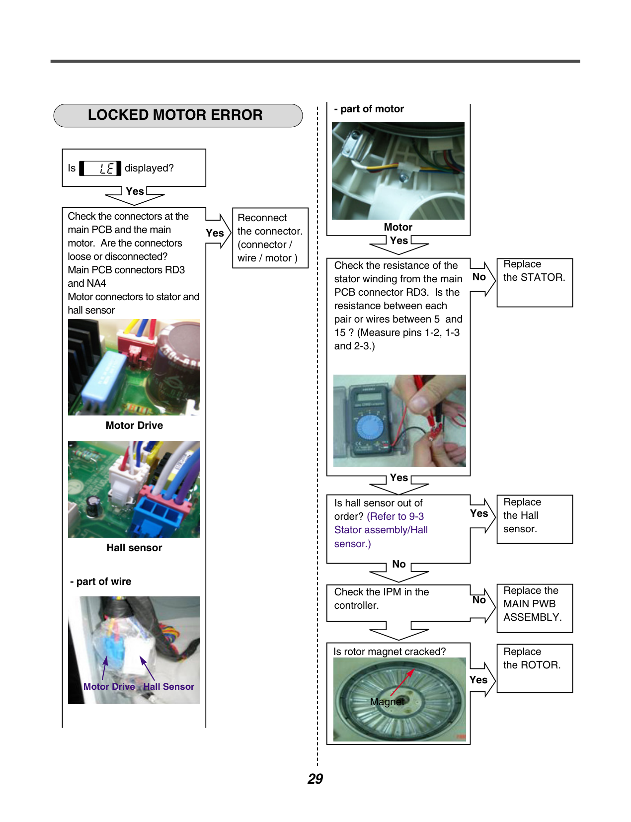
No
|Replace the Hall sensor.| |---|
Check the IPM in the controller.
####################### No
|Replace the MAIN PWB ASSEMBLY.| |---|
Is rotor magnet cracked?

Yes
|Replace the ROTOR.| |---|
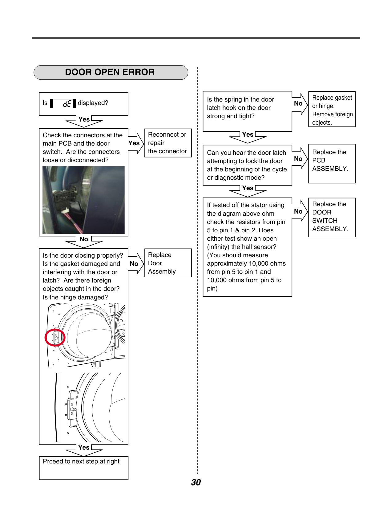
############ DOOR OPEN ERROR
Is displayed?
####################### Yes
|Reconnect or repair the connector| |---|
Check the connectors at the main PCB and the door switch. Are the connectors loose or disconnected?
Yes
| | | |---|---| | | |

No
Replace Door Assembly
Is the door closing properly? Is the gasket damaged and interfering with the door or latch? Are there foreign objects caught in the door? Is the hinge damaged?
No
Yes
Prceed to next step at right
Is the spring in the door latch hook on the door strong and tight?
No
| | | |---|---| | | |
Yes
|Replace gasket or hinge. Remove foreign objects.| |---|
Can you hear the door latch attempting to lock the door at the beginning of the cycle or diagnostic mode?
No
| | | |---|---| | | |
Yes
|Replace the PCB ASSEMBLY.| |---|
If tested off the stator using the diagram above ohm check the resistors from pin 5 to pin 1 & pin 2. Does either test show an open (infinity) the hall sensor? (You should measure approximately 10,000 ohms from pin 5 to pin 1 and 10,000 ohms from pin 5 to pin)
No
|Replace the DOOR SWITCH ASSEMBLY.| |---|
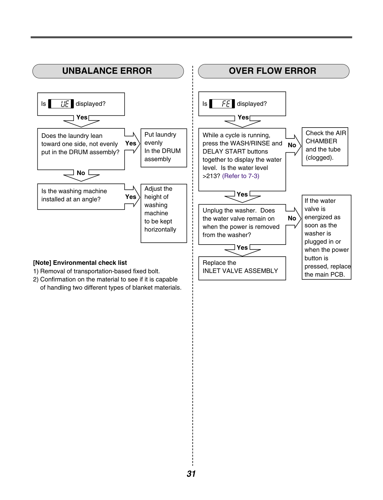
############ UNBALANCE ERROR OVER FLOW ERROR
Is displayed?
####################### Yes
|Put laundry evenly In the DRUM assembly| |---|
Does the laundry lean toward one side, not evenly put in the DRUM assembly?
####################### Yes
| | |
|---|---| | | |
No
|Adjust the height of washing machine to be kept horizontally| |---|
Is the washing machine installed at an angle?
Yes
####################### [Note] Environmental check list
Is displayed?
####################### Yes
|Check the AIR CHAMBER and the tube (clogged).| |---|
While a cycle is running, press the WASH/RINSE and DELAY START buttons together to display the water level. Is the water level >213? (Refer to 7-3)
####################### No
| | | |---|---| | | |
Yes
|If the water valve is energized as soon as the washer is plugged in or when the power button is pressed, replace the main PCB.| |---|
Unplug the washer. Does the water valve remain on when the power is removed from the washer?
No
| | | |---|---| | | |
Yes
|Replace the INLET VALVE ASSEMBLY| |---|
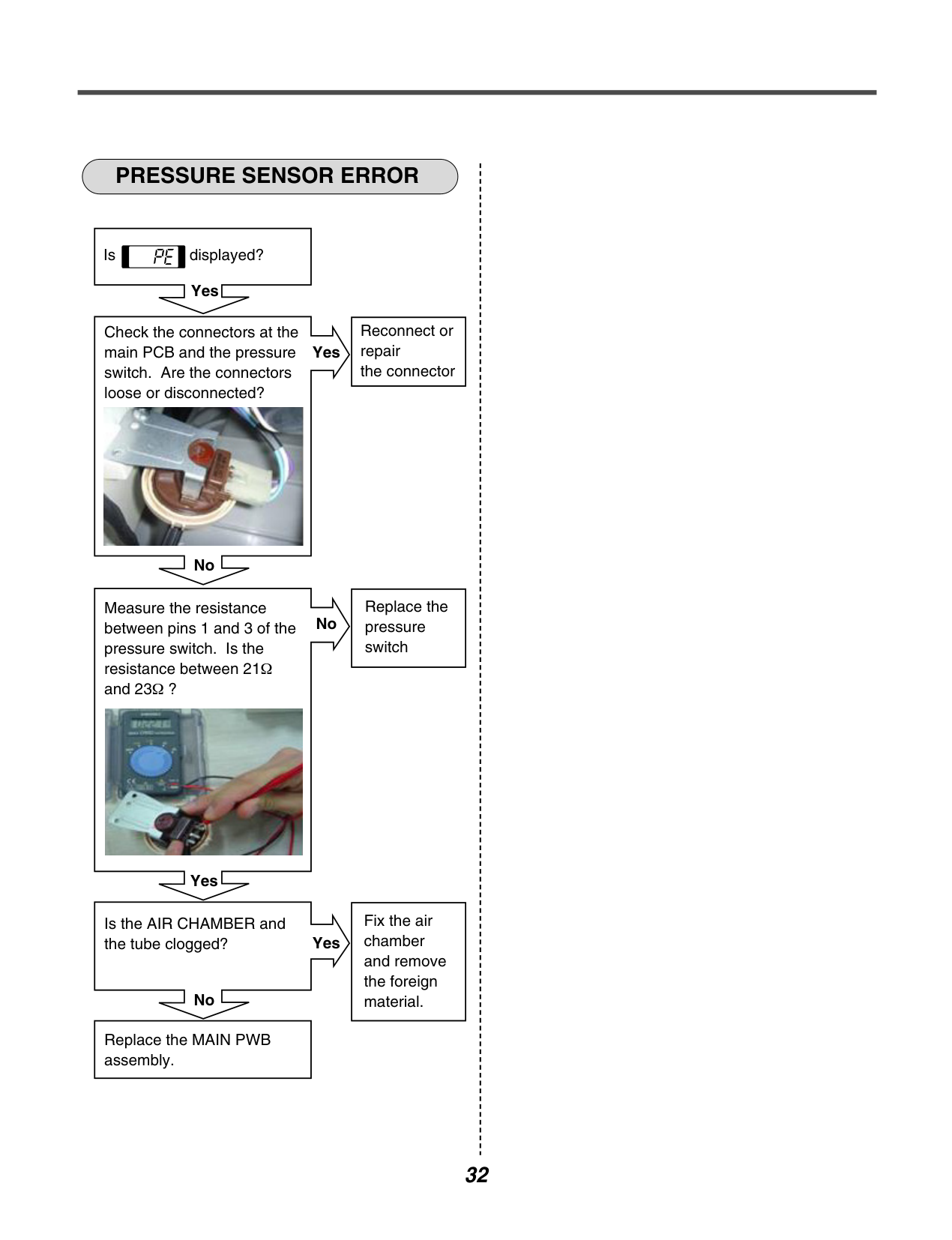
############ PRESSURE SENSOR ERROR
Is displayed?
####################### Yes
|Reconnect or repair the connector| |---|
Check the connectors at the main PCB and the pressure switch. Are the connectors loose or disconnected?
Yes
| | | |---|---|
| | |

No
|Replace the pressure switch| |---|
Measure the resistance between pins 1 and 3 of the pressure switch. Is the resistance between 21 and 23Ω ?
No
|Ω| | |---|---| | | |

Yes
|Fix the air chamber and remove the foreign material.| |---|
Is the AIR CHAMBER and the tube clogged?
####################### Yes
| | | |---|---| | | |
No
|Replace the MAIN PWB assembly.| |---|
######### 8-5. TROUBLE SHOOTING ELSE
############ CAUTION
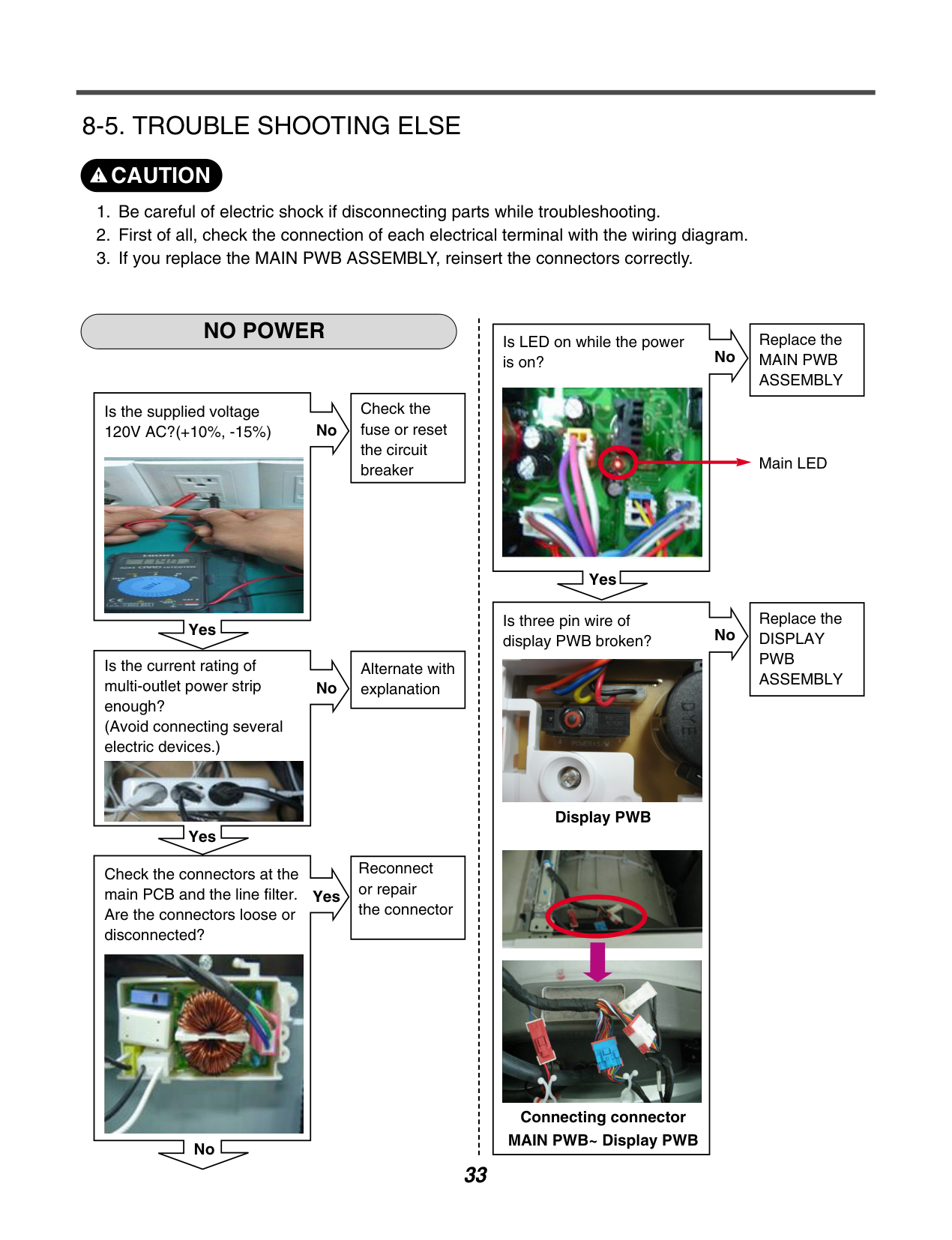
NO POWER
|Check the fuse or reset the circuit breaker| |---|
Is the supplied voltage 120V AC?(+10%, -15%)
No
| | | |---|---| | | |

Yes
|Alternate with explanation| |---|
Is the current rating of multi-outlet power strip enough? (Avoid connecting several electric devices.)
No
| | | |---|---| | | |

Yes
|Reconnect or repair the connector| |---|
Check the connectors at the main PCB and the line filter. Are the connectors loose or disconnected?
Yes
| | | |---|---| | | |

No
Is LED on while the power is on?
No

Yes
Is three pin wire of display PWB broken?

Display PWB


Connecting connector MAIN PWB~ Display PWB
No
|Replace the MAIN PWB ASSEMBLY| |---|
Main LED
|Replace the DISPLAY PWB ASSEMBLY| |---|
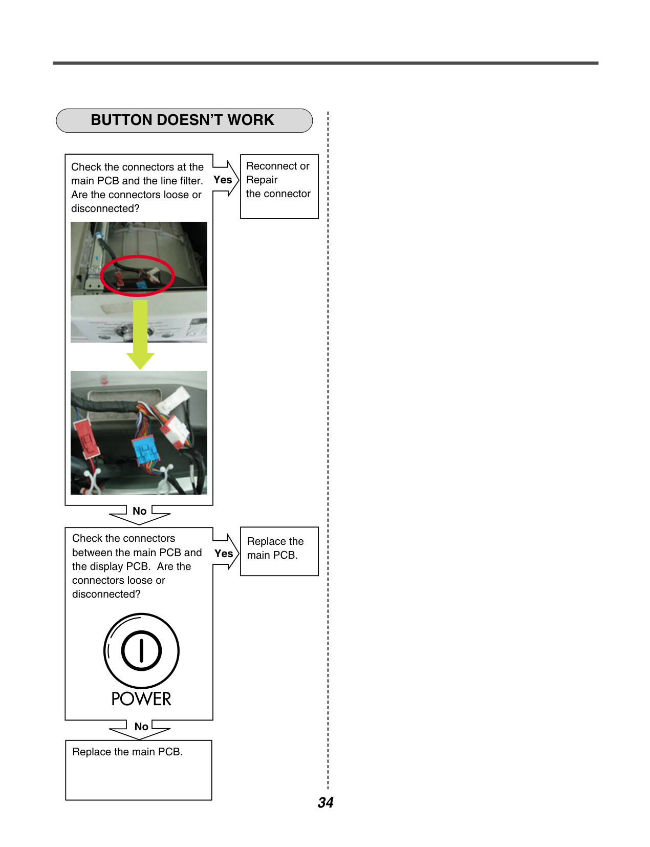
############ BUTTON DOESN’T WORK
|Reconnect or Repair the connector| |---|
Check the connectors at the main PCB and the line filter. Are the connectors loose or disconnected?
####################### Yes
| | |
|---|---| | | |


No
|Replace the main PCB.| |---|
Check the connectors between the main PCB and the display PCB. Are the connectors loose or disconnected?
Yes
| | | |---|---| | | |
No
|Replace the main PCB.| |---|
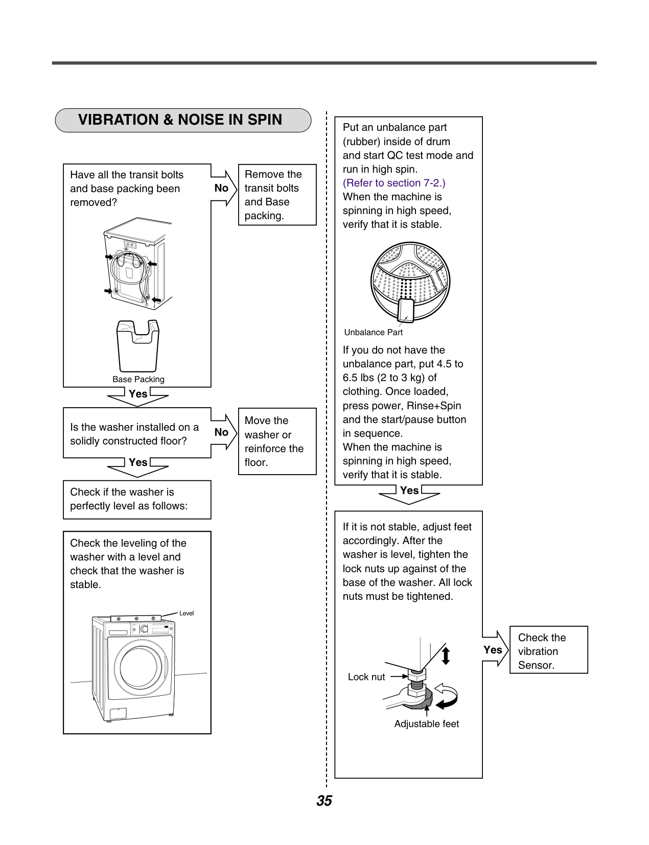
############ VIBRATION & NOISE IN SPIN
|Remove the transit bolts and Base packing.| |---|
Have all the transit bolts and base packing been removed?
No
| | | |---|---| | | |
Base Packing
Yes
|Move the washer or reinforce the floor.| |---|
Is the washer installed on a solidly constructed floor?
No
| | | |---|---| | | |
Yes
|Check if the washer is perfectly level as follows:| |---|
|Check the leveling of the washer with a level and check that the washer is stable.| |---|
Put an unbalance part (rubber) inside of drum and start QC test mode and run in high spin. (Refer to section 7-2.) When the machine is spinning in high speed, verify that it is stable.
Unbalance Part
If you do not have the unbalance part, put 4.5 to 6.5 lbs (2 to 3 kg) of clothing. Once loaded, press power, Rinse+Spin and the start/pause button in sequence. When the machine is spinning in high speed, verify that it is stable.
Yes
If it is not stable, adjust feet accordingly. After the washer is level, tighten the lock nuts up against of the base of the washer. All lock nuts must be tightened.
Yes
|Check the vibration Sensor.| |---|
| | | |---|---| | | |
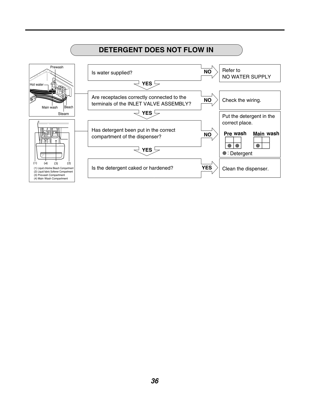
############ DETERGENT DOES NOT FLOW IN
Is water supplied?
NO
| | | |---|---| | | |
YES
Are receptacles correctly connected to the terminals of the INLET VALVE ASSEMBLY?
NO
| | | |---|---|
| | |
YES
Has detergent been put in the correct compartment of the dispenser?
NO
| | | |---|---| | | |
YES
Is the detergent caked or hardened?
YES
|Refer to NO WATER SUPPLY| |---|
|Check the wiring.| |---|
|Put the detergent in the correct place.
| |---|
|Clean the dispenser.| |---|
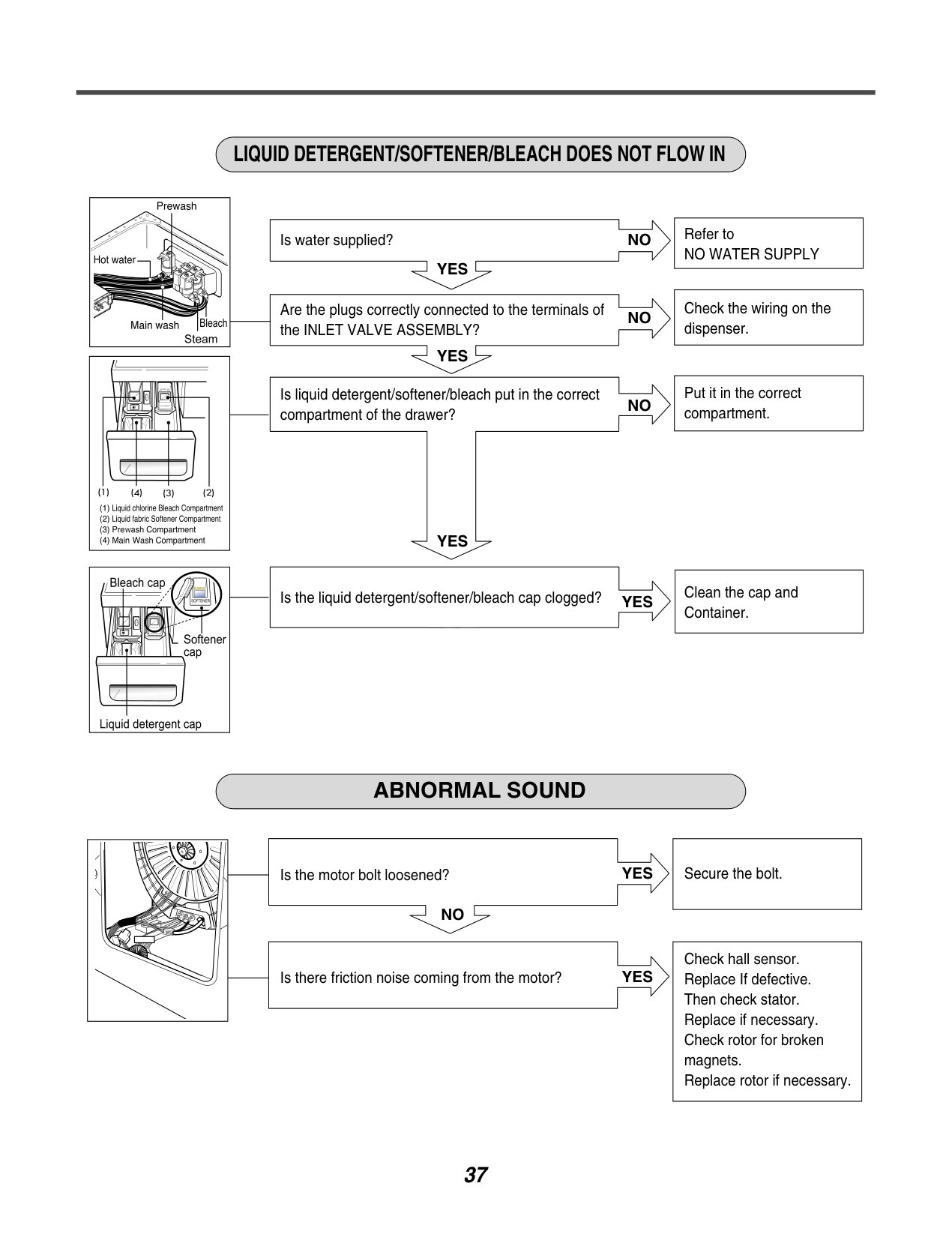
############ LIQUID DETERGENT/SOFTENER/BLEACH DOES NOT FLOW IN
| | | |---|---| | | |
Is water supplied?
YES
NO
Are the plugs correctly connected to the terminals of the INLET VALVE ASSEMBLY?
NO
| | | |---|---| | | |
YES
Is liquid detergent/softener/bleach put in the correct compartment of the drawer?
NO
| | | |---|---| | | |
YES
|

| | |---|---| |

| |
Is the liquid detergent/softener/bleach cap clogged?
YES
|Refer to NO WATER SUPPLY| |---|
|Check the wiring on the dispenser.| |---|
|Put it in the correct compartment.| |---|
|Clean the cap and Container.| |---|
############ ABNORMAL SOUND
Is the motor bolt loosened?
NO
YES
| | | |---|---| | | |
Is there friction noise coming from the motor?
YES
|Secure the bolt.| |---|
|Check hall sensor. Replace If defective. Then check stator. Replace if necessary. Check rotor for broken magnets. Replace rotor if necessary.| |---|
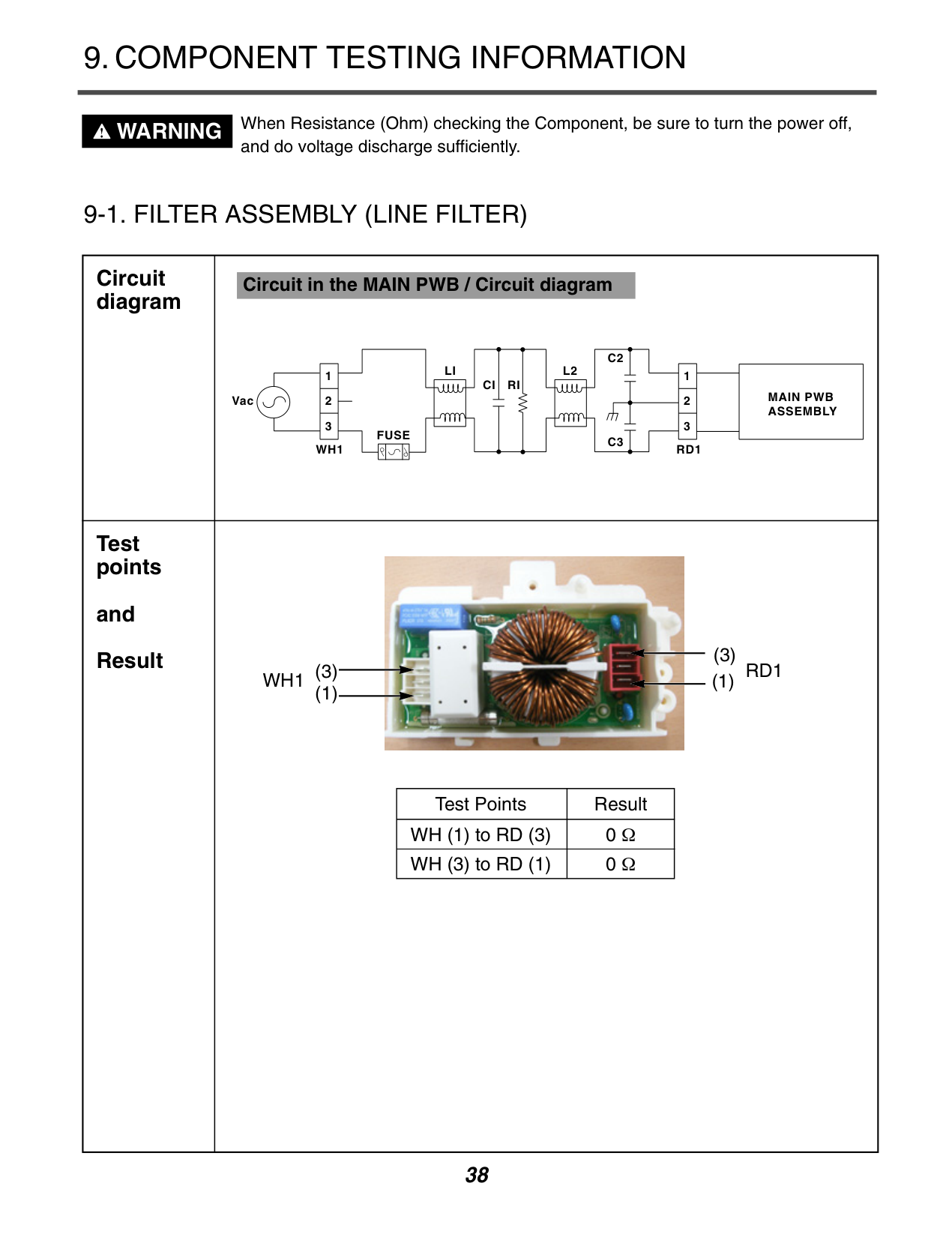
#### 9.COMPONENT TESTING INFORMATION
############ WARNING
When Resistance (Ohm) checking the Component, be sure to turn the power off, and do voltage discharge sufficiently.
|Circuit diagram|Circuit in the MAIN PWB / Circuit diagram
Vac MAIN PWB
ASSEMBLY FUSE
RD1WH1
LI L2 RICI
C2
C3
3
2
1
3
2
1
| |---|---| |Test points
and Result|
|Test Points|Result| |---|---| |WH (1) to RD (3)|0 Ω| |WH (3) to RD (1)|0 Ω|
(3) (1)
WH1
(3) (1)
RD1|
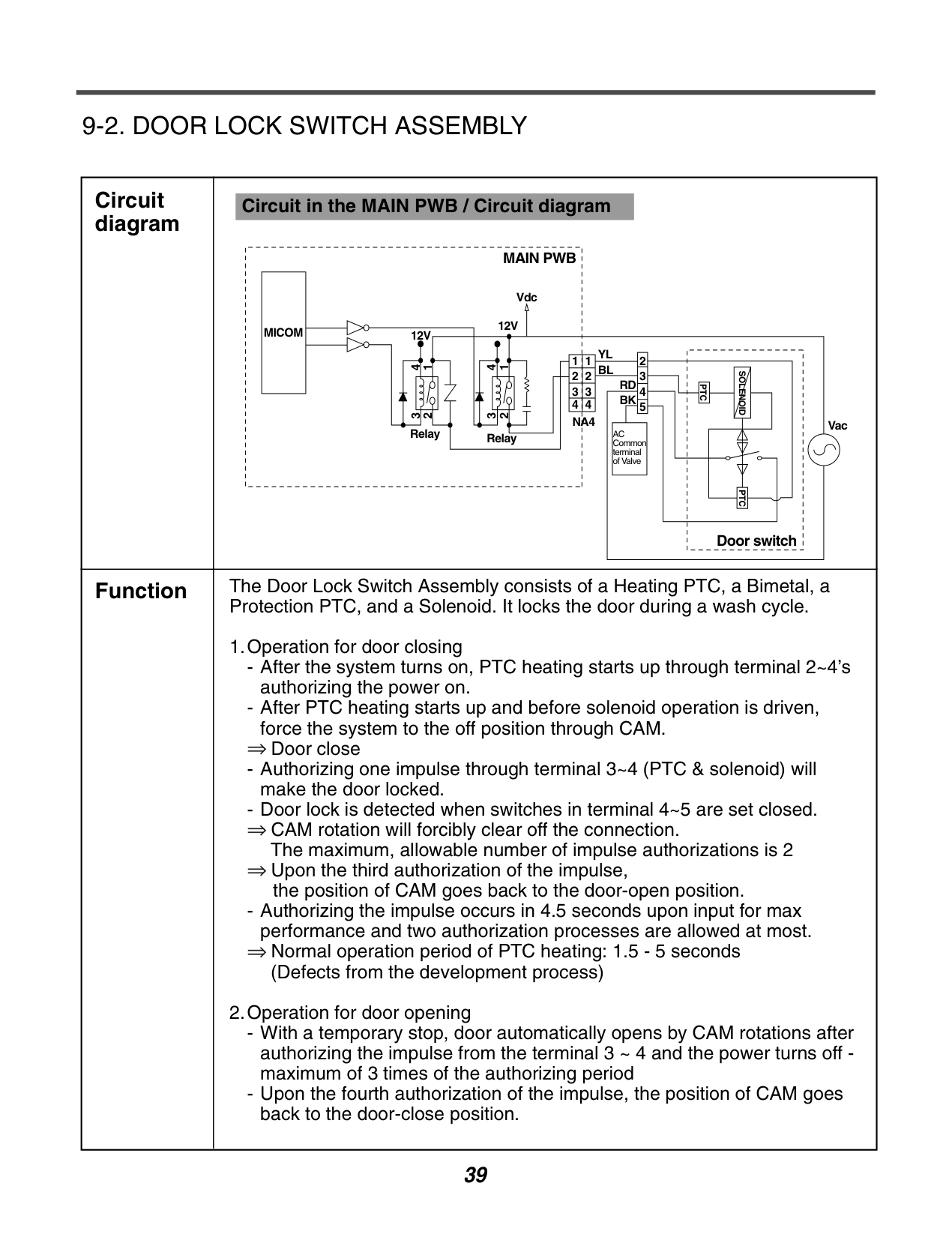
######### 9-2. DOOR LOCK SWITCH ASSEMBLY
|Circuit diagram
|Circuit in the MAIN PWB / Circuit diagram
MAIN PWB
Vdc
Vac
|MICOM| | |---|---| |MICOM| | |MICOM| |
12V
12V
4
1
3
2
4
1
3
2
Relay Relay
NA4
1
2
3
4
1
2
3
4
2
3
4
PTC
PTC
Door switch
SOLENOID
5
YL BL
RD BK
AC Common terminal of Valve
| |---|---| |Function|The Door Lock Switch Assembly consists of a Heating PTC, a Bimetal, a Protection PTC, and a Solenoid. It locks the door during a wash cycle.
1.Operation for door closing
- After the system turns on, PTC heating starts up through terminal 2~4’s authorizing the power on.
- After PTC heating starts up and before solenoid operation is driven, force the system to the off position through CAM.

Door close
- Authorizing one impulse through terminal 3~4 (PTC & solenoid) will make the door locked.
- Door lock is detected when switches in terminal 4~5 are set closed. CAM rotation will forcibly clear off the connection. The maximum, allowable number of impulse authorizations is 2 Upon the third authorization of the impulse, the position of CAM goes back to the door-open position.


- Authorizing the impulse occurs in 4.5 seconds upon input for max performance and two authorization processes are allowed at most.

Normal operation period of PTC heating: 1.5 - 5 seconds (Defects from the development process)
2.Operation for door opening
-With a temporary stop, door automatically opens by CAM rotations after authorizing the impulse from the terminal 3 ~ 4 and the power turns off maximum of 3 times of the authorizing period
- Upon the fourth authorization of the impulse, the position of CAM goes back to the door-close position.
|
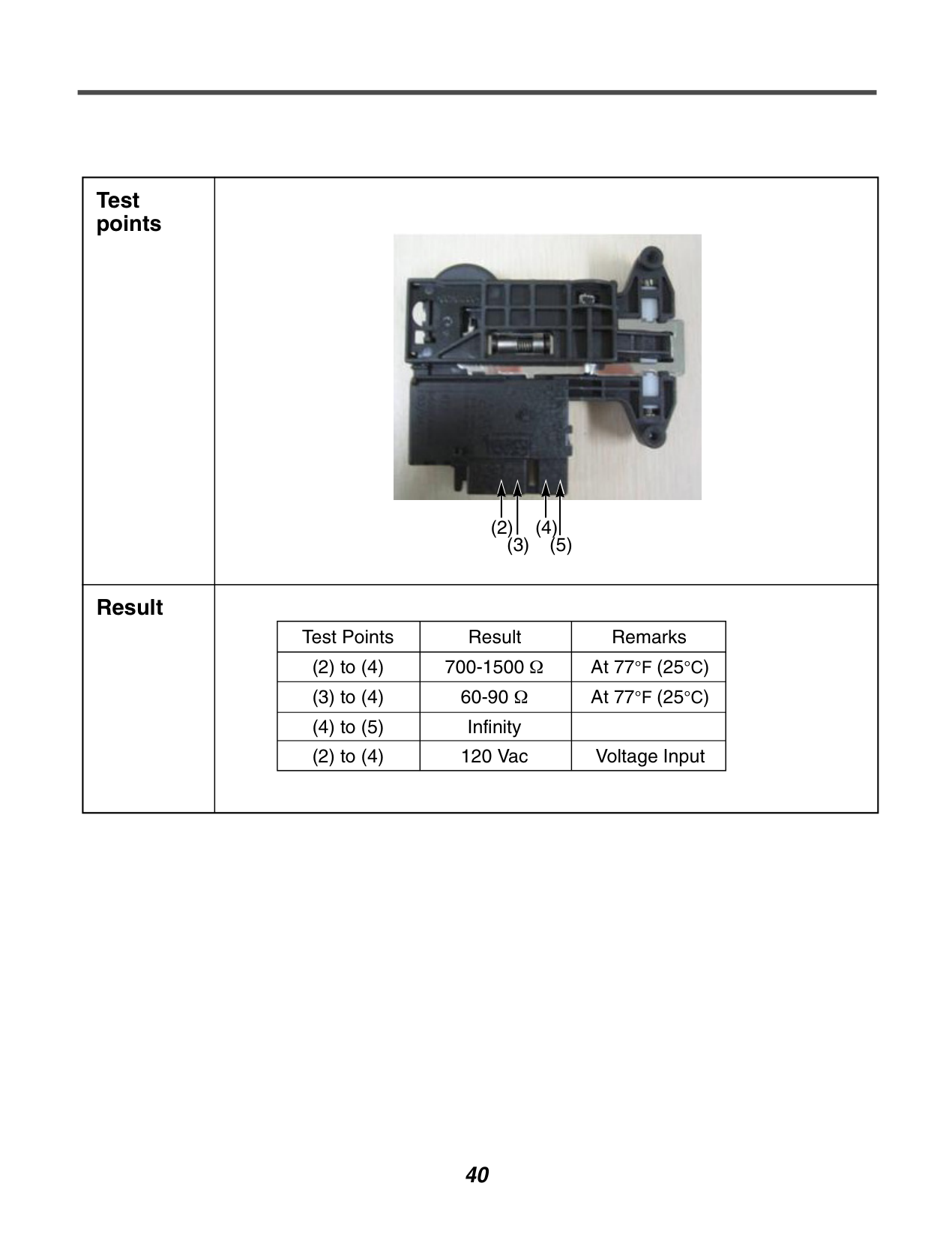
|Test points|
(2)
(3)
(4)
(5)
| |---|---| |Result||Test Points|Result|Remarks| |---|---|---| |(2) to (4)|700-1500 Ω|At 77°F (25°C)| |(3) to (4)|60-90 Ω|At 77°F (25°C)| |(4) to (5)|Infinity| | |(2) to (4)|120 Vac|Voltage Input| |
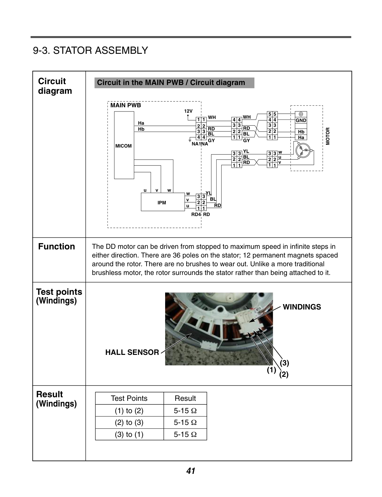
######### 9-3. STATOR ASSEMBLY
|Circuit diagram|Circuit in the MAIN PWB / Circuit diagram
MAIN PWB
MICOM
Ha
12V
NA1NA
WH WH
GND
MOTOR
Hb Ha
RD RD BLBL GY
YLw
wvu
v u
BL
RD RDRD4
IPM
GY YL w BL RD
u
v
1
11
2
3
4
2
3
1
2
3
1
2
3
1
2
3
1
2
3
1
3
2 2 1
3
4
1
2
3
4
5
1
2
3
4
5
2
3
4
1
2
3
4
Hb
| |---|---| |Function|The DD motor can be driven from stopped to maximum speed in infinite steps in either direction. There are 36 poles on the stator; 12 permanent magnets spaced around the rotor. There are no brushes to wear out. Unlike a more traditional brushless motor, the rotor surrounds the stator rather than being attached to it.| |Test points (Windings)
|
WINDINGS
HALL SENSOR
(1)
(2)
(3)
| |Result (Windings)||Test Points|Result| |---|---| |(1) to (2)|5-15 Ω| |(2) to (3)|5-15 Ω| |(3) to (1)|5-15 Ω| |
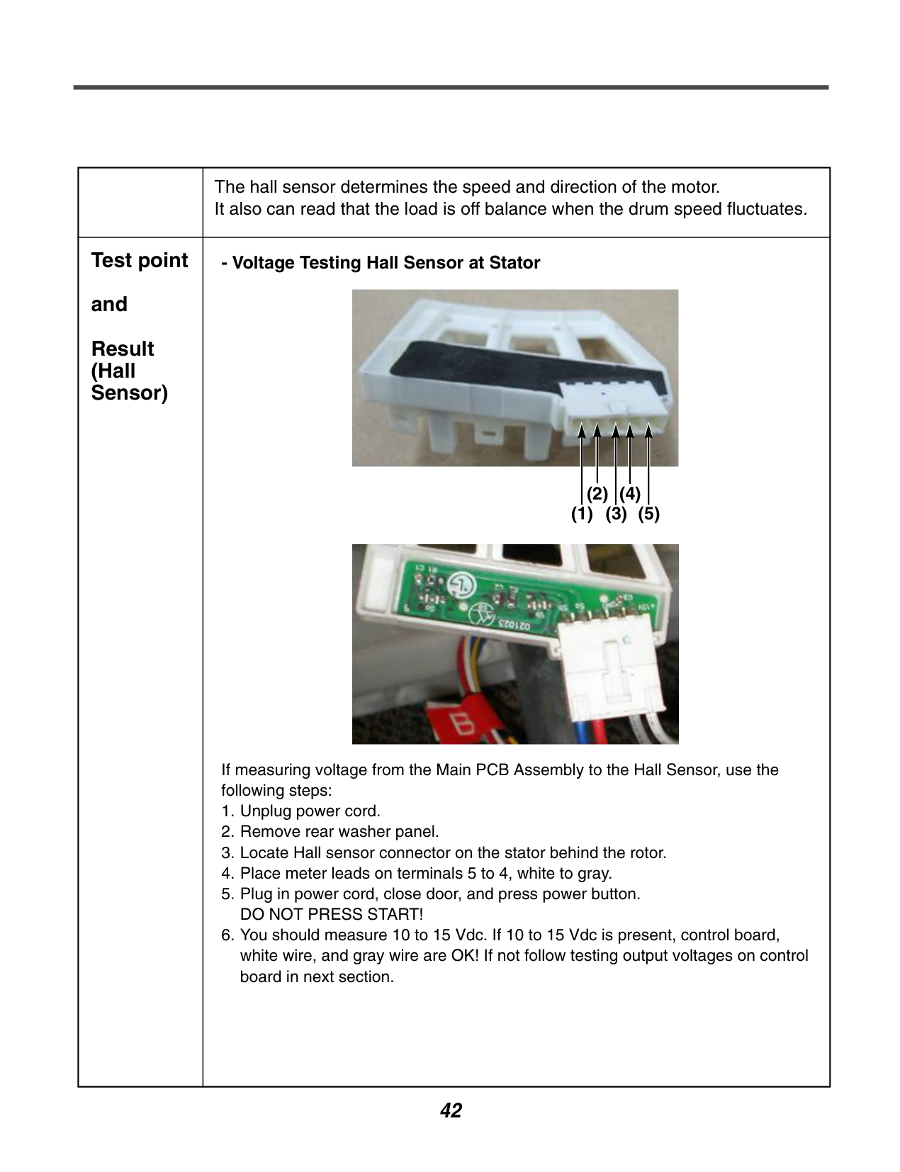
| |The hall sensor determines the speed and direction of the motor. It also can read that the load is off balance when the drum speed fluctuates.| |---|---| |Test point and Result (Hall Sensor)|- Voltage Testing Hall Sensor at Stator


If measuring voltage from the Main PCB Assembly to the Hall Sensor, use the following steps:
1. Unplug power cord.
2. Remove rear washer panel.
3. Locate Hall sensor connector on the stator behind the rotor.
4. Place meter leads on terminals 5 to 4, white to gray.
5. Plug in power cord, close door, and press power button. DO NOT PRESS START!
6. You should measure 10 to 15 Vdc. If 10 to 15 Vdc is present, control board, white wire, and gray wire are OK! If not follow testing output voltages on control board in next section.
(1) (3) (5)
(2) (4)
|
| |7. To measure output signal voltage from the hall sensor, carefully move test leads to terminals 1 to 4, blue and gray. Slowly rotate motor rotor by hand. You should read a pulsing 10 Vdc. If 10 Vdc is measured from 1 to 4, move lead on blue wire to red wire, terminal 2. Repeat rotating motor rotor by hand. You should read a pulsing 10 Vdc from red to gray.
8. If pulsing 10 Vdc is measured from 1 to 4 and 2 to 4, hall sensor is OK! If either test netted only 9 to 10 Vdc without changing (no pulsing) the hall sensor is likely defective. Disconnect power by unplugging washer and ohm check hall sensor to verify failure of the hall sensor.
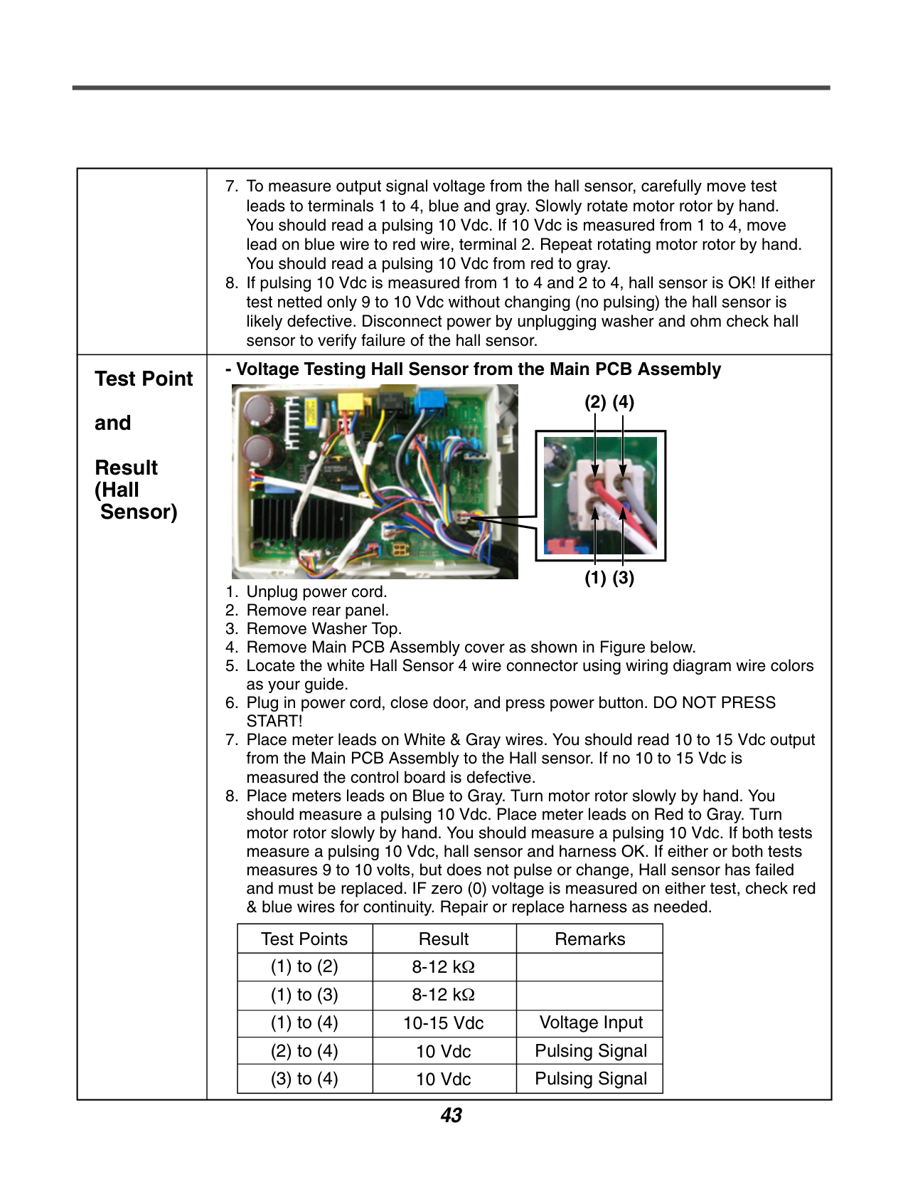
| |---|---| |Test Point and Result (Hall
Sensor)|
1. Unplug power cord.
2. Remove rear panel.
3. Remove Washer Top.
4. Remove Main PCB Assembly cover as shown in Figure below.
5. Locate the white Hall Sensor 4 wire connector using wiring diagram wire colors as your guide.
6. Plug in power cord, close door, and press power button. DO NOT PRESS START!
7. Place meter leads on White & Gray wires. You should read 10 to 15 Vdc output from the Main PCB Assembly to the Hall sensor. If no 10 to 15 Vdc is measured the control board is defective.
8. Place meters leads on Blue to Gray. Turn motor rotor slowly by hand. You should measure a pulsing 10 Vdc. Place meter leads on Red to Gray. Turn motor rotor slowly by hand. You should measure a pulsing 10 Vdc. If both tests measure a pulsing 10 Vdc, hall sensor and harness OK. If either or both tests measures 9 to 10 volts, but does not pulse or change, Hall sensor has failed and must be replaced. IF zero (0) voltage is measured on either test, check red & blue wires for continuity. Repair or replace harness as needed.
- Voltage Testing Hall Sensor from the Main PCB Assembly
|Test Points|Result|Remarks| |---|---|---| |(1) to (2)|8-12 kΩ| |
|(1) to (3)|8-12 kΩ| | |(1) to (4)|10-15 Vdc|Voltage Input| |(2) to (4)|10 Vdc|Pulsing Signal| |(3) to (4)|10 Vdc|Pulsing Signal|

(1) (3)
(2) (4)
|
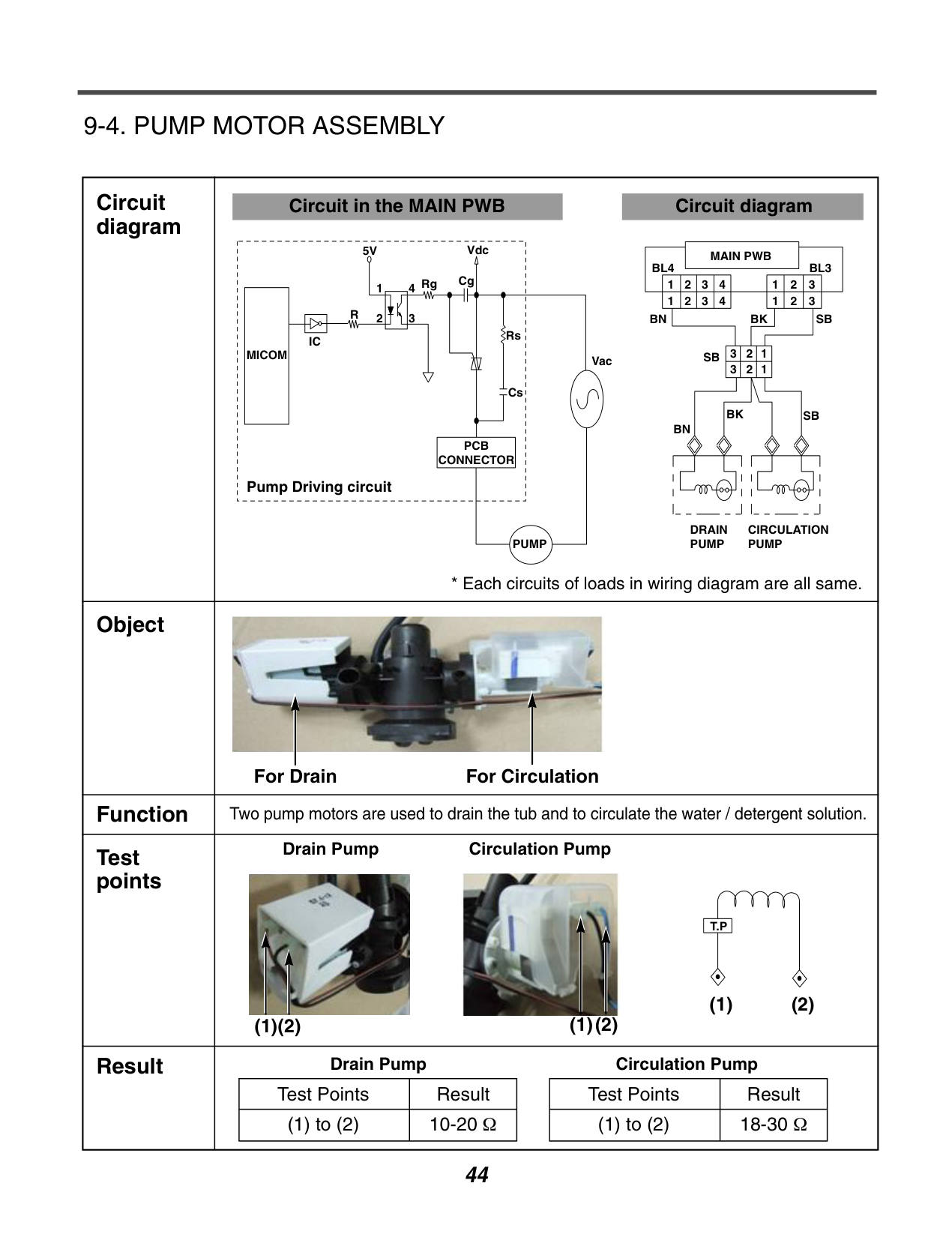
######### 9-4. PUMP MOTOR ASSEMBLY
|Circuit diagram|Circuit in the MAIN PWB Circuit diagram
MICOM
IC
R
5V
Rg Cg
Vdc
Rs
Cs
PCB CONNECTOR
PUMP
Vac
2
14
3
Pump Driving circuit
MAIN PWB BL4
123 123
321 321
123
4 1234
BL3
SB
SB
SB
BKBN
BN
DRAIN PUMP
CIRCULATION PUMP
BK
* Each circuits of loads in wiring diagram are all same.| |---|---| |Object|
For Drain For Circulation
| |Function|Two pump motors are used to drain the tub and to circulate the water / detergent solution.| |Test points|Drain Pump Circulation Pump


T.P
(1)(2) (2)(1)
(1) (2)| |Result|Drain Pump Circulation Pump
|Test Points|Result| |---|---| |(1) to (2)|10-20 Ω|
|Test Points|Result| |---|---| |(1) to (2)|18-30 Ω| |
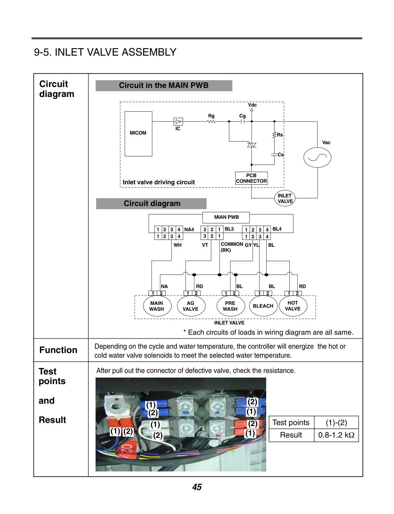
######### 9-5. INLET VALVE ASSEMBLY
|Circuit diagram|Circuit in the MAIN PWB
INLET VALVE
Vac
Rs
Vdc CgRg
IC MICOM
Cs
PCB
CONNECTORInlet valve driving circuit
Circuit diagram
MAIN WASH
AG VALVE
PRE WASH
BLEACH
HOT VALVE
12 12 12 12 12
RDBLBLRDNA
WH
NA4
VT GY YL BL
BL4BL34321123 123 4321
4321 4321
COMMON (BK)
MIAN PWB
INLET VALVE
* Each circuits of loads in wiring diagram are all same.| |---|---| |Function|Depending on the cycle and water temperature, the controller will energize the hot or cold water valve solenoids to meet the selected water temperature.| |Test points
and Result|After pull out the connector of defective valve, check the resistance.
|Test points|(1)-(2)| |---|---| |Result|0.8-1.2 kΩ|

(1)
(1)
(2)
(1)
(2)
(2)
(1)
(2)
(1)(2)(1)
(1)
(2)
(1)
(2)
(2)
(1)
(2)
(1)(2)
|
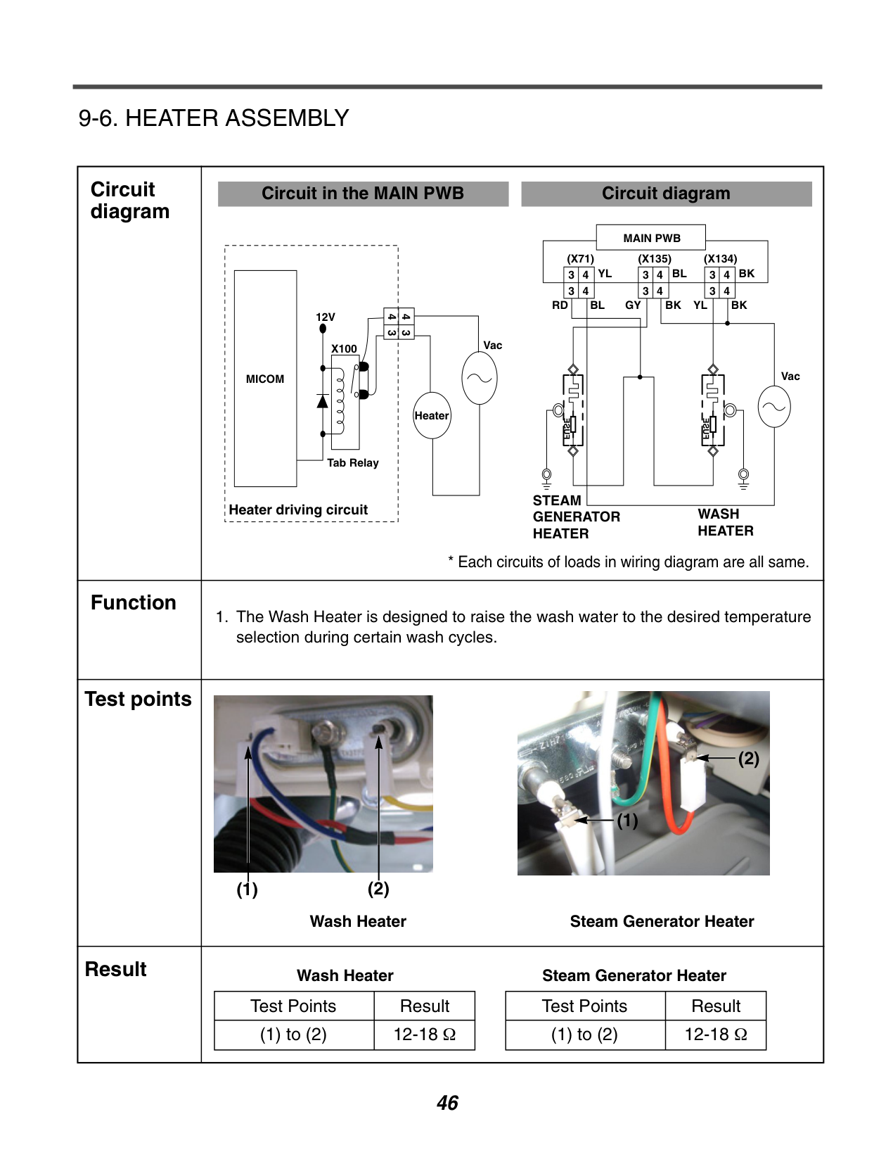
######### 9-6. HEATER ASSEMBLY
|Circuit diagram|Circuit in the MAIN PWB
MICOM
12V
Heater
VacX100
43 43
Tab Relay
Heater driving circuit
Circuit diagram
MAIN PWB (X71)
34 34
34 34
34 34
(X135) (X134) BKBLYL
RD GYBL BK BK
Vac
WASH HEATER
STEAM GENERATOR HEATER
YL
FUSE
FUSE
* Each circuits of loads in wiring diagram are all same.|
|---|---| |Function|1. The Wash Heater is designed to raise the wash water to the desired temperature selection during certain wash cycles.| |Test points|Wash Heater Steam Generator Heater


(1) (2)
(2)
(1)| |Result|Wash Heater Steam Generator Heater
|Test Points|Result| |---|---| |(1) to (2)|12-18 Ω|
|Test Points|Result| |---|---| |(1) to (2)|12-18 Ω| |
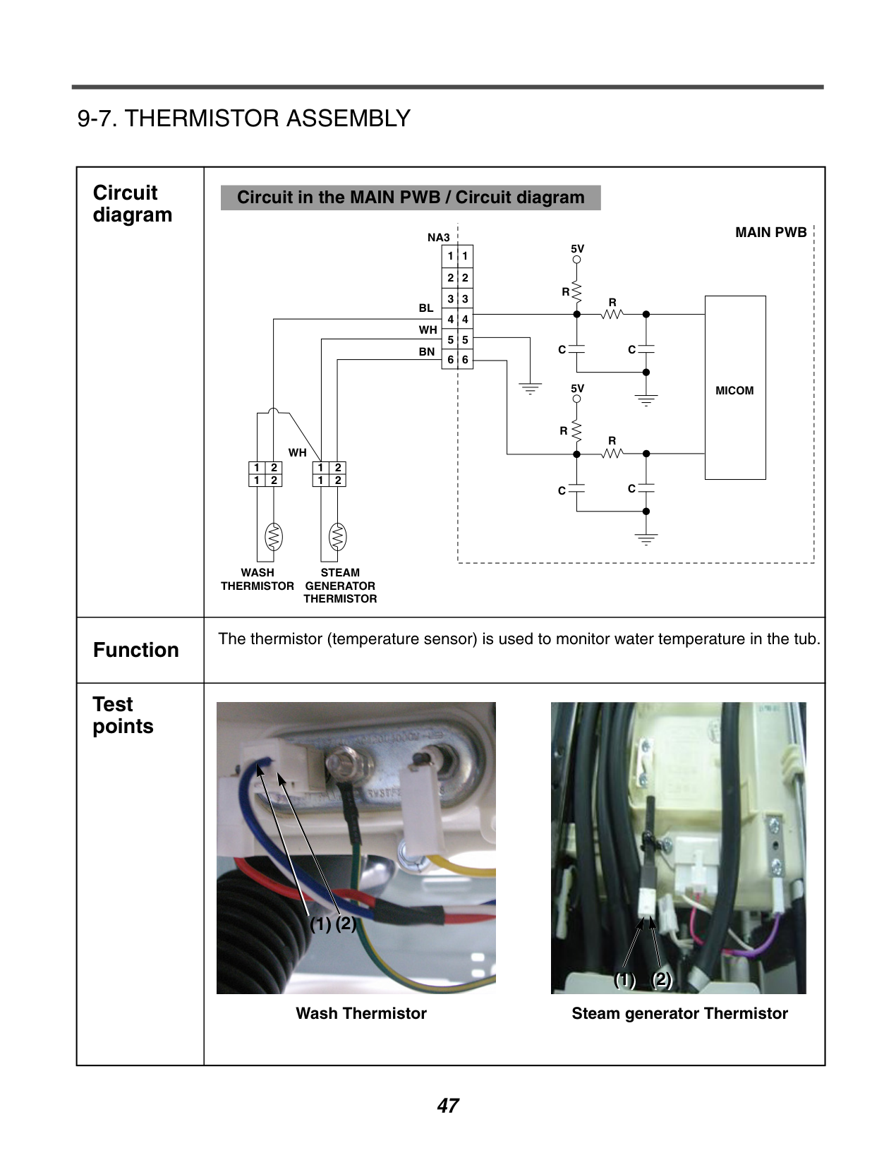
######### 9-7. THERMISTOR ASSEMBLY
|Circuit diagram|Circuit in the MAIN PWB / Circuit diagram
MAIN PWB
|MICOM| |---|
NA3
BL
BN
WH
1
2
1 2 1 2
1 2
WH
WASH THERMISTOR
STEAM GENERATOR THERMISTOR
1 2
3
4
5
6
1
5V
5V
R
R
R
R
C
C C
C
2
3
4
5
6
| |---|---| |Function|The thermistor (temperature sensor) is used to monitor water temperature in the tub.| |Test points|Wash Thermistor

(2)(1)
Steam generator Thermistor

(1) (2)|
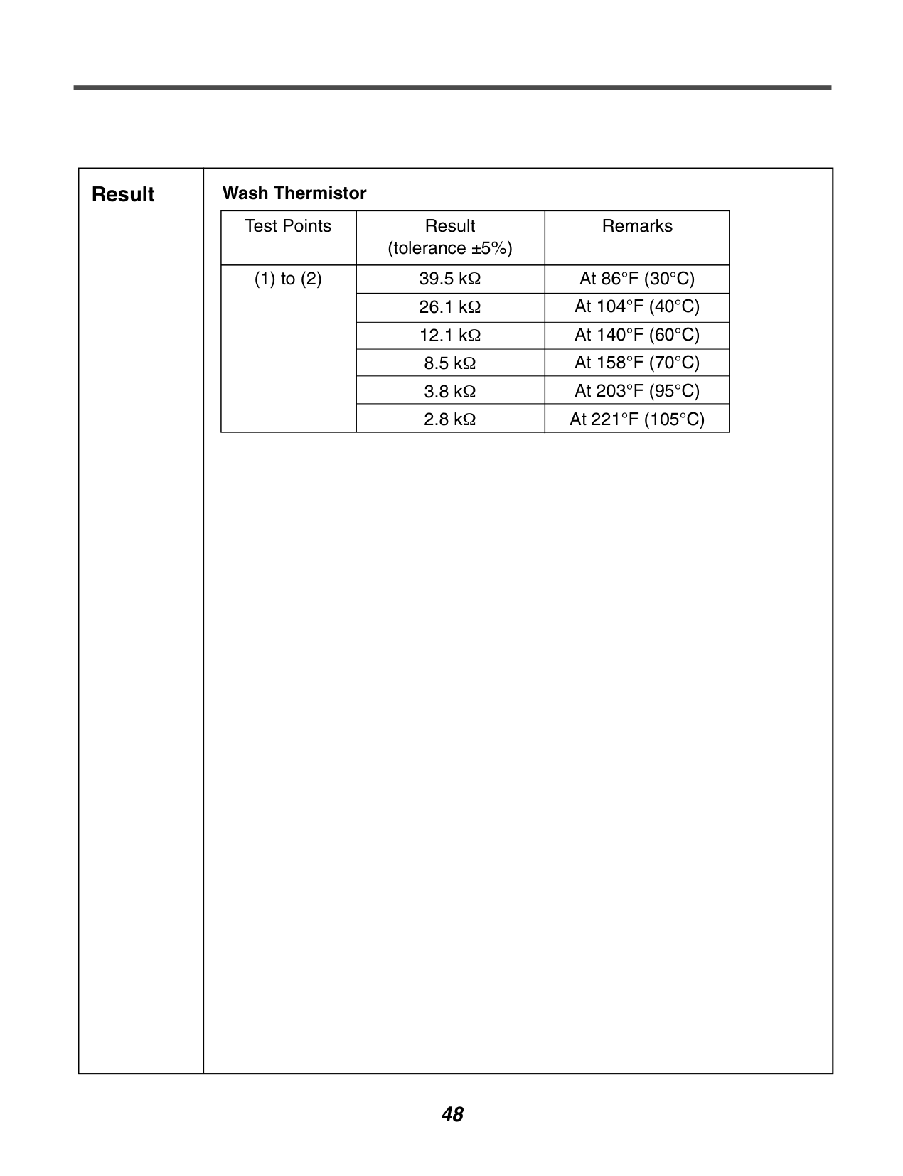
|Result|Wash Thermistor
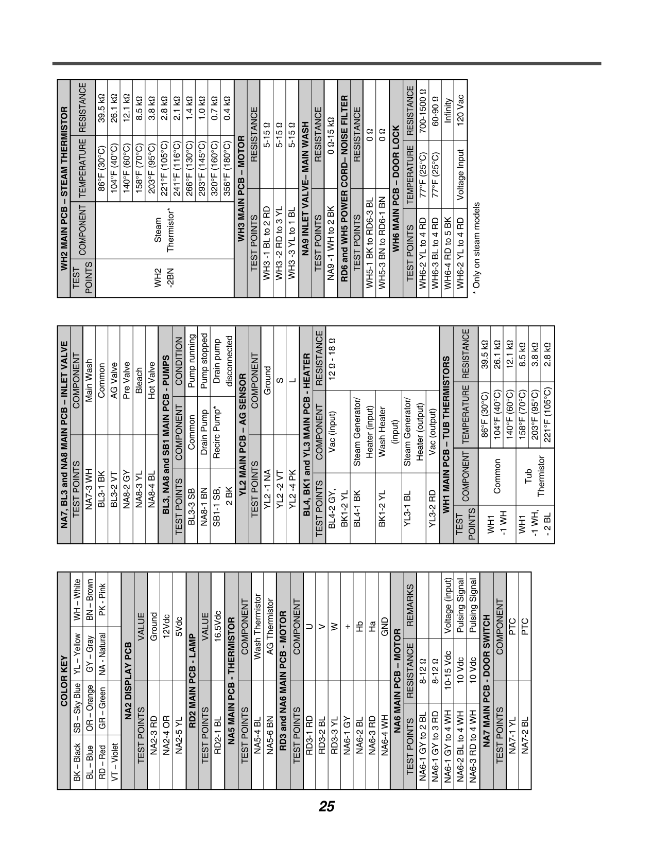
|Test Points|Result (tolerance ±5%)|Remarks| |---|---|---| |(1) to (2)|39.5 kΩ|At 86°F (30°C)| |(1) to (2)|26.1 kΩ|At 104°F (40°C)| |(1) to (2)|12.1 kΩ|At 140°F (60°C)| |(1) to (2)|8.5 kΩ|At 158°F (70°C)| |(1) to (2)|3.8 kΩ|At 203°F (95°C)| |(1) to (2)|2.8 kΩ|At 221°F (105°C)| | |---|---|
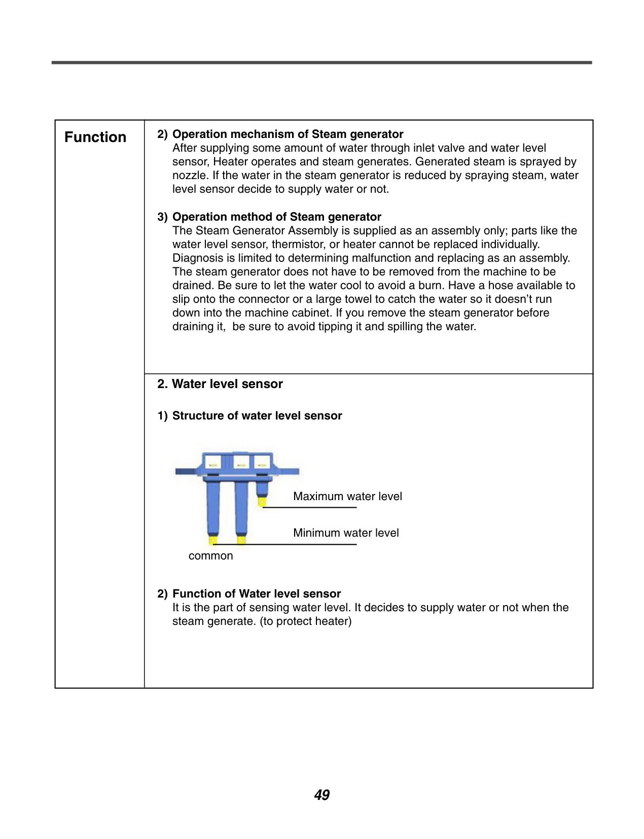
|Function|2) Operation mechanism of Steam generator After supplying some amount of water through inlet valve and water level sensor, Heater operates and steam generates. Generated steam is sprayed by nozzle. If the water in the steam generator is reduced by spraying steam, water level sensor decide to supply water or not.
3) Operation method of Steam generator The Steam Generator Assembly is supplied as an assembly only; parts like the water level sensor, thermistor, or heater cannot be replaced individually. Diagnosis is limited to determining malfunction and replacing as an assembly. The steam generator does not have to be removed from the machine to be drained. Be sure to let the water cool to avoid a burn. Have a hose available to slip onto the connector or a large towel to catch the water so it doesn’t run down into the machine cabinet. If you remove the steam generator before draining it, be sure to avoid tipping it and spilling the water.
| |---|---| |Function|
2. Water level sensor
1) Structure of water level sensor
2) Function of Water level sensor It is the part of sensing water level. It decides to supply water or not when the steam generate. (to protect heater)
Maximum water level
Minimum water level common|
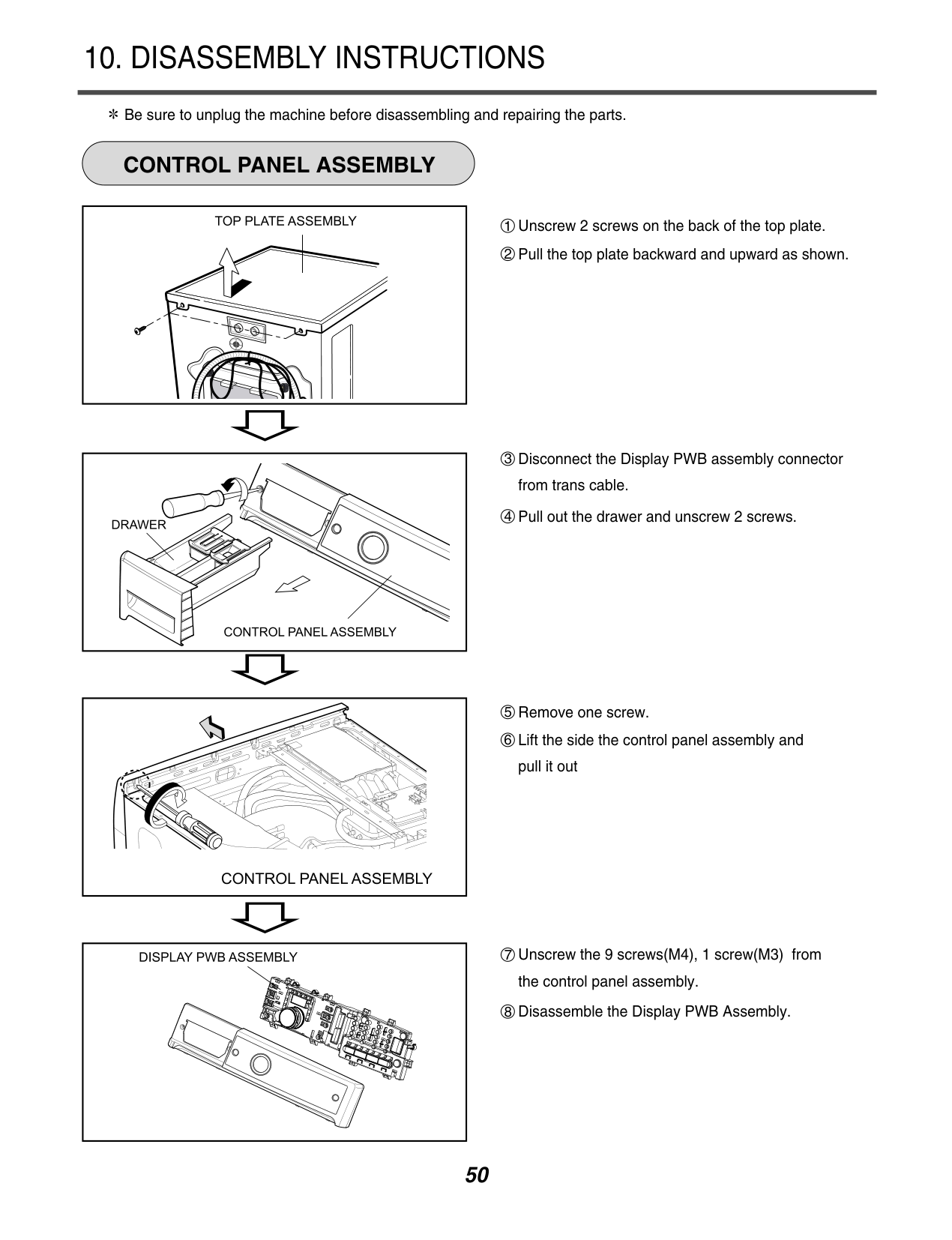
#### 10. DISASSEMBLY INSTRUCTIONS
############ CONTROL PANEL ASSEMBLY
Be sure to unplug the machine before disassembling and repairing the parts.
8 Disassemble the Display PWB Assembly.


| | |---|
| | |---|
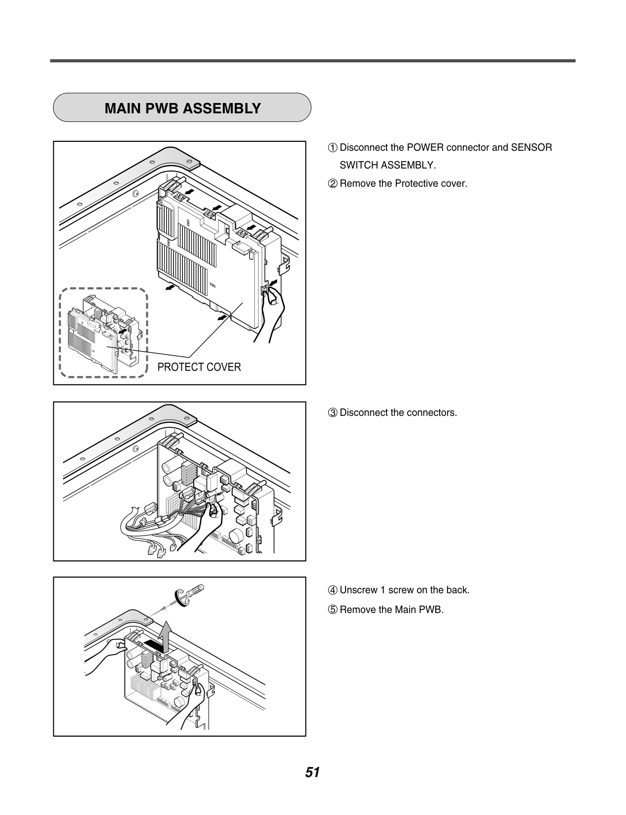
############ MAIN PWB ASSEMBLY
| | |---|
| | | |---|---| | | |
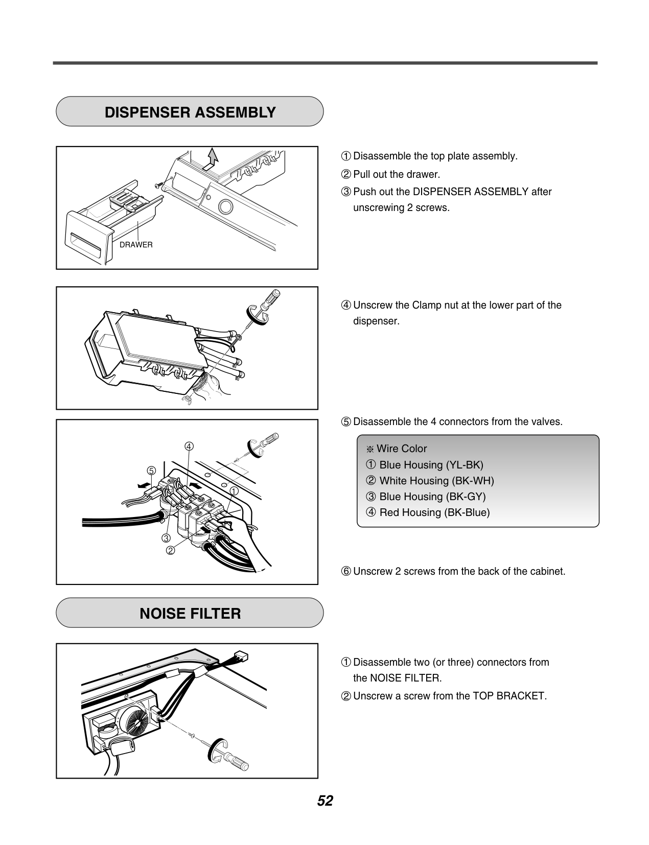
############ DISPENSER ASSEMBLY
| | |---|
| | |---|
############ NOISE FILTER
| | |---|
Wire Color Blue Housing (YL-BK) White Housing (BK-WH) Blue Housing (BK-GY) Red Housing (BK-Blue)

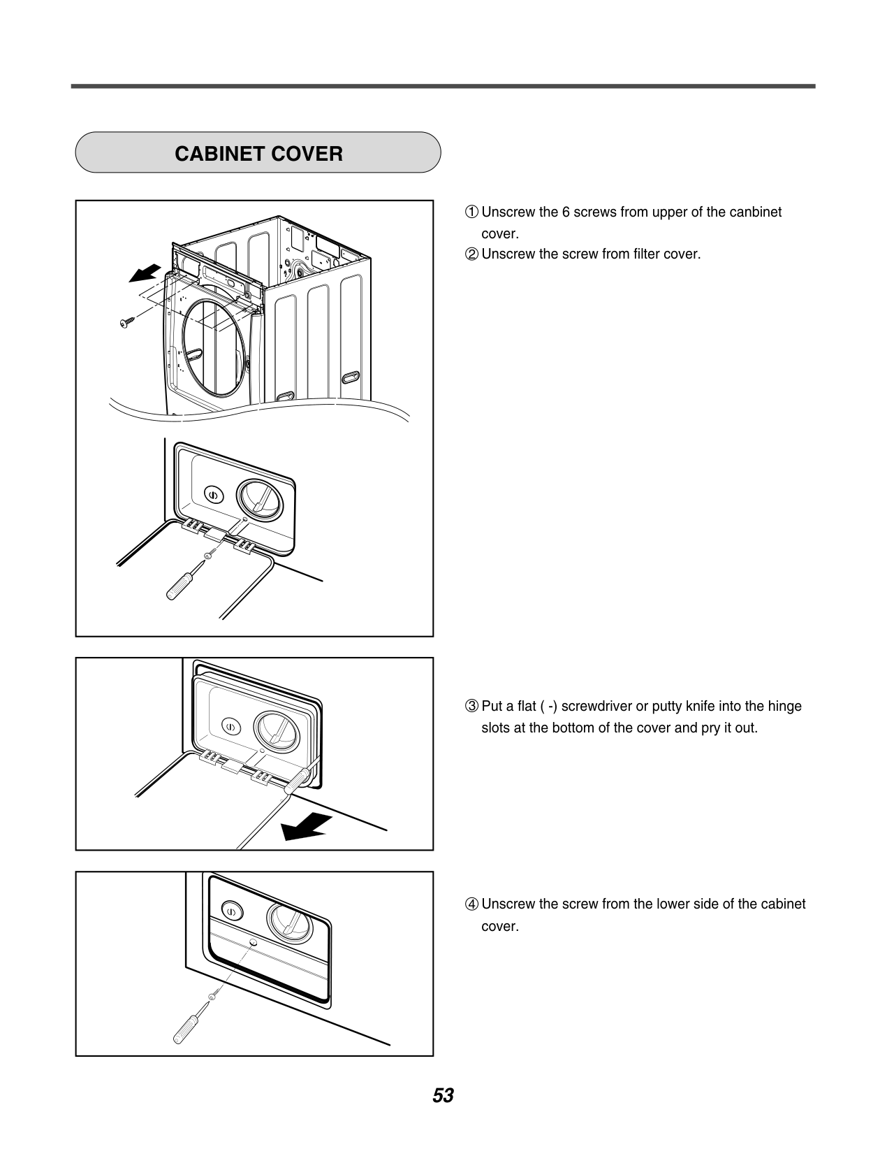
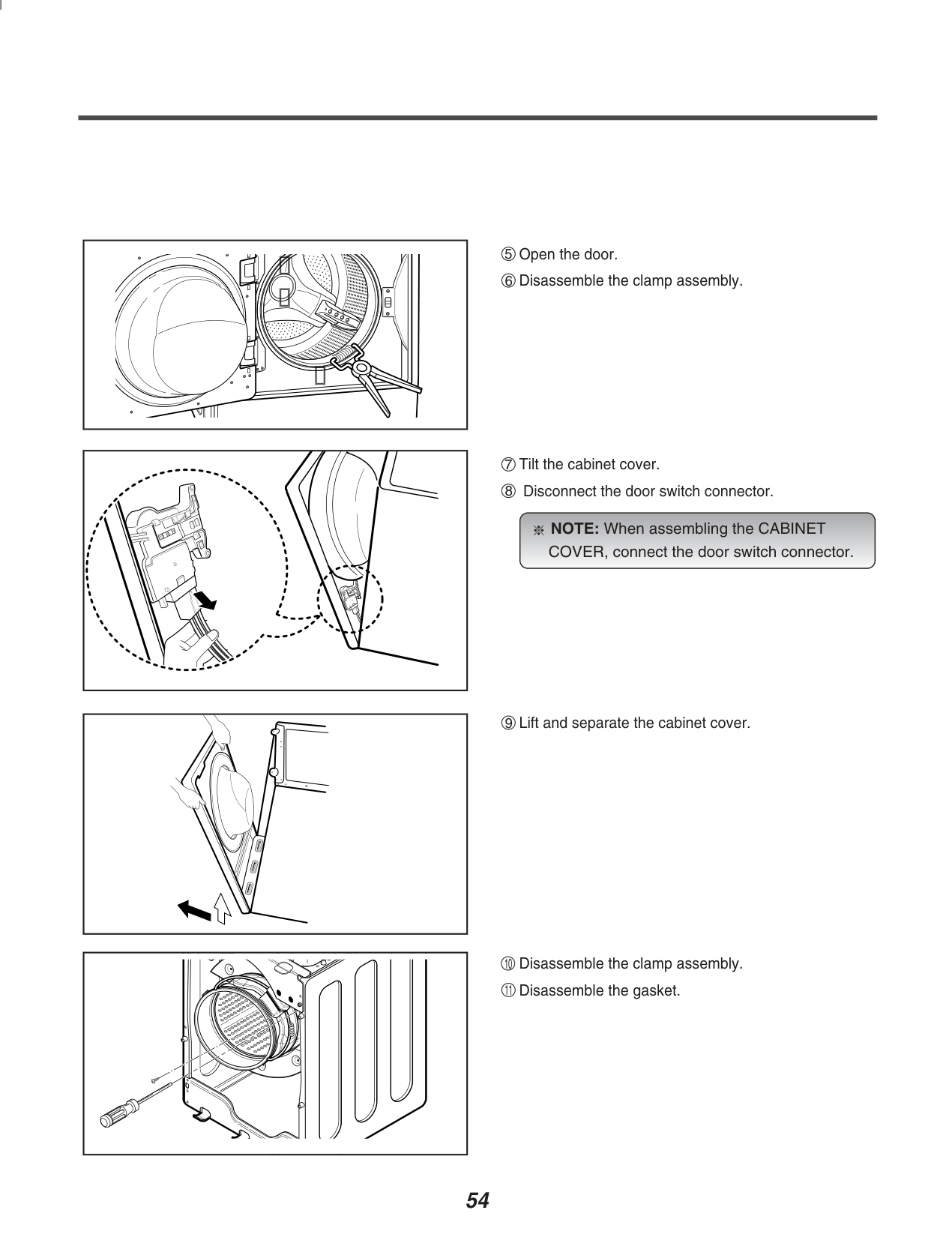
############ CABINET COVER
| |
|---|
NOTE: When assembling the CABINET COVER, connect the door switch connector.

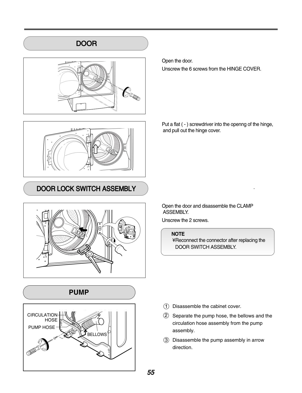
############ DOOR

############ DOOR LOCK SWITCH ASSEMBLY
Open the door. Unscrew the 6 screws from the HINGE COVER.
Put a flat ( - ) screwdriver into the openng of the hinge, and pull out the hinge cover.
.
Open the door and disassemble the CLAMP ASSEMBLY.
Unscrew the 2 screws.
NOTE ¥ Reconnect the connector after replacing the
DOOR SWITCH ASSEMBLY.
############ PUMP
CIRCULATION
HOSE PUMP HOSE
BELLOWS
Disassemble the cabinet cover. Separate the pump hose, the bellows and the circulation hose assembly from the pump assembly. Disassemble the pump assembly in arrow direction.
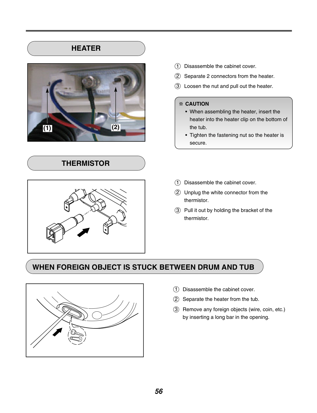
############ HEATER
|
(2)(1)
| |---|
############ THERMISTOR
| | |---|
1 2 3
Disassemble the cabinet cover. Separate 2 connectors from the heater. Loosen the nut and pull out the heater.
####################### CAUTION

Disassemble the cabinet cover. Unplug the white connector from the thermistor. Pull it out by holding the bracket of the thermistor.
############ WHEN FOREIGN OBJECT IS STUCK BETWEEN DRUM AND TUB
| | |---|
Disassemble the cabinet cover. Separate the heater from the tub. Remove any foreign objects (wire, coin, etc.) by inserting a long bar in the opening.
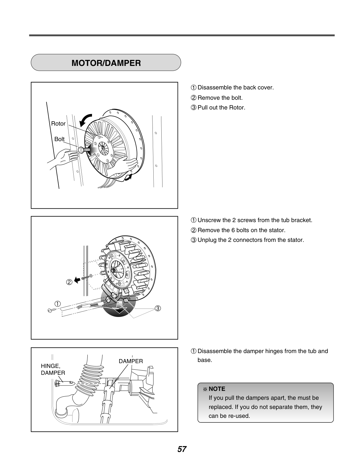
############ MOTOR/DAMPER
| | |---|
| | |---|
| | |---|
1 Disassemble the damper hinges from the tub and base.
NOTE If you pull the dampers apart, the must be replaced. If you do not separate them, they can be re-used.

11. EXPLODED VIEW
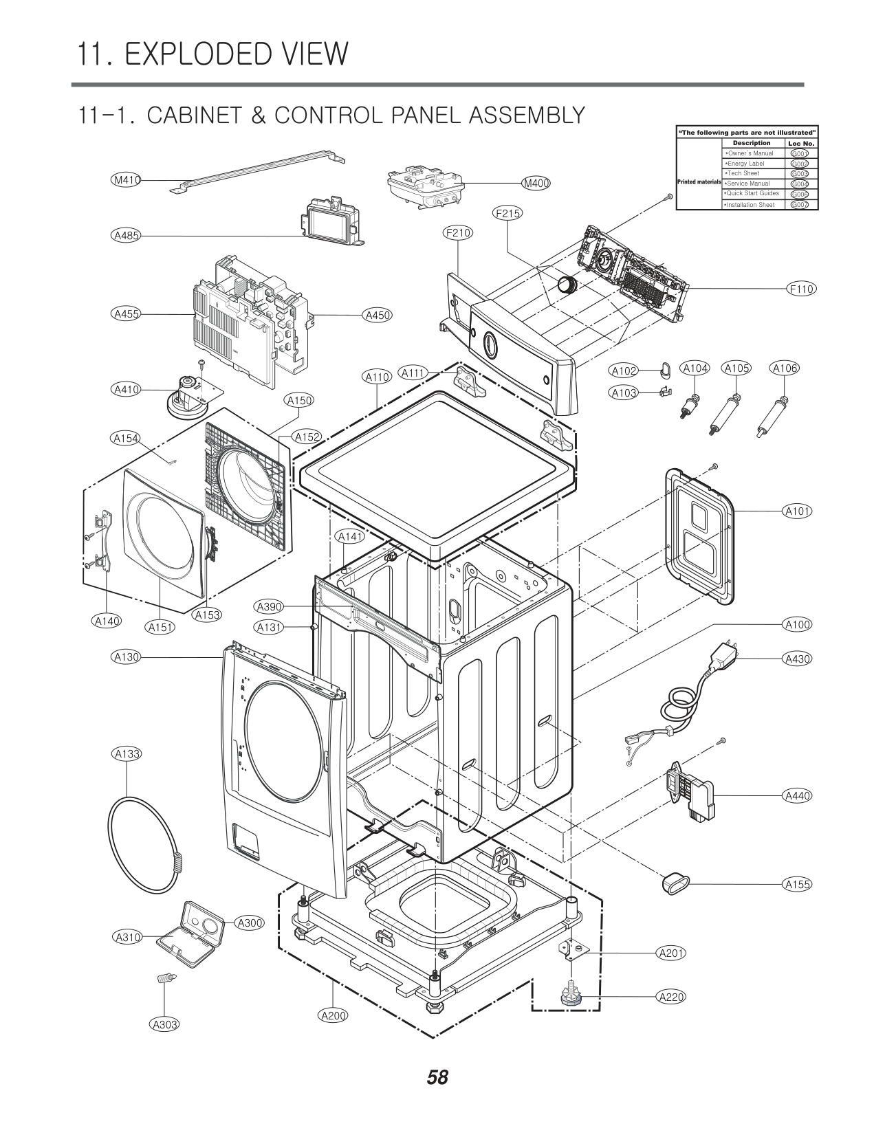
########## 11-1. CABINET & CONTROL PANEL ASSEMBLY
############################ “The following parts are not illustrated"
Description
Loc No.
M410
M400 Printed materials
F215
F210
A485
F110
A455 A450
A104 A105 A106
A111 A102 A103
A110
A410
A150
A152
A154
A101
A141
A390
A153
A140
A100
A151
A131
A130
A430
A133
A440
A155
A300
A310
A201

A220
A200
A303
######## 11-2. DRUM & TUB ASSEMBLY
K123K143K360K350K351
K610
K611
K115
K141
K140
K320
K131
K510
F140
K411
K410
F466
K130 K530
F145 F468
K135
K571
K572
K570
K512 K560
K346
K348
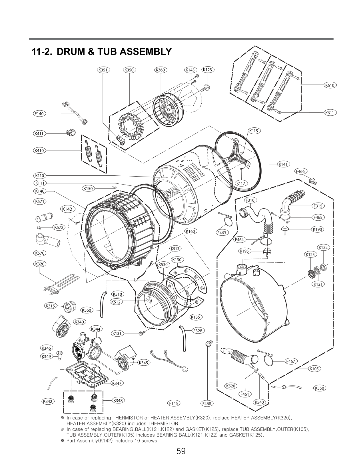
K344
K347
K345
F328
K349
K340
K342
K315
K150
K160
K117
F310
F315
########################### K142
F465
K190
F463
F464
K513
K195
K125
F467
K105
K520
K550
F461
K540
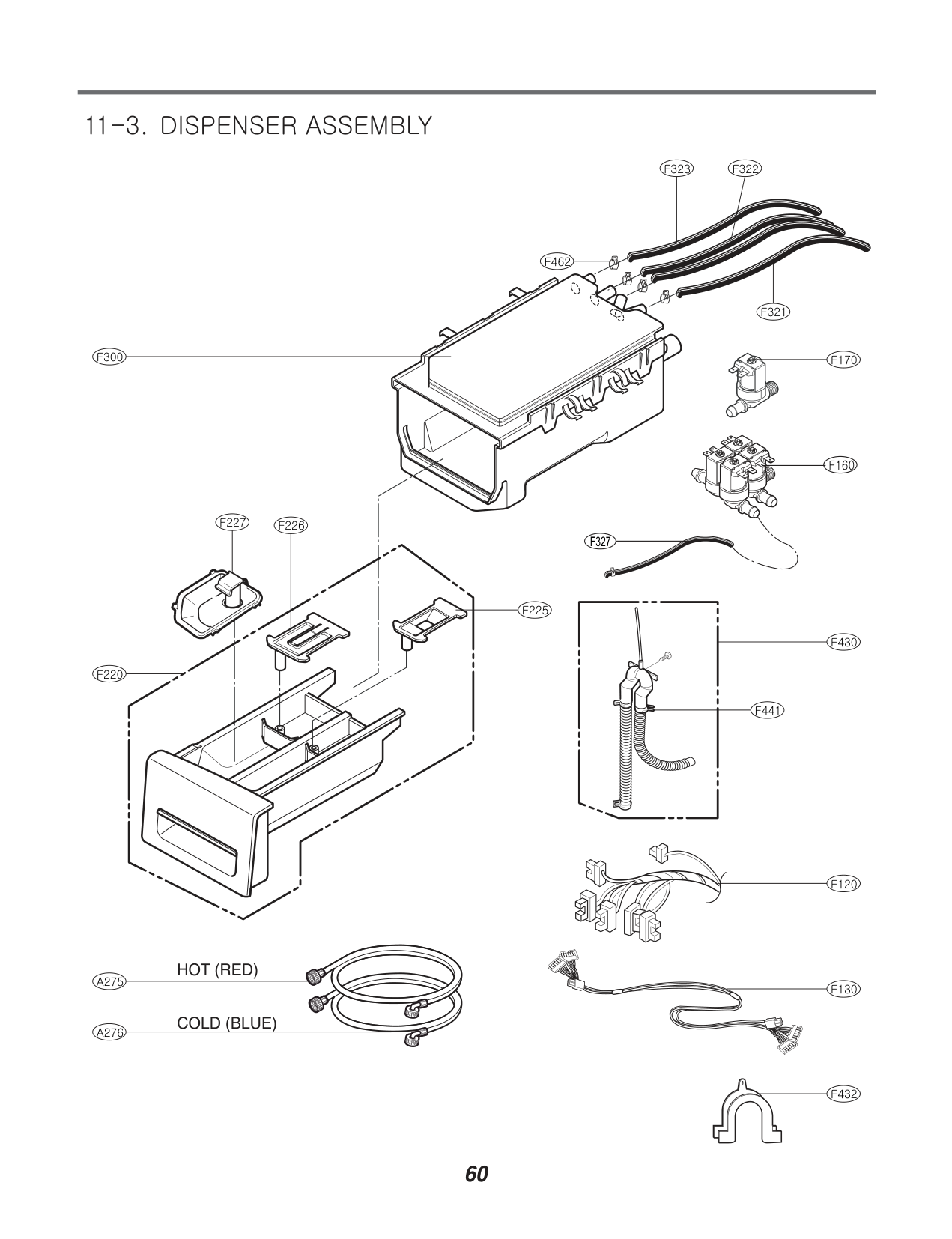
########## 11-3. DISPENSER ASSEMBLY
F300
F220
F322F323
F462
F321
F170
F160
F227 F226
F327
F225
F430
F441
F120
F130
F432