
Ask AI
— answers from the official manualAnswers from the official manual.
Common questions
Common Questions
10 totalHow do I reset my Wagon R to factory settings?
Press and hold the Power button for 10 seconds until the LED flashes red. This will clear all settings and return the vehicle to its initial configurations, necessitating re-pairing of any connected devices after this action. (Page 23)
What should I do if my Keyless Entry System stops working?
Ensure that the transmitter is not exposed to impacts, moisture, high temperatures, or magnetic objects as these can damage the system. Additionally, make sure no other transmitters are near your vehicle, interfering with its functions.
How do I program shock sensor sensitivity for my security system?
Press and hold the Security switch until you hear a chirp sound confirming entry into shock sensor sensitivity adjustment mode. Then press either Lock or Unlock buttons to adjust sensitivity higher or lower, reaching up to 16 levels.
What do I need to know about my vehicle’s fuel recommendation?
Use unleaded petrol with an octane number of 91 or higher. Avoid using fuels containing methanol, except those with up to 5% methanol and necessary cosolvents/corrosion inhibitors.
How do I properly fold the rear seats for more cargo space?
Fold the rear seat by hooking the webbing of the outboard lap-shoulder belts in the belt hangers, lowering head restraints fully (if applicable), then pulling up and releasing the knob on top of each split seat to fold them forward.
Where can I find information on adjusting my electric mirrors?
To adjust your electric mirrors, locate the switch on the driver's door panel. Choose which mirror you want to adjust by moving the selector switch left or right; press the outer part of the switch in the desired direction and return the selector switch to center.
Full Manual
168 pages
| | | | | | | | | | | | | | |---|---|---|---|---|---|---|---|---|---|---|---|---| | | | | | | | | | | | | | | | | | | | | | | | | | | | | | | | | | | | | | | | | | | | | | | | | | | | | | | | | | | | | | | | | | | | | | | | | | | | | | | | | | | | | | | | | | | | | | | | | | | | | | | | | | | | | | | | | | | | | | | | | | | | | | | | | | | | | | | | | | | | | | | | | | | | | | | | | | | | | | | | | | | | | | | | | | | | | | | | | | | | | | | | | | | | | | | | | | | | | | | | | | | | | | | | | | | | | | | | | | | | | | | | | | | | | | | | | | | | | | | | | | | | | | | | | | | | |
| | | | | | | | |---|---|---|---|---|---|---| | | | | | | | | | | | | | | | | | | | | | | | | | | | | | | | | | | | | | | | | | | | | | | | | | | | | | | | | | | | | | | | | | | | | | | | | | | | | | | | | | | | | | | | | | | | | | | | | | | | | | | | |
| | | | | | | | | | | | | | | | | | | | | | | |
| | |---| | | | |
| | |---| | |
| | |---| | |
| | |---| | | | | | | | |
| | |---| | |
| | |---| | |
| | | |
| | |---| | | | |
| | |---| | | | |
| | | | | | | | | | | | | |---|---|---|---|---|---|---|---|---|---|---|---| | | | | | | | | | | | | | | | | | | | | | | | | | | | | | | | | | | | | | | | | | | | | | | | | | | | | | | | | | | | | | | | | | | | | | | | | | | | | | | | | | | | | | | | | | | | | | | | | | | | | | | | | | | | | | | | | | | | | | | | | | | | | | | | | | | | | | | | | | | | | | | | | | | | | | | | | | | | | | | | | | | | | | | | | | | | | | | | | | | | | | | | | | | | | | | | | | | |
| | |---|
| | | |
| | |---| | |
| | | | | | | | | | | | | |---|---|---|---|---|---|---|---|---|---|---|---| | | | | | | | | | | | | | | | | | | | | | | | | | | | | | | | | | | | | | | | | | | | | | | | | | | | | | | | | | | | | | | | | | | | | | | | | | | | | | | | | | | | | | | | | | | | | | | | | | | | | | | | | | | | | | | | | | | | | | | | | | | | | | | | | | | | | | | | | | | | | | | | | | | | | | | | | | | | | | | | | | | | | | | | | | | | | | | | | | | | | | | | | | | | | | | | | | | |
| | |---| | | | |
| | |---| | |
| | |---| | | | |
| | |---| | |
| | |---| | |
| | |---| | | | |
| | |---| | | | | | | | | | |
| | |---| | | | |
| | |---| | |
| | |---| | | | | | |
| | |---| | | | | | | | |
| | | | | | | | | | |---|---|---|---|---|---|---|---|---| | | | | | | | | | | | | | | | | | | | | | | | | | | | | | | | | | | | | | | | | | | | | | | | | | | | | | | | | | | | | | | | | | | | | | |
| | |---| | | | |
| | |---| | | | | | | | |
| | |---| | | | |
| | |---| | |
| | | | | | | | | | |---|---|---|---|---|---|---|---|---| | | | | | | | | | | | | | | | | | | | | | | | | | | | | | | | | | | | | | | | | | | | | | | | | | | | | | | | | | | | | | | | | | | | | | |
| | |---| | |

| | |---| | |
| | |---| | | | |
| | |---| | | | |
| | |---| | | | |
| | |---| | | | | | | | | | | | |
| | |---| | | | |
| | |---| | |
| | |---| | | | | | |
| | |---| | | | | | | | |
| | | | | | | | | | |---|---|---|---|---|---|---|---|---| | | | | | | | | | | | | | | | | | | | | | | | | | | | | | | | | | | | | | | | | | | | | | | | | | | | | | | | | | | | | | | | | | | | | | |
| | |---| | | | |
| | |---| | | | | | | | |
| | |---| | | | |
| | |---| | |
| | | | | | | | | | |---|---|---|---|---|---|---|---|---| | | | | | | | | | | | | | | | | | | | | | | | | | | | | | | | | | | | | | | | | | | | | | | | | | | | | | | | | | | | | | | | | | | | | | |
FOREWORD
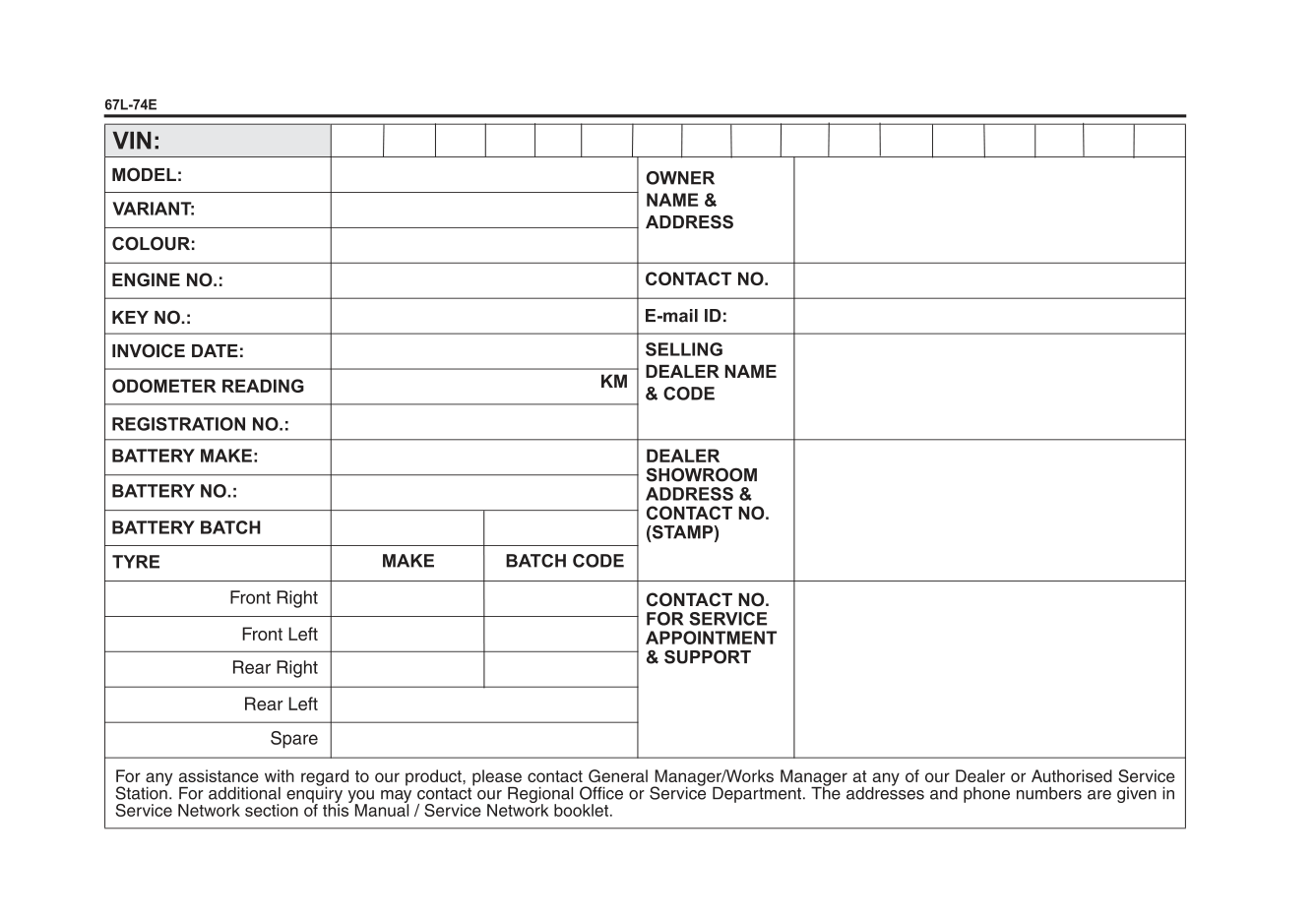
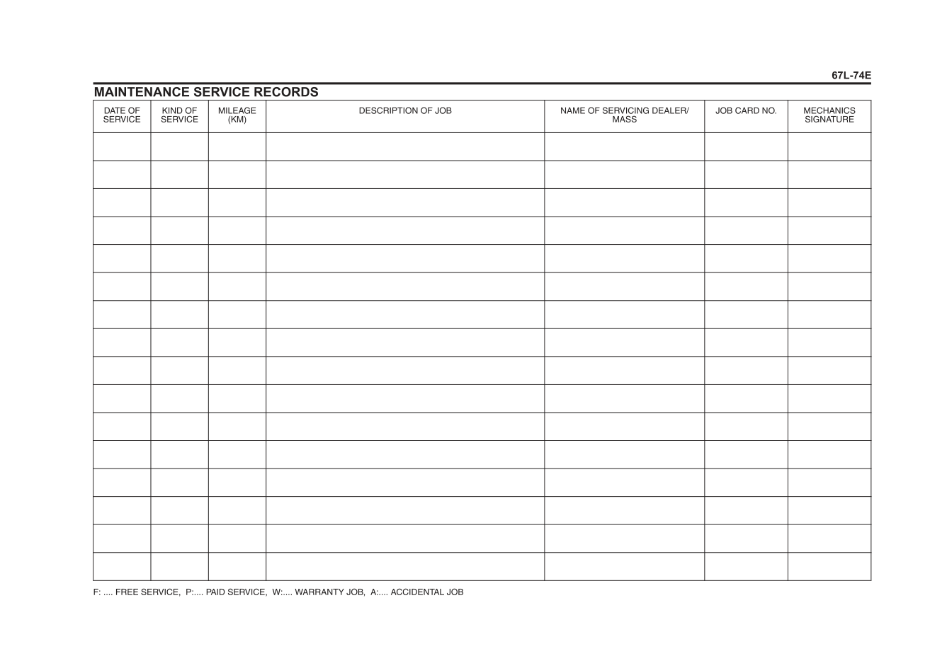
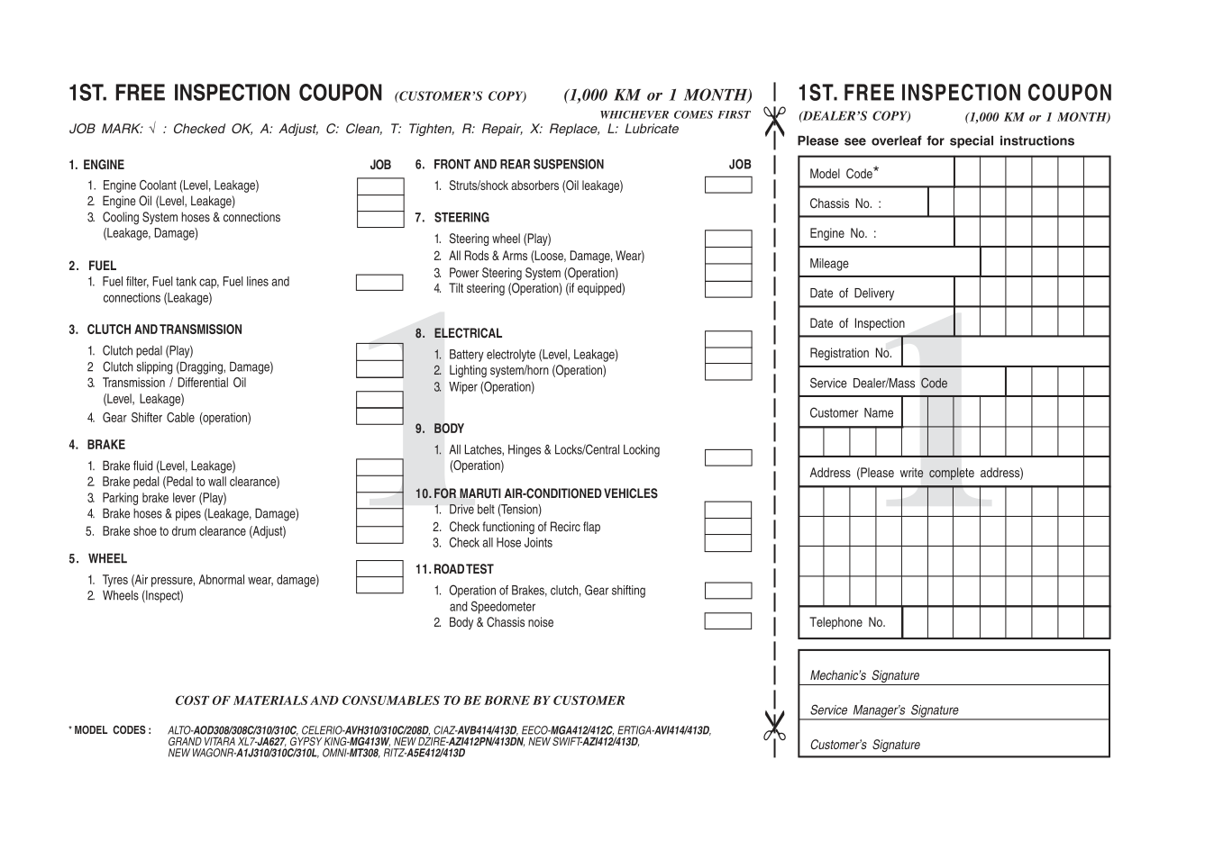
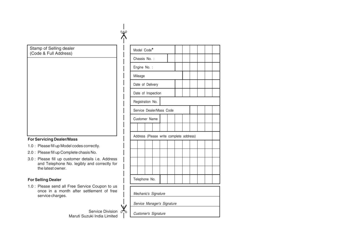
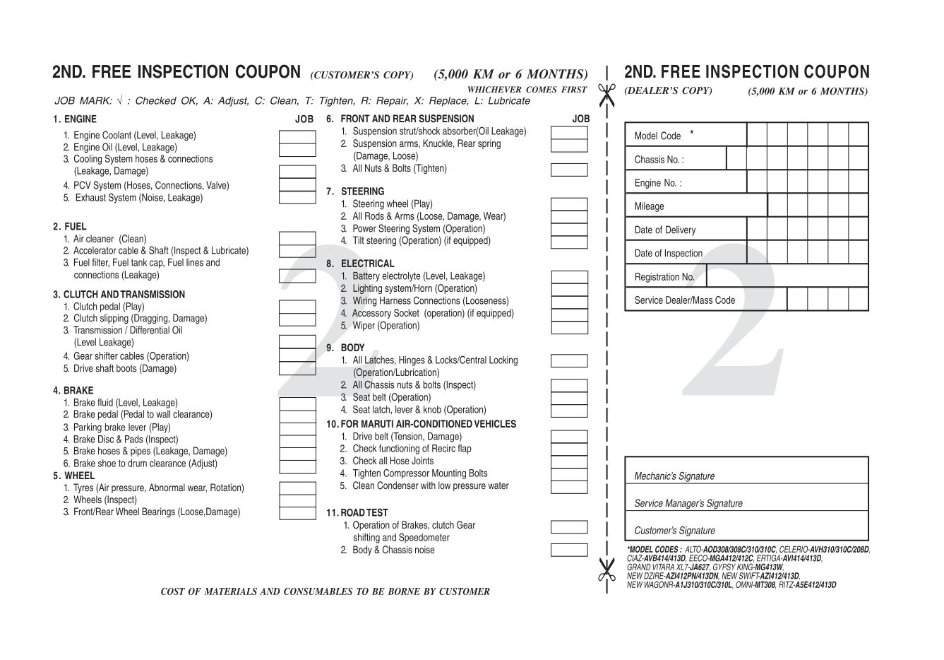
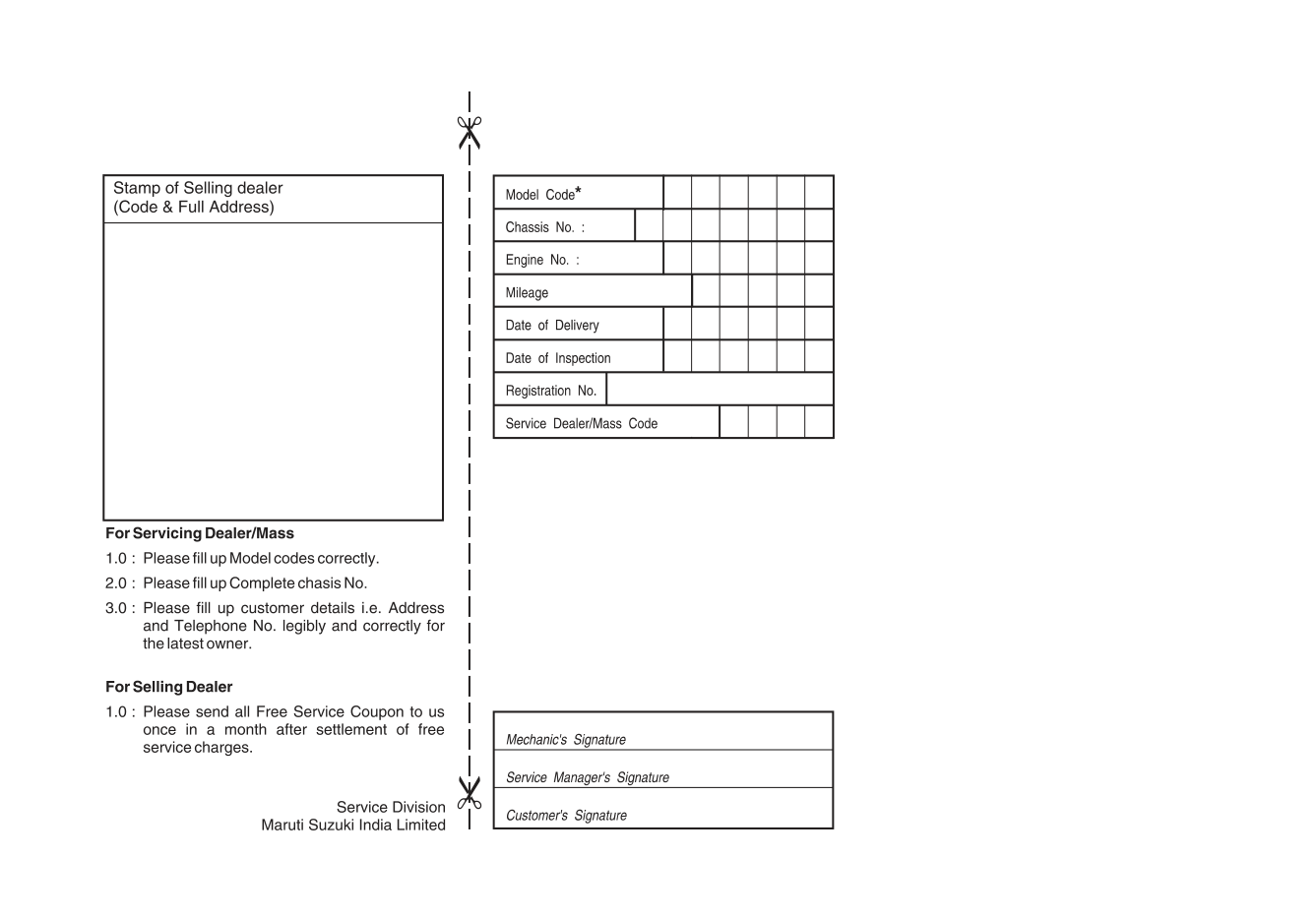
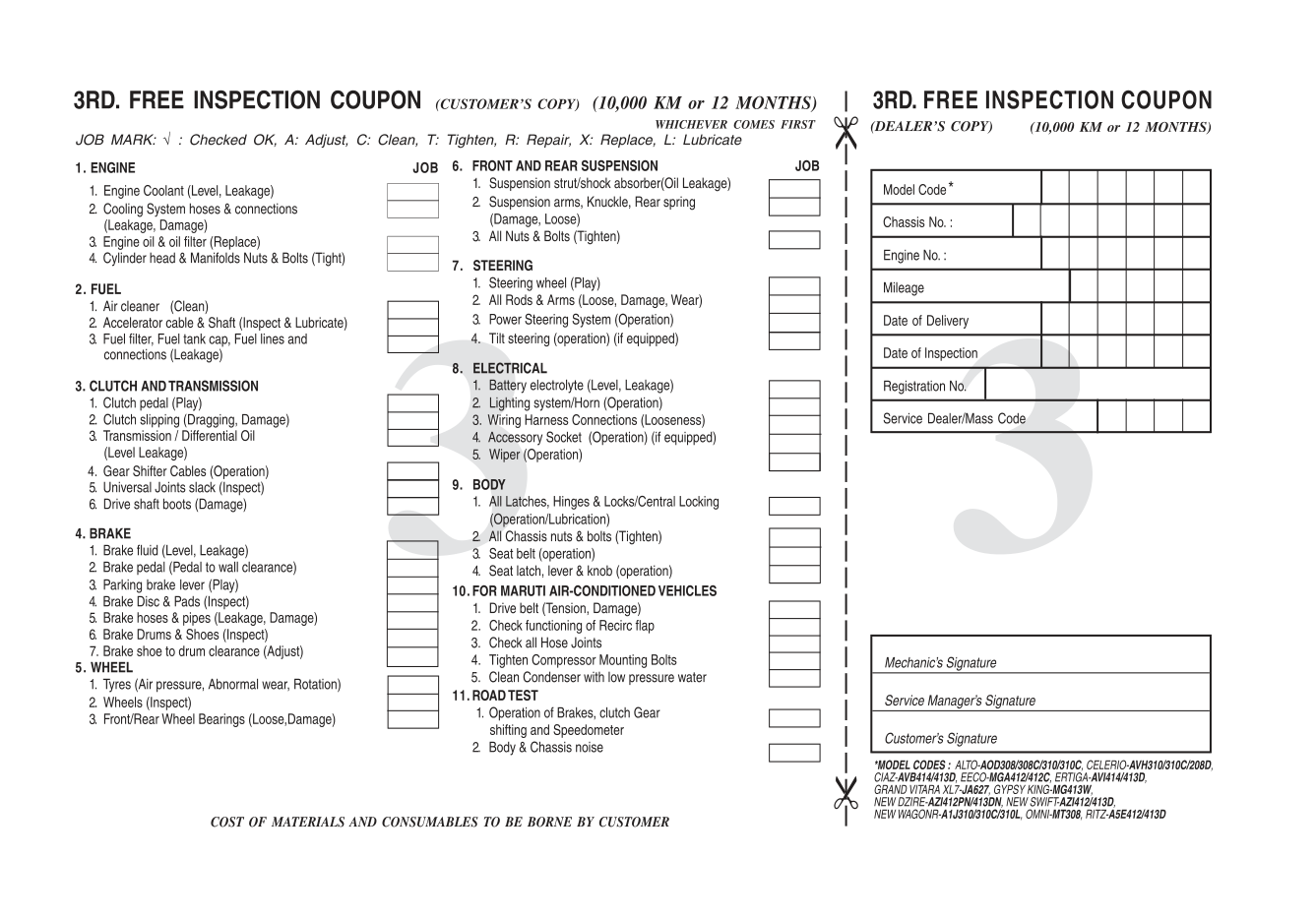
This manual is an essential part of your vehicle and should remain with the vehicle when resold or otherwise transferred to a new owner or operator. Please read this manual carefully before operating your new MARUTI SUZUKI and review the manual from time to time. It contains important information on safety, operation and maintenance. You are invited to avail the three Free Inspection Services as described in the manual. Three free inspection coupons are attached to this manual. Please show this manual to your dealer while you take your MARUTI SUZUKI for any Service. To prolong the life of your vehicle and reduce maintenance cost, the periodic maintenance must be carried out according to “PERIODIC MAINTENANCE SCHEDULE” described in “INSPECTION AND MAINTENANCE” section of this manual. It is essential for preventing trouble and accidents to ensure your satisfaction and safety. Daily inspection and care as per “DAILY INSPECTION CHECKLIST” described in the “INSPECTION AND MAINTENANCE” section of this manual is essential for prolonging the life of the vehicle and for safe driving.
MARUTI SUZUKI INDIA LIMITED believes in conservation and protection of Earth’s natural resources.
To that end, we encourage every vehicle owner to recycle, trade-in or properly dispose of, as appropriate, used Engine Oil, coolant and other fluids, batteries and tyres etc.
MARUTI SUZUKI INDIA LIMITED
All information in this manual is based on the latest product information available at the time of publication. Due to improvements or other changes, there may be discrepancies between information in this manual and your vehicle. MARUTI SUZUKI INDIA LIMITED reserves the right to make production changes at any time, without notice and without incurring any obligation to make the same or similar changes to vehicles previously built or sold.
This vehicle may not comply with standards or regulations of other countries. Before attempting to register this vehicle in any other country, check all applicable regulations and make any necessary modifications.
IMPORTANT
######## WARNING/ CAUTION/NOTICE/ NOTE
Please read this manual and follow its instructions carefully. To emphasize special information, the symbol and the words WARNING, CAUTION, NOTICE and NOTE have special meanings. Pay particular attention to messages highlighted by these signal words:
|WARNING| |---| |Indicates a potential hazard that could result in death or serious injury.
|
|CAUTION
| |---| |Indicates a potential hazard that could result in minor or moderate injury.|
|NOTICE| |---| |Indicates a potential hazard that could result in vehicle damage.|
NOTE: Indicates special information to make maintenance easier or instructions clearer.
75F135
The circle with a slash in this manual means “Don’t do this” or “Don’t let this happen”.
MODIFICATION WARNING
|WARNING| |---| |Do not modify your vehicle. Modification could adversely affect safety, handling, performance, or durability and may violate governmental regulations. In addition, damage or performance problems resulting from modification may not be covered under warranty.|
|NOTICE| |---| |Improper installation of mobile communication equipment such as cellular telephones, CB (Citizen’s Band) radios or any other wireless transmitters may cause electronic interference with your vehicle’s ignition system, resulting in vehicle performance problems. Consult your authorised Maruti Suzuki workshop or qualified service technician for advice.|
|NOTICE| |---| |Severe damage may be caused by the use of either poor quality fuel and/or lubricants not recommended by MARUTI SUZUKI.|
WARRANTY POLICY
Maruti Suzuki India Limited (hereinafter called “Maruti Suzuki”), warrants that each new Maruti Suzuki vehicle distributed in India by Maruti Suzuki and sold by an authorised Maruti Suzuki dealer will be free, under normal use and service, from any defects in material and workmanship at the time of manufacture SUBJECT TO THE FOLLOWING TERMS AND CONDITIONS:
(4) Limitation: This warranty shall not apply to:
EMISSION WARRANTY POLICY
Maruti Suzuki offers the Emission Warranty on all Maruti Suzuki vehicles (apart from the Regular Warranty and will run parallel to the regular product warranty) only in four metropolitan cities (New Delhi, Kolkata, Mumbai and Chennai) with effect from July 1st, 2001.
####### Terms:
The Emission Warranty will be applicable for 80,000 kms or 3 years (Whichever comes earlier) from the date of invoice to the first owner. The remaining warranty terms will be valid in case of any change in ownership provided the production of all valid documents.
####### Conditions:
####### Conditions under which the Emission Warranty is not APPLICABLE
Annexure - A List of parts covered under Emission Warranty
TABLE OF CONTENTS
|FUEL RECOMMENDATION|1| | |---|---|---|
|BEFORE DRIVING|2| | |---|---|---|
|OPERATING YOUR VEHICLE|3| | |---|---|---|
|DRIVING TIPS|4| | |---|---|---|
|OTHER CONTROLS AND EQUIPMENT|5| | |---|---|---|

|VEHICLE LOADING AND TOWING|6| | |---|---|---|
|INSPECTION AND MAINTENANCE|7| | |---|---|---|
EMERGENCY SERVICE 8
|APPEARANCE CARE|9| | |---|---|---|
|GENERAL INFORMATION|10| | |---|---|---|
|SPECIFICATIONS|11| | |---|---|---|
|SERVICE NETWORK|12| | |---|---|---|
###### FUEL RECOMMENDATION
| | |---|
65D394
FUEL RECOMMENDATION
Fuel Recommendation ........................................................ 1-1
|1| | |---|---|
FUEL RECOMMENDATION Fuel Recommendation
should switch back to unleaded petrol containing no alcohol.
You must use unleaded petrol with an octane number (RON) of 91 or higher.
|CAUTION| |---| |The fuel tank has an air space to allow for fuel expansion in hot weather. If you continue to add fuel after the filler nozzle has automatically shut off or an initial blowback occurs, the air chamber will become full. Exposure to heat when fully fuelled in this manner will result in leakage due to fuel expansion. To prevent such fuel leakage, stop filling after the filler nozzle has automatically shut off, or when using an alternative non-automatic system, initial vent blowback occurs.|
Petrol/Ethanol blends Blends of unleaded petrol and ethanol (grain alcohol), also known as gasohol, are commercially available in some areas. Blends of this type may be used in your vehicle if they are no more than 10% ethanol. Make sure this petrol-ethanol blend has octane ratings no lower than those recommended for petrol. Petrol/Methanol blends Blends of unleaded petrol and methanol (wood alcohol) are also commercially available in some areas. DO NOT USE fuels containing more than 5% methanol under any circumstances. Fuel system damage or vehicle performance problems resulting from the use of such fuels are not the responsibility of MARUTI SUZUKI and may not be covered under the New Vehicle Warranty. Fuels containing 5% or less methanol may be suitable for use in your vehicle if they contain cosolvents and corrosion inhibitors.
|CAUTION| |---| |Be careful not to spill fuel containing alcohol while refueling. If fuel is spilled on the vehicle body, wipe it up immediately. Fuels containing alcohol can cause paint damage, which is not covered under the New Vehicle Limited Warranty.|
NOTE: If you are not satisfied with the driveability or fuel economy of your vehicle when you are using a petrol/alcohol blend, you
##### 1-1
BEFORE DRIVING
| | |---|
60G404
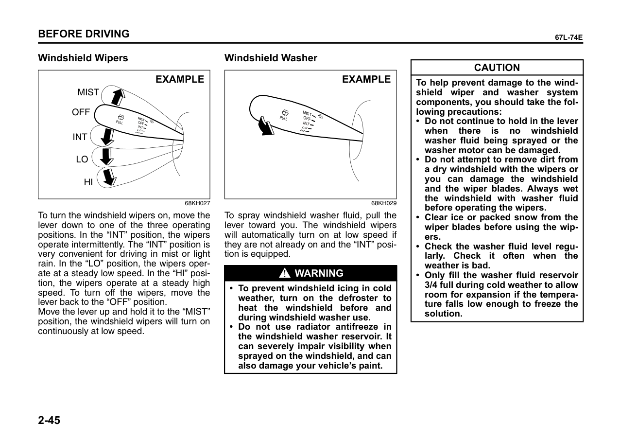
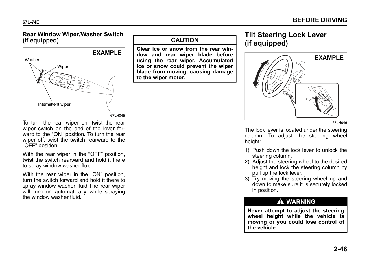
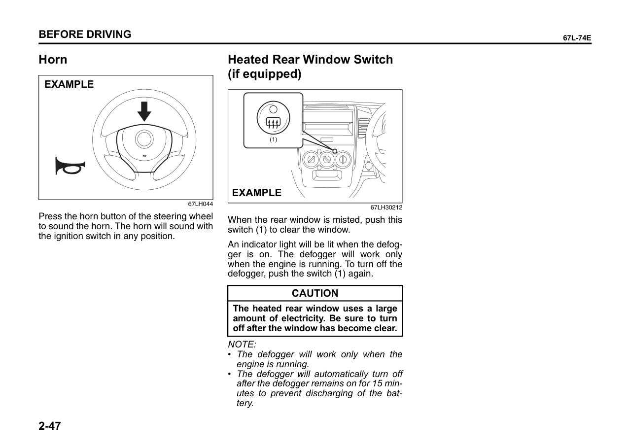
Keys ...................................................................................... 2-1 Door Locks .......................................................................... 2-2 Keyless Entry Cum Alarm System (if equipped) .............. 2-4 Windows .............................................................................. 2-12 Mirrors .................................................................................. 2-13 Front Seats .......................................................................... 2-14 Rear Seats ............................................................................ 2-16 Seat Belts and Child Restraint Systems ........................... 2-17 Supplemental Restraint System (air bags) (if equipped) ......................................................................... 2-26 Instrument Cluster .............................................................. 2-32 Warning and Indicator Lights ............................................ 2-33 Speedometer/Odometer/Trip meter/Meter Illumination Control ................................................................................. 2-37 Tachometer (if equipped) ................................................... 2-38 Fuel Gauge ........................................................................... 2-39 Information Display (if equipped) ...................................... 2-39 Lighting Control Lever ........................................................ 2-41 Rear Fog Light Switch (if equipped) .................................. 2-42 Front Fog Light Switch (if equipped) ................................ 2-43 Headlight Leveling Switch .................................................. 2-43 Turn Signal Control Lever .................................................. 2-43 Hazard Warning Switch ...................................................... 2-44 Windshield Wiper and Washer Lever ................................ 2-44 Tilt Steering Lock Lever (if equipped) ............................... 2-46 Horn ...................................................................................... 2-47 Heated Rear Window Switch (if equipped) ....................... 2-47
###### 2
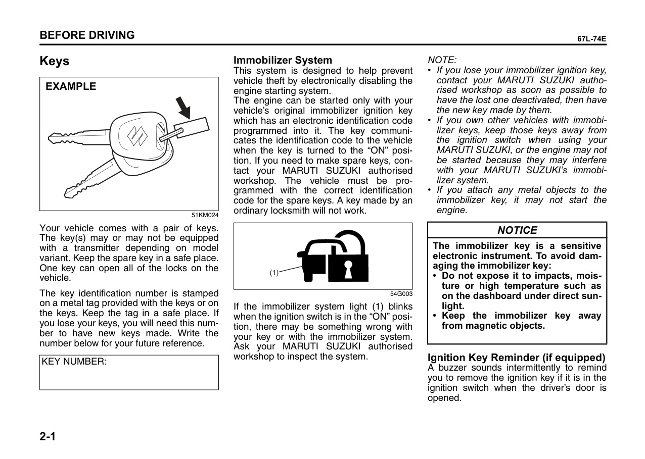
Keys
|EXAMPLE
| |---|
51KM024
Your vehicle comes with a pair of keys. The key(s) may or may not be equipped with a transmitter depending on model variant. Keep the spare key in a safe place. One key can open all of the locks on the vehicle.
The key identification number is stamped on a metal tag provided with the keys or on the keys. Keep the tag in a safe place. If you lose your keys, you will need this number to have new keys made. Write the number below for your future reference.
|KEY NUMBER:| |---|
Immobilizer System This system is designed to help prevent vehicle theft by electronically disabling the engine starting system. The engine can be started only with your vehicle’s original immobilizer ignition key which has an electronic identification code programmed into it. The key communicates the identification code to the vehicle when the key is turned to the “ON” position. If you need to make spare keys, contact your MARUTI SUZUKI authorised workshop. The vehicle must be programmed with the correct identification code for the spare keys. A key made by an ordinary locksmith will not work.
|| |---|
54G003
If the immobilizer system light (1) blinks when the ignition switch is in the “ON” position, there may be something wrong with your key or with the immobilizer system. Ask your MARUTI SUZUKI authorised workshop to inspect the system.
NOTE:
|NOTICE| |---| |The immobilizer key is a sensitive electronic instrument. To avoid damaging the immobilizer key:
• Do not expose it to impacts, moisture or high temperature such as on the dashboard under direct sunlight.
• Keep the immobilizer key away from magnetic objects.
|
Ignition Key Reminder (if equipped) A buzzer sounds intermittently to remind you to remove the ignition key if it is in the ignition switch when the driver’s door is opened.
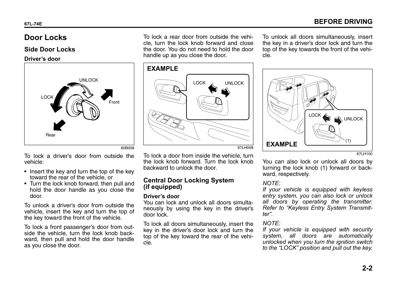
Door Locks Side Door Locks Driver’s door
|
UNLOCK
LOCK
Front
Rear| |---|
60B008
To lock a driver’s door from outside the vehicle:
To unlock a driver’s door from outside the vehicle, insert the key and turn the top of the key toward the front of the vehicle.
To lock a front passenger’s door from outside the vehicle, turn the lock knob backward, then pull and hold the door handle as you close the door.
To lock a rear door from outside the vehicle, turn the lock knob forward and close the door. You do not need to hold the door handle up as you close the door.
|UNLOCKLOCK
EXAMPLE| |---|
67LH008
To lock a door from inside the vehicle, turn the lock knob forward. Turn the lock knob backward to unlock the door.
####### Central Door Locking System (if equipped)
######## Driver’s door
You can lock and unlock all doors simultaneously by using the key in the driver’s door lock.
To lock all doors simultaneously, insert the key in the driver’s door lock and turn the top of the key toward the rear of the vehicle.
To unlock all doors simultaneously, insert the key in a driver’s door lock and turn the top of the key towards the front of the vehicle.
|(1)
LOCK
UNLOCK
EXAMPLE| |---|
67LH100
You can also lock or unlock all doors by turning the lock knob (1) forward or backward, respectively.
NOTE: If your vehicle is equipped with keyless entry system, you can also lock or unlock all doors by operating the transmitter. Refer to “Keyless Entry System Transmitter”.
NOTE: If your vehicle is equipped with security system, all doors are automatically unlocked when you turn the ignition switch to the “LOCK” position and pull out the key.
| | |---|
####### Child-Proof Locks (rear door)
|EXAMPLE
(2)
(1)| |---|
67LH010
Each of the rear doors is equipped with a child-proof lock which can be used to help prevent unwanted opening of the door from inside the vehicle. When the lock lever is in the “LOCK” position (1), the rear door can only be opened from outside. When the
lock lever is in the “UNLOCK” position (2), the rear door can be opened from inside or outside.
|WARNING
| |---| |Be sure to place the child-proof lock in the “LOCK” position whenever children are seated in the rear.|
####### Tailgate
|EXAMPLE| |---|
67LH011
To open the tailgate, insert the key and turn it clockwise to unlatch and lift the tailgate.
| | |---|
67LH012
You can also unlatch the tailgate by pulling the release lever located on the outboard side of the driver’s seat.
|WARNING
| |---| |Always make sure that the tailgate is closed and latched securely. Completely closing the tailgate helps prevent occupants from being thrown from the vehicle in the event of an accident. Completely closing it also helps keep exhaust gases from entering the car.|
|CAUTION| |---| |Do not use the key to lift up the lid, or the key may break off in the lock.|
Keyless Entry Cum Alarm System (if equipped)

| | |---|
67LM2001
The Keyless Entry Cum Alarm System has two basic functions.
####### Keyless Entry
You can lock / unlock all doors simultaneously by operating the transmitter near the vehicle.
NOTE:
• The operating distance of the keyless entry system transmitter is about 20 meters, but this may vary depending on the condition of transmitter’s battery and surroundings especially near other
transmitting devices such as radio towers.
|CAUTION| |---| |The transmitter is a sensitive electronic instrument. To avoid damaging the transmitter:
• Do not expose it to impacts, moisture or high temperature such as by leaving it on the dashboard under direct sunlight.
• Do not tamper with internal parts.
• Keep the transmitter away from magnetic objects such as a television.
|
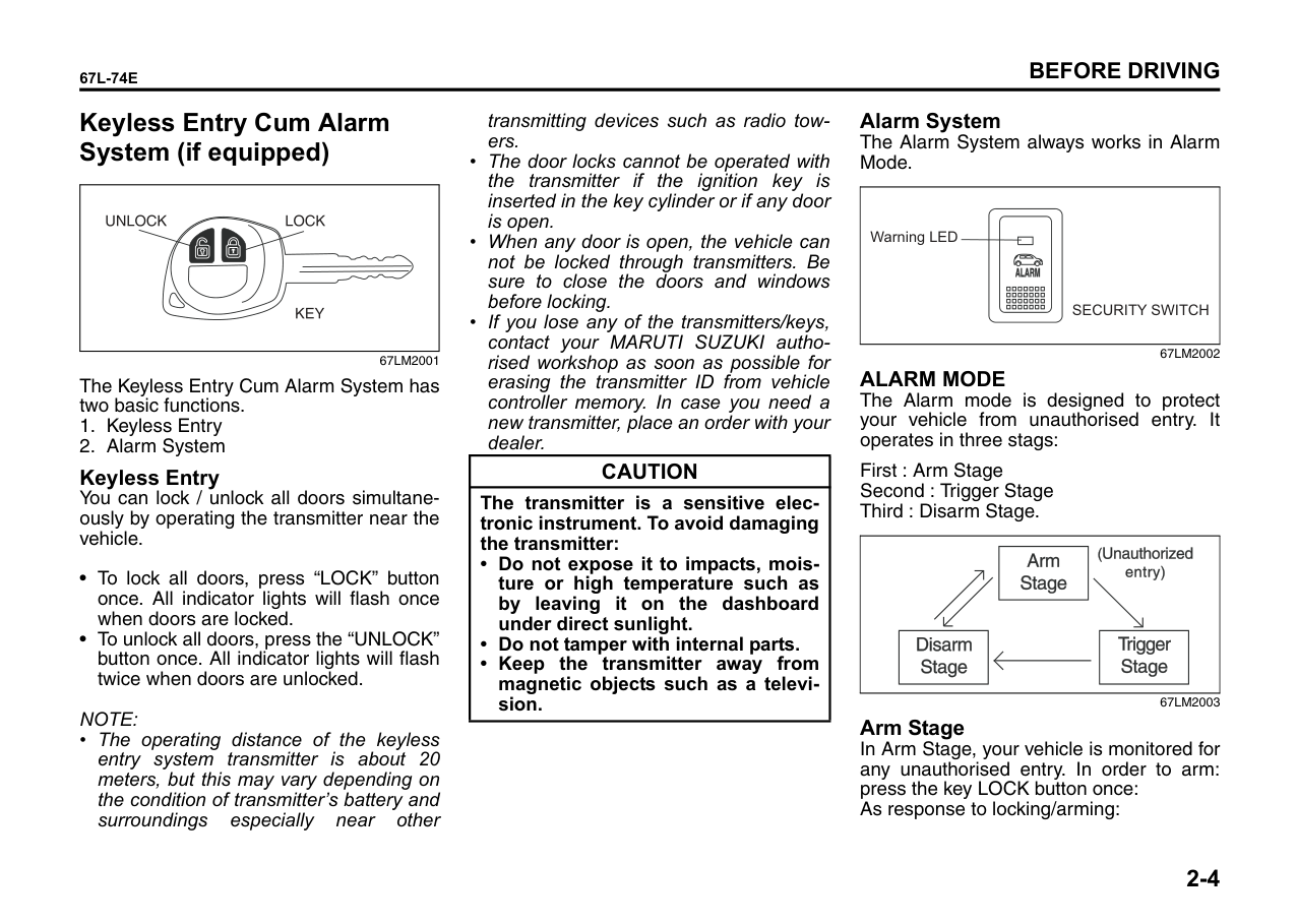
Alarm System The Alarm System always works in Alarm Mode.
|Warning LED
SECURITY SWITCH| |---|
ALARM MODE
The Alarm mode is designed to protect your vehicle from unauthorised entry. It operates in three stags:
First : Arm Stage Second : Trigger Stage Third : Disarm Stage.
| | |---|
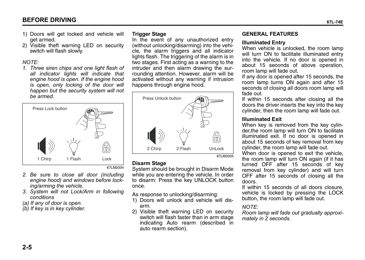
Arm Stage In Arm Stage, your vehicle is monitored for any unauthorised entry. In order to arm: press the key LOCK button once: As response to locking/arming:
NOTE:
67LM2004
| | |---|
######## Trigger Stage
In the event of any unauthorized entry (without unlocking/disarming) into the vehicle, the alarm triggers and all indicator lights flash. The triggering of the alarm is in two stages. First acting as a warning to the intruder and then alarm drawing the surrounding attention. However, alarm will be activated without any warning if intrusion happens through engine hood.
| | |---|
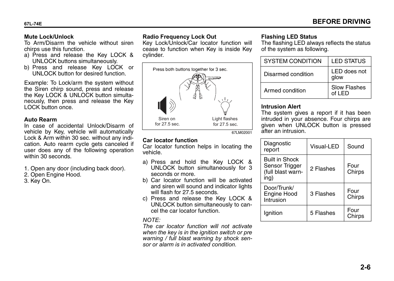
67LM2005 Disarm Stage
System should be brought in Disarm Mode while you are entering the vehicle. In order to disarm: Press the key UNLOCK button once.
As response to unlocking/disarming:
GENERAL FEATURES Illuminated Entry When vehicle is unlocked, the room lamp will turn ON to facilitate illuminated entry into the vehicle. If no door is opened in about 15 seconds of above operation, room lamp will fade out. If any door is opened after 15 seconds, the room lamp turns ON again and after 15 seconds of closing all doors room lamp will fade out. If within 15 seconds after closing all the doors the driver inserts the key into the key cylinder, then the room lamp will fade out. Illuminated Exit When key is removed from the key cylinder,the room lamp will turn ON to facilitate illuminated exit. If no door is opened in about 15 seconds of key removal from key cylinder, the room lamp will fade out. When door is opened to exit the vehicle, the room lamp will turn ON again (if it has turned OFF after 15 seconds of key removal from key cylinder) and will turn OFF after 15 seconds of closing all the doors. If within 15 seconds of all doors closure, vehicle is locked by pressing the LOCK button, the room lamp will fade out.
NOTE: Room lamp will fade out gradually approximately in 2 seconds.
Mute Lock/Unlock To Arm/Disarm the vehicle without siren chirps use this function.
Example: To Lock/arm the system without the Siren chirp sound, press and release the Key LOCK & UNLOCK button simultaneously, then press and release the Key LOCK button once.
######## Auto Rearm
In case of accidental Unlock/Disarm of vehicle by Key, vehicle will automatically Lock & Arm within 30 sec. without any indication. Auto rearm cycle gets canceled if user does any of the following operation within 30 seconds.
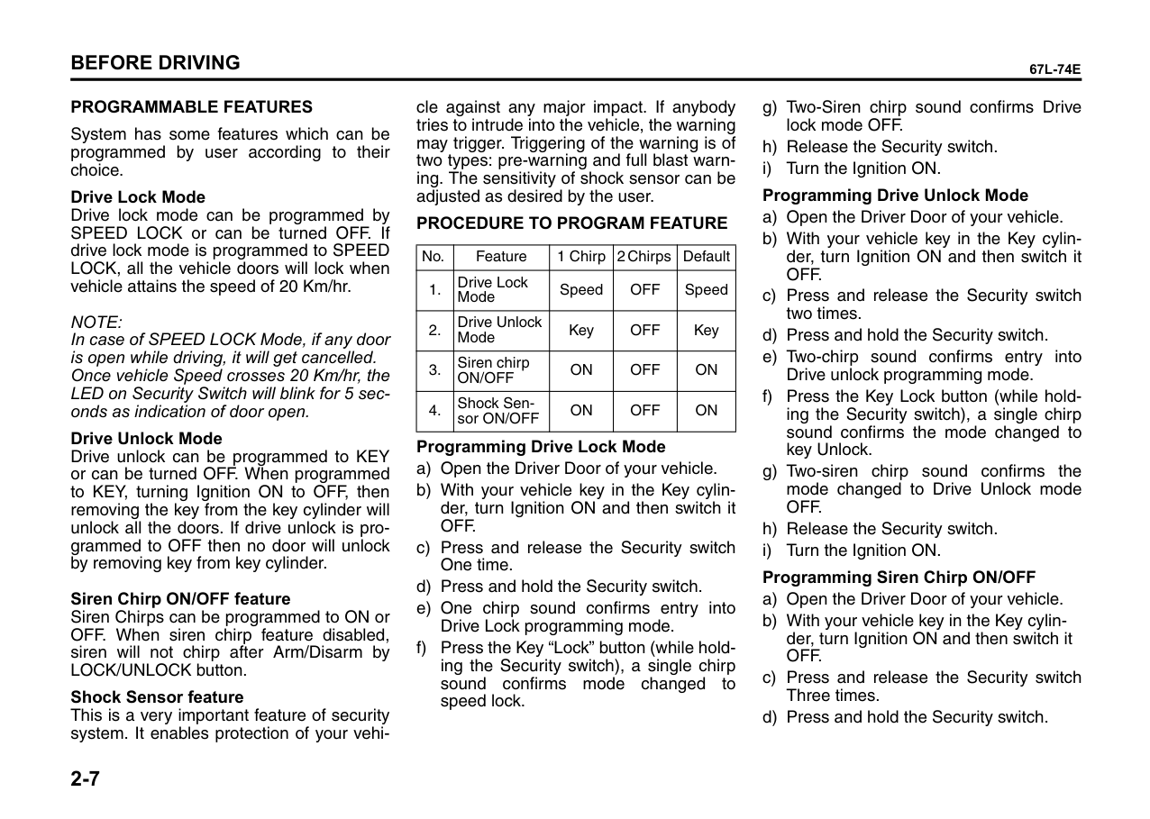
######## Radio Frequency Lock Out
Key Lock/Unlock/Car locator function will cease to function when Key is inside Key cylinder.
|
Siren on for 27.5 sec.
Light flashes for 27.5 sec.| |---|
67LM02001
Car locator function Car locator function helps in locating the vehicle.
NOTE: The car locator function will not activate when the key is in the ignition switch or pre warning / full blast warning by shock sensor or alarm is in activated condition.
Flashing LED Status The flashing LED always reflects the status of the system as following.
|SYSTEM CONDITION|LED STATUS| |---|---| |Disarmed condition|LED does not glow| |Armed condition|Slow Flashes of LED|
######## Intrusion Alert
The system gives a report if it has been intruded in your absence. Four chirps are given when UNLOCK button is pressed after an intrusion.
|Diagnostic report|Visual-LED|Sound| |---|---|---| |Built in Shock Sensor Trigger (full blast warning)|2 Flashes|Four Chirps| |Door/Trunk/ Engine Hood Intrusion|3 Flashes|Four Chirps| |Ignition|5 Flashes|Four Chirps|
######## PROGRAMMABLE FEATURES
System has some features which can be programmed by user according to their choice.
######## Drive Lock Mode
Drive lock mode can be programmed by SPEED LOCK or can be turned OFF. If drive lock mode is programmed to SPEED LOCK, all the vehicle doors will lock when vehicle attains the speed of 20 Km/hr.
NOTE: In case of SPEED LOCK Mode, if any door is open while driving, it will get cancelled. Once vehicle Speed crosses 20 Km/hr, the LED on Security Switch will blink for 5 seconds as indication of door open.
######## Drive Unlock Mode
Drive unlock can be programmed to KEY or can be turned OFF. When programmed to KEY, turning Ignition ON to OFF, then removing the key from the key cylinder will unlock all the doors. If drive unlock is programmed to OFF then no door will unlock by removing key from key cylinder.
######## Siren Chirp ON/OFF feature
Siren Chirps can be programmed to ON or OFF. When siren chirp feature disabled, siren will not chirp after Arm/Disarm by LOCK/UNLOCK button.
######## Shock Sensor feature
This is a very important feature of security system. It enables protection of your vehi-
cle against any major impact. If anybody tries to intrude into the vehicle, the warning may trigger. Triggering of the warning is of two types: pre-warning and full blast warning. The sensitivity of shock sensor can be adjusted as desired by the user.
PROCEDURE TO PROGRAM FEATURE
|No.|Feature|1 Chirp|2 Chirps|Default| |---|---|---|---|---| |1.|Drive Lock Mode|Speed|OFF|Speed| |2.|Drive Unlock Mode|Key|OFF|Key| |3.|Siren chirp ON/OFF|ON|OFF|ON| |4.|Shock Sensor ON/OFF|ON|OFF|ON|
Programming Drive Lock Mode
######## Shock Sensor Sensitivity Adjustment via Key Full Blast adjustment
Full Blast can be adjusted in 16 levels as mentioned below.
Pre-warn Adjustment Pre-warn can be adjusted in 16 levels as mentioned below:
Program Customer Pin-code (Personalized Pin-code)
The Personalized 4-digit number can be changed from the factory default to ensure Personalized Security.
######## Pin code entry
Emergency Disarm by Personalized pin code
The Personalized 4- Digit Pin Code acts as a secret Key, to Emergency Disarm the vehicle.
NOTE: The default pin will be provided by the dealer at the time of delivery. It is recommended to personalize the pin for increased security. The pin must be remembered as it is not possible to retrieve a lost pin.
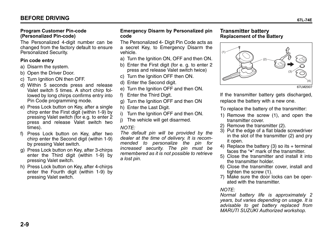
####### Transmitter battery Replacement of the Battery
|(1)
(2)
(3)
(4)
| |---|
67LM2007 If the transmitter battery gets discharged, replace the battery with a new one. To replace the battery of the transmitter:
NOTE: Normal battery life is approximately 2 years, but varies depending on usage. It is advisable to get battery replaced from MARUTI SUZUKI Authorized workshop.
|CAUTION| |---| |Do not remove the screw from the key unnecessarily as it damages the screw head. Kindly replace the screw once the transmitter battery is changed.|
| | |---|
############## 80MJ133
|CAUTION| |---|
|Dispose off the used battery properly according to applicable rules or regulations. Do not dispose off lithium batteries with ordinary household trash.|
|WARNING
| |---| |Swallowing a lithium battery may cause serious internal injury. Do not allow anyone to swallow a lithium battery. Keep lithium batteries away from children and pets. If swallowed, contact a physician immediately.|
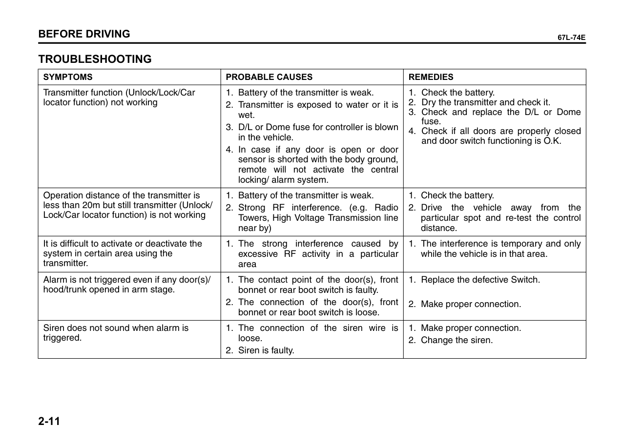
##### TROUBLESHOOTING
|SYMPTOMS|PROBABLE CAUSES|REMEDIES| |---|---|---| |Transmitter function (Unlock/Lock/Car locator function) not working|1. Battery of the transmitter is weak.
2. Transmitter is exposed to water or it is wet.
3. D/L or Dome fuse for controller is blown in the vehicle.
4. In case if any door is open or door sensor is shorted with the body ground, remote will not activate the central locking/ alarm system.
|1. Check the battery.
2. Dry the transmitter and check it.
3. Check and replace the D/L or Dome fuse.
4. Check if all doors are properly closed and door switch functioning is O.K.
| |Operation distance of the transmitter is less than 20m but still transmitter (Unlock/ Lock/Car locator function) is not working|1. Battery of the transmitter is weak.
2. Strong RF interference. (e.g. Radio Towers, High Voltage Transmission line near by)
|1. Check the battery.
2. Drive the vehicle away from the particular spot and re-test the control distance.
| |It is difficult to activate or deactivate the system in certain area using the transmitter.|1. The strong interference caused by excessive RF activity in a particular area|1. The interference is temporary and only while the vehicle is in that area.| |Alarm is not triggered even if any door(s)/ hood/trunk opened in arm stage.|1. The contact point of the door(s), front bonnet or rear boot switch is faulty.
2. The connection of the door(s), front bonnet or rear boot switch is loose.
|1. Replace the defective Switch.
2. Make proper connection.
| |Siren does not sound when alarm is triggered.|1. The connection of the siren wire is loose.
2. Siren is faulty.
|1. Make proper connection.
2. Change the siren.
|
Windows
####### Manual Window Control (if equipped)
|
EXAMPLE| |---|
60G010
Raise or lower the door windows by turning the handle located on the door panel.
Electric Window Controls (if equipped)
The electric windows can only be operated when the ignition switch is in the “ON” position.
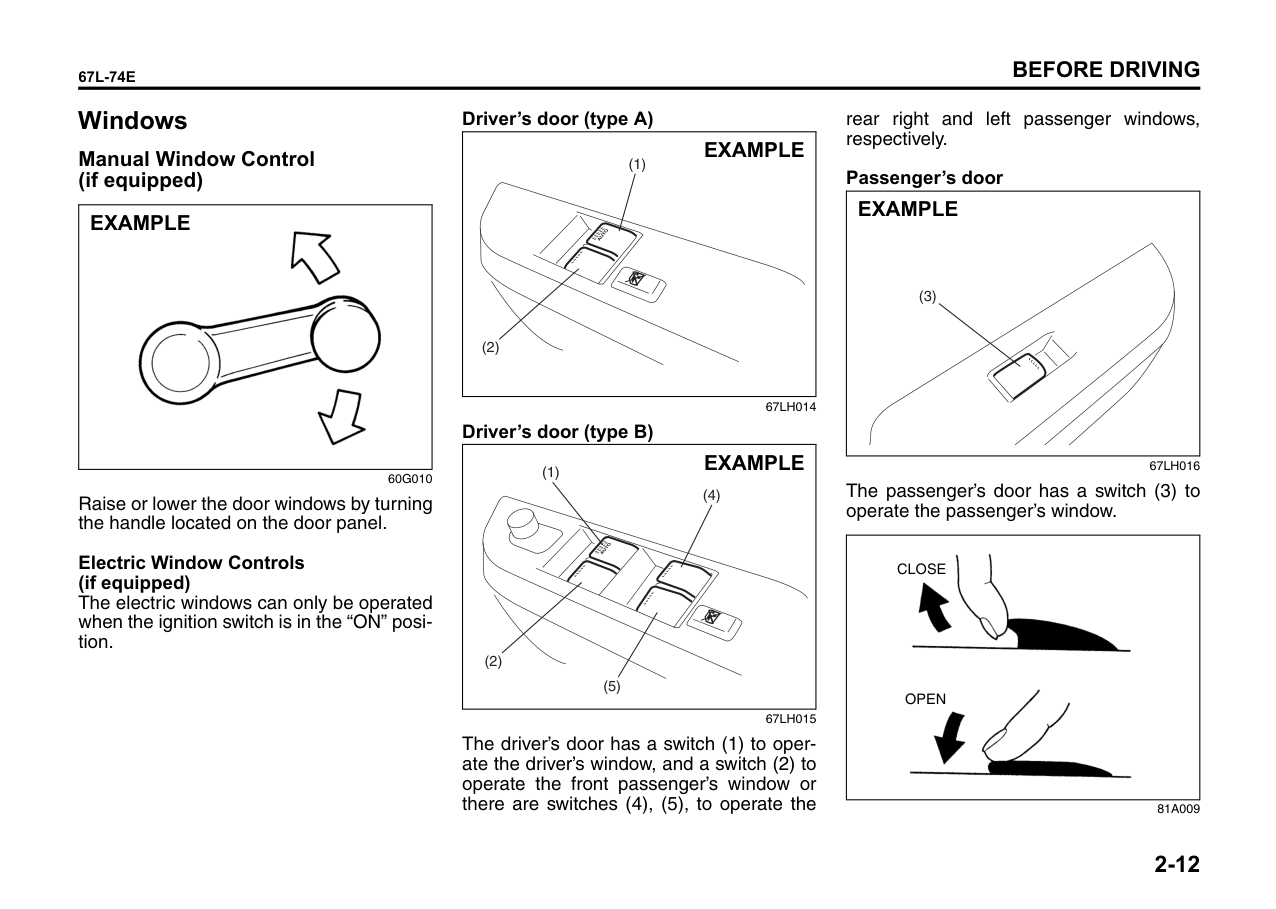
######## Driver’s door (type A)
|(1)
(2)
EXAMPLE| |---|
Driver’s door (type B)
|(1)
(2)
(4)
(5)
EXAMPLE| |---|
The driver’s door has a switch (1) to operate the driver’s window, and a switch (2) to operate the front passenger’s window or there are switches (4), (5), to operate the
rear right and left passenger windows, respectively.
######## Passenger’s door
|(3)
EXAMPLE| |---|
67LH016
The passenger’s door has a switch (3) to operate the passenger’s window.
|
CLOSE
OPEN| |---|
81A009
To open a window, push the top part of the switch and to close the window, lift up the top part of the switch. The driver’s window has an “auto-down” feature for added convenience (at toll booths or drive-through restaurants, for example). This means you can open the window without holding the window switch in the “Down” position. Press the driver’s window switch completely down and release it. To stop the window before it reaches the bottom, pull the switch up briefly.
Lock switch (type B)
|EXAMPLE| |---|
|EXAMPLE| |---|
The driver’s door also has a lock switch for the passenger’s windows. When you push in the lock switch, the passenger’s windows cannot be raised or lowered by operating any of the switches (2), (3), (4) or (5). To restore normal operation, release the lock switch by pushing again.
|WARNING
| |---| |• You should always lock the passenger’s window operation when there are children in the vehicle. Children can be seriously injured if they get part of their body caught by the window during operation.
• To avoid injuring an occupant by window entrapment, be sure no part of the occupant’s body such as hands or head is in the path of the electric windows when closing them.
• Always remove the ignition key when leaving the vehicle even if only for a short time. Also do not leave children alone in a parked vehicle. Unattended children could use the electric window switches and get trapped by the window.
|
NOTE: If you drive with one of the rear windows open, you may hear a loud sound caused by air vibration. To reduce the sound, open the driver’s or front passenger’s window, or narrow the rear window opening.
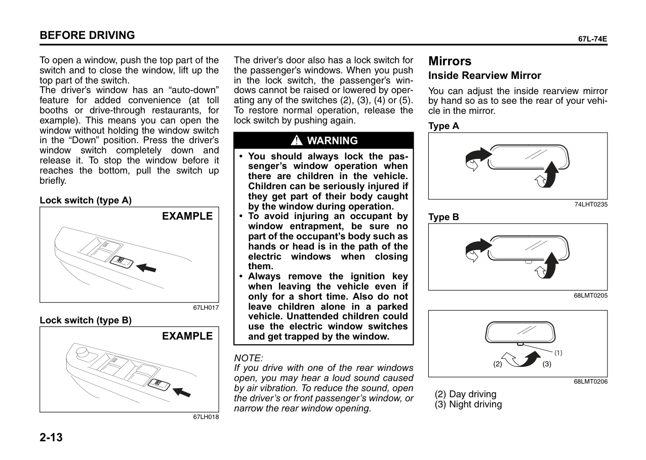
Mirrors Inside Rearview Mirror
You can adjust the inside rearview mirror by hand so as to see the rear of your vehicle in the mirror.
######## Type A
| | |---|
74LHT0235
######## Type B
| | |---|
|(1)
(2) (3)| |---|
To adjust the mirror, set the selector tab (1) to the day position, then move the mirror up, down or sideways by hand to obtain the best view.
When driving at night, you can move the selector tab to the night position to reduce glare from the headlights of vehicles behind you.
|WARNING
| |---| |• Always adjust the mirror with the selector set to the day position.
• Only use the night position if it is necessary to reduce glare from the headlights of vehicles behind you. Be aware that in this position you may not be able to see some objects that could be seen in the day position.
|
####### Outside Rearview Mirrors
Adjust the outside rearview mirrors so you can just see the side of your vehicle in the mirrors.
|WARNING
| |---| |Be careful when judging the size or distance of a vehicle or other object seen in the side convex mirror. Be aware that objects look smaller and appear farther away than when seen in a flat mirror.|
|EXAMPLE| |---|
######## 68KH008 Electric Mirrors (if equipped)
|(1)
(3)(2)
(4)
(2)
(4)
(3)
(1)
EXAMPLE| |---|
67LH019
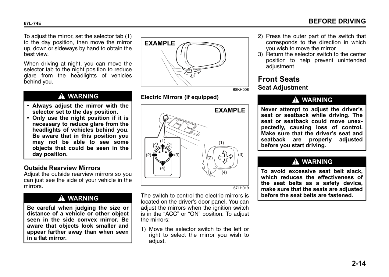
The switch to control the electric mirrors is located on the driver’s door panel. You can adjust the mirrors when the ignition switch is in the “ACC” or “ON” position. To adjust the mirrors:
1) Move the selector switch to the left or right to select the mirror you wish to adjust.
Front Seats Seat Adjustment
|WARNING
| |---| |Never attempt to adjust the driver’s seat or seatback while driving. The seat or seatback could move unexpectedly, causing loss of control. Make sure that the driver’s seat and seatback are properly adjusted before you start driving.|
|WARNING
| |---| |To avoid excessive seat belt slack, which reduces the effectiveness of the seat belts as a safety device, make sure that the seats are adjusted before the seat belts are fastened.|
####### Adjusting Seat Position
|EXAMPLE|
|---|
67LH020
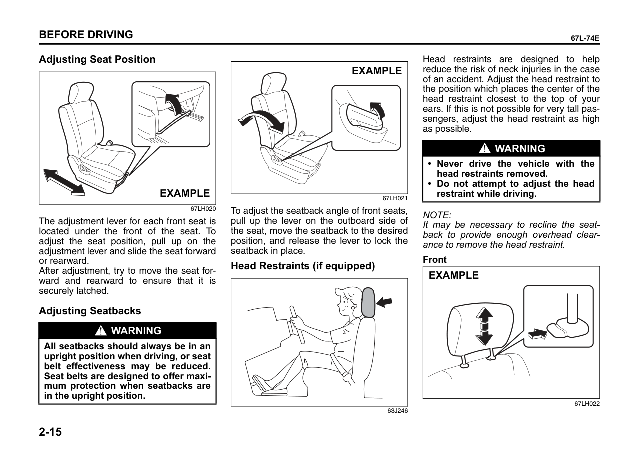
The adjustment lever for each front seat is located under the front of the seat. To adjust the seat position, pull up on the adjustment lever and slide the seat forward or rearward. After adjustment, try to move the seat forward and rearward to ensure that it is securely latched.
Adjusting Seatbacks
|WARNING
| |---| |All seatbacks should always be in an upright position when driving, or seat belt effectiveness may be reduced. Seat belts are designed to offer maximum protection when seatbacks are in the upright position.|
|EXAMPLE| |---|
67LH021
To adjust the seatback angle of front seats, pull up the lever on the outboard side of the seat, move the seatback to the desired position, and release the lever to lock the seatback in place.
####### Head Restraints (if equipped)
| | |---|
63J246
Head restraints are designed to help reduce the risk of neck injuries in the case of an accident. Adjust the head restraint to the position which places the center of the head restraint closest to the top of your ears. If this is not possible for very tall passengers, adjust the head restraint as high as possible.
|WARNING
| |---| |• Never drive the vehicle with the head restraints removed.
• Do not attempt to adjust the head restraint while driving.
|
NOTE: It may be necessary to recline the seatback to provide enough overhead clearance to remove the head restraint.
######## Front
|EXAMPLE| |---|
67LH022
To raise the front head restraint, pull upward on the restraint until it clicks. To lower the restraint, push down on the restraint while holding in the lock lever. If a head restraint must be removed (for cleaning, replacement, etc.), push in the lock lever and pull the head restraint all the way out.
Rear Seats Head Restraints (if equipped)
Head restraints are designed to help reduce the risk of neck injuries in the case of an accident.
|WARNING
| |---| |• Never drive the vehicle with the head restraints removed.
• Do not attempt to adjust the head restraint while driving.
|
NOTE: It may be necessary to fold forward the seatback to provide enough overhead clearance to remove the head restraint.
Adjust the head restraint to the position which places the center of the head restraint closest to the top of your ears. If this is not possible for very tall passengers adjust the head restraint as high as possible.
|EXAMPLE| |---|
67LH023
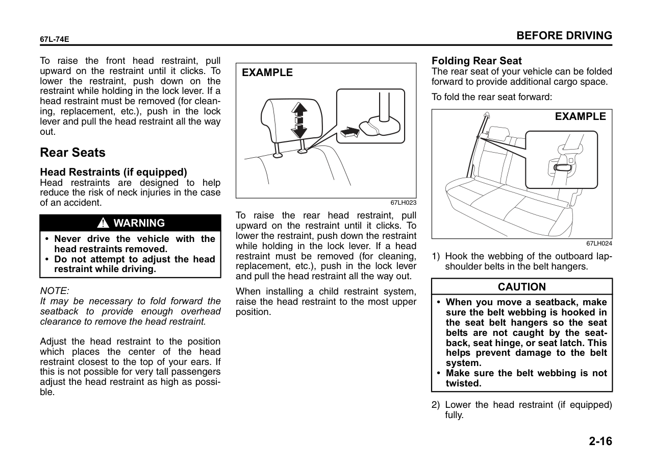
To raise the rear head restraint, pull upward on the restraint until it clicks. To lower the restraint, push down the restraint while holding in the lock lever. If a head restraint must be removed (for cleaning, replacement, etc.), push in the lock lever and pull the head restraint all the way out.
When installing a child restraint system, raise the head restraint to the most upper position.
Folding Rear Seat The rear seat of your vehicle can be folded forward to provide additional cargo space.
To fold the rear seat forward:
|EXAMPLE| |---|
67LH024
|CAUTION| |---| |• When you move a seatback, make sure the belt webbing is hooked in the seat belt hangers so the seat belts are not caught by the seatback, seat hinge, or seat latch. This helps prevent damage to the belt system.
• Make sure the belt webbing is not twisted.
|
|EXAMPLE| |---|
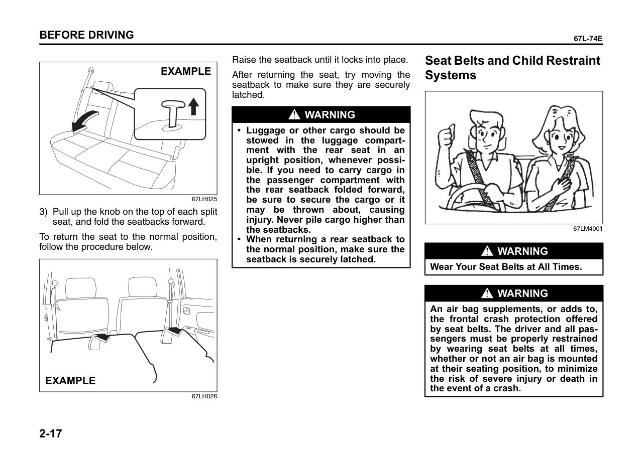
67LH025
To return the seat to the normal position, follow the procedure below.
|EXAMPLE| |---|
67LH026
Raise the seatback until it locks into place. After returning the seat, try moving the seatback to make sure they are securely latched.
|WARNING
|
|---| |• Luggage or other cargo should be stowed in the luggage compartment with the rear seat in an upright position, whenever possible. If you need to carry cargo in the passenger compartment with the rear seatback folded forward, be sure to secure the cargo or it may be thrown about, causing injury. Never pile cargo higher than the seatbacks.
• When returning a rear seatback to the normal position, make sure the seatback is securely latched.
|
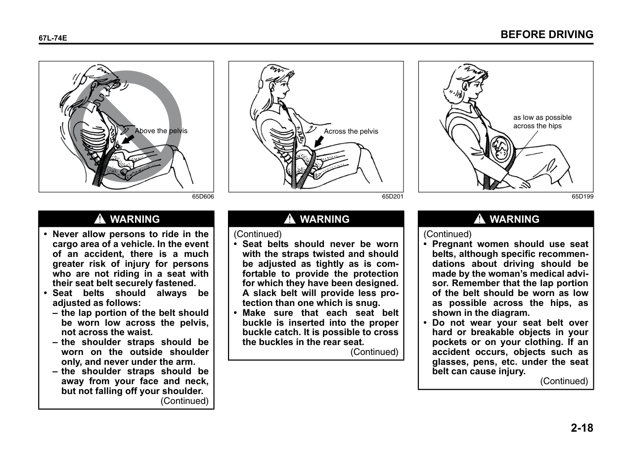
Seat Belts and Child Restraint Systems
|| |---|
67LM4001
|WARNING
| |---| |Wear Your Seat Belts at All Times.|
|WARNING
| |---| |An air bag supplements, or adds to, the frontal crash protection offered by seat belts. The driver and all passengers must be properly restrained by wearing seat belts at all times, whether or not an air bag is mounted at their seating position, to minimize the risk of severe injury or death in the event of a crash.|
|
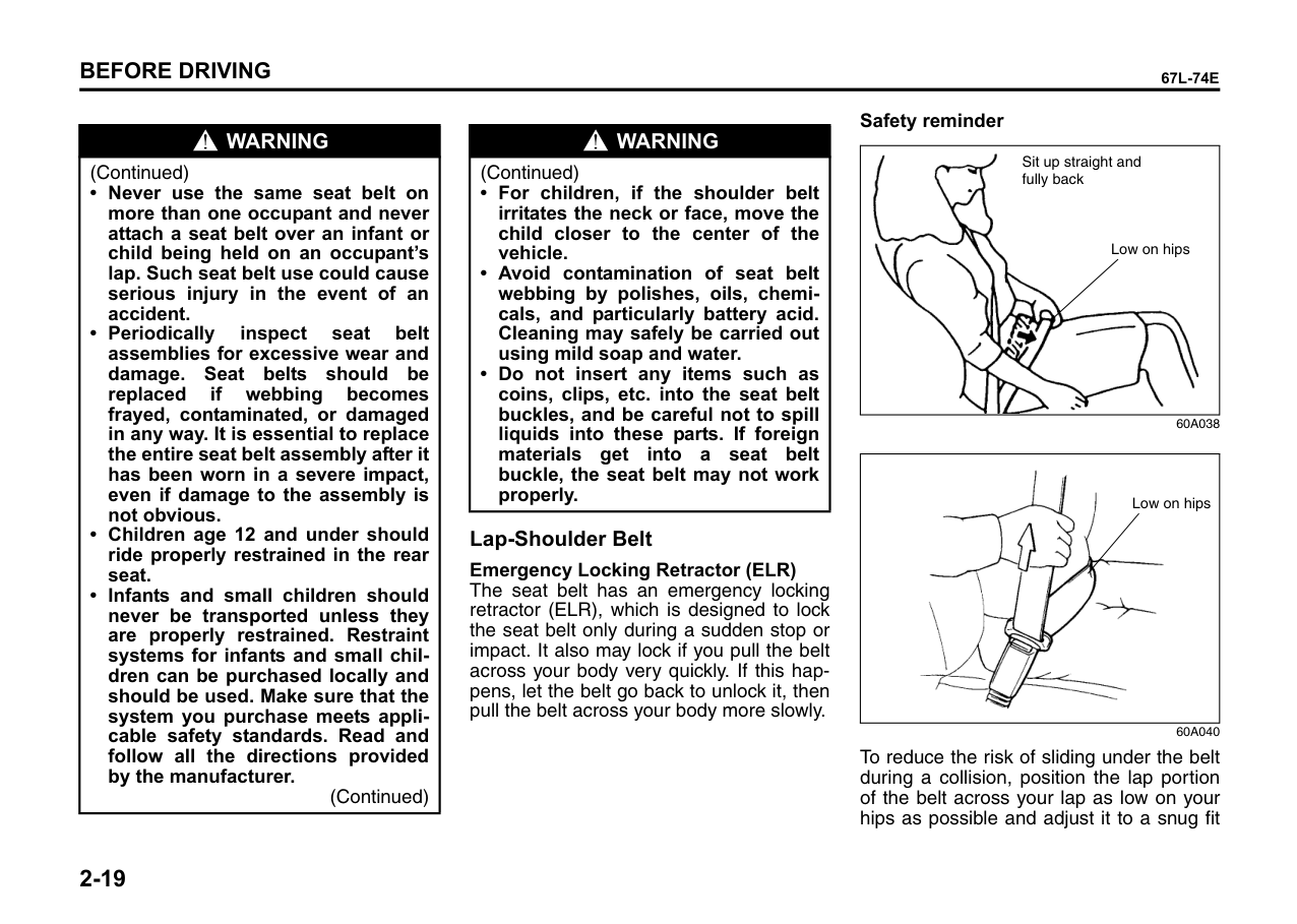
Above the pelvis| |---|
|
Across the pelvis| |---|
|
as low as possible across the hips| |---|
65D606 65D201 65D199
|WARNING
|
|---| |• Never allow persons to ride in the cargo area of a vehicle. In the event of an accident, there is a much greater risk of injury for persons who are not riding in a seat with their seat belt securely fastened.
• Seat belts should always be adjusted as follows:
– the lap portion of the belt should be worn low across the pelvis, not across the waist.
– the shoulder straps should be worn on the outside shoulder only, and never under the arm.
– the shoulder straps should be away from your face and neck, but not falling off your shoulder.
(Continued)|
|WARNING
| |---| |(Continued)
• Seat belts should never be worn with the straps twisted and should be adjusted as tightly as is comfortable to provide the protection for which they have been designed. A slack belt will provide less protection than one which is snug.
• Make sure that each seat belt buckle is inserted into the proper buckle catch. It is possible to cross the buckles in the rear seat.
(Continued)|
|WARNING
| |---| |(Continued)
• Pregnant women should use seat belts, although specific recommendations about driving should be made by the woman’s medical advisor. Remember that the lap portion of the belt should be worn as low as possible across the hips, as shown in the diagram.
• Do not wear your seat belt over hard or breakable objects in your pockets or on your clothing. If an accident occurs, objects such as glasses, pens, etc. under the seat belt can cause injury.
(Continued)|
|WARNING
| |---| |(Continued)
• Never use the same seat belt on more than one occupant and never attach a seat belt over an infant or child being held on an occupant’s lap. Such seat belt use could cause serious injury in the event of an accident.
• Periodically inspect seat belt assemblies for excessive wear and damage. Seat belts should be replaced if webbing becomes frayed, contaminated, or damaged in any way. It is essential to replace the entire seat belt assembly after it has been worn in a severe impact, even if damage to the assembly is not obvious.
• Children age 12 and under should ride properly restrained in the rear seat.
• Infants and small children should never be transported unless they are properly restrained. Restraint systems for infants and small children can be purchased locally and should be used. Make sure that the system you purchase meets applicable safety standards. Read and follow all the directions provided by the manufacturer.
(Continued)|
|WARNING
| |---| |(Continued)
• For children, if the shoulder belt irritates the neck or face, move the child closer to the center of the vehicle.
• Avoid contamination of seat belt webbing by polishes, oils, chemicals, and particularly battery acid. Cleaning may safely be carried out using mild soap and water.
• Do not insert any items such as coins, clips, etc. into the seat belt buckles, and be careful not to spill liquids into these parts. If foreign materials get into a seat belt buckle, the seat belt may not work properly.
|
Lap-Shoulder Belt Emergency Locking Retractor (ELR)
The seat belt has an emergency locking retractor (ELR), which is designed to lock the seat belt only during a sudden stop or impact. It also may lock if you pull the belt across your body very quickly. If this happens, let the belt go back to unlock it, then pull the belt across your body more slowly.
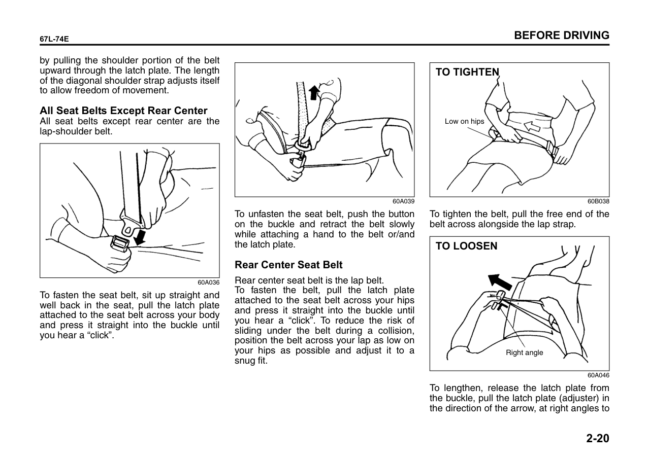
######## Safety reminder
|
Sit up straight and fully back
Low on hips| |---|
60A038
|
Low on hips|
|---|
60A040
To reduce the risk of sliding under the belt during a collision, position the lap portion of the belt across your lap as low on your hips as possible and adjust it to a snug fit
by pulling the shoulder portion of the belt upward through the latch plate. The length of the diagonal shoulder strap adjusts itself to allow freedom of movement.
All Seat Belts Except Rear Center All seat belts except rear center are the lap-shoulder belt.
|| |---|
60A036
To fasten the seat belt, sit up straight and well back in the seat, pull the latch plate attached to the seat belt across your body and press it straight into the buckle until you hear a “click”.
|| |---|
60A039
To unfasten the seat belt, push the button on the buckle and retract the belt slowly while attaching a hand to the belt or/and the latch plate.
####### Rear Center Seat Belt
Rear center seat belt is the lap belt. To fasten the belt, pull the latch plate attached to the seat belt across your hips and press it straight into the buckle until you hear a “click”. To reduce the risk of sliding under the belt during a collision, position the belt across your lap as low on your hips as possible and adjust it to a snug fit.
|
TO TIGHTEN
Low on hips| |---|
60B038
To tighten the belt, pull the free end of the belt across alongside the lap strap.
|
Right angle
TO LOOSEN| |---|
60A046
To lengthen, release the latch plate from the buckle, pull the latch plate (adjuster) in the direction of the arrow, at right angles to
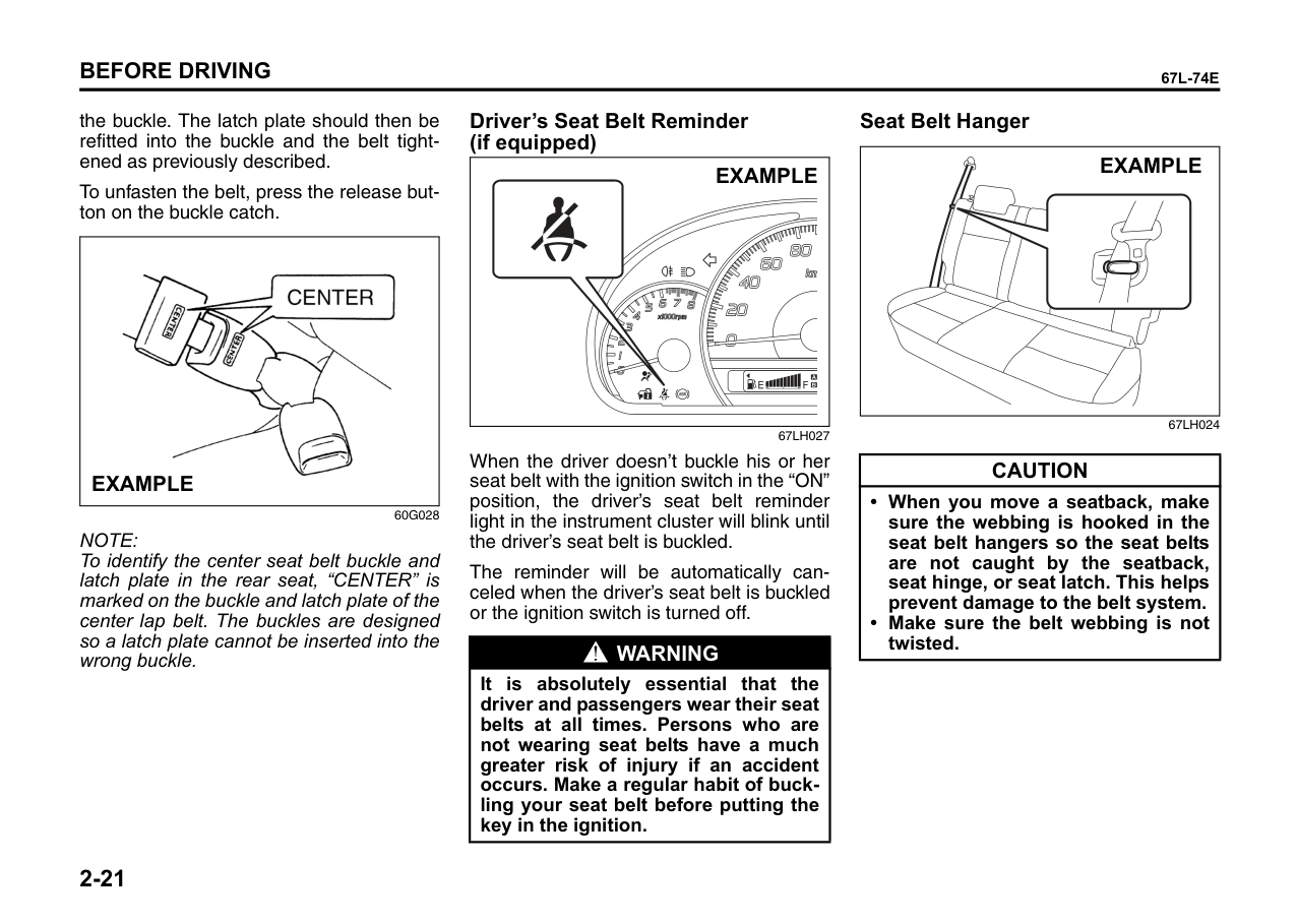
the buckle. The latch plate should then be refitted into the buckle and the belt tightened as previously described.
To unfasten the belt, press the release button on the buckle catch.
|
EXAMPLE| |---|
60G028
NOTE: To identify the center seat belt buckle and latch plate in the rear seat, “CENTER” is marked on the buckle and latch plate of the center lap belt. The buckles are designed so a latch plate cannot be inserted into the wrong buckle.
####### Driver’s Seat Belt Reminder (if equipped)
####### Seat Belt Hanger
EXAMPLE
EXAMPLE
67LH024
67LH027
When the driver doesn’t buckle his or her seat belt with the ignition switch in the “ON” position, the driver’s seat belt reminder light in the instrument cluster will blink until the driver’s seat belt is buckled.
|CAUTION|
|---| |• When you move a seatback, make sure the webbing is hooked in the seat belt hangers so the seat belts are not caught by the seatback, seat hinge, or seat latch. This helps prevent damage to the belt system.
• Make sure the belt webbing is not twisted.
|
The reminder will be automatically canceled when the driver’s seat belt is buckled or the ignition switch is turned off.
|WARNING
| |---| |It is absolutely essential that the driver and passengers wear their seat belts at all times. Persons who are not wearing seat belts have a much greater risk of injury if an accident occurs. Make a regular habit of buckling your seat belt before putting the key in the ignition.|
####### Seat Belt Inspection
|
EXAMPLE| |---|
65D209S
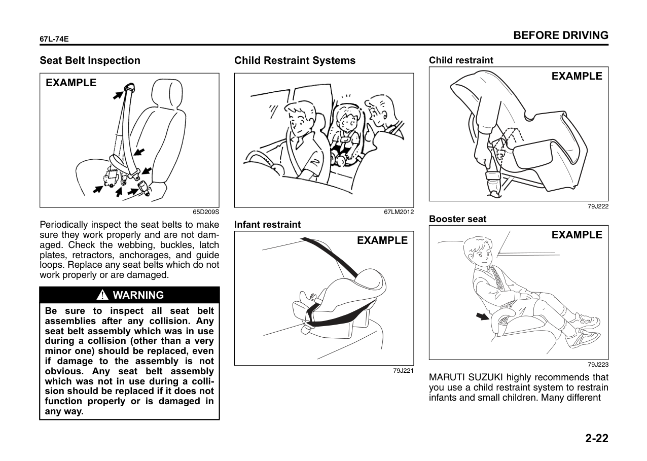
Periodically inspect the seat belts to make sure they work properly and are not damaged. Check the webbing, buckles, latch plates, retractors, anchorages, and guide loops. Replace any seat belts which do not work properly or are damaged.
|WARNING
| |---| |Be sure to inspect all seat belt assemblies after any collision. Any seat belt assembly which was in use during a collision (other than a very minor one) should be replaced, even if damage to the assembly is not obvious. Any seat belt assembly which was not in use during a collision should be replaced if it does not function properly or is damaged in any way.|
####### Child Restraint Systems
|| |---|
######## 67LM2012 Infant restraint
|EXAMPLE| |---|
79J221
Child restraint
|EXAMPLE| |---|
|EXAMPLE| |---|
MARUTI SUZUKI highly recommends that you use a child restraint system to restrain infants and small children. Many different
types of child restraint systems are available; make sure that the restraint system you select meets applicable safety standards.
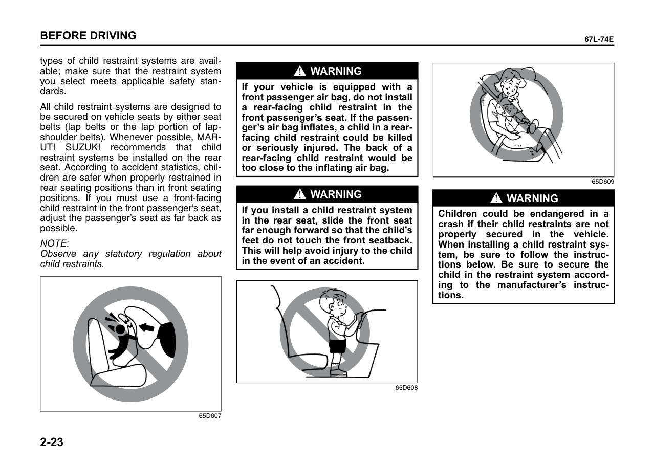
All child restraint systems are designed to be secured on vehicle seats by either seat belts (lap belts or the lap portion of lapshoulder belts). Whenever possible, MARUTI SUZUKI recommends that child restraint systems be installed on the rear seat. According to accident statistics, children are safer when properly restrained in rear seating positions than in front seating positions. If you must use a front-facing child restraint in the front passenger’s seat, adjust the passenger’s seat as far back as possible.
NOTE: Observe any statutory regulation about child restraints.
|| |---|
65D607
|WARNING
| |---| |If your vehicle is equipped with a front passenger air bag, do not install a rear-facing child restraint in the front passenger’s seat. If the passenger’s air bag inflates, a child in a rearfacing child restraint could be killed or seriously injured. The back of a rear-facing child restraint would be too close to the inflating air bag.|
|WARNING
|
|---| |If you install a child restraint system in the rear seat, slide the front seat far enough forward so that the child’s feet do not touch the front seatback. This will help avoid injury to the child in the event of an accident.|
|| |---|
65D608
|| |---|
65D609
|WARNING
| |---| |Children could be endangered in a crash if their child restraints are not properly secured in the vehicle. When installing a child restraint system, be sure to follow the instructions below. Be sure to secure the child in the restraint system according to the manufacturer’s instructions.|
Installation with Lap-Shoulder Seat Belts
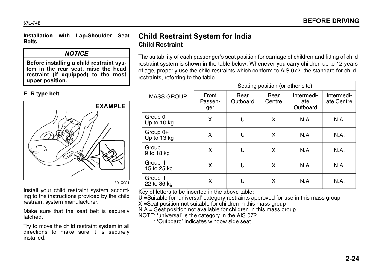
|NOTICE| |---| |Before installing a child restraint system in the rear seat, raise the head restraint (if equipped) to the most upper position.|
ELR type belt
|
EXAMPLE| |---|
80JC021
Install your child restraint system according to the instructions provided by the child restraint system manufacturer.
Make sure that the seat belt is securely latched.
Try to move the child restraint system in all directions to make sure it is securely installed.
Child Restraint System for India Child Restraint
The suitability of each passenger’s seat position for carriage of children and fitting of child restraint system is shown in the table below. Whenever you carry children up to 12 years of age, properly use the child restraints which conform to AIS 072, the standard for child restraints, referring to the table.
|MASS GROUP|Seating position (or other site)|Seating position (or other site)|Seating position (or other site)|Seating position (or other site)|Seating position (or other site)| |---|---|---|---|---|---| |MASS GROUP|Front Passenger|Rear Outboard|Rear Centre|Intermediate Outboard|Intermediate Centre| |Group 0 Up to 10 kg|X|U|X|N.A.|N.A.| |Group 0+ Up to 13 kg|X|U|X|N.A.|N.A.| |Group I 9 to 18 kg|X|U|X|N.A.|N.A.| |Group II 15 to 25 kg|X|U|X|N.A.|N.A.| |Group III 22 to 36 kg|X|U|X|N.A.|N.A.|
Key of letters to be inserted in the above table: U =Suitable for ‘universal’ category restraints approved for use in this mass group X =Seat position not suitable for children in this mass group N.A = Seat position not available for children in this mass group. NOTE: ‘universal’ is the category in the AIS 072.
: ‘Outboard’ indicates window side seat.
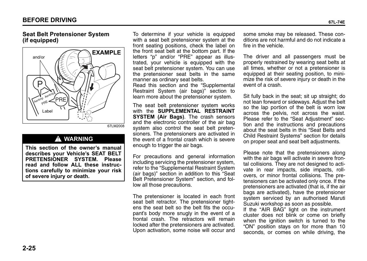
####### Seat Belt Pretensioner System (if equipped)
|and/or
Label
EXAMPLE| |---|
67LM2008
|WARNING
| |---| |This section of the owner’s manual describes your Vehicle’s SEAT BELT PRETENSIONER SYSTEM. Please read and follow ALL these instructions carefully to minimize your risk of severe injury or death.|
To determine if your vehicle is equipped with a seat belt pretensioner system at the front seating positions, check the label on the front seat belt at the bottom part. If the letters “p” and/or “PRE” appear as illustrated, your vehicle is equipped with the seat belt pretensioner system. You can use the pretensioner seat belts in the same manner as ordinary seat belts. Read this section and the “Supplemental Restraint System (air bags)” section to learn more about the pretensioner system.
The seat belt pretensioner system works with the SUPPLEMENTAL RESTRAINT SYSTEM (Air Bags). The crash sensors and the electronic controller of the air bag system also control the seat belt pretensioners. The pretensioners are activated in the event of a frontal crash which is severe enough to trigger the air bags.
For precautions and general information including servicing the pretensioner system, refer to the “Supplemental Restraint System (air bags)” section in addition to this “Seat Belt Pretensioner System” section, and follow all those precautions.
The pretensioner is located in each front seat belt retractor. The pretensioner tightens the seat belt so the belt fits the occupant’s body more snugly in the event of a frontal crash. The retractors will remain locked after the pretensioners are activated. Upon activation, some noise will occur and
some smoke may be released. These conditions are not harmful and do not indicate a fire in the vehicle.
The driver and all passengers must be properly restrained by wearing seat belts at all times, whether or not a pretensioner is equipped at their seating position, to minimize the risk of severe injury or death in the event of a crash.
Sit fully back in the seat; sit up straight; do not lean forward or sideways. Adjust the belt so the lap portion of the belt is worn low across the pelvis, not across the waist. Please refer to the “Seat Adjustment” section and the instructions and precautions about the seat belts in this “Seat Belts and Child Restraint Systems” section for details on proper seat and seat belt adjustments.
Please note that the pretensioners along with the air bags will activate in severe frontal collisions. They are not designed to activate in rear impacts, side impacts, rollovers, or minor frontal collisions. The pretensioners can be activated only once. If the pretensioners are activated (that is, if the air bags are activated), have the pretensioner system serviced by an authorised Maruti Suzuki workshop as soon as possible. If the “AIR BAG” light on the instrument cluster does not blink or come on briefly when the ignition switch is turned to the “ON” position stays on for more than 10 seconds, or comes on while driving, the
pretensioner system or the air bag system may not work properly. Have both systems inspected by an authorised Maruti Suzuki workshop as soon as possible.
Service on or around the pretensioner system components or wiring must be performed only by an authorised Maruti Suzuki workshop who is specially trained. Improper service could result in unintended activation of pretensioners or could render the pretensioner inoperative. Either of these two conditions may result in personal injury.
To prevent damage or unintended activation of the pretensioners, be sure the battery is disconnected and the ignition switch has been in the “LOCK” position for at least 90 seconds before performing any electrical service work on your vehicle.
Do not touch pretensioner system components or wiring. The wires are wrapped with yellow tape or yellow tubing, and the couplers are yellow. When scrapping your Vehicle, ask your authorised Maruti Suzuki workshop body repair shop, or scrap yard for assistance.
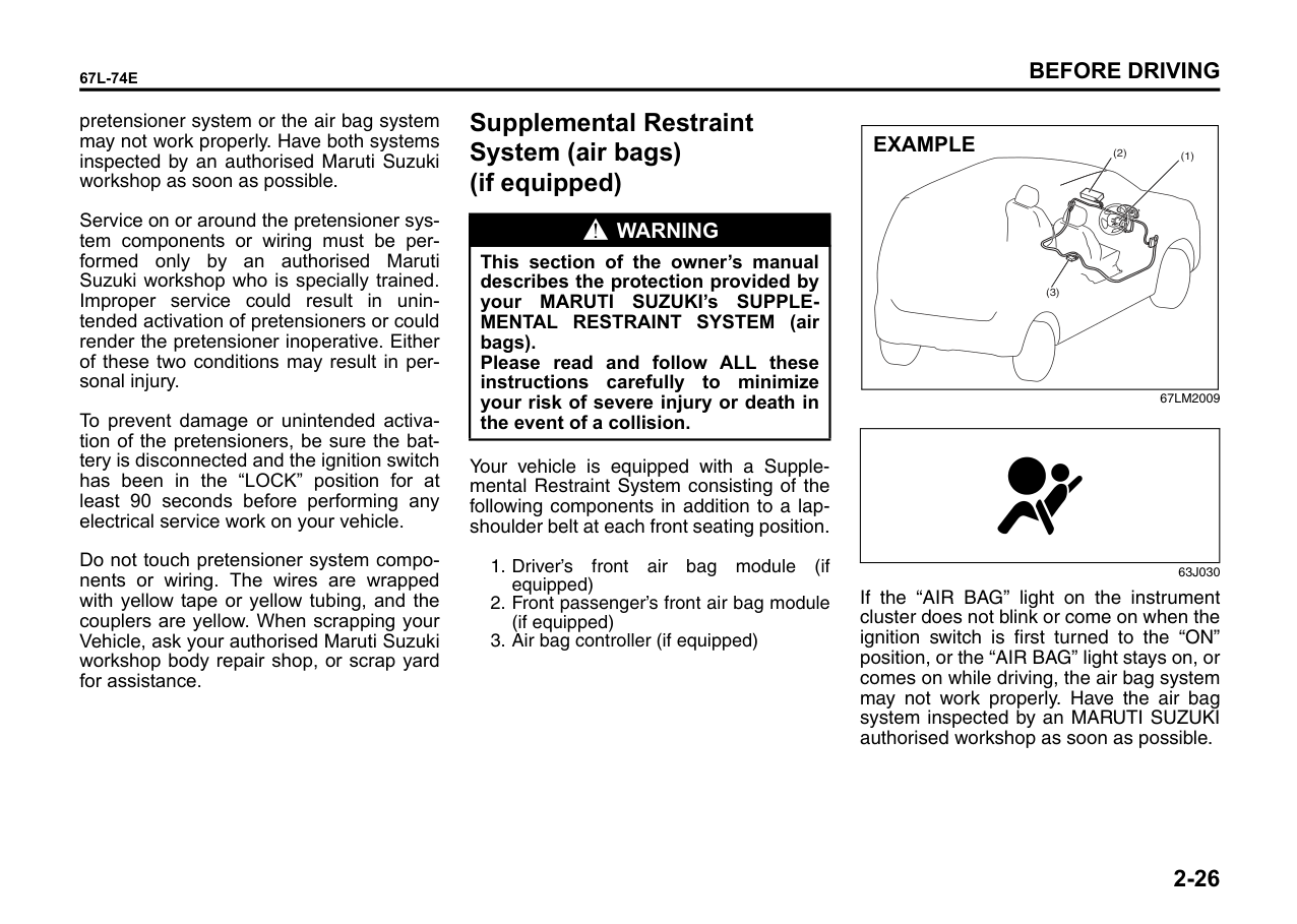
Supplemental Restraint System (air bags) (if equipped)
|WARNING
| |---| |This section of the owner’s manual describes the protection provided by your MARUTI SUZUKI’s SUPPLEMENTAL RESTRAINT SYSTEM (air bags). Please read and follow ALL these instructions carefully to minimize your risk of severe injury or death in the event of a collision.|
Your vehicle is equipped with a Supplemental Restraint System consisting of the following components in addition to a lapshoulder belt at each front seating position.
|(3)
(1)(2)
EXAMPLE| |---|
67LM2009
| | |---|
63J030
If the “AIR BAG” light on the instrument cluster does not blink or come on when the ignition switch is first turned to the “ON” position, or the “AIR BAG” light stays on, or comes on while driving, the air bag system may not work properly. Have the air bag system inspected by an MARUTI SUZUKI authorised workshop as soon as possible.
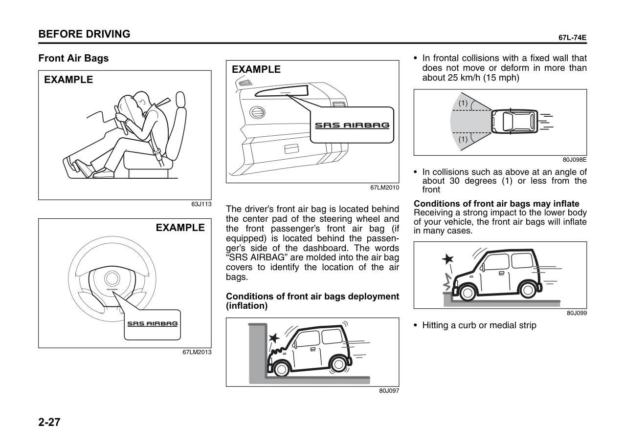
####### Front Air Bags
|EXAMPLE
| |---|
63J113
|EXAMPLE
| |---|
67LM2013
|EXAMPLE| |---|
67LM2010
The driver’s front air bag is located behind the center pad of the steering wheel and the front passenger’s front air bag (if equipped) is located behind the passenger’s side of the dashboard. The words “SRS AIRBAG” are molded into the air bag covers to identify the location of the air bags.
Conditions of front air bags deployment (inflation)
| | |---|
80J097
80J098E
|(1)
(1)| |---|
Conditions of front air bags may inflate
Receiving a strong impact to the lower body of your vehicle, the front air bags will inflate in many cases.
| | |---|
80J099
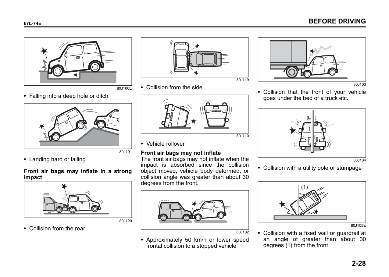
• Hitting a curb or medial strip
| | |---|
80J101
Front air bags may inflate in a strong impact
80J120
| | |---|
| | |---|
| | |---|
80J119
80J110
Front air bags may not inflate
The front air bags may not inflate when the impact is absorbed since the collision object moved, vehicle body deformed, or collision angle was greater than about 30 degrees from the front.
80J102
| | |---|
| | |---|
| | |---|
80J103
• Collision with a utility pole or stumpage
|| |(1)| |---|---| | | | | |---|
| | |---|
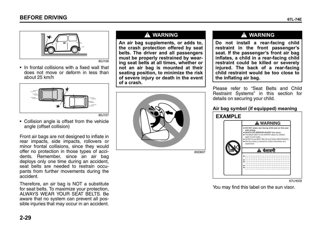
80J106
80J107
| | |---|
Front air bags are not designed to inflate in rear impacts, side impacts, rollovers or minor frontal collisions, since they would offer no protection in those types of accidents. Remember, since an air bag deploys only one time during an accident, seat belts are needed to restrain occupants from further movements during the accident.
Therefore, an air bag is NOT a substitute for seat belts. To maximize your protection, ALWAYS WEAR YOUR SEAT BELTS. Be aware that no system can prevent all possible injuries that may occur in an accident.
|WARNING
| |---| |An air bag supplements, or adds to, the crash protection offered by seat belts. The driver and all passengers must be properly restrained by wearing seat belts at all times, whether or not an air bag is mounted at their seating position, to minimize the risk of severe injury or death in the event of a crash.|
|| |---|
65D607
|WARNING
| |---| |Do not install a rear-facing child restraint in the front passenger’s seat. If the passenger’s front air bag inflates, a child in a rear-facing child restraint could be killed or severely injured. The back of a rear-facing child restraint would be too close to the inflating air bag.|
Please refer to “Seat Belts and Child Restraint Systems” in this section for details on securing your child.
######## Air bag symbol (if equipped) meaning
|| | | |---|---| | | | | | | | | |
EXAMPLE| |---|
67LH029 You may find this label on the sun visor.
|WARNING
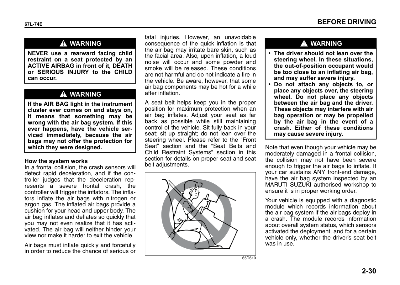
| |---| |NEVER use a rearward facing child restraint on a seat protected by an ACTIVE AIRBAG in front of it, DEATH or SERIOUS INJURY to the CHILD can occur.|
|WARNING
| |---| |If the AIR BAG light in the instrument cluster ever comes on and stays on, it means that something may be wrong with the air bag system. If this ever happens, have the vehicle serviced immediately, because the air bags may not offer the protection for which they were designed.|
######## How the system works
In a frontal collision, the crash sensors will detect rapid deceleration, and if the controller judges that the deceleration represents a severe frontal crash, the controller will trigger the inflators. The inflators inflate the air bags with nitrogen or argon gas. The inflated air bags provide a cushion for your head and upper body. The air bag inflates and deflates so quickly that you may not even realize that it has activated. The air bag will neither hinder your view nor make it harder to exit the vehicle.
Air bags must inflate quickly and forcefully in order to reduce the chance of serious or
fatal injuries. However, an unavoidable consequence of the quick inflation is that the air bag may irritate bare skin, such as the facial area. Also, upon inflation, a loud noise will occur and some powder and smoke will be released. These conditions are not harmful and do not indicate a fire in the vehicle. Be aware, however, that some air bag components may be hot for a while after inflation.
A seat belt helps keep you in the proper position for maximum protection when an air bag inflates. Adjust your seat as far back as possible while still maintaining control of the vehicle. Sit fully back in your seat; sit up straight; do not lean over the steering wheel. Please refer to the “Front Seat” section and the “Seat Belts and Child Restraint Systems” section in this section for details on proper seat and seat belt adjustments.
|| |---|
65D610
|WARNING
| |---| |• The driver should not lean over the steering wheel. In these situations, the out-of-position occupant would be too close to an inflating air bag, and may suffer severe injury.
• Do not attach any objects to, or place any objects over, the steering wheel. Do not place any objects between the air bag and the driver. These objects may interfere with air bag operation or may be propelled by the air bag in the event of a crash. Either of these conditions may cause severe injury.
|
Note that even though your vehicle may be moderately damaged in a frontal collision, the collision may not have been severe enough to trigger the air bags to inflate. If your car sustains ANY front-end damage, have the air bag system inspected by an MARUTI SUZUKI authorised workshop to ensure it is in proper working order.
Your vehicle is equipped with a diagnostic module which records information about the air bag system if the air bags deploy in a crash. The module records information about overall system status, which sensors activated the deployment, and for a certain vehicle only, whether the driver’s seat belt was in use.
######## Servicing the air bag system
If the air bags inflate, have the air bags and related components replaced by an authorized MARUTI SUZUKI dealer as soon as possible.
If your vehicle ever gets in deep water and the driver’s floor is submerged, the air bag controller could be damaged. If it does, have the air bag system inspected by the MARUTI SUZUKI authorised workshop as soon as possible.
Special procedures are required for servicing or replacing an air bag. For that reason, only an MARUTI SUZUKI authorised workshop should be allowed to service or replace your air bags. Please remind anyone who services your MARUTI SUZUKI that it has air bags.
Service on or around air bag components or wiring must be performed only by an MARUTI SUZUKI authorised workshop. Improper service could result in unintended air bag deployment or could render the air bag inoperative. Either of these two conditions may result in severe injury.
To prevent damage or unintended inflation of the air bag system, be sure the battery is disconnected and the ignition switch has been in the “LOCK” position for at least 90 seconds before performing any electrical service work on your MARUTI SUZUKI. Do not touch air bag system components or wires. The wires are wrapped with yellow
tape or yellow tubing, and the couplers are yellow for easy identification.
Scrapping a car that has an uninflated air bag can be hazardous. Ask your dealer, body repair shop or scrap yard for help with disposal.
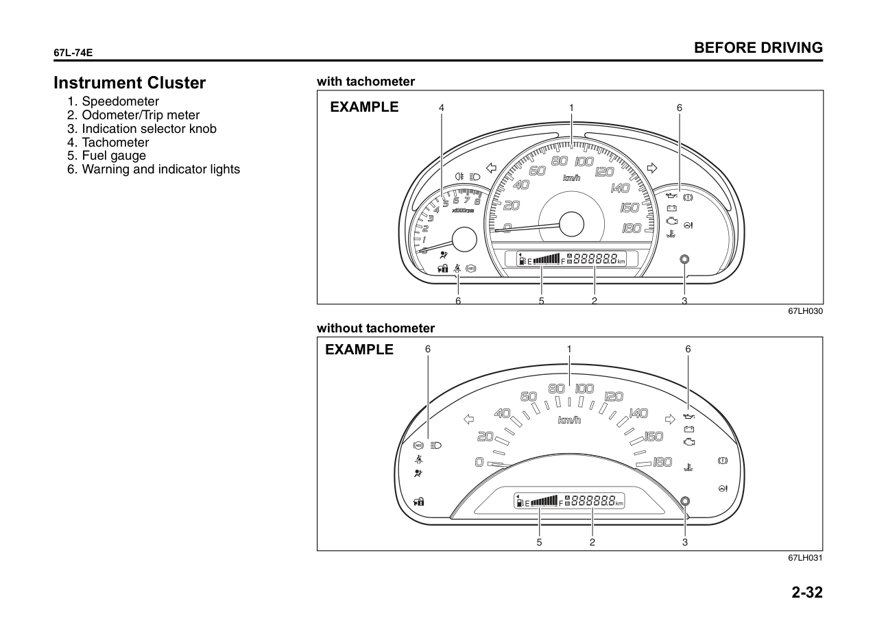
Instrument Cluster
######## with tachometer
|6
| | | | | | |---|---|---|---|---| | | | | | |
352
14 6EXAMPLE
| |---|
without tachometer
|352
16 6EXAMPLE
| |---|
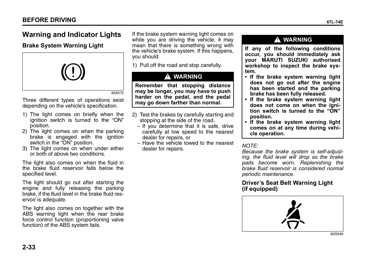
Warning and Indicator Lights Brake System Warning Light
|| |---|
60A072
Three different types of operations exist depending on the vehicle’s specification.
The light also comes on when the fluid in the brake fluid reservoir falls below the specified level.
The light should go out after starting the engine and fully releasing the parking brake, if the fluid level in the brake fluid reservoir is adequate.
The light also comes on together with the ABS warning light when the rear brake force control function (proportioning valve function) of the ABS system fails.
If the brake system warning light comes on while you are driving the vehicle, it may mean that there is something wrong with the vehicle’s brake system. If this happens, you should:
|WARNING
| |---| |Remember that stopping distance may be longer, you may have to push harder on the pedal, and the pedal may go down farther than normal.|
dealer for repairs.
|WARNING
| |---| |If any of the following conditions occur, you should immediately ask your MARUTI SUZUKI authorised workshop to inspect the brake system.
• If the brake system warning light does not go out after the engine has been started and the parking brake has been fully released.
• If the brake system warning light does not come on when the ignition switch is turned to the “ON” position.
• If the brake system warning light comes on at any time during vehicle operation.
|
NOTE: Because the brake system is self-adjusting, the fluid level will drop as the brake pads become worn. Replenishing the brake fluid reservoir is considered normal periodic maintenance.
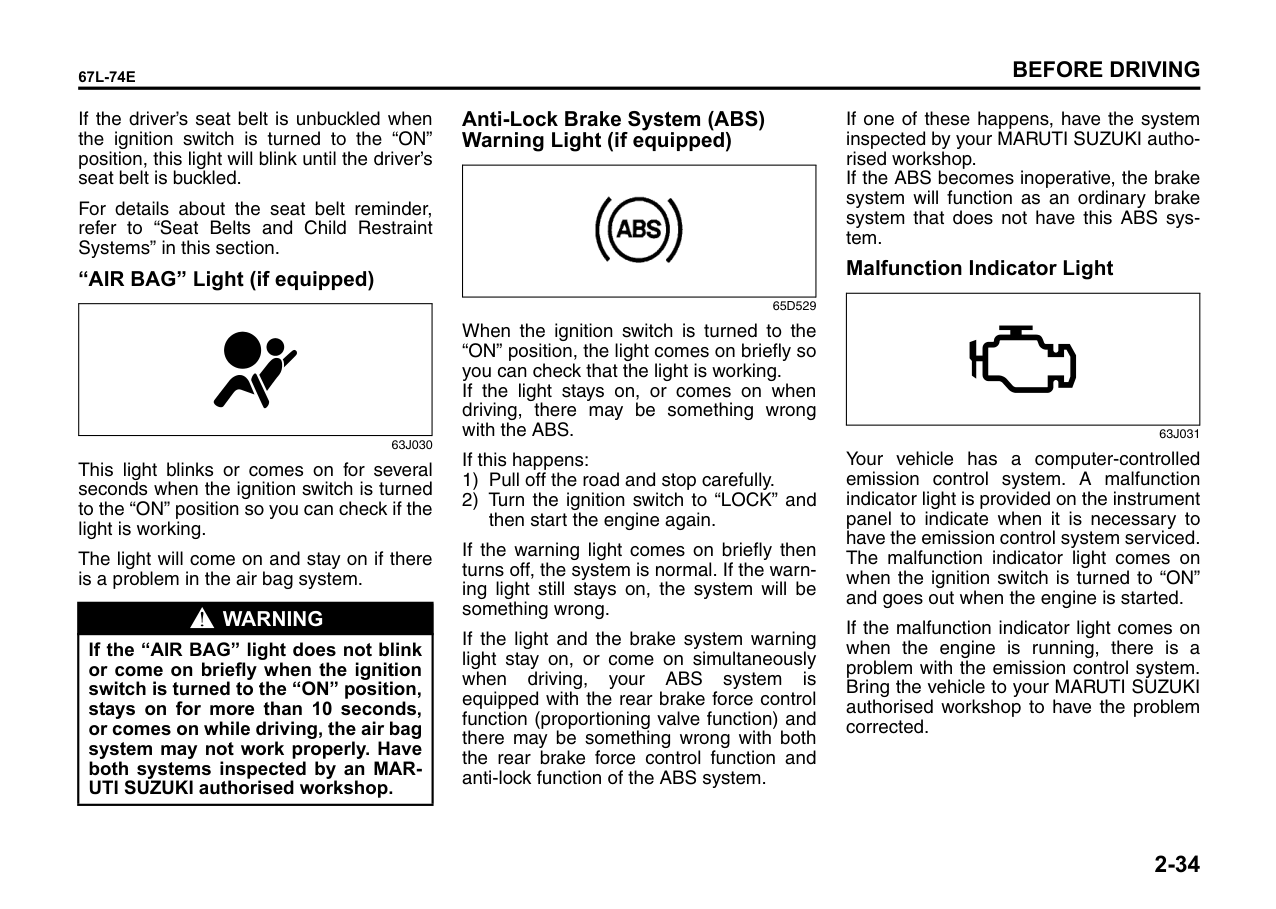
####### Driver’s Seat Belt Warning Light (if equipped)
|| |---|
60G049
If the driver’s seat belt is unbuckled when the ignition switch is turned to the “ON” position, this light will blink until the driver’s seat belt is buckled.
For details about the seat belt reminder, refer to “Seat Belts and Child Restraint Systems” in this section.
####### “AIR BAG” Light (if equipped)
| | |---|
63J030
This light blinks or comes on for several seconds when the ignition switch is turned to the “ON” position so you can check if the light is working.
The light will come on and stay on if there is a problem in the air bag system.
|WARNING
| |---| |If the “AIR BAG” light does not blink or come on briefly when the ignition switch is turned to the “ON” position, stays on for more than 10 seconds, or comes on while driving, the air bag system may not work properly. Have both systems inspected by an MARUTI SUZUKI authorised workshop.|
If one of these happens, have the system inspected by your MARUTI SUZUKI authorised workshop. If the ABS becomes inoperative, the brake system will function as an ordinary brake system that does not have this ABS system.
####### Anti-Lock Brake System (ABS) Warning Light (if equipped)
|| |---|
####### Malfunction Indicator Light
| | |---|
65D529
When the ignition switch is turned to the “ON” position, the light comes on briefly so you can check that the light is working. If the light stays on, or comes on when driving, there may be something wrong with the ABS.
63J031
Your vehicle has a computer-controlled emission control system. A malfunction indicator light is provided on the instrument panel to indicate when it is necessary to have the emission control system serviced. The malfunction indicator light comes on when the ignition switch is turned to “ON” and goes out when the engine is started.
If this happens:
If the warning light comes on briefly then turns off, the system is normal. If the warning light still stays on, the system will be something wrong.
If the malfunction indicator light comes on when the engine is running, there is a problem with the emission control system. Bring the vehicle to your MARUTI SUZUKI authorised workshop to have the problem corrected.
If the light and the brake system warning light stay on, or come on simultaneously when driving, your ABS system is equipped with the rear brake force control function (proportioning valve function) and there may be something wrong with both the rear brake force control function and anti-lock function of the ABS system.
|NOTICE| |---| |Continuing to drive the vehicle when the malfunction indicator light is on can cause permanent damage to the vehicle’s emission control system, and can affect fuel economy and driveability.|
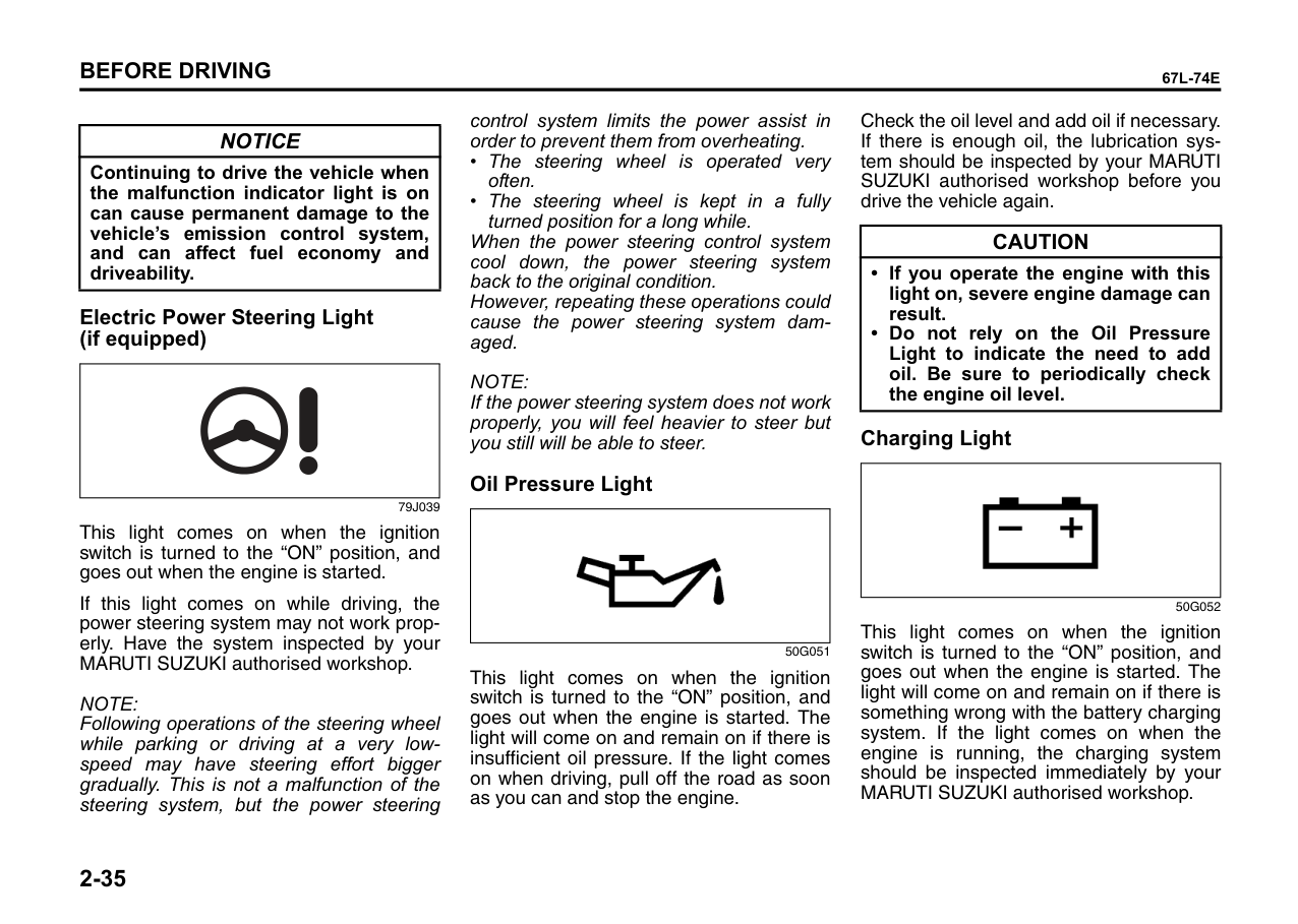
####### Electric Power Steering Light (if equipped)
| | |---|
79J039
This light comes on when the ignition switch is turned to the “ON” position, and goes out when the engine is started.
If this light comes on while driving, the power steering system may not work properly. Have the system inspected by your MARUTI SUZUKI authorised workshop.
NOTE: Following operations of the steering wheel while parking or driving at a very lowspeed may have steering effort bigger gradually. This is not a malfunction of the steering system, but the power steering
control system limits the power assist in order to prevent them from overheating.
When the power steering control system cool down, the power steering system back to the original condition. However, repeating these operations could cause the power steering system damaged.
NOTE: If the power steering system does not work properly, you will feel heavier to steer but you still will be able to steer.
####### Oil Pressure Light
|| |---|
50G051
This light comes on when the ignition switch is turned to the “ON” position, and goes out when the engine is started. The light will come on and remain on if there is insufficient oil pressure. If the light comes on when driving, pull off the road as soon as you can and stop the engine.
Check the oil level and add oil if necessary. If there is enough oil, the lubrication system should be inspected by your MARUTI SUZUKI authorised workshop before you drive the vehicle again.
|CAUTION| |---| |• If you operate the engine with this light on, severe engine damage can result.
• Do not rely on the Oil Pressure Light to indicate the need to add oil. Be sure to periodically check the engine oil level.
|
####### Charging Light
|| |---|
50G052
This light comes on when the ignition switch is turned to the “ON” position, and goes out when the engine is started. The light will come on and remain on if there is something wrong with the battery charging system. If the light comes on when the engine is running, the charging system should be inspected immediately by your MARUTI SUZUKI authorised workshop.
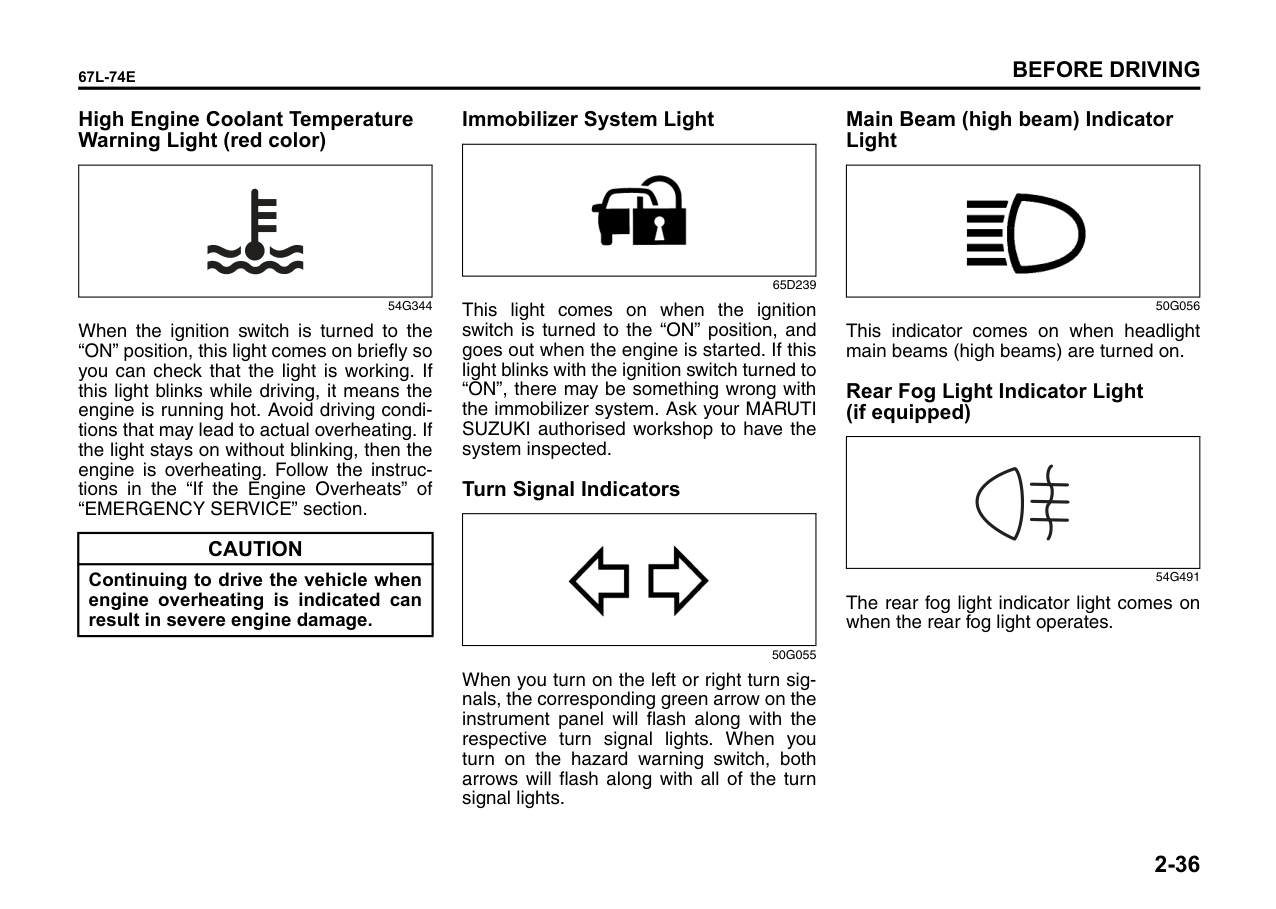
####### High Engine Coolant Temperature Warning Light (red color)
####### Immobilizer System Light
|| |---|
| | |---|
65D239
54G344
This light comes on when the ignition switch is turned to the “ON” position, and goes out when the engine is started. If this light blinks with the ignition switch turned to “ON”, there may be something wrong with the immobilizer system. Ask your MARUTI SUZUKI authorised workshop to have the system inspected.
When the ignition switch is turned to the “ON” position, this light comes on briefly so you can check that the light is working. If this light blinks while driving, it means the engine is running hot. Avoid driving conditions that may lead to actual overheating. If the light stays on without blinking, then the engine is overheating. Follow the instructions in the “If the Engine Overheats” of “EMERGENCY SERVICE” section.
####### Turn Signal Indicators
|| |---|
|CAUTION| |---| |Continuing to drive the vehicle when engine overheating is indicated can result in severe engine damage.|
50G055
When you turn on the left or right turn signals, the corresponding green arrow on the instrument panel will flash along with the respective turn signal lights. When you turn on the hazard warning switch, both arrows will flash along with all of the turn signal lights.
####### Main Beam (high beam) Indicator Light
|| |---|
50G056
This indicator comes on when headlight main beams (high beams) are turned on.
####### Rear Fog Light Indicator Light (if equipped)
| | |---|
54G491
The rear fog light indicator light comes on when the rear fog light operates.
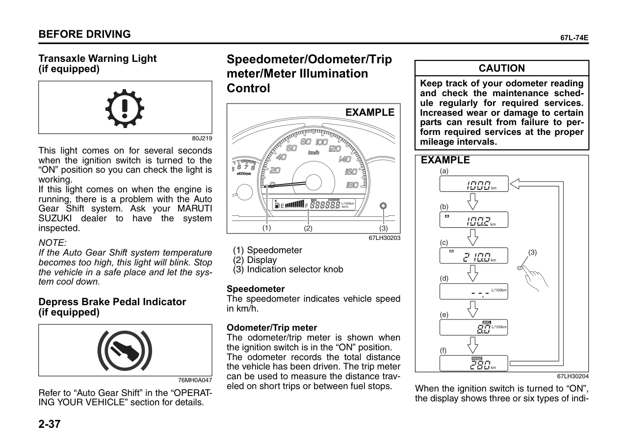
Speedometer/Odometer/Trip meter/Meter Illumination Control
####### Transaxle Warning Light (if equipped)
|CAUTION| |---| |Keep track of your odometer reading and check the maintenance schedule regularly for required services. Increased wear or damage to certain parts can result from failure to perform required services at the proper mileage intervals.|
| | |---|
####### EXAMPLE
80J219
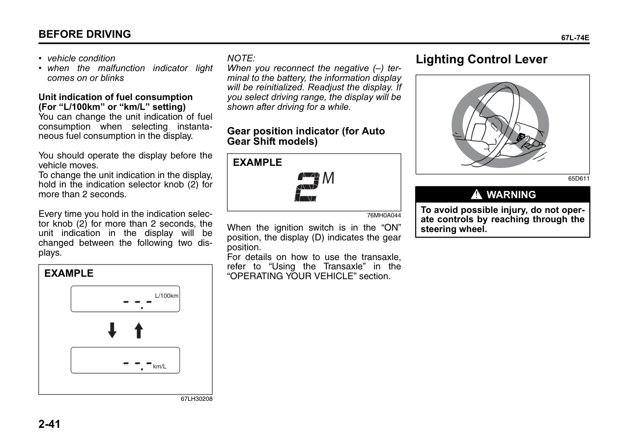
This light comes on for several seconds when the ignition switch is turned to the “ON” position so you can check the light is working. If this light comes on when the engine is running, there is a problem with the Auto Gear Shift system. Ask your MARUTI SUZUKI dealer to have the system inspected.
|(3)
(a)
(b)
(c)
(d)
(e)
(f)
km
km
km
L/100km
L/100km
km
EXAMPLE| |---|
L/100km km/L
(1) (2) (3)
67LH30203
NOTE: If the Auto Gear Shift system temperature becomes too high, this light will blink. Stop the vehicle in a safe place and let the system cool down.
Speedometer The speedometer indicates vehicle speed in km/h.
####### Depress Brake Pedal Indicator (if equipped)
Odometer/Trip meter The odometer/trip meter is shown when the ignition switch is in the “ON” position. The odometer records the total distance the vehicle has been driven. The trip meter can be used to measure the distance traveled on short trips or between fuel stops.
| | |---|
67LH30204
76MH0A047
When the ignition switch is turned to “ON”, the display shows three or six types of indi-
Refer to “Auto Gear Shift” in the “OPERATING YOUR VEHICLE” section for details.
cation; odometer (a), trip meter A (b), trip meter B (c), and if your vehicle is equipped with the information display, instantaneous fuel consumption (d), average fuel consumption (e), and driving range (f). Push the indication selector knob (3) quickly to switch the indication among three or six. For the indication (d), (e), or (f), refer to “Information Display” in this section for details.
|WARNING
| |---| |If you attempt to adjust the display while driving, you could lose control of the vehicle.
Do not attempt to adjust the display while driving.|
|(3)
EXAMPLE| |---|
67LH30205
To reset the trip meter to zero, hold the indication selector knob (3) for more than 2 seconds.
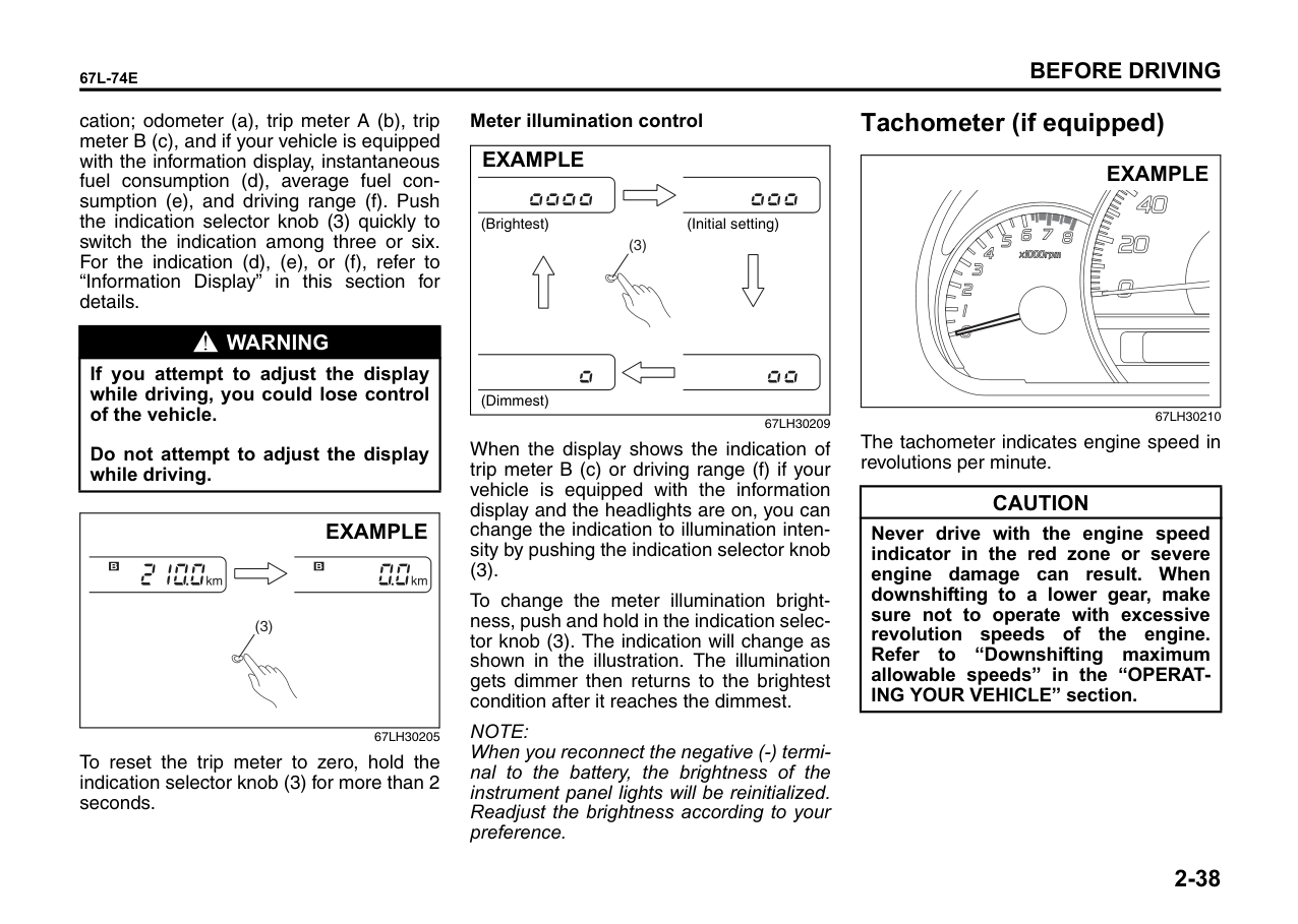
######## Meter illumination control
|(3)
EXAMPLE
(Brightest) (Initial setting)
(Dimmest)| |---|
67LH30209
When the display shows the indication of trip meter B (c) or driving range (f) if your vehicle is equipped with the information display and the headlights are on, you can change the indication to illumination intensity by pushing the indication selector knob (3).
To change the meter illumination brightness, push and hold in the indication selector knob (3). The indication will change as shown in the illustration. The illumination gets dimmer then returns to the brightest condition after it reaches the dimmest.
NOTE: When you reconnect the negative (-) terminal to the battery, the brightness of the instrument panel lights will be reinitialized. Readjust the brightness according to your preference.
Tachometer (if equipped)
####### EXAMPLE
67LH30210
The tachometer indicates engine speed in revolutions per minute.
|CAUTION| |---| |Never drive with the engine speed indicator in the red zone or severe engine damage can result. When downshifting to a lower gear, make sure not to operate with excessive revolution speeds of the engine. Refer to “Downshifting maximum allowable speeds” in the “OPERATING YOUR VEHICLE” section.|
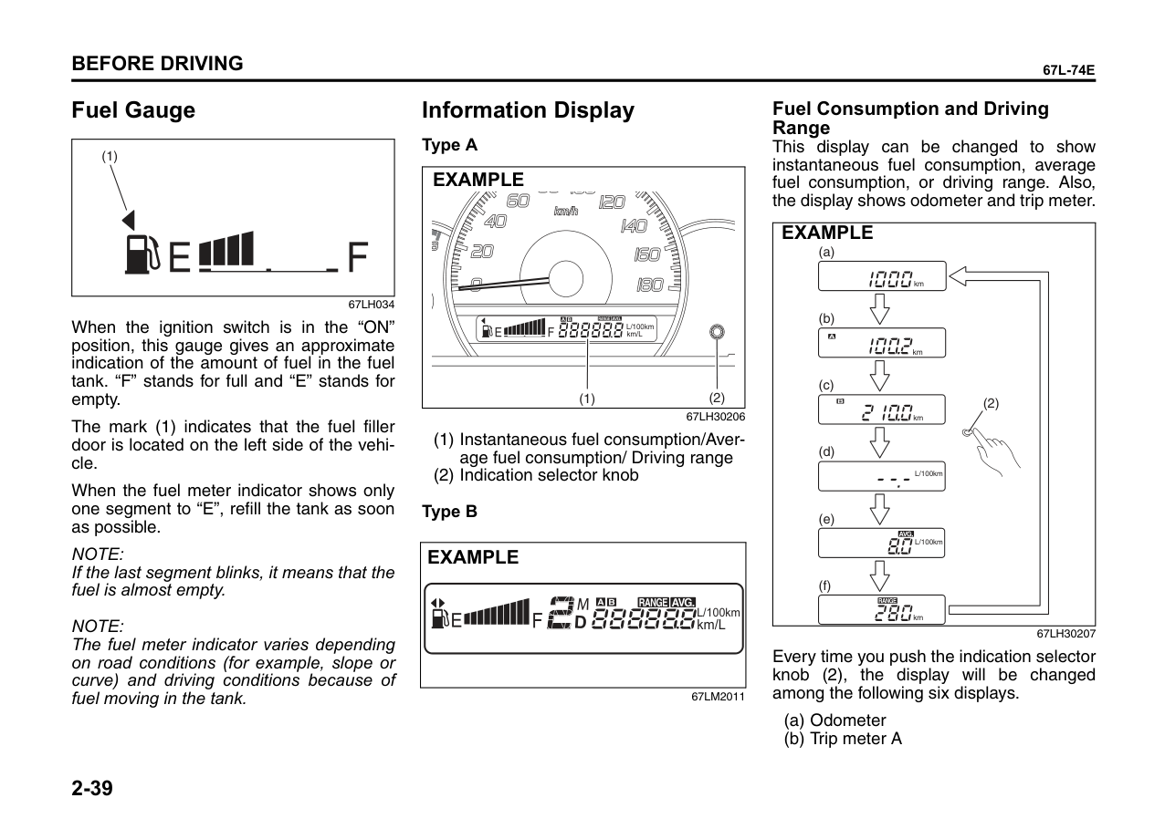
Fuel Gauge
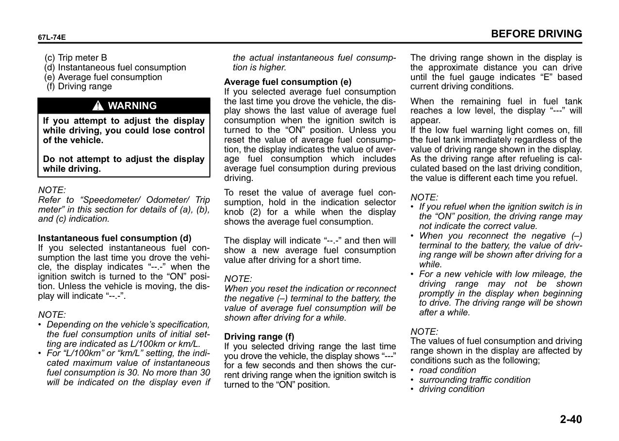
Information Display
####### Fuel Consumption and Driving Range
######## Type A
This display can be changed to show instantaneous fuel consumption, average fuel consumption, or driving range. Also, the display shows odometer and trip meter.
|(1)
| |---|
####### EXAMPLE
|(2)
(a)
(b)
(c)
(d)
(e)
(f)
km
km
km
L/100km
L/100km
km
EXAMPLE| |---|
67LH034
When the ignition switch is in the “ON” position, this gauge gives an approximate indication of the amount of fuel in the fuel tank. “F” stands for full and “E” stands for empty.
L/100km km/L
(1) (2)
67LH30206 (1) Instantaneous fuel consumption/Aver-
The mark (1) indicates that the fuel filler door is located on the left side of the vehicle.
age fuel consumption/ Driving range
(2) Indication selector knob
When the fuel meter indicator shows only one segment to “E”, refill the tank as soon as possible.
######## Type B
|km/L
L/100km D
EXAMPLE| |---|
NOTE: If the last segment blinks, it means that the fuel is almost empty.
NOTE: The fuel meter indicator varies depending on road conditions (for example, slope or curve) and driving conditions because of fuel moving in the tank.
67LH30207
Every time you push the indication selector knob (2), the display will be changed among the following six displays.
67LM2011
(c) Trip meter B
|WARNING
| |---| |If you attempt to adjust the display while driving, you could lose control of the vehicle.
Do not attempt to adjust the display while driving.|
NOTE: Refer to “Speedometer/ Odometer/ Trip meter” in this section for details of (a), (b), and (c) indication.
######## Instantaneous fuel consumption (d)
If you selected instantaneous fuel consumption the last time you drove the vehicle, the display indicates “--.-” when the ignition switch is turned to the “ON” position. Unless the vehicle is moving, the display will indicate “--.-”.
NOTE:
the actual instantaneous fuel consumption is higher.
######## Average fuel consumption (e)
If you selected average fuel consumption the last time you drove the vehicle, the display shows the last value of average fuel consumption when the ignition switch is turned to the “ON” position. Unless you reset the value of average fuel consumption, the display indicates the value of average fuel consumption which includes average fuel consumption during previous driving.
To reset the value of average fuel consumption, hold in the indication selector knob (2) for a while when the display shows the average fuel consumption.
The display will indicate “--.-” and then will show a new average fuel consumption value after driving for a short time.
NOTE: When you reset the indication or reconnect the negative (–) terminal to the battery, the value of average fuel consumption will be shown after driving for a while.
######## Driving range (f)
If you selected driving range the last time you drove the vehicle, the display shows “---” for a few seconds and then shows the current driving range when the ignition switch is turned to the “ON” position.
The driving range shown in the display is the approximate distance you can drive until the fuel gauge indicates “E” based current driving conditions.
When the remaining fuel in fuel tank reaches a low level, the display “---” will appear. If the low fuel warning light comes on, fill the fuel tank immediately regardless of the value of driving range shown in the display. As the driving range after refueling is calculated based on the last driving condition, the value is different each time you refuel.
NOTE:
NOTE:
The values of fuel consumption and driving range shown in the display are affected by conditions such as the following;
Unit indication of fuel consumption (For “L/100km” or “km/L” setting)
You can change the unit indication of fuel consumption when selecting instantaneous fuel consumption in the display.
You should operate the display before the vehicle moves. To change the unit indication in the display, hold in the indication selector knob (2) for more than 2 seconds.
Every time you hold in the indication selector knob (2) for more than 2 seconds, the unit indication in the display will be changed between the following two displays.
|km/L
L/100km
EXAMPLE| |---|
67LH30208
NOTE: When you reconnect the negative (–) terminal to the battery, the information display will be reinitialized. Readjust the display. If you select driving range, the display will be shown after driving for a while.
####### Gear position indicator (for Auto Gear Shift models)
|EXAMPLE| |---|
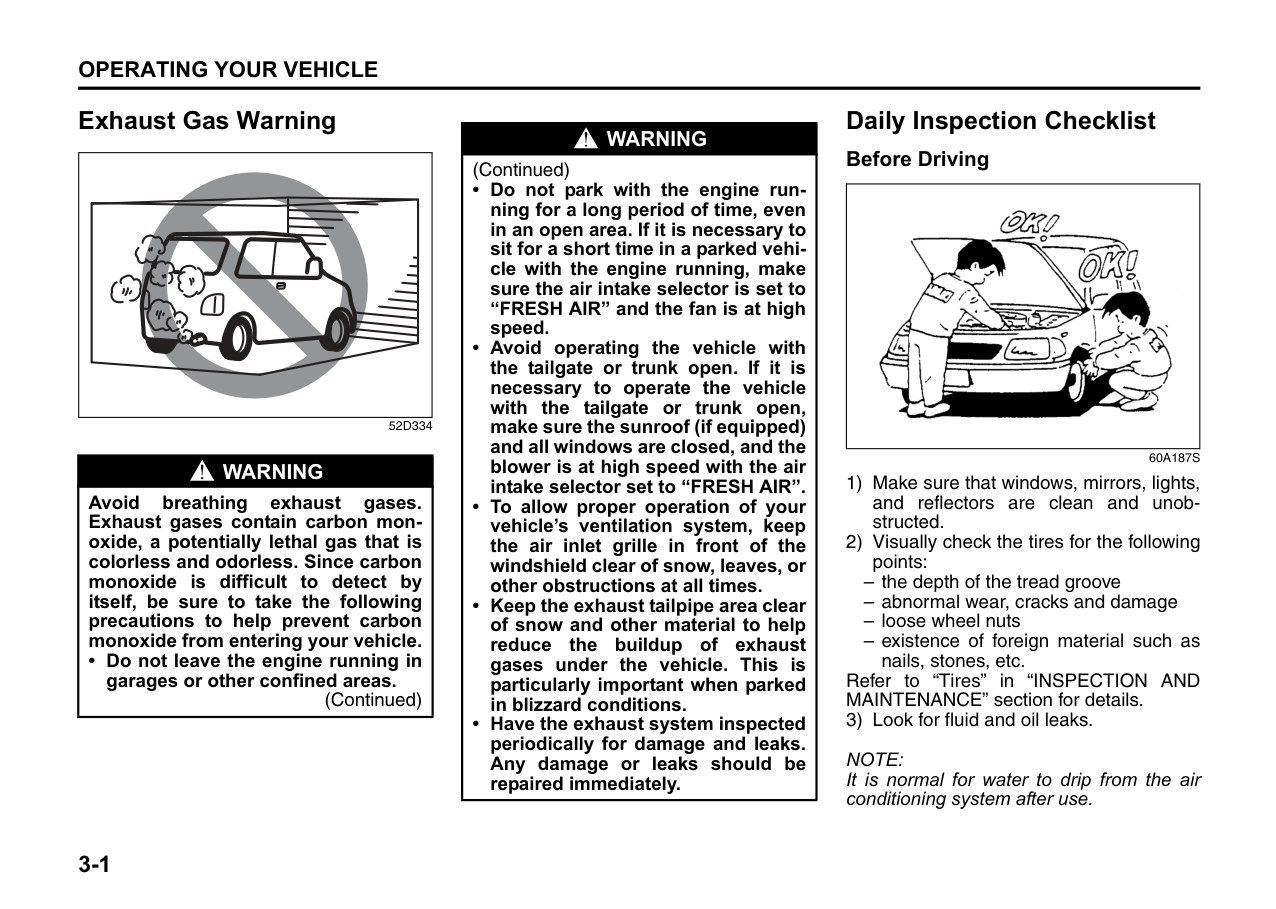
76MH0A044
When the ignition switch is in the “ON” position, the display (D) indicates the gear position. For details on how to use the transaxle, refer to “Using the Transaxle” in the “OPERATING YOUR VEHICLE” section.
Lighting Control Lever
|| |---|
65D611
|WARNING
| |---| |To avoid possible injury, do not operate controls by reaching through the steering wheel.|
####### Lighting Operation
|(2) (1)
(3)
EXAMPLE| |---|
68KH098
To turn the lights on or off, twist the knob on the end of the lever. There are three positions:
OFF (1) All lights are off.
######## (2)
Front position lights, tail lights, license plate light and instrument lights are on, but headlights are off.
######## (3)
Front position lights, tail lights, license plate light, instrument lights and head lights are on.
|EXAMPLE| |---|
61J061
With the headlights on, push the lever forward to switch to the high beams (main beams) or pull the lever toward you to switch to the low beams. When the high beams (main beams) are on, a light on the instrument panel will come on. To momentarily activate the high beams (main beams) as a passing signal, pull the lever slightly toward you and release it when you have completed the signal.
######## Lights “On” reminder (if equipped)
A buzzer/chime sounds to remind you to turn off the lights if they are left on when the ignition key is removed and the driver’s door is opened.
Rear Fog Light Switch (if equipped)
|EXAMPLE| |---|
67LH040
To turn the rear fog light on, twist the knob as shown in the illustration with the head lights are on. When the rear fog light is on, an indicator light on the instrument cluster will come on. Do not turn the rear fog light switch unless the head lights are on.
NOTE: When the head light switch is returned to the “OFF” position, the rear fog light switch will be cancelled automatically.
Front Fog Light Switch (if equipped)
EXAMPLE
67LH041
The front fog light comes on when the fog light switch is pushed in with the position lights, tail lights and/or the headlights are on. An indicator light above the switch will be lit when the front fog light is on.
NOTE: In some countries the lighting operation may be different from the above description according to local regulations.
Headlight Leveling Switch
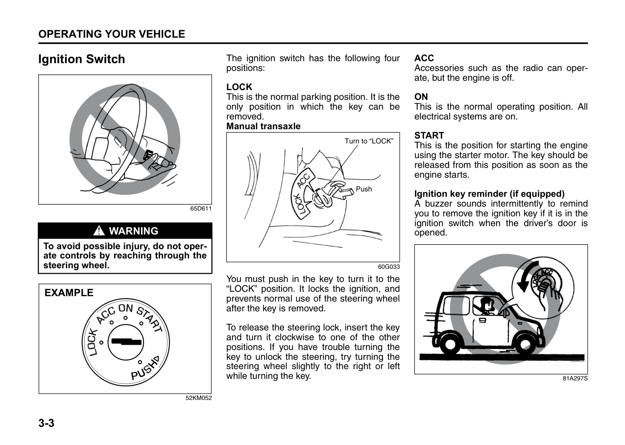
|EXAMPLE| |---|
67LH042
Level the headlight beam according to the load condition of your vehicle by turning this switch when the position lights, tail lights and/or headlights are on. The chart below shows the appropriate switch position for different vehicle-load conditions.
|Vehicle Load Condition|Switch Position| |---|---| |Driver only|0| |Driver + 1 passenger (in front seat)|0| |Driver + 4 passengers, no cargo|1| |Driver + 4 passengers, cargo added|2| |Driver + full cargo|3| |Dummy|4|
Turn Signal Control Lever
|| |---|
65D611
|WARNING
| |---| |To avoid possible injury, do not operate controls by reaching through the steering wheel.|
####### Turn Signal Operation
With the ignition switch in the “ON” position, move the lever up or down to activate the right or left turn signals.
######## Normal turn signal
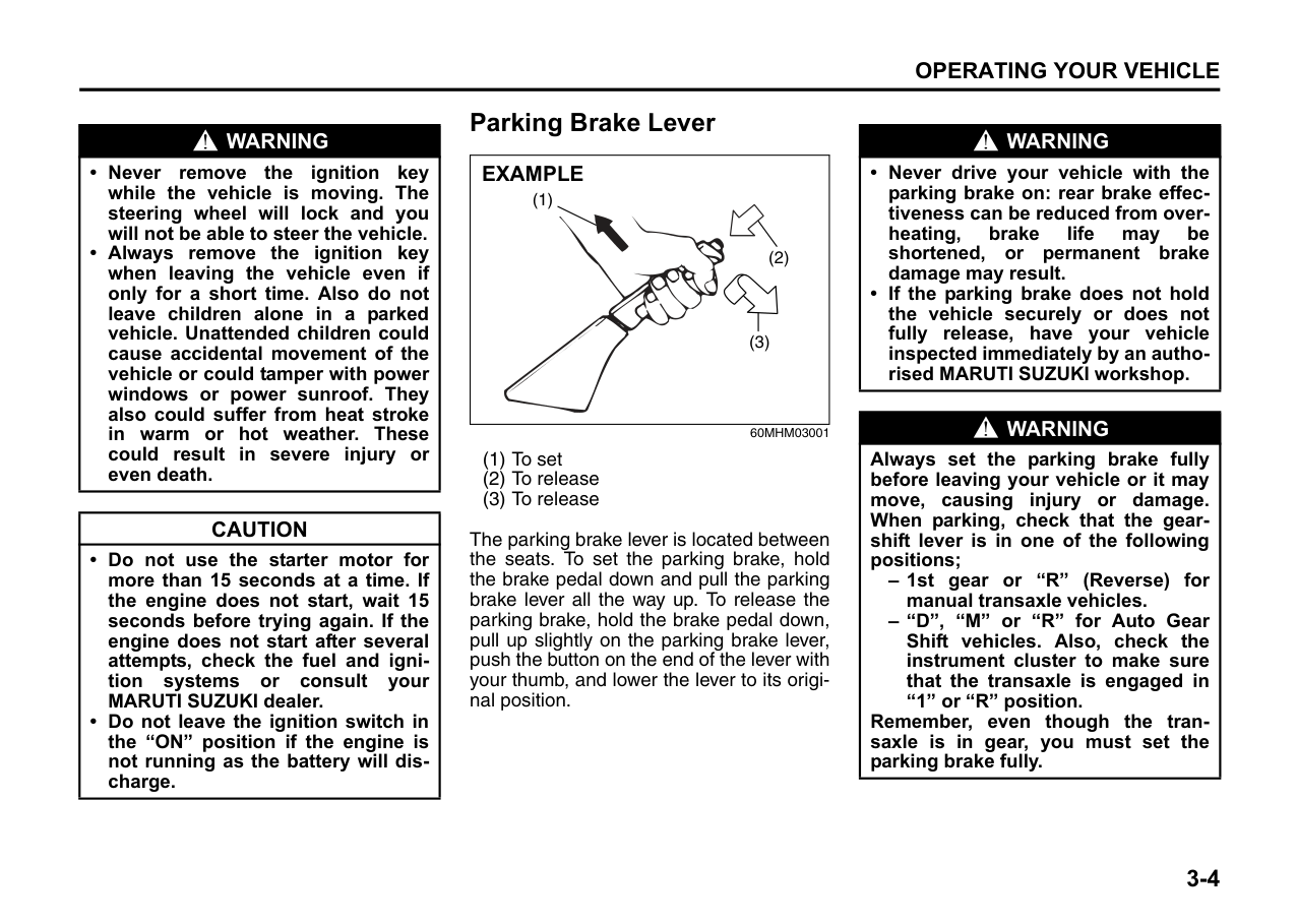
|EXAMPLE| |---|
61J062
Move the lever all the way upward or downward to signal. When the turn is completed, the signal will cancel and the lever will return to its normal position.
######## Lane change signal
|EXAMPLE| |---|
61J063
Sometimes, such as when changing lanes, the steering wheel is not turned far enough to cancel the turn signal. For convenience, you can flash the turn signal by moving the lever part way and holding it there. The lever will return to its normal position when you release it.
Hazard Warning Switch
|EXAMPLE| |---|
67LH30211
Push in the hazard warning switch to activate the hazard warning lights. All turn signal lights and both turn signal indicators will flash simultaneously. To turn off the lights, push the switch again. Use the hazard warning lights to warn other traffic during emergency parking or when your vehicle could otherwise become a traffic hazard.
Windshield Wiper and Washer Lever
|| |---|
65D611
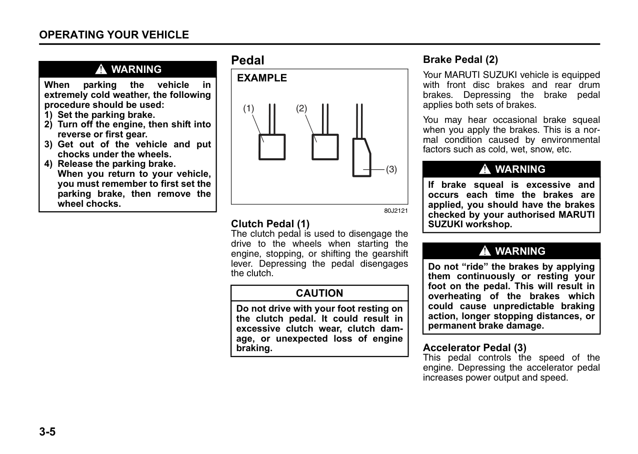
|WARNING
| |---| |To avoid possible injury, do not operate controls by reaching through the steering wheel.|
####### Wiper and Washer Operation
When the ignition switch is in the “ON” position, you can use the wiper/washer lever or switch (if equipped).
####### Windshield Wipers
|MIST
INT LO
HI
OFF
EXAMPLE| |---|
68KH027
To turn the windshield wipers on, move the lever down to one of the three operating positions. In the “INT” position, the wipers operate intermittently. The “INT” position is very convenient for driving in mist or light rain. In the “LO” position, the wipers operate at a steady low speed. In the “HI” position, the wipers operate at a steady high speed. To turn off the wipers, move the lever back to the “OFF” position. Move the lever up and hold it to the “MIST” position, the windshield wipers will turn on continuously at low speed.
####### Windshield Washer
|EXAMPLE| |---|
68KH029
To spray windshield washer fluid, pull the lever toward you. The windshield wipers will automatically turn on at low speed if they are not already on and the “INT” position is equipped.
|WARNING
| |---| |• To prevent windshield icing in cold weather, turn on the defroster to heat the windshield before and during windshield washer use.
• Do not use radiator antifreeze in the windshield washer reservoir. It can severely impair visibility when sprayed on the windshield, and can also damage your vehicle’s paint.
|
|CAUTION| |---| |To help prevent damage to the windshield wiper and washer system components, you should take the following precautions:
• Do not continue to hold in the lever when there is no windshield washer fluid being sprayed or the washer motor can be damaged.
• Do not attempt to remove dirt from a dry windshield with the wipers or you can damage the windshield and the wiper blades. Always wet the windshield with washer fluid before operating the wipers.
• Clear ice or packed snow from the wiper blades before using the wipers.
• Check the washer fluid level regularly. Check it often when the weather is bad.
• Only fill the washer fluid reservoir 3/4 full during cold weather to allow room for expansion if the temperature falls low enough to freeze the solution.
|
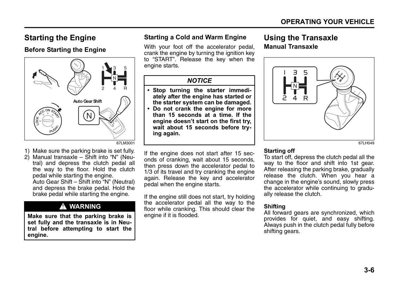
####### Rear Window Wiper/Washer Switch (if equipped)
|Intermittent wiper
Washer
Wiper
EXAMPLE| |---|
67LH045
To turn the rear wiper on, twist the rear wiper switch on the end of the lever forward to the “ON” position. To turn the rear wiper off, twist the switch rearward to the “OFF” position.
With the rear wiper in the “OFF” position, twist the switch rearward and hold it there to spray window washer fluid.
With the rear wiper in the “ON” position, turn the switch forward and hold it there to spray window washer fluid.The rear wiper will turn on automatically while spraying the window washer fluid.
|CAUTION| |---| |Clear ice or snow from the rear window and rear wiper blade before using the rear wiper. Accumulated ice or snow could prevent the wiper blade from moving, causing damage to the wiper motor.|
Tilt Steering Lock Lever (if equipped)
|EXAMPLE| |---|
67LH046
The lock lever is located under the steering column. To adjust the steering wheel height:
|WARNING
|
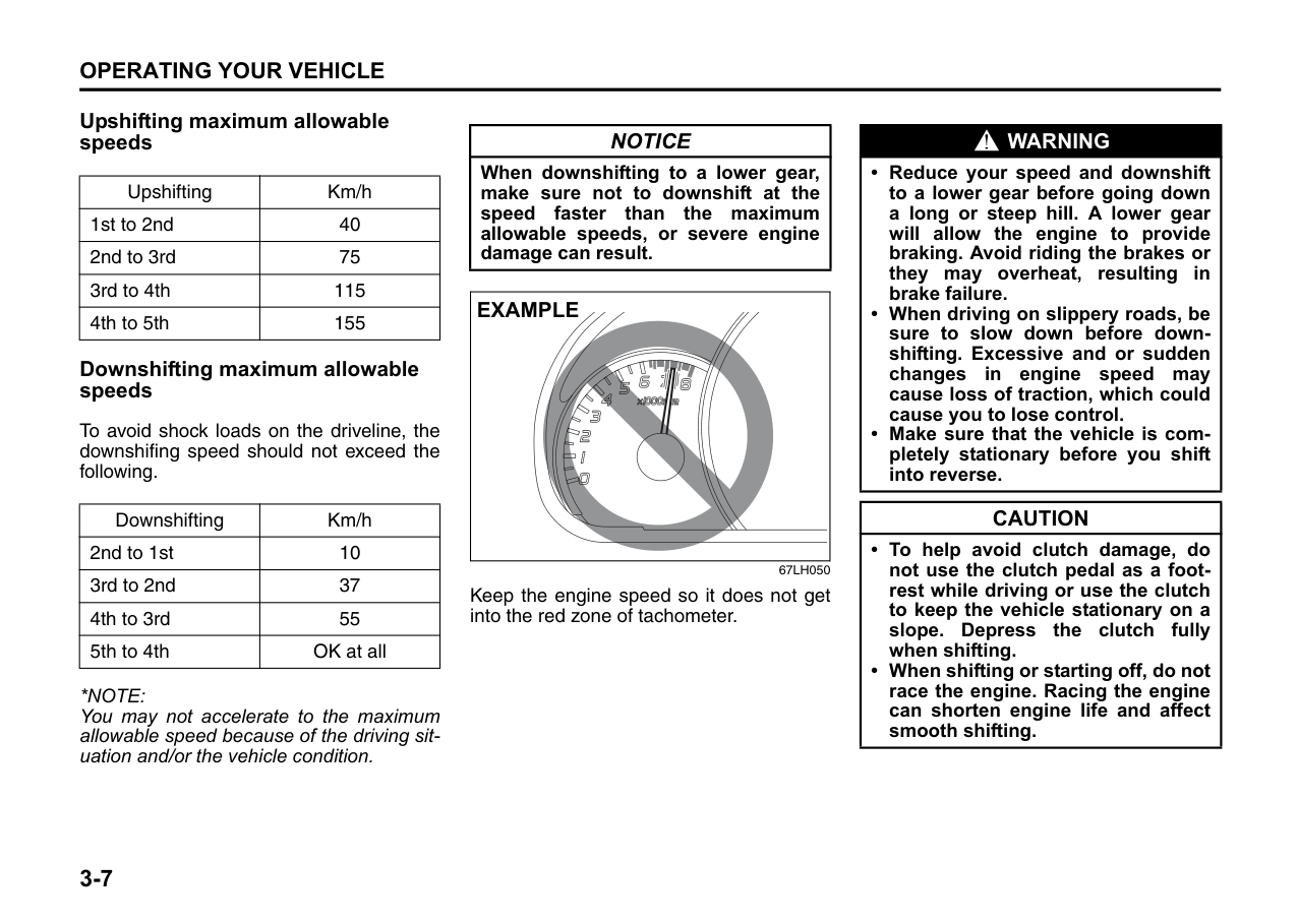
|---| |Never attempt to adjust the steering wheel height while the vehicle is moving or you could lose control of the vehicle.|
Horn
|EXAMPLE| |---|
67LH044
Press the horn button of the steering wheel to sound the horn. The horn will sound with the ignition switch in any position.
Heated Rear Window Switch (if equipped)
|(1)
EXAMPLE| |---|
67LH30212
When the rear window is misted, push this switch (1) to clear the window.
An indicator light will be lit when the defogger is on. The defogger will work only when the engine is running. To turn off the defogger, push the switch (1) again.
|CAUTION| |---| |The heated rear window uses a large amount of electricity. Be sure to turn off after the window has become clear.|
NOTE:
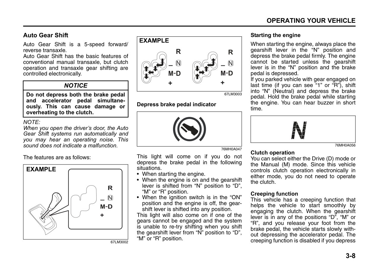
OPERATING YOUR VEHICLE
| | |---|
60MHMT3001
Exhaust Gas Warning ......................................................... 3-1 Daily Inspection Checklist .................................................. 3-1 Engine Oil Consumption .................................................... 3-2 Ignition Switch ..................................................................... 3-3 Parking Brake Lever ........................................................... 3-4 Pedal ..................................................................................... 3-5 Starting the Engine ............................................................. 3-6 Using the Transaxle ............................................................ 3-6 Braking ................................................................................. 3-15
###### 3
Exhaust Gas Warning
| | |---|
52D334
|WARNING
| |---| |Avoid breathing exhaust gases. Exhaust gases contain carbon monoxide, a potentially lethal gas that is colorless and odorless. Since carbon monoxide is difficult to detect by itself, be sure to take the following precautions to help prevent carbon monoxide from entering your vehicle. • Do not leave the engine running in
garages or other confined areas.
(Continued)|
|WARNING
| |---| |(Continued)
• Do not park with the engine running for a long period of time, even in an open area. If it is necessary to sit for a short time in a parked vehicle with the engine running, make sure the air intake selector is set to “FRESH AIR” and the fan is at high speed.
• Avoid operating the vehicle with the tailgate or trunk open. If it is necessary to operate the vehicle with the tailgate or trunk open, make sure the sunroof (if equipped) and all windows are closed, and the blower is at high speed with the air intake selector set to “FRESH AIR”.
• To allow proper operation of your vehicle’s ventilation system, keep the air inlet grille in front of the windshield clear of snow, leaves, or other obstructions at all times.
• Keep the exhaust tailpipe area clear of snow and other material to help reduce the buildup of exhaust gases under the vehicle. This is particularly important when parked in blizzard conditions.
• Have the exhaust system inspected periodically for damage and leaks. Any damage or leaks should be repaired immediately.
|
Daily Inspection Checklist Before Driving
|| |---|
60A187S
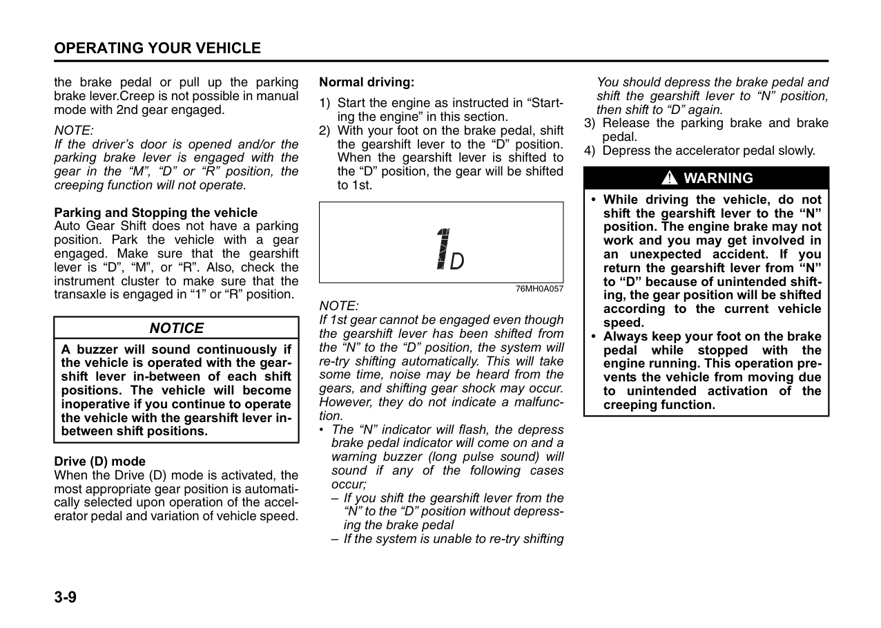
Refer to “Tires” in “INSPECTION AND MAINTENANCE” section for details.
NOTE: It is normal for water to drip from the air conditioning system after use.
Once a week, or each time you fill your fuel tank, perform the following under-hood checks:
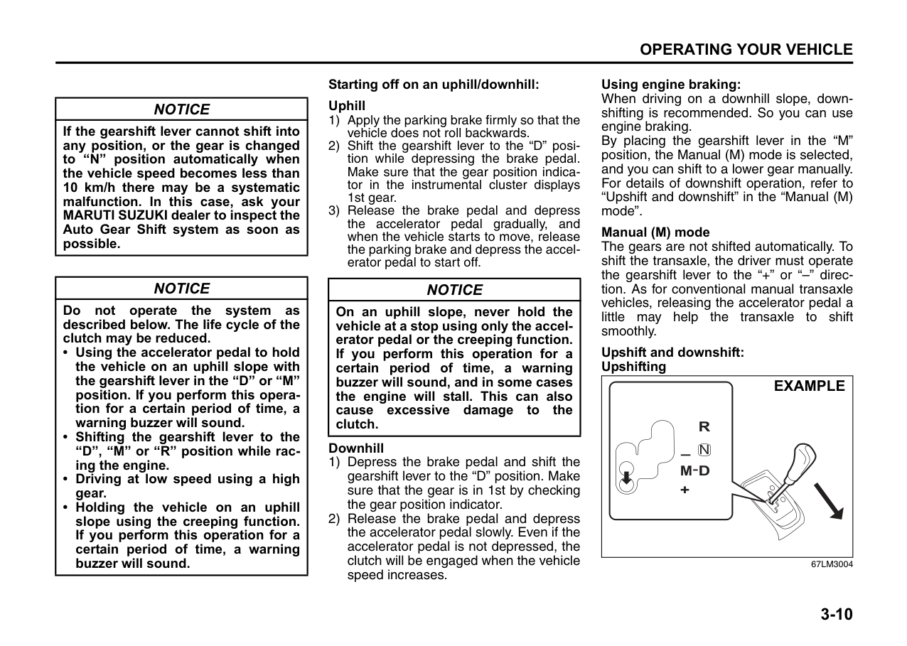
latches, hinges & locks” of “CHASSIS AND BODY” in the “Periodic Maintenance Schedule” in the “INSPECTION AND MAINTENANCE” section for lubrication schedule.
|WARNING
| |---| |Make sure the hood is fully closed and latched before driving. If it is not, it can fly up unexpectedly during driving, obstructing your view and resulting in an accident.|
Once a month, or each time you fill your fuel tank, check the tire pressure using a tire pressure gauge. Also check the tire pressure of the spare tire.
Engine Oil Consumption
It is normal for the engine to consume some engine oil during normal vehicle operation.
The amount of engine oil consumed depends on the viscosity of the oil, the quality of the oil and the conditions the vehicle is driven under. More oil is consumed during high-speed driving and when there is frequent acceleration and deceleration. Under high loads, your engine also will consume more oil. A new engine also consumes more oil, since its pistons, piston rings and cylinder walls have not yet become conditioned. New engines reach the normal level of oil
consumption only after approximately 5000 km driving.
Oil consumption: Max. 1.0 L per 1000km
When judging the amount of oil consumption, note that the oil may become diluted and make it difficult to accurately judge the true oil level. As an example, if a vehicle is used for repeated short trips, and consumes a normal amount of oil, the dipstick may not show any drop in the oil level at all, even after 1000 km or more of driving. This is because the oil is gradually becoming diluted with fuel or moisture, making it appear that the oil level has not changed. You should also be aware that the diluting ingredients evaporate out when the vehicle is subsequently driven at high speeds, such as on an expressway, making it appear that oil is excessively consumed after high-speed driving.
Ignition Switch
|| |---|
65D611
|WARNING
| |---| |To avoid possible injury, do not operate controls by reaching through the steering wheel.|
|EXAMPLE| |---|
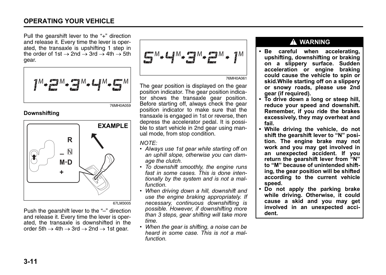
52KM052
The ignition switch has the following four positions:
######## LOCK
This is the normal parking position. It is the only position in which the key can be removed.
######## Manual transaxle
|
Turn to “LOCK”
Push| |---|
60G033
You must push in the key to turn it to the “LOCK” position. It locks the ignition, and prevents normal use of the steering wheel after the key is removed.
To release the steering lock, insert the key and turn it clockwise to one of the other positions. If you have trouble turning the key to unlock the steering, try turning the steering wheel slightly to the right or left while turning the key.
ACC Accessories such as the radio can operate, but the engine is off.
ON This is the normal operating position. All electrical systems are on.
######## START
This is the position for starting the engine using the starter motor. The key should be released from this position as soon as the engine starts.
######## Ignition key reminder (if equipped)
A buzzer sounds intermittently to remind you to remove the ignition key if it is in the ignition switch when the driver’s door is opened.
|| |---|
81A297S
|WARNING
| |---| |• Never remove the ignition key while the vehicle is moving. The steering wheel will lock and you will not be able to steer the vehicle.
• Always remove the ignition key when leaving the vehicle even if only for a short time. Also do not leave children alone in a parked vehicle. Unattended children could cause accidental movement of the vehicle or could tamper with power windows or power sunroof. They also could suffer from heat stroke in warm or hot weather. These could result in severe injury or even death.
|
|CAUTION| |---| |• Do not use the starter motor for more than 15 seconds at a time. If the engine does not start, wait 15 seconds before trying again. If the engine does not start after several attempts, check the fuel and ignition systems or consult your MARUTI SUZUKI dealer.
• Do not leave the ignition switch in the “ON” position if the engine is not running as the battery will discharge.
|
Parking Brake Lever
|EXAMPLE
(2)
(3)
(1)
| |---|
60MHM03001
The parking brake lever is located between the seats. To set the parking brake, hold the brake pedal down and pull the parking brake lever all the way up. To release the parking brake, hold the brake pedal down, pull up slightly on the parking brake lever, push the button on the end of the lever with your thumb, and lower the lever to its original position.
|WARNING
| |---| |• Never drive your vehicle with the parking brake on: rear brake effectiveness can be reduced from overheating, brake life may be shortened, or permanent brake damage may result.
• If the parking brake does not hold the vehicle securely or does not fully release, have your vehicle inspected immediately by an authorised MARUTI SUZUKI workshop.
|
|WARNING
| |---| |Always set the parking brake fully before leaving your vehicle or it may move, causing injury or damage. When parking, check that the gearshift lever is in one of the following positions;
– 1st gear or “R” (Reverse) for manual transaxle vehicles.
– “D”, “M” or “R” for Auto Gear Shift vehicles. Also, check the instrument cluster to make sure that the transaxle is engaged in “1” or “R” position.
Remember, even though the transaxle is in gear, you must set the parking brake fully.|
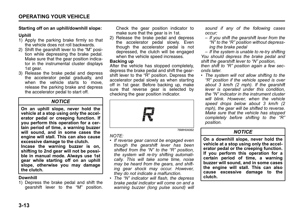
|WARNING
| |---| |When parking the vehicle in extremely cold weather, the following procedure should be used:
1) Set the parking brake.
2) Turn off the engine, then shift into reverse or first gear.
3) Get out of the vehicle and put chocks under the wheels.
4) Release the parking brake. When you return to your vehicle, you must remember to first set the parking brake, then remove the wheel chocks.
|
Pedal
|(2)(1)
(3)
EXAMPLE| |---|
####### 80J2121 Clutch Pedal (1)
The clutch pedal is used to disengage the drive to the wheels when starting the engine, stopping, or shifting the gearshift lever. Depressing the pedal disengages the clutch.
|CAUTION| |---| |Do not drive with your foot resting on the clutch pedal. It could result in excessive clutch wear, clutch damage, or unexpected loss of engine braking.|
####### Brake Pedal (2)
Your MARUTI SUZUKI vehicle is equipped with front disc brakes and rear drum brakes. Depressing the brake pedal applies both sets of brakes.
You may hear occasional brake squeal when you apply the brakes. This is a normal condition caused by environmental factors such as cold, wet, snow, etc.
|WARNING
| |---| |If brake squeal is excessive and occurs each time the brakes are applied, you should have the brakes checked by your authorised MARUTI SUZUKI workshop.|
|WARNING
| |---| |Do not “ride” the brakes by applying them continuously or resting your foot on the pedal. This will result in overheating of the brakes which could cause unpredictable braking action, longer stopping distances, or permanent brake damage.|
####### Accelerator Pedal (3)
This pedal controls the speed of the engine. Depressing the accelerator pedal increases power output and speed.
Starting the Engine Before Starting the Engine
|Auto Gear Shift| |---|
67LM3001
|WARNING
| |---| |Make sure that the parking brake is set fully and the transaxle is in Neutral before attempting to start the engine.|
####### Starting a Cold and Warm Engine
With your foot off the accelerator pedal, crank the engine by turning the ignition key to “START”. Release the key when the engine starts.
|NOTICE| |---| |• Stop turning the starter immediately after the engine has started or the starter system can be damaged.
• Do not crank the engine for more than 15 seconds at a time. If the engine doesn’t start on the first try, wait about 15 seconds before trying again.
|
If the engine does not start after 15 seconds of cranking, wait about 15 seconds, then press down the accelerator pedal to 1/3 of its travel and try cranking the engine again. Release the key and accelerator pedal when the engine starts.
If the engine still does not start, try holding the accelerator pedal all the way to the floor while cranking. This should clear the engine if it is flooded.
Using the Transaxle Manual Transaxle
| |
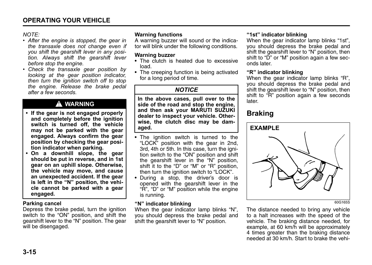
|---|
67LH049 Starting off
To start off, depress the clutch pedal all the way to the floor and shift into 1st gear. After releasing the parking brake, gradually release the clutch. When you hear a change in the engine’s sound, slowly press the accelerator while continuing to gradually release the clutch.
######## Shifting
All forward gears are synchronized, which provides for quiet, and easy shifting. Always push in the clutch pedal fully before shifting gears.
Upshifting maximum allowable speeds
|Upshifting|Km/h| |---|---| |1st to 2nd|40| |2nd to 3rd|75| |3rd to 4th|115| |4th to 5th|155|
Downshifting maximum allowable speeds
To avoid shock loads on the driveline, the downshifing speed should not exceed the following.
|Downshifting|Km/h| |---|---| |2nd to 1st|10| |3rd to 2nd|37| |4th to 3rd|55| |5th to 4th|OK at all|
*NOTE: You may not accelerate to the maximum allowable speed because of the driving situation and/or the vehicle condition.
|NOTICE| |---|
|When downshifting to a lower gear, make sure not to downshift at the speed faster than the maximum allowable speeds, or severe engine damage can result.|
EXAMPLE
67LH050
Keep the engine speed so it does not get into the red zone of tachometer.
|WARNING
| |---| |• Reduce your speed and downshift to a lower gear before going down a long or steep hill. A lower gear will allow the engine to provide braking. Avoid riding the brakes or they may overheat, resulting in brake failure.
• When driving on slippery roads, be sure to slow down before downshifting. Excessive and or sudden changes in engine speed may cause loss of traction, which could cause you to lose control.
• Make sure that the vehicle is completely stationary before you shift into reverse.
|
CAUTION
####### Auto Gear Shift
Auto Gear Shift is a 5-speed forward/ reverse transaxle. Auto Gear Shift has the basic features of conventional manual transaxle, but clutch operation and transaxle gear shifting are controlled electronically.
|NOTICE| |---| |Do not depress both the brake pedal and accelerator pedal simultaneously. This can cause damage or overheating to the clutch.|
NOTE: When you open the driver’s door, the Auto Gear Shift systems run automatically and you may hear an operating noise. This sound does not indicate a malfunction.
The features are as follows:
|M +
R N
D-
EXAMPLE| |---|
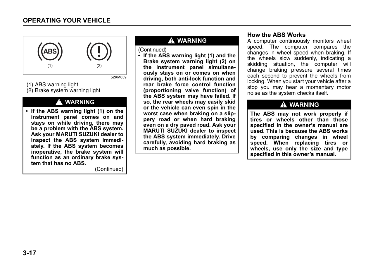
67LM3002
|-
M
+
R
N
D-
-
M
+
R
N
D-
EXAMPLE| |---|
######## 67LM3003 Depress brake pedal indicator
| | |---|
76MH0A047
This light will come on if you do not depress the brake pedal in the following situations.
This light will also come on if one of the gears cannot be engaged and the system is unable to re-try shifting when you shift the gearshift lever from “N” position to “D”, “M” or “R” position.
######## Starting the engine
When starting the engine, always place the gearshift lever in the “N” position and depress the brake pedal firmly. The engine cannot be started unless the gearshift lever is in the “N” position and the brake pedal is depressed. If you parked vehicle with gear engaged on last time (if you can see “1” or “R”), shift into “N” (Neutral) and depress the brake pedal. Hold the brake pedal while starting the engine. You can hear buzzer in short time.
| | |---|
76MH0A056 Clutch operation
You can select either the Drive (D) mode or the Manual (M) mode. Since this vehicle controls clutch operation electronically in either mode, you do not need to operate the clutch.
######## Creeping function
This vehicle has a creeping function that helps the vehicle to start smoothly by engaging the clutch. When the gearshift lever is in any of the positions “D”, “M” or “R”, and you release your foot from the brake pedal, the vehicle starts slowly without depressing the accelerator pedal. The creeping function is disabled if you depress
the brake pedal or pull up the parking brake lever.Creep is not possible in manual mode with 2nd gear engaged.
NOTE: If the driver’s door is opened and/or the parking brake lever is engaged with the gear in the “M”, “D” or “R” position, the creeping function will not operate.
######## Parking and Stopping the vehicle
Auto Gear Shift does not have a parking position. Park the vehicle with a gear engaged. Make sure that the gearshift lever is “D”, “M”, or “R”. Also, check the instrument cluster to make sure that the transaxle is engaged in “1” or “R” position.
|NOTICE| |---| |A buzzer will sound continuously if the vehicle is operated with the gearshift lever in-between of each shift positions. The vehicle will become inoperative if you continue to operate the vehicle with the gearshift lever inbetween shift positions.|
######## Drive (D) mode
When the Drive (D) mode is activated, the most appropriate gear position is automatically selected upon operation of the accelerator pedal and variation of vehicle speed.
######## Normal driving:
| | |---|
76MH0A057
NOTE: If 1st gear cannot be engaged even though the gearshift lever has been shifted from the “N” to the “D” position, the system will re-try shifting automatically. This will take some time, noise may be heard from the gears, and shifting gear shock may occur. However, they do not indicate a malfunction.
• The “N” indicator will flash, the depress brake pedal indicator will come on and a warning buzzer (long pulse sound) will sound if any of the following cases occur;
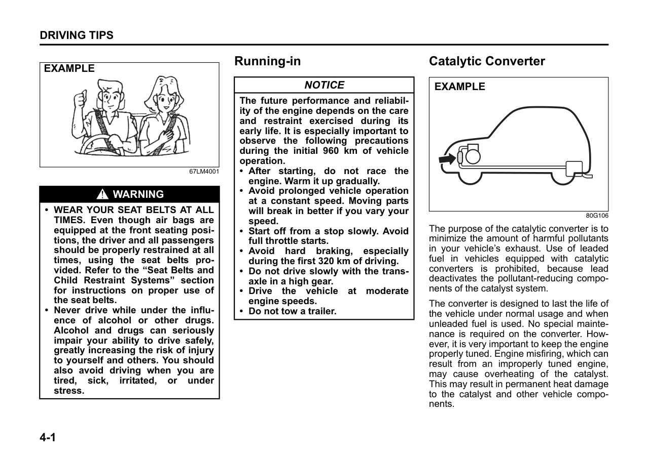
You should depress the brake pedal and shift the gearshift lever to “N” position, then shift to “D” again.
|WARNING
| |---| |• While driving the vehicle, do not shift the gearshift lever to the “N” position. The engine brake may not work and you may get involved in an unexpected accident. If you return the gearshift lever from “N” to “D” because of unintended shifting, the gear position will be shifted according to the current vehicle speed.
• Always keep your foot on the brake pedal while stopped with the engine running. This operation prevents the vehicle from moving due to unintended activation of the creeping function.
|
|NOTICE| |---| |If the gearshift lever cannot shift into any position, or the gear is changed to “N” position automatically when the vehicle speed becomes less than 10 km/h there may be a systematic malfunction. In this case, ask your MARUTI SUZUKI dealer to inspect the Auto Gear Shift system as soon as possible.|
|NOTICE| |---| |Do not operate the system as described below. The life cycle of the clutch may be reduced.
• Using the accelerator pedal to hold the vehicle on an uphill slope with the gearshift lever in the “D” or “M” position. If you perform this operation for a certain period of time, a warning buzzer will sound.
• Shifting the gearshift lever to the “D”, “M” or “R” position while racing the engine.
• Driving at low speed using a high gear.
• Holding the vehicle on an uphill slope using the creeping function. If you perform this operation for a certain period of time, a warning buzzer will sound.
|
######## Starting off on an uphill/downhill: Uphill
|NOTICE| |---| |On an uphill slope, never hold the vehicle at a stop using only the accelerator pedal or the creeping function. If you perform this operation for a certain period of time, a warning buzzer will sound, and in some cases the engine will stall. This can also cause excessive damage to the clutch.|
######## Downhill
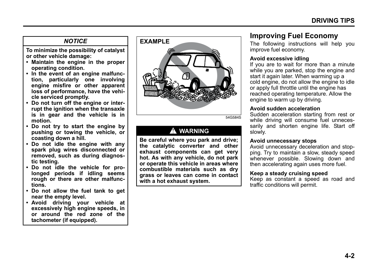
Using engine braking: When driving on a downhill slope, downshifting is recommended. So you can use engine braking. By placing the gearshift lever in the “M” position, the Manual (M) mode is selected, and you can shift to a lower gear manually. For details of downshift operation, refer to “Upshift and downshift” in the “Manual (M) mode”.
######## Manual (M) mode
The gears are not shifted automatically. To shift the transaxle, the driver must operate the gearshift lever to the “+” or “–” direction. As for conventional manual transaxle vehicles, releasing the accelerator pedal a little may help the transaxle to shift smoothly.
Upshift and downshift: Upshifting
|M +
R N
D-
EXAMPLE| |---|
67LM3004
Pull the gearshift lever to the “+” direction and release it. Every time the lever is operated, the transaxle is upshifting 1 step in the order of 1st 2nd 3rd 4th 5th gear.
| | |---|
######## 76MH0A059 Downshifting
|-
M
+
R
N
D-
EXAMPLE| |---|
67LM3005
Push the gearshift lever to the “–” direction and release it. Every time the lever is operated, the transaxle is downshifted in the order 5th 4th 3rd 2nd 1st gear.
| | |---|
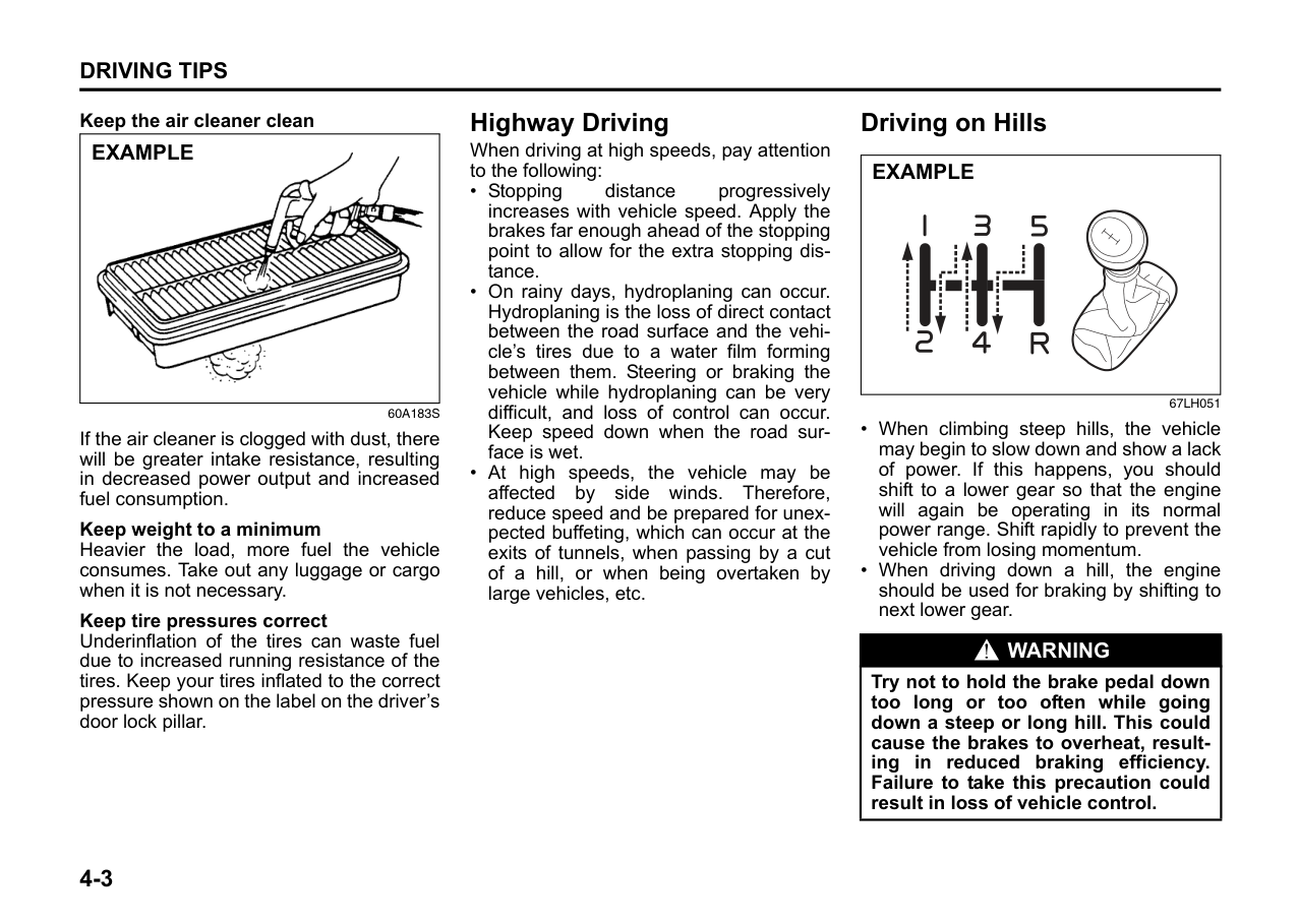
76MH0A061
The gear position is displayed on the gear position indicator. The gear position indicator shows the transaxle gear position. Before starting off, always check the gear position indicator to make sure that the transaxle is engaged in 1st or reverse, then depress the accelerator pedal. It is possible to start vehicle in 2nd gear using manual mode, from stop condition.
NOTE:
|WARNING
| |---| |• Be careful when accelerating, upshifting, downshifting or braking on a slippery surface. Sudden acceleration or engine braking could cause the vehicle to spin or skid.While starting off on a slippery or snowy roads, please use 2nd gear (if required).
• To drive down a long or steep hill, reduce your speed and downshift. Remember, if you ride the brakes excessively, they may overheat and fail.
• While driving the vehicle, do not shift the gearshift lever to “N” position. The engine brake may not work and you may get involved in an unexpected accident. If you return the gearshift lever from “N” to “M” because of unintended shifting, the gear position will be shifted according to the current vehicle speed.
• Do not apply the parking brake while driving. Otherwise, it could cause a skid and you may get involved in an unexpected accident.
|
|NOTICE| |---| |• If the gearshift lever cannot shift into any position, or the gear is changed to “N” position automatically when the vehicle speed becomes less than 10 km/h there may be a systematic malfunction. In this case, ask your MARUTI SUZUKI dealer to inspect the Auto Gear Shift system as soon as possible.
• The manual (M) mode does not upshift even if the engine speed reaches the rev-limit.
• The system will not allow shifting up or down to a gear that would cause engine over-revving or under-revving.
• If frequently driving at low speed using a high gear position, the life cycle of the clutch may be reduced.
• Frequent downshifting (more than 3 positions consecutively) causes the reduction of transaxle life.
|
######## Starting off:
NOTE:
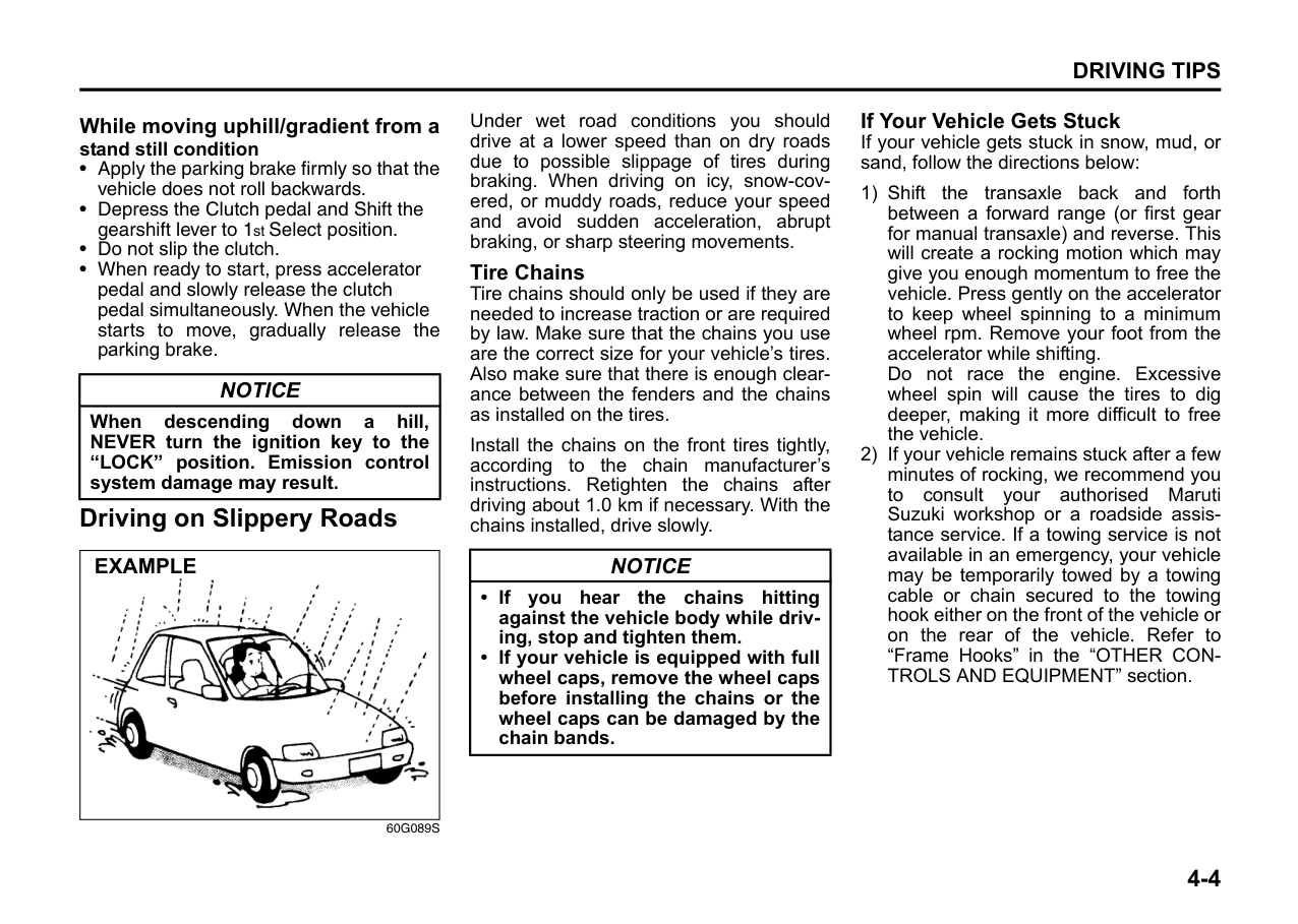
######### 3) Release the parking brake and brake pedal. Depress the accelerator pedal slowly for smooth starting.
|WARNING
| |---| |Always keep your foot on the brake pedal or pull up the parking lever while stopping with the engine running. These operations prevent the vehicle from starting due to unintended activation of the creeping function.|
|NOTICE| |---| |Do not operate the system as described below. The life cycle of the clutch may be reduced.
• Using the accelerator pedal to hold the vehicle on an uphill slope operation with the gearshift lever in the “M” or “D” position. If you perform this operation for a certain period of time, a warning buzzer will sound.
• Shifting the gearshift lever to the “M”, “D” or “R” position while racing the engine.
• Driving at low speed using a high gear.
• Stopping on a slope using the creeping function. If you perform this operation for a certain period of time, a warning buzzer will sound.
|
Starting off on an uphill/downhill slope: Uphill
1) Apply the parking brake firmly so that the vehicle does not roll backwards. 2) Shift the gearshift lever to the “M” position while depressing the brake pedal. Make sure that the gear position indicator in the instrumental cluster displays 1st gear.
3) Release the brake pedal and depress the accelerator pedal gradually, and when the vehicle starts to move, release the parking brake and depress the accelerator pedal to start off.
|NOTICE| |---| |On an uphill slope, never hold the vehicle at a stop using only the accelerator pedal or creeping function. If you perform this operation for a certain period of time, a warning buzzer will sound, and in some cases the engine will stall. This can also cause excessive damage to the clutch. Incase the warning buzzer is on, shifting to 2nd gear will not be possible in manual mode. Always use 1st gear while starting off on an uphill slope, otherwise you may damage the clutch.|
######## Downhill
1) Depress the brake pedal and shift the gearshift lever to the “M” position.
Check the gear position indicator to make sure that the gear is in 1st.
2) Release the brake pedal and depress the accelerator pedal slowly. Even though the accelerator pedal is not depressed, the clutch will be engaged when the vehicle speed increases.
######## Backing up
After the vehicle has stopped completely, depress the brake pedal and shift the gearshift lever to the “R” position. Depress the accelerator pedal slowly as when starting off in 1st gear. Before backing up, make sure that reverse gear is selected by checking the gear position indicator.
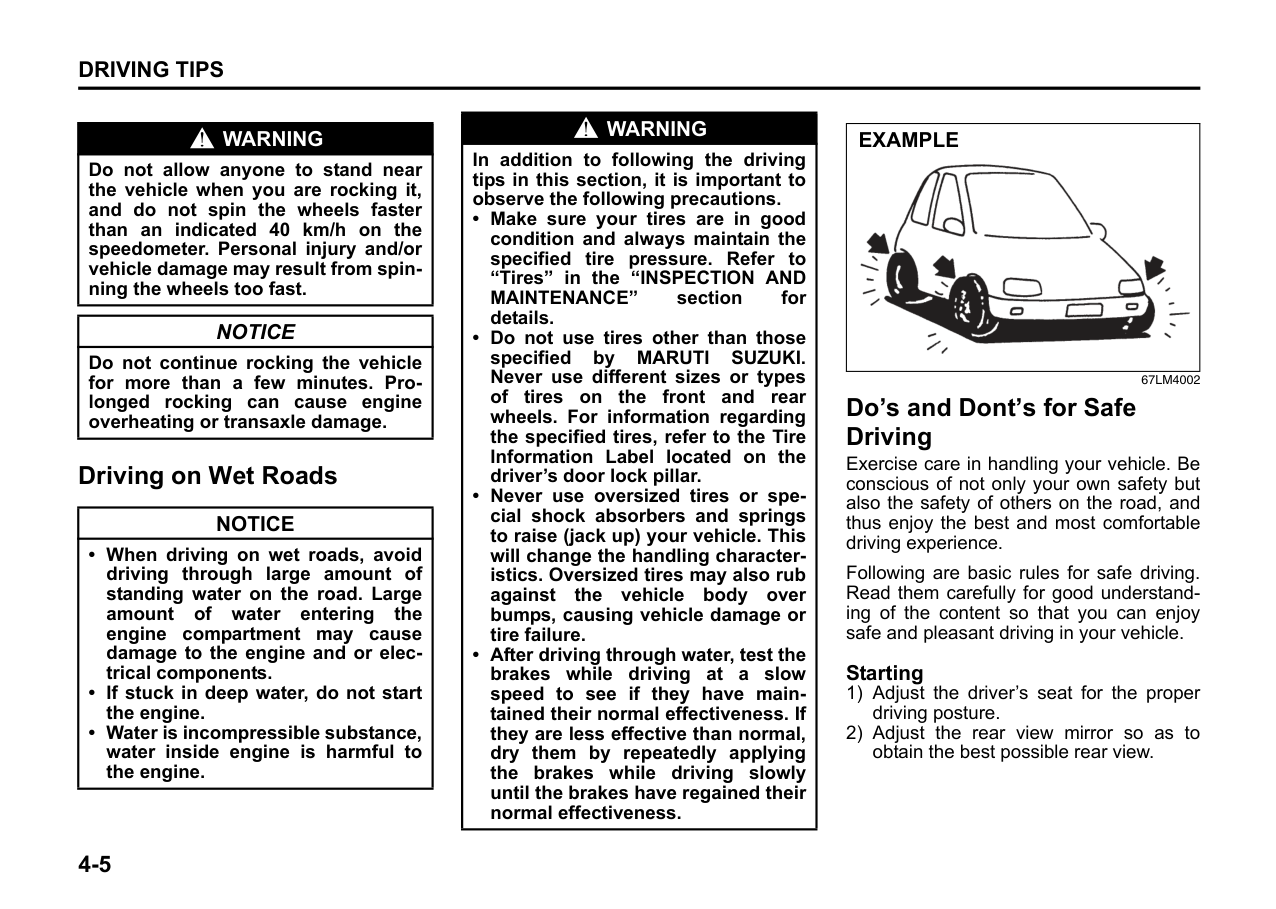
| | |---|
76MH0A062 NOTE:
sound if any of the following cases occur;
You should depress the brake pedal and shift the gearshift lever to “N” position, then shift to “R” position again a few seconds later.
• The system will not allow shifting to the “R” position if the vehicle speed is over about 3 km/h (2 mph). If the gearshift lever is operated under this condition, the “N” indicator in the instrument cluster will blink. However, when the vehicle speed drops below about 3 km/h (2 mph), the gear will be shifted to reverse. Make sure that the vehicle has stopped completely before shifting to the “R” position.
|NOTICE| |---| |On a downhill slope, never hold the vehicle at a stop using only the accelerator pedal or the creeping function. If you perform this operation for a certain period of time, a warning buzzer will sound, and in some cases the engine will stall. This can also cause excessive damage to the clutch.|
######## Stopping
The vehicle can be stopped by depressing the brake pedal regardless of the gear position. This is because the clutch is automatically disengaged to prevent the engine from stopping.
|WARNING
| |---| |• When stopping, for example, at a traffic light, be sure to depress the brake pedal firmly. For your safety, apply the parking brake, too, when stopping on a hill.
• When racing the engine, make sure that the gear is in the “N” position by checking the gear position indicator. If the accelerator is operated with the gear in any other position, the vehicle may move resulting in an unexpected accident.
• Do not leave your vehicle unattended while the engine is running.
• When leaving the vehicle, stop the engine and park the vehicle with a gear engaged. If you need to leave the vehicle with the engine running, apply the parking brakes firmly, and shift the gearshift lever to the “N” position. Otherwise, the vehicle may move unexpectedly and may cause an accident.
|
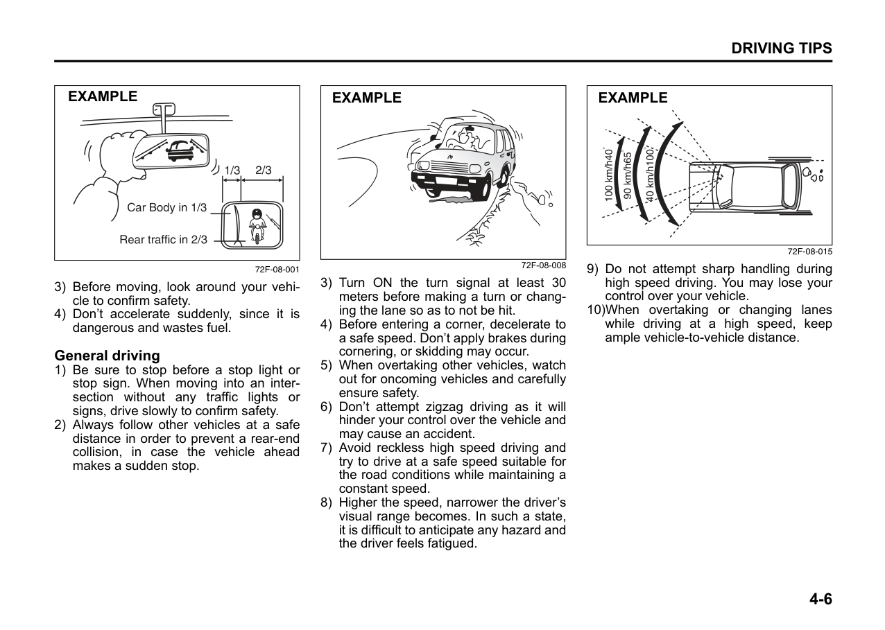
|NOTICE| |---| |• On a slope, never hold the vehicle at a stop using only the accelerator pedal or the creeping function. If you perform this operation for a certain period of time, a warning buzzer will sound, and in some cases the engine will stall. This can also cause excessive damage to the clutch.
• If the gearshift lever is operated more than necessary, the system may not allow operation of the gearshift lever for a certain period of time, and the gear may not be shifted appropriately. Therefore, do not operate the gearshift lever if not necessary.
|
######## Parking
Unlike an automatic transaxle, Auto Gear Shift does not have a parking position. Park the vehicle with a gear engaged.
NOTE:
|WARNING
| |---| |• If the gear is not engaged properly and completely before the ignition switch is turned off, the vehicle may not be parked with the gear engaged. Always confirm the gear position by checking the gear position indicator when parking.
• On a downhill slope, the gear should be put in reverse, and in 1st gear on an uphill slope. Otherwise, the vehicle may move, and cause an unexpected accident. If the gear is left in the “N” position, the vehicle cannot be parked with a gear engaged.
|
######## Parking cancel
Depress the brake pedal, turn the ignition switch to the “ON” position, and shift the gearshift lever to the “N” position. The gear will be disengaged.
######## Warning functions
A warning buzzer will sound or the indicator will blink under the following conditions.
######## Warning buzzer
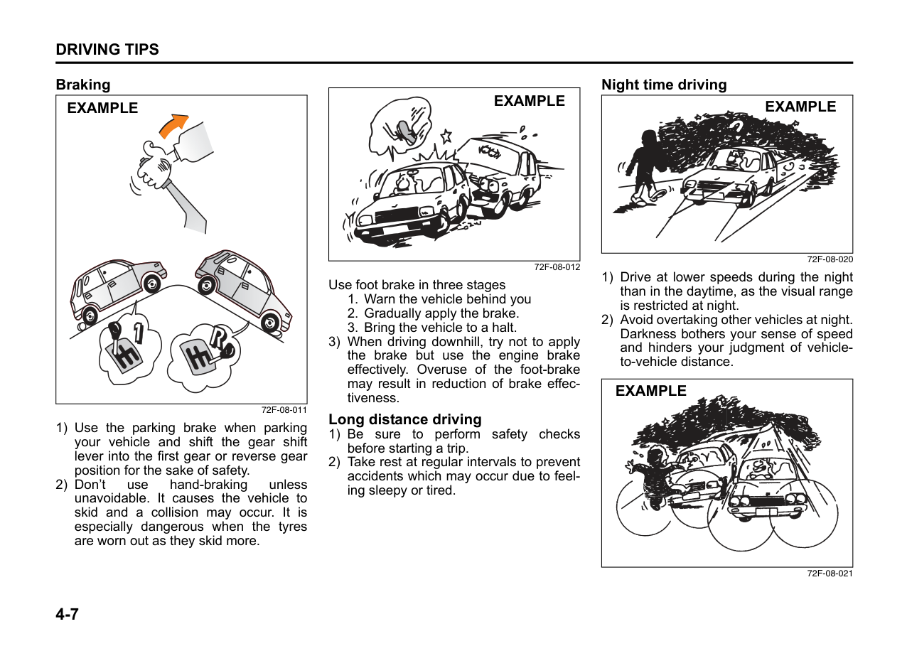
|NOTICE| |---| |In the above cases, pull over to the side of the road and stop the engine, and then ask your MARUTI SUZUKI dealer to inspect your vehicle. Otherwise, the clutch disc may be damaged.|
######## “N” indicator blinking
When the gear indicator lamp blinks “N”, you should depress the brake pedal and shift the gearshift lever to “N” position.
######## “1st” indicator blinking
When the gear indicator lamp blinks “1st”, you should depress the brake pedal and shift the gearshift lever to “N” position, then shift to “D” or “M” position again a few seconds later.
######## “R” indicator blinking
When the gear indicator lamp blinks “R”, you should depress the brake pedal and shift the gearshift lever to “N” position, then shift to “R” position again a few seconds later.
Braking
|
EXAMPLE| |---|
60G165S
The distance needed to bring any vehicle to a halt increases with the speed of the vehicle. The braking distance needed, for example, at 60 km/h will be approximately 4 times greater than the braking distance needed at 30 km/h. Start to brake the vehi-
cle when there is plenty of distance between your vehicle and the stopping point, and slow down gradually.
|WARNING
| |---| |If water gets into the brake drums, brake performance may become poor and unpredictable. After driving through water or washing the underside of the vehicle, test the brakes while driving at a slow speed to see if they have maintained their normal effectiveness. If the brakes are less effective than normal, dry them by repeatedly applying the brakes while driving slowly until the brakes have regained their normal effectiveness.|
####### Power-Assisted Brakes
Your vehicle has power-assisted brakes. If power assistance is lost due to a stalled engine or other failures, the system is still fully operational on reserve power and you can bring the vehicle to a complete stop by pressing the brake pedal once and holding it down. The reserve power is partly used up when you depress the brake pedal and reduces each time the pedal is pressed. Apply smooth and even pressure to the pedal. Do not pump the pedal.
|WARNING
| |---| |Even without reserve power in the brake system, you can still stop the vehicle by pressing the brake pedal harder than normally required. However, the stopping distance may be longer.|
Anti-Lock Brake System (ABS) (if equipped) ABS will help you avoid skidding by electronically controlling braking pressure. It will also help you maintain steering control when braking on slippery surfaces or when braking hard. The ABS works automatically, so you do not need any special braking technique. Just push the brake pedal down without pumping. The ABS will operate whenever it senses that the wheels are locking up. You may feel the brake pedal moves a little while the ABS is operating.
NOTE: The ABS will not work if vehicle speed is under about 10 km/h.
|WARNING
| |---| |• On some types of loose surfaces (such as gravel, snow-covered roads, etc.) the stopping distance required for an ABS-equipped vehicle may be slightly greater than for a comparable vehicle with a conventional brake system. With a conventional brake system, skidding tires are able to “plow” the gravel or snow layer, shortening the stopping distance, ABS minimizes this resistance effect. Allow for extra stopping distance when driving on loose surfaces.
• On regular paved roads, some drivers may be able to obtain slightly shorter stopping distances with conventional brake systems than with ABS.
• In both of the above conditions, ABS will still offer the advantage of helping you maintain directional control. However, remember that ABS will not compensate for bad road or weather conditions or poor driver judgment. Use good judgment and do not drive faster than conditions will safely allow.
|
|(1) (2)
| |---|
52KM059
|WARNING
| |---| |• If the ABS warning light (1) on the instrument panel comes on and stays on while driving, there may be a problem with the ABS system. Ask your MARUTI SUZUKI dealer to inspect the ABS system immediately. If the ABS system becomes inoperative, the brake system will function as an ordinary brake system that has no ABS.
(Continued)|
|WARNING
| |---|

|(Continued)
• If the ABS warning light (1) and the Brake system warning light (2) on the instrument panel simultaneously stays on or comes on when driving, both anti-lock function and rear brake force control function (proportioning valve function) of the ABS system may have failed. If so, the rear wheels may easily skid or the vehicle can even spin in the worst case when braking on a slippery road or when hard braking even on a dry paved road. Ask your MARUTI SUZUKI dealer to inspect the ABS system immediately. Drive carefully, avoiding hard braking as much as possible.|
####### How the ABS Works
A computer continuously monitors wheel speed. The computer compares the changes in wheel speed when braking. If the wheels slow suddenly, indicating a skidding situation, the computer will change braking pressure several times each second to prevent the wheels from locking. When you start your vehicle after a stop you may hear a momentary motor noise as the system checks itself.
|WARNING
| |---| |The ABS may not work properly if tires or wheels other than those specified in the owner’s manual are used. This is because the ABS works by comparing changes in wheel speed. When replacing tires or wheels, use only the size and type specified in this owner’s manual.|
DRIVING TIPS
| | |---|
60G409
Running-in ........................................................................... 4-1 Catalytic Converter ............................................................. 4-1 Improving Fuel Economy ................................................... 4-2 Highway Driving .................................................................. 4-3 Driving on Hills .................................................................... 4-3 Driving on Slippery Roads ................................................. 4-4 Driving on Wet Roads ......................................................... 4-5 Do’s & Don’ts for Safe Driving ........................................... 4-5 Driving on Hills .................................................................... 4-8
###### 4
|
EXAMPLE| |---|
67LM4001
|WARNING
| |---| |• WEAR YOUR SEAT BELTS AT ALL TIMES. Even though air bags are equipped at the front seating positions, the driver and all passengers should be properly restrained at all times, using the seat belts provided. Refer to the “Seat Belts and Child Restraint Systems” section for instructions on proper use of the seat belts.
• Never drive while under the influence of alcohol or other drugs. Alcohol and drugs can seriously impair your ability to drive safely, greatly increasing the risk of injury to yourself and others. You should also avoid driving when you are tired, sick, irritated, or under stress.
|
Running-in Catalytic Converter
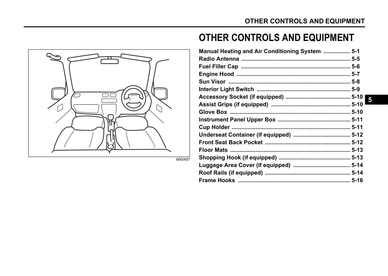
|NOTICE| |---| |The future performance and reliability of the engine depends on the care and restraint exercised during its early life. It is especially important to observe the following precautions during the initial 960 km of vehicle operation.
• After starting, do not race the engine. Warm it up gradually.
• Avoid prolonged vehicle operation at a constant speed. Moving parts will break in better if you vary your speed.
• Start off from a stop slowly. Avoid full throttle starts.
• Avoid hard braking, especially during the first 320 km of driving.
• Do not drive slowly with the transaxle in a high gear.
• Drive the vehicle at moderate engine speeds.
• Do not tow a trailer.
|
|EXAMPLE| |---|
############## 80G106
The purpose of the catalytic converter is to minimize the amount of harmful pollutants in your vehicle’s exhaust. Use of leaded fuel in vehicles equipped with catalytic converters is prohibited, because lead deactivates the pollutant-reducing components of the catalyst system.
The converter is designed to last the life of the vehicle under normal usage and when unleaded fuel is used. No special maintenance is required on the converter. However, it is very important to keep the engine properly tuned. Engine misfiring, which can result from an improperly tuned engine, may cause overheating of the catalyst. This may result in permanent heat damage to the catalyst and other vehicle components.
|NOTICE| |---| |To minimize the possibility of catalyst or other vehicle damage:
• Maintain the engine in the proper operating condition.
• In the event of an engine malfunction, particularly one involving engine misfire or other apparent loss of performance, have the vehicle serviced promptly.
• Do not turn off the engine or interrupt the ignition when the transaxle is in gear and the vehicle is in motion.
• Do not try to start the engine by pushing or towing the vehicle, or coasting down a hill.
• Do not idle the engine with any spark plug wires disconnected or removed, such as during diagnostic testing.
• Do not idle the vehicle for prolonged periods if idling seems rough or there are other malfunctions.
• Do not allow the fuel tank to get near the empty level.
• Avoid driving your vehicle at excessively high engine speeds, in or around the red zone of the tachometer (if equipped).
|
|
EXAMPLE| |---|
54G584S
|WARNING
| |---| |Be careful where you park and drive; the catalytic converter and other exhaust components can get very hot. As with any vehicle, do not park or operate this vehicle in areas where combustible materials such as dry grass or leaves can come in contact with a hot exhaust system.|
Improving Fuel Economy The following instructions will help you improve fuel economy. Avoid excessive idling If you are to wait for more than a minute while you are parked, stop the engine and start it again later. When warming up a cold engine, do not allow the engine to idle or apply full throttle until the engine has reached operating temperature. Allow the engine to warm up by driving. Avoid sudden acceleration
Sudden acceleration starting from rest or while driving will consume fuel unnecessarily and shorten engine life. Start off slowly.
######## Avoid unnecessary stops
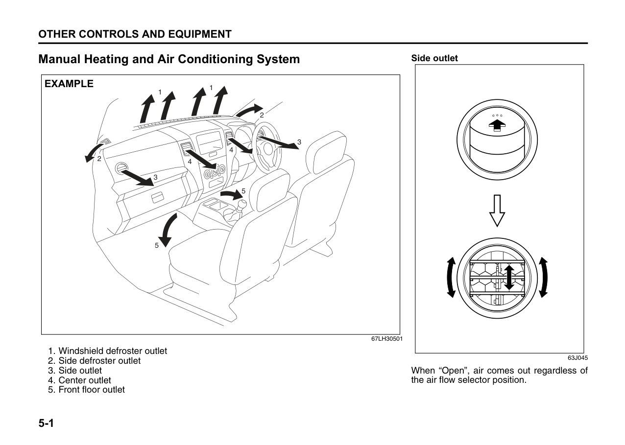
Avoid unnecessary deceleration and stopping. Try to maintain a slow, steady speed whenever possible. Slowing down and then accelerating again uses more fuel.
Keep a steady cruising speed Keep as constant a speed as road and traffic conditions will permit.
######## Keep the air cleaner clean
|
EXAMPLE| |---|
60A183S
If the air cleaner is clogged with dust, there will be greater intake resistance, resulting in decreased power output and increased fuel consumption.
######## Keep weight to a minimum
Heavier the load, more fuel the vehicle consumes. Take out any luggage or cargo when it is not necessary.
######## Keep tire pressures correct
Underinflation of the tires can waste fuel due to increased running resistance of the tires. Keep your tires inflated to the correct pressure shown on the label on the driver’s door lock pillar.
Highway Driving When driving at high speeds, pay attention to the following:
Driving on Hills
|EXAMPLE| |---|
67LH051
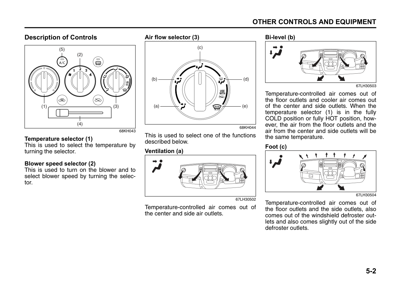
|WARNING
| |---| |Try not to hold the brake pedal down too long or too often while going down a steep or long hill. This could cause the brakes to overheat, resulting in reduced braking efficiency. Failure to take this precaution could result in loss of vehicle control.|
####### While moving uphill/gradient from a stand still condition
|NOTICE| |---| |When descending down a hill, NEVER turn the ignition key to the “LOCK” position. Emission control system damage may result.|
Driving on Slippery Roads
|
EXAMPLE| |---|
60G089S
Under wet road conditions you should drive at a lower speed than on dry roads due to possible slippage of tires during braking. When driving on icy, snow-covered, or muddy roads, reduce your speed and avoid sudden acceleration, abrupt braking, or sharp steering movements.
####### Tire Chains
Tire chains should only be used if they are needed to increase traction or are required by law. Make sure that the chains you use are the correct size for your vehicle’s tires. Also make sure that there is enough clearance between the fenders and the chains as installed on the tires.
Install the chains on the front tires tightly, according to the chain manufacturer’s instructions. Retighten the chains after driving about 1.0 km if necessary. With the chains installed, drive slowly.
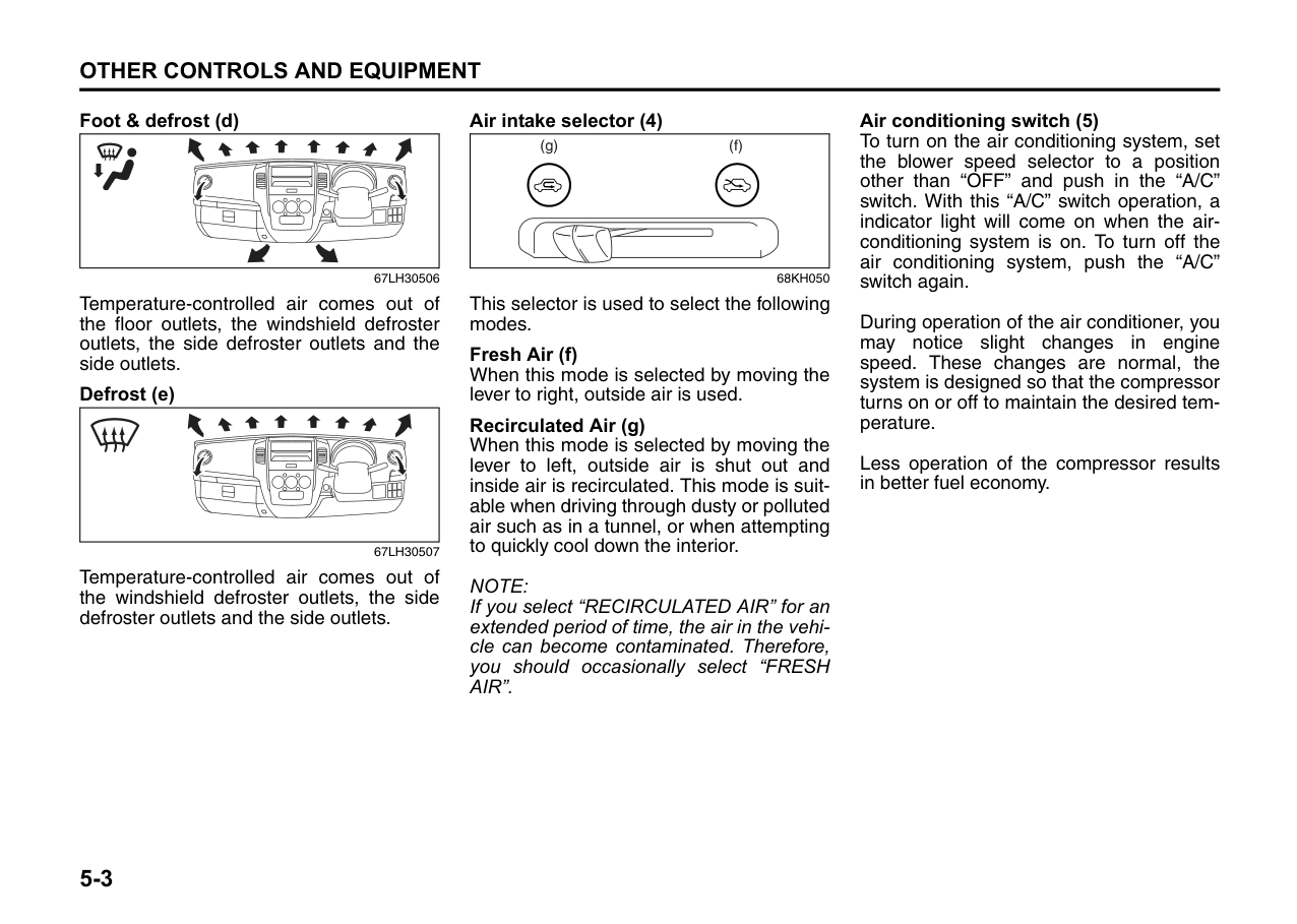
|NOTICE| |---| |• If you hear the chains hitting against the vehicle body while driving, stop and tighten them.
• If your vehicle is equipped with full wheel caps, remove the wheel caps before installing the chains or the wheel caps can be damaged by the chain bands.
|
If Your Vehicle Gets Stuck If your vehicle gets stuck in snow, mud, or sand, follow the directions below:
|WARNING
| |---| |Do not allow anyone to stand near the vehicle when you are rocking it, and do not spin the wheels faster than an indicated 40 km/h on the speedometer. Personal injury and/or vehicle damage may result from spinning the wheels too fast.|
|NOTICE| |---| |Do not continue rocking the vehicle for more than a few minutes. Prolonged rocking can cause engine overheating or transaxle damage.|
Driving on Wet Roads
|NOTICE| |---| |• When driving on wet roads, avoid driving through large amount of standing water on the road. Large amount of water entering the engine compartment may cause damage to the engine and or electrical components.
• If stuck in deep water, do not start the engine.
• Water is incompressible substance, water inside engine is harmful to the engine.
|
|WARNING
| |---| |In addition to following the driving tips in this section, it is important to observe the following precautions.
• Make sure your tires are in good condition and always maintain the specified tire pressure. Refer to “Tires” in the “INSPECTION AND MAINTENANCE” section for details.
• Do not use tires other than those specified by MARUTI SUZUKI. Never use different sizes or types of tires on the front and rear wheels. For information regarding the specified tires, refer to the Tire Information Label located on the driver’s door lock pillar.
• Never use oversized tires or special shock absorbers and springs to raise (jack up) your vehicle. This will change the handling characteristics. Oversized tires may also rub against the vehicle body over bumps, causing vehicle damage or tire failure.
• After driving through water, test the brakes while driving at a slow speed to see if they have maintained their normal effectiveness. If they are less effective than normal, dry them by repeatedly applying the brakes while driving slowly until the brakes have regained their normal effectiveness.
|
|
EXAMPLE| |---|
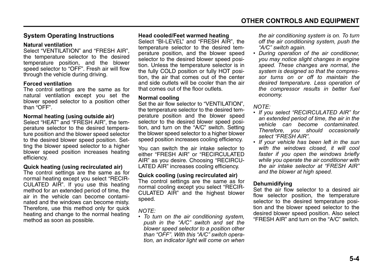
67LM4002
Do’s and Dont’s for Safe Driving
Exercise care in handling your vehicle. Be conscious of not only your own safety but also the safety of others on the road, and thus enjoy the best and most comfortable driving experience.
Following are basic rules for safe driving. Read them carefully for good understanding of the content so that you can enjoy safe and pleasant driving in your vehicle.
####### Starting
|EXAMPLE| |---|
############## 72F-08-001
####### General driving
|
EXAMPLE| |---|
72F-08-008
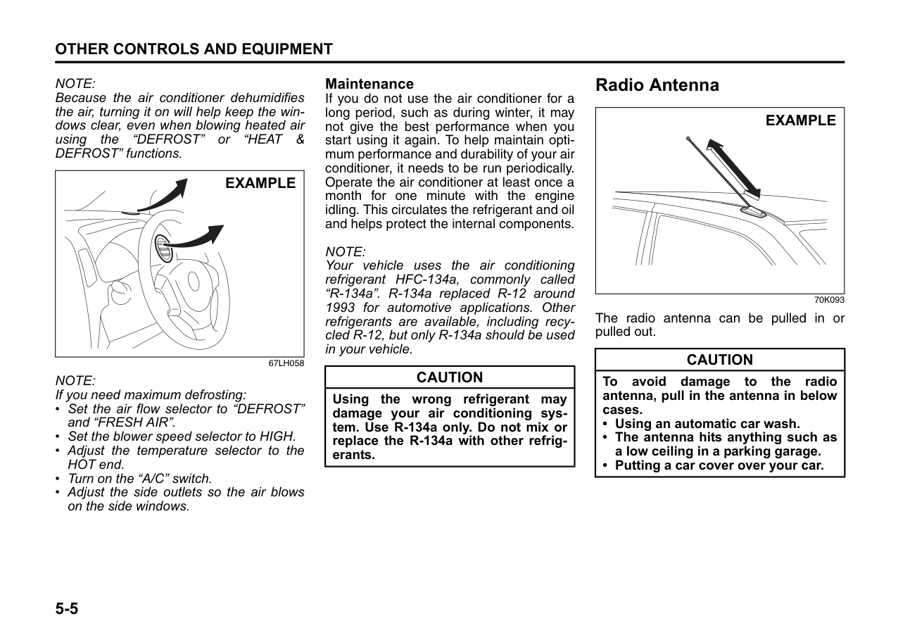
|EXAMPLE| |---|
############## 72F-08-015
####### Braking
|


EXAMPLE| |---|
72F-08-011
|EXAMPLE| |---|
72F-08-012 Use foot brake in three stages
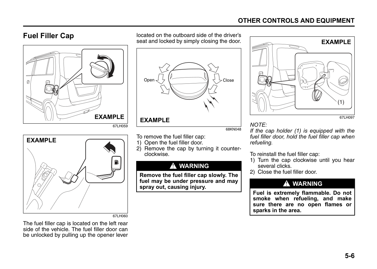
3) When driving downhill, try not to apply the brake but use the engine brake effectively. Overuse of the foot-brake may result in reduction of brake effectiveness.
####### Long distance driving
####### Night time driving
|EXAMPLE| |---|
|EXAMPLE| |---|
|EXAMPLE| |---|
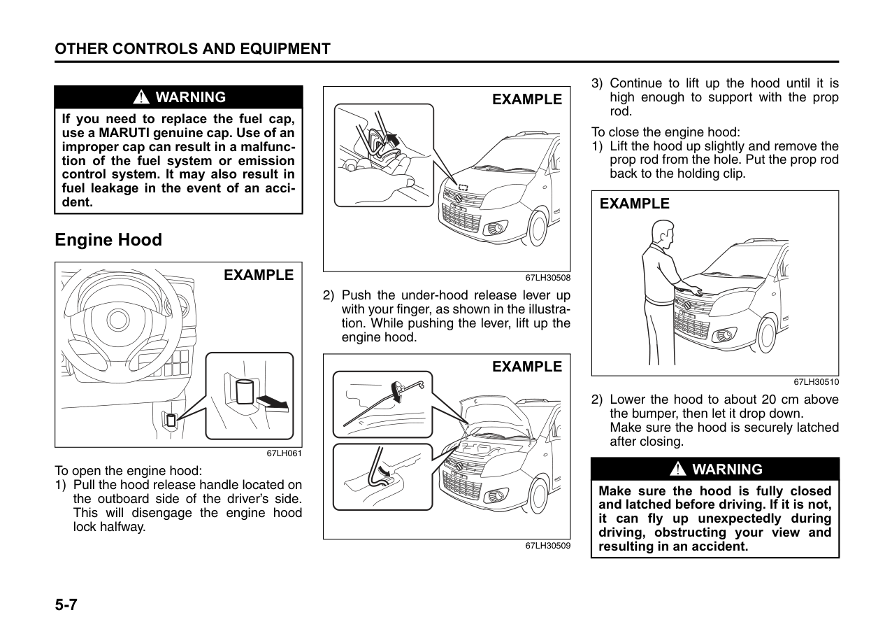
72F-08-022
Margin for Safety
It is important to allow yourself a margin for safety during driving so that you can cope with erroneous or unexpected driving of other drivers. For that, observe the following.
####### Conclusion
A perfect driver does not exist. The endeavour of every motorist should be to strive for perfection. Safety consciousness not only ensures your safety and the safety of other road users, it also helps reduce the wear and tear on your vehicle, lengthens its life, gives better fuel efficiency and ensures a comfortable driving experience.
Follow the do’s and dont’s listed, and driving will never be the same again.
OTHER CONTROLS AND EQUIPMENT
| | |---|
60G407
Manual Heating and Air Conditioning System ................. 5-1 Radio Antenna ..................................................................... 5-5 Fuel Filler Cap ..................................................................... 5-6 Engine Hood ........................................................................ 5-7 Sun Visor ............................................................................. 5-8 Interior Light Switch ........................................................... 5-9 Accessory Socket (if equipped) ......................................... 5-10 Assist Grips (if equipped) .................................................. 5-10 Glove Box ............................................................................ 5-10 Instrument Panel Upper Box .............................................. 5-11 Cup Holder ........................................................................... 5-11 Underseat Container (if equipped) .................................... 5-12 Front Seat Back Pocket ...................................................... 5-12 Floor Mats ............................................................................ 5-13 Shopping Hook (if equipped) ............................................. 5-13 Luggage Area Cover (if equipped) .................................... 5-14 Roof Rails (if equipped) ...................................................... 5-14 Frame Hooks ....................................................................... 5-16
###### 5
Manual Heating and Air Conditioning System
|1 1
3
3
5
5
4 42
2
EXAMPLE|
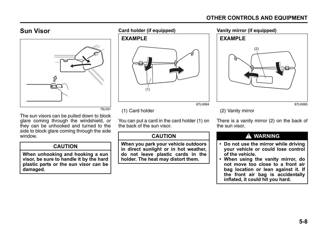
|---|
67LH30501
######## Side outlet
| | |---|
63J045
When “Open”, air comes out regardless of the air flow selector position.
####### Description of Controls
|(1) (3)
(4)
(2)
(5)| |---|
68KH043
Temperature selector (1) This is used to select the temperature by turning the selector.
######## Blower speed selector (2)
This is used to turn on the blower and to select blower speed by turning the selector.
######## Air flow selector (3)
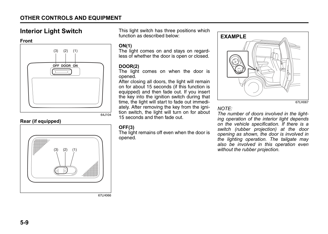
|(a)
(b)
(e)
(d)
(c)| |---|
68KH044
This is used to select one of the functions described below.
######## Ventilation (a)
| | |---|
67LH30502
Temperature-controlled air comes out of the center and side air outlets.
######## Bi-level (b)
| | |---|
Temperature-controlled air comes out of the floor outlets and cooler air comes out of the center and side outlets. When the temperature selector (1) is in the fully COLD position or fully HOT position, however, the air from the floor outlets and the air from the center and side outlets will be the same temperature.
Foot (c)
| | |---|
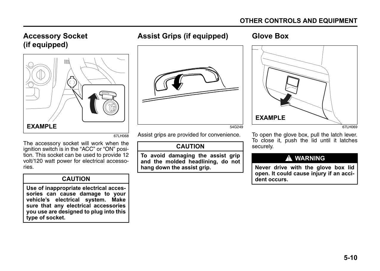
Temperature-controlled air comes out of the floor outlets and the side outlets, also comes out of the windshield defroster outlets and also comes slightly out of the side defroster outlets.
######## Foot & defrost (d)
| | |---|
Temperature-controlled air comes out of the floor outlets, the windshield defroster outlets, the side defroster outlets and the side outlets.
Defrost (e)
| | |---|
Temperature-controlled air comes out of the windshield defroster outlets, the side defroster outlets and the side outlets.
######## Air intake selector (4)
|(g) (f)
| |---|
68KH050
This selector is used to select the following modes.
Fresh Air (f) When this mode is selected by moving the lever to right, outside air is used.
######## Recirculated Air (g)
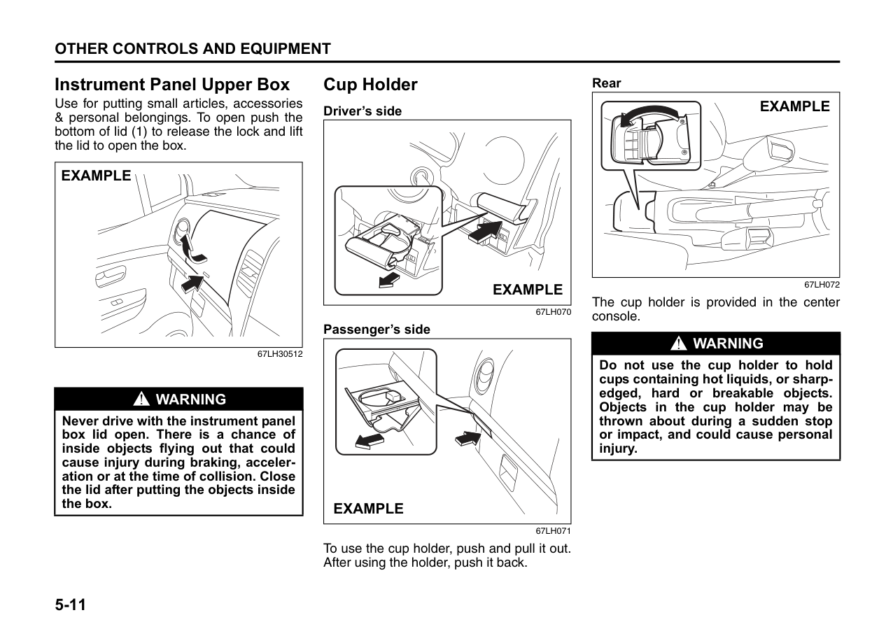
When this mode is selected by moving the lever to left, outside air is shut out and inside air is recirculated. This mode is suitable when driving through dusty or polluted air such as in a tunnel, or when attempting to quickly cool down the interior.
NOTE: If you select “RECIRCULATED AIR” for an extended period of time, the air in the vehicle can become contaminated. Therefore, you should occasionally select “FRESH AIR”.
######## Air conditioning switch (5)
To turn on the air conditioning system, set the blower speed selector to a position other than “OFF” and push in the “A/C” switch. With this “A/C” switch operation, a indicator light will come on when the airconditioning system is on. To turn off the air conditioning system, push the “A/C” switch again.
During operation of the air conditioner, you may notice slight changes in engine speed. These changes are normal, the system is designed so that the compressor turns on or off to maintain the desired temperature.
Less operation of the compressor results in better fuel economy.
####### System Operating Instructions Natural ventilation
Select “VENTILATION” and “FRESH AIR”, the temperature selector to the desired temperature position, and the blower speed selector to “OFF”. Fresh air will flow through the vehicle during driving.
######## Forced ventilation
The control settings are the same as for natural ventilation except you set the blower speed selector to a position other than “OFF”.
######## Normal heating (using outside air)
Select “HEAT” and “FRESH AIR”, the temperature selector to the desired temperature position and the blower speed selector to the desired blower speed position. Setting the blower speed selector to a higher blower speed position increases heating efficiency.
######## Quick heating (using recirculated air)
The control settings are the same as for normal heating except you select “RECIRCULATED AIR”. If you use this heating method for an extended period of time, the air in the vehicle can become contaminated and the windows can become misty. Therefore, use this method only for quick heating and change to the normal heating method as soon as possible.
######## Head cooled/Feet warmed heating
Select “BI-LEVEL” and “FRESH AIR”, the temperature selector to the desired temperature position, and the blower speed selector to the desired blower speed position. Unless the temperature selector is in the fully COLD position or fully HOT position, the air that comes out of the center and side outlets will be cooler than the air that comes out of the floor outlets.
######## Normal cooling
Set the air flow selector to “VENTILATION”, the temperature selector to the desired temperature position and the blower speed selector to the desired blower speed position, and turn on the “A/C” switch. Setting the blower speed selector to a higher blower speed position increases cooling efficiency.
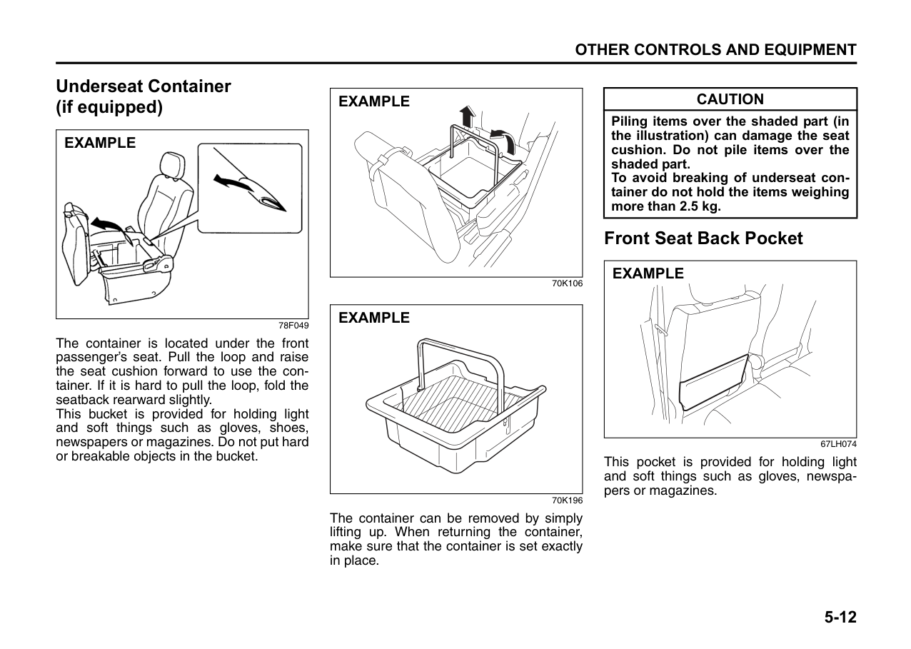
You can switch the air intake selector to either “FRESH AIR” or “RECIRCULATED AIR” as you desire. Choosing “RECIRCULATED AIR” increases cooling efficiency.
Quick cooling (using recirculated air) The control settings are the same as for normal cooling except you select “RECIRCULATED AIR” and the highest blower speed. NOTE: • To turn on the air conditioning system,
push in the “A/C” switch and set the blower speed selector to a position other than “OFF”. With this “A/C” switch operation, an indicator light will come on when
the air conditioning system is on. To turn off the air conditioning system, push the “A/C” switch again.
• During operation of the air conditioner, you may notice slight changes in engine speed. These changes are normal, the system is designed so that the compressor turns on or off to maintain the desired temperature. Less operation of the compressor results in better fuel economy.
NOTE:
######## Dehumidifying
Set the air flow selector to a desired air flow selector position, the temperature selector to the desired temperature position and the blower speed selector to the desired blower speed position. Also select “FRESH AIR” and turn on the “A/C” switch.
NOTE: Because the air conditioner dehumidifies the air, turning it on will help keep the windows clear, even when blowing heated air using the “DEFROST” or “HEAT & DEFROST” functions.
|EXAMPLE| |---|
67LH058
NOTE: If you need maximum defrosting:
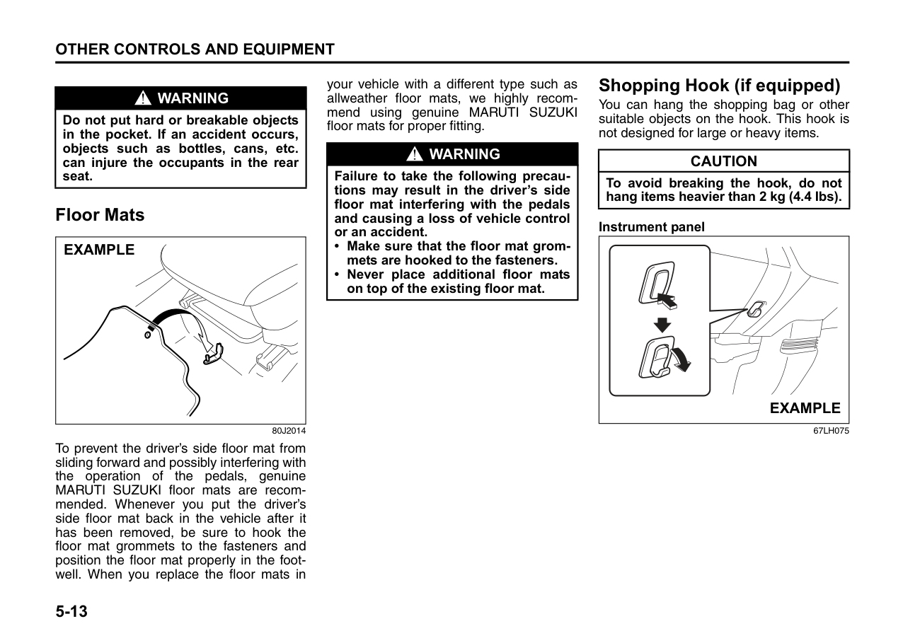
####### Maintenance
If you do not use the air conditioner for a long period, such as during winter, it may not give the best performance when you start using it again. To help maintain optimum performance and durability of your air conditioner, it needs to be run periodically. Operate the air conditioner at least once a month for one minute with the engine idling. This circulates the refrigerant and oil and helps protect the internal components.
NOTE: Your vehicle uses the air conditioning refrigerant HFC-134a, commonly called “R-134a”. R-134a replaced R-12 around 1993 for automotive applications. Other refrigerants are available, including recycled R-12, but only R-134a should be used in your vehicle.
|CAUTION| |---| |Using the wrong refrigerant may damage your air conditioning system. Use R-134a only. Do not mix or replace the R-134a with other refrigerants.|
Radio Antenna
|EXAMPLE| |---|
70K093
The radio antenna can be pulled in or pulled out.
|CAUTION| |---| |To avoid damage to the radio antenna, pull in the antenna in below cases.
• Using an automatic car wash.
• The antenna hits anything such as a low ceiling in a parking garage.
• Putting a car cover over your car.
|
Fuel Filler Cap
|EXAMPLE| |---|
|EXAMPLE|
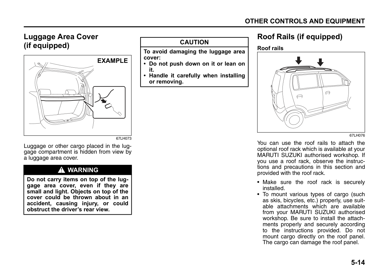
|---|
The fuel filler cap is located on the left rear side of the vehicle. The fuel filler door can be unlocked by pulling up the opener lever
located on the outboard side of the driver’s seat and locked by simply closing the door.
|Open Close
EXAMPLE| |---|
68KN048 To remove the fuel filler cap:
|WARNING
| |---| |Remove the fuel filler cap slowly. The fuel may be under pressure and may spray out, causing injury.|
|(1)
EXAMPLE| |---|
67LH097
NOTE: If the cap holder (1) is equipped with the fuel filler door, hold the fuel filler cap when refueling.
To reinstall the fuel filler cap:
|WARNING
|
|---| |Fuel is extremely flammable. Do not smoke when refueling, and make sure there are no open flames or sparks in the area.|
|WARNING
| |---| |If you need to replace the fuel cap, use a MARUTI genuine cap. Use of an improper cap can result in a malfunction of the fuel system or emission control system. It may also result in fuel leakage in the event of an accident.|
Engine Hood
EXAMPLE
67LH061 To open the engine hood:
1) Pull the hood release handle located on the outboard side of the driver’s side. This will disengage the engine hood lock halfway.
|EXAMPLE| |---|
67LH30508
2) Push the under-hood release lever up with your finger, as shown in the illustration. While pushing the lever, lift up the engine hood.
|EXAMPLE| |---|
67LH30509
3) Continue to lift up the hood until it is high enough to support with the prop rod.
To close the engine hood:
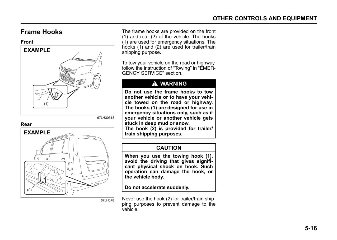
67LH30510
|EXAMPLE| |---|
|WARNING
| |---| |Make sure the hood is fully closed and latched before driving. If it is not, it can fly up unexpectedly during driving, obstructing your view and resulting in an accident.|
Sun Visor
| | |---|
79J161
The sun visors can be pulled down to block glare coming through the windshield, or they can be unhooked and turned to the side to block glare coming through the side window.
|CAUTION| |---| |When unhooking and hooking a sun visor, be sure to handle it by the hard plastic parts or the sun visor can be damaged.|
######## Card holder (if equipped)
|(1)
EXAMPLE| |---|
67LH064

(1) Card holder
You can put a card in the card holder (1) on the back of the sun visor.
|CAUTION| |---| |When you park your vehicle outdoors in direct sunlight or in hot weather, do not leave plastic cards in the holder. The heat may distort them.|
######## Vanity mirror (if equipped)
|(2)
EXAMPLE| |---|
67LH065
(2) Vanity mirror
There is a vanity mirror (2) on the back of the sun visor.
|WARNING
| |---| |• Do not use the mirror while driving your vehicle or could lose control of the vehicle.
• When using the vanity mirror, do not move too close to a front air bag location or lean against it. If the front air bag is accidentally inflated, it could hit you hard.
|
Interior Light Switch Front
|(1)(2)(3)
| |---|
######## 64J104 Rear (if equipped)
|(3) (2) (1)
| |---|
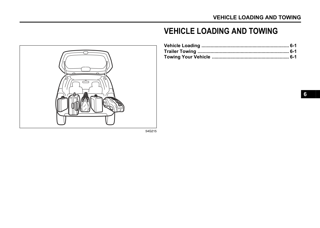
67LH066
This light switch has three positions which function as described below:
######## ON(1)
The light comes on and stays on regardless of whether the door is open or closed.
DOOR(2) The light comes on when the door is opened. After closing all doors, the light will remain on for about 15 seconds (if this function is equipped) and then fade out. If you insert the key into the ignition switch during that time, the light will start to fade out immediately. After removing the key from the ignition switch, the light will turn on for about 15 seconds and then fade out.
OFF(3) The light remains off even when the door is opened.
|EXAMPLE| |---|
67LH067
NOTE: The number of doors involved in the lighting operation of the interior light depends on the vehicle specification. If there is a switch (rubber projection) at the door opening as shown, the door is involved in the lighting operation. The tailgate may also be involved in this operation even without the rubber projection.
Accessory Socket (if equipped)
Assist Grips (if equipped)
Glove Box
|| |---|
|EXAMPLE| |---|
EXAMPLE
54G249 Assist grips are provided for convenience.
67LH069
To open the glove box, pull the latch lever. To close it, push the lid until it latches securely.
67LH068
The accessory socket will work when the ignition switch is in the “ACC” or “ON” position. This socket can be used to provide 12 volt/120 watt power for electrical accessories.
|CAUTION| |---| |To avoid damaging the assist grip and the molded headlining, do not hang down the assist grip.|
|WARNING
| |---| |Never drive with the glove box lid open. It could cause injury if an accident occurs.|
|CAUTION| |---| |Use of inappropriate electrical accessories can cause damage to your vehicle’s electrical system. Make sure that any electrical accessories you use are designed to plug into this type of socket.|
Instrument Panel Upper Box
Use for putting small articles, accessories & personal belongings. To open push the bottom of lid (1) to release the lock and lift the lid to open the box.
|EXAMPLE| |---|
67LH30512
|WARNING
| |---|
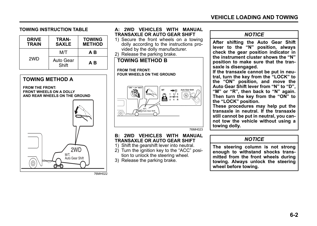
|Never drive with the instrument panel box lid open. There is a chance of inside objects flying out that could cause injury during braking, acceleration or at the time of collision. Close the lid after putting the objects inside the box.|
Cup Holder Driver’s side
|EXAMPLE| |---|
|EXAMPLE| |---|
To use the cup holder, push and pull it out. After using the holder, push it back.
######## Rear
|EXAMPLE| |---|
67LH072
The cup holder is provided in the center console.
|WARNING
| |---| |Do not use the cup holder to hold cups containing hot liquids, or sharpedged, hard or breakable objects. Objects in the cup holder may be thrown about during a sudden stop or impact, and could cause personal injury.|
Underseat Container (if equipped)
|
EXAMPLE|

|---|
78F049
The container is located under the front passenger’s seat. Pull the loop and raise the seat cushion forward to use the container. If it is hard to pull the loop, fold the seatback rearward slightly. This bucket is provided for holding light and soft things such as gloves, shoes, newspapers or magazines. Do not put hard or breakable objects in the bucket.
|EXAMPLE| |---|
70K106
|EXAMPLE| |---|
70K196
The container can be removed by simply lifting up. When returning the container, make sure that the container is set exactly in place.
|CAUTION| |---| |Piling items over the shaded part (in the illustration) can damage the seat cushion. Do not pile items over the shaded part. To avoid breaking of underseat container do not hold the items weighing more than 2.5 kg.|
Front Seat Back Pocket
|EXAMPLE| |---|
67LH074
This pocket is provided for holding light and soft things such as gloves, newspapers or magazines.
|WARNING
|
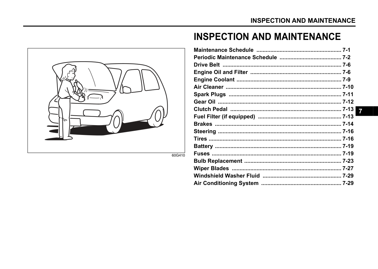
|---| |Do not put hard or breakable objects in the pocket. If an accident occurs, objects such as bottles, cans, etc. can injure the occupants in the rear seat.|
Floor Mats
|EXAMPLE| |---|
80J2014
To prevent the driver’s side floor mat from sliding forward and possibly interfering with the operation of the pedals, genuine MARUTI SUZUKI floor mats are recommended. Whenever you put the driver’s side floor mat back in the vehicle after it has been removed, be sure to hook the floor mat grommets to the fasteners and position the floor mat properly in the footwell. When you replace the floor mats in
your vehicle with a different type such as allweather floor mats, we highly recommend using genuine MARUTI SUZUKI floor mats for proper fitting.
|WARNING
| |---| |Failure to take the following precautions may result in the driver’s side floor mat interfering with the pedals and causing a loss of vehicle control or an accident.
• Make sure that the floor mat grommets are hooked to the fasteners.
• Never place additional floor mats on top of the existing floor mat.
|
Shopping Hook (if equipped)
You can hang the shopping bag or other suitable objects on the hook. This hook is not designed for large or heavy items.
|CAUTION| |---| |To avoid breaking the hook, do not hang items heavier than 2 kg (4.4 Ibs).|
######## Instrument panel
|EXAMPLE| |---|
67LH075
Luggage Area Cover (if equipped)
|EXAMPLE| |---|
67LH073
Luggage or other cargo placed in the luggage compartment is hidden from view by a luggage area cover.
|WARNING
| |---| |Do not carry items on top of the luggage area cover, even if they are small and light. Objects on top of the cover could be thrown about in an accident, causing injury, or could obstruct the driver’s rear view.|
|CAUTION| |---| |To avoid damaging the luggage area cover:
• Do not push down on it or lean on it.
• Handle it carefully when installing or removing.
|
Roof Rails (if equipped) Roof rails
| | |---|
67LH076
You can use the roof rails to attach the optional roof rack which is available at your MARUTI SUZUKI authorised workshop. If you use a roof rack, observe the instructions and precautions in this section and provided with the roof rack.
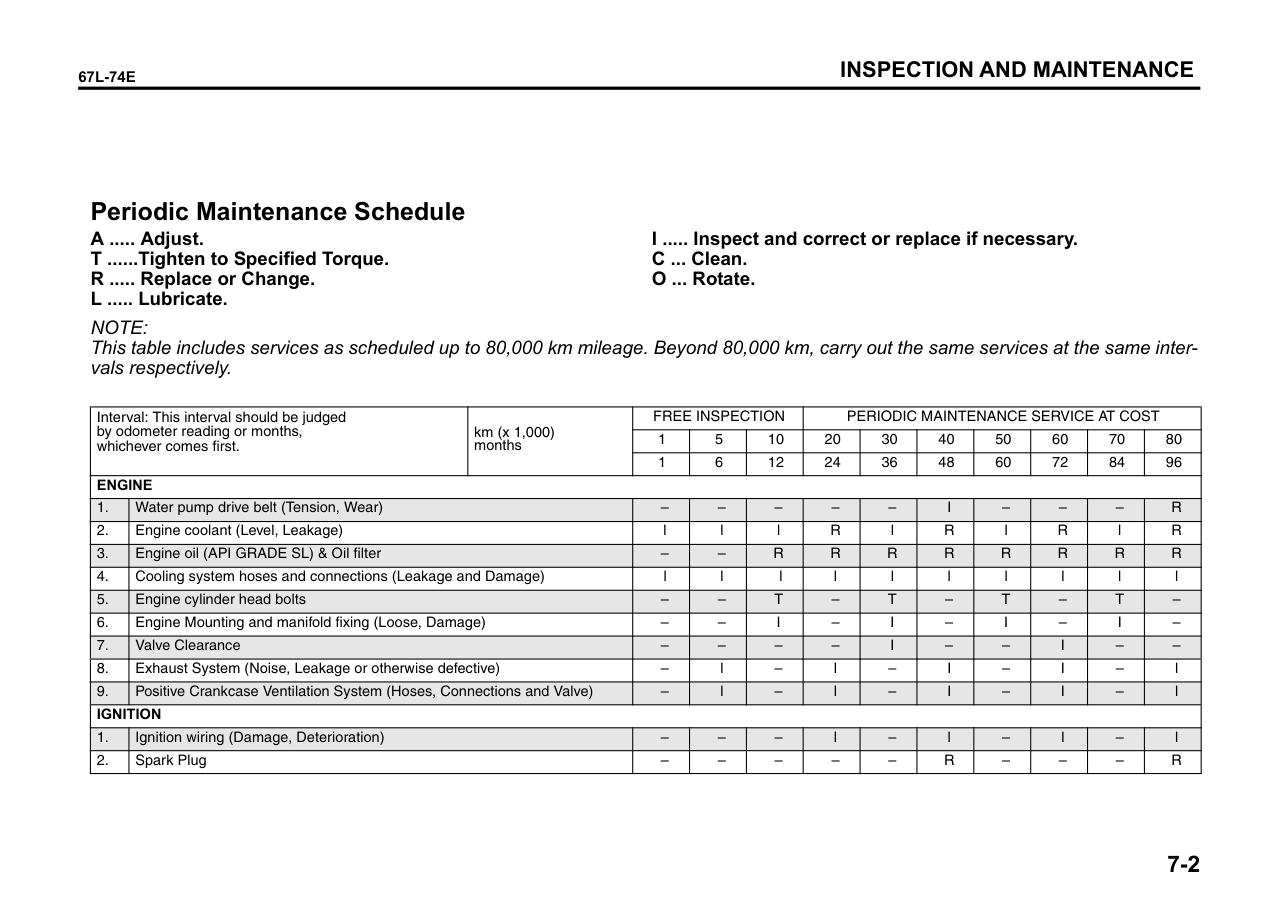
|WARNING
| |---| |• Abrupt maneuvers or failure to properly secure cargo can allow the cargo to fly off the vehicle and hit others, causing personal injury or property damage.
• Mount cargo securely and avoid abrupt maneuvers such as “jackrabbit” starts, sharp turns, fast cornering and sudden braking. Check periodically to make sure that cargo is securely fastened.
• Large, bulky, long, or flat items can affect vehicle aerodynamics or be caught by the wind, and can reduce vehicle control resulting in an accident and personal injury. Drive cautiously at a safely reduced speed when carrying this type of cargo.
|
Frame Hooks Front
|(1)
EXAMPLE| |---|
67LH30513 Rear
||(2)| |---|
EXAMPLE| |---|
67LH078
The frame hooks are provided on the front (1) and rear (2) of the vehicle. The hooks (1) are used for emergency situations. The hooks (1) and (2) are used for trailer/train shipping purpose.
To tow your vehicle on the road or highway, follow the instruction of “Towing” in “EMERGENCY SERVICE” section.
|WARNING
| |---| |Do not use the frame hooks to tow another vehicle or to have your vehicle towed on the road or highway. The hooks (1) are designed for use in emergency situations only, such as if your vehicle or another vehicle gets stuck in deep mud or snow. The hook (2) is provided for trailer/ train shipping purposes.|
|CAUTION| |---|
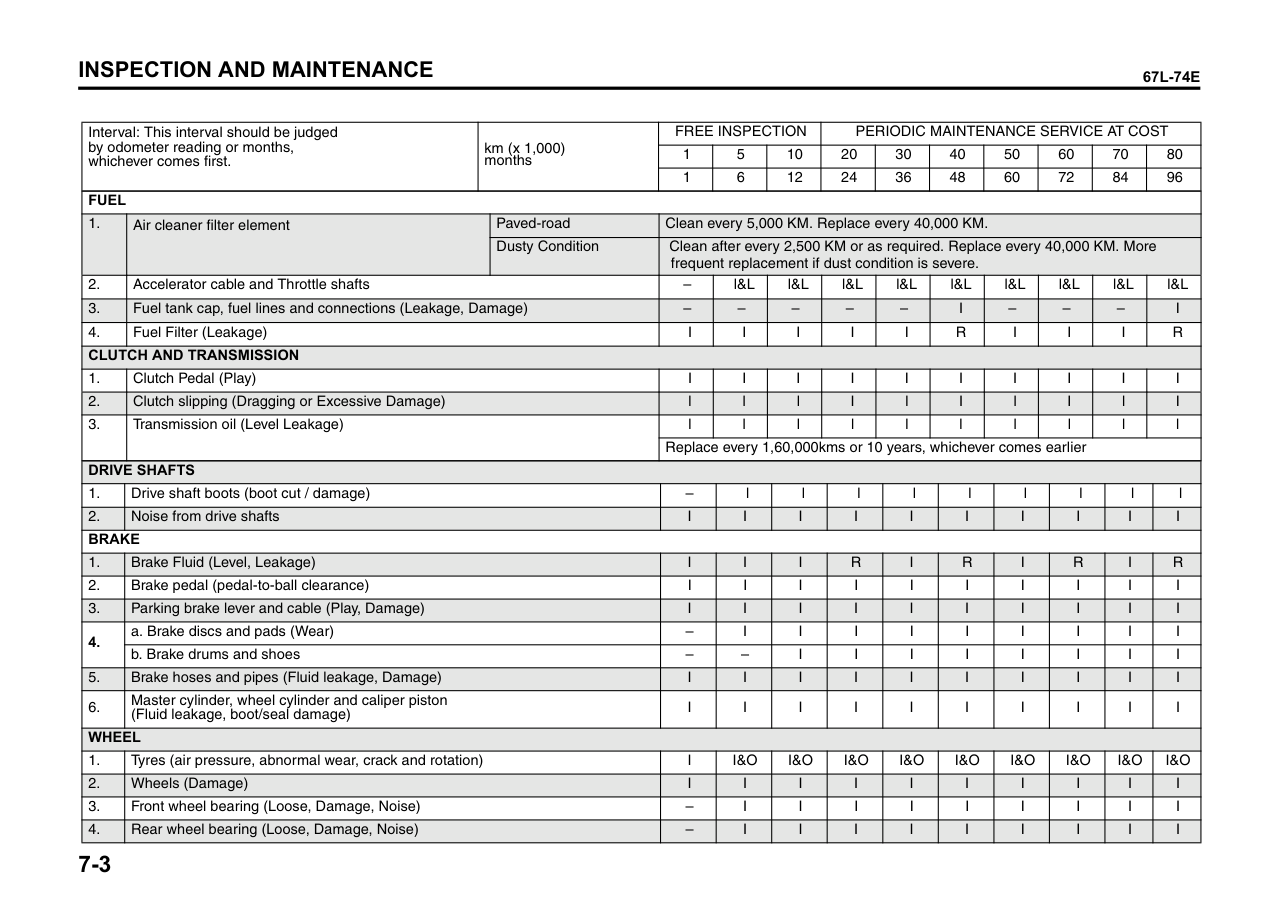
|When you use the towing hook (1), avoid the driving that gives significant physical shock on hook. Such operation can damage the hook, or the vehicle body.
Do not accelerate suddenly.|
Never use the hook (2) for trailer/train shipping purposes to prevent damage to the vehicle.
VEHICLE LOADING AND TOWING
| | |---|
54G215
Vehicle Loading ................................................................... 6-1 Trailer Towing ...................................................................... 6-1 Towing Your Vehicle ........................................................... 6-1
###### 6
VEHICLE LOADING AND TOWING Vehicle Loading
Towing Your Vehicle
|WARNING
| |---| |Never overload your vehicle. The gross vehicle weight (sum of the weights of the vehicle, all the occupants, accessories, cargo plus trailer nose weight if towing a trailer) must never exceed the Gross Vehicle Weight Rating (GVWR). In addition, never distribute a load so that the weight on either the front or rear axle exceeds the Permissible maximum Axle Weight (PAW).|
Your vehicle was designed for specific weight capacities. The weight capacities of your vehicle are indicated by the Gross Vehicle Weight Rating (GVWR) and the Permissible maximum Axle Weight (PAW, front and rear). The GVWR and PAW (front and rear) are listed in the “SPECIFICATIONS” section.
Your vehicle may be towed behind another vehicle, provided your vehicle is 2 wheel drive (2WD) and you use the proper towing method specified for your vehicle. The towing method you must use depends on the specifications of your vehicle: whether it is a manual transaxle vehicle or an Auto Gear Shift vehicle.
GVWR – Maximum permissible overall weight of the fully loaded vehicle (including all the occupants, accessories and cargo plus the trailer nose weight if towing a trailer). PAW – (Front and Rear) Maximum permissible weight on an individual axle.
Use the towing instruction table to select the proper towing method for your vehicle, and carefully follow the corresponding instructions.3.
|WARNING
| |---| |When you tow your vehicle, follow the instructions below to avoid accidents and damage to your vehicle. In addition, be sure to observe government and local requirements regarding vehicle lighting and trailer hitches or tow bars.|
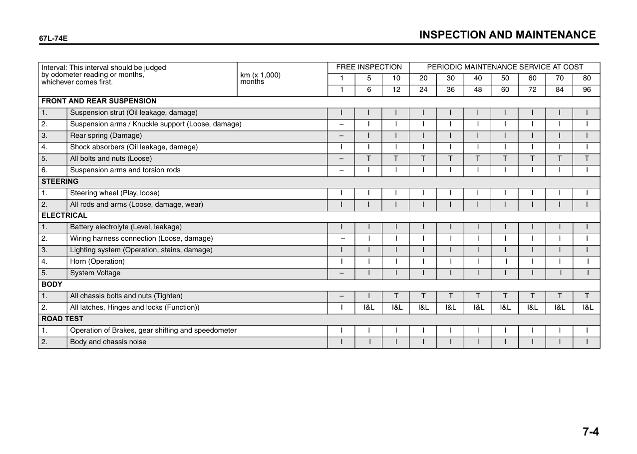
|WARNING
| |---| |Always distribute cargo evenly. To avoid personal injury or damage to your vehicle, always secure cargo to prevent it from shifting if the vehicle moves suddenly. Place heavier objects on the floor and as far forward in the cargo area as possible. Never pile cargo higher than the top of the seat backs.|
Actual weight of the loaded vehicle and actual loads at the front and rear axles can only be determined by weighing the vehicle. Compare these weights to the GVWR and PAW (front and rear). If the gross vehicle weight or the load on either axle exceeds these ratings, you must remove enough weight to bring the load down to the rated capacity.
|WARNING
| |---| |A safety chain should always be used when you tow your vehicle.|
Trailer Towing
Your MARUTI SUZUKI was originally designed to carry people and a normal amount of cargo, not to tow a trailer.MARUTI SUZUKI does not recommend you use your vehicle to tow a trailer. Towing a trailer can adversely affect handling, durability, and fuel economy.
6-1
TOWING INSTRUCTION TABLE
|DRIVE TRAIN|TRANSAXLE|TOWING METHOD| |---|---|---| |2WD|M/T|A B| |2WD|Auto Gear Shift|A B|
|TOWING METHOD A
FROM THE FRONT: FRONT WHEELS ON A DOLLY AND REAR WHEELS ON THE GROUND
M/T, Auto Gear Shift
2WD| |---|
76MH022
######## A: 2WD VEHICLES WITH MANUALTRANSAXLE OR AUTO GEAR SHIFT
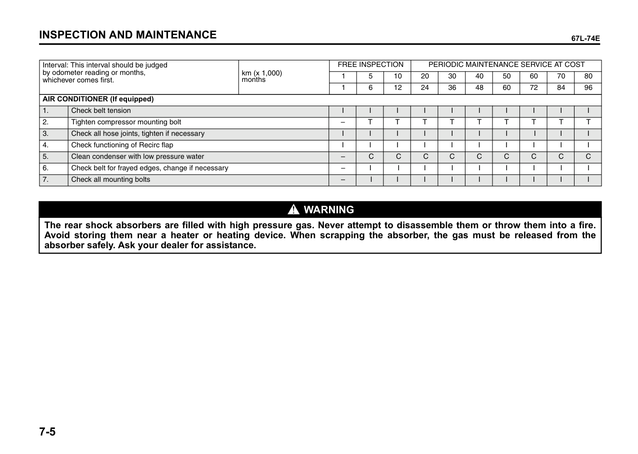
|TOWING METHOD B
FROM THE FRONT: FOUR WHEELS ON THE GROUND
| |---|
76MH023
######## B: 2WD VEHICLES WITH MANUALTRANSAXLE OR AUTO GEAR SHIFT
|NOTICE| |---| |After shifting the Auto Gear Shift lever to the “N” position, always check the gear position indicator in the instrument cluster shows the “N” position to make sure that the transaxle is disengaged. If the transaxle cannot be put in neutral, turn the key from the “LOCK” to the “ON” position, and move the Auto Gear Shift lever from “N” to “D”, “M” or “R”, then back to “N” again. Then turn the key from the “ON” to the “LOCK” position. These procedures may help put the transaxle in neutral. If the transaxle still cannot be put in neutral, you cannot tow the vehicle without using a towing dolly.|
|NOTICE| |---| |The steering column is not strong enough to withstand shocks transmitted from the front wheels during towing. Always unlock the steering wheel before towing.|
6-2
###### INSPECTION AND MAINTENANCE
INSPECTION AND MAINTENANCE
| | |---|
60G410
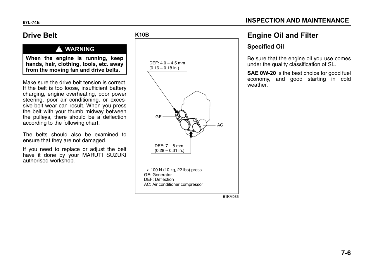
Maintenance Schedule ....................................................... 7-1 Periodic Maintenance Schedule ........................................ 7-2 Drive Belt ............................................................................. 7-6 Engine Oil and Filter ........................................................... 7-6 Engine Coolant .................................................................... 7-9 Air Cleaner ........................................................................... 7-10 Spark Plugs ......................................................................... 7-11 Gear Oil ................................................................................ 7-12 Clutch Pedal ........................................................................ 7-13 Fuel Filter (if equipped) ...................................................... 7-13 Brakes .................................................................................. 7-14 Steering ................................................................................ 7-16 Tires ...................................................................................... 7-16 Battery .................................................................................. 7-19 Fuses .................................................................................... 7-19 Bulb Replacement ............................................................... 7-23 Wiper Blades ....................................................................... 7-27 Windshield Washer Fluid ................................................... 7-29 Air Conditioning System .................................................... 7-29
###### 7
|| |---|
60A187S
|WARNING
| |---| |You should take extreme care when working on your vehicle to prevent accidental injury. Here are a few precautions that you should be especially careful to observe:
• To prevent damage or unintended activation of the air bag system, be sure the battery is disconnected and the ignition switch has been in the “LOCK” position for at least 90 seconds before performing any electrical service work on your MARUTI SUZUKI. Do not touch air bag system components or wires. The wires are wrapped with yellow tape or yellow tubing, and the couplers are yellow for easy identification.
(Continued)|
|WARNING
| |---| |(Continued)
• Do not leave the engine running in garages or other confined areas.
• When the engine is running, keep hands, clothing, tools, and other objects away from the fan and drive belt. Even though the fan may not be moving, it can automatically turn on without warning.
• When it is necessary to do service work with the engine running, make sure that the parking brake is set fully and the transaxle is in Neutral.
• Do not touch ignition wires or other ignition system parts when starting the engine or when the engine is running, or you could receive an electric shock.
• Be careful not to touch a hot engine, exhaust manifold and pipes, muffler, radiator and water hoses.
• Do not allow smoking, sparks, or flames around fuel or the battery. Flammable fumes are present.
• Do not get under your vehicle if it is supported only with the portable jack provided in your vehicle.
• Be careful not to cause accidental short circuits between the positive and negative battery terminals.
(Continued)|
|WARNING
| |---| |(Continued)
• Keep used oil, coolant, and other fluids away from children and pets. Dispose of used fluids properly; never pour them on the ground, into sewers, etc.|
Maintenance Schedule
The following table shows the times when you should perform regular maintenance on your vehicle. This table shows in kilometers and months when you should perform inspections, adjustments, lubrication and other services. These intervals should be shortened if driving is usually done under severe conditions.
|WARNING
| |---| |MARUTI SUZUKI recommends that maintenance should be performed by your MARUTI SUZUKI authorised workshop. If you are not sure whether you can successfully complete any maintenance jobs, ask your MARUTI SUZUKI authorised workshop to do the maintenance for you.|
|CAUTION| |---|
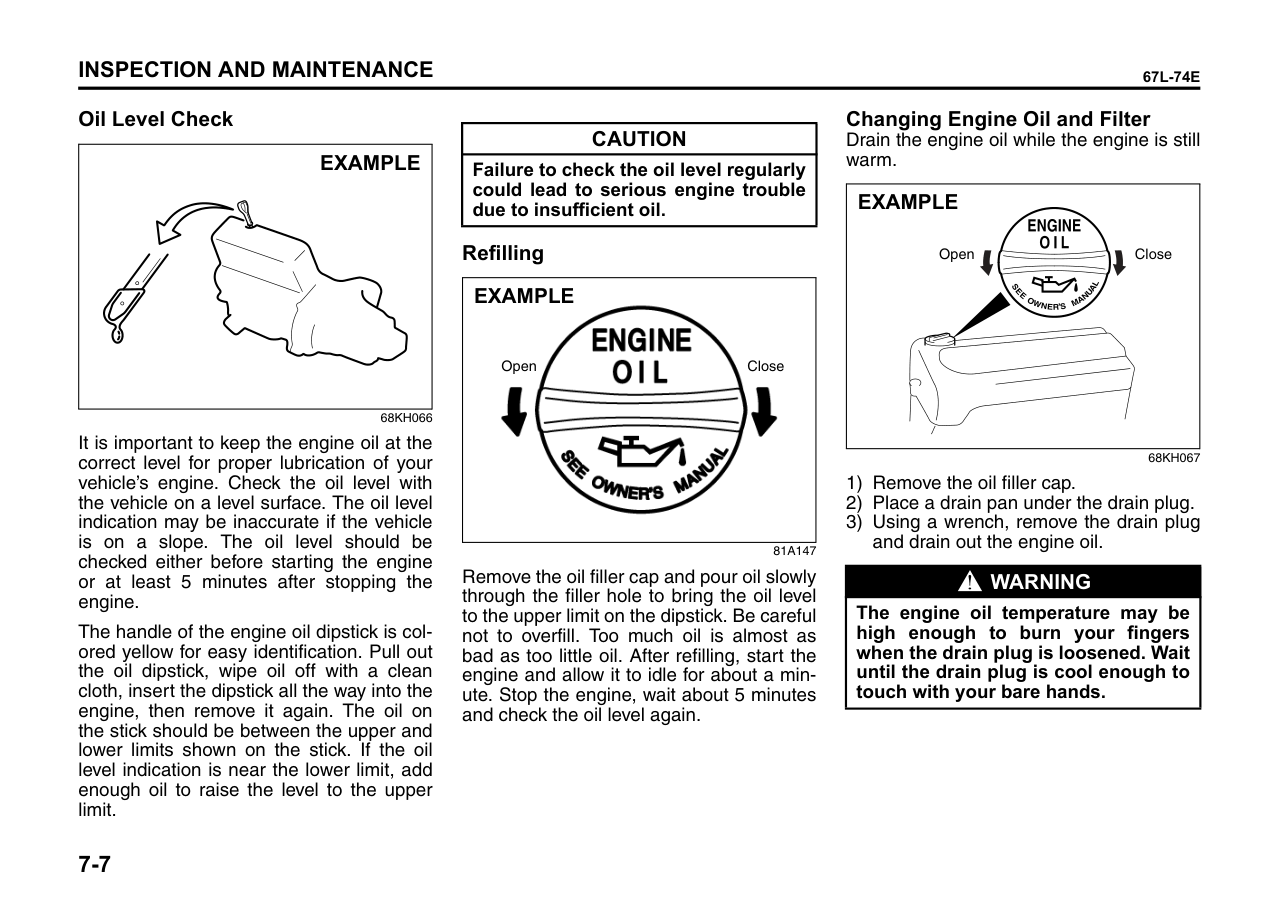
|Whenever it becomes necessary to replace parts on your vehicle, it is recommended that you use MARUTI genuine parts.|
Periodic Maintenance Schedule A ..... Adjust. T ......Tighten to Specified Torque. R ..... Replace or Change. L ..... Lubricate.
I ..... Inspect and correct or replace if necessary. C ... Clean. O ... Rotate.
NOTE: This table includes services as scheduled up to 80,000 km mileage. Beyond 80,000 km, carry out the same services at the same intervals respectively.
|Interval: This interval should be judged by odometer reading or months, whichever comes first.|Interval: This interval should be judged by odometer reading or months, whichever comes first.|km (x 1,000) months|FREE INSPECTION|FREE INSPECTION|FREE INSPECTION|PERIODIC MAINTENANCE SERVICE AT COST|PERIODIC MAINTENANCE SERVICE AT COST|PERIODIC MAINTENANCE SERVICE AT COST|PERIODIC MAINTENANCE SERVICE AT COST|PERIODIC MAINTENANCE SERVICE AT COST|PERIODIC MAINTENANCE SERVICE AT COST|PERIODIC MAINTENANCE SERVICE AT COST| |---|---|---|---|---|---|---|---|---|---|---|---|---| |Interval: This interval should be judged by odometer reading or months, whichever comes first.|Interval: This interval should be judged by odometer reading or months, whichever comes first.|km (x 1,000) months|1|5|10|20|30|40|50|60|70|80| |Interval: This interval should be judged by odometer reading or months, whichever comes first.|Interval: This interval should be judged by odometer reading or months, whichever comes first.|km (x 1,000) months|1|6|12|24|36|48|60|72|84|96| |ENGINE|ENGINE|ENGINE|ENGINE|ENGINE|ENGINE|ENGINE|ENGINE|ENGINE|ENGINE|ENGINE|ENGINE|ENGINE| |1.|Water pump drive belt (Tension, Wear)|Water pump drive belt (Tension, Wear)|–|–|–|–|–|I|–|–|–|R| |2|.Engine coolant (Level, Leakage)|.Engine coolant (Level, Leakage)|l| | |R|l|R|l|R|l|R| |3.|Engine oil (API GRADE SL) & Oil filter|Engine oil (API GRADE SL) & Oil filter|–|–|R|R|R|R|R|R|R|R| |4.|Cooling system hoses and connections (Leakage and Damage)|Cooling system hoses and connections (Leakage and Damage)|l|l|l|l|l|l|l|l|l|l| |5.|Engine cylinder head bolts|Engine cylinder head bolts|–|–|T|–|T|–|T|–|T|–| |6.|Engine Mounting and manifold fixing (Loose, Damage)|Engine Mounting and manifold fixing (Loose, Damage)|–|–|I|–|I|–|I|–|I|–| |7.|Valve Clearance|Valve Clearance|–|–|–|–|I|–|–|I|–|–| |8.|Exhaust System (Noise, Leakage or otherwise defective)|Exhaust System (Noise, Leakage or otherwise defective)|–|l|–|l|–|I|–|I|–|l| |9.|Positive Crankcase Ventilation System (Hoses, Connections and Valve)|Positive Crankcase Ventilation System (Hoses, Connections and Valve)|–|l|–|l|–|I|–|I|–|l| |IGNITION|IGNITION|IGNITION|IGNITION|IGNITION|IGNITION|IGNITION|IGNITION|IGNITION|IGNITION|IGNITION|IGNITION|IGNITION| |1.|Ignition wiring (Damage, Deterioration)|Ignition wiring (Damage, Deterioration)|–|–|–|l|–|l|–|l|–|l| |2|.Spark Plug|.Spark Plug|–|–|–|–|–|R|–|–|–|R|
|Interval: This interval should be judged by odometer reading or months, whichever comes first.|Interval: This interval should be judged by odometer reading or months, whichever comes first.|km (x 1,000) months|km (x 1,000) months|FREE INSPECTION|FREE INSPECTION|FREE INSPECTION|FREE INSPECTION|PERIODIC MAINTENANCE SERVICE AT COST|PERIODIC MAINTENANCE SERVICE AT COST|PERIODIC MAINTENANCE SERVICE AT COST|PERIODIC MAINTENANCE SERVICE AT COST|PERIODIC MAINTENANCE SERVICE AT COST|PERIODIC MAINTENANCE SERVICE AT COST|PERIODIC MAINTENANCE SERVICE AT COST|PERIODIC MAINTENANCE SERVICE AT COST|PERIODIC MAINTENANCE SERVICE AT COST|PERIODIC MAINTENANCE SERVICE AT COST|PERIODIC MAINTENANCE SERVICE AT COST|PERIODIC MAINTENANCE SERVICE AT COST|PERIODIC MAINTENANCE SERVICE AT COST|PERIODIC MAINTENANCE SERVICE AT COST| |---|---|---|---|---|---|---|---|---|---|---|---|---|---|---|---|---|---|---|---|---|---| |Interval: This interval should be judged by odometer reading or months, whichever comes first.|Interval: This interval should be judged by odometer reading or months, whichever comes first.|km (x 1,000) months|km (x 1,000) months|1|5|10|10|20|20|30|30|40|40|50|50|60|60|70|70|80|80| |Interval: This interval should be judged by odometer reading or months, whichever comes first.|Interval: This interval should be judged by odometer reading or months, whichever comes first.|km (x 1,000) months|km (x 1,000) months|1|6|12|12|24|24|36|36|48|48|60|60|72|72|84|84|96|96| |FUEL|FUEL|FUEL|FUEL|FUEL|FUEL|FUEL|FUEL|FUEL|FUEL|FUEL|FUEL|FUEL|FUEL|FUEL|FUEL|FUEL|FUEL|FUEL|FUEL|FUEL|FUEL| |1.|Air cleaner filter element|Air cleaner filter element|Paved-road|Clean every 5,000 KM. Replace every 40,000 KM.|Clean every 5,000 KM. Replace every 40,000 KM.|Clean every 5,000 KM. Replace every 40,000 KM.|Clean every 5,000 KM. Replace every 40,000 KM.|Clean every 5,000 KM. Replace every 40,000 KM.|Clean every 5,000 KM. Replace every 40,000 KM.|Clean every 5,000 KM. Replace every 40,000 KM.|Clean every 5,000 KM. Replace every 40,000 KM.|Clean every 5,000 KM. Replace every 40,000 KM.|Clean every 5,000 KM. Replace every 40,000 KM.|Clean every 5,000 KM. Replace every 40,000 KM.|Clean every 5,000 KM. Replace every 40,000 KM.|Clean every 5,000 KM. Replace every 40,000 KM.|Clean every 5,000 KM. Replace every 40,000 KM.|Clean every 5,000 KM. Replace every 40,000 KM.|Clean every 5,000 KM. Replace every 40,000 KM.|Clean every 5,000 KM. Replace every 40,000 KM.|Clean every 5,000 KM. Replace every 40,000 KM.| |1.|Air cleaner filter element|Air cleaner filter element|Dusty Condition|Clean after every 2,500 KM or as required. Replace every 40,000 KM. More frequent replacement if dust condition is severe.|Clean after every 2,500 KM or as required. Replace every 40,000 KM. More frequent replacement if dust condition is severe.|Clean after every 2,500 KM or as required. Replace every 40,000 KM. More frequent replacement if dust condition is severe.|Clean after every 2,500 KM or as required. Replace every 40,000 KM. More frequent replacement if dust condition is severe.|Clean after every 2,500 KM or as required. Replace every 40,000 KM. More frequent replacement if dust condition is severe.|Clean after every 2,500 KM or as required. Replace every 40,000 KM. More frequent replacement if dust condition is severe.|Clean after every 2,500 KM or as required. Replace every 40,000 KM. More frequent replacement if dust condition is severe.|Clean after every 2,500 KM or as required. Replace every 40,000 KM. More frequent replacement if dust condition is severe.|Clean after every 2,500 KM or as required. Replace every 40,000 KM. More frequent replacement if dust condition is severe.|Clean after every 2,500 KM or as required. Replace every 40,000 KM. More frequent replacement if dust condition is severe.|Clean after every 2,500 KM or as required. Replace every 40,000 KM. More frequent replacement if dust condition is severe.|Clean after every 2,500 KM or as required. Replace every 40,000 KM. More frequent replacement if dust condition is severe.|Clean after every 2,500 KM or as required. Replace every 40,000 KM. More frequent replacement if dust condition is severe.|Clean after every 2,500 KM or as required. Replace every 40,000 KM. More frequent replacement if dust condition is severe.|Clean after every 2,500 KM or as required. Replace every 40,000 KM. More frequent replacement if dust condition is severe.|Clean after every 2,500 KM or as required. Replace every 40,000 KM. More frequent replacement if dust condition is severe.|Clean after every 2,500 KM or as required. Replace every 40,000 KM. More frequent replacement if dust condition is severe.|Clean after every 2,500 KM or as required. Replace every 40,000 KM. More frequent replacement if dust condition is severe.| |2.|Accelerator cable and Throttle shafts|Accelerator cable and Throttle shafts|Accelerator cable and Throttle shafts|–|l&L|l&L|l&L|l&L|l&L|l&L|l&L|l&L|l&L|l&L|l&L|l&L|l&L|l&L|l&L|l&L|l&L| |3.|Fuel tank cap, fuel lines and connections (Leakage, Damage)|Fuel tank cap, fuel lines and connections (Leakage, Damage)|Fuel tank cap, fuel lines and connections (Leakage, Damage)|–|–|–|–|–|–|–|–|I|I|–|–|–|–|–|–|I|I|
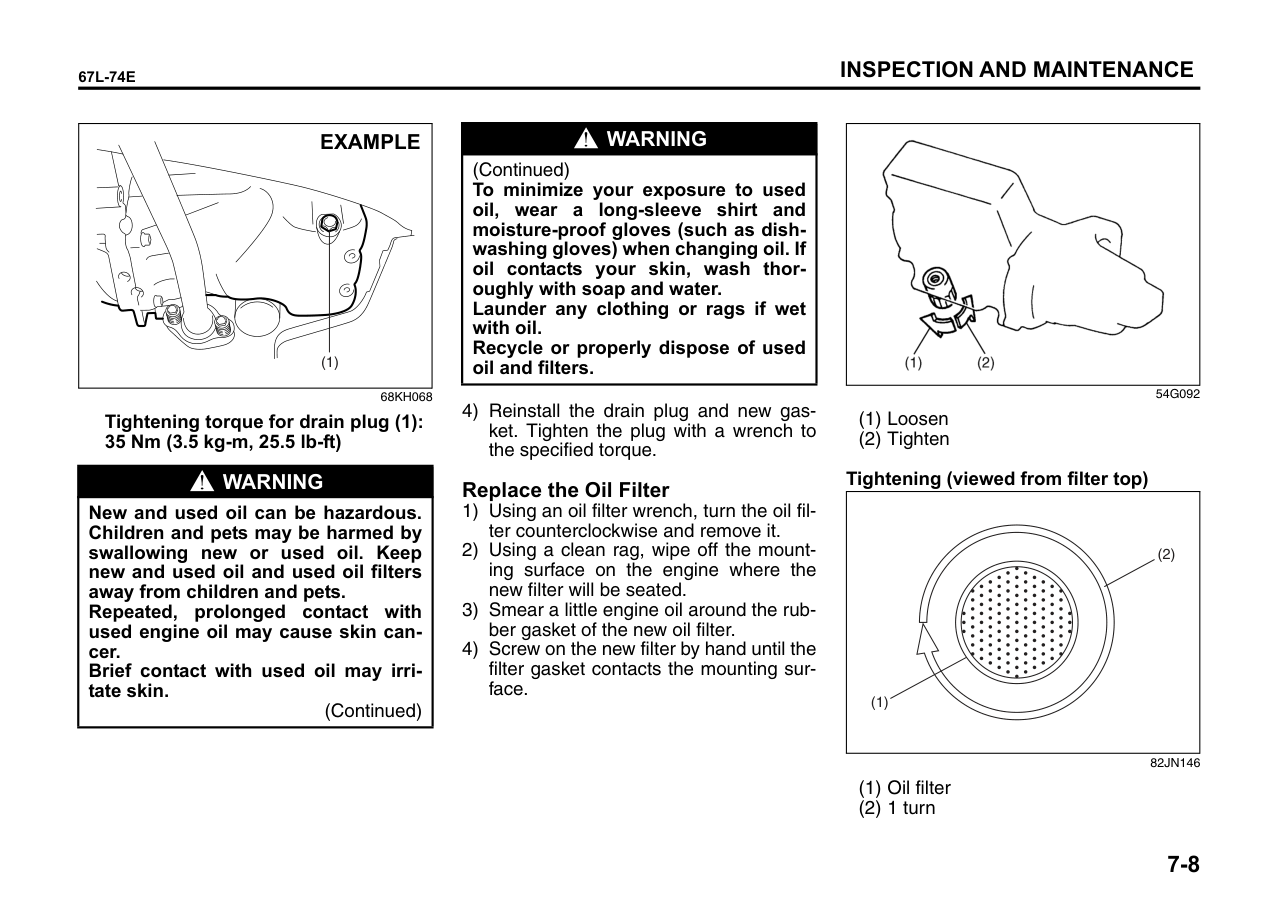
|4.|Fuel Filter (Leakage)|Fuel Filter (Leakage)|Fuel Filter (Leakage)|I|I|I|I|I|I|I|I|R|R|I|I|I|I|I|I|R|R| |CLUTCH AND TRANSMISSION|CLUTCH AND TRANSMISSION|CLUTCH AND TRANSMISSION|CLUTCH AND TRANSMISSION|CLUTCH AND TRANSMISSION|CLUTCH AND TRANSMISSION|CLUTCH AND TRANSMISSION|CLUTCH AND TRANSMISSION|CLUTCH AND TRANSMISSION|CLUTCH AND TRANSMISSION|CLUTCH AND TRANSMISSION|CLUTCH AND TRANSMISSION|CLUTCH AND TRANSMISSION|CLUTCH AND TRANSMISSION|CLUTCH AND TRANSMISSION|CLUTCH AND TRANSMISSION|CLUTCH AND TRANSMISSION|CLUTCH AND TRANSMISSION|CLUTCH AND TRANSMISSION|CLUTCH AND TRANSMISSION|CLUTCH AND TRANSMISSION|CLUTCH AND TRANSMISSION| |1.|Clutch Pedal (Play)|Clutch Pedal (Play)|Clutch Pedal (Play)|I|I|I|I|I|I|I|I|I|I|I|I|I|I|I|I|I|I| |2.|Clutch slipping (Dragging or Excessive Damage)|Clutch slipping (Dragging or Excessive Damage)|Clutch slipping (Dragging or Excessive Damage)|l|l|l|l|I|I|l|l|I|I|l|l|I|I|l|l|I|I| |3.|Transmission oil (Level Leakage)|Transmission oil (Level Leakage)|Transmission oil (Level Leakage)|l|l|l|l|l|l|l|l|l|l|l|l|l|l|l|l|l|l| |3.|Transmission oil (Level Leakage)|Transmission oil (Level Leakage)|Transmission oil (Level Leakage)|Replace every 1,60,000kms or 10 years, whichever comes earlier|Replace every 1,60,000kms or 10 years, whichever comes earlier|Replace every 1,60,000kms or 10 years, whichever comes earlier|Replace every 1,60,000kms or 10 years, whichever comes earlier|Replace every 1,60,000kms or 10 years, whichever comes earlier|Replace every 1,60,000kms or 10 years, whichever comes earlier|Replace every 1,60,000kms or 10 years, whichever comes earlier|Replace every 1,60,000kms or 10 years, whichever comes earlier|Replace every 1,60,000kms or 10 years, whichever comes earlier|Replace every 1,60,000kms or 10 years, whichever comes earlier|Replace every 1,60,000kms or 10 years, whichever comes earlier|Replace every 1,60,000kms or 10 years, whichever comes earlier|Replace every 1,60,000kms or 10 years, whichever comes earlier|Replace every 1,60,000kms or 10 years, whichever comes earlier|Replace every 1,60,000kms or 10 years, whichever comes earlier|Replace every 1,60,000kms or 10 years, whichever comes earlier|Replace every 1,60,000kms or 10 years, whichever comes earlier|Replace every 1,60,000kms or 10 years, whichever comes earlier| |DRIVE SHAFTS|DRIVE SHAFTS|DRIVE SHAFTS|DRIVE SHAFTS|DRIVE SHAFTS|DRIVE SHAFTS|DRIVE SHAFTS|DRIVE SHAFTS|DRIVE SHAFTS|DRIVE SHAFTS|DRIVE SHAFTS|DRIVE SHAFTS|DRIVE SHAFTS|DRIVE SHAFTS|DRIVE SHAFTS|DRIVE SHAFTS|DRIVE SHAFTS|DRIVE SHAFTS|DRIVE SHAFTS|DRIVE SHAFTS|DRIVE SHAFTS|DRIVE SHAFTS| |1.|Drive shaft boots (boot cut / damage)|Drive shaft boots (boot cut / damage)|Drive shaft boots (boot cut / damage)|–|l|l|l|l|l|l|l|l|l|l|l|l|l|l|l|l|l| |2.|Noise from drive shafts|Noise from drive shafts|Noise from drive shafts|I|I|I|I|I|I|I|I|I|I|I|I|I|I|I|I|I|I| |BRAKE|BRAKE|BRAKE|BRAKE|BRAKE|BRAKE|BRAKE|BRAKE|BRAKE|BRAKE|BRAKE|BRAKE|BRAKE|BRAKE|BRAKE|BRAKE|BRAKE|BRAKE|BRAKE|BRAKE|BRAKE|BRAKE| |1.|Brake Fluid (Level, Leakage)|Brake Fluid (Level, Leakage)|Brake Fluid (Level, Leakage)|I|I|I|I|I|R|R|I|I|R|R|I|I|R|R|I|I|R| |2.|Brake pedal (pedal-to-ball clearance)|Brake pedal (pedal-to-ball clearance)|Brake pedal (pedal-to-ball clearance)|I|I|I|I|I|I|I|I|I|I|I|I|I|I|I|I|I|I| |3.|Parking brake lever and cable (Play, Damage)|Parking brake lever and cable (Play, Damage)|Parking brake lever and cable (Play, Damage)|I|I|I|I|I|I|I|I|I|I|I|I|I|I|I|I|I|I| |4.|a. Brake discs and pads (Wear)|a. Brake discs and pads (Wear)|a. Brake discs and pads (Wear)|–|I|I|I|I|I|I|I|I|I|I|I|I|I|I|I|I|I| |4.|b. Brake drums and shoes|b. Brake drums and shoes|b. Brake drums and shoes|–|–|–|I|I|I|I|I|I|I|I|I|I|I|I|I|I|I| |5.|Brake hoses and pipes (Fluid leakage, Damage)|Brake hoses and pipes (Fluid leakage, Damage)|Brake hoses and pipes (Fluid leakage, Damage)|I|I|I|I|I|I|I|I|I|I|I|I|I|I|I|I|I|I| |6.|Master cylinder, wheel cylinder and caliper piston (Fluid leakage, boot/seal damage)|Master cylinder, wheel cylinder and caliper piston (Fluid leakage, boot/seal damage)|Master cylinder, wheel cylinder and caliper piston (Fluid leakage, boot/seal damage)|I|I|I|I|I|I|I|I|I|I|I|I|I|I|I|I|I|I| |WHEEL|WHEEL|WHEEL|WHEEL|WHEEL|WHEEL|WHEEL|WHEEL|WHEEL|WHEEL|WHEEL|WHEEL|WHEEL|WHEEL|WHEEL|WHEEL|WHEEL|WHEEL|WHEEL|WHEEL|WHEEL|WHEEL| |1.|Tyres (air pressure, abnormal wear, crack and rotation)|Tyres (air pressure, abnormal wear, crack and rotation)|Tyres (air pressure, abnormal wear, crack and rotation)|I|I&O|I&O|I&O|I&O|I&O|I&O|I&O|I&O|I&O|I&O|I&O|I&O|I&O|I&O|I&O|I&O|I&O| |2.|Wheels (Damage)|Wheels (Damage)|Wheels (Damage)|I|I|I|I|I|I|I|I|I|I|I|I|I|I|I|I|I|I| |3.|Front wheel bearing (Loose, Damage, Noise)|Front wheel bearing (Loose, Damage, Noise)|Front wheel bearing (Loose, Damage, Noise)|–|I|I|I|I|I|I|I|I|I|I|I|I|I|I|I|I|I| |4.|Rear wheel bearing (Loose, Damage, Noise)|Rear wheel bearing (Loose, Damage, Noise)|Rear wheel bearing (Loose, Damage, Noise)|–|I|I|I|I|I|I|I|I|I|I|I|I|I|I|I|I|I|
|Interval: This interval should be judged by odometer reading or months, whichever comes first.|Interval: This interval should be judged by odometer reading or months, whichever comes first.|km (x 1,000) months|FREE INSPECTION|FREE INSPECTION|FREE INSPECTION|PERIODIC MAINTENANCE SERVICE AT COST|PERIODIC MAINTENANCE SERVICE AT COST|PERIODIC MAINTENANCE SERVICE AT COST|PERIODIC MAINTENANCE SERVICE AT COST|PERIODIC MAINTENANCE SERVICE AT COST|PERIODIC MAINTENANCE SERVICE AT COST|PERIODIC MAINTENANCE SERVICE AT COST| |---|---|---|---|---|---|---|---|---|---|---|---|---| |Interval: This interval should be judged by odometer reading or months, whichever comes first.|Interval: This interval should be judged by odometer reading or months, whichever comes first.|km (x 1,000) months|1|5|10|20|30|40|50|60|70|80| |Interval: This interval should be judged by odometer reading or months, whichever comes first.|Interval: This interval should be judged by odometer reading or months, whichever comes first.|km (x 1,000) months|1|6|12|24|36|48|60|72|84|96| |FRONT AND REAR SUSPENSION|FRONT AND REAR SUSPENSION|FRONT AND REAR SUSPENSION|FRONT AND REAR SUSPENSION|FRONT AND REAR SUSPENSION|FRONT AND REAR SUSPENSION|FRONT AND REAR SUSPENSION|FRONT AND REAR SUSPENSION|FRONT AND REAR SUSPENSION|FRONT AND REAR SUSPENSION|FRONT AND REAR SUSPENSION|FRONT AND REAR SUSPENSION|FRONT AND REAR SUSPENSION| |1.|Suspension strut (Oil leakage, damage)|Suspension strut (Oil leakage, damage)|I|I|I|I|I|I|I|I|I|I| |2.|Suspension arms / Knuckle support (Loose, damage)|Suspension arms / Knuckle support (Loose, damage)|–|I|I|I|I|I|I|I|I|I| |3.|Rear spring (Damage)|Rear spring (Damage)|–|I|I|I|I|I|I|I|I|I| |4.|Shock absorbers (Oil leakage, damage)|Shock absorbers (Oil leakage, damage)|I|I|I|I|I|I|I|I|I|I| |5.|All bolts and nuts (Loose)|All bolts and nuts (Loose)|–|T|T|T|T|T|T|T|T|T| |6.|Suspension arms and torsion rods|Suspension arms and torsion rods|–|I|I|I|I|I|I|I|I|I| |STEERING|STEERING|STEERING|STEERING|STEERING|STEERING|STEERING|STEERING|STEERING|STEERING|STEERING|STEERING|STEERING| |1.|Steering wheel (Play, loose)|Steering wheel (Play, loose)|I|I|I|I|I|I|I|I|I|I|
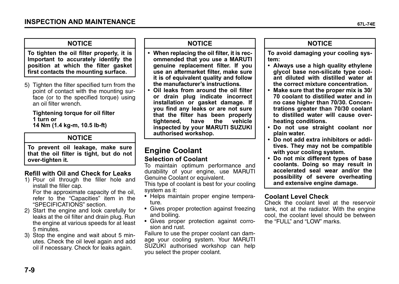
|2.|All rods and arms (Loose, damage, wear)|All rods and arms (Loose, damage, wear)|I|I|I|I|I|I|I|I|I|I| |ELECTRICAL|ELECTRICAL|ELECTRICAL|ELECTRICAL|ELECTRICAL|ELECTRICAL|ELECTRICAL|ELECTRICAL|ELECTRICAL|ELECTRICAL|ELECTRICAL|ELECTRICAL|ELECTRICAL| |1.|Battery electrolyte (Level, leakage)|Battery electrolyte (Level, leakage)|I|I|I|I|I|I|I|I|I|I| |2.|Wiring harness connection (Loose, damage)|Wiring harness connection (Loose, damage)|–|– I|I|I|I|I|I|I|I|I| |3.|Lighting system (Operation, stains, damage)|Lighting system (Operation, stains, damage)|I|I|I|I|I|I|I|I|I|I| |4.|Horn (Operation)|Horn (Operation)|I|I| | |I|I|I|I|I I|I| |5.|System Voltage|System Voltage|–|I|I|I|I|I|I|I|I|I| |BODY|BODY|BODY|BODY|BODY|BODY|BODY|BODY|BODY|BODY|BODY|BODY|BODY| |1.|All chassis bolts and nuts (Tighten)|All chassis bolts and nuts (Tighten)|–|I|T|T|T|T|T|T|T|T| |2.|All latches, Hinges and locks (Function))|All latches, Hinges and locks (Function))|I|I&L|I&L|I&L|I&L|I&L|I&L|I&L|I&L|I&L| |ROAD TEST|ROAD TEST|ROAD TEST|ROAD TEST|ROAD TEST|ROAD TEST|ROAD TEST|ROAD TEST|ROAD TEST|ROAD TEST|ROAD TEST|ROAD TEST|ROAD TEST| |1.|Operation of Brakes, gear shifting and speedometer|Operation of Brakes, gear shifting and speedometer|I|I|I|I|I|I|I|I|I|I| |2.|Body and chassis noise|Body and chassis noise|I|I|I|I|I|I|I|I|I|I|
|Interval: This interval should be judged by odometer reading or months, whichever comes first.|Interval: This interval should be judged by odometer reading or months, whichever comes first.|km (x 1,000) months|FREE INSPECTION|FREE INSPECTION|FREE INSPECTION|PERIODIC MAINTENANCE SERVICE AT COST|PERIODIC MAINTENANCE SERVICE AT COST|PERIODIC MAINTENANCE SERVICE AT COST|PERIODIC MAINTENANCE SERVICE AT COST|PERIODIC MAINTENANCE SERVICE AT COST|PERIODIC MAINTENANCE SERVICE AT COST|PERIODIC MAINTENANCE SERVICE AT COST| |---|---|---|---|---|---|---|---|---|---|---|---|---| |Interval: This interval should be judged by odometer reading or months, whichever comes first.|Interval: This interval should be judged by odometer reading or months, whichever comes first.|km (x 1,000) months|1|5|10|20|30|40|50|60|70|80| |Interval: This interval should be judged by odometer reading or months, whichever comes first.|Interval: This interval should be judged by odometer reading or months, whichever comes first.|km (x 1,000) months|1|6|12|24|36|48|60|72|84|96| |AIR CONDITIONER (If equipped)|AIR CONDITIONER (If equipped)|AIR CONDITIONER (If equipped)|AIR CONDITIONER (If equipped)|AIR CONDITIONER (If equipped)|AIR CONDITIONER (If equipped)|AIR CONDITIONER (If equipped)|AIR CONDITIONER (If equipped)|AIR CONDITIONER (If equipped)|AIR CONDITIONER (If equipped)|AIR CONDITIONER (If equipped)|AIR CONDITIONER (If equipped)|AIR CONDITIONER (If equipped)| |1.|Check belt tension|Check belt tension|I|I|I|I|I|I|I|I|I|I| |2.|Tighten compressor mounting bolt|Tighten compressor mounting bolt|–|T|T|T|T|T|T|T|T|T| |3.|Check all hose joints, tighten if necessary|Check all hose joints, tighten if necessary|I|I|I|I|I|I|I|I|I|I| |4.|Check functioning of Recirc flap|Check functioning of Recirc flap|I|I|I|I|I|I|I|I|I|I| |5.|Clean condenser with low pressure water|Clean condenser with low pressure water|–|C|C|C|C|C|C|C|C|C| |6.|Check belt for frayed edges, change if necessary|Check belt for frayed edges, change if necessary|–|I|I|I|I|I|I|I|I|I| |7.|Check all mounting bolts|Check all mounting bolts|–|I|I|I|I|I|I|I|I|I|
|WARNING
| |---| |The rear shock absorbers are filled with high pressure gas. Never attempt to disassemble them or throw them into a fire. Avoid storing them near a heater or heating device. When scrapping the absorber, the gas must be released from the absorber safely. Ask your dealer for assistance.|
Drive Belt
|WARNING
|
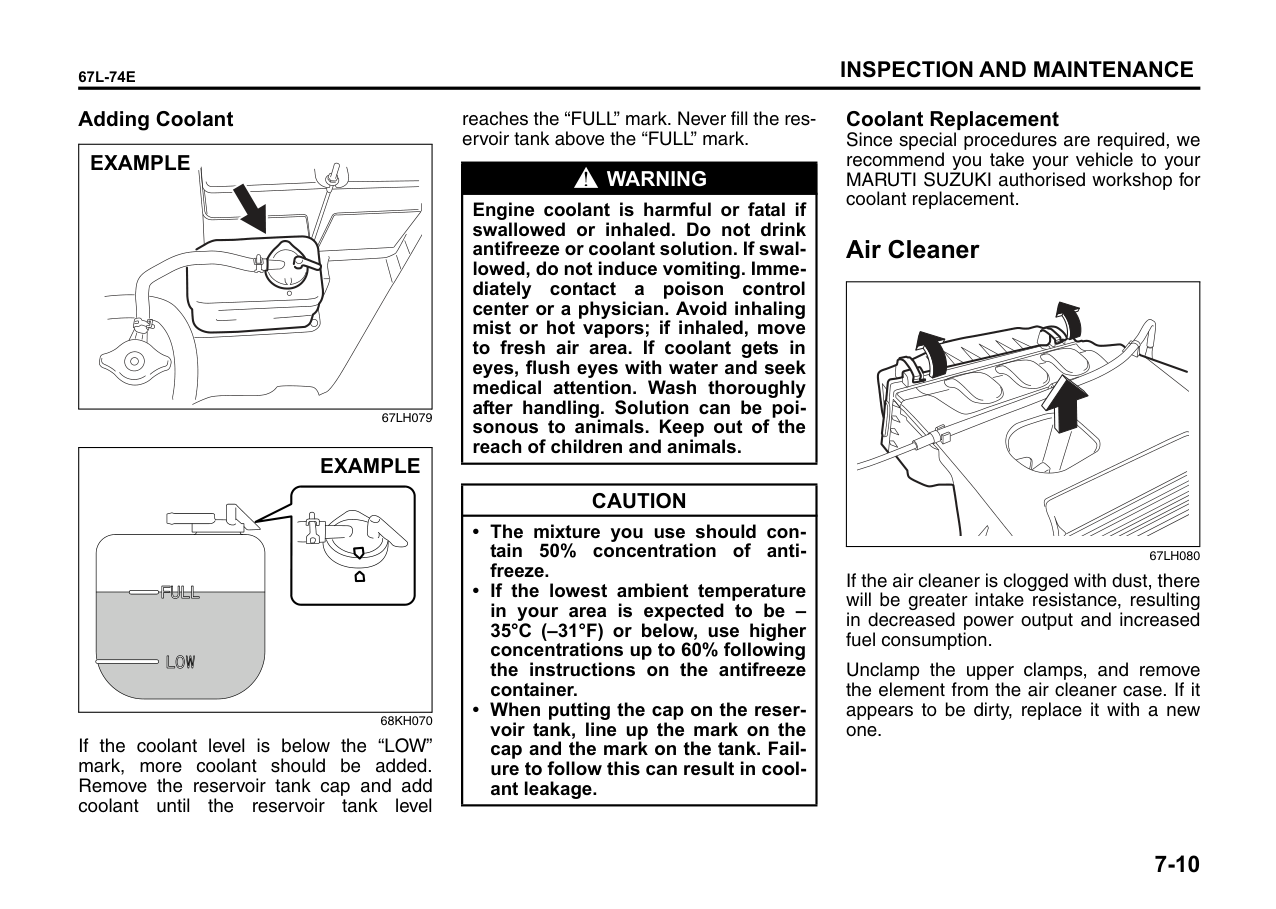
|---| |When the engine is running, keep hands, hair, clothing, tools, etc. away from the moving fan and drive belts.|
Make sure the drive belt tension is correct. If the belt is too loose, insufficient battery charging, engine overheating, poor power steering, poor air conditioning, or excessive belt wear can result. When you press the belt with your thumb midway between the pulleys, there should be a deflection according to the following chart.
The belts should also be examined to ensure that they are not damaged.
If you need to replace or adjust the belt have it done by your MARUTI SUZUKI authorised workshop.
######## K10B
|
: 100 N (10 kg, 22 lbs) press GE: Generator DEF: Deflection AC: Air conditioner compressor
DEF: 4.0 – 4.5 mm (0.16 – 0.18 in.)
GE
AC
DEF: 7 – 8 mm (0.28 – 0.31 in.)| |---|
51KM036
Engine Oil and Filter Specified Oil
Be sure that the engine oil you use comes under the quality classification of SL.
SAE 0W-20 is the best choice for good fuel economy, and good starting in cold weather.
####### Oil Level Check
|EXAMPLE| |---|
68KH066
It is important to keep the engine oil at the correct level for proper lubrication of your vehicle’s engine. Check the oil level with the vehicle on a level surface. The oil level indication may be inaccurate if the vehicle is on a slope. The oil level should be checked either before starting the engine or at least 5 minutes after stopping the engine.
The handle of the engine oil dipstick is colored yellow for easy identification. Pull out the oil dipstick, wipe oil off with a clean cloth, insert the dipstick all the way into the engine, then remove it again. The oil on the stick should be between the upper and lower limits shown on the stick. If the oil level indication is near the lower limit, add enough oil to raise the level to the upper limit.
|CAUTION|
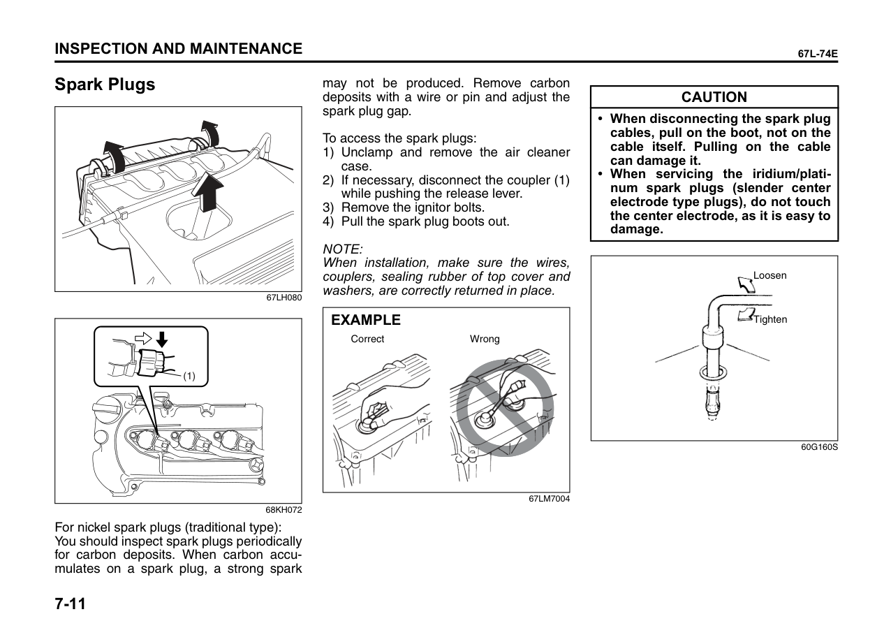
|---| |Failure to check the oil level regularly could lead to serious engine trouble due to insufficient oil.|
####### Refilling
|
CloseOpen
EXAMPLE| |---|
81A147
Remove the oil filler cap and pour oil slowly through the filler hole to bring the oil level to the upper limit on the dipstick. Be careful not to overfill. Too much oil is almost as bad as too little oil. After refilling, start the engine and allow it to idle for about a minute. Stop the engine, wait about 5 minutes and check the oil level again.
Changing Engine Oil and Filter Drain the engine oil while the engine is still warm.
|Open Close
EXAMPLE| |---|
68KH067
|WARNING
| |---| |The engine oil temperature may be high enough to burn your fingers when the drain plug is loosened. Wait until the drain plug is cool enough to touch with your bare hands.|
|(1)
EXAMPLE| |---|
68KH068
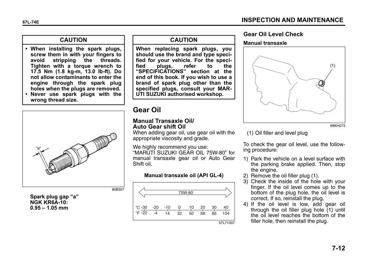
Tightening torque for drain plug (1): 35 Nm (3.5 kg-m, 25.5 lb-ft)
|WARNING
| |---| |New and used oil can be hazardous. Children and pets may be harmed by swallowing new or used oil. Keep new and used oil and used oil filters away from children and pets. Repeated, prolonged contact with used engine oil may cause skin cancer. Brief contact with used oil may irritate skin.
(Continued)|
|WARNING
| |---| |(Continued) To minimize your exposure to used oil, wear a long-sleeve shirt and moisture-proof gloves (such as dishwashing gloves) when changing oil. If oil contacts your skin, wash thoroughly with soap and water. Launder any clothing or rags if wet with oil. Recycle or properly dispose of used oil and filters.|
4) Reinstall the drain plug and new gasket. Tighten the plug with a wrench to the specified torque.
####### Replace the Oil Filter
|| |---|
54G092
######## Tightening (viewed from filter top)
|(1)
(2)
| |---|
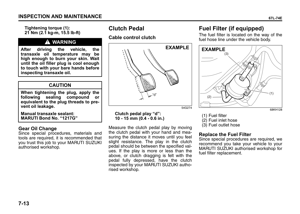
82JN146
|NOTICE| |---| |To tighten the oil filter properly, it is Important to accurately identify the position at which the filter gasket first contacts the mounting surface.|
Tightening torque for oil filter 1 turn or 14 Nm (1.4 kg-m, 10.5 lb-ft)
|NOTICE| |---| |To prevent oil leakage, make sure that the oil filter is tight, but do not over-tighten it.|
####### Refill with Oil and Check for Leaks
|NOTICE| |---| |• When replacing the oil filter, it is recommended that you use a MARUTI genuine replacement filter. If you use an aftermarket filter, make sure it is of equivalent quality and follow the manufacturer’s instructions.
• Oil leaks from around the oil filter or drain plug indicate incorrect installation or gasket damage. If you find any leaks or are not sure that the filter has been properly tightened, have the vehicle inspected by your MARUTI SUZUKI authorised workshop.
|
Engine Coolant Selection of Coolant To maintain optimum performance and durability of your engine, use MARUTI Genuine Coolant or equivalent. This type of coolant is best for your cooling system as it:
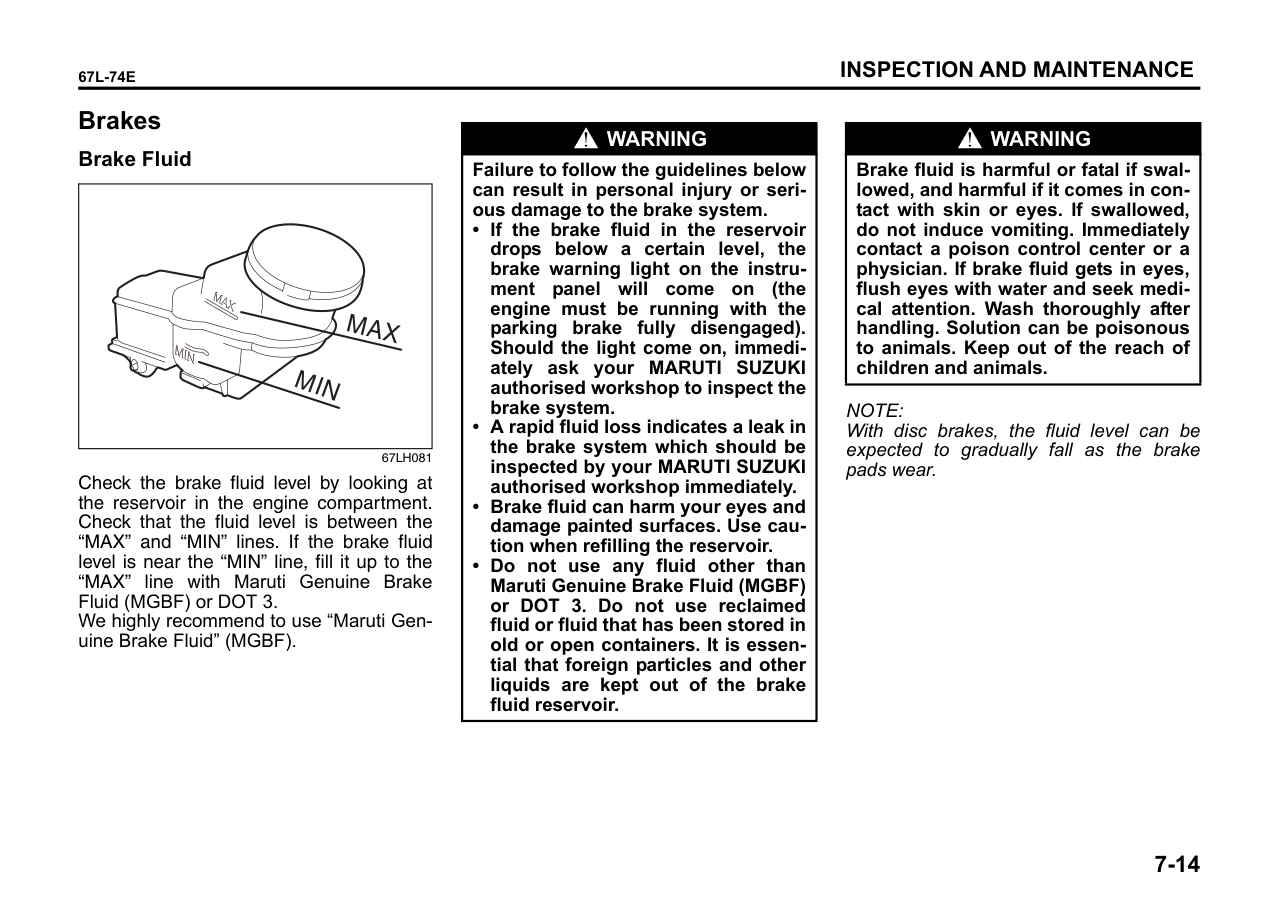
Failure to use the proper coolant can damage your cooling system. Your MARUTI SUZUKI authorised workshop can help you select the proper coolant.
|NOTICE| |---| |To avoid damaging your cooling system:
• Always use a high quality ethylene glycol base non-silicate type coolant diluted with distilled water at the correct mixture concentration.
• Make sure that the proper mix is 30/ 70 coolant to distilled water and in no case higher than 70/30. Concentrations greater than 70/30 coolant to distilled water will cause overheating conditions.
• Do not use straight coolant nor plain water.
• Do not add extra inhibitors or additives. They may not be compatible with your cooling system.
• Do not mix different types of base coolants. Doing so may result in accelerated seal wear and/or the possibility of severe overheating and extensive engine damage.
|
####### Coolant Level Check
Check the coolant level at the reservoir tank, not at the radiator. With the engine cool, the coolant level should be between the “FULL” and “LOW” marks.
####### Adding Coolant
|EXAMPLE| |---|
|EXAMPLE| |---|
If the coolant level is below the “LOW” mark, more coolant should be added. Remove the reservoir tank cap and add coolant until the reservoir tank level
reaches the “FULL” mark. Never fill the reservoir tank above the “FULL” mark.
|WARNING
| |---| |Engine coolant is harmful or fatal if swallowed or inhaled. Do not drink antifreeze or coolant solution. If swallowed, do not induce vomiting. Immediately contact a poison control center or a physician. Avoid inhaling mist or hot vapors; if inhaled, move to fresh air area. If coolant gets in eyes, flush eyes with water and seek medical attention. Wash thoroughly after handling. Solution can be poisonous to animals. Keep out of the reach of children and animals.|
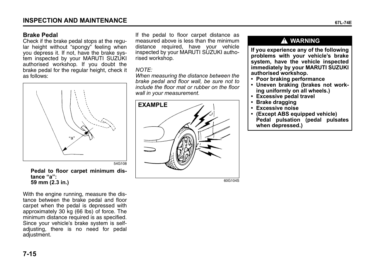
|CAUTION| |---| |• The mixture you use should contain 50% concentration of antifreeze.
• If the lowest ambient temperature in your area is expected to be – 35°C (–31°F) or below, use higher concentrations up to 60% following the instructions on the antifreeze container.
• When putting the cap on the reservoir tank, line up the mark on the cap and the mark on the tank. Failure to follow this can result in coolant leakage.
|
####### Coolant Replacement
Since special procedures are required, we recommend you take your vehicle to your MARUTI SUZUKI authorised workshop for coolant replacement.
Air Cleaner
| | |---|
67LH080
If the air cleaner is clogged with dust, there will be greater intake resistance, resulting in decreased power output and increased fuel consumption.
Unclamp the upper clamps, and remove the element from the air cleaner case. If it appears to be dirty, replace it with a new one.
Spark Plugs
| | |---|
|(1)
| |---|
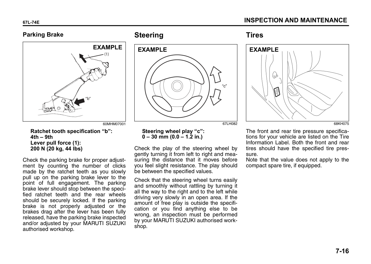
For nickel spark plugs (traditional type): You should inspect spark plugs periodically for carbon deposits. When carbon accumulates on a spark plug, a strong spark
may not be produced. Remove carbon deposits with a wire or pin and adjust the spark plug gap.
To access the spark plugs:
NOTE: When installation, make sure the wires, couplers, sealing rubber of top cover and washers, are correctly returned in place.
|Correct Wrong
EXAMPLE

| |---|
67LM7004
|CAUTION| |---| |• When disconnecting the spark plug cables, pull on the boot, not on the cable itself. Pulling on the cable can damage it.
• When servicing the iridium/platinum spark plugs (slender center electrode type plugs), do not touch the center electrode, as it is easy to damage.
|
|
Loosen
Tighten| |---|
60G160S
|CAUTION| |---| |• When installing the spark plugs, screw them in with your fingers to avoid stripping the threads. Tighten with a torque wrench to 17.5 Nm (1.8 kg-m, 13.0 lb-ft). Do not allow contaminants to enter the engine through the spark plug holes when the plugs are removed.
• Never use spark plugs with the wrong thread size.
|
||
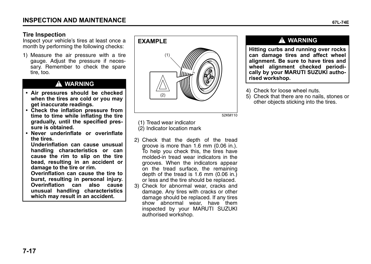
|---|
60B307
Spark plug gap “a” NGK KR6A-10: 0.95 – 1.05 mm
|CAUTION| |---| |When replacing spark plugs, you should use the brand and type specified for your vehicle. For the specified plugs, refer to the “SPECIFICATIONS” section at the end of this book. If you wish to use a brand of spark plug other than the specified plugs, consult your MARUTI SUZUKI authorised workshop.|
Gear Oil
Manual Transaxle Oil/ Auto Gear shift Oil When adding gear oil, use gear oil with the appropriate viscosity and grade.
We highly recommend you use: “MARUTI SUZUKI GEAR OIL 75W-80” for manual transaxle gear oil or Auto Gear Shift oil.
######## Manual transaxle oil (API GL-4)
|C Fo
o -30 -22
-20
-4
-10 14 32506886 104
010203040
75W-80| |---|
57L71007
####### Gear Oil Level Check Manual transaxle
|(1)
| |---|
68KH073
(1) Oil filler and level plug
To check the gear oil level, use the following procedure:
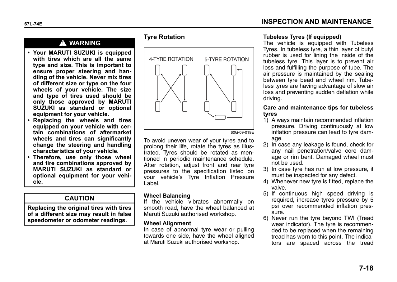
Tightening torque (1): 21 Nm (2.1 kg-m, 15.5 lb-ft)
|WARNING
| |---| |After driving the vehicle, the transaxle oil temperature may be high enough to burn your skin. Wait until the oil filler plug is cool enough to touch with your bare hands before inspecting transaxle oil.|
|CAUTION| |---| |When tightening the plug, apply the following sealing compound or equivalent to the plug threads to prevent oil leakage.
Manual transaxle sealant: MARUTI Bond No. “1217G”|
####### Gear Oil Change
Since special procedures, materials and tools are required, it is recommended that you trust this job to your MARUTI SUZUKI authorised workshop.
Clutch Pedal Cable control clutch
|
EXAMPLE| |---|
54G274
Clutch pedal play “d”: 10 - 15 mm (0.4 - 0.6 in.)
Measure the clutch pedal play by moving the clutch pedal with your hand and measuring the distance it moves until you feel slight resistance. The play in the clutch pedal should be between the specified values. If the play is more or less than the above, or clutch dragging is felt with the pedal fully depressed, have the clutch inspected by your MARUTI SUZUKI authorised workshop.
Fuel Filter (if equipped) The fuel filter is located on the way of the fuel hose line under the vehicle body.
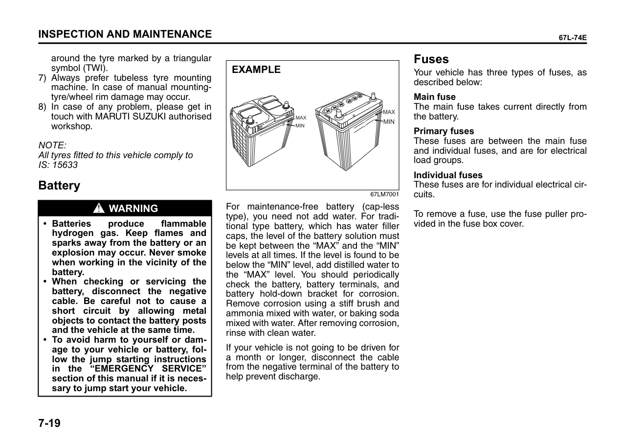
|(1)
(3)
(2)
EXAMPLE| |---|
68KH128
####### Replace the Fuel Filter
Since special procedures are required, we recommend you take your vehicle to your MARUTI SUZUKI authorised workshop for fuel filter replacement.
Brakes Brake Fluid
| | |---|
67LH081
Check the brake fluid level by looking at the reservoir in the engine compartment. Check that the fluid level is between the “MAX” and “MIN” lines. If the brake fluid level is near the “MIN” line, fill it up to the “MAX” line with Maruti Genuine Brake Fluid (MGBF) or DOT 3. We highly recommend to use “Maruti Genuine Brake Fluid” (MGBF).
|WARNING
| |---| |Failure to follow the guidelines below can result in personal injury or serious damage to the brake system.
• If the brake fluid in the reservoir drops below a certain level, the brake warning light on the instrument panel will come on (the engine must be running with the parking brake fully disengaged). Should the light come on, immediately ask your MARUTI SUZUKI authorised workshop to inspect the brake system.
• A rapid fluid loss indicates a leak in the brake system which should be inspected by your MARUTI SUZUKI authorised workshop immediately.
• Brake fluid can harm your eyes and damage painted surfaces. Use caution when refilling the reservoir.
• Do not use any fluid other than Maruti Genuine Brake Fluid (MGBF) or DOT 3. Do not use reclaimed fluid or fluid that has been stored in old or open containers. It is essential that foreign particles and other liquids are kept out of the brake fluid reservoir.
|
|WARNING
| |---| |Brake fluid is harmful or fatal if swallowed, and harmful if it comes in contact with skin or eyes. If swallowed, do not induce vomiting. Immediately contact a poison control center or a physician. If brake fluid gets in eyes, flush eyes with water and seek medical attention. Wash thoroughly after handling. Solution can be poisonous to animals. Keep out of the reach of children and animals.|
NOTE: With disc brakes, the fluid level can be expected to gradually fall as the brake pads wear.
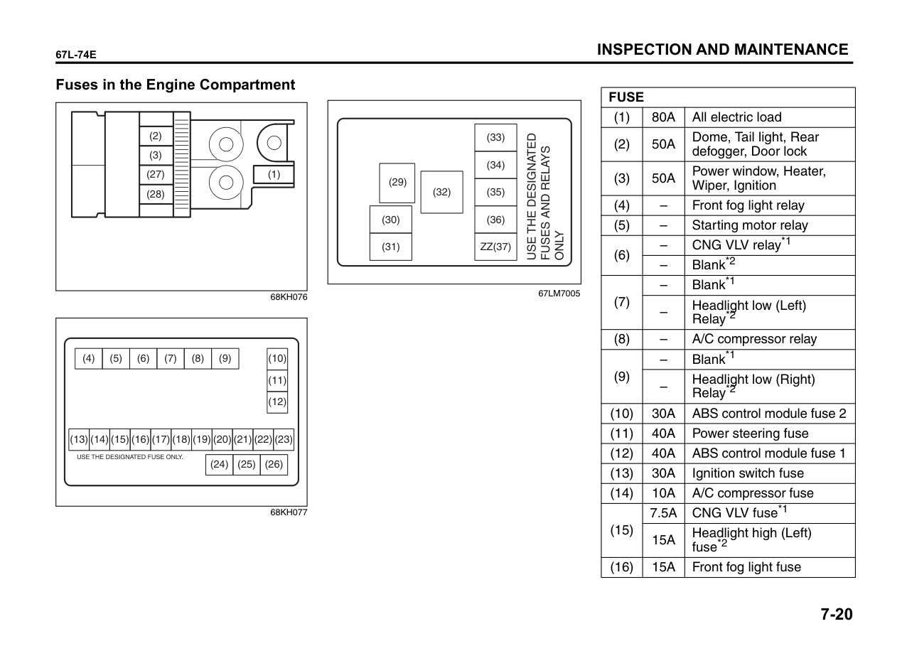
####### Brake Pedal
Check if the brake pedal stops at the regular height without “spongy” feeling when you depress it. If not, have the brake system inspected by your MARUTI SUZUKI authorised workshop. If you doubt the brake pedal for the regular height, check it as follows:
|| |---|
54G108
Pedal to floor carpet minimum distance “a”: 59 mm (2.3 in.)
If the pedal to floor carpet distance as measured above is less than the minimum distance required, have your vehicle inspected by your MARUTI SUZUKI authorised workshop.
NOTE: When measuring the distance between the brake pedal and floor wall, be sure not to include the floor mat or rubber on the floor wall in your measurement.
|
EXAMPLE| |---|
60G104S
|WARNING
| |---| |If you experience any of the following problems with your vehicle’s brake system, have the vehicle inspected immediately by your MARUTI SUZUKI authorised workshop.
• Poor braking performance
• Uneven braking (brakes not working uniformly on all wheels.)
• Excessive pedal travel
• Brake dragging
• Excessive noise
• (Except ABS equipped vehicle) Pedal pulsation (pedal pulsates when depressed.)
|
With the engine running, measure the distance between the brake pedal and floor carpet when the pedal is depressed with approximately 30 kg (66 lbs) of force. The minimum distance required is as specified. Since your vehicle’s brake system is selfadjusting, there is no need for pedal adjustment.
####### Parking Brake
|
(1)
“b”
EXAMPLE| |---|
60MHM07001
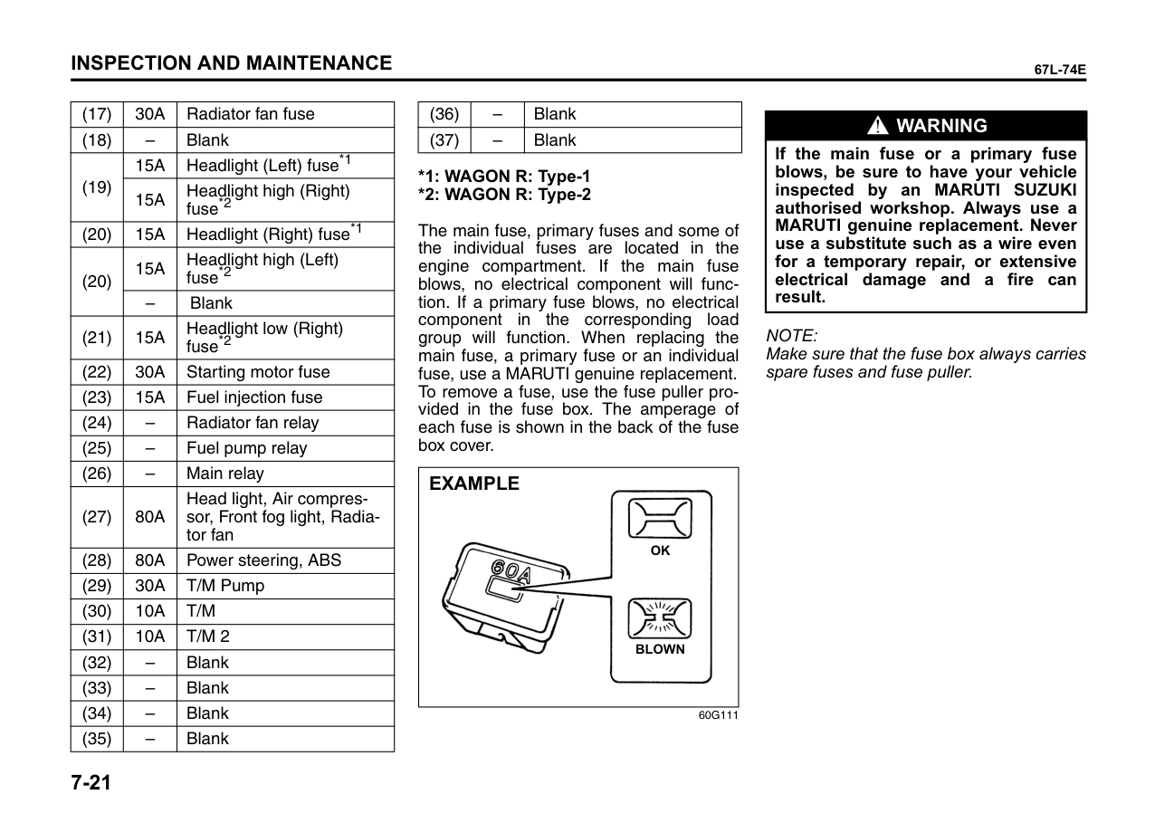
Ratchet tooth specification “b”: 4th – 9th Lever pull force (1): 200 N (20 kg, 44 lbs)
Check the parking brake for proper adjustment by counting the number of clicks made by the ratchet teeth as you slowly pull up on the parking brake lever to the point of full engagement. The parking brake lever should stop between the specified ratchet teeth and the rear wheels should be securely locked. If the parking brake is not properly adjusted or the brakes drag after the lever has been fully released, have the parking brake inspected and/or adjusted by your MARUTI SUZUKI authorised workshop.
Steering
|“c”
EXAMPLE| |---|
67LH082
Steering wheel play “c”: 0 – 30 mm (0.0 – 1.2 in.)
Check the play of the steering wheel by gently turning it from left to right and measuring the distance that it moves before you feel slight resistance. The play should be between the specified values.
Check that the steering wheel turns easily and smoothly without rattling by turning it all the way to the right and to the left while driving very slowly in an open area. If the amount of free play is outside the specification or you find anything else to be wrong, an inspection must be performed by your MARUTI SUZUKI authorised workshop.
Tires
|EXAMPLE| |---|
68KH075
The front and rear tire pressure specifications for your vehicle are listed on the Tire Information Label. Both the front and rear tires should have the specified tire pressure. Note that the value does not apply to the compact spare tire, if equipped.
Tire Inspection Inspect your vehicle’s tires at least once a month by performing the following checks:
1) Measure the air pressure with a tire gauge. Adjust the pressure if necessary. Remember to check the spare tire, too.
|WARNING
| |---| |• Air pressures should be checked when the tires are cold or you may get inaccurate readings.
• Check the inflation pressure from time to time while inflating the tire gradually, until the specified pressure is obtained.
• Never underinflate or overinflate the tires. Underinflation can cause unusual handling characteristics or can cause the rim to slip on the tire bead, resulting in an accident or damage to the tire or rim. Overinflation can cause the tire to burst, resulting in personal injury. Overinflation can also cause unusual handling characteristics which may result in an accident.
|
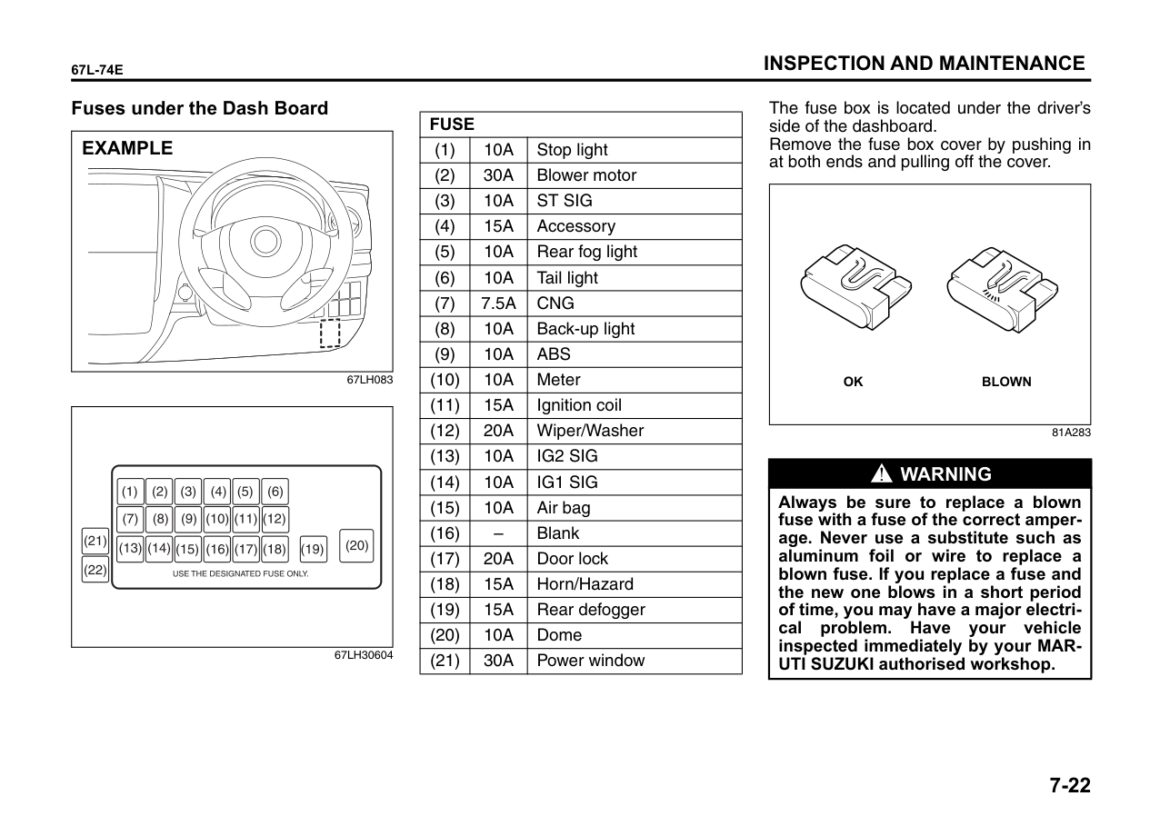
|(1)
(2)
EXAMPLE| |---|
52KM110
|WARNING
| |---| |Hitting curbs and running over rocks can damage tires and affect wheel alignment. Be sure to have tires and wheel alignment checked periodically by your MARUTI SUZUKI authorised workshop.|
|WARNING
| |---| |• Your MARUTI SUZUKI is equipped with tires which are all the same type and size. This is important to ensure proper steering and handling of the vehicle. Never mix tires of different size or type on the four wheels of your vehicle. The size and type of tires used should be only those approved by MARUTI SUZUKI as standard or optional equipment for your vehicle.
• Replacing the wheels and tires equipped on your vehicle with certain combinations of aftermarket wheels and tires can significantly change the steering and handling characteristics of your vehicle.
• Therefore, use only those wheel and tire combinations approved by MARUTI SUZUKI as standard or optional equipment for your vehicle.
|
|CAUTION| |---| |Replacing the original tires with tires of a different size may result in false speedometer or odometer readings.|
####### Tyre Rotation
| | |---|
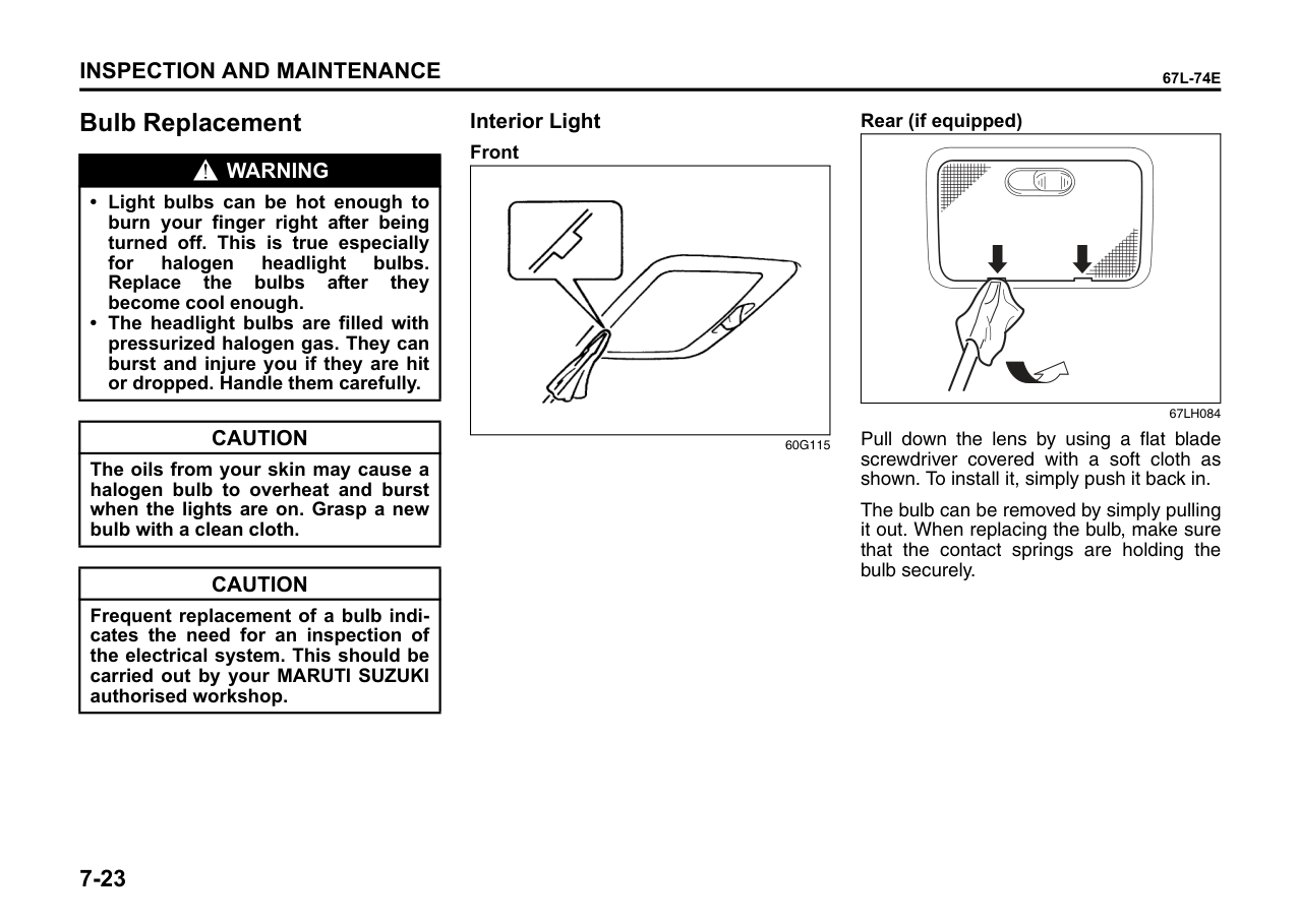
60G-09-019E
To avoid uneven wear of your tyres and to prolong their life, rotate the tyres as illustrated. Tyres should be rotated as mentioned in periodic maintenance schedule. After rotation, adjust front and rear tyre pressures to the specification listed on your vehicle’s Tyre Inflation Pressure Label.
######## Wheel Balancing
If the vehicle vibrates abnormally on smooth road, have the wheel balanced at Maruti Suzuki authorised workshop.
######## Wheel Alignment
In case of abnormal tyre wear or pulling towards one side, have the wheel aligned at Maruti Suzuki authorised workshop.
######## Tubeless Tyres (If equipped)
The vehicle is equipped with Tubeless Tyres. In tubeless tyre, a thin layer of butyl rubber is used for lining the inside of the tubeless tyre. This layer is to prevent air loss and fulfilling the purpose of tube. The air pressure is maintained by the sealing between tyre bead and wheel rim. Tubeless tyres are having advantage of slow air loss and preventing sudden deflation while driving.
Care and maintenance tips for tubeless tyres
around the tyre marked by a triangular symbol (TWI).
NOTE: All tyres fitted to this vehicle comply to IS: 15633
Battery
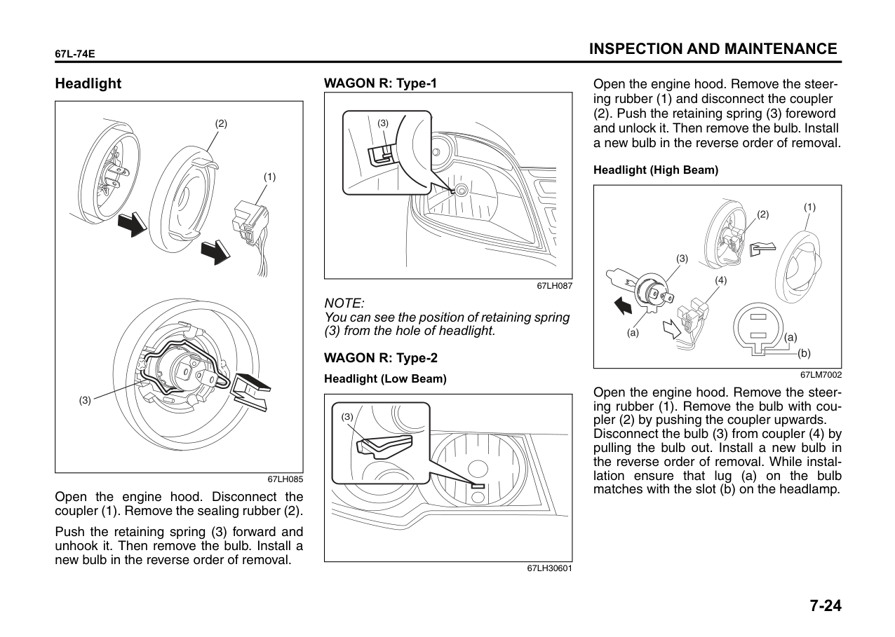
|WARNING
| |---| |• Batteries produce flammable hydrogen gas. Keep flames and sparks away from the battery or an explosion may occur. Never smoke when working in the vicinity of the battery.
• When checking or servicing the battery, disconnect the negative cable. Be careful not to cause a short circuit by allowing metal objects to contact the battery posts and the vehicle at the same time.
• To avoid harm to yourself or damage to your vehicle or battery, follow the jump starting instructions in the “EMERGENCY SERVICE” section of this manual if it is necessary to jump start your vehicle.
|
|EXAMPLE
| |---|
67LM7001
For maintenance-free battery (cap-less type), you need not add water. For traditional type battery, which has water filler caps, the level of the battery solution must be kept between the “MAX” and the “MIN” levels at all times. If the level is found to be below the “MIN” level, add distilled water to the “MAX” level. You should periodically check the battery, battery terminals, and battery hold-down bracket for corrosion. Remove corrosion using a stiff brush and ammonia mixed with water, or baking soda mixed with water. After removing corrosion, rinse with clean water.
If your vehicle is not going to be driven for a month or longer, disconnect the cable from the negative terminal of the battery to help prevent discharge.
Fuses Your vehicle has three types of fuses, as described below: Main fuse The main fuse takes current directly from the battery. Primary fuses
These fuses are between the main fuse and individual fuses, and are for electrical load groups.
Individual fuses These fuses are for individual electrical circuits.
To remove a fuse, use the fuse puller provided in the fuse box cover.
####### Fuses in the Engine Compartment
|(1)
(2)
(3)
(27)
(28)
| |---|
||(4)|(5)|(6)|(7)|(8)|(9)| |---|---|---|---|---|---|
|(24)|(25)|(26)|
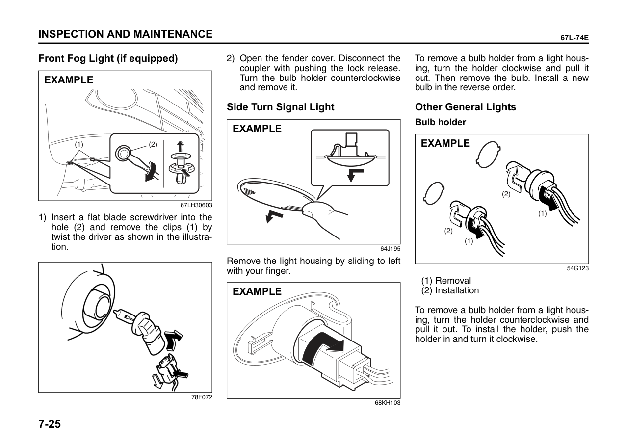
|---|---|---|
|(13)|(14)|(15)|(16)|(17)|(18)|(19)|(20)|(21)|(22)|(23)| |---|---|---|---|---|---|---|---|---|---|---|
|(10)| |---| |(11)| |(12)| | |---|
||(30)| |---| |(31)|
|(32)| |---|
|(33)| |---| |(34)| |(35)| |(36)| |ZZ(37)|
|(29)| |---| | |---|
67LM7005
|FUSE|FUSE|FUSE| |---|---|---| |(1)|80A|All electric load| |(2)|50A|Dome, Tail light, Rear defogger, Door lock| |(3)|50A|Power window, Heater, Wiper, Ignition| |(4)|–|Front fog light relay| |(5)|–|Starting motor relay|
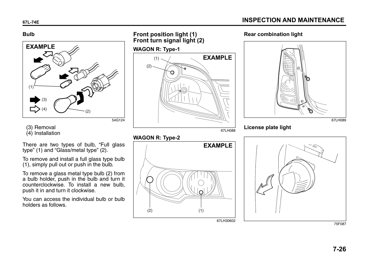
|(6)|–|CNG VLV relay*1| |(6)|–|Blank*2| |(7)|–|Blank*1| |(7)|–|Headlight low (Left) Relay*2| |(8)|–|A/C compressor relay| |(9)|–|Blank*1| |(9)|–|Headlight low (Right) Relay*2| |(10)|30A|ABS control module fuse 2| |(11)|40A|Power steering fuse| |(12)|40A|ABS control module fuse 1| |(13)|30A|Ignition switch fuse| |(14)|10A|A/C compressor fuse| |(15)|7.5A|CNG VLV fuse*1| |(15)|15A|Headlight high (Left) fuse*2| |(16)|15A|Front fog light fuse|
|(17)|30A|Radiator fan fuse| |---|---|---| |(18)|–|Blank| |(19)|15A|Headlight (Left) fuse*1| |(19)|15A|Headlight high (Right) fuse*2| |(20)|15A|Headlight (Right) fuse*1| |(20)|15A|Headlight high (Left) fuse*2| |(20)|–|Blank| |(21)|15A|Headlight low (Right) fuse*2| |(22)|30A|Starting motor fuse| |(23)|15A|Fuel injection fuse| |(24)|–|Radiator fan relay| |(25)|–|Fuel pump relay| |(26)|–|Main relay| |(27)|80A|Head light, Air compressor, Front fog light, Radiator fan| |(28)|80A|Power steering, ABS| |(29)|30A|T/M Pump| |(30)|10A|T/M| |(31)|10A|T/M 2| |(32)|–|Blank|
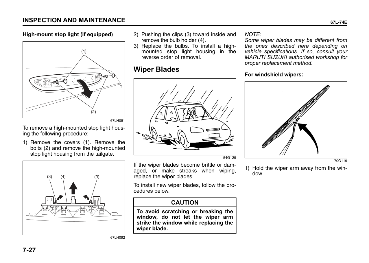
|(33)|–|Blank| |(34)|–|Blank| |(35)|–|Blank|
|(36)|–|Blank| |---|---|---| |(37)|–|Blank|
The main fuse, primary fuses and some of the individual fuses are located in the engine compartment. If the main fuse blows, no electrical component will function. If a primary fuse blows, no electrical component in the corresponding load group will function. When replacing the main fuse, a primary fuse or an individual fuse, use a MARUTI genuine replacement. To remove a fuse, use the fuse puller provided in the fuse box. The amperage of each fuse is shown in the back of the fuse box cover.
|
EXAMPLE
BLOWN
OK| |---|
60G111
|WARNING
| |---| |If the main fuse or a primary fuse blows, be sure to have your vehicle inspected by an MARUTI SUZUKI authorised workshop. Always use a MARUTI genuine replacement. Never use a substitute such as a wire even for a temporary repair, or extensive electrical damage and a fire can result.|
NOTE: Make sure that the fuse box always carries spare fuses and fuse puller.
####### Fuses under the Dash Board
####### EXAMPLE
67LH083
| | |---|
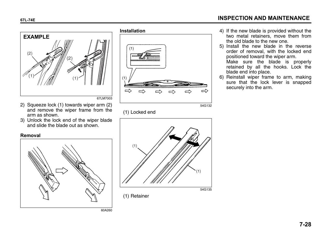
67LH30604
|FUSE|FUSE|FUSE| |---|---|---| |(1)|10A|Stop light| |(2)|30A|Blower motor| |(3)|10A|ST SIG| |(4)|15A|Accessory| |(5)|10A|Rear fog light| |(6)|10A|Tail light| |(7)|7.5A|CNG| |(8)|10A|Back-up light| |(9)|10A|ABS| |(10)|10A|Meter| |(11)|15A|Ignition coil| |(12)|20A|Wiper/Washer| |(13)|10A|IG2 SIG| |(14)|10A|IG1 SIG| |(15)|10A|Air bag| |(16)|–|Blank| |(17)|20A|Door lock| |(18)|15A|Horn/Hazard| |(19)|15A|Rear defogger| |(20)|10A|Dome| |(21)|30A|Power window|
The fuse box is located under the driver’s side of the dashboard. Remove the fuse box cover by pushing in at both ends and pulling off the cover.
|BLOWNOK| |---|
81A283
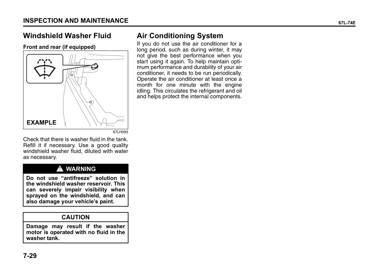
|WARNING
| |---| |Always be sure to replace a blown fuse with a fuse of the correct amperage. Never use a substitute such as aluminum foil or wire to replace a blown fuse. If you replace a fuse and the new one blows in a short period of time, you may have a major electrical problem. Have your vehicle inspected immediately by your MARUTI SUZUKI authorised workshop.|
Bulb Replacement Interior Light
######## Front
|WARNING
| |---| |• Light bulbs can be hot enough to burn your finger right after being turned off. This is true especially for halogen headlight bulbs. Replace the bulbs after they become cool enough.
• The headlight bulbs are filled with pressurized halogen gas. They can burst and injure you if they are hit or dropped. Handle them carefully.
|
|| |---|
|CAUTION| |---| |The oils from your skin may cause a halogen bulb to overheat and burst when the lights are on. Grasp a new bulb with a clean cloth.|
60G115
|CAUTION| |---| |Frequent replacement of a bulb indicates the need for an inspection of the electrical system. This should be carried out by your MARUTI SUZUKI authorised workshop.|
######## Rear (if equipped)
| | |---|
67LH084
Pull down the lens by using a flat blade screwdriver covered with a soft cloth as shown. To install it, simply push it back in.
The bulb can be removed by simply pulling it out. When replacing the bulb, make sure that the contact springs are holding the bulb securely.
####### Headlight
|(2)
(1)
(3)
| |---|
67LH085
Open the engine hood. Disconnect the coupler (1). Remove the sealing rubber (2).
Push the retaining spring (3) forward and unhook it. Then remove the bulb. Install a new bulb in the reverse order of removal.
######## WAGON R: Type-1
|(3)
| |---|
67LH087
NOTE: You can see the position of retaining spring
(3) from the hole of headlight.
######## WAGON R: Type-2Headlight (Low Beam)
|(3)
| |---|
67LH30601
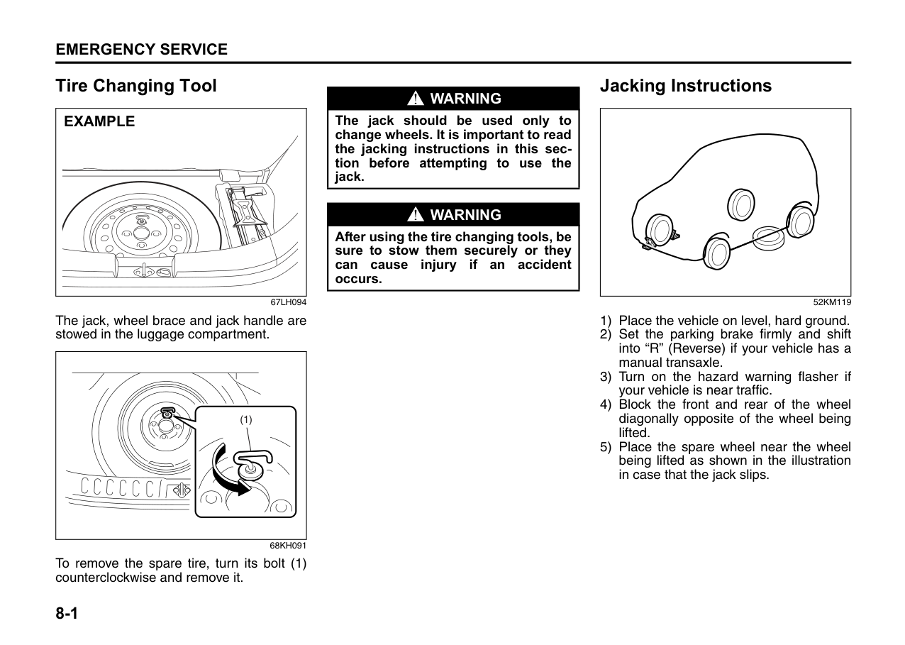
Open the engine hood. Remove the steering rubber (1) and disconnect the coupler
(2). Push the retaining spring (3) foreword and unlock it. Then remove the bulb. Install a new bulb in the reverse order of removal.
Headlight (High Beam)
| | |---|
67LM7002
Open the engine hood. Remove the steering rubber (1). Remove the bulb with coupler (2) by pushing the coupler upwards. Disconnect the bulb (3) from coupler (4) by pulling the bulb out. Install a new bulb in the reverse order of removal. While installation ensure that lug (a) on the bulb matches with the slot (b) on the headlamp.
####### Front Fog Light (if equipped)
|(2)(1)
EXAMPLE| |---|
67LH30603
|| |---|
78F072
2) Open the fender cover. Disconnect the coupler with pushing the lock release. Turn the bulb holder counterclockwise and remove it.
####### Side Turn Signal Light
|EXAMPLE| |---|
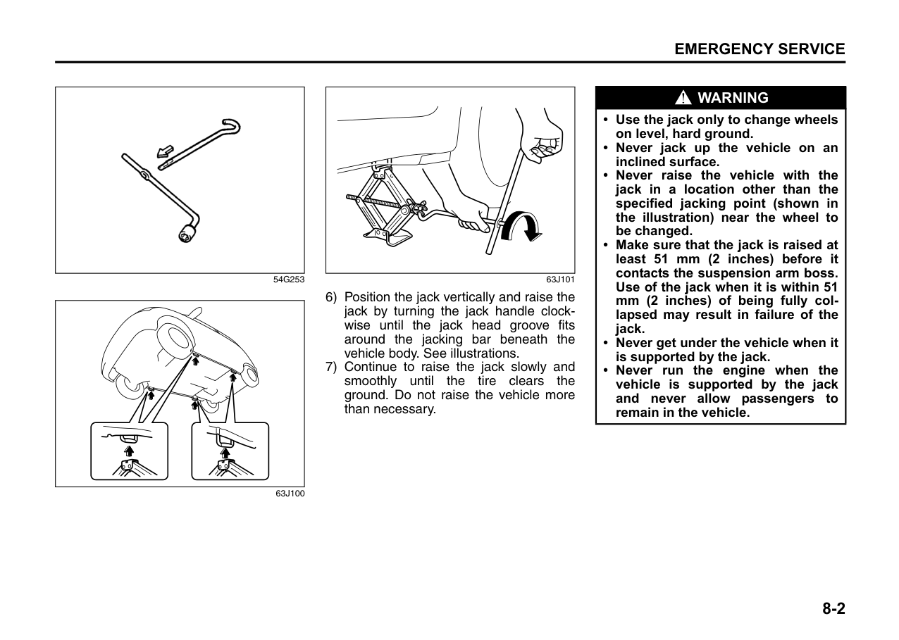
64J195
Remove the light housing by sliding to left with your finger.
|EXAMPLE| |---|
68KH103
To remove a bulb holder from a light housing, turn the holder clockwise and pull it out. Then remove the bulb. Install a new bulb in the reverse order. Other General Lights Bulb holder
|(1)
(1)
(2)
(2)
EXAMPLE| |---|
54G123
To remove a bulb holder from a light housing, turn the holder counterclockwise and pull it out. To install the holder, push the holder in and turn it clockwise.
######## Bulb
|(1)
(2)
(3)
(4)
EXAMPLE| |---|
54G124
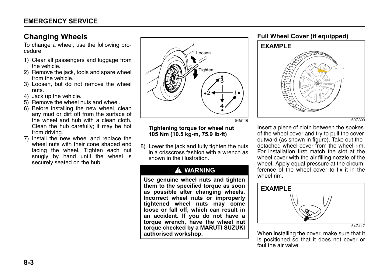
There are two types of bulb, “Full glass type” (1) and “Glass/metal type” (2).
To remove and install a full glass type bulb
(1), simply pull out or push in the bulb.
To remove a glass metal type bulb (2) from a bulb holder, push in the bulb and turn it counterclockwise. To install a new bulb, push it in and turn it clockwise.
You can access the individual bulb or bulb holders as follows.
####### Front position light (1) Front turn signal light (2)
######## WAGON R: Type-1
|(1)
(2)
EXAMPLE| |---|
67LH088
######## WAGON R: Type-2
|(1)(2)
EXAMPLE| |---|
67LH30602
Rear combination light
| | |---|
67LH089 License plate light
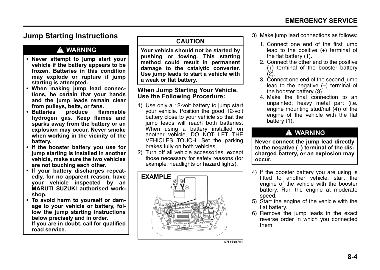
|
| |---|
75F087
######## High-mount stop light (if equipped)
|(1)
(2)| |---|
67LH091
To remove a high-mounted stop light housing the following procedure:
|(3) (4)
| | | | |---|---|---| | | | |
(3)| |---|
67LH092
Wiper Blades
|| |---|
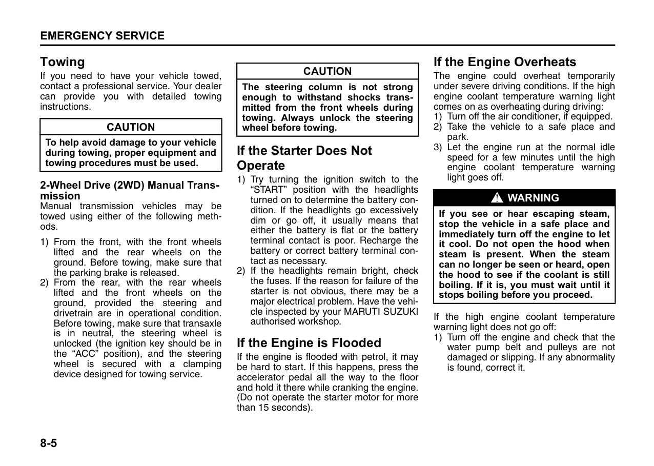
54G129
If the wiper blades become brittle or damaged, or make streaks when wiping, replace the wiper blades.
To install new wiper blades, follow the procedures below.
|CAUTION| |---| |To avoid scratching or breaking the window, do not let the wiper arm strike the window while replacing the wiper blade.|
NOTE: Some wiper blades may be different from the ones described here depending on vehicle specifications. If so, consult your MARUTI SUZUKI authorised workshop for proper replacement method.
######## For windshield wipers:
|| |---|
70G119 1) Hold the wiper arm away from the win-
dow.
|

EXAMPLE| |---|
67LM7003
######## Removal
||
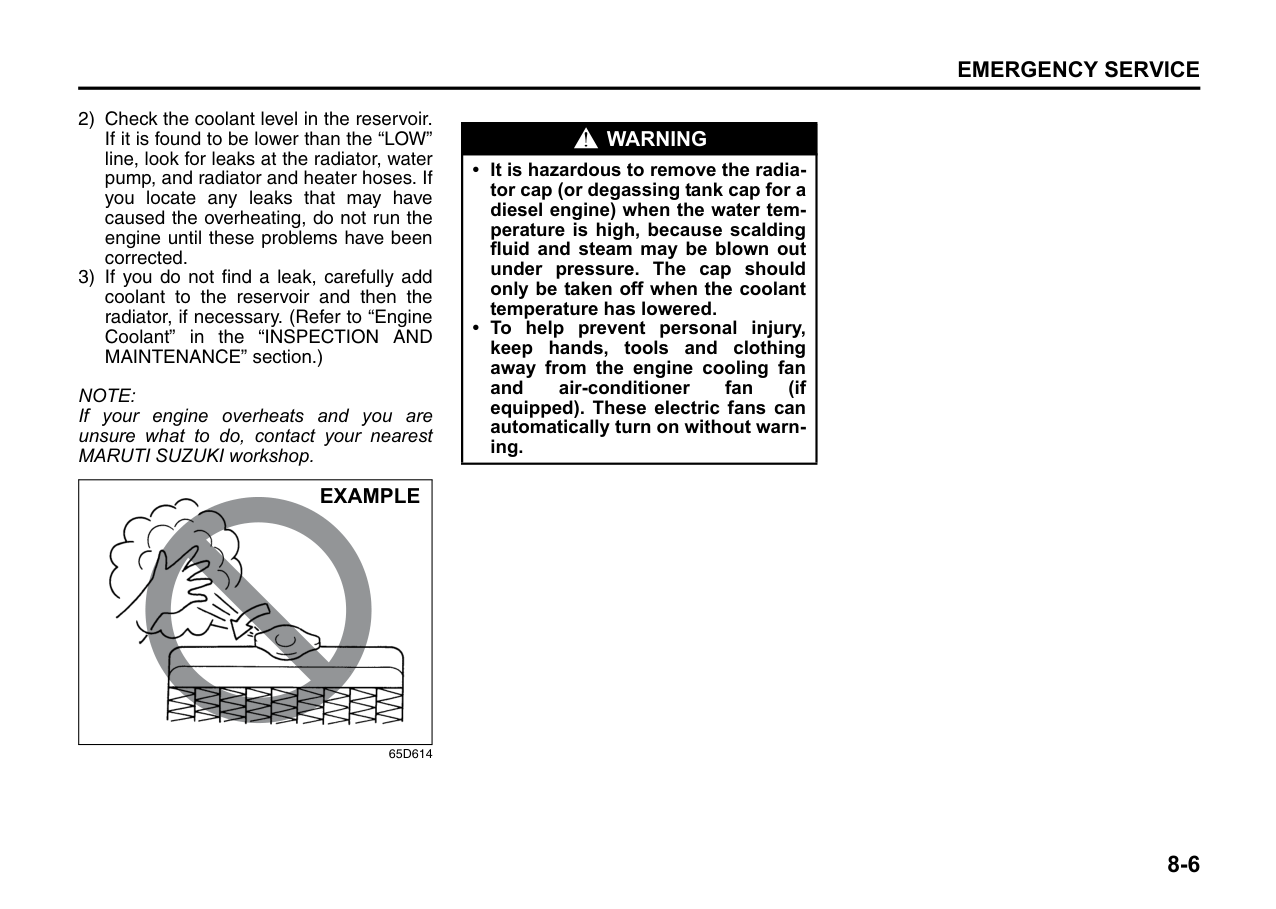
|---|
60A260
######## Installation
|| |---|
54G132
(1) Locked end
|| |---|
54G135
(1) Retainer
Windshield Washer Fluid Front and rear (if equipped)
|EXAMPLE| |---|
67LH093
Check that there is washer fluid in the tank. Refill it if necessary. Use a good quality windshield washer fluid, diluted with water as necessary.
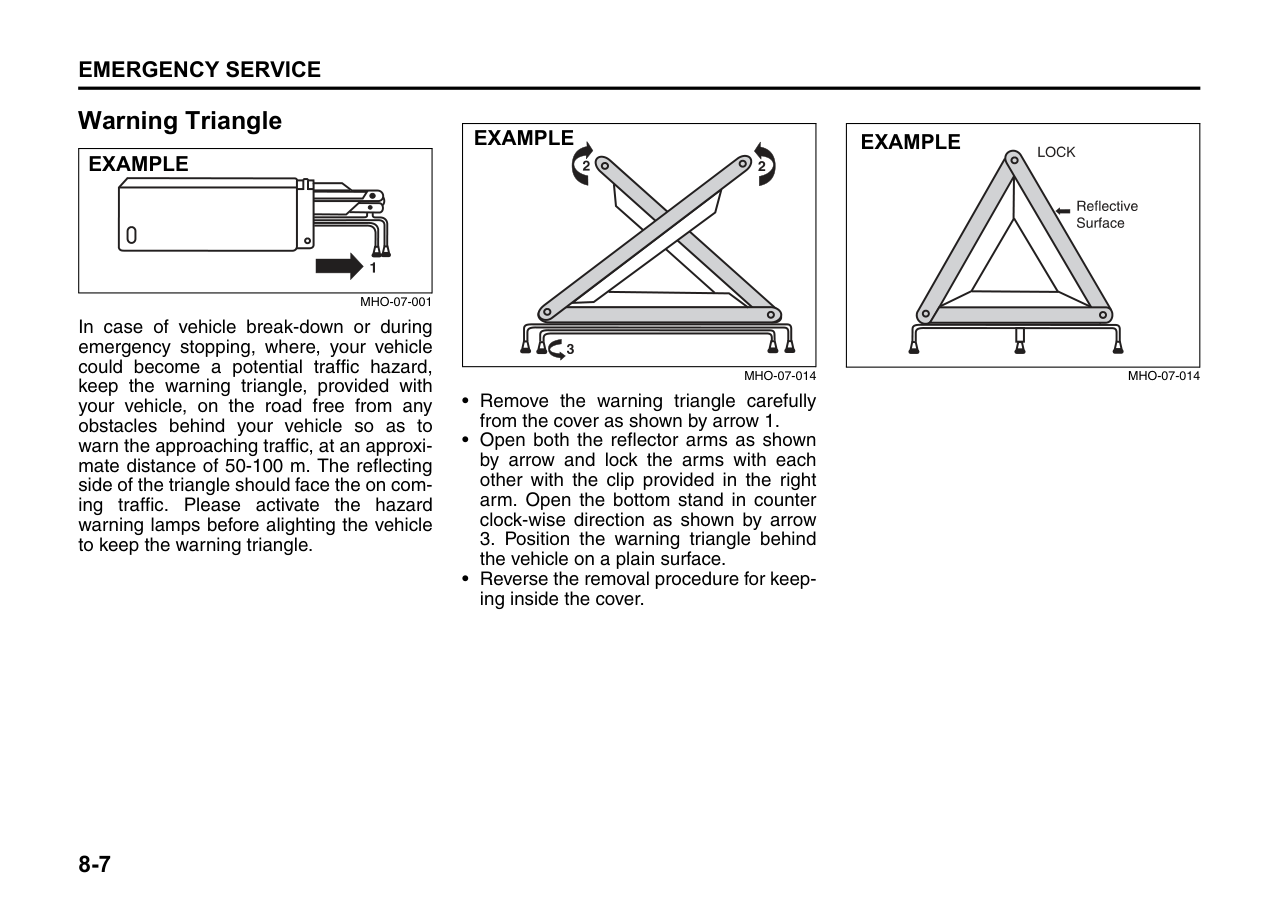
|WARNING
| |---| |Do not use “antifreeze” solution in the windshield washer reservoir. This can severely impair visibility when sprayed on the windshield, and can also damage your vehicle’s paint.|
Air Conditioning System
If you do not use the air conditioner for a long period, such as during winter, it may not give the best performance when you start using it again. To help maintain optimum performance and durability of your air conditioner, it needs to be run periodically. Operate the air conditioner at least once a month for one minute with the engine idling. This circulates the refrigerant and oil and helps protect the internal components.
|CAUTION| |---| |Damage may result if the washer motor is operated with no fluid in the washer tank.|
EMERGENCY SERVICE
| | |---|
60G411
Tire Changing Tool .................................................................8-1 Jacking Instructions ...............................................................8-1 Changing Wheels ....................................................................8-3 Jump Starting Instructions ....................................................8-4 Towing ......................................................................................8-5 If the Starter Does Not Operate ..............................................8-5 If the Engine is Flooded ..........................................................8-5 If the Engine Overheats ..........................................................8-5 Warning triangle ......................................................................8-7
###### 8
Tire Changing Tool
|EXAMPLE| |---|
67LH094
The jack, wheel brace and jack handle are stowed in the luggage compartment.
|(1)| |---|
68KH091
To remove the spare tire, turn its bolt (1) counterclockwise and remove it.
|WARNING
| |---| |The jack should be used only to change wheels. It is important to read the jacking instructions in this section before attempting to use the jack.|
|WARNING
| |---| |After using the tire changing tools, be sure to stow them securely or they can cause injury if an accident occurs.|
Jacking Instructions
| | |---|
52KM119
|| |---|
54G253
| | |---|
63J100
| | |---|
63J101
|WARNING
| |---| |• Use the jack only to change wheels on level, hard ground.
• Never jack up the vehicle on an inclined surface.
• Never raise the vehicle with the jack in a location other than the specified jacking point (shown in the illustration) near the wheel to be changed.
• Make sure that the jack is raised at least 51 mm (2 inches) before it contacts the suspension arm boss. Use of the jack when it is within 51 mm (2 inches) of being fully collapsed may result in failure of the jack.
• Never get under the vehicle when it is supported by the jack.
• Never run the engine when the vehicle is supported by the jack and never allow passengers to remain in the vehicle.
|
Changing Wheels To change a wheel, use the following procedure:
|
Loosen
Tighten| |---|
54G116
Tightening torque for wheel nut 105 Nm (10.5 kg-m, 75.9 lb-ft)
8) Lower the jack and fully tighten the nuts in a crisscross fashion with a wrench as shown in the illustration.
|WARNING
| |---| |Use genuine wheel nuts and tighten them to the specified torque as soon as possible after changing wheels. Incorrect wheel nuts or improperly tightened wheel nuts may come loose or fall off, which can result in an accident. If you do not have a torque wrench, have the wheel nut torque checked by a MARUTI SUZUKI authorised workshop.|
####### Full Wheel Cover (if equipped)
|EXAMPLE| |---|
60G309
Insert a piece of cloth between the spokes of the wheel cover and try to pull the cover outward (as shown in figure). Take out the detached wheel cover from the wheel rim. For installation first match the slot at the wheel cover with the air filling nozzle of the wheel. Apply equal pressure at the circumference of the wheel cover to fix it in the wheel rim.
|
EXAMPLE| |---|
54G117
When installing the cover, make sure that it is positioned so that it does not cover or foul the air valve.
Jump Starting Instructions
|WARNING
| |---| |• Never attempt to jump start your vehicle if the battery appears to be frozen. Batteries in this condition may explode or rupture if jump starting is attempted.
• When making jump lead connections, be certain that your hands and the jump leads remain clear from pulleys, belts, or fans.
• Batteries produce flammable hydrogen gas. Keep flames and sparks away from the battery or an explosion may occur. Never smoke when working in the vicinity of the battery.
• If the booster battery you use for jump starting is installed in another vehicle, make sure the two vehicles are not touching each other.
• If your battery discharges repeatedly, for no apparent reason, have your vehicle inspected by an MARUTI SUZUKI authorised workshop.
• To avoid harm to yourself or damage to your vehicle or battery, follow the jump starting instructions below precisely and in order. If you are in doubt, call for qualified road service.
|
|CAUTION| |---| |Your vehicle should not be started by pushing or towing. This starting method could result in permanent damage to the catalytic converter. Use jump leads to start a vehicle with a weak or flat battery.|
####### When Jump Starting Your Vehicle, Use the Following Procedure:
|EXAMPLE| |---|
67LH30701
(2).
|WARNING
| |---| |Never connect the jump lead directly to the negative (–) terminal of the discharged battery, or an explosion may occur.|
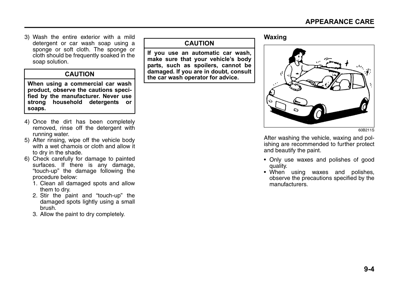
Towing
If you need to have your vehicle towed, contact a professional service. Your dealer can provide you with detailed towing instructions.
|CAUTION| |---| |To help avoid damage to your vehicle during towing, proper equipment and towing procedures must be used.|
|CAUTION| |---| |The steering column is not strong enough to withstand shocks transmitted from the front wheels during towing. Always unlock the steering wheel before towing.|
If the Starter Does Not Operate
If the Engine is Flooded
If the engine is flooded with petrol, it may be hard to start. If this happens, press the accelerator pedal all the way to the floor and hold it there while cranking the engine. (Do not operate the starter motor for more than 15 seconds).
If the Engine Overheats
The engine could overheat temporarily under severe driving conditions. If the high engine coolant temperature warning light comes on as overheating during driving:

|WARNING
| |---| |If you see or hear escaping steam, stop the vehicle in a safe place and immediately turn off the engine to let it cool. Do not open the hood when steam is present. When the steam can no longer be seen or heard, open the hood to see if the coolant is still boiling. If it is, you must wait until it stops boiling before you proceed.|
If the high engine coolant temperature warning light does not go off:
1) Turn off the engine and check that the water pump belt and pulleys are not damaged or slipping. If any abnormality is found, correct it.
NOTE: If your engine overheats and you are unsure what to do, contact your nearest MARUTI SUZUKI workshop.
|
EXAMPLE| |---|
65D614
|WARNING
| |---| |• It is hazardous to remove the radiator cap (or degassing tank cap for a diesel engine) when the water temperature is high, because scalding fluid and steam may be blown out under pressure. The cap should only be taken off when the coolant temperature has lowered.
• To help prevent personal injury, keep hands, tools and clothing away from the engine cooling fan and air-conditioner fan (if equipped). These electric fans can automatically turn on without warning.
|
Warning Triangle
|EXAMPLE
| | | |---|---| | | | | | | |
|---|
MHO-07-001
In case of vehicle break-down or during emergency stopping, where, your vehicle could become a potential traffic hazard, keep the warning triangle, provided with your vehicle, on the road free from any obstacles behind your vehicle so as to warn the approaching traffic, at an approximate distance of 50-100 m. The reflecting side of the triangle should face the on coming traffic. Please activate the hazard warning lamps before alighting the vehicle to keep the warning triangle.
|EXAMPLE| |---|
MHO-07-014
|EXAMPLE| |---|
MHO-07-014
APPEARANCE CARE
| | |---|
60G412
Corrosion Prevention ......................................................... 9-1 Vehicle Cleaning ................................................................. 9-2
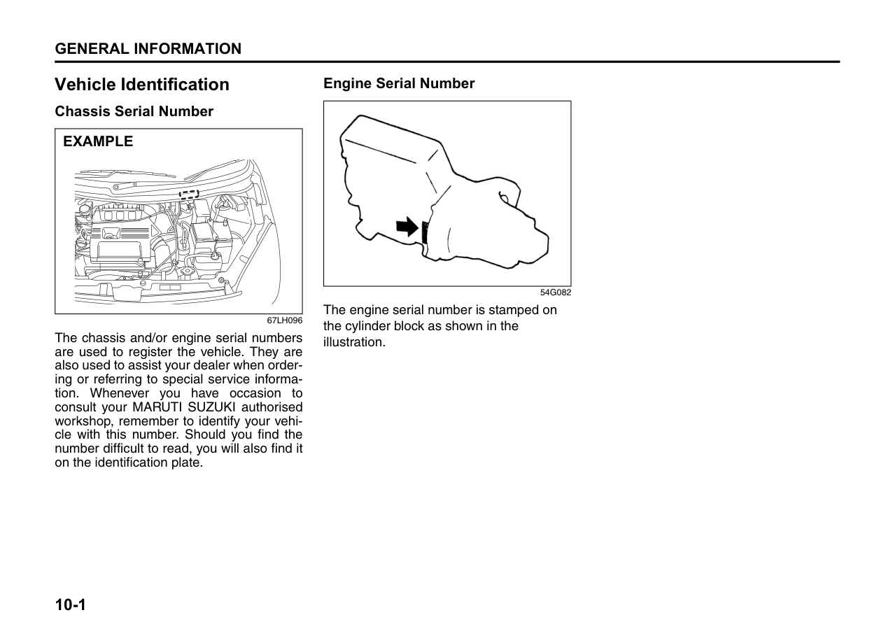
###### 9
Corrosion Prevention
It is important to take good care of your vehicle to protect it from corrosion. Listed below are instructions for how to maintain your vehicle to prevent corrosion. Please read and follow these instructions carefully.
####### Important Information About Corrosion
######## Common causes of corrosion
Environmental conditions which accelerate corrosion
vehicle which are not well ventilated to permit quick drying.
This information illustrates the necessity of keeping your vehicle (particularly the underbody) as clean and dry as possible. It is equally important to repair any damage to the paint or protective coatings as soon as possible.
How to Help Prevent Corrosion Wash your vehicle frequently The best way to preserve the finish on your vehicle and to help avoid corrosion is to keep it clean with frequent washing. Wash your vehicle at least once during the winter and once immediately after the winter. Keep your vehicle, particularly the underside, as clean and dry as possible. If you frequently drive on salted roads, your vehicle should be washed at least once a month during the winter. If you live near the ocean, your vehicle should be washed at least once a month throughout the year.
For washing instructions, refer to the “Vehicle Cleaning” section.
######## Remove foreign material deposits
Foreign material such as salts, chemicals, road oil or tar, tree sap, bird droppings and industrial fall-out may damage the finish of your vehicle if it is left on painted surfaces. Remove these types of deposits as quickly as possible. If these deposits are difficult to wash off, an additional cleaner may be
required. Be sure that any cleaner you use is not harmful to painted surfaces and is specifically intended for your purposes. Follow the manufacturer’s directions when using these special cleaners.
######## Repair finish damage
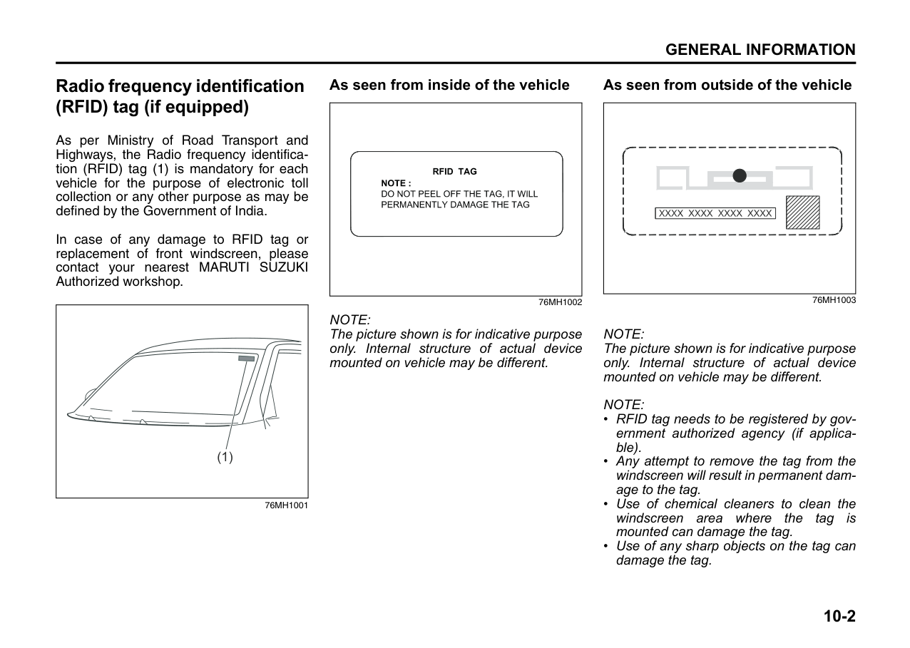
Carefully examine your vehicle for damage to the painted surfaces. Should you find any chips or scratches in the paint, touch them up immediately to prevent corrosion from starting. If the chips or scratches have gone through to the bare metal, have a qualified body shop make the repair.
Keep passenger and luggage compartments clean Moisture, dirt or mud can accumulate under the floor mats and may cause corrosion. Occasionally, check under these mats to ensure that this area is clean and dry. More frequent checks are necessary if the vehicle is used off road or in wet weather. Certain cargos such as chemicals, fertilizers, cleaners, salts, etc. are extremely corrosive by nature. These products should be transported in sealed containers. If a spill or leak does occur, clean and dry the area immediately.
Store your vehicle in a dry, well-ventilated area
Do not park your vehicle in a damp, poorly ventilated area. If you often wash your vehicle in the garage or if you frequently drive it in when wet, your garage may be damp. The high humidity in the garage may cause or accelerate corrosion. A wet vehicle may corrode even in a heated garage if the ventilation is poor.
|WARNING
| |---| |Do not apply additional undercoating or rust preventive coating on or around exhaust system components such as the catalytic converter, exhaust pipes, etc. A fire could be started if the undercoating substance becomes overheated.|
Vehicle Cleaning
|| |---|
76G044S
|WARNING
| |---| |When cleaning the interior or exterior of the vehicle, NEVER USE flammable solvents such as lacquer thinners, petrol, benzene or cleaning materials such as bleaches or strong household detergents. The materials could cause personal injury or damage to the vehicle.|
Cleaning the Interior Vinyl upholstery Prepare a solution of soap or mild detergent mixed with warm water. Apply the solution to the vinyl with a sponge or soft cloth and let it soak for a few minutes to loosen dirt. Rub the surface with a clean, damp cloth to remove dirt and the soap solution. If some dirt still remains on the surface, repeat this procedure.
######## Fabric upholstery
Remove loose dirt with a vacuum cleaner. Using a mild soap solution, rub stained areas with a clean damp cloth. To remove soap, rub the areas again with a cloth dampened with water. Repeat this until the stain is removed, or use a commercial fabric cleaner for tougher stains. If you use a fabric cleaner, carefully follow the manufacturer’s instructions and precautions.
######## Seat belts
Clean seat belts with a mild soap and water. Do not use bleach or dye on the belts. They may weaken the fabric in the belts.

######## Vinyl floor mats
Ordinary dirt can be removed from vinyl with water or mild soap. Use a brush to help loosen dirt. After the dirt is loosened, rinse the mat thoroughly with water and dry it in the shade.
######## Carpets
Remove dirt and soil as much as possible with a vacuum cleaner. Using a mild soap solution, rub stained areas with a clean damp cloth. To remove soap, rub the areas again with a cloth dampened with water. Repeat this until the stain is removed, or use a commercial carpet cleaner for tougher stains. If you use a carpet cleaner, carefully follow the manufacturer’s instructions and precautions.
####### Cleaning the Exterior
|CAUTION| |---| |It is important that your vehicle be kept clean and free from dirt. Failure to keep your vehicle clean may result in fading of the paint or corrosion to various parts of the vehicle body.|
Caring for Aluminum Wheels NOTE:
####### Washing
|| |---|
60B212S
|WARNING
| |---| |• Never attempt to wash and wax your vehicle with the engine running.
• When cleaning the underside of the body and fender, where there may be sharp-edged parts, you should wear gloves and a long-sleeved shirt to protect your hands and arms from being cut.
• After washing your vehicle, carefully test the brakes before driving to make sure they have maintained their normal effectiveness.
|
When washing the vehicle, park it where direct sunlight does not fall on it and follow the instructions below:
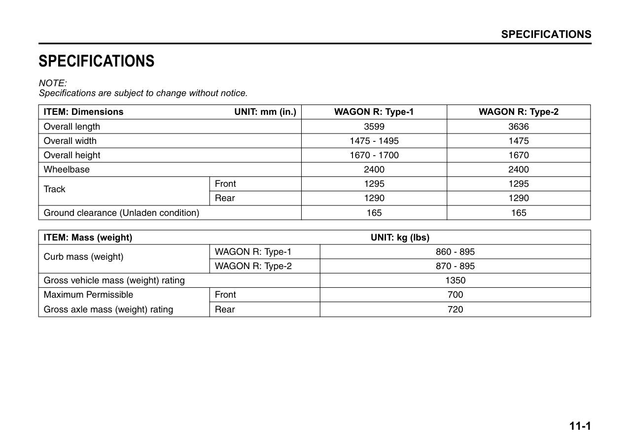
|CAUTION| |---| |When washing the vehicle:
• Avoid directing steam or hot water of more than 80°C (176°F) on plastic parts.
• To avoid damaging engine components, do not use pressurized water in the engine compartment.
|
|CAUTION| |---| |To avoid damage to the paint or plastic surface, do not wipe the dirt off without ample water. Be sure to follow above procedure.|
|CAUTION| |---| |When using a commercial car wash product, observe the cautions specified by the manufacturer. Never use strong household detergents or soaps.|
|CAUTION| |---| |If you use an automatic car wash, make sure that your vehicle’s body parts, such as spoilers, cannot be damaged. If you are in doubt, consult the car wash operator for advice.|
####### Waxing
||
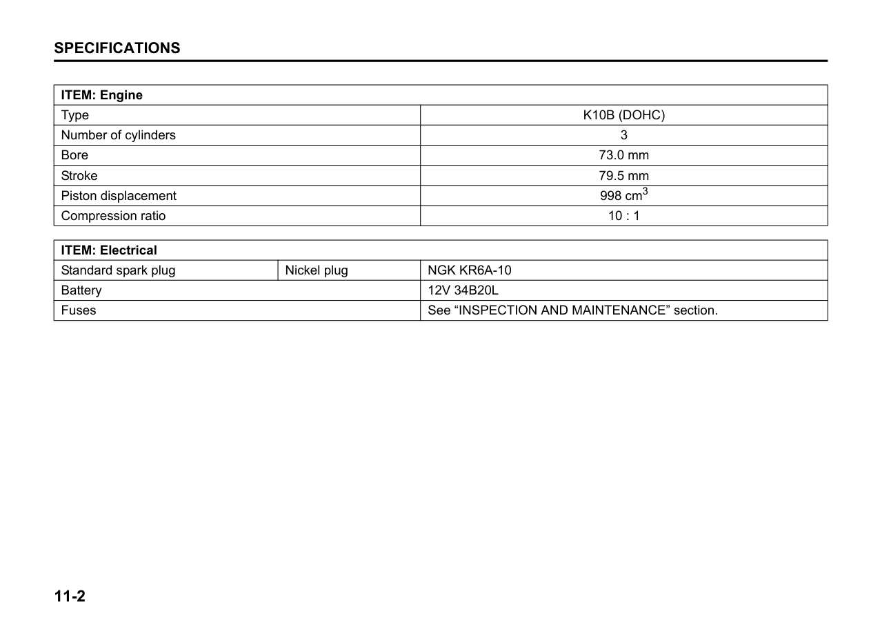
|---|
60B211S
After washing the vehicle, waxing and polishing are recommended to further protect and beautify the paint.
GENERAL INFORMATION
Vehicle Identification .......................................................... 10-1 Radio frequency identification (RFID) tag (if equipped) ...................................................... 10-2
| | |---|
1084MM01001
GENERAL INFORMATION Vehicle Identification Chassis Serial Number
####### Engine Serial Number
|| |---|
|EXAMPLE| |---|
54G082 The engine serial number is stamped on the cylinder block as shown in the illustration.
67LH096
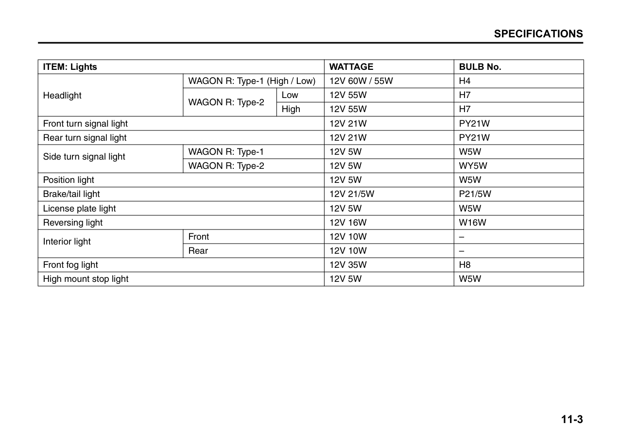
The chassis and/or engine serial numbers are used to register the vehicle. They are also used to assist your dealer when ordering or referring to special service information. Whenever you have occasion to consult your MARUTI SUZUKI authorised workshop, remember to identify your vehicle with this number. Should you find the number difficult to read, you will also find it on the identification plate.
##### 10-1
Radio frequency identification (RFID) tag (if equipped)
As per Ministry of Road Transport and Highways, the Radio frequency identification (RFID) tag (1) is mandatory for each vehicle for the purpose of electronic toll collection or any other purpose as may be defined by the Government of India.
In case of any damage to RFID tag or replacement of front windscreen, please contact your nearest MARUTI SUZUKI Authorized workshop.
|(1)| |---|
76MH1001
####### As seen from inside of the vehicle
| | |---|
############## 76MH1002
NOTE: The picture shown is for indicative purpose only. Internal structure of actual device mounted on vehicle may be different.
####### As seen from outside of the vehicle
| | |---|
############## 76MH1003
NOTE: The picture shown is for indicative purpose only. Internal structure of actual device mounted on vehicle may be different.
NOTE:
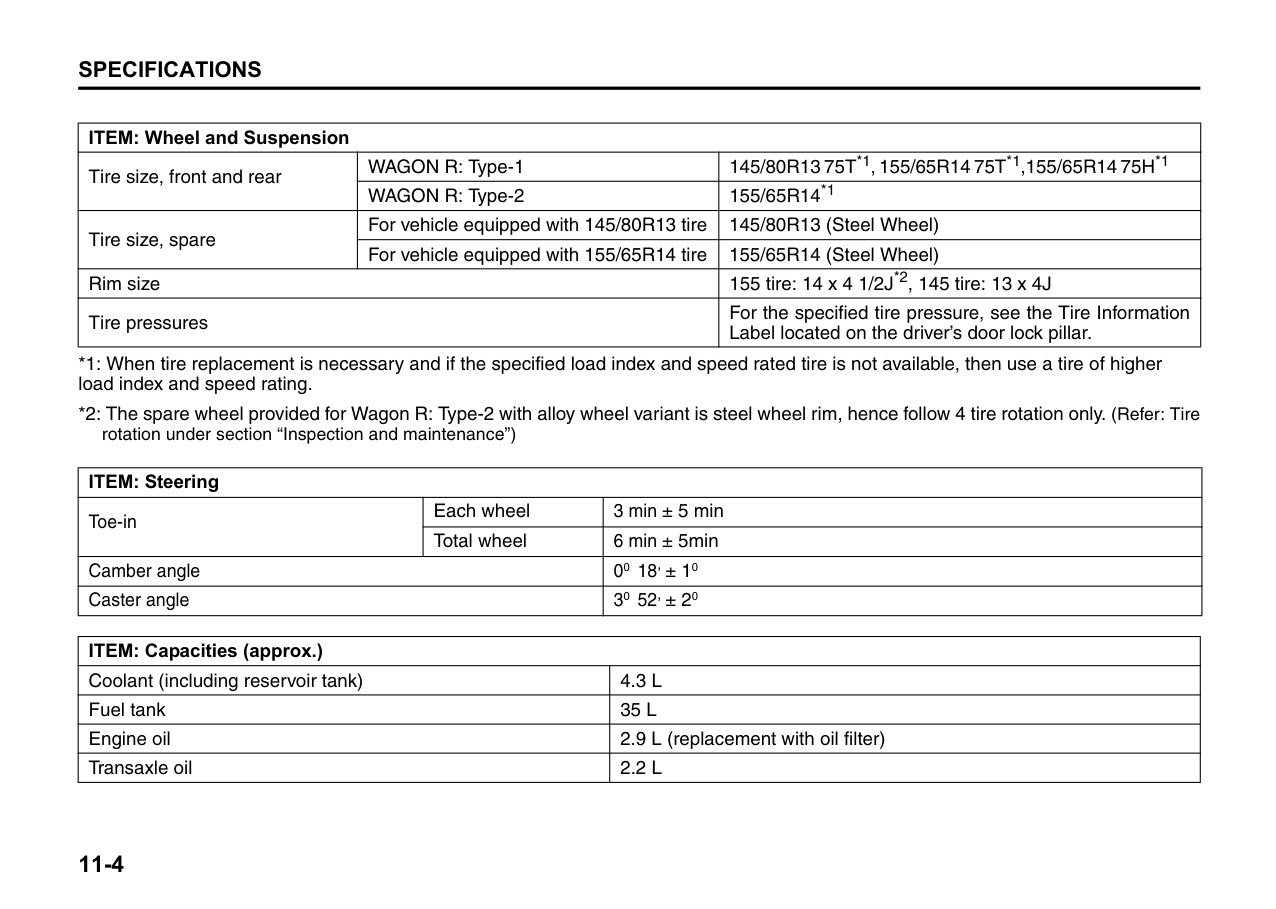
10-2
SPECIFICATIONS
NOTE: Specifications are subject to change without notice.
|ITEM: Dimensions UNIT: mm (in.)|ITEM: Dimensions UNIT: mm (in.)|WAGON R: Type-1|WAGON R: Type-2| |---|---|---|---| |Overall length|Overall length|3599|3636| |Overall width|Overall width|1475 - 1495|1475| |Overall height|Overall height|1670 - 1700|1670| |Wheelbase|Wheelbase|2400|2400| |Track|Front|1295|1295| |Track|Rear|1290|1290| |Ground clearance (Unladen condition)|Ground clearance (Unladen condition)|165|165|
|ITEM: Mass (weight) UNIT: kg (lbs)|ITEM: Mass (weight) UNIT: kg (lbs)|ITEM: Mass (weight) UNIT: kg (lbs)| |---|---|---| |Curb mass (weight)|WAGON R: Type-1|860 - 895| |Curb mass (weight)|WAGON R: Type-2|870 - 895| |Gross vehicle mass (weight) rating|Gross vehicle mass (weight) rating|1350| |Maximum Permissible Gross axle mass (weight) rating|Front|700| |Maximum Permissible Gross axle mass (weight) rating|Rear|720|
|ITEM: Engine|ITEM: Engine| |---|---| |Type|K10B (DOHC)| |Number of cylinders|3| |Bore|73.0 mm| |Stroke|79.5 mm| |Piston displacement|998 cm3| |Compression ratio|10 : 1|
|ITEM: Electrical|ITEM: Electrical|ITEM: Electrical| |---|---|---| |Standard spark plug|Nickel plug|NGK KR6A-10| |Battery|Battery|12V 34B20L| |Fuses|Fuses|See “INSPECTION AND MAINTENANCE” section.|
|ITEM: Lights|ITEM: Lights|ITEM: Lights|WATTAGE|BULB No.| |---|---|---|---|---| |Headlight|WAGON R: Type-1 (High / Low)|WAGON R: Type-1 (High / Low)|12V 60W / 55W|H4| |Headlight|WAGON R: Type-2|Low|12V 55W|H7| |Headlight|WAGON R: Type-2|High|12V 55W|H7| |Front turn signal light|Front turn signal light|Front turn signal light|12V 21W|PY21W| |Rear turn signal light|Rear turn signal light|Rear turn signal light|12V 21W|PY21W| |Side turn signal light|WAGON R: Type-1|WAGON R: Type-1|12V 5W|W5W| |Side turn signal light|WAGON R: Type-2|WAGON R: Type-2|12V 5W|WY5W| |Position light|Position light|Position light|12V 5W|W5W| |Brake/tail light|Brake/tail light|Brake/tail light|12V 21/5W|P21/5W| |License plate light|License plate light|License plate light|12V 5W|W5W| |Reversing light|Reversing light|Reversing light|12V 16W|W16W| |Interior light|Front|Front|12V 10W|–| |Interior light|Rear|Rear|12V 10W|–| |Front fog light|Front fog light|Front fog light|12V 35W|H8| |High mount stop light|High mount stop light|High mount stop light|12V 5W|W5W|
|ITEM: Wheel and Suspension|ITEM: Wheel and Suspension|ITEM: Wheel and Suspension| |---|---|---| |Tire size, front and rear|WAGON R: Type-1|145/80R13 75T*1, 155/65R14 75T*1,155/65R14 75H*1| |Tire size, front and rear|WAGON R: Type-2|155/65R14*1| |Tire size, spare|For vehicle equipped with 145/80R13 tire|145/80R13 (Steel Wheel)| |Tire size, spare|For vehicle equipped with 155/65R14 tire|155/65R14 (Steel Wheel)| |Rim size|Rim size|155 tire: 14 x 4 1/2J*2, 145 tire: 13 x 4J| |Tire pressures|Tire pressures|For the specified tire pressure, see the Tire Information Label located on the driver’s door lock pillar.|
rotation under section “Inspection and maintenance”)
|ITEM: Steering|ITEM: Steering|ITEM: Steering| |---|---|---| |Toe-in|Each wheel|3 min ± 5 min| |Toe-in|Total wheel|6 min ± 5min| |Camber angle|Camber angle|00 18, ± 10| |Caster angle|Caster angle|30 52, ± 20|
|ITEM: Capacities (approx.)|ITEM: Capacities (approx.)| |---|---| |Coolant (including reservoir tank)|4.3 L| |Fuel tank|35 L| |Engine oil|2.9 L (replacement with oil filter)| |Transaxle oil|2.2 L|