
Ask AI
— answers from the official manualAnswers from the official manual.
Common questions
Common Questions
3 totalWhat is the procedure for changing the engine oil?
Use SE, SF, SG, SH or SJ grade engine oil. Before draining engine oil, check for leaks. Drain oil by removing drain plug and reinstall securely with torque of 50 N·m (5.0 kg-m, 36.0 lb-ft). After draining, replace the filter, apply proper torque, fill to full level on dipstick after a three-minute run cycle, and check again until correct level is reached.
What are the warning signs for a failing clutch pedal?
Check free travel of pedal and height ensuring it is within proper range, typically about 5 – 20 mm (0.2-0.8 in). Refer to Section 7C for adjustment if necessary.
What precautions are given for raising the vehicle safely?
Before lifting the car up with hoists or jacks, place safety stands to ensure that body does not slide off and is supported securely. Avoid contact of hoist arm with brake pipes, fuel pipes, brackets etc.
Full Manual
358 pages
#### IMPORTANT WARNING/CAUTION/NOTE
Please read this manual and follow its instructions carefully. To emphasize special information, the words WARNING, CAUTION and NOTE have special meanings. Pay special attention to the messages highlighted by these signal words.
|WARNING: Indicates a potential hazard that could result in death or injury.| |---|
|CAUTION: Indicates a potential hazard that could result in vehicle damage.| |---|
NOTE: Indicates special information to make maintenance easier or instructions clearer.
|WARNING: This service manual is intended for authorized Maruti dealers and qualified service mechanics only. Inexperienced mechanics or mechanics without the proper tools and equipment may not be able to properly perform the services described in this manual. Improper repair may result in injury to the mechanic and may render the vehicle unsafe for the driver and passengers.| |---|
|| |---|
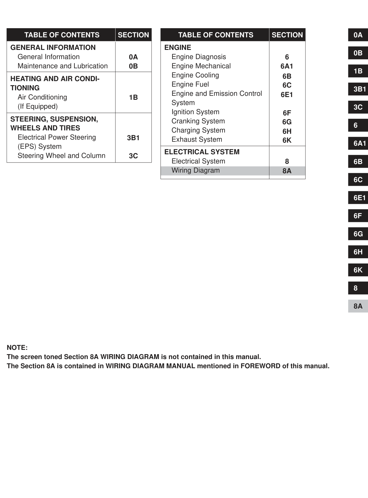
|TABLE OF CONTENTS|SECTION| |---|---| |GENERAL INFORMATION General Information Maintenance and Lubrication|0B
0A| |HEATING AND AIR CONDITIONING
Air Conditioning (If Equipped)|1B|
|STEERING, SUSPENSION, WHEELS AND TIRES
Electrical Power Steering (EPS) System Steering Wheel and Column|3B1
3C
|
|TABLE OF CONTENTS|SECTION| |---|---| |ENGINE Engine Diagnosis Engine Mechanical Engine Cooling Engine Fuel Engine and Emission Control System Ignition System Cranking System Charging System Exhaust System|6A1
6B
6C
6E1
6F
6G
6H 6K
6| |ELECTRICAL SYSTEM Electrical System Wiring Diagram|8 8A|
6K
8A
8
1B
6
NOTE: The screen toned Section 8A WIRING DIAGRAM is not contained in this manual. The Section 8A is contained in WIRING DIAGRAM MANUAL mentioned in FOREWORD of this manual.
SECTION 0A
0A
GENERAL INFORMATION
CONTENTS HOW TO USE THIS MANUAL 0A- 2. . . . . . . . . . . . . . . . . . . . . . . . . . . . . . . . . . . . . . . . . . . . . . . . . . . . . . . . . . . . . . . . . . . . . PRECAUTIONS 0A- 3. . . . . . . . . . . . . . . . . . . . . . . . . . . . . . . . . . . . . . . . . . . . . . . . . . . . . . . . . . . . . . . . . . . . . . . . . . . . . . . . .
General Precautions 0A- 3. . . . . . . . . . . . . . . . . . . . . . . . . . . . . . . . . . . . . . . . . . . . . . . . . . . . . . . . . . . . . . . . . . . . . . . . . . . Precautions for Catalytic Converter 0A- 5. . . . . . . . . . . . . . . . . . . . . . . . . . . . . . . . . . . . . . . . . . . . . . . . . . . . . . . . . . . . . . . Precautions for Electrical Circuit Service 0A- 6. . . . . . . . . . . . . . . . . . . . . . . . . . . . . . . . . . . . . . . . . . . . . . . . . . . . . . . . . . Electrical Circuit Inspection Procedure 0A- 7. . . . . . . . . . . . . . . . . . . . . . . . . . . . . . . . . . . . . . . . . . . . . . . . . . . . . . . . . . . . Intermittent and Poor Connection 0A-10. . . . . . . . . . . . . . . . . . . . . . . . . . . . . . . . . . . . . . . . . . . . . . . . . . . . . . . . . . . . . . . . Precaution for Installing Mobile Communication Equipment 0A-11. . . . . . . . . . . . . . . . . . . . . . . . . . . . . . . . . . . . . . . . . .
IDENTIFICATION INFORMATION 0A-11. . . . . . . . . . . . . . . . . . . . . . . . . . . . . . . . . . . . . . . . . . . . . . . . . . . . . . . . . . . . . . . . . . Vehicle Identification Number 0A-11. . . . . . . . . . . . . . . . . . . . . . . . . . . . . . . . . . . . . . . . . . . . . . . . . . . . . . . . . . . . . . . . . . . . Engine Identification Number 0A-11. . . . . . . . . . . . . . . . . . . . . . . . . . . . . . . . . . . . . . . . . . . . . . . . . . . . . . . . . . . . . . . . . . . . Transmission Identification Number 0A-11. . . . . . . . . . . . . . . . . . . . . . . . . . . . . . . . . . . . . . . . . . . . . . . . . . . . . . . . . . . . . .
VEHICLE LIFTING POINTS 0A-12. . . . . . . . . . . . . . . . . . . . . . . . . . . . . . . . . . . . . . . . . . . . . . . . . . . . . . . . . . . . . . . . . . . . . . . ABBREVIATIONS MAY BE USED IN THIS MANUAL 0A-14. . . . . . . . . . . . . . . . . . . . . . . . . . . . . . . . . . . . . . . . . . . . . . . . METRIC INFORMATION 0A-16. . . . . . . . . . . . . . . . . . . . . . . . . . . . . . . . . . . . . . . . . . . . . . . . . . . . . . . . . . . . . . . . . . . . . . . . . .
Metric Fasteners 0A-16. . . . . . . . . . . . . . . . . . . . . . . . . . . . . . . . . . . . . . . . . . . . . . . . . . . . . . . . . . . . . . . . . . . . . . . . . . . . . . . Fasteners Strength Identification 0A-16. . . . . . . . . . . . . . . . . . . . . . . . . . . . . . . . . . . . . . . . . . . . . . . . . . . . . . . . . . . . . . . . . Standard Tightening Torque 0A-16. . . . . . . . . . . . . . . . . . . . . . . . . . . . . . . . . . . . . . . . . . . . . . . . . . . . . . . . . . . . . . . . . . . . .
#### HOW TO USE THIS MANUAL
||
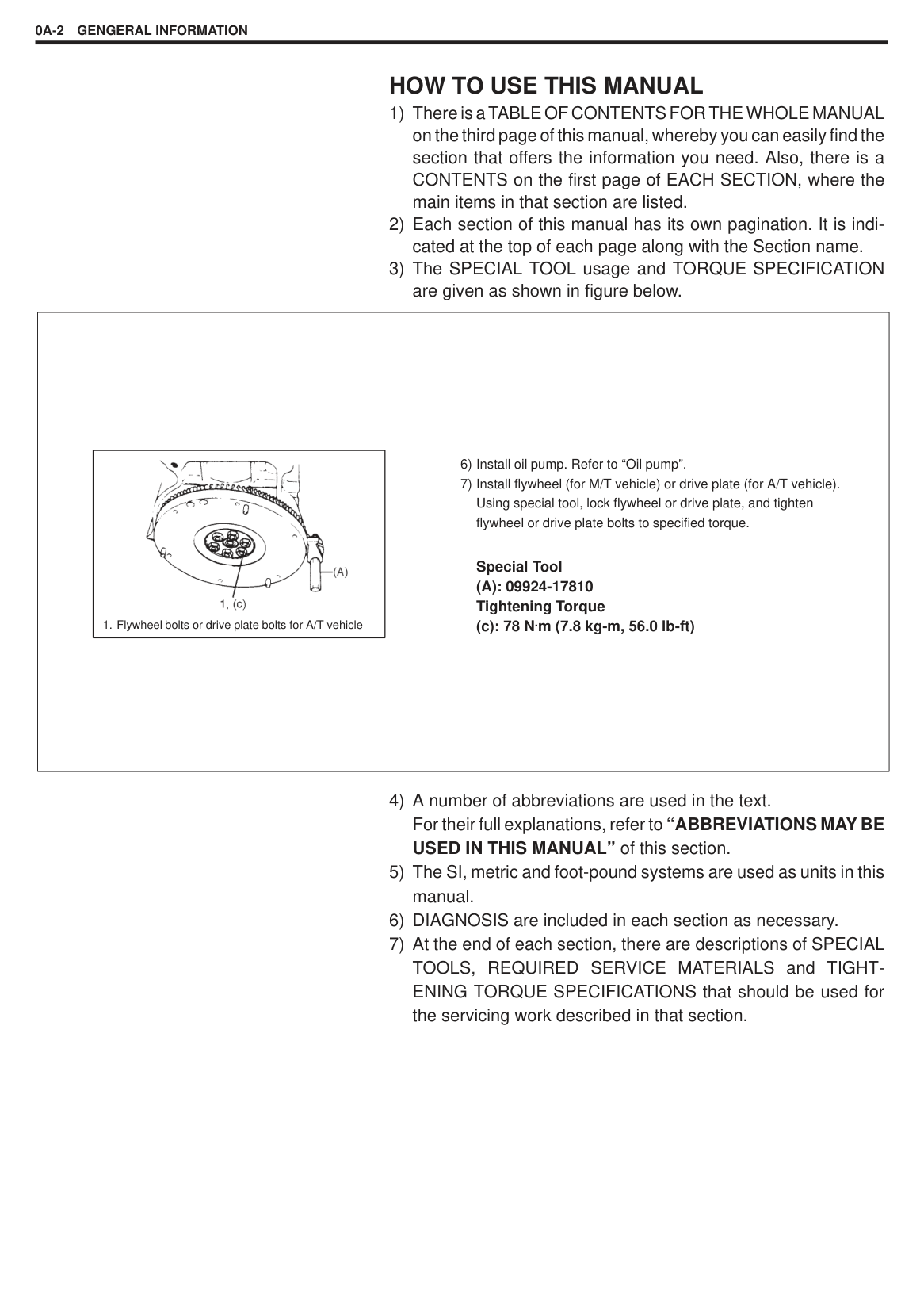
1. Flywheel bolts or drive plate bolts for A/T vehicle| |---|
6) Install oil pump. Refer to “Oil pump”.
7) Install flywheel (for M/T vehicle) or drive plate (for A/T vehicle). Using special tool, lock flywheel or drive plate, and tighten flywheel or drive plate bolts to specified torque.
Special Tool (A): 09924-17810 Tightening Torque (c): 78 N.m (7.8 kg-m, 56.0 lb-ft)| |---|
PRECAUTIONS GENERAL PRECAUTIONS
The WARNING and CAUTION below describe some general precautions that you should observe when servicing a vehicle. These general precautions apply to many of the service procedures described in this manual, and they will not necessarily be repeated with each procedure to which they apply.
|WARNING: Whenever raising a vehicle for service, be sure to follow the instructions under “VEHICLE LIFTING POINTS” on SECTION 0A. When it is necessary to do service work with the engine running, make sure that the parking brake is set fully and the transmission is in Neutral (for manual transmission vehicles) or Park (for automatic transmission vehicles), Keep hands, hair, clothing, tools, etc. away from the fan and belts when the engine is running. When it is necessary to run the engine indoors, make sure that the exhaust gas is forced outdoors. Do not perform service work in areas where combustible materials can come in contact with a hot exhaust system. When working with toxic or flammable materials (such as gasoline and refrigerant), make sure that the area you work in is well-ventilated. To avoid getting burned, keep away from hot metal parts such as the radiator, exhaust manifold, tailpipe, muffler, etc. New and used engine oil can be hazardous. Children and pets may be harmed by swallowing new or used oil. Keep new and used oil and used engine oil filters away from children and pets. Continuous contact with used engine oil has been found to cause [skin] cancer in laboratory animals. Brief contact with used oil may irritate skin. To minimize your exposure to used engine oil, wear a long-sleeve shirt and moisture-proof gloves (such as dish washing gloves) when changing engine oil. If engine oil contacts your skin, wash thoroughly with soap and water. Launder any clothing or rags if wet with oil, recycle or properly dispose of used oil and filters. Make sure the bonnet is fully closed and latched before driving. If it is not, it can fly up unexpectedly during driving, obstructing your view and resulting in an accident.| |---|
|| |---|
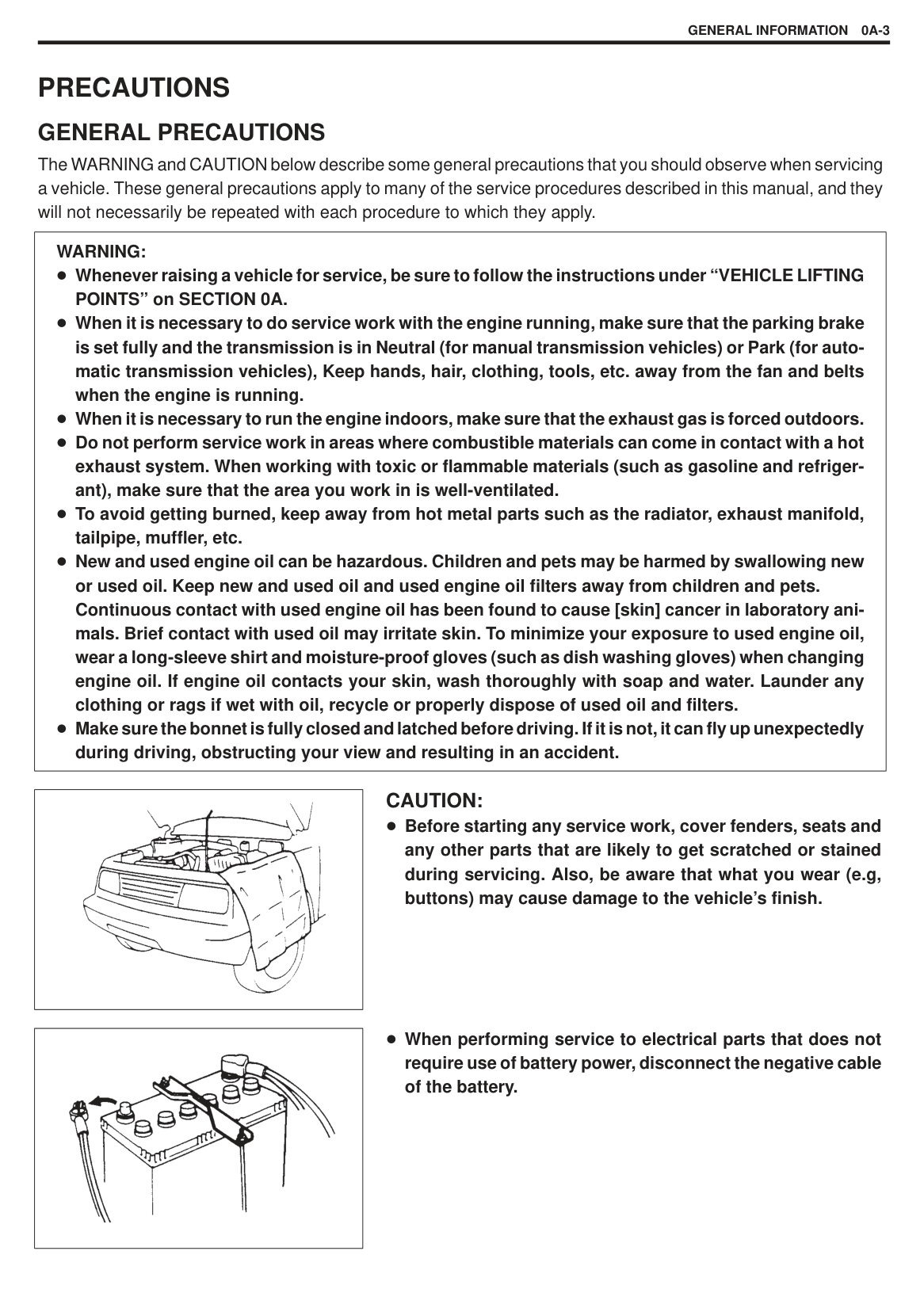
###### CAUTION:
Before starting any service work, cover fenders, seats and any other parts that are likely to get scratched or stained during servicing. Also, be aware that what you wear (e.g, buttons) may cause damage to the vehicle’s finish.
|| |---|
When performing service to electrical parts that does not require use of battery power, disconnect the negative cable of the battery.
||
|---|
|| |---|
|| |---|
|| |---|
|| |---|
When removing the battery, be sure to disconnect the negative cable first and then the positive cable. When reconnecting the battery, connect the positive cable first and then the negative cable, and replace the terminal cover.
When removing parts that are to be reused, be sure to keep them arranged in an orderly manner so that they may be reinstalled in the proper order and position.
Whenever you use oil seals, gaskets, packing, O-rings, locking washers, split pins, self-locking nuts, and certain other parts as specified, be sure to use new ones. Also, before installing new gaskets, packing, etc., be sure to remove any residual material from the mating surfaces.
Make sure that all parts used in reassembly are perfectly clean. When use of a certain type of lubricant, bond or sealant is specified, be sure to use the specified type.
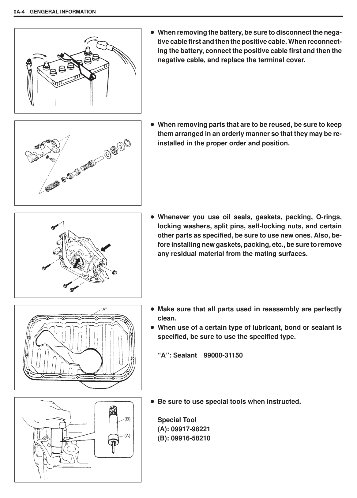
“A”: Sealant 99000-31150
Be sure to use special tools when instructed.
Special Tool
|| |---|
|| |---|
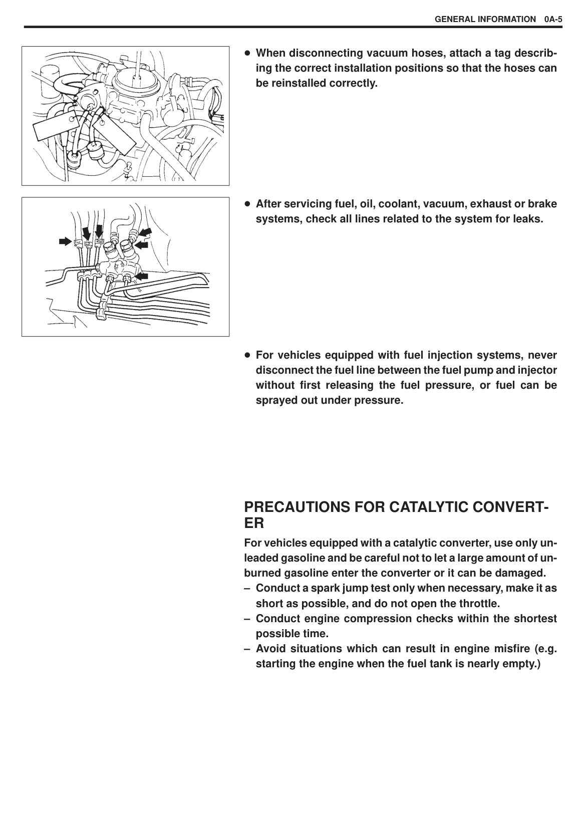
When disconnecting vacuum hoses, attach a tag describing the correct installation positions so that the hoses can be reinstalled correctly.
After servicing fuel, oil, coolant, vacuum, exhaust or brake systems, check all lines related to the system for leaks.
For vehicles equipped with fuel injection systems, never disconnect the fuel line between the fuel pump and injector without first releasing the fuel pressure, or fuel can be sprayed out under pressure.
#### PRECAUTIONS FOR CATALYTIC CONVERTER
For vehicles equipped with a catalytic converter, use only unleaded gasoline and be careful not to let a large amount of unburned gasoline enter the converter or it can be damaged.
|| |---|
|| |---|
|| |---|
|| |---|
#### PRECAUTIONS FOR ELECTRICAL CIRCUIT SERVICE
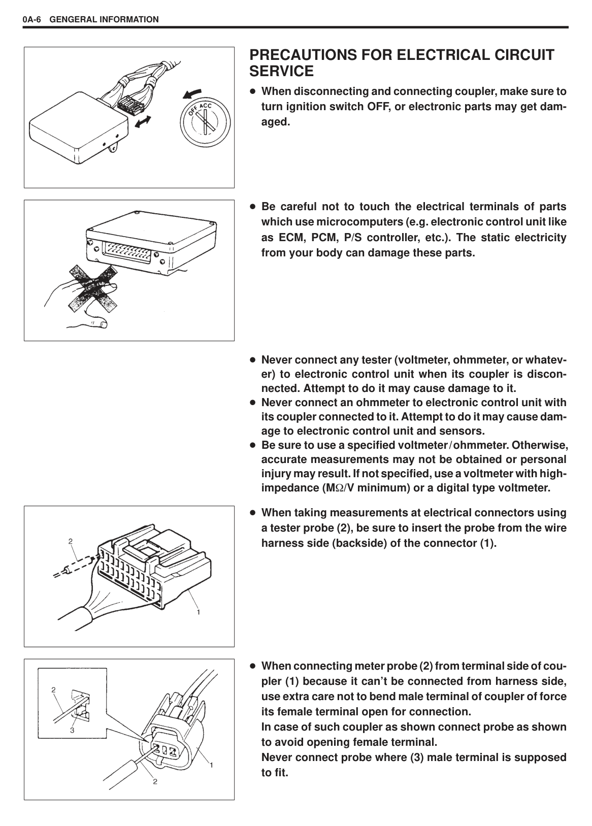
When disconnecting and connecting coupler, make sure to turn ignition switch OFF, or electronic parts may get damaged.
Be careful not to touch the electrical terminals of parts which use microcomputers (e.g. electronic control unit like as ECM, PCM, P/S controller, etc.). The static electricity from your body can damage these parts.
Never connect any tester (voltmeter, ohmmeter, or whatever) to electronic control unit when its coupler is disconnected. Attempt to do it may cause damage to it. Never connect an ohmmeter to electronic control unit with its coupler connected to it. Attempt to do it may cause damage to electronic control unit and sensors. Be sure to use a specified voltmeter/ohmmeter. Otherwise, accurate measurements may not be obtained or personal injury may result. If not specified, use a voltmeter with highimpedance (M /V minimum) or a digital type voltmeter.
When taking measurements at electrical connectors using a tester probe (2), be sure to insert the probe from the wire harness side (backside) of the connector (1).
When connecting meter probe (2) from terminal side of coupler (1) because it can’t be connected from harness side, use extra care not to bend male terminal of coupler of force its female terminal open for connection. In case of such coupler as shown connect probe as shown to avoid opening female terminal. Never connect probe where (3) male terminal is supposed to fit.
When checking connection of terminals, check its male half for bend and female half for excessive opening and both for locking (looseness), corrosion, dust, etc.
|| |---|
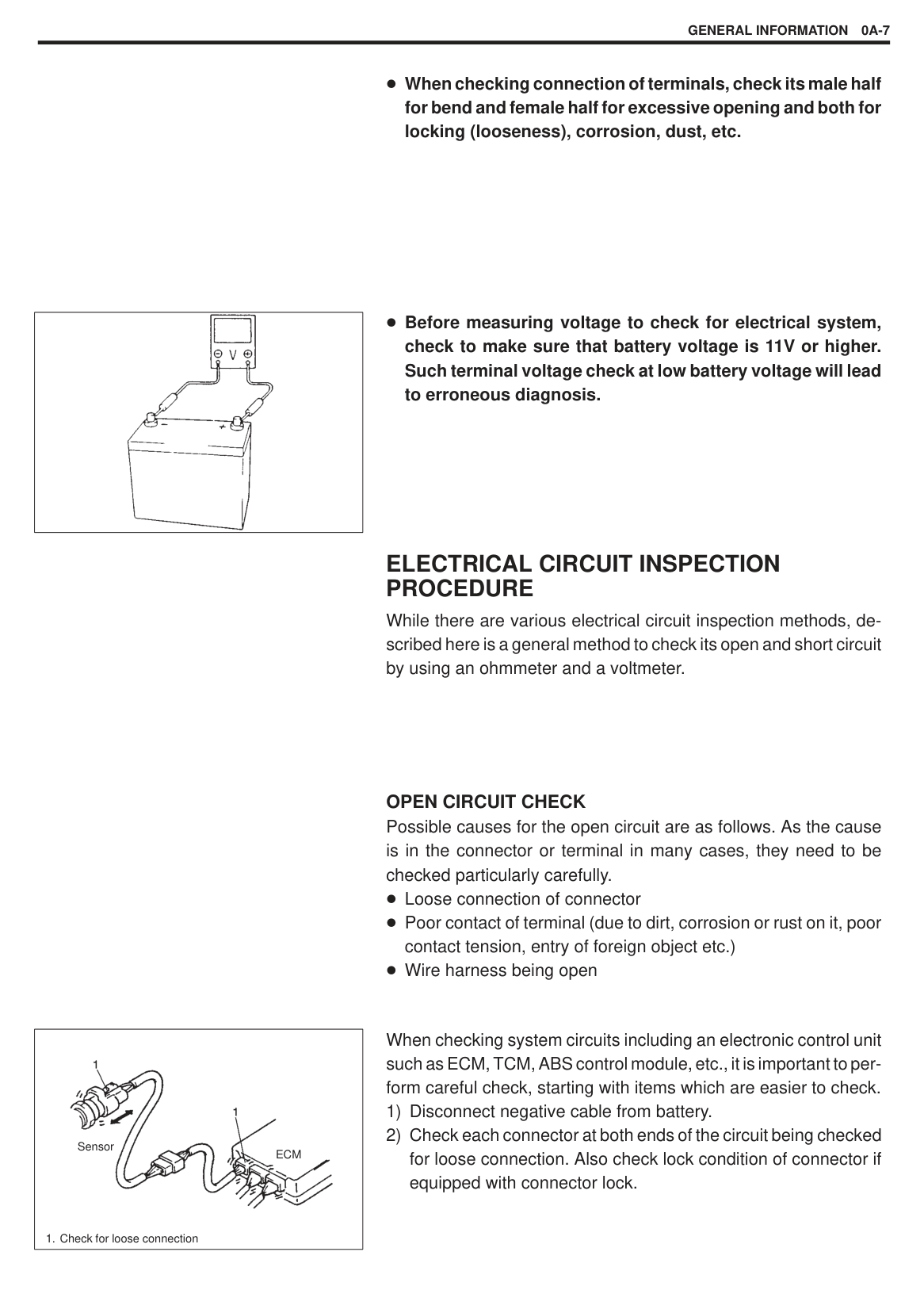
Before measuring voltage to check for electrical system, check to make sure that battery voltage is 11V or higher. Such terminal voltage check at low battery voltage will lead to erroneous diagnosis.
#### ELECTRICAL CIRCUIT INSPECTION PROCEDURE
While there are various electrical circuit inspection methods, described here is a general method to check its open and short circuit by using an ohmmeter and a voltmeter.
######## OPEN CIRCUIT CHECK
Possible causes for the open circuit are as follows. As the cause is in the connector or terminal in many cases, they need to be checked particularly carefully.
Loose connection of connector Poor contact of terminal (due to dirt, corrosion or rust on it, poor contact tension, entry of foreign object etc.) Wire harness being open
|
1. Check for loose connection
Sensor
ECM| |---|
When checking system circuits including an electronic control unit such as ECM, TCM, ABS control module, etc., it is important to perform careful check, starting with items which are easier to check.
|
Check contact tension by inserting and removing just for once| |---|
|
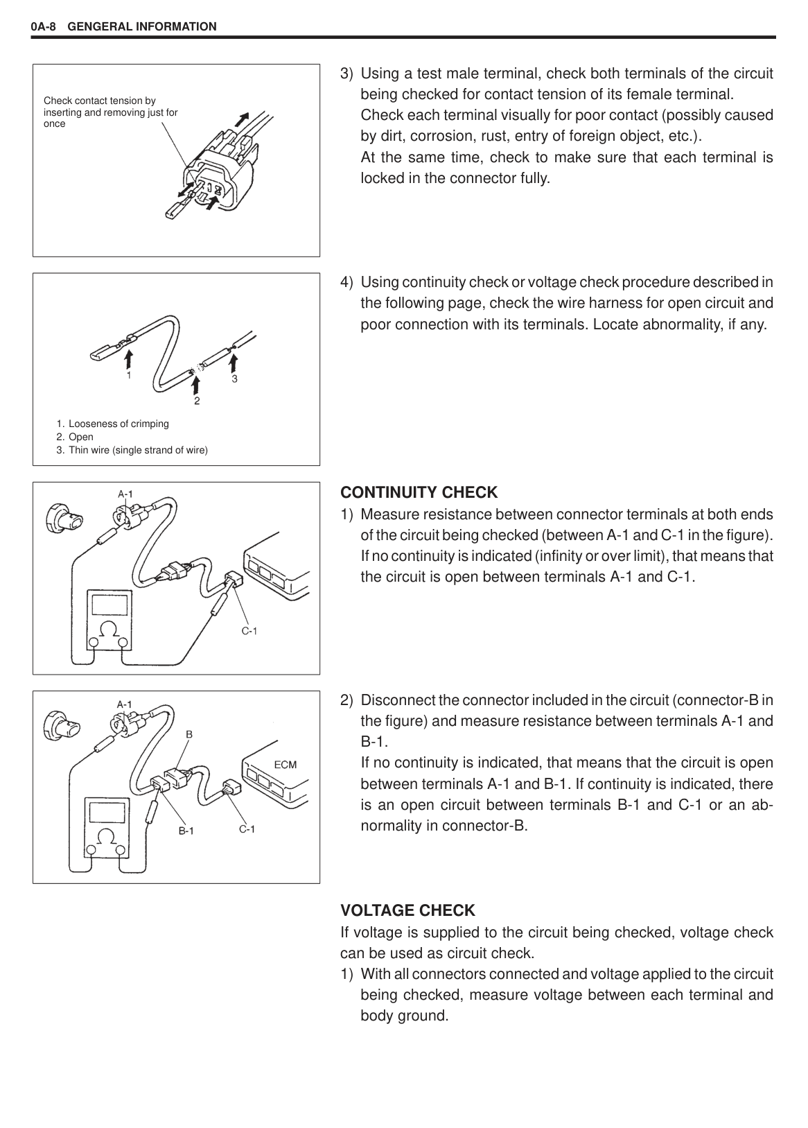
1. Looseness of crimping
2. Open
3. Thin wire (single strand of wire)
| |---|
||
|---|
######## CONTINUITY CHECK
|| |---|
VOLTAGE CHECK If voltage is supplied to the circuit being checked, voltage check can be used as circuit check.
1) With all connectors connected and voltage applied to the circuit being checked, measure voltage between each terminal and body ground.
|
0V| |---|
|
1. Other parts| |---|
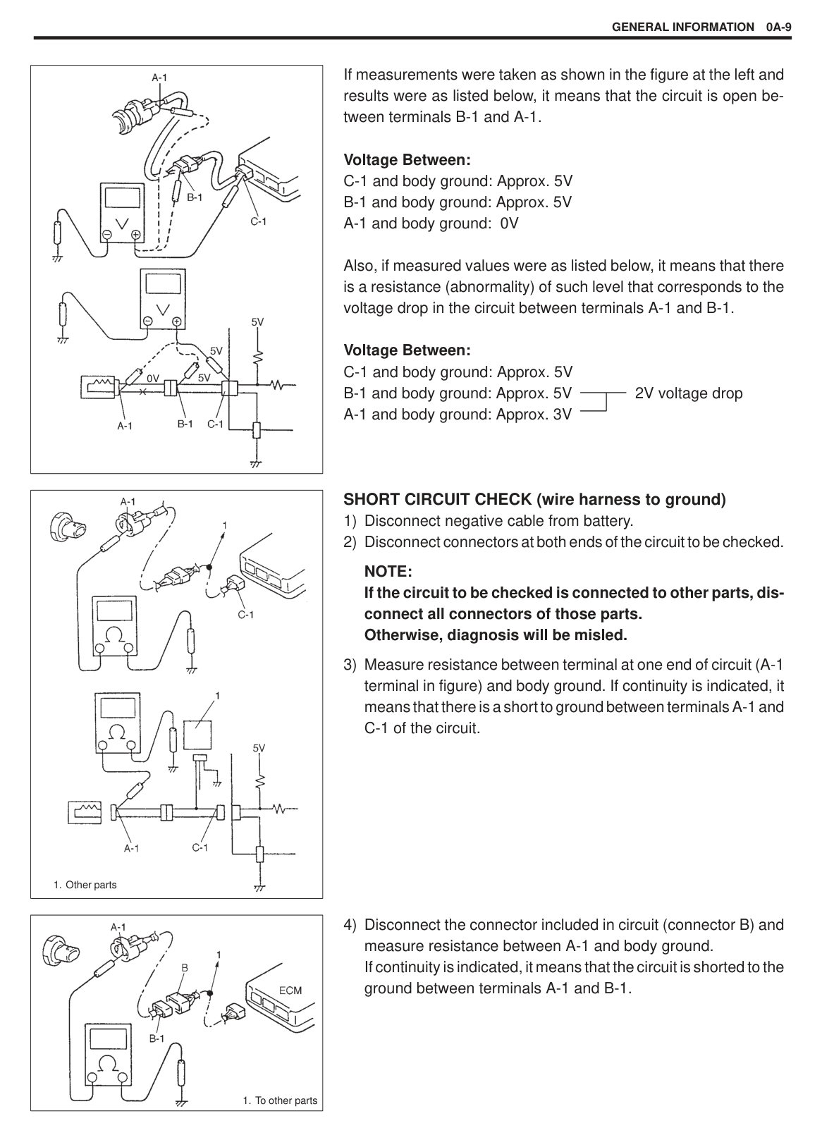
If measurements were taken as shown in the figure at the left and results were as listed below, it means that the circuit is open between terminals B-1 and A-1.
Voltage Between: C-1 and body ground: Approx. 5V
Also, if measured values were as listed below, it means that there is a resistance (abnormality) of such level that corresponds to the voltage drop in the circuit between terminals A-1 and B-1.
Voltage Between: C-1 and body ground: Approx. 5V
######## SHORT CIRCUIT CHECK (wire harness to ground)
NOTE: If the circuit to be checked is connected to other parts, disconnect all connectors of those parts. Otherwise, diagnosis will be misled.
|
1. To other parts| |---|
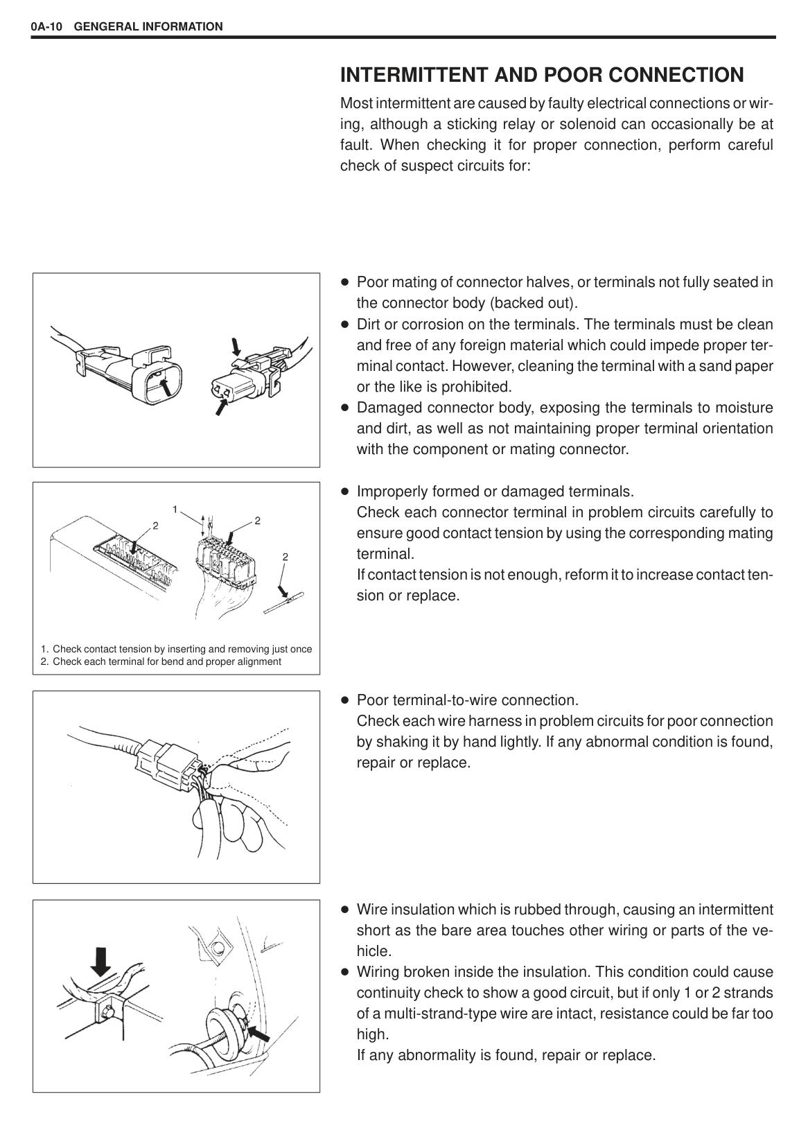
#### INTERMITTENT AND POOR CONNECTION
Most intermittent are caused by faulty electrical connections or wiring, although a sticking relay or solenoid can occasionally be at fault. When checking it for proper connection, perform careful check of suspect circuits for:
|| |---|
|
1. Check contact tension by inserting and removing just once
2. Check each terminal for bend and proper alignment
| |---|
|| |---|
|| |---|
Poor mating of connector halves, or terminals not fully seated in the connector body (backed out). Dirt or corrosion on the terminals. The terminals must be clean and free of any foreign material which could impede proper terminal contact. However, cleaning the terminal with a sand paper or the like is prohibited. Damaged connector body, exposing the terminals to moisture and dirt, as well as not maintaining proper terminal orientation with the component or mating connector.
Improperly formed or damaged terminals. Check each connector terminal in problem circuits carefully to ensure good contact tension by using the corresponding mating terminal. If contact tension is not enough, reform it to increase contact tension or replace.
Poor terminal-to-wire connection. Check each wire harness in problem circuits for poor connection by shaking it by hand lightly. If any abnormal condition is found, repair or replace.
Wire insulation which is rubbed through, causing an intermittent short as the bare area touches other wiring or parts of the vehicle. Wiring broken inside the insulation. This condition could cause continuity check to show a good circuit, but if only 1 or 2 strands of a multi-strand-type wire are intact, resistance could be far too high. If any abnormality is found, repair or replace.
#### PRECAUTION FOR INSTALLING MOBILE COMMUNICATION EQUIPMENT
When installing mobile communication equipment such as CB (Citizens-Band)-radio or cellular-telephone, be sure to observe the following precautions. Failure to follow cautions may adversely affect electronic control system.
Keep the antenna as far away as possible from the vehicle’s electronic control unit. Keep the antenna feeder more than 20 cm (7.9 in) away from electronic control unit and its wire harnesses. Do not run the antenna feeder parallel with other wire harnesses. Confirm that the antenna and feeder are correctly adjusted.
|| |---|
|| |---|
|
M/T A/T| |---|
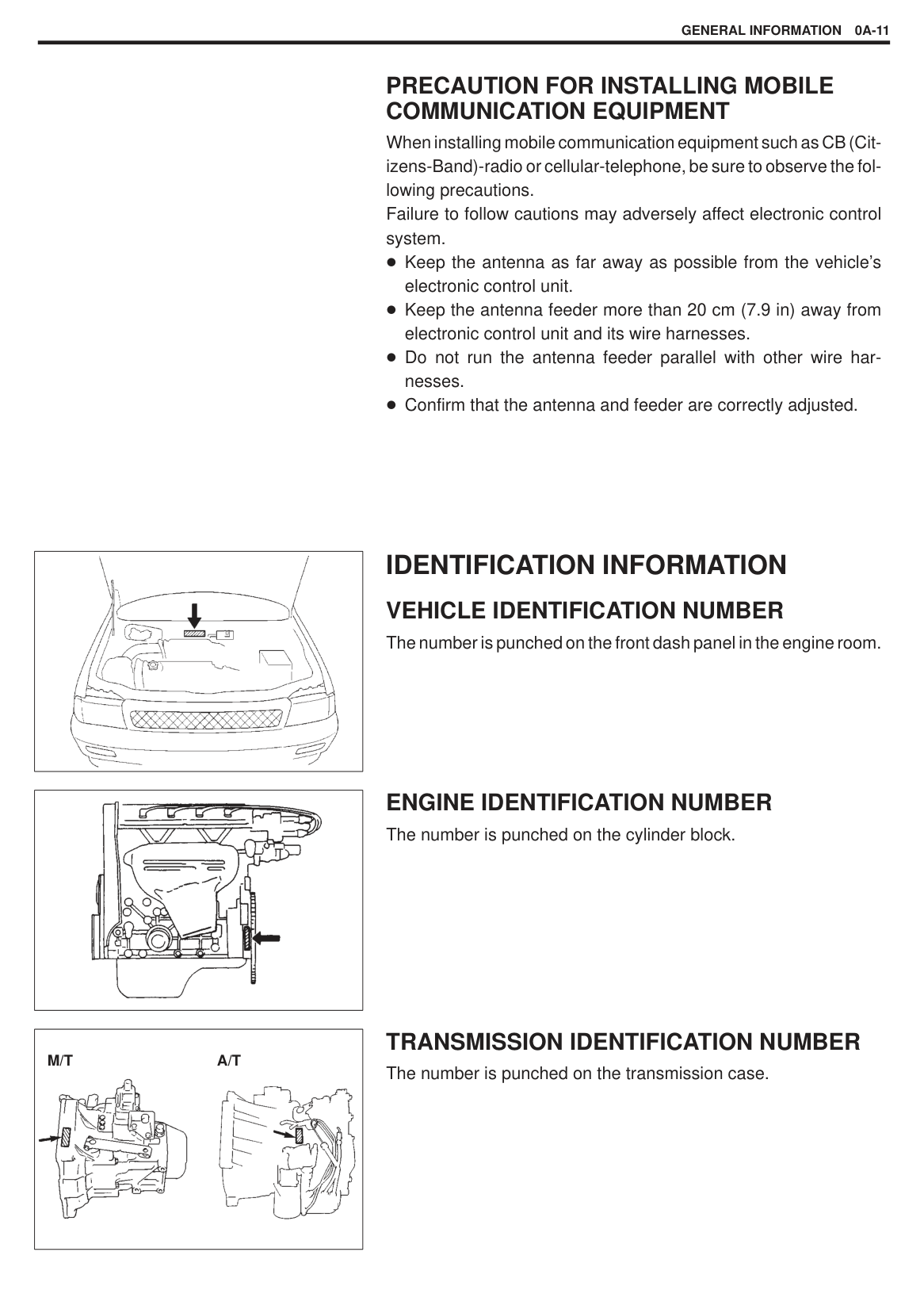
IDENTIFICATION INFORMATION VEHICLE IDENTIFICATION NUMBER The number is punched on the front dash panel in the engine room.
#### ENGINE IDENTIFICATION NUMBER The number is punched on the cylinder block.
#### TRANSMISSION IDENTIFICATION NUMBER The number is punched on the transmission case.
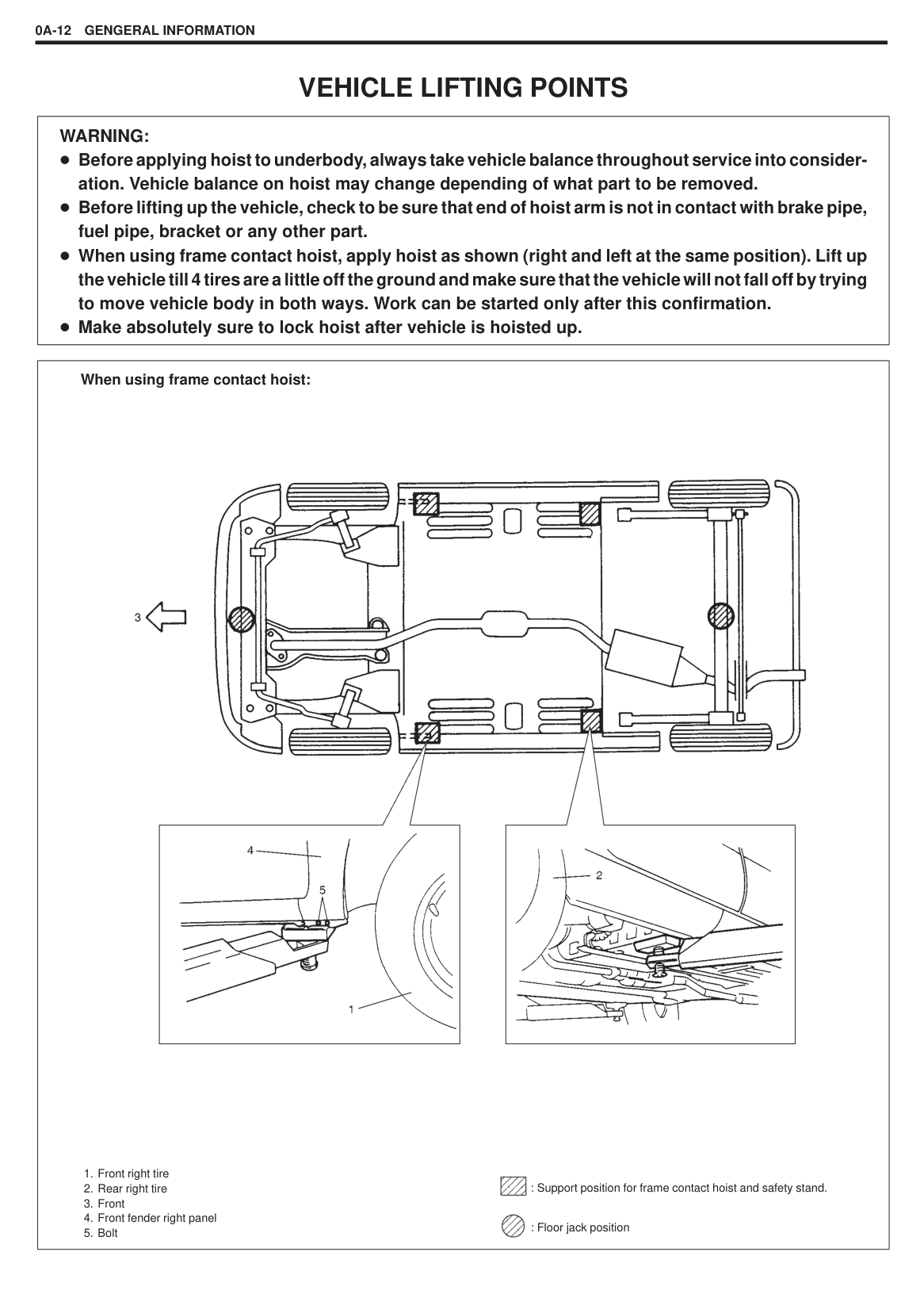
VEHICLE LIFTING POINTS
|WARNING: Before applying hoist to underbody, always take vehicle balance throughout service into consideration. Vehicle balance on hoist may change depending of what part to be removed. Before lifting up the vehicle, check to be sure that end of hoist arm is not in contact with brake pipe, fuel pipe, bracket or any other part. When using frame contact hoist, apply hoist as shown (right and left at the same position). Lift up the vehicle till 4 tires are a little off the ground and make sure that the vehicle will not fall off by trying to move vehicle body in both ways. Work can be started only after this confirmation. Make absolutely sure to lock hoist after vehicle is hoisted up.| |---|
|
When using frame contact hoist:
1. Front right tire
2. Rear right tire
3. Front
4. Front fender right panel
5. Bolt

: Support position for frame contact hoist and safety stand.
: Floor jack position
| |---|
|

When using floor jack:| |---|
In raising front or rear vehicle end off the floor by jacking, be sure to put the jack against the center portion of front cross member (1) or rear axle (2).
|WARNING: Never apply jack against suspension parts (i.e., stabilizer, etc.) or vehicle floor, or it may get deformed. If the vehicle to be jacked up only at the front or rear end, be sure to block the wheels on ground in order to ensure safety. After the vehicle is jacked up, be sure to support it on stands. It is extremely dangerous to do any work on the vehicle raised on jack alone.| |---|
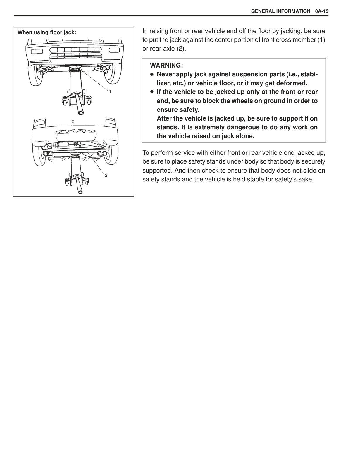
To perform service with either front or rear vehicle end jacked up, be sure to place safety stands under body so that body is securely supported. And then check to ensure that body does not slide on safety stands and the vehicle is held stable for safety’s sake.
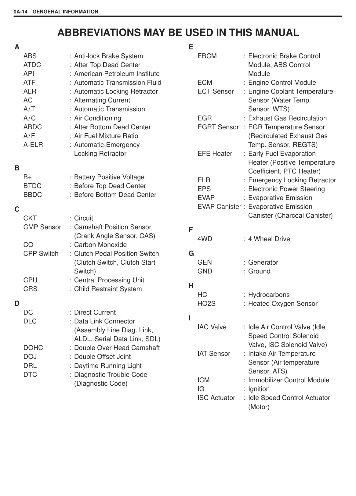
ABBREVIATIONS MAY BE USED IN THIS MANUAL
Locking Retractor
(Crank Angle Sensor, CAS) CO : Carbon Monoxide CPP Switch : Clutch Pedal Position Switch
(Clutch Switch, Clutch Start Switch) CPU : Central Processing Unit CRS : Child Restraint System
(Assembly Line Diag. Link, ALDL, Serial Data Link, SDL)
DOHC : Double Over Head Camshaft DOJ : Double Offset Joint DRL : Daytime Running Light DTC : Diagnostic Trouble Code
(Diagnostic Code)
Module, ABS Control Module
ECM : Engine Control Module ECT Sensor : Engine Coolant Temperature
Sensor (Water Temp. Sensor, WTS)
EGR : Exhaust Gas Recirculation EGRT Sensor : EGR Temperature Sensor
(Recirculated Exhaust Gas Temp. Sensor, REGTS)
EFE Heater : Early Fuel Evaporation Heater (Positive Temperature Coefficient, PTC Heater)
ELR : Emergency Locking Retractor EPS : Electronic Power Steering EVAP : Evaporative Emission EVAP Canister : Evaporative Emission
Canister (Charcoal Canister)
Speed Control Solenoid Valve, ISC Solenoid Valve)
IAT Sensor : Intake Air Temperature Sensor (Air temperature Sensor, ATS)
ICM : Immobilizer Control Module IG : Ignition ISC Actuator : Idle Speed Control Actuator
(Motor)
######## L
LH : Left Hand LSPV : Load Sensing Proportioning
Valve
(Air Flow Sensor, AFS, Air Flow Meter, AFM)
MAP Sensor : Manifold Absolute Pressure
Sensor (Pressure Sensor, PS) Max : Maximum MFI : Multiport Fuel Injection
(Multipoint Fuel Injection) Min : Minimum MIL : Malfunction Indicator Lamp M/T : Manual Transmission
(Self-Diagnosis Function) O/D : Overdrive OHC : Over Head Camshaft
Switch (P/S Pressure Switch) PCM : Powertrain Control Module PCV : Positive Crankcase Ventilation
Engineers
SDM : Sensing and Diagnostic Module (Air bag controller, Air bag control module)
SFI : Sequential Multiport Fuel Injection
SOHC : Single Over Head Camshaft
######## T
TBI : Throttle Body Fuel Injection (Single-Point Fuel Injection, SPI)
TCC : Torque Converter Clutch TCM : Transmission Control Module
(A/T Controller, A/T Control Module)
TP Sensor : Throttle Position Sensor TVV : Thermal Vacuum Valve
(Thermal Vacuum Switching Valve, TVSV, Bimetal Vacuum Switching Valve, BVSV)
TWC : Three Way Catalytic Converter (Three Way Catalyst)
2WD : 2 Wheel Drive
Number VSS : Vehicle Speed Sensor
Catalytic Converter WU-TWC : Warm Up Three Way Catalytic Converter
|

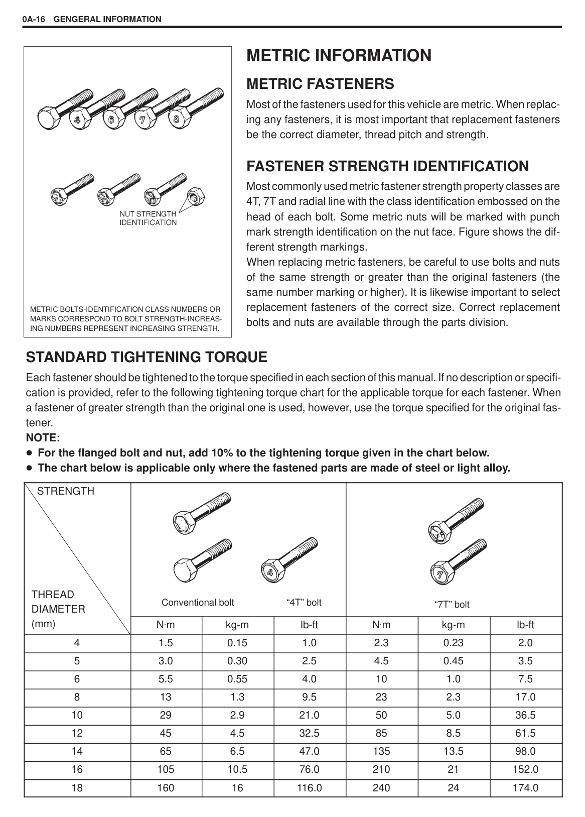
METRIC BOLTS-IDENTIFICATION CLASS NUMBERS OR MARKS CORRESPOND TO BOLT STRENGTH-INCREASING NUMBERS REPRESENT INCREASING STRENGTH.| |---|
METRIC INFORMATION METRIC FASTENERS
Most of the fasteners used for this vehicle are metric. When replacing any fasteners, it is most important that replacement fasteners be the correct diameter, thread pitch and strength.
FASTENER STRENGTH IDENTIFICATION Most commonly used metric fastener strength property classes are 4T, 7T and radial line with the class identification embossed on the head of each bolt. Some metric nuts will be marked with punch mark strength identification on the nut face. Figure shows the different strength markings. When replacing metric fasteners, be careful to use bolts and nuts of the same strength or greater than the original fasteners (the same number marking or higher). It is likewise important to select replacement fasteners of the correct size. Correct replacement bolts and nuts are available through the parts division.
#### STANDARD TIGHTENING TORQUE
Each fastener should be tightened to the torque specified in each section of this manual. If no description or specification is provided, refer to the following tightening torque chart for the applicable torque for each fastener. When a fastener of greater strength than the original one is used, however, use the torque specified for the original fastener.
NOTE: For the flanged bolt and nut, add 10% to the tightening torque given in the chart below. The chart below is applicable only where the fastened parts are made of steel or light alloy.
|STRENGTH
THREAD DIAMETER (mm)|
Conventional bolt “4T” bolt|
Conventional bolt “4T” bolt|
Conventional bolt “4T” bolt|
“7T” bolt|
“7T” bolt|
“7T” bolt| |---|---|---|---|---|---|---| |STRENGTH
THREAD DIAMETER (mm)|N.m|kg-m|lb-ft|N.m|kg-m|lb-ft| |4|1.5|0.15|1.0|2.3|0.23|2.0| |5|3.0|0.30|2.5|4.5|0.45|3.5| |6|5.5|0.55|4.0|10|1.0|7.5| |8|13|1.3|9.5|23|2.3|17.0| |10|29|2.9|21.0|50|5.0|36.5| |12|45|4.5|32.5|85|8.5|61.5| |14|65|6.5|47.0|135|13.5|98.0| |16|105|10.5|76.0|210|21|152.0| |18|160|16|116.0|240|24|174.0|
MAINTENANCE AND LUBRICATION0B-1
SECTION 0B
MAINTENANCE AND LUBRICATION
0B
#### CONTENTS
PERIODIC MAINTENANCE SCHEDULE 0B-2. . . . . . . . . . . . . . . . . . . . . . . . . . . . . . . . . . . . . . . . . . . . . . . . . . . . . . . . . . .
MAINTENANCE SERVICE 0B-5. . . . . . . . . . . . . . . . . . . . . . . . . . . . . . . . . . . . . . . . . . . . . . . . . . . . . . . . . . . . . . . . . . . . . . . . Engine 0B-5. . . . . . . . . . . . . . . . . . . . . . . . . . . . . . . . . . . . . . . . . . . . . . . . . . . . . . . . . . . . . . . . . . . . . . . . . . . . . . . . . . . . . . . . Ignition System 0B-10. . . . . . . . . . . . . . . . . . . . . . . . . . . . . . . . . . . . . . . . . . . . . . . . . . . . . . . . . . . . . . . . . . . . . . . . . . . . . . . . Fuel System 0B-10. . . . . . . . . . . . . . . . . . . . . . . . . . . . . . . . . . . . . . . . . . . . . . . . . . . . . . . . . . . . . . . . . . . . . . . . . . . . . . . . . . . Emission Control System 0B-11. . . . . . . . . . . . . . . . . . . . . . . . . . . . . . . . . . . . . . . . . . . . . . . . . . . . . . . . . . . . . . . . . . . . . . . Brake 0B-12. . . . . . . . . . . . . . . . . . . . . . . . . . . . . . . . . . . . . . . . . . . . . . . . . . . . . . . . . . . . . . . . . . . . . . . . . . . . . . . . . . . . . . . . . Chassis and Body 0B-13. . . . . . . . . . . . . . . . . . . . . . . . . . . . . . . . . . . . . . . . . . . . . . . . . . . . . . . . . . . . . . . . . . . . . . . . . . . . . . Final Inspection 0B-18. . . . . . . . . . . . . . . . . . . . . . . . . . . . . . . . . . . . . . . . . . . . . . . . . . . . . . . . . . . . . . . . . . . . . . . . . . . . . . . .
RECOMMENDED FLUIDS AND LUBRICANTS 0B-19. . . . . . . . . . . . . . . . . . . . . . . . . . . . . . . . . . . . . . . . . . . . . . . . . . . . . .
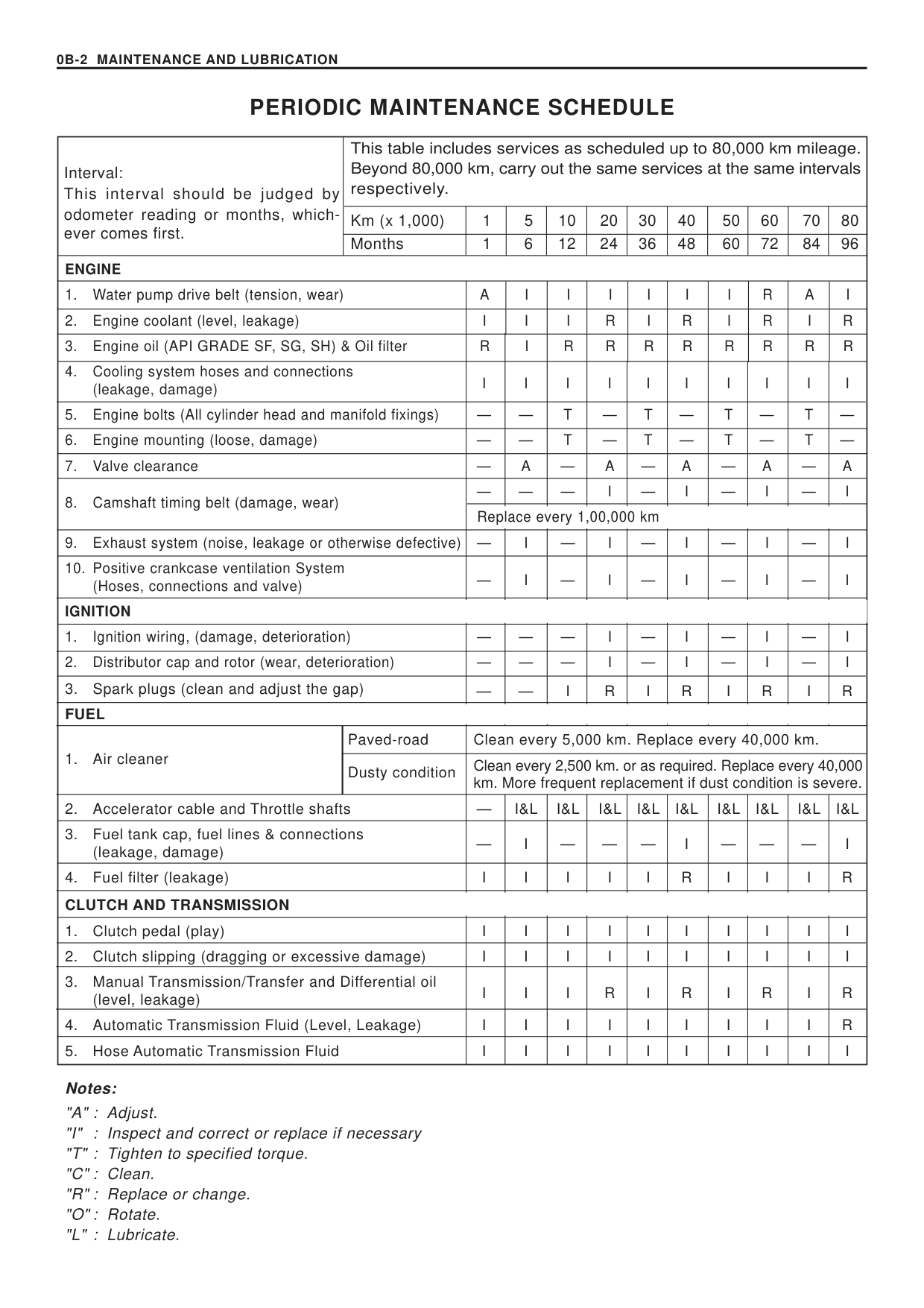
#### PERIODIC MAINTENANCE SCHEDULE
|Interval: This interval should be judged by odometer reading or months, whichever comes first.|This table includes services as scheduled up to 80,000 km mileage. Beyond 80,000 km, carry out the same services at the same intervals respectively.|This table includes services as scheduled up to 80,000 km mileage. Beyond 80,000 km, carry out the same services at the same intervals respectively.|This table includes services as scheduled up to 80,000 km mileage. Beyond 80,000 km, carry out the same services at the same intervals respectively.|This table includes services as scheduled up to 80,000 km mileage. Beyond 80,000 km, carry out the same services at the same intervals respectively.|This table includes services as scheduled up to 80,000 km mileage. Beyond 80,000 km, carry out the same services at the same intervals respectively.|This table includes services as scheduled up to 80,000 km mileage. Beyond 80,000 km, carry out the same services at the same intervals respectively.|This table includes services as scheduled up to 80,000 km mileage. Beyond 80,000 km, carry out the same services at the same intervals respectively.|This table includes services as scheduled up to 80,000 km mileage. Beyond 80,000 km, carry out the same services at the same intervals respectively.|This table includes services as scheduled up to 80,000 km mileage. Beyond 80,000 km, carry out the same services at the same intervals respectively.|This table includes services as scheduled up to 80,000 km mileage. Beyond 80,000 km, carry out the same services at the same intervals respectively.|This table includes services as scheduled up to 80,000 km mileage. Beyond 80,000 km, carry out the same services at the same intervals respectively.| |---|---|---|---|---|---|---|---|---|---|---|---| |Interval: This interval should be judged by odometer reading or months, whichever comes first.|Km (x 1,000)|1|5|10|20|30|40|50|60|70|80| |Interval: This interval should be judged by odometer reading or months, whichever comes first.|Months|1|6|12|24|36|48|60|72|84|96| |ENGINE|ENGINE|ENGINE|ENGINE|ENGINE|ENGINE|ENGINE|ENGINE|ENGINE|ENGINE|ENGINE|ENGINE| |1. Water pump drive belt (tension, wear)|1. Water pump drive belt (tension, wear)|A|I|I|I|I|I|I|R|A|I| |2. Engine coolant (level, leakage)|2. Engine coolant (level, leakage)|I|I|I|R|I|R|I|R|I|R| |3. Engine oil (API GRADE SF, SG, SH) & Oil filter|3. Engine oil (API GRADE SF, SG, SH) & Oil filter|R|I|R|R|R|R|R|R|R|R| |4. Cooling system hoses and connections (leakage, damage)|4. Cooling system hoses and connections (leakage, damage)|I| | | |I|I| |I| |I| |5. Engine bolts (All cylinder head and manifold fixings)|5. Engine bolts (All cylinder head and manifold fixings)|—|—|T|—|T|—|T|—|T|—| |6. Engine mounting (loose, damage)|6. Engine mounting (loose, damage)|—|—|T|—|T|—|T|—|T|—| |7. Valve clearance|7. Valve clearance|—|A|—|A|—|A|—|A|—|A| |8. Camshaft timing belt (damage, wear)|8. Camshaft timing belt (damage, wear)|—|—|—|I|—|I|—|I|—|I| |8. Camshaft timing belt (damage, wear)|8. Camshaft timing belt (damage, wear)|Rep|ace e|ery 1|00,00|km| | | | | |
|9. Exhaust system (noise, leakage or otherwise defective)|9. Exhaust system (noise, leakage or otherwise defective)|—|I|—|I|—|I|—|I|—|I| |10. Positive crankcase ventilation System (Hoses, connections and valve)|10. Positive crankcase ventilation System (Hoses, connections and valve)|—| | | |—|I| |I| |I| |IGNITION|IGNITION| | | | | | | | | | | |1. Ignition wiring, (damage, deterioration)|1. Ignition wiring, (damage, deterioration)|—|—|—|I|—|I|—|I|—|I| |2. Distributor cap and rotor (wear, deterioration)|2. Distributor cap and rotor (wear, deterioration)|—|—|—|I|—|I|—
|I|—|I| |3. Spark plugs (clean and adjust the gap)|3. Spark plugs (clean and adjust the gap)|—|—|I| |I|R| |R| |R| |FUEL|FUEL| | | | | | | | | | | |1. Air cleaner|Paved-road|Cle|n eve|y 5,0|0 km|Rep|ace e|ery|0,00|km.| | |1. Air cleaner|Dusty condition|Clea km.|ever ore f|2,50 eque|km. t repl|r as r cem|quire nt if|. Rep ust c|ace e nditio|ery 4 is se|,000 ere.| |2. Accelerator cable and Throttle shafts|2. Accelerator cable and Throttle shafts|—|I&L|I&L|I&L|I&L|I&L|I&L|I&L|I&L|I&L| |3. Fuel tank cap, fuel lines & connections (leakage, damage)|3. Fuel tank cap, fuel lines & connections (leakage, damage)|—| | |—|—|I| |—|—|I| |4. Fuel filter (leakage)|4. Fuel filter (leakage)|I|I|I|I|I|R|I|I|I|R| |CLUTCH AND TRANSMISSION|CLUTCH AND TRANSMISSION| | | | | | | | | | | |1. Clutch pedal (play)|1. Clutch pedal (play)|I| | | |I|I| |I| |I| |2. Clutch slipping (dragging or excessive damage)|2. Clutch slipping (dragging or excessive damage)|I| | | |I|I| |I| |I| |3. Manual Transmission/Transfer and Differential oil (level, leakage)|3. Manual Transmission/Transfer and Differential oil (level, leakage)|I| | |R|I|R|I|R|I|R| |4. Automatic Transmission Fluid (Level, Leakage)|4. Automatic Transmission Fluid (Level, Leakage)|I| | | |I|I| |I| |R| |5. Hose Automatic Transmission Fluid|5. Hose Automatic Transmission Fluid|I| | | |I|I| |I| |I|
Notes: "A" : Adjust. "I" : Inspect and correct or replace if necessary "T" : Tighten to specified torque. "C" : Clean. "R" : Replace or change. "O" : Rotate. "L" : Lubricate.
############## MAINTENANCE AND LUBRICATION 0B-3
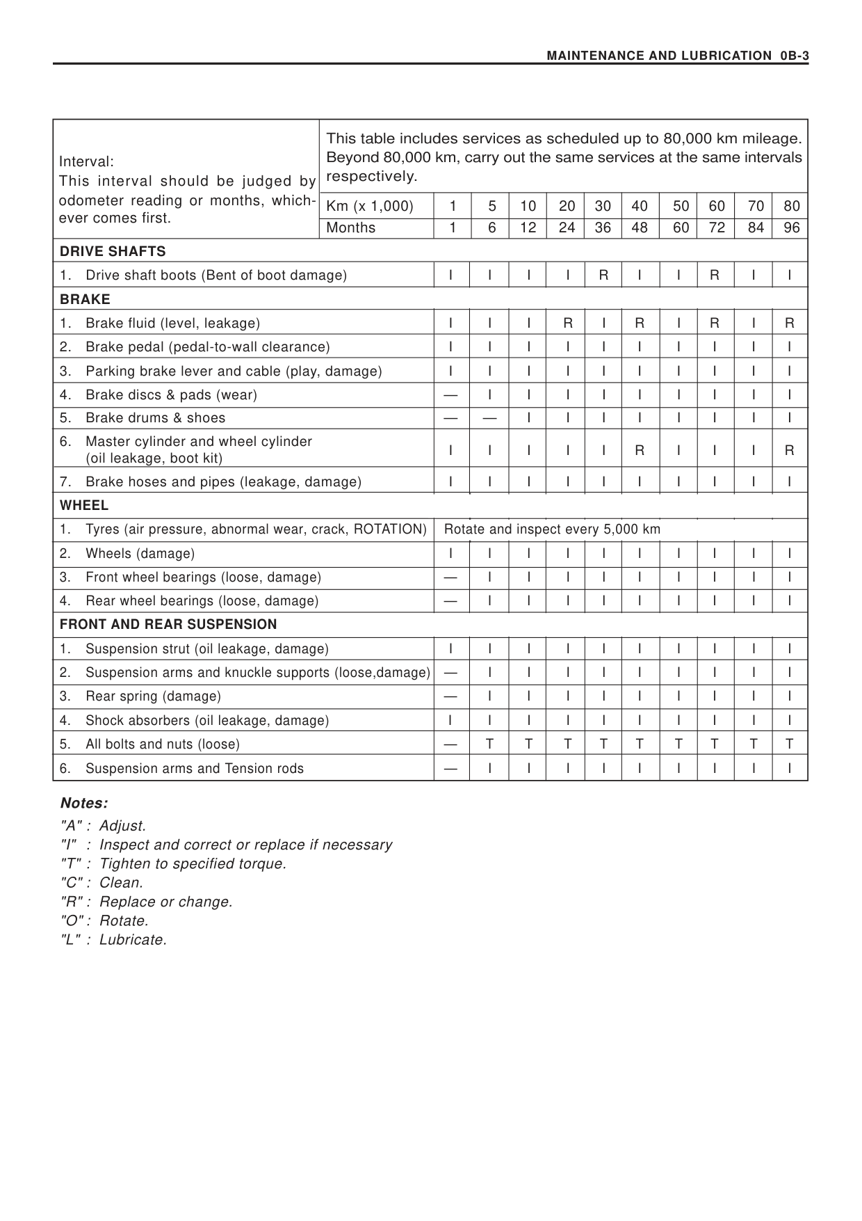
|Interval: This interval should be judged by odometer reading or months, whichever comes first.|This table includes services as scheduled up to 80,000 km mileage. Beyond 80,000 km, carry out the same services at the same intervals respectively.|This table includes services as scheduled up to 80,000 km mileage. Beyond 80,000 km, carry out the same services at the same intervals respectively.|This table includes services as scheduled up to 80,000 km mileage. Beyond 80,000 km, carry out the same services at the same intervals respectively.|This table includes services as scheduled up to 80,000 km mileage. Beyond 80,000 km, carry out the same services at the same intervals respectively.|This table includes services as scheduled up to 80,000 km mileage. Beyond 80,000 km, carry out the same services at the same intervals respectively.|This table includes services as scheduled up to 80,000 km mileage. Beyond 80,000 km, carry out the same services at the same intervals respectively.|This table includes services as scheduled up to 80,000 km mileage. Beyond 80,000 km, carry out the same services at the same intervals respectively.|This table includes services as scheduled up to 80,000 km mileage. Beyond 80,000 km, carry out the same services at the same intervals respectively.|This table includes services as scheduled up to 80,000 km mileage. Beyond 80,000 km, carry out the same services at the same intervals respectively.|This table includes services as scheduled up to 80,000 km mileage. Beyond 80,000 km, carry out the same services at the same intervals respectively.|This table includes services as scheduled up to 80,000 km mileage. Beyond 80,000 km, carry out the same services at the same intervals respectively.| |---|---|---|---|---|---|---|---|---|---|---|---|
|Interval: This interval should be judged by odometer reading or months, whichever comes first.|Km (x 1,000)|1|5|10|20|30|40|50|60|70|80| |Interval: This interval should be judged by odometer reading or months, whichever comes first.|Months|1|6|12|24|36|48|60|72|84|96| |DRIVE SHAFTS|DRIVE SHAFTS|DRIVE SHAFTS|DRIVE SHAFTS|DRIVE SHAFTS|DRIVE SHAFTS|DRIVE SHAFTS|DRIVE SHAFTS|DRIVE SHAFTS|DRIVE SHAFTS|DRIVE SHAFTS|DRIVE SHAFTS| |1. Drive shaft boots (Bent of boot damage)|1. Drive shaft boots (Bent of boot damage)|I|I|I|I|R|I|I|R|I|I| |BRAKE|BRAKE| | | | | | | | | | | |1. Brake fluid (level, leakage)|1. Brake fluid (level, leakage)|I|I|I|R|I|R|I|R|I|R| |2. Brake pedal (pedal-to-wall clearance)|2. Brake pedal (pedal-to-wall clearance)|I| | | |I|I| |I| |I| |3. Parking brake lever and cable (play, damage)|3. Parking brake lever and cable (play, damage)|I| | | |I|I| |I| |I| |4. Brake discs & pads (wear)|4. Brake discs & pads (wear)|—|I|I|I|I|I|I|I|I|I| |5. Brake drums & shoes|5. Brake drums & shoes|—|—|I|I|I|I|I|I|I|I| |6. Master cylinder and wheel cylinder (oil leakage, boot kit)|6. Master cylinder and wheel cylinder (oil leakage, boot kit)|I|I|I|I|I|R|I|I|I|R| |7. Brake hoses and pipes (leakage, damage)|7. Brake hoses and pipes (leakage, damage)|I| | | |I|I| |I| |I| |WHEEL|WHEEL| | | | | | | | | | | |1. Tyres (air pressure, abnormal wear, crack, ROTATION)|1. Tyres (air pressure, abnormal wear, crack, ROTATION)|Rot|te an|insp|ct ev|ry 5,|00 k| | | | | |2. Wheels (damage)|2. Wheels (damage)|I|I|I|I|I|I|I|I|I|I| |3. Front wheel bearings (loose, damage)|3. Front wheel bearings (loose, damage)|—|I|I|I|I|I|I|I|I|I| |4. Rear wheel bearings (loose, damage)|4. Rear wheel bearings (loose, damage)|—|I|I|I|I|I|I|I|I|I| |FRONT AND REAR SUSPENSION
|FRONT AND REAR SUSPENSION
| | | | | | | | | | | |1. Suspension strut (oil leakage, damage)|1. Suspension strut (oil leakage, damage)|I|I|I|I|I|I|I|I|I|I| |2. Suspension arms and knuckle supports (loose,damage)|2. Suspension arms and knuckle supports (loose,damage)|—|I|I|I|I|I|I|I|I|I| |3. Rear spring (damage)|3. Rear spring (damage)|—|I|I|I|I|I|I|I|I|I| |4. Shock absorbers (oil leakage, damage)|4. Shock absorbers (oil leakage, damage)|I|I|I|I|I|I|I|I|I|I| |5. All bolts and nuts (loose)|5. All bolts and nuts (loose)|—|T|T|T|T|T|T|T|T|T| |6. Suspension arms and Tension rods|6. Suspension arms and Tension rods|—|I|I|I|I|I|I|I|I|I|
Notes: "A" : Adjust. "I" : Inspect and correct or replace if necessary "T" : Tighten to specified torque. "C" : Clean. "R" : Replace or change. "O" : Rotate. "L" : Lubricate.
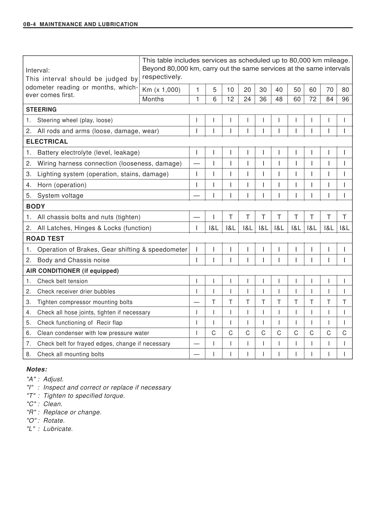
|Interval: This interval should be judged by odometer reading or months, whichever comes first.|This table includes services as scheduled up to 80,000 km mileage. Beyond 80,000 km, carry out the same services at the same intervals respectively.|This table includes services as scheduled up to 80,000 km mileage. Beyond 80,000 km, carry out the same services at the same intervals respectively.|This table includes services as scheduled up to 80,000 km mileage. Beyond 80,000 km, carry out the same services at the same intervals respectively.|This table includes services as scheduled up to 80,000 km mileage. Beyond 80,000 km, carry out the same services at the same intervals respectively.|This table includes services as scheduled up to 80,000 km mileage. Beyond 80,000 km, carry out the same services at the same intervals respectively.|This table includes services as scheduled up to 80,000 km mileage. Beyond 80,000 km, carry out the same services at the same intervals respectively.|This table includes services as scheduled up to 80,000 km mileage. Beyond 80,000 km, carry out the same services at the same intervals respectively.|This table includes services as scheduled up to 80,000 km mileage. Beyond 80,000 km, carry out the same services at the same intervals respectively.|This table includes services as scheduled up to 80,000 km mileage. Beyond 80,000 km, carry out the same services at the same intervals respectively.|This table includes services as scheduled up to 80,000 km mileage. Beyond 80,000 km, carry out the same services at the same intervals respectively.|This table includes services as scheduled up to 80,000 km mileage. Beyond 80,000 km, carry out the same services at the same intervals respectively.| |---|---|---|---|---|---|---|---|---|---|---|---| |Interval: This interval should be judged by odometer reading or months, whichever comes first.|Km (x 1,000)|1|5|10|20|30|40|50|60|70|80| |Interval: This interval should be judged by odometer reading or months, whichever comes first.|Months|1|6|12|24|36|48|60|72|84|96| |STEERING|STEERING|STEERING|STEERING|STEERING|STEERING|STEERING|STEERING|STEERING|STEERING|STEERING|STEERING| |1. Steering wheel (play, loose)|1. Steering wheel (play, loose)|I|I|I|I|I|I|I|I|I|I| |2. All rods and arms (loose, damage, wear)|2. All rods and arms (loose, damage, wear)|I| | | |I|I| |I| |I| |ELECTRICAL|ELECTRICAL| | | | | | | | | | | |1. Battery electrolyte (level, leakage)|1. Battery electrolyte (level, leakage)|I| | | |I|I| |I| |I| |2. Wiring harness connection (looseness, damage)|2. Wiring harness connection (looseness, damage)|—|I|I|I|I|I|I|I|I|I| |3. Lighting system (operation, stains, damage)|3. Lighting system (operation, stains, damage)|I| | | |I|I| |I| |I| |4. Horn (operation)|4. Horn (operation)|I| | | |I|I| |I| |I| |5. System voltage|5. System voltage|—|I|I|I|I|I|I|I|I|I| |BODY|BODY| | | | | | | | | | | |1. All chassis bolts and nuts (tighten)|1. All chassis bolts and nuts (tighten)|—|I|T|T|T|T|T|T|T|T| |2. All Latches, Hinges & Locks (function)|2. All Latches, Hinges & Locks (function)|I|I&L|I&L|I&L|I&L|I&L|I&L|I&L|I&L|I&L| |ROAD TEST|ROAD TEST| | | | | | | | | | | |1. Operation of Brakes, Gear shifting & speedometer|1. Operation of Brakes, Gear shifting & speedometer|I| | | |I|I| |I| |I| |2. Body and Chassis noise|2. Body and Chassis noise|I| | | |I|I| |I| |I| |AIR CONDITIONER (if equipped)|AIR CONDITIONER (if equipped)| | | | | | | | | | | |1. Check belt tension|1. Check belt tension|I|I|I|I|I|I|I|I|I|I| |2. Check receiver drier bubbles|2. Check receiver drier bubbles|I|I|I|I|I|I|I|I|I|I| |3. Tighten compressor mounting bolts|3. Tighten compressor mounting bolts|—|T|T|T|T|T|T|T|T|T| |4. Check all hose joints, tighten if necessary|4. Check all hose joints, tighten if necessary|I|I|I|I|I|I|I|I|I|I|
|5. Check functioning of Recir flap|5. Check functioning of Recir flap|I|I|I|I|I|I|I|I|I|I| |6. Clean condenser with low pressure water|6. Clean condenser with low pressure water|I|C|C|C|C|C|C|C|C|C| |7. Check belt for frayed edges, change if necessary|7. Check belt for frayed edges, change if necessary|—|I|I|I|I|I|I|I|I|I| |8. Check all mounting bolts|8. Check all mounting bolts|—|I|I|I|I|I|I|I|I|I|
Notes: "A" : Adjust. "I" : Inspect and correct or replace if necessary "T" : Tighten to specified torque. "C" : Clean. "R" : Replace or change. "O" : Rotate. "L" : Lubricate.
############### MAINTENANCE AND LUBRICATION0B-5
MAINTENANCE SERVICE ENGINE
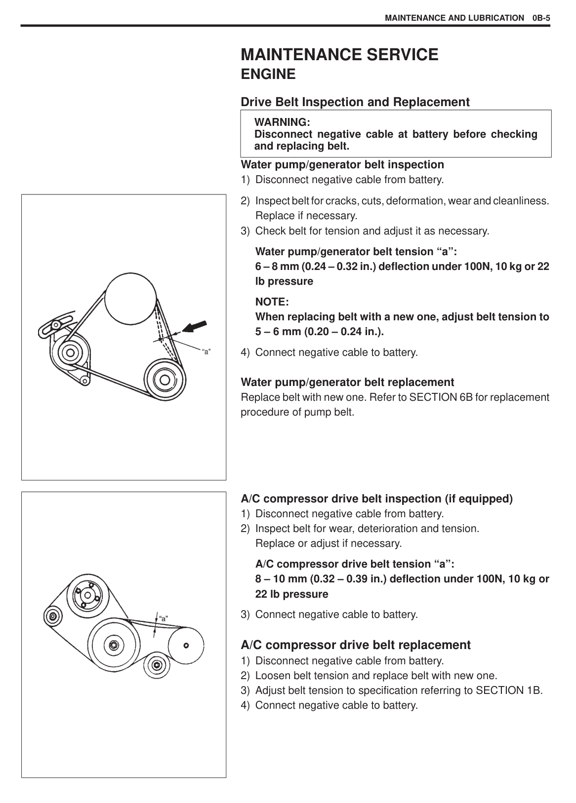
###### Drive Belt Inspection and Replacement
######## Water pump/generator belt inspection
|WARNING: Disconnect negative cable at battery before checking and replacing belt.| |---|
|| |---|
Water pump/generator belt tension “a”: 6 – 8 mm (0.24 – 0.32 in.) deflection under 100N, 10 kg or 22 lb pressure
NOTE: When replacing belt with a new one, adjust belt tension to 5 – 6 mm (0.20 – 0.24 in.).
Water pump/generator belt replacement Replace belt with new one. Refer to SECTION 6B for replacement procedure of pump belt.
|| |---|
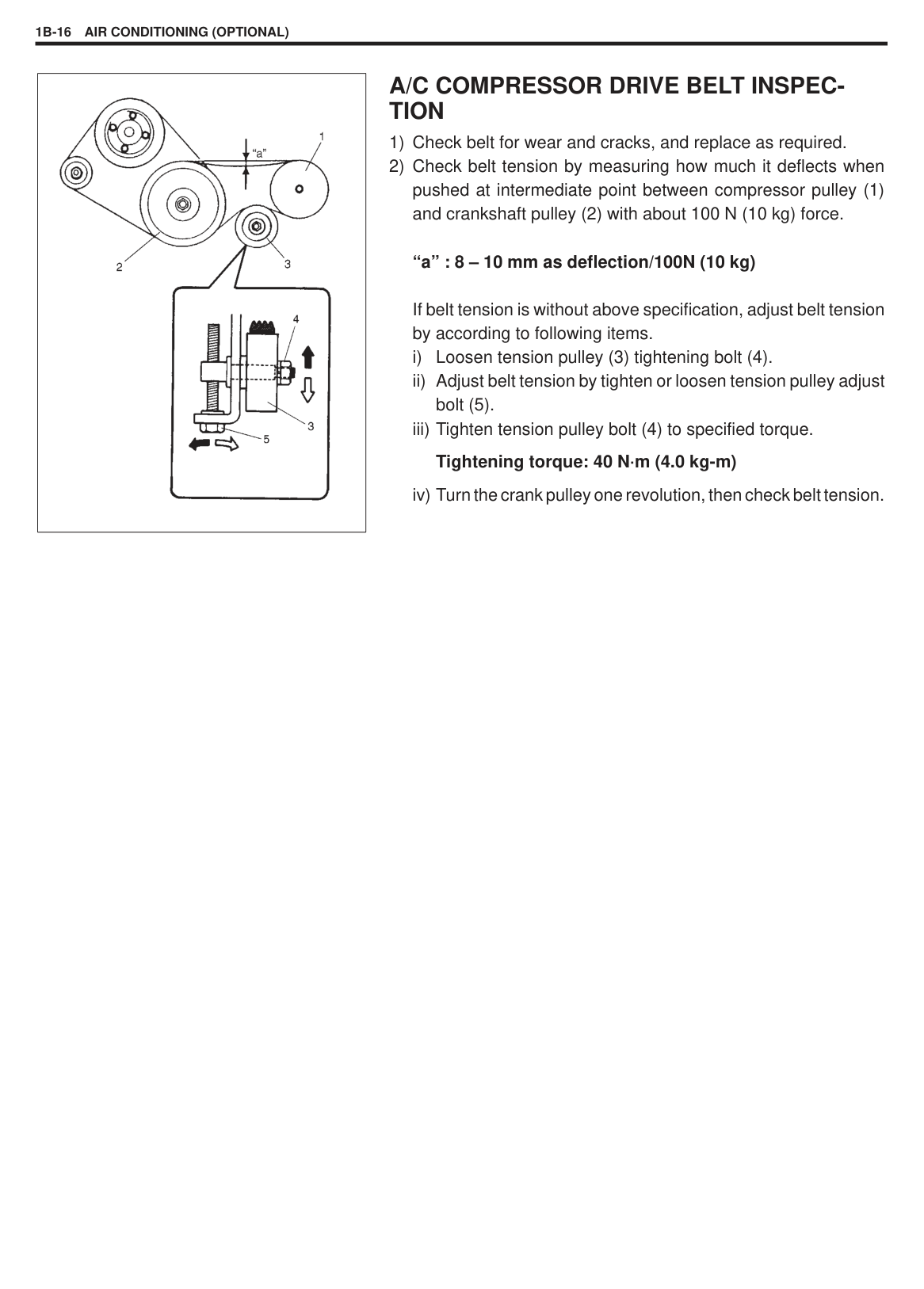
######## A/C compressor drive belt inspection (if equipped)
A/C compressor drive belt tension “a”: 8 – 10 mm (0.32 – 0.39 in.) deflection under 100N, 10 kg or 22 lb pressure
###### A/C compressor drive belt replacement
|| |---|
|
| |---|
|
Proper Engine Oil Viscosity Chart| |---|
|
1, (a)| |---|
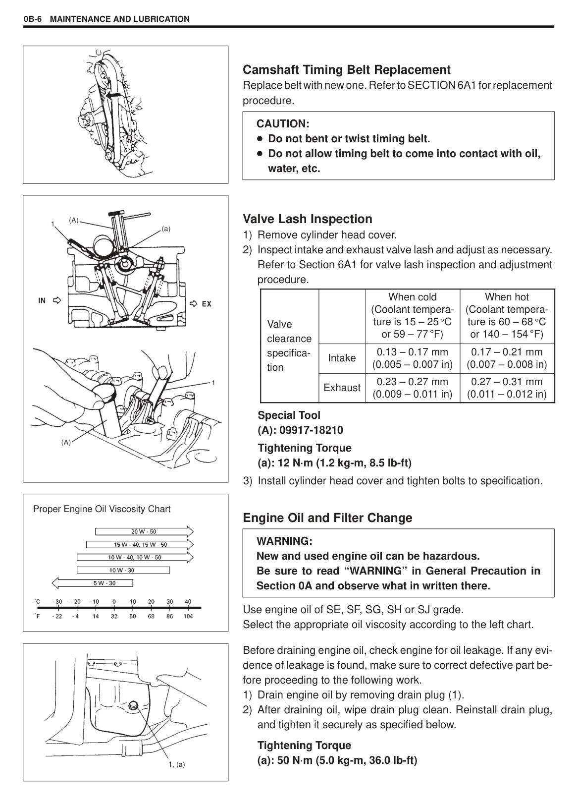
Camshaft Timing Belt Replacement Replace belt with new one. Refer to SECTION 6A1 for replacement procedure.
|CAUTION: Do not bent or twist timing belt. Do not allow timing belt to come into contact with oil, water, etc.| |---|
###### Valve Lash Inspection
Special Tool (A): 09917-18210 Tightening Torque (a): 12 N·m (1.2 kg-m, 8.5 lb-ft)
|Valve clearance specification| |When cold (Coolant temperature is 15 – 25 C or 59 – 77 F)|When hot (Coolant temperature is 60 – 68 C or 140 – 154 F)| |---|---|---|---| |Valve clearance specification|Intake|0.13 – 0.17 mm (0.005 – 0.007 in)|0.17 – 0.21 mm (0.007 – 0.008 in)| |Valve clearance specification|Exhaust|0.23 – 0.27 mm (0.009 – 0.011 in)|0.27 – 0.31 mm (0.011 – 0.012 in)|
###### Engine Oil and Filter Change
|WARNING: New and used engine oil can be hazardous. Be sure to read “WARNING” in General Precaution in Section 0A and observe what in written there.| |---|
Use engine oil of SE, SF, SG, SH or SJ grade. Select the appropriate oil viscosity according to the left chart.
Before draining engine oil, check engine for oil leakage. If any evidence of leakage is found, make sure to correct defective part before proceeding to the following work.
######### Tightening Torque (a): 50 N·m (5.0 kg-m, 36.0 lb-ft)
MAINTENANCE AND LUBRICATION 0B-7
|| |---|
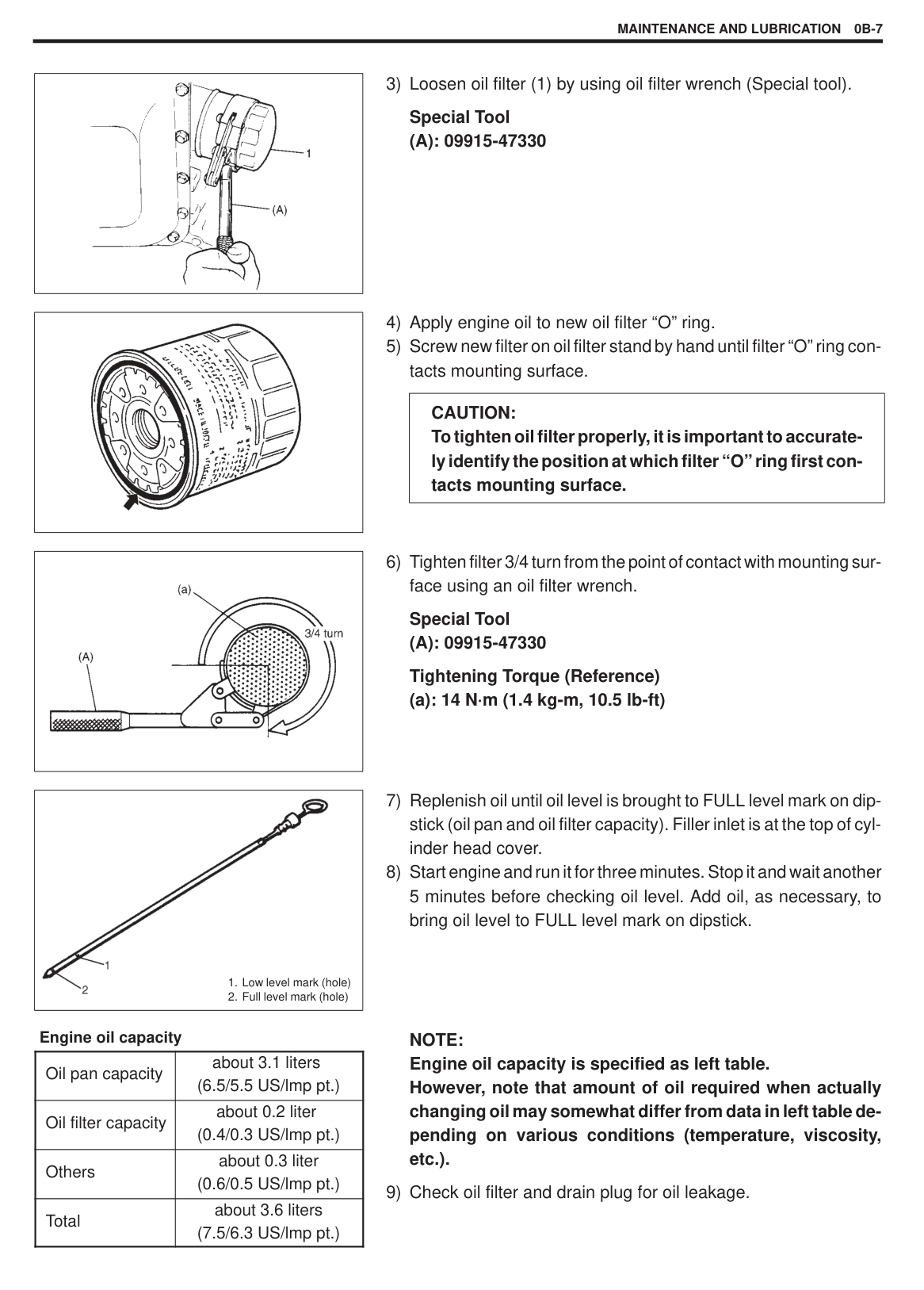
Engine oil capacity
|Oil pan capacity|about 3.1 liters (6.5/5.5 US/lmp pt.)| |---|---| |Oil filter capacity|about 0.2 liter (0.4/0.3 US/lmp pt.)| |Others|about 0.3 liter (0.6/0.5 US/lmp pt.)| |Total|about 3.6 liters (7.5/6.3 US/lmp pt.)|
Special Tool (A): 09915-47330
|| |---|
|CAUTION: To tighten oil filter properly, it is important to accurately identify the position at which filter “O” ring first contacts mounting surface.| |---|
|| |---|
Special Tool (A): 09915-47330
Tightening Torque (Reference) (a): 14 N·m (1.4 kg-m, 10.5 lb-ft)
|
1. Low level mark (hole)
2. Full level mark (hole)
| |---|
NOTE: Engine oil capacity is specified as left table. However, note that amount of oil required when actually changing oil may somewhat differ from data in left table depending on various conditions (temperature, viscosity, etc.).
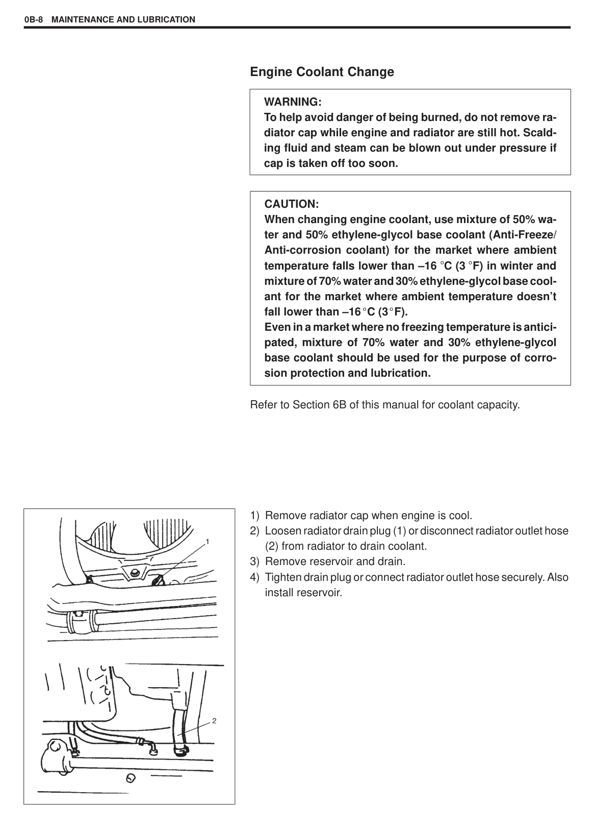
###### Engine Coolant Change
|WARNING: To help avoid danger of being burned, do not remove radiator cap while engine and radiator are still hot. Scalding fluid and steam can be blown out under pressure if cap is taken off too soon.| |---|
|CAUTION: When changing engine coolant, use mixture of 50% water and 50% ethylene-glycol base coolant (Anti-Freeze/ Anti-corrosion coolant) for the market where ambient temperature falls lower than –16 C (3 F) in winter and mixture of 70% water and 30% ethylene-glycol base coolant for the market where ambient temperature doesn’t fall lower than –16 C (3 F). Even in a market where no freezing temperature is anticipated, mixture of 70% water and 30% ethylene-glycol base coolant should be used for the purpose of corrosion protection and lubrication.
| |---|
Refer to Section 6B of this manual for coolant capacity.
|
| |---|
(2) from radiator to drain coolant.
|| |---|
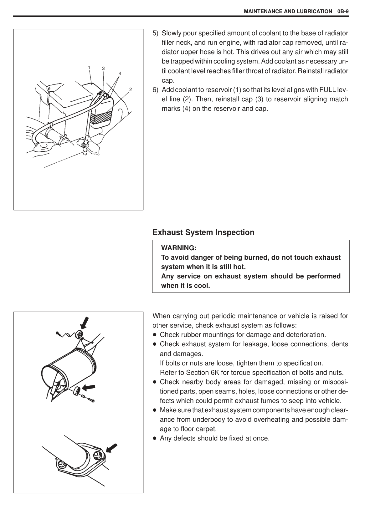
###### Exhaust System Inspection
|WARNING: To avoid danger of being burned, do not touch exhaust system when it is still hot. Any service on exhaust system should be performed when it is cool.| |---|
|| |---|
When carrying out periodic maintenance or vehicle is raised for other service, check exhaust system as follows:
Check rubber mountings for damage and deterioration. Check exhaust system for leakage, loose connections, dents and damages. If bolts or nuts are loose, tighten them to specification. Refer to Section 6K for torque specification of bolts and nuts. Check nearby body areas for damaged, missing or mispositioned parts, open seams, holes, loose connections or other defects which could permit exhaust fumes to seep into vehicle. Make sure that exhaust system components have enough clearance from underbody to avoid overheating and possible damage to floor carpet. Any defects should be fixed at once.
#### IGNITION SYSTEM
Spark Plugs Replacement Replace spark plugs with new ones referring to Section 6F1.
|| |---|
|| |---|
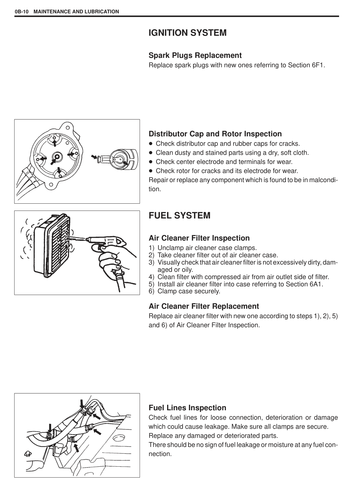
Distributor Cap and Rotor Inspection Check distributor cap and rubber caps for cracks. Clean dusty and stained parts using a dry, soft cloth. Check center electrode and terminals for wear. Check rotor for cracks and its electrode for wear.
Repair or replace any component which is found to be in malcondition.
#### FUEL SYSTEM
###### Air Cleaner Filter Inspection
Air Cleaner Filter Replacement Replace air cleaner filter with new one according to steps 1), 2), 5) and 6) of Air Cleaner Filter Inspection.
|| |---|
Fuel Lines Inspection Check fuel lines for loose connection, deterioration or damage which could cause leakage. Make sure all clamps are secure. Replace any damaged or deteriorated parts. There should be no sign of fuel leakage or moisture at any fuel connection.
|| |---|
|| |---|
|| |---|
|| |---|
|| |---|
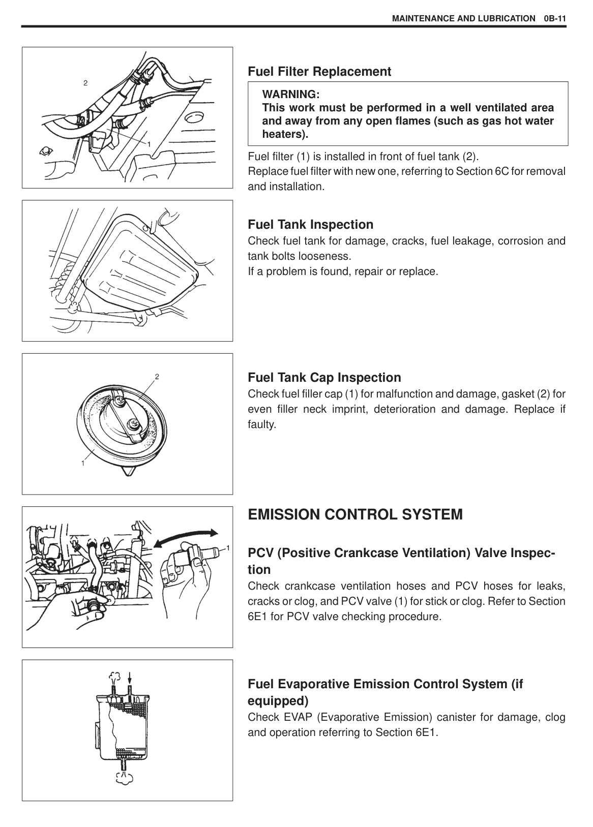
###### Fuel Filter Replacement
|WARNING: This work must be performed in a well ventilated area and away from any open flames (such as gas hot water heaters).| |---|
Fuel filter (1) is installed in front of fuel tank (2). Replace fuel filter with new one, referring to Section 6C for removal and installation.
Fuel Tank Inspection Check fuel tank for damage, cracks, fuel leakage, corrosion and tank bolts looseness. If a problem is found, repair or replace.
###### Fuel Tank Cap Inspection
Check fuel filler cap (1) for malfunction and damage, gasket (2) for even filler neck imprint, deterioration and damage. Replace if faulty.
#### EMISSION CONTROL SYSTEM
###### PCV (Positive Crankcase Ventilation) Valve Inspection
Check crankcase ventilation hoses and PCV hoses for leaks, cracks or clog, and PCV valve (1) for stick or clog. Refer to Section 6E1 for PCV valve checking procedure.
Fuel Evaporative Emission Control System (if equipped) Check EVAP (Evaporative Emission) canister for damage, clog and operation referring to Section 6E1.
|

| |---|
|
| |---|
|| |---|
#### BRAKE
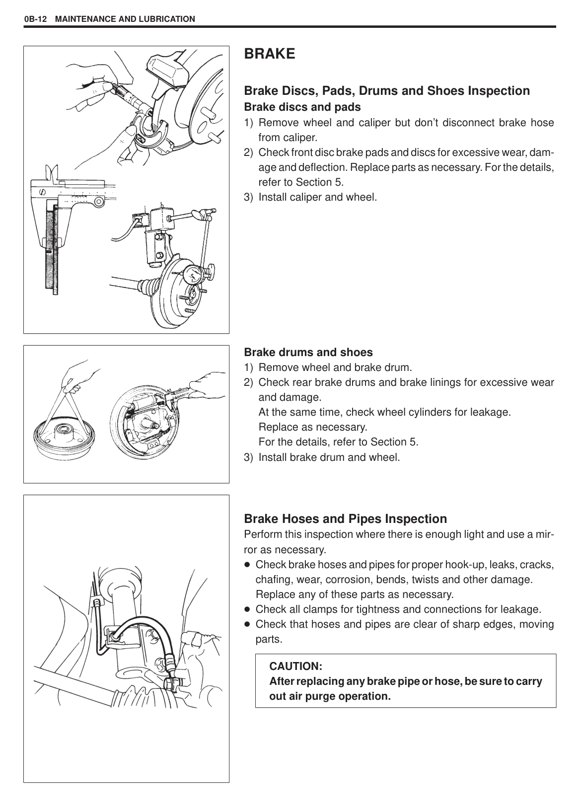
###### Brake Discs, Pads, Drums and Shoes Inspection Brake discs and pads
######## Brake drums and shoes
Brake Hoses and Pipes Inspection Perform this inspection where there is enough light and use a mirror as necessary.
Check brake hoses and pipes for proper hook-up, leaks, cracks, chafing, wear, corrosion, bends, twists and other damage. Replace any of these parts as necessary. Check all clamps for tightness and connections for leakage. Check that hoses and pipes are clear of sharp edges, moving parts.
|CAUTION: After replacing any brake pipe or hose, be sure to carry out air purge operation.| |---|
###### Brake Fluid Change
|CAUTION: Since brake system of this vehicle is factory-filled with brake fluid indicated on reservoir cap, do not use or mix different type of fluid when refilling; otherwise serious damage will occur. Do not use old or used brake fluid, or any fluid from a unsealed container.| |---|
Change brake fluid as follows. Drain existing fluid from brake system completely, fill system with specified fluid and carry out air purge operation. For air purging procedure, refer to Section 5.
|
“a”:Parking brake lever stroke: 3 – 8 notches (With 20 kg or 44 lbs of pull pressure)| |---|
|| |---|
|| |---|
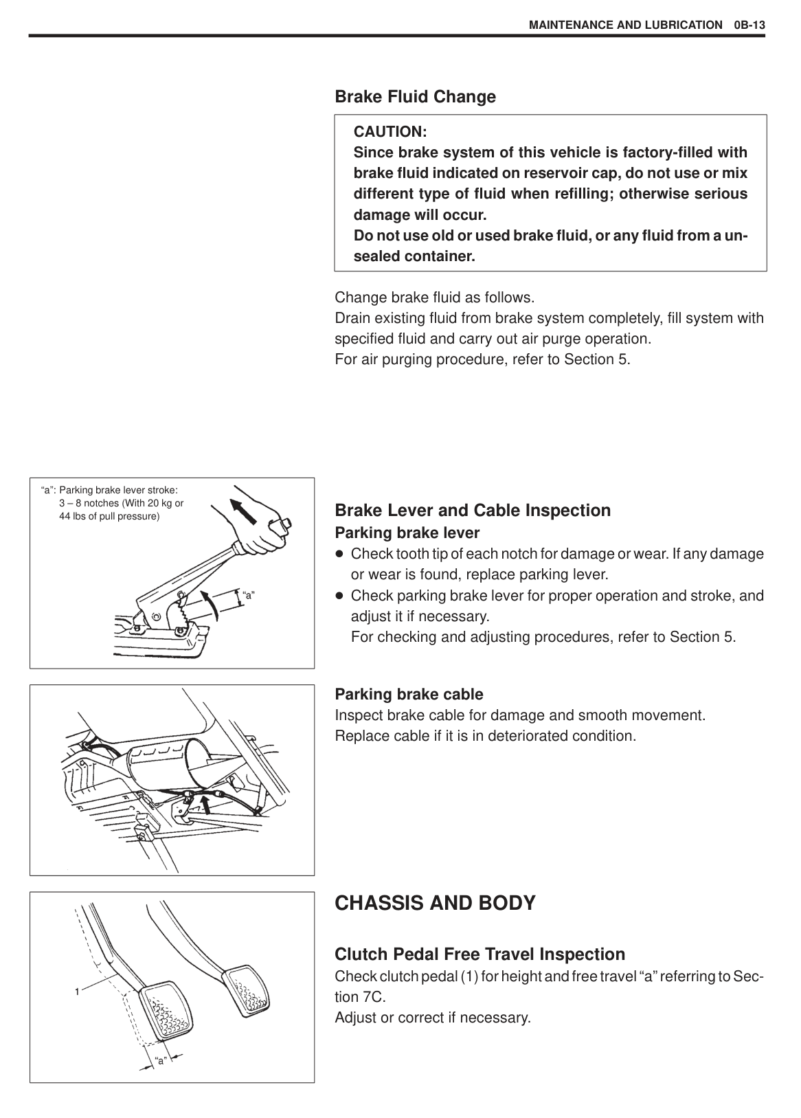
###### Brake Lever and Cable Inspection Parking brake lever
Check tooth tip of each notch for damage or wear. If any damage or wear is found, replace parking lever. Check parking brake lever for proper operation and stroke, and adjust it if necessary. For checking and adjusting procedures, refer to Section 5.
Parking brake cable Inspect brake cable for damage and smooth movement. Replace cable if it is in deteriorated condition.
#### CHASSIS AND BODY
Clutch Pedal Free Travel Inspection Check clutch pedal (1) for height and free travel “a” referring to Section 7C. Adjust or correct if necessary.
|
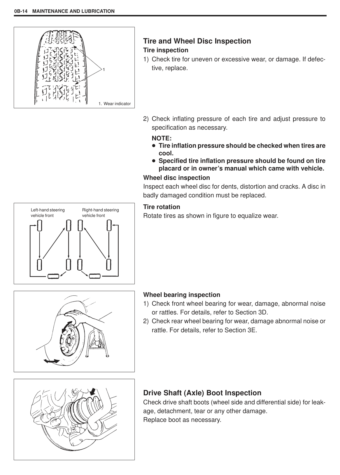
1.Wear indicator| |---|
|
Left-hand steering vehicle front
Right-hand steering vehicle front| |---|
|| |---|
|
| |---|
###### Tire and Wheel Disc Inspection Tire inspection
NOTE: Tire inflation pressure should be checked when tires are cool. Specified tire inflation pressure should be found on tire placard or in owner’s manual which came with vehicle.
Wheel disc inspection Inspect each wheel disc for dents, distortion and cracks. A disc in badly damaged condition must be replaced.
Tire rotation Rotate tires as shown in figure to equalize wear.
######### Wheel bearing inspection
Drive Shaft (Axle) Boot Inspection Check drive shaft boots (wheel side and differential side) for leakage, detachment, tear or any other damage. Replace boot as necessary.
|| |---|
|
| |---|
|
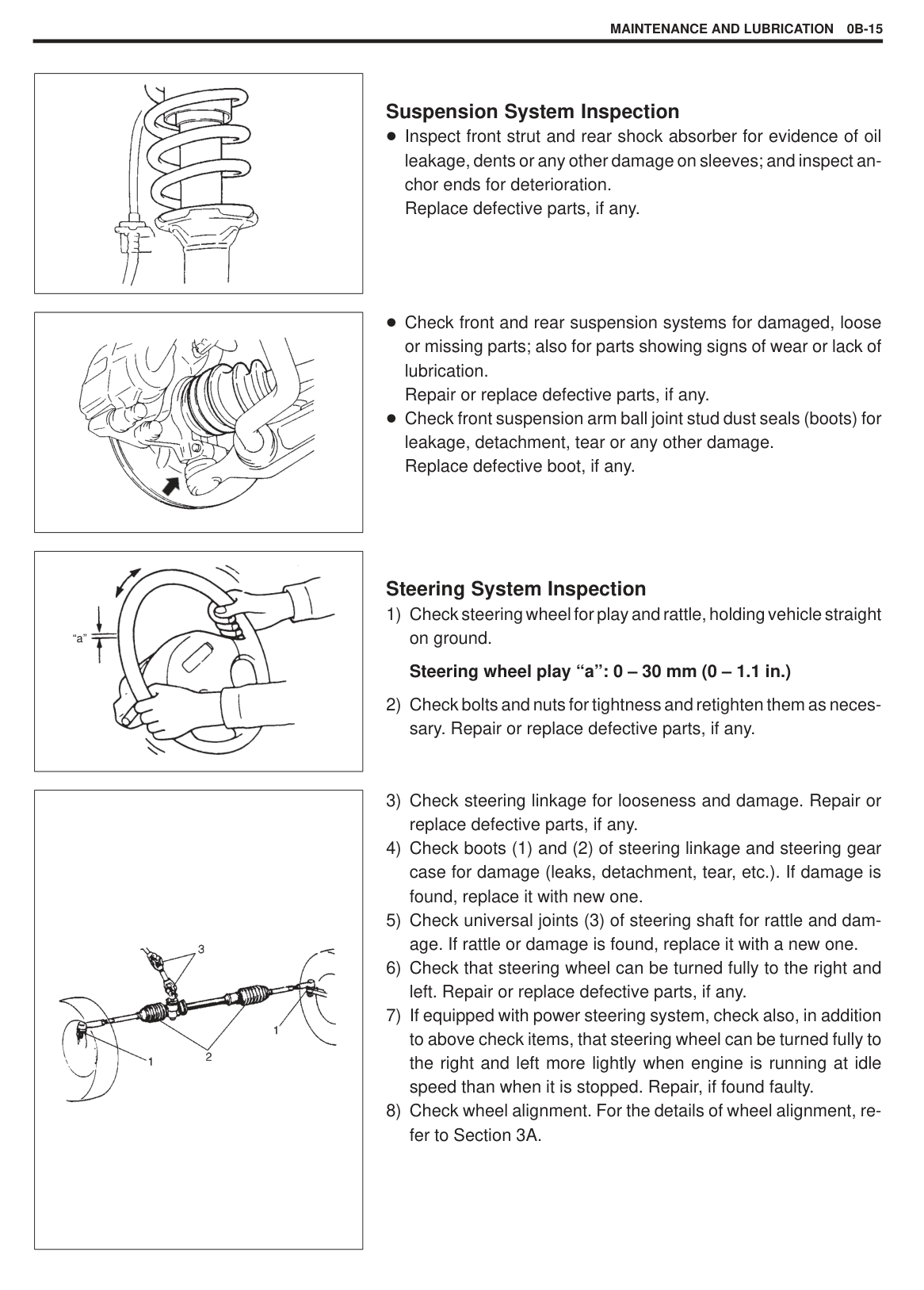
“a”| |---|
Suspension System Inspection Inspect front strut and rear shock absorber for evidence of oil leakage, dents or any other damage on sleeves; and inspect anchor ends for deterioration. Replace defective parts, if any.
Check front and rear suspension systems for damaged, loose or missing parts; also for parts showing signs of wear or lack of lubrication. Repair or replace defective parts, if any. Check front suspension arm ball joint stud dust seals (boots) for leakage, detachment, tear or any other damage. Replace defective boot, if any.
###### Steering System Inspection
|| |---|
|| |---|
|
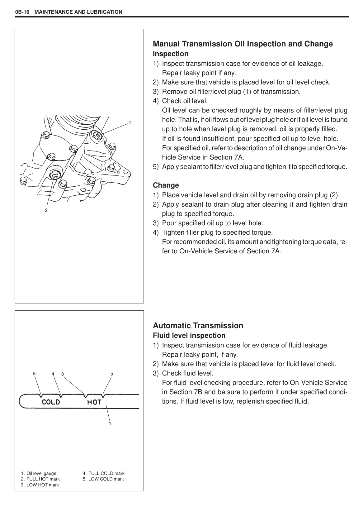
1.Oil level gauge
2.FULL HOT mark
3.LOW HOT mark
4.FULL COLD mark
5.LOW COLD mark
| |---|
###### Manual Transmission Oil Inspection and Change Inspection
######## Change
###### Automatic Transmission Fluid level inspection
|
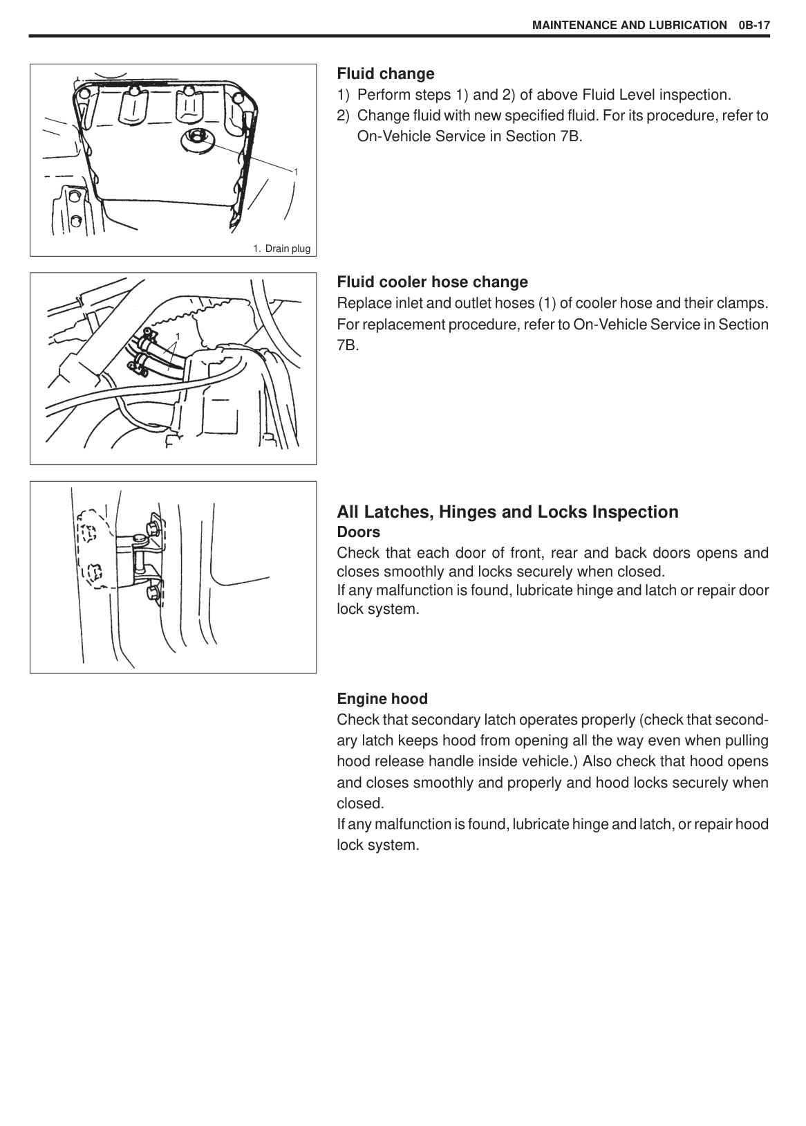
1.Drain plug| |---|
|| |---|
|| |---|
######## Fluid change
######## Fluid cooler hose change
Replace inlet and outlet hoses (1) of cooler hose and their clamps. For replacement procedure, refer to On-Vehicle Service in Section 7B.
###### All Latches, Hinges and Locks Inspection Doors
Check that each door of front, rear and back doors opens and closes smoothly and locks securely when closed. If any malfunction is found, lubricate hinge and latch or repair door lock system.
Engine hood Check that secondary latch operates properly (check that secondary latch keeps hood from opening all the way even when pulling hood release handle inside vehicle.) Also check that hood opens and closes smoothly and properly and hood locks securely when closed. If any malfunction is found, lubricate hinge and latch, or repair hood lock system.
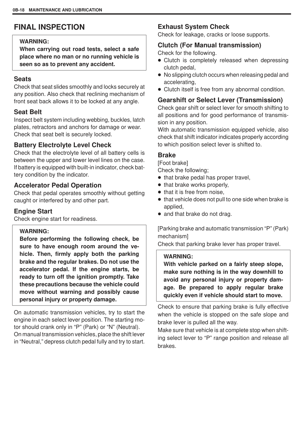
#### FINAL INSPECTION
|WARNING: When carrying out road tests, select a safe place where no man or no running vehicle is seen so as to prevent any accident.| |---|
###### Seats
Check that seat slides smoothly and locks securely at any position. Also check that reclining mechanism of front seat back allows it to be locked at any angle.
Seat Belt Inspect belt system including webbing, buckles, latch plates, retractors and anchors for damage or wear. Check that seat belt is securely locked. Battery Electrolyte Level Check
Check that the electrolyte level of all battery cells is between the upper and lower level lines on the case. If battery is equipped with built-in indicator, check battery condition by the indicator.
Accelerator Pedal Operation Check that pedal operates smoothly without getting caught or interfered by and other part.
Engine Start Check engine start for readiness.
|WARNING: Before performing the following check, be sure to have enough room around the vehicle. Then, firmly apply both the parking brake and the regular brakes. Do not use the accelerator pedal. If the engine starts, be ready to turn off the ignition promptly. Take these precautions because the vehicle could move without warning and possibly cause personal injury or property damage.| |---|
On automatic transmission vehicles, try to start the engine in each select lever position. The starting motor should crank only in “P” (Park) or “N” (Neutral). On manual transmission vehicles, place the shift lever in “Neutral,” depress clutch pedal fully and try to start.
Exhaust System Check Check for leakage, cracks or loose supports.
###### Clutch (For Manual transmission) Check for the following.
Clutch is completely released when depressing clutch pedal, No slipping clutch occurs when releasing pedal and accelerating, Clutch itself is free from any abnormal condition.
Gearshift or Select Lever (Transmission) Check gear shift or select lever for smooth shifting to all positions and for good performance of transmission in any position. With automatic transmission equipped vehicle, also check that shift indicator indicates properly according to which position select lever is shifted to.
Brake [Foot brake] Check the following;
that brake pedal has proper travel, that brake works properly, that it is free from noise, that vehicle does not pull to one side when brake is applied, and that brake do not drag.
[Parking brake and automatic transmission “P” (Park) mechanism] Check that parking brake lever has proper travel.
|WARNING: With vehicle parked on a fairly steep slope, make sure nothing is in the way downhill to avoid any personal injury or property damage. Be prepared to apply regular brake quickly even if vehicle should start to move.| |---|
Check to ensure that parking brake is fully effective when the vehicle is stopped on the safe slope and brake lever is pulled all the way. Make sure that vehicle is at complete stop when shifting select lever to “P” range position and release all brakes.
############### MAINTENANCE AND LUBRICATION 0B-19
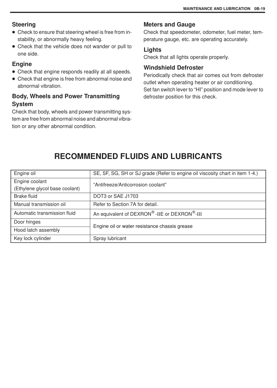
Steering Check to ensure that steering wheel is free from instability, or abnormally heavy feeling. Check that the vehicle does not wander or pull to one side.
###### Engine
Check that engine responds readily at all speeds. Check that engine is free from abnormal noise and abnormal vibration.
###### Body, Wheels and Power Transmitting System
Check that body, wheels and power transmitting system are free from abnormal noise and abnormal vibration or any other abnormal condition.
Meters and Gauge Check that speedometer, odometer, fuel meter, temperature gauge, etc. are operating accurately.
Lights Check that all lights operate properly.
Windshield Defroster Periodically check that air comes out from defroster outlet when operating heater or air conditioning. Set fan switch lever to “HI” position and mode lever to defroster position for this check.
RECOMMENDED FLUIDS AND LUBRICANTS
|Engine oil|SE, SF, SG, SH or SJ grade (Refer to engine oil viscosity chart in item 1-4.)| |---|---| |Engine coolant (Ethylene glycol base coolant)|“Antifreeze/Anticorrosion coolant”| |Brake fluid|DOT3 or SAE J1703| |Manual transmission oil|Refer to Section 7A for detail.| |Automatic transmission fluid|An equivalent of DEXRON - E or DEXRON -| |Door hinges|Engine oil or water resistance chassis greaseEngine oil or water resistance chassis grease
| |Hood latch assembly|Engine oil or water resistance chassis greaseEngine oil or water resistance chassis grease
| |Key lock cylinder|Spray lubricant|
AIR CONDITIONING (OPTIONAL)1B-1
SECTION 1B
AIR CONDITIONING (OPTIONAL)
######## 1B
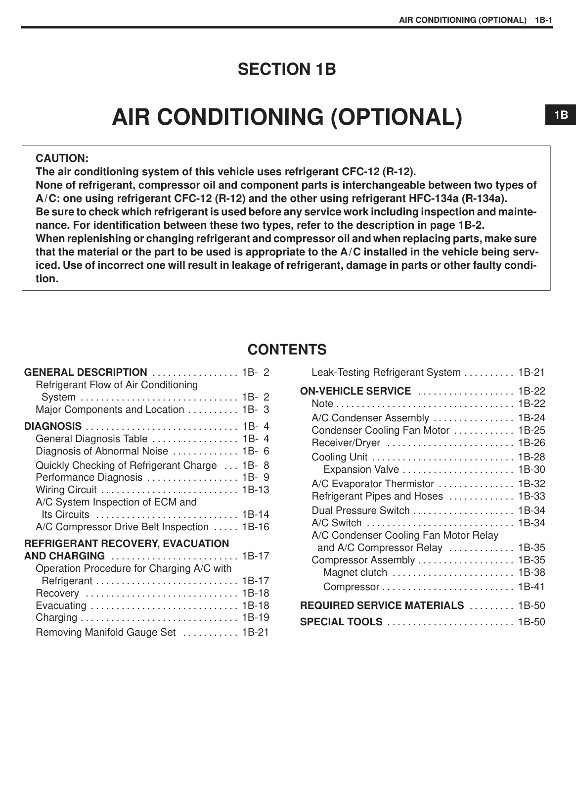
|CAUTION: The air conditioning system of this vehicle uses refrigerant CFC-12 (R-12). None of refrigerant, compressor oil and component parts is interchangeable between two types of A/C: one using refrigerant CFC-12 (R-12) and the other using refrigerant HFC-134a (R-134a). Be sure to check which refrigerant is used before any service work including inspection and maintenance. For identification between these two types, refer to the description in page 1B-2. When replenishing or changing refrigerant and compressor oil and when replacing parts, make sure that the material or the part to be used is appropriate to the A/C installed in the vehicle being serviced. Use of incorrect one will result in leakage of refrigerant, damage in parts or other faulty condition.| |---|
#### CONTENTS
GENERAL DESCRIPTION 1B-2. . . . . . . . . . . . . . . . .
Refrigerant Flow of Air Conditioning
System 1B-2. . . . . . . . . . . . . . . . . . . . . . . . . . . . . . . Major Components and Location 1B-3. . . . . . . . . .
DIAGNOSIS 1B-4. . . . . . . . . . . . . . . . . . . . . . . . . . . . . . General Diagnosis Table 1B-4. . . . . . . . . . . . . . . . . Diagnosis of Abnormal Noise 1B-6. . . . . . . . . . . . . Quickly Checking of Refrigerant Charge 1B-8. . . Performance Diagnosis 1B-9. . . . . . . . . . . . . . . . . . Wiring Circuit 1B-13. . . . . . . . . . . . . . . . . . . . . . . . . . . A/C System Inspection of ECM and
Its Circuits 1B-14. . . . . . . . . . . . . . . . . . . . . . . . . . . . A/C Compressor Drive Belt Inspection 1B-16. . . . .
REFRIGERANT RECOVERY, EVACUATION AND CHARGING 1B-17. . . . . . . . . . . . . . . . . . . . . . . . .
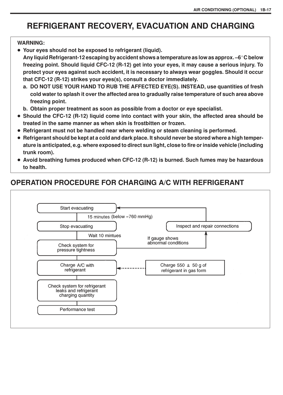
Operation Procedure for Charging A/C with
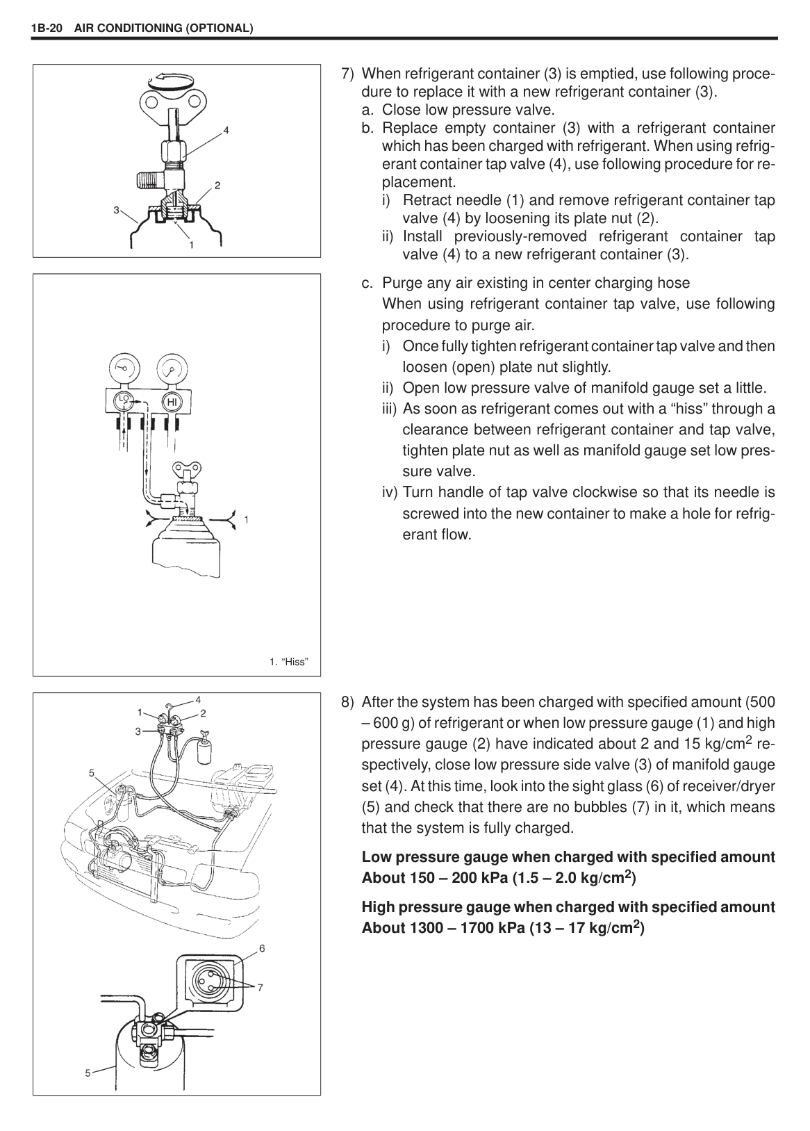
Refrigerant 1B-17. . . . . . . . . . . . . . . . . . . . . . . . . . . . Recovery 1B-18. . . . . . . . . . . . . . . . . . . . . . . . . . . . . . Evacuating 1B-18. . . . . . . . . . . . . . . . . . . . . . . . . . . . . Charging 1B-19. . . . . . . . . . . . . . . . . . . . . . . . . . . . . . . Removing Manifold Gauge Set 1B-21. . . . . . . . . . .
Leak-Testing Refrigerant System 1B-21. . . . . . . . . .
ON-VEHICLE SERVICE 1B-22. . . . . . . . . . . . . . . . . . . Note 1B-22. . . . . . . . . . . . . . . . . . . . . . . . . . . . . . . . . . . A/C Condenser Assembly 1B-24. . . . . . . . . . . . . . . . Condenser Cooling Fan Motor 1B-25. . . . . . . . . . . . Receiver/Dryer 1B-26. . . . . . . . . . . . . . . . . . . . . . . . . Cooling Unit 1B-28. . . . . . . . . . . . . . . . . . . . . . . . . . . .
Expansion Valve 1B-30. . . . . . . . . . . . . . . . . . . . . . A/C Evaporator Thermistor 1B-32. . . . . . . . . . . . . . . Refrigerant Pipes and Hoses 1B-33. . . . . . . . . . . . . Dual Pressure Switch 1B-34. . . . . . . . . . . . . . . . . . . . A/C Switch 1B-34. . . . . . . . . . . . . . . . . . . . . . . . . . . . . A/C Condenser Cooling Fan Motor Relay
and A/C Compressor Relay 1B-35. . . . . . . . . . . . .
Compressor Assembly 1B-35. . . . . . . . . . . . . . . . . . . Magnet clutch 1B-38. . . . . . . . . . . . . . . . . . . . . . . . Compressor 1B-41. . . . . . . . . . . . . . . . . . . . . . . . . .
REQUIRED SERVICE MATERIALS 1B-50. . . . . . . . . SPECIAL TOOLS 1B-50. . . . . . . . . . . . . . . . . . . . . . . . .
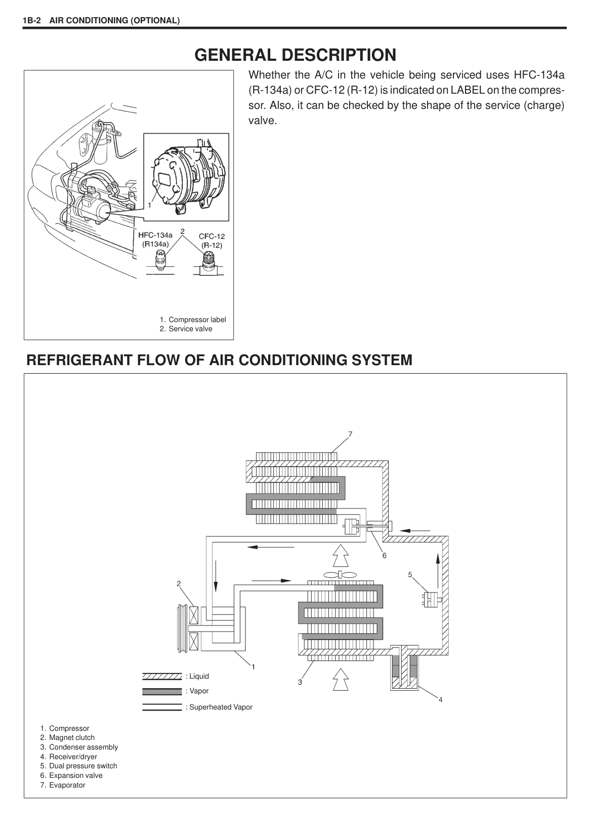
GENERAL DESCRIPTION
Whether the A/C in the vehicle being serviced uses HFC-134a (R-134a) or CFC-12 (R-12) is indicated on LABEL on the compressor. Also, it can be checked by the shape of the service (charge) valve.
|
1. Compressor label
2. Service valve
| |---|
#### REFRIGERANT FLOW OF AIR CONDITIONING SYSTEM
|
1. Compressor
2. Magnet clutch
3. Condenser assembly
4. Receiver/dryer
5. Dual pressure switch
6. Expansion valve
7. Evaporator
: Liquid : Vapor : Superheated Vapor| |---|
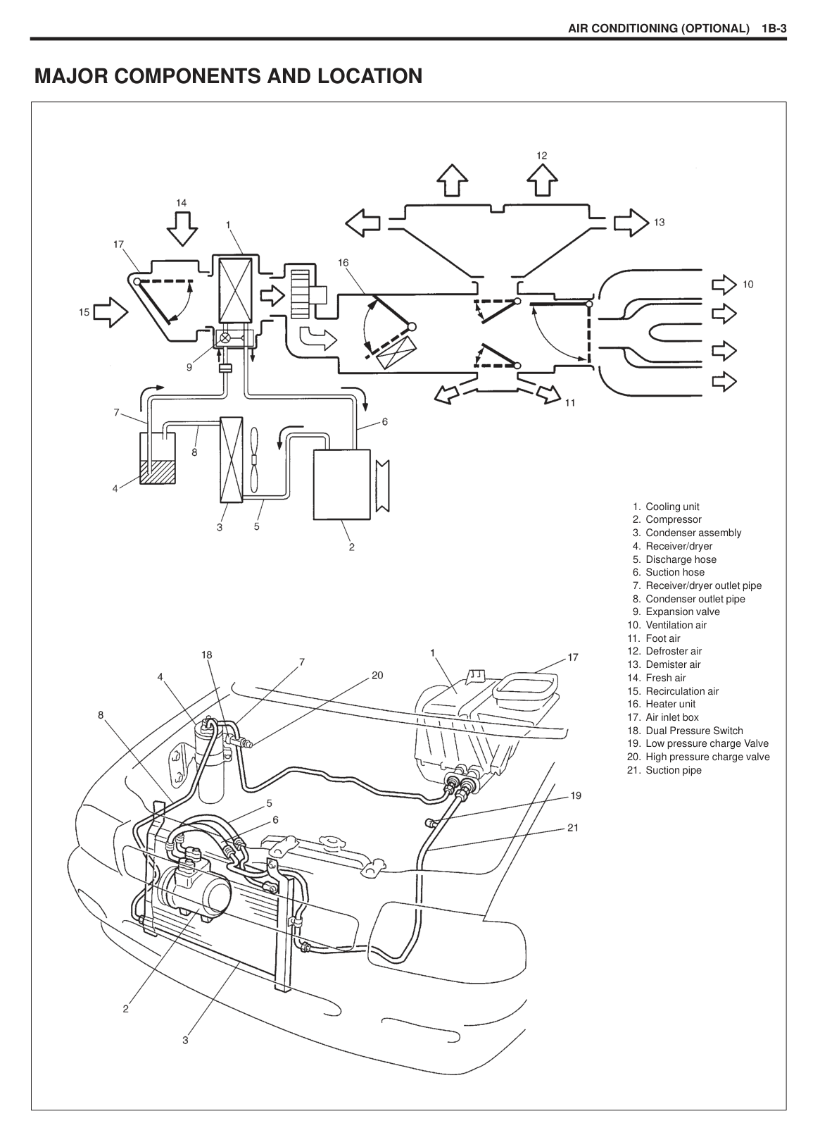
#### MAJOR COMPONENTS AND LOCATION
|

1. Cooling unit
2. Compressor
3. Condenser assembly
4. Receiver/dryer
5. Discharge hose
6. Suction hose
7. Receiver/dryer outlet pipe
8. Condenser outlet pipe
9. Expansion valve
10. Ventilation air
11. Foot air
12. Defroster air
13. Demister air
14. Fresh air
15. Recirculation air
16. Heater unit
17. Air inlet box
18. Dual Pressure Switch
19. Low pressure charge Valve
20. High pressure charge valve
21. Suction pipe
| |---|
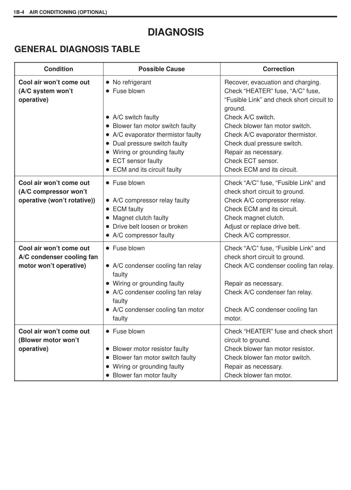
DIAGNOSIS GENERAL DIAGNOSIS TABLE
|Condition|Possible Cause|Correction| |---|---|---| |Cool air won’t come out (A/C system won’t operative)|No refrigerant Fuse blown
A/C switch faulty Blower fan motor switch faulty A/C evaporator thermistor faulty Dual pressure switch faulty Wiring or grounding faulty ECT sensor faulty ECM and its circuit faulty|Recover, evacuation and charging. Check “HEATER” fuse, “A/C” fuse, “Fusible Link” and check short circuit to ground. Check A/C switch. Check blower fan motor switch. Check A/C evaporator thermistor. Check dual pressure switch. Repair as necessary. Check ECT sensor. Check ECM and its circuit.| |Cool air won’t come out (A/C compressor won’t operative (won’t rotative))|Fuse blown
A/C compressor relay faulty ECM faulty Magnet clutch faulty Drive belt loosen or broken A/C compressor faulty|Check “A/C” fuse, “Fusible Link” and check short circuit to ground. Check A/C compressor relay. Check ECM and its circuit. Check magnet clutch. Adjust or replace drive belt. Check A/C compressor.| |Cool air won’t come out A/C condenser cooling fan motor won’t operative)|Fuse blown
A/C condenser cooling fan relay faulty Wiring or grounding faulty A/C condenser cooling fan relay faulty A/C condenser cooling fan motor faulty|Check “A/C” fuse, “Fusible Link” and check short circuit to ground. Check A/C condenser cooling fan relay.
Repair as necessary. Check A/C condenser fan relay.
Check A/C condenser cooling fan motor.| |Cool air won’t come out (Blower motor won’t operative)|Fuse blown
Blower motor resistor faulty Blower fan motor switch faulty Wiring or grounding faulty Blower fan motor faulty|Check “HEATER” fuse and check short circuit to ground. Check blower fan motor resistor. Check blower fan motor switch. Repair as necessary. Check blower fan motor.|
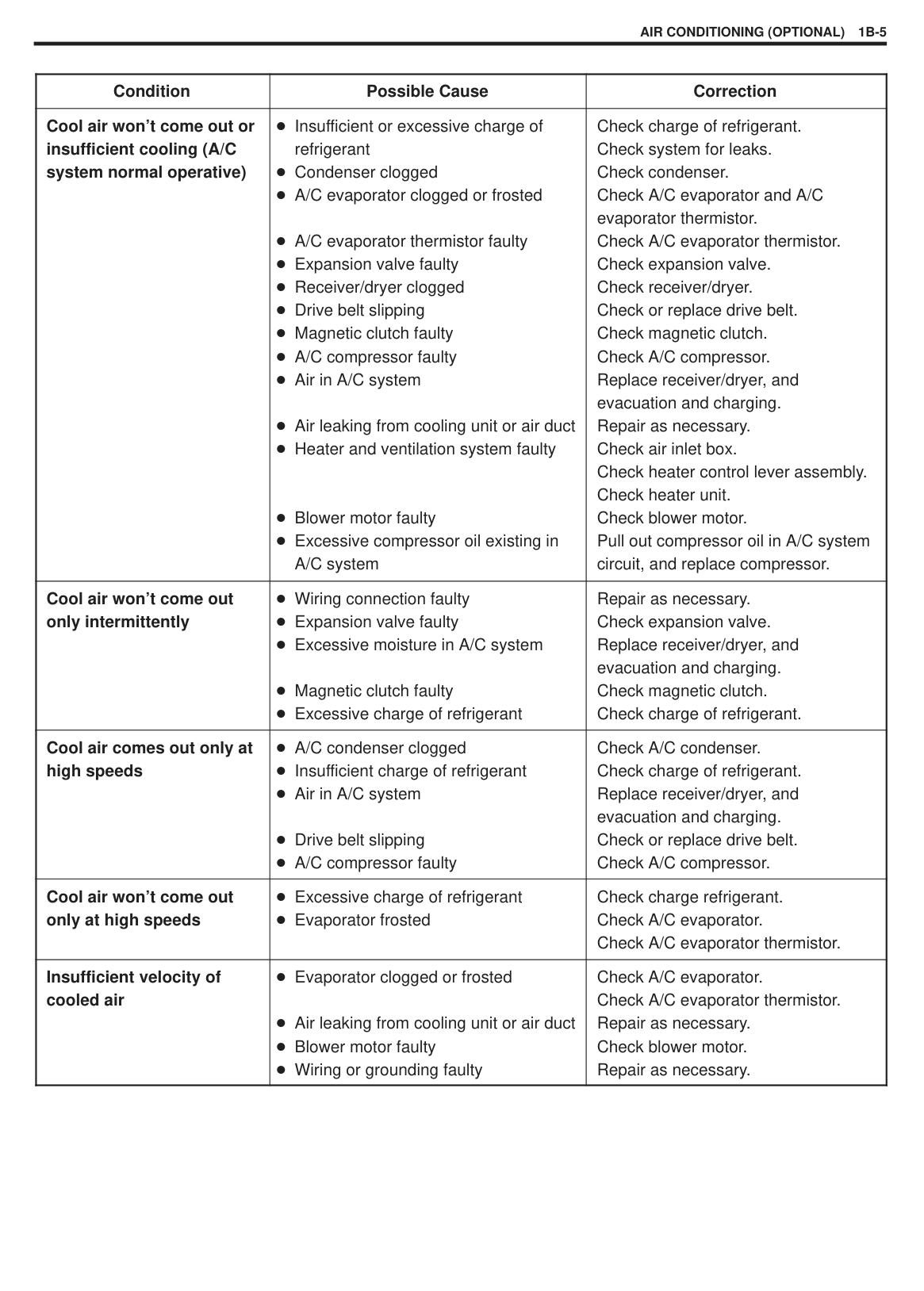
|Condition|Possible Cause|Correction| |---|---|---| |Cool air won’t come out or insufficient cooling (A/C system normal operative)|Insufficient or excessive charge of refrigerant Condenser clogged A/C evaporator clogged or frosted
A/C evaporator thermistor faulty Expansion valve faulty Receiver/dryer clogged Drive belt slipping Magnetic clutch faulty A/C compressor faulty Air in A/C system
Air leaking from cooling unit or air duct Heater and ventilation system faulty
Blower motor faulty Excessive compressor oil existing in A/C system|Check charge of refrigerant. Check system for leaks. Check condenser. Check A/C evaporator and A/C evaporator thermistor. Check A/C evaporator thermistor. Check expansion valve. Check receiver/dryer. Check or replace drive belt. Check magnetic clutch. Check A/C compressor. Replace receiver/dryer, and evacuation and charging. Repair as necessary. Check air inlet box. Check heater control lever assembly. Check heater unit. Check blower motor. Pull out compressor oil in A/C system circuit, and replace compressor.| |Cool air won’t come out only intermittently|Wiring connection faulty Expansion valve faulty Excessive moisture in A/C system
Magnetic clutch faulty Excessive charge of refrigerant|Repair as necessary. Check expansion valve. Replace receiver/dryer, and evacuation and charging. Check magnetic clutch. Check charge of refrigerant.| |Cool air comes out only at high speeds|A/C condenser clogged Insufficient charge of refrigerant Air in A/C system
Drive belt slipping A/C compressor faulty|Check A/C condenser. Check charge of refrigerant. Replace receiver/dryer, and evacuation and charging. Check or replace drive belt. Check A/C compressor.| |Cool air won’t come out only at high speeds|Excessive charge of refrigerant Evaporator frosted|Check charge refrigerant. Check A/C evaporator. Check A/C evaporator thermistor.| |Insufficient velocity of cooled air|Evaporator clogged or frosted
Air leaking from cooling unit or air duct Blower motor faulty Wiring or grounding faulty|Check A/C evaporator. Check A/C evaporator thermistor. Repair as necessary. Check blower motor. Repair as necessary.|
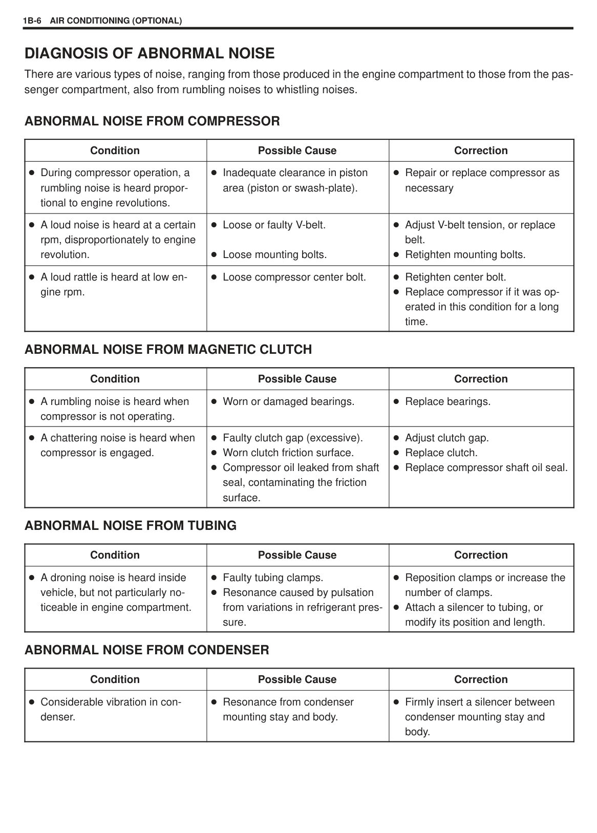
DIAGNOSIS OF ABNORMAL NOISE There are various types of noise, ranging from those produced in the engine compartment to those from the passenger compartment, also from rumbling noises to whistling noises.
ABNORMAL NOISE FROM COMPRESSOR
|Condition|Possible Cause|Correction|
|---|---|---| |During compressor operation, a rumbling noise is heard proportional to engine revolutions.|Inadequate clearance in piston area (piston or swash-plate).|Repair or replace compressor as necessary| |A loud noise is heard at a certain rpm, disproportionately to engine revolution.|Loose or faulty V-belt.
Loose mounting bolts.|Adjust V-belt tension, or replace belt. Retighten mounting bolts.| |A loud rattle is heard at low engine rpm.|Loose compressor center bolt.|Retighten center bolt. Replace compressor if it was operated in this condition for a long time.|
ABNORMAL NOISE FROM MAGNETIC CLUTCH
|Condition|Possible Cause|Correction| |---|---|---| |A rumbling noise is heard when compressor is not operating.|Worn or damaged bearings.|Replace bearings.| |A chattering noise is heard when compressor is engaged.|Faulty clutch gap (excessive). Worn clutch friction surface. Compressor oil leaked from shaft seal, contaminating the friction surface.|Adjust clutch gap. Replace clutch. Replace compressor shaft oil seal.|
ABNORMAL NOISE FROM TUBING
|Condition|Possible Cause|Correction| |---|---|---| |A droning noise is heard inside vehicle, but not particularly noticeable in engine compartment.|Faulty tubing clamps. Resonance caused by pulsation from variations in refrigerant pressure.|Reposition clamps or increase the number of clamps. Attach a silencer to tubing, or modify its position and length.|
ABNORMAL NOISE FROM CONDENSER
|Condition|Possible Cause|Correction| |---|---|---| |Considerable vibration in condenser.|Resonance from condenser mounting stay and body.|Firmly insert a silencer between condenser mounting stay and body.|
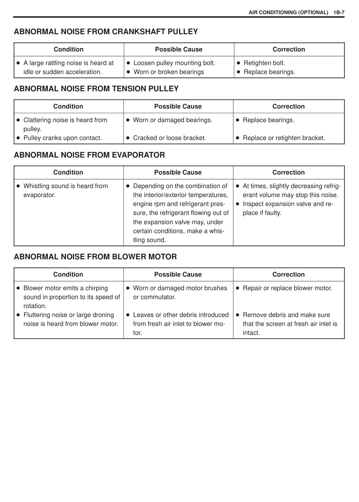
ABNORMAL NOISE FROM CRANKSHAFT PULLEY
|Condition|Possible Cause|Correction| |---|---|---| |A large rattling noise is heard at idle or sudden acceleration.|Loosen pulley mounting bolt. Worn or broken bearings|Retighten bolt. Replace bearings.|
ABNORMAL NOISE FROM TENSION PULLEY
|Condition|Possible Cause|Correction| |---|---|---| |Clattering noise is heard from pulley. Pulley cranks upon contact.|Worn or damaged bearings.
Cracked or loose bracket.|Replace bearings.
Replace or retighten bracket.|
ABNORMAL NOISE FROM EVAPORATOR
|Condition|Possible Cause|Correction| |---|---|---| |Whistling sound is heard from evaporator.|Depending on the combination of the interior/exterior temperatures, engine rpm and refrigerant pressure, the refrigerant flowing out of the expansion valve may, under certain conditions, make a whistling sound.|At times, slightly decreasing refrigerant volume may stop this noise. Inspect expansion valve and replace if faulty.|
ABNORMAL NOISE FROM BLOWER MOTOR
|Condition|Possible Cause|Correction|
|---|---|---| |Blower motor emits a chirping sound in proportion to its speed of rotation. Fluttering noise or large droning noise is heard from blower motor.|Worn or damaged motor brushes or commutator.
Leaves or other debris introduced from fresh air inlet to blower motor.|Repair or replace blower motor.
Remove debris and make sure that the screen at fresh air inlet is intact.|
|
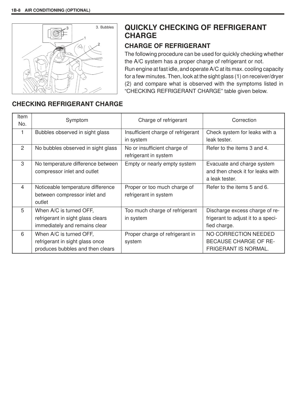
3. Bubbles| |---|
#### QUICKLY CHECKING OF REFRIGERANT CHARGE CHARGE OF REFRIGERANT
The following procedure can be used for quickly checking whether the A/C system has a proper charge of refrigerant or not. Run engine at fast idle, and operate A/C at its max. cooling capacity for a few minutes. Then, look at the sight glass (1) on receiver/dryer (2) and compare what is observed with the symptoms listed in “CHECKING REFRIGERANT CHARGE” table given below.
###### CHECKING REFRIGERANT CHARGE
|Item No.|Symptom|Charge of refrigerant|Correction| |---|---|---|---| |1|Bubbles observed in sight glass|Insufficient charge of refrigerant in system|Check system for leaks with a leak tester.| |2|No bubbles observed in sight glass|No or insufficient charge of refrigerant in system|Refer to the items 3 and 4.| |3|No temperature difference between compressor inlet and outlet|Empty or nearly empty system|Evacuate and charge system and then check it for leaks with a leak tester.| |4|Noticeable temperature difference between compressor inlet and outlet|Proper or too much charge of refrigerant in system|Refer to the items 5 and 6.| |5|When A/C is turned OFF, refrigerant in sight glass clears immediately and remains clear|Too much charge of refrigerant in system|Discharge excess charge of refrigerant to adjust it to a specified charge.| |6|When A/C is turned OFF, refrigerant in sight glass once produces bubbles and then clears|Proper charge of refrigerant in system|NO CORRECTION NEEDED BECAUSE CHARGE OF REFRIGERANT IS NORMAL.|
|| |---|
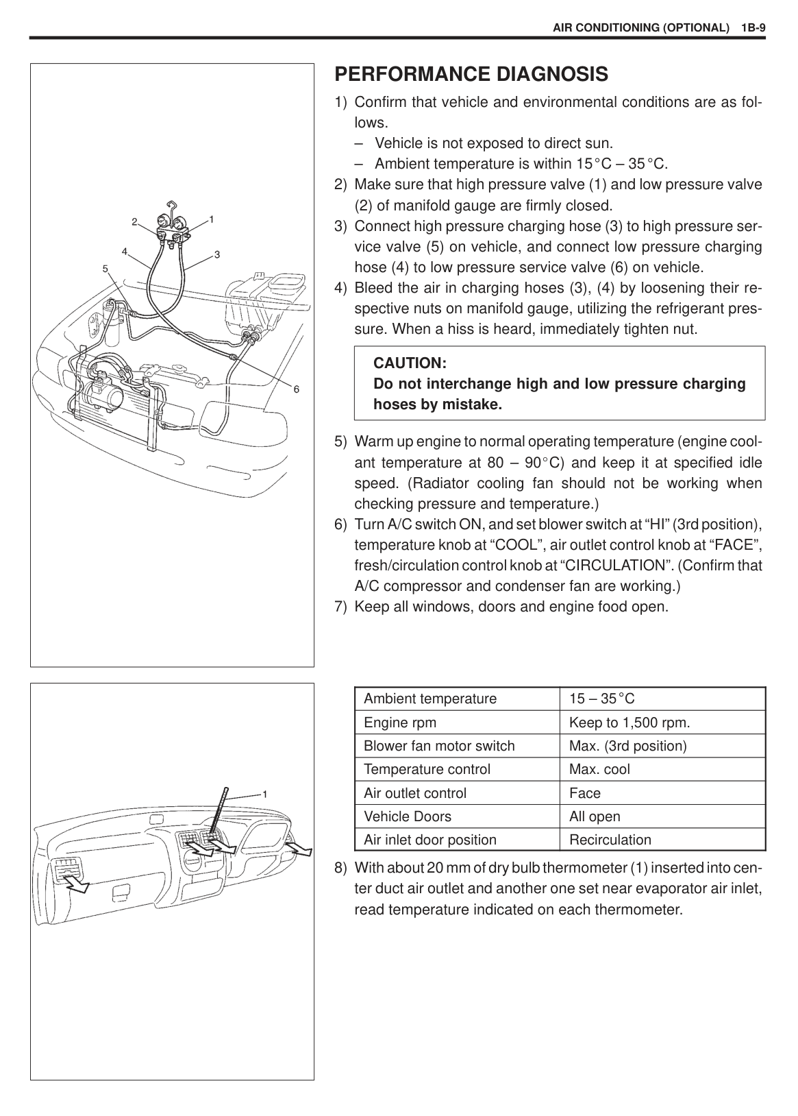
#### PERFORMANCE DIAGNOSIS
(2) of manifold gauge are firmly closed.
|CAUTION: Do not interchange high and low pressure charging hoses by mistake.| |---|
|| |---|
|Ambient temperature|15 – 35 C| |---|---| |Engine rpm|Keep to 1,500 rpm.| |Blower fan motor switch|Max. (3rd position)| |Temperature control|Max. cool| |Air outlet control|Face| |Vehicle Doors|All open| |Air inlet door position|Recirculation|
|
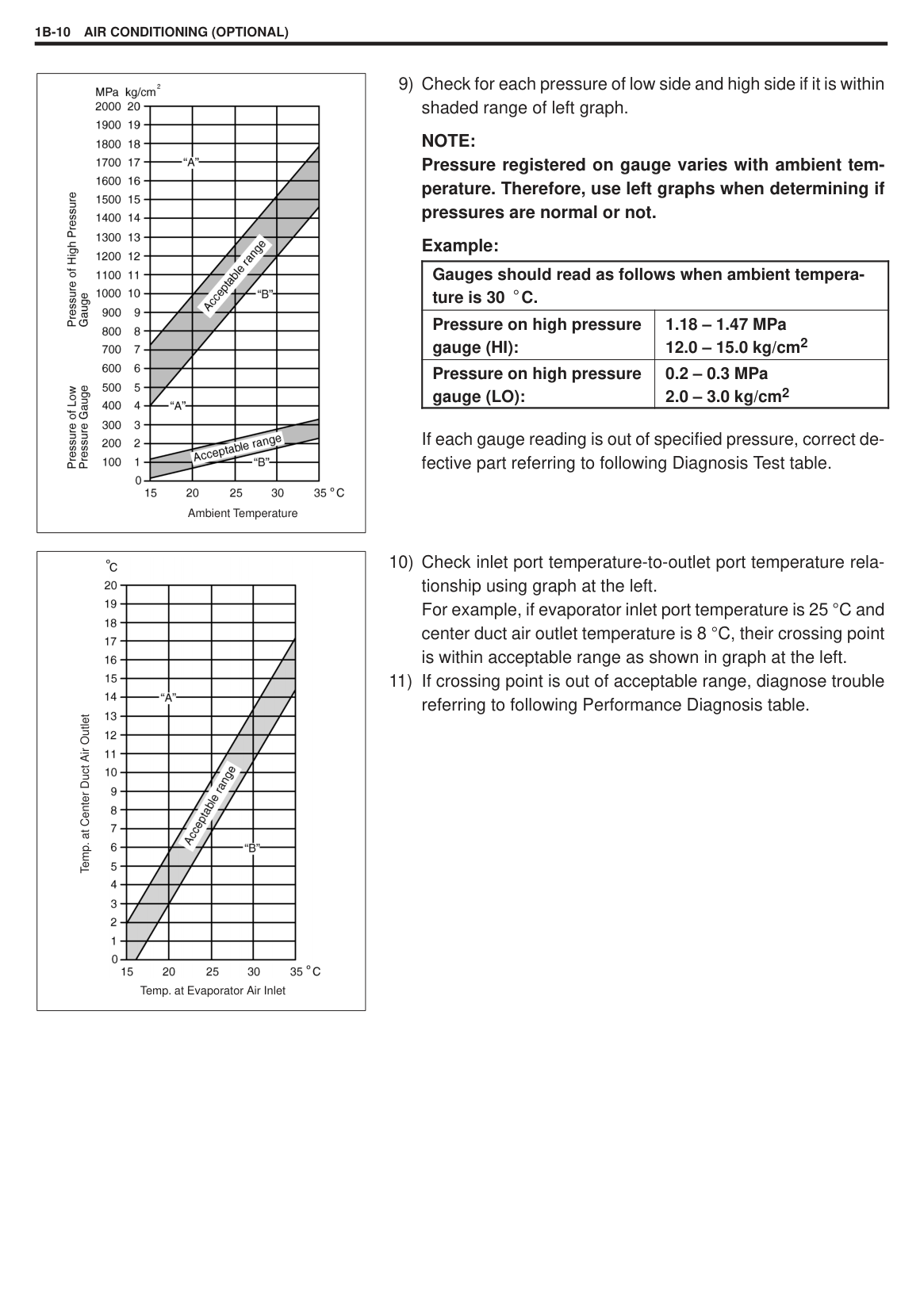
Ambient Temperature| |---|
NOTE: Pressure registered on gauge varies with ambient temperature. Therefore, use left graphs when determining if pressures are normal or not.
Example:
If each gauge reading is out of specified pressure, correct defective part referring to following Diagnosis Test table.
|Gauges should read as follows when ambient temperature is 30 C.|Gauges should read as follows when ambient temperature is 30 C.| |---|---| |Pressure on high pressure gauge (HI):|1.18 – 1.47 MPa 12.0 – 15.0 kg/cm2| |Pressure on high pressure gauge (LO):|0.2 – 0.3 MPa 2.0 – 3.0 kg/cm2|
|
Temp. at Evaporator Air Inlet
Temp. at Center Duct Air Outlet| |---|
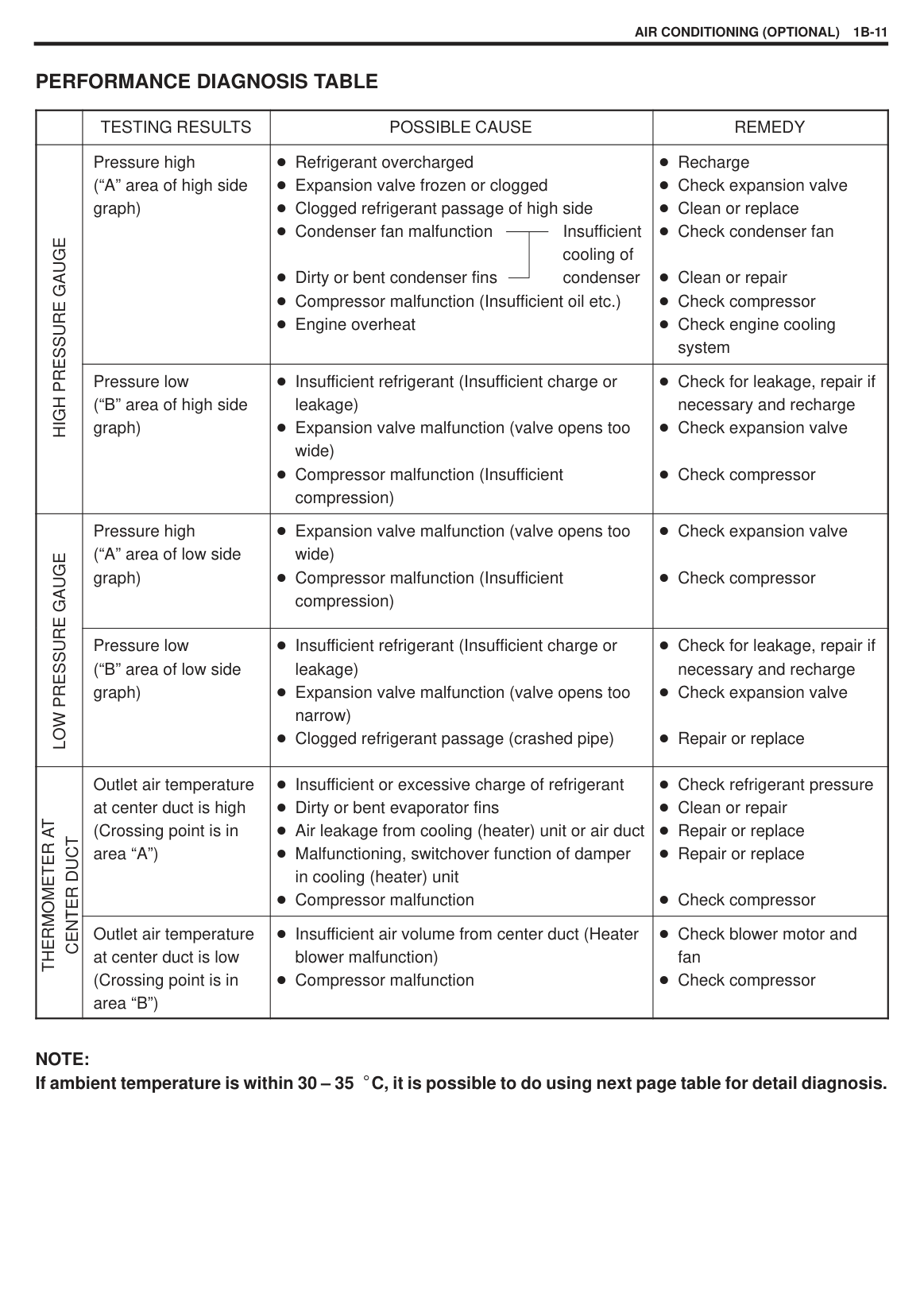
###### PERFORMANCE DIAGNOSIS TABLE
| |TESTING RESULTS|POSSIBLE CAUSE|REMEDY| |---|---|---|---| |SSURE GAUGEHIGH PRE
|Pressure high (“A” area of high side graph)|Refrigerant overcharged Expansion valve frozen or clogged Clogged refrigerant passage of high side Condenser fan malfunction Insufficient
cooling of Dirty or bent condenser fins condenser Compressor malfunction (Insufficient oil etc.) Engine overheat|Recharge Check expansion valve Clean or replace Check condenser fan
Clean or repair Check compressor Check engine cooling system| |SSURE GAUGEHIGH PRE
|Pressure low (“B” area of high side graph)|Insufficient refrigerant (Insufficient charge or leakage) Expansion valve malfunction (valve opens too wide) Compressor malfunction (Insufficient compression)|Check for leakage, repair if necessary and recharge Check expansion valve
Check compressor| |E GAUGELOW PRESSURE
|Pressure high (“A” area of low side graph)|Expansion valve malfunction (valve opens too wide) Compressor malfunction (Insufficient compression)|Check expansion valve
Check compressor| |E GAUGELOW PRESSURE
|Pressure low (“B” area of low side graph)|Insufficient refrigerant (Insufficient charge or leakage) Expansion valve malfunction (valve opens too narrow) Clogged refrigerant passage (crashed pipe)|Check for leakage, repair if necessary and recharge Check expansion valve
Repair or replace| |MOMETER AT
ER DUCT THERM
CENT
|Outlet air temperature at center duct is high (Crossing point is in area “A”)|Insufficient or excessive charge of refrigerant Dirty or bent evaporator fins Air leakage from cooling (heater) unit or air duct Malfunctioning, switchover function of damper in cooling (heater) unit Compressor malfunction|Check refrigerant pressure Clean or repair Repair or replace Repair or replace
Check compressor| |MOMETER AT
ER DUCT THERM
CENT
|Outlet air temperature at center duct is low (Crossing point is in area “B”)|Insufficient air volume from center duct (Heater blower malfunction) Compressor malfunction|Check blower motor and fan Check compressor|
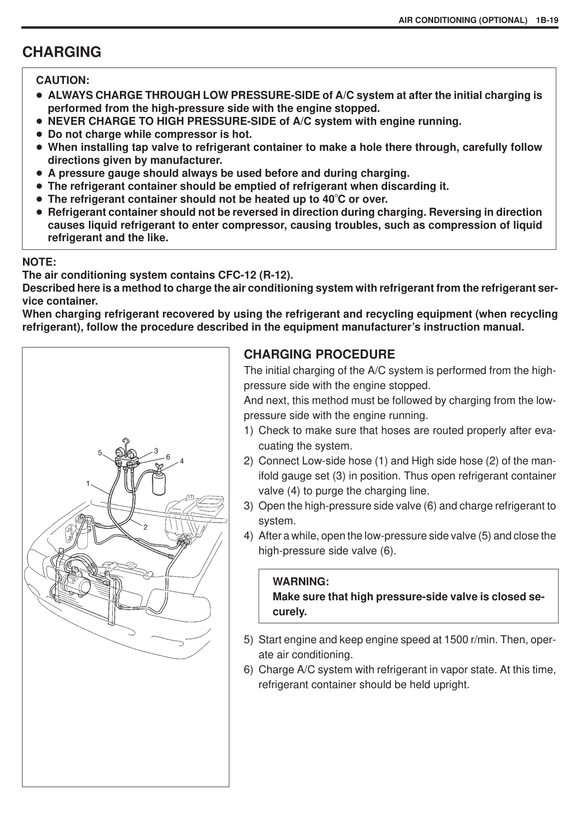
NOTE: If ambient temperature is within 30 – 35 C, it is possible to do using next page table for detail diagnosis.
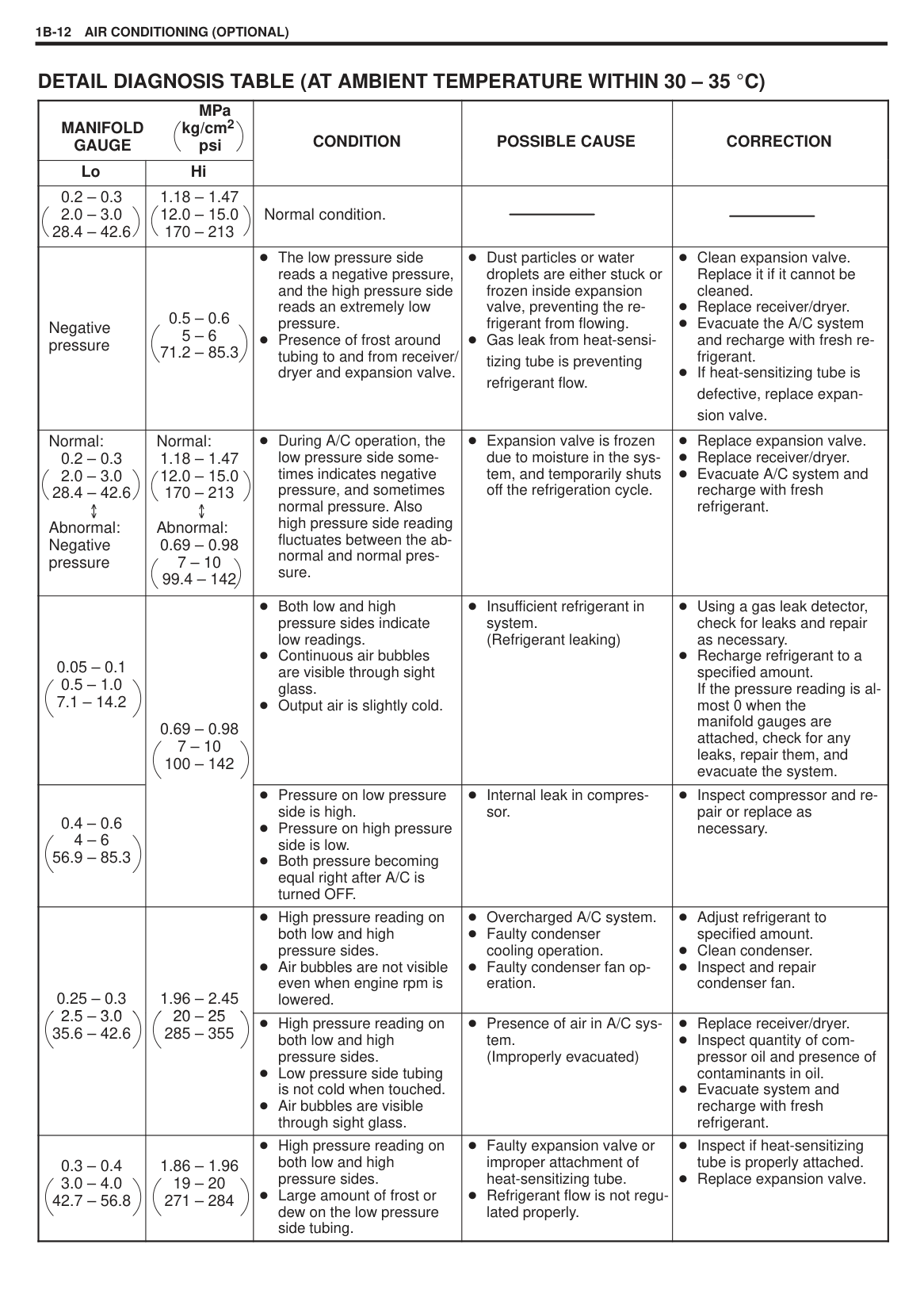
###### DETAIL DIAGNOSIS TABLE (AT AMBIENT TEMPERATURE WITHIN 30 – 35 C)
|MPa
MANIFOLD kg/cm2 GAUGE psi|MPa
MANIFOLD kg/cm2 GAUGE psi|CONDITION
|POSSIBLE CAUSE
|CORRECTION
| |---|---|---|---|---| |Lo|Hi|CONDITION
|POSSIBLE CAUSE
|CORRECTION
| |0.2 – 0.3 2.0 – 3.0 28.4 – 42.6|1.18 – 1.47 12.0 – 15.0 170 – 213|Normal condition.| | | |Negative pressure|0.5 – 0.6 5 – 6 71.2 – 85.3|The low pressure side reads a negative pressure, and the high pressure side reads an extremely low pressure. Presence of frost around tubing to and from receiver/ dryer and expansion valve.|Dust particles or water droplets are either stuck or frozen inside expansion valve, preventing the refrigerant from flowing. Gas leak from heat-sensitizing tube is preventing refrigerant flow.|Clean expansion valve. Replace it if it cannot be cleaned. Replace receiver/dryer. Evacuate the A/C system and recharge with fresh refrigerant. If heat-sensitizing tube is defective, replace expansion valve.| |Normal:
0.2 – 0.3 2.0 – 3.0 28.4 – 42.6
Abnormal: Negative pressure|Normal:
1.18 – 1.47 12.0 – 15.0 170 – 213 Abnormal:
0.69 – 0.98 7 – 10 99.4 – 142|During A/C operation, the low pressure side sometimes indicates negative pressure, and sometimes normal pressure. Also high pressure side reading fluctuates between the abnormal and normal pressure.|Expansion valve is frozen due to moisture in the system, and temporarily shuts off the refrigeration cycle.|Replace expansion valve. Replace receiver/dryer. Evacuate A/C system and recharge with fresh refrigerant.| |0.05 – 0.1 0.5 – 1.0 7.1 – 14.2|0.69 – 0.98 7 – 10 100 – 142
|Both low and high pressure sides indicate low readings. Continuous air bubbles are visible through sight glass. Output air is slightly cold.|Insufficient refrigerant in system. (Refrigerant leaking)|Using a gas leak detector, check for leaks and repair as necessary. Recharge refrigerant to a specified amount. If the pressure reading is almost 0 when the manifold gauges are attached, check for any leaks, repair them, and evacuate the system.| |0.4 – 0.6 4 – 6 56.9 – 85.3|0.69 – 0.98 7 – 10 100 – 142
|Pressure on low pressure side is high. Pressure on high pressure side is low. Both pressure becoming equal right after A/C is turned OFF.|Internal leak in compressor.|Inspect compressor and repair or replace as necessary.| |0.25 – 0.3
25 302.5 – 3.0 35.6 – 42.6
|1.96 – 2.45 20 2520 – 25 285 – 355
|High pressure reading on both low and high pressure sides. Air bubbles are not visible even when engine rpm is lowered.|Overcharged A/C system. Faulty condenser cooling operation. Faulty condenser fan operation.|Adjust refrigerant to specified amount. Clean condenser. Inspect and repair condenser fan.| |0.25 – 0.3
25 302.5 – 3.0 35.6 – 42.6
|1.96 – 2.45 20 2520 – 25 285 – 355
|High pressure reading on both low and high pressure sides. Low pressure side tubing is not cold when touched. Air bubbles are visible through sight glass.|Presence of air in A/C system. (Improperly evacuated)|Replace receiver/dryer. Inspect quantity of compressor oil and presence of contaminants in oil. Evacuate system and recharge with fresh refrigerant.| |0.3 – 0.4 3.0 – 4.0 42.7 – 56.8|1.86 – 1.96 19 – 20 271 – 284|High pressure reading on both low and high pressure sides. Large amount of frost or dew on the low pressure side tubing.|Faulty expansion valve or improper attachment of heat-sensitizing tube. Refrigerant flow is not regulated properly.|Inspect if heat-sensitizing tube is properly attached. Replace expansion valve.|
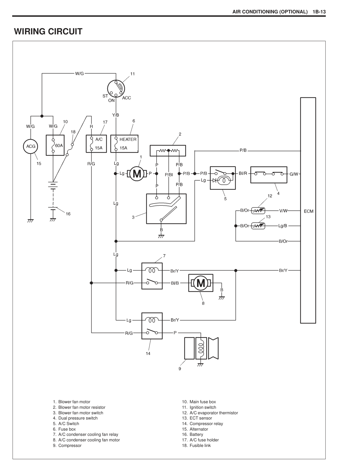
#### WIRING CIRCUIT
|
1. Blower fan motor
2. Blower fan motor resistor
3. Blower fan motor switch
4. Dual pressure switch
5. A/C Switch
6. Fuse box
7. A/C condenser cooling fan relay
8. A/C condenser cooling fan motor
9. Compressor
10. Main fuse box
11. Ignition switch
12. A/C evaporator thermistor
13. ECT sensor
14. Compressor relay
15. Alternator
16. Battery
17. A/C fuse holder
18. Fusible link
| |---|
|

Fig. A
Fig. B
| |---|
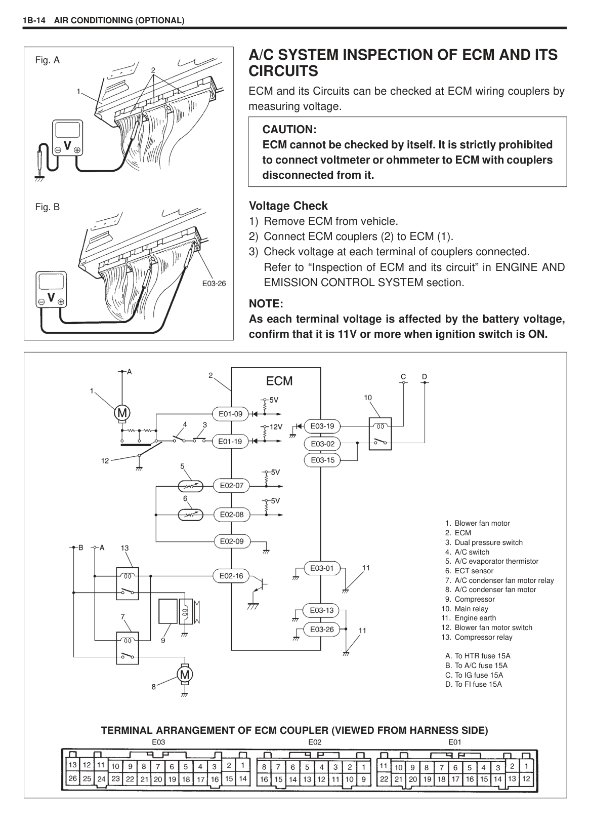
#### A/C SYSTEM INSPECTION OF ECM AND ITS CIRCUITS
ECM and its Circuits can be checked at ECM wiring couplers by measuring voltage.
|CAUTION: ECM cannot be checked by itself. It is strictly prohibited to connect voltmeter or ohmmeter to ECM with couplers disconnected from it.| |---|
######## Voltage Check
######### NOTE: As each terminal voltage is affected by the battery voltage, confirm that it is 11V or more when ignition switch is ON.
|

TERMINAL ARRANGEMENT OF ECM COUPLER (VIEWED FROM HARNESS SIDE)
1. Blower fan motor
2. ECM
3. Dual pressure switch
4. A/C switch
5. A/C evaporator thermistor
6. ECT sensor
7. A/C condenser fan motor relay
8. A/C condenser fan motor
9. Compressor
10. Main relay
11. Engine earth
12. Blower fan motor switch
13. Compressor relay
A. To HTR fuse 15A
B. To A/C fuse 15A
C. To IG fuse 15A
D. To FI fuse 15A
| |---|
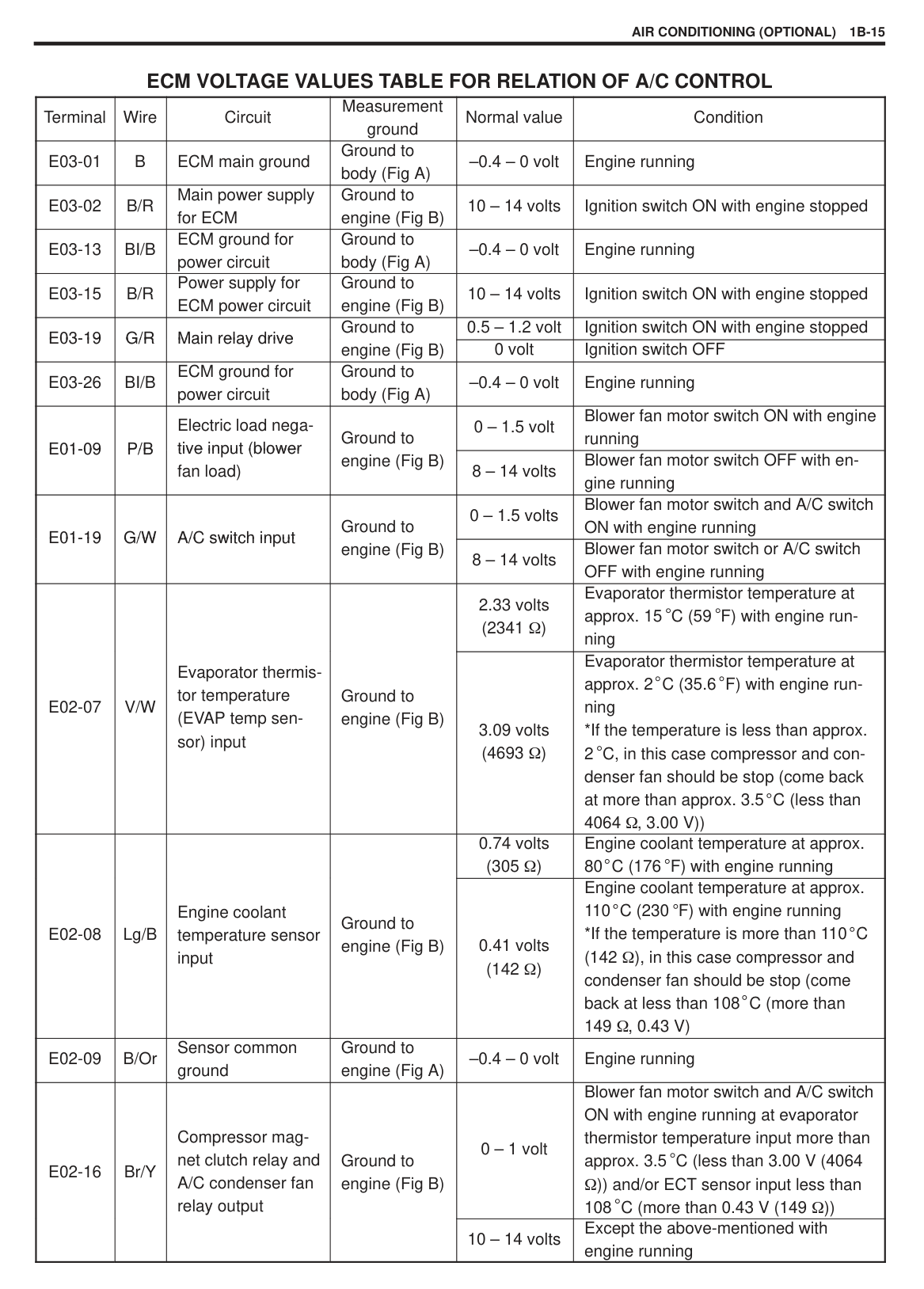
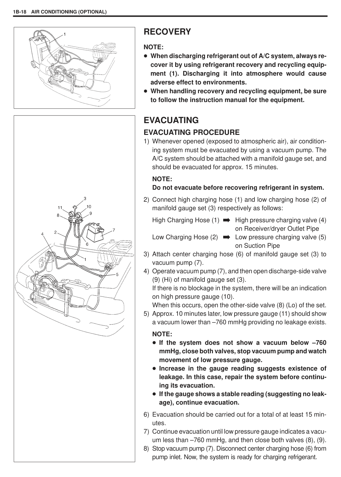
###### ECM VOLTAGE VALUES TABLE FOR RELATION OF A/C CONTROL
|Terminal|Wire|Circuit|Measurement ground|Normal value|Condition|
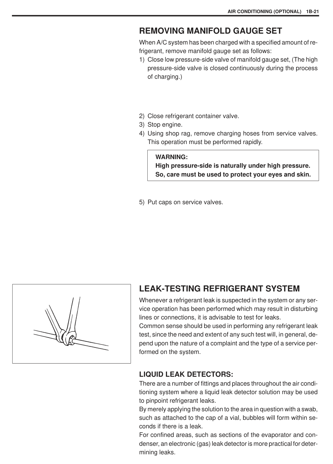
|---|---|---|---|---|---| |E03-01|B|ECM main ground|Ground to body (Fig A)|–0.4 – 0 volt|Engine running| |E03-02|B/R|Main power supply for ECM|Ground to engine (Fig B)|10 – 14 volts|Ignition switch ON with engine stopped| |E03-13|BI/B|ECM ground for power circuit|Ground to body (Fig A)|–0.4 – 0 volt|Engine running| |E03-15|B/R|Power supply for ECM power circuit|Ground to engine (Fig B)|10 – 14 volts|Ignition switch ON with engine stopped| |E03-19E03-19
|G/R
|Main relay driveMain relay drive
|Ground to engine (Fig B)
|0.5 – 1.2 volt|Ignition switch ON with engine stopped| |E03-19E03-19
|G/R
|Main relay driveMain relay drive
|Ground to engine (Fig B)
|0 volt|Ignition switch OFF| |E03-26|BI/B|ECM ground for power circuit|Ground to body (Fig A)|–0.4 – 0 volt|Engine running| |E01-09E01-09
|P/B|Electric load negative input (blowertive in ut (blower fan load)
|Ground to engine (Fig B)
|0 – 1.5 volt|Blower fan motor switch ON with engine running| |E01-09E01-09
|P/B|Electric load negative input (blowertive in ut (blower fan load)
|Ground to engine (Fig B)
|8 – 14 volts|Blower fan motor switch OFF with engine running| |E01-19E01-19
|G/W
|A/C switch inputA/C switch in ut
|Ground to engine (Fig B)
|0 – 1.5 volts|Blower fan motor switch and A/C switch ON with engine running| |E01-19E01-19
|G/W
|A/C switch inputA/C switch in ut
|Ground to engine (Fig B)
|8 – 14 volts|Blower fan motor switch or A/C switch OFF with engine running| |E02-07|V/W
|Evaporator thermistor temperature (EVAP temp sensor) input
|Ground to engine (Fig B)|2.33 volts (2341 )|Evaporator thermistor temperature at approx. 15 C (59 F) with engine running| |E02-07|V/W
|Evaporator thermistor temperature (EVAP temp sensor) input
|Ground to engine (Fig B)|3.09 volts (4693 )|Evaporator thermistor temperature at approx. 2 C (35.6 F) with engine running
*If the temperature is less than approx. 2 C, in this case compressor and condenser fan should be stop (come back at more than approx. 3.5 C (less than 4064 , 3.00 V))| |E02-08
|Lg/B|Engine coolant temperature sensor input
|Ground to engine (Fig B)|0.74 volts (305 )|Engine coolant temperature at approx. 80 C (176 F) with engine running| |E02-08
|Lg/B|Engine coolant temperature sensor input
|Ground to engine (Fig B)|0.41 volts (142 )|Engine coolant temperature at approx. 110 C (230 F) with engine running
*If the temperature is more than 110 C (142 ), in this case compressor and condenser fan should be stop (come back at less than 108 C (more than 149 , 0.43 V)| |E02-09|B/Or|Sensor common ground|Ground to engine (Fig A)|–0.4 – 0 volt|Engine running| |E02-16
|Br/Y
|Compressor magnet clutch relay and A/C condenser fan relay output
|Ground to engine (Fig B)
|0 – 1 volt|Blower fan motor switch and A/C switch ON with engine running at evaporator thermistor temperature input more than approx. 3.5 C (less than 3.00 V (4064
)) and/or ECT sensor input less than 108 C (more than 0.43 V (149 ))| |E02-16
|Br/Y
|Compressor magnet clutch relay and A/C condenser fan relay output
|Ground to engine (Fig B)
|10 – 14 volts|Except the above-mentioned with engine running|
|| |---|
#### A/C COMPRESSOR DRIVE BELT INSPECTION
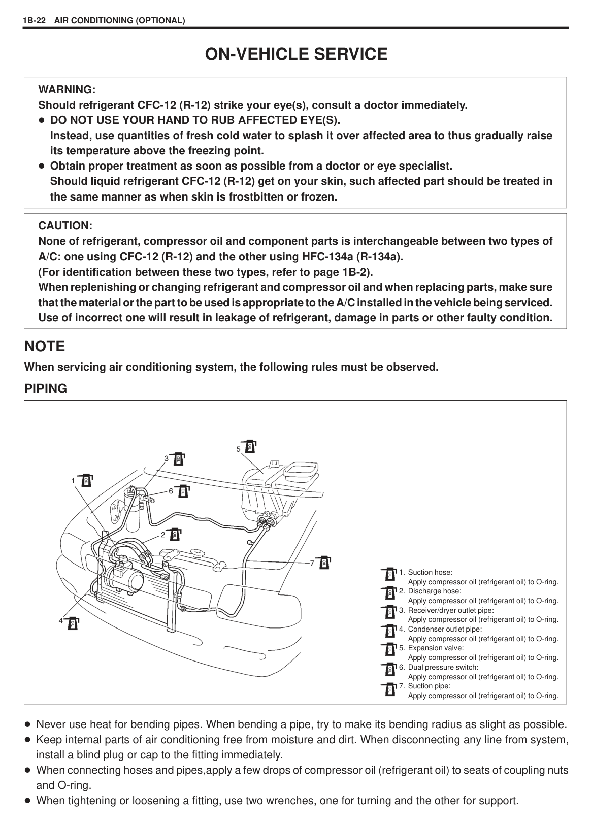
######### “a” : 8 – 10 mm as deflection/100N (10 kg)
If belt tension is without above specification, adjust belt tension by according to following items.
REFRIGERANT RECOVERY, EVACUATION AND CHARGING
|WARNING: Your eyes should not be exposed to refrigerant (liquid). Any liquid Refrigerant-12 escaping by accident shows a temperature as low as approx. –6 C below freezing point. Should liquid CFC-12 (R-12) get into your eyes, it may cause a serious injury. To protect your eyes against such accident, it is necessary to always wear goggles. Should it occur that CFC-12 (R-12) strikes your eyes(s), consult a doctor immediately.
a. DO NOT USE YOUR HAND TO RUB THE AFFECTED EYE(S). INSTEAD, use quantities of fresh cold water to splash it over the affected area to gradually raise temperature of such area above freezing point.
b. Obtain proper treatment as soon as possible from a doctor or eye specialist. Should the CFC-12 (R-12) liquid come into contact with your skin, the affected area should be treated in the same manner as when skin is frostbitten or frozen. Refrigerant must not be handled near where welding or steam cleaning is performed. Refrigerant should be kept at a cold and dark place. It should never be stored where a high temperature is anticipated, e.g. where exposed to direct sun light, close to fire or inside vehicle (including trunk room). Avoid breathing fumes produced when CFC-12 (R-12) is burned. Such fumes may be hazardous to health.
| |---|
#### OPERATION PROCEDURE FOR CHARGING A/C WITH REFRIGERANT
|| |---|
|| |---|
|| |---|
#### RECOVERY NOTE:
When discharging refrigerant out of A/C system, always recover it by using refrigerant recovery and recycling equipment (1). Discharging it into atmosphere would cause adverse effect to environments. When handling recovery and recycling equipment, be sure to follow the instruction manual for the equipment.
#### EVACUATING EVACUATING PROCEDURE
NOTE: Do not evacuate before recovering refrigerant in system.
High Charging Hose (1) High pressure charging valve (4) on Receiver/dryer Outlet Pipe Low Charging Hose (2) Low pressure charging valve (5) on Suction Pipe
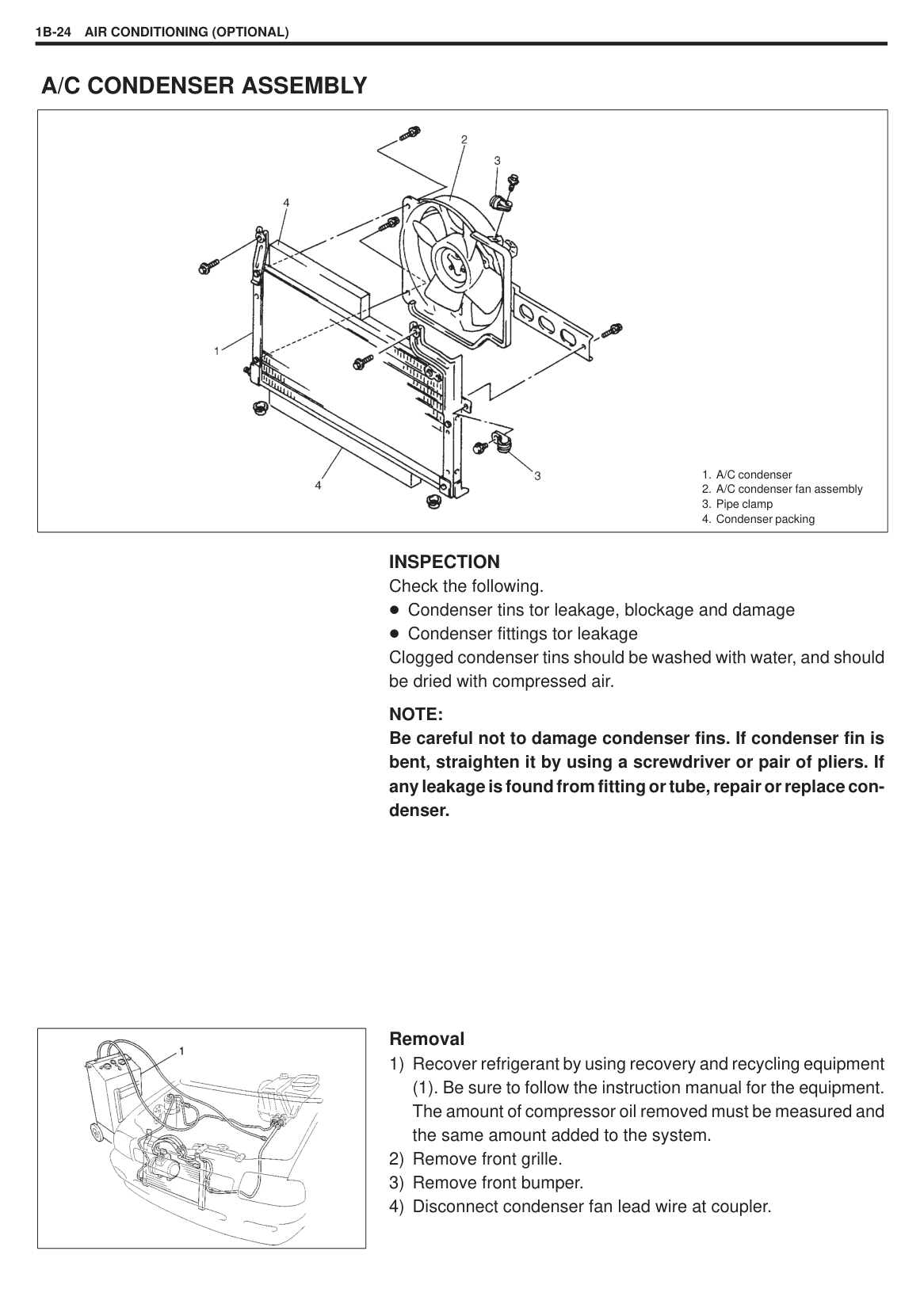
(9) (Hi) of manifold gauge set (3). If there is no blockage in the system, there will be an indication on high pressure gauge (10). When this occurs, open the other-side valve (8) (Lo) of the set.
NOTE: If the system does not show a vacuum below –760 mmHg, close both valves, stop vacuum pump and watch movement of low pressure gauge. Increase in the gauge reading suggests existence of leakage. In this case, repair the system before continuing its evacuation. If the gauge shows a stable reading (suggesting no leakage), continue evacuation.
#### CHARGING
|CAUTION: ALWAYS CHARGE THROUGH LOW PRESSURE-SIDE of A/C system at after the initial charging is performed from the high-pressure side with the engine stopped. NEVER CHARGE TO HIGH PRESSURE-SIDE of A/C system with engine running. Do not charge while compressor is hot. When installing tap valve to refrigerant container to make a hole there through, carefully follow directions given by manufacturer. A pressure gauge should always be used before and during charging. The refrigerant container should be emptied of refrigerant when discarding it. The refrigerant container should not be heated up to 40 C or over. Refrigerant container should not be reversed in direction during charging. Reversing in direction causes liquid refrigerant to enter compressor, causing troubles, such as compression of liquid refrigerant and the like.
| |---|
NOTE: The air conditioning system contains CFC-12 (R-12). Described here is a method to charge the air conditioning system with refrigerant from the refrigerant service container. When charging refrigerant recovered by using the refrigerant and recycling equipment (when recycling refrigerant), follow the procedure described in the equipment manufacturer’s instruction manual.
|| |---|
CHARGING PROCEDURE The initial charging of the A/C system is performed from the highpressure side with the engine stopped. And next, this method must be followed by charging from the lowpressure side with the engine running.
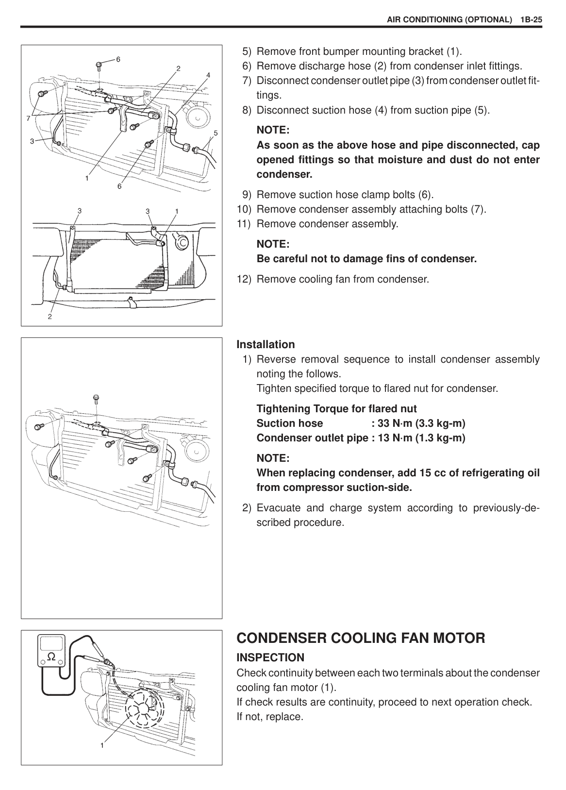
|WARNING: Make sure that high pressure-side valve is closed securely.| |---|
|| |---|
|
1. “Hiss”| |---|
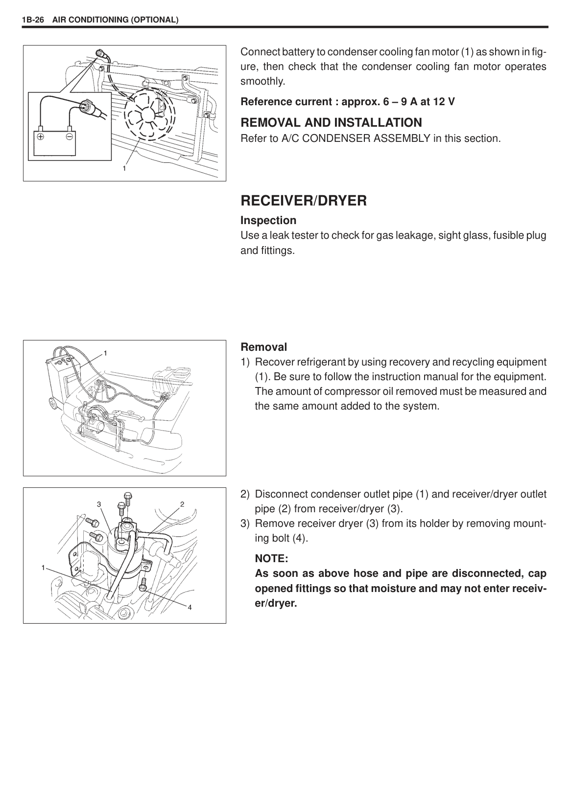
|| |---|
– 600 g) of refrigerant or when low pressure gauge (1) and high pressure gauge (2) have indicated about 2 and 15 kg/cm2 respectively, close low pressure side valve (3) of manifold gauge set (4). At this time, look into the sight glass (6) of receiver/dryer (5) and check that there are no bubbles (7) in it, which means that the system is fully charged.
Low pressure gauge when charged with specified amount About 150 – 200 kPa (1.5 – 2.0 kg/cm2)
High pressure gauge when charged with specified amount About 1300 – 1700 kPa (13 – 17 kg/cm2)
REMOVING MANIFOLD GAUGE SET When A/C system has been charged with a specified amount of refrigerant, remove manifold gauge set as follows:
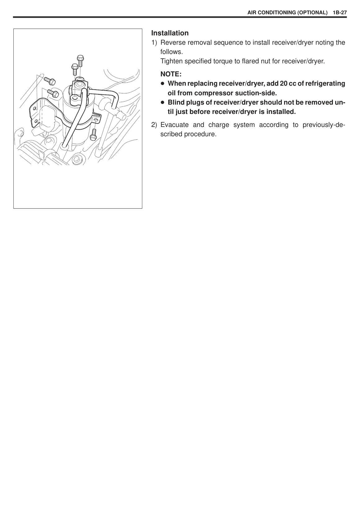
|WARNING: High pressure-side is naturally under high pressure. So, care must be used to protect your eyes and skin.| |---|
|| |---|
LEAK-TESTING REFRIGERANT SYSTEM Whenever a refrigerant leak is suspected in the system or any service operation has been performed which may result in disturbing lines or connections, it is advisable to test for leaks. Common sense should be used in performing any refrigerant leak test, since the need and extent of any such test will, in general, depend upon the nature of a complaint and the type of a service performed on the system.
LIQUID LEAK DETECTORS: There are a number of fittings and places throughout the air conditioning system where a liquid leak detector solution may be used to pinpoint refrigerant leaks. By merely applying the solution to the area in question with a swab, such as attached to the cap of a vial, bubbles will form within seconds if there is a leak. For confined areas, such as sections of the evaporator and condenser, an electronic (gas) leak detector is more practical for determining leaks.
ON-VEHICLE SERVICE
|WARNING: Should refrigerant CFC-12 (R-12) strike your eye(s), consult a doctor immediately.
DO NOT USE YOUR HAND TO RUB AFFECTED EYE(S). Instead, use quantities of fresh cold water to splash it over affected area to thus gradually raise its temperature above the freezing point. Obtain proper treatment as soon as possible from a doctor or eye specialist. Should liquid refrigerant CFC-12 (R-12) get on your skin, such affected part should be treated in the same manner as when skin is frostbitten or frozen.| |---|
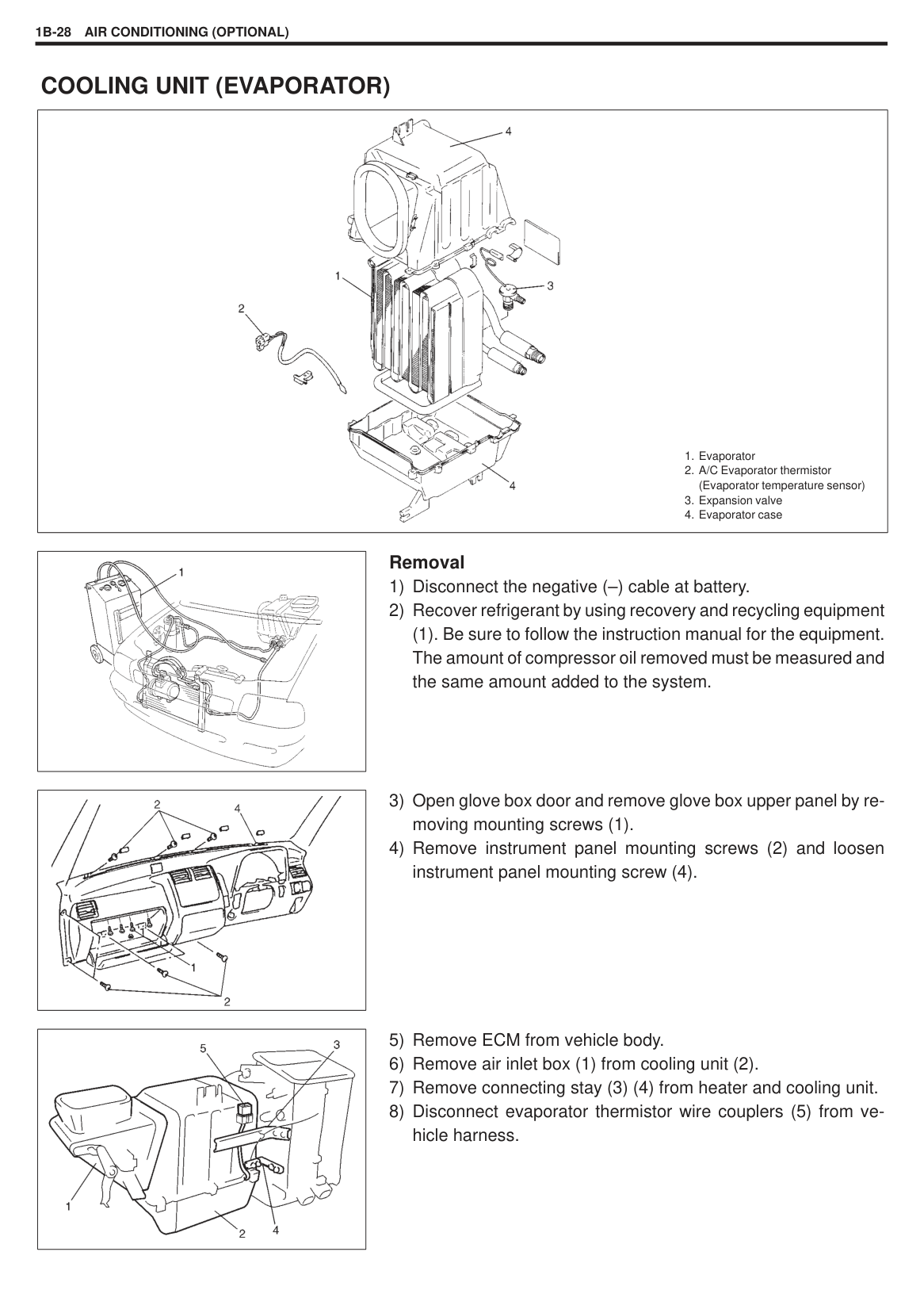
|CAUTION: None of refrigerant, compressor oil and component parts is interchangeable between two types of A/C: one using CFC-12 (R-12) and the other using HFC-134a (R-134a). (For identification between these two types, refer to page 1B-2). When replenishing or changing refrigerant and compressor oil and when replacing parts, make sure that the material or the part to be used is appropriate to the A/C installed in the vehicle being serviced. Use of incorrect one will result in leakage of refrigerant, damage in parts or other faulty condition.| |---|
NOTE When servicing air conditioning system, the following rules must be observed. PIPING
|
1. Suction hose: Apply compressor oil (refrigerant oil) to O-ring.
2. Discharge hose: Apply compressor oil (refrigerant oil) to O-ring.
3. Receiver/dryer outlet pipe: Apply compressor oil (refrigerant oil) to O-ring.
4. Condenser outlet pipe: Apply compressor oil (refrigerant oil) to O-ring.
5. Expansion valve: Apply compressor oil (refrigerant oil) to O-ring.
6. Dual pressure switch: Apply compressor oil (refrigerant oil) to O-ring.
7. Suction pipe: Apply compressor oil (refrigerant oil) to O-ring.


| |---|
Never use heat for bending pipes. When bending a pipe, try to make its bending radius as slight as possible. Keep internal parts of air conditioning free from moisture and dirt. When disconnecting any line from system, install a blind plug or cap to the fitting immediately. When connecting hoses and pipes,apply a few drops of compressor oil (refrigerant oil) to seats of coupling nuts and O-ring. When tightening or loosening a fitting, use two wrenches, one for turning and the other for support.
Tighten flared nuts according to Table of Tightening Torque as shown below:
Tightening Torque (Flared Nut Used for) 8mm pipe: 13 N·m (1.3 kg-m, 9.5 lb-ft) 14.5 mm pipe: 23 N·m (2.3 kg-m, 16.6 Ib-ft) 16 mm pipe: 33 N·m (3.3 kg-m, 23.8 Ib-ft)
Route drain hose so that drained water does not make any contact to vehicle components.
HANDLING REFRIGERANT CFC-12 (R-12) When handling refrigerant, always wear goggles to protect your eyes. Avoid you direct contact to liquid refrigerant. Do not heat refrigerant container higher than 40 C. Do not discharge refrigerant into atmosphere. Do not allow liquid refrigerant to touch bright metals. Refrigerant combined with moisture is corrosive and will tarnish surfaces of bright metals including chrome. After recovering refrigerant from system, the amount of compressor oil removed must be measured and the same amount added to the system.
###### REFRIGERANT RECOVERY
When discharging refrigerant out of A/C system, always recover it by using refrigerant recovery and recycling equipment. Discharging refrigerant CFC-12 (R-12) into atmosphere would cause adverse effect to environments
NOTE: When handling recovery and recycling equipment, be sure to follow the instruction manual for the equipment.
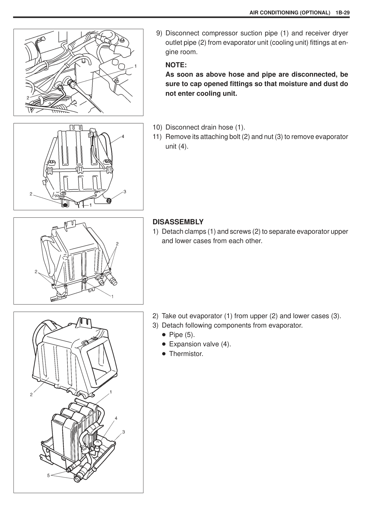
#### A/C CONDENSER ASSEMBLY
|
1. A/C condenser
2. A/C condenser fan assembly
3. Pipe clamp
4. Condenser packing
| |---|
INSPECTION Check the following.
Condenser tins tor leakage, blockage and damage Condenser fittings tor leakage
Clogged condenser tins should be washed with water, and should be dried with compressed air.
NOTE: Be careful not to damage condenser fins. If condenser fin is bent, straighten it by using a screwdriver or pair of pliers. If any leakage is found from fitting or tube, repair or replace condenser.
|| |---|
######## Removal
(1). Be sure to follow the instruction manual for the equipment. The amount of compressor oil removed must be measured and the same amount added to the system.
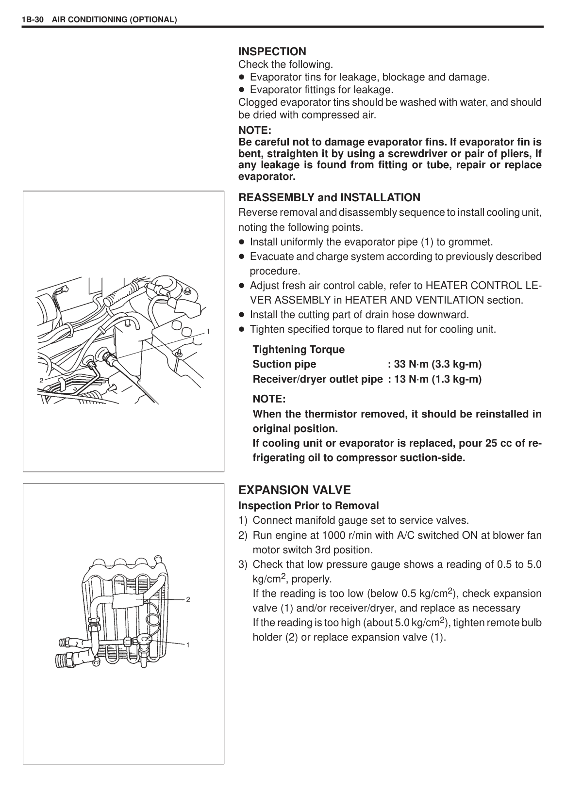
|
| |---|
|| |---|
|| |---|
NOTE: As soon as the above hose and pipe disconnected, cap opened fittings so that moisture and dust do not enter condenser.
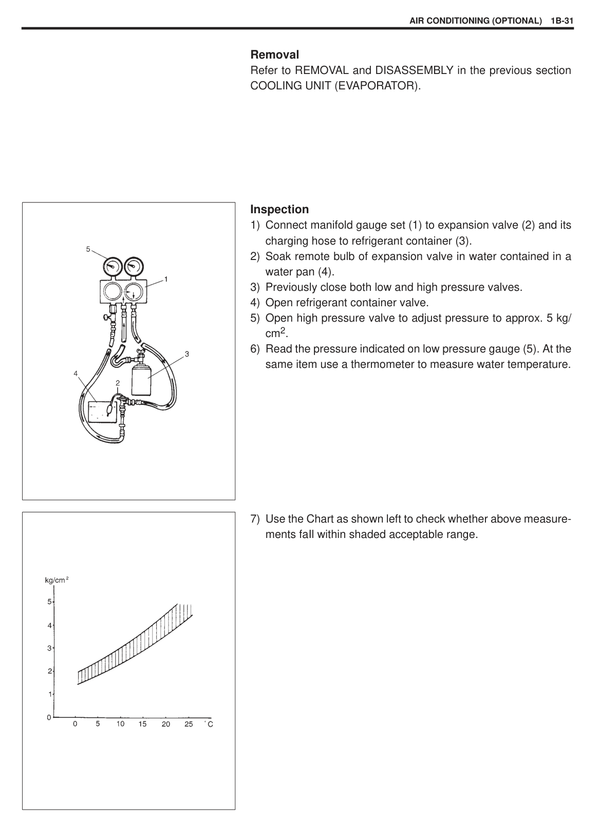
NOTE: Be careful not to damage fins of condenser.
######## Installation
Tightening Torque for flared nut Suction hose : 33 N·m (3.3 kg-m) Condenser outlet pipe : 13 N·m (1.3 kg-m)
NOTE: When replacing condenser, add 15 cc of refrigerating oil from compressor suction-side.
CONDENSER COOLING FAN MOTOR INSPECTION Check continuity between each two terminals about the condenser cooling fan motor (1). If check results are continuity, proceed to next operation check. If not, replace.
|| |---|
Connect battery to condenser cooling fan motor (1) as shown in figure, then check that the condenser cooling fan motor operates smoothly.
Reference current : approx. 6 – 9 A at 12 V REMOVAL AND INSTALLATION Refer to A/C CONDENSER ASSEMBLY in this section.
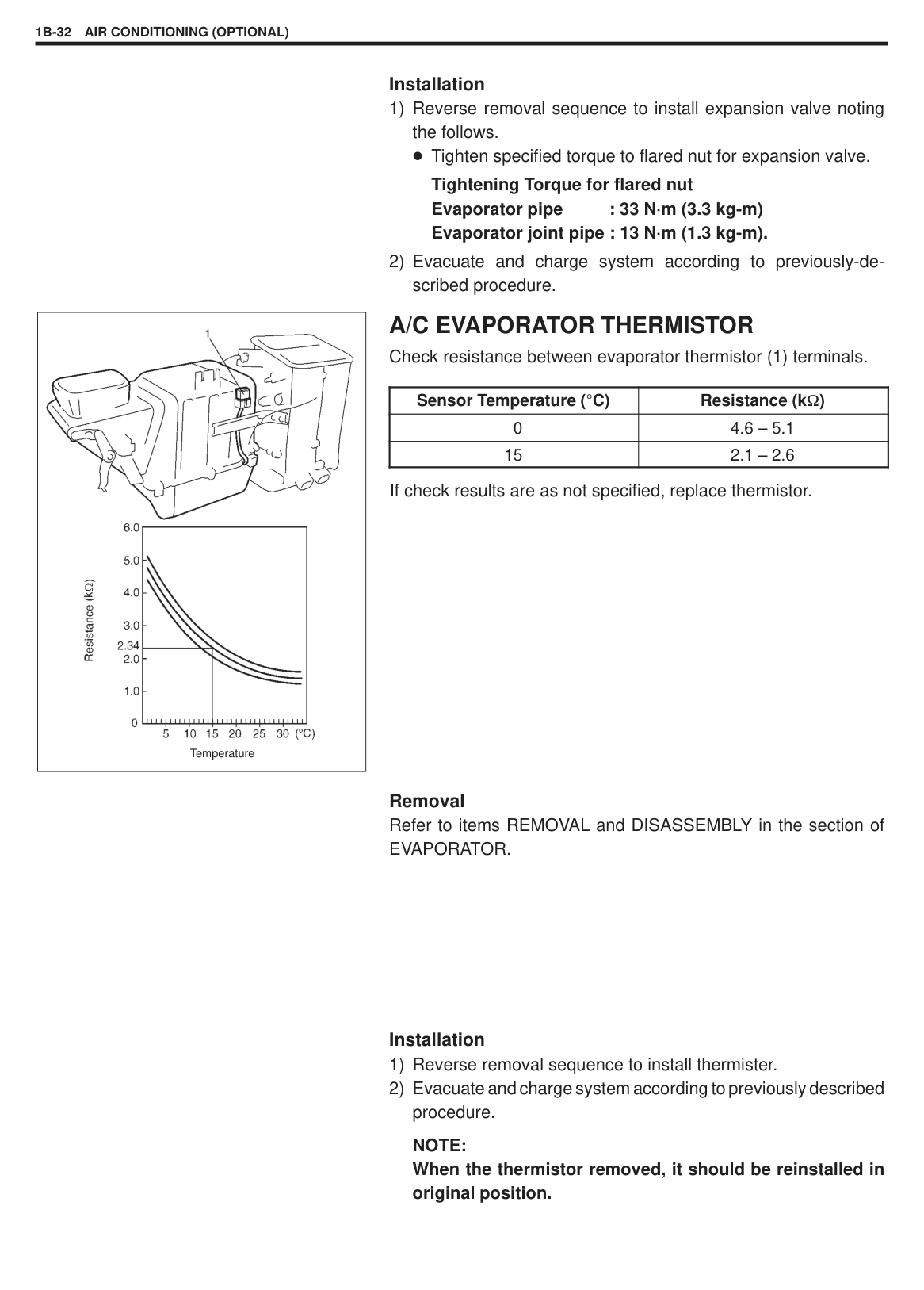
RECEIVER/DRYER Inspection Use a leak tester to check for gas leakage, sight glass, fusible plug and fittings.
|| |---|
######## Removal
(1). Be sure to follow the instruction manual for the equipment. The amount of compressor oil removed must be measured and the same amount added to the system.
|| |---|
######### NOTE: As soon as above hose and pipe are disconnected, cap opened fittings so that moisture and may not enter receiver/dryer.
|| |---|
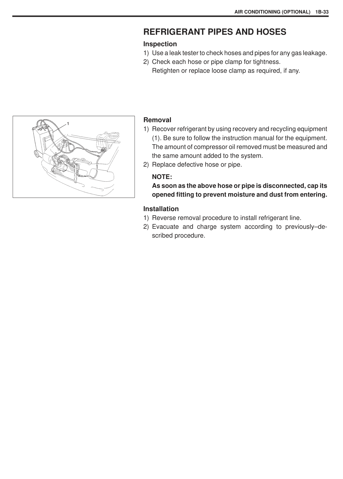
######## Installation
NOTE: When replacing receiver/dryer, add 20 cc of refrigerating oil from compressor suction-side. Blind plugs of receiver/dryer should not be removed until just before receiver/dryer is installed.
#### COOLING UNIT (EVAPORATOR)
|
1. Evaporator
2. A/C Evaporator thermistor (Evaporator temperature sensor)
3. Expansion valve
4. Evaporator case
| |---|
|| |---|
######## Removal
(1). Be sure to follow the instruction manual for the equipment. The amount of compressor oil removed must be measured and the same amount added to the system.
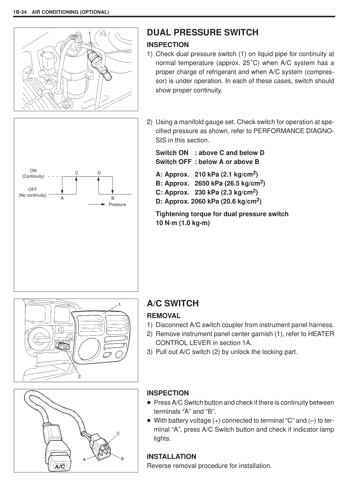
|| |---|
|| |---|
|| |---|
NOTE: As soon as above hose and pipe are disconnected, be sure to cap opened fittings so that moisture and dust do not enter cooling unit.
||
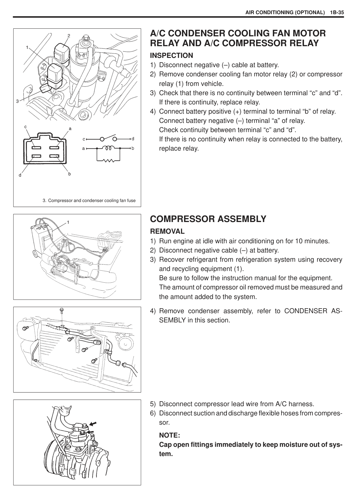
|---|
|| |---|
######## DISASSEMBLY
|| |---|
|| |---|
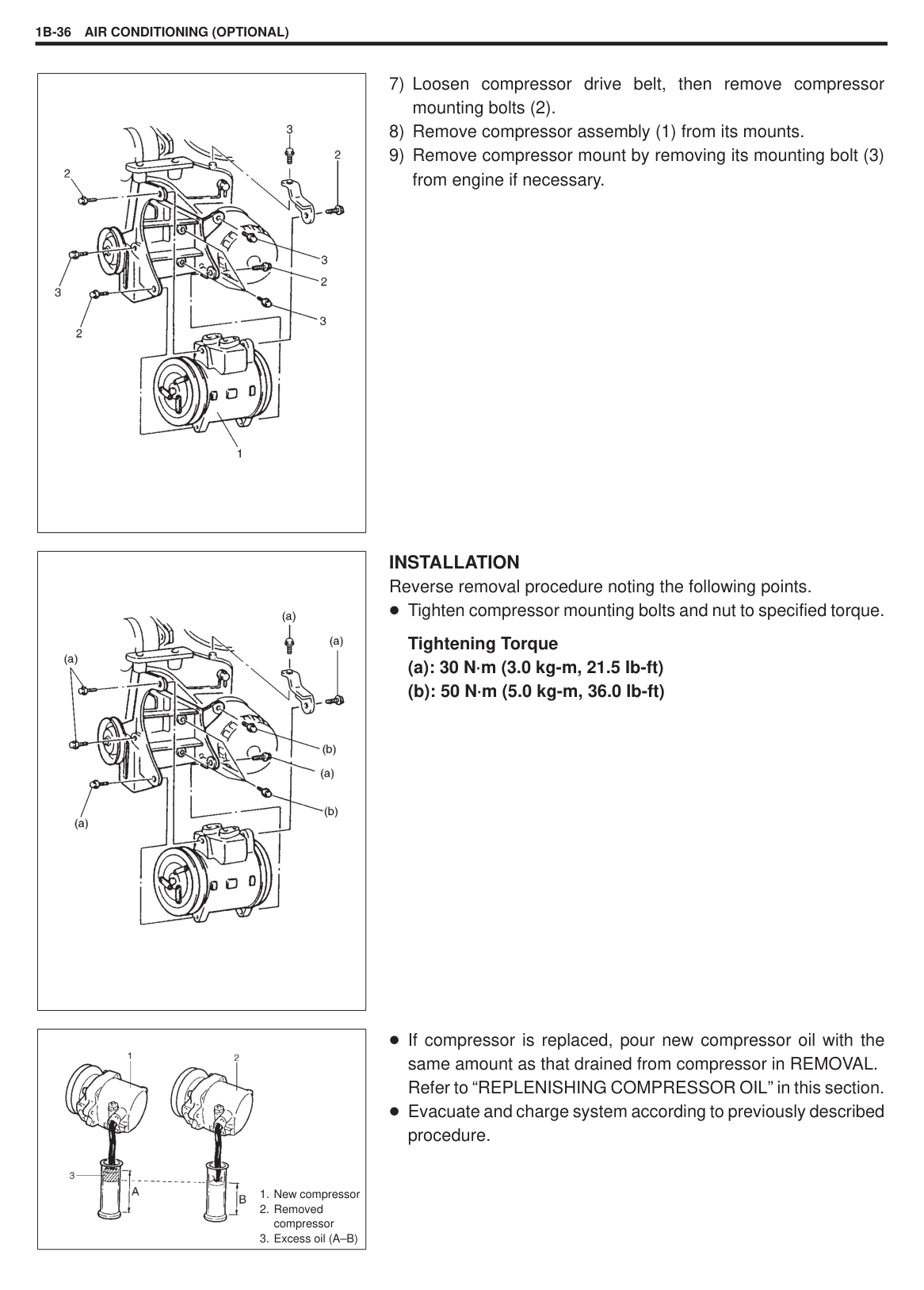
|| |---|
INSPECTION Check the following.
Evaporator tins for leakage, blockage and damage. Evaporator fittings for leakage.
Clogged evaporator tins should be washed with water, and should be dried with compressed air.
NOTE: Be careful not to damage evaporator fins. If evaporator fin is bent, straighten it by using a screwdriver or pair of pliers, If any leakage is found from fitting or tube, repair or replace evaporator.
REASSEMBLY and INSTALLATION Reverse removal and disassembly sequence to install cooling unit, noting the following points.
Install uniformly the evaporator pipe (1) to grommet. Evacuate and charge system according to previously described procedure. Adjust fresh air control cable, refer to HEATER CONTROL LEVER ASSEMBLY in HEATER AND VENTILATION section. Install the cutting part of drain hose downward. Tighten specified torque to flared nut for cooling unit.
Tightening Torque Suction pipe : 33 N·m (3.3 kg-m) Receiver/dryer outlet pipe : 13 N·m (1.3 kg-m)
NOTE: When the thermistor removed, it should be reinstalled in original position. If cooling unit or evaporator is replaced, pour 25 cc of refrigerating oil to compressor suction-side.
EXPANSION VALVE Inspection Prior to Removal
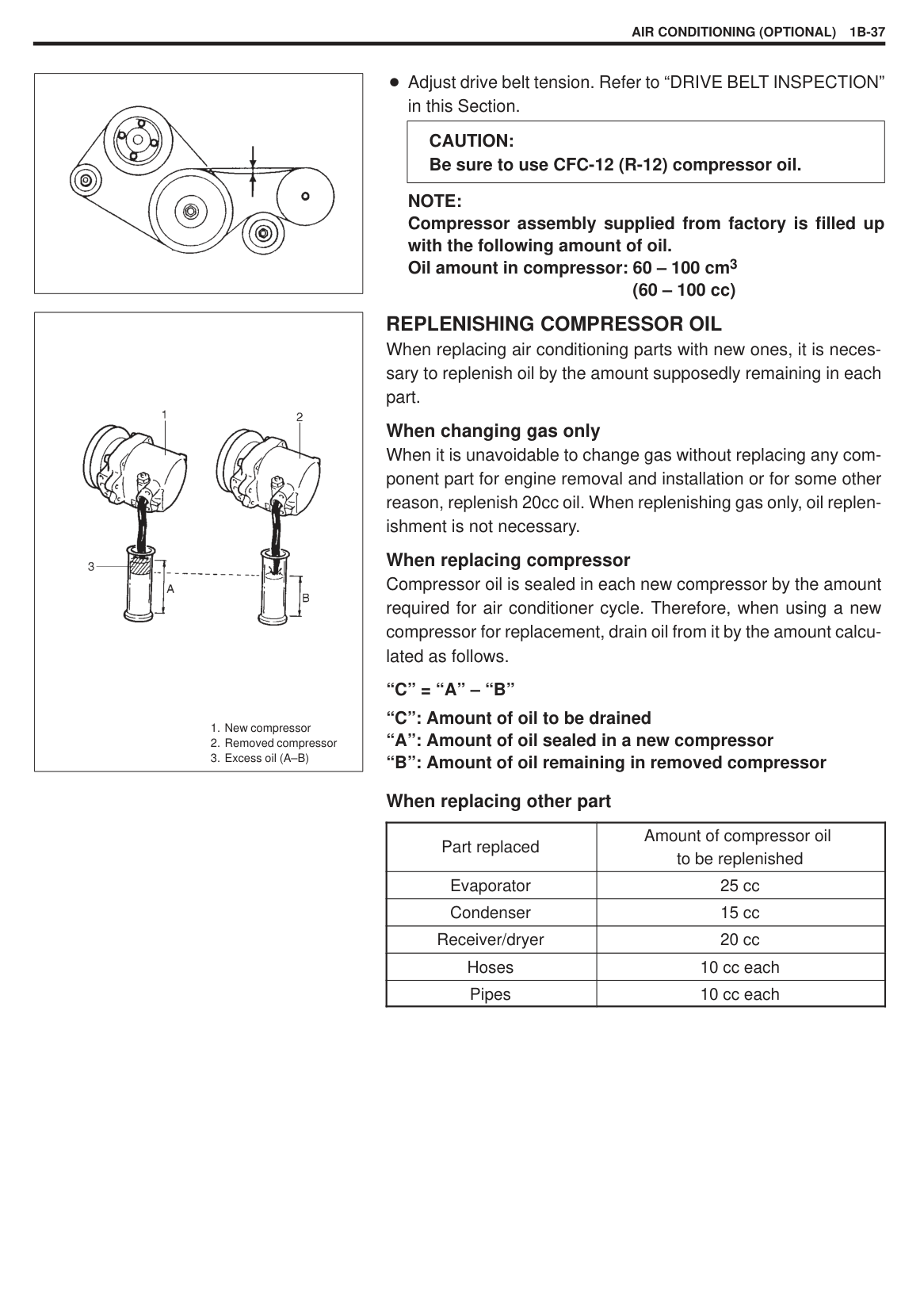
Removal Refer to REMOVAL and DISASSEMBLY in the previous section COOLING UNIT (EVAPORATOR).
|| |---|
######## Inspection
|| |---|
|

Temperature| |---|
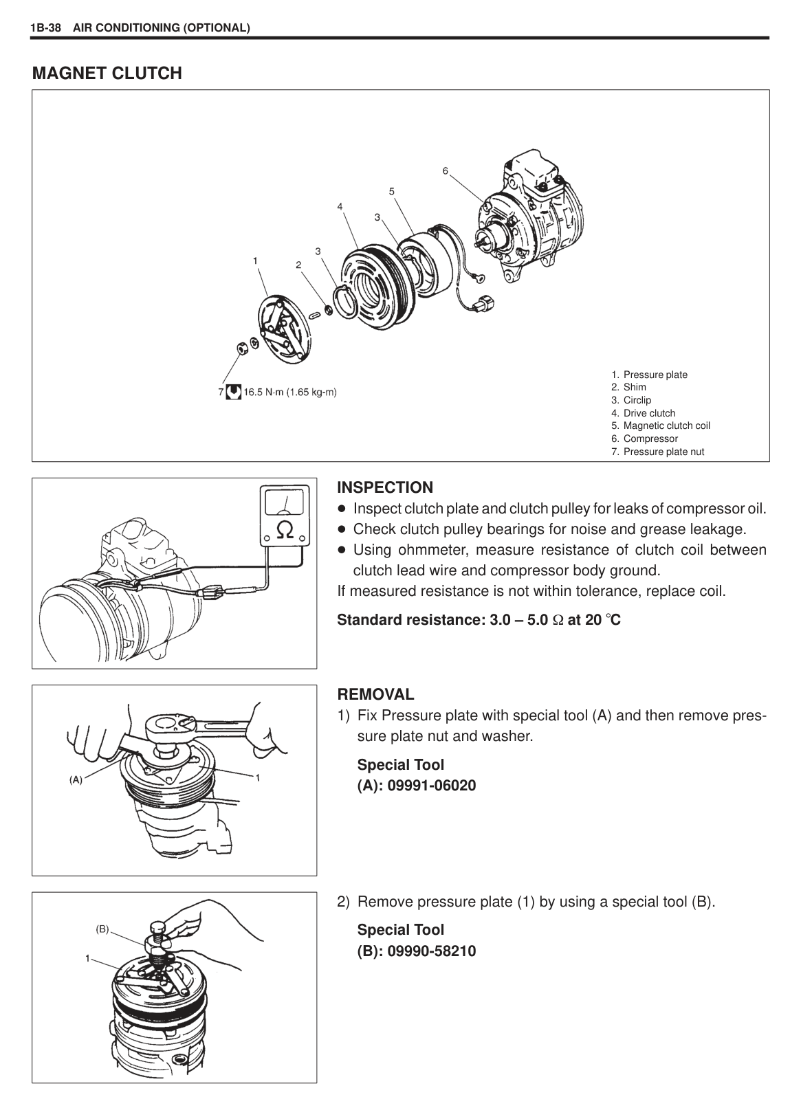
######## Installation
########## 1) Reverse removal sequence to install expansion valve notingthe follows.
Tighten specified torque to flared nut for expansion valve. Tightening Torque for flared nut Evaporator pipe : 33 N·m (3.3 kg-m) Evaporator joint pipe : 13 N·m (1.3 kg-m).
########## 2) Evacuate and charge system according to previously-de-scribed procedure.
A/C EVAPORATOR THERMISTOR Check resistance between evaporator thermistor (1) terminals.
|Sensor Temperature ( C)|Resistance (k )| |---|---| |0|4.6 – 5.1| |15|2.1 – 2.6|
If check results are as not specified, replace thermistor.
Removal Refer to items REMOVAL and DISASSEMBLY in the section of EVAPORATOR.
######## Installation
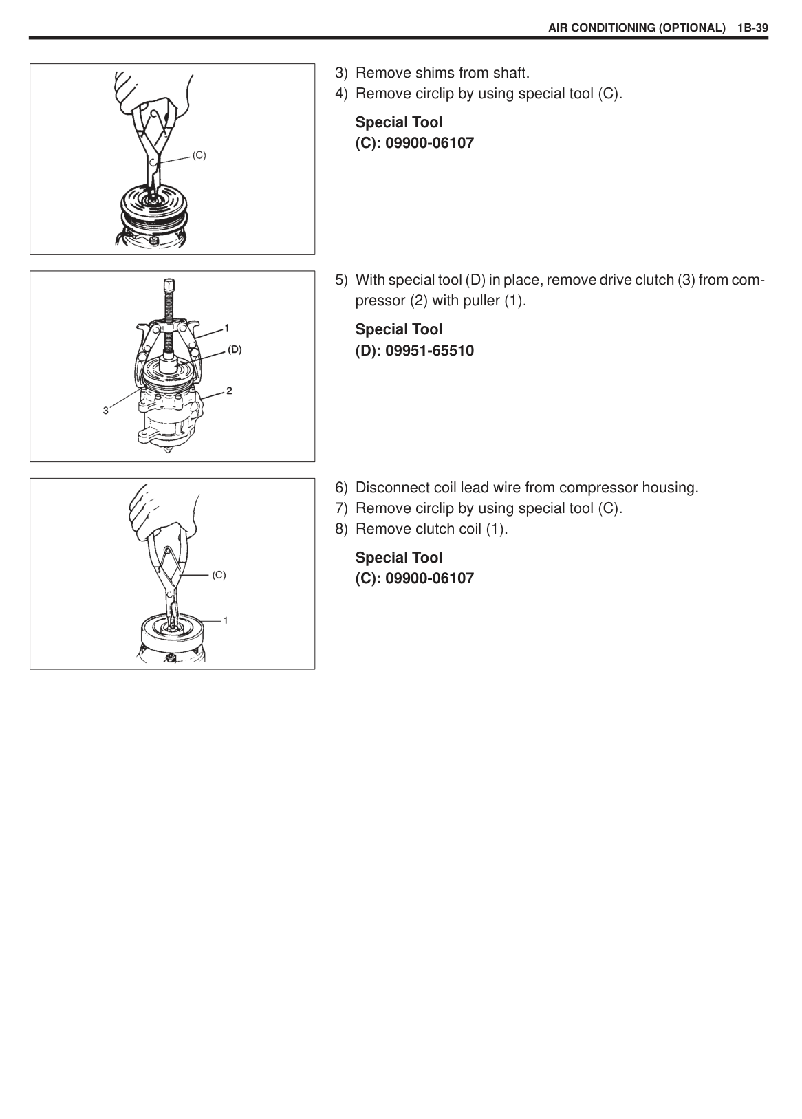
######### NOTE: When the thermistor removed, it should be reinstalled in original position.
#### REFRIGERANT PIPES AND HOSES Inspection
|| |---|
######## Removal
(1). Be sure to follow the instruction manual for the equipment. The amount of compressor oil removed must be measured and the same amount added to the system.
NOTE: As soon as the above hose or pipe is disconnected, cap its opened fitting to prevent moisture and dust from entering.
######## Installation
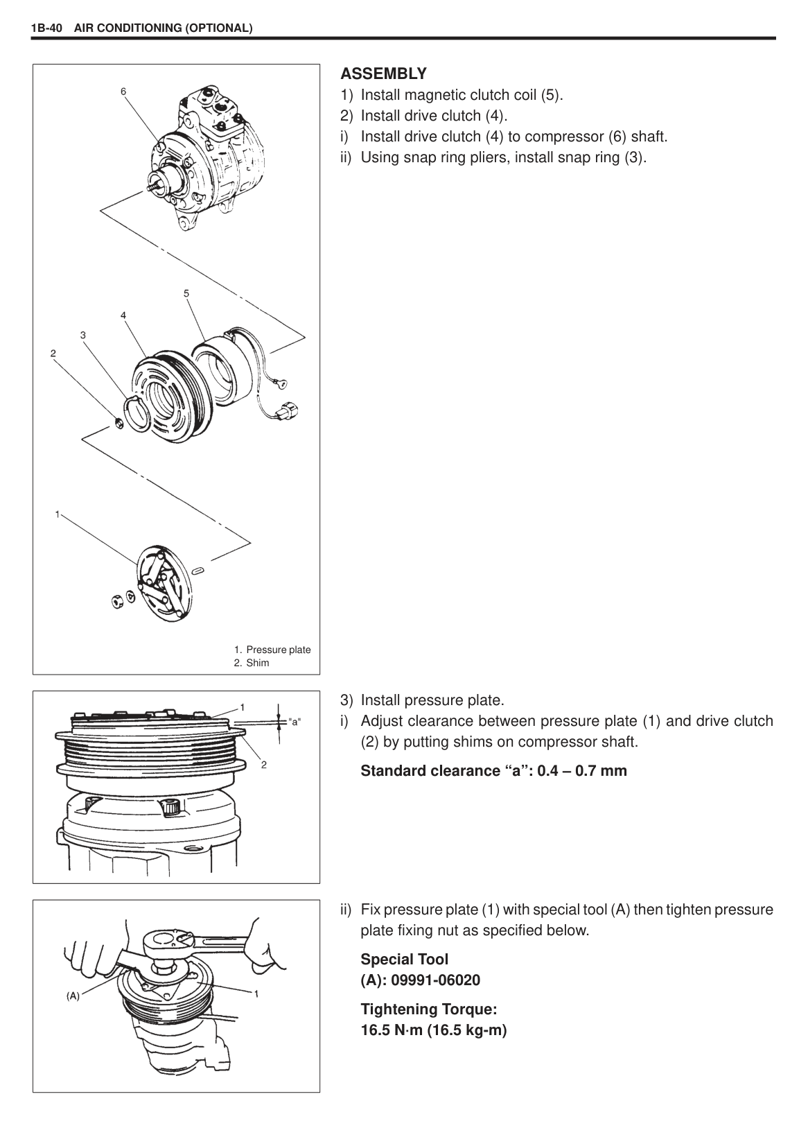
|| |---|
#### DUAL PRESSURE SWITCH INSPECTION
|Pressure
AB
CD
ON (Continuity)
OFF (No continuity)| |---|
Switch ON : above C and below D Switch OFF : below A or above B
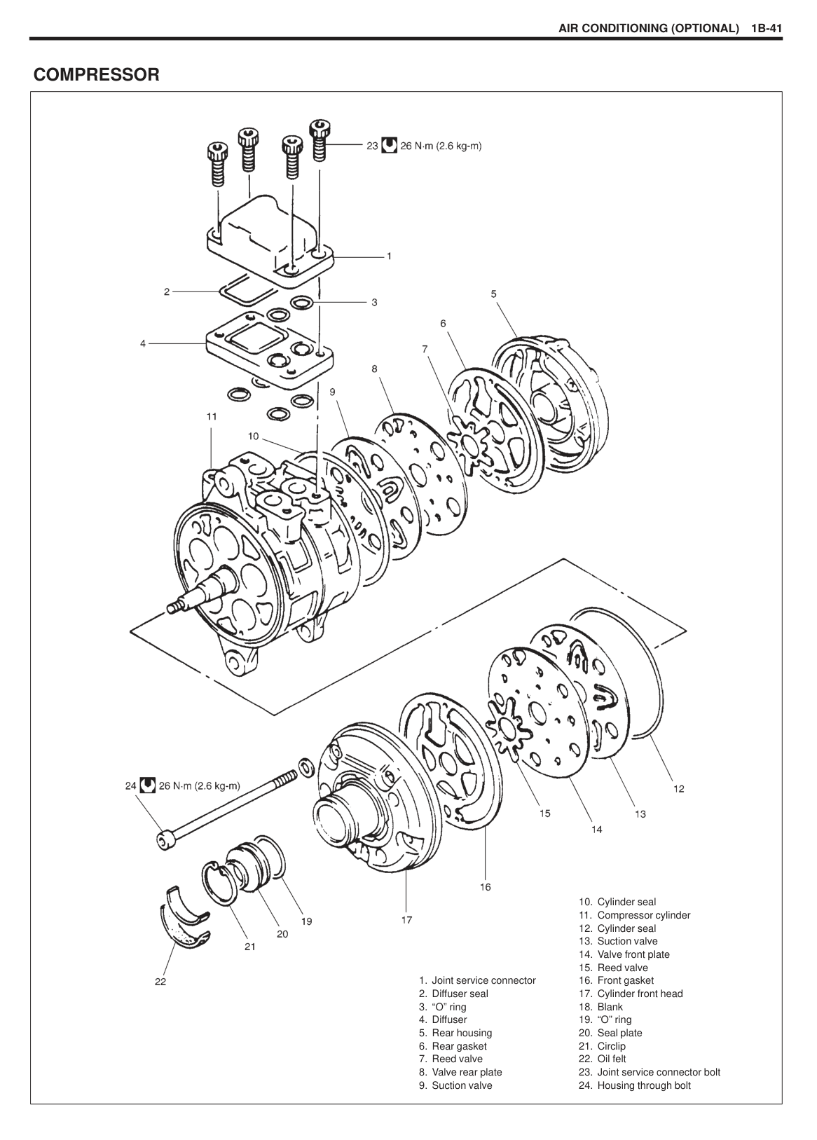
Tightening torque for dual pressure switch 10 N·m (1.0 kg-m)
|| |---|
|| |---|
#### A/C SWITCH REMOVAL
INSPECTION Press A/C Switch button and check if there is continuity between terminals “A” and “B”. With battery voltage (+) connected to terminal “C” and (–) to terminal “A”, press A/C Switch button and check if indicator lamp lights.
INSTALLATION Reverse removal procedure for installation.
|


3. Compressor and condenser cooling fan fuse| |---|
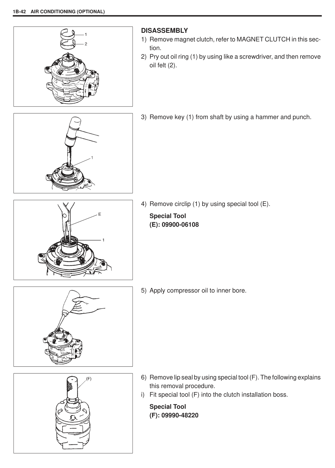
|| |---|
#### A/C CONDENSER COOLING FAN MOTOR RELAY AND A/C COMPRESSOR RELAY INSPECTION
#### COMPRESSOR ASSEMBLY REMOVAL
|| |---|
||
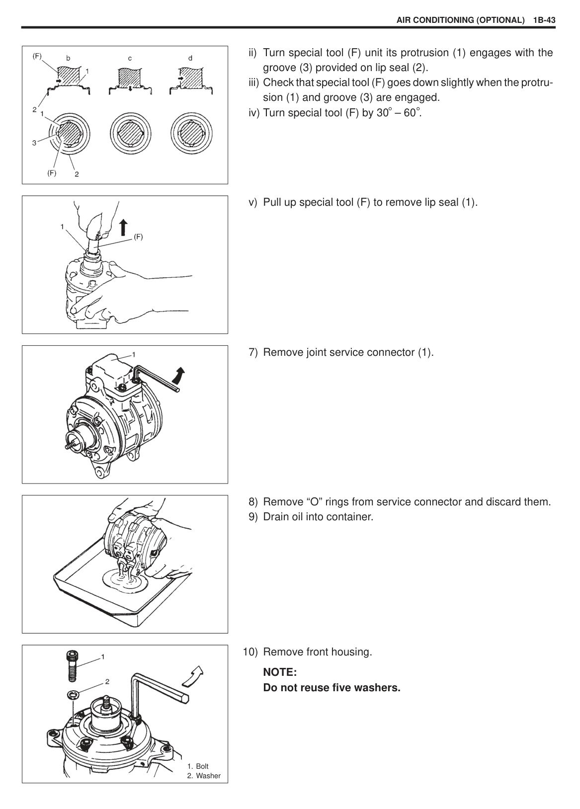
|---|
######### NOTE: Cap open fittings immediately to keep moisture out of system.
|| |---|
|| |---|
|
1. New compressor
2. Removed compressor
3. Excess oil (A–B)
| |---|
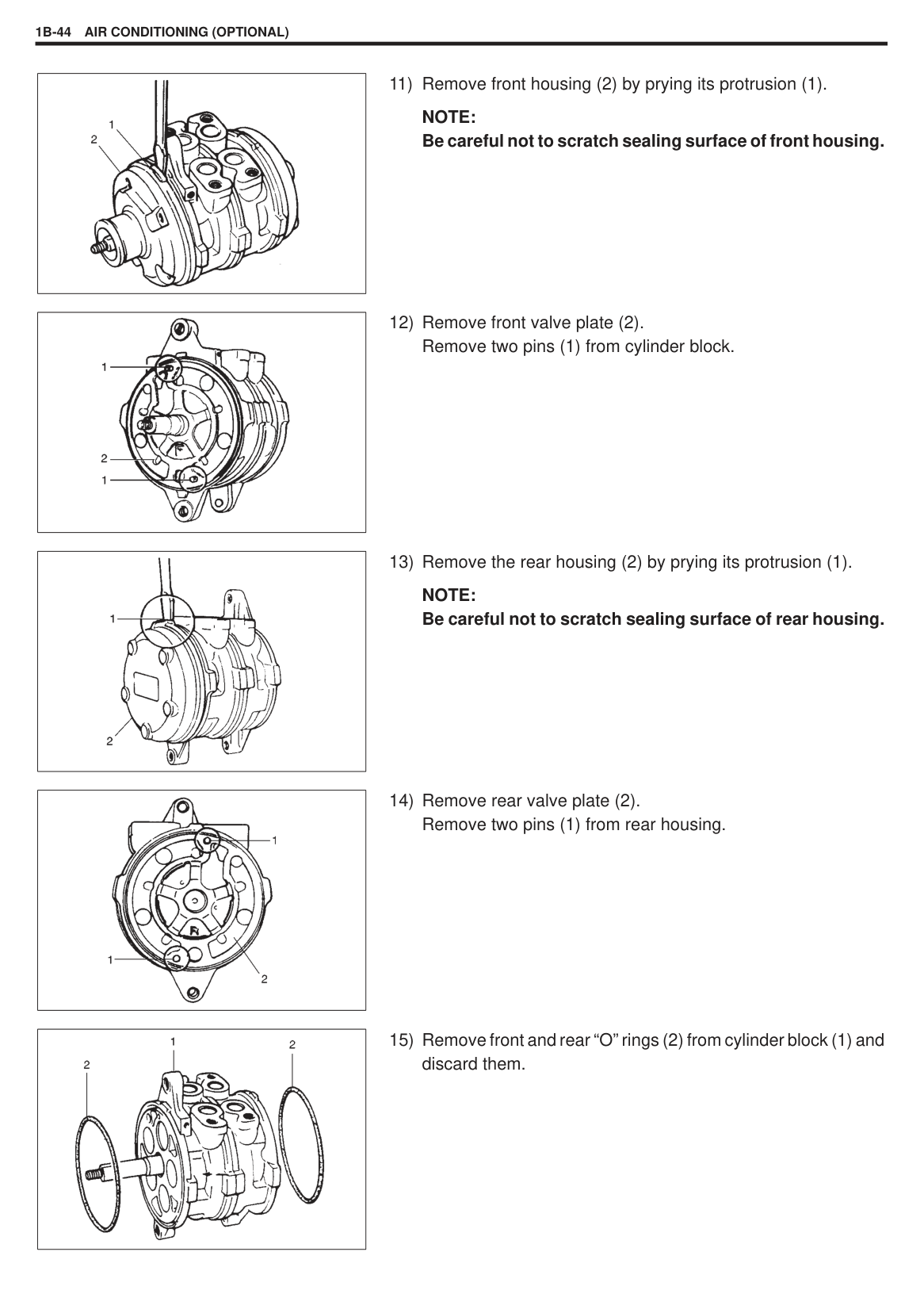
INSTALLATION Reverse removal procedure noting the following points.
Tighten compressor mounting bolts and nut to specified torque. Tightening Torque
If compressor is replaced, pour new compressor oil with the same amount as that drained from compressor in REMOVAL. Refer to “REPLENISHING COMPRESSOR OIL” in this section. Evacuate and charge system according to previously described procedure.
|| |---|
|
1. New compressor
2. Removed compressor
3. Excess oil (A–B)
| |---|
Adjust drive belt tension. Refer to “DRIVE BELT INSPECTION” in this Section.
|CAUTION: Be sure to use CFC-12 (R-12) compressor oil.| |---|
NOTE: Compressor assembly supplied from factory is filled up with the following amount of oil. Oil amount in compressor: 60 – 100 cm3
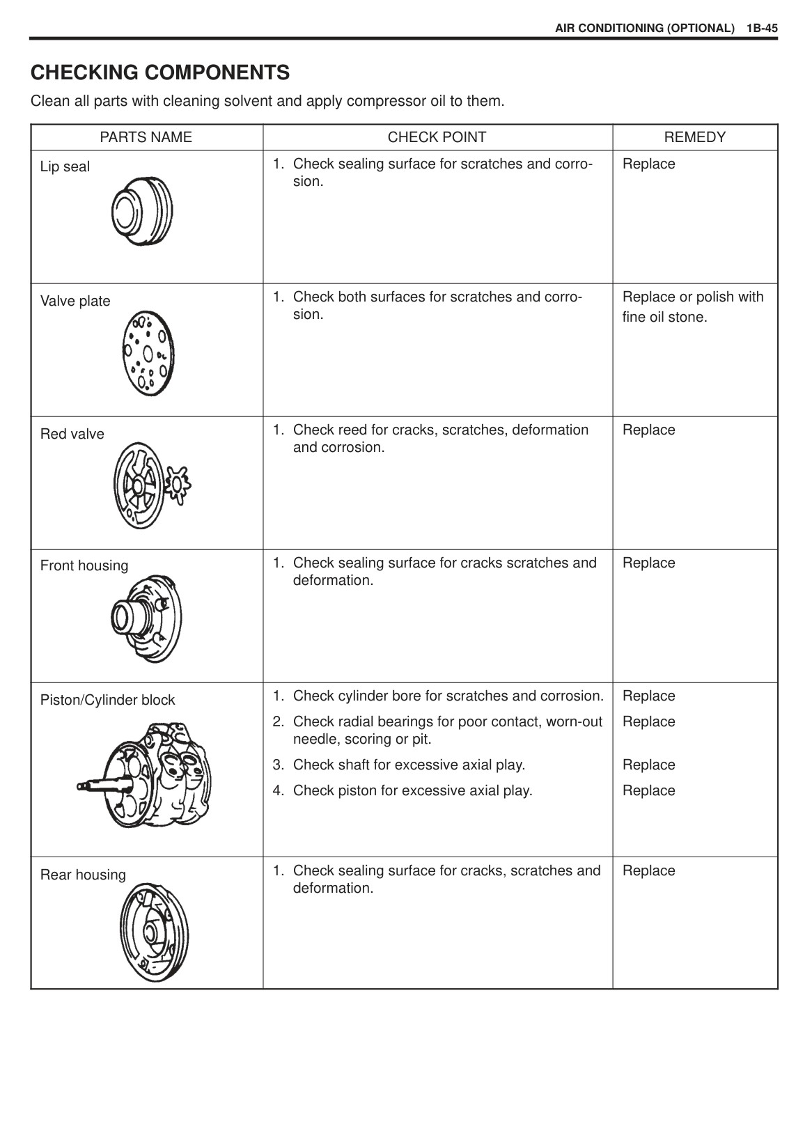
###### (60 – 100 cc) REPLENISHING COMPRESSOR OIL
When replacing air conditioning parts with new ones, it is necessary to replenish oil by the amount supposedly remaining in each part.
######## When changing gas only
When it is unavoidable to change gas without replacing any component part for engine removal and installation or for some other reason, replenish 20cc oil. When replenishing gas only, oil replenishment is not necessary.
######## When replacing compressor
Compressor oil is sealed in each new compressor by the amount required for air conditioner cycle. Therefore, when using a new compressor for replacement, drain oil from it by the amount calculated as follows.
“C” = “A” – “B” “C”: Amount of oil to be drained
|Part replaced|Amount of compressor oil to be replenished| |---|---| |Evaporator|25 cc| |Condenser|15 cc| |Receiver/dryer|20 cc| |Hoses|10 cc each| |Pipes|10 cc each|
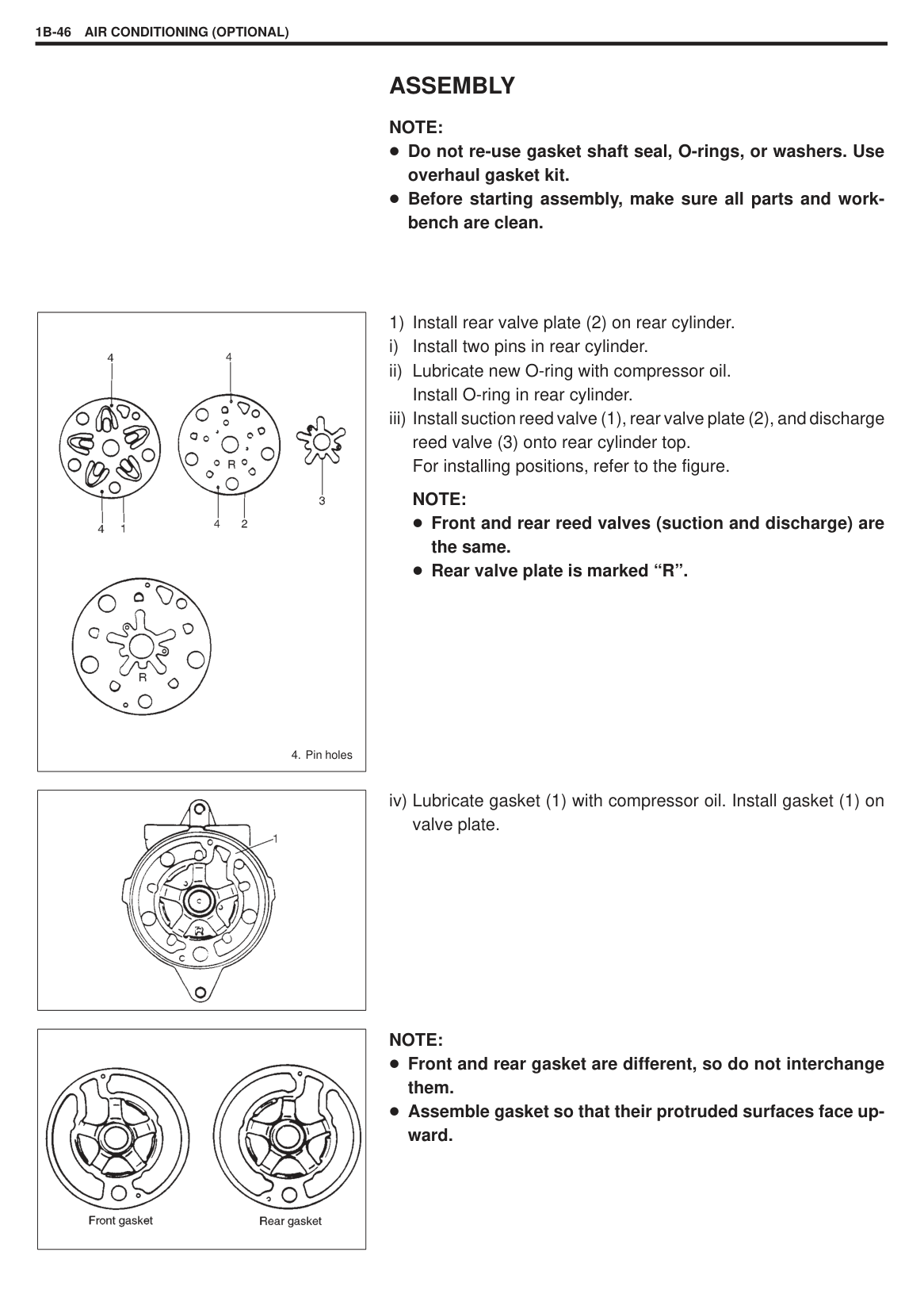
###### MAGNET CLUTCH
|
1. Pressure plate
2. Shim
3. Circlip
4. Drive clutch
5. Magnetic clutch coil
6. Compressor
7. Pressure plate nut
| |---|
|| |---|
INSPECTION Inspect clutch plate and clutch pulley for leaks of compressor oil. Check clutch pulley bearings for noise and grease leakage. Using ohmmeter, measure resistance of clutch coil between clutch lead wire and compressor body ground.
If measured resistance is not within tolerance, replace coil. Standard resistance: 3.0 – 5.0 at 20 C
|| |---|
######## REMOVAL
||
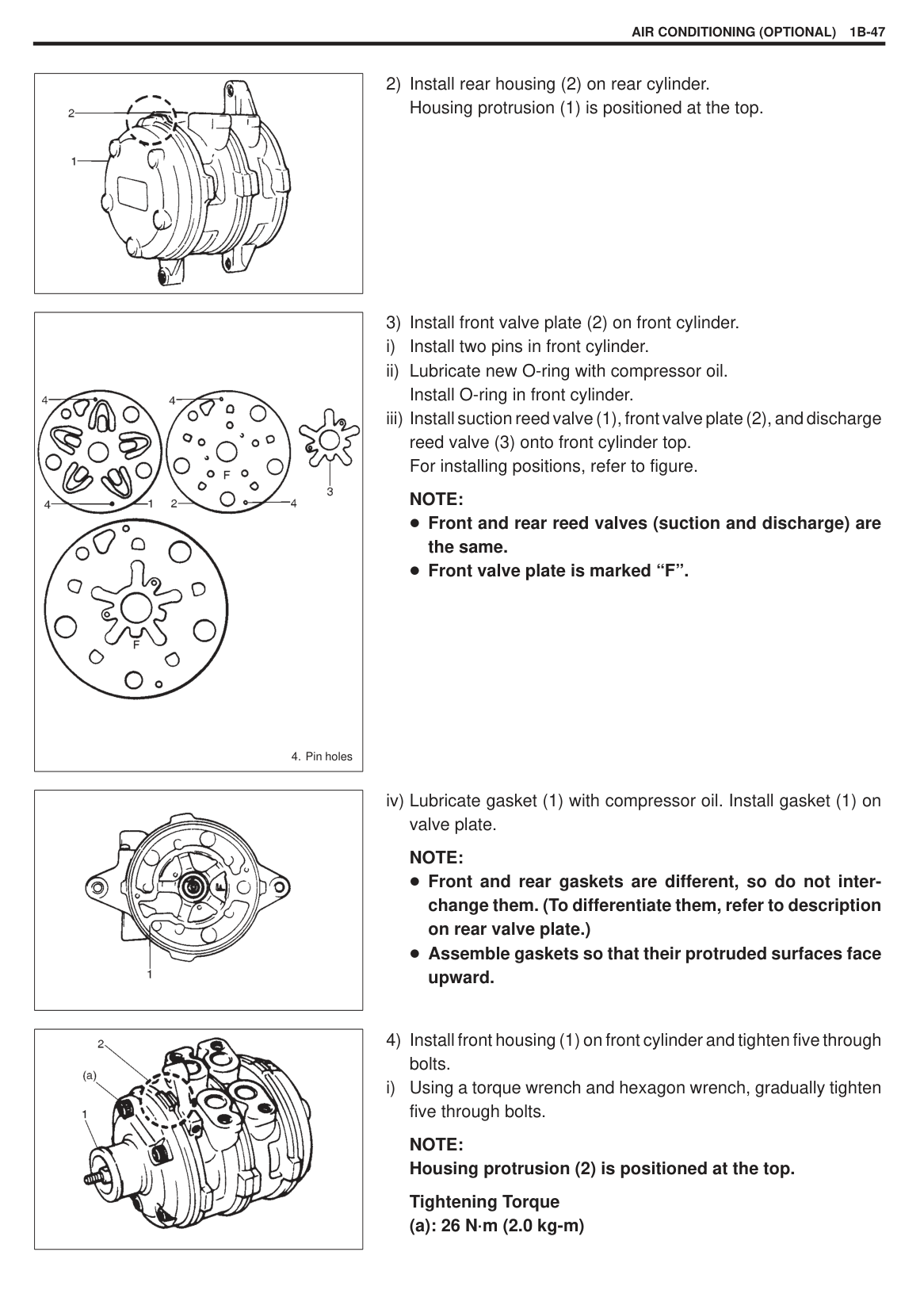
|---|
2) Remove pressure plate (1) by using a special tool (B).
Special Tool
|| |---|
|| |---|
||
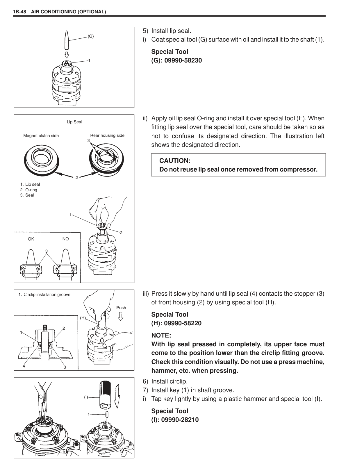
|---|
5) With special tool (D) in place, remove drive clutch (3) from compressor (2) with puller (1). Special Tool
######### Special Tool (C): 09900-06107
|
1. Pressure plate
2. Shim
| |---|
######## ASSEMBLY
|| |---|
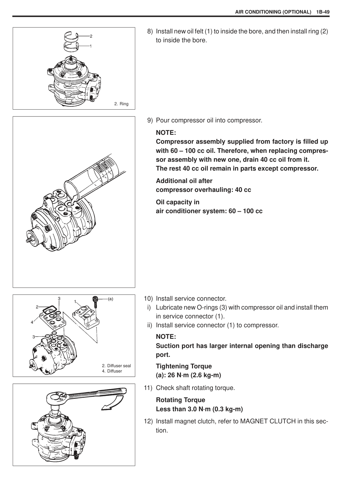
(2) by putting shims on compressor shaft. Standard clearance “a”: 0.4 – 0.7 mm
|| |---|
Special Tool (A): 09991-06020
Tightening Torque: 16.5 N·m (16.5 kg-m)
###### COMPRESSOR
|
10. Cylinder seal
11. Compressor cylinder
12. Cylinder seal
13. Suction valve
14. Valve front plate
15. Reed valve
16. Front gasket
17. Cylinder front head
18. Blank
19. “O” ring
20. Seal plate
21. Circlip
22. Oil felt
23. Joint service connector bolt
24. Housing through bolt
1. Joint service connector
2. Diffuser seal
3. “O” ring
4. Diffuser
5. Rear housing
6. Rear gasket
7. Reed valve
8. Valve rear plate
9. Suction valve
| |---|
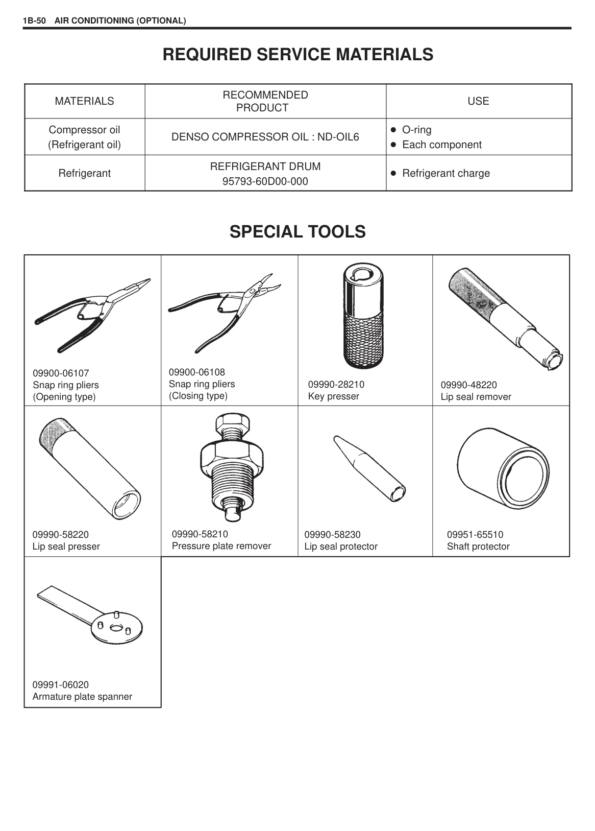
|| |---|
######## DISASSEMBLY
|| |---|
|| |---|
Special Tool (E): 09900-06108
|| |---|
|| |---|
Special Tool (F): 09990-48220
|| |---|
|| |---|
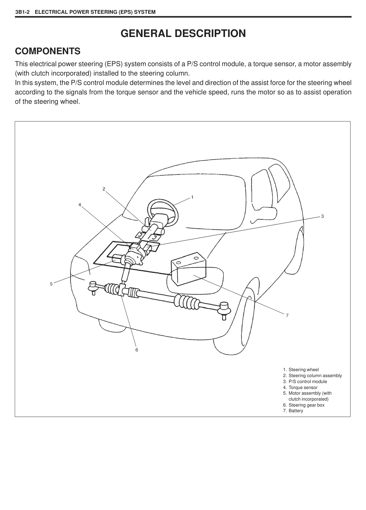
|| |---|
|| |---|
|
1. Bolt
2. Washer
| |---|
######### NOTE: Do not reuse five washers.
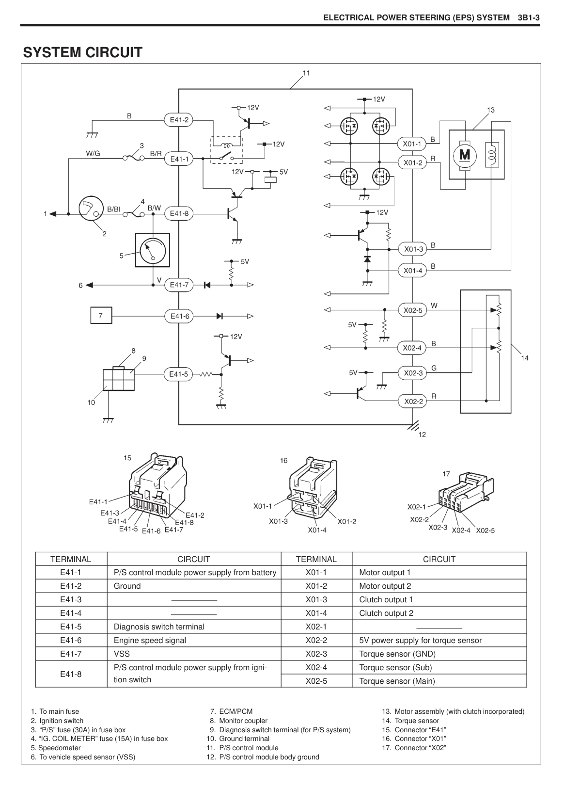
|| |---|
|| |---|
|| |---|
|| |---|
|| |---|
########## 11) Remove front housing (2) by prying its protrusion (1).
NOTE: Be careful not to scratch sealing surface of front housing.
########## 12) Remove front valve plate (2).Remove two pins (1) from cylinder block.
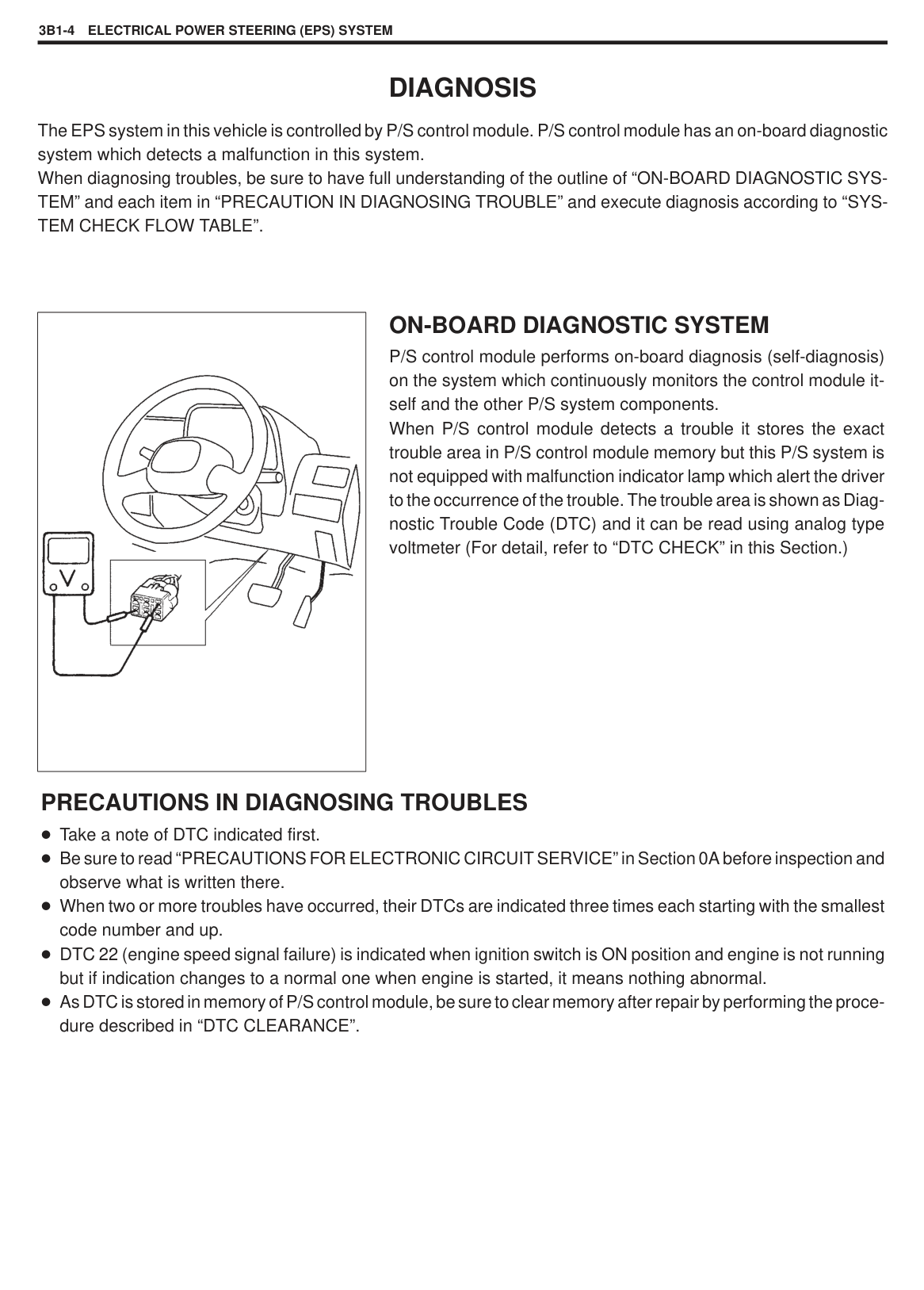
########## 13) Remove the rear housing (2) by prying its protrusion (1).
NOTE: Be careful not to scratch sealing surface of rear housing.
########## 14) Remove rear valve plate (2).Remove two pins (1) from rear housing.
########## 15) Remove front and rear “O” rings (2) from cylinder block (1) anddiscard them.
##### CHECKING COMPONENTS Clean all parts with cleaning solvent and apply compressor oil to them.
|PARTS NAME|CHECK POINT|REMEDY| |---|---|---| |
Lip seal|1. Check sealing surface for scratches and corrosion.|Replace| |
Valve plate|1. Check both surfaces for scratches and corrosion.|Replace or polish with fine oil stone.| |
Red valve|1. Check reed for cracks, scratches, deformation and corrosion.|Replace| |
Front housing|1. Check sealing surface for cracks scratches and deformation.|Replace| |
Piston/Cylinder block|1. Check cylinder bore for scratches and corrosion.
2. Check radial bearings for poor contact, worn-out needle, scoring or pit.
3. Check shaft for excessive axial play.
4. Check piston for excessive axial play.
|Replace Replace
Replace Replace| |
Rear housing|1. Check sealing surface for cracks, scratches and deformation.|Replace|
#### ASSEMBLY NOTE:
######### Do not re-use gasket shaft seal, O-rings, or washers. Use overhaul gasket kit. Before starting assembly, make sure all parts and workbench are clean.
|
4. Pin holes| |---|
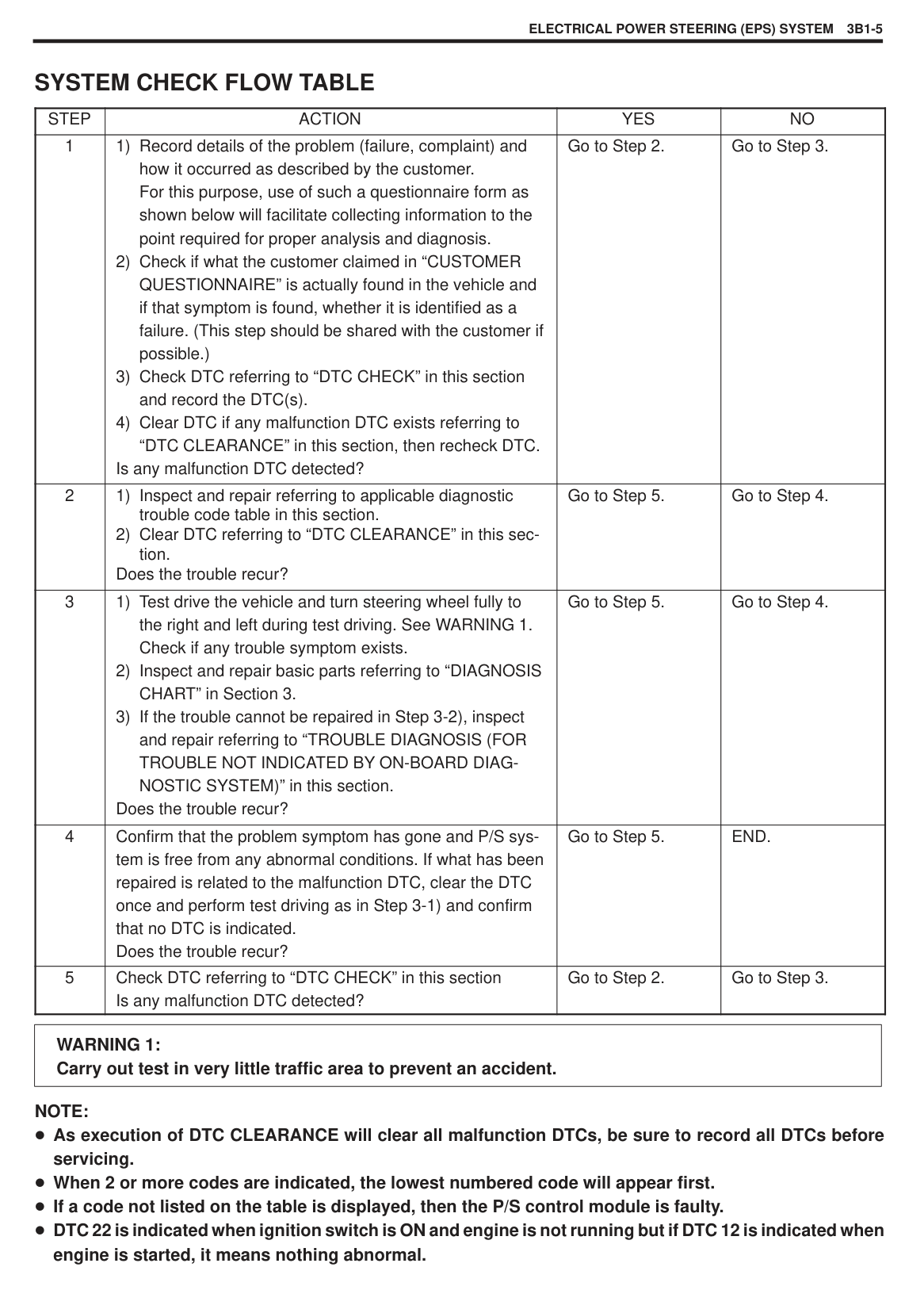
NOTE: Front and rear reed valves (suction and discharge) are the same. Rear valve plate is marked “R”.
|| |---|
|| |---|
NOTE: Front and rear gasket are different, so do not interchange them. Assemble gasket so that their protruded surfaces face upward.
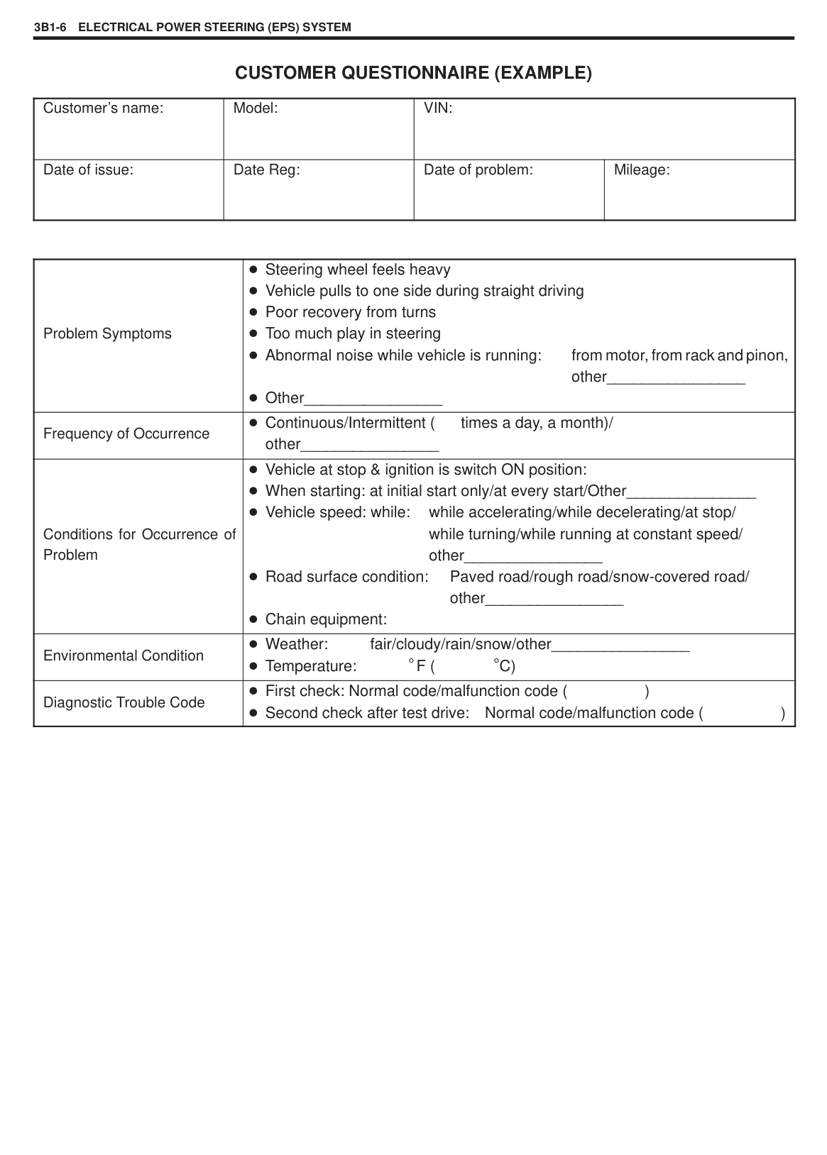
|
4. Pin holes| |---|
NOTE: Front and rear reed valves (suction and discharge) are the same. Front valve plate is marked “F”.
|| |---|
NOTE: Front and rear gaskets are different, so do not interchange them. (To differentiate them, refer to description on rear valve plate.) Assemble gaskets so that their protruded surfaces face upward.
|| |---|
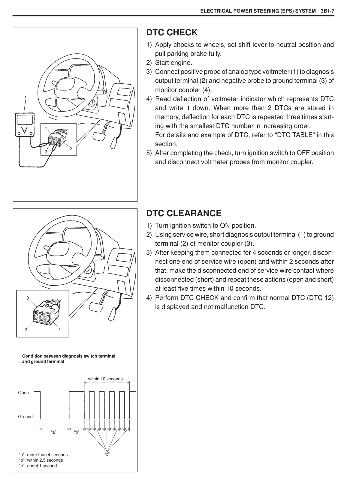
i) Using a torque wrench and hexagon wrench, gradually tighten five through bolts.
NOTE: Housing protrusion (2) is positioned at the top.
Tightening Torque (a): 26 N·m (2.0 kg-m)
|| |---|
Special Tool (G): 09990-58230
|
1. Lip seal
2. O-ring
3. Seal
| |---|
|CAUTION: Do not reuse lip seal once removed from compressor.| |---|
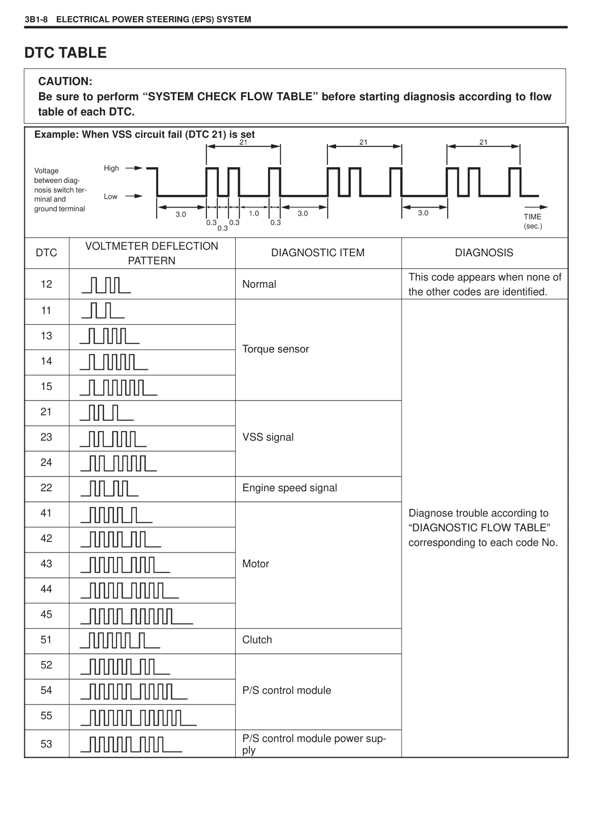
|
1. Circlip installation groove| |---|
Special Tool (H): 09990-58220
NOTE: With lip seal pressed in completely, its upper face must come to the position lower than the circlip fitting groove. Check this condition visually. Do not use a press machine, hammer, etc. when pressing.
|| |---|
######### Special Tool (I): 09990-28210
########## 8) Install new oil felt (1) to inside the bore, and then install ring (2)to inside the bore.
||
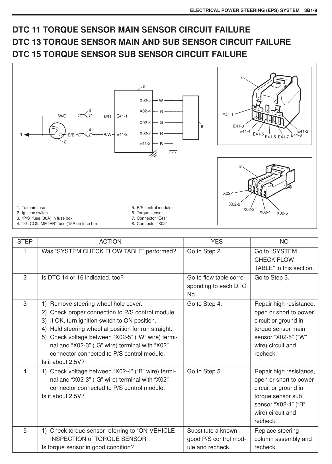
|---|
|
2. Diffuser seal
4. Diffuser| |---|
|| |---|
########## 9) Pour compressor oil into compressor.
NOTE: Compressor assembly supplied from factory is filled up with 60 – 100 cc oil. Therefore, when replacing compressor assembly with new one, drain 40 cc oil from it. The rest 40 cc oil remain in parts except compressor.
Additional oil after compressor overhauling: 40 cc
Oil capacity in air conditioner system: 60 – 100 cc
########## 10) Install service connector.
NOTE: Suction port has larger internal opening than discharge port. Tightening Torque (a): 26 N·m (2.6 kg-m)

########## 11) Check shaft rotating torque.
Rotating Torque Less than 3.0 N·m (0.3 kg-m)
########## 12) Install magnet clutch, refer to MAGNET CLUTCH in this sec-tion.
REQUIRED SERVICE MATERIALS
|MATERIALS|RECOMMENDED PRODUCT|USE| |---|---|---| |Compressor oil (Refrigerant oil)|DENSO COMPRESSOR OIL : ND-OIL6|O-ring Each component| |Refrigerant|REFRIGERANT DRUM 95793-60D00-000|Refrigerant charge|
SPECIAL TOOLS
|
09900-06107 Snap ring pliers (Opening type)|
09900-06108 Snap ring pliers (Closing type)|
09990-28210 Key presser|
09990-48220 Lip seal remover| |---|---|---|---| |
09990-58220 Lip seal presser|
09990-58210 Pressure plate remover|
09990-58230 Lip seal protector|
09951-65510 Shaft protector| |
09991-06020 Armature plate spanner| | | |
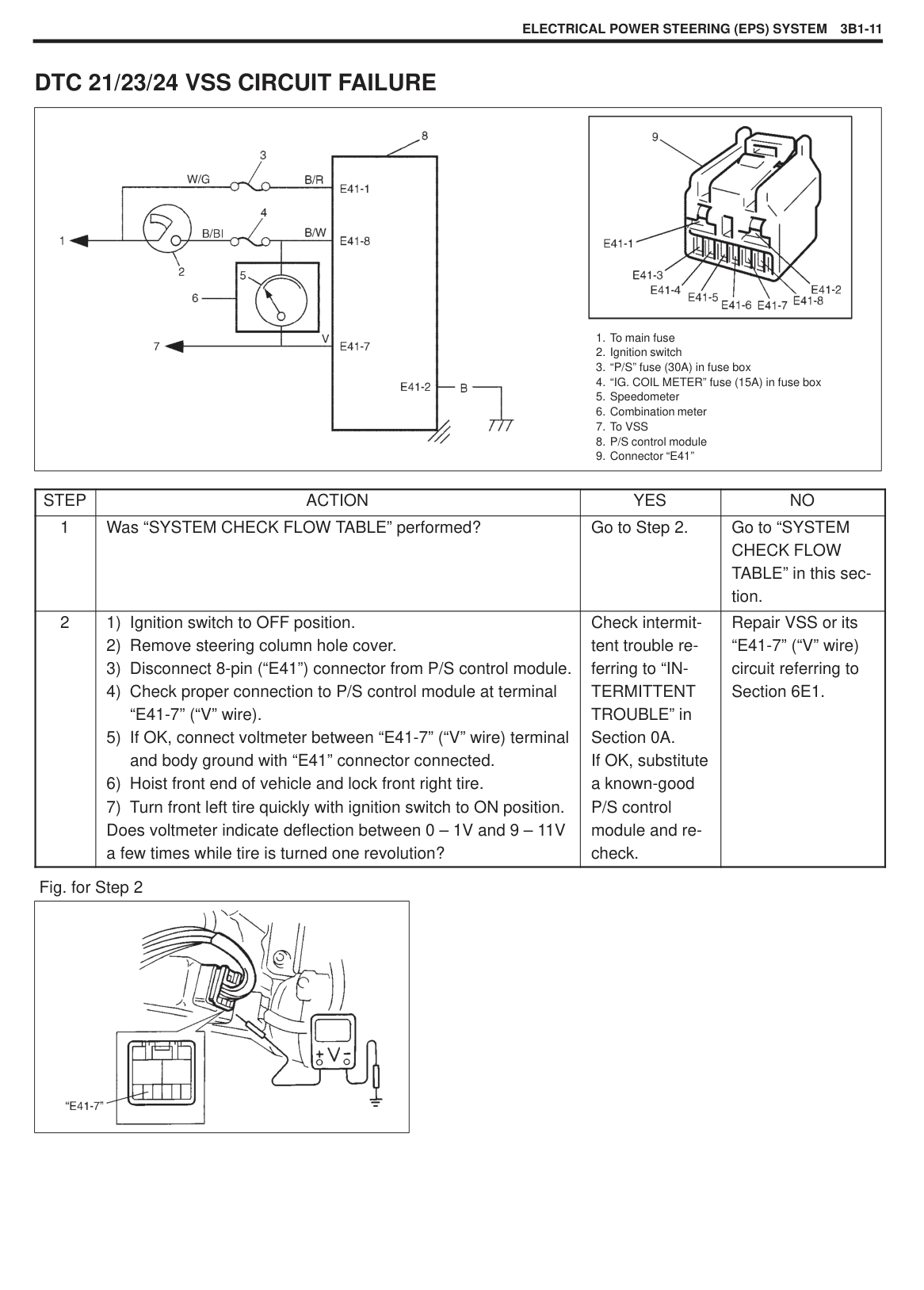
SECTION 3B1
ELECTRICAL POWER STEERING (EPS) SYSTEM
3B1
#### CONTENTS
GENERAL DESCRIPTION 3B1- 2. . . . . . . . . . . . . . . . . . . . . . . . . . . . . . . . . . . . . . . . . . . . . . . . . . . . . . . . . . . . . . . . . . . . . . . Components 3B1- 2. . . . . . . . . . . . . . . . . . . . . . . . . . . . . . . . . . . . . . . . . . . . . . . . . . . . . . . . . . . . . . . . . . . . . . . . . . . . . . . . . System circuit 3B1- 3. . . . . . . . . . . . . . . . . . . . . . . . . . . . . . . . . . . . . . . . . . . . . . . . . . . . . . . . . . . . . . . . . . . . . . . . . . . . . . . .
DIAGNOSIS 3B1- 4. . . . . . . . . . . . . . . . . . . . . . . . . . . . . . . . . . . . . . . . . . . . . . . . . . . . . . . . . . . . . . . . . . . . . . . . . . . . . . . . . . . . On-board diagnostic system 3B1- 4. . . . . . . . . . . . . . . . . . . . . . . . . . . . . . . . . . . . . . . . . . . . . . . . . . . . . . . . . . . . . . . . . . . . Precautions in diagnosing troubles 3B1- 4. . . . . . . . . . . . . . . . . . . . . . . . . . . . . . . . . . . . . . . . . . . . . . . . . . . . . . . . . . . . . . System check flow table 3B1- 5. . . . . . . . . . . . . . . . . . . . . . . . . . . . . . . . . . . . . . . . . . . . . . . . . . . . . . . . . . . . . . . . . . . . . . . DTC check 3B1- 7. . . . . . . . . . . . . . . . . . . . . . . . . . . . . . . . . . . . . . . . . . . . . . . . . . . . . . . . . . . . . . . . . . . . . . . . . . . . . . . . . . . DTC clearance 3B1- 7. . . . . . . . . . . . . . . . . . . . . . . . . . . . . . . . . . . . . . . . . . . . . . . . . . . . . . . . . . . . . . . . . . . . . . . . . . . . . . . DTC table 3B1- 8. . . . . . . . . . . . . . . . . . . . . . . . . . . . . . . . . . . . . . . . . . . . . . . . . . . . . . . . . . . . . . . . . . . . . . . . . . . . . . . . . . . . DTC 11 Torque sensor main sensor circuit failure 3B1- 9. . . . . . . . . . . . . . . . . . . . . . . . . . . . . . . . . . . . . . . . . . . . . . . . .
ON-VEHICLE SERVICE 3B1-20. . . . . . . . . . . . . . . . . . . . . . . . . . . . . . . . . . . . . . . . . . . . . . . . . . . . . . . . . . . . . . . . . . . . . . . . . Steering column assembly 3B1-20. . . . . . . . . . . . . . . . . . . . . . . . . . . . . . . . . . . . . . . . . . . . . . . . . . . . . . . . . . . . . . . . . . . . . Checking steering column assembly and lower shaft for accident damage 3B1-20. . . . . . . . . . . . . . . . . . . . . . . . . . . . P/S control module 3B1-20. . . . . . . . . . . . . . . . . . . . . . . . . . . . . . . . . . . . . . . . . . . . . . . . . . . . . . . . . . . . . . . . . . . . . . . . . . . . Torque sensor 3B1-21. . . . . . . . . . . . . . . . . . . . . . . . . . . . . . . . . . . . . . . . . . . . . . . . . . . . . . . . . . . . . . . . . . . . . . . . . . . . . . . . Motor assembly (with clutch incorporated) 3B1-21. . . . . . . . . . . . . . . . . . . . . . . . . . . . . . . . . . . . . . . . . . . . . . . . . . . . . . . .
GENERAL DESCRIPTION
COMPONENTS This electrical power steering (EPS) system consists of a P/S control module, a torque sensor, a motor assembly (with clutch incorporated) installed to the steering column. In this system, the P/S control module determines the level and direction of the assist force for the steering wheel according to the signals from the torque sensor and the vehicle speed, runs the motor so as to assist operation of the steering wheel.
|
1. Steering wheel
2. Steering column assembly
3. P/S control module
4. Torque sensor
5. Motor assembly (with clutch incorporated)
6. Steering gear box
7. Battery
| |---|
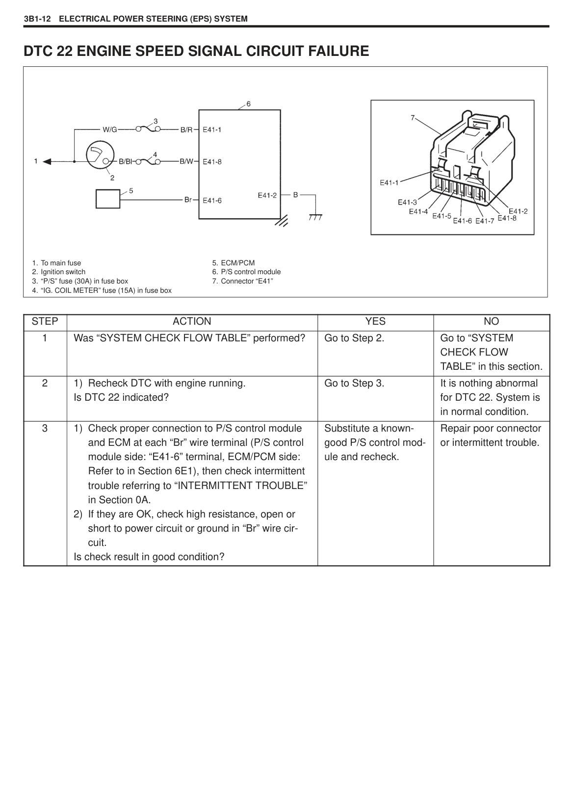
#### SYSTEM CIRCUIT
|

1. To main fuse
2. Ignition switch
3. “P/S” fuse (30A) in fuse box
4. “IG. COIL METER” fuse (15A) in fuse box
5. Speedometer
6. To vehicle speed sensor (VSS)
7. ECM/PCM
8. Monitor coupler
9. Diagnosis switch terminal (for P/S system)
10. Ground terminal
11. P/S control module
12. P/S control module body ground
13. Motor assembly (with clutch incorporated)
14. Torque sensor
15. Connector “E41”
16. Connector “X01”
17. Connector “X02”
|TERMINAL|CIRCUIT|TERMINAL|CIRCUIT| |---|---|---|---| |E41-1|P/S control module power supply from battery|X01-1|Motor output 1| |E41-2|Ground|X01-2|Motor output 2| |E41-3| |X01-3|Clutch output 1| |E41-4| |X01-4|Clutch output 2| |E41-5|Diagnosis switch terminal|X02-1| | |E41-6|Engine speed signal|X02-2|5V power supply for torque sensor| |E41-7|VSS|X02-3|Torque sensor (GND)| |E41 8E41-8
|P/S control module power supply from ignition switch
|X02-4|Torque sensor (Sub)| |E41 8E41-8
|P/S control module power supply from ignition switch
|X02-5|Torque sensor (Main)| | |---|
DIAGNOSIS
The EPS system in this vehicle is controlled by P/S control module. P/S control module has an on-board diagnostic system which detects a malfunction in this system. When diagnosing troubles, be sure to have full understanding of the outline of “ON-BOARD DIAGNOSTIC SYSTEM” and each item in “PRECAUTION IN DIAGNOSING TROUBLE” and execute diagnosis according to “SYSTEM CHECK FLOW TABLE”.
|| |---|
ON-BOARD DIAGNOSTIC SYSTEM P/S control module performs on-board diagnosis (self-diagnosis) on the system which continuously monitors the control module itself and the other P/S system components. When P/S control module detects a trouble it stores the exact trouble area in P/S control module memory but this P/S system is not equipped with malfunction indicator lamp which alert the driver to the occurrence of the trouble. The trouble area is shown as Diagnostic Trouble Code (DTC) and it can be read using analog type voltmeter (For detail, refer to “DTC CHECK” in this Section.)
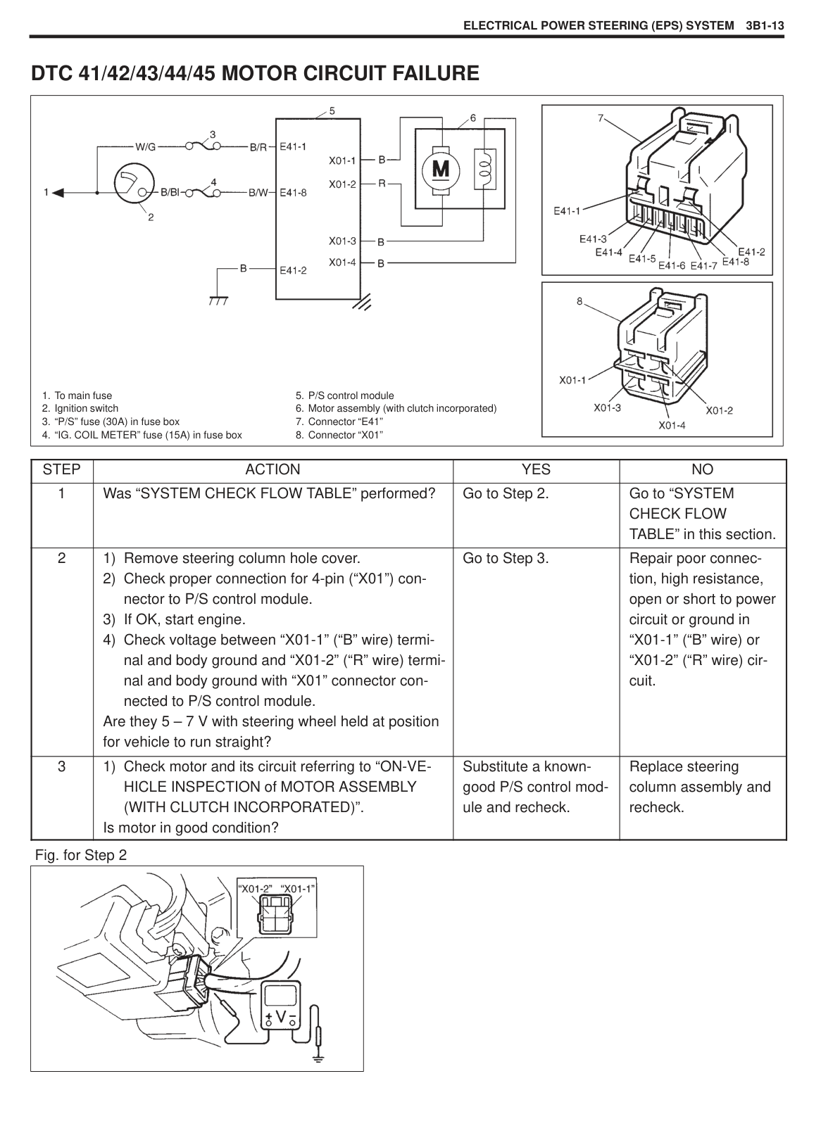
PRECAUTIONS IN DIAGNOSING TROUBLES Take a note of DTC indicated first. Be sure to read “PRECAUTIONS FOR ELECTRONIC CIRCUIT SERVICE” in Section 0A before inspection and observe what is written there. When two or more troubles have occurred, their DTCs are indicated three times each starting with the smallest code number and up. DTC 22 (engine speed signal failure) is indicated when ignition switch is ON position and engine is not running but if indication changes to a normal one when engine is started, it means nothing abnormal. As DTC is stored in memory of P/S control module, be sure to clear memory after repair by performing the procedure described in “DTC CLEARANCE”.
#### SYSTEM CHECK FLOW TABLE
|STEP|ACTION|YES|NO| |---|---|---|---| |1|1) Record details of the problem (failure, complaint) and how it occurred as described by the customer. For this purpose, use of such a questionnaire form as shown below will facilitate collecting information to the point required for proper analysis and diagnosis.
2) Check if what the customer claimed in “CUSTOMER QUESTIONNAIRE” is actually found in the vehicle and if that symptom is found, whether it is identified as a failure. (This step should be shared with the customer if possible.)
3) Check DTC referring to “DTC CHECK” in this section and record the DTC(s).
4) Clear DTC if any malfunction DTC exists referring to “DTC CLEARANCE” in this section, then recheck DTC.
Is any malfunction DTC detected?|Go to Step 2.|Go to Step 3.| |2|1) Inspect and repair referring to applicable diagnostic trouble code table in this section.
2) Clear DTC referring to “DTC CLEARANCE” in this section.
Does the trouble recur?|Go to Step 5.|Go to Step 4.| |3|1) Test drive the vehicle and turn steering wheel fully to the right and left during test driving. See WARNING 1. Check if any trouble symptom exists.
2) Inspect and repair basic parts referring to “DIAGNOSIS CHART” in Section 3.
3) If the trouble cannot be repaired in Step 3-2), inspect and repair referring to “TROUBLE DIAGNOSIS (FOR TROUBLE NOT INDICATED BY ON-BOARD DIAGNOSTIC SYSTEM)” in this section.
Does the trouble recur?|Go to Step 5.|Go to Step 4.| |4|Confirm that the problem symptom has gone and P/S system is free from any abnormal conditions. If what has been repaired is related to the malfunction DTC, clear the DTC once and perform test driving as in Step 3-1) and confirm that no DTC is indicated. Does the trouble recur?|Go to Step 5.|END.| |5|Check DTC referring to “DTC CHECK” in this section Is any malfunction DTC detected?|Go to Step 2.|Go to Step 3.|
|WARNING 1: Carry out test in very little traffic area to prevent an accident.| |---|
NOTE: As execution of DTC CLEARANCE will clear all malfunction DTCs, be sure to record all DTCs before servicing. When 2 or more codes are indicated, the lowest numbered code will appear first. If a code not listed on the table is displayed, then the P/S control module is faulty. DTC 22 is indicated when ignition switch is ON and engine is not running but if DTC 12 is indicated when engine is started, it means nothing abnormal.
###### CUSTOMER QUESTIONNAIRE (EXAMPLE)
|Customer’s name:|Model:|VIN:|VIN:| |---|---|---|---| |Date of issue:|Date Reg:|Date of problem:|Mileage:|
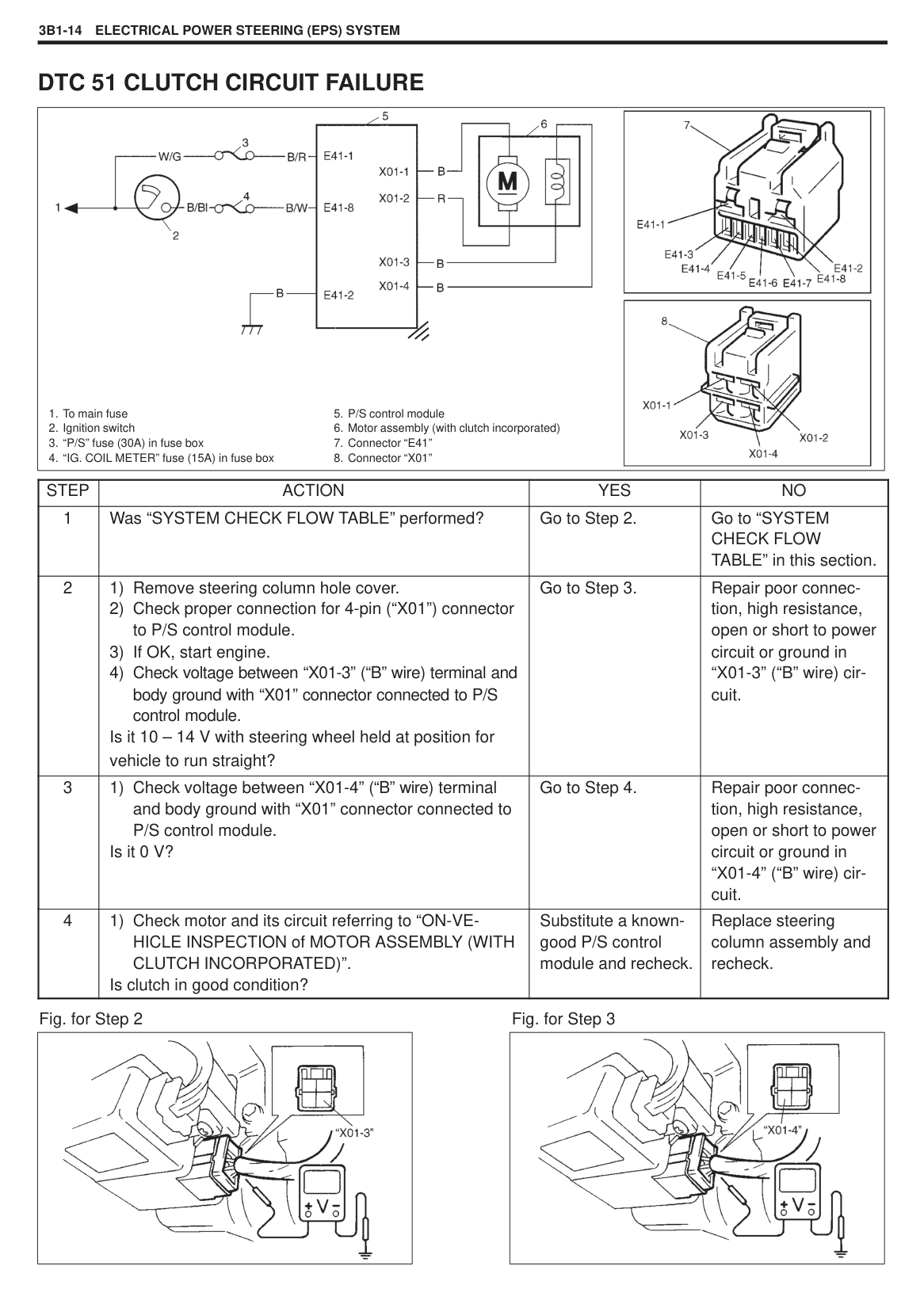
|Problem Symptoms|Steering wheel feels heavy Vehicle pulls to one side during straight driving Poor recovery from turns Too much play in steering Abnormal noise while vehicle is running: from motor, from rack and pinon,
other________________ Other________________| |---|---| |Frequency of Occurrence|Continuous/Intermittent ( times a day, a month)/ other________________| |Conditions for Occurrence of Problem|Vehicle at stop & ignition is switch ON position: When starting: at initial start only/at every start/Other_______________ Vehicle speed: while: while accelerating/while decelerating/at stop/
while turning/while running at constant speed/ other________________
Road surface condition: Paved road/rough road/snow-covered road/
other________________ Chain equipment:| |Environmental Condition|Weather: fair/cloudy/rain/snow/other________________ Temperature: F ( C)| |Diagnostic Trouble Code|First check: Normal code/malfunction code ( ) Second check after test drive: Normal code/malfunction code ( )|
|| |---|
|

Condition between diagnosis switch terminal and ground terminal
within 10 seconds
Open
Ground
“a”: more than 4 seconds
“b”: within 2.5 seconds
“c”: about 1 second
| |---|
#### DTC CHECK
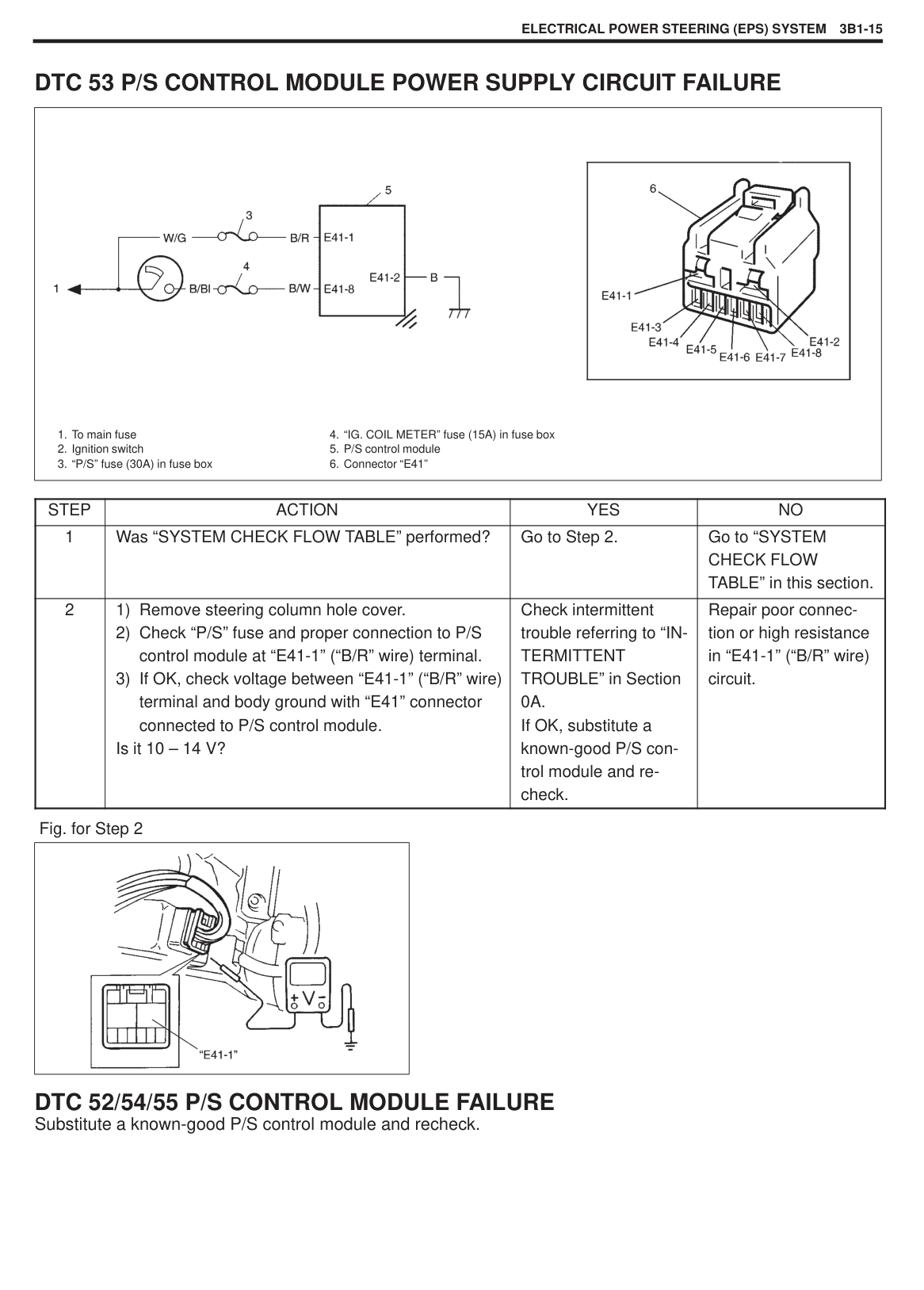
#### DTC CLEARANCE
#### DTC TABLE
|CAUTION: Be sure to perform “SYSTEM CHECK FLOW TABLE” before starting diagnosis according to flow table of each DTC.| |---|
|
Voltage between diagnosis switch terminal and ground terminal
Example: When VSS circuit fail (DTC 21) is set
High
Low
TIME (sec.)|
Voltage between diagnosis switch terminal and ground terminal
Example: When VSS circuit fail (DTC 21) is set
High
Low
TIME (sec.)|
Voltage between diagnosis switch terminal and ground terminal
Example: When VSS circuit fail (DTC 21) is set
High
Low
TIME (sec.)|
Voltage between diagnosis switch terminal and ground terminal
Example: When VSS circuit fail (DTC 21) is set
High
Low
TIME (sec.)| |---|---|---|---| |DTC|VOLTMETER DEFLECTION PATTERN|DIAGNOSTIC ITEM|DIAGNOSIS| |12||Normal|This code appears when none of the other codes are identified.| |11||Torque sensorTorque sensor|Diagnose trouble according to “DIAGNOSTIC FLOW TABLE”“DIAGNOSTIC FLOW TABLE” corresponding to each code No.
| |13||Torque sensorTorque sensor|Diagnose trouble according to “DIAGNOSTIC FLOW TABLE”“DIAGNOSTIC FLOW TABLE” corresponding to each code No.
| |14||Torque sensorTorque sensor|Diagnose trouble according to “DIAGNOSTIC FLOW TABLE”“DIAGNOSTIC FLOW TABLE” corresponding to each code No.
| |15||Torque sensorTorque sensor|Diagnose trouble according to “DIAGNOSTIC FLOW TABLE”“DIAGNOSTIC FLOW TABLE” corresponding to each code No.
| |21||VSS signal|Diagnose trouble according to “DIAGNOSTIC FLOW TABLE”“DIAGNOSTIC FLOW TABLE” corresponding to each code No.
| |23||VSS signal|Diagnose trouble according to “DIAGNOSTIC FLOW TABLE”“DIAGNOSTIC FLOW TABLE” corresponding to each code No.
| |24||VSS signal|Diagnose trouble according to “DIAGNOSTIC FLOW TABLE”“DIAGNOSTIC FLOW TABLE” corresponding to each code No.
| |22||Engine speed signal|Diagnose trouble according to “DIAGNOSTIC FLOW TABLE”“DIAGNOSTIC FLOW TABLE” corresponding to each code No.
|
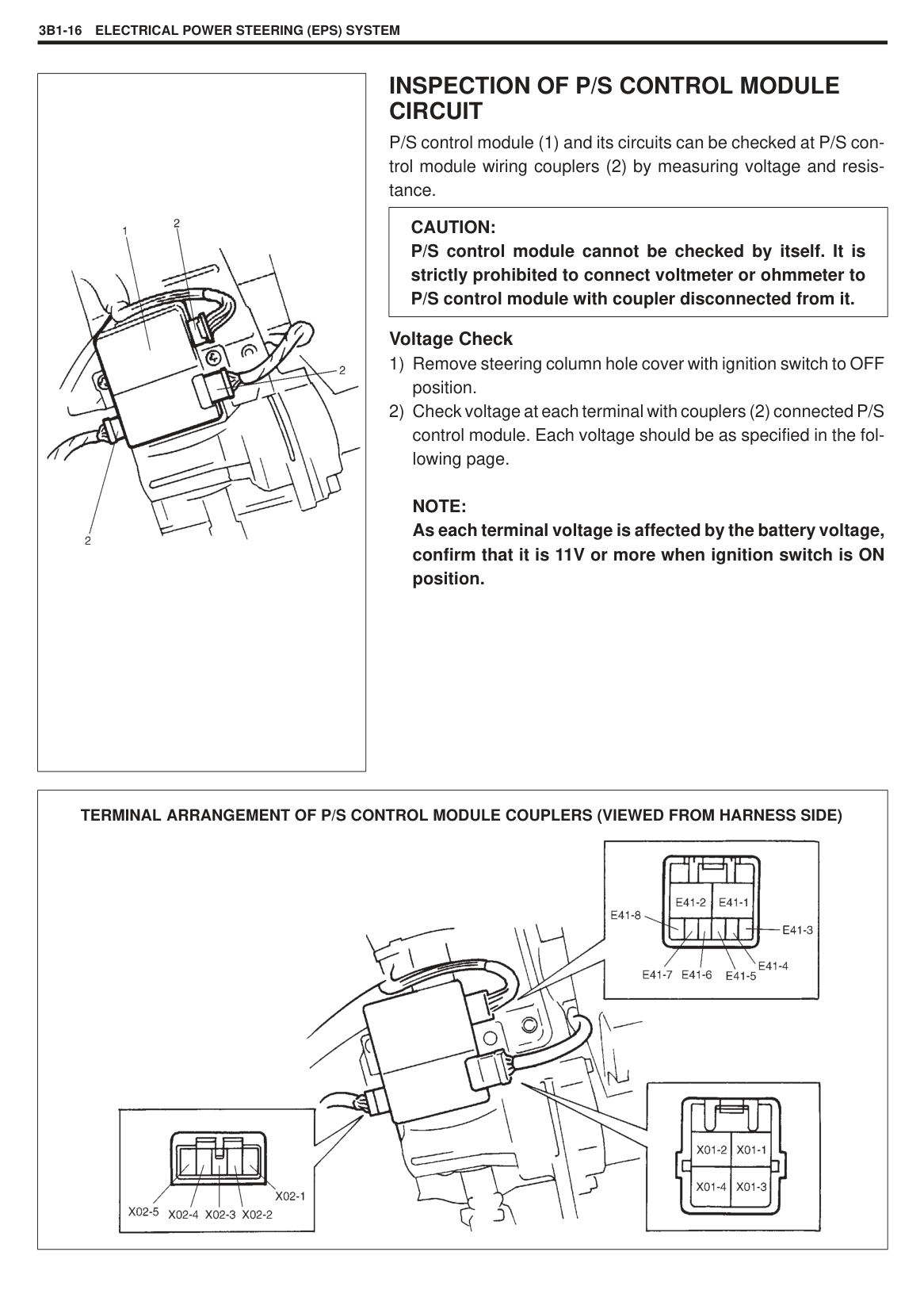
|41||Motor|Diagnose trouble according to “DIAGNOSTIC FLOW TABLE”“DIAGNOSTIC FLOW TABLE” corresponding to each code No.
| |42||Motor|Diagnose trouble according to “DIAGNOSTIC FLOW TABLE”“DIAGNOSTIC FLOW TABLE” corresponding to each code No.
| |43||Motor|Diagnose trouble according to “DIAGNOSTIC FLOW TABLE”“DIAGNOSTIC FLOW TABLE” corresponding to each code No.
| |44||Motor|Diagnose trouble according to “DIAGNOSTIC FLOW TABLE”“DIAGNOSTIC FLOW TABLE” corresponding to each code No.
| |45||Motor|Diagnose trouble according to “DIAGNOSTIC FLOW TABLE”“DIAGNOSTIC FLOW TABLE” corresponding to each code No.
| |51||Clutch|Diagnose trouble according to “DIAGNOSTIC FLOW TABLE”“DIAGNOSTIC FLOW TABLE” corresponding to each code No.
| |52||P/S control module|Diagnose trouble according to “DIAGNOSTIC FLOW TABLE”“DIAGNOSTIC FLOW TABLE” corresponding to each code No.
| |54||P/S control module|Diagnose trouble according to “DIAGNOSTIC FLOW TABLE”“DIAGNOSTIC FLOW TABLE” corresponding to each code No.
| |55||P/S control module|Diagnose trouble according to “DIAGNOSTIC FLOW TABLE”“DIAGNOSTIC FLOW TABLE” corresponding to each code No.
| |53||P/S control module power supply|Diagnose trouble according to “DIAGNOSTIC FLOW TABLE”“DIAGNOSTIC FLOW TABLE” corresponding to each code No.
|
#### DTC 11 TORQUE SENSOR MAIN SENSOR CIRCUIT FAILURE
#### DTC 13 TORQUE SENSOR MAIN AND SUB SENSOR CIRCUIT FAILUREDTC 15 TORQUE SENSOR SUB SENSOR CIRCUIT FAILURE
|

1. To main fuse
2. Ignition switch
3. “P/S” fuse (30A) in fuse box
4. “IG. COIL METER” fuse (15A) in fuse box
5. P/S control module
6. Torque sensor
7. Connector “E41”
8. Connector “X02”
| |---|
|STEP|ACTION|YES|NO| |---|---|---|---| |1|Was “SYSTEM CHECK FLOW TABLE” performed?|Go to Step 2.|Go to “SYSTEM CHECK FLOW TABLE” in this section.| |2|Is DTC 14 or 16 indicated, too?|Go to flow table corresponding to each DTC No.|Go to Step 3.| |3|1) Remove steering wheel hole cover.
2) Check proper connection to P/S control module.
3) If OK, turn ignition switch to ON position.
4) Hold steering wheel at position for run straight.
5) Check voltage between “X02-5” (“W” wire) terminal and “X02-3” (“G” wire) terminal with “X02” connector connected to P/S control module.
Is it about 2.5V?|Go to Step 4.|Repair high resistance, open or short to power circuit or ground in torque sensor main sensor “X02-5” (“W” wire) circuit and recheck.| |4|1) Check voltage between “X02-4” (“B” wire) terminal and “X02-3” (“G” wire) terminal with “X02” connector connected to P/S control module.
Is it about 2.5V?|Go to Step 5.|Repair high resistance, open or short to power circuit or ground in torque sensor sub sensor “X02-4” (“B” wire) circuit and recheck.|
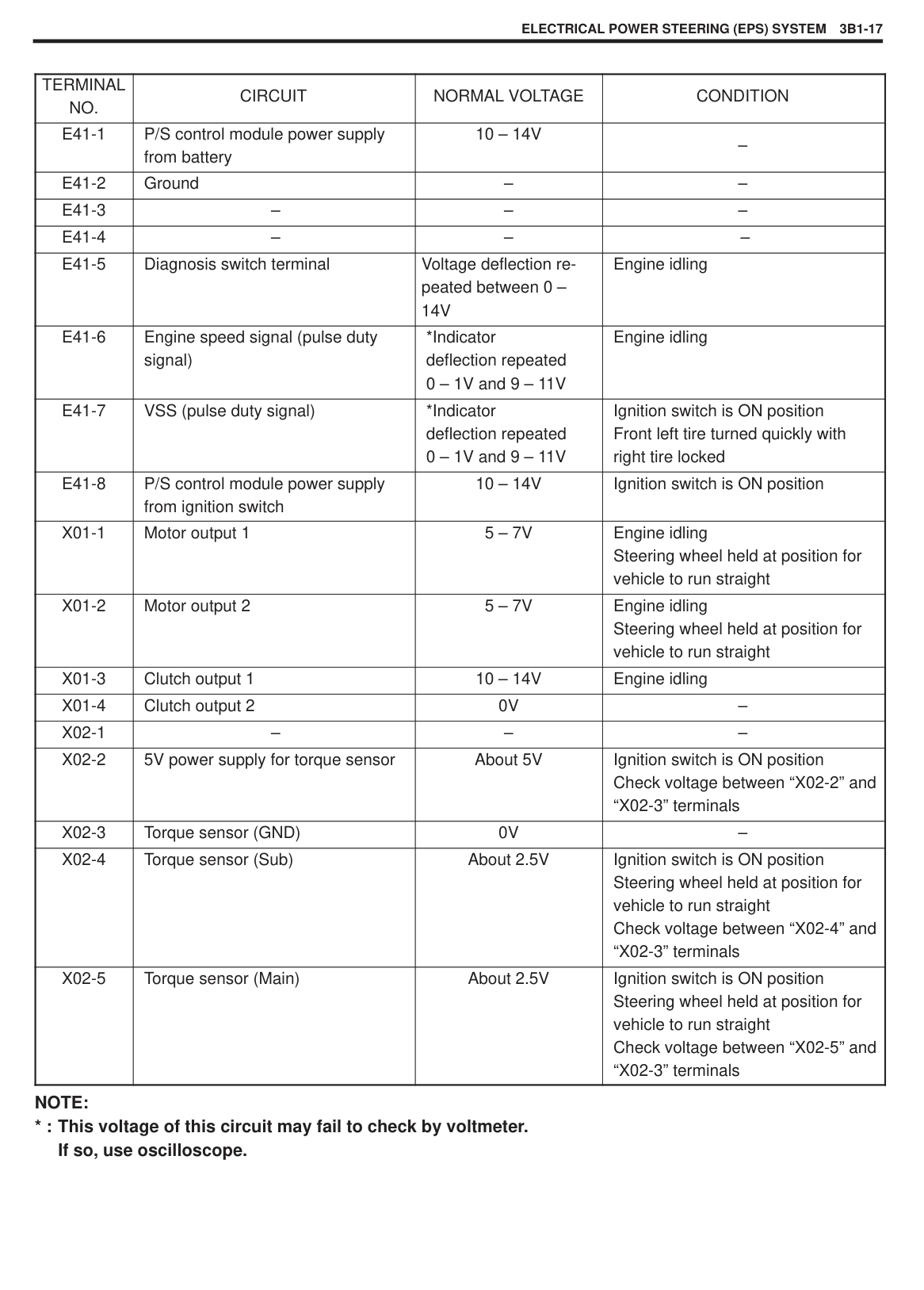
|5|1) Check torque sensor referring to “ON-VEHICLE
INSPECTION of TORQUE SENSOR”. Is torque sensor in good condition?|Substitute a knowngood P/S control module and recheck.|Replace steering column assembly and recheck.|
#### DTC 14 TORQUE SENSOR 5V POWER SUPPLY CIRCUIT FAILURE
|

1. To main fuse
2. Ignition switch
3. “P/S” fuse (30A) in fuse box
4. “IG. COIL METER” fuse (15A) in fuse box
5. P/S control module
6. Torque sensor
7. Connector “E41”
8. Connector “X02”
| |---|
|STEP|ACTION|YES|NO| |---|---|---|---| |1|Was “SYSTEM CHECK FLOW TABLE” performed?|Go to Step 2.|Go to “SYSTEM CHECK FLOW TABLE” in this section.| |2|1) Remove steering column hole cover.
2) Check proper connection for 5-pin (“X02”) connector to P/S control module.
3) If OK, turn ignition switch to ON position.
4) Check voltage between “X02-2” (“R” wire) terminal and body ground with “X02” connector connected to P/S control module.
Is it about 5 V?|Go to Step 3.|Repair high resistance, open or short to power circuit or ground in 5V power supply and “X02-2” (“R” wire) circuit and recheck.| |3|1) Check torque sensor referring to “ON-VEHICLE
INSPECTION of TORQUE SENSOR”. Is torque sensor in good condition?|Substitute a knowngood P/S control module and recheck.|Replace steering column assembly and recheck.|
Fig. for Step 2
|| |---|
#### DTC 21/23/24 VSS CIRCUIT FAILURE
|

1. To main fuse
2. Ignition switch
3. “P/S” fuse (30A) in fuse box
4. “IG. COIL METER” fuse (15A) in fuse box
5. Speedometer
6. Combination meter
7. To VSS
8. P/S control module
9. Connector “E41”
| |---|
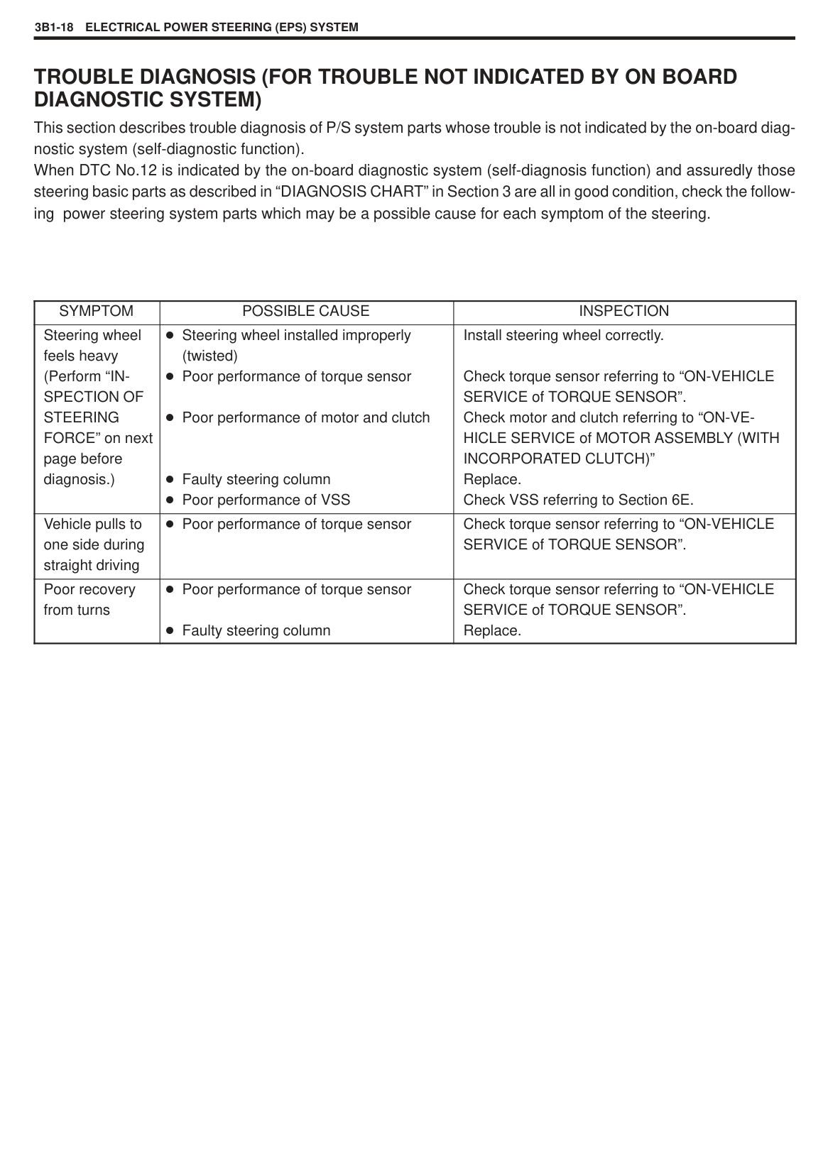
|STEP|ACTION|YES|NO| |---|---|---|---| |1|Was “SYSTEM CHECK FLOW TABLE” performed?|Go to Step 2.|Go to “SYSTEM CHECK FLOW TABLE” in this section.| |2|1) Ignition switch to OFF position.
2) Remove steering column hole cover.
3) Disconnect 8-pin (“E41”) connector from P/S control module.
4) Check proper connection to P/S control module at terminal “E41-7” (“V” wire).
5) If OK, connect voltmeter between “E41-7” (“V” wire) terminal and body ground with “E41” connector connected.
6) Hoist front end of vehicle and lock front right tire.
7) Turn front left tire quickly with ignition switch to ON position. Does voltmeter indicate deflection between 0 – 1V and 9 – 11V a few times while tire is turned one revolution?
|Check intermittent trouble referring to “INTERMITTENT TROUBLE” in Section 0A. If OK, substitute a known-good P/S control module and recheck.|Repair VSS or its “E41-7” (“V” wire) circuit referring to Section 6E1.|
Fig. for Step 2
|| |---|
#### DTC 22 ENGINE SPEED SIGNAL CIRCUIT FAILURE
|

1. To main fuse
2. Ignition switch
3. “P/S” fuse (30A) in fuse box
4. “IG. COIL METER” fuse (15A) in fuse box
5. ECM/PCM
6. P/S control module
7. Connector “E41”
| |---|
|STEP|ACTION|YES|NO| |---|---|---|---| |1|Was “SYSTEM CHECK FLOW TABLE” performed?|Go to Step 2.|Go to “SYSTEM CHECK FLOW TABLE” in this section.| |2|1) Recheck DTC with engine running. Is DTC 22 indicated?|Go to Step 3.|It is nothing abnormal for DTC 22. System is in normal condition.| |3|1) Check proper connection to P/S control module and ECM at each “Br” wire terminal (P/S control module side: “E41-6” terminal, ECM/PCM side: Refer to in Section 6E1), then check intermittent trouble referring to “INTERMITTENT TROUBLE” in Section 0A.
2) If they are OK, check high resistance, open or short to power circuit or ground in “Br” wire circuit.
Is check result in good condition?|Substitute a knowngood P/S control module and recheck.|Repair poor connector or intermittent trouble.|
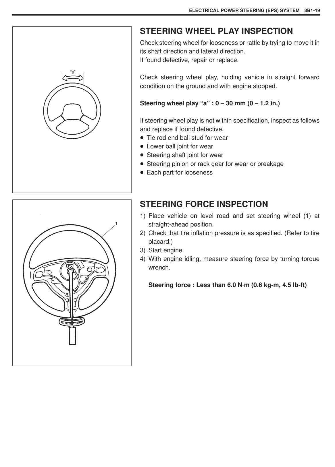
#### DTC 41/42/43/44/45 MOTOR CIRCUIT FAILURE
|
1. To main fuse
2. Ignition switch
3. “P/S” fuse (30A) in fuse box
4. “IG. COIL METER” fuse (15A) in fuse box
5. P/S control module
6. Motor assembly (with clutch incorporated)
7. Connector “E41”
8. Connector “X01”
| |---|
|STEP|ACTION|YES|NO| |---|---|---|---| |1|Was “SYSTEM CHECK FLOW TABLE” performed?|Go to Step 2.|Go to “SYSTEM CHECK FLOW TABLE” in this section.| |2|1) Remove steering column hole cover.
2) Check proper connection for 4-pin (“X01”) connector to P/S control module.
3) If OK, start engine.
4) Check voltage between “X01-1” (“B” wire) terminal and body ground and “X01-2” (“R” wire) terminal and body ground with “X01” connector connected to P/S control module.
Are they 5 – 7 V with steering wheel held at position for vehicle to run straight?|Go to Step 3.|Repair poor connection, high resistance, open or short to power circuit or ground in
“X01-1” (“B” wire) or
“X01-2” (“R” wire) circuit.
| |3|1) Check motor and its circuit referring to “ON-VEHICLE INSPECTION of MOTOR ASSEMBLY (WITH CLUTCH INCORPORATED)”.
Is motor in good condition?|Substitute a knowngood P/S control module and recheck.|Replace steering column assembly and recheck.|
Fig. for Step 2
|| |---|
#### DTC 51 CLUTCH CIRCUIT FAILURE
|
1. To main fuse
2. Ignition switch
3. “P/S” fuse (30A) in fuse box
4. “IG. COIL METER” fuse (15A) in fuse box
5. P/S control module
6. Motor assembly (with clutch incorporated)
7. Connector “E41”
8. Connector “X01”
| |---|
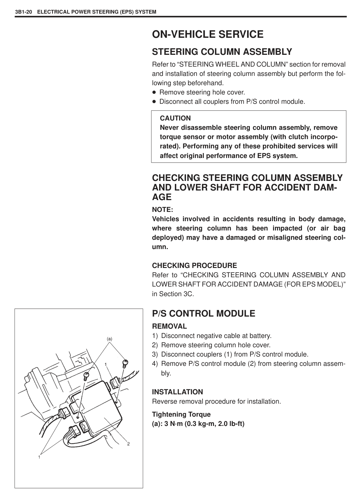
|STEP|ACTION|YES|NO| |---|---|---|---| |1|Was “SYSTEM CHECK FLOW TABLE” performed?|Go to Step 2.|Go to “SYSTEM CHECK FLOW TABLE” in this section.| |2|1) Remove steering column hole cover.
2) Check proper connection for 4-pin (“X01”) connector to P/S control module.
3) If OK, start engine.
4) Check voltage between “X01-3” (“B” wire) terminal and body ground with “X01” connector connected to P/S control module.
Is it 10 – 14 V with steering wheel held at position for vehicle to run straight?|Go to Step 3.|Repair poor connection, high resistance, open or short to power circuit or ground in “X01-3” (“B” wire) circuit.| |3|1) Check voltage between “X01-4” (“B” wire) terminal and body ground with “X01” connector connected to P/S control module.
Is it 0 V?|Go to Step 4.|Repair poor connection, high resistance, open or short to power circuit or ground in “X01-4” (“B” wire) circuit.| |4|1) Check motor and its circuit referring to “ON-VEHICLE INSPECTION of MOTOR ASSEMBLY (WITH CLUTCH INCORPORATED)”.
Is clutch in good condition?|Substitute a knowngood P/S control module and recheck.|Replace steering column assembly and recheck.|
Fig. for Step 2
|| |---|
Fig. for Step 3
|| |---|
#### DTC 53 P/S CONTROL MODULE POWER SUPPLY CIRCUIT FAILURE
|

1. To main fuse
2. Ignition switch
3. “P/S” fuse (30A) in fuse box
4. “IG. COIL METER” fuse (15A) in fuse box
5. P/S control module
6. Connector “E41”
| |---|
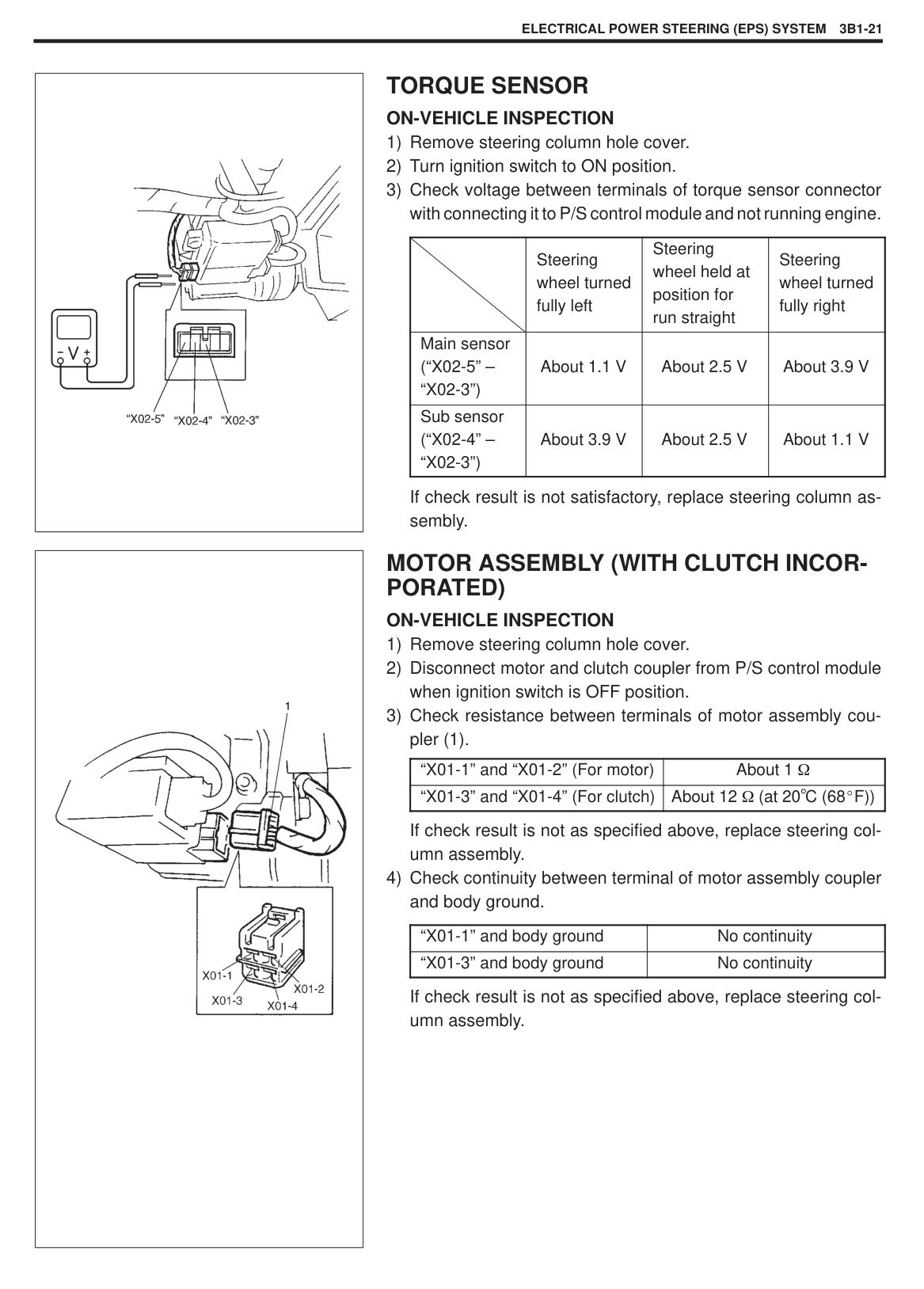
|STEP|ACTION|YES|NO| |---|---|---|---| |1|Was “SYSTEM CHECK FLOW TABLE” performed?|Go to Step 2.|Go to “SYSTEM CHECK FLOW TABLE” in this section.| |2|1) Remove steering column hole cover.
2) Check “P/S” fuse and proper connection to P/S control module at “E41-1” (“B/R” wire) terminal.
3) If OK, check voltage between “E41-1” (“B/R” wire) terminal and body ground with “E41” connector connected to P/S control module.
Is it 10 – 14 V?|Check intermittent trouble referring to “INTERMITTENT TROUBLE” in Section 0A. If OK, substitute a known-good P/S control module and recheck.|Repair poor connection or high resistance in “E41-1” (“B/R” wire) circuit.|
Fig. for Step 2
|| |---|
#### DTC 52/54/55 P/S CONTROL MODULE FAILURE Substitute a known-good P/S control module and recheck.
|| |---|
#### INSPECTION OF P/S CONTROL MODULE CIRCUIT
P/S control module (1) and its circuits can be checked at P/S control module wiring couplers (2) by measuring voltage and resistance.
|CAUTION: P/S control module cannot be checked by itself. It is strictly prohibited to connect voltmeter or ohmmeter to P/S control module with coupler disconnected from it.| |---|
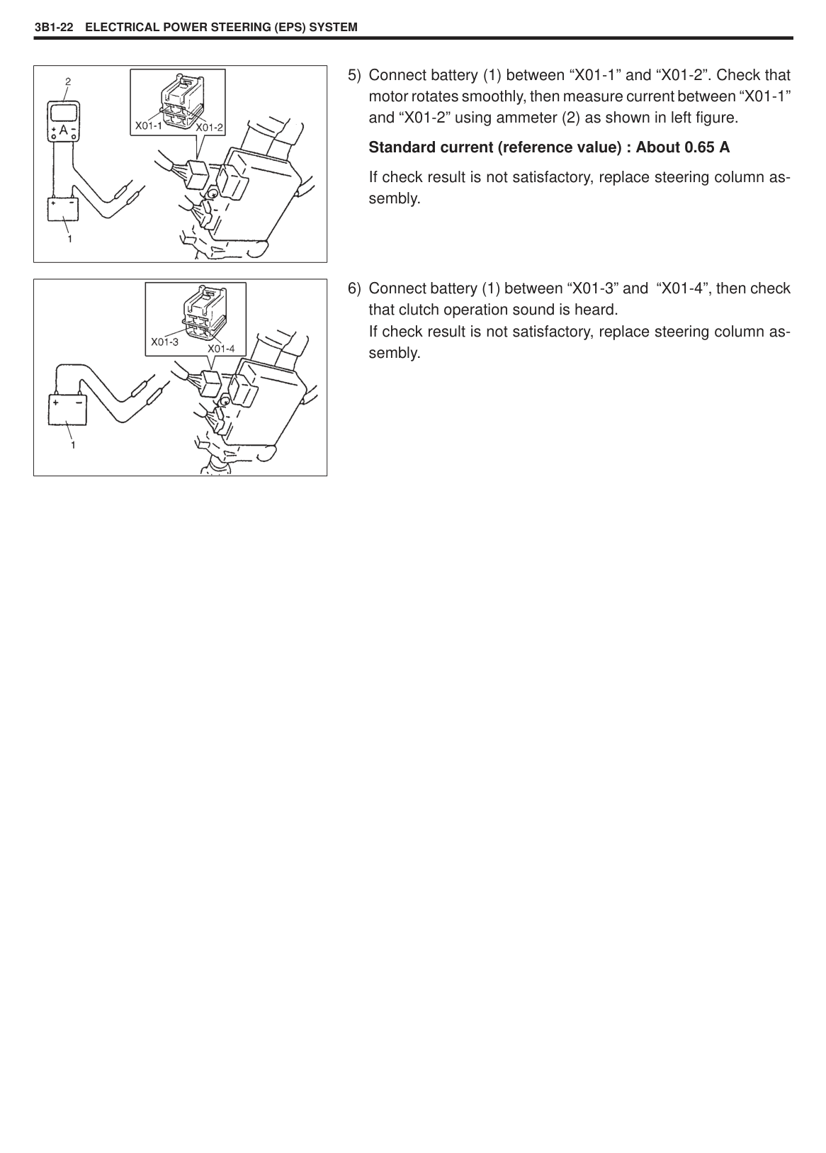
######## Voltage Check
NOTE: As each terminal voltage is affected by the battery voltage, confirm that it is 11V or more when ignition switch is ON position.
|
TERMINAL ARRANGEMENT OF P/S CONTROL MODULE COUPLERS (VIEWED FROM HARNESS SIDE)| |---|
|TERMINAL NO.|CIRCUIT|NORMAL VOLTAGE|CONDITION| |---|---|---|---| |E41-1|P/S control module power supply from battery|10 – 14V|–| |E41-2|Ground|–|–| |E41-3|–|–|–| |E41-4|–|–|–| |E41-5|Diagnosis switch terminal|Voltage deflection repeated between 0 – 14V|Engine idling| |E41-6|Engine speed signal (pulse duty signal)|*Indicator deflection repeated 0 – 1V and 9 – 11V|Engine idling| |E41-7|VSS (pulse duty signal)|*Indicator deflection repeated 0 – 1V and 9 – 11V|Ignition switch is ON position Front left tire turned quickly with right tire locked| |E41-8|P/S control module power supply from ignition switch|10 – 14V|Ignition switch is ON position| |X01-1|Motor output 1|5 – 7V|Engine idling Steering wheel held at position for vehicle to run straight| |X01-2|Motor output 2|5 – 7V|Engine idling Steering wheel held at position for vehicle to run straight| |X01-3|Clutch output 1|10 – 14V|Engine idling| |X01-4|Clutch output 2|0V|–|
|X02-1|–|–|–| |X02-2|5V power supply for torque sensor|About 5V|Ignition switch is ON position Check voltage between “X02-2” and “X02-3” terminals| |X02-3|Torque sensor (GND)|0V|–| |X02-4|Torque sensor (Sub)|About 2.5V|Ignition switch is ON position Steering wheel held at position for vehicle to run straight Check voltage between “X02-4” and “X02-3” terminals| |X02-5|Torque sensor (Main)|About 2.5V|Ignition switch is ON position Steering wheel held at position for vehicle to run straight Check voltage between “X02-5” and “X02-3” terminals|
NOTE:
#### TROUBLE DIAGNOSIS (FOR TROUBLE NOT INDICATED BY ON BOARD DIAGNOSTIC SYSTEM)
This section describes trouble diagnosis of P/S system parts whose trouble is not indicated by the on-board diagnostic system (self-diagnostic function). When DTC No.12 is indicated by the on-board diagnostic system (self-diagnosis function) and assuredly those steering basic parts as described in “DIAGNOSIS CHART” in Section 3 are all in good condition, check the following power steering system parts which may be a possible cause for each symptom of the steering.
|SYMPTOM|POSSIBLE CAUSE|INSPECTION| |---|---|---| |Steering wheel feels heavy (Perform “INSPECTION OF STEERING FORCE” on next page before diagnosis.)|Steering wheel installed improperly (twisted) Poor performance of torque sensor
Poor performance of motor and clutch
Faulty steering column Poor performance of VSS|Install steering wheel correctly.
Check torque sensor referring to “ON-VEHICLE SERVICE of TORQUE SENSOR”. Check motor and clutch referring to “ON-VEHICLE SERVICE of MOTOR ASSEMBLY (WITH INCORPORATED CLUTCH)” Replace. Check VSS referring to Section 6E.| |Vehicle pulls to one side during straight driving|Poor performance of torque sensor|Check torque sensor referring to “ON-VEHICLE SERVICE of TORQUE SENSOR”.| |Poor recovery from turns|Poor performance of torque sensor
Faulty steering column|Check torque sensor referring to “ON-VEHICLE SERVICE of TORQUE SENSOR”. Replace.|
|
| |---|
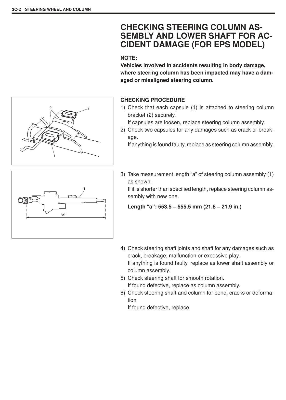
|| |---|
STEERING WHEEL PLAY INSPECTION Check steering wheel for looseness or rattle by trying to move it in its shaft direction and lateral direction. If found defective, repair or replace.
Check steering wheel play, holding vehicle in straight forward condition on the ground and with engine stopped.
######### Steering wheel play “a” : 0 – 30 mm (0 – 1.2 in.)
If steering wheel play is not within specification, inspect as follows and replace if found defective.
Tie rod end ball stud for wear Lower ball joint for wear Steering shaft joint for wear Steering pinion or rack gear for wear or breakage Each part for looseness
#### STEERING FORCE INSPECTION
######### Steering force : Less than 6.0 N·m (0.6 kg-m, 4.5 Ib-ft)
ON-VEHICLE SERVICE STEERING COLUMN ASSEMBLY
Refer to “STEERING WHEEL AND COLUMN” section for removal and installation of steering column assembly but perform the following step beforehand.
Remove steering hole cover. Disconnect all couplers from P/S control module.
|CAUTION Never disassemble steering column assembly, remove torque sensor or motor assembly (with clutch incorporated). Performing any of these prohibited services will affect original performance of EPS system.| |---|
CHECKING STEERING COLUMN ASSEMBLY AND LOWER SHAFT FOR ACCIDENT DAMAGE NOTE: Vehicles involved in accidents resulting in body damage, where steering column has been impacted (or air bag deployed) may have a damaged or misaligned steering column.
######## CHECKING PROCEDURE
Refer to “CHECKING STEERING COLUMN ASSEMBLY AND LOWER SHAFT FOR ACCIDENT DAMAGE (FOR EPS MODEL)” in Section 3C.
|| |---|
#### P/S CONTROL MODULE REMOVAL
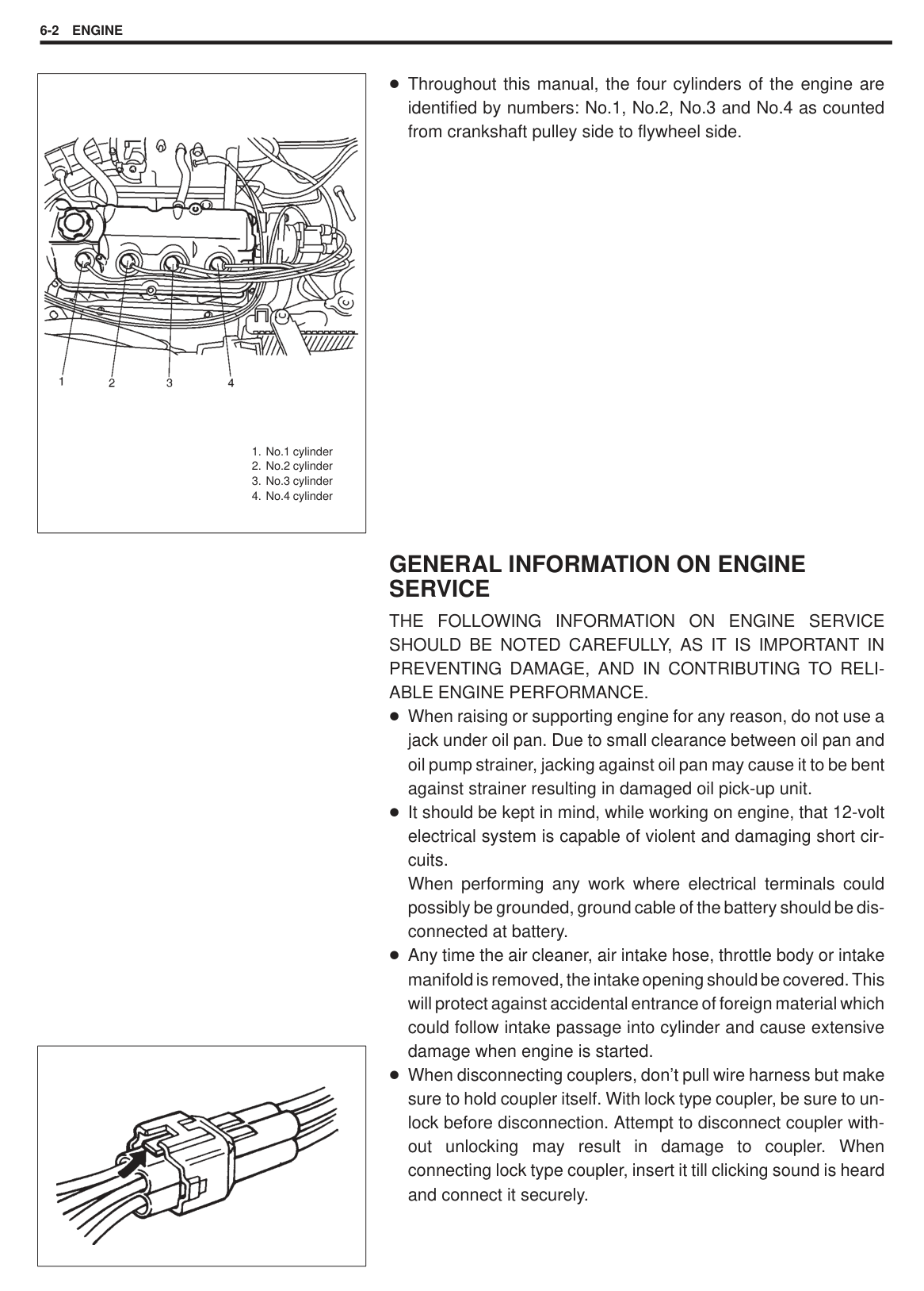
INSTALLATION Reverse removal procedure for installation.
Tightening Torque (a): 3 N·m (0.3 kg-m, 2.0 lb-ft)
|| |---|
|| |---|
#### TORQUE SENSOR ON-VEHICLE INSPECTION
| |Steering wheel turned fully left|Steering wheel held at position for run straight|Steering wheel turned fully right| |---|---|---|---| |Main sensor (“X02-5” – “X02-3”)|About 1.1 V|About 2.5 V|About 3.9 V| |Sub sensor (“X02-4” – “X02-3”)|About 3.9 V|About 2.5 V|About 1.1 V|
If check result is not satisfactory, replace steering column assembly.
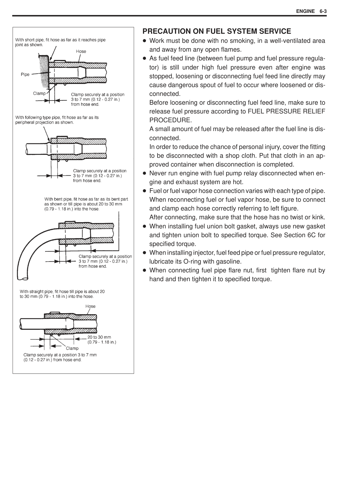
#### MOTOR ASSEMBLY (WITH CLUTCH INCORPORATED) ON-VEHICLE INSPECTION
If check result is not as specified above, replace steering column assembly.
|“X01-1” and “X01-2” (For motor)|About 1| |---|---| |“X01-3” and “X01-4” (For clutch)|About 12 (at 20 C (68 F))|
|“X01-1” and body ground|No continuity| |---|---| |“X01-3” and body ground|No continuity|
If check result is not as specified above, replace steering column assembly.
|| |---|
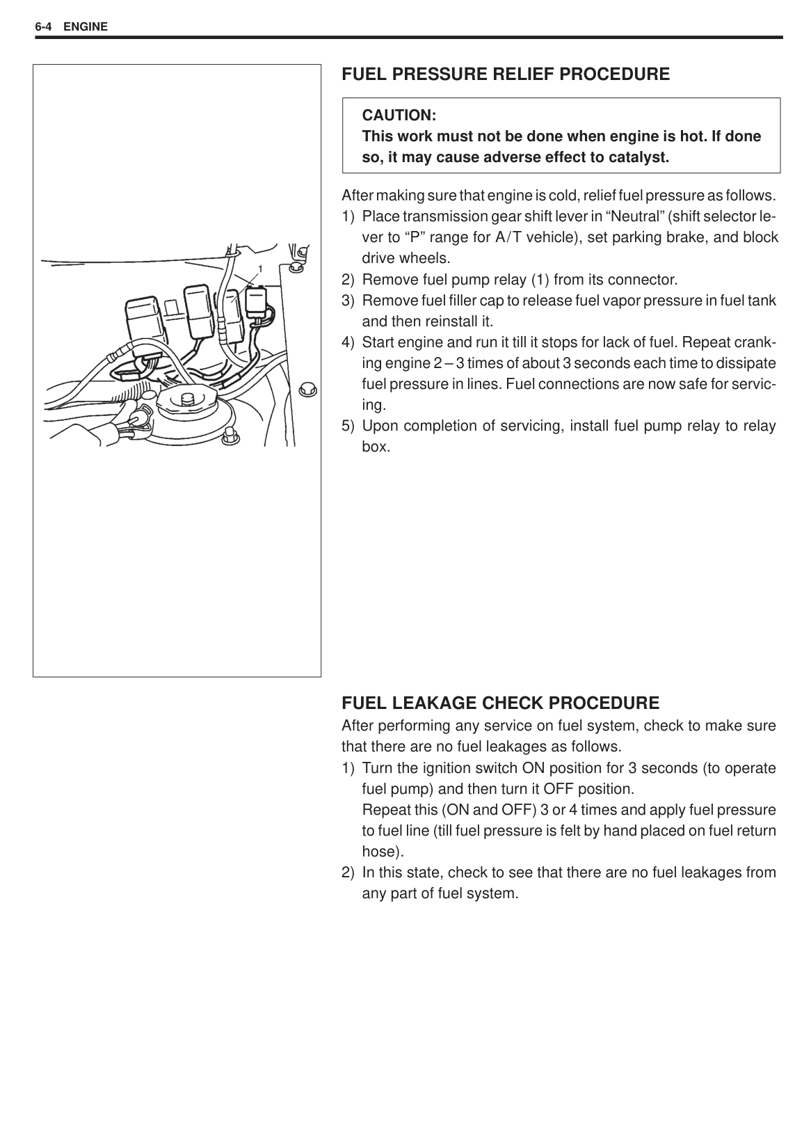
|| |---|
########## 5) Connect battery (1) between “X01-1” and “X01-2”. Check thatmotor rotates smoothly, then measure current between “X01-1”and “X01-2” using ammeter (2) as shown in left figure.Standard current (reference value) : About 0.65 A
If check result is not satisfactory, replace steering column assembly.
########## 6) Connect battery (1) between “X01-3” and “X01-4”, then checkthat clutch operation sound is heard.If check result is not satisfactory, replace steering column as-sembly.
STEERING WHEEL AND COLUMN 3C-1
SECTION 3C
STEERING WHEEL AND COLUMN
NOTE: For the descriptions (items) not found in this section, refer to the same section of Service Manual mentioned in Forward of this manual.
3C
#### CONTENTS
CHECKING STEERING COLUMN ASSEMBLY AND LOWER SHAFT FOR ACCIDENT DAMAGE (FOR EPS MODEL) 3C-2. . . . . . . . . . . . . . . . . . . . . . . . . . . . . . . . . . . . . . . . . . . . . . . . . . . . . . . . . . . . . . . . . . . . . . . . . . . . . . .
############### 3C-2 STEERING WHEEL AND COLUMN
CHECKING STEERING COLUMN ASSEMBLY AND LOWER SHAFT FOR ACCIDENT DAMAGE (FOR EPS MODEL)
NOTE: Vehicles involved in accidents resulting in body damage, where steering column has been impacted may have a damaged or misaligned steering column.
|| |---|
CHECKING PROCEDURE
|| |---|
SECTION 6
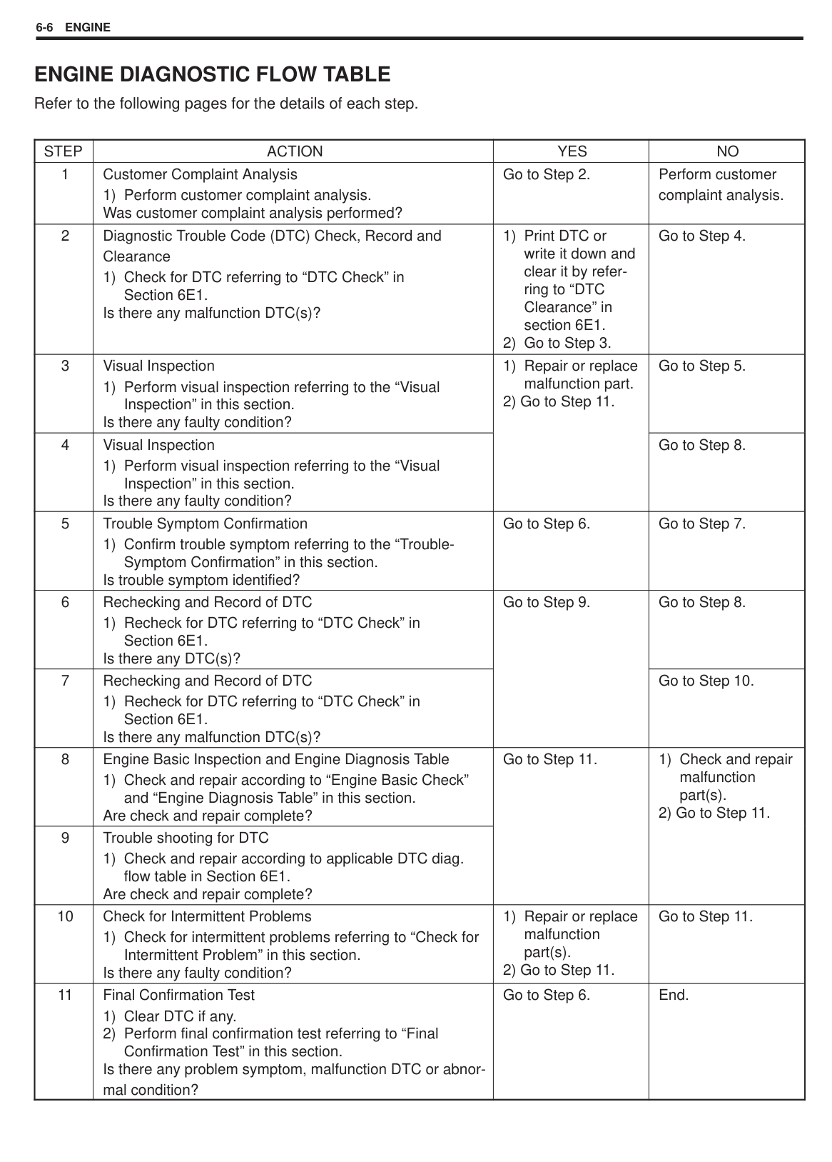
ENGINE
#### CONTENTS
GENERAL INFORMATION 6- 1. . . . . . . . . . . . . . . . . . . . . . . . . . . . . . . . . . . . . . . . . . . . . . . . . . . . . . . . . . . . . . . . . . . . ENGINE DIAGNOSIS 6- 5. . . . . . . . . . . . . . . . . . . . . . . . . . . . . . . . . . . . . . . . . . . . . . . . . . . . . . . . . . . . . . . . . . . . . . . . .
On-Board Diagnostic System 6- 5. . . . . . . . . . . . . . . . . . . . . . . . . . . . . . . . . . . . . . . . . . . . . . . . . . . . . . . . . . . . . . . . Precaution in Diagnosing Troubles 6- 5. . . . . . . . . . . . . . . . . . . . . . . . . . . . . . . . . . . . . . . . . . . . . . . . . . . . . . . . . . . Engine Diagnostic Flow Table 6- 6. . . . . . . . . . . . . . . . . . . . . . . . . . . . . . . . . . . . . . . . . . . . . . . . . . . . . . . . . . . . . . . Engine Diagnosis Table 6-10. . . . . . . . . . . . . . . . . . . . . . . . . . . . . . . . . . . . . . . . . . . . . . . . . . . . . . . . . . . . . . . . . . . . .
6
GENERAL INFORMATION STATEMENT ON CLEANLINESS AND CARE
An automobile engine is a combination of many machined, honed, polished and lapped surfaces with tolerances that are measured in the thousands of an millimeter (ten thousands of inch). Accordingly, when any internal engine parts are serviced, care and cleanliness are important. Throughout this section, it should be understood that proper cleaning and protection of machined surfaces and friction areas is part of the repair procedure. This is considered standard shop practice even if not specifically stated.
A liberal coating of engine oil should be applied to friction areas during assembly to protect and lubricate the surfaces on initial operation. Whenever valve train components, pistons, piston rings, connecting rods, rod bearings, and crankshaft journal bearings are removed for service, they should be retained in order. At the time of installation, they should be installed in the same locations and with the same mating surfaces as when removed. Battery cables should be disconnected before any major work is performed on the engine. Failure to disconnect cables may result in damage to wire harness or other electrical parts.
|
1. No.1 cylinder
2. No.2 cylinder
3. No.3 cylinder
4. No.4 cylinder
| |---|
|| |---|
Throughout this manual, the four cylinders of the engine are identified by numbers: No.1, No.2, No.3 and No.4 as counted from crankshaft pulley side to flywheel side.
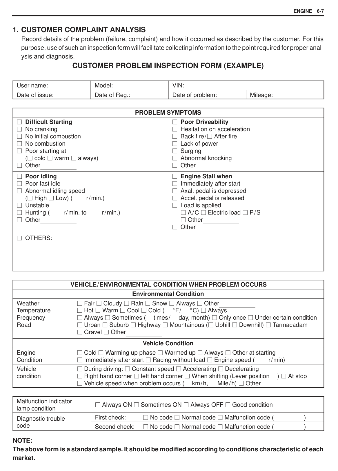
#### GENERAL INFORMATION ON ENGINE SERVICE
THE FOLLOWING INFORMATION ON ENGINE SERVICE SHOULD BE NOTED CAREFULLY, AS IT IS IMPORTANT IN PREVENTING DAMAGE, AND IN CONTRIBUTING TO RELIABLE ENGINE PERFORMANCE.
When raising or supporting engine for any reason, do not use a jack under oil pan. Due to small clearance between oil pan and oil pump strainer, jacking against oil pan may cause it to be bent against strainer resulting in damaged oil pick-up unit. It should be kept in mind, while working on engine, that 12-volt electrical system is capable of violent and damaging short circuits. When performing any work where electrical terminals could possibly be grounded, ground cable of the battery should be disconnected at battery. Any time the air cleaner, air intake hose, throttle body or intake manifold is removed, the intake opening should be covered. This will protect against accidental entrance of foreign material which could follow intake passage into cylinder and cause extensive damage when engine is started. When disconnecting couplers, don’t pull wire harness but make sure to hold coupler itself. With lock type coupler, be sure to unlock before disconnection. Attempt to disconnect coupler without unlocking may result in damage to coupler. When connecting lock type coupler, insert it till clicking sound is heard and connect it securely.
|| |---|
PRECAUTION ON FUEL SYSTEM SERVICE Work must be done with no smoking, in a well-ventilated area and away from any open flames. As fuel feed line (between fuel pump and fuel pressure regulator) is still under high fuel pressure even after engine was stopped, loosening or disconnecting fuel feed line directly may cause dangerous spout of fuel to occur where loosened or disconnected. Before loosening or disconnecting fuel feed line, make sure to release fuel pressure according to FUEL PRESSURE RELIEF PROCEDURE. A small amount of fuel may be released after the fuel line is disconnected. In order to reduce the chance of personal injury, cover the fitting to be disconnected with a shop cloth. Put that cloth in an approved container when disconnection is completed. Never run engine with fuel pump relay disconnected when engine and exhaust system are hot. Fuel or fuel vapor hose connection varies with each type of pipe. When reconnecting fuel or fuel vapor hose, be sure to connect and clamp each hose correctly referring to left figure. After connecting, make sure that the hose has no twist or kink. When installing fuel union bolt gasket, always use new gasket and tighten union bolt to specified torque. See Section 6C for specified torque. When installing injector, fuel feed pipe or fuel pressure regulator, lubricate its O-ring with gasoline. When connecting fuel pipe flare nut, first tighten flare nut by hand and then tighten it to specified torque.
|| |---|
###### FUEL PRESSURE RELIEF PROCEDURE
|CAUTION: This work must not be done when engine is hot. If done so, it may cause adverse effect to catalyst.| |---|
After making sure that engine is cold, relief fuel pressure as follows.
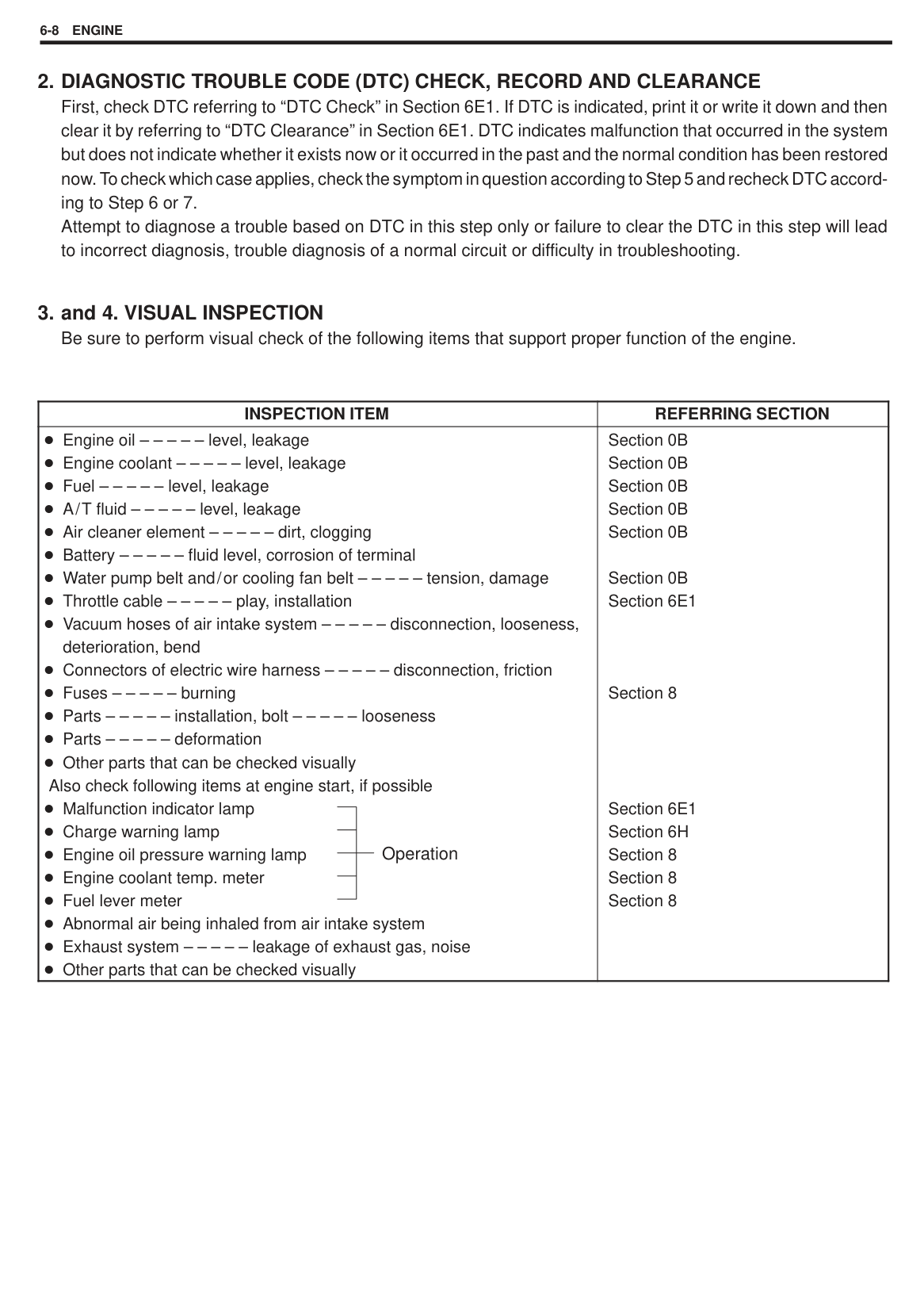
FUEL LEAKAGE CHECK PROCEDURE After performing any service on fuel system, check to make sure that there are no fuel leakages as follows.
ENGINE DIAGNOSIS
This vehicle is equipped with an engine and emission control system, which controls the A/F mixture, ignition timing, emission, etc. suitably to engine conditions by ECM. ECM has an On-Board Diagnostic system which detects a malfunction in this system. When diagnosing a trouble in the engine including this system, be sure to have understanding of the outline of “OnBoard Diagnostic system” and each item in “Precaution in Diagnosing Trouble” and follow “ENGINE DIAGNOSTIC FLOW TABLE” given below to obtain correct result smoothly.
ON-BOARD DIAGNOSTIC SYSTEM Refer to “On-Board Diagnostic System” in Section 6E1.
PRECAUTION IN DIAGNOSING TROUBLES Be sure to read “Precaution in Diagnosing Troubles” in Section 6E1 and observe what is written there.
##### ENGINE DIAGNOSTIC FLOW TABLE Refer to the following pages for the details of each step.
|STEP|ACTION|YES|NO| |---|---|---|---| |1|Customer Complaint Analysis
1) Perform customer complaint analysis. Was customer complaint analysis performed?|Go to Step 2.|Perform customer complaint analysis.| |2|Diagnostic Trouble Code (DTC) Check, Record and Clearance
1) Check for DTC referring to “DTC Check” in Section 6E1. Is there any malfunction DTC(s)?|1) Print DTC or write it down and clear it by referring to “DTC Clearance” in section 6E1.
2) Go to Step 3.
|Go to Step 4.|
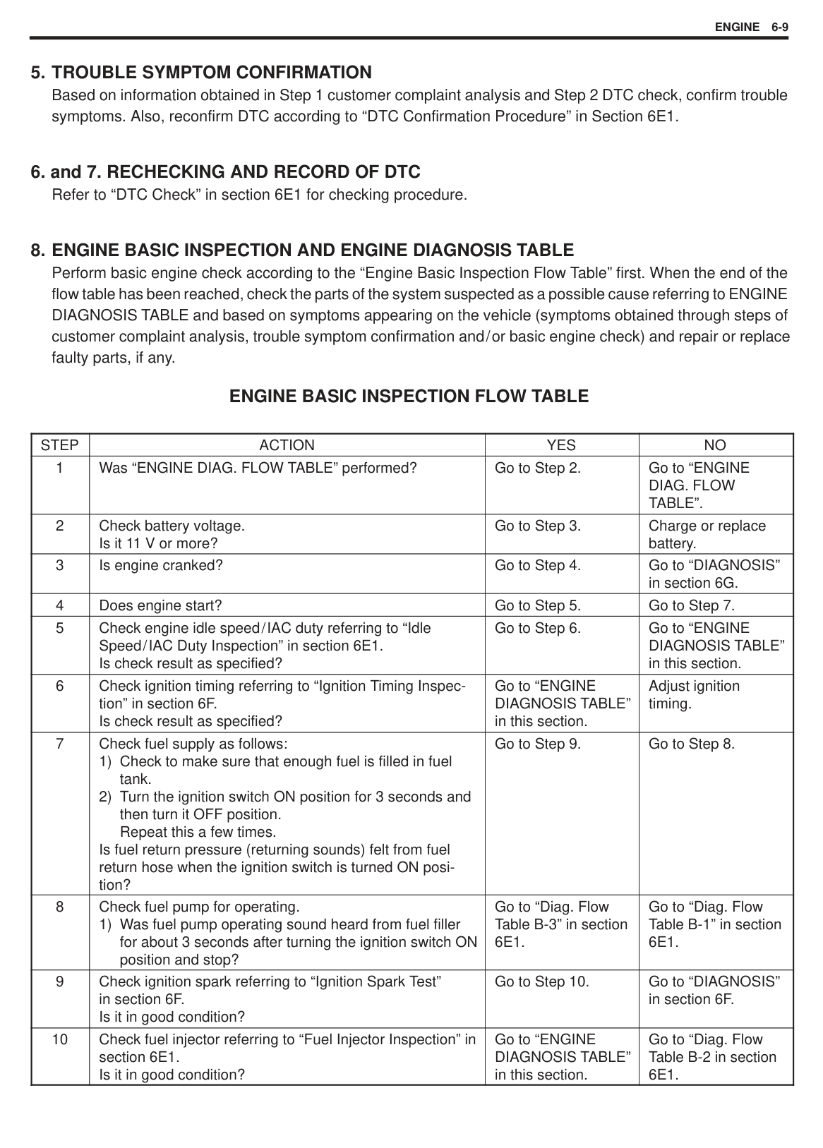
|3|Visual Inspection
1) Perform visual inspection referring to the “Visual
Inspection” in this section. Is there any faulty condition?|1) Repair or replace malfunction part.
2) Go to Step 11.
|Go to Step 5.| |4|Visual Inspection
1) Perform visual inspection referring to the “Visual
Inspection” in this section. Is there any faulty condition?|1) Repair or replace malfunction part.
2) Go to Step 11.
|Go to Step 8.| |5|Trouble Symptom Confirmation
1) Confirm trouble symptom referring to the “Trouble-
Symptom Confirmation” in this section. Is trouble symptom identified?|Go to Step 6.|Go to Step 7.| |6|Rechecking and Record of DTC
1) Recheck for DTC referring to “DTC Check” in Section 6E1. Is there any DTC(s)?|Go to Step 9.
|Go to Step 8.| |7|Rechecking and Record of DTC
1) Recheck for DTC referring to “DTC Check” in Section 6E1. Is there any malfunction DTC(s)?|Go to Step 9.
|Go to Step 10.| |8|Engine Basic Inspection and Engine Diagnosis Table
1) Check and repair according to “Engine Basic Check”
and “Engine Diagnosis Table” in this section. Are check and repair complete?|Go to Step 11.
|1) Check and repair malfunction part(s).
2) Go to Step 11.
| |9|Trouble shooting for DTC
1) Check and repair according to applicable DTC diag.
flow table in Section 6E1. Are check and repair complete?|Go to Step 11.
|1) Check and repair malfunction part(s).
2) Go to Step 11.
| |10|Check for Intermittent Problems
1) Check for intermittent problems referring to “Check for
Intermittent Problem” in this section. Is there any faulty condition?|1) Repair or replace malfunction part(s).
2) Go to Step 11.
|Go to Step 11.| |11|Final Confirmation Test
1) Clear DTC if any.
2) Perform final confirmation test referring to “Final Confirmation Test” in this section.
Is there any problem symptom, malfunction DTC or abnormal condition?|Go to Step 6.|End.|
###### CUSTOMER PROBLEM INSPECTION FORM (EXAMPLE)
|User name:|Model:|VIN:|VIN:| |---|---|---|---| |Date of issue:|Date of Reg.:|Date of problem:|Mileage:|
|PROBLEM SYMPTOMS| |---| |Difficult Starting No cranking No initial combustion No combustion Poor starting at ( cold warm always) Other
Poor Driveability Hesitation on acceleration Back fire/ After fire Lack of power Surging Abnormal knocking Other
| |Poor idling Poor fast idle Abnormal idling speed ( High Low) ( r/min.) Unstable Hunting ( r/min. to r/min.) Other
Engine Stall when Immediately after start Axal. pedal is depressed Accel. pedal is released Load is applied
A/C Electric load P/S Other
Other
| |OTHERS:|
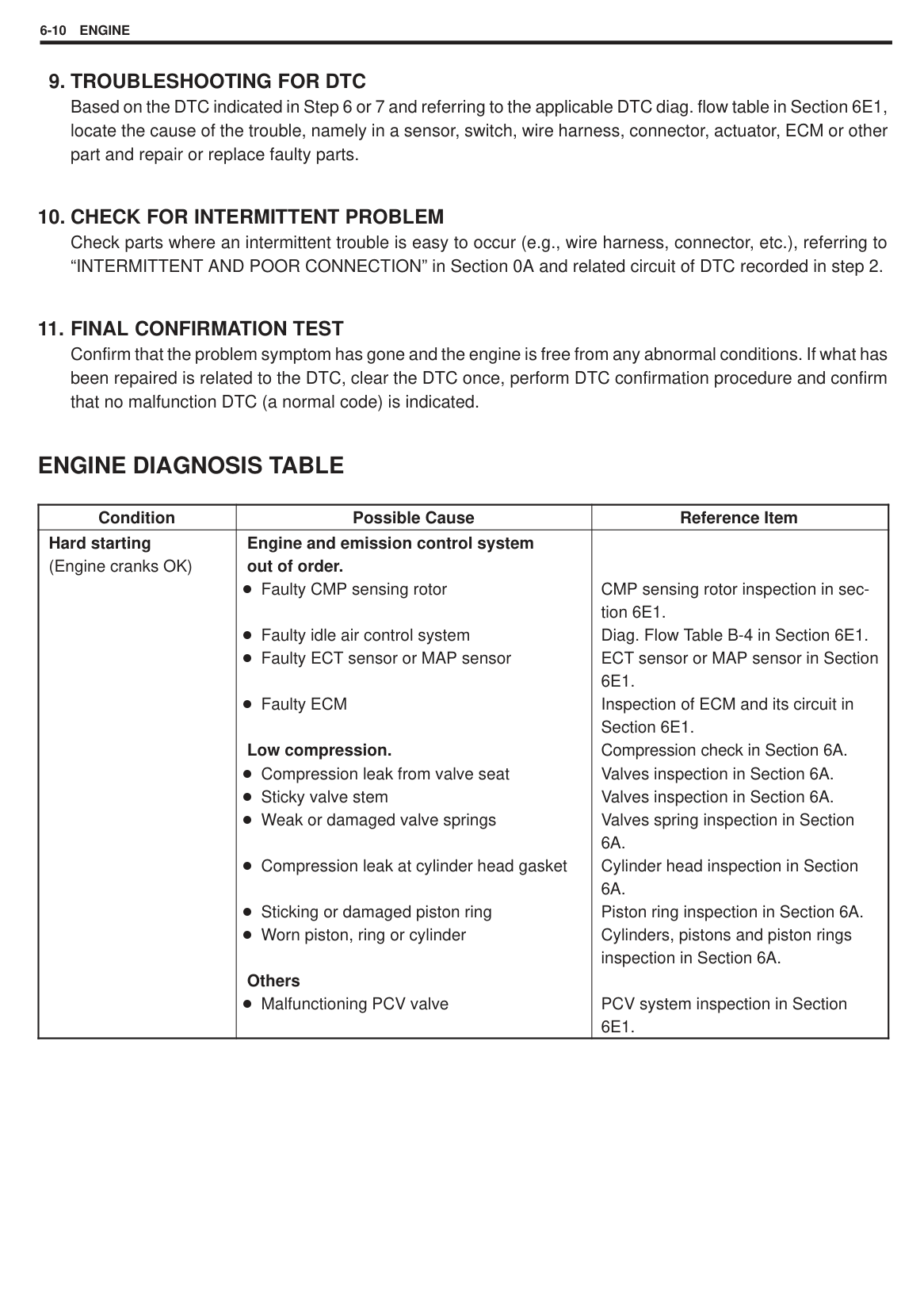
|VEHICLE/ENVIRONMENTAL CONDITION WHEN PROBLEM OCCURS|VEHICLE/ENVIRONMENTAL CONDITION WHEN PROBLEM OCCURS| |---|---| |Environmental Condition|Environmental Condition| |Weather Temperature Frequency Road|Fair Cloudy Rain Snow Always Other Hot Warm Cool Cold ( F/ C) Always Always Sometimes ( times/ day, month) Only once Under certain condition Urban Suburb Highway Mountainous ( Uphill Downhill) Tarmacadam Gravel Other
| |Vehicle Condition|Vehicle Condition| |Engine Condition|Cold Warming up phase Warmed up Always Other at starting Immediately after start Racing without load Engine speed ( r/min)| |Vehicle condition|During driving: Constant speed Accelerating Decelerating Right hand corner left hand corner When shifting (Lever position ) At stop Vehicle speed when problem occurs ( km/h, Mile/h) Other|
|Malfunction indicator lamp condition|Always ON Sometimes ON Always OFF Good condition| |---|---| |Diagnostic troubleg code
|First check: No code Normal code Malfunction code ( )| |Diagnostic troubleg code
|Second check: No code Normal code Malfunction code ( )|
NOTE: The above form is a standard sample. It should be modified according to conditions characteristic of each market.
|INSPECTION ITEM|REFERRING SECTION| |---|---| |Operation
Engine oil – – – – – level, leakage Engine coolant – – – – – level, leakage Fuel – – – – – level, leakage A/T fluid – – – – – level, leakage Air cleaner element – – – – – dirt, clogging Battery – – – – – fluid level, corrosion of terminal Water pump belt and/or cooling fan belt – – – – – tension, damage Throttle cable – – – – – play, installation Vacuum hoses of air intake system – – – – – disconnection, looseness, deterioration, bend Connectors of electric wire harness – – – – – disconnection, friction Fuses – – – – – burning Parts – – – – – installation, bolt – – – – – looseness Parts – – – – – deformation Other parts that can be checked visually
Also check following items at engine start, if possible Malfunction indicator lamp Charge warning lamp Engine oil pressure warning lamp Engine coolant temp. meter Fuel lever meter Abnormal air being inhaled from air intake system Exhaust system – – – – – leakage of exhaust gas, noise Other parts that can be checked visually|Section 0B Section 0B Section 0B Section 0B Section 0B
Section 0B Section 6E1
Section 8
Section 6E1 Section 6H Section 8 Section 8 Section 8|
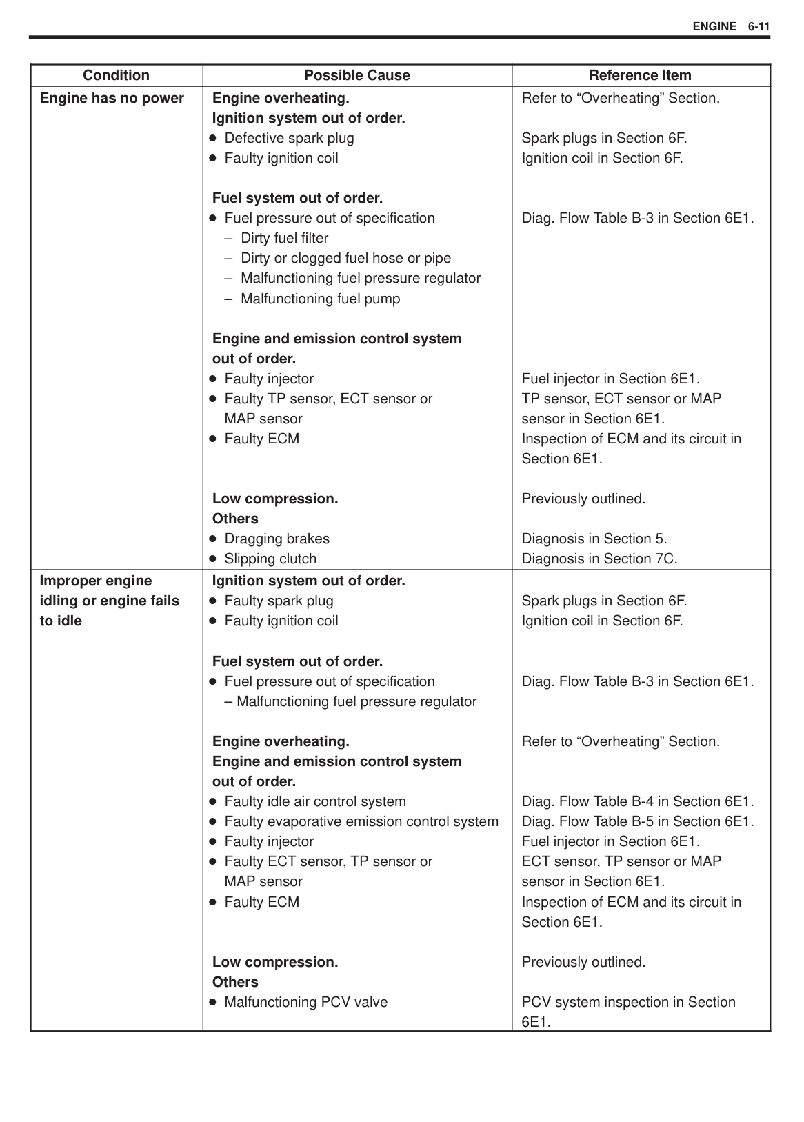
###### ENGINE BASIC INSPECTION FLOW TABLE
|STEP|ACTION|YES|NO| |---|---|---|---| |1|Was “ENGINE DIAG. FLOW TABLE” performed?|Go to Step 2.|Go to “ENGINE DIAG. FLOW TABLE”.| |2|Check battery voltage. Is it 11 V or more?|Go to Step 3.|Charge or replace battery.| |3|Is engine cranked?|Go to Step 4.|Go to “DIAGNOSIS” in section 6G.| |4|Does engine start?|Go to Step 5.|Go to Step 7.| |5|Check engine idle speed/IAC duty referring to “Idle Speed/IAC Duty Inspection” in section 6E1. Is check result as specified?|Go to Step 6.|Go to “ENGINE DIAGNOSIS TABLE” in this section.| |6|Check ignition timing referring to “Ignition Timing Inspection” in section 6F. Is check result as specified?|Go to “ENGINE DIAGNOSIS TABLE” in this section.|Adjust ignition timing.| |7|Check fuel supply as follows:
1) Check to make sure that enough fuel is filled in fuel tank.
2) Turn the ignition switch ON position for 3 seconds and then turn it OFF position. Repeat this a few times.
Is fuel return pressure (returning sounds) felt from fuel return hose when the ignition switch is turned ON position?|Go to Step 9.|Go to Step 8.| |8|Check fuel pump for operating.
1) Was fuel pump operating sound heard from fuel filler for about 3 seconds after turning the ignition switch ON position and stop?|Go to “Diag. Flow Table B-3” in section 6E1.|Go to “Diag. Flow Table B-1” in section 6E1.| |9|Check ignition spark referring to “Ignition Spark Test” in section 6F. Is it in good condition?|Go to Step 10.|Go to “DIAGNOSIS” in section 6F.| |10|Check fuel injector referring to “Fuel Injector Inspection” in section 6E1. Is it in good condition?|Go to “ENGINE DIAGNOSIS TABLE” in this section.|Go to “Diag. Flow Table B-2 in section 6E1.|
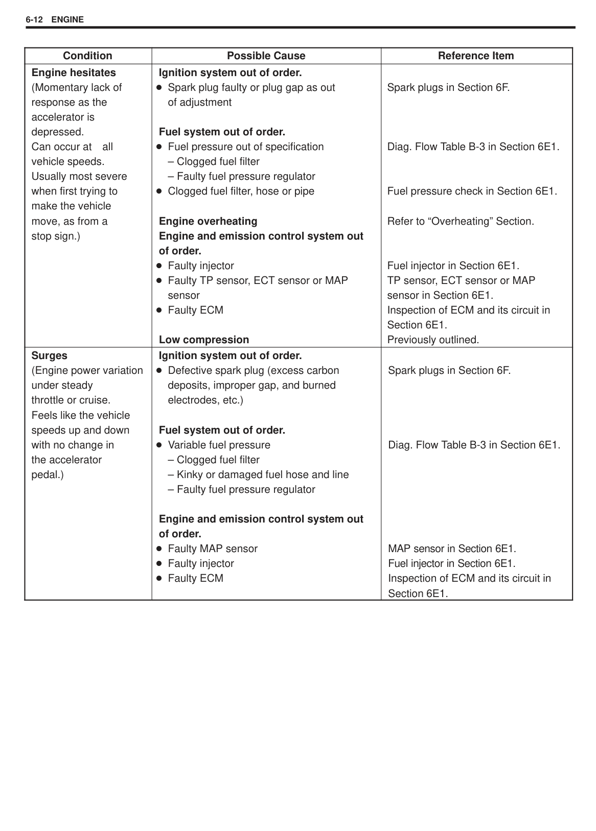
#### ENGINE DIAGNOSIS TABLE
|Condition|Possible Cause|Reference Item| |---|---|---| |Hard starting (Engine cranks OK)|Engine and emission control system out of order.
Faulty CMP sensing rotor
Faulty idle air control system Faulty ECT sensor or MAP sensor
Faulty ECM
Low compression. Compression leak from valve seat Sticky valve stem Weak or damaged valve springs
Compression leak at cylinder head gasket
Sticking or damaged piston ring Worn piston, ring or cylinder
Others
Malfunctioning PCV valve|CMP sensing rotor inspection in section 6E1. Diag. Flow Table B-4 in Section 6E1. ECT sensor or MAP sensor in Section 6E1. Inspection of ECM and its circuit in Section 6E1. Compression check in Section 6A. Valves inspection in Section 6A. Valves inspection in Section 6A. Valves spring inspection in Section 6A. Cylinder head inspection in Section 6A. Piston ring inspection in Section 6A. Cylinders, pistons and piston rings inspection in Section 6A.
PCV system inspection in Section 6E1.|
|Condition|Possible Cause|Reference Item| |---|---|---| |Engine has no power|Engine overheating. Ignition system out of order.
Defective spark plug Faulty ignition coil
Fuel system out of order.
Fuel pressure out of specification
– Dirty fuel filter
– Dirty or clogged fuel hose or pipe
– Malfunctioning fuel pressure regulator
– Malfunctioning fuel pump
Engine and emission control system out of order.
Faulty injector Faulty TP sensor, ECT sensor or MAP sensor Faulty ECM
Low compression. Others
Dragging brakes Slipping clutch|Refer to “Overheating” Section.
Spark plugs in Section 6F. Ignition coil in Section 6F.
Diag. Flow Table B-3 in Section 6E1.
Fuel injector in Section 6E1. TP sensor, ECT sensor or MAP sensor in Section 6E1. Inspection of ECM and its circuit in Section 6E1.
Previously outlined.
Diagnosis in Section 5. Diagnosis in Section 7C.| |Improper engine idling or engine fails to idle|Ignition system out of order. Faulty spark plug Faulty ignition coil
Fuel system out of order.
Fuel pressure out of specification
– Malfunctioning fuel pressure regulator
Engine overheating. Engine and emission control system out of order.
Faulty idle air control system Faulty evaporative emission control system Faulty injector Faulty ECT sensor, TP sensor or MAP sensor Faulty ECM
Low compression. Others
Malfunctioning PCV valve|Spark plugs in Section 6F. Ignition coil in Section 6F.
Diag. Flow Table B-3 in Section 6E1.
Refer to “Overheating” Section.
Diag. Flow Table B-4 in Section 6E1.
Diag. Flow Table B-5 in Section 6E1. Fuel injector in Section 6E1. ECT sensor, TP sensor or MAP sensor in Section 6E1. Inspection of ECM and its circuit in Section 6E1.
Previously outlined.
PCV system inspection in Section 6E1.|
|Condition|Possible Cause|Reference Item| |---|---|---| |Engine hesitates (Momentary lack of response as the accelerator is depressed. Can occur at all vehicle speeds. Usually most severe when first trying to make the vehicle move, as from a stop sign.)|Ignition system out of order. Spark plug faulty or plug gap as out of adjustment
Fuel system out of order.
Fuel pressure out of specification
– Clogged fuel filter
– Faulty fuel pressure regulator Clogged fuel filter, hose or pipe
Engine overheating Engine and emission control system out of order.
Faulty injector Faulty TP sensor, ECT sensor or MAP sensor Faulty ECM
Low compression|Spark plugs in Section 6F.
Diag. Flow Table B-3 in Section 6E1.
Fuel pressure check in Section 6E1.
Refer to “Overheating” Section.
Fuel injector in Section 6E1. TP sensor, ECT sensor or MAP sensor in Section 6E1. Inspection of ECM and its circuit in Section 6E1. Previously outlined.| |Surges (Engine power variation under steady throttle or cruise. Feels like the vehicle speeds up and down with no change in the accelerator pedal.)|Ignition system out of order. Defective spark plug (excess carbon deposits, improper gap, and burned electrodes, etc.)
Fuel system out of order.
Variable fuel pressure
– Clogged fuel filter
– Kinky or damaged fuel hose and line
– Faulty fuel pressure regulator
Engine and emission control system out of order.
Faulty MAP sensor Faulty injector Faulty ECM|Spark plugs in Section 6F.
Diag. Flow Table B-3 in Section 6E1.
MAP sensor in Section 6E1. Fuel injector in Section 6E1. Inspection of ECM and its circuit in Section 6E1.|
|Condition|Possible Cause|Reference Item| |---|---|---| |Excessive detonation (The engine makes sharp metallic knocks that change with throttle opening. Sounds like pop corn popping.)
|Engine overheating Ignition system out of order.
Faulty spark plug Improper ignition timing
Fuel system out of order.
Clogged fuel filter and fuel lines
Engine and emission control system out of order.
Faulty ECT sensor or MAP sensor
Faulty injector Faulty ECM
Others
Excessive combustion chamber deposits
|Refer to “Overheating” Section.
Spark plugs in Section 6F. Ignition timing in Section 6F.
Fuel pressure check in Section 6E1.
ECT sensor or MAP sensor in Section 6E1. Fuel injector in Section 6E1. Inspection of ECM and its circuit in Section 6E1.
Piston and cylinder head cleaning in Section 6A.
|
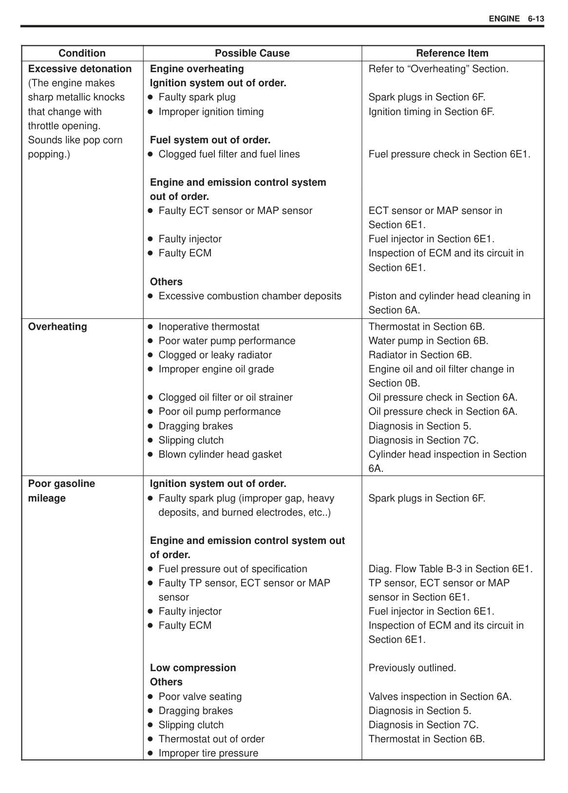
|Overheating|Inoperative thermostat Poor water pump performance Clogged or leaky radiator Improper engine oil grade
Clogged oil filter or oil strainer Poor oil pump performance Dragging brakes Slipping clutch Blown cylinder head gasket|Thermostat in Section 6B. Water pump in Section 6B. Radiator in Section 6B. Engine oil and oil filter change in Section 0B. Oil pressure check in Section 6A. Oil pressure check in Section 6A. Diagnosis in Section 5. Diagnosis in Section 7C. Cylinder head inspection in Section 6A.| |Poor gasoline mileage|Ignition system out of order. Faulty spark plug (improper gap, heavy deposits, and burned electrodes, etc..)
Engine and emission control system out of order.
Fuel pressure out of specification Faulty TP sensor, ECT sensor or MAP sensor Faulty injector Faulty ECM
Low compression Others
Poor valve seating Dragging brakes Slipping clutch Thermostat out of order Improper tire pressure|Spark plugs in Section 6F.
Diag. Flow Table B-3 in Section 6E1. TP sensor, ECT sensor or MAP sensor in Section 6E1. Fuel injector in Section 6E1. Inspection of ECM and its circuit in Section 6E1.
Previously outlined.
Valves inspection in Section 6A. Diagnosis in Section 5. Diagnosis in Section 7C. Thermostat in Section 6B.|
|Condition|Possible Cause|Reference Item| |---|---|---| |Excessive engine oil consumption|Oil entering combustion chamber Sticky piston ring Worn piston and cylinder
Worn piston ring groove and ring
Improper location of piston ring gap Worn or damaged valve stem seal
Worn valve stem|Piston cleaning in Section 6A. Cylinders, pistons and piston rings inspection in Section 6A. Pistons and piston rings inspection in Section 6A. Pistons installation in Section 6A. Valves and cylinder head in Section 6A. Valves inspection in Section 6A.| |Low oil pressure|Improper oil viscosity
Malfunctioning oil pressure switch
Clogged oil strainer
Functional deterioration of oil pump Worn oil pump relief valve Excessive clearance in various sliding parts|Engine oil and oil filter change in Section 0B. Oil pressure switch inspection in Section 8. Oil pan and oil pump strainer cleaning in Section 6A. Oil pump in Section 6A. Oil pump in Section 6A.| |Engine noise Note: Before checking the mechanical noise, make sure that:
Ignition timing is properly adjusted. Specified spark plug is used. Specified fuel is used.|Valve noise Improper valve lash Worn valve stem and guide Weak or broken valve spring
Warped or bent valve Loose camshaft housing bolts
Piston, ring and cylinder noise
Worn piston, ring and cylinder bore
Connecting rod noise
Worn crankpin bearing
Worn crankpin
Loose connecting rod nuts
Low oil pressure
Crankshaft noise Low oil pressure Worn crankshaft journal bearing
Worn crankshaft journal
Loose lower crankcase (bearing cap) bolts Excessive crankshaft thrust play|Valve lash in Section 6A. Valves inspection in Section 6A. Valve springs inspection in Section 6A. Valves inspection in Section 6A. Camshafts in Section 6A.
Pistons and cylinders inspection in Section 6A.
Crankpin and connecting rod bearing inspection in Section 6A. Crankpin and connecting rod bearing inspection in Section 6A. Connecting rod installation in Section 6A. Previously outlined.
Previously outlined. Crankshaft and bearing inspection in Section 6A. Crankshaft and bearing inspection in Section 6A. Crankshaft installation in Section 6A.
Crankshaft inspection in Section 6A.|
|Condition|Possible Cause|Referring Item| |---|---|---| |Excessive hydrocarbon (HC) emission or Excessive carbon monoxide (CO) emission|Ignition system out of order
Defective spark plug
Fuel system out of order
Fuel pressure out of specification
Engine and Emission control system out of order.
Lead contamination of three way catalytic converter (if equipped) Malfunctioning PCV valve Faulty EVAP control system
Closed loop system (A/F feed back compensation) fails
– Faulty TP sensor
– Faulty ECT sensor or MAP sensor
– Faulty O2 sensor Faulty injector Faulty ECM
Low compression|Fuel pressure check in Section 6E1.
Check for absence of filler neck restrictor. PCV valve in Section 6E1. EVAP control system check in Section 6E1. Check oxygen sensor output voltage referring to DTC No.14 Diag. Flow Table in Section 6E1.
Fuel injector in Section 6E1. Inspection of ECM and its circuit in Section 6E1.
Previously outlined.| |Excessive nitrogen oxides (NOx) emission|Fuel system out of order
Fuel pressure out of specification
Engine and emission control system Lead contamination of three way catalytic converter (if equipped) Closed loop system (A/F feed back compensation) fails
– Faulty TP sensor
– Faulty ECT sensor or MAP sensor
– Faulty O2 sensor Faulty injector Faulty ECM
|Fuel pressure check in Section 6E1.
Check for absence of filler neck restrictor. Check oxygen sensor output voltage referring to DTC No.14 Diag. Flow Table in Section 6E1.
Fuel injector Section 6E1. Inspection of ECM and its circuit in Section 6E1.|
SECTION 6A1
ENGINE MECHANICAL
#### CONTENTS
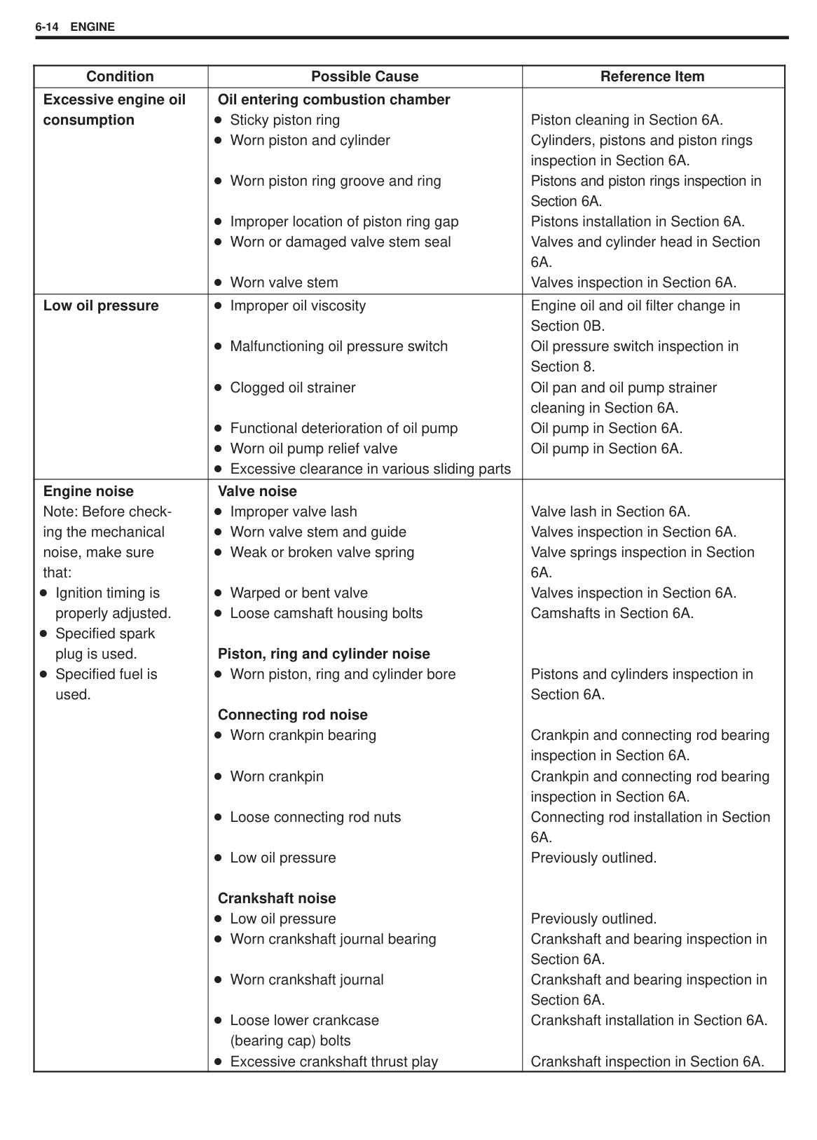
Oil Pan and Oil Pump Strainer 6A1-22. . . . . . . . Oil Pump 6A1-25. . . . . . . . . . . . . . . . . . . . . . . . . . Rocker Arms, Rocker Arm Shaft and
Camshaft 6A1-30. . . . . . . . . . . . . . . . . . . . . . . . . Valves and Cylinder Head 6A1-38. . . . . . . . . . . . Piston, Piston Rings, Connecting
Rods and Cylinders 6A1-50. . . . . . . . . . . . . . . .
UNIT REPAIR OVERHAUL 6A1-60. . . . . . . . . . . . . Engine mounting 6A1-60. . . . . . . . . . . . . . . . . . . . Engine Assembly 6A1-61. . . . . . . . . . . . . . . . . . . Main Bearings, Crankshaft and
Cylinder Block 6A1-66. . . . . . . . . . . . . . . . . . . . . SPECIAL TOOLS 6A1-78. . . . . . . . . . . . . . . . . . . . . REQUIRED SERVICE MATERIALS 6A1-79. . . . .
6A1
GENERAL DESCRIPTION ENGINE
The engine is a water-cooled, in line 4 cylinders, 4 stroke cycle gasoline unit with its S.O.H.C. (Single Overhead Camshaft) valve mechanism arranged for “V”-type valve configuration and 16 valves (IN2 and EX2/one cylinder).
The single overhead camshaft is mounted over the cylinder head; it is driven from crankshaft through timing belt, and no push rods are provided in the valve train system.
|| |---|
#### ENGINE LUBRICATION
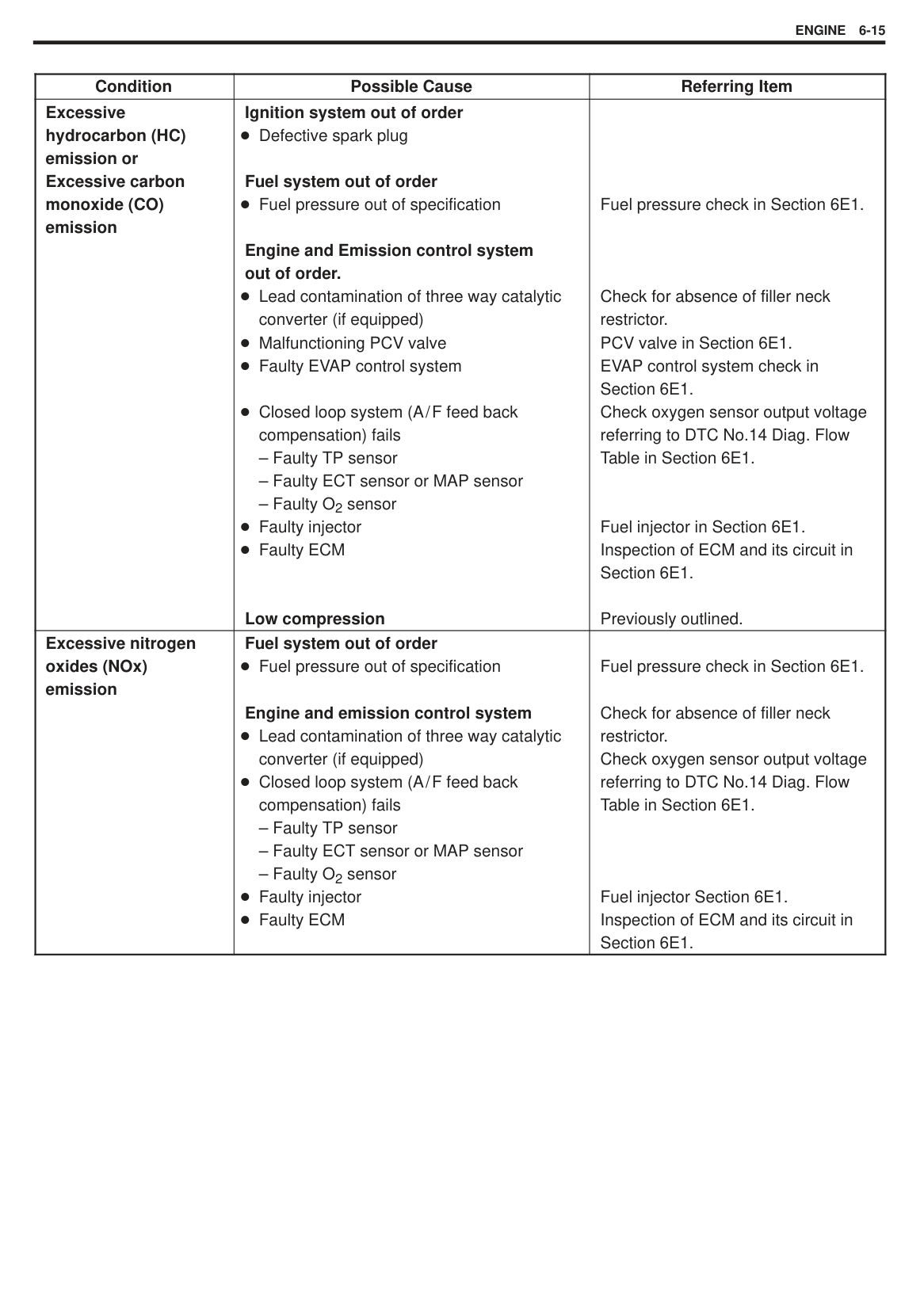
The oil pump is of a trochoid type, and mounted on crankshaft at crankshaft pulley side. Oil is drawn up through oil pump strainer and passed through pump to oil filter. The filtered oil flows into two paths in cylinder block. In one path, oil reaches crankshaft journal bearings. Oil from crankshaft journal bearings is supplied to connecting rod bearings by means of intersecting passages drilled in crankshaft, and then injected from a small hole provided on big end of connecting rod to lubricate piston, rings, and cylinder wall.
In another path, oil goes up to cylinder head and lubricates camshaft journals, rocker arms, camshaft, etc., after passing through the internal oilway of rocker arm shafts.
An oil relief valve is provided on oil pump. This valve starts relieving oil pressure when the pressure comes over about 390 kPa (4.0 kg/cm2, 56.88 psi). Relieved oil drains back to oil pan.


ON-VEHICLE SERVICE COMPRESSION CHECK Check compression pressure on all four cylinders as follows:
NOTE: After warming up engine, place transmission gear shift lever in “Neutral” (shift selector lever to “P” range for A/T model), and set parking brake and block drive wheels.
|| |---|
|WARNING: Failure in disconnecting the coupler can cause spark to occur in engine room possibly resulting in a dangerous explosion.| |---|
|| |---|
|| |---|
NOTE: For measuring compression pressure, crank engine at least 250 r/min. by using fully charged battery.
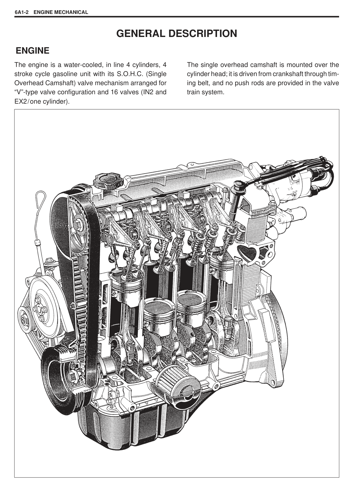
| |Compression pressure| |---|---| |Standard|1400 kPa (14.0 kg/cm2, 199.0 psi)| |Limit|1100 kPa (11.0 kg/cm2, 156.4 psi)| |Max. difference between any two cylinders|100 kPa (1.0 kg/cm2, 14.2 psi)|
############### ENGINE MECHANICAL6A1-5
|| |---|
#### ENGINE VACUUM CHECK
The engine vacuum that develops in the intake line is a good indicator of the condition of the engine. The vacuum checking procedure is as follows:
NOTE: After warming up engine, place transmission gear shift lever in “Neutral” (shift selector lever to “P” range for A/T model), and set parking brake and block drive wheels.
||
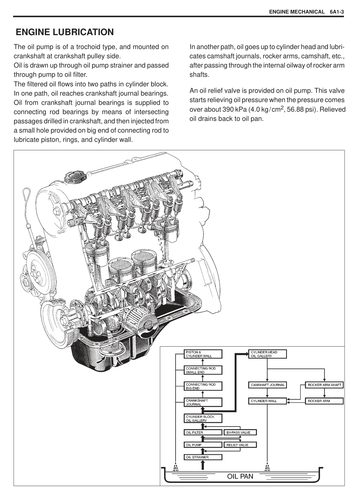
|---|
Vacuum specification:52.6 – 65.8 kPa (40 – 50 cm.Hg, (at sea level) 15.7 – 19.7 in.Hg) at specified
idling speed
NOTE: Prior to checking oil pressure, check the followings.
Oil level in oil pan. If oil level is low, add oil up to Full level hole on oil level gauge. Oil quality. If oil is discolored, or deteriorated, change it. For particular oil to be used, refer to the table in Section 0B. Oil leaks. If leak is found, repair it.
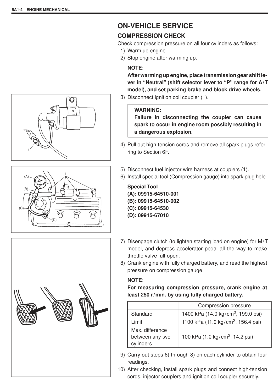
|| |---|
Special Tool (A): 09915-77310
NOTE: Be sure to place transmission gear shift lever in “Neutral” (shift selector lever to “P” range for A/T model), and set parking brake and block drive wheels.
Oil pressure specification: 360 – 440 kPa (3.6 – 4.4 kg/cm2, 51.2 – 62.6 psi) at 3,960 – 4,040 r/min (rpm)
|| |---|
NOTE: If sealing tape edge is bulged out from screw threads of switch, cut it off.
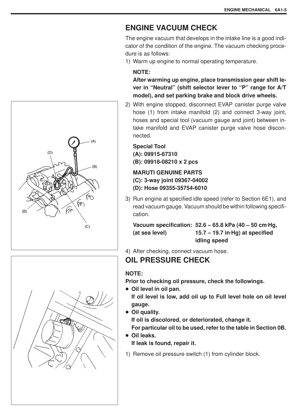
Tightening Torque (a): 14 N·m (1.4 kg-m, 10.5 lb-ft)
|| |---|
#### VALVE LASH (CLEARANCE)
|| |---|
|| |---|
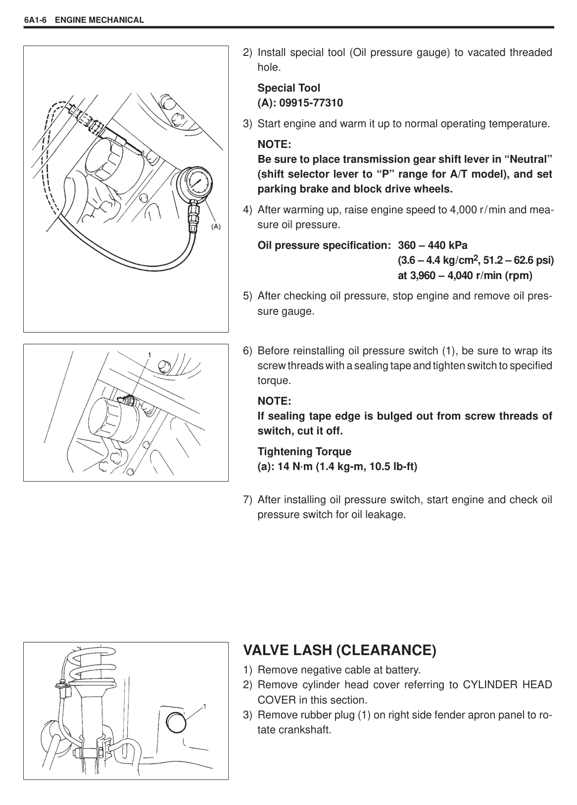
NOTE: When checking valve clearance, insert thickness gauge between camshaft and cam-riding face of rocker arm.
|

1. Thickness gauge| |---|
|Valve clearance SifiSpecification
| |When cold (Coolant temperature is 15 – 25 C or 59 – 77 F)|When hot (Coolant temperature is 60 – 68 C or 140 – 154 F)| |---|---|---|---| |Valve clearance SifiSpecification
|Intake|0.13 – 0.17 mm (0.005 – 0.007 in.)|0.17 – 0.21 mm (0.007 – 0.008 in.)| |Valve clearance SifiSpecification
|Exhaust|0.23 – 0.27 mm (0.009 – 0.011 in.)|0.27 – 0.31 mm (0.011 – 0.012 in.)|
Special Tool (A): 09917-18210
Tightening Torque (a): 12 N.m (1.2 kg-m, 9.0 lb-ft)
|| |---|
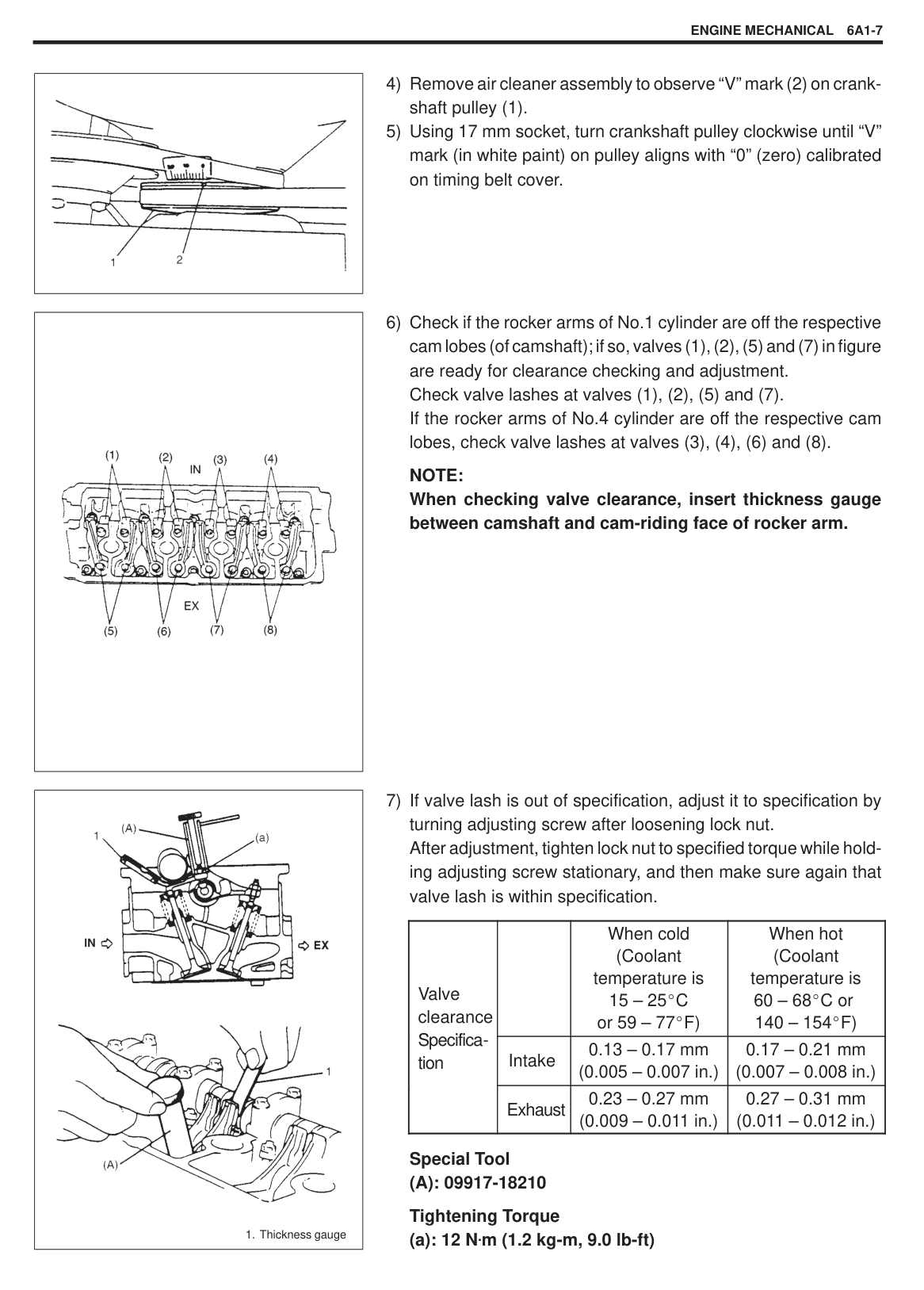
|| |---|
|| |---|
(1), (2), (5), and (7)). Adjust them as necessary.
AIR CLEANER FILTER This air cleaner filter is of dry type. Remember that it needs cleaning according to following procedure.
######## REMOVAL
INSPECTION Check air cleaner filter for dirt. Replace excessively dirty element.
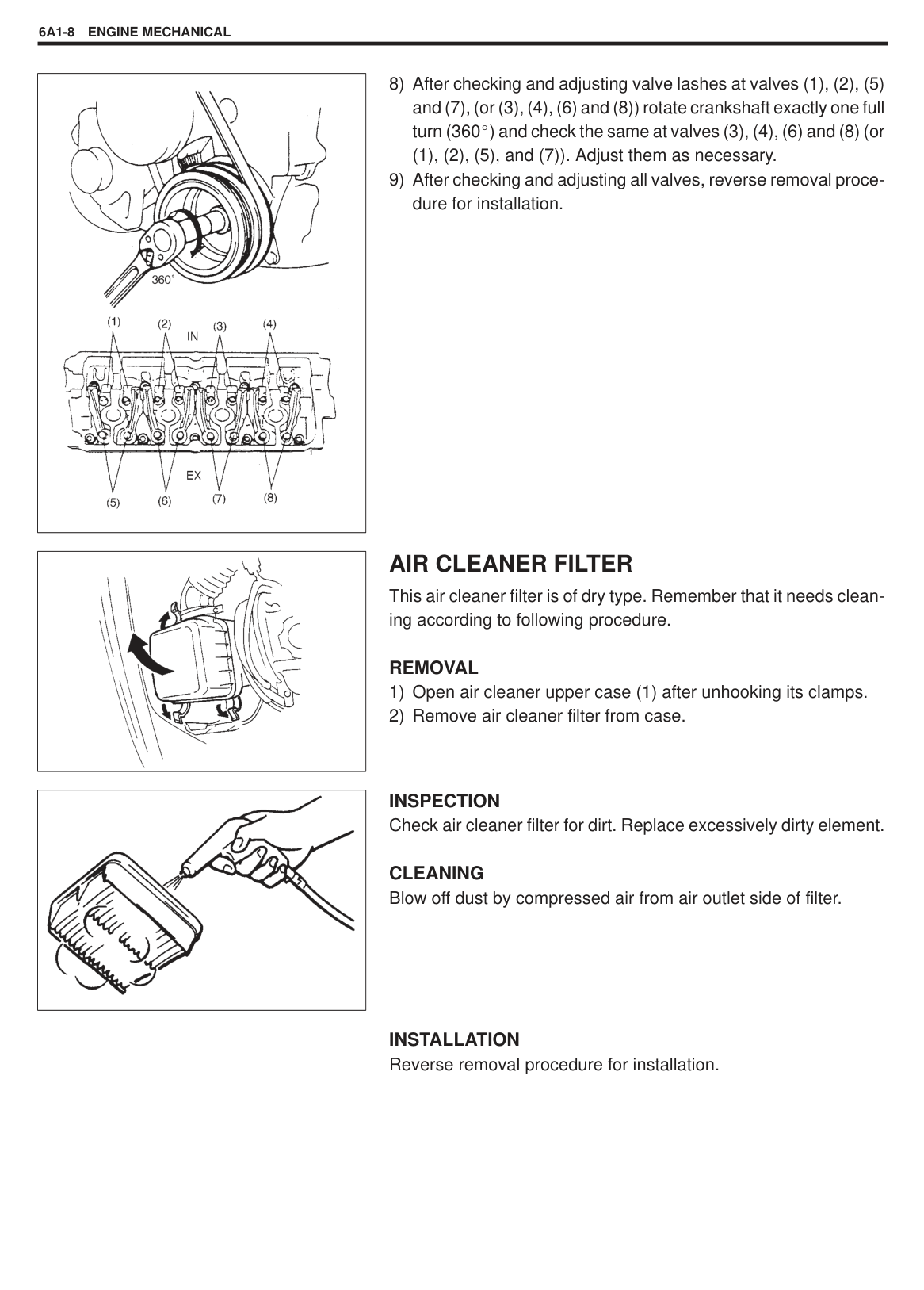
CLEANING Blow off dust by compressed air from air outlet side of filter.
INSTALLATION Reverse removal procedure for installation.
|| |---|
|| |---|
#### AIR CLEANER ASSEMBLY REMOVAL
1) Disconnect air cleaner outlet hose (1) from air cleaner assembly
(2).
2) Remove air cleaner assembly by removing bolts (3) shown in figure.
INSTALLATION Reverse removal procedure for installation.
#### AIR CLEANER OUTLET HOSE REMOVAL
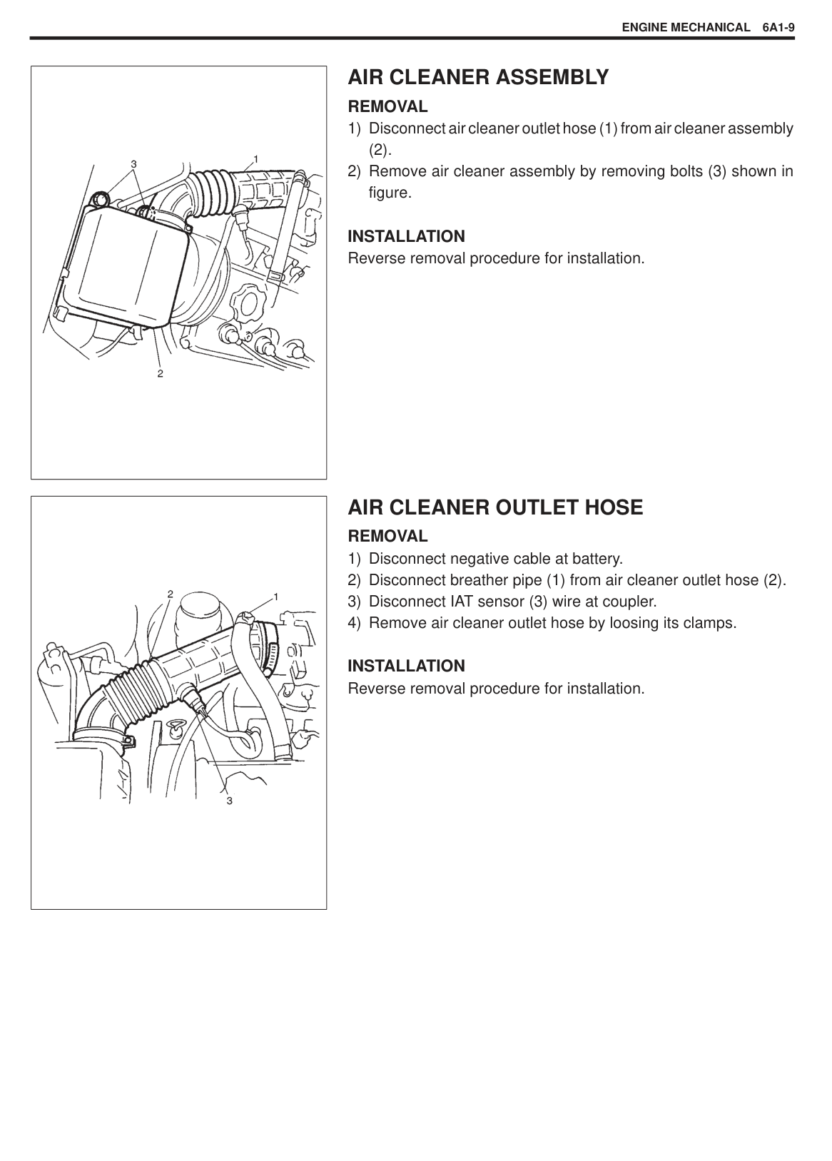
INSTALLATION Reverse removal procedure for installation.
|| |---|
|| |---|
#### CYLINDER HEAD COVER REMOVAL
######## INSTALLATION
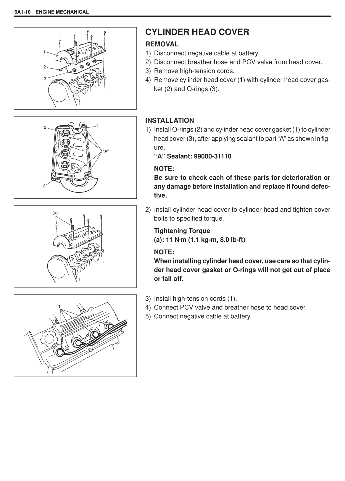
NOTE: Be sure to check each of these parts for deterioration or any damage before installation and replace if found defective.
|| |---|
Tightening Torque (a): 11 N.m (1.1 kg-m, 8.0 lb-ft)
NOTE: When installing cylinder head cover, use care so that cylinder head cover gasket or O-rings will not get out of place or fall off.
|| |---|
#### THROTTLE BODY AND INTAKE MANIFOLD
|
1. Intake manifold
2. Throttle body
3. Gasket
4. Fuel delivery pipe
5. Fuel injector
6. EVAP canister purge valve
7. MAP sensor
: Do not reuse
| |---|
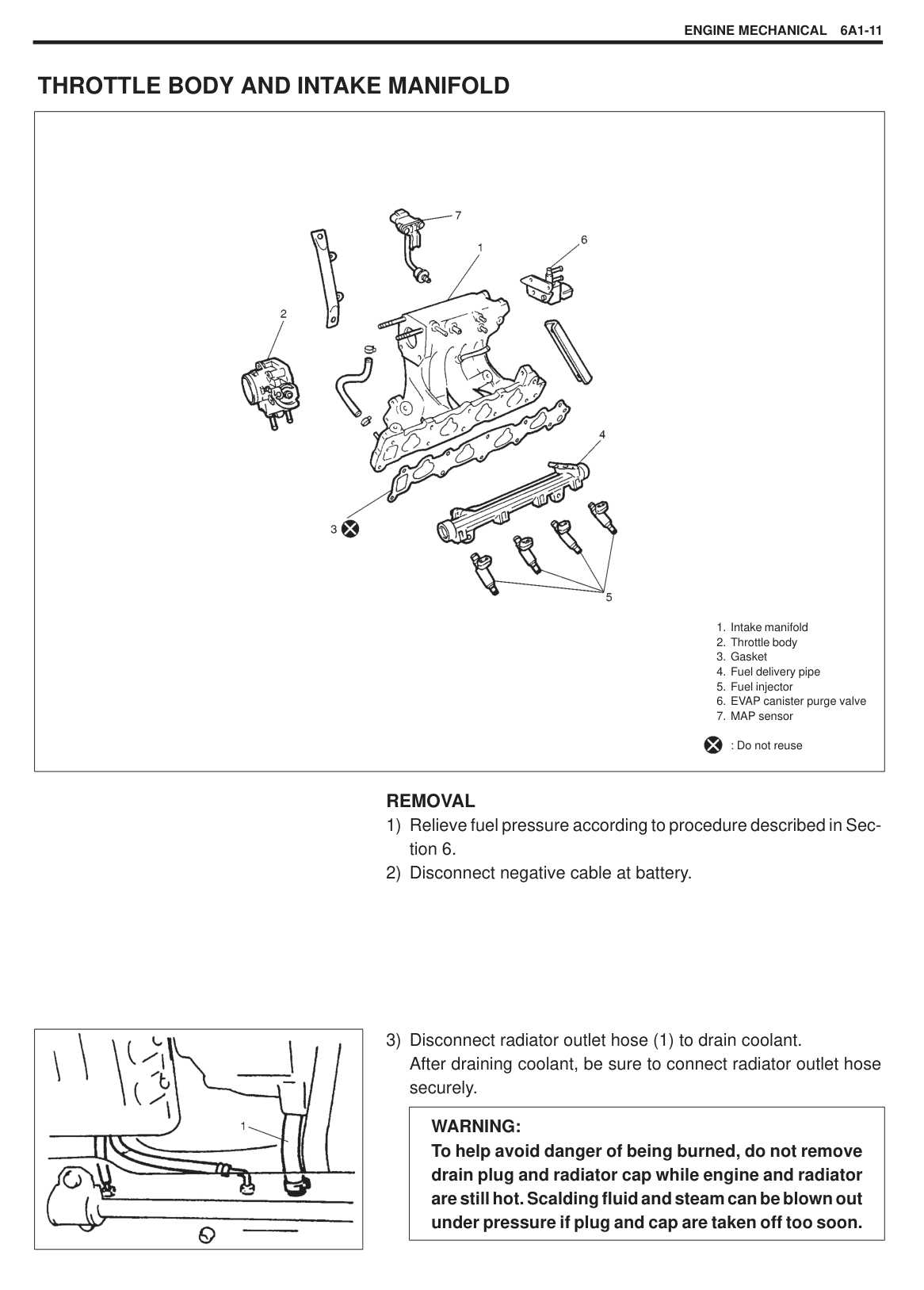
######## REMOVAL
|| |---|
|WARNING: To help avoid danger of being burned, do not remove drain plug and radiator cap while engine and radiator are still hot. Scalding fluid and steam can be blown out under pressure if plug and cap are taken off too soon.| |---|
|| |---|
|| |---|
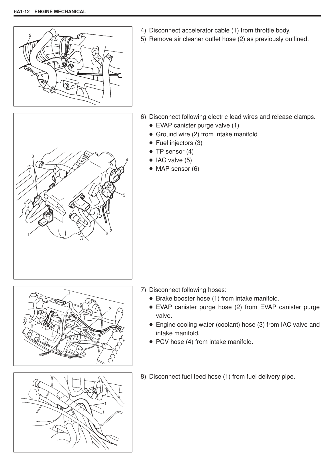
|| |---|
|| |---|
|
| |---|
|| |---|
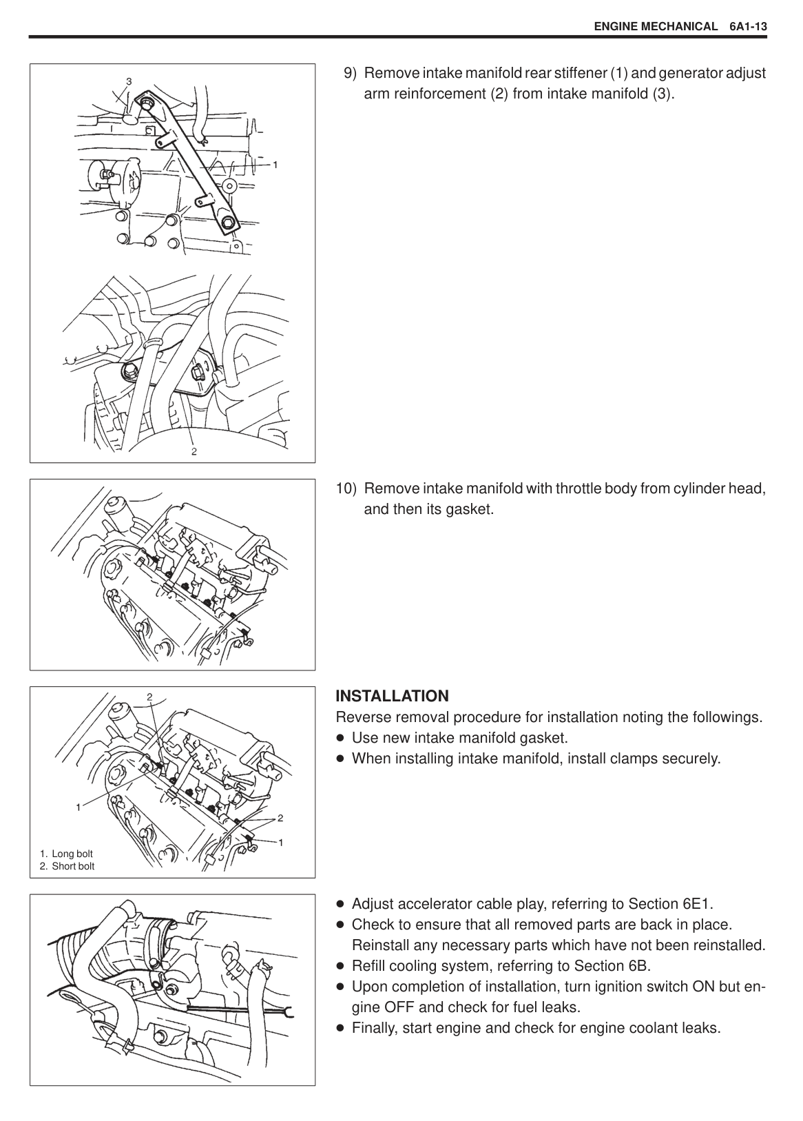
|
1. Long bolt
2. Short bolt
| |---|
|| |---|
INSTALLATION Reverse removal procedure for installation noting the followings.
Use new intake manifold gasket. When installing intake manifold, install clamps securely.
Adjust accelerator cable play, referring to Section 6E1. Check to ensure that all removed parts are back in place. Reinstall any necessary parts which have not been reinstalled. Refill cooling system, referring to Section 6B. Upon completion of installation, turn ignition switch ON but engine OFF and check for fuel leaks. Finally, start engine and check for engine coolant leaks.
#### EXHAUST MANIFOLD
|
1. Exhaust manifold
2. Engine hook
3. Exhaust manifold cover
4. Oxygen sensor
5. Exhaust manifold gasket
6. Exhaust pipe seal ring
7. Exhaust pipe
8. Exhaust manifold cover bolt
9. Stud bolt
10. Catalytic converter case gasket
11. Exhaust manifold bolt (long)
12. Exhaust manifold bolt (short)
13. Exhaust manifold nut
14. Exhaust pipe bolt
15. Catalytic converter case nut
: Tightening Torque : Do not reuse

| |---|
|WARNING: To avoid danger of being burned, do not service exhaust system while it is still hot. Service should be performed after system cools down.| |---|
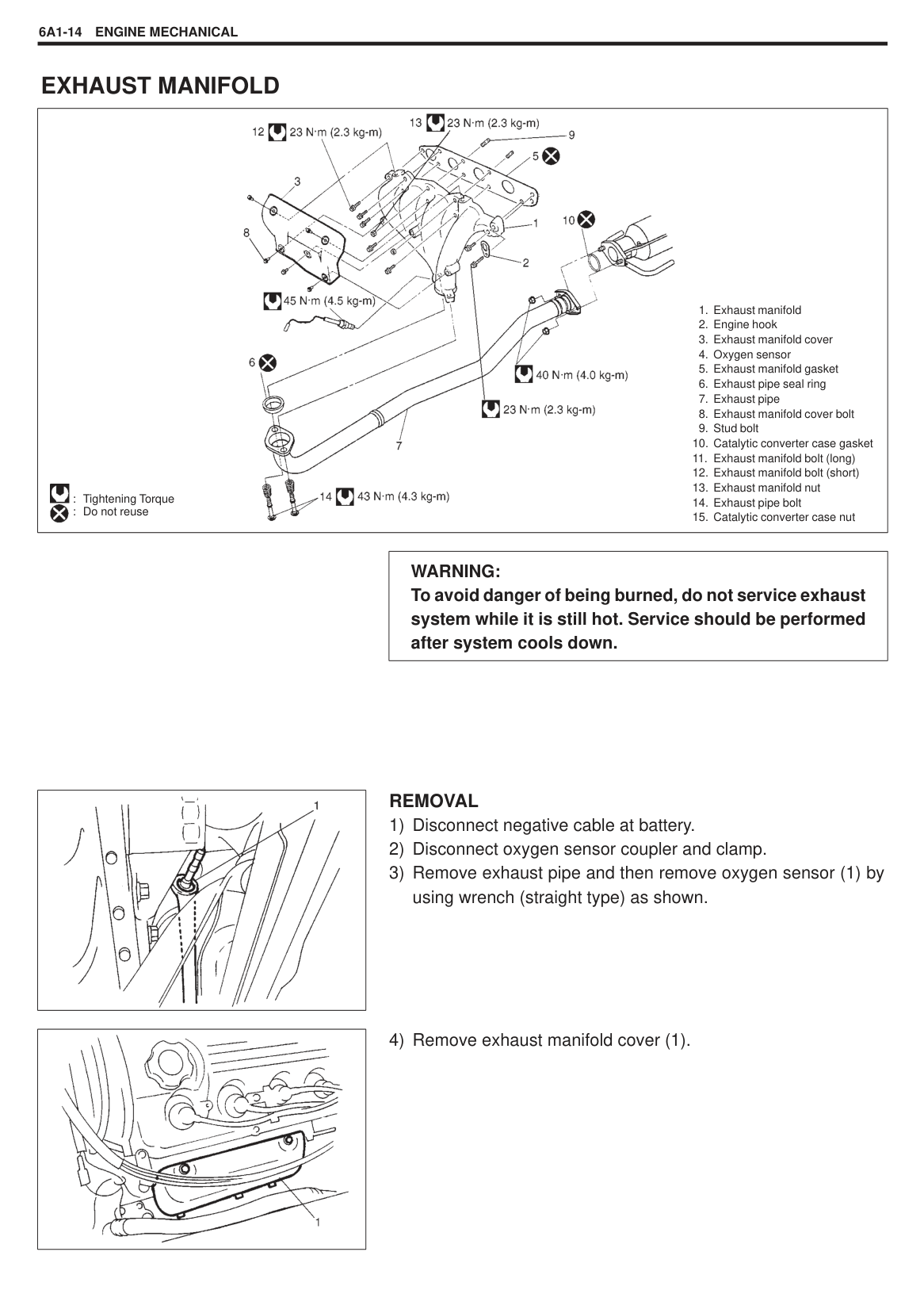
|| |---|
######## REMOVAL
|| |---|
|| |---|
|| |---|
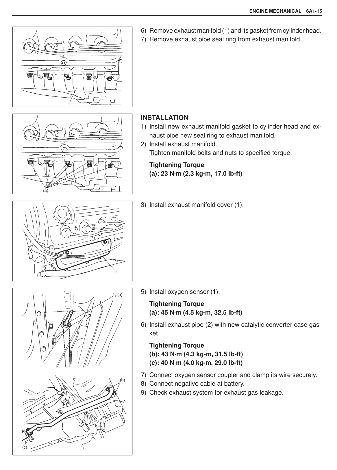
######## INSTALLATION
Tightening Torque (a): 23 N.m (2.3 kg-m, 17.0 lb-ft)
|| |---|
|
| |---|
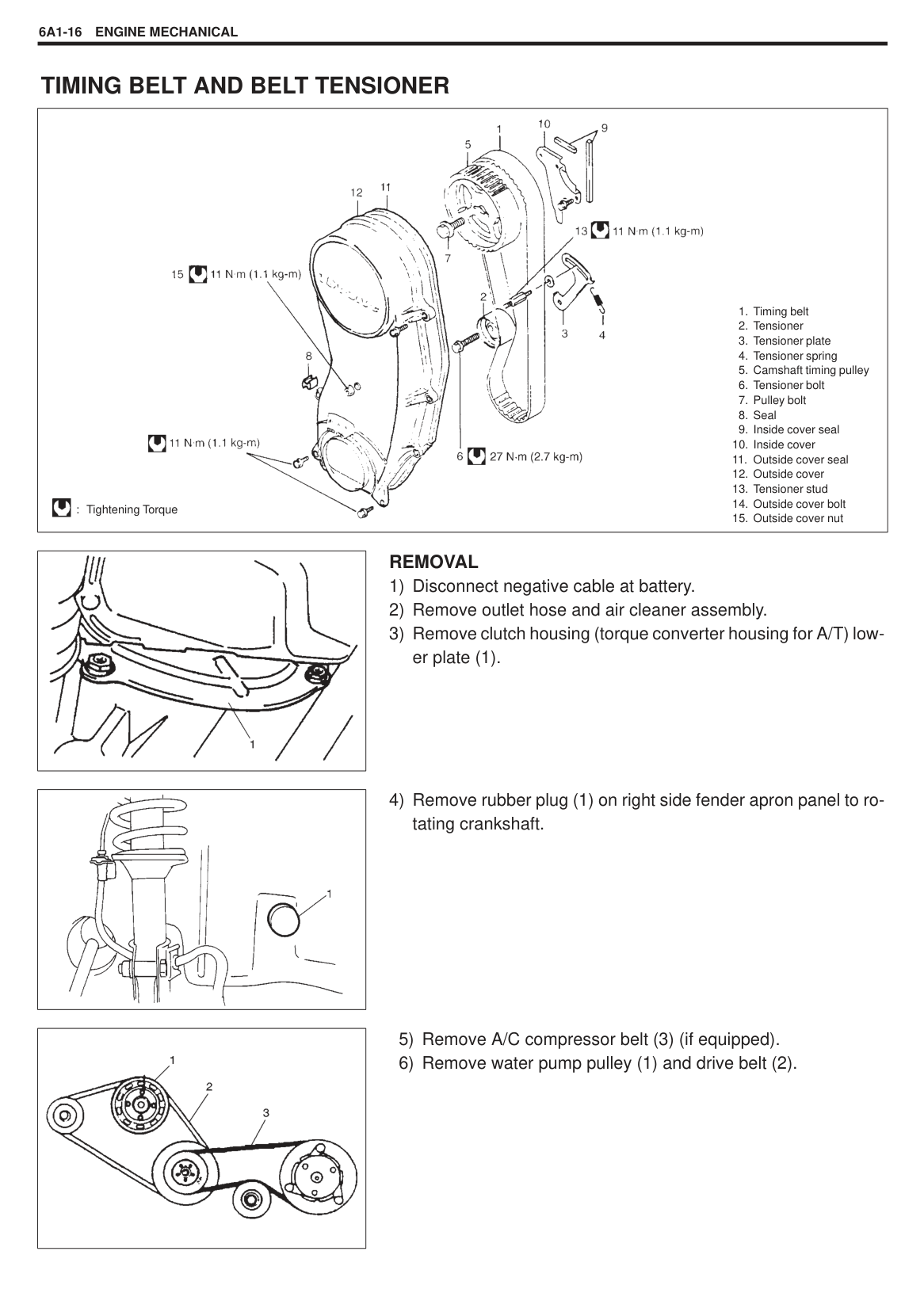
6) Install exhaust pipe (2) with new catalytic converter case gasket. Tightening Torque
#### TIMING BELT AND BELT TENSIONER
|
: Tightening Torque

1. Timing belt
2. Tensioner
3. Tensioner plate
4. Tensioner spring
5. Camshaft timing pulley
6. Tensioner bolt
7. Pulley bolt
8. Seal
9. Inside cover seal
10. Inside cover
11. Outside cover seal
12. Outside cover
13. Tensioner stud
14. Outside cover bolt
15. Outside cover nut
| |---|
|| |---|
######## REMOVAL
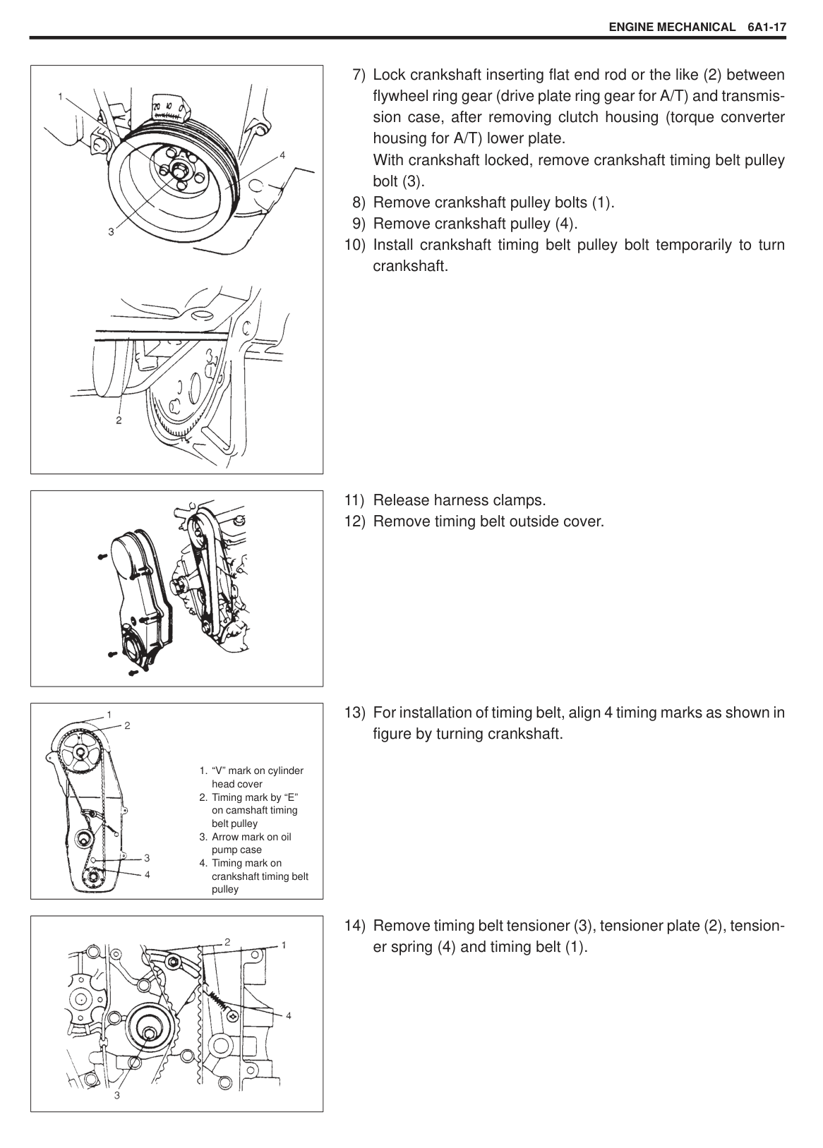
|| |---|
|| |---|
|
| |---|
||
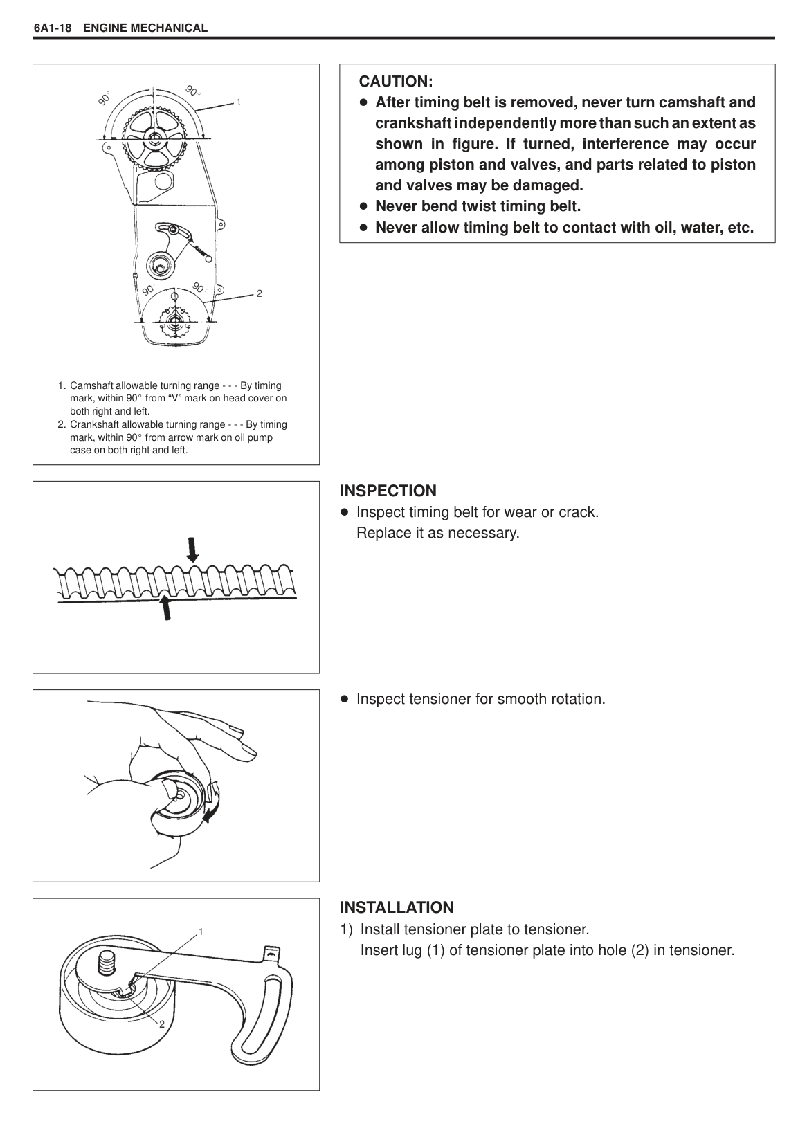
|---|
|
1. “V” mark on cylinder head cover
2. Timing mark by “E” on camshaft timing belt pulley
3. Arrow mark on oil pump case
4. Timing mark on crankshaft timing belt pulley
| |---|
|| |---|
|
1. Camshaft allowable turning range - - - By timing mark, within 90 from “V” mark on head cover on both right and left.
2. Crankshaft allowable turning range - - - By timing mark, within 90 from arrow mark on oil pump case on both right and left.
| |---|
|| |---|
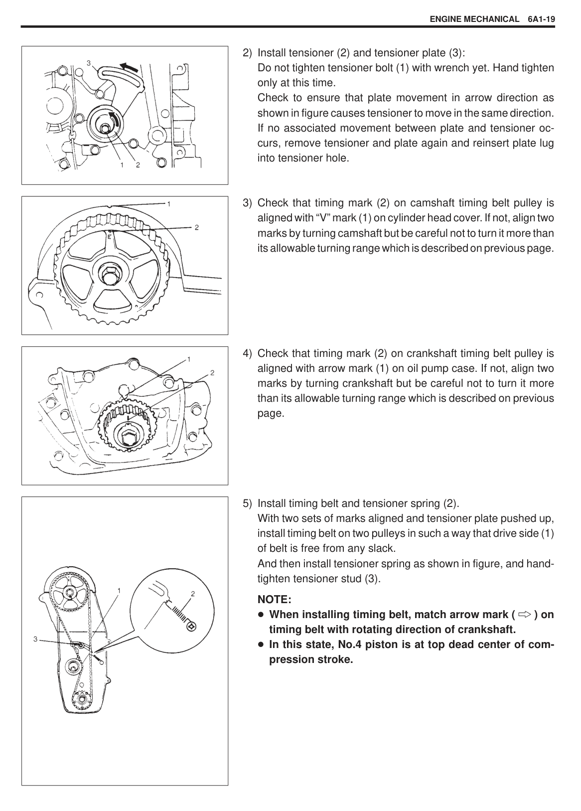
|| |---|
|| |---|
|CAUTION: After timing belt is removed, never turn camshaft and crankshaft independently more than such an extent as shown in figure. If turned, interference may occur among piston and valves, and parts related to piston and valves may be damaged. Never bend twist timing belt. Never allow timing belt to contact with oil, water, etc.| |---|
INSPECTION Inspect timing belt for wear or crack. Replace it as necessary.
Inspect tensioner for smooth rotation.
######## INSTALLATION
|| |---|
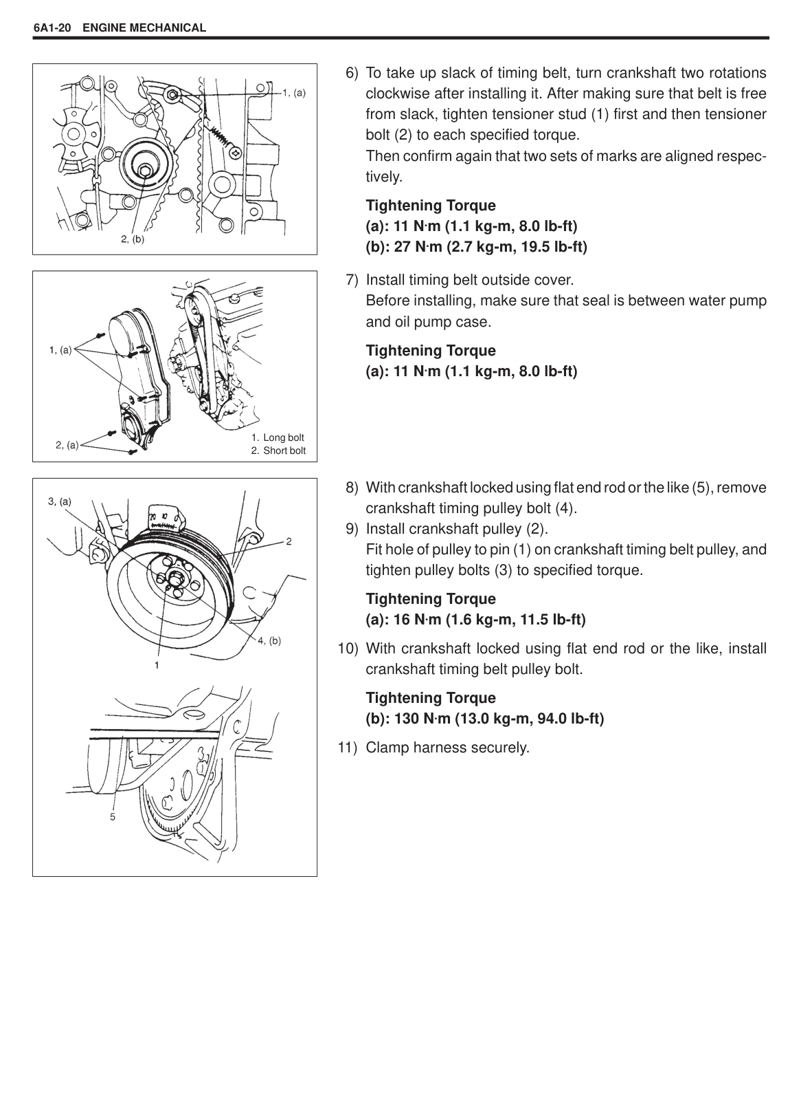
|| |---|
|| |---|
NOTE: When installing timing belt, match arrow mark ( ) on timing belt with rotating direction of crankshaft. In this state, No.4 piston is at top dead center of compression stroke.
|| |---|
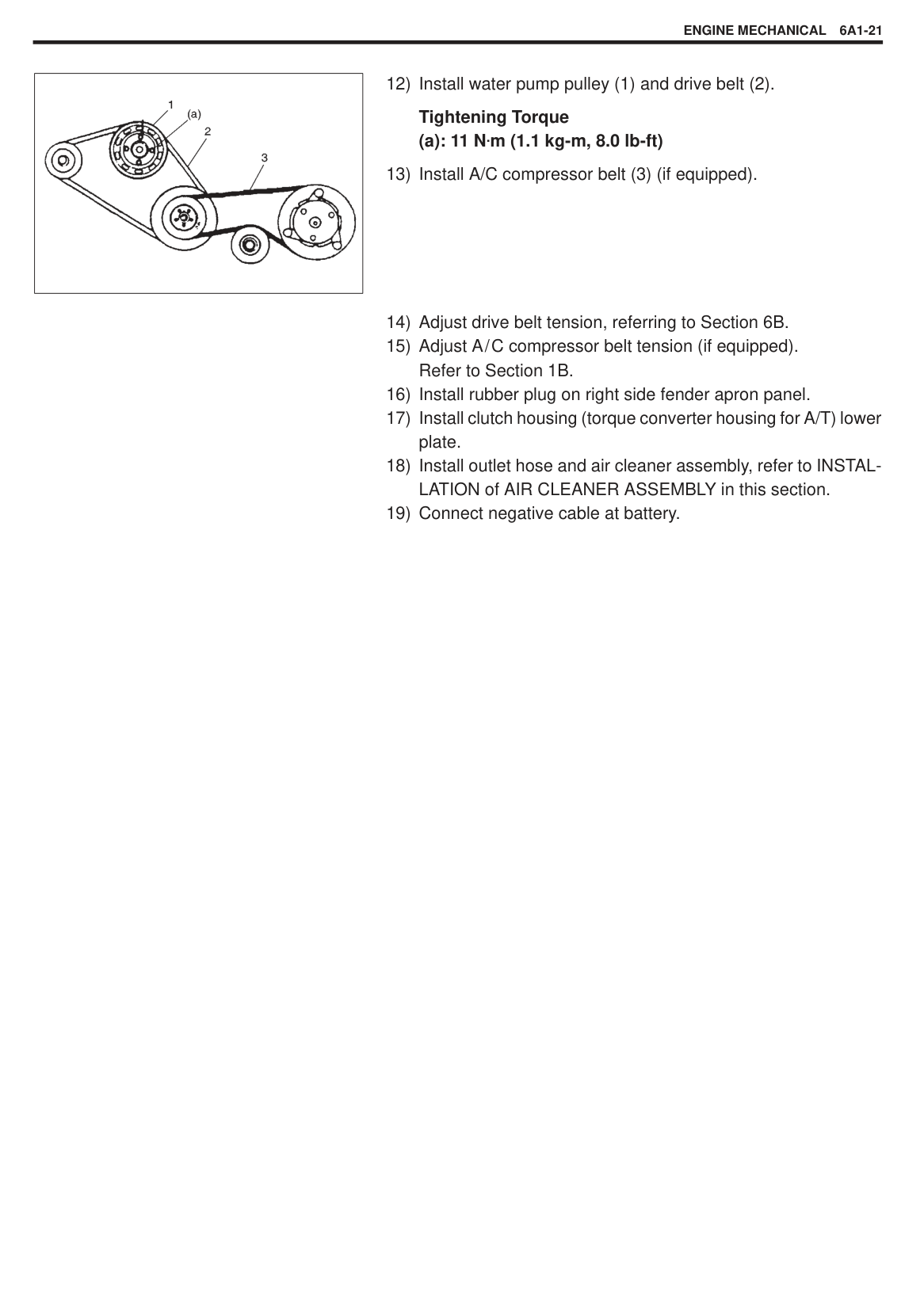
|
1. Long bolt
2. Short bolt
| |---|
Tightening Torque (a): 11 N.m (1.1 kg-m, 8.0 lb-ft)
|
| |---|
10) With crankshaft locked using flat end rod or the like, install crankshaft timing belt pulley bolt. Tightening Torque
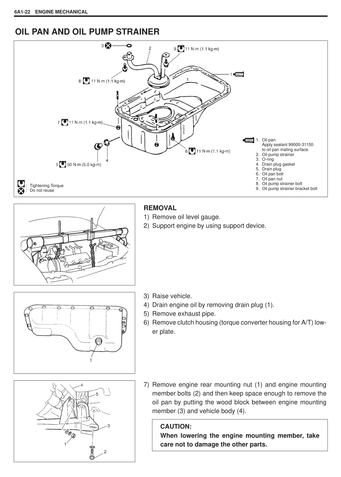
Tightening Torque (a): 11 N.m (1.1 kg-m, 8.0 lb-ft)
#### OIL PAN AND OIL PUMP STRAINER
|
1. Oil pan: Apply sealant 99000-31150 to oil pan mating surface.
2. Oil pump strainer
3. O-ring
4. Drain plug gasket
5. Drain plug
6. Oil pan bolt
7. Oil pan nut
8. Oil pump strainer bolt
9. Oil pump strainer bracket bolt

: Tightening Torque : Do not reuse

| |---|
|| |---|
######## REMOVAL
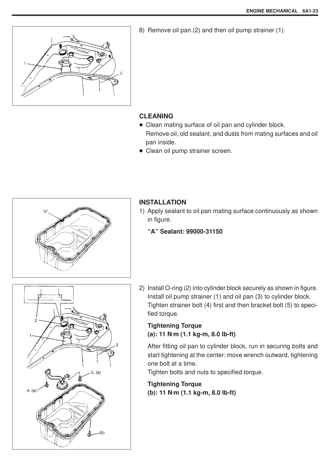
|| |---|
|| |---|
|CAUTION: When lowering the engine mounting member, take care not to damage the other parts.| |---|
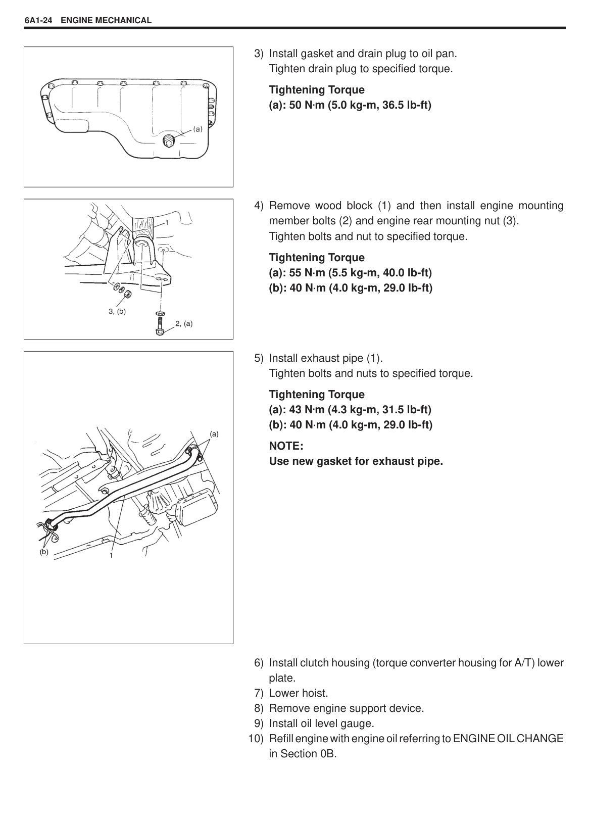
CLEANING Clean mating surface of oil pan and cylinder block. Remove oil, old sealant, and dusts from mating surfaces and oil pan inside. Clean oil pump strainer screen.
|| |---|
######## INSTALLATION
|| |---|
######### (a): 11 N.m (1.1 kg-m, 8.0 lb-ft)
After fitting oil pan to cylinder block, run in securing bolts and start tightening at the center: move wrench outward, tightening one bolt at a time. Tighten bolts and nuts to specified torque.
Tightening Torque
######### (b): 11 N.m (1.1 kg-m, 8.0 lb-ft)
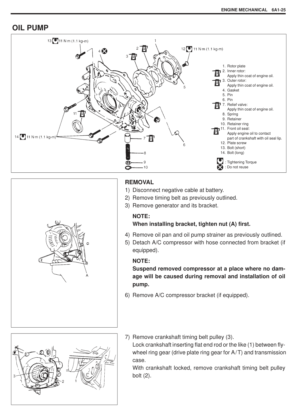
Tightening Torque (a): 50 N.m (5.0 kg-m, 36.5 lb-ft)
|| |---|
|| |---|
NOTE: Use new gasket for exhaust pipe.
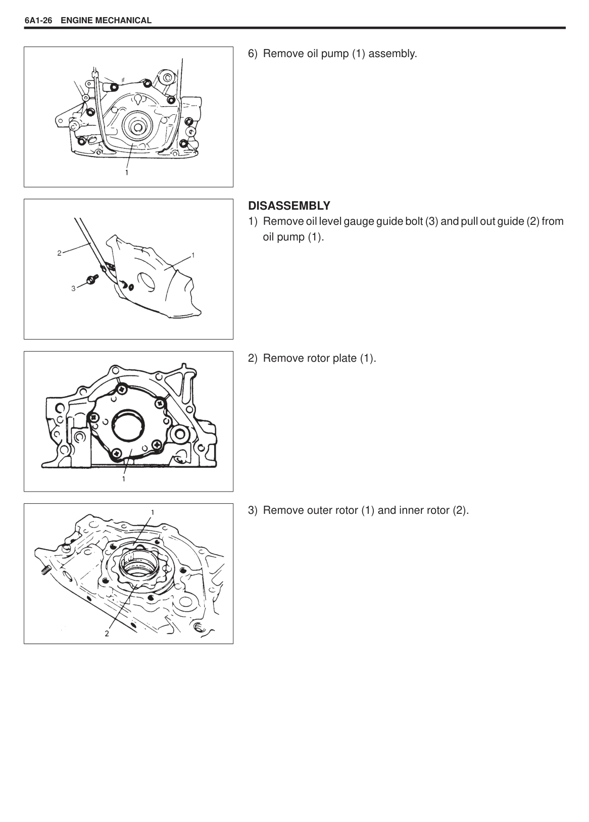
#### OIL PUMP
|
1. Rotor plate
2. Inner rotor: Apply thin coat of engine oil.
3. Outer rotor: Apply thin coat of engine oil.
4. Gasket
5. Pin
6. Pin
7. Relief valve: Apply thin coat of engine oil.
8. Spring
9. Retainer
10. Retainer ring
11. Front oil seal: Apply engine oil to contact part of crankshaft with oil seal lip.
12. Plate screw
13. Bolt (short)
14. Bolt (long)
: Tightening Torque : Do not reuse


| |---|
|| |---|
######## REMOVAL
NOTE: When installing bracket, tighten nut (A) first.
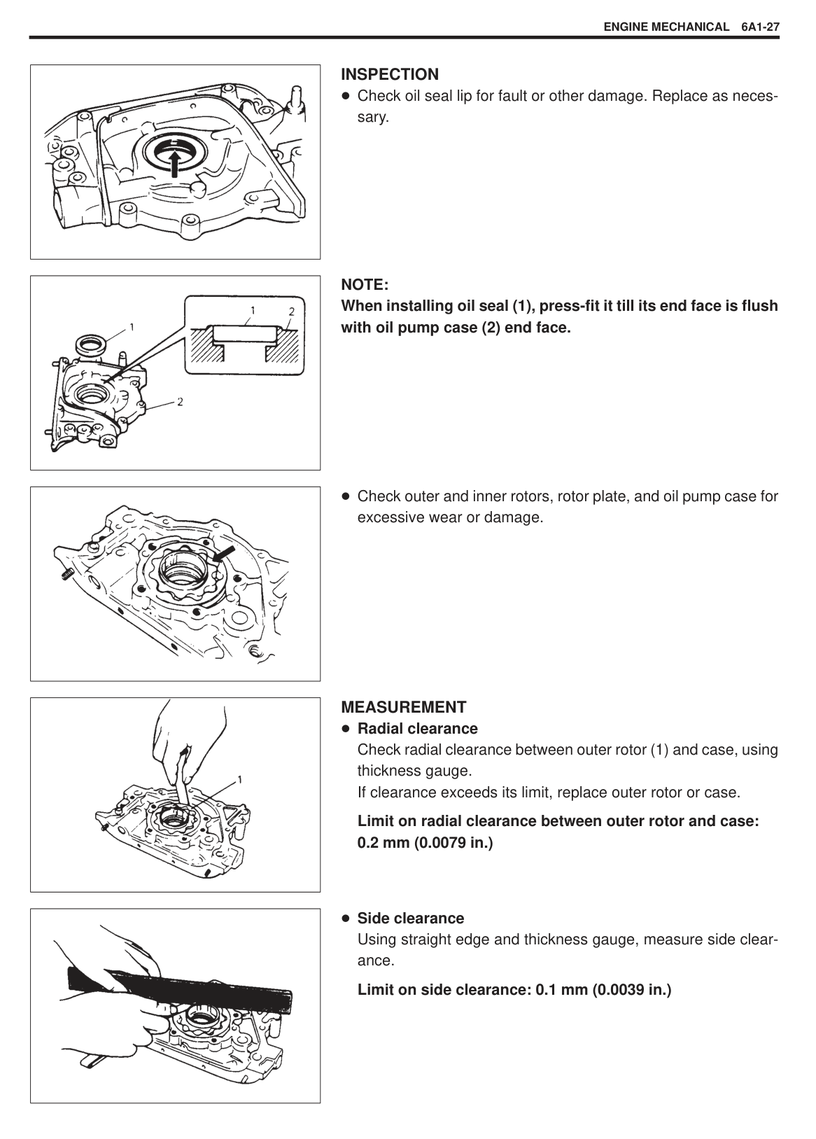
NOTE: Suspend removed compressor at a place where no damage will be caused during removal and installation of oil pump.
|
| |---|
6) Remove oil pump (1) assembly.
|| |---|
######## DISASSEMBLY
|| |---|
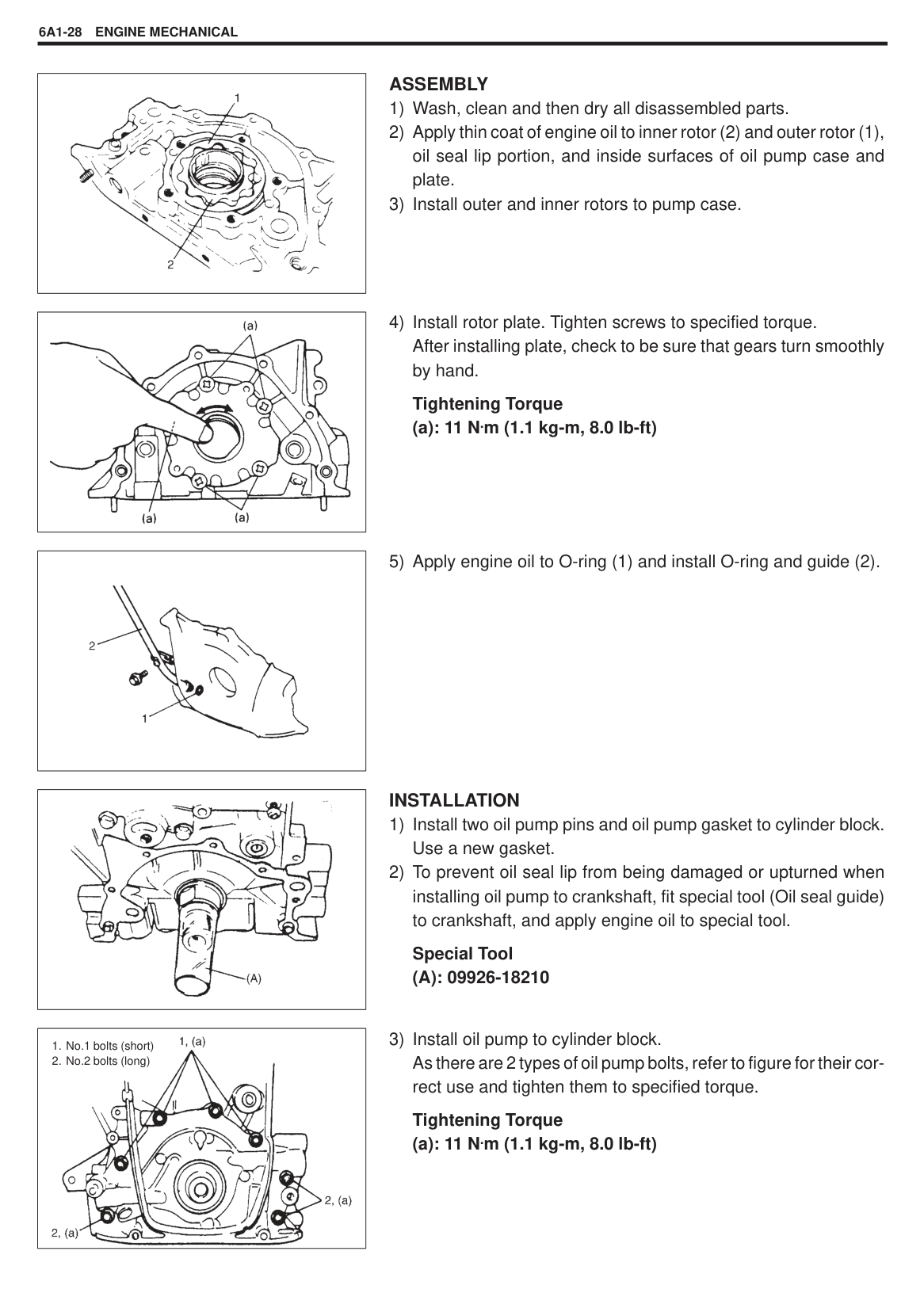
|| |---|
|| |---|
|| |---|
|| |---|
|| |---|
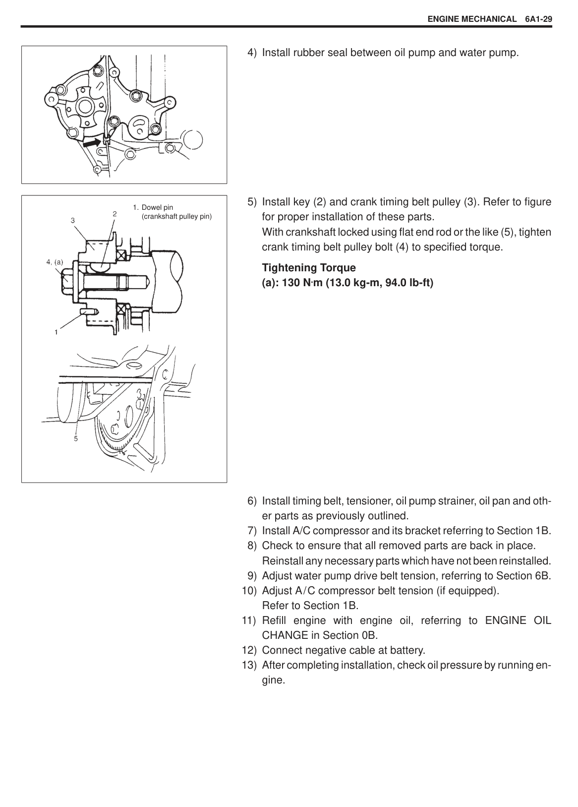
|| |---|
INSPECTION Check oil seal lip for fault or other damage. Replace as necessary.
######### NOTE: When installing oil seal (1), press-fit it till its end face is flush with oil pump case (2) end face.
Check outer and inner rotors, rotor plate, and oil pump case for excessive wear or damage.
MEASUREMENT Radial clearance Check radial clearance between outer rotor (1) and case, using thickness gauge. If clearance exceeds its limit, replace outer rotor or case.
Limit on radial clearance between outer rotor and case: 0.2 mm (0.0079 in.)
Side clearance Using straight edge and thickness gauge, measure side clearance.
######### Limit on side clearance: 0.1 mm (0.0039 in.)
|| |---|
######## ASSEMBLY
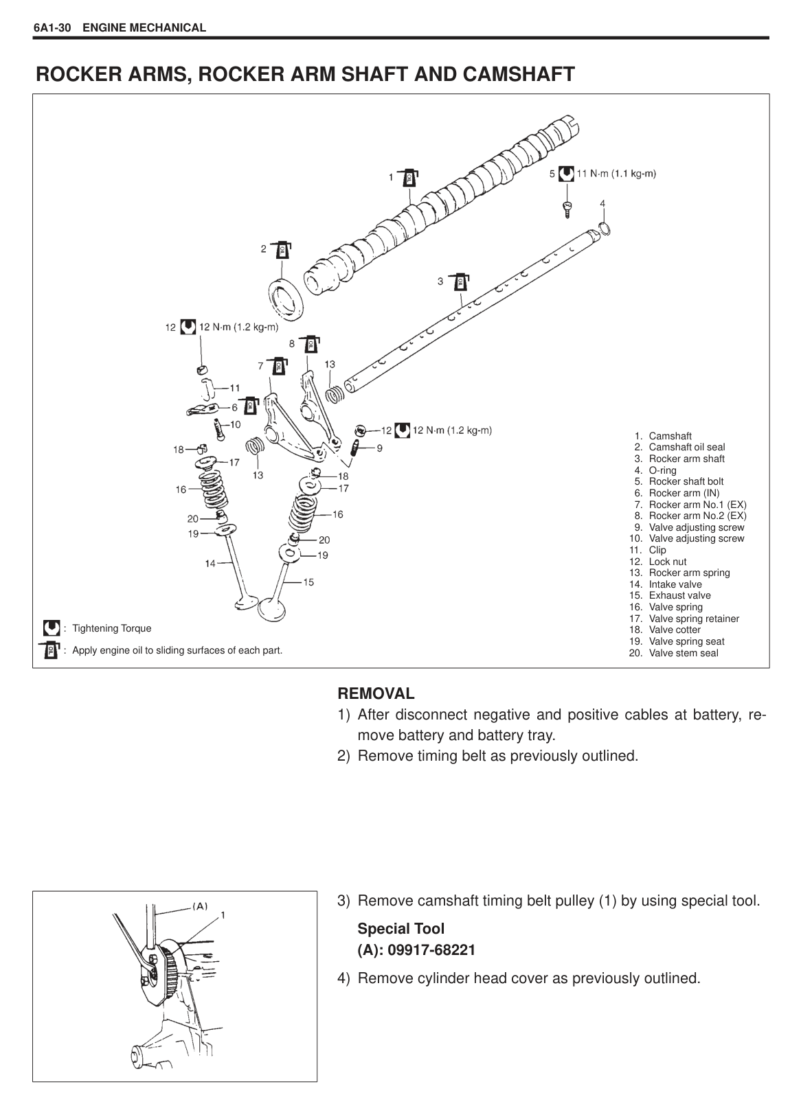
|| |---|
Tightening Torque (a): 11 N.m (1.1 kg-m, 8.0 lb-ft)
|| |---|
|| |---|
######## INSTALLATION
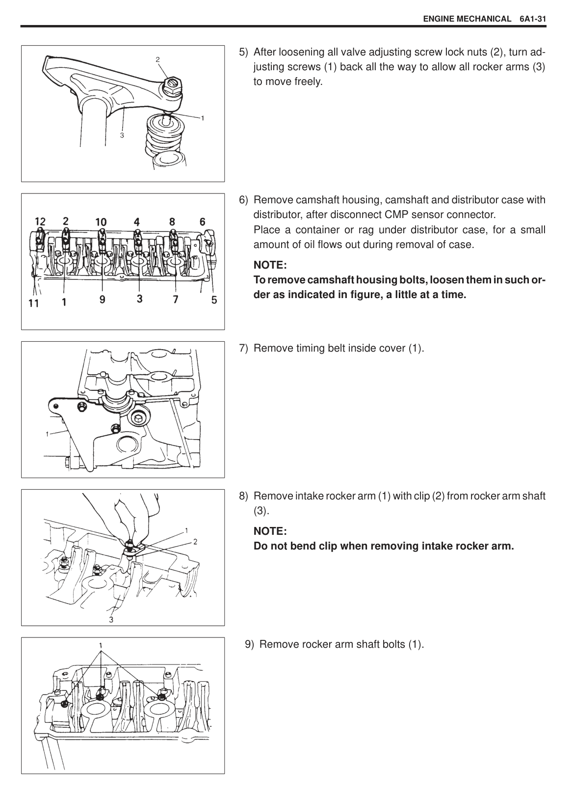
Special Tool (A): 09926-18210
|
1. No.1 bolts (short)
2. No.2 bolts (long)
| |---|
######### Tightening Torque (a): 11 N.m (1.1 kg-m, 8.0 lb-ft)
|

1. Dowel pin (crankshaft pulley pin)| |---|
Tightening Torque (a): 130 N.m (13.0 kg-m, 94.0 lb-ft)
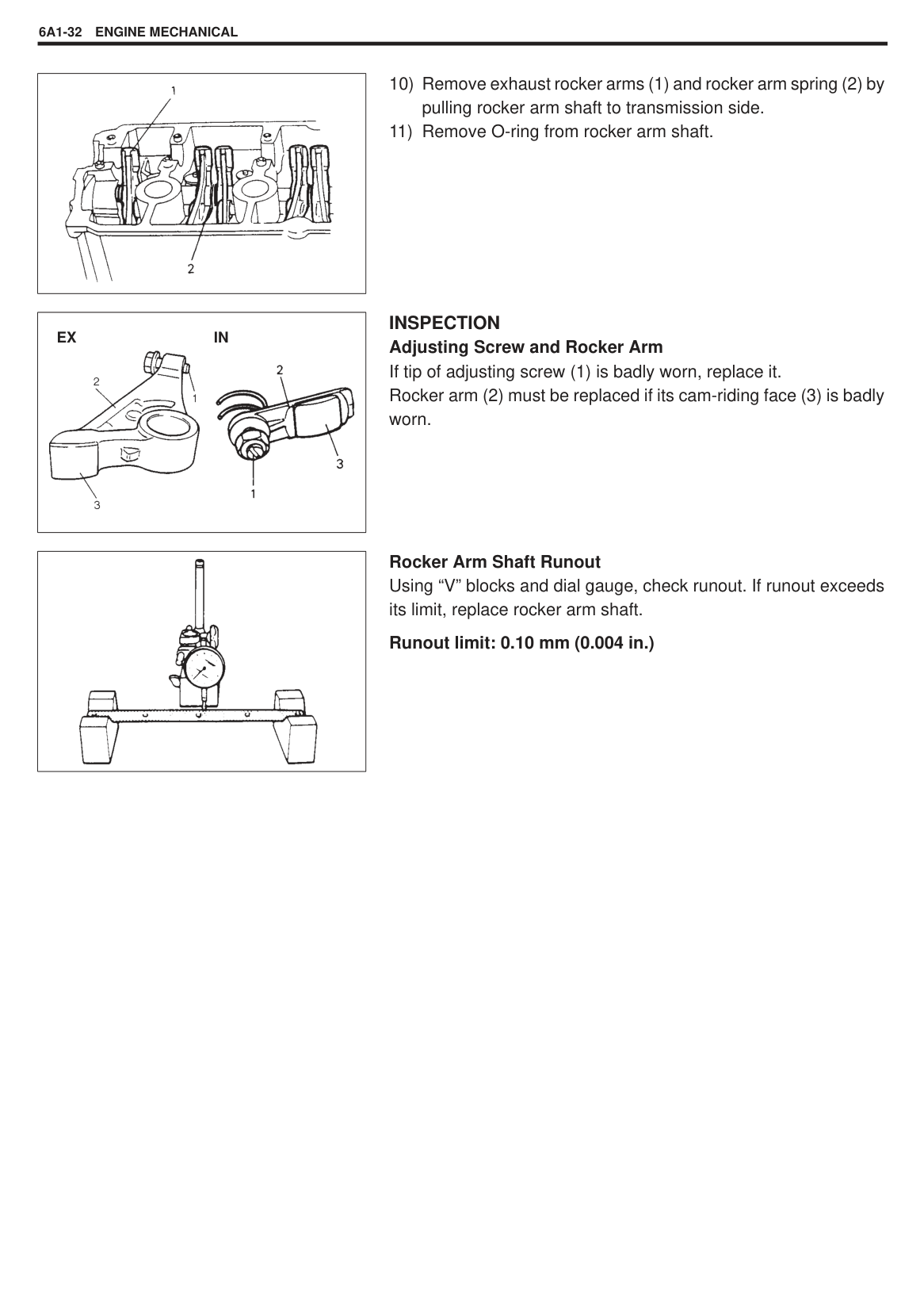
#### ROCKER ARMS, ROCKER ARM SHAFT AND CAMSHAFT
|
1. Camshaft
2. Camshaft oil seal
3. Rocker arm shaft
4. O-ring
5. Rocker shaft bolt
6. Rocker arm (IN)
7. Rocker arm No.1 (EX)
8. Rocker arm No.2 (EX)
9. Valve adjusting screw
10. Valve adjusting screw
11. Clip
12. Lock nut
13. Rocker arm spring
14. Intake valve
15. Exhaust valve
16. Valve spring
17. Valve spring retainer
18. Valve cotter
19. Valve spring seat
20. Valve stem seal
: Tightening Torque : Apply engine oil to sliding surfaces of each part.

| |---|
######## REMOVAL
|| |---|
Special Tool (A): 09917-68221
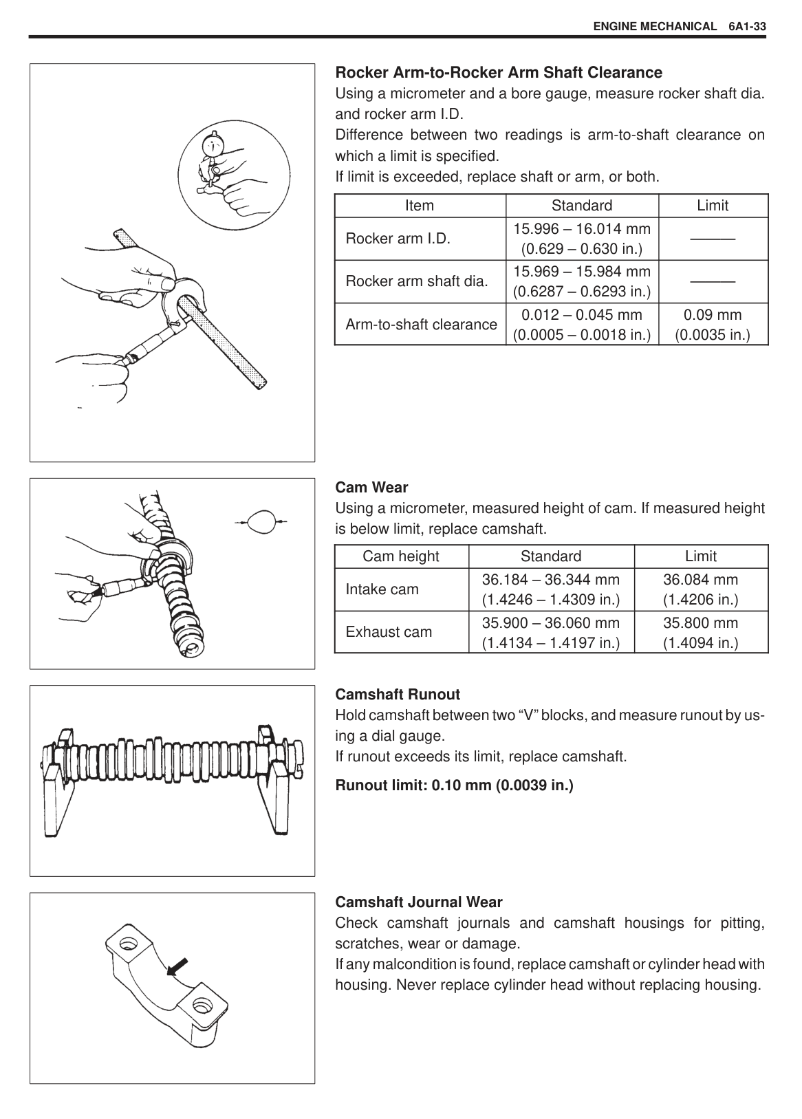
########## 5) After loosening all valve adjusting screw lock nuts (2), turn ad-justing screws (1) back all the way to allow all rocker arms (3)to move freely.
|| |---|
########## 6) Remove camshaft housing, camshaft and distributor case withdistributor, after disconnect CMP sensor connector.Place a container or rag under distributor case, for a smallamount of oil flows out during removal of case.
NOTE: To remove camshaft housing bolts, loosen them in such order as indicated in figure, a little at a time.
|| |---|
|| |---|
|| |---|
########## 7) Remove timing belt inside cover (1).
########## 8) Remove intake rocker arm (1) with clip (2) from rocker arm shaft
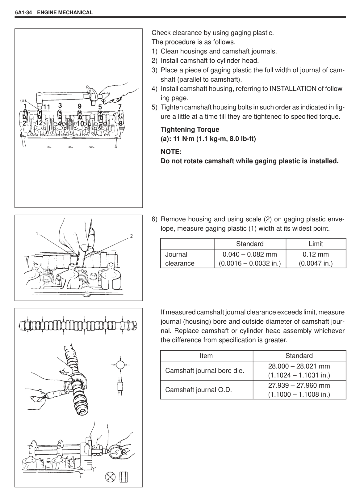
(3).
NOTE: Do not bend clip when removing intake rocker arm.
########## 9) Remove rocker arm shaft bolts (1).
|| |---|
|

EX IN| |---|
|| |---|
INSPECTION Adjusting Screw and Rocker Arm If tip of adjusting screw (1) is badly worn, replace it. Rocker arm (2) must be replaced if its cam-riding face (3) is badly worn.
Rocker Arm Shaft Runout Using “V” blocks and dial gauge, check runout. If runout exceeds its limit, replace rocker arm shaft.
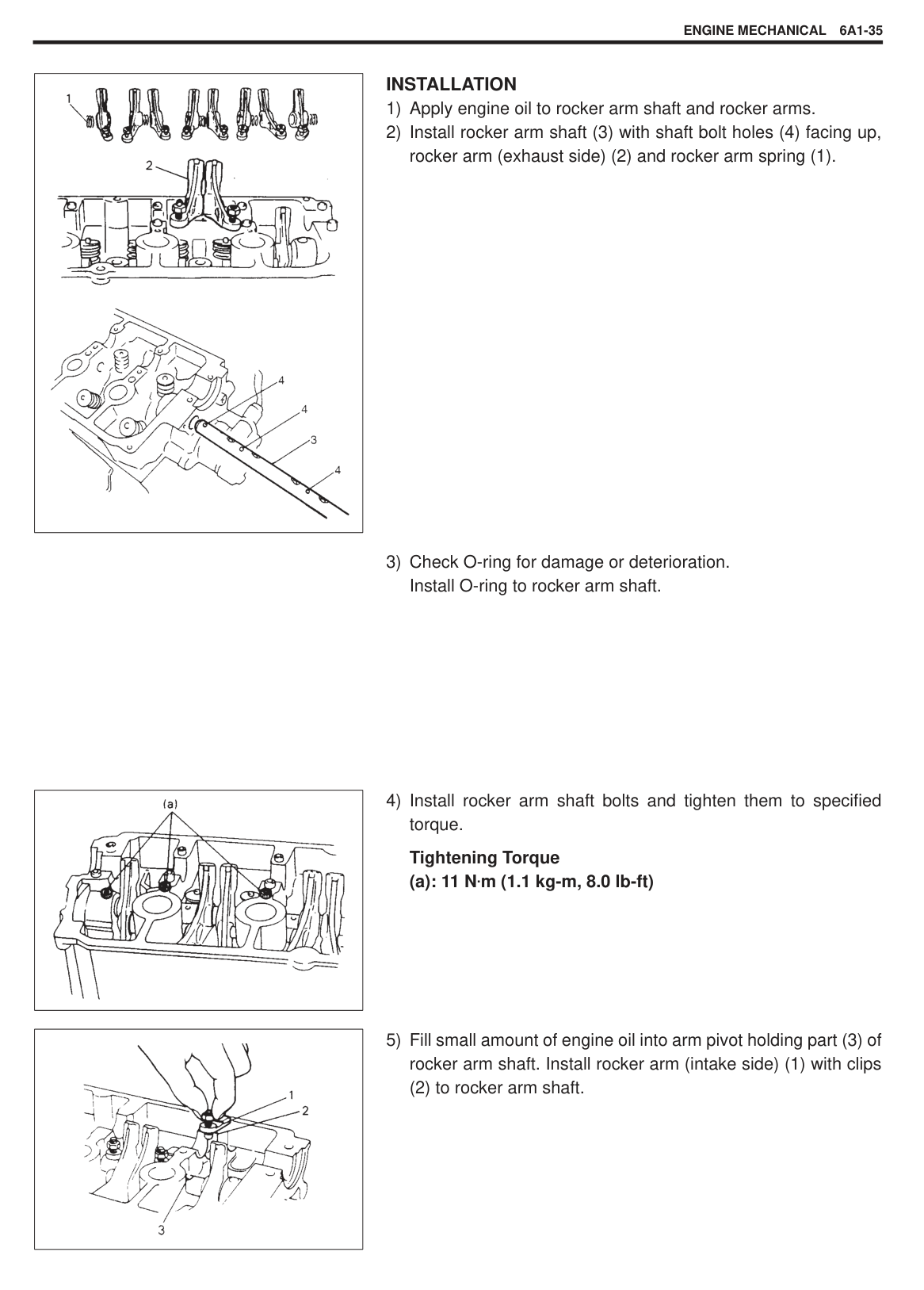
######### Runout limit: 0.10 mm (0.004 in.)
|| |---|
|| |---|
|| |---|
|| |---|
Rocker Arm-to-Rocker Arm Shaft Clearance Using a micrometer and a bore gauge, measure rocker shaft dia. and rocker arm I.D. Difference between two readings is arm-to-shaft clearance on which a limit is specified. If limit is exceeded, replace shaft or arm, or both.
|Item|Standard|Limit| |---|---|---| |Rocker arm I.D.|15.996 – 16.014 mm (0.629 – 0.630 in.)|———| |Rocker arm shaft dia.|15.969 – 15.984 mm (0.6287 – 0.6293 in.)|———| |Arm-to-shaft clearance|0.012 – 0.045 mm (0.0005 – 0.0018 in.)|0.09 mm (0.0035 in.)|
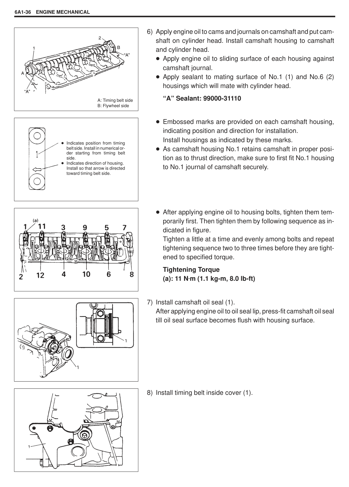
Cam Wear Using a micrometer, measured height of cam. If measured height is below limit, replace camshaft.
|Cam height|Standard|Limit| |---|---|---| |Intake cam|36.184 – 36.344 mm (1.4246 – 1.4309 in.)|36.084 mm (1.4206 in.)| |Exhaust cam|35.900 – 36.060 mm (1.4134 – 1.4197 in.)|35.800 mm (1.4094 in.)|
Camshaft Runout Hold camshaft between two “V” blocks, and measure runout by using a dial gauge. If runout exceeds its limit, replace camshaft.
######### Runout limit: 0.10 mm (0.0039 in.)
Camshaft Journal Wear Check camshaft journals and camshaft housings for pitting, scratches, wear or damage. If any malcondition is found, replace camshaft or cylinder head with housing. Never replace cylinder head without replacing housing.
|| |---|
Check clearance by using gaging plastic. The procedure is as follows.
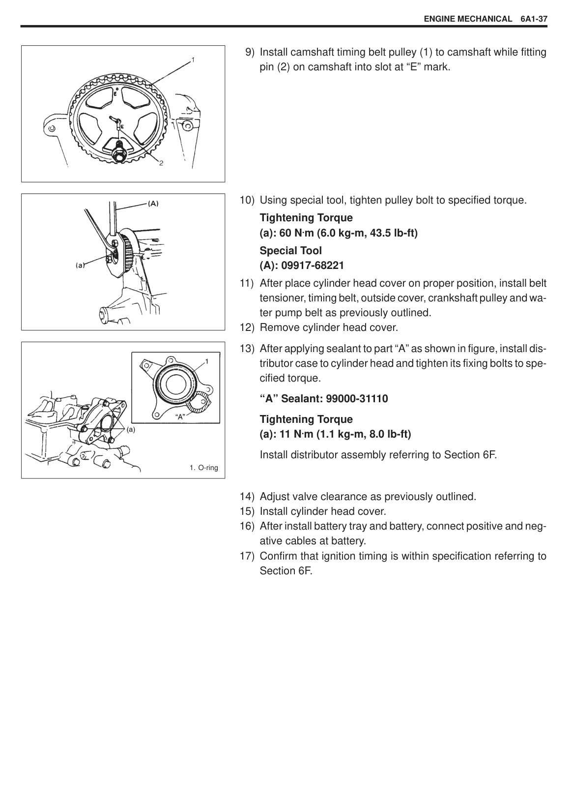
Tightening Torque (a): 11 N.m (1.1 kg-m, 8.0 lb-ft)
NOTE: Do not rotate camshaft while gaging plastic is installed.
|| |---|
| |Standard|Limit| |---|---|---| |Journal clearance|0.040 – 0.082 mm (0.0016 – 0.0032 in.)|0.12 mm (0.0047 in.)|
|
| |---|
If measured camshaft journal clearance exceeds limit, measure journal (housing) bore and outside diameter of camshaft journal. Replace camshaft or cylinder head assembly whichever the difference from specification is greater.
|Item|Standard| |---|---|
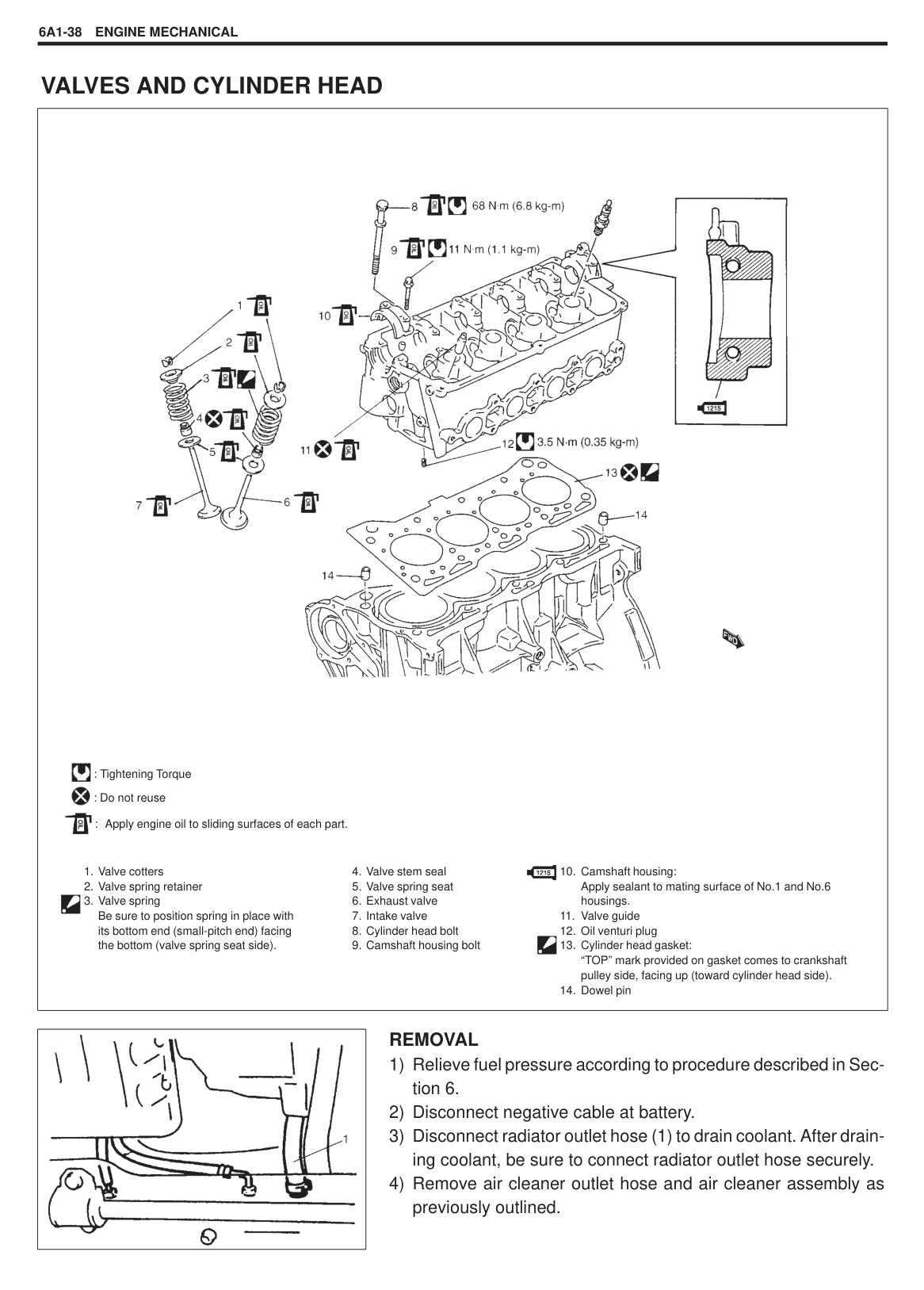
|Camshaft journal bore die.|28.000 – 28.021 mm (1.1024 – 1.1031 in.)| |Camshaft journal O.D.|27.939 – 27.960 mm (1.1000 – 1.1008 in.)|
|
| |---|
######## INSTALLATION
|| |---|
Tightening Torque (a): 11 N.m (1.1 kg-m, 8.0 lb-ft)
|| |---|
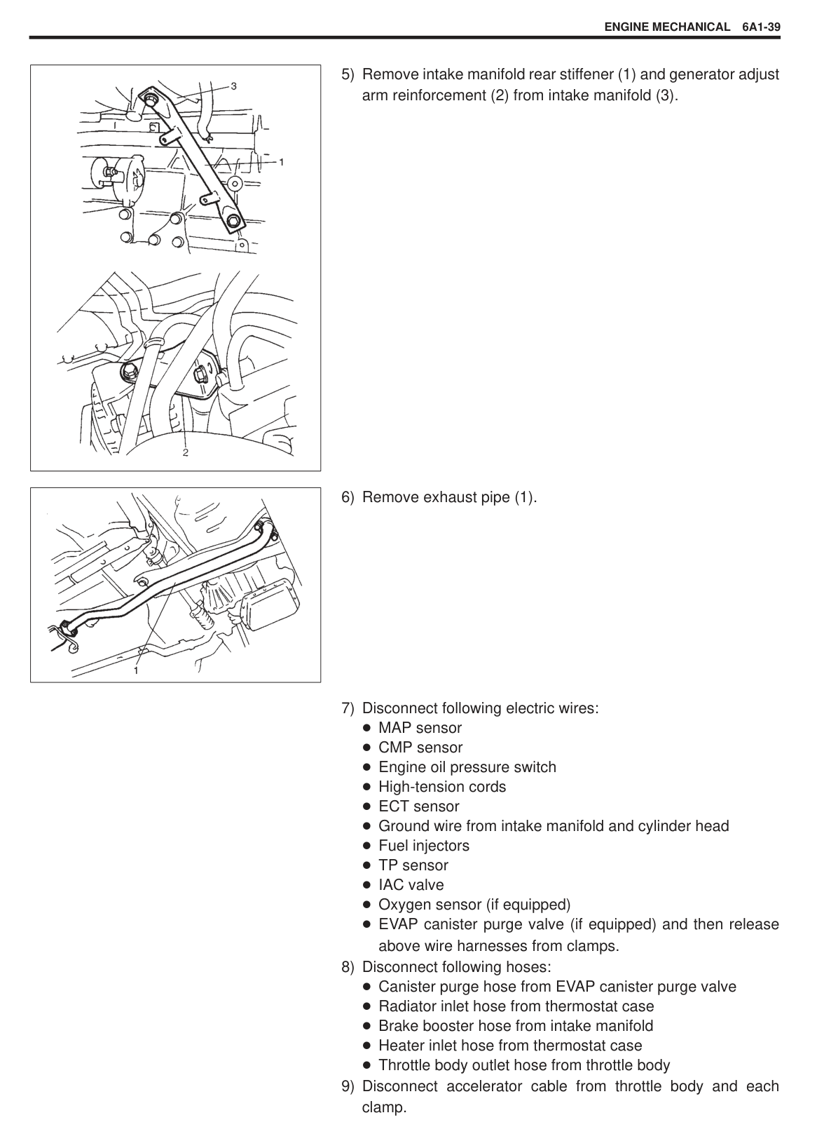
(2) to rocker arm shaft.
|
A: Timing belt side
B: Flywheel side
| |---|
|
Indicates position from timing belt side. Install in numerical order starting from timing belt side.
Indicates direction of housing. Install so that arrow is directed toward timing belt side.| |---|
|| |---|
|| |---|
|| |---|
########## 6) Apply engine oil to cams and journals on camshaft and put cam-shaft on cylinder head. Install camshaft housing to camshaftand cylinder head.
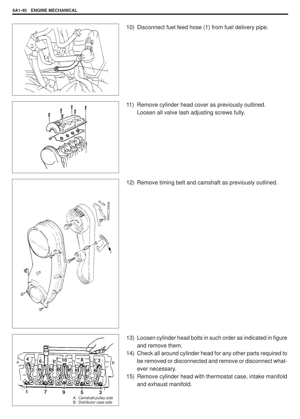
Apply engine oil to sliding surface of each housing against camshaft journal. Apply sealant to mating surface of No.1 (1) and No.6 (2) housings which will mate with cylinder head.
“A” Sealant: 99000-31110
Embossed marks are provided on each camshaft housing, indicating position and direction for installation. Install housings as indicated by these marks. As camshaft housing No.1 retains camshaft in proper position as to thrust direction, make sure to first fit No.1 housing to No.1 journal of camshaft securely.
After applying engine oil to housing bolts, tighten them temporarily first. Then tighten them by following sequence as indicated in figure. Tighten a little at a time and evenly among bolts and repeat tightening sequence two to three times before they are tightened to specified torque.
Tightening Torque (a): 11 N.m (1.1 kg-m, 8.0 lb-ft)
########## 7) Install camshaft oil seal (1).After applying engine oil to oil seal lip, press-fit camshaft oil sealtill oil seal surface becomes flush with housing surface.
########## 8) Install timing belt inside cover (1).
|| |---|
|| |---|
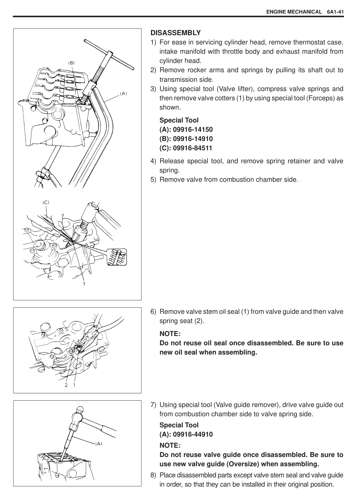
|
1. O-ring| |---|
Tightening Torque (a): 11 N.m (1.1 kg-m, 8.0 lb-ft)
Install distributor assembly referring to Section 6F.
#### VALVES AND CYLINDER HEAD
|
4. Valve stem seal
5. Valve spring seat
6. Exhaust valve
7. Intake valve
8. Cylinder head bolt
9. Camshaft housing bolt
10. Camshaft housing: Apply sealant to mating surface of No.1 and No.6 housings.
11. Valve guide
12. Oil venturi plug
13. Cylinder head gasket: “TOP” mark provided on gasket comes to crankshaft pulley side, facing up (toward cylinder head side).
14. Dowel pin
1. Valve cotters
2. Valve spring retainer
3. Valve spring Be sure to position spring in place with its bottom end (small-pitch end) facing the bottom (valve spring seat side).


: Tightening Torque : Do not reuse : Apply engine oil to sliding surfaces of each part.


| |---|
||
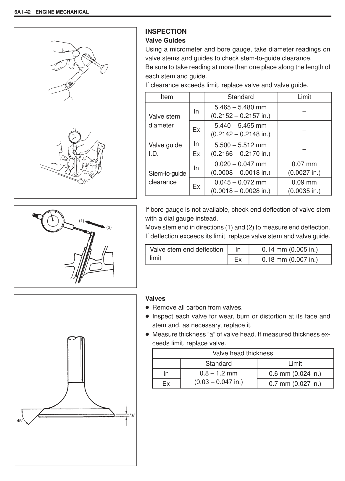
|---|
######## REMOVAL
|
| |---|
|| |---|
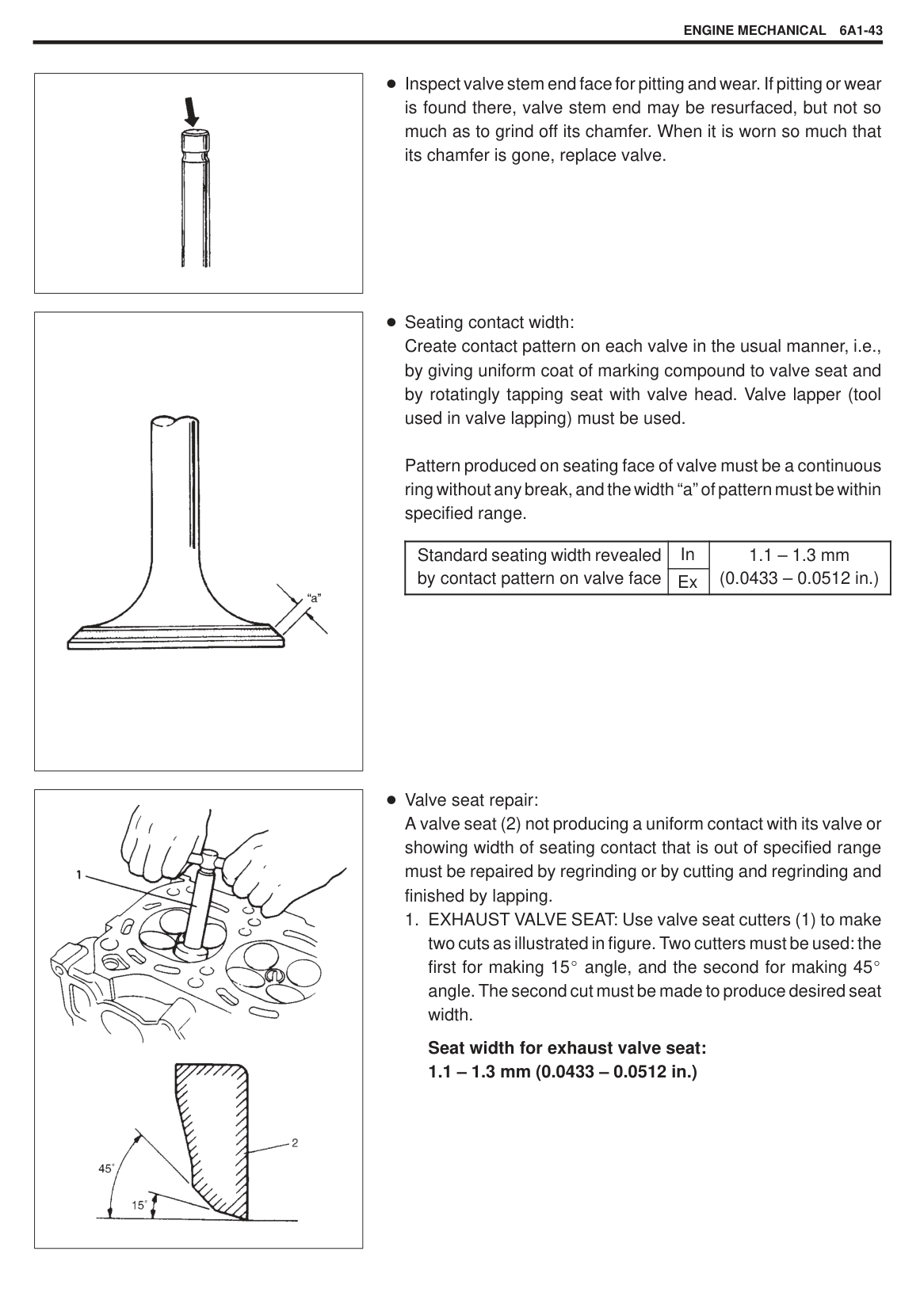
|| |---|
|| |---|
|| |---|
|
A: Camshaft pulley side
B: Distributor case side
| |---|
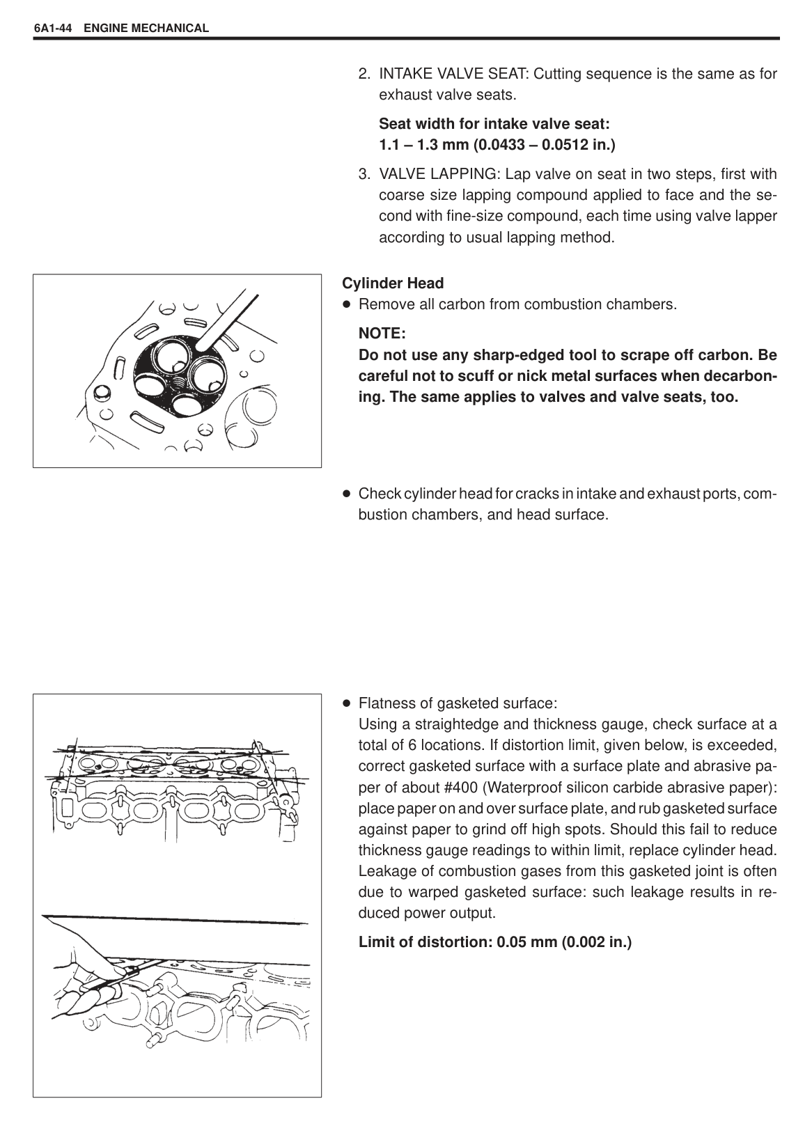
|| |---|
######## DISASSEMBLY
|| |---|
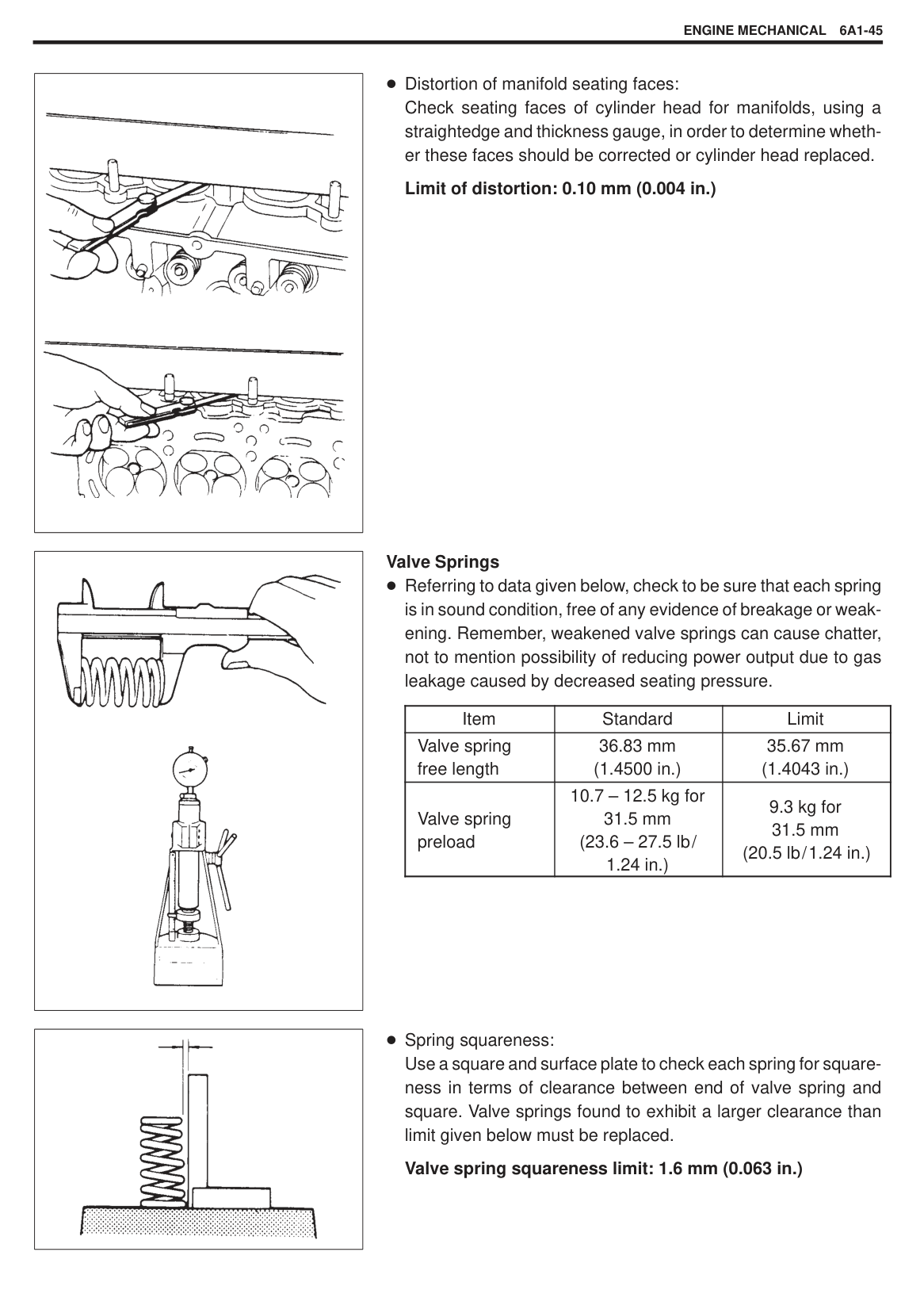
NOTE: Do not reuse oil seal once disassembled. Be sure to use new oil seal when assembling.
|| |---|
|| |---|
|| |---|
|| |---|
INSPECTION Valve Guides Using a micrometer and bore gauge, take diameter readings on valve stems and guides to check stem-to-guide clearance. Be sure to take reading at more than one place along the length of each stem and guide. If clearance exceeds limit, replace valve and valve guide.
|Item| |Standard|Limit| |---|---|---|---|
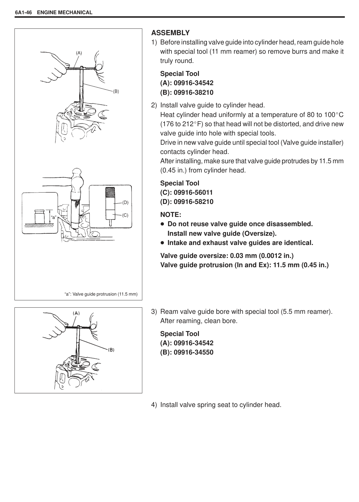
|Valve stem diameter
|In|5.465 – 5.480 mm (0.2152 – 0.2157 in.)|–| |Valve stem diameter
|Ex|5.440 – 5.455 mm (0.2142 – 0.2148 in.)|–| |Valve guideg
I.D.|In|5.500 – 5.512 mm (0.2166 – 0.2170 in.)
|–
| |Valve guideg
I.D.|Ex
|5.500 – 5.512 mm (0.2166 – 0.2170 in.)
|–
| |Stem-to-guideg clearance
|In|0.020 – 0.047 mm (0.0008 – 0.0018 in.)|0.07 mm (0.0027 in.)| |Stem-to-guideg clearance
|Ex|0.045 – 0.072 mm (0.0018 – 0.0028 in.)|0.09 mm (0.0035 in.)|
If bore gauge is not available, check end deflection of valve stem with a dial gauge instead. Move stem end in directions (1) and (2) to measure end deflection. If deflection exceeds its limit, replace valve stem and valve guide.
|Valve stem end deflection limit
|In|0.14 mm (0.005 in.)| |---|---|---| |Valve stem end deflection limit
|Ex|0.18 mm (0.007 in.)|
Valves Remove all carbon from valves. Inspect each valve for wear, burn or distortion at its face and stem and, as necessary, replace it. Measure thickness “a” of valve head. If measured thickness exceeds limit, replace valve.
|Valve head thickness|Valve head thickness|Valve head thickness| |---|---|---| | |Standard|Limit| |In|0.8 – 1.2 mm (0.03 – 0.047 in.)
|0.6 mm (0.024 in.)| |Ex|0.8 – 1.2 mm (0.03 – 0.047 in.)
|0.7 mm (0.027 in.)|
|| |---|
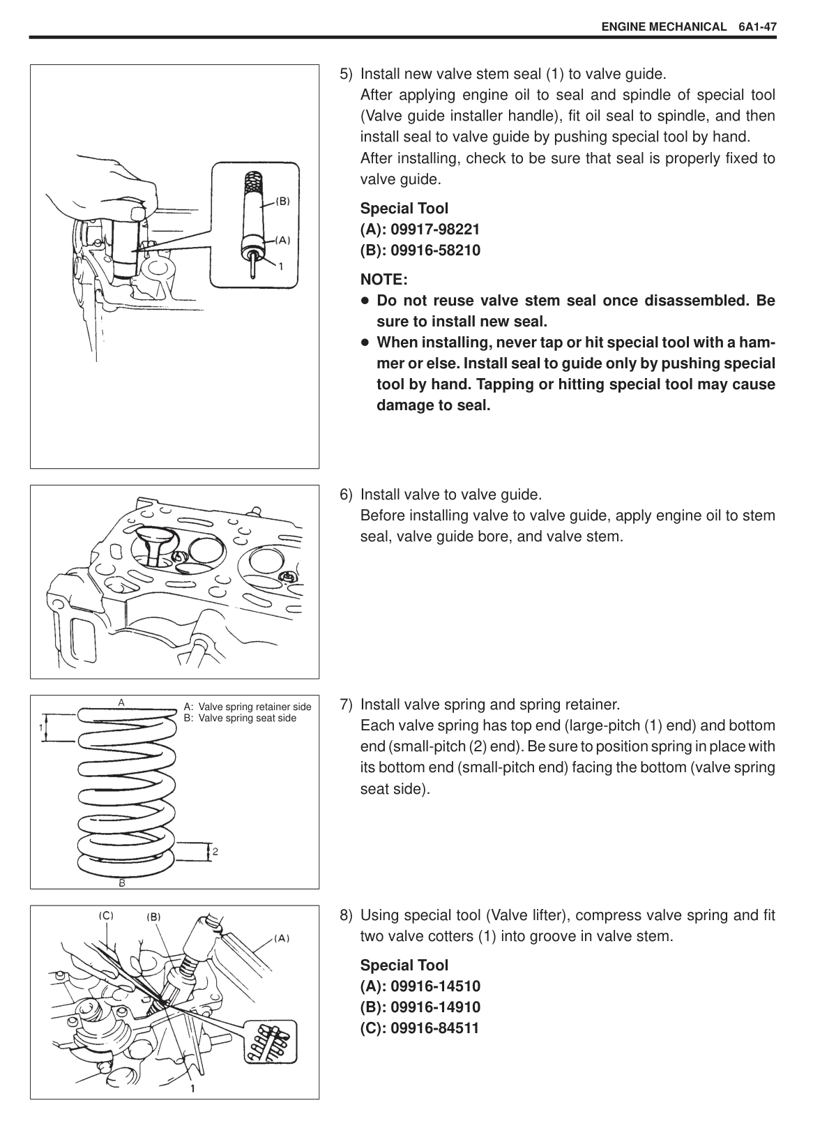
|| |---|
|
| |---|
Inspect valve stem end face for pitting and wear. If pitting or wear is found there, valve stem end may be resurfaced, but not so much as to grind off its chamfer. When it is worn so much that its chamfer is gone, replace valve.
Seating contact width: Create contact pattern on each valve in the usual manner, i.e., by giving uniform coat of marking compound to valve seat and by rotatingly tapping seat with valve head. Valve lapper (tool used in valve lapping) must be used.
Pattern produced on seating face of valve must be a continuous ring without any break, and the width “a” of pattern must be within specified range.
|Standard seating width revealed by contact pattern on valve face
|In|1.1 – 1.3 mm (0.0433 – 0.0512 in.)
| |---|---|---| |Standard seating width revealed by contact pattern on valve face
|Ex|1.1 – 1.3 mm (0.0433 – 0.0512 in.)
|
Valve seat repair: A valve seat (2) not producing a uniform contact with its valve or showing width of seating contact that is out of specified range must be repaired by regrinding or by cutting and regrinding and finished by lapping.
Seat width for exhaust valve seat:
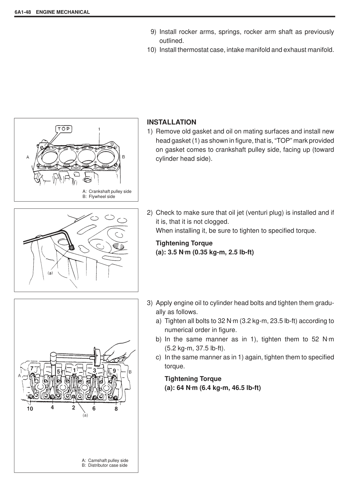
Seat width for intake valve seat: 1.1 – 1.3 mm (0.0433 – 0.0512 in.)
|| |---|
######### Cylinder Head
Remove all carbon from combustion chambers.
NOTE: Do not use any sharp-edged tool to scrape off carbon. Be careful not to scuff or nick metal surfaces when decarboning. The same applies to valves and valve seats, too.
Check cylinder head for cracks in intake and exhaust ports, combustion chambers, and head surface.
|| |---|
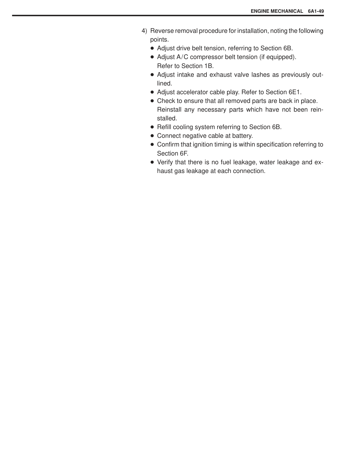
Flatness of gasketed surface: Using a straightedge and thickness gauge, check surface at a total of 6 locations. If distortion limit, given below, is exceeded, correct gasketed surface with a surface plate and abrasive paper of about #400 (Waterproof silicon carbide abrasive paper): place paper on and over surface plate, and rub gasketed surface against paper to grind off high spots. Should this fail to reduce thickness gauge readings to within limit, replace cylinder head. Leakage of combustion gases from this gasketed joint is often due to warped gasketed surface: such leakage results in reduced power output.
######### Limit of distortion: 0.05 mm (0.002 in.)
|| |---|
|| |---|
|| |---|
Distortion of manifold seating faces: Check seating faces of cylinder head for manifolds, using a straightedge and thickness gauge, in order to determine whether these faces should be corrected or cylinder head replaced.
Limit of distortion: 0.10 mm (0.004 in.)
Valve Springs
Referring to data given below, check to be sure that each spring is in sound condition, free of any evidence of breakage or weakening. Remember, weakened valve springs can cause chatter, not to mention possibility of reducing power output due to gas leakage caused by decreased seating pressure.
|Item|Standard|Limit|
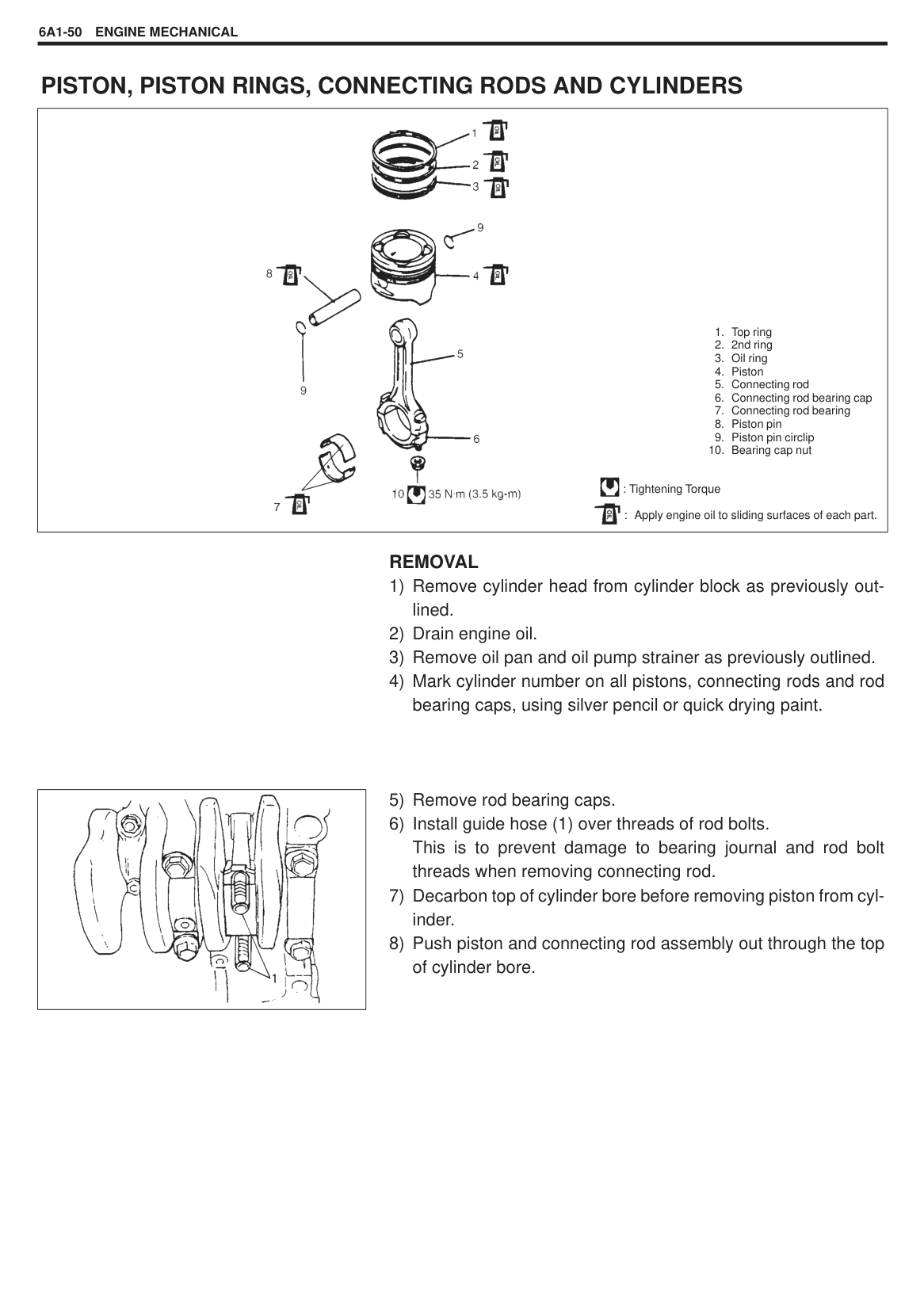
|---|---|---| |Valve spring free length|36.83 mm (1.4500 in.)|35.67 mm (1.4043 in.)| |Valve spring preload|10.7 – 12.5 kg for 31.5 mm (23.6 – 27.5 lb/ 1.24 in.)|9.3 kg for 31.5 mm (20.5 lb/1.24 in.)|
Spring squareness: Use a square and surface plate to check each spring for squareness in terms of clearance between end of valve spring and square. Valve springs found to exhibit a larger clearance than limit given below must be replaced.
######### Valve spring squareness limit: 1.6 mm (0.063 in.)
|
“a”: Valve guide protrusion (11.5 mm)| |---|
|| |---|
######## ASSEMBLY
2) Install valve guide to cylinder head. Heat cylinder head uniformly at a temperature of 80 to 100 C (176 to 212 F) so that head will not be distorted, and drive new valve guide into hole with special tools. Drive in new valve guide until special tool (Valve guide installer) contacts cylinder head. After installing, make sure that valve guide protrudes by 11.5 mm (0.45 in.) from cylinder head.
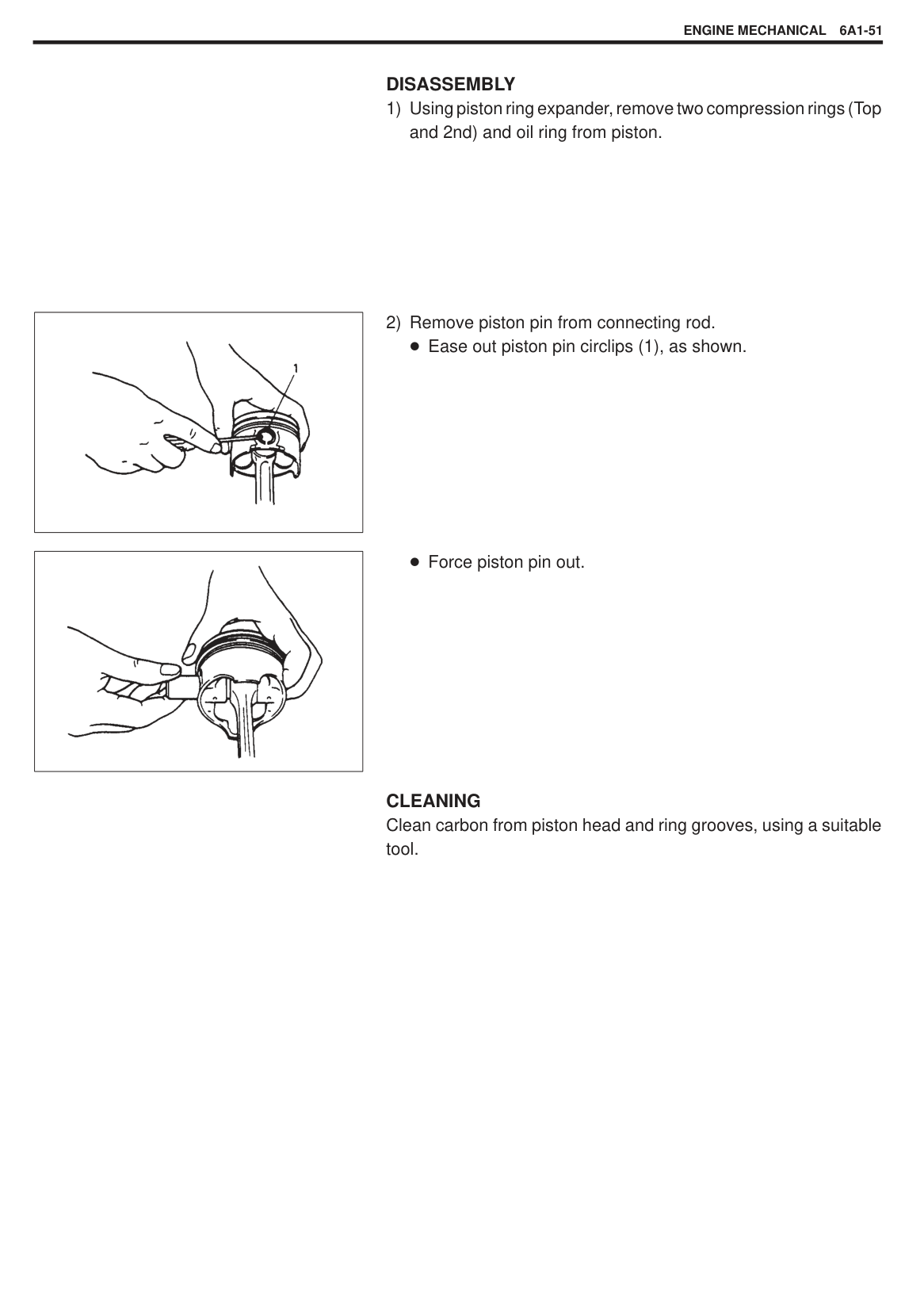
Special Tool
NOTE: Do not reuse valve guide once disassembled. Install new valve guide (Oversize). Intake and exhaust valve guides are identical.
Valve guide oversize: 0.03 mm (0.0012 in.) Valve guide protrusion (In and Ex): 11.5 mm (0.45 in.)
|| |---|
Special Tool (A): 09917-98221 (B): 09916-58210
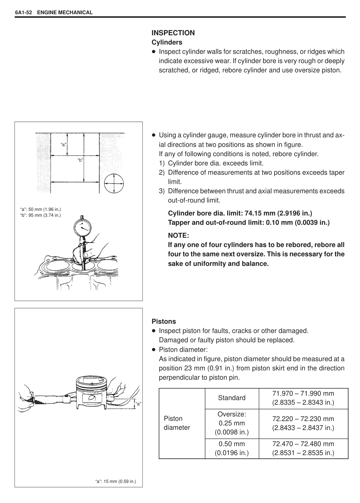
NOTE: Do not reuse valve stem seal once disassembled. Be sure to install new seal. When installing, never tap or hit special tool with a hammer or else. Install seal to guide only by pushing special tool by hand. Tapping or hitting special tool may cause damage to seal.
|| |---|
|
A: Valve spring retainer side
B: Valve spring seat side
| |---|
|| |---|
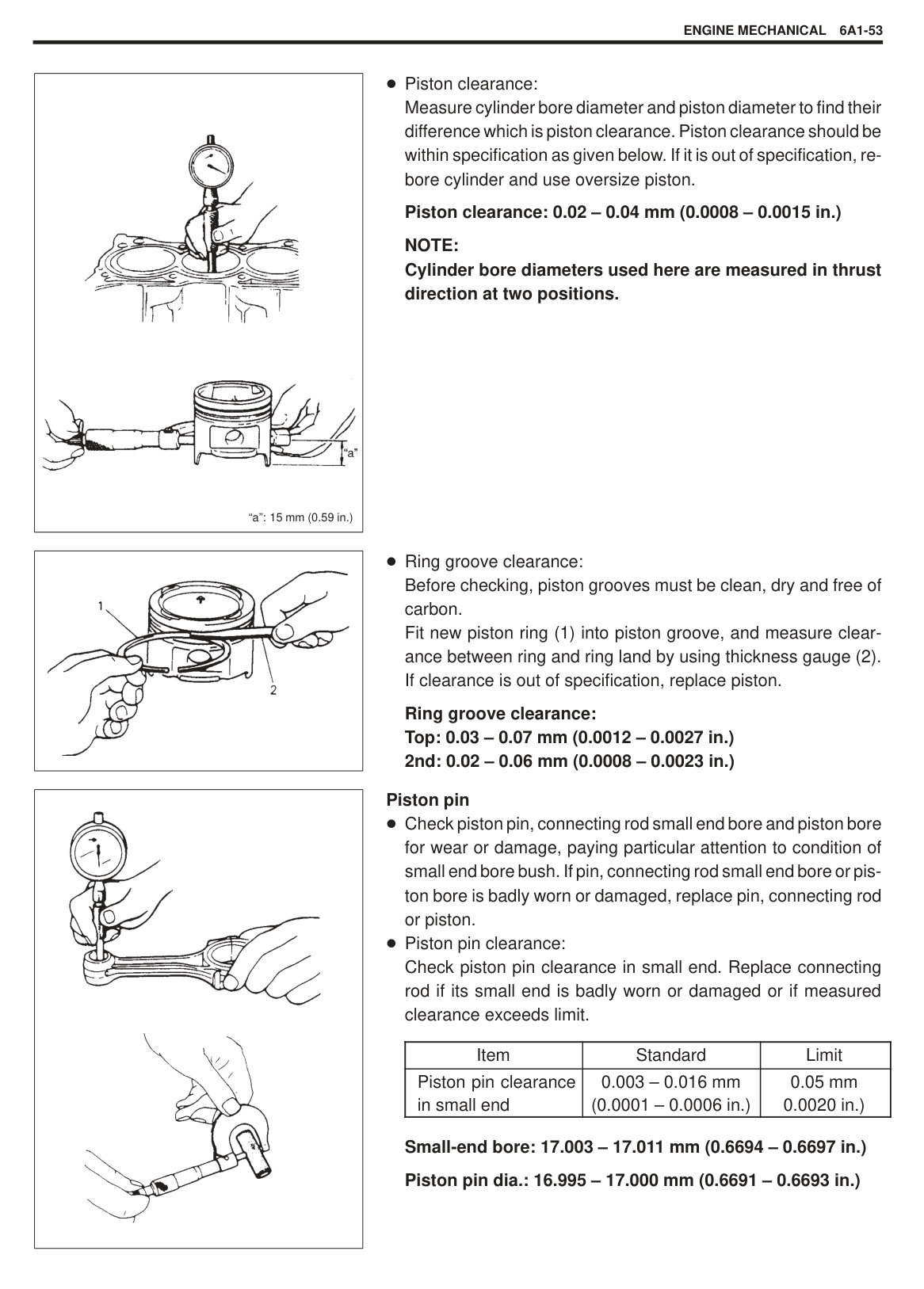
|
A: Crankshaft pulley side
B: Flywheel side
| |---|
######## INSTALLATION
|| |---|
Tightening Torque (a): 3.5 N.m (0.35 kg-m, 2.5 lb-ft)
|
A: Camshaft pulley side
B: Distributor case side
| |---|
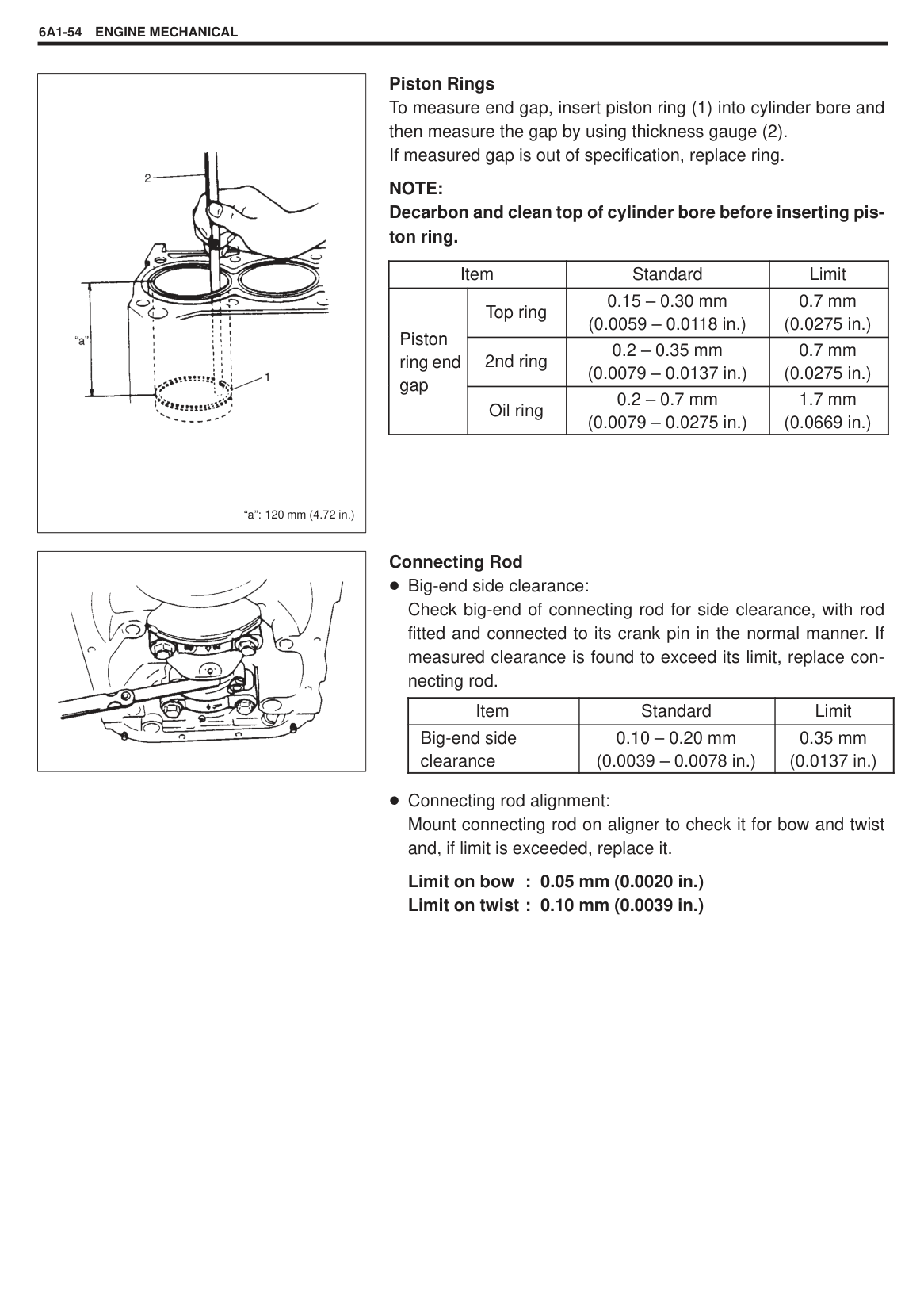
######### Tightening Torque (a): 64 N.m (6.4 kg-m, 46.5 lb-ft)
Adjust drive belt tension, referring to Section 6B. Adjust A/C compressor belt tension (if equipped). Refer to Section 1B. Adjust intake and exhaust valve lashes as previously outlined. Adjust accelerator cable play. Refer to Section 6E1. Check to ensure that all removed parts are back in place. Reinstall any necessary parts which have not been reinstalled. Refill cooling system referring to Section 6B. Connect negative cable at battery. Confirm that ignition timing is within specification referring to Section 6F. Verify that there is no fuel leakage, water leakage and exhaust gas leakage at each connection.
#### PISTON, PISTON RINGS, CONNECTING RODS AND CYLINDERS
|
1. Top ring
2. 2nd ring
3. Oil ring
4. Piston
5. Connecting rod
6. Connecting rod bearing cap
7. Connecting rod bearing
8. Piston pin
9. Piston pin circlip
10. Bearing cap nut
: Tightening Torque : Apply engine oil to sliding surfaces of each part.

| |---|
######## REMOVAL
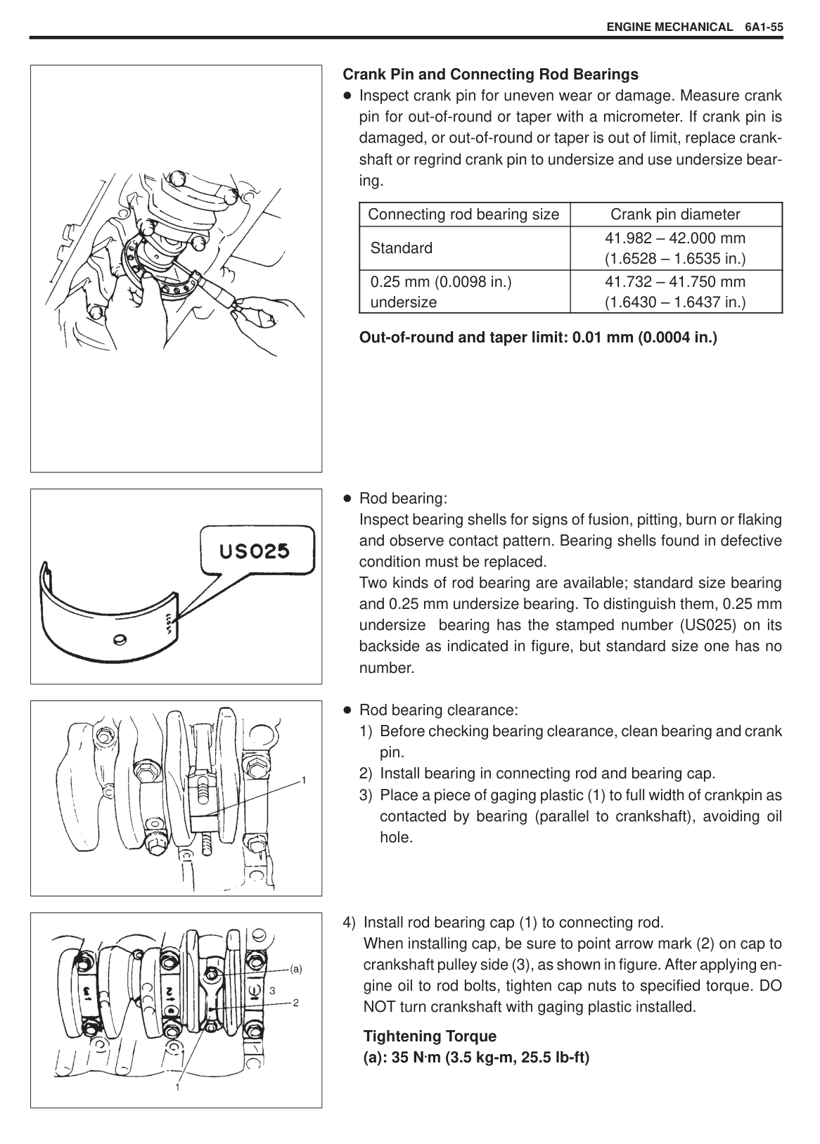
|| |---|
######## DISASSEMBLY
|| |---|
|| |---|
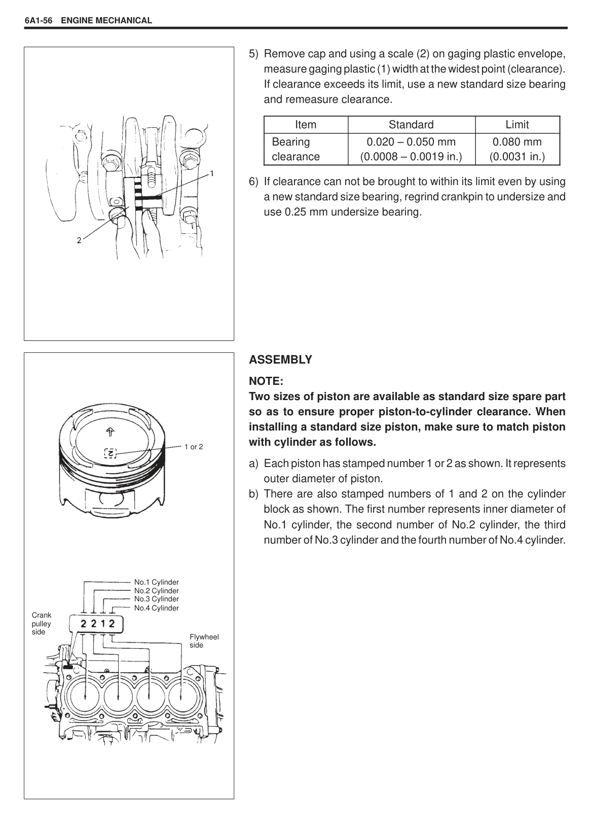
Force piston pin out.
CLEANING Clean carbon from piston head and ring grooves, using a suitable tool.
######## INSPECTION Cylinders
Inspect cylinder walls for scratches, roughness, or ridges which indicate excessive wear. If cylinder bore is very rough or deeply scratched, or ridged, rebore cylinder and use oversize piston.
|
“a”: 50 mm (1.96 in.)
“b”: 95 mm (3.74 in.)
| |---|
|
“a”: 15 mm (0.59 in.)| |---|
Using a cylinder gauge, measure cylinder bore in thrust and axial directions at two positions as shown in figure. If any of following conditions is noted, rebore cylinder.
Cylinder bore dia. limit: 74.15 mm (2.9196 in.) Tapper and out-of-round limit: 0.10 mm (0.0039 in.)
NOTE: If any one of four cylinders has to be rebored, rebore all four to the same next oversize. This is necessary for the sake of uniformity and balance.
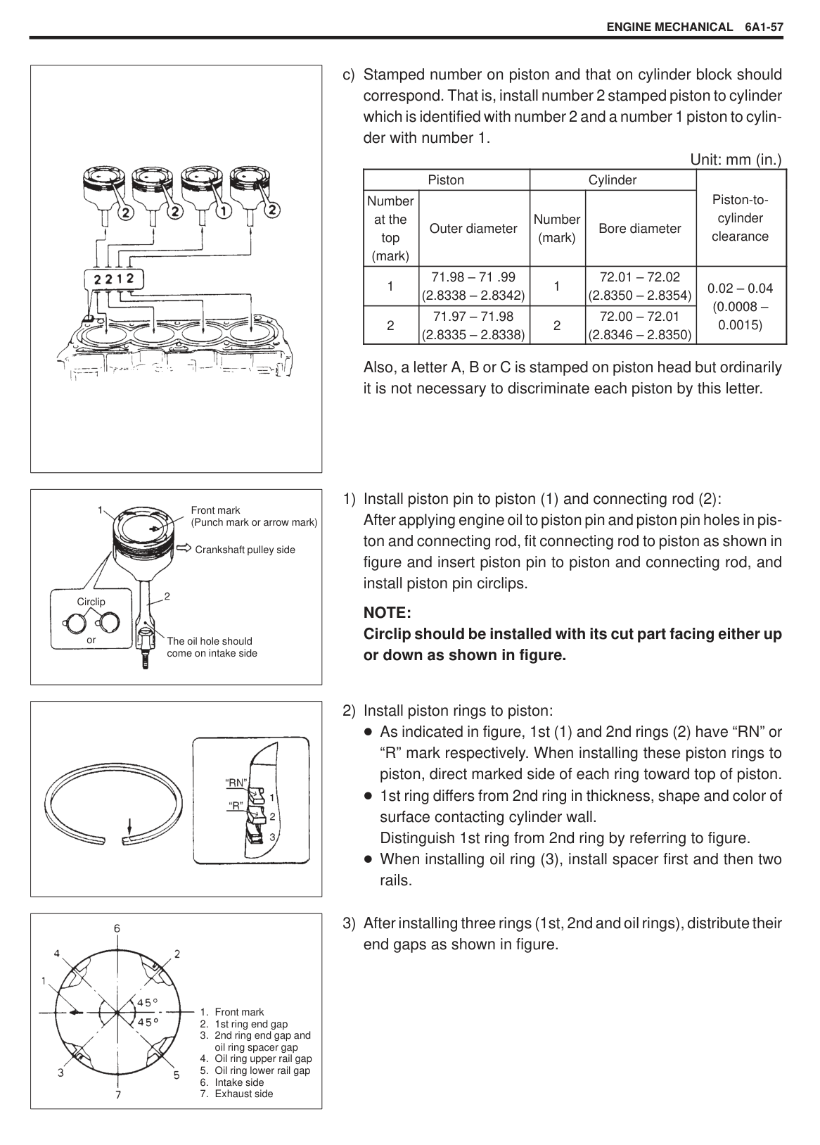
Pistons Inspect piston for faults, cracks or other damaged. Damaged or faulty piston should be replaced. Piston diameter: As indicated in figure, piston diameter should be measured at a position 23 mm (0.91 in.) from piston skirt end in the direction perpendicular to piston pin.
|Piston diameter
|Standard|71.970 – 71.990 mm (2.8335 – 2.8343 in.)| |---|---|---| |Piston diameter
|Oversize: 0.25 mm (0.0098 in.)|72.220 – 72.230 mm (2.8433 – 2.8437 in.)| |Piston diameter
|0.50 mm (0.0196 in.)|72.470 – 72.480 mm (2.8531 – 2.8535 in.)|
|
“a”: 15 mm (0.59 in.)| |---|
|| |---|
|| |---|
Piston clearance: Measure cylinder bore diameter and piston diameter to find their difference which is piston clearance. Piston clearance should be within specification as given below. If it is out of specification, rebore cylinder and use oversize piston.
Piston clearance: 0.02 – 0.04 mm (0.0008 – 0.0015 in.) NOTE: Cylinder bore diameters used here are measured in thrust direction at two positions.
Ring groove clearance: Before checking, piston grooves must be clean, dry and free of carbon. Fit new piston ring (1) into piston groove, and measure clearance between ring and ring land by using thickness gauge (2). If clearance is out of specification, replace piston.
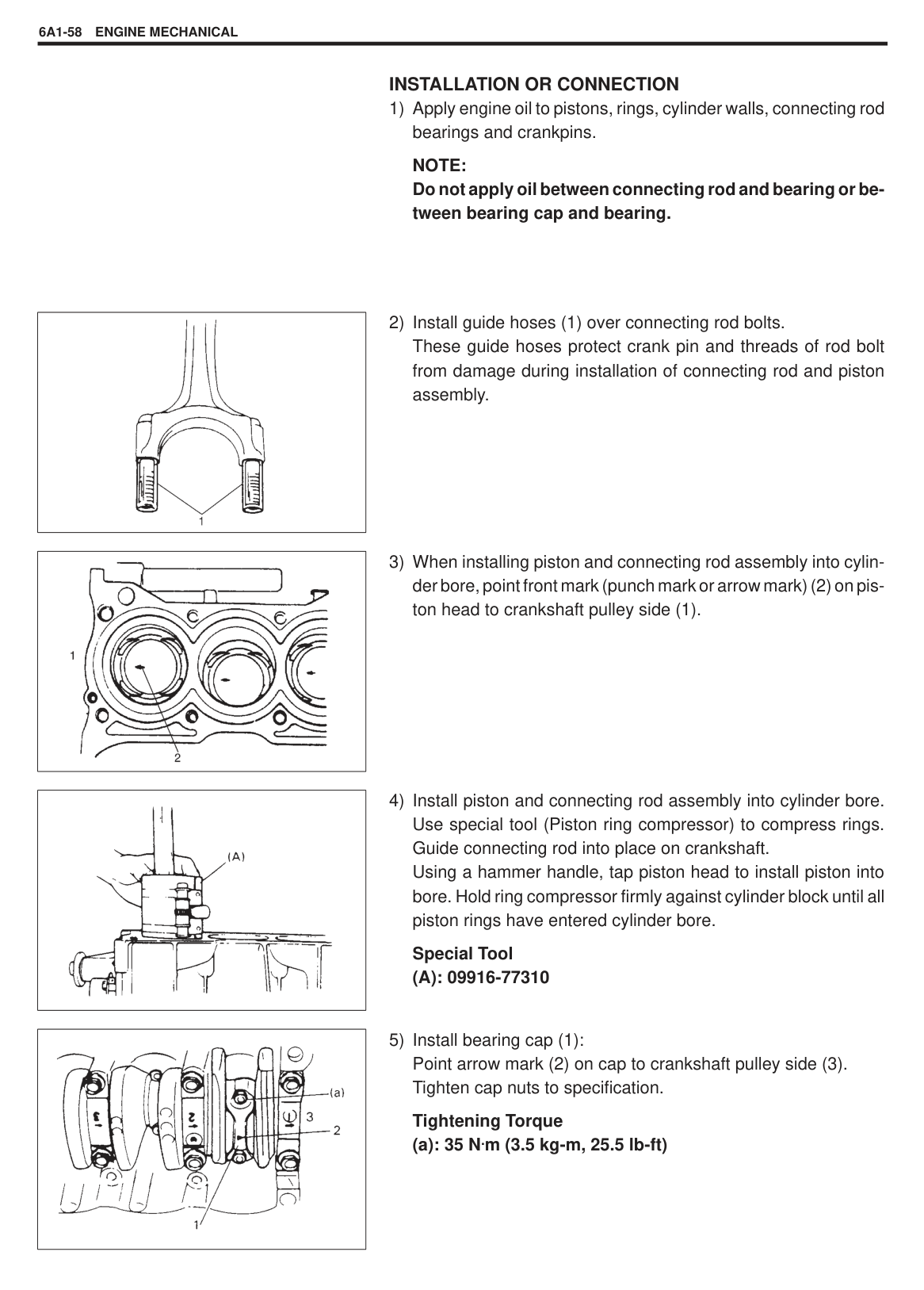
Ring groove clearance: Top: 0.03 – 0.07 mm (0.0012 – 0.0027 in.) 2nd: 0.02 – 0.06 mm (0.0008 – 0.0023 in.)
Piston pin Check piston pin, connecting rod small end bore and piston bore for wear or damage, paying particular attention to condition of small end bore bush. If pin, connecting rod small end bore or piston bore is badly worn or damaged, replace pin, connecting rod or piston. Piston pin clearance: Check piston pin clearance in small end. Replace connecting rod if its small end is badly worn or damaged or if measured clearance exceeds limit.
|Item|Standard|Limit| |---|---|---| |Piston pin clearance in small end|0.003 – 0.016 mm (0.0001 – 0.0006 in.)|0.05 mm 0.0020 in.)|
######### Small-end bore: 17.003 – 17.011 mm (0.6694 – 0.6697 in.) Piston pin dia.: 16.995 – 17.000 mm (0.6691 – 0.6693 in.)
|
“a”: 120 mm (4.72 in.)| |---|
|| |---|
Piston Rings To measure end gap, insert piston ring (1) into cylinder bore and then measure the gap by using thickness gauge (2). If measured gap is out of specification, replace ring.
NOTE: Decarbon and clean top of cylinder bore before inserting piston ring.
|Item|Item|Standard|Limit| |---|---|---|---|
|PistonPiston ring end pga
|Top ring|0.15 – 0.30 mm (0.0059 – 0.0118 in.)|0.7 mm (0.0275 in.)| |PistonPiston ring end pga
|2nd ring|0.2 – 0.35 mm (0.0079 – 0.0137 in.)|0.7 mm (0.0275 in.)| |PistonPiston ring end pga
|Oil ring|0.2 – 0.7 mm (0.0079 – 0.0275 in.)|1.7 mm (0.0669 in.)|
Connecting Rod Big-end side clearance: Check big-end of connecting rod for side clearance, with rod fitted and connected to its crank pin in the normal manner. If measured clearance is found to exceed its limit, replace connecting rod.
|Item|Standard|Limit| |---|---|---| |Big-end side clearance|0.10 – 0.20 mm (0.0039 – 0.0078 in.)|0.35 mm (0.0137 in.)|
Connecting rod alignment: Mount connecting rod on aligner to check it for bow and twist and, if limit is exceeded, replace it.
Limit on bow : 0.05 mm (0.0020 in.) Limit on twist : 0.10 mm (0.0039 in.)
|| |---|
|| |---|
|| |---|
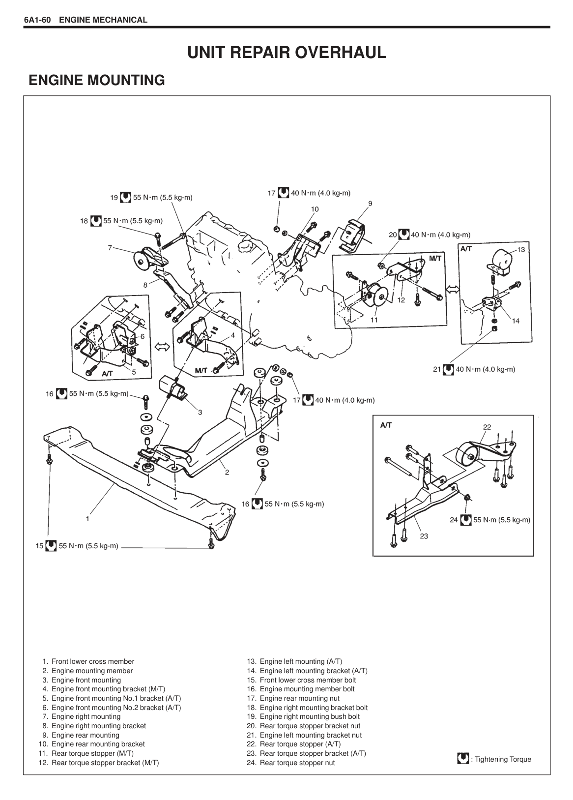
######### Crank Pin and Connecting Rod Bearings
Inspect crank pin for uneven wear or damage. Measure crank pin for out-of-round or taper with a micrometer. If crank pin is damaged, or out-of-round or taper is out of limit, replace crankshaft or regrind crank pin to undersize and use undersize bearing.
|Connecting rod bearing size|Crank pin diameter| |---|---| |Standard|41.982 – 42.000 mm (1.6528 – 1.6535 in.)| |0.25 mm (0.0098 in.) undersize|41.732 – 41.750 mm (1.6430 – 1.6437 in.)|
######### Out-of-round and taper limit: 0.01 mm (0.0004 in.)
Rod bearing: Inspect bearing shells for signs of fusion, pitting, burn or flaking and observe contact pattern. Bearing shells found in defective condition must be replaced. Two kinds of rod bearing are available; standard size bearing and 0.25 mm undersize bearing. To distinguish them, 0.25 mm undersize bearing has the stamped number (US025) on its backside as indicated in figure, but standard size one has no number.
Rod bearing clearance:
|| |---|
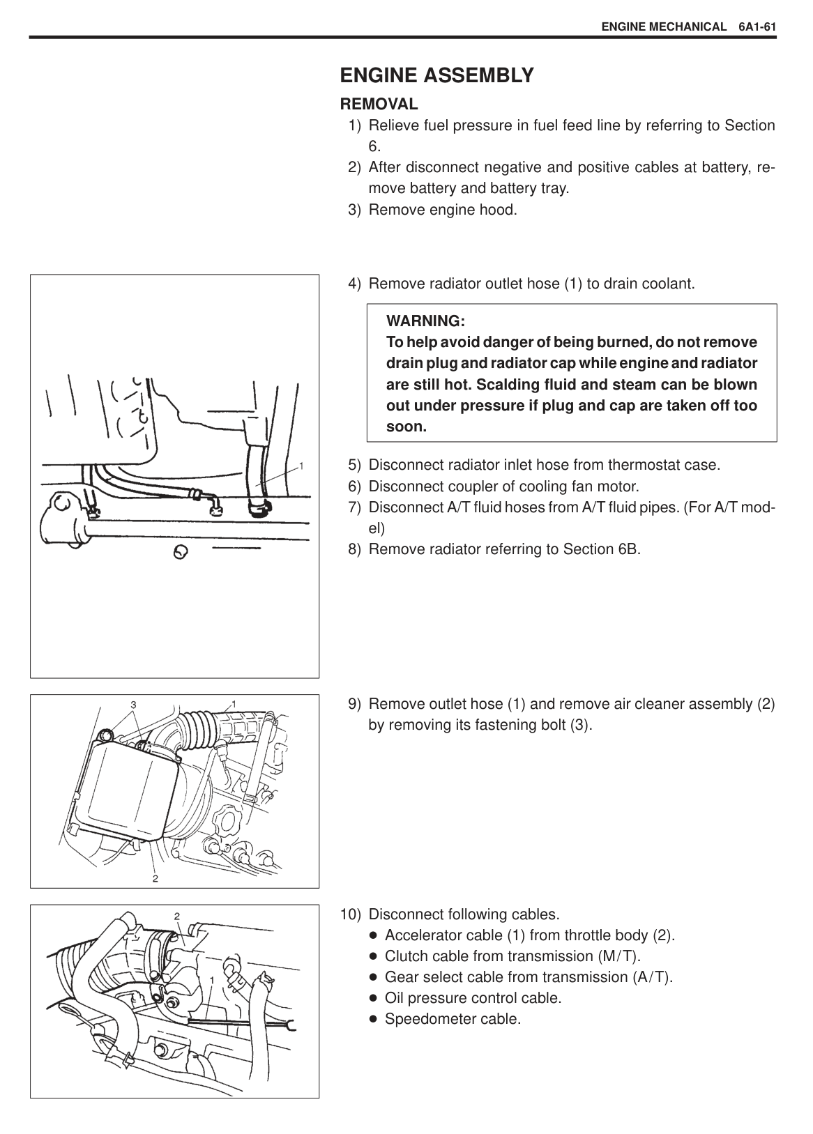
######### Tightening Torque (a): 35 N.m (3.5 kg-m, 25.5 lb-ft)
|| |---|
|
Flywheel side
1 or 2
Crank pulley side
No.1 Cylinder
No.2 Cylinder
No.3 Cylinder
No.4 Cylinder
| |---|
|Item|Standard|Limit| |---|---|---| |Bearing clearance
|0.020 – 0.050 mm (0.0008 – 0.0019 in.)
|0.080 mm (0.0031 in.)
|
######## ASSEMBLY
NOTE: Two sizes of piston are available as standard size spare part so as to ensure proper piston-to-cylinder clearance. When installing a standard size piston, make sure to match piston with cylinder as follows.
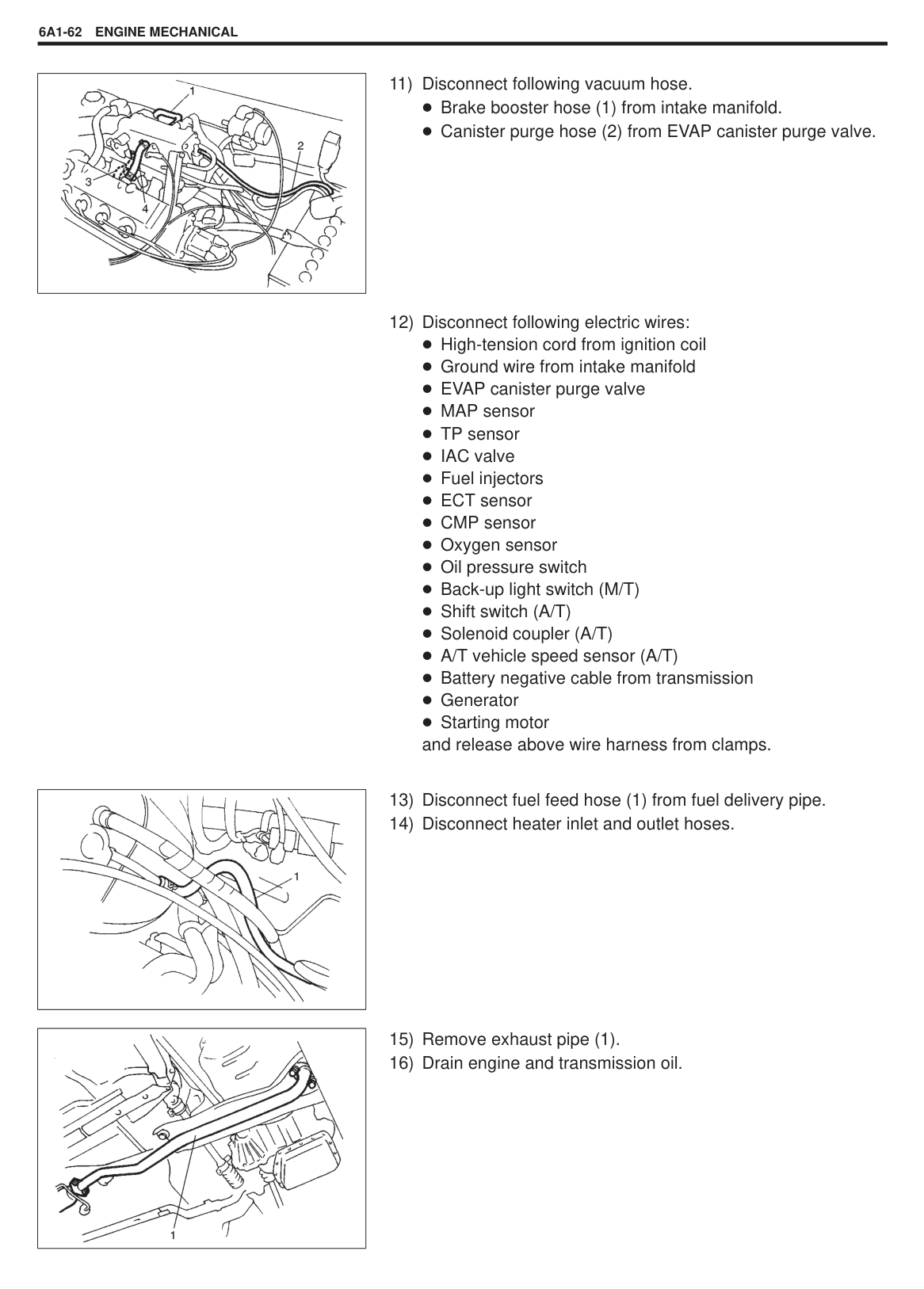
|| |---|
|
Front mark (Punch mark or arrow mark)
Crankshaft pulley side
The oil hole should come on intake side
Circlip
or| |---|
Unit: mm (in.)
|Piston|Piston|Cylinder|Cylinder|Piston-tocylinder clearance
| |---|---|---|---|---| |Number at the top (mark)|Outer diameter|Number (mark)|Bore diameter|Piston-tocylinder clearance
| |1|71.98 – 71 .99 (2.8338 – 2.8342)|1|72.01 – 72.02 (2.8350 – 2.8354)|0.02 – 0.04 (0 0008(0.0008 – 0.0015)
| |2|71.97 – 71.98 (2.8335 – 2.8338)|2|72.00 – 72.01 (2.8346 – 2.8350)|0.02 – 0.04 (0 0008(0.0008 – 0.0015)
|
Also, a letter A, B or C is stamped on piston head but ordinarily it is not necessary to discriminate each piston by this letter.
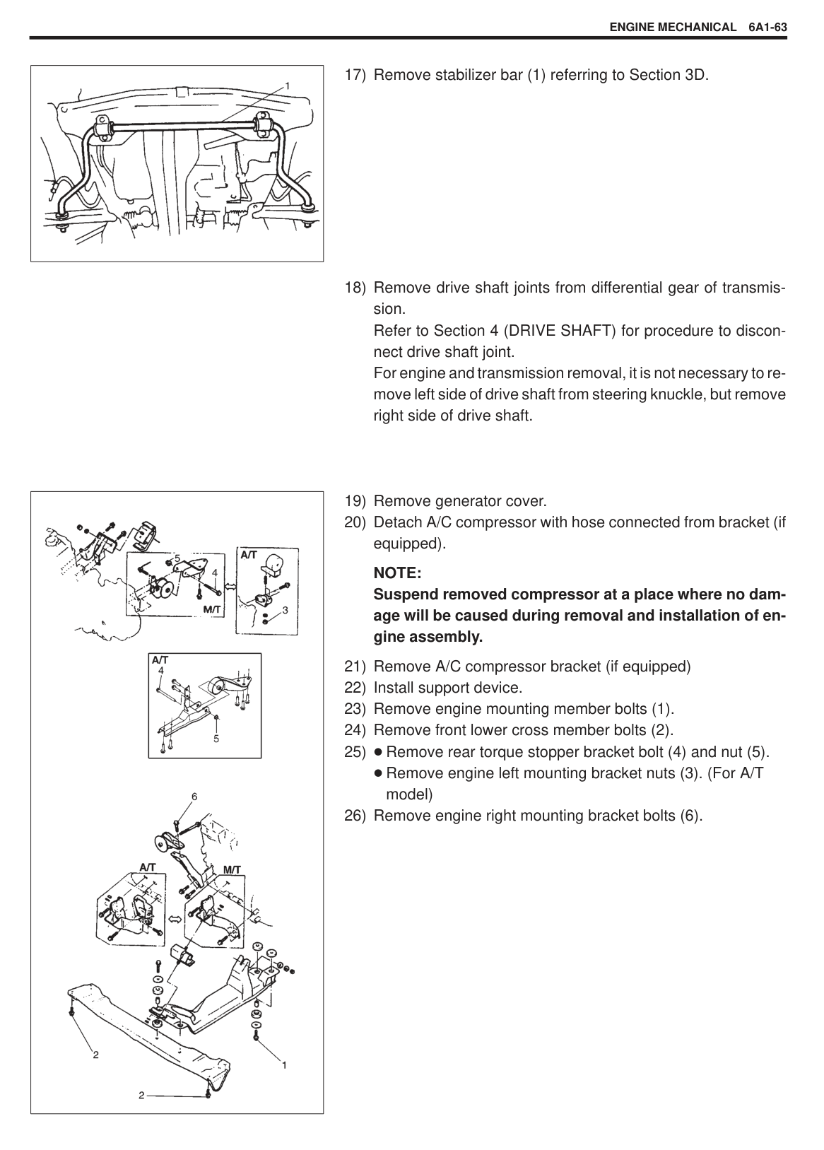
NOTE: Circlip should be installed with its cut part facing either up or down as shown in figure.
|| |---|
|
1. Front mark
2. 1st ring end gap
3. 2nd ring end gap and oil ring spacer gap
4. Oil ring upper rail gap
5. Oil ring lower rail gap
6. Intake side
7. Exhaust side
| |---|
######## INSTALLATION OR CONNECTION
NOTE: Do not apply oil between connecting rod and bearing or between bearing cap and bearing.
|| |---|
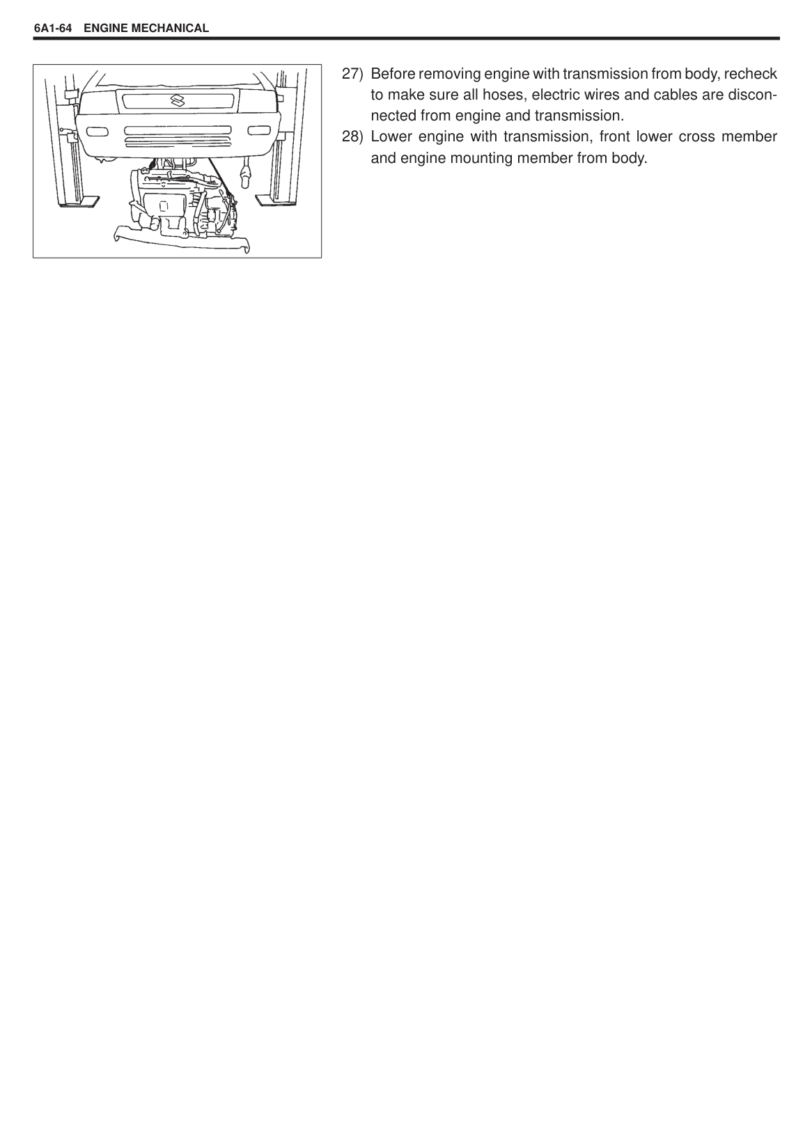
|| |---|
|| |---|
Special Tool (A): 09916-77310
|| |---|
######### Tightening Torque (a): 35 N.m (3.5 kg-m, 25.5 lb-ft)
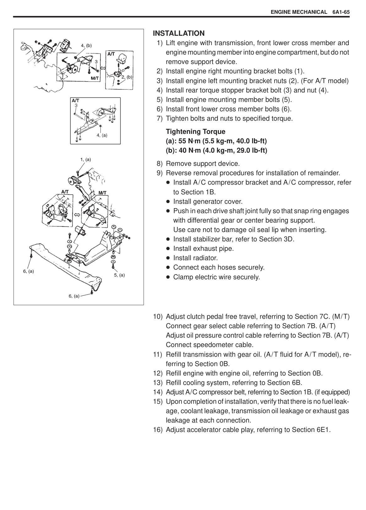
Adjust water pump drive belt tension, referring to Section 6B. Adjust A/C compressor belt tension (if equipped). Refer to Section 1B. Adjust accelerator cable play. Refer to Section 6E1. Check to ensure that all removed parts are back in place. Reinstall any necessary parts which have not been reinstalled. Refill engine with engine oil, referring to ENGINE OIL CHANGE in Section 0B. Refill cooling system referring to Section 6B. Connect negative cable at battery. Verify that ignition timing is within specification referring to Section 6F. Verify that there is no fuel leakage, coolant leakage, oil leakage and exhaust gas leakage at each connection.
UNIT REPAIR OVERHAUL ENGINE MOUNTING
|
1. Front lower cross member
2. Engine mounting member
3. Engine front mounting
4. Engine front mounting bracket (M/T)
5. Engine front mounting No.1 bracket (A/T)
6. Engine front mounting No.2 bracket (A/T)
7. Engine right mounting
8. Engine right mounting bracket
9. Engine rear mounting
10. Engine rear mounting bracket
11. Rear torque stopper (M/T)
12. Rear torque stopper bracket (M/T)
13. Engine left mounting (A/T)
14. Engine left mounting bracket (A/T)
15. Front lower cross member bolt
16. Engine mounting member bolt
17. Engine rear mounting nut
18. Engine right mounting bracket bolt
19. Engine right mounting bush bolt
20. Rear torque stopper bracket nut
21. Engine left mounting bracket nut
22. Rear torque stopper (A/T)
23. Rear torque stopper bracket (A/T)
24. Rear torque stopper nut : Tightening Torque
| |---|
#### ENGINE ASSEMBLY REMOVAL
|| |---|
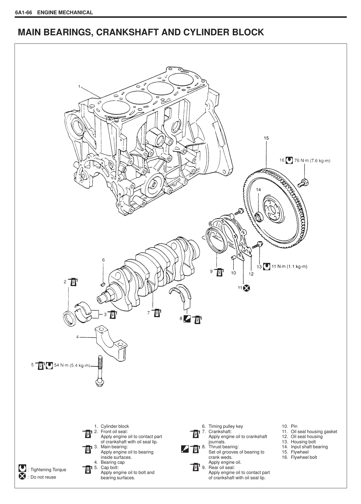
|WARNING: To help avoid danger of being burned, do not remove drain plug and radiator cap while engine and radiator are still hot. Scalding fluid and steam can be blown out under pressure if plug and cap are taken off too soon.| |---|
|| |---|
|| |---|
and release above wire harness from clamps.
|| |---|
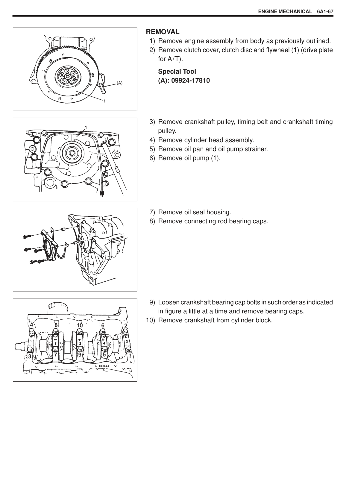
|| |---|
|| |---|
|

| |---|
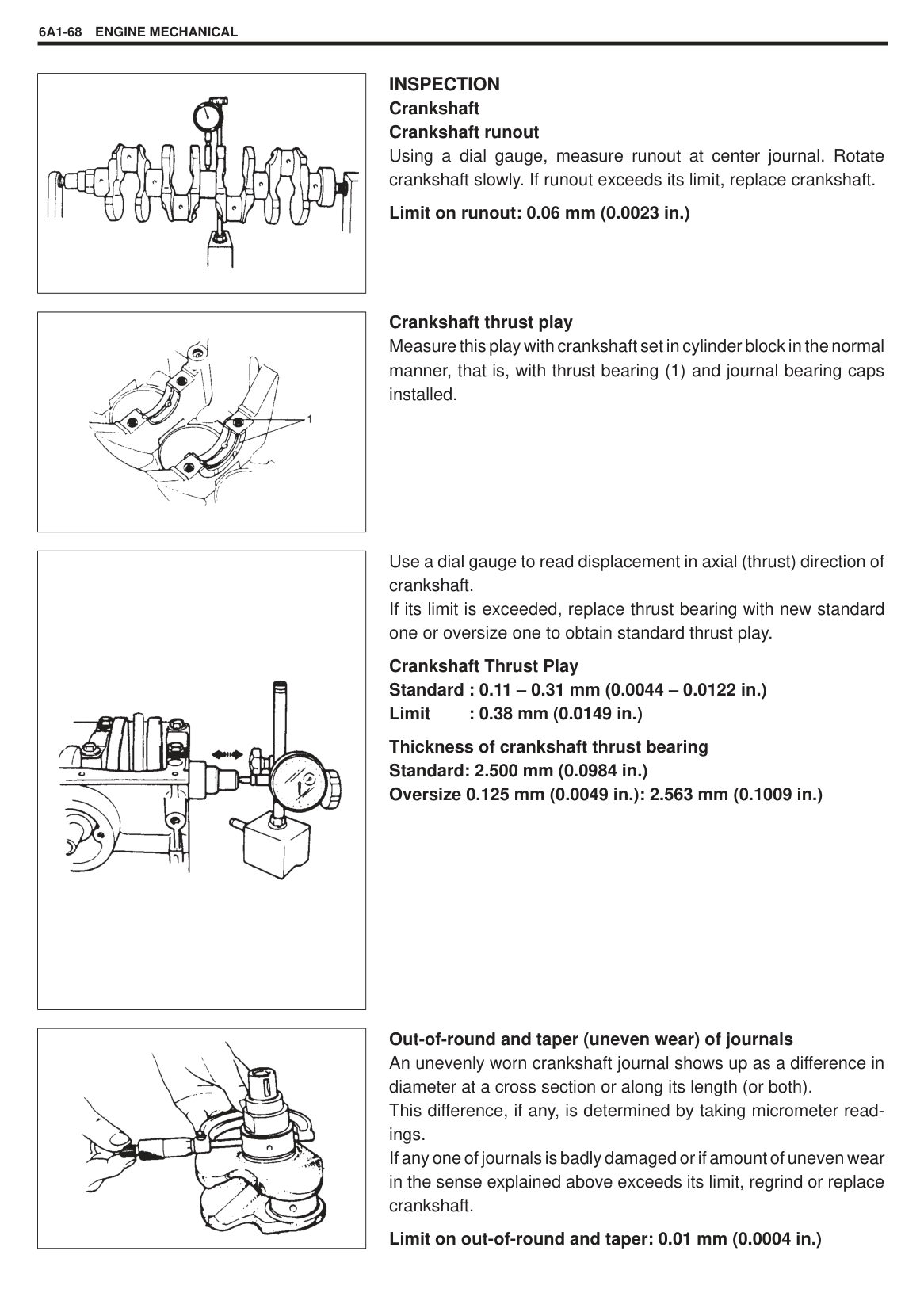
NOTE: Suspend removed compressor at a place where no damage will be caused during removal and installation of engine assembly.
|

| |---|
######## INSTALLATION
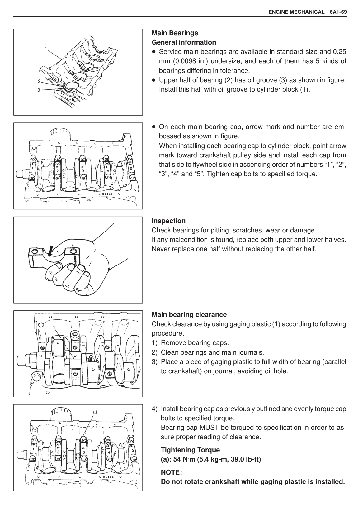
Tightening Torque (a): 55 N.m (5.5 kg-m, 40.0 lb-ft) (b): 40 N.m (4.0 kg-m, 29.0 lb-ft)
#### MAIN BEARINGS, CRANKSHAFT AND CYLINDER BLOCK
|
1. Cylinder block
2. Front oil seal: Apply engine oil to contact part of crankshaft with oil seal lip.
3. Main bearing: Apply engine oil to bearing inside surfaces.
4. Bearing cap
5. Cap bolt: Apply engine oil to bolt and bearing surfaces.
: Tightening Torque : Do not reuse


6. Timing pulley key
7. Crankshaft: Apply engine oil to crankshaft journals.
8. Thrust bearing: Set oil grooves of bearing to crank weds. Apply engine oil.
9. Rear oil seal: Apply engine oil to contact part of crankshaft with oil seal lip.
10. Pin
11. Oil seal housing gasket
12. Oil seal housing
13. Housing bolt
14. Input shaft bearing
15. Flywheel
16. Flywheel bolt


| |---|
|| |---|
######## REMOVAL
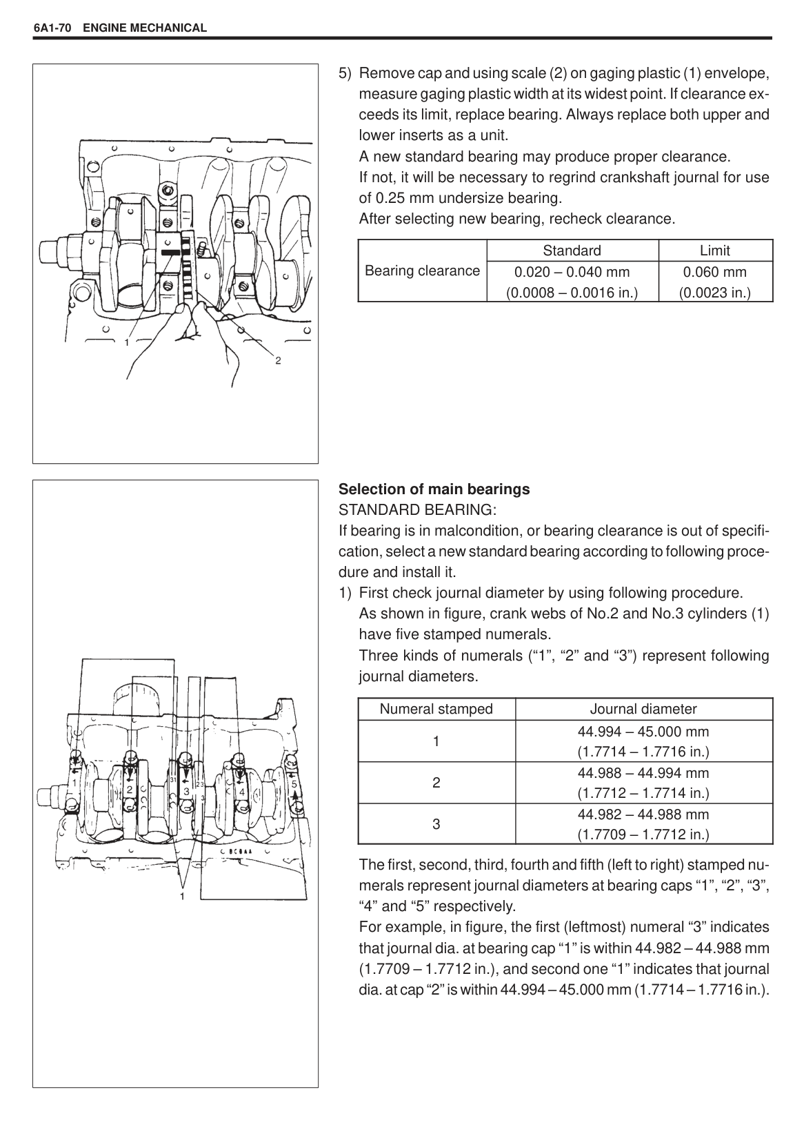
Special Tool (A): 09924-17810
|| |---|
|| |---|
|| |---|
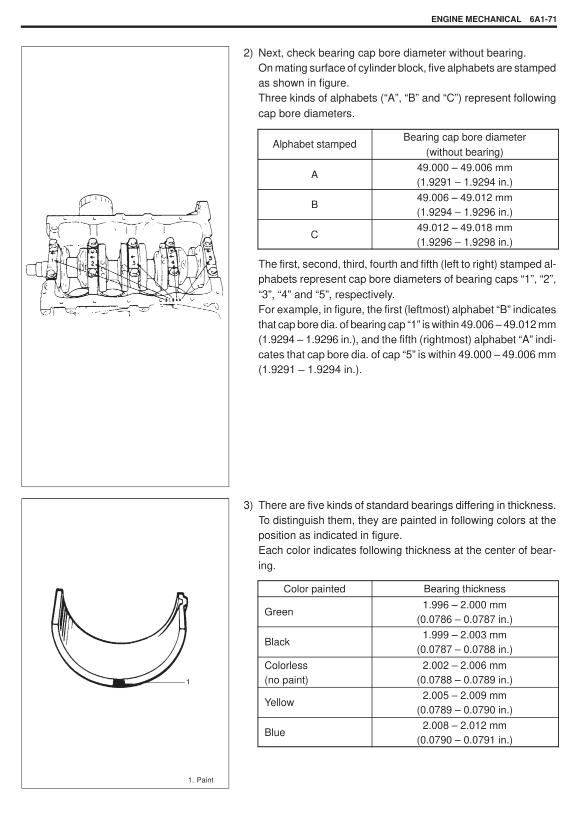
|| |---|
|| |---|
|| |---|
|| |---|
INSPECTION Crankshaft Crankshaft runout Using a dial gauge, measure runout at center journal. Rotate crankshaft slowly. If runout exceeds its limit, replace crankshaft.
Limit on runout: 0.06 mm (0.0023 in.)
Crankshaft thrust play
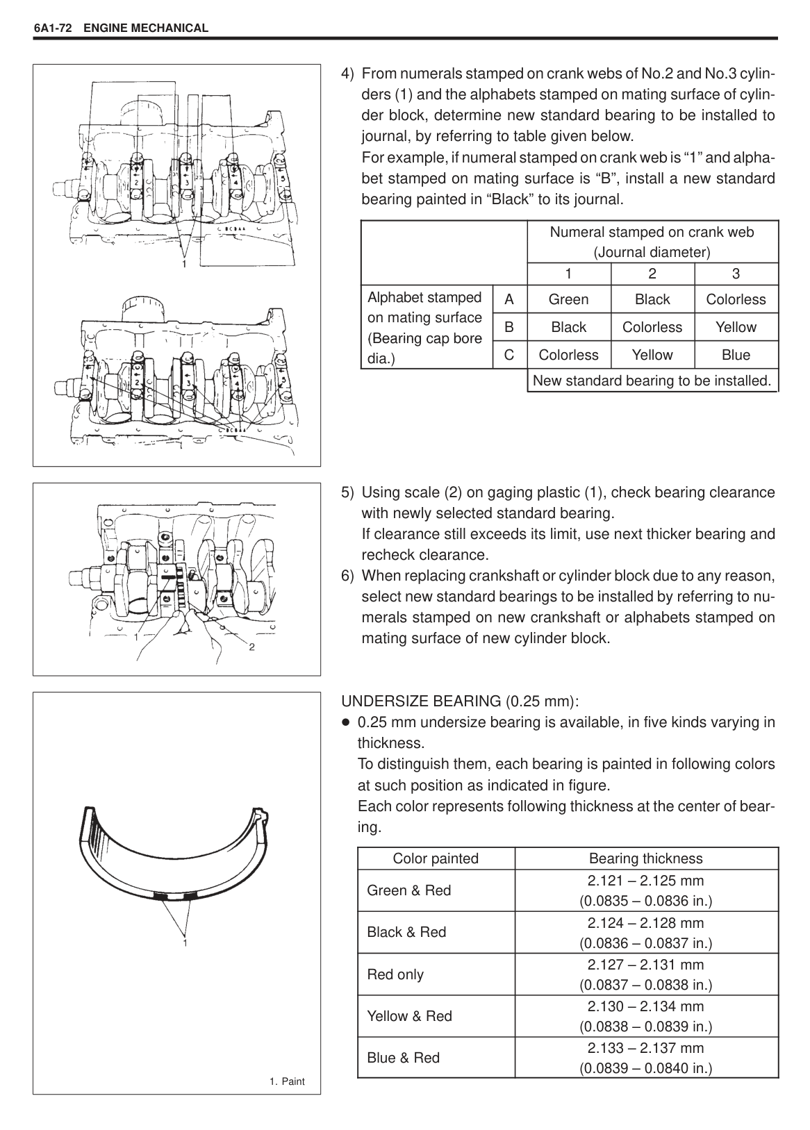
Measure this play with crankshaft set in cylinder block in the normal manner, that is, with thrust bearing (1) and journal bearing caps installed.
Use a dial gauge to read displacement in axial (thrust) direction of crankshaft. If its limit is exceeded, replace thrust bearing with new standard one or oversize one to obtain standard thrust play.
Crankshaft Thrust Play Standard : 0.11 – 0.31 mm (0.0044 – 0.0122 in.) Limit : 0.38 mm (0.0149 in.)
Thickness of crankshaft thrust bearing Standard: 2.500 mm (0.0984 in.) Oversize 0.125 mm (0.0049 in.): 2.563 mm (0.1009 in.)
Out-of-round and taper (uneven wear) of journals An unevenly worn crankshaft journal shows up as a difference in diameter at a cross section or along its length (or both). This difference, if any, is determined by taking micrometer readings. If any one of journals is badly damaged or if amount of uneven wear in the sense explained above exceeds its limit, regrind or replace crankshaft.
######### Limit on out-of-round and taper: 0.01 mm (0.0004 in.)
|| |---|
|| |---|
|| |---|
|| |---|
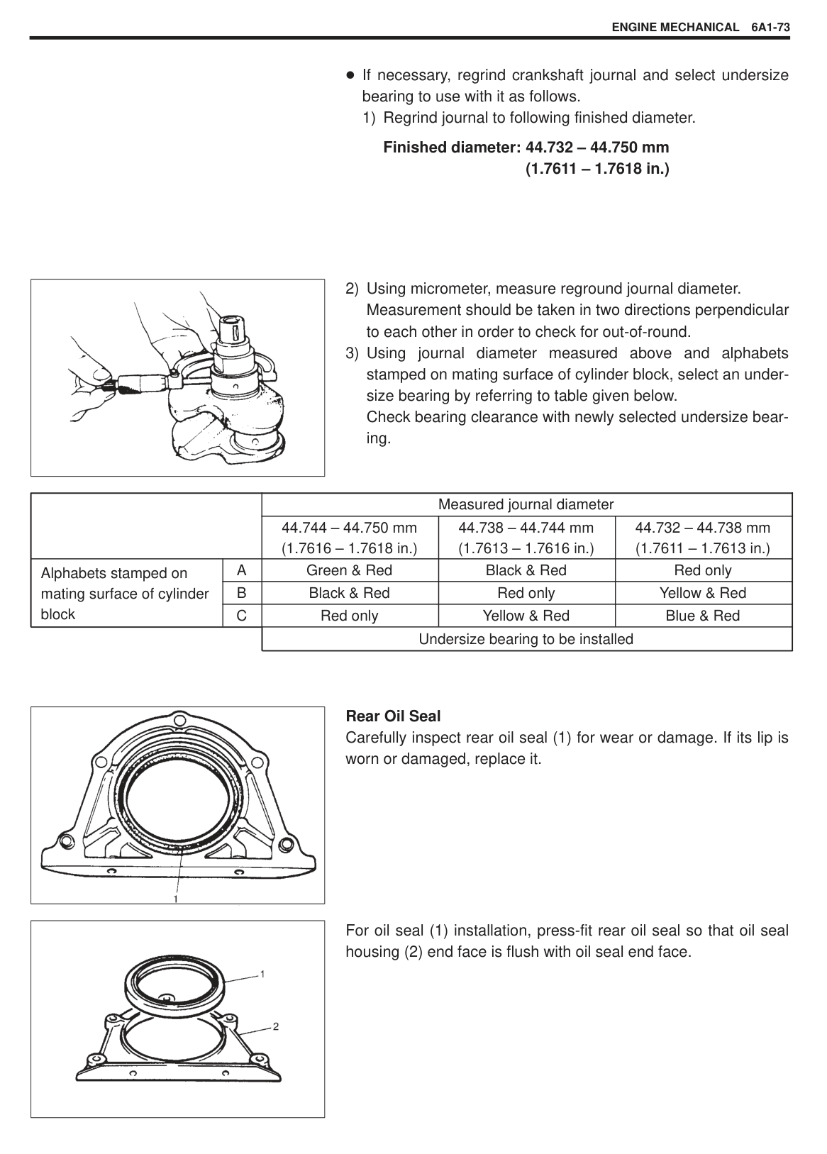
Main Bearings General information
Service main bearings are available in standard size and 0.25 mm (0.0098 in.) undersize, and each of them has 5 kinds of bearings differing in tolerance. Upper half of bearing (2) has oil groove (3) as shown in figure. Install this half with oil groove to cylinder block (1).
On each main bearing cap, arrow mark and number are embossed as shown in figure. When installing each bearing cap to cylinder block, point arrow mark toward crankshaft pulley side and install each cap from that side to flywheel side in ascending order of numbers “1”, “2”, “3”, “4” and “5”. Tighten cap bolts to specified torque.
Inspection Check bearings for pitting, scratches, wear or damage. If any malcondition is found, replace both upper and lower halves. Never replace one half without replacing the other half.
Main bearing clearance Check clearance by using gaging plastic (1) according to following procedure.
|| |---|
Tightening Torque (a): 54 N.m (5.4 kg-m, 39.0 lb-ft)
NOTE: Do not rotate crankshaft while gaging plastic is installed.
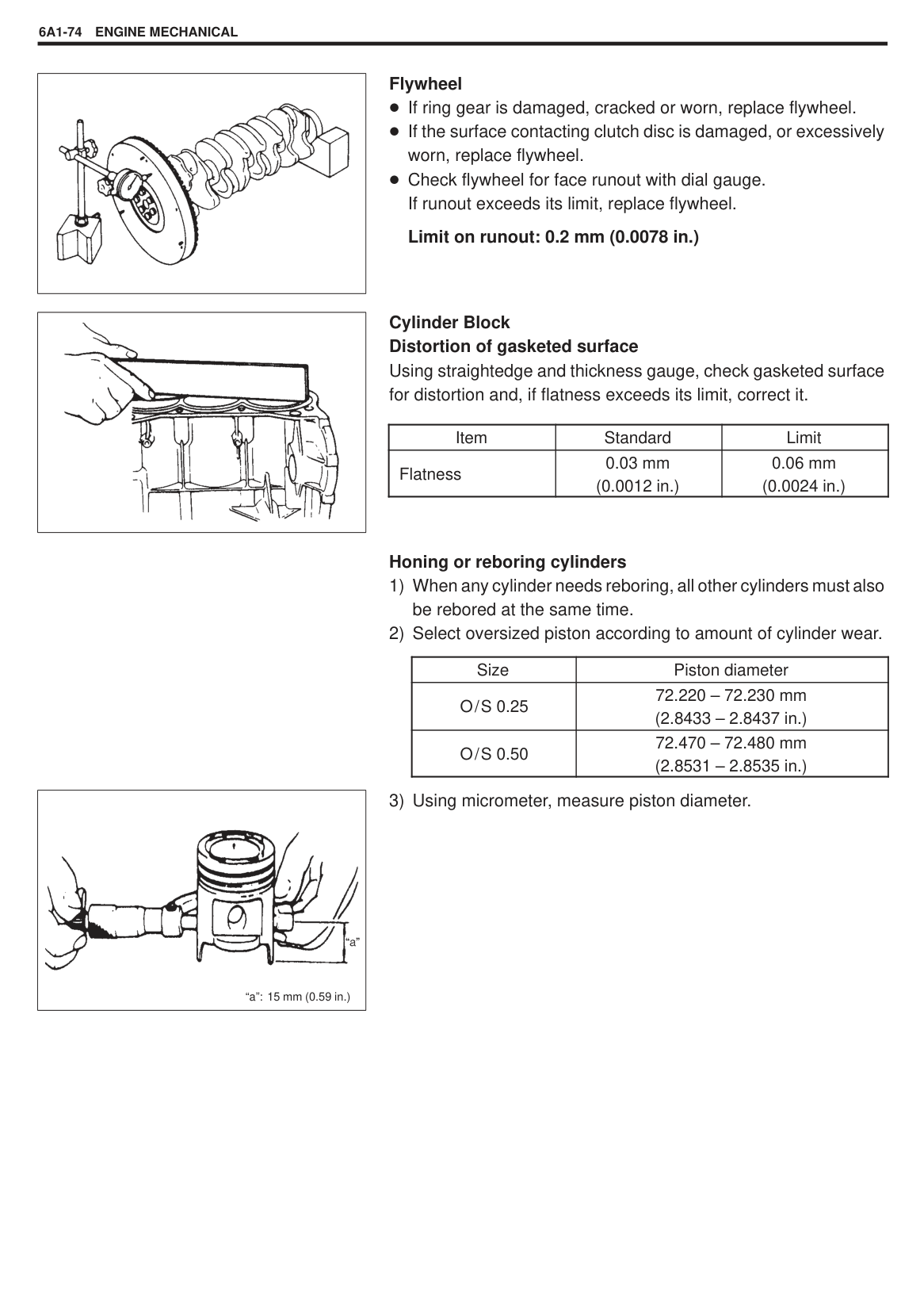
|| |---|
|| |---|
|Bearing clearance
|Standard|Limit| |---|---|---| |Bearing clearance
|0.020 – 0.040 mm (0.0008 – 0.0016 in.)|0.060 mm (0.0023 in.)|
Selection of main bearings STANDARD BEARING: If bearing is in malcondition, or bearing clearance is out of specification, select a new standard bearing according to following procedure and install it.
|Numeral stamped|Journal diameter| |---|---| |1|44.994 – 45.000 mm (1.7714 – 1.7716 in.)| |2|44.988 – 44.994 mm (1.7712 – 1.7714 in.)|
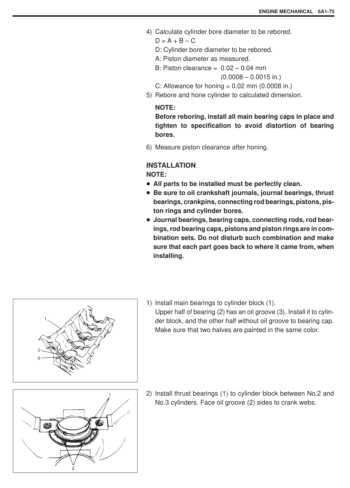
|3|44.982 – 44.988 mm (1.7709 – 1.7712 in.)|
The first, second, third, fourth and fifth (left to right) stamped numerals represent journal diameters at bearing caps “1”, “2”, “3”, “4” and “5” respectively. For example, in figure, the first (leftmost) numeral “3” indicates that journal dia. at bearing cap “1” is within 44.982 – 44.988 mm (1.7709 – 1.7712 in.), and second one “1” indicates that journal dia. at cap “2” is within 44.994 – 45.000 mm (1.7714 – 1.7716 in.).
|| |---|
The first, second, third, fourth and fifth (left to right) stamped alphabets represent cap bore diameters of bearing caps “1”, “2”, “3”, “4” and “5”, respectively. For example, in figure, the first (leftmost) alphabet “B” indicates that cap bore dia. of bearing cap “1” is within 49.006 – 49.012 mm (1.9294 – 1.9296 in.), and the fifth (rightmost) alphabet “A” indicates that cap bore dia. of cap “5” is within 49.000 – 49.006 mm (1.9291 – 1.9294 in.).
|
1. Paint| |---|
|Alphabet stamped|Bearing cap bore diameter (without bearing)| |---|---| |A|49.000 – 49.006 mm (1.9291 – 1.9294 in.)| |B|49.006 – 49.012 mm (1.9294 – 1.9296 in.)| |C|49.012 – 49.018 mm (1.9296 – 1.9298 in.)|
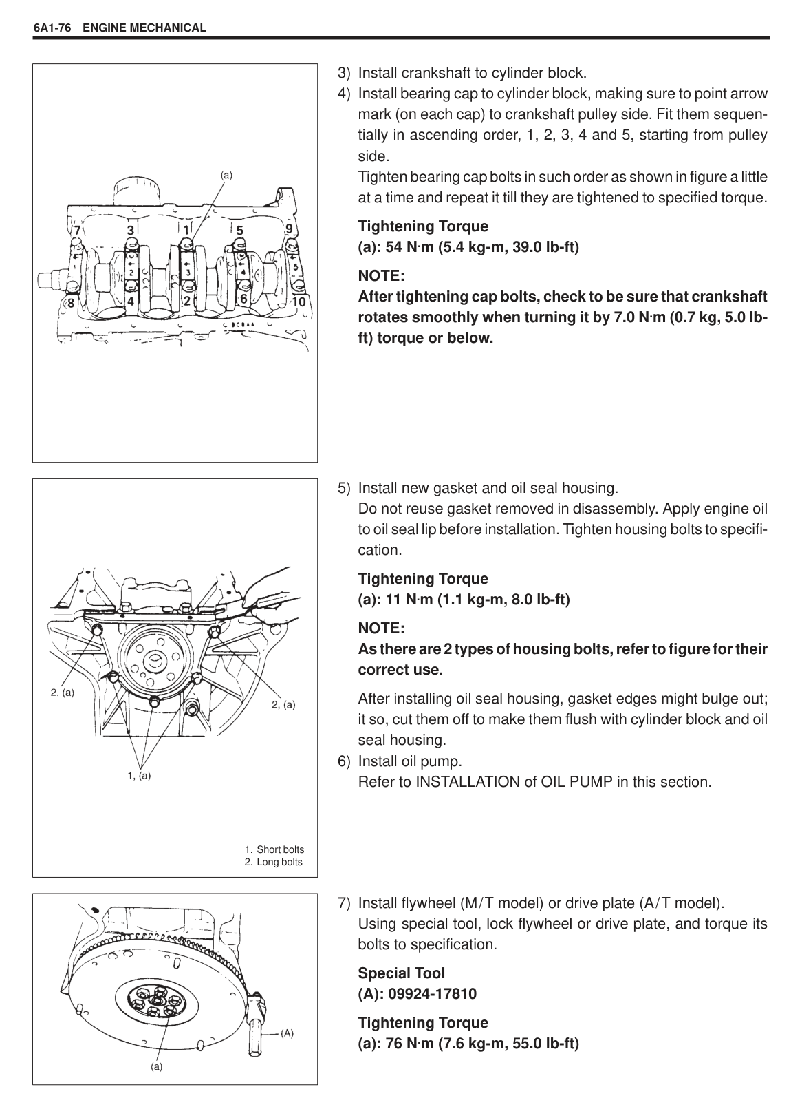
|Color painted|Bearing thickness| |---|---| |Green|1.996 – 2.000 mm (0.0786 – 0.0787 in.)| |Black|1.999 – 2.003 mm (0.0787 – 0.0788 in.)| |Colorless (no paint)|2.002 – 2.006 mm (0.0788 – 0.0789 in.)| |Yellow|2.005 – 2.009 mm (0.0789 – 0.0790 in.)| |Blue|2.008 – 2.012 mm (0.0790 – 0.0791 in.)|
|
| |---|
| | |Numeral stamped on crank web (Journal diameter)
|Numeral stamped on crank web (Journal diameter)
|Numeral stamped on crank web (Journal diameter)
| |---|---|---|---|---| | | |1|2|3| |Alphabet stamped ion mating surface (Bearing cap(Bearing ca bore dia.)
|A|Green|Black|Colorless| |Alphabet stamped ion mating surface (Bearing cap(Bearing ca bore dia.)
|B|Black|Colorless|Yellow| |Alphabet stamped ion mating surface (Bearing cap(Bearing ca bore dia.)
|C|Colorless|Yellow|Blue| | | |New standard bearing to be installed.|New standard bearing to be installed.|New standard bearing to be installed.|
||
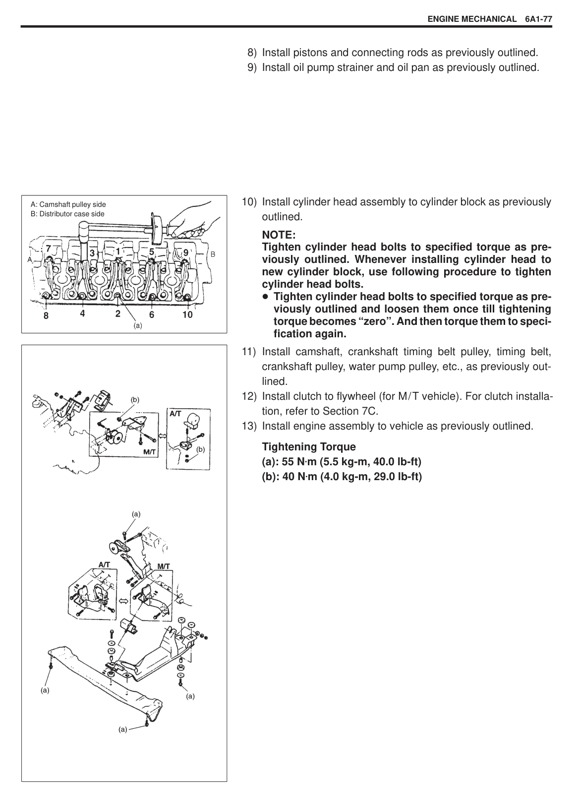
|---|
|
1. Paint| |---|
UNDERSIZE BEARING (0.25 mm): 0.25 mm undersize bearing is available, in five kinds varying in thickness. To distinguish them, each bearing is painted in following colors at such position as indicated in figure. Each color represents following thickness at the center of bearing.
|Color painted|Bearing thickness| |---|---| |Green & Red|2.121 – 2.125 mm (0.0835 – 0.0836 in.)| |Black & Red|2.124 – 2.128 mm (0.0836 – 0.0837 in.)| |Red only|2.127 – 2.131 mm (0.0837 – 0.0838 in.)| |Yellow & Red|2.130 – 2.134 mm (0.0838 – 0.0839 in.)| |Blue & Red|2.133 – 2.137 mm (0.0839 – 0.0840 in.)|
If necessary, regrind crankshaft journal and select undersize bearing to use with it as follows.
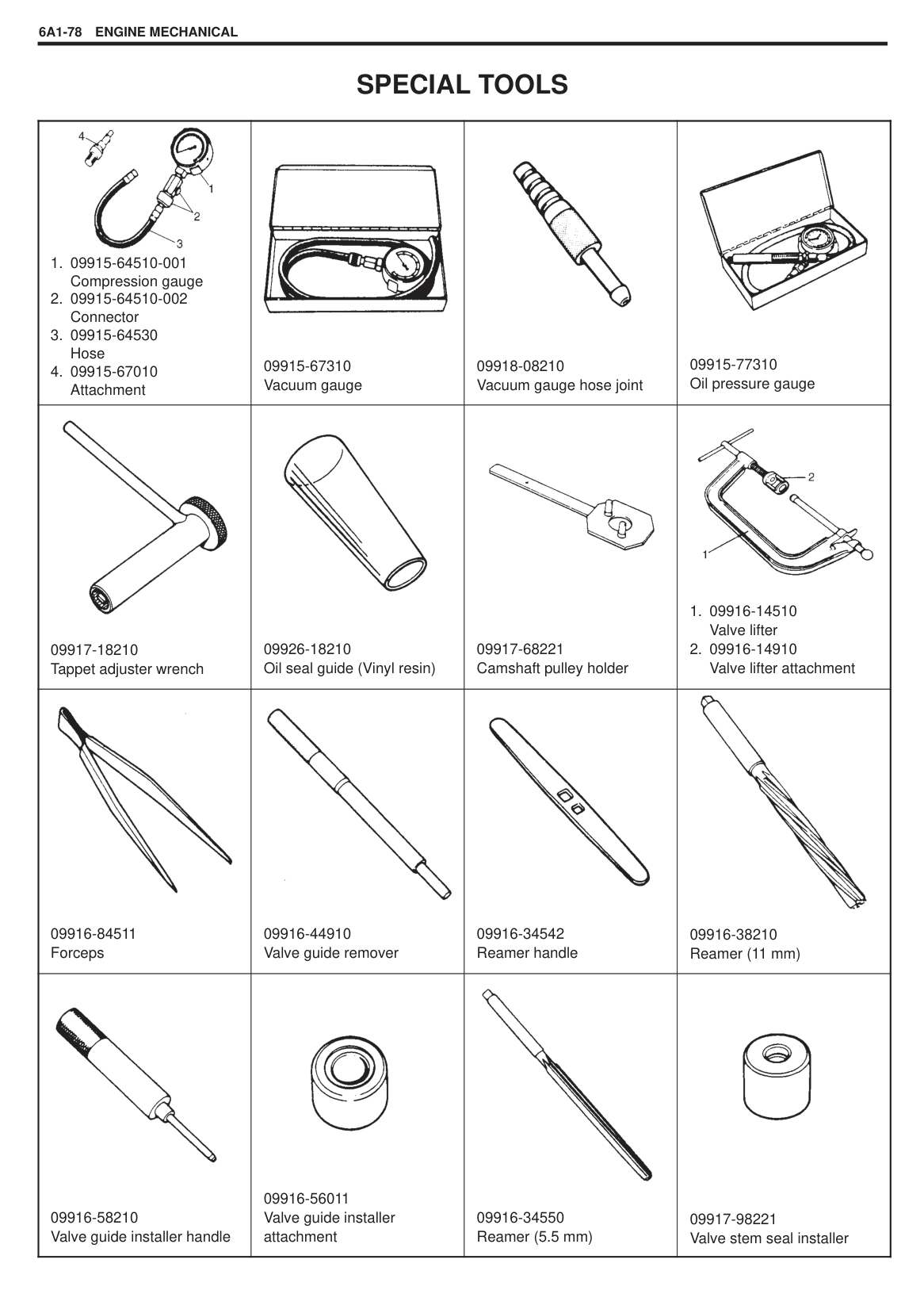
Finished diameter: 44.732 – 44.750 mm (1.7611 – 1.7618 in.)
|| |---|
| | |Measured journal diameter|Measured journal diameter|Measured journal diameter| |---|---|---|---|---| | | |44.744 – 44.750 mm (1.7616 – 1.7618 in.)|44.738 – 44.744 mm (1.7613 – 1.7616 in.)|44.732 – 44.738 mm (1.7611 – 1.7613 in.)| |Alphabets stamped on mating surface of cylinder block
|A|Green & Red|Black & Red|Red only| |Alphabets stamped on mating surface of cylinder block
|B|Black & Red|Red only|Yellow & Red| |Alphabets stamped on mating surface of cylinder block
|C|Red only|Yellow & Red|Blue & Red| | | |Undersize bearing to be installed|Undersize bearing to be installed|Undersize bearing to be installed|
|| |---|
|| |---|
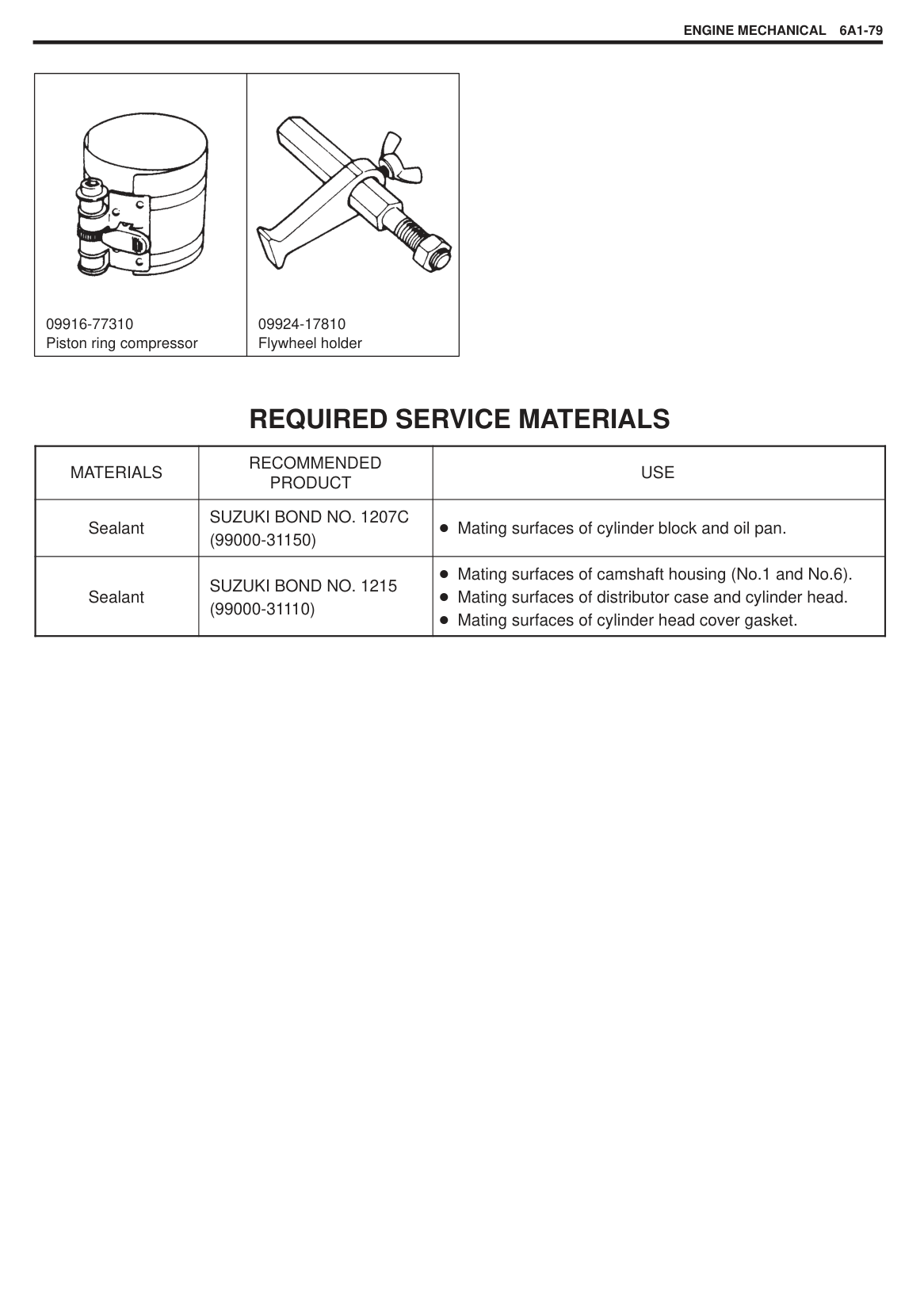
Rear Oil Seal Carefully inspect rear oil seal (1) for wear or damage. If its lip is worn or damaged, replace it.
For oil seal (1) installation, press-fit rear oil seal so that oil seal housing (2) end face is flush with oil seal end face.
|| |---|
|| |---|
Flywheel If ring gear is damaged, cracked or worn, replace flywheel. If the surface contacting clutch disc is damaged, or excessively worn, replace flywheel. Check flywheel for face runout with dial gauge. If runout exceeds its limit, replace flywheel.
######### Limit on runout: 0.2 mm (0.0078 in.)
Cylinder Block Distortion of gasketed surface Using straightedge and thickness gauge, check gasketed surface for distortion and, if flatness exceeds its limit, correct it.
|Item|Standard|Limit| |---|---|---| |Flatness|0.03 mm (0.0012 in.)|0.06 mm (0.0024 in.)|
######### Honing or reboring cylinders
|
“a”: 15 mm (0.59 in.)| |---|
|Size|Piston diameter| |---|---| |O/S 0.25|72.220 – 72.230 mm (2.8433 – 2.8437 in.)| |O/S 0.50|72.470 – 72.480 mm (2.8531 – 2.8535 in.)|
NOTE: Before reboring, install all main bearing caps in place and tighten to specification to avoid distortion of bearing bores.
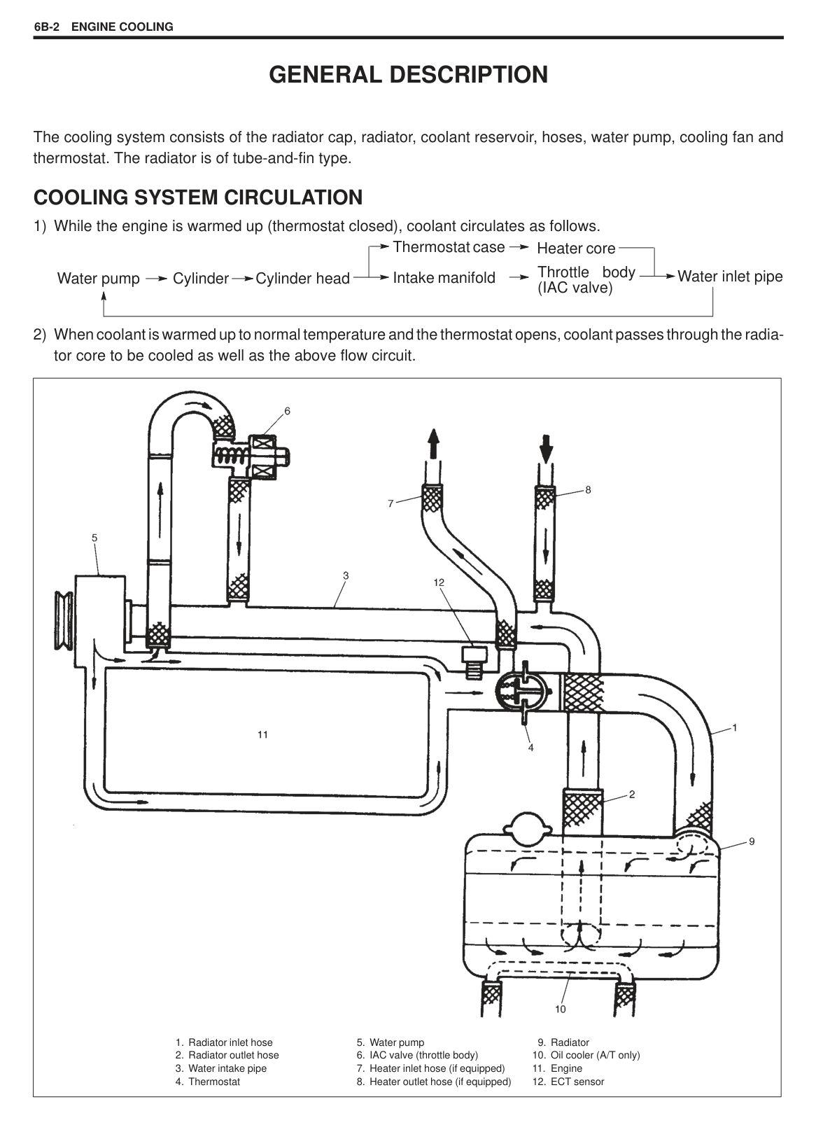
######## INSTALLATION NOTE:
All parts to be installed must be perfectly clean. Be sure to oil crankshaft journals, journal bearings, thrust bearings, crankpins, connecting rod bearings, pistons, piston rings and cylinder bores. Journal bearings, bearing caps, connecting rods, rod bearings, rod bearing caps, pistons and piston rings are in combination sets. Do not disturb such combination and make sure that each part goes back to where it came from, when installing.
|| |---|
|| |---|
|| |---|
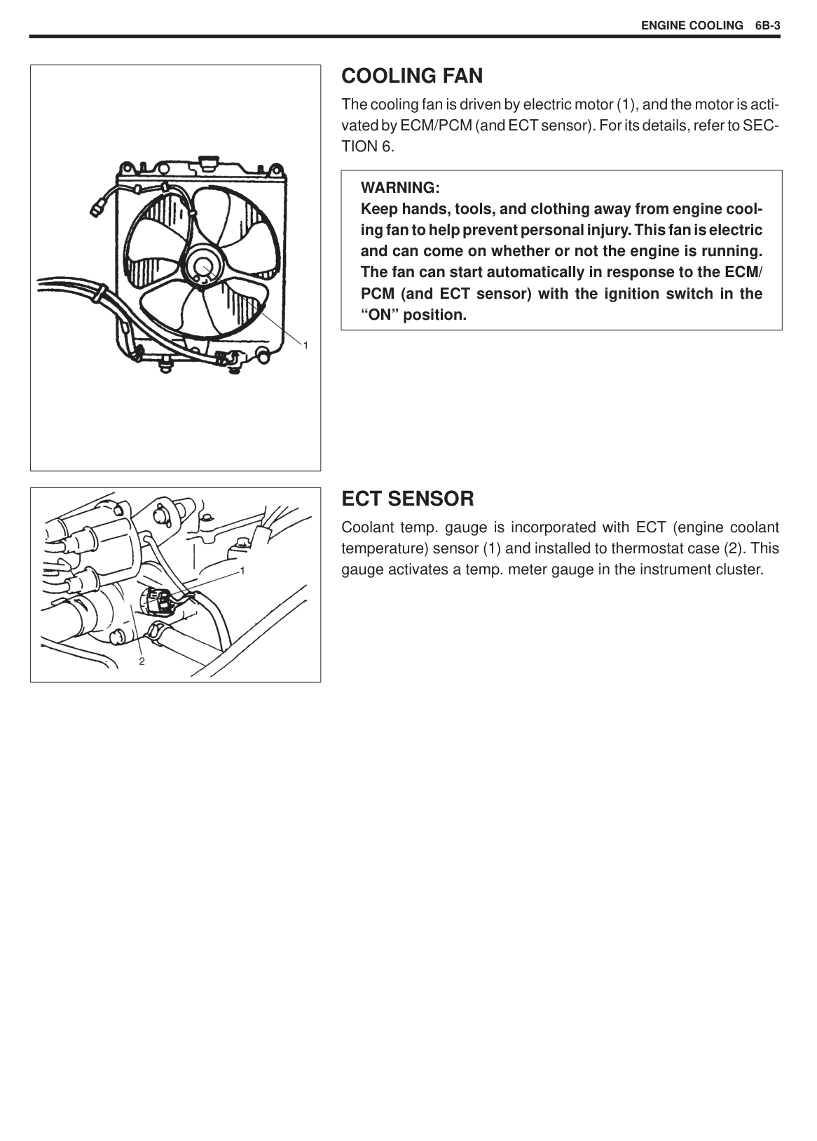
Tightening Torque (a): 54 N.m (5.4 kg-m, 39.0 lb-ft)
NOTE: After tightening cap bolts, check to be sure that crankshaft rotates smoothly when turning it by 7.0 N.m (0.7 kg, 5.0 lbft) torque or below.
|
1. Short bolts
2. Long bolts
| |---|
Tightening Torque (a): 11 N.m (1.1 kg-m, 8.0 lb-ft)
NOTE: As there are 2 types of housing bolts, refer to figure for their correct use.
After installing oil seal housing, gasket edges might bulge out; it so, cut them off to make them flush with cylinder block and oil seal housing.
|| |---|
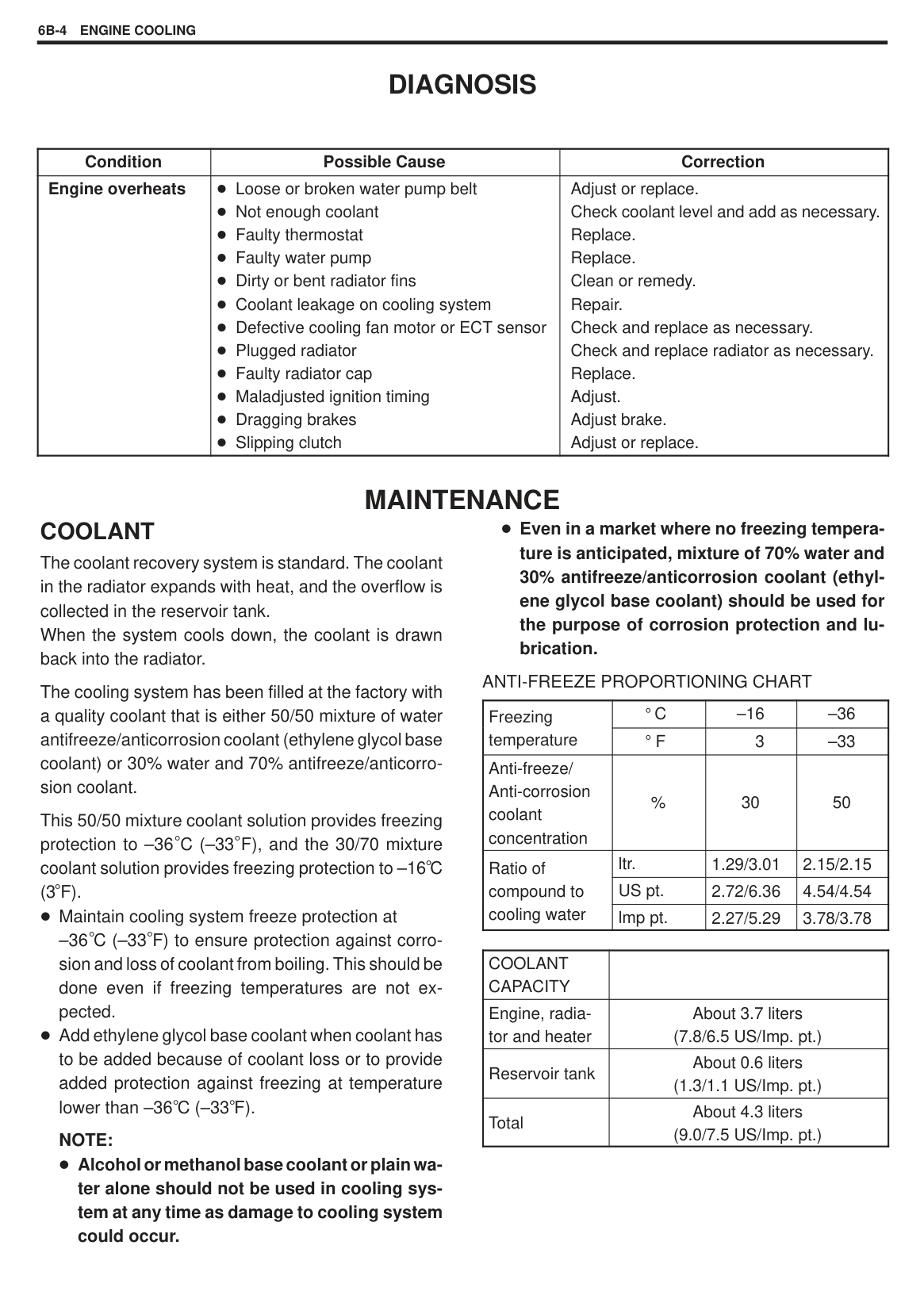
Special Tool (A): 09924-17810
Tightening Torque (a): 76 N.m (7.6 kg-m, 55.0 lb-ft)
|
A: Camshaft pulley side
B: Distributor case side
| |---|
NOTE: Tighten cylinder head bolts to specified torque as previously outlined. Whenever installing cylinder head to new cylinder block, use following procedure to tighten cylinder head bolts.
Tighten cylinder head bolts to specified torque as previously outlined and loosen them once till tightening torque becomes “zero”. And then torque them to specification again.
|| |---|
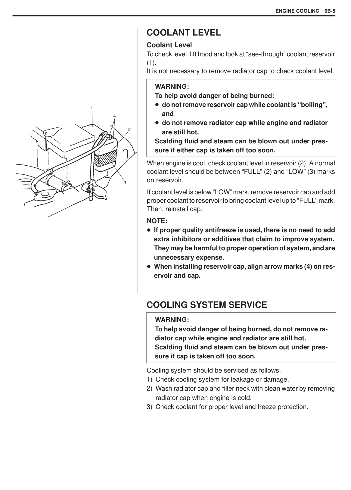
SPECIAL TOOLS
|
1. 09915-64510-001 Compression gauge
2. 09915-64510-002 Connector
3. 09915-64530 Hose
4. 09915-67010 Attachment
|
09915-67310 Vacuum gauge|
09918-08210 Vacuum gauge hose joint|
09915-77310 Oil pressure gauge| |---|---|---|---| |
09917-18210 Tappet adjuster wrench|
09926-18210 Oil seal guide (Vinyl resin)|
09917-68221 Camshaft pulley holder|
1. 09916-14510 Valve lifter
2. 09916-14910 Valve lifter attachment
| |
09916-84511 Forceps|
09916-44910 Valve guide remover|
09916-34542 Reamer handle|
09916-38210 Reamer (11 mm)| |
09916-58210 Valve guide installer handle|
09916-56011 Valve guide installer attachment|
09916-34550 Reamer (5.5 mm)|
09917-98221 Valve stem seal installer|
ENGINE MECHANICAL6A1-79
|
09916-77310 Piston ring compressor|
09924-17810 Flywheel holder| |---|---|
REQUIRED SERVICE MATERIALS
|MATERIALS|RECOMMENDED PRODUCT|USE| |---|---|---| |Sealant|SUZUKI BOND NO. 1207C (99000-31150)|Mating surfaces of cylinder block and oil pan.| |Sealant|SUZUKI BOND NO. 1215 (99000-31110)|Mating surfaces of camshaft housing (No.1 and No.6). Mating surfaces of distributor case and cylinder head. Mating surfaces of cylinder head cover gasket.|
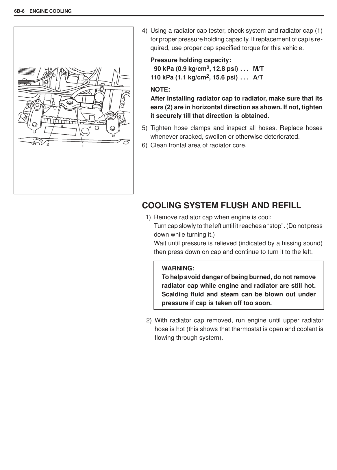
SECTION 6B
ENGINE COOLING
#### CONTENTS
DIAGNOSIS 6B- 4. . . . . . . . . . . . . . . . . . . . . . . . . . . . . . . . . . . . . . . . . . . . . . . . . . . . . . . . . . . . . . . . . . . . . . . . . . . . . . . . MAINTENANCE 6B- 4. . . . . . . . . . . . . . . . . . . . . . . . . . . . . . . . . . . . . . . . . . . . . . . . . . . . . . . . . . . . . . . . . . . . . . . . . . . .
Coolant 6B- 4. . . . . . . . . . . . . . . . . . . . . . . . . . . . . . . . . . . . . . . . . . . . . . . . . . . . . . . . . . . . . . . . . . . . . . . . . . . . . . . . . . Coolant Level 6B- 5. . . . . . . . . . . . . . . . . . . . . . . . . . . . . . . . . . . . . . . . . . . . . . . . . . . . . . . . . . . . . . . . . . . . . . . . . . . . Cooling System Service 6B- 5. . . . . . . . . . . . . . . . . . . . . . . . . . . . . . . . . . . . . . . . . . . . . . . . . . . . . . . . . . . . . . . . . . . Cooling System Flush and Refill 6B- 6. . . . . . . . . . . . . . . . . . . . . . . . . . . . . . . . . . . . . . . . . . . . . . . . . . . . . . . . . . . . Water Pump Belt Tension 6B- 7. . . . . . . . . . . . . . . . . . . . . . . . . . . . . . . . . . . . . . . . . . . . . . . . . . . . . . . . . . . . . . . . . .
REQUIRED SERVICE MATERIALS 6B-13. . . . . . . . . . . . . . . . . . . . . . . . . . . . . . . . . . . . . . . . . . . . . . . . . . . . . . . . . . .
6B
GENERAL DESCRIPTION
The cooling system consists of the radiator cap, radiator, coolant reservoir, hoses, water pump, cooling fan and thermostat. The radiator is of tube-and-fin type.
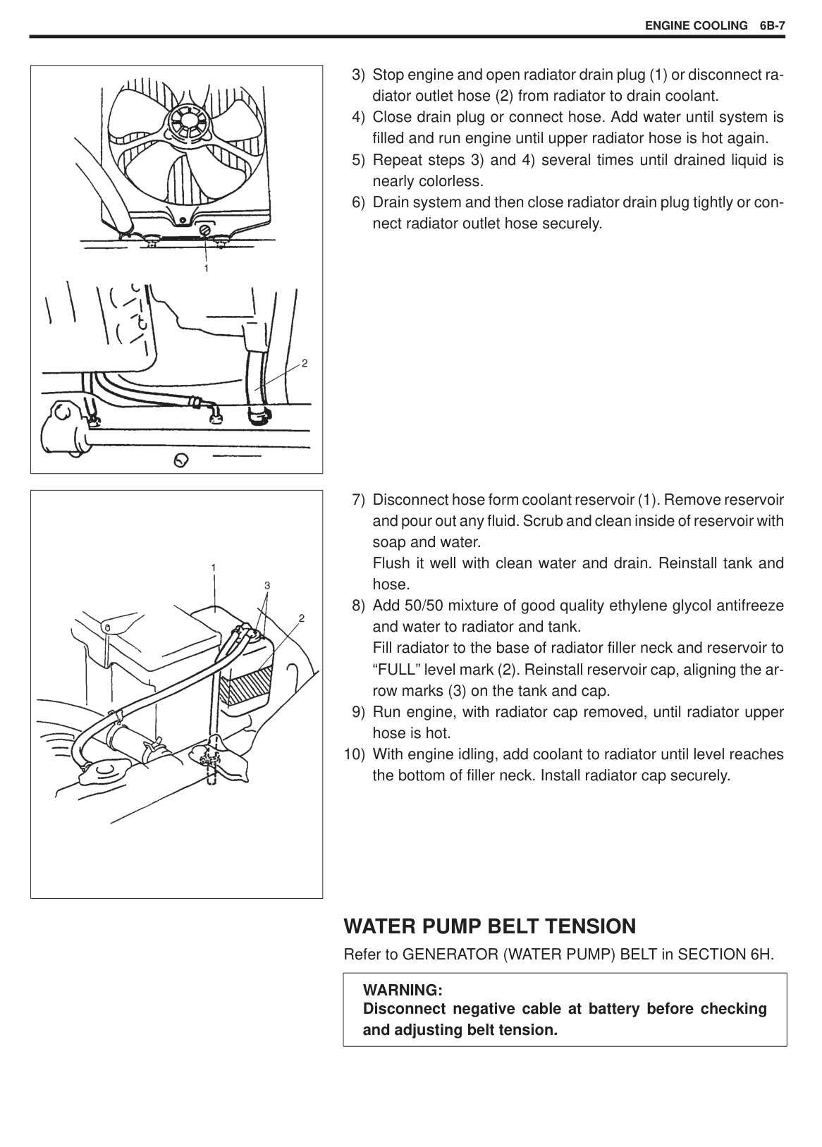
#### COOLING SYSTEM CIRCULATION
Water pump Cylinder Cylinder head Throttle body (IAC valve) Intake manifold Water inlet pipe
Thermostat case Heater core
|
1. Radiator inlet hose
2. Radiator outlet hose
3. Water intake pipe
4. Thermostat
5. Water pump
6. IAC valve (throttle body)
7. Heater inlet hose (if equipped)
8. Heater outlet hose (if equipped)
9. Radiator
10. Oil cooler (A/T only)
11. Engine
12. ECT sensor
| |---|
|| |---|
|| |---|
#### COOLING FAN
The cooling fan is driven by electric motor (1), and the motor is activated by ECM/PCM (and ECT sensor). For its details, refer to SECTION 6.
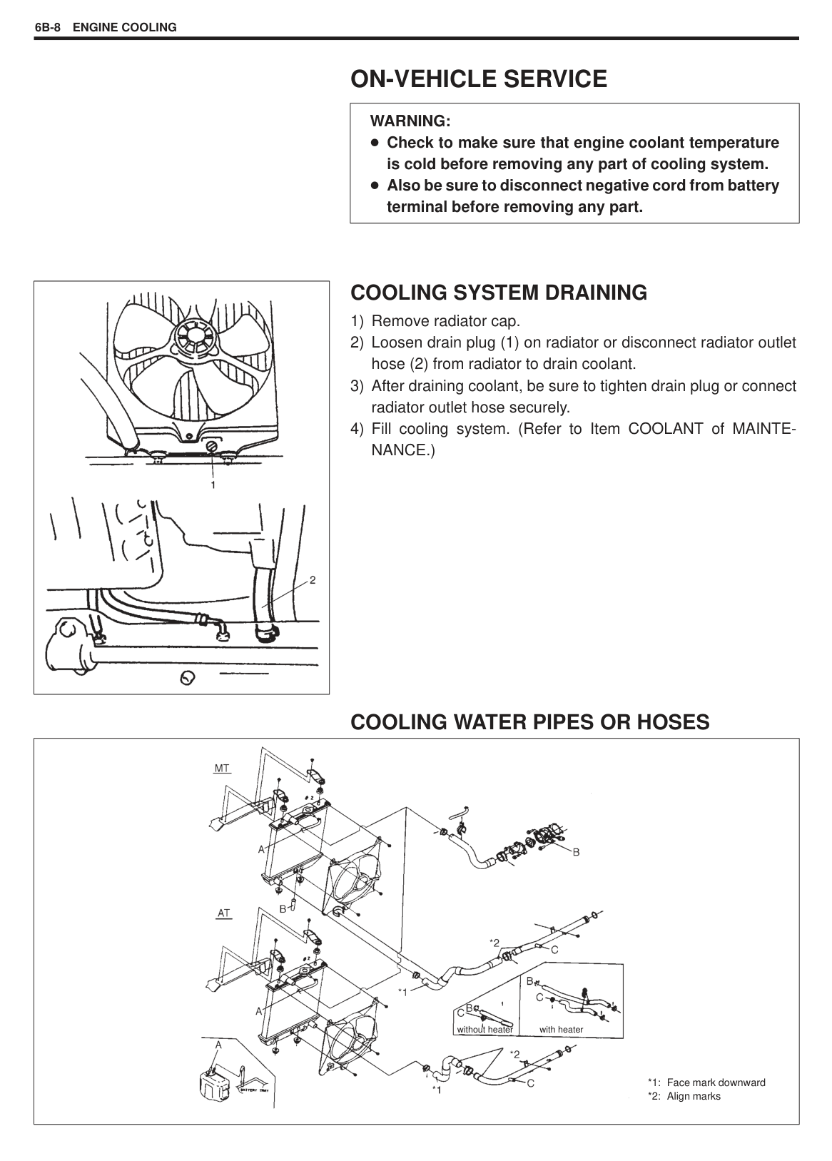
|WARNING: Keep hands, tools, and clothing away from engine cooling fan to help prevent personal injury. This fan is electric and can come on whether or not the engine is running. The fan can start automatically in response to the ECM/ PCM (and ECT sensor) with the ignition switch in the “ON” position.| |---|
#### ECT SENSOR
Coolant temp. gauge is incorporated with ECT (engine coolant temperature) sensor (1) and installed to thermostat case (2). This gauge activates a temp. meter gauge in the instrument cluster.
DIAGNOSIS
|Condition|Possible Cause|Correction| |---|---|---| |Engine overheats|Loose or broken water pump belt Not enough coolant Faulty thermostat Faulty water pump Dirty or bent radiator fins Coolant leakage on cooling system Defective cooling fan motor or ECT sensor Plugged radiator Faulty radiator cap Maladjusted ignition timing Dragging brakes Slipping clutch|Adjust or replace. Check coolant level and add as necessary. Replace. Replace. Clean or remedy. Repair. Check and replace as necessary. Check and replace radiator as necessary. Replace. Adjust. Adjust brake. Adjust or replace.|
MAINTENANCE
COOLANT The coolant recovery system is standard. The coolant in the radiator expands with heat, and the overflow is collected in the reservoir tank. When the system cools down, the coolant is drawn back into the radiator.
Even in a market where no freezing temperature is anticipated, mixture of 70% water and 30% antifreeze/anticorrosion coolant (ethylene glycol base coolant) should be used for the purpose of corrosion protection and lubrication.
ANTI-FREEZE PROPORTIONING CHART
The cooling system has been filled at the factory with a quality coolant that is either 50/50 mixture of water antifreeze/anticorrosion coolant (ethylene glycol base coolant) or 30% water and 70% antifreeze/anticorrosion coolant.
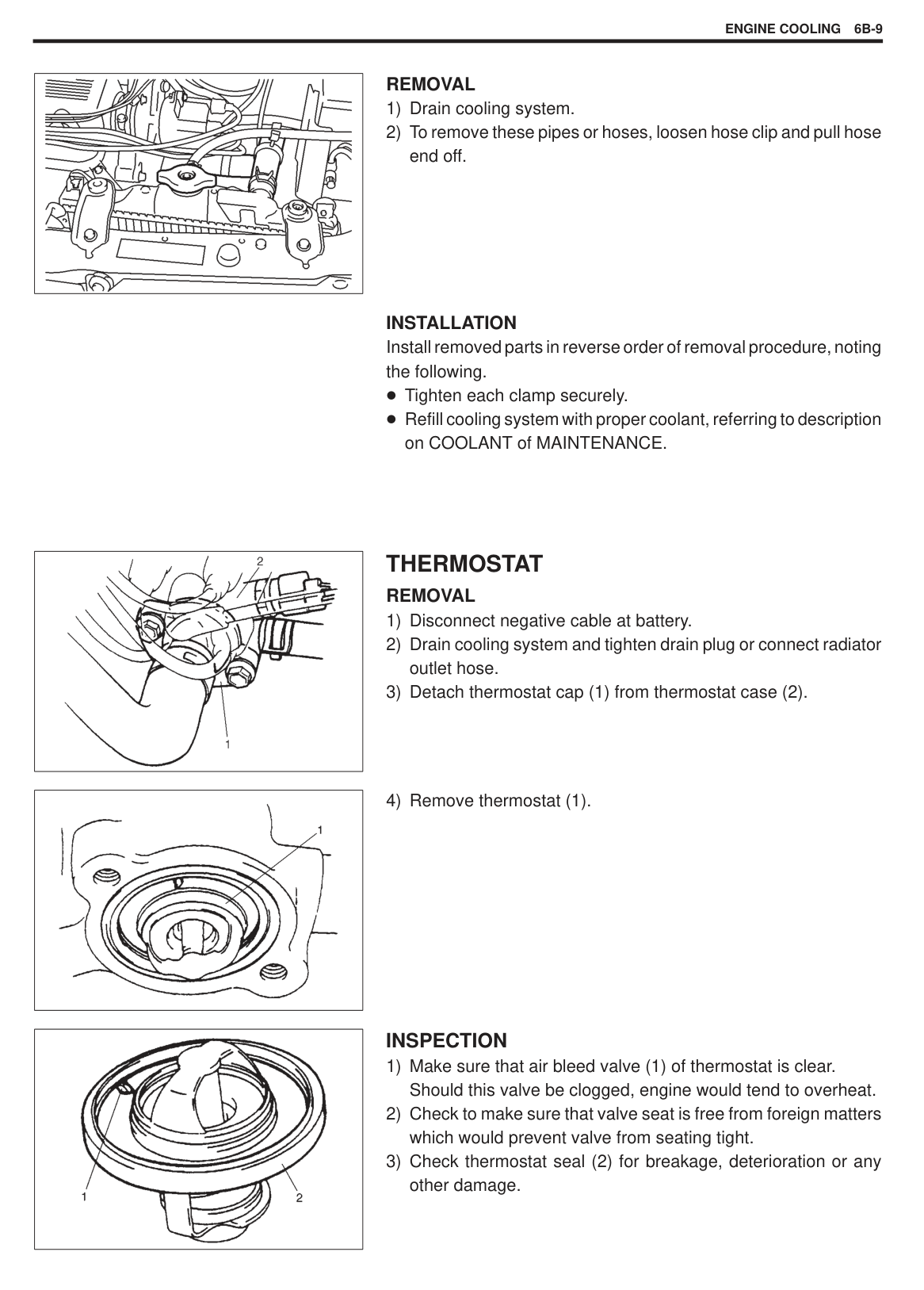
|Freezingg temperature
|C|–16|–36| |---|---|---|---| |Freezingg temperature
|F|3|–33| |Anti-freeze/ Anti-corrosion coolant concentration|%|30|50| |Ratio of compound to cooling water
|ltr.|1.29/3.01|2.15/2.15| |Ratio of compound to cooling water
|US pt.|2.72/6.36|4.54/4.54| |Ratio of compound to cooling water
|lmp pt.|2.27/5.29|3.78/3.78|
This 50/50 mixture coolant solution provides freezing protection to –36 C (–33 F), and the 30/70 mixture coolant solution provides freezing protection to –16 C (3 F).
Maintain cooling system freeze protection at
–36 C (–33 F) to ensure protection against corrosion and loss of coolant from boiling. This should be done even if freezing temperatures are not expected. Add ethylene glycol base coolant when coolant has to be added because of coolant loss or to provide added protection against freezing at temperature lower than –36 C (–33 F).
|COOLANT CAPACITY| | |---|---| |Engine, radiator and heater|About 3.7 liters (7.8/6.5 US/Imp. pt.)| |Reservoir tank|About 0.6 liters (1.3/1.1 US/Imp. pt.)| |Total|About 4.3 liters (9.0/7.5 US/Imp. pt.)|
NOTE:
Alcohol or methanol base coolant or plain water alone should not be used in cooling system at any time as damage to cooling system could occur.
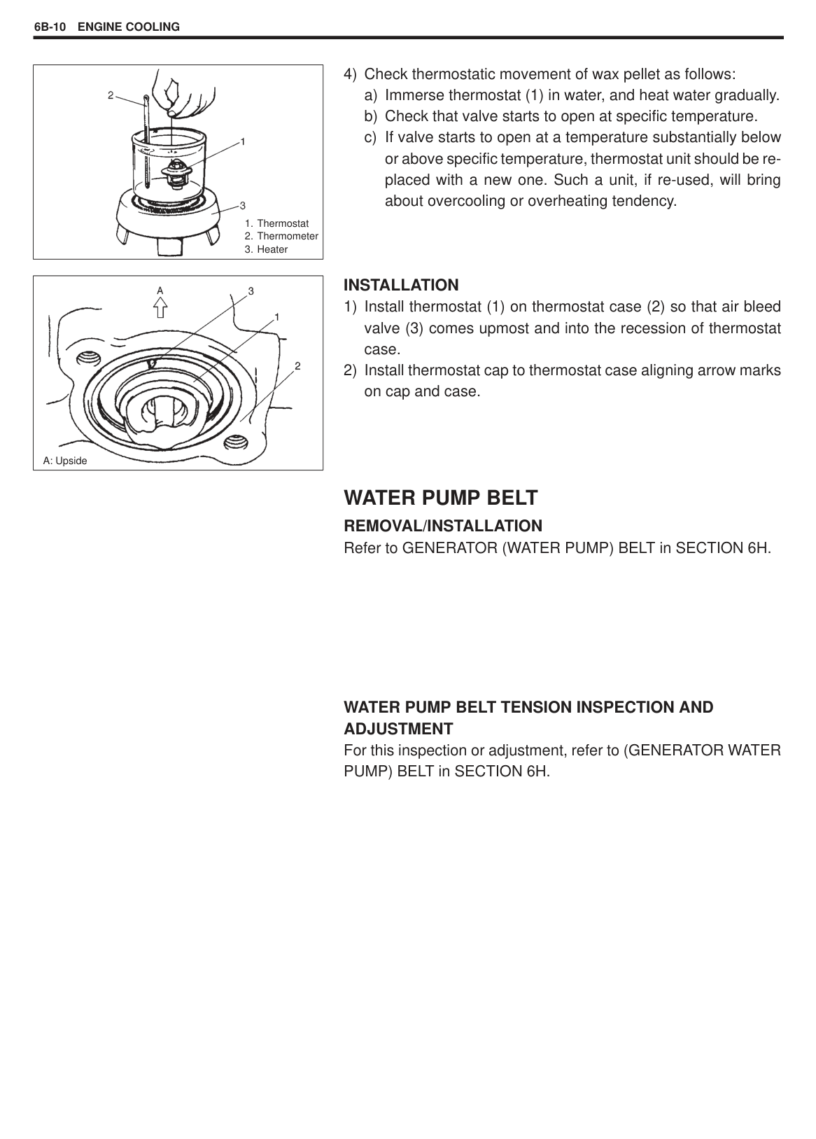
|| |---|
COOLANT LEVEL Coolant Level To check level, lift hood and look at “see-through” coolant reservoir
(1). It is not necessary to remove radiator cap to check coolant level.
|WARNING: To help avoid danger of being burned:
do not remove reservoir cap while coolant is “boiling”, and do not remove radiator cap while engine and radiator are still hot.
Scalding fluid and steam can be blown out under pressure if either cap is taken off too soon.| |---|
When engine is cool, check coolant level in reservoir (2). A normal coolant level should be between “FULL” (2) and “LOW” (3) marks on reservoir.
If coolant level is below “LOW” mark, remove reservoir cap and add proper coolant to reservoir to bring coolant level up to “FULL” mark. Then, reinstall cap.
NOTE: If proper quality antifreeze is used, there is no need to add extra inhibitors or additives that claim to improve system. They may be harmful to proper operation of system, and are unnecessary expense. When installing reservoir cap, align arrow marks (4) on reservoir and cap.
#### COOLING SYSTEM SERVICE
|WARNING: To help avoid danger of being burned, do not remove radiator cap while engine and radiator are still hot. Scalding fluid and steam can be blown out under pressure if cap is taken off too soon.| |---|
Cooling system should be serviced as follows.
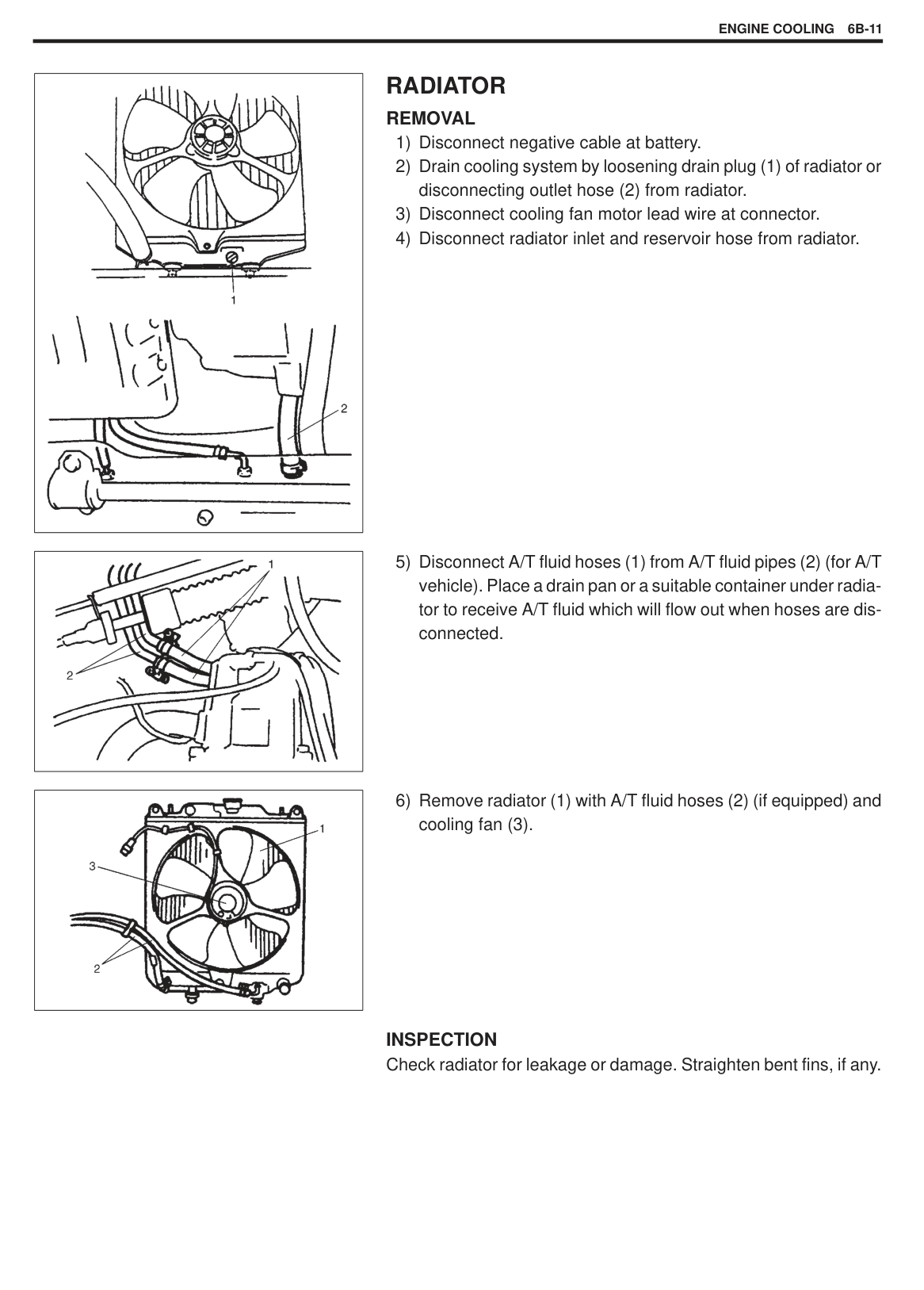
|| |---|
Pressure holding capacity:
90 kPa (0.9 kg/cm2, 12.8 psi) M/T. . . 110 kPa (1.1 kg/cm2, 15.6 psi) A/T. . . NOTE: After installing radiator cap to radiator, make sure that its ears (2) are in horizontal direction as shown. If not, tighten it securely till that direction is obtained.
#### COOLING SYSTEM FLUSH AND REFILL
|WARNING: To help avoid danger of being burned, do not remove radiator cap while engine and radiator are still hot. Scalding fluid and steam can be blown out under pressure if cap is taken off too soon.| |---|
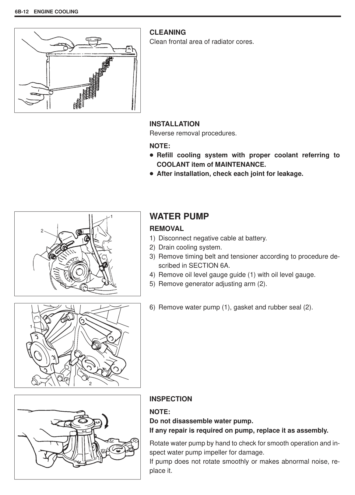
|
| |---|
|| |---|
WATER PUMP BELT TENSION Refer to GENERATOR (WATER PUMP) BELT in SECTION 6H.
|WARNING: Disconnect negative cable at battery before checking and adjusting belt tension.|
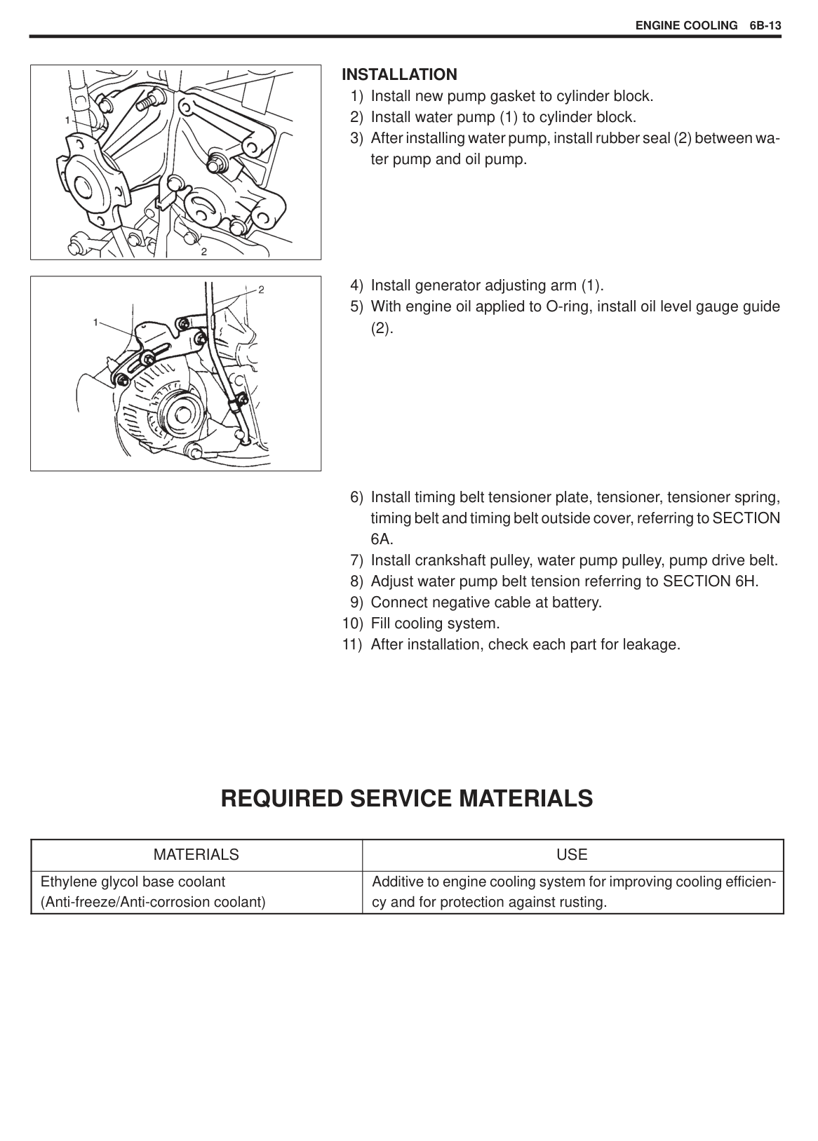
|---|
ON-VEHICLE SERVICE
|WARNING: Check to make sure that engine coolant temperature is cold before removing any part of cooling system. Also be sure to disconnect negative cord from battery terminal before removing any part.| |---|
|
| |---|
#### COOLING SYSTEM DRAINING
#### COOLING WATER PIPES OR HOSES
|
without heater with heater
*1: Face mark downward
*2: Align marks
| |---|
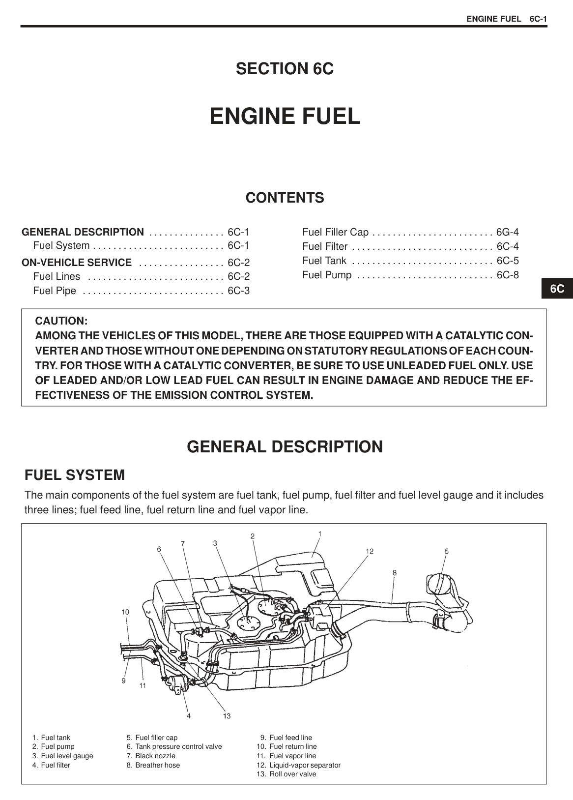
|| |---|
######## REMOVAL
INSTALLATION Install removed parts in reverse order of removal procedure, noting the following.
Tighten each clamp securely. Refill cooling system with proper coolant, referring to description on COOLANT of MAINTENANCE.
|| |---|
#### THERMOSTAT REMOVAL
||
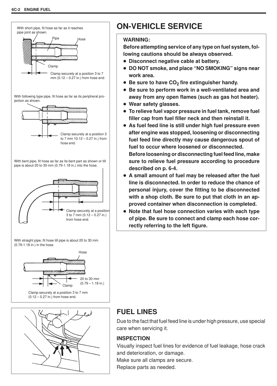
|---|
|| |---|
###### INSPECTION
|
1. Thermostat
2. Thermometer
3. Heater
| |---|
|
A: Upside| |---|
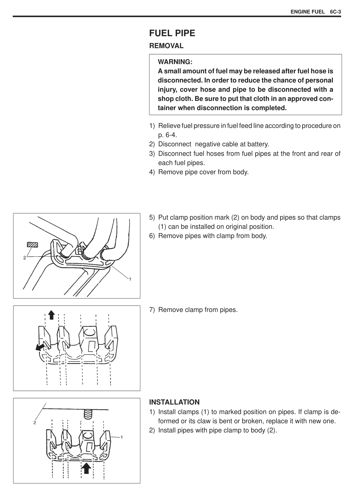
######## INSTALLATION
WATER PUMP BELT REMOVAL/INSTALLATION Refer to GENERATOR (WATER PUMP) BELT in SECTION 6H.
WATER PUMP BELT TENSION INSPECTION AND ADJUSTMENT For this inspection or adjustment, refer to (GENERATOR WATER PUMP) BELT in SECTION 6H.
|
| |---|
#### RADIATOR REMOVAL
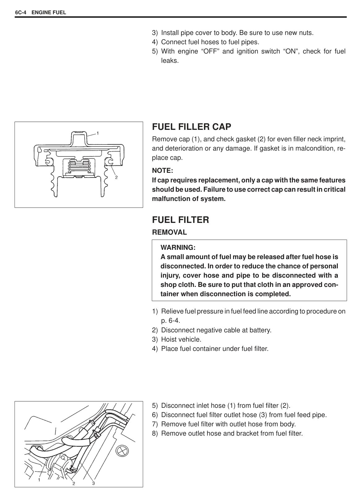
|| |---|
|| |---|
INSPECTION Check radiator for leakage or damage. Straighten bent fins, if any.
|| |---|
CLEANING Clean frontal area of radiator cores.
INSTALLATION Reverse removal procedures.
NOTE: Refill cooling system with proper coolant referring to COOLANT item of MAINTENANCE. After installation, check each joint for leakage.
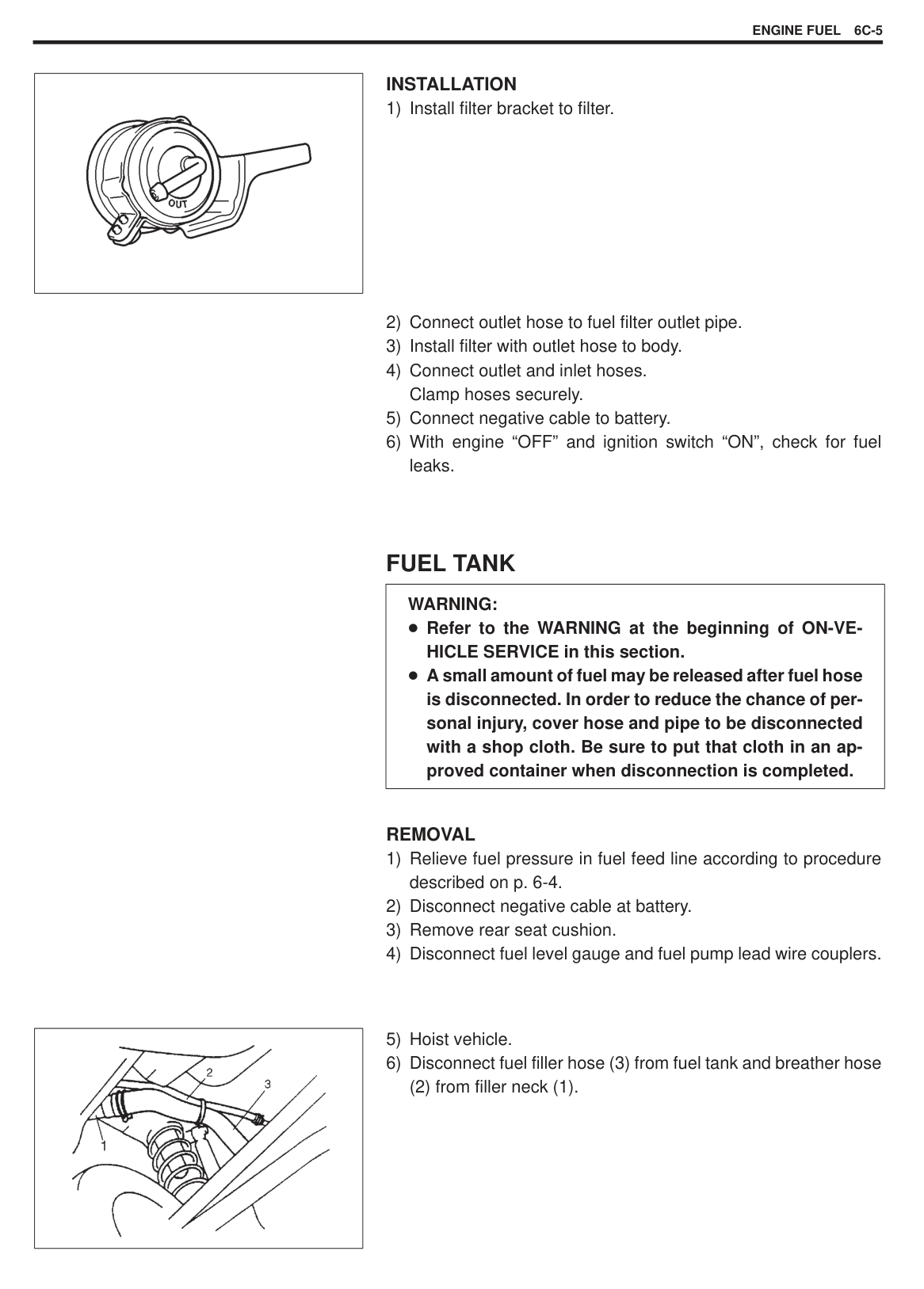
|| |---|
#### WATER PUMP REMOVAL
|| |---|
|| |---|
######## INSPECTION
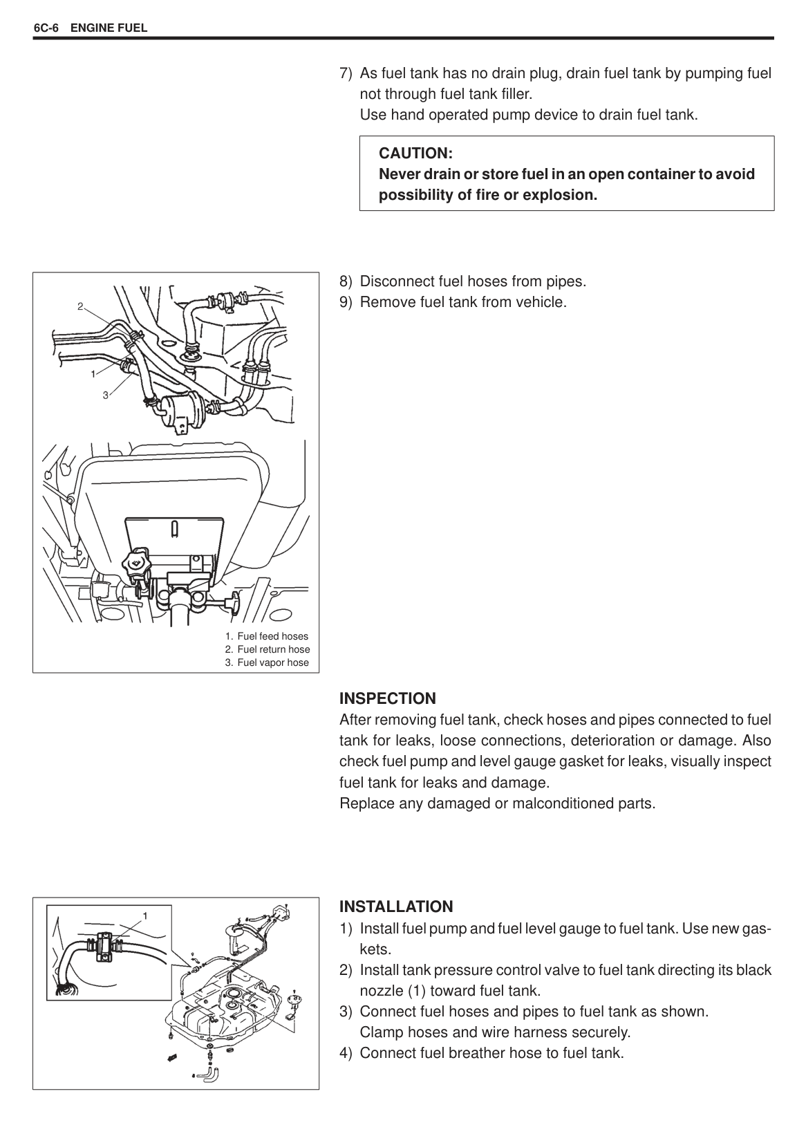
NOTE: Do not disassemble water pump. If any repair is required on pump, replace it as assembly.
Rotate water pump by hand to check for smooth operation and inspect water pump impeller for damage. If pump does not rotate smoothly or makes abnormal noise, replace it.
|| |---|
######## INSTALLATION
|| |---|
(2).
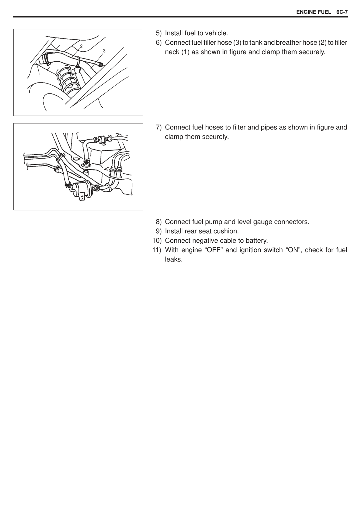
REQUIRED SERVICE MATERIALS
|MATERIALS|USE| |---|---| |Ethylene glycol base coolant (Anti-freeze/Anti-corrosion coolant)|Additive to engine cooling system for improving cooling efficiency and for protection against rusting.|
SECTION 6C
ENGINE FUEL
#### CONTENTS
Fuel Filler Cap 6G-4. . . . . . . . . . . . . . . . . . . . . . . . Fuel Filter 6C-4. . . . . . . . . . . . . . . . . . . . . . . . . . . . Fuel Tank 6C-5. . . . . . . . . . . . . . . . . . . . . . . . . . . . Fuel Pump 6C-8. . . . . . . . . . . . . . . . . . . . . . . . . . .
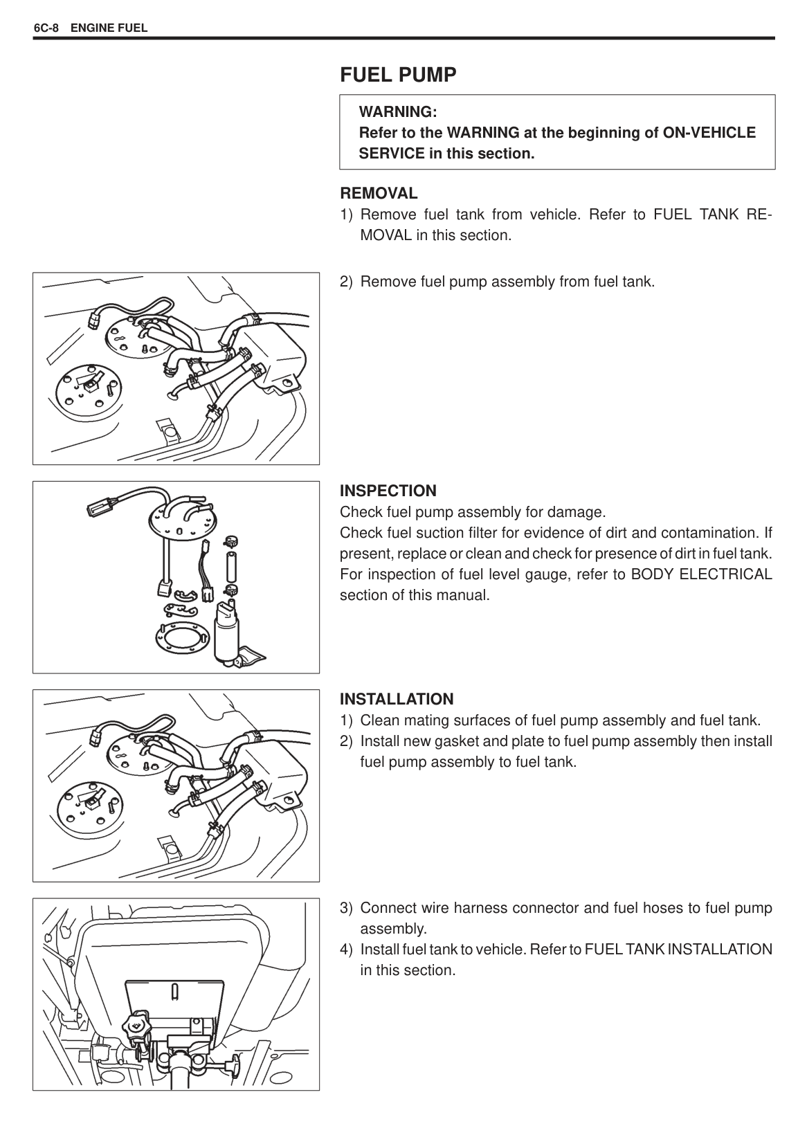
6C
|CAUTION: AMONG THE VEHICLES OF THIS MODEL, THERE ARE THOSE EQUIPPED WITH A CATALYTIC CONVERTER AND THOSE WITHOUT ONE DEPENDING ON STATUTORY REGULATIONS OF EACH COUNTRY. FOR THOSE WITH A CATALYTIC CONVERTER, BE SURE TO USE UNLEADED FUEL ONLY. USE OF LEADED AND/OR LOW LEAD FUEL CAN RESULT IN ENGINE DAMAGE AND REDUCE THE EFFECTIVENESS OF THE EMISSION CONTROL SYSTEM.| |---|
GENERAL DESCRIPTION
FUEL SYSTEM The main components of the fuel system are fuel tank, fuel pump, fuel filter and fuel level gauge and it includes three lines; fuel feed line, fuel return line and fuel vapor line.
|
1. Fuel tank
2. Fuel pump
3. Fuel level gauge
4. Fuel filter
5. Fuel filler cap
6. Tank pressure control valve
7. Black nozzle
8. Breather hose
9. Fuel feed line
10. Fuel return line
11. Fuel vapor line
12. Liquid-vapor separator
13. Roll over valve
| |---|
|
Clamp securely at a position 3 to 7 mm (0.12 – 0.27 in.) from hose end.
With short pipe, fit hose as far as it reaches pipe joint as shown.
Clamp securely at a position 3 to 7 mm (0.12 – 0.27 in.) from hose end.
With following type pipe, fit hose as far as its peripheral projection as shown.
Clamp securely at a position 3 to 7 mm 10.12 – 0.27 in.) from hose end.
With bent pipe, fit hose as far as its bent part as shown or till pipe is about 20 to 30 mm (0.79-1.18 in.) into the hose.
Clamp securely at a position 3 to 7 mm (0.12 – 0.27 in.) from hose end.
With straight pipe, fit hose till pipe is about 20 to 30 mm (0.79-1.18 in.) in the hose.
20 to 30 mm (0.79 – 1.18 in.)
Pipe Hose
Clamp
Hose
Clamp| |---|
|| |---|
ON-VEHICLE SERVICE
|WARNING: Before attempting service of any type on fuel system, following cautions should be always observed.
Disconnect negative cable at battery. DO NOT smoke, and place “NO SMOKING” signs near work area. Be sure to have CO2 fire extinguisher handy. Be sure to perform work in a well-ventilated area and away from any open flames (such as gas hot heater). Wear safety glasses. To relieve fuel vapor pressure in fuel tank, remove fuel filler cap from fuel filler neck and then reinstall it. As fuel feed line is still under high fuel pressure even after engine was stopped, loosening or disconnecting fuel feed line directly may cause dangerous spout of fuel to occur where loosened or disconnected. Before loosening or disconnecting fuel feed line, make sure to relieve fuel pressure according to procedure described on p. 6-4. A small amount of fuel may be released after the fuel line is disconnected. In order to reduce the chance of personal injury, cover the fitting to be disconnected with a shop cloth. Be sure to put that cloth in an approved container when disconnection is completed. Note that fuel hose connection varies with each type of pipe. Be sure to connect and clamp each hose correctly referring to the left figure.| |---|
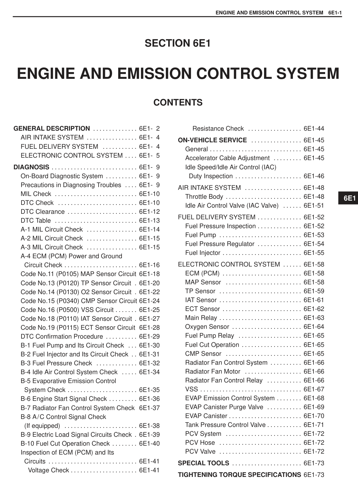
FUEL LINES Due to the fact that fuel feed line is under high pressure, use special care when servicing it. INSPECTION Visually inspect fuel lines for evidence of fuel leakage, hose crack and deterioration, or damage. Make sure all clamps are secure. Replace parts as needed.
#### FUEL PIPE REMOVAL
|WARNING: A small amount of fuel may be released after fuel hose is disconnected. In order to reduce the chance of personal injury, cover hose and pipe to be disconnected with a shop cloth. Be sure to put that cloth in an approved container when disconnection is completed.| |---|
|| |---|
(1) can be installed on original position.
||

|---|
|| |---|
######## INSTALLATION
|| |---|
#### FUEL FILLER CAP
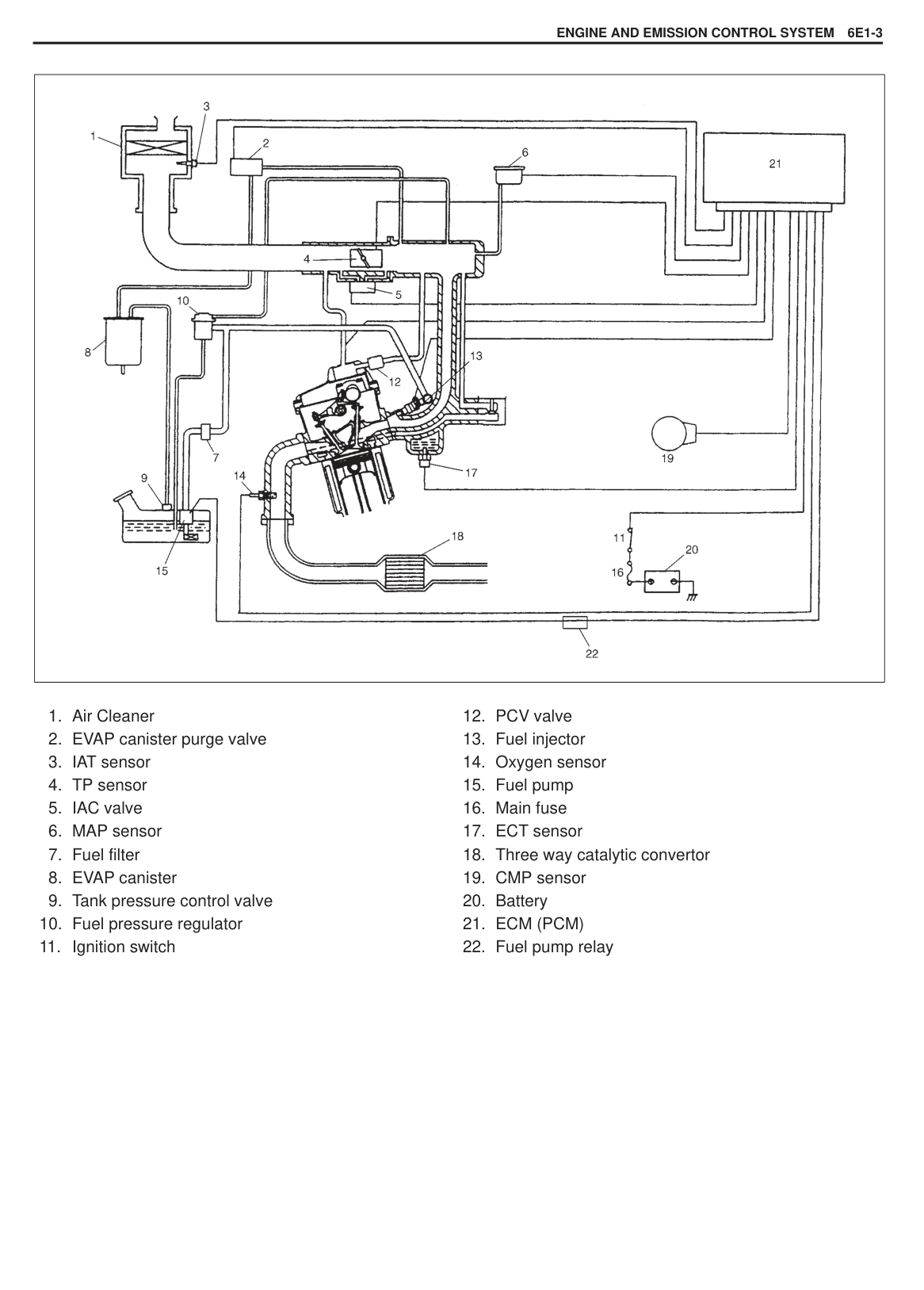
Remove cap (1), and check gasket (2) for even filler neck imprint, and deterioration or any damage. If gasket is in malcondition, replace cap.
NOTE: If cap requires replacement, only a cap with the same features should be used. Failure to use correct cap can result in critical malfunction of system.
#### FUEL FILTER REMOVAL
|WARNING: A small amount of fuel may be released after fuel hose is disconnected. In order to reduce the chance of personal injury, cover hose and pipe to be disconnected with a shop cloth. Be sure to put that cloth in an approved container when disconnection is completed.| |---|
|| |---|
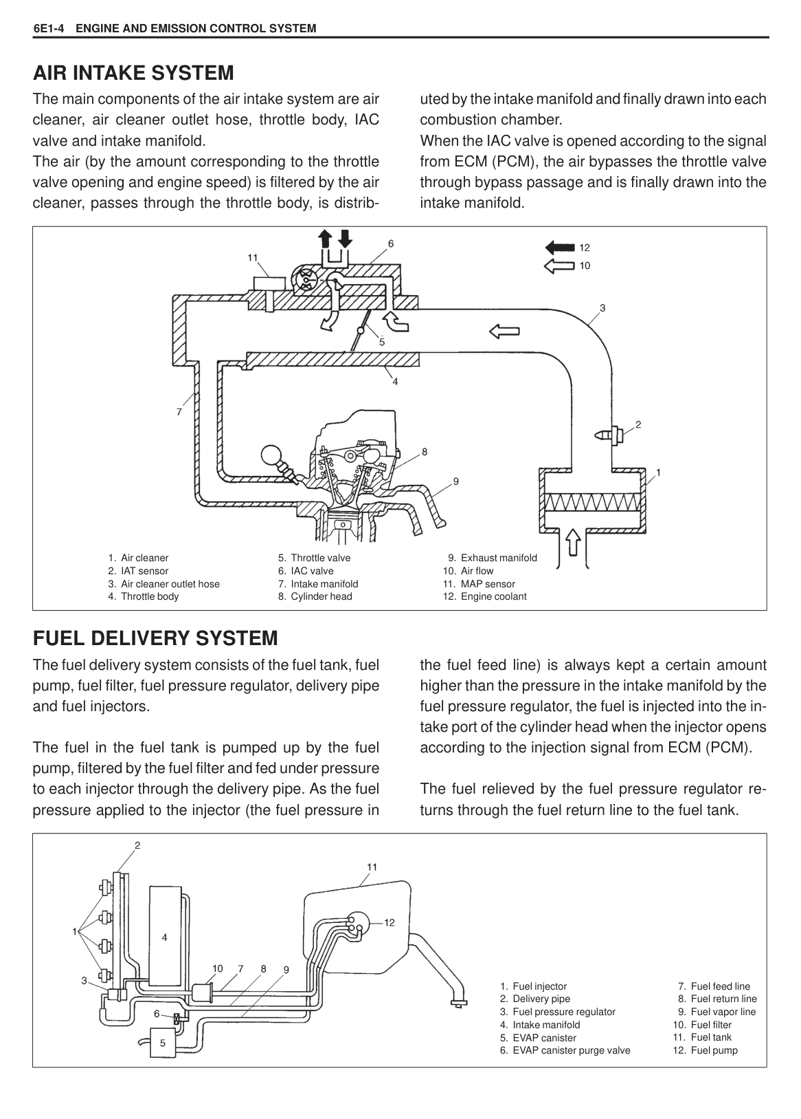
|| |---|
######## INSTALLATION
#### FUEL TANK
|WARNING: Refer to the WARNING at the beginning of ON-VEHICLE SERVICE in this section. A small amount of fuel may be released after fuel hose is disconnected. In order to reduce the chance of personal injury, cover hose and pipe to be disconnected with a shop cloth. Be sure to put that cloth in an approved container when disconnection is completed.| |---|
######## REMOVAL
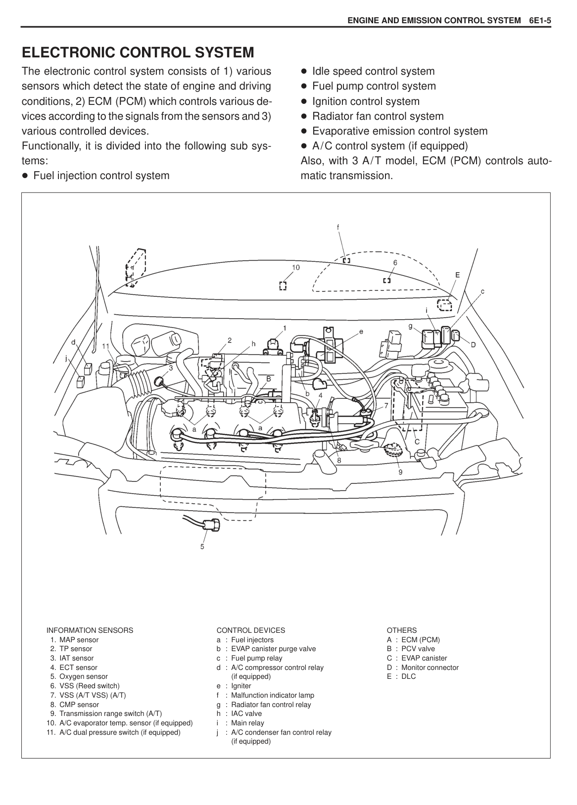
|| |---|
(2) from filler neck (1).
|CAUTION: Never drain or store fuel in an open container to avoid possibility of fire or explosion.| |---|
|

1. Fuel feed hoses
2. Fuel return hose
3. Fuel vapor hose
| |---|
INSPECTION After removing fuel tank, check hoses and pipes connected to fuel tank for leaks, loose connections, deterioration or damage. Also check fuel pump and level gauge gasket for leaks, visually inspect fuel tank for leaks and damage. Replace any damaged or malconditioned parts.
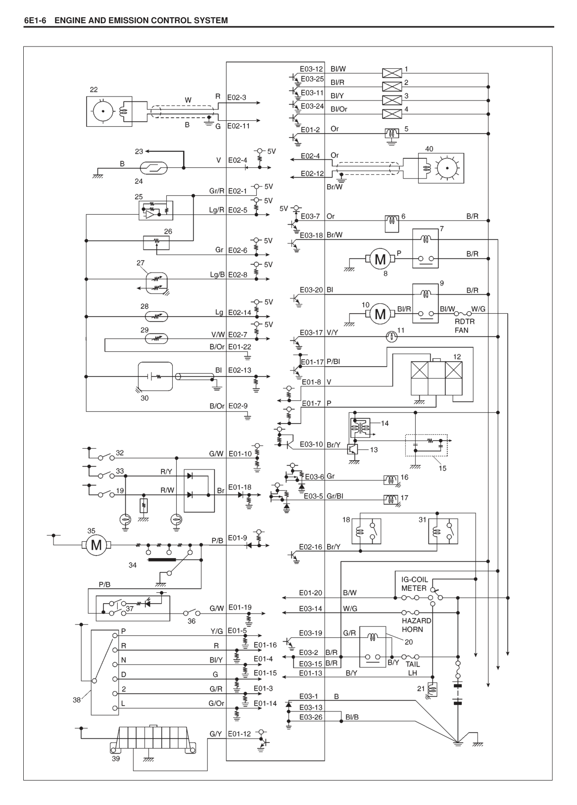
|| |---|
######## INSTALLATION
|| |---|
|| |---|
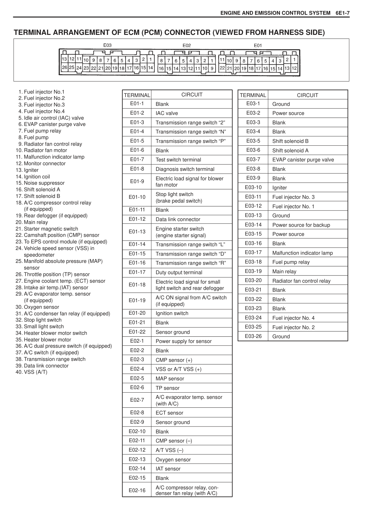
#### FUEL PUMP
######## REMOVAL
|WARNING: Refer to the WARNING at the beginning of ON-VEHICLE SERVICE in this section.| |---|
|| |---|
|| |---|
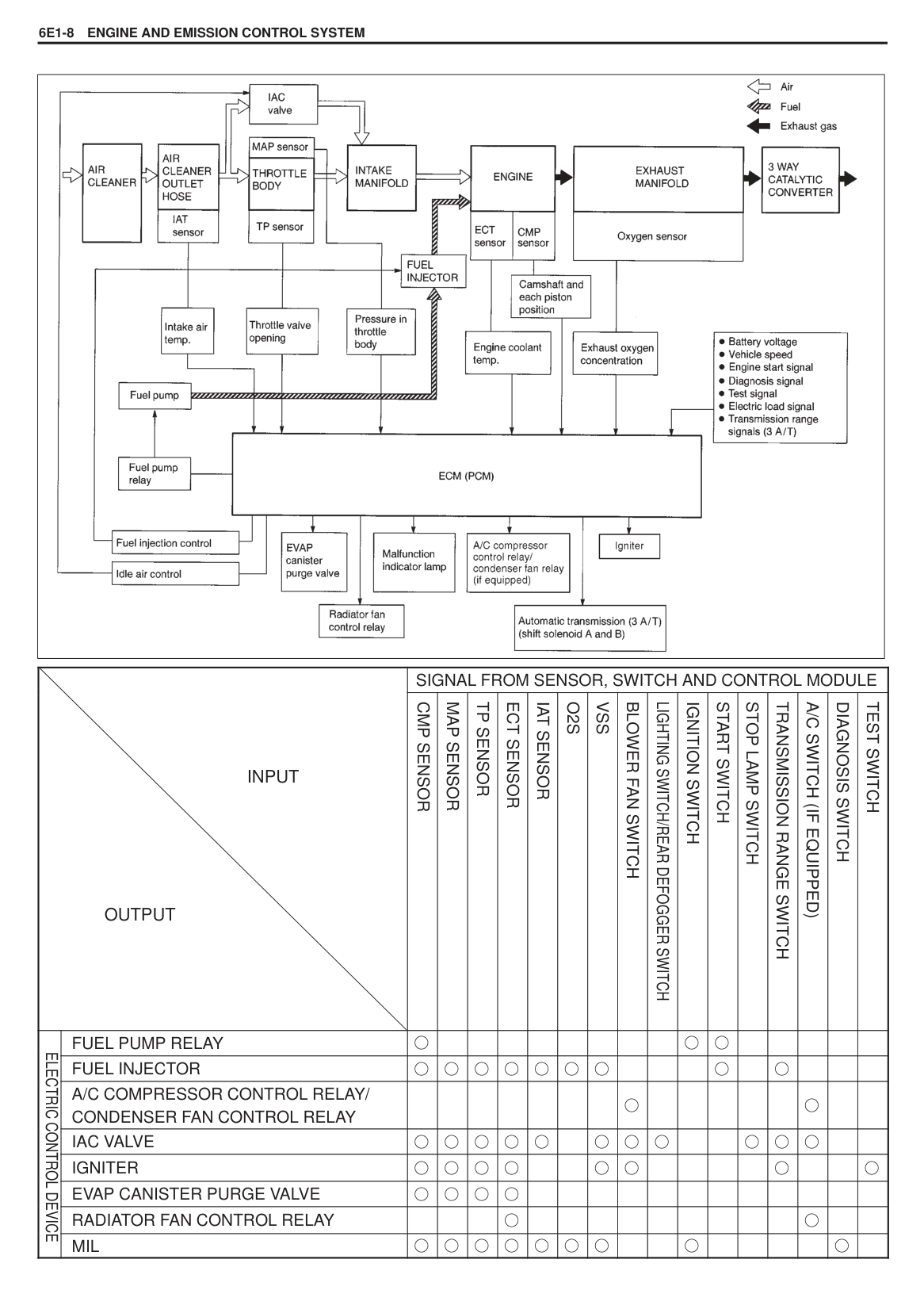
|| |---|
INSPECTION Check fuel pump assembly for damage. Check fuel suction filter for evidence of dirt and contamination. If present, replace or clean and check for presence of dirt in fuel tank. For inspection of fuel level gauge, refer to BODY ELECTRICAL section of this manual.
######## INSTALLATION
|| |---|
SECTION 6E1
ENGINE AND EMISSION CONTROL SYSTEM
#### CONTENTS
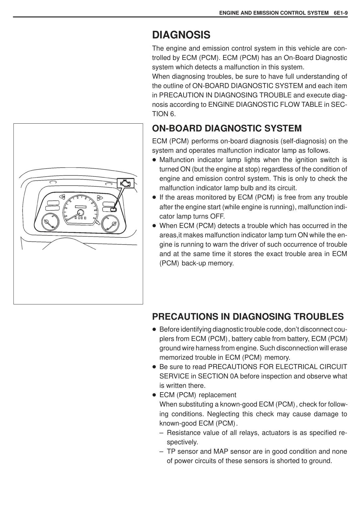
Code No.11 (P0105) MAP Sensor Circuit 6E1-18 Code No.13 (P0120) TP Sensor Circuit 6E1-20. Code No.14 (P0130) O2 Sensor Circuit 6E1-22. Code No.15 (P0340) CMP Sensor Circuit 6E1-24 Code No.16 (P0500) VSS Circuit 6E1-25. . . . . . .
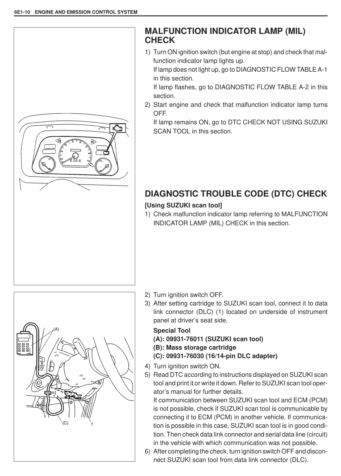
Circuits 6E1-41. . . . . . . . . . . . . . . . . . . . . . . . . . . . Voltage Check 6E1-41. . . . . . . . . . . . . . . . . . . . .
Resistance Check 6E1-44. . . . . . . . . . . . . . . . .
ON-VEHICLE SERVICE 6E1-45. . . . . . . . . . . . . . . . General 6E1-45. . . . . . . . . . . . . . . . . . . . . . . . . . . . . Accelerator Cable Adjustment 6E1-45. . . . . . . . . Idle Speed/Idle Air Control (IAC)
Duty Inspection 6E1-46. . . . . . . . . . . . . . . . . . . . .
AIR INTAKE SYSTEM 6E1-48. . . . . . . . . . . . . . . . . . Throttle Body 6E1-48. . . . . . . . . . . . . . . . . . . . . . . . Idle Air Control Valve (IAC Valve) 6E1-51. . . . . .
FUEL DELIVERY SYSTEM 6E1-52. . . . . . . . . . . . . . Fuel Pressure Inspection 6E1-52. . . . . . . . . . . . . . Fuel Pump 6E1-53. . . . . . . . . . . . . . . . . . . . . . . . . . Fuel Pressure Regulator 6E1-54. . . . . . . . . . . . . . Fuel Injector 6E1-55. . . . . . . . . . . . . . . . . . . . . . . . .
ELECTRONIC CONTROL SYSTEM 6E1-58. . . . . . ECM (PCM) 6E1-58. . . . . . . . . . . . . . . . . . . . . . . . . MAP Sensor 6E1-58. . . . . . . . . . . . . . . . . . . . . . . . TP Sensor 6E1-59. . . . . . . . . . . . . . . . . . . . . . . . . . IAT Sensor 6E1-61. . . . . . . . . . . . . . . . . . . . . . . . . . ECT Sensor 6E1-62. . . . . . . . . . . . . . . . . . . . . . . . . Main Relay 6E1-63. . . . . . . . . . . . . . . . . . . . . . . . . . Oxygen Sensor 6E1-64. . . . . . . . . . . . . . . . . . . . . . Fuel Pump Relay 6E1-65. . . . . . . . . . . . . . . . . . . . Fuel Cut Operation 6E1-65. . . . . . . . . . . . . . . . . . . CMP Sensor 6E1-65. . . . . . . . . . . . . . . . . . . . . . . . Radiator Fan Control System 6E1-66. . . . . . . . . . Radiator Fan Motor 6E1-66. . . . . . . . . . . . . . . . . . Radiator Fan Control Relay 6E1-66. . . . . . . . . . . VSS 6E1-67. . . . . . . . . . . . . . . . . . . . . . . . . . . . . . . . EVAP Emission Control System 6E1-68. . . . . . . . EVAP Canister Purge Valve 6E1-69. . . . . . . . . . . EVAP Canister 6E1-70. . . . . . . . . . . . . . . . . . . . . . . Tank Pressure Control Valve 6E1-71. . . . . . . . . . . PCV System 6E1-72. . . . . . . . . . . . . . . . . . . . . . . . PCV Hose 6E1-72. . . . . . . . . . . . . . . . . . . . . . . . . . PCV Valve 6E1-72. . . . . . . . . . . . . . . . . . . . . . . . . .
########### SPECIAL TOOLS 6E1-73. . . . . . . . . . . . . . . . . . . . . . TIGHTENING TORQUE SPECIFICATIONS 6E1-73
6E1
GENERAL DESCRIPTION
The engine and emission control system has 4 major sub-systems: air intake system, fuel delivery system, electronic control system and emission control system. Air intake system includes air cleaner, MAP sensor, throttle body, IAC valve and intake manifold.
Fuel delivery system includes fuel pump, delivery pipe, fuel pressure regulator, fuel injectors, etc. Electronic control system includes ECM (PCM), various sensors and controlled devices.
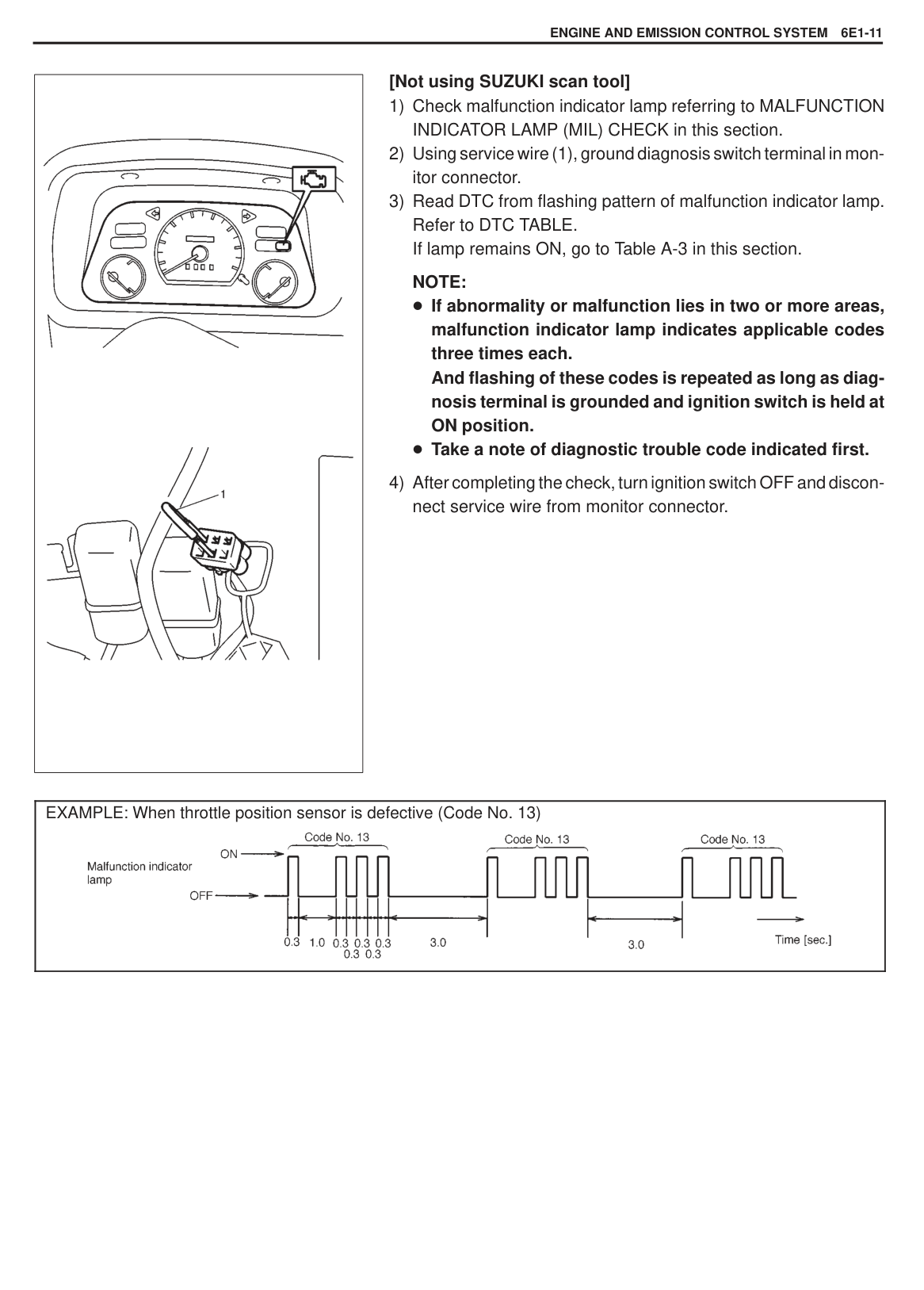
Emission control system includes EVAP and PCV systems.
|| |---|
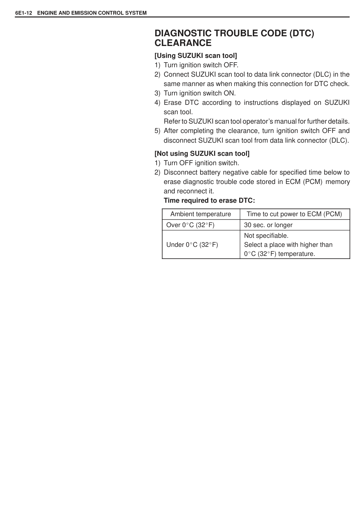
AIR INTAKE SYSTEM The main components of the air intake system are air cleaner, air cleaner outlet hose, throttle body, IAC valve and intake manifold. The air (by the amount corresponding to the throttle valve opening and engine speed) is filtered by the air cleaner, passes through the throttle body, is distrib-
uted by the intake manifold and finally drawn into each combustion chamber. When the IAC valve is opened according to the signal from ECM (PCM), the air bypasses the throttle valve through bypass passage and is finally drawn into the intake manifold.
|
1. Air cleaner
2. IAT sensor
3. Air cleaner outlet hose
4. Throttle body
5. Throttle valve
6. IAC valve
7. Intake manifold
8. Cylinder head
9. Exhaust manifold
10. Air flow
11. MAP sensor
12. Engine coolant
| |---|
#### FUEL DELIVERY SYSTEM
The fuel delivery system consists of the fuel tank, fuel pump, fuel filter, fuel pressure regulator, delivery pipe and fuel injectors.
The fuel in the fuel tank is pumped up by the fuel pump, filtered by the fuel filter and fed under pressure to each injector through the delivery pipe. As the fuel pressure applied to the injector (the fuel pressure in
the fuel feed line) is always kept a certain amount higher than the pressure in the intake manifold by the fuel pressure regulator, the fuel is injected into the intake port of the cylinder head when the injector opens according to the injection signal from ECM (PCM).
The fuel relieved by the fuel pressure regulator returns through the fuel return line to the fuel tank.
|
1. Fuel injector
2. Delivery pipe
3. Fuel pressure regulator
4. Intake manifold
5. EVAP canister
6. EVAP canister purge valve
7. Fuel feed line
8. Fuel return line
9. Fuel vapor line
10. Fuel filter
11. Fuel tank
12. Fuel pump
|
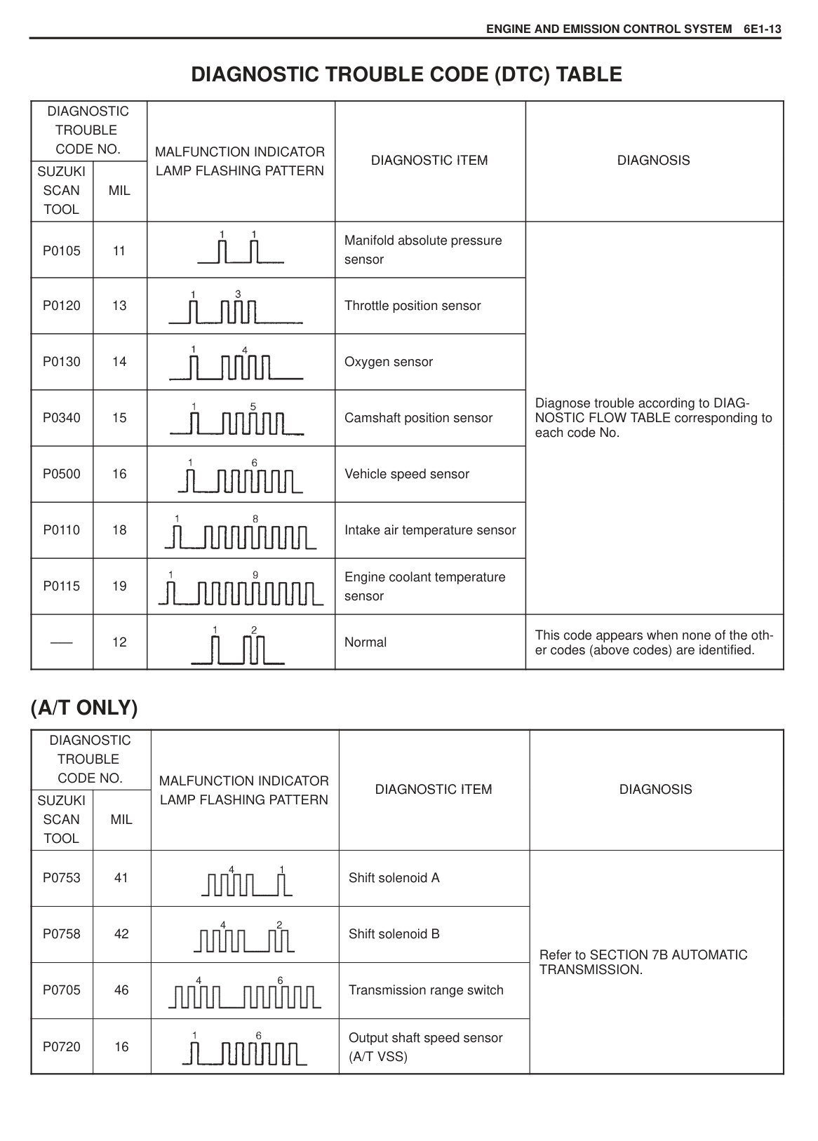
|---|
ELECTRONIC CONTROL SYSTEM The electronic control system consists of 1) various sensors which detect the state of engine and driving conditions, 2) ECM (PCM) which controls various devices according to the signals from the sensors and 3) various controlled devices. Functionally, it is divided into the following sub systems:
Fuel injection control system
Idle speed control system Fuel pump control system Ignition control system Radiator fan control system Evaporative emission control system A/C control system (if equipped)
Also, with 3 A/T model, ECM (PCM) controls automatic transmission.
|
INFORMATION SENSORS
1. MAP sensor
2. TP sensor
3. IAT sensor
4. ECT sensor
5. Oxygen sensor
6. VSS (Reed switch)
7. VSS (A/T VSS) (A/T)
8. CMP sensor
9. Transmission range switch (A/T)
10. A/C evaporator temp. sensor (if equipped)
11. A/C dual pressure switch (if equipped)
CONTROL DEVICES
a : Fuel injectors
b : EVAP canister purge valve
c : Fuel pump relay
d : A/C compressor control relay (if equipped)
e : Igniter
f : Malfunction indicator lamp
g : Radiator fan control relay
h : IAC valve
i : Main relay
j : A/C condenser fan control relay (if equipped)
OTHERS
A : ECM (PCM)
B : PCV valve
C : EVAP canister
D : Monitor connector
E : DLC
| |---|
|| |---|
######## TERMINAL ARRANGEMENT OF ECM (PCM) CONNECTOR (VIEWED FROM HARNESS SIDE)
|| |---|
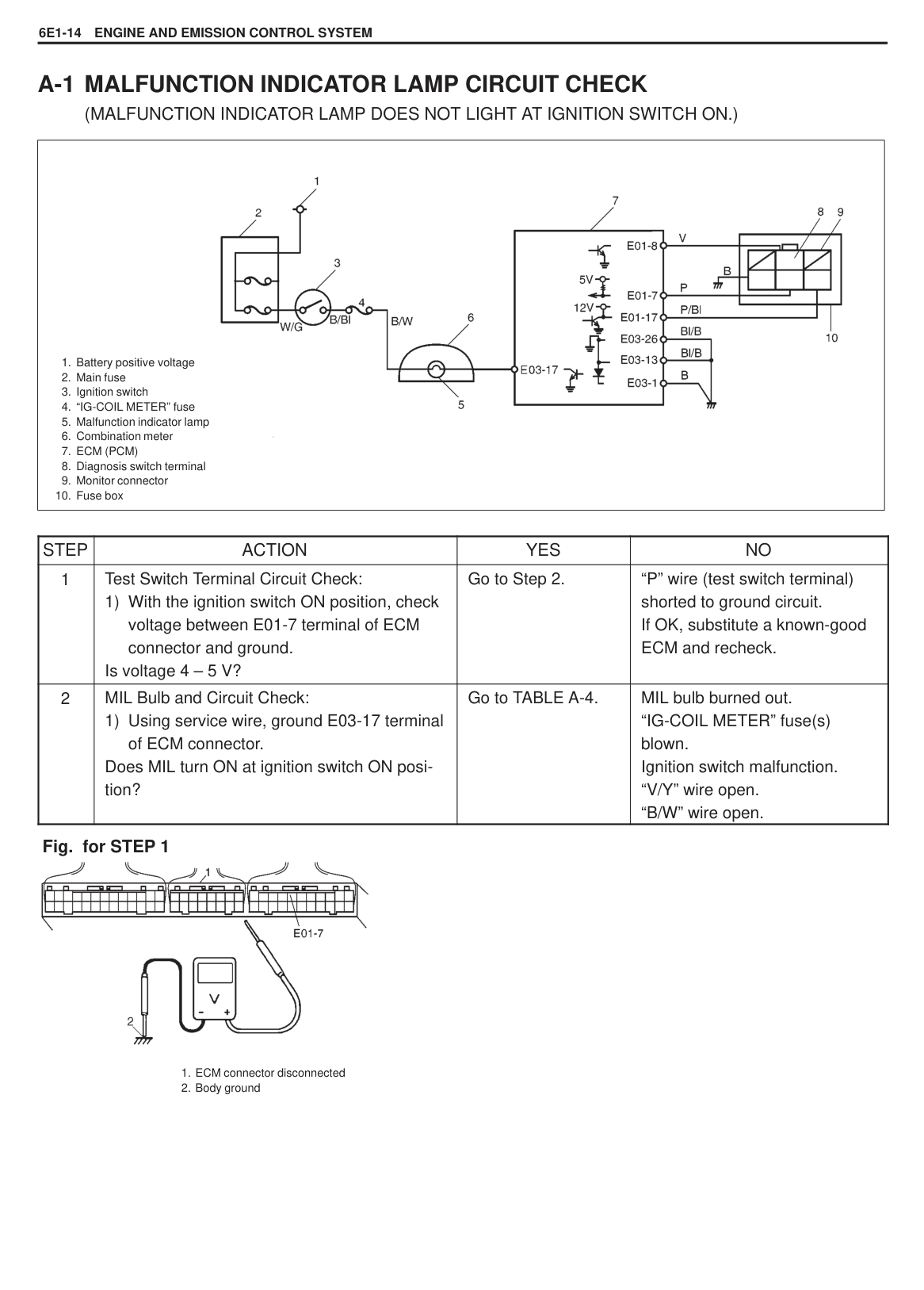
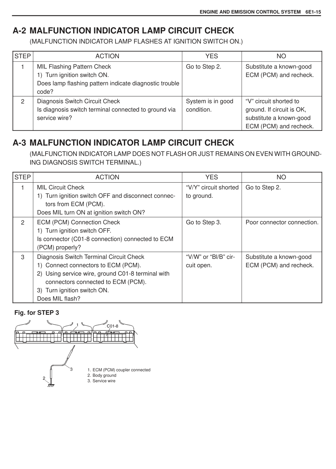
|TERMINAL|CIRCUIT| |---|---| |E01-1|Blank| |E01-2|IAC valve| |E01-3|Transmission range switch “2”| |E01-4|Transmission range switch “N”| |E01-5|Transmission range switch “P”| |E01-6|Blank| |E01-7|Test switch terminal| |E01-8|Diagnosis switch terminal| |E01-9|Electric load signal for blower fan motor|
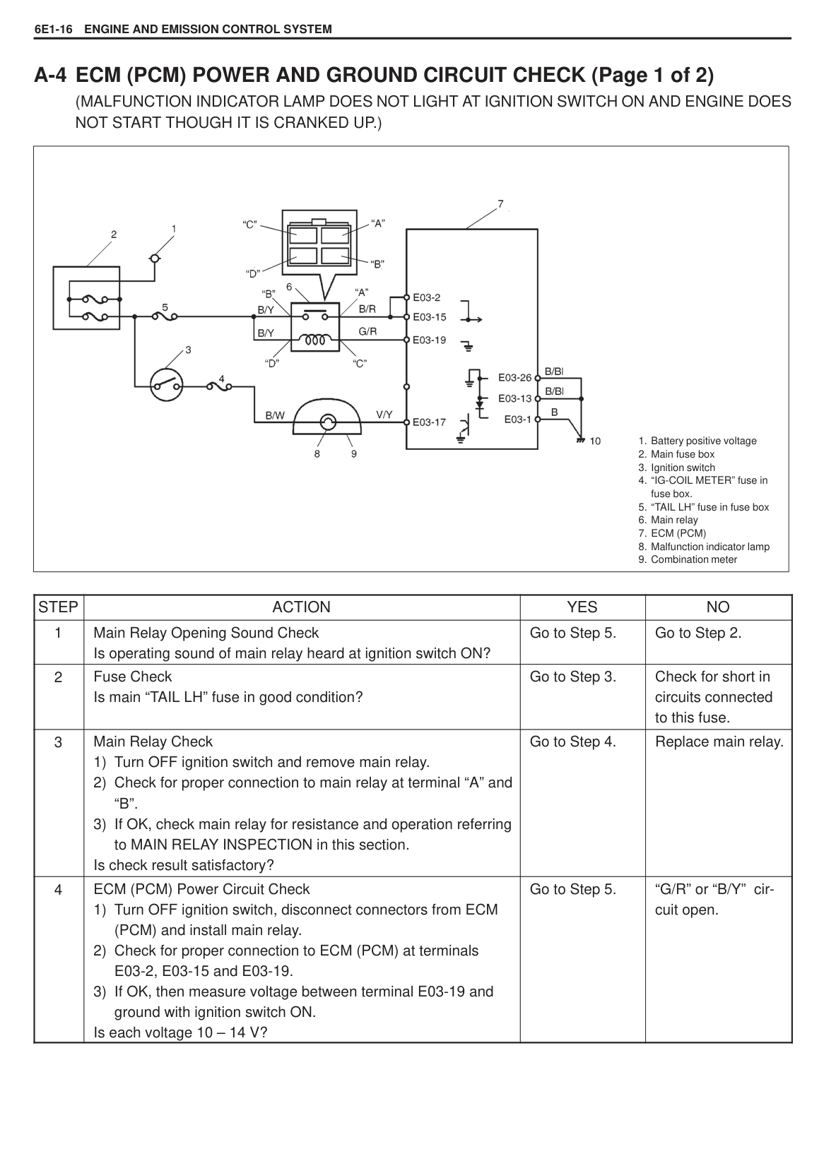
|E01-10|Stop light switch (brake pedal switch)| |E01-11|Blank| |E01-12|Data link connector| |E01-13|Engine starter switch (engine starter signal)| |E01-14|Transmission range switch “L”| |E01-15|Transmission range switch “D”| |E01-16|Transmission range switch “R”| |E01-17|Duty output terminal| |E01-18|Electric load signal for small light switch and rear defogger| |E01-19|A/C ON signal from A/C switch (if equipped)| |E01-20|Ignition switch| |E01-21|Blank| |E01-22|Sensor ground| |E02-1|Power supply for sensor| |E02-2|Blank| |E02-3|CMP sensor (+)| |E02-4|VSS or A/T VSS (+)| |E02-5|MAP sensor| |E02-6|TP sensor| |E02-7|A/C evaporator temp. sensor (with A/C)| |E02-8|ECT sensor| |E02-9|Sensor ground| |E02-10|Blank| |E02-11|CMP sensor (–)| |E02-12|A/T VSS (–)| |E02-13|Oxygen sensor|
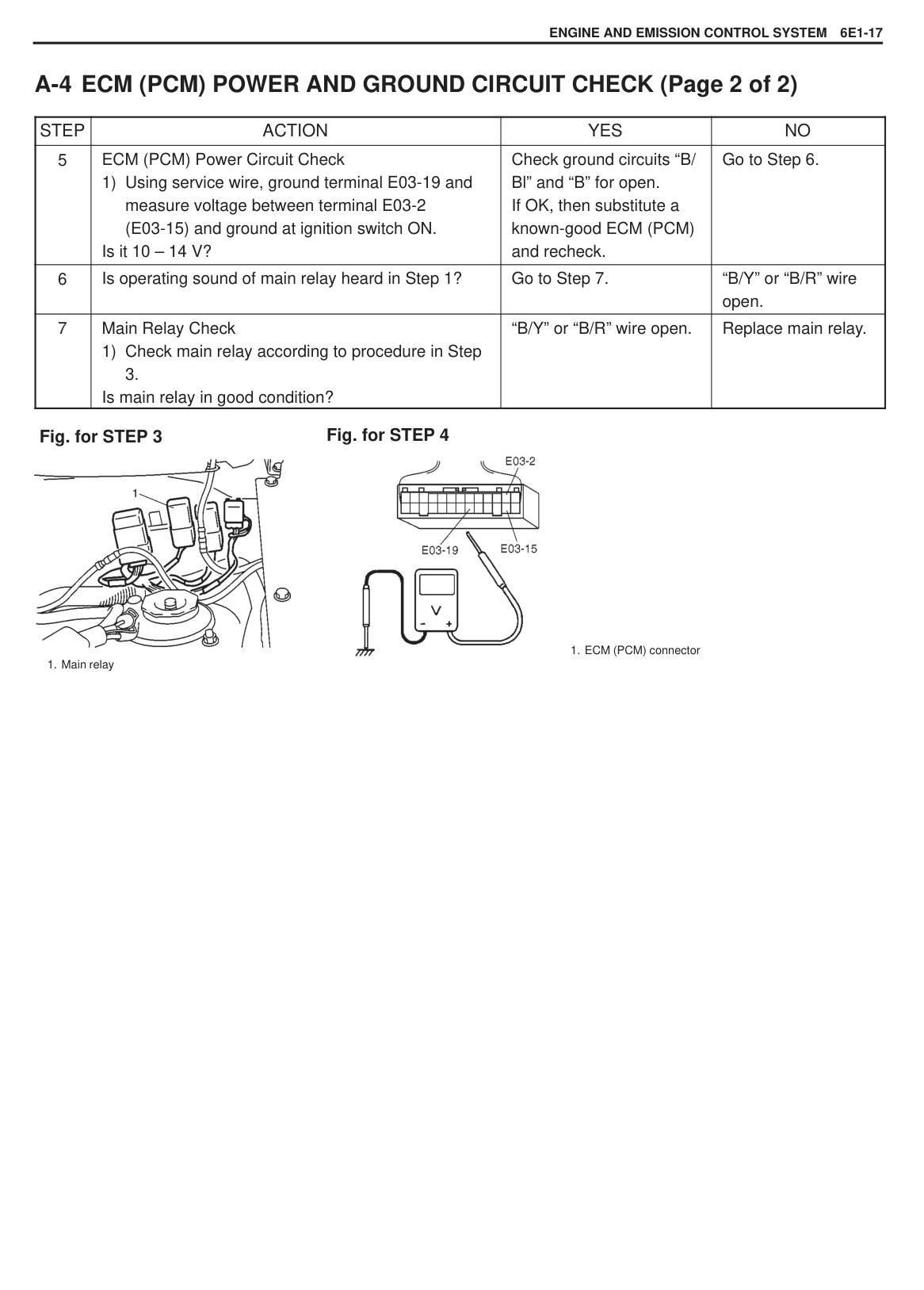
|E02-14|IAT sensor| |E02-15|Blank| |E02-16|A/C compressor relay, condenser fan relay (with A/C)|
|TERMINAL|CIRCUIT| |---|---| |E03-1|Ground| |E03-2|Power source| |E03-3|Blank| |E03-4|Blank| |E03-5|Shift solenoid B| |E03-6|Shift solenoid A| |E03-7|EVAP canister purge valve| |E03-8|Blank| |E03-9|Blank| |E03-10|Igniter| |E03-11|Fuel injector No. 3
| |E03-12|Fuel injector No. 1| |E03-13|Ground| |E03-14|Power source for backup| |E03-15|Power source| |E03-16|Blank| |E03-17|Malfunction indicator lamp| |E03-18|Fuel pump relay| |E03-19|Main relay|
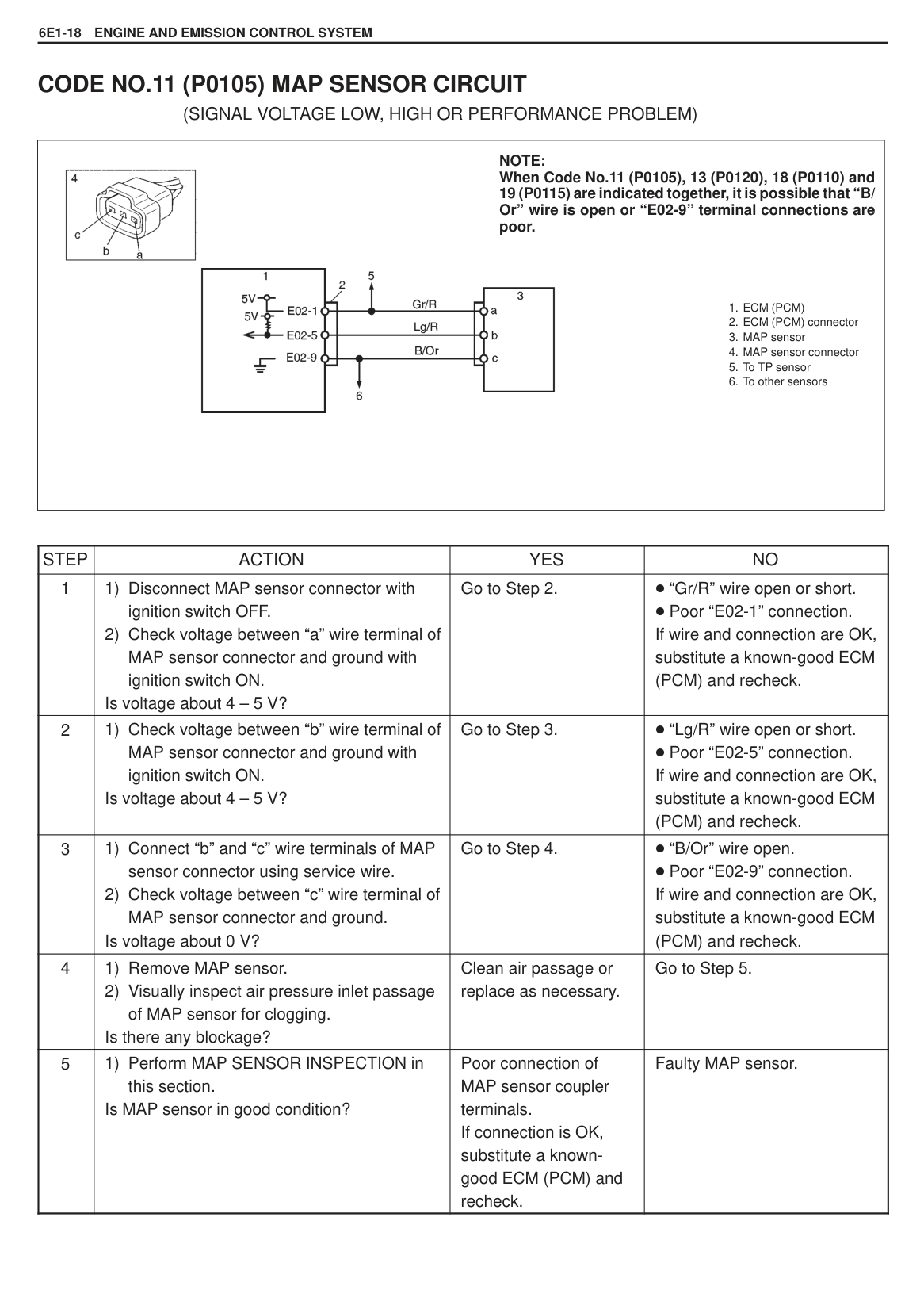
|E03-20|Radiator fan control relay| |E03-21|Blank| |E03-22|Blank| |E03-23|Blank| |E03-24|Fuel injector No. 4| |E03-25|Fuel injector No. 2| |E03-26|Ground|
|| |---|
|INPUT
OUTPUT|INPUT
OUTPUT|SIGNAL FROM SENSOR, SWITCH AND CONTROL MODULE|SIGNAL FROM SENSOR, SWITCH AND CONTROL MODULE|SIGNAL FROM SENSOR, SWITCH AND CONTROL MODULE|SIGNAL FROM SENSOR, SWITCH AND CONTROL MODULE|SIGNAL FROM SENSOR, SWITCH AND CONTROL MODULE|SIGNAL FROM SENSOR, SWITCH AND CONTROL MODULE|SIGNAL FROM SENSOR, SWITCH AND CONTROL MODULE|SIGNAL FROM SENSOR, SWITCH AND CONTROL MODULE|SIGNAL FROM SENSOR, SWITCH AND CONTROL MODULE|SIGNAL FROM SENSOR, SWITCH AND CONTROL MODULE|SIGNAL FROM SENSOR, SWITCH AND CONTROL MODULE|SIGNAL FROM SENSOR, SWITCH AND CONTROL MODULE|SIGNAL FROM SENSOR, SWITCH AND CONTROL MODULE|SIGNAL FROM SENSOR, SWITCH AND CONTROL MODULE|SIGNAL FROM SENSOR, SWITCH AND CONTROL MODULE|SIGNAL FROM SENSOR, SWITCH AND CONTROL MODULE| |---|---|---|---|---|---|---|---|---|---|---|---|---|---|---|---|---|---| |INPUT
OUTPUT|INPUT
OUTPUT|CMP SENSOR|MAP SENSOR|TP SENSOR|ECT SENSOR|IAT SENSOR|O2S|VSS|BLOWER FAN SWITCH| |IGNITION SWITCH|START SWITCH|STOP LAMP SWITCH|TRANSMISSION RANGE SWITCH|A/C SWITCH (IF EQUIPPED)|DIAGNOSIS SWITCH|TEST SWITCH| | |FUEL PUMP RELAY| | | | | | | | | | | | | | | | | | |FUEL INJECTOR| | | | | | | | | | | | | | | | | | |A/C COMPRESSOR CONTROL RELAY/ CONDENSER FAN CONTROL RELAY| | | | | | | | | | | | | | | | | | |IAC VALVE| | | | | | | | | | | | | | | | | | |IGNITER| | | | | | | | | | | | | | | | | | |EVAP CANISTER PURGE VALVE| | | | | | | | | | | | | | | | | | |RADIATOR FAN CONTROL RELAY| | | | | | | | | | | | | | | | | | |MIL| | | | | | | | | | | | | | | | |
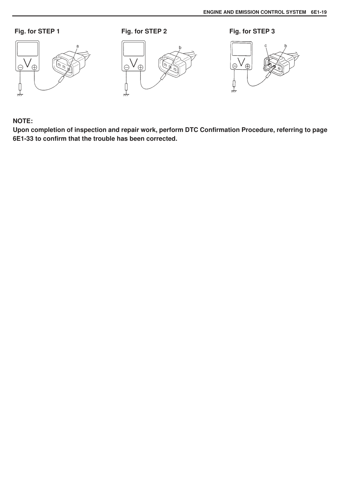
|| |---|
DIAGNOSIS The engine and emission control system in this vehicle are controlled by ECM (PCM). ECM (PCM) has an On-Board Diagnostic system which detects a malfunction in this system. When diagnosing troubles, be sure to have full understanding of the outline of ON-BOARD DIAGNOSTIC SYSTEM and each item in PRECAUTION IN DIAGNOSING TROUBLE and execute diagnosis according to ENGINE DIAGNOSTIC FLOW TABLE in SECTION 6. ON-BOARD DIAGNOSTIC SYSTEM
ECM (PCM) performs on-board diagnosis (self-diagnosis) on the system and operates malfunction indicator lamp as follows.
Malfunction indicator lamp lights when the ignition switch is turned ON (but the engine at stop) regardless of the condition of engine and emission control system. This is only to check the malfunction indicator lamp bulb and its circuit. If the areas monitored by ECM (PCM) is free from any trouble after the engine start (while engine is running), malfunction indicator lamp turns OFF. When ECM (PCM) detects a trouble which has occurred in the areas,it makes malfunction indicator lamp turn ON while the engine is running to warn the driver of such occurrence of trouble and at the same time it stores the exact trouble area in ECM (PCM) back-up memory.
PRECAUTIONS IN DIAGNOSING TROUBLES Before identifying diagnostic trouble code, don’t disconnect couplers from ECM (PCM), battery cable from battery, ECM (PCM) ground wire harness from engine. Such disconnection will erase memorized trouble in ECM (PCM) memory. Be sure to read PRECAUTIONS FOR ELECTRICAL CIRCUIT SERVICE in SECTION 0A before inspection and observe what is written there. ECM (PCM) replacement When substituting a known-good ECM (PCM), check for following conditions. Neglecting this check may cause damage to known-good ECM (PCM).
|| |---|
#### MALFUNCTION INDICATOR LAMP (MIL) CHECK
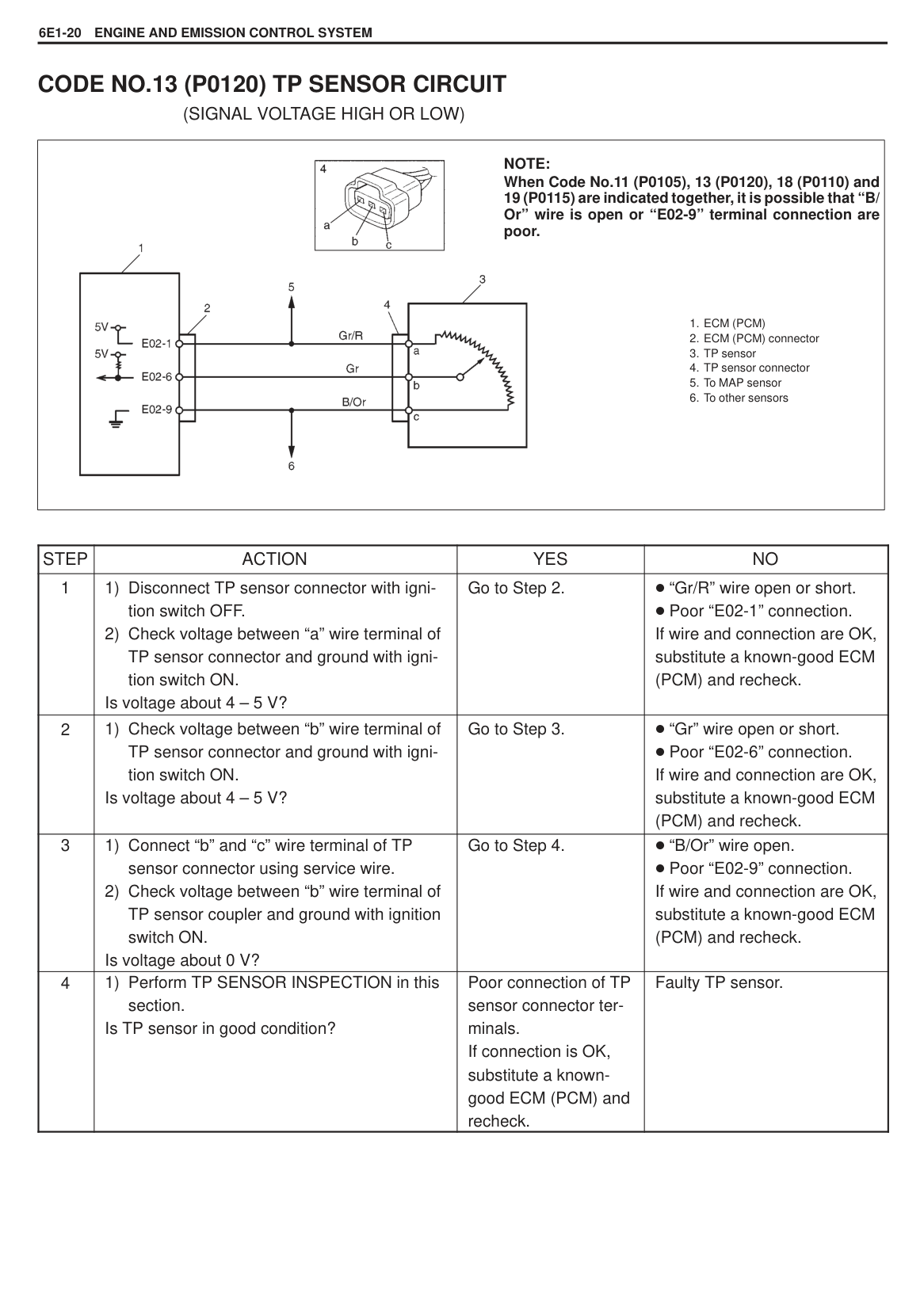
#### DIAGNOSTIC TROUBLE CODE (DTC) CHECK [Using SUZUKI scan tool]
|| |---|
|
| |---|
######### [Not using SUZUKI scan tool]
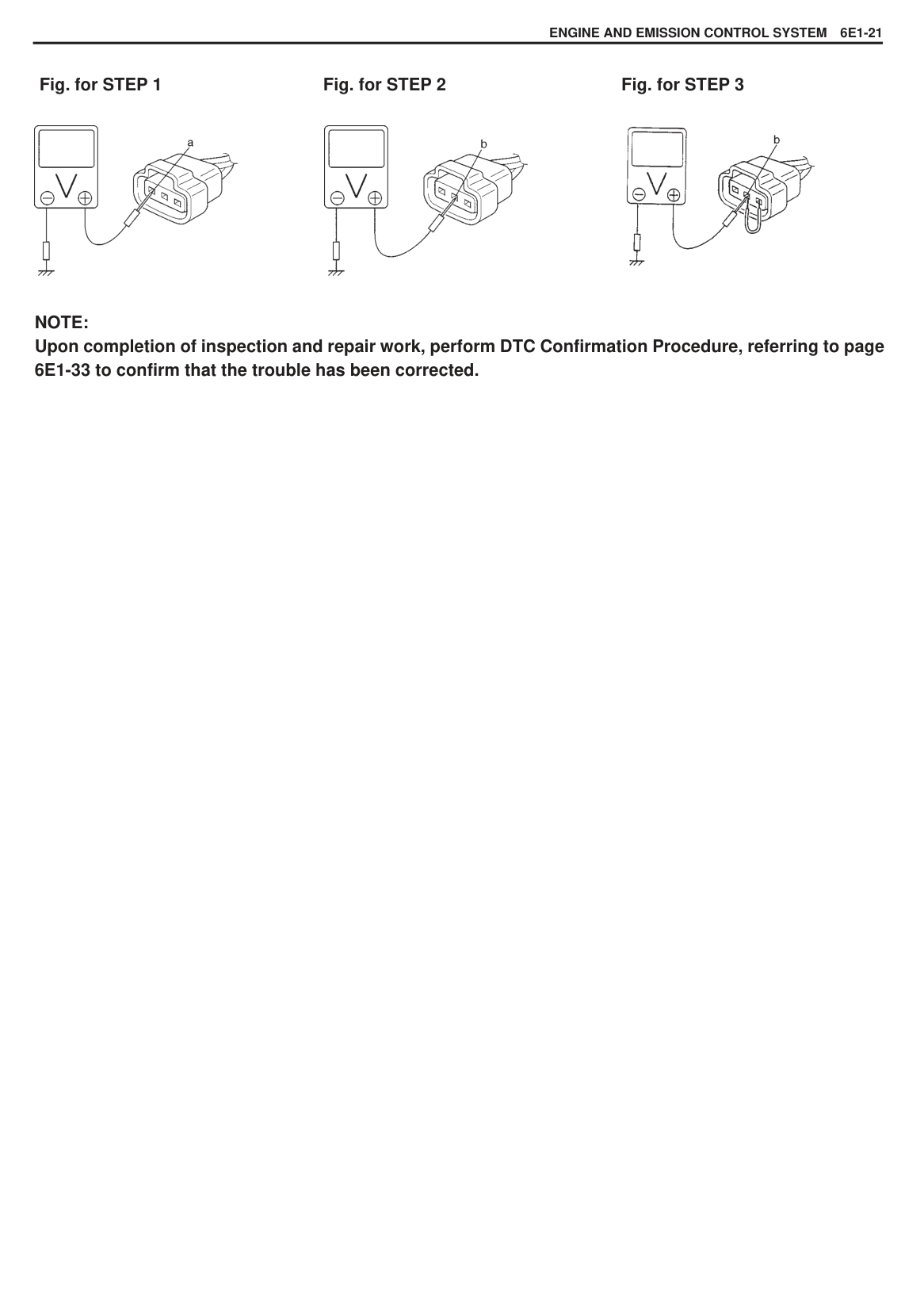
NOTE: If abnormality or malfunction lies in two or more areas, malfunction indicator lamp indicates applicable codes three times each. And flashing of these codes is repeated as long as diagnosis terminal is grounded and ignition switch is held at ON position. Take a note of diagnostic trouble code indicated first.
|
EXAMPLE: When throttle position sensor is defective (Code No. 13)| |---|
#### DIAGNOSTIC TROUBLE CODE (DTC) CLEARANCE [Using SUZUKI scan tool]
######### [Not using SUZUKI scan tool]
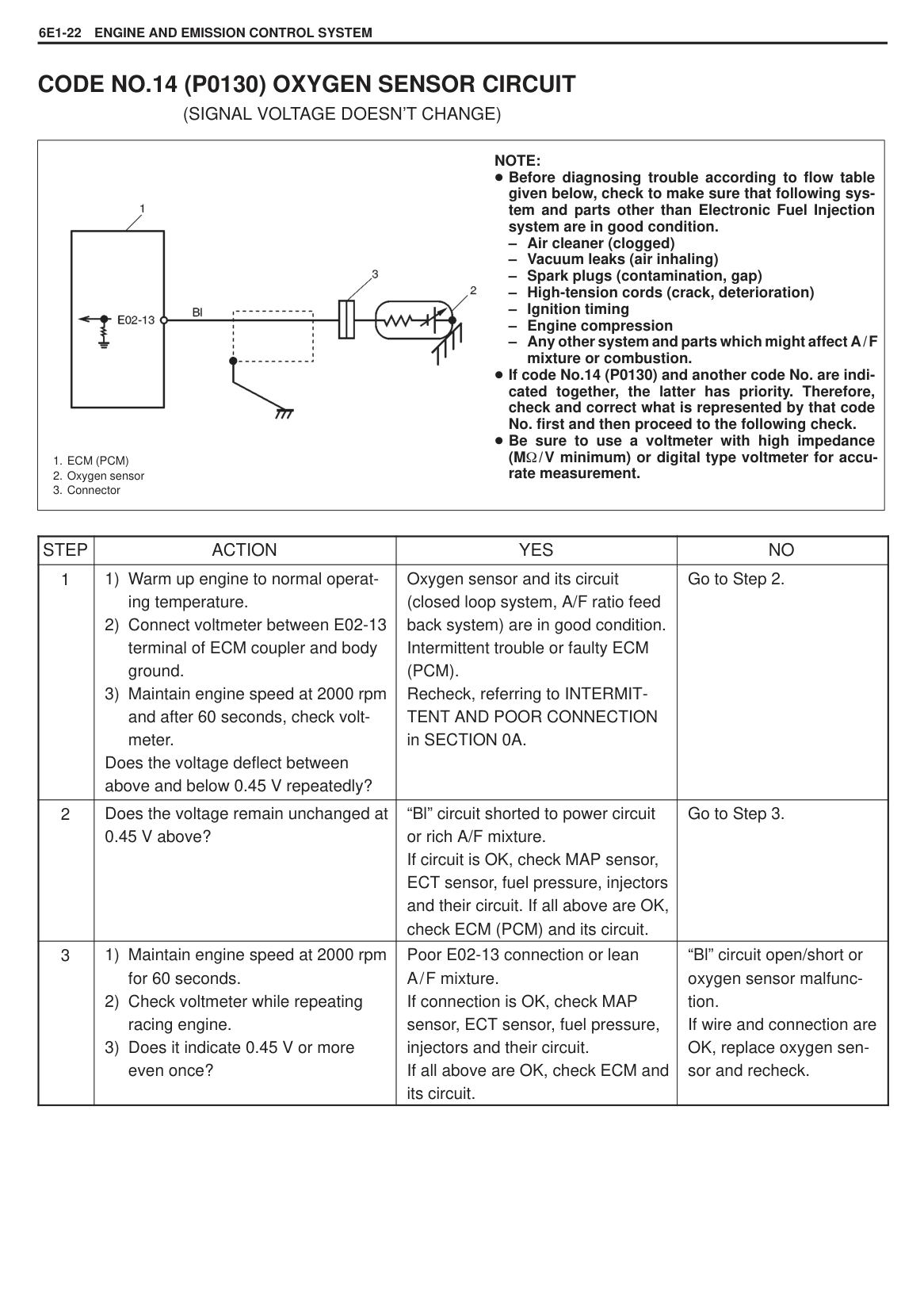
|Ambient temperature|Time to cut power to ECM (PCM)| |---|---| |Over 0 C (32 F)|30 sec. or longer| |Under 0 C (32 F)|Not specifiable. Select a place with higher than 0 C (32 F) temperature.|
#### DIAGNOSTIC TROUBLE CODE (DTC) TABLE
|DIAGNOSTIC TROUBLE CODE NO.|DIAGNOSTIC TROUBLE CODE NO.|MALFUNCTION INDICATOR LAMP FLASHING PATTERN
|DIAGNOSTIC ITEMDIAGNOSTIC ITEM
|DIAGNOSIS
| |---|---|---|---|---| |SUZUKI SCAN TOOL|MIL
|MALFUNCTION INDICATOR LAMP FLASHING PATTERN
|DIAGNOSTIC ITEMDIAGNOSTIC ITEM
|DIAGNOSIS
| |P0105|11||Manifold absolute pressure sensor|Diagnose trouble according to DIAGNOSTIC FLOW TABLE corresponding to each code No.
| |P0120|13||Throttle position sensor|Diagnose trouble according to DIAGNOSTIC FLOW TABLE corresponding to each code No.
| |P0130|14||Oxygen sensor|Diagnose trouble according to DIAGNOSTIC FLOW TABLE corresponding to each code No.
| |P0340|15||Camshaft position sensor|Diagnose trouble according to DIAGNOSTIC FLOW TABLE corresponding to each code No.
| |P0500|16||Vehicle speed sensor|Diagnose trouble according to DIAGNOSTIC FLOW TABLE corresponding to each code No.
| |P0110|18||Intake air temperature sensor|Diagnose trouble according to DIAGNOSTIC FLOW TABLE corresponding to each code No.
| |P0115|19||Engine coolant temperature sensor|Diagnose trouble according to DIAGNOSTIC FLOW TABLE corresponding to each code No.
| |–––|12||Normal|This code appears when none of the other codes (above codes) are identified.|
#### (A/T ONLY)
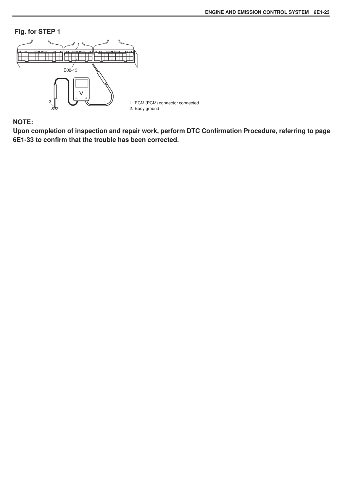
|DIAGNOSTIC TROUBLE CODE NO.|DIAGNOSTIC TROUBLE CODE NO.|MALFUNCTION INDICATOR LAMP FLASHING PATTERN
|DIAGNOSTIC ITEMDIAGNOSTIC ITEM
|DIAGNOSIS
| |---|---|---|---|---| |SUZUKI SCAN TOOL|MIL|MALFUNCTION INDICATOR LAMP FLASHING PATTERN
|DIAGNOSTIC ITEMDIAGNOSTIC ITEM
|DIAGNOSIS
| |P0753|41|
41|Shift solenoid A|Refer to SECTION 7B AUTOMATIC TRANSMISSION.
| |P0758|42|
42|Shift solenoid B|Refer to SECTION 7B AUTOMATIC TRANSMISSION.
| |P0705|46|
4|Transmission range switch|Refer to SECTION 7B AUTOMATIC TRANSMISSION.
| |P0720|16||Output shaft speed sensor (A/T VSS)|Refer to SECTION 7B AUTOMATIC TRANSMISSION.
|
(MALFUNCTION INDICATOR LAMP DOES NOT LIGHT AT IGNITION SWITCH ON.)
|
1. Battery positive voltage
2. Main fuse
3. Ignition switch
4. “IG-COIL METER” fuse
5. Malfunction indicator lamp
6. Combination meter
7. ECM (PCM)
8. Diagnosis switch terminal
9. Monitor connector
10. Fuse box
| |---|
|STEP|ACTION|YES|NO| |---|---|---|---| |1|Test Switch Terminal Circuit Check:
1) With the ignition switch ON position, check voltage between E01-7 terminal of ECM connector and ground.
Is voltage 4 – 5 V?|Go to Step 2.|“P” wire (test switch terminal) shorted to ground circuit. If OK, substitute a known-good ECM and recheck.| |2|MIL Bulb and Circuit Check:
1) Using service wire, ground E03-17 terminal
of ECM connector. Does MIL turn ON at ignition switch ON position?|Go to TABLE A-4.|MIL bulb burned out. “IG-COIL METER” fuse(s) blown. Ignition switch malfunction. “V/Y” wire open. “B/W” wire open.|
######### Fig. for STEP 1

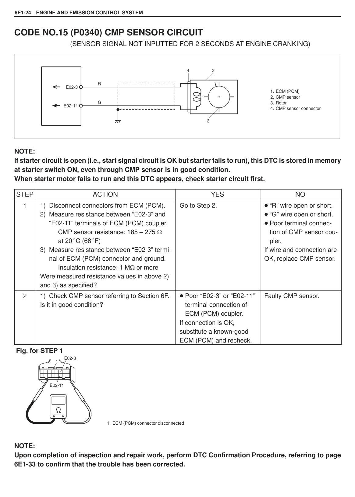
(MALFUNCTION INDICATOR LAMP FLASHES AT IGNITION SWITCH ON.)
|STEP|ACTION|YES|NO| |---|---|---|---| |1|MIL Flashing Pattern Check
1) Turn ignition switch ON. Does lamp flashing pattern indicate diagnostic trouble code?|Go to Step 2.|Substitute a known-good ECM (PCM) and recheck.| |2|Diagnosis Switch Circuit Check Is diagnosis switch terminal connected to ground via service wire?|System is in good condition.|“V” circuit shorted to ground. If circuit is OK, substitute a known-good ECM (PCM) and recheck.|
|STEP|ACTION|YES|NO| |---|---|---|---| |1|MIL Circuit Check
1) Turn ignition switch OFF and disconnect connectors from ECM (PCM). Does MIL turn ON at ignition switch ON?|“V/Y” circuit shorted to ground.|Go to Step 2.| |2|ECM (PCM) Connection Check
1) Turn ignition switch OFF. Is connector (C01-8 connection) connected to ECM (PCM) properly?|Go to Step 3.|Poor connector connection.| |3|Diagnosis Switch Terminal Circuit Check
1) Connect connectors to ECM (PCM).
2) Using service wire, ground C01-8 terminal with connectors connected to ECM (PCM).
3) Turn ignition switch ON. Does MIL flash?
|“V/W” or “Bl/B” circuit open.|Substitute a known-good ECM (PCM) and recheck.|
######### Fig. for STEP 3

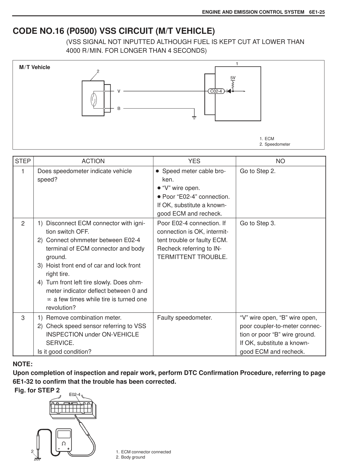
########## (MALFUNCTION INDICATOR LAMP DOES NOT LIGHT AT IGNITION SWITCH ON AND ENGINE DOES NOT START THOUGH IT IS CRANKED UP.)
|
1. Battery positive voltage
2. Main fuse box
3. Ignition switch
4. “IG-COIL METER” fuse in fuse box.
5. “TAIL LH” fuse in fuse box
6. Main relay
7. ECM (PCM)
8. Malfunction indicator lamp
9. Combination meter
| |---|
|STEP|ACTION|YES|NO| |---|---|---|---| |1|Main Relay Opening Sound Check Is operating sound of main relay heard at ignition switch ON?|Go to Step 5.|Go to Step 2.| |2|Fuse Check Is main “TAIL LH” fuse in good condition?|Go to Step 3.|Check for short in circuits connected to this fuse.| |3|Main Relay Check
1) Turn OFF ignition switch and remove main relay.
2) Check for proper connection to main relay at terminal “A” and “B”.
3) If OK, check main relay for resistance and operation referring to MAIN RELAY INSPECTION in this section.
Is check result satisfactory?|Go to Step 4.|Replace main relay.| |4|ECM (PCM) Power Circuit Check
1) Turn OFF ignition switch, disconnect connectors from ECM (PCM) and install main relay.
2) Check for proper connection to ECM (PCM) at terminals E03-2, E03-15 and E03-19.
3) If OK, then measure voltage between terminal E03-19 and ground with ignition switch ON.
Is each voltage 10 – 14 V?|Go to Step 5.|“G/R” or “B/Y” circuit open.|
|STEP|ACTION|YES|NO| |---|---|---|---| |5|ECM (PCM) Power Circuit Check
1) Using service wire, ground terminal E03-19 and measure voltage between terminal E03-2 (E03-15) and ground at ignition switch ON.
Is it 10 – 14 V?|Check ground circuits “B/ Bl” and “B” for open. If OK, then substitute a known-good ECM (PCM) and recheck.|Go to Step 6.| |6|Is operating sound of main relay heard in Step 1?|Go to Step 7.|“B/Y” or “B/R” wire open.| |7|Main Relay Check
1) Check main relay according to procedure in Step 3. Is main relay in good condition?|“B/Y” or “B/R” wire open.|Replace main relay.|
######### Fig. for STEP 3 Fig. for STEP 4
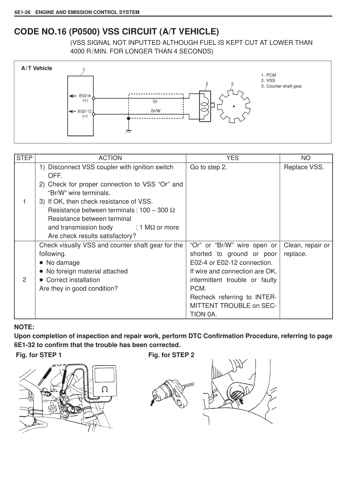


#### CODE NO.11 (P0105) MAP SENSOR CIRCUIT
(SIGNAL VOLTAGE LOW, HIGH OR PERFORMANCE PROBLEM)
|

NOTE: When Code No.11 (P0105), 13 (P0120), 18 (P0110) and 19 (P0115) are indicated together, it is possible that “B/ Or” wire is open or “E02-9” terminal connections are poor.
1. ECM (PCM)
2. ECM (PCM) connector
3. MAP sensor
4. MAP sensor connector
5. To TP sensor
6. To other sensors
| |---|
|STEP|ACTION|YES|NO| |---|---|---|---| |1|1) Disconnect MAP sensor connector with ignition switch OFF.
2) Check voltage between “a” wire terminal of MAP sensor connector and ground with ignition switch ON.
Is voltage about 4 – 5 V?|Go to Step 2.|“Gr/R” wire open or short. Poor “E02-1” connection.
If wire and connection are OK, substitute a known-good ECM (PCM) and recheck.| |2|1) Check voltage between “b” wire terminal of MAP sensor connector and ground with ignition switch ON. Is voltage about 4 – 5 V?|Go to Step 3.|“Lg/R” wire open or short. Poor “E02-5” connection.
If wire and connection are OK, substitute a known-good ECM (PCM) and recheck.| |3|1) Connect “b” and “c” wire terminals of MAP sensor connector using service wire.
2) Check voltage between “c” wire terminal of MAP sensor connector and ground.
Is voltage about 0 V?|Go to Step 4.|“B/Or” wire open. Poor “E02-9” connection.
If wire and connection are OK, substitute a known-good ECM (PCM) and recheck.| |4|1) Remove MAP sensor.
2) Visually inspect air pressure inlet passage of MAP sensor for clogging.
Is there any blockage?|Clean air passage or replace as necessary.|Go to Step 5.| |5|1) Perform MAP SENSOR INSPECTION in this section. Is MAP sensor in good condition?|Poor connection of MAP sensor coupler terminals. If connection is OK, substitute a knowngood ECM (PCM) and recheck.|Faulty MAP sensor.|
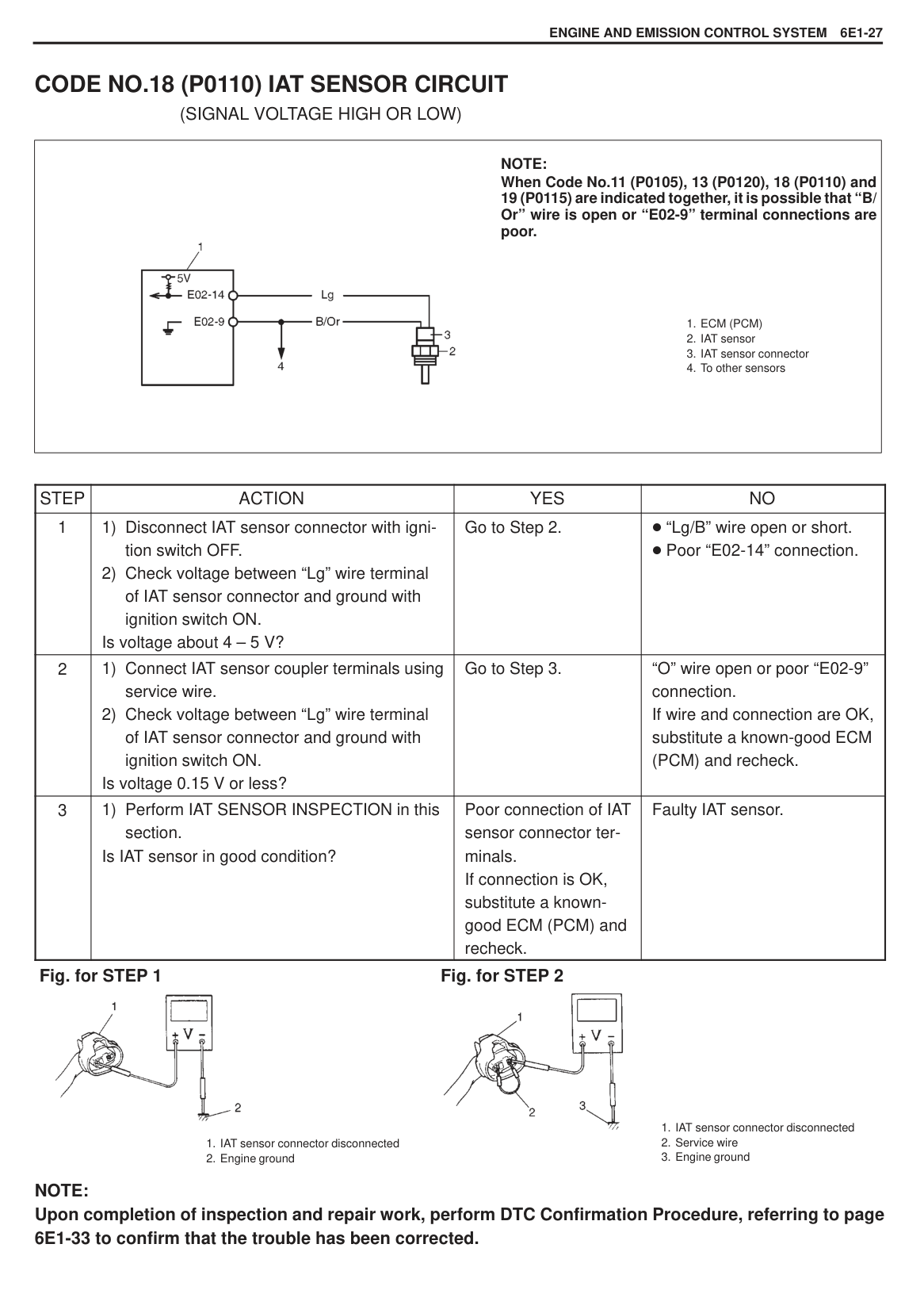


######### NOTE: Upon completion of inspection and repair work, perform DTC Confirmation Procedure, referring to page 6E1-33 to confirm that the trouble has been corrected.
#### CODE NO.13 (P0120) TP SENSOR CIRCUIT(SIGNAL VOLTAGE HIGH OR LOW)
|

1. ECM (PCM)
2. ECM (PCM) connector
3. TP sensor
4. TP sensor connector
5. To MAP sensor
6. To other sensors
NOTE:
When Code No.11 (P0105), 13 (P0120), 18 (P0110) and 19 (P0115) are indicated together, it is possible that “B/ Or” wire is open or “E02-9” terminal connection are poor.| |---|
|STEP|ACTION|YES|NO| |---|---|---|---| |1|1) Disconnect TP sensor connector with ignition switch OFF.
2) Check voltage between “a” wire terminal of TP sensor connector and ground with ignition switch ON.
Is voltage about 4 – 5 V?|Go to Step 2.|“Gr/R” wire open or short. Poor “E02-1” connection.
If wire and connection are OK, substitute a known-good ECM (PCM) and recheck.| |2|1) Check voltage between “b” wire terminal of TP sensor connector and ground with ignition switch ON.
Is voltage about 4 – 5 V?|Go to Step 3.|“Gr” wire open or short. Poor “E02-6” connection.
If wire and connection are OK, substitute a known-good ECM (PCM) and recheck.| |3|1) Connect “b” and “c” wire terminal of TP sensor connector using service wire.
2) Check voltage between “b” wire terminal of TP sensor coupler and ground with ignition switch ON.
Is voltage about 0 V?|Go to Step 4.|“B/Or” wire open. Poor “E02-9” connection.
If wire and connection are OK, substitute a known-good ECM (PCM) and recheck.| |4|1) Perform TP SENSOR INSPECTION in this section. Is TP sensor in good condition?|Poor connection of TP sensor connector terminals. If connection is OK, substitute a knowngood ECM (PCM) and recheck.|Faulty TP sensor.|


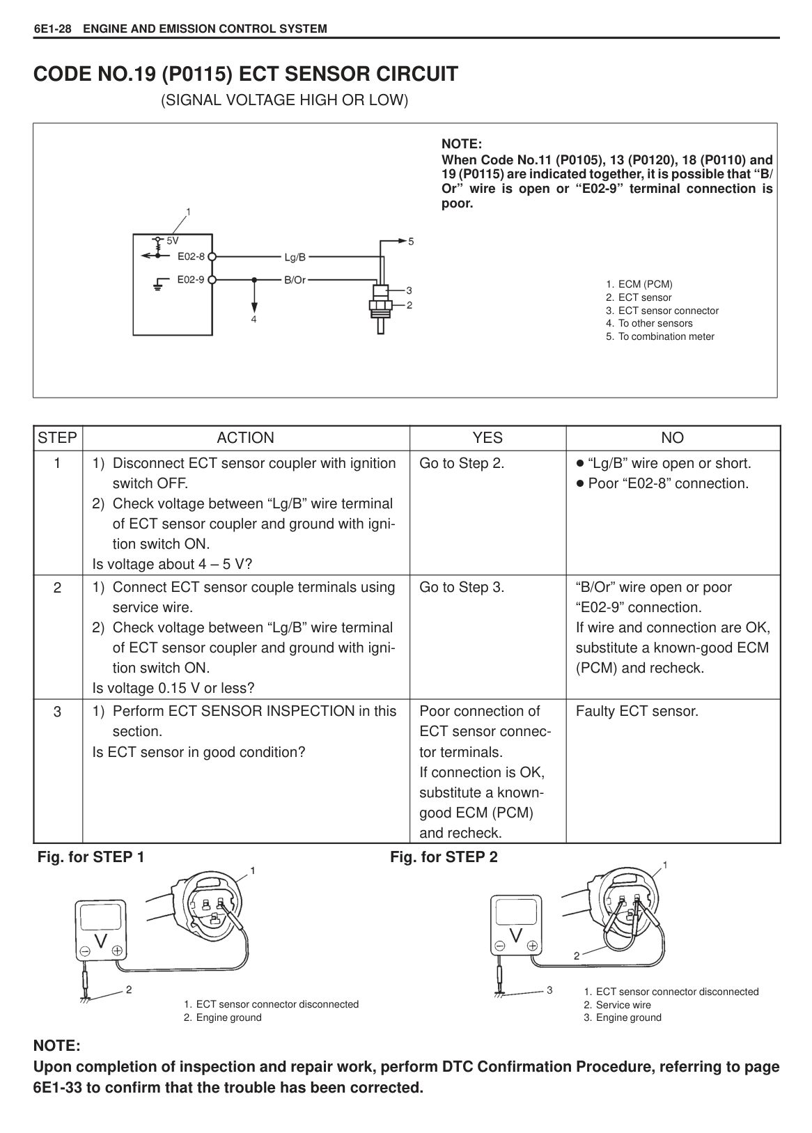

######### NOTE: Upon completion of inspection and repair work, perform DTC Confirmation Procedure, referring to page 6E1-33 to confirm that the trouble has been corrected.
#### CODE NO.14 (P0130) OXYGEN SENSOR CIRCUIT(SIGNAL VOLTAGE DOESN’T CHANGE)
|
NOTE:
Before diagnosing trouble according to flow table given below, check to make sure that following system and parts other than Electronic Fuel Injection system are in good condition.
– Air cleaner (clogged)
– Vacuum leaks (air inhaling)
– Spark plugs (contamination, gap)
– High-tension cords (crack, deterioration)
– Ignition timing
– Engine compression
– Any other system and parts which might affect A/F mixture or combustion.
If code No.14 (P0130) and another code No. are indicated together, the latter has priority. Therefore, check and correct what is represented by that code No. first and then proceed to the following check. Be sure to use a voltmeter with high impedance (M /V minimum) or digital type voltmeter for accurate measurement.
1. ECM (PCM)
2. Oxygen sensor
3. Connector
| |---|
|STEP|ACTION|YES|NO| |---|---|---|---| |1|1) Warm up engine to normal operating temperature.
2) Connect voltmeter between E02-13 terminal of ECM coupler and body ground.
3) Maintain engine speed at 2000 rpm and after 60 seconds, check voltmeter.
Does the voltage deflect between above and below 0.45 V repeatedly?|Oxygen sensor and its circuit (closed loop system, A/F ratio feed back system) are in good condition. Intermittent trouble or faulty ECM (PCM). Recheck, referring to INTERMITTENT AND POOR CONNECTION in SECTION 0A.|Go to Step 2.| |2|Does the voltage remain unchanged at 0.45 V above?|“Bl” circuit shorted to power circuit or rich A/F mixture. If circuit is OK, check MAP sensor, ECT sensor, fuel pressure, injectors and their circuit. If all above are OK, check ECM (PCM) and its circuit.|Go to Step 3.| |3|1) Maintain engine speed at 2000 rpm for 60 seconds.
2) Check voltmeter while repeating racing engine.
3) Does it indicate 0.45 V or more even once?
|Poor E02-13 connection or lean A/F mixture. If connection is OK, check MAP sensor, ECT sensor, fuel pressure, injectors and their circuit. If all above are OK, check ECM and its circuit.|“Bl” circuit open/short or oxygen sensor malfunction. If wire and connection are OK, replace oxygen sensor and recheck.|
######### Fig. for STEP 1

######### NOTE: Upon completion of inspection and repair work, perform DTC Confirmation Procedure, referring to page 6E1-33 to confirm that the trouble has been corrected.
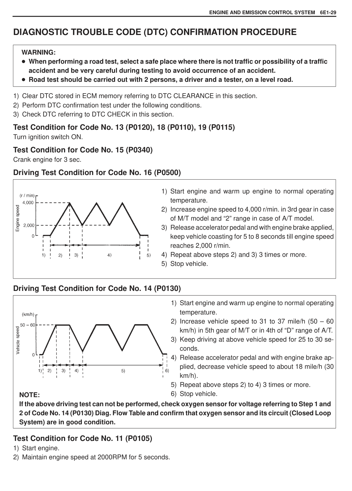
|
1. ECM (PCM)
2. CMP sensor
3. Rotor
4. CMP sensor connector
| |---|
NOTE: If starter circuit is open (i.e., start signal circuit is OK but starter fails to run), this DTC is stored in memory at starter switch ON, even through CMP sensor is in good condition. When starter motor fails to run and this DTC appears, check starter circuit first.
|STEP|ACTION|YES|NO| |---|---|---|---| |1|1) Disconnect connectors from ECM (PCM).
2) Measure resistance between “E02-3” and “E02-11” terminals of ECM (PCM) coupler.
CMP sensor resistance: 185 – 275 at 20 C (68 F)
3) Measure resistance between “E02-3” terminal of ECM (PCM) connector and ground.
Insulation resistance: 1 M or more Were measured resistance values in above 2) and 3) as specified?|Go to Step 2.|“R” wire open or short. “G” wire open or short. Poor terminal connection of CMP sensor coupler.
If wire and connection are OK, replace CMP sensor.| |2|1) Check CMP sensor referring to Section 6F. Is it in good condition?|Poor “E02-3” or “E02-11” terminal connection of ECM (PCM) coupler.
If connection is OK, substitute a known-good ECM (PCM) and recheck.|Faulty CMP sensor.|

######### NOTE: Upon completion of inspection and repair work, perform DTC Confirmation Procedure, referring to page 6E1-33 to confirm that the trouble has been corrected.
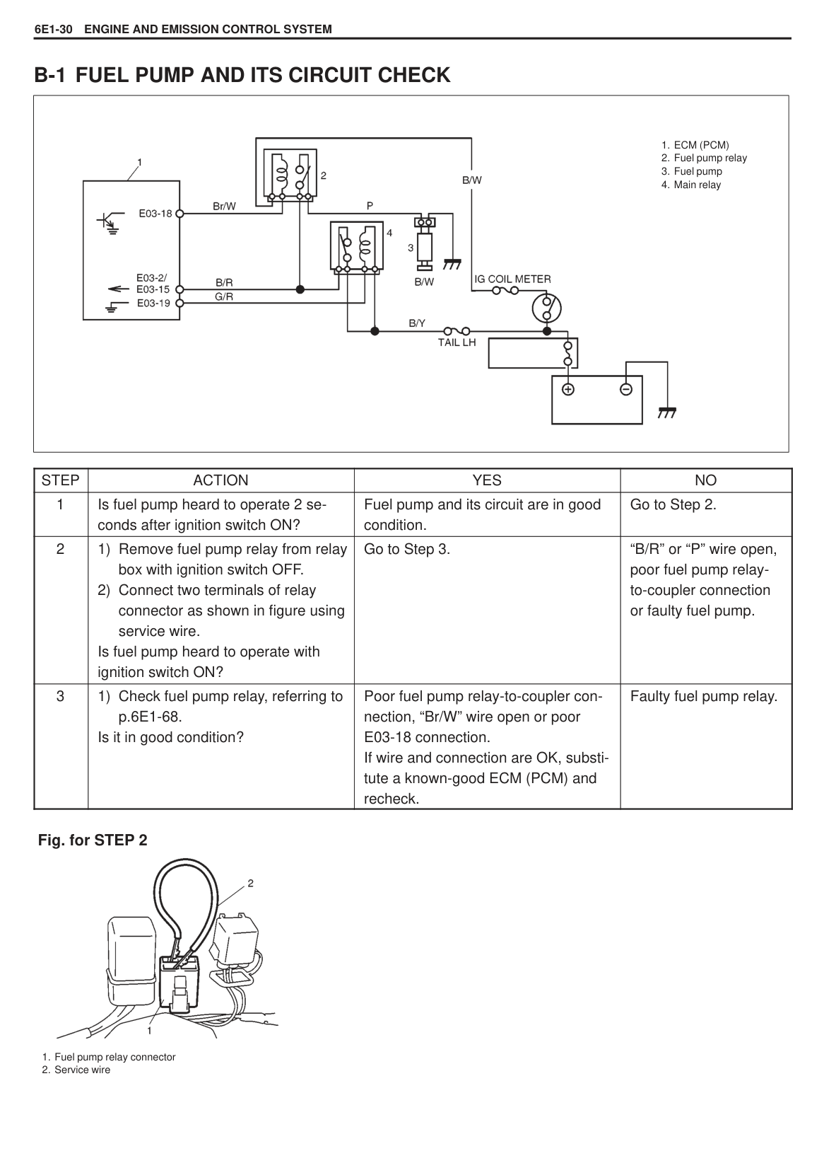
|
1. ECM
2. Speedometer
M/T Vehicle| |---|
|STEP|ACTION|YES|NO| |---|---|---|---| |1|Does speedometer indicate vehicle speed?|Speed meter cable broken. “V” wire open. Poor “E02-4” connection.
If OK, substitute a knowngood ECM and recheck.|Go to Step 2.| |2|1) Disconnect ECM connector with ignition switch OFF.
2) Connect ohmmeter between E02-4 terminal of ECM connector and body ground.
3) Hoist front end of car and lock front right tire.
4) Turn front left tire slowly. Does ohmmeter indicator deflect between 0 and
a few times while tire is turned one revolution?|Poor E02-4 connection. If connection is OK, intermittent trouble or faulty ECM. Recheck referring to INTERMITTENT TROUBLE.|Go to Step 3.| |3|1) Remove combination meter.
2) Check speed sensor referring to VSS INSPECTION under ON-VEHICLE SERVICE.
Is it good condition?|Faulty speedometer.|“V” wire open, “B” wire open, poor coupler-to-meter connection or poor “B” wire ground. If OK, substitute a knowngood ECM and recheck.|
NOTE: Upon completion of inspection and repair work, perform DTC Confirmation Procedure, referring to page 6E1-32 to confirm that the trouble has been corrected.

CODE NO.16 (P0500) VSS CIRCUIT (A/T VEHICLE) (VSS SIGNAL NOT INPUTTED ALTHOUGH FUEL IS KEPT CUT AT LOWER THAN 4000 R/MIN. FOR LONGER THAN 4 SECONDS)
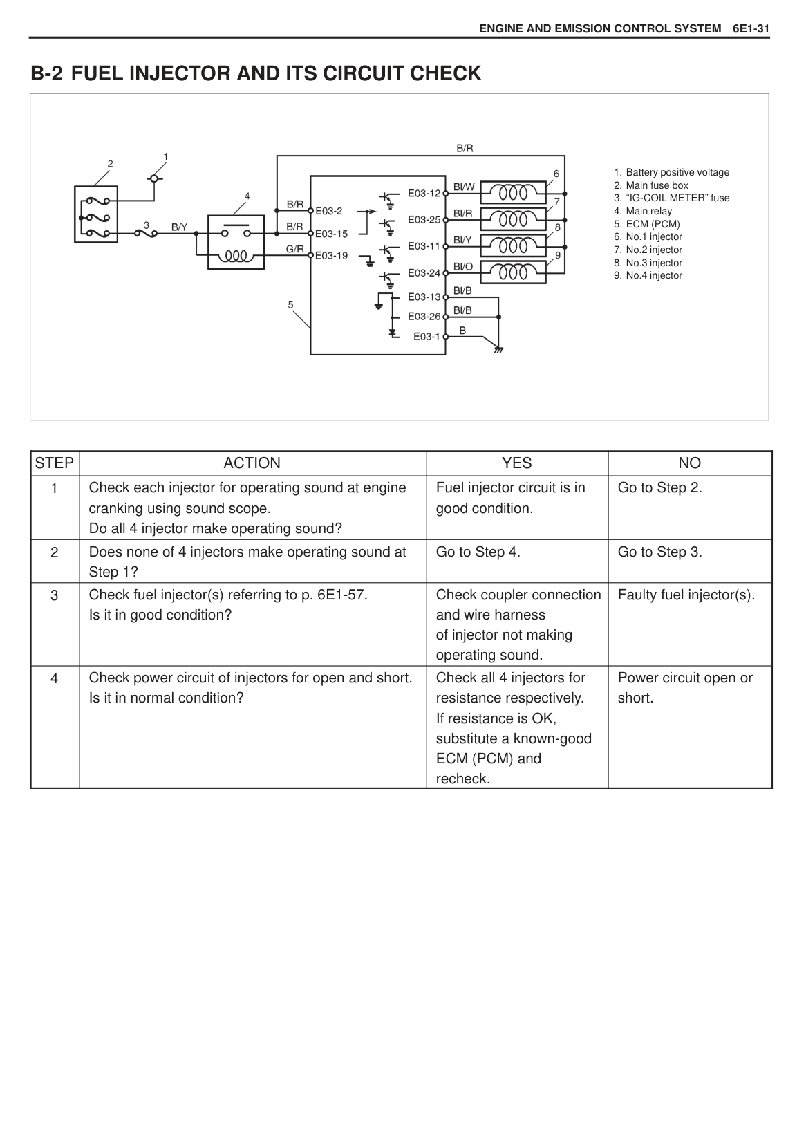
|
1. PCM
2. VSS
3. Counter shaft gear
A/T Vehicle| |---|
|STEP|ACTION|YES|NO| |---|---|---|---| |1|1) Disconnect VSS coupler with ignition switch OFF.
2) Check for proper connection to VSS “Or” and “Br/W” wire terminals.
3) If OK, then check resistance of VSS. Resistance between terminals : 100 – 300 Resistance between terminal and transmission body : 1 M or more Are check results satisfactory?
|Go to step 2.|Replace VSS.| |2|Check visually VSS and counter shaft gear for the following.
No damage No foreign material attached Correct installation
Are they in good condition?|“Or” or “Br/W” wire open or shorted to ground or poor E02-4 or E02-12 connection. If wire and connection are OK, intermittent trouble or faulty PCM. Recheck referring to INTERMITTENT TROUBLE on SECTION 0A.|Clean, repair or replace.|
NOTE: Upon completion of inspection and repair work, perform DTC Confirmation Procedure, referring to page 6E1-32 to confirm that the trouble has been corrected.
Fig. for STEP 1 Fig. for STEP 2


#### CODE NO.18 (P0110) IAT SENSOR CIRCUIT(SIGNAL VOLTAGE HIGH OR LOW)
|
1. ECM (PCM)
2. IAT sensor
3. IAT sensor connector
4. To other sensors
NOTE:
When Code No.11 (P0105), 13 (P0120), 18 (P0110) and 19 (P0115) are indicated together, it is possible that “B/ Or” wire is open or “E02-9” terminal connections are poor.| |---|
|STEP|ACTION|YES|NO| |---|---|---|---|
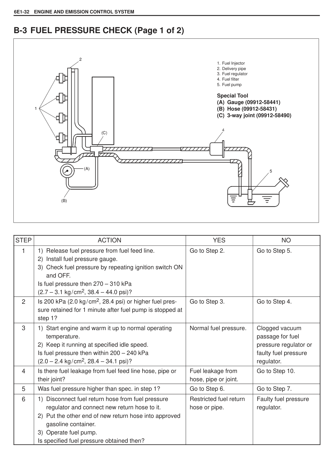
|1|1) Disconnect IAT sensor connector with ignition switch OFF.
2) Check voltage between “Lg” wire terminal of IAT sensor connector and ground with ignition switch ON.
Is voltage about 4 – 5 V?|Go to Step 2.|“Lg/B” wire open or short. Poor “E02-14” connection.| |2|1) Connect IAT sensor coupler terminals using service wire.
2) Check voltage between “Lg” wire terminal of IAT sensor connector and ground with ignition switch ON.
Is voltage 0.15 V or less?|Go to Step 3.|“O” wire open or poor “E02-9” connection. If wire and connection are OK, substitute a known-good ECM (PCM) and recheck.| |3|1) Perform IAT SENSOR INSPECTION in this section. Is IAT sensor in good condition?|Poor connection of IAT sensor connector terminals. If connection is OK, substitute a knowngood ECM (PCM) and recheck.|Faulty IAT sensor.|
######### Fig. for STEP 1 Fig. for STEP 2


#### CODE NO.19 (P0115) ECT SENSOR CIRCUIT(SIGNAL VOLTAGE HIGH OR LOW)
|
1. ECM (PCM)
2. ECT sensor
3. ECT sensor connector
4. To other sensors
5. To combination meter
NOTE:
When Code No.11 (P0105), 13 (P0120), 18 (P0110) and 19 (P0115) are indicated together, it is possible that “B/ Or” wire is open or “E02-9” terminal connection is poor.| |---|
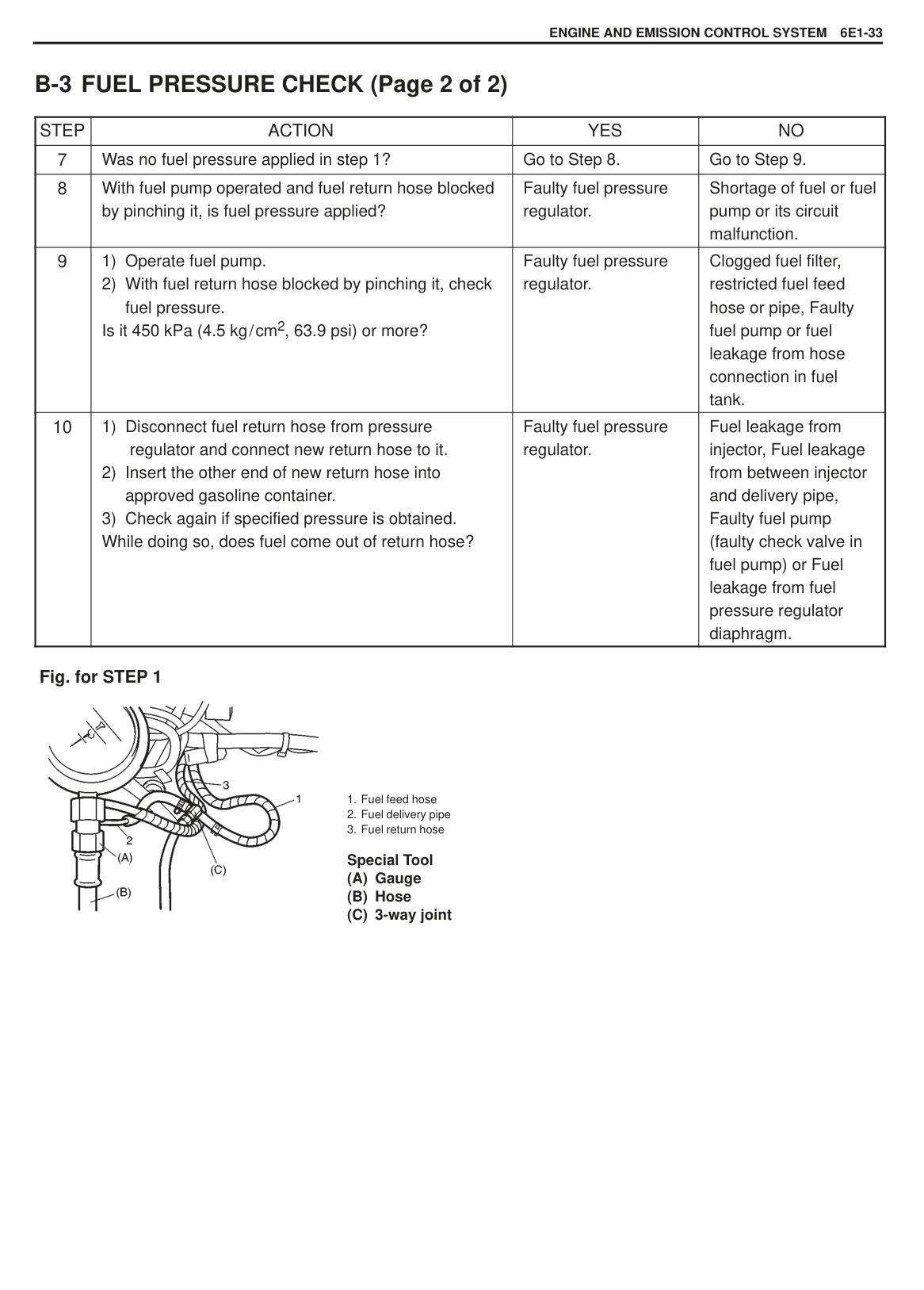
|STEP|ACTION|YES|NO| |---|---|---|---| |1|1) Disconnect ECT sensor coupler with ignition switch OFF.
2) Check voltage between “Lg/B” wire terminal of ECT sensor coupler and ground with ignition switch ON.
Is voltage about 4 – 5 V?|Go to Step 2.|“Lg/B” wire open or short. Poor “E02-8” connection.| |2|1) Connect ECT sensor couple terminals using service wire.
2) Check voltage between “Lg/B” wire terminal of ECT sensor coupler and ground with ignition switch ON.
Is voltage 0.15 V or less?|Go to Step 3.|“B/Or” wire open or poor “E02-9” connection. If wire and connection are OK, substitute a known-good ECM (PCM) and recheck.| |3|1) Perform ECT SENSOR INSPECTION in this section. Is ECT sensor in good condition?|Poor connection of ECT sensor connector terminals. If connection is OK, substitute a knowngood ECM (PCM) and recheck.|Faulty ECT sensor.|
######### Fig. for STEP 1 Fig. for STEP 2


#### DIAGNOSTIC TROUBLE CODE (DTC) CONFIRMATION PROCEDURE
|WARNING: When performing a road test, select a safe place where there is not traffic or possibility of a traffic accident and be very careful during testing to avoid occurrence of an accident. Road test should be carried out with 2 persons, a driver and a tester, on a level road.| |---|
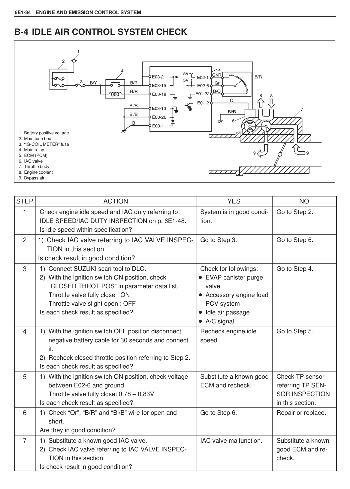
|
1) Start engine and warm up engine to normal operating temperature.
2) Increase engine speed to 4,000 r/min. in 3rd gear in case of M/T model and “2” range in case of A/T model.
3) Release accelerator pedal and with engine brake applied, keep vehicle coasting for 5 to 8 seconds till engine speed reaches 2,000 r/min.
4) Repeat above steps 2) and 3) 3 times or more.
5) Stop vehicle.
| |---|
Driving Test Condition for Code No. 14 (P0130)
|
1) Start engine and warm up engine to normal operating temperature.
2) Increase vehicle speed to 31 to 37 mile/h (50 – 60 km/h) in 5th gear of M/T or in 4th of “D” range of A/T.
3) Keep driving at above vehicle speed for 25 to 30 seconds.
4) Release accelerator pedal and with engine brake applied, decrease vehicle speed to about 18 mile/h (30 km/h).
5) Repeat above steps 2) to 4) 3 times or more.
6) Stop vehicle.NOTE:
If the above driving test can not be performed, check oxygen sensor for voltage referring to Step 1 and 2 of Code No. 14 (P0130) Diag. Flow Table and confirm that oxygen sensor and its circuit (Closed Loop System) are in good condition.| |---|
Test Condition for Code No. 11 (P0105)
#### B-1 FUEL PUMP AND ITS CIRCUIT CHECK
|
1. ECM (PCM)
2. Fuel pump relay
3. Fuel pump
4. Main relay
|
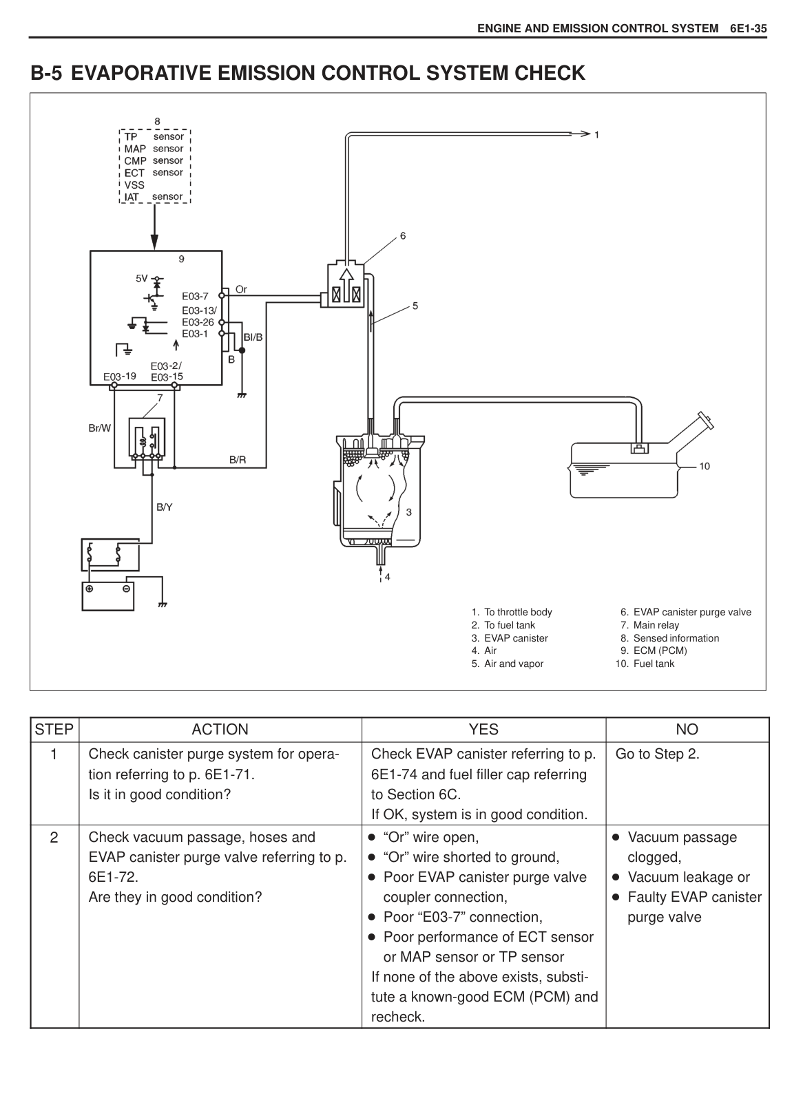
|---|
|STEP|ACTION|YES|NO| |---|---|---|---| |1|Is fuel pump heard to operate 2 seconds after ignition switch ON?|Fuel pump and its circuit are in good condition.|Go to Step 2.| |2|1) Remove fuel pump relay from relay box with ignition switch OFF.
2) Connect two terminals of relay connector as shown in figure using service wire.
Is fuel pump heard to operate with ignition switch ON?|Go to Step 3.|“B/R” or “P” wire open, poor fuel pump relayto-coupler connection or faulty fuel pump.| |3|1) Check fuel pump relay, referring to p.6E1-68. Is it in good condition?|Poor fuel pump relay-to-coupler connection, “Br/W” wire open or poor E03-18 connection. If wire and connection are OK, substitute a known-good ECM (PCM) and recheck.|Faulty fuel pump relay.|
######### Fig. for STEP 2

#### B-2 FUEL INJECTOR AND ITS CIRCUIT CHECK
|
1. Battery positive voltage
2. Main fuse box
3. “IG-COIL METER” fuse
4. Main relay
5. ECM (PCM)
6. No.1 injector
7. No.2 injector
8. No.3 injector
9. No.4 injector
| |---|
|STEP|ACTION|YES|NO| |---|---|---|---|
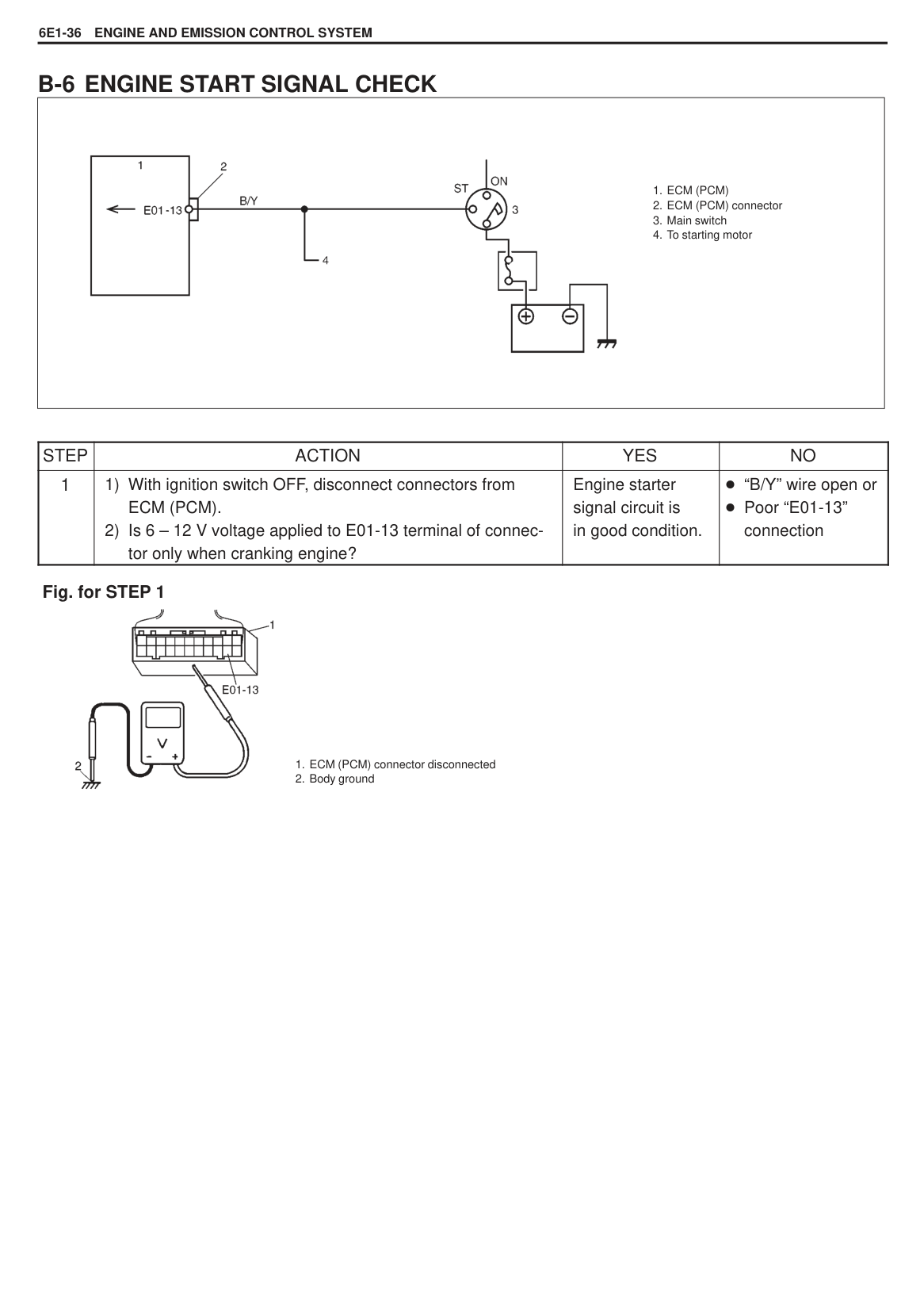
|1|Check each injector for operating sound at engine cranking using sound scope. Do all 4 injector make operating sound?|Fuel injector circuit is in good condition.|Go to Step 2.| |2|Does none of 4 injectors make operating sound at Step 1?|Go to Step 4.|Go to Step 3.| |3|Check fuel injector(s) referring to p. 6E1-57. Is it in good condition?|Check coupler connection and wire harness of injector not making operating sound.|Faulty fuel injector(s).| |4|Check power circuit of injectors for open and short. Is it in normal condition?|Check all 4 injectors for resistance respectively. If resistance is OK, substitute a known-good ECM (PCM) and recheck.|Power circuit open or short.|
|
1. Fuel Injector
2. Delivery pipe
3. Fuel regulator
4. Fuel filter
5. Fuel pump Special Tool
(A) Gauge (09912-58441)
(B) Hose (09912-58431)
(C) 3-way joint (09912-58490)
| |---|
|STEP|ACTION|YES|NO| |---|---|---|---| |1|1) Release fuel pressure from fuel feed line.
2) Install fuel pressure gauge.
3) Check fuel pressure by repeating ignition switch ON and OFF.
Is fuel pressure then 270 – 310 kPa (2.7 – 3.1 kg/cm2, 38.4 – 44.0 psi)?|Go to Step 2.|Go to Step 5.| |2|Is 200 kPa (2.0 kg/cm2, 28.4 psi) or higher fuel pressure retained for 1 minute after fuel pump is stopped at step 1?|Go to Step 3.|Go to Step 4.| |3|1) Start engine and warm it up to normal operating temperature.
2) Keep it running at specified idle speed. Is fuel pressure then within 200 – 240 kPa (2.0 – 2.4 kg/cm2, 28.4 – 34.1 psi)?
|Normal fuel pressure.|Clogged vacuum passage for fuel pressure regulator or faulty fuel pressure regulator.| |4|Is there fuel leakage from fuel feed line hose, pipe or their joint?|Fuel leakage from hose, pipe or joint.|Go to Step 10.| |5|Was fuel pressure higher than spec. in step 1?|Go to Step 6.|Go to Step 7.| |6|1) Disconnect fuel return hose from fuel pressure regulator and connect new return hose to it.
2) Put the other end of new return hose into approved gasoline container.
3) Operate fuel pump. Is specified fuel pressure obtained then?
|Restricted fuel return hose or pipe.|Faulty fuel pressure regulator.|
|STEP|ACTION|YES|NO| |---|---|---|---| |7|Was no fuel pressure applied in step 1?|Go to Step 8.|Go to Step 9.| |8|With fuel pump operated and fuel return hose blocked by pinching it, is fuel pressure applied?|Faulty fuel pressure regulator.|Shortage of fuel or fuel pump or its circuit malfunction.| |9|1) Operate fuel pump.
2) With fuel return hose blocked by pinching it, check fuel pressure.
Is it 450 kPa (4.5 kg/cm2, 63.9 psi) or more?|Faulty fuel pressure regulator.|Clogged fuel filter, restricted fuel feed hose or pipe, Faulty fuel pump or fuel leakage from hose connection in fuel tank.| |10|1) Disconnect fuel return hose from pressure regulator and connect new return hose to it.
2) Insert the other end of new return hose into approved gasoline container.
3) Check again if specified pressure is obtained. While doing so, does fuel come out of return hose?
|Faulty fuel pressure regulator.|Fuel leakage from injector, Fuel leakage from between injector and delivery pipe, Faulty fuel pump (faulty check valve in fuel pump) or Fuel leakage from fuel pressure regulator diaphragm.|
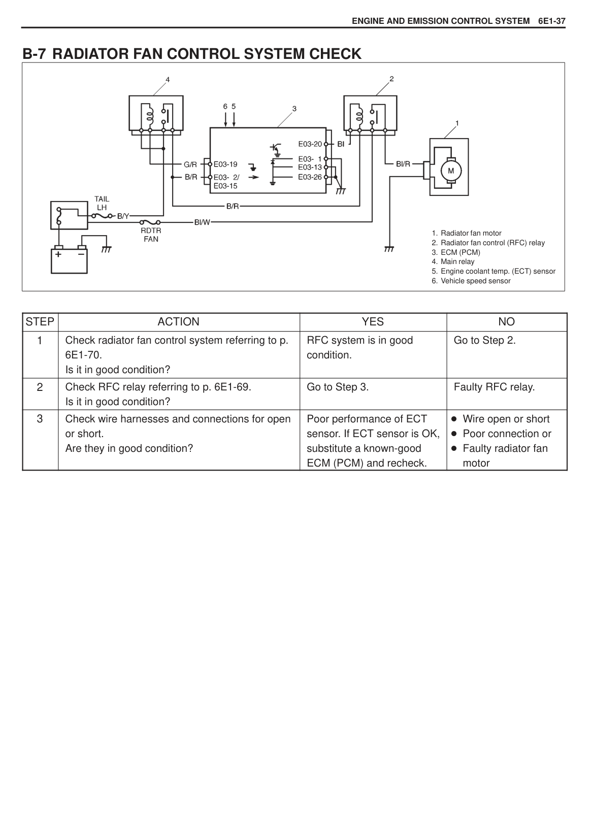
######### Fig. for STEP 1

#### B-4 IDLE AIR CONTROL SYSTEM CHECK
|
1. Battery positive voltage
2. Main fuse box
3. “IG-COIL METER” fuse
4. Main relay
5. ECM (PCM)
6. IAC valve
7. Throttle body
8. Engine coolant
9. Bypass air
| |---|
|STEP|ACTION|YES|NO| |---|---|---|---| |1|Check engine idle speed and IAC duty referring to IDLE SPEED/IAC DUTY INSPECTION on p. 6E1-48. Is idle speed within specification?|System is in good condition.|Go to Step 2.| |2|1) Check IAC valve referring to IAC VALVE INSPECTION in this section. Is check result in good condition?|Go to Step 3.|Go to Step 6.|
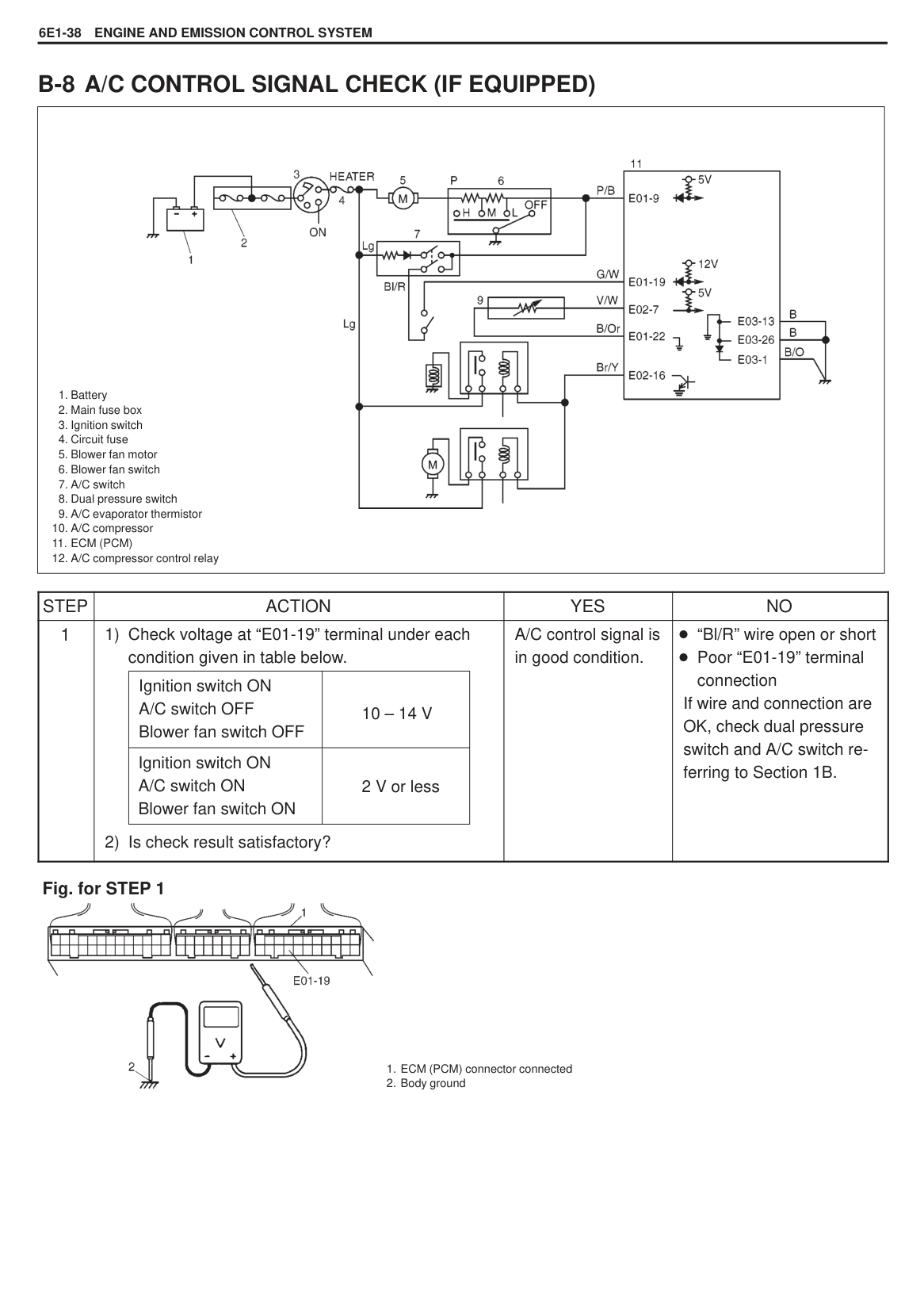
|3|1) Connect SUZUKI scan tool to DLC.
2) With the ignition switch ON position, check “CLOSED THROT POS” in parameter data list. Throttle valve fully close : ON Throttle valve slight open : OFF
Is each check result as specified?|Check for followings: EVAP canister purge valve Accessory engine load PCV system Idle air passage A/C signal|Go to Step 4.| |4|1) With the ignition switch OFF position disconnect negative battery cable for 30 seconds and connect it.
2) Recheck closed throttle position referring to Step 2. Is each check result as specified?
|Recheck engine idle speed.|Go to Step 5.| |5|1) With the ignition switch ON position, check voltage between E02-6 and ground. Throttle valve fully close: 0.78 – 0.83V
Is each check result as specified?|Substitute a known good ECM and recheck.|Check TP sensor referring TP SENSOR INSPECTION in this section.| |6|1) Check “Or”, “B/R” and “Bl/B” wire for open and short. Are they in good condition?|Go to Step 6.|Repair or replace.| |7|1) Substitute a known good IAC valve.
2) Check IAC valve referring to IAC VALVE INSPECTION in this section.
Is check result in good condition?|IAC valve malfunction.|Substitute a known good ECM and recheck.|
#### B-5 EVAPORATIVE EMISSION CONTROL SYSTEM CHECK
|
1. To throttle body
2. To fuel tank
3. EVAP canister
4. Air
5. Air and vapor
6. EVAP canister purge valve
7. Main relay
8. Sensed information
9. ECM (PCM)
10. Fuel tank
| |---|
|STEP|ACTION|YES|NO| |---|---|---|---| |1|Check canister purge system for operation referring to p. 6E1-71. Is it in good condition?|Check EVAP canister referring to p. 6E1-74 and fuel filler cap referring to Section 6C. If OK, system is in good condition.|Go to Step 2.| |2|Check vacuum passage, hoses and EVAP canister purge valve referring to p. 6E1-72. Are they in good condition?|“Or” wire open, “Or” wire shorted to ground, Poor EVAP canister purge valve coupler connection, Poor “E03-7” connection, Poor performance of ECT sensor or MAP sensor or TP sensor
If none of the above exists, substitute a known-good ECM (PCM) and recheck.|Vacuum passage clogged, Vacuum leakage or Faulty EVAP canister purge valve|
#### B-6 ENGINE START SIGNAL CHECK
|
1. ECM (PCM)
2. ECM (PCM) connector
3. Main switch
4. To starting motor
| |---|
|STEP|ACTION|YES|NO|

|---|---|---|---| |1|1) With ignition switch OFF, disconnect connectors from ECM (PCM).
2) Is 6 – 12 V voltage applied to E01-13 terminal of connector only when cranking engine?
|Engine starter signal circuit is in good condition.|“B/Y” wire open or Poor “E01-13” connection|
######### Fig. for STEP 1

#### B-7 RADIATOR FAN CONTROL SYSTEM CHECK
|
1. Radiator fan motor
2. Radiator fan control (RFC) relay
3. ECM (PCM)
4. Main relay
5. Engine coolant temp. (ECT) sensor
6. Vehicle speed sensor
| |---|
|STEP|ACTION|YES|NO| |---|---|---|---| |1|Check radiator fan control system referring to p. 6E1-70. Is it in good condition?|RFC system is in good condition.|Go to Step 2.| |2|Check RFC relay referring to p. 6E1-69. Is it in good condition?|Go to Step 3.|Faulty RFC relay.| |3|Check wire harnesses and connections for open or short. Are they in good condition?|Poor performance of ECT sensor. If ECT sensor is OK, substitute a known-good ECM (PCM) and recheck.|Wire open or short Poor connection or Faulty radiator fan motor|
#### B-8 A/C CONTROL SIGNAL CHECK (IF EQUIPPED)
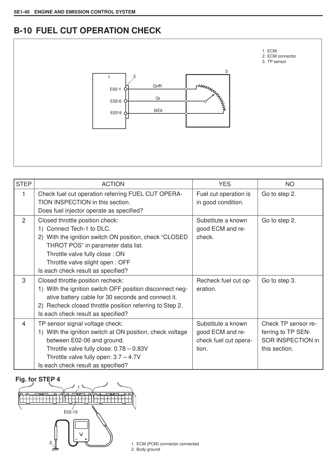
|
1. Battery
2. Main fuse box
3. Ignition switch
4. Circuit fuse
5. Blower fan motor
6. Blower fan switch
7. A/C switch
8. Dual pressure switch
9. A/C evaporator thermistor
10. A/C compressor
11. ECM (PCM)
12. A/C compressor control relay
| |---|
|STEP|ACTION|YES|NO| |---|---|---|---| |1|1) Check voltage at “E01-19” terminal under each condition given in table below.
2) Is check result satisfactory?
|Ignition switch ON A/C switch OFF Blower fan switch OFF|10 – 14 V| |---|---| |Ignition switch ON A/C switch ON Blower fan switch ON|2 V or less| |A/C control signal is in good condition.|“Bl/R” wire open or short Poor “E01-19” terminal connection
If wire and connection are OK, check dual pressure switch and A/C switch referring to Section 1B.|
######### Fig. for STEP 1

#### B-9 ELECTRIC LOAD SIGNAL CIRCUITS CHECK
|
1. ECM (PCM)
2. ECM (PCM) connector
3. From lighting switch (small)/Rear defogger
4. From heater blower switch
| |---|
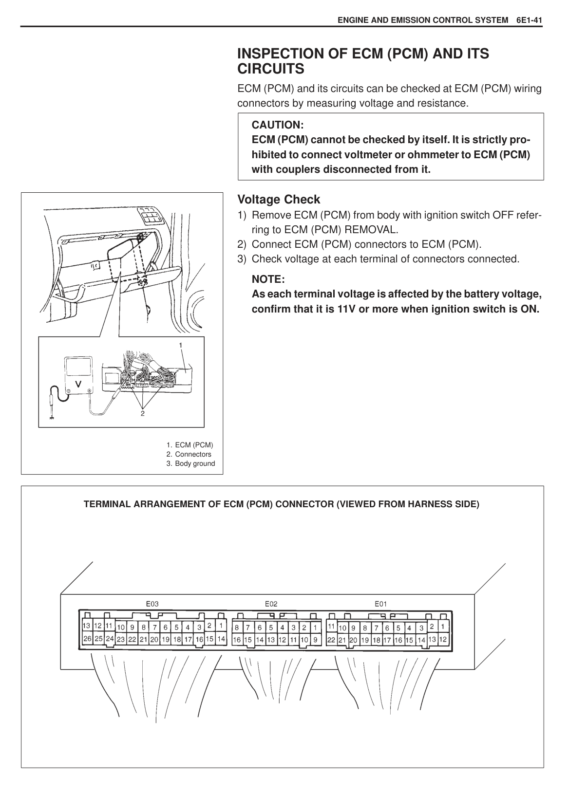
|STEP|ACTION|YES|NO| |---|---|---|---| |1|Check voltage at E01-18 terminal under each condition given below.
|Small light turned OFF Small light turned ON|1 V or less 10 – 14 V| |---|---|
Is check result satisfactory?|Go to Step 2.|“Br” wire open or short Poor “E01-18” terminal connection| |2|Check voltage at E01-9 terminal under each condition given below.
|Ignition switch ON Heater blower fan switch : OFF|4 – 14 V| |---|---| |Ignition switch ON Heater blower fan switch : except for OFF|2 V or less|
Is check result satisfactory?|Electric load signal circuit are in good condition.|“P/B” wire open or short Poor “E01-9” terminal connection|
######### Fig. for STEP 1 and 2

#### B-10 FUEL CUT OPERATION CHECK
|
1. ECM
2. ECM connector
3. TP sensor
| |---|
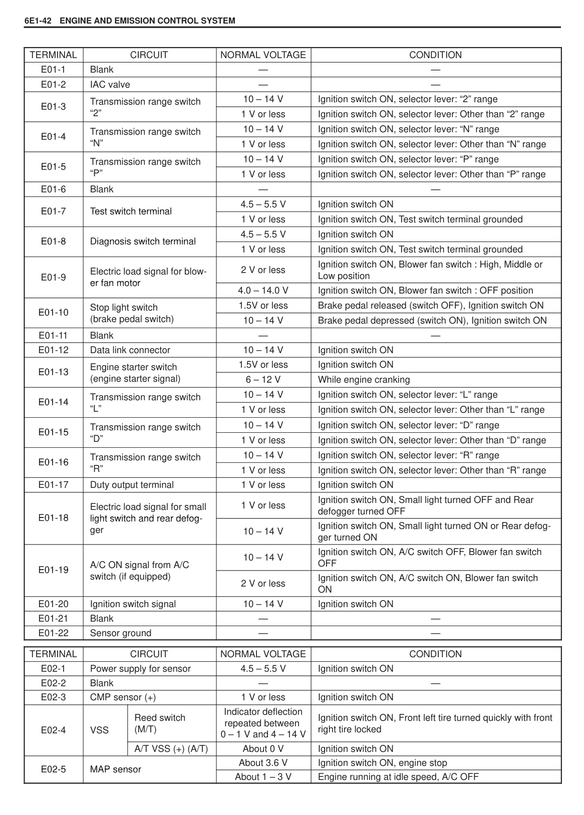
|STEP|ACTION|YES|NO| |---|---|---|---| |1|Check fuel cut operation referring FUEL CUT OPERATION INSPECTION in this section. Does fuel injector operate as specified?|Fuel cut operation is in good condition.|Go to step 2.| |2|Closed throttle position check:
1) Connect Tech-1 to DLC.
2) With the ignition switch ON position, check “CLOSED THROT POS” in parameter data list. Throttle valve fully close : ON Throttle valve slight open : OFF
Is each check result as specified?|Substitute a known good ECM and recheck.|Go to step 2.| |3|Closed throttle position recheck:
1) With the ignition switch OFF position disconnect negative battery cable for 30 seconds and connect it.
2) Recheck closed throttle position referring to Step 2. Is each check result as specified?
|Recheck fuel cut operation.|Go to step 3.| |4|TP sensor signal voltage check:
1) With the ignition switch at ON position, check voltage between E02-06 and ground. Throttle valve fully close: 0.78 – 0.83V Throttle valve fully open: 3.7 – 4.7V
Is each check result as specified?|Substitute a known good ECM and recheck fuel cut operation.|Check TP sensor referring to TP SENSOR INSPECTION in this section.|
######### Fig. for STEP 4

#### INSPECTION OF ECM (PCM) AND ITS CIRCUITS
ECM (PCM) and its circuits can be checked at ECM (PCM) wiring connectors by measuring voltage and resistance.
|CAUTION: ECM (PCM) cannot be checked by itself. It is strictly prohibited to connect voltmeter or ohmmeter to ECM (PCM) with couplers disconnected from it.| |---|
|
1. ECM (PCM)
2. Connectors
3. Body ground
| |---|
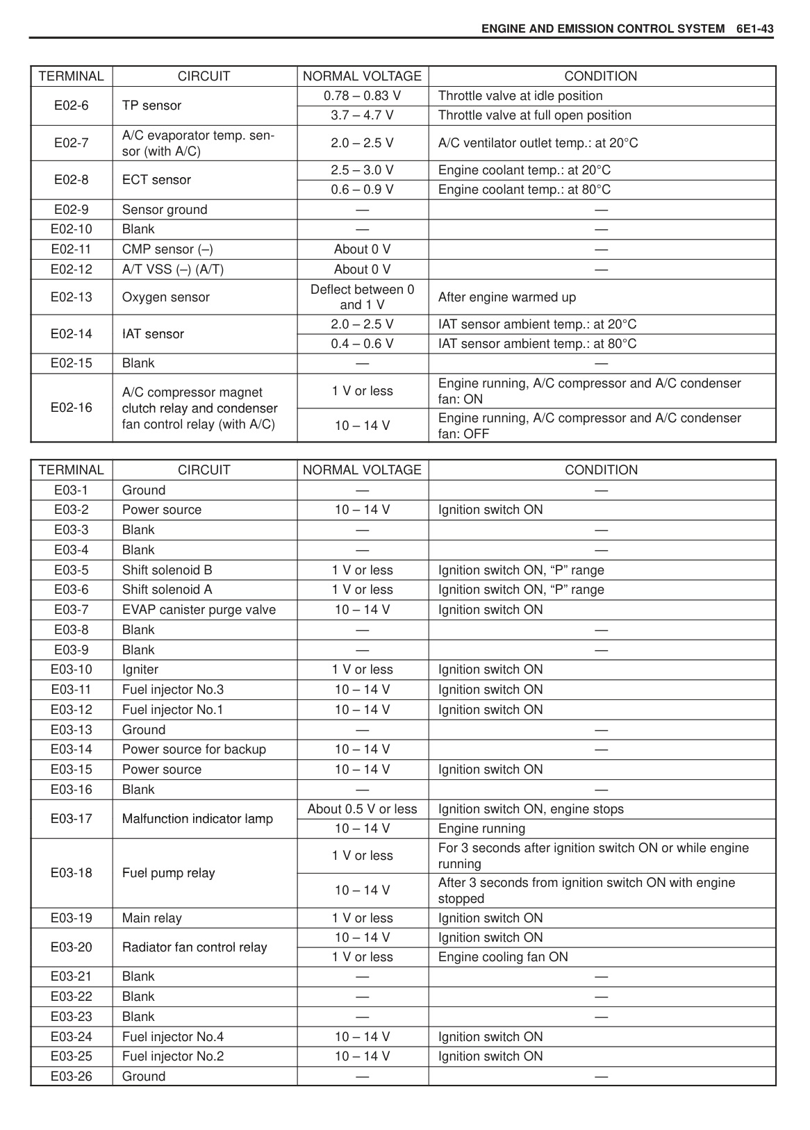
###### Voltage Check
######### NOTE: As each terminal voltage is affected by the battery voltage, confirm that it is 11V or more when ignition switch is ON.
|
TERMINAL ARRANGEMENT OF ECM (PCM) CONNECTOR (VIEWED FROM HARNESS SIDE)| |---|
|TERMINAL|CIRCUIT|NORMAL VOLTAGE|CONDITION| |---|---|---|---| |E01-1|Blank|—|—| |E01-2|IAC valve|—|—| |E01-3E01-3
|Transmission range switchg “2”
|10 – 14 V|Ignition switch ON, selector lever: “2” range| |E01-3E01-3
|Transmission range switchg “2”
|1 V or less|Ignition switch ON, selector lever: Other than “2” range| |E01-4E01-4
|Transmission range switchg “N”
|10 – 14 V|Ignition switch ON, selector lever: “N” range| |E01-4E01-4
|Transmission range switchg “N”
|1 V or less|Ignition switch ON, selector lever: Other than “N” range| |E01-5E01-5
|Transmission range switchg “P”
|10 – 14 V|Ignition switch ON, selector lever: “P” range| |E01-5E01-5
|Transmission range switchg “P”
|1 V or less|Ignition switch ON, selector lever: Other than “P” range| |E01-6|Blank|—|—|
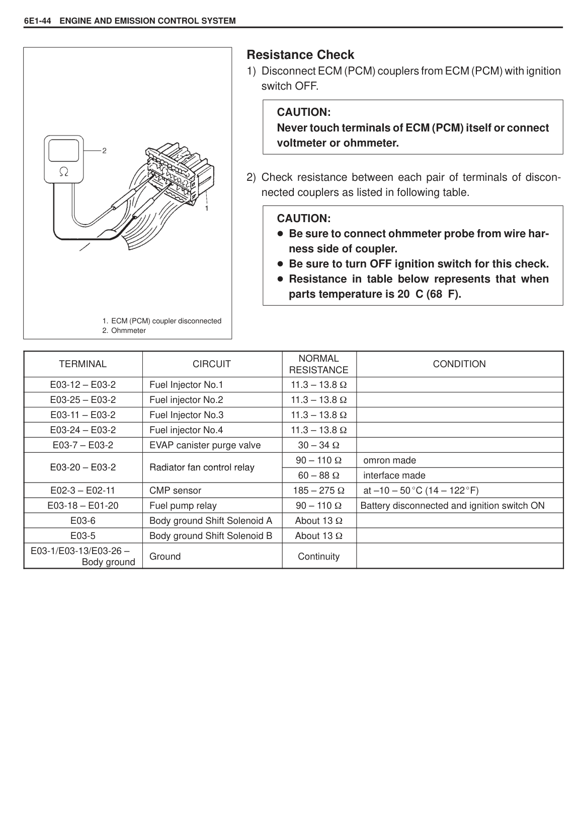
|E01-7E01-7
|Test switch terminalTest switch terminal
|4.5 – 5.5 V|Ignition switch ON| |E01-7E01-7
|Test switch terminalTest switch terminal
|1 V or less|Ignition switch ON, Test switch terminal grounded| |E01-8E01-8
|Diagnosis switch terminalDiagnosis switch terminal
|4.5 – 5.5 V|Ignition switch ON| |E01-8E01-8
|Diagnosis switch terminalDiagnosis switch terminal
|1 V or less|Ignition switch ON, Test switch terminal grounded| |E01-9
|Electric load signal for blower fan motorer fan motor
|2 V or less|Ignition switch ON, Blower fan switch : High, Middle or Low position| |E01-9
|Electric load signal for blower fan motorer fan motor
|4.0 – 14.0 V|Ignition switch ON, Blower fan switch : OFF position| |E01-10E01-10
|Stop light switchg (brake pedal switch)
|1.5V or less|Brake pedal released (switch OFF), Ignition switch ON| |E01-10E01-10
|Stop light switchg (brake pedal switch)
|10 – 14 V|Brake pedal depressed (switch ON), Ignition switch ON| |E01-11|Blank|—|—| |E01-12|Data link connector|10 – 14 V|Ignition switch ON| |E01-13E01-13
|Engine starter switchg (engine starter signal)
|1.5V or less|Ignition switch ON| |E01-13E01-13
|Engine starter switchg (engine starter signal)
|6 – 12 V|While engine cranking| |E01-14E01-14
|Transmission range switchg “L”
|10 – 14 V|Ignition switch ON, selector lever: “L” range| |E01-14E01-14
|Transmission range switchg “L”
|1 V or less|Ignition switch ON, selector lever: Other than “L” range| |E01-15E01-15
|Transmission range switchg “D”
|10 – 14 V|Ignition switch ON, selector lever: “D” range| |E01-15E01-15
|Transmission range switchg “D”
|1 V or less|Ignition switch ON, selector lever: Other than “D” range| |E01-16E01-16
|Transmission range switchg “R”
|10 – 14 V|Ignition switch ON, selector lever: “R” range| |E01-16E01-16
|Transmission range switchg “R”
|1 V or less|Ignition switch ON, selector lever: Other than “R” range| |E01-17|Duty output terminal|1 V or less|Ignition switch ON| |E01-18E01-18
|Electric load signal for small light switch and rear defoglight switch and rear defogger
|1 V or less|Ignition switch ON, Small light turned OFF and Rear defogger turned OFF| |E01-18E01-18
|Electric load signal for small light switch and rear defoglight switch and rear defogger
|10 – 14 V|Ignition switch ON, Small light turned ON or Rear defogger turned ON| |E01-19E01-19
|A/C ON signal from A/Cg switch (if equipped)
|10 – 14 V|Ignition switch ON, A/C switch OFF, Blower fan switch OFF| |E01-19E01-19
|A/C ON signal from A/Cg switch (if equipped)
|2 V or less|Ignition switch ON, A/C switch ON, Blower fan switch ON| |E01-20|Ignition switch signal|10 – 14 V|Ignition switch ON| |E01-21|Blank|—|—| |E01-22|Sensor ground|—|—|
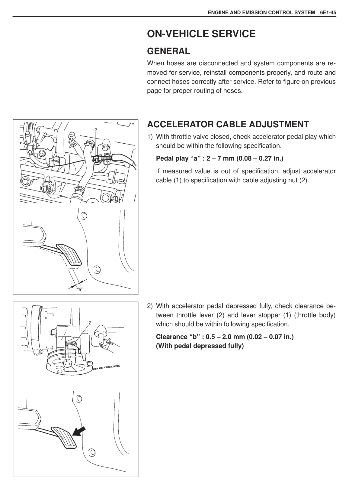
|TERMINAL|CIRCUIT|CIRCUIT|NORMAL VOLTAGE|CONDITION| |---|---|---|---|---| |E02-1|Power supply for sensor|Power supply for sensor|4.5 – 5.5 V|Ignition switch ON| |E02-2|Blank|Blank|—|—| |E02-3|CMP sensor (+)|CMP sensor (+)|1 V or less|Ignition switch ON| |E02-4
|VSS
|Reed switch (M/T)|Indicator deflection repeated between 0 – 1 V and 4 – 14 V|Ignition switch ON, Front left tire turned quickly with front right tire locked| |E02-4
|VSS
|A/T VSS (+) (A/T)|About 0 V|Ignition switch ON| |E02-5E02-5
|MAP sensorMAP sensor
|MAP sensorMAP sensor
|About 3.6 V|Ignition switch ON, engine stop| |E02-5E02-5
|MAP sensorMAP sensor
|MAP sensorMAP sensor
|About 1 – 3 V|Engine running at idle speed, A/C OFF|
|TERMINAL|CIRCUIT|NORMAL VOLTAGE|CONDITION| |---|---|---|---| |E02-6E02-6
|TP sensorTP sensor
|0.78 – 0.83 V|Throttle valve at idle position| |E02-6E02-6
|TP sensorTP sensor
|3.7 – 4.7 V|Throttle valve at full open position| |E02-7|A/C evaporator temp. sensor (with A/C)|2.0 – 2.5 V|A/C ventilator outlet temp.: at 20 C| |E02-8E02-8
|ECT sensorECT sensor
|2.5 – 3.0 V|Engine coolant temp.: at 20 C| |E02-8E02-8
|ECT sensorECT sensor
|0.6 – 0.9 V|Engine coolant temp.: at 80 C| |E02-9|Sensor ground|—|—| |E02-10|Blank|—|—| |E02-11|CMP sensor (–)|About 0 V|—| |E02-12|A/T VSS (–) (A/T)|About 0 V|—| |E02-13|Oxygen sensor|Deflect between 0 and 1 V|After engine warmed up| |E02-14E02-14
|IAT sensorIAT sensor
|2.0 – 2.5 V|IAT sensor ambient temp.: at 20 C|
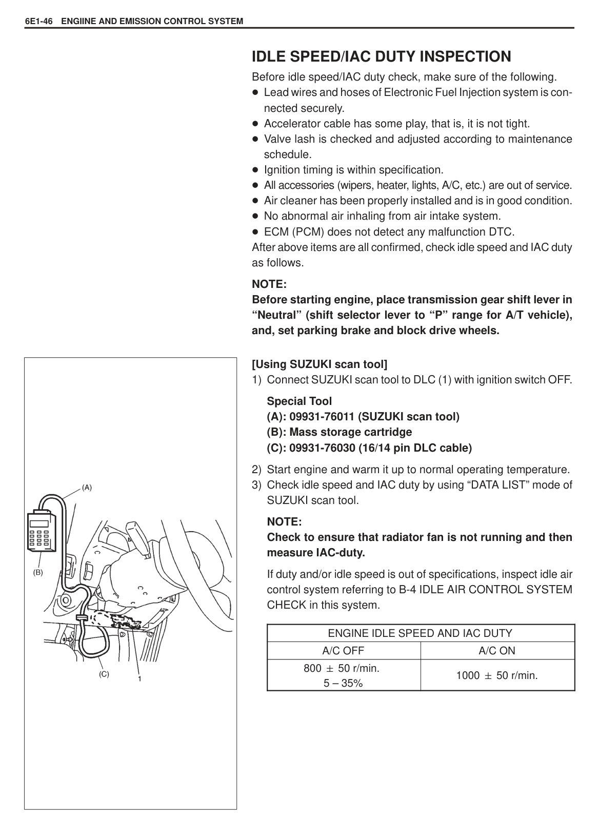
|E02-14E02-14
|IAT sensorIAT sensor
|0.4 – 0.6 V|IAT sensor ambient temp.: at 80 C| |E02-15|Blank|—|—| |E02-16E02-16
|A/C compressor magnet clutch relay and condenserclutch relay and condenser fan control relay (with A/C)
|1 V or less|Engine running, A/C compressor and A/C condenser fan: ON| |E02-16E02-16
|A/C compressor magnet clutch relay and condenserclutch relay and condenser fan control relay (with A/C)
|10 – 14 V|Engine running, A/C compressor and A/C condenser fan: OFF|
|TERMINAL|CIRCUIT|NORMAL VOLTAGE|CONDITION| |---|---|---|---| |E03-1|Ground|—|—| |E03-2|Power source|10 – 14 V|Ignition switch ON| |E03-3|Blank|—|—| |E03-4|Blank|—|—| |E03-5|Shift solenoid B|1 V or less|Ignition switch ON, “P” range| |E03-6|Shift solenoid A|1 V or less|Ignition switch ON, “P” range| |E03-7|EVAP canister purge valve|10 – 14 V|Ignition switch ON| |E03-8|Blank|—|—| |E03-9|Blank|—|—| |E03-10|Igniter|1 V or less|Ignition switch ON| |E03-11|Fuel injector No.3|10 – 14 V|Ignition switch ON| |E03-12|Fuel injector No.1|10 – 14 V|Ignition switch ON| |E03-13|Ground|—|—| |E03-14|Power source for backup|10 – 14 V|—| |E03-15|Power source|10 – 14 V|Ignition switch ON| |E03-16|Blank|—|—| |E03-17E03-17
|Malfunction indicator lampMalfunction indicator lam
|About 0.5 V or less|Ignition switch ON, engine stops| |E03-17E03-17
|Malfunction indicator lampMalfunction indicator lam
|10 – 14 V|Engine running|
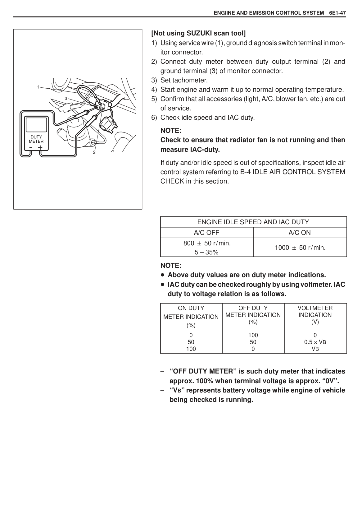
|E03-18E03-18
|p pFuelum relay
|1 V or less|For 3 seconds after ignition switch ON or while engine running| |E03-18E03-18
|p pFuelum relay
|10 – 14 V|After 3 seconds from ignition switch ON with engine stopped| |E03-19|Main relay|1 V or less|Ignition switch ON| |E03-20E03-20
|Radiator fan control relayRadiator fan control relay
|10 – 14 V|Ignition switch ON| |E03-20E03-20
|Radiator fan control relayRadiator fan control relay
|1 V or less|Engine cooling fan ON| |E03-21|Blank|—|—| |E03-22|Blank|—|—| |E03-23|Blank|—|—| |E03-24|Fuel injector No.4|10 – 14 V|Ignition switch ON| |E03-25|Fuel injector No.2|10 – 14 V|Ignition switch ON| |E03-26|Ground|—|—|
|
1. ECM (PCM) coupler disconnected
2. Ohmmeter
| |---|
###### Resistance Check
|CAUTION: Never touch terminals of ECM (PCM) itself or connect voltmeter or ohmmeter.| |---|
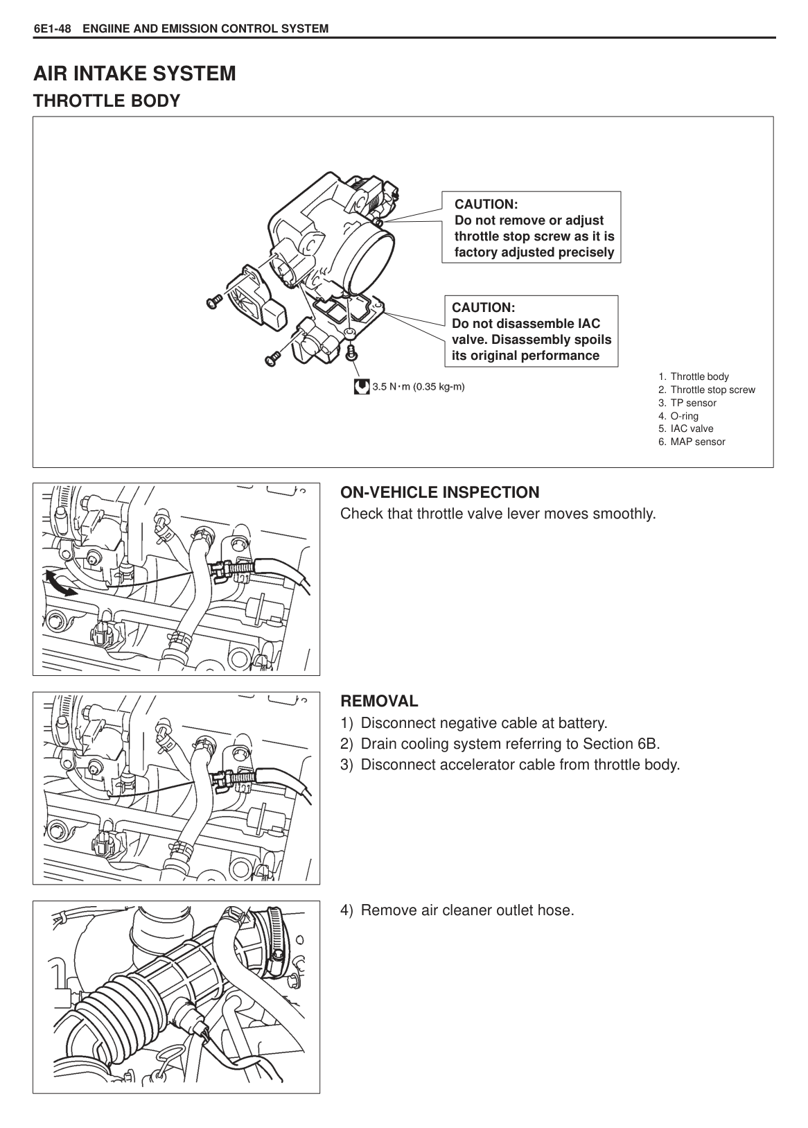
|CAUTION: Be sure to connect ohmmeter probe from wire harness side of coupler. Be sure to turn OFF ignition switch for this check. Resistance in table below represents that when parts temperature is 20 C (68 F).| |---|
|TERMINAL|CIRCUIT|NORMAL RESISTANCE|CONDITION| |---|---|---|---| |E03-12 – E03-2|Fuel Injector No.1|11.3 – 13.8| | |E03-25 – E03-2|Fuel injector No.2|11.3 – 13.8| | |E03-11 – E03-2|Fuel Injector No.3|11.3 – 13.8| | |E03-24 – E03-2|Fuel injector No.4|11.3 – 13.8| | |E03-7 – E03-2|EVAP canister purge valve|30 – 34| | |E03-20 – E03-2E03-20 – E03-2
|Radiator fan control relayRadiator fan control relay
|90 – 110|omron made| |E03-20 – E03-2E03-20 – E03-2
|Radiator fan control relayRadiator fan control relay
|60 – 88|interface made| |E02-3 – E02-11|CMP sensor|185 – 275|at –10 – 50 C (14 – 122 F)| |E03-18 – E01-20|Fuel pump relay|90 – 110|Battery disconnected and ignition switch ON| |E03-6|Body ground Shift Solenoid A|About 13| | |E03-5|Body ground Shift Solenoid B|About 13| | |E03-1/E03-13/E03-26 – Body ground|Ground|Continuity| |
ON-VEHICLE SERVICE GENERAL
When hoses are disconnected and system components are removed for service, reinstall components properly, and route and connect hoses correctly after service. Refer to figure on previous page for proper routing of hoses.
|
|
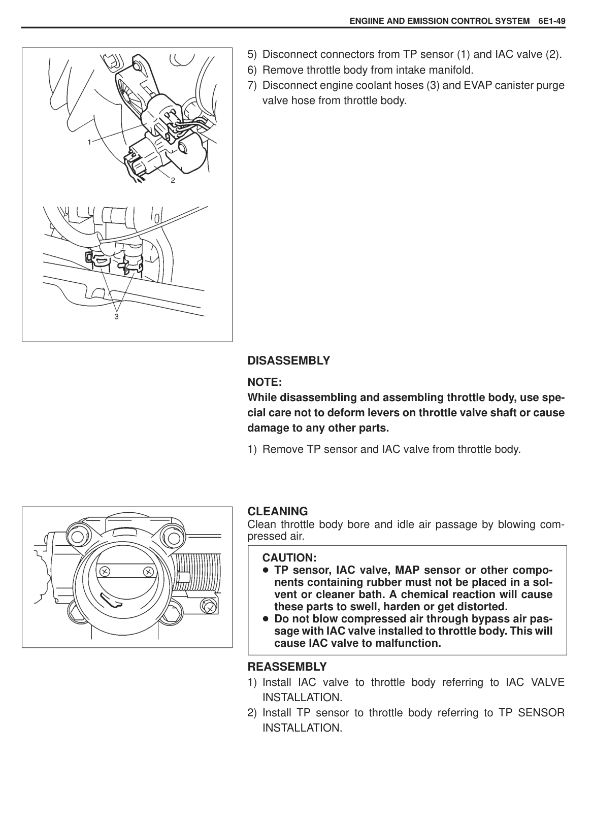
|---|
#### ACCELERATOR CABLE ADJUSTMENT
If measured value is out of specification, adjust accelerator cable (1) to specification with cable adjusting nut (2).
|
| |---|
######### Clearance “b” : 0.5 – 2.0 mm (0.02 – 0.07 in.) (With pedal depressed fully)
IDLE SPEED/IAC DUTY INSPECTION Before idle speed/IAC duty check, make sure of the following.
Lead wires and hoses of Electronic Fuel Injection system is connected securely. Accelerator cable has some play, that is, it is not tight. Valve lash is checked and adjusted according to maintenance schedule. Ignition timing is within specification. All accessories (wipers, heater, lights, A/C, etc.) are out of service. Air cleaner has been properly installed and is in good condition. No abnormal air inhaling from air intake system. ECM (PCM) does not detect any malfunction DTC.
After above items are all confirmed, check idle speed and IAC duty as follows.
NOTE: Before starting engine, place transmission gear shift lever in “Neutral” (shift selector lever to “P” range for A/T vehicle), and, set parking brake and block drive wheels.
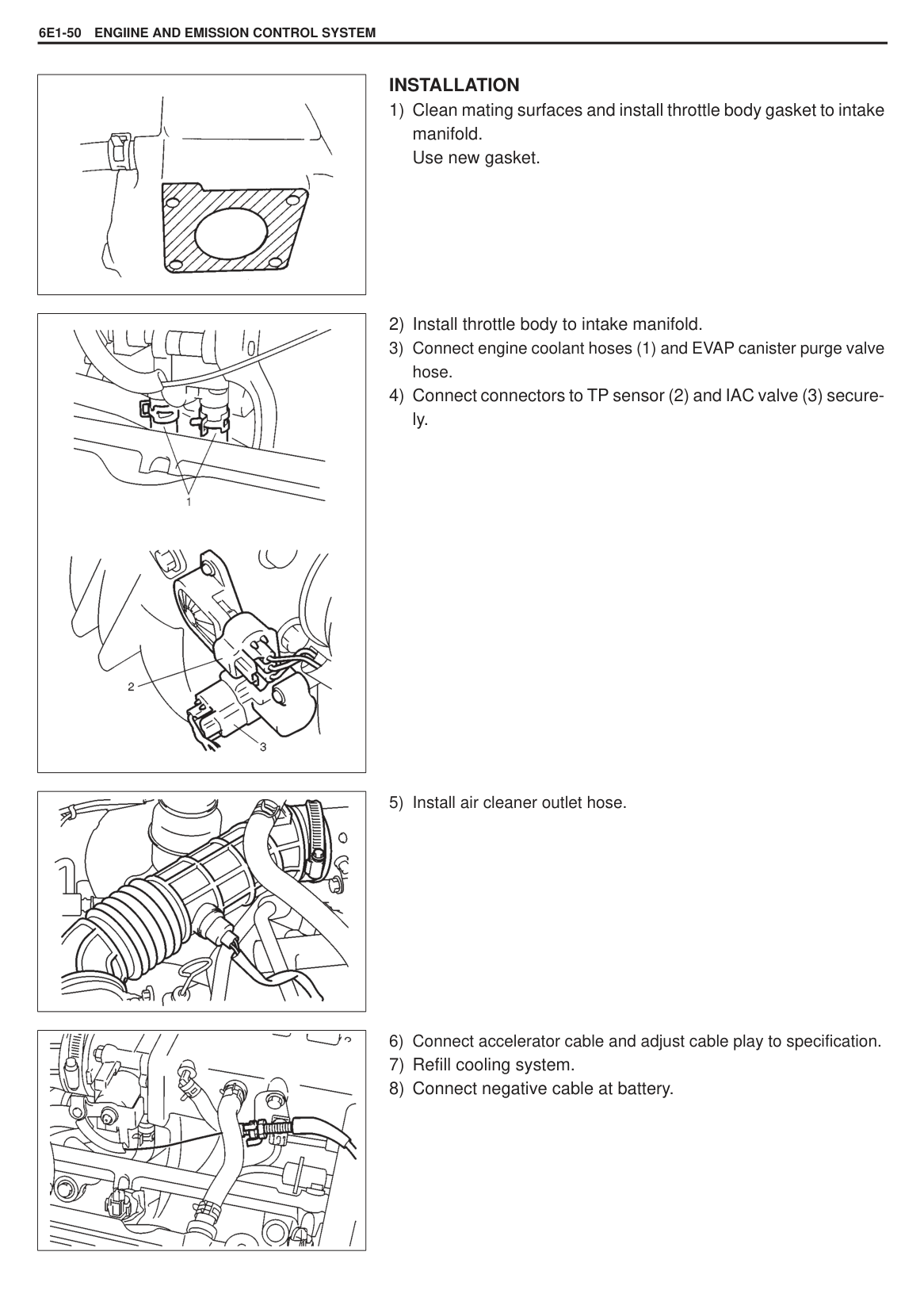
|| |---|
[Using SUZUKI scan tool]
NOTE: Check to ensure that radiator fan is not running and then measure IAC-duty.
If duty and/or idle speed is out of specifications, inspect idle air control system referring to B-4 IDLE AIR CONTROL SYSTEM CHECK in this system.
|ENGINE IDLE SPEED AND IAC DUTY|ENGINE IDLE SPEED AND IAC DUTY| |---|---| |A/C OFF|A/C ON| |800 50 r/min. 5 – 35%|1000 50 r/min.|
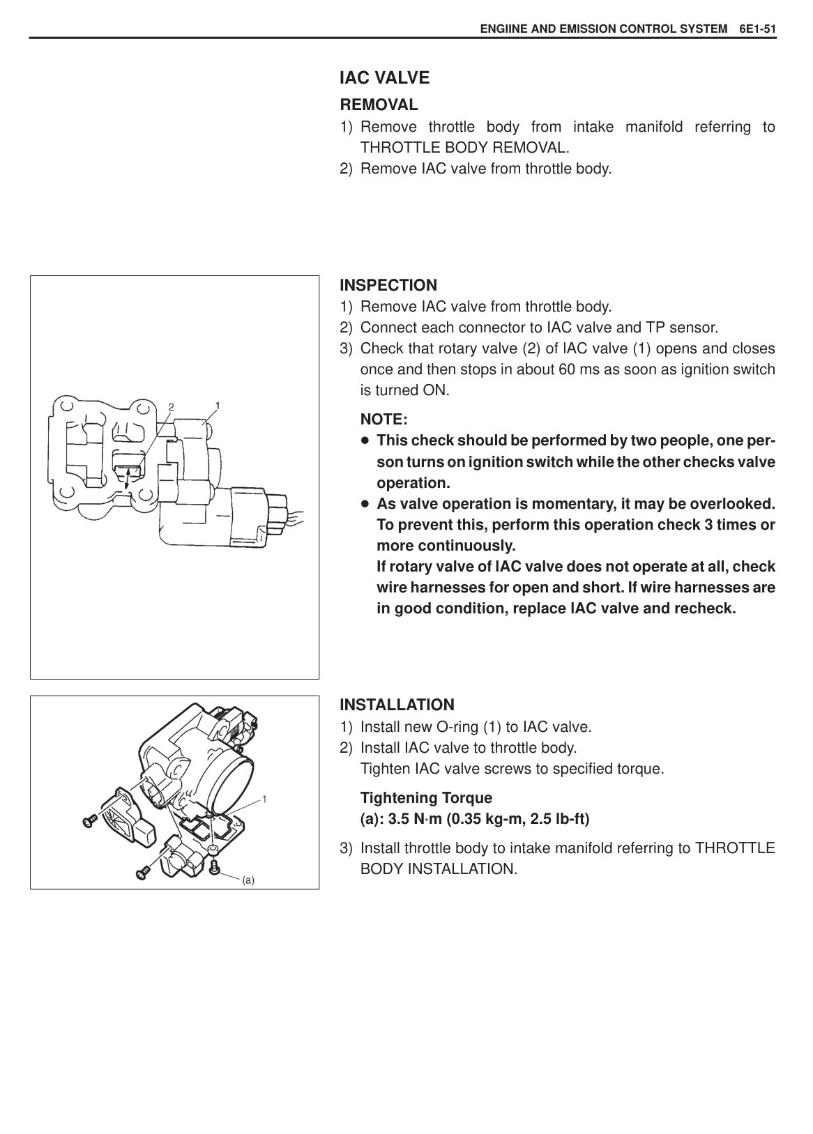
|| |---|
######### [Not using SUZUKI scan tool]
NOTE: Check to ensure that radiator fan is not running and then measure IAC-duty.
If duty and/or idle speed is out of specifications, inspect idle air control system referring to B-4 IDLE AIR CONTROL SYSTEM CHECK in this section.
|ENGINE IDLE SPEED AND IAC DUTY|ENGINE IDLE SPEED AND IAC DUTY| |---|---| |A/C OFF|A/C ON| |800 50 r/min. 5 – 35%|1000 50 r/min.|
NOTE: Above duty values are on duty meter indications. IAC duty can be checked roughly by using voltmeter. IAC duty to voltage relation is as follows.
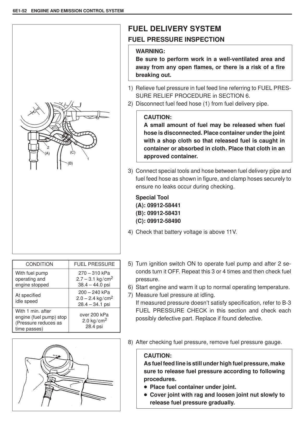
|ON DUTY METER INDICATION (%)|OFF DUTY METER INDICATION (%)|VOLTMETER INDICATION (V)| |---|---|---| |0 50 100|100 50 0|0 0.5 VB VB|
#### AIR INTAKE SYSTEM THROTTLE BODY
|
1. Throttle body
2. Throttle stop screw
3. TP sensor
4. O-ring
5. IAC valve
6. MAP sensor
CAUTION: Do not remove or adjust throttle stop screw as it is factory adjusted precisely
CAUTION: Do not disassemble IAC valve. Disassembly spoils its original performance
| |---|
|| |---|
ON-VEHICLE INSPECTION Check that throttle valve lever moves smoothly.
|| |---|

######## REMOVAL
|| |---|
|
| |---|
######## DISASSEMBLY
NOTE: While disassembling and assembling throttle body, use special care not to deform levers on throttle valve shaft or cause damage to any other parts.
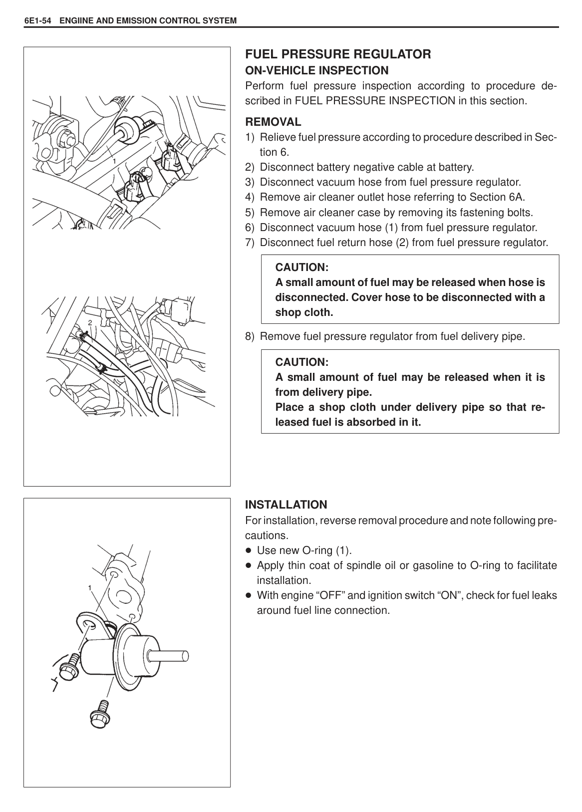
1) Remove TP sensor and IAC valve from throttle body.
|| |---|
CLEANING Clean throttle body bore and idle air passage by blowing compressed air.
|CAUTION: TP sensor, IAC valve, MAP sensor or other components containing rubber must not be placed in a solvent or cleaner bath. A chemical reaction will cause these parts to swell, harden or get distorted. Do not blow compressed air through bypass air passage with IAC valve installed to throttle body. This will cause IAC valve to malfunction.| |---|
######## REASSEMBLY
|| |---|
######## INSTALLATION
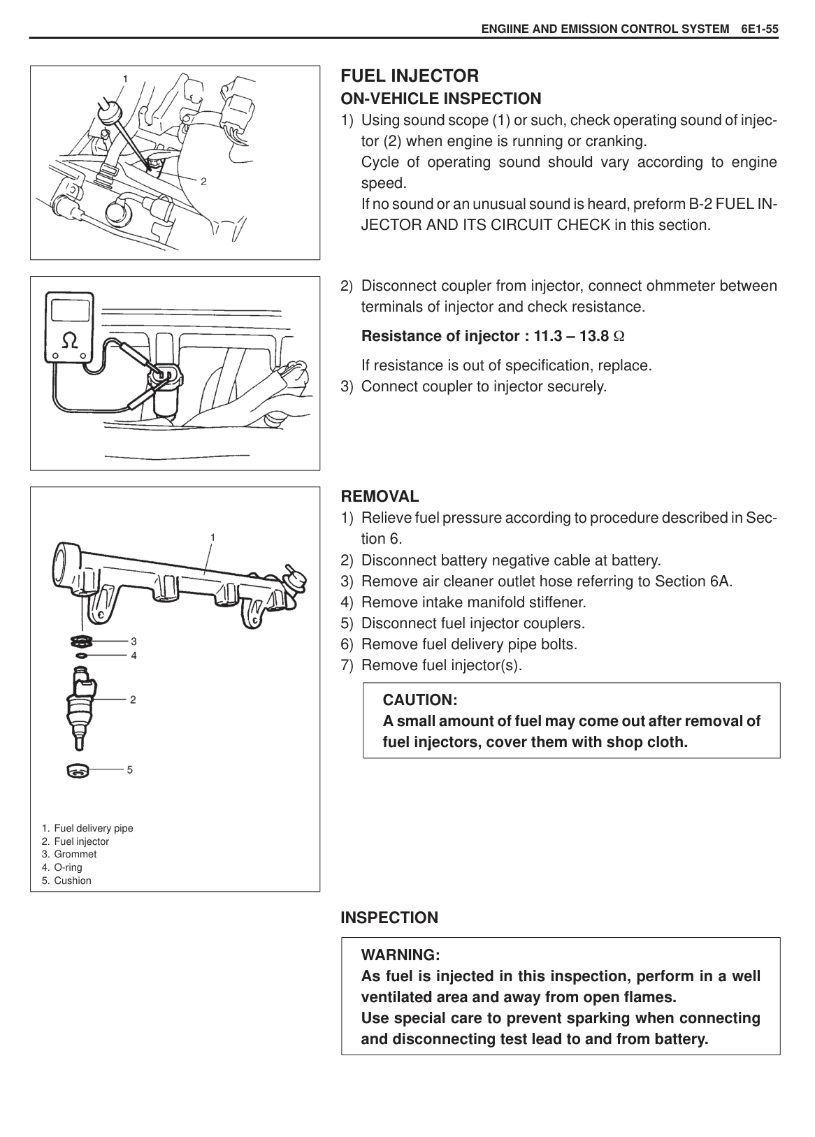
|
| |---|
|| |---|
|| |---|
###### IAC VALVE REMOVAL
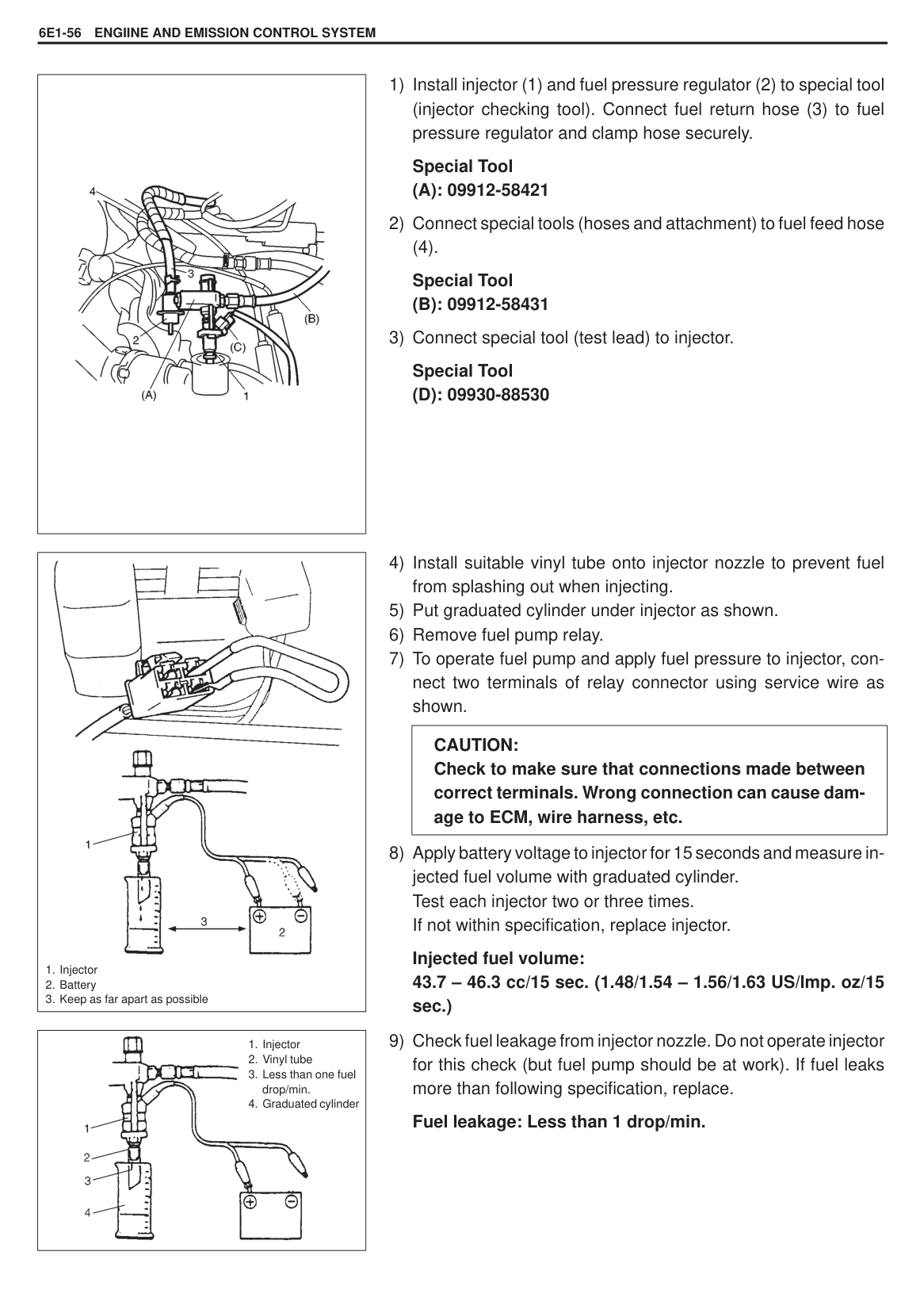
|| |---|
|| |---|
######## INSPECTION
NOTE: This check should be performed by two people, one person turns on ignition switch while the other checks valve operation. As valve operation is momentary, it may be overlooked. To prevent this, perform this operation check 3 times or more continuously. If rotary valve of lAC valve does not operate at all, check wire harnesses for open and short. If wire harnesses are in good condition, replace lAC valve and recheck.
######## INSTALLATION
Tightening Torque (a): 3.5 N·m (0.35 kg-m, 2.5 lb-ft)
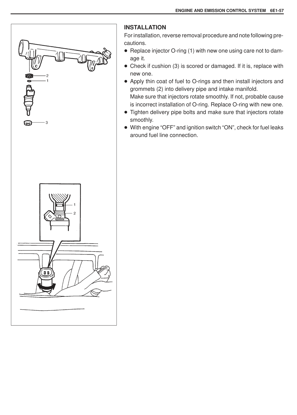
|| |---|
#### FUEL DELIVERY SYSTEM FUEL PRESSURE INSPECTION
Special Tool (A): 09912-58441 (B): 09912-58431 (C): 09912-58490
|WARNING: Be sure to perform work in a well-ventilated area and away from any open flames, or there is a risk of a fire breaking out.| |---|
|CAUTION: A small amount of fuel may be released when fuel hose is disconnected. Place container under the joint with a shop cloth so that released fuel is caught in container or absorbed in cloth. Place that cloth in an approved container.| |---|
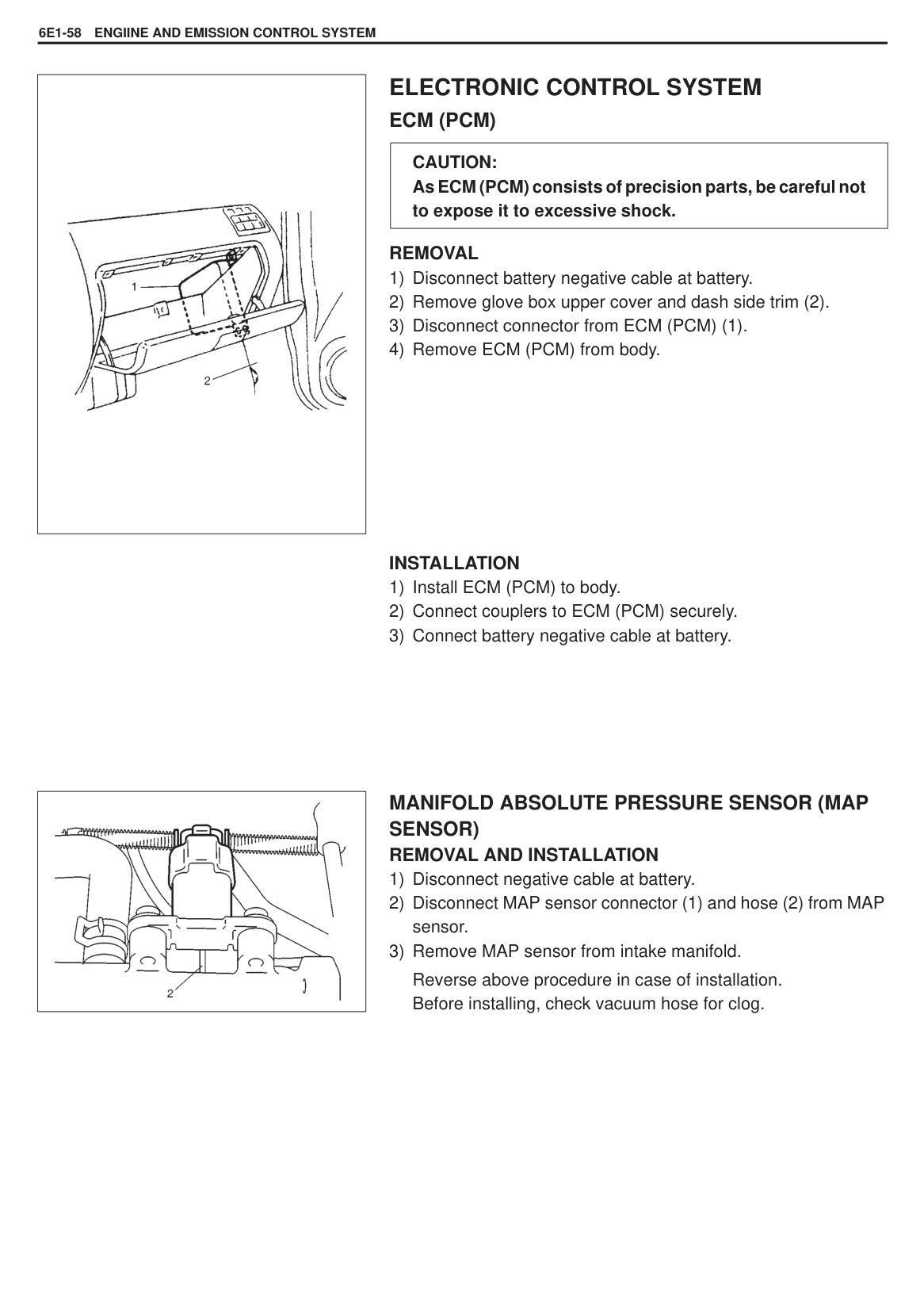
|CONDITION|FUEL PRESSURE| |---|---| |With fuel pump operating and engine stopped|270 – 310 kPa 2.7 – 3.1 kg/cm2 38.4 – 44.0 psi| |At specified idle speed|200 – 240 kPa 2.0 – 2.4 kg/cm2 28.4 – 34.1 psi| |With 1 min. after engine (fuel pump) stop (Pressure reduces as time passes)|over 200 kPa 2.0 kg/cm2 28.4 psi|
|| |---|
|CAUTION: As fuel feed line is still under high fuel pressure, make sure to release fuel pressure according to following procedures.
Place fuel container under joint. Cover joint with rag and loosen joint nut slowly to release fuel pressure gradually.| |---|
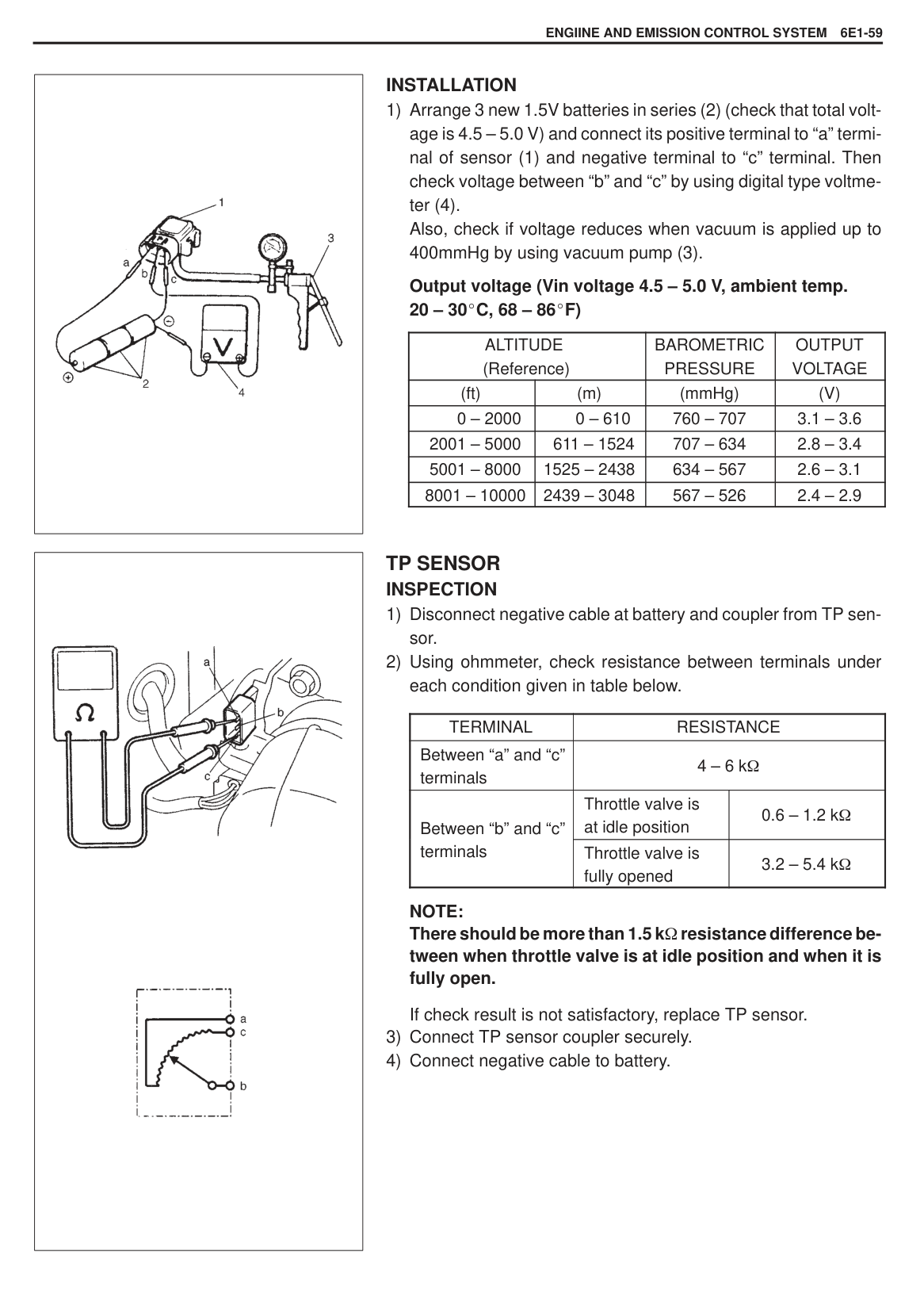
###### FUEL PUMP ON-VEHICLE INSPECTION
|CAUTION: When fuel filler cap is removed in any procedure, work must be done in a well-ventilated area, keep away from any open flames and without smoking.| |---|
|
1. Fuel filler
2. Ignition switch
| |---|
If above check result is not satisfactory, advance to DIAGNOSTIC FLOW TABLE B-1.
|| |---|
If fuel pressure is not felt, advance to DIAGNOSTIC FLOW TABLE B-3.
|| |---|
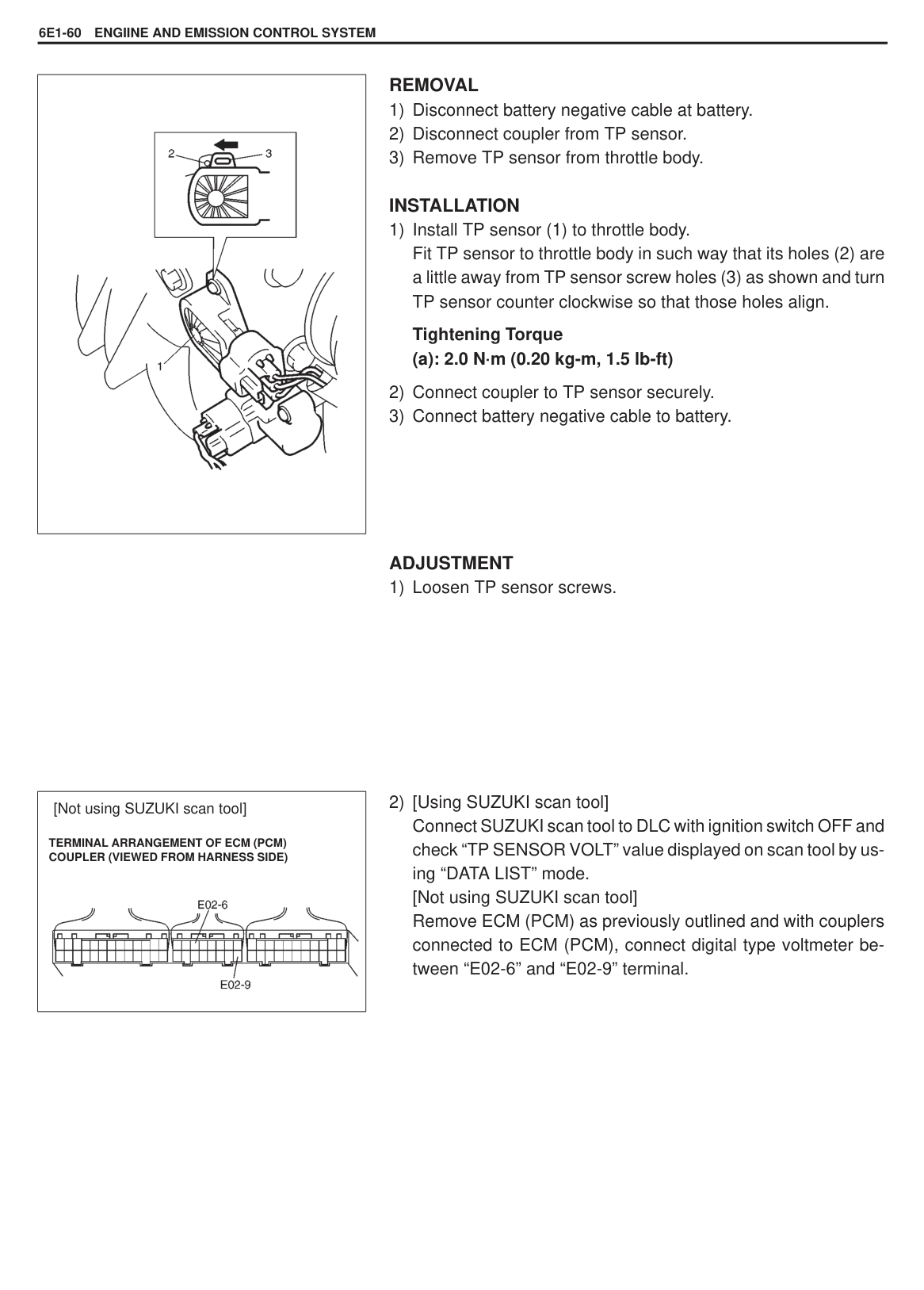
REMOVAL Remove fuel tank from body according to procedure described in Section 6C and remove fuel pump from fuel tank. INSPECTION Check fuel pump filter for evidence of dirt and contamination. If present, clean and check for presence of dirt in fuel tank. INSTALLATION Install fuel pump to fuel tank and then install fuel tank to body according procedure described in Section 6C.
|
| |---|
|| |---|
FUEL PRESSURE REGULATOR ON-VEHICLE INSPECTION Perform fuel pressure inspection according to procedure described in FUEL PRESSURE INSPECTION in this section.
######## REMOVAL
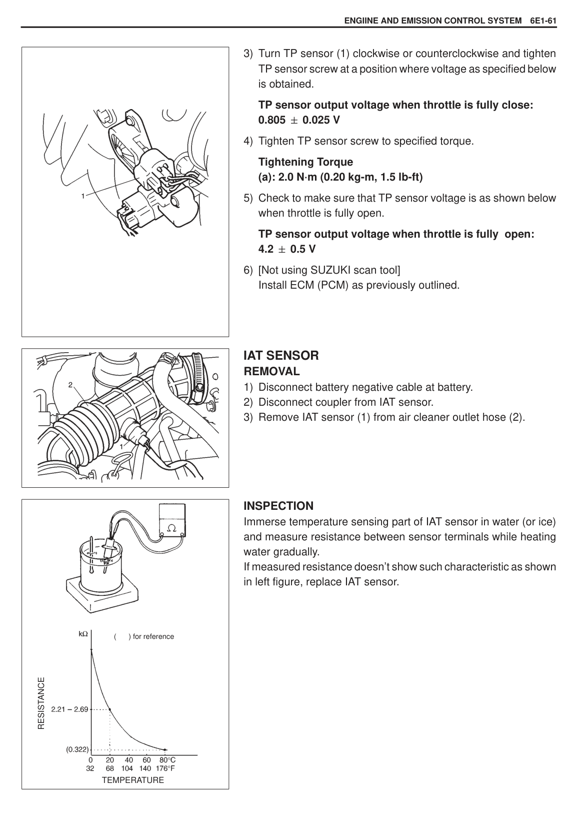
|CAUTION: A small amount of fuel may be released when hose is disconnected. Cover hose to be disconnected with a shop cloth.| |---|
|CAUTION: A small amount of fuel may be released when it is from delivery pipe. Place a shop cloth under delivery pipe so that released fuel is absorbed in it.| |---|
INSTALLATION For installation, reverse removal procedure and note following precautions.
Use new O-ring (1). Apply thin coat of spindle oil or gasoline to O-ring to facilitate installation. With engine “OFF” and ignition switch “ON”, check for fuel leaks around fuel line connection.
|| |---|
###### FUEL INJECTOR ON-VEHICLE INSPECTION
|| |---|
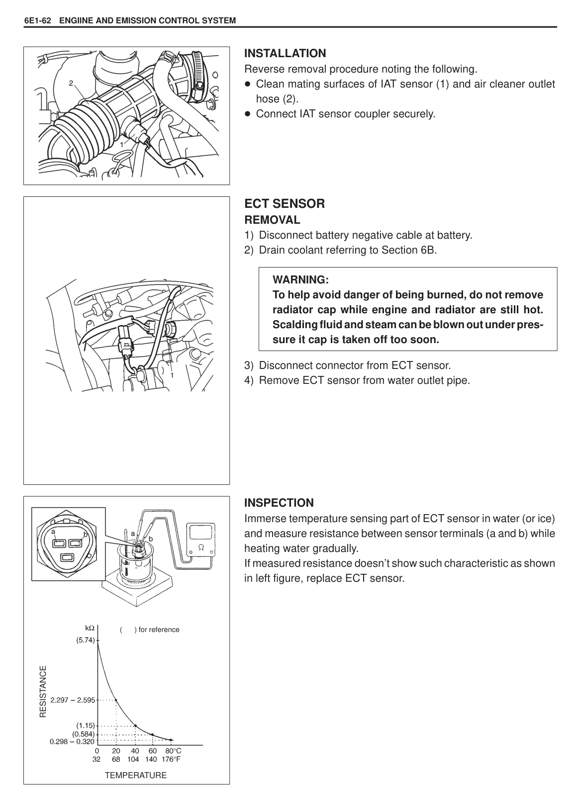
|
1. Fuel delivery pipe
2. Fuel injector
3. Grommet
4. O-ring
5. Cushion
| |---|
######## REMOVAL
|CAUTION: A small amount of fuel may come out after removal of fuel injectors, cover them with shop cloth.| |---|
######## INSPECTION
|WARNING: As fuel is injected in this inspection, perform in a well ventilated area and away from open flames. Use special care to prevent sparking when connecting and disconnecting test lead to and from battery.| |---|
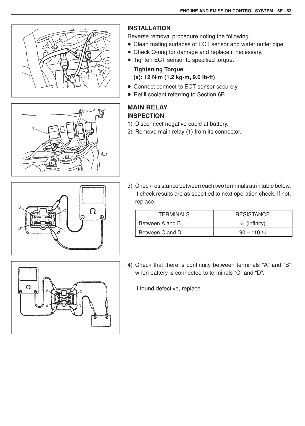
|| |---|
2) Connect special tools (hoses and attachment) to fuel feed hose
(4). Special Tool
Special Tool (D): 09930-88530
|

1. Injector
2. Battery
3. Keep as far apart as possible
| |---|
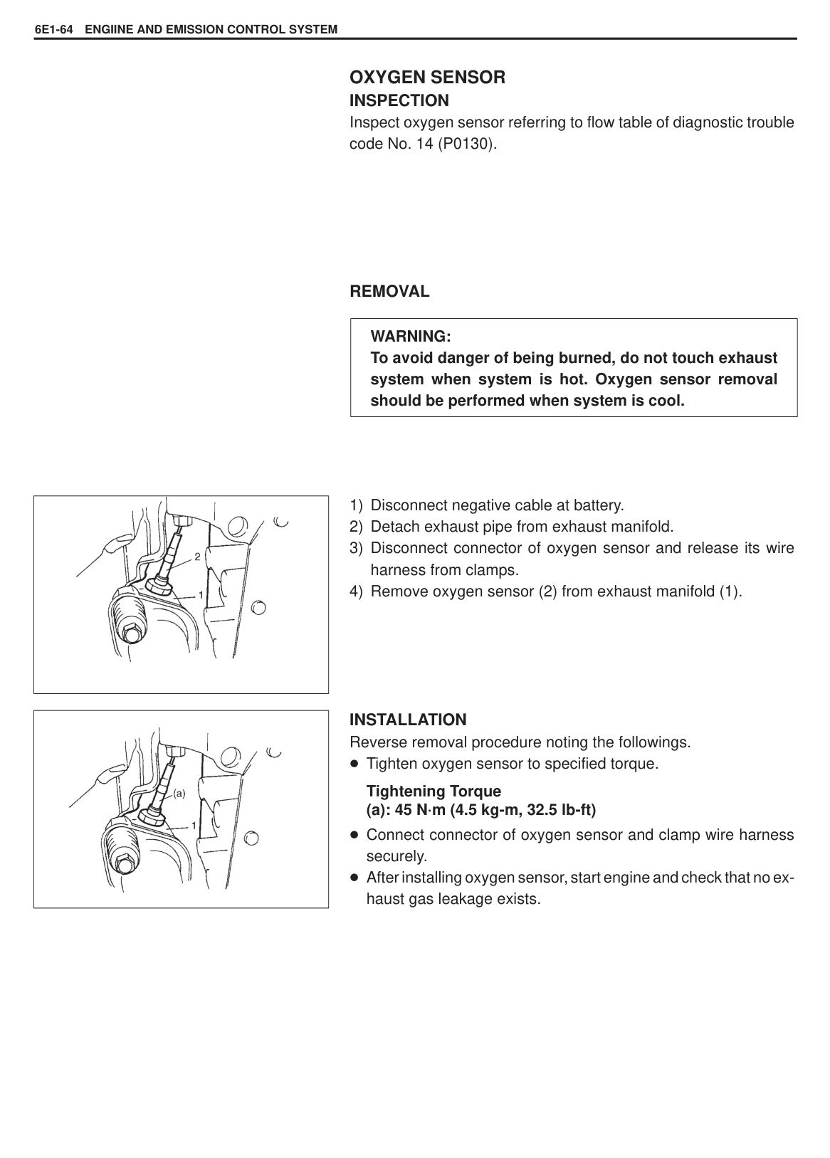
|CAUTION: Check to make sure that connections made between correct terminals. Wrong connection can cause damage to ECM, wire harness, etc.| |---|
Injected fuel volume: 43.7 – 46.3 cc/15 sec. (1.48/1.54 – 1.56/1.63 US/lmp. oz/15 sec.)
|
1. Injector
2. Vinyl tube
3. Less than one fuel drop/min.
4. Graduated cylinder
| |---|
|
| |---|
For installation, reverse removal procedure and note following precautions.
Replace injector O-ring (1) with new one using care not to damage it. Check if cushion (3) is scored or damaged. If it is, replace with new one. Apply thin coat of fuel to O-rings and then install injectors and grommets (2) into delivery pipe and intake manifold. Make sure that injectors rotate smoothly. If not, probable cause is incorrect installation of O-ring. Replace O-ring with new one. Tighten delivery pipe bolts and make sure that injectors rotate smoothly. With engine “OFF” and ignition switch “ON”, check for fuel leaks around fuel line connection.
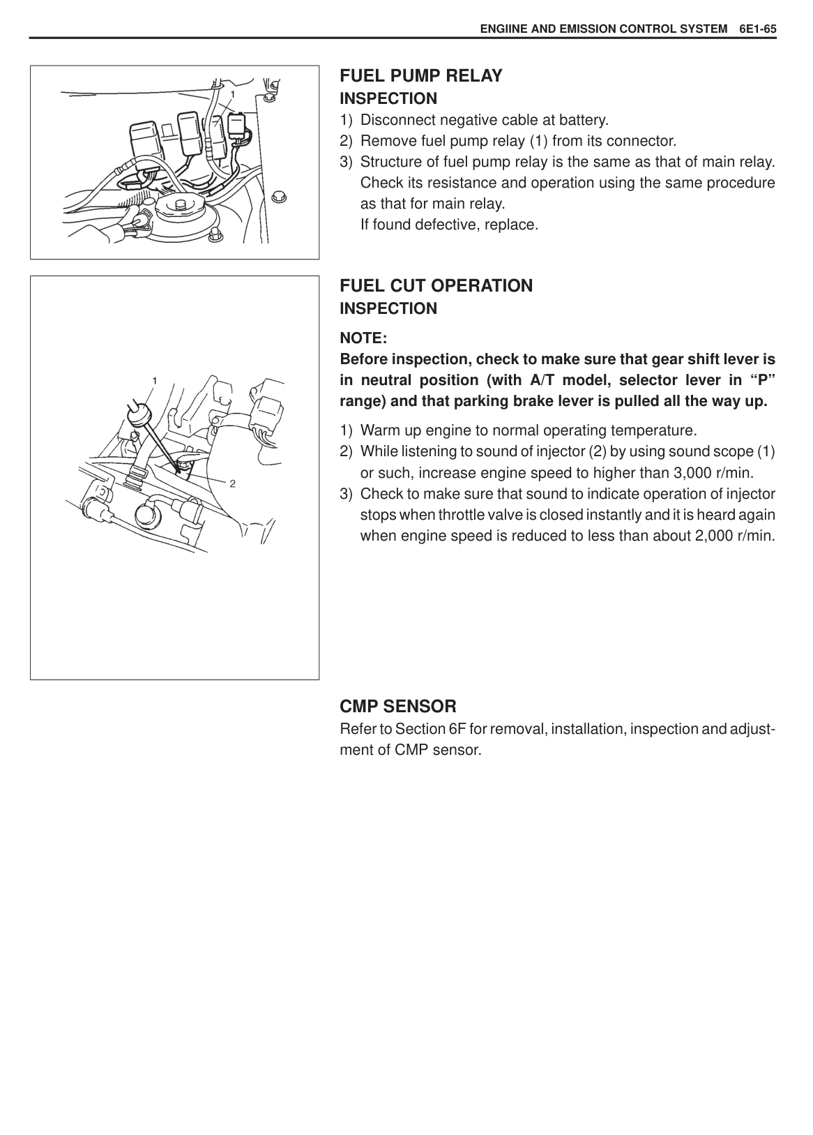
|| |---|
#### ELECTRONIC CONTROL SYSTEM ECM (PCM)
|CAUTION: As ECM (PCM) consists of precision parts, be careful not to expose it to excessive shock.| |---|
######## REMOVAL
######## INSTALLATION
||
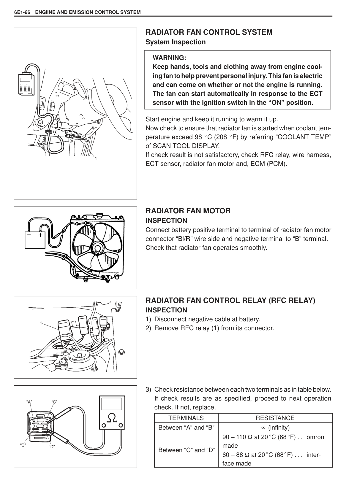
|---|
###### MANIFOLD ABSOLUTE PRESSURE SENSOR (MAP SENSOR) REMOVAL AND INSTALLATION
|| |---|
1) Arrange 3 new 1.5V batteries in series (2) (check that total voltage is 4.5 – 5.0 V) and connect its positive terminal to “a” terminal of sensor (1) and negative terminal to “c” terminal. Then check voltage between “b” and “c” by using digital type voltmeter (4). Also, check if voltage reduces when vacuum is applied up to 400mmHg by using vacuum pump (3).
Output voltage (Vin voltage 4.5 – 5.0 V, ambient temp. 20 – 30 C, 68 – 86 F)
|ALTITUDE (Reference)|ALTITUDE (Reference)|BAROMETRIC PRESSURE|OUTPUT VOLTAGE| |---|---|---|---| |(ft)|(m)|(mmHg)|(V)| |0 – 2000|0 – 610|760 – 707|3.1 – 3.6| |2001 – 5000|611 – 1524|707 – 634|2.8 – 3.4| |5001 – 8000|1525 – 2438|634 – 567|2.6 – 3.1| |8001 – 10000|2439 – 3048|567 – 526|2.4 – 2.9|
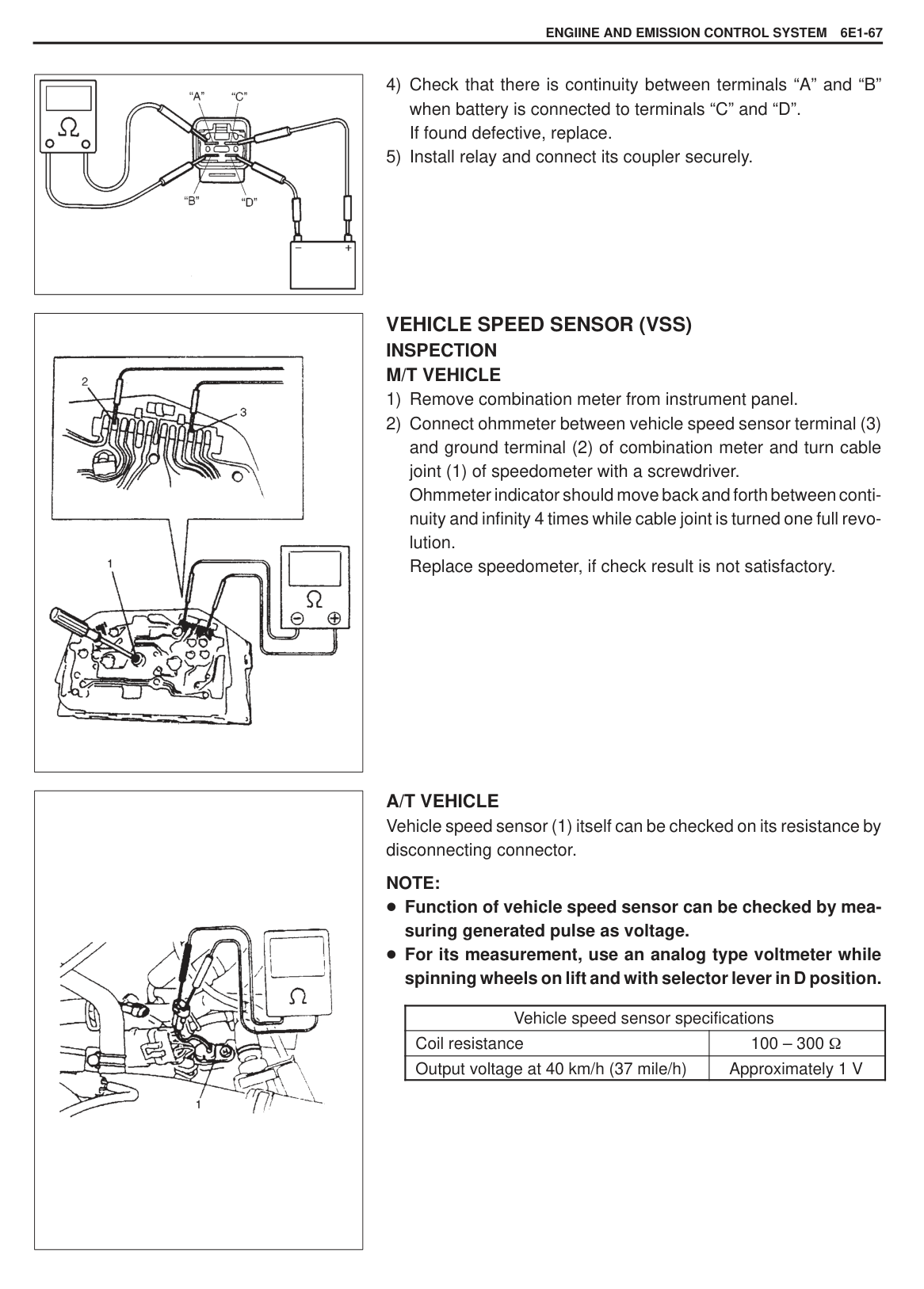
|
| |---|
###### TP SENSOR INSPECTION
NOTE: There should be more than 1.5 k resistance difference between when throttle valve is at idle position and when it is fully open.
If check result is not satisfactory, replace TP sensor.
|TERMINAL|RESISTANCE|RESISTANCE| |---|---|---| |Between “a” and “c” terminals|4 – 6 k|4 – 6 k| |Between “b” and “c” terminals
|Throttle valve is at idle position|0.6 – 1.2 k| |Between “b” and “c” terminals
|Throttle valve is fully opened|3.2 – 5.4 k|
||
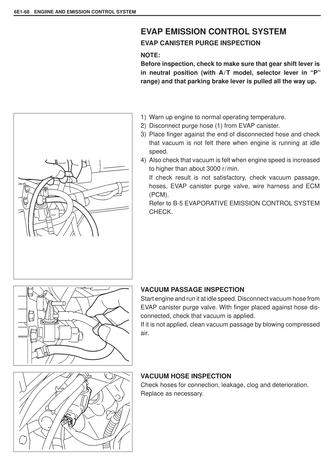
|---|
######## REMOVAL
######## INSTALLATION
Tightening Torque (a): 2.0 N·m (0.20 kg-m, 1.5 lb-ft)
######## ADJUSTMENT
|
TERMINAL ARRANGEMENT OF ECM (PCM) COUPLER (VIEWED FROM HARNESS SIDE)
[Not using SUZUKI scan tool]| |---|
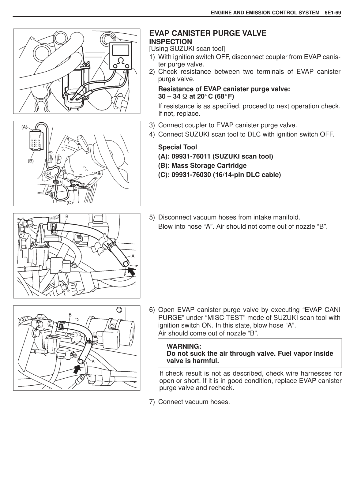
|| |---|
|| |---|
|
( ) for reference
TEMPERATURE
RESISTANCE| |---|
TP sensor output voltage when throttle is fully close: 0.805 0.025 V
Tightening Torque (a): 2.0 N·m (0.20 kg-m, 1.5 lb-ft)
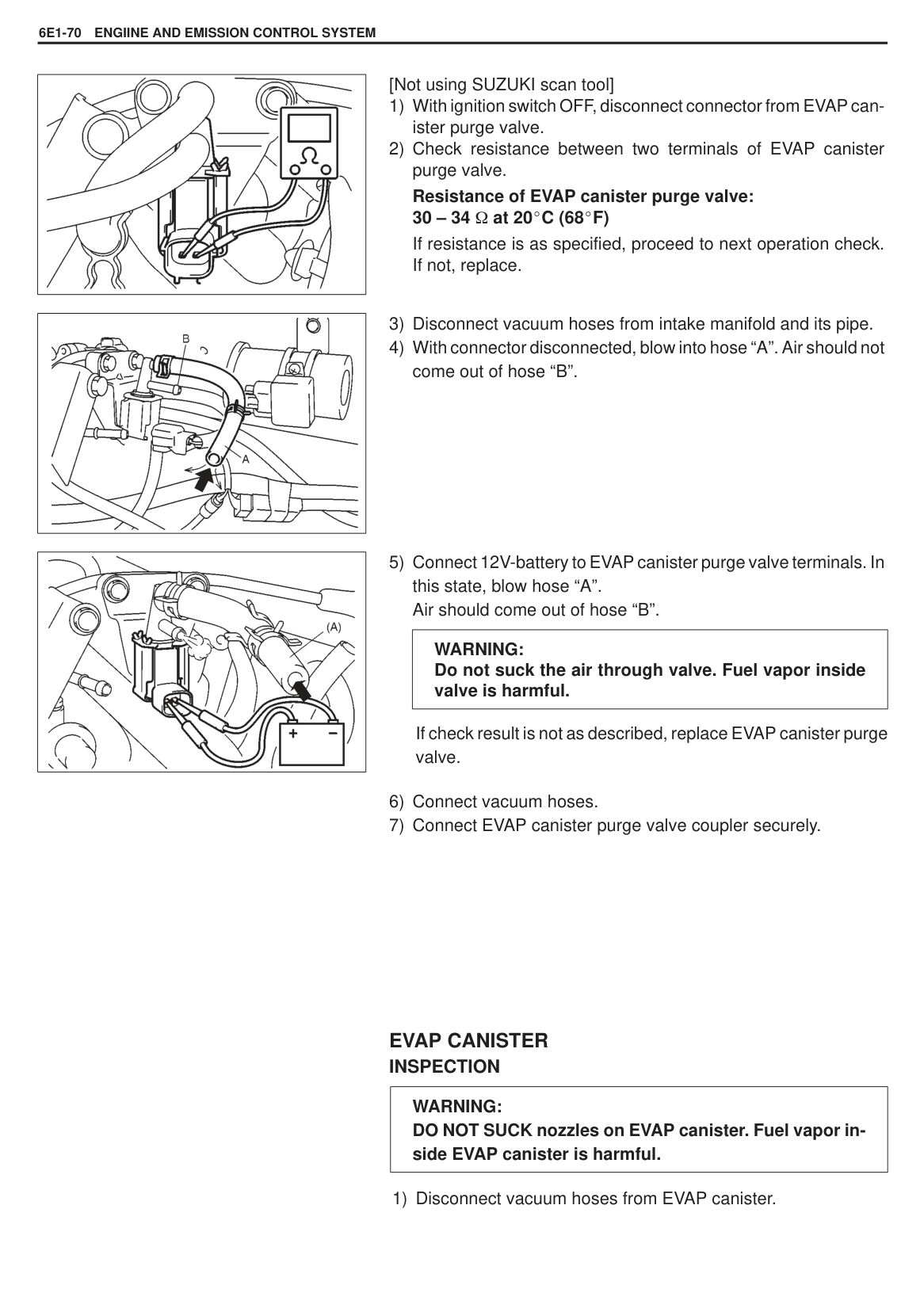
TP sensor output voltage when throttle is fully open: 4.2 0.5 V
###### IAT SENSOR REMOVAL
INSPECTION Immerse temperature sensing part of IAT sensor in water (or ice) and measure resistance between sensor terminals while heating water gradually. If measured resistance doesn’t show such characteristic as shown in left figure, replace IAT sensor.
|| |---|
Reverse removal procedure noting the following. Clean mating surfaces of IAT sensor (1) and air cleaner outlet hose (2). Connect IAT sensor coupler securely.
|| |---|
###### ECT SENSOR REMOVAL
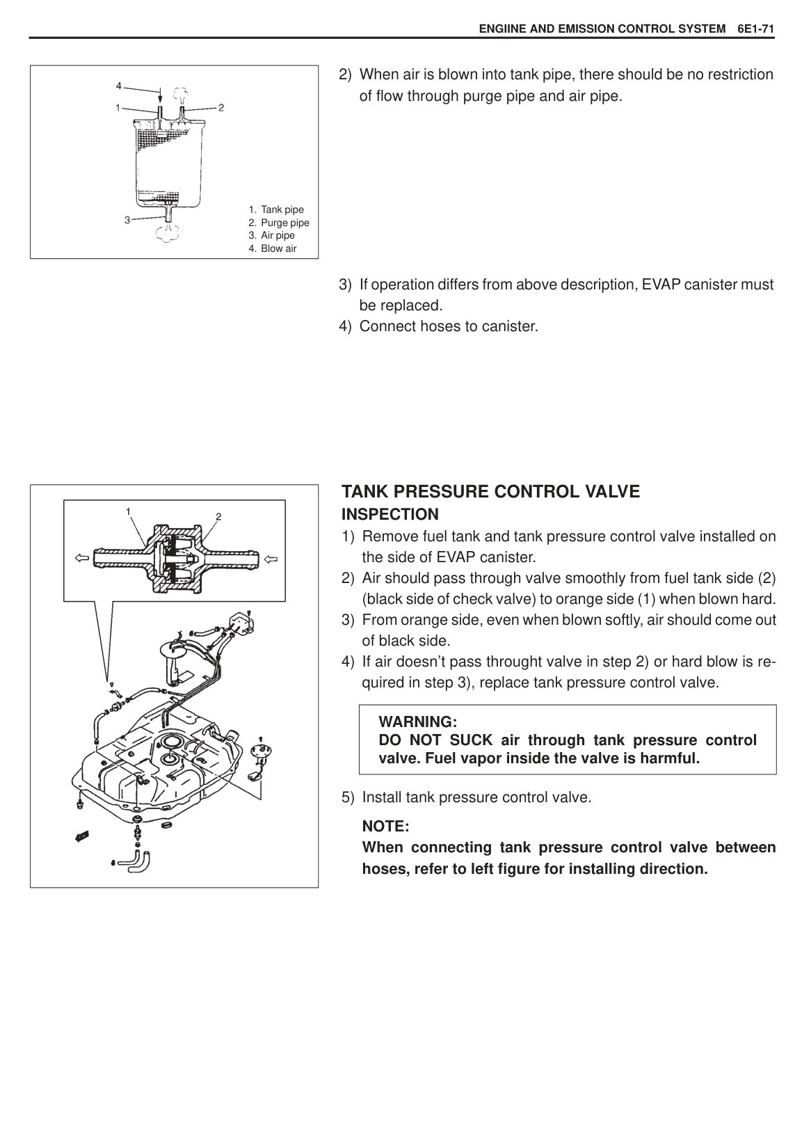
|WARNING: To help avoid danger of being burned, do not remove radiator cap while engine and radiator are still hot. Scalding fluid and steam can be blown out under pressure it cap is taken off too soon.| |---|
|
( ) for reference
TEMPERATURE
RESISTANCE| |---|
INSPECTION Immerse temperature sensing part of ECT sensor in water (or ice) and measure resistance between sensor terminals (a and b) while heating water gradually. If measured resistance doesn’t show such characteristic as shown in left figure, replace ECT sensor.
|| |---|
Reverse removal procedure noting the following. Clean mating surfaces of ECT sensor and water outlet pipe. Check O-ring for damage and replace if necessary. Tighten ECT sensor to specified torque.
Tightening Torque (a): 12 N·m (1.2 kg-m, 9.0 lb-ft)
Connect connect to ECT sensor securely. Refill coolant referring to Section 6B.
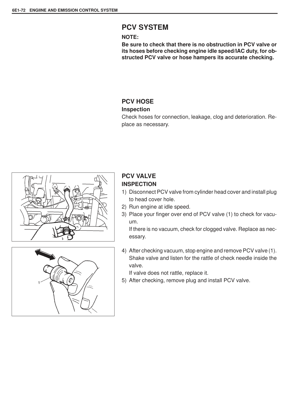
|| |---|
###### MAIN RELAY INSPECTION
|| |---|
|| |---|
|TERMINALS|RESISTANCE| |---|---| |Between A and B|(infinity)|
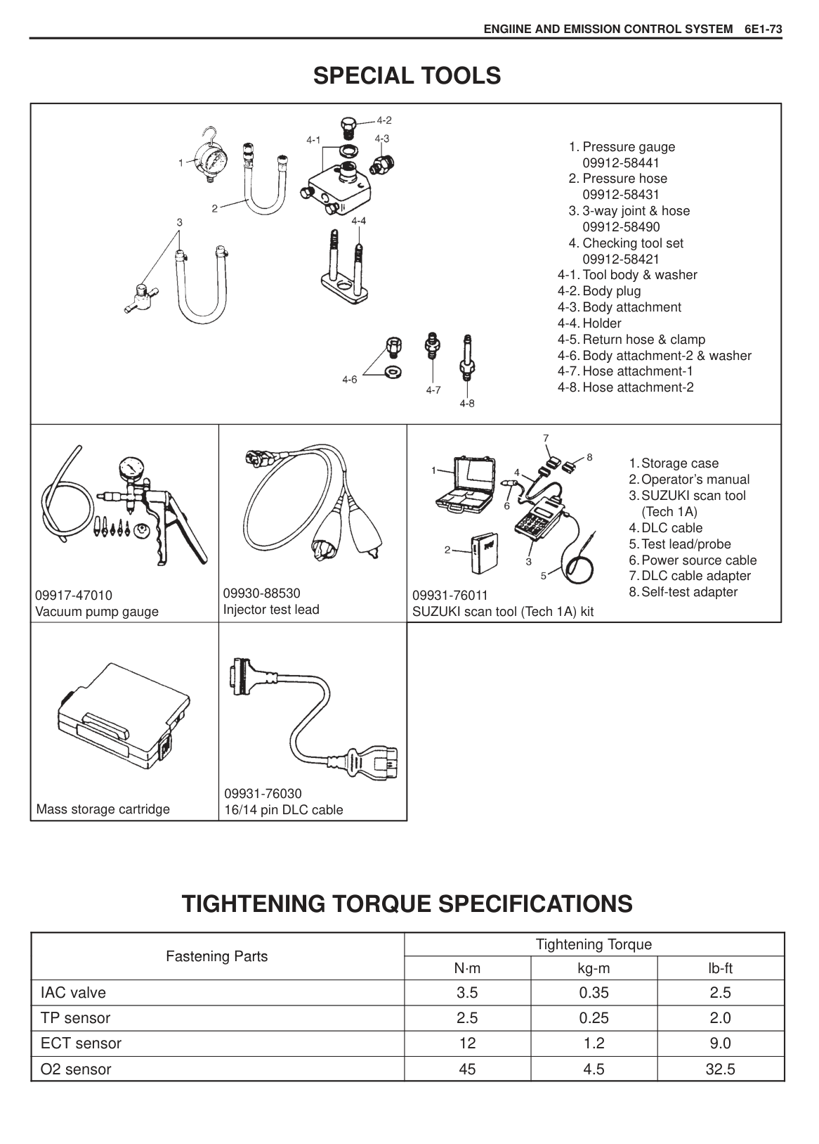
|Between C and D|90 – 110|
If found defective, replace.
OXYGEN SENSOR INSPECTION Inspect oxygen sensor referring to flow table of diagnostic trouble code No. 14 (P0130).
######## REMOVAL
|WARNING: To avoid danger of being burned, do not touch exhaust system when system is hot. Oxygen sensor removal should be performed when system is cool.| |---|
|| |---|
|| |---|
INSTALLATION Reverse removal procedure noting the followings.
Tighten oxygen sensor to specified torque.
Tightening Torque (a): 45 N·m (4.5 kg-m, 32.5 lb-ft)
Connect connector of oxygen sensor and clamp wire harness securely. After installing oxygen sensor, start engine and check that no exhaust gas leakage exists.
|| |---|
|| |---|
###### FUEL PUMP RELAY INSPECTION
###### FUEL CUT OPERATION INSPECTION
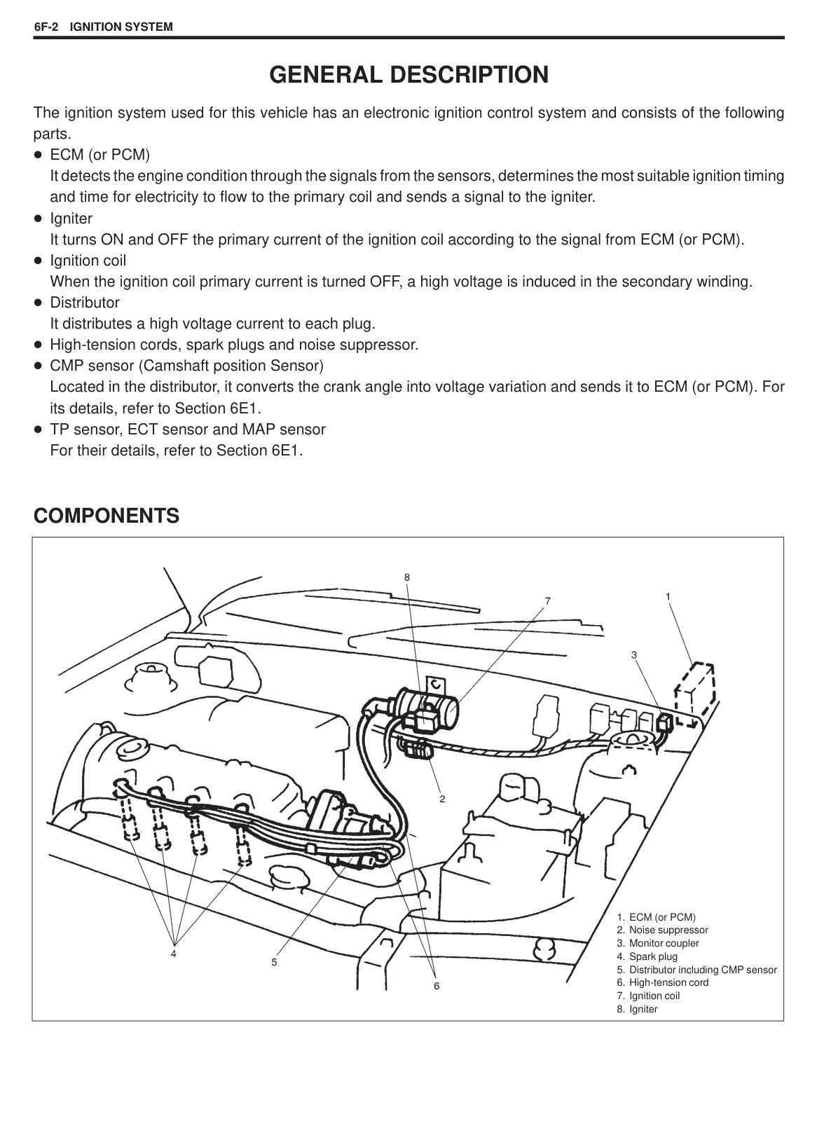
NOTE: Before inspection, check to make sure that gear shift lever is in neutral position (with A/T model, selector lever in “P” range) and that parking brake lever is pulled all the way up.
CMP SENSOR Refer to Section 6F for removal, installation, inspection and adjustment of CMP sensor.
|| |---|
|| |---|
|| |---|
###### RADIATOR FAN CONTROL SYSTEM System Inspection
|WARNING: Keep hands, tools and clothing away from engine cooling fan to help prevent personal injury. This fan is electric and can come on whether or not the engine is running. The fan can start automatically in response to the ECT sensor with the ignition switch in the “ON” position.| |---|
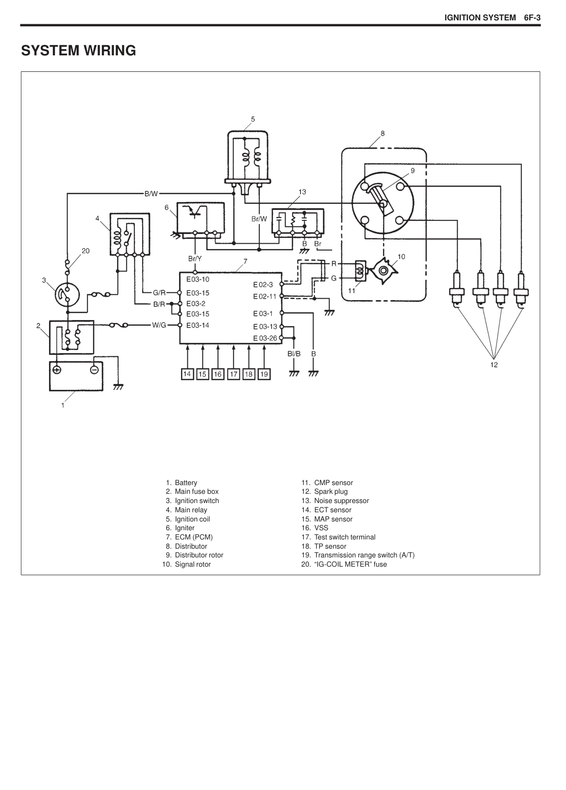
Start engine and keep it running to warm it up. Now check to ensure that radiator fan is started when coolant temperature exceed 98 C (208 F) by referring “COOLANT TEMP” of SCAN TOOL DISPLAY. If check result is not satisfactory, check RFC relay, wire harness, ECT sensor, radiator fan motor and, ECM (PCM).
RADIATOR FAN MOTOR INSPECTION Connect battery positive terminal to terminal of radiator fan motor connector “Bl/R” wire side and negative terminal to “B” terminal. Check that radiator fan operates smoothly.
###### RADIATOR FAN CONTROL RELAY (RFC RELAY) INSPECTION
|| |---|
|TERMINALS|RESISTANCE| |---|---| |Between “A” and “B”|(infinity)| |“C” “D”Between “C” and “D”
|90 – 110 at 20 C (68 F) omron. . made| |“C” “D”Between “C” and “D”
|60 – 88 at 20 C (68 F) inter-. . . face made|
|| |---|
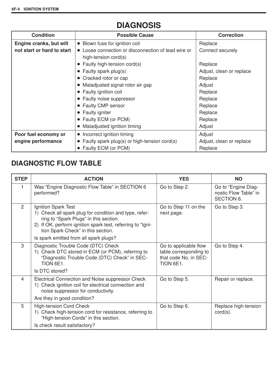
|| |---|
|| |---|
###### VEHICLE SPEED SENSOR (VSS) INSPECTION M/T VEHICLE
A/T VEHICLE Vehicle speed sensor (1) itself can be checked on its resistance by disconnecting connector.
NOTE: Function of vehicle speed sensor can be checked by measuring generated pulse as voltage. For its measurement, use an analog type voltmeter while spinning wheels on lift and with selector lever in D position.
|Vehicle speed sensor specifications|Vehicle speed sensor specifications| |---|---|
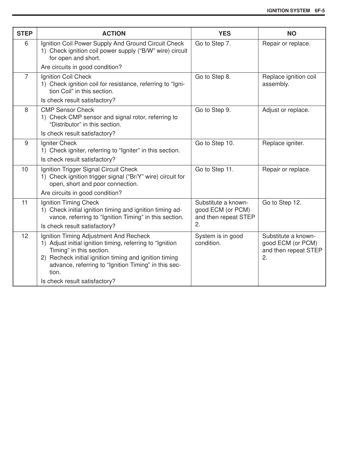
|Coil resistance|100 – 300| |Output voltage at 40 km/h (37 mile/h)|Approximately 1 V|
#### EVAP EMISSION CONTROL SYSTEM EVAP CANISTER PURGE INSPECTION
######### NOTE: Before inspection, check to make sure that gear shift lever is in neutral position (with A/T model, selector lever in “P” range) and that parking brake lever is pulled all the way up.
|| |---|
|| |---|
|| |---|
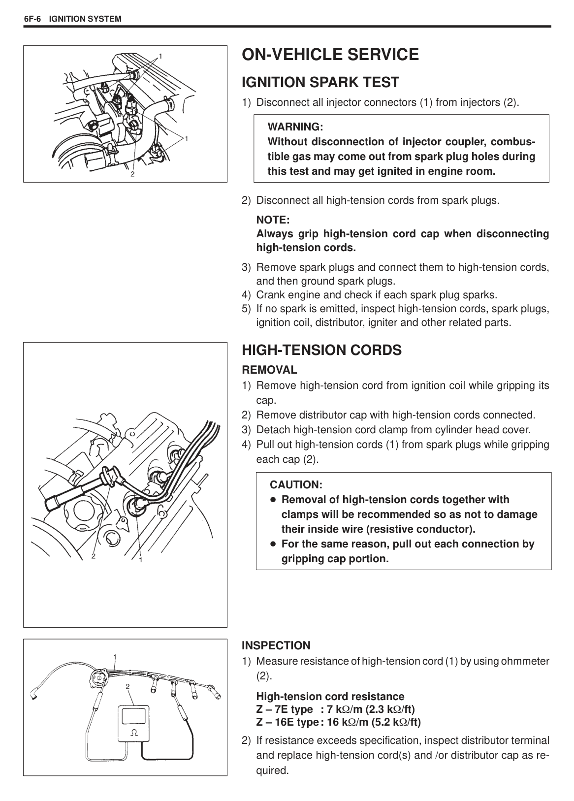
VACUUM PASSAGE INSPECTION Start engine and run it at idle speed. Disconnect vacuum hose from EVAP canister purge valve. With finger placed against hose disconnected, check that vacuum is applied. If it is not applied, clean vacuum passage by blowing compressed air.
VACUUM HOSE INSPECTION Check hoses for connection, leakage, clog and deterioration. Replace as necessary.
|| |---|
###### EVAP CANISTER PURGE VALVE INSPECTION [Using SUZUKI scan tool]
Resistance of EVAP canister purge valve: 30 – 34 at 20 C (68 F)
If resistance is as specified, proceed to next operation check. If not, replace.
|| |---|
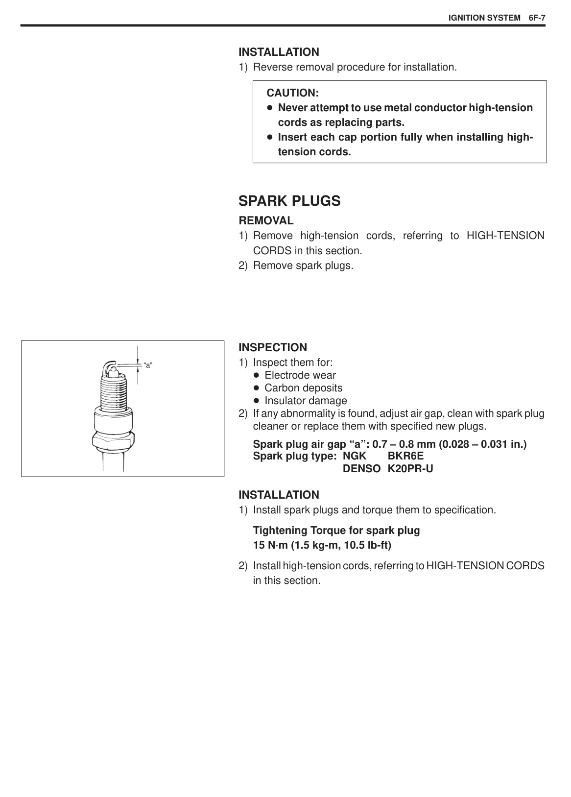
|| |---|
|| |---|
|WARNING: Do not suck the air through valve. Fuel vapor inside valve is harmful.| |---|
If check result is not as described, check wire harnesses for open or short. If it is in good condition, replace EVAP canister purge valve and recheck.
|| |---|
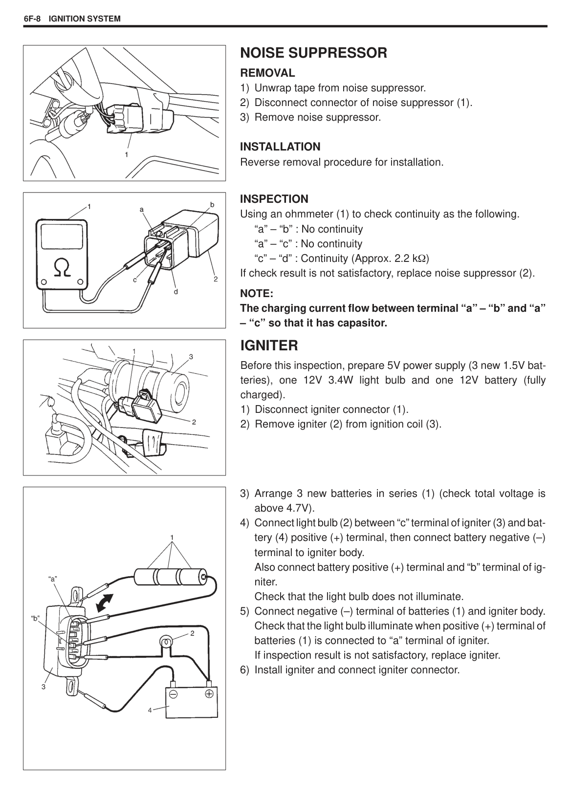
[Not using SUZUKI scan tool]
Resistance of EVAP canister purge valve: 30 – 34 at 20 C (68 F)
If resistance is as specified, proceed to next operation check. If not, replace.
|| |---|
|| |---|
|WARNING: Do not suck the air through valve. Fuel vapor inside valve is harmful.| |---|
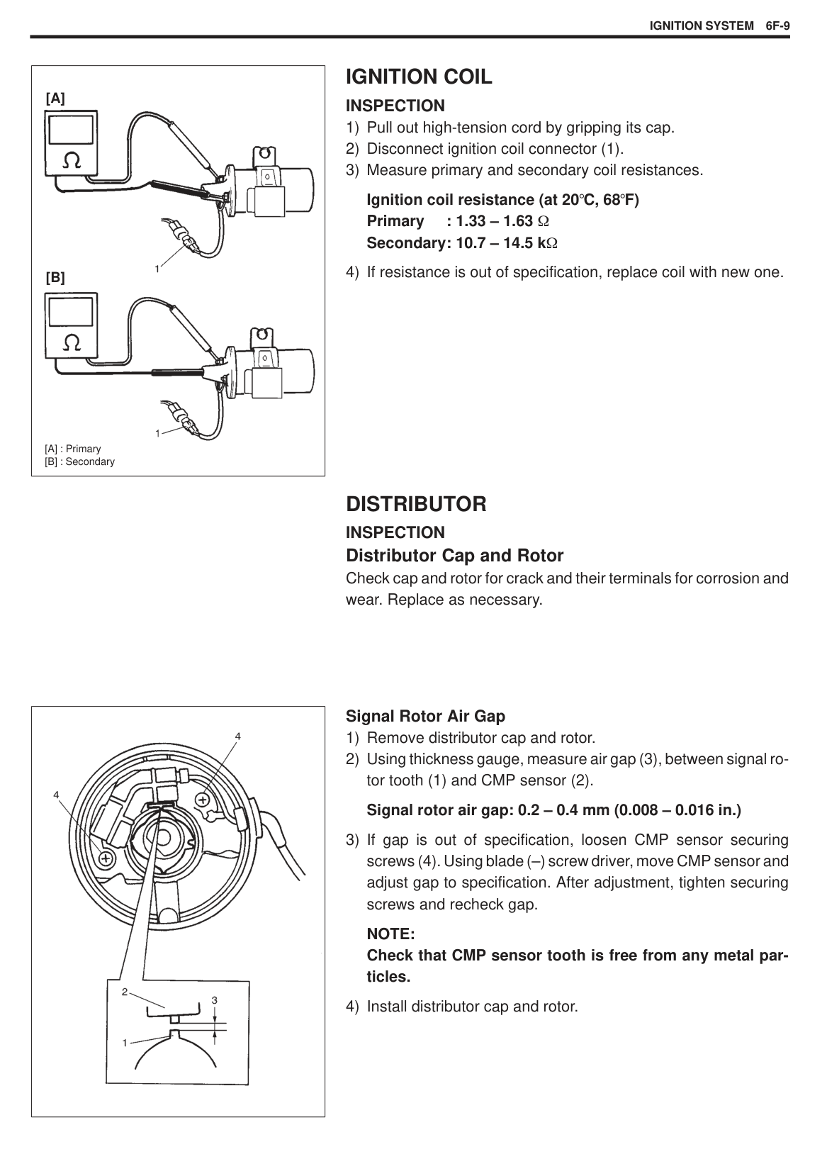
If check result is not as described, replace EVAP canister purge valve.
###### EVAP CANISTER INSPECTION
|WARNING: DO NOT SUCK nozzles on EVAP canister. Fuel vapor inside EVAP canister is harmful.| |---|
|
1. Tank pipe
2. Purge pipe
3. Air pipe
4. Blow air
| |---|
||
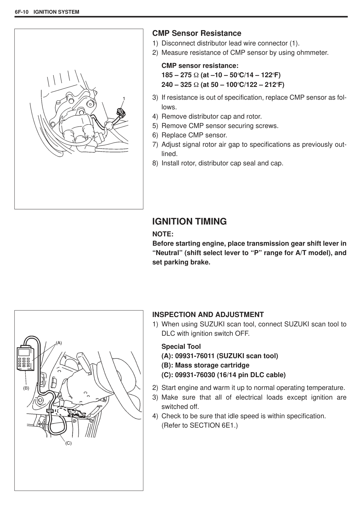
|---|
|WARNING: DO NOT SUCK air through tank pressure control valve. Fuel vapor inside the valve is harmful.| |---|
###### TANK PRESSURE CONTROL VALVE INSPECTION
NOTE: When connecting tank pressure control valve between hoses, refer to left figure for installing direction.
#### PCV SYSTEM NOTE:
######### Be sure to check that there is no obstruction in PCV valve or its hoses before checking engine idle speed/IAC duty, for obstructed PCV valve or hose hampers its accurate checking.
PCV HOSE Inspection Check hoses for connection, leakage, clog and deterioration. Replace as necessary.
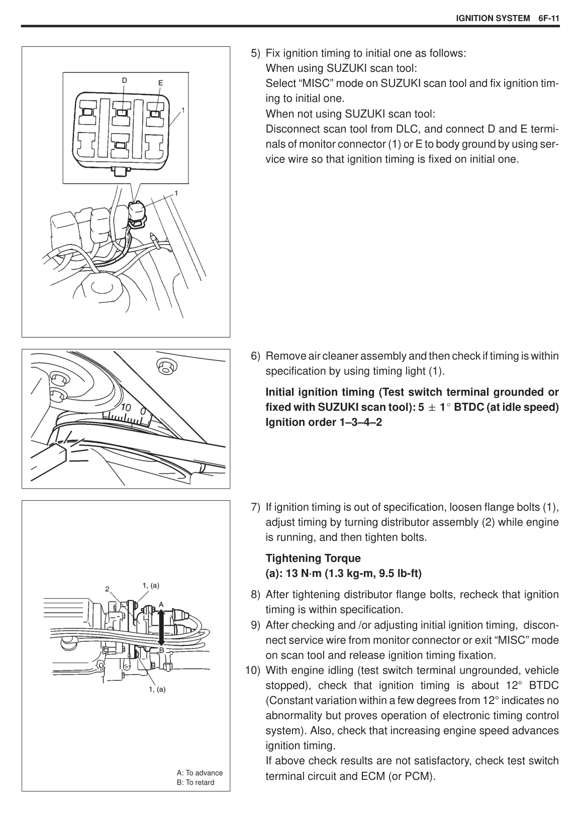
|| |---|
###### PCV VALVE INSPECTION
|| |---|
SPECIAL TOOLS
|
1. Pressure gauge 09912-58441
2. Pressure hose 09912-58431
3. 3-way joint & hose 09912-58490
4. Checking tool set 09912-58421
4-1.Tool body & washer
4-2.Body plug
4-3.Body attachment
4-4.Holder
4-5.Return hose & clamp
4-6.Body attachment-2 & washer
4-7.Hose attachment-1
4-8.Hose attachment-2
|
1. Pressure gauge 09912-58441
2. Pressure hose 09912-58431
3. 3-way joint & hose 09912-58490
4. Checking tool set 09912-58421
4-1.Tool body & washer
4-2.Body plug
4-3.Body attachment
4-4.Holder
4-5.Return hose & clamp
4-6.Body attachment-2 & washer
4-7.Hose attachment-1
4-8.Hose attachment-2
|
1. Pressure gauge 09912-58441
2. Pressure hose 09912-58431
3. 3-way joint & hose 09912-58490
4. Checking tool set 09912-58421
4-1.Tool body & washer
4-2.Body plug
4-3.Body attachment
4-4.Holder
4-5.Return hose & clamp
4-6.Body attachment-2 & washer
4-7.Hose attachment-1
4-8.Hose attachment-2
| |---|---|---| |
09917-47010 Vacuum pump gauge
|
09930-88530 Injector test lead|
09931-76011 SUZUKI scan tool (Tech 1A) kit
1.Storage case
2.Operator’s manual
3.SUZUKI scan tool (Tech 1A)
4.DLC cable
5.Test lead/probe
6.Power source cable
7.DLC cable adapter
8.Self-test adapter
| |
Mass storage cartridge|
09931-76030 16/14 pin DLC cable| |
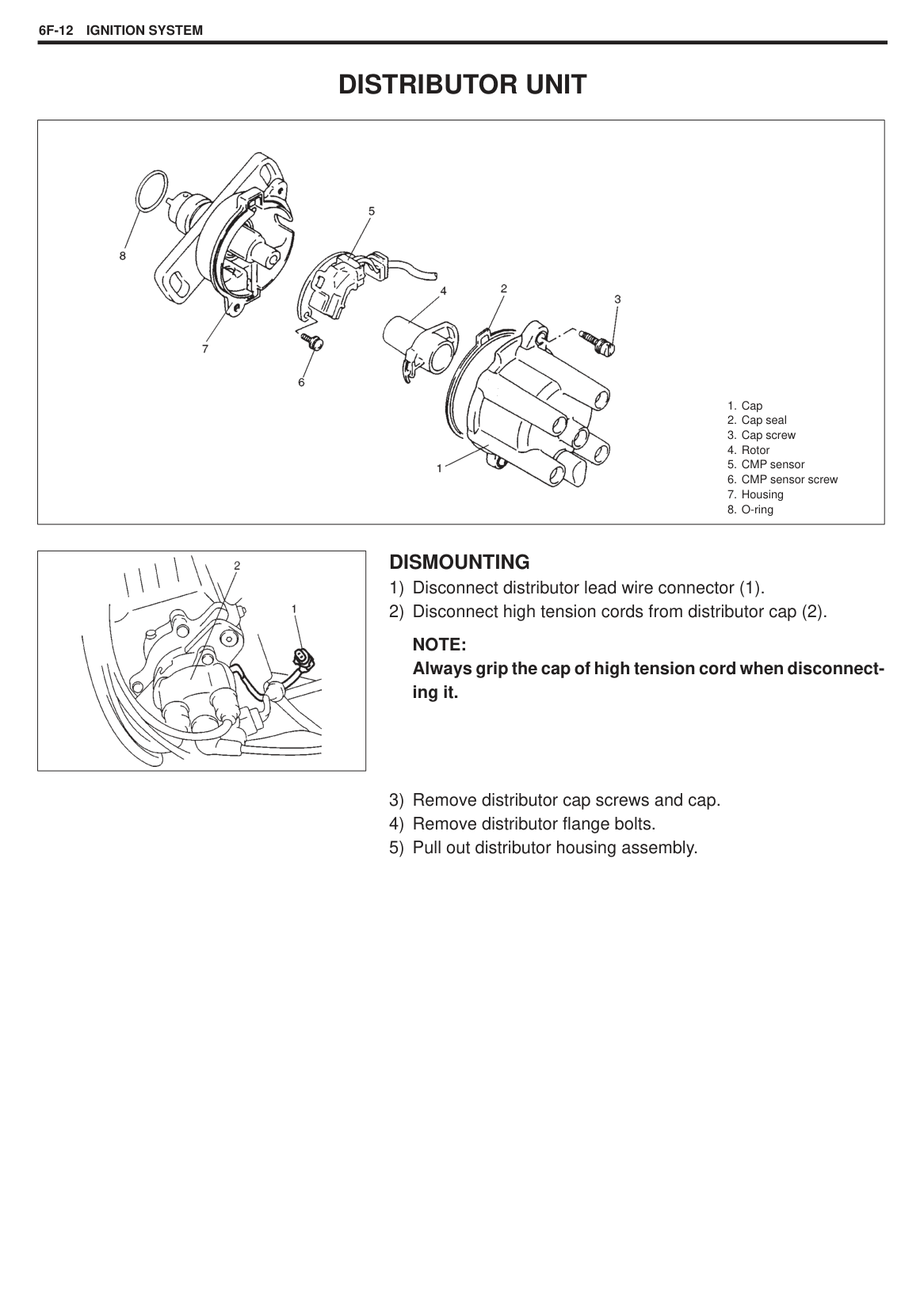
TIGHTENING TORQUE SPECIFICATIONS
|Fastening PartsFastening Parts
|Tightening Torque|Tightening Torque|Tightening Torque| |---|---|---|---| |Fastening PartsFastening Parts
|N·m|kg-m|lb-ft| |IAC valve|3.5|0.35|2.5| |TP sensor|2.5|0.25|2.0| |ECT sensor|12|1.2|9.0| |O2 sensor|45|4.5|32.5|
SECTION 6F
IGNITION SYSTEM
#### CONTENTS
ON-VEHICLE SERVICE 6F- 6. . . . . . . . . . . . . . . . . . . Ignition Spark Test 6F- 6. . . . . . . . . . . . . . . . . . . . . . High-Tension Cords 6F- 6. . . . . . . . . . . . . . . . . . . . .
Spark Plugs 6F- 7. . . . . . . . . . . . . . . . . . . . . . . . . . . . Noise Suppressor 6F- 8. . . . . . . . . . . . . . . . . . . . . . . Igniter 6F- 8. . . . . . . . . . . . . . . . . . . . . . . . . . . . . . . . . Ignition Coil 6F- 9. . . . . . . . . . . . . . . . . . . . . . . . . . . . Distributor 6F- 9. . . . . . . . . . . . . . . . . . . . . . . . . . . . . . Ignition Timing 6F-10. . . . . . . . . . . . . . . . . . . . . . . . . .
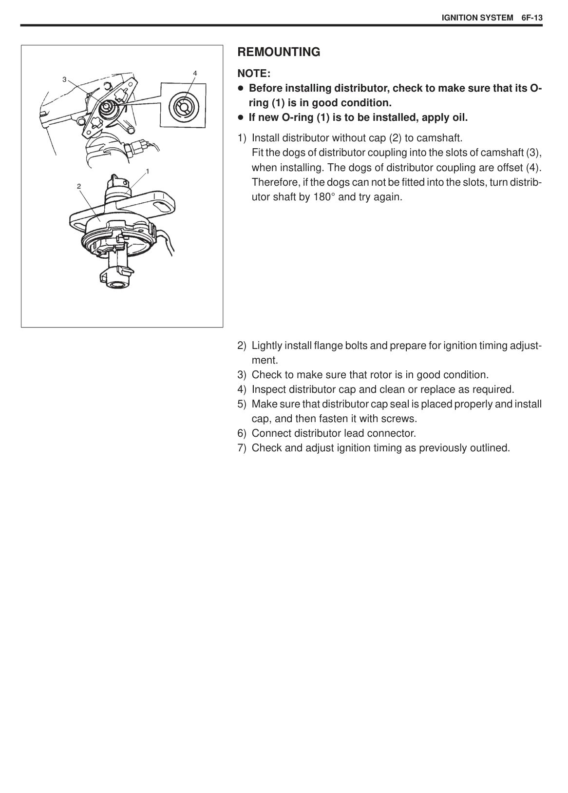
DISTRIBUTOR UNIT 6F-12. . . . . . . . . . . . . . . . . . . . . . SPECIAL TOOLS 6F-14. . . . . . . . . . . . . . . . . . . . . . . . .
6F
GENERAL DESCRIPTION
The ignition system used for this vehicle has an electronic ignition control system and consists of the following parts.
ECM (or PCM) It detects the engine condition through the signals from the sensors, determines the most suitable ignition timing and time for electricity to flow to the primary coil and sends a signal to the igniter. Igniter It turns ON and OFF the primary current of the ignition coil according to the signal from ECM (or PCM). Ignition coil When the ignition coil primary current is turned OFF, a high voltage is induced in the secondary winding. Distributor It distributes a high voltage current to each plug. High-tension cords, spark plugs and noise suppressor. CMP sensor (Camshaft position Sensor) Located in the distributor, it converts the crank angle into voltage variation and sends it to ECM (or PCM). For its details, refer to Section 6E1. TP sensor, ECT sensor and MAP sensor For their details, refer to Section 6E1.
#### COMPONENTS
|
1. ECM (or PCM)
2. Noise suppressor
3. Monitor coupler
4. Spark plug
5. Distributor including CMP sensor
6. High-tension cord
7. Ignition coil
8. Igniter
| |---|
#### SYSTEM WIRING
|
1. Battery
2. Main fuse box
3. Ignition switch
4. Main relay
5. Ignition coil
6. Igniter
7. ECM (PCM)
8. Distributor
9. Distributor rotor
10. Signal rotor
11. CMP sensor
12. Spark plug
13. Noise suppressor
14. ECT sensor
15. MAP sensor
16. VSS
17. Test switch terminal
18. TP sensor
19. Transmission range switch (A/T)
20. “IG-COIL METER” fuse
| |---|
DIAGNOSIS
|Condition|Possible Cause|Correction|
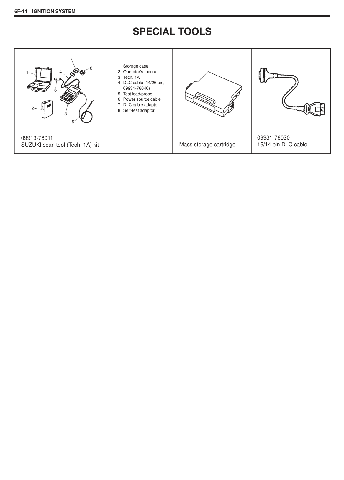
|---|---|---| |Engine cranks, but will not start or hard to start|Blown fuse for ignition coil Loose connection or disconnection of lead wire or high-tension cord(s) Faulty high-tension cord(s) Faulty spark plug(s) Cracked rotor or cap Maladjusted signal rotor air gap Faulty ignition coil Faulty noise suppressor Faulty CMP sensor Faulty igniter Faulty ECM (or PCM) Maladjusted ignition timing|Replace Connect securely
Replace Adjust, clean or replace Replace Adjust Replace Replace Replace Replace Replace Adjust| |Poor fuel economy or engine performance|Incorrect ignition timing Faulty spark plug(s) or high-tension cord(s) Faulty ECM (or PCM)|Adjust Adjust, clean or replace Replace|
DIAGNOSTIC FLOW TABLE
|STEP|ACTION|YES|NO| |---|---|---|---| |1|Was “Engine Diagnostic Flow Table” in SECTION 6 performed?|Go to Step 2.|Go to “Engine Diagnostic Flow Table” in SECTION 6.| |2|Ignition Spark Test
1) Check all spark plug for condition and type, referring to “Spark Plugs” in this section.
2) If OK, perform ignition spark test, referring to “Ignition Spark Check” in this section.
Is spark emitted from all spark plugs?|Go to Step 11 on the next page.|Go to Step 3.| |3|Diagnostic Trouble Code (DTC) Check
1) Check DTC stored in ECM (or PCM), referring to “Diagnostic Trouble Code (DTC) Check” in SECTION 6E1.
Is DTC stored?|Go to applicable flow table corresponding to that code No. in SECTION 6E1.|Go to Step 4.| |4|Electrical Connection and Noise suppressor Check
1) Check ignition coil for electrical connection and
noise suppressor for conductivity. Are they in good condition?|Go to Step 5.|Repair or replace.| |5|High-tension Cord Check
1) Check high-tension cord for resistance, referring to
“High-tension Cords” in this section. Is check result satisfactory?|Go to Step 6.|Replace high-tension cord(s).|
|STEP|ACTION|YES|NO| |---|---|---|---| |6|Ignition Coil Power Supply And Ground Circuit Check
1) Check ignition coil power supply (“B/W” wire) circuit for open and short. Are circuits in good condition?|Go to Step 7.|Repair or replace.| |7|Ignition Coil Check
1) Check ignition coil for resistance, referring to “Ignition Coil” in this section. Is check result satisfactory?|Go to Step 8.|Replace ignition coil assembly.| |8|CMP Sensor Check
1) Check CMP sensor and signal rotor, referring to
“Distributor” in this section. Is check result satisfactory?|Go to Step 9.|Adjust or replace.| |9|Igniter Check
1) Check igniter, referring to “Igniter” in this section. Is check result satisfactory?|Go to Step 10.|Replace igniter.| |10|Ignition Trigger Signal Circuit Check
1) Check ignition trigger signal (“Br/Y” wire) circuit for
open, short and poor connection. Are circuits in good condition?|Go to Step 11.|Repair or replace.| |11|Ignition Timing Check
1) Check initial ignition timing and ignition timing ad-
vance, referring to “Ignition Timing” in this section. Is check result satisfactory?|Substitute a knowngood ECM (or PCM) and then repeat STEP 2.|Go to Step 12.| |12|Ignition Timing Adjustment And Recheck
1) Adjust initial ignition timing, referring to “Ignition Timing” in this section.
2) Recheck initial ignition timing and ignition timing advance, referring to “Ignition Timing” in this section.
Is check result satisfactory?|System is in good condition.|Substitute a knowngood ECM (or PCM) and then repeat STEP 2.|
|| |---|
|| |---|
|| |---|
ON-VEHICLE SERVICE IGNITION SPARK TEST
|WARNING: Without disconnection of injector coupler, combustible gas may come out from spark plug holes during this test and may get ignited in engine room.| |---|
NOTE: Always grip high-tension cord cap when disconnecting high-tension cords.
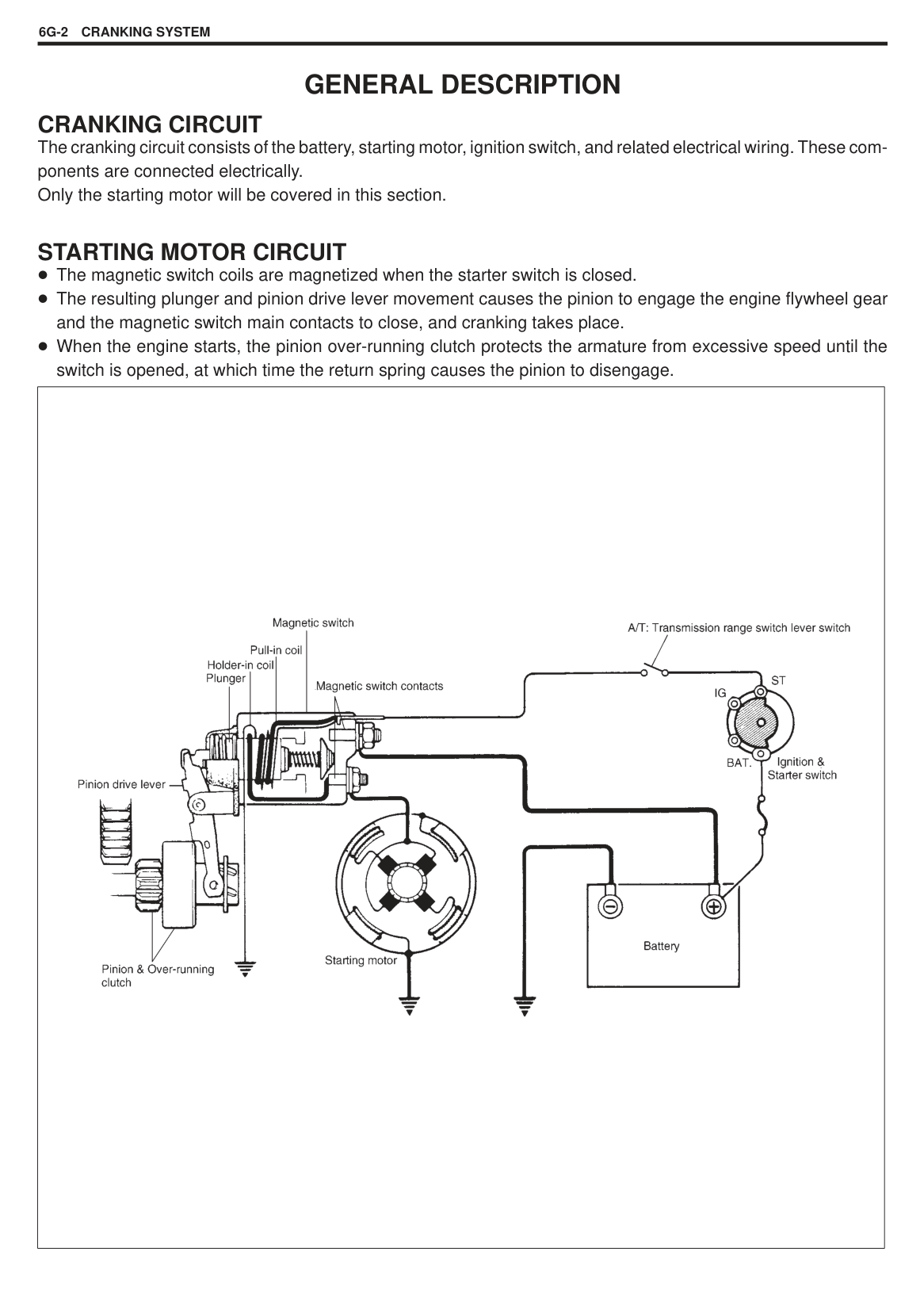
#### HIGH-TENSION CORDS REMOVAL
|CAUTION: Removal of high-tension cords together with clamps will be recommended so as not to damage their inside wire (resistive conductor). For the same reason, pull out each connection by gripping cap portion.| |---|
######## INSPECTION
(2).
High-tension cord resistance Z – 7E type : 7 k /m (2.3 k /ft) Z – 16E type: 16 k /m (5.2 k /ft)
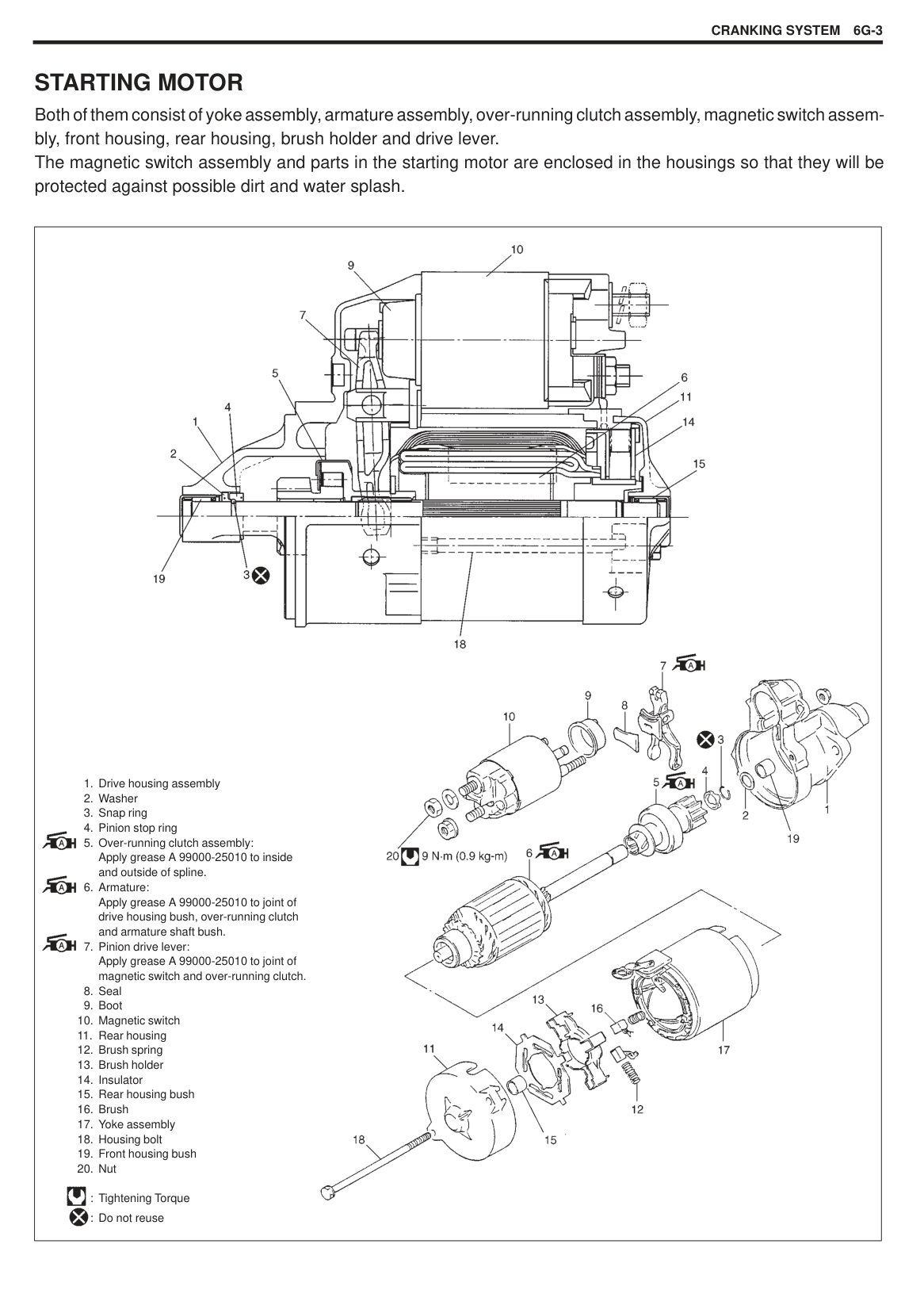
######## INSTALLATION
1) Reverse removal procedure for installation.
|CAUTION: Never attempt to use metal conductor high-tension cords as replacing parts. Insert each cap portion fully when installing hightension cords.| |---|
#### SPARK PLUGS REMOVAL
|| |---|
######## INSPECTION
Spark plug air gap “a”: 0.7 – 0.8 mm (0.028 – 0.031 in.) Spark plug type: NGK BKR6E
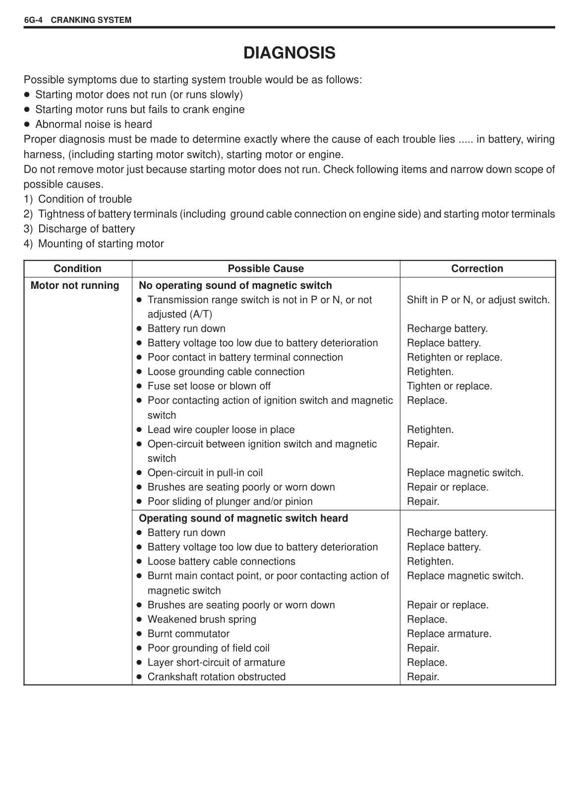
DENSO K20PR-U INSTALLATION
Tightening Torque for spark plug 15 N·m (1.5 kg-m, 10.5 lb-ft)
|| |---|
|| |---|
|| |---|
#### NOISE SUPPRESSOR REMOVAL
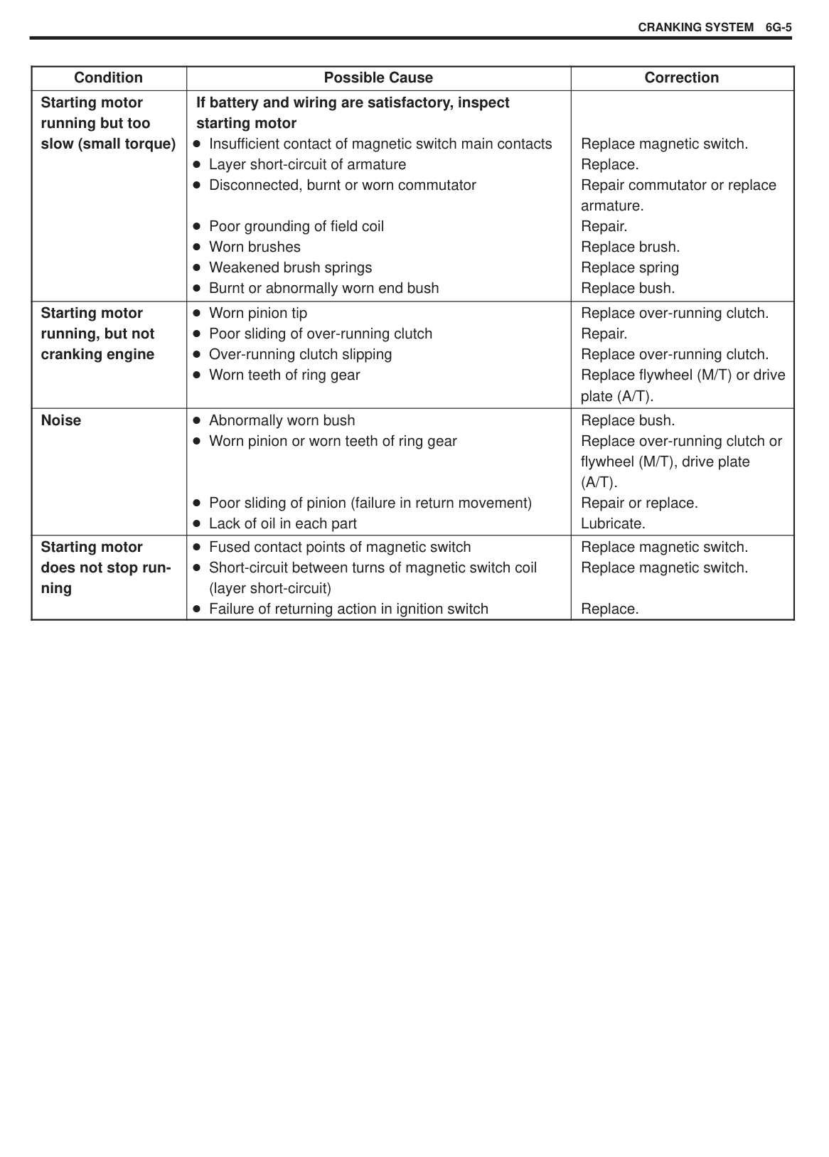
INSTALLATION Reverse removal procedure for installation.
INSPECTION Using an ohmmeter (1) to check continuity as the following.
“a” – “b” : No continuity “a” – “c” : No continuity “c” – “d” : Continuity (Approx. 2.2 k )
If check result is not satisfactory, replace noise suppressor (2).
NOTE: The charging current flow between terminal “a” – “b” and “a”
– “c” so that it has capasitor. IGNITER
Before this inspection, prepare 5V power supply (3 new 1.5V batteries), one 12V 3.4W light bulb and one 12V battery (fully charged).
|| |---|
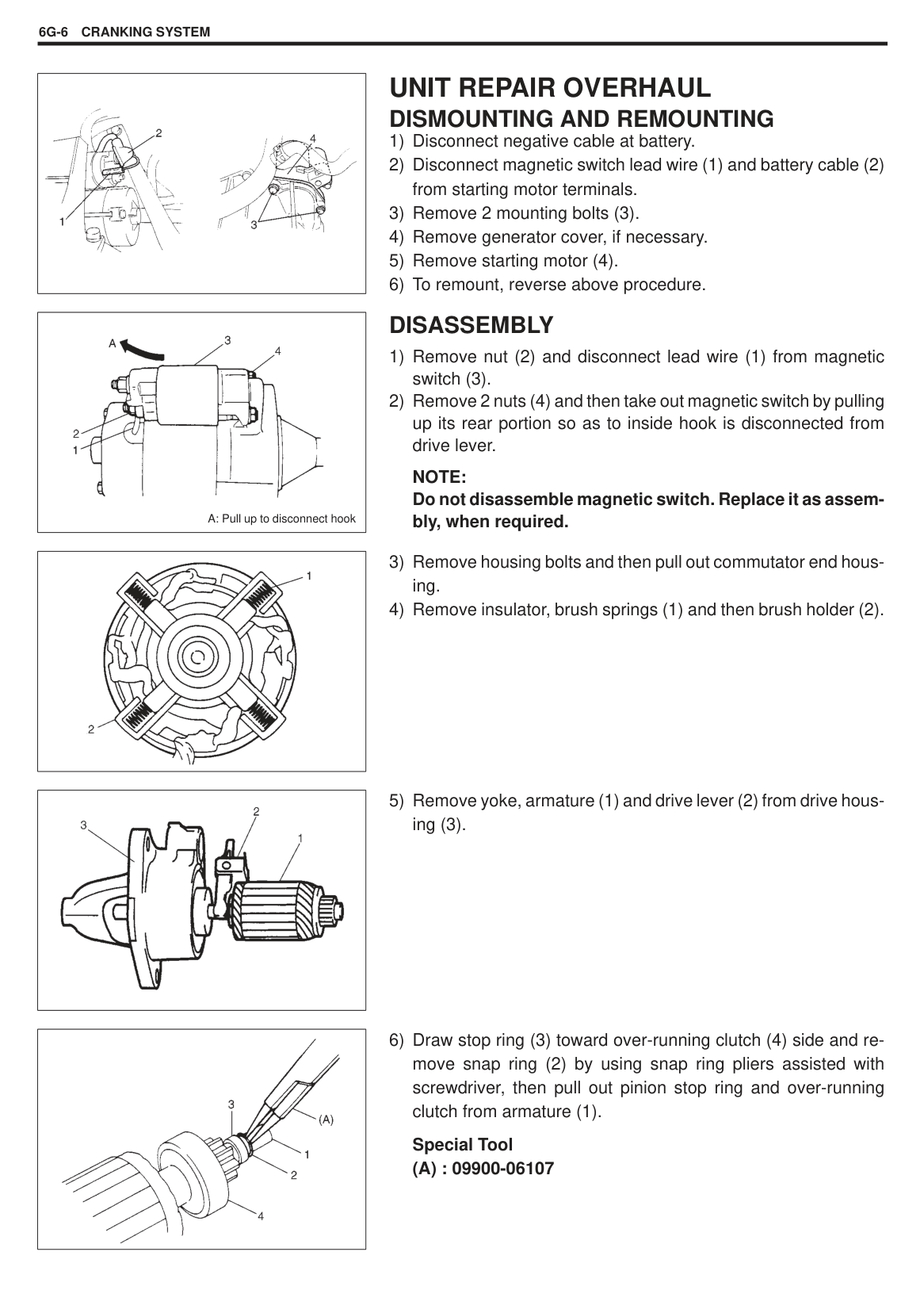
|
[A]
[B]
[A] : Primary
[B] : Secondary
| |---|
#### IGNITION COIL INSPECTION
Ignition coil resistance (at 20 C, 68 F) Primary : 1.33 – 1.63 Secondary: 10.7 – 14.5 k
DISTRIBUTOR INSPECTION Distributor Cap and Rotor Check cap and rotor for crack and their terminals for corrosion and wear. Replace as necessary.
|| |---|
######## Signal Rotor Air Gap
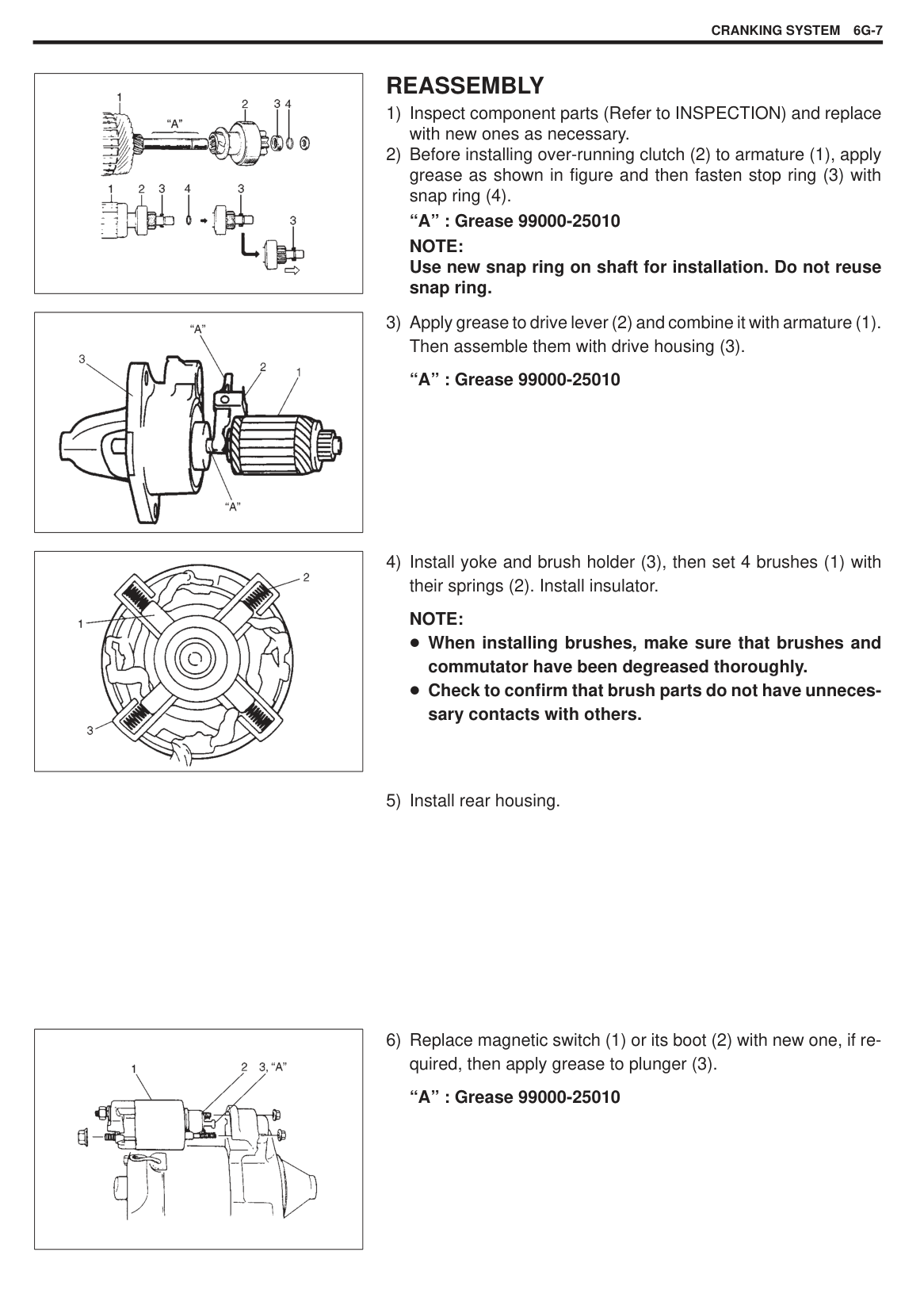
NOTE: Check that CMP sensor tooth is free from any metal particles.
|| |---|
###### CMP Sensor Resistance
CMP sensor resistance: 185 – 275 (at –10 – 50 C/14 – 122 F) 240 – 325 (at 50 – 100 C/122 – 212 F)
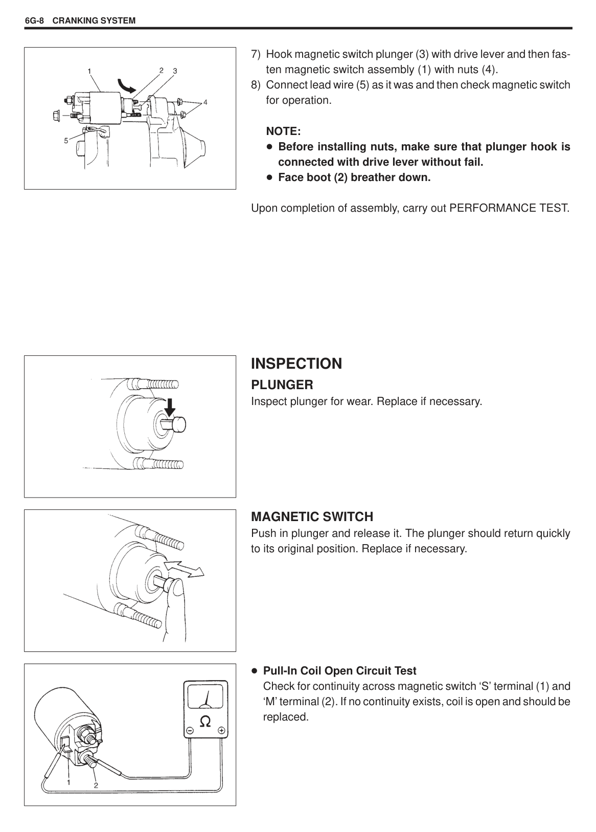
IGNITION TIMING NOTE: Before starting engine, place transmission gear shift lever in “Neutral” (shift select lever to “P” range for A/T model), and set parking brake.
|| |---|
######## INSPECTION AND ADJUSTMENT
|| |---|
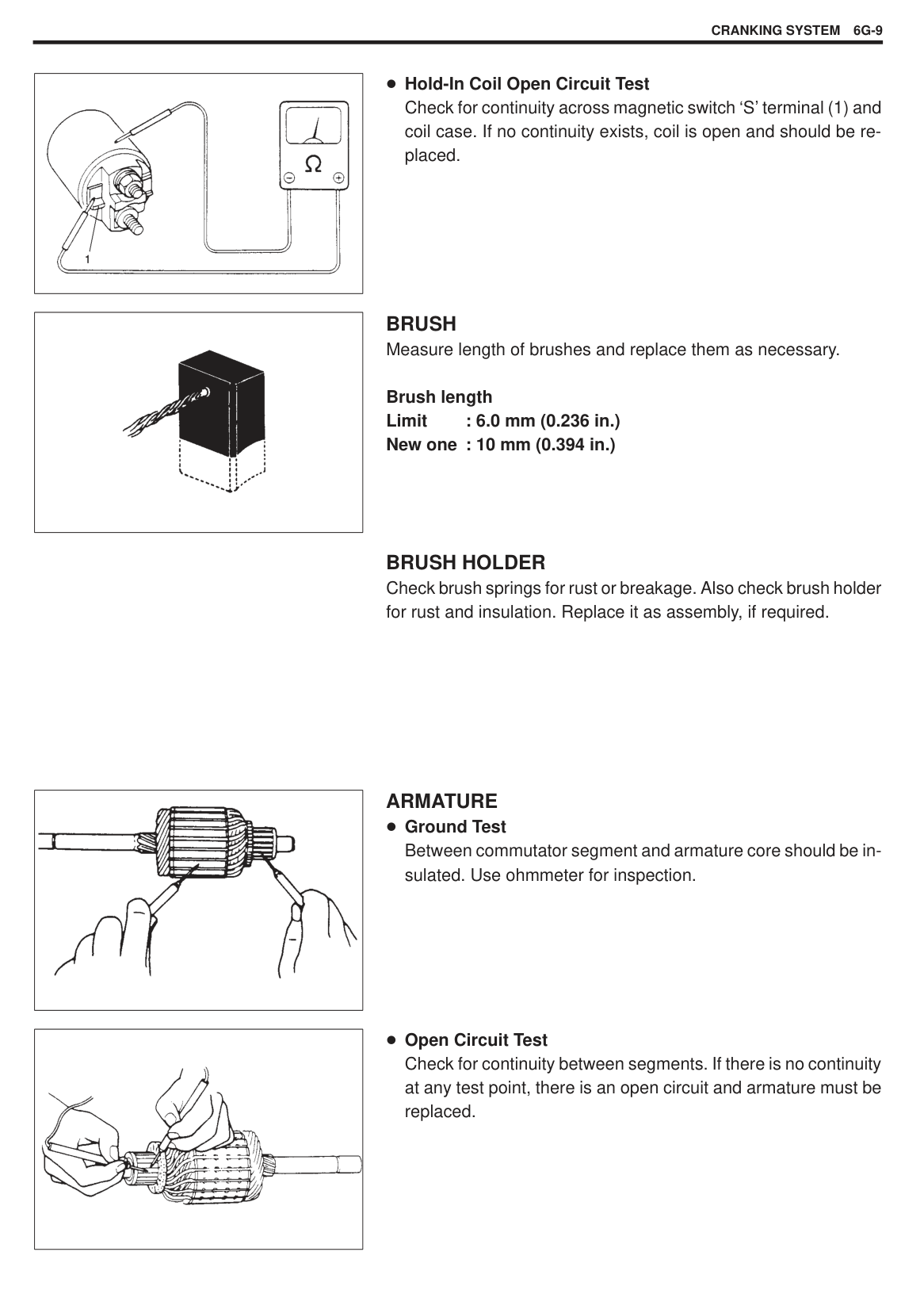
|| |---|
Initial ignition timing (Test switch terminal grounded or fixed with SUZUKI scan tool): 5 1 BTDC (at idle speed) Ignition order 1–3–4–2
|
A: To advance
B: To retard
| |---|
Tightening Torque (a): 13 N·m (1.3 kg-m, 9.5 lb-ft)
DISTRIBUTOR UNIT
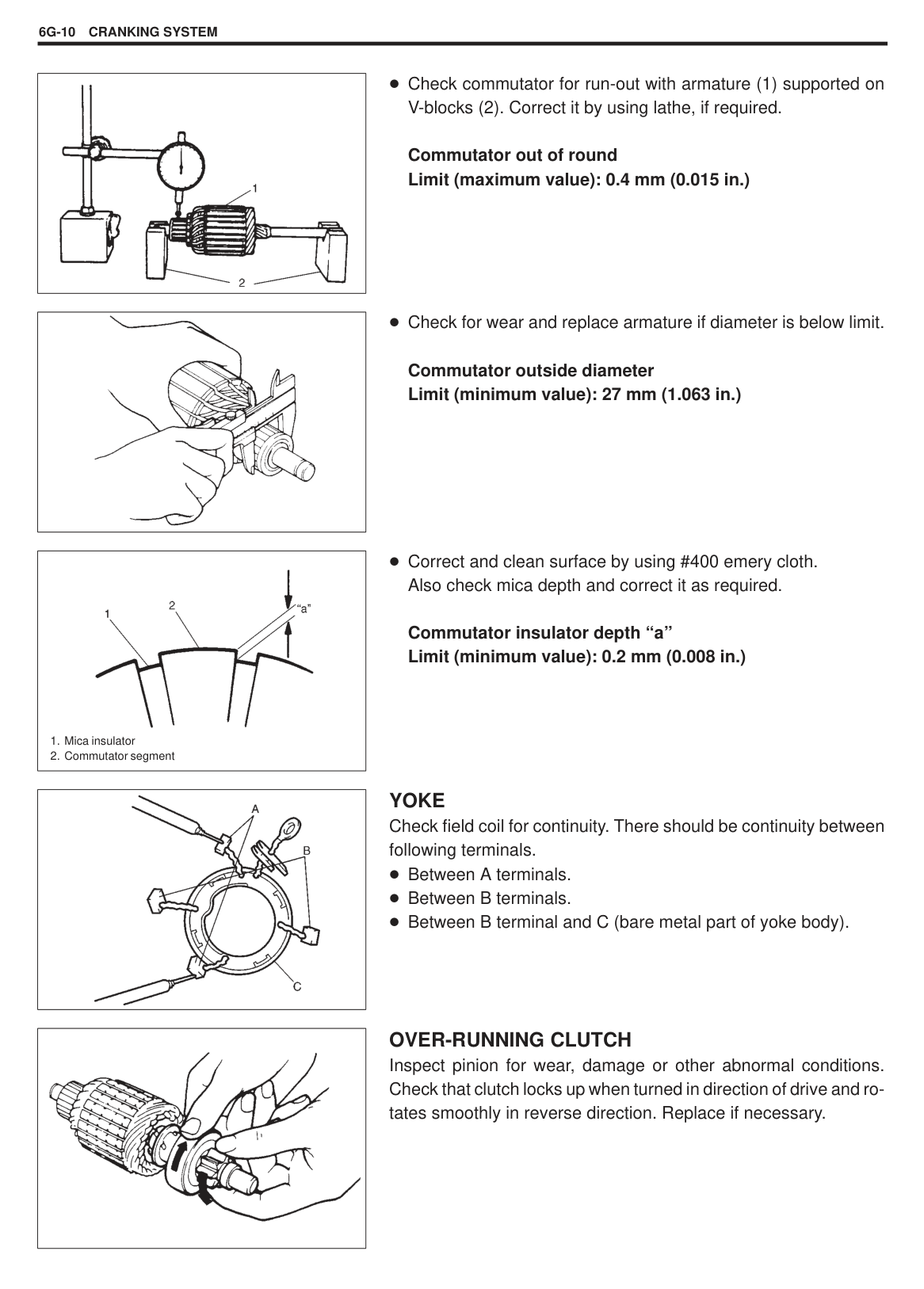
|
1. Cap
2. Cap seal
3. Cap screw
4. Rotor
5. CMP sensor
6. CMP sensor screw
7. Housing
8. O-ring
| |---|
|| |---|
###### DISMOUNTING
NOTE: Always grip the cap of high tension cord when disconnecting it.
|| |---|
###### REMOUNTING NOTE:
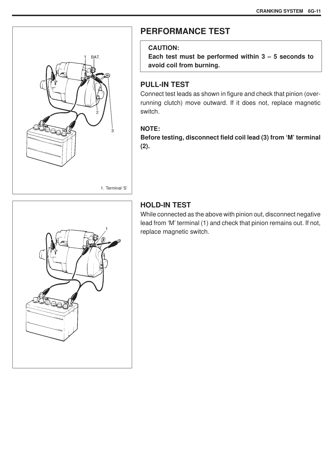
Before installing distributor, check to make sure that its Oring (1) is in good condition. If new O-ring (1) is to be installed, apply oil.
SPECIAL TOOLS
|
09913-76011 SUZUKI scan tool (Tech. 1A) kit
1. Storage case
2. Operator’s manual
3. Tech. 1A
4. DLC cable (14/26 pin, 09931-76040)
5. Test lead/probe
6. Power source cable
7. DLC cable adaptor
8. Self-test adaptor
|
Mass storage cartridge|
09931-76030 16/14 pin DLC cable| |---|---|---|
SECTION 6G
CRANKING SYSTEM
#### CONTENTS
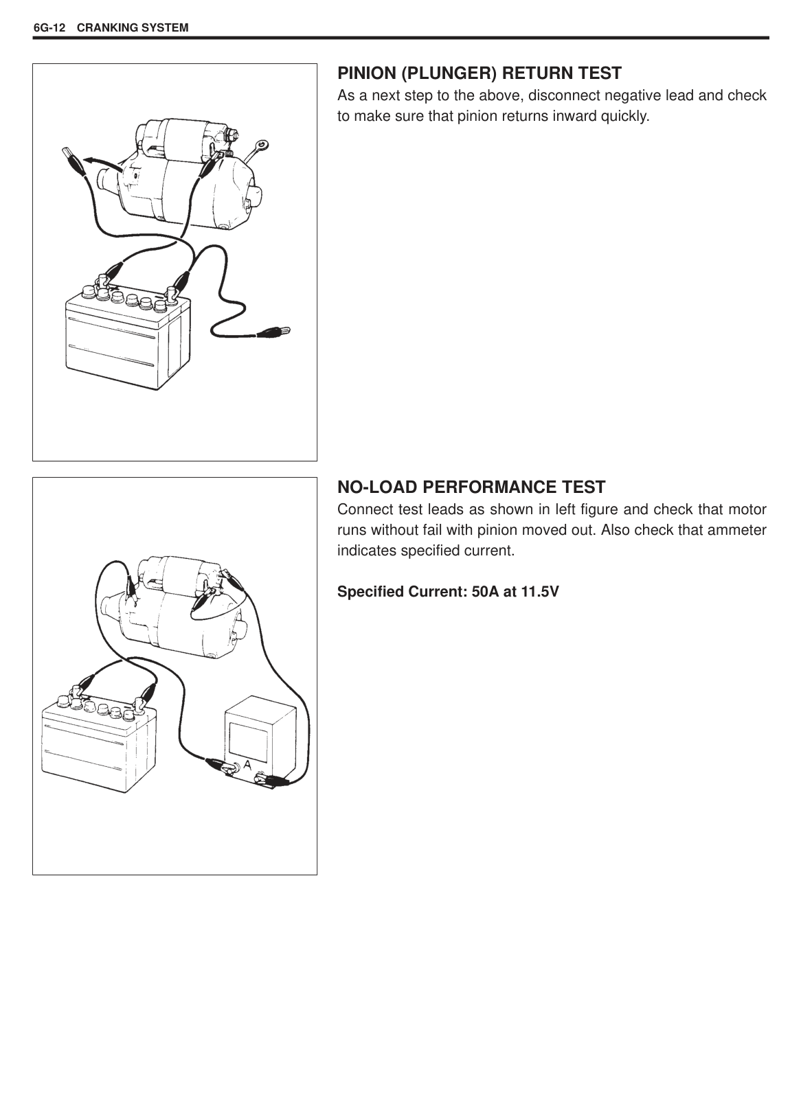
Performance Test 6G-11. . . . . . . . . . . . . . . . . . . . . . Pull-in test 6G-11. . . . . . . . . . . . . . . . . . . . . . . . . . Hold-in test 6G-11. . . . . . . . . . . . . . . . . . . . . . . . . Pinion return test 6G-12. . . . . . . . . . . . . . . . . . . . No-load performance test 6G-12. . . . . . . . . . . . .
SPECIFICATIONS 6G-13. . . . . . . . . . . . . . . . . . . . . . . REQUIRED SERVICE MATERIAL 6G-13. . . . . . . . . SPECIAL TOOL 6G-13. . . . . . . . . . . . . . . . . . . . . . . . .
6G
GENERAL DESCRIPTION
CRANKING CIRCUIT The cranking circuit consists of the battery, starting motor, ignition switch, and related electrical wiring. These components are connected electrically. Only the starting motor will be covered in this section.
STARTING MOTOR CIRCUIT The magnetic switch coils are magnetized when the starter switch is closed. The resulting plunger and pinion drive lever movement causes the pinion to engage the engine flywheel gear and the magnetic switch main contacts to close, and cranking takes place. When the engine starts, the pinion over-running clutch protects the armature from excessive speed until the switch is opened, at which time the return spring causes the pinion to disengage.
|| |---|
STARTING MOTOR Both of them consist of yoke assembly, armature assembly, over-running clutch assembly, magnetic switch assembly, front housing, rear housing, brush holder and drive lever. The magnetic switch assembly and parts in the starting motor are enclosed in the housings so that they will be protected against possible dirt and water splash.
|

1. Drive housing assembly
2. Washer
3. Snap ring
4. Pinion stop ring
5. Over-running clutch assembly: Apply grease A 99000-25010 to inside and outside of spline.
6. Armature: Apply grease A 99000-25010 to joint of drive housing bush, over-running clutch and armature shaft bush.
7. Pinion drive lever: Apply grease A 99000-25010 to joint of magnetic switch and over-running clutch.
8. Seal
9. Boot
10. Magnetic switch
11. Rear housing
12. Brush spring
13. Brush holder
14. Insulator
15. Rear housing bush
16. Brush
17. Yoke assembly
18. Housing bolt
19. Front housing bush
20. Nut
: Tightening Torque : Do not reuse


| |---|
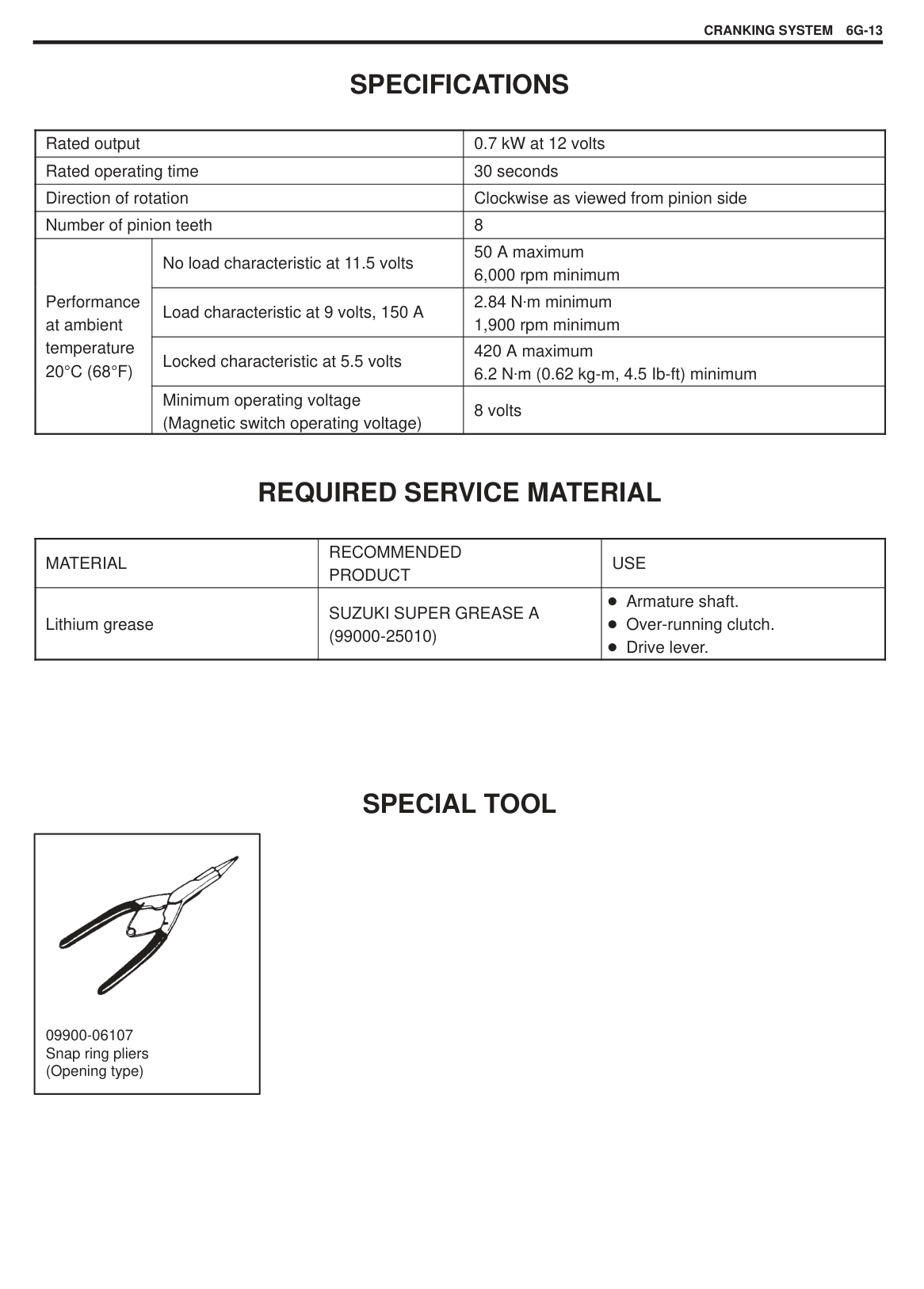
DIAGNOSIS
Possible symptoms due to starting system trouble would be as follows:
Starting motor does not run (or runs slowly) Starting motor runs but fails to crank engine Abnormal noise is heard
Proper diagnosis must be made to determine exactly where the cause of each trouble lies ..... in battery, wiring harness, (including starting motor switch), starting motor or engine. Do not remove motor just because starting motor does not run. Check following items and narrow down scope of possible causes.
|Condition|Possible Cause|Correction| |---|---|---| |Motor not running
|No operating sound of magnetic switch Transmission range switch is not in P or N, or not adjusted (A/T) Battery run down Battery voltage too low due to battery deterioration Poor contact in battery terminal connection Loose grounding cable connection Fuse set loose or blown off Poor contacting action of ignition switch and magnetic switch Lead wire coupler loose in place Open-circuit between ignition switch and magnetic switch Open-circuit in pull-in coil Brushes are seating poorly or worn down Poor sliding of plunger and/or pinion|Shift in P or N, or adjust switch.
Recharge battery. Replace battery. Retighten or replace. Retighten. Tighten or replace. Replace.
Retighten. Repair.
Replace magnetic switch. Repair or replace. Repair.| |Motor not running
|Operating sound of magnetic switch heard Battery run down Battery voltage too low due to battery deterioration Loose battery cable connections Burnt main contact point, or poor contacting action of magnetic switch Brushes are seating poorly or worn down Weakened brush spring Burnt commutator Poor grounding of field coil Layer short-circuit of armature Crankshaft rotation obstructed|Recharge battery. Replace battery. Retighten. Replace magnetic switch.
Repair or replace. Replace. Replace armature. Repair. Replace. Repair.|
|Condition|Possible Cause|Correction| |---|---|---| |Starting motor running but too slow (small torque)|If battery and wiring are satisfactory, inspect starting motor
Insufficient contact of magnetic switch main contacts Layer short-circuit of armature Disconnected, burnt or worn commutator
Poor grounding of field coil Worn brushes Weakened brush springs Burnt or abnormally worn end bush|Replace magnetic switch. Replace. Repair commutator or replace armature. Repair. Replace brush. Replace spring Replace bush.| |Starting motor running, but not cranking engine|Worn pinion tip Poor sliding of over-running clutch Over-running clutch slipping Worn teeth of ring gear|Replace over-running clutch. Repair. Replace over-running clutch. Replace flywheel (M/T) or drive plate (A/T).|
|Noise|Abnormally worn bush Worn pinion or worn teeth of ring gear
Poor sliding of pinion (failure in return movement) Lack of oil in each part|Replace bush. Replace over-running clutch or flywheel (M/T), drive plate (A/T). Repair or replace. Lubricate.| |Starting motor does not stop running|Fused contact points of magnetic switch Short-circuit between turns of magnetic switch coil (layer short-circuit) Failure of returning action in ignition switch|Replace magnetic switch. Replace magnetic switch.
Replace.|
|
| |---|
|
A: Pull up to disconnect hook| |---|
UNIT REPAIR OVERHAUL DISMOUNTING AND REMOUNTING
NOTE: Do not disassemble magnetic switch. Replace it as assembly, when required.
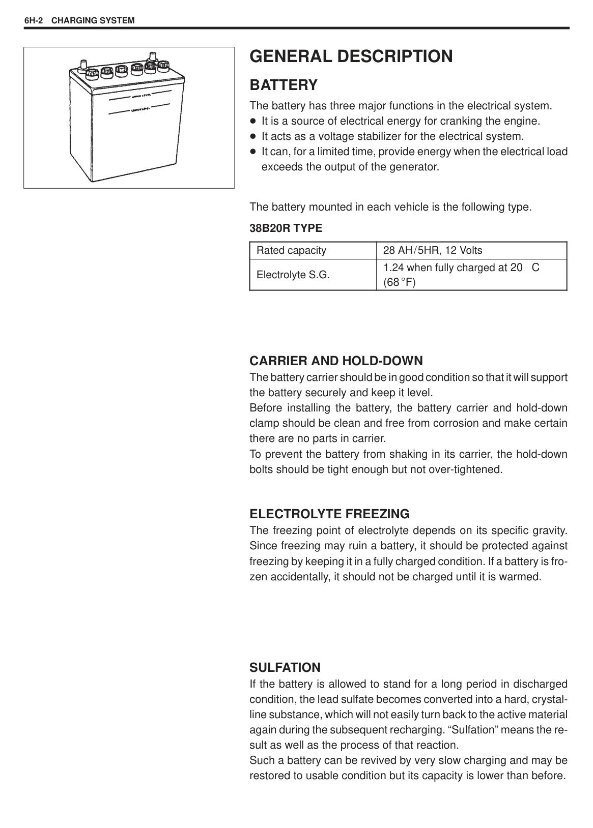
|| |---|
|| |---|
|| |---|
######### Special Tool (A) : 09900-06107
|| |---|
#### REASSEMBLY
NOTE: Use new snap ring on shaft for installation. Do not reuse snap ring.
|| |---|
|| |---|
NOTE: When installing brushes, make sure that brushes and commutator have been degreased thoroughly. Check to confirm that brush parts do not have unnecessary contacts with others.
|| |---|
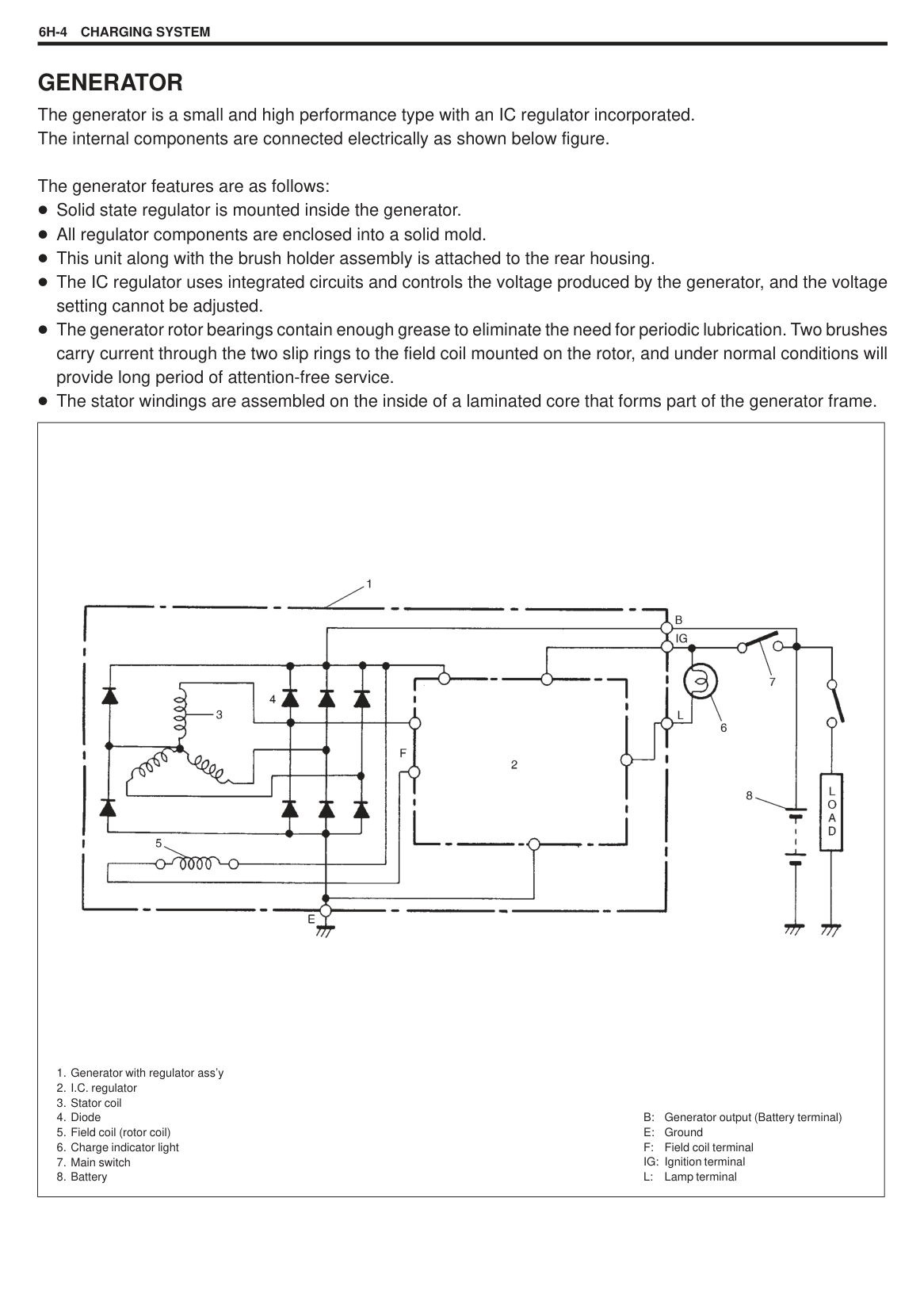
NOTE: Before installing nuts, make sure that plunger hook is connected with drive lever without fail. Face boot (2) breather down.
Upon completion of assembly, carry out PERFORMANCE TEST.
|| |---|
|| |---|
|| |---|
INSPECTION PLUNGER Inspect plunger for wear. Replace if necessary.
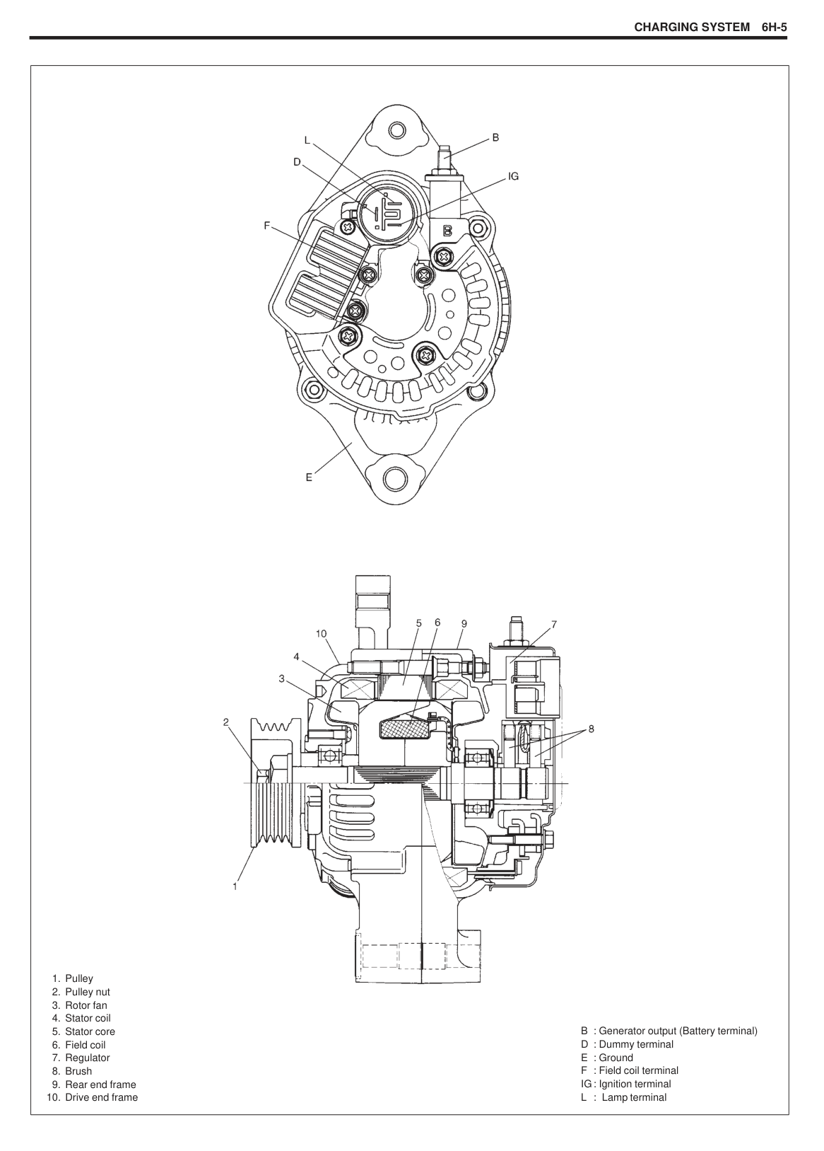
MAGNETIC SWITCH Push in plunger and release it. The plunger should return quickly to its original position. Replace if necessary.
######### Pull-In Coil Open Circuit Test
Check for continuity across magnetic switch ‘S’ terminal (1) and ‘M’ terminal (2). If no continuity exists, coil is open and should be
|| |---|
|| |---|
######### Hold-In Coil Open Circuit Test
Check for continuity across magnetic switch ‘S’ terminal (1) and coil case. If no continuity exists, coil is open and should be replaced.
BRUSH Measure length of brushes and replace them as necessary.
Brush length Limit : 6.0 mm (0.236 in.) New one : 10 mm (0.394 in.)
BRUSH HOLDER Check brush springs for rust or breakage. Also check brush holder for rust and insulation. Replace it as assembly, if required.
||
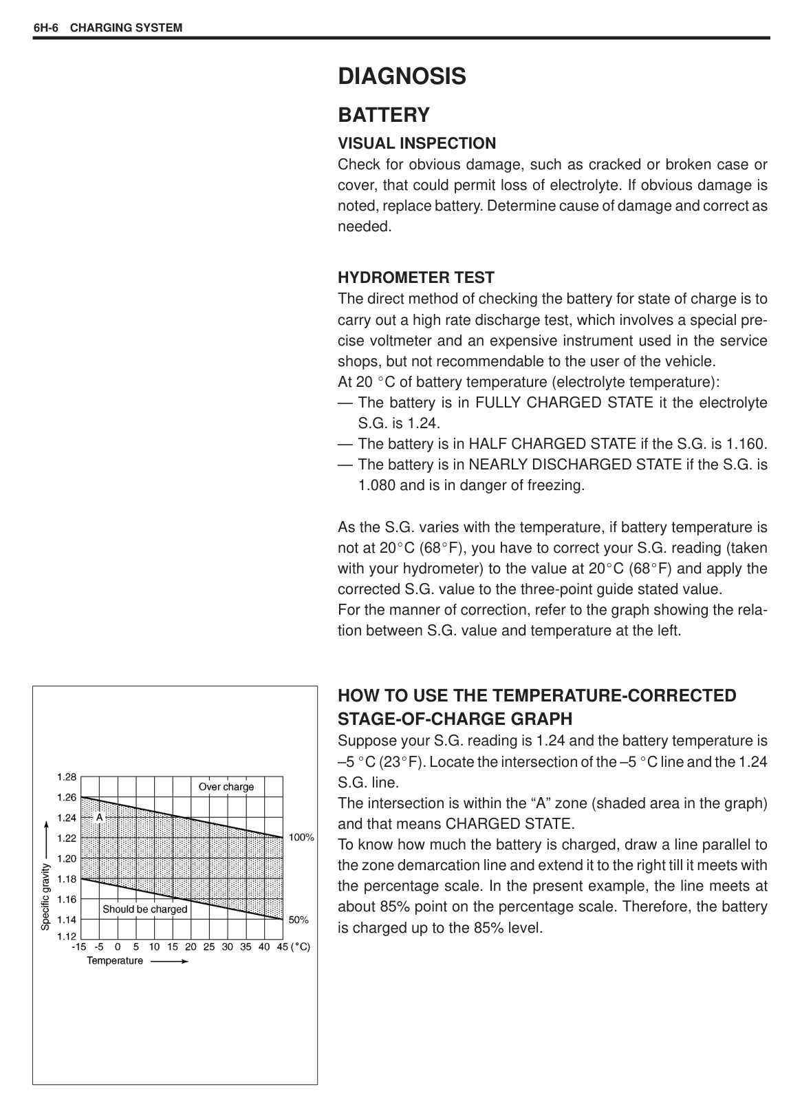
|---|
|| |---|
ARMATURE Ground Test Between commutator segment and armature core should be insulated. Use ohmmeter for inspection.
######### Open Circuit Test
Check for continuity between segments. If there is no continuity at any test point, there is an open circuit and armature must be
Check commutator for run-out with armature (1) supported on V-blocks (2). Correct it by using lathe, if required.
######### Commutator out of round Limit (maximum value): 0.4 mm (0.015 in.)
|| |---|
Check for wear and replace armature if diameter is below limit.
######### Commutator outside diameter Limit (minimum value): 27 mm (1.063 in.)
|
1. Mica insulator
2. Commutator segment
|
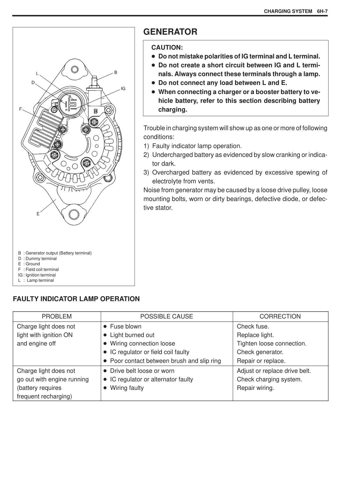
|---|
|| |---|
|| |---|
Correct and clean surface by using #400 emery cloth. Also check mica depth and correct it as required.
######### Commutator insulator depth “a” Limit (minimum value): 0.2 mm (0.008 in.)
YOKE Check field coil for continuity. There should be continuity between following terminals.
Between A terminals. Between B terminals. Between B terminal and C (bare metal part of yoke body).
###### OVER-RUNNING CLUTCH
Inspect pinion for wear, damage or other abnormal conditions. Check that clutch locks up when turned in direction of drive and rotates smoothly in reverse direction. Replace if necessary.
|
1. Terminal ‘S’| |---|
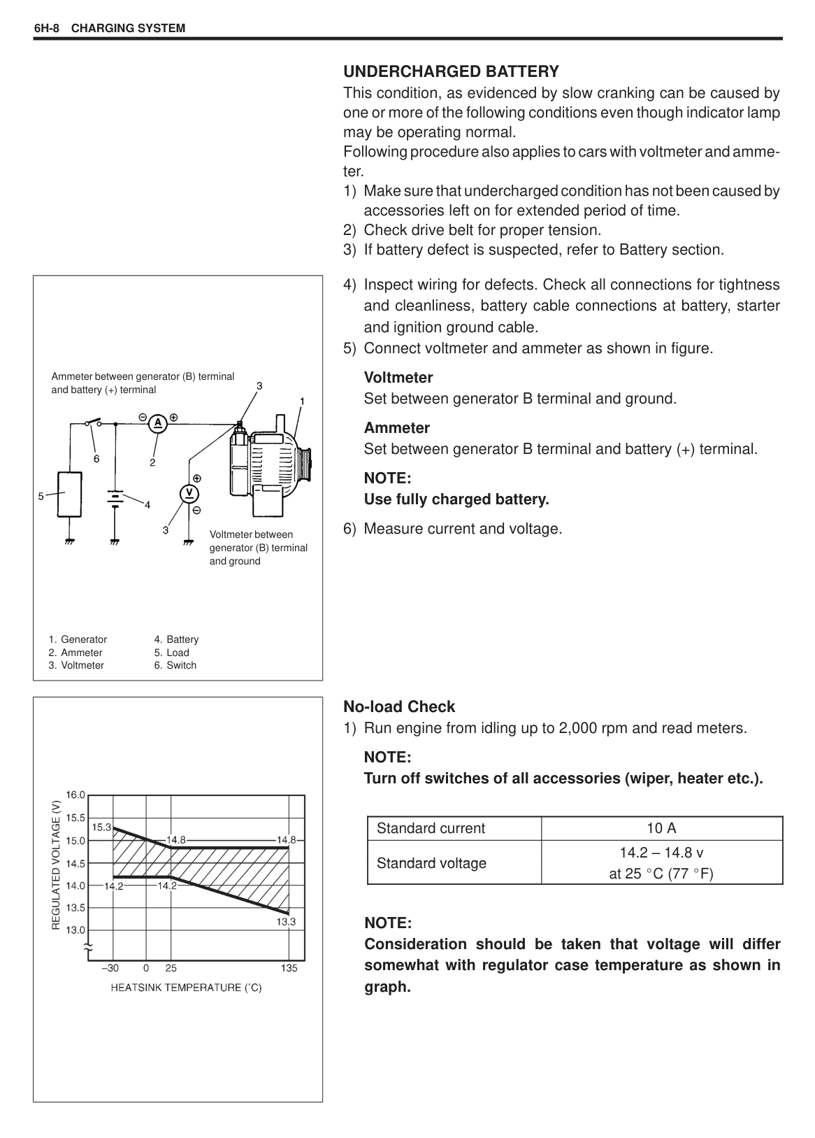
|| |---|
#### PERFORMANCE TEST
|CAUTION: Each test must be performed within 3 – 5 seconds to avoid coil from burning.| |---|
###### PULL-IN TEST
Connect test leads as shown in figure and check that pinion (overrunning clutch) move outward. If it does not, replace magnetic switch.
NOTE: Before testing, disconnect field coil lead (3) from ‘M’ terminal
(2).
###### HOLD-IN TEST
While connected as the above with pinion out, disconnect negative lead from ‘M’ terminal (1) and check that pinion remains out. If not, replace magnetic switch.
|| |---|
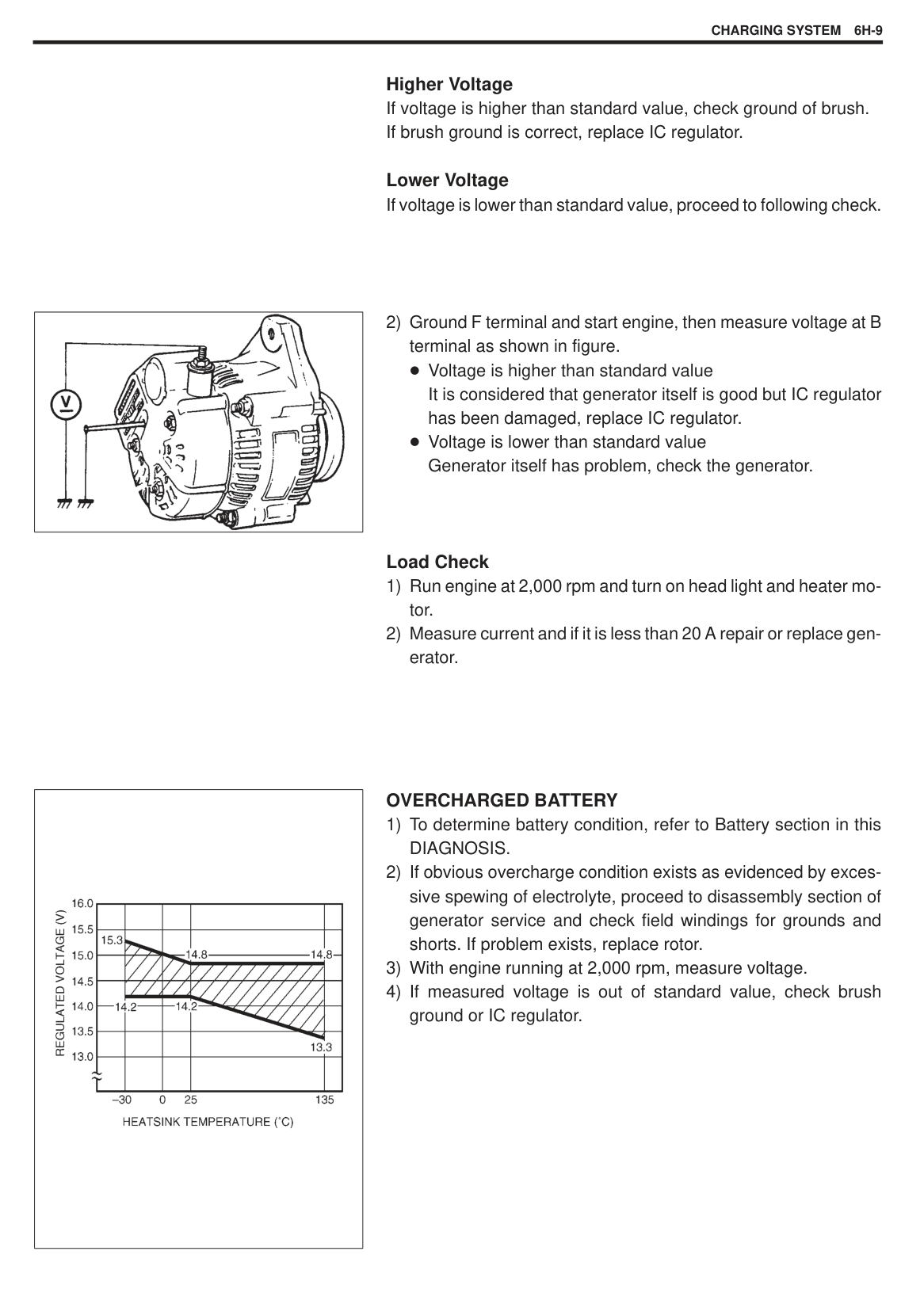
|| |---|
PINION (PLUNGER) RETURN TEST As a next step to the above, disconnect negative lead and check to make sure that pinion returns inward quickly.
###### NO-LOAD PERFORMANCE TEST
Connect test leads as shown in left figure and check that motor runs without fail with pinion moved out. Also check that ammeter indicates specified current.
######### Specified Current: 50A at 11.5V
CRANKING SYSTEM6G-13
SPECIFICATIONS
|Rated output|Rated output|0.7 kW at 12 volts| |---|---|---| |Rated operating time|Rated operating time|30 seconds| |Direction of rotation|Direction of rotation|Clockwise as viewed from pinion side| |Number of pinion teeth|Number of pinion teeth|8| |Performance at ambient temperature 20 C (68 F)
|No load characteristic at 11.5 volts|50 A maximum 6,000 rpm minimum| |Performance at ambient temperature 20 C (68 F)
|Load characteristic at 9 volts, 150 A|2.84 N m minimum 1,900 rpm minimum| |Performance at ambient temperature 20 C (68 F)
|Locked characteristic at 5.5 volts|420 A maximum 6.2 N m (0.62 kg-m, 4.5 Ib-ft) minimum| |Performance at ambient temperature 20 C (68 F)
|Minimum operating voltage (Magnetic switch operating voltage)|8 volts|
REQUIRED SERVICE MATERIAL
|MATERIAL|RECOMMENDED PRODUCT|USE| |---|---|---| |Lithium grease|SUZUKI SUPER GREASE A (99000-25010)|Armature shaft. Over-running clutch. Drive lever.|
|
09900-06107 Snap ring pliers (Opening type)| |---|
SPECIAL TOOL
SECTION 6H
CHARGING SYSTEM
#### CONTENTS
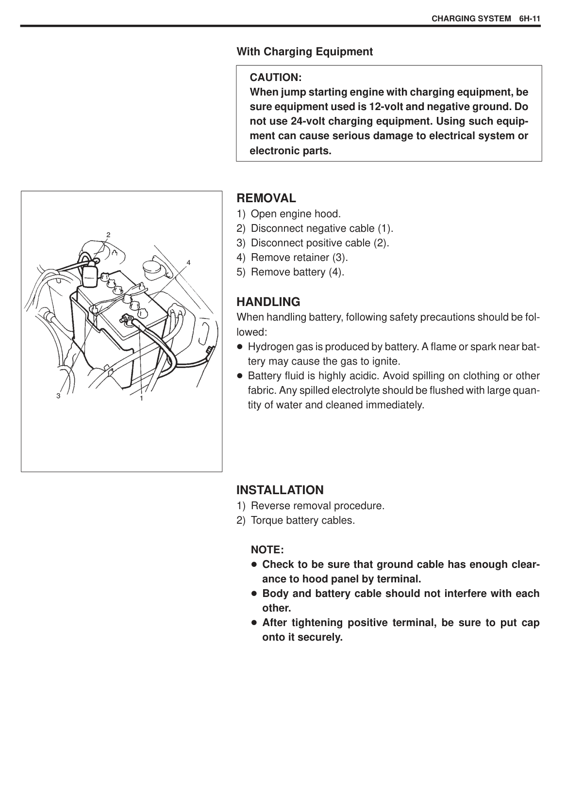
ON-VEHICLE SERVICE 6H-10. . . . . . . . . . . . . . . . . . . . . . . . . . . . . . . . . . . . . . . . . . . . . . . . . . . . . . . . . . . . . . . . . . .
Battery 6H-10. . . . . . . . . . . . . . . . . . . . . . . . . . . . . . . . . . . . . . . . . . . . . . . . . . . . . . . . . . . . . . . . . . . . . . . . . . . . . . . . Jump starting in case of emergency with auxiliary (booster) battery 6H-10. . . . . . . . . . . . . . . . . . . . . . . . . . Removal 6H-11. . . . . . . . . . . . . . . . . . . . . . . . . . . . . . . . . . . . . . . . . . . . . . . . . . . . . . . . . . . . . . . . . . . . . . . . . . . . . Handling 6H-11. . . . . . . . . . . . . . . . . . . . . . . . . . . . . . . . . . . . . . . . . . . . . . . . . . . . . . . . . . . . . . . . . . . . . . . . . . . . .
Generator 6H-12. . . . . . . . . . . . . . . . . . . . . . . . . . . . . . . . . . . . . . . . . . . . . . . . . . . . . . . . . . . . . . . . . . . . . . . . . . . . . . Removal 6H-12. . . . . . . . . . . . . . . . . . . . . . . . . . . . . . . . . . . . . . . . . . . . . . . . . . . . . . . . . . . . . . . . . . . . . . . . . . . . .
Generator/Water Pump Drive Belt 6H-13. . . . . . . . . . . . . . . . . . . . . . . . . . . . . . . . . . . . . . . . . . . . . . . . . . . . . . . . . Belt tension inspection 6H-13. . . . . . . . . . . . . . . . . . . . . . . . . . . . . . . . . . . . . . . . . . . . . . . . . . . . . . . . . . . . . . . . Removal 6H-13. . . . . . . . . . . . . . . . . . . . . . . . . . . . . . . . . . . . . . . . . . . . . . . . . . . . . . . . . . . . . . . . . . . . . . . . . . . . .
Disassembly 6H-15. . . . . . . . . . . . . . . . . . . . . . . . . . . . . . . . . . . . . . . . . . . . . . . . . . . . . . . . . . . . . . . . . . . . . . . . . Inspection 6H-17. . . . . . . . . . . . . . . . . . . . . . . . . . . . . . . . . . . . . . . . . . . . . . . . . . . . . . . . . . . . . . . . . . . . . . . . . . . Replace Brush 6H-19. . . . . . . . . . . . . . . . . . . . . . . . . . . . . . . . . . . . . . . . . . . . . . . . . . . . . . . . . . . . . . . . . . . . . . . Assembly 6H-20. . . . . . . . . . . . . . . . . . . . . . . . . . . . . . . . . . . . . . . . . . . . . . . . . . . . . . . . . . . . . . . . . . . . . . . . . . . .
########## SPECIFICATIONS 6H-22. . . . . . . . . . . . . . . . . . . . . . . . . . . . . . . . . . . . . . . . . . . . . . . . . . . . . . . . . . . . . . . . . . . .
6H
||
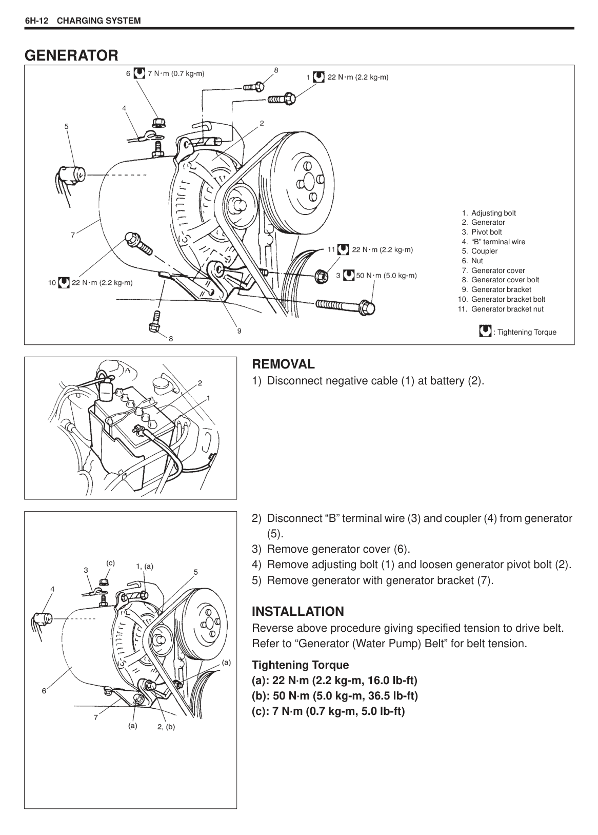
|---|
GENERAL DESCRIPTION BATTERY The battery has three major functions in the electrical system. It is a source of electrical energy for cranking the engine. It acts as a voltage stabilizer for the electrical system. It can, for a limited time, provide energy when the electrical load exceeds the output of the generator.
The battery mounted in each vehicle is the following type. 38B20R TYPE
|Rated capacity|28 AH/5HR, 12 Volts| |---|---| |Electrolyte S.G.|1.24 when fully charged at 20 C (68 F)|
CARRIER AND HOLD-DOWN The battery carrier should be in good condition so that it will support the battery securely and keep it level. Before installing the battery, the battery carrier and hold-down clamp should be clean and free from corrosion and make certain there are no parts in carrier. To prevent the battery from shaking in its carrier, the hold-down bolts should be tight enough but not over-tightened.
###### ELECTROLYTE FREEZING
The freezing point of electrolyte depends on its specific gravity. Since freezing may ruin a battery, it should be protected against freezing by keeping it in a fully charged condition. If a battery is frozen accidentally, it should not be charged until it is warmed.
SULFATION If the battery is allowed to stand for a long period in discharged condition, the lead sulfate becomes converted into a hard, crystalline substance, which will not easily turn back to the active material again during the subsequent recharging. “Sulfation” means the result as well as the process of that reaction. Such a battery can be revived by very slow charging and may be restored to usable condition but its capacity is lower than before.
###### CARE OF BATTERY
When keeping battery on vehicle over a long period of time, follow instructions given below.
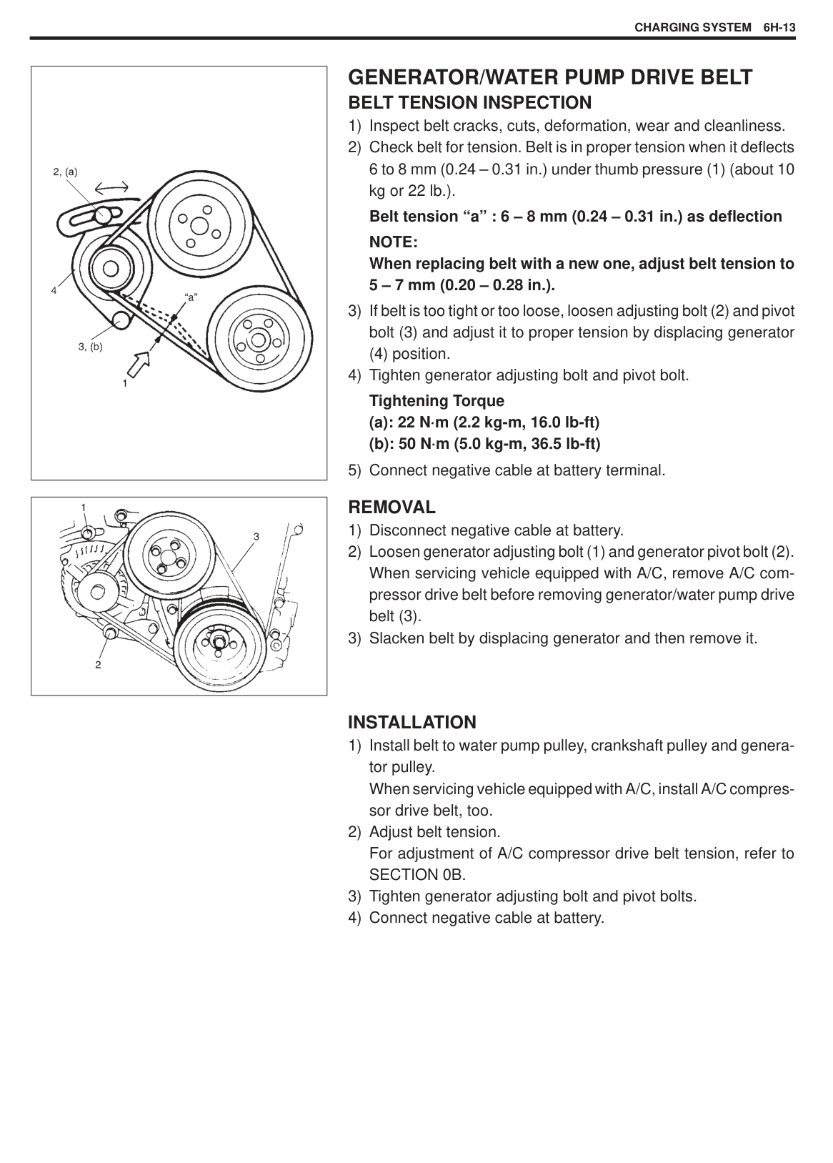
Weekly, start the engine and run it until it reaches normal operating temperature with engine speed of 2000 to 3000 rpm. Make sure all electric switches are off before storing the vehicle. Recharge the battery twice a month to prevent it from discharging excessively. This is especially important when ambient temperature is low. The battery discharges even when it is not used, while vehicles are being stored. Battery electrolyte can freeze and battery case can crack at cold ambient condition if battery is not properly charged.
|WARNING: Never expose battery to open flame or electric spark because of battery generate gas which is flammable and explosive. Do not allow battery fluid to contact eyes, skin, fabrics, or painted surfaces as fluid is a corrosive acid. Flush any contacted area with water immediately and thoroughly. Batteries should always be kept out of reach of children.| |---|
GENERATOR The generator is a small and high performance type with an IC regulator incorporated. The internal components are connected electrically as shown below figure.
The generator features are as follows: Solid state regulator is mounted inside the generator. All regulator components are enclosed into a solid mold. This unit along with the brush holder assembly is attached to the rear housing. The IC regulator uses integrated circuits and controls the voltage produced by the generator, and the voltage setting cannot be adjusted. The generator rotor bearings contain enough grease to eliminate the need for periodic lubrication. Two brushes carry current through the two slip rings to the field coil mounted on the rotor, and under normal conditions will provide long period of attention-free service. The stator windings are assembled on the inside of a laminated core that forms part of the generator frame.
|
1. Generator with regulator ass’y
2. I.C. regulator
3. Stator coil
4. Diode
5. Field coil (rotor coil)
6. Charge indicator light
7. Main switch
8. Battery
B: Generator output (Battery terminal)
E: Ground
F: Field coil terminal IG: Ignition terminal L: Lamp terminal
| |---|
|

1. Pulley
2. Pulley nut
3. Rotor fan
4. Stator coil
5. Stator core
6. Field coil
7. Regulator
8. Brush
9. Rear end frame
10. Drive end frame
B : Generator output (Battery terminal)
D : Dummy terminal
E : Ground
F : Field coil terminal IG: Ignition terminal L : Lamp terminal
| |---|
DIAGNOSIS BATTERY VISUAL INSPECTION
Check for obvious damage, such as cracked or broken case or cover, that could permit loss of electrolyte. If obvious damage is noted, replace battery. Determine cause of damage and correct as needed.
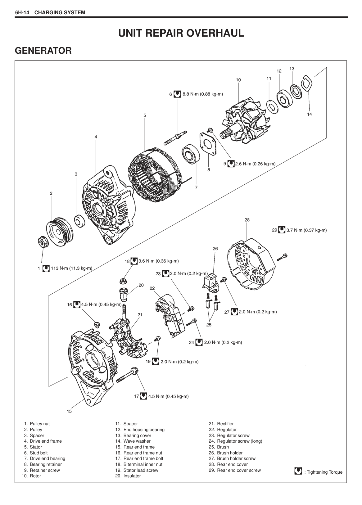
HYDROMETER TEST The direct method of checking the battery for state of charge is to carry out a high rate discharge test, which involves a special precise voltmeter and an expensive instrument used in the service shops, but not recommendable to the user of the vehicle. At 20 C of battery temperature (electrolyte temperature):
— The battery is in FULLY CHARGED STATE it the electrolyte S.G. is 1.24.
— The battery is in HALF CHARGED STATE if the S.G. is 1.160. — The battery is in NEARLY DISCHARGED STATE if the S.G. is
1.080 and is in danger of freezing.
As the S.G. varies with the temperature, if battery temperature is not at 20 C (68 F), you have to correct your S.G. reading (taken with your hydrometer) to the value at 20 C (68 F) and apply the corrected S.G. value to the three-point guide stated value. For the manner of correction, refer to the graph showing the relation between S.G. value and temperature at the left.
|| |---|
HOW TO USE THE TEMPERATURE-CORRECTED STAGE-OF-CHARGE GRAPH Suppose your S.G. reading is 1.24 and the battery temperature is –5 C (23 F). Locate the intersection of the –5 C line and the 1.24 S.G. line. The intersection is within the “A” zone (shaded area in the graph) and that means CHARGED STATE. To know how much the battery is charged, draw a line parallel to the zone demarcation line and extend it to the right till it meets with the percentage scale. In the present example, the line meets at about 85% point on the percentage scale. Therefore, the battery is charged up to the 85% level.
|
B : Generator output (Battery terminal)
D : Dummy terminal
E : Ground
F : Field coil terminal IG: Ignition terminal L : Lamp terminal
| |---|
#### GENERATOR
|CAUTION: Do not mistake polarities of IG terminal and L terminal. Do not create a short circuit between IG and L terminals. Always connect these terminals through a lamp. Do not connect any load between L and E. When connecting a charger or a booster battery to vehicle battery, refer to this section describing battery charging.| |---|
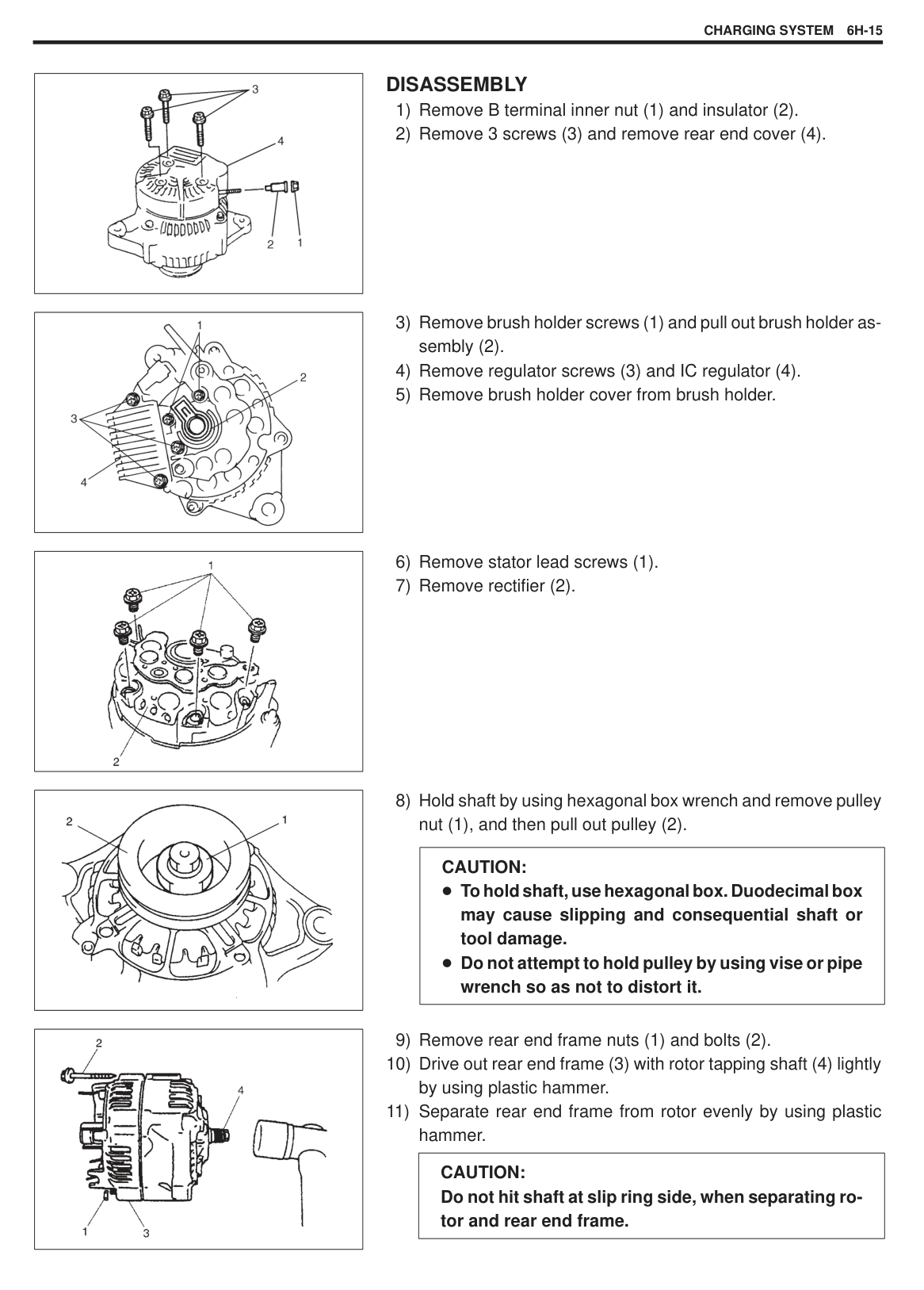
Trouble in charging system will show up as one or more of following conditions:
Noise from generator may be caused by a loose drive pulley, loose mounting bolts, worn or dirty bearings, defective diode, or defective stator.
######## FAULTY INDICATOR LAMP OPERATION
|PROBLEM|POSSIBLE CAUSE|CORRECTION| |---|---|---| |Charge light does not light with ignition ON and engine off|Fuse blown Light burned out Wiring connection loose IC regulator or field coil faulty Poor contact between brush and slip ring|Check fuse. Replace light. Tighten loose connection. Check generator. Repair or replace.| |Charge light does not go out with engine running (battery requires frequent recharging)|Drive belt loose or worn IC regulator or alternator faulty Wiring faulty|Adjust or replace drive belt. Check charging system. Repair wiring.|
UNDERCHARGED BATTERY This condition, as evidenced by slow cranking can be caused by one or more of the following conditions even though indicator lamp may be operating normal. Following procedure also applies to cars with voltmeter and ammeter.
|
1. Generator
2. Ammeter
3. Voltmeter
4. Battery
5. Load
6. Switch
Ammeter between generator (B) terminal and battery (+) terminal
Voltmeter between generator (B) terminal and ground| |---|
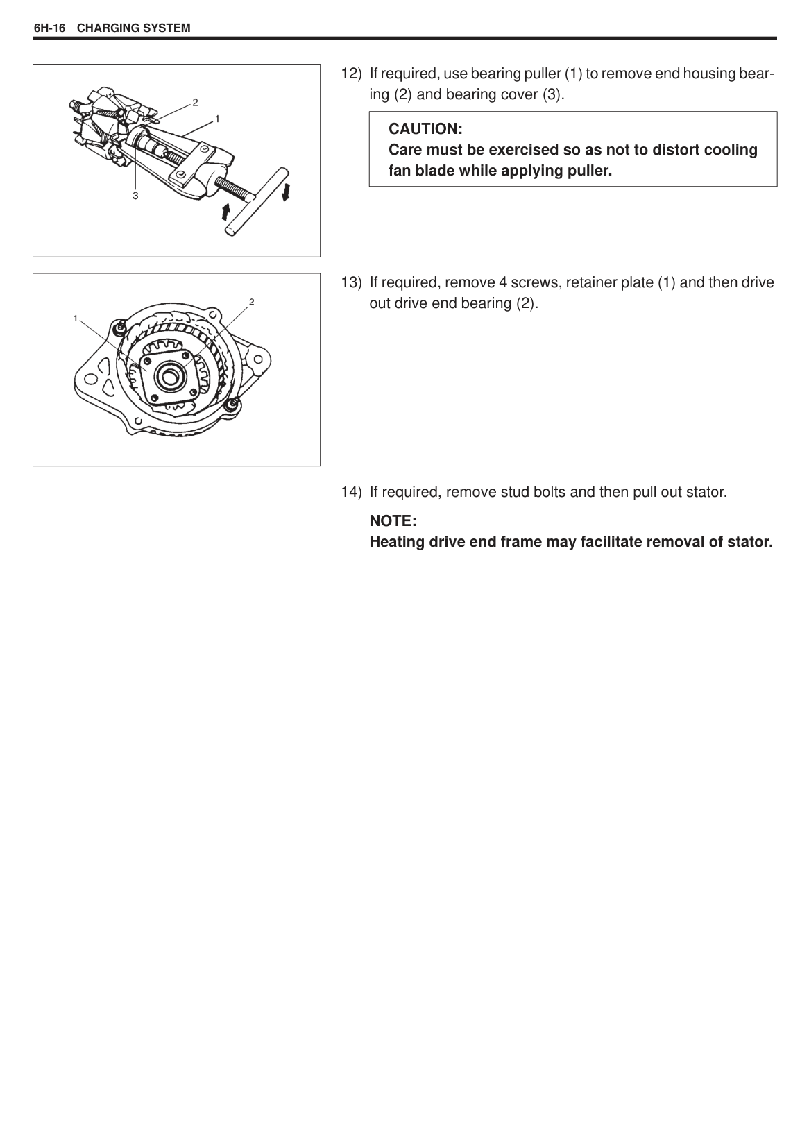
Voltmeter Set between generator B terminal and ground.
Ammeter Set between generator B terminal and battery (+) terminal.
NOTE: Use fully charged battery.
|| |---|
######## No-load Check
NOTE: Turn off switches of all accessories (wiper, heater etc.).
|Standard current|10 A|
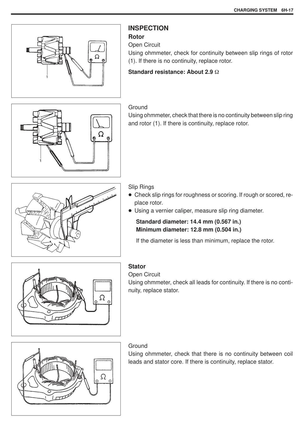
|---|---| |Standard voltageStandard voltage
|14.2 – 14.8 v at 25 C (77 F)
|
NOTE: Consideration should be taken that voltage will differ somewhat with regulator case temperature as shown in graph.
Higher Voltage If voltage is higher than standard value, check ground of brush. If brush ground is correct, replace IC regulator.
Lower Voltage If voltage is lower than standard value, proceed to following check.
|| |---|
Voltage is higher than standard value It is considered that generator itself is good but IC regulator has been damaged, replace IC regulator. Voltage is lower than standard value Generator itself has problem, check the generator.
######## Load Check
||
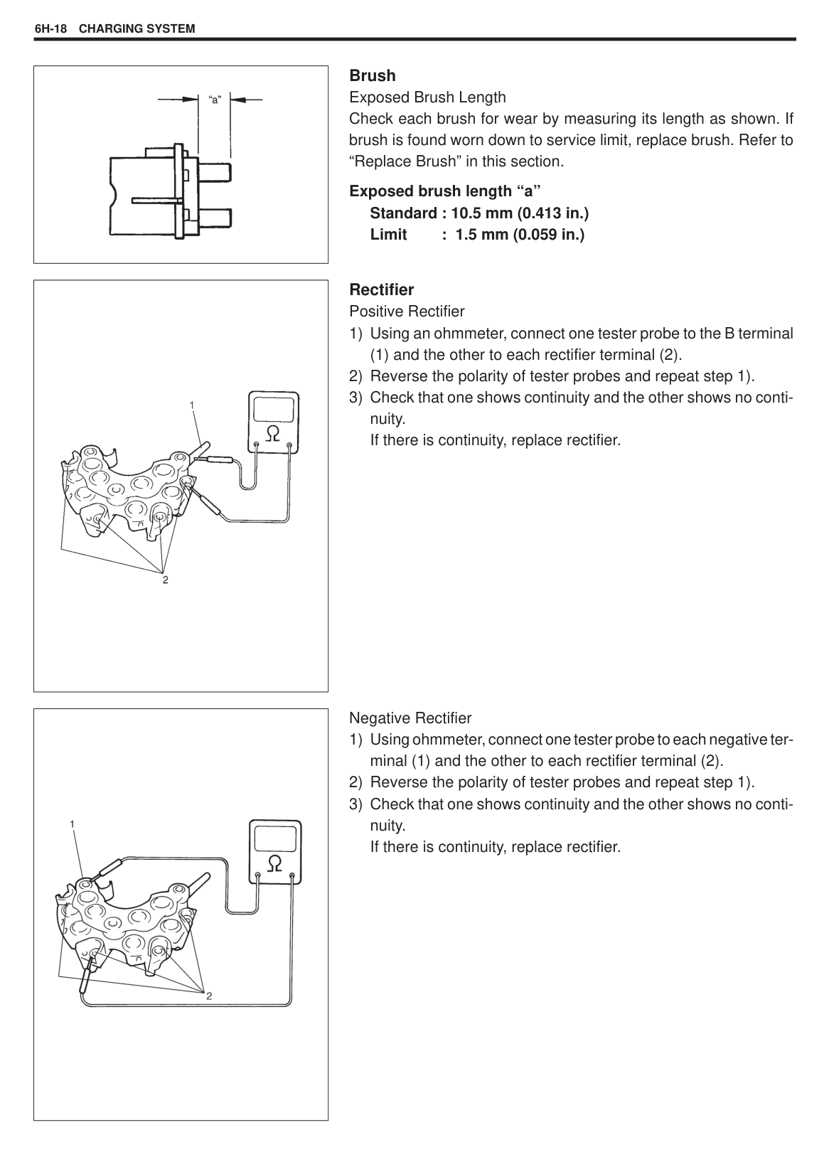
|---|
######## OVERCHARGED BATTERY
ON-VEHICLE SERVICE BATTERY
###### JUMP STARTING IN CASE OF EMERGENCY WITH AUXILIARY (BOOSTER) BATTERY
Both booster and discharged battery should be treated carefully when using jumper cables. Follow procedure outlined below, being careful not to cause sparks.
|WARNING: Departure from these conditions or procedure described below could result in:
1) Serious personal injury (particularly to eyes) or property damage from such causes as battery explosion, battery acid, or electrical burns.
2) Damage to electronic components of either vehicle. Remove rings, watches, and other jewelry. Wear approved eye protection. Be careful so that metal tools or jumper cables do not contact positive battery terminal (or metal in contact with it) and any other metal on vehicle, because a short circuit could occur.
| |---|
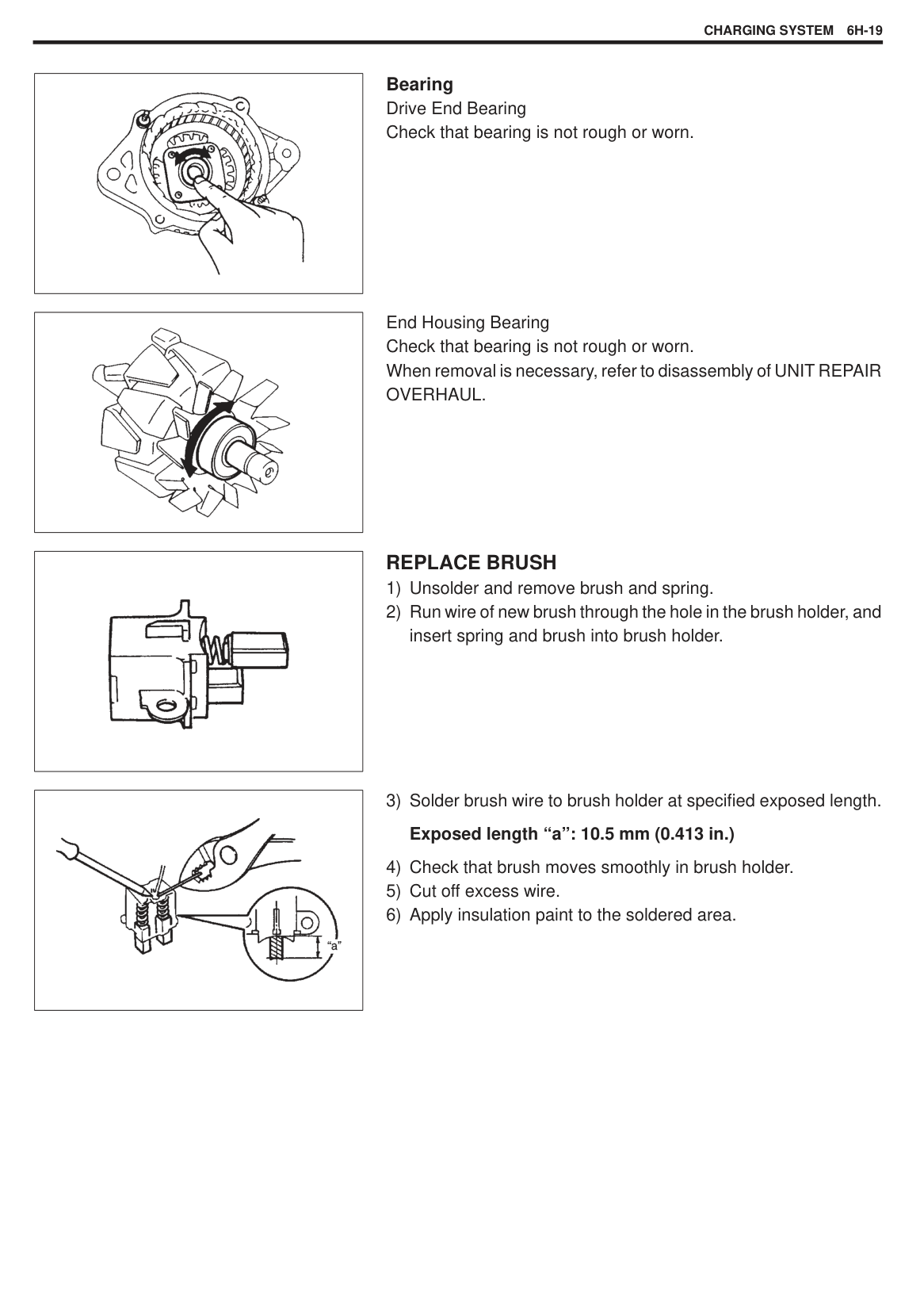
|WARNING: Do not connect negative cable directly to negative terminal of dead battery.| |---|
######## With Charging Equipment
|CAUTION: When jump starting engine with charging equipment, be sure equipment used is 12-volt and negative ground. Do not use 24-volt charging equipment. Using such equipment can cause serious damage to electrical system or electronic parts.| |---|
|| |---|
###### REMOVAL
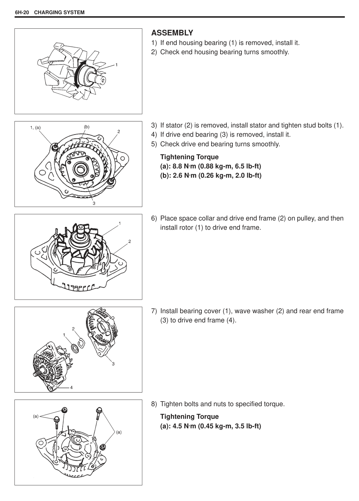
HANDLING When handling battery, following safety precautions should be followed:
Hydrogen gas is produced by battery. A flame or spark near battery may cause the gas to ignite. Battery fluid is highly acidic. Avoid spilling on clothing or other fabric. Any spilled electrolyte should be flushed with large quantity of water and cleaned immediately.
###### INSTALLATION
NOTE: Check to be sure that ground cable has enough clearance to hood panel by terminal. Body and battery cable should not interfere with each other. After tightening positive terminal, be sure to put cap onto it securely.
#### GENERATOR
|
1. Adjusting bolt
2. Generator
3. Pivot bolt
4. “B” terminal wire
5. Coupler
6. Nut
7. Generator cover
8. Generator cover bolt
9. Generator bracket
10. Generator bracket bolt
11. Generator bracket nut
: Tightening Torque
| |---|
|| |---|
###### REMOVAL
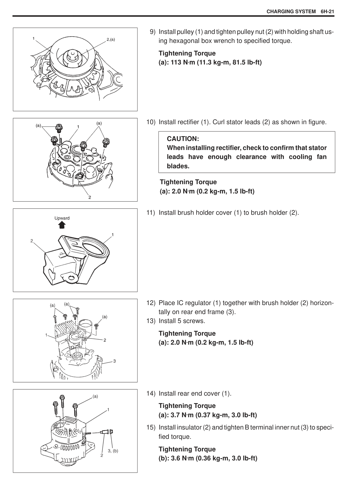
|| |---|
(5).
INSTALLATION Reverse above procedure giving specified tension to drive belt. Refer to “Generator (Water Pump) Belt” for belt tension.
Tightening Torque
|| |---|
|| |---|
#### GENERATOR/WATER PUMP DRIVE BELT BELT TENSION INSPECTION
(4) position.
###### INSTALLATION
UNIT REPAIR OVERHAUL GENERATOR
|
1. Pulley nut
2. Pulley
3. Spacer
4. Drive end frame
5. Stator
6. Stud bolt
7. Drive end bearing
8. Bearing retainer
9. Retainer screw
10. Rotor
11. Spacer
12. End housing bearing
13. Bearing cover
14. Wave washer
15. Rear end frame
16. Rear end frame nut
17. Rear end frame bolt
18. B terminal inner nut
19. Stator lead screw
20. Insulator
21. Rectifier
22. Regulator
23. Regulator screw
24. Regulator screw (long)
25. Brush
26. Brush holder
27. Brush holder screw
28. Rear end cover
29. Rear end cover screw : Tightening Torque
| |---|
|| |---|
###### DISASSEMBLY
|| |---|
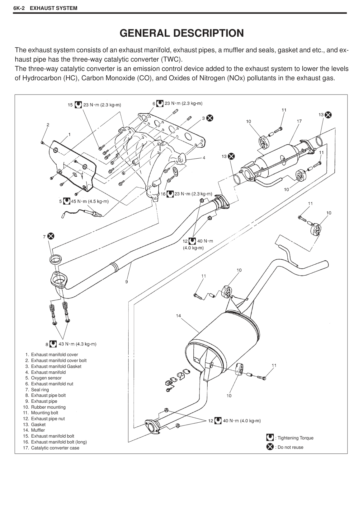
|| |---|
|| |---|
|CAUTION: To hold shaft, use hexagonal box. Duodecimal box may cause slipping and consequential shaft or tool damage. Do not attempt to hold pulley by using vise or pipe wrench so as not to distort it.| |---|
|| |---|
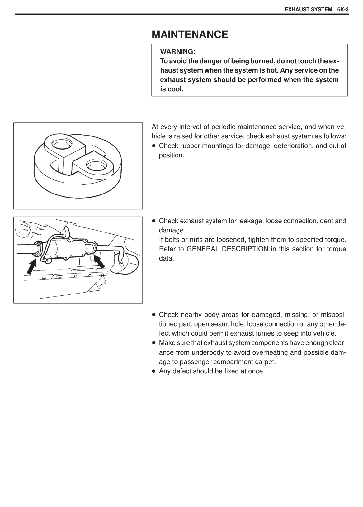
|CAUTION: Do not hit shaft at slip ring side, when separating rotor and rear end frame.| |---|
|| |---|
|CAUTION: Care must be exercised so as not to distort cooling fan blade while applying puller.| |---|
|| |---|
######### NOTE: Heating drive end frame may facilitate removal of stator.
|| |---|
|| |---|
|| |---|
|| |---|
|| |---|
INSPECTION Rotor Open Circuit Using ohmmeter, check for continuity between slip rings of rotor
(1). If there is no continuity, replace rotor. Standard resistance: About 2.9
Ground Using ohmmeter, check that there is no continuity between slip ring and rotor (1). If there is continuity, replace rotor.
Slip Rings Check slip rings for roughness or scoring. If rough or scored, replace rotor. Using a vernier caliper, measure slip ring diameter.
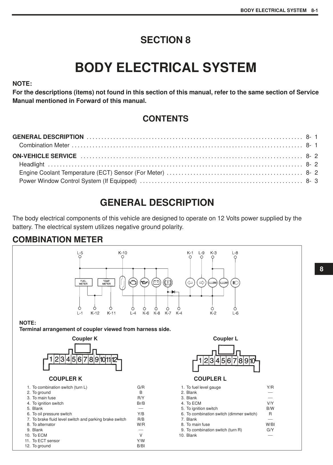
Standard diameter: 14.4 mm (0.567 in.) Minimum diameter: 12.8 mm (0.504 in.)
If the diameter is less than minimum, replace the rotor.
Stator Open Circuit Using ohmmeter, check all leads for continuity. If there is no continuity, replace stator.
Ground Using ohmmeter, check that there is no continuity between coil leads and stator core. If there is continuity, replace stator.
|| |---|
|| |---|
|| |---|
Brush Exposed Brush Length Check each brush for wear by measuring its length as shown. If brush is found worn down to service limit, replace brush. Refer to “Replace Brush” in this section.
Exposed brush length “a” Standard : 10.5 mm (0.413 in.) Limit : 1.5 mm (0.059 in.)
Rectifier Positive Rectifier
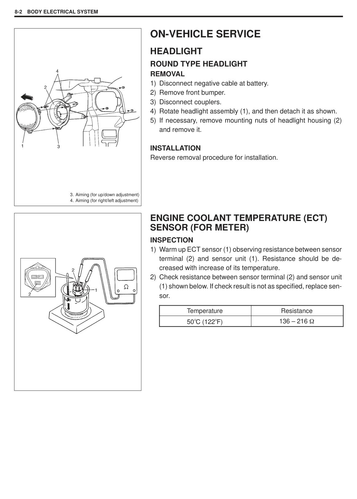
(1) and the other to each rectifier terminal (2).
Negative Rectifier
|| |---|
|| |---|
|| |---|
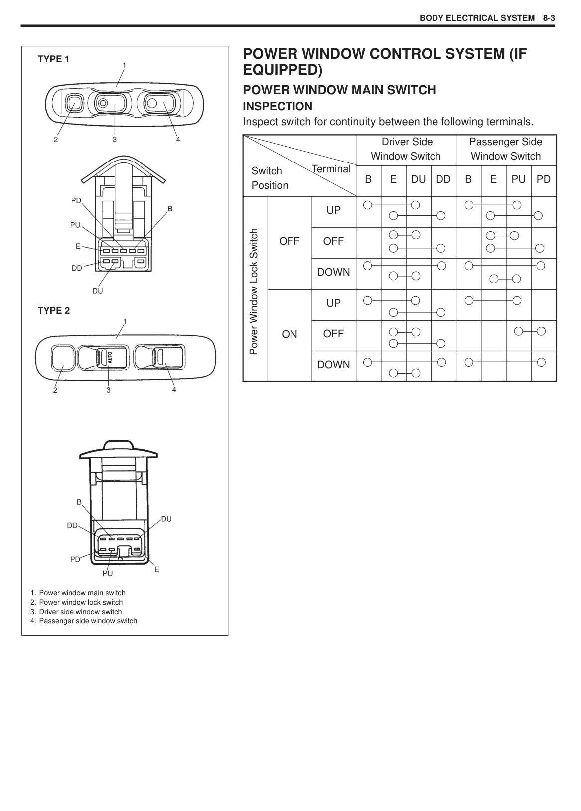
Bearing Drive End Bearing Check that bearing is not rough or worn.
End Housing Bearing Check that bearing is not rough or worn. When removal is necessary, refer to disassembly of UNIT REPAIR OVERHAUL.
###### REPLACE BRUSH
|| |---|
|| |---|
###### ASSEMBLY
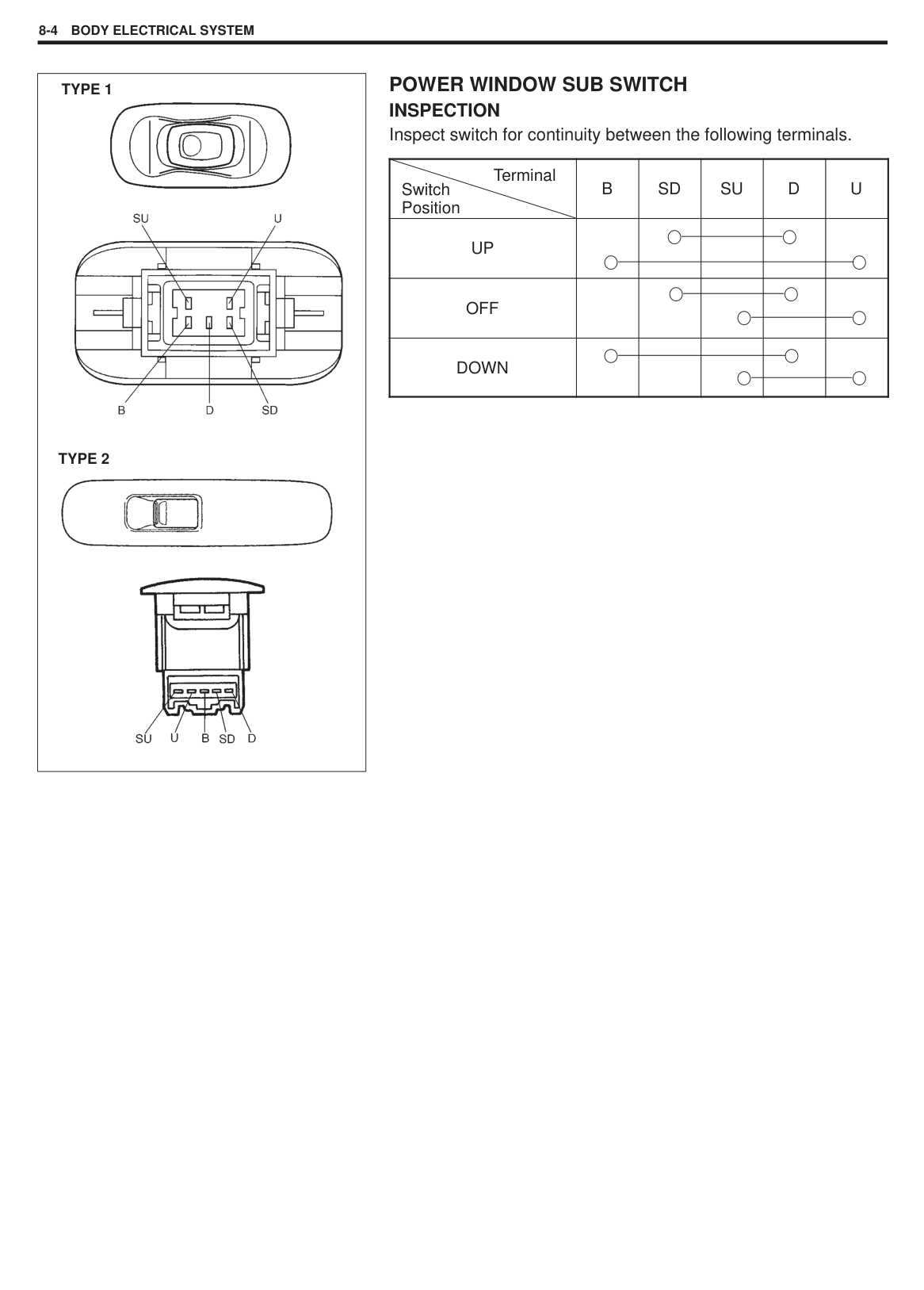
|| |---|
Tightening Torque (a): 8.8 N.m (0.88 kg-m, 6.5 lb-ft) (b): 2.6 N.m (0.26 kg-m, 2.0 lb-ft)
|| |---|
|| |---|
(3) to drive end frame (4).

|| |---|
######### Tightening Torque (a): 4.5 N.m (0.45 kg-m, 3.5 lb-ft)
|| |---|
Tightening Torque (a): 113 N.m (11.3 kg-m, 81.5 lb-ft)
|| |---|
|CAUTION: When installing rectifier, check to confirm that stator leads have enough clearance with cooling fan blades.| |---|
Tightening Torque (a): 2.0 N.m (0.2 kg-m, 1.5 lb-ft)
|| |---|
|| |---|
|| |---|
14) Install rear end cover (1).
Tightening Torque
######### Tightening Torque (b): 3.6 N.m (0.36 kg-m, 3.0 lb-ft)
|| |---|
SPECIFICATIONS BATTERY
|Rated capacity|28 AH/5 HR, 12 Volts| |---|---| |Electrolyte|EXCIDE : 2.4 L (5.07/4.22 US/lmp pt) STANDARD : 2.2 L (4.65/3.87 US/lmp pt) AMCO : 2.4 L (5.07/4.22 US/lmp pt)| |Electrolyte S.G.|1.24 when fully charged at 20 C (68 F)|
GENERATOR
|Rated voltage|12 V| |---|---| |Nominal output|55 A (at 13.5 V)| |Permissible max. speed|18,000 rpm| |No-load speed|1,070 r/min (rpm)| |Setting voltage|14.2 to 14.8 V| |Permissible ambient temperature|–30 to 90 C (–22 to 194 F)| |Polarity|Negative ground| |Rotation|Clockwise viewed from pulley side|
SECTION 6K
EXHAUST SYSTEM
#### CONTENTS
GENERAL DESCRIPTION 6K-2. . . . . . . . . . . . . . . . . . . . . . . . . . . . . . . . . . . . . . . . . . . . . . . . . . . . . . . . . . . . . . . . . . . . . . . . . MAINTENANCE 6K-3. . . . . . . . . . . . . . . . . . . . . . . . . . . . . . . . . . . . . . . . . . . . . . . . . . . . . . . . . . . . . . . . . . . . . . . . . . . . . . . . . . ON-VEHICLE SERVICE 6K-4. . . . . . . . . . . . . . . . . . . . . . . . . . . . . . . . . . . . . . . . . . . . . . . . . . . . . . . . . . . . . . . . . . . . . . . . . . .
|CAUTION: THE ENGINE OF THIS VEHICLE REQUIRES THE USE OF UNLEADED FUEL ONLY. USE OF LEADED AND/OR LOW LEAD FUEL CAN RESULT IN DAMAGE AND REDUCE THE EFFECTIVENESS OF THE CATALYTIC CONVERTER.| |---|
6K
GENERAL DESCRIPTION
The exhaust system consists of an exhaust manifold, exhaust pipes, a muffler and seals, gasket and etc., and exhaust pipe has the three-way catalytic converter (TWC). The three-way catalytic converter is an emission control device added to the exhaust system to lower the levels of Hydrocarbon (HC), Carbon Monoxide (CO), and Oxides of Nitrogen (NOx) pollutants in the exhaust gas.
|

: Tightening Torque : Do not reuse

1. Exhaust manifold cover
2. Exhaust manifold cover bolt
3. Exhaust manifold Gasket
4. Exhaust manifold
5. Oxygen sensor
6. Exhaust manifold nut
7. Seal ring
8. Exhaust pipe bolt
9. Exhaust pipe
10. Rubber mounting
11. Mounting bolt
12. Exhaust pipe nut
13. Gasket
14. Muffler
15. Exhaust manifold bolt
16. Exhaust manifold bolt (long)
17. Catalytic converter case
| |---|
MAINTENANCE
|WARNING: To avoid the danger of being burned, do not touch the exhaust system when the system is hot. Any service on the exhaust system should be performed when the system is cool.| |---|
|| |---|
|| |---|
At every interval of periodic maintenance service, and when vehicle is raised for other service, check exhaust system as follows:
Check rubber mountings for damage, deterioration, and out of position.
Check exhaust system for leakage, loose connection, dent and damage. If bolts or nuts are loosened, tighten them to specified torque. Refer to GENERAL DESCRIPTION in this section for torque data.
Check nearby body areas for damaged, missing, or mispositioned part, open seam, hole, loose connection or any other defect which could permit exhaust fumes to seep into vehicle. Make sure that exhaust system components have enough clearance from underbody to avoid overheating and possible damage to passenger compartment carpet. Any defect should be fixed at once.
|WARNING: To avoid the danger of being burned, do not touch the exhaust system when the system is hot. Any service on the exhaust system should be performed when the system is cool.| |---|
EXHAUST MANIFOLD Refer to Section 6A1 for removal and installation procedures of exhaust manifold.
Check gasket and seal for deterioration or damage. Replace them as necessary.
EXHAUST PIPE For replacement of exhaust pipe, be sure to hoist vehicle and observe WARNING under “Maintenance” and the following.
|CAUTION: Exhaust pipe have three way catalytic converter in it, it should not be exposed to any impulse. Be careful not to drop it or hit it against something.| |---|
Tighten bolts and nuts to specified torque when reassembling. Refer to GENERAL DESCRIPTION in this section for location of bolts and nuts. After installation, start engine and check each joint of exhaust system for leakage.
SECTION 8
BODY ELECTRICAL SYSTEM
NOTE: For the descriptions (items) not found in this section of this manual, refer to the same section of Service Manual mentioned in Forward of this manual.
#### CONTENTS
GENERAL DESCRIPTION 8- 1. . . . . . . . . . . . . . . . . . . . . . . . . . . . . . . . . . . . . . . . . . . . . . . . . . . . . . . . . . . . . . . . . . . . . . . . . Combination Meter 8- 1. . . . . . . . . . . . . . . . . . . . . . . . . . . . . . . . . . . . . . . . . . . . . . . . . . . . . . . . . . . . . . . . . . . . . . . . . . . . . .
ON-VEHICLE SERVICE 8- 2. . . . . . . . . . . . . . . . . . . . . . . . . . . . . . . . . . . . . . . . . . . . . . . . . . . . . . . . . . . . . . . . . . . . . . . . . . . Headlight 8- 2. . . . . . . . . . . . . . . . . . . . . . . . . . . . . . . . . . . . . . . . . . . . . . . . . . . . . . . . . . . . . . . . . . . . . . . . . . . . . . . . . . . . . . Engine Coolant Temperature (ECT) Sensor (For Meter) 8- 2. . . . . . . . . . . . . . . . . . . . . . . . . . . . . . . . . . . . . . . . . . . . . . Power Window Control System (If Equipped) 8- 3. . . . . . . . . . . . . . . . . . . . . . . . . . . . . . . . . . . . . . . . . . . . . . . . . . . . . . .
GENERAL DESCRIPTION
The body electrical components of this vehicle are designed to operate on 12 Volts power supplied by the battery. The electrical system utilizes negative ground polarity.
COMBINATION METER
|


NOTE: Terminal arrangement of coupler viewed from harness side.
1. To combination switch (turn L)
2. To ground
3. To main fuse
4. To ignition switch
5. Blank
6. To oil pressure switch
7. To brake fluid level switch and parking brake switch
8. To alternator
9. Blank
10. To ECM
11. To ECT sensor
12. To ground
G/R B R/Y Br/B
Y/B R/B W/R
V Y/W B/BI
1. To fuel level gauge
2. Blank
3. Blank
4. To ECM
5. To ignition switch
6. To combination switch (dimmer switch)
7. Blank
8. To main fuse
9. To combination switch (turn R)
10. Blank
Y/R
V/Y B/W
R
W/BI G/Y
COUPLER K
Coupler K Coupler L
COUPLER L| |---|
8
|
3. Aiming (for up/down adjustment)
4. Aiming (for right/left adjustment)
| |---|
#### HEADLIGHT ROUND TYPE HEADLIGHT REMOVAL
INSTALLATION Reverse removal procedure for installation.
|| |---|
#### ENGINE COOLANT TEMPERATURE (ECT) SENSOR (FOR METER) INSPECTION
(1) shown below. If check result is not as specified, replace sensor.
|Temperature|Resistance| |---|---| |50 C (122 F)|136 – 216|
|


1. Power window main switch
2. Power window lock switch
3. Driver side window switch
4. Passenger side window switch
TYPE 1
TYPE 2
| |---|
#### POWER WINDOW CONTROL SYSTEM (IF EQUIPPED) POWER WINDOW MAIN SWITCH INSPECTION Inspect switch for continuity between the following terminals.
Driver Side Window Switch
Passenger Side Window Switch
Terminal
Switch Position
B E DU DD B E PU PD
UP
Power Window Lock Switch
OFF OFF
DOWN
UP
ON OFF
DOWN
|


TYPE 1
TYPE 2
| |---|
####### POWER WINDOW SUB SWITCH INSPECTION Inspect switch for continuity between the following terminals.
Terminal
B SD SU D U
Switch Position
UP
OFF
DOWN
Prepared by
Overseas Service Department
1st Ed. January, 2000
Printing: January, 2000 356