
Ask AI
— answers from the official manualAnswers from the official manual.
Common questions
Common Questions
17 totalHow do I reset the battery warning system?
If the TPMS (Tire Pressure Monitoring System) warning light turns on and then remains illuminated, it indicates that there's a malfunction in the system. To resolve this issue, contact an authorized MG repair service as soon as possible. (Page 37)
What should I do if the engine coolant temperature warning light is on?
If the engine coolant temperature warning lamp illuminates in red, it signifies that the coolant temperature is too high. This could lead to severe damage. Immediately pull over when safe to do so, switch off the vehicle, and contact an authorized MG repair service promptly. (Page 42)
What does the battery charge system malfunction indicator mean?
When the low voltage battery charging system warning lamp illuminates after starting the car, it indicates a failure in this system. If it starts to flash, it shows that the battery voltage is too low and may restrict the operation of some electrical systems; this message will appear on the instrument panel as well. (Page 42)
How do I manage TPMS alerts?
The TPM warning light turning on suggests that there is low pressure in one or more tires. To address this, check and refill the tires with appropriate pressure settings. A flashing indicator followed by remaining illuminated signifies a failure within the TPMS system itself - request professional help for resolving issues. (Page 37)
How do I change the battery in my MG Mg3?
To replace the battery, switch off all vehicle electrical systems and disconnect the negative terminal of the existing battery before installing a new one. Ensure to connect the positive terminal first when fitting the replacement battery (Page 145).
Why does my MG Mg3's low oil pressure warning light come on?
The low oil pressure warning light indicates an issue with the engine lubrication system. Pressing and holding the power button until the LED flashes red will perform a reset, but if it remains illuminated after restarting, there could be a serious engine problem requiring immediate repair (Page 28).
Show 11 more questions
What does TPMS light mean on my MG Mg3?
Why isn't my seat belt warning off?
How do I reset the service interval on my MG Mg3?
How do I set the cruise control in my MG Mg3?
What should I do if my MG Mg3's anti-lock brake system warning light comes on?
How do I manually adjust my MG Mg3's headlamp height?
How do I refill the washer fluid in my MG Mg3?
How do I change a worn brake pad on my MG Mg3?
How do I properly park and secure my MG3 on an incline?
How do I check and adjust the headlights?
What do I need to know about handling accidents involving high voltage?
Full Manual
275 pages
#### Preface................................................................................................................................ 1
Introduction ....................................................................................................................................1 The Owner's Handbook......................................................................................................................................................... 1 Status at Time of Printing ....................................................................................................................................................... 1 Symbols Used ............................................................................................................................................................................ 1 In an Emergency........................................................................................................................................................................ 2
Vehicle Identification Information................................................................................................3 Vehicle Identification................................................................................................................................................................ 3 Vehicle Identification Label..................................................................................................................................................... 4
#### 1 Instruments and Controls............................................................................................. 7Instruments and Controls .............................................................................................................8Instrument Pack ...........................................................................................................................10
Tachometer..............................................................................................................................................................................10 Speedometer............................................................................................................................................................................10 Fuel Gauge................................................................................................................................................................................10
Information Centre......................................................................................................................11 Gear Display and Gear Shift Indication..............................................................................................................................11 Vehicle Information Display..................................................................................................................................................11
####### Warning Lights and Indicators....................................................................................................16 Lights and Switches......................................................................................................................23
Master Light Switch................................................................................................................................................................23 Headlamp Levelling Manual Adjustment............................................................................................................................24 Fog Lamps Switch ...................................................................................................................................................................25 Direction Indicator/Main Beam Switch..............................................................................................................................26 Hazard Warning Lamps.........................................................................................................................................................27
Wipers and Washers....................................................................................................................28 Front Windscreen Wiper Controls ...................................................................................................................................28 Programmed Wipe.................................................................................................................................................................29 Rear Windscreen Wiper Controls.....................................................................................................................................30
Steering System ...........................................................................................................................31
Adjustment of Steering Column..........................................................................................................................................31 Horn...............................................................................................................................................32 Rearview Mirrors..........................................................................................................................33
Exterior Rearview Mirrors...................................................................................................................................................33 Interior Rearview Mirror......................................................................................................................................................35
####### Sunvisor.........................................................................................................................................36
Windows........................................................................................................................................37 Power Operated Window Switch ......................................................................................................................................37 Window Operation................................................................................................................................................................37
Interior Light ................................................................................................................................39
Interior Lights..........................................................................................................................................................................39 Front Console Power Socket.......................................................................................................40 Storage Devices............................................................................................................................41
Instructions ..............................................................................................................................................................................41 Glove Box.................................................................................................................................................................................41
Cup Holder ...................................................................................................................................42
#### 2 Air Conditioning and Audio Systems ........................................................................ 43
Ventilation.....................................................................................................................................44 Particle/Pollen Filter...............................................................................................................................................................45 Vents ..........................................................................................................................................................................................45
Manual Temperature Control *...................................................................................................47 Control Panel...........................................................................................................................................................................47 Temperature Control.............................................................................................................................................................47 Air Recirculation.....................................................................................................................................................................47
Blower Motor Speed Control..............................................................................................................................................47 Heated Rear Window ...........................................................................................................................................................48 Air Distribution.......................................................................................................................................................................48
Electronic Temperature Control *..............................................................................................50 Control Panel...........................................................................................................................................................................50 System On/Off.........................................................................................................................................................................51 Blower Motor Speed Control..............................................................................................................................................51 Temperature Control.............................................................................................................................................................51 A/C On/Off..............................................................................................................................................................................51 Air Distribution.......................................................................................................................................................................51 Defrost/Demist .......................................................................................................................................................................52 Heated Rear Window ...........................................................................................................................................................52 Air Recirculation.....................................................................................................................................................................53
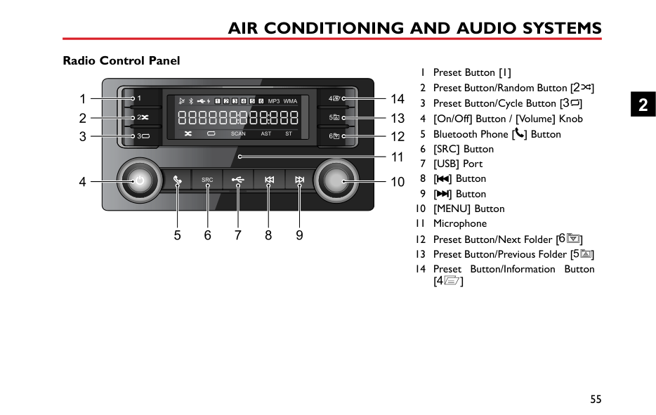
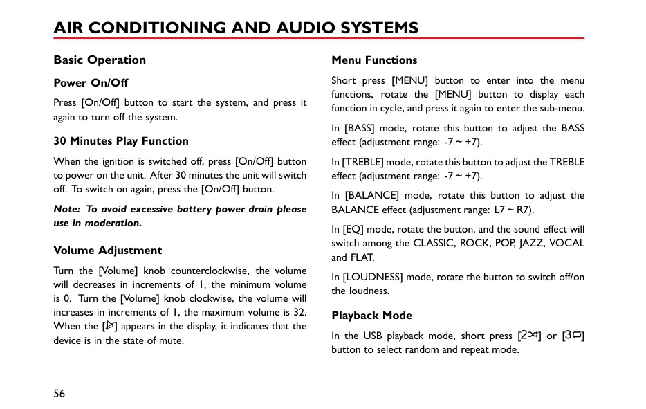
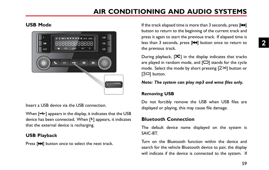
Radio *............................................................................................................................................54 Instructions ..............................................................................................................................................................................54 Radio Control Panel...............................................................................................................................................................55 Basic Operation.......................................................................................................................................................................56 Radio Function.........................................................................................................................................................................57 USB Mode.................................................................................................................................................................................59
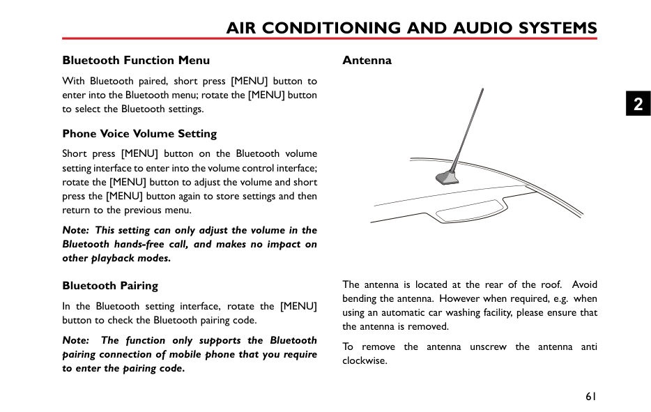
Bluetooth Connection...........................................................................................................................................................59 Bluetooth Music......................................................................................................................................................................60 Bluetooth Phone.....................................................................................................................................................................60 Bluetooth Function Menu.....................................................................................................................................................61 Antenna.....................................................................................................................................................................................61
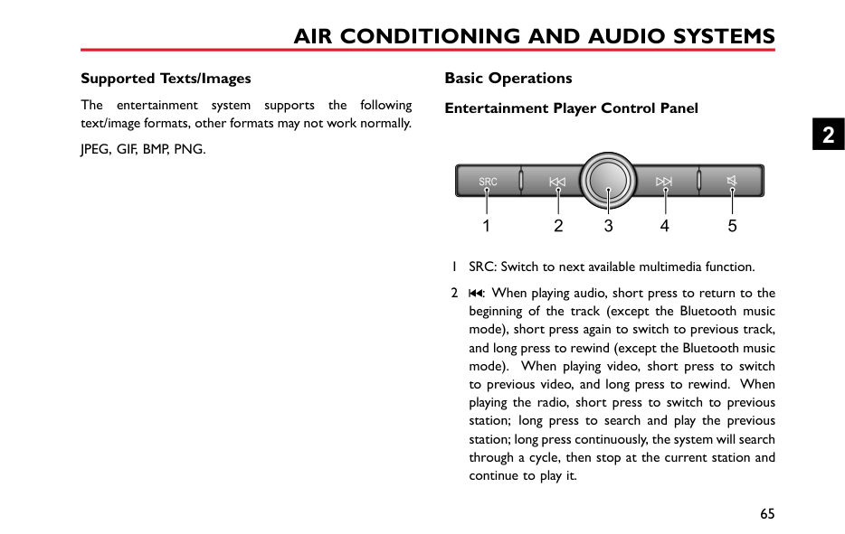
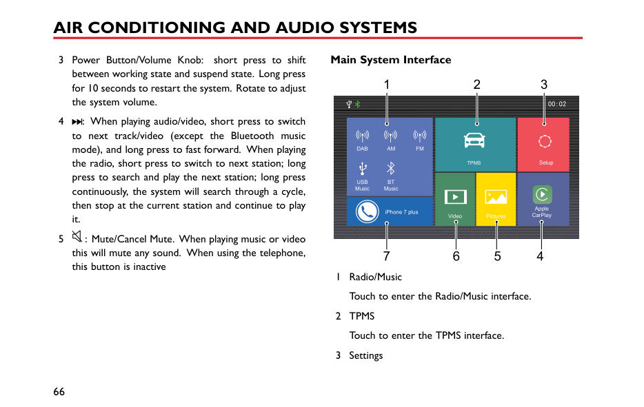
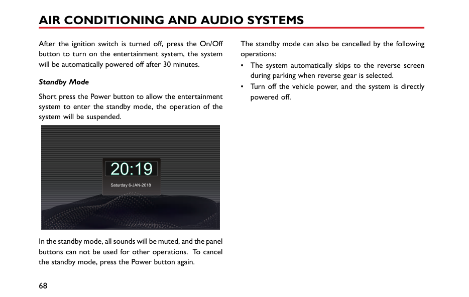
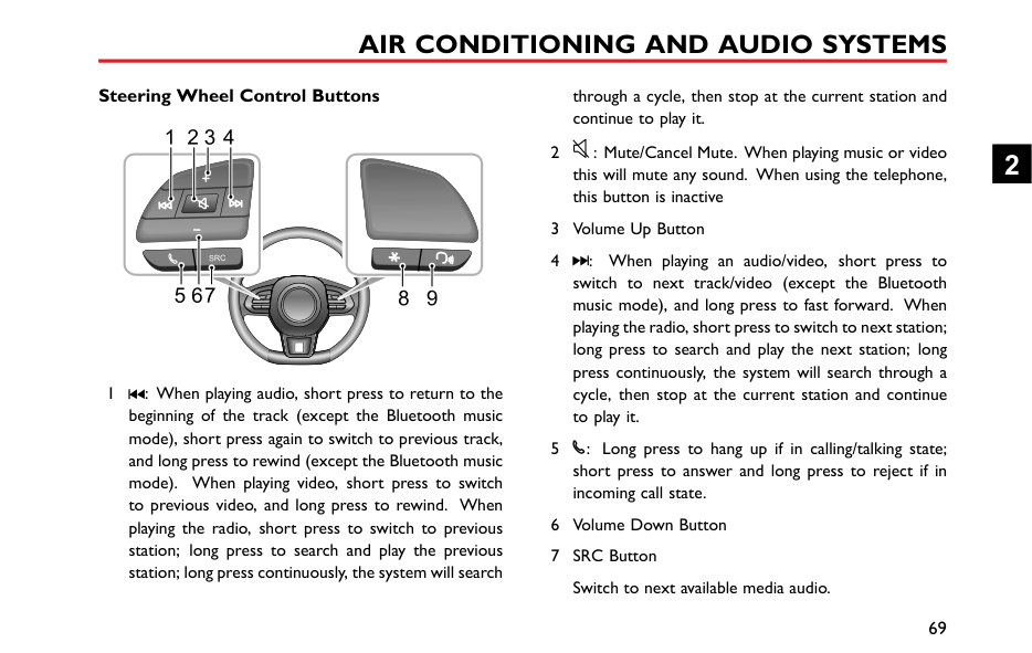
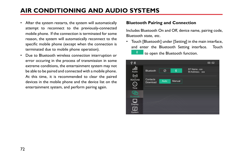
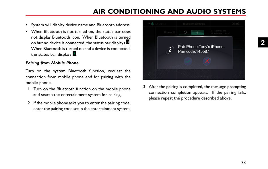
Entertainment System * ..............................................................................................................62 Important Safety Information...............................................................................................................................................62 Cautions for Using Screen....................................................................................................................................................63 Playable File Format for Entertainment System...............................................................................................................64 Basic Operations.....................................................................................................................................................................65 Bluetooth Phone.....................................................................................................................................................................71 Entertainment..........................................................................................................................................................................84 Apple CarPlay..........................................................................................................................................................................93 TPMS..........................................................................................................................................................................................97 A/C Display *............................................................................................................................................................................98 Settings......................................................................................................................................................................................99
#### 3 Seats and Restraints ..................................................................................................107
Seats.............................................................................................................................................108 Overview................................................................................................................................................................................108
Head Restraints.....................................................................................................................................................................109 Manual Adjustment of Seats ..............................................................................................................................................110 Rear Seats...............................................................................................................................................................................111
Seat Belts ....................................................................................................................................112 Protection Provided by Seat Belts ....................................................................................................................................113 Wearing Seat Belts................................................................................................................................................................114 Seat Belt Pre-tensioners......................................................................................................................................................118 Seat Belt Checks, Maintenance and Replacement.........................................................................................................119
Airbag Supplementary Restraint System................................................................................121 Overview................................................................................................................................................................................121 Airbag Deployment..............................................................................................................................................................122 Conditions in Which Airbags Will Not Deploy............................................................................................................125 Disabling the Passenger Airbag *.......................................................................................................................................126 Passenger Airbag Off Warning Light *..............................................................................................................................127 Service and Replacement of Airbags................................................................................................................................128 Disposal of Airbags...............................................................................................................................................................129
Child Restraints ..........................................................................................................................130 Important Safety Instructions about Using Child Restraints......................................................................................130 Child Restraints Groups......................................................................................................................................................133
Approved Child Restraint Positions.................................................................................................................................136
#### 4 Starting and Driving ..................................................................................................141
Keys..............................................................................................................................................142 Overview................................................................................................................................................................................142 Replacing the Battery...........................................................................................................................................................143
####### Child Proof Locks .......................................................................................................................145 Alarm Systems ...........................................................................................................................146
Engine Immobilisation..........................................................................................................................................................146 Locking and Unlocking.........................................................................................................................................................147 Tailgate.....................................................................................................................................................................................149
Starting and Stopping Engine ...................................................................................................151 Ignition Switch.......................................................................................................................................................................151 Starting the Engine................................................................................................................................................................152 Stopping the Engine..............................................................................................................................................................154
Economical and Environmental Driving ..................................................................................155 Running-in...............................................................................................................................................................................155 Environment Protection......................................................................................................................................................155 Driving Style...........................................................................................................................................................................155
Fuel Saving and Extending Vehicle Life.............................................................................................................................156 Maintenance...........................................................................................................................................................................157
####### Catalytic Converter ...................................................................................................................158 Fuel System.................................................................................................................................160
Fuel Requirements................................................................................................................................................................160 Fuel Filler ................................................................................................................................................................................161 Refueling..................................................................................................................................................................................161
####### Manual Transmission..................................................................................................................162 5-speed Manual Transmission ...........................................................................................................................................162
Brake System..............................................................................................................................164 Foot Brake..............................................................................................................................................................................164 Anti-lock Brake System (ABS)...........................................................................................................................................167 Parking Brake.........................................................................................................................................................................168
Automated Stop/Start —Intelligent Fuel Saving System ......................................................170 Automatic Shutdown of Engine.........................................................................................................................................171 Engine Auto Stop Conditions ............................................................................................................................................171 Stop/Start Prohibited...........................................................................................................................................................171 Automatic Engine Start .......................................................................................................................................................171 Start Inhibition.......................................................................................................................................................................172
Stall Assist...............................................................................................................................................................................172 Battery.....................................................................................................................................................................................173 Automated Stop/Start Intelligent Fuel Saving System Failure ....................................................................................173 Starter Inoperative, Serious Battery Capacity Loss ....................................................................................................174
####### Stability Control System (SCS) and Traction Control System (TCS) ................................175 Cruise Control System *............................................................................................................177 Parking Aid * ...............................................................................................................................180
Ultrasonic Sensor Parking Aid * ........................................................................................................................................180 Parking Camera * ..................................................................................................................................................................181
####### Tyre Pressure Monitoring System(TPMS).................................................................. 183 Load Carrying.............................................................................................................................185
Loadspace Loading................................................................................................................................................................185 Internal Loading.....................................................................................................................................................................186 General Towing Safety.........................................................................................................................................................186
#### 5 Emergency Information ............................................................................................189
Hazard Warning Devices...........................................................................................................190 Hazard Warning Lamps.......................................................................................................................................................190 Warning Triangle...................................................................................................................................................................190
Emergency Starting ...................................................................................................................192 Using Booster Cables ..........................................................................................................................................................192 Starting the Vehicle...............................................................................................................................................................192
Vehicle Recovery.........................................................................................................................194 Towing for Recovery............................................................................................................................................................194 Transporter or Trailer with Rope.....................................................................................................................................197
Tyre Repair and Wheel Replacement ......................................................................................198 Tool Identification (including tyre repair tool)...............................................................................................................198 Tyre Repair.............................................................................................................................................................................198 Accessing the Spare Wheel and Tools * ..........................................................................................................................201 Changing a Wheel *..............................................................................................................................................................202
Fuse Replacement......................................................................................................................205 Fuse..........................................................................................................................................................................................205 Fuse Box .................................................................................................................................................................................206 Passenger Compartment Fuse Box..................................................................................................................................206 Engine Compartment Fuse Box ........................................................................................................................................209
Bulb Replacement ......................................................................................................................211 Bulb Specification..................................................................................................................................................................211 Bulb Replacement.................................................................................................................................................................212
#### 6 Maintenance ...............................................................................................................221
####### Maintenance................................................................................................................................222 Routine Maintenance ...........................................................................................................................................................222
Bonnet .........................................................................................................................................226 Opening the Bonnet.............................................................................................................................................................226 Closing the Bonnet...............................................................................................................................................................226 Bonnet Open Warning........................................................................................................................................................226
####### Engine Compartment................................................................................................................228 1.5L Engine Compartment..................................................................................................................................................228
Engine..........................................................................................................................................229 1.5L Engine Oil ......................................................................................................................................................................229 Engine Oil Level Check and Refill.....................................................................................................................................229 Engine Oil Specification.......................................................................................................................................................230
Cooling System...........................................................................................................................231 Coolant Check and Refill....................................................................................................................................................231 Coolant Specification...........................................................................................................................................................231
####### Brakes..........................................................................................................................................233 Brake Pads..............................................................................................................................................................................233
Brake Fluid Check and Top Up..........................................................................................................................................233 Brake Fluid Specification .....................................................................................................................................................234
Power Steering ..........................................................................................................................235 Power Steering Fluid Check and Top Up .......................................................................................................................235 Power Steering Fluid Specification ..................................................................................................................................236
Battery.........................................................................................................................................237 Battery Maintenance............................................................................................................................................................237 Battery Replacement............................................................................................................................................................237
Washer ........................................................................................................................................239 Windscreen Washer Check and Top Up........................................................................................................................239 Washer Nozzles....................................................................................................................................................................240 Washer Fluid Specification .................................................................................................................................................240
Wipers.........................................................................................................................................241 Wiper Blades.........................................................................................................................................................................241 Replacing Front Wiper Blades...........................................................................................................................................242 Replacing Rear Wiper Blades.............................................................................................................................................243
Tyres.............................................................................................................................................244 Overview................................................................................................................................................................................244 Caring for Your Tyres ..........................................................................................................................................................246
Tyre Wear Indicators...........................................................................................................................................................246 Replacement Tyres ...............................................................................................................................................................247 Wheel Fitment Rotation.....................................................................................................................................................247 Snow Chains ..........................................................................................................................................................................248
Cleaning and Vehicle Care.........................................................................................................249 External Car...........................................................................................................................................................................249 Cleaning the Interior............................................................................................................................................................252
Towing Weights.....................................................................................................................................................................258 Major Parameters of Engine .....................................................................................................259 Recommended Fluids and Capacities ......................................................................................260 Wheel Alignment (Unladen).....................................................................................................261 Wheels and Tyres .......................................................................................................................261 Tyre Pressure (Cold) ..................................................................................................................261
#### Introduction The Owner's Handbook
####### Symbols Used
The following symbols used within the handbook call your attention to specific types of information.
This handbook describes all of the vehicles and standard equipment specification within the model range. Some of the information therefore, may not apply to your particular car.
########## Warning
This warning symbol identifies procedures that must be followed precisely, or information that must be considered with great care, in order to reduce the risk of personal injury or serious damage to the car.
Always remember that if you have any queries concerning the operation or specification of your car, your MG Authorised Repairer will be glad to advise you.
####### Status at Time of Printing
########## Important
MG operates a policy of constant product improvement and therefore reserves the right to change specifications without notice at any time.
|IMPORTANT| |---| |The statements stated here must be followed strictly, otherwise your car could be damaged.|
Whilst every effort is made to ensure complete accuracy of the information in this publication, no liabilities for inaccuracies or the consequences thereof, including loss or damage to property, or injury to persons, can be accepted by the manufacturer or MG Authorised Repairer who supplied the publication, except in respect of personal injury caused by the negligence of the manufacturer or MG Authorised Repairer.
Note Note: This describes helpful information.
####### In an Emergency
|IMPORTANT| |---| |Remember the breakdown safety code If a breakdown occurs while travelling:
• Wherever possible, consistent with road safety and traffic conditions, the car should be moved off the main thoroughfare, preferably into a lay-by. If a breakdown occurs on a motorway, pull well over to the inside of the hard shoulder.
• Switch on hazard lights.
• If available, position a warning triangle or a flashing amber light 50 to 150 metres (150 to 500 ft) behind your vehicle to warn approaching traffic. Note it is a legal requirement of some countries that a warning triangle is carried in the vehicle, if in doubt consult the local highways agency for further information.
• Consider evacuating passengers through nearside doors onto the verge to reduce risk of injury in the event of collision.
|
This symbol indicates that parts described must be disposed of by authorised persons or bodies to protect the environment.
########## Asterisk
An asterisk (*) appearing within the text, identifies features or items of equipment that are either optional, or are only fitted to some vehicles in the model range.
########## Illustration Information
Identifies components being explained.
Identifies movement of components being explained.
All illustrations in this handbook are based on a RHD vehicle except where LHD model is stated.
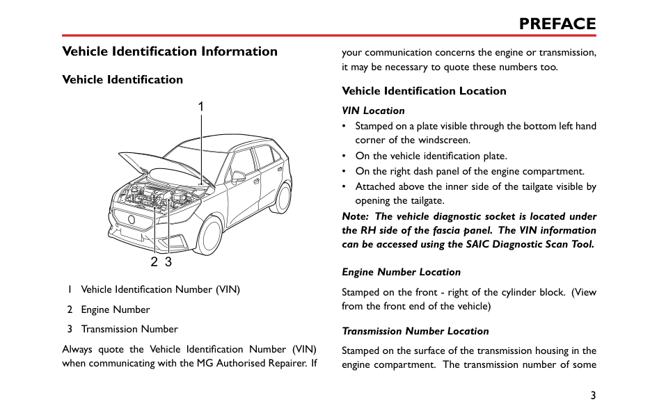
#### Vehicle Identification Information Vehicle Identification
your communication concerns the engine or transmission, it may be necessary to quote these numbers too.
########## Vehicle Identification Location VIN Location
| | |---|
Note: The vehicle diagnostic socket is located under the RH side of the fascia panel. The VIN information can be accessed using the SAIC Diagnostic Scan Tool.
Engine Number Location Stamped on the front - right of the cylinder block. (View from the front end of the vehicle) Transmission Number Location
Always quote the Vehicle Identification Number (VIN) when communicating with the MG Authorised Repairer. If
Stamped on the surface of the transmission housing in the engine compartment. The transmission number of some
vehicles can be seen when the vehicle is lifted. Please contact an MG Authorised Repairer.
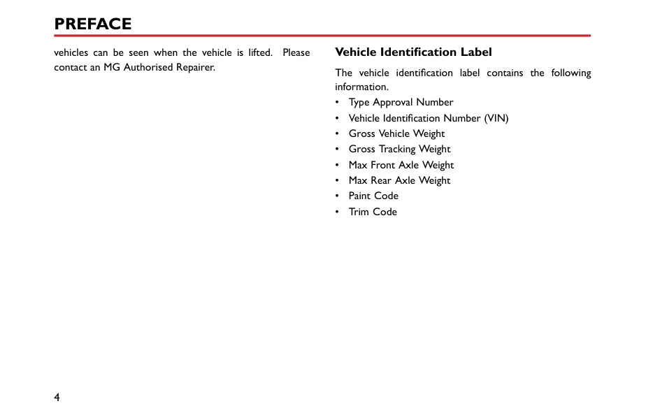
####### Vehicle Identification Label
The vehicle identification label contains the following information.
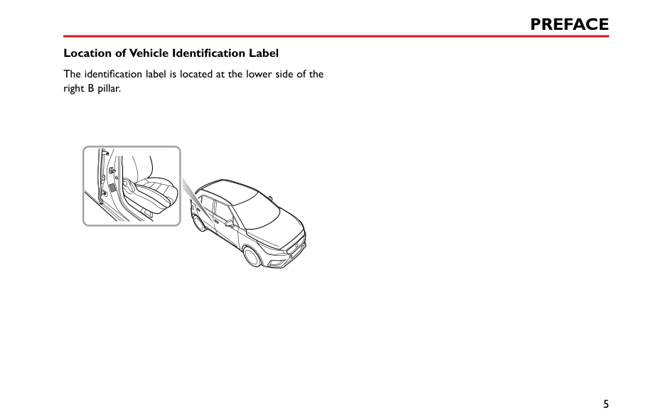
########## Location of Vehicle Identification Label
The identification label is located at the lower side of the right B pillar.
|
| |---|
Instruments and Controls 8 Instruments and Controls
1
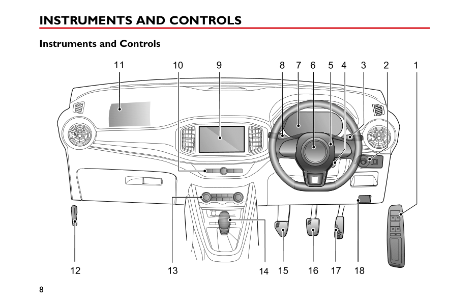
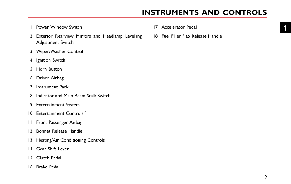
#### Instruments and Controls
5 3679111084 12
1615 1817141312
1
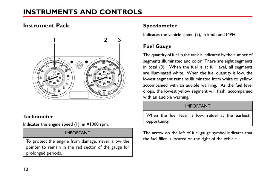
#### Instrument Pack
|1 2 3
| |---|
Tachometer Indicates the engine speed (1), in ×1000 rpm.
|IMPORTANT| |---| |To protect the engine from damage, never allow the pointer to remain in the red sector of the gauge for prolonged periods.|
Speedometer Indicates the vehicle speed (2), in km/h and MPH.
####### Fuel Gauge
The quantity of fuel in the tank is indicated by the number of segments illuminated and color. There are eight segments in total (3). When the fuel is at full level, all segments are illuminated white. When the fuel quantity is low, the lowest segment remains illuminated from white to yellow, accompanied with an audible warning. As the fuel level drops, the lowest yellow segment will flash, accompanied with an audible warning.
|IMPORTANT| |---| |When the fuel level is low, refuel at the earliest opportunity.|
The arrow on the left of fuel gauge symbol indicates that the fuel filler is located on the right of the vehicle.
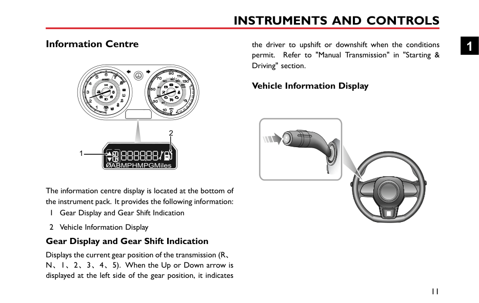
#### Information Centre
2
1
ABMPHMPGMiles0
The information centre display is located at the bottom of the instrument pack. It provides the following information:
####### Gear Display and Gear Shift Indication
Displays the current gear position of the transmission (R、 N、1、2、3、4、5). When the Up or Down arrow is displayed at the left side of the gear position, it indicates
the driver to upshift or downshift when the conditions permit. Refer to "Manual Transmission" in "Starting & Driving" section.
Vehicle Information Display


1
The vehicle information display screen provides the following information:
When Trip A, Trip B, Average Fuel Consumption or Average Speed is selected for display, long press (longer than 2s) the button at the end of the steering wheel stalk, the selected item can be reset.
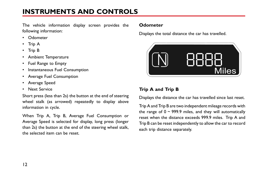
Odometer Displays the total distance the car has travelled.
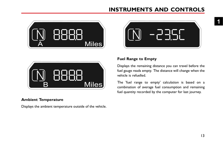
Trip A and Trip B Displays the distance the car has travelled since last reset.
Ambient Temperature Displays the ambient temperature outside of the vehicle.
########## Fuel Range to Empty
Displays the remaining distance you can travel before the fuel gauge reads empty. The distance will change when the vehicle is refuelled.
The 'fuel range to empty' calculation is based on a combination of average fuel consumption and remaining fuel quantity recorded by the computer for last journey.
########## Instantaneous Fuel Consumption
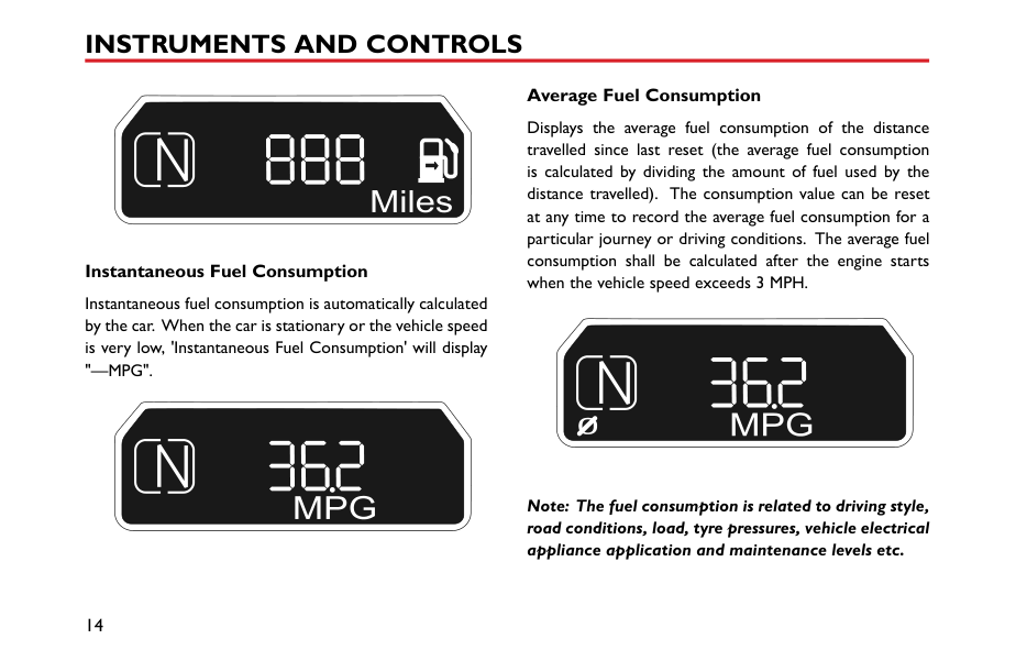
Instantaneous fuel consumption is automatically calculated by the car. When the car is stationary or the vehicle speed is very low, 'Instantaneous Fuel Consumption' will display "—MPG".
########## Average Fuel Consumption
Displays the average fuel consumption of the distance travelled since last reset (the average fuel consumption is calculated by dividing the amount of fuel used by the distance travelled). The consumption value can be reset at any time to record the average fuel consumption for a particular journey or driving conditions. The average fuel consumption shall be calculated after the engine starts when the vehicle speed exceeds 3 MPH.
0
############# Note: The fuel consumption is related to driving style, road conditions, load, tyre pressures, vehicle electrical appliance application and maintenance levels etc.
########## Average Speed
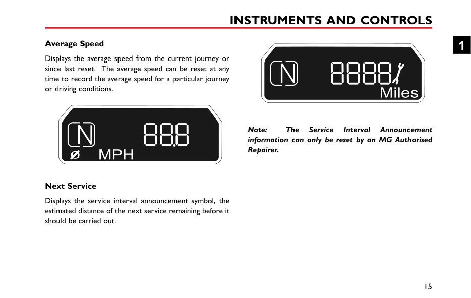
Displays the average speed from the current journey or since last reset. The average speed can be reset at any time to record the average speed for a particular journey or driving conditions.
############# Note: The Service Interval Announcement information can only be reset by an MG Authorised Repairer.
########## Next Service
Displays the service interval announcement symbol, the estimated distance of the next service remaining before it should be carried out.
#### Warning Lights and Indicators
| | |---|
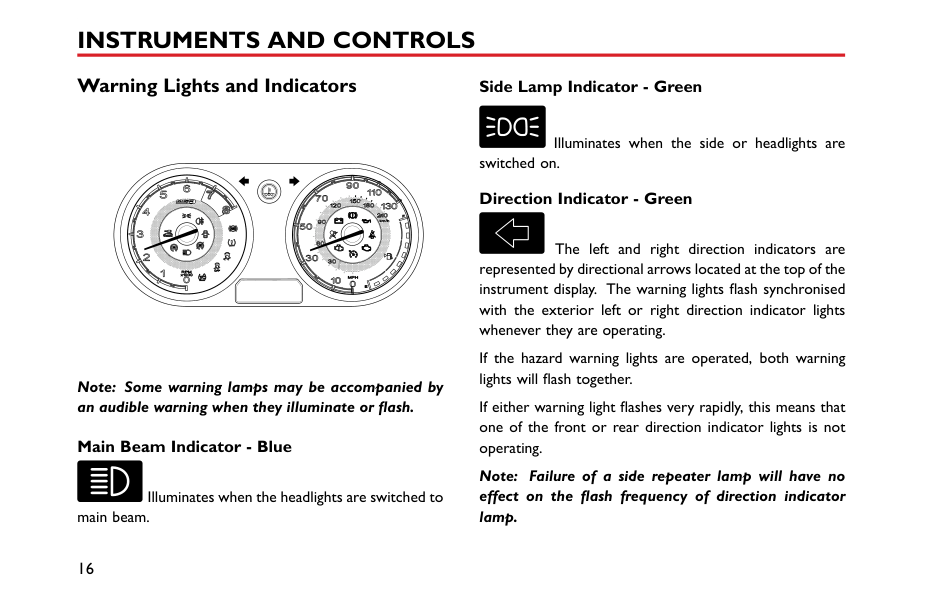
Note: Some warning lamps may be accompanied by an audible warning when they illuminate or flash.
########## Main Beam Indicator - Blue
Illuminates when the headlights are switched to main beam.
########## Side Lamp Indicator - Green
Illuminates when the side or headlights are switched on. Direction Indicator - Green
The left and right direction indicators are represented by directional arrows located at the top of the instrument display. The warning lights flash synchronised with the exterior left or right direction indicator lights whenever they are operating.
If the hazard warning lights are operated, both warning lights will flash together.
If either warning light flashes very rapidly, this means that one of the front or rear direction indicator lights is not operating.
Note: Failure of a side repeater lamp will have no effect on the flash frequency of direction indicator lamp.
########## Rear Fog Lamp Indicator - Yellow
unfastened, this warning light will remain illuminated. If the seat belt for driver’s or front passenger seat remains unfastened once the vehicle speed has exceeded 15 MPH (25 km/h), the warning lamp will flash accompanied by an audible warning. This warning will continue until either the seat belt is fastened correctly or 90 seconds has elapsed.
Illuminates when the rear fog lights are switched
########## on. Airbag Warning Lamp - Red
########## Low Oil Pressure Warning Lamp - Red
This warning light illuminates and extinguishes as a lamp check when the ignition is switched on. If this lamp does not extinguish or illuminates during driving, it indicates an airbag restraint system fault has been detected, then an audible warning will be given. Please seek an MG Authorised Repairer at the earliest opportunity. An SRS or seat belt fault may mean the components may not be deployed in the event of an accident.
This warning light illuminates when the ignition is switched on and extinguishes when the engine is running. If the light remains on or illuminates continuously when driving, serious engine damage could occur; stop the vehicle as soon as safety permits and SWITCH OFF THE ENGINE IMMEDIATELY. Seek qualified assistance or advice from an MG Authorised Repairer before driving.
########## Seat Belt Unfastened Warning Lamp - Red
########## Alternator Malfunction Indicator - Red
This warning light illuminates and extinguishes as a lamp check when the ignition is switched on. If a seat belt for the driver’s or front passenger seat remains
This warning light illuminates when the ignition is switched on and extinguishes as soon as the engine is running. If this lamp does not extinguish after starting
the engine or illuminates during driving, consult an MG Authorised Repairer at the earliest opportunity.
########## ABS Malfunction Indicator - Yellow
ABS

This warning light illuminates and extinguishes as a lamp check when the ignition is switched on. If the light fails to extinguish or illuminates whilst driving, a fault has occurred with the ABS system and you should seek qualified assistance or an MG Authorised Repairer at the earliest opportunity.
If an ABS failure occurs while driving, ABS operation will be suspended, but normal braking will still be available. Please seek an MG Authorised Repairer at the earliest opportunity.
########## Brake System Malfunction Indicator - Red
This warning light illuminates and extinguishes as a lamp check when the ignition is switched on. Subsequent illumination may indicate a fault with the
braking system such as parking brake on, brake fluid level is low or electronic brake force distribution failure.
If the parking brake is inadvertently left applied, the light will flash and an audible warning will sound when the vehicle speed exceeds 3 MPH (5 km/h). If the warning lamp remains on after the parking brake has been released, it indicates that there is a failure in the braking system. Stop the car as soon as safety permits and seek qualified assistance or an MG Authorised Repairer at the earliest opportunity.
When the ignition is switched off and the driver's door is opened, if the parking brake is not applied, the parking brake alarm will be activated. The warning light will flash accompanied by an audible warning.
########## Engine Emissions Malfunction Warning Lamp Yellow
This warning light is used to indicate an emissions related fault has been detected by the engine management system. The lamp illuminates when the
ignition is switched on and extinguishes as soon as the engine is running. If an engine operation problem occurs while the vehicle is being driven, the lamp will illuminate. Please seek an MG Authorised Repairer at the earliest opportunity.
check when the ignition is switched on. If the warning light illuminates blue, it indicates that the coolant temperature is low, and if the warning light illuminates red, it indicates that the coolant temperature is high. If the coolant temperature continues to rise, the warning light will flash accompanied by an audible warning. If the system detects that the signal is missing, the warning light will illuminate and flash blue. Seek an MG Authorised Repairer at the earliest opportunity.
########## Engine Malfunction Indicator - Yellow
This warning light is used to indicate an engine operation fault has been detected by the engine management system. The lamp illuminates and extinguishes as a lamp check when the ignition is switched on. If a non-emissions related fault occurs, the lamp will fail to extinguish or illuminate whilst driving. Please seek an MG Authorised Repairer at the earliest opportunity.
If the engine is too hot, severe damage could result; stop the vehicle as soon as safety permits and seek qualified assistance or an MG Authorised Repairer at the earliest opportunity.
########## Immobiliser System Warning Lamp - Red
########## Engine Coolant Temperature Warning Lamp Red/Blue
This warning light does not illuminate when the ignition is switched on, it has two functions.
If the warning light remains on, it indicates that there is an immobiliser verification failure, this could be an invalid key inserted into the ignition switch - please ensure the correct key is used.
This warning light is used to indicate the temperature of engine coolant. It consists of 2 colours, blue and red. The warning light illuminates as a system
If this warning lamp flashes accompanied by an audible warning it indicates the battery in the handset is low. Please replace the handset battery as soon as possible.
########## Tyre Pressure Monitoring System (TPMS) Warning Lamp - Yellow
This warning light illuminates and extinguishes as a lamp check when the ignition is switched on. If this lamp does not extinguish or illuminates during driving, it indicates a tyre pressure is low, please check the tyre pressures as soon as possible. Depending on trim level it may be possible to consult the entertainment system for precise location of the low tyre pressure - see 'TPMS' in 'Air Conditioning and Audio Systems' section*. If this lamp flashes first and then remains on after a period of time, it indicates the system has a failure. Seek an MG Authorised Repairer at the earliest opportunity.
########## Door Open Warning Lamp - Red
This warning light indicates that the vehicle doors, bonnet or tailgate are not closed. The warning light does not illuminate when the ignition is switched on. If there is a door, bonnet or tailgate not closed, the warning light will illuminate. If the panel remains open once the vehicle speed has exceeded 3 MPH (5 km/h), the warning light will flash accompanied by an audible warning. The warning will continue until all panels are closed correctly or 30 seconds has expired.
########## Cruise Control Indicator - Yellow/Green *
This warning light illuminates and extinguishes as a lamp check when the ignition is switched on. When the cruise control system is active, this lamp illuminates yellow. When the cruise master switch is pressed, but no speed is set, this lamp illuminates green. If any fault is detected, this lamp will flash yellow.
When the cruise control system is active, the cruise set target value will be displayed on the instrument pack
message centre till the actual speed reaches the cruise set value. Then LCD will return to previous interface.
lamp illuminates yellow. Please seek an MG Authorised Repairer at the earliest opportunity.
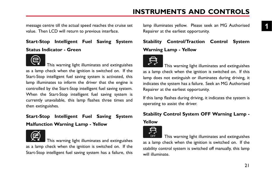
########## Start-Stop Intelligent Fuel Saving System Status Indicator - Green
This warning light illuminates and extinguishes as a lamp check when the ignition is switched on. If the Start-Stop intelligent fuel saving system is activated, this lamp illuminates to inform the driver that the engine is controlled by the Start-Stop intelligent fuel saving system. When the Start-Stop intelligent fuel saving system is currently unavailable, this lamp flashes three times and then extinguishes.
########## Start-Stop Intelligent Fuel Saving System Malfunction Warning Lamp - Yellow
This warning light illuminates and extinguishes as a lamp check when the ignition is switched on. If the Start-Stop intelligent fuel saving system has a failure, this
########## Stability Control/Traction Control System Warning Lamp - Yellow
This warning light illuminates and extinguishes as a lamp check when the ignition is switched on. If this lamp does not extinguish or illuminates during driving, it indicates the system has a failure. Seek an MG Authorised Repairer at the earliest opportunity.
If this lamp flashes during driving, it indicates the system is operating to assist the driver.
########## Stability Control System OFF Warning Lamp Yellow
This warning light illuminates and extinguishes as a lamp check when the ignition is switched on. If the stability control system is switched off manually, this lamp will illuminate.
########## Traction Control System OFF Warning Lamp Yellow
This warning light illuminates and extinguishes
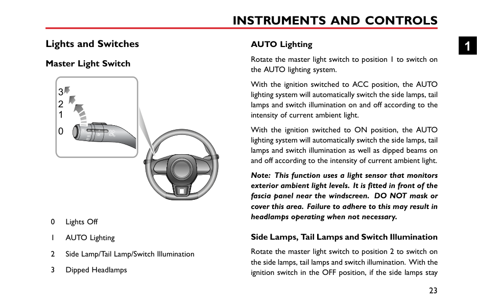
#### Lights and Switches Master Light Switch
1 0

########## AUTO Lighting
With the ignition switched to ACC position, the AUTO lighting system will automatically switch the side lamps, tail lamps and switch illumination on and off according to the intensity of current ambient light.
With the ignition switched to ON position, the AUTO lighting system will automatically switch the side lamps, tail lamps and switch illumination as well as dipped beams on and off according to the intensity of current ambient light.
Note: This function uses a light sensor that monitors exterior ambient light levels. It is fitted in front of the fascia panel near the windscreen. DO NOT mask or cover this area. Failure to adhere to this may result in headlamps operating when not necessary.
Side Lamps, Tail Lamps and Switch Illumination
1
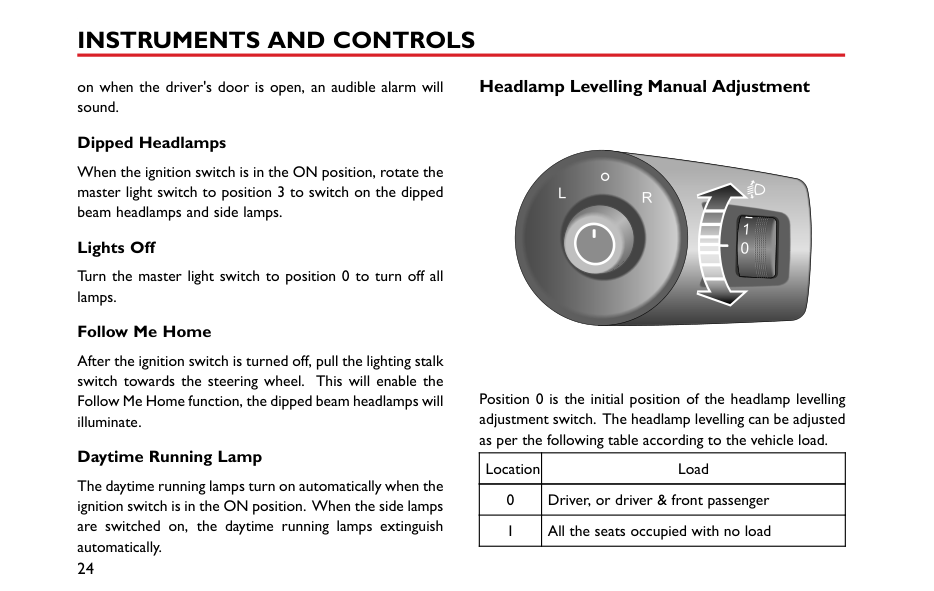
####### Headlamp Levelling Manual Adjustment
on when the driver's door is open, an audible alarm will sound.
|


| |---|
########## Dipped Headlamps
When the ignition switch is in the ON position, rotate the master light switch to position 3 to switch on the dipped beam headlamps and side lamps.
########## Lights Off
Turn the master light switch to position 0 to turn off all lamps.
########## Follow Me Home
After the ignition switch is turned off, pull the lighting stalk switch towards the steering wheel. This will enable the Follow Me Home function, the dipped beam headlamps will illuminate.
Position 0 is the initial position of the headlamp levelling adjustment switch. The headlamp levelling can be adjusted as per the following table according to the vehicle load.
########## Daytime Running Lamp
|Location|Load| |---|---| |0|Driver, or driver & front passenger|
|1|All the seats occupied with no load|
The daytime running lamps turn on automatically when the ignition switch is in the ON position. When the side lamps are switched on, the daytime running lamps extinguish automatically.
|Location|Load| |---|---| |2|All the seats occupied plus an evenly distributed load in the boot & driver only, plus an evenly distributed load in the boot| |3|Currently not used|
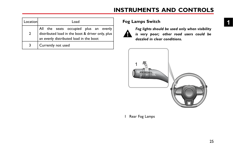
####### Fog Lamps Switch
############# Fog lights should be used only when visibility is very poor; other road users could be dazzled in clear conditions.
1


1 Rear Fog Lamps
1
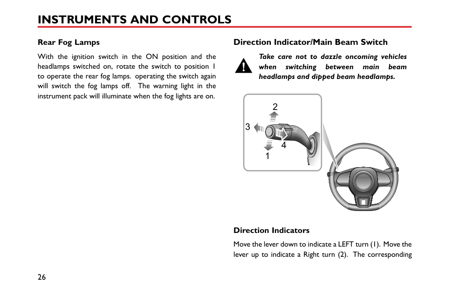
########## Rear Fog Lamps
With the ignition switch in the ON position and the headlamps switched on, rotate the switch to position 1 to operate the rear fog lamps. operating the switch again will switch the fog lamps off. The warning light in the instrument pack will illuminate when the fog lights are on.
####### Direction Indicator/Main Beam Switch
############# Take care not to dazzle oncoming vehicles when switching between main beam headlamps and dipped beam headlamps.
3
4


########## Direction Indicators
Move the lever down to indicate a LEFT turn (1). Move the lever up to indicate a Right turn (2). The corresponding
GREEN indicator lamp in the instrument pack will flash when the turn signal lamps are working.
Rotating the steering wheel will cancel the indicator operation (small movements of the steering wheel may not operate the self cancelling). To indicate a lane change, move the lever briefly and release, the indicators will flash three times and then cancel.
########## Main/Dipped Beam Headlamps Switching
With the ignition switch in the ON position and the master lighting switch turned to position 3, or the auto function has switched the dipped headlamps on, push the lever (3) towards the instrument panel to turn on headlamp high beams. The high beam indicator lamp in instrument pack illuminates, press the lever (3) again to switch to headlamp dipped beams.
########## Main Beam Flash
To briefly flash the main beam on and off, pull the lever (4) towards the steering wheel and then release.
####### Hazard Warning Lamps
Press the hazard warning lamp button to operate the hazard warning lamps. All turn signal lamps and direction indicator lamps will flash together. Press the button again to switch off the hazard warning lamp. All turn signal lamps and direction indicator lamps will stop flashing. For the location of the hazard warning lamp switch, refer to 'Hazard Warning Devices' under 'Emergency Information'.
1
#### Wipers and Washers


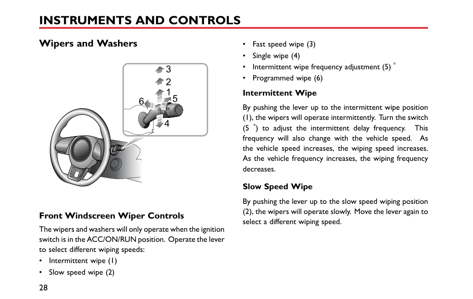


####### Front Windscreen Wiper Controls
The wipers and washers will only operate when the ignition switch is in the ACC/ON/RUN position. Operate the lever to select different wiping speeds:
Slow Speed Wipe By pushing the lever up to the slow speed wiping position
########## Fast Speed Wipe
By pushing the lever up to the fast speed wiping position (3), the wipers will operate at fast speed. Move the lever again to select a different wiping speed.
########## Single Wipe
Pressing the lever down to the single wiping position (4) and releasing will operate a single wipe. If the lever remains in the single wiping position (4), the wipers will operate at high speed until the lever is released.
|IMPORTANT| |---| |• Avoid operating the wipers on a dry windscreen.
• In freezing or extremely hot conditions, make sure that the wiper blades are not frozen or adhered to the windscreen.
• In winter, remove snow or ice from around the arms and blades, including the wiped area of the screen.
|
####### Programmed Wipe
Pulling the lever toward the steering wheel (6) will operate the front windscreen washers. After a short delay, the wipers will commence operating in conjunction with the washers.
Note: The wipers continue operating for a further three wipes after the lever is released. After several seconds, there will be a further wipe to remove any fluid draining down the screen.
|IMPORTANT| |---| |If the washers fail to deliver the screen wash solution, release the lever immediately. This will prevent the wipers from operating, and the consequent risk of visibility being impaired by dirt smearing across the unwashed windscreen.|
1
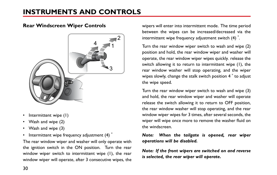
####### Rear Windscreen Wiper Controls
4


wipers will enter into intermittent mode. The time period between the wipes can be increased/decreased via the intermittent wipe frequency adjustment switch (4) *.
Note: When the tailgate is opened, rear wiper operations will be disabled.
Note: If the front wipers are switched on and reverse is selected, the rear wiper will operate.
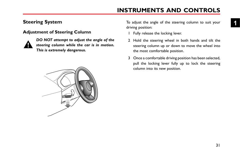
Steering System Adjustment of Steering Column
DO NOT attempt to adjust the angle of the steering column while the car is in motion. This is extremely dangerous.
To adjust the angle of the steering column to suit your driving position:
1

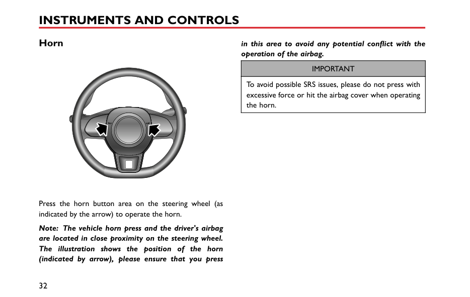
#### Horn
in this area to avoid any potential conflict with the operation of the airbag.
|IMPORTANT| |---| |To avoid possible SRS issues, please do not press with excessive force or hit the airbag cover when operating the horn.|
Press the horn button area on the steering wheel (as indicated by the arrow) to operate the horn.
Note: The vehicle horn press and the driver's airbag are located in close proximity on the steering wheel. The illustration shows the position of the horn (indicated by arrow), please ensure that you press
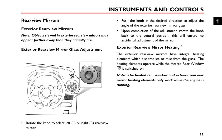
Rearview Mirrors Exterior Rearview Mirrors
Note: Objects viewed in exterior rearview mirrors may appear further away than they actually are.
########## Exterior Rearview Mirror Glass Adjustment
########## Exterior Rearview Mirror Heating *
The exterior rearview mirrors have integral heating elements which disperse ice or mist from the glass. The heating elements operate while the Heated Rear Window
is switched on.
Note: The heated rear window and exterior rearview mirror heating elements only work while the engine is running.
1
• Rotate the knob to select left (L) or right (R) rearview mirror.
|IMPORTANT| |---| |• Exterior rearview mirror glass adjustments are operated by electrical motors. Operating them directly by hand may damage the internal components.
• Washing or flushing exterior rearview mirrors with high pressure water jets or car washes may result in electrical motor failure.
|
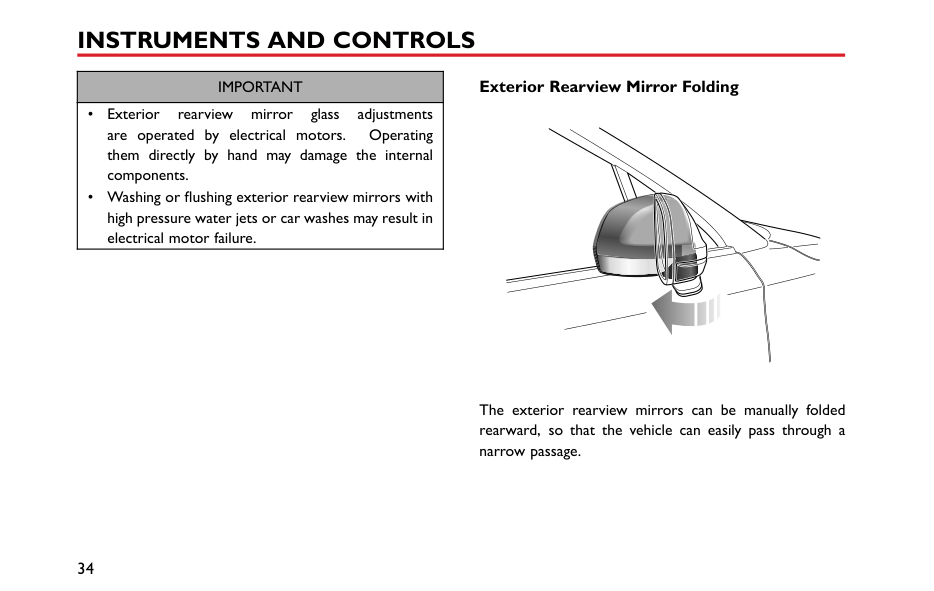
########## Exterior Rearview Mirror Folding
The exterior rearview mirrors can be manually folded rearward, so that the vehicle can easily pass through a narrow passage.
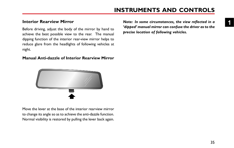
####### Interior Rearview Mirror
Before driving, adjust the body of the mirror by hand to achieve the best possible view to the rear. The manual dipping function of the interior rear-view mirror helps to reduce glare from the headlights of following vehicles at night.
########## Manual Anti-dazzle of Interior Rearview Mirror
|


| |---|
Move the lever at the base of the interior rearview mirror to change its angle so as to achieve the anti-dazzle function. Normal visibility is restored by pulling the lever back again.
Note: In some circumstances, the view reflected in a ‘dipped’ manual mirror can confuse the driver as to the precise location of following vehicles.
1
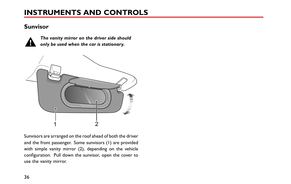
#### Sunvisor
############# The vanity mirror on the driver side should only be used when the car is stationary.
| | |---|
Sunvisors are arranged on the roof ahead of both the driver and the front passenger. Some sunvisors (1) are provided with simple vanity mirror (2), depending on the vehicle configuration. Pull down the sunvisor, open the cover to use the vanity mirror.
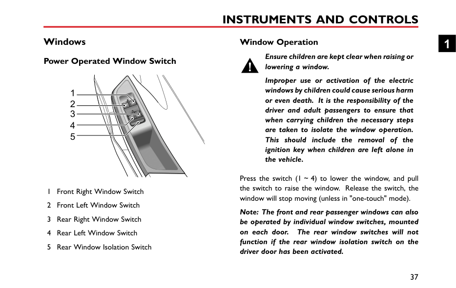
#### Windows Power Operated Window Switch
|1
2
3
4
5
| |---|
####### Window Operation
Ensure children are kept clear when raising or lowering a window.
Improper use or activation of the electric windows by children could cause serious harm or even death. It is the responsibility of the driver and adult passengers to ensure that when carrying children the necessary steps are taken to isolate the window operation. This should include the removal of the ignition key when children are left alone in the vehicle.
Press the switch (1~4) to lower the window, and pull the switch to raise the window. Release the switch, the window will stop moving (unless in "one-touch" mode).
Note: The front and rear passenger windows can also be operated by individual window switches, mounted on each door. The rear window switches will not function if the rear window isolation switch on the driver door has been activated.
1
Note: When the ignition switch is in the ACC or ON/RUN/START position, the power windows can be operated (doors should be closed). Rear Window Isolation Switch Press the switch (5) to isolate the rear window controls, and press again to restore control.
Note: It is recommended that you ISOLATE the rear window switches when carrying children.
"One-touch" Down The driver's window control switch (1) has 2 positions.
Short press the window control switch to the "2" position and release. The window automatically descends to fully open.
Window movement can be stopped at a desired position
Note: DO NOT operate the power window controls continuously several times in a short time frame,
in some cases the power window controls may be disabled to protect the motor. If this occurs, please wait a few seconds until the motor cools down.
#### Interior Light Interior Lights
|


| |---|

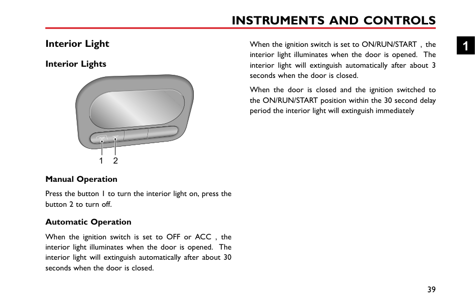
########## Manual Operation
Press the button 1 to turn the interior light on, press the button 2 to turn off.
########## Automatic Operation
When the ignition switch is set to OFF or ACC,the interior light illuminates when the door is opened. The interior light will extinguish automatically after about 30 seconds when the door is closed.
When the ignition switch is set to ON/RUN/START,the interior light illuminates when the door is opened. The interior light will extinguish automatically after about 3 seconds when the door is closed.
When the door is closed and the ignition switched to the ON/RUN/START position within the 30 second delay period the interior light will extinguish immediately
1
Front Console Power Socket
Please ensure the socket blanking plug is inserted when the power socket is not in use. This will ensure no debris or foreign objects enter the socket preventing its use or cause short circuits.
The 12V power socket has a voltage rating of 12V, and the maximum power of 120 Watt, please DO NOT use any electrical appliance that exceeds this rating.
Extended use of the accessory power socket and USB socket when the engine is switched off will cause premature discharging of the vehicle battery.
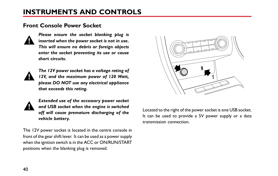
The 12V power socket is located in the centre console in front of the gear shift lever. It can be used as a power supply when the ignition switch is in the ACC or ON/RUN/START positions when the blanking plug is removed.
| | |---|
Located to the right of the power socket is one USB socket. It can be used to provide a 5V power supply or a data transmission connection.
#### Storage Devices Instructions
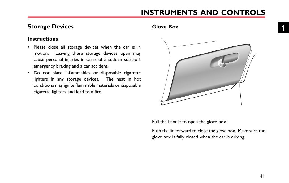
####### Glove Box
1
Pull the handle to open the glove box. Push the lid forward to close the glove box. Make sure the glove box is fully closed when the car is driving.
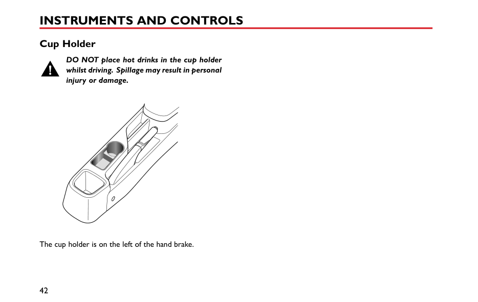
Cup Holder
DO NOT place hot drinks in the cup holder whilst driving. Spillage may result in personal injury or damage.
|


| |---|
The cup holder is on the left of the hand brake.
Air Conditioning and Audio Systems
44 Ventilation 47 Manual Temperature Control * 50 Electronic Temperature Control * 54 Radio * 62 Entertainment System *
2
#### Ventilation
|25
2
1
5
133
44
| |---|
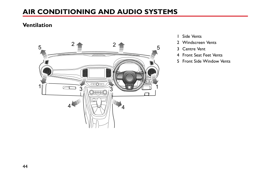
1 Side Vents 2 Windscreen Vents 3 Centre Vent 4 Front Seat Feet Vents 5 Front Side Window Vents
The heating, ventilation and air conditioning * system provides fresh, heated or cooling air to the interior of the car. Fresh air is drawn in through the air intake grille under the front windscreen and the A/C filter.
Always keep the air intake grille clear of obstructions such as leaves, snow or ice.
####### Particle/Pollen Filter
The particle/pollen filter helps to keep the car interior free from pollen and dust. To remain fully effective, the filter should be replaced at the recommended service interval.
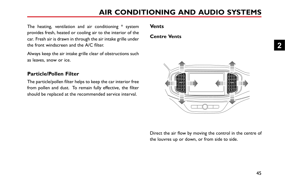
####### Vents Centre Vents
| | |---|
Direct the air flow by moving the control in the centre of the louvres up or down, or from side to side.
2
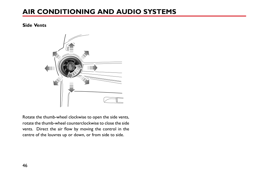
########## Side Vents
Rotate the thumb-wheel clockwise to open the side vents, rotate the thumb-wheel counterclockwise to close the side vents. Direct the air flow by moving the control in the centre of the louvres up or down, or from side to side.
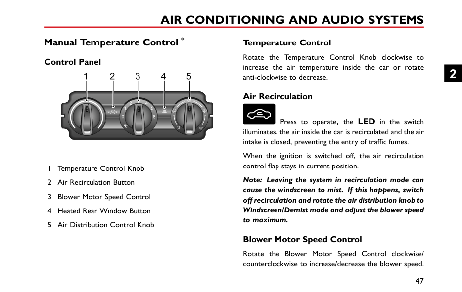
#### Manual Temperature Control * Control Panel
1 2 3 54
3
0 6
####### Temperature Control
Rotate the Temperature Control Knob clockwise to increase the air temperature inside the car or rotate anti-clockwise to decrease.
####### Air Recirculation
Press to operate, the LED in the switch illuminates, the air inside the car is recirculated and the air intake is closed, preventing the entry of traffic fumes.
When the ignition is switched off, the air recirculation control flap stays in current position.
Note: Leaving the system in recirculation mode can cause the windscreen to mist. If this happens, switch off recirculation and rotate the air distribution knob to Windscreen/Demist mode and adjust the blower speed to maximum.
####### Blower Motor Speed Control
Rotate the Blower Motor Speed Control clockwise/ counterclockwise to increase/decrease the blower speed.
2
The blower is switched off when the blower motor control is set to 0, and the blower motor speed increases gradually from 1 to 6.
Note: To turn off the system, adjust the blower motor control to 0; to turn on the system, adjust the blower motor control to other position.
####### Heated Rear Window
############# The heating elements on the inside of the rear screen are easily damaged. DO NOT scrape or scratch the inside of the glass. DO NOT stick labels over the heating elements.
Press to operate; the LED in the switch will illuminate indicating the heated rear window is switched on. The LED extinguishes when the heated rear window is turned off. The heated rear window will switch off automatically after 15 minutes.
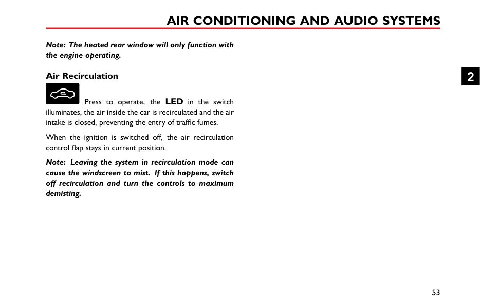
Note: The heated rear window will only function with the engine operating.
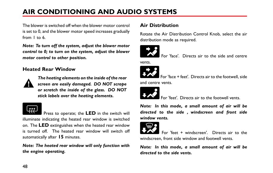
####### Air Distribution
Rotate the Air Distribution Control Knob, select the air distribution mode as required.
For 'face'. Directs air to the side and centre vents.
For 'face + feet'. Directs air to the footwell, side and centre vents.
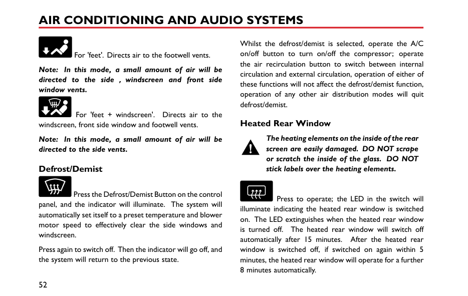
For 'feet'. Directs air to the footwell vents.
Note: In this mode, a small amount of air will be directed to the side,windscreen and front side window vents.
For 'feet + windscreen'. Directs air to the windscreen, front side window and footwell vents.
Note: In this mode, a small amount of air will be directed to the side vents.
For 'windscreen'. Directs air to the windscreen and front side window vents.
Note: In this mode, a small amount of air will be directed to the side vents.
2
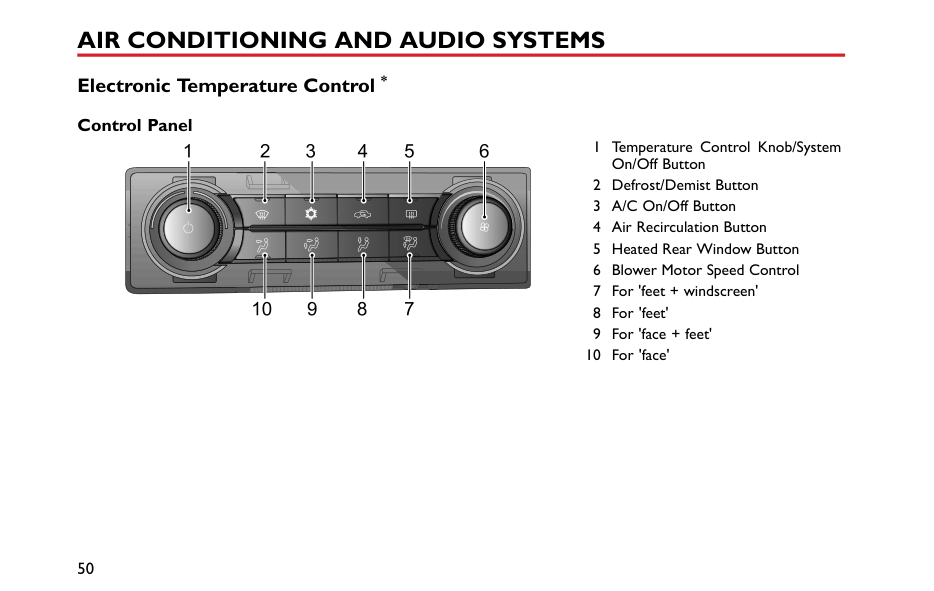
#### Electronic Temperature Control * Control Panel
6 1 Temperature Control Knob/SystemOn/OffButton
1 2 3 4 5
AC
EM
78910
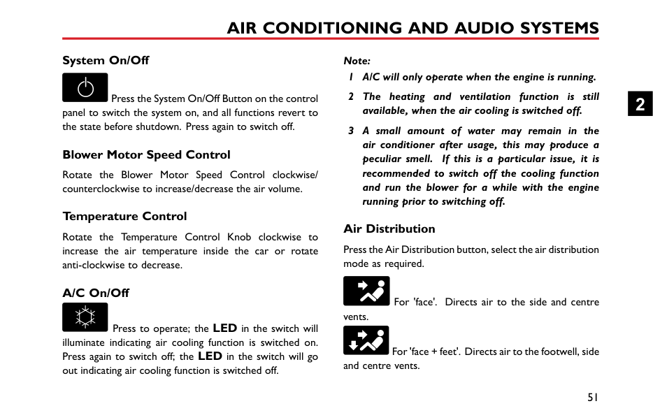
####### System On/Off
Press the System On/Off Button on the control panel to switch the system on, and all functions revert to the state before shutdown. Press again to switch off.
####### Blower Motor Speed Control
Rotate the Blower Motor Speed Control clockwise/ counterclockwise to increase/decrease the air volume.
####### Temperature Control
Rotate the Temperature Control Knob clockwise to increase the air temperature inside the car or rotate anti-clockwise to decrease.
####### A/C On/Off
Press to operate; the LED in the switch will illuminate indicating air cooling function is switched on. Press again to switch off; the LED in the switch will go out indicating air cooling function is switched off.
Note:
####### Air Distribution
Press the Air Distribution button, select the air distribution mode as required.
For 'face'. Directs air to the side and centre vents.
For 'face + feet'. Directs air to the footwell, side and centre vents.
2
For 'feet'. Directs air to the footwell vents.
Note: In this mode, a small amount of air will be directed to the side,windscreen and front side window vents.
For 'feet + windscreen'. Directs air to the windscreen, front side window and footwell vents.
Note: In this mode, a small amount of air will be directed to the side vents.
####### Defrost/Demist
Press the Defrost/Demist Button on the control panel, and the indicator will illuminate. The system will automatically set itself to a preset temperature and blower motor speed to effectively clear the side windows and windscreen.
Press again to switch off. Then the indicator will go off, and the system will return to the previous state.
Whilst the defrost/demist is selected, operate the A/C on/off button to turn on/off the compressor; operate the air recirculation button to switch between internal circulation and external circulation, operation of either of these functions will not affect the defrost/demist function, operation of any other air distribution modes will quit defrost/demist.
####### Heated Rear Window
############# The heating elements on the inside of the rear screen are easily damaged. DO NOT scrape or scratch the inside of the glass. DO NOT stick labels over the heating elements.
Press to operate; the LED in the switch will illuminate indicating the heated rear window is switched on. The LED extinguishes when the heated rear window is turned off. The heated rear window will switch off automatically after 15 minutes. After the heated rear window is switched off, if switched on again within 5 minutes, the heated rear window will operate for a further 8 minutes automatically.
Note: The heated rear window will only function with the engine operating.
####### Air Recirculation
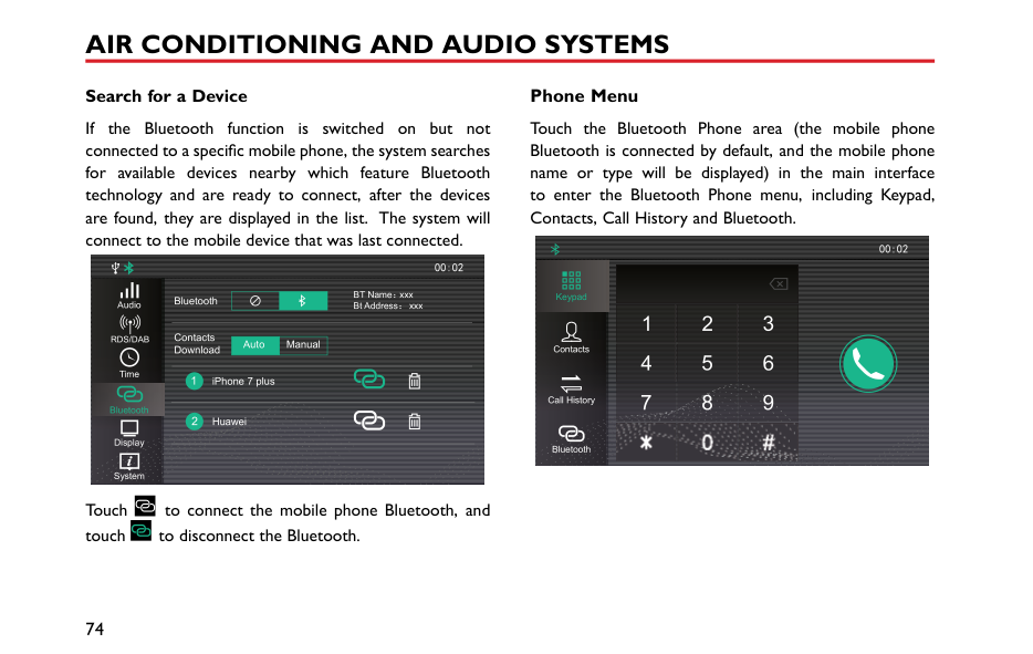
Press to operate, the LED in the switch illuminates, the air inside the car is recirculated and the air intake is closed, preventing the entry of traffic fumes.
When the ignition is switched off, the air recirculation control flap stays in current position.
Note: Leaving the system in recirculation mode can cause the windscreen to mist. If this happens, switch off recirculation and turn the controls to maximum demisting.
2
#### Radio * Instructions
|IMPORTANT| |---| |Only use the radio controls when road conditions permit.|
####### Radio Control Panel


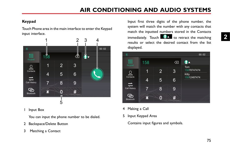


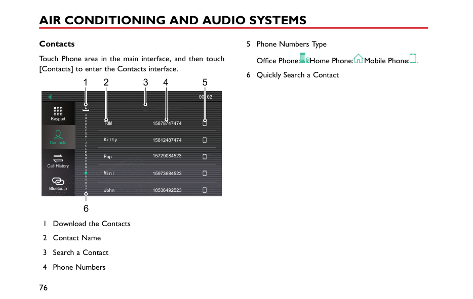
2
####### Basic Operation Power On/Off
Press [On/Off] button to start the system, and press it again to turn off the system.
########## 30 Minutes Play Function
When the ignition is switched off, press [On/Off] button to power on the unit. After 30 minutes the unit will switch off. To switch on again, press the [On/Off] button.
Note: To avoid excessive battery power drain please use in moderation.
########## Volume Adjustment
Turn the [Volume] knob counterclockwise, the volume will decreases in increments of 1, the minimum volume is 0. Turn the [Volume] knob clockwise, the volume will increases in increments of 1, the maximum volume is 32. When the [ ] appears in the display, it indicates that the device is in the state of mute.
########## Menu Functions
Short press [MENU] button to enter into the menu functions, rotate the [MENU] button to display each function in cycle, and press it again to enter the sub-menu.
In [BASS] mode, rotate this button to adjust the BASS effect (adjustment range: -7~+7).
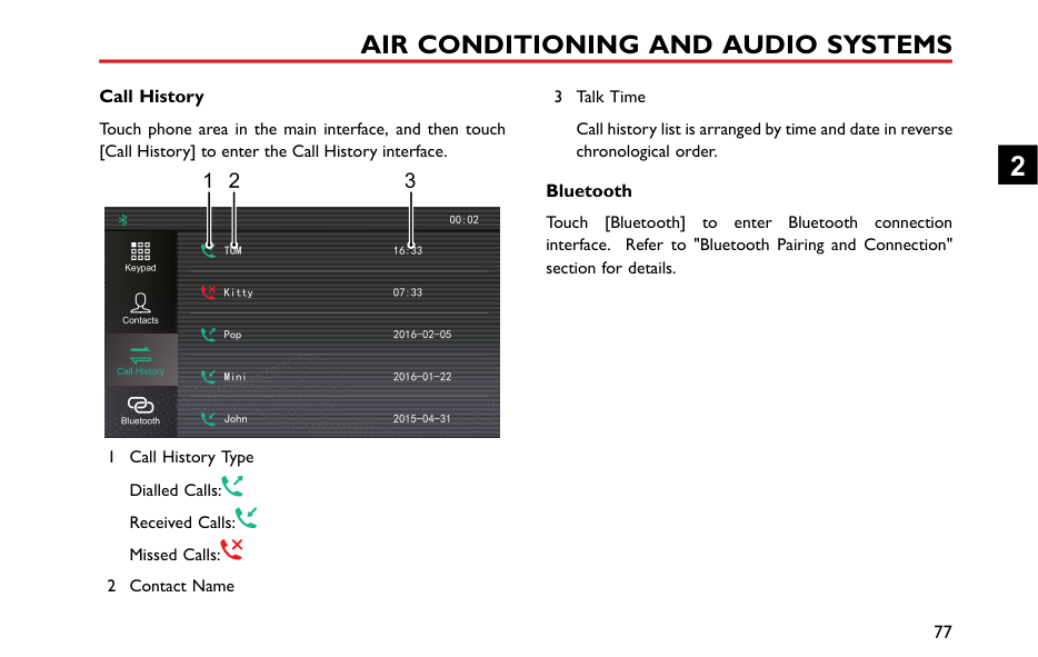
In [TREBLE] mode, rotate this button to adjust the TREBLE effect (adjustment range: -7~+7).
In [BALANCE] mode, rotate this button to adjust the BALANCE effect (adjustment range: L7~R7).
In [EQ] mode, rotate the button, and the sound effect will switch among the CLASSIC, ROCK, POP, JAZZ, VOCAL and FLAT.
In [LOUDNESS] mode, rotate the button to switch off/on the loudness.
########## Playback Mode
In the USB playback mode, short press [ ] or [ ] button to select random and repeat mode.
########## Folder Mode
In the USB playback mode, short press [ ] or [ ] button to enter into folder selection (upward/downward) mode; short press [ ] or [ ] again to select the folder upward or downward.
Radio Function Band Selection Press [SRC] button to select FM1, FM2, FMA and AM.
Note: If the radio is in stereo, the bottom of the screen will display ‘ST’.
########## Tuning
The system is provided with 3 tuning modes. These 3 tuning modes respectively are the automatic tuning, manual tuning and preset tuning.
############# Automatic Tuning
Short press [ ]/[ ] button, the radio automatically searches the frequency range, looking for a radio station of acceptable strength. Once a station is found, that station will be played.
############# Manual Tuning
In the radio mode, rotate the [MENU] button to search the station manually.
2
############# Preset Tuning
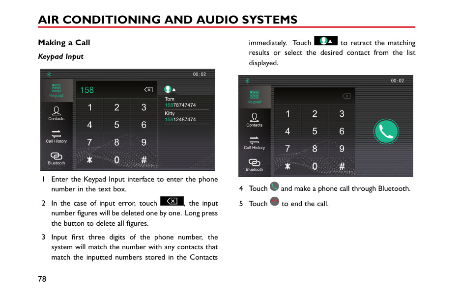
The memory has 24 preset positions (FM1, FM2, FMA, AM) for storing stations. Press numbers 1~6 to select a stored frequency.
########## Storing a Station
The system can provide 2 storing modes: manual store and auto store mode.
############# Manual Store
############# Note: Manual store overwrites any stations which already stored in the memory.
Auto Store In the desired waveband, long press [SRC]] button, the
FMA or AM memory according to signal strength. If the auto-store is unable to find 6 strong stations, the stations previously stored in the memory positions will be retained and not be overwritten.
When the [AST] appears in the display, it indicates that received stations are being stored automatically.
Note: Auto store overwrites any stations already stored by the FMA and AM preset buttons.
############ Scanning a Station
In FM or AM mode, long press the [MENU] to search for stations automatically. When a station signal is located, the unit will stop searching and play the current station for 10s, the frequency will flash 10 times in the display. If you want to stick to the current station, long press the [MENU] button again. If not, the unit will search for the next station automatically after 10s's playback.
When the [SCAN] appears in the display, it indicates that the stations are being searched.
####### USB Mode
If the track elapsed time is more than 3 seconds, press [ ] button to return to the beginning of the current track and press it again to start the previous track. If elapsed time is less than 3 seconds, press [ ] button once to return to the previous track.
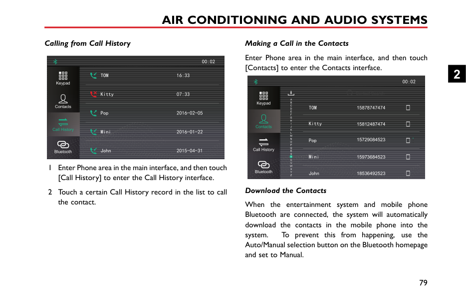


################# 1 2 3 4 5 6 MP3 WMA
################## SCAN AST ST


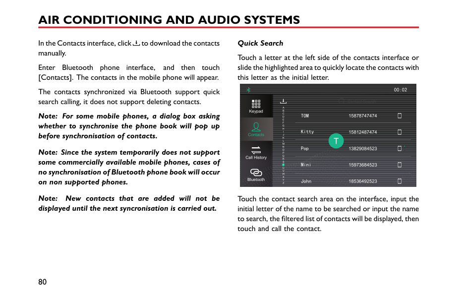

| | | | |are| |---|---|---|---|---| | |SRC| | | |
During playback, [ ] in the display indicates that tracks
played in random mode, and [ ] stands for the cycle mode. Select the mode by short pressing [ ] button or [ ] button.
Note: The system can play mp3 and wma files only.
############ Removing USB
Do not forcibly remove the USB when USB files are displayed or playing, this may cause file damage.
Insert a USB device via the USB connection.
When [ ] appears in the display, it indicates that the USB device has been connected. When [ ] appears, it indicates that the external device is recharging.
####### Bluetooth Connection
The default device name displayed on the system is SAIC-BT.
USB Playback Press [ ] button once to select the next track.
Turn on the Bluetooth function within the device and search for the vehicle Bluetooth device to pair, the display will indicate if the device is connected to the system. If
2
the Bluetooth device is enabled but not connected to the system, it will search and automatically attempt to connect with the last device that was paired to the system.
[ ] in the display indicates that the Bluetooth has been connected.
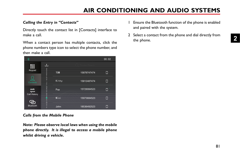
####### Bluetooth Music
Press SRC to switch to the Bluetooth music playback mode. In this mode, track selection (upward/downward) operation can be made on the onboard entertainment system, while the functional switch between fast-forward/fast-backward, track selection (upward/downward) and the random/repeat mode can be made on the device (some devices do not support this function), of which the operation method is same as the USB.
####### Bluetooth Phone
With a mobile phone connected, if there is an incoming call, the current track will be stopped and the call number will be displayed instead. Press [ ] to make the Bluetooth call. Long press [ ] to end the call. Short press [ ]
button in the phone call to make a shift between the private conversation and the hands-free function.
####### Bluetooth Function Menu
With Bluetooth paired, short press [MENU] button to enter into the Bluetooth menu; rotate the [MENU] button to select the Bluetooth settings.
########## Phone Voice Volume Setting
Short press [MENU] button on the Bluetooth volume setting interface to enter into the volume control interface; rotate the [MENU] button to adjust the volume and short press the [MENU] button again to store settings and then return to the previous menu.
Note: This setting can only adjust the volume in the Bluetooth hands-free call, and makes no impact on other playback modes.
########## Bluetooth Pairing
In the Bluetooth setting interface, rotate the [MENU] button to check the Bluetooth pairing code.
Note: The function only supports the Bluetooth pairing connection of mobile phone that you require to enter the pairing code.
####### Antenna
|


| |---|
The antenna is located at the rear of the roof. Avoid bending the antenna. However when required, e.g. when using an automatic car washing facility, please ensure that the antenna is removed.
To remove the antenna unscrew the antenna anti clockwise.
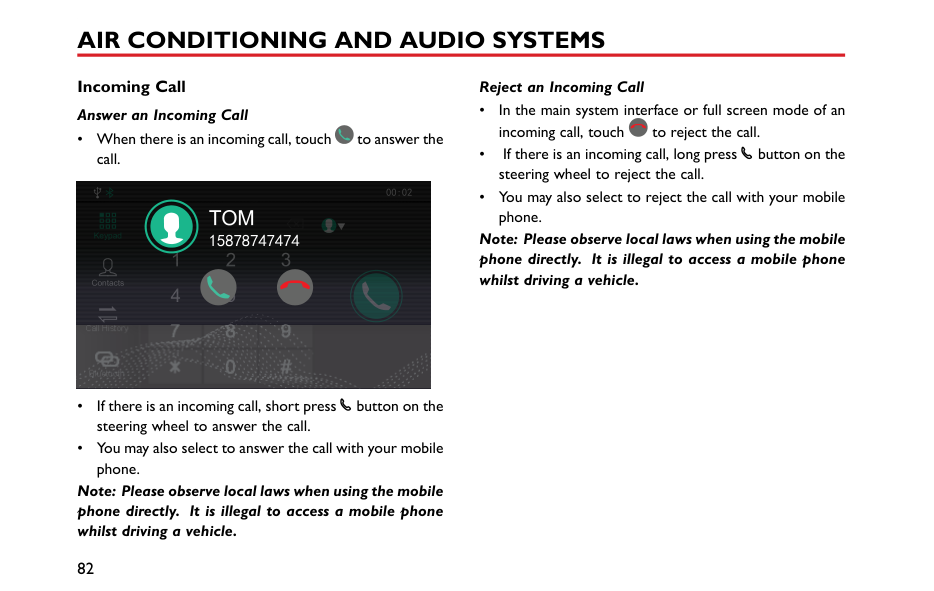
2
#### Entertainment System * Important Safety Information
Cautions for Using Screen
To protect the screen against damage, always touch the panel buttons with your finger. A touch pen may be used for special calibration. The touch pen should not be used for normal operation.
2
scratch the surface. Do not use irritative or abrasive chemical cleaners.
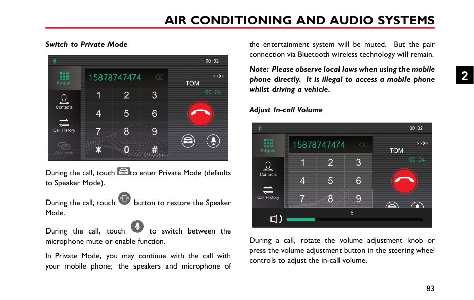
Note: The images in this manual are illustrations only for your reference.
Note: Along with the product improvement, specifications and designs are subject to change without any prior notice.
Note: All rights related to this document are reserved. Note: Without the permission of the copyright owner, reproduction and usage of this document in any form, either in whole or in part, is strictly prohibited.
####### Playable File Format for Entertainment System
########## Precautions
########## Audio Support
The entertainment system supports the following audio formats, other formats may not work normally.
MP3, WMA, OGG, WAV, APE and FLAC. Video Support
The entertainment system supports the following video formats, other formats may not work normally.
WMV, H264, MPEG2, MPEG4 and HD Video Playback.
########## Supported Texts/Images
The entertainment system supports the following text/image formats, other formats may not work normally.
JPEG, GIF, BMP, PNG.
####### Basic Operations Entertainment Player Control Panel
2
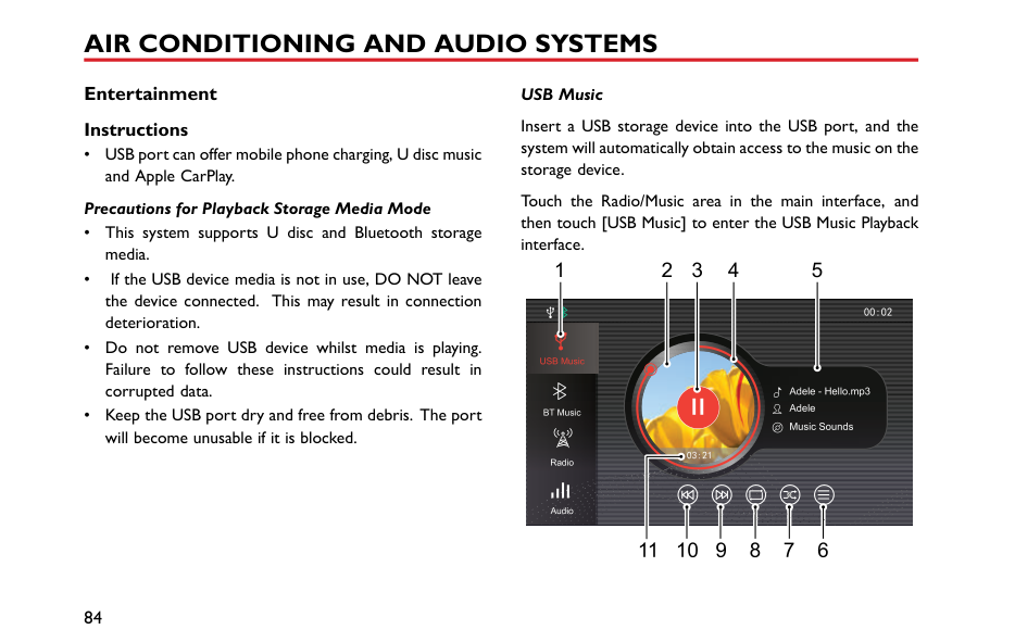
########## Main System Interface
1 2 3
DAB AM
FM
TPMS Setup
USB Music
BT Music
Apple CarPlay
Phone 7 plus
Video Pictures
7 45
6
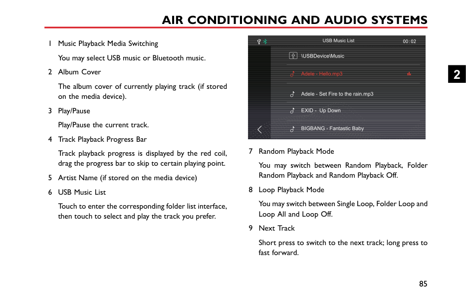
Power On/Off Power On Short press the power button to start the system.
If the vehicle power is turned off with the system currently in playback mode, the system will be automatically powered on when the vehicle power is turned on again.
If the vehicle power is turned off with the system in the Off state, short press the Power button on the system control panel to power-on the system after the vehicle power is turned on again.
With the system ON, long press the Power button on the system control panel for a period greater than 10 seconds, and the system will be automatically restarted.
############# Power Off
With the system operating, long press the power button to switch the system off.
Turn off the vehicle power, and the system is automatically powered off.
2
After the ignition switch is turned off, press the On/Off button to turn on the entertainment system, the system will be automatically powered off after 30 minutes.
############# Standby Mode
Short press the Power button to allow the entertainment system to enter the standby mode, the operation of the system will be suspended.
The standby mode can also be cancelled by the following operations:
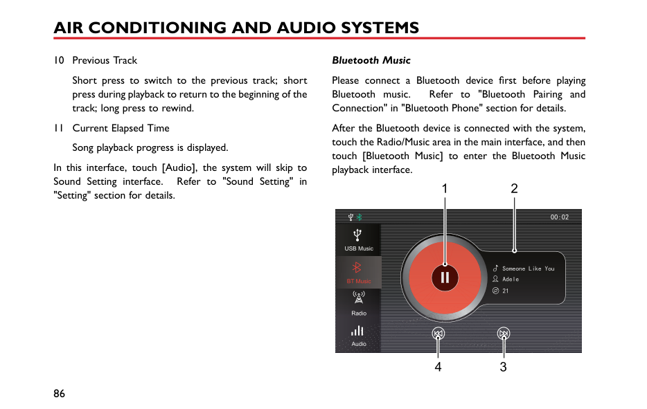

20:19
Saturday 6-JAN-2018


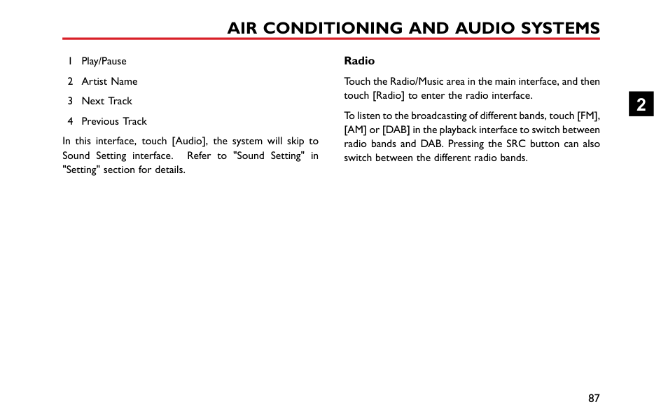


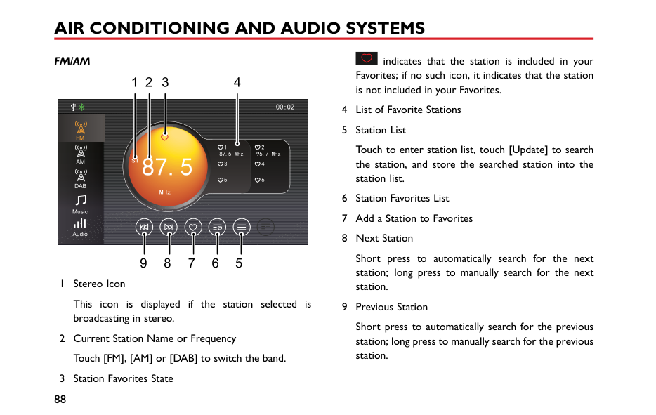


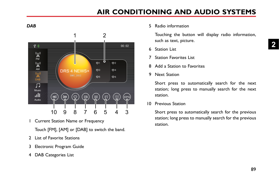


In the standby mode, all sounds will be muted, and the panel buttons can not be used for other operations. To cancel the standby mode, press the Power button again.
########## Steering Wheel Control Buttons
|1 32 4
5 67 98
| |---|
1 : When playing audio, short press to return to the beginning of the track (except the Bluetooth music mode), short press again to switch to previous track, and long press to rewind (except the Bluetooth music mode). When playing video, short press to switch to previous video, and long press to rewind. When playing the radio, short press to switch to previous station; long press to search and play the previous station; long press continuously, the system will search
through a cycle, then stop at the current station and continue to play it.
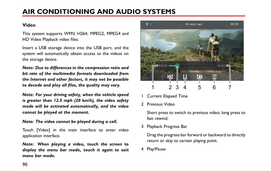
2
The steering wheel “*” button can be set as the shortcut key to CarPlay/Home interface. To access the setting page press and hold for 2 seconds.
Activate/Cancel SIRI function. This button will only be used after Apple CarPlay is enabled.
########## Volume Adjustment
You can adjust the volume of different audio functions via the volume knob and steering wheel buttons. During the volume adjustment, the system will automatically display a pop up volume indication window, this will display the current volume setting, and change in accordance with control request. If no volume adjustment is detected for 3 seconds or other operations (e.g., pressing the panel button, touching the screen) are performed, the volume indication window automatically disappears.
Note: The playback volume of Bluetooth audios can be adjusted through the devices themselves as well as the entertainment player.
########## Connecting/Disconnecting a USB Storage Device Inserting a USB Storage Device
The USB port is located at the front of the centre console, insert a USB device into the USB port for connection.
############# Removing the USB Storage Device
Check and confirm that there is no data being accessed, then pull out the USB storage device.
Note: Do not use excessive force to insert a USB device, this may cause damage to the socket or socket securing device.
Note: Some USB storage devices may be unidentifiable.
Note: The entertainment device may not achieve optimum performance when some USB storage devices are used.
Note: Connection via a USB hub is not allowed.
####### Bluetooth Phone Instructions
2
|mobile phone (except when the connection is terminated due to mobile phone operation).
to Bluetooth wireless connection interruption or occuring in the process of transmission in some conditions, the entertainment system may not able to be paired and connected with a mobile phone. this time, it is recommended to clear the paired in the mobile phone and the device list on the
• Touch [Bluetooth] under and enter the Bluetoo
to open the Blu
Audio Bluetooth
Contacts Download
Auto MRDS/DAB
|[Setting] in the main interface, h Setting interface. Touch tooth function.
anual
BT Name xxx Bt Address xxx| |---|---| |entertainment system, and perform pairing again. Time


Bluetooth
Display
System
| |
########## Bluetooth Pairing and Connection
Includes Bluetooth On and Off, device name, pairing code, Bluetooth state, etc.
############# Pairing from Mobile Phone
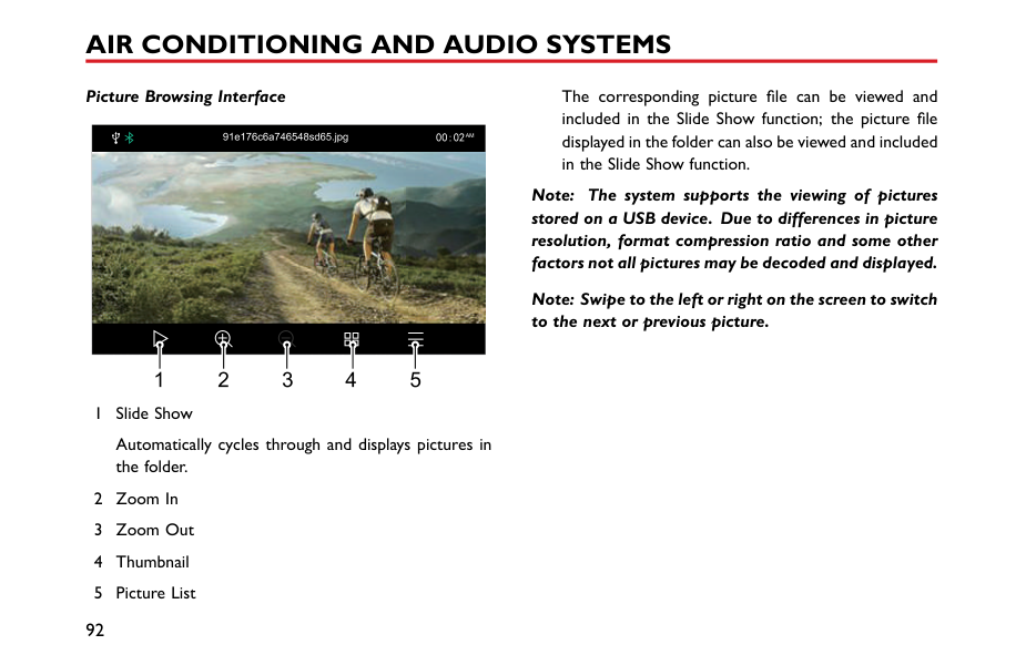
Turn on the system Bluetooth function, request the connection from mobile phone end for pairing with the mobile phone.


Bluetooth Settings
################ Bluetooth Settings


BT Name xxx Bt Address xxx
T xxx


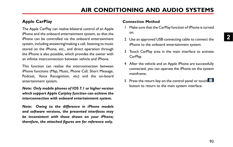


Bluetooth
Address xxxBluetooth


Download

Pair Phon e:Tony’s iPhone Pair code:14 5587


3 After the pairing is completed, the message prompting connection completion appears. If the pairing fails, please repeat the procedure described above.
2
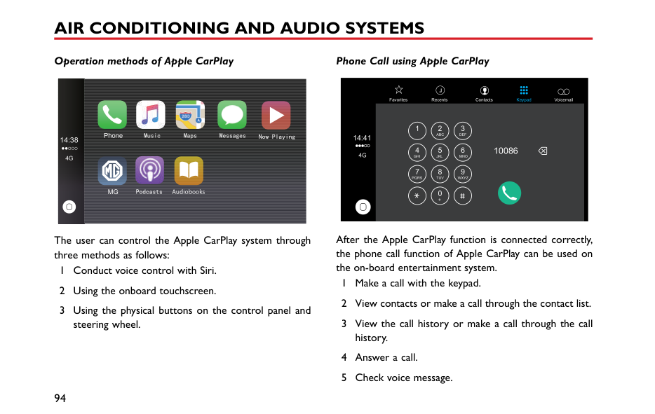
############ Search for a Device
If the Bluetooth function is switched on but not connected to a specific mobile phone, the system searches for available devices nearby which feature Bluetooth technology and are ready to connect, after the devices are found, they are displayed in the list. The system will connect to the mobile device that was last connected.

BT Name xxx Bt Address xxx
Bluetooth
Audio
Contacts Download
RDS/DAB
Auto Manual
Time
iPhone 7 plus


Bluetooth
Huawei
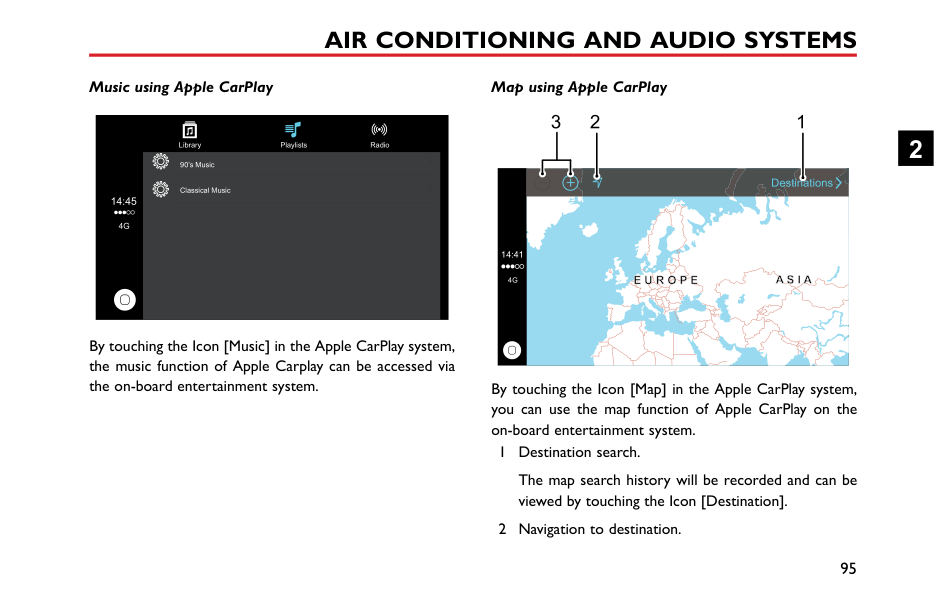
Display
System

Touch to connect the mobile phone Bluetooth, and touch to disconnect the Bluetooth.
########## Phone Menu
Touch the Bluetooth Phone area (the mobile phone Bluetooth is connected by default, and the mobile phone name or type will be displayed) in the main interface to enter the Bluetooth Phone menu, including Keypad, Contacts, Call History and Bluetooth.


Keypad
Contacts

Call History
Bluetooth
########## Keypad
############## Touch Phone area in the main interface to enter the Keypad input interface.
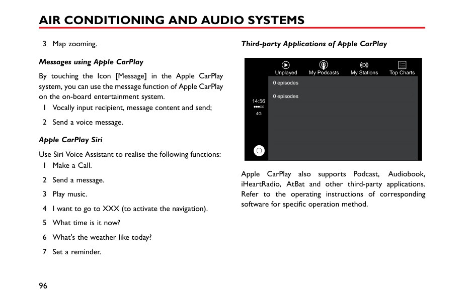
1
2 3 4


Keypad
Contacts

Call History
Bluetooth
5
Input first three digits of the phone number, the system will match the number with any contacts that match the inputted numbers stored in the Contacts immediately. Touch
| | |---|
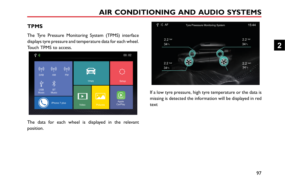
to retract the matching results or select the desired contact from the list displayed.


Keypad
Tom 15878747474
tty 15812487474
Contacts

Call History
Bluetooth
2
########## Contacts
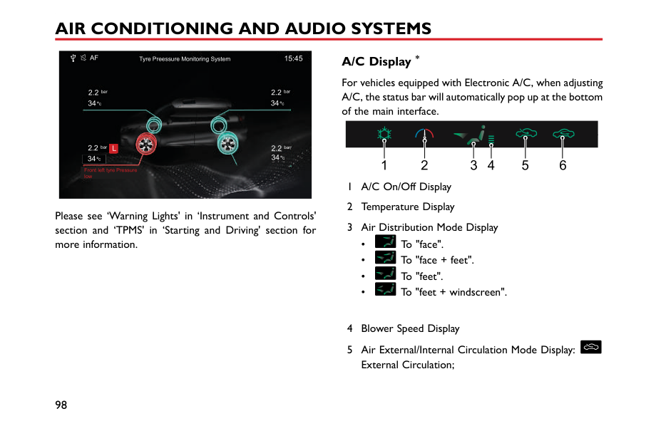
Touch Phone area in the main interface, and then touch [Contacts] to enter the Contacts interface.
|

A
B
C
D
E
F
G
H
Keypad
Contacts
1 2
|15878747474
15812487474
Contact Search
3 4 5| |---|---| |
K
M
N
O
P
Q
R
S
T
U
V
W
X
Y
Z
Bluetooth
Call History
6

1 Download the Contacts
2 Contact Name
|15973684523
18536492523|
########## Call History
############## Touch phone area in the main interface, and then touch [Call History] to enter the Call History interface.
###### 1 2 3

Keypad
Contacts


Call History
Bluetooth

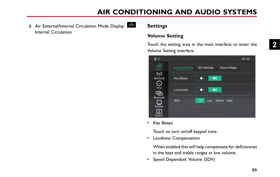
3 Talk Time
Call history list is arranged by time and date in reverse chronological order.
########## Bluetooth
Touch [Bluetooth] to enter Bluetooth connection interface. Refer to "Bluetooth Pairing and Connection" section for details.
2
|Making a Call Keypad Input


Keypad
Contacts
|Tom 15878747474
itty 15812487474
immediately. Touch results or select the d displayed.
| | |---|


Keypad
|to retract the matching esired contact from the list| |---|---|---| |
Bluetooth
Call History

1 Enter the Keypad Input i number in the text box.
2 In the case of input err number figures will be d the button to delete all f
| | |---|
3 Input first three digits
|nterface to enter the phone
r, touch , the input leted one by one. Long press igures.
of the phone number, the
Bluetooth
Contacts
Call History
4 Touch and make a p
5 Touch to end the c
|

one call through Bluetooth.
ll.|
############## system will match the number with any contacts that match the inputted numbers stored in the Contacts
############# Calling from Call History

Keypad
Contacts

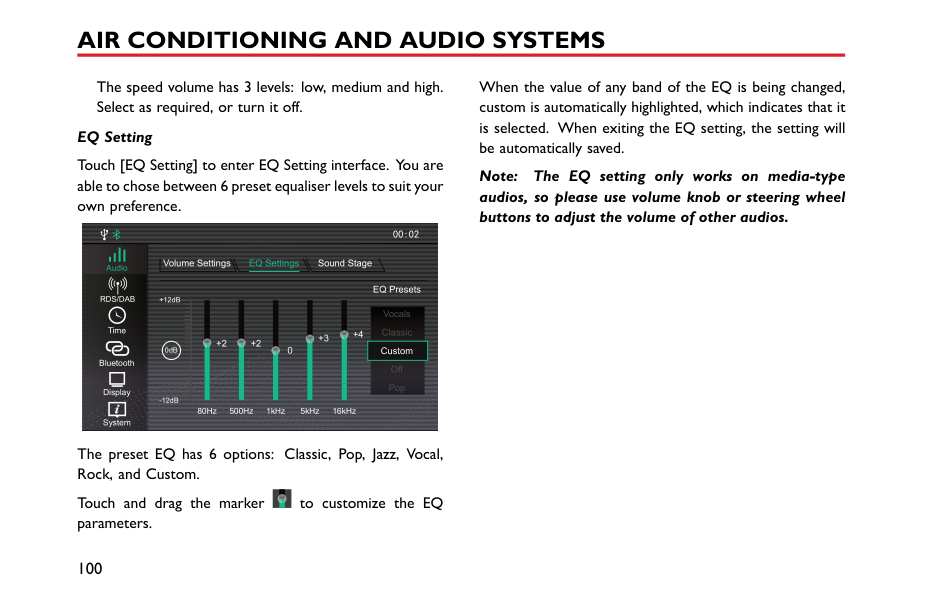

Call History
Bluetooth

############# Making a Call in the Contacts
Enter Phone area in the main interface, and then touch [Contacts] to enter the Contacts interface.

Contact Search
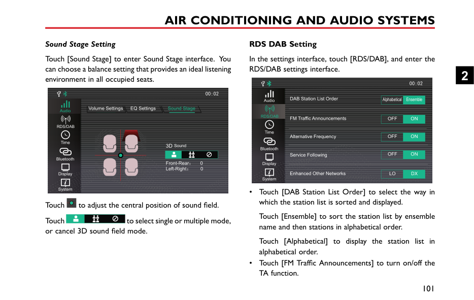
Keypad
15878747474


15812487474
Contacts
Call History
15973684523
18536492523Bluetooth

############# Download the Contacts
When the entertainment system and mobile phone Bluetooth are connected, the system will automatically download the contacts in the mobile phone into the system. To prevent this from happening, use the Auto/Manual selection button on the Bluetooth homepage and set to Manual.
2
In the Contacts interface, click to download the contacts manually.
Quick Search
Touch a letter at the left side of the contacts interface or slide the highlighted area to quickly locate the contacts with
Enter Bluetooth phone interface, and then touch [Contacts].
|The contacts in the mobile phone will appear. contacts synchronized via Bluetooth support quick
calling, it does not support deleting contacts.
For some mobile phones, a dialog box asking to synchronise the phone book will pop up
this letter as the initial letter


A
B
C
D
E
F
G
H
Keypad
Contacts
|15878747474
15812487474
Contact Search| |---|---| |synchronisation of contacts. Since the system temporarily does not support
commercially available mobile phones, cases of
synchronisation of Bluetooth phone book will occur supported phones. New contacts that are added will not be
until the next syncronisation is carried out.

K
M
N
O
P
Q
R
S
T
U
V
W
X
Y
Z
Bluetooth
Call History

Touch the contact search ar initial letter of the name to b to search, the filtered list of c touch and call the contact.|15973684523
18536492523
T
a on the interface, input the searched or input the name ntacts will be displayed, then|
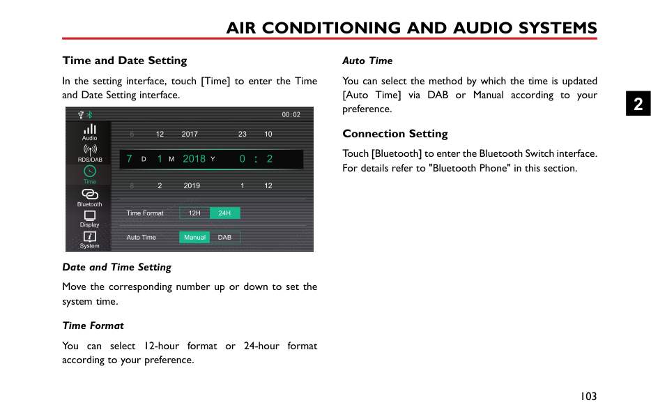
The search Note: whether before Note: some no on non Note: displayed
############# Calling the Entry in “Contacts”
Directly touch the contact list in [Contacts] interface to make a call.
the phone.
When a contact person has multiple contacts, click the phone numbers type icon to select the phone number, and
|then make a call.


A
B
C
D
F
G
J
Keypad
Contacts
|15878747474
15812487474
Contact Search| |---|---| |
K
L
M
N
O
P
Q
R
S
T
U
V
W
X
YBluetooth
Call History

Calls from the Mobile Pho Note: Please observe local l phone directly. It is illega|15973684523
18536492523 e
aws when using the mobile to access a mobile phone|
2
Incoming Call Answer an Incoming Call

TOM

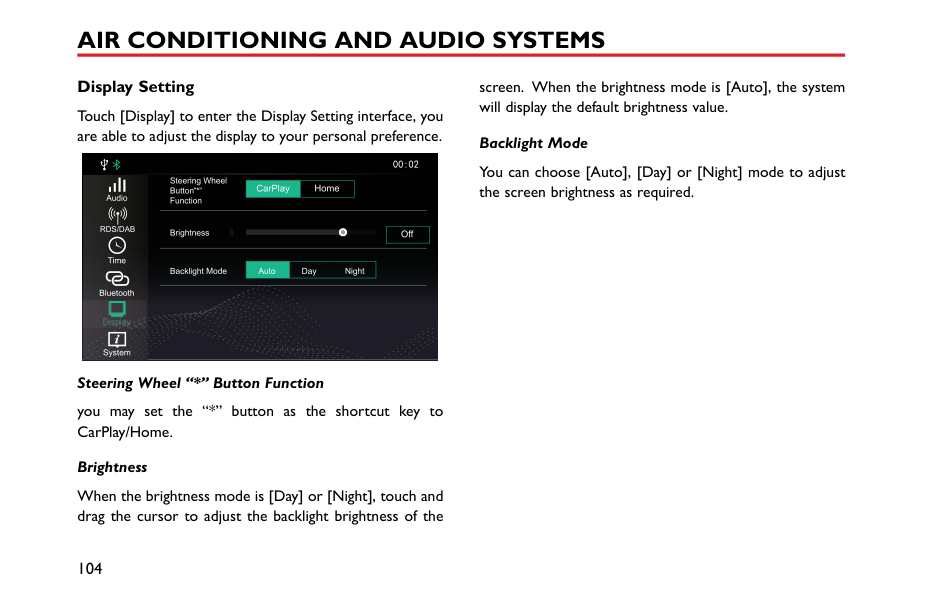
Note: Please observe local laws when using the mobile phone directly. It is illegal to access a mobile phone
Reject an Incoming Call
############# Note: Please observe local laws when using the mobile phone directly. It is illegal to access a mobile phone whilst driving a vehicle.
|Switch to Private Mode


Keypad
Contacts
Call History
|TOM
the entertainment system will be muted. But the pair connection via Bluetooth wireless technology will remain.
Note: Please observe local laws when using the mobile phone directly. It is illegal to access a mobile phone whilst driving a vehicle.
Adjust In-call Volume

2|TOM
the entertainment system will be muted. But the pair connection via Bluetooth wireless technology will remain.
Note: Please observe local laws when using the mobile phone directly. It is illegal to access a mobile phone whilst driving a vehicle.
Adjust In-call Volume

2| |---|---|---| |Bluetooth

During the call, touch to enter Private Mode (defaults to Speaker Mode).
During the call, touch button to restore the Speaker Mode.
During the call, touch to switch between the microphone mute or enable function.
In Private Mode, you may continue with the call with your mobile phone; the speakers and microphone of


Bluetooth
Keypad
Contacts
Call History
During a call, rotate the v press the volume adjustmen controls to adjust the in-call
|Bluetooth

During the call, touch to enter Private Mode (defaults to Speaker Mode).
During the call, touch button to restore the Speaker Mode.
During the call, touch to switch between the microphone mute or enable function.
In Private Mode, you may continue with the call with your mobile phone; the speakers and microphone of


Bluetooth
Keypad
Contacts
Call History
During a call, rotate the v press the volume adjustmen controls to adjust the in-call
|TOM
olume adjustment knob or button in the steering wheel
volume.
83|
####### Entertainment Instructions
• USB port can offer mobile phone charging, U disc music and Apple CarPlay.
############# Precautions for Playback Storage Media Mode
|system supports U disc and Bluetooth storage
USB device media is not in use, DO NOT leave
device connected. This may result in connection deterioration.
not remove USB device whilst media is playing. to follow these instructions could result in
data.
interface.


USB Music
1 2 3
|Adele - Hello mp3 Adele
4 5| |---|---| |the USB port dry and free from debris. The port become unusable if it is blocked.


Audio
BT Mus c
Radio
91011

|Music Sounds
678|
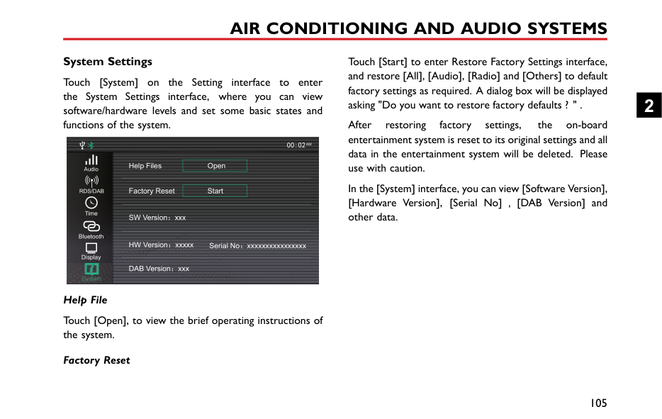
############# USB Music
Insert a USB storage device into the USB port, and the system will automatically obtain access to the music on the storage device.
Touch the Radio/Music area in the main interface, and then touch [USB Music] to enter the USB Music Playback
The album cover of currently playing track (if stored on the media device).
Track playback progress is displayed by the red coil, drag the progress bar to skip to certain playing point.
Touch to enter the corresponding folder list interface, then touch to select and play the track you prefer.
USB Music List

\USBDevice\Music
Adele - Hello.mp3
Adele - Set Fire to the rain.mp3
EXID - Up Down

BIGBANG - Fantastic Baby
You may switch between Random Playback, Folder Random Playback and Random Playback Off.
You may switch between Single Loop, Folder Loop and Loop All and Loop Off.
Short press to switch to the next track; long press to fast forward.
2
Short press to switch to the previous track; short press during playback to return to the beginning of the track;
|long press to rewind. Elapsed Time playback progress is displayed.
interface, touch [Audio], the system will skip to Setting interface. Refer to "Sound Setting" in
section for details.
Connection" in "Bluetooth P After the Bluetooth device i touch the Radio/Music area i touch [Bluetooth Music] to playback interface.
USB Music
1|one" section for details.
connected with the system, the main interface, and then enter the Bluetooth Music


2
| |---|---| |


Audio
BT Music
Radio
4

|3|
In this Sound "Setting"
############# Bluetooth Music
Please connect a Bluetooth device first before playing Bluetooth music. Refer to "Bluetooth Pairing and

In this interface, touch [Audio], the system will skip to Sound Setting interface. Refer to "Sound Setting" in "Setting" section for details.
########## Radio
Touch the Radio/Music area in the main interface, and then touch [Radio] to enter the radio interface.
To listen to the broadcasting of different bands, touch [FM], [AM] or [DAB] in the playback interface to switch between radio bands and DAB. Pressing the SRC button can also switch between the different radio bands.
2
############# FM/AM
Touch to enter station list, touch [Update] to search the station, and store the searched station into the station list.
Short press to automatically search for the next station; long press to manually search for the next station.
21 3 4


FM
AM
DAB


Music

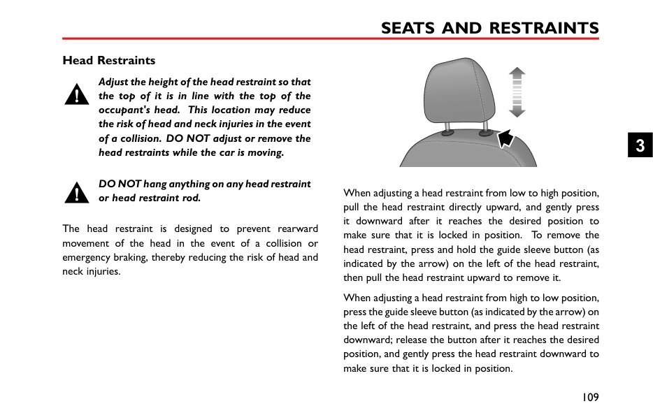
T
Audio
56789
This icon is displayed if the station selected is broadcasting in stereo.
Short press to automatically search for the previous station; long press to manually search for the previous station.
############# DAB
5 Radio information
|DRS 4 NEWAM
M
1|

S+
2 Touching the button will display radio
such as text, picture.
6 Station List
7 Station Favorites List
8 Add a Station to Favorites
| |---|---| |


Audio
Music
DAB
10 89

1 Current Station Name o|T EPG
5 4 367 r Frequency
9 Next Station
Short press to automatically search for station; long press to manually search for station.
10 Previous Station
Short press to automatically search for the station; long press to manually search for the station.|
information,
the next the next
previous previous
Touch [FM], [AM] or [DAB] to switch the band. 2 List of Favorite Stations 3 Electronic Program Guide 4 DAB Categories List
2
########## Video
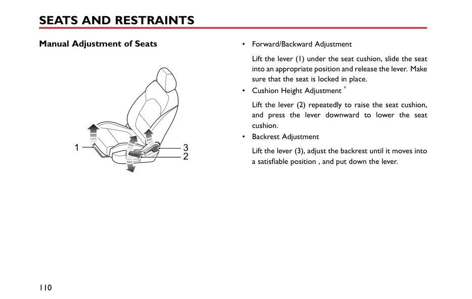
This system supports WMV, H264, MPEG2, MPEG4 and HD Video Playback video files.
Insert a USB storage device into the USB port, and the system will automatically obtain access to the videos on the storage device.
Note: Due to differences in the compression ratio and bit rate of the multimedia formats downloaded from the Internet and other factors, it may not be possible to decode and play all files, the quality may vary.
Note: For your driving safety, when the vehicle speed is greater than 12.5 mph (20 km/h), the video safety mode will be activated automatically, and the video cannot be played at the moment.
Note: The video cannot be played during a call.
Touch [Video] in the main interface to enter video application interface.
Note: When playing a video, touch the screen to display the menu bar mode, touch it again to exit menu bar mode.


00:00:24 00:02:24

7654321

Short press to switch to previous video; long press to fast rewind.
Drag the progress bar forward or backward to directly return or skip to certain playing point.
Short press to switch to next video; long press to fast forward.
The corresponding video file can be viewed and played; video files displayed in the folder can also be viewed and played.
########## Picture
Insert a USB storage device into the USB port, and the system will automatically obtain access to the pictures on the storage device.
Touch [Picture] in the main interface to enter picture application interface.
Touch picture file to display the picture in full screen. When viewing pictures, click the screen to display the menu bar mode, and click it again to exit menu bar mode.
2
############# Picture Browsing Interface


Automatically cycles through and displays pictures in the folder.
The corresponding picture file can be viewed and included in the Slide Show function; the picture file displayed in the folder can also be viewed and included in the Slide Show function.
Note: The system supports the viewing of pictures stored on a USB device. Due to differences in picture resolution, format compression ratio and some other factors not all pictures may be decoded and displayed.
Note: Swipe to the left or right on the screen to switch to the next or previous picture.
####### Apple CarPlay
############ Connection Method
The Apple CarPlay can realise bilateral control of an Apple iPhone and the onboard entertainment system, so that the iPhone can be controlled via the onboard entertainment system, including answering/making a call, listening to music stored on the iPhone, etc., and direct operation through the iPhone is also possible, which provides the owner with an infinite interconnection between vehicle and iPhone.
This function can realise the interconnection between iPhone functions (Map, Music, Phone Call, Short Message, Podcast, Voice Recognition, etc) and the on-board entertainment system.
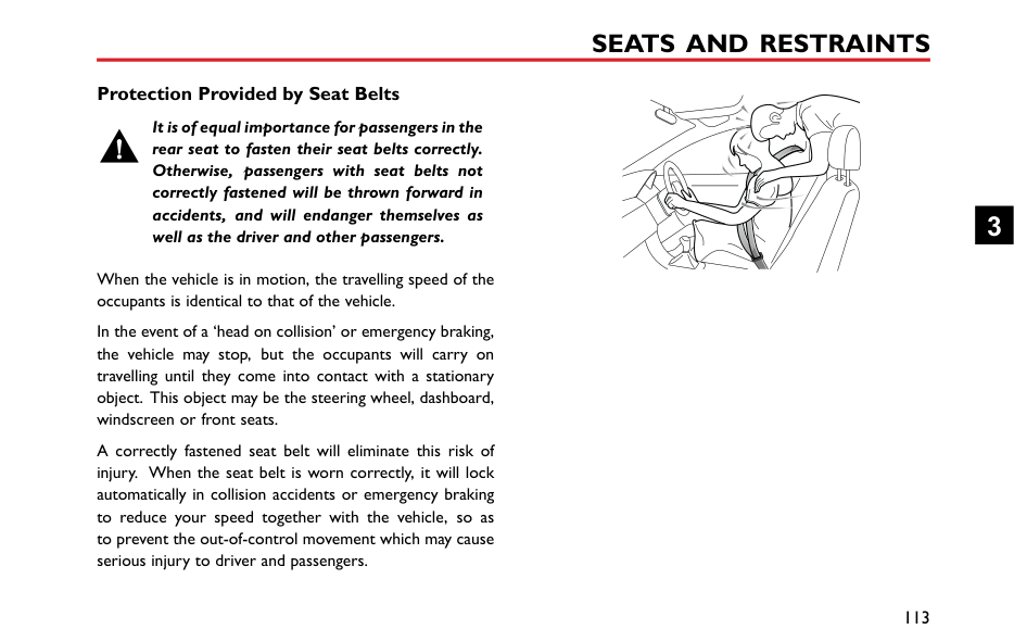

Note: Only mobile phones of IOS 7.1 or higher version which support Apple Carplay function can achieve the interconnection with onboard entertainment system.
Note: Owing to the difference in iPhone models and software versions, the presented interfaces may be inconsistent with those shown on your iPhone; therefore, the attached figures are for reference only.
2
############# Phone Call using Apple CarPlay
############# Operation methods of Apple CarPlay

Vo cema lFavoritesRecentsContactsKeypad


1
2 ABC
3 DEF
Phone
14:41
14:38
4G 1008 6
4 GH
5 L
6 MNO
4G

7 PQR S
8 TUV
9 WXYZ
AudiobooksMG
0 +
After the Apple CarPlay function is connected correctly, the phone call function of Apple CarPlay can be used on the on-board entertainment system.
The user can control the Apple CarPlay system through three methods as follows:
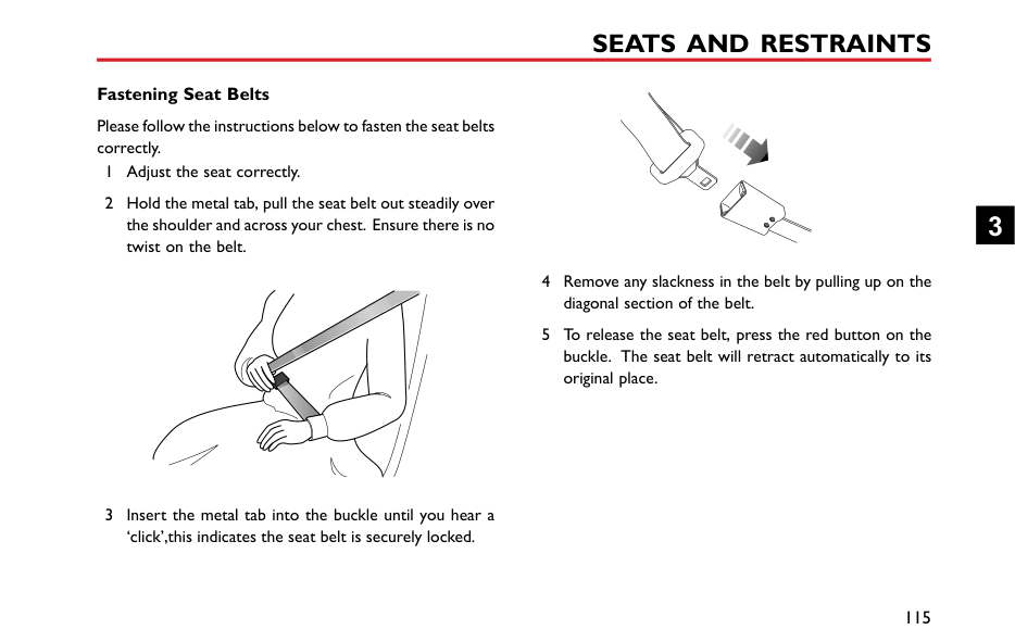
############# Music using Apple CarPlay
|14:45
4G
Library Playlsts Rad o
90’s Music
Class ca Music
| |---|
By touching the Icon [Music] in the Apple CarPlay system, the music function of Apple Carplay can be accessed via the on-board entertainment system.
############# Map using Apple CarPlay
123
Destinations
14:41
A S I A
U R O P E
| | | |---|---| | | |
| | | |---|---| | | |
4G
By touching the Icon [Map] in the Apple CarPlay system, you can use the map function of Apple CarPlay on the on-board entertainment system.
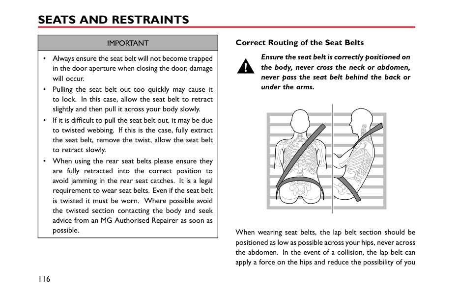
The map search history will be recorded and can be viewed by touching the Icon [Destination].
2
3 Map zooming.
############# Messages using Apple CarPlay
By touching the Icon [Message] in the Apple CarPlay system, you can use the message function of Apple CarPlay on the on-board entertainment system.
Apple CarPlay Siri Use Siri Voice Assistant to realise the following functions:
############# Third-party Applications of Apple CarPlay
|14:56
4G
Unplayed 0 episodes
0 episodes
My Podcasts My Stations Top Charts
| |---|
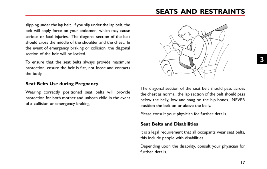
Apple CarPlay also supports Podcast, Audiobook, iHeartRadio, AtBat and other third-party applications. Refer to the operating instructions of corresponding software for specific operation method.

AF
####### TPMS
15:44
Tyre Preessure Monitoring System
The Tyre Pressure Monitoring System (TPMS) interface displays tyre pressure and temperature data for each wheel. Touch TPMS to access.
2.2
2.2
bar
bar
2
34
34
c
c


2.2 34
2.2 bar 4 c
bar
c
If a low tyre pressure, high tyre temperature or the data is missing is detected the information will be displayed in red text

The data for each wheel is displayed in the relevant position.

AF
15:45
Tyre Preessure Mon toring System
2.2
2.2
bar
bar
34
34
c
c


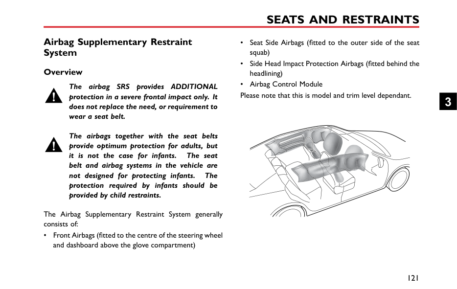


2.2 34
2.2 bar 4 c
L
bar


c
Front left tyre Pressure
ow
Please see ‘Warning Lights' in ‘Instrument and Controls' section and ‘TPMS' in ‘Starting and Driving' section for more information.
####### A/C Display *
For vehicles equipped with Electronic A/C, when adjusting A/C, the status bar will automatically pop up at the bottom of the main interface.


2 4 5 631


####### Settings Volume Setting
6 Air External/Internal Circulation Mode Display: Internal Circulation
############## Touch the setting area in the main interface to enter the Volume Setting interface.


Volume Settings EQ Settings Sound StageAudio
RDS/DAB Key Beeps
T me
Loundness
Bluetooth
SDV Off Low Medium High
Display
System

When enabled this will help compensate for deficiencies in the bass and treble ranges at low volume.
2
|The speed volume has 3 l Select as required, or tur
EQ Setting
Touch [EQ Setting] to enter E able to chose between 6 pres own preference.
+12dB
Volume Se tings EQAudio
RDS/DAB|vels: low, medium and high. it off.
Q Setting interface. You are t equaliser levels to suit your


EQ Presets
Vocals
Set ings Sound Stage
When the value of any band of the EQ is being custom is automatically highlighted, which indicates is selected. When exiting the EQ setting, the be automatically saved.
Note: The EQ setting only works on audios, so please use volume knob or steering buttons to adjust the volume of other audios.| |---|---| |0dB
-12dB
+2
80Hz 500Hz
+2
Time
Bluetooth
Display
System
The preset EQ has 6 optio Rock, and Custom.
Touch and drag the marke parameters.
100
|
1kHz 5kHz 16kHz
0
+3 +4 Classic


Custom Off
Pop

s: Classic, Pop, Jazz, Vocal,
to customize the EQ|
changed, that it setting will
############# media-type wheel
############# Sound Stage Setting
Touch [Sound Stage] to enter Sound Stage interface. You can choose a balance setting that provides an ideal listening environment in all occupied seats.


Volume Settings EQ Settings
Sound Stage
Audio
RDS/DAB
T me
Sound3D
Bluetooth
Front-Rear 0 Left-Right 0
Display
System

Touch to adjust the central position of sound field. Touch to select single or multiple mode, or cancel 3D sound field mode.
############ RDS DAB Setting
############## In the settings interface, touch [RDS/DAB], and enter the RDS/DAB settings interface.

DAB Station List Order
Alphabetica Ensemble
Audio


RDS/DAB
FM Traffic Announcements
OFF ON
Time
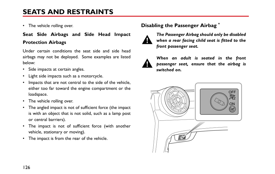
OFF ON
Alternative Frequency
Bluetooth
OFF ON
Service Following
Display
Enhanced Other Networks
LO DX
System

Touch [Ensemble] to sort the station list by ensemble name and then stations in alphabetical order.
Touch [Alphabetical] to display the station list in alphabetical order.
2
Selecting TA [On] allows the system to analyse and communicate traffic messages to the driver. This information may be in the form of voice messages.
Select [Off] to inhibit traffic announcements.
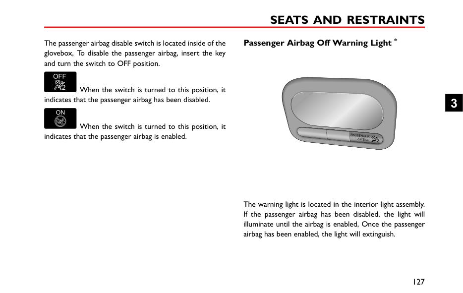
AF is alternative frequency,when the signal is below a certain level, AF will automatic search for an alternative frequency of the current station if the current station supports this function.
Service Following is the term applied to maintaining the same audio or data content that the user has selected in varying reception conditions if the current station supports this function.
EON - Enhanced Other Networks enables the system to obtain information from other networks as well
as the one selected. Select LO for Local or DX for networks further afield.
########## Time and Date Setting
In the setting interface, touch [Time] to enter the Time and Date Setting interface.

8
12 2017 23 10
Audio


############### 1 2018 0 2
D M Y
RDS/DAB


T me
2 2019 1 12
Bluetooth
24H12HTimeFormat
Display
Manua DABAutoTime
System

############# Date and Time Setting
Move the corresponding number up or down to set the system time.
############# Time Format
You can select 12-hour format or 24-hour format according to your preference.
############# Auto Time
You can select the method by which the time is updated [Auto Time] via DAB or Manual according to your preference.
########## Connection Setting
Touch [Bluetooth] to enter the Bluetooth Switch interface. For details refer to "Bluetooth Phone" in this section.
2


AIR CONDITIONING AND AUDIO SYSTEMS
########## Display Setting
screen. When the brightness mode is [Auto], the system will display the default brightness value.
Touch [Display] to enter the Display Setting interface, you are able to adjust the display to your personal preference.
############# Backlight Mode


You can choose [Auto], [Day] or [Night] mode to adjust the screen brightness as required.


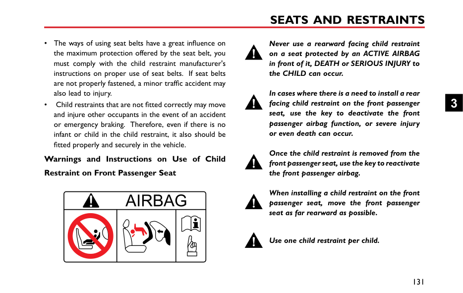

############# Steering Wheel “*” Button Function
you may set the “*” button as the shortcut key to CarPlay/Home.
############# Brightness
When the brightness mode is [Day] or [Night], touch and drag the cursor to adjust the backlight brightness of the
########## System Settings
Touch [System] on the Setting interface to enter the System Settings interface, where you can view software/hardware levels and set some basic states and functions of the system.

OpenAudio
Help Files
Factory Reset
Start
RDS/DAB
me
SW Version xxx
Bluetooth
HW Version xxxxx Serial No xxxxxxxxxxxxxxxx
Display
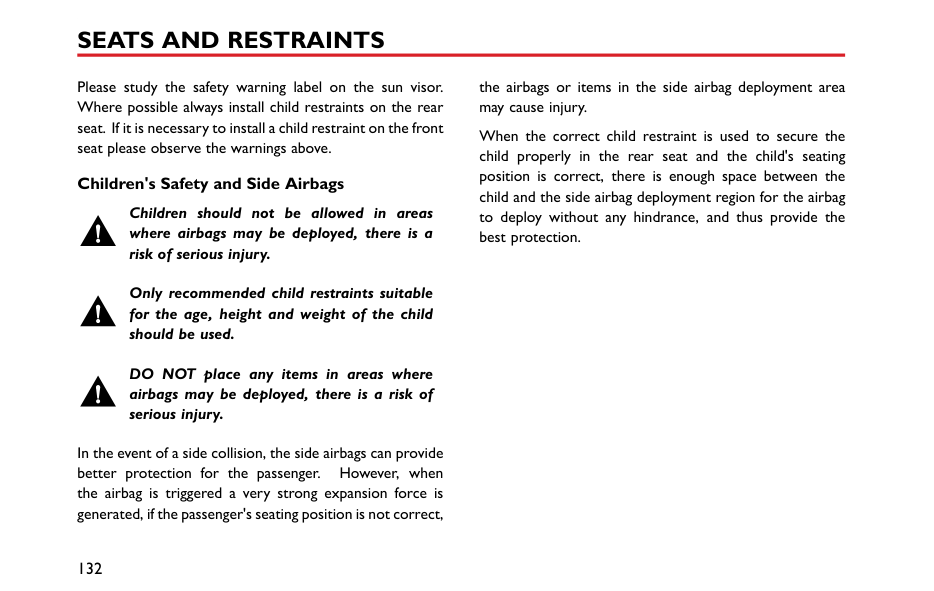

DAB Version xxx
System
############# Help File
Touch [Open], to view the brief operating instructions of the system.
Factory Reset
Touch [Start] to enter Restore Factory Settings interface, and restore [All], [Audio], [Radio] and [Others] to default factory settings as required. A dialog box will be displayed asking "Do you want to restore factory defaults ? " .
After restoring factory settings, the on-board entertainment system is reset to its original settings and all data in the entertainment system will be deleted. Please use with caution.
In the [System] interface, you can view [Software Version], [Hardware Version], [Serial No] , [DAB Version] and other data.
2
Seats and Restraints
108 Seats 112 Seat Belts 121 Airbag Supplementary Restraint
System 130 Child Restraints
3
Seats Overview
To avoid personal injuries due to the loss of control, DO NOT adjust the seats while the car is moving.
The vehicle is equipped with 6-direction or 4-direction adjustable front seats and 60/40 split rear seats with foldable backrests.
An ideal position of the seat should make sure your driving position is comfortable, which allows you to hold the steering wheel with your arms and legs slightly bent and control all the equipment. Make sure your driving position is comfortable and enables you to maintain full control of the vehicle. Take care when adjusting the height of front seats - the feet of the rear passenger could become trapped when the seat is lowered.
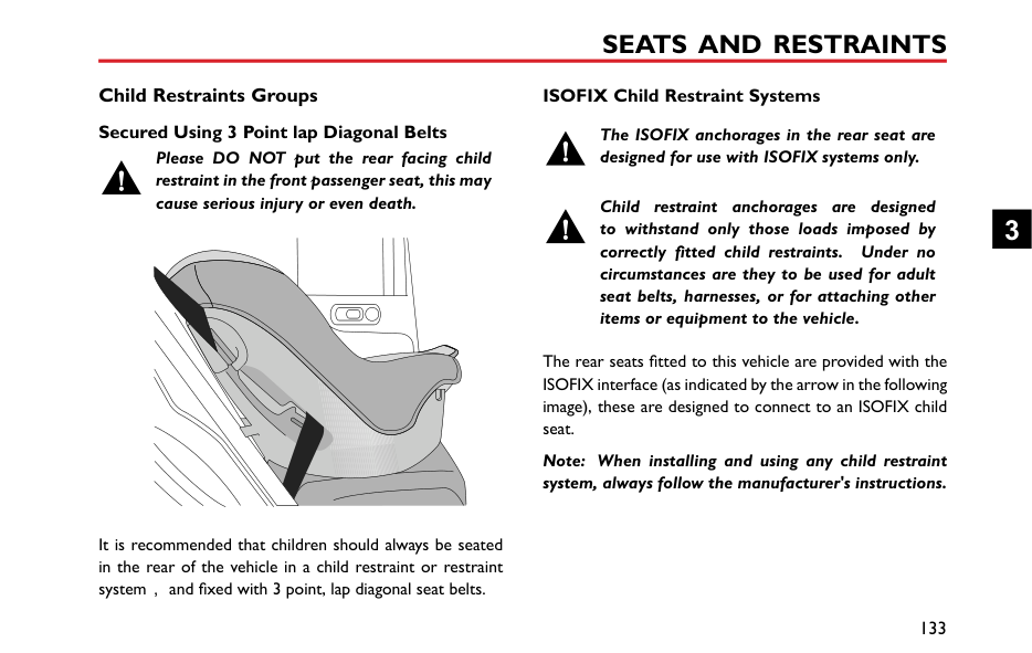
Do not incline the front-seat backrest excessively. Optimum benefit is obtained from the seat belt with the backrest angle set to approximately 25° from the upright (vertical). The driver and front passenger seats should
be positioned as far rearward as practical. A properly adjusted seat helps reduce the risk of injury from sitting too close to an inflating airbag.
####### Head Restraints
Adjust the height of the head restraint so that the top of it is in line with the top of the occupant's head. This location may reduce the risk of head and neck injuries in the event of a collision. DO NOT adjust or remove the head restraints while the car is moving.
DO NOT hang anything on any head restraint or head restraint rod.
The head restraint is designed to prevent rearward movement of the head in the event of a collision or emergency braking, thereby reducing the risk of head and neck injuries.
When adjusting a head restraint from low to high position, pull the head restraint directly upward, and gently press it downward after it reaches the desired position to make sure that it is locked in position. To remove the head restraint, press and hold the guide sleeve button (as indicated by the arrow) on the left of the head restraint, then pull the head restraint upward to remove it.
When adjusting a head restraint from high to low position, press the guide sleeve button (as indicated by the arrow) on the left of the head restraint, and press the head restraint downward; release the button after it reaches the desired position, and gently press the head restraint downward to make sure that it is locked in position.
3
####### Manual Adjustment of Seats
|


| |---|
Lift the lever (1) under the seat cushion, slide the seat into an appropriate position and release the lever. Make sure that the seat is locked in place.
Lift the lever (2) repeatedly to raise the seat cushion, and press the lever downward to lower the seat cushion.
Lift the lever (3), adjust the backrest until it moves into a satisfiable position , and put down the lever.
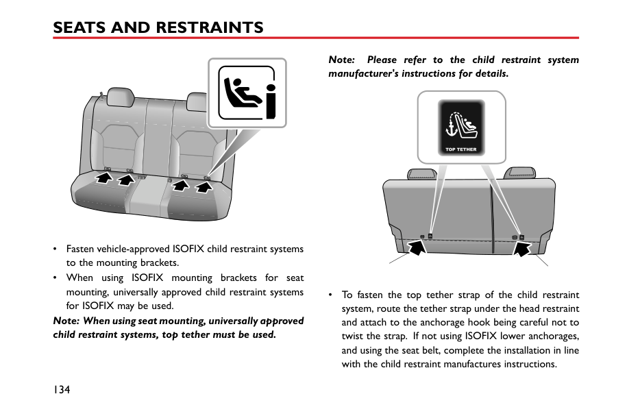
####### Rear Seats
Note: When the head restraint of the rear seat is not fully lowered or the backrest of the front seat is inclined backward excessively, the folding of the rear seat is very likely to damage the back of the front seat, small storage compartment or head restraint of the rear seat.
|
|


| |---|


| |---|
3
########## Unfolding and Locking Rear Seat Backrests
When returning the rear seat backrest to the upright position, pull up the backrest unlock straps to release the locked state, push the backrest until it reaches an appropriate position, and the backrest is locked when you hear a click.
Note: When returning the rear seat backrest to the desired position, make sure that the rear seat belt is not trapped.
########## Folding Rear Seats
To increase luggage space, first fully lower (or remove) all the rear seat head restraints, and then pull up the backrest unlock straps on both sides respectively and fold the seat backrests forward.
Seat Belts
It is important that all seat belts are worn correctly. Always check that all passengers are wearing seat belts. DO NOT carry passengers that are unable to wear correctly positioned seat belts. Wearing seat belts incorrectly may cause serious injury or even death in the event of a collision.
Airbags can not replace seat belts. Airbags can only provide extra support when triggered, and not all traffic accidents will trigger airbags. Whether airbags are triggered or not, seat belts can reduce the risks of serious injury or death in accidents. Therefore, seat belts must be worn properly.
NEVER unfasten a seat belt whilst driving, serious injury or death may occur in the case of an accident or emergency braking.
NEVER fasten the driver seat belt or use a buckle replacement when the driver seat is vacant or when exiting the vehicle. This could cause the engine to restart automatically.
This vehicle is equipped with seat belt warning lamp to remind you to fasten your seat belt. During driving, seat belts must be fastened,this is because:

Therefore, all passengers must wear seat belts correctly, even during short-distance journeys.
####### Protection Provided by Seat Belts
It is of equal importance for passengers in the rear seat to fasten their seat belts correctly. Otherwise, passengers with seat belts not correctly fastened will be thrown forward in accidents, and will endanger themselves as well as the driver and other passengers.
When the vehicle is in motion, the travelling speed of the occupants is identical to that of the vehicle.
In the event of a ‘head on collision’ or emergency braking, the vehicle may stop, but the occupants will carry on travelling until they come into contact with a stationary object. This object may be the steering wheel, dashboard, windscreen or front seats.
A correctly fastened seat belt will eliminate this risk of injury. When the seat belt is worn correctly, it will lock automatically in collision accidents or emergency braking to reduce your speed together with the vehicle, so as to prevent the out-of-control movement which may cause serious injury to driver and passengers.
3
####### Wearing Seat Belts
Incorrectly worn seat belts could cause injury or death in the event of an accident.
Seat belts are designed for one person, DO NOT share seat belts.
DO NOT wrap a seat belt around when holding a baby or child in your arms.
Remove any heavy coats or clothing when wearing a seat belt, failure to do so can affect protection provided by the seat belt.
Seat belts should not be wrapped around hard or sharp objects such as pens, spectacles or keys.
Seat belts cannot function correctly when the seats are reclined excessively. DO NOT drive when the seats are excessively reclined.
The seat belts fitted to your vehicle are designed for use by normal sized adults. This part of the literature refers to adult use.
All seat belts are 3 point lap-diagonal belts.
In order to maintain effective protection, the passengers must sit in the correct orientation, feet placed on the floor in front of them, with an upright body (no excessive recline) and the seat belt correctly fastened.
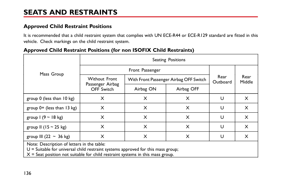
########## Fastening Seat Belts
Please follow the instructions below to fasten the seat belts correctly.
3
|IMPORTANT| |---| |• Always ensure the seat belt will not become trapped in the door aperture when closing the door, damage will occur.
• Pulling the seat belt out too quickly may cause it to lock. In this case, allow the seat belt to retract slightly and then pull it across your body slowly.
• If it is difficult to pull the seat belt out, it may be due to twisted webbing. If this is the case, fully extract the seat belt, remove the twist, allow the seat belt to retract slowly.
• When using the rear seat belts please ensure they are fully retracted into the correct position to avoid jamming in the rear seat catches. It is a legal requirement to wear seat belts. Even if the seat belt is twisted it must be worn. Where possible avoid the twisted section contacting the body and seek advice from an MG Authorised Repairer as soon as possible.
|
########## Correct Routing of the Seat Belts
############# Ensure the seat belt is correctly positioned on the body, never cross the neck or abdomen, never pass the seat belt behind the back or under the arms.
| | | |---|---| | | |
When wearing seat belts, the lap belt section should be positioned as low as possible across your hips, never across the abdomen. In the event of a collision, the lap belt can apply a force on the hips and reduce the possibility of you
slipping under the lap belt. If you slip under the lap belt, the belt will apply force on your abdomen, which may cause serious or fatal injuries. The diagonal section of the belt should cross the middle of the shoulder and the chest. In the event of emergency braking or collision, the diagonal section of the belt will be locked.
To ensure that the seat belts always provide maximum protection, ensure the belt is flat, not loose and contacts the body.
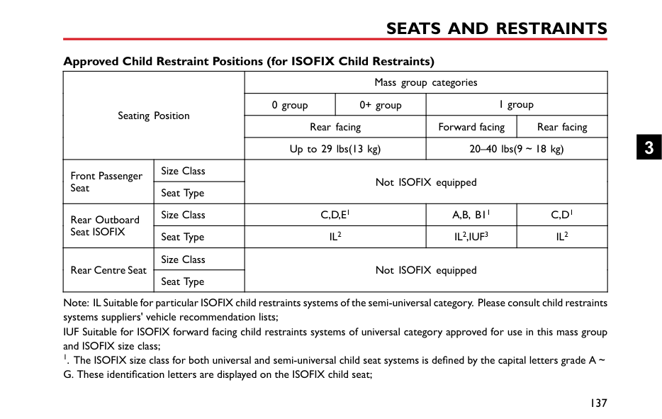
########## Seat Belts Use during Pregnancy
Wearing correctly positioned seat belts will provide protection for both mother and unborn child in the event of a collision or emergency braking.
The diagonal section of the seat belt should pass across the chest as normal, the lap section of the belt should pass below the belly, low and snug on the hip bones. NEVER position the belt on or above the belly.
Please consult your physician for further details. Seat Belts and Disabilities
It is a legal requirement that all occupants wear seat belts, this include people with disabilities.
Depending upon the disability, consult your physician for further details.
3
####### Seat Belt Pre-tensioners
The seat belt pre-tensioners will only be activated once and then MUST BE REPLACED. Failure to replace the pre-tensioners will reduce the efficiency of the vehicle's front restraint system.
If the pre-tensioners have been activated, the seat belts will still function as restraints, and must be worn in the event that the vehicle remains in a drivable condition. The seat belt pre tensioners should be replaced at the earliest opportunity by an MG Authorised Repairer.
The vehicle is fitted with seat belt pre-tensioners, these are designed to retract the front seat belts and work in conjunction with the airbags in the event of a severe collision. They are designed to retract the seat belt and 'secure' the occupant in the seat.
The airbag warning light on the instrument pack will alert the driver to any malfunction of the seat belt
pretensioners.(see ‘Warning Lamps and Indicators' in the ‘Instruments and Controls’ chapter).
The seat belt pre-tensioners can only be activated once, after activation they must be replaced. This may also involve replacement of other SRS components. Please refer to 'Replacing Airbag System Parts'.
|IMPORTANT| |---| |• Seat belt pre-tensioners will not be activated by minor impacts.
• The removal or replacement of a pre-tensioner must be carried out by the manufacturer trained, dealer technicians.
• 10 years from the initial date of registration (or installation date of a replacement seat belt pre-tensioner), some components will need to be replaced. The appropriate page of the Service Portfolio must be signed and stamped once the work has been completed.
|
####### Seat Belt Checks, Maintenance and Replacement
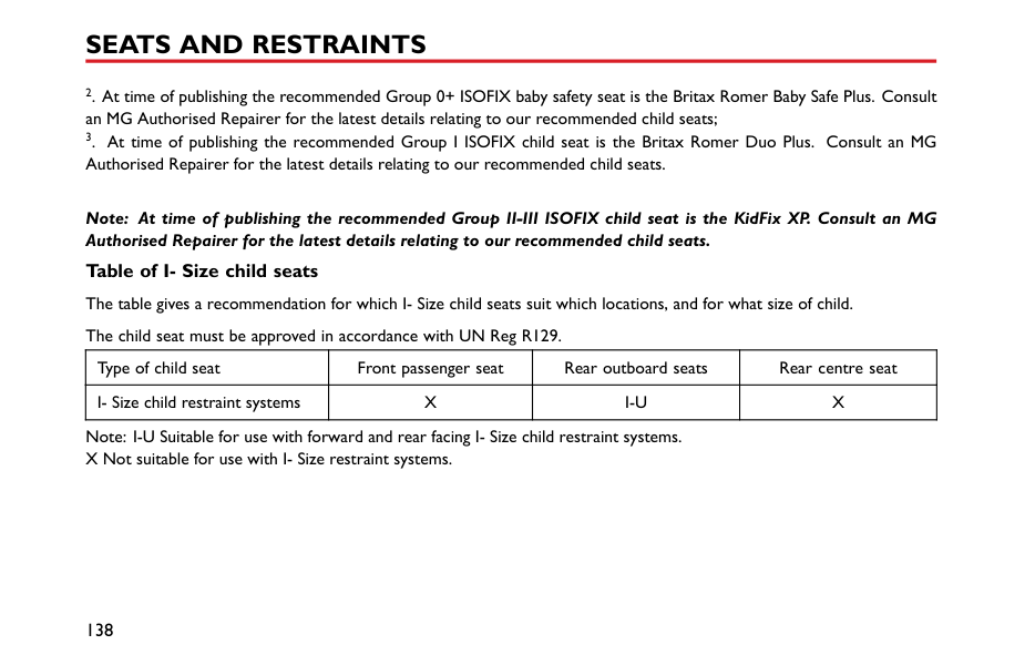
########## Seat Belt Checks
Split, worn or frayed seat belts may not function correctly in the event of a collision, if there are any signs of damage, replace the belt immediately.
Always ensure the red release button on the seat belt buckle is pointing upwards to ensure easy release in the event of an emergency.
########## Seat Belts Maintenance
DO NOT attempt to remove, install, modify, disassemble or dispose of the seat belts. Have any necessary repairs carried out by your MG Authorised Repairer. Inappropriate handling may lead to incorrect operation。
Please follow the instructions below to regularly check whether the seat belt warning lamp, seat belt, metal tab, buckle, retractor and fixing device are working correctly:
3
########## Replacing Seat Belts
Ensure no foreign or sharp objects become lodged in the seat belt mechanisms. DO NOT allow liquids to contaminate the seat belt buckle, this could affect the buckle engagement.
Collision accidents may damage the seat belt system. The seat belt system may not be able to protect users after damage and may cause serious injury or even death when an accident occurs. After the accident, seat belts should be checked immediately and replaced as necessary.
Seat belts should only be cleaned with warm soapy water. Do not use any solvent to clean the seat belt. Do not attempt to bleach or dye the seat belt, it may weaken the seat belt. After cleaning, wipe with a cloth and allow to dry. Do not allow the seat belt to fully retract before it is completely dry. Keep seat belts clean and dry.
Seat belts should not require change after minor collisions, however, some other parts of the seat belt system may require attention. Please consult an MG Authorised Repairer for advice.
If there are contaminants accumulated in the retractor, the retraction of the seat belt will be slow. Please use a clean and dry cloth to remove any contaminants.
#### Airbag Supplementary Restraint System
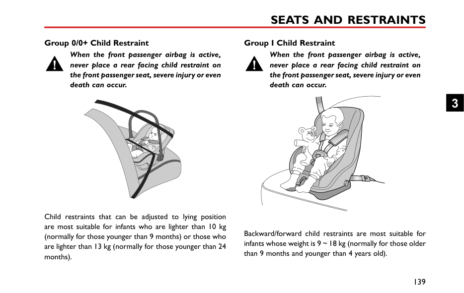
####### Overview
The airbag SRS provides ADDITIONAL protection in a severe frontal impact only. It does not replace the need, or requirement to wear a seat belt.
The airbags together with the seat belts provide optimum protection for adults, but it is not the case for infants. The seat belt and airbag systems in the vehicle are not designed for protecting infants. The protection required by infants should be provided by child restraints.
The Airbag Supplementary Restraint System generally consists of:
• Front Airbags (fitted to the centre of the steering wheel and dashboard above the glove compartment)
Please note that this is model and trim level dependant.


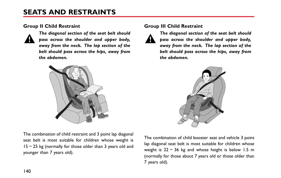


3
####### Airbag Deployment
In the corresponding position where airbags are fitted, there is a warning sign stating ‘AIRBAG’.
Front seat passengers should not place feet, knees or any other part of the body in contact with, or in close proximity to a front airbag.
########## Airbag Warning Light
To minimise the risk of accidental injury from inflating airbags, seat belts should be worn correctly at all times. In addition, both driver and front seat passenger should adjust their seat to provide sufficient distance from the front airbags. If side airbags/side head impact protection airbags are fitted, both driver and front seat passenger should be seated to maintain sufficient distance from the upper part of the body to the sides of the vehicle, this will ensure maximum protection when the side airbags/side head impact protection airbags are deployed.
The airbag warning light is located in the instrument pack. If this lamp does not extinguish or illuminates during driving, it indicates that there is a failure in the SRS or seat belt. Please seek an MG Authorised Repairer at the earliest opportunity. An SRS or seat belt fault may mean the components may not be deployed in the event of an accident.
When airbags are deployed, children without proper protection may suffer from serious injury or even death. DO NOT carry children in the arms or on the knees during traveling. Children should wear seat belts suitable to age. DO NOT lean out of windows.
DO NOT knock or strike the position where airbags or related parts are located, so as to avoid accidental airbag deployment which may cause serious injury or even death.
In the event of a collision, the airbag control unit monitors the rate of deceleration or acceleration induced by the collision, to determine whether the airbags should be deployed. Airbag deployment is virtually instantaneous and occurs with considerable force, accompanied by a loud noise.
An inflating airbag can cause facial abrasions and other injuries if the occupant is too close to the airbag at the time of its deployment.
DO NOT affix or place any objects on, or adjacent to the airbags. This may affect the airbag passage or create projectiles that may cause injury or serious harm in the event of airbag deployment.
Provided the front seat occupants are correctly seated and with seat belts properly worn, the airbags will provide additional protection to the chest and facial areas in the event of the car receiving a severe frontal impact.
Side airbags and side head impact protection airbags are designed to offer additional protection to the side of the body facing the impact, if a severe side collision occurs.
After deployment the airbag components become very hot. DO NOT touch any airbag related components, it may cause burns or serious injury.
3
|IMPORTANT| |---| |• Airbags can not protect lower body parts of passengers.
• Airbags are not designed for rear collision, minor frontal or side impacts, or if the vehicle overturns; nor will it operate as a result of heavy braking.
• Deployment and retraction of the frontal and side airbags takes place very quickly and will not protect against the effects of secondary impacts that may occur.
• When an airbag inflates, a fine powder is released. This is not an indication of a malfunction, however, the powder may cause irritation to the skin and should be thoroughly flushed from the eyes and any cuts or abrasions of the skin.
• After inflation, front and side airbags deflate immediately. This provides a gradual cushioning effect for the occupant and also ensures that the driver's forward vision is not obscured.
|
Front Airbags
NEVER use a rearward facing child restraint on a seat protected by an ACTIVE AIRBAG in front of it, DEATH or SERIOUS INJURY to the CHILD can occur. Refer to ‘Disabling the Passenger Airbag'.
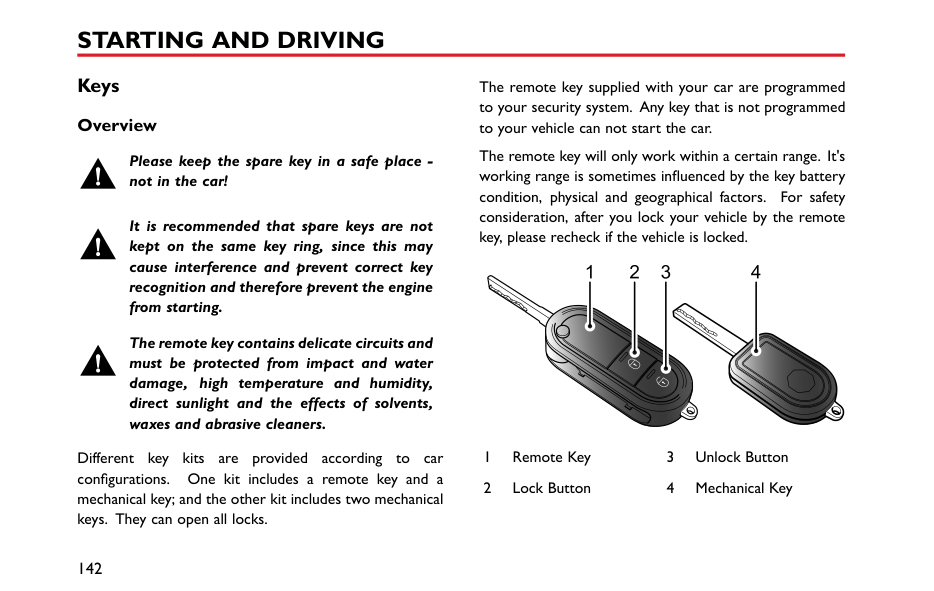
Front seat passengers should not place feet, knees or any other part of the body in contact with, or in close proximity to a front airbag.
In extreme cases driving on very uneven surfaces may cause airbag deployment. Please take extra care when driving on uneven roads.
Airbags are designed to deploy during serious impacts, the following conditions may cause airbag deployment.
Seat Side Airbags
The manufacture and material of the seat is critical to the correct operation of side airbags. Therefore, please DO NOT fit seat covers which may affect side airbag deployment.
In the event of a serious side impact, the relevant side airbag will deploy (only the affected side).
• The airbag will be deployed in the event that the side of the vehicle is impacted with a solid object or another vehicle.
########## Side Head Impact Protection Airbags
In the event of a serious side impact, the relevant side curtain airbag will deploy (only the affected side).
####### Conditions in Which Airbags Will Not Deploy
The deployment of airbags does not depend on the vehicle speed, but on the object that the vehicle hits, angle of impact and the rate at which the car changes speed as a result of a collision. When the impact force of collision is absorbed or dispersed to vehicle body, airbags may not deploy; however, airbags may sometimes deploy according to impact condition. Therefore, the deployment of airbags shall not be judged based on the severity of vehicle damage.
########## Front Airbags
Under certain conditions the front airbags may not be deployed. Some examples are listed below:
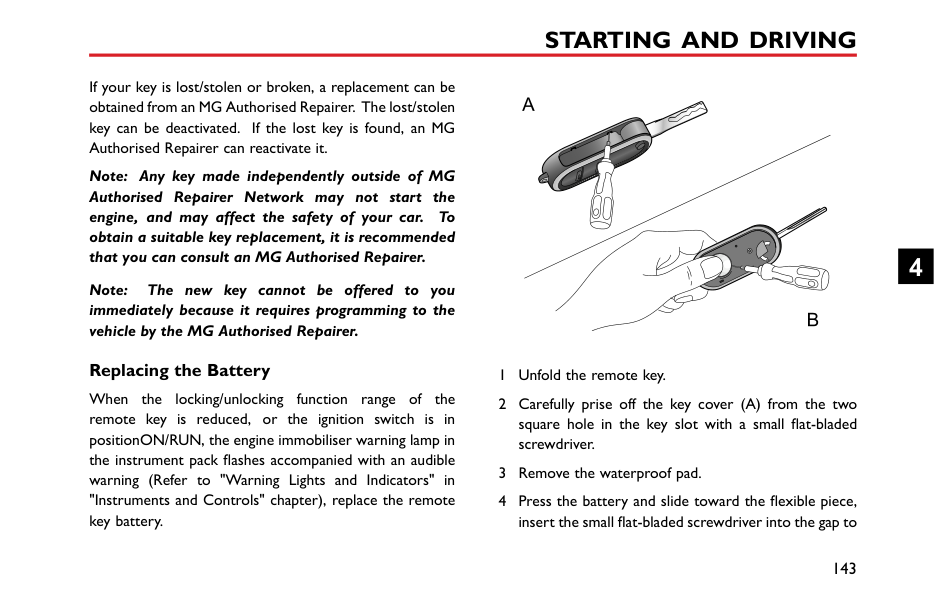
3
Under certain conditions the seat side and side head airbags may not be deployed. Some examples are listed below:
Disabling the Passenger Airbag *
The Passenger Airbag should only be disabled when a rear facing child seat is fitted to the front passenger seat.
When an adult is seated in the front passenger seat, ensure that the airbag is switched on.
|


| |---|
The passenger airbag disable switch is located inside of the glovebox, To disable the passenger airbag, insert the key and turn the switch to OFF position.
When the switch is turned to this position, it indicates that the passenger airbag has been disabled.
When the switch is turned to this position, it indicates that the passenger airbag is enabled.
####### Passenger Airbag Off Warning Light *
|


| |---|
The warning light is located in the interior light assembly. If the passenger airbag has been disabled, the light will illuminate until the airbag is enabled, Once the passenger airbag has been enabled, the light will extinguish.
3
Service and Replacement of Airbags Service Information
DO NOT install or modify the airbag. Any changes to the vehicle structure or airbag system wiring harness are strictly prohibited.
Changes to vehicle structure is prohibited. This may affect the normal operation of the SRS.
DO NOT allow these areas to be flooded with liquid and DO NOT use petrol, detergent, furniture cream or polishes.
If water contaminates or enters the SRS it may cause damage and affect deployment. In this case contact an MG Authorised Repairer immediately.
To prevent damage to the airbag SRS, the following areas should be cleaned sparingly with a damp cloth and upholstery cleaner ONLY:
If the airbag warning lamp fails to illuminate, stays on, or if there is damage to the front or side of the vehicle, or the airbag covers show signs of damage, contact an MG Authorised Repairer immediately.
|IMPORTANT| |---| |• The removal or replacement of an airbag module should be carried out by an MG Authorised Repairer.
• After 10 years from the initial date of registration (or installation date of a replacement airbag), some components will need to be replaced by an MG Authorised Repairer. The appropriate page of the Service Portfolio Manual must be signed and stamped once the work has been completed.
|
########## Replacing Aribag System Parts
Even if the airbag does not deploy, collisions may cause damage to SRS in the vehicle. Airbags may not function properly after damage, and can not protect you and other passengers when a second collision occurs, which may cause serious injury or even death. To ensure that SRS can function properly after collision, please go to an MG Authorised Repairer to check airbags and repair as necessary.
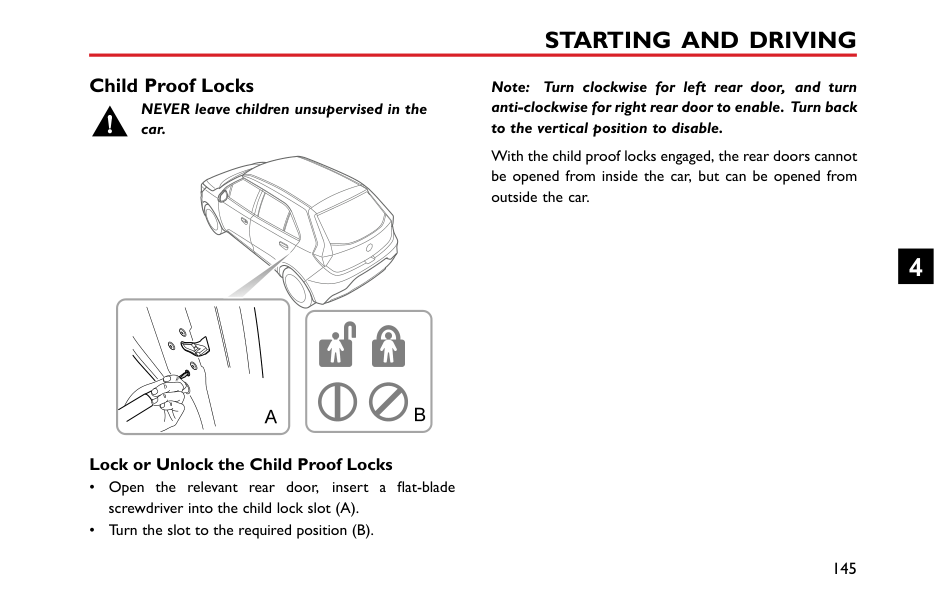
Airbags are designed for using once only. Once the airbag is deployed, you must replace SRS parts.
Please go to an MG Authorised Repairer for replacement. Disposal of Airbags
When your vehicle is sold, ensure that the new owner knows the vehicle is equipped with airbags, and is aware of the replacement date of SRS.
If the vehicle is scrapped, the undeployed airbags may have potential risks, therefore, before the disposal, they must be deployed safely in a certain environment by a professional from an MG Authorised Repairer.
3
#### Child Restraints
####### Important Safety Instructions about Using Child Restraints
It is recommended that children below the age of 12 years old should be seated on the rear seat of the vehicle, in a child restraint system appropriate to the children's weight and size. Infants less than 2 years old should be restrained in an infant child restraint system.
It is recommended that a child restraint system that complies with UN ECE-R44 or ECE-R129 standard are fitted in this vehicle. Check markings on the child restraint system.
There are a number of child restraint systems available of different type and specification. For optimum protection, it is recommended that you choose restraint systems appropriate to the child’s age and weight.
It is important to comply with installation instructions supplied by the child restraint manufacturer and that child restraint system is properly secured to the vehicle. Failure to follow these instructions may cause death or serious injury to the child in an event of a sudden stop or accident.
Warnings and Instructions on Use of Child Restraint on Front Passenger Seat
||AIRBAG|AIRBAG|AIRBAG| |---|---|---| | | | |
| |---|
Never use a rearward facing child restraint on a seat protected by an ACTIVE AIRBAG in front of it, DEATH or SERIOUS INJURY to the CHILD can occur.
In cases where there is a need to install a rear facing child restraint on the front passenger seat, use the key to deactivate the front passenger airbag function, or severe injury or even death can occur.
Once the child restraint is removed from the front passenger seat, use the key to reactivate the front passenger airbag.
When installing a child restraint on the front passenger seat, move the front passenger seat as far rearward as possible.
Use one child restraint per child.
3
Please study the safety warning label on the sun visor. Where possible always install child restraints on the rear seat. If it is necessary to install a child restraint on the front seat please observe the warnings above.
########## Children's Safety and Side Airbags
Children should not be allowed in areas where airbags may be deployed, there is a risk of serious injury.
Only recommended child restraints suitable for the age, height and weight of the child should be used.
DO NOT place any items in areas where airbags may be deployed, there is a risk of serious injury.
In the event of a side collision, the side airbags can provide better protection for the passenger. However, when the airbag is triggered a very strong expansion force is generated, if the passenger's seating position is not correct,
the airbags or items in the side airbag deployment area may cause injury.
When the correct child restraint is used to secure the child properly in the rear seat and the child's seating position is correct, there is enough space between the child and the side airbag deployment region for the airbag to deploy without any hindrance, and thus provide the best protection.
Child Restraints Groups Secured Using 3 Point lap Diagonal Belts
Please DO NOT put the rear facing child restraint in the front passenger seat, this may cause serious injury or even death.
########## ISOFIX Child Restraint Systems
The ISOFIX anchorages in the rear seat are designed for use with ISOFIX systems only.
Child restraint anchorages are designed to withstand only those loads imposed by correctly fitted child restraints. Under no circumstances are they to be used for adult seat belts, harnesses, or for attaching other items or equipment to the vehicle.
The rear seats fitted to this vehicle are provided with the ISOFIX interface (as indicated by the arrow in the following image), these are designed to connect to an ISOFIX child seat.
Note: When installing and using any child restraint system, always follow the manufacturer's instructions.
It is recommended that children should always be seated in the rear of the vehicle in a child restraint or restraint system, and fixed with 3 point, lap diagonal seat belts.
3
|


|


| |---|


| |---|
Note: Please refer to the child restraint system manufacturer's instructions for details.
• To fasten the top tether strap of the child restraint system, route the tether strap under the head restraint and attach to the anchorage hook being careful not to twist the strap. If not using ISOFIX lower anchorages, and using the seat belt, complete the installation in line with the child restraint manufactures instructions.
Note: When using seat mounting, universally approved child restraint systems, top tether must be used.
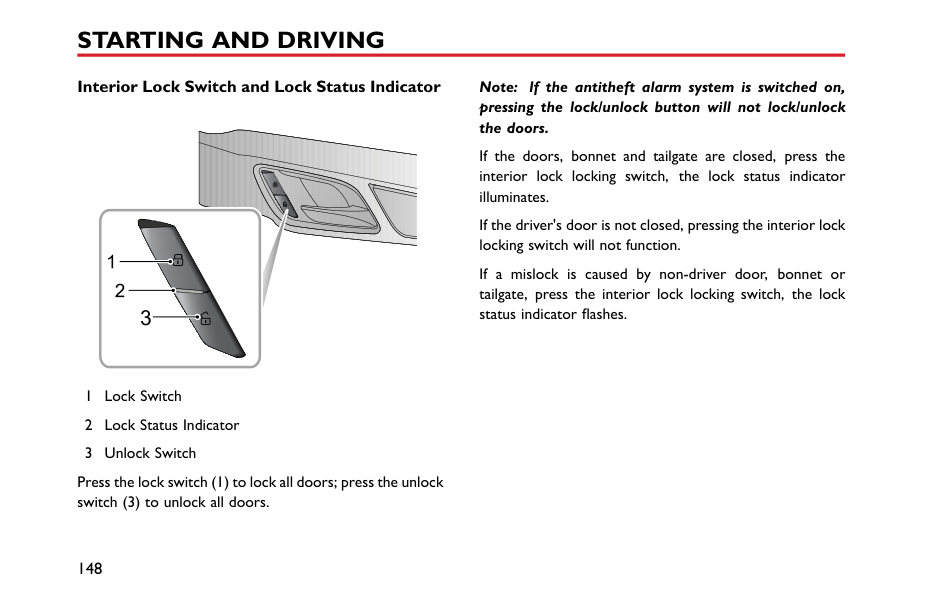
• After installation apply suitable force to ensure the restraint is securely fastened.
3
####### Approved Child Restraint Positions
It is recommended that a child restraint system that complies with UN ECE-R44 or ECE-R129 standard are fitted in this vehicle. Check markings on the child restraint system.
######## Approved Child Restraint Positions (for non ISOFIX Child Restraints)
|Mass Group
|Seating Positions|Seating Positions|Seating Positions|Seating Positions|Seating Positions| |---|---|---|---|---|---| |Mass Group
|Front Passenger|Front Passenger|Front Passenger|Rear Outboard|Rear Middle| |Mass Group
|Without Front Passenger Airbag OFF Switch|With Front Passenger Airbag OFF Switch|With Front Passenger Airbag OFF Switch|Rear Outboard|Rear Middle| |Mass Group
|Without Front Passenger Airbag OFF Switch|Airbag ON|Airbag OFF|Rear Outboard|Rear Middle| |group 0 (less than 10 kg)|X|X|X|U|X| |group 0+ (less than 13 kg)|X|X|X|U|X| |group I (9~18 kg)|X|X|X|U|X| |group II (15~25 kg)|X|X|X|U|X| |group III (22 ~ 36 kg)|X|X|X|U|X| |Note: Description of letters in the table: U = Suitable for universal child restraint systems approved for this mass group; X = Seat position not suitable for child restraint systems in this mass group.|Note: Description of letters in the table: U = Suitable for universal child restraint systems approved for this mass group; X = Seat position not suitable for child restraint systems in this mass group.|Note: Description of letters in the table: U = Suitable for universal child restraint systems approved for this mass group; X = Seat position not suitable for child restraint systems in this mass group.|Note: Description of letters in the table: U = Suitable for universal child restraint systems approved for this mass group; X = Seat position not suitable for child restraint systems in this mass group.|Note: Description of letters in the table: U = Suitable for universal child restraint systems approved for this mass group; X = Seat position not suitable for child restraint systems in this mass group.|Note: Description of letters in the table: U = Suitable for universal child restraint systems approved for this mass group; X = Seat position not suitable for child restraint systems in this mass group.|
######## Approved Child Restraint Positions (for ISOFIX Child Restraints)
|Seating Position|Seating Position|Mass group categories|Mass group categories|Mass group categories|Mass group categories| |---|---|---|---|---|---| |Seating Position|Seating Position|0 group|0+ group|I group|I group| |Seating Position|Seating Position|Rear facing|Rear facing|Forward facing|Rear facing| |Seating Position|Seating Position|Up to 29 lbs(13 kg)|Up to 29 lbs(13 kg)|20–40 lbs(9~18 kg)|20–40 lbs(9~18 kg)| |Front Passenger Seat
|Size Class|Not ISOFIX equipped|Not ISOFIX equipped|Not ISOFIX equipped|Not ISOFIX equipped| |Front Passenger Seat
|Seat Type|Not ISOFIX equipped|Not ISOFIX equipped|Not ISOFIX equipped|Not ISOFIX equipped| |Rear Outboard Seat ISOFIX|Size Class|C,D,E1|C,D,E1|A,B, B11|C,D1| |Rear Outboard Seat ISOFIX|Seat Type|IL2|IL2|IL2,IUF3|IL2| |Rear Centre Seat|Size Class|Not ISOFIX equipped
|Not ISOFIX equipped
|Not ISOFIX equipped
|Not ISOFIX equipped
| |Rear Centre Seat|Seat Type|Not ISOFIX equipped
|Not ISOFIX equipped
|Not ISOFIX equipped
|Not ISOFIX equipped
|
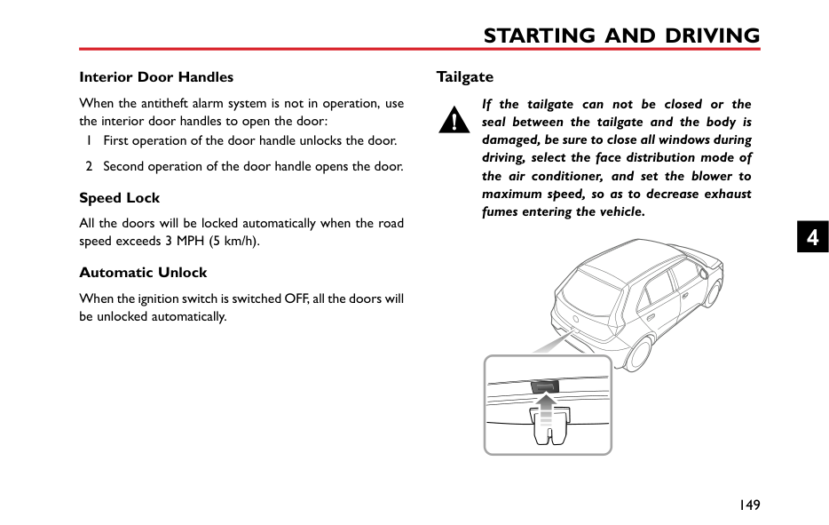
Note: IL Suitable for particular ISOFIX child restraints systems of the semi-universal category. Please consult child restraints systems suppliers' vehicle recommendation lists; IUF Suitable for ISOFIX forward facing child restraints systems of universal category approved for use in this mass group and ISOFIX size class;
3
Note: At time of publishing the recommended Group II-III ISOFIX child seat is the KidFix XP. Consult an MG Authorised Repairer for the latest details relating to our recommended child seats.
Table of I- Size child seats The table gives a recommendation for which I- Size child seats suit which locations, and for what size of child. The child seat must be approved in accordance with UN Reg R129.
|Type of child seat|Front passenger seat|Rear outboard seats|Rear centre seat| |---|---|---|---| |I- Size child restraint systems|X|I-U|X|
Note: I-U Suitable for use with forward and rear facing I- Size child restraint systems. X Not suitable for use with I- Size restraint systems.
Group 0/0+ Child Restraint
When the front passenger airbag is active, never place a rear facing child restraint on the front passenger seat, severe injury or even death can occur.
Child restraints that can be adjusted to lying position are most suitable for infants who are lighter than 10 kg (normally for those younger than 9 months) or those who are lighter than 13 kg (normally for those younger than 24 months).
Group I Child Restraint
When the front passenger airbag is active, never place a rear facing child restraint on the front passenger seat, severe injury or even death can occur.
Backward/forward child restraints are most suitable for infants whose weight is 9~18 kg (normally for those older than 9 months and younger than 4 years old).

3
Group II Child Restraint
The diagonal section of the seat belt should pass across the shoulder and upper body, away from the neck. The lap section of the belt should pass across the hips, away from the abdomen.
The combination of child restraint and 3 point lap diagonal seat belt is most suitable for children whose weight is 15~25 kg (normally for those older than 3 years old and younger than 7 years old).
Group III Child Restraint
The diagonal section of the seat belt should pass across the shoulder and upper body, away from the neck. The lap section of the belt should pass across the hips, away from the abdomen.
The combination of child booster seat and vehicle 3 point lap diagonal seat belt is most suitable for children whose weight is 22~36 kg and whose height is below 1.5 m (normally for those about 7 years old or those older than 7 years old).
Starting and Driving
142 Keys 145 Child Proof Locks 146 Alarm Systems 151 Starting and Stopping Engine 155 Economical and Environmental Driving 158 Catalytic Converter 160 Fuel System 162 Manual Transmission 164 Brake System 170 Automated Stop/Start —Intelligent
Fuel Saving System
175 Stability Control System (SCS) and Traction Control System (TCS) 177 Cruise Control System *
180 Parking Aid * 183 Tyre Pressure Monitoring System
(TPMS)
185 Load Carrying
4
Keys Overview
The remote key supplied with your car are programmed to your security system. Any key that is not programmed to your vehicle can not start the car.
The remote key will only work within a certain range. It's working range is sometimes influenced by the key battery condition, physical and geographical factors. For safety consideration, after you lock your vehicle by the remote key, please recheck if the vehicle is locked.
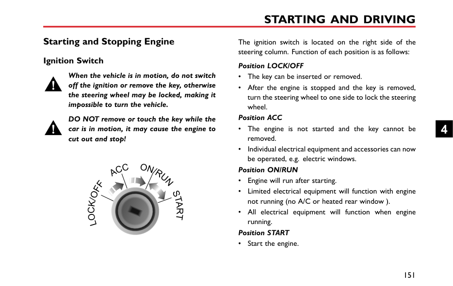
Please keep the spare key in a safe place not in the car!
It is recommended that spare keys are not kept on the same key ring, since this may cause interference and prevent correct key recognition and therefore prevent the engine from starting.


The remote key contains delicate circuits and must be protected from impact and water damage, high temperature and humidity, direct sunlight and the effects of solvents, waxes and abrasive cleaners.
Different key kits are provided according to car configurations. One kit includes a remote key and a mechanical key; and the other kit includes two mechanical keys. They can open all locks.
|


| |---|
If your key is lost/stolen or broken, a replacement can be obtained from an MG Authorised Repairer. The lost/stolen key can be deactivated. If the lost key is found, an MG Authorised Repairer can reactivate it.
Note: Any key made independently outside of MG Authorised Repairer Network may not start the engine, and may affect the safety of your car. To obtain a suitable key replacement, it is recommended that you can consult an MG Authorised Repairer.
4
Note: The new key cannot be offered to you immediately because it requires programming to the vehicle by the MG Authorised Repairer.
####### Replacing the Battery
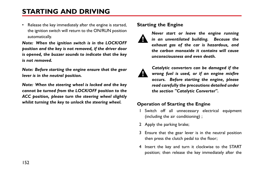
When the locking/unlocking function range of the remote key is reduced, or the ignition switch is in positionON/RUN, the engine immobiliser warning lamp in the instrument pack flashes accompanied with an audible warning (Refer to "Warning Lights and Indicators" in "Instruments and Controls" chapter), replace the remote key battery.
remove the battery, ensuring that correct polarity is maintained (B).
Note: Finger marks will adversely affect battery life; if possible, avoid touching the flat surfaces of the battery.
Note: It is recommended that you fit a CR2032 remote key battery.
|IMPORTANT| |---| |• Use of an incorrect or inappropriate battery may damage the remote key. The new replacement’s rated voltage, sizes and specifications must be the same as the old one.
• Incorrect fitting of the battery may damage the remote key.
• Disposal of the used battery must be strictly in accordance with relevant environmental protection acts.
|
Child Proof Locks
NEVER leave children unsupervised in the car.
Note: Turn clockwise for left rear door, and turn anti-clockwise for right rear door to enable. Turn back to the vertical position to disable.
With the child proof locks engaged, the rear doors cannot be opened from inside the car, but can be opened from outside the car.
4
######## Lock or Unlock the Child Proof Locks
• Open the relevant rear door, insert a flat-blade
screwdriver into the child lock slot (A). • Turn the slot to the required position (B).
#### Alarm Systems
Your vehicle is fitted with engine immobiliser system. To ensure maximum safety and operation convenience, we strongly recommend you to carefully read this chapter to fully understand the activation and deactivation of antitheft systems.
engine still can not be started by using the spare key, please contact a local MG Authorised Repairer.
####### Engine Immobilisation
Engine immobilisation is designed to safeguard the vehicle from theft. Engine immobilisation can only be deactivated to start the engine by using the matched key.
########## Engine Immobilisation
When the matched key is inserted into the ignition switch and the car is started, engine immobilisation is deactivated automatically. When the key is removed from the ignition switch, the vehicle will automatically enable engine immobilisation. When the ignition switch is in the ON position, if the engine immobiliser cannot identify the key inserted into the ignition switch, the engine immobilisation warning lamp on the instrument pack illuminates. If the
####### Locking and Unlocking Key Locking
########## Key Unlocking
Note: If there are no other operations within 30 seconds after the vehicle is unlocked by using the remote key, all doors will automatically relock.
########## Mislock
If the driver's door is not fully closed when the handset lock button is pressed, the vehicle horn will sound once, indicating a mislock. In this case, none of the doors will lock, the alarm system will not be armed and the direction indicator lamps will not flash.
If the driver's door is closed, the passenger door, bonnet and tailgate are not fully closed, the horn sounds once to indicate mislock when the car undergoes locking operation. However, the ‘partial arming’ attributes of the security system will enable as much of the system to be armed as possible (all fully closed doors, bonnet or tailgate apertures will be protected, but an open door will not!). The alarm indicator will flash. As soon as the open panel is closed the system will automatically revert to an armed state.
4
########## Interior Lock Switch and Lock Status Indicator


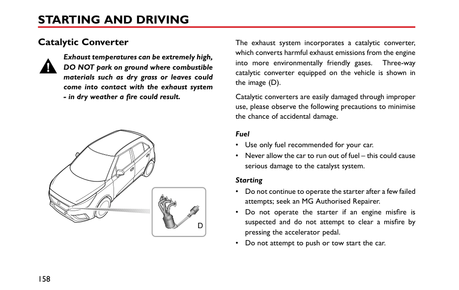


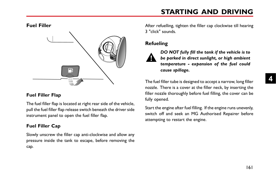


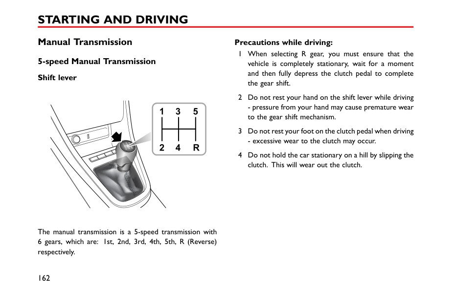


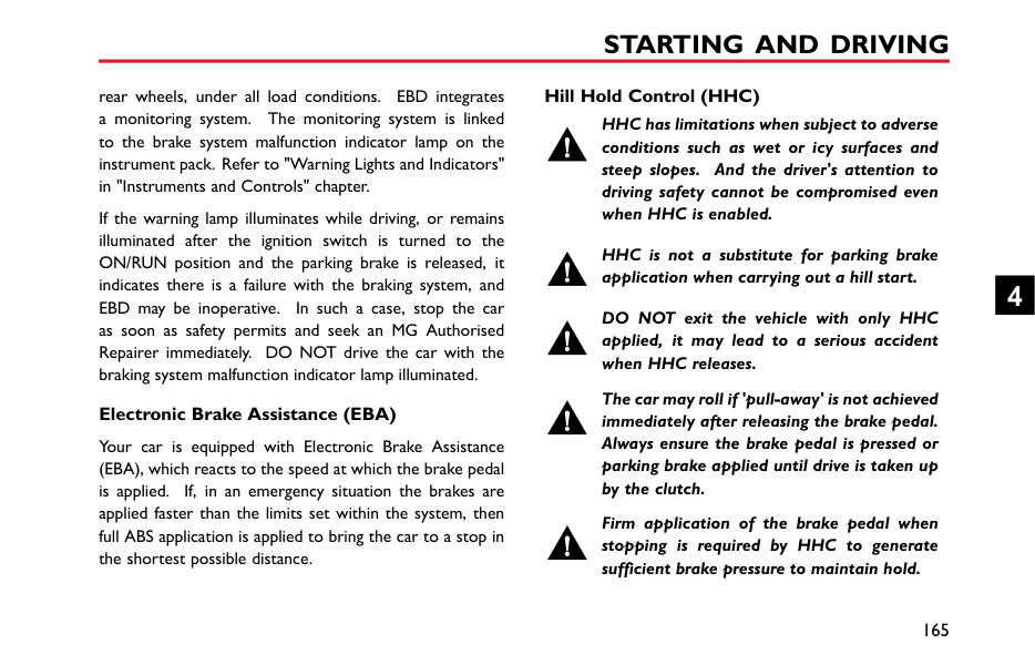


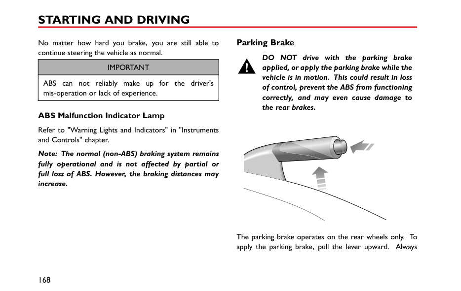


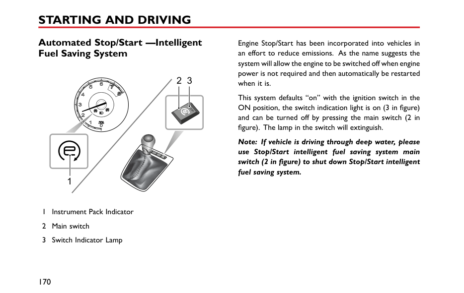


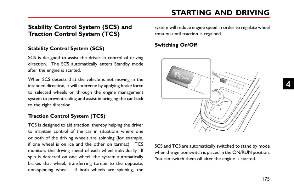


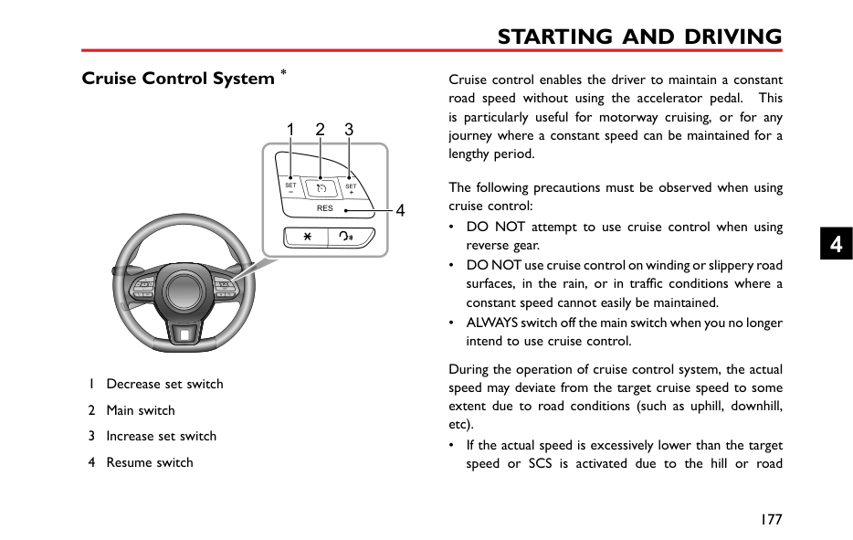


Note: If the antitheft alarm system is switched on, pressing the lock/unlock button will not lock/unlock the doors.
If the doors, bonnet and tailgate are closed, press the interior lock locking switch, the lock status indicator illuminates.
If the driver's door is not closed, pressing the interior lock locking switch will not function.
If a mislock is caused by non-driver door, bonnet or tailgate, press the interior lock locking switch, the lock status indicator flashes.
Press the lock switch (1) to lock all doors; press the unlock switch (3) to unlock all doors.
########## Interior Door Handles
When the antitheft alarm system is not in operation, use the interior door handles to open the door:
########## Speed Lock
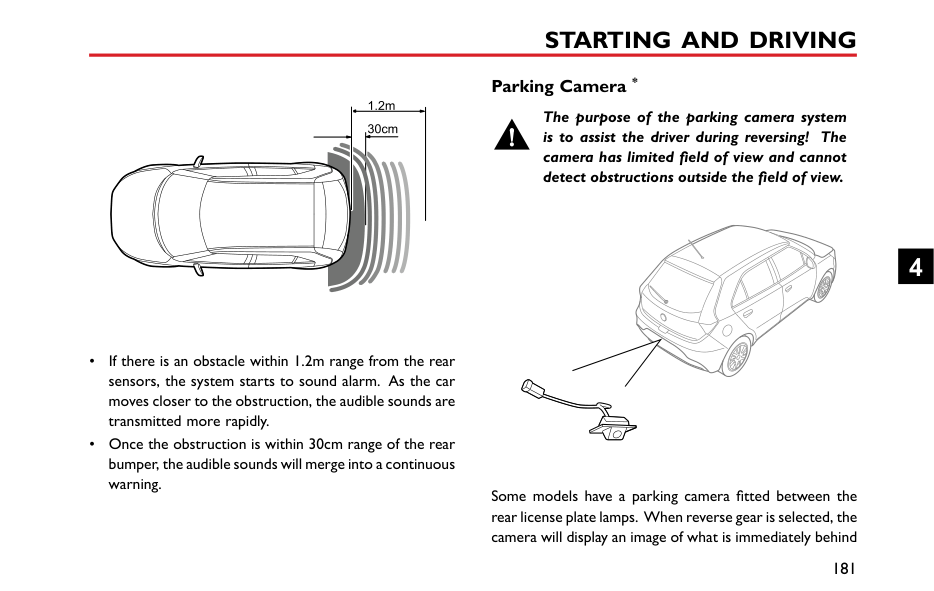
All the doors will be locked automatically when the road speed exceeds 3 MPH (5 km/h).
########## Automatic Unlock
When the ignition switch is switched OFF, all the doors will be unlocked automatically.
####### Tailgate
If the tailgate can not be closed or the seal between the tailgate and the body is damaged, be sure to close all windows during driving, select the face distribution mode of the air conditioner, and set the blower to maximum speed, so as to decrease exhaust fumes entering the vehicle.
| | |---|
4
Tailgate Opening The tailgate can be opened by the following means: When the car is unlocked, press the open switch on the tailgate to open the tailgate (as illustrated).
Starting and Stopping Engine Ignition Switch
When the vehicle is in motion, do not switch off the ignition or remove the key, otherwise the steering wheel may be locked, making it impossible to turn the vehicle.
DO NOT remove or touch the key while the car is in motion, it may cause the engine to cut out and stop!
|


| |---|
The ignition switch is located on the right side of the steering column. Function of each position is as follows:
############# Position LOCK/OFF

############# Position ACC
be operated, e.g. electric windows. Position ON/RUN
############# Position START
• Start the engine.
4
• Release the key immediately after the engine is started, the ignition switch will return to the ON/RUN position automatically.
Note: When the ignition switch is in the LOCK/OFF position and the key is not removed, if the driver door is opened, the buzzer sounds to indicate that the key is not removed.
Note: Before starting the engine ensure that the gear lever is in the neutral position.
Note: When the steering wheel is locked and the key cannot be turned from the LOCK/OFF position to the ACC position, please turn the steering wheel slightly whilst turning the key to unlock the steering wheel.
####### Starting the Engine
Never start or leave the engine running in an unventilated building. Because the exhaust gas of the car is hazardous, and the carbon monoxide it contains will cause unconsciousness and even death.
Catalytic converters can be damaged if the wrong fuel is used, or if an engine misfire occurs. Before starting the engine, please read carefully the precautions detailed under the section "Catalytic Converter".
########## Operation of Starting the Engine
engine has started, and the key will return back to the ON/RUN position.
Note: Continued use of the starter with the key not released after engine startup will not only discharge the battery, but may damage the starter, flywheel and catalytic converter.
DO NOT press the accelerator pedal while starting and DO NOT operate the starter for more than 15 seconds at a time. If the engine fails to start, remove the key and wait for at least 10s before the second attempt.
If the key is not recognised by the engine immobilisation system when it is inserted into the ignition switch, the engine will be disabled. The engine immobilisation system warning lamp will illuminate (refer to "Warning Lights and Indicators" in "Instruments and Controls" chapter.).
|IMPORTANT| |---| |• If you try to start consecutively for 3 times and it fails, please seek assistance from your local MG Authorised Repairer. When attempting to start the car consecutively, please allow 10 minutes between attempts to allow battery restoration and engine cooling, failure to do this may result in battery or engine damage.
• Do not leave the ignition switch in the ACC or ON/RUN position for lengthy periods when the engine is not running, otherwise it may lead to battery discharge.
• Your car is controlled by electronic control systems. When starting the engine, please make sure there are no electronic devices that can create electromagnetic interference near the vehicle. This may cause issues with the electronic control systems on the vehicle.
|
4
########## Cold Climates
In temperatures of -10℃ and below, engine cranking times will increase. It is essential that all unnecessary electrical equipment are switched off while cranking.
Stopping the Engine Stopping the engine as follows:
Note: After strenuous towing or driving at high speed (particularly in hot weather), it is recommended to allow the engine to idle for a few minutes before switching off , which enables the cooling system to work continuously to lower the engine temperature.
#### Economical and Environmental Driving Running-in
The engine, transmission, brakes and tyres need time to 'bed-in' and adjust to the demands of everyday motoring. During the first 900 miles, it is essential that you drive with consideration for the running-in process and heed the following advice:
####### Environment Protection
Your vehicle has been designed with the latest technology in order to minimize the environmental impact of exhaust emissions.
####### Driving Style
The way in which you drive your car has a significant bearing on environmental pollution, as well as affecting the amount of fuel you use.
########## Avoid full throttle acceleration
Steady, rather than rapid, acceleration uses considerably less fuel, reduces exhaust pollutants and also minimizes the wear to mechanical components.
########## Avoid driving at maximum speed
Fuel consumption, exhaust emissions and noise levels all increase significantly at high speeds.
########## Do not drive in a low gear for longer than necessary
Driving in lower gears uses more fuel and creates more noise. Change up to a higher gear as soon as possible, provided it does NOT cause the engine to labour.
4
########## Drive smoothly
Anticipating obstructions and slowing down well in advance, avoids the need for unnecessary acceleration and harsh braking. A smooth driving style not only reduces fuel consumption, but can reduce the emission of noxious gases.
########## Driving in rain
############# Emergency braking, accelerating and steering on slippery roads will reduce the vehicle's handling performance and grip.
When raining the windows may fog, reducing visibility (Use the Air-conditioning demist function).
Grip will be reduced, so please drive carefully. Reduce speed when it rains.
Avoid aquaplaning (the effect of a film of water between the tyres and the road) affecting steering and braking performance.
Avoid driving through floods after heavy rain, which may lead to serious damage to the vehicle.
####### Fuel Saving and Extending Vehicle Life
The following are some suggestions on saving fuel and extending the life of the vehicles.
####### Maintenance Have the vehicle regularly serviced
Regular servicing will ensure optimum fuel consumption and minimize exhaust pollutants, as well as effectively extending the service life of the car.
########## Check tyre pressures regularly
Under-inflated tyres increase the rolling resistance of the car which, in turn, increases fuel consumption. Over or under-inflated tyres wear out more rapidly and also have a detrimental effect on the car’s handling characteristics.
########## Do not carry unnecessary loads
The additional weight of unnecessary loads wastes fuel, especially in stop/start conditions where the car is frequently required to set off from stationary.
4
Catalytic Converter
Exhaust temperatures can be extremely high, DO NOT park on ground where combustible materials such as dry grass or leaves could come into contact with the exhaust system - in dry weather a fire could result.
||D
| |---| | |---|
The exhaust system incorporates a catalytic converter, which converts harmful exhaust emissions from the engine into more environmentally friendly gases. Three-way catalytic converter equipped on the vehicle is shown in the image (D).
Catalytic converters are easily damaged through improper use, please observe the following precautions to minimise the chance of accidental damage.
############# Fuel
############# Starting
Driving Please pay attention to the following conditions:
Note: Any engine misfire, loss of engine performance or engine run-on, could seriously damage the catalytic converter. Regular maintenance must be carried out in accordance with the schedule specified in the ‘Service Portfolio’. Any modifications to engine without being authorised is prohibited.
4
Fuel System Fuel Requirements
Use only the recommended fuel which meets national standard! Serious damage to the catalytic converter will occur if the wrong fuel is used.
Use the fuel recommended by the manufacturer. See "Major Parameters of Engine" in "Technical Data" chapter.
If a lower grade of fuel is used, an engine knocking noise may occur, please use the recommended or above grade fuel as soon as possible. If the engine knocking noise is still noticeable after using the recommended or above grade fuel, please contact MG Authorised Repairer immediately.
########## Safety Precautions in a Fuel Filling Station
############# Vehicle fuel gases are highly flammable and, in confined spaces, are also extremely explosive.
Always take care when refueling:

####### Fuel Filler
After refuelling, tighten the filler cap clockwise till hearing 3 "click" sounds.
########## Fuel Filler Flap
The fuel filler flap is located at right rear side of the vehicle, pull the fuel filler flap release switch beneath the driver side instrument panel to open the fuel filler flap.
########## Fuel Filler Cap
Slowly unscrew the filler cap anti-clockwise and allow any pressure inside the tank to escape, before removing the cap.
####### Refueling
DO NOT fully fill the tank if the vehicle is to be parked in direct sunlight, or high ambient temperature - expansion of the fuel could cause spillage.
The fuel filler tube is designed to accept a narrow, long filler nozzle. There is a cover at the filler neck, by inserting the filler nozzle thoroughly before fuel filling, the cover can be fully opened.
Start the engine after fuel filling. If the engine runs unevenly, switch off and seek an MG Authorised Repairer before attempting to restart the engine.
4
#### Manual Transmission 5-speed Manual Transmission Shift lever
|1 3 5
2 4 R
| |---|

The manual transmission is a 5-speed transmission with
########## Precautions while driving:

########## Gear Shift Indications
When the vehicle is in motion and the clutch pedal fully released, the information centre will display the currently selected gear (1~5). An Up/Down arrow is displayed to the left of the number indicating to the driver to either upshift or downshift when driving conditions permit.
4
Brake System Foot Brake For added safety, the hydraulic braking system operates through dual circuits. If one circuit should fail, the other will continue to function, but greater pedal pressure will be needed, increased brake pedal travel and longer stopping distances will be experienced. If the stopping distance obviously gets longer and the braking force increases, the car should be brought to a halt as soon as traffic conditions safely allow. DO NOT continue driving - seek an MG Authorised Repairer. Servo Assistance The braking system is servo assisted, always be aware of the followings during the operation:
########## Wet Conditions
Driving through water or heavy rain may adversely affect braking efficiency. In this case, keep a safe distance from other vehicles and intermittently apply the brake pedal to keep the brake surface dry.
########## Electronic Brake Force Distribution (EBD)
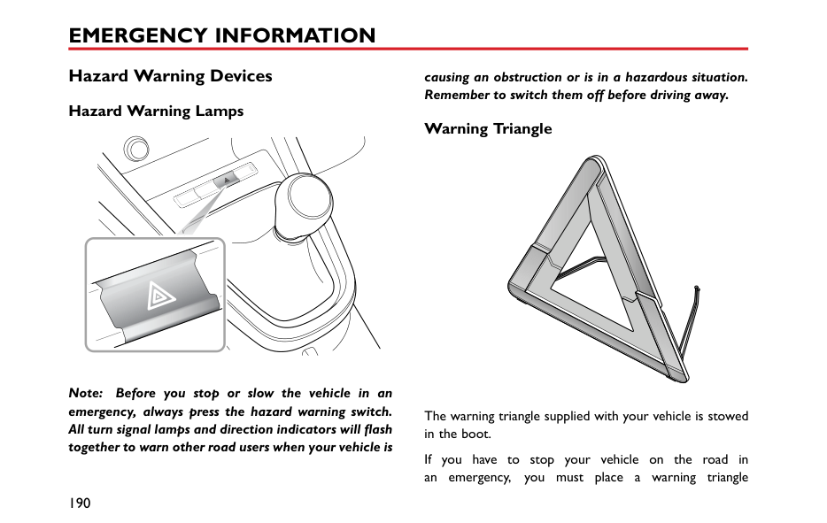
Your car is equipped with Electronic Brake Force Distribution (EBD), which, in order to maintain braking efficiency, distributes braking forces between front and
Hill Hold Control (HHC)
rear wheels, under all load conditions. EBD integrates a monitoring system. The monitoring system is linked to the brake system malfunction indicator lamp on the instrument pack. Refer to "Warning Lights and Indicators" in "Instruments and Controls" chapter.
HHC has limitations when subject to adverse conditions such as wet or icy surfaces and steep slopes. And the driver's attention to driving safety cannot be compromised even when HHC is enabled.
If the warning lamp illuminates while driving, or remains illuminated after the ignition switch is turned to the ON/RUN position and the parking brake is released, it indicates there is a failure with the braking system, and EBD may be inoperative. In such a case, stop the car
HHC is not a substitute for parking brake application when carrying out a hill start.
DO NOT exit the vehicle with only HHC applied, it may lead to a serious accident when HHC releases.
The car may roll if 'pull-away' is not achieved immediately after releasing the brake pedal. Always ensure the brake pedal is pressed or parking brake applied until drive is taken up by the clutch.
########## Electronic Brake Assistance (EBA)
Your car is equipped with Electronic Brake Assistance (EBA), which reacts to the speed at which the brake pedal is applied. If, in an emergency situation the brakes are applied faster than the limits set within the system, then full ABS application is applied to bring the car to a stop in the shortest possible distance.
Firm application of the brake pedal when stopping is required by HHC to generate sufficient brake pressure to maintain hold.
4
Hill Hold Control (HHC) is a comfort function. It works on inclines when the car detects it has come to a 'stand still status'. Once the clutch pedal has been pressed down and the brake pedal released, the vehicle will maintain pressure in the braking system for 1 ~ 2 seconds. After this, the Hill Hold will release. HHC assists the driver by 'holding' the vehicle during hill starts.
The following conditions must be fulfilled to activate HHC:

Note: HHC is available in both forward and backward directions when pulling away on uphill slopes.
Note: HHC cannot overcome physical limitations. DO NOT solely rely on HHC.
Anti-lock Brake System (ABS)
ABS cannot overcome the physical limitations of stopping the car in too short a distance, cornering at too high a speed, or the danger of aquaplaning, i.e. where a layer of water prevents adequate contact between the tyres and the road surface.
The purpose of the ABS is to prevent the wheels from locking while braking, thereby enabling the driver to retain steering control of the car.
The fact that a car is fitted with ABS must never tempt the driver into taking risks that could affect his/her safety or that of other road users. In all cases, it remains the driver's responsibility to drive within normal safety margins, having due consideration for prevailing weather and traffic conditions.
Under normal braking conditions, ABS will not be activated. However, once the braking force exceeds the available adhesion between the tyres and the road surface, thereby causing the wheels to lock, ABS will automatically
come into operation. This will be recognisable by a rapid pulsation felt through the brake pedal.
Braking in an Emergency
DO NOT pump the brake pedal at any time; this will interrupt the operation of ABS and may increase the braking distance.
If an emergency situation occurs, the driver should apply full braking effort even when the road surface is slippery. ABS will ensure that the wheels do not lock and that the car is brought to a halt in the shortest possible distance for the prevailing road surface conditions.
Note: On soft surfaces such as powdery snow, sand or gravel, the braking distance produced by the ABS system may be greater than that for a non-ABS system, even improved steering would be experienced. This is because the natural action of locked wheels on soft surfaces is to build up a wedge of material in front of the tyre contact patch. This effect assists the car to stop.
4
No matter how hard you brake, you are still able to continue steering the vehicle as normal.
|IMPORTANT| |---| |ABS can not reliably make up for the driver's mis-operation or lack of experience.|
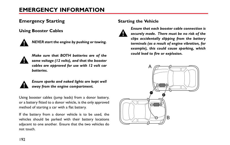
########## ABS Malfunction Indicator Lamp
Refer to "Warning Lights and Indicators" in "Instruments and Controls" chapter.
Note: The normal (non-ABS) braking system remains fully operational and is not affected by partial or full loss of ABS. However, the braking distances may increase.
####### Parking Brake
DO NOT drive with the parking brake applied, or apply the parking brake while the vehicle is in motion. This could result in loss of control, prevent the ABS from functioning correctly, and may even cause damage to the rear brakes.
| | |---|
The parking brake operates on the rear wheels only. To apply the parking brake, pull the lever upward. Always
apply the parking brake lever fully whenever you park the car.
To release, pull the lever up slightly, then press the button at the end of parking brake lever (as indicated by the arrow in the figure) and fully lower the lever.
When parking on a steep slope, do not rely on the parking brake alone to hold the vehicle.
4
#### Automated Stop/Start —Intelligent Fuel Saving System
|
1
2 3
| |---|
1 Instrument Pack Indicator 2 Main switch 3 Switch Indicator Lamp
Engine Stop/Start has been incorporated into vehicles in an effort to reduce emissions. As the name suggests the system will allow the engine to be switched off when engine power is not required and then automatically be restarted when it is.
This system defaults “on” with the ignition switch in the ON position, the switch indication light is on (3 in figure) and can be turned off by pressing the main switch (2 in figure). The lamp in the switch will extinguish.
Note: If vehicle is driving through deep water, please use Stop/Start intelligent fuel saving system main switch (2 in figure) to shut down Stop/Start intelligent fuel saving system.
Automatic Shutdown of Engine
Although the engine is not running after an automatic stop, the system is prepared to auto start therefore the following actions could be dangerous:
####### Engine Auto Stop Conditions
Engine Auto Stop Conditions (Under Stop Start Control, warning lamp on, figure 1 in illustration)
Stop/Start Prohibited Stop Start will not operate if:
####### Automatic Engine Start
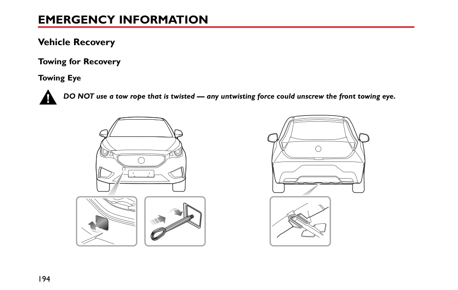
With the engine stopped in the automatic stop/start condition, the following driver actions will cause an automatic restart, at this time the instrument pack indicator lamp is off.
4
With the engine stopped in the automatic stop/start condition, the following actions will cause an automatic restart.
Start Inhibition
Note: When a vehicle is under automatic Stop/Start control and the engine is required to restart, but neutral position is not selected, the engine will restart when neutral position is selected.
If any of the following conditions occur during automatic engine stop, the engine can only be restarted using the
key, during this time the instrument pack indicator will extinguish.
####### Stall Assist
Once Stop/Start intelligent fuel saving system is enabled without inhibition conditions.
If the engine cuts out, or is stalled whilst Stop/Start is enabled, selection of neutral and pressing the clutch pedal will automatically restart the engine.
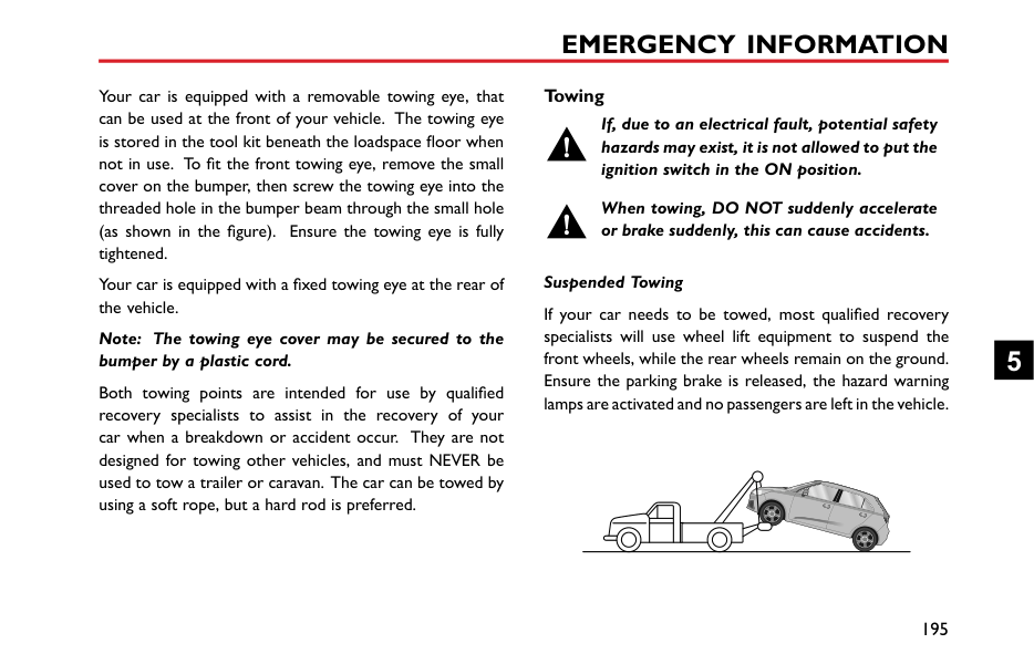
Note: Extremely low battery power may result in the engine not re-starting automatically, or even using the key. In this instance, external power is needed to start the engine or the battery will require re-charging. See the section ‘Emergency Starting’ in the ‘Emergency Information’ Chapter.
Battery
When charging the battery, starting the car with an external power source or supplying power from the vehicle, the negative cable must be connected to a suitable position on the vehicle body. Failure to do this will result in inaccurate battery power calculation which will effect automatic Stop/Start control.
DO NOT disconnect the battery sensor unless absolutely necessary. removal will result in inaccurate battery power calculation which will effect automatic Stop/Start control.
Note: Failure to operate within the following guidelines will effect battery performance and automatic Stop/Start control:
1 After power interruptions (battery disconnection) the automatic Stop/Start function will be suspended until the vehicle is left in a locked state for at least 4 hours whilst the system relearns the state of the battery.
Failure to adhere to this can affect the automatic Stop/Start system.
####### Automated Stop/Start Intelligent Fuel Saving System Failure
In the event of a Stop/Start Intelligent Fuel Saving System failure, contact an MG Authorised Repairer.
The Stop/Start Intelligent Fuel Saving System can be effected by faults within other vehicle systems - in the event of failure contact an MG Authorised Repairer.
4
####### Starter Inoperative, Serious Battery Capacity Loss
In the case of serious battery power loss, automatic Stop/Start and key start may not be possible. In this case see the section ‘Emergency Starting’ in the ‘Emergency Information’ Chapter.
#### Stability Control System (SCS) and Traction Control System (TCS)
########## Stability Control System (SCS)
SCS is designed to assist the driver in control of driving direction. The SCS automatically enters Standby mode after the engine is started.
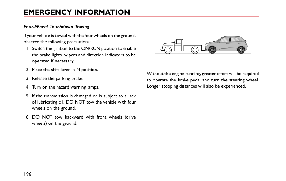
When SCS detects that the vehicle is not moving in the intended direction, it will intervene by applying brake force to selected wheels or through the engine management system to prevent sliding and assist in bringing the car back to the right direction.
########## Traction Control System (TCS)
TCS is designed to aid traction, thereby helping the driver to maintain control of the car in situations where one or both of the driving wheels are spinning (for example, if one wheel is on ice and the other on tarmac). TCS monitors the driving speed of each wheel individually. If spin is detected on one wheel, the system automatically brakes that wheel, transferring torque to the opposite, non-spinning wheel. If both wheels are spinning, the
system will reduce engine speed in order to regulate wheel rotation until traction is regained.
########## Switching On/Off
SCS and TCS are automatically switched to stand by mode when the ignition switch is placed in the ON/RUN position. You can switch them off after the engine is started.
4
To switch off the TCS and SCS press the switch in the centre console. The 'OFF' warning lamps will illuminate in the instrument pack (Refer to "Warning Lights and Indicators" in "Instruments and Controls". To reinstate the TCS and SCS press the switch again. The systems are automatically reinstated if the ignition is cycled.
Note: Disabling SCS and TCS will not affect the operation of ABS. Always disable SCS and TCS when driving with snow chains fitted.
Stability Control/Traction Control System Warning Lamps, Stability Control/Traction Control System OFF Warning Lamps
Refer to "Warning Lights and Indicators" in "Instruments and Controls" chapter.
#### Cruise Control System *
|RES
S SET
+
1 32
4
| |---|
Cruise control enables the driver to maintain a constant road speed without using the accelerator pedal. This is particularly useful for motorway cruising, or for any journey where a constant speed can be maintained for a lengthy period.
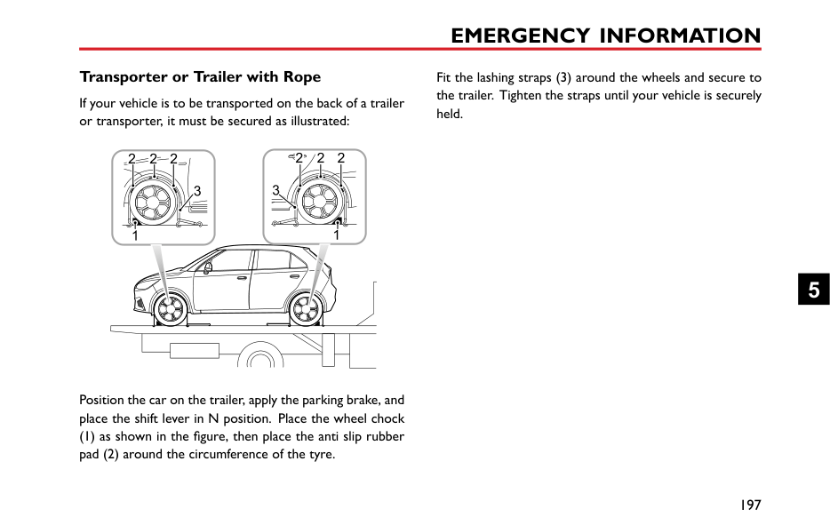
The following precautions must be observed when using cruise control:
During the operation of cruise control system, the actual speed may deviate from the target cruise speed to some extent due to road conditions (such as uphill, downhill, etc).
• If the actual speed is excessively lower than the target speed or SCS is activated due to the hill or road
4
surfaces, the cruise control system may automatically revert to standby mode.
• DO NOT operate the switch for excessively long periods, or press multiple switches simultaneously, this may cause the system to fail. If this situation occurs, when it is safe to do so, cycle the ignition.
########## Cruise Control System Operation
The cruise control system consists of four switches: the main switch, resume switch and two speed increase/decrease set switches. All switches are mounted
accelerator pedal. Cruise control will only operate between vehicle speeds of 25 - 125 mph (40 - 200 km/h).
Note: The set speed held in the cruise control memory will be cancelled when either the cruise control main switch is pressed or the ignition key removed.
Cruise control will be disengaged if either the brake or clutch pedal is pressed. To return to your previous set speed, press the RES switch (4 in the figure) .
Note: The cruise control system will only operate when in the 3rd gear or above.
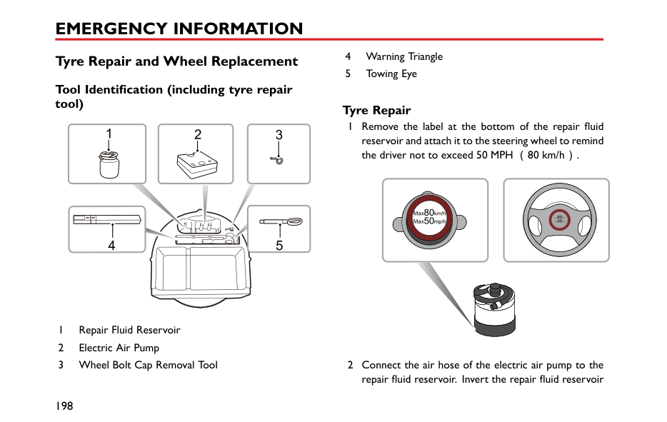
########## Change the Set Speed
Short press (less than 0.5 seconds)the SET + / SET - switch to increase/decrease the vehicle set speed in increments of 1mph/1km/h, then the vehicle will accelerate/decelerate to the new set speed. Pressing and holding the SET + / SET - switch will accelerate / decelerate the vehicle until the switch is released. The selected speed is set accordingly.
The vehicle can also be driven using the accelerator pedal with the cruise control activated. Once the accelerator pedal is released, the system will return to the set speed.
When accelerating, press the SET + switch, the system will apply the higher vehicle speed as the new set speed.
4
Parking Aid * Ultrasonic Sensor Parking Aid *
The purpose of the parking aid is to assist the driver during reversing! The sensors may not be able to detect certain types of obstruction, e.g. narrow posts or small objects no more than a few inches wide, small objects close to the ground, objects above the tailgate and some objects with nonreflective surfaces.
Keep the sensors free from dirt, ice and snow. If deposits build up on the surface of the sensors, their performance may be impaired. When washing the car, avoid aiming high pressure water jets directly at the sensors from close range.
########## Rear Parking Aid *
The ultrasonic sensors in the rear bumper monitor the area behind the vehicle to search for obstacles. If any obstacle is detected, the system will calculate its distance from the rear of the vehicle and communicates the message to the driver by sounding warning chimes.
########## Parking Aid Operation
When the ignition switch is in the ON position, the rear parking aid is enabled automatically when reverse gear is selected, it is switched off as soon as reverse gear is disengaged. A short beep is given by the parking aid within 1 second after selecting reverse gear to indicate that the system is operating normally.
Note: If a longer, higher pitched sound is emitted for 3 seconds when reverse gear is selected, this indicates a fault in the system, seek assistance from your MG Authorised Repairer.
With the parking aid function enabled, when obstacles are detected, the system will give sounds in different frequencies (there might be blind zones).
|1.2m 30cm
| |---|
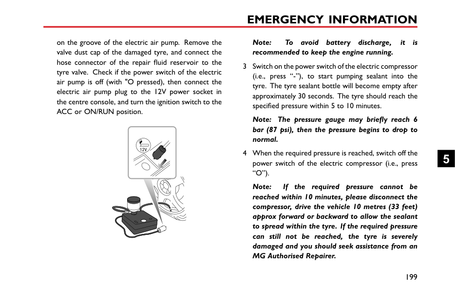
Parking Camera *
The purpose of the parking camera system is to assist the driver during reversing! The camera has limited field of view and cannot detect obstructions outside the field of view.
| | |---|
Some models have a parking camera fitted between the rear license plate lamps. When reverse gear is selected, the camera will display an image of what is immediately behind
4
############## the car. This image will be shown on the entertainment system display.
Tyre Pressure Monitoring System (TPMS)
TPMS can not replace routine maintenance and checks of the tyre condition and pressure.
If radio transmission devices such as mobile telephones or wireless headsets are used in close proximity to the vehicle it may result in interference with the TPMS and could register as a fault.
Note: TPMS only warns of low tyre pressure, it does not re-inflate the tyre.
TPMS uses pressure sensors built into tyre valves to continuously monitor pressure and transmits the signal to an ECU inside the vehicle using RF signals. If it deduces that the pressure of a tyre has fallen below the predefined limit of the system, the warning light on the instrument pack will illuminate yellow. For more information, please refer to ‘Warning Lamps and Indicators’ in ‘Instruments and Controls’ section. On certain levels of entertainment
system it is possible to check the individual tyre data - see 'TPMS' in 'Air Conditioning and Audio Systems' section. Check your tyres at the earliest opportunity and reinflate to the correct pressure. Please refer to ‘Tyre Pressure (Cold)’ in ‘Technical Data’ section.
This system is self-monitoring, if a malfunction is detected, the TPMS warning lamp (yellow) on the instrument pack will flash for 90 seconds first and then illuminate.
If a low tyre pressure is detected the warning lamp in the instrument pack will illuminate yellow. For more information, please refer to ‘Warning Lamps and Indicators’ in ‘Instruments and Controls’ section.
Note: When a puncture is detected, the system will require some time to analyse information prior to illuminating the warning lamp.
Under certain conditions the warning light may illuminate when a fault is not present, these conditions include:
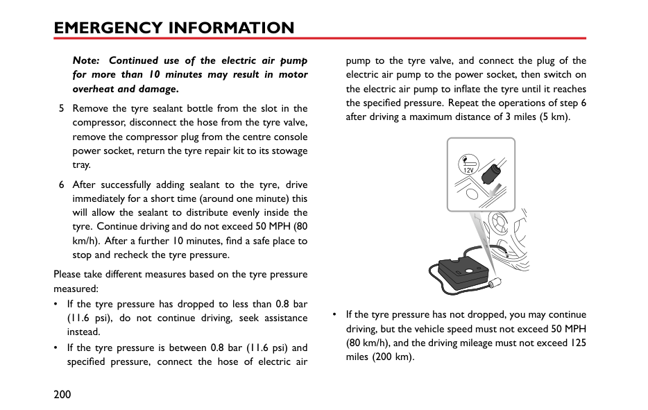
4
The TPMS system is a 'self learning' system, after resetting tyre pressures it will be necessary to allow the system to go through a self learning process. This is done by driving the car, during this process system monitoring may be suspended. If sensors or receiver module are replaced the system will be required to be programmed and go through the self learning process, consult an MG Authorised Repairer.
Load Carrying
DO NOT exceed the gross vehicle weight or the permitted front and rear axle loads. Failure may result in vehicle damage or serious injury.
####### Loadspace Loading
Ensure that the rear seat backrests are securely latched in the upright position when loads are carried in the load space behind the seats.
If the tailgate can not be closed due to the type of cargo loaded, be sure to close all windows during driving, select the face distribution mode of the air condition, and set the blower to maximum speed, so as to decrease exhaust fumes entering the vehicle.
When luggage is carried in the load space, always ensure heavy items are placed as low and as far forward as possible,
so as to avoid the cargo shift in the event of an accident or sudden stop.
Drive carefully and avoid emergency braking or manoeuvres.
Driving with the tailgate open is very dangerous. If the load being carried requires the tailgate to be open, please ensure the cargo is suitably secured and every measure is taken to prevent exhaust fumes entering the vehicle.
|IMPORTANT| |---| |Traffic regulations must be observed when loading cargo, if the cargo extrudes the loadspace appropriate warning measures must be taken to warn other road users.|
4
####### Internal Loading
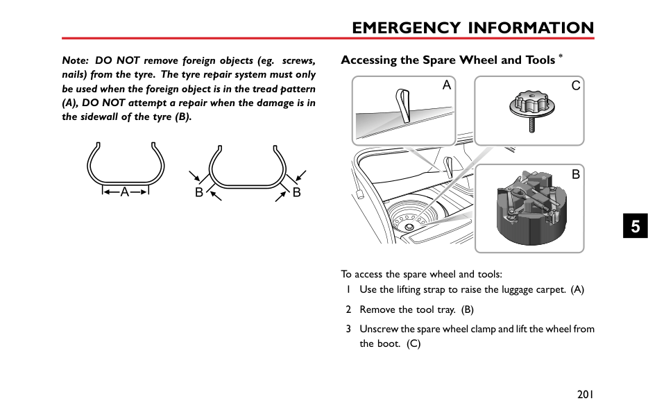
DO NOT carry unsecured equipment, tools or luggage that could move, causing personal injury in the event of an accident, or emergency braking or hard acceleration.
DO NOT obstruct the driver's or passenger's vision with loads.
Folding the rear seats can increase luggage space, refer to “Rear Seats” described in the “Seats and Restraints” section.
When cargo is loaded in the vehicle, place it at a position as low as possible and ensure that it is tightly secured, so as to avoid personal injury caused by cargo movement when traffic accidents or emergency braking occurs. If the cargo has to be placed on a seat, then the seat must not be used by an occupant during that time.
####### General Towing Safety
Your vehicle can tow a trailer if you carefully observe load limits, use approved equipment, and follow the towing guidelines. Always check load limits before towing.
Towing loads in excess of the maximum towing weight can seriously affect vehicle handling and performance, and could damage your vehicles engine and drive-train.
Note: Exceeding any load limits advised by MG Motor UK Ltd is dangerous. Consult the recommended load limits and loading prior to any journey.
Note: Check the loading of your vehicle and trailer carefully before starting to drive.
Trailer hitch load should never exceed the limit advised by MG Motor UK Ltd.
Note: Excessive towing loads reduce front tyre traction and steering control, too little trailer nose load can make the trailer unstable and cause it to sway.
Tow bars:Only genuine MG Approved tow bars should be fitted to your vehicle. Only use the attachment method specified by the vehicle manufacturer for securing the
towing hitch. Contact your MG Authorised Repairer for more information.
Safety chains : Safety chains must be used as a precautionary measure should the trailer become unintentionally unhitched. Make sure the safety chain is securely attached to both the trailer and the vehicle prior to departure.
Altitude: Your engine delivers less power at higher altitude. If you tow a trailer in a mountainous area you should reduce the combined vehicle and trailer weight by 10% for every 1000m of elevation.
Gradients: Where possible, when towing, you should plan your journey to avoid steep gradients. The advised brake towing mass stated assumes a maximum gradient capability of 12% where possible it is recommended you drive on gradients less than 12%. Follow the trailer associations recommendations for suitable roads.
Running in period: Avoid towing a trailer during your vehicles first 1000km or 625 miles.
Stop/Start function: Turn off Automated Stop/Start function when towing just use. The trailer weight can affect
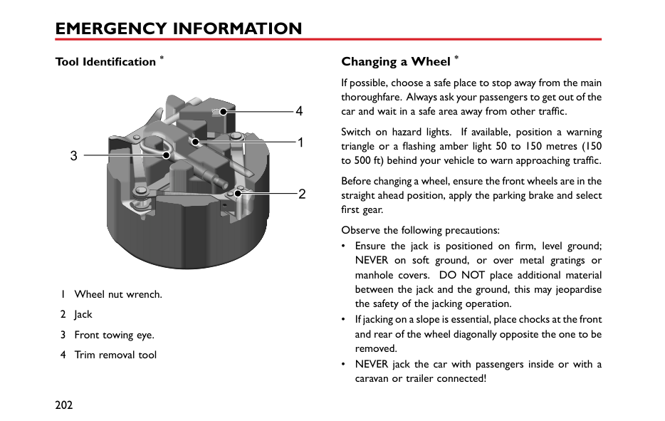
your vehicles braking efficiency if Automated Stop/Start is activated on a hill while towing a trailer.
4
Emergency Information
190 Hazard Warning Devices 192 Emergency Starting 194 Vehicle Recovery 198 Tyre Repair and Wheel
Replacement 205 Fuse Replacement 211 Bulb Replacement 5
#### Hazard Warning Devices Hazard Warning Lamps
causing an obstruction or is in a hazardous situation. Remember to switch them off before driving away.
####### Warning Triangle
Note: Before you stop or slow the vehicle in an emergency, always press the hazard warning switch. All turn signal lamps and direction indicators will flash together to warn other road users when your vehicle is
The warning triangle supplied with your vehicle is stowed in the boot.
If you have to stop your vehicle on the road in an emergency, you must place a warning triangle
approximately 50 — 150 metres behind the vehicle, if possible, to warn other road users of your position.
5
Emergency Starting Using Booster Cables
NEVER start the engine by pushing or towing.
Make sure that BOTH batteries are of the same voltage (12 volts), and that the booster cables are approved for use with 12 volt car batteries.
Ensure sparks and naked lights are kept well away from the engine compartment.
Using booster cables (jump leads) from a donor battery, or a battery fitted to a donor vehicle, is the only approved method of starting a car with a flat battery.
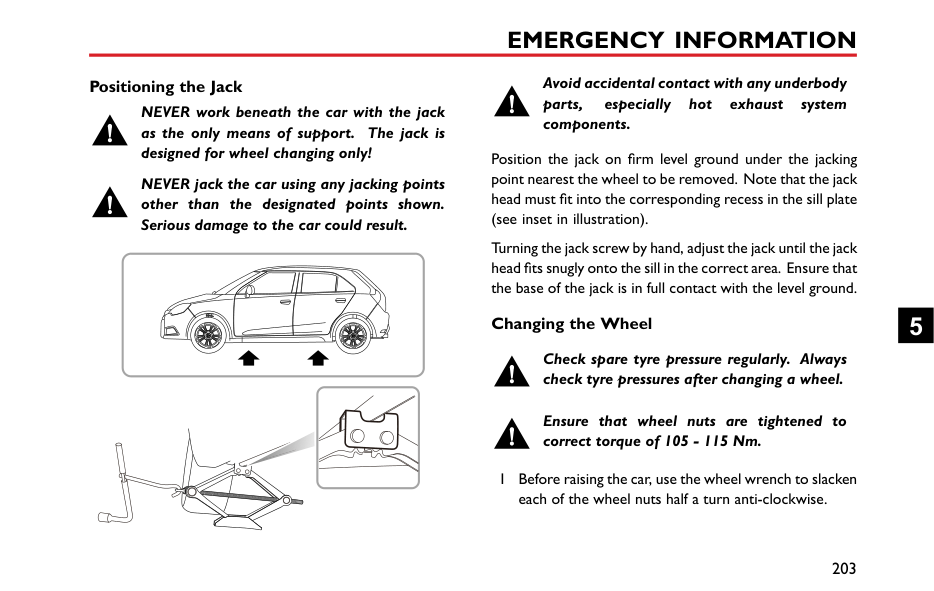
If the battery from a donor vehicle is to be used, the vehicles should be parked with their battery locations adjacent to one another. Ensure that the two vehicles do not touch.
####### Starting the Vehicle
Ensure that each booster cable connection is securely made. There must be no risk of the clips accidentally slipping from the battery terminals (as a result of engine vibration, for example), this could cause sparking, which could lead to fire or explosion.
| | |---|
Remove the ignition key and switch off ALL electrical equipment of BOTH vehicles, then follow the instructions below:
than 2 minutes before shutting down the engine of the donor vehicle and disconnecting the booster cables.
5 Disconnecting the booster cables. Disconnecting the booster cables must be an exact reversal of the procedure used to connect them, i.e. disconnect the BLACK negative cable from the earth point on the disabled vehicle FIRST.
|IMPORTANT| |---| |NEVER turn on any electrical equipment on the disabled vehicle before removing the booster cables.|
5
Vehicle Recovery Towing for Recovery Towing Eye
DO NOT use a tow rope that is twisted — any untwisting force could unscrew the front towing eye.
Your car is equipped with a removable towing eye, that can be used at the front of your vehicle. The towing eye is stored in the tool kit beneath the loadspace floor when not in use. To fit the front towing eye, remove the small cover on the bumper, then screw the towing eye into the threaded hole in the bumper beam through the small hole (as shown in the figure). Ensure the towing eye is fully tightened.
Your car is equipped with a fixed towing eye at the rear of the vehicle.
Note: The towing eye cover may be secured to the bumper by a plastic cord.
Both towing points are intended for use by qualified recovery specialists to assist in the recovery of your car when a breakdown or accident occur. They are not designed for towing other vehicles, and must NEVER be used to tow a trailer or caravan. The car can be towed by using a soft rope, but a hard rod is preferred.
Towing
If, due to an electrical fault, potential safety hazards may exist, it is not allowed to put the ignition switch in the ON position.
When towing, DO NOT suddenly accelerate or brake suddenly, this can cause accidents.
Suspended Towing
If your car needs to be towed, most qualified recovery specialists will use wheel lift equipment to suspend the front wheels, while the rear wheels remain on the ground. Ensure the parking brake is released, the hazard warning lamps are activated and no passengers are left in the vehicle.
|


| |---|
5
############# Four-Wheel Touchdown Towing


If your vehicle is towed with the four wheels on the ground, observe the following precautions:

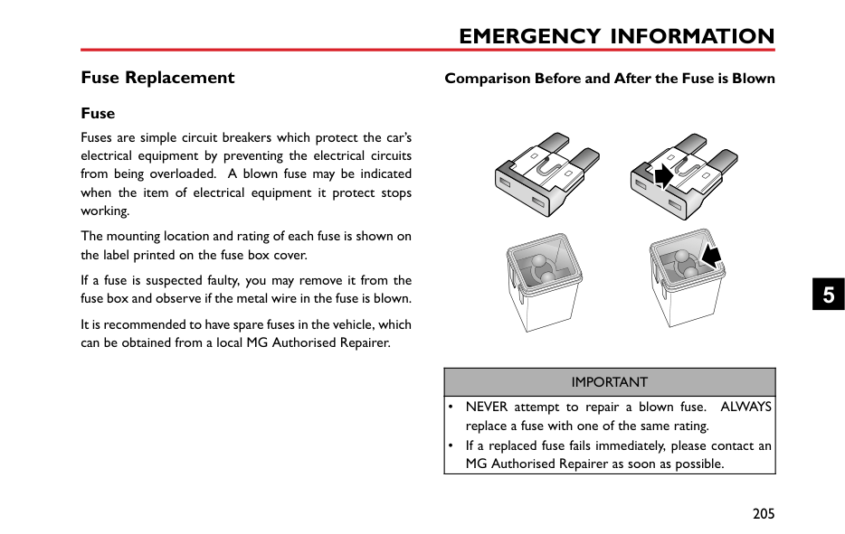


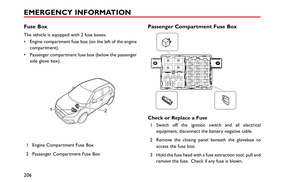


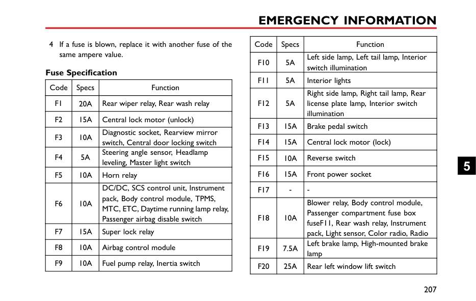


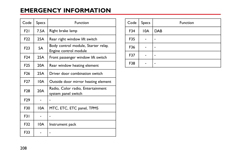


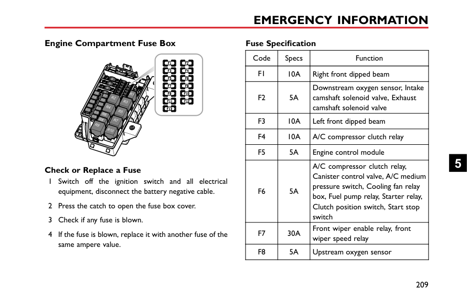


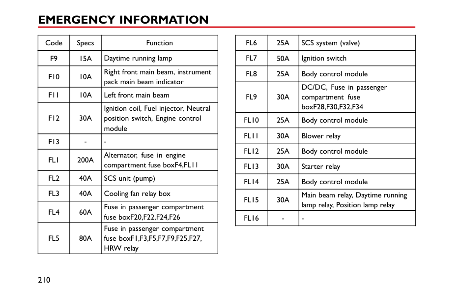


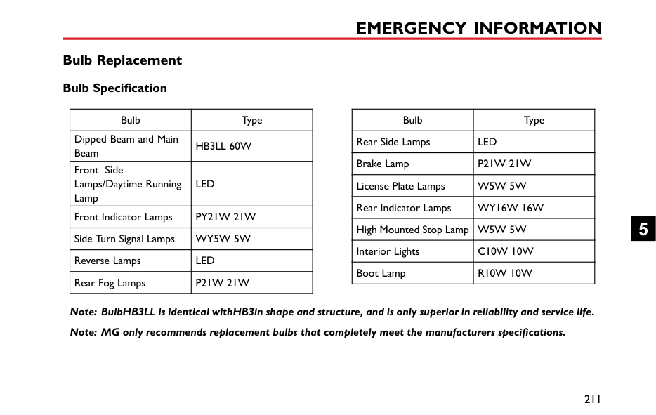


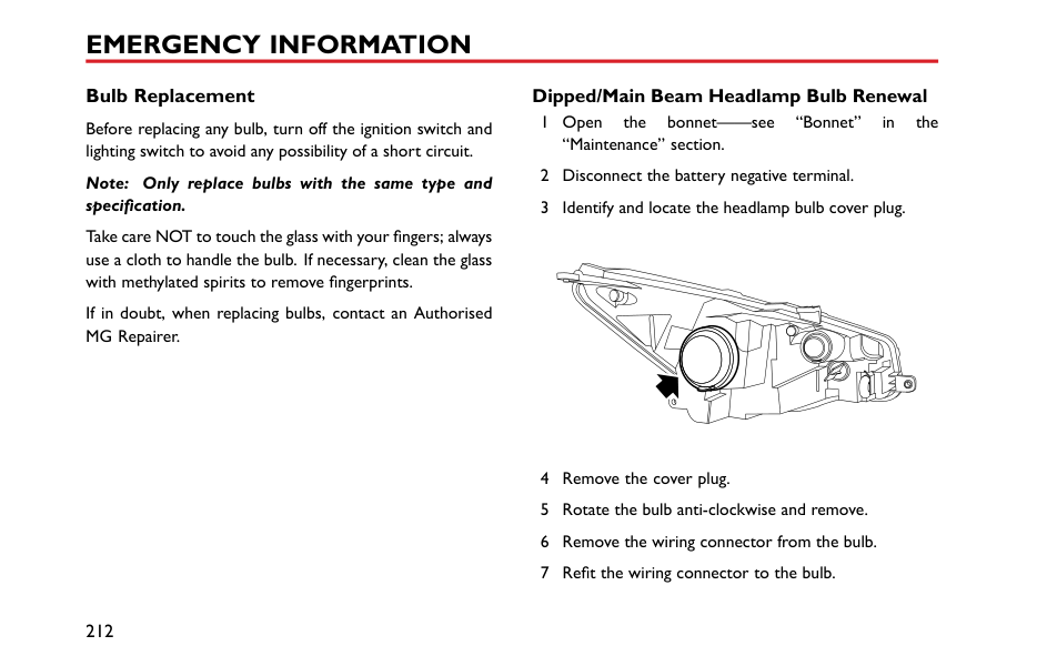


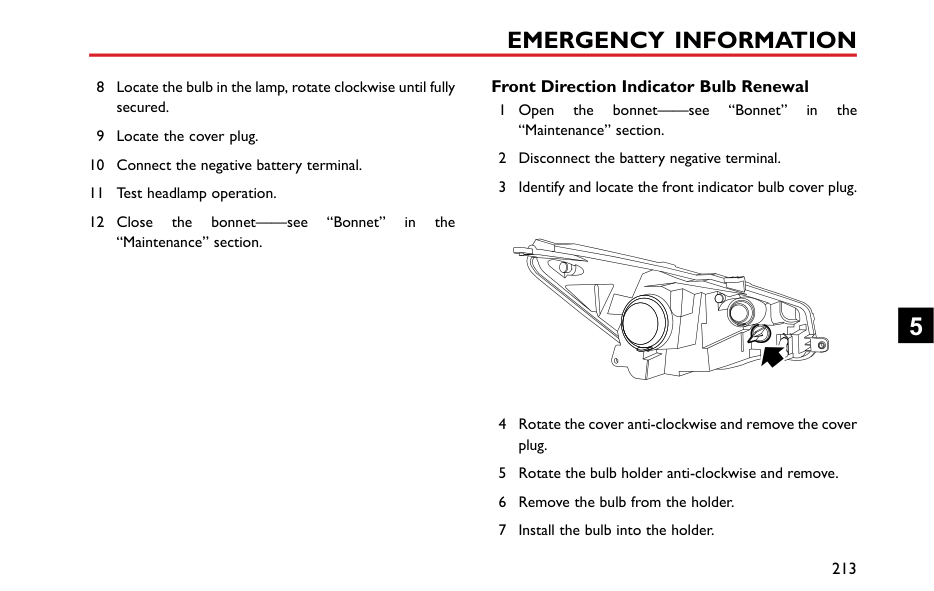


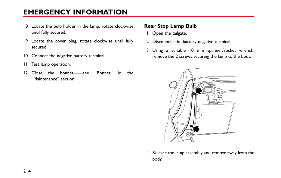


Without the engine running, greater effort will be required to operate the brake pedal and turn the steering wheel. Longer stopping distances will also be experienced.
####### Transporter or Trailer with Rope
If your vehicle is to be transported on the back of a trailer or transporter, it must be secured as illustrated:
Fit the lashing straps (3) around the wheels and secure to the trailer. Tighten the straps until your vehicle is securely held.
Position the car on the trailer, apply the parking brake, and place the shift lever in N position. Place the wheel chock (1) as shown in the figure, then place the anti slip rubber pad (2) around the circumference of the tyre.
5
#### Tyre Repair and Wheel Replacement
####### Tool Identification (including tyre repair tool)
|


| |---|
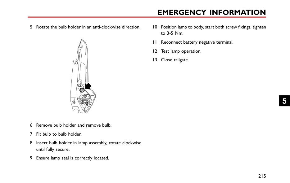
####### Tyre Repair
|
| |---|
on the groove of the electric air pump. Remove the valve dust cap of the damaged tyre, and connect the hose connector of the repair fluid reservoir to the tyre valve. Check if the power switch of the electric air pump is off (with "O pressed), then connect the electric air pump plug to the 12V power socket in the centre console, and turn the ignition switch to the ACC or ON/RUN position.
Note: To avoid battery discharge, it is recommended to keep the engine running.
Note: The pressure gauge may briefly reach 6 bar (87 psi), then the pressure begins to drop to normal.
|
| |---|
Note: If the required pressure cannot be reached within 10 minutes, please disconnect the compressor, drive the vehicle 10 metres (33 feet) approx forward or backward to allow the sealant to spread within the tyre. If the required pressure can still not be reached, the tyre is severely damaged and you should seek assistance from an MG Authorised Repairer.
5
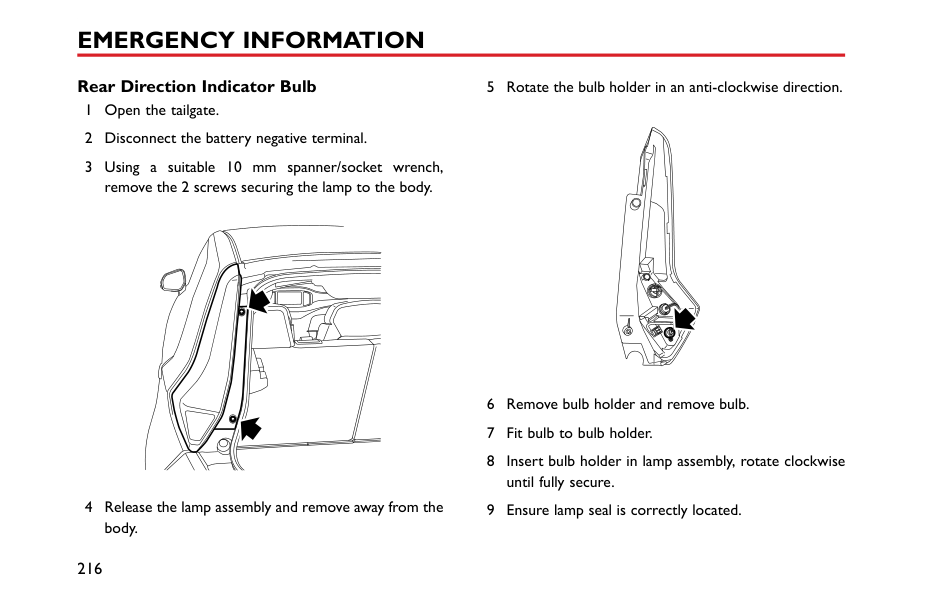
Note: Continued use of the electric air pump for more than 10 minutes may result in motor overheat and damage.
Please take different measures based on the tyre pressure measured:
pump to the tyre valve, and connect the plug of the electric air pump to the power socket, then switch on the electric air pump to inflate the tyre until it reaches the specified pressure. Repeat the operations of step 6 after driving a maximum distance of 3 miles (5 km).
| | |---|
• If the tyre pressure has not dropped, you may continue driving, but the vehicle speed must not exceed 50 MPH (80 km/h), and the driving mileage must not exceed 125 miles (200 km).
Note: DO NOT remove foreign objects (eg. screws, nails) from the tyre. The tyre repair system must only be used when the foreign object is in the tread pattern (A), DO NOT attempt a repair when the damage is in the sidewall of the tyre (B).
Accessing the Spare Wheel and Tools *
To access the spare wheel and tools:
5
########## Tool Identification *
|| | | |---|---| | | | | | | | | |
| |---|
1 Wheel nut wrench. 2 Jack 3 Front towing eye. 4 Trim removal tool
####### Changing a Wheel *
If possible, choose a safe place to stop away from the main thoroughfare. Always ask your passengers to get out of the car and wait in a safe area away from other traffic.
Switch on hazard lights. If available, position a warning triangle or a flashing amber light 50 to 150 metres (150 to 500 ft) behind your vehicle to warn approaching traffic.
Before changing a wheel, ensure the front wheels are in the straight ahead position, apply the parking brake and select first gear.
Observe the following precautions:
Positioning the Jack
NEVER work beneath the car with the jack as the only means of support. The jack is designed for wheel changing only!
NEVER jack the car using any jacking points other than the designated points shown. Serious damage to the car could result.
Avoid accidental contact with any underbody parts, especially hot exhaust system components.
Position the jack on firm level ground under the jacking point nearest the wheel to be removed. Note that the jack head must fit into the corresponding recess in the sill plate (see inset in illustration).
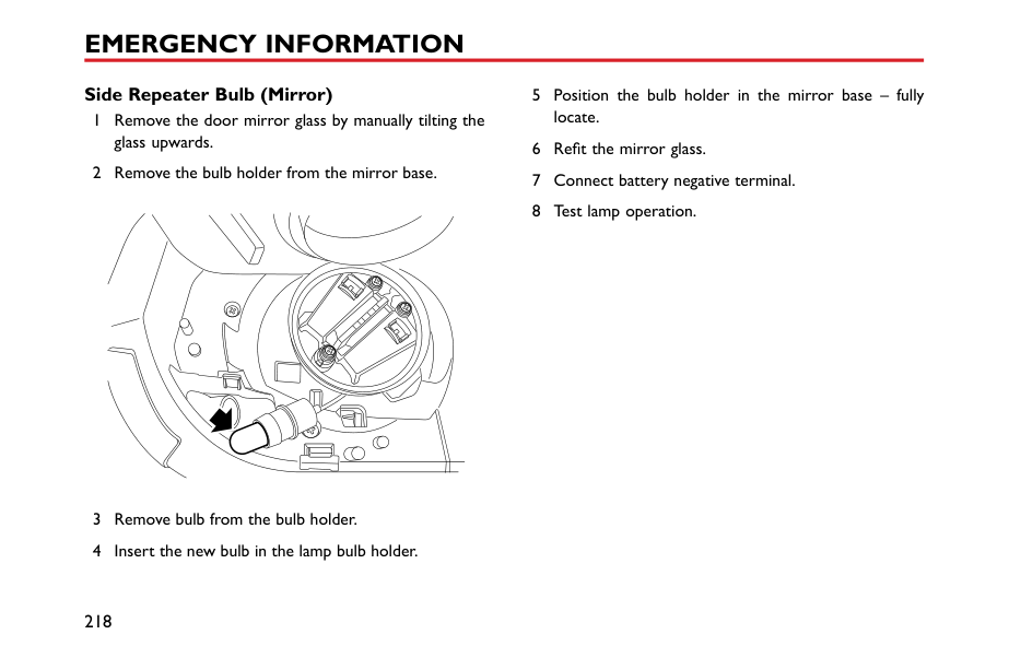
Turning the jack screw by hand, adjust the jack until the jack head fits snugly onto the sill in the correct area. Ensure that the base of the jack is in full contact with the level ground.
########## Changing the Wheel
Check spare tyre pressure regularly. Always check tyre pressures after changing a wheel.
Ensure that wheel nuts are tightened to correct torque of 105 - 115 Nm.
1 Before raising the car, use the wheel wrench to slacken each of the wheel nuts half a turn anti-clockwise.
5
Note: Depending on the style of wheels fitted it may be necessary to remove wheel nut covers, centre cap or wheel trim. Use the special tool located within the tool kit to remove the relevant trim type.
Note: The locking wheel nuts on vehicles fitted with them (one locking wheel nut per wheel) can only be loosened or tightened by using the adapter provided. *
Note: Avoid placing wheels face down on the ground - the surface may be scratched.
Note: Recheck the wheel nut torque after initial tightening.
Note: Consult your MG Authorised Repairer or tyre specialist for a replacement tyre, as soon as possible.
#### Fuse Replacement Fuse
Fuses are simple circuit breakers which protect the car’s electrical equipment by preventing the electrical circuits from being overloaded. A blown fuse may be indicated when the item of electrical equipment it protect stops working.
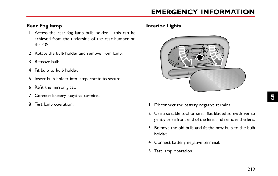
The mounting location and rating of each fuse is shown on the label printed on the fuse box cover.
If a fuse is suspected faulty, you may remove it from the fuse box and observe if the metal wire in the fuse is blown.
It is recommended to have spare fuses in the vehicle, which can be obtained from a local MG Authorised Repairer.
Comparison Before and After the Fuse is Blown
|IMPORTANT| |---| |• NEVER attempt to repair a blown fuse. ALWAYS replace a fuse with one of the same rating.
• If a replaced fuse fails immediately, please contact an MG Authorised Repairer as soon as possible.
|
5
Fuse Box The vehicle is equipped with 2 fuse boxes:
|21
| |---|
####### Passenger Compartment Fuse Box
|| | |---|
| | |---|
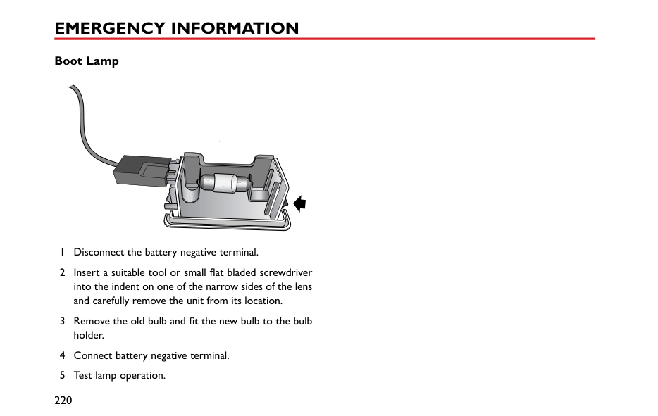
| | |---|
| | |---|
| | |---|
| | |---|
| | |---|
| | |---|
| | |---|
| | |---|
| | |---|
| | |---|
| | |---|
| | |---|
| | |---|
| | |---|
| | |---|
| | |---|
| | |---|
| | |---|
| | |---|
| | |---|
| | |---|
| | |---|
| | |---|
| | |---|
| | |---|
| | |---|
| | |---|
| | |---|
| | |---|
| | |---|
| | |---|
| | |---|
| | |---|
| | |---|
| | |---|
| | |---|
| | |---|
| | |---|
| | |---| | |---|
########## Check or Replace a Fuse
|Code|Specs|Function| |---|---|---| |F10|5A|Left side lamp, Left tail lamp, Interior switch illumination| |F11|5A|Interior lights| |F12|5A|Right side lamp, Right tail lamp, Rear license plate lamp, Interior switch illumination| |F13|15A|Brake pedal switch| |F14|15A|Central lock motor (lock)| |F15|10A|Reverse switch| |F16|15A|Front power socket| |F17|-|-| |F18|10A|Blower relay, Body control module, Passenger compartment fuse box fuseF11, Rear wash relay, Instrument pack, Light sensor, Color radio, Radio| |F19|7.5A|Left brake lamp, High-mounted brake lamp| |F20|25A|Rear left window lift switch|
4 If a fuse is blown, replace it with another fuse of the
same ampere value. Fuse Specification
|Code|Specs|Function| |---|---|---| |F1|20A|Rear wiper relay, Rear wash relay| |F2|15A|Central lock motor (unlock)| |F3|10A|Diagnostic socket, Rearview mirror switch, Central door locking switch| |F4|5A|Steering angle sensor, Headlamp leveling, Master light switch| |F5|10A|Horn relay| |F6|10A|DC/DC, SCS control unit, Instrument pack, Body control module, TPMS, MTC, ETC, Daytime running lamp relay, Passenger airbag disable switch| |F7|15A|Super lock relay| |F8|10A|Airbag control module| |F9|10A|Fuel pump relay, Inertia switch|
5
|Code|Specs|Function| |---|---|---| |F21|7.5A|Right brake lamp| |F22|25A|Rear right window lift switch| |F23|5A|Body control module, Starter relay, Engine control module| |F24|25A|Front passenger window lift switch| |F25|20A|Rear window heating element| |F26|25A|Driver door combination switch| |F27|10A|Outside door mirror heating element| |F28|20A|Radio, Color radio, Entertainment system panel switch| |F29|-|-| |F30|10A|MTC, ETC, ETC panel, TPMS| |F31|-|-| |F32|10A|Instrument pack| |F33|-|-|
|Code|Specs|Function| |---|---|---| |F34|10A|DAB| |F35|-|-|
|F36|-|-| |F37|-|-| |F38|-|-|
####### Engine Compartment Fuse Box
Fuse Specification
|Code|Specs|Function| |---|---|---| |F1|10A|Right front dipped beam| |F2|5A|Downstream oxygen sensor, Intake camshaft solenoid valve, Exhaust camshaft solenoid valve| |F3|10A|Left front dipped beam| |F4|10A|A/C compressor clutch relay| |F5|5A|Engine control module| |F6|5A|A/C compressor clutch relay, Canister control valve, A/C medium pressure switch, Cooling fan relay box, Fuel pump relay, Starter relay, Clutch position switch, Start stop switch| |F7|30A|Front wiper enable relay, front wiper speed relay| |F8|5A|Upstream oxygen sensor|
| | |---|
########## Check or Replace a Fuse
5
|FL6|25A|SCS system (valve)|

|---|---|---| |FL7|50A|Ignition switch| |FL8|25A|Body control module| |FL9|30A|DC/DC, Fuse in passenger compartment fuse boxF28,F30,F32,F34| |FL10|25A|Body control module| |FL11|30A|Blower relay| |FL12|25A|Body control module| |FL13|30A|Starter relay| |FL14|25A|Body control module| |FL15|30A|Main beam relay, Daytime running lamp relay, Position lamp relay| |FL16|-|-|
|Code|Specs|Function| |---|---|---| |F9|15A|Daytime running lamp| |F10|10A|Right front main beam, instrument pack main beam indicator| |F11|10A|Left front main beam| |F12|30A|Ignition coil, Fuel injector, Neutral position switch, Engine control module| |F13|-|-| |FL1|200A|Alternator, fuse in engine compartment fuse boxF4,FL11| |FL2|40A|SCS unit (pump)| |FL3|40A|Cooling fan relay box| |FL4|60A|Fuse in passenger compartment fuse boxF20,F22,F24,F26| |FL5|80A|Fuse in passenger compartment fuse boxF1,F3,F5,F7,F9,F25,F27, HRW relay|
#### Bulb Replacement Bulb Specification
|Bulb|Type| |---|---| |Dipped Beam and Main Beam|HB3LL 60W| |Front Side Lamps/Daytime Running Lamp|LED| |Front Indicator Lamps|PY21W 21W| |Side Turn Signal Lamps|WY5W 5W| |Reverse Lamps|LED|
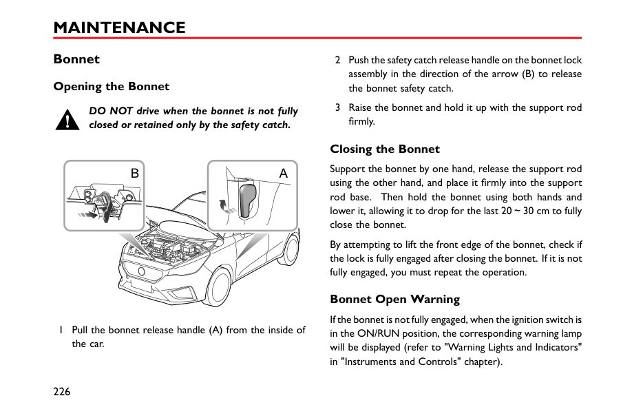
|Rear Fog Lamps|P21W 21W|
|Bulb|Type| |---|---| |Rear Side Lamps|LED| |Brake Lamp|P21W 21W| |License Plate Lamps|W5W 5W| |Rear Indicator Lamps|WY16W 16W| |High Mounted Stop Lamp|W5W 5W| |Interior Lights|C10W 10W| |Boot Lamp|R10W 10W|
Note: BulbHB3LL is identical withHB3in shape and structure, and is only superior in reliability and service life. Note: MG only recommends replacement bulbs that completely meet the manufacturers specifications.
5
####### Bulb Replacement
Before replacing any bulb, turn off the ignition switch and lighting switch to avoid any possibility of a short circuit.
Note: Only replace bulbs with the same type and specification.
Take care NOT to touch the glass with your fingers; always use a cloth to handle the bulb. If necessary, clean the glass with methylated spirits to remove fingerprints.
If in doubt, when replacing bulbs, contact an Authorised MG Repairer.
######## Dipped/Main Beam Headlamp Bulb Renewal
| | |---|
######## Front Direction Indicator Bulb Renewal
| | |---|
5
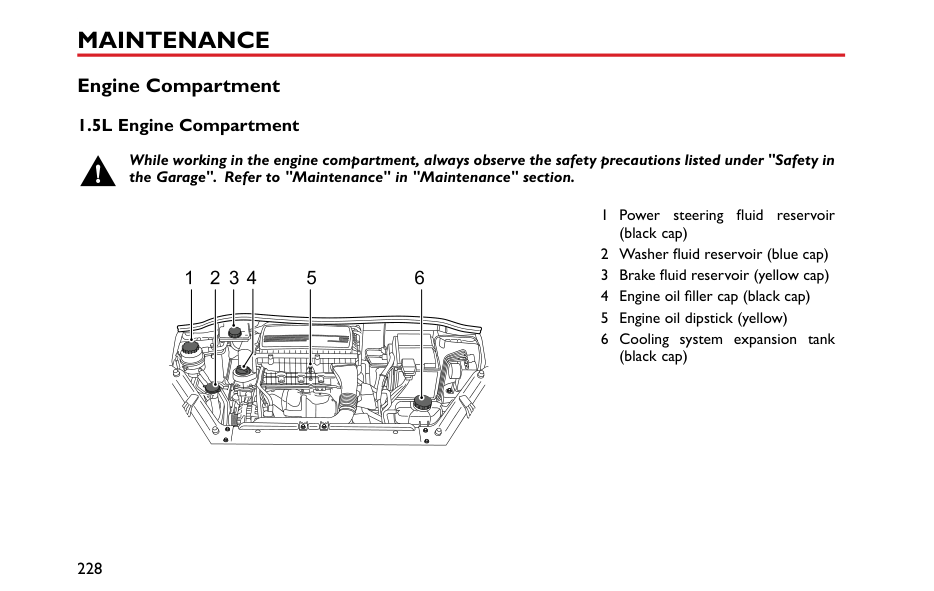
######## Rear Stop Lamp Bulb
| | |---|
| | |---|
5
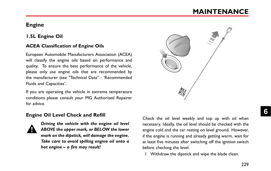
######## Rear Direction Indicator Bulb
| | |---|
| | |---|
######## License Plate Lamp Bulbs
5
######## Side Repeater Bulb (Mirror)
| | |---|
5 Position the bulb holder in the mirror base – fully
locate. 6 Refit the mirror glass. 7 Connect battery negative terminal. 8 Test lamp operation.
######## Rear Fog lamp
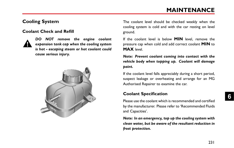
######## Interior Lights
5
######## Boot Lamp


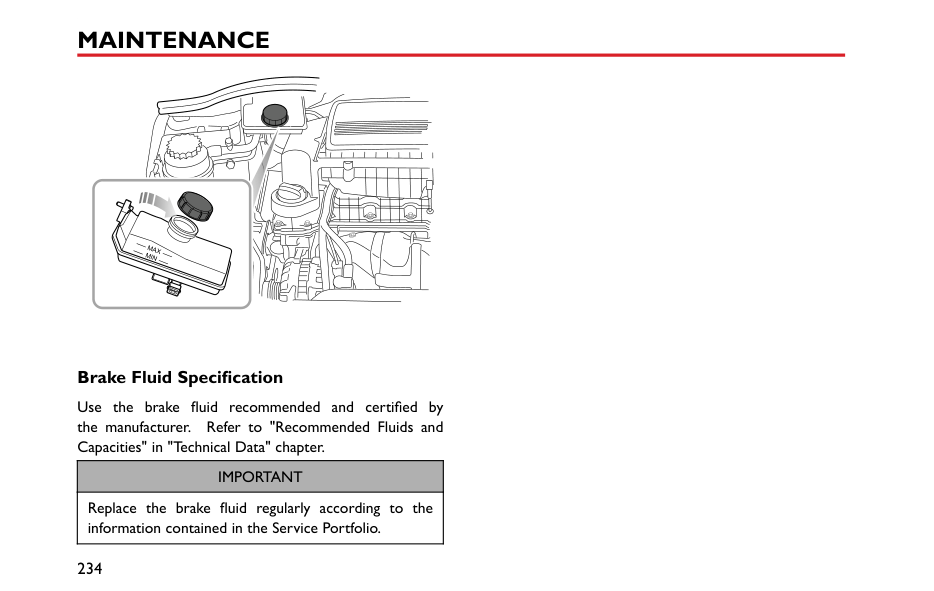


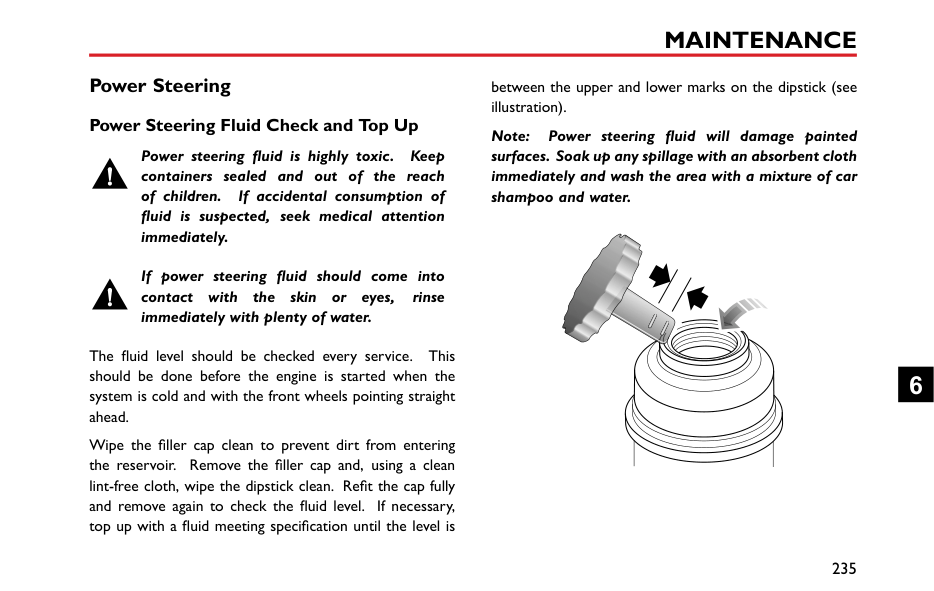


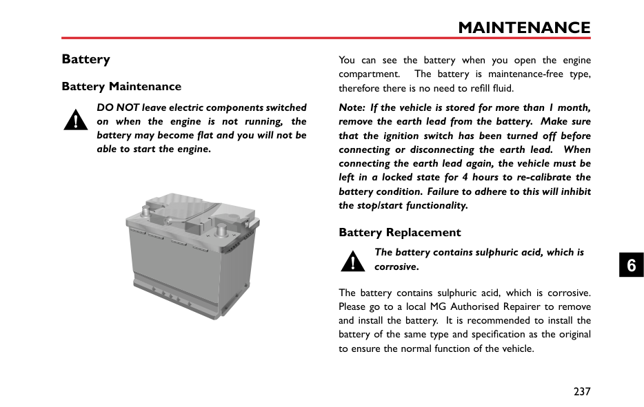


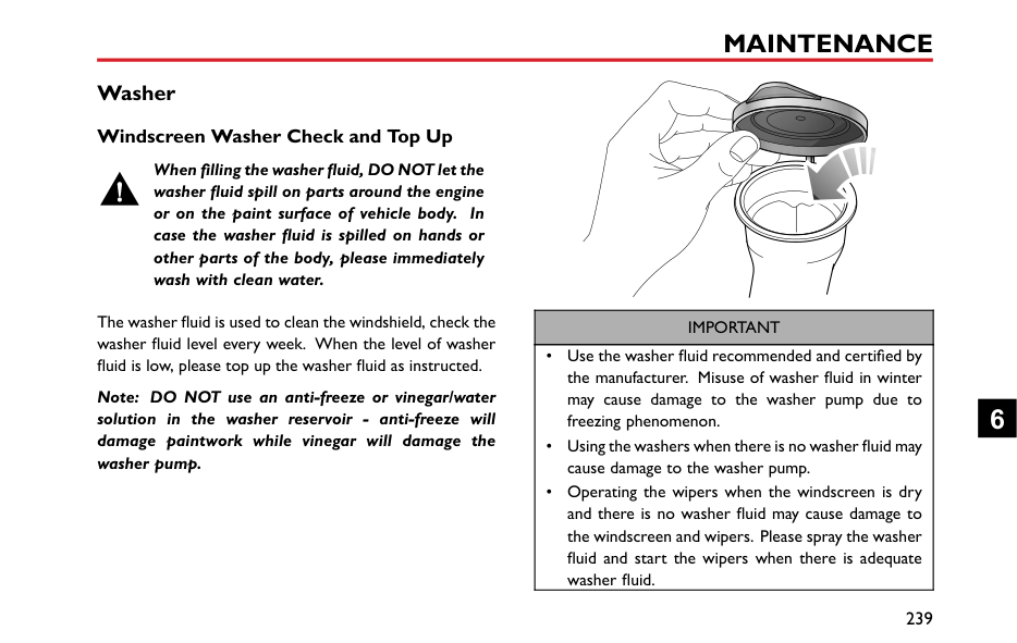


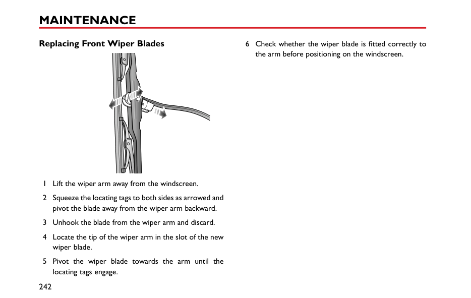


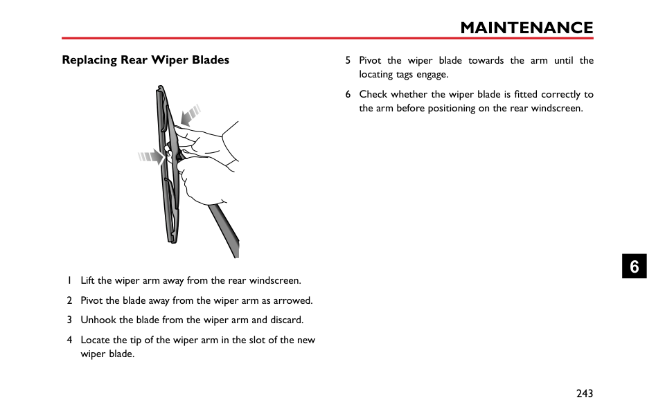


Maintenance
222 Maintenance 226 Bonnet
6
#### Maintenance Routine Maintenance
The safety, reliability and performance of your car will depend partly on how well it is maintained. You must ensure that maintenance is carried out when required and according to the information contained in the ‘Service Schedule’.
########## Servicing
For Next Service *,please refer to “Information Centre” in “Instruments and Controls” section. After each service, ‘Next Service' will be reset by the local MG Authorised Repairer, which performed the maintenance.
Note: If a service is not carried out (or the display is not reset by the local MG Authorised Repairer after service), the service display cannot provide correct information.
########## Service History
Ensure your local MG Authorised Repairer fills in the Service Records after each service.
########## Brake Fluid Replacement
Replace the brake fluid according to the information contained in the “Service Schedule”.
Note: Brake fluid replacement will be an additional cost.
########## Coolant Replacement
Replace the engine coolant (mixed solution of antifreeze and water) according to the information contained in the “Service Schedule”.
Note: Coolant replacement will be an additional cost. Emission Control
Your car is fitted with emission and evaporative control equipment designed to meet specific territorial and legal requirements. Incorrect engine settings may adversely affect exhaust emissions, engine performance and fuel consumption, as well as causing high temperatures, which could result in damage to the catalytic converters and engine.
|IMPORTANT| |---| |You should be aware that unauthorised replacement, modification or tampering with this equipment by an owner or motor vehicle repairer could result in the manufacturer’s warranty being deemed as invalid. In addition, engine settings must not be tampered with.|
########## Owner Maintenance
Any significant or sudden drop in fluid levels, or uneven tyre wear, should be reported without delay. For further information, refer to an MG Authorised Repairer.
########## Special Operating Conditions
In addition to the routine services referred to previously, a number of simple checks must be carried out more frequently. You can carry out these checks yourself and advice is given on the pages that follow.
If your car is frequently used in dusty conditions, or operated in extreme climates where sub-zero or very high ambient temperatures are normal, more frequent attention may need to be paid to servicing requirements. You need to carry out special maintenance operations (refer to Service Portfolio or contact your MG Authorised Repairer).
Daily Checks
6
########## Safety in the Garage
Cooling fans may commence operating after the engine is switched off, and continue operating for a number of minutes. Keep clear of all fans while working in the engine compartment.
If you need to carry out maintenance, observe the following safety precautions at all times:
########## Toxic Liquid
Fluids used in motor vehicles are poisonous and should not be consumed or brought into contact with open wounds. These include: battery acid, coolant, brake fluid, power steering fluid, fuel, engine oil and windscreen washer additives.
For your own safety, ALWAYS read and observe all instructions printed on labels and containers.
########## Used Engine Oil
Prolonged contact with engine oil may cause serious skin disorders, including dermatitis and cancer of the skin. Wash thoroughly after contact. Used engine oil should
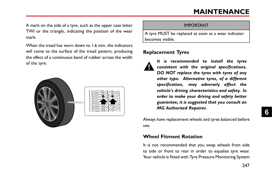
be disposed of correctly. Incorrect disposal can cause a threat to the environment.
6
Bonnet Opening the Bonnet
DO NOT drive when the bonnet is not fully closed or retained only by the safety catch.
|

|


| |---|
|


| |---| | |---|
1 Pull the bonnet release handle (A) from the inside of the car.
####### Closing the Bonnet
Support the bonnet by one hand, release the support rod using the other hand, and place it firmly into the support rod base. Then hold the bonnet using both hands and lower it, allowing it to drop for the last 20~30 cm to fully close the bonnet.
By attempting to lift the front edge of the bonnet, check if the lock is fully engaged after closing the bonnet. If it is not fully engaged, you must repeat the operation.
####### Bonnet Open Warning
If the bonnet is not fully engaged, when the ignition switch is in the ON/RUN position, the corresponding warning lamp will be displayed (refer to "Warning Lights and Indicators" in "Instruments and Controls" chapter).
|IMPORTANT| |---| |• For safety reasons, the bonnet should be closed well when driving. Therefore you must check after closing the bonnet that the bonnet is securely latched, e.g. the bonnet edge is flush with the body of the car.
• You should stop the car immediately when safety permits and close the bonnet if it is not closed fully when driving.
• When releasing the bonnet support rod the bonnet will require external support until closed. Damage or personal injury may occur if no support is applied.
• Beware of injury to hands while fully closing the bonnet with a downward force.
|
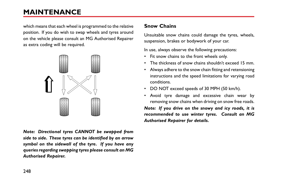
6
Engine Compartment 1.5L Engine Compartment
While working in the engine compartment, always observe the safety precautions listed under "Safety in the Garage". Refer to "Maintenance" in "Maintenance" section.
1 Power steering fluid reservoir
|1 2 3 4 5 6
| |---|
(black cap) 2 Washer fluid reservoir (blue cap) 3 Brake fluid reservoir (yellow cap) 4 Engine oil filler cap (black cap) 5 Engine oil dipstick (yellow) 6 Cooling system expansion tank
(black cap)
#### Engine 1.5L Engine Oil ACEA Classification of Engine Oils
European Automobile Manufacturers Association (ACEA) will classify the engine oils based on performance and quality. To ensure the best performance of the vehicle, please only use engine oils that are recommended by the manufacturer (see "Technical Data" - ‘Recommended Fluids and Capacities’.
If you are operating the vehicle in extreme temperature conditions please consult your MG Authorised Repairer for advice.
####### Engine Oil Level Check and Refill
Driving the vehicle with the engine oil level ABOVE the upper mark, or BELOW the lower mark on the dipstick, will damage the engine. Take care to avoid spilling engine oil onto a hot engine – a fire may result!
Check the oil level weekly and top up with oil when necessary. Ideally, the oil level should be checked with the engine cold and the car resting on level ground. However, if the engine is running and already getting warm, wait for at least five minutes after switching off the ignition switch before checking the level.
1 Withdraw the dipstick and wipe the blade clean.
6
####### Engine Oil Specification
Use the engine oil recommended and certified by the manufacturer. Refer to "Recommended Fluids and Capacities" in "Technical Data" section.
############# Note: DO NOT use any oil additives.
|IMPORTANT| |---| |Check the engine oil more frequently if the vehicle is driven at high speeds for prolonged periods.|
Cooling System Coolant Check and Refill
DO NOT remove the engine coolant expansion tank cap when the cooling system is hot - escaping steam or hot coolant could cause serious injury.
|


| |---|
The coolant level should be checked weekly when the cooling system is cold and with the car resting on level ground.
If the coolant level is below MIN level, remove the pressure cap when cold and add correct coolant MIN to MAX level.
Note: Prevent coolant coming into contact with the vehicle body when topping up. Coolant will damage paint.
If the coolant level falls appreciably during a short period, suspect leakage or overheating and arrange for an MG Authorised Repairer to examine the car.
####### Coolant Specification
Please use the coolant which is recommended and certified by the manufacturer. Please refer to ‘Recommended Fluids and Capacities’.
Note: In an emergency, top up the cooling system with clean water, but be aware of the resultant reduction in frost protection.
6
Note: The addition of corrosion inhibitors or other additives to the cooling system of this car may severely disrupt the efficiency of the system and cause cooling assembly damage. For cooling system issues please consult an MG Authorised Repairer.
Antifreeze is poisonous and can be fatal if swallowed - keep containers sealed and out of the reach of children. If accidental contact is suspected, seek medical attention immediately.
Prevent antifreeze coming into contact with the skin or eyes. If this occurs, rinse immediately with plenty of water. If eyes are still red, painful or uncomfortable, seek medical attention immediately.
Brakes Brake Pads
DO NOT rest your foot on the brake pedal while driving; this may overheat the brakes, reduce their efficiency and cause excessive wear.
For the first 900miles(1500km), you should avoid situations where heavy braking is required.
Remember that regular servicing is vital to ensure that all the brake components are examined for wear at the correct intervals, and replaced when required to ensure long term safety and optimum performance during the interval prescribed in Service Portfolio.
When the front brake pads reach their wear limit a metallic squeal may be detected, consult your MG Authorised Repairer for assistance.
Brake Fluid Check and Top Up
Brake fluid is highly toxic, keep containers sealed and out of the reach of children. If accidental contact of brake fluid is suspected, seek medical attention immediately.
Prevent brake fluid coming into contact with the skin or eyes. If this occurs, rinse immediately with plenty of water.
The brake fluid level should be checked weekly when the system is cold and with the car on level ground.
The fluid level can be seen through the reservoir neck and should be maintained as close to the "MAX" mark as possible. Do not allow the level to drop below the "MIN" mark.
Note: Brake fluid will damage painted surfaces. If you accidentally spill the brake fluid on the painted surface, soak up any spillage with an absorbent cloth immediately and wash the area with water or car shampoo.
6
||MAX MIN
| |---| |
|---|
####### Brake Fluid Specification
Use the brake fluid recommended and certified by the manufacturer. Refer to "Recommended Fluids and Capacities" in "Technical Data" chapter.
|IMPORTANT| |---| |Replace the brake fluid regularly according to the information contained in the Service Portfolio.|
Power Steering Power Steering Fluid Check and Top Up
Power steering fluid is highly toxic. Keep containers sealed and out of the reach of children. If accidental consumption of fluid is suspected, seek medical attention immediately.
If power steering fluid should come into contact with the skin or eyes, rinse immediately with plenty of water.
The fluid level should be checked every service. This should be done before the engine is started when the system is cold and with the front wheels pointing straight ahead.
Wipe the filler cap clean to prevent dirt from entering the reservoir. Remove the filler cap and, using a clean lint-free cloth, wipe the dipstick clean. Refit the cap fully and remove again to check the fluid level. If necessary, top up with a fluid meeting specification until the level is
between the upper and lower marks on the dipstick (see illustration).
Note: Power steering fluid will damage painted surfaces. Soak up any spillage with an absorbent cloth immediately and wash the area with a mixture of car shampoo and water.
6
|IMPORTANT| |---| |Take care not to spill power steering fluid on to a hot engine - a fire may result.|
####### Power Steering Fluid Specification
Use the power steering fluid which is recommended and certified by the manufacturer. Please refer to ‘Recommended Fluids and Capacities’ in ‘Technical Data’ chapter.
Battery Battery Maintenance
DO NOT leave electric components switched on when the engine is not running, the battery may become flat and you will not be able to start the engine.
| | |---|
You can see the battery when you open the engine compartment. The battery is maintenance-free type, therefore there is no need to refill fluid.
Note: If the vehicle is stored for more than 1 month, remove the earth lead from the battery. Make sure that the ignition switch has been turned off before connecting or disconnecting the earth lead. When connecting the earth lead again, the vehicle must be left in a locked state for 4 hours to re-calibrate the battery condition. Failure to adhere to this will inhibit the stop/start functionality.
Battery Replacement
The battery contains sulphuric acid, which is corrosive.
The battery contains sulphuric acid, which is corrosive. Please go to a local MG Authorised Repairer to remove and install the battery. It is recommended to install the battery of the same type and specification as the original to ensure the normal function of the vehicle.
6
The battery must be disposed of using an approved method, used batteries can be harmful to the environment. It should be recycled by a professional company. Please consult an MG Authorised Repairer for more details.
Washer Windscreen Washer Check and Top Up
When filling the washer fluid, DO NOT let the washer fluid spill on parts around the engine or on the paint surface of vehicle body. In case the washer fluid is spilled on hands or other parts of the body, please immediately wash with clean water.
The washer fluid is used to clean the windshield, check the washer fluid level every week. When the level of washer fluid is low, please top up the washer fluid as instructed.
Note: DO NOT use an anti-freeze or vinegar/water solution in the washer reservoir - anti-freeze will damage paintwork while vinegar will damage the washer pump.
| | |---|
|IMPORTANT|
|---| |• Use the washer fluid recommended and certified by the manufacturer. Misuse of washer fluid in winter may cause damage to the washer pump due to freezing phenomenon.
• Using the washers when there is no washer fluid may cause damage to the washer pump.
• Operating the wipers when the windscreen is dry and there is no washer fluid may cause damage to the windscreen and wipers. Please spray the washer fluid and start the wipers when there is adequate washer fluid.
|
6
####### Washer Nozzles
Operate the washers periodically to check that the nozzles are clear and properly directed.
The windscreen washer jets are aligned during production. If they require adjustment this can be carried out by inserting a suitable pin into the jet nozzle and moving the nozzle until the desired position is achieved.
If the nozzle is obstructed, insert a needle or thin metal wire into the hole to remove the obstruction.
####### Washer Fluid Specification
Use the washer fluid recommended and certified by the manufacturer. Refer to "Recommended Fluids and Capacities" in "Technical Data" chapter.
Wipers Wiper Blades
|IMPORTANT| |---| |• Grease, silicon and petroleum products impair the blade's wiping capability. Clean the wiper blades in warm soap water, and check their status periodically.
• Clean the windscreen frequently. DO NOT use wipers to remove stubborn or ingrained dirt, it will reduce their effect and their life span.
• If signs of hardness or cracking in the rubber are found, or if the wipers leave streaks or unwiped areas on the screen, then the wiper blades should be replaced.
• Clean the windscreen regularly with an approved glass cleaner and ensure the windscreen is thoroughly cleaned before fitting replacement wiper blades.
• Only fit replacement wiper blades that are identical to the original specification.
• Clean ice and snow from the wipers and ensure they are not frozen or otherwise sticking to the windscreen before attempting to operate them.
|
6
####### Replacing Front Wiper Blades
6 Check whether the wiper blade is fitted correctly to the arm before positioning on the windscreen.

####### Replacing Rear Wiper Blades
6
#### Tyres Overview
########## New Tyres
New tyres may not have the best adhesive ability at the beginning. Therefore, driving your vehicle at moderate
speed and in a prudent way at the first 300 miles (500 kilometers), which is also beneficial to the service life of the tyres.
The damage of tyre or rim may happen unnoticed. If abnormal vibration or handling is experienced, that means the tyre or rim may have been damaged. Please slow down and park your vehicle in absolute safety, then check the tyre and rim. If you can't see the damage from the outside, you should continue to drive with low speed and go to the nearest MG Authorised Repairer for inspection.

########## Directional Tyres
Directional tyres are marked with ‘direction of rotation' (DOR). To maintain handling characteristics, tyre performance, low road noise and extend tyre life, tyres/wheels must always be fitted with indication arrow showing the correct ‘DOR'.
########## Tyre Life
Correct tyre pressure and moderate driving style can extend tyre life.
Recommendations:
############# Tyre Pressure
Incorrect pressure will cause the abnormal wear of the tyre, greatly shorten the service life, and have an adverse effect on the driving characteristics of the vehicle. Tyre pressure should be checked at least once a month, and once prior to each long-distance journey.
############# Driving Style
Excessively harsh acceleration and braking or driving at high speed whilst cornering will increase the wear of tyres.
############# Wheel Balance
The wheels are balanced during manufacture and are tested prior to the vehicle leaving the factory. There are many factors why they may become 'out of balance'.
If wheels are out of balance, shaking or vibration of the steering mechanism may occur and the tyres may be excessively worn. It is important to rectify this quickly. Each wheel should be rebalanced after installing a new tyre or having the tyre repaired.
############# Wheel Alignment
Incorrect wheel alignment can cause excessive tyre wear and affect vehicle safety. If the tyres show signs of abnormal wear seek advice from an MG Authorised Repairer.
6
####### Caring for Your Tyres
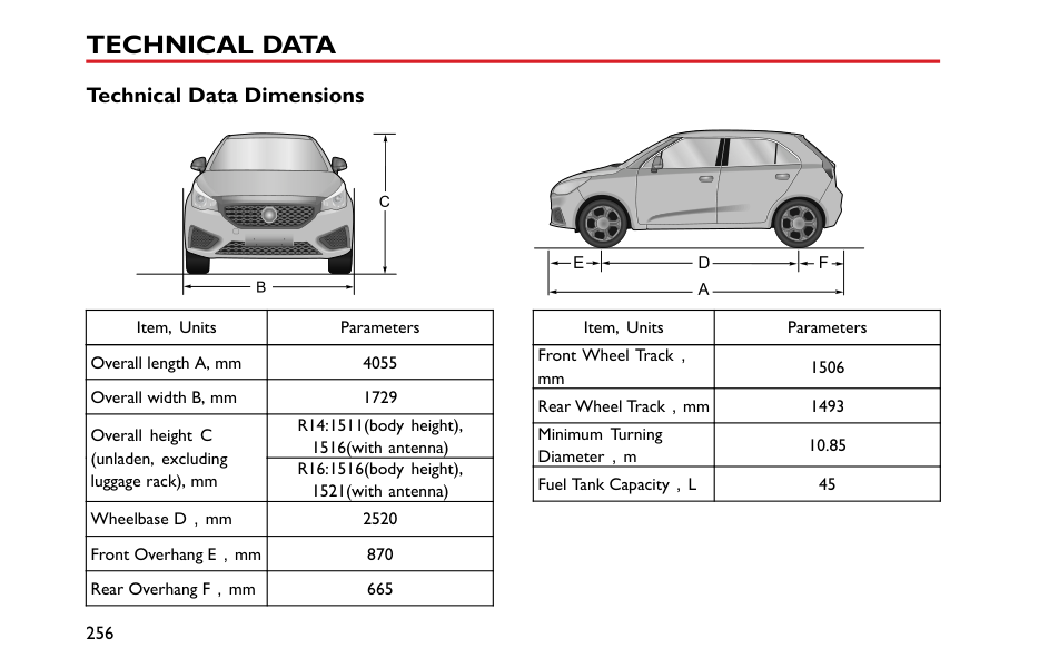
DEFECTIVE TYRES ARE DANGEROUS! DO NOT drive if any tyre is damaged, is excessively worn, or is inflated to an incorrect pressure.
Always drive with consideration for the condition of the tyres, and regularly inspect the tread and side walls for any sign of distortion (bulges), cuts or wear.
Note: If possible, protect tyres from contamination by oil, grease and fuel.
########## Tyre Pressure
############# Before a long distance journey, the tyre pressure must be checked.
Check the pressures (including the spare wheel) at least every month, when the tyres are cold.
If it is necessary to check the tyres when they are warm, you should expect the pressures to have increased by 0.3 to 0.4 bar (4.35 to 5.8 psi). In this circumstance, NEVER let
air out of the tyres in order to match the recommended pressures (cold).
########## Valves
Keep the valve caps screwed down firmly - they prevent dirt from entering the valve. Check the valve for leaks (listen for a tell-tale hissing) when you check the tyre pressure.
########## Punctured Tyres
If a sharp object penetrates the tyre and remains in it, the tyre may not leak. If you are aware of this occurring, reduce speed immediately and drive with caution until the spare wheel can be fitted, or repairs undertaken.
Note: If the sidewall of the tyre is damaged or distorted, replace the tyre immediately, DO NOT attempt a repair.
####### Tyre Wear Indicators
At the bottom of the original tyre tread, there is a 1.6 millimeter high wear mark perpendicular to the wheel rolling direction. These indicators are moulded into the tread pattern at several points around the circumference.
A mark on the side of a tyre, such as the upper case letter TWI or the triangle, indicating the position of the wear mark.
When the tread has worn down to 1.6 mm, the indicators will come to the surface of the tread pattern, producing the effect of a continuous band of rubber across the width of the tyre.
|IMPORTANT|
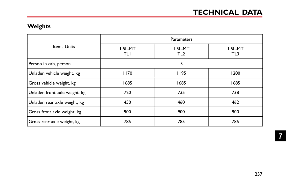
|---| |A tyre MUST be replaced as soon as a wear indicator becomes visible.|
####### Replacement Tyres
It is recommended to install the tyres consistent with the original specifications. DO NOT replace the tyres with tyres of any other type. Alternative tyres, of a different specification, may adversely affect the vehicle's driving characteristics and safety. In order to make your driving and safety better guarantee, it is suggested that you consult an MG Authorised Repairer.
Always have replacement wheels and tyres balanced before use.
####### Wheel Fitment Rotation
It is not recommended that you swap wheels from side to side or front to rear in order to equalise tyre wear. Your vehicle is fitted with Tyre Pressure Monitoring System
6
which means that each wheel is programmed to the relative position. If you do wish to swap wheels and tyres around on the vehicle please consult an MG Authorised Repairer as extra coding will be required.
####### Snow Chains
Unsuitable snow chains could damage the tyres, wheels, suspension, brakes or bodywork of your car.
In use, always observe the following precautions:
############# Note: If you drive on the snowy and icy roads, it is recommended to use winter tyres. Consult an MG Authorised Repairer for details.
Note: Directional tyres CANNOT be swapped from side to side. These tyres can be identified by an arrow symbol on the sidewall of the tyre. If you have any queries regarding swapping tyres please consult an MG Authorised Repairer.
Cleaning and Vehicle Care

Observe all safety precautions on cleaning products; do not drink fluids and keep them away from the eyes.
External Car Washing Your Car
Some high pressure cleaning systems will penetrate door, window and sunroof seals, and damage lock mechanisms. DO NOT aim water jets directly at components that might be easily damaged.
Do not clean the engine compartment with high pressure water since it may damage the electrical system of the vehicle.
In order to preserve the paint finish on your car, please observe the following care points:
If the car is particularly dirty, use a hose to flush grime and grit from the bodywork, prior to washing. Then, wash the car using cold or lukewarm water containing a good quality wash and wax shampoo. Always use plenty of water to ensure that grit is flushed from the surface and not ground into the paintwork. After washing, rinse the bodywork with clean water and dry off with a chamois leather.
Cleaning the underside
Note: DO NOT use a high pressure hose to clean the engine compartment – damage to the car’s electronic systems may occur.
From time to time, but particularly during winter months when salt has been used on the roads, use a hose to wash the underside of the car. Flush away accumulations of mud and thoroughly clean those areas where debris can easily collect (wheel arches and panel seams, for example).
6
|IMPORTANT| |---| |• Avoid cleaning the vehicle in direct sunlight.
• When cleaning the vehicle in winter avoid spraying water directly onto door locks and panel gaps due to risk of icing.
• Do not use rough sponges or cloth to clean the car, this will damage the paintwork finish.
• When cleaning the headlamps, do not use a dry cloth or sponge, use only warm soapy water.
|
|IMPORTANT| |---|

|• Please pay attention to the operating instructions of high pressure cleaner.
• Soft parts on the vehicle should be kept in a large enough distance from the high pressure cleaner.
|
########## Removing tar spots
Use white spirit to remove tar spots and stubborn grease stains from the paintwork. Then wash the area immediately with soapy water to remove all traces of the spirit.
Cleaning with a High Pressure Cleaner Note: Always read the manufacturers operating instructions.
########## Body Protection
After washing, examine the paintwork for damage. If the damage has revealed bare metal, use a colored primer first, then apply the correct colour base coat and finish off with a lacquer pencil, if appropriate. Carry out this treatment after washing but before polishing or waxing. More extensive damage to paint or bodywork must be repaired in accordance with the manufacturer’s recommendations. Failure to do this will invalidate the Anti-Corrosion Warranty. If in doubt, ask your MG Authorised Repairer.
When using high pressure washers, always ensure there is adequate distance between the spray nozzle and any soft materials, decals or rubber seals.
########## Polishing the Paintwork
############# DO NOT use car polish containing coarse abrasives – these will remove the paint film and damage the gloss finish.
Occasionally treat the paint surface with an approved polish containing the following properties:
Note: If possible, avoid applying polish or wax products to window glass and rubber seals.
########## Wiper Blades
Wash in warm soapy water. DO NOT use spirit or petrol based cleaners.
########## Windows and Mirrors
Regularly clean all windows, inside and out, using an approved glass cleaner.
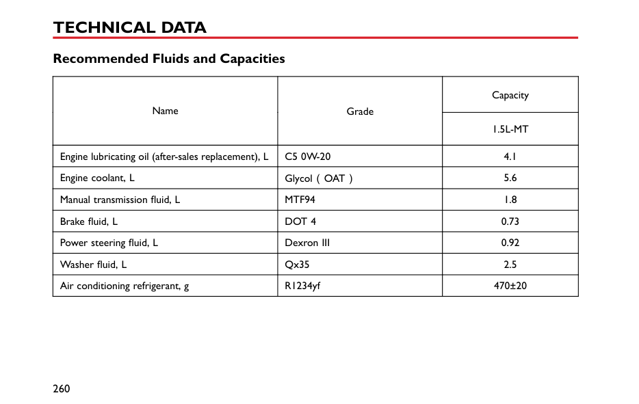
Windscreen:In particular, clean the outside of the screen with glass cleaner after washing the car with wash and wax products, and before fitting new wiper blades.
Rear screen:Clean the inside with a soft cloth, using a side to side motion to avoid damaging the heating elements.
Note: DO NOT scrape or use abrasive cleaners on the inside of the rear screen – this will damage the heating elements.
Mirrors:Wash with soapy water. Use a plastic scraper to remove ice. DO NOT use abrasive cleaning compounds or metal scraper.
########## Plastic Components
Any plastic components should be cleaned using conventional cleaning methods and not be treated with abrasive materials.
6
########## Paint Damage
Any paint damage or stonechips should be treated with suitable paint/lacquer materials immediately to avoid invalidating the Anti Corrosion Warranty.
########## Weather Strips and Rubber Seals
Any weather strips or rubber aperture seals should be treated with suitable materials (silica gel) if they are cleaned using strong detergents, this should avoid any sticking and maintain the service life of the seal.
########## Wheels
############# When cleaning the wheels any materials or water that contact the brake disc directly may effect braking efficiency.
In order to ensure the wheels are kept in optimum condition, they should be cleaned regularly.
Only use a recommended non-acidic propriety wheel cleaner. Always read the instructions on the product.
####### Cleaning the Interior Plastic materials
Clean plastic-faced materials with diluted upholstery cleaner, then wipe with a damp cloth.
Note: DO NOT polish dashboard components – these should remain non-reflective.
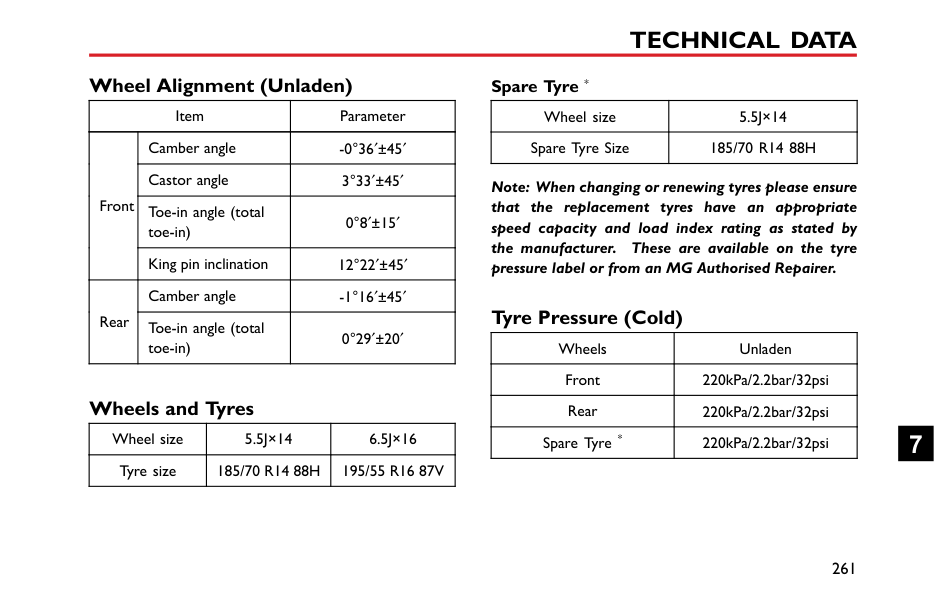
Carpet and fabrics Clean with diluted upholstery cleaner - test a concealed area first. Leather
Clean leather trim with warm water and a non-detergent soap. Dry and polish the leather with a dry, clean, lint-free cloth.
Note: DO NOT use petrol, detergents, furniture creams or polishes as cleaning agents.
Instrument Pack, Audio and Navigation Display Clean with a dry cloth only. DO NOT use cleaning fluids or sprays.
########## Airbag Module Covers
############# DO NOT allow these areas to be flooded with liquid and DO NOT use petrol, detergent, furniture cream or polishes.
To protect damage to the airbag SRS, the following areas should be cleaned sparingly with a damp cloth and upholstery cleaner ONLY:
enclose the side head impact protection modules. Seat Belts
DO NOT use bleaches, dyes or cleaning solvents on seat belts.
Extend the belts, then use warm water and a non-detergent soap to clean. Allow the belts to dry naturally; DO NOT retract them or use the car until they are completely dry.
6
Technical Data
7
#### Technical Data Dimensions


C
FE B
D A
|Item, Units|Parameters| |---|---| |Overall length A, mm|4055| |Overall width B, mm|1729| |Overall height C (unladen, excluding luggage rack), mm
|R14:1511(body height), 1516(with antenna)| |Overall height C (unladen, excluding luggage rack), mm
|R16:1516(body height), 1521(with antenna)| |Wheelbase D,mm|2520| |Front Overhang E,mm|870| |Rear Overhang F,mm|665|
|Item, Units|Parameters| |---|---| |Front Wheel Track, mm|1506| |Rear Wheel Track,mm|1493| |Minimum Turning Diameter,m|10.85| |Fuel Tank Capacity,L|45|
#### Weights
|Item, Units|Parameters|Parameters|Parameters| |---|---|---|---| |Item, Units|1.5L-MT TL1|1.5L-MT TL2|1.5L-MT TL3| |Person in cab, person|5|5|5| |Unladen vehicle weight, kg|1170|1195|1200| |Gross vehicle weight, kg|1685|1685|1685| |Unladen front axle weight, kg|720|735|738| |Unladen rear axle weight, kg|450|460|462| |Gross front axle weight, kg|900|900|900| |Gross rear axle weight, kg|785|785|785|
####### Towing Weights
|Item, units|Parameter|Parameter|Parameter| |---|---|---|---| |Item, units|1.5L-MT TL1|1.5L-MT TL2|1.5L-MT TL3| |Towing limit un-braked, kg|200|200|200| |Towing limit braked, kg|200|200|200|
#### Major Parameters of Engine
|Vehicle
|Parameter| |---|---| |Vehicle
|1.5L-MT| |Bore × Stroke, mm × mm|75×84.8| |Capacity, Litres|1.498| |Compression ratio|11.5:1| |Fuel type, RON|Unleaded 95 RON to EN228 SPEC|
#### Recommended Fluids and Capacities
|Name|Grade|Capacity| |---|---|---| |Name|Grade|1.5L-MT| |Engine lubricating oil (after-sales replacement), L|C5 0W-20|4.1| |Engine coolant, L|Glycol(OAT)|5.6| |Manual transmission fluid, L|MTF94|1.8| |Brake fluid, L|DOT 4|0.73| |Power steering fluid, L|Dexron III|0.92| |Washer fluid, L|Qx35|2.5| |Air conditioning refrigerant, g|R1234yf|470±20|
Wheel Alignment (Unladen)
|Item|Item|Parameter| |---|---|---| |Front|Camber angle|-0°36 ±45| |Front|Castor angle|3°33 ±45| |Front|Toe-in angle (total toe-in)|0°8 ±15| |Front|King pin inclination|12°22 ±45| |Rear|Camber angle|-1°16 ±45| |Rear|Toe-in angle (total toe-in)|0°29 ±20|
Wheels and Tyres
|Wheel size|5.5J×14|6.5J×16| |---|---|---| |Tyre size|185/70 R14 88H|195/55 R16 87V|
Spare Tyre *
|Wheel size|5.5J×14| |---|---| |Spare Tyre Size|185/70 R14 88H|
Note: When changing or renewing tyres please ensure that the replacement tyres have an appropriate speed capacity and load index rating as stated by the manufacturer. These are available on the tyre pressure label or from an MG Authorised Repairer.
#### Tyre Pressure (Cold)
|Wheels|Unladen| |---|---| |Front|220kPa/2.2bar/32psi| |Rear|220kPa/2.2bar/32psi| |Spare Tyre *|220kPa/2.2bar/32psi|