
Ask AI
— answers from the official manualAnswers from the official manual.
Common questions
Common Questions
19 totalHow does the Auto Hold system indicate a failure on the instrument panel?
The AUTO HOLD system failure is indicated by a dedicated warning lamp on the instrument panel. Separate indicator states show when the system is operating normally, when it is in standby state, and when it has a failure. If you see the failure indication, the system is not functioning correctly. (Page 39)
How do I adjust the headlamp levelling based on vehicle load?
Headlamp levelling is adjusted using a switch with positions 0 through 3 depending on vehicle load. Position 0 is for driver only or driver and front passenger; position 1 is for all seats occupied with no boot load; position 2 is for all seats occupied plus an evenly distributed load in the boot; and position 3 is for driver only plus an evenly distributed load in the boot. (Page 50)
What are the conditions required for the Smart Main Beam (Automatic High Beam) system to activate?
Three conditions must be met for the smart main beam system to activate: the lighting lever switch must be placed in AUTO position with dipped beams automatically on, the vehicle must be running at a speed exceeding 40 km/h (20 mph), and the front fog lights must not be turned on. The system uses the front view camera to detect light intensity from vehicles ahead. (Page 52)
What happens if the high-voltage battery pack warning lamp flashes while I am driving?
If the power battery warning lamp flashes, it indicates the high voltage battery temperature is too high. You should stop the car as soon as safety permits, power off the vehicle, leave the vehicle immediately, and contact an MG Authorised Repairer at the earliest opportunity. If the lamp illuminates solidly rather than flashing, it indicates a serious malfunction of the battery system and the same urgent actions apply. (Page 46)
How do I properly dispose of or recycle the high-voltage battery pack?
The high-voltage battery pack MUST be recycled by an MG Authorised Repairer or a professional approved dismantling agent. The battery pack contains several lithium-based cells and is classed as a Category 9 hazardous material, meaning it must be transported by vehicles qualified for Category 9 hazardous materials. Arbitrary disposal may cause pollution, hazard, and damage to the environment. (Page 23)
What should I do if the windscreen washers fail to deliver fluid while the wipers are operating?
Release the lever immediately if the washers fail to deliver screen wash solution, as dirt or ice may have blocked the jets. Releasing the lever will prevent the wipers from operating, avoiding the risk of visibility being impaired by dirt smearing across an unwashed windscreen. (Page 58)
Show 13 more questions
What does the warning message about high-voltage battery imply?
How do I check for vehicle malfunctions according to warning lights?
What safety instructions should I follow if the vehicle catches fire?
How do I ensure the best battery health in my hybrid vehicle?
How do I operate the hazard warning lights?
How do I adjust my seat belts for safety?
How do I troubleshoot issues if ABS fails?
How do I switch between main beam and dipped beam headlights?
What temperature range is recommended for operating the MG ZS Hybrid+ to protect the high-voltage battery?
What should I do if the Engine Coolant Temperature warning lamp illuminates red while driving?
What does it mean if the Tyre Pressure Monitoring System (TPMS) warning lamp flashes and then stays on?
What should I do immediately after a collision involving the MG ZS Hybrid+?
How do I handle a low fuel situation?
Full Manual
337 pages
MG ZS/MG ZS Hybrid+ Version 1.0 December 27,2023 1 1
Contents
MG ZS/MG ZS Hybrid+ .................................................................................................................1 1 Instructions Before Using the Vehicle ....................................................................... 17 Introduction to User's Handbook...............................................................................................18 The Owner's Handbook .......................................................................................................................................................18 Status at Time of Printing .....................................................................................................................................................18 Warranty and Service............................................................................................................................................................18 Symbols Used ..........................................................................................................................................................................19 In an Emergency......................................................................................................................................................................20 Vehicle Identification Information..............................................................................................21 Vehicle Identification Markings(Gasoline) .........................................................................................................................21 Vehicle Identification Markings(HEV).................................................................................................................................21 Vehicle Identification Plate....................................................................................................................................................22 Instructions for Use of Hybrid Vehicle*......................................................................................23 Effects of Ambient Temperature .........................................................................................................................................23 Instructions for High Voltage Battery Pack Recycling....................................................................................................23 Precautions in the Event of an Accident ...........................................................................................................................24 High Voltage System...............................................................................................................................................................25 Crash Outage Control ..........................................................................................................................................................27 2
Contents
2 Brief Introduction to Vehicle Functions .................................................................... 29 Instrument Pack ...........................................................................................................................30 Instrument Message Display Operation ............................................................................................................................30 Instrument Pack - Type A *...................................................................................................................................................31 Instrument Pack - Type B * ...................................................................................................................................................33 Warning Message....................................................................................................................................................................34 Warning Lights and Indicators....................................................................................................35 Lights and Switches......................................................................................................................49 Master Lighting Switch...........................................................................................................................................................49 Headlamp Levelling.................................................................................................................................................................50 Switching between Main Beam and Dipped Beam Headlamps.....................................................................................51 Turn Signal Lamps ...................................................................................................................................................................53 Fog Lamps.................................................................................................................................................................................54 Hazard Warning Lamps.........................................................................................................................................................55 Wipers and Washers....................................................................................................................56 Windscreen Wiper and Washer Operation ....................................................................................................................56 Wash and wipe........................................................................................................................................................................57 Rear Window Wiper and Washer Operation* ...............................................................................................................58 Horn...............................................................................................................................................60 3
Contents
Rearview Mirrors..........................................................................................................................61 Exterior Rearview Mirrors...................................................................................................................................................61 Interior Rearview Mirror......................................................................................................................................................63 Windows........................................................................................................................................64 Power Operated Window Switch ......................................................................................................................................64 Window Operation................................................................................................................................................................65 Sunroof* .............................................................................................................................................67 Instructions ..............................................................................................................................................................................67 Sunroof Operation .................................................................................................................................................................67 Sunvisor .........................................................................................................................................72 Interior Lighting ...........................................................................................................................73 AUTO ON Function..............................................................................................................................................................74 Power Socket ................................................................................................................................75 Front Console Power Socket...............................................................................................................................................75 Rear Console Power Socket*...............................................................................................................................................76 Power Socket of Interior Rearview Mirrors*...................................................................................................................76 Storage Devices ............................................................................................................................77 Instructions for Use ...............................................................................................................................................................77 4
Contents
Glove Box.................................................................................................................................................................................77 Storage Box..............................................................................................................................................................................78 Glasses Box*.............................................................................................................................................................................78 Cup Holder....................................................................................................................................80 Centre Console Cup Holder...............................................................................................................................................80 3 Preparations for Trip ................................................................................................... 83 Keys................................................................................................................................................84 Overview..................................................................................................................................................................................84 Alarm System...............................................................................................................................87 Power Immobiliser .................................................................................................................................................................87 Body Anti-theft System .........................................................................................................................................................87 Alcohol Interlocks* .......................................................................................................................91 Tailgate ..........................................................................................................................................92 Tailgate Emergency Open .....................................................................................................................................................93 Load Carrying...............................................................................................................................95 Loadspace Loading..................................................................................................................................................................95 Internal Loading.......................................................................................................................................................................96 Towing* ..........................................................................................................................................97 5
Contents
Fuel System...................................................................................................................................99 Fuel Requirements..................................................................................................................................................................99 Fuel Filler ................................................................................................................................................................................100 Refueling..................................................................................................................................................................................100 Steering System Adjustment....................................................................................................101 Steering Wheel Position Adjustment...............................................................................................................................101 Electric Power Steering.......................................................................................................................................................101 Electric Power Steering Module Angle Initialisation.....................................................................................................102 Steering Wheel Heating*.....................................................................................................................................................102 4 Drive the Vehicle........................................................................................................ 103 Power Start/Stop........................................................................................................................104 Power start (Key Start)*......................................................................................................................................................104 Power starting(Keyless Start)*.....................................................................................................................................105 Power starting ......................................................................................................................................................................106 Stop power system...............................................................................................................................................................108 Electric Drive Transmission* .....................................................................................................109 Gear Shift Control................................................................................................................................................................109 Protection Mode...................................................................................................................................................................110 6
Contents
Manual Transmission*.................................................................................................................111 Gear Shift Indications...........................................................................................................................................................112 Continuously Variable Automatic Transmission (CVT)*........................................................113 Instructions for Use .............................................................................................................................................................113 Gear Shift................................................................................................................................................................................113 Protection Mode...................................................................................................................................................................117 Drive Mode* ................................................................................................................................118 Parking Brake..............................................................................................................................120 Parking Brake System - Electronic Parking Brake (EPB )*............................................................................................120 Parking Brake System - Manual Parking Brake*..............................................................................................................122 Service Brake..............................................................................................................................123 Energy Regeneration* ................................................................................................................125 5 Leave Home Safe ....................................................................................................... 127 Seat Belt......................................................................................................................................128 Protection Provided by Seat Belts ....................................................................................................................................129 Wearing Seat Belts................................................................................................................................................................130 Children and Seat Belts.......................................................................................................................................................133 Seat Belt Pre-tensioners......................................................................................................................................................135 7
Contents
Seat Belt Checks, Maintenance and Replacement.........................................................................................................136 Airbag ..........................................................................................................................................139 Overview................................................................................................................................................................................139 Airbag Deployment ..............................................................................................................................................................140 Conditions in Which Airbags Will Not Deploy ............................................................................................................145 Service and Replacement of Airbags................................................................................................................................149 Child Restraints ..........................................................................................................................151 Important Safety Instructions about Using Child Restraints ......................................................................................151 Fixing Child Restraints.........................................................................................................................................................155 Child Restraint Groups and Installation Position..........................................................................................................158 Child Proof Locks .......................................................................................................................162 Body Stability Control System..................................................................................................163 Resuming the body stability control system...................................................................................................................164 Anti-lock Brake System (ABS) .................................................................................................165 Auxiliary Brake System .............................................................................................................166 Auto Hold* ..................................................................................................................................167 Hill Hold Control (HHC)...........................................................................................................169 Hill Descent Control (HDC) .....................................................................................................170 8
Contents
Active Rollover Protection (ARP) ............................................................................................173 Emergency Braking Hazard Warning Strobe (HAZ)*............................................................174 Multi-Collision Brake System(MCB)*.......................................................................................175 Tyre Pressure Monitoring System (TPMS)*.............................................................................176 6 Comfortable Experience........................................................................................... 179 Seat Adjustment.........................................................................................................................180 Front Seats .............................................................................................................................................................................180 Rear Seats...............................................................................................................................................................................182 Head Restraint Operation..................................................................................................................................................182 Ventilation System .....................................................................................................................184 A/C Filter Element................................................................................................................................................................185 Vents ........................................................................................................................................................................................185 A/C Control Panel-1*..................................................................................................................187 A/C Control Panel-2*..................................................................................................................188 Shortcut Key of A/C On/Off..............................................................................................................................................188 Defrost/Demist Button .......................................................................................................................................................188 Heated Rear Window Button............................................................................................................................................188 A/C Control Interface................................................................................................................190 9
Contents
System On/Off.......................................................................................................................................................................190 AUTO A/C mode* ..........................................................................................................................................................................190 Heat Pump Heatin On/Off..................................................................................................................................................190 Air Distribution Mode.........................................................................................................................................................190 Air Recirculation Mode.......................................................................................................................................................191 Defrost/Demist Mode* ........................................................................................................................................................191 A/C Settings*..........................................................................................................................................................................191 Blower Speed Control.........................................................................................................................................................192 Temperature Control...........................................................................................................................................................192 Radio*...........................................................................................................................................193 MOGI Screen.........................................................................................................................................................................193 Steering Wheel Entertainment Control Buttons..........................................................................................................193 Notes On Playing Storage Media Mode For USB Music..............................................................................................194 Connecting/Disconnecting a USB Storage Device .......................................................................................................195 Bluetooth Pairing and Connection ...................................................................................................................................195 Intelligent Display Interface* .....................................................................................................196 Steering Wheel Entertainment Control Buttons..........................................................................................................196 Basic Operations...................................................................................................................................................................197 Main System Interface..........................................................................................................................................................197 10
Contents
Bluetooth Pairng and Connection ....................................................................................................................................198 Vehicle-Mobile Phone Interconnection............................................................................................................................199 7 Intelligent Driver Assistance..................................................................................... 201 Instructions for Intelligent Driver Assistance .........................................................................202 Disclaimers for Intelligent Driver Assistance Function................................................................................................202 Camera and Radar .....................................................................................................................204 Driver Assistance Camera..................................................................................................................................................204 Driver Assistance Radar......................................................................................................................................................207 Constant Speed Cruise Control* ..............................................................................................209 Adaptive Cruise Control(ACC )* ..............................................................................................212 Adaptive Cruise Activation.................................................................................................................................................212 Adaptive Cruise Target Following Distance Adjustment.............................................................................................214 Adaptive Cruise Target Speed Adjustment.....................................................................................................................214 Adaptive Cruise Pause.........................................................................................................................................................215 Automatic Deactivation of Adaptive Cruise ..................................................................................................................215 Adaptive Cruise Override ..................................................................................................................................................216 Adaptive Cruise Resume.....................................................................................................................................................216 Clearing Target Speed Memory.........................................................................................................................................216 11
Contents
Special Driving Environments.............................................................................................................................................217 Intelligent Cruise Assit(ICA )* ..................................................................................................220 Intelligent Overspeed Warning* ...............................................................................................223 Speed Limit Assistance System*...............................................................................................225 Speed Limit Assistance System..........................................................................................................................................225 Lane Departure Assist*..............................................................................................................229 Front Collision Assist*................................................................................................................232 Blind Zone Safety Assit( ((Bsd 、
、、Lca )
) )* ...............................................................................234 Rear Cross Traffic Alert( ((Rcta )
) )* ........................................................................................236 Door opening warning( ((Dow )
) )* ...........................................................................................238 Rear Collision Warning( ((Rcw )
) )* ..........................................................................................240 Ultrasonic Sensor Parking Aid*.................................................................................................241 Parking Camera* ........................................................................................................................243 360 Around View Monitor System* ..........................................................................................244 Drive Fatigue Monitoring System* ...........................................................................................245 8 Road Emergency Response....................................................................................... 247 Hazard Warning Devices...........................................................................................................248 12
Contents
Warning Triangle...................................................................................................................................................................248 Emergency Starting ...................................................................................................................249 eCall-SOS Emergency Assistance* ...........................................................................................253 Vehicle Recovery.........................................................................................................................256 Towing Vehicle.......................................................................................................................................................................256 Transporting the Vehicle .....................................................................................................................................................258 Tyre Repair and Tyre Replace* ..................................................................................................260 Tyre repair tool*....................................................................................................................................................................260 Tyre repair tool*....................................................................................................................................................................260 Tyre Repair*............................................................................................................................................................................261 Spare Wheel and Tools*......................................................................................................................................................263 Spare Wheel Replacement Tool*.......................................................................................................................................263 Wheel Replacement* ...........................................................................................................................................................264 9 Maintenance ............................................................................................................... 269 Maintenance Instructions ..........................................................................................................270 Regular Maintenance............................................................................................................................................................270 High Voltage Battery Pack* .......................................................................................................274 Precautions and restricted conditions for use of battery ...........................................................................................274 13
Contents
Bonnet .........................................................................................................................................276 Opening the Bonnet.............................................................................................................................................................276 Closing the Bonnet...............................................................................................................................................................276 Bonnet Open Alarm* ...........................................................................................................................................................276 Front Compartment ..................................................................................................................278 Engine Oil....................................................................................................................................281 Engine Oil ..............................................................................................................................................................................281 Engine Oil Check and Refill................................................................................................................................................282 Engine Oil Specification.......................................................................................................................................................283 Catalytic Converter ...................................................................................................................284 Cooling System...........................................................................................................................286 Coolant Check and Top Up ...............................................................................................................................................286 Coolant Specification...........................................................................................................................................................288 Brake............................................................................................................................................289 Brake Fluid Check and Top Up..........................................................................................................................................290 Brake Fluid Specification .....................................................................................................................................................291 Fuse Replacement......................................................................................................................292 Fuse..........................................................................................................................................................................................292 Passenger Compartment Fuse Box ..................................................................................................................................293 14
Contents
Front Compartment Fuse Box ..........................................................................................................................................296 12V Battery.................................................................................................................................300 Battery Maintenance ............................................................................................................................................................300 Battery Replacement............................................................................................................................................................301 Bulb Replacement ......................................................................................................................302 Bulb Specification..................................................................................................................................................................302 Bulb Replacement..........................................................................................................................................................302 Washer ........................................................................................................................................309 Washer Fluid Check and Top Up......................................................................................................................................309 Washer Nozzles....................................................................................................................................................................310 Wipers .........................................................................................................................................311 Wiper Blades .........................................................................................................................................................................311 Windscreen Wiper Blade Replacement..........................................................................................................................312 Rear Window Wiper Blade Replacement.......................................................................................................................313 Replacing the Smart Key Battery.............................................................................................314 Tyres.............................................................................................................................................317 Overview................................................................................................................................................................................317 Caring for Your Tyres ..........................................................................................................................................................319 Tyre Wear Indicators...........................................................................................................................................................320 15
Contents
Wheel Fitment Rotation.....................................................................................................................................................321 Tyre/Snow Chains.................................................................................................................................................................322 Cleaning and Caring...................................................................................................................323 Exterior...................................................................................................................................................................................323 Cleaning the Interior............................................................................................................................................................327 10 Technical Data.......................................................................................................... 329 Technical Data Dimensions .......................................................................................................330 Complete Vehicle Mass Parameters ........................................................................................332 Towing Weights.....................................................................................................................................................................334 Main Engine Parameters ...........................................................................................................336 Dynamic Performance Parameters..........................................................................................338 Parameters of Drive Motor*......................................................................................................339 Recommended Fluids and Capacities ......................................................................................340 Wheel Alignment (Unladen Condition) ..................................................................................342 Wheels and Tyres .......................................................................................................................343 Tyre Pressures (Cold).................................................................................................................344 16
Instructions Before Using the Vehicle Introduction to User's Handbook 18 Vehicle Identification Information 21 Instructions for Use of Hybrid Vehicle* 23 1
Instructions Before Using The Vehicle
Introduction to User's Handbook The Owner's Handbook This Handbook describes all of the vehicles and standard equipment specification within the model range. Some information may be inapplicable to your individual model. If you have any questions about the operation and parameters of the vehicle, please contact anMg
Authorised Repairer will be glad to advise you. The illustrations in the Owner's Handbook are for reference only. The information contained in this Handbook may vary slightly depending on the vehicle configuration, software version and sales regions. Status at Time of Printing MG operates a policy of constant product improvement and therefore reserves the right to change specifications without notice at any time. Whilst every effort is made to ensure complete accuracy of the information in this publication, no liabilities for inaccuracies or the consequences thereof, including loss or damage to property, or injury to persons, can be accepted by the manufacturer or the MG Authorised Repairer who supplied the publication, except in respect of personal injury caused by the negligence of the manufacturer or the MG Authorised Repairer . Warranty and Service Please consult the owners section at MG website for the warranty terms and conditions, warranty statement,exemptions and service item renewal schedule. 18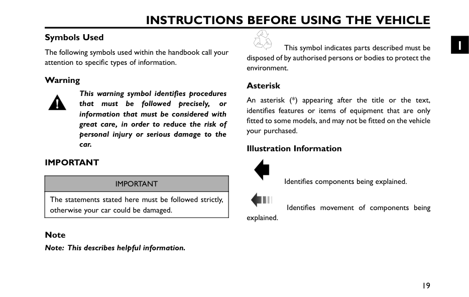
Instructions Before Using The Vehicle
Symbols Used The following symbols used within the handbook call your attention to specific types of information. Warning This warning symbol identifies procedures that must be followed precisely, or information that must be considered with great care, in order to reduce the risk of personal injury or serious damage to the car.Important
Important
The statements stated here must be followed strictly, otherwise your car could be damaged. Note Note: This describes helpful information. This symbol indicates parts described must be disposed of by authorised persons or bodies to protect the environment. Asterisk An asterisk (*) appearing after the title or the text, identifies features or items of equipment that are only fitted to some models, and may not be fitted on the vehicle your purchased. Illustration Information Identifies components being explained. Identifies movement of components being explained. 19 1
Instructions Before Using The Vehicle
In an EmergencyImportant
Remember the breakdown safety code If a breakdown occurs while travelling: • Wherever possible, consistent with road safety and traffic conditions, the car should be moved off the main thoroughfare, preferably into a lay-by. If a breakdown occurs on a motorway, pull well over to the inside of the hard shoulder. • Switch on hazard lights. • If available, position a warning triangle or a flashing amber light 50 to 150 metres (150 to 500 ft) behind your vehicle to warn approaching traffic. Note it is a legal requirement of some countries that a warning triangle is carried in the vehicle, if in doubt consult the local highways agency for further information. • Consider evacuating passengers through nearside doors onto the verge to reduce risk of injury in the event of collision. 20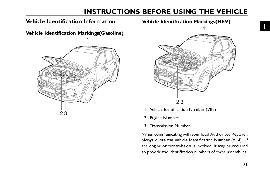
Instructions Before Using The Vehicle
Vehicle Identification Information Vehicle Identification Markings(Gasoline) Vehicle Identification Markings(HEV) 1 Vehicle Identification Number (VIN) 2 Engine Number 3 Transmission Number When communicating with your local Authorised Repairer, always quote the Vehicle Identification Number (VIN) . If the engine or transmission is involved, it may be required to provide the identification numbers of these assemblies. 21 1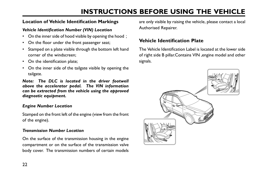
Instructions Before Using The Vehicle
Location of Vehicle Identification Markings Vehicle Identification Number (VIN) Location • On the inner side of hood visible by opening the hood; • On the floor under the front passenger seat; • Stamped on a plate visible through the bottom left hand corner of the windscreen; • On the identification plate; • On the inner side of the tailgate visible by opening the tailgate. Note: The DLC is located in the driver footwell above the accelerator pedal. The VIN information can be extracted from the vehicle using the approved diagnostic equipment. Engine Number Location Stamped on the front left of the engine (view from the front of the engine). Transmission Number Location On the surface of the transmission housing in the engine compartment or on the surface of the transmission valve body cover. The transmission numbers of certain models are only visible by raising the vehicle, please contact a local Authorised Repairer. Vehicle Identification Plate The Vehicle Identification Label is located at the lower side of right side B pillar.Contains VIN ,engine model and other signals. 22
Instructions Before Using The Vehicle
Instructions for Use of Hybrid Vehicle* Effects of Ambient Temperature Extremely high or low temperatures will affect the performance of the high-voltage battery pack and the vehicle. It is recommended that where possible the vehicle should be used within the temperature range of -30℃~55℃. This will ensure that the vehicle is in the optimum working state, and help extend the service life of the high-voltage battery pack. Instructions for High Voltage Battery Pack Recycling If you decide not to use the recommended MG Authorised Repairer to dispose of your high voltage battery, the responsibility of the consequences of environmental pollution or accidents must be bourne by the owner. The high-voltage battery pack contains several lithium based battery cells. Arbitrary disposal may cause pollution, hazard and damage to the environment. The high-voltage battery pack MUST be recycled by an MG Authorised Repairer or a professional approved dismantling agent. Please refer to the following information and requirements. • ONLY qualified personnel should work with the high voltage system - there is danger of DEATH. • High voltage safety: the high-voltage battery pack contains high voltage components such as lithium battery packs and high voltage wiring harness; DO NOT attempt to dismantle any area of this system, suitably trained professional staff must observe insulation safety protection before working on or near the high voltage system. 23 1
Instructions Before Using The Vehicle
• Transportation: The high-voltage battery pack is classed as a Category 9 hazardous material and must be transported by vehicles qualified in transporting Category 9 hazardous materials. • Storage: All HV components (including batteries) should be stored at room temperature and in a dry environment. They must be kept away from dangerous sources, such as flammable objects, heat and water sources. It is strongly recommended that the used high-voltage battery pack generated from vehicle scrappage or any other reasons should be disposed of by an MG Authorised Repairer. Please consult an MG Authorised Repairer for more details. Precautions in the Event of an Accident Ensure the vehicle is in P gear and the vehicle power system/ignition is OFF. If any cables on the vehicle are exposed, in order to prevent electric shock or even death DO NOT make any contact with any cable. If the vehicle catches fire, and the fire is small and slow, a carbon dioxide extinguisher can be used to extinguish the fire, and contact the fire services as soon as possible; if the fire is large and spreading quickly, immediately evacuate the vehicle and contact the fire services immediately. If the vehicle is involved in a collision, it cannot be re-started, the negative cable of 12V battery and Manual Service Disconnect (MSD) MUST be disconnected prior to rescue. 24
Instructions Before Using The Vehicle
When the vehicle is completely or partially immersed in water, switch off the vehicle power system and evacuate the car immediately. The negative cable of 12V battery and Manual Service Disconnect(Msd)
Must
be disconnected prior to rescue or as soon as the vehicle is refloated/removed from the water. Observe the water/vehicle for any abnormal signs such as excessive bubbles or noises, this may indicate battery short circuit issues. If no signs are evident, there should not be a shock risk from the bodywork and recovery can commence. After the accident is resolved, please contact an MG Authorised Repairer for maintenance. High Voltage System All high voltage components have warning labels attached - please observe these warnings and any requirements when operating within or close to these areas. ONLY qualified personnel should work on, or with, the high voltage system - there is danger of DEATH. 25 1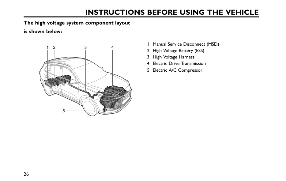
Instructions Before Using The Vehicle
The high voltage system component layout is shown below: 1 Manual Service Disconnect (MSD) 2 High Voltage Battery (ESS) 3 High Voltage Harness 4 Electric Drive Transmission 5 Electric A/C Compressor 26
Instructions Before Using The Vehicle
Crash Outage Control If a serious collision occurs, the vehicle will automatically cut off the high-voltage output to ensure personal safety. 27 1
Brief Introduction to Vehicle Functions Instrument Pack 30 Warning Lights and Indicators 35 Lights and Switches 49 Wipers and Washers 56 Horn 60 Rearview Mirrors 61 Windows 64 Sunroof* 67 Sunvisor 72 Interior Lighting 73 Power Socket 75 Storage Devices 77 Cup Holder 80 2
Brief Introduction To Vehicle Functions
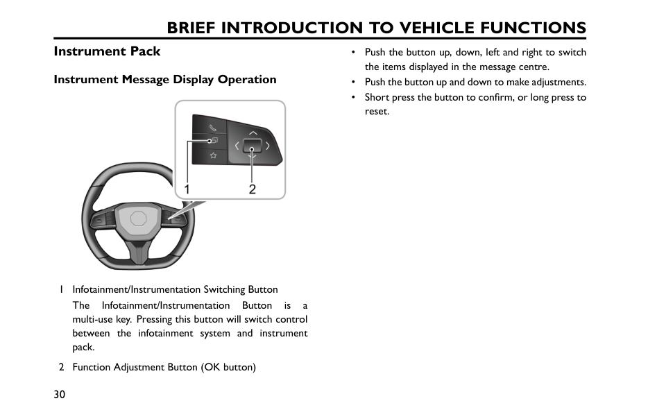
Instrument Pack Instrument Message Display Operation 1 Infotainment/Instrumentation Switching Button The Infotainment/Instrumentation Button is a multi-use key. Pressing this button will switch control between the infotainment system and instrument pack. 2 Function Adjustment Button (OK button) • Push the button up, down, left and right to switch the items displayed in the message centre. • Push the button up and down to make adjustments. • Short press the button to confirm, or long press to reset. 30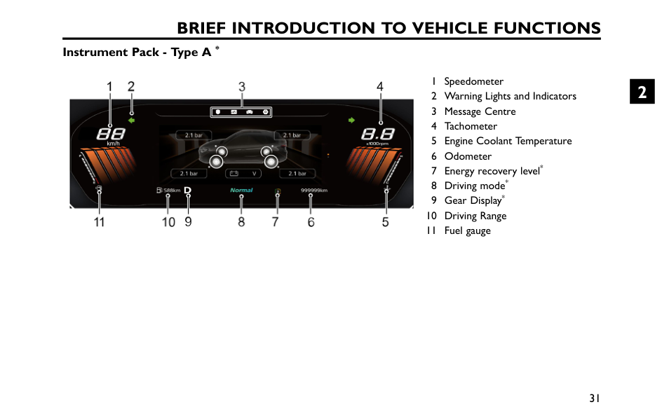
Brief Introduction To Vehicle Functions
Instrument Pack - Type A * 1 Speedometer 2 Warning Lights and Indicators 3 Message Centre 4 Tachometer 5 Engine Coolant Temperature 6 Odometer 7 Energy recovery level* 8 Driving mode* 9 Gear Display* 10 Driving Range 11 Fuel gauge 31 2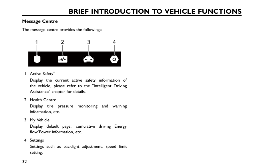
Brief Introduction To Vehicle Functions
Message Centre The message centre provides the followings: 1 Active Safety* Display the current active safety information of the vehicle, please refer to the "Intelligent Driving Assistance" chapter for details. 2 Health Centre Display tire pressure monitoring and warning information, etc. 3 My Vehicle Display default page, cumulative driving Energy flow*Power information, etc. 4 Settings Settings such as backlight adjustment, speed limit setting. 32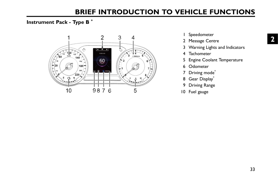
Brief Introduction To Vehicle Functions
Instrument Pack - Type B * 1 Speedometer 2 Message Centre 3 Warning Lights and Indicators 4 Tachometer 5 Engine Coolant Temperature 6 Odometer 7 Driving mode* 8 Gear Display* 9 Driving Range 10 Fuel gauge 33 2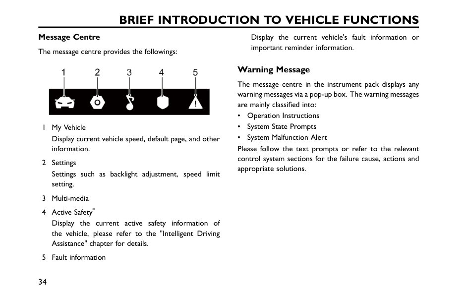
Brief Introduction To Vehicle Functions
Message Centre The message centre provides the followings: 1 My Vehicle Display current vehicle speed, default page, and other information. 2 Settings Settings such as backlight adjustment, speed limit setting. 3 Multi-media 4 Active Safety* Display the current active safety information of the vehicle, please refer to the "Intelligent Driving Assistance" chapter for details. 5 Fault information Display the current vehicle's fault information or important reminder information. Warning Message The message centre in the instrument pack displays any warning messages via a pop-up box. The warning messages are mainly classified into: • Operation Instructions • System State Prompts • System Malfunction Alert Please follow the text prompts or refer to the relevant control system sections for the failure cause, actions and appropriate solutions. 34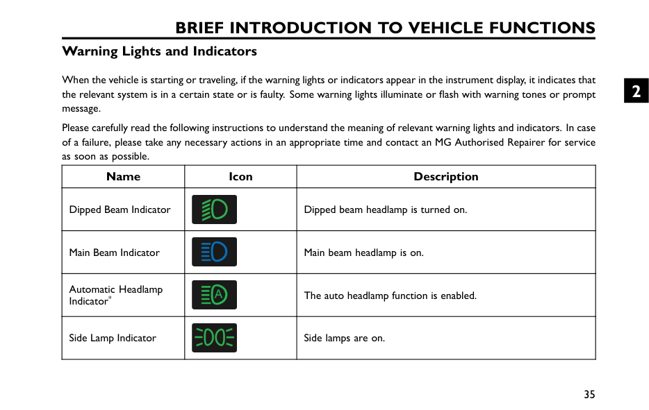
Brief Introduction To Vehicle Functions
Warning Lights and Indicators When the vehicle is starting or traveling, if the warning lights or indicators appear in the instrument display, it indicates that the relevant system is in a certain state or is faulty. Some warning lights illuminate or flash with warning tones or prompt message. Please carefully read the following instructions to understand the meaning of relevant warning lights and indicators. In case of a failure, please take any necessary actions in an appropriate time and contact an MG Authorised Repairer for service as soon as possible. Name Icon Description Dipped Beam Indicator Dipped beam headlamp is turned on. Main Beam Indicator Main beam headlamp is on. Automatic Headlamp Indicator* The auto headlamp function is enabled. Side Lamp Indicator Side lamps are on. 35 2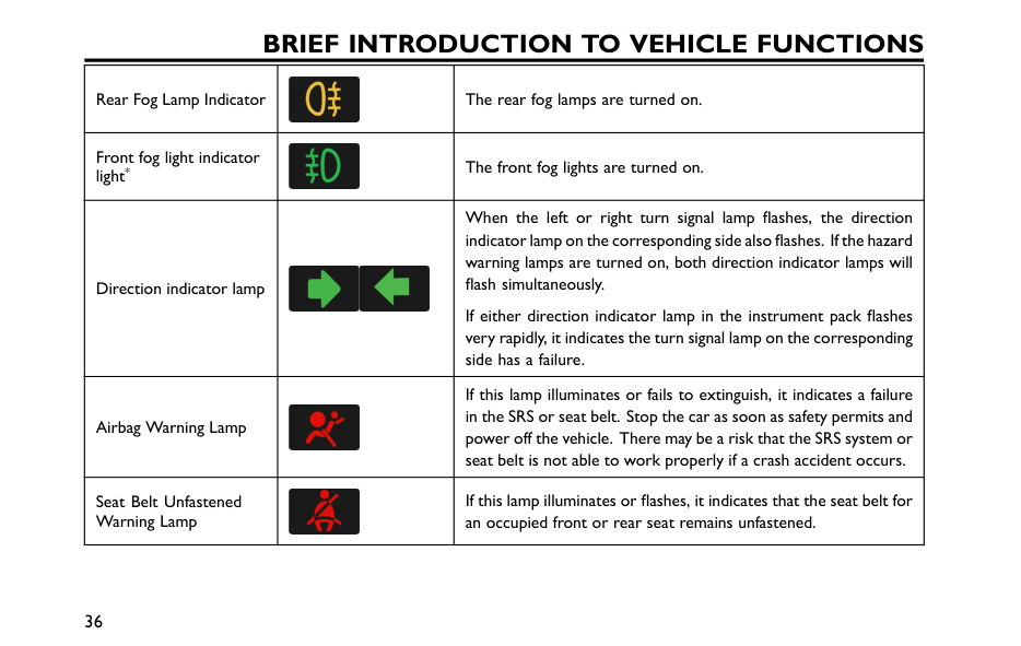
Brief Introduction To Vehicle Functions
Rear Fog Lamp Indicator The rear fog lamps are turned on. Front fog light indicator light* The front fog lights are turned on. Direction indicator lamp When the left or right turn signal lamp flashes, the direction indicator lamp on the corresponding side also flashes. If the hazard warning lamps are turned on, both direction indicator lamps will flash simultaneously. If either direction indicator lamp in the instrument pack flashes very rapidly, it indicates the turn signal lamp on the corresponding side has a failure. Airbag Warning Lamp If this lamp illuminates or fails to extinguish, it indicates a failure in the SRS or seat belt. Stop the car as soon as safety permits and power off the vehicle. There may be a risk that the SRS system or seat belt is not able to work properly if a crash accident occurs. Seat Belt Unfastened Warning Lamp If this lamp illuminates or flashes, it indicates that the seat belt for an occupied front or rear seat remains unfastened. 36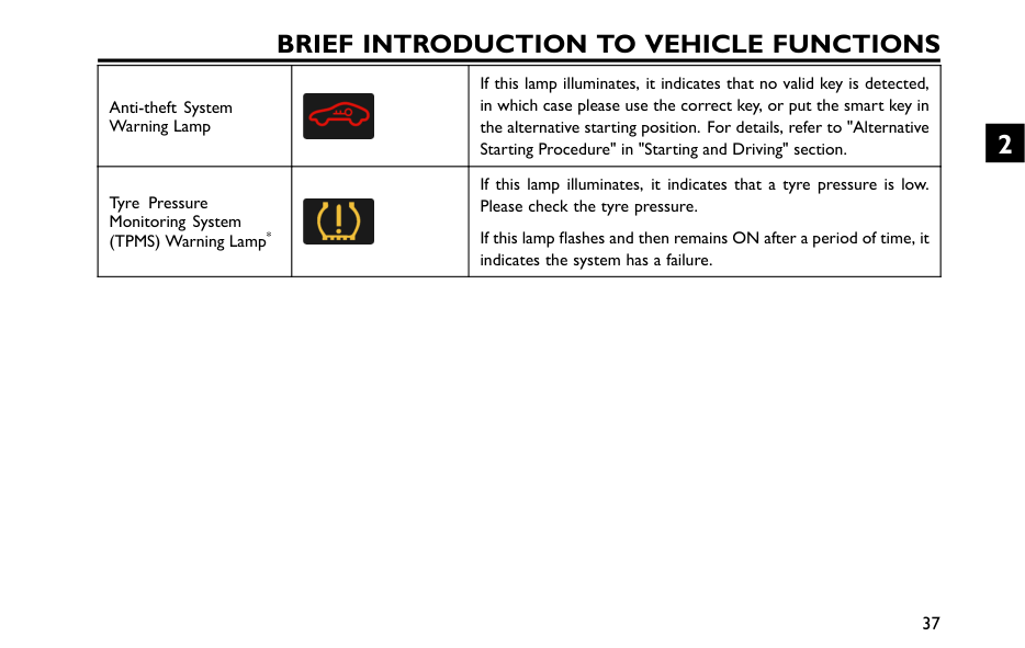
Brief Introduction To Vehicle Functions
Anti-theft System Warning Lamp If this lamp illuminates, it indicates that no valid key is detected, in which case please use the correct key, or put the smart key in the alternative starting position. For details, refer to "Alternative Starting Procedure" in "Starting and Driving" section. Tyre Pressure Monitoring System (TPMS) Warning Lamp* If this lamp illuminates, it indicates that a tyre pressure is low. Please check the tyre pressure. If this lamp flashes and then remains ON after a period of time, it indicates the system has a failure. 37 2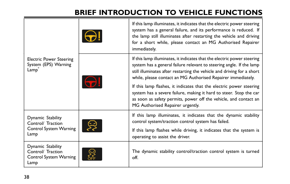
Brief Introduction To Vehicle Functions
If this lamp illuminates, it indicates that the electric power steering system has a general failure, and its performance is reduced. If the lamp still illuminates after restarting the vehicle and driving for a short while, please contact an MG Authorised Repairer immediately. Electric Power Steering System (EPS) Warning Lamp* If this lamp illuminates, it indicates that the electric power steering system has a general failure relevant to steering angle. If the lamp still illuminates after restarting the vehicle and driving for a short while, please contact an MG Authorised Repairer immediately. If this lamp flashes, it indicates that the electric power steering system has a severe failure, making it hard to steer. Stop the car as soon as safety permits, power off the vehicle, and contact an MG Authorised Repairer urgently. Dynamic Stability Control/ Traction Control System Warning Lamp If this lamp illuminates, it indicates that the dynamic stability control system/traction control system has failed. If this lamp flashes while driving, it indicates that the system is operating to assist the driver. Dynamic Stability Control/ Traction Control System Warning Lamp The dynamic stability control/traction control system is turned off. 38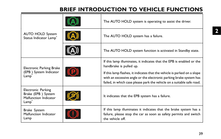
Brief Introduction To Vehicle Functions
The AUTO HOLD system is operating to assist the driver. The AUTO HOLD system has a failure. AUTO HOLD System Status Indicator Lamp* The AUTO HOLD system function is activated in Standby state. Electronic Parking Brake (EPB ) System Indicator Lamp* If this lamp illuminates, it indicates that the EPB is enabled or the handbrake is pulled up. If this lamp flashes, it indicates that the vehicle is parked on a slope with an excessive angle or the electronic parking brake system has failed, in which case please park the vehicle on a suitable safe road. Electronic Parking Brake (EPB ) System Malfunction Indicator Lamp* It indicates that the EPB system has a failure. Brake System Malfunction Indicator Lamp If this lamp illuminates it indicates that the brake system has a failure, please stop the car as soon as safety permits and switch the vehicle off. 39 2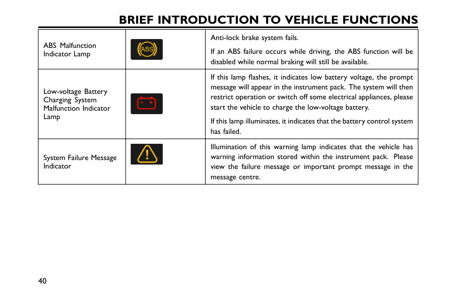
Brief Introduction To Vehicle Functions
ABS Malfunction Indicator Lamp Anti-lock brake system fails. If an ABS failure occurs while driving, the ABS function will be disabled while normal braking will still be available. Low-voltage Battery Charging System Malfunction Indicator Lamp If this lamp flashes, it indicates low battery voltage, the prompt message will appear in the instrument pack. The system will then restrict operation or switch off some electrical appliances, please start the vehicle to charge the low-voltage battery. If this lamp illuminates, it indicates that the battery control system has failed. System Failure Message Indicator Illumination of this warning lamp indicates that the vehicle has warning information stored within the instrument pack. Please view the failure message or important prompt message in the message centre. 40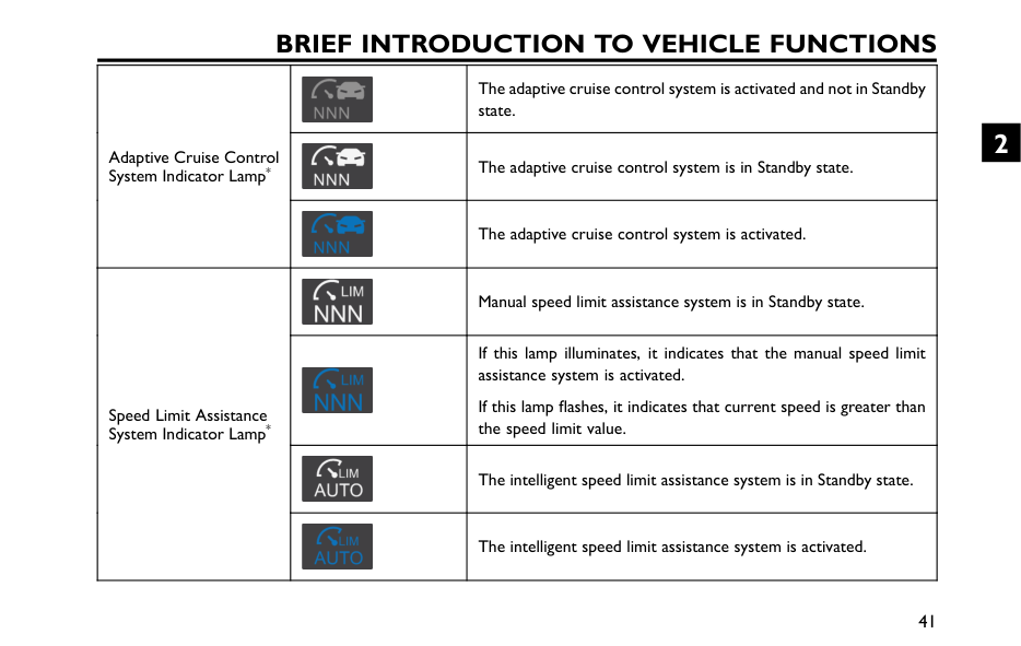
Brief Introduction To Vehicle Functions
The adaptive cruise control system is activated and not in Standby state. The adaptive cruise control system is in Standby state. Adaptive Cruise Control System Indicator Lamp* The adaptive cruise control system is activated. Manual speed limit assistance system is in Standby state. If this lamp illuminates, it indicates that the manual speed limit assistance system is activated. If this lamp flashes, it indicates that current speed is greater than the speed limit value. The intelligent speed limit assistance system is in Standby state. Speed Limit Assistance System Indicator Lamp* The intelligent speed limit assistance system is activated. 41 2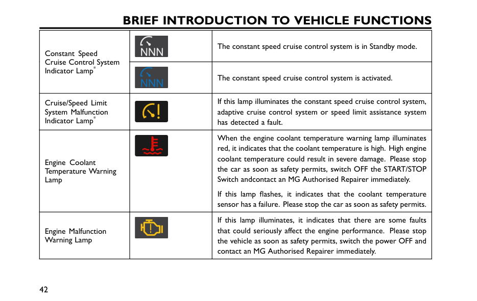
Brief Introduction To Vehicle Functions
The constant speed cruise control system is in Standby mode. Constant Speed Cruise Control System Indicator Lamp* The constant speed cruise control system is activated. Cruise/Speed Limit System Malfunction Indicator Lamp* If this lamp illuminates the constant speed cruise control system, adaptive cruise control system or speed limit assistance system has detected a fault. Engine Coolant Temperature Warning Lamp When the engine coolant temperature warning lamp illuminates red, it indicates that the coolant temperature is high. High engine coolant temperature could result in severe damage. Please stop the car as soon as safety permits, switch OFF the START/STOP Switch andcontact an MG Authorised Repairer immediately. If this lamp flashes, it indicates that the coolant temperature sensor has a failure. Please stop the car as soon as safety permits. Engine Malfunction Warning Lamp If this lamp illuminates, it indicates that there are some faults that could seriously affect the engine performance. Please stop the vehicle as soon as safety permits, switch the power OFF and contact an MG Authorised Repairer immediately. 42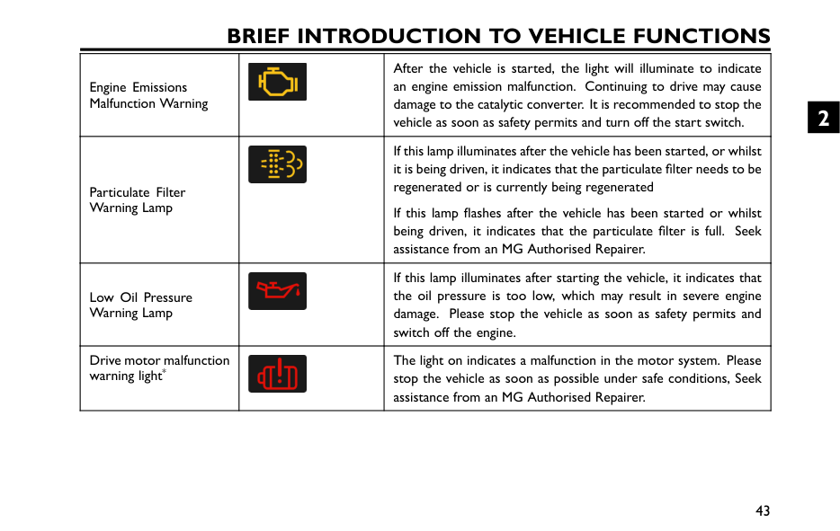
Brief Introduction To Vehicle Functions
Engine Emissions Malfunction Warning After the vehicle is started, the light will illuminate to indicate an engine emission malfunction. Continuing to drive may cause damage to the catalytic converter. It is recommended to stop the vehicle as soon as safety permits and turn off the start switch. Particulate Filter Warning Lamp If this lamp illuminates after the vehicle has been started, or whilst it is being driven, it indicates that the particulate filter needs to be regenerated or is currently being regenerated If this lamp flashes after the vehicle has been started or whilst being driven, it indicates that the particulate filter is full. Seek assistance from an MG Authorised Repairer. Low Oil Pressure Warning Lamp If this lamp illuminates after starting the vehicle, it indicates that the oil pressure is too low, which may result in severe engine damage. Please stop the vehicle as soon as safety permits and switch off the engine. Drive motor malfunction warning light* The light on indicates a malfunction in the motor system. Please stop the vehicle as soon as possible under safe conditions, Seek assistance from an MG Authorised Repairer. 43 2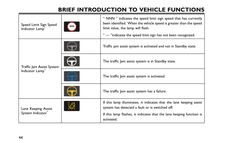
Brief Introduction To Vehicle Functions
Speed Limit Sign Speed Indicator Lamp* “ NNN ” indicates the speed limit sign speed that has currently been identified. When the vehicle speed is greater than the speed limit value, the lamp will flash. “ — ”indicates the speed limit sign has not been recognized. Traffic jam assist system is activated and not in Standby state. The traffic Jam assist system is in Standby state. The traffic Jam assist system is activated. Traffic Jam Assist System Indicator Lamp* The traffic Jam assist system has a failure. Lane Keeping Assist System Indicator* If this lamp illuminates, it indicates that the lane keeping assist system has detected a fault or is switched off. If this lamp flashes, it indicates that the lane keeping function is activated. 44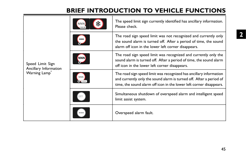
Brief Introduction To Vehicle Functions
The speed limit sign currently identified has ancillary information. Please check. The road sign speed limit was not recognized and currently only the sound alarm is turned off. After a period of time, the sound alarm off icon in the lower left corner disappears. The road sign speed limit was recognized and currently only the sound alarm is turned off. After a period of time, the sound alarm off icon in the lower left corner disappears. The road sign speed limit was recognized has ancillary information and currently only the sound alarm is turned off. After a period of time, the sound alarm off icon in the lower left corner disappears. Simultaneous shutdown of overspeed alarm and intelligent speed limit assist system. Speed Limit Sign Ancillary Information Warning Lamp* Overspeed alarm fault. 45 2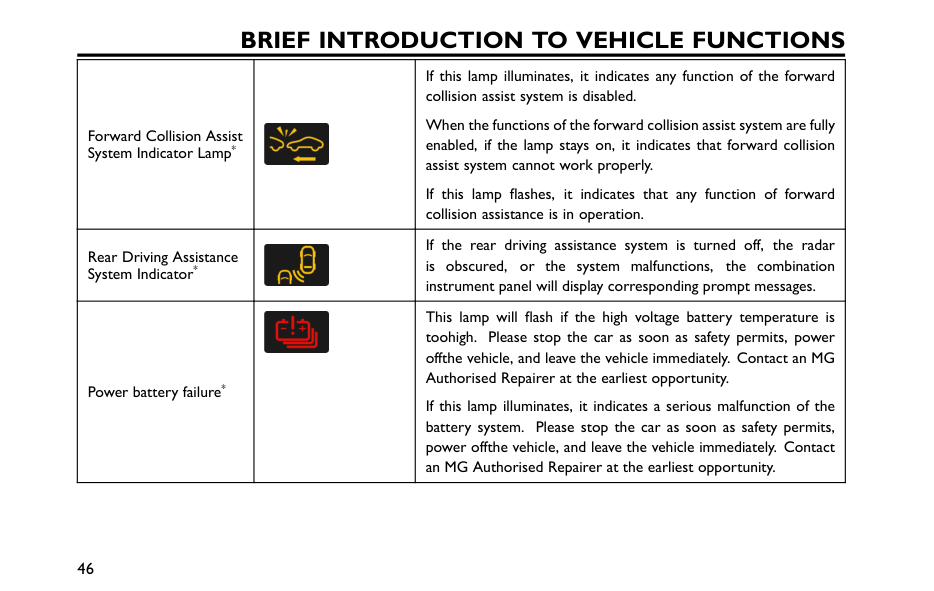
Brief Introduction To Vehicle Functions
Forward Collision Assist System Indicator Lamp* If this lamp illuminates, it indicates any function of the forward collision assist system is disabled. When the functions of the forward collision assist system are fully enabled, if the lamp stays on, it indicates that forward collision assist system cannot work properly. If this lamp flashes, it indicates that any function of forward collision assistance is in operation. Rear Driving Assistance System Indicator* If the rear driving assistance system is turned off, the radar is obscured, or the system malfunctions, the combination instrument panel will display corresponding prompt messages. Power battery failure* This lamp will flash if the high voltage battery temperature is toohigh. Please stop the car as soon as safety permits, power offthe vehicle, and leave the vehicle immediately. Contact an MG Authorised Repairer at the earliest opportunity. If this lamp illuminates, it indicates a serious malfunction of the battery system. Please stop the car as soon as safety permits, power offthe vehicle, and leave the vehicle immediately. Contact an MG Authorised Repairer at the earliest opportunity. 46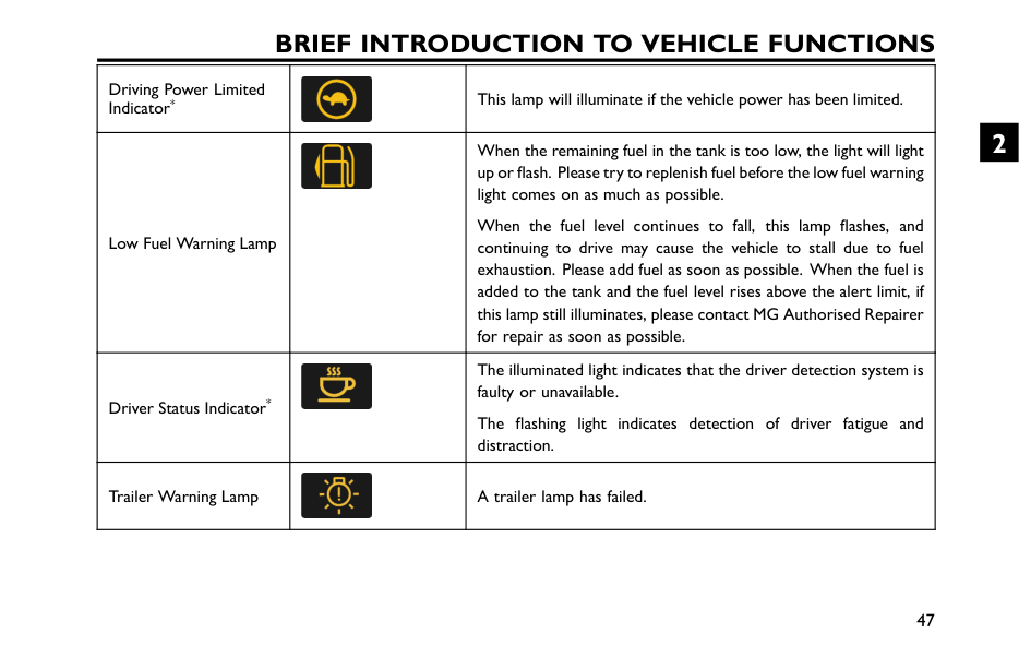
Brief Introduction To Vehicle Functions
Driving Power Limited Indicator* This lamp will illuminate if the vehicle power has been limited. Low Fuel Warning Lamp When the remaining fuel in the tank is too low, the light will light up or flash. Please try to replenish fuel before the low fuel warning light comes on as much as possible. When the fuel level continues to fall, this lamp flashes, and continuing to drive may cause the vehicle to stall due to fuel exhaustion. Please add fuel as soon as possible. When the fuel is added to the tank and the fuel level rises above the alert limit, if this lamp still illuminates, please contact MG Authorised Repairer for repair as soon as possible. Driver Status Indicator* The illuminated light indicates that the driver detection system is faulty or unavailable. The flashing light indicates detection of driver fatigue and distraction. Trailer Warning Lamp A trailer lamp has failed. 47 2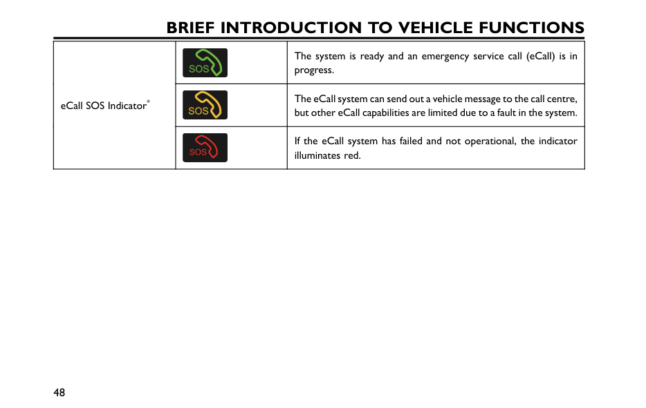
Brief Introduction To Vehicle Functions
The system is ready and an emergency service call (eCall) is in progress. The eCall system can send out a vehicle message to the call centre, but other eCall capabilities are limited due to a fault in the system. eCall SOS Indicator* If the eCall system has failed and not operational, the indicator illuminates red. 48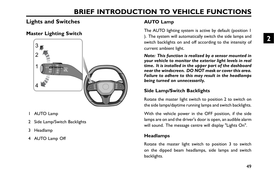
Brief Introduction To Vehicle Functions
Lights and Switches Master Lighting Switch 1 AUTO Lamp 2 Side Lamp/Switch Backlights 3 Headlamp 4 AUTO Lamp Off AUTO Lamp The AUTO lighting system is active by default (position 1 ). The system will automatically switch the side lamps and switch backlights on and off according to the intensity of current ambient light. Note: This function is realized by a sensor mounted in your vehicle to monitor the exterior light levels in real time. It is installed in the upper part of the dashboard near the windscreen. DO NOT mask or cover this area. Failure to adhere to this may result in the headlamps being turned on unnecessarily. Side Lamp/Switch Backlights Rotate the master light switch to position 2 to switch on the side lamps/daytime running lamps and switch backlights. With the vehicle power in the OFF position, if the side lamps are on and the driver's door is open, an audible alarm will sound. The message centre will display "Lights On". Headlamps Rotate the master light switch to position 3 to switch on the dipped beam headlamps, side lamps and switch backlights. 49 2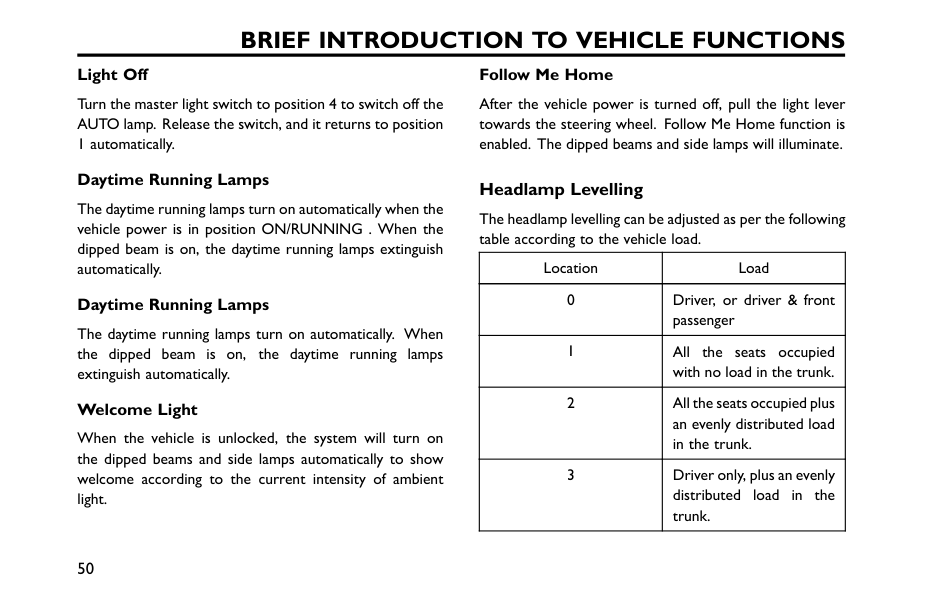
Brief Introduction To Vehicle Functions
Light Off Turn the master light switch to position 4 to switch off the AUTO lamp. Release the switch, and it returns to position 1 automatically. Daytime Running Lamps The daytime running lamps turn on automatically when the vehicle power is in position ON/RUNNING . When the dipped beam is on, the daytime running lamps extinguish automatically. Daytime Running Lamps The daytime running lamps turn on automatically. When the dipped beam is on, the daytime running lamps extinguish automatically. Welcome Light When the vehicle is unlocked, the system will turn on the dipped beams and side lamps automatically to show welcome according to the current intensity of ambient light. Follow Me Home After the vehicle power is turned off, pull the light lever towards the steering wheel. Follow Me Home function is enabled. The dipped beams and side lamps will illuminate. Headlamp Levelling The headlamp levelling can be adjusted as per the following table according to the vehicle load. Location Load 0 Driver, or driver & front passenger 1 All the seats occupied with no load in the trunk. 2 All the seats occupied plus an evenly distributed load in the trunk. 3 Driver only, plus an evenly distributed load in the trunk. 50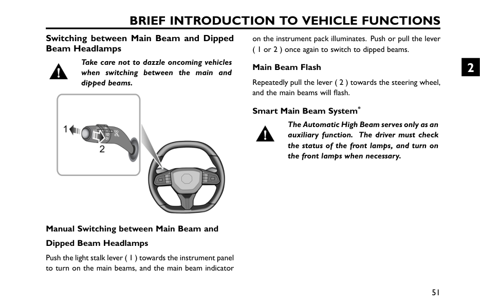
Brief Introduction To Vehicle Functions
Switching between Main Beam and Dipped Beam Headlamps Take care not to dazzle oncoming vehicles when switching between the main and dipped beams. Manual Switching between Main Beam and Dipped Beam Headlamps Push the light stalk lever ( 1 ) towards the instrument panel to turn on the main beams, and the main beam indicator on the instrument pack illuminates. Push or pull the lever ( 1 or 2 ) once again to switch to dipped beams. Main Beam Flash Repeatedly pull the lever ( 2 ) towards the steering wheel, and the main beams will flash. Smart Main Beam System* The Automatic High Beam serves only as an auxiliary function. The driver must check the status of the front lamps, and turn on the front lamps when necessary. 51 2
Brief Introduction To Vehicle Functions
The Automatic High Beam may not operate normally in the following cases, but not limited to them, so the main and dipped beams should be switched manually: • The windscreen is dirty, broken or obstructed by other objects blocking the view of the sensor. • The lamps of other vehicles are missing, damaged, blocked or cannot be detected due to weather and other reasons. • When pedestrians, non-motor vehicles and other objects with no obvious light or reflected light are encountered. • When the headlamps and tail lamps of other vehicles cannot be detected due to the sensor view being impaired due to undulating road conditions such as bends, dips or hills. • When the car is driving on a winding road or mountainous road. • The wiper switch is in the "Fast" position. Smart main beam system detects the light intensity of the vehicle ahead by the front view camera, and the main beams can be turned on or off once certain conditions are met. When the smart main beam system is enabled, smart main beam indicator on the instrument pack illuminates. With the automatic control, when it is dark and there is no vehicle in the surroundings, the system will turn on the main beams; when it is quite bright or the system detects the headlamps or tail lamps ahead, the system will turn off the main beams. To enable the smart main beam system, the following conditions should be met: 1 The lighting lever switch is placed in AUTO position and the dipped beams automatically turn on. 2 The vehicle is running with the speed exceeding 40 km( 20 mile)/h. 3 Front fog lights not turned on* The vehicle will exit the smart main beam system if the following conditions are met. With the system exited, quick pushing the main beam ON switch twice towards the instrument panel will enter the smart main beam system again. Only 3 exits is allowed in a start cycle. If it is exited 52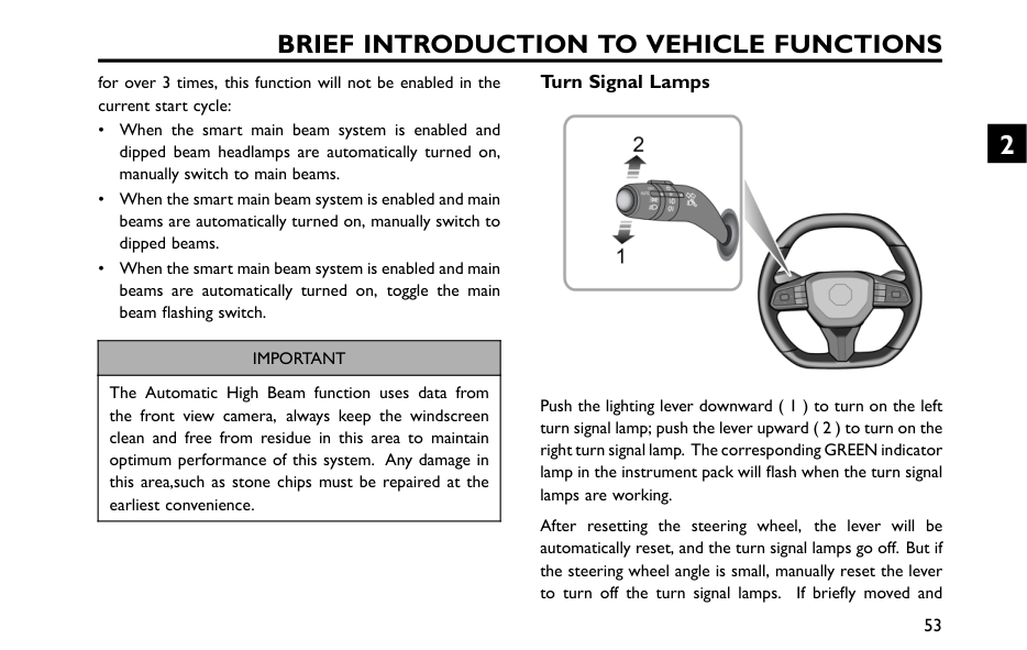
Brief Introduction To Vehicle Functions
for over 3 times, this function will not be enabled in the current start cycle: • When the smart main beam system is enabled and dipped beam headlamps are automatically turned on, manually switch to main beams. • When the smart main beam system is enabled and main beams are automatically turned on, manually switch to dipped beams. • When the smart main beam system is enabled and main beams are automatically turned on, toggle the main beam flashing switch.Important
The Automatic High Beam function uses data from the front view camera, always keep the windscreen clean and free from residue in this area to maintain optimum performance of this system. Any damage in this area,such as stone chips must be repaired at the earliest convenience. Turn Signal Lamps Push the lighting lever downward ( 1 ) to turn on the left turn signal lamp; push the lever upward ( 2 ) to turn on the right turn signal lamp. The corresponding GREEN indicator lamp in the instrument pack will flash when the turn signal lamps are working. After resetting the steering wheel, the lever will be automatically reset, and the turn signal lamps go off. But if the steering wheel angle is small, manually reset the lever to turn off the turn signal lamps. If briefly moved and 53 2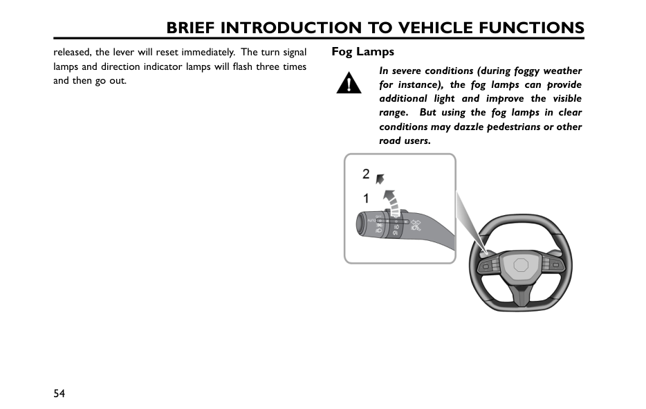
Brief Introduction To Vehicle Functions
released, the lever will reset immediately. The turn signal lamps and direction indicator lamps will flash three times and then go out. Fog Lamps In severe conditions (during foggy weather for instance), the fog lamps can provide additional light and improve the visible range. But using the fog lamps in clear conditions may dazzle pedestrians or other road users. 54
Brief Introduction To Vehicle Functions
Front Fog Lamps* The headlamps turned on, turn the switch to position 1 to turn on the front fog lamps. The indicator illuminates on the instrument panel when the front fog lamps are on. Rear Fog Lamps When the headlamps turned on, turn the switch to position 2 to turn on the rear fog lamps. The indicator illuminates on the instrument panel when the rear fog lamps are on. Hazard Warning Lamps Press the hazard warning lamp button at the middle of the centre vents to operate the hazard warning lamps. All turn signal lamps and direction indicator lamps will flash together. Press the button again to switch off the hazard warning lamp. All turn signal lamps and direction indicator lamps will stop flashing. 55 2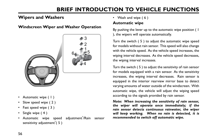
Brief Introduction To Vehicle Functions
Wipers and Washers Windscreen Wiper and Washer Operation • Automatic wipe ( 1 ) • Slow speed wipe ( 2 ) • Fast speed wipe ( 3 ) • Single wipe ( 4 ) • Automatic wipe speed adjustment*/Rain sensor sensitivity adjustment*( 5 ) • Wash and wipe ( 6 ) Automatic wipe By pushing the lever up to the automatic wipe position ( 1 ), the wipers will operate automatically. Turn the switch ( 5 ) to adjust the automatic wipe speed for models without rain sensor. This speed will also change with the vehicle speed. As the vehicle speed increases, the wiping interval decreases. As the vehicle speed decreases, the wiping interval increases. Turn the switch ( 5 ) to adjust the sensitivity of rain sensor for models equipped with a rain sensor. As the sensitivity increases, the wiping interval decreases. Rain sensor is equipped in the interior rearview mirror base to detect varying amounts of water outside of the windscreen. With automatic wipe, the vehicle will adjust the wiping speed according to the signals provided by rain sensor. Note: When increasing the sensitivity of rain sensor, the wiper will operate once immediately; if the rain sensor detects continuous rainwater, the wiper will keep working. When no rain is detected, it is recommended to switch off automatic wipe. 56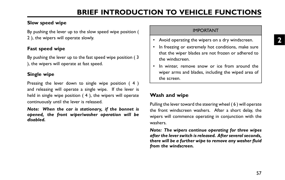
Brief Introduction To Vehicle Functions
Slow speed wipe By pushing the lever up to the slow speed wipe position ( 2 ), the wipers will operate slowly. Fast speed wipe By pushing the lever up to the fast speed wipe position ( 3 ), the wipers will operate at fast speed. Single wipe Pressing the lever down to single wipe position ( 4 ) and releasing will operate a single wipe. If the lever is held in single wipe position ( 4 ), the wipers will operate continuously until the lever is released. Note: When the car is stationary, if the bonnet is opened, the front wiper/washer operation will be disabled.Important
• Avoid operating the wipers on a dry windscreen. • In freezing or extremely hot conditions, make sure that the wiper blades are not frozen or adhered to the windscreen. • In winter, remove snow or ice from around the wiper arms and blades, including the wiped area of the screen. Wash and wipe Pulling the lever toward the steering wheel ( 6 ) will operate the front windscreen washers. After a short delay, the wipers will commence operating in conjunction with the washers. Note: The wipers continue operating for three wipes after the lever switch is released. After several seconds, there will be a further wipe to remove any washer fluid from the windscreen. 57 2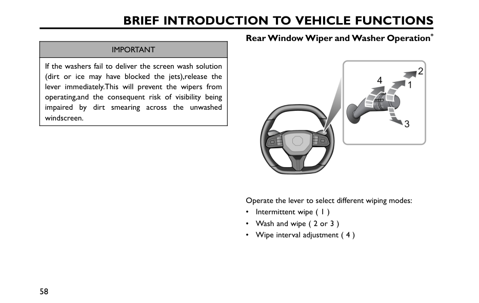
Brief Introduction To Vehicle Functions
Important
If the washers fail to deliver the screen wash solution (dirt or ice may have blocked the jets),release the lever immediately.This will prevent the wipers from operating,and the consequent risk of visibility being impaired by dirt smearing across the unwashed windscreen. Rear Window Wiper and Washer Operation* Operate the lever to select different wiping modes: • Intermittent wipe ( 1 ) • Wash and wipe ( 2 or 3 ) • Wipe interval adjustment ( 4 ) 58
Brief Introduction To Vehicle Functions
Intermittent wipe If the rear wiper switch is turned to intermittent wipe ( 1 ), the rear wiper will operate. It will complete 3 continuous wipes before changing to intermittent mode. The interval between the wipes can be increased/decreased via the switch ( 4 ). Wash and wipe If the rear wash and wipe ( 2 ) is selected, the rear wiper and washer will operate together, and the rear wiper will move fast. If the switch is released to intermittent wipe ( 1 ), the rear washer will stop operating. If the rear wipe and wash ( 3 ) is selected, the rear wiper and washer will operate together. If the switch is released to off position, the rear wiper and washer stop operating. After several seconds, there will be a further wipe to remove any fluid draining down the screen. Note: When the tail gate is opened, rear wiper operations will be disabled. Note: After the windscreen wipers are switched on, if the shift lever is in “R” position, the rear wiper will operate. 59 2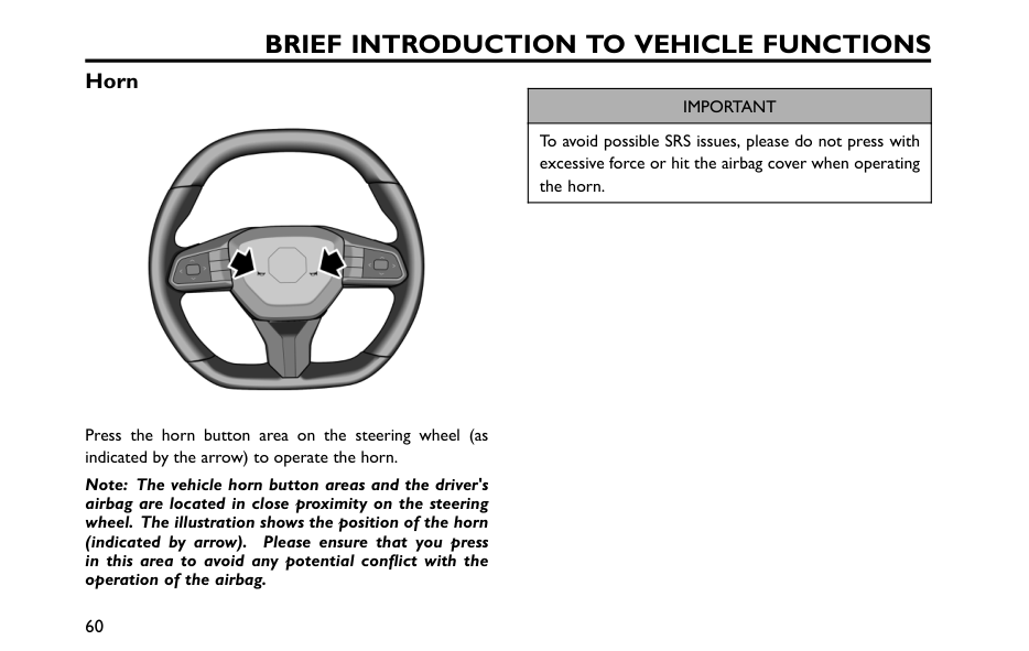
Brief Introduction To Vehicle Functions
Horn Press the horn button area on the steering wheel (as indicated by the arrow) to operate the horn. Note: The vehicle horn button areas and the driver's airbag are located in close proximity on the steering wheel. The illustration shows the position of the horn (indicated by arrow). Please ensure that you press in this area to avoid any potential conflict with the operation of the airbag.Important
To avoid possible SRS issues, please do not press with excessive force or hit the airbag cover when operating the horn. 60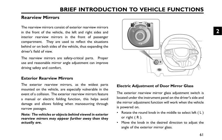
Brief Introduction To Vehicle Functions
Rearview Mirrors The rearview mirrors consist of exterior rearview mirrors in the front of the vehicle, the left and right sides and interior rearview mirrors in the front of passenger compartment. They are used to reflect the situations behind or on both sides of the vehicle, thus expanding the driver's field of view. The rearview mirrors are safety-critical parts. Proper use and reasonable mirror angle adjustment can improve driving safety and comfort. Exterior Rearview Mirrors The exterior rearview mirrors, as the widest parts mounted on the vehicle, are especially vulnerable in the event of a collision. The exterior rearview mirrors feature a manual or electric folding function, this helps avoid damage and allows folding when manoeuvring through narrow passages. Note: The vehicles or objects behind viewed in exterior rearview mirrors may appear further away than they actually are. Electric Adjustment of Door Mirror Glass The exterior rearview mirror glass adjustment switch is located under the instrument panel on the driver's side and the mirror adjustment function will work when the vehicle is powered on. • Rotate the round knob in the middle to select left ( L ) or right ( R ). • Move the knob in the desired direction to adjust the angle of the exterior mirror glass. 61 2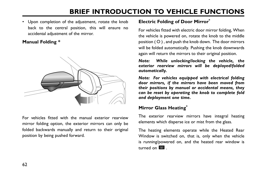
Brief Introduction To Vehicle Functions
• Upon completion of the adjustment, rotate the knob back to the central position, this will ensure no accidental adjustment of the mirror. Manual Folding * For vehicles fitted with the manual exterior rearview mirror folding option, the exterior mirrors can only be folded backwards manually and return to their original position by being pushed forward. Electric Folding of Door Mirror* For vehicles fitted with electric door mirror folding, When the vehicle is powered on, rotate the knob to the middle position ( O ) , and push the knob down. The door mirrors will be folded automatically. Pushing the knob downwards again will return the mirrors to their original position. Note: While unlocking/locking the vehicle, the exterior rearview mirrors will be deployed/folded automatically. Note: For vehicles equipped with electrical folding door mirrors, if the mirrors have been moved from their positions by manual or accidental means, they can be reset by operating the knob to complete fold and deployment one time. Mirror Glass Heating* The exterior rearview mirrors have integral heating elements which disperse ice or mist from the glass. The heating elements operate while the Heated Rear Window is switched on, that is, only when the vehicle is running/powered on, and the heated rear window is turned on . 62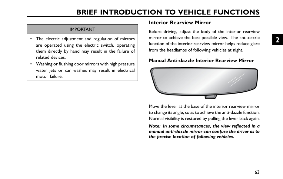
Brief Introduction To Vehicle Functions
Important
• The electric adjustment and regulation of mirrors are operated using the electric switch, operating them directly by hand may result in the failure of related devices. • Washing or flushing door mirrors with high pressure water jets or car washes may result in electrical motor failure. Interior Rearview Mirror Before driving, adjust the body of the interior rearview mirror to achieve the best possible view. The anti-dazzle function of the interior rearview mirror helps reduce glare from the headlamps of following vehicles at night. Manual Anti-dazzle Interior Rearview Mirror Move the lever at the base of the interior rearview mirror to change its angle, so as to achieve the anti-dazzle function. Normal visibility is restored by pulling the lever back again. Note: In some circumstances, the view reflected in a manual anti-dazzle mirror can confuse the driver as to the precise location of following vehicles. 63 2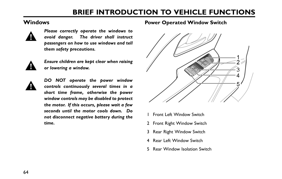
Brief Introduction To Vehicle Functions
Windows Please correctly operate the windows to avoid danger. The driver shall instruct passengers on how to use windows and tell them safety precautions. Ensure children are kept clear when raising or lowering a window.Do
Not
operate the power window controls continuously several times in a short time frame, otherwise the power window controls may be disabled to protect the motor. If this occurs, please wait a few seconds until the motor cools down. Do not disconnect negative battery during the time. Power Operated Window Switch 1 Front Left Window Switch 2 Front Right Window Switch 3 Rear Right Window Switch 4 Rear Left Window Switch 5 Rear Window Isolation Switch 64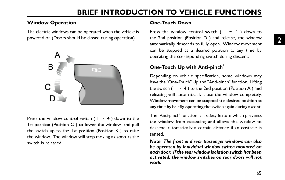
Brief Introduction To Vehicle Functions
Window Operation The electric windows can be operated when the vehicle is powered on (Doors should be closed during operation). Press the window control switch ( 1 ~4 ) down to the 1st position (Position C ) to lower the window, and pull the switch up to the 1st position (Position B ) to raise the window. The window will stop moving as soon as the switch is released. One-Touch Down Press the window control switch ( 1 ~4 ) down to the 2nd position (Position D ) and release, the window automatically descends to fully open. Window movement can be stopped at a desired position at any time by operating the corresponding switch during descent. One-Touch Up with Anti-pinch* Depending on vehicle specification, some windows may have the "One-Touch" Up and "Anti-pinch" function. Lifting the switch ( 1 ~4 ) to the 2nd position (Position A ) and releasing will automatically close the window completely. Window movement can be stopped at a desired position at any time by briefly operating the switch again during ascent. The 'Anti-pinch' function is a safety feature which prevents the window from ascending and allows the window to descend automatically a certain distance if an obstacle is sensed. Note: The front and rear passenger windows can also be operated by individual window switch mounted on each door. If the rear window isolation switch has been activated, the window switches on rear doors will not work. 65 2
Brief Introduction To Vehicle Functions
Rear Window Isolation Switch Press the switch ( 5 ) to isolate the rear window controls (an indicator lamp in the switch illuminates), and press again to restore control. Note: If the battery is de-energized during the window lifting and lowering process, the "one-touch" up and "anti-pinch" mode will be invalidated. When the battery is energized again, lift the switch briefly and continuously to raise the window to the top, and after lifting the switch continuously for about 5 seconds, the "one-touch" up and "anti-pinch" mode will be recovered. 66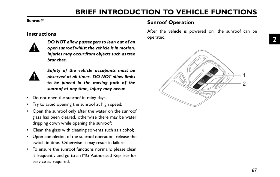
Brief Introduction To Vehicle Functions
Sunroof* Instructions DO NOT allow passengers to lean out of an open sunroof whilst the vehicle is in motion. Injuries may occur from objects such as tree branches. Safety of the vehicle occupants must be observed at all times. DO NOT allow limbs to be placed in the moving path of the sunroof at any time, injury may occur. • Do not open the sunroof in rainy days; • Try to avoid opening the sunroof at high speed; • Open the sunroof only after the water on the sunroof glass has been cleared, otherwise there may be water dripping down while opening the sunroof; • Clean the glass with cleaning solvents such as alcohol; • Upon completion of the sunroof operation, release the switch in time. Otherwise it may result in failure; • To ensure the sunroof functions normally, please clean it frequently and go to an MG Authorised Repairer for service as required. Sunroof Operation After the vehicle is powered on, the sunroof can be operated. 67 2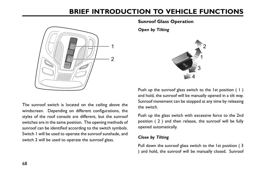
Brief Introduction To Vehicle Functions
The sunroof switch is located on the ceiling above the windscreen. Depending on different configurations, the styles of the roof console are different, but the sunroof switches are in the same position. The opening methods of sunroof can be identified according to the switch symbols. Switch 1 will be used to operate the sunroof sunshade, and switch 2 will be used to operate the sunroof glass. Sunroof Glass Operation Open by Tilting Push up the sunroof glass switch to the 1st position ( 1 ) and hold, the sunroof will be manually opened in a tilt way. Sunroof movement can be stopped at any time by releasing the switch. Push up the glass switch with excessive force to the 2nd position ( 2 ) and then release, the sunroof will be fully opened automatically. Close by Tilting Pull down the sunroof glass switch to the 1st position ( 3 ) and hold, the sunroof will be manually closed. Sunroof 68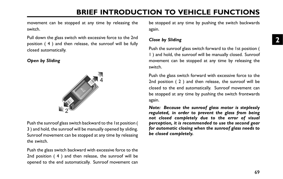
Brief Introduction To Vehicle Functions
movement can be stopped at any time by releasing the switch. Pull down the glass switch with excessive force to the 2nd position ( 4 ) and then release, the sunroof will be fully closed automatically. Open by Sliding Push the sunroof glass switch backward to the 1st position ( 3 ) and hold, the sunroof will be manually opened by sliding. Sunroof movement can be stopped at any time by releasing the switch. Push the glass switch backward with excessive force to the 2nd position ( 4 ) and then release, the sunroof will be opened to the end automatically. Sunroof movement can be stopped at any time by pushing the switch backwards again. Close by Sliding Push the sunroof glass switch forward to the 1st position ( 1 ) and hold, the sunroof will be manually closed. Sunroof movement can be stopped at any time by releasing the switch. Push the glass switch forward with excessive force to the 2nd position ( 2 ) and then release, the sunroof will be closed to the end automatically. Sunroof movement can be stopped at any time by pushing the switch frontwards again. Note: Because the sunroof glass motor is steplessly regulated, in order to prevent the glass from being not closed completely due to the error of visual perception, it is recommended to use the second gear for automatic closing when the sunroof glass needs to be closed completely. 69 2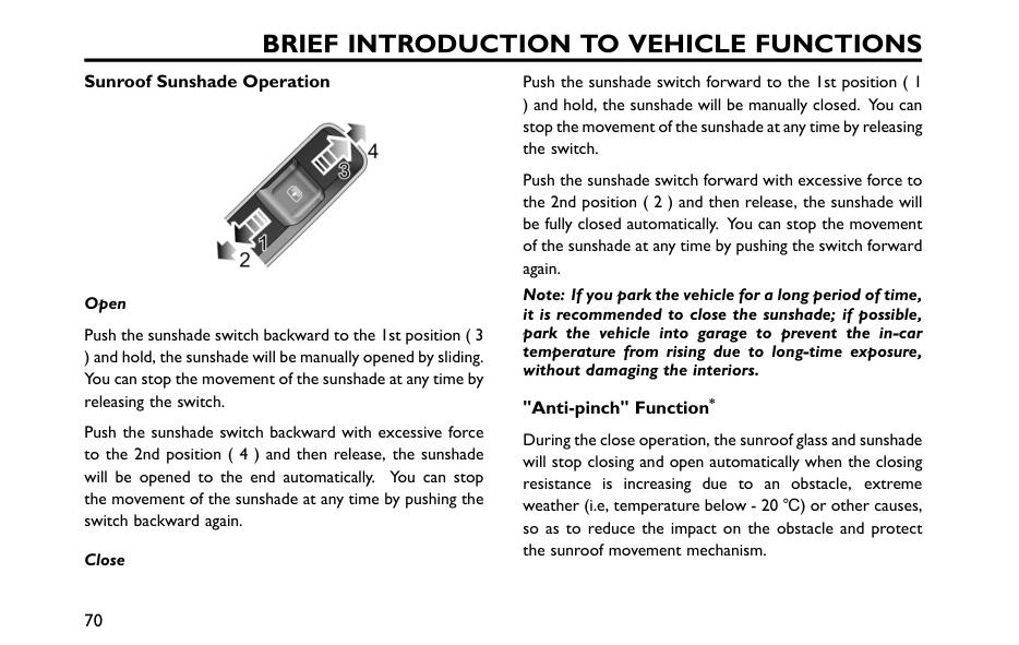
Brief Introduction To Vehicle Functions
Sunroof Sunshade Operation Open Push the sunshade switch backward to the 1st position ( 3 ) and hold, the sunshade will be manually opened by sliding. You can stop the movement of the sunshade at any time by releasing the switch. Push the sunshade switch backward with excessive force to the 2nd position ( 4 ) and then release, the sunshade will be opened to the end automatically. You can stop the movement of the sunshade at any time by pushing the switch backward again. Close Push the sunshade switch forward to the 1st position ( 1 ) and hold, the sunshade will be manually closed. You can stop the movement of the sunshade at any time by releasing the switch. Push the sunshade switch forward with excessive force to the 2nd position ( 2 ) and then release, the sunshade will be fully closed automatically. You can stop the movement of the sunshade at any time by pushing the switch forward again. Note: If you park the vehicle for a long period of time, it is recommended to close the sunshade; if possible, park the vehicle into garage to prevent the in-car temperature from rising due to long-time exposure, without damaging the interiors. "Anti-pinch" Function* During the close operation, the sunroof glass and sunshade will stop closing and open automatically when the closing resistance is increasing due to an obstacle, extreme weather (i.e, temperature below - 20 ℃) or other causes, so as to reduce the impact on the obstacle and protect the sunroof movement mechanism. 70
Brief Introduction To Vehicle Functions
Forcibly Close the Sunroof Glass To forcibly close the sunroof glass reopened due to activation of anti-pinch function in a particular case: slide the glass switch forward to the 1st position within 5 seconds and hold it until the sunroof glass is fully closed. Please note that the anti-pinch function is not available when closing the sunroof glass. Forcibly Close the Sunshade To forcibly close the sunshade reopened due to activation of anti-pinch function in a particular case: slide the sunshade switch forward to the 1st position within 5 seconds and hold it until the sunshade is fully closed. Please note that the anti-pinch function is not available when closing the sunshade. Linkage between Sunshade and Sunroof Glass To prevent the sunshade from being exposed, the sunshade will move together when the sunroof glass is opened. To close the sunshade, please close the sunroof glass first. Sunroof Initialization Sunroof operation will be affected by power failure when sunroof glass or sunshade is in motion, and it is necessary to initialize after power on. Glass initialization: fully close the glass, push the sunroof glass switch forward to the 2nd position and hold for about 10 seconds, the glass will automatically slide open for a distance during which the switch shall keep sliding to the 2nd position and then close. Sunshade initialization: fully close the sunshade, push the sunshade glass switch forward to the 2nd position and hold for about 10 seconds, the sunshade will automatically slide open for a distance and then close, during the entire process, the switch shall be hold in the 2nd position. Thermal Protection To prevent the sunroof glass motor and sunshade motor from damage due to overheating, they are provided with thermal protection function. In thermal protection state, only the closing operation is allowed. 71 2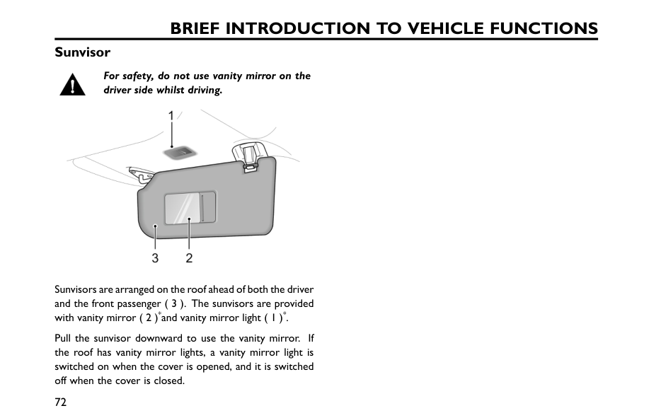
Brief Introduction To Vehicle Functions
Sunvisor For safety, do not use vanity mirror on the driver side whilst driving. Sunvisors are arranged on the roof ahead of both the driver and the front passenger ( 3 ). The sunvisors are provided with vanity mirror ( 2 )*and vanity mirror light ( 1 )*. Pull the sunvisor downward to use the vanity mirror. If the roof has vanity mirror lights, a vanity mirror light is switched on when the cover is opened, and it is switched off when the cover is closed. 72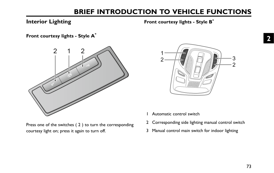
Brief Introduction To Vehicle Functions
Interior Lighting Front courtesy lights - Style A* Press one of the switches ( 2 ) to turn the corresponding courtesy light on; press it again to turn off. Front courtesy lights - Style B* 1 Automatic control switch 2 Corresponding side lighting manual control switch 3 Manual control main switch for indoor lighting 73 2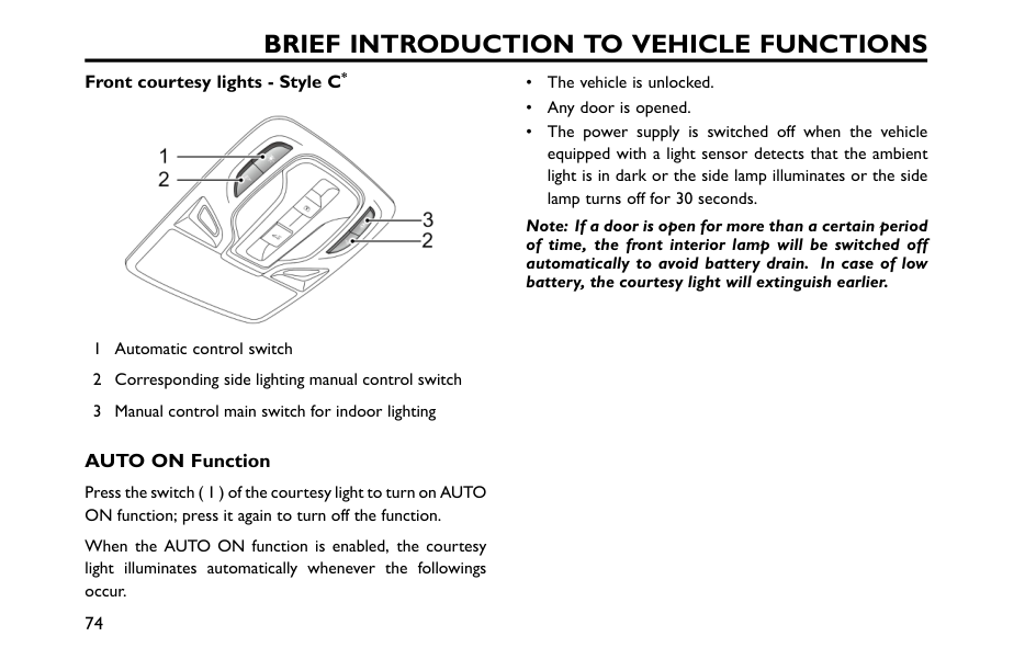
Brief Introduction To Vehicle Functions
Front courtesy lights - Style C* 1 Automatic control switch 2 Corresponding side lighting manual control switch 3 Manual control main switch for indoor lighting AUTO ON Function Press the switch ( 1 ) of the courtesy light to turn on AUTO ON function; press it again to turn off the function. When the AUTO ON function is enabled, the courtesy light illuminates automatically whenever the followings occur. • The vehicle is unlocked. • Any door is opened. • The power supply is switched off when the vehicle equipped with a light sensor detects that the ambient light is in dark or the side lamp illuminates or the side lamp turns off for 30 seconds. Note: If a door is open for more than a certain period of time, the front interior lamp will be switched off automatically to avoid battery drain. In case of low battery, the courtesy light will extinguish earlier. 74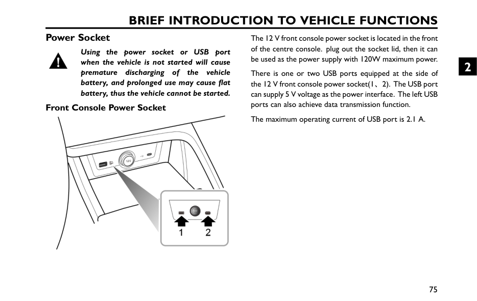
Brief Introduction To Vehicle Functions
Power Socket Using the power socket or USB port when the vehicle is not started will cause premature discharging of the vehicle battery, and prolonged use may cause flat battery, thus the vehicle cannot be started. Front Console Power Socket The 12 V front console power socket is located in the front of the centre console. plug out the socket lid, then it can be used as the power supply with 120W maximum power. There is one or two USB ports equipped at the side of the 12 V front console power socket(1、2). The USB port can supply 5 V voltage as the power interface. The left USB ports can also achieve data transmission function. The maximum operating current of USB port is 2.1 A. 75 2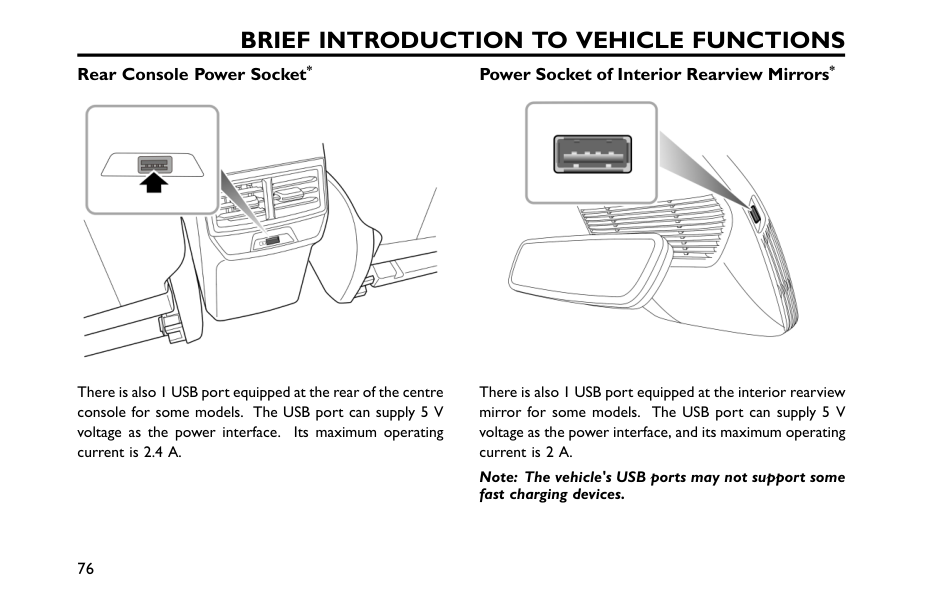
Brief Introduction To Vehicle Functions
Rear Console Power Socket* There is also 1 USB port equipped at the rear of the centre console for some models. The USB port can supply 5 V voltage as the power interface. Its maximum operating current is 2.4 A. Power Socket of Interior Rearview Mirrors* There is also 1 USB port equipped at the interior rearview mirror for some models. The USB port can supply 5 V voltage as the power interface, and its maximum operating current is 2 A. Note: The vehicle's USB ports may not support some fast charging devices. 76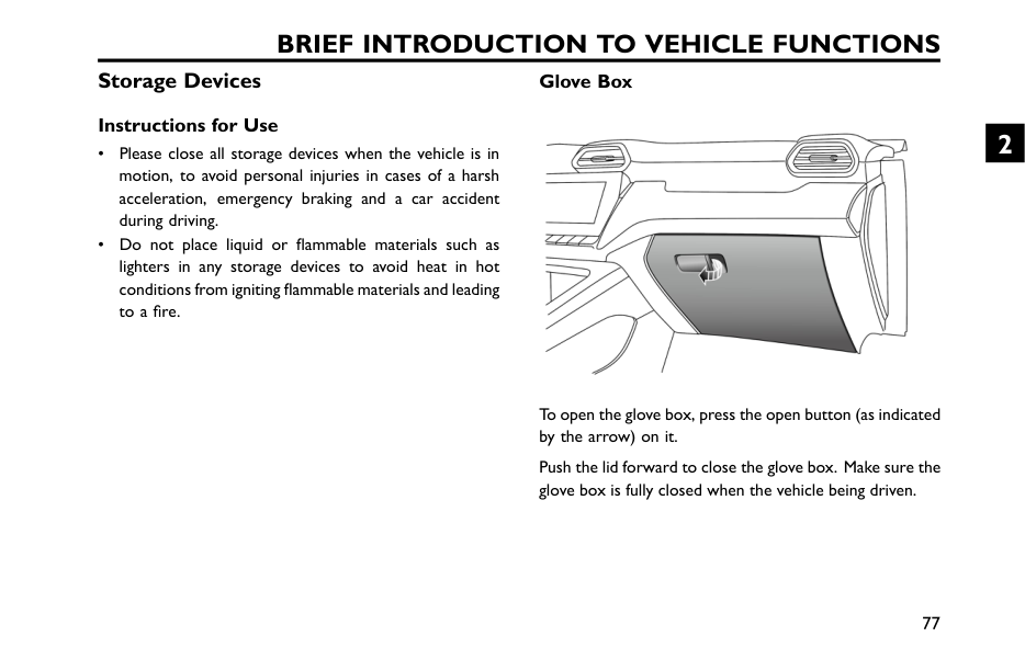
Brief Introduction To Vehicle Functions
Storage Devices Instructions for Use • Please close all storage devices when the vehicle is in motion, to avoid personal injuries in cases of a harsh acceleration, emergency braking and a car accident during driving. • Do not place liquid or flammable materials such as lighters in any storage devices to avoid heat in hot conditions from igniting flammable materials and leading to a fire. Glove Box To open the glove box, press the open button (as indicated by the arrow) on it. Push the lid forward to close the glove box. Make sure the glove box is fully closed when the vehicle being driven. 77 2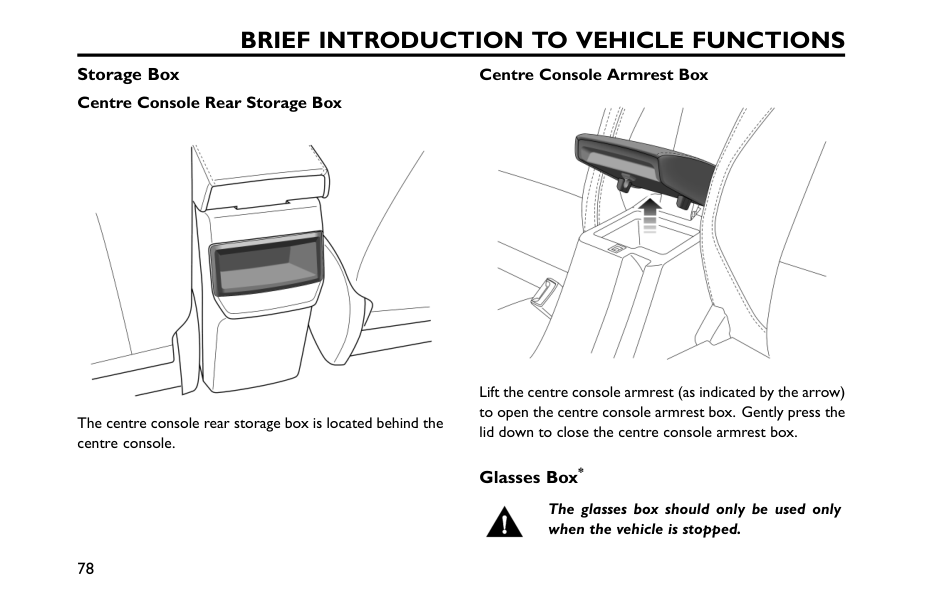
Brief Introduction To Vehicle Functions
Storage Box Centre Console Rear Storage Box The centre console rear storage box is located behind the centre console. Centre Console Armrest Box Lift the centre console armrest (as indicated by the arrow) to open the centre console armrest box. Gently press the lid down to close the centre console armrest box. Glasses Box* The glasses box should only be used only when the vehicle is stopped. 78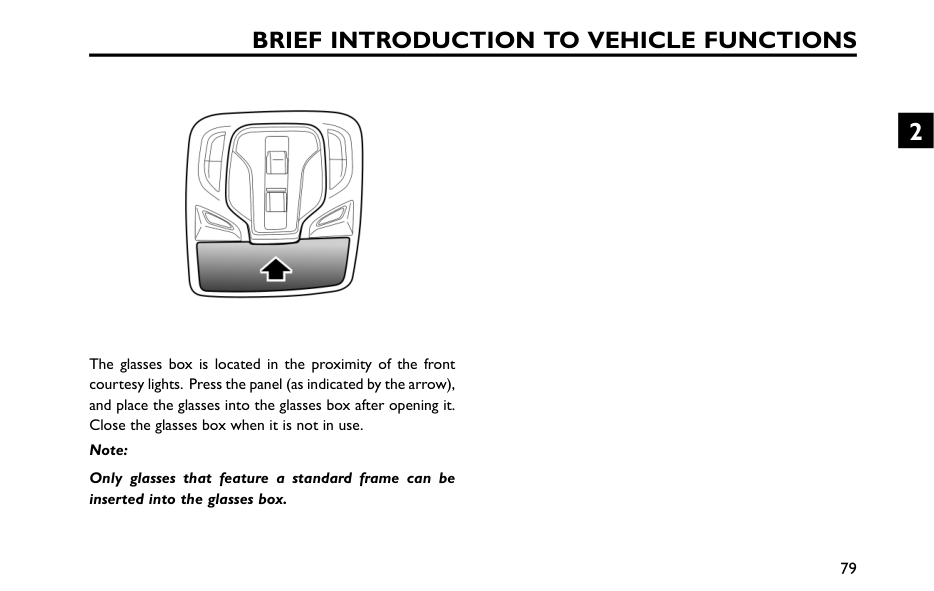
Brief Introduction To Vehicle Functions
The glasses box is located in the proximity of the front courtesy lights. Press the panel (as indicated by the arrow), and place the glasses into the glasses box after opening it. Close the glasses box when it is not in use. Note: Only glasses that feature a standard frame can be inserted into the glasses box. 79 2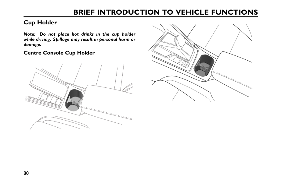
Brief Introduction To Vehicle Functions
Cup Holder Note: Do not place hot drinks in the cup holder while driving. Spillage may result in personal harm or damage. Centre Console Cup Holder 80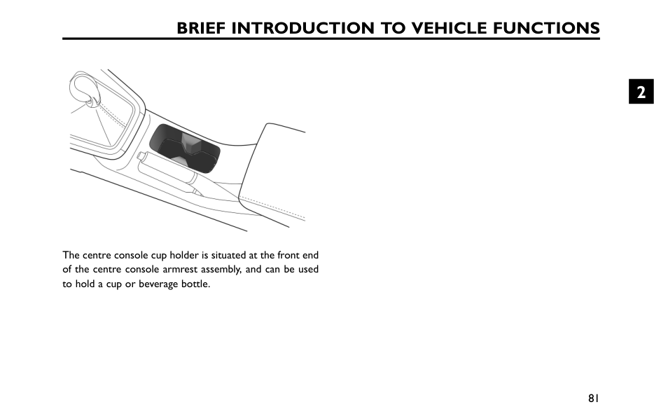
Brief Introduction To Vehicle Functions
The centre console cup holder is situated at the front end of the centre console armrest assembly, and can be used to hold a cup or beverage bottle. 81 2
Preparations for Trip Keys 84 Alarm System 87 Alcohol Interlocks* 91 Tailgate 92 Load Carrying 95 Towing* 97 Fuel System 99 Steering System Adjustment 101 3
Preparations For Trip
Keys Overview Please keep the spare key in a safe place - not in the car! It is recommended that spare keys are not kept on the same key ring, since this may cause interference and prevent correct key recognition and therefore prevent the correct operation of the vehicle power system. The smart key contains delicate circuits and must be protected from impact, high temperature, humidity, direct sunlight and fluid corrosion.Warning
The keys of vehicle contains coin / button batteries. The battery is HZARDOUS and is to be kept away from children (whether the battery is new or used).Warning
A
lithium coin / button battery can cause SEVERE or FATAL injuries within 2 hours or less if it is swallowed or placed inside any part of the body.Warning
If you think batteries may have been swallowed or placed inside any part of the body, please seek medical rescue immediately. 84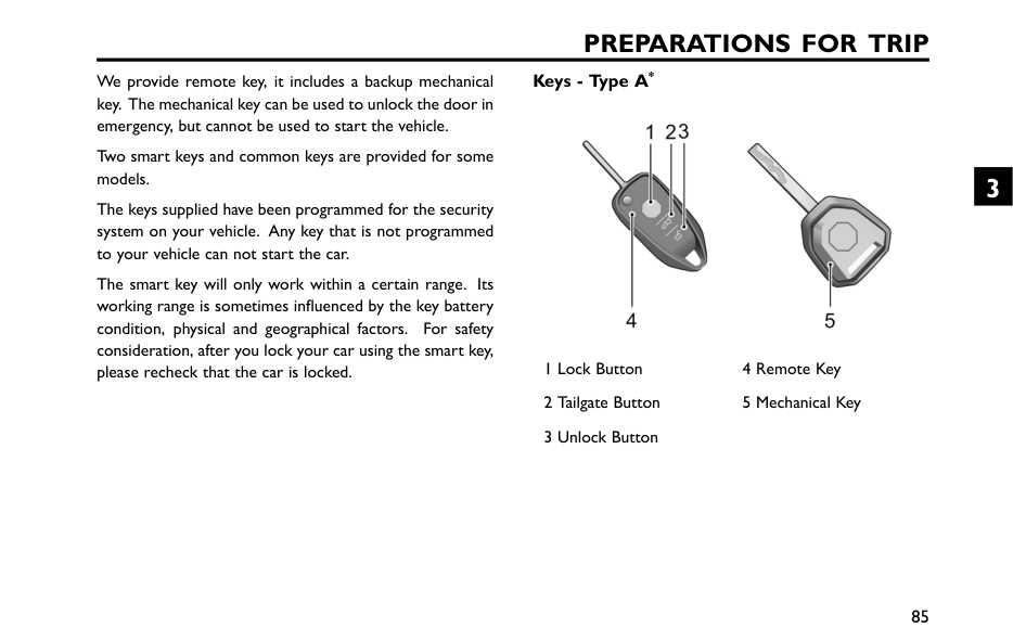
Preparations For Trip
We provide remote key, it includes a backup mechanical key. The mechanical key can be used to unlock the door in emergency, but cannot be used to start the vehicle. Two smart keys and common keys are provided for some models. The keys supplied have been programmed for the security system on your vehicle. Any key that is not programmed to your vehicle can not start the car. The smart key will only work within a certain range. Its working range is sometimes influenced by the key battery condition, physical and geographical factors. For safety consideration, after you lock your car using the smart key, please recheck that the car is locked. Keys - Type A* 1 Lock Button 4 Remote Key 2 Tailgate Button 5 Mechanical Key 3 Unlock Button 85 3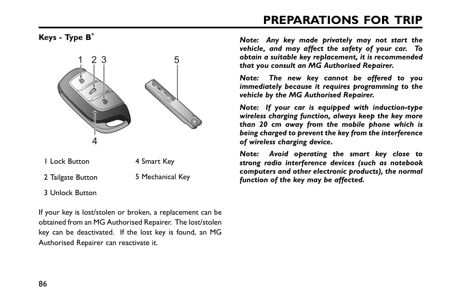
Preparations For Trip
Keys - Type B* 1 Lock Button 4 Smart Key 2 Tailgate Button 5 Mechanical Key 3 Unlock Button If your key is lost/stolen or broken, a replacement can be obtained from an MG Authorised Repairer. The lost/stolen key can be deactivated. If the lost key is found, an MG Authorised Repairer can reactivate it. Note: Any key made privately may not start the vehicle, and may affect the safety of your car. To obtain a suitable key replacement, it is recommended that you consult an MG Authorised Repairer. Note: The new key cannot be offered to you immediately because it requires programming to the vehicle by the MG Authorised Repairer. Note: If your car is equipped with induction-type wireless charging function, always keep the key more than 20 cm away from the mobile phone which is being charged to prevent the key from the interference of wireless charging device. Note: Avoid operating the smart key close to strong radio interference devices (such as notebook computers and other electronic products), the normal function of the key may be affected. 86
Preparations For Trip
Alarm System Your vehicle is fitted with power immobiliser and body anti-theft system. To ensure maximum safety and operation convenience, we strongly recommend you to read this section carefully to fully understand the activation and deactivation of anti-theft systems. Power Immobiliser Power Immobiliser is designed to safeguard the vehicle from theft. A vehicle cannot be started until the engine immobiliser is deactivated. Once a valid key is detected in the vehicle, power immobiliser will be deactivated automatically. Body Anti-theft System Locking and Unlocking When the vehicle is locked, the turn signal lamps illuminate three times; when it is unlocked, the turn signal lamps illuminate once. Operation of Door Lock System (Key) Key Locking • Using the remote key to lock: press the Lock button on the smart key to lock the vehicle after closing the doors, bonnet and tailgate. • Using the mechanical key to lock: open the driver side door lock trim cover, insert the key into the lockhole and turn clockwise to lock the car. Key Unlocking • Using the remote key to unlock: press the Unlock button on the key to unlock the vehicle. • Using the mechanical key to unlock: open the driver door lock trim cover, insert the key into the lockhole and turn counterclockwise to unlock the car. Find My Car 87 3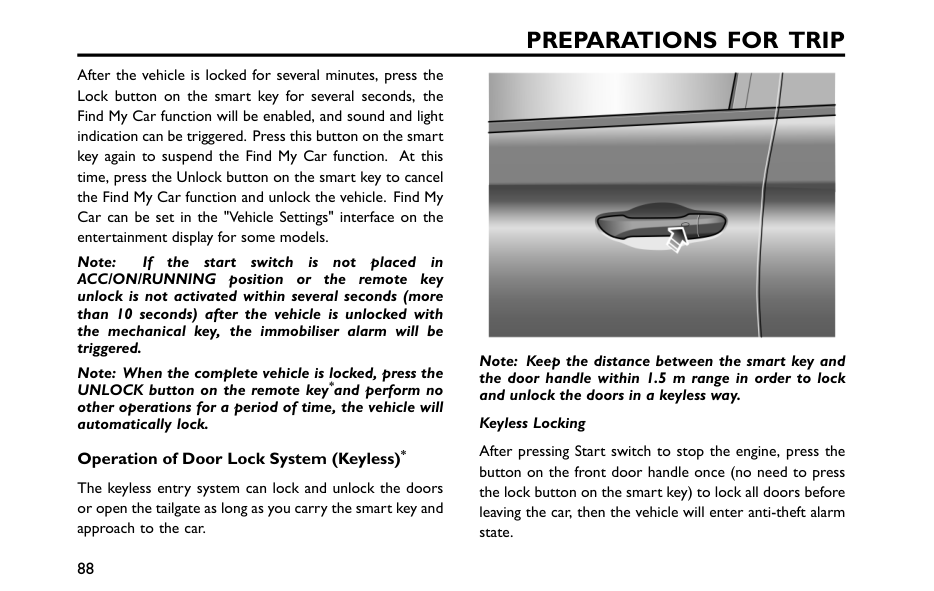
Preparations For Trip
After the vehicle is locked for several minutes, press the Lock button on the smart key for several seconds, the Find My Car function will be enabled, and sound and light indication can be triggered. Press this button on the smart key again to suspend the Find My Car function. At this time, press the Unlock button on the smart key to cancel the Find My Car function and unlock the vehicle. Find My Car can be set in the "Vehicle Settings" interface on the entertainment display for some models. Note: If the start switch is not placed inAcc/On/Running
position or the remote key unlock is not activated within several seconds (more than 10 seconds) after the vehicle is unlocked with the mechanical key, the immobiliser alarm will be triggered. Note: When the complete vehicle is locked, press the UNLOCK button on the remote key*and perform no other operations for a period of time, the vehicle will automatically lock. Operation of Door Lock System (Keyless)* The keyless entry system can lock and unlock the doors or open the tailgate as long as you carry the smart key and approach to the car. Note: Keep the distance between the smart key and the door handle within 1.5 m range in order to lock and unlock the doors in a keyless way. Keyless Locking After pressing Start switch to stop the engine, press the button on the front door handle once (no need to press the lock button on the smart key) to lock all doors before leaving the car, then the vehicle will enter anti-theft alarm state. 88
Preparations For Trip
Keyless Unlocking Press the button at the front door handle once to unlock the door, and pull the door handle to open the door. Note: When the vehicle is locked, if you are within the smart key range and operate the door handle button,but carry out no further action, after 30 seconds the vehicle will automatically re-lock itself to remain secure.Important
After the door is locked by using the key, press the button on the door handle to unlock the vehicle. If the vehicle can not be unlocked or locked normally, please contact a local MG Authorised Repairer. Mislock If locking operation is performed when the driver's door is not fully closed, the door will not be locked, and the horn will sound once to indicate a mislock, with the body anti-theft system inoperative. If locking operation is performed when the driver's door is closed but the passenger’s door or tailgate is not fully closed, the vehicle horn will sound once, indicating a mislock. In this case, the "partial arming" attributes of the body anti-theft system will enable (all fully closed doors or tailgate apertures will be protected, but an open aperture will not!). As soon as the open aperture is closed, the system will automatically revert to an armed state, if the remote key is placed back (or left behind) in the car and the opened door is closed, the entire vehicle will automatically unlock. Note: When the entire vehicle is locked, only unlock and open the tailgate, reposition (or leave) the remote key in the car and close the tailgate. At this time, the tailgate will automatically pop open and cannot be closed Anti-theft Alarm If the anti-theft alarm has been activated, before it is turned off, the car horn will sound continuously. The anti-theft alarm can be released by pressing the unlock button on the smart key. 89 3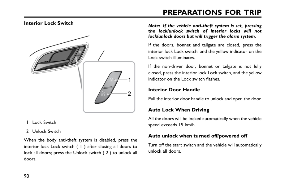
Preparations For Trip
Interior Lock Switch 1 Lock Switch 2 Unlock Switch When the body anti-theft system is disabled, press the interior lock Lock switch ( 1 ) after closing all doors to lock all doors; press the Unlock switch ( 2 ) to unlock all doors. Note: If the vehicle anti-theft system is set, pressing the lock/unlock switch of interior locks will not lock/unlock doors but will trigger the alarm system. If the doors, bonnet and tailgate are closed, press the interior lock Lock switch, and the yellow indicator on the Lock switch illuminates. If the non-driver door, bonnet or tailgate is not fully closed, press the interior lock Lock switch, and the yellow indicator on the Lock switch flashes. Interior Door Handle Pull the interior door handle to unlock and open the door. Auto Lock When Driving All the doors will be locked automatically when the vehicle speed exceeds 15 km/h. Auto unlock when turned off/powered off Turn off the start switch and the vehicle will automatically unlock all doors. 90
Preparations For Trip
Alcohol Interlocks* The alcohol lock is a detection device used to assist in limiting drivers from driving when their blood alcohol concentration exceeds a preset limit. You are responsible for the safety of your passengers and other road users. Drink driving is an offence and is strictly prohibited. After installing the alcohol lock and before starting the vehicle, you will need to blow into the handheld device to test the driver's alcohol concentration levels. After passing the test, you can start the vehicle. Note: The handheld device should be placed in a position that is easy to access and does not affect driving. Please contact an MG Authorised Repairer for device installation and set up.Important
If the alcohol test fails, for safety reasons, do not attempt to forcefully start the vehicle. If you suspect a malfunction with the alcohol lock device, please contact an MG Authorised Repairer for device installation and set up. 91 3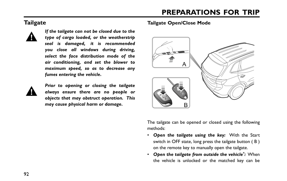
Preparations For Trip
Tailgate If the tailgate can not be closed due to the type of cargo loaded, or the weatherstrip seal is damaged, it is recommended you close all windows during driving, select the face distribution mode of the air conditioning, and set the blower to maximum speed, so as to decrease any fumes entering the vehicle. Prior to opening or closing the tailgate always ensure there are no people or objects that may obstruct operation. This may cause physical harm or damage. Tailgate Open/Close Mode The tailgate can be opened or closed using the following methods: • Open the tailgate using the key: With the Start switch in OFF state, long press the tailgate button ( B ) on the remote key to manually open the tailgate. • Open the tailgate from outside the vehicle*: When the vehicle is unlocked or the matched key can be 92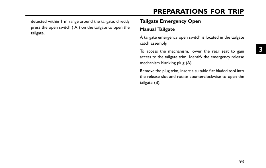
Preparations For Trip
detected within 1 m range around the tailgate, directly press the open switch ( A ) on the tailgate to open the tailgate. Tailgate Emergency Open Manual Tailgate A tailgate emergency open switch is located in the tailgate catch assembly. To access the mechanism, lower the rear seat to gain access to the tailgate trim. Identify the emergency release mechanism blanking plug (A). Remove the plug trim, insert a suitable flat bladed tool into the release slot and rotate counterclockwise to open the tailgate (B). 93 3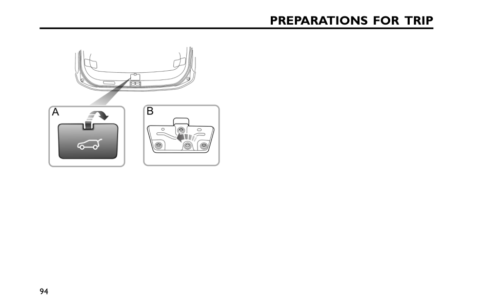
Preparations For Trip
94
Preparations For Trip
Load Carrying DO NOT exceed the gross vehicle weight or the permitted front and rear axle loads. Failure may result in vehicle damage or serious injury. Loadspace Loading Ensure that the rear seat backrests are securely latched in the upright position when loads are carried in the load space behind the seats. When luggage is carried in the load space, always ensure heavy items are placed as low and as far forward as possible, so as to avoid cargo shift in the event of an accident or sudden stop. Drive carefully and avoid emergency braking or hard acceleration when loaded with large or heavy items.Important
Traffic regulations must be observed when loading cargo, if the cargo extrudes the loadspace appropriate warning measures must be taken to warn other road users. 95 3
Preparations For Trip
Internal LoadingDo
Not
carry unsecured equipment, tools or luggage that could move, causing personal injury in the event of an accident, or emergency braking or hard acceleration.Do
Not
obstruct the driver's or passenger's vision with loads. Folding the rear seats can increase luggage space, refer to "Seat adjustment” described in the "Comfort Systems" section. 96
Preparations For Trip
Towing* General TowingSafety Exceeding any load limits advised by MG Motor is dangerous. Consult the recommended load limits and loading prior to any journey. Excessive towing loads reduce front tyre traction and steering control, too little trailer nose load can make the trailer unstable and cause it to sway. Yourvehicle can tow a trailer if you carefully observe load limits, useapproved equipment, and follow the towing guidelines. Always checkload limits before towing. Towing loads in excess of the maximumtowing weight can seriously affect vehicle handling and performance,this could damage your vehicle and drive-train. When adding a towing device to the vehicle When towing, all rear vehicle lights must remain visible to road users behindthe vehicle and must not be obscured / partially obscured. If towing light sources are obscured, a secondary lighting sourceshall be used such as a lighting board. When not towing, thefitted towing device must not obscure any lighting source. If thetowing device obscures or partially obscures a lighting source suchas the fog lamp it must be removed or retracted when not towing. Tow bars Only genuine MG approved towbars should be fitted to your vehicle. Only use the attachment methodspecified by the vehicle manufacturer for securing the towing hitch.Contact an MG Authorized Repairer for more information. Safety chains Safety chains mustbe used as a precautionary measure avoiding the trailer become unintentionallyunhitched. Make sure the safety chain is securely attached to boththe trailer and the vehicle prior to departure. Altitude 97 3
Preparations For Trip
Your engine delivers less power at higher altitude.If you tow a trailer in a mountainous area you should reduce the combinedvehicle and trailer weight by 10% for every 1000 m of elevation. Gradients Wherepossible, when towing, you should plan your journey to avoid steepgradients. The advised brake towing mass stated assumes a maximumgradient capability of 12% . Where possible it is recommendedyou drive on gradients less than 12% . Follow the trailerassociations recommendations for suitable roads. Running in period Avoid towing a trailer during your vehiclesfirst 1000 km. Towing Mode Your vehicle provides towing mode selection, it can be engaged or disengaged via: 1 Automatically: Connection or disconnection of the electrical connectionwith the trailer and the vehicle. 2 Manually: Enter the entertainment display to switch the function On/Off. Note: When towing mode is engaged automatically, manual adjustment via the entertainment display is not possible. When towing mode is activated, some vehicle functions will be limited or turned off, such as: • Auto emergency brake*; • Adaptive cruise control system*; • Traffic jam assist system*; • Lane departure assist system*; • Rear driving assistance system*; • Rear parking aid system. Note: If the towed device is equipped with a tail light cluster, the vehicle also controls the trailer's lights after connecting the electrical connection. Note: When operating the rear fog lamps, the trailer's rear fog lamps will also operate. 98
Preparations For Trip
Fuel System Fuel Requirements Use only gasoline which meets the national standards and the OEM specifications. Serious damage to the catalytic converter, a reduction in engine power / torque and increase in fuel consumption will occur if the wrong fuel is used. Please carry out refueling according to the information on the refueling label. Refer to "Main Engine Parameters" in the "Technical Data" section for details. E5: Unleaded petrol fuel containing a maximum 2.7% (m/m) of oxygen and a maximum 5% (v/v) of ethanol. E10: Unleaded petrol fuel containing a maximum 3.7% (m/m) of oxygen and a maximum 10% (v/v) of ethanol. If a lower grade of fuel is used, an engine knocking noisemay occur, please use the recommended or above gradegasoline as soon as possible. If the engine knocking noiseis still noticeable after using the recommended or abovegrade fuel, please contact an MG Authorised Repairerimmediately. It is permitted that the octane number ofgasoline is higher than that required by the engine, butit is not advantageous for engine output power and fuelconsumption. 99 3
Preparations For Trip
Fuel Filler Fuel Filler Flap The fuel filler door is located on the left rear side of the vehicle, and the small door lock is connected to the central control door lock system. When the door lock is open, press the left side of the small door to open it. Note: The fuel filler can only be locked when the car door is lock. Fuel Filler Cap Slowly rotate the fuel filler cap counterclockwise to release the pressure inside the tank before opening it. After refueling, replace the fuel filler cap and tighten it till you hear a "click". Refueling Vehicle fuel gases are highly flammable and, in confined spaces, are also extremely explosive. Always take care when refueling: • Turn off the power system; • Do not smoke or use a naked flame; • Do not use a mobile phone; • Prevent fuel spillage; • Do not overfill the tank. Do not fully refuel the tank if the vehicle is to be parked in direct sunlight or high ambient temperature - expansion of the fuel could cause a leakage. Start the engine after the fuel filling. If the engine does not run smoothly, shut down and do not start it again, contact an MG Authorise Repairer immediately for service.Important
During refueling, gasoline should be prevented from splashing on the surface of any painted or adjacent exterior parts. Contamination may cause the surface of the paint or adjacent exterior parts to become damaged. 100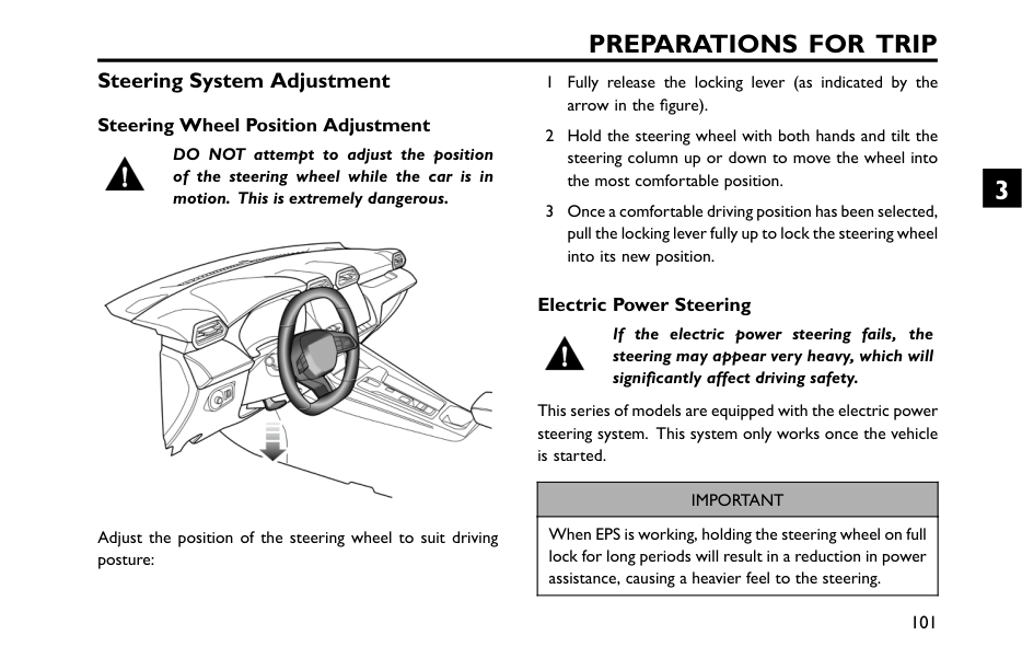
Preparations For Trip
Steering System Adjustment Steering Wheel Position Adjustment DO NOT attempt to adjust the position of the steering wheel while the car is in motion. This is extremely dangerous. Adjust the position of the steering wheel to suit driving posture: 1 Fully release the locking lever (as indicated by the arrow in the figure). 2 Hold the steering wheel with both hands and tilt the steering column up or down to move the wheel into the most comfortable position. 3 Once a comfortable driving position has been selected, pull the locking lever fully up to lock the steering wheel into its new position. Electric Power Steering If the electric power steering fails, the steering may appear very heavy, which will significantly affect driving safety. This series of models are equipped with the electric power steering system. This system only works once the vehicle is started.Important
When EPS is working, holding the steering wheel on full lock for long periods will result in a reduction in power assistance, causing a heavier feel to the steering. 101 3
Preparations For Trip
Electric Power Steering Module Angle Initialisation When the battery is reconnected after disconnection, the electric power steering ( EPS ) warning lamps may illuminate in yellow. In this case, the electric power steering ( EPS ) requires intialisation, i.e., rotate the steering wheel from lock to lock; after the initialisation is complete, the warning lamps extinguish. Steering Wheel Heating* Some models in this vehicle are equipped with steering wheel heating function. The heating function can improve driving comfort in low temperature environments. The heating function can be turned on or off through the switch on the entertainment display screen. 102
Drive the Vehicle Power Start/Stop 104 Electric Drive Transmission* 109 Manual Transmission* 111 Continuously Variable Automatic Transmission (CVT)* 113 Drive Mode* 118 Parking Brake 120 Service Brake 123 Energy Regeneration* 125 4
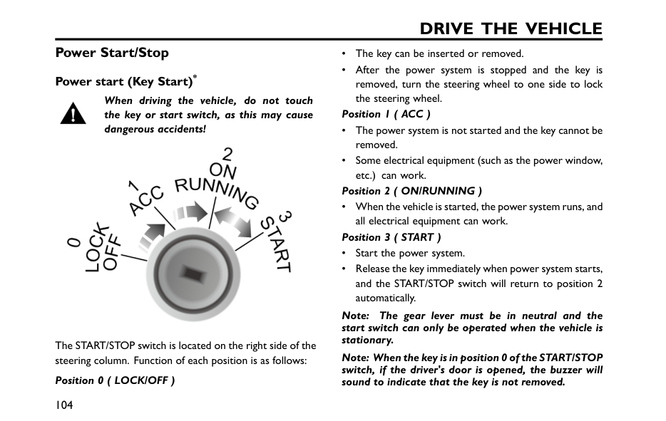
Drive The Vehicle
Power Start/Stop Power start (Key Start)* When driving the vehicle, do not touch the key or start switch, as this may cause dangerous accidents! The START/STOP switch is located on the right side of the steering column. Function of each position is as follows: Position 0 ( LOCK/OFF ) • The key can be inserted or removed. • After the power system is stopped and the key is removed, turn the steering wheel to one side to lock the steering wheel. Position 1 ( ACC ) • The power system is not started and the key cannot be removed. • Some electrical equipment (such as the power window, etc.) can work. Position 2 ( ON/RUNNING ) • When the vehicle is started, the power system runs, and all electrical equipment can work. Position 3 ( START ) • Start the power system. • Release the key immediately when power system starts, and the START/STOP switch will return to position 2 automatically. Note: The gear lever must be in neutral and the start switch can only be operated when the vehicle is stationary. Note: When the key is in position 0 of the START/STOP switch, if the driver's door is opened, the buzzer will sound to indicate that the key is not removed. 104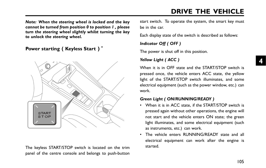
Drive The Vehicle
Note: When the steering wheel is locked and the key cannot be turned from position 0 to position 1 , please turn the steering wheel slightly whilst turning the key to unlock the steering wheel. Power starting( ( (Keyless Start) ) )* The keyless START/STOP switch is located on the trim panel of the centre console and belongs to push-button start switch. To operate the system, the smart key must be in the car. Each display state of the switch is described as follows: Indicator Off ( OFF ) The power is shut off in this position. Yellow Light ( ACC ) When it is in OFF state and the START/STOP switch is pressed once, the vehicle enters ACC state, the yellow light of the START/STOP switch illuminates, and some electrical equipment (such as the power window, etc.) can work. Green Light ( ON/RUNNING/READY ) • When it is in ACC state, if the START/STOP switch is pressed again without other operations, the engine will not start and the vehicle enters ON state; the green light illuminates, and some electrical equipment (such as instruments, etc.) can work. • The vehicle enters RUNNING/READY state and all electrical equipment can work after the engine is started. 105 4
Drive The Vehicle
Note: When the START/STOP Switch is turned off and a door is opened, if the key is still in the car, the horn will sound in succession when the door is closed. The warning sound will emit when the door is opened again, and the warning icon and prompt message will be displayed in the instrument pack to indicate that Please Take Your Key. A strong radio signal will interfere with the keyless start system. If your vehicle is close to a strong radio signal, the push-button start may be inoperative. Power starting Do not start and run the engine for a long time in an unventilated room. Exhaust fumes are harmful and contain carbon monoxide, which can cause unconsciousness or even death。 。 。 Starting Procedure 1 Switch off all unnecessary electrical equipment (including the air conditioning); 2 For vehicles with automatic transmission, make sure the shift lever is in P or N position and press the brake pedal; 3 For manual transmission vehicle, ensure neutral is selected when the clutch pedal is fully pressed; 4 Press the START/STOP Switch on the instrumentpanel, and release the button after the engine begins to start. 106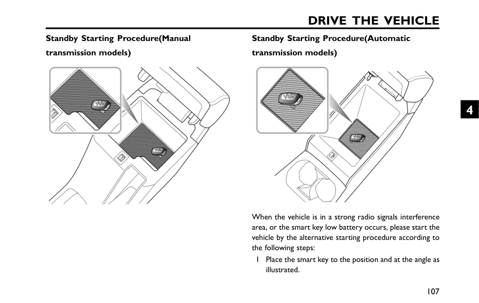
Drive The Vehicle
Standby Starting Procedure(Manual transmission models) Standby Starting Procedure(Automatic transmission models) When the vehicle is in a strong radio signals interference area, or the smart key low battery occurs, please start the vehicle by the alternative starting procedure according to the following steps: 1 Place the smart key to the position and at the angle as illustrated. 107 4
Drive The Vehicle
2 Make sure the shift lever is in P position, and then press the brake pedal and the Start switch to start the power system. 3 For manual transmission models, please place the gear lever in neutral, press the clutch pedal, operate the start switch, and start the power system. After the battery of smart key is replaced or the car leaves the interference area, if the keyless start procedure can still not be used normally, seek a local Authorised Repairer.Important
• If three consecutive attempts to start are unsuccessful, please seek assistance. Otherwise, multiple consecutive starts may cause damage to the power system and battery. • This car is equipped with an anti-theft system. Any privately prepared key cannot start the vehicle. • In environments with temperatures below -10 degrees Celsius, the time for the power system to start will increase. Therefore, when starting, turn off all unnecessary electrical equipment. Stop power system Turn off the vehicle's power system as follows: 1 After safely sbringing the vehicle to a stop, press the brake pedal (automatic transmission) or clutch pedal (manual transmission); 2 Activate parking brake; 3 Automatic transmission models, please place the shift lever in the P positin. 4 For manual transmission models, please place the gear lever in neutral. 5 Operate the start switch to turn off the power system. 108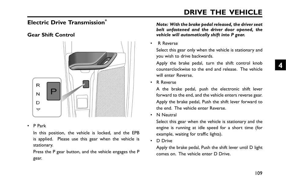
Drive The Vehicle
Electric Drive Transmission* Gear Shift Control • P Park In this position, the vehicle is locked, and the EPB is applied. Please use this gear when the vehicle is stationary. Press the P gear button, and the vehicle engages the P gear. Note: With the brake pedal released, the driver seat belt unfastened and the driver door opened, the vehicle will automatically shift into P gear. • R Reverse Select this gear only when the vehicle is stationary and you wish to drive backwards. Apply the brake pedal, turn the shift control knob counterclockwise to the end and release. The vehicle will enter Reverse. • R Reverse A the brake pedal, push the electronic shift lever forward to the end, and the vehicle enters reverse gear. Apply the brake pedal, Push the shift lever forward to the end. The vehicle enter Reverse. • N Neutral Select this gear when the vehicle is stationary and the engine is running at idle speed for a short time (for example, waiting for traffic lights). • D Drive Apply the brake pedal, Push the shift lever until D light comes on. The vehicle enter D Drive. 109 4
Drive The Vehicle
Protection Mode When parking, drive the vehicle to a safe area on the premise of ensuring your own safety and complying with traffic regulations. Shift System Malfunction If serious functional faults are detected in the gear shifting system, the instrument pack will display "EP". At this time, for the sake of driving safety, when the speed is below a certain value, the power system will forcibly cut off the power transmission, and the vehicle will not be able to be driven! Please contact an MG Authorised Repairer immediately. Electric Drive Transmission Motor Malfunction When the system detects a fault with the electric drive transmission motor or controller, the warning indicator light illuminates red. Please park the vehicle safely and contact an MG Authorised Repairer immediately. Power Limitation of Electric DriveTransmission The electric drive transmission may become very hot in a high-temperature environments with frequent starting, frequent rapid acceleration and deceleration, long-term continuous steep climbing, and thus overload the electric drive transmission. In some cases, to avoid motor damage, the system will implement power limitation. the warning indicator illuminates. In this situation, stop at a safe place or maintain a lower load to continue moving at a constant speed to cool the motor. After the motor temperature drops and the warning indicator light goes out, normal driving can be reinstated. If the electric drive transmission has cooled down for a long time (about 20 minutes) and the warning indicator has not disappeared, please park the vehicle safely and contact an MG Authorised Repairer immediately, otherwise it may seriously damage the electric drive transmission. 110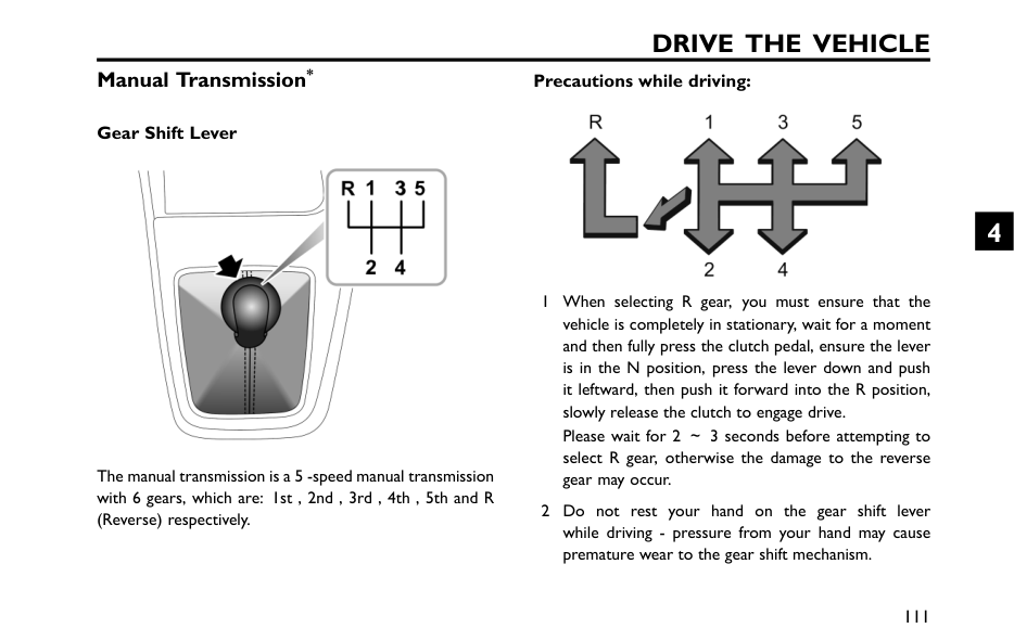
Drive The Vehicle
Manual Transmission* Gear Shift Lever The manual transmission is a 5 -speed manual transmission with 6 gears, which are: 1st , 2nd , 3rd , 4th , 5th and R (Reverse) respectively. Precautions while driving: 1 When selecting R gear, you must ensure that the vehicle is completely in stationary, wait for a moment and then fully press the clutch pedal, ensure the lever is in the N position, press the lever down and push it leftward, then push it forward into the R position, slowly release the clutch to engage drive. Please wait for 2 ~3 seconds before attempting to select R gear, otherwise the damage to the reverse gear may occur. 2 Do not rest your hand on the gear shift lever while driving - pressure from your hand may cause premature wear to the gear shift mechanism. 111 4
Drive The Vehicle
3 Do not rest your foot on the clutch pedal when driving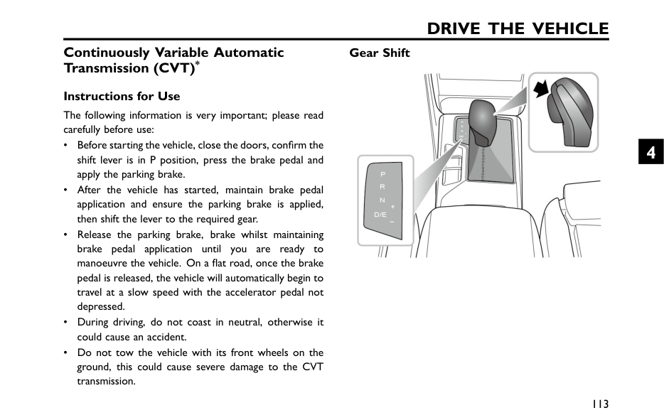
Drive The Vehicle
Continuously Variable Automatic Transmission (CVT)* Instructions for Use The following information is very important; please read carefully before use: • Before starting the vehicle, close the doors, confirm the shift lever is in P position, press the brake pedal and apply the parking brake. • After the vehicle has started, maintain brake pedal application and ensure the parking brake is applied, then shift the lever to the required gear. • Release the parking brake, brake whilst maintaining brake pedal application until you are ready to manoeuvre the vehicle. On a flat road, once the brake pedal is released, the vehicle will automatically begin to travel at a slow speed with the accelerator pedal not depressed. • During driving, do not coast in neutral, otherwise it could cause an accident. • Do not tow the vehicle with its front wheels on the ground, this could cause severe damage to the CVT transmission. Gear Shift 113 4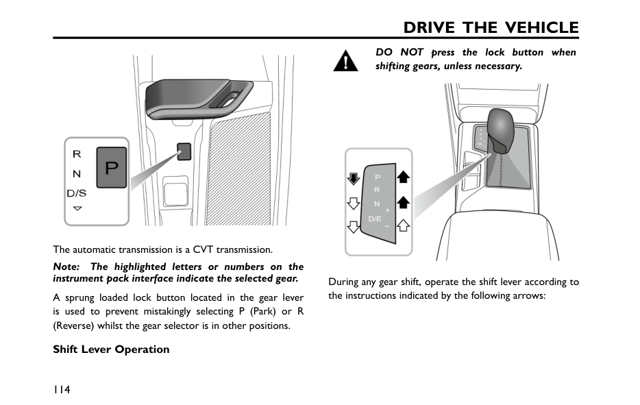
Drive The Vehicle
The automatic transmission is a CVT transmission. Note: The highlighted letters or numbers on the instrument pack interface indicate the selected gear. A sprung loaded lock button located in the gear lever is used to prevent mistakingly selecting P (Park) or R (Reverse) whilst the gear selector is in other positions. Shift Lever Operation DO NOT press the lock button when shifting gears, unless necessary. During any gear shift, operate the shift lever according to the instructions indicated by the following arrows: 114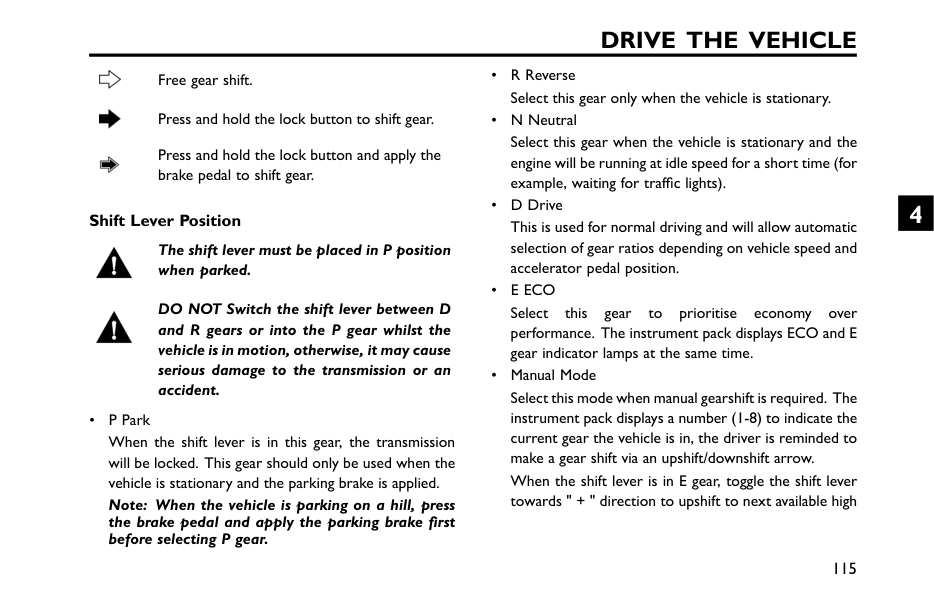
Drive The Vehicle
Free gear shift. Press and hold the lock button to shift gear. Press and hold the lock button and apply the brake pedal to shift gear. Shift Lever Position The shift lever must be placed in P position when parked. DO NOT Switch the shift lever between D and R gears or into the P gear whilst the vehicle is in motion, otherwise, it may cause serious damage to the transmission or an accident. • P Park When the shift lever is in this gear, the transmission will be locked. This gear should only be used when the vehicle is stationary and the parking brake is applied. Note: When the vehicle is parking on a hill, press the brake pedal and apply the parking brake first before selecting P gear. • R Reverse Select this gear only when the vehicle is stationary. • N Neutral Select this gear when the vehicle is stationary and the engine will be running at idle speed for a short time (for example, waiting for traffic lights). • D Drive This is used for normal driving and will allow automatic selection of gear ratios depending on vehicle speed and accelerator pedal position. •E Eco
Select this gear to prioritise economy over performance. The instrument pack displays ECO and E gear indicator lamps at the same time. • Manual Mode Select this mode when manual gearshift is required. The instrument pack displays a number (1-8) to indicate the current gear the vehicle is in, the driver is reminded to make a gear shift via an upshift/downshift arrow. When the shift lever is in E gear, toggle the shift lever towards " + " direction to upshift to next available high 115 4
Drive The Vehicle
gear; or toggle the shift lever towards " - " to downshift to next available low gear. Whilst in manual mode, if the driver makes an unreasonable gear selection, such as requesting an upshift during low engine speeds, or requesting a downshift during high engine speeds, the transmission will not respond and will remain in the current gear. If the vehicle is driven and the engine speed falls below a preset threshold in certain gears, the transmission will automatically shift down to the next gear to avoid engine stalling; when the vehicle accelerates, if the engine speed increases continuously and exceeds the allowable maximum speed with no upshift request received, the transmission will automatically shift up to the next gear to protect the engine. To return to other gear modes, move the shift lever leftwards and select D. Gearshift Speed With D or E gear selected, the speed of one gear varies depending on the accelerator pedal position: a smaller throttle opening will result in the gear shift at a lower speed, and a larger throttle opening will cause the transmission to delay the gear shift action, until the gear shift is completed when the vehicle reaches a higher speed. Kick-down The drive wheels may skid when kick-down is activated on road surfaces with low adhesion, this may lead to the vehicle sliding out of control. With D or E gear selected, pressing the accelerator pedal all the way down in one motion (also known as Kick-down ) will provide better acceleration performance during overtaking. Under certain conditions, it will allow the transmission to shift to a lower gear immediately, and provide fast acceleration. Once the accelerator pedal is released, it will resume a suitable higher gear (based on the vehicle speed and the position of the accelerator pedal). 116
Drive The Vehicle
Protection Mode When parking, drive the vehicle to a safe area on the premise of ensuring your own safety and complying with traffic regulations. CVT Transmission Failure If the transmission develops faults or works improperly, the engine emission malfunction indicator lamp in the instrument pack illuminates. In such a case, seek a local Authorised Repairer for service as soon as possible. Limp Mode When some failures occur, the transmission will enter Limp Mode and will only function in some gears, in some cases it may fail to engage reverse, during this time the instrument pack will display the engine emission malfunction indicator lamp. In such a case, contact an MG Authorised Repairer for service as soon as possible. Gear Shift System Failure If some serious functional failures occur in the gear shift system, the instrument pack will display " EP ". During this time, for safe driving, if the vehicle speed is below a certain value, the power system will forcibly cut off the power transmission, and the vehicle will not be able to drive! In this case, please contact an MG Authorised Repairer for service as soon as possible. 117 4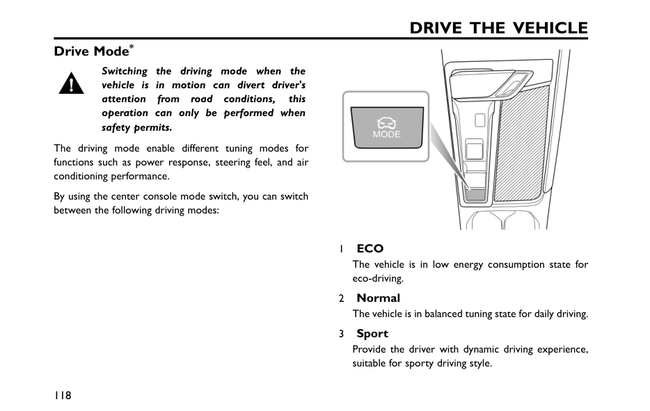
Drive The Vehicle
Drive Mode* Switching the driving mode when the vehicle is in motion can divert driver's attention from road conditions, this operation can only be performed when safety permits. The driving mode enable different tuning modes for functions such as power response, steering feel, and air conditioning performance. By using the center console mode switch, you can switch between the following driving modes: 1Eco
The vehicle is in low energy consumption state for eco-driving. 2 Normal The vehicle is in balanced tuning state for daily driving. 3 Sport Provide the driver with dynamic driving experience, suitable for sporty driving style. 118
Drive The Vehicle
Note: When switching the driving mode in manual mode, the power system will maintain the shift logic of manual mode. 119 4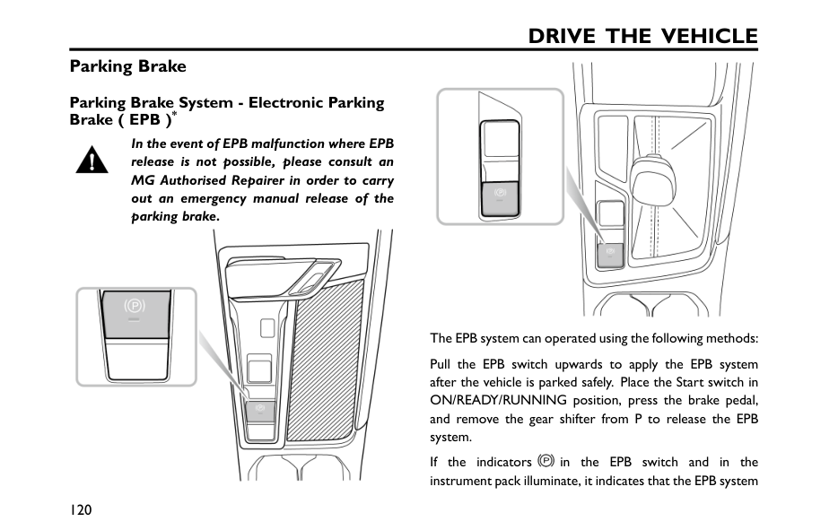
Drive The Vehicle
Parking Brake Parking Brake System - Electronic Parking Brake ( EPB )* In the event of EPB malfunction where EPB release is not possible, please consult an MG Authorised Repairer in order to carry out an emergency manual release of the parking brake. The EPB system can operated using the following methods: Pull the EPB switch upwards to apply the EPB system after the vehicle is parked safely. Place the Start switch in ON/READY/RUNNING position, press the brake pedal, and remove the gear shifter from P to release the EPB system. If the indicators in the EPB switch and in the instrument pack illuminate, it indicates that the EPB system 120
Drive The Vehicle
has been applied. If the indicators in the EPB switch and in the instrument pack extinguish, it indicates that the EPB system has been released. Note: When leaving the vehicle, the EPB must be applied. Note: An audible motor noise may be heard when applying or releasing the EPB. The electronic parking system cannot be activated or deactivated when the vehicle battery is discharged. If this is the case, apply the emergency starting power system with a jumper cable, please refer to the "Jump Start" section in the "Emergency"section. Start Assist If the driver's seat belt is fastened, the engine is running, D or R gear is selected and the accelerator pedal is pressed to pull away, the EPB system will automatically release. Emergency Braking Function Inappropriate use of EPB can lead to accidents and injuries. DO NOT apply the EPB for vehicle braking whilst moving, unless in an emergency. During emergency braking using the EPB, DO NOT switch off the ignition/power system, this could result in serious injury. In the event of normal brake failure during driving, emergency braking can be initiated by pulling and holding the EPB switch upward. An audible warning will sound during emergency braking. The braking process will be canceled by releasing the EPB switch. 121 4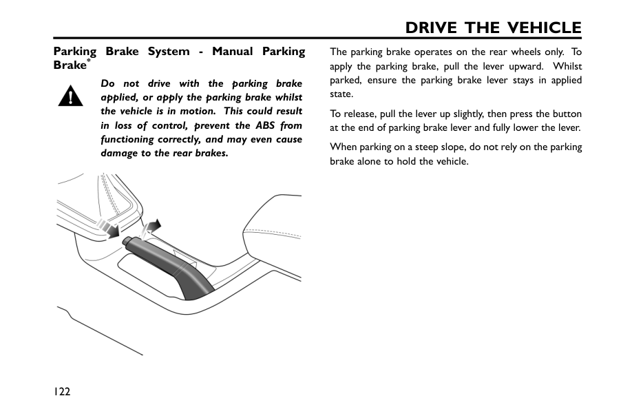
Drive The Vehicle
Parking Brake System - Manual Parking Brake* Do not drive with the parking brake applied, or apply the parking brake whilst the vehicle is in motion. This could result in loss of control, prevent the ABS from functioning correctly, and may even cause damage to the rear brakes. The parking brake operates on the rear wheels only. To apply the parking brake, pull the lever upward. Whilst parked, ensure the parking brake lever stays in applied state. To release, pull the lever up slightly, then press the button at the end of parking brake lever and fully lower the lever. When parking on a steep slope, do not rely on the parking brake alone to hold the vehicle. 122
Drive The Vehicle
Service Brake Some models are equipped with vacuum assisted hydraulic brake system as the service brake system. It allows the driver to apply the brake more easily, and also improves the braking performance. Note: When the engine is not started, the brake pedal will feel hard, but when the engine is started, the brake pedal will feel soft, which is the brake booster in action. The vacuum assisted hydraulic brake system helps the driver save effort when depressing the brake pedal, and ensures a safe and quick braking, however, in daily driving, the following non-standard operations should be avoided: • Never allow the car to freewheel with the engine turned off. Since the vacuum assisted hydraulic brake system functions with the engine started up only, braking when the car is freewheeling with the engine flameout may cause braking failure. • In case of flameout while driving, you should depress the brake pedal to stop the vehicle as quickly as traffic safety permits. During braking, DO NOT pump the brake pedal, because it will excessively consume the vacuum assist in the braking system, thereby requiring increased pressing force, and reducing the easiness in braking. During driving, the following matters should be noted: • When the braking efficiency of vacuum booster decreases due to the change of atmospheric pressure from plain to plateau regions, the user needs to depress the brake pedal with greater effort than usual to gain effective braking. • When driving through puddles or heavy rain, a water film may form on the surface of brake disc, which easily reduces the braking efficiency and extends braking distance. In this case, keep a safe distance from other vehicles and intermittently apply the brake pedal to keep the brake disc surface dry. • If the braking efficiency decreases due to vehicle failure, please contact a local MG Authorised Repairer for service as soon as possible. Some models are equipped with an integrated braking system (IBS), which has the advantages of high integration, faster braking response, and higher stability without relying on vacuum environment. Please note the following points when using IBS: 123 4
Drive The Vehicle
• IBS only works when the power system is ready, please do not coast with the power system turned off. • If the power system is turned off during driving, you should firmly press the brake pedal and stop as soon as traffic safety permits. • When the power supply of IBS decreases due to low power or other reasons, it is necessary to apply more force than usual to the brake pedal to obtain effective braking. 124
Drive The Vehicle
Energy Regeneration* Deceleration caused by energy regeneration isNot
a substitute for braking safely. The driver must ALWAYS be prepared to make braking manoeuvres to maintain safe driving. When the vehicle is braking, in an overrun or coasting state, the energy regeneration function is activated, and the motor converts part of the kinetic energy of the vehicle into electric energy, which is then stored in the high-voltage battery pack. Energy cannot be regenerated or is limited under some conditions, such as: • N gear is selected (During driving do not coast in N gear) ; • During torque intervention (SCS or traction control operation) ; • High voltage battery pack is fully charged; • High voltage battery pack temperature is too high or too low. Energy Regeneration Level : High High Level: Maximum energy is regenerated, the vehicle exhibits shorter coasting distances and a strong sensation of over-run drag or motor braking. Medium Medium Level: Moderate energy regenerated. Low Low Level: Minimum energy is regenerated, the vehicle exhibits longer coasting distances and no significant sensation of over-run drag or motor braking. The energy regeneration level can be selected in the entertainment display screen. Note: It is recommended to choose Low or Medium levels on surfaces that have low adhesion levels (e.g. icy roads). 125 4
Leave Home Safe Seat Belt 128 Airbag 139 Child Restraints 151 Child Proof Locks 162 Body Stability Control System 163 Anti-lock Brake System (ABS) 165 Auxiliary Brake System 166 Auto Hold* 167 Hill Hold Control (HHC) 169 Hill Descent Control (HDC) 170 Active Rollover Protection (ARP) 173 Emergency Braking Hazard Warning Strobe
(Haz)*
174 Multi-Collision Brake System(MCB)* 175 Tyre Pressure Monitoring System (TPMS)* 176 5
Leave Home Safe
Seat Belt It is important that all seat belts are worn correctly. Always check that all passengers are wearing seat belts.Do
NOT carry passengers that are unable to wear correctly positioned seat belts. Wearing seat belts incorrectly may cause serious injury or even death in the event of a collision. Airbags can not replace seat belts. Airbags can only provide extra support when triggered, and not all traffic accident swill trigger airbags. Whether airbags are triggered or not, seat belts can reduce the risks of serious injury or death in accidents. Therefore, seat belts must be worn properly. NEVER unfasten a seat belt whilst driving, serious injury or death may occur in the event of an accident or emergency braking. Never fasten the driver seat belt or use a buckle replacement when the driver seat is vacant or when exiting the vehicle. This vehicle is equipped with a seat belt warninglamp to remind you to fasten your seat belt. During driving, seat belts must be fastened,this is because: • You can never predict if you will be involved in a collisionaccident and how serious it may be. • In many cases of collision accidents, passengers withseat belts properly fastened are well-protected, whilepassengers with seat belts not fastened suffer fromserious injury or even death.Therefore, all passengers must wear seat belts correctly,even during short-distance journeys. Therefore, all passengers must wear seat belts correctly, even during short-distance journeys. 128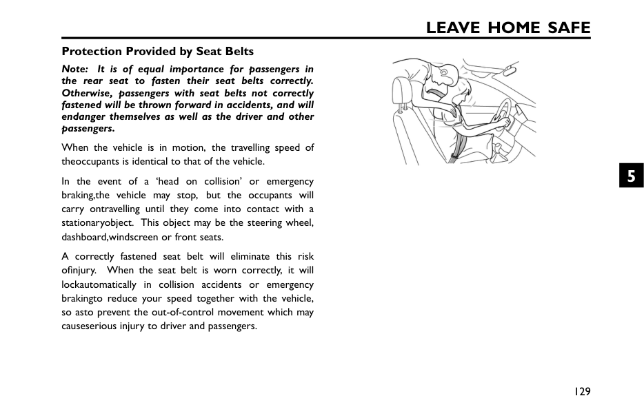
Leave Home Safe
Protection Provided by Seat Belts Note: It is of equal importance for passengers in the rear seat to fasten their seat belts correctly. Otherwise, passengers with seat belts not correctly fastened will be thrown forward in accidents, and will endanger themselves as well as the driver and other passengers. When the vehicle is in motion, the travelling speed of theoccupants is identical to that of the vehicle. In the event of a ‘head on collision’ or emergency braking,the vehicle may stop, but the occupants will carry ontravelling until they come into contact with a stationaryobject. This object may be the steering wheel, dashboard,windscreen or front seats. A correctly fastened seat belt will eliminate this risk ofinjury. When the seat belt is worn correctly, it will lockautomatically in collision accidents or emergency brakingto reduce your speed together with the vehicle, so asto prevent the out-of-control movement which may causeserious injury to driver and passengers. 129 5
Leave Home Safe
Wearing Seat Belts Incorrectly worn seat belts could cause injury or death in the event of an accident. Seat belts are designed for one person, DO NOT share seat belts. DO NOT wrap a seat belt around when holding a baby or child in your arms. Remove any heavy coats or clothing when wearing a seat belt, failure to do so can affect protection provided by the seat belt. Seat belts should not be wrapped around hard or sharp objects such as pens, spectacles or keys. Seat belts can not function correctly when the seats are reclined excessively.Do
NOT drive when the seats are excessively reclined. The seat belts fitted to your vehicle are designed for use by normal sized adults. This part of the literature refers to adult use.All seat belts are 3 point lap-diagonal belts. In order to maintain effective protection, the passengers must sit in the correct orientation, feet placed on the floor in front of them, with an upright body (no excessive recline) and the seat belt correctly fastened. 130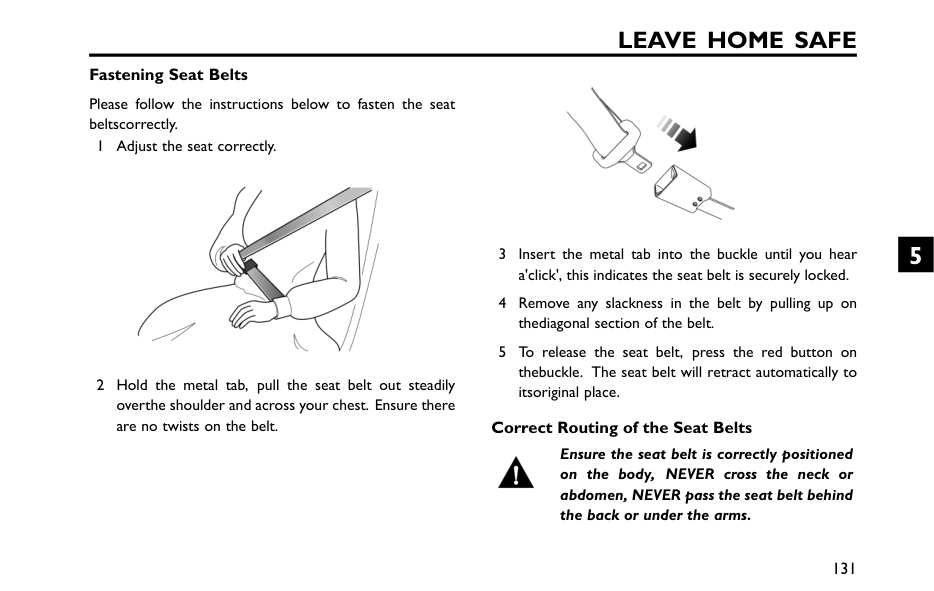
Leave Home Safe
Fastening Seat Belts Please follow the instructions below to fasten the seat beltscorrectly. 1 Adjust the seat correctly. 2 Hold the metal tab, pull the seat belt out steadily overthe shoulder and across your chest. Ensure there are no twists on the belt. 3 Insert the metal tab into the buckle until you hear a'click', this indicates the seat belt is securely locked. 4 Remove any slackness in the belt by pulling up on thediagonal section of the belt. 5 To release the seat belt, press the red button on thebuckle. The seat belt will retract automatically to itsoriginal place. Correct Routing of the Seat Belts Ensure the seat belt is correctly positioned on the body, NEVER cross the neck or abdomen, NEVER pass the seat belt behind the back or under the arms. 131 5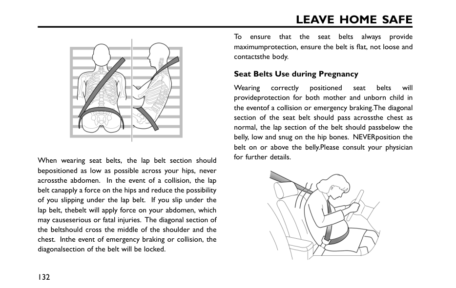
Leave Home Safe
When wearing seat belts, the lap belt section should bepositioned as low as possible across your hips, never acrossthe abdomen. In the event of a collision, the lap belt canapply a force on the hips and reduce the possibility of you slipping under the lap belt. If you slip under the lap belt, thebelt will apply force on your abdomen, which may causeserious or fatal injuries. The diagonal section of the beltshould cross the middle of the shoulder and the chest. Inthe event of emergency braking or collision, the diagonalsection of the belt will be locked. To ensure that the seat belts always provide maximumprotection, ensure the belt is flat, not loose and contactsthe body. Seat Belts Use during Pregnancy Wearing correctly positioned seat belts will provideprotection for both mother and unborn child in the eventof a collision or emergency braking.The diagonal section of the seat belt should pass acrossthe chest as normal, the lap section of the belt should passbelow the belly, low and snug on the hip bones. NEVERposition the belt on or above the belly.Please consult your physician for further details. 132
Leave Home Safe
Please consult your physician for further details. Seat Belts and Disabilities It is a legal requirement that all occupants wear seat belts, this include people with disabilities. Depending upon the disability, consult your physician for further details. Children and Seat Belts Only recommended child restraints suitable for the age, height and weight of the child should be used. For safety reasons, children must travel in a child restraintdevice fixed to the rear seat. 133 5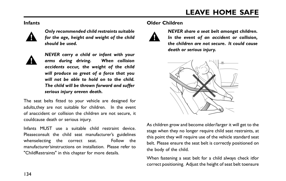
Leave Home Safe
Infants Only recommended child restraints suitable for the age, height and weight of the child should be used. NEVER carry a child or infant with your arms during driving. When collision accidents occur, the weight of the child will produce so great of a force that you will not be able to hold on to the child. The child will be thrown forward and suffer serious injury oreven death. The seat belts fitted to your vehicle are designed for adults,they are not suitable for children. In the event of anaccident or collision the children are not secure, it couldcause death or serious injury. Infants MUST use a suitable child restraint device. Pleaseconsult the child seat manufacturer’s guidelines whenselecting the correct seat. Follow the manufacturer’sinstructions on installation. Please refer to "ChildRestraints" in this chapter for more details. Older Children NEVER share a seat belt amongst children. In the event of an accident or collision, the children are not secure. It could cause death or serious injury. As children grow and become older/larger it will get to the stage when they no longer require child seat restraints, at this point they will require use of the vehicle standard seat belt. Please ensure the seat belt is correctly positioned on the body of the child. When fastening a seat belt for a child always check itfor correct positioning. Adjust the height of seat belt toensure 134
Leave Home Safe
the shoulder belt is kept away from the child's faceand neck. Position the lap belt across the hips as lowas possible, and tighten adequately. Correct positioning means that the seat belts can pass the applied force to thestrongest part of child's body in accidents. If the shoulder belt is too close to child's face or neck, itmay be necessary to use a child booster cushion (alwaysensure that it meets any relevant laws or standards. Seat Belt Pre-tensioners The seat belt pre-tensioners will only be activated once and thenMust
BE REPLACED. Failure to replace the pre-tensioners will reduce the efficiency of the vehicle's restraint system. If the pre-tensioners have been activated, the seat belts will still function as restraints, and must be worn in the event that the vehicle remains in a drivable condition. The seatbelt pre-tensioners should be replaced at the earliest opportunity by an MG Authorised Repairer. The vehicle is fitted with seat belt pre-tensioners. Theseare designed to retract the seat belts and work inconjunction with the airbags in the event of a severecollision. They are designed to retract the seat belt and'secure' the occupant in the seat. The airbag warning light on the instrument pack willalert the driver to any malfunction of the seat belt pretensioners.(see ‘Warning Lights and Indicators' in the‘Instruments and Controls’ chapter). The seat belt pre-tensioners can only be activated once.After activation they must be replaced. This may alsoinvolve replacement of otherSrs
components. Pleaserefer to 'Replacing Airbag System Parts'. 135 5
Leave Home Safe
Important
• Seat belt pre-tensioners will not be activated by minor impacts. • The removal or replacement of a pre-tensioner must be carried out by the technicians trained by the manufacturer. • 10 years from the initial date of registration (or installation date of a replacement seat belt pre tensioner), some components will need to be replaced. The appropriate page of the Service Records must be signed and stamped once the work has been completed. Seat Belt Checks, Maintenance and Replacement Seat Belt Checks Split, worn or frayed seat belts may not function correctly in the event of a collision, if there are any signs of damage, replace the belt immediately. Always ensure the red release button on the seat belt buckle is pointing upwards ensure easy release in the event of an emergency. Please follow the instructions below to check the seat belt warning light, seat belt, metal tab, buckle, retractor and fixing device regularly: • Insert the seat belt metal tab into the corresponding buckle and pull seat belt webbing close to the buckle quickly to check that the belt clasp locks. • Hold the metal tab and pull the seat belt forward quickly to check that the seat belt reel locks automatically, preventing the webbing from extending. • Fully extract the seat belt and visibly examine for twists, fraying, splits or worn areas. 136
Leave Home Safe
• Fully extract the seat belt and allow to return slowly toensure continual and complete smooth operation. • Visibly examine the seat belt for missing or broken components or components that may affect the normal operation. • Ensure the seat belt warning system is fully functional. If the seat belt fails any of the above tests or inspections,contact anMg
Authorised Repairer immediately forrepairs. Seat Belt MaintenanceDo
Not
attempt to remove, install, modify, disassemble or dispose of the seat belts. Have any necessary repairs carried out by an MG Authorised Repairer. Inappropriate handling may lead to incorrect operation. Ensure no foreign or sharp objects become lodged in the seat belt mechanisms.Do
NOT allow liquids to contaminate the seat belt buckle, this could affect the buckle engagement. Seat belts should only be cleaned with warm soapy water. Never use any solvent to clean the seat belt. Never attempt to bleach or dye the seat belt, otherwise the strength of the seat belt will be severely weakened. After cleaning, wipe with a cloth and allow to dry. Never allow the seat belt to fully retract before it is completely dry. Keep seat belts clean and dry. If there are contaminants accumulated in the retractor, the retraction of seat belt will be slow. Please use a clean and dry cloth to remove any contaminants. 137 5
Leave Home Safe
Seat Belt Replacement Collision accidents may damage the seat belt system. The seat belt system may not be able to protect users after damage, which may result in serious injury or even death. After an accident, seat belts should be checked and replaced as needed immediately. Seat belts should not require change after minor collisions, however, some other parts of the seat belt system may require attention. Please consult an MG Authorised Repairer for advice. 138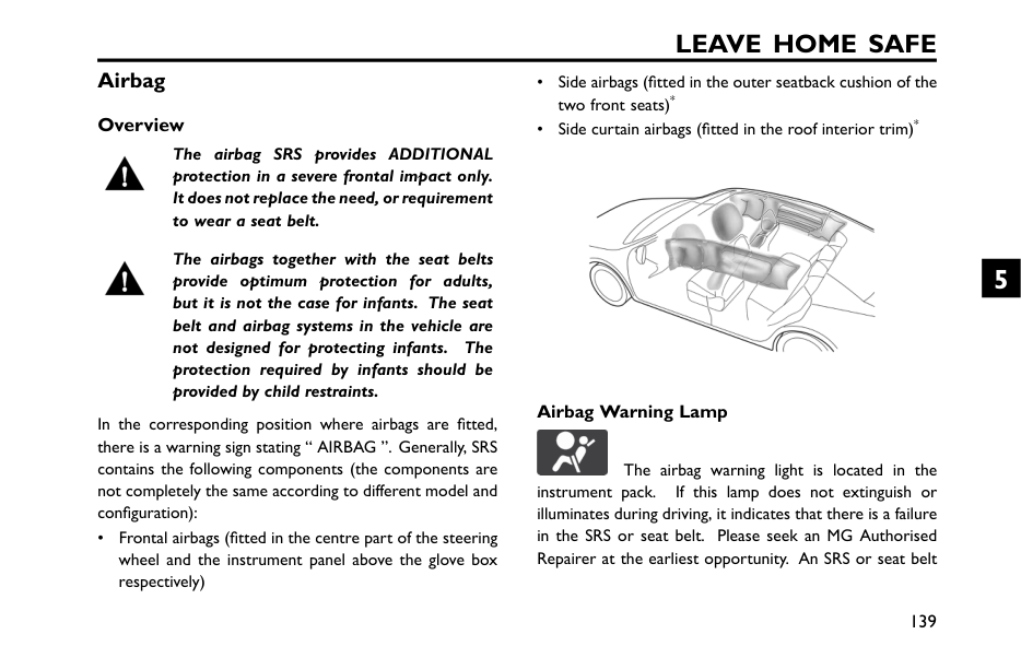
Leave Home Safe
Airbag Overview The airbag SRS provides ADDITIONAL protection in a severe frontal impact only. It does not replace the need, or requirement to wear a seat belt. The airbags together with the seat belts provide optimum protection for adults, but it is not the case for infants. The seat belt and airbag systems in the vehicle are not designed for protecting infants. The protection required by infants should be provided by child restraints. In the corresponding position where airbags are fitted, there is a warning sign stating “ AIRBAG ”. Generally, SRS contains the following components (the components are not completely the same according to different model and configuration): • Frontal airbags (fitted in the centre part of the steering wheel and the instrument panel above the glove box respectively) • Side airbags (fitted in the outer seatback cushion of the two front seats)* • Side curtain airbags (fitted in the roof interior trim)* Airbag Warning Lamp The airbag warning light is located in the instrument pack. If this lamp does not extinguish or illuminates during driving, it indicates that there is a failure in the SRS or seat belt. Please seek an MG Authorised Repairer at the earliest opportunity. An SRS or seat belt 139 5
Leave Home Safe
fault may mean the components may not be deployed in the event of an accident. Airbag Deployment Front seat passengers should not place feet, knees or any other part of the body in contact with, or in close proximity to a front airbag. To minimise the risk of accidental injury from inflating airbags, seat belts should be worn correctly at all times. In addition, both driver and front passenger should adjust their seat to provide sufficient distance from the frontal airbags, so as to avoid severe or even fatal injury when the airbag is deployed. If side airbags and side head impact protection airbags are fitted, both driver and front seat passenger should be seated to maintain sufficient distance from the upper part of the body to the sides of the vehicle, this will ensure maximum protection when the side airbags/side head impact protection airbags are deployed. 140
Leave Home Safe
An inflating airbag can cause facial abrasions and other injuries if the occupant is too close to the airbag at the time of its deployment. When airbags are deployed, children without proper protection may suffer from serious injury or even death.Do Not
carry children in the arms or on the knees during traveling. Children should wear seat belts suitable to age. DO NOT lean out of windows. After deployment, the relative airbag components will become very hot, such as the steering wheel, instrument panel and both sides of the roof rails . DO NOT touch any airbag related components after airbag deployment, it may cause burns or serious injury. DO NOT knock or strike the position where any airbag related parts are located, so as to avoid accidental airbag deployment which may cause serious injury or even death. DO NOT affix or place any objects on, or adjacent to the airbags. This may affect the airbag passage or create projectiles that may cause injury or serious harm in the event of airbag deployment In the event of a collision, the airbag control unit monitors the rate of deceleration or acceleration induced by the collision, to determine whether the airbags should be deployed. Airbag deployment is virtually instantaneous and occurs with considerable force, accompanied by a loud noise. In the event of a severe frontal collision, a completely deployed airbag, along with a correctly worn seat belt, can limit the movement of the driver and front passenger, reducing the risk of head and chest injuries. For vehicles fitted with side airbags and side curtain airbags, when the vehicle encounters a serious side collision, the completely 141 5
Leave Home Safe
deployed airbag will form a cushion of air between the occupant and the vehicle side to reduce the risk of body side injuries. Provided the front seat occupants are correctly seated and with seat belts properly worn, the airbags will provide additional protection to the chest and facial areas in the event of the car receiving a severe frontal impact.Important
• Airbags cannot protect lower body parts of passengers. • Airbags are not designed for rear collision, minor frontal collision or if the vehicle rolls over, nor will it operate as a result of heavy braking. • Deployment and deflation of the airbags takes place very quickly and will not protect against the effects of a secondary impact if it occurs. • When an airbag inflates, a fine powder is released. This is not an indication of a malfunction. However, the powder may cause irritation to the skin and should be thoroughly flushed from the eyes and any cuts or abrasions of the skin. If your skin, eyes, nose or throat etc feels uncomfortable, please consult a doctor. • After inflation, front and side airbags deflate immediately. This provides a gradual cushioning effect for the occupant and also ensures that the driver's forward vision is not obscured. 142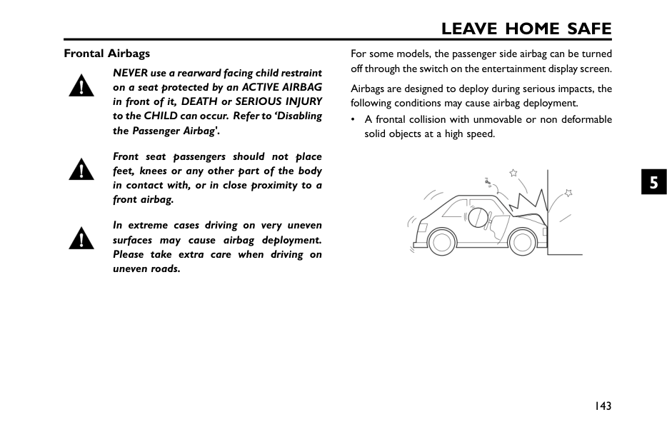
Leave Home Safe
Frontal Airbags NEVER use a rearward facing child restraint on a seat protected by an ACTIVE AIRBAG in front of it, DEATH or SERIOUS INJURY to the CHILD can occur. Refer to ‘Disabling the Passenger Airbag'. Front seat passengers should not place feet, knees or any other part of the body in contact with, or in close proximity to a front airbag. In extreme cases driving on very uneven surfaces may cause airbag deployment. Please take extra care when driving on uneven roads. For some models, the passenger side airbag can be turned off through the switch on the entertainment display screen. Airbags are designed to deploy during serious impacts, the following conditions may cause airbag deployment. • A frontal collision with unmovable or non deformable solid objects at a high speed. 143 5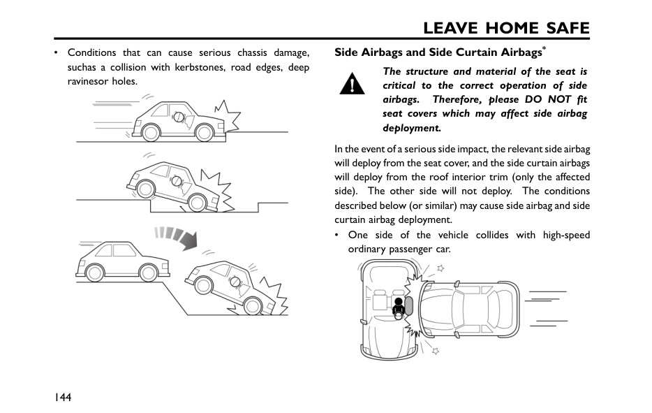
Leave Home Safe
• Conditions that can cause serious chassis damage, suchas a collision with kerbstones, road edges, deep ravinesor holes. Side Airbags and Side Curtain Airbags* The structure and material of the seat is critical to the correct operation of side airbags. Therefore, please DO NOT fit seat covers which may affect side airbag deployment. In the event of a serious side impact, the relevant side airbag will deploy from the seat cover, and the side curtain airbags will deploy from the roof interior trim (only the affected side). The other side will not deploy. The conditions described below (or similar) may cause side airbag and side curtain airbag deployment. • One side of the vehicle collides with high-speed ordinary passenger car. 144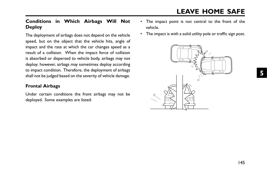
Leave Home Safe
Conditions in Which Airbags Will Not Deploy The deployment of airbags does not depend on the vehicle speed, but on the object that the vehicle hits, angle of impact and the rate at which the car changes speed as a result of a collision. When the impact force of collision is absorbed or dispersed to vehicle body, airbags may not deploy; however, airbags may sometimes deploy according to impact condition. Therefore, the deployment of airbags shall not be judged based on the severity of vehicle damage. Frontal Airbags Under certain conditions the front airbags may not be deployed. Some examples are listed: • The impact point is not central to the front of the vehicle. • The impact is with a solid utility pole or traffic sign post. 145 5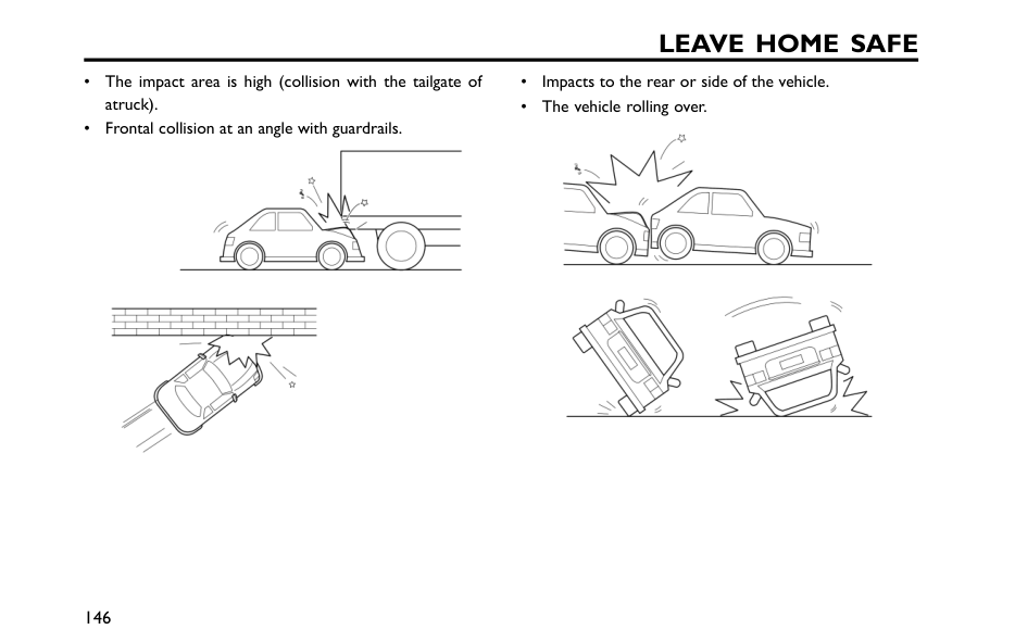
Leave Home Safe
• The impact area is high (collision with the tailgate of atruck). • Frontal collision at an angle with guardrails. • Impacts to the rear or side of the vehicle. • The vehicle rolling over. 146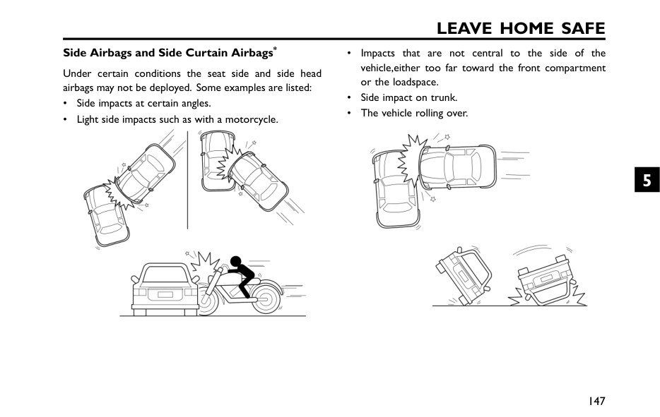
Leave Home Safe
Side Airbags and Side Curtain Airbags* Under certain conditions the seat side and side head airbags may not be deployed. Some examples are listed: • Side impacts at certain angles. • Light side impacts such as with a motorcycle. • Impacts that are not central to the side of the vehicle,either too far toward the front compartment or the loadspace. • Side impact on trunk. • The vehicle rolling over. 147 5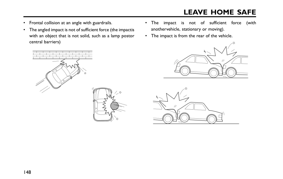
Leave Home Safe
• Frontal collision at an angle with guardrails. • The angled impact is not of sufficient force (the impactis with an object that is not solid, such as a lamp postor central barriers) • The impact is not of sufficient force (with anothervehicle, stationary or moving). • The impact is from the rear of the vehicle. 148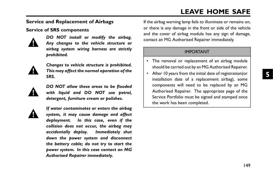
Leave Home Safe
Service and Replacement of Airbags Service of SRS components DO NOT install or modify the airbag. Any changes to the vehicle structure or airbag system wiring harness are strictly prohibited. Changes to vehicle structure is prohibited. This may affect the normal operation of theSrs.
DO NOT allow these areas to be flooded with liquid and DO NOT use petrol, detergent, furniture cream or polishes. If water contaminates or enters the airbag system, it may cause damage and affect deployment. In this case, even if the collision does not occur, the airbag may accidentally deploy. Immediately shut down the power system and disconnect the battery cable; do not try to start the power system. In this case contact an MG Authorised Repairer immediately. If the airbag warning lamp fails to illuminate or remains on, or there is any damage in the front or side of the vehicle and the cover of airbag module has any sign of damage, contact an MG Authorised Repairer immediately.Important
• The removal or replacement of an airbag module should be carried out by an MG Authorised Repairer. • After 10 years from the initial date of registration(or installation date of a replacement airbag), some components will need to be replaced by an MG Authorised Repairer. The appropriate page of the Service Portfolio must be signed and stamped once the work has been completed. 149 5
Leave Home Safe
Replacing Airbag System Parts Even if the airbag does not deploy, collisions may cause damage to SRS in the vehicle. Airbags may not function properly after damage, and can not protect you and other passengers when a second collision occurs, which may cause serious injury or even death. To ensure that SRS can function properly after collision, please go to an MG Authorised Repairer to check airbags and repair as necessary. Airbags are designed for using once only. Once the airbagis deployed, you must replace SRS parts.Please go to an MG Authorised Repairer for replacement. Disposal of Airbags When your vehicle is sold, ensure that the new owner knows the vehicle is equipped with airbags, and is aware of the replacement date of SRS. If the vehicle is scrapped, the undeployed airbags may have potential risks, therefore, before the disposal, they must be deployed safely in a certain environment by a professional agency or an MG Authorised Repairer. 150
Leave Home Safe
Child Restraints Important Safety Instructions about Using Child Restraints Children under the age of 12 years are recommended to be seated in the rear seats. Compared with adults, children'smuscles and bones do not fully develop, so you need to use dedicated child restraints to protect children. Use child restraints in rear seats to protect children based on thechild's age, height and weight. It is recommended that a child restraint system thatcomplies with UN ECE-R44 and ECE-R129 are fitted in this vehicle. When choosing a child restraint, check relevant marks or instructions about the weight range applicablefor the child restraint and the usage message on it. When installing and using a child restraint, it is necessary to comply with relevant laws and regulations, the instructions supplied by the child restraint manufacturer, and theinstructions on children's safety in this manual. The correct use of child restraints will greatly reduce children's injury risk in accidents or relieve their injuryseverity, and please pay attention to the followings whenyou use child restraints: • It is recommended that children shorter than 1.5 metres (or under 12 years of age) should use the appropriate child restraint, and cannot use regular seatbelt, otherwise it may cause the abdomen and neck injuries. • Never let your children ride in unprotected case. Care should not be neglected because of children sitting onthe child restraint. • Only one child may be carried in any one restraint. • DO NOT put the child on the lap or in arms when sittingin any seat. • Proper child restraint can provide protection for your children. • Relevant front seat may need to be adjusted frontward for installing the rear-facing child restraint to the rearseats. • The position of seat head restraints may need to be adjusted for installing the forward facing child restraint to the rear seats. • Never let your child stand or kneel on the seat during driving, otherwise, your child may be tossed and thus 151 5
Leave Home Safe
lead to injury to their own and other people or even death when an accident occurs. • If a child's body leans forward or the posture is not correct during driving, then the accident will increase the risk of injury. • The method of using seat belts have a great influenceon the maximum protection offered by the seat belt,you must comply with the child restraint manufacturer's instructions on proper use of seat belts. If seat belts are not properly fastened, even a minor traffic accident maylead to injury. • Child restraints that are not fitted correctly may move and injure other occupants in the event of an accidentor emergency braking. Therefore, even if there is no infant or child in the child restraint, it should be fitted properly and securely in the vehicle. 152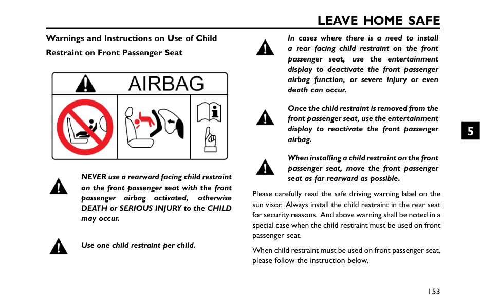
Leave Home Safe
Warnings and Instructions on Use of Child Restraint on Front Passenger Seat NEVER use a rearward facing child restraint on the front passenger seat with the front passenger airbag activated, otherwise DEATH or SERIOUS INJURY to the CHILD may occur. Use one child restraint per child. In cases where there is a need to install a rear facing child restraint on the front passenger seat, use the entertainment display to deactivate the front passenger airbag function, or severe injury or even death can occur. Once the child restraint is removed from the front passenger seat, use the entertainment display to reactivate the front passenger airbag. When installing a child restraint on the front passenger seat, move the front passenger seat as far rearward as possible. Please carefully read the safe driving warning label on the sun visor. Always install the child restraint in the rear seat for security reasons. And above warning shall be noted in a special case when the child restraint must be used on front passenger seat. When child restraint must be used on front passenger seat, please follow the instruction below. 153 5
Leave Home Safe
Important
• Move the front passenger seat as far back and as high as it can be adjusted to creat the largest possible distance between the child seat and the front passenger front airbag. • Move the backrest to the upright position. • Set the seat belt heights so that the seat belt routing follows a natural path adapted to the child seat without excessive deviations. For rear-facing child seats, use the lowest position of the belt height adjuster. • Only use child seats that have been approved by the child seat manufacturer for use on a front passenger seat with front and side airbag. Important Instructions on Children's Safety and Side Airbags Children should not be allowed in areas where side airbags may be deployed, there is a risk of serious injury. Only recommended child restraints suitable for the age, height and weight of the child should be used and firmly fixed in the vehicle. DO NOT place any items in areas where side airbags may be deployed, there is a risk of serious injury. In the event of a side collision, the side airbags can provide better protection for the passenger. However, when the airbag is triggered, a very strong expansion force is generated, if the passenger's seating position is not correct, the airbags or items in the side airbag deployment area may cause injury. Therefore, the correct child restraint must be used to secure the child correctly in the rear seat whilst ensuring the child's seating position is correct and there is enough space between the child and the side airbag deployment area for the airbag to deploy without any hindrance in a traffic accident, this will provide the best protection. 154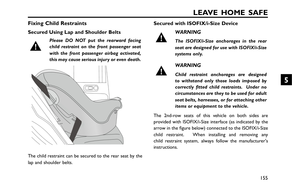
Leave Home Safe
Fixing Child Restraints Secured Using Lap and Shoulder Belts Please DO NOT put the rearward facing child restraint on the front passenger seat with the front passenger airbag activated, this may cause serious injury or even death. The child restraint can be secured to the rear seat by the lap and shoulder belts. Secured with ISOFIX/i-Size DeviceWarning
The ISOFIX/i-Size anchorages in the rear seat are designed for use with ISOFIX/i-Size systems only.Warning
Child restraint anchorages are designed to withstand only those loads imposed by correctly fitted child restraints. Under no circumstances are they to be used for adult seat belts, harnesses, or for attaching other items or equipment to the vehicle. The 2nd-row seats of this vehicle on both sides are provided with ISOFIX/i-Size interface (as indicated by the arrow in the figure below) connected to the ISOFIX/i-Size child restraint. When installing and removing any child restraint system, always follow the manufacturer's instructions. 155 5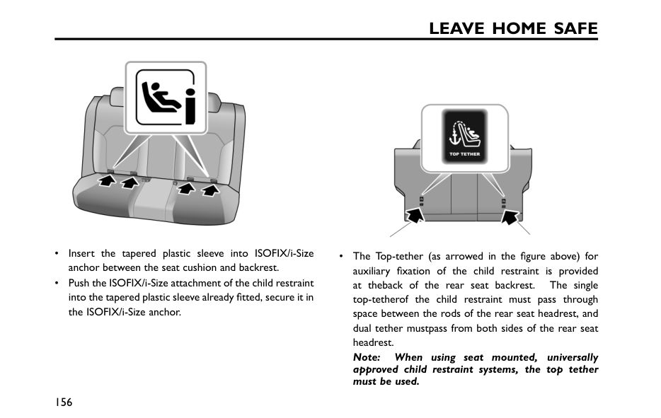
Leave Home Safe
• Insert the tapered plastic sleeve into ISOFIX/i-Size anchor between the seat cushion and backrest. • Push the ISOFIX/i-Size attachment of the child restraint into the tapered plastic sleeve already fitted, secure it in the ISOFIX/i-Size anchor. • The Top-tether (as arrowed in the figure above) for auxiliary fixation of the child restraint is provided at theback of the rear seat backrest. The single top-tetherof the child restraint must pass through space between the rods of the rear seat headrest, and dual tether mustpass from both sides of the rear seat headrest. Note: When using seat mounted, universally approved child restraint systems, the top tether must be used. 156
Leave Home Safe
• After the installation, push or shake the child restraint with moderate force to confirm it is properly secured. 157 5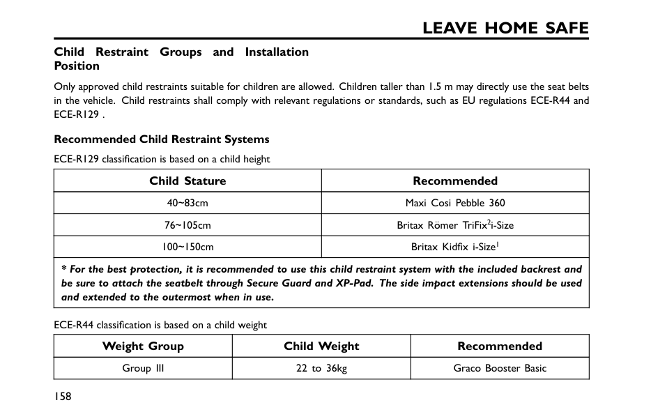
Leave Home Safe
Child Restraint Groups and Installation Position Only approved child restraints suitable for children are allowed. Children taller than 1.5 m may directly use the seat belts in the vehicle. Child restraints shall comply with relevant regulations or standards, such as EU regulations ECE-R44 andEce-R129 .
Recommended Child Restraint Systems ECE-R129 classification is based on a child height Child Stature Recommended 40~83cm Maxi Cosi Pebble 360 76~105cm Britax Römer TriFix2i-Size 100~150cm Britax Kidfix i-Size1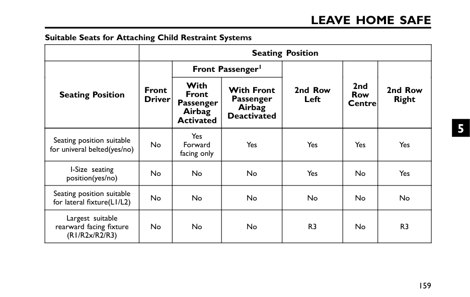
Leave Home Safe
Suitable Seats for Attaching Child Restraint Systems Seating Position Front Passenger1 Seating Position Front Driver With Front Passenger Airbag Activated With Front Passenger Airbag Deactivated 2nd Row Left 2nd Row Centre 2nd Row Right Seating position suitable for univeral belted(yes/no) No Yes Forward facing only Yes Yes Yes Yes I-Size seating position(yes/no) No No No Yes No Yes Seating position suitable for lateral fixture(L1/L2) No No No No No No Largest suitable rearward facing fixture (R1/R2x/R2/R3) No No NoR3
NoR3
159 5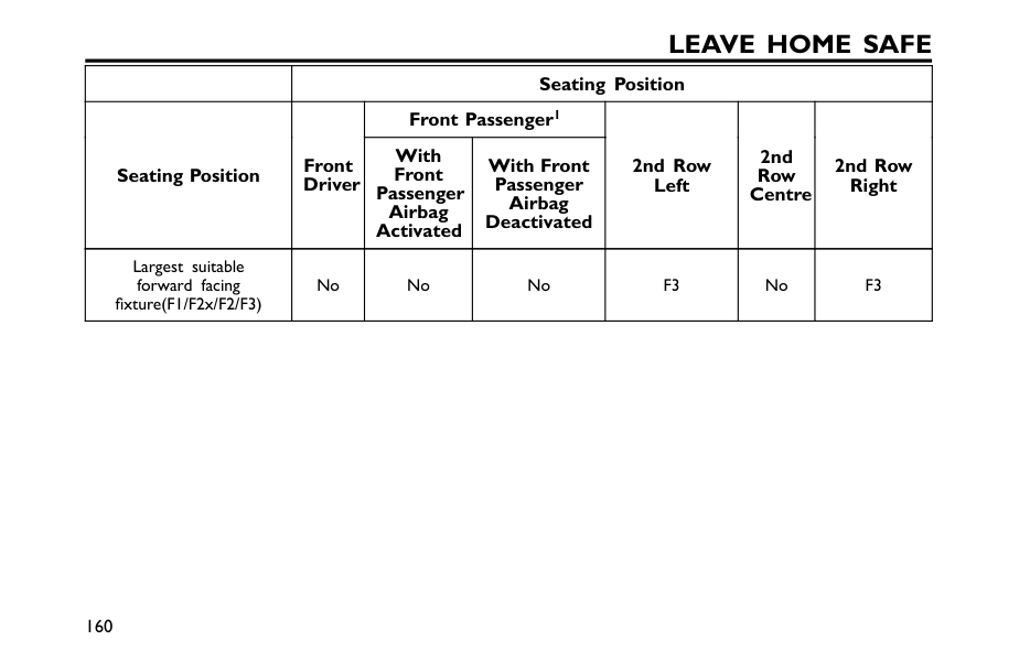
Leave Home Safe
Seating Position Front Passenger1 Seating Position Front Driver With Front Passenger Airbag Activated With Front Passenger Airbag Deactivated 2nd Row Left 2nd Row Centre 2nd Row Right Largest suitable forward facing fixture(F1/F2x/F2/F3) No No NoF3
NoF3
160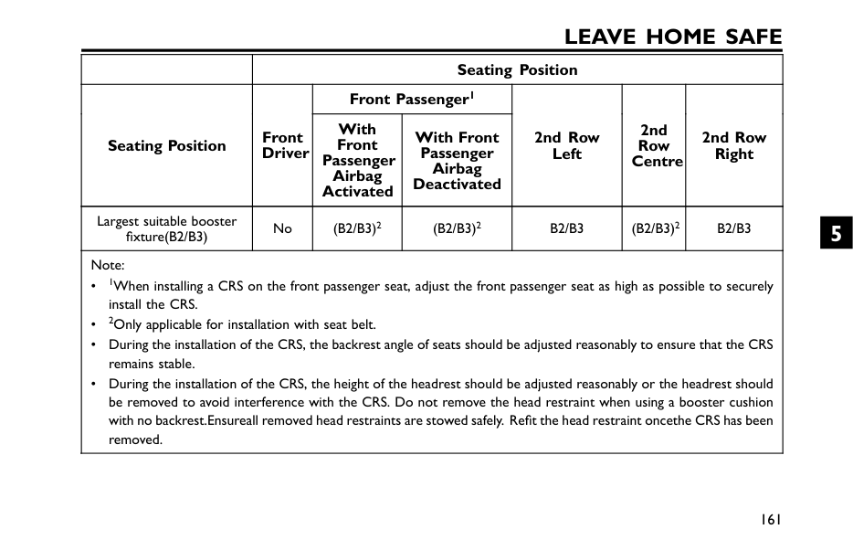
Leave Home Safe
Seating Position Front Passenger1 Seating Position Front Driver With Front Passenger Airbag Activated With Front Passenger Airbag Deactivated 2nd Row Left 2nd Row Centre 2nd Row Right Largest suitable booster fixture(B2/B3) No(B2/B3)2
(B2/B3)2
B2/B3
(B2/B3)2
B2/B3
Note: • 1When installing a CRS on the front passenger seat, adjust the front passenger seat as high as possible to securely install the CRS. • 2Only applicable for installation with seat belt. • During the installation of the CRS, the backrest angle of seats should be adjusted reasonably to ensure that the CRS remains stable. • During the installation of the CRS, the height of the headrest should be adjusted reasonably or the headrest should be removed to avoid interference with the CRS. Do not remove the head restraint when using a booster cushion with no backrest.Ensureall removed head restraints are stowed safely. Refit the head restraint oncethe CRS has been removed. 161 5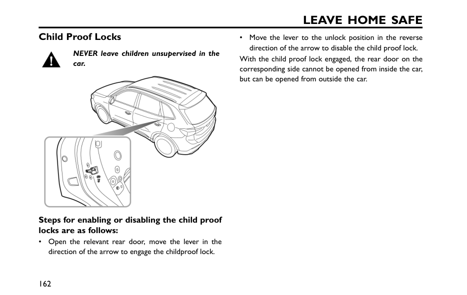
Leave Home Safe
Child Proof Locks NEVER leave children unsupervised in the car. Steps for enabling or disabling the child proof locks are as follows: • Open the relevant rear door, move the lever in the direction of the arrow to engage the childproof lock. • Move the lever to the unlock position in the reverse direction of the arrow to disable the child proof lock. With the child proof lock engaged, the rear door on the corresponding side cannot be opened from inside the car, but can be opened from outside the car. 162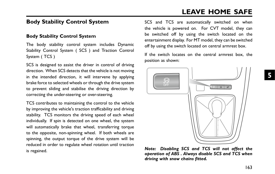
Leave Home Safe
Body Stability Control System Body Stability Control System The body stability control system includes Dynamic Stability Control System ( SCS ) and Traction Control System ( TCS ) SCS is designed to assist the driver in control of driving direction. When SCS detects that the vehicle is not moving in the intended direction, it will intervene by applying brake force to selected wheels or through the drive system to prevent sliding and stabilise the driving direction by correcting the under-steering or over-steering. TCS contributes to maintaining the control to the vehicle by improving the vehicle's traction trafficability and driving stability. TCS monitors the driving speed of each wheel individually. If spin is detected on one wheel, the system will automatically brake that wheel, transferring torque to the opposite, non-spinning wheel. If both wheels are spinning, the output torque of the drive system will be reduced in order to regulate wheel rotation until traction is regained. SCS and TCS are automatically switched on when the vehicle is powered on. For CVT model, they can be switched off by using the switch located on the entertainment display. For MT model, they can be switched off by using the switch located on central armrest box. If the switch locates on the central armrest box, the position as shown: Note: Disabling SCS and TCS will not affect the operation of ABS . Always disable SCS and TCS when driving with snow chains fitted. 163 5
Leave Home Safe
Resuming the body stability control system After a battery disconnection/reconnection, the body stability control warning lamps will illuminate, and the dynamic stability control/traction control system will not work correctly. In this case, the electric power steering (EPS) will require initialisation, i.e., move the steering wheel from lock to lock. The electric power steering (EPS) warning lamps and the body stability control warning extinguish, and the dynamic stability control/traction control system will be reinstated. 164
Leave Home Safe
Anti-lock Brake System (ABS) When travelling at high speed or there is a danger of aquaplaning, i.e. where a layerof water prevents adequate contact between the tyres and the road surface,Abs
cannot overcome the physical limitations of stopping the car in a short distance. In these cases, it is the responsibility of the driver to maintain a safe distance from other vehicles. DO NOT pump the brake pedal at any time, this will interrupt the operation of ABS and may increase the braking distance. The ABS is mainly used to automatically adjust the braking force of each brake when braking to prevent the wheels from being locked, thus avoiding dangerous situations such as loss of direction or side slip during emergency braking. This system enables the driver to maintain control over the steering in case of emergency braking, keeping the vehicle stable, and improving safety. Under normal braking conditions, ABS will not be activated. However, if the braking force exceeds the adhesion between the tyres and the road surface, causing the wheels to lock, the ABS will automatically come into operation. This will be recognisable by a rapid pulsation felt through the brake pedal. If an emergency situation occurs, the driver should apply full braking effort to trigger the ABS even when the road surface is slippery. Note: On soft surfaces such as powdery snow, sand or gravel, vehicles equipped with ABS may have a braking distance greater than those without ABS. This is because the natural action of locked wheels on soft surfaces is to build up a wedge of material in front of (or to the side of, if steering) the tyre contact patch. This effect assists the car to stop when braking or to change direction when steering.Important
• Although ABS can greatly improve driving safety, the real safety still depends on the driver's own standard driving behavior. • The normal braking system remains fully operational and is not affected by partial or full loss of anti-lock braking system ( ABS ). 165 5
Leave Home Safe
Auxiliary Brake System The auxiliary brake system consists of Electronic Brake Force Distribution System ( EBD )*and Electronic Brake Assistance System ( EBA ). The EBD *automatically distributes the braking force between the front and rear wheels, so that the vehicle can have optimum braking performance under different load conditions. The EBA increases the braking force applied on each wheel during emergency braking to assist the driver in quickly triggering ABS , thereby reducing the braking distance. 166
Leave Home Safe
Auto Hold* The auto hold function cannot guarantee the stability of the vehicle when starting off or braking on hills especially on slippery or icy surfaces. When auto hold stops the vehicle, for reasons such as engine shut-down, releasing the seat belt or pressing the auto hold switch, the electronic parking brake is applied. It cannot be guaranteed that the vehicle will be stabilised in all cases. For example, the rear wheels are on a slippery road surface, or the vehicle incline is too great (larger than 20%). Please make sure that the vehicle is safely stabilised prior to exiting. DO NOT leave the vehicle when the engine is operating and the auto hold is active. Auto hold cannot guarantee the electronic parking brake operation in all cases where the ignition system is shut down. Please ensure the electronic parking brake is applied and the vehicle is stabilised prior to exiting the vehicle. The auto hold function should be switched off during the use of automatic car washes, the electronic parking brake may suddenly apply and cause vehicle damage. If the vehicle is required to stop frequently for long periods while driving (such as wait at the traffic lights, stop on a slope or in urban stop-and-go conditions), the Auto Hold function can assist you in stabilising the vehicle, enabling you to remove your foot from the brake pedal when the vehicle is stationary and the Auto Hold is active. Auto Hold has 3 states as follows: The Auto Hold Switch is located on the entertainment display screen. 1 Standby: 167 5
Leave Home Safe
With the driver's seat belt fastened, the door closed and the power system running, press the Auto Hold switch to switch the function from Off to Standby state. The indicator of Auto Hold Switch illuminates. 2 Operating: When the vehicle is moving forward, depress the brake pedal to a certain depth. After the vehicle is fully stopped, the Auto Hold function is switched from Standby to Parking state. In this state, the green indicator on the instrument panel illuminates. When the Auto Hold is in the Parking state, engaging D gear and depressing the accelerator pedal will automatically release the Auto Hold function based on the slope. The Auto Hold will release from the Parking state if R gear is selected.3 Off:
Press Auto Hold switch again to disable the function. The Auto Hold will exit the parking state under some circumstances such as releasing the seat belt, turning off the power system, remaining static for a length of time or pressing the Auto Hold switch. At this time, the EPB will be applied. Note: With the brake pedal pressed, operating the switch to turn the auto hold off, the system will NOT apply the parking brake. Note: When the vehicle is in P gear, the auto hold function will not be engaged. 168
Leave Home Safe
Hill Hold Control (HHC) It is impossible for HHC to keep the vehicle in a standstill state under all circumstances (e.g. slippery ground, snow and ice, etc.) when going uphill, and the driver must constantly pay attention to the vehicle condition. With the HHC in service, the driver is strictly prohibited from leaving the vehicle, otherwise serious accidents may occur. During hill start under a stop-and-go road condition, please step on the brake pedal deeply for several seconds before each start. HHC assists the driver by "holding" the vehicle during hill starts. If the driver releases the brake pedal, the HHC will hold the vehicle stationary for a short time. The HHC will be activated when the following conditions are met simultaneously: • The driver's seat belt has been fastened and the driver's door is closed. • The vehicle is stopped steadily on a slope. • SCS is fault free. • EPB / manual parking brake is fault free and released. • The power systeme is started. • In D or R gear. • Sufficient force has been applied on the brake pedal before start. Note: The HHC can also work when the vehicle is reversing uphill. 169 5
Leave Home Safe
Hill Descent Control (HDC) HDC is just an auxiliary function, which cannot ensure that the vehicle is driven down a steep slope at low speed under all circumstances (such as slippery ground, snowy road surface or excessive slope, etc.). Even when HDC is in use, the driver shall still pay close attention to the driving state of the vehicle, and take active control when necessary. Because in certain cases, HDC may remove itself from the operating state temporarily. Under some driving conditions on downhill surfaces (e.g. driving down a slope with high speed, small slope, etc.), HDC is inoperative, so the driver shall be required to control the speed by depressing the brake pedal to ensure the safe driving. HDC system is an auxiliary function designed for vehicles running on acute downhill surface. It reduces the speed by applying the brake force, thus assists the driver to drive on acute downhill surface smoothly. Note: When the HDC is working, it is normal for the brake system to generate slight vibration or working noise. Note: When the HDC is working, do not shift to N gear, since this operation will deactivate the HDC function. 170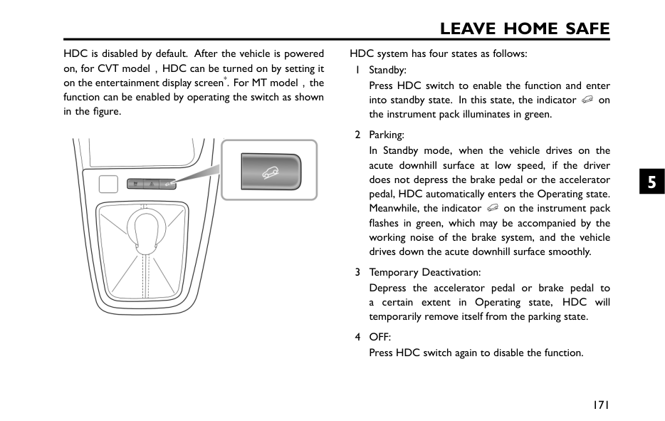
Leave Home Safe
HDC is disabled by default. After the vehicle is powered on, for CVT model,HDC can be turned on by setting it on the entertainment display screen*. For MT model,the function can be enabled by operating the switch as shown in the figure. HDC system has four states as follows: 1 Standby: Press HDC switch to enable the function and enter into standby state. In this state, the indicator on the instrument pack illuminates in green. 2 Parking: In Standby mode, when the vehicle drives on the acute downhill surface at low speed, if the driver does not depress the brake pedal or the accelerator pedal, HDC automatically enters the Operating state. Meanwhile, the indicator on the instrument pack flashes in green, which may be accompanied by the working noise of the brake system, and the vehicle drives down the acute downhill surface smoothly. 3 Temporary Deactivation: Depress the accelerator pedal or brake pedal to a certain extent in Operating state, HDC will temporarily remove itself from the parking state.4 Off:
Press HDC switch again to disable the function. 171 5
Leave Home Safe
Note: When the vehicle makes a sharp turn on a certain slope, HDC may switch from Standby to Operating. Note: With HDC operative, the brake system will automatically pressurize and hold, and you will be responded with a certain pressure feedback when depressing the brake pedal at this time, which is normal. 172
Leave Home Safe
Active Rollover Protection (ARP) Active Rollover Protection ( ARP ) The ARP system is a driver aid to assist the stability of the vehicle. It is not a guarantee that the vehicle will not roll over. When the vehicle is at risk of rollover during dynamic driving (such as lane change) or steady driving (such as loop driving), the ARP will automatically brake the outside wheels to cause the vehicle to understeer and prevent rollover. Note: With ARP in use, the vehicle under-steers and it is normal if it fails to steer in accordance to driver expectations. 173 5
Leave Home Safe
Emergency Braking Hazard Warning Strobe (HAZ)* If the driver makes an emergency braking manoeuvre and certain conditions are met while driving, the brake lamps will automatically flash to alert the drivers behind, thereby reducing the risk of rear-end collision accidents. Note: If the hazard warning lamps are being operated manually, this suspends the HAZ function. When the emergency braking manoeuvre is exited, the HAZ function will be switched off after a few seconds. Note: As the car speed drops to below 6 mph (10 km/h) and the system no longer flashes the brake lamps, the hazard warning lamps will illuminate automatically. Short press the hazard warning lamp switch or increase your speed to above 12 mph (20 km/h) for 5 s to switch off the hazard warning lamps. 174
Leave Home Safe
Multi-Collision Brake System(MCB)* The MCB function will automatically apply the brake to reduce the vehicle speed and improve the vehicle stability after a collision. It is designed to reduce the risk of a secondary collision caused by the uncontrolled movementof the vehicle after a collision. The MCB will be activated when the following conditions are all met at the same time: • A vehicle collision where airbags are deployed; • The vehicle speed is less than 60 km/h; • The steering wheel has not been turned in excess of 180° ; • SCS is fault free. If the driver firmly presses the accelerator pedal after the MCB function is triggered, the system will exit the braking state. Note: The MCB function cannot decelerate the vehicle in all cases of collision due to the fact that the collision process may cause some parts to malfunction or fail and affect the normal operation of the function. 175 5
Leave Home Safe
Tyre Pressure Monitoring System(Tpms)*
TPMS can not replace routine maintenance and checks of the tyre condition and pressure. Using equipment that transmits on frequencies similar to that of the TPMS may interfere with the operation of the Tyre Pressure Monitoring System, this may illuminate a warning or register a temporary fault. TPMS uses pressure sensors built into tyre valves tocontinuously monitor pressure and transmit data to the ECU inside the vehicle using RF signals. If it deduces that the pressure of that tyre has fallen below the predefined limit of the system, the warning light in the instrument pack will illuminate (always yellow). Formore information, please refer to ‘Instrument Pack’ in‘Instruments and Controls’ section. TPMS can remind you of low tyre pressure, but it can not replace normal tyre maintenance. For tyre maintenance, please refer to ‘Tyres’ in ‘Maintenance’ chapter. Note: TPMS only gives the driver a warning when the tyre pressure is low, and it will not inflate the tyre. If the TPMS malfunction indicator lamp illuminates, and the warning message such as “ XX Tyre Pressure Insufficient” or “ XX Tyre Pressure Low” is displayed, it is advised that you should stop the vehicle as soon as possible, check the tyre pressure and inflate the tyre to the standard pressure value. The tyre pressure label attached to the B pillar indicates the standard pressure value required by your vehicle tyres when they are cold. Driving with under-inflated tyres may overheat and cause tyre fault.Over or under-inflated tyres wear out more rapidlyand also have a detrimental effect on the car’s handlingcharacteristics. Under-inflated tyres increase the rollingresistance of the car which, in turn, increases power. TPMS Self-learning When replacing a TPMS sensor or receiver, or performing tyre rotation, TPMS self-learning is required, some 176
Leave Home Safe
vehicles can perform the following operations to complete self-learning: 1 Power off and lock the vehicle for 25 minutes. 2 Drive continuously at speeds in excess of 25mph (30 km/h) making numerous turns during the learning process. Note: Ensure that the TPMS sensor is an original factory component. Note: If self-learning fails, the TPMS malfunction indicator lamp will illuminate, please try repeating the above operations. If you have any questions during the self-learning, please consult an MG Authorised Repairer for assistance. 177 5
Comfortable Experience Seat Adjustment 180 Ventilation System 184 A/C Control Panel-1* 187 A/C Control Panel-2* 188 A/C Control Interface 190 Radio* 193 Intelligent Display Interface* 196 6
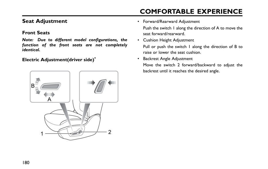
Comfortable Experience
Seat Adjustment Front Seats Note: Due to different model configurations, the function of the front seats are not completely identical. Electric Adjustment(driver side)* • Forward/Rearward Adjustment Push the switch 1 along the direction of A to move the seat forward/rearward. • Cushion Height Adjustment Pull or push the switch 1 along the direction of B to raise or lower the seat cushion. • Backrest Angle Adjustment Move the switch 2 forward/backward to adjust the backrest until it reaches the desired angle. 180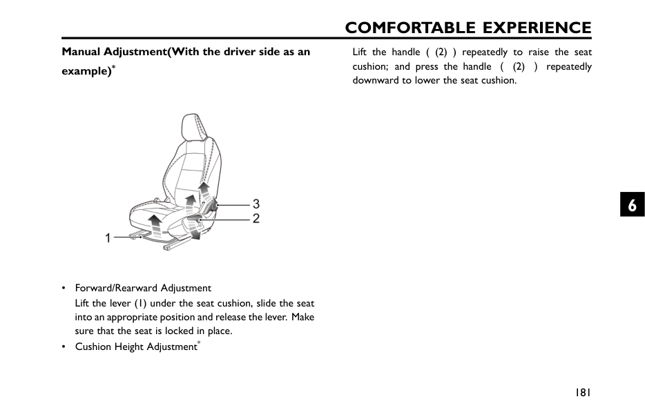
Comfortable Experience
Manual Adjustment(With the driver side as an example)* • Forward/Rearward Adjustment Lift the lever (1) under the seat cushion, slide the seat into an appropriate position and release the lever. Make sure that the seat is locked in place. • Cushion Height Adjustment* Lift the handle ( (2) ) repeatedly to raise the seat cushion; and press the handle ((2) )repeatedly downward to lower the seat cushion. 181 6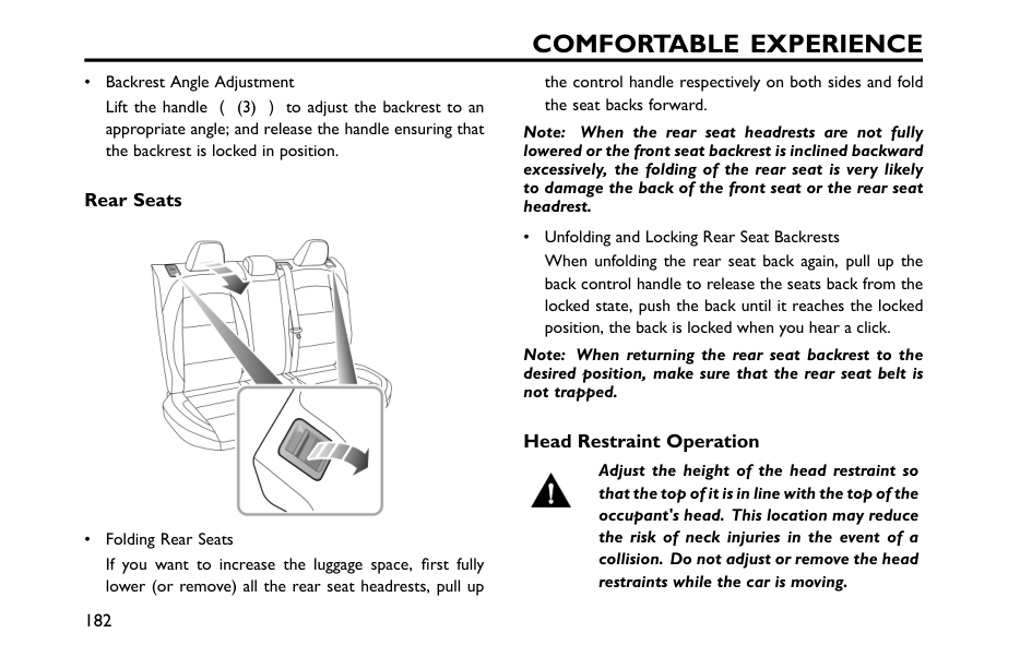
Comfortable Experience
• Backrest Angle Adjustment Lift the handle ((3) )to adjust the backrest to an appropriate angle; and release the handle ensuring that the backrest is locked in position. Rear Seats • Folding Rear Seats If you want to increase the luggage space, first fully lower (or remove) all the rear seat headrests, pull up the control handle respectively on both sides and fold the seat backs forward. Note: When the rear seat headrests are not fully lowered or the front seat backrest is inclined backward excessively, the folding of the rear seat is very likely to damage the back of the front seat or the rear seat headrest. • Unfolding and Locking Rear Seat Backrests When unfolding the rear seat back again, pull up the back control handle to release the seats back from the locked state, push the back until it reaches the locked position, the back is locked when you hear a click. Note: When returning the rear seat backrest to the desired position, make sure that the rear seat belt is not trapped. Head Restraint Operation Adjust the height of the head restraint so that the top of it is in line with the top of the occupant's head. This location may reduce the risk of neck injuries in the event of a collision. Do not adjust or remove the head restraints while the car is moving. 182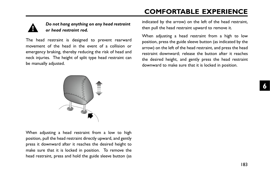
Comfortable Experience
Do not hang anything on any head restraint or head restraint rod. The head restraint is designed to prevent rearward movement of the head in the event of a collision or emergency braking, thereby reducing the risk of head and neck injuries. The height of split type head restraint can be manually adjusted. When adjusting a head restraint from a low to high position, pull the head restraint directly upward, and gently press it downward after it reaches the desired height to make sure that it is locked in position. To remove the head restraint, press and hold the guide sleeve button (as indicated by the arrow) on the left of the head restraint, then pull the head restraint upward to remove it. When adjusting a head restraint from a high to low position, press the guide sleeve button (as indicated by the arrow) on the left of the head restraint, and press the head restraint downward; release the button after it reaches the desired height, and gently press the head restraint downward to make sure that it is locked in position. 183 6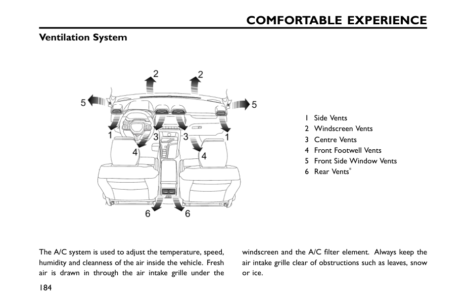
Comfortable Experience
Ventilation System 1 Side Vents 2 Windscreen Vents 3 Centre Vents 4 Front Footwell Vents 5 Front Side Window Vents 6 Rear Vents* The A/C system is used to adjust the temperature, speed, humidity and cleanness of the air inside the vehicle. Fresh air is drawn in through the air intake grille under the windscreen and the A/C filter element. Always keep the air intake grille clear of obstructions such as leaves, snow or ice. 184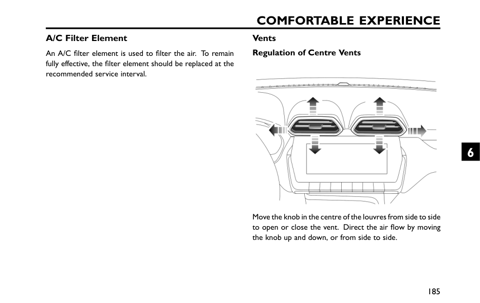
Comfortable Experience
A/C Filter Element An A/C filter element is used to filter the air. To remain fully effective, the filter element should be replaced at the recommended service interval. Vents Regulation of Centre Vents Move the knob in the centre of the louvres from side to side to open or close the vent. Direct the air flow by moving the knob up and down, or from side to side. 185 6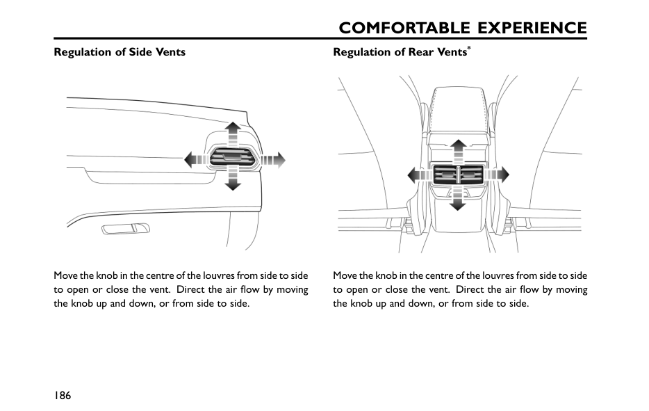
Comfortable Experience
Regulation of Side Vents Move the knob in the centre of the louvres from side to side to open or close the vent. Direct the air flow by moving the knob up and down, or from side to side. Regulation of Rear Vents* Move the knob in the centre of the louvres from side to side to open or close the vent. Direct the air flow by moving the knob up and down, or from side to side. 186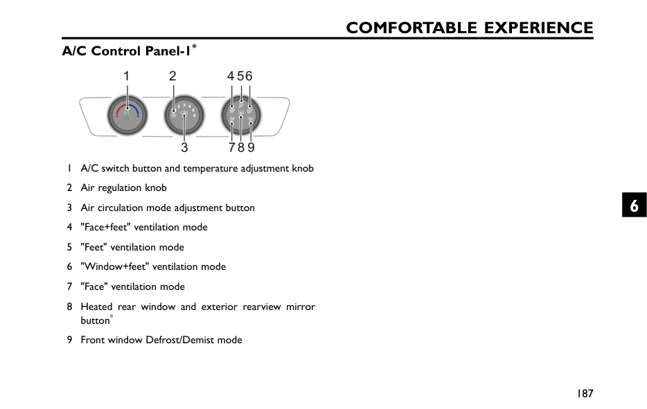
Comfortable Experience
A/C Control Panel-1* 1 A/C switch button and temperature adjustment knob 2 Air regulation knob 3 Air circulation mode adjustment button 4 "Face+feet" ventilation mode 5 "Feet" ventilation mode 6 "Window+feet" ventilation mode 7 "Face" ventilation mode 8 Heated rear window and exterior rearview mirror button* 9 Front window Defrost/Demist mode 187 6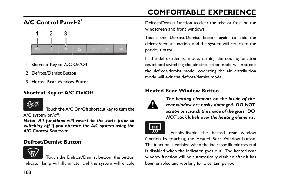
Comfortable Experience
A/C Control Panel-2* 1 Shortcut Key to A/C On/Off 2 Defrost/Demist Button 3 Heated Rear Window Button Shortcut Key of A/C On/Off Touch the A/C On/Off shortcut key to turn the A/C system on/off. Note: All functions will revert to the state prior to switching off if you operate the A/C system using the A/C Control Shortcut. Defrost/Demist Button Touch the Defrost/Demist button, the button indicator lamp will illuminate, and the system will enable Defrost/Demist function to clear the mist or frost on the windscreen and front windows. Touch the Defrost/Demist button again to exit the defrost/demist function, and the system will return to the previous state. In the defrost/demist mode, turning the cooling function on/off and switching the air circulation mode will not exit the defrost/demist mode; operating the air distribution mode will exit the defrost/demist mode. Heated Rear Window Button The heating elements on the inside of the rear window are easily damaged. DO NOT scrape or scratch the inside of the glass. DO NOT stick labels over the heating elements. Enable/disable the heated rear window function by touching the Heated Rear Window button. The function is enabled when the indicator illuminates and is disabled when the indicator goes out. The heated rear window function will be automatically disabled after it has been enabled and working for a certain period. 188
Comfortable Experience
Note: The heated rear window function will only operate when the vehicle is in the READY/RUNNING state. 189 6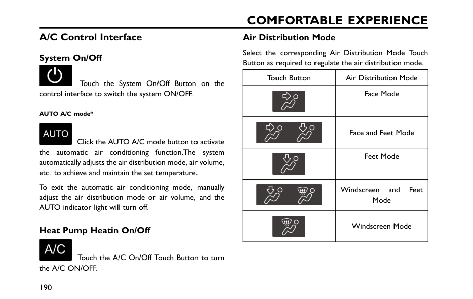
Comfortable Experience
A/C Control Interface System On/Off Touch the System On/Off Button on the control interface to switch the system ON/OFF. AUTO A/C mode* Click the AUTO A/C mode button to activate the automatic air conditioning function.The system automatically adjusts the air distribution mode, air volume, etc. to achieve and maintain the set temperature. To exit the automatic air conditioning mode, manually adjust the air distribution mode or air volume, and the AUTO indicator light will turn off. Heat Pump Heatin On/Off Touch the A/C On/Off Touch Button to turn the A/C ON/OFF. Air Distribution Mode Select the corresponding Air Distribution Mode Touch Button as required to regulate the air distribution mode. Touch Button Air Distribution Mode Face Mode Face and Feet Mode Feet Mode Windscreen and Feet Mode Windscreen Mode 190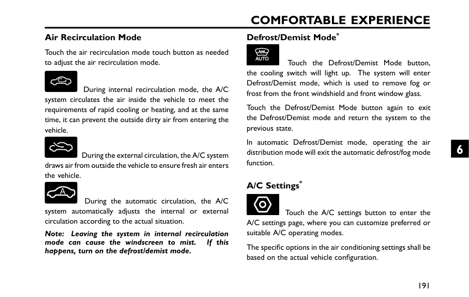
Comfortable Experience
Air Recirculation Mode Touch the air recirculation mode touch button as needed to adjust the air recirculation mode. During internal recirculation mode, the A/C system circulates the air inside the vehicle to meet the requirements of rapid cooling or heating, and at the same time, it can prevent the outside dirty air from entering the vehicle. During the external circulation, the A/C system draws air from outside the vehicle to ensure fresh air enters the vehicle. During the automatic circulation, the A/C system automatically adjusts the internal or external circulation according to the actual situation. Note: Leaving the system in internal recirculation mode can cause the windscreen to mist. If this happens, turn on the defrost/demist mode. Defrost/Demist Mode* Touch the Defrost/Demist Mode button, the cooling switch will light up. The system will enter Defrost/Demist mode, which is used to remove fog or frost from the front windshield and front window glass. Touch the Defrost/Demist Mode button again to exit the Defrost/Demist mode and return the system to the previous state. In automatic Defrost/Demist mode, operating the air distribution mode will exit the automatic defrost/fog mode function. A/C Settings* Touch the A/C settings button to enter the A/C settings page, where you can customize preferred or suitable A/C operating modes. The specific options in the air conditioning settings shall be based on the actual vehicle configuration. 191 6
Comfortable Experience
Blower Speed Control Touch and Slide the blower speed control bar to regulate the blower speed. Temperature Control Touch and Slide the temperature control bar to regulate the temperature of the air supplied by the vents. 192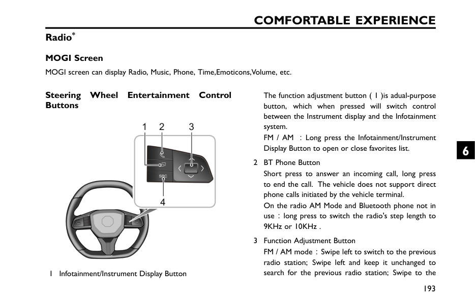
Comfortable Experience
Radio* MOGI Screen MOGI screen can display Radio, Music, Phone, Time,Emoticons,Volume, etc. Steering Wheel Entertainment Control Buttons 1 Infotainment/Instrument Display Button The function adjustment button ( 1 )is adual-purpose button, which when pressed will switch control between the Instrument display and the Infotainment system. FM / AM :Long press the Infotainment/Instrument Display Button to open or close favorites list. 2 BT Phone Button Short press to answer an incoming call, long press to end the call. The vehicle does not support direct phone calls initiated by the vehicle terminal. On the radio AM Mode and Bluetooth phone not in use:long press to switch the radio's step length to 9KHz or 10KHz . 3 Function Adjustment Button FM / AM mode:Swipe left to switch to the previous radio station; Swipe left and keep it unchanged to search for the previous radio station; Swipe to the 193 6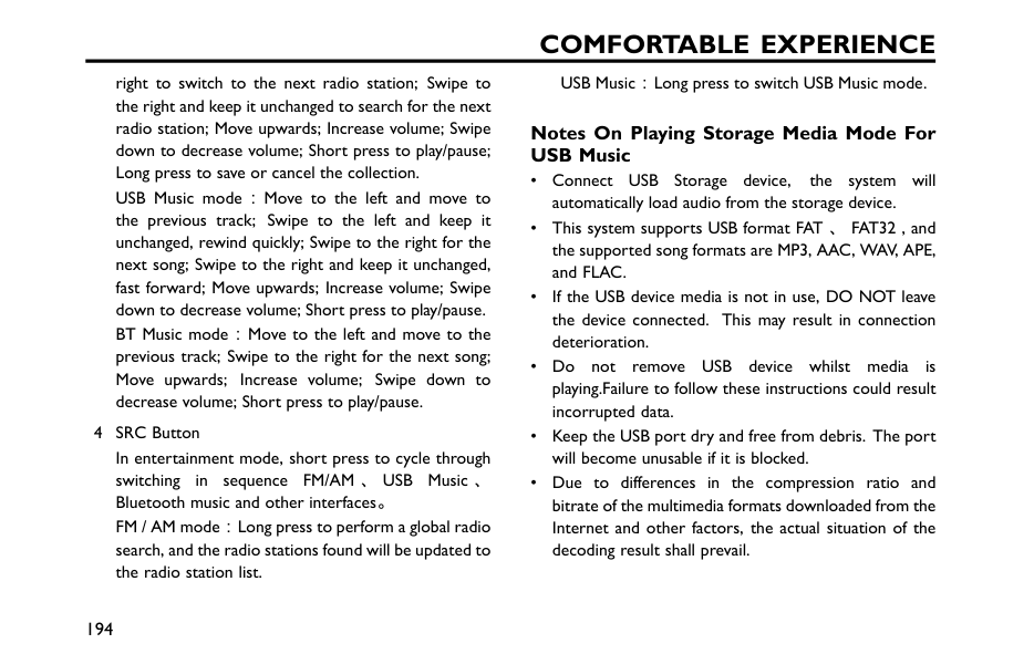
Comfortable Experience
right to switch to the next radio station; Swipe to the right and keep it unchanged to search for the next radio station; Move upwards; Increase volume; Swipe down to decrease volume; Short press to play/pause; Long press to save or cancel the collection. USB Music mode:Move to the left and move to the previous track; Swipe to the left and keep it unchanged, rewind quickly; Swipe to the right for the next song; Swipe to the right and keep it unchanged, fast forward; Move upwards; Increase volume; Swipe down to decrease volume; Short press to play/pause. BT Music mode:Move to the left and move to the previous track; Swipe to the right for the next song; Move upwards; Increase volume; Swipe down to decrease volume; Short press to play/pause. 4 SRC Button In entertainment mode, short press to cycle through switching in sequenceFm/Am 、Usb
Music 、 Bluetooth music and other interfaces。 FM / AM mode:Long press to perform a global radio search, and the radio stations found will be updated to the radio station list. USB Music:Long press to switch USB Music mode. Notes On Playing Storage Media Mode For USB Music • ConnectUsb
Storage device, the system will automatically load audio from the storage device. • This system supports USB format FAT 、FAT32 , and the supported song formats are MP3, AAC, WAV, APE, and FLAC. • If the USB device media is not in use, DO NOT leave the device connected. This may result in connection deterioration. • Do not removeUsb
device whilst media is playing.Failure to follow these instructions could result incorrupted data. • Keep the USB port dry and free from debris. The port will become unusable if it is blocked. • Due to differences in the compression ratio and Internet and other factors, the actual situation of the decoding result shall prevail. 194
Comfortable Experience
Connecting/Disconnecting a USB Storage Device Inserting a USB Storage Device Insert the USB device into the interface to connect. Removing the USB Storage Device Check and confirm that there is no data being accessed,then pull out the USB storage device. Note: If any data loss or breach occurs whilst the USB storage device is inserted or being used, it will generally be unrecoverable. MG Motor accepts no responsibility for any data loss or breach. Note: SomeUsb
storage devices may be unidentifiable. Note: Using a USB hub or extension cable may result in the USB device not being recognised. Bluetooth Pairing and Connection The steps of Bluetooth pairing and connection are as follows: 1 Enable Bluetooth function on your phone and search for the entertainment host for pairing。 2 The car will receive a Bluetooth pairing request, and the instrument pack will display a Bluetooth pairing request. Short press the Function Adjustment Button to agree to pairing, long press the Function Adjustment Button to refuse pairing. 3 After successful pairing, the instrument panel will prompt "Connection successful". If pairing fails, please try repeating the above steps. When the vehicle restarts, the car will automatically connect to the previously connected Bluetooth device. 195 6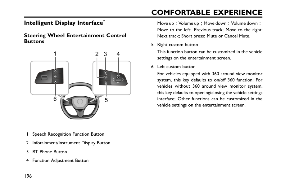
Comfortable Experience
Intelligent Display Interface* Steering Wheel Entertainment Control Buttons 1 Speech Recognition Function Button 2 Infotainment/Instrument Display Button 3 BT Phone Button 4 Function Adjustment Button Move up:Volume up;Move down:Volume down; Move to the left: Previous track; Move to the right: Next track; Short press: Mute or Cancel Mute. 5 Right custom button This function button can be customized in the vehicle settings on the entertainment screen. 6 Left custom button For vehicles equipped with 360 around view monitor system, this key defaults to on/off 360 function; For vehicles without 360 around view monitor system, this key defaults to opening/closing the vehicle settings interface; Other functions can be customized in the vehicle settings on the entertainment screen. 196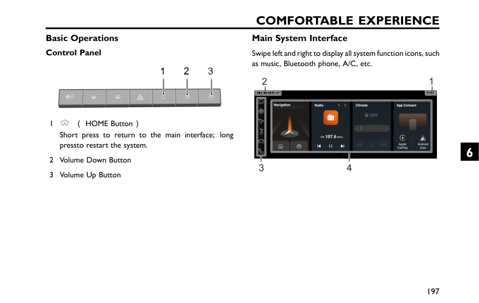
Comfortable Experience
Basic Operations Control Panel 1 (HOME Button) Short press to return to the main interface; long pressto restart the system. 2 Volume Down Button 3 Volume Up Button Main System Interface Swipe left and right to display all system function icons, such as music, Bluetooth phone, A/C, etc. 197 6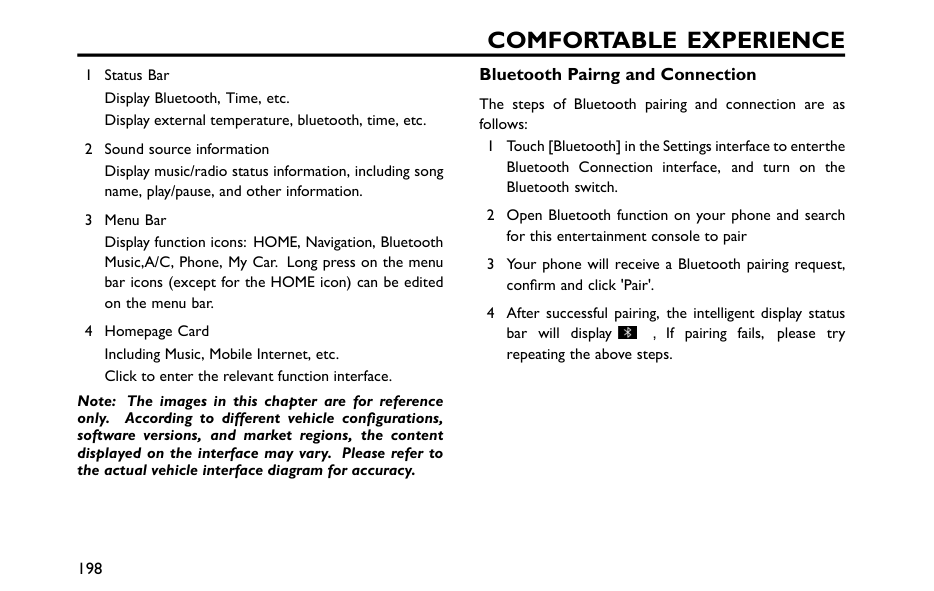
Comfortable Experience
1 Status Bar Display Bluetooth, Time, etc. Display external temperature, bluetooth, time, etc. 2 Sound source information Display music/radio status information, including song name, play/pause, and other information. 3 Menu Bar Display function icons: HOME, Navigation, Bluetooth Music,A/C, Phone, My Car. Long press on the menu bar icons (except for the HOME icon) can be edited on the menu bar. 4 Homepage Card Including Music, Mobile Internet, etc. Click to enter the relevant function interface. Note: The images in this chapter are for reference only. According to different vehicle configurations, software versions, and market regions, the content displayed on the interface may vary. Please refer to the actual vehicle interface diagram for accuracy. Bluetooth Pairng and Connection The steps of Bluetooth pairing and connection are as follows: 1 Touch [Bluetooth] in the Settings interface to enterthe Bluetooth Connection interface, and turn on the Bluetooth switch. 2 Open Bluetooth function on your phone and search for this entertainment console to pair 3 Your phone will receive a Bluetooth pairing request, confirm and click 'Pair'. 4 After successful pairing, the intelligent display status bar will display ,If pairing fails, please try repeating the above steps. 198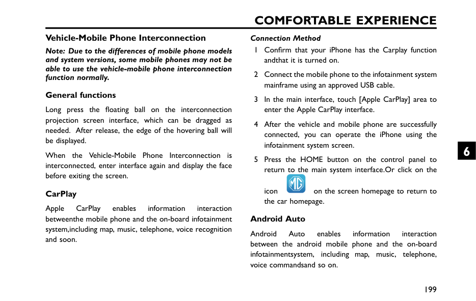
Comfortable Experience
Vehicle-Mobile Phone Interconnection Note: Due to the differences of mobile phone models and system versions, some mobile phones may not be able to use the vehicle-mobile phone interconnection function normally. General functions Long press the floating ball on the interconnection projection screen interface, which can be dragged as needed. After release, the edge of the hovering ball will be displayed. When the Vehicle-Mobile Phone Interconnection is interconnected, enter interface again and display the face before exiting the screen. CarPlay Apple CarPlay enables information interaction betweenthe mobile phone and the on-board infotainment system,including map, music, telephone, voice recognition and soon. Connection Method 1 Confirm that your iPhone has the Carplay function andthat it is turned on. 2 Connect the mobile phone to the infotainment system mainframe using an approved USB cable. 3 In the main interface, touch [Apple CarPlay] area to enter the Apple CarPlay interface. 4 After the vehicle and mobile phone are successfully connected, you can operate the iPhone using the infotainment system screen. 5 Press the HOME button on the control panel to return to the main system interface.Or click on the icon on the screen homepage to return to the car homepage. Android Auto Android Auto enables information interaction between the android mobile phone and the on-board infotainmentsystem, including map, music, telephone, voice commandsand so on. 199 6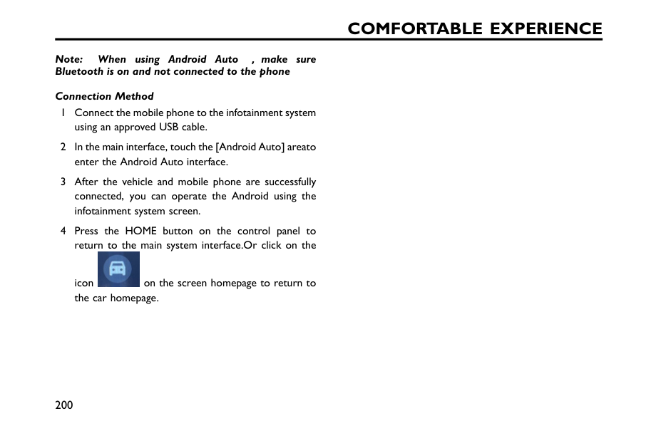
Comfortable Experience
Note: When using Android Auto , , ,make sure Bluetooth is on and not connected to the phone Connection Method 1 Connect the mobile phone to the infotainment system using an approved USB cable. 2 In the main interface, touch the [Android Auto] areato enter the Android Auto interface. 3 After the vehicle and mobile phone are successfully connected, you can operate the Android using the infotainment system screen. 4 Press the HOME button on the control panel to return to the main system interface.Or click on the icon on the screen homepage to return to the car homepage. 200
Intelligent Driver Assistance Instructions for Intelligent Driver Assistance 202 Camera and Radar 204 Constant Speed Cruise Control* 209 Adaptive Cruise Control(ACC )* 212 Intelligent Cruise Assit(ICA )* 220 Intelligent Overspeed Warning* 223 Speed Limit Assistance System* 225 Lane Departure Assist* 229 Front Collision Assist* 232 Blind Zone Safety Assit(BSD 、LCA )* 234 Rear Cross Traffic Alert(RCTA )* 236 Door opening warning(DOW )* 238 Rear Collision Warning(RCW )* 240 Ultrasonic Sensor Parking Aid* 241 Parking Camera* 243 360 Around View Monitor System* 244 Drive Fatigue Monitoring System* 245 7
Intelligent Driver Assistance
Instructions for Intelligent Driver Assistance Disclaimers for Intelligent Driver Assistance Function Before using the Driver Assistance functions, the user should read, accept, understand and pay particular attention to the following: 1 At present, all available Intelligent Driver Assistance functions require the driver to maintain full control during the entire driving process, the vehicle is NOT to be considered as full autonomous driving. 2 The user and driver should carefully read, learn, understand and implement the relevant content in the Owner's Handbook of this vehicle, and use these functions (and any related functions) in accordance with the requirements herein (in particular, the functional module instructions and use restrictions for intelligent driver assistance and intelligent cockpit). The user and the driver must always ensure they maintain full control and responsibility, observing all local Road Traffic Safety Laws and Regulations, and always be in a state of readiness to resume control of the steering wheel and braking of the vehicle. In the event of any personal or property damage caused by the user or the driver (for example, failure to use the vehicle in accordance with the requirements set out in the Owner's Handbook, or failure to retake control of the steering wheel and/or brakes at any time as required by the Road Traffic Safety Law), the user or the driver shall bear all responsibilities and consequences. 3 The Intelligent Driver Assistance function can only play an auxiliary role under certain conditions, and CANNOT replace the driver's observation of the road environment. The driver should drive cautiously and MUST NOT rely on the function. The Owner's Handbook has stated clearly in its obligation the various restrictions on the use of auxiliary functions (i.e. the circumstances under which certain functions may not be enabled, become impaired or may stop working). 4 The Intelligent Driver Assistance function has requirements for complete and successful operation, these include conditions such as weather, road 202
Intelligent Driver Assistance
surfaces and driver operations, operation may become impaired, fail or become limited due to several factors, which are not related to the design and application defects of the product. If the user and the driver cannot understand or accept the above disclaimers, do not use the Intelligent Driver Assistance functions. If the functions are enabled, please exit immediately. Camera and radar operation may be impaired in certain driving situations, weather and road conditions. In areas where there are complex traffic conditions such as intersections road junctions with congestion, or poor general conditions, the driver MUST take full control of the vehicle. The Intelligent Driver Assistance system can detect the road and environmental information ahead of the vehicle using the camera. It can provide warning messages or intervene when certain conditions are met in order to assist the driver in controlling the vehicle in a more safe and reliable manner. Note: DO NOT operate any infotainment switches whilst driving. If you wish to make any settings changes, please pull over when it is safe and legal to do so. 203 7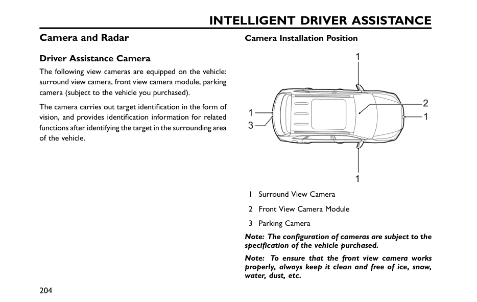
Intelligent Driver Assistance
Camera and Radar Driver Assistance Camera The following view cameras are equipped on the vehicle: surround view camera, front view camera module, parking camera (subject to the vehicle you purchased). The camera carries out target identification in the form of vision, and provides identification information for related functions after identifying the target in the surrounding area of the vehicle. Camera Installation Position 1 Surround View Camera 2 Front View Camera Module 3 Parking Camera Note: The configuration of cameras are subject to the specification of the vehicle purchased. Note: To ensure that the front view camera works properly, always keep it clean and free of ice, snow, water, dust, etc. 204
Intelligent Driver Assistance
Note: To ensure the camera works properly, always keep the windshield in front of the camera clean with no objects blocking the view between the camera and the windshield. Note: Please wipe camera lenses with a soft cloth or wash with water (of low pressure) when foreign objects are found on the camera surface. Do not use a high pressure water jet to flush the camera, and do not use abrasive or sharp objects to clean the camera. Camera Calibration Anyone other than an Authorised Repair personnel cannot remove/refit the camera. Recalibrate the front view camera module in the following situations: • The module has a maladjustment failure, for example the position of the camera has changed; • Remove/refit the camera or its bracket; • Remove/refit the windscreen; • The four-wheel alignment parameters have changed. Note: If the front detection radar is subject to strong vibration or slight impact, the mounting position of the front detection radar needs to be checked and re-calibrated as necessary. Note: Please consult an MG Authorised Repairer for more details about camera calibration. In the following situations, the detection performance of front view camera will be affected: • The camera is defaced or obscured by obvious foreign objects; and in the case of being covered by ice, snow, mud and dust. • In poor visibility or a bad weather (such as heavy rain, snow, fog, haze, smoke, dust, sand storm, etc.). • In poor light such as: in the evening, at night, in the tunnel without illumination, etc. • Due to the dust and water spraying caused by the sanitation vehicles and sprinklers in operation on the side lane; or the water mist caused by frontal or lateral vehicles on the highway in the rainy day. Construction areas of the unpaved road surface. • The view of the camera is interfered by the strong light (such as the headlamps of a coming vehicle, the headlamps of a rear vehicles or the direct sunlight). • Excessive light such as strong light and slanting sunshine (Backlight phenomenon is more common at high altitude regions). 205 7
Intelligent Driver Assistance
• When driving on the boulevard at night, the road lamp flashes erratically; and quick bright/dark jump (tunnel entrance/exit). • Travelling on the high-reflection road, for example, after the rain, snow or other high-reflection conditions. • The temperature of an extremely hot or cold weather will interfere with or affect the sensor performance to some extent. • The camera view is partially or wholly sheltered in such conditions, such as stains, tree gum, oil, stickers, etc. on the windscreen, the detection view sheltered by foreign objects like moldings and stickers, and the outer side of windscreen not sprayed and wiped in time. • The windscreen in the camera view is broken or has cracks or other optical-affected changes; • The slow wiping speed or the worn, aged and warped wipe blade causes the view of front view camera not to be wiped clean, and there are water stains and scratch marks in the view of the sensor. • The demist/defrost effect of the front windscreen is unsatisfactory in wet conditions. • The camera is not secured in place or firmly, or the fixture itself wobbles. • The camera is not calibrated after removal or replacement. 206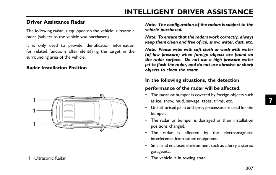
Intelligent Driver Assistance
Driver Assistance Radar The following radar is equipped on the vehicle: ultrasonic radar (subject to the vehicle you purchased). It is only used to provide identification information for related functions after identifying the target in the surrounding area of the vehicle. Radar Installation Position 1 Ultrasonic Radar Note: The configuration of the radars is subject to the vehicle purchased. Note: To ensure that the radars work correctly, always keep them clean and free of ice, snow, water, dust, etc. Note: Please wipe with soft cloth or wash with water (of low pressure) when foreign objects are found on the radar surface. Do not use a high pressure water jet to flush the radar, and do not use abrasive or sharp objects to clean the radar. In the following situations, the detection performance of the radar will be affected: • The radar or bumper is covered by foreign objects such as ice, snow, mud, sewage, tapes, trims, etc. • Unauthorised paint and spray processes are used for the bumper. • The radar or bumper is damaged or their installation positions changed. • The radar is affected by the electromagnetic interference from other equipment. • Small and enclosed environment such as a ferry, a stereo garage,etc. • The vehicle is in towing state. 207 7
Intelligent Driver Assistance
• The radar may not work properly due to limited detection performance in an open field (such as an open parking lot) or on an open road. Note: Any snow on the radar should be removed with a brush, while any ice is preferably removed with a deicing spray. 208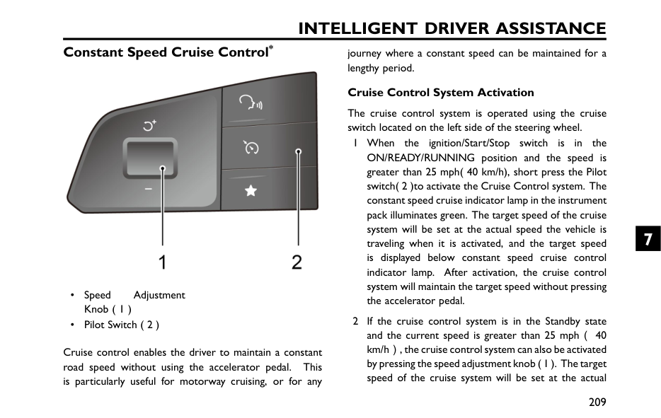
Intelligent Driver Assistance
Constant Speed Cruise Control* • Speed Adjustment Knob ( 1 ) • Pilot Switch ( 2 ) Cruise control enables the driver to maintain a constant road speed without using the accelerator pedal. This is particularly useful for motorway cruising, or for any journey where a constant speed can be maintained for a lengthy period. Cruise Control System Activation The cruise control system is operated using the cruise switch located on the left side of the steering wheel. 1 When the ignition/Start/Stop switch is in the ON/READY/RUNNING position and the speed is greater than 25 mph( 40 km/h), short press the Pilot switch( 2 )to activate the Cruise Control system. The constant speed cruise indicator lamp in the instrument pack illuminates green. The target speed of the cruise system will be set at the actual speed the vehicle is traveling when it is activated, and the target speed is displayed below constant speed cruise control indicator lamp. After activation, the cruise control system will maintain the target speed without pressing the accelerator pedal. 2 If the cruise control system is in the Standby state and the current speed is greater than 25 mph(40 km/h), the cruise control system can also be activated by pressing the speed adjustment knob ( 1 ). The target speed of the cruise system will be set at the actual 209 7
Intelligent Driver Assistance
speed the vehicle is traveling when it is activated, the target speed is displayed below constant speed cruise control indicator lamp. Note: The adjustment knob can be operated in various ways such as being moved up/down, or being pressed. Pressing the adjustment knob when the constant speed cruise control system is activated will update the vehicle speed to the current speed. Target Cruise Speed Adjustment When the cruise control is active: The vehicle can still be accelerated by pressing the accelerator pedal (such as overtaking). When the new desired speed is achieved, press the speed adjustment knob ( 1 ) to update the target cruise speed to the current speed. Push the knob ( 1 ) upwards/downwards and and hold to accelerate or decelerate automatically, then release the switch when the desired speed is reached. In addition, pushing the knob upwards/downwards and releasing immediately can adjust the speed. Each push will increase or decrease the speed appr. 1 mph(1 km/h). When the cruise control system is in operation, the vehicle can still be accelerated by pressing the accelerator pedal (such as overtaking). Releasing the accelerator pedal will return the vehicle to the set cruise speed. Pause Cruise control will drop from active to Standby, and the constant cruise control indicator lamp in the instrument panel will illuminate white if: • Short press Pilot Switch ( 2 ). • Brake pedal is applied. • The shift control knob is moved to N position. • Poor road conditions may lead to the activation of the Stability Control System ( SCS ). For safety reasons, the cruise control system will automatically exit to Standby state. • Undulating roads or hills may cause the vehicle's speed to drop or rise excessively, and the cruise control system will automatically exit to the Standby state. • The electronic parking brake ( EPB ) is activated. 210
Intelligent Driver Assistance
Resume When the cruise control remains in Standby after the disengagement, move the speed adjustment knob ( 1 ) upwards once to activate it again. The target cruise speed will return to the target speed before exiting the cruise control system.Off
Long press the Pilot switch ( 2 ) to turn off the cruise control system. Note: • Do not use the constant speed cruise control system in unsuitable conditions, such as in rainy days, on slippery surfaces, or in traffic conditions that do not allow to maintain a constant speed. • ALWAYS turn off the constant speed cruise control system when it is not in use. • When the vehicle is in "Sport" mode, it is not recommended to use the constant speed cruise control system. • During the operation of cruise control system, the actual speed may deviate from the target speed to some extent due to control precision or road conditions. • Excessive deviation of the actual vehicle speed from the target speed due to a slope or road surface, etc., or triggering the SCS to operate may cause the constant speed cruise control system to automatically exit to the "Standby" mode. • Do not press a switch for excessively long periods, or press multiple switches simultaneously, this may cause the constant speed cruise control system to fail. If this situation occurs, when it is safe to do so, please restart the vehicle. 211 7
Intelligent Driver Assistance
Adaptive Cruise Control( ACC )* The adaptive cruise control system is designed as a comfort system. It provides assistance to the driver, but DOES NOT replace any of the driver’s responsibilities. When using the adaptive cruise control system, it is important that the driver maintains concentration at ALL times and is prepared to take action. Otherwise, accidents or personal injuries may occur. Depending on whether there is vehicle ahead, the adaptive cruise control system can also conduct automatic switching between constant speed cruise and car-following cruise. With the adaptive cruise control system, the vehicle is allowed to conduct constant speed cruise within a certain speed range, or conduct car-following cruise by setting the distance between the vehicle and vehicles ahead. If a vehicle is detected in your driving path, the ACC system may apply moderate brakes or acceleration to maintain the selected following distance. Note: The adaptive cruise control system is designed for highways and roads in good condition. It is recommended that it is NOT used on urban roads and mountain roads. Adaptive Cruise Activation After following the vehicle ahead to a stop, the driver must ensure that there are no obstacles or other traffic participants, such as pedestrians,directly in front of the vehicle before starting off to follow the vehicle ahead again. Whilst using the car following cruise function, it is strongly recommended that the driver does not touch the accelerator pedal. Any activation of the accelerator will not allow the adaptive cruise control system to automatically apply the brakes, and the vehicle is only controlled by the driver's manipulation of the accelerator pedal. 212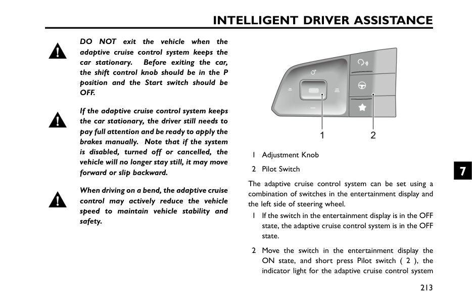
Intelligent Driver Assistance
Do
Not
exit the vehicle when the adaptive cruise control system keeps the car stationary. Before exiting the car, the shift control knob should be in the P position and the Start switch should beOff.
If the adaptive cruise control system keeps the car stationary, the driver still needs to pay full attention and be ready to apply the brakes manually. Note that if the system is disabled, turned off or cancelled, the vehicle will no longer stay still, it may move forward or slip backward. When driving on a bend, the adaptive cruise control may actively reduce the vehicle speed to maintain vehicle stability and safety. 1 Adjustment Knob 2 Pilot Switch The adaptive cruise control system can be set using a combination of switches in the entertainment display and the left side of steering wheel. 1 If the switch in the entertainment display is in the OFF state, the adaptive cruise control system is in the OFF state. 2 Move the switch in the entertainment display the ON state, and short press Pilot switch ( 2 ), the indicator light for the adaptive cruise control system 213 7
Intelligent Driver Assistance
on the instrument pack will turn blue, and the adaptive cruise control system is in Activated state ,The speed should be more than 3 mph(5 km/h)for first activation, its target speed is the actual speed at activation ,If your vehicle speed is less than 20 mph (30 km/h), then the target speed of the system is set at 20 mph(30 km/h). If the speed of the vehicle ahead is greater than the target cruise speed of your vehicle, your vehicle will maintain the target speed to conduct constant speed cruise; if the speed of the vehicle ahead is lower than the target cruise speed of your vehicle, it will enter the car-following cruise, and the tail schematic of the vehicle ahead is displayed on the instrument pack. In the car-following cruise, you can follow the vehicle ahead to a stop. If the stop time is less than a certain time, your vehicle may automatically start off to follow the vehicle ahead, otherwise the driver needs to re-activate the adaptive cruise control system according to the instrument prompt. Note: Manual deactivation of either the Electronic Stability Controller ( ((Esc )
) )will inhibit the operation of the adaptive cruise control system. Adaptive Cruise Target Following Distance Adjustment When the adaptive cruise control system is activated, move the adjustment knob to the right (to increase the distance) or left (to decrease the distance) to adjust the following distance,there are 3 distance settings, the distance setting will be displayed on the instrument pack. Select an appropriate following distance according to the difference in relative speed with the vehicle ahead, the higher the relative speed, the longer the following distance that should be selected. Considering the traffic and weather conditions, the optional following distance range may not be suitable for all drivers and driving conditions. Adaptive Cruise Target Speed Adjustment When the adaptive cruise control system is active: • Use the accelerator pedal to reach the desired speed, press the adjustment knob ( 1 ), then release the adjustment knob and accelerator pedal. The vehicle will cruise at the desired speed. • Move the adjustment knob upward or hold, the target speed will increase until the desired set speed appears 214
Intelligent Driver Assistance
on the instrument pack, then release the knob. When it is confirmed that there is no vehicle ahead or the vehicle ahead is beyond the pre-selected following distance, the vehicle speed can be increased to the set speed. • Move the adjustment knob downward or hold, the target speed will decrease until the desired set speed appears on the instrument pack, then release the knob, and the speed will be decreased to the set speed. Note: If the vehicle ahead continuously makes hard acceleration or deceleration, the ACC system may not be able to keep the following distance accurately, the driver must pay attention and perform the operations such as braking or lane change in time according to the surrounding environment. Adaptive Cruise Pause When the adaptive cruise control system is activated, short press the Pilot switch to cancel the function, and the system will exit to the Standby state. Automatic Deactivation of Adaptive Cruise In the following situations, the adaptive cruise controlsystem may be automatically deactivated, this transfers full control of the vehicle to the driver: • Operate the switch to turn off the ACC; • Press the brake pedal whilst the vehicle is in motion; • Move the shift control knob to either R or N position; • The driver unfastens his/her seat belt; • Press and hold the accelerator pedal beyond a preset time period; • Open any door, bonnet or tailgate; • Pull the EPB switch up to apply the parking brake; • Follow the vehicle ahead to a stop and the stop timeexceeds a certain period of time. • The camera or radar view is blocked, the surrounding environment triggers the preset safe exit mechanism of the sensors, or the system fails. Note: If following the vehicle ahead to a stop with the adaptive cruise control system enabled, if any of the following conditions occur whilst the vehicle is in a stopped state, the EPB will automatically be applied: • The driver unfastens the seat belt; • The driver door is opened; • The stationary time exceeds the preset time period. 215 7
Intelligent Driver Assistance
Adaptive Cruise Override If the driver has cause to use the accelerator pedalwhen the adaptive cruise control system is activated, the vehicle will remain in Cruise mode while the vehicle speed increases. When the accelerator pedal is released, the adaptive cruise control system will resume to operate at previously set cruise speed. Adaptive Cruise Resume If the adaptive cruise control system has reverted to, or been switched to, the Standby mode it can be reactivated by moving the adjustment knob upwards.The target cruise speed will automatically be set to thetarget speed before exiting the adaptive cruise control system. Clearing Target Speed Memory Turning off the switch of adaptive cruise control system on the entertainment display will turn off the adaptive cruise control system, synchronously clearing the system’s set speed in the memory. Switching off the ignition will also clear the set speed stored. Adaptive Cruise Control System Impairmentand Ineffectiveness: • Encounters a vehicle or object which is stationary ortraversing the lanes; • Approaching the vehicle ahead too fast, and the system cannot apply sufficient braking force; • The vehicle ahead is an oncoming vehicle, or makes an emergency braking manoeuvre; • The vehicle ahead reverses; • A vehicle suddenly cuts into the lane in front; • Encounters a vehicle driving at a low speed; • Encounters a vehicle with loaded items protruding from the body profile of the vehicle; • Encounters a vehicle with a higher chassis (e.g., a truck); • Encounters pedestrians, non-motor vehicles or animals; • The vehicle is driving on an uneven road or a complex traffic road section; • The vehicle makes a sharp turn; • Enters and leaves a tunnel or drives in the tunnel; • Drives in the shade of mottled trees; 216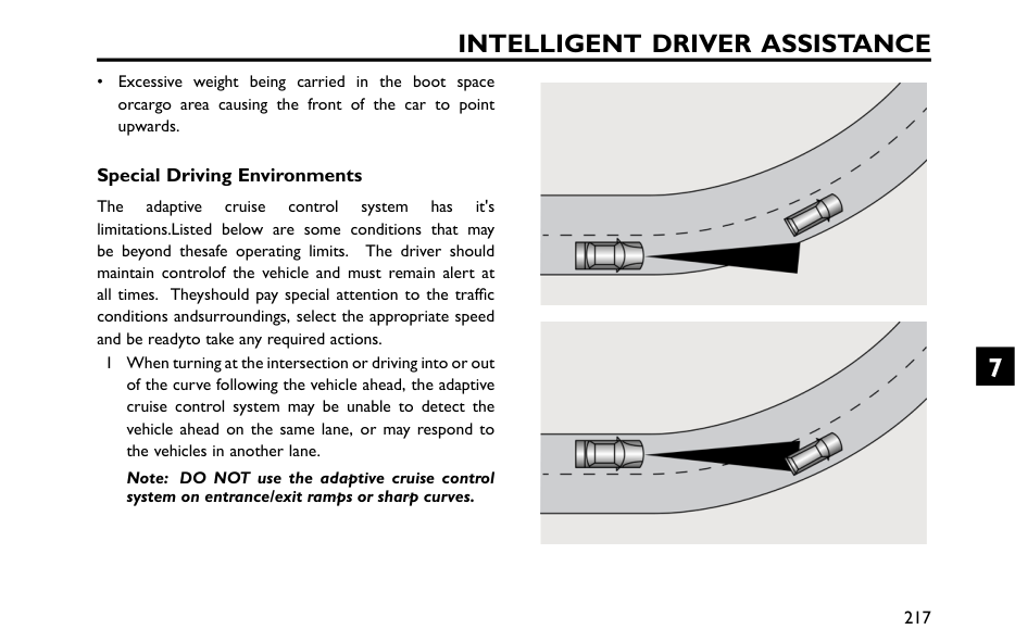
Intelligent Driver Assistance
• Excessive weight being carried in the boot space orcargo area causing the front of the car to point upwards. Special Driving Environments The adaptive cruise control system has it's limitations.Listed below are some conditions that may be beyond thesafe operating limits. The driver should maintain controlof the vehicle and must remain alert at all times. Theyshould pay special attention to the traffic conditions andsurroundings, select the appropriate speed and be readyto take any required actions. 1 When turning at the intersection or driving into or out of the curve following the vehicle ahead, the adaptive cruise control system may be unable to detect the vehicle ahead on the same lane, or may respond to the vehicles in another lane. Note: DO NOT use the adaptive cruise control system on entrance/exit ramps or sharp curves. 217 7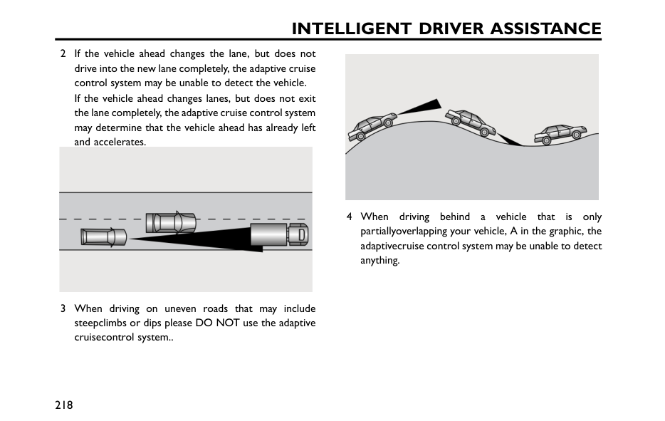
Intelligent Driver Assistance
2 If the vehicle ahead changes the lane, but does not drive into the new lane completely, the adaptive cruise control system may be unable to detect the vehicle. If the vehicle ahead changes lanes, but does not exit the lane completely, the adaptive cruise control system may determine that the vehicle ahead has already left and accelerates. 3 When driving on uneven roads that may include steepclimbs or dips please DO NOT use the adaptive cruisecontrol system.. 4 When driving behind a vehicle that is only partiallyoverlapping your vehicle, A in the graphic, the adaptivecruise control system may be unable to detect anything. 218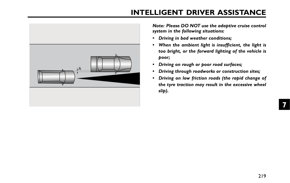
Intelligent Driver Assistance
Note: Please DO NOT use the adaptive cruise control system in the following situations: • Driving in bad weather conditions; • When the ambient light is insufficient, the light is too bright, or the forward lighting of the vehicle is poor; • Driving on rough or poor road surfaces; • Driving through roadworks or construction sites; • Driving on low friction roads (the rapid change of the tyre traction may result in the excessive wheel slip). 219 7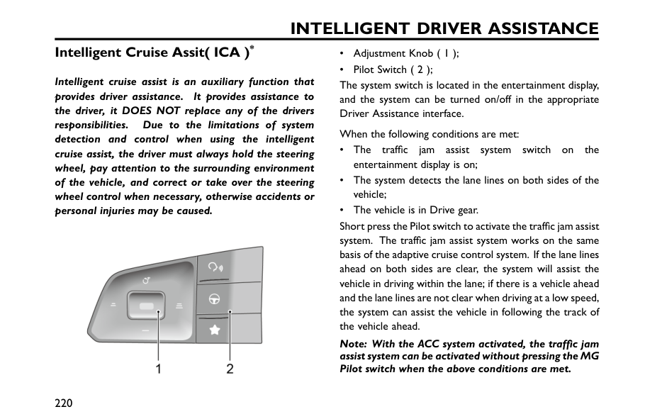
Intelligent Driver Assistance
Intelligent Cruise Assit( ICA )* Intelligent cruise assist is an auxiliary function that provides driver assistance. It provides assistance to the driver, it DOES NOT replace any of the drivers responsibilities. Due to the limitations of system detection and control when using the intelligent cruise assist, the driver must always hold the steering wheel, pay attention to the surrounding environment of the vehicle, and correct or take over the steering wheel control when necessary, otherwise accidents or personal injuries may be caused. • Adjustment Knob ( 1 ); • Pilot Switch ( 2 ); The system switch is located in the entertainment display, and the system can be turned on/off in the appropriate Driver Assistance interface. When the following conditions are met: • The traffic jam assist system switch on the entertainment display is on; • The system detects the lane lines on both sides of the vehicle; • The vehicle is in Drive gear. Short press the Pilot switch to activate the traffic jam assist system. The traffic jam assist system works on the same basis of the adaptive cruise control system. If the lane lines ahead on both sides are clear, the system will assist the vehicle in driving within the lane; if there is a vehicle ahead and the lane lines are not clear when driving at a low speed, the system can assist the vehicle in following the track of the vehicle ahead. Note: With the ACC system activated, the traffic jam assist system can be activated without pressing the MG Pilot switch when the above conditions are met. 220
Intelligent Driver Assistance
When the system detects that the driver has not controlled the steering wheel in a certain period of time, it will give warnings to prompt the driver. Note: Drivers should adjust their vehicle speed and distance from the vehicle ahead based on road visibility, weather, and road traffic conditions. The intelligent cruise assist system will not respond to pedestrians, animals, stationary vehicles, vehicles crossing the lane, or oncoming vehicles on the same lane. If the intelligent cruise assist system cannot fully reduce the speed, braking should be carried out by pressing the brake pedal. In congested conditions, if other vehicles enter this lane due to congestion, the braking may not be timely due to the vehicles not entering the system detection range. The driver should take the initiative to brake. The traffic jam assist system will be impaired orineffective in the following conditions: • The driver turns on the turn signal lamps; • The driver turns on the hazard warning lamp; • The driver applies the accelerator rapidly, carries outan emergency manoeuvre or makes a hard brake pedal application; • The system detects that the driver has not moved thesteering wheel for a preset time period; • During system intervention, the steering wheel is beingmanipulated by the driver; • The lane line is too thin, damaged or fuzzy; • The vehicle is being driven on a bend with a smallcurvature radius, the road is too narrow or too wide; • The vehicle has just entered a road section with lanelines or is being driven on a road section without lanelines; • The vehicle is in R gear; • The vehicle changes lanes or sways laterally too fast; • The turning radius of the car using the traffic jam assistsystem to track in front is too small; • The anti-lock brake system ( ABS ) and the dynamic stability control system ( SCS ) are activated; • Faults exist in the anti-lock brake system ( ABS ), dynamicstability control system ( SCS ), electric power steeringsystem ( EPS ), etc. It is recommended to turn off the traffic jam assist system in the following situations: 221 7
Intelligent Driver Assistance
• Driving in a sports style or manner; • Driving in bad weather conditions; • Driving on rough or poor road surfaces; • Driving through roadworks or construction sites; • Driving on steep, winding or slippery roads (such assnow covered and icy roads, wet roads and roadscovered with water); • Driving on grass tracks or unpaved roads.Important
• In cases where the number of lanes increase or lanes merge the driver MUST take full control of the vehicle. • In areas where there are complex traffic conditions such as intersections or road junctions with congestion, the driver MUST take full control. • The driver MUST be aware of the surroundings and be able to assume full control of the vehicle when using the traffic jam assist system to track the car in front should the need arise. 222
Intelligent Driver Assistance
Intelligent Overspeed Warning* The intelligent speed assist system is an auxiliary function. It may display an incorrect speed limit value or no speed limit value in the instrument pack due to various factors. As a result, the vehicle speed is not restricted within the correct range. The driver still needs to observe the speed limit of the road traffic, and speeding is strictly prohibited. The front view camera cannot recognise speed limit signs painted on the road surface. The driver MUST observe these speed limits and adjust the their speed accordingly. The setting interface for the intelligent overspeed warning is in the entertainment display. The driver can operate the intelligent overspeed warning system using the soft switch in this display. The vehicle detects the speed limit sign (such as ) at the roadside with the front view camera. When the vehicle speed exceeds the speed limit indicated by the speed limit sign speed indicator, the indicator flashes accompanied by a warning sound to remind the driver to control the vehicle speed. The speed limit sign speed indicator illuminates when the intelligent overspeed warning is active. When the vehicle passes the first speed limit sign identified, the speed sign speed indicator displays the real-time speed limit value. If a speed limit sign with the same limit value is detected, the limit value displayed in the speed sign speed indicator remains. Note: If the vehicle changes lane, makes a turn, turns around in the intersection, or identifies the speed limit cancellation, the original speed limit value on the instrument pack may be reset and displayed as “–” till a new speed limit sign is detected. If the conditions are not met, the original speed limit value will maintain and not be reset. The driver MUST observe the speed limits and adjust the their speed accordingly. The intelligent overspeed warning system function may be impaired if: 1 The detection performance of front view camera is affected; 2 The vehicle is driven at a high speed; 223 7
Intelligent Driver Assistance
3 The speed limit signs are obscured by trees at the roadside, ice/frost, snows, dust, etc; or the speed limit signs are placed improperly or damaged; 4 When there are several speed limit signs set up over the road or at the roadside, the overspeed warning will be carried out according to the maximum speed limit value.Important
• The camera may not correctly recognise speed limit signs during poor lighting conditions, bad weather, non-standardized or sheltered speed limit signs or the camera’s own restrictions which include the recognition of similar signs (e.g., recognise a weight limit sign as a speed limit sign, or recognise a minimum speed sign as the maximum speed sign). • The camera cannot identify the text provided below the speed limit sign, such as Auxiliary Lane, 100 m Ahead, School Section, 7:00-10:00 , etc. The camera will identify the speed limit sign with text as a normal speed limit sign. • Some drastic and rapid steering operations of the driver may be judged as changing lane or turning around in the intersection by the system, resulting in the identified speed limit signs being cleared. • In cases where a speed limit sign contains multiple speed limits. The camera may not identify all the speed limits. 224
Intelligent Driver Assistance
Speed Limit Assistance System* Speed Limit Assistance System The speed limit assistance system is only an auxiliary function. In cases where the speed limit sign is not standardized or the front view camera is blocked, the wrong speed limit value or no speed limit value may be displayed on the instrument pack, and the vehicle is not restricted in the correct speed range, so the driver still needs to be responsible for real-time evaluation of the speed limit on the road. The front view camera cannot recognise speed limit signs painted on the road surface. The driver MUST observe these speed limits and adjust the their speed accordingly. The setting interface of the speed limit assistance system is located in the entertainment display. Enter the Vehicle Settings - Speed Limit Assistance System interface to select from the following modes: Smart, Manual and Off. 1 Smart: i.e. smart speed limit. The vehicle detects the speed limit sign (such as ) at the roadside with the front view camera, and intervenes using the speed control to keep the vehicle speed in the permitted maximum speed limit; 2 Manual : i.e. manual speed limit. The driver sets the maximum speed with the button on the left side of the steering wheel and uses the speed control system to keep the speed in the permitted maximum speed limit. Refer to “Speed Settings of Manual Speed Limit” for the description; 3 Off: Turn off the speed limit assistance system. Note: If the mode selection cannot be performed, please confirm that the cruise function in the entertainment display is OFF and try again. Speed Settings of Manual Speed Limit After the manual speed limit function is enabled, the speed limit can be set by using the button on the left side of the steering wheel, as follows: 225 7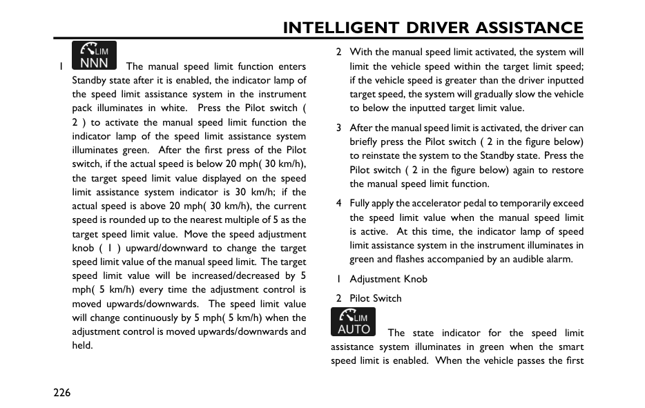
Intelligent Driver Assistance
1 The manual speed limit function enters Standby state after it is enabled, the indicator lamp of the speed limit assistance system in the instrument pack illuminates in white. Press the Pilot switch ( 2 ) to activate the manual speed limit function the indicator lamp of the speed limit assistance system illuminates green. After the first press of the Pilot switch, if the actual speed is below 20 mph( 30 km/h), the target speed limit value displayed on the speed limit assistance system indicator is 30 km/h; if the actual speed is above 20 mph( 30 km/h), the current speed is rounded up to the nearest multiple of 5 as the target speed limit value. Move the speed adjustment knob ( 1 ) upward/downward to change the target speed limit value of the manual speed limit. The target speed limit value will be increased/decreased by 5 mph( 5 km/h) every time the adjustment control is moved upwards/downwards. The speed limit value will change continuously by 5 mph( 5 km/h) when the adjustment control is moved upwards/downwards and held. 2 With the manual speed limit activated, the system will limit the vehicle speed within the target limit speed; if the vehicle speed is greater than the driver inputted target speed, the system will gradually slow the vehicle to below the inputted target limit value. 3 After the manual speed limit is activated, the driver can briefly press the Pilot switch ( 2 in the figure below) to reinstate the system to the Standby state. Press the Pilot switch ( 2 in the figure below) again to restore the manual speed limit function. 4 Fully apply the accelerator pedal to temporarily exceed the speed limit value when the manual speed limit is active. At this time, the indicator lamp of speed limit assistance system in the instrument illuminates in green and flashes accompanied by an audible alarm. 1 Adjustment Knob 2 Pilot Switch The state indicator for the speed limit assistance system illuminates in green when the smart speed limit is enabled. When the vehicle passes the first 226
Intelligent Driver Assistance
speed limit sign identified, the speed sign speed indicator displays the real-time speed limit value. If a speed limit sign with the same limit value is detected, the limit value displayed in the speed sign speed indicator remains. Note: If the vehicle changes lane, makes a turn, turns around in the intersection, or identifies the speed limit cancellation, the original speed limit value on the instrument pack may be reset and displayed as “–” till a new speed limit sign is detected. If the conditions are not met, the original speed limit value will remain and not be reset. The driver MUST observe the speed limitsand adjust the their speed accordingly. The driver can temporarily exit the speed limit assistance system by the following operations: 1 Fully apply the accelerator pedal to temporarily exceed the speed limit value. At this time, the indicator lamp of speed limit assistance system in the instrument pack illuminates in green and flashes accompanied by an audible alarm; 2 Briefly pressing the Pilot switch ( 2 in the figure above) can temporarily exit the speed limit assistance system functions. In this case, the indicator lamp of the speed limit assistance system in the instrument changes into white (into dark colour in daylight mode); press the Pilot switch again to resume the speed limit assistance system functions. 227 7
Intelligent Driver Assistance
The smart speed limit may may be impaired if: 1 The detection performance of front view camera is affected; 2 The vehicle is driven at a high speed; 3 The speed limit signs are obscured by trees at the roadside, ice/frost, snows, dust, etc; or the speed limit signs are placed improperly or damaged; 4 There are multiple speed limit signs set up over the road or at the roadside; Currently, the front view camera can only identify the speed limit signs for the lane the vehicle is being driven in; 5 The speed limit signs set up at the forks in the road, the curves and the on-ramp/off-ramp; 6 Lane change, etc.Important
• The camera may not correctly recognise speed limit signs during poor lighting conditions, bad weather, non-standardized or sheltered speed limit signs or the camera’s own restrictions which include the recognition of similar signs (e.g., recognise a weight limit sign as a speed limit sign, or recognise a minimum speed sign as the maximum speed sign). • The camera cannot identify the text provided below the speed limit sign, such as Auxiliary Lane, 100 m Ahead, School Section, 7:00-10:00 , etc. The camera will identify the speed limit sign with text as a normal speed limit sign. • Some drastic and rapid steering operations of the driver may be judged as changing lane or turning around in the intersection by the system, resulting in the identified speed limit signs being cleared. • In cases where a speed limit sign contains multiple speed limits. The camera may not identify all the speed limits. 228
Intelligent Driver Assistance
Lane Departure Assist* The lane departure assist system is an auxiliary system, which can provide assistance to the driver. It does NOT remove the responsibility of safe driving from the driver. When choosing to use the lane keeping assist system, the driver MUST always pay attention to the surroundings, hold the steering wheel and be prepared to make manoeuvres at any time. Failure to maintain overall control of the vehicle may result in an accident or personal injury. The lane departure assist system does not always recognise the lane lines or kerbs. Sometimes poor road surfaces, certain road structures or objects may be mistaken for lane lines or kerbs. When such situations occur, the lane departure assist system must be turned off immediately. The lane departure assist system switch is located on the entertainment display. The system can be turned on/off in the appropriate Intelligent Driver Assistance interface, and the mode can be selected. Alert The system detects the lane lines ahead when the following detection conditions are met: • The function is in ON state; • The vehicle speed is above 60 km/h; • The lane lines are clear, and the system detects at least one lane line; When the wheel is about to press the lane line or has already pressed the lane line, the system will give warnings to remind the driver to correct the direction in time and keep the vehicle running within the lane lines. The function will exit when the speed is less than 55 km/h. Assist The system uses the front view camera to detect the lane lines ahead of the vehicle. The system will be activated when the following detection conditions are met: • The function is switched ON. • Vehicle speed is above 60 km/h. 229 7
Intelligent Driver Assistance
• Lane line markings are clear and the system recognises at least one lane line. When a wheel is about to cross the lane line, or has already crossed the line, the system will provide assistance to the driver by keeping the vehicle in between the lane lines by applying corrective steering intervention and simultaneously displaying a prompt. The function will automatically exit when the vehicle speed drops below 55 km/h. Emergency Lane Keeping ( ((Elk )
) ) The system uses the front view camera to detect lane lines, kerb and adjacent lanes of oncoming traffic ahead. The system will be activated when the following detection conditions are met: • The function is switched ON. • Vehicle speed is above 60 km/h. • Lane line markings are clear and the system recognises at least one lane line. When a wheel is about to cross the lane line or kerb, or the vehicle is approaching oncoming traffic in the adjacent lane, and there is a collision trend, the system will provide assistance to the driver by keeping the vehicle in between the lane lines or kerbs, or avoiding sharply by applying corrective steering intervention and simultaneously displaying a prompt. The function will automatically exit when the vehicle speed drops below 55 km/h. In cases of several interventions within a certain period of time and in the absence of detecting any steering input by the driver during the interventions, the system will provide warnings.Important
• In cases where the number of lanes increase or lanes merge, the driver MUST take full control of the vehicle. • In areas where there are complex traffic conditions such as intersections or road junctions with congestion, the driver MUST take full control of the vehicle. 230
Intelligent Driver Assistance
The lane departure assist system will be impaired or ineffective in the following conditions: • The driver indicates in the direction of the lane line about to be crossed. • The hazard lamps are activated. • The driver applies the accelerator rapidly, carries out an emergency manoeuvre or makes a hard brake pedal application. • The system detects that the driver has not moved the steering wheel for a preset time period (in the mode of assist or emergency lane keeping). • During system intervention the steering wheel is operated (in the mode of assist or emergency lane keeping). • The lane line is too thin, damaged, or fuzzy. • Irregular or damaged kerbs. • The vehicle is driven on the bend with a small curvature radius, the road is too narrow or too wide. • The vehicle has just entered a road section with lane lines or is driven on a road section without lane lines. • The vehicle changes lanes or sways laterally too fast. • The vehicle is not in D. • The vehicle speed is below 55 km/h, or too high. • The anti-lock brake system (ABS) and the dynamic stability control system (SCS) are activated. • Faults exist in the anti-lock brake system (ABS), dynamic stability control system (SCS), electric power steering system (EPS), etc. It is recommended to turn off the lane assist system in the following situations: • Driving in a sports style or manner. • Driving in bad weather conditions. • Driving on rough or poor road surfaces. • Driving through roadworks or construction sites. 231 7
Intelligent Driver Assistance
Front Collision Assist* The driver remains responsible for the safety of the entire driving process, even if the vehicle is equipped with a forward collision system. The driver MUST pay full attention and drive carefully. As with all the driver assist systems, the forward collision system cannot prevent accidents or avoid collisions in all situations. The driver MUST always remain in control to avoid accidents or emergency situations. Ensure forward collision system or ignition/vehicle power system is switched off when being towed. If forward collision system is enabled when the vehicle is being towed, adverse effects may affect the safety of your vehicle, the towing vehicle and the people around. To avoid the occurrence of accidents, never specially test the functions of forward collision system. The front collision assist switch is located on the entertainment display. The system can be turned on/off in the appropriate Intelligent Driver Assistance interface. Alarm When the system detects a risk of collision between this vehicle and the vehicle ahead in this lane or pedestrians, it will give warnings to prompt the driver to slow down and keep a relatively safe distance from the vehicle ahead or pedestrians and a relatively safe speed. • There is oncoming traffic, the vehicle ahead drives across transversely or cuts suddenly; • The vehicle ahead does not follow the rules of driving (for example, driving across lanes) and parking (on the roads transversely); • The vehicle ahead is not on the same lane of this vehicle or is partially blocked; • The vehicle ahead is a non-standard motor vehicle (for example, a refitted vehicle); • The vehicle ahead is a vehicle with high chassis. • The vehicle ahead is a large vehicle and at a close distance (such as a tractor, a trailer, a towing vehicle, a mud-carrying vehicle and a sanitation truck); 232
Intelligent Driver Assistance
• The vehicle ahead is some means of transportation rarely can be seen on the road (such as the ox cart, carriage or others); • The vehicle ahead is a bicycle, motorbike or small wheeled object (such as suitcases, shopping carts or wheelchairs); • The contour of the vehicle ahead is unclear due to the water sprayed by the wheels of the surrounding vehicles; • The vehicle ahead does not turn on the tail lamps when driving at night or in the tunnel; • The tail lamps of the vehicle ahead are all LED lamps or other home-made fairy lights; • When driving on the boulevard, the road lamp flashes erratically; • The pedestrian is not directly in front of the vehicle or not fully visible; • The pedestrian does not stand upright or is a shorter child; • A crowd of people or the pedestrian is in the tree shadow or in the dark; • There are animals or foreign obstacles on the ground ahead (such as a roadblock, an isolation pile, an isolation strip, big rocks, other scattered objects, etc.); • There are signs, guardrails, bridges, buildings, etc. ahead; • The vehicle drives on a slope, the section coming on/off the bridge or curve; • The vehicle is in Reverse gear; • The vehicle is in braking or harsh acceleration state. 233 7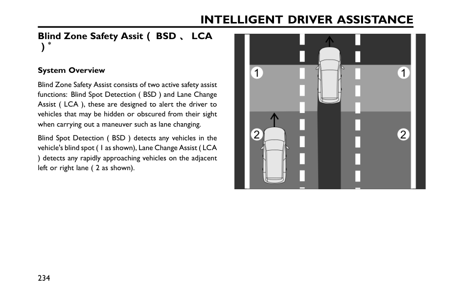
Intelligent Driver Assistance
Blind Zone Safety Assit( ((Bsd 、
、、Lca
) ) )* System Overview Blind Zone Safety Assist consists of two active safety assist functions: Blind Spot Detection ( BSD ) and Lane Change Assist ( LCA ), these are designed to alert the driver to vehicles that may be hidden or obscured from their sight when carrying out a maneuver such as lane changing. Blind Spot Detection ( BSD ) detects any vehicles in the vehicle's blind spot ( 1 as shown), Lane Change Assist ( LCA ) detects any rapidly approaching vehicles on the adjacent left or right lane ( 2 as shown). 234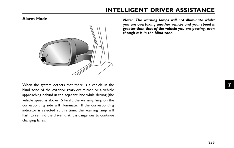
Intelligent Driver Assistance
Alarm Mode When the system detects that there is a vehicle in the blind zone of the exterior rearview mirror or a vehicle approaching behind in the adjacent lane while driving (the vehicle speed is above 15 km/h, the warning lamp on the corresponding side will illuminate. If the corresponding indicator is selected at this time, the warning lamp will flash to remind the driver that it is dangerous to continue changing lanes. Note: The warning lamps will not illuminate whilst you are overtaking another vehicle and your speed is greater than that of the vehicle you are passing, even though it is in the blind zone. 235 7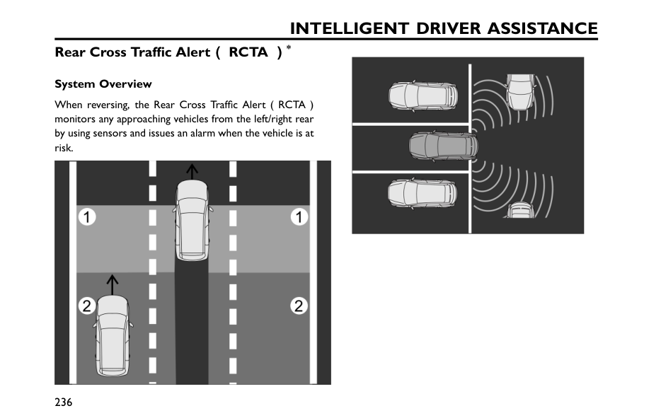
Intelligent Driver Assistance
Rear Cross Traffic Alert( ((Rcta )
) )* System Overview When reversing, the Rear Cross Traffic Alert ( RCTA ) monitors any approaching vehicles from the left/right rear by using sensors and issues an alarm when the vehicle is at risk. 236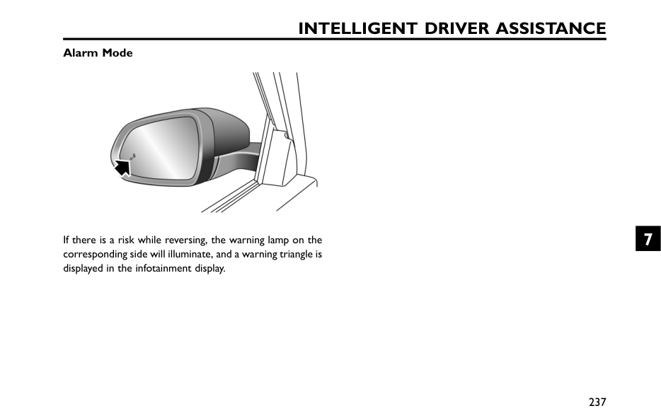
Intelligent Driver Assistance
Alarm Mode If there is a risk while reversing, the warning lamp on the corresponding side will illuminate, and a warning triangle is displayed in the infotainment display. 237 7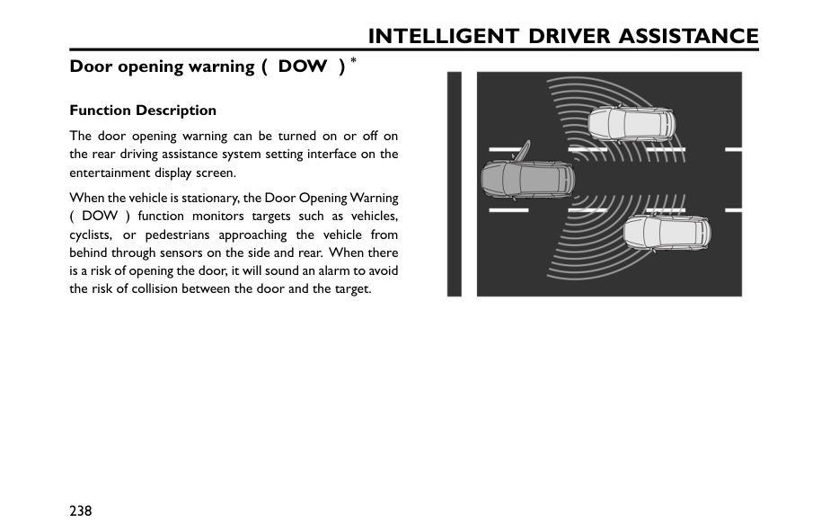
Intelligent Driver Assistance
Door opening warning( ((Dow )
) )* Function Description The door opening warning can be turned on or off on the rear driving assistance system setting interface on the entertainment display screen. When the vehicle is stationary, the Door Opening Warning ( DOW ) function monitors targets such as vehicles, cyclists, or pedestrians approaching the vehicle from behind through sensors on the side and rear. When there is a risk of opening the door, it will sound an alarm to avoid the risk of collision between the door and the target. 238
Intelligent Driver Assistance
Alarm Mode When there is a risk of collision, the corresponding warning light on the side will light up. If the car door continues to be opened at this time, the warning light will flash and accompanied by an alarm sound. 239 7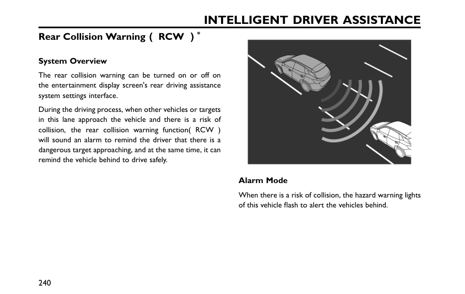
Intelligent Driver Assistance
Rear Collision Warning( ((Rcw )
) )* System Overview The rear collision warning can be turned on or off on the entertainment display screen's rear driving assistance system settings interface. During the driving process, when other vehicles or targets in this lane approach the vehicle and there is a risk of collision, the rear collision warning function( RCW ) will sound an alarm to remind the driver that there is a dangerous target approaching, and at the same time, it can remind the vehicle behind to drive safely. Alarm Mode When there is a risk of collision, the hazard warning lights of this vehicle flash to alert the vehicles behind. 240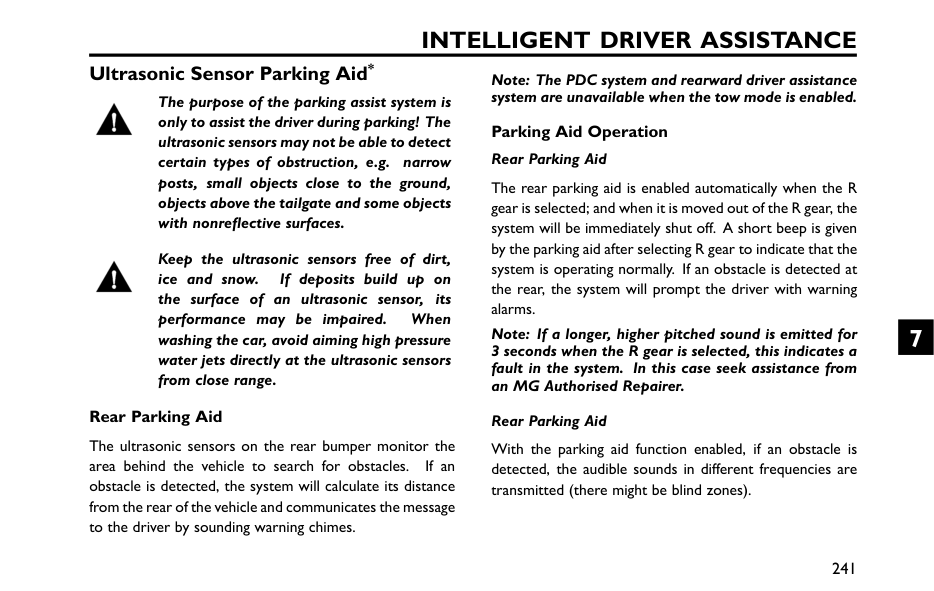
Intelligent Driver Assistance
Ultrasonic Sensor Parking Aid* The purpose of the parking assist system is only to assist the driver during parking! The ultrasonic sensors may not be able to detect certain types of obstruction, e.g. narrow posts, small objects close to the ground, objects above the tailgate and some objects with nonreflective surfaces. Keep the ultrasonic sensors free of dirt, ice and snow. If deposits build up on the surface of an ultrasonic sensor, its performance may be impaired. When washing the car, avoid aiming high pressure water jets directly at the ultrasonic sensors from close range. Rear Parking Aid The ultrasonic sensors on the rear bumper monitor the area behind the vehicle to search for obstacles. If an obstacle is detected, the system will calculate its distance from the rear of the vehicle and communicates the message to the driver by sounding warning chimes. Note: The PDC system and rearward driver assistance system are unavailable when the tow mode is enabled. Parking Aid Operation Rear Parking Aid The rear parking aid is enabled automatically when the R gear is selected; and when it is moved out of the R gear, the system will be immediately shut off. A short beep is given by the parking aid after selecting R gear to indicate that the system is operating normally. If an obstacle is detected at the rear, the system will prompt the driver with warning alarms. Note: If a longer, higher pitched sound is emitted for 3 seconds when the R gear is selected, this indicates a fault in the system. In this case seek assistance from an MG Authorised Repairer. Rear Parking Aid With the parking aid function enabled, if an obstacle is detected, the audible sounds in different frequencies are transmitted (there might be blind zones). 241 7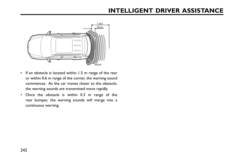
Intelligent Driver Assistance
• If an obstacle is located within 1.5 m range of the rear or within 0.6 m range of the corner, the warning sound commences. As the car moves closer to the obstacle, the warning sounds are transmitted more rapidly. • Once the obstacle is within 0.3 m range of the rear bumper, the warning sounds will merge into a continuous warning. 242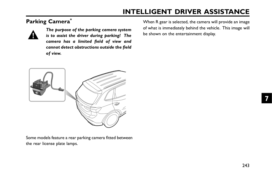
Intelligent Driver Assistance
Parking Camera* The purpose of the parking camera system is to assist the driver during parking! The camera has a limited field of view and cannot detect obstructions outside the field of view. Some models feature a rear parking camera fitted between the rear license plate lamps. When R gear is selected, the camera will provide an image of what is immediately behind the vehicle. This image will be shown on the entertainment display. 243 7
Intelligent Driver Assistance
360 Around View Monitor System* The purpose of the 360 around view system is to assist the driver during parking! The cameras have a limited field of view and cannot detect obstructions outside the field of view. Although the infotainment display can provide images around the vehicle, please still pay attention to the current actual road conditions for your driving safety. With the 360 around view system working, the entertainment display interface will show a 360 around view of the vehicle to facilitate the observation of surrounding environment and make the driving environment much safer. You can touch buttons on the display to view images from different perspectives around the vehicle. You can enter the 360 around view system using the following operations: • Select R gear. • Click 360 icon. • Using the 'Setting' interface to select low speed switching of corner lights/indicators, this will automatically open the 360 around view system when the indicators are used at low speeds and exit when the indicators are cancelled. • After setting the shortcut button on the steering wheel to 360 function, press this button. In the 360 around view system display interface, select the settings icon to enable personal settings for system functions. Note: When the shift control knob is placed in D , the 360 around view system is inhibited at speeds above or equal to 20 mph/ ( 35 km/h ) 244
Intelligent Driver Assistance
Drive Fatigue Monitoring System* The driver should always ensure that their physical state is suitable for driving,even if the vehicle is equipped with an indirect driver fatigue reminder system.Never
drive the vehicle when fatigued. The indirect driver fatigue reminder system cannot always identify the driver's fatigue level accurately. It calculates the fatigue level through the driver's operational control status instead of monitoring the driver's actual physical characteristics such as distraction, it cannot provide an emergency reminder to the driver who has just become fatigued. The driver attention warning system calculates the driver's fatigue level by comparing information such as vehicle speed and steering wheel angle with basic data obtained based on mass data statistics. The system will constantly compare the calculated fatigue level with the current operational state of the driver. If the system recognizes that the driver is becoming fatigued, a warning will be issued. When the indirect driver fatigue reminder system is active, the vehicle speed is over 37 mph/ 60 km/h. When the driver performs the following operations, the system will stop monitoring the driver's fatigue level: 1 The driver removes the seat belt and opens the driver door; 2 The stop time exceeds 15 minutes; 3 The ignition or power system is turned off. System Settings After the vehicle starts, the indirect driver fatigue reminder system is enabled by default, and can be turned off/on and sensitivity set in the entertainment display screen. Note: The indirect driver fatigue reminder system is not easily triggered if the vehicle is passing through low-quality road sections, continuous bends, or sections with large amounts of traffic lights. 245 7
Road Emergency Response Hazard Warning Devices 248 Emergency Starting 249 eCall-SOS Emergency Assistance* 253 Vehicle Recovery 256 Tyre Repair and Tyre Replace* 260 8
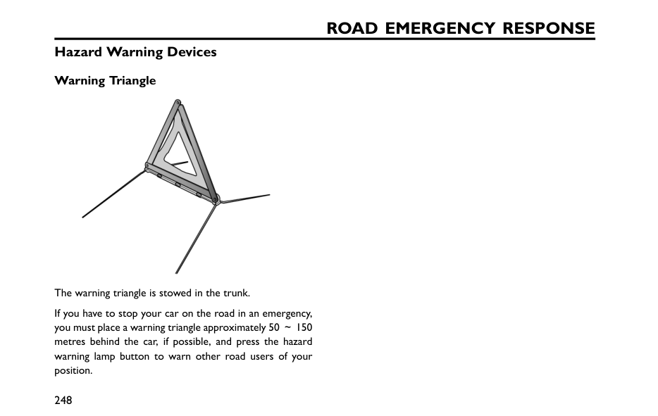
Road Emergency Response
Hazard Warning Devices Warning Triangle The warning triangle is stowed in the trunk. If you have to stop your car on the road in an emergency, you must place a warning triangle approximately 50 ~150 metres behind the car, if possible, and press the hazard warning lamp button to warn other road users of your position. 248
Road Emergency Response
Emergency Starting NEVER attempt to power the vehicle by pushing or towing. Make sure that both batteries are of the same rated voltage (12 volts), and that the booster cables are approved for use with 12 volt car batteries. Ensure sparks and open flames are kept well away from the front compartment. Ensure that booster cables are firmly connected and do not touch each other or other moving parts, otherwise, sparks may be caused, resulting in fire or explosion. In case of low battery, the vehicle can be started by using a booster cable to connect the battery of another vehicle or to connect the battery externally. WhenHEV models start with a jump start, try to use the positive terminal of the battery as the positive jump point when the tailgate is allowed to open. If the tailgate cannot be opened, open the front compartment fuse box, and the terminal shown in the figure can serve as the positive terminal jumper. When starting fuel vehicles with a jump start, try to use the positive terminal of the battery as the positive jump point. If the positive terminal of the battery cannot be used, open the front compartment fuse box, and the terminal shown in the figure can serve as the positive jump point. 249 8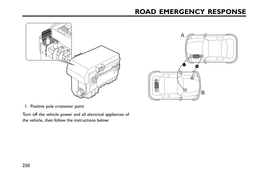
Road Emergency Response
1 Positive pole crossover point Turn off the vehicle power and all electrical appliances of the vehicle, then follow the instructions below: 250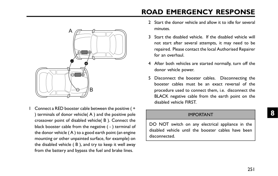
Road Emergency Response
1 Connect a RED booster cable between the positive ( + ) terminals of donor vehicle( A ) and the positive pole crossover point of disabled vehicle( B ). Connect the black booster cable from the negative ( - ) terminal of the donor vehicle ( A ) to a good earth point (an engine mounting or other unpainted surface, for example) on the disabled vehicle ( B ), and try to keep it well away from the battery and bypass the fuel and brake lines. 2 Start the donor vehicle and allow it to idle for several minutes. 3 Start the disabled vehicle. If the disabled vehicle will not start after several attempts, it may need to be repaired. Please contact the local Authorised Repairer for an overhaul. 4 After both vehicles are started normally, turn off the donor vehicle power. 5 Disconnect the booster cables. Disconnecting the booster cables must be an exact reversal of the procedure used to connect them, i.e. disconnect the BLACK negative cable from the earth point on the disabled vehicle FIRST.Important
DO NOT switch on any electrical appliance in the disabled vehicle until the booster cables have been disconnected. 251 8
Road Emergency Response
Note: It is recommended to turn off the lights, air conditioner and other comfort appliances after starting the vehicle with power loss, and keep the vehicle running for 1~2 hours to restore the battery power. If the battery is fully charged, the vehicle still cannot be normally started, please contact an MG Authorised Repairer for service. Note: If the vehicle still cannot be started by connecting the booster cables, please consult an MG Authorised Repairer for service. 252
Road Emergency Response
eCall-SOS Emergency Assistance* The eCall service is a public service of general interest and is accessible free of charge. The emergency call centre will establish verbal communication with the vehicle occupants in order to understand the extent of the emergency and the level of assistance required. If verbal communication is not achievable an attempt will be made to send the following vehicle information message to the emergency call centre. The appropriate emergency services will be deployed to the vehicle’s current location if known. • Current time, location and direction of travel • Vehicle Type • Vehicle Identification Number (VIN) • Whether the call was automatically or manually initiated • Vehicle Category • Number of passengers This system will ensure that your personal data is securely protected. It is designed to ensure that it is not traceable and other external systems are not able to gain access. When the eCall triggers, the system will only transmit the data information to the relevant public safety answering points designated by the respective public authorities of the country on which territory they are located, which will receive and process your emergency call request. The system will retain data locally within 13 hours of triggering. You have the right to access the data information stored in this system, and to request the rectification, erasure or blocking of data information that does not meet the requirements of the regulations. When you think your personal data is infringed, you have the right to complain to the competent data protection authority. For manual activation, press and release the SOS button in the overhead console for about 1 second to activate an emergency services call. A single beep will be heard when the eCall is triggered and a message will be displayed on the vehicle’s message centre and entertainment player. The entertainment player will be muted whilst the emergency services call is active. Manually triggered emergency services calls may be cancelled by pressing and releasing the SOS button again within about 5 seconds of the initial press, and the messages will be removed. 253 8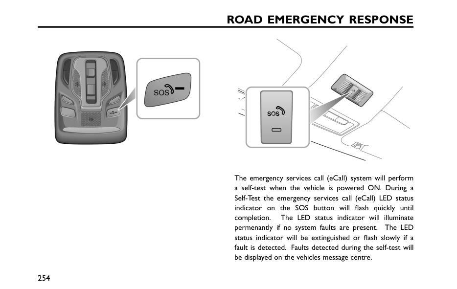
Road Emergency Response
The emergency services call (eCall) system will perform a self-test when the vehicle is powered ON. During a Self-Test the emergency services call (eCall) LED status indicator on the SOS button will flash quickly until completion. The LED status indicator will illuminate permenantly if no system faults are present. The LED status indicator will be extinguished or flash slowly if a fault is detected. Faults detected during the self-test will be displayed on the vehicles message centre. 254
Road Emergency Response
Note: The operation of eCall - SOS Emergency Assistance relies on cellular coverage and may be affected by signal outages or low signal strength. Note: The automatic emergency services call (eCall) function may be disabled by a local MG Authorised Repairer upon request. Note: It is strongly recommended the eCall function is not disabled, any action requested by the owner must be accompanied by a signed request. 255 8
Road Emergency Response
Vehicle Recovery Towing Vehicle Do not tow the vehicle with any of the driven wheels in contact with the road surface, this will avoid electric drive transmission damage. When it is necessary to temporarily push or tow the vehicle from a dangerous situation or onto the transporter, the speed must remain below 3 mph (5 km/h) and be completed with in 3 minutes. When pushing or towing the vehicle for temporary situation, the driver's side seat belt should be inserted into the lock and maintained in the inserted state, the transmission placed inNeutral and the parking brake must be OFF, otherwise the vehicle may be damaged. Towing Hook Do not use a tow rope that is twisted, the towing eye may become unscrewed. 256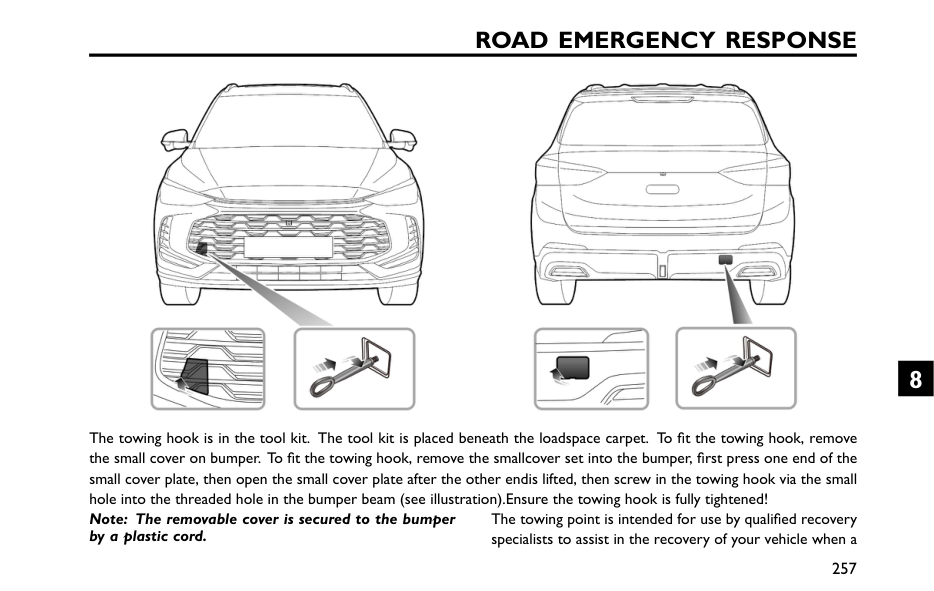
Road Emergency Response
The towing hook is in the tool kit. The tool kit is placed beneath the loadspace carpet. To fit the towing hook, remove the small cover on bumper. To fit the towing hook, remove the smallcover set into the bumper, first press one end of the small cover plate, then open the small cover plate after the other endis lifted, then screw in the towing hook via the small hole into the threaded hole in the bumper beam (see illustration).Ensure the towing hook is fully tightened! Note: The removable cover is secured to the bumper by a plastic cord. The towing point is intended for use by qualified recovery specialists to assist in the recovery of your vehicle when a 257 8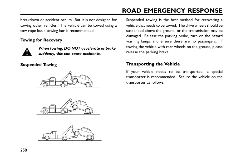
Road Emergency Response
breakdown or accident occurs. But it is not designed for towing other vehicles. The vehicle can be towed using a tow rope but a towing bar is recommended. Towing for Recovery When towing, DO NOT accelerate or brake suddenly, this can cause accidents. Suspended Towing Suspended towing is the best method for recovering a vehicle that needs to be towed. The drive wheels should be suspended above the ground, or the transmission may be damaged. Release the parking brake, turn on the hazard warning lamps and ensure there are no passengers. If towing the vehicle with rear wheels on the ground, please release the parking brake. Transporting the Vehicle If your vehicle needs to be transported, a special transporter is recommended. Secure the vehicle on the transporter as follows: 258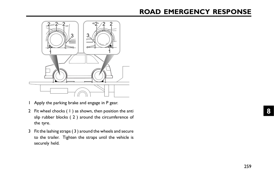
Road Emergency Response
1 Apply the parking brake and engage in P gear. 2 Fit wheel chocks ( 1 ) as shown, then position the anti slip rubber blocks ( 2 ) around the circumference of the tyre. 3 Fit the lashing straps ( 3 ) around the wheels and secure to the trailer. Tighten the straps until the vehicle is securely held. 259 8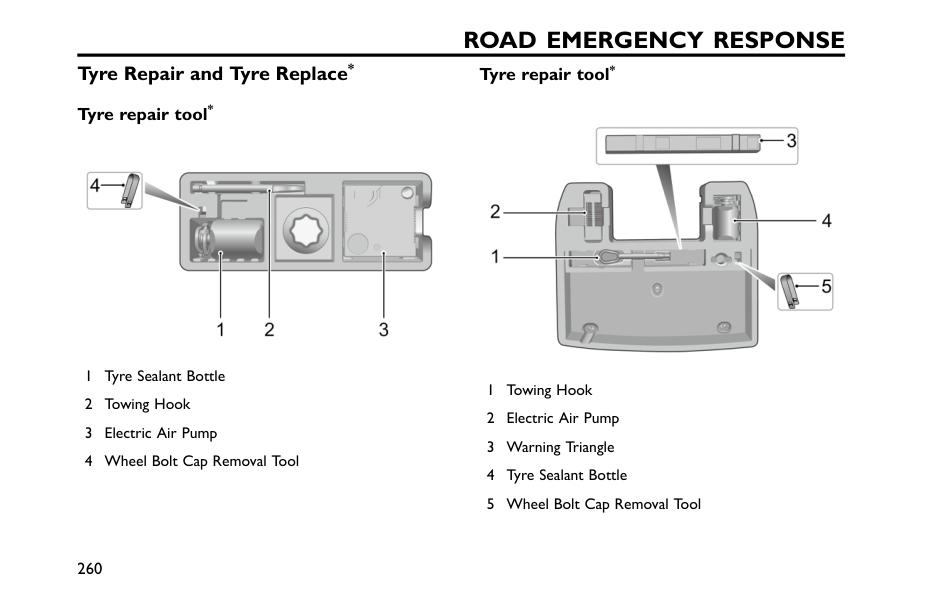
Road Emergency Response
Tyre Repair and Tyre Replace* Tyre repair tool* 1 Tyre Sealant Bottle 2 Towing Hook 3 Electric Air Pump 4 Wheel Bolt Cap Removal Tool Tyre repair tool* 1 Towing Hook 2 Electric Air Pump 3 Warning Triangle 4 Tyre Sealant Bottle 5 Wheel Bolt Cap Removal Tool 260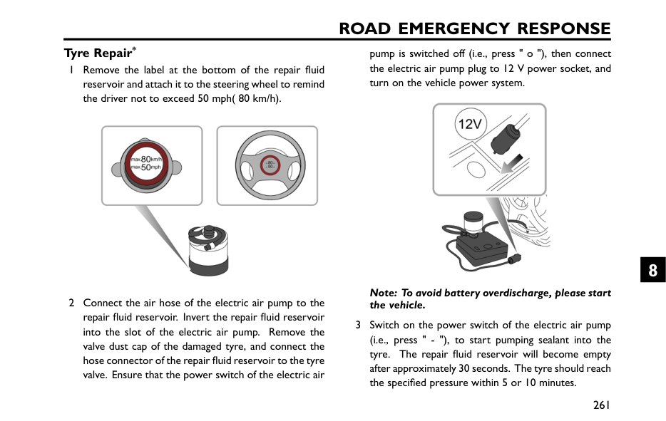
Road Emergency Response
Tyre Repair* 1 Remove the label at the bottom of the repair fluid reservoir and attach it to the steering wheel to remind the driver not to exceed 50 mph( 80 km/h). 2 Connect the air hose of the electric air pump to the repair fluid reservoir. Invert the repair fluid reservoir into the slot of the electric air pump. Remove the valve dust cap of the damaged tyre, and connect the hose connector of the repair fluid reservoir to the tyre valve. Ensure that the power switch of the electric air pump is switched off (i.e., press " o "), then connect the electric air pump plug to 12 V power socket, and turn on the vehicle power system. Note: To avoid battery overdischarge, please start the vehicle. 3 Switch on the power switch of the electric air pump (i.e., press " - "), to start pumping sealant into the tyre. The repair fluid reservoir will become empty after approximately 30 seconds. The tyre should reach the specified pressure within 5 or 10 minutes. 261 8
Road Emergency Response
Note: When the pressure gauge of the air pump starts to work, it may briefly indicate up to 600 kPa (i.e. 6 bar), then the pressure returns to normal. 4 When the required pressure is reached, switch off the electric air pump (i.e., press " o "). Note: If the required pressure cannot be reached within 10 minutes, please disconnect the compressor, drive the vehicle 10 metres approx forward or backward to allow the sealant to spread within the tyre. If the required pressure can still not be reached, the tyre is severely damaged and you should seek assistance from the Roadside Assistance company or an MG Authorised Repairer. Note: Consecutive operation of electric air pump for more than 10 minutes may result in damage to the compressor. 5 Remove the tyre sealant bottle from the slot, and disconnect the hose of the tyre sealant bottle from the tyre valve. Then remove the plug of the electric air pump from the centre console power socket, return the tyre repair kit to its stowage tray. 6 After successfully adding sealant to the tyre, drive immediately for a short time (around one minute).This will allow the sealant to distribute evenly inside the tyre. Continue driving and do not exceed 50 mph (80 km/h).After a further 10 minutes, find a safe place to stop and recheck the tyre pressure.Please follow different guidelines based on the tyre pressure measured:If the tyre pressure has dropped to less than 80 kPa( 0.8 bar), do not continue driving, seek assistanceinstead.If the tyre pressure is between 80 kPa ( 0.8 bar) andthe specified pressure, connect the hose of the electricair pump to the tyre value, and inflate the tyre until itreaches the specified pressure. Repeat Step 6 .If the tyre pressure has not dropped, you may continue driving, but the vehicle speed must not exceed 50 mph (80 km/h), and the driving mileage must not exceed 120 miles (200 km). Note: DO NOT remove foreign objects (eg. screws, nails etc) from the tyre. The tyre repair system must only be used when the foreign object is in the tread pattern ( A ), DO NOT attempt a repair when the damage is in the sidewall of the tyre ( B ). 262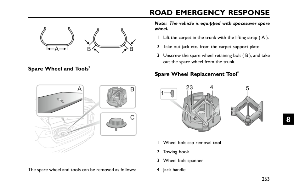
Road Emergency Response
Spare Wheel and Tools* The spare wheel and tools can be removed as follows: Note: The vehicle is equipped with spacesaver spare wheel. 1 Lift the carpet in the trunk with the lifting strap ( A ). 2 Take out jack etc. from the carpet support plate. 3 Unscrew the spare wheel retaining bolt ( B ), and take out the spare wheel from the trunk. Spare Wheel Replacement Tool* 1 Wheel bolt cap removal tool 2 Towing hook 3 Wheel bolt spanner 4 Jack handle 263 8
Road Emergency Response
5 Jack Wheel Replacement* If you need to change the wheel during the journey, choose a safe place to stop away from the main road if possible. Always ask your passengers to get out of the car and wait in a safe area away from other traffic. Switch on hazard warning lamps. If available, position a warning triangle about 50 ~150 metres behind your vehicle to warn approaching traffic. Before changing a wheel, ensure the front wheels are in the straight ahead position. Apply the parking brake and place the shift lever in N position (MT) or P position (AT). Place the Start switch in OFF position. Positioning the Jack DO NOT work underneath the car with a wheel changing jack as the only means of support. The jack is designed for wheel changing only! NEVER jack the car using any positions other than the jacking points, otherwise serious damage may be caused. 264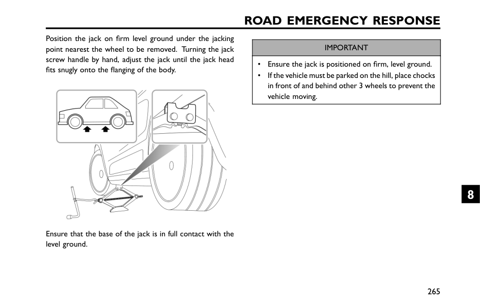
Road Emergency Response
Position the jack on firm level ground under the jacking point nearest the wheel to be removed. Turning the jack screw handle by hand, adjust the jack until the jack head fits snugly onto the flanging of the body. Ensure that the base of the jack is in full contact with the level ground.Important
• Ensure the jack is positioned on firm, level ground. • If the vehicle must be parked on the hill, place chocks in front of and behind other 3 wheels to prevent the vehicle moving. 265 8
Road Emergency Response
Fitting the Spare Wheel Regularly check the spare wheel tyre pressure, it may be under pressure due to being unused for long periods of time. Always check the tyre pressure after changing a wheel. The wheel bolts must be tightened to the specified torque after changing a wheel (120 ~ ~ ~130 Nm). 1 Before raising the car, use the vehicle tool to remove each wheel bolt cap. Use the wheel bolt spanner to slacken each bolt half a turn anti-clockwise. 2 Turn the handle in a clockwise direction until the tyre is clear of the ground. Note: For your safety, place the spare tyre under the body flange near the jack, and avoid placing wheels face down on the ground - the surface may be scratched. 3 Remove the wheel bolts and put away to prevent them from being lost. Make sure the vehicle is steady and there is no risk of slip or movement before removing wheel bolts. 4 Pull out the wheel and place it flatwise. Note: Place the removed wheel under the body flange near the jack, and avoid placing wheels face down on the ground - the surface may be scratched. 5 Fit the spare wheel and tighten the wheel bolts until the wheel is seated firmly against the hub. 6 Lower the vehicle and remove the jack, then FULLY tighten the wheel bolts in a diagonal sequence. 7 Place the tools back, and put the replaced wheel into the trunk in place. Note: DO NOT stand on the handle of the wheel bolt spanner or use extension tube on the handle of the spanner. Note: When replacing the wheel, please fully tighten the bolts in the diagonal sequence twice. Note: Consult an MG Authorised Repairer or tyre specialist for a replacement tyre as soon as possible. 266
Road Emergency Response
Spacesaver Spare Wheel Only one spacesaver spare wheel can be used at any one time, otherwise the operational performance and brake performance may be reduced, thereby leading to accident or injury to yourself and others. When driving on snow covered or icy roads, it is advised to fit the spacesaver wheel to the rear wheels of the vehicle to maintain adequate stability. If the front wheel tyre is damaged, a rear wheel should be moved to the position of a front wheel, and then fit the spacesaver spare wheel in the position of the rear wheel. Snow chains can not be used on the spacesaver spare wheel, this can cause damage to the car and snow chain. When the spacesaver spare wheel is fitted, drive the car with care, and the speed should not exceed 80 km/h. Please have the full-scale tyre repaired and replace the spare wheel as soon as possible. This will extend the life span of the spare wheel for other emergencies. Note: DO NOT use an automatic car wash when the spacesaver wheel is fitted, the guide rails of the car wash may conflict with the wheel/tyre and cause damage. 267 8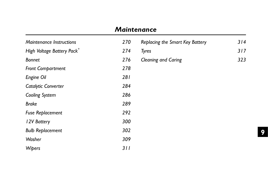
Maintenance Maintenance Instructions 270 High Voltage Battery Pack* 274 Bonnet 276 Front Compartment 278 Engine Oil 281 Catalytic Converter 284 Cooling System 286 Brake 289 Fuse Replacement 292 12V Battery 300 Bulb Replacement 302 Washer 309 Wipers 311 Replacing the Smart Key Battery 314 Tyres 317 Cleaning and Caring 323 9
Maintenance
Maintenance Instructions Regular Maintenance The safety, reliability and performance of your vehicle will depend partly on how well it is maintained. You must ensure that maintenance is carried out when required and according to the information contained in the Warranty and Maintenance Handbook. Servicing For next service information, please refer to "Instrument Pack" in "Brief Introduction to Vehicle Functions " section or information related to the entertainment system. After the completion of each service, the next service display will be reset by your MG Authorised Repairer. Note: If the maintenance is not carried out (or the display is not reset by an MG Authorised Repairer after maintenance), the maintenance display will not be able to provide correct information. Maintenance History After each maintenance, always ask your local Authorised Dealer to register the maintenance. Fluid Please use the fluid recommended and certified by SAIC Motor. Refer to "Recommended Fluids and Capacities" in the "Technical Data" section.Important
Using fluids or additives inapplicable to this vehicle may damage the components or devices; please consult a local Authorised Repairer for details. Emission Control Your car is fitted with exhaust emission and evaporative control equipment designed to meet specific territorial and legal requirements. Incorrect engine settings may adversely affect exhaust emissions, engine performance and fuel consumption, as well as cause high temperatures, which could result in damage to the catalytic converters and engine. 270
Maintenance
Important
You should be aware that unauthorized replacement, modification or tampering with this equipment by an owner or motor vehicle repairer could result in the manufacturer's warranty being deemed as invalid. In addition, no adjustment can be made to the engine settings. Otherwise, the vehicle emission indexes could be affected. Owner Maintenance Any significant or sudden drop in fluid levels, or uneven tyre wear, should be reported without delay to an MG Authorised Repairer. In addition to the maintenance referred to previously, some simple checks must be carried out more frequently. Daily Check • Operation of lights, horn, wipers, washers and warning lights. • Operation of seat belts and brakes. • Look for fluid deposits underneath the car that might indicate a leak. • Check tyre appearance. Weekly Check • Engine oil level. • Coolant level. • Brake fluid level. • Windscreen washer fluid level. • Tyre pressure. • Operate air conditioning. Note: The engine oil level should be checked more frequently if the car is driven for prolonged periods at high speeds. 271 9
Maintenance
Special Operating Conditions If your vehicle is frequently used in dusty conditions, or operated in extreme climates where sub-zero or very high ambient temperatures are normal, more frequent attention may need to be paid to maintenance requirements. You need to carry out special maintenance operations (refer to Warranty and Maintenance Handbook) or contact the local Authorised Repairer. Safety in the Garage Cooling fans may commence operating after the engine is switched off, and continue operating for a number of minutes. Keep clear of all fans while working in the engine compartment. If you need to carry out maintenance, observe the following safety precautions at all times: • Keep your hands and clothing away from drive belts and pulleys. • If the car has been driven recently, DO NOT TOUCH exhaust and cooling system components until the engine has cooled. • DO NOT TOUCH electrical leads or components while the engine is running, or with the Start switch on. • NEVER leave the engine running in an unventilated area
Maintenance
Used Engine Oil Prolonged contact with engine oil may cause serious skin disorders such as dermatitis and cancer of the skin. Wash thoroughly after contact. Used engine oil should be disposed of correctly. Incorrect disposal can cause a threat to the environment. 273 9
Maintenance
High Voltage Battery Pack* Precautions and restricted conditions for use of battery If the vehicle is not going to be used, parked, or stored for a long time it is necessary to use the vehicle at least once every two months for more than 30 minutes each time (the power of high-voltage battery pack shall be maintained at 50% charge (or 4 gauge blocks) or more). It is strictly prohibited to park or store a vehicle fitted with a high-voltage battery pack for more than 7 days if the power of the high-voltage battery pack is low, failure to follow these guidelines may effect the high voltage battery warranty. DO NOT attempt to dismantle the battery pack or any High Voltage components - THESE ARE DANGEROUS. Any signs of dismantling or damage caused by attempts to dismantle will invalidate the warranty. 1 DO NOT park the vehicle in conditions where the ambient temperature exceeds 45℃for more than 15 days. This will effect the performance and service life of the high voltage battery. 2 In order to better extend the service life of the high-voltage battery pack, it is recommended to use the vehicle at least once a month for more than 30 minutes each time to facilitate the vehicle to charge and maintain the high-voltage battery pack. 3 When the vehicle is used for the first time or after a long period of storage, the SOC displayed in the instrument pack may not be accurate. It is recommended to drive at a low speed of 19~30 mph ( 30~50 km/h) for 20~30 minutes before normal use. 4 The cooling system of high-voltage battery pack is equipped with air filter element, please replace it as per manufacturers maintenance schedule. 5 In the event of an accident, damage to the high voltage battery or any of its related components, or any repairs made to the high voltage system the car must be inspected by qualified personel at an MG Authorised Repairer. 274
Maintenance
6 In the event of any accident or body repairs being required please consult the qualified personnel at an MG Authorised Repairer. The repair may require high voltage battery isolation or specialist HV component removal.Important
Only fully trained and qualified personel are allowed to work on the high voltage systems and components of this vehicle. Any disassembly of such systems or components is strictly prohibited. 275 9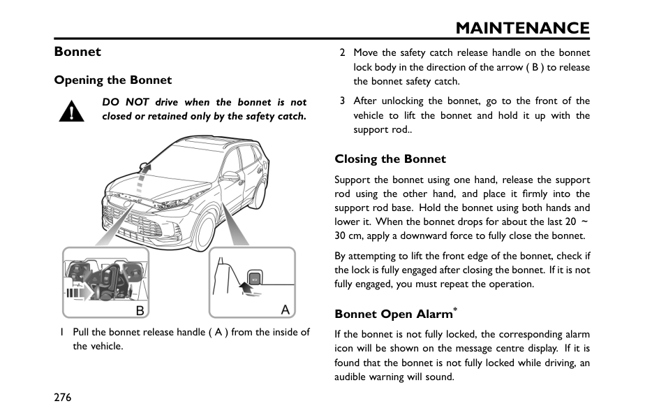
Maintenance
Bonnet Opening the Bonnet DO NOT drive when the bonnet is not closed or retained only by the safety catch. 1 Pull the bonnet release handle ( A ) from the inside of the vehicle. 2 Move the safety catch release handle on the bonnet lock body in the direction of the arrow ( B ) to release the bonnet safety catch. 3 After unlocking the bonnet, go to the front of the vehicle to lift the bonnet and hold it up with the support rod.. Closing the Bonnet Support the bonnet using one hand, release the support rod using the other hand, and place it firmly into the support rod base. Hold the bonnet using both hands and lower it. When the bonnet drops for about the last 20 ~ 30 cm, apply a downward force to fully close the bonnet. By attempting to lift the front edge of the bonnet, check if the lock is fully engaged after closing the bonnet. If it is not fully engaged, you must repeat the operation. Bonnet Open Alarm* If the bonnet is not fully locked, the corresponding alarm icon will be shown on the message centre display. If it is found that the bonnet is not fully locked while driving, an audible warning will sound. 276
Maintenance
Important
• For safety reasons, the bonnet should always be closed well when driving. Therefore you must check after closing the bonnet that the bonnet is securely latched, e.g. the bonnet edge is flush with the body of the vehicle. • You should stop the vehicle immediately when safety permits and close the bonnet if it is not fully closed when driving. • Beware of hands being pinched while fully closing the bonnet with a downward force. 277 9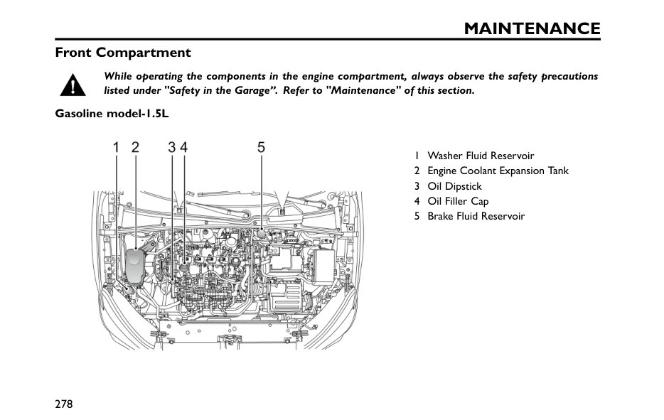
Maintenance
Front Compartment While operating the components in the engine compartment, always observe the safety precautions listed under "Safety in the Garage”. Refer to "Maintenance" of this section. Gasoline model-1.5L 1 Washer Fluid Reservoir 2 Engine Coolant Expansion Tank 3 Oil Dipstick 4 Oil Filler Cap 5 Brake Fluid Reservoir 278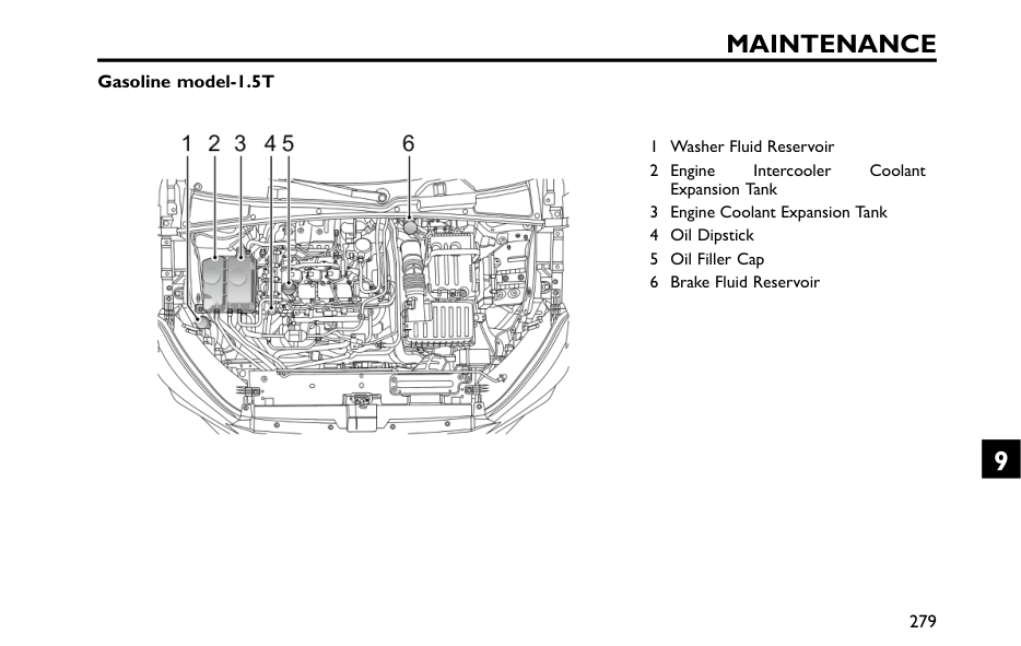
Maintenance
Gasoline model-1.5T 1 Washer Fluid Reservoir 2 Engine Intercooler Coolant Expansion Tank 3 Engine Coolant Expansion Tank 4 Oil Dipstick 5 Oil Filler Cap 6 Brake Fluid Reservoir 279 9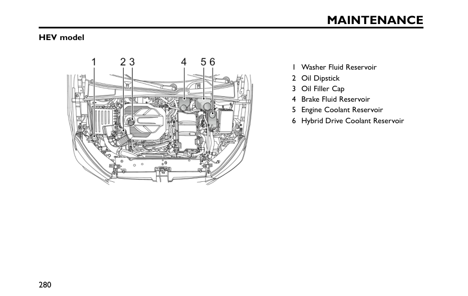
Maintenance
HEV model 1 Washer Fluid Reservoir 2 Oil Dipstick 3 Oil Filler Cap 4 Brake Fluid Reservoir 5 Engine Coolant Reservoir 6 Hybrid Drive Coolant Reservoir 280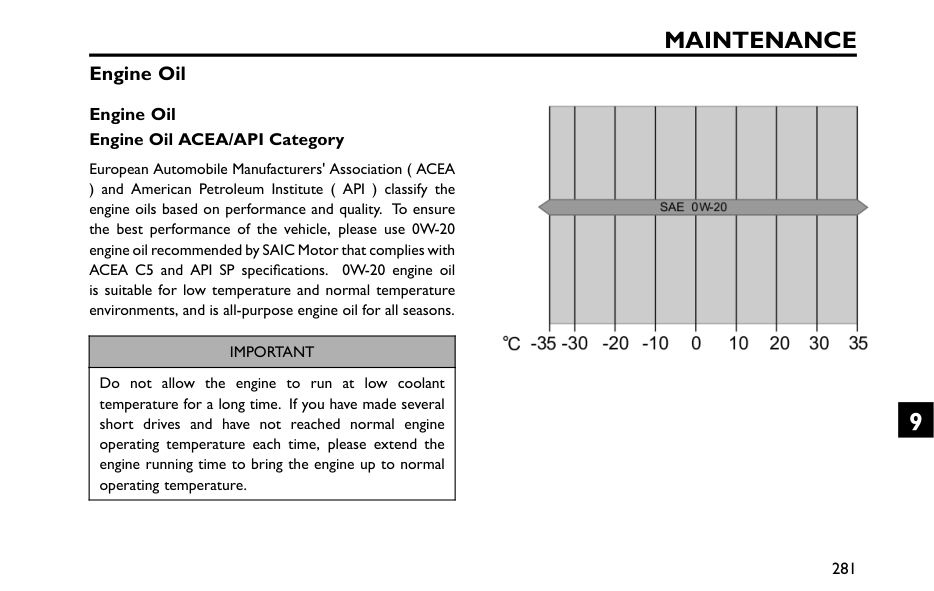
Maintenance
Engine Oil Engine Oil Engine Oil ACEA/API Category European Automobile Manufacturers' Association ( ACEA ) and American Petroleum Institute ( API ) classify the engine oils based on performance and quality. To ensure the best performance of the vehicle, please use 0W-20 engine oil recommended by SAIC Motor that complies with ACEA C5 and API SP specifications. 0W-20 engine oil is suitable for low temperature and normal temperature environments, and is all-purpose engine oil for all seasons.Important
Do not allow the engine to run at low coolant temperature for a long time. If you have made several short drives and have not reached normal engine operating temperature each time, please extend the engine running time to bring the engine up to normal operating temperature. 281 9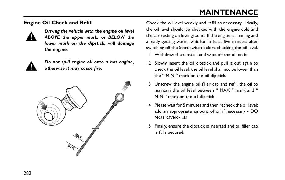
Maintenance
Engine Oil Check and Refill Driving the vehicle with the engine oil level ABOVE the upper mark, or BELOW the lower mark on the dipstick, will damage the engine. Do not spill engine oil onto a hot engine, otherwise it may cause fire. Check the oil level weekly and refill as necessary. Ideally, the oil level should be checked with the engine cold and the car resting on level ground. If the engine is running and already getting warm, wait for at least five minutes after switching off the Start switch before checking the oil level. 1 Withdraw the dipstick and wipe off the oil on it. 2 Slowly insert the oil dipstick and pull it out again to check the oil level; the oil level shall not be lower than the “ MIN ” mark on the oil dipstick. 3 Unscrew the engine oil filler cap and refill the oil to maintain the oil level between “ MAX ” mark and “ MIN ” mark on the oil dipstick. 4 Please wait for 5 minutes and then recheck the oil level; add an appropriate amount of oil if necessary - DONot Overfill!
5 Finally, ensure the dipstick is inserted and oil filler cap is fully secured. 282
Maintenance
Engine Oil Specification Use the engine oil recommended and certified by the SAIC Motor. Refer to "Recommended Fluids and Capacities" in the "Technical Data" section. Note: Any engine misfire, loss of engine performance or engine run-on, could seriously damage the catalytic converter and particulate filter. Regular maintenance must be carried out in accordance with the maintenance schedule specified by the manufacturer. Any modifications to the engine without manufacturer authorisation is prohibited.Important
Check the engine oil level more frequently if the vehicle is driven at high speeds for prolonged periods. 283 9
Maintenance
Catalytic Converter The temperatures of exhaust systems that contain particulate filters and catalytic converters can be extremely high,Do
NOT park on ground where combustible materials such as dry grass or leaves could come into contact with the exhaust system
Maintenance
• If the engine is shaking abnormally, or the vehicle lacks power while driving, consult an Authorised Repairer immediately. • Do not drive on terrain likely to subject the underside of the car to heavy impacts. Note: Any engine misfire, loss of engine performance or engine run-on, could seriously damage the catalytic converter and particulate filter. Regular maintenance must be carried out in accordance with the maintenance schedule specified by the manufacturer. Any modifications to the engine without manufacturer authorisation is prohibited. 285 9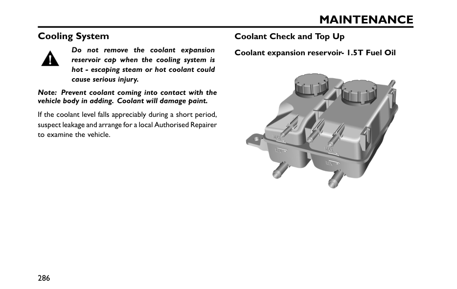
Maintenance
Cooling System Do not remove the coolant expansion reservoir cap when the cooling system is hot - escaping steam or hot coolant could cause serious injury. Note: Prevent coolant coming into contact with the vehicle body in adding. Coolant will damage paint. If the coolant level falls appreciably during a short period, suspect leakage and arrange for a local Authorised Repairer to examine the vehicle. Coolant Check and Top Up Coolant expansion reservoir- 1.5T Fuel Oil 286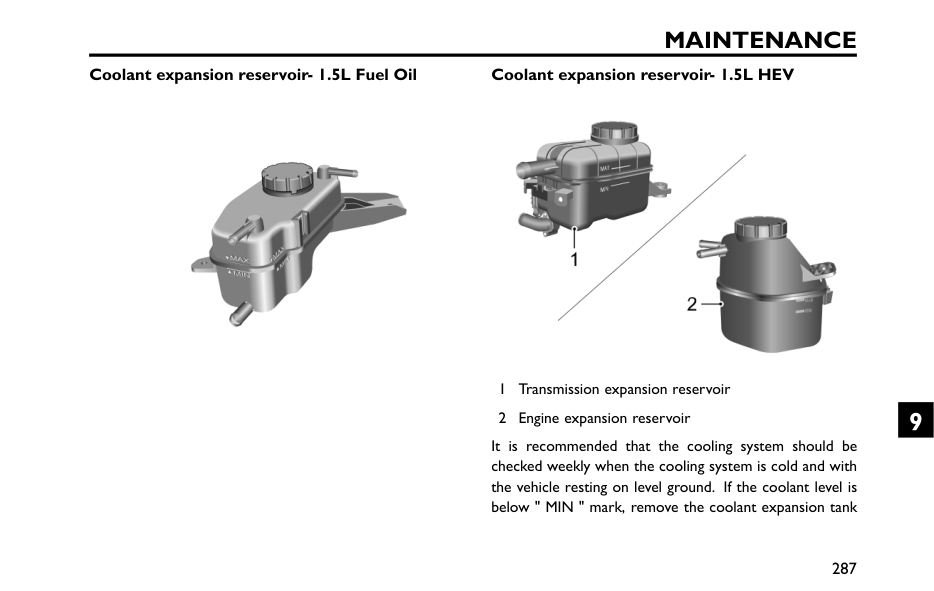
Maintenance
Coolant expansion reservoir- 1.5L Fuel Oil Coolant expansion reservoir- 1.5L HEV 1 Transmission expansion reservoir 2 Engine expansion reservoir It is recommended that the cooling system should be checked weekly when the cooling system is cold and with the vehicle resting on level ground. If the coolant level is below " MIN " mark, remove the coolant expansion tank 287 9
Maintenance
cap and add coolant, but the level shall not be higher than " MAX " mark. Coolant Specification Coolant is poisonous and can be fatal if swallowed - keep coolant containers sealed and out of the reach of children. If accidental contact of coolant by children is suspected, seek medical assistance immediately. Prevent the coolant from coming into contact with the skin or eyes. If this occurs, rinse immediately with plenty of water. If eyes are still red, painful or uncomfortable, seek medical attention immediately. Please use the coolant recommended and certified by the manufacturer. Refer to "Recommended Fluids and Capacities" in "Technical Data" section. Note: The addition of corrosion inhibitors or other additives to the cooling system of this car may severely disrupt the efficiency of the system and cause parts damage. For cooling system issues please consult an MG Authorised Repairer. 288
Maintenance
Brake DO NOT rest your foot on the brake pedal while driving; this may overheat the brakes, reduce their efficiency and cause excessive wear to the brake components. The free stroke of brake pedal is in the range of 0 ~30 mm. Reasonable usage scope of brake friction pair: not less than 2 mm for thickness of brake pads. For MT model,20 ~ 22 mm for front brake disc, and 8 ~ 10 mm for rear brake disc*,MAX231.5mm for rear brake drum*. For CVT or HEV model,23 ~ 25 mm for front brake disc, and 8 ~ 10 mm for rear brake disc. For the first 900 miles( 1500 km), you should avoid situations where heavy braking is required. Note that regular maintenance is vital to ensure that all the brake components are examined for wear at the correct intervals, and replaced when necessary to ensure long-term safety during the interval prescribed in Warranty and Maintenance Handbook. The vehicle needs to run in for 500 miles( 800 km) after the brake pad or disc is replaced. 289 9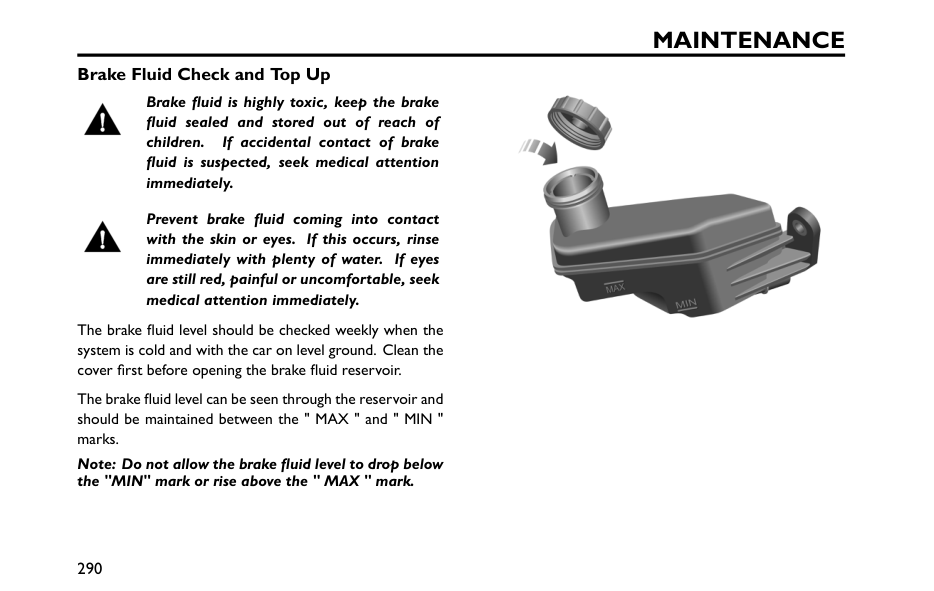
Maintenance
Brake Fluid Check and Top Up Brake fluid is highly toxic, keep the brake fluid sealed and stored out of reach of children. If accidental contact of brake fluid is suspected, seek medical attention immediately. Prevent brake fluid coming into contact with the skin or eyes. If this occurs, rinse immediately with plenty of water. If eyes are still red, painful or uncomfortable, seek medical attention immediately. The brake fluid level should be checked weekly when the system is cold and with the car on level ground. Clean the cover first before opening the brake fluid reservoir. The brake fluid level can be seen through the reservoir and should be maintained between the " MAX " and " MIN " marks. Note: Do not allow the brake fluid level to drop below the "MIN" mark or rise above the " MAX " mark. 290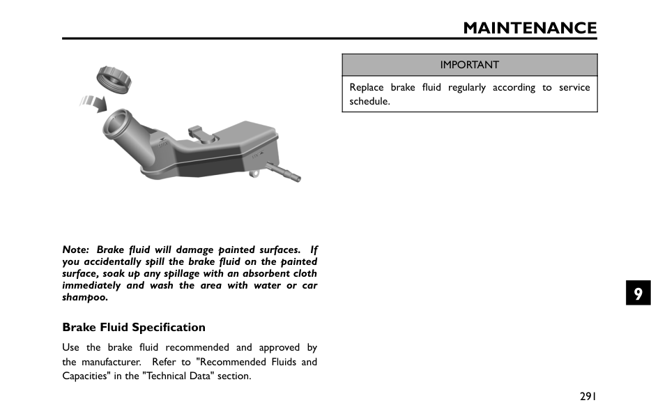
Maintenance
Note: Brake fluid will damage painted surfaces. If you accidentally spill the brake fluid on the painted surface, soak up any spillage with an absorbent cloth immediately and wash the area with water or car shampoo. Brake Fluid Specification Use the brake fluid recommended and approved by the manufacturer. Refer to "Recommended Fluids and Capacities" in the "Technical Data" section.Important
Replace brake fluid regularly according to service schedule. 291 9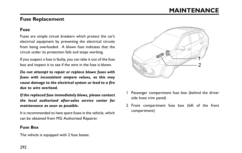
Maintenance
Fuse Replacement Fuse Fuses are simple circuit breakers which protect the car’s electrical equipment by preventing the electrical circuits from being overloaded. A blown fuse indicates that the circuit under its protection fails and stops working. If you suspect a fuse is faulty, you can take it out of the fuse box and inspect it to see if the wire in the fuse is blown. Do not attempt to repair or replace blown fuses with fuses with inconsistent ampere values, as this may cause damage to the electrical system or lead to a fire due to wire overload. If the replaced fuse immediately blows, please contact the local authorized after-sales service center for maintenance as soon as possible. It is recommended to have spare fuses in the vehicle, which can be obtained from MG Authorised Repairer. Fuse Box The vehicle is equipped with 2 fuse boxes: 1 Passenger compartment fuse box (behind the driver side knee trim panel) 2 Front compartment fuse box (left of the front compartment) 292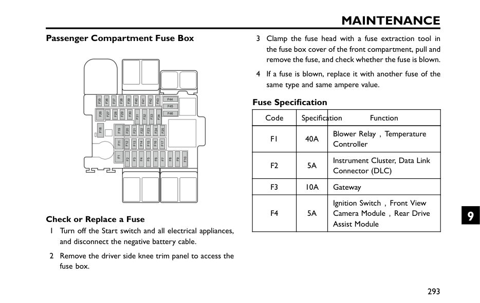
Maintenance
Passenger Compartment Fuse Box Check or Replace a Fuse 1 Turn off the Start switch and all electrical appliances, and disconnect the negative battery cable. 2 Remove the driver side knee trim panel to access the fuse box. 3 Clamp the fuse head with a fuse extraction tool in the fuse box cover of the front compartment, pull and remove the fuse, and check whether the fuse is blown. 4 If a fuse is blown, replace it with another fuse of the same type and same ampere value. Fuse Specification Code Specification FunctionF1
40A
Blower Relay,Temperature ControllerF2
5A
Instrument Cluster, Data Link Connector (DLC)F3
10A
GatewayF4
5A
Ignition Switch,Front View Camera Module,Rear Drive Assist Module 293 9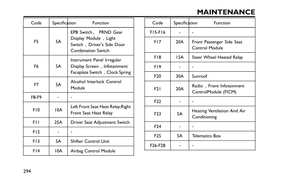
Maintenance
Code Specification FunctionF5
5A
EPB Switch、PRND Gear Display Module,Light Switch,Driver's Side Door Combination SwitchF6
5A
Instrument Panel Irregular Display Screen,Infotainment Faceplate Switch,Clock SpringF7
5A
Alcohol Interlock Control ModuleF8-F9
F10
10A
Left Front Seat Heat Relay;Right Front Seat Heat RelayF11
25A
Driver Seat Adjustment SwitchF12
F13
5A
Shifter Control UnitF14
10A
Airbag Control Module Code Specification FunctionF15-F16
F17
20A
Front Passenger Side Seat Control ModuleF18
15A
Steer Wheel Heated RelayF19
F20
30A
SunroofF21
20A
Radio,Front Infotainment ControlModule (FICM)F22
F23
5A
Heating Ventilation And Air ConditioningF24
F25
5A
Telematics BoxF26-F28
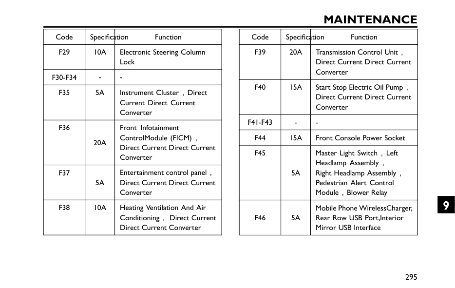
Maintenance
Code Specification FunctionF29
10A
Electronic Steering Column LockF30-F34
F35
5A
Instrument Cluster,Direct Current Direct Current ConverterF36
20A
Front Infotainment ControlModule (FICM), Direct Current Direct Current ConverterF37
5A
Entertainment control panel, Direct Current Direct Current ConverterF38
10A
Heating Ventilation And Air Conditioning,Direct Current Direct Current Converter Code Specification FunctionF39
20A
Transmission Control Unit, Direct Current Direct Current ConverterF40
15A
Start Stop Electric Oil Pump, Direct Current Direct Current ConverterF41-F43
F44
15A
Front Console Power SocketF45
5A
Master Light Switch,Left Headlamp Assembly, Right Headlamp Assembly, Pedestrian Alert Control Module,Blower RelayF46
5A
Mobile Phone WirelessCharger, Rear Row USB Port,Interior Mirror USB Interface 295 9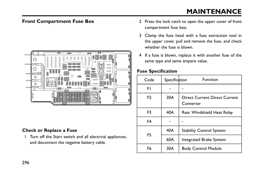
Maintenance
Front Compartment Fuse Box Check or Replace a Fuse 1 Turn off the Start switch and all electrical appliances, and disconnect the negative battery cable. 2 Press the lock catch to open the upper cover of front compartment fuse box. 3 Clamp the fuse head with a fuse extraction tool in the upper cover, pull and remove the fuse, and check whether the fuse is blown. 4 If a fuse is blown, replace it with another fuse of the same type and same ampere value. Fuse Specification Code Specification FunctionF1
F2
30A
Direct Current Direct Current ConverterF3
40A
Rear Windshield Heat RelayF4
40A
Stability Control SystemF5
60A
Integrated Brake SystemF6
30A
Body Control Module 296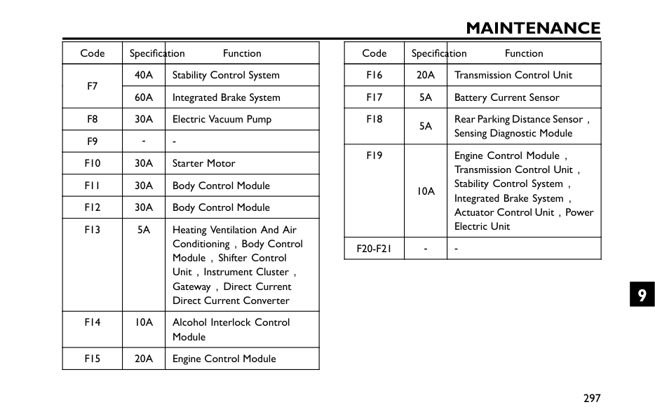
Maintenance
Code Specification Function40A
Stability Control SystemF7
60A
Integrated Brake SystemF8
30A
Electric Vacuum PumpF9
F10
30A
Starter MotorF11
30A
Body Control ModuleF12
30A
Body Control ModuleF13
5A
Heating Ventilation And Air Conditioning,Body Control Module,Shifter Control Unit,Instrument Cluster, Gateway,Direct Current Direct Current ConverterF14
10A
Alcohol Interlock Control ModuleF15
20A
Engine Control Module Code Specification FunctionF16
20A
Transmission Control UnitF17
5A
Battery Current SensorF18
5A
Rear Parking Distance Sensor, Sensing Diagnostic ModuleF19
10A
Engine Control Module, Transmission Control Unit, Stability Control System, Integrated Brake System, Actuator Control Unit,Power Electric UnitF20-F21
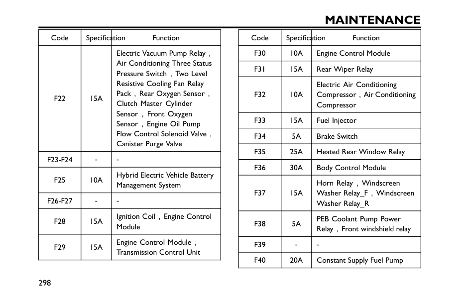
Maintenance
Code Specification FunctionF22
15A
Electric Vacuum Pump Relay, Air Conditioning Three Status Pressure Switch,Two Level Resistive Cooling Fan Relay Pack,Rear Oxygen Sensor, Clutch Master Cylinder Sensor,Front Oxygen Sensor,Engine Oil Pump Flow Control Solenoid Valve, Canister Purge ValveF23-F24
F25
10A
Hybrid Electric Vehicle Battery Management SystemF26-F27
F28
15A
Ignition Coil,Engine Control ModuleF29
15A
Engine Control Module, Transmission Control Unit Code Specification FunctionF30
10A
Engine Control ModuleF31
15A
Rear Wiper RelayF32
10A
Electric Air Conditioning Compressor,Air Conditioning CompressorF33
15A
Fuel InjectorF34
5A
Brake SwitchF35
25A
Heated Rear Window RelayF36
30A
Body Control ModuleF37
15A
Horn Relay,Windscreen Washer Relay_F,Windscreen Washer Relay_RF38
5A
PEB Coolant Pump Power Relay,Front windshield relayF39
F40
20A
Constant Supply Fuel Pump 298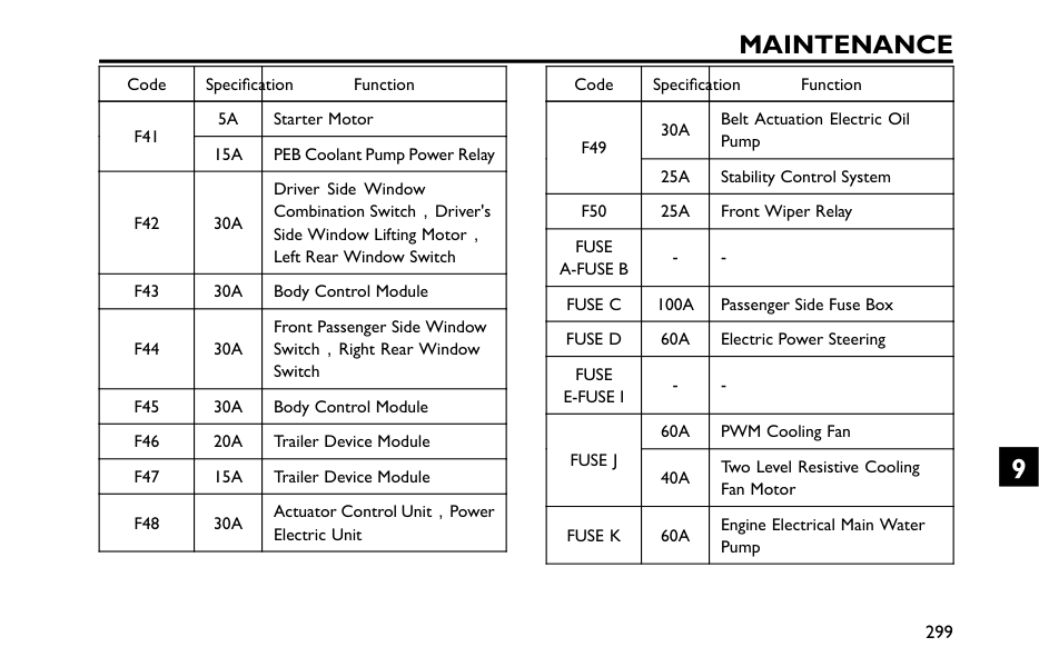
Maintenance
Code Specification Function5A
Starter MotorF41
15A
PEB Coolant Pump Power RelayF42
30A
Driver Side Window Combination Switch,Driver's Side Window Lifting Motor, Left Rear Window SwitchF43
30A
Body Control ModuleF44
30A
Front Passenger Side Window Switch,Right Rear Window SwitchF45
30A
Body Control ModuleF46
20A
Trailer Device ModuleF47
15A
Trailer Device ModuleF48
30A
Actuator Control Unit,Power Electric Unit Code Specification Function30A
Belt Actuation Electric Oil PumpF49
25A
Stability Control SystemF50
25A
Front Wiper RelayFuse
A-Fuse B
Fuse C
100A
Passenger Side Fuse BoxFuse D
60A
Electric Power SteeringFuse
E-Fuse I
60A
PWM Cooling FanFuse J
40A
Two Level Resistive Cooling Fan MotorFuse K
60A
Engine Electrical Main Water Pump 299 9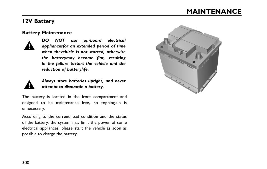
Maintenance
12V Battery Battery MaintenanceDo
Not
use on-board electrical appliancesfor an extended period of time when thevehicle is not started, otherwise the batterymay become flat, resulting in the failure tostart the vehicle and the reduction of batterylife. Always store batteries upright, and never attempt to dismantle a battery. The battery is located in the front compartment and designed to be maintenance free, so topping-up is unnecessary. According to the current load condition and the status of the battery, the system may limit the power of some electrical appliances, please start the vehicle as soon as possible to charge the battery. 300
Maintenance
Note: When the vehicle will not be used for an extended period, it is recommended that the battery negative terminal clamping pile head should be disconnected. Make sure that the vehicle is powered off before connecting or disconnecting the negative battery cable. When reconnecting the negative battery cable, ensure that the clamping pile head and the negative battery cable are securely secured. When the vehicle will not be used for a long period of time without disconnecting the negative battery cable, it is recommended that the vehicle be driven or idled for more than half an hour per week to help prolong the life of the battery. Battery Replacement The battery contains sulphuric acid, which is corrosive. Please contact a local Authorised Repairer to remove and install the battery. Only fit a replacement battery of the same type and specification as the original to maintain the correct vehicle functionality. Used batteries can be harmful to the environment, so they must be disposed of using an approved method and be recycled by a professional company. Please consult a local Authorised Repairer for more details. 301 9
Maintenance
Bulb Replacement Bulb Specification Bulb Specification Front Reading Lamp*W5W 5W
High and low beams*Hb3 60W
Front Turn Signal BulbPy21W 21W
License Plate LampW5W 5W
Rear Turn Signal BulbWy16W 16W
Reverse LampW16W 16W
Rear Fog LampH21W 21W
Note: Other light sources not listed are LED , which cannot be replaced separately. Bulb Replacement Before replacing any bulb, turn off the vehicle's power supply to avoid any possibility of a short circuit. Note: The replacement bulb must be identical to the original one in type and specification. If the bulb glass is scratched or contaminated, it may cause the bulb to not concentrate the light. Take care NOT to touch the glass with your fingers; If necessary, clean the glass with methylated spirits to remove fingerprints. For other bulbs not listed and to be replaced, ask an MG Authorised Repairer for guidance. 302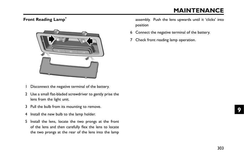
Maintenance
Front Reading Lamp* 1 Disconnect the negative terminal of the battery. 2 Use a small flat-bladed screwdriver to gently prise the lens from the light unit. 3 Pull the bulb from its mounting to remove. 4 Install the new bulb to the lamp holder. 5 Install the lens, locate the two prongs at the front of the lens and then carefully flex the lens to locate the two prongs at the rear of the lens into the lamp assembly. Push the lens upwards until it ‘clicks’ into position 6 Connect the negative terminal of the battery. 7 Check front reading lamp operation. 303 9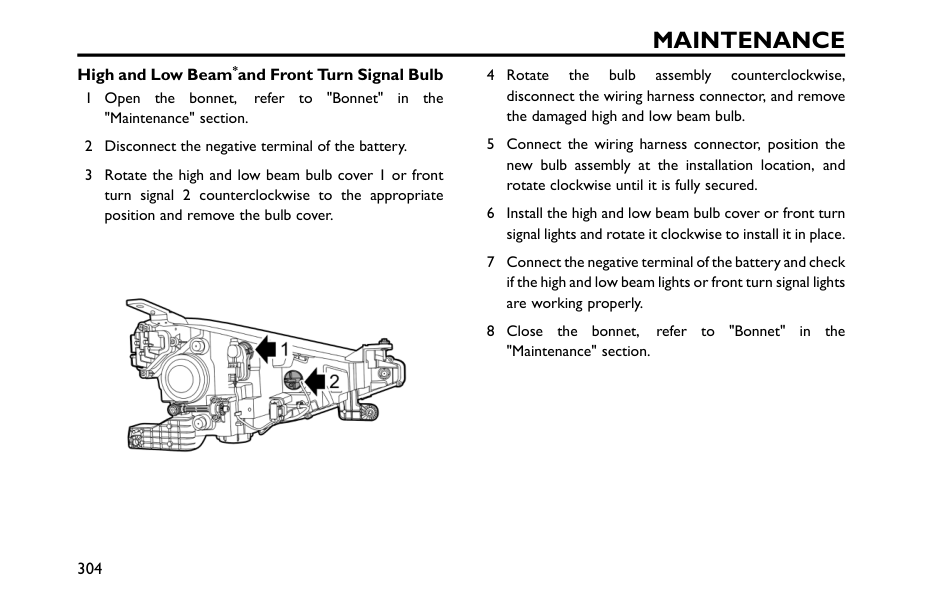
Maintenance
High and Low Beam*and Front Turn Signal Bulb 1 Open the bonnet, refer to "Bonnet" in the "Maintenance" section. 2 Disconnect the negative terminal of the battery. 3 Rotate the high and low beam bulb cover 1 or front turn signal 2 counterclockwise to the appropriate position and remove the bulb cover. 4 Rotate the bulb assembly counterclockwise, disconnect the wiring harness connector, and remove the damaged high and low beam bulb. 5 Connect the wiring harness connector, position the new bulb assembly at the installation location, and rotate clockwise until it is fully secured. 6 Install the high and low beam bulb cover or front turn signal lights and rotate it clockwise to install it in place. 7 Connect the negative terminal of the battery and check if the high and low beam lights or front turn signal lights are working properly. 8 Close the bonnet, refer to "Bonnet" in the "Maintenance" section. 304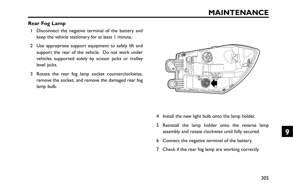
Maintenance
Rear Fog Lamp 1 Disconnect the negative terminal of the battery and keep the vehicle stationary for at least 1 minute. 2 Use appropriate support equipment to safely lift and support the rear of the vehicle. Do not work under vehicles supported solely by scissor jacks or trolley level jacks. 3 Rotate the rear fog lamp socket counterclockwise, remove the socket, and remove the damaged rear fog lamp bulb. 4 Install the new light bulb onto the lamp holder. 5 Reinstall the lamp holder onto the reverse lamp assembly and rotate clockwise until fully secured. 6 Connect the negative terminal of the battery. 7 Check if the rear fog lamp are working correctly. 305 9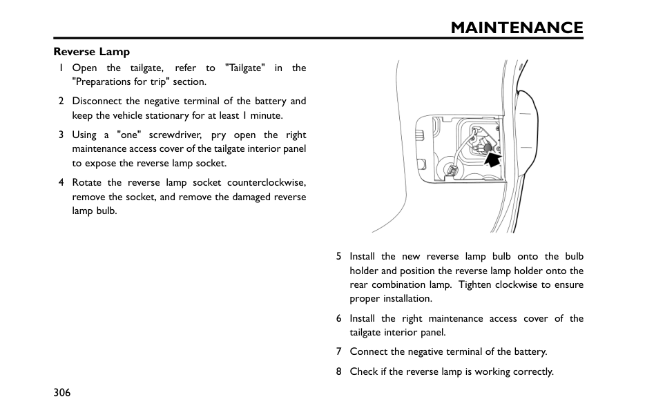
Maintenance
Reverse Lamp 1 Open the tailgate, refer to "Tailgate" in the "Preparations for trip" section. 2 Disconnect the negative terminal of the battery and keep the vehicle stationary for at least 1 minute. 3 Using a "one" screwdriver, pry open the right maintenance access cover of the tailgate interior panel to expose the reverse lamp socket. 4 Rotate the reverse lamp socket counterclockwise, remove the socket, and remove the damaged reverse lamp bulb. 5 Install the new reverse lamp bulb onto the bulb holder and position the reverse lamp holder onto the rear combination lamp. Tighten clockwise to ensure proper installation. 6 Install the right maintenance access cover of the tailgate interior panel. 7 Connect the negative terminal of the battery. 8 Check if the reverse lamp is working correctly. 306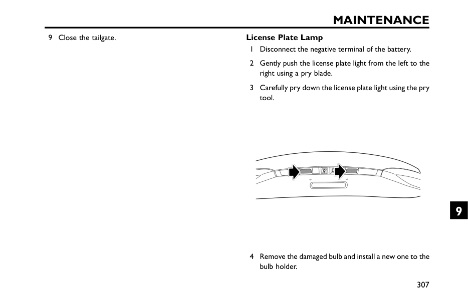
Maintenance
9 Close the tailgate. License Plate Lamp 1 Disconnect the negative terminal of the battery. 2 Gently push the license plate light from the left to the right using a pry blade. 3 Carefully pry down the license plate light using the pry tool. 4 Remove the damaged bulb and install a new one to the bulb holder. 307 9
Maintenance
5 When installing the license plate light, first fit the left side of the license plate light into the groove. 6 Push the right side of the license plate lamp upwards with your fingers and hear a "click" sound. 7 Connect the negative terminal of the battery. 8 Check if the rear license plate light is working correctly.Important
Take extra care so as not to damage the paint surface and clips around the license plate light. 308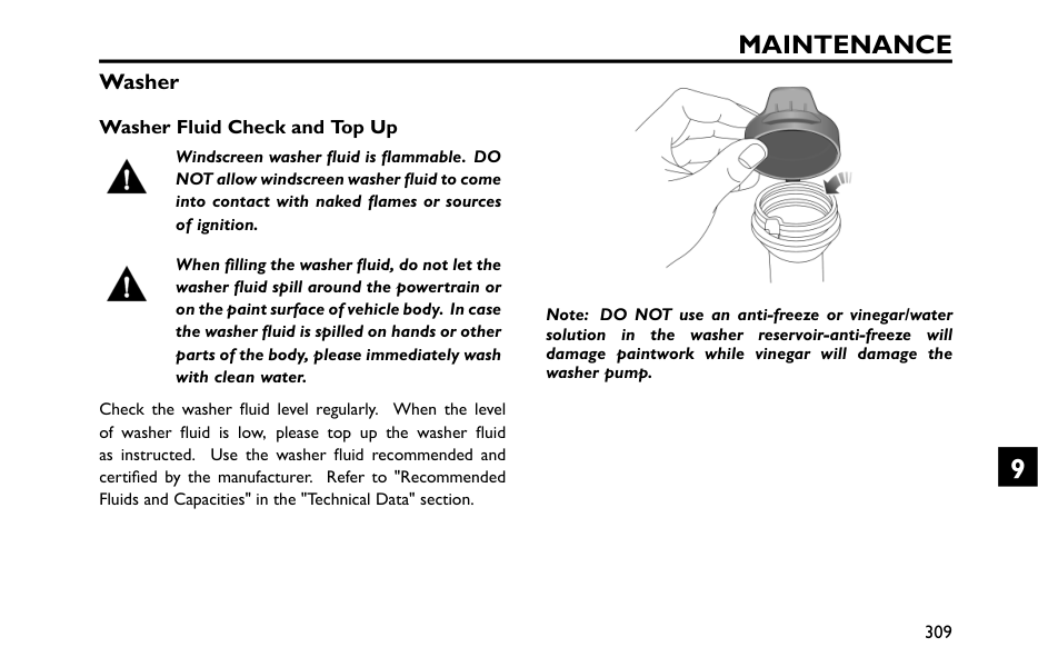
Maintenance
Washer Washer Fluid Check and Top Up Windscreen washer fluid is flammable. DO NOT allow windscreen washer fluid to come into contact with naked flames or sources of ignition. When filling the washer fluid, do not let the washer fluid spill around the powertrain or on the paint surface of vehicle body. In case the washer fluid is spilled on hands or other parts of the body, please immediately wash with clean water. Check the washer fluid level regularly. When the level of washer fluid is low, please top up the washer fluid as instructed. Use the washer fluid recommended and certified by the manufacturer. Refer to "Recommended Fluids and Capacities" in the "Technical Data" section. Note: DO NOT use an anti-freeze or vinegar/water solution in the washer reservoir-anti-freeze will damage paintwork while vinegar will damage the washer pump. 309 9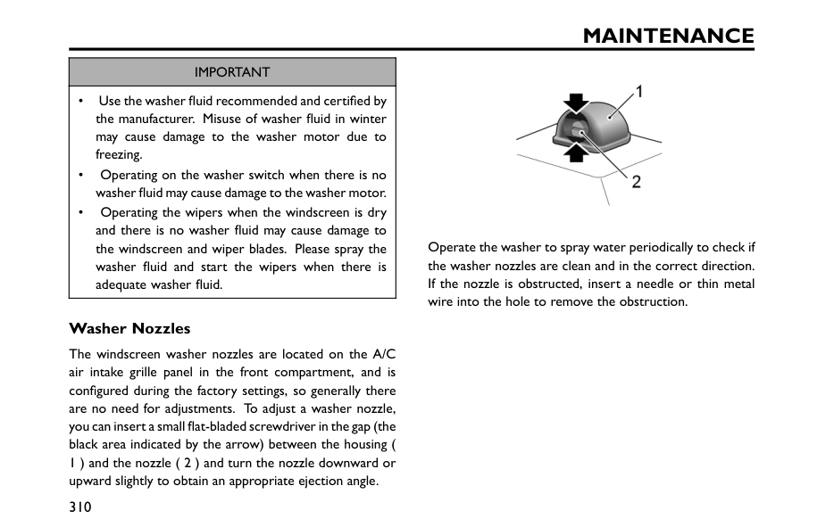
Maintenance
Important
• Use the washer fluid recommended and certified by the manufacturer. Misuse of washer fluid in winter may cause damage to the washer motor due to freezing. • Operating on the washer switch when there is no washer fluid may cause damage to the washer motor. • Operating the wipers when the windscreen is dry and there is no washer fluid may cause damage to the windscreen and wiper blades. Please spray the washer fluid and start the wipers when there is adequate washer fluid. Washer Nozzles The windscreen washer nozzles are located on the A/C air intake grille panel in the front compartment, and is configured during the factory settings, so generally there are no need for adjustments. To adjust a washer nozzle, you can insert a small flat-bladed screwdriver in the gap (the black area indicated by the arrow) between the housing ( 1 ) and the nozzle ( 2 ) and turn the nozzle downward or upward slightly to obtain an appropriate ejection angle. Operate the washer to spray water periodically to check if the washer nozzles are clean and in the correct direction. If the nozzle is obstructed, insert a needle or thin metal wire into the hole to remove the obstruction. 310
Maintenance
Wipers Wiper BladesImportant
• Grease, silicon and petroleum products impair the blade's wiping capability. Clean the wiper blades in warm soap water, and check their status periodically. • Clean the windscreen frequently. DO NOT use wiper blades to remove stubborn or ingrained dirt, it will reduce their effect and their life span. • If signs of hardness or cracking in the rubber are found, or if the wipers leave streaks or unwiped areas on the windscreen, then the wiper blades should be replaced. • Clean the windscreen regularly with an approved glass cleaner and ensure the windscreen is thoroughly cleaned before the replacement of wiper blades. • Only fit the wiper blades that are identical to the original specification. • Clean ice and snow from the wipers and ensure they are not frozen or otherwise, sticking to the windscreen before attempting to operate them. 311 9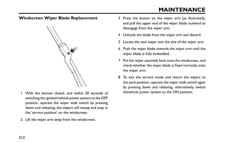
Maintenance
Windscreen Wiper Blade Replacement 1 With the bonnet closed, and within 20 seconds of switching the ignition/vehicle power system to the OFF position, operate the wiper stalk switch by pressing down and releasing, the wipers will sweep and stop in the 'service position' on the windscreen. 2 Lift the wiper arm away from the windscreen. 3 Press the button on the wiper arm (as illustrated), and pull the upper end of the wiper blade outward to disengage from the wiper arm. 4 Unhook the blade from the wiper arm and discard. 5 Locate the new wiper into the slot of the wiper arm. 6 Push the wiper blade towards the wiper arm until the wiper blade is fully embedded. 7 Put the wiper assembly back onto the windscreen, and check whether the wiper blade is fixed correctly onto the wiper arm. 8 To exit the service mode and return the wipers to the park position, operate the wiper stalk switch again by pressing down and releasing, alternatively, switch thevehicle power system to the ON position. 312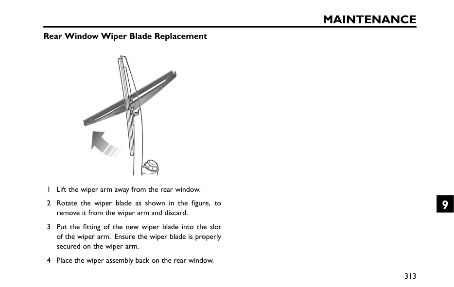
Maintenance
Rear Window Wiper Blade Replacement 1 Lift the wiper arm away from the rear window. 2 Rotate the wiper blade as shown in the figure, to remove it from the wiper arm and discard. 3 Put the fitting of the new wiper blade into the slot of the wiper arm. Ensure the wiper blade is properly secured on the wiper arm. 4 Place the wiper assembly back on the rear window. 313 9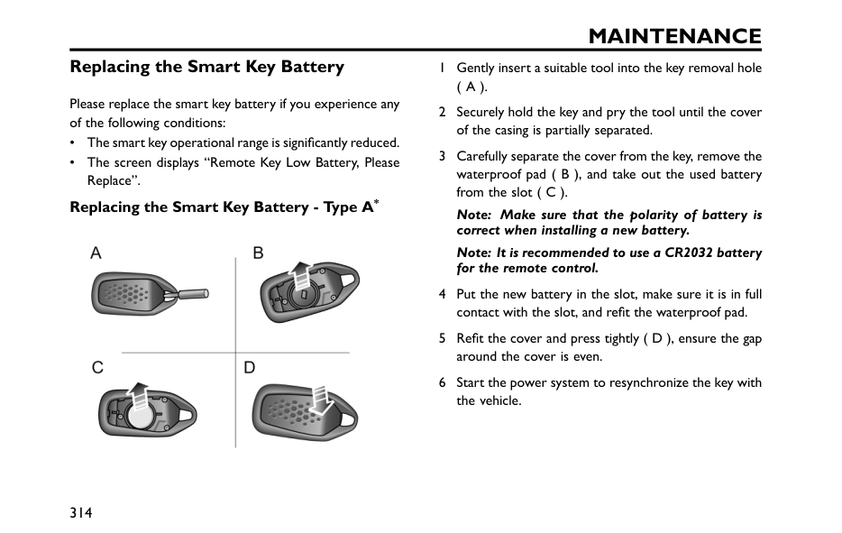
Maintenance
Replacing the Smart Key Battery Please replace the smart key battery if you experience any of the following conditions: • The smart key operational range is significantly reduced. • The screen displays “Remote Key Low Battery, Please Replace”. Replacing the Smart Key Battery - Type A* 1 Gently insert a suitable tool into the key removal hole( A ).
2 Securely hold the key and pry the tool until the cover of the casing is partially separated. 3 Carefully separate the cover from the key, remove the waterproof pad ( B ), and take out the used battery from the slot ( C ). Note: Make sure that the polarity of battery is correct when installing a new battery. Note: It is recommended to use a CR2032 battery for the remote control. 4 Put the new battery in the slot, make sure it is in full contact with the slot, and refit the waterproof pad. 5 Refit the cover and press tightly ( D ), ensure the gap around the cover is even. 6 Start the power system to resynchronize the key with the vehicle. 314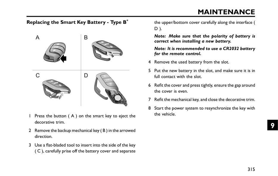
Maintenance
Replacing the Smart Key Battery - Type B* 1 Press the button ( A ) on the smart key to eject the decorative trim. 2 Remove the backup mechanical key ( B ) in the arrowed direction. 3 Use a flat-bladed tool to insert into the side of the key ( C ), carefully prise off the battery cover and separate the upper/bottom cover carefully along the interface (D ).
Note: Make sure that the polarity of battery is correct when installing a new battery. Note: It is recommended to use a CR2032 battery for the remote control. 4 Remove the used battery from the slot. 5 Put the new battery in the slot, and make sure it is in full contact with the slot. 6 Refit the cover and press tightly, ensure the gap around the cover is even. 7 Refit the mechanical key, and close the decorative trim. 8 Start the power system to resynchronize the key with the vehicle. 315 9
Maintenance
Important
• Use of an incorrect or inappropriate battery may damage the smart key. The new replacement's rated voltage, sizes and specifications must be the same as the old one. • Incorrect fitting of the battery may damage the key. • Disposal of the used battery must be strictly in accordance with relevant environmental protection acts. 316
Maintenance
Tyres Overview • Take extra care when using new tyres for the first 300 300 miles ( 500 km) • Avoid excessive cornering at speed. • Where possible, do not allow wheels to bump on/off kerbs, always take extra care when crossing kerbs/driveways. • Regularly check tyres for damage (cuts, scratches, cracks and pits) and remove any foreign objects from the tread. • Prevent the tyre from contacting oil, grease and fuel. • Ensure valve caps are always fitted. • If the tyre is to be removed always mark the tyre/wheel orientation to ensure correct re-installation. • Wheels or tyres that have been disassembled should be kept in a cool, dry and light-free place. Directional Tyres Directional tyres are marked with "direction of rotation"(Dor).
To maintain handling characteristics, tyre performance, low road noise and extend tyre life, tyres/wheels must always be fitted with indication arrow showing the correct "DOR". 317 9
Maintenance
Service Life of Tyres Correct tyre pressure and moderate driving styles can extend tyre life.. Recommendations: • Check the tyre pressures at least once a month when the tyre is cold; • Avoid cornering at excessive speeds; • Regularly check tyres for abnormal wear patterns. • When the vehicle is to be parked for a long time, the vehicle should be moved at least once every two weeks to prevent permanent deformation of the tyres due to long-term stress. The following factors affect the tyre life: Tyre Pressure Over or under-inflated tyres will cause the abnormal wear of the tyre, greatly shorten the service life, and have an adverse effect on the driving characteristics of the vehicle. Driving Style Excessively harsh acceleration and braking whilst cornering will reduce tyre life. Wheel Balance The wheels of a new vehicle are subject to dynamic balance testing, but out-of-balance wheels may still be caused due to the effects of various factors in operation. If wheels are out of balance, shaking or vibration of the steering mechanism may occur and the tyres may start to wear excessively. It is important to restore wheel balance as quick as possible. Each wheel should be rebalanced after installing a new tyre or having a tyre repair. Wheel Alignment Defect Incorrect wheel alignment can cause excessive tyre wear and affect vehicle safety. If the tyres show signs of abnormal wear, check the wheel alignment and seek advice from an MG Authorised repairer. 318
Maintenance
Caring for Your TyresUse
Of
Defective
Tyres
Are
DANGEROUS! DO NOT drive if any tyre is damaged, excessively worn, or inflated to an incorrect pressure. When replacing tyres it is strongly recommended that the new tyres are of the same specification as the original tyres. DO NOT replace the tyres with tyres of any other type. Alternative tyres, of a different specification, may adversely affect the vehicle's driving characteristics and safety. In order to maintain driving characteristics and safety , it is suggested that you consult an MG Authorised Repairer. Always drive with consideration for the condition of the tyres, and regularly inspect the tread and side walls for any sign of distortion (bulges), cuts or wear. Note: Prevent tyres from coming into contact with oil, grease and fuel. Tyre Pressure Before a long distance journey, the tyre pressure must be checked. Check the pressures at least every month, when the tyres are cold. If it is necessary to check the tyres when they are warm, you should expect the pressures to have increased by 30 ~40 kPa (i.e. 0.3 ~0.4 bar). In this circumstance, NEVER let air out of the tyres in order to match the recommended pressures (cold) in the technical data. Valves Keep the valve caps firmly secured to prevent dirt from entering the valve. Check the valve for leaks (listen for a tell-tale hissing) when you check the tyre pressure. Punctured Tyres Your vehicle is fitted with tyres which may not leak if penetrated by a sharp object, provided the object remains in the tyre. If you are aware of this occurring, reduce speed immediately and drive with caution until the spare wheel can be fitted, or repairs undertaken. 319 9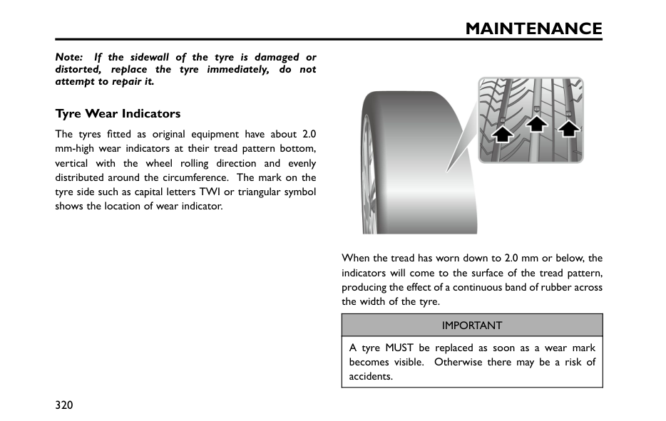
Maintenance
Note: If the sidewall of the tyre is damaged or distorted, replace the tyre immediately, do not attempt to repair it. Tyre Wear Indicators The tyres fitted as original equipment have about 2.0 mm-high wear indicators at their tread pattern bottom, vertical with the wheel rolling direction and evenly distributed around the circumference. The mark on the tyre side such as capital letters TWI or triangular symbol shows the location of wear indicator. When the tread has worn down to 2.0 mm or below, the indicators will come to the surface of the tread pattern, producing the effect of a continuous band of rubber across the width of the tyre.Important
A tyre MUST be replaced as soon as a wear mark becomes visible. Otherwise there may be a risk of accidents. 320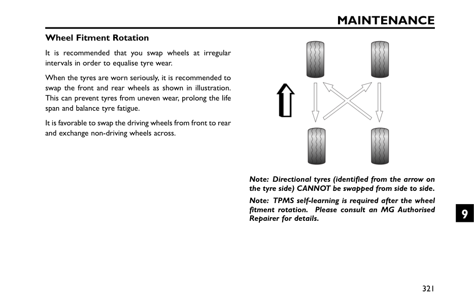
Maintenance
Wheel Fitment Rotation It is recommended that you swap wheels at irregular intervals in order to equalise tyre wear. When the tyres are worn seriously, it is recommended to swap the front and rear wheels as shown in illustration. This can prevent tyres from uneven wear, prolong the life span and balance tyre fatigue. It is favorable to swap the driving wheels from front to rear and exchange non-driving wheels across. Note: Directional tyres (identified from the arrow on the tyre side) CANNOT be swapped from side to side. Note: TPMS self-learning is required after the wheel fitment rotation. Please consult an MG Authorised Repairer for details. 321 9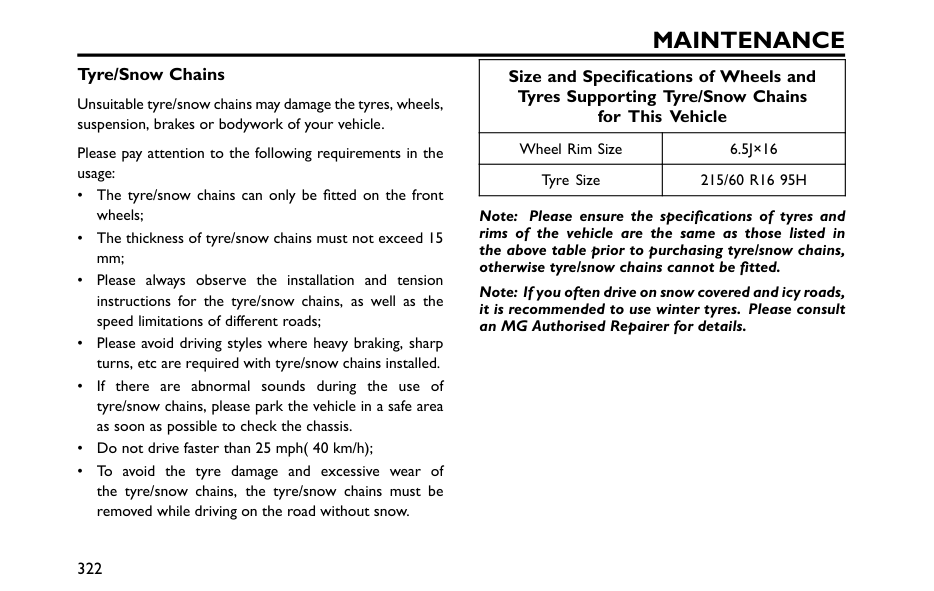
Maintenance
Tyre/Snow Chains Unsuitable tyre/snow chains may damage the tyres, wheels, suspension, brakes or bodywork of your vehicle. Please pay attention to the following requirements in the usage: • The tyre/snow chains can only be fitted on the front wheels; • The thickness of tyre/snow chains must not exceed 15 mm; • Please always observe the installation and tension instructions for the tyre/snow chains, as well as the speed limitations of different roads; • Please avoid driving styles where heavy braking, sharp turns, etc are required with tyre/snow chains installed. • If there are abnormal sounds during the use of tyre/snow chains, please park the vehicle in a safe area as soon as possible to check the chassis. • Do not drive faster than 25 mph( 40 km/h); • To avoid the tyre damage and excessive wear of the tyre/snow chains, the tyre/snow chains must be removed while driving on the road without snow. Size and Specifications of Wheels and Tyres Supporting Tyre/Snow Chains for This Vehicle Wheel Rim Size6.5J×16
Tyre Size215/60 R16 95H
Note: Please ensure the specifications of tyres and rims of the vehicle are the same as those listed in the above table prior to purchasing tyre/snow chains, otherwise tyre/snow chains cannot be fitted. Note: If you often drive on snow covered and icy roads, it is recommended to use winter tyres. Please consult an MG Authorised Repairer for details. 322
Maintenance
Cleaning and Caring Observe all safety precautions on cleaning products; Do Not drink fluids and keep them away from the eyes. Exterior Washing Your Car In order to prevent accidents you should only clean your car when the power system is OFF. Do not clean the front compartment with high pressure water since it may damage the electrical system of the vehicle. Some high pressure cleaning systems will penetrate door, window and sunroof seals, and damage lock mechanisms.Do Not
aim water jets directly at components that might be easily damaged. In order to preserve the paint finish on your car, please observe the following care points: • DO NOT use hot water to wash the car. • DO NOT use detergents or washing up liquid. • In hot weather, DO NOT wash the car in direct sunlight. • When using a hose, DO NOT aim the water directly at window, door or sunroof seals, or through wheel apertures onto the brake components. If the car is particularly dirty, use a hose to flush grime and grit from the bodywork, prior to washing. Then, wash the car using cold or lukewarm water containing a good quality wash and wax shampoo. Always use plenty of water to ensure that grit is flushed from the surface and not ground into the paintwork. After washing, rinse the bodywork with clean water and dry off with a chamois leather. Cleaning the underside Do not clean the front compartment with high pressure water since it may damage the electrical system of the vehicle. From time to time, but particularly during winter months when salt has been used on the roads, use a hose to wash the underside of the car. Flush away accumulations of mud and thoroughly clean those areas where debris can easily collect (wheel arches and panel seams, for example). 323 9
Maintenance
Important
• Avoid cleaning the vehicle in direct sunlight. • When cleaning the vehicle in winter avoid spraying water directly onto door locks and panel gaps due to risk of icing. • Do not use rough sponges or cloth to clean the car, this will damage the paintwork finish. • When cleaning the headlamps do not use a dry cloth or sponge, use only warm soapy water. Cleaning with High Pressure Cleaner Always read the manufacturers operating instructions. When using high pressure washers, always ensure there is adequate distance between the spray nozzle and any soft materials, decals or rubber seals. Note: DO NOT direct the pressure washer nozzle directly toward the high voltage components or high voltage connections.Important
• Please pay attention to the operating instructions of high pressure cleaner. • Soft parts on the vehicle should be kept in a large enough distance from the high pressure cleaner. Polishing the Paintwork Occasionally treat the paint surface with an approved polish containing the following properties: • Very mild abrasives to remove surface contamination without removing or damaging the paint. • Filling compounds that will fill scratches and reduce their visibility. • Wax to provide a protective coating between the paint and the elements. Note: If possible, avoid applying polish or wax products to window glass and rubber seals. Matte paint Matte paint is a special kind of coating, and special care should be taken when washing cars and caring for them. 324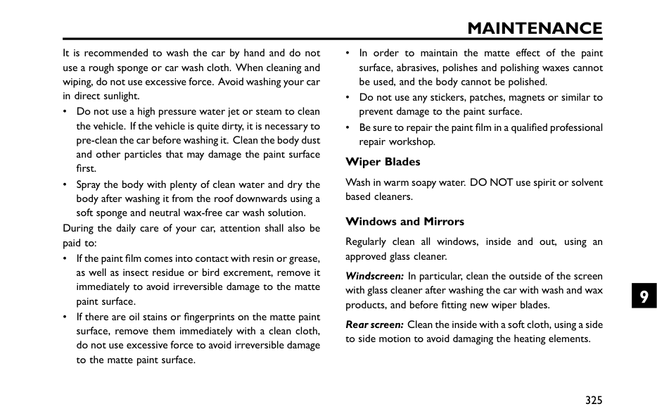
Maintenance
It is recommended to wash the car by hand and do not use a rough sponge or car wash cloth. When cleaning and wiping, do not use excessive force. Avoid washing your car in direct sunlight. • Do not use a high pressure water jet or steam to clean the vehicle. If the vehicle is quite dirty, it is necessary to pre-clean the car before washing it. Clean the body dust and other particles that may damage the paint surface first. • Spray the body with plenty of clean water and dry the body after washing it from the roof downwards using a soft sponge and neutral wax-free car wash solution. During the daily care of your car, attention shall also be paid to: • If the paint film comes into contact with resin or grease, as well as insect residue or bird excrement, remove it immediately to avoid irreversible damage to the matte paint surface. • If there are oil stains or fingerprints on the matte paint surface, remove them immediately with a clean cloth, do not use excessive force to avoid irreversible damage to the matte paint surface. • In order to maintain the matte effect of the paint surface, abrasives, polishes and polishing waxes cannot be used, and the body cannot be polished. • Do not use any stickers, patches, magnets or similar to prevent damage to the paint surface. • Be sure to repair the paint film in a qualified professional repair workshop. Wiper Blades Wash in warm soapy water. DO NOT use spirit or solvent based cleaners. Windows and Mirrors Regularly clean all windows, inside and out, using an approved glass cleaner. Windscreen: In particular, clean the outside of the screen with glass cleaner after washing the car with wash and wax products, and before fitting new wiper blades. Rear screen: Clean the inside with a soft cloth, using a side to side motion to avoid damaging the heating elements. 325 9
Maintenance
Mirrors: Wash with soapy water. Use a plastic scraper to remove ice. DO NOT use abrasive cleaning compounds or metal scraper. Plastic Components Any plastic components should be cleaned using conventional cleaning methods and not be treated with abrasive materials. Paint Damage Any paint damage or stonechips should be treated with suitable paint/lacquer materials immediately to avoid invalidating the Anti Corrosion Warranty. Weather Strips Any weather strips or rubber aperture seals should be treated with suitable materials (silica gel) if they are cleaned using strong detergents, this should avoid any sticking and maintain the service life of the seal. Wheels When cleaning the wheels any materials orwater that contact the brake. In order to ensure the wheels are kept in optimum condition they should be cleaned regularly. Only use a recommended non-acidic propriety wheel cleaner. Always read the instructions on the product. 326
Maintenance
Cleaning the Interior Plastic materials Clean plastic-faced materials with diluted upholstery cleaner, then wipe with a damp cloth. Note: DO NOT polish dashboard components – these should remain non-reflective. Carpet and fabrics Clean with diluted upholstery cleaner - test a concealed area first. Leather Clean leather trim with warm water and a non-detergent soap. Dry and polish the leather with a dry, clean, lint-free cloth. Note: DO NOT use petrol, detergents, furniture creams or polishes as cleaning agents. Instrument Pack, Infotainment Display Clean with a dry cloth only. DO NOT use cleaning fluids or sprays. Airbag Module Covers DO NOT allow these areas to be flooded with liquid and DO NOT use petrol, detergent, furniture cream or polishes. To protect damage to the airbag SRS, the following areas should be cleaned sparingly with a damp cloth and upholstery cleaner ONLY: • Steering wheel centre pad. • Area of dashboard containing the passenger airbag. • Area of roof lining and front pillar finishers which enclose the side head impact protection modules. Seat Belts DO NOT use bleaches, dyes or cleaning solvents on seat belts. Extend the belts, then use warm water and a non-detergent soap to clean. Allow the belts to dry naturally; DO NOT retract them or use the car until they are completely dry. 327 9
Technical Data Technical Data Dimensions 330 Complete Vehicle Mass Parameters 332 Main Engine Parameters 336 Dynamic Performance Parameters 338 Parameters of Drive Motor* 339 Recommended Fluids and Capacities 340 Wheel Alignment (Unladen Condition) 342 Wheels and Tyres 343 Tyre Pressures (Cold) 344 10
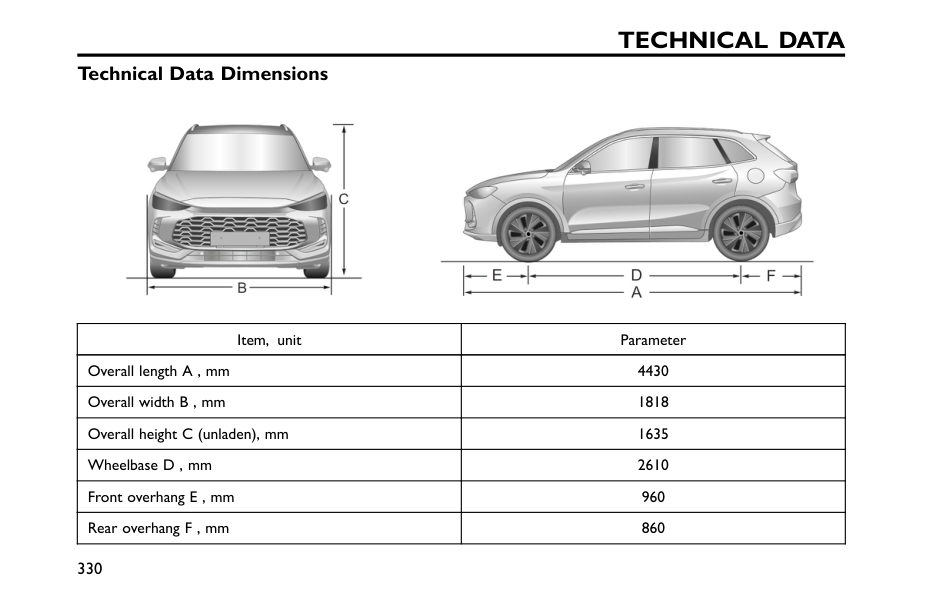
Technical Data
Technical Data Dimensions Item, unit Parameter Overall length A , mm 4430 Overall width B , mm 1818 Overall height C (unladen), mm 1635 Wheelbase D , mm 2610 Front overhang E , mm 960 Rear overhang F , mm 860 330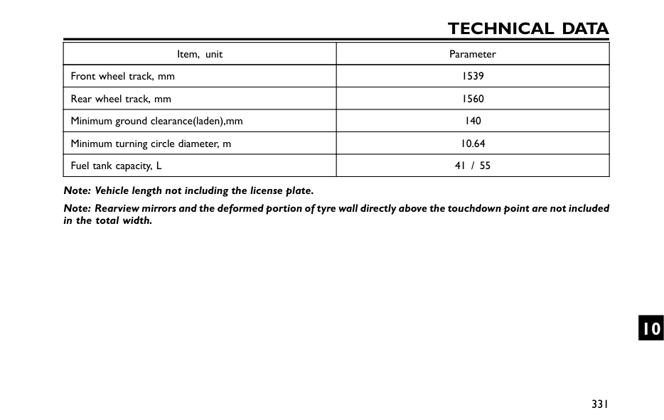
Technical Data
Item, unit Parameter Front wheel track, mm 1539 Rear wheel track, mm 1560 Minimum ground clearance(laden),mm 140 Minimum turning circle diameter, m 10.64 Fuel tank capacity, L 41 / 55 Note: Vehicle length not including the license plate. Note: Rearview mirrors and the deformed portion of tyre wall directly above the touchdown point are not included in the total width. 331 10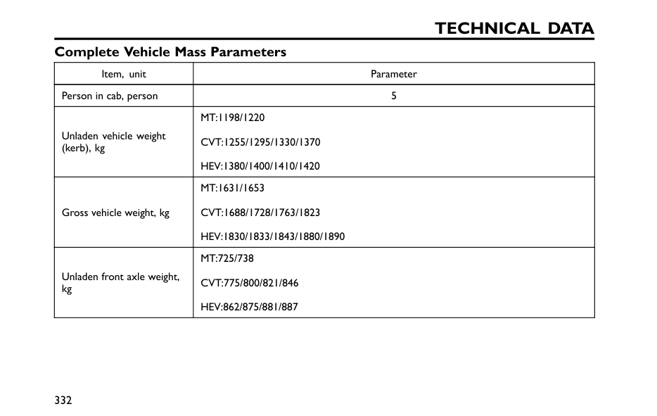
Technical Data
Complete Vehicle Mass Parameters Item, unit Parameter Person in cab, person 5 Unladen vehicle weight (kerb), kgMt:1198/1220
Cvt:1255/1295/1330/1370
Hev:1380/1400/1410/1420
Gross vehicle weight, kgMt:1631/1653
Cvt:1688/1728/1763/1823
Hev:1830/1833/1843/1880/1890
Unladen front axle weight, kgMt:725/738
Cvt:775/800/821/846
Hev:862/875/881/887
332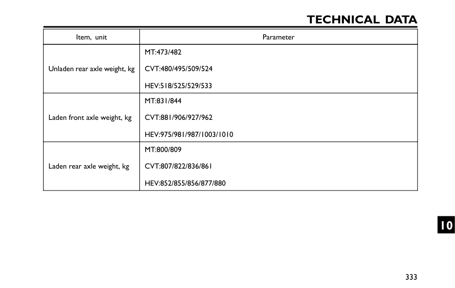
Technical Data
Item, unit Parameter Unladen rear axle weight, kgMt:473/482
Cvt:480/495/509/524
Hev:518/525/529/533
Laden front axle weight, kgMt:831/844
Cvt:881/906/927/962
Hev:975/981/987/1003/1010
Laden rear axle weight, kgMt:800/809
Cvt:807/822/836/861
Hev:852/855/856/877/880
333 10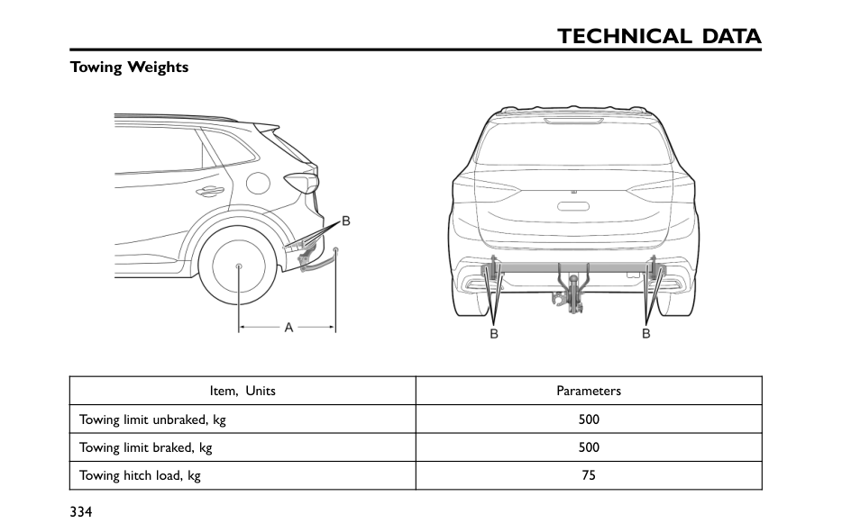
Technical Data
Towing Weights Item, Units Parameters Towing limit unbraked, kg 500 Towing limit braked, kg 500 Towing hitch load, kg 75 334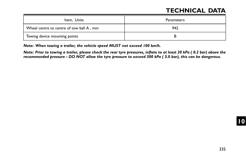
Technical Data
Item, Units Parameters Wheel centre to centre of tow ball A , mm 942 Towing device mounting pointsB
Note: When towing a trailer, the vehicle speed MUST not exceed 100 km/h. Note: Prior to towing a trailer, please check the rear tyre pressures, inflate to at least 20 kPa ( 0.2 bar) above the recommended pressure - DO NOT allow the tyre pressure to exceed 300 kPa ( 3.0 bar), this can be dangerous. 335 10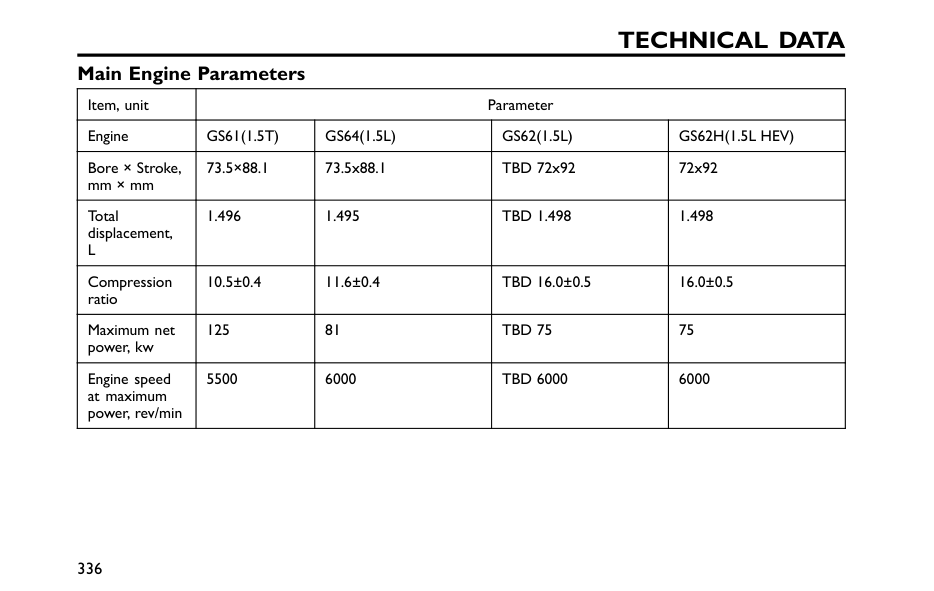
Technical Data
Main Engine Parameters Item, unit Parameter EngineGs61(1.5T)
Gs64(1.5L)
Gs62(1.5L)
Gs62H(1.5L Hev)
Bore × Stroke, mm × mm 73.5×88.1 73.5x88.1 TBD 72x92 72x92 Total displacement,L
1.496 1.495Tbd 1.498
1.498 Compression ratio 10.5±0.4 11.6±0.4Tbd 16.0±0.5
16.0±0.5 Maximum net power, kw 125 81Tbd 75
75 Engine speed at maximum power, rev/min 5500 6000Tbd 6000
6000 336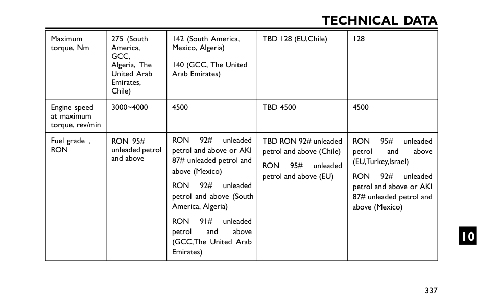
Technical Data
Maximum torque, Nm 275 (South America,Gcc,
Algeria, The United Arab Emirates, Chile) 142 (South America, Mexico, Algeria) 140 (GCC, The United Arab Emirates) TBD 128 (EU,Chile) 128 Engine speed at maximum torque, rev/min 3000~4000 4500Tbd 4500
4500 Fuel grade,Ron
Ron 95#
unleaded petrol and aboveRon
92# unleaded petrol and above or AKI 87# unleaded petrol and above (Mexico)Ron
92# unleaded petrol and above (South America, Algeria)Ron
91# unleaded petrol and above (GCC,The United Arab Emirates) TBD RON 92# unleaded petrol and above (Chile)Ron
95# unleaded petrol and above (EU)Ron
95# unleaded petrol and above (EU,Turkey,Israel)Ron
92# unleaded petrol and above or AKI 87# unleaded petrol and above (Mexico) 337 10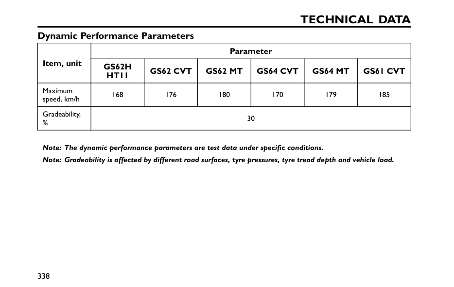
Technical Data
Dynamic Performance Parameters Parameter Item, unitGs62H
Ht11
Gs62 Cvt
Gs62 Mt
Gs64 Cvt
Gs64 Mt
Gs61 Cvt
Maximum speed, km/h 168 176 180 170 179 185 Gradeability, % 30 Note: The dynamic performance parameters are test data under specific conditions. Note: Gradeability is affected by different road surfaces, tyre pressures, tyre tread depth and vehicle load. 338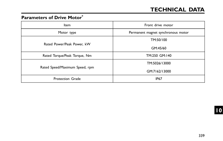
Technical Data
Parameters of Drive Motor* Item Front drive motor Motor type Permanent magnet synchronous motor Rated Power/Peak Power, kWTm:50/100
Gm:45/60
Rated Torque/Peak Torque, NmTm:250 Gm:140
Rated Speed/Maximum Speed, rpmTm:5026/13000
Gm:7162/13000
Protection GradeIp67
339 10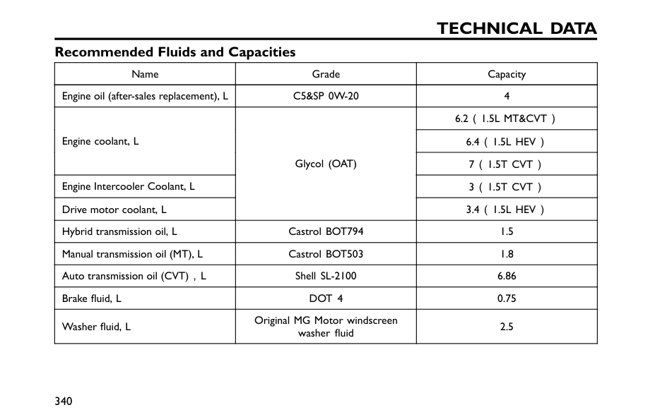
Technical Data
Recommended Fluids and Capacities Name Grade Capacity Engine oil (after-sales replacement), LC5&Sp 0W-20
46.2(1.5L Mt&Cvt)
6.4(1.5L Hev)
Engine coolant, L7(1.5T Cvt)
Engine Intercooler Coolant, L3(1.5T Cvt)
Drive motor coolant, L Glycol (OAT)3.4(1.5L Hev)
Hybrid transmission oil, L Castrol BOT794 1.5 Manual transmission oil (MT), L Castrol BOT503 1.8 Auto transmission oil (CVT),L Shell SL-2100 6.86 Brake fluid, LDot 4
0.75 Washer fluid, L Original MG Motor windscreen washer fluid 2.5 340
Technical Data
Name Grade Capacity R-134a* 520±20 g R-1234yf* 0.52±0.02 kg 0.52±0.02 kgGwp 0.501
Air conditioning refrigerant HFC-1234yf* CO2eq 0.0003t 341 10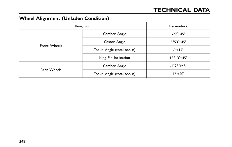
Technical Data
Wheel Alignment (Unladen Condition) Item, unit Parameters Camber Angle -27′±45' Castor Angle 5°53′±45' Toe-in Angle (total toe-in) 6′±12' Front Wheels King Pin Inclination 13°13′±45' Camber Angle -1°25′±45' Rear Wheels Toe-in Angle (total toe-in) 12′±20' 342
Technical Data
Wheels and Tyres Wheel Rim Size6.5J×16
7.0J×17
7.0J×18
Tyre Size215/60 R16 95H
215/55 R17 94V 215/55
R17 98V
215/50 R18 92V 215/50
R18 96V
Wheel Rim Size 4Bx16 Spare Wheel* Tyre SizeT125/90R16 98M
343 10