
Ask AI
— answers from the official manualAnswers from the official manual.
Common questions
Common Questions
8 totalWhat personal protective equipment is required when using the melter?
Wear eye or face protection, clothing that protects exposed skin, and heat-protective gloves when servicing equipment containing molten hot melt as per warning in Tables 1-1 (Page 15).
What are the clearance requirements for mounting the melter?
Ensure a minimum of 370 mm (P4 & P7) or 391 mm (P10) clearance from the outer edge of the hose to the front face of the melter; also, at least 243 mm (P4 & P7) or 268mm (P10) for opening the pump enclosure door. See Table 3-1 (Page 27).
What is the power requirement for my melter?
Refer to Appendix A, Calculating Melter Power Requirements or Table 3-2 to determine the maximum allowable hose lengths and gun wattages based on your application. Detailed requirements vary by model (Page 28).
How do I configure the electrical service?
Configure an electrical connector as specified in Table 3-3 by selecting a voltage plug appropriate for your electrical service type and installing it in either TB1 or J1 on the main board. Follow steps detailed under Configuring the Electrical Service (Page 35).
What is the role of the air filter?
The air filter provides a clean, dry air supply to the melter’s pneumatic system. Connect it properly using NPTF threads and ensure correct pressure adjustment following steps described under Connecting an Air Supply (Page 39).
How do I set up hose connections?
Connect hoses to the receptacles on each hose/gun module, using port 1 first and ensuring compliance with safety cautions regarding char buildup and hose fitting usage. Consult Figure 3-8 for detailed connection steps (Pages 40 through 42).
Show 2 more questions
Full Manual
319 pages

###### ProBlue Adhesive Melters Models P4, P7, and P10
Customer Product Manual Part 1024496_06 Issued 3/14
This document contains important safety information Be sure to read and follow all safety information in this document and any other related documentation.
NORDSON CORPORATION DULUTH, GEORGIA USA www.nordson.com
###################### For CE Declaration, refer to equipment documentation.
Nordson Corporation welcomes requests for information, comments, and inquiries about its products. General information about Nordson can be found on the Internet using the following address: http://www.nordson.com.
Address all correspondence to:
Nordson Corporation Attn: Customer Service 11475 Lakefield Drive Duluth, GA 30097
Notice This is a Nordson Corporation publication which is protected by copyright. Original copyright date 2002. No part of this document may be photocopied, reproduced, or translated to another language without the prior written consent of Nordson Corporation. The information contained in this publication is subject to change without notice.
###################### Trademarks
AccuJet, AeroCharge, Apogee, AquaGuard, Asymtek, Automove, Baitgun, Blue Box, Bowtie, CanWorks, Century, CF, CleanSleeve, CleanSpray, ColorMax, Color‐on‐Demand, Control Coat, Coolwave, Cross‐Cut, cScan+, Dispensejet, DispenseMate, DuraBlue, DuraDrum, Durafiber, DuraPail, Dura‐Screen, Durasystem, Easy Coat, Easymove Plus, Ecodry, Econo‐Coat, e.DOT, EFD, Emerald, Encore, ESP, e stylized, ETI ‐ stylized, Excel 2000, Fillmaster, FlexiCoat, Flex‐O‐Coat, Flow Sentry, Fluidmove, FoamMelt, FoamMix, Fulfill, GreenUV, HDLV, Heli‐flow, Horizon, Hot Shot, iControl, iDry, iFlow, Isocoil, Isocore, Iso‐Flo, iTRAX, Kinetix, LEAN CELL, Little Squirt, LogiComm, Magnastatic, March, Maverick, MEG, Meltex, Microcoat, Micromark, MicroSet, Millennium, Mini Squirt, Mountaingate, Nordson, Optimum, Package of Values, Pattern View, PermaFlo, PicoDot, Porous Coat, PowderGrid, Powderware, Precisecoat, PRIMARC, Printplus, Prism, ProBlue, Prodigy, Pro‐Flo, ProLink, Pro‐Meter, Pro‐Stream, RBX, Rhino, Saturn, Saturn with rings, Scoreguard, Seal Sentry, Select Charge, Select Coat, Select Cure, Signature, Slautterback, Smart‐Coat, Solder Plus, Spectrum, Speed‐Coat, SureBead, Sure Coat, Sure‐Max, Sure Wrap, Tracking Plus, TRAK, Trends, Tribomatic, TrueBlue, TrueCoat, Ultra, UpTime, u‐TAH, Vantage, VersaBlue, Versa‐Coat, VersaDrum, VersaPail, Versa‐Screen, Versa‐Spray, Watermark, and When you expect more. are registered trademarks of Nordson Corporation.
Accubar, Advanced Plasma Systems, AeroDeck, AeroWash, AltaBlue, AltaSlot, Alta Spray, Artiste, ATS, Auto‐Flo, AutoScan, Axiom, Best Choice, Blue Series, Bravura, CanPro, Champion, Check Mate, ClassicBlue, Classic IX, Clean Coat, Cobalt, Controlled Fiberization, Control Weave, ContourCoat, CPX, cSelect, Cyclo‐Kinetic, DispensLink, Dry Cure, DuraBraid, DuraCoat, DuraPUR, Easy Clean, EasyOn, EasyPW, Eclipse, e.dot+, E‐Nordson, Equalizer, EquiBead, FillEasy, Fill Sentry, Flow Coat, Fluxplus, Get Green With Blue, G‐Net, G‐Site, IntelliJet, iON, Iso‐Flex, iTrend, Lacquer Cure, Maxima, Mesa, MicroFin, MicroMax, Mikros, MiniBlue, MiniEdge, Minimeter, Multifill, MultiScan, Myritex, Nano, NexJet, OmniScan, OptiMix, OptiStroke, Partnership+Plus, PatternJet, PatternPro, PCI, Pinnacle, Plasmod, Powder Pilot, Powder Port, Powercure, Process Sentry, Pulse Spray, PURBlue, PURJet, Ready Coat, RediCoat, Royal Blue, Select Series, Sensomatic, Shaftshield, SheetAire, Smart, Smartfil, SolidBlue, Spectral, SpeedKing, Spray Works, Summit, SureFoam, Sure Mix, SureSeal, Swirl Coat, TAH, ThruWave, Trade Plus, Trilogy, Ultra FoamMix, UltraMax, Ultrasaver, Ultrasmart, Universal, ValueMate, Versa, Vista, Web Cure, and 2 Rings (Design) are trademarks of Nordson Corporation.
Designations and trademarks stated in this document may be brands that, when used by third parties for their own purposes, could lead to violation of the owners' rights.

DeviceNet is a trademark of Open DeviceNet Vendors Association, Inc. EtherNet/IP is a trademark used under license by ODVA. Loctite is a registered trademark of Loctite Corporation. Never Seez is a registered trademark of Bostik Inc. Parker Lubricant is a registered trademark of Parker Seal. PROFIBUS is a registered trademark of PROFIBUS International. Viton is a registered trademark of DuPont Dow Elastomers. L.L.C. Windows is a registered trademark of Microsoft Corporation.
Part 1024496_06 2014 Nordson Corporation All rights reserved
Table of Contents i
Table of Contents
Safety 1-1..................................................... Safety Alert Symbols 1‐1......................................... Responsibilities of the Equipment Owner 1‐2.......................
Safety Information 1‐2........................................ Instructions, Requirements, and Standards 1‐2................... User Qualifications 1‐3........................................
Applicable Industry Safety Practices 1‐3........................... Intended Use of the Equipment 1‐3............................. Instructions and Safety Messages 1‐4........................... Installation Practices 1‐4...................................... Operating Practices 1‐4....................................... Maintenance and Repair Practices 1‐5..........................
Equipment Safety Information 1‐5.................................
Equipment Shutdown 1‐6..................................... Relieving System Hydraulic Pressure 1‐6..................... De‐energizing the System 1‐6............................... Disabling the Applicators 1‐6................................
General Safety Warnings and Cautions 1‐7...................... Other Safety Precautions 1‐10.................................. First Aid 1‐10..................................................
Safety Labels and Tags 1‐11......................................
Description 2-1................................................ Other Sources of Information 2‐2.................................
Installation Guide 2‐2....................................... User's Guide 2‐2........................................... Online Support 2‐2......................................... Product Resource CD 2‐2...................................
Product Description 2‐3......................................... Intended Use 2‐4............................................. Limitations of Use 2‐4......................................... Modes of Operation 2‐4....................................... Melter Identification 2‐5.......................................
Key Components 2‐6........................................... Optional Equipment 2‐8.........................................
Table of Contentsii
Installation 3-1................................................. Quick‐Start 3‐1................................................. Installing 400/480 Volt Melters 3‐1................................ Overview 3‐2..................................................
Installation Requirements 3‐4.................................... Clearances 3‐4.............................................. Ventilation 3‐5............................................... Electrical Power 3‐5.......................................... Compressed Air 3‐6.......................................... Other Considerations 3‐6......................................
Unpacking the Melter 3‐8........................................ Contents of the Installation Kit 3‐8............................... Customer‐Supplied Materials 3‐8...............................
Mounting the Melter 3‐10......................................... Configuring the Electrical Service 3‐13.............................. Connecting a Compressed Air Supply 3‐18.......................... Connecting Hoses and Guns 3‐20................................. Setting Up the Melter 3‐24........................................
Quick Setup 3‐24.............................................. Operating Parameters 3‐26.....................................
Selecting Operating Parameters 3‐26.......................... Reading or Editing Operating Parameters 3‐26..................
Set‐point Temperature of the Tank, Hoses, and Guns 3‐32.......... Save and Restore Melter Settings 3‐34........................... Review Parameter and Set‐point Temperature Changes 3‐36.......
Installing Melter Inputs 3‐40....................................... Installing Melter Outputs 3‐44..................................... Installing Optional Equipment 3‐47................................. Connecting a Gun Driver, Pattern Controller, or Timer 3‐47............. Flushing the Melter 3‐47.......................................... Setting Up Melter Communications 3‐47............................
Table of Contents iii
############### Operation 4-1..................................................
Confirm that the Melter is Operating Correctly 4‐7................. Monitor Component Temperatures 4‐8.......................... Monitor Melter Faults 4‐10......................................
How F1, F2, and F3 Faults are Handled 4‐14................... How F4 Faults are Handled 4‐15..............................
Monitor the Level of Hot Melt in the Tank 4‐17..................... Monitor and Adjust the Operating Air Pressure 4‐17................ Monitor the Service Interval 4‐18................................
Adjusting Component Temperatures 4‐19........................... Entering the Melter Password 4‐24................................. Using the Melter Function Keys 4‐25...............................
Heater Key 4‐25.............................................. Pump Key 4‐26............................................... Setup Key 4‐26............................................... Seven‐day Clock Key 4‐27..................................... Standby Key 4‐28.............................................
Shutting Down the Melter 4‐29.....................................
Maintenance 5-1............................................... Relieving System Pressure 5‐2................................... Locking Out External Communications 5‐2......................... Cleaning the Melter 5‐4.......................................... Replacing the Filter 5‐6..........................................
Monitoring the Life of the Filter 5‐6........................... Cleaning the Tank 5‐8........................................... Removing the Melter from the Sub‐base 5‐10........................
Troubleshooting 6-1............................................ 400/480 Volt Melters 6‐1......................................... Safety 6‐1...................................................... Melter Faults 6‐2............................................... Using the Troubleshooting Flowchart 6‐4...........................
Troubleshooting Quick‐checks 6‐4.............................. Returning the Melter Setup to Factory Settings 6‐5................ Identifying Electrical Components 6‐5...........................
Diagnostic Procedures 6‐11.......................................
ProBlue Troubleshooting Flowcharts 6‐21...........................
Table of Contentsiv
Parts 7-1...................................................... Using the Illustrated Parts List 7‐1.................................
Fasteners 7‐1................................................ Tank, Pump, and Manifold Parts List 7‐2........................... Manifold Assembly Parts List 7‐4.................................. Pump Assembly Parts Lists 7‐7...................................
15:1 Pump Assembly Parts 7‐7................................. 15:1 Low‐Viscosity Pump Assembly Parts 7‐10.................... 6:1 Pump Assembly Parts 7‐14.................................. Pump Shifter Assembly Parts 7‐18............................... Pump Piston Assembly Parts 7‐20...............................
Pneumatic Components Parts List 7‐22............................. Electrical Enclosure Parts List 7‐24................................. Exterior Panels Parts List 7‐26..................................... Chassis Components Parts List 7‐28............................... Ribbon Cable Parts List 7‐30...................................... Service Kits 7‐31................................................
15:1 Pump Replacement 7‐31................................... 15:1 Low‐Viscosity Pump Replacement 7‐31...................... 6:1 Pump Replacement 7‐31.................................... Pump General Service 7‐32.................................... Filter 7‐32.................................................... Pneumatic Panel 7‐32......................................... Pressure Discharge Valve 7‐33.................................. Manifold Service Kit 7‐33....................................... RTD 7‐33.................................................... Thermostat 7‐33.............................................. Main Circuit Board 7‐34........................................ Central Processor Unit (CPU) 7‐34.............................. Operator's Panel 7‐34.......................................... Hose/Gun Module 7‐34........................................ Main Circuit Board Fuses 7‐34.................................. Hose/Gun Module Fuses 7‐35.................................. Basic Spare Parts 7‐35......................................... Expanded Spare Parts 7‐35.................................... Level Switch 7‐35............................................. Manifold Guard (P4) 7‐36...................................... Manifold Guard (P10) 7‐36..................................... Vent Guard (P10) 7‐36......................................... Replacement Tank 7‐36........................................ Tank Lid Hinge Pin 7‐36........................................ Heater Block 230V 7‐37........................................ Manifold 4‐ or 6‐Hose/230V or 480V 7‐37.........................
Option Kits 7‐38................................................. 6‐Hose Extension 7‐38......................................... Input/Output Expansion Card 7‐38............................... Fill Master 7‐38............................................... Ethernet Card 7‐38............................................ DeviceNet Card 7‐39.......................................... Profibus Card 7‐39............................................ P10 8 H/G Expansion Base 7‐39................................
Schedule of Fasteners 7‐40.......................................
Table of Contents v
Technical Data 8-1............................................. General Specifications 8‐1....................................... Electrical Specifications 8‐2...................................... Pump Specifications 8‐2......................................... Melter Power Requirements 8‐2.................................. Dimensions 8‐3................................................
P4 Melter 8‐3................................................ P7 Melter 8‐4................................................ P10 Melter 8‐5............................................... Sub‐base 8‐6................................................
Wiring Diagrams—200/240 VAC Melter 8‐7........................
############### Calculating Melter Power Requirements A-1.....................
Operating Parameters B-1...................................... Standard B‐2................................................... Temperature Control B‐6........................................ Input Setup B‐9................................................. Output Setup B‐12............................................... Seven‐day Clock B‐14............................................
Melter Communications C-1..................................... Software Availability C‐1......................................... System Requirements C‐1....................................... Installing the Software C‐2.......................................
Removing the Software from Your PC C‐4........................ Connecting the PC and the Melter C‐5............................. Using Nordson Configuration Manager C‐6.........................
Saving and Restoring Melter Settings C‐6........................ Upgrading or Restoring Melter Firmware C‐8.....................
Troubleshooting C‐11............................................ Using Nordson Configuration Manager C‐11......................
Table of Contentsvi
############### SP Pump Diagnostics and Repair D-1............................
Pump Isolation Valve D‐2................................... Pressure Discharge Valve D‐2...............................
Pump Diagnostics D‐4........................................... Pump Disassembly and Reassembly D‐6...........................
Melter Preparation D‐6........................................ Required Tools and Materials D‐6..............................
Tools D‐6................................................. Service Parts D‐7.......................................... Supplies D‐7..............................................
Remove the Pump from the Melter D‐8..........................
Special Reassembly Instructions D‐8......................... Remove the Actuator and Air Manifold and the Cylinder Assembly D‐10
Special Reassembly Instructions D‐10......................... Remove the Magnetic Actuator Assembly D‐12.................... Remove the Valve Spool and Sleeve D‐15........................
Special Reassembly Instructions D‐16......................... Remove the Shifter Fork D‐18...................................
Special Reassembly Instructions D‐18......................... Remove the Piston Cups D‐20...................................
Special Reassembly Instructions D‐20......................... Remove the Pump Frame and the Insulator D‐22...................
Special Reassembly Instructions D‐22......................... Remove the Lower Ball Seat Assembly and the Piston D‐26.........
Special Reassembly Instructions D‐26......................... Disassemble the Lower Ball Seat and the Pressure Ball Assemblies D‐28..............................................
Special Reassembly Instructions D‐28......................... Remove the O‐ring and the Pump Seal D‐30......................
Special Reassembly Instructions D‐30.........................
Pump Assembly Parts List D‐32.................................... Pump Service Kit D‐34......................................... Other Pump Maintenance Kits D‐34.............................. Schedule of Fasteners D‐34.....................................
Table of Contents vii
############### 400/480 Volt ProBlue Adhesive Melters E-1.......................
Installation E‐6................................................. Clearances E‐6.............................................. Installation Kit Components E‐7................................ Prepare the Transformer for Installation E‐8...................... Mount the Transformer to the Parent Machine E‐10................ Connect the Electrical Service to the Transformer E‐12.............. Mount the Melter to the Transformer E‐14......................... Connect the Transformer to the Melter E‐16.......................
Troubleshooting E‐19............................................ Parts E‐20......................................................
Transformer Assembly E‐20.................................... 400/480‐Volt Melter‐Specific Components E‐23................... Service Kits E‐23..............................................
Wiring Diagram E‐23.............................................
############# Table of Contentsviii
Section 1 Safety
Read this section before using the equipment. This section contains recommendations and practices applicable to the safe installation, operation, and maintenance (hereafter referred to as “use”) of the product described in this document (hereafter referred to as “equipment”). Additional safety information, in the form of task‐specific safety alert messages, appears as appropriate throughout this document.
WARNING! Failure to follow the safety messages, recommendations, and
hazard avoidance procedures provided in this document can result in personal injury, including death, or damage to equipment or property.
#### Safety Alert Symbols
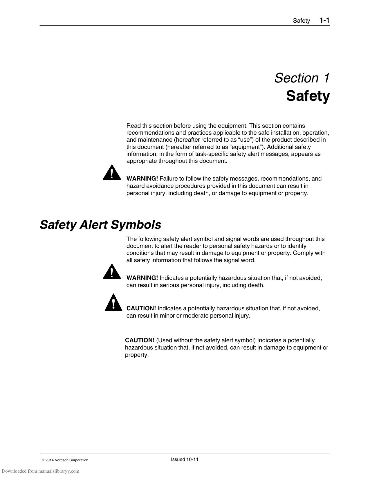
The following safety alert symbol and signal words are used throughout this document to alert the reader to personal safety hazards or to identify conditions that may result in damage to equipment or property. Comply with all safety information that follows the signal word.
WARNING! Indicates a potentially hazardous situation that, if not avoided, can result in serious personal injury, including death.
CAUTION! Indicates a potentially hazardous situation that, if not avoided, can result in minor or moderate personal injury.

CAUTION! (Used without the safety alert symbol) Indicates a potentially hazardous situation that, if not avoided, can result in damage to equipment or property.
#### Responsibilities of the Equipment Owner
Equipment owners are responsible for managing safety information, ensuring that all instructions and regulatory requirements for use of the equipment are met, and for qualifying all potential users.
######## Safety Information
Research and evaluate safety information from all applicable sources, including the owner‐specific safety policy, best industry practices, governing regulations, material manufacturer's product information, and this document.
Make safety information available to equipment users in accordance with governing regulations. Contact the authority having jurisdiction for information.
Maintain safety information, including the safety labels affixed to the equipment, in readable condition.
Instructions, Requirements, and Standards Ensure that the equipment is used in accordance with the information provided in this document, governing codes and regulations, and best industry practices.
If applicable, receive approval from your facility's engineering or safety department, or other similar function within your organization, before installing or operating the equipment for the first time.
Provide appropriate emergency and first aid equipment. Conduct safety inspections to ensure required practices are being followed. Re‐evaluate safety practices and procedures whenever changes are made to the process or equipment.
######## User Qualifications
Equipment owners are responsible for ensuring that users:
receive safety training appropriate to their job function as directed by governing regulations and best industry practices
are familiar with the equipment owner's safety and accident prevention policies and procedures
receive equipment‐ and task‐specific training from another qualified individual
NOTE: Nordson can provide equipment‐specific installation, operation, and maintenance training. Contact your Nordson representative for information
possess industry‐ and trade‐specific skills and a level of experience appropriate to their job function
are physically capable of performing their job function and are not under the influence of any substance that degrades their mental capacity or physical capabilities
#### Applicable Industry Safety Practices
The following safety practices apply to the use of the equipment in the manner described in this document. The information provided here is not meant to include all possible safety practices, but represents the best safety practices for equipment of similar hazard potential used in similar industries.
Intended Use of the Equipment Use the equipment only for the purposes described and within the limits specified in this document.
Do not modify the equipment. Do not use incompatible materials or unapproved auxiliary devices. Contact your Nordson representative if you have any questions on material compatibility or the use of non‐standard auxiliary devices.
Instructions and Safety Messages Read and follow the instructions provided in this document and other referenced documents.
Familiarize yourself with the location and meaning of the safety warning labels and tags affixed to the equipment. Refer to Safety Labels and Tags at the end of this section.
If you are unsure of how to use the equipment, contact your Nordson representative for assistance.
######## Installation Practices
Install the equipment in accordance with the instructions provided in this document and in the documentation provided with auxiliary devices.
Ensure that the equipment is rated for the environment in which it will be used. This equipment has not been certified for compliance with the ATEX directive nor as nonincendive and should not be installed in potentially explosive environments.
Ensure that the processing characteristics of the material will not create a hazardous environment. Refer to the Material Safety Data Sheet (MSDS) for the material.
If the required installation configuration does not match the installation instructions, contact your Nordson representative for assistance.
Position the equipment for safe operation. Observe the requirements for clearance between the equipment and other objects.
Install lockable power disconnects to isolate the equipment and all independently powered auxiliary devices from their power sources.
Properly ground all equipment. Contact your local building code enforcement agency for specific requirements.
Ensure that fuses of the correct type and rating are installed in fused equipment.
Contact the authority having jurisdiction to determine the requirement for installation permits or inspections.
######## Operating Practices
Familiarize yourself with the location and operation of all safety devices and indicators.
Confirm that the equipment, including all safety devices (guards, interlocks, etc.), is in good working order and that the required environmental conditions exist.
Use the personal protective equipment (PPE) specified for each task. Refer to Equipment Safety Information or the material manufacturer's instructions and MSDS for PPE requirements.
Do not use equipment that is malfunctioning or shows signs of a potential malfunction.
Maintenance and Repair Practices Allow only personnel with appropriate training and experience to operate or service the equipment.
Perform scheduled maintenance activities at the intervals described in this document.
Relieve system hydraulic and pneumatic pressure before servicing the equipment.
De‐energize the equipment and all auxiliary devices before servicing the equipment.
Use only new Nordson‐authorized refurbished or replacement parts. Read and comply with the manufacturer's instructions and the MSDS supplied with equipment cleaning compounds. NOTE: MSDSs for cleaning compounds that are sold by Nordson are available at www.nordson.com or by calling your Nordson representative. Confirm the correct operation of all safety devices before placing the equipment back into operation. Dispose of waste cleaning compounds and residual process materials according to governing regulations. Refer to the applicable MSDS or contact the authority having jurisdiction for information. Keep equipment safety warning labels clean. Replace worn or damaged labels.
#### Equipment Safety Information
This equipment safety information is applicable to the following types of Nordson equipment:
hot melt and cold adhesive application equipment and all related accessories
pattern controllers, timers, detection and verification systems, and all other optional process control devices
######## Equipment Shutdown
To safely complete many of the procedures described in this document, the equipment must first be shut down. The level of shut down required varies by the type of equipment in use and the procedure being completed. If required, shut down instructions are specified at the start of the procedure. The levels of shut down are:
########### Relieving System Hydraulic Pressure
Completely relieve system hydraulic pressure before breaking any hydraulic connection or seal. Refer to the melter‐specific product manual for instructions on relieving system hydraulic pressure.
########### De‐energizing the System
Isolate the system (melter, hoses, applicators, and optional devices) from all power sources before accessing any unprotected high‐voltage wiring or connection point.
NOTE: Government regulations and industry standards dictate specific requirements for the isolation of hazardous energy sources. Refer to the appropriate regulation or standard.
Disabling the Applicators NOTE: Adhesive dispensing applicators are referred to as “guns” in some previous publications. All electrical or mechanical devices that provide an activation signal to the applicators, applicator solenoid valve(s), or the melter pump must be disabled before work can be performed on or around an applicator that is connected to a pressurized system.
######## General Safety Warnings and Cautions
Table 1‐1 contains the general safety warnings and cautions that apply to Nordson hot melt and cold adhesive equipment. Review the table and carefully read all of the warnings or cautions that apply to the type of equipment described in this manual.
Equipment types are designated in Table 1‐1 as follows: HM = Hot melt (melters, hoses, applicators, etc.) PC = Process control CA = Cold adhesive (dispensing pumps, pressurized container, and applicators)
Table 1‐1 General Safety Warnings and Cautions
|Equipment Type|Warning or Caution| |---|---| |HM|WARNING! Hazardous vapors! Before processing any polyurethane reactive (PUR) hot melt or solvent‐based material through a compatible Nordson melter, read and comply with the material's MSDS. Ensure that the material's processing temperature and flashpoints will not be exceeded and that all requirements for safe handling, ventilation, first aid, and personal protective equipment are met. Failure to comply with MSDS requirements can cause personal injury, including death.| |HM|WARNING! Reactive material! Never clean any aluminum component or flush Nordson equipment with halogenated hydrocarbon fluids. Nordson melters and applicators contain aluminum components that may react violently with halogenated hydrocarbons. The use of halogenated hydrocarbon compounds in Nordson equipment can cause personal injury, including death.| |HM, CA|WARNING! System pressurized! Relieve system hydraulic pressure
before breaking any hydraulic connection or seal. Failure to relieve the system hydraulic pressure can result in the uncontrolled release of hot melt or cold adhesive, causing personal injury.| |Continued...|Continued...|
######## General Safety Warnings and Cautions (contd)
Table 1‐1 General Safety Warnings and Cautions (contd)
|Equipment Type|Warning or Caution| |---|---| |HM|WARNING! Molten material! Wear eye or face protection, clothing that protects exposed skin, and heat‐protective gloves when servicing equipment that contains molten hot melt. Even when solidified, hot melt can still cause burns. Failure to wear appropriate personal protective equipment can result in personal injury.| |HM, PC|WARNING! Equipment starts automatically! Remote triggering devices are used to control automatic hot melt applicators. Before working on or near an operating applicator, disable the applicator's triggering device and remove the air supply to the applicator's solenoid valve(s). Failure to disable the applicator's triggering device and remove the supply of air to the solenoid valve(s) can result in personal injury.| |HM, CA, PC|WARNING! Risk of electrocution! Even when switched off and electrically isolated at the disconnect switch or circuit breaker, the equipment may still be connected to energized auxiliary devices. De‐energize and electrically isolate all auxiliary devices before servicing the equipment. Failure to properly isolate electrical power to auxiliary equipment before servicing the equipment can result in personal injury, including death.| |HM, CA, PC|WARNING! Risk of fire or explosion! Nordson adhesive equipment is not rated for use in explosive environments and has not been cerfified for the ATEX directive or as nonincendive. In addition, this equipment should not be used with solvent‐based adhesives that can create an explosive atmosphere when processed. Refer to the MSDS for the adhesive to determine its processing characteristics and limitations. The use of incompatible solvent‐based adhesives or the improper processing of solvent‐based adhesives can result in personal injury, including death.|
|Continued...|Continued...|
################ Table 1‐1 General Safety Warnings and Cautions (contd)
|Equipment Type|Warning or Caution| |---|---| |HM, CA, PC|WARNING! Allow only personnel with appropriate training and experience to operate or service the equipment. The use of untrained or inexperienced personnel to operate or service the equipment can result in injury, including death, to themselves and others and can damage to the equipment.| |HM|CAUTION! Hot surfaces! Avoid contact with the hot metal surfaces of
applicators, hoses, and certain components of the melter. If contact can not be avoided, wear heat‐protective gloves and clothing when working around heated equipment. Failure to avoid contact with hot metal surfaces can result in personal injury.| |HM|CAUTION! Some Nordson melters are specifically designed to process polyurethane reactive (PUR) hot melt. Attempting to process PUR in equipment not specifically designed for this purpose can damage the equipment and cause premature reaction of the hot melt. If you are unsure of the equipment's ability to process PUR, contact your Nordson representative for assistance.| |HM, CA|CAUTION! Before using any cleaning or flushing compound on or in the equipment, read and comply with the manufacturer's instructions and the MSDS supplied with the compound. Some cleaning compounds can react unpredictably with hot melt or cold adhesive, resulting in damage to the equipment.| |HM|CAUTION! Nordson hot melt equipment is factory tested with Nordson Type R fluid that contains polyester adipate plasticizer. Certain hot melt materials can react with Type R fluid and form a solid gum that can clog the equipment. Before using the equipment, confirm that the hot melt is compatible with Type R fluid.|
Other Safety Precautions Do not use an open flame to heat hot melt system components. Check high pressure hoses daily for signs of excessive wear, damage, or leaks. Never point a dispensing handgun at yourself or others. Suspend dispensing handguns by their proper suspension point.
######## First Aid
If molten hot melt comes in contact with your skin:
#### Safety Labels and Tags
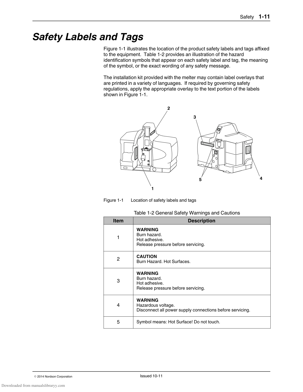
Figure 1‐1 illustrates the location of the product safety labels and tags affixed to the equipment. Table 1‐2 provides an illustration of the hazard identification symbols that appear on each safety label and tag, the meaning of the symbol, or the exact wording of any safety message.
The installation kit provided with the melter may contain label overlays that are printed in a variety of languages. If required by governing safety regulations, apply the appropriate overlay to the text portion of the labels shown in Figure 1‐1.
2
3
5 4
1
Figure 1‐1 Location of safety labels and tags
Table 1‐2 General Safety Warnings and Cautions
|Item|Description| |---|---| |1|WARNING Burn hazard. Hot adhesive. Release pressure before servicing.| |2|CAUTION Burn Hazard. Hot Surfaces.| |3|WARNING Burn hazard. Hot adhesive. Release pressure before servicing.|
|4|WARNING Hazardous voltage. Disconnect all power supply connections before servicing.| |5|Symbol means: Hot Surface! Do not touch.|
Section 2 Description
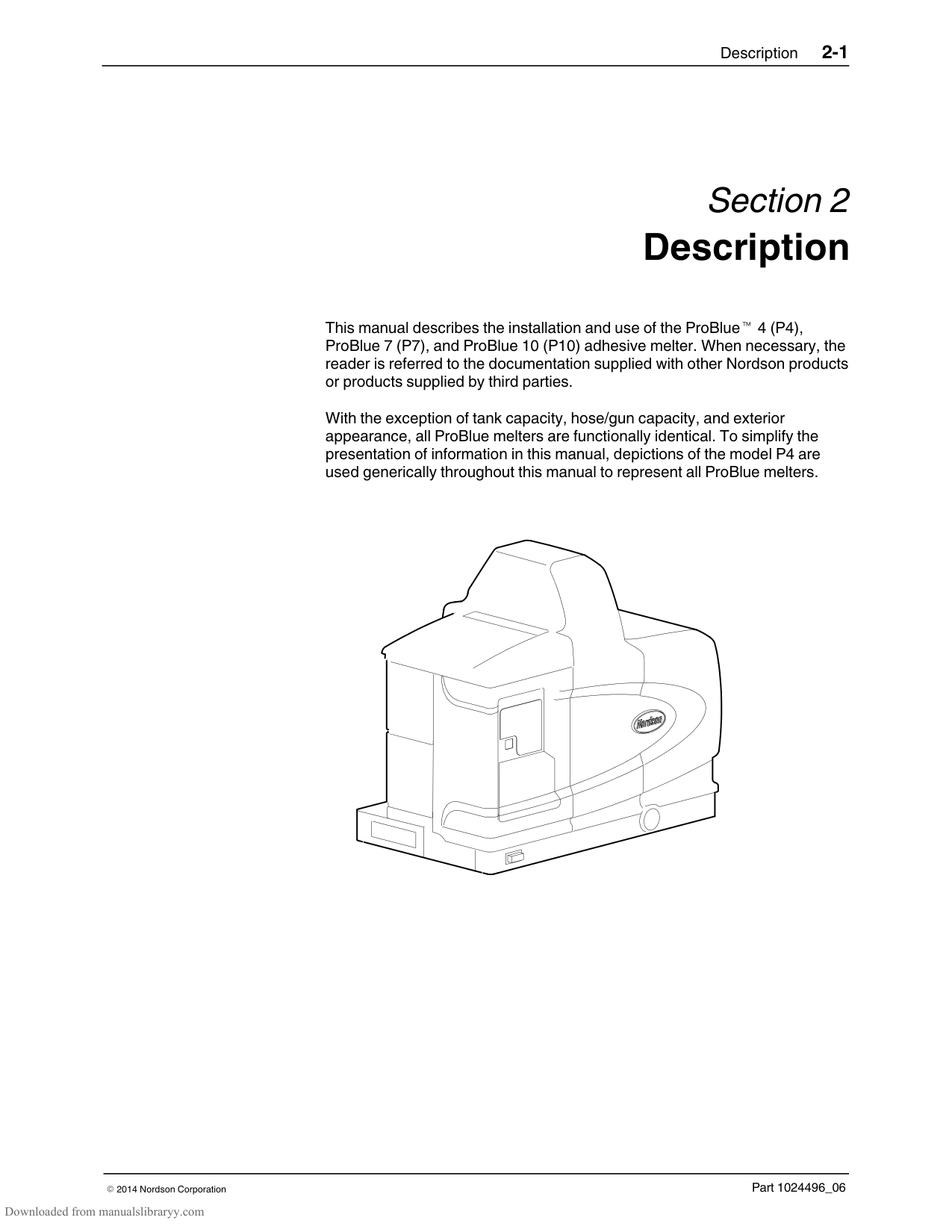
This manual describes the installation and use of the ProBlue 4 (P4), ProBlue 7 (P7), and ProBlue 10 (P10) adhesive melter. When necessary, the reader is referred to the documentation supplied with other Nordson products or products supplied by third parties.
With the exception of tank capacity, hose/gun capacity, and exterior appearance, all ProBlue melters are functionally identical. To simplify the presentation of information in this manual, depictions of the model P4 are used generically throughout this manual to represent all ProBlue melters.
#### Other Sources of Information
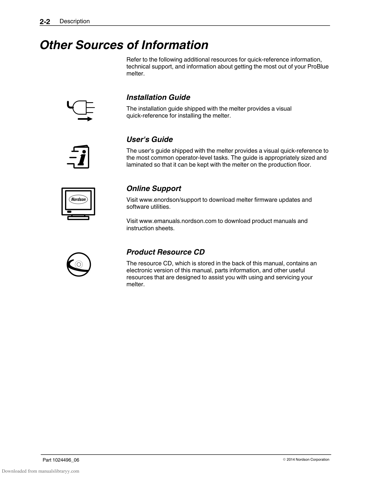
Refer to the following additional resources for quick‐reference information, technical support, and information about getting the most out of your ProBlue melter.
| | | |---|---| | | |
########### Installation Guide
The installation guide shipped with the melter provides a visual quick‐reference for installing the melter.
########### User's Guide
The user's guide shipped with the melter provides a visual quick‐reference to the most common operator‐level tasks. The guide is appropriately sized and laminated so that it can be kept with the melter on the production floor.
########### Online Support
Visit www.enordson/support to download melter firmware updates and software utilities.
Visit www.emanuals.nordson.com to download product manuals and instruction sheets.
########### Product Resource CD
The resource CD, which is stored in the back of this manual, contains an electronic version of this manual, parts information, and other useful resources that are designed to assist you with using and servicing your melter.
#### Product Description
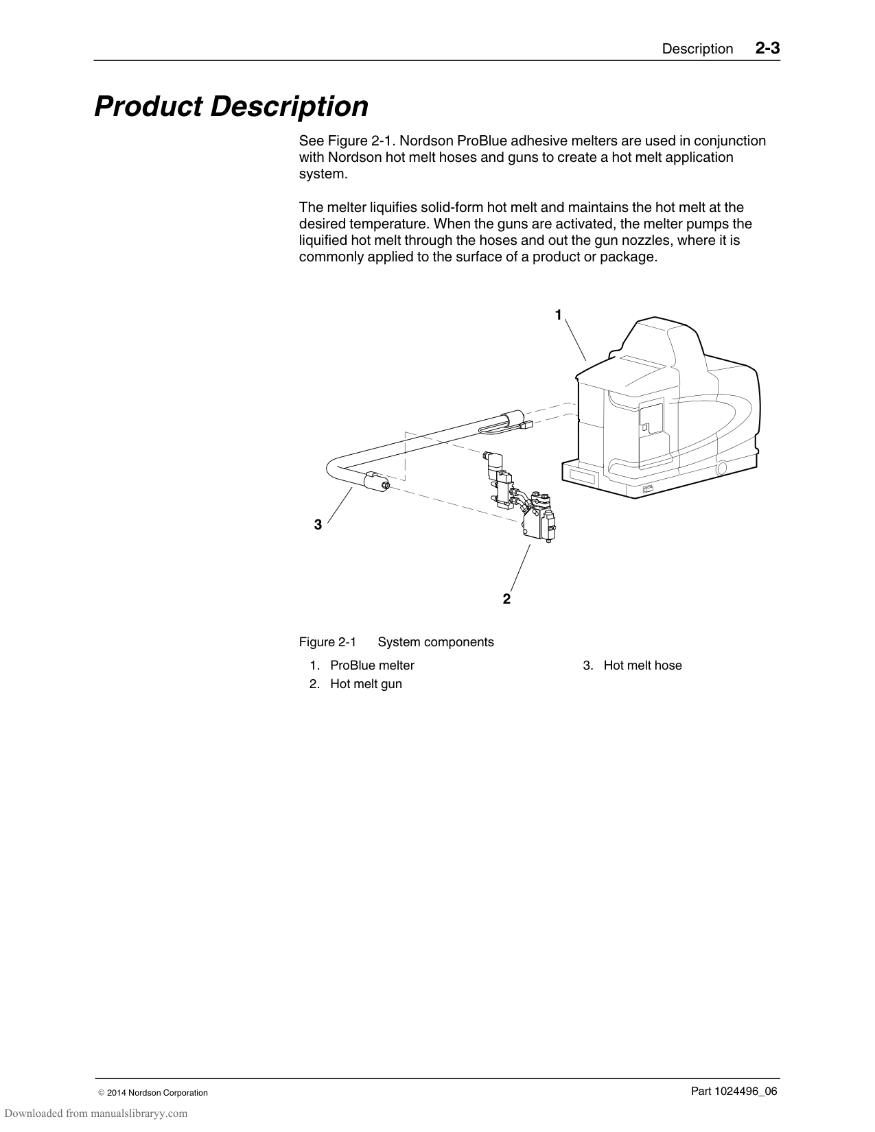
See Figure 2‐1. Nordson ProBlue adhesive melters are used in conjunction with Nordson hot melt hoses and guns to create a hot melt application system.
The melter liquifies solid‐form hot melt and maintains the hot melt at the desired temperature. When the guns are activated, the melter pumps the liquified hot melt through the hoses and out the gun nozzles, where it is commonly applied to the surface of a product or package.
Figure 2-1 System components
######## Intended Use
ProBlue melters are specifically designed to:
Melt and pump solid‐form hot melt materials that are engineered to be liquified and extruded at temperatures below 230 C (450 F)
Be used with compatible hot melt hoses and guns that are manufactured by Nordson Corporation
Be used in non‐explosive environments
######## Limitations of Use
Use ProBlue melters only for the purpose for which they are designed. ProBlue melters should not be used
to melt or pump polyurethane reactive or polyamid hot melt materials or any other material that creates a health or safety hazard when heated
in environments that will require the melter to be cleaned using a water wash or spray
######## Modes of Operation
ProBlue melters operate in the following modes:
Automatic scan—The melter automatically checks and displays the current temperature of the tank, hoses, and guns to confirm that they are within their pre‐defined temperature range. By default, the melter is always in the automatic scan mode unless it is placed into another operating mode.
Standby—The temperatures of the tank, hoses, and guns are reduced down from their operating temperature (hereafter referred to as set‐point temperature) by a pre‐set number of degrees.
Setup—The setup mode is used to configure melter control options and features and to review stored operating data. To prevent unauthorized changes to the melter's configuration, the melter can be password‐protected
Fault—The melter alerts the operator when an abnormal event occurs.
######## Melter Identification
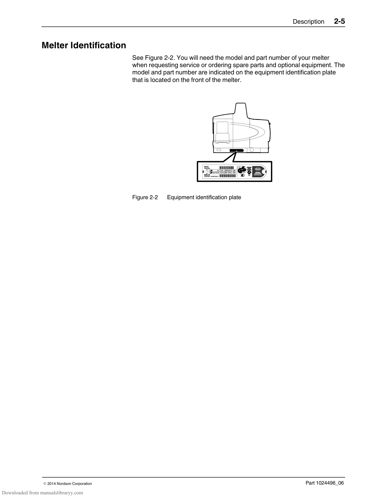
See Figure 2‐2. You will need the model and part number of your melter when requesting service or ordering spare parts and optional equipment. The model and part number are indicated on the equipment identification plate that is located on the front of the melter.
1/3O AC 200−240V60HZ35A
| | | |---|---| | | |
1/3ON/PEAC 400/230V50HZ33A
R

Figure 2-2 Equipment identification plate

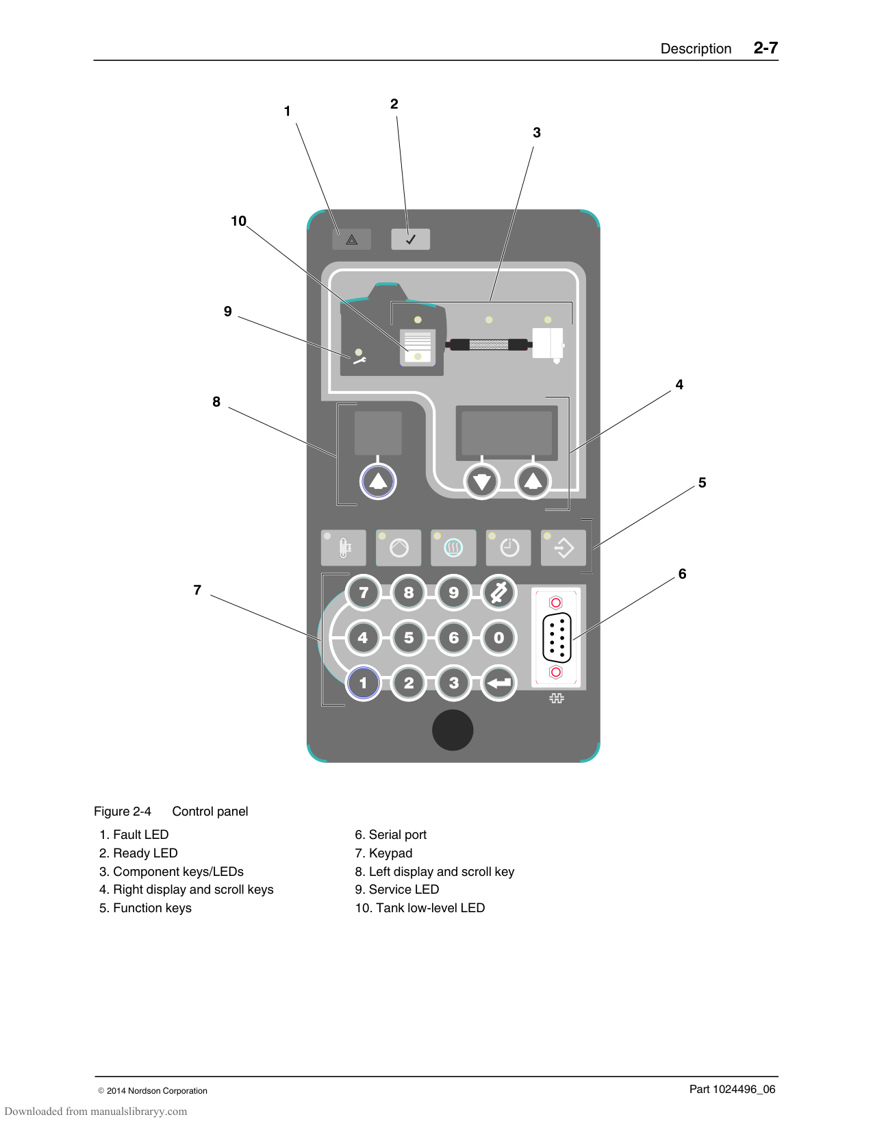
#### Key Components
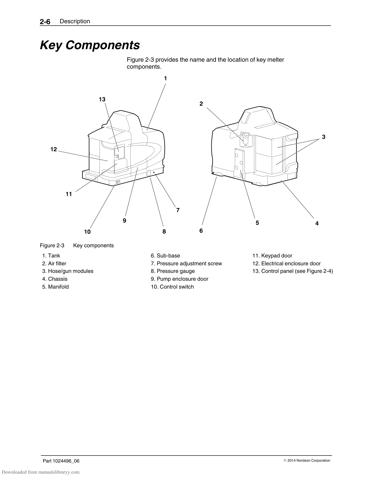
Figure 2‐3 provides the name and the location of key melter components.
| | | |---|---| | | | | | |
#### Optional Equipment
The following equipment may be ordered to expand the functionality and capacity of ProBlue adhesive melters.
Input/output (I/O) expansion cards that allow you to expand the number of available control inputs.
Communications cards that allow the melter to communicate with other process equipment or a controller that uses standard network protocols.
Hose/Gun modules that allow you to increase the number of hoses/guns that can be connected to the melter.
Automatic Fill Systems that provide automated transfer of dry adhesive materials to your melter. Choose either the FillEasy or FillMaster product.
8‐Hose/Gun Expansion Base that expands the capacity of a P10 adhesive melter from 6‐hoses/guns to 8‐hoses/guns.
Section 3 Installation
WARNING! Allow only personnel with appropriate training and experience to operate or service the equipment. The use of untrained or inexperienced personnel to operate or service the equipment can result in injury, including death, to themselves and others, and damage to the equipment.
#### Quick‐Start
If you have already installed the melter using the installation guide (P/N 1024498) that is provided inside the shipping container, and you have no questions concerning the installation, go to Setting Up the Melter later in this section for information about how to prepare the melter to operate with your manufacturing process.
#### Installing 400/480 Volt Melters
Refer to Appendix E for information about installing 400/480 volt ProBlue adhesive melters. After completing the procedures described in Appendix E, you will be referred back to this section to set up the melter.
#### Overview
ProBlue melters are factory‐configured for each order and require only the assembly and set up tasks described in this section. If your melter was ordered as a complete system, the shipping container will also contain one or more hot melt hoses and guns. ProBlue 400/480 volt melters include a transformer assembly that is shipped separately from the melter.
The melter is shipped from the factory with an installation kit that contains components that must be assembled onto the melter by the customer. Some additional materials must also be supplied by the customer to complete the installation.
If optional equipment was ordered with the melter, refer to the documentation provided with the optional equipment for installation and operating instructions.
The illustrations accompanying the procedures in this section depict the P4 melter. Unless otherwise noted, the instructions also apply to the P7 and P10 melter.
######## Additional Information
This section presents installation procedures in their most commonly used form. Procedural variations or special considerations are explained in the additional information table that follows most procedures. Where applicable, some table entries also contain cross‐reference information. Additional information tables are indicated by the symbol shown to the left.
######## Installation Tasks
The installation sequence is as follows:
######## Experience of Installation Personnel
The instructions provided in this section are intended to be used by personnel who have experience in the following subjects:
Hot melt application processes Industrial power and control wiring Industrial mechanical installation practices Basic process control and instrumentation
#### Installation Requirements
Before installing the melter, ensure that the desired installation location provides the required clearances, environmental conditions, and utilities.
######## Clearances
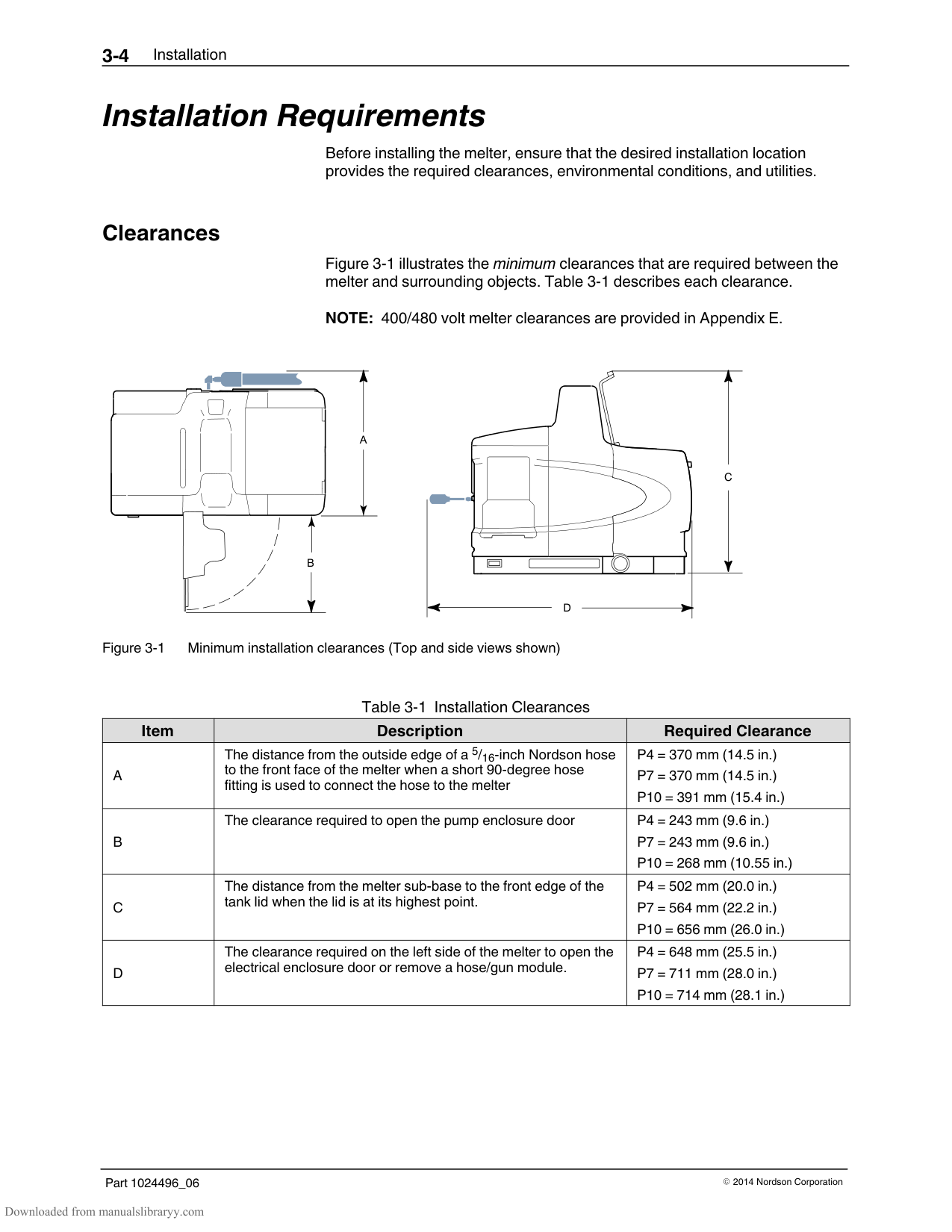
Figure 3‐1 illustrates the minimum clearances that are required between the melter and surrounding objects. Table 3‐1 describes each clearance.
NOTE: 400/480 volt melter clearances are provided in Appendix E.
| | | | |---|---|---|
| | | |
A
| | | |---|---| | | |
B
D
Figure 3‐1 Minimum installation clearances (Top and side views shown)
C
Table 3‐1 Installation Clearances
|Item|Description|Required Clearance| |---|---|---| |A|The distance from the outside edge of a 5/16‐inch Nordson hose to the front face of the melter when a short 90‐degree hose fitting is used to connect the hose to the melter|P4 = 370 mm (14.5 in.) P7 = 370 mm (14.5 in.) P10 = 391 mm (15.4 in.)| |B|The clearance required to open the pump enclosure door|P4 = 243 mm (9.6 in.) P7 = 243 mm (9.6 in.) P10 = 268 mm (10.55 in.)| |C|The distance from the melter sub‐base to the front edge of the tank lid when the lid is at its highest point.|P4 = 502 mm (20.0 in.) P7 = 564 mm (22.2 in.) P10 = 656 mm (26.0 in.)|
|D|The clearance required on the left side of the melter to open the electrical enclosure door or remove a hose/gun module.|P4 = 648 mm (25.5 in.) P7 = 711 mm (28.0 in.) P10 = 714 mm (28.1 in.)|
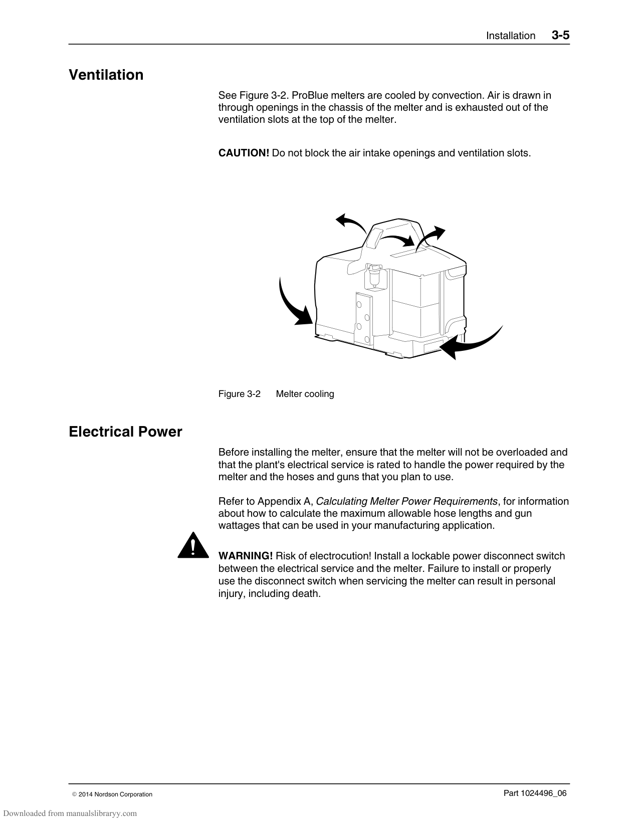
######## Ventilation
See Figure 3‐2. ProBlue melters are cooled by convection. Air is drawn in through openings in the chassis of the melter and is exhausted out of the ventilation slots at the top of the melter.
CAUTION! Do not block the air intake openings and ventilation slots.
Figure 3‐2 Melter cooling
######## Electrical Power
Before installing the melter, ensure that the melter will not be overloaded and that the plant's electrical service is rated to handle the power required by the melter and the hoses and guns that you plan to use.
Refer to Appendix A, Calculating Melter Power Requirements, for information about how to calculate the maximum allowable hose lengths and gun wattages that can be used in your manufacturing application.
WARNING! Risk of electrocution! Install a lockable power disconnect switch between the electrical service and the melter. Failure to install or properly use the disconnect switch when servicing the melter can result in personal injury, including death.
######## Compressed Air
To achieve maximum hot melt output, the melter must be connected to an air supply that is capable of providing a maximum of 6.2 Bar (90 psi) of dry, nonlubricated air. The actual pressure required for the melter to support your manufacturing process will depend on such factors as the type of hot melt and gun you are using and the required dimensions of the hot melt bead.
NOTE: The minimum operating air pressure is 0.7 bar (10 psi). Operating the melter with the air pressure set to less than 0.7 bar (10 psi) may cause the pump to function erratically.
Nordson recommends that an isolation valve be installed in the plant air supply line just before the melter.
######## Other Considerations
Consider the following additional factors when evaluating where to install the melter.
The maximum distance between the melter and each gun is dictated by the power requirement of each hose. Refer to Appendix A, Calculating Melter Power Requirements, for information about how to determine the maximum allowable length. The operator must be able to safely reach the control panel and accurately monitor the control panel indicators. The operator must be able to safely observe the level of hot melt inside the tank. The melter must be installed so that it can be safely removed from its sub‐base. The melter must be installed away from areas with strong drafts or where sudden temperature changes occur. The melter must be installed where it will be in conformance with the ventilation requirements specified in the Material Safety Data Sheet for the hot melt being used. The melter should not be exposed to excessive vibration. P4 and P7 melters provide an auxiliary hose port at the bottom of the manifold. If the auxiliary hose port will be used, the parent machine or other support structure must provide clearance under the melter to connect the hose to the auxiliary hose port.
################ This page intentionally left blank.
#### Unpacking the Melter
Before starting the installation, remove the melter from the pallet, locate the installation kit, and inspect the melter for damaged and missing parts. Report any problems to your Nordson representative.
######## Contents of the Installation Kit
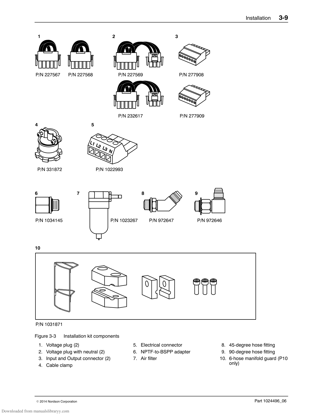
The installation kit provided with the melter contains the components shown in Figure 3‐3. The quantity and type of hose fittings provided in the kit depends upon the melter's model number and configuration.
NOTE: 400/480 volt transformers are shipped with a separate installation kit. Refer to Appendix E for information about the contents of the transformer installation kit.
The installation kit also contains a package of safety label overlays that are printed in a variety of languages. If required by local regulations, the appropriate language overlay should be applied over the English version of the same label. Refer to Section 1, Safety Labels and Tags, for the location of each safety label.
NOTE: P10 melters also include a manifold guard kit P/N 1031871.
######## Customer‐Supplied Materials
The following additional materials are also required to install the melter.
A power cable. If the cable clamp that is provided in the installation kit is not used, rigid or flexible electrical conduit will be required.
Four 8 mm (5/16 in.) machine bolts with locking hardware A plant air supply with an in‐line isolation valve
| | | | |---|---|---| | | | | | | | |
| | | | |---|---|---| | | | | | | | |
| | | | |---|---|---| | | | | | | | |
| | | | |---|---|---| | | | | | | | |
| | |---| | |
| | | |---|---| | | |
| | | | |---|---|---| | | | | | | | |
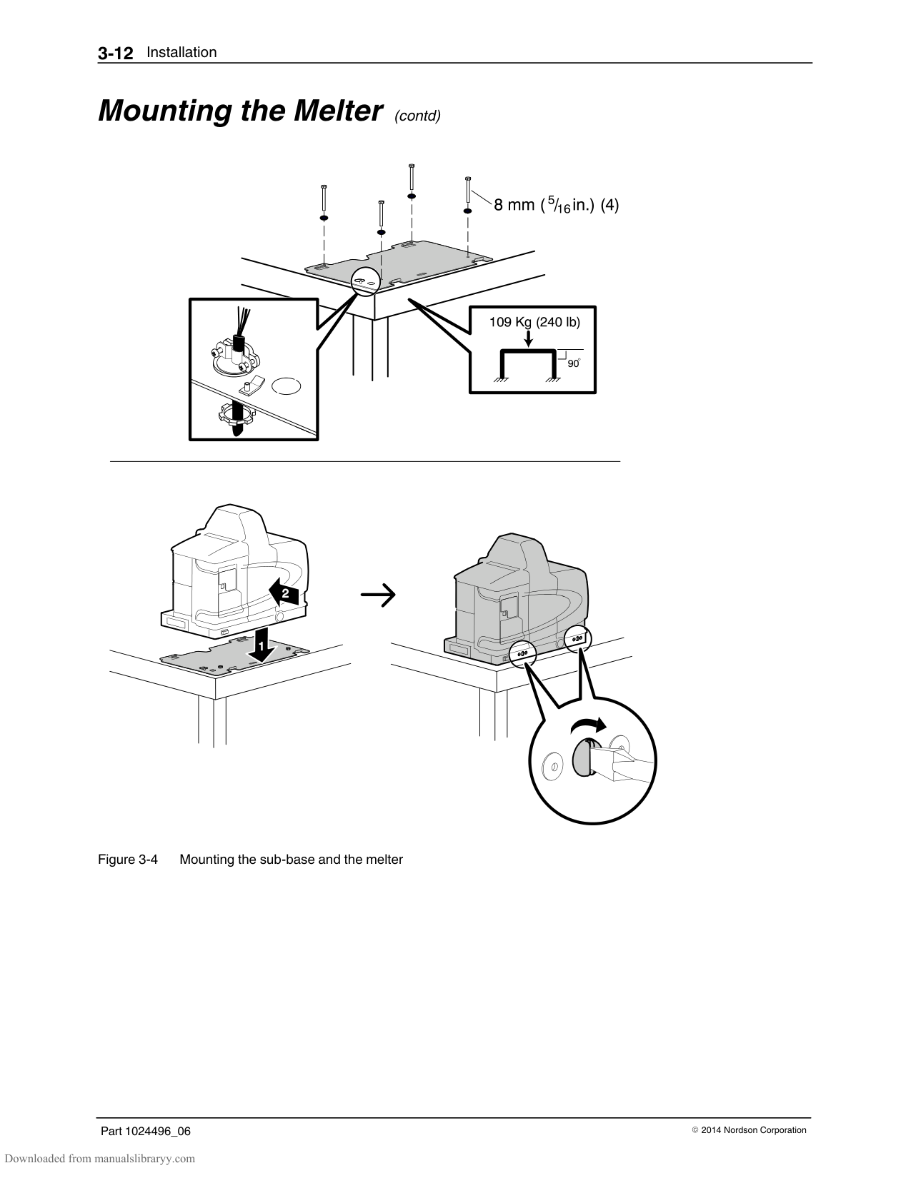
#### Mounting the Melter
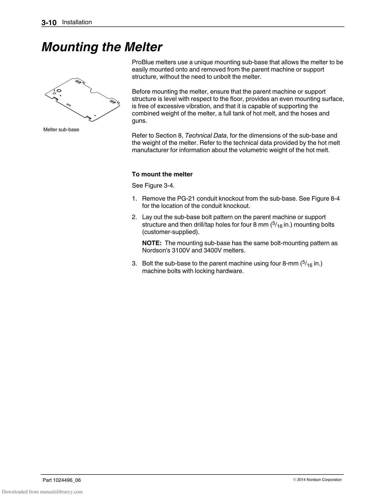
Melter sub‐base
ProBlue melters use a unique mounting sub‐base that allows the melter to be easily mounted onto and removed from the parent machine or support structure, without the need to unbolt the melter.
Before mounting the melter, ensure that the parent machine or support structure is level with respect to the floor, provides an even mounting surface, is free of excessive vibration, and that it is capable of supporting the combined weight of the melter, a full tank of hot melt, and the hoses and guns.
Refer to Section 8, Technical Data, for the dimensions of the sub‐base and the weight of the melter. Refer to the technical data provided by the hot melt manufacturer for information about the volumetric weight of the hot melt.
To mount the melter See Figure 3‐4.
structure and then drill/tap holes for four 8 mm (5/16 in.) mounting bolts (customer‐supplied).
NOTE: The mounting sub‐base has the same bolt‐mounting pattern as Nordson's 3100V and 3400V melters.
WARNING! Risk of electrical shock or short circuit. Use the cable clamp that is provided or use electrical conduit to protect the power cable from the sharp edge of the conduit knockout.
CAUTION! Before setting the melter down onto the sub‐base, ensure that both locking srews on the front chassis of the melter are turned fully counterclockwise until they stop.
#### Mounting the Melter (contd)
#### Configuring the Electrical Service
ProBlue melters are shipped from the factory without an attached power cable and without an electrical service type specified. To configure the melter to function in your facility, you must connect a power cable and a Nordson‐supplied voltage plug to the melter.
############### To connect a power cable to the melter
The maximum power draw for each ProBlue shipping configuration, operating at 230 volt, in both 1‐phase and 3‐phase are listed in Table 3‐2. The values presented in Table 3‐2 assume that each hose gun module is being used at its maximum capacity of 2000 watts.
NOTE: Contact your Nordson representative for assistance in calculating the melter's power draw for operating voltages other than 230 volts or for assistance in calculating the exact power draw for specific hoses and guns that are manufactured by Nordson Corporation.
Table 3‐2 Melter Power Requirement
|Melter|Number of Hose/Guns|1‐Phase Power Draw (Amps)|3‐Phase Power|3‐Phase Power| |---|---|---|---|---| |Melter|Number of Hose/Guns|1‐Phase Power Draw (Amps)|Without Neutral|With Neutral| |P4|2|17|15|9| |P4|4|26|23|17| |P7|2|18|16|10|
|P7|4|27|24|17| |P10|2|18|16|10| |P10|4|27|24|17| |P10|6|36|31|18|
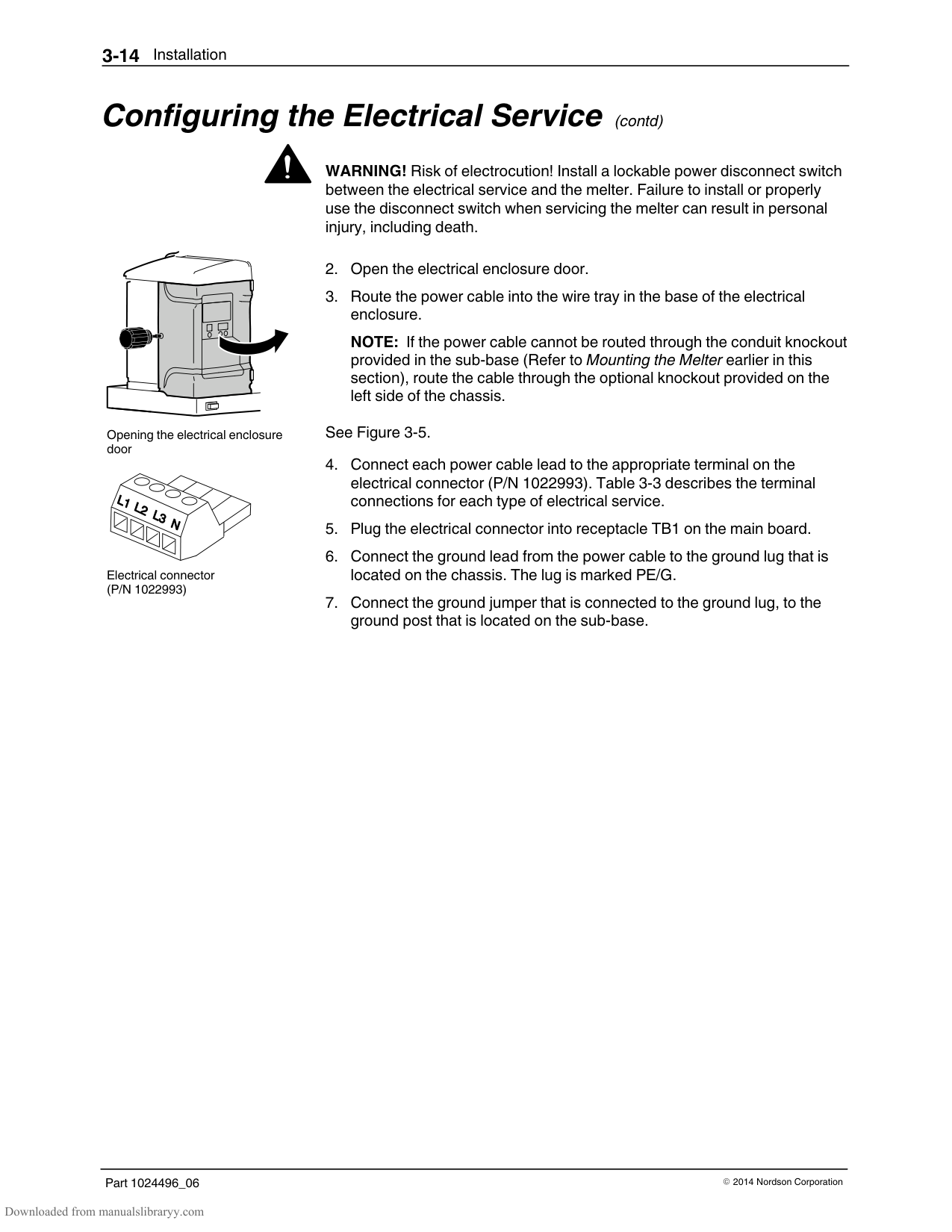
#### Configuring the Electrical Service (contd)
WARNING! Risk of electrocution! Install a lockable power disconnect switch between the electrical service and the melter. Failure to install or properly use the disconnect switch when servicing the melter can result in personal injury, including death.
Opening the electrical enclosure door
Electrical connector (P/N 1022993)
NOTE: If the power cable cannot be routed through the conduit knockout provided in the sub‐base (Refer to Mounting the Melter earlier in this section), route the cable through the optional knockout provided on the left side of the chassis.
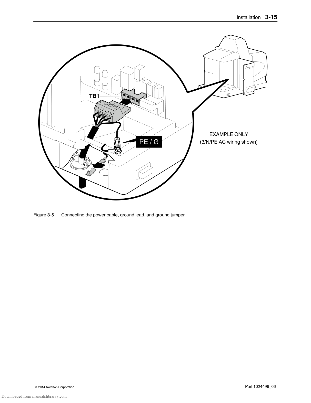
See Figure 3‐5.
############## TB1
########## PE / G
EXAMPLE ONLY (3/N/PE AC wiring shown)
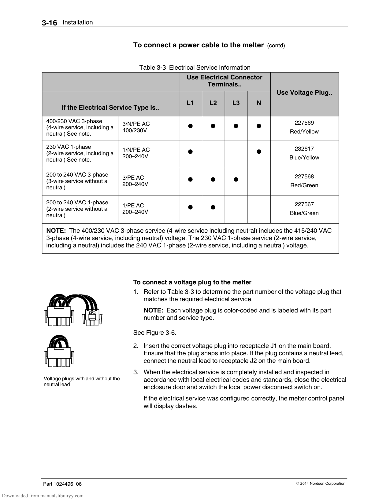
############## To connect a power cable to the melter (contd)
Table 3‐3 Electrical Service Information
| | |Use Electrical Connector Terminals..|Use Electrical Connector Terminals..|Use Electrical Connector Terminals..|Use Electrical Connector Terminals..|Use Voltage Plug..| |---|---|---|---|---|---|---| |If the Electrical Service Type is..|If the Electrical Service Type is..|L1|L2|L3|N|Use Voltage Plug..| |400/230 VAC 3‐phase (4‐wire service, including a neutral) See note.|3/N/PE AC 400/230V|||||227569 Red/Yellow| |230 VAC 1‐phase (2‐wire service, including a neutral) See note.|1/N/PE AC 200–240V|| | ||232617 Blue/Yellow| |200 to 240 VAC 3‐phase (3‐wire service without a neutral)|3/PE AC 200–240V|||| |227568 Red/Green| |200 to 240 VAC 1‐phase (2‐wire service without a neutral)|1/PE AC 200–240V||| | |227567 Blue/Green| |NOTE: The 400/230 VAC 3‐phase service (4‐wire service including neutral) includes the 415/240 VAC 3‐phase (4‐wire service, including neutral) voltage. The 230 VAC 1‐phase service (2‐wire service, including a neutral) includes the 240 VAC 1‐phase (2‐wire service, including a neutral) voltage.|NOTE: The 400/230 VAC 3‐phase service (4‐wire service including neutral) includes the 415/240 VAC 3‐phase (4‐wire service, including neutral) voltage. The 230 VAC 1‐phase service (2‐wire service, including a neutral) includes the 240 VAC 1‐phase (2‐wire service, including a neutral) voltage.|NOTE: The 400/230 VAC 3‐phase service (4‐wire service including neutral) includes the 415/240 VAC 3‐phase (4‐wire service, including neutral) voltage. The 230 VAC 1‐phase service (2‐wire service, including a neutral) includes the 240 VAC 1‐phase (2‐wire service, including a neutral) voltage.|NOTE: The 400/230 VAC 3‐phase service (4‐wire service including neutral) includes the 415/240 VAC 3‐phase (4‐wire service, including neutral) voltage. The 230 VAC 1‐phase service (2‐wire service, including a neutral) includes the 240 VAC 1‐phase (2‐wire service, including a neutral) voltage.|NOTE: The 400/230 VAC 3‐phase service (4‐wire service including neutral) includes the 415/240 VAC 3‐phase (4‐wire service, including neutral) voltage. The 230 VAC 1‐phase service (2‐wire service, including a neutral) includes the 240 VAC 1‐phase (2‐wire service, including a neutral) voltage.|NOTE: The 400/230 VAC 3‐phase service (4‐wire service including neutral) includes the 415/240 VAC 3‐phase (4‐wire service, including neutral) voltage. The 230 VAC 1‐phase service (2‐wire service, including a neutral) includes the 240 VAC 1‐phase (2‐wire service, including a neutral) voltage.|NOTE: The 400/230 VAC 3‐phase service (4‐wire service including neutral) includes the 415/240 VAC 3‐phase (4‐wire service, including neutral) voltage. The 230 VAC 1‐phase service (2‐wire service, including a neutral) includes the 240 VAC 1‐phase (2‐wire service, including a neutral) voltage.|

| | |---| | |
| | | |---|---| | | |
Voltage plugs with and without the neutral lead
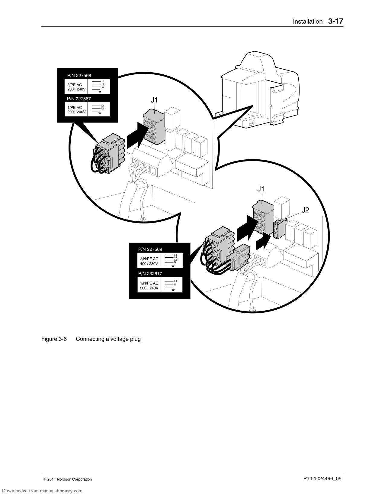
############### To connect a voltage plug to the melter
NOTE: Each voltage plug is color‐coded and is labeled with its part number and service type.
See Figure 3‐6.
If the electrical service was configured correctly, the melter control panel will display dashes.
| | | |---|---|
| | | |---|---|
| | | |---|---|
################## Figure 3‐6 Connecting a voltage plug
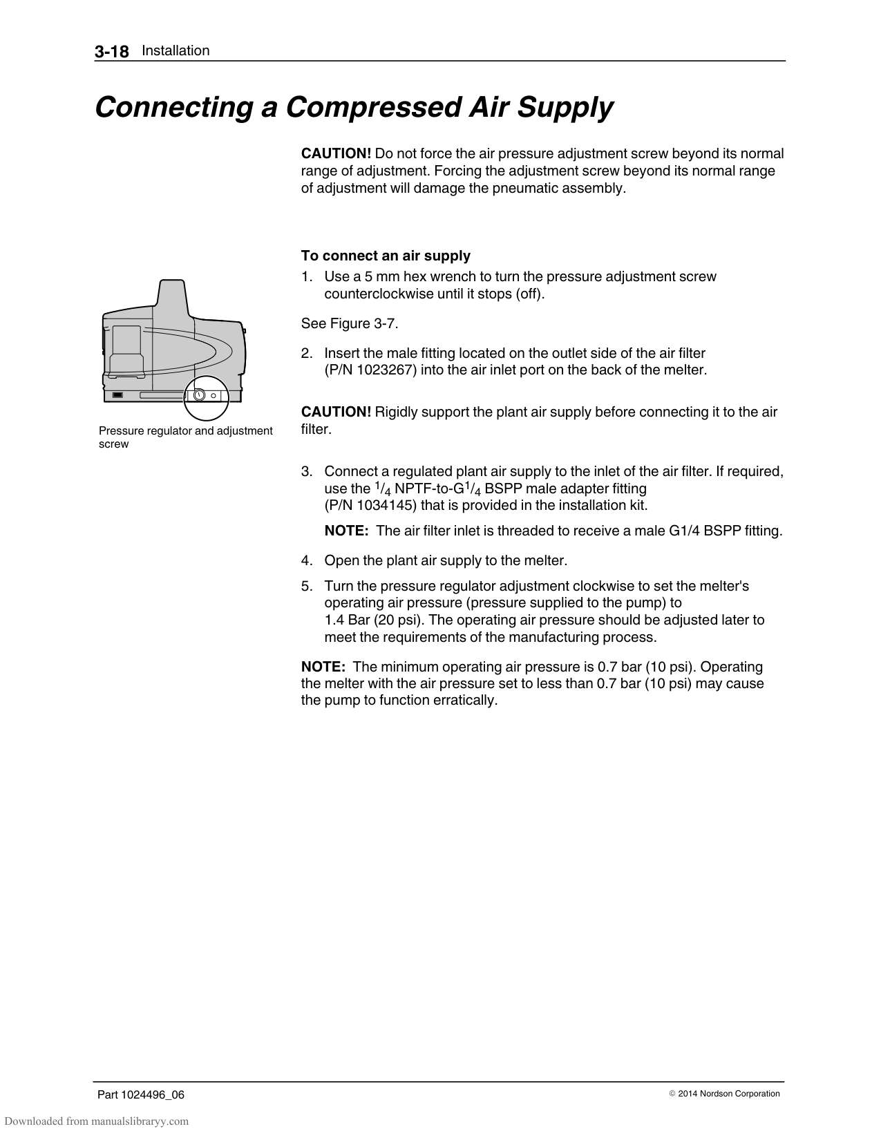
#### Connecting a Compressed Air Supply
CAUTION! Do not force the air pressure adjustment screw beyond its normal range of adjustment. Forcing the adjustment screw beyond its normal range of adjustment will damage the pneumatic assembly.
Pressure regulator and adjustment screw
############### To connect an air supply
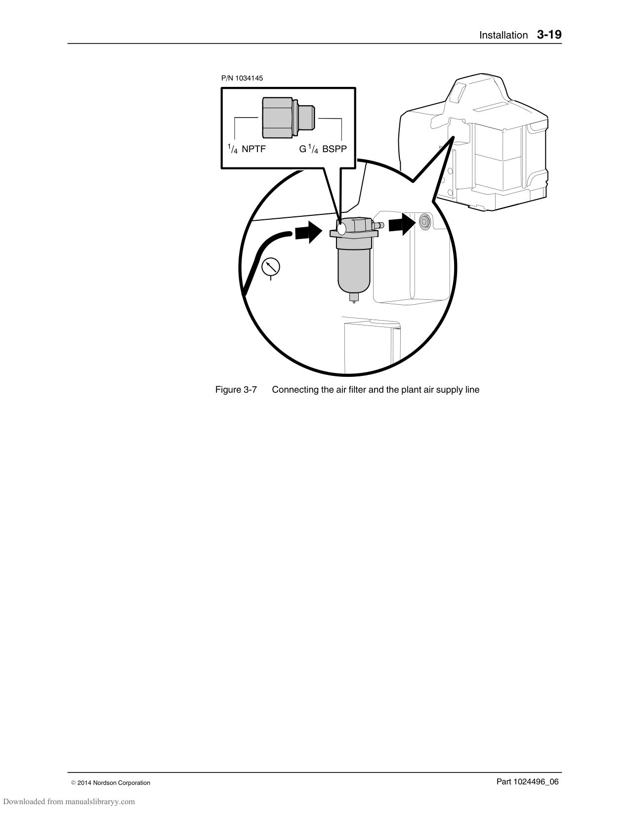
See Figure 3‐7.
CAUTION! Rigidly support the plant air supply before connecting it to the air filter.
use the 1/4 NPTF‐to‐G1/4 BSPP male adapter fitting (P/N 1034145) that is provided in the installation kit.
NOTE: The air filter inlet is threaded to receive a male G1/4 BSPP fitting.
NOTE: The minimum operating air pressure is 0.7 bar (10 psi). Operating the melter with the air pressure set to less than 0.7 bar (10 psi) may cause the pump to function erratically.
P/N 1034145
1/4 NPTF 1/4 BSPPG
Figure 3‐7 Connecting the air filter and the plant air supply line
#### Connecting Hoses and Guns
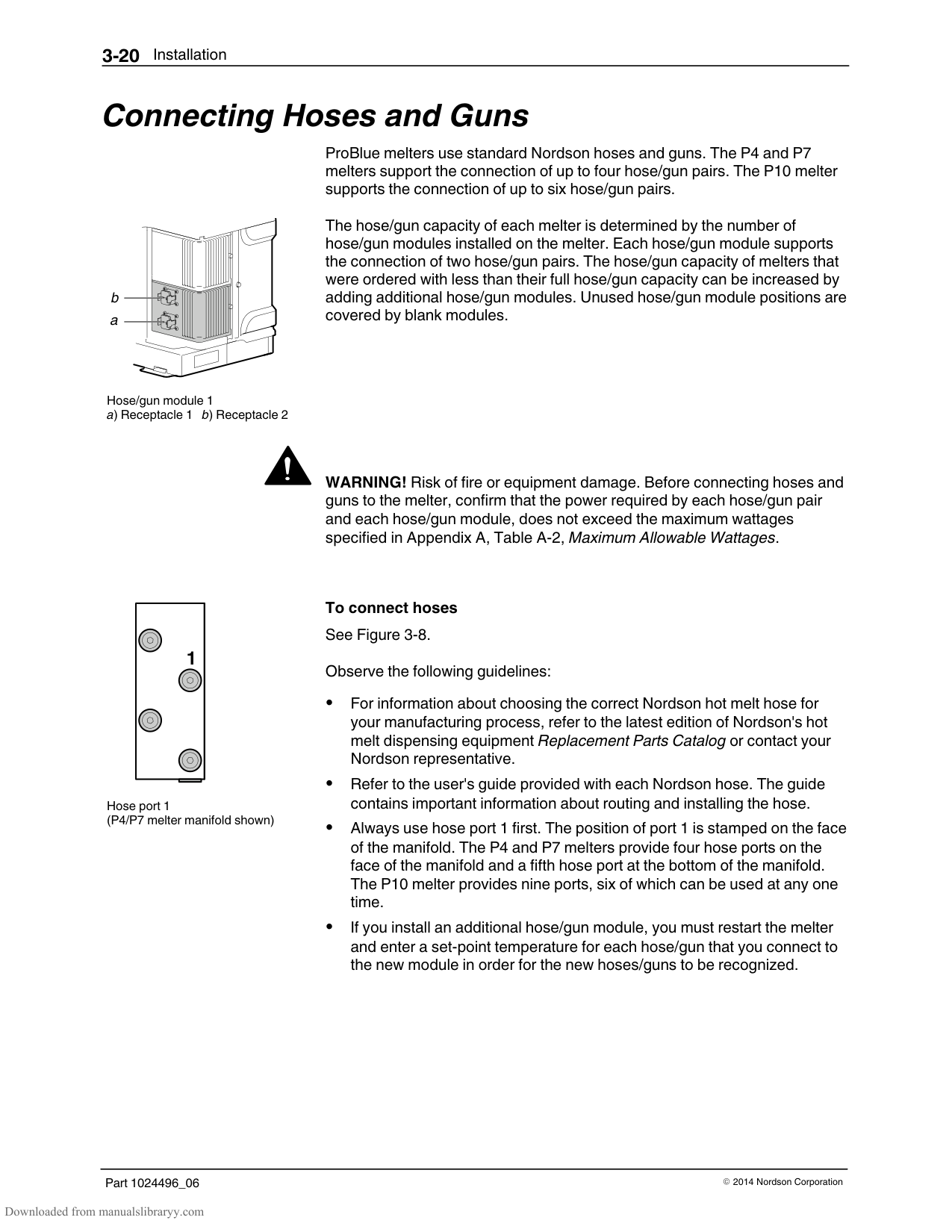
ProBlue melters use standard Nordson hoses and guns. The P4 and P7 melters support the connection of up to four hose/gun pairs. The P10 melter supports the connection of up to six hose/gun pairs.
Hose/gun module 1 a) Receptacle 1 b) Receptacle 2
The hose/gun capacity of each melter is determined by the number of hose/gun modules installed on the melter. Each hose/gun module supports the connection of two hose/gun pairs. The hose/gun capacity of melters that were ordered with less than their full hose/gun capacity can be increased by adding additional hose/gun modules. Unused hose/gun module positions are covered by blank modules.
WARNING! Risk of fire or equipment damage. Before connecting hoses and guns to the melter, confirm that the power required by each hose/gun pair and each hose/gun module, does not exceed the maximum wattages specified in Appendix A, Table A‐2, Maximum Allowable Wattages.
|1| |---|
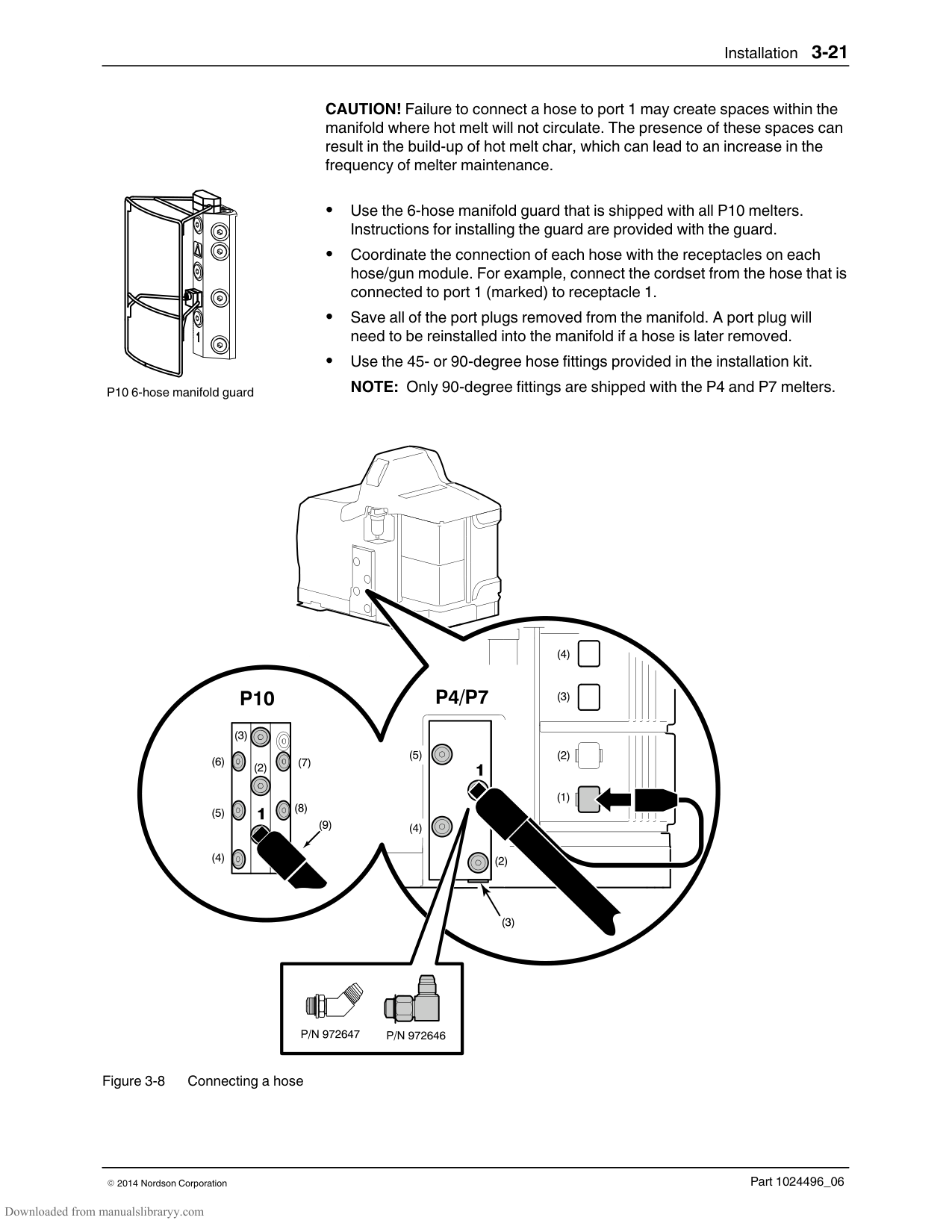
Hose port 1 (P4/P7 melter manifold shown)
To connect hoses See Figure 3‐8. Observe the following guidelines:
For information about choosing the correct Nordson hot melt hose for your manufacturing process, refer to the latest edition of Nordson's hot melt dispensing equipment Replacement Parts Catalog or contact your Nordson representative.
Refer to the user's guide provided with each Nordson hose. The guide contains important information about routing and installing the hose.
Always use hose port 1 first. The position of port 1 is stamped on the face of the manifold. The P4 and P7 melters provide four hose ports on the face of the manifold and a fifth hose port at the bottom of the manifold. The P10 melter provides nine ports, six of which can be used at any one time.
If you install an additional hose/gun module, you must restart the melter and enter a set‐point temperature for each hose/gun that you connect to the new module in order for the new hoses/guns to be recognized.
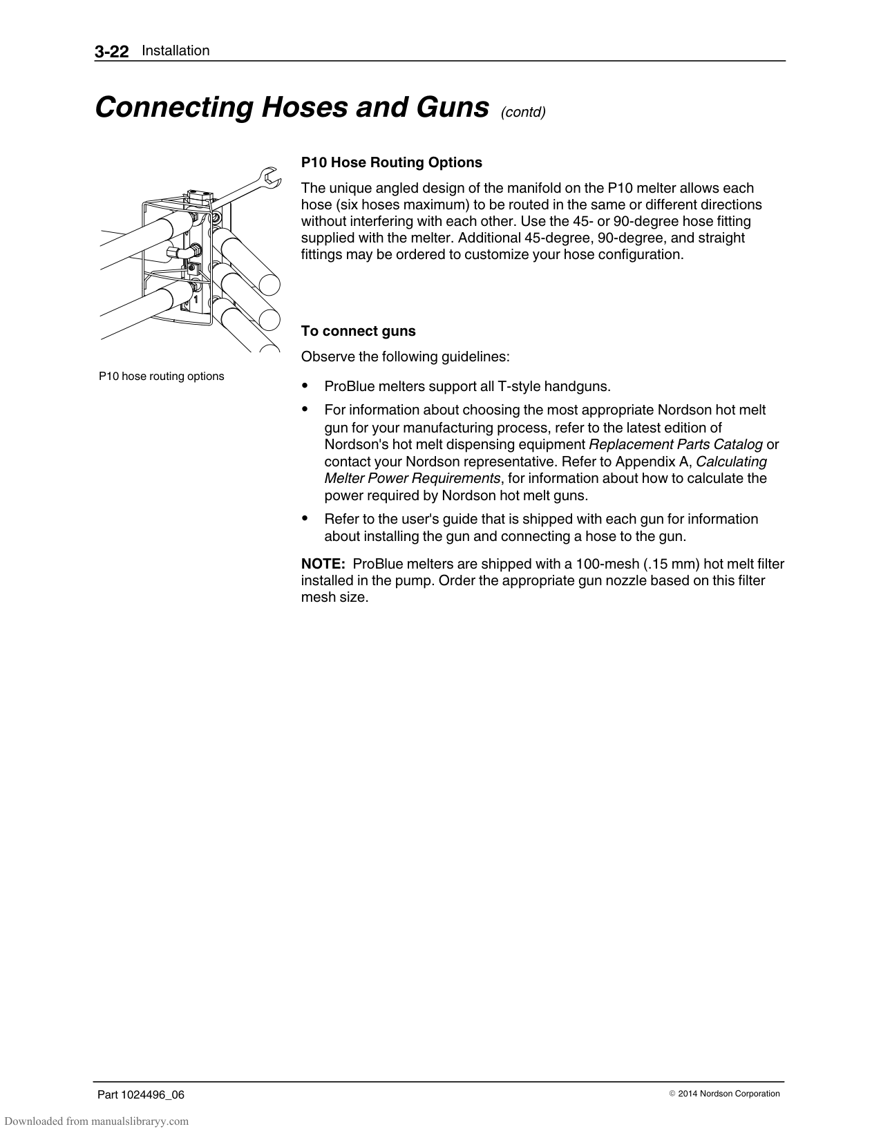
P10 6‐hose manifold guard
CAUTION! Failure to connect a hose to port 1 may create spaces within the manifold where hot melt will not circulate. The presence of these spaces can result in the build‐up of hot melt char, which can lead to an increase in the frequency of melter maintenance.
Use the 6‐hose manifold guard that is shipped with all P10 melters. Instructions for installing the guard are provided with the guard.
Coordinate the connection of each hose with the receptacles on each hose/gun module. For example, connect the cordset from the hose that is connected to port 1 (marked) to receptacle 1.
Save all of the port plugs removed from the manifold. A port plug will need to be reinstalled into the manifold if a hose is later removed.
Use the 45‐ or 90‐degree hose fittings provided in the installation kit. NOTE: Only 90‐degree fittings are shipped with the P4 and P7 melters.
| | | | |---|---|---|
| | | |---|---| | | |
| | | | |---|---|---| | | | |
| | | | |---|---|---| | | | |
| | | |---|---| | | |
| | | |---|---| | | | | | |
| | | |---|---| | | | | | |
| | | | | |---|---|---|---| | | | | | | | | | |
Figure 3‐8 Connecting a hose
| | |---| | |
#### Connecting Hoses and Guns (contd)
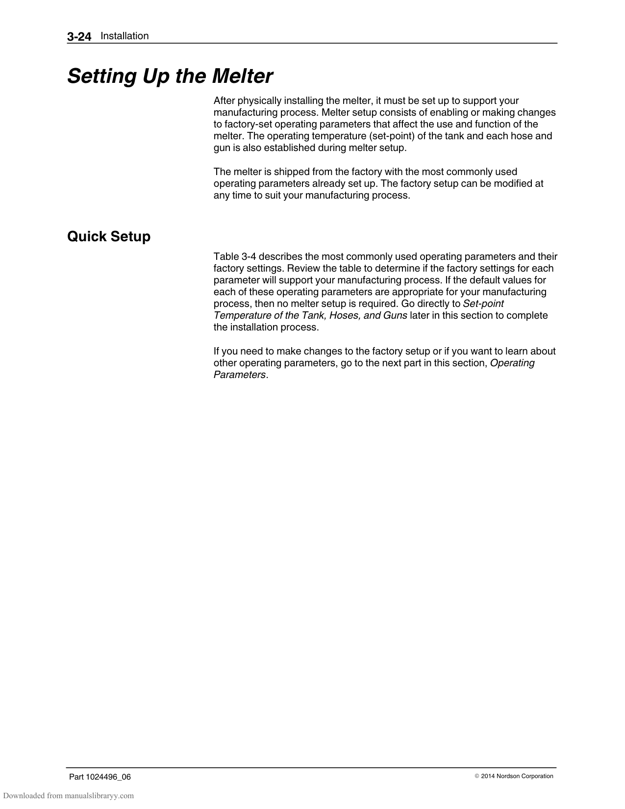
P10 hose routing options
############### P10 Hose Routing Options
The unique angled design of the manifold on the P10 melter allows each hose (six hoses maximum) to be routed in the same or different directions without interfering with each other. Use the 45‐ or 90‐degree hose fitting supplied with the melter. Additional 45‐degree, 90‐degree, and straight fittings may be ordered to customize your hose configuration.
To connect guns Observe the following guidelines:
ProBlue melters support all T‐style handguns. For information about choosing the most appropriate Nordson hot melt gun for your manufacturing process, refer to the latest edition of Nordson's hot melt dispensing equipment Replacement Parts Catalog or contact your Nordson representative. Refer to Appendix A, Calculating Melter Power Requirements, for information about how to calculate the power required by Nordson hot melt guns. Refer to the user's guide that is shipped with each gun for information about installing the gun and connecting a hose to the gun.
NOTE: ProBlue melters are shipped with a 100‐mesh (.15 mm) hot melt filter installed in the pump. Order the appropriate gun nozzle based on this filter mesh size.
################ This page intentionally left blank.
#### Setting Up the Melter
After physically installing the melter, it must be set up to support your manufacturing process. Melter setup consists of enabling or making changes to factory‐set operating parameters that affect the use and function of the melter. The operating temperature (set‐point) of the tank and each hose and gun is also established during melter setup.
The melter is shipped from the factory with the most commonly used operating parameters already set up. The factory setup can be modified at any time to suit your manufacturing process.
######## Quick Setup
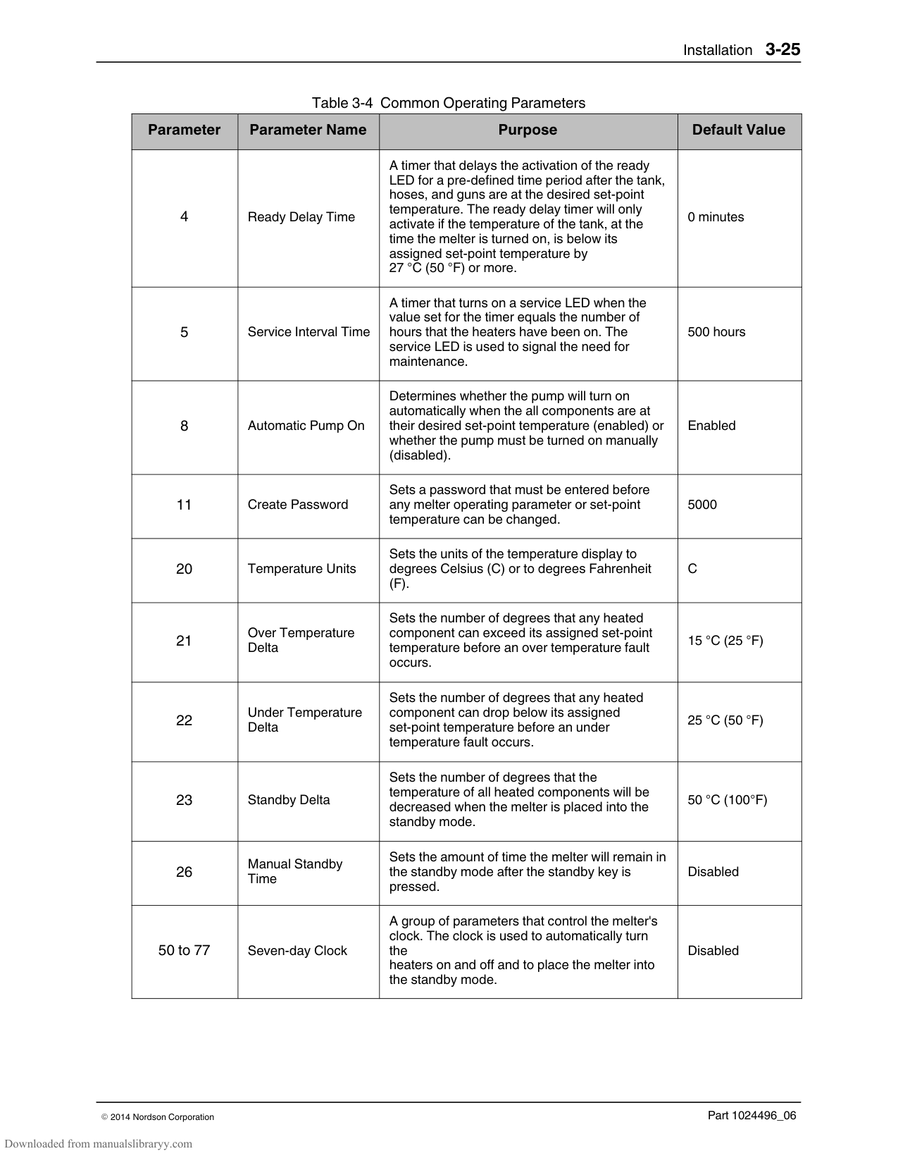
Table 3‐4 describes the most commonly used operating parameters and their factory settings. Review the table to determine if the factory settings for each parameter will support your manufacturing process. If the default values for each of these operating parameters are appropriate for your manufacturing process, then no melter setup is required. Go directly to Set‐point Temperature of the Tank, Hoses, and Guns later in this section to complete the installation process. If you need to make changes to the factory setup or if you want to learn about other operating parameters, go to the next part in this section, Operating Parameters.
################ Table 3‐4 Common Operating Parameters
|Parameter|Parameter Name|Purpose|Default Value| |---|---|---|---| |4|Ready Delay Time|A timer that delays the activation of the ready LED for a pre‐defined time period after the tank, hoses, and guns are at the desired set‐point temperature. The ready delay timer will only activate if the temperature of the tank, at the time the melter is turned on, is below its assigned set‐point temperature by 27 C (50 F) or more.|0 minutes| |5|Service Interval Time|A timer that turns on a service LED when the value set for the timer equals the number of hours that the heaters have been on. The service LED is used to signal the need for maintenance.|500 hours| |8|Automatic Pump On|Determines whether the pump will turn on automatically when the all components are at their desired set‐point temperature (enabled) or whether the pump must be turned on manually (disabled).|Enabled| |11|Create Password|Sets a password that must be entered before any melter operating parameter or set‐point temperature can be changed.|5000| |20|Temperature Units|Sets the units of the temperature display to degrees Celsius (C) or to degrees Fahrenheit (F).|C|
|21|Over Temperature Delta|Sets the number of degrees that any heated component can exceed its assigned set‐point temperature before an over temperature fault occurs.|15 C (25 F)| |22|Under Temperature Delta|Sets the number of degrees that any heated component can drop below its assigned set‐point temperature before an under temperature fault occurs.|25 C (50 F)| |23|Standby Delta|Sets the number of degrees that the temperature of all heated components will be decreased when the melter is placed into the standby mode.|50 C (100F)| |26|Manual Standby Time|Sets the amount of time the melter will remain in the standby mode after the standby key is pressed.|Disabled| |50 to 77|Seven‐day Clock|A group of parameters that control the melter's clock. The clock is used to automatically turn the heaters on and off and to place the melter into the standby mode.|Disabled|
######## Operating Parameters
The melter uses operating parameters to store noneditable and editable values. Noneditable values are those that provide information about the historical performance of the melter. Editable values are either a numeric set‐point or a control option setting. Control options settings affect the display of information or the function of the melter.
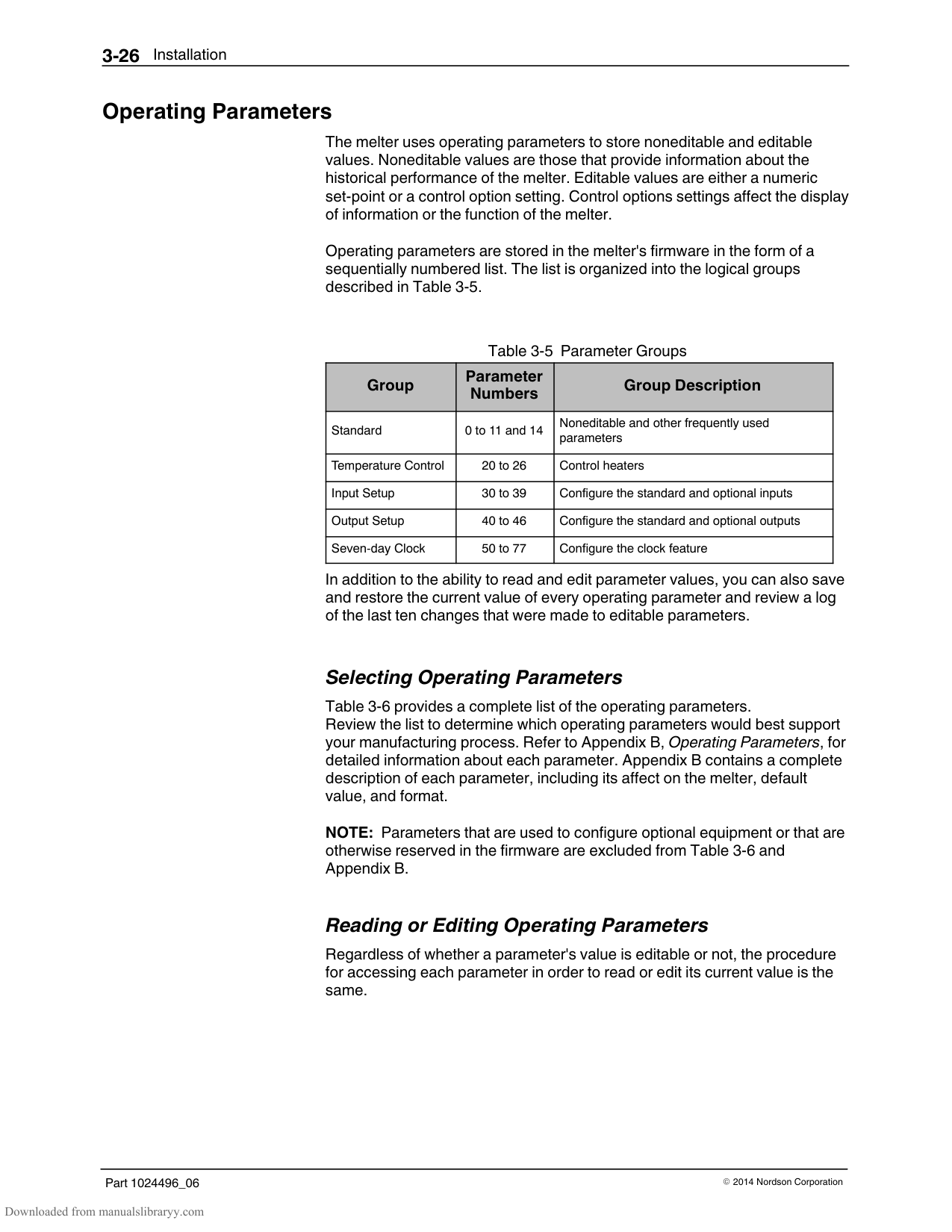
Operating parameters are stored in the melter's firmware in the form of a sequentially numbered list. The list is organized into the logical groups described in Table 3‐5.
Table 3‐5 Parameter Groups
|Group|Parameter Numbers|Group Description| |---|---|---| |Standard|0 to 11 and 14|Noneditable and other frequently used parameters| |Temperature Control|20 to 26|Control heaters| |Input Setup|30 to 39|Configure the standard and optional inputs| |Output Setup|40 to 46|Configure the standard and optional outputs| |Seven-day Clock|50 to 77|Configure the clock feature|
In addition to the ability to read and edit parameter values, you can also save and restore the current value of every operating parameter and review a log of the last ten changes that were made to editable parameters.
########### Selecting Operating Parameters
Table 3‐6 provides a complete list of the operating parameters. Review the list to determine which operating parameters would best support your manufacturing process. Refer to Appendix B, Operating Parameters, for detailed information about each parameter. Appendix B contains a complete description of each parameter, including its affect on the melter, default value, and format.
NOTE: Parameters that are used to configure optional equipment or that are otherwise reserved in the firmware are excluded from Table 3‐6 and Appendix B.
########### Reading or Editing Operating Parameters
Regardless of whether a parameter's value is editable or not, the procedure for accessing each parameter in order to read or edit its current value is the same.
Melter control switch (On/Off)
Setup key
Clear/Reset key
| | | |---|---| | | | | | |
Enter key
############### To read or edit a parameter
NOTE: If you incorrectly enter the parameter number, press the Clear/Reset key to return to parameter 1 and then re‐enter the correct parameter number. When you have finished entering the one‐ or two‐digit parameter number, the right display indicates the parameter's current value.
NOTE: If the keypad has no affect on the right display, the melter is password protected. You must enter a valid password before you can edit parameters. Refer to Section 4, Entering the Melter Password.
If the numeric set‐point or control option is accepted, the left and right displays index to the next sequential parameter number and value.
If the numeric set‐point or control option is not accepted, the right display will indicate dashes (‐‐‐‐) for three seconds and then it will change back to the original value.
################ Table 3‐6 Operating Parameters
|Parameter|Name|Range of Values|Default Value| |---|---|---|---| |Standard|Standard|Standard|Standard| |0|Enter Password|0 to 9999|4000| |1|Total Hours with Heaters On (noneditable)|0-999,999|0| |2|Fault Log (noneditable)|—|_‐F0 (empty)| |3|Change History Log (noneditable)|—|P‐_ (empty)| |4|Ready Delay Time|0 to 60 minutes|0 minutes| |5|Service Interval Time|0 to 8736 hours|500 hours| |6|Service LED Heater Hours|0 to 9999 hours|0| |8|Automatic Pump On|0 (disabled) or 1 (enabled)|1 (enabled)| |9|Automatic Pump On Temperature|0 (disabled) or (1 to 230 C)|0 (disabled)| |10|Enable or Disable Password|0 (disabled) or 1 (enabled)|0 (disabled)| |11|Create Password|0 to 9999|5000| |14|External Communications Lock‐out|0 or 1|0 (disabled)| |Temperature Control|Temperature Control|Temperature Control|Temperature Control| |20|Temperature Units (degrees C or F)|C (degrees Celsius) or F (degrees Fahrenheit)|C (degrees Celsius)| |21|Over Temperature Delta|5 C (10 F) to 60 C (110 F)|15 C (25 F)| |22|Under Temperature Delta|5 C (10 F) to 60 C (110 F)|25 C (50 F)| |23|Standby Delta|25 C (50 F) to 190 C (350 F)|50 C (100 F)| |24|Automatic Standby Timeout|0 to 1440 minutes|0 (disabled)| |25|Automatic Heaters Off Time|0 to 1440 minutes|0 (disabled)| |26|Manual Standby Time|0 to 180 minutes|0 (disabled)| |Input Setup|Input Setup|Input Setup|Input Setup| |30|Standard Input 1|0-10, 15-16|10 (Automatic Standby)|
|31|Standard Input 2|0-9, 15-16|1 (Standby on/off)| |32|Standard Input 3|0-9, 15-16|2 (Heaters on/off)| |33|Standard Input 4|0-9, 15-16|4 (Hose/gun 1 enable/disable)| |34|Optional Input 5|0-9, 15-16|0 (disabled)| |35|Optional Input 6|0-9, 15-16|0 (disabled)| |36|Optional Input 7|0-9, 15-16|0 (disabled)| |37|Optional Input 8|0-9, 15-16|0 (disabled)| |38|Optional Input 9|0-9, 15-16|0 (disabled)| |39|Optional Input 10|0-9, 15-16|0 (disabled)| |Continued...|Continued...|Continued...|Continued...|
|Parameter|Name|Range of Values|Default Value| |---|---|---|---| |Output Setup|Output Setup|Output Setup|Output Setup| |40|Standard Output 1|0–6|1 (Ready)| |41|Standard Output 2|0–6|3 (Fault)| |42|Standard Output 3|0–6|4| |43|Optional Output 4|0–6|0 (disabled)| |44|Optional Output 5|0–6|0 (disabled)| |45|Optional Output 6|0–6|0 (disabled)| |46|Optional Output 7|0–6|0 (disabled)| |Seven‐day Clock|Seven‐day Clock|Seven‐day Clock|Seven‐day Clock| |50|Current Day|1 to 7 (1 = Monday)|—| |51|Current hour|0000 to 2359|—|
|55|Schedule 1 Heaters On|0000 to 2359|06:00| |56|Schedule 1 Heaters Off|0000 to 2359|17:00| |57|Schedule 1 Enter Standby|0000 to 2359|—:—| |58|Schedule 1 Exit Standby|0000 to 2359|—:—| |60|Schedule 2 Heaters On|0000 to 2359|—:—| |61|Schedule 2 Heaters Off|0000 to 2359|—:—| |62|Schedule 2 Enter Standby|0000 to 2359|—:—| |63|Schedule 2 Exit Standby|0000 to 2359|—:—| |65|Schedule 3 Heaters On|0000 to 2359|—:—| |66|Schedule 3 Heaters Off|0000 to 2359|—:—| |67|Schedule 3 Enter Standby|0000 to 2359|—:—| |68|Schedule 3 Exit Standby|0000 to 2359|—:—| |71|Schedule for Monday|0-7|0| |72|Schedule for Tuesday|0-7|0| |73|Schedule for Wednesday|0-7|0| |74|Schedule for Thursday|0-7|0| |75|Schedule for Friday|0-7|0| |76|Schedule for Saturday|0-7|0| |77|Schedule for Sunday|0-7|0|
You can exit the setup mode at any time by pressing the Setup key.
Parameter numbers that are not applicable are skipped when you scroll through the operating parameter list in the left display. When the right display is flashing, you can quickly set the value of the current parameter to it's lowest possible value by simultaneously pressing both of the right‐display scroll keys. While in the setup mode, if no key is pressed for two minutes, the melter will return to the automatic scan mode. You can also use the right‐display scroll keys to enter or change a parameter's value or control option. After entering the parameter's number in the left display, press either of the right‐display scroll keys to change the value or control option. If password protection is enabled, the melter will return to the password protected mode whenever you exit the setup mode.
Appendix B, Parameter 10
################ This page intentionally left blank.
######## Set‐point Temperature of the Tank, Hoses, and Guns
The melter is shipped from the factory with the tank set‐point temperature at 175 C (350 F) and the hose and gun set‐point temperatures at 0 degrees (turned off).
Before the melter can be used, a set‐point temperature must be assigned to the tank, hoses, and guns. Assign set‐point temperatures using any of the following methods:
Global—The tank and all hoses and guns are set to the same set‐point temperature.
Global‐by‐component group—All of the hoses or all of the guns are set to the same set‐point temperature.
Individual Component—The set‐point temperature of the tank and each hose and gun is set individually.
Since most manufacturing processes will require the tank, hoses, and guns to be set to the same temperature, only the global method of assigning set‐point temperatures is described in this section. For information about the other two methods of assigning set‐point temperatures, refer to Section 4, Adjusting Component Temperatures.
As with operating parameters, you can also save and restore set‐point temperatures and review past changes that were made to set‐point temperatures.
| | | | | | | |---|---|---|---|---|---| | | | | | | |
Tank key
Left display and scroll key
| | | |---|---| | | | | | |
Enter key
Ready LED
############### To assign a global set‐point temperature
The right display indicates all dashes (‐‐‐‐) and the LEDs on the tank, hose, and gun keys turn green.
Refer to the technical data sheet provided by the manufacturer of the hot melt to determine the optimal set‐point temperature.

Each component begins to heat or cool to the new global set‐point temperature and the melter returns to the automatic scan mode.
When all of the components reach the global set‐point temperature, the ready LED turns on (green).
######## Save and Restore Melter Settings
The current value of all editable operating parameters and the set‐point temperature of each component can be saved and, if necessary, restored at a later time. When saved settings are restored, they overwrite the settings that are presently in use.
+
Saving current settings
This save‐restore feature is useful in instances where the settings that are in use are deliberately or accidentally changed and you need to return the melter to its pre‐change setup.
To save current settings With the melter in the automatic scan mode, simultaneously press the
To restore saved settings
CAUTION! All melter settings will be deleted! Before restoring saved settings, ensure that use of the restored settings will not disrupt the current process or create an unsafe operating condition.
With the melter in the automatic scan mode, simultaneously press the number 2 key and the Setup key.
+
Restoring saved settings
If you use the restore feature before the save feature is used for the very first time, the factory default set‐point temperatures will be restored. This will cause the hoses and guns to stop heating.
Refer to Appendix C, Melter Communications
You can transfer melter settings from one melter to another using the Nordson Configuration Manager software utility.
################ This page intentionally left blank.
######## Review Parameter and Set‐point Temperature Changes
Setup key
Left display and scroll key
| | |---| | |
| | | | |---|---|---| | | | | | | | |
| | | | | |---|---|---|---| | | | | | | | | | |
Component key LEDs
Scrolling through the log
The melter stores in a change history log, a record of the last ten changes that were made to either operating parameters or set‐point temperatures. Since the log only stores ten changes, old log entries are overwritten beginning with the first log entry, by the eleventh and following log entries.
############### To review the change history log
If the last change was to an editable parameter, all of the component key LEDs remain off.
or
If the last change was to a set‐point temperature, the LED on the associated component key(s) turns on.
and The right display indicates the four‐digit log entry associated with the last change that was made.
Table 3‐7 provides the meaning, from left to right, of each digit in the log entry. Following the table are two example log entries.
Table 3‐7 Change History Log
|First Digit|Second Digit|Third and Fourth Digits|Third and Fourth Digits|Third and Fourth Digits|Third and Fourth Digits| |---|---|---|---|---|---| |P
(Parameter)|-|Indicates the number of the parameter that was changed|Indicates the number of the parameter that was changed|Indicates the number of the parameter that was changed|Indicates the number of the parameter that was changed|
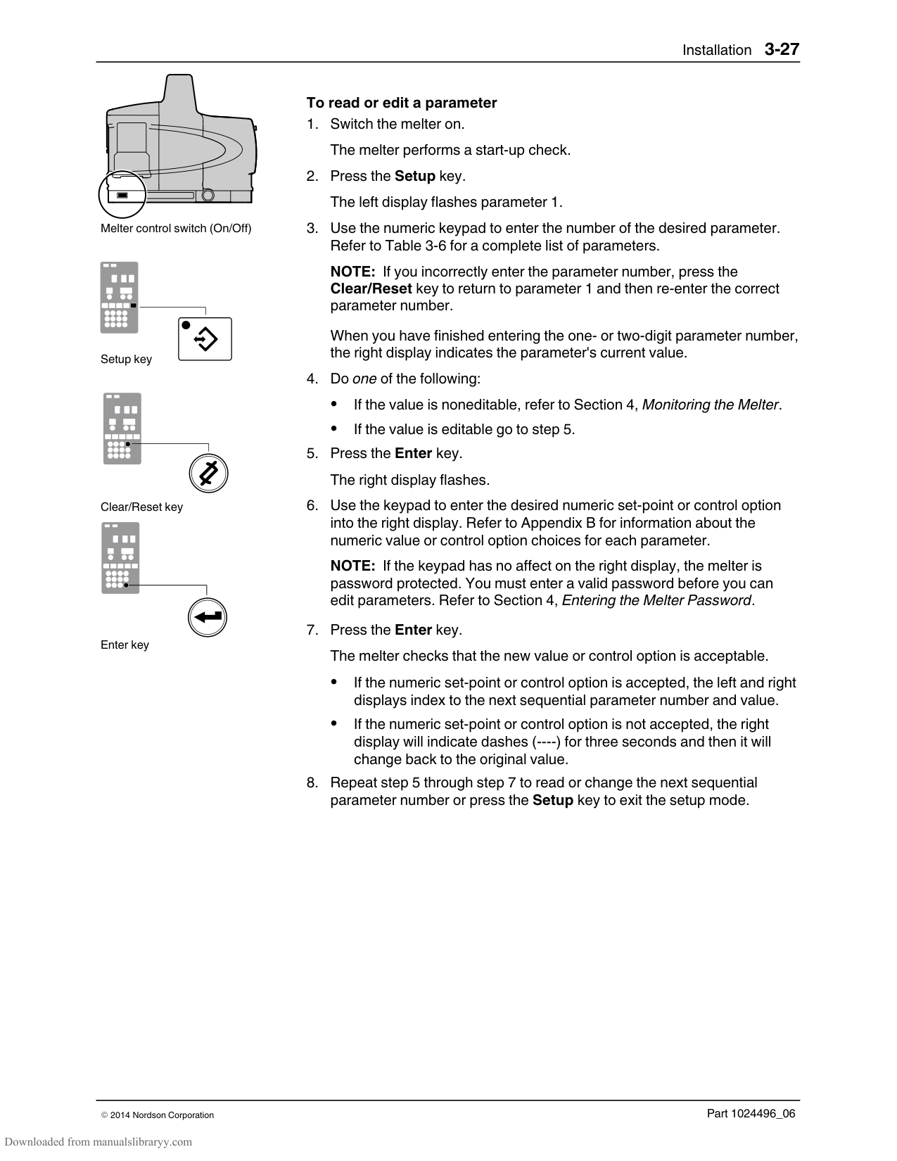
|S
(Set‐point)|-|Are used in conjunction with the LEDs on the component keys to indicate the location and method of a set‐point temperature change.|Are used in conjunction with the LEDs on the component keys to indicate the location and method of a set‐point temperature change.|Are used in conjunction with the LEDs on the component keys to indicate the location and method of a set‐point temperature change.|Are used in conjunction with the LEDs on the component keys to indicate the location and method of a set‐point temperature change.| |S
(Set‐point)|-|When this LED is on..|And the Fourth Digit Indicates..|The change was to..|And the Method of Change was..| |S
(Set‐point)|-|Tank Key|1|The tank|Individual| |S
(Set‐point)|-|Hose Key|1– 6|A single hose|Individual| |S
(Set‐point)|-|Gun Key|1– 6|A single gun|Individual| |S
(Set‐point)|-|All Keys|0|All components|Global| |S
(Set‐point)|-|Hose Key|0|All hoses|Global‐by‐ component| |S
(Set‐point)|-|Gun Key|0|All guns|Global‐by‐ component|
############### Change History Log Examples
Parameter 4 (ready delay) was changed.
If the LED on the gun key is on, then this display would indicate that the global‐by‐component method was used to change the temperature of the guns.
######## Review Parameter and Set‐point Temperature Changes (contd)
Unused log entries in the change history log are indicated by “P‐_” in the right display.
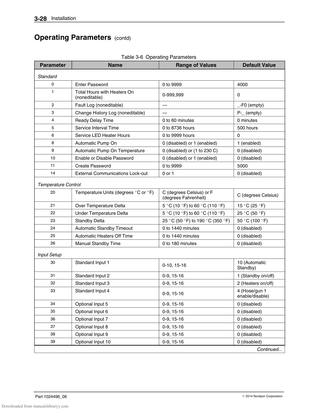
To view how many heater hours have elapsed since a specific change (displayed) was made, simultaneously press both of the right‐display scroll keys.
################ This page intentionally left blank.
#### Installing Melter Inputs
ProBlue melters are equipped with four standard inputs. Each input is customer‐wired to the melter and then set up to provide one of the following control options:
Place the melter into the standby mode Turn the heaters on and off Enable or disable a specific hose or gun Turn the pump on and off
Inputs are activated using a constant 10 to 30 VDC signal voltage, which is supplied by the customer's control equipment. The inputs are not polarity sensitive.
WARNING! The operator can override the melter inputs by using the control panel function keys. Ensure that the control logic for any external device that sends an input signal to the melter is programmed to prevent the creation of an unsafe condition in the event that the operator overrides an external input to the melter.
Opening the electrical enclosure door
############### To wire inputs to the melter
NOTE: Use a signal cable suitable for NEC class1 remote control and signaling circuits. To reduce the possibility of electrical shorting, route the cable so that it does not touch nearby circuit boards.
Connector P/N 277909
See Figure 3‐9.
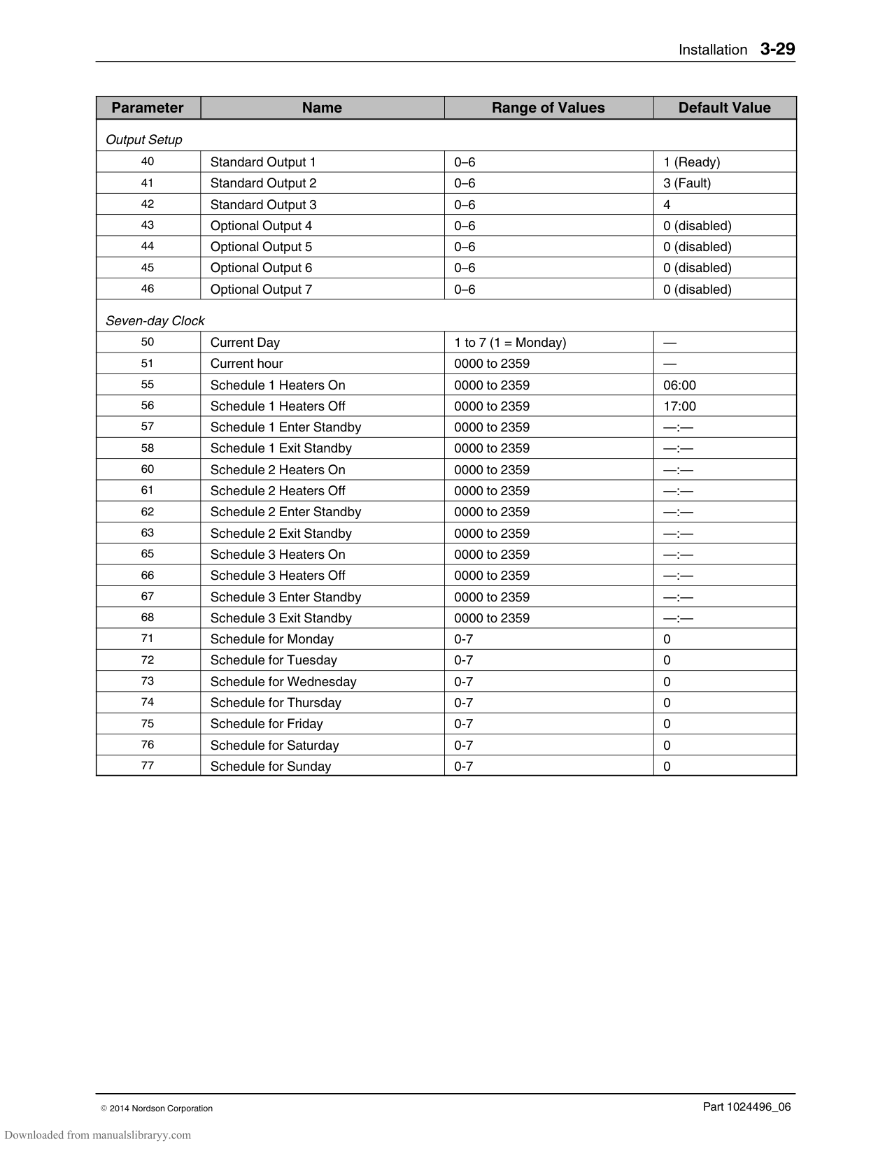
14) on connector P/N 277909. If input number four is used, terminal 7 on connector P/N 277908 must also be used. Both connectors are provided in the installation kit. Table 3‐8 lists the terminal numbers that correspond to each input.
NOTE: Connector P/N 277909 is physically keyed to prevent it from being used in place of connector P/N 277908, which has terminals numbered 1 through 7.
################# TB2
| | |---| | |
8 9 10 11 12 13 14
Figure 3‐9 Wiring inputs
#### Installing Melter Inputs (contd)
############### To set up an input
Set up the parameter control option for each input that you connected to the melter. Table 3‐8 list the available control options. Refer to Setting Up the Melter earlier in this section for information about how to select operating parameters and edit parameter control options.
With the exception of the pump enable/disable control option (Table 3‐8), All inputs are transition‐based.
Appendix B, Input Setup
Section 7, Parts
The input capacity of the melter may be increased from four inputs to a total of ten inputs by adding an optional I/O card that is available from Nordson Corporation.
################ Table 3‐8 Input Data
|Input|Terminals|Operating Parameter|Control Option|Note| |---|---|---|---|---| |Standard Inputs|Standard Inputs|Standard Inputs|Standard Inputs|Standard Inputs| |1|8 and 9|30|0 ‐ Input Disabled
1 ‐ Standby On/Off
2 ‐ Heaters On/Off
3 ‐ Pump Enable/Disable
4 ‐ Hose/Gun 1 Enable/Disable
5 ‐ Hose/Gun 2 Enable/Disable
6 ‐ Hose/Gun 3 Enable/Disable
7 ‐ Hose/Gun 4 Enable/Disable
8 ‐ Hose/Gun 5 Enable/Disable
9 ‐ Hose/Gun 6 Enable/Disable
10 – Automatic standby (Default)
|A, B
C
F D| |2|10 and 11|31|0 ‐ Input Disabled
1 ‐ Standby On/Off (Default)
2 ‐ Heaters On/Off
3 ‐ Pump Enable/Disable
4 ‐ Hose/Gun 1 Enable/Disable
5 ‐ Hose/Gun 2 Enable/Disable
6 ‐ Hose/Gun 3 Enable/Disable
7 ‐ Hose/Gun 4 Enable/Disable
8 ‐ Hose/Gun 5 Enable/Disable
9 ‐ Hose/Gun 6 Enable/Disable
|F| |3|12 and 13|32|Same as parameter 31 (Default=2)| | |4|7 and 14|33|Same as parameter 31 (Default=4)| | |Optional Inputs|Optional Inputs|Optional Inputs|Optional Inputs|Optional Inputs| |5|11 and 12|34|0 (Disabled)|E| |6|13 and 14|35|0 (Disabled)|E| |7|15 and 16|36|0 (Disabled)|E| |8|17 and 18|37|0 (Disabled)|E| |9|19 and 20|38|0 (Disabled)|E|

|10|9 and 10|39|0 (Disabled)|E| |NOTE A: Parameter 30 has 10 control options. parameters 31, 32, and 33 each have only 9 control options.
B: Parameters 34 through 39 are reserved for the six inputs created when the optional I/O expansion card is installed. The six optional inputs have the same control options as parameter 31.
C: If control option 3 is selected, the pump will not turn on—even if you press the pump key—if voltage is not present on the input’s contacts.
D: If control option 10 is selected for input 1, a time must be set in parameter 24.
E: Refer to the instruction sheet provided with the optional I/O expansion card for wiring information.
F: When the 8-Hose/Gun Expansion option is installed, the option for Hose/Gun 7 or 8 Enable/Disable appear as options 15 and 16 respectively.
|NOTE A: Parameter 30 has 10 control options. parameters 31, 32, and 33 each have only 9 control options.
B: Parameters 34 through 39 are reserved for the six inputs created when the optional I/O expansion card is installed. The six optional inputs have the same control options as parameter 31.
C: If control option 3 is selected, the pump will not turn on—even if you press the pump key—if voltage is not present on the input’s contacts.
D: If control option 10 is selected for input 1, a time must be set in parameter 24.
E: Refer to the instruction sheet provided with the optional I/O expansion card for wiring information.
F: When the 8-Hose/Gun Expansion option is installed, the option for Hose/Gun 7 or 8 Enable/Disable appear as options 15 and 16 respectively.
|
#### Installing Melter Outputs
The melter is equipped with three user‐configurable outputs. Outputs are used to communicate with user‐supplied production equipment or control hardware, such as a programmable logic controller.
Each output is customer‐wired and then set up in the melter's firmware to provide one of the following outputs:
The melter is ready The melter is ready and the pump is on A fault has occurred The hot melt level is low The service LED is on A potential fault is detected
All outputs contacts are rated at 240 VAC 2 A or 30 VDC 2 A. All contacts are normally open when the melter is turned off.
Opening the electrical enclosure door
Connector P/N 277908
To connect an output to the melter See Figure 3‐10.
NOTE: Use a signal cable suitable for NEC class1 remote control and signaling circuits. To reduce the possibility of electrical shorting, route the cable so that it does not touch nearby circuit boards.
NOTE: Terminal number 7 on connector P/N 277908 is reserved for input number four.Connector P/N 277908 is physically keyed to prevent it from being used as connector P/N 277909, which has terminals numbered 8 through 14.
################# TB2
| | |---| | |
1234567
Figure 3‐10 Wiring outputs
############### To set up an output
Set up the parameter control option for each output that you connected to the melter. Table 3‐9 lists the available control options. Refer to Setting Up the Melter earlier in this section for information about how to select operating parameters and edit parameter control options.
The output capacity of the melter may be increased from three outputs to seven outputs by adding an optional I/O expansion card that is available from Nordson Corporation.
Section 7, Parts
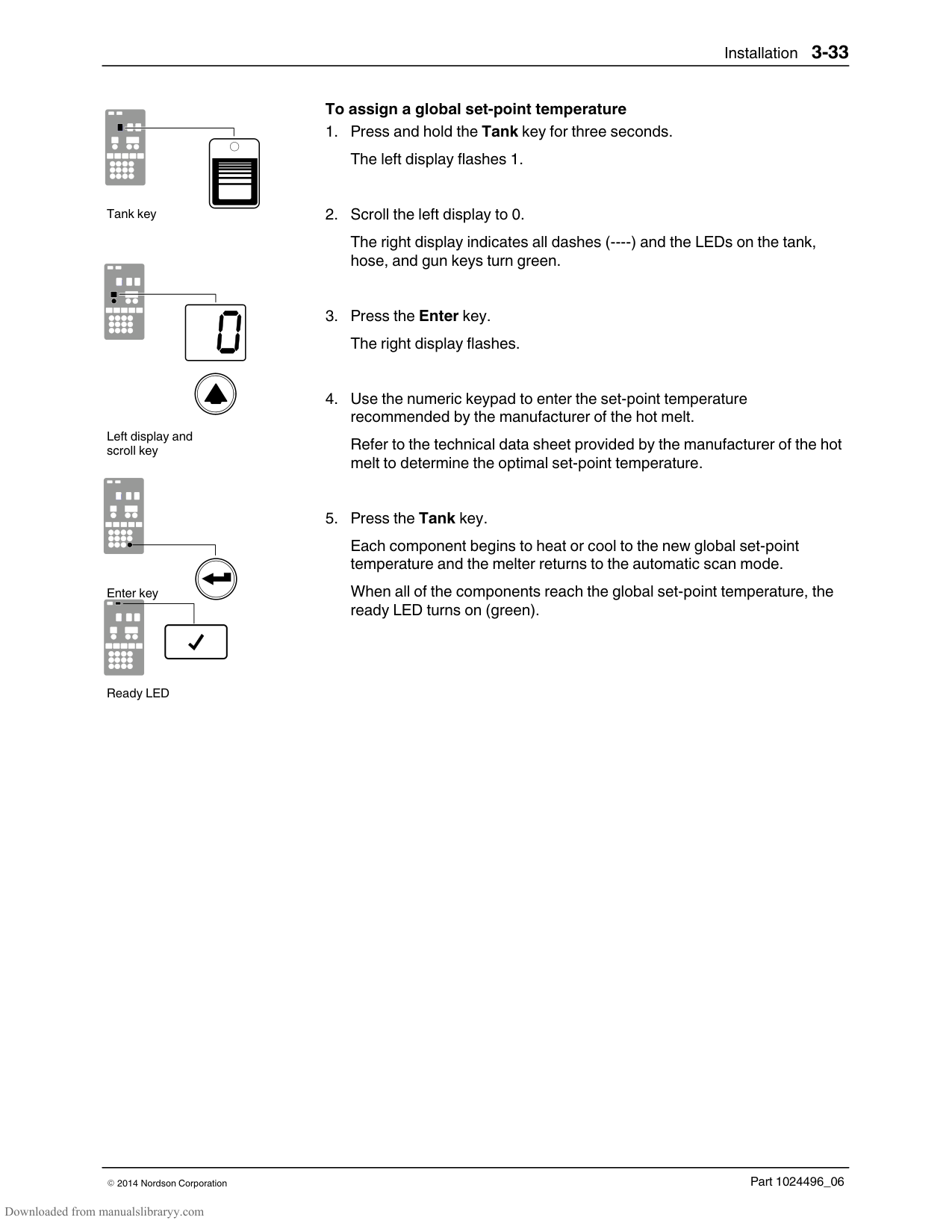
#### Installing Melter Outputs (contd)
Table 3‐9 Output Data
|Output|Terminals|Operating Parameter|Control Options|Note| |---|---|---|---|---| |Standard Outputs|Standard Outputs|Standard Outputs|Standard Outputs|Standard Outputs| |1|1 and 2|40|0 ‐ Output Disabled
1 ‐ Ready (Default)
2 ‐ Ready and the pump is on
3 ‐ Fault
4 ‐ Tank Low Level
5 ‐ Service LED is On
6 ‐ Alert
|A A
A
B A
C
| |2|3 and 4|41|Same as parameter 40 (Default=3)| | |3|5 and 6|42|Same as parameter 40 (Default=4)| | |Optional Outputs|Optional Outputs|Optional Outputs|Optional Outputs|Optional Outputs| |4|1 and 2|43|0 (Disabled)|D| |5|3 and 4|44|0 (Disabled)|D| |6|5 and 6|45|0 (Disabled)|D| |7|7 and 8|46|0 (Disabled)|D| |NOTE A: When control option condition occurs, contacts close. Contacts are normally open when power is off.
B: When control option condition occurs, contacts open. Contacts are normally open when power is off.
C: Control option 6 provides an output signal when a potential fault is detected. If control option 3 and 6 are both used, then both a fault output and an alert output signal will be present when the fault LED turns on.
D: For wiring information, refer to the instruction sheet that is provided with the optional I/O expansion card
|NOTE A: When control option condition occurs, contacts close. Contacts are normally open when power is off.
B: When control option condition occurs, contacts open. Contacts are normally open when power is off.
C: Control option 6 provides an output signal when a potential fault is detected. If control option 3 and 6 are both used, then both a fault output and an alert output signal will be present when the fault LED turns on.
D: For wiring information, refer to the instruction sheet that is provided with the optional I/O expansion card
|
#### Installing Optional Equipment
Each item of optional equipment is shipped with instructions for installing and operating the equipment. Refer to Section 7, Parts, for equipment part numbers.
#### Connecting a Gun Driver, Pattern Controller, or Timer
If applicable, complete the melter installation by connecting the guns to the desired gun driver, pattern control, or timer. Refer to the product manual provided with the device for information about installing and operating the equipment.
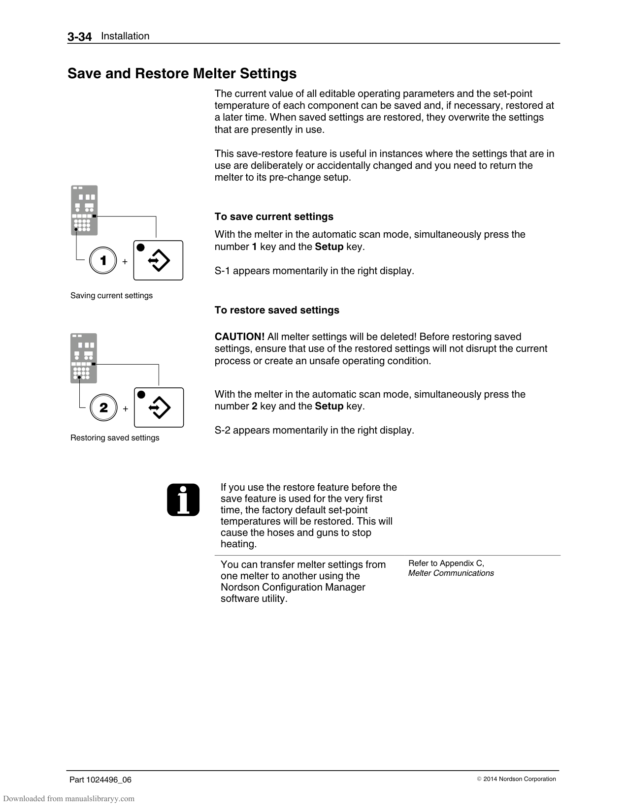
#### Flushing the Melter
Before using the melter for production, it should be flushed to remove any residue left over from factory‐testing. Flushing the melter is accomplished by processing a minimum of one tank volume of hot melt through the melter, hoses, and guns.
Refer to Section 4, Operation, for information about filling the tank and operating the melter.
#### Setting Up Melter Communications
You can transfer melter settings between melters, and upgrade or downgrade the melters operating firmware by using a personal computer that is connected to your melter's serial port.
Refer to Appendix C, Melter Communications, for information about downloading, installing, and using the software that is required to connect a personal computer to your melter.
Section 4 Operation
WARNING! Allow only personnel with appropriate training and experience to operate or service the equipment. The use of untrained or inexperienced personnel to operate or service the equipment can result in injury, including death, to themselves and others, and damage to the equipment.
This section provides information about the following operator‐level tasks: Filling the melter tank Starting the melter Monitoring melter operation Adjusting the operating temperature of heated components Using the melter function keys Shutting the melter down
Most of the controls described in this section are located on the control panel behind the keypad door. Refer to Section 2, Key Components, for the location of the control panel.
#### Additional Information
This section presents operating procedures in their most commonly used form. Procedural variations or special considerations are explained in the additional information table that follows most procedures. Where applicable, some table entries also contain cross‐reference information. Additional information tables are indicated by the symbol shown to the left.

#### More About Heated Components
| | | | |---|---|---| | | | | | | | |
| | | | | |---|---|---|---| | | | | |
Component keys (tank, hose, and gun)
The melter contains three groups of heated components. These are the tank group, which contains the tank and the manifold, the hose group, and the gun group. Component groups are represented on the control panel by the component keys shown to the left.
Heated components within each group are identified by their position number. The position of the tank and pump is fixed at 1. Hose and gun position numbers are automatically assigned based on the hose/gun receptacle they are connected to. For example, the position numbers of a hose/gun pair that is connected to the second receptacle would be hose position 2 and gun position 2.
The number of hose/gun receptacles available on each melter depends on the configuration in which the melter was ordered. ProBlue adhesive melters may have either two, four, or six hose/gun receptacles. An optional expansion base may be ordered that adds receptacles for two additional hoses/guns.
#### Filling the Tank
Before filling the tank, confirm that the hot melt material is compatible with the melter. Refer to Section 2, Intended Use, for information about hot melt materials that should not be used in ProBlue melters.
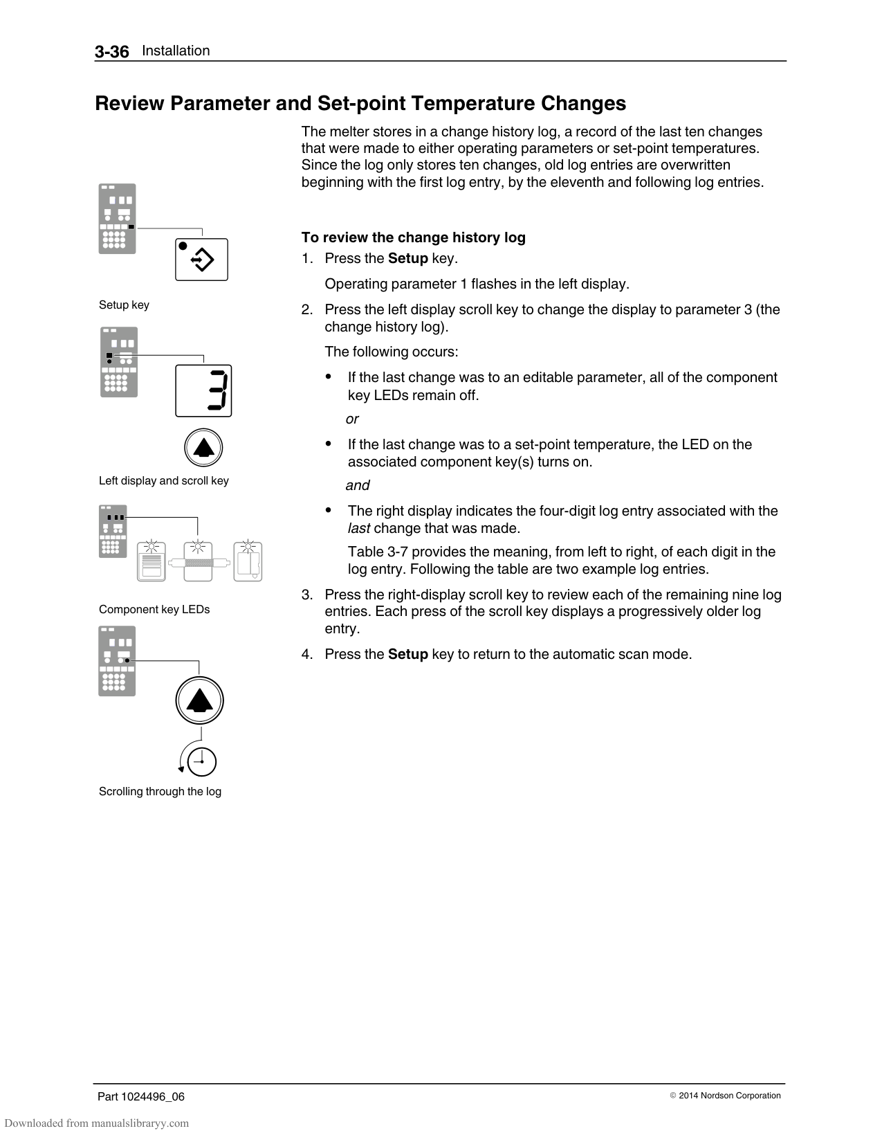
The tank is equipped with a low‐level float switch. When the volume of adhesive in the tank reaches approximately one‐half of the tank's rated capacity, the float switch turns on the low‐level LED located on the control panel.
Low‐level LED (yellow)
To fill the tank WARNING! Hot! Risk of burns! Use a scoop to fill the tank with hot melt Never use your bare hands. Using your bare hands to fill the tank may result in personal injury.
Figure 4-1 Tank fill line
Table 4‐1 Tank Capacity
|Model|Capacity|Capacity|Capacity| |---|---|---|---| | |Liters|Kilograms|Pounds| |P4|4|4|9| |P7|7|7|15| |P10|10|10|22|
*Assumes a hot melt with a specific gravity of 1
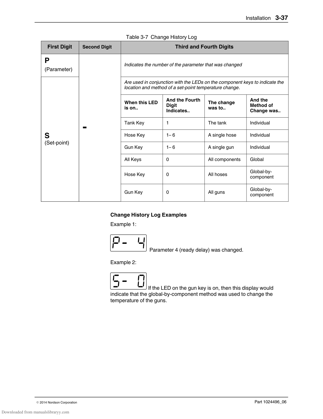
#### Starting the Melter
Before starting the melter for the first time, confirm that the
Melter control switch (on/off)
| | | | |---|---|---| | | | | | | | |
Heaters LED
| | |---| | |
| | |---| | |
| | | |
|---|---|---| | | | | | | | |
| | | | | | |---|---|---|---|---| | | | | | | | | | | | |
Automatic scan sequence
Ready LED
Air pressure gauge
melter is fully installed including any required inputs and outputs, gun drivers, pattern controllers, and timers
melter's operating parameters are set up to support the current manufacturing process
Refer to Section 3, Installation, if any of the items listed above are not complete.
############### To start the melter

Tests the control panel LEDs Turns on the heaters (the heaters LED turns green) Begins to automatically scan through and display the actual temperature of the tank and each hose and gun that has a set‐point temperature that is greater than zero degrees. The sequence of the automatic scan is: tank, each hose and gun pair, and then back to the tank. Turns on the ready LED (green) when the tank and all of the hoses and guns are within 3 C (5 F) of their assigned set‐point temperature.
NOTE: Appendix D contains a functional description of the pump.
NOTE: The minimum operating air pressure is 0.7 bar (10 psi). Operating the melter with the air pressure set to less than 0.7 bar (10 psi) may cause the pump to function erratically.
If the melter is switched on when the temperature of the tank is 27 C (50
F) or greater below its assigned set‐point temperature (cold start condition), the ready LED will not turn on until the ready delay (defined when the melter was set up) has elapsed.
Appendix B, Parameter 4
The time remaining on the ready delay (in minutes) appears in right display at the end of every scan cycle. When only one minute remains in the ready delay time, the right display counts down in seconds.
Appendix B, Parameter 4
You can by‐pass the ready delay time by pressing the Heaters key twice.
The appearance of F4 in the right display immediately after the melter is switched on indicates a problem with the melter's processor or main board.
Section 4, Monitor Melter Faults
The appearance of F1 in the right display immediately after starting the melter indicates that a hose or gun cordset may be loose or disconnected.
Section 6, Troubleshooting
If the melter is set up for manual pump activation, the pump LED will not turn on when the melter is ready.
Appendix B, Parameter 8
The condition of one or more inputs, may prevent the heaters from turning on.
If the seven‐day clock feature was set up and turned on when the melter was last switched off, the clock will automatically turn on the next time the melter is switched on.
It is normal for the pump to slowly cycle when no hot melt is being dispensed from the guns.
If a power failure occurs, the melter will restart in its normal heat‐up cycle, even if the heaters were off or the melter was in standby prior to the power failure. If the seven‐day clock was on prior to the power failure, the melter will restart in the mode dictated by the clock schedule at the time the melter restarts.
#### Monitoring the Melter
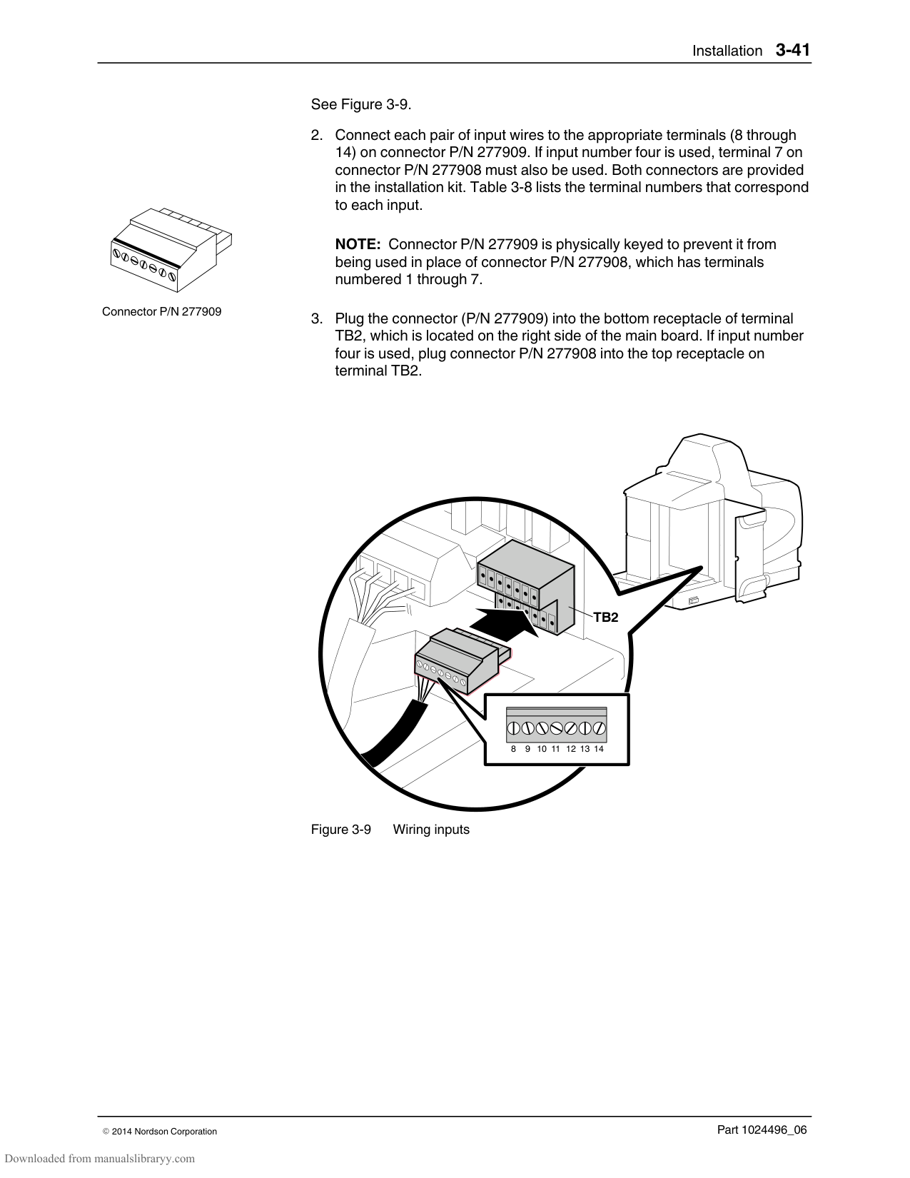
The melter provides indicators that allow you to: Quickly confirm that the melter is operating correctly Monitor the actual temperature of the manifold and each hose and gun Identify melter faults Identify when the level of hot melt in the tank is low Check the operating air pressure Determine when service is required
The melter automatically determines the number and location of all hoses and guns that are connected to it. Refer to More About Heated Components earlier in this section for information about hose/gun capacity and the identification of heated components. You can also use a personal computer to monitor the melter. Refer to Appendix C, Melter Communications, for information about connecting a personal computer to the melter and installing the required software.
######## Confirm that the Melter is Operating Correctly
Ready LED
The ready LED turns on (green) when all of the heated components are within 3 C (5 F) of their set‐point temperature.
The ready LED will not turn on, or will turn off, if any of the following events occur:
The ready delay is still counting down. The operator or a remote input places the melter in the standby mode. The seven‐day clock places the melter in the standby mode. There is a fault (the fault LED will turn on).
Refer to Monitoring Melter Faults and Using Melter Function Keys later in this section for information about melter faults and using the seven‐day clock and standby functions. Refer to Appendix B, Parameter 4, for information about the ready delay.
Heated components with a set‐point temperature of zero degrees are skipped during the automatic scan cycle.
The set‐point temperature of the tank and the manifold cannot be set independently.
The time remaining on the ready delay appears in the right display at the end of each scan cycle.
Appendix B, Parameter 4
You can override the seven‐day clock at any time. If the clock has turned the heaters off, pressing the heaters key will turn the heaters back on. If the clock has placed the melter into the standby mode, pressing the standby key will return the heated components to their assigned set‐point temperature.
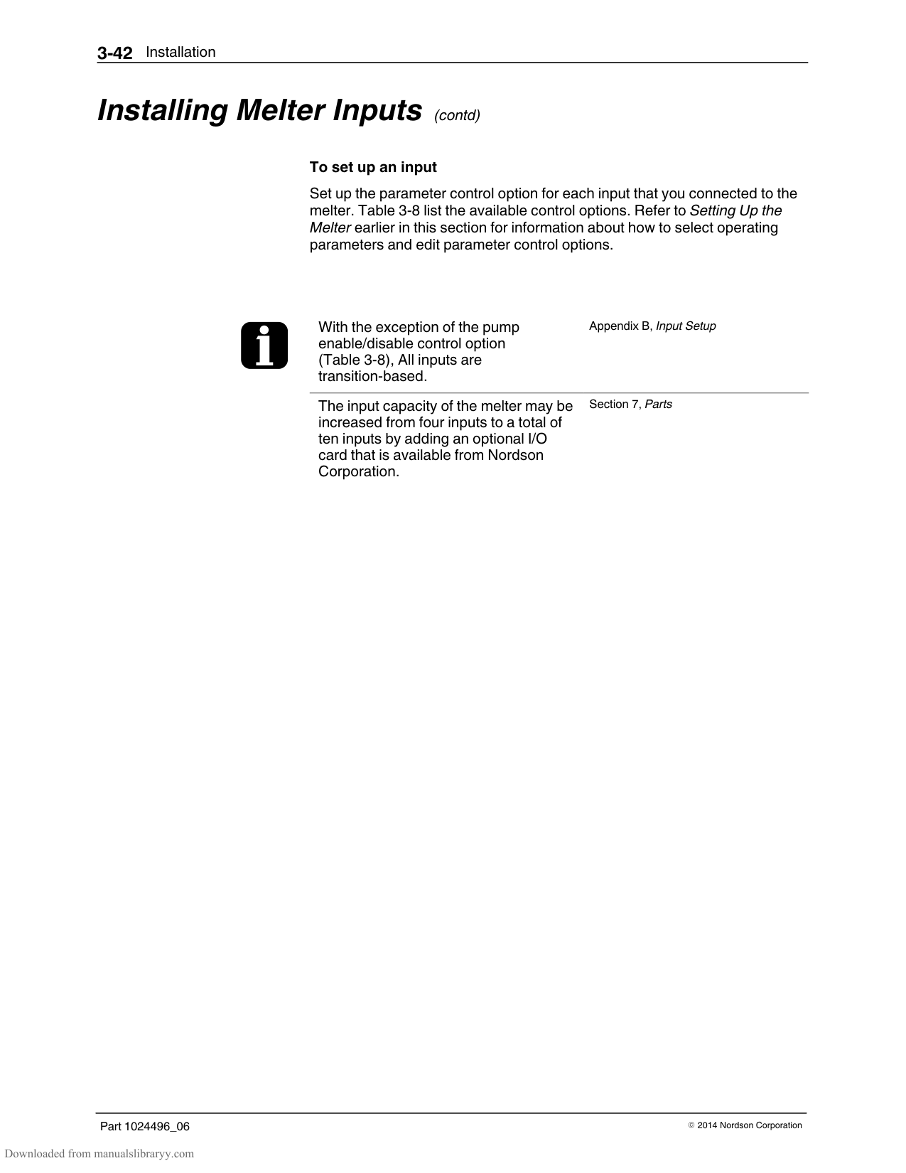
Section 4, Using Melter Function Keys
######## Monitor Component Temperatures
You can check the actual temperature of each heated component—the tank and each hose and gun—using the automatic scan mode or by manually selecting and checking each component.
By default, the melter remains in the automatic scan mode except when: The melter is placed into the setup mode The set‐point temperature of all hoses and guns is set to zero degrees A fault occurs
| | |---| | |
| | | | |---|---|---| | | | | | | | |
| | | | | | |---|---|---|---|---| | | | | | | | | | | | |
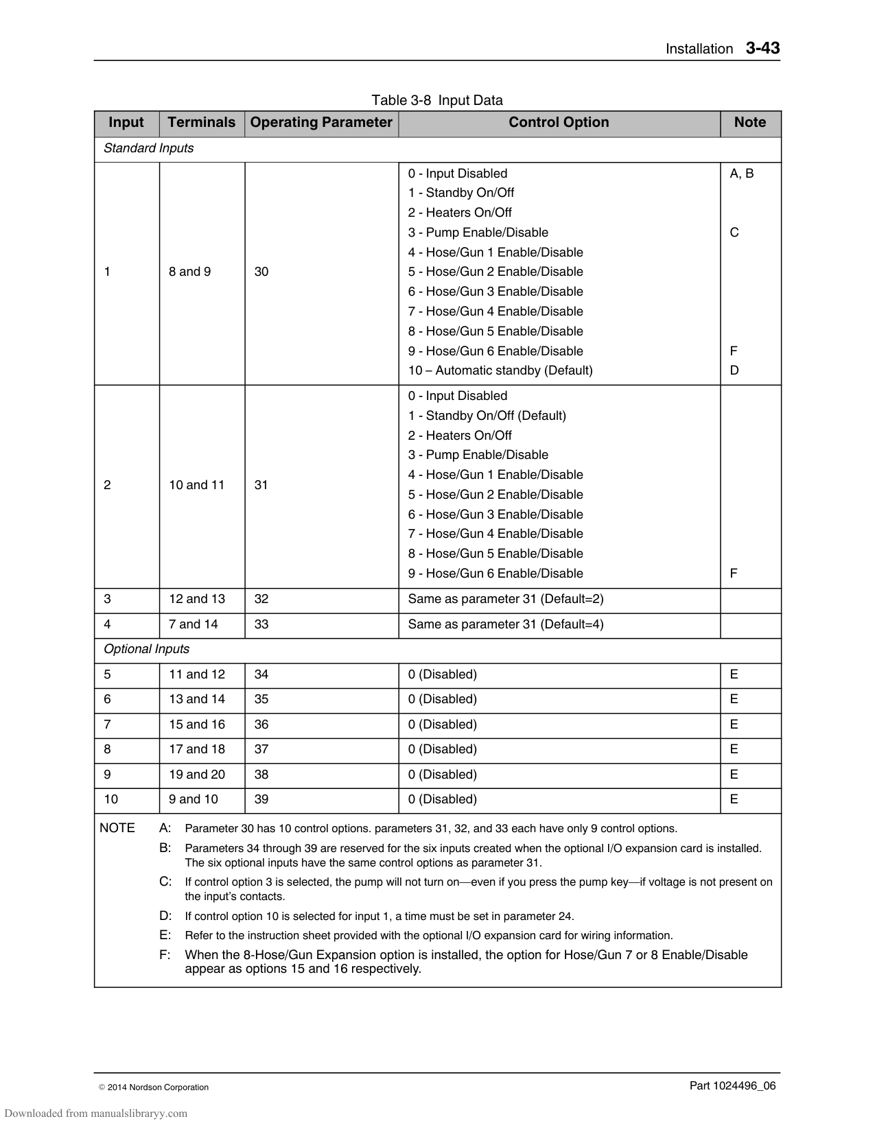
LEDs on component keys
############### To check component temperatures using the automatic scan mode
Left display and scroll key
Component temperature display
############### To manually check a component's temperature
The automatic scan stops and the left display indicates the number of the first sequential component in the selected component group. The right display indicates the component's actual temperature.
NOTE: When the tank key is pressed, the left display does not indicate a component number (blank display).
The right display indicates the actual temperature of the selected component.
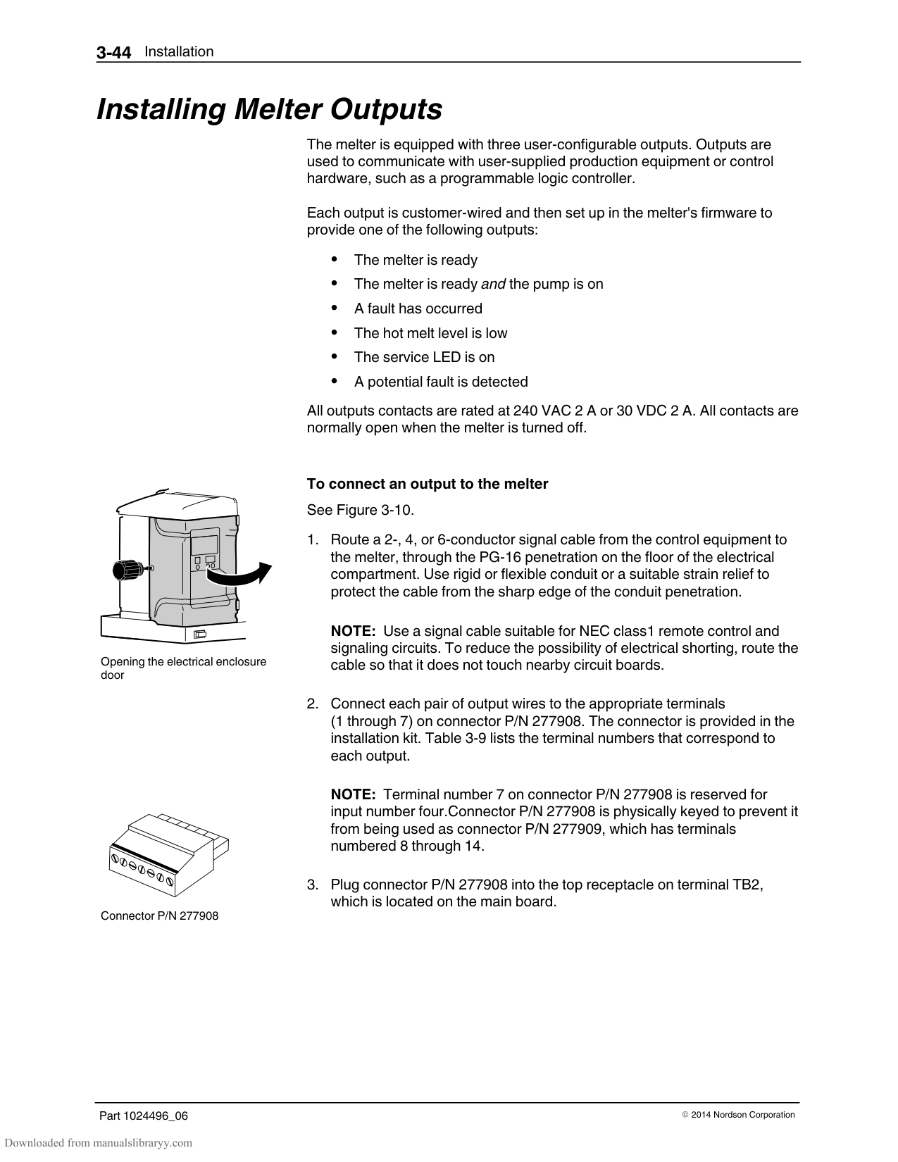
######## Monitor Component Temperatures (contd)
When you scroll the left display past the number of the last sequential component in a component group, the number of the first sequential component in the next component group appears in the left display.
The melter will return to the automatic scan mode two minutes after the last key is pressed.
When you press the Tank key, it is the manifold temperature that is actually indicated in the right display. To check the actual temperature of the tank, simultaneously press the Tank key and the left‐display scroll key.
The default unit for temperature display is degrees Celsius (C). This may be changed to degrees Fahrenheit using operating parameter 20.
Appendix B, Parameter 20
The LEDs on each component key will change from green to yellow if any component in the component group drops more than 3 C (5 F) below its assigned set‐point temperature.
You can check the set‐point temperature of a component at any time, by pressing the right‐display UP scroll key. Holding down the scroll key while the melter is in the automatic scan mode reveals the set‐point of each component that is scanned.
######## Monitor Melter Faults
The melter alerts the operator to the faults listed in Table 4‐3. Faults affect the melter in one of three ways: the heaters turn off; the heaters remain on, but the fault condition persists; or the melter stops functioning.
When a fault occurs, you must diagnose and correct the fault condition and then place the melter back into operation. You can use the fault log to determine the type, order, and relative time of the last ten faults.
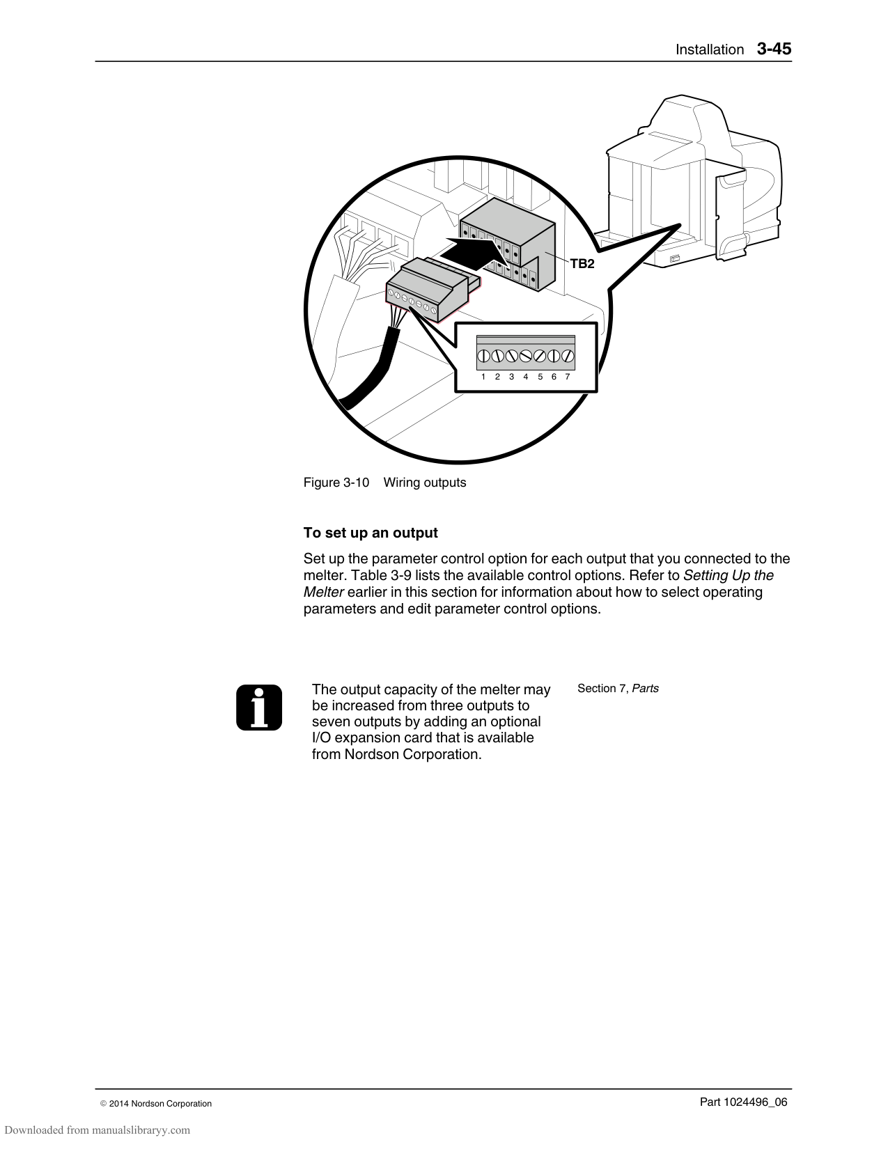
Setup Key
Left display and scroll key
Scrolling through the fault log
############### To review the fault log
The automatic scan stops and operating parameter 1 appears in the left display.
If the last fault was an F1, F2, or F3 fault, then the LED on the affected component key turns yellow.
If the last fault to occur was an F4 fault, then the LEDs on all of the component keys turn off.
The right display indicates the log entry for the last fault to occur. Table 4‐2 provides the meaning of each digit in the log entry. Following the table are two example fault log entries.
NOTE: The fault log only stores the last ten faults. After ten faults occur, the existing log entries are overwritten, beginning with the oldest entry, by the eleventh and following log entries.
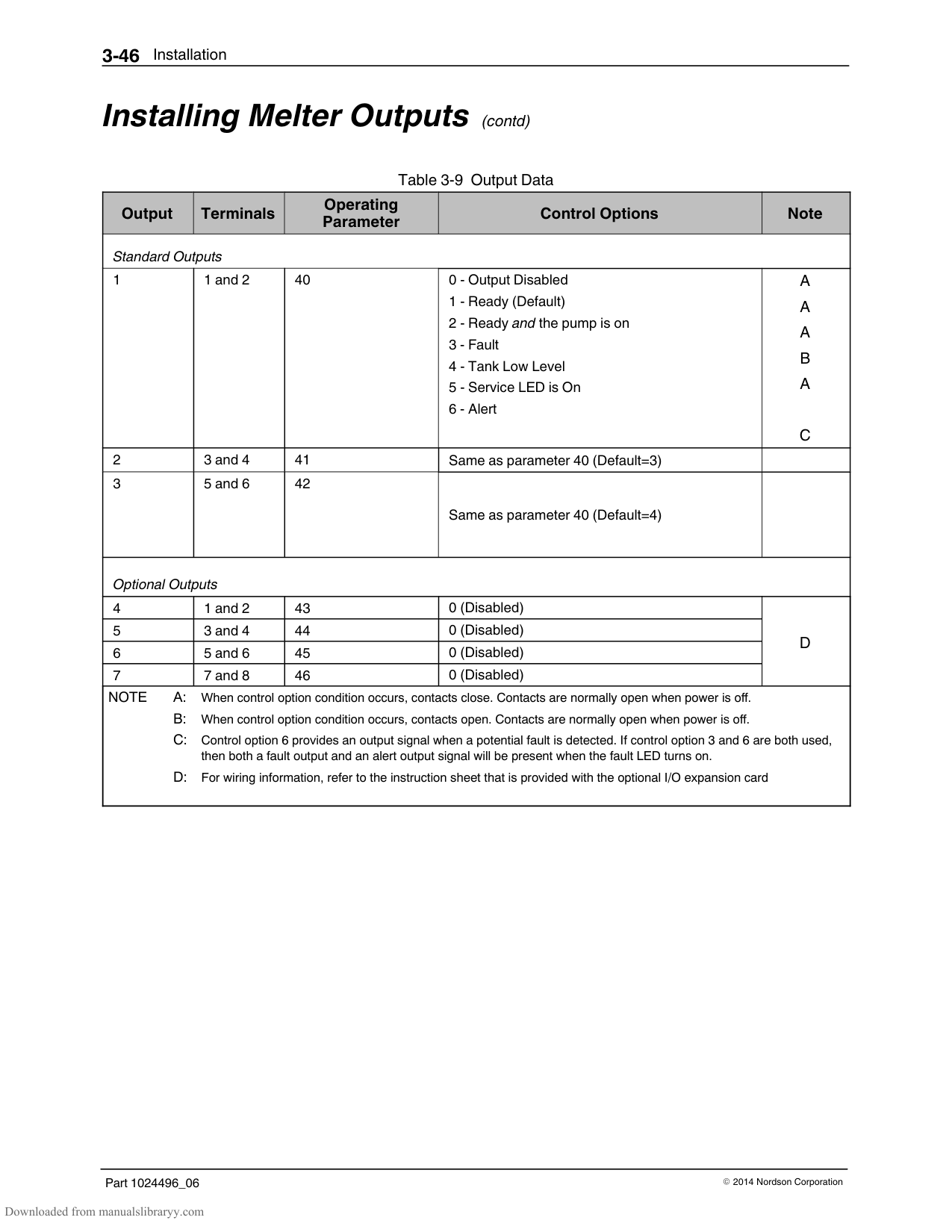
Table 4‐2 Fault Log
|First Digit|Second and Third Digits|Fourth Digit| |---|---|---| |Component:
1 = Tank or hose/gun 1
2 = Manifold or hose/gun 2
3 = Hose 3 or gun 3
4 = Hose 4 or gun 4
5 = Hose 5 or gun 5
6 = Hose 6 or gun 6
|‐ F|Type of fault:
0 = Unused log entry
1 = RTD (open or short)
2 = Component under temperature
3 = Component over temperature
4 = Processor or electrical failure
|
############### Fault Log Examples
An unused log entry.
If the LED on the tank key were on, this log entry would indicate that the tank is under temperature. If the LED on the hose key were on, this log entry would indicate that hose 1 is under temperature.
To view the number of heater hours that have elapsed since a log entry was created, simultaneously press both of the right‐display scroll keys. The hours are indicated in the right display.
The melter will return to the automatic scan mode if the fault log is left open for a period of two minutes without any key being pressed.

When an F1 fault is the result of a hose/gun pair being disconnected from the melter, two fault log entries are created. The first entry is for the gun and the second entry is for the hose.
######## Monitor Melter Faults (contd)
Table 4‐3 Melter Faults
|Display Code/Sub‐code|Name|Affect on Melter|Cause| |---|---|---|---| |F1/None|RTD|Heaters turn off|The RTD for the component indicated has failed or the component was disconnected from the melter.| |F2/None|Under temperature|Heaters turn off|The actual temperature of the component indicated has dropped below the under temperature delta, which was set using parameter 22.| |F3/None|Over temperature|Heaters turn off|The actual temperature of the component indicated has increased beyond the over temperature delta, which was set using parameter 21.| |F4/1|RAM test|Melter stops functioning|Internal RAM failure| |F4/2|Internal Clock time|Heaters remain on, but fault condition persists|Internal clock failure| |F4/4|Internal clock battery backed RAM|Heaters remain on, but fault condition persists|Battery‐backed RAM failure| |F4/5|Internal clock battery|Heaters remain on, but fault condition persists|Battery‐backed RAM battery dead| |F4/6|Analog‐to‐digital|Melter stops functioning|RTD analog‐to‐digital converter failed| |F4/7|Analog‐to‐digital calibration|Melter stops functioning|RTD analog‐to‐digital converter could not be calibrated
Faulty hose or gun.| |F4/8|Main board feedback|Melter stops functioning|Communication failure between main board and CPU| |F4/A|Thermostat|Melter stops functioning|Tank or manifold thermostat is open| |F4/d|Communications with optional I/O card|Heaters remain on, but fault condition persists|Communication failure between CPU and the optional I/O card| |F4/E|Fieldbus communications failure|Alert output (if output option 6 is selected) Melter continues to operate normally.|Fieldbus card failure.|
Clear/Reset key

| | | | |---|---|---| | | | | | | | |
Heater key
############### To put the melter back into operation
NOTE: When a fatal F4 fault exists, the control switch will not function. Remove power to the melter at the local disconnect switch.
Fault LED (red)
########### How F1, F2, and F3 Faults are Handled
When the melter detects an F1, F2, or an F3 fault:

If the LED on the tank key is on, the left display will indicate either 1 for the tank or 2 for the manifold.
If the LED on the hose or gun key is on, the left display will indicate the number of the affected hose or gun.
########### How F4 Faults are Handled When the melter detects an F4 fault:
Fatal—The fault LED turns on and stays on and the melter stops functioning completely.
Nonfatal—The fault LED turns on for five seconds, but the heaters and pump continue to operate normally. Nonfatal faults affect the internal clock and the optional I/Os.
Refer to Section 6, Troubleshooting, for information about diagnosing F4 faults.
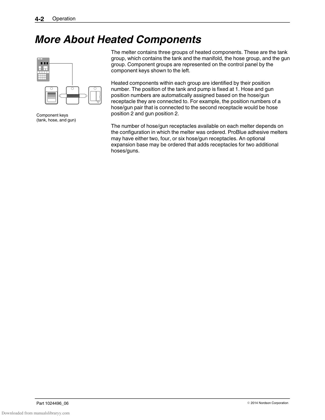
########### How F4 Faults are Handled (contd)
To view the temperature of a heated component when an F2 or F3 fault exists, simultaneously press and hold both of the right‐display scroll keys.
You can temporarily dismiss an F1 fault (RTD) and return to the automatic scan mode by pressing the
Clear/Reset key. The heaters will, however, remain off. If the fault condition still exists two minutes after pressing the clear/reset key, the fault LED will turn back on.
When an F1 fault code appears, you can determine whether the fault was caused by an open or a shorted RTD by simultaneously pressing both of the right‐display scroll keys. If the right display indicates OP, the RTD is open, if it indicates SH, the RTD has shorted.
If, for any reason, a component reaches 235 C (458 F), an immediate F3 fault will occur (no two‐minute monitoring period).
If F4 appears in the right display when you press the clock key, the internal clock function has failed.
######## Monitor the Level of Hot Melt in the Tank
Low‐level LED (yellow)
The tank contains a low‐level float switch. When the volume of hot melt in the tank drops below one‐half of the tank's rated capacity, the float switch turns on the low‐level LED located inside the tank key.
Nordson recommends that the tank be kept at least one‐half full while the melter is operating.
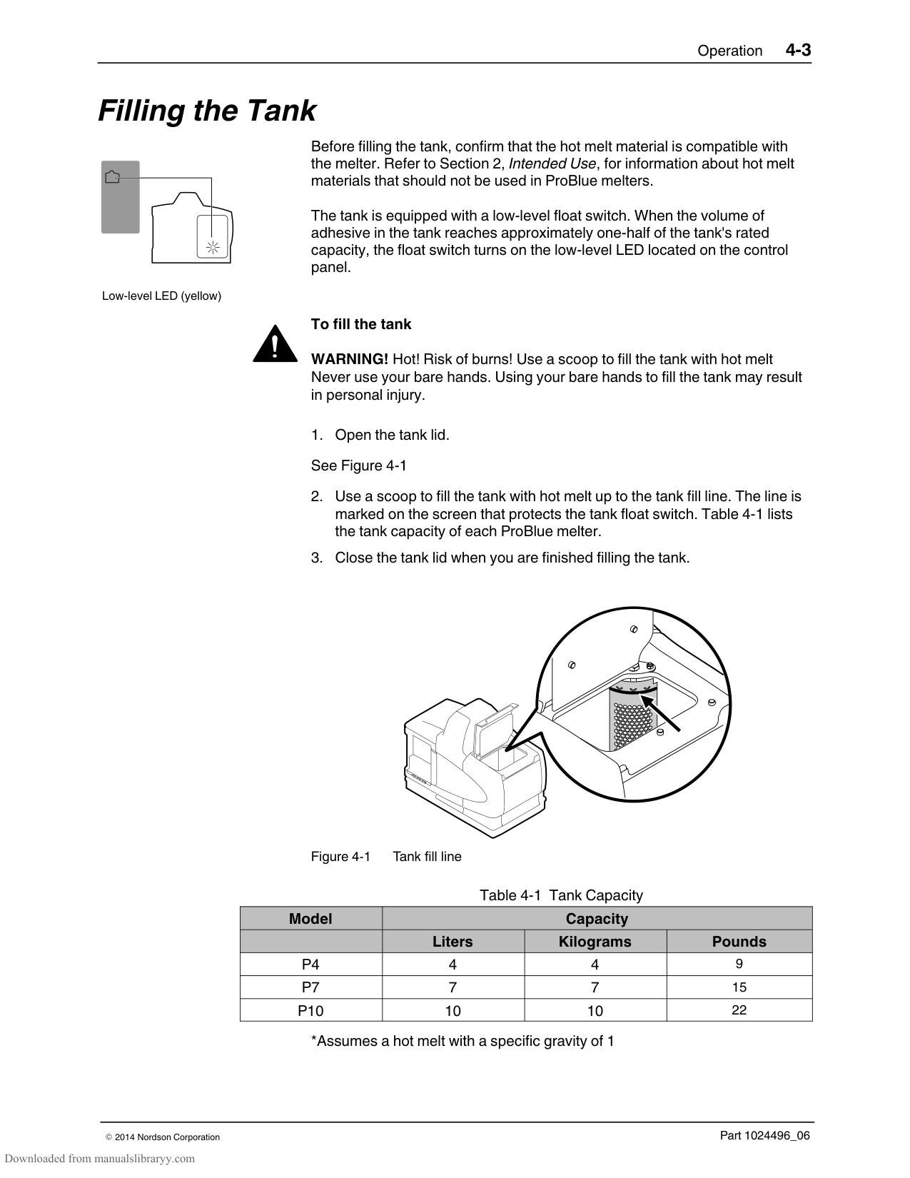
NOTE: The melter is also equipped with a low‐level output that can be connected to a customer‐supplied signaling device or process control system. Refer to Section 3, Installing Melter Outputs, for information about using the low‐level output.
######## Monitor and Adjust the Operating Air Pressure
Pressure regulator and adjustment screw
The air pressure gauge located on the front of the melter indicates the air pressure that is supplied to the melter's pump. The air pressure must be adjusted to meet the requirements of your manufacturing process.
NOTE: The minimum operating air pressure is 0.7 bar (10 psi). Operating the melter with the air pressure set to less than 0.7 bar (10 psi) may cause the pump to function erratically.
Use the adjustment screw located to the right of the pressure gauge to adjust the operating air pressure.
Typically, adjustments to the operating air pressure are made in order to change the volume of hot melt dispensed by the guns. Other factors such as the temperature of the hot melt, the speed of the manufacturing line, and the type and size of the nozzles used on the guns also impact the volume of hot melt that is dispensed.
CAUTION! Do not force the air pressure adjustment screw beyond its normal range of adjustment. Forcing the adjustment screw beyond its normal range of adjustment will damage the pneumatic assembly.
######## Monitor the Service Interval
The melter can be set up so that the service LED located on the left side of the control panel turns on after a customer‐defined time period elapses. The service LED may be used to signal the need to change the hot melt filter or to complete any other customer‐specified maintenance activity. Once the specified maintenance is performed, the service LED must be reset.
############### To reset the service LED
With the melter in the scan mode, press the Clear/Reset key to turn off the service LED and reset the service interval time.
Service LED (yellow)
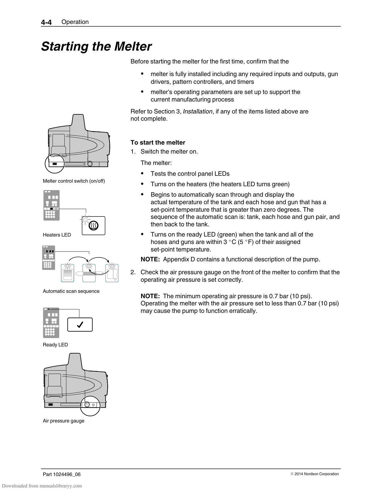
Clear/Reset key
The default setting for the service interval time is 500 hours.
Appendix B, Parameter 5
#### Adjusting Component Temperatures
You can adjust the the set‐point temperature of heated components using the following methods:
| | | | | | | |---|---|---|---|---|---| | | | | | | |
Tank key
Left display and scroll key
| | | |---|---| | | | | | |
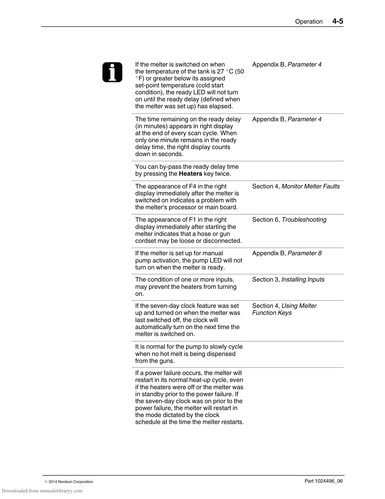
Enter key
Ready LED
Global—The tank and all hoses and guns are set to the same set‐point temperature.
Global‐by‐component group—All of the hoses or all of the guns are set to the same set‐point temperature.
Individual Component—The set‐point temperature of the tank and each hose and gun is adjusted independently.
Before adjusting set‐point temperatures, confirm that each hose/gun pair is connected to the correct hose/gun module. For example, hose/gun pair 1 should be connected to the first receptacle (lowest) on hose/gun module 1 (lowest module). Refer to More About Heated Components earlier in this section for information about hose/gun modules.
############### To adjust set‐point temperatures using the global method
The right display indicates all dashes (‐ ‐ ‐ ‐) and the LEDs on all of the component keys turn green.
NOTE: If the keypad or the right‐display scroll keys have no affect on the right display, the melter is password protected. You must enter a valid password before you can change set‐point temperatures. Refer to Entering the Melter Password later in this section.
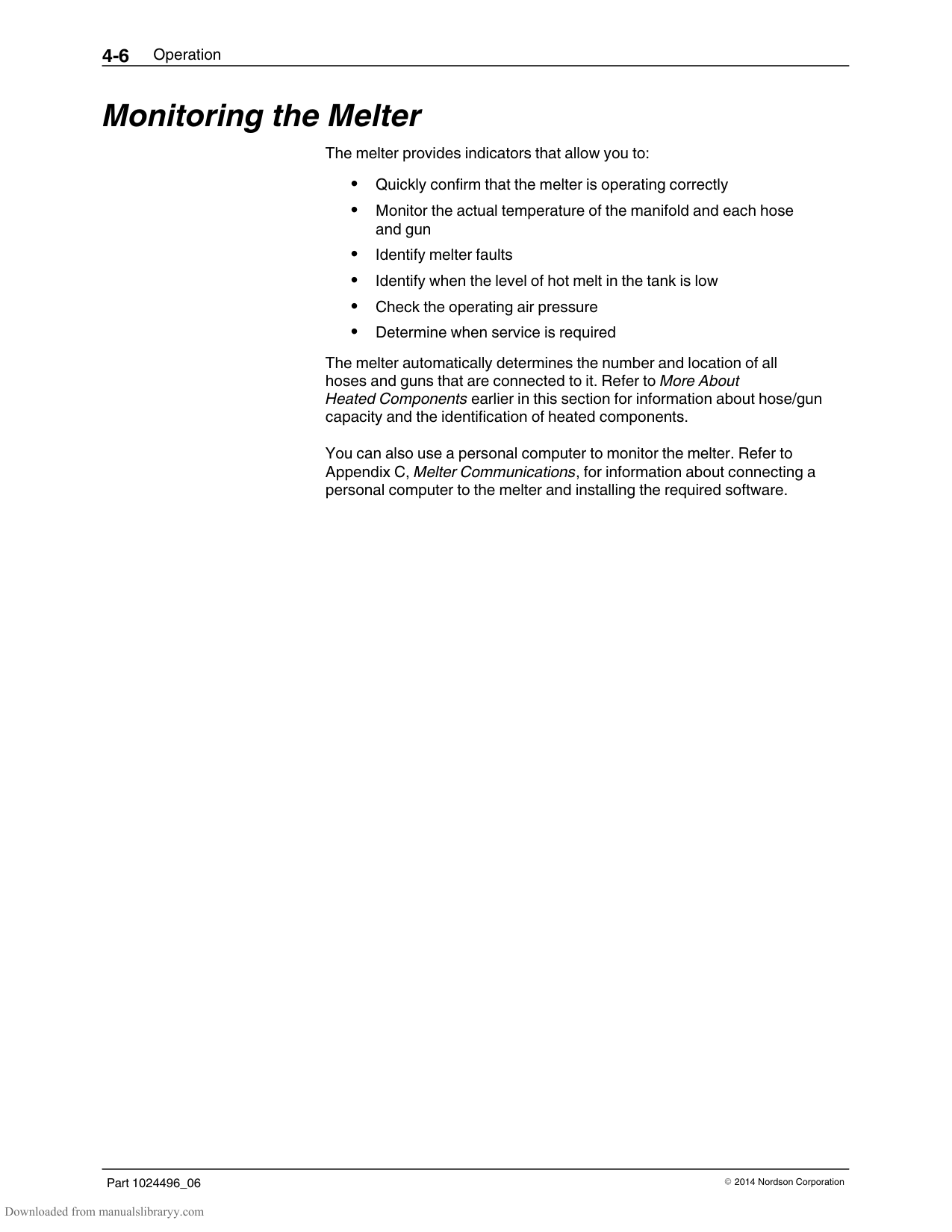
All components begin to heat or cool to the new global set‐point temperature. When all of the components reach their set‐point temperature, the ready LED turns on (green).
| | |---| | |
| | |---| | |
| | | | |---|---|---| | | | | | | | |
| | | | | |---|---|---|---| | | | | |
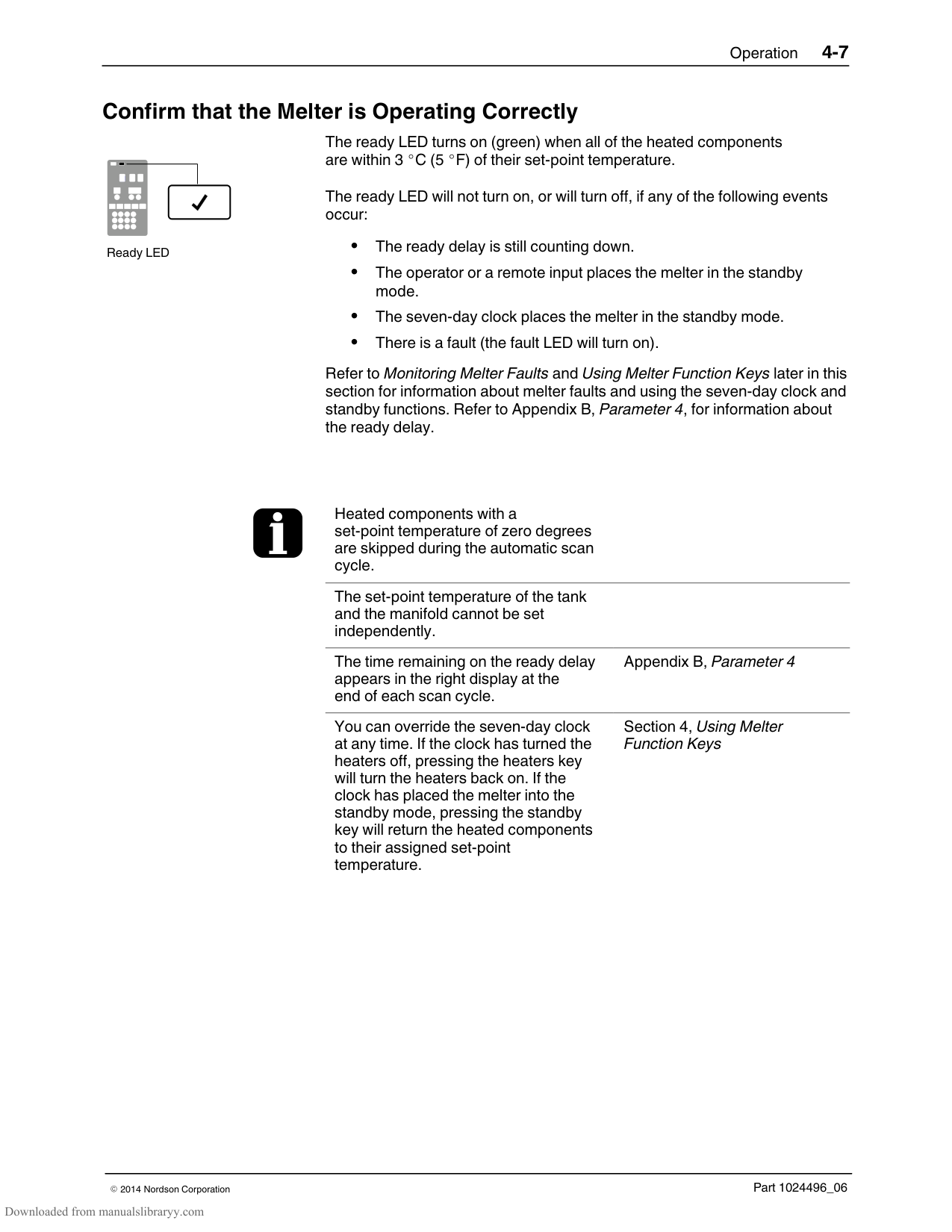
Tank, hose, and gun keys
To adjust the set‐point temperature using the global‐by‐component method
The left display indicates the number of the first sequential hose or gun. The right display indicates the current set‐point temperature of the hose or the gun.
NOTE: If the keypad or the right‐display scroll keys have no affect on the right display, the melter is password protected. You must enter a valid password before you can change set‐point temperatures. Refer to Entering the Melter Password later in this section.
The hoses or the guns begin to heat or cool to their new set‐point temperature.
############### To adjust the set‐point temperature of an individual component
If the tank key was pressed, the left display indicates 1 (Flashing). If a hose or gun key was pressed, the left display indicates the number of the first sequential hose or gun (Flashing). The right display indicates the current set‐point temperature of the component indicated in the left display.
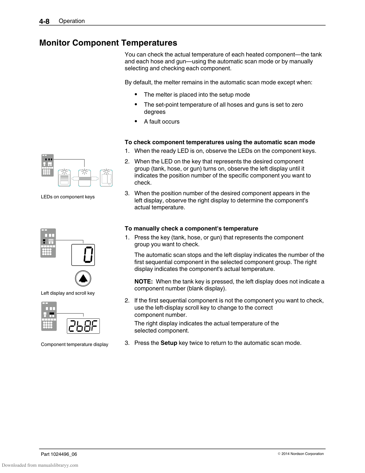
The right display indicates the current set‐point temperature of the component that you selected in the left display.
The right display flashes.
NOTE: If the keypad or the right‐display scroll keys have no affect on the right display, the melter is password protected. You must enter a valid password before you can change set‐point temperatures. Refer to Entering the Melter Password later in this section.
To register the new set‐point temperature and then move on to change the set‐point temperature of the next sequential component, press the Enter key and then repeat steps 4 and 5.
To register the new set‐point temperature and return to the automatic scan mode, go to step 6.
The selected component begins to heat or cool to its new set‐point temperature.
############## To adjust the set‐point temperature of an individual component (contd)
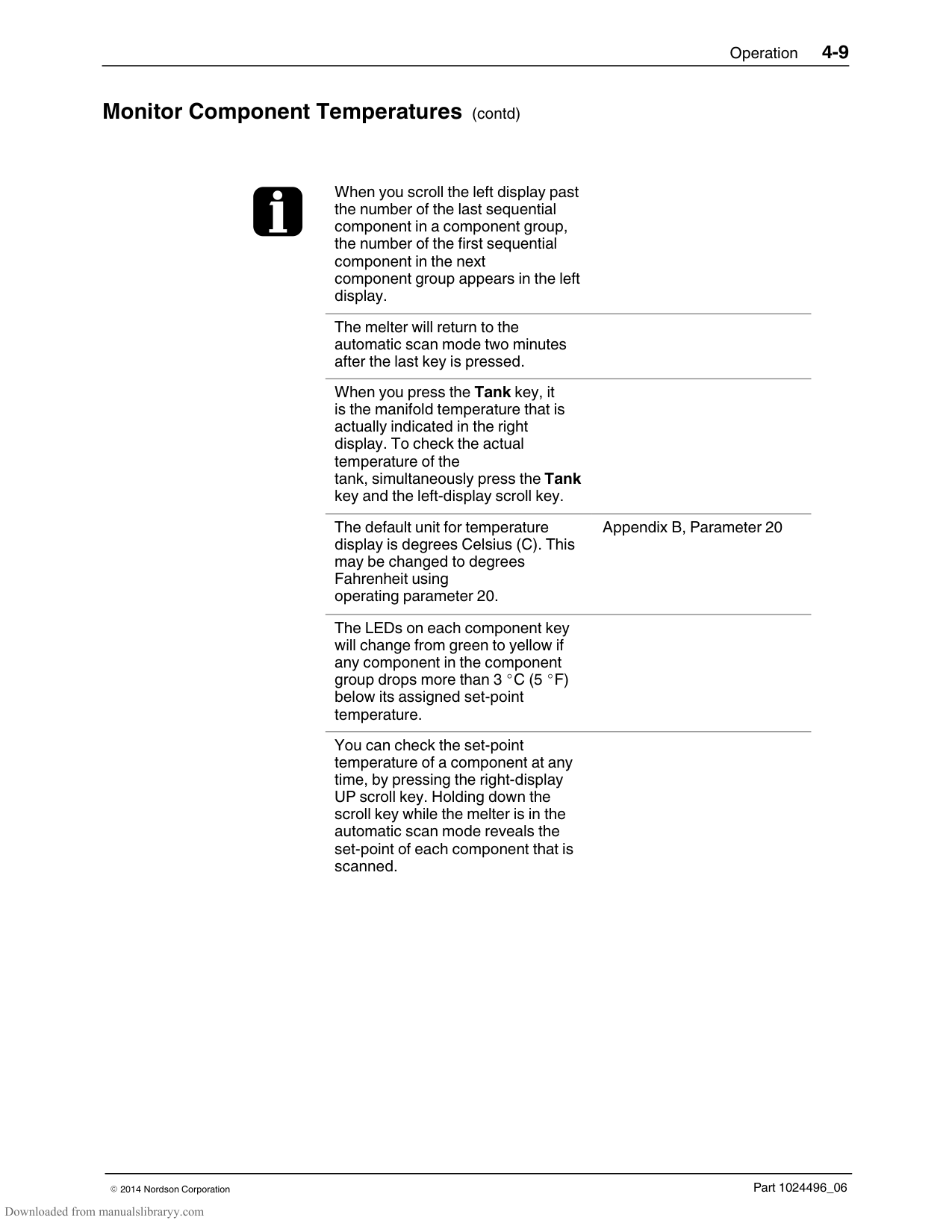
If you enter a valid set‐point temperature for a hose/gun that is not connected to the melter or if you enter a set‐point temperature that is out of range, the right display will indicate dashes (‐‐‐‐) for three seconds and then change back to the original set‐point temperature.
When the right display is flashing, you can quickly change the current set‐point temperature to 0 degrees (off) by simultaneously pressing both of right‐display scroll keys.
After removing a hose or a gun, use the individual component method of set‐point temperature adjustment to set the component's temperature to zero degrees (off). This will avoid causing an F1 fault when a hose or gun is added.
The factory set‐point temperature of the tank is 175 C (350 F). The factory set‐point temperature of all others components is zero degrees (off).
When the units of temperature is set to degrees Celsius, the minimum and maximum set‐point temperatures are 40
C and 230 C. When the units of temperature are set to degrees Fahrenheit, the minimum and maximum set‐point temperatures are 100 F and 450 F.
When using the right‐display scroll keys to adjust a set‐point temperature, the right display automatically increments between 0, 175, and 230 C or between 0, 350, and 450
F. If you make a mistake while you are changing a set‐point temperature, but you have not yet pressed the enter key, press the Clear/Reset key to reset the right display to the original temperature. The melter will exit the setup mode and return to the automatic scan mode two minutes after the last key is pressed. A global set‐point temperature of zero degrees (Celsius or Fahrenheit) turns all components off. When scrolling through component numbers in the left display, component numbers that are associated with unused hose/gun receptacles are skipped. The melter stores a record of the last ten changes made to the set‐point temperatures (and operating parameters) in the change history log.
Section 3, Installation, Review Parameter and Set‐point Temperature Changes
You can save set‐point temperature changes by simultaneously pressing the 1 key and the Setup key.
Section 3, Operation, Save and Restore Melter Setting
#### Entering the Melter Password
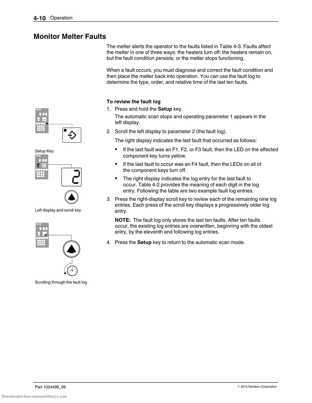
If the melter is password protected, a valid password must be entered before any set‐point temperature or melter parameter can be changed.
############### To enter a melter password
The left display indicates parameter 0 (flashing) and the right display indicates 4000.
If the password is correct, the left display indicates parameter 1. If the password is incorrect, the left display remains at 0 and the right display momentarily indicates dashes (‐‐‐‐) and then returns to 4000. If the password is incorrect, re‐enter it and then press the Enter key.
The melter will automatically revert back to the password‐protected mode two minutes after the last key press (any key). To force the melter back into the password protected mode before two minutes has elapsed, press the Setup key twice.
The melter password is created and enabled/disabled during system setup.
Section 3, Setting Up the Melter
#### Using the Melter Function Keys
The control panel provides the following standard and special function keys.
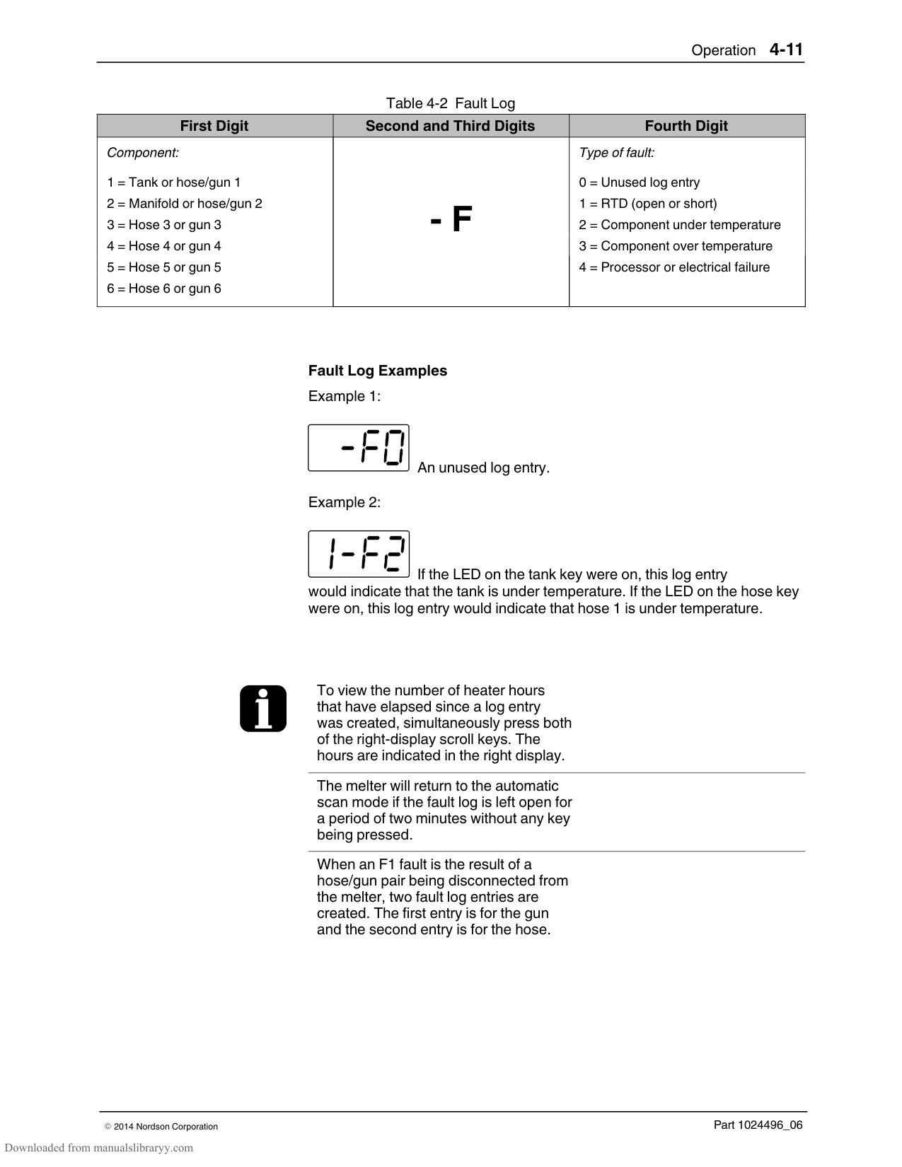
Standard function keys Heater Pump Setup
Special function keys Seven‐day clock Standby
CAUTION: Unintentionally activating function keys can, under the correct circumstances, have undesirable effects on the melter or the manufacturing process. Only personnel who are familiar with the melter’s setup and its connection with the manufacturing process should use the function keys. Improper use of the function keys can result in erratic process behavior or personal injury.
######## Heater Key
| | | | |---|---|---| | | | | | | | |
Heater key
Use the heater key to manually turn the component heaters on and off. Pressing the heater key overrides the control (on or off) of the heaters by either the seven‐day clock feature or a remote input. The LED on the heater key turns on when the heaters are on.
When a fault occurs (Refer to Monitor Melter Faults earlier in this section) the heaters automatically turn off. The heater key is used to turn the heaters back on after correcting a fault condition.
######## Pump Key
Pump key
######## Setup Key
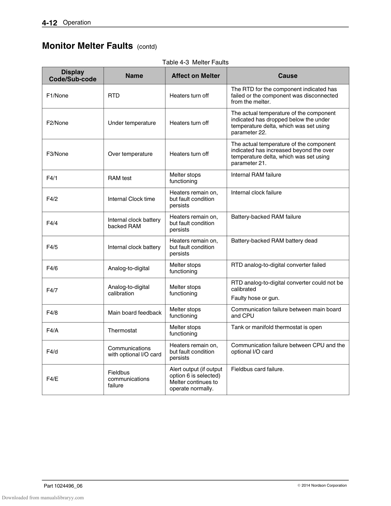
Setup key
Use the pump key to start or stop the pump. The LED on the pump key turns on (green) when the pump is running.
If the automatic pump on feature (parameter 8) is disabled, then the pump key must be used to start the pump when the melter is ready.
If any of the inputs are set up to use the pump enable/disable control option (option 3), the pump will not start until the pump key is pressed (LED on) and the correct voltage is applied to the input contacts. If the pump is enabled, but the input voltage is not present, the pump LED will flash green.
Use the setup key to place the melter into and take the melter out of the setup mode. When the melter is placed into the setup mode, the automatic scan stops and the left and right displays are used to select and read or edit operating parameters.
######## Seven‐day Clock Key
| | | |---|---| | | |
Seven‐day clock key
Use the seven‐day clock key to turn the melter's clock feature on and off. When the clock is on, the temperature of each heated component is automatically regulated based on a set of user‐defined schedules.
To accommodate daily shift work and non‐working days, four clock schedules are available. Schedules 1, 2, and 3 are used to specify when the heaters should turn on and off or when the melter should enter and exit the standby mode. Schedule 0 is used to keep the melter in the last condition dictated by the clock (heaters on or off, or standby).
When a clock schedule calls for the heaters to be on, the heaters are regulated at their pre‐assigned set‐point temperatures. When the clock activates the standby mode, the set‐point temperature of each component is temporarily reduced by a pre‐set standby delta.
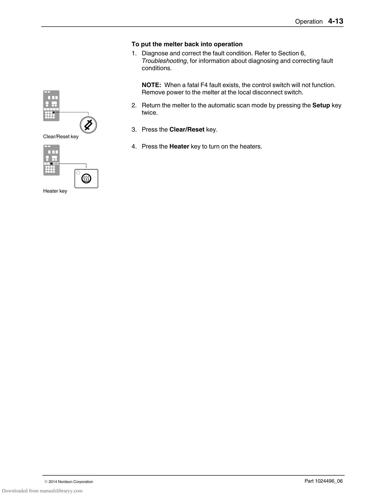
Refer to Appendix B, Operating Parameters, Seven‐day Clock, for information about setting up the seven‐day clock and the standby delta.
If the melter is switched off while the clock is on, the clock will automatically turn back on the next time the melter is switched back on.
If the heaters are manually turned off at the time that a clock schedule calls for the heaters to be on, the heaters will not turn back on until the next clock schedule calls for them to be on.
The clock will still operate when the melter is faulting or is in the setup mode.
If F4 appears in the right display when you press the clock key, the internal clock function has failed.
Section 7, Troubleshooting
######## Standby Key
Standby key
Use the standby key to manually place the melter into, and take it out of, the standby mode. Using the standby mode during periods of time when the melter is inactive helps to conserve energy and allows heated components to quickly return to their set‐point temperatures when the melter is once again needed.
When the melter is placed into the standby mode, the temperatures of all components are reduced down from their set‐point temperature by a pre‐set standby delta. The melter will remain in the standby mode until the standby key is pressed or the function of one of the operating parameters takes the melter out of the standby mode.
If the melter was set up to use the manual standby timer (parameter 26), pressing the standby key will place the melter in the standby mode for the period of time specified by the timer. After the manual standby time has elapsed, the melter will once again begin heating all of the components to their assigned set‐point temperature.
Using the standby key overrides the control of the melter (on or off) by the seven‐day clock or a remote input.
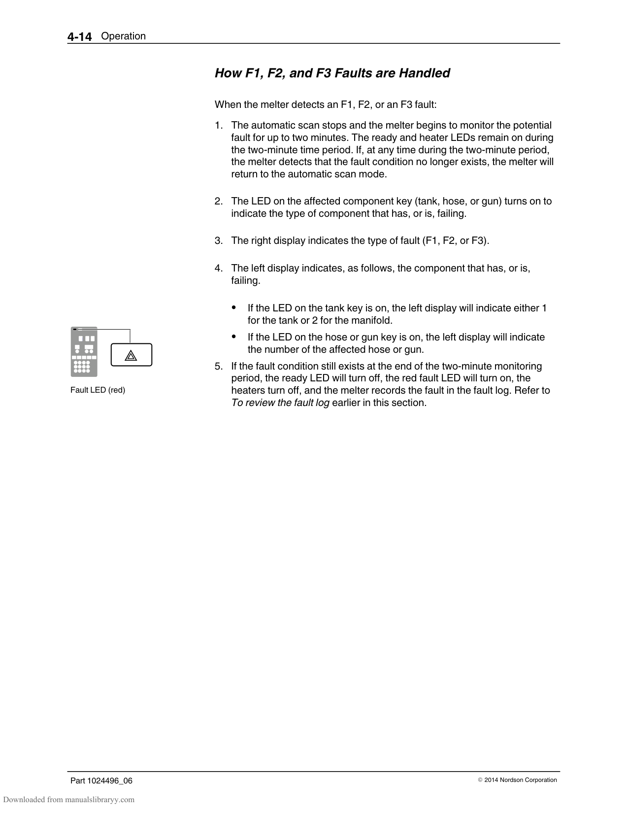
Refer to Section 3, Operation, Setting Up the Melter, and to Appendix B, Operating Parameters, for information about setting the standby delta and the standby timer.
The melter may also be set up to enter the standby mode using a variety of operating parameters.
Appendix B, Parameters 23, 24, 25, 26, 30–33, 57, 62, and 67
Appendix B, Parameter 26
Whenever manual standby is enabled, the standby LED blinks.
#### Shutting Down the Melter
Shut down the melter when it will not be used for an extended period of time.
Melter control switch (on/off)
############### To shut the melter down
The automatic pressure discharge (APD) valve relieves the hydraulic pressure in the manifold back to the tank.
Section 5 Maintenance
WARNING! Allow only qualified personnel to perform the following tasks. Follow the safety instructions in this document and all other related documentation.
Table 5‐1 describes the preventive maintenance tasks required to keep ProBlue melters operating within their specified limits and to prevent equipment malfunctions. For information about maintaining optional equipment that was supplied by Nordson, refer to the instructions provided with the equipment.
If the melter stops operating or is operating incorrectly, refer to Section 6, Troubleshooting, for information about diagnosing common problems and performing corrective maintenance.
Table 5‐1 Preventive Maintenance Tasks
|Task|Frequency|Reference| |---|---|---| |Relieving system pressure|Before performing any maintenance task that requires opening a hydraulic connection or port|Relieving System Pressure| |Lockout external communications|Before performing any maintenance task|Locking Out External Communications| |Cleaning the exterior of the melter, hoses, and guns|Daily|Cleaning the Melter| |Replacing the filter|As needed
When changing the type or grade of hot melt|Replacing the Filter| |Cleaning the tank|When changing the type or grade of hot melt
When excessive charring occurs|Cleaning the Tank| |Removing the melter from the sub‐base|As needed|Removing the Melter from the Sub‐base|
#### Relieving System Pressure
Melter control switch (on/off)
Before disconnecting any hydraulic fitting or opening any pressurized port, always complete the following procedure to safely relieve hydraulic pressure that may be trapped inside the melter, hoses, and guns.
############### To relieve system pressure
#### Locking Out External Communications
WARNING! Disable external inputs and fieldbus communcations (if installed) with the melter before performing maintenance. Failure to disable external inputs or fieldbus communications with the melter can result in personal injury due to unexpected operation of the melter while performing maintenance.
############### To lockout external communications with the melter
Set the control option for operating parameter 14 to 1 (Enabled).
Refer to Section 3, Setting Up the Melter, for information about changing operating parameters.
################## Figure 5-1 Lowering the drain chute and opening the drain valve
#### Cleaning the Melter
To prevent components from overheating due to heat build‐up or loss of air circulation, regularly remove any hot melt that collects on the exterior of the melter, hoses, and guns.
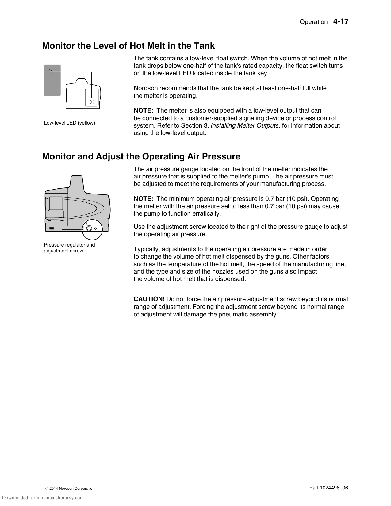
If hot melt inadvertently spills inside the pump compartment or other interior spaces, the exterior panels can be removed in order to clean out the spilled hot melt.
WARNING! Risk of electricution and fire! Do not clean the melter with a direct stream of water or steam. Use only water or an appropriate, non‐flammable cleaning solution that is applied using a clean cloth. Cleaning the melter using a direct stream of water or steam or a flammable solvent can result in property damage and personal injury, including death.
############### To clean the exterior of the melter
Use citrus‐based or other cleaning compounds that are compatible with polyester.
Apply cleaning compounds using a soft cloth. Do not use pointed or sharp tools to clean the exterior surface.
To remove and replace the exterior panels See Figure 5‐2.
NOTE: The location of the screws on the P7 and P10 melter vary slightly from Figure 5‐2.
NOTE: When re‐installing panel P4, ensure that the metal hooks on P4 engage the hinge pin before rotating the panel back into position.
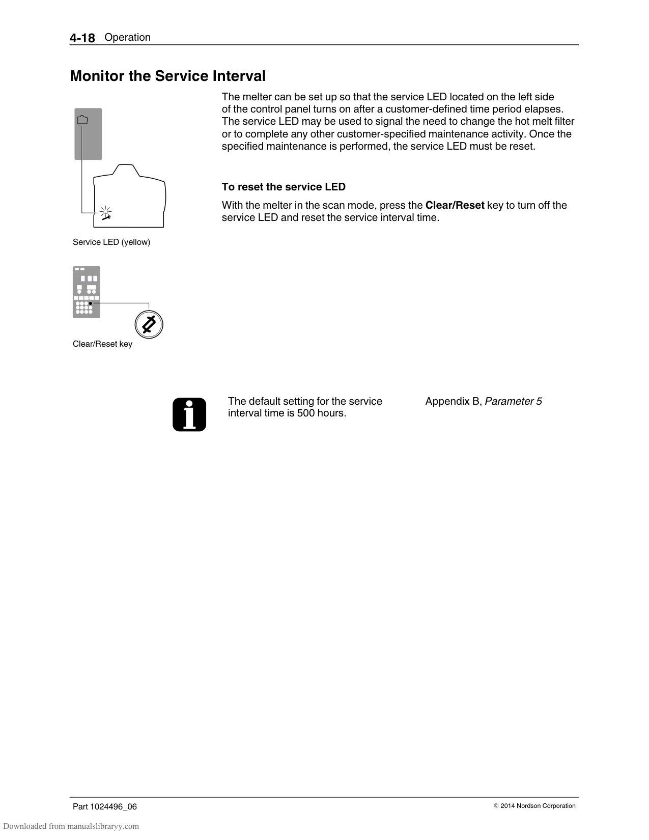
P1
P2
| | | |---|---| | | |
| | | |---|---| | | |
P3
P4
#### Replacing the Filter
Filter location
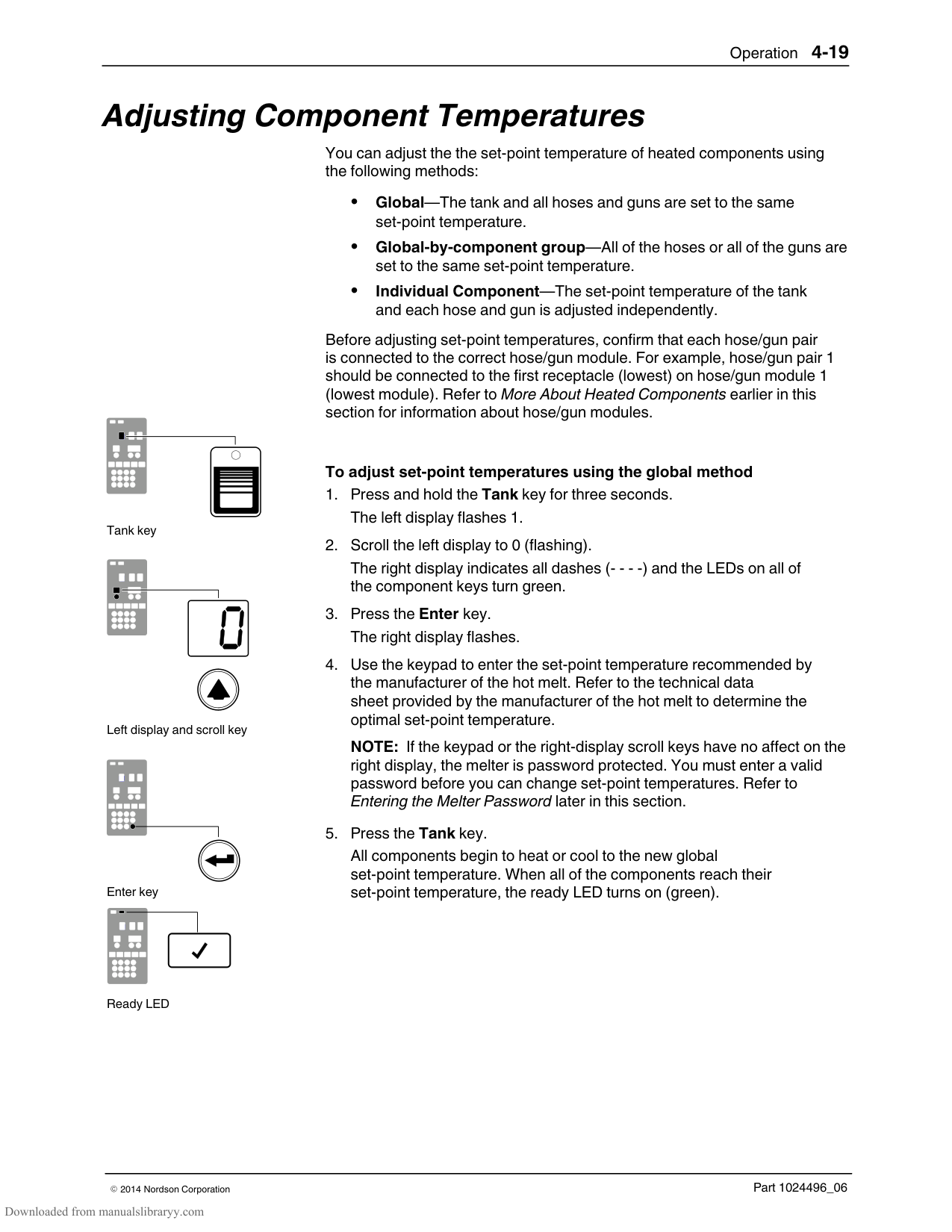
ProBlue melters are equipped with a 100‐mesh (.15 mm) disposable hot melt filter. The filter removes debris and char from the hot melt as it flows from the tank. Hot melt flows from the inside to the outside of the filter, trapping contaminants inside the filter. There is no need to back‐flush or clean the filter.
When the filter reaches the end of its service life, it should be replaced. The factors that determine the service life of the filter are:
the type, grade, and purity of the solid‐form hot melt the set point temperature of the tank the period of time that the hot melt remains in the tank
| | | | | | | |---|---|---|---|---|---| | | | | | | | | | | | | | | | | | | | | | | | | | | | | | | | | | | |
Hot melt flow path
The filter should also be replaced when making the change to a different type or grade of hot melt.
To determine the optimal service life for the filter, monitor and compare the total number of hours that the heaters are on with observations of:
the purity of the dispensed hot melt increases in operating pressure the frequency of gun nozzle replacement or cleaning
########### Monitoring the Life of the Filter
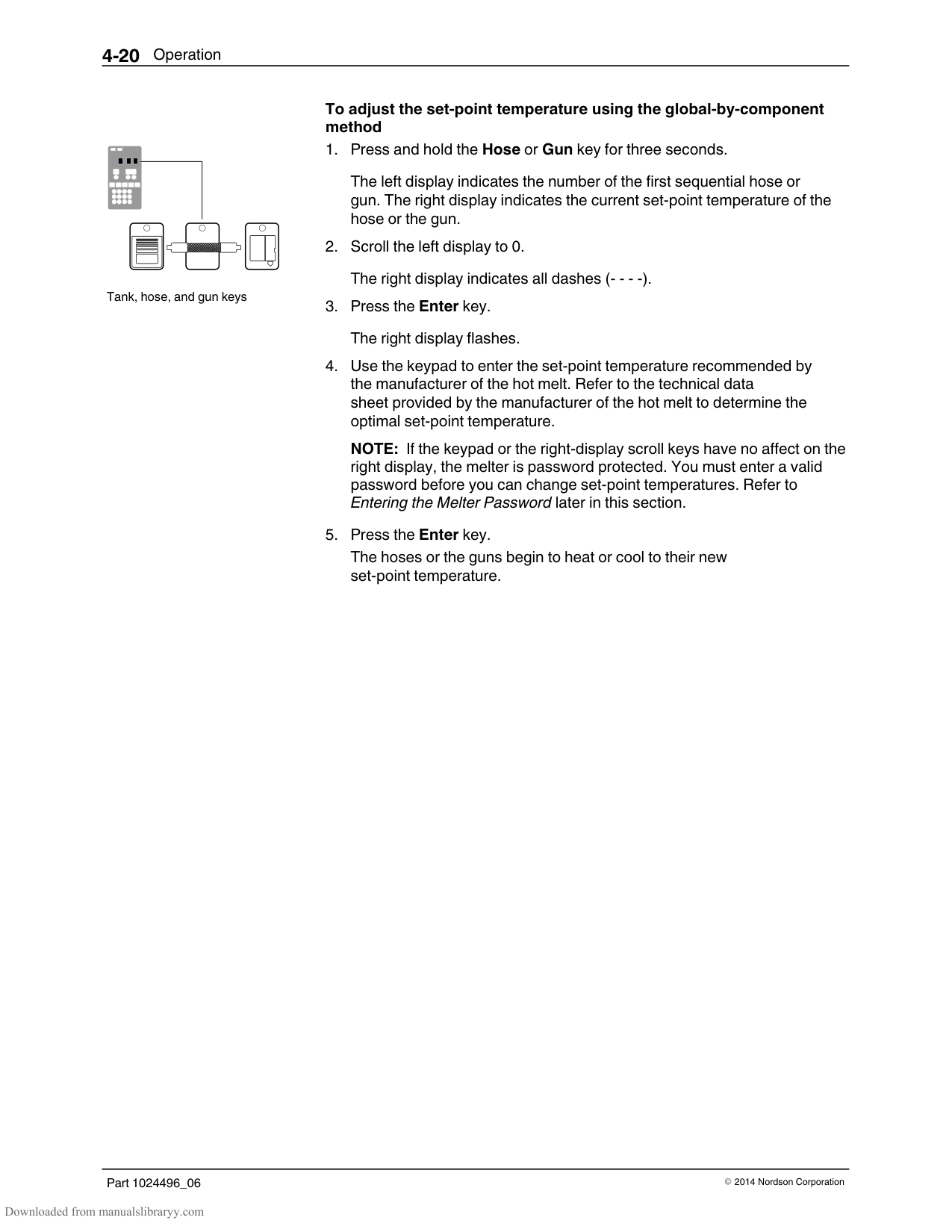
As an aid to ensuring that the filter is replaced at the end of its service life, the melter is equipped with a service LED that turns on at the end of a customer‐defined time period. You can use this feature to alert you when it is time to change the filter. Refer to Section 3, Setting Up the Melter, for information about the service interval time.
When the service LED turns on, replace the filter, and then press the Clear/Reset key to reset the timer and turn off the service LED. NOTE: The melter must be in the automatic scan mode when you press the Clear/Reset key.
Pump key
Loosening the filter
To replace the filter NOTE: Instructions for replacing the filter are also provided on the inside of the pump enclosure door.
#### Cleaning the Tank
To avoid the problems that can occur when different hot melt materials are mixed or when hot melt char forms in the tank, clean the tank when:
changing to a different type of hot melt excessive char builds up inside the tank
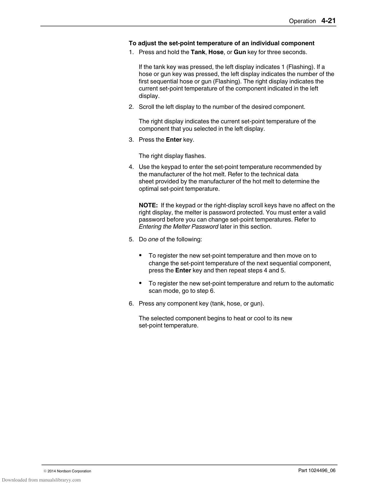
NOTE: The tank cleaning procedures provided in this section require that an appropriate hot melt cleaning fluid be used to soften or dissolve residual hot melt. Each type of hot melt should be supplied with a technical data sheet that names the appropriate cleaning fluid. If the technical data sheet is not available, contact the hot melt supplier.
Pump key
############### To clean the tank when changing hot melt
Pump key
############### To clean the tank of excessive char
See Figure 5‐1.
#### Removing the Melter from the Sub‐base
NOTE: For 400/480 VAC melters, refer to Appendix E.
See Figure 3‐5.
See Figure 3‐4.
Section 6 Troubleshooting
WARNING! Allow only qualified personnel to perform the following tasks. Follow the safety instructions in this document and all other related documentation.
This section provides quick‐reference information for diagnosing melter faults indications as well as comprehensive melter diagnostic information that is provided in flowchart format. When required, the troubleshooting flowchart will refer you to diagnostic procedures provided later in this section.
If you cannot resolve the problem using the troubleshooting flowchart, contact your Nordson representative for technical assistance.
#### 400/480 Volt Melters
Refer to Appendix E for information about troubleshooting the transformer, 400/480 volt heater information, and information about parts that are specific to 400/480 volt melters.
NOTE: With the exception of power supply and heater failure problems, the information provided in this section applies to all ProBlue adhesive melters.
#### Safety
Never disconnect cables from, or reconnect cables to, the main board while the melter is energized.
Before breaking any hydraulic connection, always relieve system pressure. Refer to Section 5, Relieving System Pressure.
Refer to the safety information provided with optional equipment. If the melter is removed from its sub‐base for diagnostic checks or service, ensure that the ground lead between the chassis and the sub‐base is re‐attached when the melter is reconnected to the sub‐base.
#### Melter Faults
Table 6‐1 lists the four types of melter faults, potential causes, and expected corrective actions.
Table 6‐1 Melter Faults
|Display Code/Sub‐code|Name|Affect on Melter|Cause|Corrective Action| |---|---|---|---|---| |F1/None|RTD|Heaters turn off|The RTD for the component indicated has failed or the component was disconnected from the melter.|Replace RTD Check hose/gun connections See flowchart T.2| |F2/None|Under temperature|Heaters turn off|The actual temperature of the component indicated has dropped below the under temperature delta, which was set using parameter 22.|Check for conditions that may cause a drop in ambient temperature
Raise the set‐point temperature of the component
Replace RTD See flowchart T.2| |F3/None|Over temperature|Heaters turn off|The actual temperature of the component indicated has increased beyond the over temperature delta, which was set using parameter 21.|Replace RTD See flowchart T.2| |F4/1|RAM test|Melter stops functioning|Internal RAM failure|Replace CPU| |F4/2|Internal Clock time|Heaters remain on, but fault condition persists|Internal clock failure|Replace CPU| |F4/4|Internal clock battery backed RAM|Heaters remain on, but fault condition persists|Battery‐backed RAM failure|Replace CPU| |F4/5|Internal clock battery|Heaters remain on, but fault condition persists|Battery‐backed RAM battery dead|Replace CPU| |F4/6|Analog‐to‐digital|Melter stops functioning|RTD analog‐to‐digital converter failed|Replace main board or CPU| |Continued...|Continued...|Continued...|Continued...|Continued...|
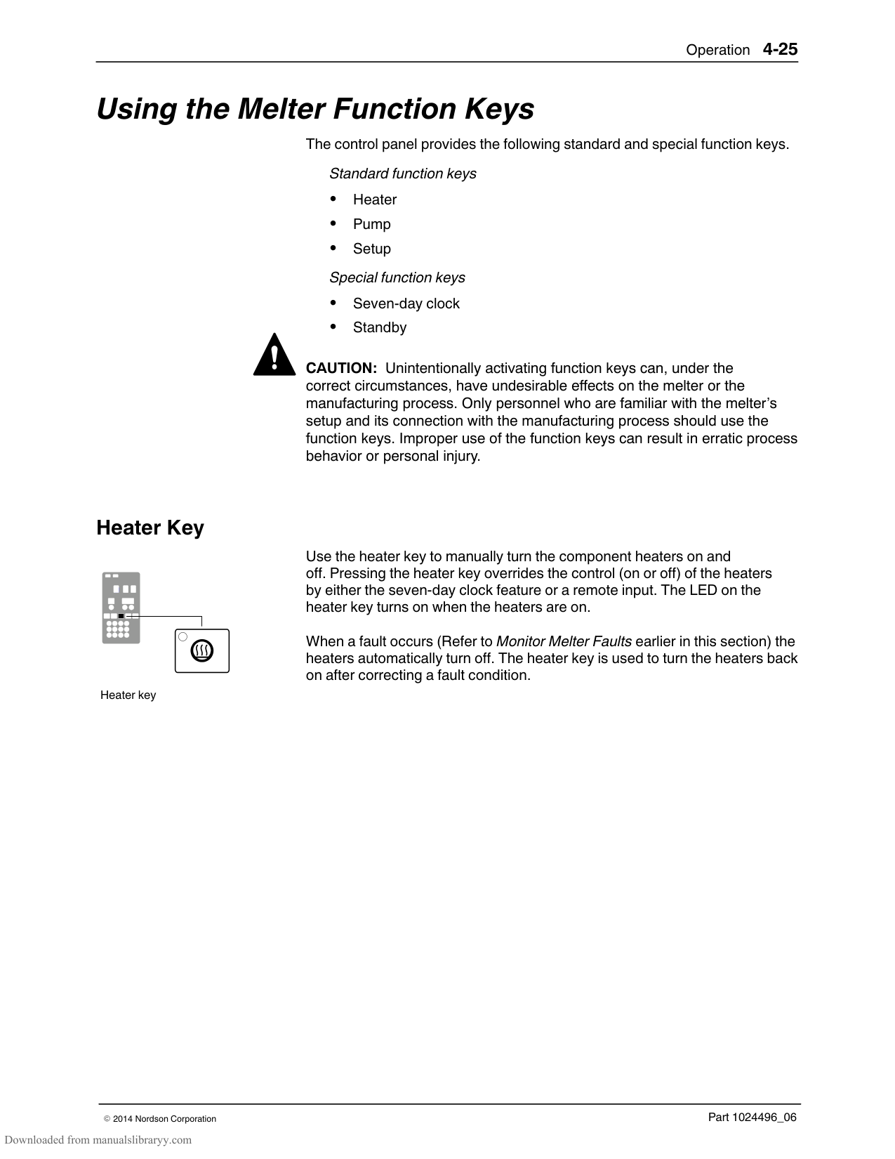
################ Table 6‐1 Melter Faults (contd)
|Display Code/Sub‐code|Name|Affect on Melter|Cause|Corrective Action| |---|---|---|---|---| |F4/7|Analog‐to‐digital calibration|Melter stops functioning|Failed hose or gun
RTD analog‐to‐digital converter could not be calibrated|Replace hose or gun. Note: Set set‐point to zero to avoid F1 fault.
Replace main board or ribbon cable, or CPU| |F4/8|Main board feedback|Melter stops functioning|Communication failure between main board and CPU|Replace main board, ribbon cable, or CPU| |F4/A|Thermostat|Melter stops functioning|Tank or manifold thermostat is open|Replace thermostat, J7 harness, or main board| |F4/d|Communications with optional I/O card|Heaters remain on, but fault condition persists|Communication failure between CPU and the optional I/O card|Replace the I/O card or CPU| |F4/E|Fieldbus communications failure|Alert output (if output option 6 is selected) Melter continues to operate normally.|Fieldbus card failure.|Replace the Fieldbus card|
#### Using the Troubleshooting Flowchart
a
b
Troubleshooting question and action blocks
a) Question b) Action
The flowchart, which is provided at the end of this section, is designed to assist you in diagnosing and correcting a complete or partial stop in hot melt output from the guns. The chart is organized in a simple question‐action block format. If your response to a question is yes (Y), continue downward in the chart to the next question or action block. If you response is no (N), continue to the right to the next question or action block. All diagnostic paths within the chart end with an action block that specifies one of the following three courses of action:
Refer to information provided elsewhere in this manual Replace a component Complete a diagnostic procedure (DP.x)
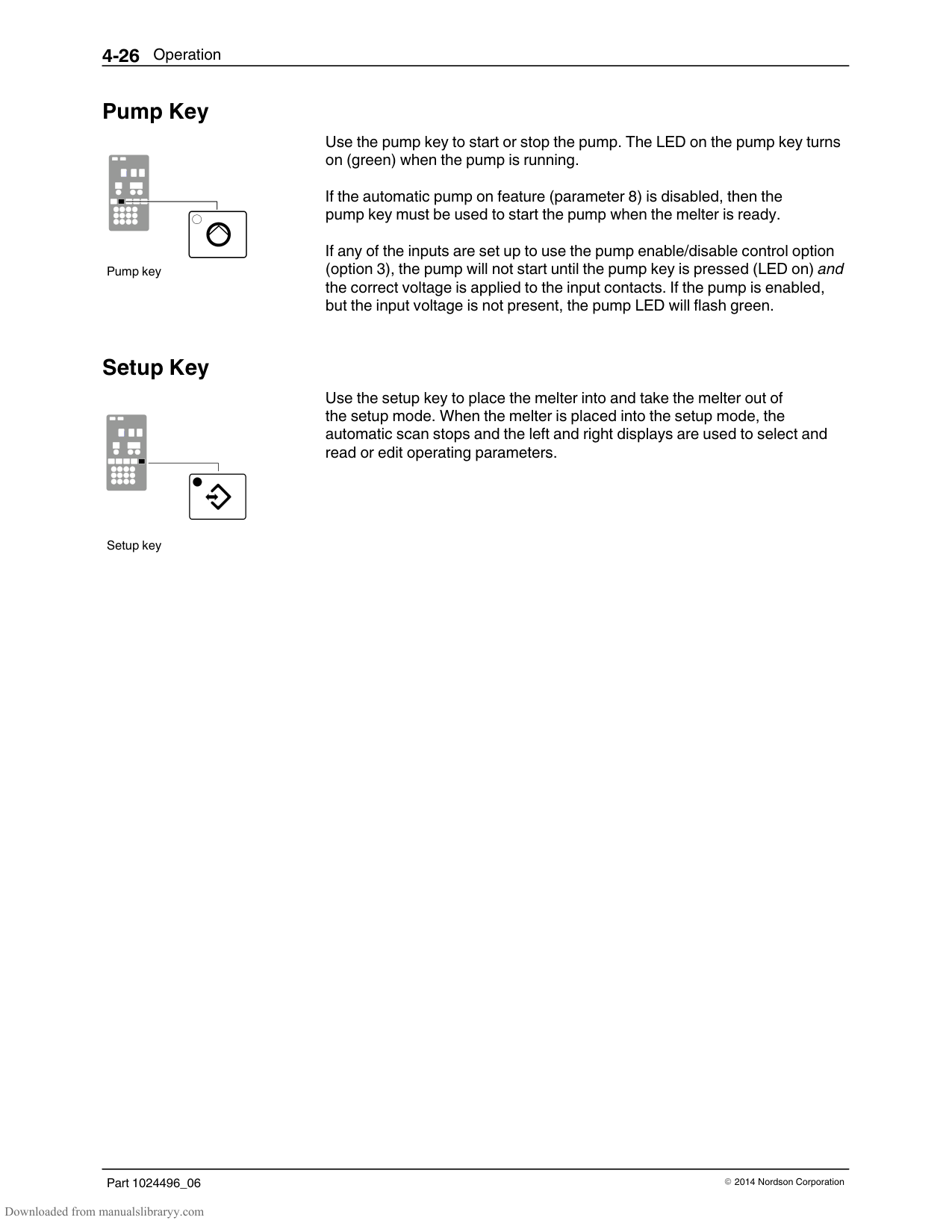
To return your melter to service as quickly as possible, the chart is designed under the assumption that it is preferable to immediately replace a faulty assembly as opposed to conducting detailed diagnostics and repair of the assembly while the melter is out of service.
Use of the chart assumes that the melter is installed correctly and that it is set up to support the current manufacturing process. Refer to Section 3, Installation, for information about installing and setting up the melter.
######## Troubleshooting Quick‐checks
Before using the troubleshooting charts confirm:
whether or not service was recently performed on the melter or the melter's settings were recently adjusted.
the correct voltage plug is installed on terminal J1. Refer to Section 3, Installation, for information about selecting the correct voltage plug.
external inputs (if used) are functioning properly. the standby or clock functions are not turned on (if not required or expected at the current time).
######## Returning the Melter Setup to Factory Settings
By returning the melter to its factory setting many common melter problems can be isolated to either a problem with the melter settings or the melter hardware.
To return the melter to its factory settings, simultaneously press and hold the Setup key and the right‐display DOWN arrow key, and then, while holding down these keys, cycle the melter control switch off and on. When the melter restarts, release the two keys.
######## Identifying Electrical Components
Tables 6‐2 through 6‐5 describe the circuit board indicators, connection points, and test points that are referred to in the troubleshooting flowchart. Figure 6‐1 illustrates the location of each of these circuit board components.
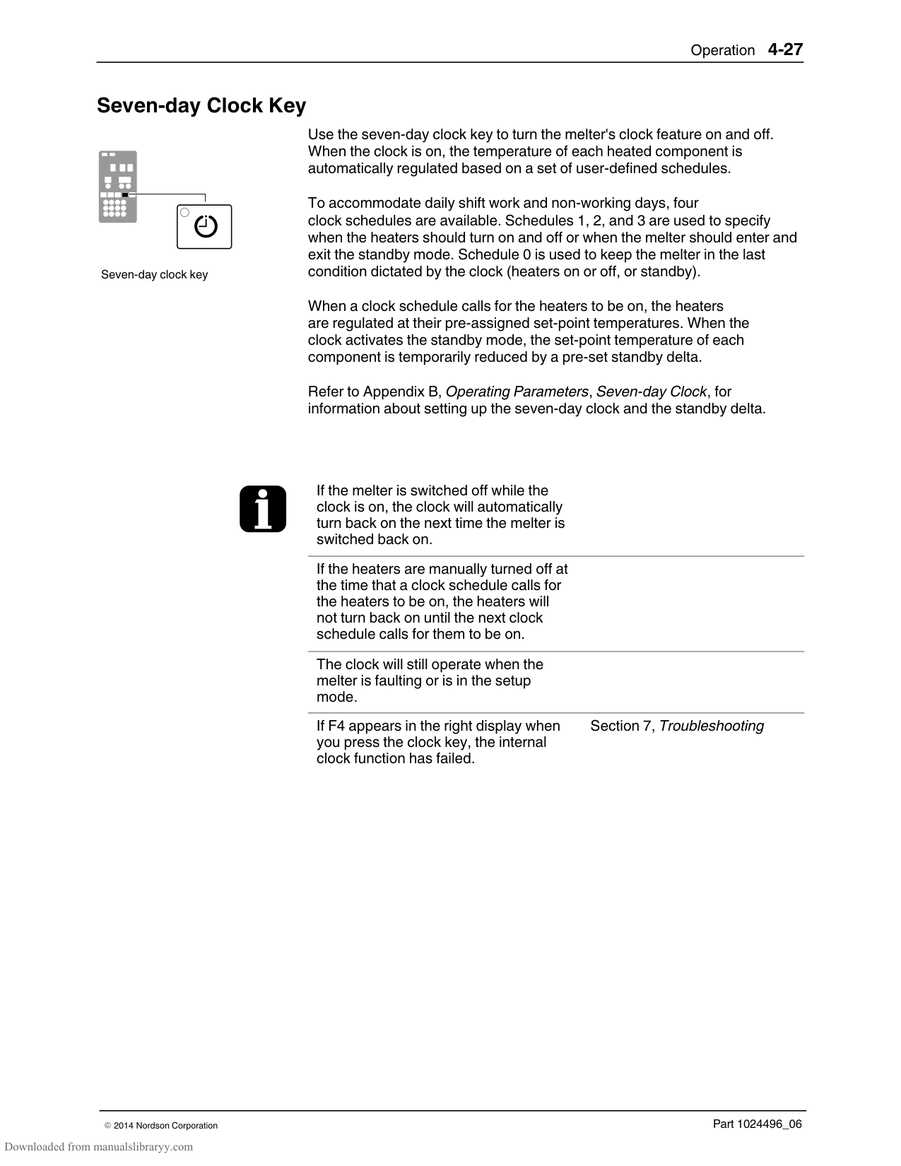
|Item Number|Type|Description| |---|---|---| |Indicators|Indicators|Indicators| |DS1|LED (Yellow)|Control signal for tank heater| |DS2|Neon (Orange)|Power available for tank and manifold heaters after fuses F1/F2| |DS3|LED (Yellow)|Control signal for manifold heater| |DS4|Neon (Orange)|Power available into main board after fuses F3/F4| |DS5|LED (Green)|+5 VDC control voltage present on board| |Fuses|Fuses|Fuses| |F1/F2|—|15 A, 250 V, Fast‐acting, 1/4 inch| |F3/F4|—|2 A, 250 V, Slow‐blow, 5 x 20 mm| |Connection Points|Connection Points|Connection Points| |J1/J2|Jumper|Voltage configuration plug with and without neutral| |TB1|Input|AC power into board| |TB2|Input/output|Output contacts 1–6. Input contacts 7–14| |J5|Input/output|Control signal between main board and 6‐hose expansion board| |J6|Output|Power harness for tank and manifold heaters| |J7|Input/Output|Control signal harness (RTD, control switch, thermostat, solenoid). See Figure 6‐2 for pin‐out.| |J8|Input/Output|Analog/digital signal cable| |J9|Output|Control signal to 400/480 VAC transformer| |J10|Input|AC power out to 6‐hose expansion board|
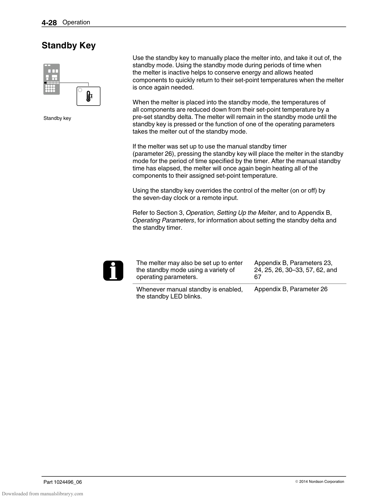
######## Identifying Electrical Components (contd)
|Item Number|Type|Description| |---|---|---| |Indicators|Indicators|Indicators| |Red LED|—|Indicates that CPU board has failed| |Green LED|—|+ 5 VDC control voltage is present at the CPU board| |Connection Points|Connection Points|Connection Points| |J1|Input/Output|Control signal between main PCA and CPU| |J5|Input/Output|Control signal between I/O expansion card or Anybus card and the CPU| |Test Points|Test Points|Test Points| |TP2/TP4|Contacts|4.75–5.25 V control voltage present at CPU|
Table 6‐4 Hose/Gun Power Module
|Item Number|Type|Description| |---|---|---| |Indicators|Indicators|Indicators| |DS1|LED (Yellow)|Control power present for odd numbered hose| |DS2|LED (Yellow)|Control power present for odd numbered gun|
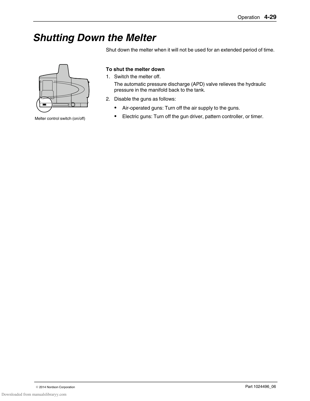
|DS3|LED (Yellow)|Control power present for even numbered hose| |DS4|LED (Yellow)|Control power present for even numbered gun| |DS5|Neon (Orange)|AC power present at module for odd hose/gun pair| |DS6|Neon (Orange)|AC power present at module for even hose/gun pair| |Fuses|Fuses|Fuses| |F1/F2 and F3/F4|—|6.3 A, 250 V, Fast‐acting, 5 x 20 mm|
Table 6‐5 6‐Hose Expansion Board (optional)
|Item Number|Type|Description| |---|---|---| |Connection Points|Connection Points|Connection Points| |J1|Input/output|Control signal between 6‐hose expansion board and main board J5| |J2|Input|AC power input to 6‐hose expansion board from main board J10|
| | |---| | | | |
| | | | |---|---|---|

| | | | | | | |
| | | |---|---|
| | | |---|---|
| | | | |---|---|---| | | | | | | | |
| | | | |---|---|---|
| | | |---|---|
| | | | |---|---|---|
| | | | |---|---|---|
| | | |---|---| | | |
| | | |---|---| | | |
| | | |---|---| | | |
| | |
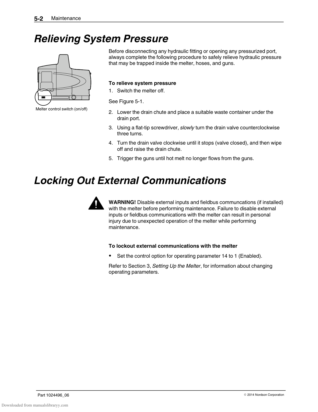
|---|---| | | |
################## Figure 6-1 Electrical components
################## Figure 6-2 Power and control harness
################## Figure 6-3 Location of the return port
1
2
3
#### Diagnostic Procedures
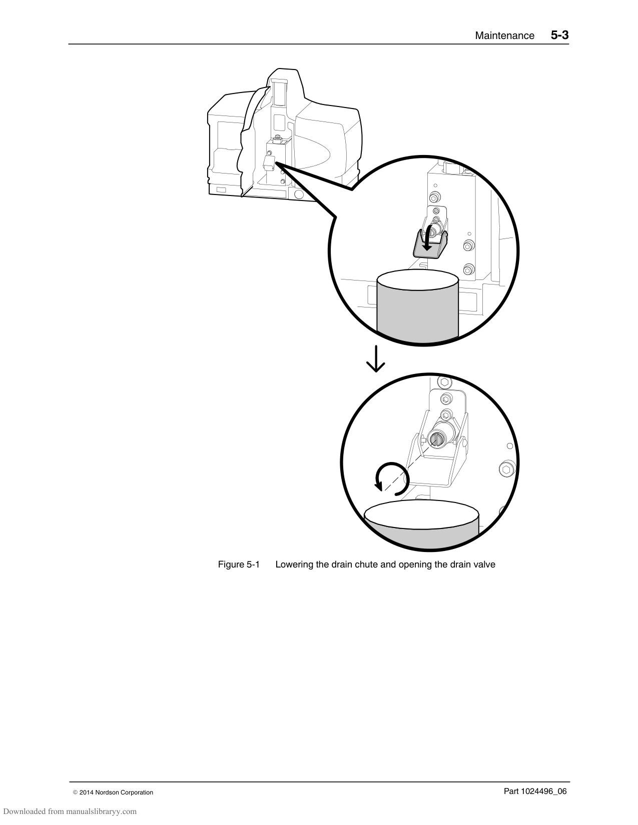
Use these diagnostic procedures when directed by the troubleshooting flowchart. If a diagnostic procedure fails to identify or correct the problem, return to the troubleshooting flowchart or contact your Nordson representative for technical assistance.
######## DP.1 Isolate a Failed Control Component
If DS5 does not illuminate, replace the main board (P4 or P7 melters, use P/N 1028322; P10 melter, use P/N 1038323).
If DS5 does illuminate, go to step 6.
Replace the component (CPU or hose/gun module) that causes LED DS5 not to illuminate when the melter is re‐energized.
######## DP.2 Check the Tank or Manifold RTD
NOTE: If the melter has already cooled down, solidified hot melt within the pump/manifold will prevent you from removing the pump. To remove the pump, you must reheat the melter. Refer to Reheating the Melter During an F1 Fault at the end of this procedure.
See Figure 6‐2.
See Figure 6‐5.
If the measured resistance is within the expected resistance range, the RTD is functioning properly. Replace the main board (P4 or P7 melters, use P/N 1028322; P10 melter, use P/N 1038323).
If the measured resistance is not within the expected resistance range, the RTD is defective. Replace the RTD (P/N 1028320).
########### Reheating the Melter During an F1 Fault
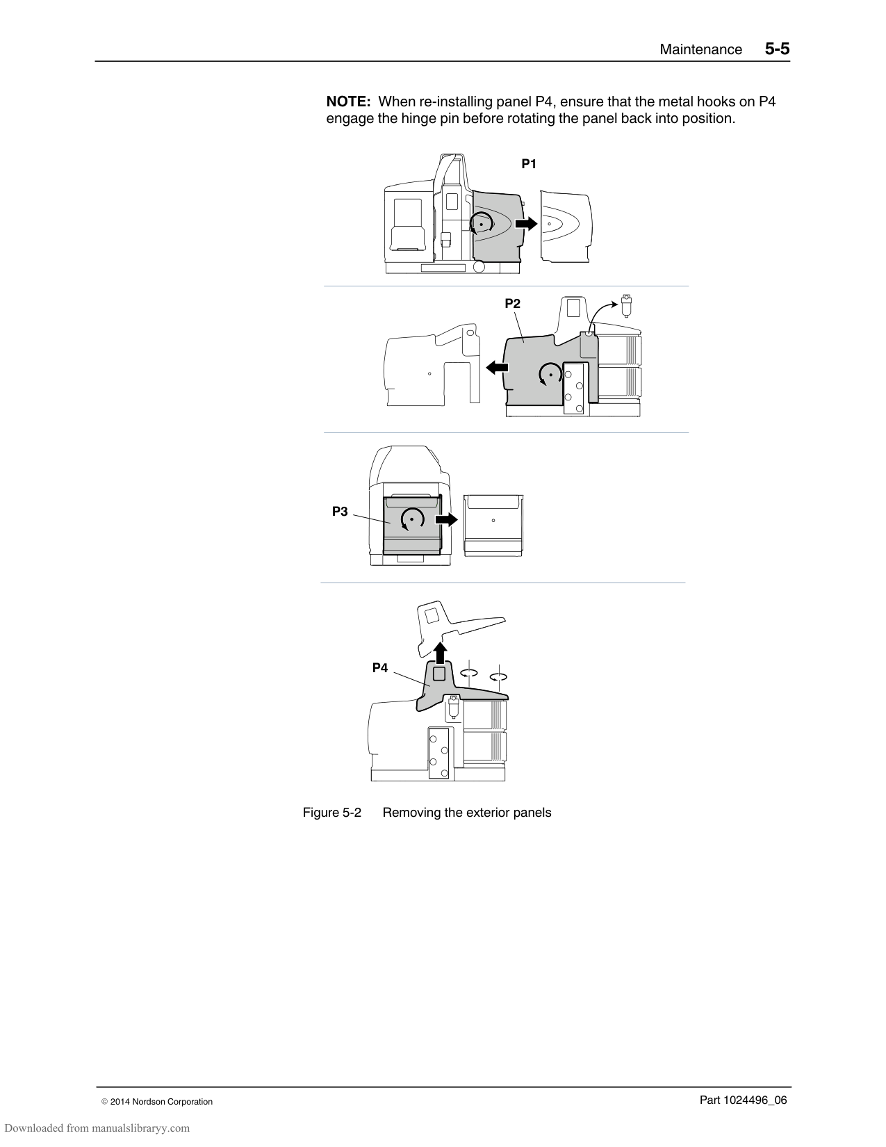
The left display will flash dashes at one second intervals to indicate that the melter is heating in the override mode. The melter will remain in the override mode for 20 minutes and then automatically switch off.
WARNING! Risk of electrocution! The control switch will remain in the on position when the melter automatically switches off after 20 minutes. Ensure that the control switch is moved back to the off position.
Removing the tank RTD
########### Remove the Tank RTD
NOTE: If the RTD is functioning properly, apply thermal compound (provided in RTD service kit P/N 1028320) to the RTD before replacing it in the retention slot.
########### Remove the Manifold RTD
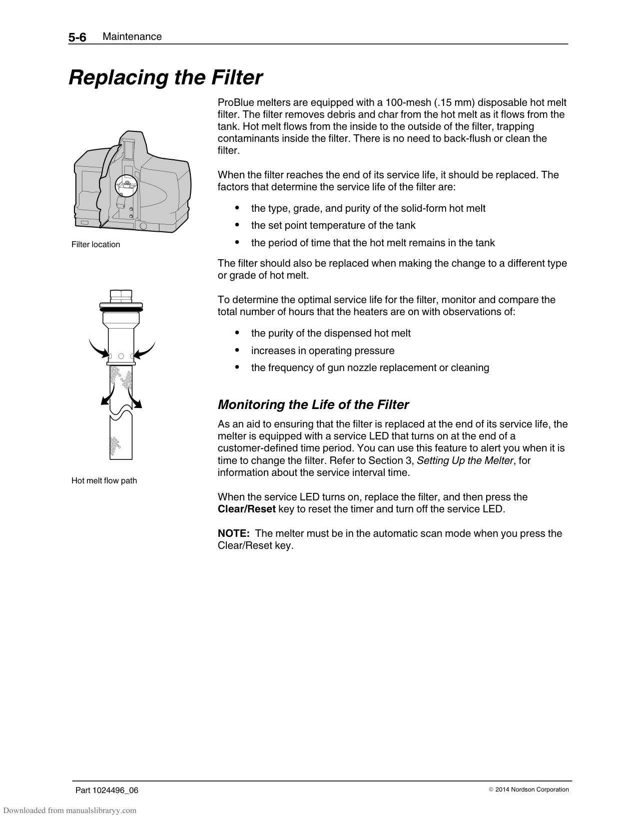
NOTE: The face of the pump body contains two M6 threaded holes. Bolts can be threaded into these holes to gain leverage when removing the pump.
CAUTION! Before replacing the pump, ensure that the cross‐over tube is in‐place between the pump and the manifold.
NOTE: Before replacing the RTD, apply thermal compound (P/N 1023441) to the RTD and its retention slot. To avoid damage to the RTD, ensure that the RTD is correctly inserted into its retention slot before replacing the pump.
######## DP.3 Check the Operation of the Power Relay or Thermostats
Removing a hose/gun module
The pre‐conditions for this diagnostic procedure are as follows: The heater LED is illuminated. Indicator DS2 on the main board is not illuminated. Indicators DS5 and DS6 on all hose/gun modules are not illuminated.
NOTE: If an F1 fault re‐occurs after re‐energizing the melter, reset the melter and turn the heaters back on.
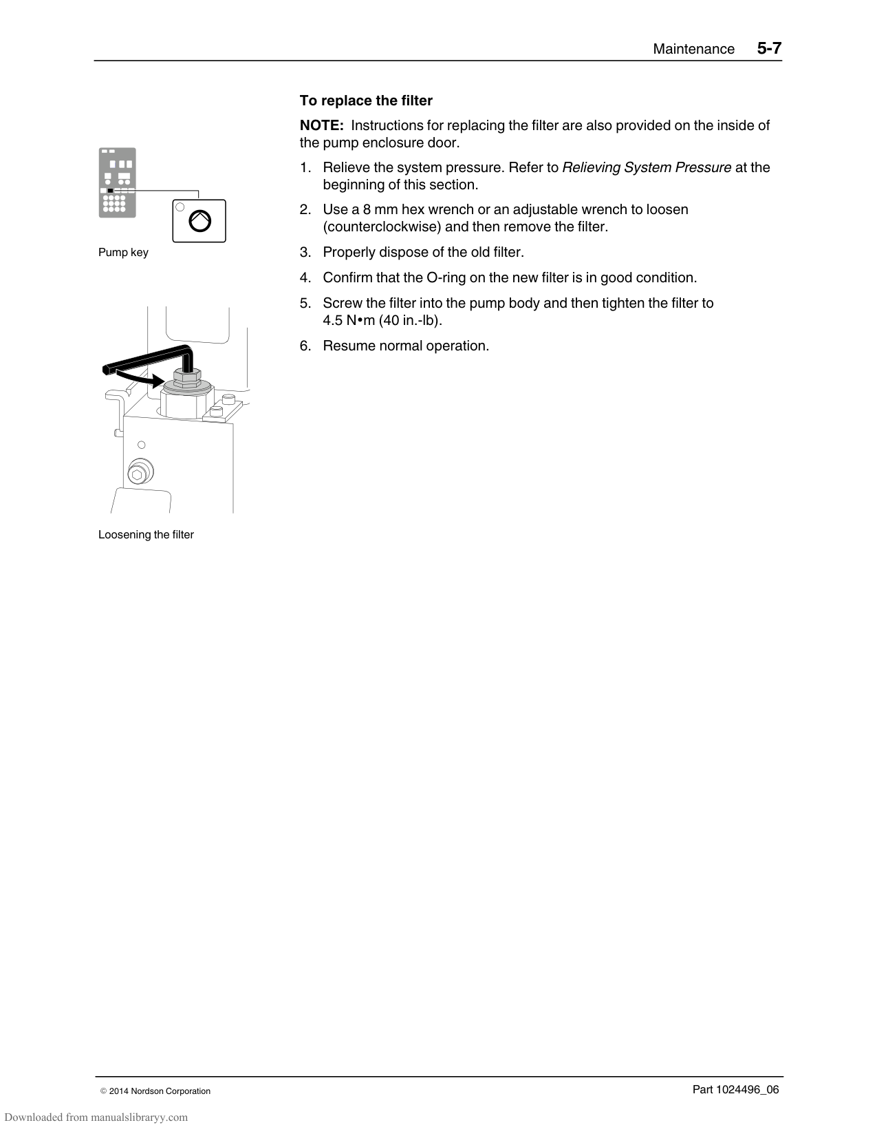
Replace the hose/gun module that causes LED DS5 not to illuminate when the melter is re‐energized.
######## DP.4 Check the Operation of the Tank or Manifold TRIAC
See Figure 6‐1.
WARNING! Risk of electrocution! Ensure that disconnect switch that serves the melter is in the off position and locked.
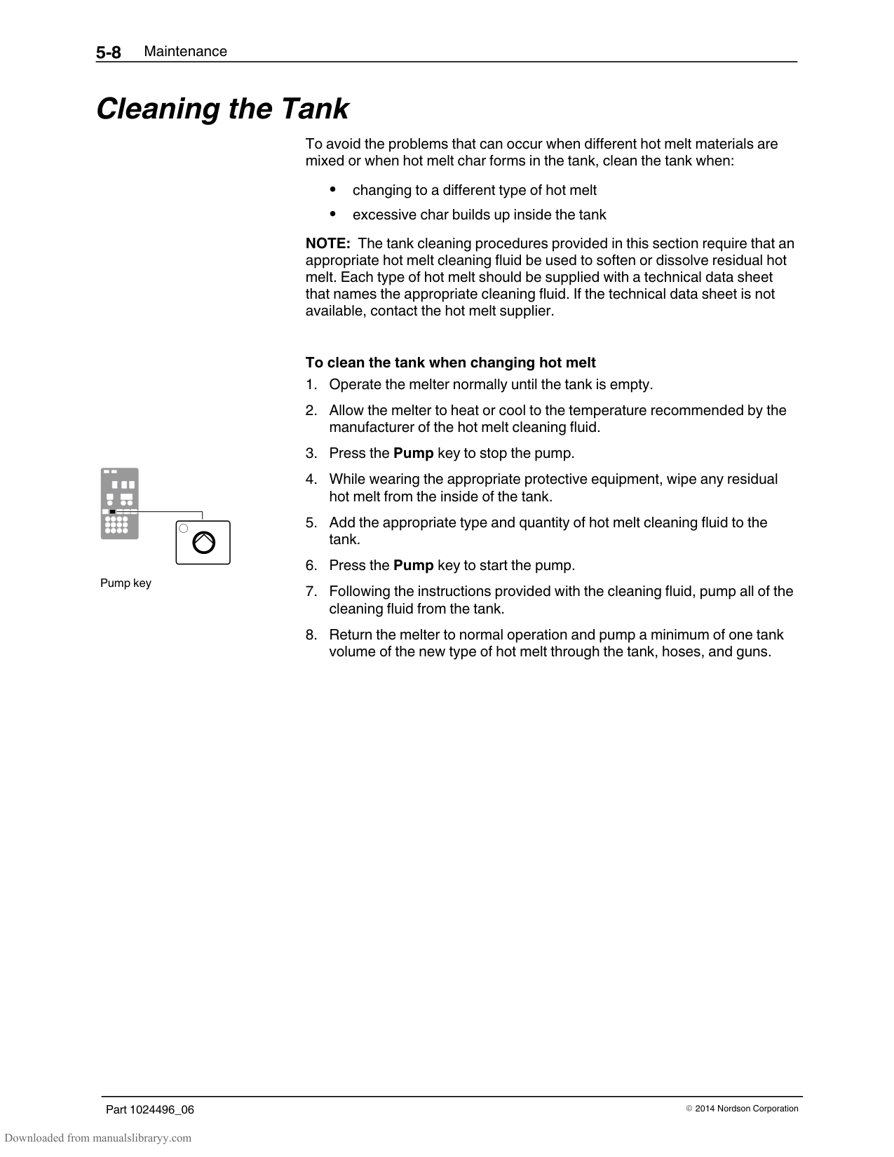
Replace the main board if either of the above voltage conditions are incorrect (P4 or P7 melters, use P/N 1028322/P10 melter, use P/N 1038323).
######## DP.5 Check the Resistance of the Tank and Manifold Heaters
WARNING! Risk of electrocution! Ensure that disconnect switch that serves the melter is in the off position and locked.
If the resistance is within the range shown in Table 6‐6, go to step 4. If the resistance is not within the range shown in Table 6‐6, go to step 8.
NOTE: Refer to Appendix E for 400/480 Volt heater resistance data.
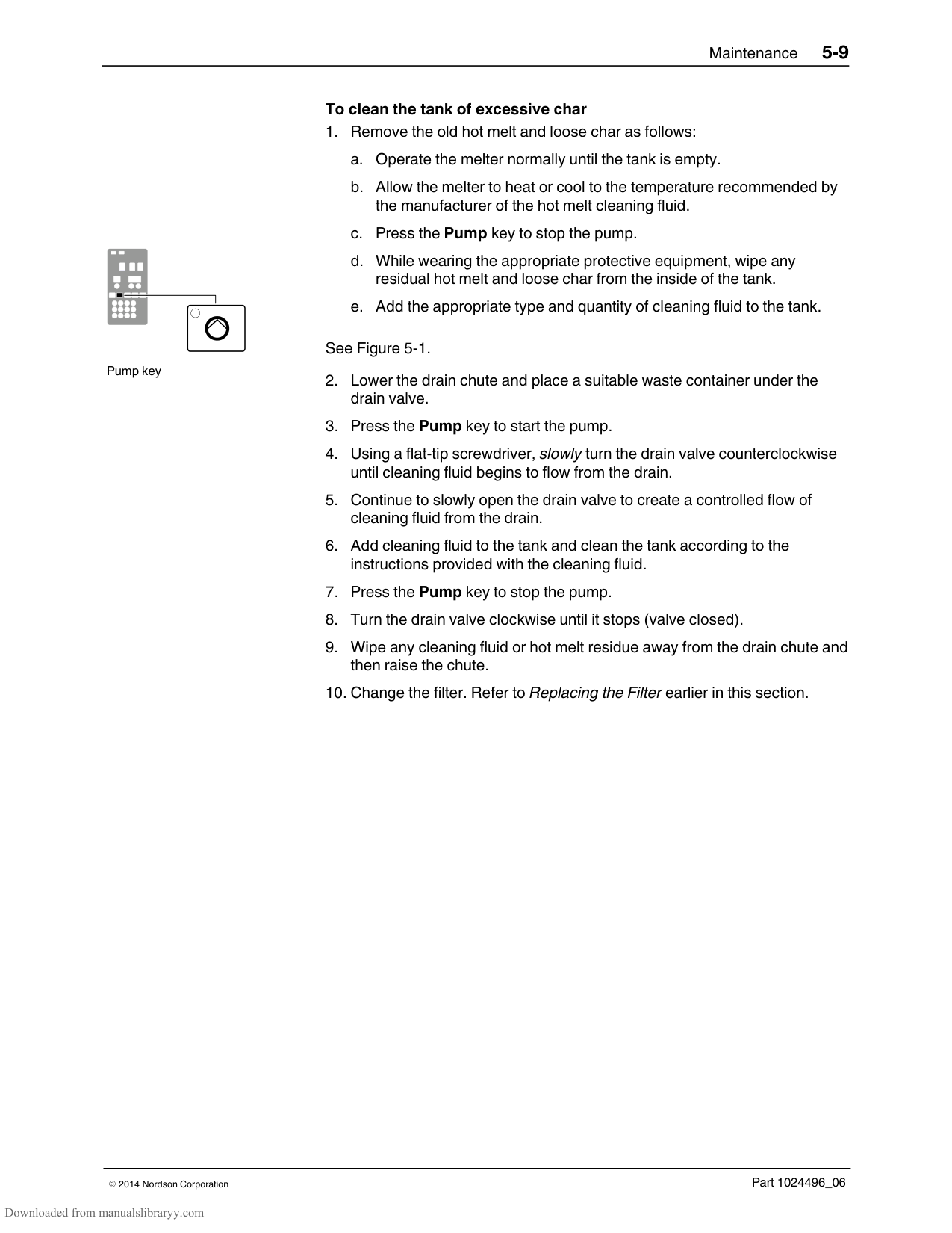
Table 6‐6 Heater Resistance
| |Resistance|Resistance| |---|---|---| |Model|Tank|Manifold| |P4|46–58 ohms|46–58 ohms| |P7|40–50 ohms|46–58 ohms| |P10|40–50 ohms|46–58 ohms|
If the resistance is greater than 1 Meg ohm, return to the troubleshooting chart.
If the resistance is less than 1 Meg ohm, go to step 5.
CAUTION! Use two wrenches and minimal force when loosening or tightening the heater terminal connections. Using a single wrench or excessive force to remove or tighten the terminals nuts can damage the heater.
######## DP.5 Check the Resistance of the Tank and Manifold Heaters (contd)
If the resistance is greater than 1 Meg ohm, replace the power harness (P/N 1024529).
If the resistance is less than 1 Meg ohm for the tank heater, replace the tank. If the resistance is less than 1 Meg ohm for the manifold, replace the manifold heater. Refer to Section 7, Parts.
If the resistance is within the range shown in Table 6‐6, replace the power harness (P/N 1024529).
If the resistance is not within the range shown in Table 6‐6 replace the tank or replace the manifold heater.
NOTE: The tank heater cannot be replaced independently.
250 240 230 220 210 200 190 180 170 160 150 140 130
| | | | | | | | | | | | | | | | |---|---|---|---|---|---|---|---|---|---|---|---|---|---|---| | | | | | | | | | | | | | | | | | | | | | | | | | | | | | | | | | | | | | | | | | | | | | | | | | | | | | | | | | | | | | | | | | | | | | | | | | | | | | | | |
| | | | | | | | | | | | | | | | | | | | | | | | | | | | | | | | | | | | | | | | | | | | | | | | | | | | | | | | | | | | | | | | | | | | | | | | | | | | | | | | | | | | | | | | | | | | | | | | | | | | | | | | | | | | | | | |
################### RESISTANCE IN OHMS
TEMPERATURE
290 280 270 260
| | | | | | | | | | | | | | | | |---|---|---|---|---|---|---|---|---|---|---|---|---|---|---| | | | | | | | | | | | | | | | | | | | | | | | | | | | | | | | | | | | | | | | | | | | | | | | | | | | | | | | | | | | | | | | | | | | | | | | | | | | | | | | | | | | | | | | | | | | | | | | | | | | | | | | | | | | | | | | | | | | | | | | | | | | | | | | |
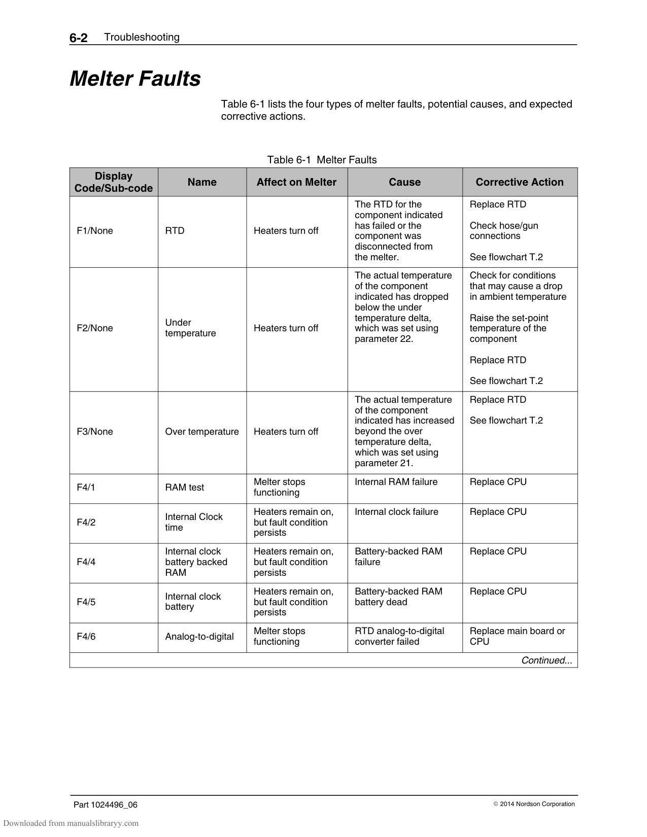
| | | | | | | | | | | | | | | | | | | | | | | | | | | | | | | | | | | | | | | | | | | | | | | | | | | | | | | | | | | | | | | |
RESISTANCE IN OHMS
250 240 230 220 210 200 190 180 170
TEMPERATURE
################## Figure 6-6 Removing the pump
Part 1024496_062014Nordson Corporation
######### Start ProBlue
#################### For 400/480V melter troubleshooting, refer to Appendix E.
######### Troubleshooting Flowcharts
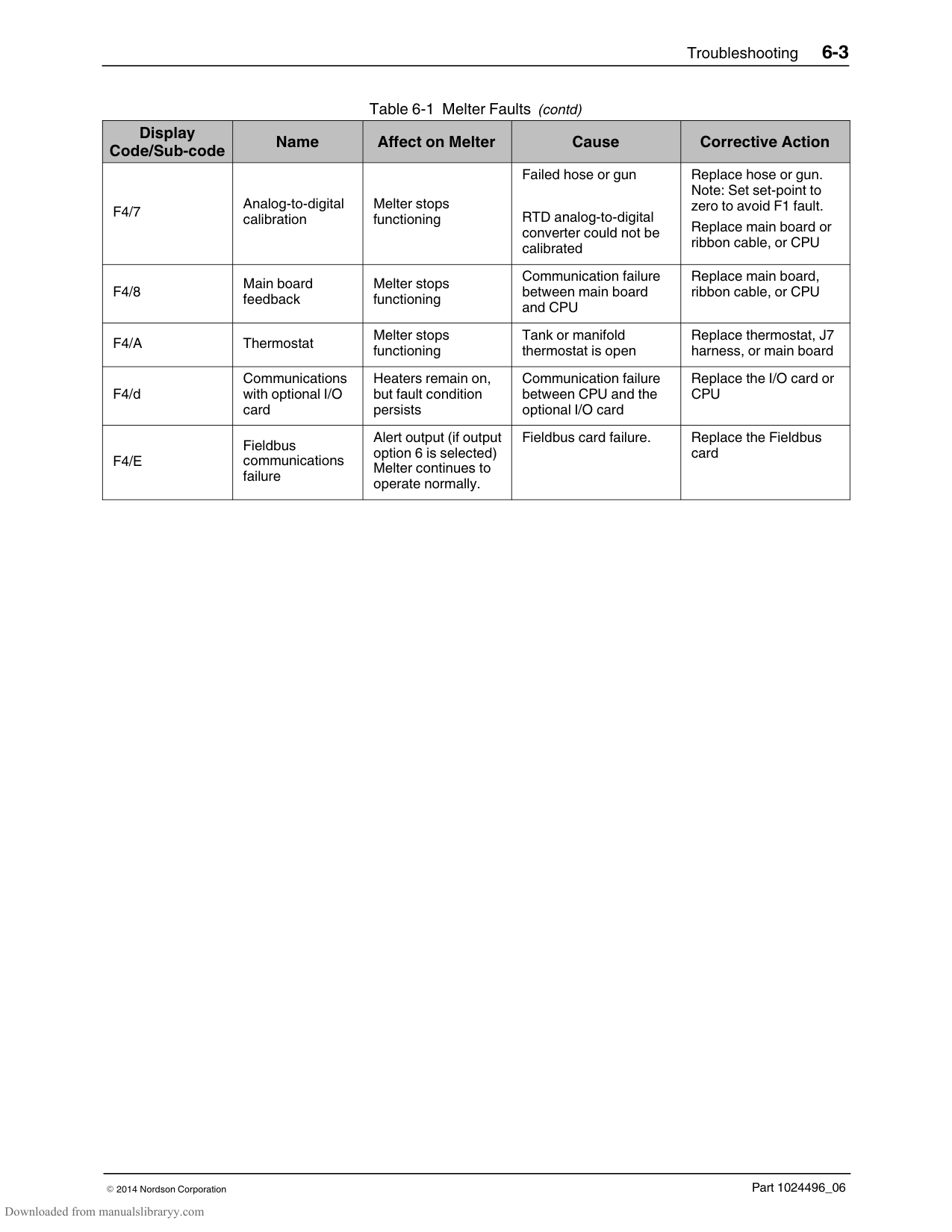
Is the control panel illuminated?
|Go to T.1| |---|
−
+
Do dashes appear in both the left and the right display?
Do the words “UP LOAd” or “COnF” appear across the display?
Is the fault LED illuminated?
Is the ready LED illuminated?
−
−
−
−
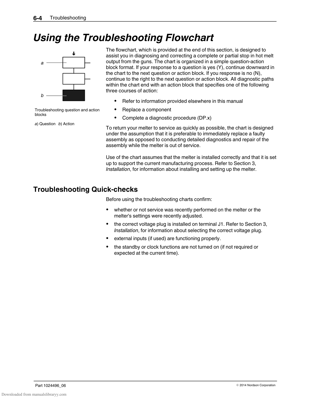
Go to T.3
+
+
+
+
Turn the control switch on. Does the melter start?
−
+
Stop.
Refer to Appendix C.
Is the wire harness that is connected to terminal J7 on the main board loose or damaged?
−
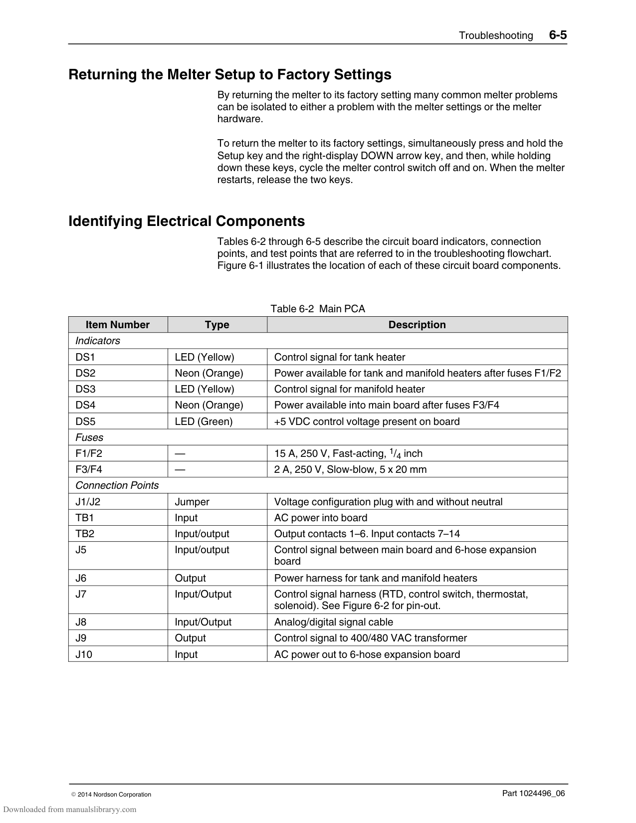
+
Turn the control switch off, secure or replace the harness, and then turn the control switch back on.
Has glue output stopped from all guns? Note: With one gun systems, both T.4 and T.5 may need to be examined to resolve the problem.
Go to T.2
Go to T.4
−
+
Replace the control switch. P/N 1017947.
Go to T.5
Troubleshooting6-21
Part 1024496_062014Nordson Corporation
This page intentionally left blank
Troubleshooting6-22
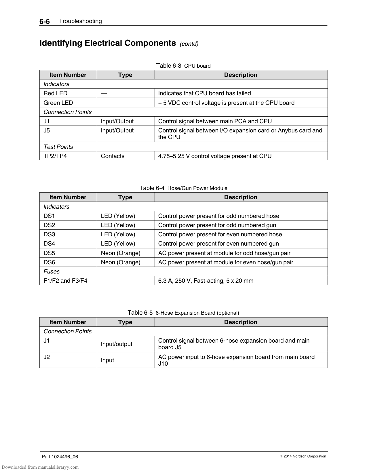
Part 1024496_062014Nordson Corporation
Quick Check: Verify that the voltage plug is correct
Is the power disconnect switch that is serving the melter turned on?
####################### Turn the disconnect switch on.
−
+
Is indicator DS4 on the main board illuminated?
Is there power at the disconnect switch?
Check/repair the plant wiring.
−
−
See Figure 6-1.
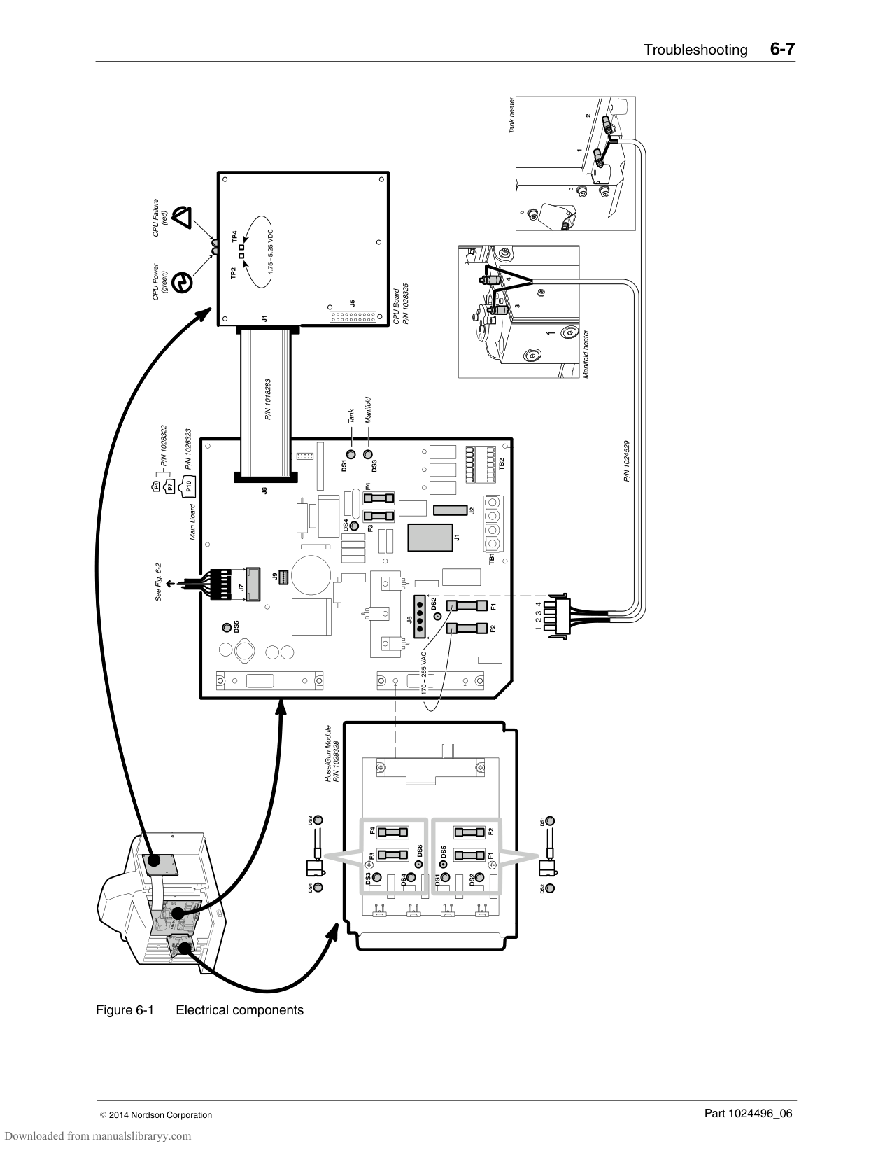
+
+
Connect securely.
Are the voltage plugs attached securely to J1 and J2 on the main board?
−
Go to T.1.1
See Figure 6-1.
+
Connect securely.
Are the wires to the electrical connector into TB1 secure?
−
See Figure 6-1.
+
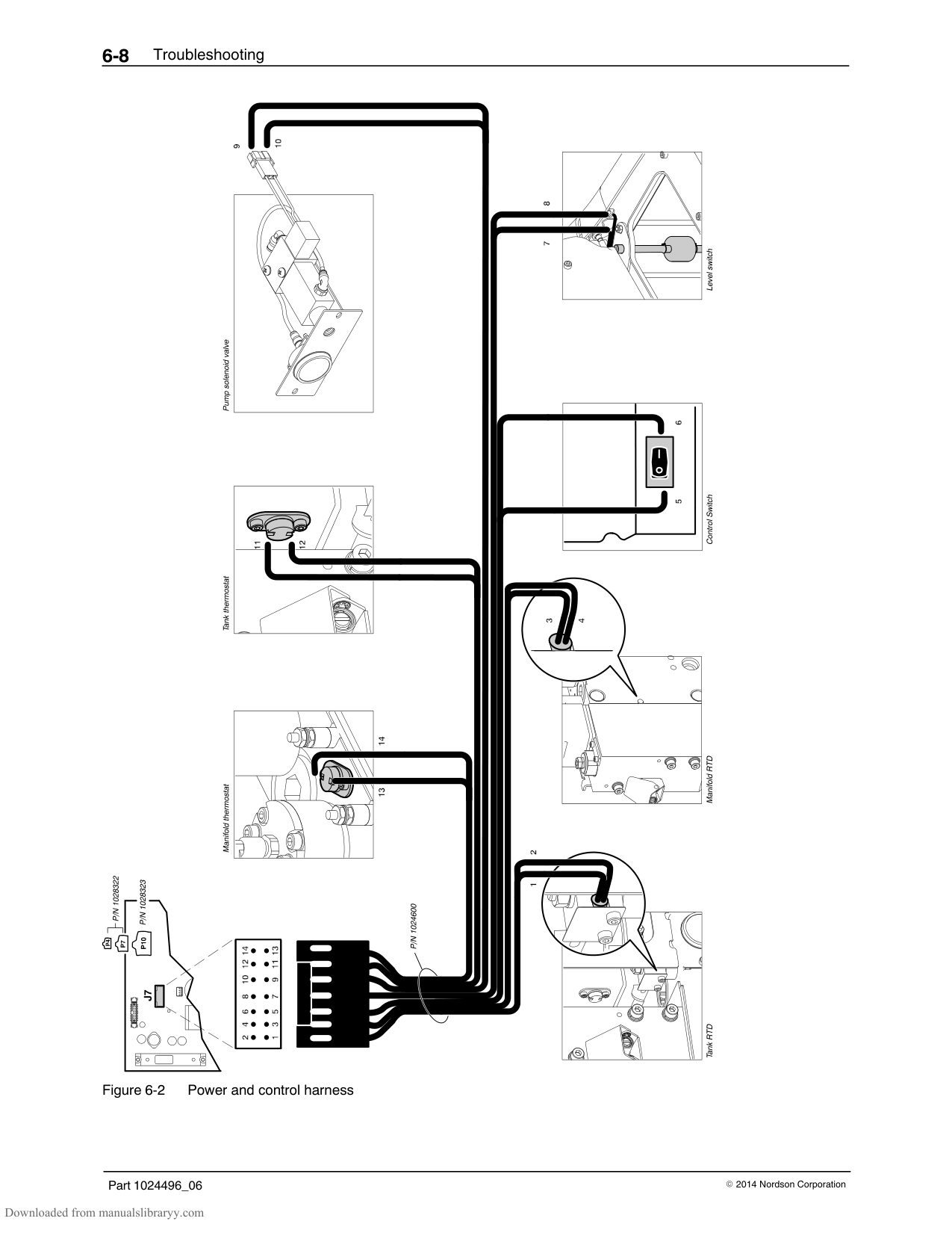
Continued on next page....
##### T.1
Starting Condition: Control panel is not illuminated
Troubleshooting6-23
Part 1024496_062014Nordson Corporation
Continued from previous page....
Is there voltage across the wires in the power cable from the disconnect switch to TB1?
Replace the power cable.
−
+
Is there voltage on the downstream side of fuses F3 and F4 on the main board?
Replace fuses F3 and F4. P/N 1028329.
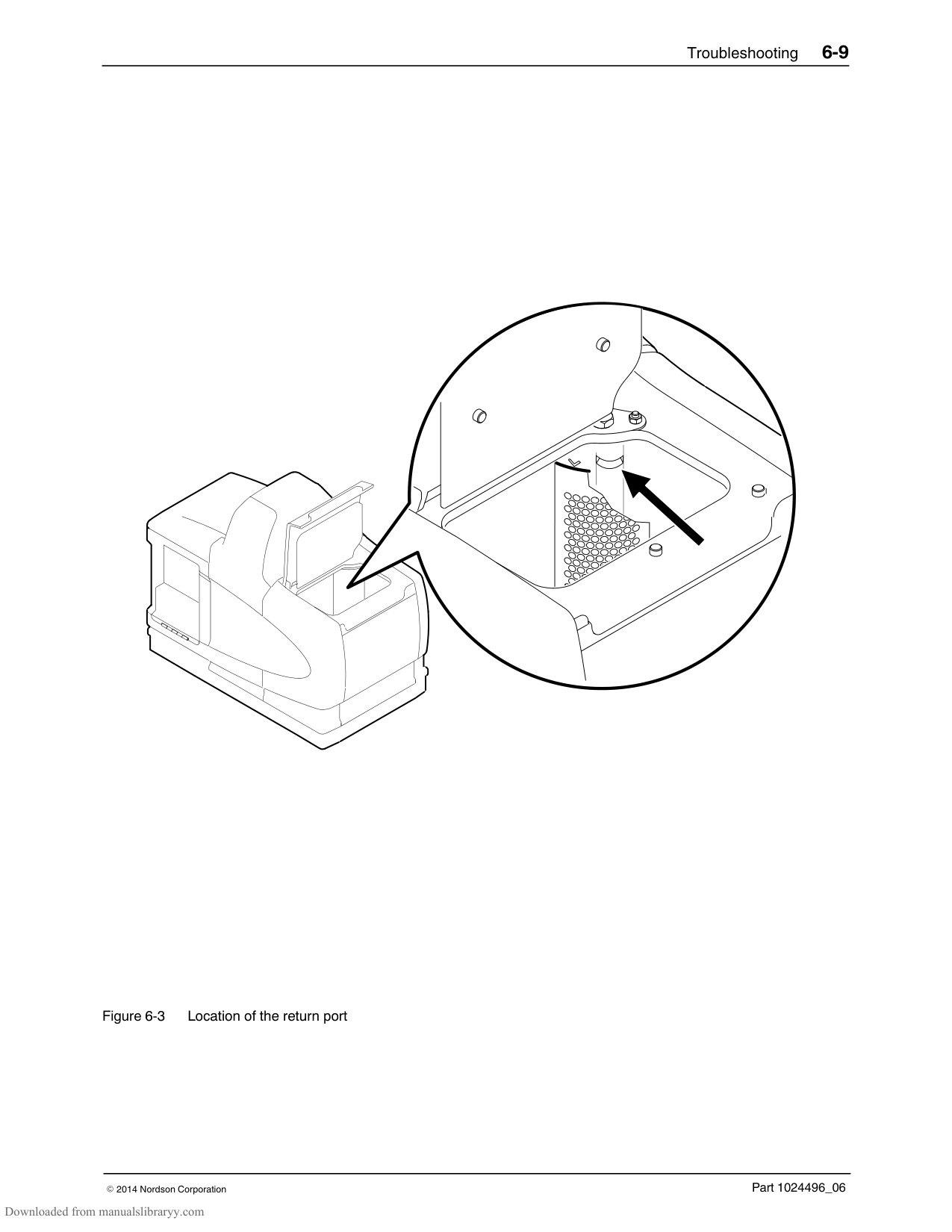
−
See Figure 6-1.
+
Replace the main board assembly.
P4/P7 − P/N 1028322. P10 − P/N 1028323.
##### T.1
Starting Condition: Control panel is not illuminated
Troubleshooting6-24
Part 1024496_062014Nordson Corporation
##### T.1.1
Is LED DS5 on the main board illuminated?
Isolate the failed control component.
Starting conditions: Control panel is not illuminated > Disconnect switch is on > DS4 is illuminated
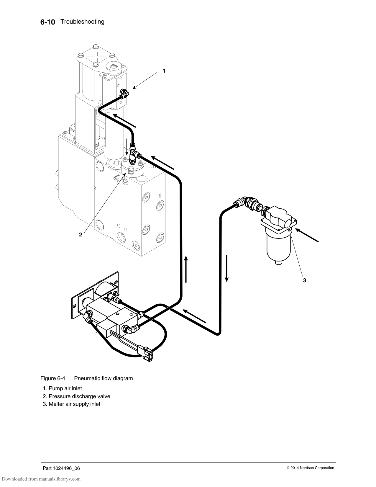
−
See Figure 6-1.
Refer to DP.1.
+
Is the green power LED on the CPU board illuminated?
Is the ribbon cable between the main board and the CPU board improperly aligned, loose or visibly damaged?
Replace the CPU. P/N 1028325.
−
−
See Figure 6-1.
See Figure 6-1.
+
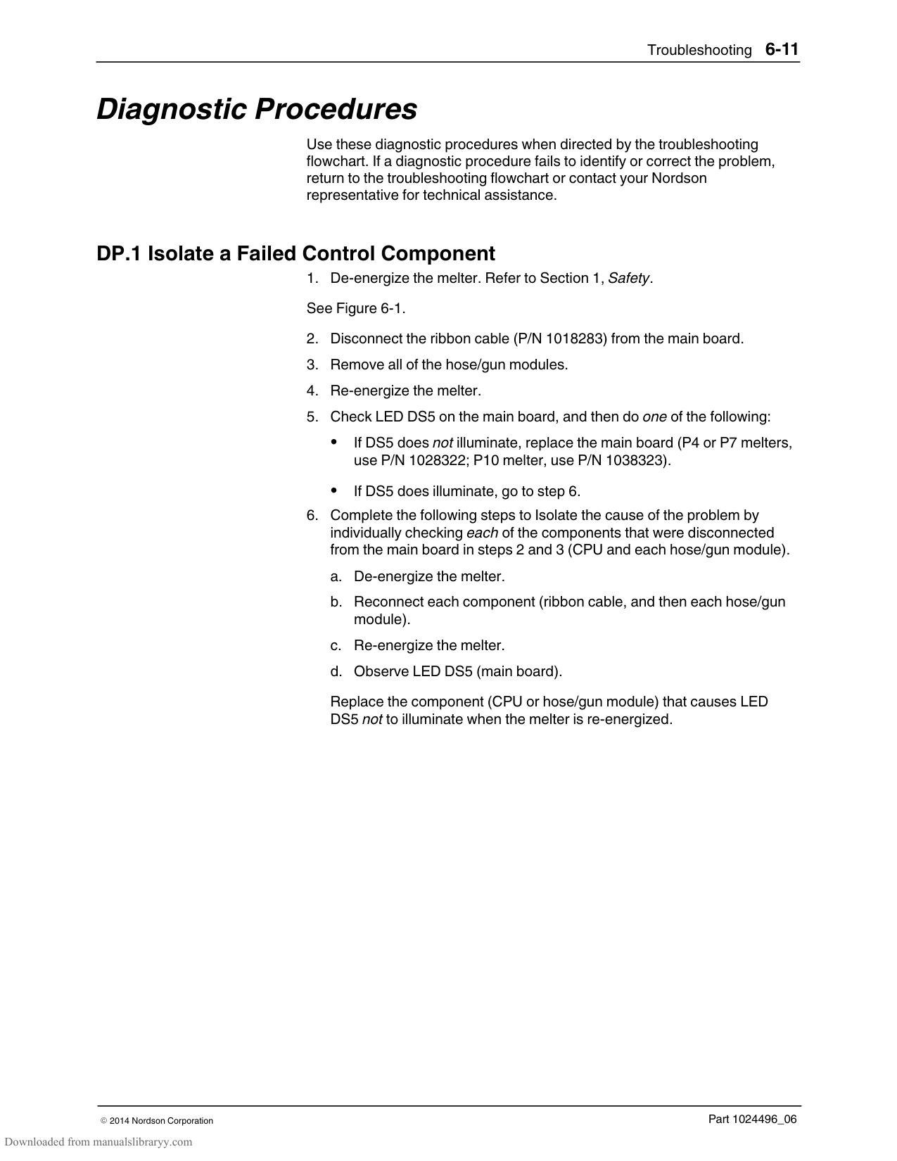
+
Is the voltage across TP2 and TP4 on the CPU board between 4.75 and 5.25 VDC?
Replace the main board assembly.
Secure or replace the ribbon cable.
−
P4/P7 − P/N 1028322. P10 − P/N 1028323.
P/N 1018283.
See Figure 6-1.
+
Is the red CPU warning LED illuminated?
Contact Nordson for technical assistance.
−
See Figure 6-1.
+
Replace the CPU board. P/N 1028325.
Troubleshooting6-25
Part 1024496_062014Nordson Corporation
This page intentionally left blank
Troubleshooting6-26
Part 1024496_062014Nordson Corporation
##### T.2
Starting Condition: Fault LED is illuminated
Is an F1 (RTD) fault indicated in the right display?
Is an F2 (under temperature) fault indicated in the right display?
Is an F3 (over temperature) fault indicated in the right display?
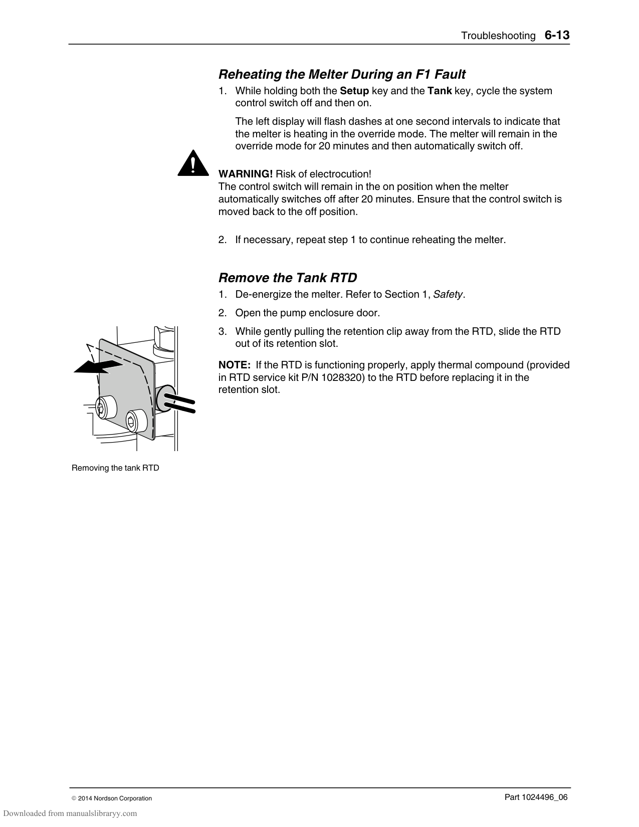
Is an F4 fault indicated in the right display?
−
−
−
+
+
+
+
Continued on next page....
Go to T.2.2Go to T.2.1
####################### Contact Nordson for technical assistance.
See Table 6-1. Does replacing the component(s) listed under the respective fault code, and then resetting the melter clear the fault?
−
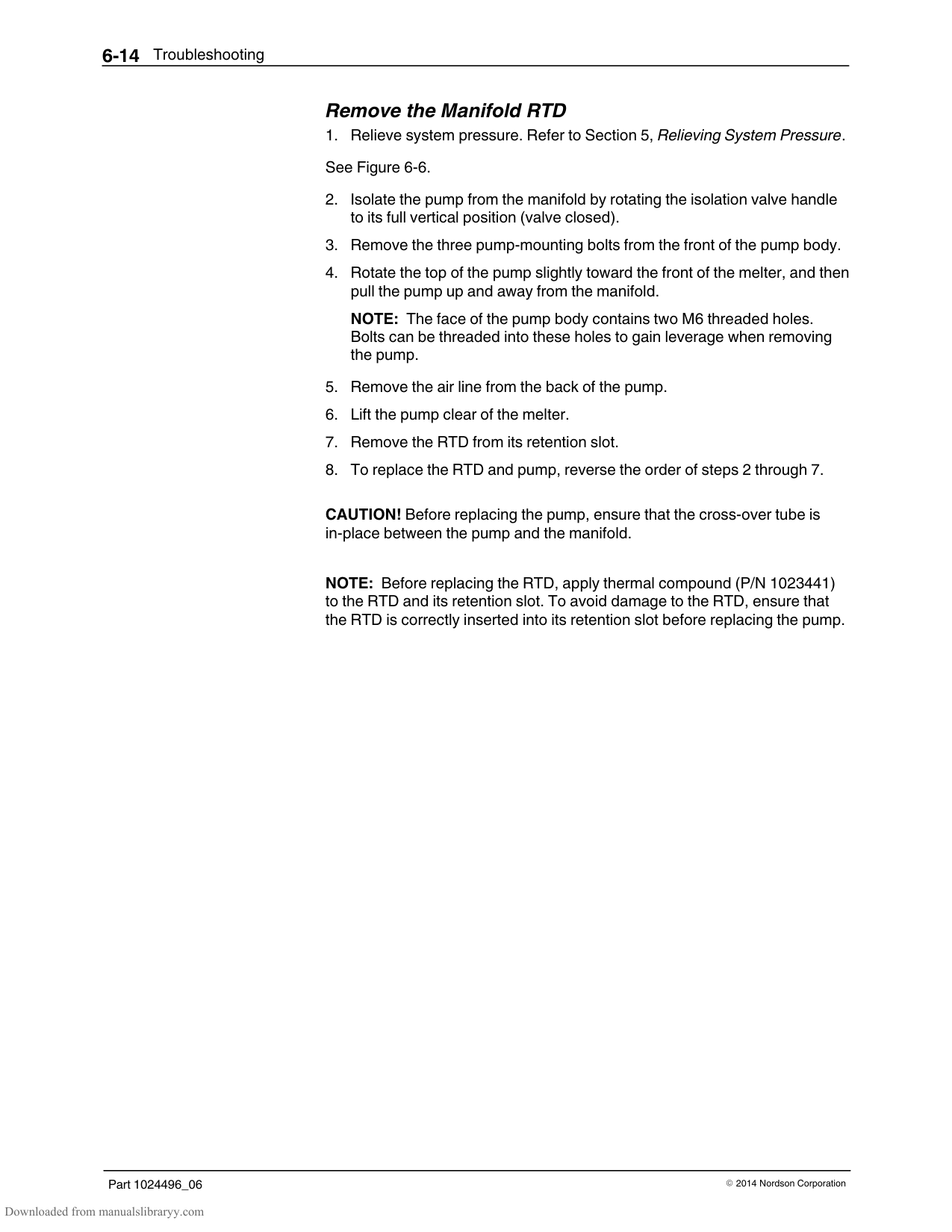
+
Stop.
Troubleshooting6-27
Part 1024496_062014Nordson Corporation
##### T.2
Starting Condition: Fault LED is illuminated
Continued from previous page....
Is the tank key LED illuminated?
Are all of the gun-to-hose and hose-to-melter electrical cordsets securely connected? (The gun or hose key LED is illuminated)
Secure the electrical connectors and then press the reset key.
−
−
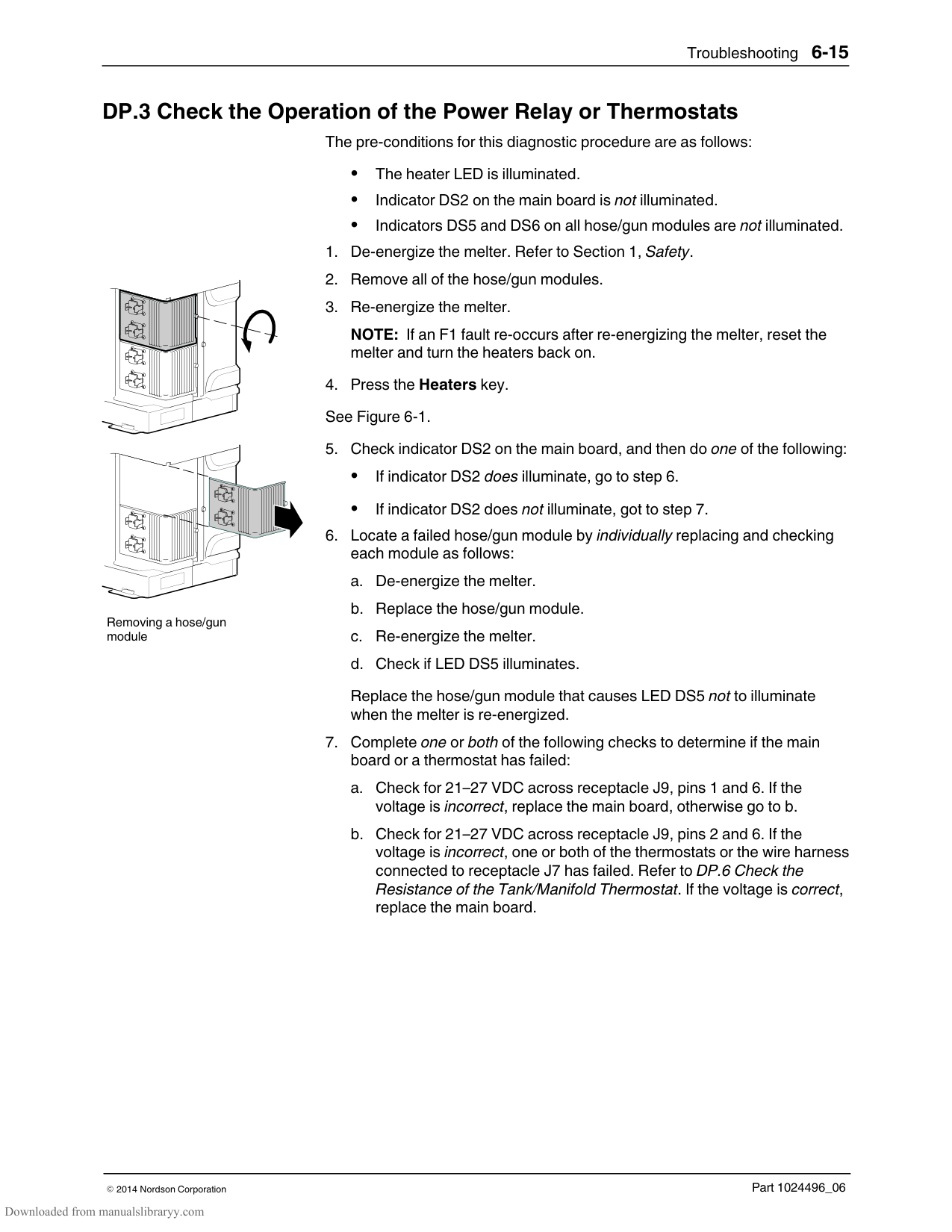
+
+
Is the ribbon cable from the 6-hose expansion board connected to the main board, aligned and functioning properly? (J5 to J1)
Confirm that the RTD has failed.
Connect securely or replace.
−
Refer to DP.2. P/N 1028320.
+
Does the fault re-occur if you move the faulting hose/gun pair to a known good hose/gun module?
Contact Nordson for technical assistance.
−
+
Replace the hose or gun RTD. Refer to the hose or gun manual.
Troubleshooting6-28
Part 1024496_062014Nordson Corporation
##### T.2.1
Starting Conditions: Fault LED is illuminated > F2 fault exists
Reset the melter and turn the heaters back on. Allow the unit to come to temperature.
Is the affected gun or hose cordset loose, or are the pins bent, loose or corroded? (the gun or hose key LED is illuminated.)
Does the manifold fail to come to temperature?
Are the wires to the electrical connector into TB1 secure?
Is the tank key LED illuminated?
−
−
−
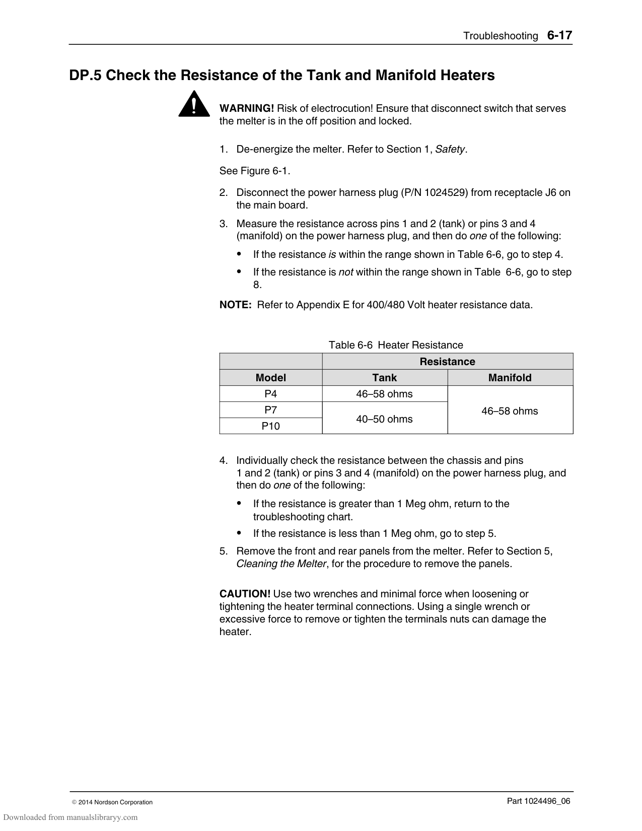
−
|+|Connect securely.| |---|---| |Is the power lead connecting the 6-hose expansion board to the main board loose or damaged? (J10 to J2) (P10 only)|Is the power lead connecting the 6-hose expansion board to the main board loose or damaged? (J10 to J2) (P10 only)|
+
+
+
Verify that the manifold heater has failed and replace.
Secure or repair the loose cordset then press the Reset key.
Refer to DP.5. P/N 1017723.
Refer to the hose or gun manual.
Connect securely.
Is the power cable that connects to J6 connected securely?
−
+
Cont. on next page
Was hot melt recently added to the tank?
−
|Go to T.2.3| |---|
−
+
+
Secure or replace.
Allow the unit to reach set-point temperature.
Troubleshooting6-29
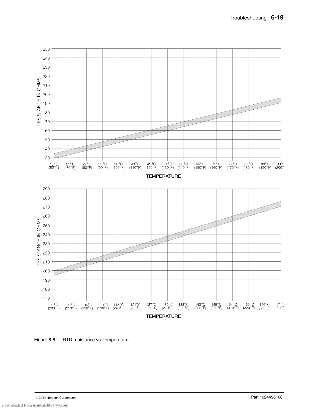
Part 1024496_062014Nordson Corporation
Continued from previous page....
Is there 240 VAC across fuses F1/F2 or F3/F4 on the affected hose/gun module, and is the hose/gun wattage properly rated?
−
+
Are the indicators DS5 or DS6 on the affected hose/gun module illuminated?
−
See Figure 6-1.
+
Are the hose and gun RTD functioning correctly?
−
+
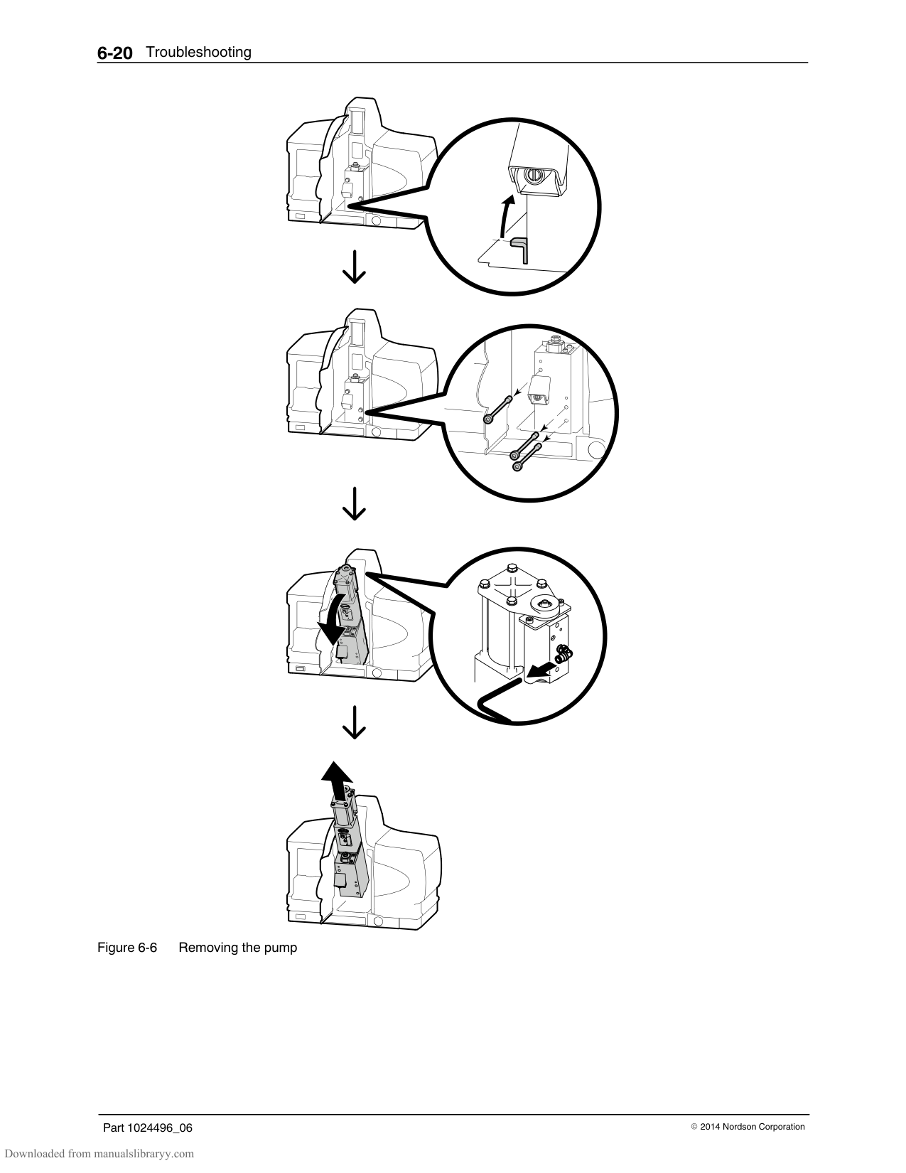
Does the fault re-occur if you replace the affected hose/gun module with a known good module?
−
+
Replace the main board. P4/P7 − P/N 1028322. P10 − P/N 1028323.
Correct the house voltage or replace the hose/gun with a properly rated hose/gun.
Replace the hose or gun RTD.
Replace the affected hose/gun module.
P/N 1028328.
##### T.2.1
Starting Conditions: Fault LED is illuminated > F2 fault exists
Is indicator DS2 on the main board or DS5 and DS6 on any hose/gun module illuminated?
−
+
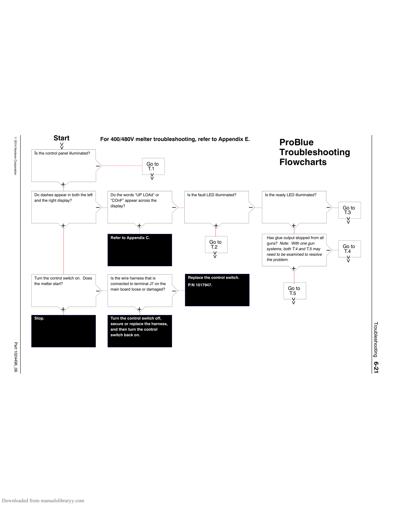
Replace fuse pairs F1/F2 or F3/F4 on the affected hose/gun module.
P/N 1028331. See Figure 6-1.
Check the operation of the power relay or thermostat.
Refer to DP.3.
Troubleshooting6-30
Part 1024496_062014Nordson Corporation
##### T.2.2
Starting conditions: Fault LED is illuminated > F3 fault exists
Reset the melter and turn the heaters back on. Allow the unit to come to temperature.
Is more than one component overheating? (Check the actual temperature of the faulting component.)
Is the tank key LED illuminated?
Is DS1, DS2, DS3 or DS4 on the hose/gun module illuminated continuously?

Replace the hose/gun P/N 1028328.
−
−
−
+
+
+
Continued on next page
Does replacing the hose or gun RTD solve the problem?
Replace the main board. P4/P7 − P/N 1028322. P10 − P/N 1028323.
−
+
Are the tank/manifold TRIACs operating properly?
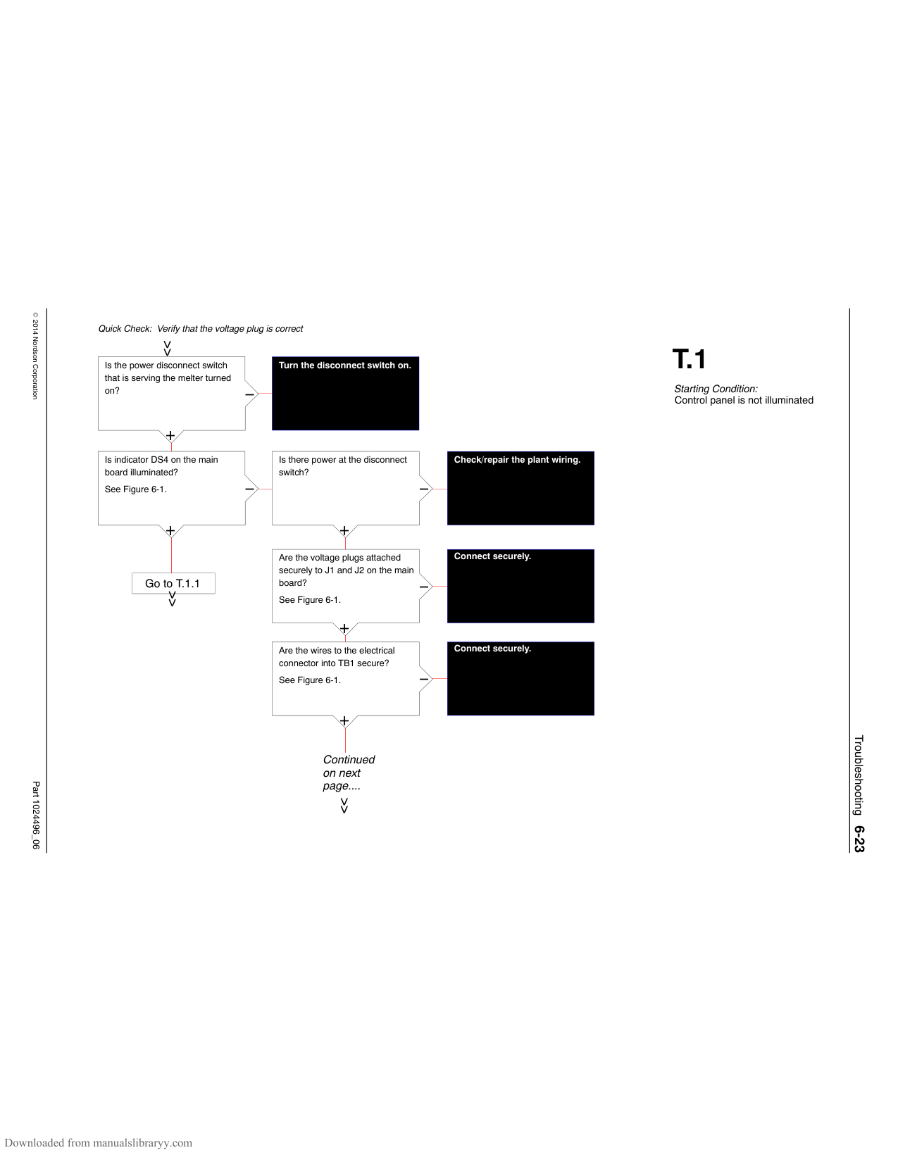
####################### Replace the main board. P4/P7 − P/N 1028322. P10 − P/N 1028323.
Stop.
−
Refer to DP.4.
+
Replace the tank/manifold RTD. P/N 1028320. Refer to DP.2.
Troubleshooting6-31
Part 1024496_062014Nordson Corporation
##### T.2.2
Starting conditions: Fault LED is illuminated > F3 fault exists
Continued from previous page....
Is there a DC drive near the melter?
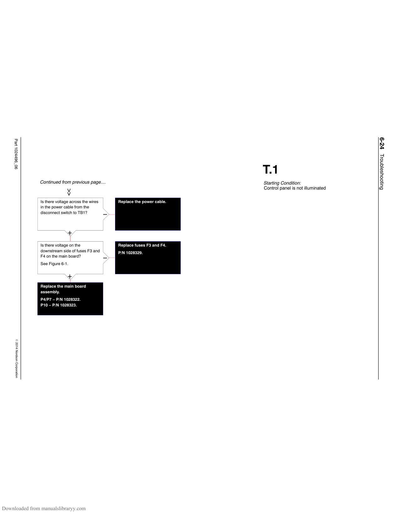
Is the power cable grounded to the melter’s chassis?
−
−
+
+
Does installing an RC snubber on the DC drive and resetting the melter clear the fault?
Is the resistance between the ground leg and earth ground on the power cable greater than zero?
−
−
P/N 332182.
+
+
Stop.
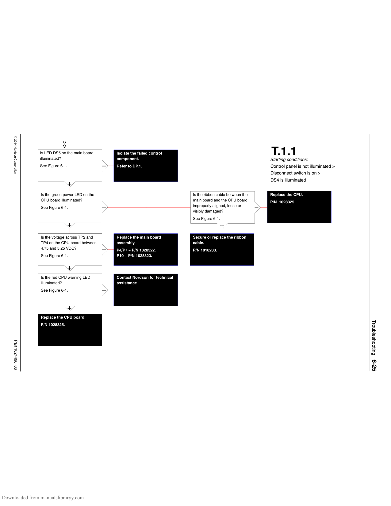
Correct or establish earth ground connection with the melter.
Ground the power cable properly to the chassis.
Does installing an RC snubber on the melter clear the fault?
−
P/N 332182.
+
Stop.
Contact Nordson for technical assistance.
Troubleshooting6-32
Part 1024496_062014Nordson Corporation
Is indicator DS2 in the main board illuminated?
−

+
Is the power harness into J6 connected securely?
−
+
Is the voltage across the downstream side of fuses F1/F2 or F3/F4 on the main board between 170 and 265 VAC?
−
See Figure 6-1.
+
Connect securely.
Check/correct the house voltage.
Continued on next page
##### T.2.3
Starting conditions: Fault LED is illuminated > F2 fault exists > Tank key LED is illuminated > Hot melt has not been added
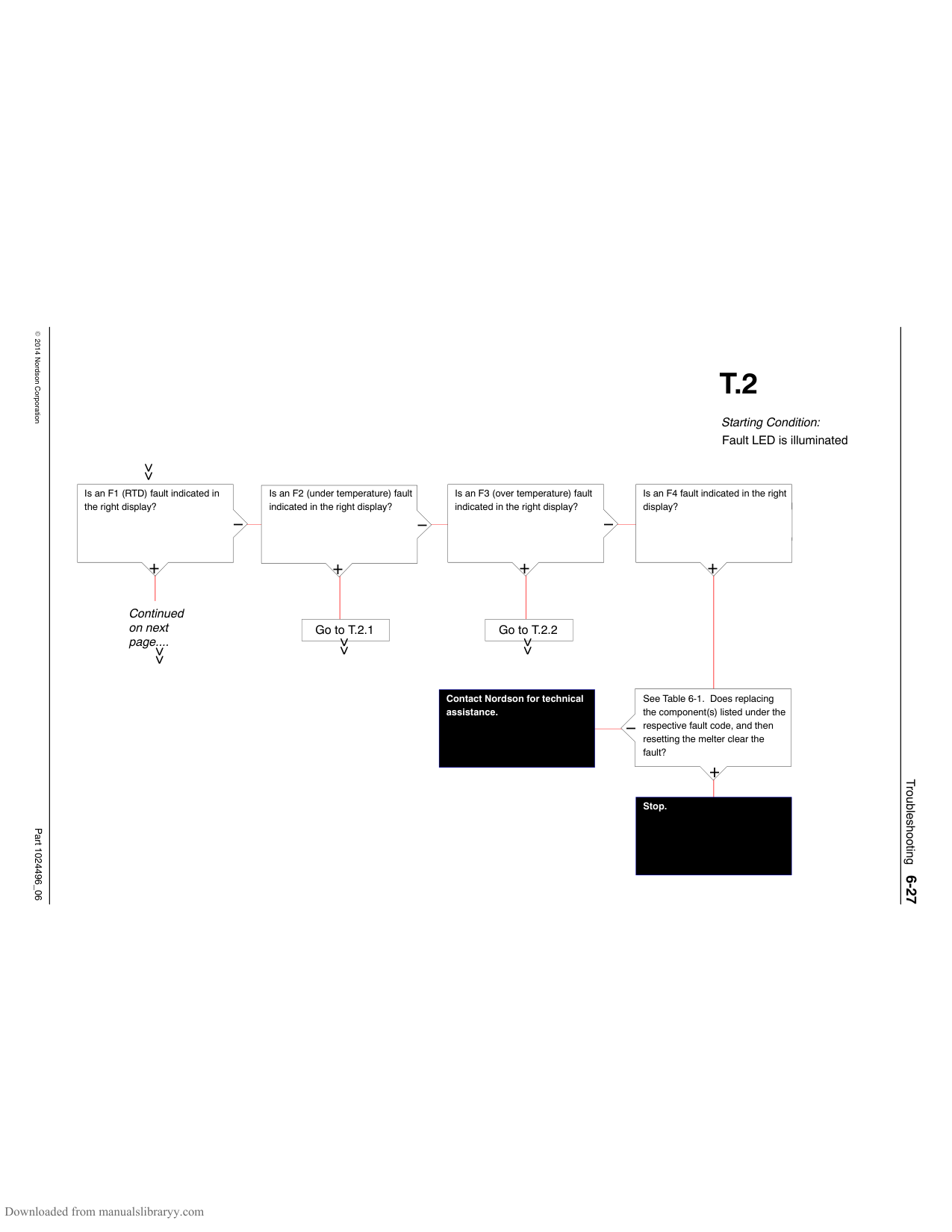
Are indicators DS5 or DS6 illuminated on any hose/gun module?
−
See Figure 6-1.
+
Does replacing fuses F1 and F2 on the main board and then resetting the melter clear the fault?
−
P/N 1028329.
+
Stop.
Check the operation of the power relay or thermostat.
Connect securely. Refer to DP.3
Replace the main board. P4/P7 − P/N 1028322. P10 − P/N 1028323.
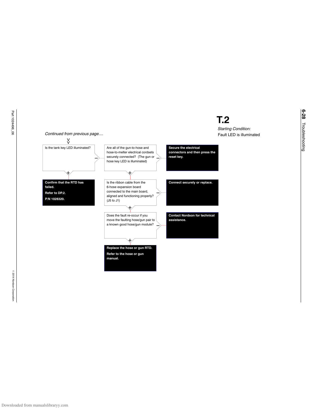
Troubleshooting6-33
Part 1024496_062014Nordson Corporation
Continued from previous page....
Replace the manifold heater, tank, or the power harness.
+
−
Is the resistance correct for the tank and the manifold heaters?
Manifold heater − P/N 1017723. Tank − P/N 1018379. Power harness − P/N 1024529.
Are the tank and the manifold TRIACs functioning properly?
Replace the main board. P4/P7 − P/N 1028322. P/10 − P/N 1028323
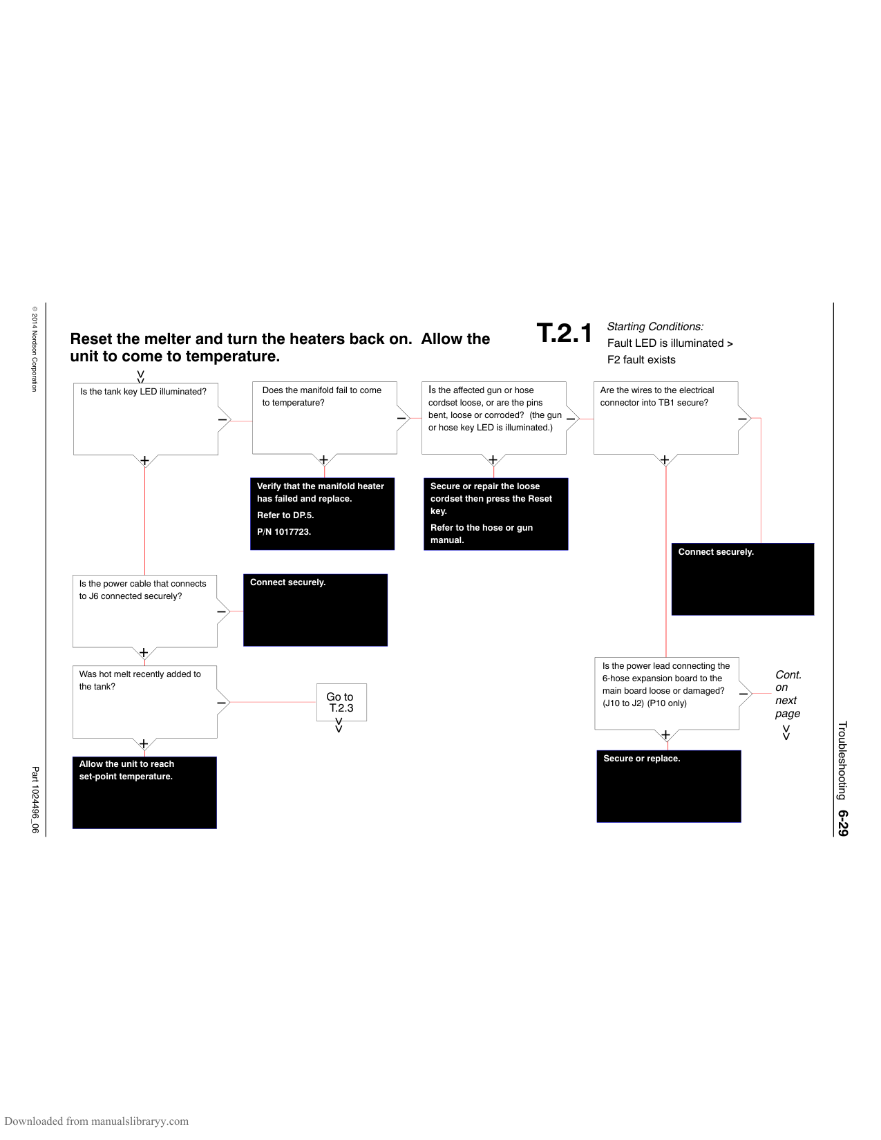
−
+
Does replacing the malfunctioning tank or manifold RTD solve the problem?
Contact Nordson for technical assistance.
−
P/N 1028320. Refer to DP.2.
+
Stop.
##### T.2.3
Starting conditions: Fault LED is illuminated > F2 fault exists > Tank key LED is illuminated > Hot melt has not been added
Troubleshooting6-34
Part 1024496_062014Nordson Corporation
Quick check: Manually activating the heater key or the pump key will override and eliminate remote inputs as the cause of a down condition.
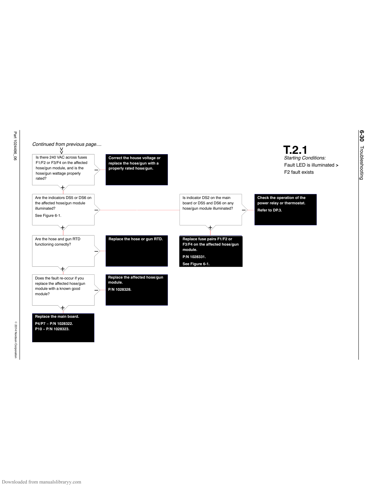
Quick check: Save settings and reset the melter to factory default settings. If the melter functions normally, isolate the input or output problem.
##### T.3
Starting conditions: No faults > Ready LED is not illuminated
Is the heater key LED illuminated?
−
+
Cont. on next page
Is the clock LED illuminated?
−
+
Is the clock schedule programmed correctly?
−
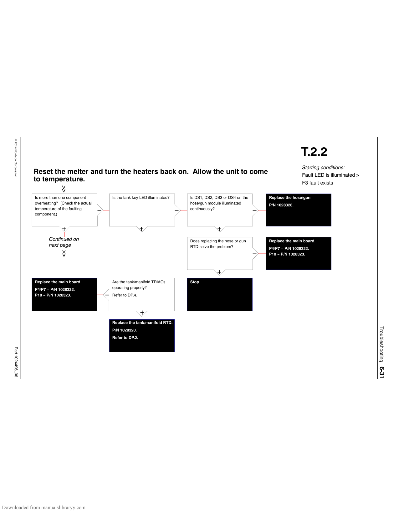
+
The current clock schedule has the heaters turned off.
Is a remote input being used to control the heaters?
−
+
Go to T.3.1
Does pressing the heater key turn the heaters on?
####################### Replace the operator panel. P4/P7 − P/N 1028326. P10 − P/N 1028327.
−
+
Stop.
Troubleshooting6-35
Part 1024496_062014Nordson Corporation
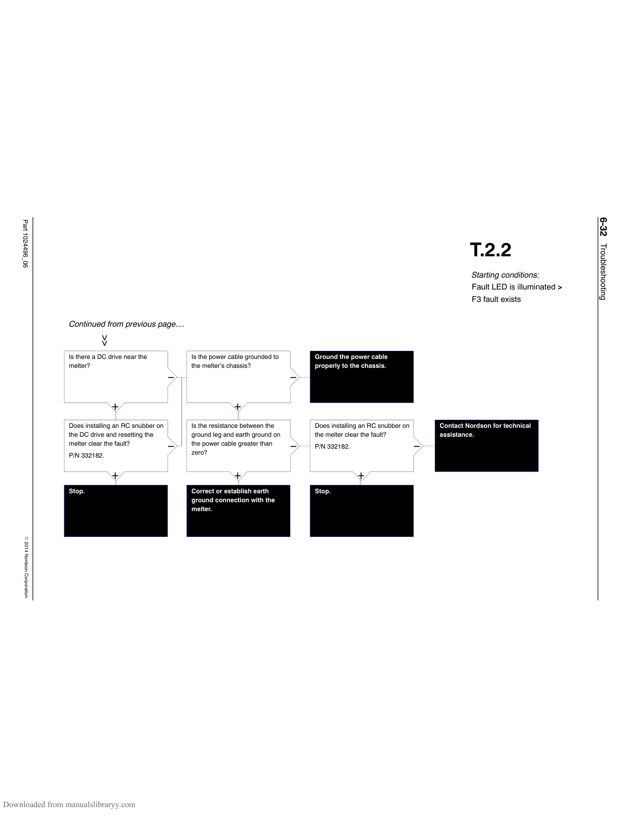
##### T.3
Continued from previous page....
Is the standby LED on?
Is the ready delay counting down?
Confirm that the tank heater has failed and replace the tank.
−
−
Tank − P/N 1018379. Refer to DP.5.
+
+
Wait for the ready delay to count down.
The melter is in the standby mode.
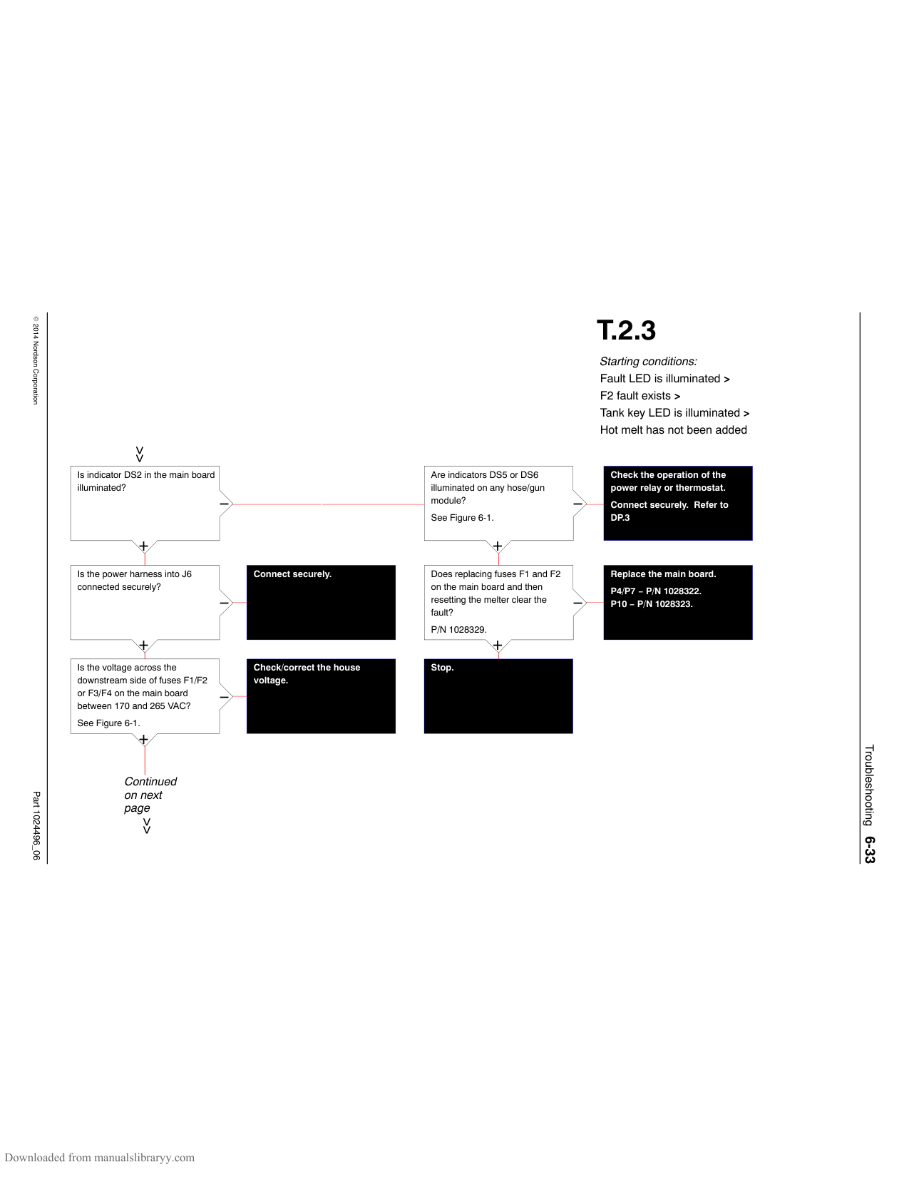
Refer to Appendix B, parameter 4.
Refer to Section 4, Standby Key.
Starting conditions: No faults > Ready LED is not illuminated
Troubleshooting6-36
Part 1024496_062014Nordson Corporation
Is there a signal at the input on the mainboard or on the I/O board?
−
+
Is the programming for the input correct?
−
+
Wait for the input to initiate the heaters or use the heater key to manually turn the heaters on.
Reprogram the input.
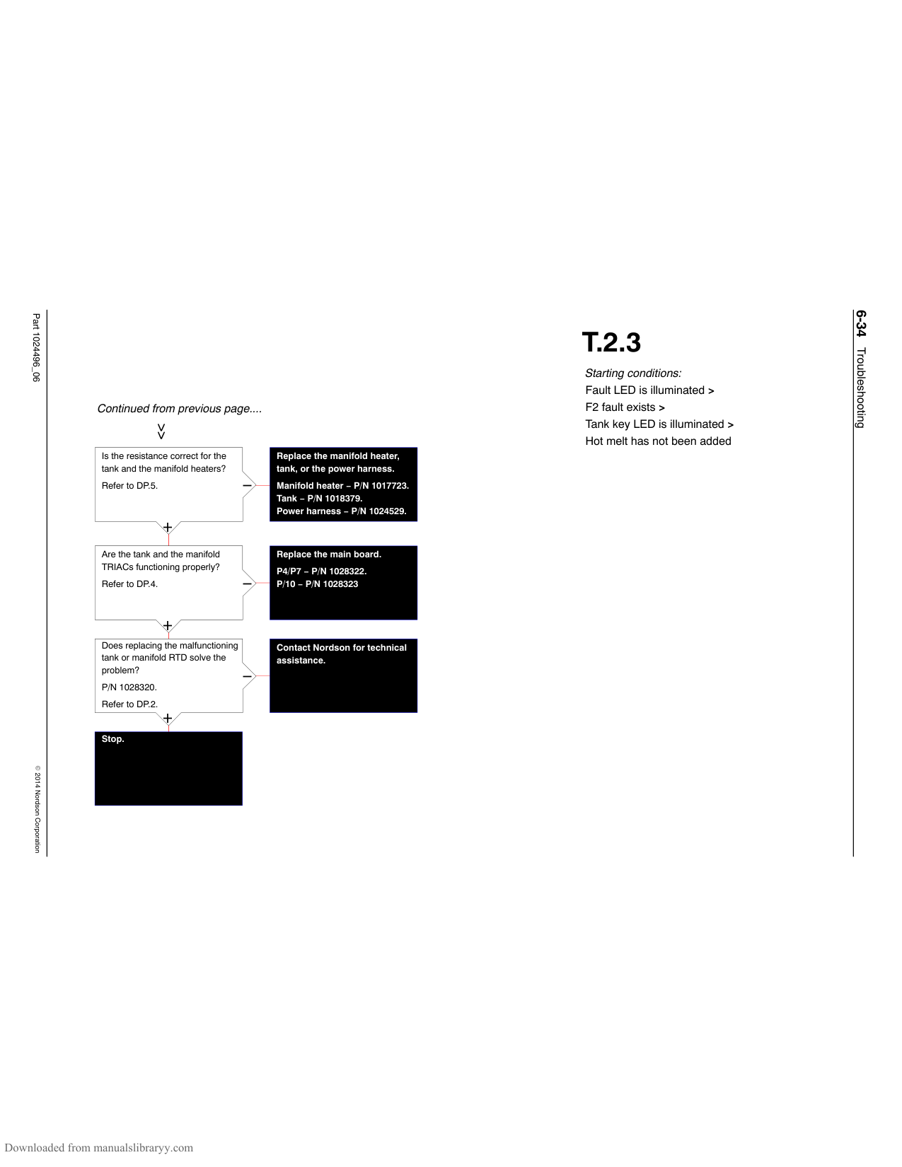
Is there a signal at the parent machine?
−
+
Is there power across the wires from the parent machine to the inputs on the main board or I/O board?
−
+
Does pressing the heaters key turn the heaters on?
−
+
Replace the I/O expansion board kit.
P/N 1036607.
##### T.3.1
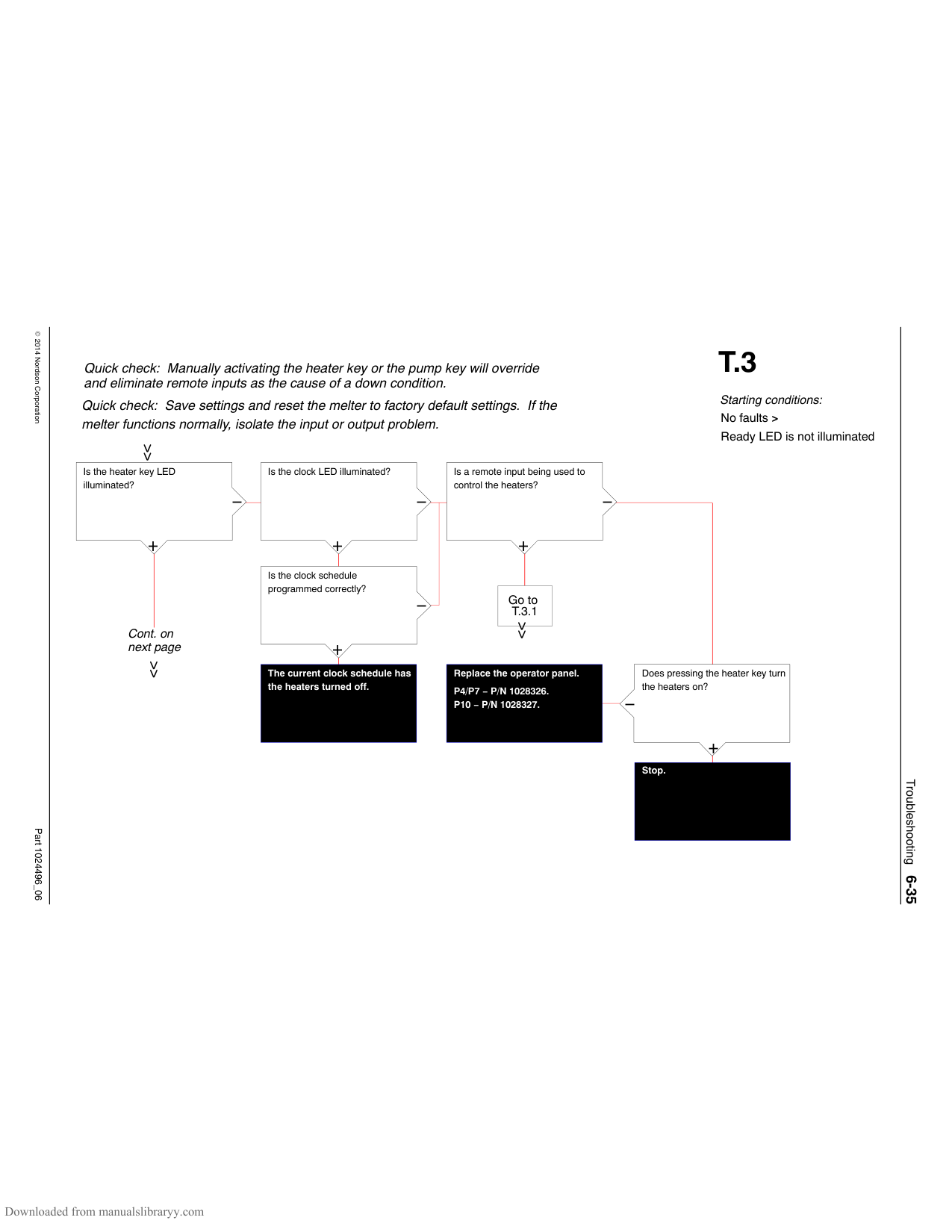
Starting conditions: No faults > Ready LED is not illuminated > Remote input is being used
Verify that the parent machine is working properly. Refer to the appropriate manual.
Inspect the wires for damage or corrosion and replace if needed.
Replace the main board. P4/P7 − P/N 1028322. P10 − P/N 1028323.
Troubleshooting6-37
Part 1024496_062014Nordson Corporation
This page intentionally left blank
Troubleshooting6-38
Part 1024496_062014Nordson Corporation
Quick check: Save settings and reset the melter to factory default settings. If the melter functions normally, isolate the input or output problem.
Quick check: Manually activating the heater key or the pump key will override and eliminate remote inputs as the cause of a down condition.
Has the pump stopped?
−
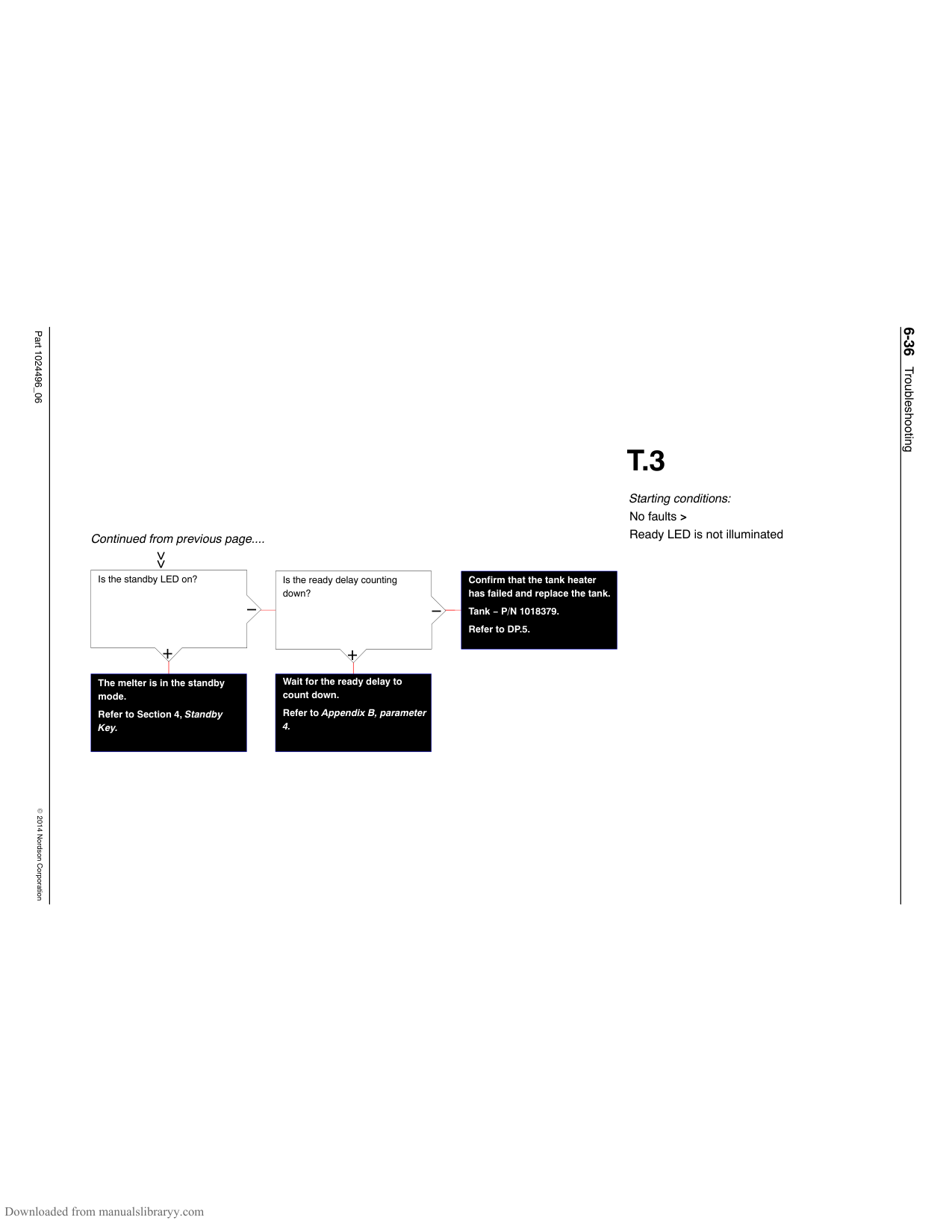
+
Is the pump cycling fast?
−
+
Go to T.4.1
Is there sufficient air pressure to the pump (greater than 0.7 bar/10 psi)?
−
+
Continued on next page
Is hot melt leaking from the system somewhere between the manifold and the guns?
−
+
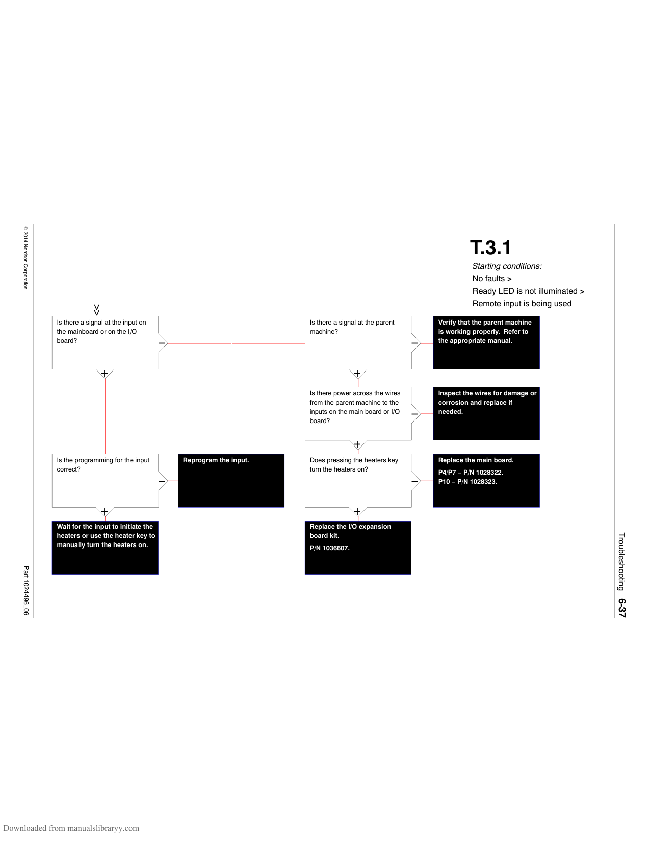
Locate and repair the leak.
Adjust the air pressure.
##### T.4
Starting conditions: No faults > Ready LED is illuminated > No hot melt output from all guns
The pump piston ball valve is stuck open.
Refer to Appendix D.
Troubleshooting6-39
Part 1024496_062014Nordson Corporation
##### T.4
Starting conditions: No faults > Ready LED is illuminated > No hot melt output from all guns
Continued from previous page....
Is the tank empty?
−

+
Turn off the pump. Fill the tank. Wait for the unit to heat the adhesive to operating temperature.
Is the isolation valve (shut off valve) closed?
−
See Figure 6-6.
+
Open the valve.
Is hot melt returning to the tank through the return port located behind the tank screen?
−
See Figure 6-3.
+
Replace the pressure discharge valve.
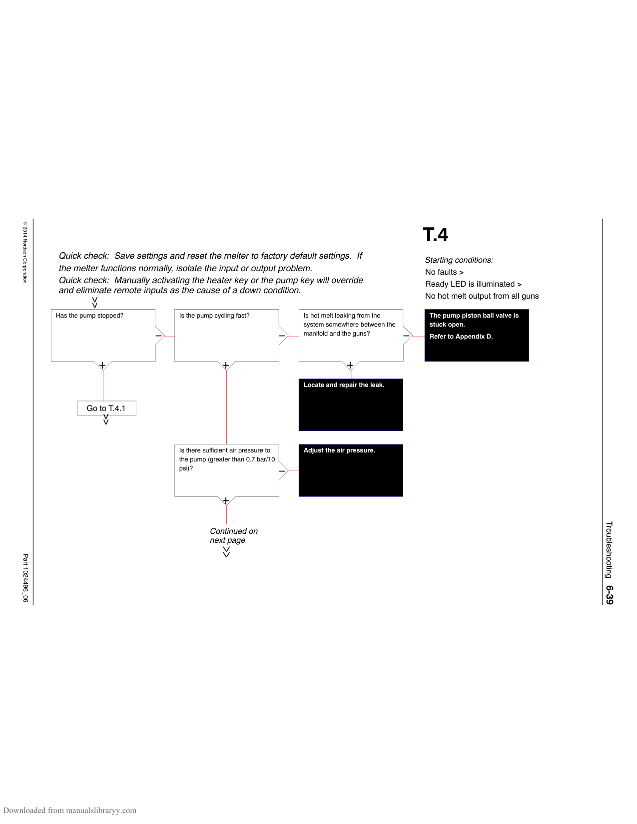
P/N 1028308.
Check and clean the outlet of the tank and the crossover tube or clean/replace the manifold.
Troubleshooting6-40
Part 1024496_062014Nordson Corporation
##### T.4.1
Starting conditions: No faults > Ready LED is illuminated > No hot melt output from all guns > Pump has stopped
Quick check: Manually activating the heater key or the pump key will override and eliminate remote inputs as the cause of a down condition.
Is the pump LED illuminated?
Does pressing the pump key turn the pump on?
Does replacing the operator’s panel and then restarting the melter correct the problem?
####################### Replace the CPU board. P/N 1028325.
−
−
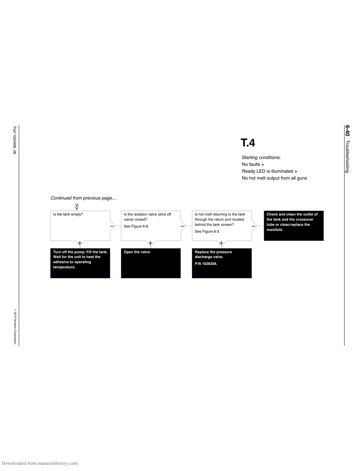
−
P4/P7 − P/N 1028326. P10 − P/N 1028327.
+
+
+
Stop.
Stop.
Is the pump LED flashing?
−
+
Are you using an optional input (parameters 5 thru 10) to enable/disable the pump?
−
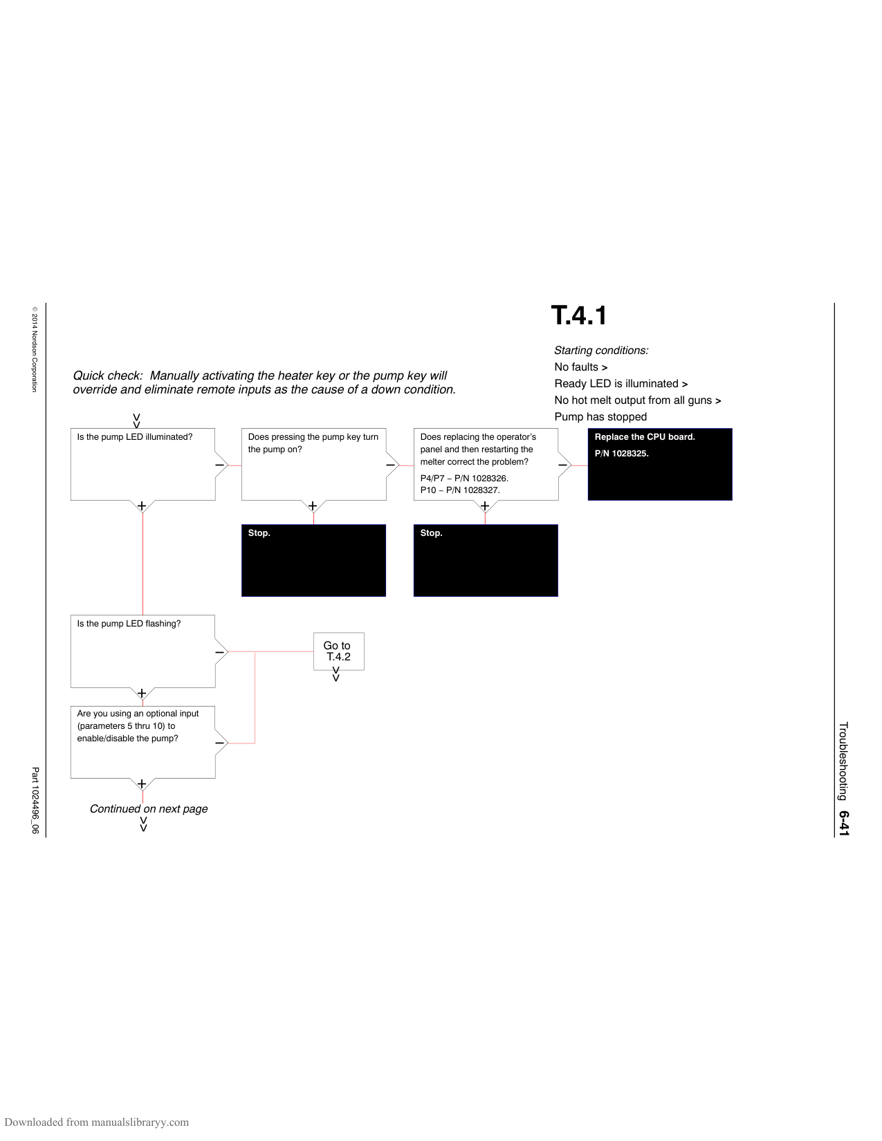
+
Continued on next page
Go to T.4.2
Troubleshooting6-41
Part 1024496_062014Nordson Corporation
Continued from previous page....
Is the power LED on the I/O board illuminated?
Replace the I/O expansion board kit.
−
P/N 1036607.
+
Are the inputs properly functioning? (Refer to table T.3.1 for diagnostic procedures)
Repair or replace the malfunctioning input.
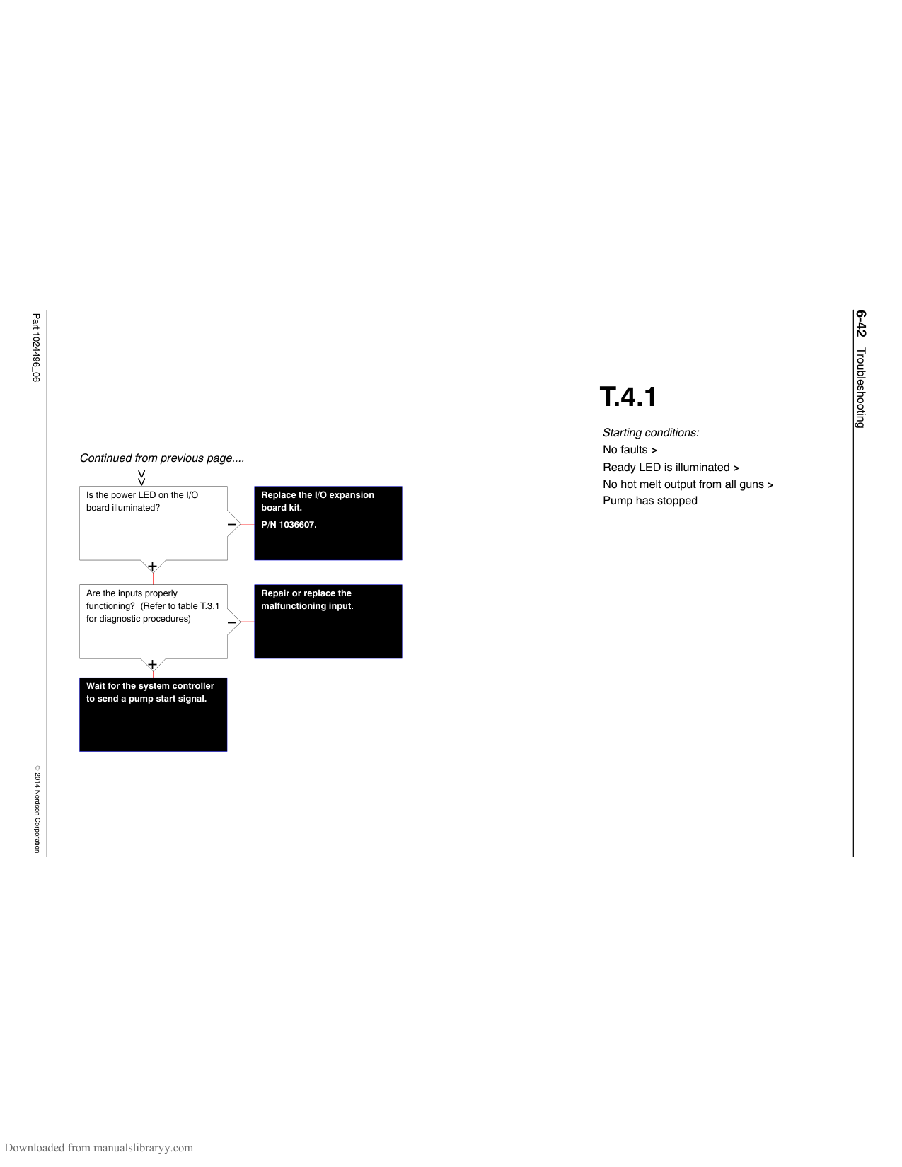
−
+
Wait for the system controller to send a pump start signal.
##### T.4.1
Starting conditions: No faults > Ready LED is illuminated > No hot melt output from all guns > Pump has stopped
Troubleshooting6-42
Part 1024496_062014Nordson Corporation
##### T.4.2
Starting conditions: No faults > Ready LED is illuminated > No hot melt output from all guns > Pump has stopped > Pump LED is illuminated > Tank set-point temperature is OK > Pump is not controlled by a remote input
Problem
Is the air supply to the melter turned off or is the plant air pressure low?
Is the operating air pressure set correctly?
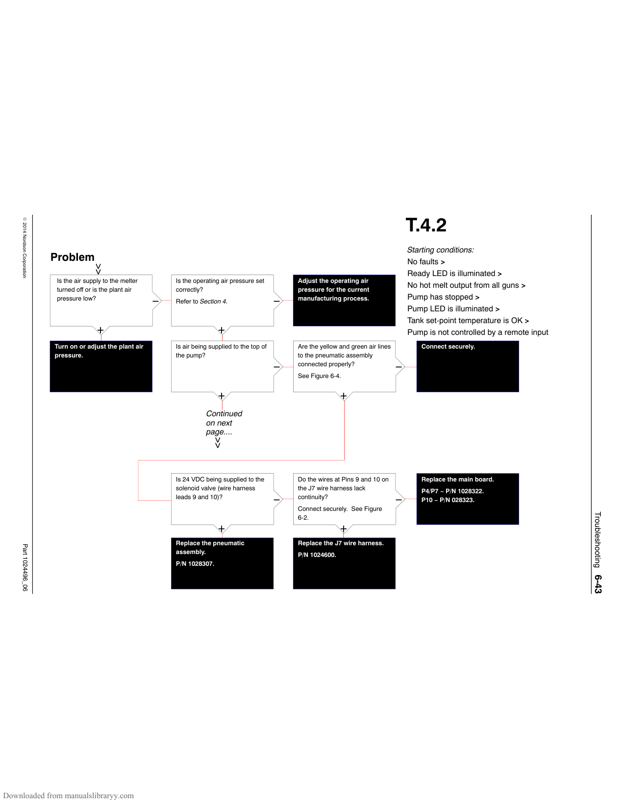
####################### Adjust the operating air pressure for the current manufacturing process.
−
−
Refer to Section 4.
|+| | |---|---| |Turn on or adju pressure.|t the plant air|
+
Is air being supplied to the top of the pump?
Are the yellow and green air lines to the pneumatic assembly connected properly?
Connect securely.
−
−
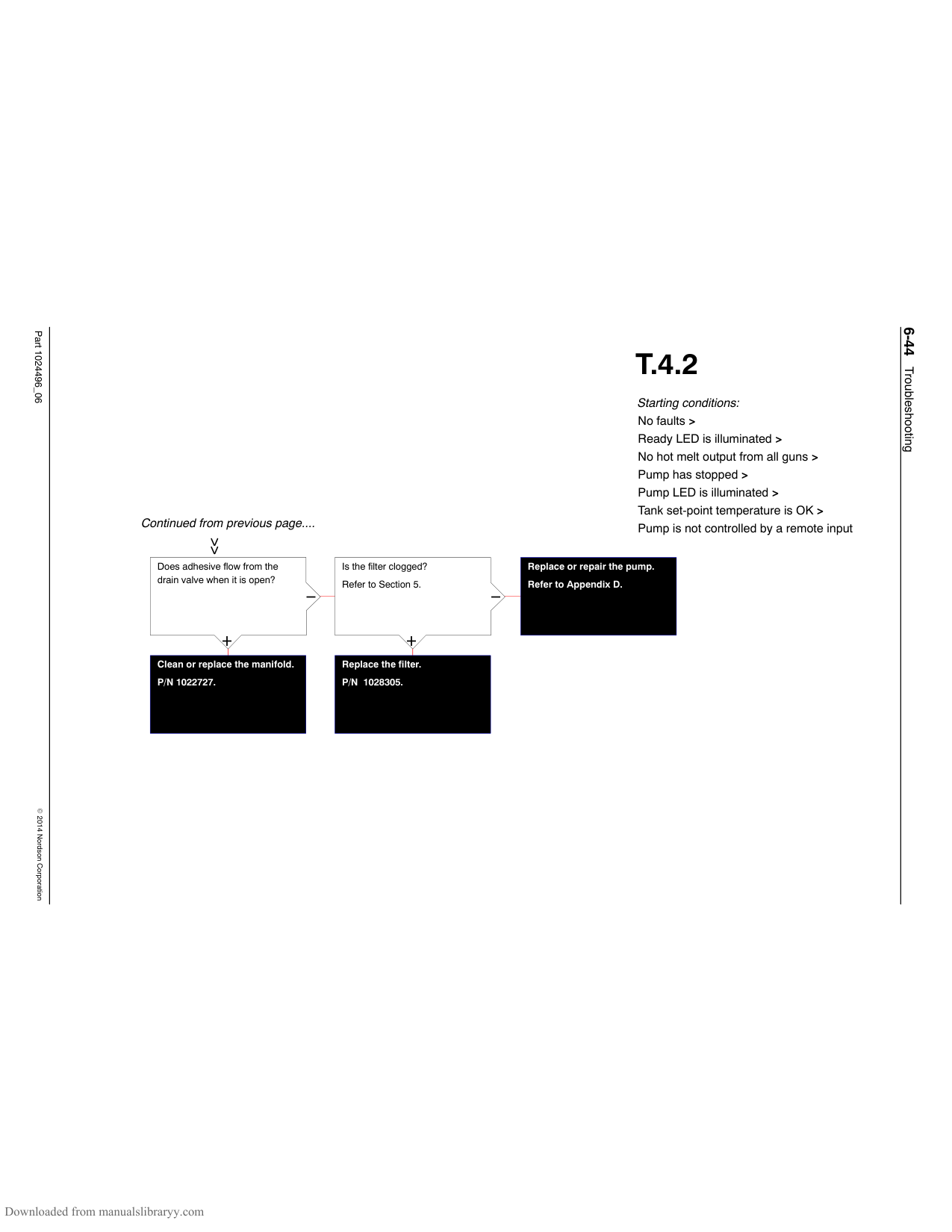
See Figure 6-4.
+
+
Continued on next page....
Is 24 VDC being supplied to the solenoid valve (wire harness leads 9 and 10)?
Do the wires at Pins 9 and 10 on the J7 wire harness lack continuity?
Replace the main board. P4/P7 − P/N 1028322. P10 − P/N 028323.
−
−
Connect securely. See Figure 6-2.
+
+
Replace the pneumatic assembly.
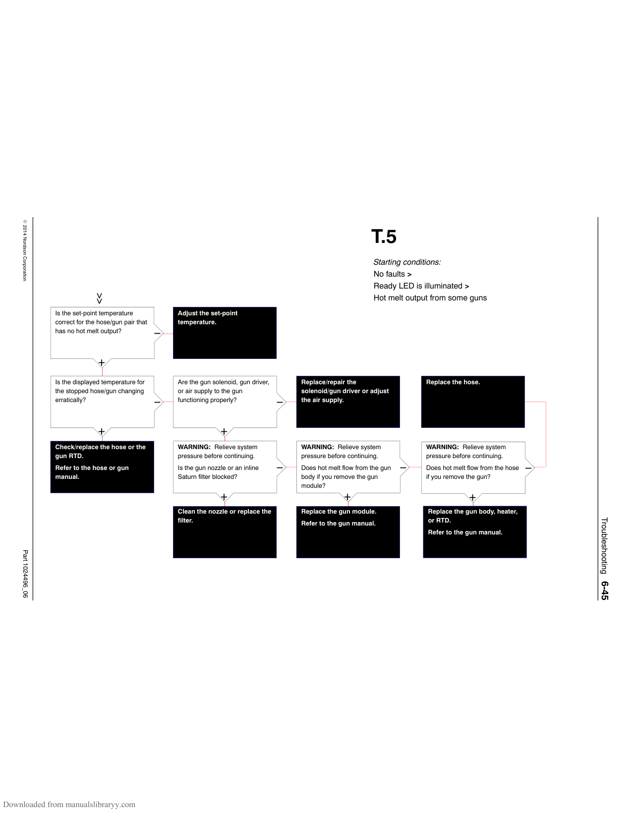
Replace the J7 wire harness. P/N 1024600.
P/N 1028307.
Troubleshooting6-43
Part 1024496_062014Nordson Corporation
##### T.4.2
Starting conditions: No faults > Ready LED is illuminated > No hot melt output from all guns > Pump has stopped > Pump LED is illuminated > Tank set-point temperature is OK > Pump is not controlled by a remote input
Continued from previous page....
Does adhesive flow from the drain valve when it is open?
Is the filter clogged? Refer to Section 5.
Replace or repair the pump. Refer to Appendix D.
−
−

+
+
Replace the filter. P/N 1028305.
Clean or replace the manifold. P/N 1022727.
Troubleshooting6-44
Part 1024496_062014Nordson Corporation
Is the set-point temperature correct for the hose/gun pair that has no hot melt output?
−
+
Is the displayed temperature for the stopped hose/gun changing erratically?
−
+
Check/replace the hose or the gun RTD.
Refer to the hose or gun manual.
####################### Adjust the set-point temperature.
Are the gun solenoid, gun driver, or air supply to the gun functioning properly?
−
+
WARNING: Relieve system pressure before continuing. Is the gun nozzle or an inline Saturn filter blocked?
−
+
Clean the nozzle or replace the filter.
##### T.5
Starting conditions: No faults > Ready LED is illuminated > Hot melt output from some guns
####################### Replace/repair the solenoid/gun driver or adjust the air supply.
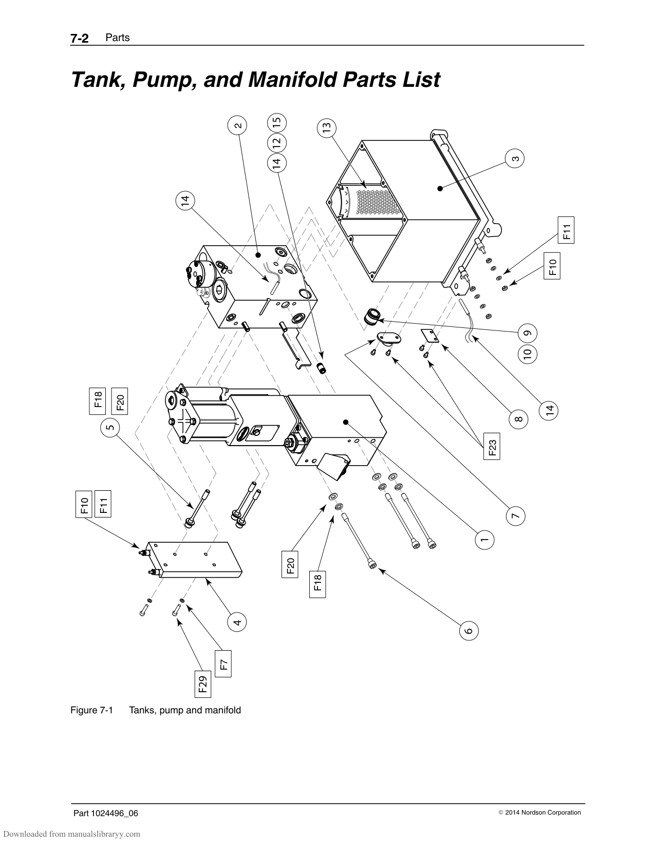
Replace the hose.
WARNING: Relieve system pressure before continuing. Does hot melt flow from the gun body if you remove the gun module?
−
+
Replace the gun module. Refer to the gun manual.
WARNING: Relieve system pressure before continuing. Does hot melt flow from the hose if you remove the gun?
−
+
Replace the gun body, heater, or RTD.
Refer to the gun manual.
Troubleshooting6-45
Part 1024496_062014Nordson Corporation
This page intentionally left blank
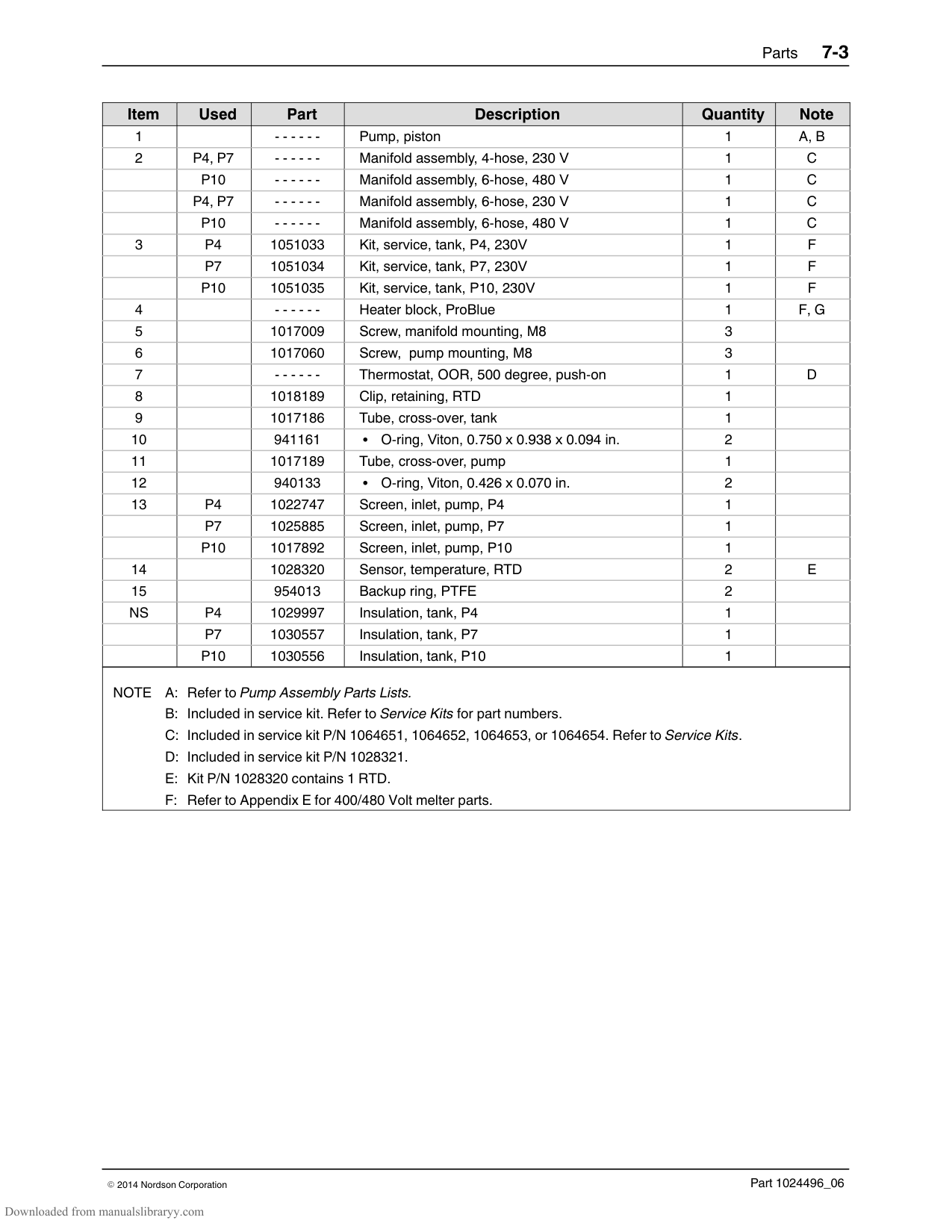
Troubleshooting6-46
Section 7 Parts
NOTE: Refer to Appendix E for information about 400/480 Volt melter parts.
#### Using the Illustrated Parts List
The parts lists provided in this section are organized into the following columns:
Item—Identifies illustrated parts that are available from Nordson Corporation.
Used—Identifies the melters in which the part is used. A blank entry indicates that the part is used in all ProBlue melters.
Part—Provides the Nordson Corporation part number for each saleable part shown in the illustration. A series of dashes in the parts column (‐ ‐ ‐ ‐ ‐ ‐) means the part cannot be ordered separately.
Description—Provides the part name, as well as its dimensions and other characteristics when appropriate. Bullets in the description, indicate the relationships between assemblies, subassemblies, and parts.
Quantity—The quantity required per unit, assembly, or subassembly.
The code AR (As Required) is used if the part number is a bulk item ordered in quantities or if the quantity per assembly depends on the product version or model.
NOTE: Illustrations of the model P4 are used throughout this section to represent all ProBlue melters. Refer to the Used column to determine the part number associated with your melter.
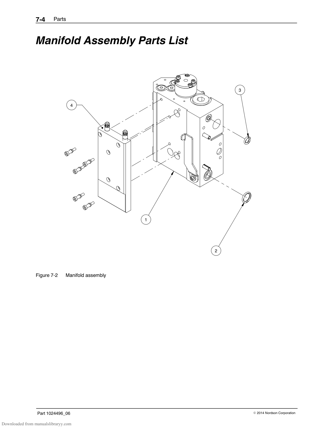
######## Fasteners
Fasteners are called out in each illustration using the convention Fx, where “x” is the fastener number used in the Schedule of Fasteners, which is located at the end of this section.
#### Tank, Pump, and Manifold Parts List
|Item|Used|Part|Description|Quantity|Note| |---|---|---|---|---|---| |1| |‐ ‐ ‐ ‐ ‐ ‐|Pump, piston|1|A, B| |2|P4, P7|‐ ‐ ‐ ‐ ‐ ‐|Manifold assembly, 4-hose, 230 V|1|C| | |P10|‐ ‐ ‐ ‐ ‐ ‐|Manifold assembly, 6-hose, 480 V|1|C| | |P4, P7|‐ ‐ ‐ ‐ ‐ ‐|Manifold assembly, 6-hose, 230 V|1|C| | |P10|‐ ‐ ‐ ‐ ‐ ‐|Manifold assembly, 6-hose, 480 V|1|C| |3|P4|1051033|Kit, service, tank, P4, 230V|1|F| | |P7|1051034|Kit, service, tank, P7, 230V|1|F| | |P10|1051035|Kit, service, tank, P10, 230V|1|F| |4| |‐ ‐ ‐ ‐ ‐ ‐|Heater block, ProBlue|1|F, G| |5| |1017009|Screw, manifold mounting, M8|3| | |6| |1017060|Screw, pump mounting, M8|3| | |7| |‐ ‐ ‐ ‐ ‐ ‐|Thermostat, OOR, 500 degree, push-on|1|D| |8| |1018189|Clip, retaining, RTD|1| | |9| |1017186|Tube, cross-over, tank|1| |
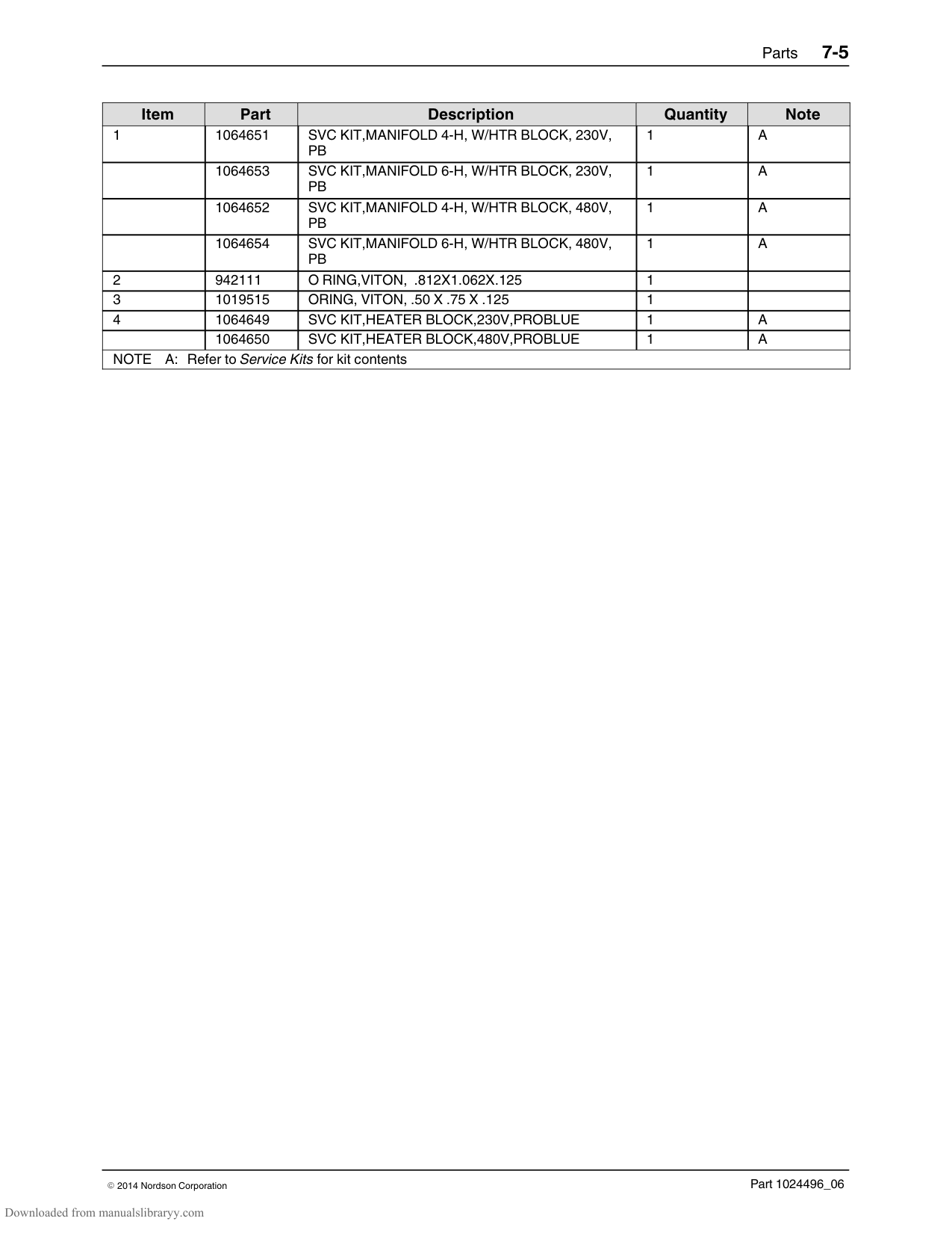
|10| |941161|O-ring, Viton, 0.750 x 0.938 x 0.094 in.|2| | |11| |1017189|Tube, cross-over, pump|1| | |12| |940133|O-ring, Viton, 0.426 x 0.070 in.|2| | |13|P4|1022747|Screen, inlet, pump, P4|1| | | |P7|1025885|Screen, inlet, pump, P7|1| | | |P10|1017892|Screen, inlet, pump, P10|1| | |14| |1028320|Sensor, temperature, RTD|2|E| |15| |954013|Backup ring, PTFE|2| | |NS|P4|1029997|Insulation, tank, P4|1| | | |P7|1030557|Insulation, tank, P7|1| | | |P10|1030556|Insulation, tank, P10|1| | |NOTE A: Refer to Pump Assembly Parts Lists.
B: Included in service kit. Refer to Service Kits for part numbers.
C: Included in service kit P/N 1064651, 1064652, 1064653, or 1064654. Refer to Service Kits.
D: Included in service kit P/N 1028321.
E: Kit P/N 1028320 contains 1 RTD.
F: Refer to Appendix E for 400/480 Volt melter parts.
|NOTE A: Refer to Pump Assembly Parts Lists.
B: Included in service kit. Refer to Service Kits for part numbers.
C: Included in service kit P/N 1064651, 1064652, 1064653, or 1064654. Refer to Service Kits.
D: Included in service kit P/N 1028321.
E: Kit P/N 1028320 contains 1 RTD.
F: Refer to Appendix E for 400/480 Volt melter parts.
|
#### Manifold Assembly Parts List
4
3
1

2
|Item|Part|Description|Quantity|Note| |---|---|---|---|---| |1|1064651|SVC KIT,MANIFOLD 4-H, W/HTR BLOCK, 230V, PB|1|A| | |1064653|SVC KIT,MANIFOLD 6-H, W/HTR BLOCK, 230V, PB|1|A| | |1064652|SVC KIT,MANIFOLD 4-H, W/HTR BLOCK, 480V, PB|1|A| | |1064654|SVC KIT,MANIFOLD 6-H, W/HTR BLOCK, 480V, PB|1|A| |2|942111|O RING,VITON, .812X1.062X.125|1| | |3|1019515|ORING, VITON, .50 X .75 X .125|1| | |4|1064649|SVC KIT,HEATER BLOCK,230V,PROBLUE|1|A| | |1064650|SVC KIT,HEATER BLOCK,480V,PROBLUE|1|A| |NOTE A: Refer to Service Kits for kit contents|NOTE A: Refer to Service Kits for kit contents|NOTE A: Refer to Service Kits for kit contents|NOTE A: Refer to Service Kits for kit contents|NOTE A: Refer to Service Kits for kit contents|
################ This page intentionally left blank.
#### Pump Assembly Parts Lists
NOTE: Refer to Appendix D, SP Pump Diagnostics and Repair, for detailed information about pump disassembly and maintenance.
######## 15:1 Pump Assembly Parts
45
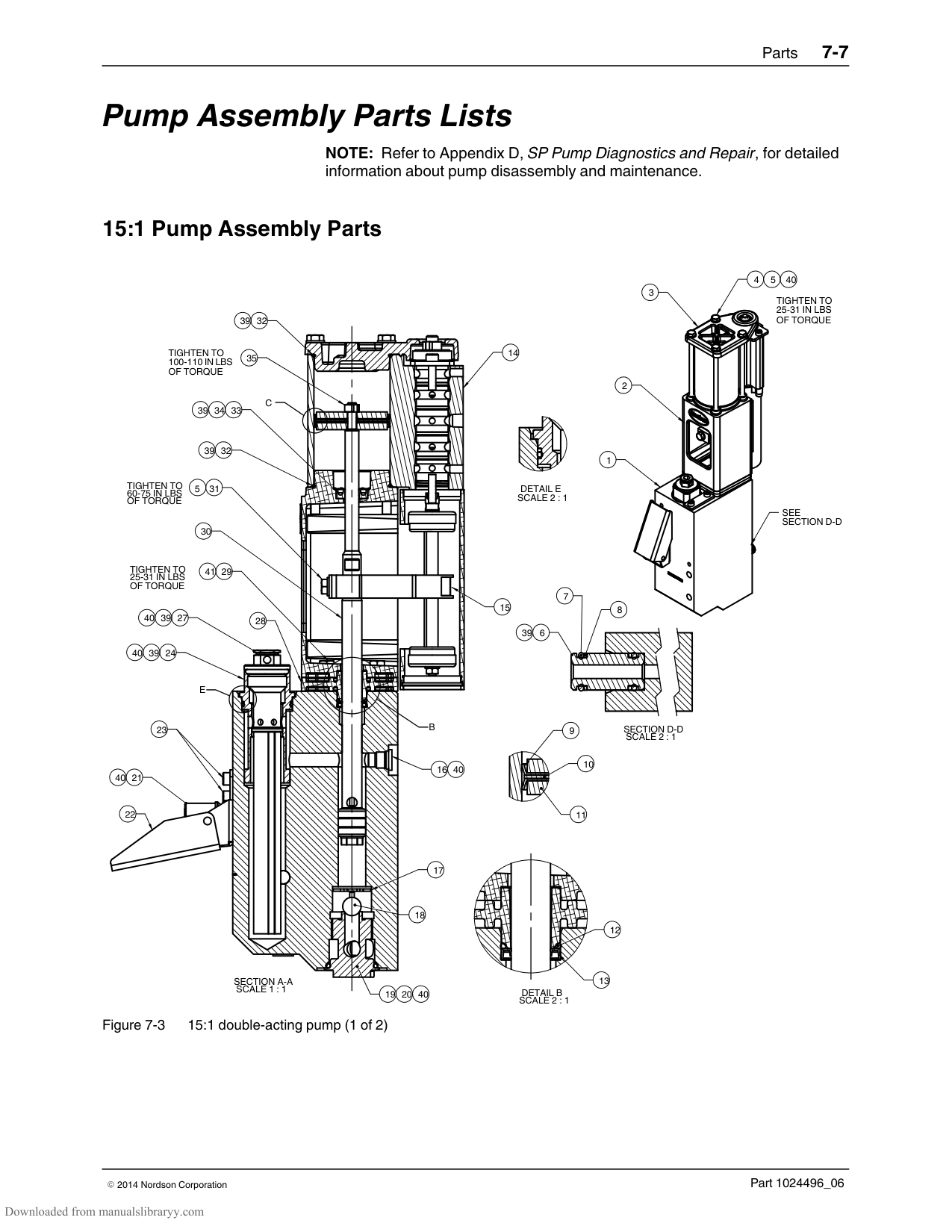
40
3
TIGHTEN TO 25-31 IN LBS OF TORQUE
39
32
TIGHTEN TO 100-110 IN LBS OF TORQUE
35
2
C
3439
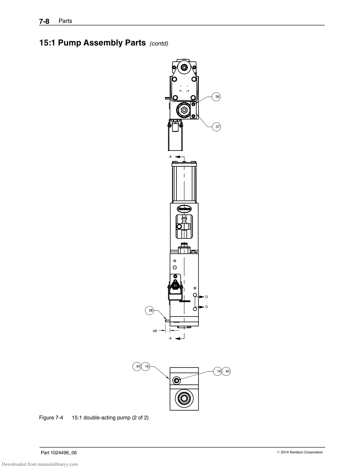
33
39 32
1
TIGHTEN TO
DETAIL E SCALE 2 : 1
5 31
60-75 IN LBS
OF TORQUE
SEE SECTION D-D
30
TIGHTEN TO
2941
25-31 IN LBS OF TORQUE
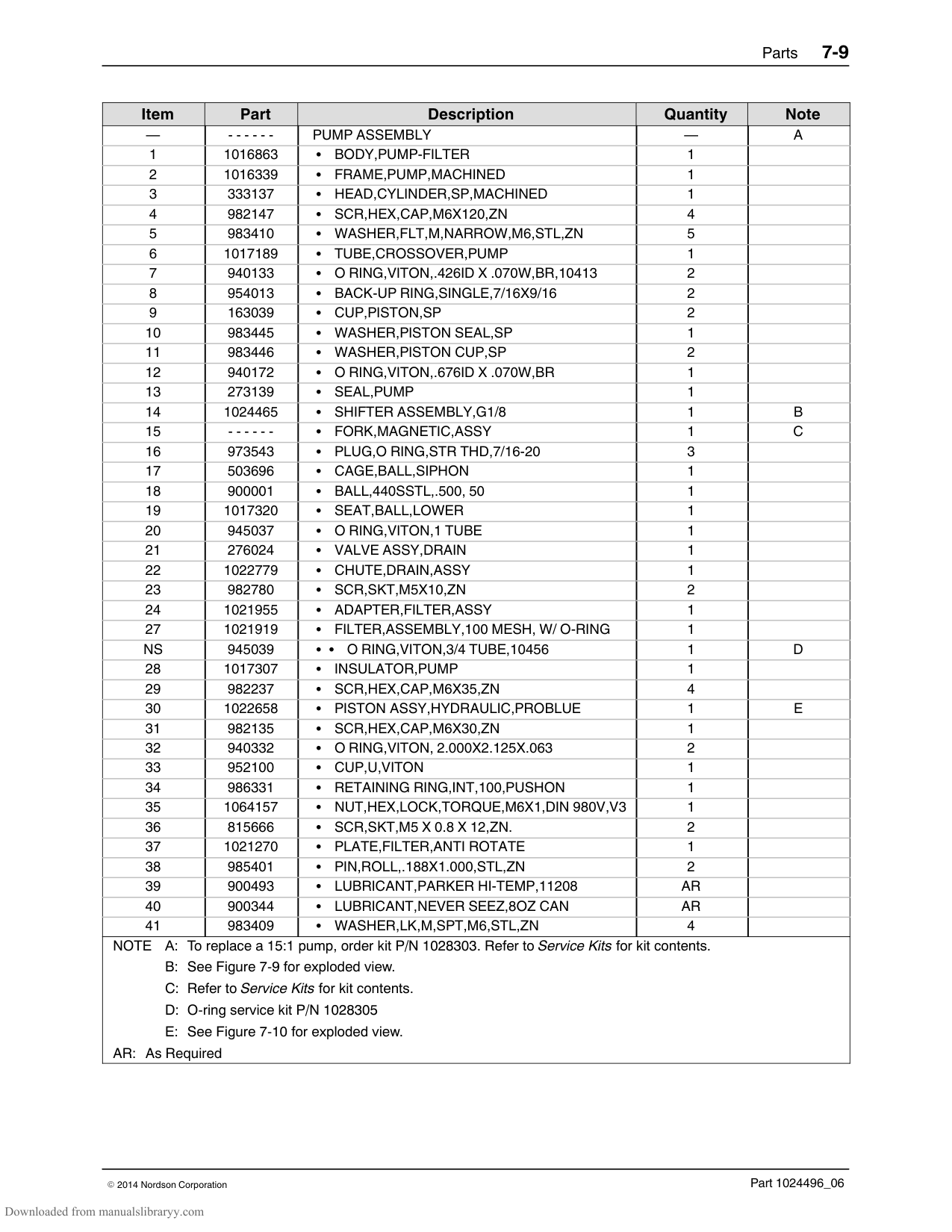
7
8
40
39
27
28
396
| | | | |---|---|---| | | | | | | | |
39
40
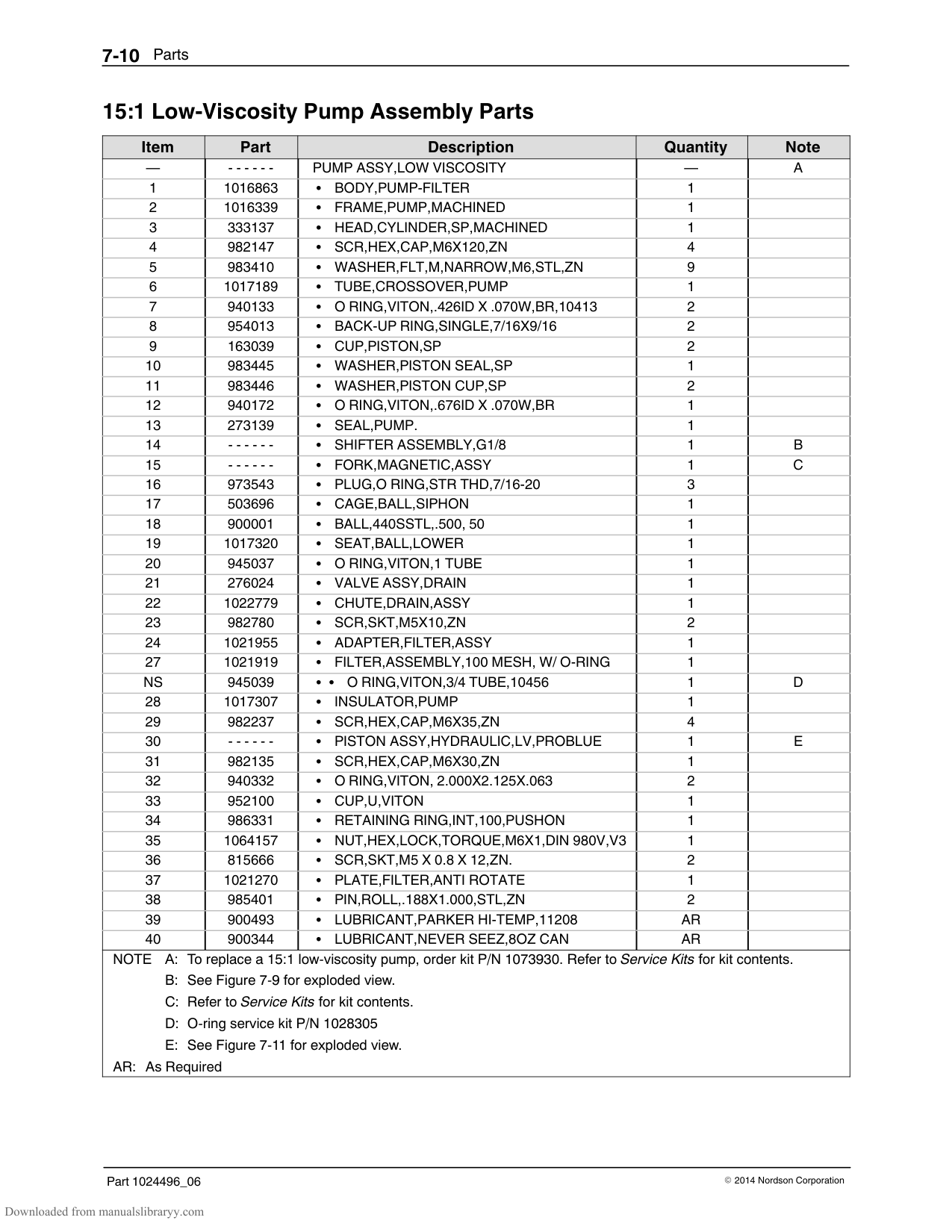
24
E
B 9
SECTION D-D
23
SCALE 2 : 1
16
40
40
21
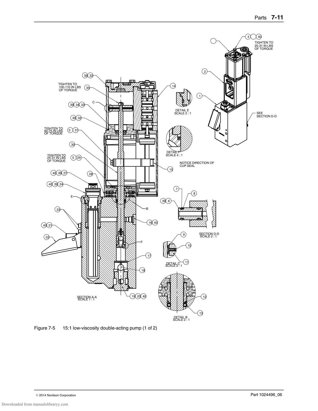
22
17
18
SECTION A-A SCALE 1 : 1
DETAIL B SCALE 2 : 1
20 4019
######## 15:1 Pump Assembly Parts (contd)
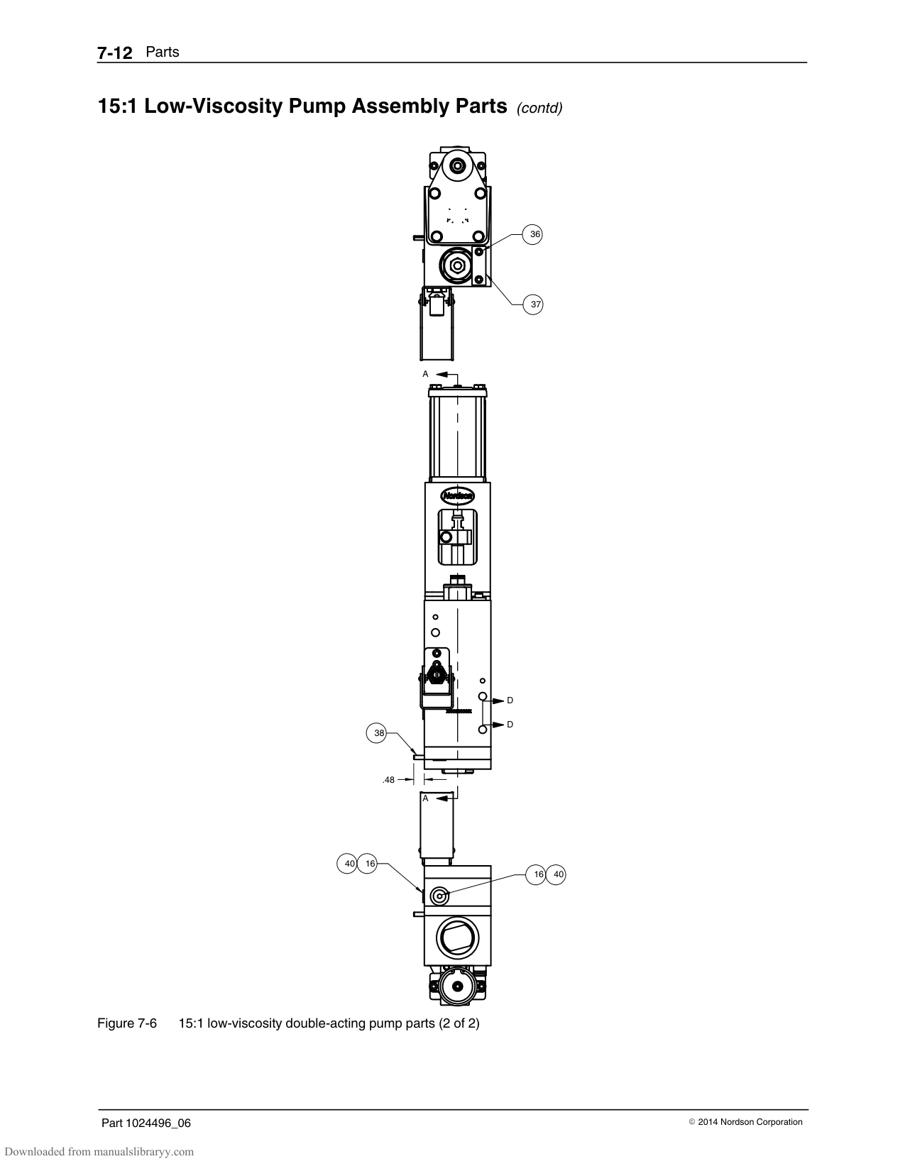
38
.48
A
| | | |---|---| | | | | | | | | |
D
D
A
1640
| | |---|

| | | | | |
4016
Figure 7-4 15:1 double-acting pump (2 of 2)
|Item|Part|Description|Quantity|Note| |---|---|---|---|---| |—|‐ ‐ ‐ ‐ ‐ ‐|PUMP ASSEMBLY|—|A| |1|1016863|BODY,PUMP-FILTER|1| | |2|1016339|FRAME,PUMP,MACHINED|1| | |3|333137|HEAD,CYLINDER,SP,MACHINED|1| | |4|982147|SCR,HEX,CAP,M6X120,ZN|4| | |5|983410|WASHER,FLT,M,NARROW,M6,STL,ZN|5| | |6|1017189|TUBE,CROSSOVER,PUMP|1| | |7|940133|O RING,VITON,.426ID X .070W,BR,10413|2| | |8|954013|BACK-UP RING,SINGLE,7/16X9/16|2| | |9|163039|CUP,PISTON,SP|2| | |10|983445|WASHER,PISTON SEAL,SP|1| | |11|983446|WASHER,PISTON CUP,SP|2| | |12|940172|O RING,VITON,.676ID X .070W,BR|1| | |13|273139|SEAL,PUMP|1| |
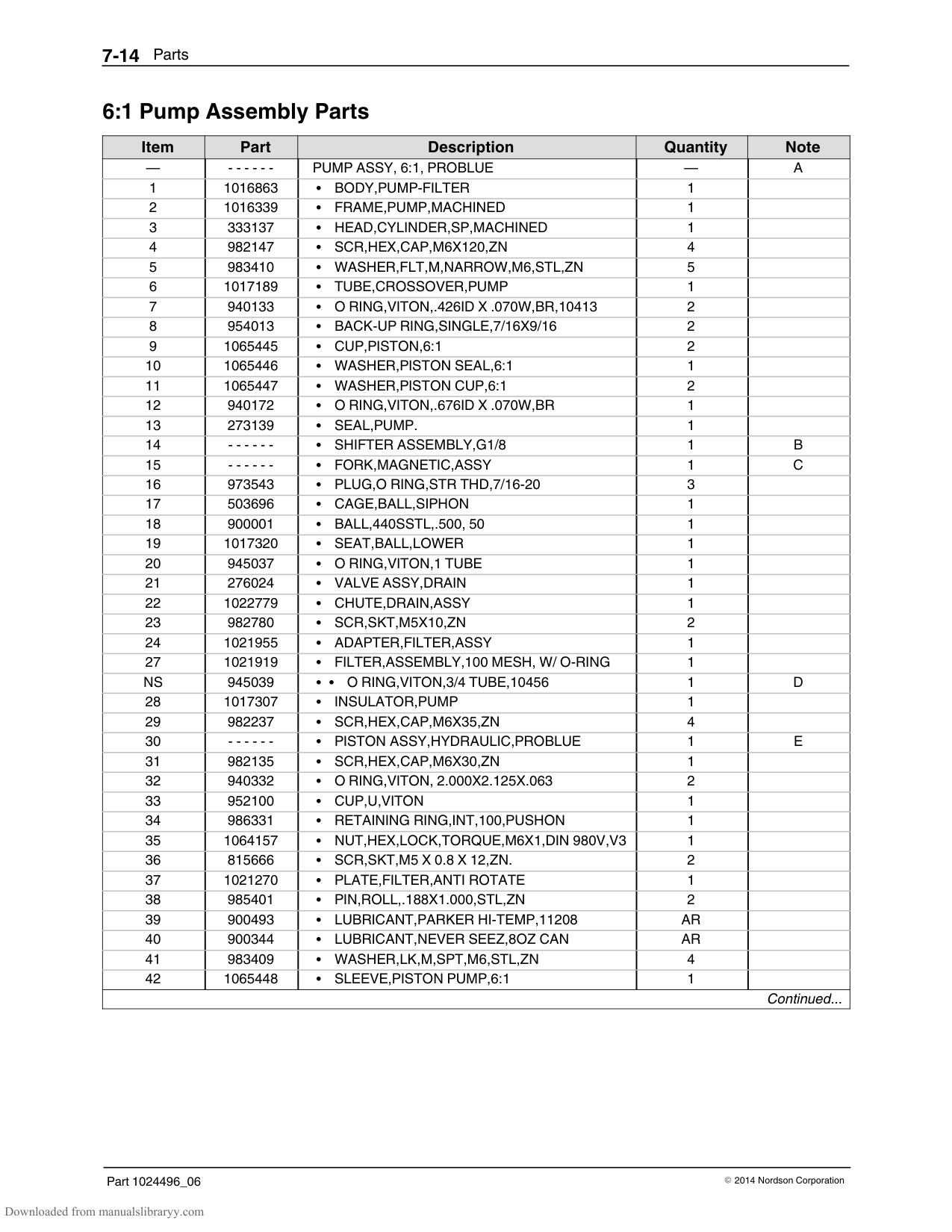
|14|1024465|SHIFTER ASSEMBLY,G1/8|1|B| |15|‐ ‐ ‐ ‐ ‐ ‐|FORK,MAGNETIC,ASSY|1|C| |16|973543|PLUG,O RING,STR THD,7/16-20|3| | |17|503696|CAGE,BALL,SIPHON|1| | |18|900001|BALL,440SSTL,.500, 50|1| | |19|1017320|SEAT,BALL,LOWER|1| | |20|945037|O RING,VITON,1 TUBE|1| | |21|276024|VALVE ASSY,DRAIN|1| | |22|1022779|CHUTE,DRAIN,ASSY|1| | |23|982780|SCR,SKT,M5X10,ZN|2| | |24|1021955|ADAPTER,FILTER,ASSY|1| | |27|1021919|FILTER,ASSEMBLY,100 MESH, W/ O-RING|1| | |NS|945039|O RING,VITON,3/4 TUBE,10456|1|D| |28|1017307|INSULATOR,PUMP|1| | |29|982237|SCR,HEX,CAP,M6X35,ZN|4| | |30|1022658|PISTON ASSY,HYDRAULIC,PROBLUE|1|E| |31|982135|SCR,HEX,CAP,M6X30,ZN|1| | |32|940332|O RING,VITON, 2.000X2.125X.063|2| | |33|952100|CUP,U,VITON|1| | |34|986331|RETAINING RING,INT,100,PUSHON|1| | |35|1064157|NUT,HEX,LOCK,TORQUE,M6X1,DIN 980V,V3|1| | |36|815666|SCR,SKT,M5 X 0.8 X 12,ZN.|2| | |37|1021270|PLATE,FILTER,ANTI ROTATE|1| | |38|985401|PIN,ROLL,.188X1.000,STL,ZN|2| | |39|900493|LUBRICANT,PARKER HI-TEMP,11208|AR| |
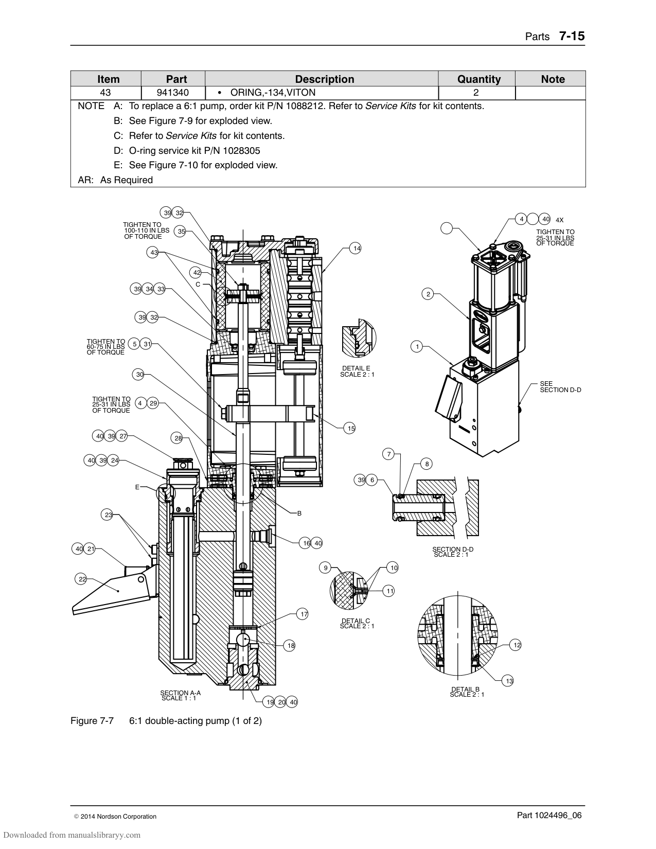
|40|900344|LUBRICANT,NEVER SEEZ,8OZ CAN|AR| | |41|983409|WASHER,LK,M,SPT,M6,STL,ZN|4| | |NOTE A: To replace a 15:1 pump, order kit P/N 1028303. Refer to Service Kits for kit contents.
B: See Figure 7-9 for exploded view.
C: Refer to Service Kits for kit contents.
D: O-ring service kit P/N 1028305
E: See Figure 7-10 for exploded view.
AR: As Required|NOTE A: To replace a 15:1 pump, order kit P/N 1028303. Refer to Service Kits for kit contents.
B: See Figure 7-9 for exploded view.
C: Refer to Service Kits for kit contents.
D: O-ring service kit P/N 1028305
E: See Figure 7-10 for exploded view.
AR: As Required|NOTE A: To replace a 15:1 pump, order kit P/N 1028303. Refer to Service Kits for kit contents.
B: See Figure 7-9 for exploded view.
C: Refer to Service Kits for kit contents.
D: O-ring service kit P/N 1028305
E: See Figure 7-10 for exploded view.
AR: As Required|NOTE A: To replace a 15:1 pump, order kit P/N 1028303. Refer to Service Kits for kit contents.
B: See Figure 7-9 for exploded view.
C: Refer to Service Kits for kit contents.
D: O-ring service kit P/N 1028305
E: See Figure 7-10 for exploded view.
AR: As Required|NOTE A: To replace a 15:1 pump, order kit P/N 1028303. Refer to Service Kits for kit contents.
B: See Figure 7-9 for exploded view.
C: Refer to Service Kits for kit contents.
D: O-ring service kit P/N 1028305
E: See Figure 7-10 for exploded view.
AR: As Required|
######## 15:1 Low‐Viscosity Pump Assembly Parts
|Item|Part|Description|Quantity|Note| |---|---|---|---|---| |—|‐ ‐ ‐ ‐ ‐ ‐|PUMP ASSY,LOW VISCOSITY|—|A| |1|1016863|BODY,PUMP-FILTER|1| | |2|1016339|FRAME,PUMP,MACHINED|1| | |3|333137|HEAD,CYLINDER,SP,MACHINED|1| | |4|982147|SCR,HEX,CAP,M6X120,ZN|4| | |5|983410|WASHER,FLT,M,NARROW,M6,STL,ZN|9| | |6|1017189|TUBE,CROSSOVER,PUMP|1| | |7|940133|O RING,VITON,.426ID X .070W,BR,10413|2| | |8|954013|BACK-UP RING,SINGLE,7/16X9/16|2| | |9|163039|CUP,PISTON,SP|2| | |10|983445|WASHER,PISTON SEAL,SP|1| | |11|983446|WASHER,PISTON CUP,SP|2| | |12|940172|O RING,VITON,.676ID X .070W,BR|1| | |13|273139|SEAL,PUMP.|1| | |14|‐ ‐ ‐ ‐ ‐ ‐|SHIFTER ASSEMBLY,G1/8|1|B| |15|‐ ‐ ‐ ‐ ‐ ‐|FORK,MAGNETIC,ASSY|1|C|
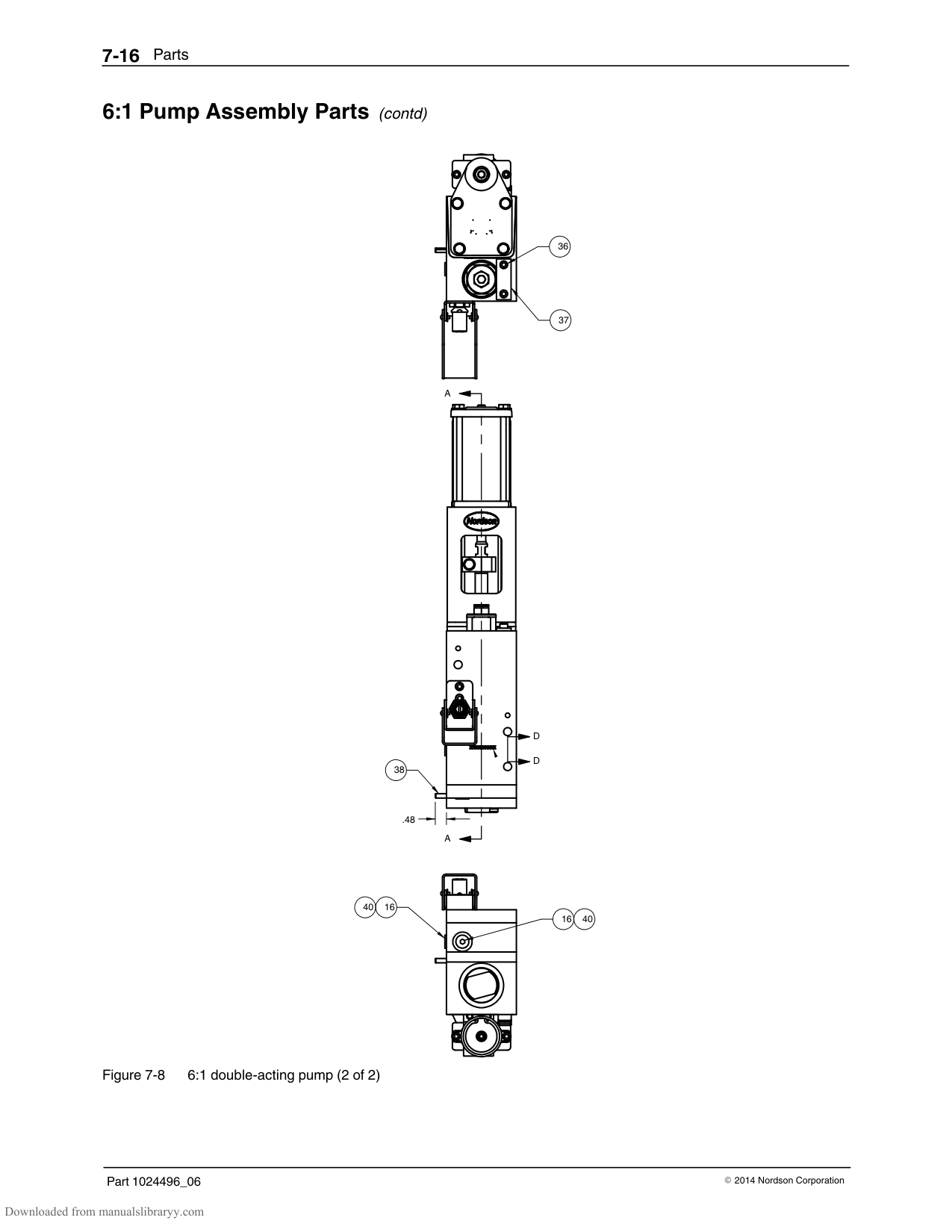
|16|973543|PLUG,O RING,STR THD,7/16-20|3| | |17|503696|CAGE,BALL,SIPHON|1| | |18|900001|BALL,440SSTL,.500, 50|1| | |19|1017320|SEAT,BALL,LOWER|1| | |20|945037|O RING,VITON,1 TUBE|1| | |21|276024|VALVE ASSY,DRAIN|1| | |22|1022779|CHUTE,DRAIN,ASSY|1| | |23|982780|SCR,SKT,M5X10,ZN|2| | |24|1021955|ADAPTER,FILTER,ASSY|1| | |27|1021919|FILTER,ASSEMBLY,100 MESH, W/ O-RING|1| | |NS|945039|O RING,VITON,3/4 TUBE,10456|1|D| |28|1017307|INSULATOR,PUMP|1| | |29|982237|SCR,HEX,CAP,M6X35,ZN|4| | |30|‐ ‐ ‐ ‐ ‐ ‐|PISTON ASSY,HYDRAULIC,LV,PROBLUE|1|E| |31|982135|SCR,HEX,CAP,M6X30,ZN|1| | |32|940332|O RING,VITON, 2.000X2.125X.063|2| | |33|952100|CUP,U,VITON|1| | |34|986331|RETAINING RING,INT,100,PUSHON|1| | |35|1064157|NUT,HEX,LOCK,TORQUE,M6X1,DIN 980V,V3|1| | |36|815666|SCR,SKT,M5 X 0.8 X 12,ZN.|2| | |37|1021270|PLATE,FILTER,ANTI ROTATE|1| | |38|985401|PIN,ROLL,.188X1.000,STL,ZN|2| | |39|900493|LUBRICANT,PARKER HI-TEMP,11208|AR| | |40|900344|LUBRICANT,NEVER SEEZ,8OZ CAN|AR| | |NOTE A: To replace a 15:1 low-viscosity pump, order kit P/N 1073930. Refer to Service Kits for kit contents.
B: See Figure 7-9 for exploded view.
C: Refer to Service Kits for kit contents.
D: O-ring service kit P/N 1028305
E: See Figure 7-11 for exploded view.
AR: As Required|NOTE A: To replace a 15:1 low-viscosity pump, order kit P/N 1073930. Refer to Service Kits for kit contents.
B: See Figure 7-9 for exploded view.
C: Refer to Service Kits for kit contents.
D: O-ring service kit P/N 1028305
E: See Figure 7-11 for exploded view.
AR: As Required|NOTE A: To replace a 15:1 low-viscosity pump, order kit P/N 1073930. Refer to Service Kits for kit contents.
B: See Figure 7-9 for exploded view.
C: Refer to Service Kits for kit contents.
D: O-ring service kit P/N 1028305
E: See Figure 7-11 for exploded view.
AR: As Required|NOTE A: To replace a 15:1 low-viscosity pump, order kit P/N 1073930. Refer to Service Kits for kit contents.
B: See Figure 7-9 for exploded view.
C: Refer to Service Kits for kit contents.
D: O-ring service kit P/N 1028305
E: See Figure 7-11 for exploded view.
AR: As Required|NOTE A: To replace a 15:1 low-viscosity pump, order kit P/N 1073930. Refer to Service Kits for kit contents.
B: See Figure 7-9 for exploded view.
C: Refer to Service Kits for kit contents.
D: O-ring service kit P/N 1028305
E: See Figure 7-11 for exploded view.
AR: As Required|

4
40
TIGHTEN TO 25-31 IN LBS OF TORQUE
2
32
39
TIGHTEN TO
14
100-110 IN LBS OF TORQUE
35
1
C
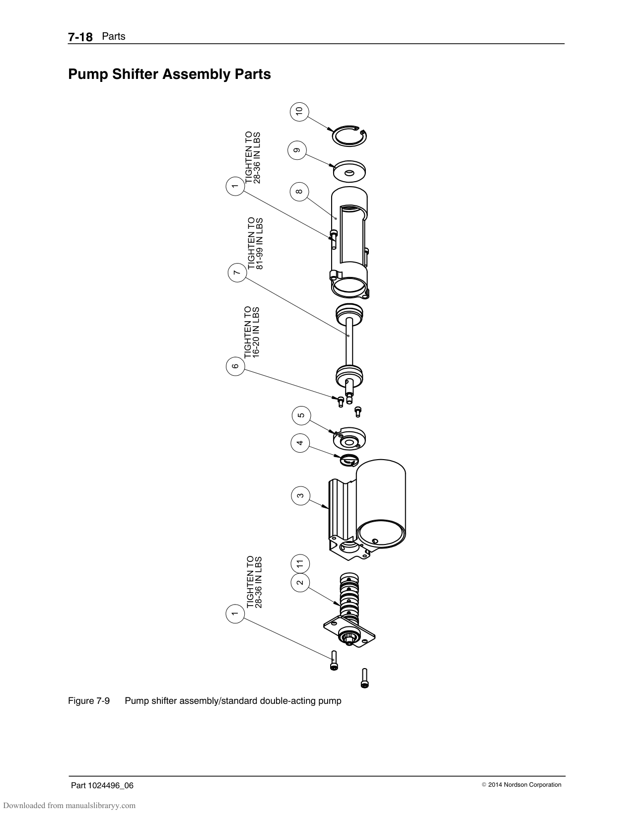
3439
33
DETAIL E SCALE 2 : 1
SEE SECTION D-D
39
32
TIGHTEN TO
5
31
60-75 IN LBS
OF TORQUE
30
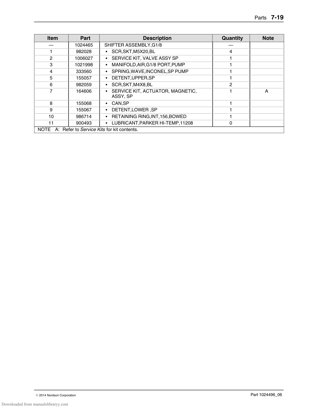
DETAIL F SCALE 4 : 1
TIGHTEN TO
5 29
25-31 IN LBS OF TORQUE
NOTICE DIRECTION OF CUP SEAL
15
40
39
27
28
40 39
24
7
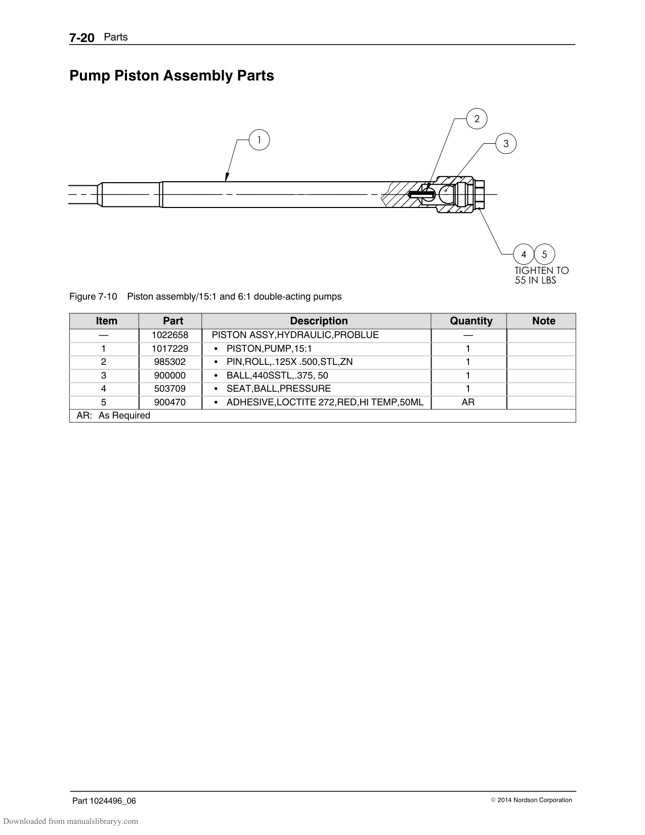
8
E
396
| | | | |---|---|---| | | | | | | | |
B
23
40
16
40
21
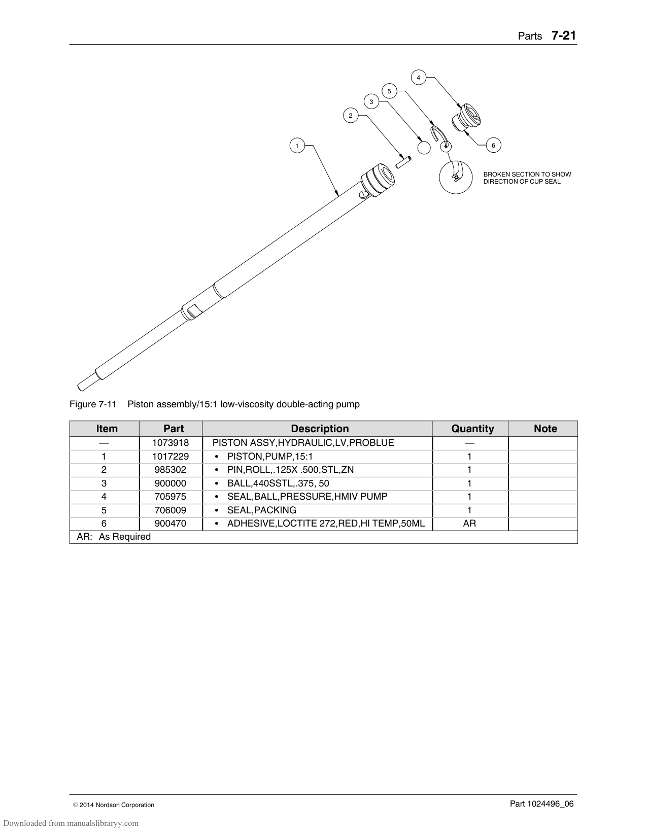
SECTION D-D
SCALE 2 : 1
22
F
9
17
DETAIL C
SCALE 2 : 1
18
19
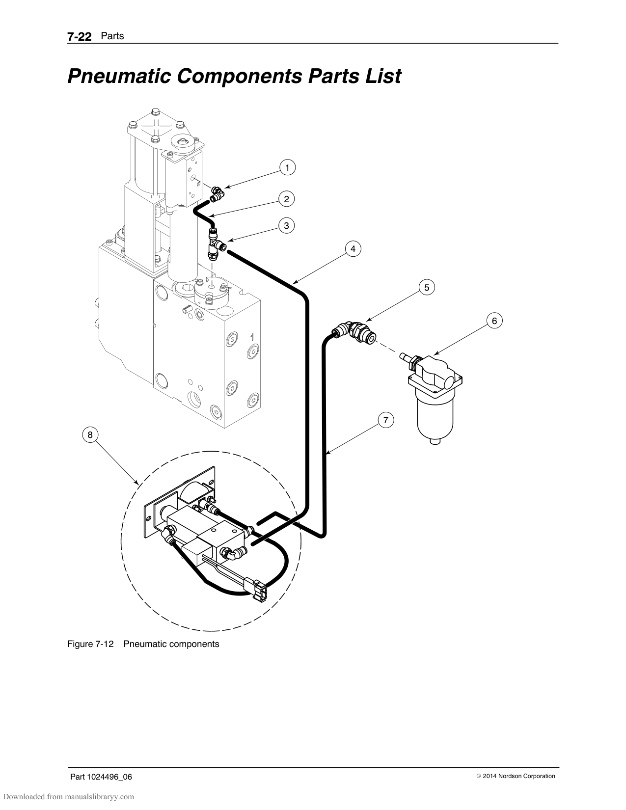
20 40
SECTION A-A
SCALE 1 : 1
DETAIL B
SCALE 2 : 1
######## 15:1 Low‐Viscosity Pump Assembly Parts (contd)
38
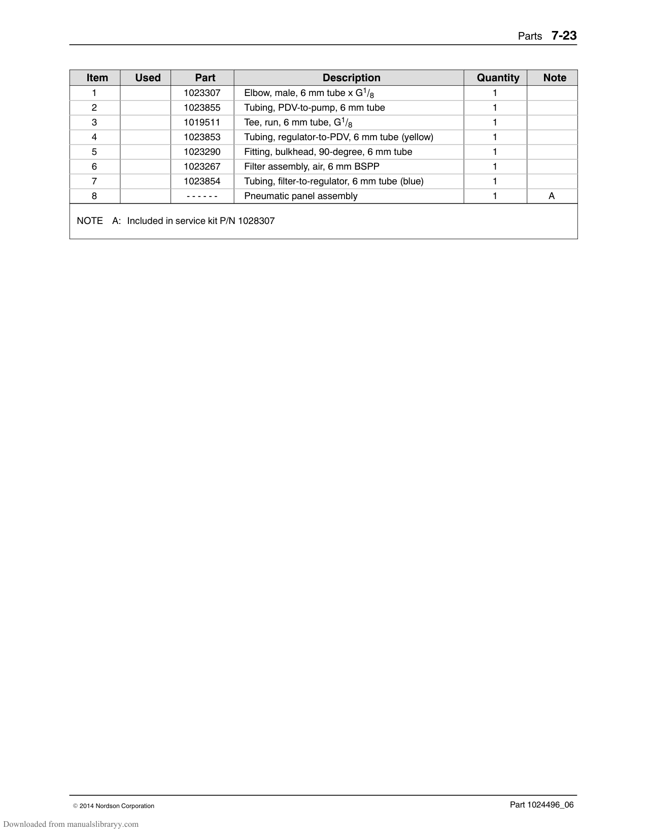
.48
A
| | | |---|---| | | | | | | | | |
D
D
A
1640
4016
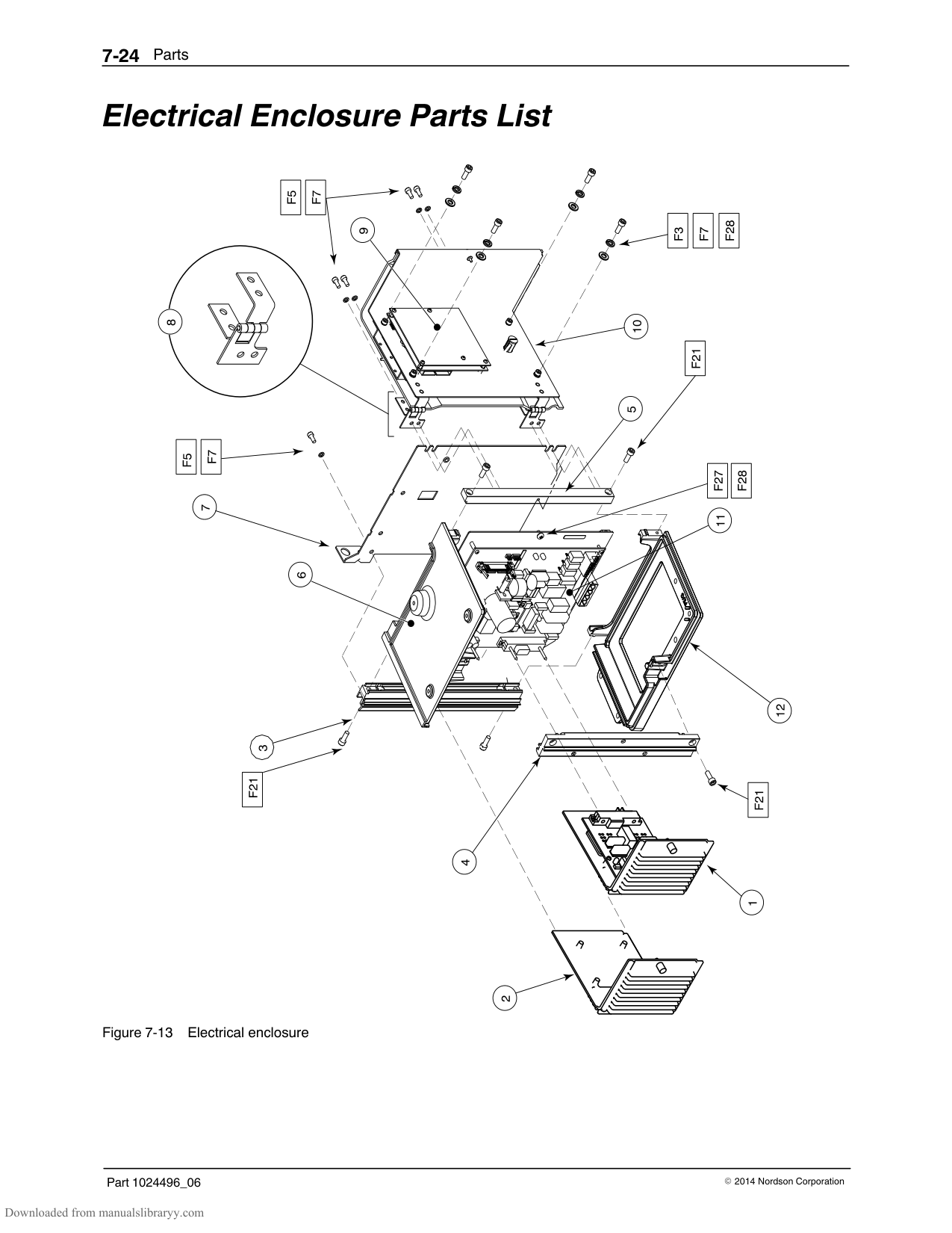
################ This page intentionally left blank.
######## 6:1 Pump Assembly Parts
|Item|Part|Description|Quantity|Note| |---|---|---|---|---| |—|‐ ‐ ‐ ‐ ‐ ‐|PUMP ASSY, 6:1, PROBLUE|—|A| |1|1016863|BODY,PUMP-FILTER|1| | |2|1016339|FRAME,PUMP,MACHINED|1| | |3|333137|HEAD,CYLINDER,SP,MACHINED|1| | |4|982147|SCR,HEX,CAP,M6X120,ZN|4| | |5|983410|WASHER,FLT,M,NARROW,M6,STL,ZN|5| | |6|1017189|TUBE,CROSSOVER,PUMP|1| | |7|940133|O RING,VITON,.426ID X .070W,BR,10413|2| | |8|954013|BACK-UP RING,SINGLE,7/16X9/16|2| | |9|1065445|CUP,PISTON,6:1|2| | |10|1065446|WASHER,PISTON SEAL,6:1|1| | |11|1065447|WASHER,PISTON CUP,6:1|2| | |12|940172|O RING,VITON,.676ID X .070W,BR|1| | |13|273139|SEAL,PUMP.|1| | |14|‐ ‐ ‐ ‐ ‐ ‐|SHIFTER ASSEMBLY,G1/8|1|B| |15|‐ ‐ ‐ ‐ ‐ ‐|FORK,MAGNETIC,ASSY|1|C| |16|973543|PLUG,O RING,STR THD,7/16-20|3| | |17|503696|CAGE,BALL,SIPHON|1| | |18|900001|BALL,440SSTL,.500, 50|1| |
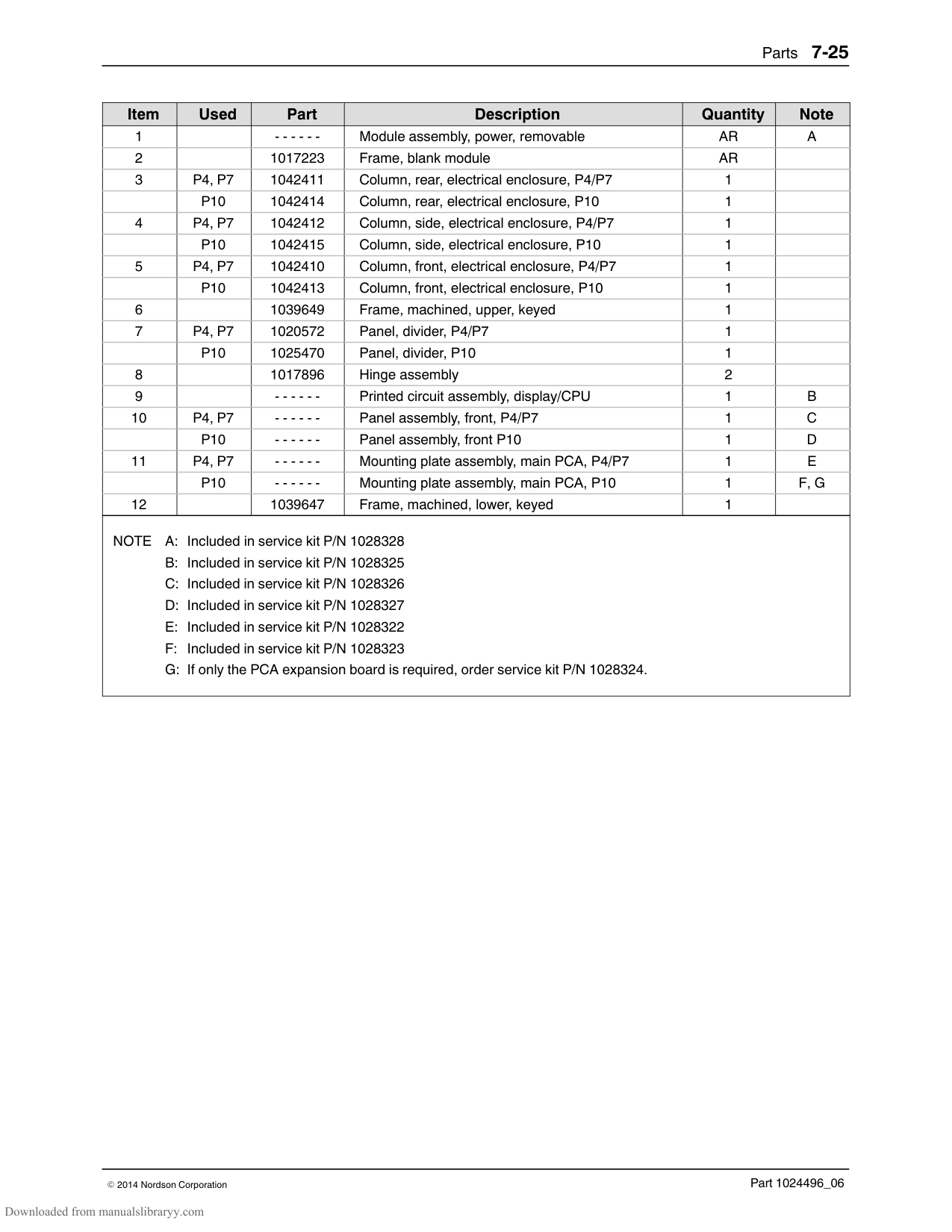
|19|1017320|SEAT,BALL,LOWER|1| | |20|945037|O RING,VITON,1 TUBE|1| | |21|276024|VALVE ASSY,DRAIN|1| | |22|1022779|CHUTE,DRAIN,ASSY|1| | |23|982780|SCR,SKT,M5X10,ZN|2| | |24|1021955|ADAPTER,FILTER,ASSY|1| | |27|1021919|FILTER,ASSEMBLY,100 MESH, W/ O-RING|1| | |NS|945039|O RING,VITON,3/4 TUBE,10456|1|D| |28|1017307|INSULATOR,PUMP|1| | |29|982237|SCR,HEX,CAP,M6X35,ZN|4| | |30|‐ ‐ ‐ ‐ ‐ ‐|PISTON ASSY,HYDRAULIC,PROBLUE|1|E| |31|982135|SCR,HEX,CAP,M6X30,ZN|1| | |32|940332|O RING,VITON, 2.000X2.125X.063|2| | |33|952100|CUP,U,VITON|1| | |34|986331|RETAINING RING,INT,100,PUSHON|1| | |35|1064157|NUT,HEX,LOCK,TORQUE,M6X1,DIN 980V,V3|1| | |36|815666|SCR,SKT,M5 X 0.8 X 12,ZN.|2| | |37|1021270|PLATE,FILTER,ANTI ROTATE|1| | |38|985401|PIN,ROLL,.188X1.000,STL,ZN|2| | |39|900493|LUBRICANT,PARKER HI-TEMP,11208|AR| | |40|900344|LUBRICANT,NEVER SEEZ,8OZ CAN|AR| | |41|983409|WASHER,LK,M,SPT,M6,STL,ZN|4| | |42|1065448|SLEEVE,PISTON PUMP,6:1|1| | |Continued...|Continued...|Continued...|Continued...|Continued...|
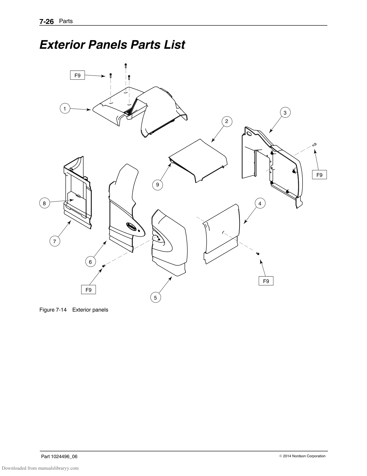
|Item|Part|Description|Quantity|Note| |---|---|---|---|---| |43|941340|ORING,-134,VITON|2| | |NOTE A: To replace a 6:1 pump, order kit P/N 1088212. Refer to Service Kits for kit contents.
B: See Figure 7-9 for exploded view.
C: Refer to Service Kits for kit contents.
D: O-ring service kit P/N 1028305
E: See Figure 7-10 for exploded view.
AR: As Required|NOTE A: To replace a 6:1 pump, order kit P/N 1088212. Refer to Service Kits for kit contents.
B: See Figure 7-9 for exploded view.
C: Refer to Service Kits for kit contents.
D: O-ring service kit P/N 1028305
E: See Figure 7-10 for exploded view.
AR: As Required|NOTE A: To replace a 6:1 pump, order kit P/N 1088212. Refer to Service Kits for kit contents.
B: See Figure 7-9 for exploded view.
C: Refer to Service Kits for kit contents.
D: O-ring service kit P/N 1028305
E: See Figure 7-10 for exploded view.
AR: As Required|NOTE A: To replace a 6:1 pump, order kit P/N 1088212. Refer to Service Kits for kit contents.
B: See Figure 7-9 for exploded view.
C: Refer to Service Kits for kit contents.
D: O-ring service kit P/N 1028305
E: See Figure 7-10 for exploded view.
AR: As Required|NOTE A: To replace a 6:1 pump, order kit P/N 1088212. Refer to Service Kits for kit contents.
B: See Figure 7-9 for exploded view.
C: Refer to Service Kits for kit contents.
D: O-ring service kit P/N 1028305
E: See Figure 7-10 for exploded view.
AR: As Required|
39
32
4
40
4X
TIGHTEN TO
100-110 IN LBS OF TORQUE
35
TIGHTEN TO 25-31 IN LBS OF TORQUE
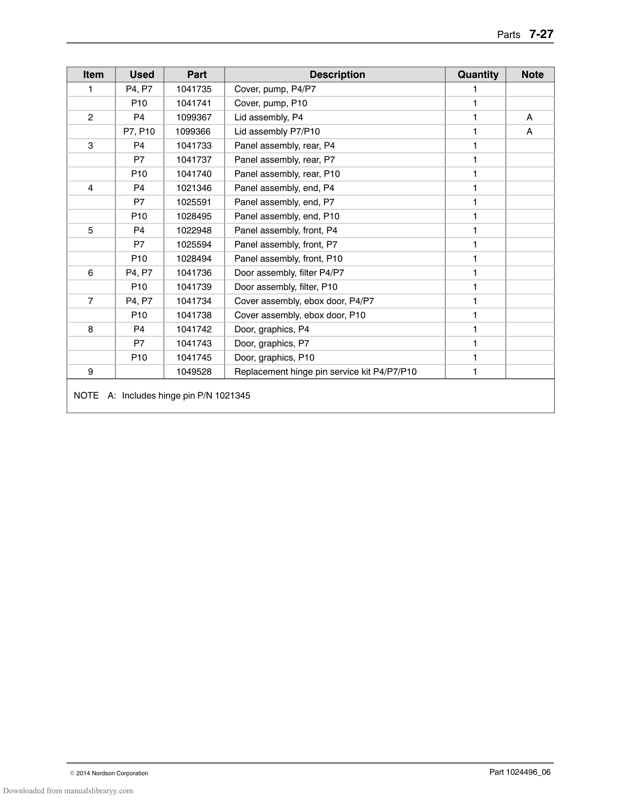
43
42
C
3439
33
2
32
39
TIGHTEN TO
5
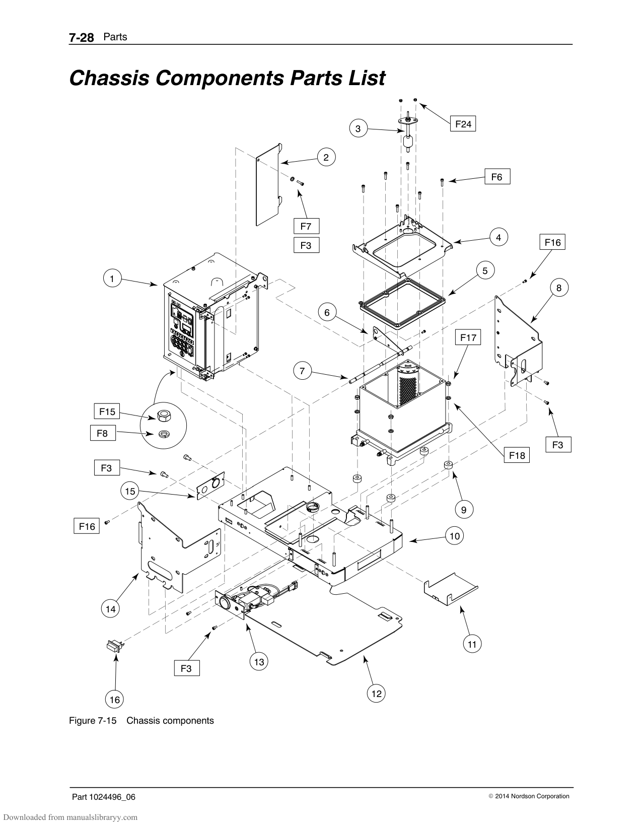
31
1
60-75 IN LBS
OF TORQUE
DETAIL E SCALE 2 : 1
30
SEE SECTION D-D
TIGHTEN TO
429
25-31 IN LBS OF TORQUE
40
39
27
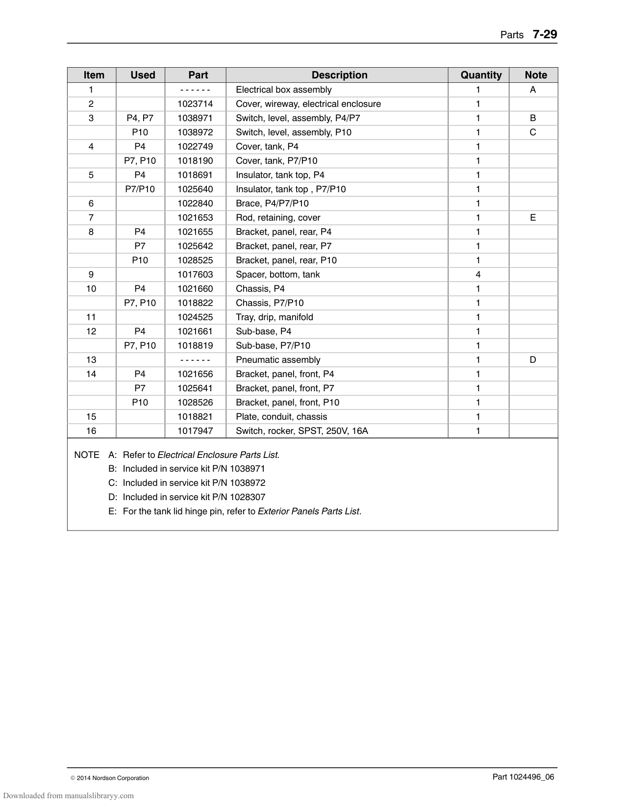
28
7
3940
24
8
396
| | | | |---|---|---| | | | | | | | |
E
B
23
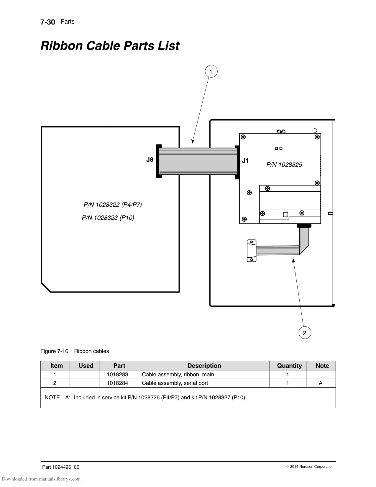
4016
40
21
SECTION D-D SCALE 2 : 1
10
9
22
11
17
DETAIL C
SCALE 2 : 1
12
18
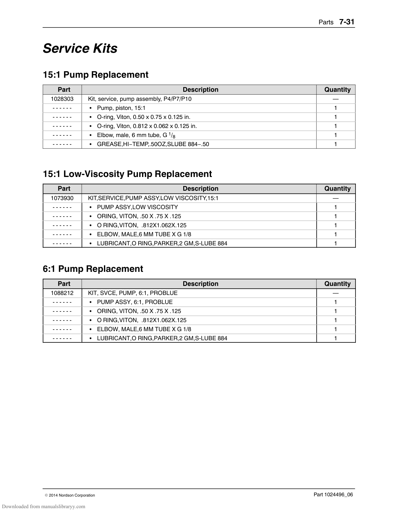
13
DETAIL B
SECTION A-A
SCALE 2 : 1
SCALE 1 : 1
19
20 40
######## 6:1 Pump Assembly Parts (contd)
38
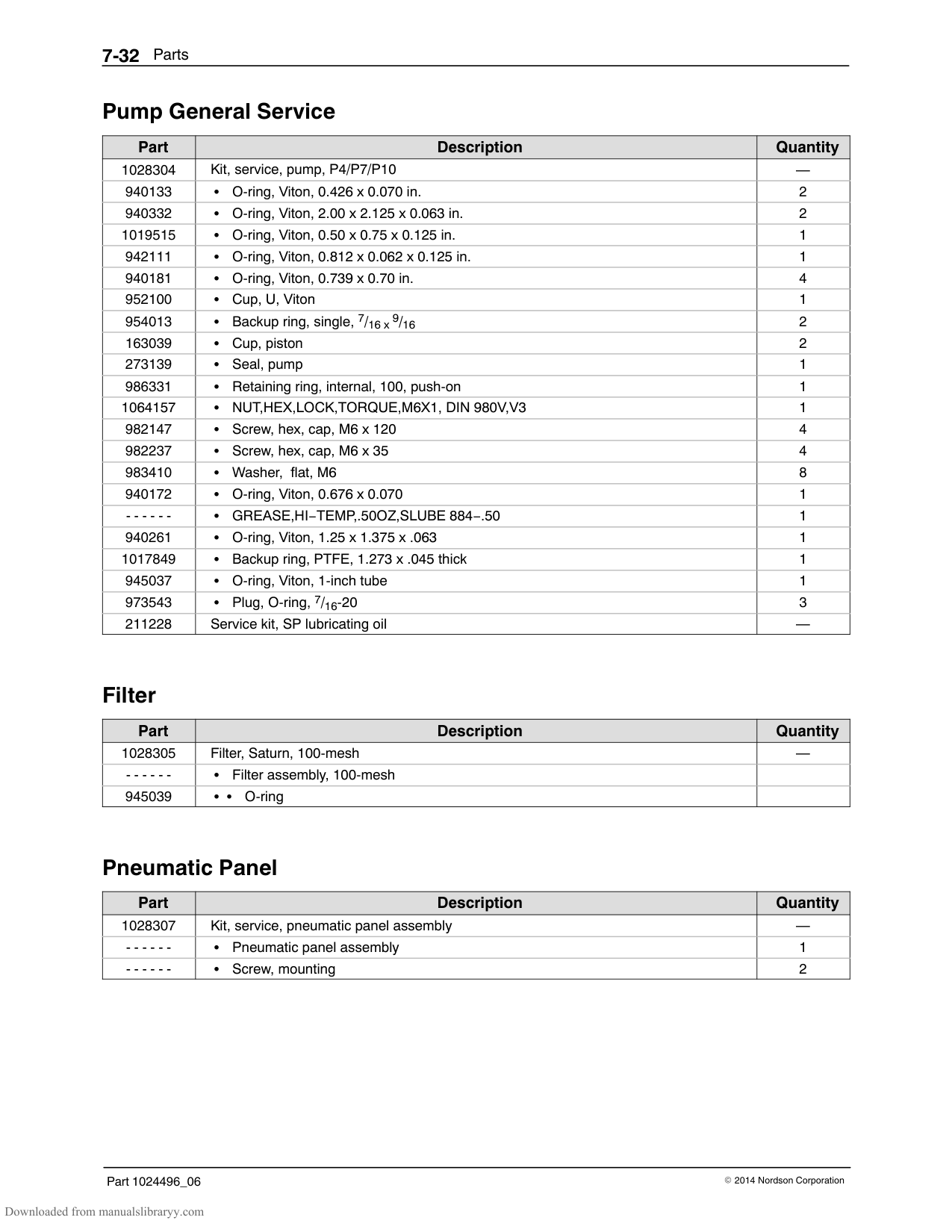
.48
A
| | | |---|---| | | | | | | | | |
D
D
A
1640
4016
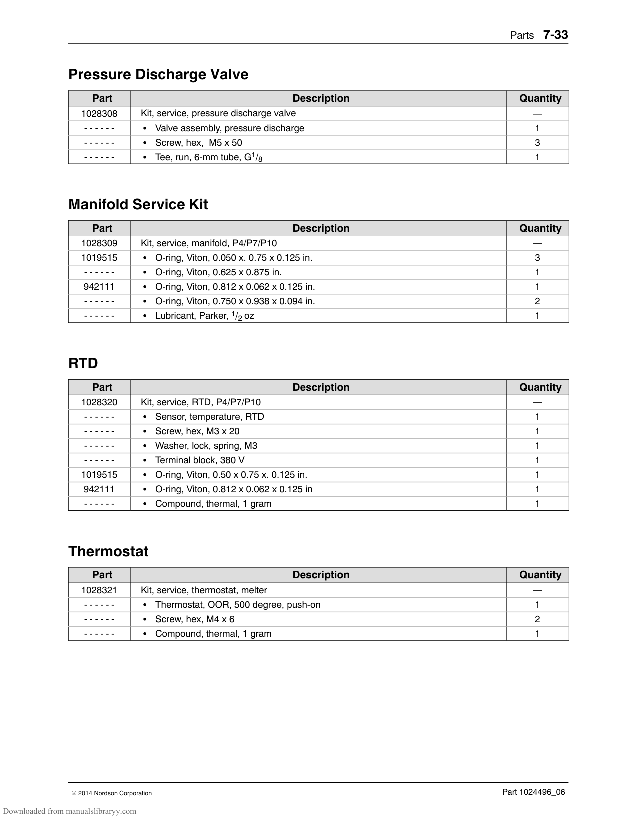
################ This page intentionally left blank.
######## Pump Shifter Assembly Parts
|Item|Part|Description|Quantity|Note| |---|---|---|---|---| |—|1024465|SHIFTER ASSEMBLY,G1/8|—| | |1|982028|SCR,SKT,M5X20,BL|4| | |2|1006027|SERVICE KIT, VALVE ASSY SP|1| | |3|1021998|MANIFOLD,AIR,G1/8 PORT,PUMP|1| | |4|333560|SPRING,WAVE,INCONEL,SP PUMP|1| | |5|155057|DETENT,UPPER,SP|1| | |6|982059|SCR,SKT,M4X8,BL|2| | |7|164606|SERVICE KIT, ACTUATOR, MAGNETIC, ASSY, SP|1|A| |8|155068|CAN,SP|1| | |9|155067|DETENT,LOWER ,SP|1| | |10|986714|RETAINING RING,INT,156,BOWED|1| | |11|900493|LUBRICANT,PARKER HI-TEMP,11208|0| | |NOTE A: Refer to Service Kits for kit contents.|NOTE A: Refer to Service Kits for kit contents.|NOTE A: Refer to Service Kits for kit contents.|NOTE A: Refer to Service Kits for kit contents.|NOTE A: Refer to Service Kits for kit contents.|
######## Pump Piston Assembly Parts
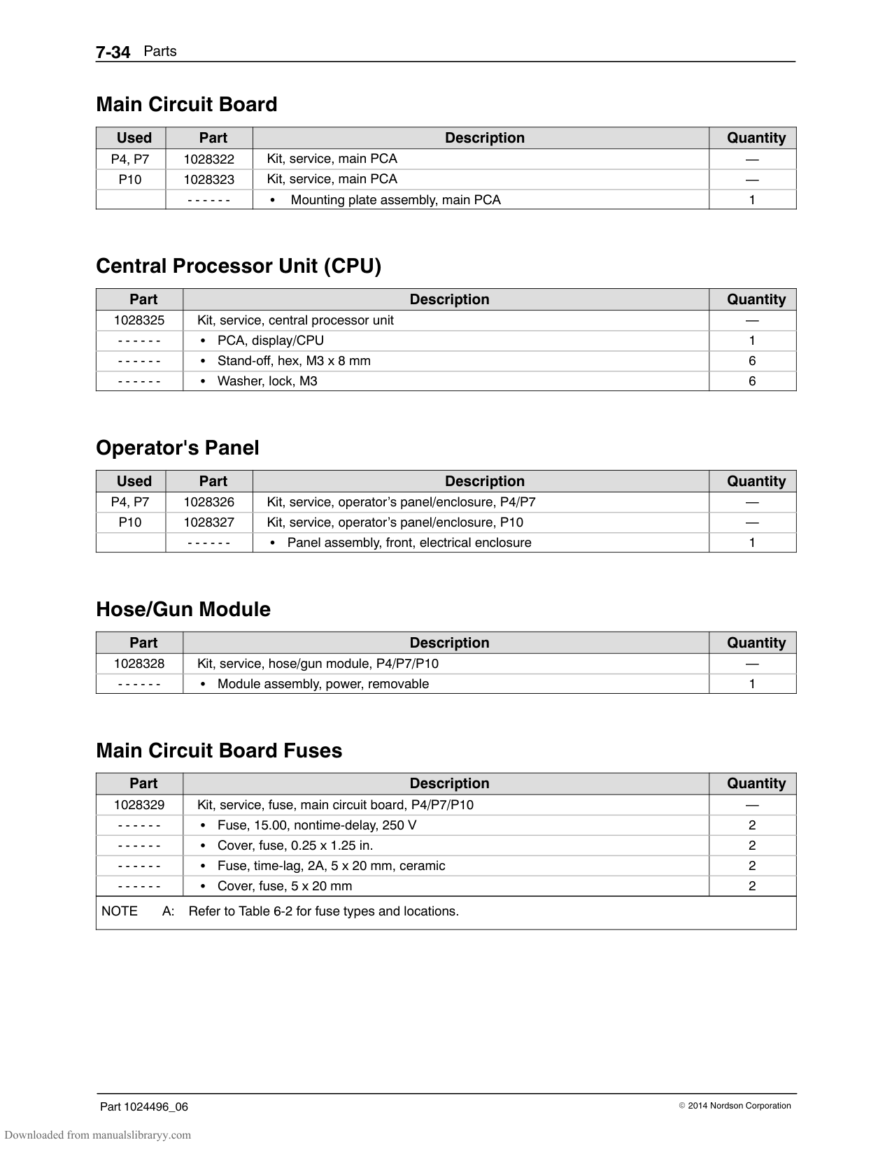
|Item|Part|Description|Quantity|Note| |---|---|---|---|---| |—|1022658|PISTON ASSY,HYDRAULIC,PROBLUE|—| | |1|1017229|PISTON,PUMP,15:1|1| | |2|985302|PIN,ROLL,.125X .500,STL,ZN|1| | |3|900000|BALL,440SSTL,.375, 50|1| | |4|503709|SEAT,BALL,PRESSURE|1| | |5|900470|ADHESIVE,LOCTITE 272,RED,HI TEMP,50ML|AR| | |AR: As Required|AR: As Required|AR: As Required|AR: As Required|AR: As Required|
4
5
3
2
6
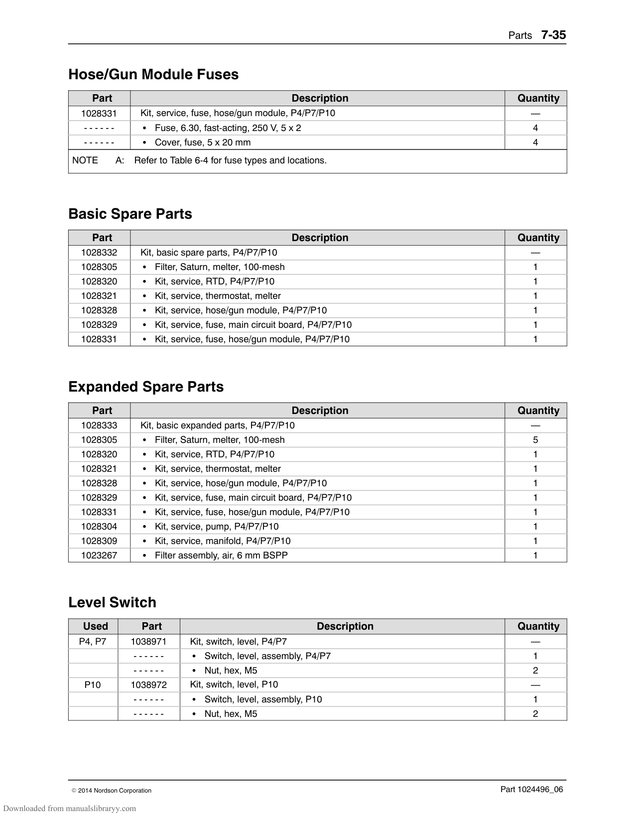
1
BROKEN SECTION TO SHOW
DIRECTION OF CUP SEAL
|Item|Part|Description|Quantity|Note| |---|---|---|---|---| |—|1073918|PISTON ASSY,HYDRAULIC,LV,PROBLUE|—| | |1|1017229|PISTON,PUMP,15:1|1| | |2|985302|PIN,ROLL,.125X .500,STL,ZN|1| | |3|900000|BALL,440SSTL,.375, 50|1| | |4|705975|SEAL,BALL,PRESSURE,HMIV PUMP|1| | |5|706009|SEAL,PACKING|1| | |6|900470|ADHESIVE,LOCTITE 272,RED,HI TEMP,50ML|AR| | |AR: As Required|AR: As Required|AR: As Required|AR: As Required|AR: As Required|
#### Pneumatic Components Parts List
1
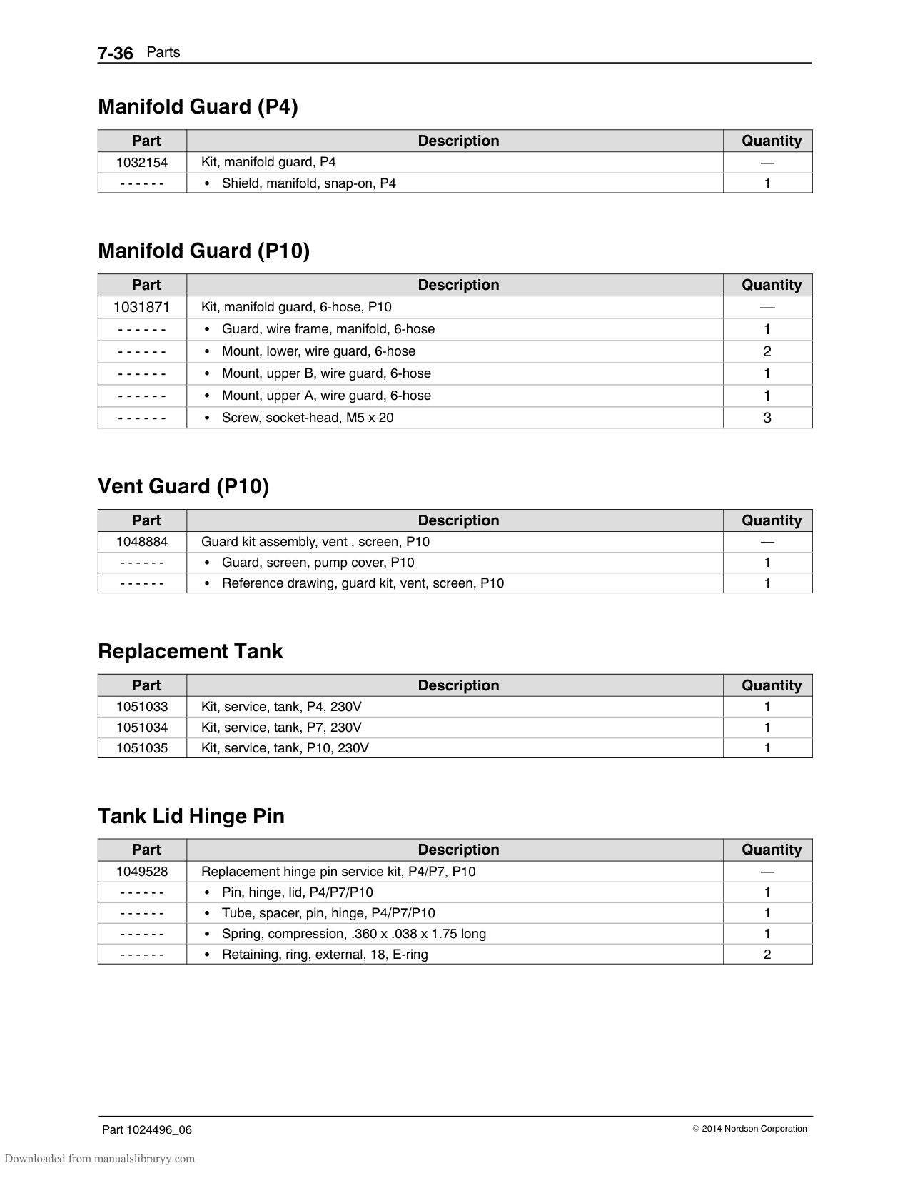
4
5
6
7 8
|Item|Used|Part|Description|Quantity|Note| |---|---|---|---|---|---| |1| |1023307|Elbow, male, 6 mm tube x G1/8|1| | |2| |1023855|Tubing, PDV-to-pump, 6 mm tube|1| | |3| |1019511|Tee, run, 6 mm tube, G1/8|1| | |4| |1023853|Tubing, regulator-to-PDV, 6 mm tube (yellow)|1| | |5| |1023290|Fitting, bulkhead, 90-degree, 6 mm tube|1| | |6| |1023267|Filter assembly, air, 6 mm BSPP|1| | |7| |1023854|Tubing, filter-to-regulator, 6 mm tube (blue)|1| |
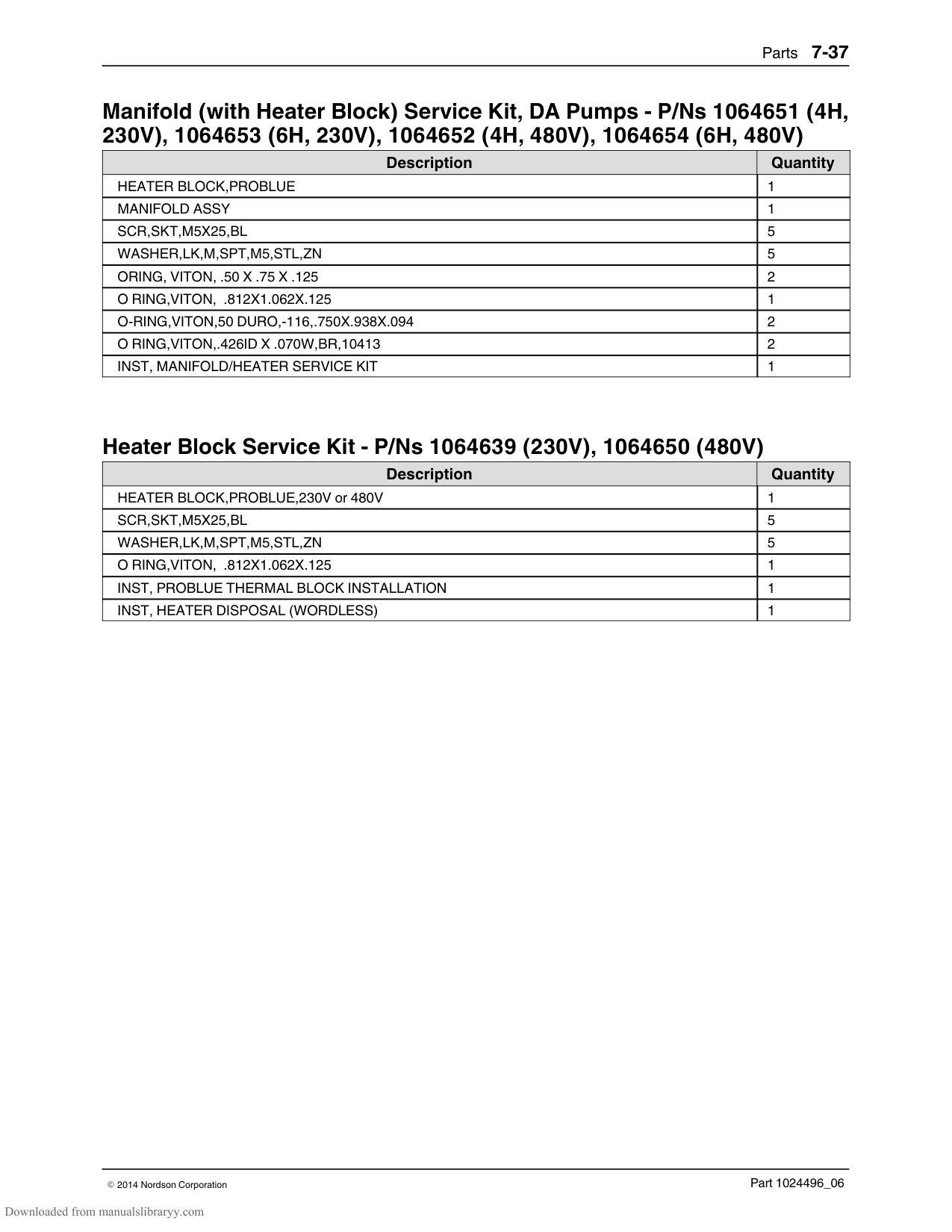
|8| |‐ ‐ ‐ ‐ ‐ ‐|Pneumatic panel assembly|1|A| |NOTE A: Included in service kit P/N 1028307|NOTE A: Included in service kit P/N 1028307|NOTE A: Included in service kit P/N 1028307|NOTE A: Included in service kit P/N 1028307|NOTE A: Included in service kit P/N 1028307|NOTE A: Included in service kit P/N 1028307|
#### Electrical Enclosure Parts List
|Item|Used|Part|Description|Quantity|Note| |---|---|---|---|---|---| |1| |‐ ‐ ‐ ‐ ‐ ‐|Module assembly, power, removable|AR|A| |2| |1017223|Frame, blank module|AR| | |3|P4, P7|1042411|Column, rear, electrical enclosure, P4/P7|1| | | |P10|1042414|Column, rear, electrical enclosure, P10|1| | |4|P4, P7|1042412|Column, side, electrical enclosure, P4/P7|1| | | |P10|1042415|Column, side, electrical enclosure, P10|1| | |5|P4, P7|1042410|Column, front, electrical enclosure, P4/P7|1| | | |P10|1042413|Column, front, electrical enclosure, P10|1| | |6| |1039649|Frame, machined, upper, keyed|1| | |7|P4, P7|1020572|Panel, divider, P4/P7|1| | | |P10|1025470|Panel, divider, P10|1| | |8| |1017896|Hinge assembly|2| | |9| |‐ ‐ ‐ ‐ ‐ ‐|Printed circuit assembly, display/CPU|1|B| |10|P4, P7|‐ ‐ ‐ ‐ ‐ ‐|Panel assembly, front, P4/P7|1|C|
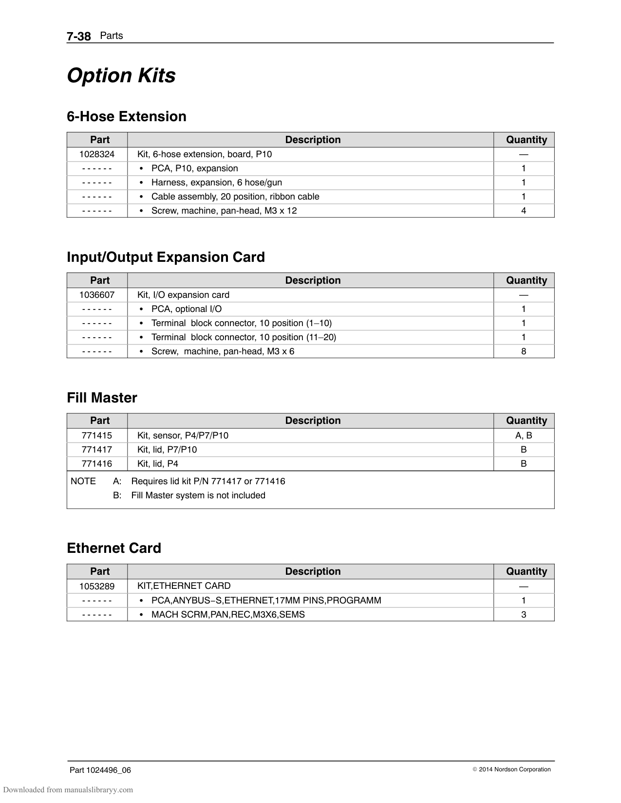
| |P10|‐ ‐ ‐ ‐ ‐ ‐|Panel assembly, front P10|1|D| |11|P4, P7|‐ ‐ ‐ ‐ ‐ ‐|Mounting plate assembly, main PCA, P4/P7|1|E| | |P10|‐ ‐ ‐ ‐ ‐ ‐|Mounting plate assembly, main PCA, P10|1|F, G| |12| |1039647|Frame, machined, lower, keyed|1| | |NOTE A: Included in service kit P/N 1028328
B: Included in service kit P/N 1028325
C: Included in service kit P/N 1028326
D: Included in service kit P/N 1028327
E: Included in service kit P/N 1028322
F: Included in service kit P/N 1028323
G: If only the PCA expansion board is required, order service kit P/N 1028324.
|NOTE A: Included in service kit P/N 1028328
B: Included in service kit P/N 1028325
C: Included in service kit P/N 1028326
D: Included in service kit P/N 1028327
E: Included in service kit P/N 1028322
F: Included in service kit P/N 1028323
G: If only the PCA expansion board is required, order service kit P/N 1028324.
|
#### Exterior Panels Parts List
|Item|Used|Part|Description|Quantity|Note| |---|---|---|---|---|---| |1|P4, P7|1041735|Cover, pump, P4/P7|1| | | |P10|1041741|Cover, pump, P10|1| | |2|P4|1099367|Lid assembly, P4|1|A| | |P7, P10|1099366|Lid assembly P7/P10|1|A| |3|P4|1041733|Panel assembly, rear, P4|1| | | |P7|1041737|Panel assembly, rear, P7|1| | | |P10|1041740|Panel assembly, rear, P10|1| | |4|P4|1021346|Panel assembly, end, P4|1| | | |P7|1025591|Panel assembly, end, P7|1| | | |P10|1028495|Panel assembly, end, P10|1| | |5|P4|1022948|Panel assembly, front, P4|1| |
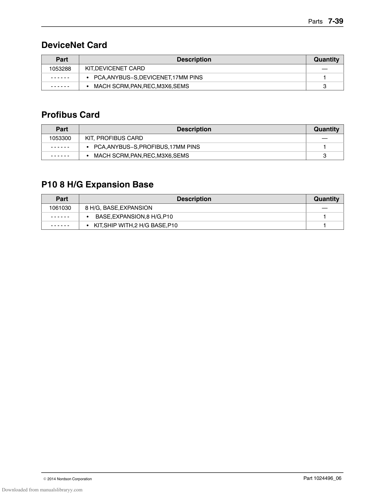
| |P7|1025594|Panel assembly, front, P7|1| | | |P10|1028494|Panel assembly, front, P10|1| | |6|P4, P7|1041736|Door assembly, filter P4/P7|1| | | |P10|1041739|Door assembly, filter, P10|1| | |7|P4, P7|1041734|Cover assembly, ebox door, P4/P7|1| | | |P10|1041738|Cover assembly, ebox door, P10|1| | |8|P4|1041742|Door, graphics, P4|1| | | |P7|1041743|Door, graphics, P7|1| | | |P10|1041745|Door, graphics, P10|1| | |9| |1049528|Replacement hinge pin service kit P4/P7/P10|1| | |NOTE A: Includes hinge pin P/N 1021345|NOTE A: Includes hinge pin P/N 1021345|NOTE A: Includes hinge pin P/N 1021345|NOTE A: Includes hinge pin P/N 1021345|NOTE A: Includes hinge pin P/N 1021345|NOTE A: Includes hinge pin P/N 1021345|
#### Chassis Components Parts List
1
|F15| |---|
|F8| |---|
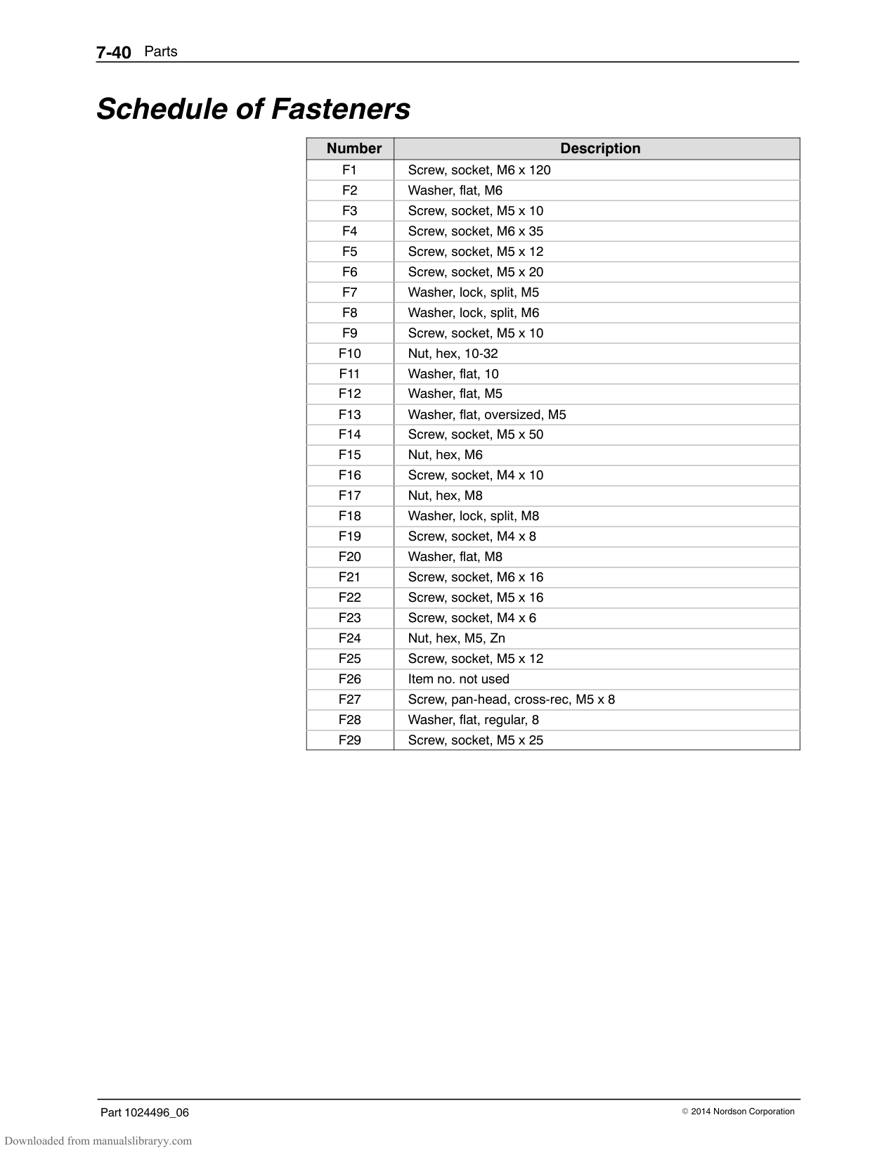
|F3| |---|
15
|F16| |---|
2
3
|F7| |---|
|F3| |---|
6
7
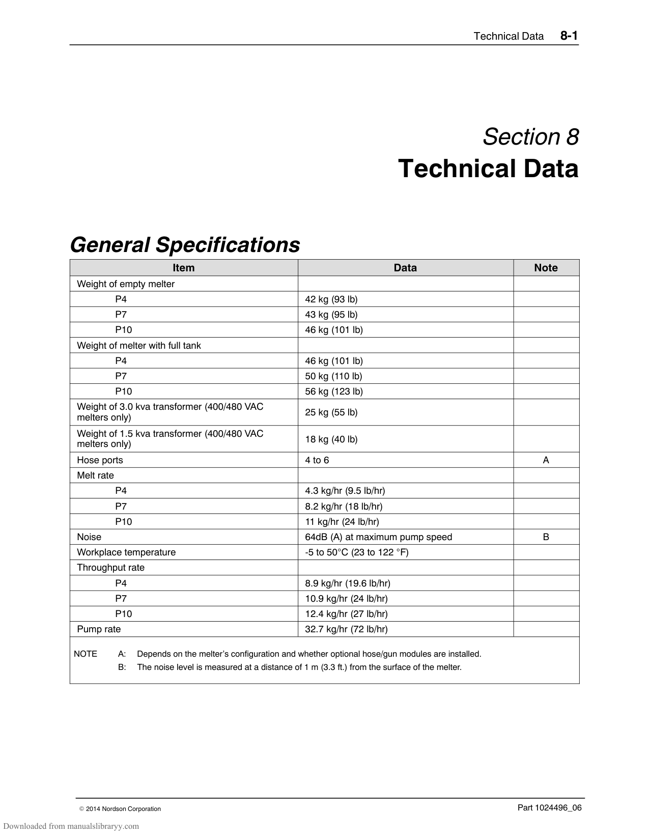
|F24| |---|
|F6| |---|
4
|F16| |---|
5
8
|F17| |---|
|F18| |---|
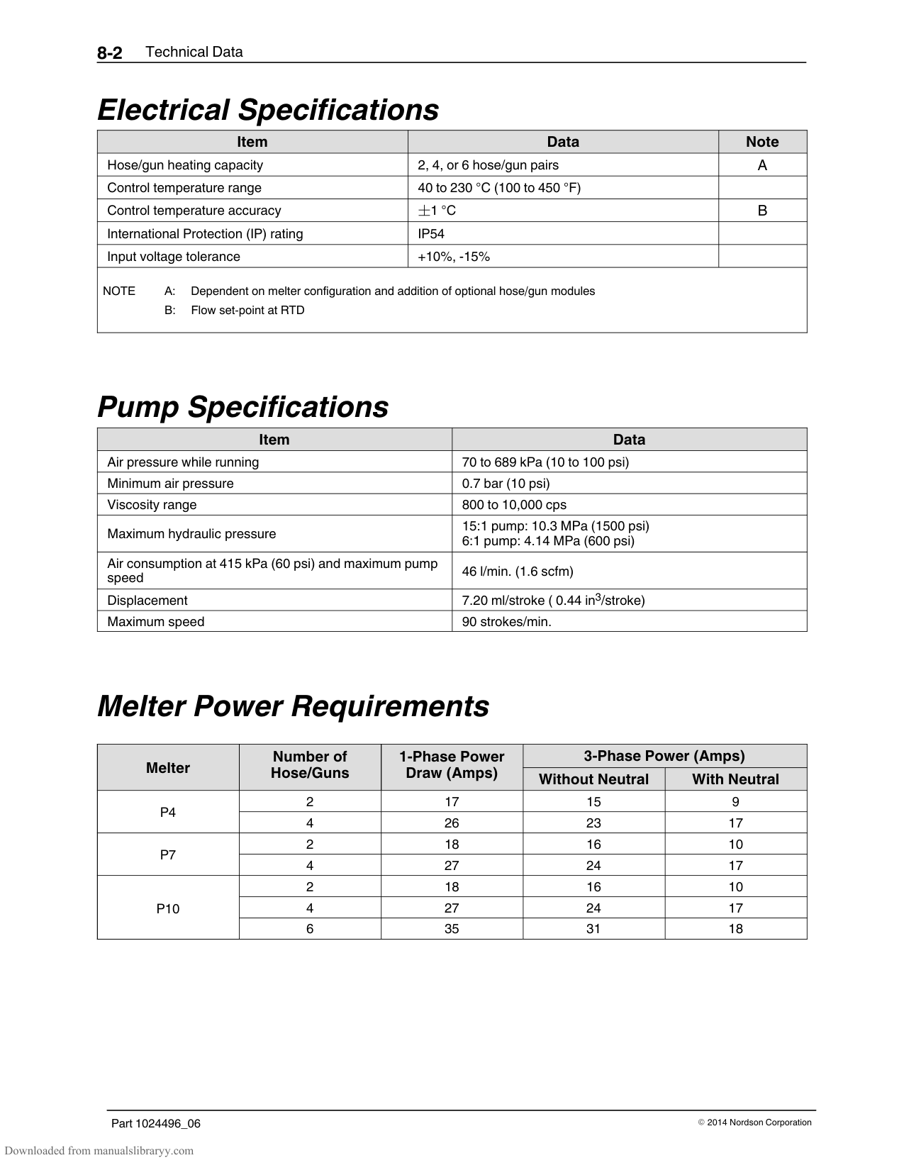
|F3| |---|
9
10
14
|F3| |---|
16
11 13
12
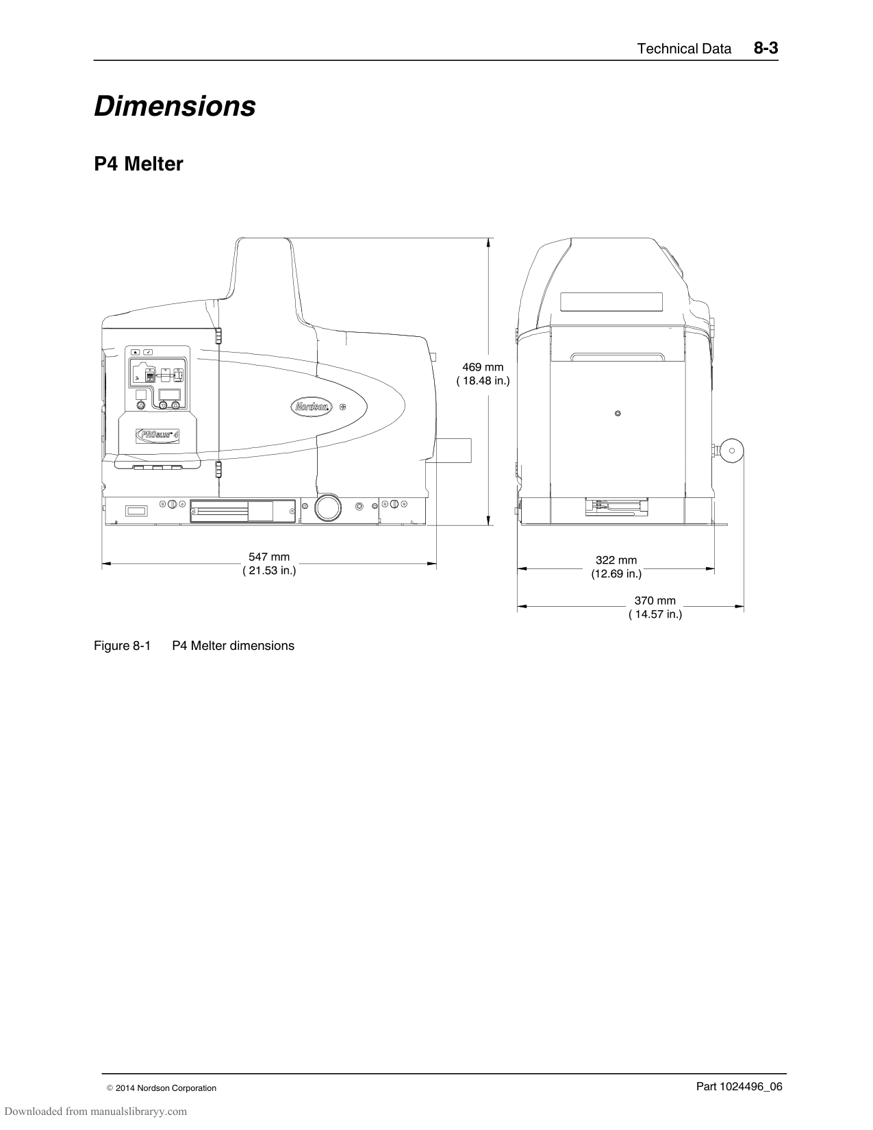
|Item|Used|Part|Description|Quantity|Note| |---|---|---|---|---|---| |1| |‐ ‐ ‐ ‐ ‐ ‐|Electrical box assembly|1|A| |2| |1023714|Cover, wireway, electrical enclosure|1| | |3|P4, P7|1038971|Switch, level, assembly, P4/P7|1|B| | |P10|1038972|Switch, level, assembly, P10|1|C| |4|P4|1022749|Cover, tank, P4|1| | | |P7, P10|1018190|Cover, tank, P7/P10|1| | |5|P4|1018691|Insulator, tank top, P4|1| | | |P7/P10|1025640|Insulator, tank top , P7/P10|1| | |6| |1022840|Brace, P4/P7/P10|1| | |7| |1021653|Rod, retaining, cover|1|E| |8|P4|1021655|Bracket, panel, rear, P4|1| | | |P7|1025642|Bracket, panel, rear, P7|1| | | |P10|1028525|Bracket, panel, rear, P10|1| | |9| |1017603|Spacer, bottom, tank|4| | |10|P4|1021660|Chassis, P4|1| | | |P7, P10|1018822|Chassis, P7/P10|1| | |11| |1024525|Tray, drip, manifold|1| | |12|P4|1021661|Sub-base, P4|1| | | |P7, P10|1018819|Sub-base, P7/P10|1| | |13| |‐ ‐ ‐ ‐ ‐ ‐|Pneumatic assembly|1|D| |14|P4|1021656|Bracket, panel, front, P4|1| | | |P7|1025641|Bracket, panel, front, P7|1| | | |P10|1028526|Bracket, panel, front, P10|1| |
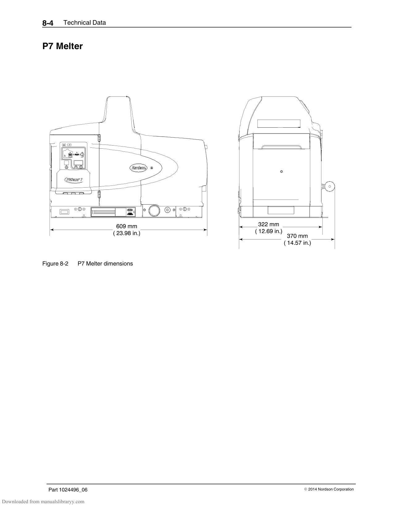
|15| |1018821|Plate, conduit, chassis|1| | |16| |1017947|Switch, rocker, SPST, 250V, 16A|1| | |NOTE A: Refer to Electrical Enclosure Parts List.
B: Included in service kit P/N 1038971
C: Included in service kit P/N 1038972
D: Included in service kit P/N 1028307
E: For the tank lid hinge pin, refer to Exterior Panels Parts List.
|NOTE A: Refer to Electrical Enclosure Parts List.
B: Included in service kit P/N 1038971
C: Included in service kit P/N 1038972
D: Included in service kit P/N 1028307
E: For the tank lid hinge pin, refer to Exterior Panels Parts List.
|NOTE A: Refer to Electrical Enclosure Parts List.
B: Included in service kit P/N 1038971
C: Included in service kit P/N 1038972
D: Included in service kit P/N 1028307
E: For the tank lid hinge pin, refer to Exterior Panels Parts List.
|NOTE A: Refer to Electrical Enclosure Parts List.
B: Included in service kit P/N 1038971
C: Included in service kit P/N 1038972
D: Included in service kit P/N 1028307
E: For the tank lid hinge pin, refer to Exterior Panels Parts List.
|NOTE A: Refer to Electrical Enclosure Parts List.
B: Included in service kit P/N 1038971
C: Included in service kit P/N 1038972
D: Included in service kit P/N 1028307
E: For the tank lid hinge pin, refer to Exterior Panels Parts List.
|NOTE A: Refer to Electrical Enclosure Parts List.
B: Included in service kit P/N 1038971
C: Included in service kit P/N 1038972
D: Included in service kit P/N 1028307
E: For the tank lid hinge pin, refer to Exterior Panels Parts List.
|
#### Ribbon Cable Parts List
|Item|Used|Part|Description|Quantity|Note| |---|---|---|---|---|---| |1| |1018283|Cable assembly, ribbon, main|1| | |2| |1018284|Cable assembly, serial port|1|A| |NOTE A: Included in service kit P/N 1028326 (P4/P7) and kit P/N 1028327 (P10)|NOTE A: Included in service kit P/N 1028326 (P4/P7) and kit P/N 1028327 (P10)|NOTE A: Included in service kit P/N 1028326 (P4/P7) and kit P/N 1028327 (P10)|NOTE A: Included in service kit P/N 1028326 (P4/P7) and kit P/N 1028327 (P10)|NOTE A: Included in service kit P/N 1028326 (P4/P7) and kit P/N 1028327 (P10)|NOTE A: Included in service kit P/N 1028326 (P4/P7) and kit P/N 1028327 (P10)|
#### Service Kits
15:1 Pump Replacement
|Part|Description|Quantity| |---|---|---| |1028303|Kit, service, pump assembly, P4/P7/P10|—| |‐ ‐ ‐ ‐ ‐ ‐|Pump, piston, 15:1|1|
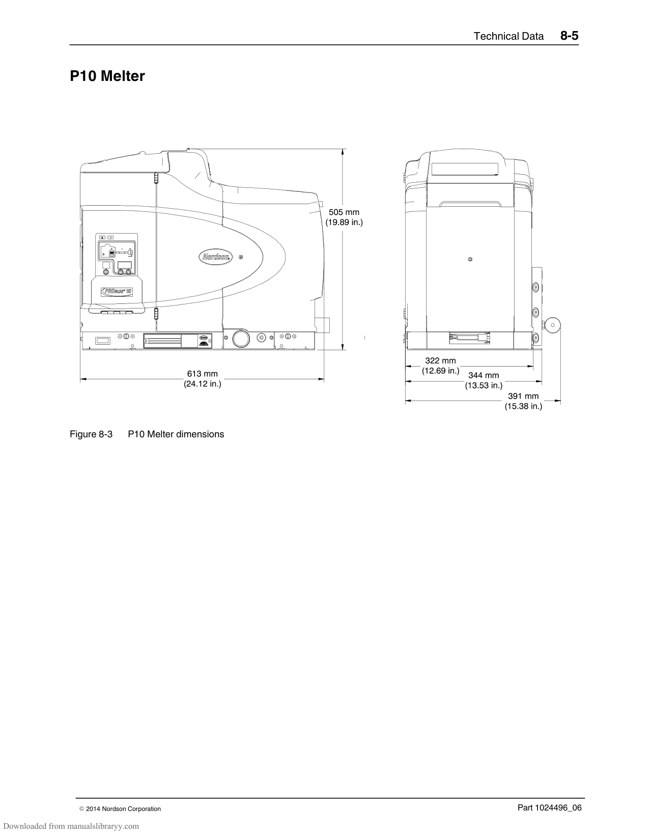
|‐ ‐ ‐ ‐ ‐ ‐|O-ring, Viton, 0.50 x 0.75 x 0.125 in.|1| |‐ ‐ ‐ ‐ ‐ ‐|O-ring, Viton, 0.812 x 0.062 x 0.125 in.|1| |‐ ‐ ‐ ‐ ‐ ‐|Elbow, male, 6 mm tube, G 1/8|1| |‐ ‐ ‐ ‐ ‐ ‐|GREASE,HI−TEMP,.50OZ,SLUBE 884−.50|1|
15:1 Low‐Viscosity Pump Replacement
|Part|Description|Quantity| |---|---|---| |1073930|KIT,SERVICE,PUMP ASSY,LOW VISCOSITY,15:1|—| |‐ ‐ ‐ ‐ ‐ ‐|PUMP ASSY,LOW VISCOSITY|1| |‐ ‐ ‐ ‐ ‐ ‐|ORING, VITON, .50 X .75 X .125|1| |‐ ‐ ‐ ‐ ‐ ‐|O RING,VITON, .812X1.062X.125|1| |‐ ‐ ‐ ‐ ‐ ‐|ELBOW, MALE,6 MM TUBE X G 1/8|1| |‐ ‐ ‐ ‐ ‐ ‐|LUBRICANT,O RING,PARKER,2 GM,S-LUBE 884|1|
6:1 Pump Replacement
|Part|Description|Quantity| |---|---|---| |1088212|KIT, SVCE, PUMP, 6:1, PROBLUE|—| |‐ ‐ ‐ ‐ ‐ ‐|PUMP ASSY, 6:1, PROBLUE|1| |‐ ‐ ‐ ‐ ‐ ‐|ORING, VITON, .50 X .75 X .125|1|
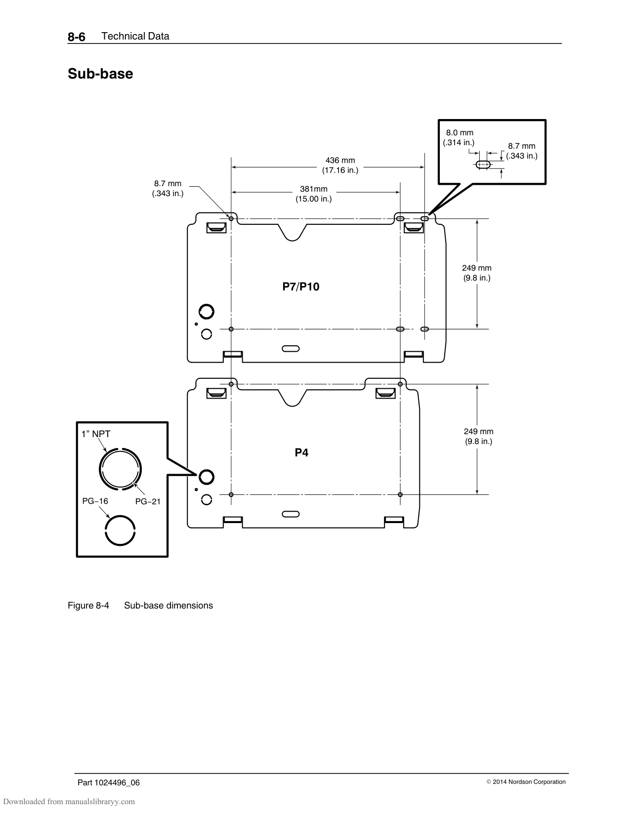
|‐ ‐ ‐ ‐ ‐ ‐|O RING,VITON, .812X1.062X.125|1| |‐ ‐ ‐ ‐ ‐ ‐|ELBOW, MALE,6 MM TUBE X G 1/8|1| |‐ ‐ ‐ ‐ ‐ ‐|LUBRICANT,O RING,PARKER,2 GM,S-LUBE 884|1|
######## Pump General Service
|Part|Description|Quantity| |---|---|---| |1028304|Kit, service, pump, P4/P7/P10|—| |940133|O-ring, Viton, 0.426 x 0.070 in.|2| |940332|O-ring, Viton, 2.00 x 2.125 x 0.063 in.|2| |1019515|O-ring, Viton, 0.50 x 0.75 x 0.125 in.|1| |942111|O-ring, Viton, 0.812 x 0.062 x 0.125 in.|1| |940181|O-ring, Viton, 0.739 x 0.70 in.|4| |952100|Cup, U, Viton|1| |954013|Backup ring, single, 7/16 x 9/16|2| |163039|Cup, piston|2| |273139|Seal, pump|1| |986331|Retaining ring, internal, 100, push-on|1| |1064157|NUT,HEX,LOCK,TORQUE,M6X1, DIN 980V,V3|1| |982147|Screw, hex, cap, M6 x 120|4| |982237|Screw, hex, cap, M6 x 35|4| |983410|Washer, flat, M6|8| |940172|O-ring, Viton, 0.676 x 0.070|1|

|‐ ‐ ‐ ‐ ‐ ‐|GREASE,HI−TEMP,.50OZ,SLUBE 884−.50|1| |940261|O-ring, Viton, 1.25 x 1.375 x .063|1| |1017849|Backup ring, PTFE, 1.273 x .045 thick|1| |945037|O-ring, Viton, 1-inch tube|1| |973543|Plug, O-ring, 7/16-20|3| |211228|Service kit, SP lubricating oil|—|
######## Filter
|Part|Description|Quantity| |---|---|---| |1028305|Filter, Saturn, 100-mesh|—| |‐ ‐ ‐ ‐ ‐ ‐|Filter assembly, 100-mesh| | |945039|O-ring| |
######## Pneumatic Panel
|Part|Description|Quantity| |---|---|---| |1028307|Kit, service, pneumatic panel assembly|—| |‐ ‐ ‐ ‐ ‐ ‐|Pneumatic panel assembly|1| |‐ ‐ ‐ ‐ ‐ ‐|Screw, mounting|2|
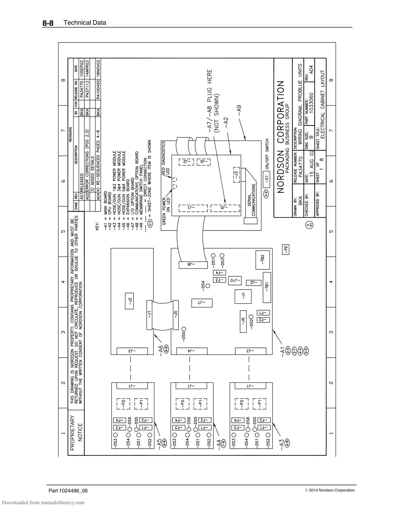
######## Pressure Discharge Valve
|Part|Description|Quantity| |---|---|---| |1028308|Kit, service, pressure discharge valve|—| |‐ ‐ ‐ ‐ ‐ ‐|Valve assembly, pressure discharge|1| |‐ ‐ ‐ ‐ ‐ ‐|Screw, hex, M5 x 50|3| |‐ ‐ ‐ ‐ ‐ ‐|Tee, run, 6-mm tube, G1/8|1|
######## Manifold Service Kit
|Part|Description|Quantity| |---|---|---| |1028309|Kit, service, manifold, P4/P7/P10|—| |1019515|O-ring, Viton, 0.050 x. 0.75 x 0.125 in.|3| |‐ ‐ ‐ ‐ ‐ ‐|O-ring, Viton, 0.625 x 0.875 in.|1| |942111|O-ring, Viton, 0.812 x 0.062 x 0.125 in.|1| |‐ ‐ ‐ ‐ ‐ ‐|O-ring, Viton, 0.750 x 0.938 x 0.094 in.|2| |‐ ‐ ‐ ‐ ‐ ‐|Lubricant, Parker, 1/2 oz|1|
######## RTD
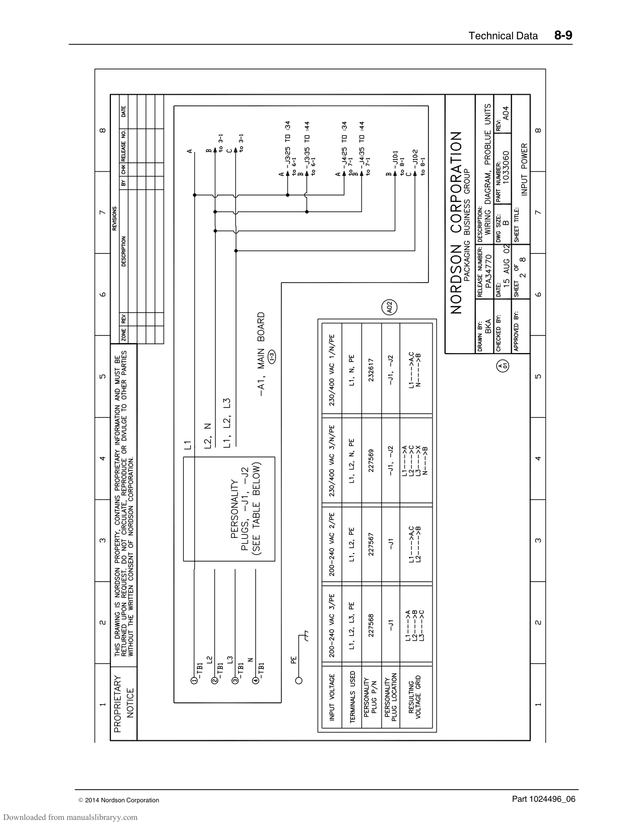
|Part|Description|Quantity| |---|---|---| |1028320|Kit, service, RTD, P4/P7/P10|—| |‐ ‐ ‐ ‐ ‐ ‐|Sensor, temperature, RTD|1| |‐ ‐ ‐ ‐ ‐ ‐|Screw, hex, M3 x 20|1| |‐ ‐ ‐ ‐ ‐ ‐|Washer, lock, spring, M3|1| |‐ ‐ ‐ ‐ ‐ ‐|Terminal block, 380 V|1| |1019515|O-ring, Viton, 0.50 x 0.75 x. 0.125 in.|1| |942111|O-ring, Viton, 0.812 x 0.062 x 0.125 in|1| |‐ ‐ ‐ ‐ ‐ ‐|Compound, thermal, 1 gram|1|
######## Thermostat
|Part|Description|Quantity| |---|---|---| |1028321|Kit, service, thermostat, melter|—| |‐ ‐ ‐ ‐ ‐ ‐|Thermostat, OOR, 500 degree, push-on|1| |‐ ‐ ‐ ‐ ‐ ‐|Screw, hex, M4 x 6|2| |‐ ‐ ‐ ‐ ‐ ‐|Compound, thermal, 1 gram|1|
######## Main Circuit Board
|Used|Part|Description|Quantity|
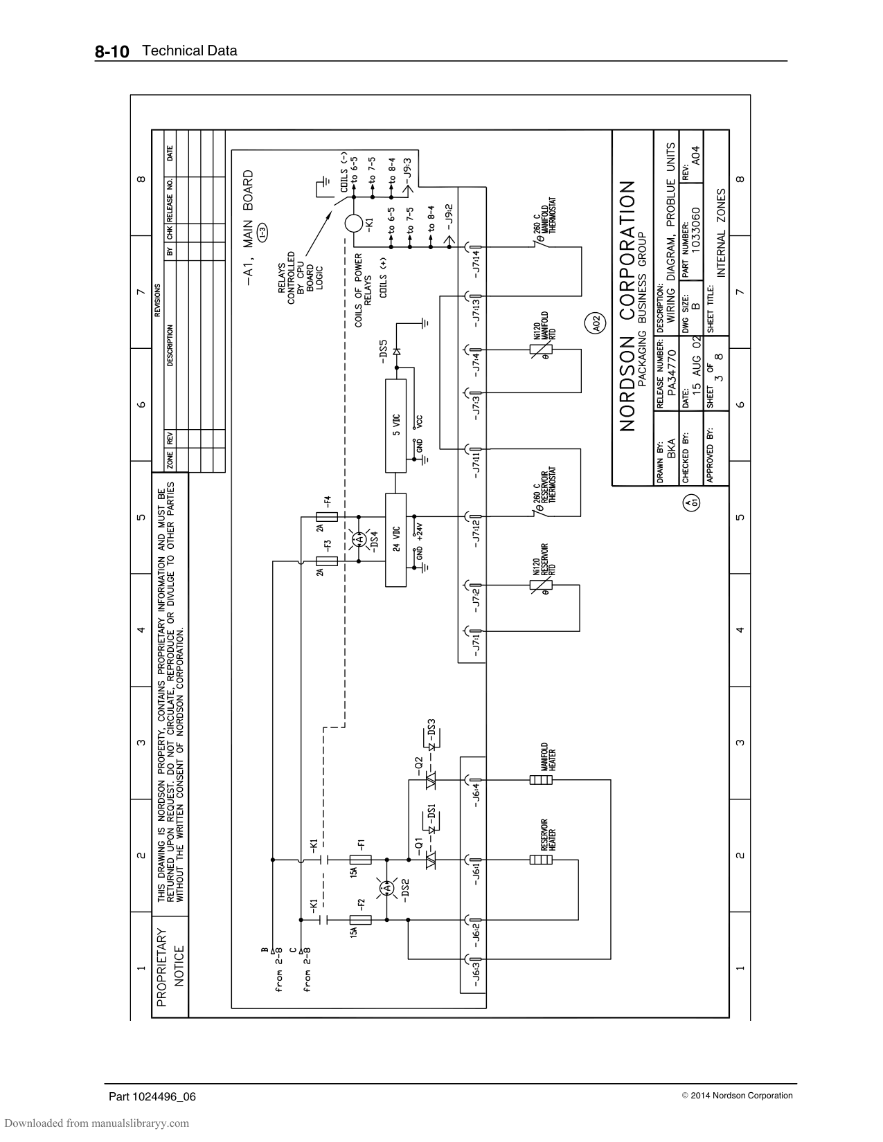
|---|---|---|---| |P4, P7|1028322|Kit, service, main PCA|—| |P10|1028323|Kit, service, main PCA|—| | |‐ ‐ ‐ ‐ ‐ ‐|Mounting plate assembly, main PCA|1|
######## Central Processor Unit (CPU)
|Part|Description|Quantity| |---|---|---| |1028325|Kit, service, central processor unit|—| |‐ ‐ ‐ ‐ ‐ ‐|PCA, display/CPU|1| |‐ ‐ ‐ ‐ ‐ ‐|Stand-off, hex, M3 x 8 mm|6| |‐ ‐ ‐ ‐ ‐ ‐|Washer, lock, M3|6|
######## Operator's Panel
|Used|Part|Description|Quantity| |---|---|---|---| |P4, P7|1028326|Kit, service, operator’s panel/enclosure, P4/P7|—| |P10|1028327|Kit, service, operator’s panel/enclosure, P10|—| | |‐ ‐ ‐ ‐ ‐ ‐|Panel assembly, front, electrical enclosure|1|
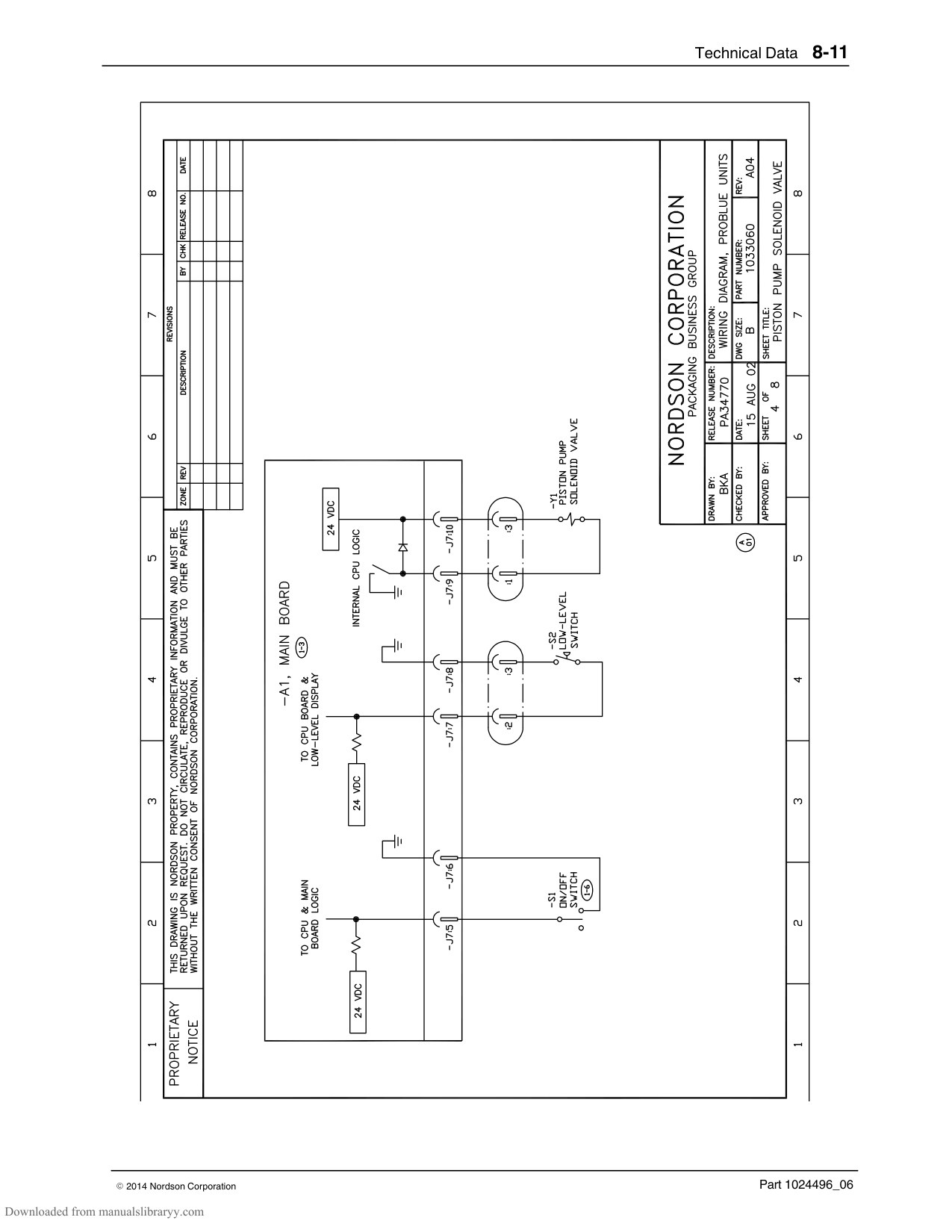
######## Hose/Gun Module
|Part|Description|Quantity| |---|---|---| |1028328|Kit, service, hose/gun module, P4/P7/P10|—| |‐ ‐ ‐ ‐ ‐ ‐|Module assembly, power, removable|1|
######## Main Circuit Board Fuses
|Part|Description|Quantity| |---|---|---| |1028329|Kit, service, fuse, main circuit board, P4/P7/P10|—| |‐ ‐ ‐ ‐ ‐ ‐|Fuse, 15.00, nontime-delay, 250 V|2| |‐ ‐ ‐ ‐ ‐ ‐|Cover, fuse, 0.25 x 1.25 in.|2| |‐ ‐ ‐ ‐ ‐ ‐|Fuse, time-lag, 2A, 5 x 20 mm, ceramic|2| |‐ ‐ ‐ ‐ ‐ ‐|Cover, fuse, 5 x 20 mm|2| |NOTE A: Refer to Table 6-2 for fuse types and locations.|NOTE A: Refer to Table 6-2 for fuse types and locations.|NOTE A: Refer to Table 6-2 for fuse types and locations.|
######## Hose/Gun Module Fuses
|Part|Description|Quantity| |---|---|---| |1028331|Kit, service, fuse, hose/gun module, P4/P7/P10|—|
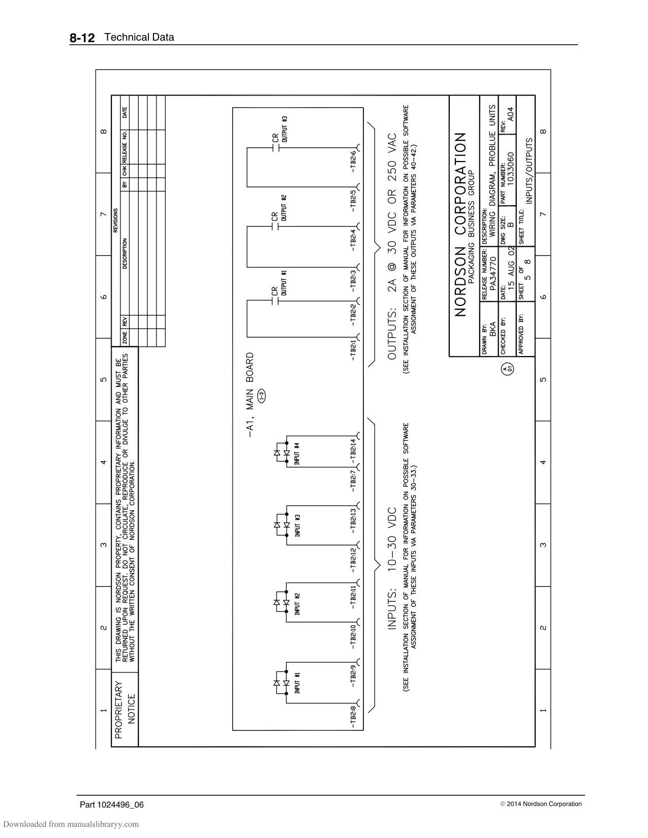
|‐ ‐ ‐ ‐ ‐ ‐|Fuse, 6.30, fast-acting, 250 V, 5 x 2|4| |‐ ‐ ‐ ‐ ‐ ‐|Cover, fuse, 5 x 20 mm|4| |NOTE A: Refer to Table 6-4 for fuse types and locations.|NOTE A: Refer to Table 6-4 for fuse types and locations.|NOTE A: Refer to Table 6-4 for fuse types and locations.|
######## Basic Spare Parts
|Part|Description|Quantity| |---|---|---| |1028332|Kit, basic spare parts, P4/P7/P10|—| |1028305|Filter, Saturn, melter, 100-mesh|1| |1028320|Kit, service, RTD, P4/P7/P10|1| |1028321|Kit, service, thermostat, melter|1| |1028328|Kit, service, hose/gun module, P4/P7/P10|1| |1028329|Kit, service, fuse, main circuit board, P4/P7/P10|1| |1028331|Kit, service, fuse, hose/gun module, P4/P7/P10|1|
######## Expanded Spare Parts
|Part|Description|Quantity| |---|---|---| |1028333|Kit, basic expanded parts, P4/P7/P10|—| |1028305|Filter, Saturn, melter, 100-mesh|5| |1028320|Kit, service, RTD, P4/P7/P10|1|
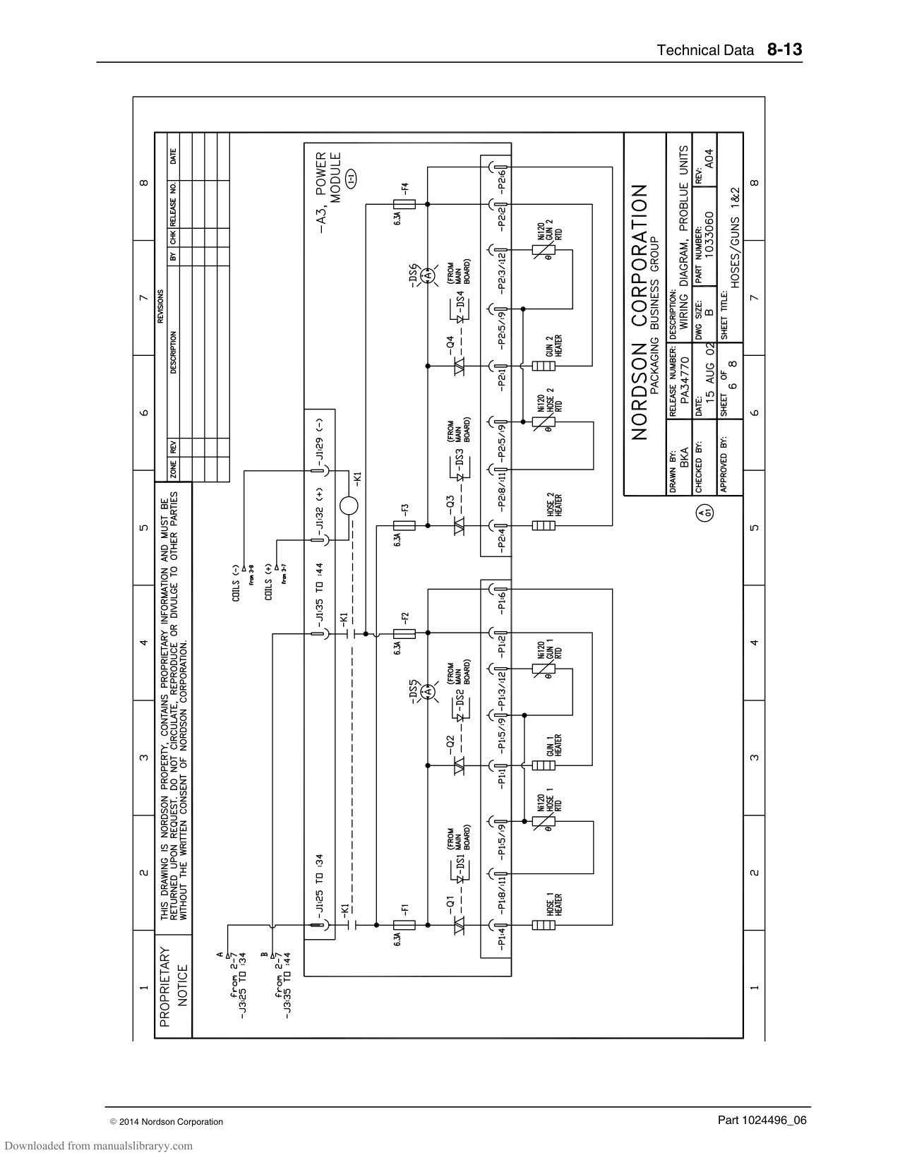
|1028321|Kit, service, thermostat, melter|1| |1028328|Kit, service, hose/gun module, P4/P7/P10|1| |1028329|Kit, service, fuse, main circuit board, P4/P7/P10|1| |1028331|Kit, service, fuse, hose/gun module, P4/P7/P10|1| |1028304|Kit, service, pump, P4/P7/P10|1| |1028309|Kit, service, manifold, P4/P7/P10|1| |1023267|Filter assembly, air, 6 mm BSPP|1|
######## Level Switch
|Used|Part|Description|Quantity| |---|---|---|---| |P4, P7|1038971|Kit, switch, level, P4/P7|—| | |‐ ‐ ‐ ‐ ‐ ‐|Switch, level, assembly, P4/P7|1| | |‐ ‐ ‐ ‐ ‐ ‐|Nut, hex, M5|2| |P10|1038972|Kit, switch, level, P10|—| | |‐ ‐ ‐ ‐ ‐ ‐|Switch, level, assembly, P10|1| | |‐ ‐ ‐ ‐ ‐ ‐|Nut, hex, M5|2|
######## Manifold Guard (P4)
|Part|Description|Quantity| |---|---|---|

|1032154|Kit, manifold guard, P4|—| |‐ ‐ ‐ ‐ ‐ ‐|Shield, manifold, snap-on, P4|1|
######## Manifold Guard (P10)
|Part|Description|Quantity| |---|---|---| |1031871|Kit, manifold guard, 6-hose, P10|—| |‐ ‐ ‐ ‐ ‐ ‐|Guard, wire frame, manifold, 6-hose|1| |‐ ‐ ‐ ‐ ‐ ‐|Mount, lower, wire guard, 6-hose|2| |‐ ‐ ‐ ‐ ‐ ‐|Mount, upper B, wire guard, 6-hose|1| |‐ ‐ ‐ ‐ ‐ ‐|Mount, upper A, wire guard, 6-hose|1| |‐ ‐ ‐ ‐ ‐ ‐|Screw, socket-head, M5 x 20|3|
######## Vent Guard (P10)
|Part|Description|Quantity| |---|---|---| |1048884|Guard kit assembly, vent , screen, P10|—| |‐ ‐ ‐ ‐ ‐ ‐|Guard, screen, pump cover, P10|1| |‐ ‐ ‐ ‐ ‐ ‐|Reference drawing, guard kit, vent, screen, P10|1|
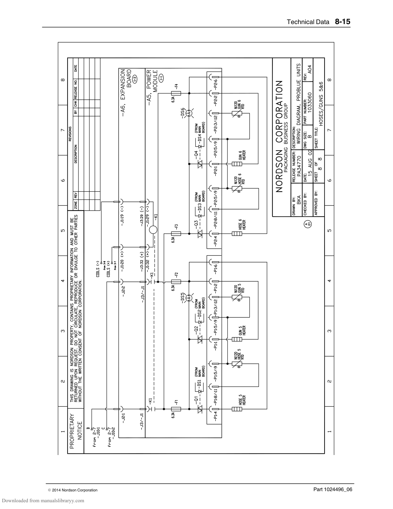
######## Replacement Tank
|Part|Description|Quantity| |---|---|---| |1051033|Kit, service, tank, P4, 230V|1| |1051034|Kit, service, tank, P7, 230V|1| |1051035|Kit, service, tank, P10, 230V|1|
######## Tank Lid Hinge Pin
|Part|Description|Quantity| |---|---|---| |1049528|Replacement hinge pin service kit, P4/P7, P10|—| |‐ ‐ ‐ ‐ ‐ ‐|Pin, hinge, lid, P4/P7/P10|1| |‐ ‐ ‐ ‐ ‐ ‐|Tube, spacer, pin, hinge, P4/P7/P10|1| |‐ ‐ ‐ ‐ ‐ ‐|Spring, compression, .360 x .038 x 1.75 long|1| |‐ ‐ ‐ ‐ ‐ ‐|Retaining, ring, external, 18, E-ring|2|
######## Manifold (with Heater Block) Service Kit, DA Pumps - P/Ns 1064651 (4H, 230V), 1064653 (6H, 230V), 1064652 (4H, 480V), 1064654 (6H, 480V)
|Description|Quantity| |---|---| |HEATER BLOCK,PROBLUE|1|

|MANIFOLD ASSY|1| |SCR,SKT,M5X25,BL|5| |WASHER,LK,M,SPT,M5,STL,ZN|5| |ORING, VITON, .50 X .75 X .125|2| |O RING,VITON, .812X1.062X.125|1| |O-RING,VITON,50 DURO,-116,.750X.938X.094|2| |O RING,VITON,.426ID X .070W,BR,10413|2| |INST, MANIFOLD/HEATER SERVICE KIT|1|
######## Heater Block Service Kit - P/Ns 1064639 (230V), 1064650 (480V)
|Description|Quantity| |---|---| |HEATER BLOCK,PROBLUE,230V or 480V|1| |SCR,SKT,M5X25,BL|5| |WASHER,LK,M,SPT,M5,STL,ZN|5| |O RING,VITON, .812X1.062X.125|1| |INST, PROBLUE THERMAL BLOCK INSTALLATION|1| |INST, HEATER DISPOSAL (WORDLESS)|1|
#### Option Kits
6‐Hose Extension
|Part|Description|Quantity| |---|---|---| |1028324|Kit, 6-hose extension, board, P10|—| |‐ ‐ ‐ ‐ ‐ ‐|PCA, P10, expansion|1| |‐ ‐ ‐ ‐ ‐ ‐|Harness, expansion, 6 hose/gun|1| |‐ ‐ ‐ ‐ ‐ ‐|Cable assembly, 20 position, ribbon cable|1| |‐ ‐ ‐ ‐ ‐ ‐|Screw, machine, pan-head, M3 x 12|4|
Input/Output Expansion Card
|Part|Description|Quantity| |---|---|---| |1036607|Kit, I/O expansion card|—| |‐ ‐ ‐ ‐ ‐ ‐|PCA, optional I/O|1| |‐ ‐ ‐ ‐ ‐ ‐|Terminal block connector, 10 position (1–10)|1| |‐ ‐ ‐ ‐ ‐ ‐|Terminal block connector, 10 position (11–20)|1| |‐ ‐ ‐ ‐ ‐ ‐|Screw, machine, pan-head, M3 x 6|8|
Fill Master
|Part|Description|Quantity| |---|---|---|
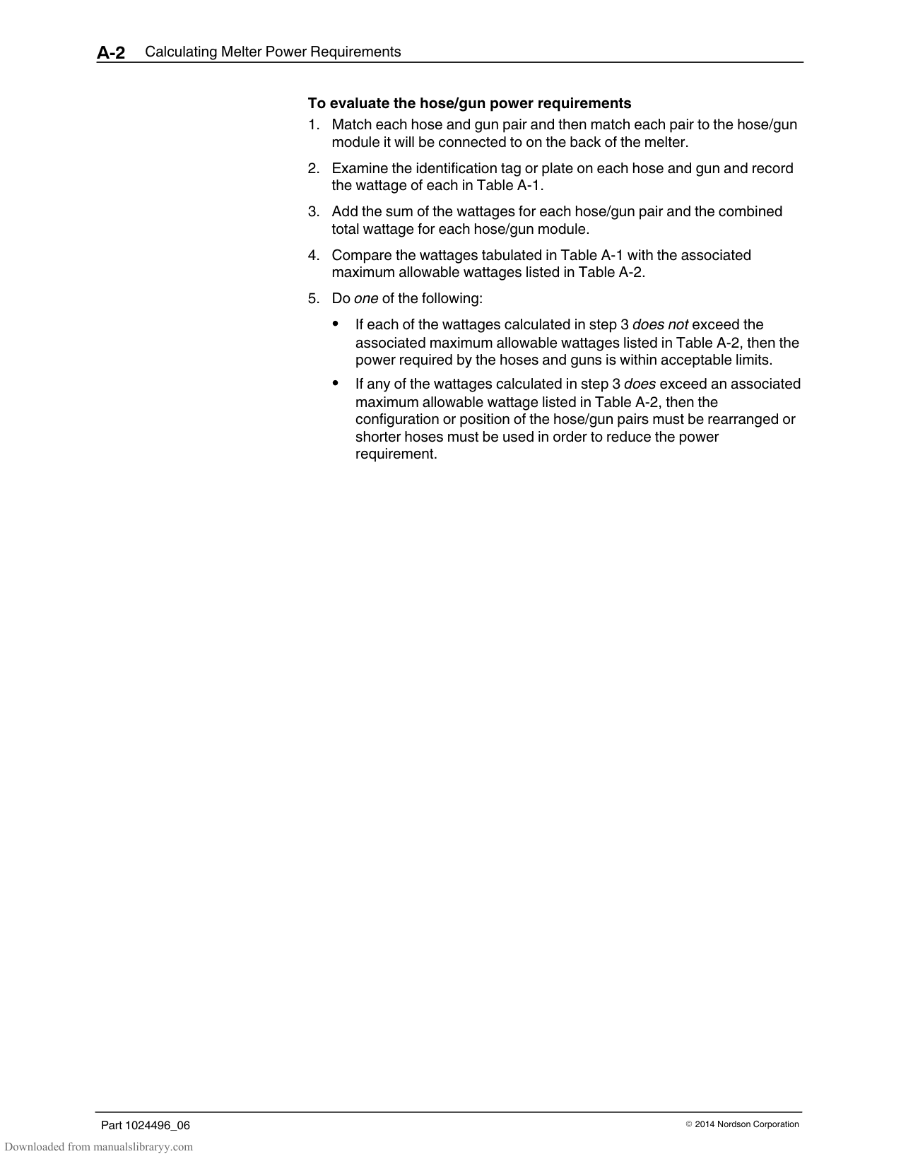
|771415|Kit, sensor, P4/P7/P10|A, B| |771417|Kit, lid, P7/P10|B| |771416|Kit, lid, P4|B| |NOTE A: Requires lid kit P/N 771417 or 771416 B: Fill Master system is not included|NOTE A: Requires lid kit P/N 771417 or 771416 B: Fill Master system is not included|NOTE A: Requires lid kit P/N 771417 or 771416 B: Fill Master system is not included|
Ethernet Card
|Part|Description|Quantity| |---|---|---| |1053289|KIT,ETHERNET CARD|—| |‐ ‐ ‐ ‐ ‐ ‐|PCA,ANYBUS−S,ETHERNET,17MM PINS,PROGRAMM|1| |‐ ‐ ‐ ‐ ‐ ‐|MACH SCRM,PAN,REC,M3X6,SEMS|3|
######## DeviceNet Card
|Part|Description|Quantity| |---|---|---| |1053288|KIT,DEVICENET CARD|—| |‐ ‐ ‐ ‐ ‐ ‐|PCA,ANYBUS−S,DEVICENET,17MM PINS|1| |‐ ‐ ‐ ‐ ‐ ‐|MACH SCRM,PAN,REC,M3X6,SEMS|3|
######## Profibus Card
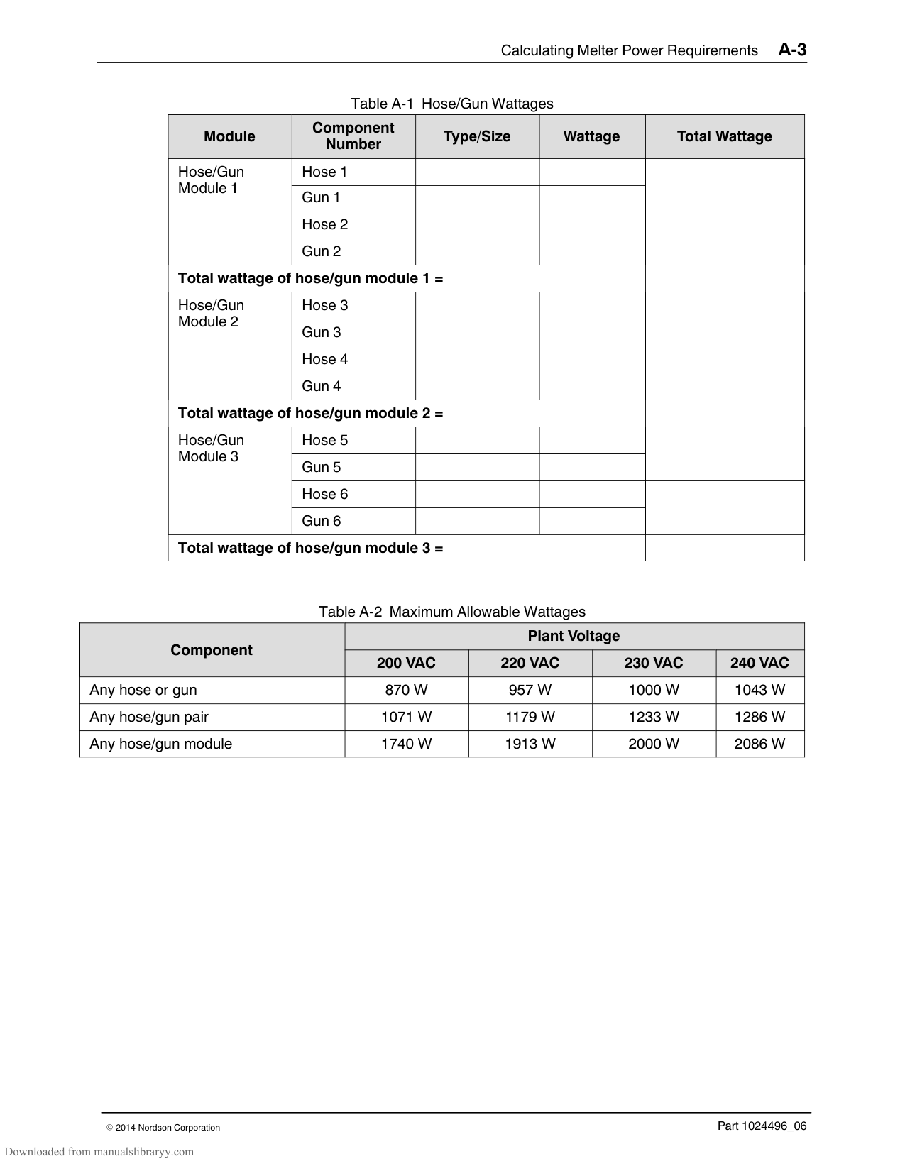
|Part|Description|Quantity| |---|---|---| |1053300|KIT, PROFIBUS CARD|—| |‐ ‐ ‐ ‐ ‐ ‐|PCA,ANYBUS−S,PROFIBUS,17MM PINS|1| |‐ ‐ ‐ ‐ ‐ ‐|MACH SCRM,PAN,REC,M3X6,SEMS|3|
######## P10 8 H/G Expansion Base
|Part|Description|Quantity| |---|---|---| |1061030|8 H/G, BASE,EXPANSION|—| |‐ ‐ ‐ ‐ ‐ ‐|BASE,EXPANSION,8 H/G,P10|1| |‐ ‐ ‐ ‐ ‐ ‐|KIT,SHIP WITH,2 H/G BASE,P10|1|
#### Schedule of Fasteners
|Number|Description| |---|---| |F1|Screw, socket, M6 x 120| |F2|Washer, flat, M6| |F3|Screw, socket, M5 x 10| |F4|Screw, socket, M6 x 35|

|F5|Screw, socket, M5 x 12| |F6|Screw, socket, M5 x 20| |F7|Washer, lock, split, M5| |F8|Washer, lock, split, M6| |F9|Screw, socket, M5 x 10| |F10|Nut, hex, 10-32| |F11|Washer, flat, 10| |F12|Washer, flat, M5| |F13|Washer, flat, oversized, M5| |F14|Screw, socket, M5 x 50| |F15|Nut, hex, M6| |F16|Screw, socket, M4 x 10| |F17|Nut, hex, M8| |F18|Washer, lock, split, M8| |F19|Screw, socket, M4 x 8| |F20|Washer, flat, M8| |F21|Screw, socket, M6 x 16| |F22|Screw, socket, M5 x 16| |F23|Screw, socket, M4 x 6| |F24|Nut, hex, M5, Zn| |F25|Screw, socket, M5 x 12| |F26|Item no. not used| |F27|Screw, pan-head, cross-rec, M5 x 8| |F28|Washer, flat, regular, 8| |F29|Screw, socket, M5 x 25|
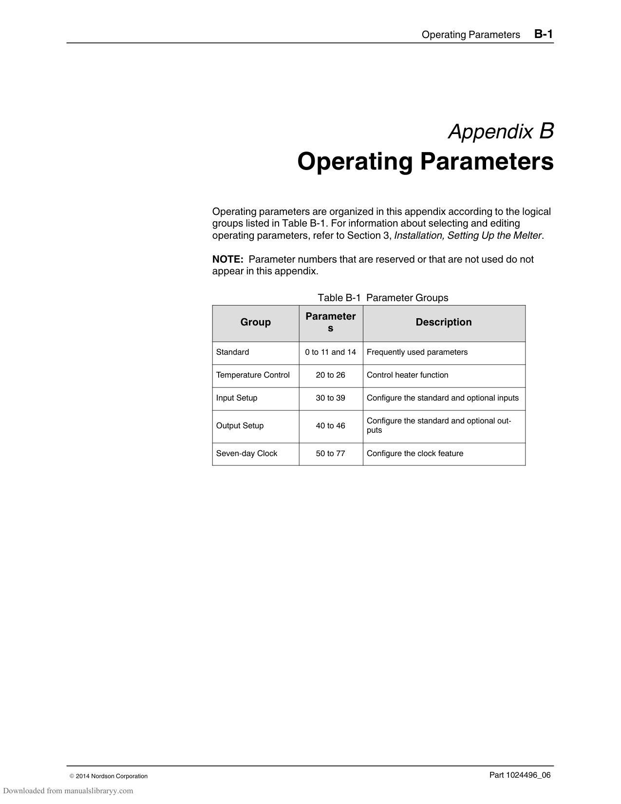
Section 8 Technical Data
General Specifications
|Item|Data|Note| |---|---|---| |Weight of empty melter| | | |P4|42 kg (93 lb)| | |P7|43 kg (95 lb)| | |P10|46 kg (101 lb)| | |Weight of melter with full tank| | | |P4|46 kg (101 lb)| | |P7|50 kg (110 lb)| | |P10|56 kg (123 lb)| | |Weight of 3.0 kva transformer (400/480 VAC melters only)|25 kg (55 lb)| | |Weight of 1.5 kva transformer (400/480 VAC melters only)|18 kg (40 lb)| | |Hose ports|4 to 6|A| |Melt rate| | | |P4|4.3 kg/hr (9.5 lb/hr)| | |P7|8.2 kg/hr (18 lb/hr)| | |P10|11 kg/hr (24 lb/hr)| | |Noise|64dB (A) at maximum pump speed|B| |Workplace temperature|-5 to 50C (23 to 122 F)| |
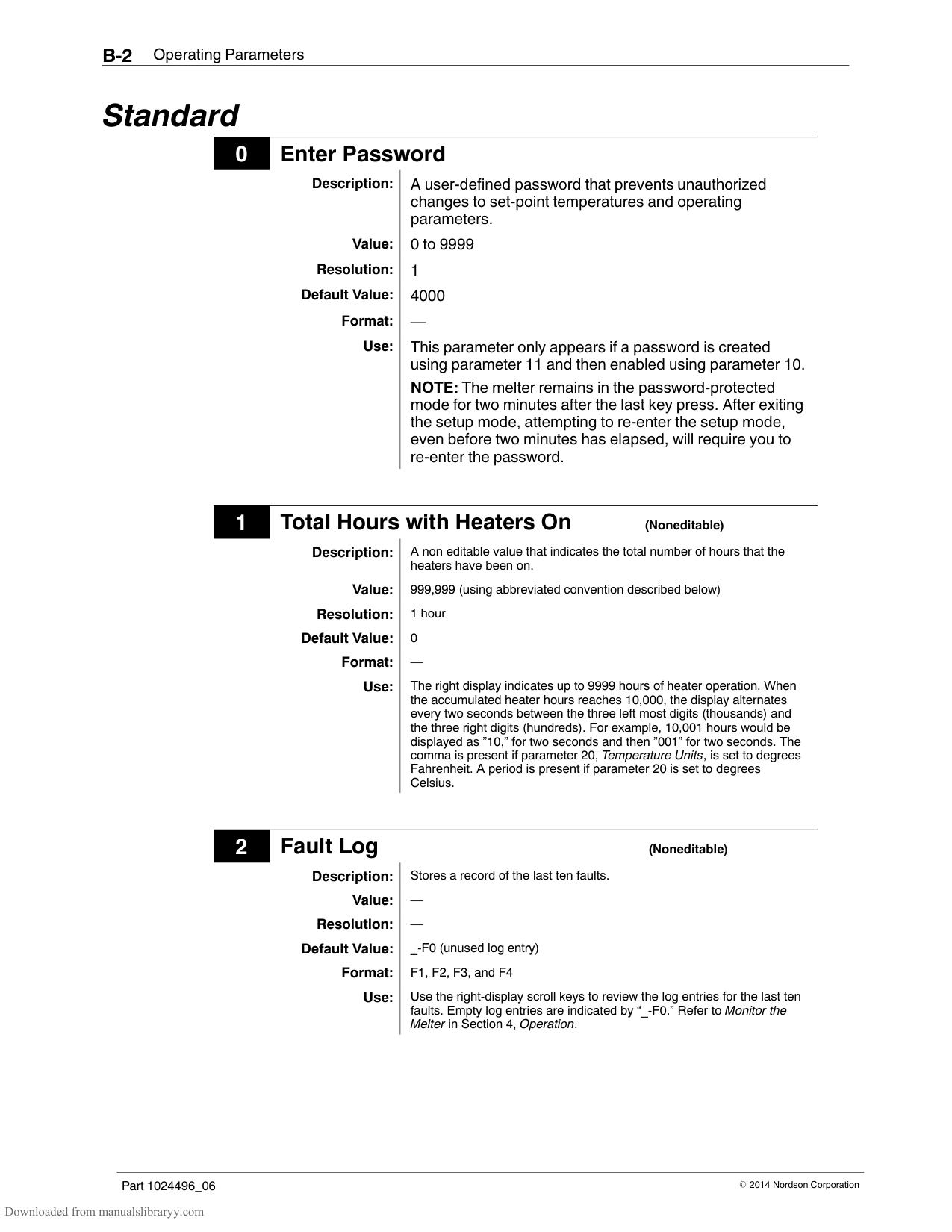
|Throughput rate| | | |P4|8.9 kg/hr (19.6 lb/hr)| | |P7|10.9 kg/hr (24 lb/hr)| | |P10|12.4 kg/hr (27 lb/hr)| | |Pump rate|32.7 kg/hr (72 lb/hr)| | |NOTE A: Depends on the melter’s configuration and whether optional hose/gun modules are installed. B: The noise level is measured at a distance of 1 m (3.3 ft.) from the surface of the melter.|NOTE A: Depends on the melter’s configuration and whether optional hose/gun modules are installed. B: The noise level is measured at a distance of 1 m (3.3 ft.) from the surface of the melter.|NOTE A: Depends on the melter’s configuration and whether optional hose/gun modules are installed. B: The noise level is measured at a distance of 1 m (3.3 ft.) from the surface of the melter.|
#### Electrical Specifications
|Item|Data|Note| |---|---|---| |Hose/gun heating capacity|2, 4, or 6 hose/gun pairs|A| |Control temperature range|40 to 230 C (100 to 450 F)| | |Control temperature accuracy|1 C|B| |International Protection (IP) rating|IP54| | |Input voltage tolerance|+10%, -15%| | |NOTE A: Dependent on melter configuration and addition of optional hose/gun modules B: Flow set-point at RTD|NOTE A: Dependent on melter configuration and addition of optional hose/gun modules B: Flow set-point at RTD|NOTE A: Dependent on melter configuration and addition of optional hose/gun modules B: Flow set-point at RTD|
#### Pump Specifications
|Item|Data| |---|---| |Air pressure while running|70 to 689 kPa (10 to 100 psi)|
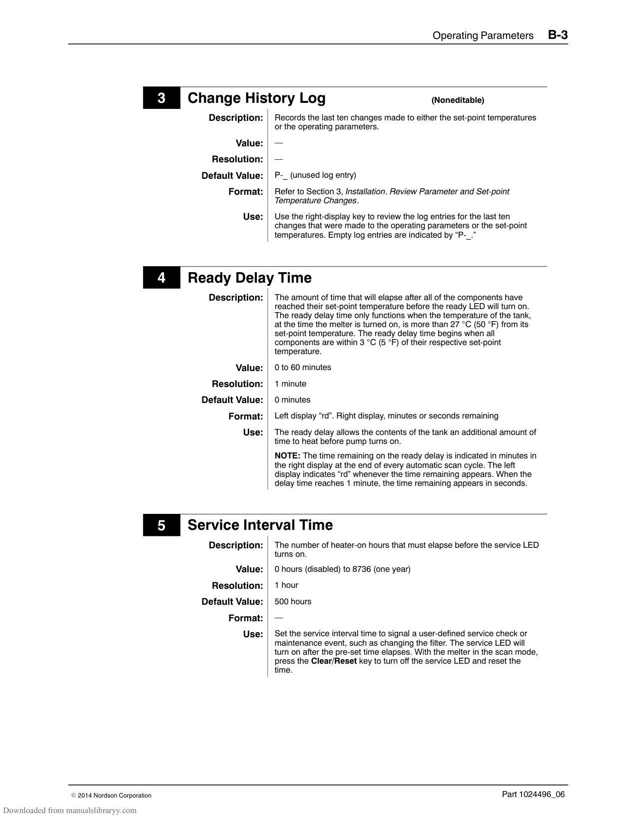
|Minimum air pressure|0.7 bar (10 psi)| |Viscosity range|800 to 10,000 cps| |Maximum hydraulic pressure|15:1 pump: 10.3 MPa (1500 psi) 6:1 pump: 4.14 MPa (600 psi)| |Air consumption at 415 kPa (60 psi) and maximum pump speed|46 l/min. (1.6 scfm)| |Displacement|7.20 ml/stroke ( 0.44 in3/stroke)| |Maximum speed|90 strokes/min.|
#### Melter Power Requirements
|Melter|Number of Hose/Guns|1‐Phase Power Draw (Amps)|3‐Phase Power (Amps)|3‐Phase Power (Amps)| |---|---|---|---|---| |Melter|Number of Hose/Guns|1‐Phase Power Draw (Amps)|Without Neutral|With Neutral| |P4|2|17|15|9| |P4|4|26|23|17| |P7|2|18|16|10| |P7|4|27|24|17| |P10|2|18|16|10| |P10|4|27|24|17| |P10|6|35|31|18|
#### Dimensions
######## P4 Melter
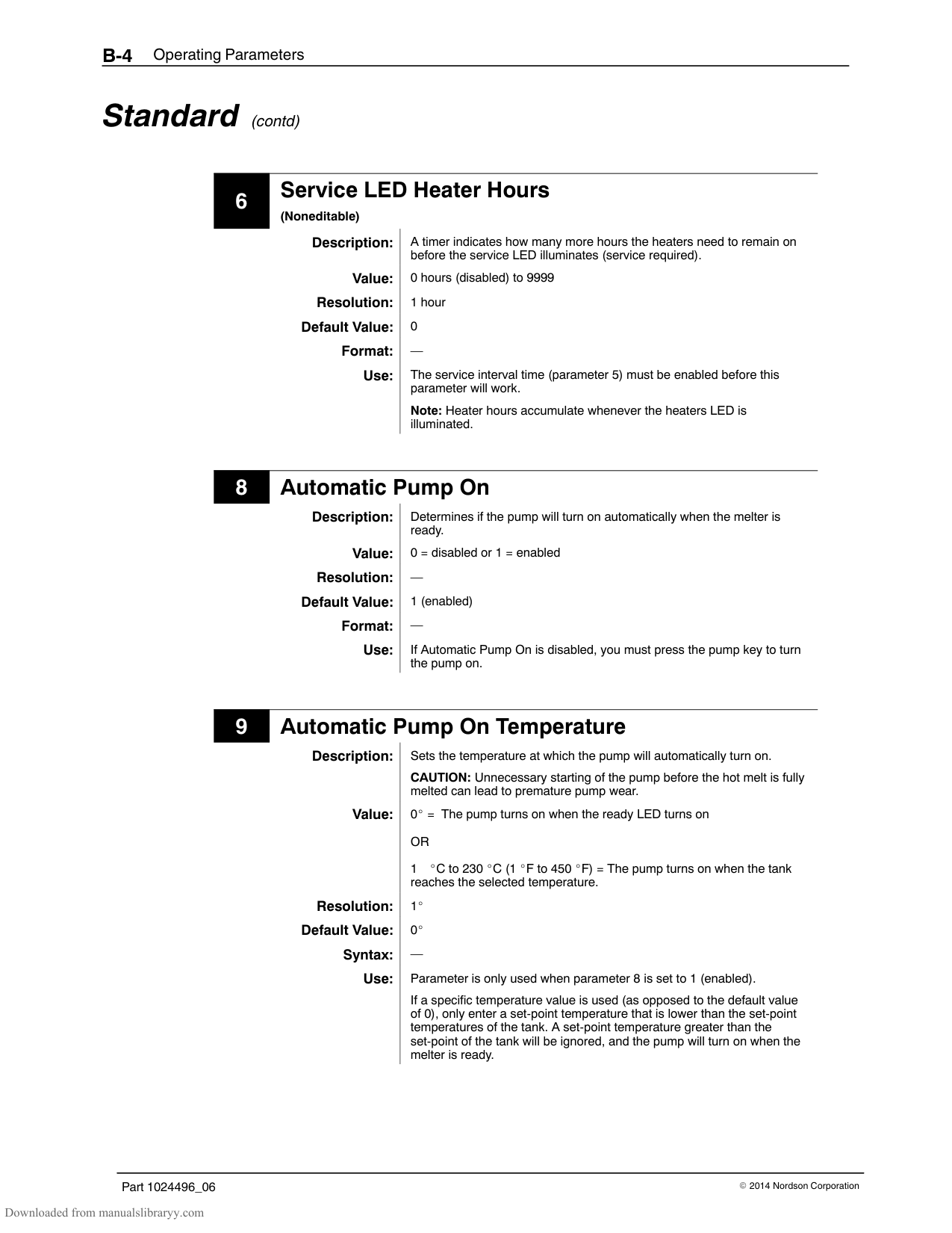
| | |---| | |
| | | |---|---| | | | | | |
######## P7 Melter
| | | |---|---|
| | |---| | |
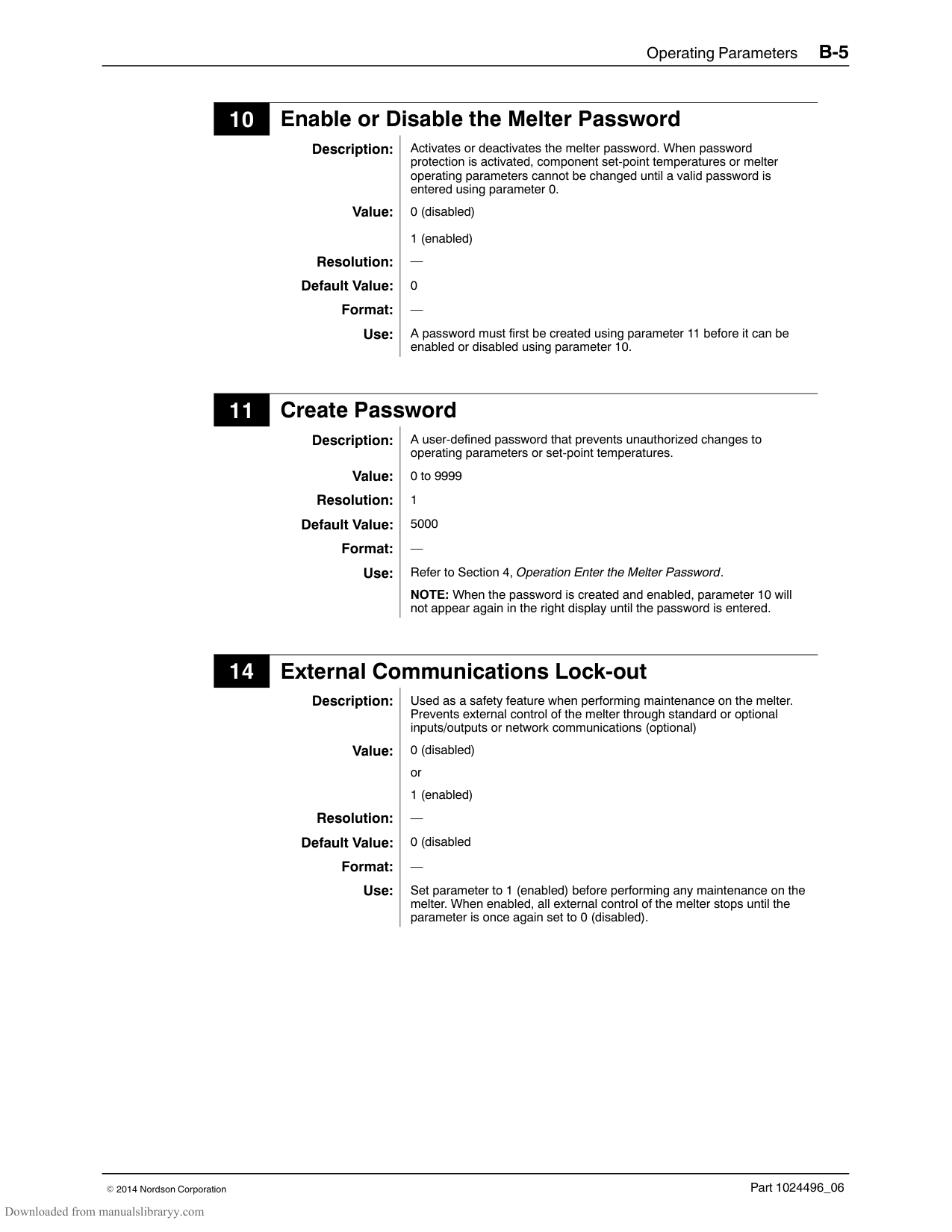
| | | | |---|---|---| | | | |
######## P10 Melter
| | | | | |---|---|---|---| | | | | | | | | | | | | | | |
######## Sub‐base
8.7 mm (.343 in.)
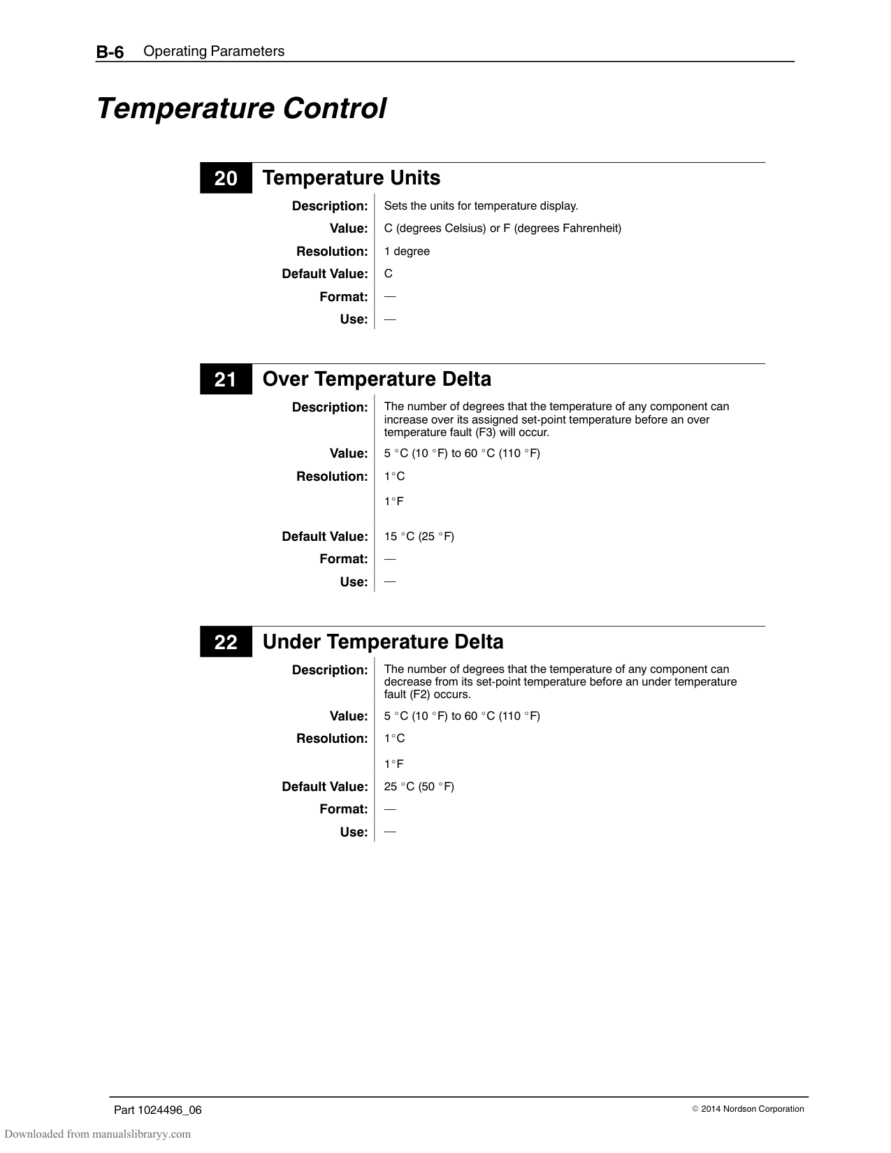
1” NPT
PG−16 PG−21
| | | |---|---| | | |
8.0 mm (.314 in.)
8.7 mm (.343 in.)
436 mm (17.16 in.)
381mm (15.00 in.)
| |249 mm (9.8 in.)| |---|---| | | |
P7/P10
249 mm (9.8 in.)
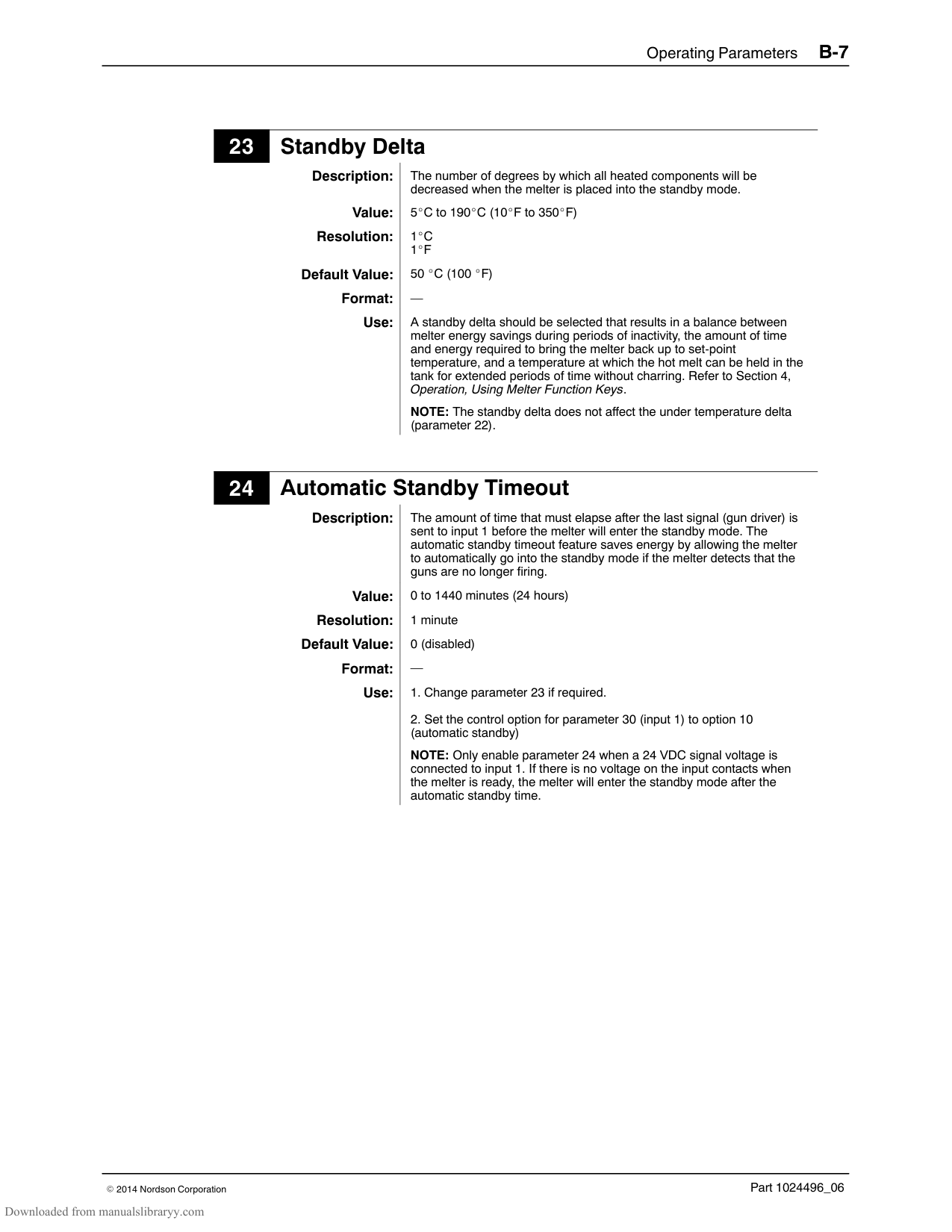
P4
#### Wiring Diagrams—200/240 VAC Melter See next eight pages. NOTE: For 400/480 Volt melters, refer to Appendix E.
| | | | | | | |---|---|---|---|---|---| | | | | | | | | | | | | | | | | | | | | | | | | | | | | | | | | | | | | | | | | | |
| | | | | | | |---|---|---|---|---|---| | | | | | | | | | | | | | | | | | | | | | | | | | | | | | | | | | | |
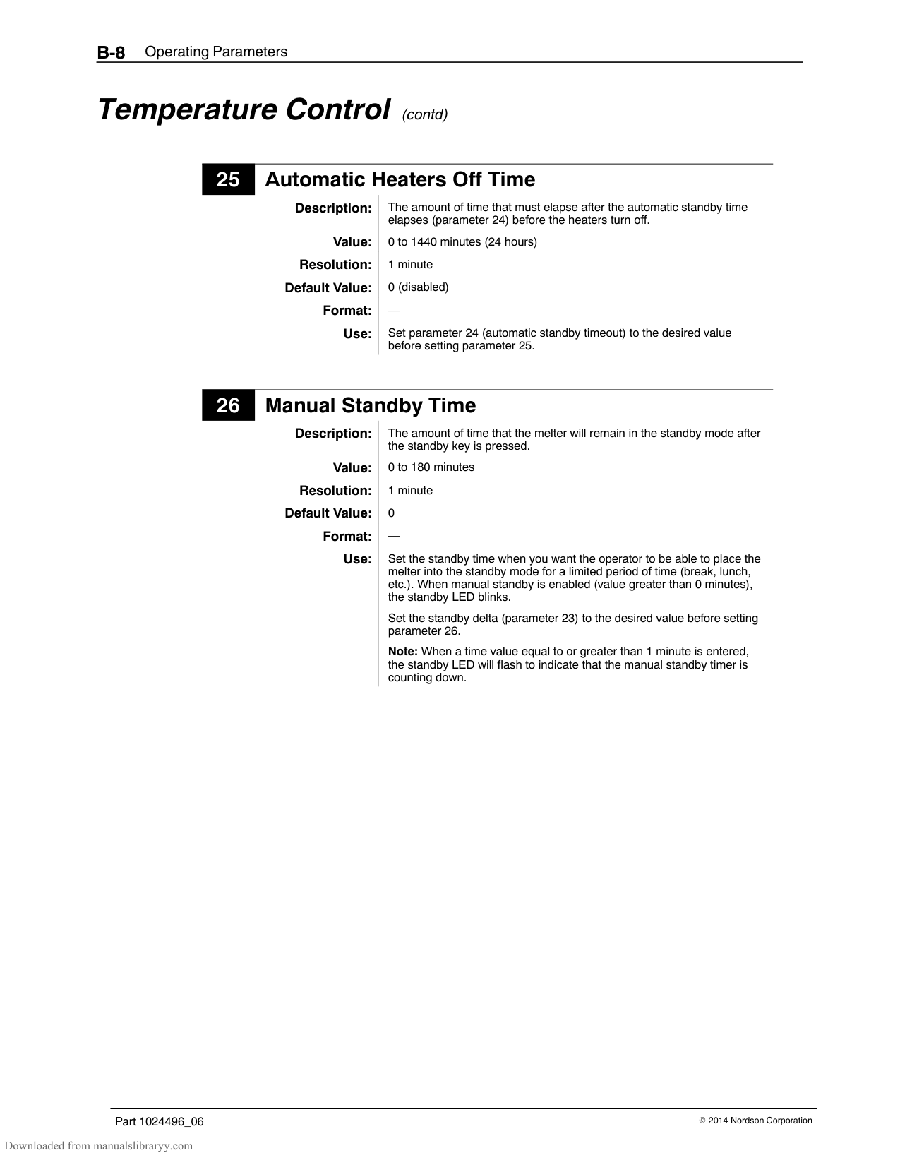
| | | | | | |
| | | |---|---| | | | | | |
| | | | | | | |---|---|---|---|---|---| | | | | | | | | | | | | | | | | | | | | | | | | | | | | | | | | | | | | | | | | | |
| | | |---|---| | | |
| | | | | | |
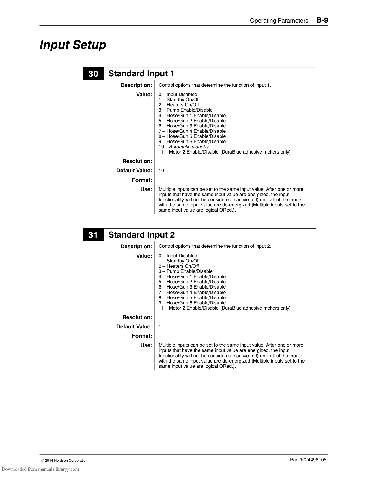
|---|---|---|---|---|---| | | | | | | | | | | | | | | | | | | | | | | | | | | | | | | | | | | | | | | | | | |
| | | |---|---| | | |
| | | |---|---| | | |
| | | |---|---| | | |
| | |
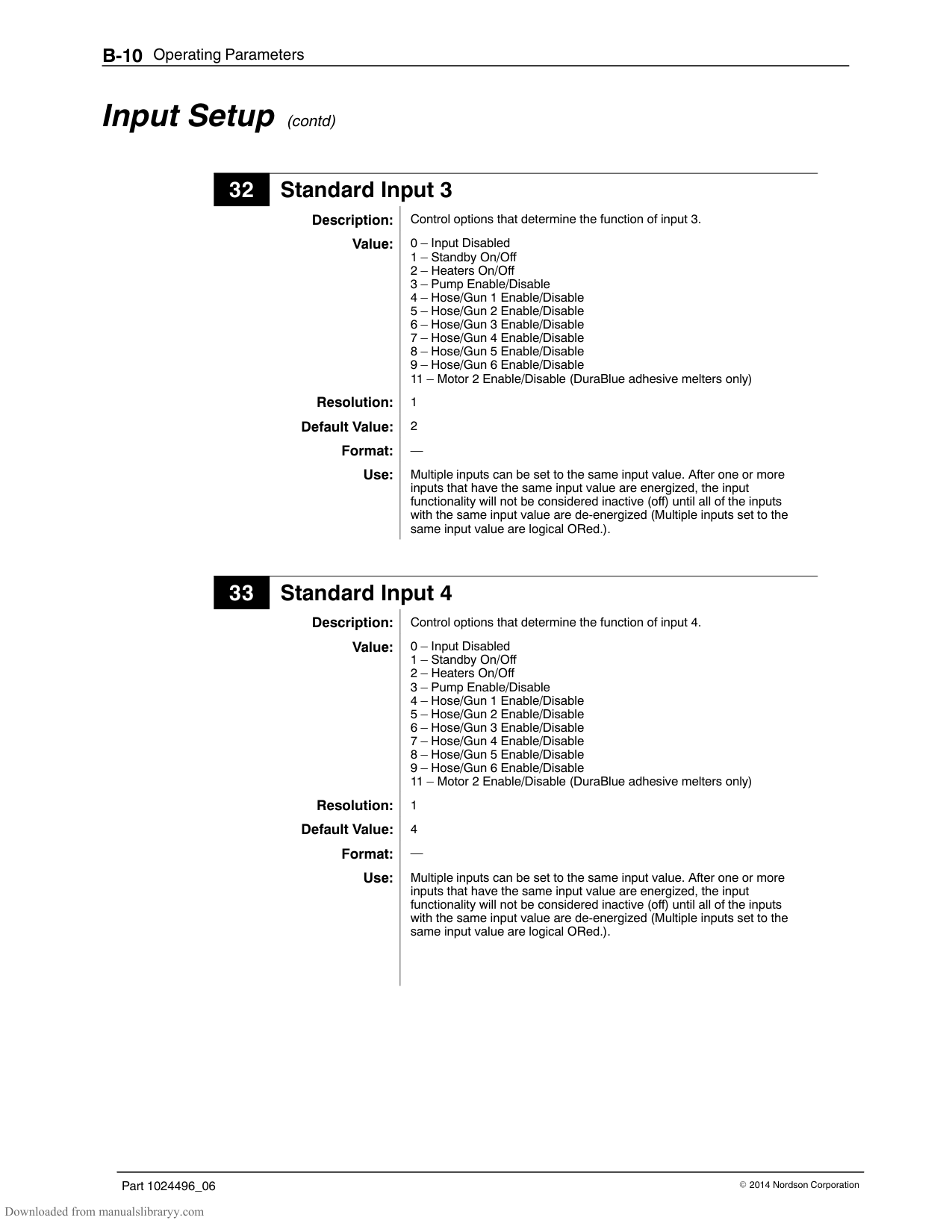
|---|---| | | |
| | | | | | | |---|---|---|---|---|---| | | | | | | | | | | | | | | | | | | | | | | | | | | | | | | | | | | | | | | | | | |
| | | | | | | |---|---|---|---|---|---| | | | | | | | | | | | | | | | | | | | | | | | | | | | | | | | | | | | | | | | | | |
| | |
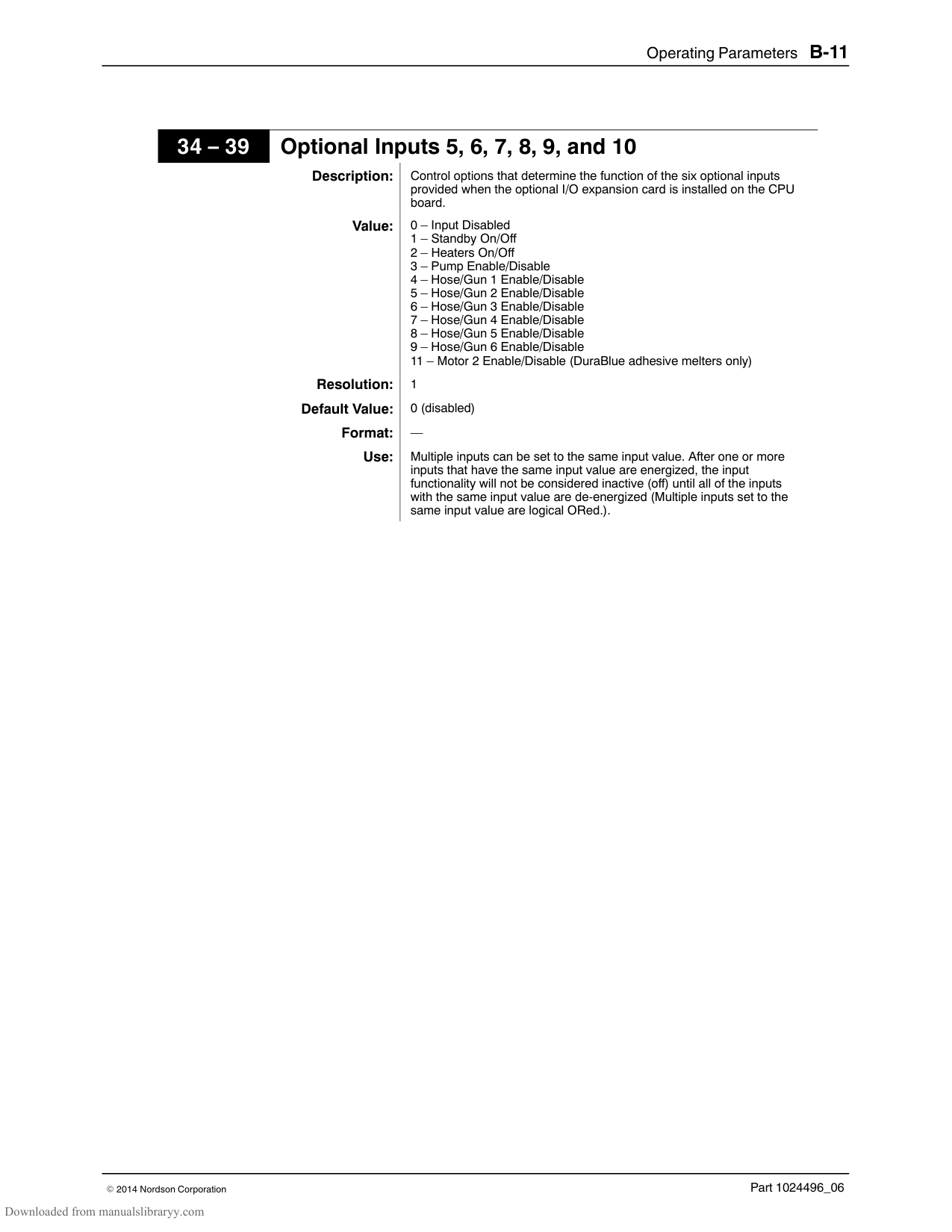
|---|---| | | |
| | | | | | | |---|---|---|---|---|---| | | | | | | | | | | | | | | | | | | | | | | | | | | | | | | | | | | | | | | | | | |
| | | | | | | |---|---|---|---|---|---| | | | | | | | | | | | | | | | | | | | | | | | | | | | | | | | | | | | | | | | | | |
Appendix A Calculating Melter Power Requirements
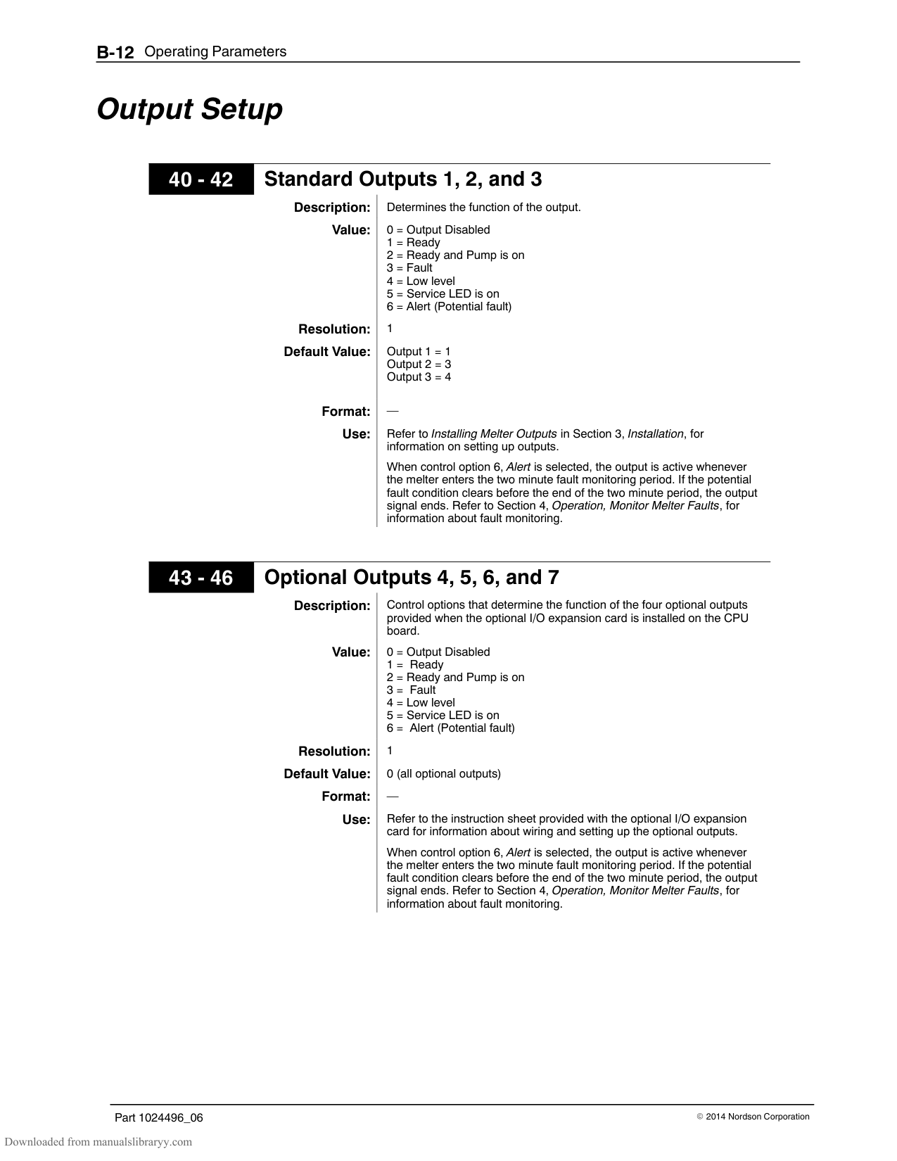
Before locating the melter on the production floor or attaching hoses and guns to the melter, you must calculate the electrical power required by the hoses and guns and confirm that the required power does not exceed maximum allowable wattages. Properly calculating melter power requirements will prevent damage to the melter and identify the maximum allowable distance between the melter and the point at which the hot melt is dispensed.
The following three maximum wattages must be considered when calculating the power required by the hoses and guns.
Single‐component maximum—The wattage of any single hose or gun
Hose/gun pair maximum—The wattage of any hose and gun (hose/gun pair)
Hose/gun module maximum—The wattage of any two hoses and two guns (two hose/gun pairs)
If your Nordson representative has already calculated the hose/gun power requirements and confirmed that the maximum allowable wattages will not be exceeded, then no further calculation is necessary. However, you should re‐evaluate the hose and gun power requirements before you:
add a new hose or gun to the melter that was not factored into the original wattage evaluation
replace an existing hose with a longer hose or an existing gun with a larger gun
############### To evaluate the hose/gun power requirements

If each of the wattages calculated in step 3 does not exceed the associated maximum allowable wattages listed in Table A‐2, then the power required by the hoses and guns is within acceptable limits.
If any of the wattages calculated in step 3 does exceed an associated maximum allowable wattage listed in Table A‐2, then the configuration or position of the hose/gun pairs must be rearranged or shorter hoses must be used in order to reduce the power requirement.
Table A‐1 Hose/Gun Wattages
|Module|Component Number|Type/Size|Wattage|Total Wattage| |---|---|---|---|---| |Hose/Gun Module 1|Hose 1| | | | |Hose/Gun Module 1|Gun 1| | | | |Hose/Gun Module 1|Hose 2| | | | |Hose/Gun Module 1|Gun 2| | | | |Total wattage of hose/gun module 1 =|Total wattage of hose/gun module 1 =|Total wattage of hose/gun module 1 =|Total wattage of hose/gun module 1 =| | |Hose/Gun Module 2|Hose 3| | | | |Hose/Gun Module 2|Gun 3| | | | |Hose/Gun Module 2|Hose 4| | | | |Hose/Gun Module 2|Gun 4| | | | |Total wattage of hose/gun module 2 =|Total wattage of hose/gun module 2 =|Total wattage of hose/gun module 2 =|Total wattage of hose/gun module 2 =| | |Hose/Gun Module 3|Hose 5| | | | |Hose/Gun Module 3|Gun 5| | | | |Hose/Gun Module 3|Hose 6| | | | |Hose/Gun Module 3|Gun 6| | | | |Total wattage of hose/gun module 3 =|Total wattage of hose/gun module 3 =|Total wattage of hose/gun module 3 =|Total wattage of hose/gun module 3 =| |
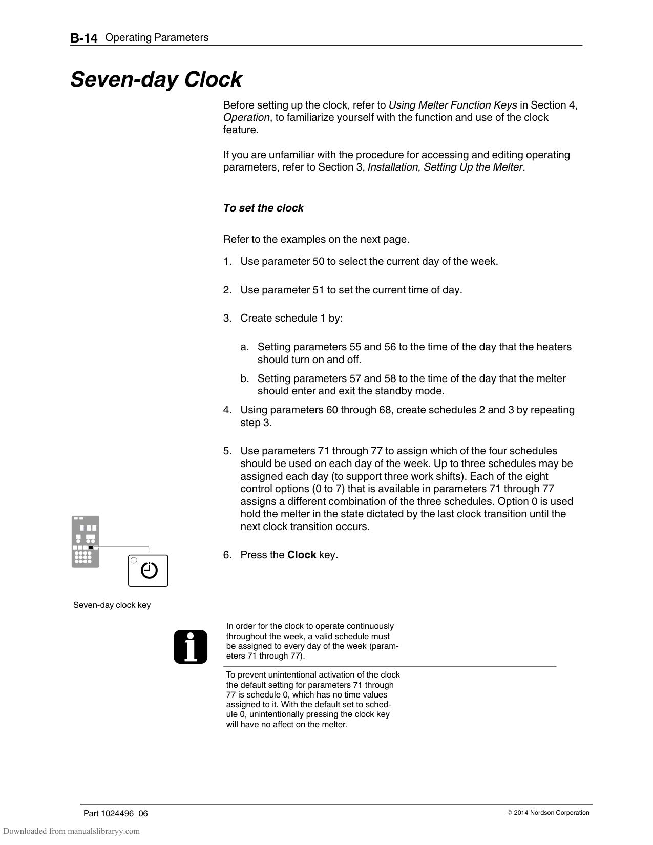
Table A‐2 Maximum Allowable Wattages
|Component|Plant Voltage|Plant Voltage|Plant Voltage|Plant Voltage| |---|---|---|---|---| |Component|200 VAC|220 VAC|230 VAC|240 VAC| |Any hose or gun|870 W|957 W|1000 W|1043 W| |Any hose/gun pair|1071 W|1179 W|1233 W|1286 W| |Any hose/gun module|1740 W|1913 W|2000 W|2086 W|
Appendix B Operating Parameters
Operating parameters are organized in this appendix according to the logical groups listed in Table B‐1. For information about selecting and editing operating parameters, refer to Section 3, Installation, Setting Up the Melter.
NOTE: Parameter numbers that are reserved or that are not used do not appear in this appendix.
Table B‐1 Parameter Groups
|Group|Parameter s|Description| |---|---|---| |Standard|0 to 11 and 14|Frequently used parameters| |Temperature Control|20 to 26|Control heater function| |Input Setup|30 to 39|Configure the standard and optional inputs| |Output Setup|40 to 46|Configure the standard and optional outputs|
|Seven-day Clock|50 to 77|Configure the clock feature|
#### Standard
######## 0 Enter Password
Description: A user‐defined password that prevents unauthorized changes to set‐point temperatures and operating parameters.
Value: 0 to 9999 Resolution: 1
Default Value: 4000 Format: —
Use: This parameter only appears if a password is created using parameter 11 and then enabled using parameter 10. NOTE: The melter remains in the password‐protected mode for two minutes after the last key press. After exiting the setup mode, attempting to re‐enter the setup mode, even before two minutes has elapsed, will require you to re‐enter the password.
######## 1 Total Hours with Heaters On (Noneditable)
Description: A non editable value that indicates the total number of hours that the
heaters have been on.
Value: 999,999 (using abbreviated convention described below) Resolution: 1 hour
Default Value: 0 Format: —
Use: The right display indicates up to 9999 hours of heater operation. When the accumulated heater hours reaches 10,000, the display alternates every two seconds between the three left most digits (thousands) and the three right digits (hundreds). For example, 10,001 hours would be displayed as ”10,” for two seconds and then ”001” for two seconds. The comma is present if parameter 20, Temperature Units, is set to degrees Fahrenheit. A period is present if parameter 20 is set to degrees Celsius.
######## 2 Fault Log (Noneditable)
Description: Stores a record of the last ten faults.
################# Value: Resolution: —
Default Value: _-F0 (unused log entry) Format: F1, F2, F3, and F4
Use: Use the right-display scroll keys to review the log entries for the last ten faults. Empty log entries are indicated by “_-F0.” Refer to Monitor the Melter in Section 4, Operation.
######## 3 Change History Log (Noneditable)
Description: Records the last ten changes made to either the set-point temperatures
or the operating parameters. Value: —
Resolution: Default Value: P-_ (unused log entry) Format: Refer to Section 3, Installation. Review Parameter and Set-point
Temperature Changes.
Use: Use the right-display key to review the log entries for the last ten changes that were made to the operating parameters or the set-point temperatures. Empty log entries are indicated by “P-_.”
######## 4 Ready Delay Time
Description: The amount of time that will elapse after all of the components have reached their set-point temperature before the ready LED will turn on. The ready delay time only functions when the temperature of the tank, at the time the melter is turned on, is more than 27 C (50 F) from its set-point temperature. The ready delay time begins when all components are within 3 C (5 F) of their respective set-point temperature.
Value: 0 to 60 minutes Resolution: 1 minute
Default Value: 0 minutes Format: Left display “rd”. Right display, minutes or seconds remaining
Use: The ready delay allows the contents of the tank an additional amount of time to heat before pump turns on. NOTE: The time remaining on the ready delay is indicated in minutes in the right display at the end of every automatic scan cycle. The left display indicates “rd” whenever the time remaining appears. When the delay time reaches 1 minute, the time remaining appears in seconds.
######## 5 Service Interval Time
Description: The number of heater-on hours that must elapse before the service LED
turns on.
Value: 0 hours (disabled) to 8736 (one year) Resolution: 1 hour Default Value: 500 hours
################# Format:
Use: Set the service interval time to signal a user-defined service check or maintenance event, such as changing the filter. The service LED will turn on after the pre-set time elapses. With the melter in the scan mode, press the Clear/Reset key to turn off the service LED and reset the time.
#### Standard (contd)
Service LED Heater Hours
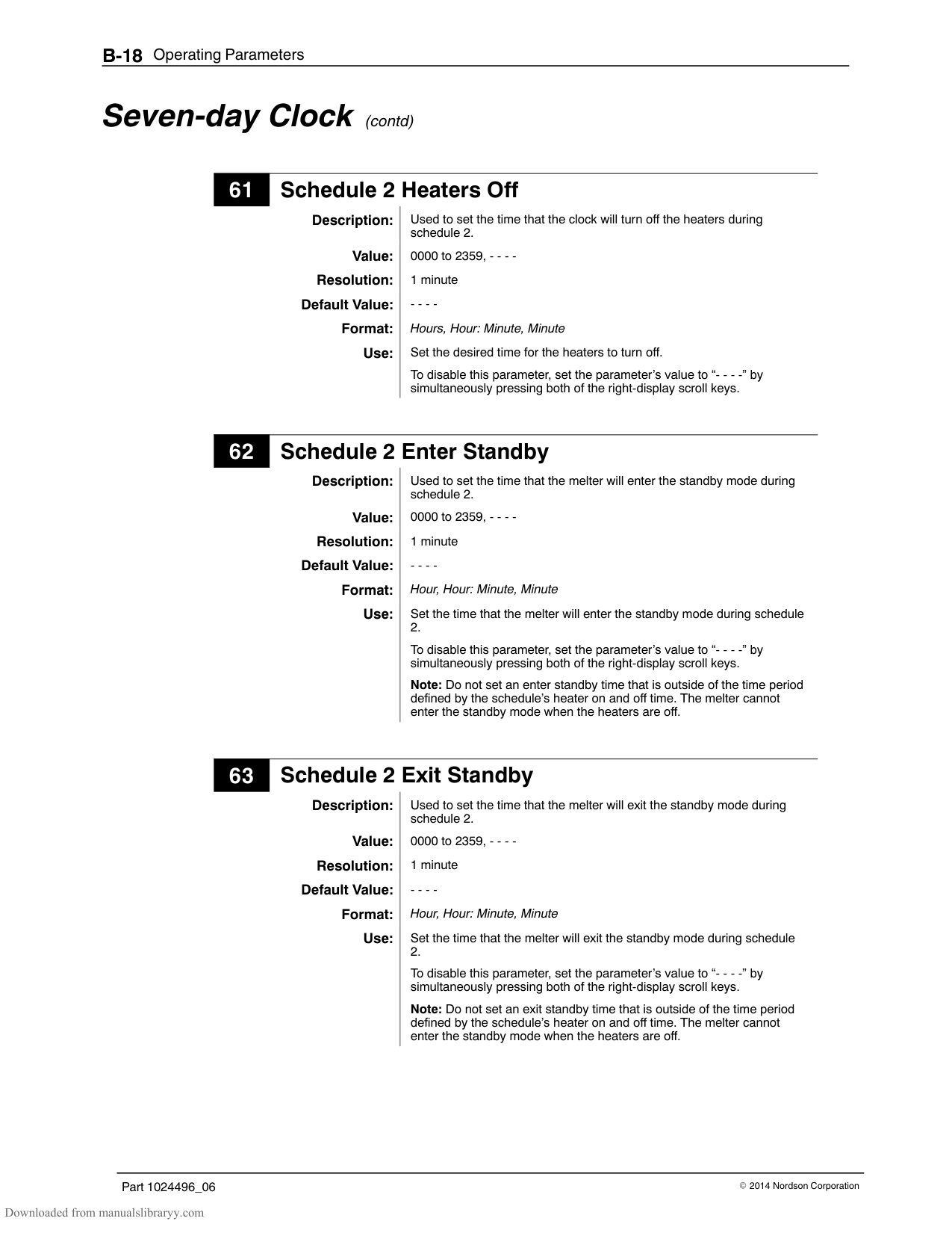
6
(Noneditable)
Description: A timer indicates how many more hours the heaters need to remain on before the service LED illuminates (service required). Value: 0 hours (disabled) to 9999
Resolution: 1 hour Default Value: 0
Format: —
Use: The service interval time (parameter 5) must be enabled before this parameter will work. Note: Heater hours accumulate whenever the heaters LED is illuminated.
######## 8 Automatic Pump On
Description: Determines if the pump will turn on automatically when the melter is
ready.
Value: 0 = disabled or 1 = enabled Resolution:
Default Value: 1 (enabled) Format: Use: If Automatic Pump On is disabled, you must press the pump key to turn
the pump on.
######## 9 Automatic Pump On Temperature
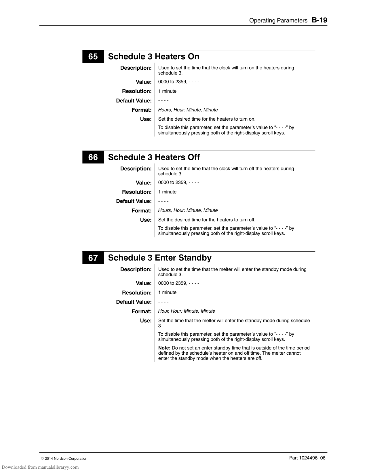
Description: Sets the temperature at which the pump will automatically turn on.
CAUTION: Unnecessary starting of the pump before the hot melt is fully melted can lead to premature pump wear.
Value: 0 = The pump turns on when the ready LED turns on OR 1 C to 230 C (1 F to 450 F) = The pump turns on when the tank reaches the selected temperature.
################# Resolution: 1 Default Value: 0
Syntax: Use: Parameter is only used when parameter 8 is set to 1 (enabled).
If a specific temperature value is used (as opposed to the default value of 0), only enter a set-point temperature that is lower than the set-point temperatures of the tank. A set-point temperature greater than the set-point of the tank will be ignored, and the pump will turn on when the melter is ready.
######## 10 Enable or Disable the Melter Password
Description: Activates or deactivates the melter password. When password protection is activated, component set-point temperatures or melter operating parameters cannot be changed until a valid password is entered using parameter 0.
Value: 0 (disabled)
1 (enabled) Resolution: —
Default Value: 0 Format: Use: A password must first be created using parameter 11 before it can be
enabled or disabled using parameter 10.
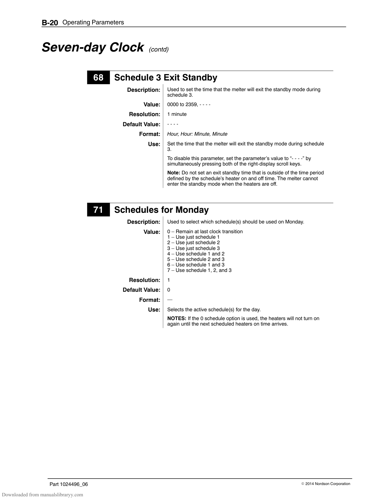
######## 11 Create Password
Description: A user-defined password that prevents unauthorized changes to
operating parameters or set-point temperatures. Value: 0 to 9999
################# Resolution: 1 Default Value: 5000
Format: Use: Refer to Section 4, Operation Enter the Melter Password.
NOTE: When the password is created and enabled, parameter 10 will not appear again in the right display until the password is entered.
######## 14 External Communications Lock-out
Description: Used as a safety feature when performing maintenance on the melter. Prevents external control of the melter through standard or optional inputs/outputs or network communications (optional)
Value: 0 (disabled) or 1 (enabled)
################# Resolution: Default Value: 0 (disabled Format: —
Use: Set parameter to 1 (enabled) before performing any maintenance on the melter. When enabled, all external control of the melter stops until the parameter is once again set to 0 (disabled).
#### Temperature Control
######## 20 Temperature Units
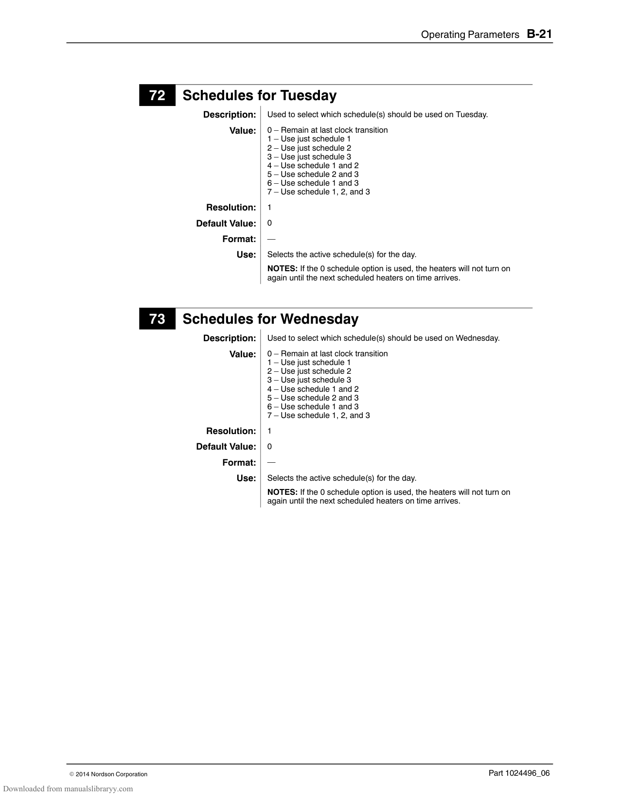
Description: Sets the units for temperature display.
Value: C (degrees Celsius) or F (degrees Fahrenheit) Resolution: 1 degree
Default Value: C
Format: Use: —
######## 21 Over Temperature Delta
Description: The number of degrees that the temperature of any component can increase over its assigned set-point temperature before an over temperature fault (F3) will occur.
Value: 5 C (10 F) to 60 C (110 F) Resolution: 1 C
1 F
Default Value: 15 C (25 F)
Format: Use: —
######## 22 Under Temperature Delta
Description: The number of degrees that the temperature of any component can decrease from its set-point temperature before an under temperature fault (F2) occurs.
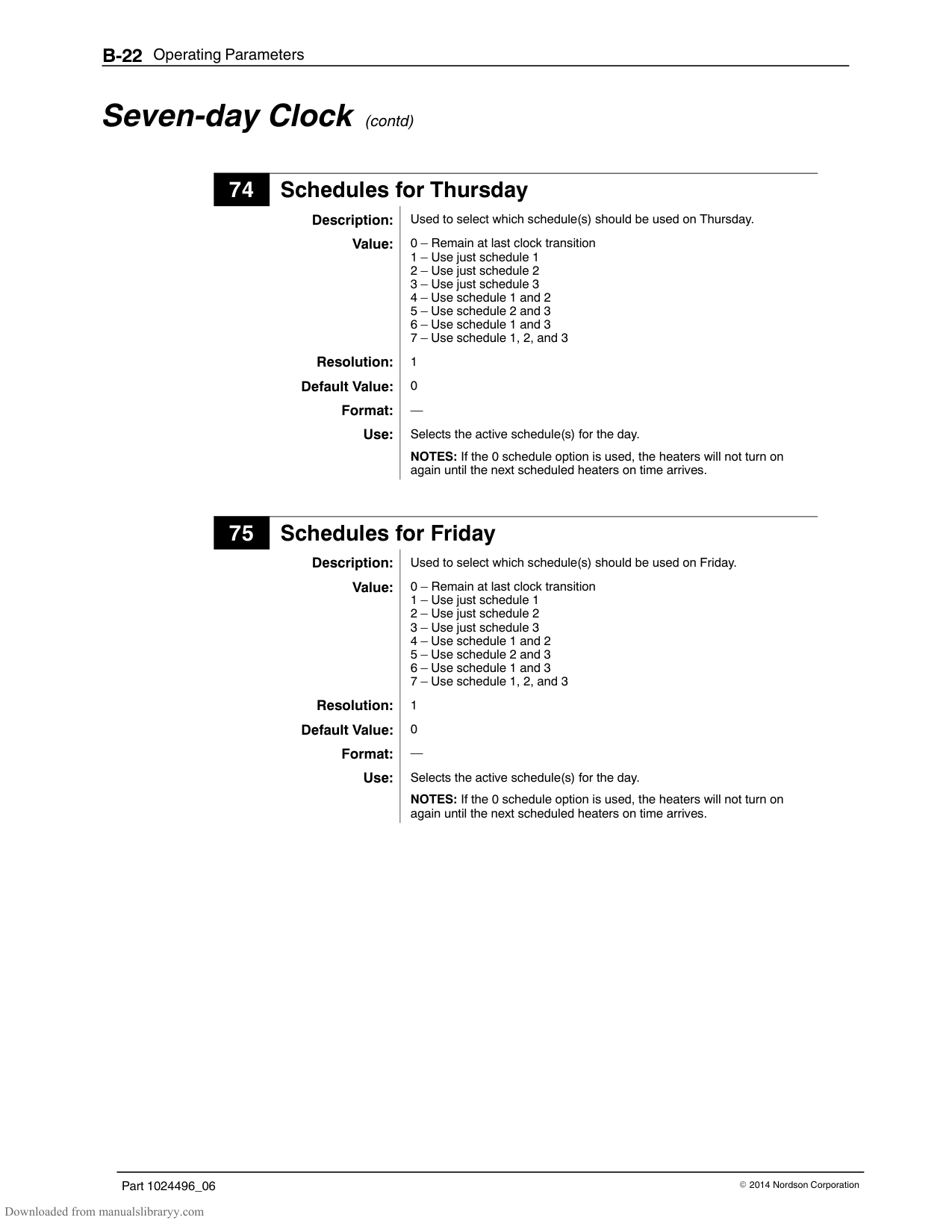
Value: 5 C (10 F) to 60 C (110 F) Resolution: 1 C
1 F
################# Default Value: 25 C (50 F) Format: Use:
######## 23 Standby Delta
Description: The number of degrees by which all heated components will be
decreased when the melter is placed into the standby mode. Value: 5 C to 190 C (10 F to 350 F)
Resolution: 1 C 1 F
Default Value: 50 C (100 F) Format: —
Use: A standby delta should be selected that results in a balance between melter energy savings during periods of inactivity, the amount of time and energy required to bring the melter back up to set-point temperature, and a temperature at which the hot melt can be held in the tank for extended periods of time without charring. Refer to Section 4, Operation, Using Melter Function Keys.
NOTE: The standby delta does not affect the under temperature delta (parameter 22).
######## 24 Automatic Standby Timeout
Description: The amount of time that must elapse after the last signal (gun driver) is sent to input 1 before the melter will enter the standby mode. The automatic standby timeout feature saves energy by allowing the melter to automatically go into the standby mode if the melter detects that the guns are no longer firing.
Value: 0 to 1440 minutes (24 hours) Resolution: 1 minute Default Value: 0 (disabled)

Format: Use: 1. Change parameter 23 if required.
NOTE: Only enable parameter 24 when a 24 VDC signal voltage is connected to input 1. If there is no voltage on the input contacts when the melter is ready, the melter will enter the standby mode after the automatic standby time.
#### Temperature Control (contd)
######## 25 Automatic Heaters Off Time
Description: The amount of time that must elapse after the automatic standby time elapses (parameter 24) before the heaters turn off. Value: 0 to 1440 minutes (24 hours)
Resolution: 1 minute Default Value: 0 (disabled)
Format: Use: Set parameter 24 (automatic standby timeout) to the desired value
before setting parameter 25.
######## 26 Manual Standby Time
Description: The amount of time that the melter will remain in the standby mode after
the standby key is pressed. Value: 0 to 180 minutes

################# Resolution: 1 minute Default Value: 0
Format: Use: Set the standby time when you want the operator to be able to place the
melter into the standby mode for a limited period of time (break, lunch, etc.). When manual standby is enabled (value greater than 0 minutes), the standby LED blinks.
Set the standby delta (parameter 23) to the desired value before setting parameter 26.
Note: When a time value equal to or greater than 1 minute is entered, the standby LED will flash to indicate that the manual standby timer is counting down.
#### Input Setup
######## 30 Standard Input 1
Description: Control options that determine the function of input 1. Value: 0 – Input Disabled
Resolution: 1
Default Value: 10 Format: —
Use: Multiple inputs can be set to the same input value. After one or more inputs that have the same input value are energized, the input functionality will not be considered inactive (off) until all of the inputs with the same input value are de-energized (Multiple inputs set to the same input value are logical ORed.).
######## 31 Standard Input 2
Description: Control options that determine the function of input 2. Value: 0 – Input Disabled
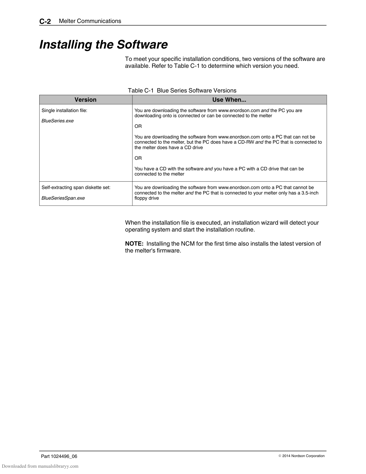
Resolution: 1 Default Value: 1
Format: —
Use: Multiple inputs can be set to the same input value. After one or more inputs that have the same input value are energized, the input functionality will not be considered inactive (off) until all of the inputs with the same input value are de-energized (Multiple inputs set to the same input value are logical ORed.).
#### Input Setup (contd)
######## 32 Standard Input 3
Description: Control options that determine the function of input 3. Value: 0 – Input Disabled
Resolution: 1 Default Value: 2
Format: —
Use: Multiple inputs can be set to the same input value. After one or more inputs that have the same input value are energized, the input functionality will not be considered inactive (off) until all of the inputs with the same input value are de-energized (Multiple inputs set to the same input value are logical ORed.).
######## 33 Standard Input 4
Description: Control options that determine the function of input 4. Value: 0 – Input Disabled
Resolution: 1 Default Value: 4
Format:
Use: Multiple inputs can be set to the same input value. After one or more inputs that have the same input value are energized, the input functionality will not be considered inactive (off) until all of the inputs with the same input value are de-energized (Multiple inputs set to the same input value are logical ORed.).

######## 34 – 39 Optional Inputs 5, 6, 7, 8, 9, and 10
Description: Control options that determine the function of the six optional inputs provided when the optional I/O expansion card is installed on the CPU board.
Value: 0 – Input Disabled
################# Resolution: 1 Default Value: 0 (disabled) Format: —
Use: Multiple inputs can be set to the same input value. After one or more inputs that have the same input value are energized, the input functionality will not be considered inactive (off) until all of the inputs with the same input value are de-energized (Multiple inputs set to the same input value are logical ORed.).
#### Output Setup
######## 40 - 42 Standard Outputs 1, 2, and 3
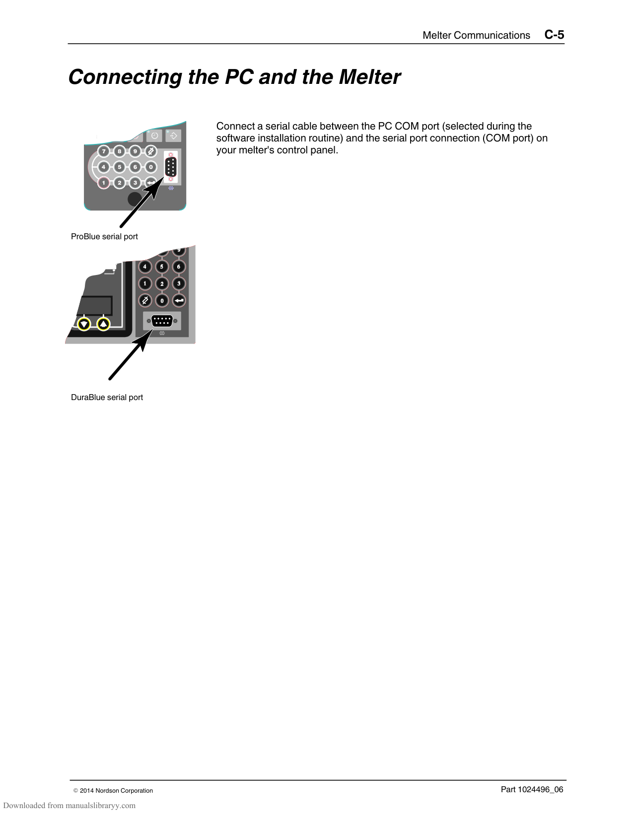
Description: Determines the function of the output. Value: 0 = Output Disabled
################# Resolution: 1 Default Value: Output 1 = 1
################# Format: —
Use: Refer to Installing Melter Outputs in Section 3, Installation, for information on setting up outputs. When control option 6, Alert is selected, the output is active whenever the melter enters the two minute fault monitoring period. If the potential fault condition clears before the end of the two minute period, the output signal ends. Refer to Section 4, Operation, Monitor Melter Faults, for information about fault monitoring.
######## 43 - 46 Optional Outputs 4, 5, 6, and 7
Description: Control options that determine the function of the four optional outputs provided when the optional I/O expansion card is installed on the CPU board.
Value: 0 = Output Disabled
################# Resolution: 1 Default Value: 0 (all optional outputs) Format: —
Use: Refer to the instruction sheet provided with the optional I/O expansion card for information about wiring and setting up the optional outputs. When control option 6, Alert is selected, the output is active whenever the melter enters the two minute fault monitoring period. If the potential fault condition clears before the end of the two minute period, the output signal ends. Refer to Section 4, Operation, Monitor Melter Faults, for information about fault monitoring.
################ This page intentionally left blank.
Seven‐day Clock Before setting up the clock, refer to Using Melter Function Keys in Section 4, Operation, to familiarize yourself with the function and use of the clock feature. If you are unfamiliar with the procedure for accessing and editing operating parameters, refer to Section 3, Installation, Setting Up the Melter.
############### To set the clock
| | | |---|---| | | |
Seven‐day clock key
Refer to the examples on the next page.
In order for the clock to operate continuously throughout the week, a valid schedule must be assigned to every day of the week (parameters 71 through 77).
To prevent unintentional activation of the clock the default setting for parameters 71 through 77 is schedule 0, which has no time values assigned to it. With the default set to schedule 0, unintentionally pressing the clock key will have no affect on the melter.
########### Example 1
To turn the heaters on at 0600 and turn them off at 0015 every day of the week:
########### Example 2
To turn the heaters on at 0700 and off at 1700 Monday through Friday, and turn the heaters off Saturday and Sunday:
Example 3
To turn the heaters on at 0600 each morning, go into standby for lunch at 1130, come out of standby after lunch at 1230, and turn the heaters off at 1600 at the end of the day, every day of the week:
######## 50 Current Day
Description: Used to set the current day of the week.
Value: 1 to 7 (1 = Monday, 2 = Tuesday, etc.) Resolution: 1
Default Value: Format: Use: Refer to Section 4, Operation, Using Melter Function Keys, for
information about the use and affects of the seven-day clock feature.
######## 51 Current Hour
Description: Used to set the local time of the day.
Value: 0000 to 2359 (European time format) Resolution: 1 minute
Default Value: (Time set at factory) Format: Hours, Hour: Minute, Minute Use: This setting only needs to be made once for all daily schedules
######## 55 Schedule 1 Heaters On
Description: Used to set the time that the clock will turn on the heaters during
schedule 1.
Value: 0000 to 2359, - - - Resolution: 1 minute
Default Value: 0600 Format: Hours, Hour: Minute, Minute Use: Set the desired time for the heaters to turn on.
To disable this parameter, set the parameter’s value to “- - - -” by simultaneously pressing both of the right-display scroll keys.
######## 56 Schedule 1 Heaters Off
Description: Used to set the time that the clock will turn off the heaters during
schedule 1.
Value: 0000 to 2359, - - - Resolution: 1 minute
Default Value: 1700 Format: Hours, Hour: Minute, Minute Use: Set the desired time for the heaters to turn off.
To disable this parameter, set the parameter’s value to “- - - -” by simultaneously pressing both of the right-display scroll keys.
######## 57 Schedule 1 Enter Standby
Description: Used to set the time that the melter will enter the standby mode during
schedule 1.
Value: 0000 to 2359, - - - Resolution: 1 minute
Default Value: - - - Format: Hour, Hour: Minute, Minute
Use: Set the time that the melter will enter the standby mode during schedule 1. To disable this parameter, set the parameter’s value to “- - - -” by simultaneously pressing both of the right-display scroll keys. Note: Do not set an enter standby time that is outside of the time period defined by the schedule’s heater on and off time. The melter cannot enter the standby mode when the heaters are off.
######## 58 Schedule 1 Exit Standby
Description: Used to set the time that the melter will exit the standby mode during
schedule 1.
Value: 0000 to 2359, - - - Resolution: 1 minute
Default Value: - - - Format: Hour, Hour: Minute, Minute

Use: Set the time that the melter will exit the standby mode during schedule 1. To disable this parameter, set the parameter’s value to “- - - -” by simultaneously pressing both of the right-display scroll keys. Note: Do not set an exit standby time that is outside of the time period defined by the schedule’s heater on and off time. The melter cannot enter the standby mode when the heaters are off.
######## 60 Schedule 2 Heaters On
Description: Used to set the time that the clock will turn on the heaters during
schedule 2.
Value: 0000 to 2359, - - - Resolution: 1 minute
Default Value: - - - Format: Hours, Hour: Minute, Minute Use: Set the desired time for the heaters to turn on.
To disable this parameter, set the parameter’s value to “- - - -” by simultaneously pressing both of the right-display scroll keys.
######## 61 Schedule 2 Heaters Off
Description: Used to set the time that the clock will turn off the heaters during
schedule 2.
Value: 0000 to 2359, - - - Resolution: 1 minute
Default Value: - - - Format: Hours, Hour: Minute, Minute Use: Set the desired time for the heaters to turn off.
To disable this parameter, set the parameter’s value to “- - - -” by simultaneously pressing both of the right-display scroll keys.
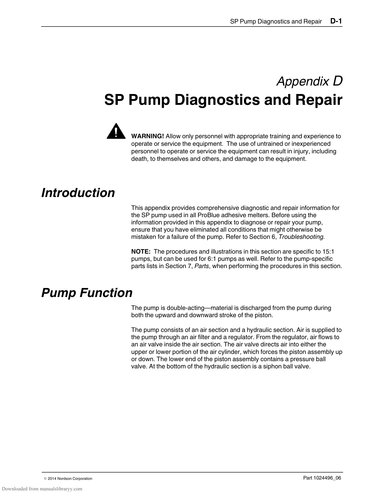
######## 62 Schedule 2 Enter Standby
Description: Used to set the time that the melter will enter the standby mode during
schedule 2.
Value: 0000 to 2359, - - - Resolution: 1 minute
Default Value: - - - Format: Hour, Hour: Minute, Minute
Use: Set the time that the melter will enter the standby mode during schedule 2. To disable this parameter, set the parameter’s value to “- - - -” by simultaneously pressing both of the right-display scroll keys. Note: Do not set an enter standby time that is outside of the time period defined by the schedule’s heater on and off time. The melter cannot enter the standby mode when the heaters are off.
######## 63 Schedule 2 Exit Standby
Description: Used to set the time that the melter will exit the standby mode during
schedule 2.
Value: 0000 to 2359, - - - Resolution: 1 minute
Default Value: - - - Format: Hour, Hour: Minute, Minute
Use: Set the time that the melter will exit the standby mode during schedule 2. To disable this parameter, set the parameter’s value to “- - - -” by simultaneously pressing both of the right-display scroll keys. Note: Do not set an exit standby time that is outside of the time period defined by the schedule’s heater on and off time. The melter cannot enter the standby mode when the heaters are off.
######## 65 Schedule 3 Heaters On
Description: Used to set the time that the clock will turn on the heaters during
schedule 3.
Value: 0000 to 2359, - - - Resolution: 1 minute
Default Value: - - - Format: Hours, Hour: Minute, Minute Use: Set the desired time for the heaters to turn on.
To disable this parameter, set the parameter’s value to “- - - -” by simultaneously pressing both of the right-display scroll keys.
######## 66 Schedule 3 Heaters Off
Description: Used to set the time that the clock will turn off the heaters during
schedule 3.
Value: 0000 to 2359, - - - Resolution: 1 minute
Default Value: - - - Format: Hours, Hour: Minute, Minute Use: Set the desired time for the heaters to turn off.
To disable this parameter, set the parameter’s value to “- - - -” by simultaneously pressing both of the right-display scroll keys.
######## 67 Schedule 3 Enter Standby

Description: Used to set the time that the melter will enter the standby mode during
schedule 3.
Value: 0000 to 2359, - - - Resolution: 1 minute
Default Value: - - - Format: Hour, Hour: Minute, Minute
Use: Set the time that the melter will enter the standby mode during schedule 3. To disable this parameter, set the parameter’s value to “- - - -” by simultaneously pressing both of the right-display scroll keys. Note: Do not set an enter standby time that is outside of the time period defined by the schedule’s heater on and off time. The melter cannot enter the standby mode when the heaters are off.
######## 68 Schedule 3 Exit Standby
Description: Used to set the time that the melter will exit the standby mode during
schedule 3.
Value: 0000 to 2359, - - - Resolution: 1 minute
Default Value: - - - Format: Hour, Hour: Minute, Minute
Use: Set the time that the melter will exit the standby mode during schedule 3. To disable this parameter, set the parameter’s value to “- - - -” by simultaneously pressing both of the right-display scroll keys. Note: Do not set an exit standby time that is outside of the time period defined by the schedule’s heater on and off time. The melter cannot enter the standby mode when the heaters are off.
######## 71 Schedules for Monday
Description: Used to select which schedule(s) should be used on Monday. Value: 0 – Remain at last clock transition
################# Resolution: 1 Default Value: 0
Format: Use: Selects the active schedule(s) for the day.
NOTES: If the 0 schedule option is used, the heaters will not turn on again until the next scheduled heaters on time arrives.
######## 72 Schedules for Tuesday
Description: Used to select which schedule(s) should be used on Tuesday. Value: 0 – Remain at last clock transition
Resolution: 1 Default Value: 0
Format: Use: Selects the active schedule(s) for the day.
NOTES: If the 0 schedule option is used, the heaters will not turn on again until the next scheduled heaters on time arrives.
######## 73 Schedules for Wednesday
Description: Used to select which schedule(s) should be used on Wednesday. Value: 0 – Remain at last clock transition
################# Resolution: 1 Default Value: 0
Format: Use: Selects the active schedule(s) for the day.
NOTES: If the 0 schedule option is used, the heaters will not turn on again until the next scheduled heaters on time arrives.
######## 74 Schedules for Thursday
Description: Used to select which schedule(s) should be used on Thursday. Value: 0 – Remain at last clock transition
Resolution: 1 Default Value: 0
Format: Use: Selects the active schedule(s) for the day.
NOTES: If the 0 schedule option is used, the heaters will not turn on again until the next scheduled heaters on time arrives.
######## 75 Schedules for Friday
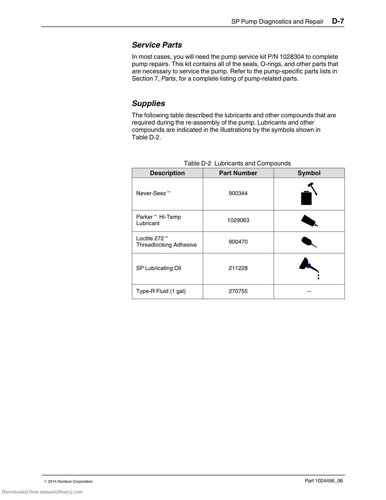
Description: Used to select which schedule(s) should be used on Friday. Value: 0 – Remain at last clock transition
################# Resolution: 1 Default Value: 0
Format: Use: Selects the active schedule(s) for the day.
NOTES: If the 0 schedule option is used, the heaters will not turn on again until the next scheduled heaters on time arrives.
######## 76 Schedules for Saturday
Description: Used to select which schedule(s) should be used on Saturday.
Value: 0 – Remain at last clock transition 1 – Use just schedule 1 2 – Use just schedule 2 3 – Use just schedule 3 4 – Use schedule 1 and 2 5 – Use schedule 2 and 3 6 – Use schedule 1 and 3 7 – Use schedule 1, 2, and 3
Resolution: 1 Default Value: 0
Format: Use: Selects the active schedule(s) for the day.
NOTES: If the 0 schedule option is used, the heaters will not turn on again until the next scheduled heaters on time arrives.
######## 77 Schedules for Sunday
Description: Used to select which schedule(s) should be used on Sunday.
Value: 0 – Remain at last clock transition 1 – Use just schedule 1 2 – Use just schedule 2 3 – Use just schedule 3 4 – Use schedule 1 and 2 5 – Use schedule 2 and 3 6 – Use schedule 1 and 3 7 – Use schedule 1, 2, and 3
################# Resolution: 1 Default Value: 0
Format: Use: Selects the active schedule(s) for the day.
NOTES: If the 0 schedule option is used, the heaters will not turn on again until the next scheduled heaters on time arrives.
Appendix C Melter Communications
This appendix describes the installation and use of the Nordson Configuration Manager (NCM) communications utility. With this utility you can:
transfer operating parameters and temperature set‐points between melters
upgrade or reload your melter's firmware
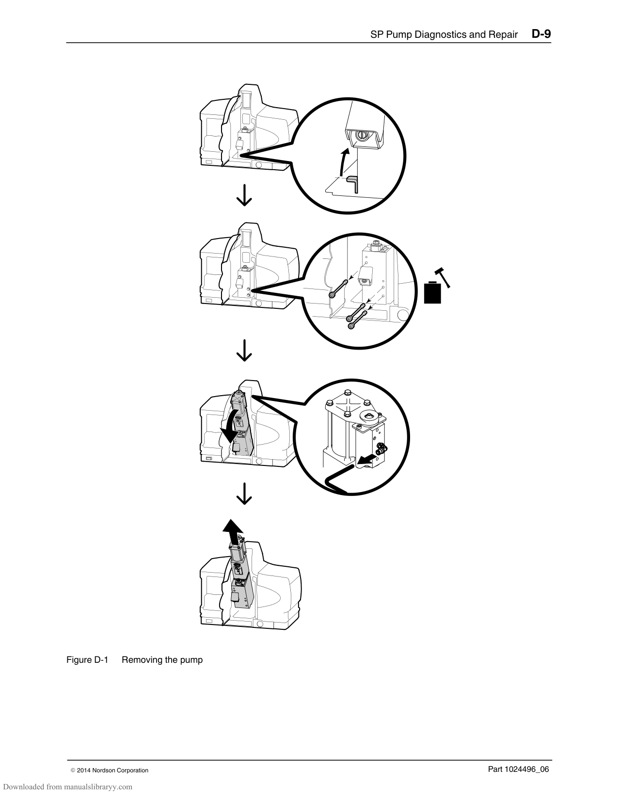
#### Software Availability
If you do not already have the NCM utility, you can download it from the internet by navigating to www.enordson.com/support.
If you do not have a connection to the internet, you can request a software CD from your Nordson representative.
#### System Requirements
The following hardware and software requirements are necessary to install and run Blue Series software:
Any ProBlue adhesive melter or a DuraBlue 10/16 adhesive melter Serial cable Personal computer with:
CD‐RW drive or 3.5‐inch floppy drive Available COM port 640 x 480 color monitor Windows 95, 98 (second edition), ME, XP, or 2000 Internet Explorer version 4.0 or later (IE 5.0 is recommended) Administrative privileges (Windows XP, 2000, and NT)
#### Installing the Software
To meet your specific installation conditions, two versions of the software are available. Refer to Table C‐1 to determine which version you need.
Table C‐1 Blue Series Software Versions
|Version|Use When...| |---|---| |Single installation file: BlueSeries.exe|You are downloading the software from www.enordson.com and the PC you are downloading onto is connected or can be connected to the melter
OR You are downloading the software from www.enordson.com onto a PC that can not be connected to the melter, but the PC does have a CD-RW and the PC that is connected to the melter does have a CD drive OR You have a CD with the software and you have a PC with a CD drive that can be connected to the melter| |Self-extracting span diskette set: BlueSeriesSpan.exe|You are downloading the software from www.enordson.com onto a PC that cannot be connected to the melter and the PC that is connected to your melter only has a 3.5-inch floppy drive|
When the installation file is executed, an installation wizard will detect your operating system and start the installation routine.
NOTE: Installing the NCM for the first time also installs the latest version of the melter's firmware.
############### To install Blue Series software
If you are installing using the single file installation, locate and double‐click on the file BlueSeries.exe.
If you are installing from the span diskette set, insert Disk 1, and then locate and double‐click on the file Setup.exe.
The Blue Series Software Setup wizard appears.
NOTE: When prompted to select an installation location, Nordson Corporation recommends that you select the default location offered.
######## Removing the Software from Your PC
Use the Remove feature provided by the Blue Series InstallShield Wizard to remove the software from your PC. Removing Blue Series software from your PC will not remove melter settings files that you have saved using the NCM. Settings files (.ncm extension) are stored in your Windows My Documents folder.
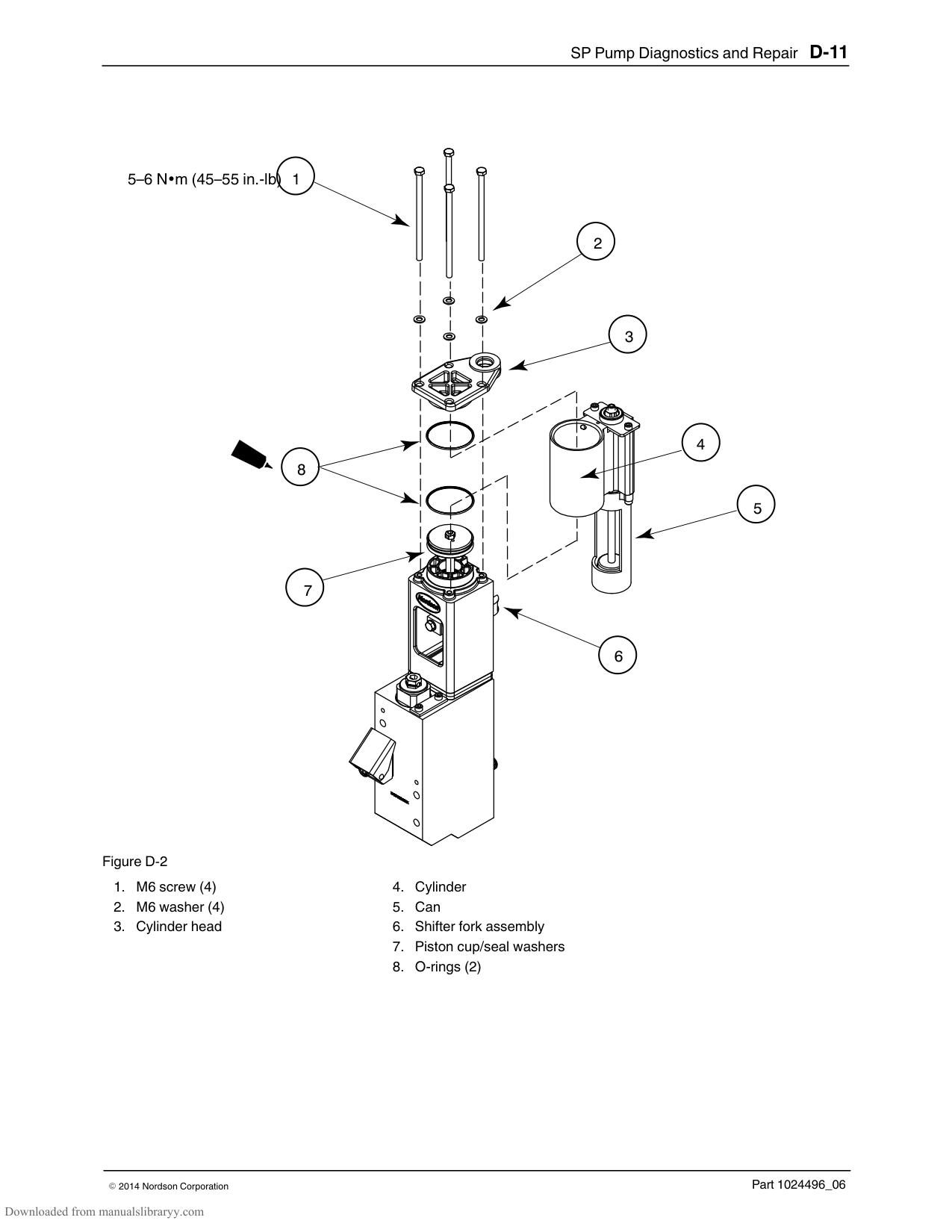
NOTE: Windows XP, 2000, and NT users must have administrator rights in order to remove software from their PC.
############### To remove Blue Series software
#### Connecting the PC and the Melter
| | | |---|---| | | | | | |
ProBlue serial port
99
44 55
66
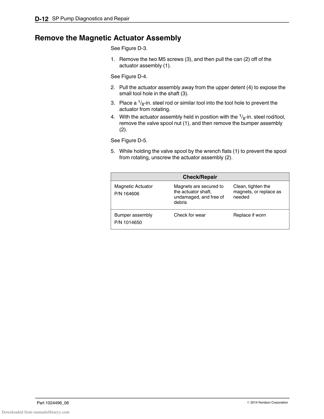
11 22
33
00
DuraBlue serial port
Connect a serial cable between the PC COM port (selected during the software installation routine) and the serial port connection (COM port) on your melter's control panel.
#### Using Nordson Configuration Manager

Configuration Manager desktop icon
Configuration Manager is launched from your Windows desktop using the icon shown to the left.
Use Configuration Manager when you want to... copy melter settings from one melter to another melter create and save more than one version of melter settings upgrade or restore a melter's firmware
Configuration Manager communicates with your melter through a PC connected to your melter's serial port. Once connected, Configuration Manager offers the choice of saving settings, restoring settings, or upgrading the melter's firmware.
The first time you download and install Configuration Manager, the latest version of the melter's firmware is also downloaded.
######## Saving and Restoring Melter Settings
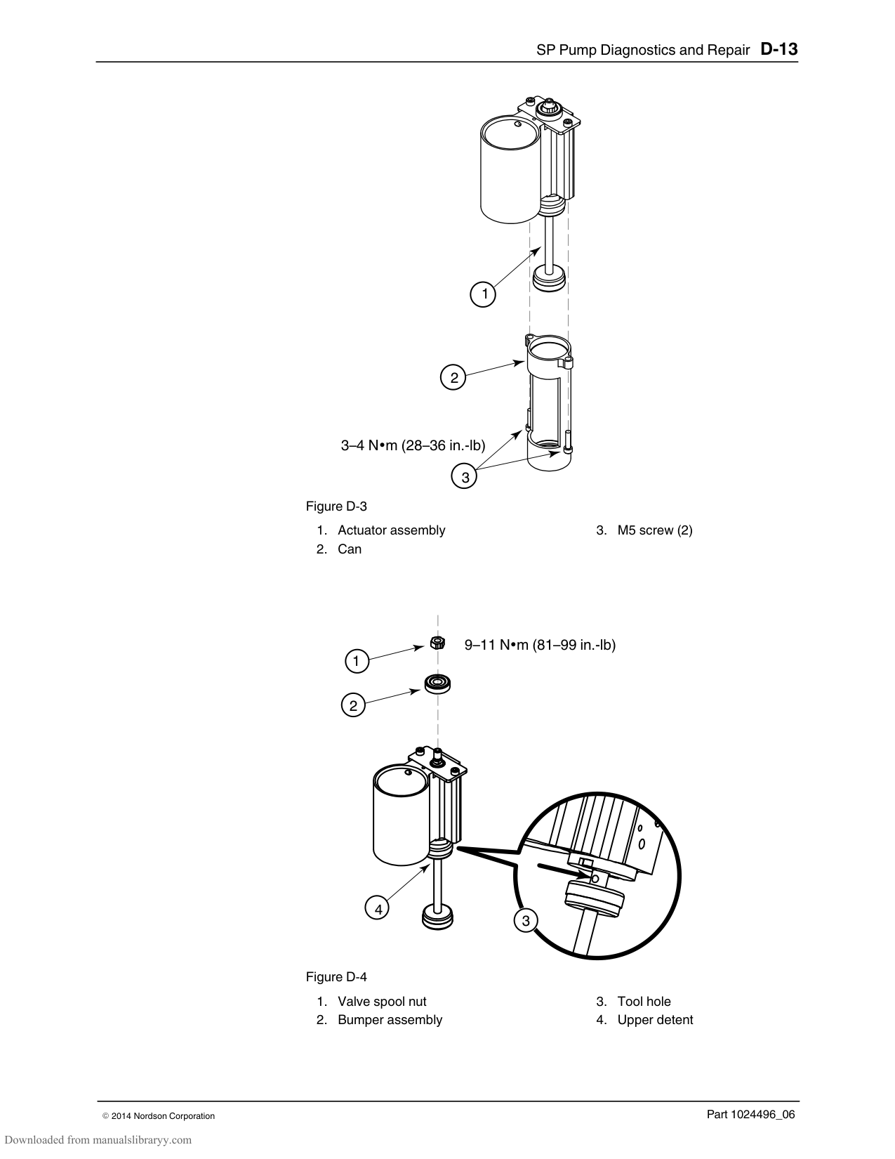
Saving settings copies all current set‐point and operating parameter values to your PC. Saved settings can be transferred back to the same melter or to any other compatible Blue Series adhesive melter.
############### To save melter settings
status area indicates “CONNECTED”.
NOTE: The default location for saving settings files is Windows My Documents folder. To avoid losing saved settings files, Nordson Corporation recommends that you do not change the default save location.
The save settings progress bar indicates the status of the save. When the save is complete, the melter automatically returns to the scan mode.
NOTE: If you are using the NCM to save multiple variations of melter settings, use a file naming convention that will allow you to easily associate each settings file (.ncm extension) with its related process or end‐use.
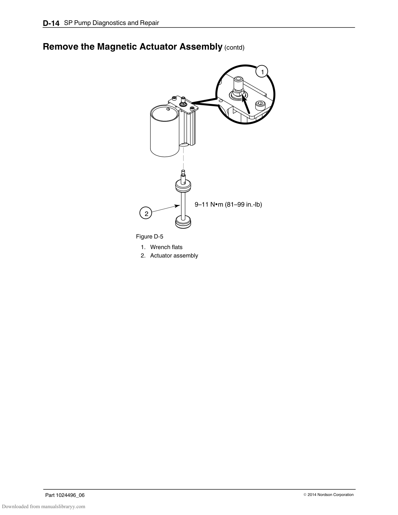
############### To restore melter settings
The Restore Settings progress bar indicates the status of the restore. When the restore is complete, the melter automatically returns to the scan mode.
######## Upgrading or Restoring Melter Firmware
Use the NCM to upgrade your melter to a newer version of firmware or reload the current version of the firmware. The version of Blue Series adhesive melter firmware that is currently available is posted on the internet at www.enordson.com/support.
NOTE: The version of firmware that is loaded on your melter appears on the control panel when the melter is first switched on.
During the upgrade process, all current melter settings are downloaded and saved on your PC. After upgrading or restoring a melter's firmware, you can use the NCM to restore the pre‐upgrade settings.
CAUTION! The upgrade process returns the melter's settings to factory configuration, with the exception that current heater hours data is saved. Data in both the fault log and the change log is lost after upgrading the firmware.
############### To upgrade or reload melter firmware
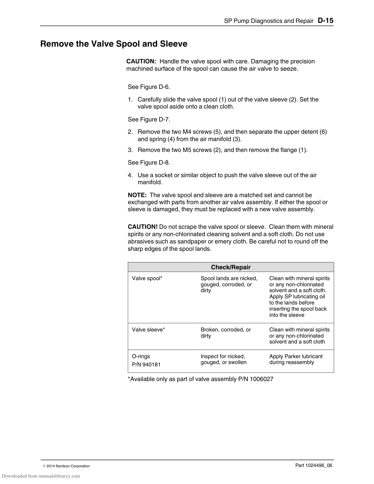
status area indicates Connected.
The Upgrade in Progress dialog box appears. The upgrade can take as long as 12 minutes. When the upgrade is complete, the Success dialog box appears and the melter restarts.
CAUTION! Once the uprade progress bar appears, do not interrupt the upgrade process for any reason. Interrupting the upgrade can corrupt the melter's firmware, which will require replacement of the IC chip (IC service kit P/N 1018817).
To restore pre‐upgrade melter settings, go to To restore pre‐upgrade melter settings on the next page.
To close the NCM, click Exit. To restore melter settings other than the settings that were in use by the melter before the upgrade, go to Saving and Restoring Melter Settings earlier in this guide.
############### To restore pre‐upgrade melter settings
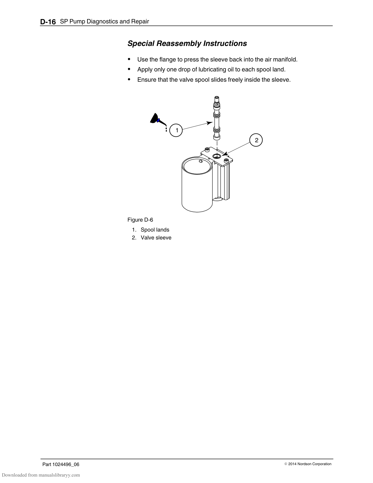
The PC and melter establish communications and a picture of the melter you selected appears in the device status area. The right side of the status area indicates “CONNECTED”.
The pre‐upgrade settings are restored and the melter returns to the scan mode.
#### Troubleshooting
Using Nordson Configuration Manager
|Symptom/Message|Action| |---|---| |After selecting a device and the COM port, an Access Denied message appears.|PC-to-Blue communications may be running or another application may be using the COM port. Close Internet Explorer and end the communications connection (if prompted). Close all other applications.| |Melter in UPLOAd mode, the update process has not been initiated, and you want to stop and exit the UPLOAd mode, but you cannot get the melter out of UPLOAd.|Cycle power to the melter at the local power disconnect switch. CAUTION: Ensure that the firmware update process is not running before taking power off of the melter.| |UPLOAd does not appear on the melter’s display when you press the Setup and left display scroll keys.|You must cycle the control switch while holding the Setup and left display scroll keys.| |Attempted a firmware update, but the melter display still indicates UPLOAd.
OR Attempted a firmware update, but the PC has stopped responding or was interrupted during the update process.|Using the local power disconnect switch, cycle power to the melter, and then re-attempt the update.
If the update is unsuccessful or the melter will not reboot, the central processor chip may be corrupted. Replace the CPU board.|
Appendix D SP Pump Diagnostics and Repair
WARNING! Allow only personnel with appropriate training and experience to operate or service the equipment. The use of untrained or inexperienced personnel to operate or service the equipment can result in injury, including death, to themselves and others, and damage to the equipment.
#### Introduction
This appendix provides comprehensive diagnostic and repair information for the SP pump used in all ProBlue adhesive melters. Before using the information provided in this appendix to diagnose or repair your pump, ensure that you have eliminated all conditions that might otherwise be mistaken for a failure of the pump. Refer to Section 6, Troubleshooting.
NOTE: The procedures and illustrations in this section are specific to 15:1 pumps, but can be used for 6:1 pumps as well. Refer to the pump‐specific parts lists in Section 7, Parts, when performing the procedures in this section.
#### Pump Function
The pump is double‐acting—material is discharged from the pump during both the upward and downward stroke of the piston.
The pump consists of an air section and a hydraulic section. Air is supplied to the pump through an air filter and a regulator. From the regulator, air flows to an air valve inside the air section. The air valve directs air into either the upper or lower portion of the air cylinder, which forces the piston assembly up or down. The lower end of the piston assembly contains a pressure ball valve. At the bottom of the hydraulic section is a siphon ball valve.
#### Pump Function (contd)
When the air valve directs the stroke of the piston upwards, the piston creates suction within the pump body, which opens the siphon ball valve and closes the pressure ball valve. As the piston moves upwards, material is simultaneously drawn into the pump below the pressure ball valve and forced out of the pump chamber above the pressure ball valve. Material leaving the pump chamber passes through a filter and then into a manifold, where it is distributed to the hoses/guns.
Attached to the piston assembly is a shifter fork. The fork travels along the shaft of the actuator assembly that has a magnet at both ends. When the stroke of the piston carries the shifter fork upwards, a magnet in the shifter fork attracts the magnet at the end of the actuator, which shifts the position of the air valve. When the valve shifts, air is redirected to the opposite side of the air cylinder, which forces the piston downwards.
On the piston downward stroke, material pressure below the piston closes the siphon ball valve and opens the pressure ball valve. As the piston moves downwards, material below the pressure ball valve is displaced, and forced through the pressure ball valve and out of the pump chamber, where again, it passes through the filter and into the manifold.
########### Pump Isolation Valve
To prevent siphoning of the tank when the pump is removed from the manifold, the manifold is equipped with an isolation valve.
########### Pressure Discharge Valve
The manifold is equipped with a pressure discharge valve. When the pump is switched off at the control panel, air is removed from the top of the valve causing it to open. When the valve opens, pressurized material within the pump and manifold is bypassed through the pressure discharge valve back to the tank.
################ This page intentionally left blank.
#### Pump Diagnostics
To determine why the pump has failed, you will, in most cases, have to partially or fully disassemble the pump. To assist you in determining the appropriate level of disassembly, Table D‐1 provides a logical breakdown of the three types of pump failures, the potential conditions that could produce each failure, and the disassembly procedure(s) in which potential condition(s) can be examined.
Disassembly procedures are provided in Pump Disassembly and Reassembly.
################ Table D‐1 Pump Diagnostics
|Problem|Possible Cause|Corrective Action| |---|---|---| |1. Pump not Stroking|Air valve dirty or damaged Valve sleeve O‐rings damaged or deteriorated
Air leaking from between the cylinder head and the air cylinder or between the air cylinder and the pump frame
Piston cups damaged
Shifter fork damaged, slipped out of position on piston, installed upside down, or magnets loose
Magnets on actuator assembly loose
Piston damaged or has char buildup
|Remove the Valve Spool and Sleeve Remove the Valve Spool and Sleeve
Remove The Actuator and the Air Cylinder Assembly
Remove the Piston Cups
Removing the Shifter Fork
Remove the Magnetic Actuator Assembly
Remove the Lower Ball Seat Assembly and the Piston| |2. Pump Leaking Adhesive
|O‐ring and/or pump seal deteriorated or damaged
O‐rings on cross‐over tubes or between the pump and manifold damaged or deteriorated
|Remove the Pump O‐ring and the Pump Seal
Removing the Pump from the Melter| |3. Pump Strokes Erratically
|Siphon ball, seat and/or cage is damaged, deteriorated, or has char buildup
Pressure ball and/or seat has char buildup or is scratched or pitted
Piston has char buildup
Pump body dirty
|Disassemble the Lower Ball Seat and Pressure Ball Assemblies
Disassemble the Lower Ball Seat and Pressure Ball Assemblies
Remove the Lower Ball Seat Assembly and the Piston
Remove the Lower Ball Seat Assembly and the Piston
|
#### Pump Disassembly and Reassembly
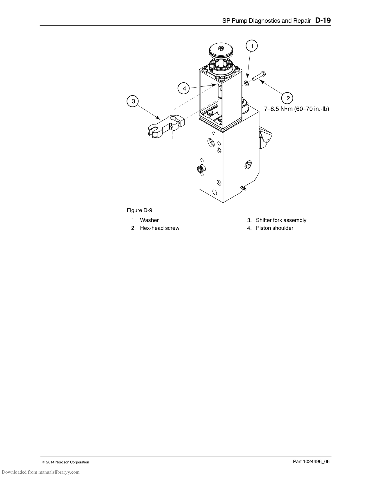
This part provides sequential pump disassembly procedures. Unless otherwise noted in the Special Reassembly Instructions, which are provided in each procedure, reassembly of the pump is the reverse of the disassembly.
Within each disassembly procedure, is a check/repair table that describes what specific conditions (from Table D‐1) to inspect for while disassembling the pump, service details, and component part numbers.
######## Melter Preparation
The melter must be brought up to operating temperature before the pump can be removed and disassembled. Once the pump is removed, the molten material within the pump will remain workable only for a short period of time. If necessary, use a heat gun to warm the pump assembly during disassembly.
######## Required Tools and Materials
Tools Heat gun 4‐mm hex wrench 5‐mm hex wrench 6‐mm hex wrench 1/8‐in. steel rod or equivalent tool 8 mm open‐end wrench 10 mm socket and ratchet Bench vise or suitable mount to hold the pump during repairs Suitable vessel to heat Type‐R fluid
WARNING! Do not heat Type R fluid with an open flame or in an unregulated heating device. Do not heat Type R fluid above 246 C (475 F).
########### Service Parts
In most cases, you will need the pump service kit P/N 1028304 to complete pump repairs. This kit contains all of the seals, O‐rings, and other parts that are necessary to service the pump. Refer to the pump‐specific parts lists in Section 7, Parts, for a complete listing of pump‐related parts.
########### Supplies
The following table described the lubricants and other compounds that are required during the re‐assembly of the pump. Lubricants and other compounds are indicated in the illustrations by the symbols shown in Table D‐2.
Table D‐2 Lubricants and Compounds
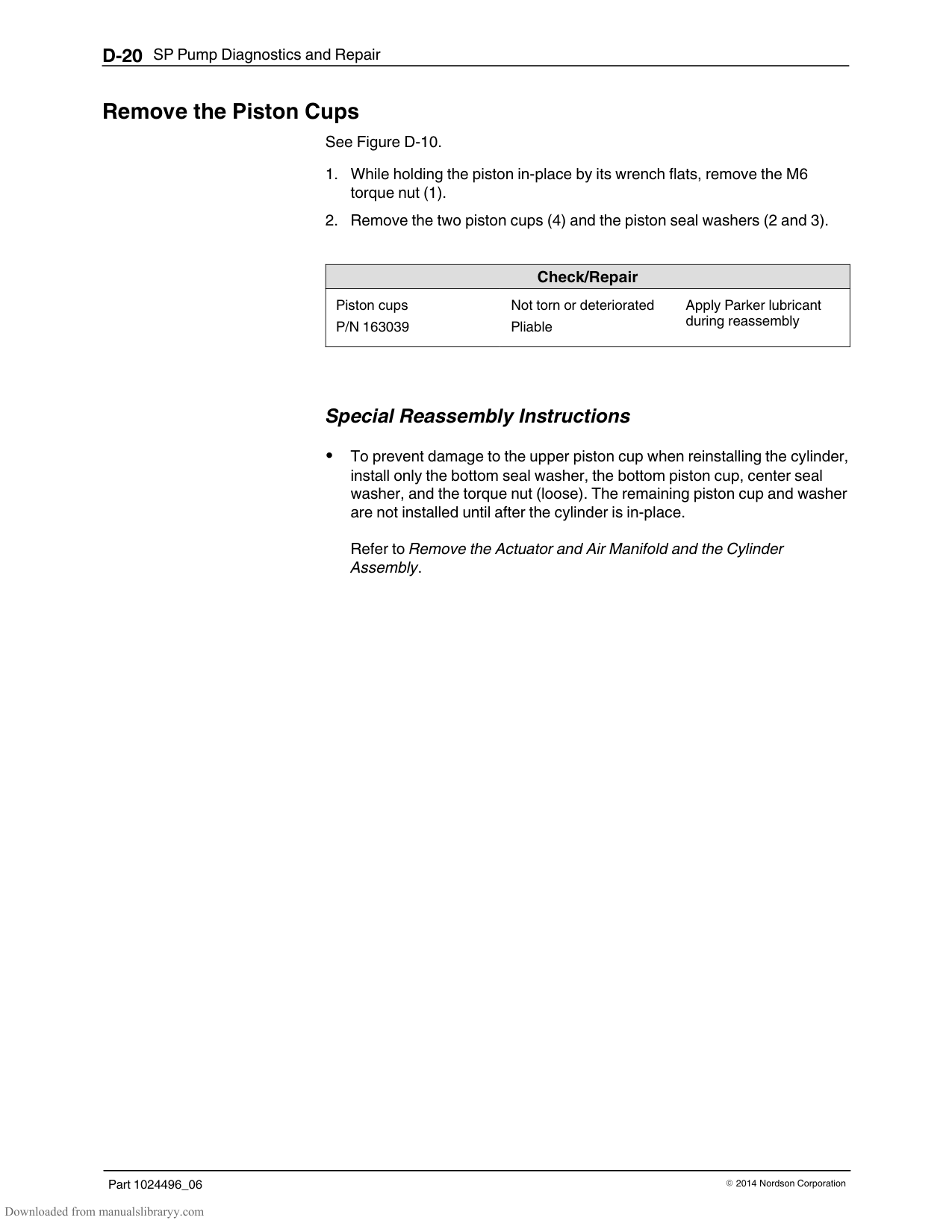
|Description|Part Number|Symbol| |---|---|---| |Never‐Seez|900344| | |Parker Hi‐Temp Lubricant|1029063| | |Loctite 272 Threadlocking Adhesive|900470| | |SP Lubricating Oil|211228| | |Type‐R Fluid (1 gal)|270755|--|
######## Remove the Pump from the Melter
See Figure D‐1.
NOTE: The face of the pump body contains two M6 threaded holes. Bolts can be threaded into these holes to gain leverage when removing the pump.
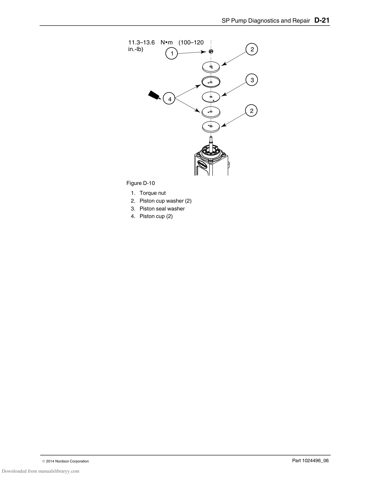
|Check/Repair| |---| |Pump‐to‐manifold O‐rings
P/N 1019515 P/N 942111
Cross‐over tube O‐rings P/N 940133 (2) PTFE back‐up ring P/N 954013
Inspect for nicks, gouging, or swelling
Inspect for nicks, gouging, or swelling
Apply Parker lubricant during reassembly
Apply Parker lubricant during reassembly
|
########### Special Reassembly Instructions
Before reinstalling the pump, lubricate the O‐rings on the cross‐over tubes and the two O‐rings between the pump and the manifold.
################## Figure D-1 Removing the pump
######## Remove the Actuator and Air Manifold and the Cylinder Assembly
See Figure D‐2.
(3), and then separate the cylinder head from the cylinder (4).
|Check/Repair| |---|
|O‐rings P/N 940332
Inspect for nicks, gouging, or swelling
Apply Parker lubricant during reassembly
|
########### Special Reassembly Instructions
Slide the cylinder over the half of the piston cup assembly (Which was installed as described in Removing the Piston Cup Assembly, Special Reassembly Instructions); and then remove the torque nut, assemble the
remaining piston cup (cupped side facing up) and seal washer, and then replace the torque nut.
Before rotating the cylinder/can assembly onto the shifter fork, center the fork inside the pump frame.
1
5–6 Nm (45–55 in.‐lb)
2
3
4
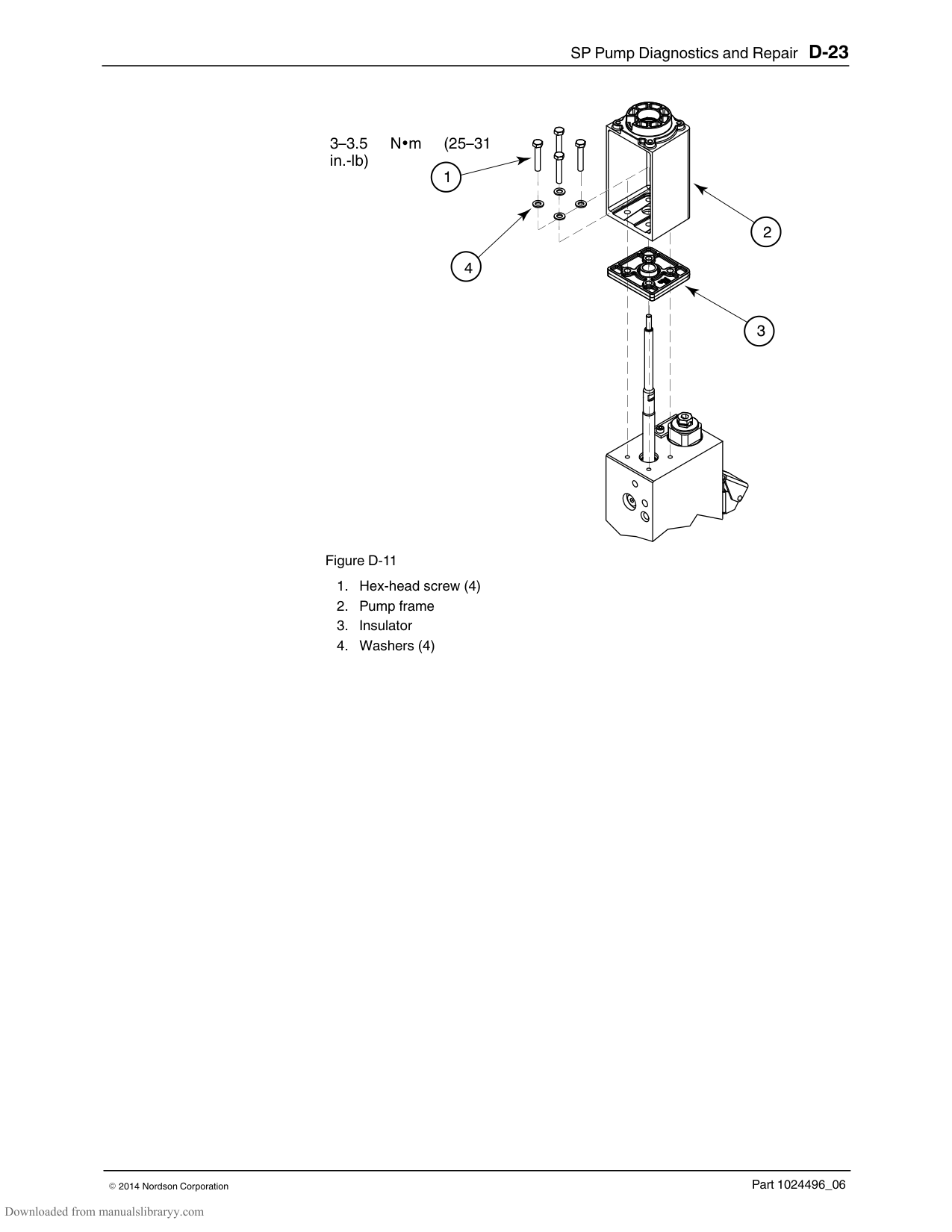
5
6
######## Remove the Magnetic Actuator Assembly
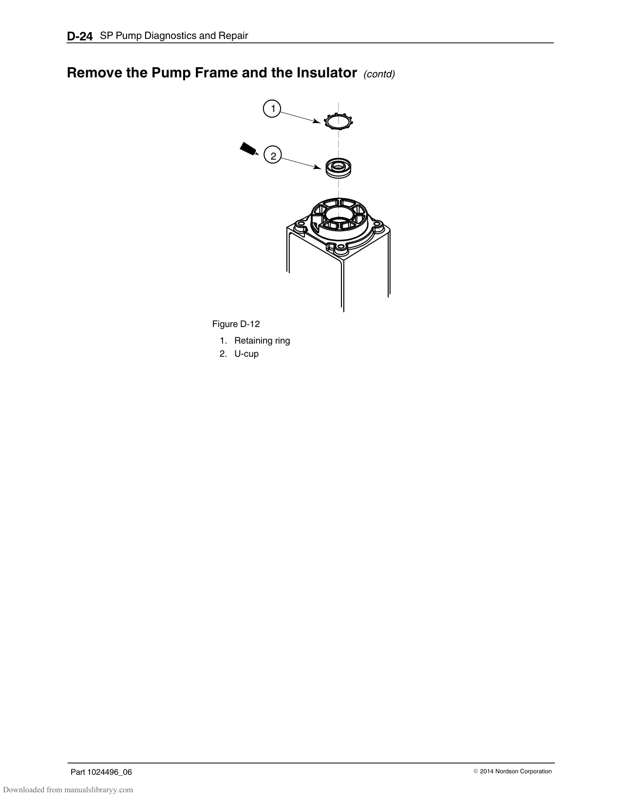
See Figure D‐4.
(2). See Figure D‐5.
|Check/Repair| |---| |Magnetic Actuator P/N 164606
Magnets are secured to the actuator shaft, undamaged, and free of debris
Clean, tighten the magnets, or replace as needed
| |Bumper assembly P/N 1014650
Check for wear Replace if worn
|
1

3–4 Nm (28–36 in.‐lb)
3
4
9–11 Nm (81–99 in.‐lb)
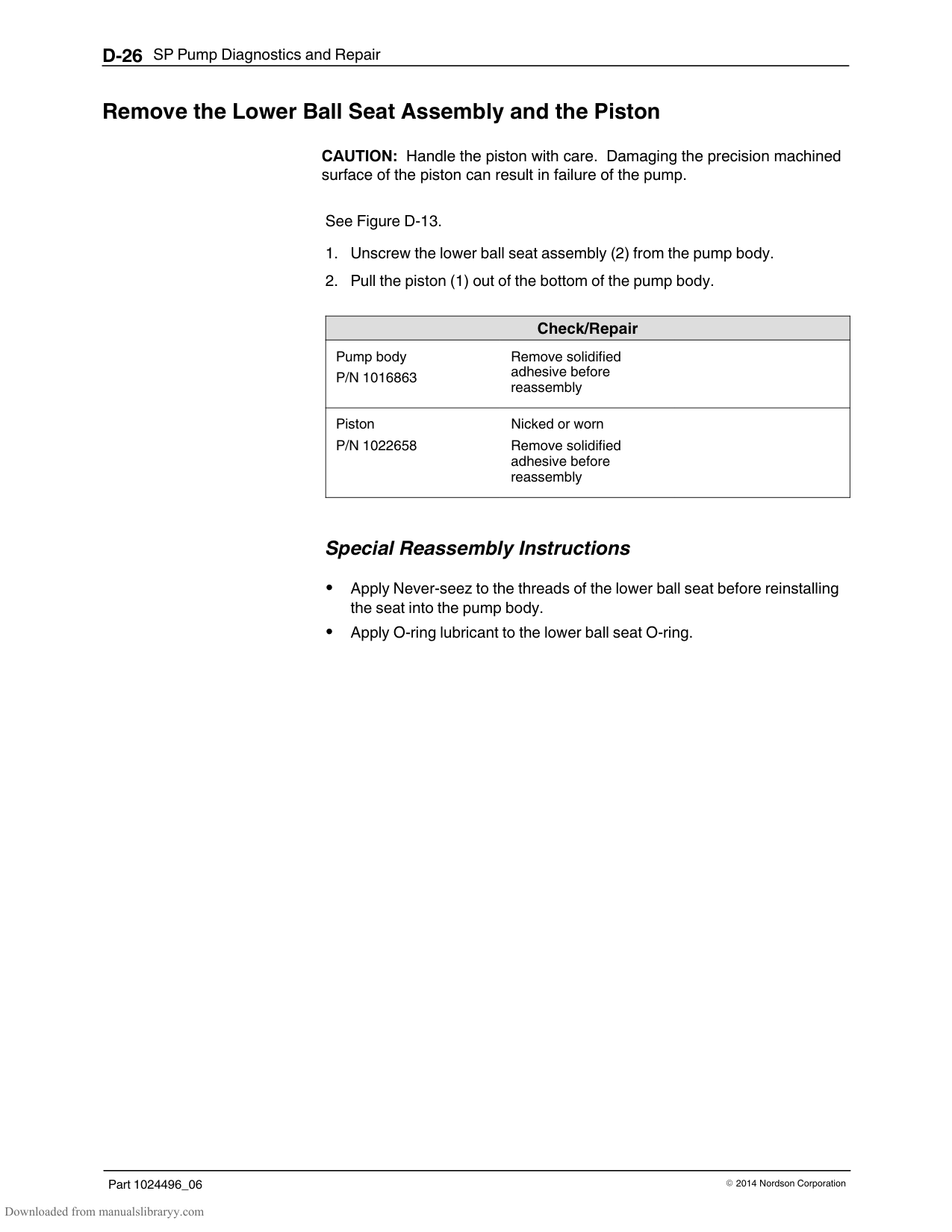
######## Remove the Magnetic Actuator Assembly (contd)
1
9–11 Nm (81–99 in.‐lb)
2
Figure D-5
######## Remove the Valve Spool and Sleeve
CAUTION: Handle the valve spool with care. Damaging the precision machined surface of the spool can cause the air valve to seeze.
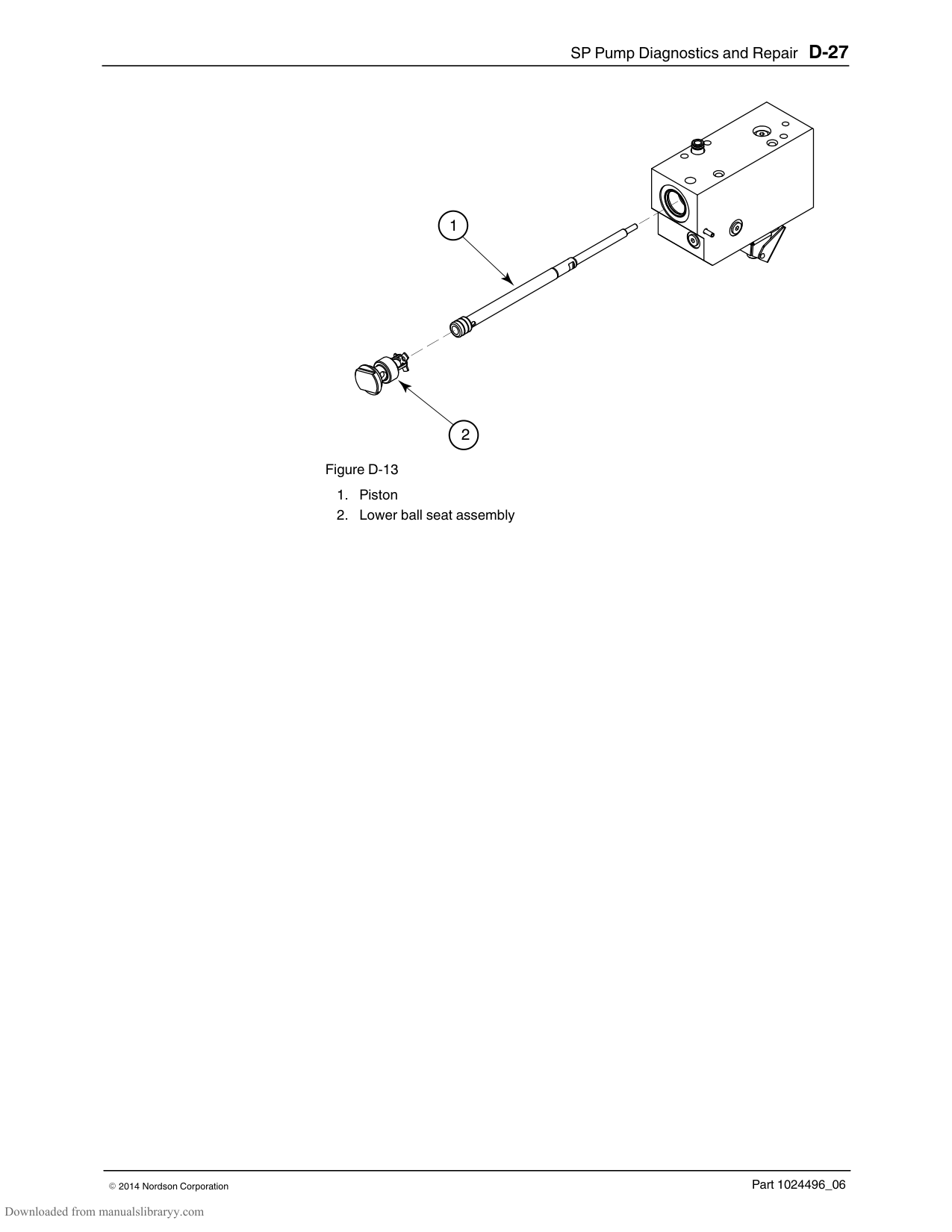
See Figure D‐7.
See Figure D‐8.
NOTE: The valve spool and sleeve are a matched set and cannot be exchanged with parts from another air valve assembly. If either the spool or sleeve is damaged, they must be replaced with a new valve assembly.
CAUTION! Do not scrape the valve spool or sleeve. Clean them with mineral spirits or any non‐chlorinated cleaning solvent and a soft cloth. Do not use abrasives such as sandpaper or emery cloth. Be careful not to round off the sharp edges of the spool lands.
|Check/Repair| |---| |Valve spool* Spool lands are nicked, gouged, corroded, or dirty
Clean with mineral spirits or any non‐chlorinated solvent and a soft cloth. Apply SP lubricating oil to the lands before inserting the spool back into the sleeve
| |Valve sleeve* Broken, corroded, or dirty
Clean with mineral spirits or any non‐chlorinated solvent and a soft cloth
| |O‐rings P/N 940181
Inspect for nicked, gouged, or swollen
Apply Parker lubricant during reassembly
|
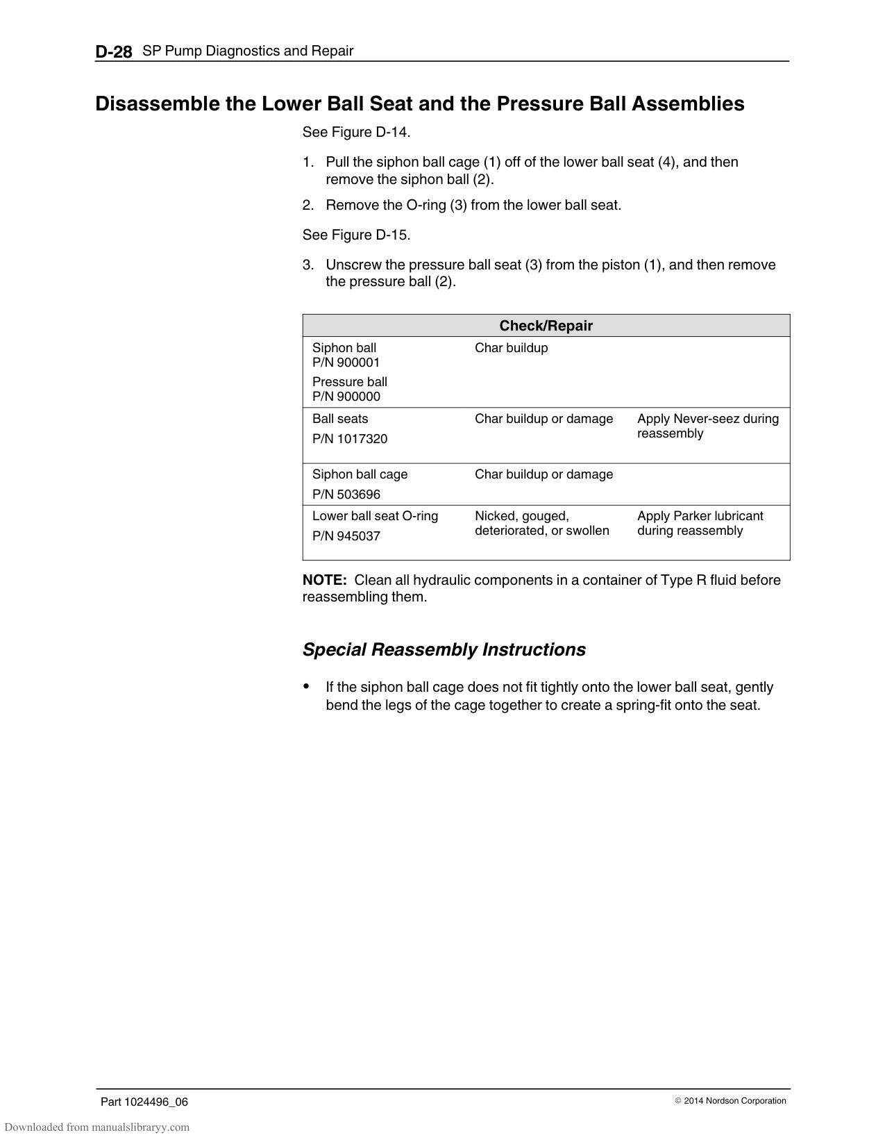
*Available only as part of valve assembly P/N 1006027
########### Special Reassembly Instructions
Use the flange to press the sleeve back into the air manifold. Apply only one drop of lubricating oil to each spool land. Ensure that the valve spool slides freely inside the sleeve.
1
2
2
3.2–4.1 Nm (28–36 in.‐lb)
1
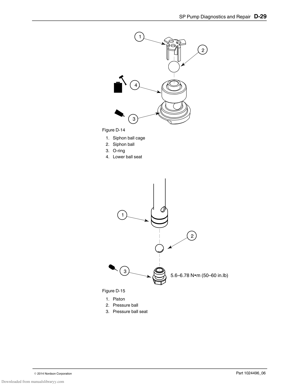
3
4
6
1.82–2.27 Nm (16–20 in. lb)
5
1
2
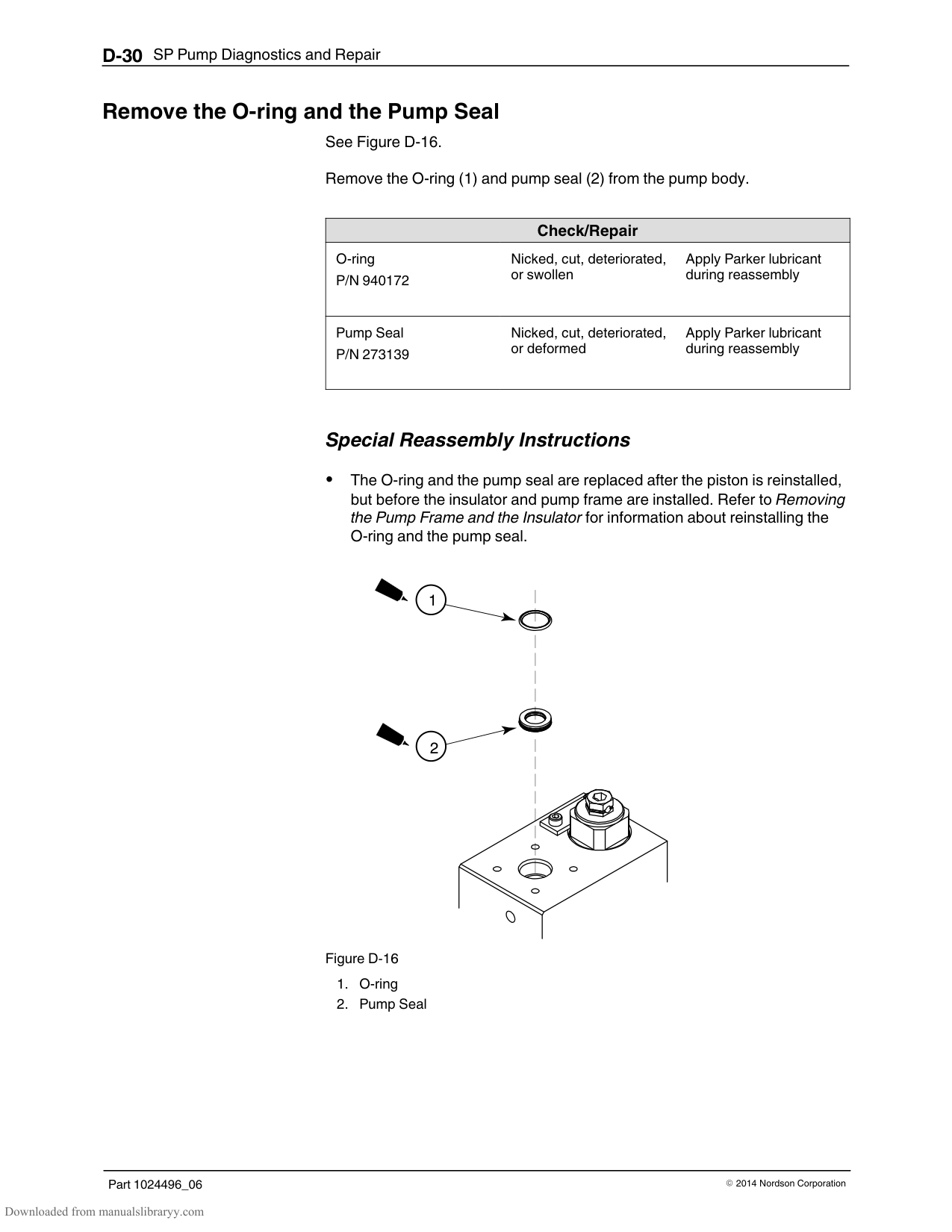
######## Remove the Shifter Fork
CAUTION! Handle the shifter fork with care. Dropping or otherwise mishandling the shifter fork may damage the magnet.
See Figure D‐9.
|Check/Repair| |---| |Shifter fork assembly P/N 166880
Word “UP” is facing upwards
Securely attached to piston
Resting on piston shoulder
Bent Magnets secure/undamaged
Replace fork if bent or magnet is damaged
|
########### Special Reassembly Instructions

The fork must be resting on the shoulder of the piston (See Figure D‐9, item 4).
The word “UP” must be facing the top of the pump frame.
1
4
23
7–8.5 Nm (60–70 in.‐lb)
Figure D-9
######## Remove the Piston Cups
See Figure D‐10.
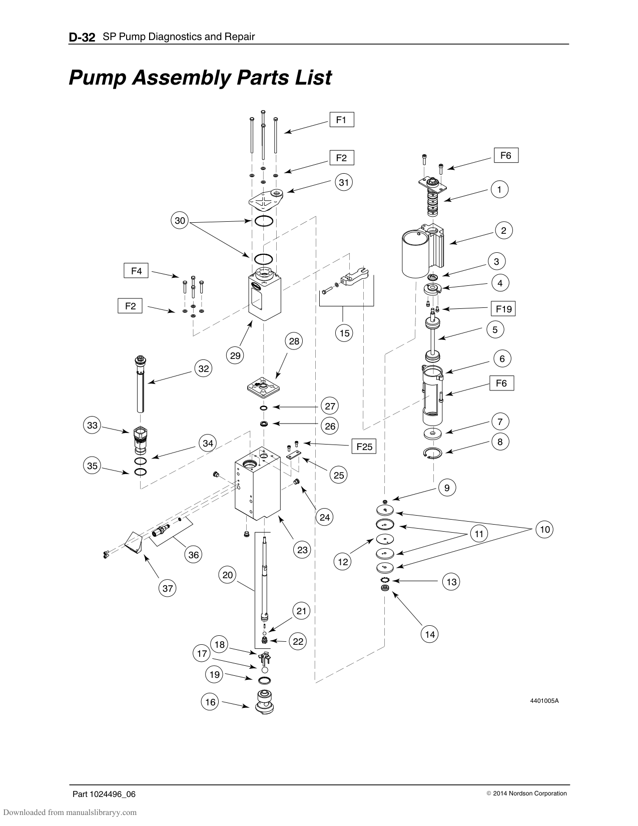
|Check/Repair| |---| |Piston cups P/N 163039
Not torn or deteriorated Pliable
Apply Parker lubricant during reassembly
|
########### Special Reassembly Instructions
To prevent damage to the upper piston cup when reinstalling the cylinder, install only the bottom seal washer, the bottom piston cup, center seal washer, and the torque nut (loose). The remaining piston cup and washer are not installed until after the cylinder is in‐place.
Refer to Remove the Actuator and Air Manifold and the Cylinder Assembly.
11.3–13.6 Nm (100–120 in.‐lb)
1
4
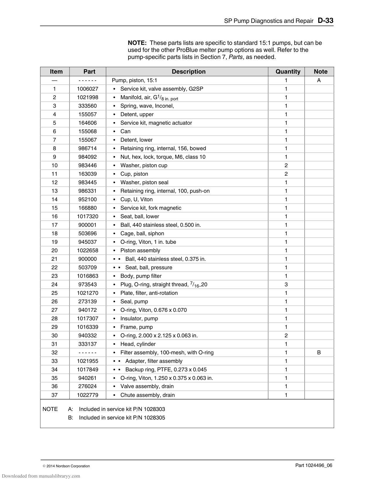
2
Figure D-10
######## Remove the Pump Frame and the Insulator
See Figure D‐12.
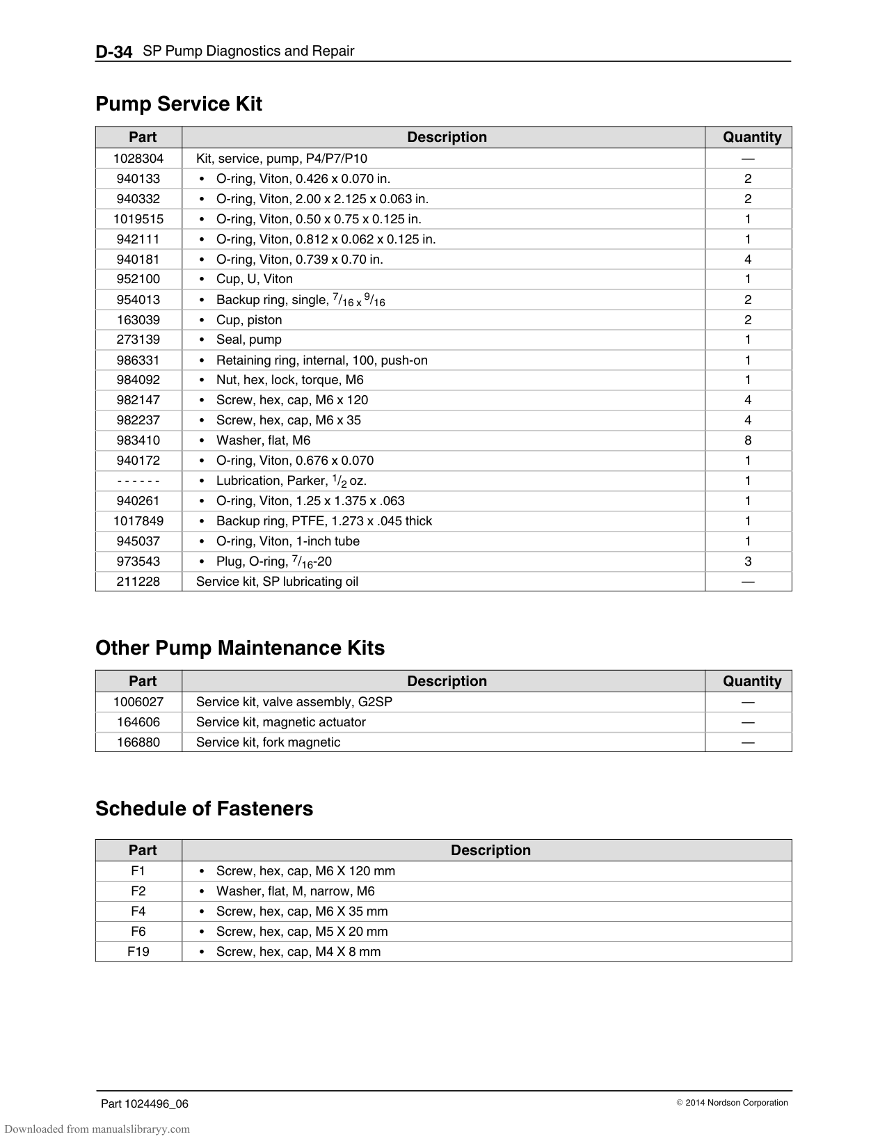
|Check/Repair| |---| |Pump insulator P/N 1017307
Cracked or warped
| |U‐cup piston seal P/N 952100
Nicked, cut, or deteriorated
Apply Parker lubricant during reassembly
|
########### Special Reassembly Instructions
Before reinstalling the insulator and pump frame, place the O‐ring and piston seal over the piston.
NOTE: Install the pump seal with the open side facing the pump body. Install the insulator with the words “This side up” facing upwards. Use the insulator to seat the O‐ring and pump seal into the groove in the pump body. The tapered end of the insulator and pump frame face the filter.
3–3.5 Nm (25–31 in.‐lb)
1
4
Figure D-11
######## Remove the Pump Frame and the Insulator (contd)
Figure D-12
################ This page intentionally left blank.
######## Remove the Lower Ball Seat Assembly and the Piston
CAUTION: Handle the piston with care. Damaging the precision machined surface of the piston can result in failure of the pump.
See Figure D‐13.
|Check/Repair| |---| |Pump body P/N 1016863
Remove solidified adhesive before reassembly
| |Piston P/N 1022658
Nicked or worn Remove solidified adhesive before reassembly
|
########### Special Reassembly Instructions
Apply Never‐seez to the threads of the lower ball seat before reinstalling the seat into the pump body.
Apply O‐ring lubricant to the lower ball seat O‐ring.
Figure D-13 1. Piston
######## Disassemble the Lower Ball Seat and the Pressure Ball Assemblies
|Check/Repair| |---| |Siphon ball P/N 900001
Pressure ball P/N 900000
Char buildup
| |Ball seats P/N 1017320
Char buildup or damage Apply Never‐seez during
reassembly
| |Siphon ball cage P/N 503696
Char buildup or damage
| |Lower ball seat O‐ring P/N 945037
Nicked, gouged, deteriorated, or swollen
Apply Parker lubricant during reassembly
|
NOTE: Clean all hydraulic components in a container of Type R fluid before reassembling them.
########### Special Reassembly Instructions
If the siphon ball cage does not fit tightly onto the lower ball seat, gently bend the legs of the cage together to create a spring‐fit onto the seat.
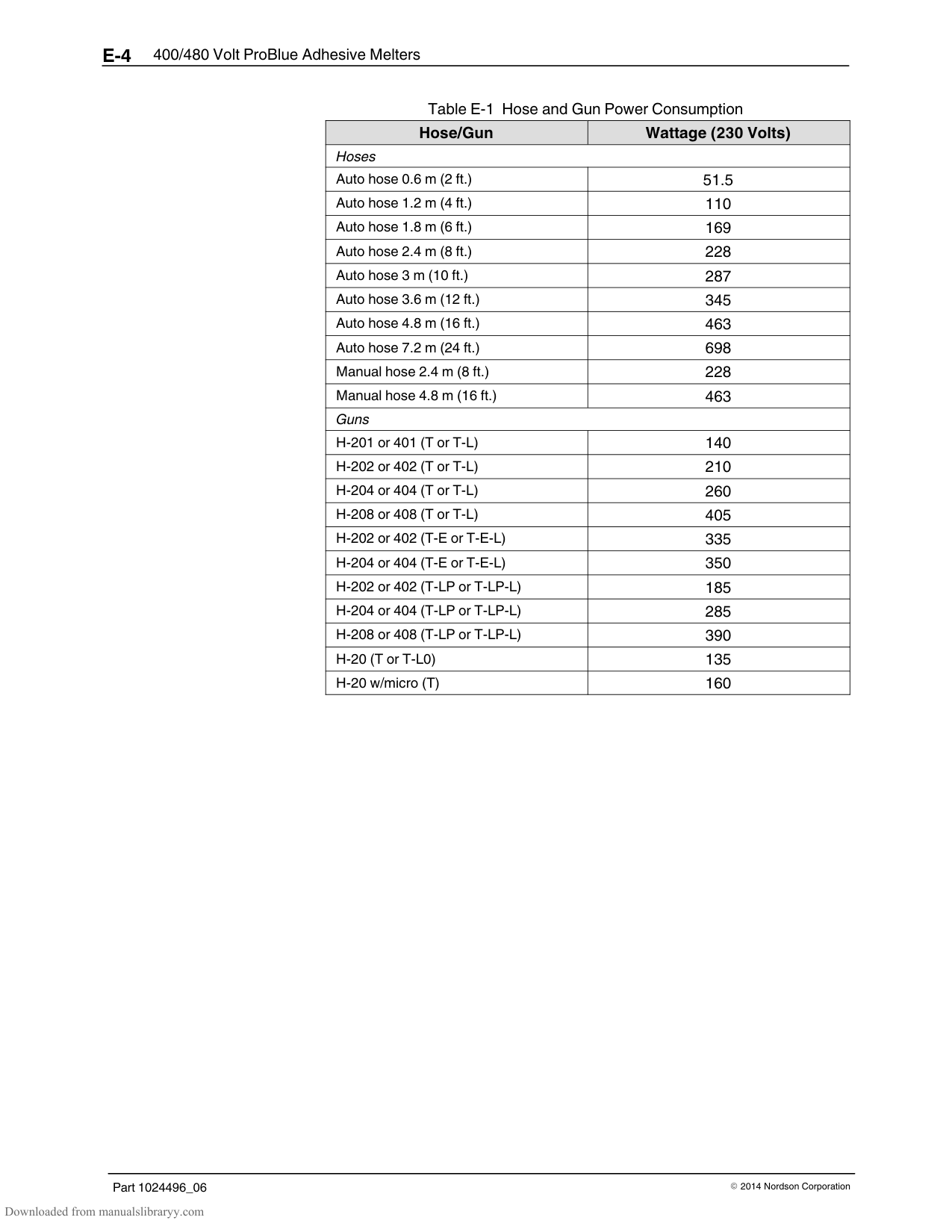
1
2
1
2
3
5.6–6.78 Nm (50–60 in.lb)
Remove the O‐ring and the Pump Seal See Figure D‐16. Remove the O‐ring (1) and pump seal (2) from the pump body.
|Check/Repair| |---| |O‐ring P/N 940172
Nicked, cut, deteriorated, or swollen
Apply Parker lubricant during reassembly
| |Pump Seal P/N 273139
Nicked, cut, deteriorated, or deformed
Apply Parker lubricant during reassembly
|
########### Special Reassembly Instructions
The O‐ring and the pump seal are replaced after the piston is reinstalled, but before the insulator and pump frame are installed. Refer to Removing the Pump Frame and the Insulator for information about reinstalling the O‐ring and the pump seal.
Figure D-16
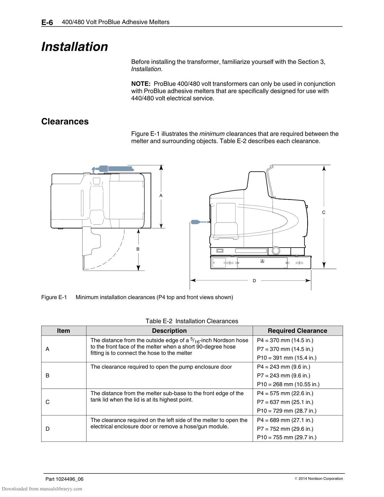
################ This page intentionally left blank.
#### Pump Assembly Parts List
|F1| |---|
33
35
30
|F4| |---|
|F2| |---|
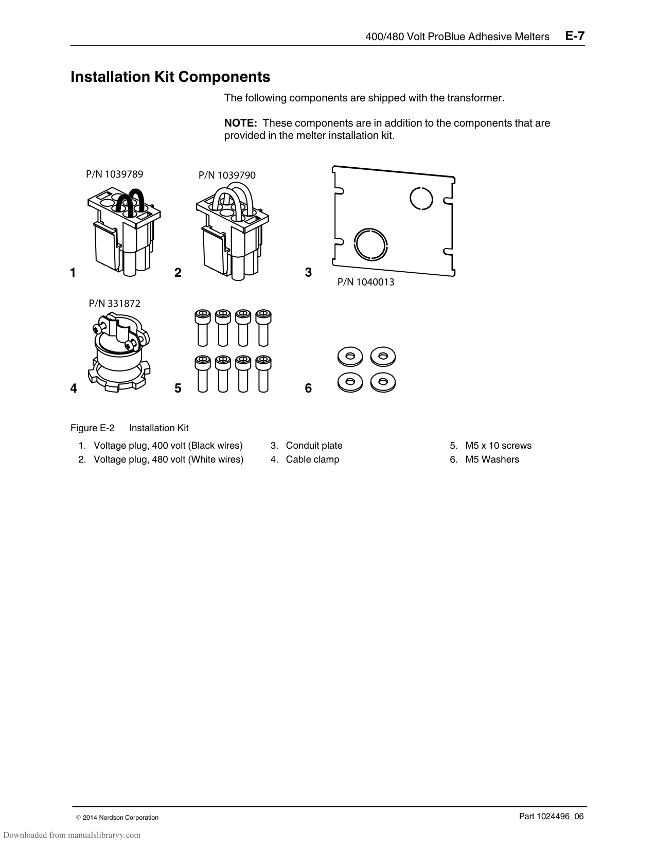
32
29
34
|F2| |---|
31
28
15
27 26
|F25| |---|
|F6|
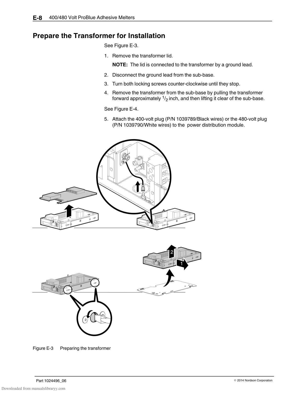
|---|
|F19| |---|
|F6|
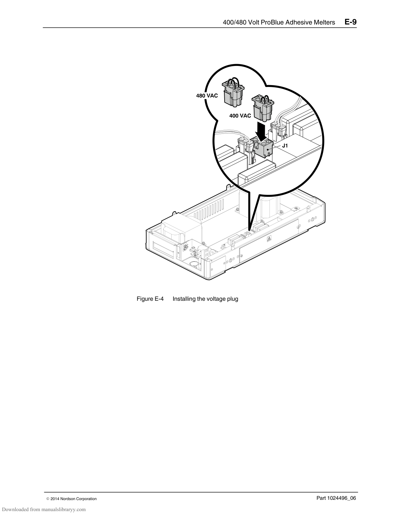
|---|
25
9
24
37
36
20
23
12
13
21
14 18
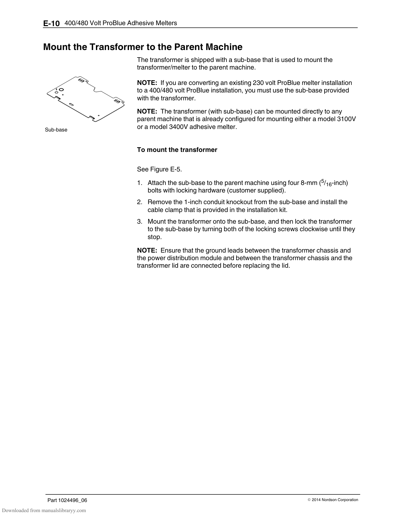
22
19
11
10
4401005A
################ NOTE: These parts lists are specific to standard 15:1 pumps, but can be used for the other ProBlue melter pump options as well. Refer to the pump‐specific parts lists in Section 7, Parts, as needed.
|Item|Part|Description|Quantity|Note| |---|---|---|---|---| |—|‐ ‐ ‐ ‐ ‐ ‐|Pump, piston, 15:1|1|A| |1|1006027|Service kit, valve assembly, G2SP|1| | |2|1021998|Manifold, air, G1/8 in. port|1| | |3|333560|Spring, wave, Inconel,|1| | |4|155057|Detent, upper|1| | |5|164606|Service kit, magnetic actuator|1| |
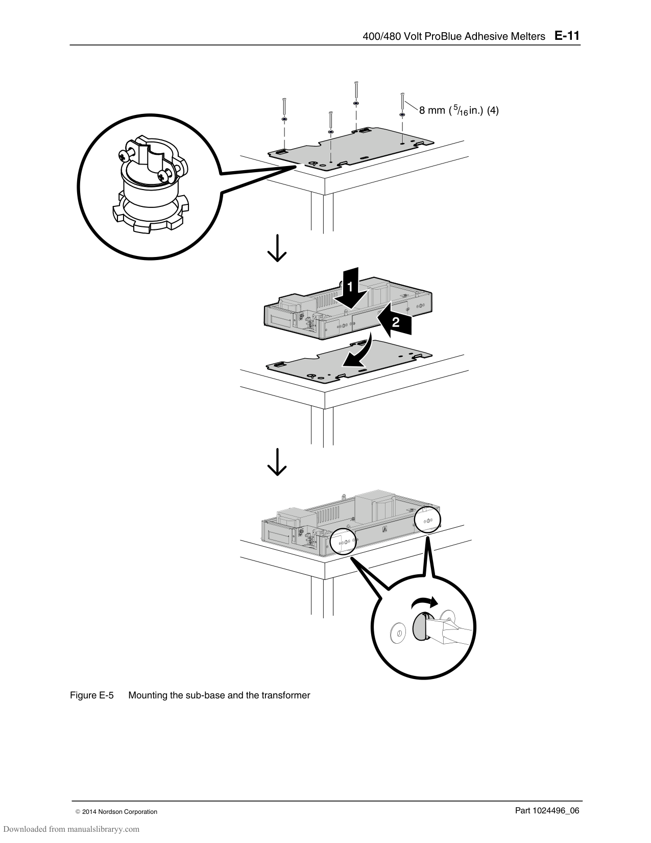
|6|155068|Can|1| | |7|155067|Detent, lower|1| | |8|986714|Retaining ring, internal, 156, bowed|1| | |9|984092|Nut, hex, lock, torque, M6, class 10|1| | |10|983446|Washer, piston cup|2| | |11|163039|Cup, piston|2| | |12|983445|Washer, piston seal|1| | |13|986331|Retaining ring, internal, 100, push‐on|1| | |14|952100|Cup, U, Viton|1| | |15|166880|Service kit, fork magnetic|1| | |16|1017320|Seat, ball, lower|1| | |17|900001|Ball, 440 stainless steel, 0.500 in.|1| | |18|503696|Cage, ball, siphon|1| | |19|945037|O‐ring, Viton, 1 in. tube|1| | |20|1022658|Piston assembly|1| | |21|900000|Ball, 440 stainless steel, 0.375 in.|1| | |22|503709|Seat, ball, pressure|1| | |23|1016863|Body, pump filter|1| | |24|973543|Plug, O‐ring, straight thread, 7/16–20|3| | |25|1021270|Plate, filter, anti‐rotation|1| | |26|273139|Seal, pump|1| | |27|940172|O‐ring, Viton, 0.676 x 0.070|1| | |28|1017307|Insulator, pump|1| | |29|1016339|Frame, pump|1| | |30|940332|O‐ring, 2.000 x 2.125 x 0.063 in.|2| |
|31|333137|Head, cylinder|1| | |32|‐ ‐ ‐ ‐ ‐ ‐|Filter assembly, 100‐mesh, with O‐ring|1|B| |33|1021955|Adapter, filter assembly|1| | |34|1017849|Backup ring, PTFE, 0.273 x 0.045|1| | |35|940261|O‐ring, Viton, 1.250 x 0.375 x 0.063 in.|1| | |36|276024|Valve assembly, drain|1| | |37|1022779|Chute assembly, drain|1| | |NOTE A: Included in service kit P/N 1028303 B: Included in service kit P/N 1028305|NOTE A: Included in service kit P/N 1028303 B: Included in service kit P/N 1028305|NOTE A: Included in service kit P/N 1028303 B: Included in service kit P/N 1028305|NOTE A: Included in service kit P/N 1028303 B: Included in service kit P/N 1028305|NOTE A: Included in service kit P/N 1028303 B: Included in service kit P/N 1028305|
######## Pump Service Kit
|Part|Description|Quantity| |---|---|---| |1028304|Kit, service, pump, P4/P7/P10|—| |940133|O‐ring, Viton, 0.426 x 0.070 in.|2| |940332|O‐ring, Viton, 2.00 x 2.125 x 0.063 in.|2| |1019515|O‐ring, Viton, 0.50 x 0.75 x 0.125 in.|1| |942111|O‐ring, Viton, 0.812 x 0.062 x 0.125 in.|1| |940181|O‐ring, Viton, 0.739 x 0.70 in.|4| |952100|Cup, U, Viton|1| |954013|Backup ring, single, 7/16 x 9/16|2| |163039|Cup, piston|2| |273139|Seal, pump|1| |986331|Retaining ring, internal, 100, push‐on|1|
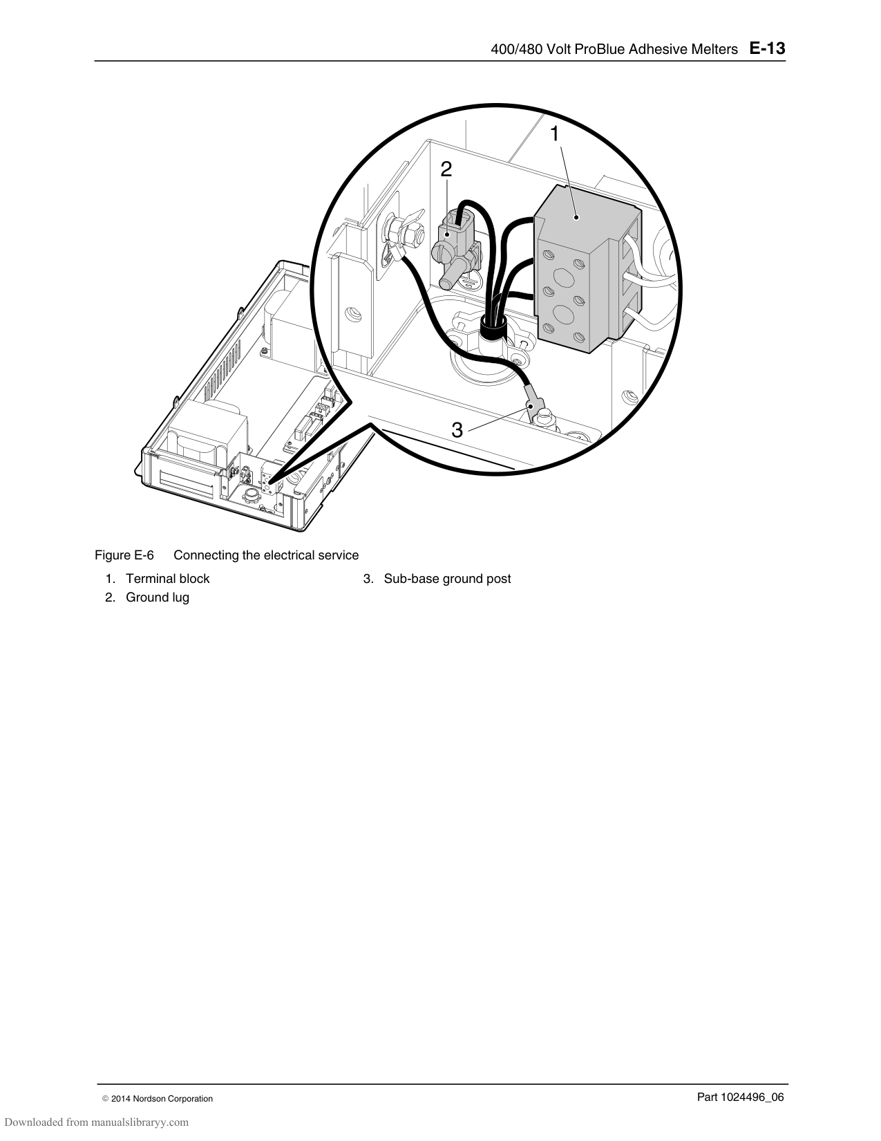
|984092|Nut, hex, lock, torque, M6|1| |982147|Screw, hex, cap, M6 x 120|4| |982237|Screw, hex, cap, M6 x 35|4| |983410|Washer, flat, M6|8| |940172|O‐ring, Viton, 0.676 x 0.070|1| |‐ ‐ ‐ ‐ ‐ ‐|Lubrication, Parker, 1/2 oz.|1| |940261|O‐ring, Viton, 1.25 x 1.375 x .063|1| |1017849|Backup ring, PTFE, 1.273 x .045 thick|1| |945037|O‐ring, Viton, 1‐inch tube|1| |973543|Plug, O‐ring, 7/16‐20|3| |211228|Service kit, SP lubricating oil|—|
######## Other Pump Maintenance Kits
|Part|Description|Quantity| |---|---|---| |1006027|Service kit, valve assembly, G2SP|—| |164606|Service kit, magnetic actuator|—| |166880|Service kit, fork magnetic|—|
######## Schedule of Fasteners
|Part|Description|
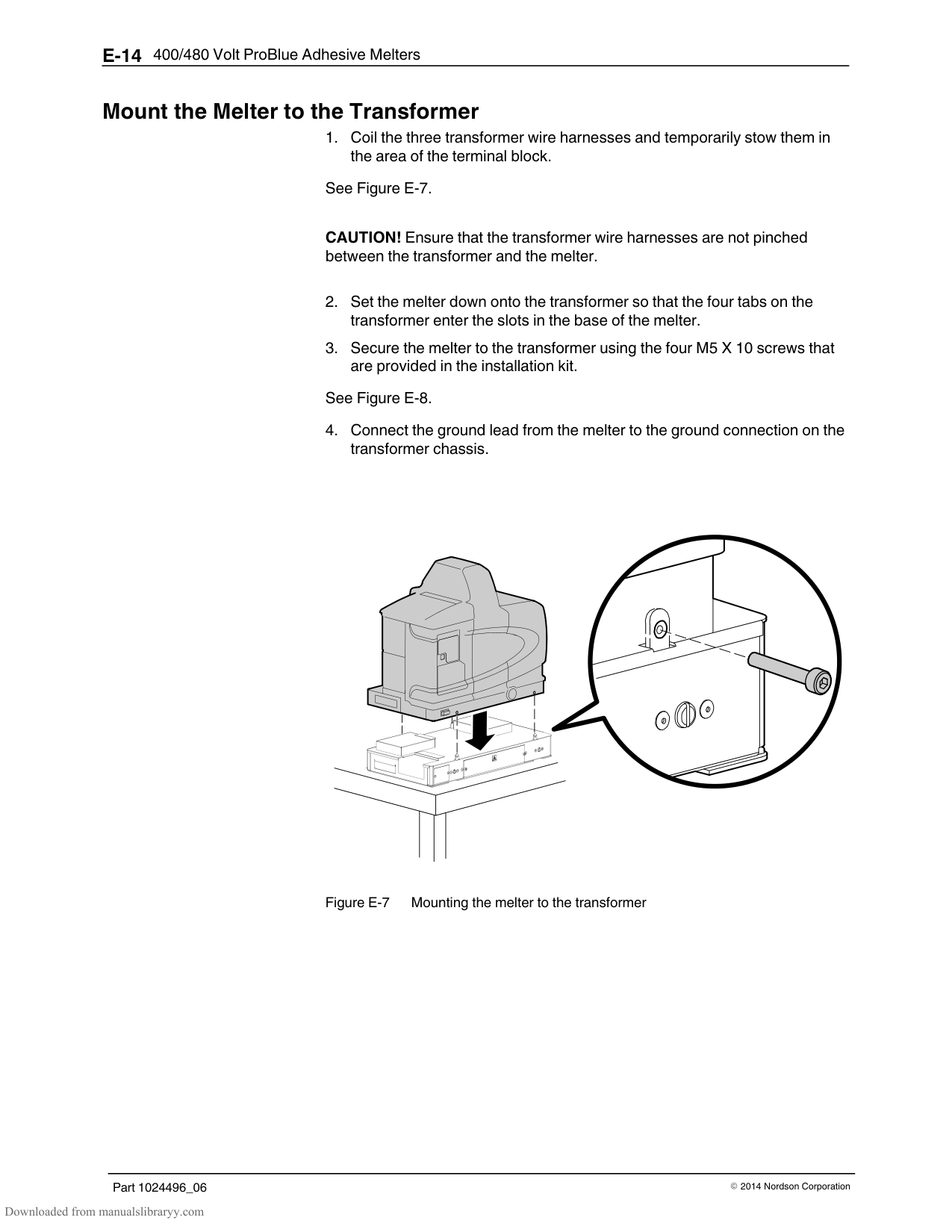
|---|---| |F1|Screw, hex, cap, M6 X 120 mm| |F2|Washer, flat, M, narrow, M6| |F4|Screw, hex, cap, M6 X 35 mm| |F6|Screw, hex, cap, M5 X 20 mm| |F19|Screw, hex, cap, M4 X 8 mm|
Appendix E 400/480 Volt ProBlue Adhesive Melters
WARNING! Allow only personnel with appropriate training and experience to operate or service the equipment. The use of untrained or inexperienced personnel to operate or service the equipment can result in injury, including death, to themselves and others, and damage to the equipment.
This appendix provides information about the 400/480 volt versions of the ProBlue adhesive melter. Key information provided in this appendix, which does not appear in the body of this manual, includes:
Installation instructions that are specific to the 400/480 volt melters and transformers
Transformer sizing guidance Transformer troubleshooting Parts and service kits that are specific to the 400/480 volt melters and transformers
For setup, operation, troubleshooting, and parts information that is common to all ProBlue adhesive melters, refer to the appropriate section of this manual.
#### Introduction
######## Safety
Before installing or operating the transformer or melter, read the safety information provided in Section 1, Safety.
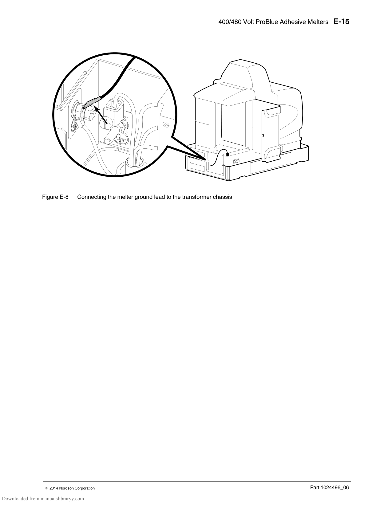
######## Intended Use
######## Unintended Use
The 1.5 kVA and 3.0 kVA transformers can only be used with ProBlue adhesive melters that are specifically designed for 400/480 volt electrical service.
Use an input electrical service rated at 400 volts 3‐phase without a neutral or 480 volts 3‐phase without a neutral.
Water wash‐down environments Explosive atmospheres
######## Transformer Sizing
Review the following transformer sizing procedure to ensure that your transformer is correctly sized for the number and type of hoses/guns you intend to use.
############### To size your transformer
############### Example
From Table E‐1, an application requires two 1.8 m Auto hoses at 155 watts each and two H‐402 (T‐LP) guns at 185 watts each.
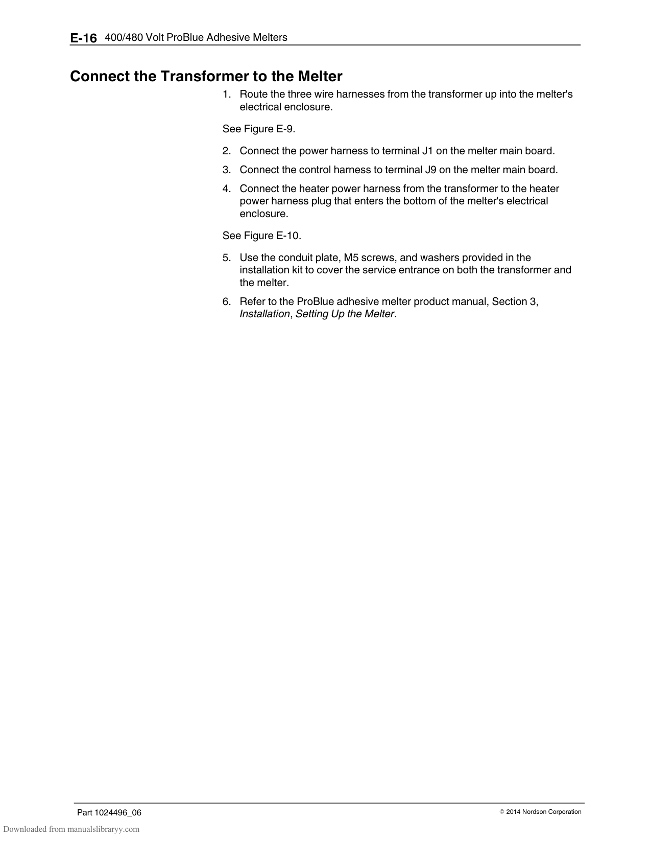
The combined wattage of the selected hoses and guns is 680 watts. 680 1000 = 0.68 kVA In this example, the 1.5 kVA transformer would be adequate.
################ Table E‐1 Hose and Gun Power Consumption
|Hose/Gun|Wattage (230 Volts)| |---|---| |Hoses|Hoses| |Auto hose 0.6 m (2 ft.)|51.5| |Auto hose 1.2 m (4 ft.)|110| |Auto hose 1.8 m (6 ft.)|169| |Auto hose 2.4 m (8 ft.)|228| |Auto hose 3 m (10 ft.)|287| |Auto hose 3.6 m (12 ft.)|345| |Auto hose 4.8 m (16 ft.)|463| |Auto hose 7.2 m (24 ft.)|698| |Manual hose 2.4 m (8 ft.)|228| |Manual hose 4.8 m (16 ft.)|463| |Guns|Guns| |H‐201 or 401 (T or T‐L)|140| |H‐202 or 402 (T or T‐L)|210| |H‐204 or 404 (T or T‐L)|260| |H‐208 or 408 (T or T‐L)|405| |H‐202 or 402 (T‐E or T‐E‐L)|335| |H‐204 or 404 (T‐E or T‐E‐L)|350| |H‐202 or 402 (T‐LP or T‐LP‐L)|185|
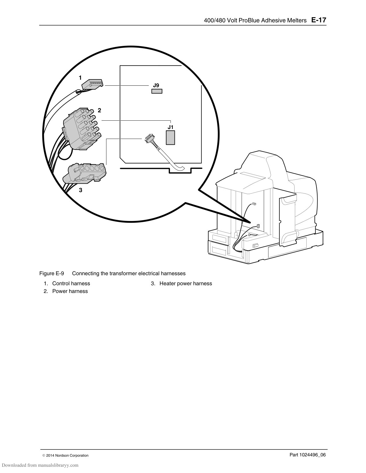
|H‐204 or 404 (T‐LP or T‐LP‐L)|285| |H‐208 or 408 (T‐LP or T‐LP‐L)|390| |H‐20 (T or T‐L0)|135| |H‐20 w/micro (T)|160|
######## Transformer Function
Input electrical service of 400 or 480 volts is split between the melter heaters and the transformer(s). The melter's manifold and tank heaters operate on line voltage, which is passed through the transformer to the melter using a special wire harness. The melter's CPU controls the duty cycle of the heaters. No change in melter programming is required in order for the transformer to operate.
The transformer(s) reduces the input electrical service to 230 volts and directs the reduced voltage to the melter's main circuit board. The main circuit board uses this voltage to power the hoses and guns and provide control power to the CPU.
CPU‐generated control signals are fed to a driver board in the transformer which uses high‐power TRIACs to switch power to the manifold and tank heaters.
#### Installation
Before installing the transformer, familiarize yourself with the Section 3, Installation.
NOTE: ProBlue 400/480 volt transformers can only be used in conjunction with ProBlue adhesive melters that are specifically designed for use with 440/480 volt electrical service.
######## Clearances
Figure E‐1 illustrates the minimum clearances that are required between the melter and surrounding objects. Table E‐2 describes each clearance.
A
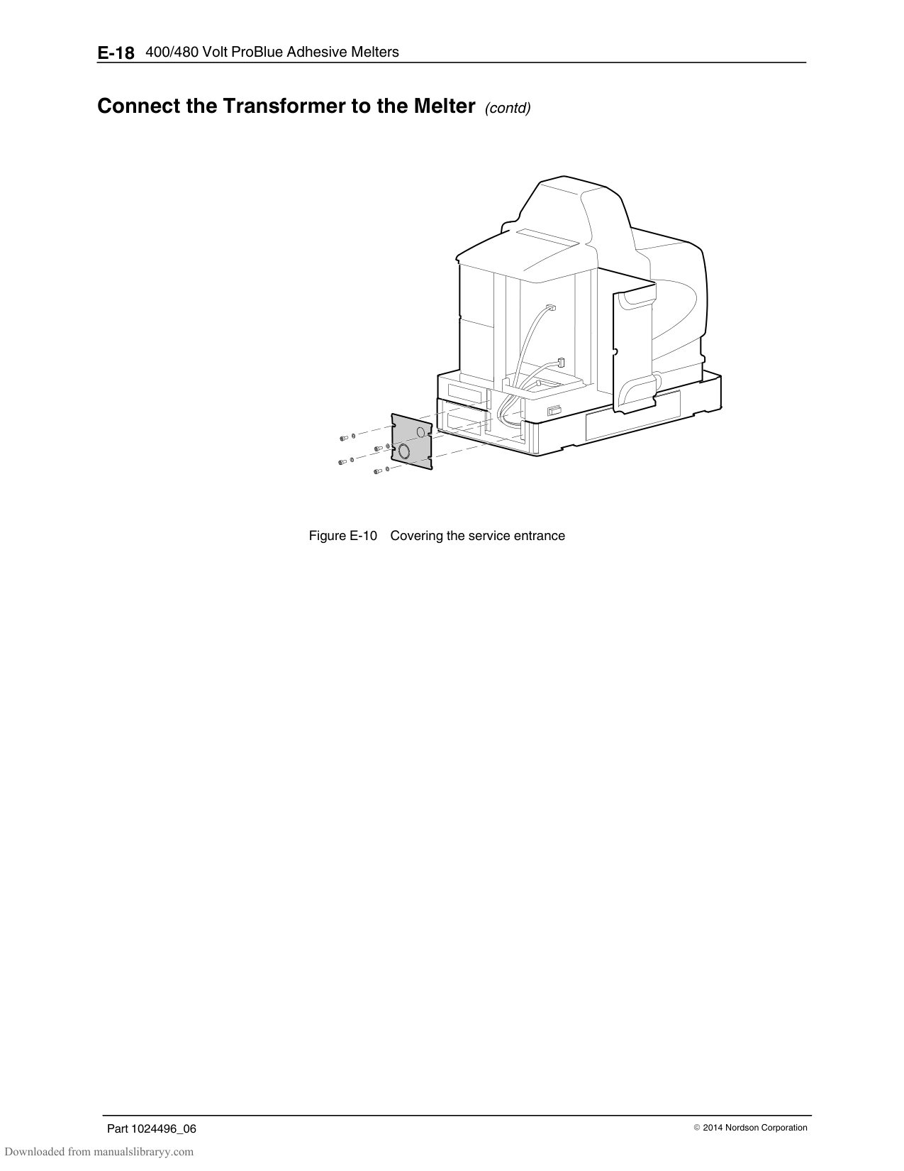
B
C
D
Table E‐2 Installation Clearances
|Item|Description|Required Clearance| |---|---|---| |A|The distance from the outside edge of a 5/16‐inch Nordson hose to the front face of the melter when a short 90‐degree hose fitting is to connect the hose to the melter|P4 = 370 mm (14.5 in.) P7 = 370 mm (14.5 in.) P10 = 391 mm (15.4 in.)| |B|The clearance required to open the pump enclosure door|P4 = 243 mm (9.6 in.) P7 = 243 mm (9.6 in.) P10 = 268 mm (10.55 in.)| |C|The distance from the melter sub‐base to the front edge of the tank lid when the lid is at its highest point.|P4 = 575 mm (22.6 in.) P7 = 637 mm (25.1 in.) P10 = 729 mm (28.7 in.)| |D|The clearance required on the left side of the melter to open the electrical enclosure door or remove a hose/gun module.|P4 = 689 mm (27.1 in.) P7 = 752 mm (29.6 in.) P10 = 755 mm (29.7 in.)|
Installation Kit Components The following components are shipped with the transformer. NOTE: These components are in addition to the components that are provided in the melter installation kit.
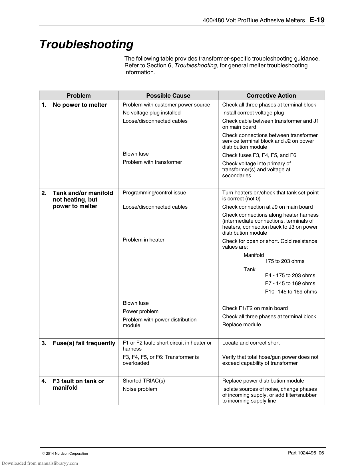
######## Prepare the Transformer for Installation
| | |
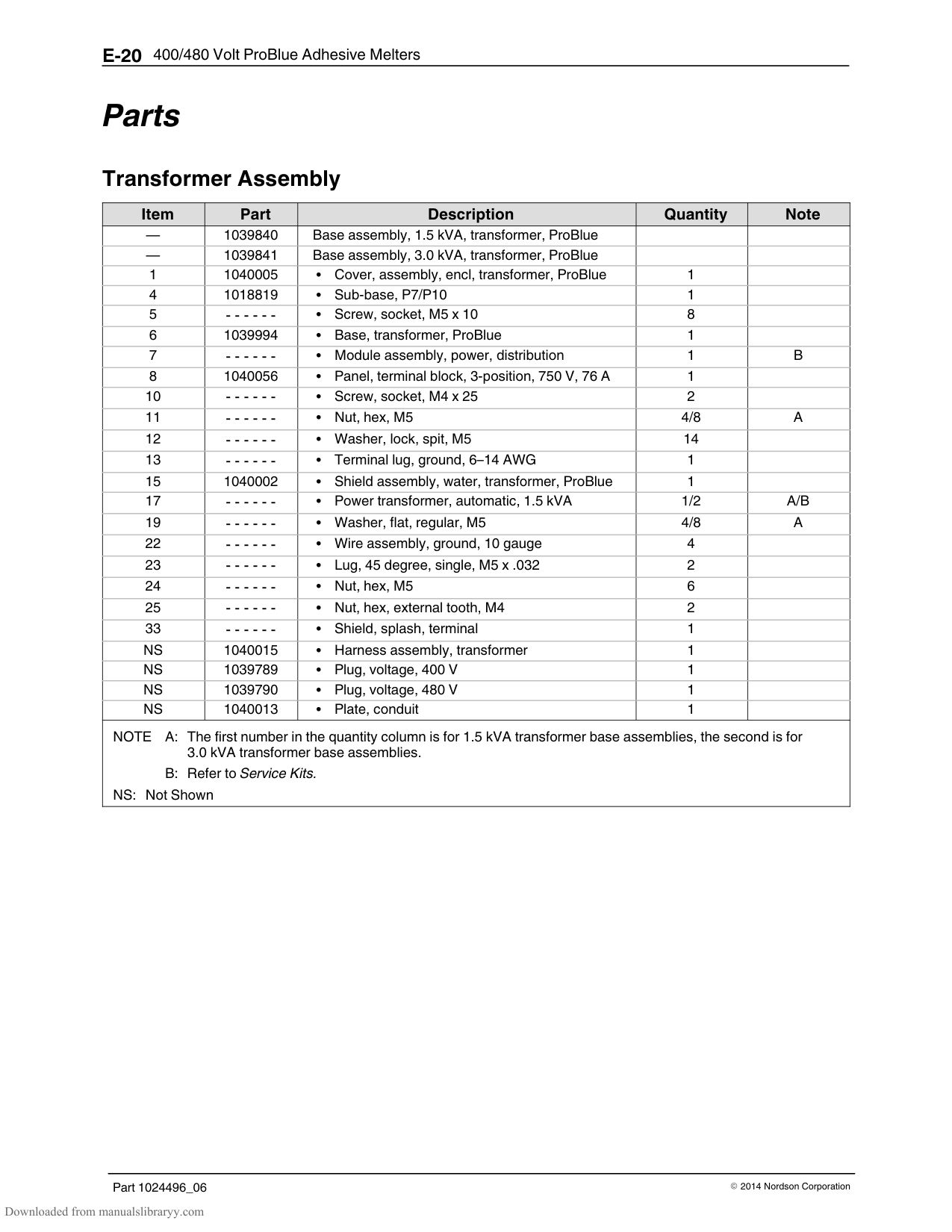
|---|---| | | |
2
1
################## Figure E‐4 Installing the voltage plug
######## Mount the Transformer to the Parent Machine
The transformer is shipped with a sub‐base that is used to mount the transformer/melter to the parent machine.
Sub‐base
NOTE: If you are converting an existing 230 volt ProBlue melter installation to a 400/480 volt ProBlue installation, you must use the sub‐base provided with the transformer.
NOTE: The transformer (with sub‐base) can be mounted directly to any parent machine that is already configured for mounting either a model 3100V or a model 3400V adhesive melter.
############### To mount the transformer
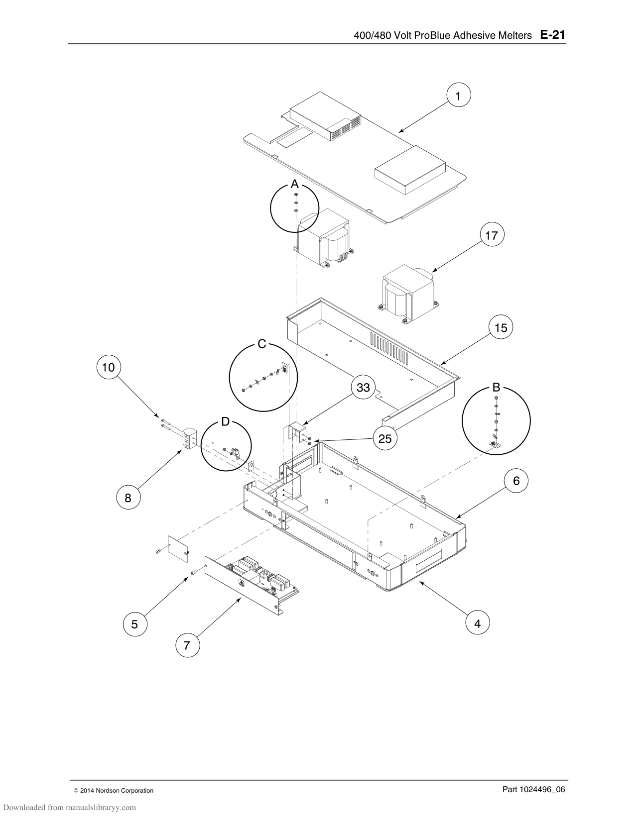
See Figure E‐5.
NOTE: Ensure that the ground leads between the transformer chassis and the power distribution module and between the transformer chassis and the transformer lid are connected before replacing the lid.
################## Figure E‐5 Mounting the sub‐base and the transformer
######## Connect the Electrical Service to the Transformer
Table E‐3 Maximum Melter Amperages
|Transformer|Maximum Amperage| |---|---| |1.5 kVA|8 A| |3.0 kVA|11 A|
WARNING! Risk of electrocution! ProBlue melters must be installed with a lockable power disconnect switch that completely de‐energizes the melter by isolating it from its power source. Failure to de‐energize the melter when required can result in personal injury, including death.
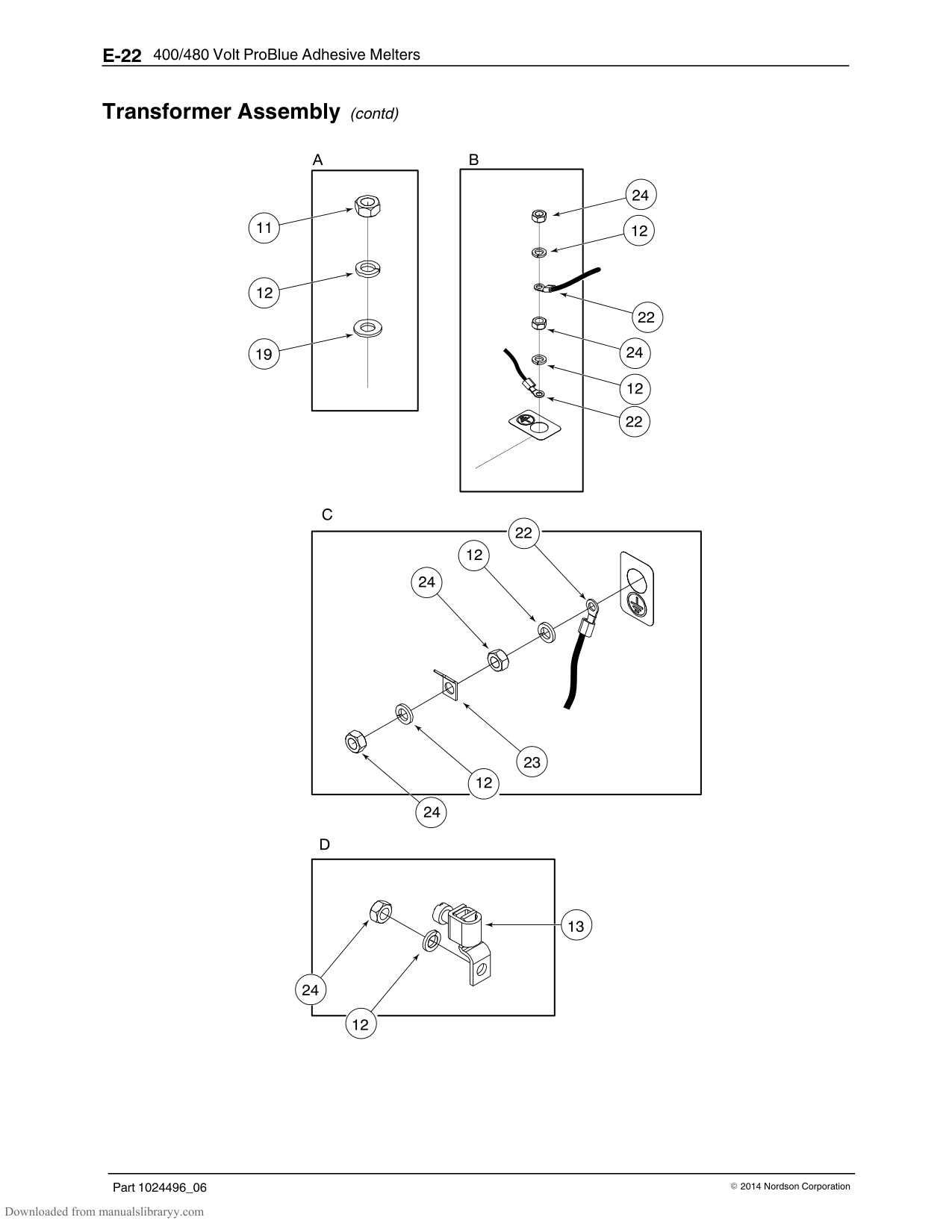
WARNING! Risk of electrical shock or short circuit. Use rigid or flexible conduit or an appropriately sized strain relief to protect the power cable from the sharp edge of the conduit knockout.
See Figure E‐6.
######## Mount the Melter to the Transformer
################ 1. Coil the three transformer wire harnesses and temporarily stow them inthe area of the terminal block.
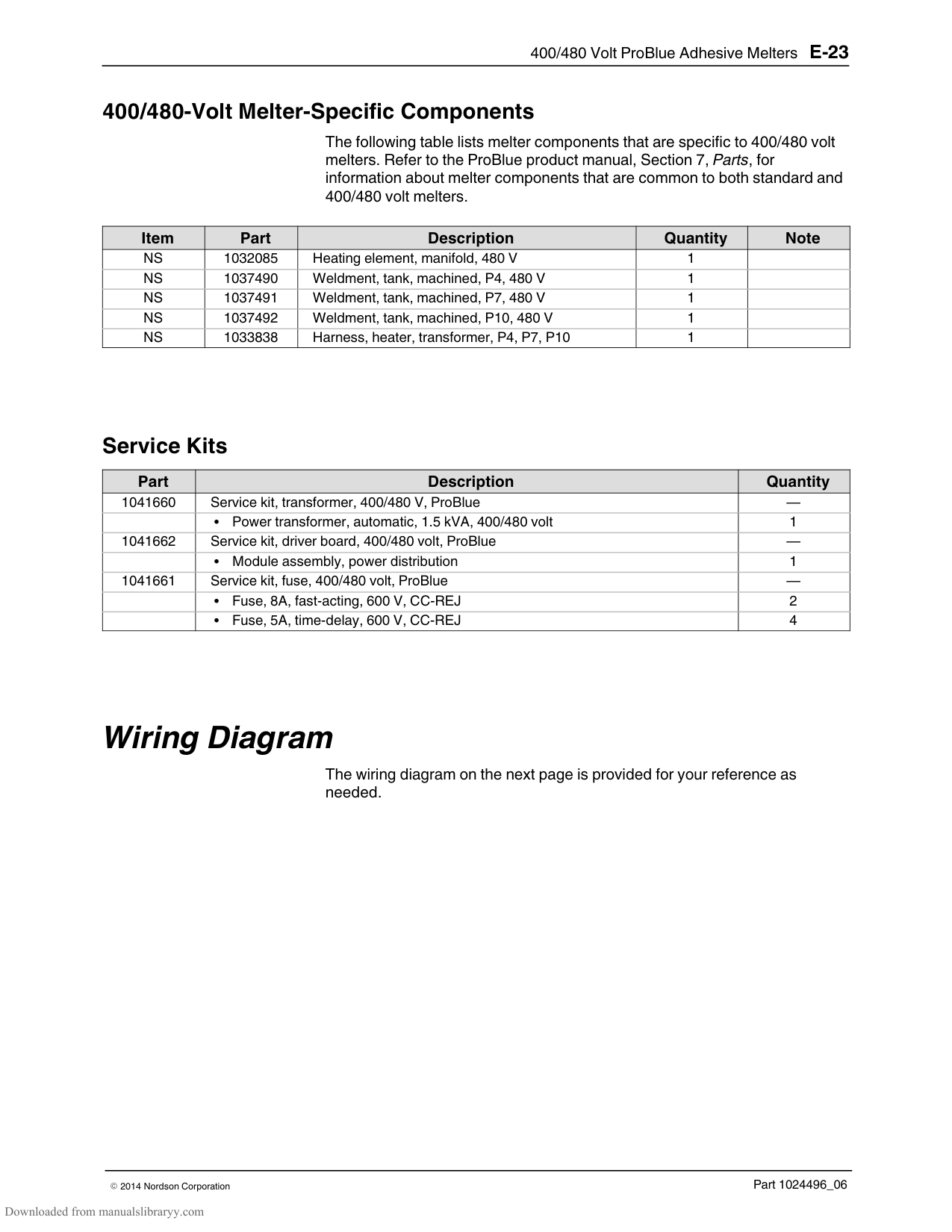
CAUTION! Ensure that the transformer wire harnesses are not pinched between the transformer and the melter.
################ 4. Connect the ground lead from the melter to the ground connection on thetransformer chassis.
Figure E‐7 Mounting the melter to the transformer
################## Figure E‐8 Connecting the melter ground lead to the transformer chassis
######## Connect the Transformer to the Melter
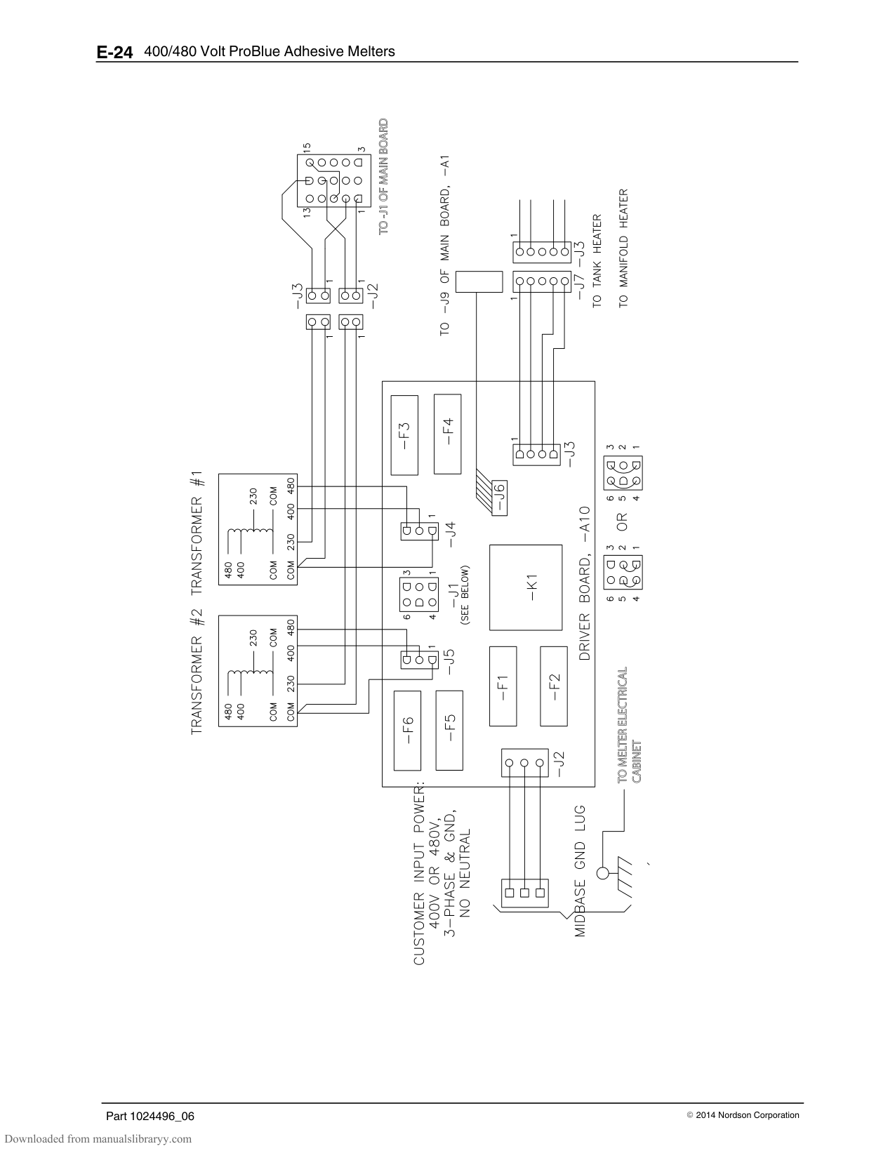
power harness plug that enters the bottom of the melter's electrical enclosure.
J9
J1
Figure E‐9 Connecting the transformer electrical harnesses
######## Connect the Transformer to the Melter (contd)
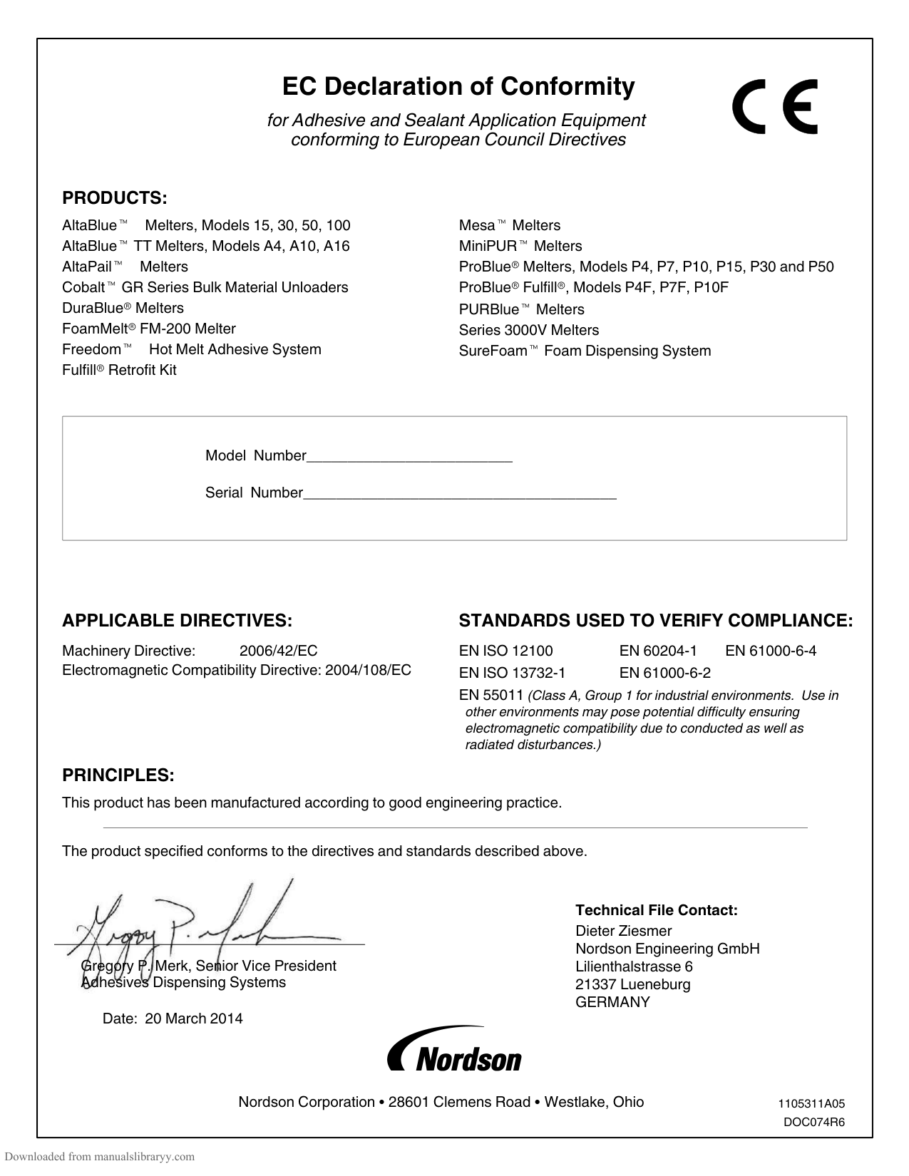
Figure E‐10 Covering the service entrance
#### Troubleshooting
The following table provides transformer‐specific troubleshooting guidance. Refer to Section 6, Troubleshooting, for general melter troubleshooting information.
|Problem|Possible Cause|Corrective Action| |---|---|---| |1. No power to melter|Problem with customer power source No voltage plug installed Loose/disconnected cables
Blown fuse Problem with transformer|Check all three phases at terminal block Install correct voltage plug Check cable between transformer and J1 on main board Check connections between transformer service terminal block and J2 on power distribution module Check fuses F3, F4, F5, and F6
Check voltage into primary of transformer(s) and voltage at secondaries.| |2. Tank and/or manifold
not heating, but power to melter|Programming/control issue
Loose/disconnected cables
Problem in heater
Blown fuse Power problem Problem with power distribution module|Turn heaters on/check that tank set‐point is correct (not 0)
Check connection at J9 on main board Check connections along heater harness (intermediate connections, terminals of heaters, connection back to J3 on power distribution module Check for open or short. Cold resistance values are:
Manifold
175 to 203 ohms Tank
P4 - 175 to 203 ohms P7 - 145 to 169 ohms P10 -145 to 169 ohms
Check F1/F2 on main board Check all three phases at terminal block Replace module| |3. Fuse(s) fail frequently
|F1 or F2 fault: short circuit in heater or harness
F3, F4, F5, or F6: Transformer is overloaded
|Locate and correct short
Verify that total hose/gun power does not exceed capability of transformer| |4. F3 fault on tank or manifold|Shorted TRIAC(s) Noise problem|Replace power distribution module
Isolate sources of noise, change phases of incoming supply, or add filter/snubber to incoming supply line|
#### Parts
Transformer Assembly
|Item|Part|Description|Quantity|Note| |---|---|---|---|---| |—|1039840|Base assembly, 1.5 kVA, transformer, ProBlue| | | |—|1039841|Base assembly, 3.0 kVA, transformer, ProBlue| | | |1|1040005|Cover, assembly, encl, transformer, ProBlue|1| | |4|1018819|Sub‐base, P7/P10|1| | |5|‐ ‐ ‐ ‐ ‐ ‐|Screw, socket, M5 x 10|8| | |6|1039994|Base, transformer, ProBlue|1| | |7|‐ ‐ ‐ ‐ ‐ ‐|Module assembly, power, distribution|1|B| |8|1040056|Panel, terminal block, 3‐position, 750 V, 76 A|1| | |10|‐ ‐ ‐ ‐ ‐ ‐|Screw, socket, M4 x 25|2| | |11|‐ ‐ ‐ ‐ ‐ ‐|Nut, hex, M5|4/8|A| |12|‐ ‐ ‐ ‐ ‐ ‐|Washer, lock, spit, M5|14| | |13|‐ ‐ ‐ ‐ ‐ ‐|Terminal lug, ground, 6–14 AWG|1| | |15|1040002|Shield assembly, water, transformer, ProBlue|1| | |17|‐ ‐ ‐ ‐ ‐ ‐|Power transformer, automatic, 1.5 kVA|1/2|A/B| |19|‐ ‐ ‐ ‐ ‐ ‐|Washer, flat, regular, M5|4/8|A| |22|‐ ‐ ‐ ‐ ‐ ‐|Wire assembly, ground, 10 gauge|4| | |23|‐ ‐ ‐ ‐ ‐ ‐|Lug, 45 degree, single, M5 x .032|2| | |24|‐ ‐ ‐ ‐ ‐ ‐|Nut, hex, M5|6| | |25|‐ ‐ ‐ ‐ ‐ ‐|Nut, hex, external tooth, M4|2| | |33|‐ ‐ ‐ ‐ ‐ ‐|Shield, splash, terminal|1| | |NS|1040015|Harness assembly, transformer|1| | |NS|1039789|Plug, voltage, 400 V|1| | |NS|1039790|Plug, voltage, 480 V|1| | |NS|1040013|Plate, conduit|1| | |NOTE A: The first number in the quantity column is for 1.5 kVA transformer base assemblies, the second is for
3.0 kVA transformer base assemblies. B: Refer to Service Kits.
NS: Not Shown|NOTE A: The first number in the quantity column is for 1.5 kVA transformer base assemblies, the second is for
3.0 kVA transformer base assemblies. B: Refer to Service Kits.
NS: Not Shown|NOTE A: The first number in the quantity column is for 1.5 kVA transformer base assemblies, the second is for
3.0 kVA transformer base assemblies. B: Refer to Service Kits.
NS: Not Shown|NOTE A: The first number in the quantity column is for 1.5 kVA transformer base assemblies, the second is for
3.0 kVA transformer base assemblies. B: Refer to Service Kits.
NS: Not Shown|NOTE A: The first number in the quantity column is for 1.5 kVA transformer base assemblies, the second is for
3.0 kVA transformer base assemblies. B: Refer to Service Kits.
NS: Not Shown|
######## Transformer Assembly (contd)
######## 400/480‐Volt Melter‐Specific Components
The following table lists melter components that are specific to 400/480 volt melters. Refer to the ProBlue product manual, Section 7, Parts, for information about melter components that are common to both standard and 400/480 volt melters.
|Item|Part|Description|Quantity|Note| |---|---|---|---|---| |NS|1032085|Heating element, manifold, 480 V|1| | |NS|1037490|Weldment, tank, machined, P4, 480 V|1| | |NS|1037491|Weldment, tank, machined, P7, 480 V|1| | |NS|1037492|Weldment, tank, machined, P10, 480 V|1| | |NS|1033838|Harness, heater, transformer, P4, P7, P10|1| |
Service Kits
|Part|Description|Quantity| |---|---|---| |1041660|Service kit, transformer, 400/480 V, ProBlue|—| | |Power transformer, automatic, 1.5 kVA, 400/480 volt|1| |1041662|Service kit, driver board, 400/480 volt, ProBlue|—| | |Module assembly, power distribution|1| |1041661|Service kit, fuse, 400/480 volt, ProBlue|—| | |Fuse, 8A, fast‐acting, 600 V, CC‐REJ|2| | |Fuse, 5A, time‐delay, 600 V, CC‐REJ|4|
#### Wiring Diagram
The wiring diagram on the next page is provided for your reference as needed.
| | | |---|---| | | |
| | | |---|---| | | |
| | | |---|---| | | |
####### EC Declaration of Conformity
for Adhesive and Sealant Application Equipment conforming to European Council Directives
PRODUCTS: AltaBlue Melters, Models 15, 30, 50, 100 AltaBlue TT Melters, Models A4, A10, A16 AltaPail Melters Cobalt GR Series Bulk Material Unloaders DuraBlue Melters FoamMelt FM‐200 Melter Freedom Hot Melt Adhesive System Fulfill Retrofit Kit
Mesa Melters MiniPUR Melters ProBlue Melters, Models P4, P7, P10, P15, P30 and P50 ProBlue Fulfill , Models P4F, P7F, P10F PURBlue Melters Series 3000V Melters SureFoam Foam Dispensing System
|Model Number_________________________
Serial Number______________________________________| |---|
############ APPLICABLE DIRECTIVES:
Machinery Directive: 2006/42/EC Electromagnetic Compatibility Directive: 2004/108/EC
############ STANDARDS USED TO VERIFY COMPLIANCE:
EN ISO 12100 EN 60204‐1 EN 61000-6-4 EN ISO 13732‐1 EN 61000‐6‐2 EN 55011 (Class A, Group 1 for industrial environments. Use in
other environments may pose potential difficulty ensuring electromagnetic compatibility due to conducted as well as radiated disturbances.)
PRINCIPLES: This product has been manufactured according to good engineering practice.
The product specified conforms to the directives and standards described above.

Technical File Contact: Dieter Ziesmer Nordson Engineering GmbH Lilienthalstrasse 6 21337 Lueneburg GERMANY
Gregory P. Merk, Senior Vice President Adhesives Dispensing Systems
Date: 20 March 2014
Nordson Corporation 28601 Clemens Road Westlake, Ohio
1105311A05 DOC074R6