
Ask AI
— answers from the official manualAnswers from the official manual.
Common questions
Common Questions
6 totalHow do I set up the IP address for the Nordson ProBlue P7 melter and its controller?
For the ProBlue P7, connect Switching hub and Personal computer with a LAN cable. Install the configuration tool 'IPConfig' and start it to select 'Enable internal DHCP server', then click OK. Turn ON the Melter and scan for devices in IPConfig to set the Melter's IP address manually if needed: IP address 192.168.250.2, Subnet mask 255.255.255.0, DHCP Off.
How do I connect the ProBlue P7 melter to the Controller using EtherNet/IP?
Follow these steps: Establish an online connection with Sysmac Studio and set up EtherNet/IP port settings (IP address 192.168.250.1, subnet mask 255.255.255.0). Create global variables needed for tag data links in Sysmac Studio, export them to CSV format, and import this into Network Configurator to register tags and set connections between devices on the network configuration pane.
What are the LED indicator statuses that show normal tag data link performance?
For ProBlue P7: Link (Activity), Link (Module Status), Link (Network Status), and Activity LEDs should be green lit. For Controller (NX/NJ series): NET RUN Green, NET ERR Not lit, LINK/ACT flashing yellow.
How do I check that the data being sent between ProBlue P7 melter and controller is correct?
In Sysmac Studio's Watch Tab Page, enter variables such as EIP002_Command_OUT, EIP002_ChannelNumber_OUT etc., set send data for the reading command (EIP002_Command_OUT value of 3), verify that online values update correctly with no faults or alerts reported.
What should I do if the Nordson melter and OMRON controller cannot establish an online connection?
Check the LED indicators on both devices for status. The Network Connection icon in Network Configurator should turn blue indicating a successful connect when Ethernet links are established properly between them (IP addresses set correctly, LAN cables connected).
How do I troubleshoot when there is an error connecting tag data links between ProBlue melter and controller?
Check the communication status in LEDs, confirm correct IP addresses set up on both devices, review settings in Sysmac Studio and Network Configurator ensuring proper registration of tags and connections (check Edit Device Parameters dialog).
Full Manual
60 pages
Machine Automation Controller NJ/NX-series
EtherNet/IP
TM Connection Guide Nordson Corporation ProBlue Adhesive Melters

P696-E1-01
About Intellectual Property Rights and Trademarks Microsoft product screen shots reprinted with permission from Microsoft Corporation. Windows is a registered trademark of Microsoft Corporation in the USA and other countries. ODVA and EtherNet/IPTM are trademarks of ODVA. EtherCAT® is registered trademark and patented technology, licensed by Beckhoff Automation GmbH, Germany. Sysmac is a trademark or registered trademark of OMRON Corporation in Japan and other countries for OMRON factory automation products. Company names and product names in this guide are the trademarks or registered trademarks of their respective companies.
Table of Contents

1. Related Manuals
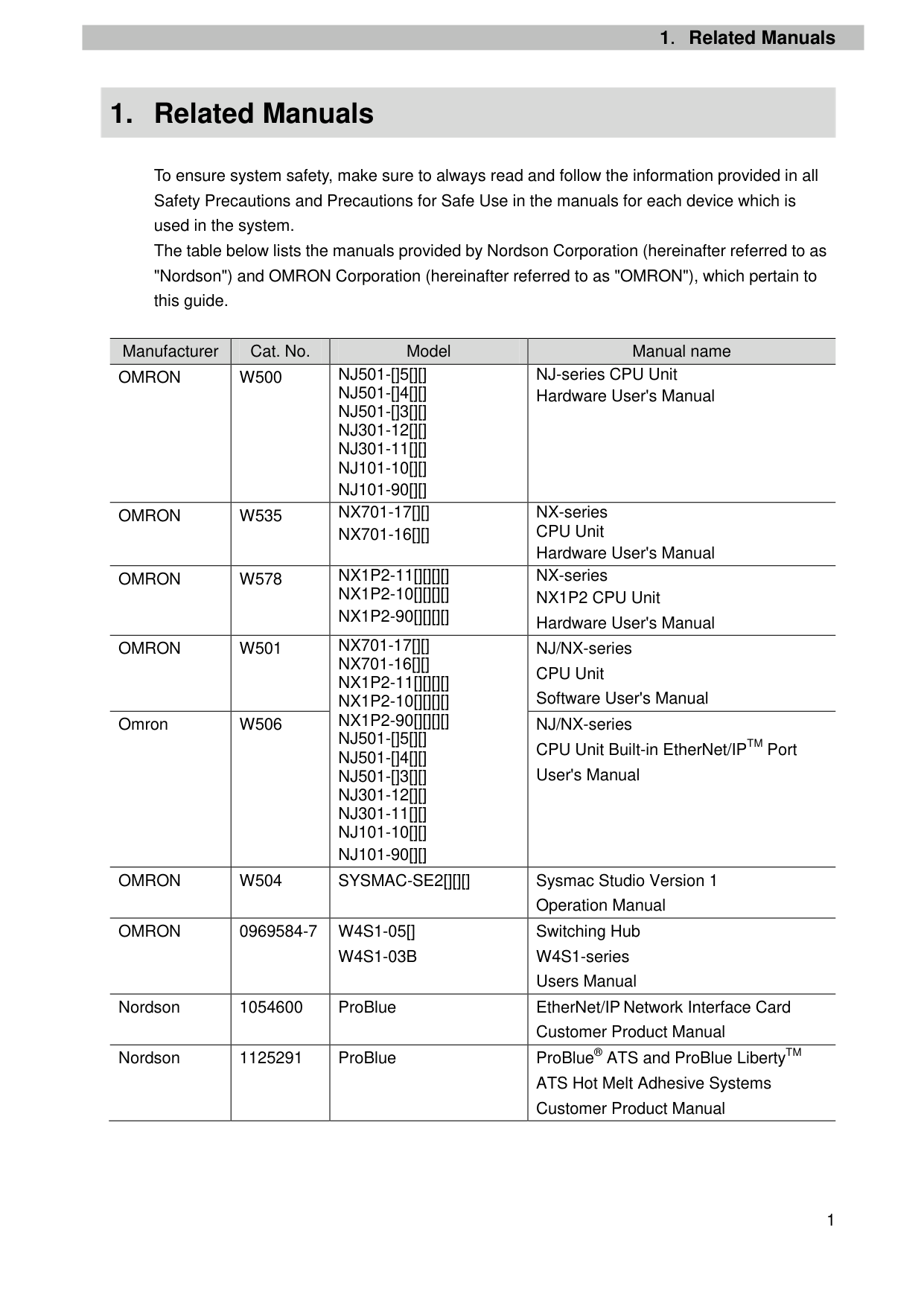
To ensure system safety, make sure to always read and follow the information provided in all Safety Precautions and Precautions for Safe Use in the manuals for each device which is used in the system. The table below lists the manuals provided by Nordson Corporation (hereinafter referred to as "Nordson") and OMRON Corporation (hereinafter referred to as "OMRON"), which pertain to this guide.
|Manufacturer|Cat. No.|Model|Manual name| |---|---|---|---| |OMRON|W500|NJ501-[]5[][] NJ501-[]4[][] NJ501-[]3[][] NJ301-12[][] NJ301-11[][] NJ101-10[][] NJ101-90[][]|NJ-series CPU Unit Hardware User's Manual| |OMRON|W535|NX701-17[][] NX701-16[][]|NX-series CPU Unit Hardware User's Manual| |OMRON|W578|NX1P2-11[][][][] NX1P2-10[][][][] NX1P2-90[][][][]|NX-series NX1P2 CPU Unit Hardware User's Manual| |OMRON|W501|NX701-17[][] NX701-16[][] NX1P2-11[][][][] NX1P2-10[][][][] NX1P2-90[][][][] NJ501-[]5[][] NJ501-[]4[][] NJ501-[]3[][] NJ301-12[][] NJ301-11[][] NJ101-10[][] NJ101-90[][]|NJ/NX-series CPU Unit Software User's Manual| |Omron|W506|NX701-17[][] NX701-16[][] NX1P2-11[][][][] NX1P2-10[][][][] NX1P2-90[][][][] NJ501-[]5[][] NJ501-[]4[][] NJ501-[]3[][] NJ301-12[][] NJ301-11[][] NJ101-10[][] NJ101-90[][]|NJ/NX-series CPU Unit Built-in EtherNet/IPTM Port User's Manual| |OMRON|W504|SYSMAC-SE2[][][]|Sysmac Studio Version 1 Operation Manual| |OMRON|0969584-7|W4S1-05[] W4S1-03B|Switching Hub W4S1-series Users Manual| |Nordson|1054600|ProBlue|EtherNet/IP Network Interface Card Customer Product Manual| |Nordson|1125291|ProBlue|ProBlue® ATS and ProBlue LibertyTM ATS Hot Melt Adhesive Systems Customer Product Manual|
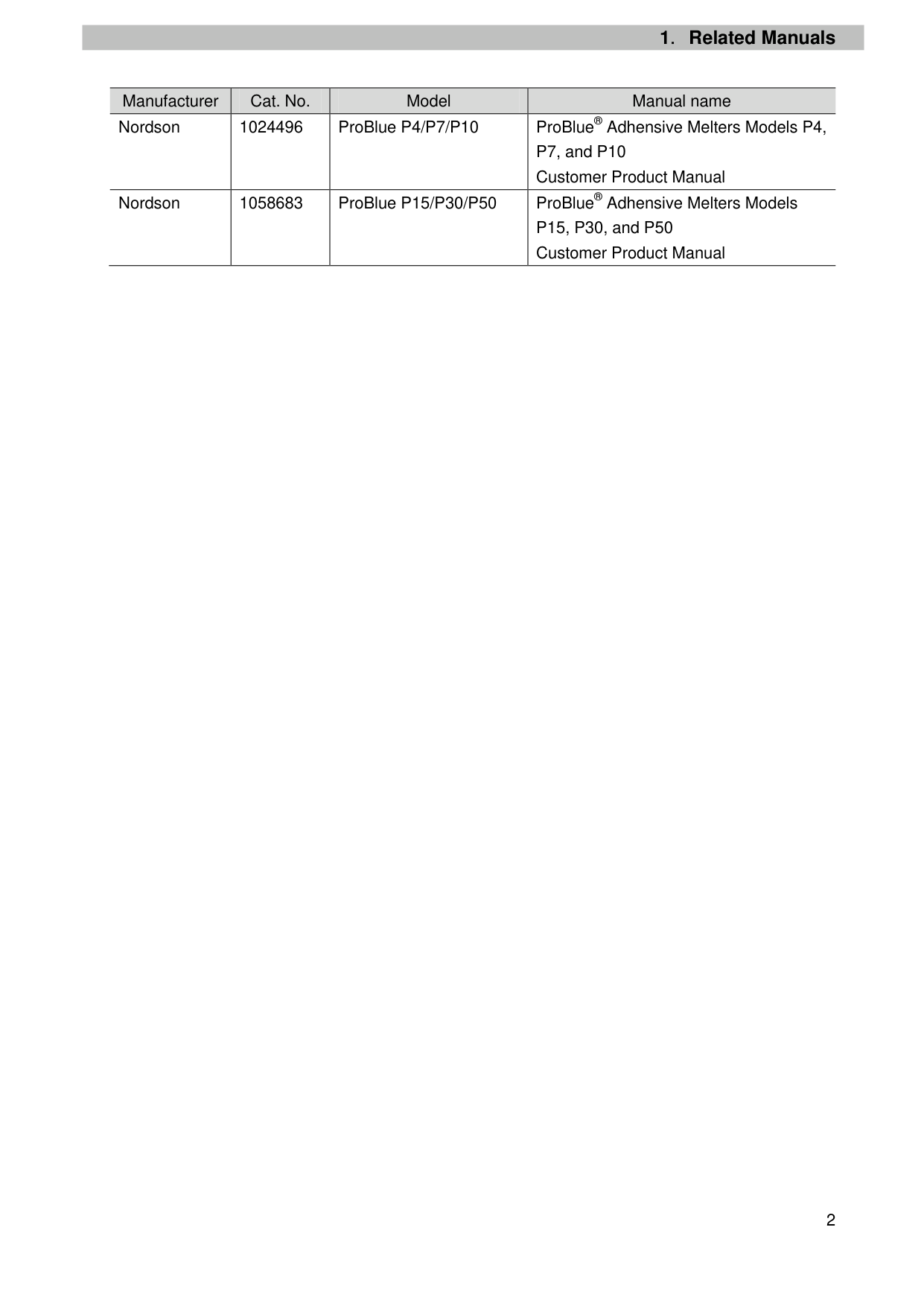
|Manufacturer|Cat. No.|Model|Manual name| |---|---|---|---| |Nordson|1024496|ProBlue P4/P7/P10|ProBlue® Adhensive Melters Models P4, P7, and P10 Customer Product Manual| |Nordson|1058683|ProBlue P15/P30/P50|ProBlue® Adhensive Melters Models P15, P30, and P50 Customer Product Manual|
2.Terms and Definitions
2. Terms and Definitions
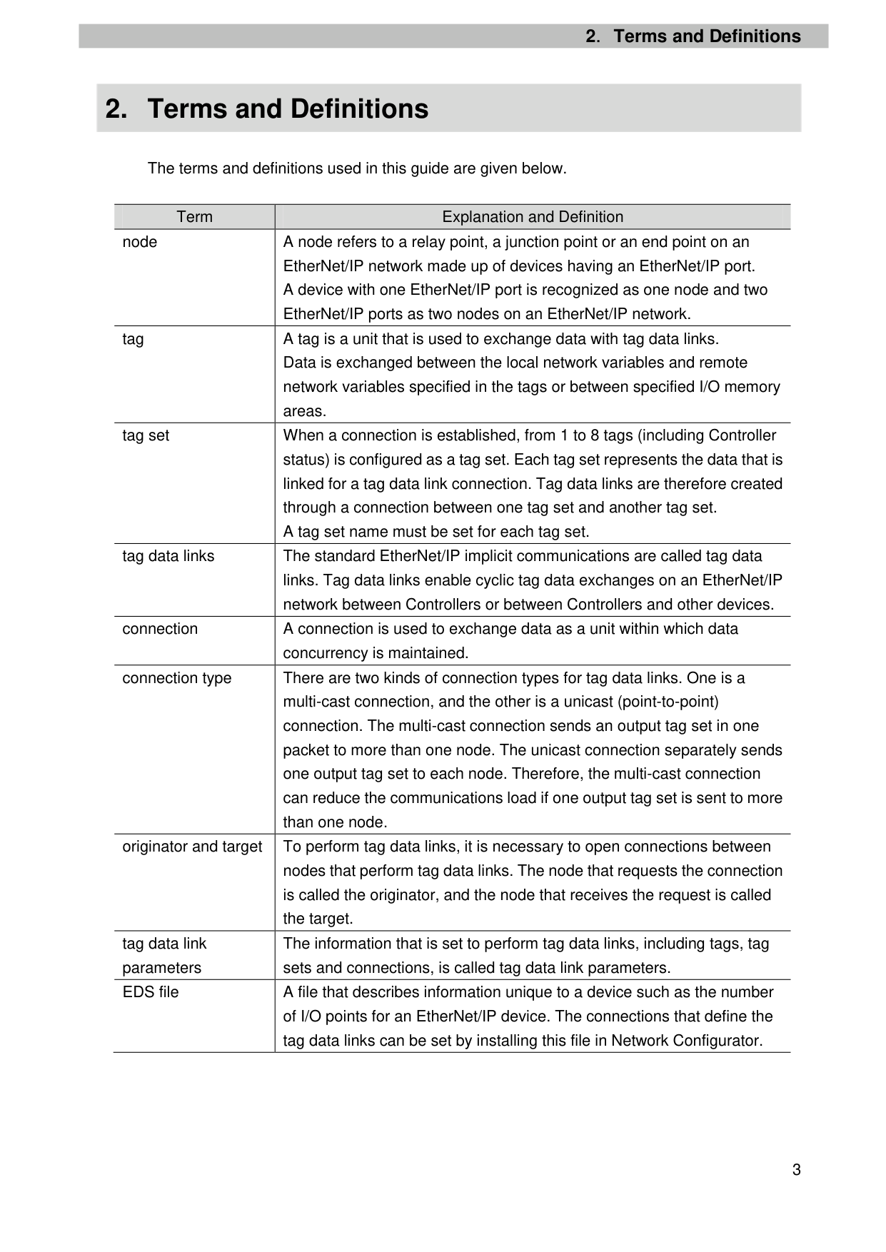
The terms and definitions used in this guide are given below.
|Term|Explanation and Definition| |---|---| |node|A node refers to a relay point, a junction point or an end point on an EtherNet/IP network made up of devices having an EtherNet/IP port. A device with one EtherNet/IP port is recognized as one node and two EtherNet/IP ports as two nodes on an EtherNet/IP network.| |tag|A tag is a unit that is used to exchange data with tag data links. Data is exchanged between the local network variables and remote network variables specified in the tags or between specified I/O memory areas.| |tag set|When a connection is established, from 1 to 8 tags (including Controller status) is configured as a tag set. Each tag set represents the data that is linked for a tag data link connection. Tag data links are therefore created through a connection between one tag set and another tag set. A tag set name must be set for each tag set.| |tag data links|The standard EtherNet/IP implicit communications are called tag data links. Tag data links enable cyclic tag data exchanges on an EtherNet/IP network between Controllers or between Controllers and other devices.| |connection|A connection is used to exchange data as a unit within which data concurrency is maintained.| |connection type|There are two kinds of connection types for tag data links. One is a multi-cast connection, and the other is a unicast (point-to-point) connection. The multi-cast connection sends an output tag set in one packet to more than one node. The unicast connection separately sends one output tag set to each node. Therefore, the multi-cast connection can reduce the communications load if one output tag set is sent to more than one node.| |originator and target|To perform tag data links, it is necessary to open connections between nodes that perform tag data links. The node that requests the connection is called the originator, and the node that receives the request is called the target.| |tag data link parameters|The information that is set to perform tag data links, including tags, tag sets and connections, is called tag data link parameters.| |EDS file|A file that describes information unique to a device such as the number of I/O points for an EtherNet/IP device. The connections that define the tag data links can be set by installing this file in Network Configurator.|
3.Precautions
3. Precautions
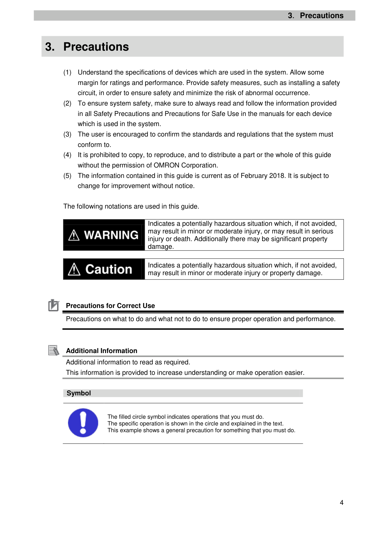
The following notations are used in this guide.
||Indicates a potentially hazardous situation which, if not avoided, may result in minor or moderate injury, or may result in serious injury or death. Additionally there may be significant property damage.| |---|---|
||Indicates a potentially hazardous situation which, if not avoided, may result in minor or moderate injury or property damage.| |---|---|

Precautions for Correct Use Precautions on what to do and what not to do to ensure proper operation and performance.

Additional Information Additional information to read as required. This information is provided to increase understanding or make operation easier.
###### Symbol

The filled circle symbol indicates operations that you must do. The specific operation is shown in the circle and explained in the text. This example shows a general precaution for something that you must do.
4.Overview
4. Overview
This guide describes procedures for connecting a Nordson ProBlue Melter (hereinafter referred to as the "Melter") to an OMRON NJ/NX-series Machine Automation Controller (hereinafter referred to as the "Controller") via EtherNet/IP and for checking their communication status. Refer to Section 6. EtherNet/IP Settings and Section 7. EtherNet/IP Connection Procedure to understand setting methods and key points to operate EtherNet/IP tag data links.
5. Applicable Devices and Device Configuration
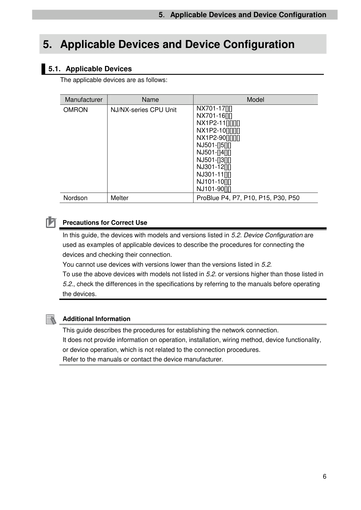
|Manufacturer|Name|Model| |---|---|---| |OMRON|NJ/NX-series CPU Unit|NX701-17[][] NX701-16[][] NX1P2-11[][][][] NX1P2-10[][][][] NX1P2-90[][][][] NJ501-[]5[][] NJ501-[]4[][] NJ501-[]3[][] NJ301-12[][] NJ301-11[][] NJ101-10[][] NJ101-90[][]| |Nordson|Melter|ProBlue P4, P7, P10, P15, P30, P50|

Precautions for Correct Use In this guide, the devices with models and versions listed in 5.2. Device Configuration are used as examples of applicable devices to describe the procedures for connecting the devices and checking their connection. You cannot use devices with versions lower than the versions listed in 5.2. To use the above devices with models not listed in 5.2. or versions higher than those listed in 5.2., check the differences in the specifications by referring to the manuals before operating the devices.

Additional Information This guide describes the procedures for establishing the network connection. It does not provide information on operation, installation, wiring method, device functionality, or device operation, which is not related to the connection procedures. Refer to the manuals or contact the device manufacturer.
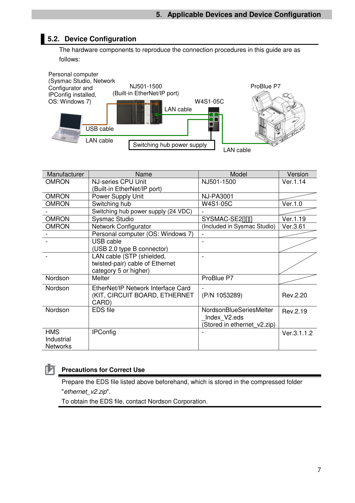
Personal computer (Sysmac Studio, Network Configurator and IPConfig installed, OS: Windows 7)
NJ501-1500 (Built-in EtherNet/IP port)
ProBlue P7

W4S1-05C

LAN cable


USB cable
| | | |---|---| |
Switching hub power supply|
Switching hub power supply|
LAN cable
LAN cable
|Manufacturer|Name|Model|Version| |---|---|---|---| |OMRON|NJ-series CPU Unit (Built-in EtherNet/IP port)|NJ501-1500|Ver.1.14| |OMRON|Power Supply Unit|NJ-PA3001| | |OMRON|Switching hub|W4S1-05C|Ver.1.0| |-|Switching hub power supply (24 VDC)|-| | |OMRON|Sysmac Studio|SYSMAC-SE2[][][]|Ver.1.19| |OMRON|Network Configurator|(Included in Sysmac Studio)|Ver.3.61| |-|Personal computer (OS: Windows 7)|-| | |-|USB cable (USB 2.0 type B connector)|-| | |-|LAN cable (STP (shielded, twisted-pair) cable of Ethernet category 5 or higher)|-| | |Nordson|Melter|ProBlue P7| | |Nordson|EtherNet/IP Network Interface Card (KIT, CIRCUIT BOARD, ETHERNET CARD)|(P/N 1053289)|Rev.2.20| |Nordson|EDS file|NordsonBlueSeriesMelter _Index_V2.eds (Stored in ethernet_v2.zip)|Rev.2.19| |HMS Industrial Networks|IPConfig|-|Ver.3.1.1.2|

Precautions for Correct Use Prepare the EDS file listed above beforehand, which is stored in the compressed folder "ethernet_v2.zip". To obtain the EDS file, contact Nordson Corporation.

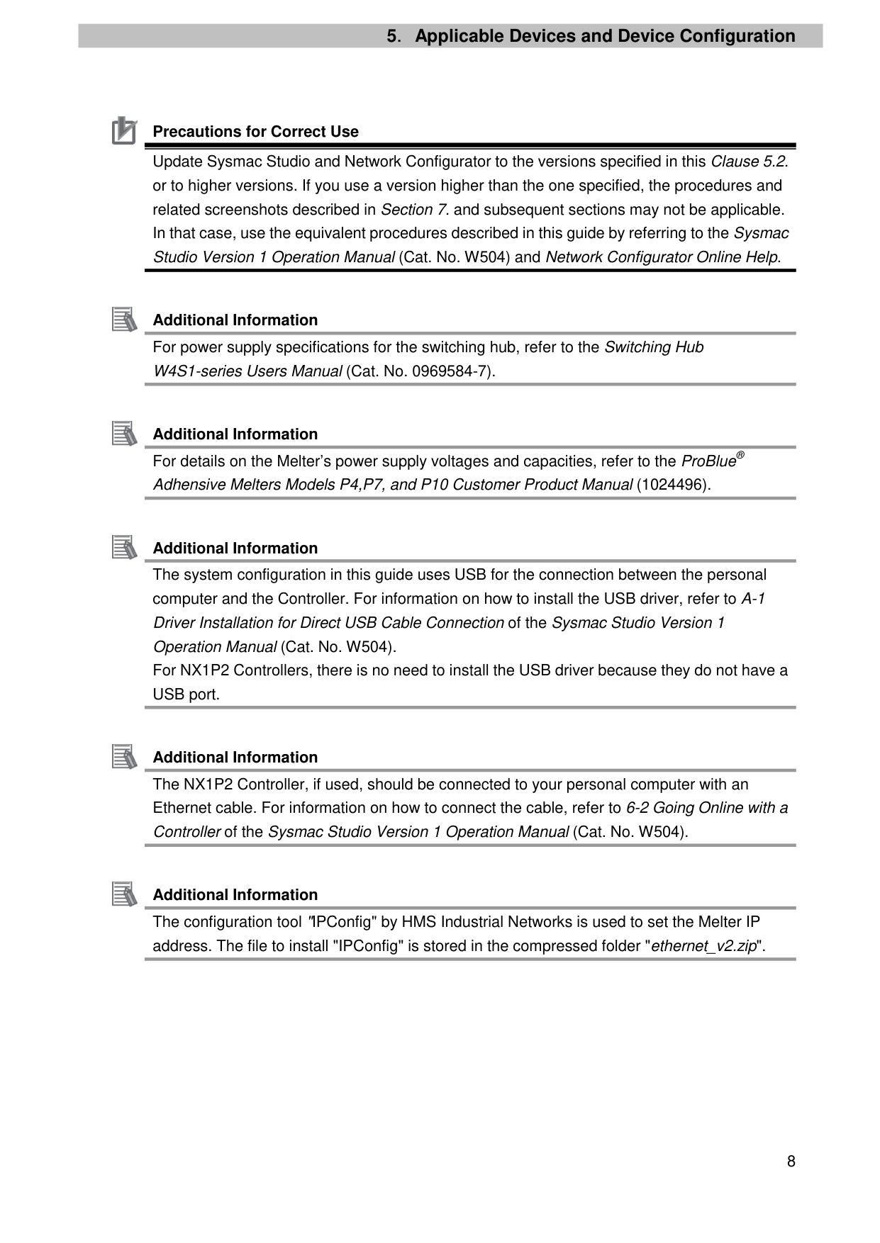
Precautions for Correct Use Update Sysmac Studio and Network Configurator to the versions specified in this Clause 5.2. or to higher versions. If you use a version higher than the one specified, the procedures and related screenshots described in Section 7. and subsequent sections may not be applicable. In that case, use the equivalent procedures described in this guide by referring to the Sysmac Studio Version 1 Operation Manual (Cat. No. W504) and Network Configurator Online Help.

Additional Information For power supply specifications for the switching hub, refer to the Switching Hub W4S1-series Users Manual (Cat. No. 0969584-7).

Additional Information For details on the Melter’s power supply voltages and capacities, refer to the ProBlue® Adhensive Melters Models P4,P7, and P10 Customer Product Manual (1024496).

Additional Information The system configuration in this guide uses USB for the connection between the personal computer and the Controller. For information on how to install the USB driver, refer to A-1 Driver Installation for Direct USB Cable Connection of the Sysmac Studio Version 1 Operation Manual (Cat. No. W504). For NX1P2 Controllers, there is no need to install the USB driver because they do not have a USB port.

Additional Information The NX1P2 Controller, if used, should be connected to your personal computer with an Ethernet cable. For information on how to connect the cable, refer to 6-2 Going Online with a Controller of the Sysmac Studio Version 1 Operation Manual (Cat. No. W504).

Additional Information The configuration tool "IPConfig" by HMS Industrial Networks is used to set the Melter IP address. The file to install "IPConfig" is stored in the compressed folder "ethernet_v2.zip".
6. EtherNet/IP Settings
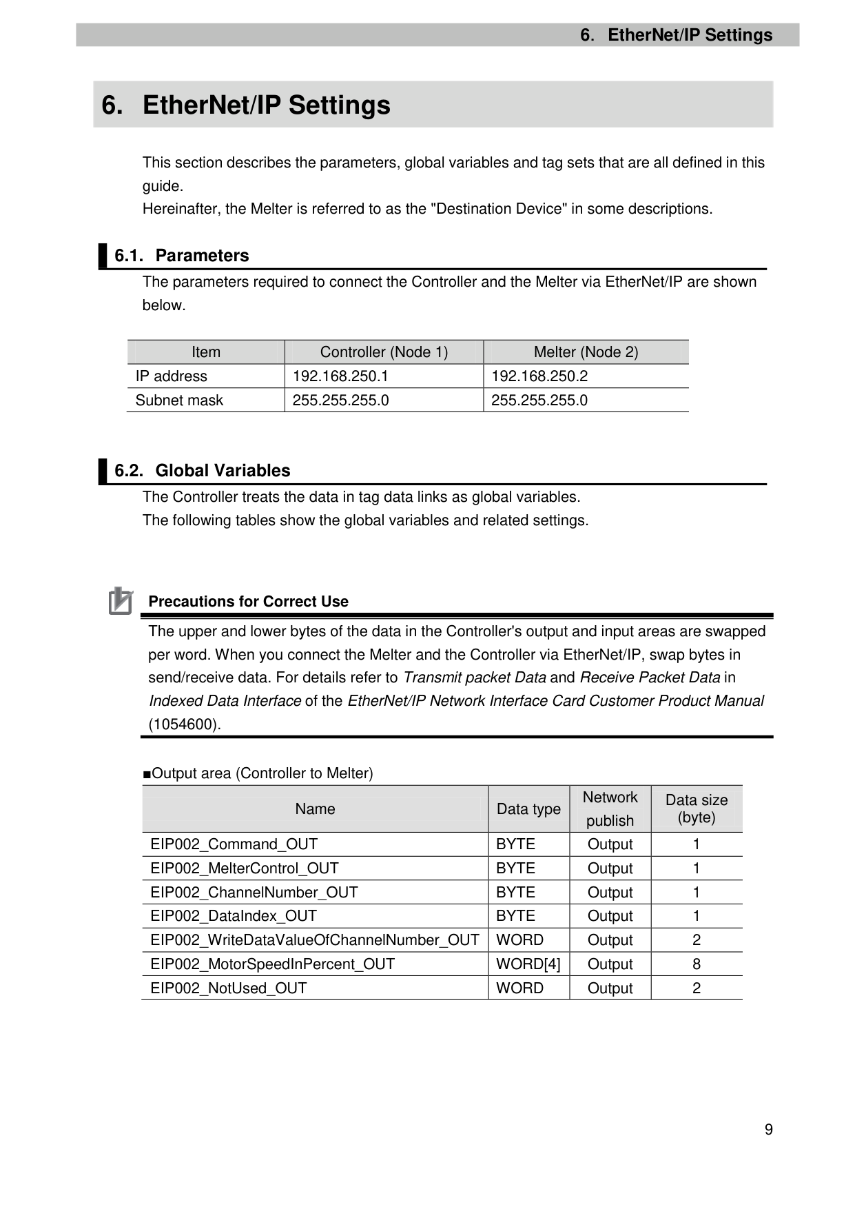
This section describes the parameters, global variables and tag sets that are all defined in this guide. Hereinafter, the Melter is referred to as the "Destination Device" in some descriptions.
|Item|Controller (Node 1)|Melter (Node 2)| |---|---|---| |IP address|192.168.250.1|192.168.250.2| |Subnet mask|255.255.255.0|255.255.255.0|

Precautions for Correct Use The upper and lower bytes of the data in the Controller's output and input areas are swapped per word. When you connect the Melter and the Controller via EtherNet/IP, swap bytes in send/receive data. For details refer to Transmit packet Data and Receive Packet Data in Indexed Data Interface of the EtherNet/IP Network Interface Card Customer Product Manual
(1054600).

|Name|Data type|Network publish
|Data size (byte)
| |---|---|---|---| |EIP002_Command_OUT|BYTE|Output|1| |EIP002_MelterControl_OUT|BYTE|Output|1| |EIP002_ChannelNumber_OUT|BYTE|Output|1| |EIP002_DataIndex_OUT|BYTE|Output|1| |EIP002_WriteDataValueOfChannelNumber_OUT|WORD|Output|2| |EIP002_MotorSpeedInPercent_OUT|WORD[4]|Output|8| |EIP002_NotUsed_OUT|WORD|Output|2|
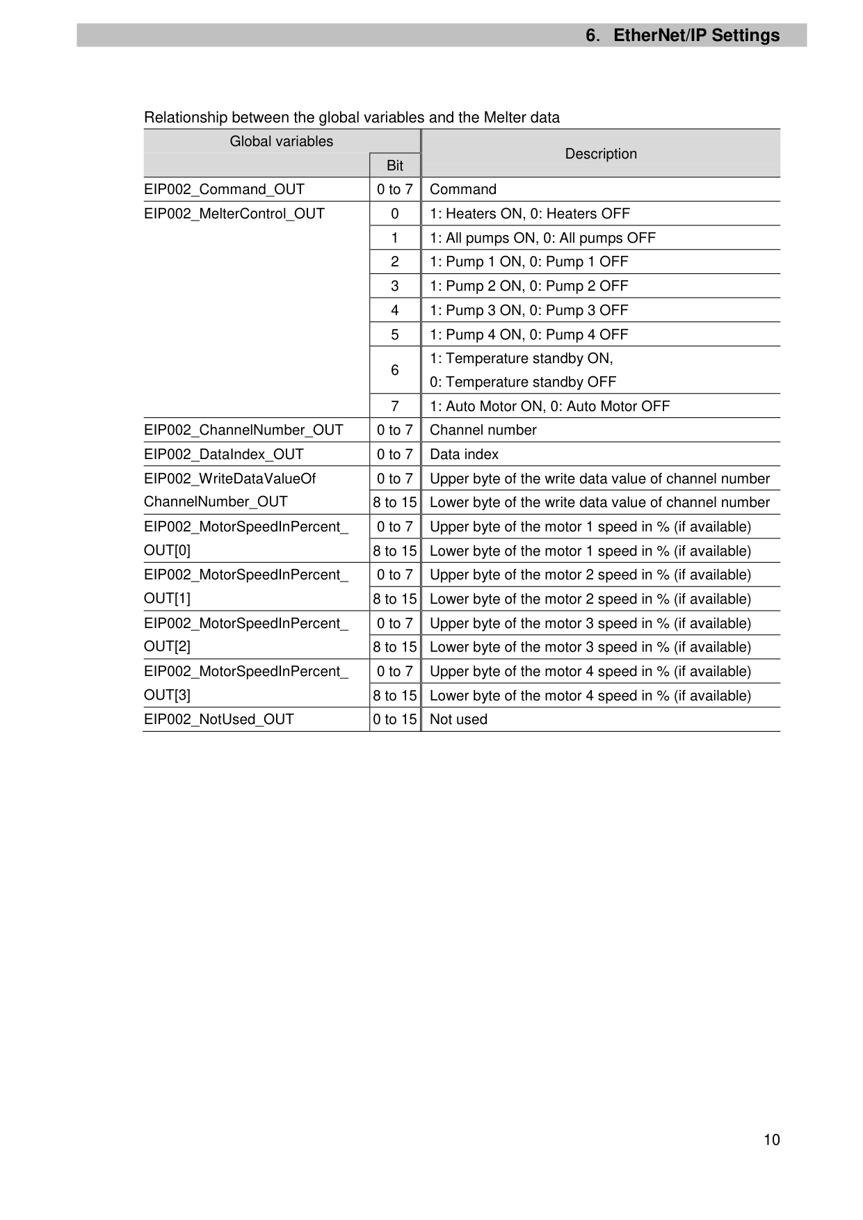
####### Relationship between the global variables and the Melter data
|Global variables|Global variables|Description| |---|---|---| | |Bit|Description| |EIP002_Command_OUT|0 to 7|Command| |EIP002_MelterControl_OUT|0|1: Heaters ON, 0: Heaters OFF| |EIP002_MelterControl_OUT|1|1: All pumps ON, 0: All pumps OFF| |EIP002_MelterControl_OUT|2|1: Pump 1 ON, 0: Pump 1 OFF| |EIP002_MelterControl_OUT|3|1: Pump 2 ON, 0: Pump 2 OFF| |EIP002_MelterControl_OUT|4|1: Pump 3 ON, 0: Pump 3 OFF| |EIP002_MelterControl_OUT|5|1: Pump 4 ON, 0: Pump 4 OFF| |EIP002_MelterControl_OUT|6|1: Temperature standby ON, 0: Temperature standby OFF
| |EIP002_MelterControl_OUT|7|1: Auto Motor ON, 0: Auto Motor OFF| |EIP002_ChannelNumber_OUT|0 to 7|Channel number| |EIP002_DataIndex_OUT|0 to 7|Data index| |EIP002_WriteDataValueOf ChannelNumber_OUT|0 to 7|Upper byte of the write data value of channel number| |EIP002_WriteDataValueOf ChannelNumber_OUT|8 to 15|Lower byte of the write data value of channel number| |EIP002_MotorSpeedInPercent_ OUT[0]|0 to 7|Upper byte of the motor 1 speed in % (if available)| |EIP002_MotorSpeedInPercent_ OUT[0]|8 to 15|Lower byte of the motor 1 speed in % (if available)| |EIP002_MotorSpeedInPercent_ OUT[1]
|0 to 7|Upper byte of the motor 2 speed in % (if available)| |EIP002_MotorSpeedInPercent_ OUT[1]
|8 to 15|Lower byte of the motor 2 speed in % (if available)| |EIP002_MotorSpeedInPercent_ OUT[2]|0 to 7|Upper byte of the motor 3 speed in % (if available)| |EIP002_MotorSpeedInPercent_ OUT[2]|8 to 15|Lower byte of the motor 3 speed in % (if available)| |EIP002_MotorSpeedInPercent_ OUT[3]
|0 to 7|Upper byte of the motor 4 speed in % (if available)|
|EIP002_MotorSpeedInPercent_ OUT[3]
|8 to 15|Lower byte of the motor 4 speed in % (if available)| |EIP002_NotUsed_OUT|0 to 15|Not used|
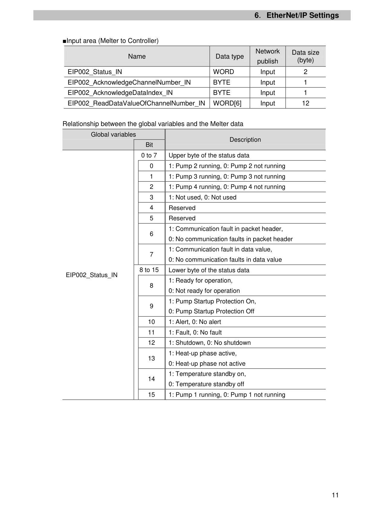
|Name|Data type|Network publish
|Data size (byte)
| |---|---|---|---| |EIP002_Status_IN|WORD|Input|2| |EIP002_AcknowledgeChannelNumber_IN|BYTE|Input|1| |EIP002_AcknowledgeDataIndex_IN|BYTE|Input|1| |EIP002_ReadDataValueOfChannelNumber_IN|WORD[6]|Input|12|
Relationship between the global variables and the Melter data
Global variables
Description Bit
0 to 7 Upper byte of the status data
1: Communication fault in packet header,
7
8 to 15 Lower byte of the status data
EIP002_Status_IN
1: Ready for operation,
9
10 1: Alert, 0: No alert 11 1: Fault, 0: No fault 12 1: Shutdown, 0: No shutdown
13
14
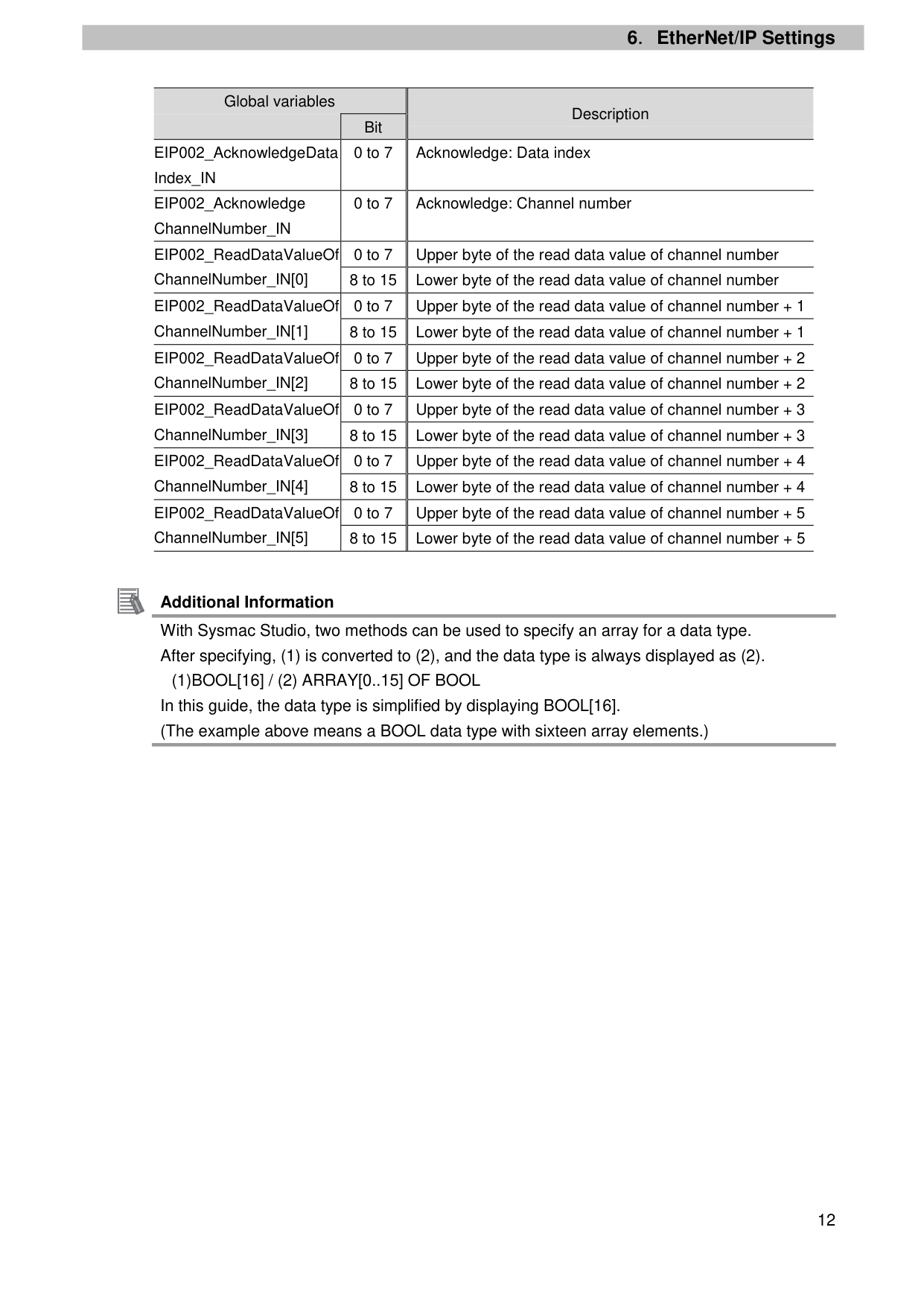
|Global variables|Global variables|Description
| |---|---|---| | |Bit|Description
| |EIP002_AcknowledgeData Index_IN|0 to 7|Acknowledge: Data index| |EIP002_Acknowledge ChannelNumber_IN|0 to 7|Acknowledge: Channel number| |EIP002_ReadDataValueOf ChannelNumber_IN[0]|0 to 7|Upper byte of the read data value of channel number| |EIP002_ReadDataValueOf ChannelNumber_IN[0]|8 to 15|Lower byte of the read data value of channel number| |EIP002_ReadDataValueOf ChannelNumber_IN[1]|0 to 7|Upper byte of the read data value of channel number + 1| |EIP002_ReadDataValueOf ChannelNumber_IN[1]|8 to 15|Lower byte of the read data value of channel number + 1| |EIP002_ReadDataValueOf ChannelNumber_IN[2]|0 to 7|Upper byte of the read data value of channel number + 2| |EIP002_ReadDataValueOf ChannelNumber_IN[2]|8 to 15|Lower byte of the read data value of channel number + 2| |EIP002_ReadDataValueOf ChannelNumber_IN[3]|0 to 7|Upper byte of the read data value of channel number + 3| |EIP002_ReadDataValueOf ChannelNumber_IN[3]|8 to 15|Lower byte of the read data value of channel number + 3| |EIP002_ReadDataValueOf ChannelNumber_IN[4]|0 to 7|Upper byte of the read data value of channel number + 4| |EIP002_ReadDataValueOf ChannelNumber_IN[4]|8 to 15|Lower byte of the read data value of channel number + 4| |EIP002_ReadDataValueOf ChannelNumber_IN[5]|0 to 7|Upper byte of the read data value of channel number + 5| |EIP002_ReadDataValueOf ChannelNumber_IN[5]|8 to 15|Lower byte of the read data value of channel number + 5|

Additional Information With Sysmac Studio, two methods can be used to specify an array for a data type. After specifying, (1) is converted to (2), and the data type is always displayed as (2).
(1)BOOL[16] / (2) ARRAY[0..15] OF BOOL In this guide, the data type is simplified by displaying BOOL[16]. (The example above means a BOOL data type with sixteen array elements.)
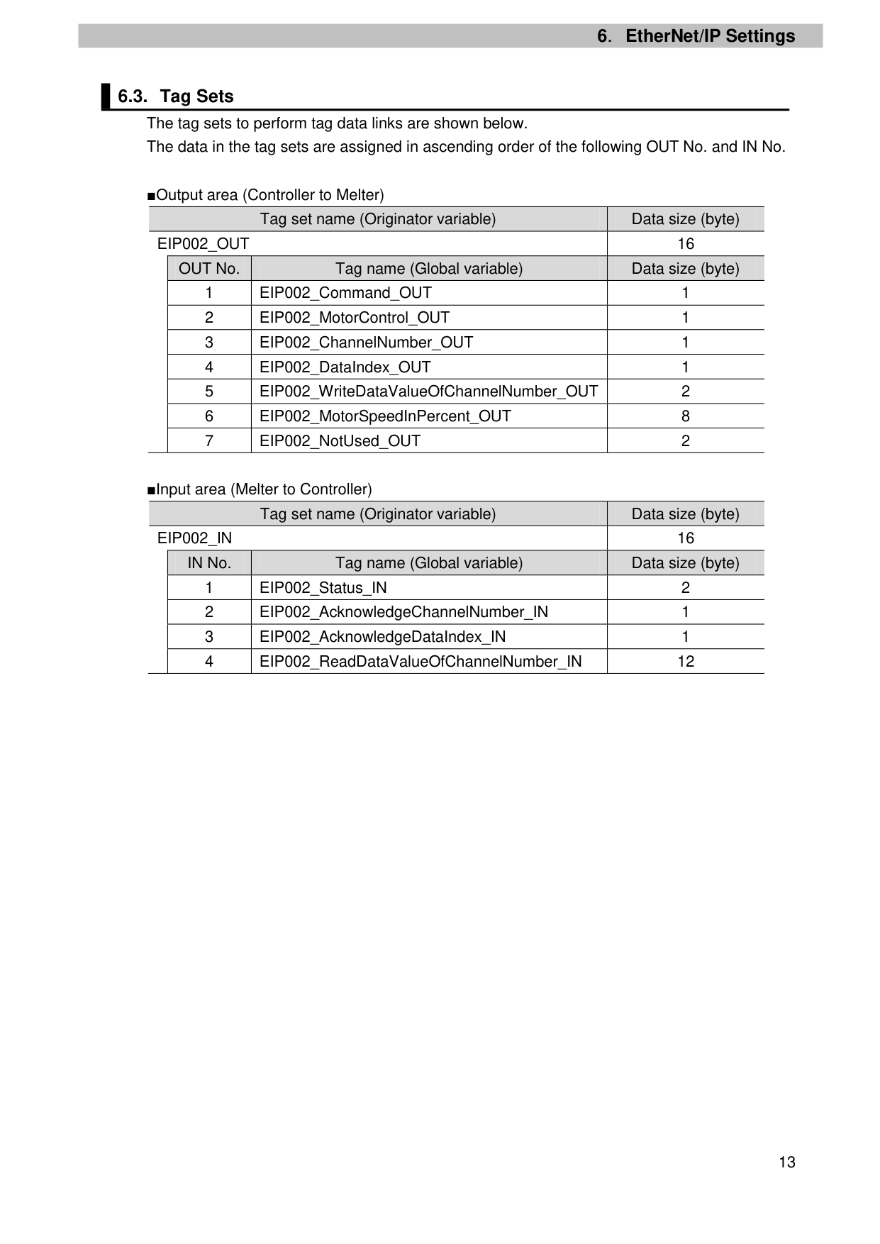
EIP002_OUT 16 OUT No. Tag name (Global variable) Data size (byte)
EIP002_IN 16 IN No. Tag name (Global variable) Data size (byte)
7. EtherNet/IP Connection Procedure
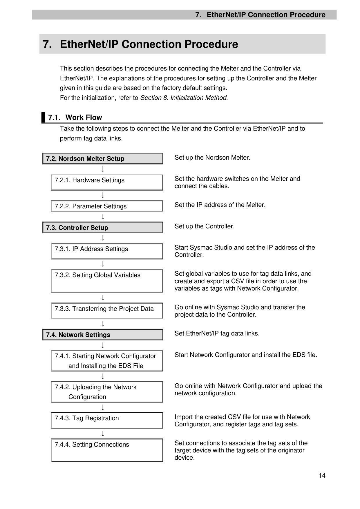
This section describes the procedures for connecting the Melter and the Controller via EtherNet/IP. The explanations of the procedures for setting up the Controller and the Melter given in this guide are based on the factory default settings. For the initialization, refer to Section 8. Initialization Method.
||7.2.1. Hardware Settings| |---| | |---|
Set the hardware switches on the Melter and connect the cables.
↓
||7.2.2. Parameter Settings| |---| | |---|
Set the IP address of the Melter. ↓
||7.3.1. IP Address Settings| |---| | |---|
Start Sysmac Studio and set the IP address of the Controller.
↓
||7.3.2. Setting Global Variables| |---| | |---|
Set global variables to use for tag data links, and create and export a CSV file in order to use the variables as tags with Network Configurator.
↓
||7.3.3. Transferring the Project Data| |---| | |---|
Go online with Sysmac Studio and transfer the project data to the Controller.
↓
||7.4.1. Starting Network Configurator and Installing the EDS File| |---| | |---|
Start Network Configurator and install the EDS file.
↓
||7.4.2. Uploading the Network Configuration| |---|
| |---|
Go online with Network Configurator and upload the network configuration.
↓
||7.4.3. Tag Registration| |---| | |---|
Import the created CSV file for use with Network Configurator, and register tags and tag sets.
↓
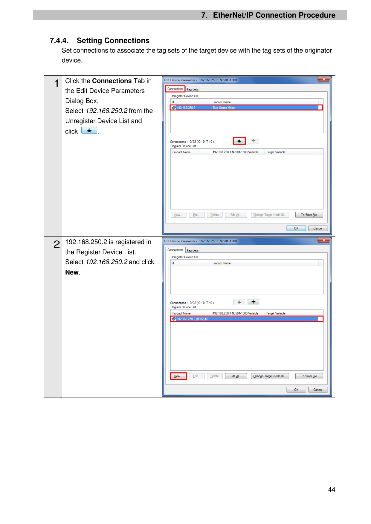
||7.4.4. Setting Connections| |---| | |---|
Set connections to associate the tag sets of the target device with the tag sets of the originator device.
↓
||7.4.5. Transferring the Tag Data Link Parameters| |---| | |---|
↓
|7.5. EtherNet/IP Communication Status Check
| |---|
↓
||7.5.1. Checking the Connection Status| |---| | |---|
↓
||7.5.2. Checking Sent and Received Data| |---| | |---|
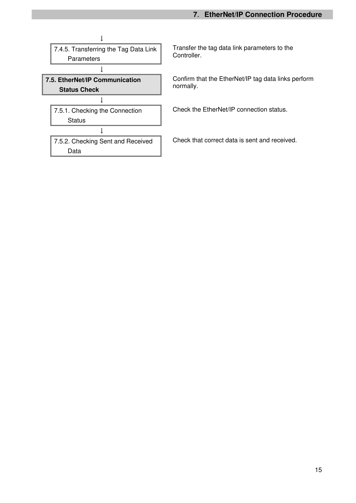
Transfer the tag data link parameters to the Controller.
Confirm that the EtherNet/IP tag data links perform normally.
Check the EtherNet/IP connection status.
Check that correct data is sent and received.
##### 7.2. Nordson Melter Setup
Set up the Nordson Melter.
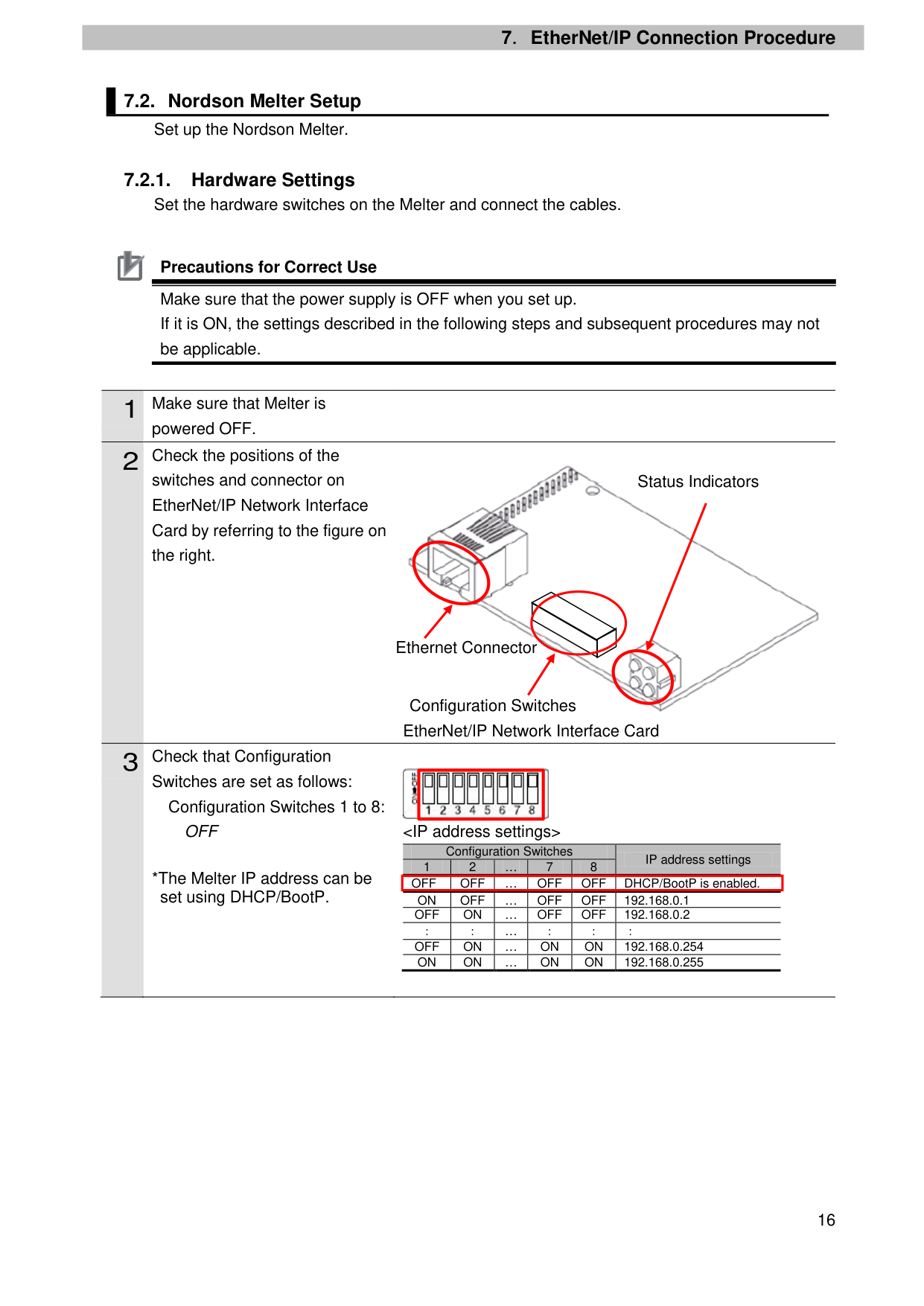
##### 7.2.1. Hardware Settings
Set the hardware switches on the Melter and connect the cables.

Precautions for Correct Use Make sure that the power supply is OFF when you set up. If it is ON, the settings described in the following steps and subsequent procedures may not be applicable.
powered OFF.
switches and connector on EtherNet/IP Network Interface Card by referring to the figure on the right.
EtherNet/IP Network Interface Card
Switches are set as follows: Configuration Switches 1 to 8: OFF
*The Melter IP address can be set using DHCP/BootP.

Status Indicators
Ethernet Connector
Configuration Switches
|| |---|
|Configuration Switches 1 2 … 7 8
|Configuration Switches 1 2 … 7 8
|Configuration Switches 1 2 … 7 8
|Configuration Switches 1 2 … 7 8
|Configuration Switches 1 2 … 7 8
|IP address settings|
|---|---|---|---|---|---| |OFF|OFF|…|OFF
|OFF|DHCP/BootP is enabled.| |ON|OFF|…|OFF|OFF|192.168.0.1| |OFF|ON|…|OFF|OFF|192.168.0.2| |:|:|…|:|:|:| |OFF|ON|…|ON|ON|192.168.0.254| |ON|ON|…|ON|ON|192.168.0.255|
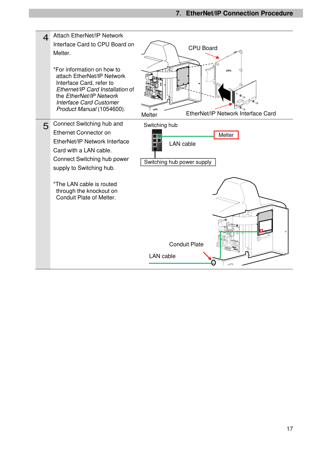
Interface Card to CPU Board on Melter.
*For information on how to attach EtherNet/IP Network Interface Card, refer to Ethernet/IP Card Installation of
the EtherNet/IP Network Interface Card Customer Product Manual (1054600).
Melter
Ethernet Connector on EtherNet/IP Network Interface Card with a LAN cable. Connect Switching hub power supply to Switching hub.
*The LAN cable is routed through the knockout on Conduit Plate of Melter.

CPU Board

EtherNet/IP Network Interface Card
Switching hub


| |
Melter| |---|---| | |
Melter|

LAN cable
| | | |---|---| |
Switching hub power supply|
Switching hub power supply|

Conduit Plate
LAN cable
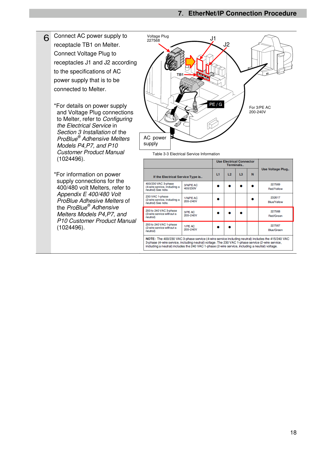
Voltage Plug 227568
J1

J2
receptacle TB1 on Melter. Connect Voltage Plug to receptacles J1 and J2 according to the specifications of AC power supply that is to be connected to Melter.

(1024496).
For 3/PE AC 200-240V
AC power supply
Table 3-3 Electrical Service Information

| | |---|
(1024496).
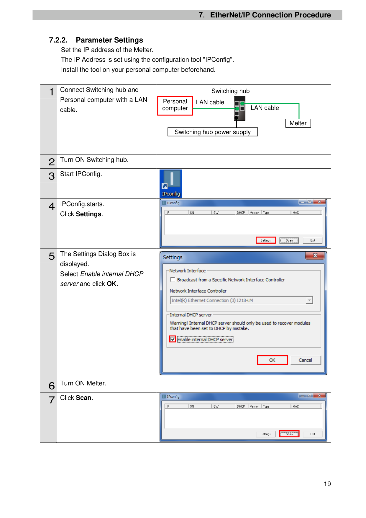
7.2.2. Parameter Settings Set the IP address of the Melter. The IP Address is set using the configuration tool "IPConfig". Install the tool on your personal computer beforehand.
1 Connect Switching hub and Personal computer with a LAN cable.
Switching hub

|Personal computer|LAN cable
| |---|---| |Personal computer| |
LAN cable
| | | |---|---| |
Switching hub power supply|
Switching hub power supply|
Melter
|2|Turn ON Switching hub.| |---|---| |3|Start IPConfig.|

Click Settings.

| | |---|

displayed. Select Enable internal DHCP server and click OK.
| | |---|
| | |---|
|6|Turn ON Melter.| |---|---| |7|Click Scan.|

| | |---|
#### 8 A DHCP request is received on

Personal computer as shown on the right. Check that the MAC address displayed in the MAC Column is the same as that of Melter. Double-click the displayed MAC address.
| | |---|
#### 9 The Configure Dialog Box is

displayed. Set the following items for Ethernet configuration.
| | |---|
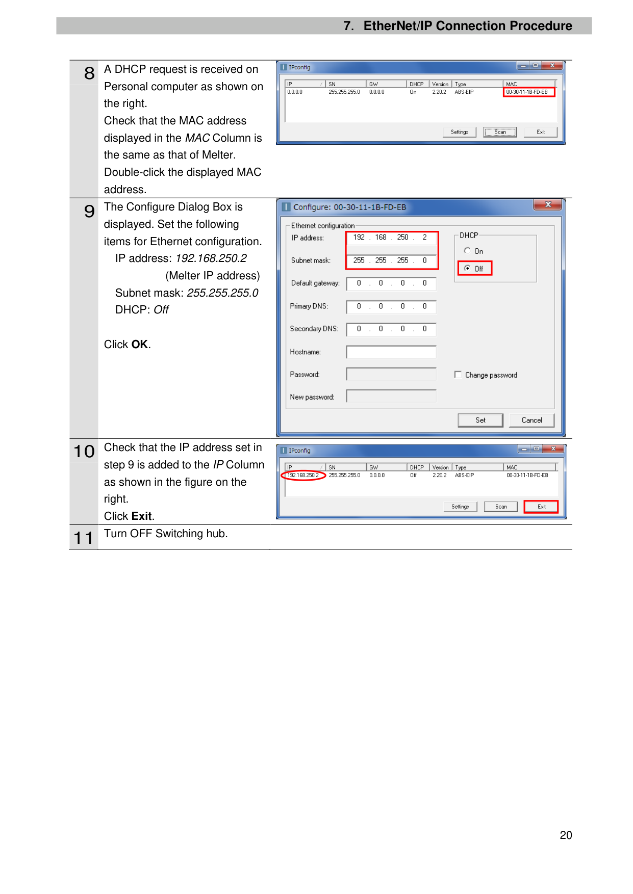
IP address: 192.168.250.2
| | |---|
(Melter IP address) Subnet mask: 255.255.255.0 DHCP: Off
Click OK.
#### 10 Check that the IP address set in

step 9 is added to the IP Column as shown in the figure on the right. Click Exit.
| | |---|
#### 11 Turn OFF Switching hub.
##### 7.3. Controller Setup
Set up the Controller.
7.3.1. IP Address Settings Start Sysmac Studio and set the IP address of the Controller. Install Sysmac Studio and the USB driver on your personal computer beforehand.
built-in EtherNet/IP port (PORT1) on Controller, and connect a USB cable to the peripheral (USB) port. As shown in 5.2. Device Configuration, connect Personal computer and Switching hub to Controller.
*If the User Account Control Dialog Box is displayed at start, make a selection to start Sysmac Studio.
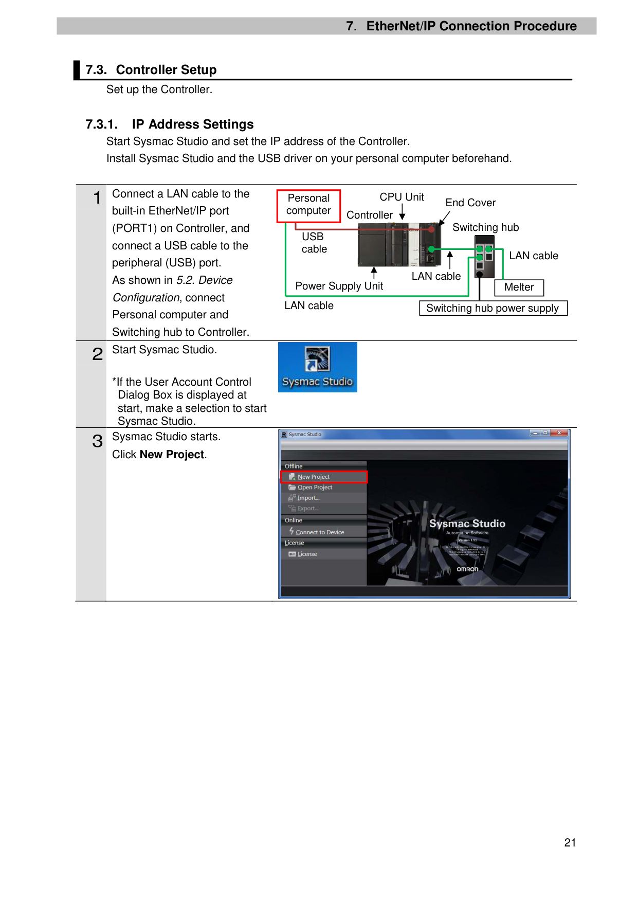
Click New Project.
CPU Unit
Personal computer
End Cover
Controller
Switching hub

USB cable

LAN cable
LAN cable
| |Melter
| |---|---| |Switching hub power supply|Switching hub power supply|
Power Supply Unit
LAN cable


| | |---|
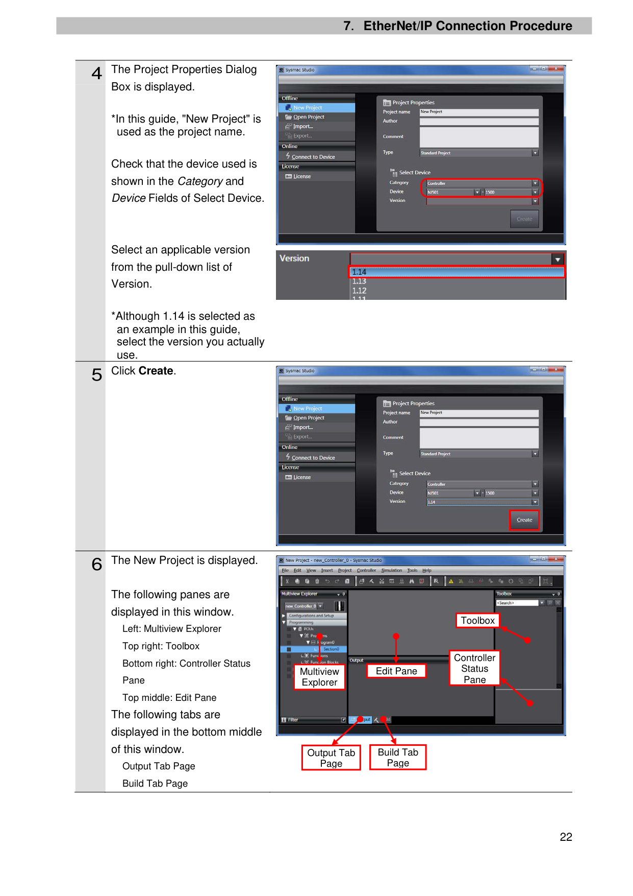
Box is displayed.
*In this guide, "New Project" is used as the project name.
Check that the device used is shown in the Category and Device Fields of Select Device.
Select an applicable version from the pull-down list of Version.
*Although 1.14 is selected as an example in this guide, select the version you actually use.
The following panes are displayed in this window. Left: Multiview Explorer Top right: Toolbox Bottom right: Controller Status Pane Top middle: Edit Pane
The following tabs are displayed in the bottom middle of this window.
Output Tab Page Build Tab Page


| | |---|

| | |---|

Toolbox
|Controller Status Pane| |---|
|Edit Pane| |---|
Multiview Explorer
Build Tab Page
Output Tab Page
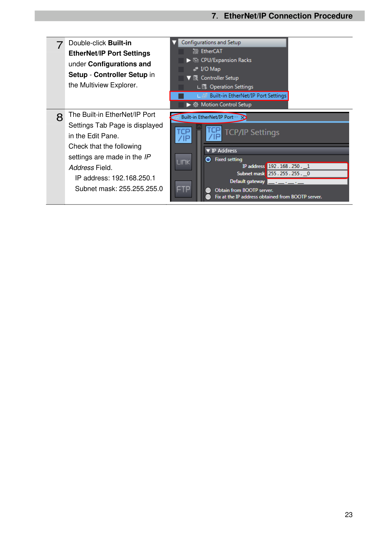
EtherNet/IP Port Settings under Configurations and Setup - Controller Setup in
the Multiview Explorer.
Settings Tab Page is displayed in the Edit Pane. Check that the following settings are made in the IP Address Field.
IP address: 192.168.250.1 Subnet mask: 255.255.255.0

| | |---|

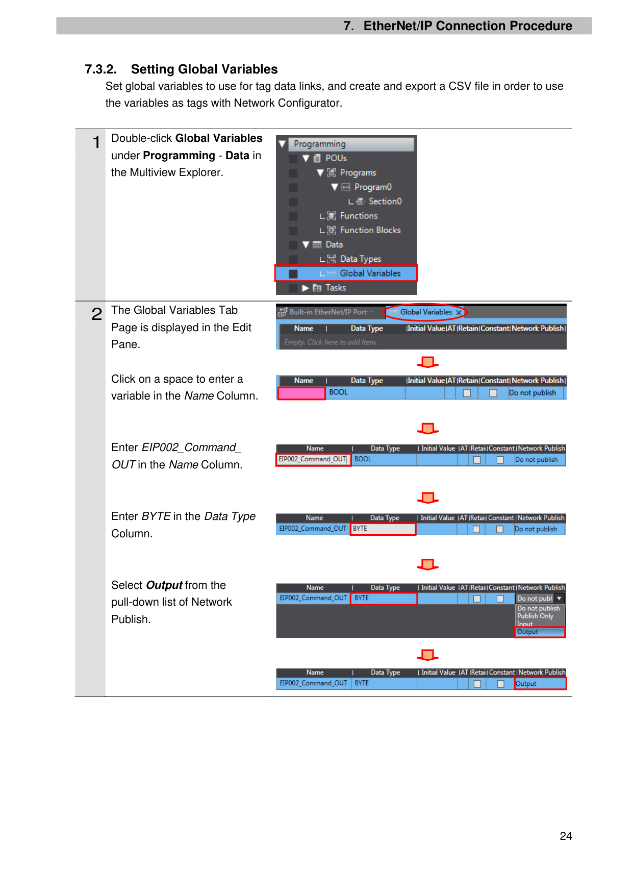
7.3.2. Setting Global Variables Set global variables to use for tag data links, and create and export a CSV file in order to use the variables as tags with Network Configurator.
1 Double-click Global Variables
under Programming - Data in the Multiview Explorer.
#### 2 The Global Variables Tab
Page is displayed in the Edit Pane.
Click on a space to enter a variable in the Name Column.

| | |---|


| | |---|
Enter EIP002_Command_ OUT in the Name Column.

| | |---|
Enter BYTE in the Data Type Column.
Select Output from the pull-down list of Network Publish.

| | |---|

| | |---|

| | |---|
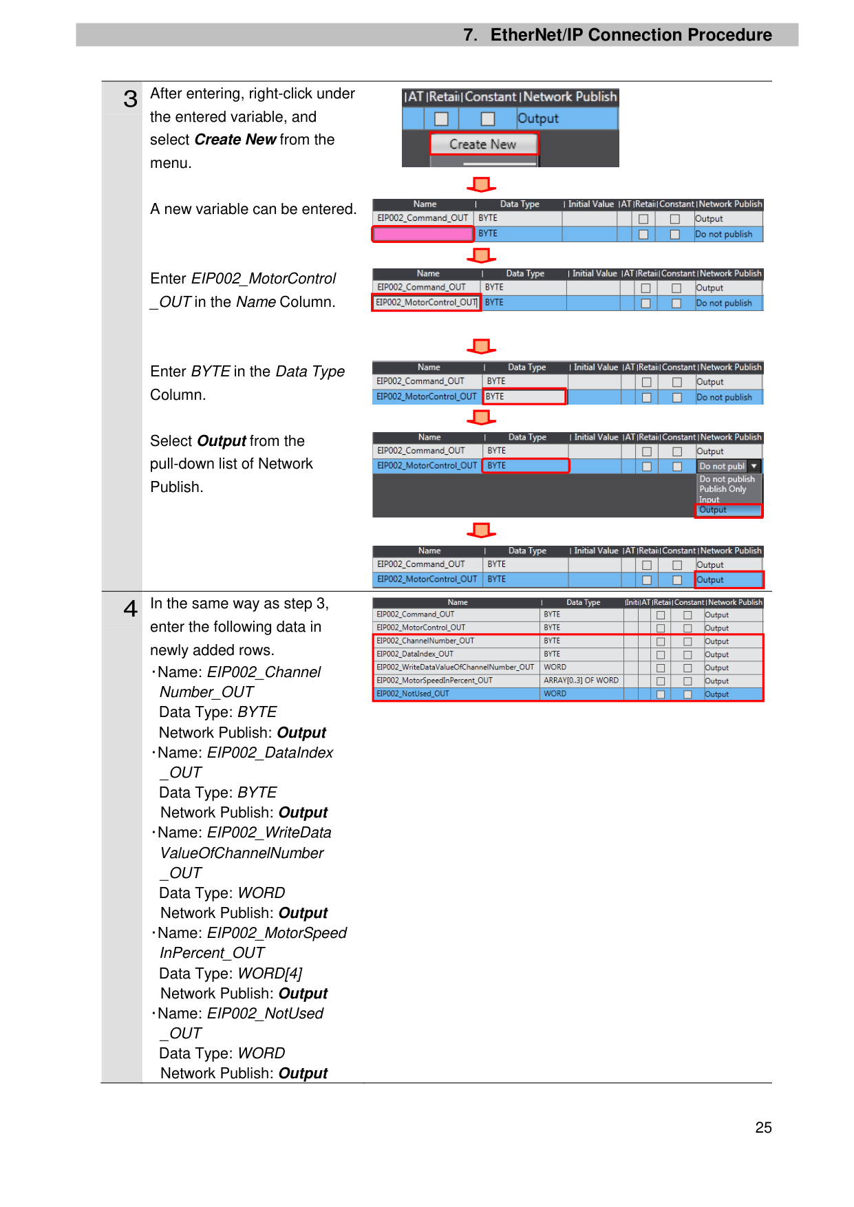
the entered variable, and select Create New from the menu.
A new variable can be entered.
Enter EIP002_MotorControl _OUT in the Name Column.
Enter BYTE in the Data Type Column.
Select Output from the pull-down list of Network Publish.
enter the following data in newly added rows. ・Name: EIP002_Channel
Number_OUT Data Type: BYTE Network Publish: Output ・Name: EIP002_DataIndex _OUT Data Type: BYTE Network Publish: Output
・Name: EIP002_WriteData ValueOfChannelNumber _OUT Data Type: WORD Network Publish: Output
・Name: EIP002_MotorSpeed InPercent_OUT Data Type: WORD[4] Network Publish: Output
・Name: EIP002_NotUsed _OUT Data Type: WORD Network Publish: Output

| | |---|


| | |---|

| | |---|

| | |---|

| | |---|
|| |---|
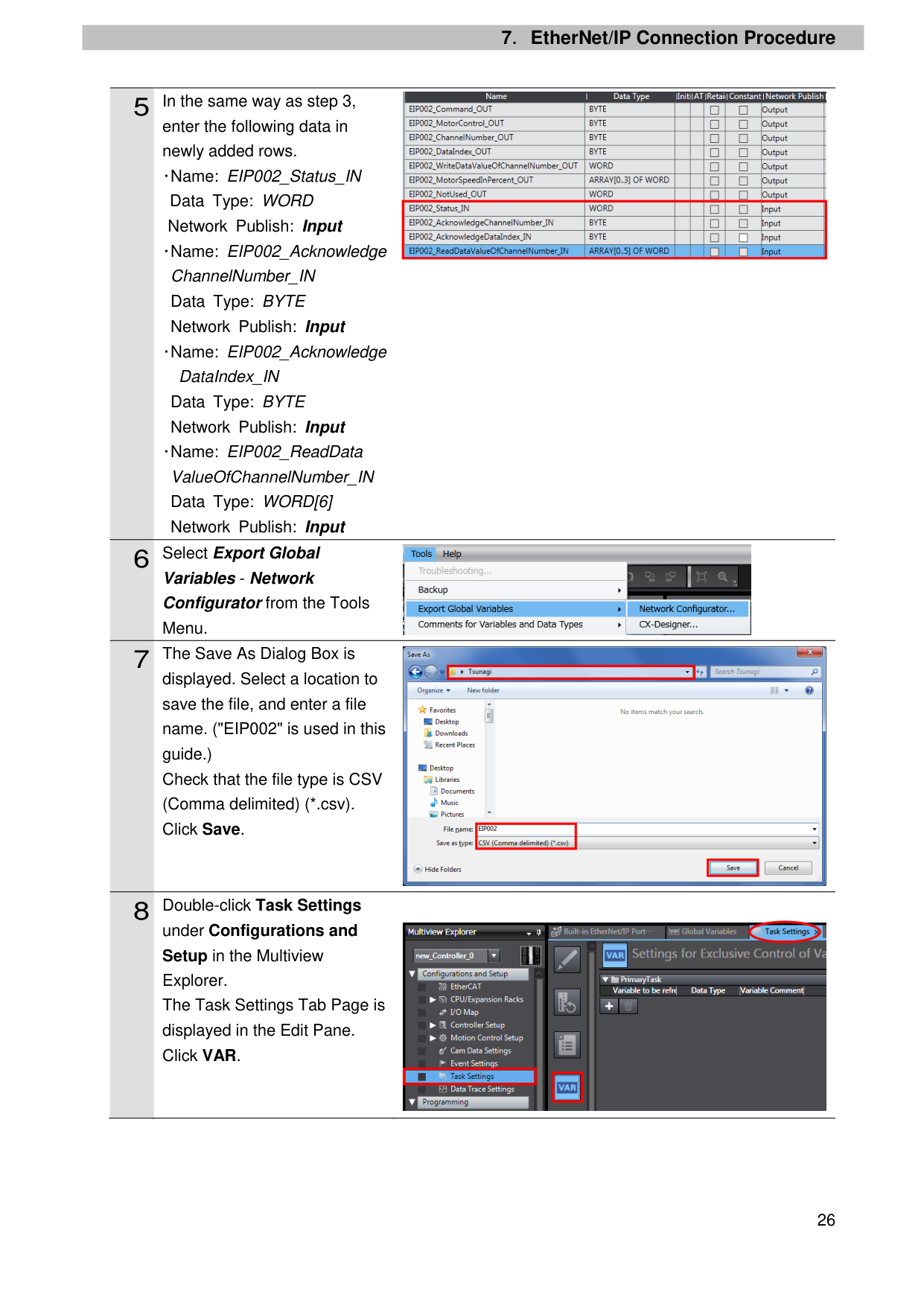
enter the following data in newly added rows. ・Name: EIP002_Status_IN
Data Type: WORD Network Publish: Input
・Name: EIP002_Acknowledge ChannelNumber_IN Data Type: BYTE Network Publish: Input
・Name: EIP002_Acknowledge
DataIndex_IN Data Type: BYTE Network Publish: Input
・Name: EIP002_ReadData ValueOfChannelNumber_IN Data Type: WORD[6] Network Publish: Input
Variables - Network Configurator from the Tools Menu.
displayed. Select a location to save the file, and enter a file name. ("EIP002" is used in this guide.) Check that the file type is CSV (Comma delimited) (*.csv). Click Save.
under Configurations and Setup in the Multiview Explorer. The Task Settings Tab Page is displayed in the Edit Pane. Click VAR.

| | |---|


| | |---|
| | |---|
| | |---|

| |
|---|
| | |---|
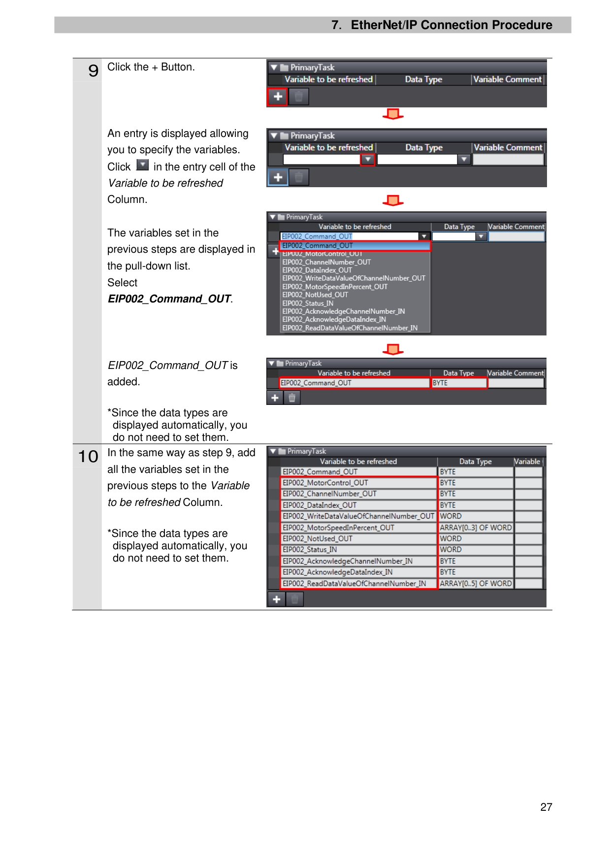
An entry is displayed allowing you to specify the variables. Click in the entry cell of the Variable to be refreshed Column.
The variables set in the previous steps are displayed in the pull-down list. Select EIP002_Command_OUT.
EIP002_Command_OUT is added.
*Since the data types are displayed automatically, you do not need to set them.

all the variables set in the previous steps to the Variable to be refreshed Column.
*Since the data types are displayed automatically, you do not need to set them.

| | |---|

| | |---|

| | |---|


| | |---|
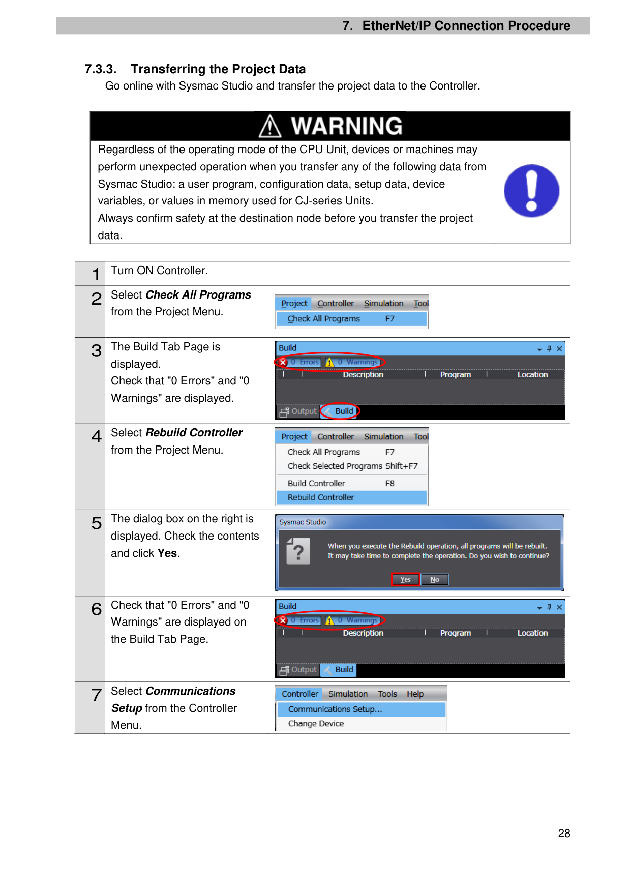
##### 7.3.3. Transferring the Project Data
Go online with Sysmac Studio and transfer the project data to the Controller.
|| |---| |Regardless of the operating mode of the CPU Unit, devices or machines may perform unexpected operation when you transfer any of the following data from Sysmac Studio: a user program, configuration data, setup data, device variables, or values in memory used for CJ-series Units. Always confirm safety at the destination node before you transfer the project data.
|
|1|Turn ON Controller.| |---|---| |2|Select Check All Programs|

from the Project Menu.
displayed. Check that "0 Errors" and "0 Warnings" are displayed.
from the Project Menu.
displayed. Check the contents and click Yes.
Warnings" are displayed on the Build Tab Page.


| | |---|


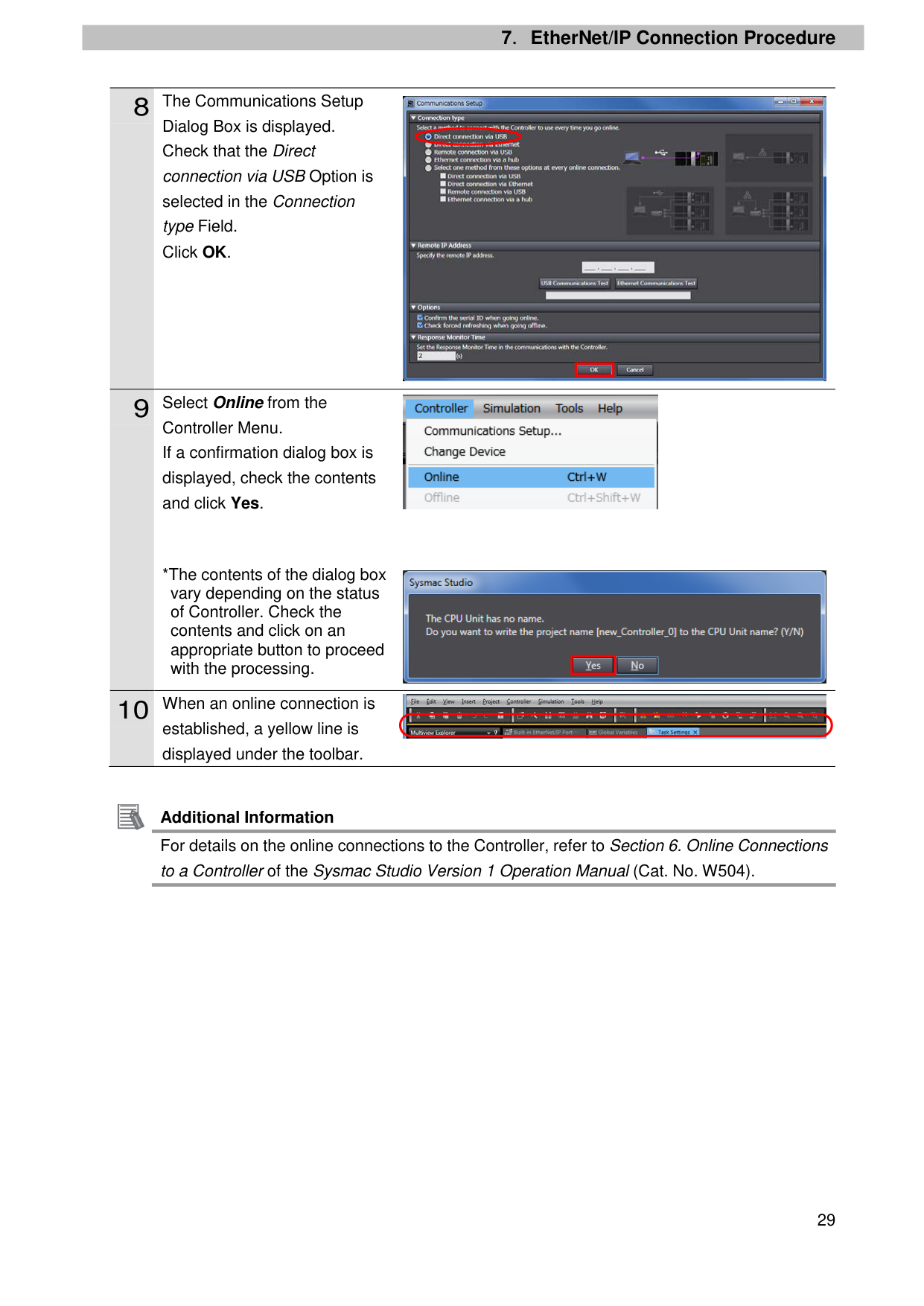
Setup from the Controller Menu.
Dialog Box is displayed. Check that the Direct connection via USB Option is selected in the Connection type Field. Click OK.
Controller Menu. If a confirmation dialog box is displayed, check the contents and click Yes.
*The contents of the dialog box vary depending on the status of Controller. Check the contents and click on an appropriate button to proceed with the processing.

| | |---|


| | |---|

established, a yellow line is displayed under the toolbar.

Additional Information For details on the online connections to the Controller, refer to Section 6. Online Connections to a Controller of the Sysmac Studio Version 1 Operation Manual (Cat. No. W504).
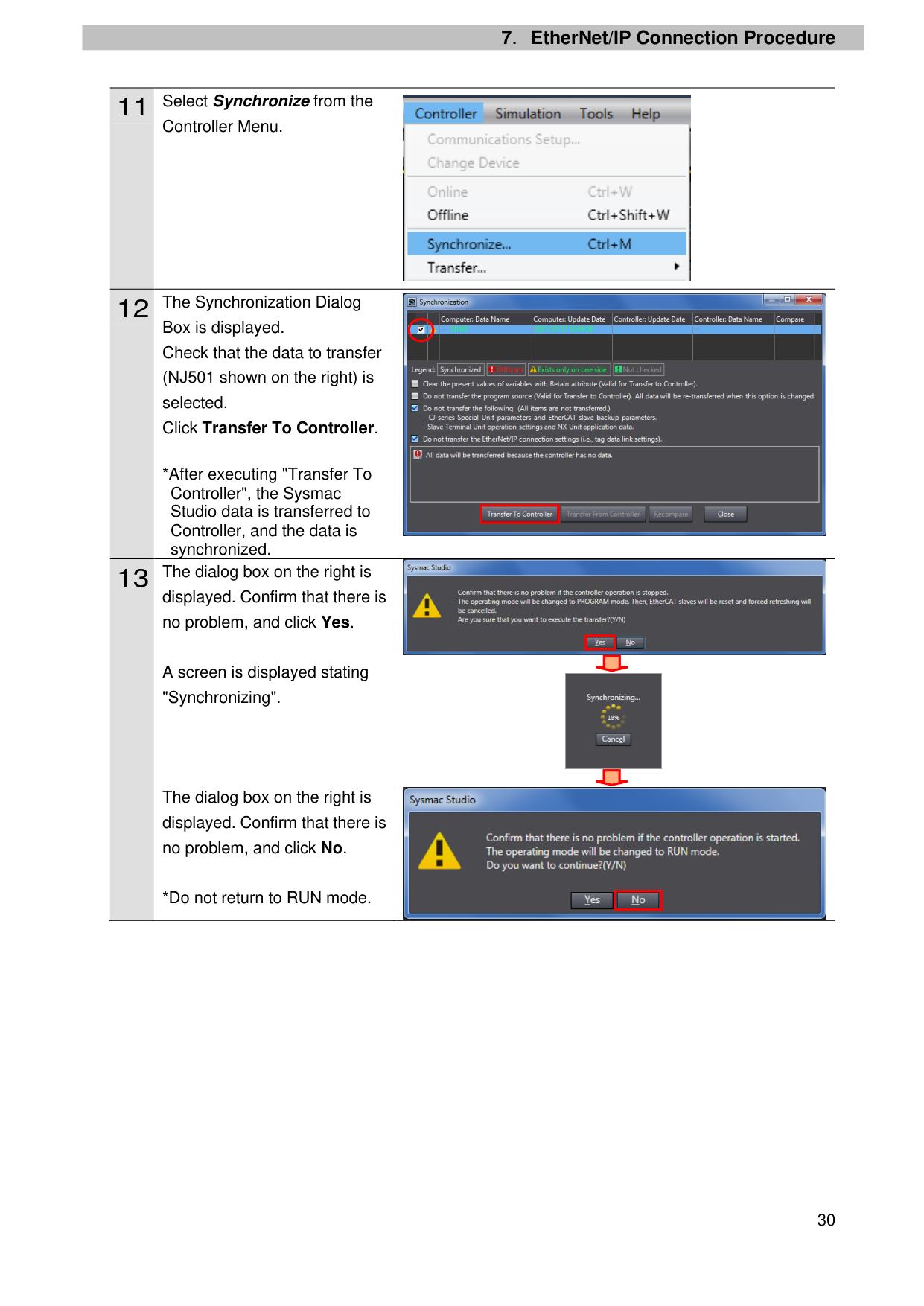
Controller Menu.
Box is displayed. Check that the data to transfer (NJ501 shown on the right) is selected. Click Transfer To Controller.
*After executing "Transfer To Controller", the Sysmac Studio data is transferred to Controller, and the data is synchronized.
displayed. Confirm that there is no problem, and click Yes.
A screen is displayed stating "Synchronizing".
The dialog box on the right is displayed. Confirm that there is no problem, and click No.
*Do not return to RUN mode.


| | |---|

| | |---|


| |
|---|
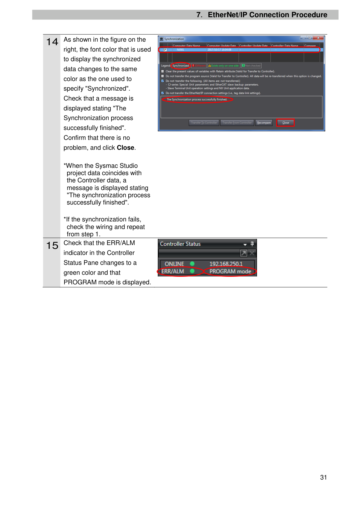
right, the font color that is used to display the synchronized data changes to the same color as the one used to specify "Synchronized". Check that a message is displayed stating "The Synchronization process successfully finished". Confirm that there is no problem, and click Close.

| | |---|

indicator in the Controller Status Pane changes to a green color and that PROGRAM mode is displayed.
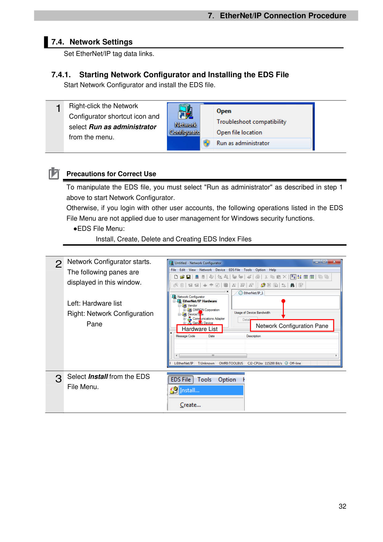
##### 7.4. Network Settings
Set EtherNet/IP tag data links.
##### 7.4.1. Starting Network Configurator and Installing the EDS FileStart Network Configurator and install the EDS file.
Configurator shortcut icon and select Run as administrator from the menu.
Precautions for Correct Use To manipulate the EDS file, you must select "Run as administrator" as described in step 1 above to start Network Configurator. Otherwise, if you login with other user accounts, the following operations listed in the EDS File Menu are not applied due to user management for Windows security functions.
●EDS File Menu: Install, Create, Delete and Creating EDS Index Files
The following panes are displayed in this window.
Left: Hardware list Right: Network Configuration
Pane


|Network Configuration Pane| |---|
Hardware List

File Menu.
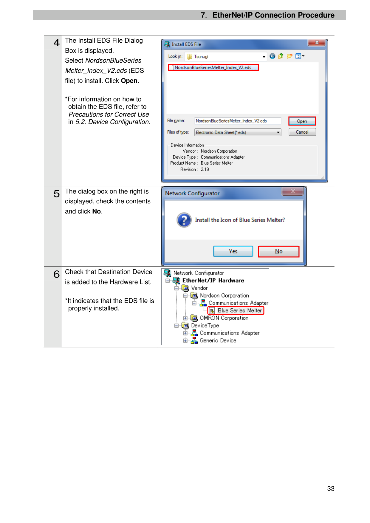
Box is displayed. Select NordsonBlueSeries Melter_Index_V2.eds (EDS file) to install. Click Open.
*For information on how to obtain the EDS file, refer to Precautions for Correct Use in 5.2. Device Configuration.

displayed, check the contents and click No.

is added to the Hardware List.
*It indicates that the EDS file is properly installed.
| | |---|
| | |---|
| | |---|

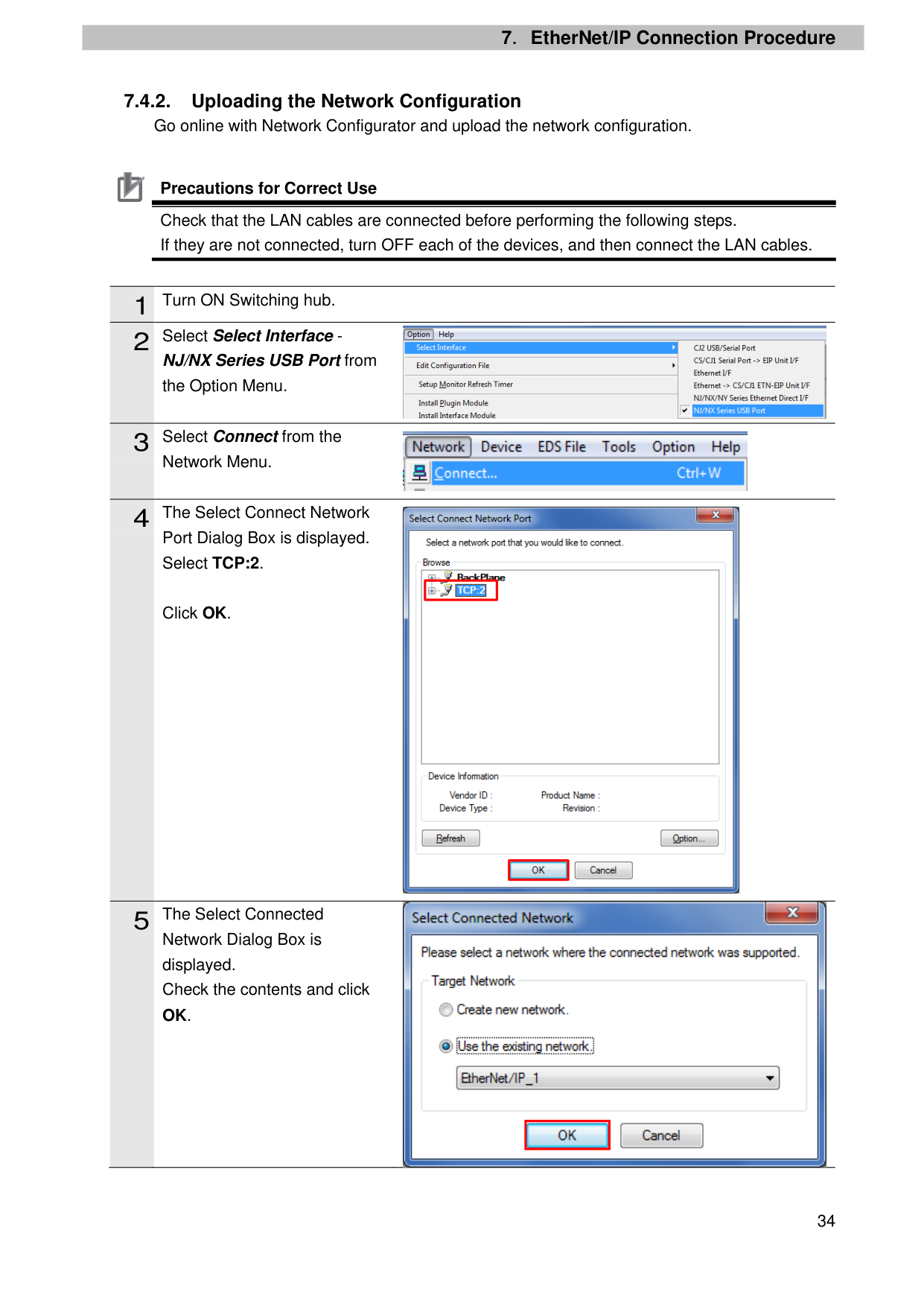
Precautions for Correct Use Check that the LAN cables are connected before performing the following steps. If they are not connected, turn OFF each of the devices, and then connect the LAN cables.
|1|Turn ON Switching hub.| |---|---| |2|Select Select Interface -|
NJ/NX Series USB Port from the Option Menu.
Network Menu.
Port Dialog Box is displayed. Select TCP:2.
Click OK.


| | |---|
| | |---|

Network Dialog Box is displayed. Check the contents and click OK.
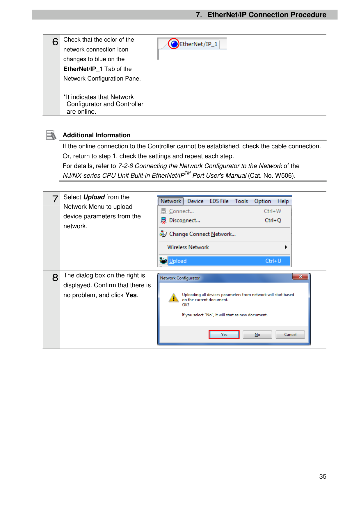
| | |---|
network connection icon changes to blue on the EtherNet/IP_1 Tab of the Network Configuration Pane.
*It indicates that Network Configurator and Controller are online.
Additional Information If the online connection to the Controller cannot be established, check the cable connection. Or, return to step 1, check the settings and repeat each step. For details, refer to 7-2-8 Connecting the Network Configurator to the Network of the NJ/NX-series CPU Unit Built-in EtherNet/IPTM Port User's Manual (Cat. No. W506).
Network Menu to upload device parameters from the network.

displayed. Confirm that there is no problem, and click Yes.


| | |---|
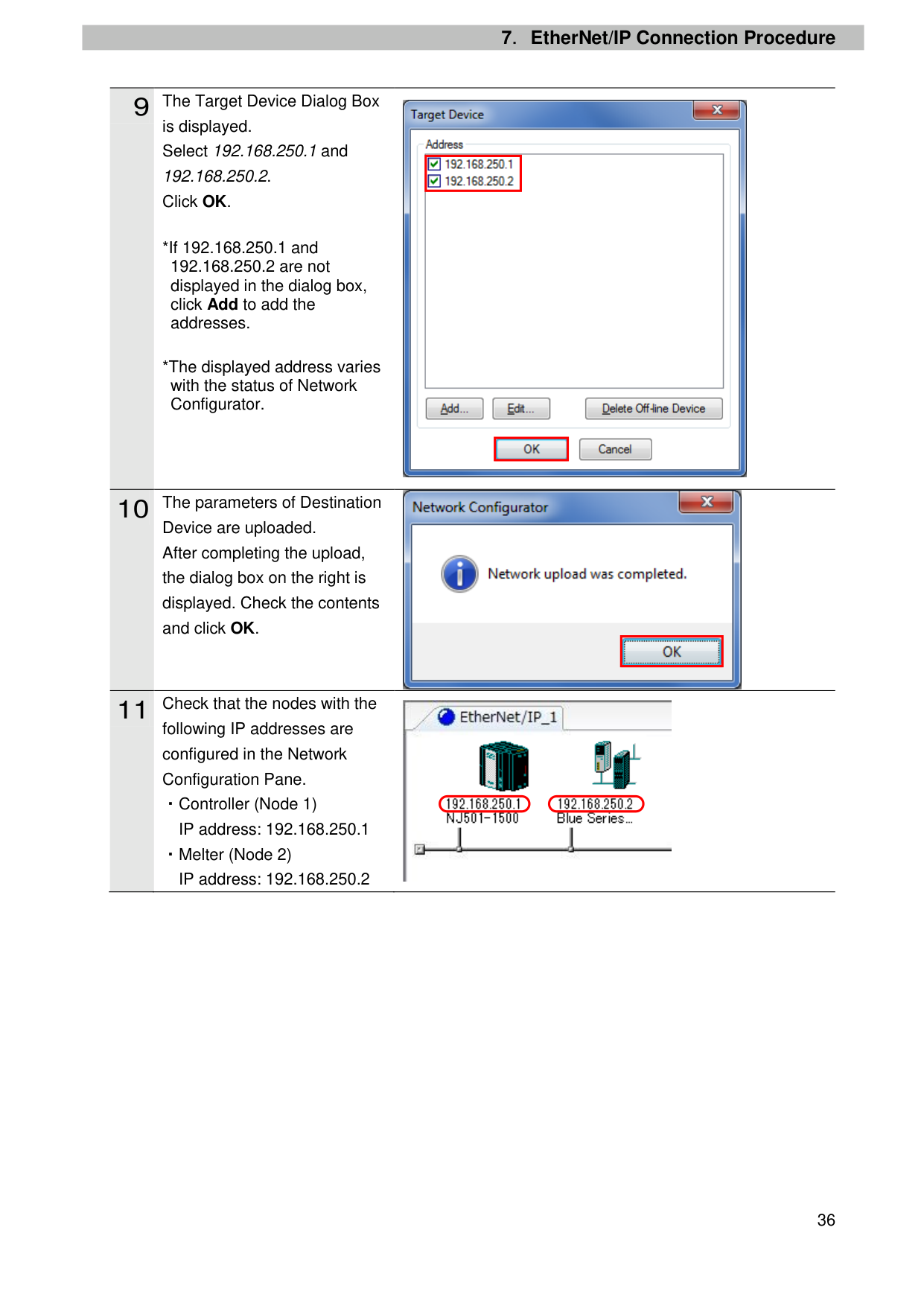
is displayed. Select 192.168.250.1 and 192.168.250.2. Click OK.
Device are uploaded. After completing the upload, the dialog box on the right is displayed. Check the contents and click OK.
following IP addresses are configured in the Network Configuration Pane. ・Controller (Node 1)
・Melter (Node 2)

| | |---|
| | |---|

| | |---|

##### 7.4.3. Tag Registration
Import the created CSV file for use with Network Configurator, and register tags and tag sets.
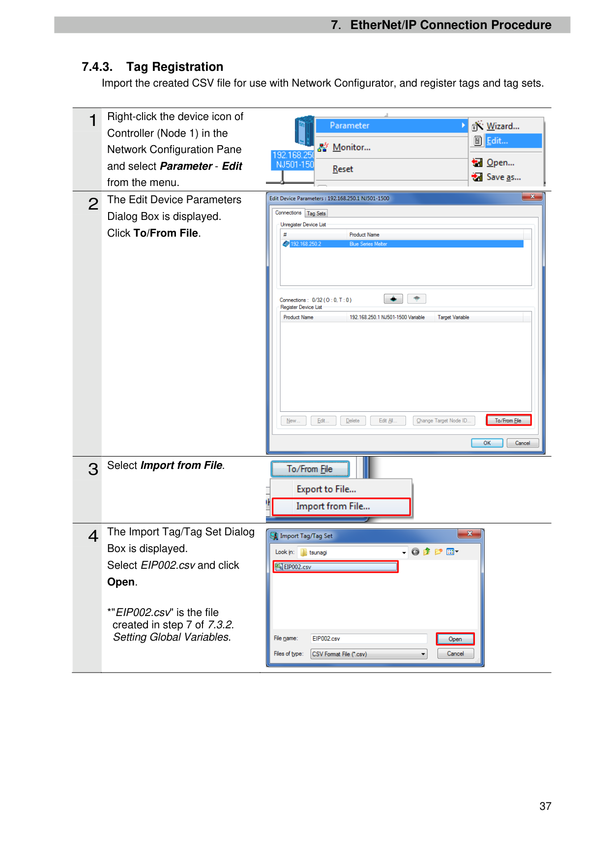
Controller (Node 1) in the Network Configuration Pane and select Parameter - Edit from the menu.
Dialog Box is displayed. Click To/From File.
Box is displayed. Select EIP002.csv and click Open.
*"EIP002.csv" is the file created in step 7 of 7.3.2. Setting Global Variables.


| | |---|

| | |---|

| | |---|
| | |---|
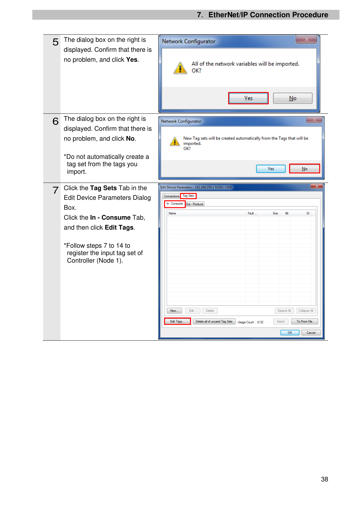
displayed. Confirm that there is no problem, and click Yes.
displayed. Confirm that there is no problem, and click No.
*Do not automatically create a tag set from the tags you import.
Edit Device Parameters Dialog Box. Click the In - Consume Tab, and then click Edit Tags.
*Follow steps 7 to 14 to register the input tag set of Controller (Node 1).

| | |---|

| | |---|

| | |---|
| | |---|
| | |---|
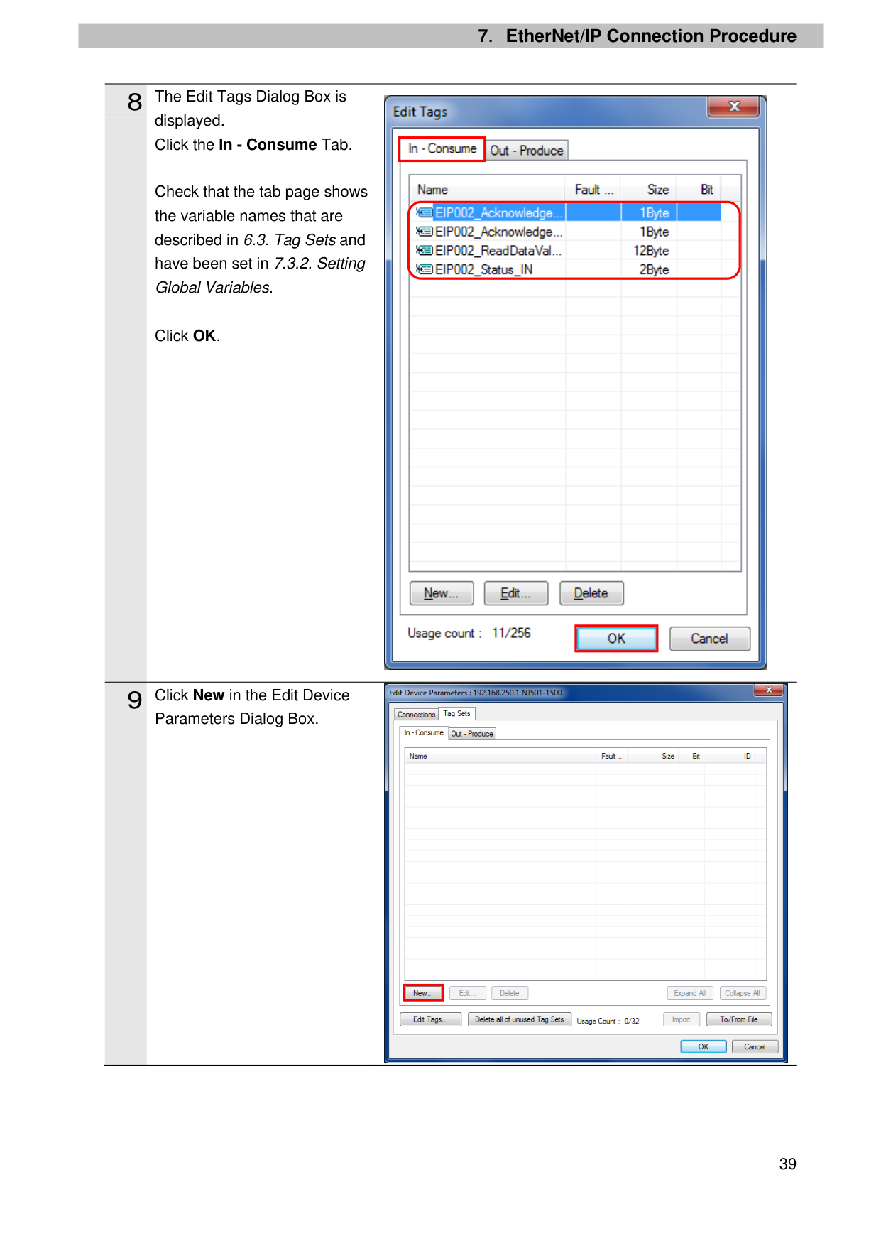
displayed. Click the In - Consume Tab.
Check that the tab page shows the variable names that are described in 6.3. Tag Sets and have been set in 7.3.2. Setting Global Variables.
Click OK.
Parameters Dialog Box.

| | |---|
| | |---|

| | |---|
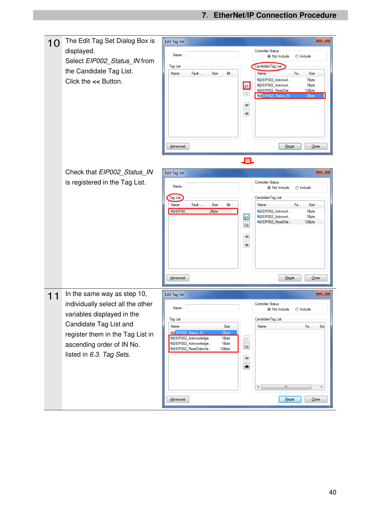
displayed. Select EIP002_Status_IN from the Candidate Tag List. Click the << Button.
Check that EIP002_Status_IN is registered in the Tag List.
individually select all the other variables displayed in the Candidate Tag List and register them in the Tag List in ascending order of IN No. listed in 6.3. Tag Sets.

| | |---|
| | |---|


| | |---|
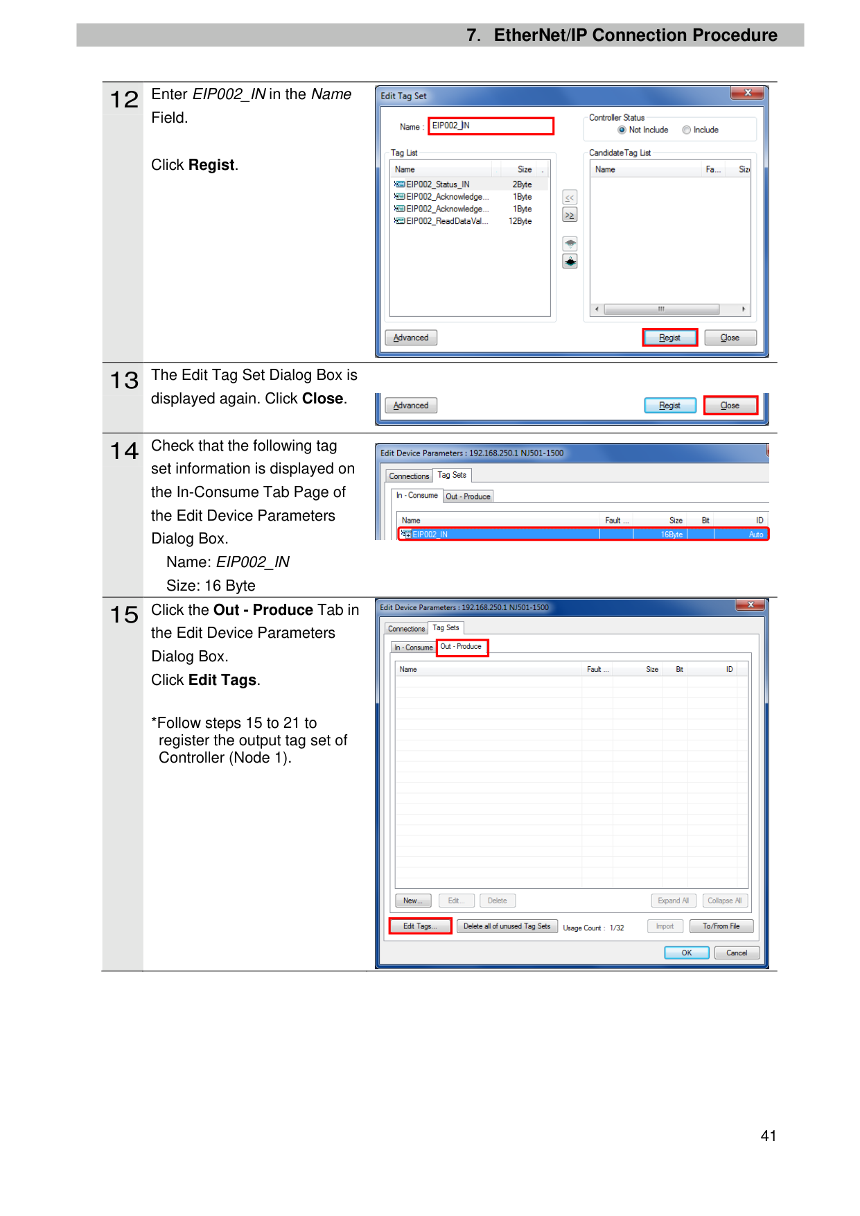
Field.
Click Regist.
displayed again. Click Close.
set information is displayed on the In-Consume Tab Page of the Edit Device Parameters Dialog Box.
Name: EIP002_IN Size: 16 Byte
the Edit Device Parameters Dialog Box. Click Edit Tags.
*Follow steps 15 to 21 to register the output tag set of Controller (Node 1).

| | |---|
| | |---|

| | |---|


| | |---|
| | |---|
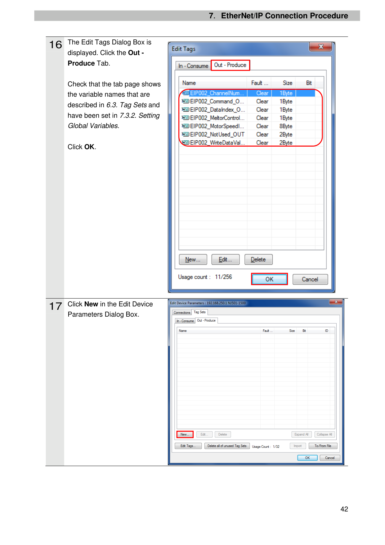
displayed. Click the Out Produce Tab.
Check that the tab page shows the variable names that are described in 6.3. Tag Sets and have been set in 7.3.2. Setting Global Variables.
Click OK.
Parameters Dialog Box.

| |
|---|
| | |---|

| | |---|
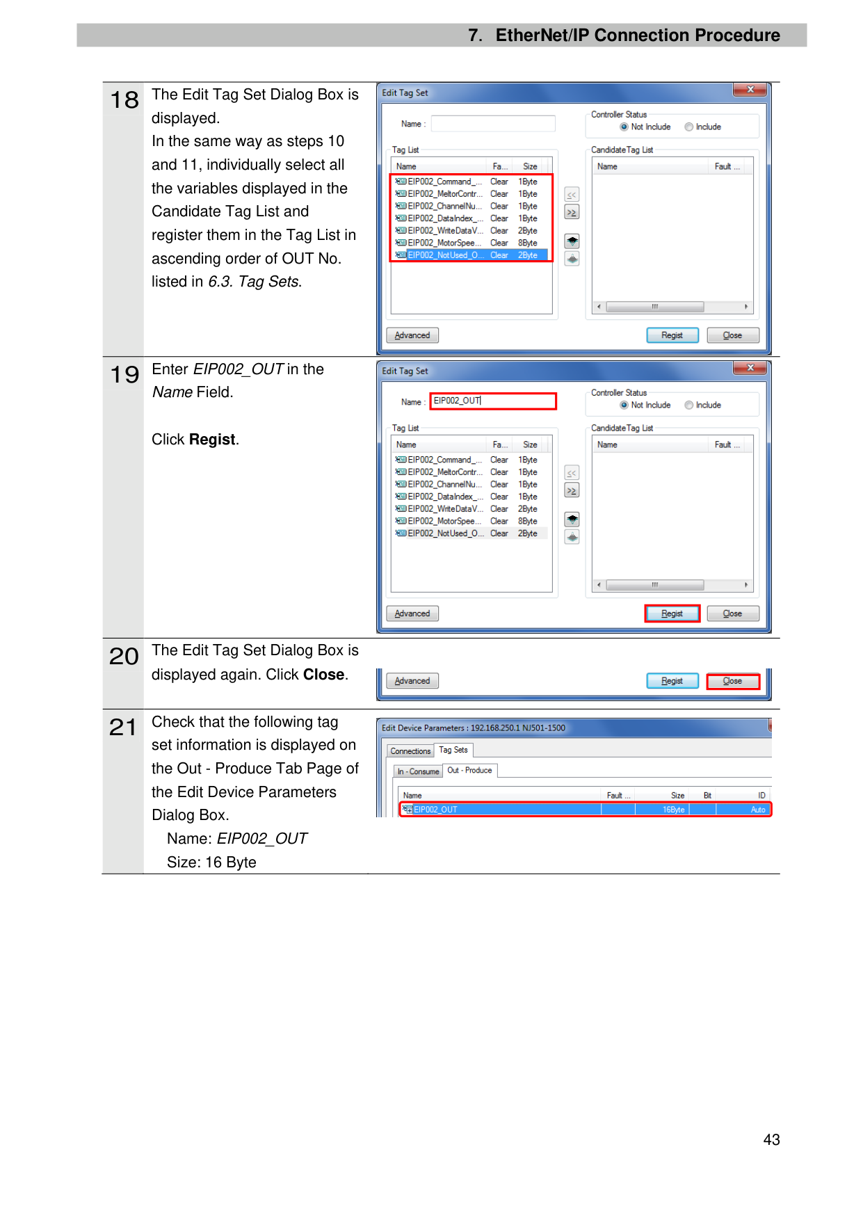
displayed. In the same way as steps 10 and 11, individually select all the variables displayed in the Candidate Tag List and register them in the Tag List in ascending order of OUT No. listed in 6.3. Tag Sets.
Name Field.
Click Regist.
displayed again. Click Close.
set information is displayed on the Out - Produce Tab Page of the Edit Device Parameters Dialog Box.
Name: EIP002_OUT Size: 16 Byte

| | |---|

| | |---|
| | |---|

| | |---|

the Edit Device Parameters Dialog Box. Select 192.168.250.2 from the Unregister Device List and click .

the Register Device List. Select 192.168.250.2 and click New.

| | |---|
| | |---|
| | |---|

| | |---|
| | |---|
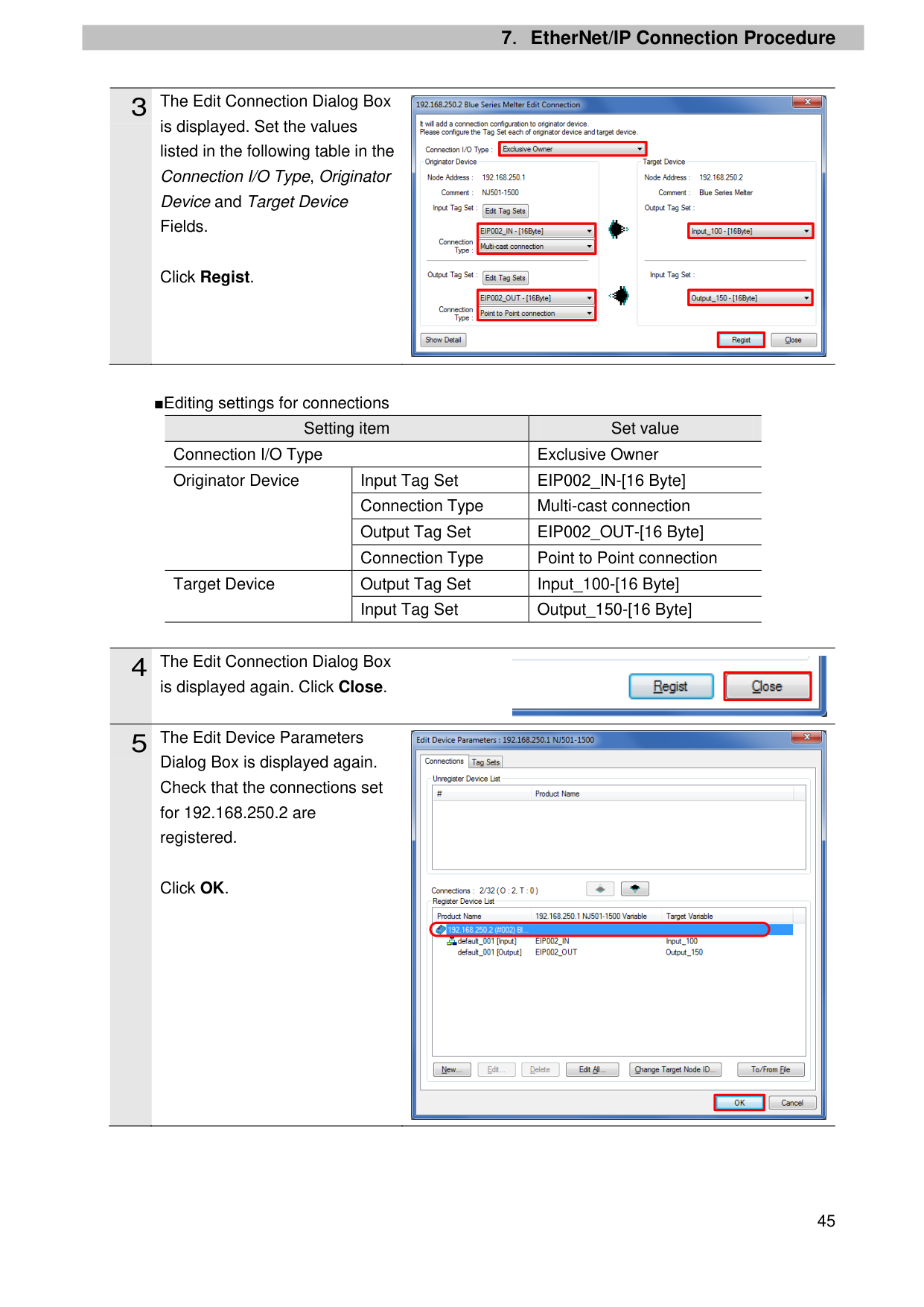
is displayed. Set the values listed in the following table in the Connection I/O Type, Originator Device and Target Device Fields.
Click Regist.
■Editing settings for connections
|Setting item|Setting item|Set value| |---|---|---| |Connection I/O Type|Connection I/O Type|Exclusive Owner| |Originator Device|Input Tag Set|EIP002_IN-[16 Byte]|
|Originator Device|Connection Type|Multi-cast connection| |Originator Device|Output Tag Set|EIP002_OUT-[16 Byte]| |Originator Device|Connection Type|Point to Point connection| |Target Device
|Output Tag Set|Input_100-[16 Byte]| |Target Device
|Input Tag Set|Output_150-[16 Byte]|
is displayed again. Click Close.
Dialog Box is displayed again. Check that the connections set for 192.168.250.2 are registered.
Click OK.

| | |---|
| | |---|
| | |---|
| | |---|
| | |---|
| | |---|

| | |---|

| | |---|
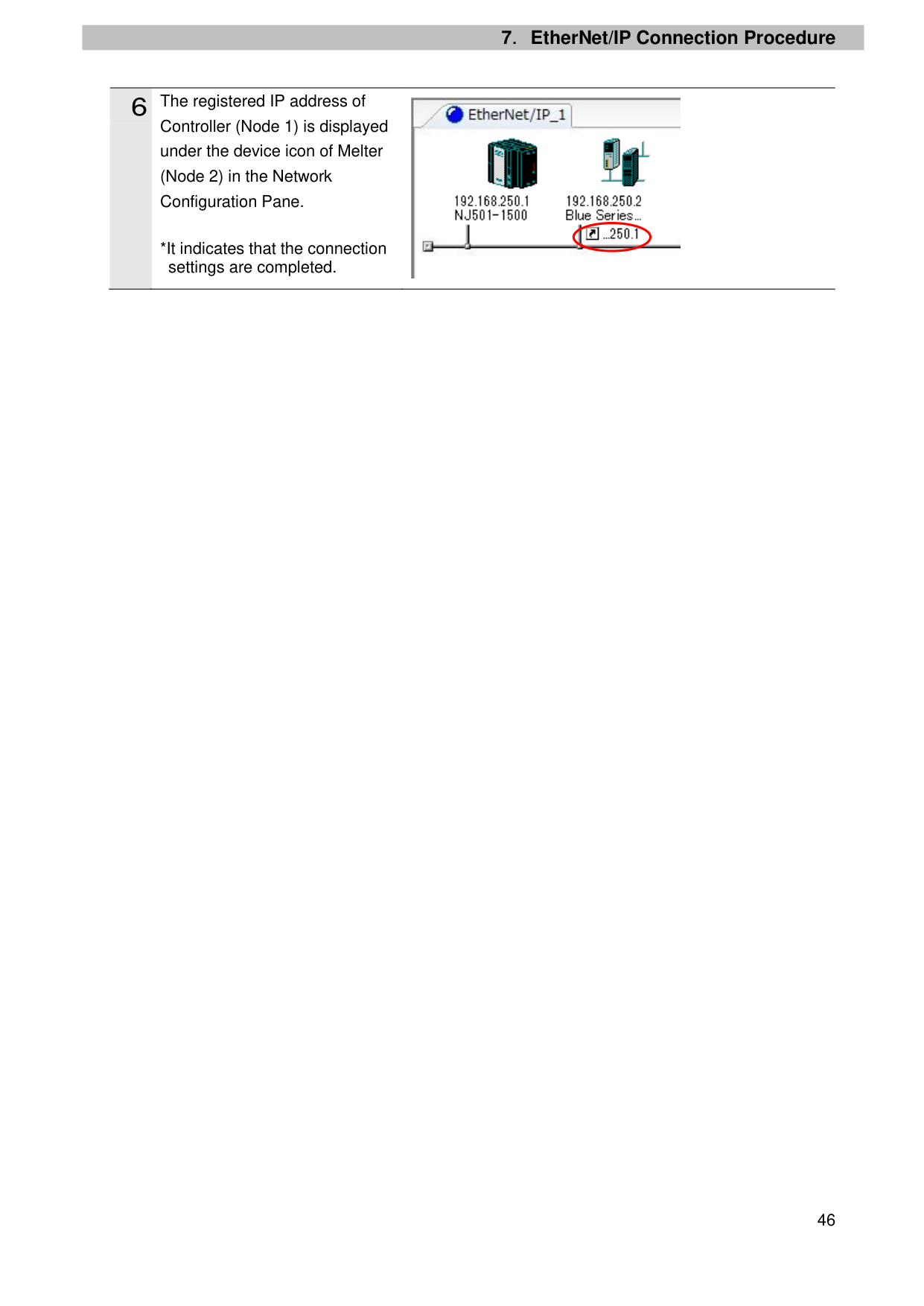
Controller (Node 1) is displayed under the device icon of Melter (Node 2) in the Network Configuration Pane.
*It indicates that the connection settings are completed.

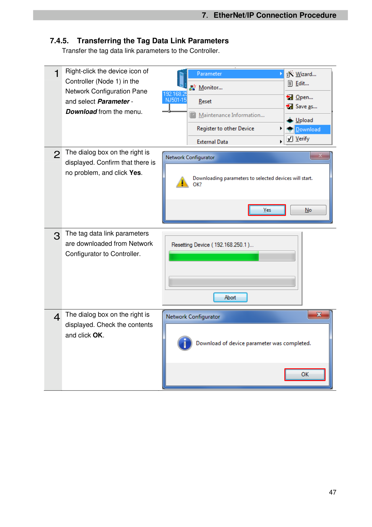
##### 7.4.5. Transferring the Tag Data Link ParametersTransfer the tag data link parameters to the Controller.
Controller (Node 1) in the Network Configuration Pane and select Parameter Download from the menu.
displayed. Confirm that there is no problem, and click Yes.
are downloaded from Network Configurator to Controller.
displayed. Check the contents and click OK.


| | |---|


| | |---|
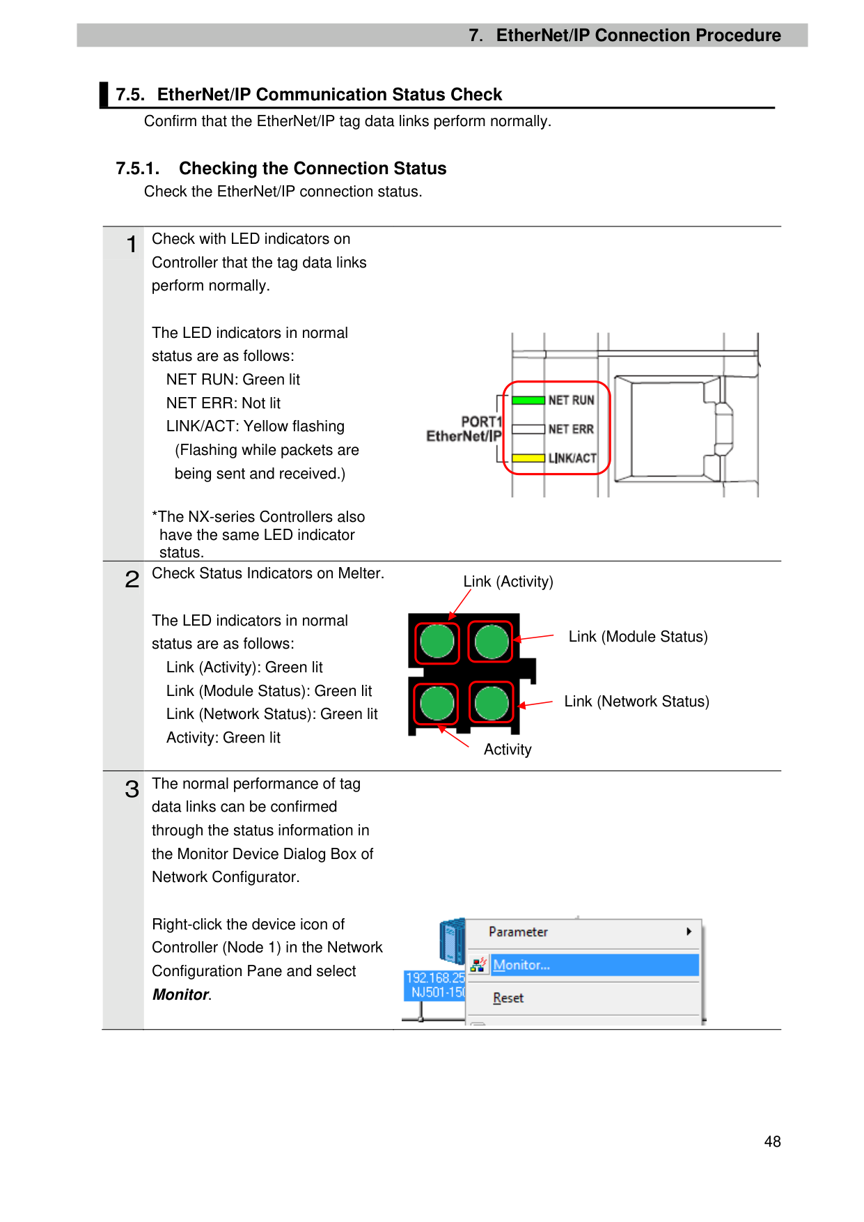
##### 7.5.1. Checking the Connection Status Check the EtherNet/IP connection status.
Controller that the tag data links perform normally.
The LED indicators in normal status are as follows:
NET RUN: Green lit NET ERR: Not lit LINK/ACT: Yellow flashing
(Flashing while packets are being sent and received.)
*The NX-series Controllers also have the same LED indicator status.
The LED indicators in normal status are as follows:
Link (Activity): Green lit Link (Module Status): Green lit Link (Network Status): Green lit Activity: Green lit
data links can be confirmed through the status information in the Monitor Device Dialog Box of Network Configurator.

Link (Activity)

Activity
Link (Module Status)
Link (Network Status)
Right-click the device icon of Controller (Node 1) in the Network Configuration Pane and select Monitor.

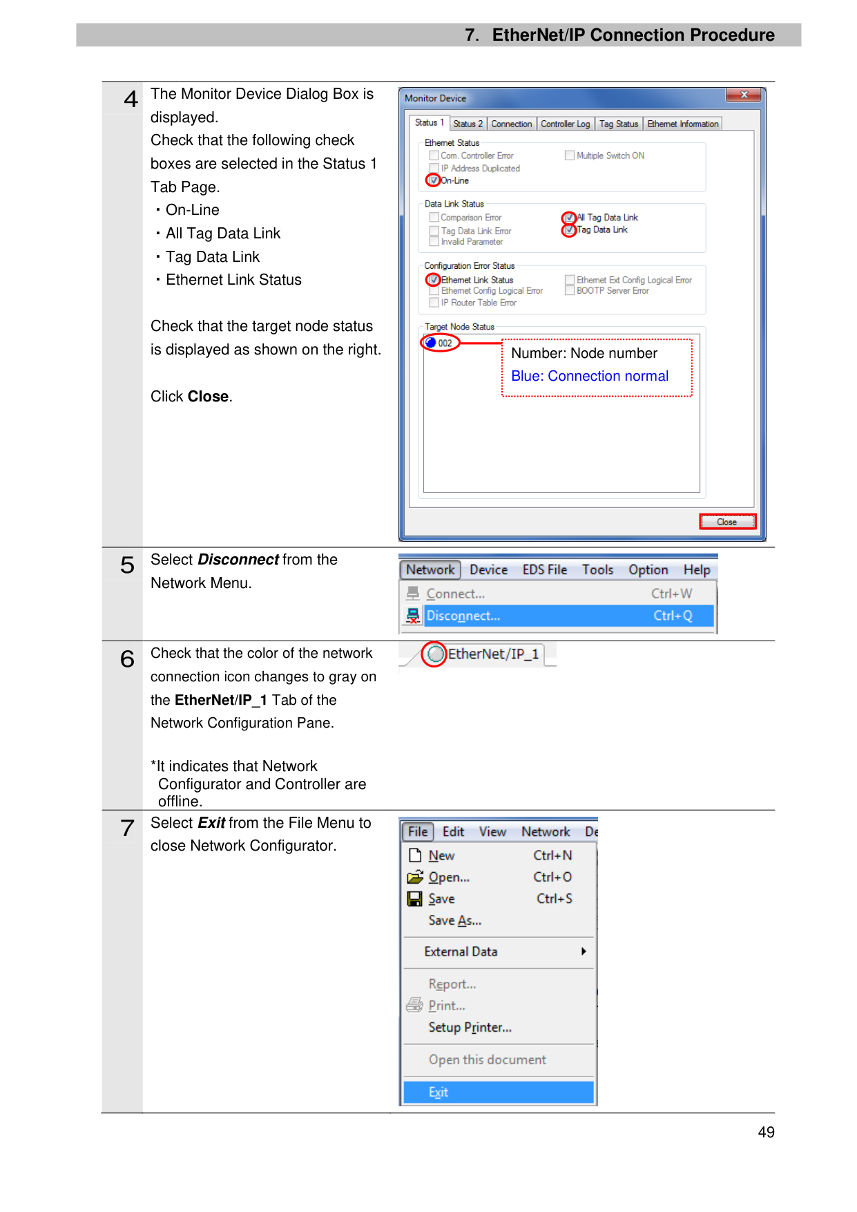
displayed. Check that the following check boxes are selected in the Status 1 Tab Page. ・On-Line ・All Tag Data Link ・Tag Data Link ・Ethernet Link Status
Check that the target node status is displayed as shown on the right.
Click Close.
Network Menu.
connection icon changes to gray on the EtherNet/IP_1 Tab of the Network Configuration Pane.
*It indicates that Network Configurator and Controller are offline.
close Network Configurator.

Number: Node number Blue: Connection normal
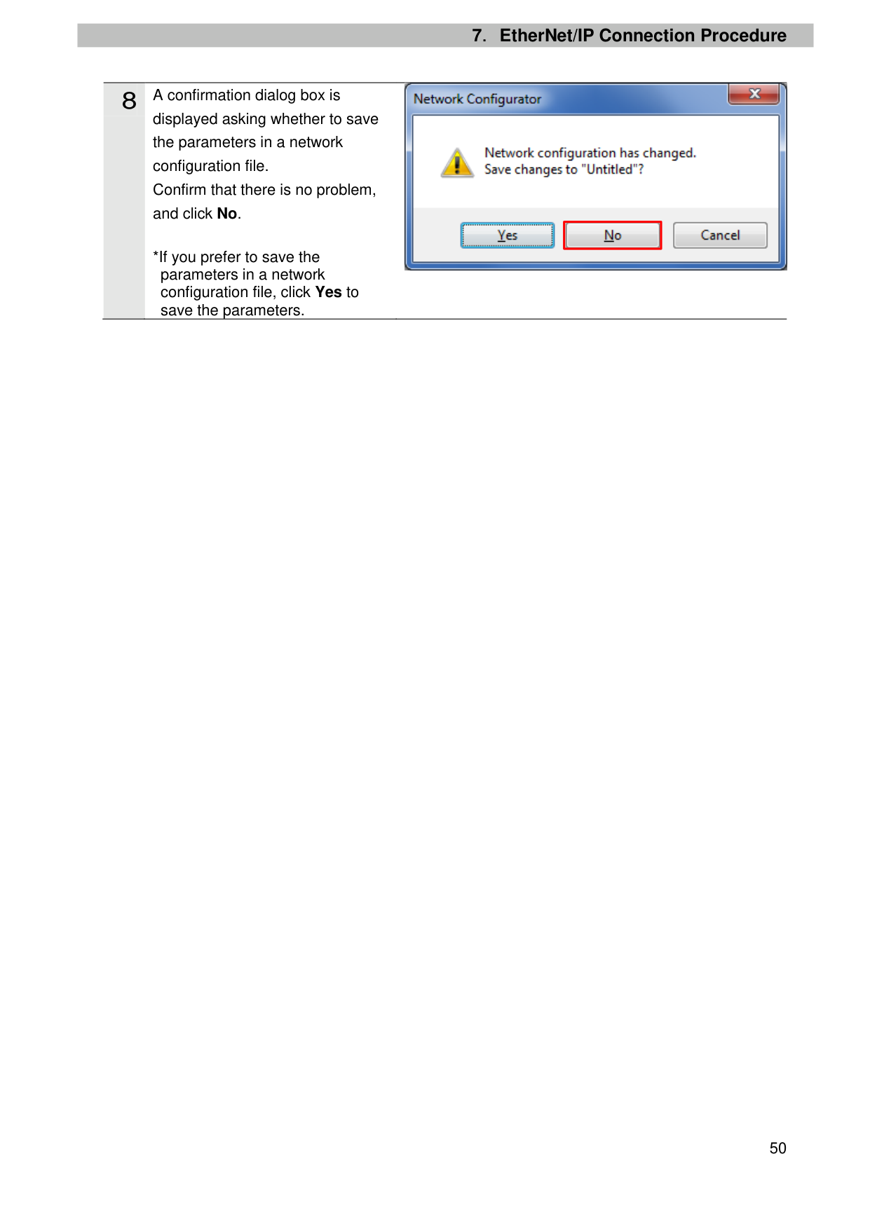
| | |---|


displayed asking whether to save the parameters in a network configuration file. Confirm that there is no problem, and click No.
*If you prefer to save the parameters in a network configuration file, click Yes to save the parameters.

| | |---|
7.5.2. Checking Sent and Received Data Check that correct data is sent and received. In this procedure, sent and received data are checked by sending a reading command of the software version from the Controller to the Melter. For details on Melter's commands, refer to Indexed Data Interface and Communication Data List of the EtherNet/IP Network Interface Card Customer Product Manual (1054600).
|| |---| |If you change the variable values on a Watch Tab Page when Sysmac Studio is online with the CPU Unit, the devices connected to the Controller may operate regardless of the operating mode of the CPU Unit. Always ensure safety before you change the variable values on a Watch Tab Page when Sysmac Studio is online with the CPU Unit.
|
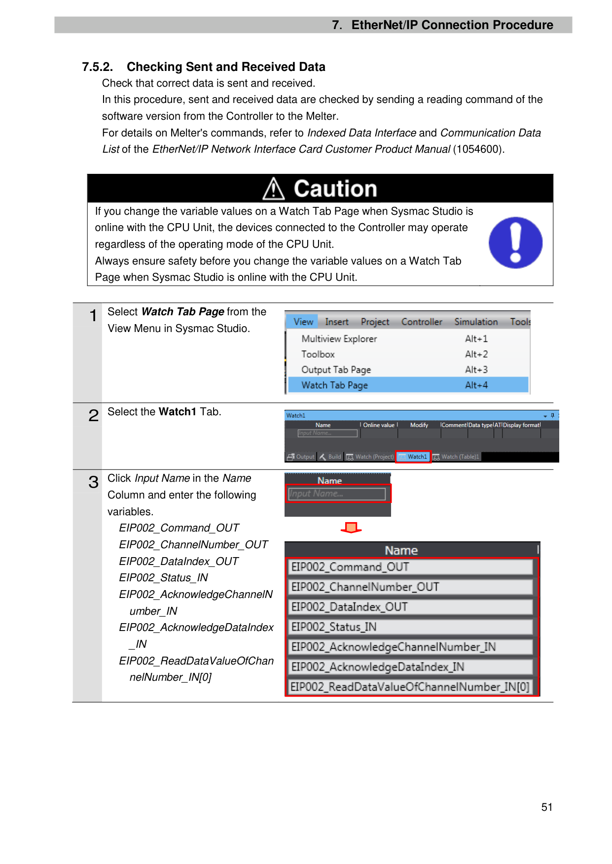
View Menu in Sysmac Studio.
Column and enter the following variables.
EIP002_Command_OUT EIP002_ChannelNumber_OUT EIP002_DataIndex_OUT EIP002_Status_IN EIP002_AcknowledgeChannelN
umber_IN EIP002_AcknowledgeDataIndex _IN EIP002_ReadDataValueOfChan nelNumber_IN[0]


| | |---|

| | |---|
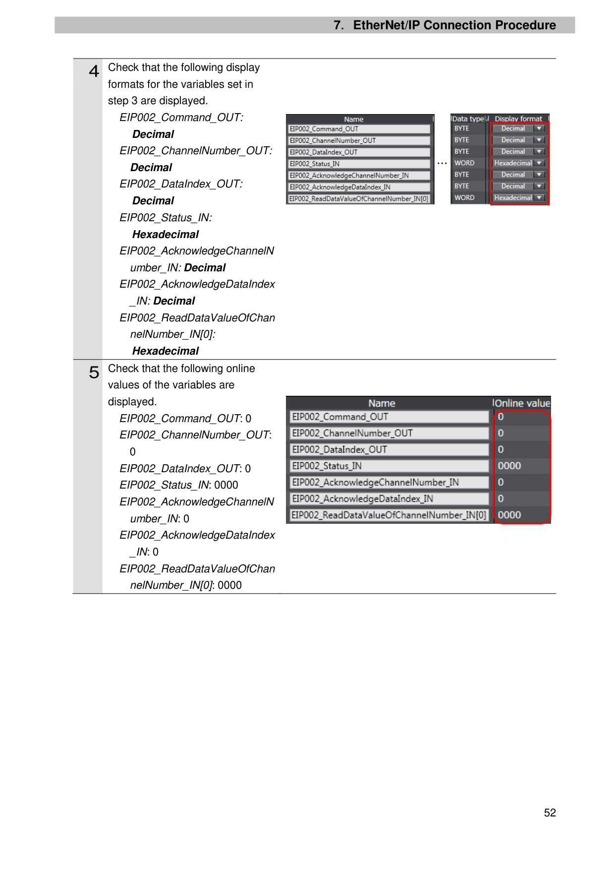
|| |---|
formats for the variables set in step 3 are displayed.
EIP002_Command_OUT:
Decimal
EIP002_ChannelNumber_OUT:
Decimal
EIP002_DataIndex_OUT:
Decimal
EIP002_Status_IN: Hexadecimal

EIP002_AcknowledgeChannelN umber_IN: Decimal EIP002_AcknowledgeDataIndex _IN: Decimal
EIP002_ReadDataValueOfChan nelNumber_IN[0]: Hexadecimal
values of the variables are displayed.
EIP002_Command_OUT: 0 EIP002_ChannelNumber_OUT:
0 EIP002_DataIndex_OUT: 0 EIP002_Status_IN: 0000 EIP002_AcknowledgeChannelN
umber_IN: 0 EIP002_AcknowledgeDataIndex _IN: 0 EIP002_ReadDataValueOfChan nelNumber_IN[0]: 0000


| | |---|
…

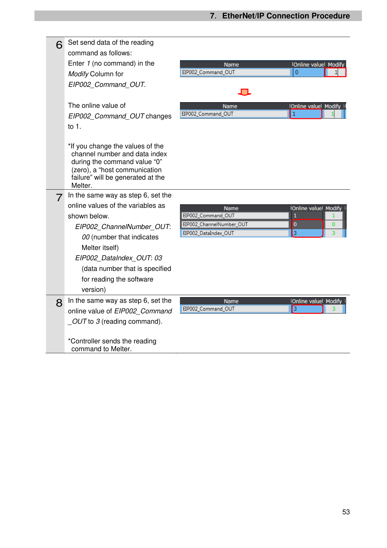
command as follows: Enter 1 (no command) in the Modify Column for EIP002_Command_OUT.
The online value of EIP002_Command_OUT changes to 1.
*If you change the values of the channel number and data index during the command value “0” (zero), a “host communication failure” will be generated at the Melter.

online values of the variables as shown below.
EIP002_ChannelNumber_OUT: 00 (number that indicates Melter itself)
EIP002_DataIndex_OUT: 03 (data number that is specified for reading the software version)
online value of EIP002_Command _OUT to 3 (reading command).

| | |---|


*Controller sends the reading command to Melter.
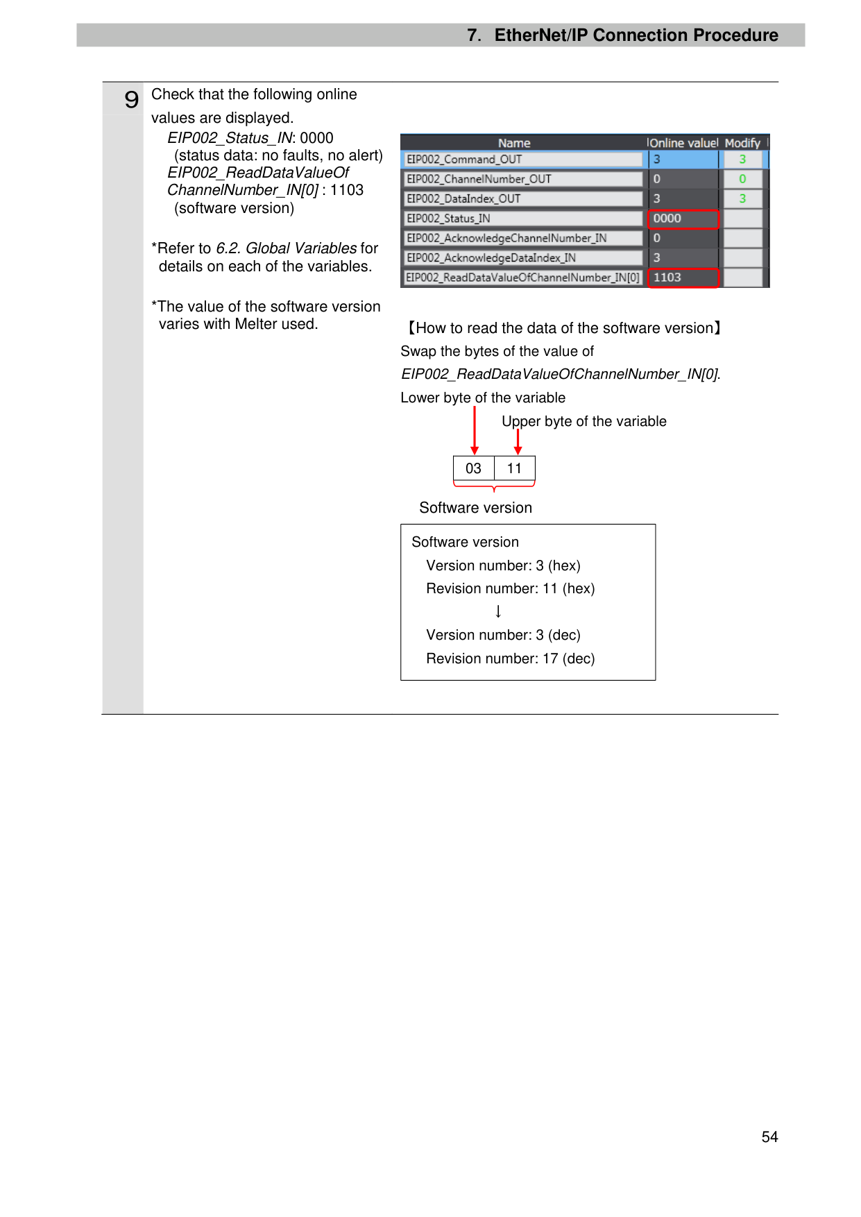
values are displayed. EIP002_Status_IN: 0000

(status data: no faults, no alert) EIP002_ReadDataValueOf ChannelNumber_IN[0] : 1103
(software version)
Swap the bytes of the value of EIP002_ReadDataValueOfChannelNumber_IN[0]. Lower byte of the variable
Upper byte of the variable
|03|11| |---|---|
Software version
Software version Version number: 3 (hex) Revision number: 11 (hex)
↓ Version number: 3 (dec) Revision number: 17 (dec)
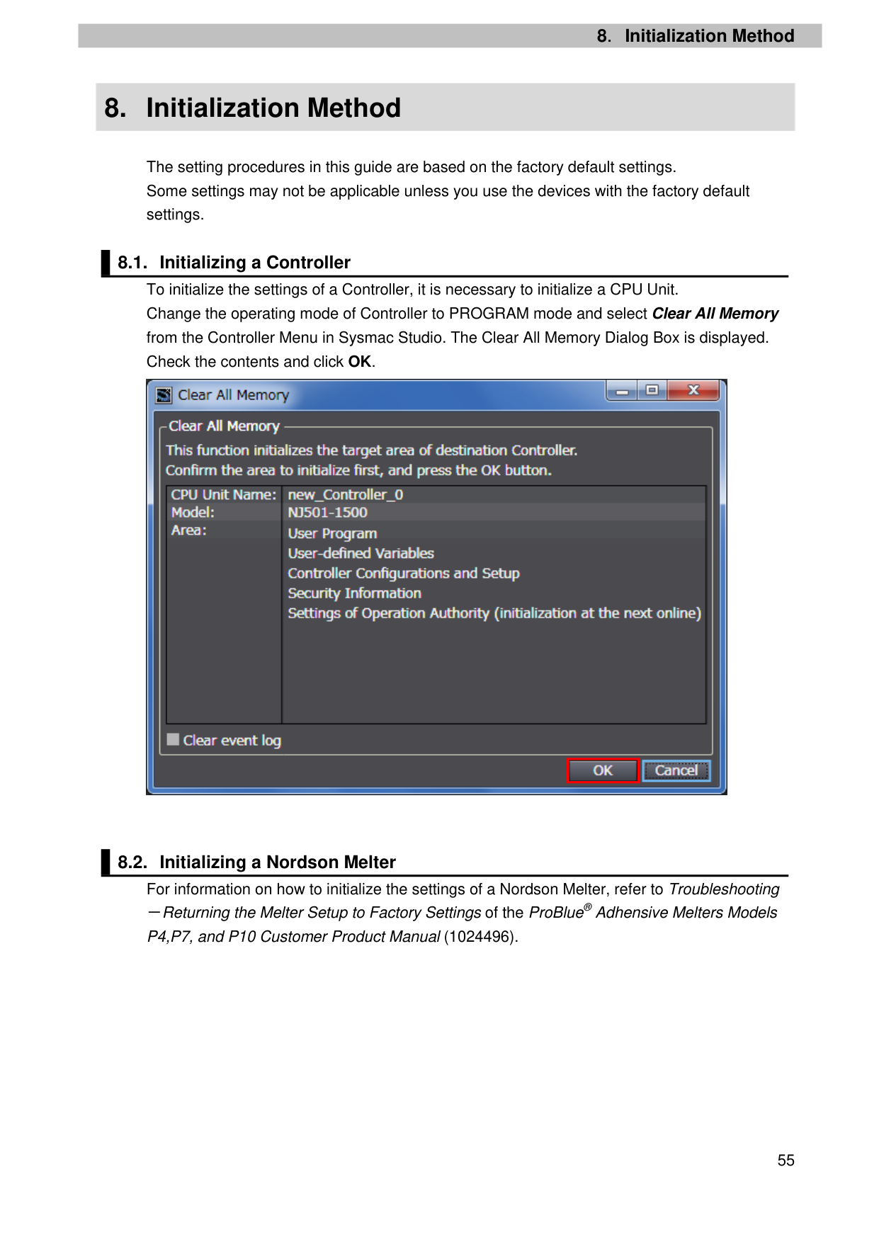
8.Initialization Method
8. Initialization Method
The setting procedures in this guide are based on the factory default settings. Some settings may not be applicable unless you use the devices with the factory default settings.

| | |---|
9.Revision History
9. Revision History
|Revision code
|Date of revision|Description of revision| |---|---|---| |01|March 19, 2018|First edition|
2018
######## 0318-(0318)P696-E1-01