
Ask AI
— answers from the official manualAnswers from the official manual.
Common questions
Common Questions
10 totalHow do I inspect and maintain the ladder for safety?
Inspect the ladder before each use to check for missing, worn or damaged parts. Do not repair any damage without permission from Werner Co; if the ladder has been exposed to excessive heat or corrosive agents like acids or alkalis, it should be destroyed (Page 4).
What are the safety warnings when using the Parkside 75012 Multi Purpose Ladder?
Do not use the ladder near electrical currents as metal conducts electricity and can cause severe injuries. Ensure all locking mechanisms, including J locks and soft touch push knobs, are engaged before using (Page 4).
How do I adjust the angle of the ladder?
Unlock the center hinges by pushing the palm buttons inward to relieve pressure. Adjust the hinge locks manually for different ladder angles, and verify the open position by confirming exposed triple inner posts on each side (Page 6).
What are the weight limits of the Parkside 75012 Multi Purpose Ladder?
The combined weight limit is 300 pounds for the user and materials, making it suitable only up to this duty rating. Exceeding this limit could result in serious injury (Page 1).
How do I lock and unlock the J locks on the ladder?
To lock: Pull out and rotate the J lock towards the rung hole while ensuring it clicks into place. To unlock: pull straight out then rotate away from the holes in the rails (Page 7).
How do I set up the ladder as a stepladder?
Unlock and adjust the angle using push knob hinges (page open position, figure 1) then raise or lower to desired height with J locks (Page 7).
Full Manual
8 pages
||300
Combined Weight of User and Materials


| |---|
P/N62320-01 ©2003 Werner Co. Printed in China September 2003| |---|
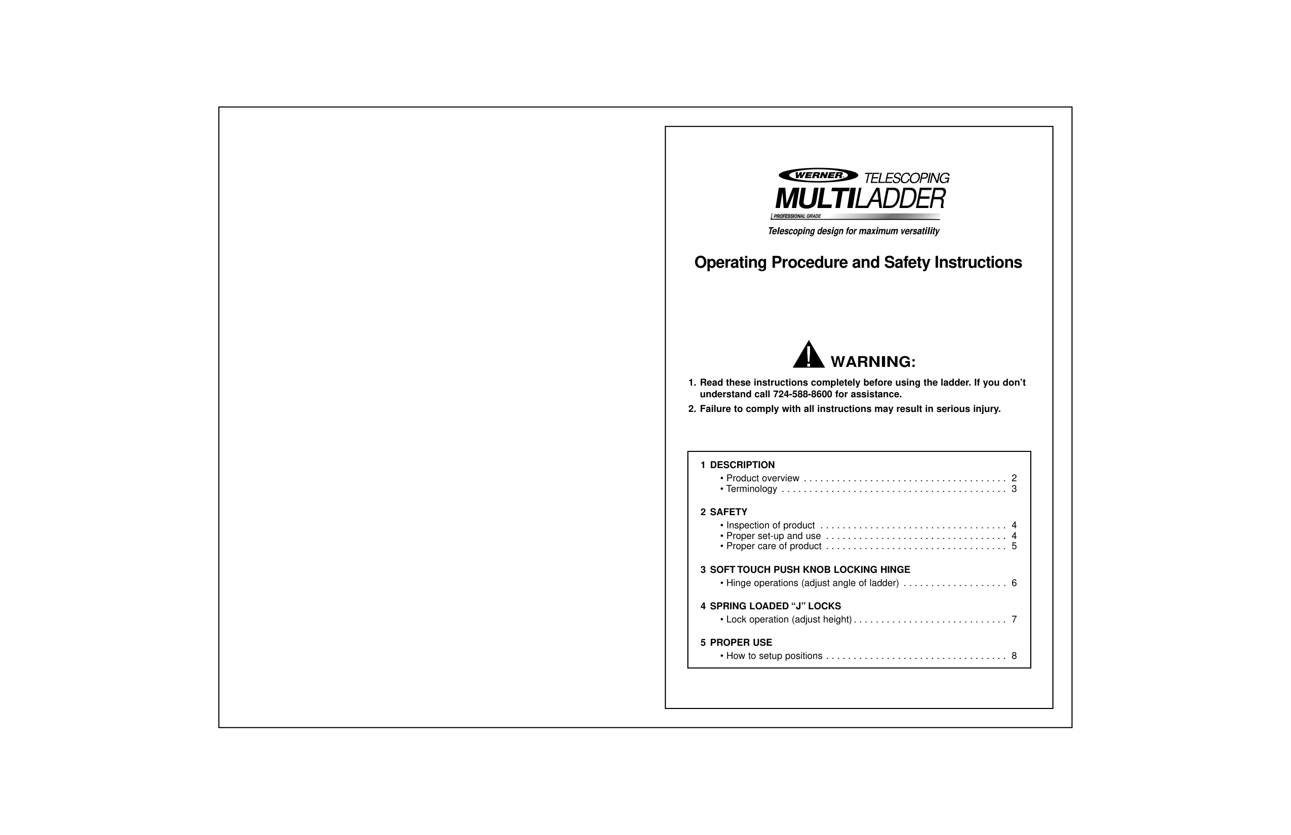
|||• Lock operation (adjust height). . . . . . . . . . . . . . . . . . . . . . . . . . . . 7| |---|
TELESCOPING


| |---| | |---|
|2
1DESCRIPTION
PRODUCT OVERVIEW
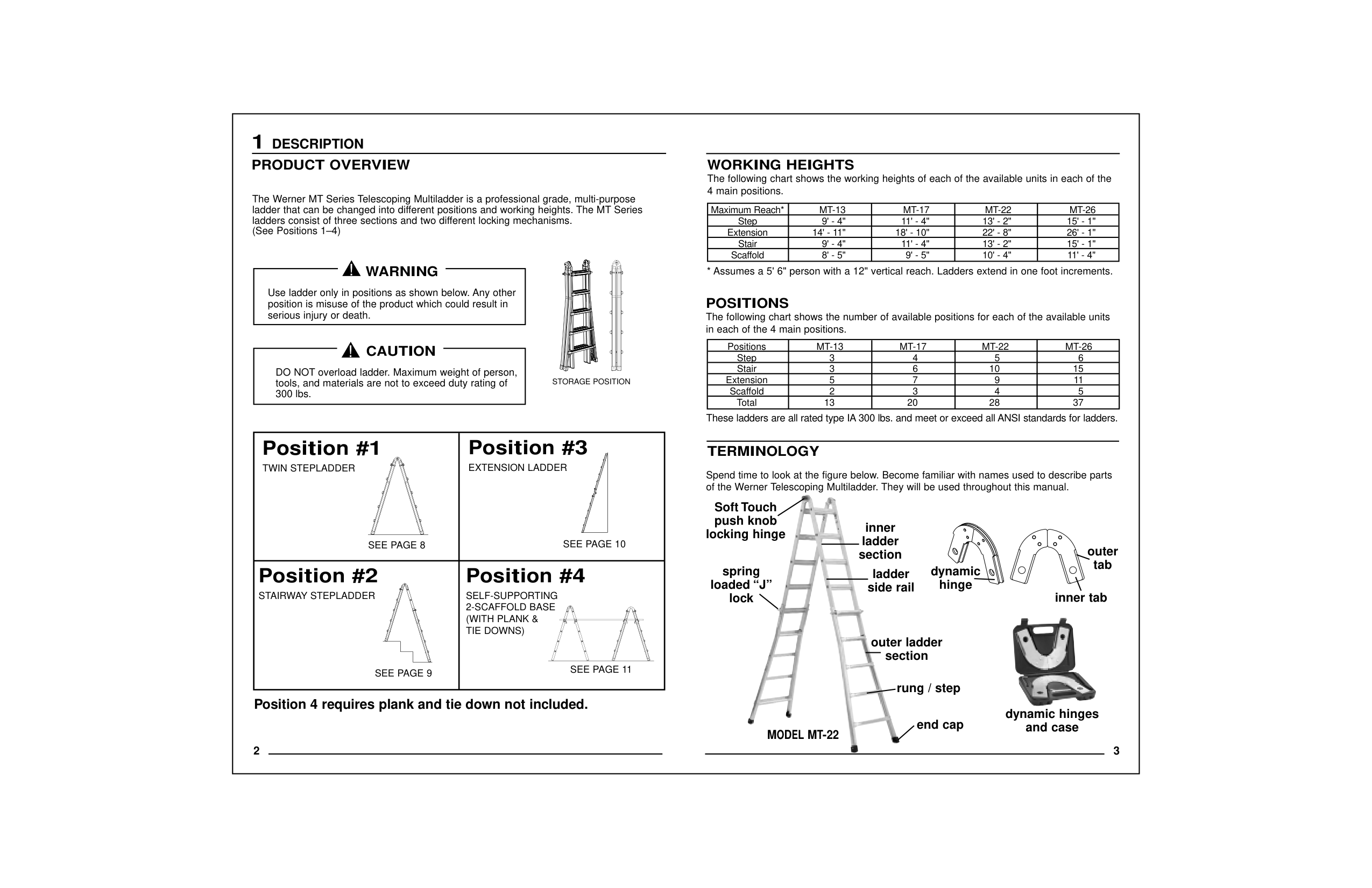
The Werner MT Series Telescoping Multiladder is a professional grade, multi-purpose ladder that can be changed into different positions and working heights. The MT Series
(See Positions 1–4)
|serious injury or death.
WARNING| |---|
|300 lbs.
CAUTION| |---|
|Position #2
STAIRWAY STEPLADDER
SEE PAGE 9|SEE PAGE 8
Position #1
TWIN STEPLADDER| |---|---| | |SEE PAGE 10|
STORAGE POSITION
| | | | | | | |---|---|---|---|---|---| |Total 13 20 28 37|Scaffold 2 3 4 5|Extension 5 7 9 11|Stair 3 6 10 15|Step 3 4 5 6|Positions MT-13 MT-17 MT-22 MT-26| | | | | | | | | | | | | | | | | | | | | |
| | | | | | |---|---|---|---|---| | | | | | | |Scaffold 8' - 5" 9' - 5" 10' - 4" 11' - 4"|Stair 9' - 4" 11' - 4" 13' - 2" 15' - 1"|Extension 14' - 11" 18' - 10" 22' - 8" 26' - 1"|Step 9' - 4" 11' - 4" 13' - 2" 15' - 1"| | | | | | | | | | | | | |
WORKING HEIGHTS
POSITIONS The following chart shows the number of available positions for each of the available units
in each of the 4 main positions.
These ladders are all rated type IA 300 lbs. and meet or exceed all ANSI standards for ladders.
* Assumes a 5' 6" person with a 12" vertical reach. Ladders extend in one foot increments.
Spend time to look at the figure below. Become familiar with names used to describe parts of the Werner Telescoping Multiladder. They will be used throughout this manual.
TERMINOLOGY


spring loaded “J”
lock
Soft Touch push knob
locking hinge
inner ladder
section ladder
side rail
section
dynamic hinge
inner tab
The following chart shows the working heights of each of the available units in each of the| |---|
|4
2SAFETY
INSPECTION OF PRODUCT
| | |---|
• Never use ladder with missing, worn or damaged parts. Inspect before each use.
• Never repair a damaged ladder without permission from Werner Co.
• Destroy ladder if exposed to excessive heat (such as in a house fire) or corrosive
agents (like acids or alkalis).
•For information on replacing parts or labels contact Werner Co. at the address given
below. If possible, know model number of ladder for reference. See I.D. label
on product.
•READ ALL LABELS.
•You should never use a ladder if you are not in good physical condition.
•DO NOT use in front of unlocked doors.
•Place feet on firm, level ground.
•If forced to use on slippery surface, secure ladder from sliding before
climbing.
•The use of ladders on drop cloths may present a sliding hazard.
•When using as a stepladder or extension ladder, always face ladder and maintain
firm grip.
• For additional care, use and safety instructions, contact your employer,
PROPER SET-UP AND USE
•Never place anything on or under ladder to gain height, or use unstable means to
adjust for uneven surfaces.
•Check that all four ladder ends are firmly supported to prevent excessive
•Use extreme caution when getting on or
•When possible, have someone
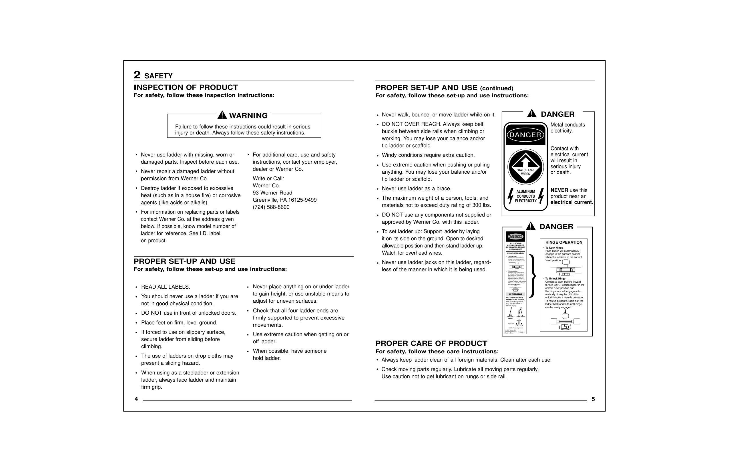
PROPER SET-UP AND USE(continued) For safety, follow these set-up and use instructions:
For safety, follow these care instructions:
working. You may lose your balance and/or tip ladder or scaffold.
Windy conditions require extra caution. Use extreme caution when pushing or pulling
anything. You may lose your balance and/or tip ladder or scaffold.
Never use ladder as a brace. The maximum weight of a person, tools, and
materials not to exceed duty rating of 300 lbs. DO NOT use any components not supplied or
approved by Werner Co. with this ladder. To set ladder up: Support ladder by laying
it on its side on the ground. Open to desired allowable position and then stand ladder up.
Watch for overhead wires. Never use ladder jacks on this ladder, regard-
less of the manner in which it is being used.
|DANGER
ALUMINUM CONDUCTS
ELECTRICITY
Metal conducts electricity.
Contact with electrical current
will result in serious injury
or death.
NEVERuse this product near an
electrical current.| |---|
||ALL LOCKING MECHANISMS MUST
BE ENGAGED BEFORE USING LADDER
P/N62298-01
HINGE OPERATION
To Unlock Hinge Compress palm buttons inward
to “self lock”. Position ladder in the correct “use” position and
the hinge lock will engage automatically. It may be difficult to
unlock hinges if there is pressure. To relieve pressure, jiggle half the
ladder back and forth until hinge can be easily engaged.
To Lock Hinge Palm button will automatically
engage to the outward position when the ladder is in the correct
“use” position.
WARNING
STRAIGHTSTEPLADDER
Plank not provided
SCAFFOLD
© 2003 Werner Co. Greenville, Pa 16125
USE LADDERS ONLY IN POSITIONS SHOWN.
Use in another position may result in death or
serious injury.| |---|
|HINGE OPERATION
To Unlock Hinge Compress palm buttons inward
to “self lock”. Position ladder in the correct “use” position and
the hinge lock will engage automatically. It may be difficult to
unlock hinges if there is pressure. To relieve pressure, jiggle half the
ladder back and forth until hinge can be easily engaged.
To Lock Hinge Palm button will automatically
engage to the outward position when the ladder is in the correct
“use” position.
| |---|
}| |---|
DANGER| |---|
to unbind the lock.
Note:
|are NOT LOCKED when ladder is in use.
using ladder EACH TIME.
WARNING| |---|
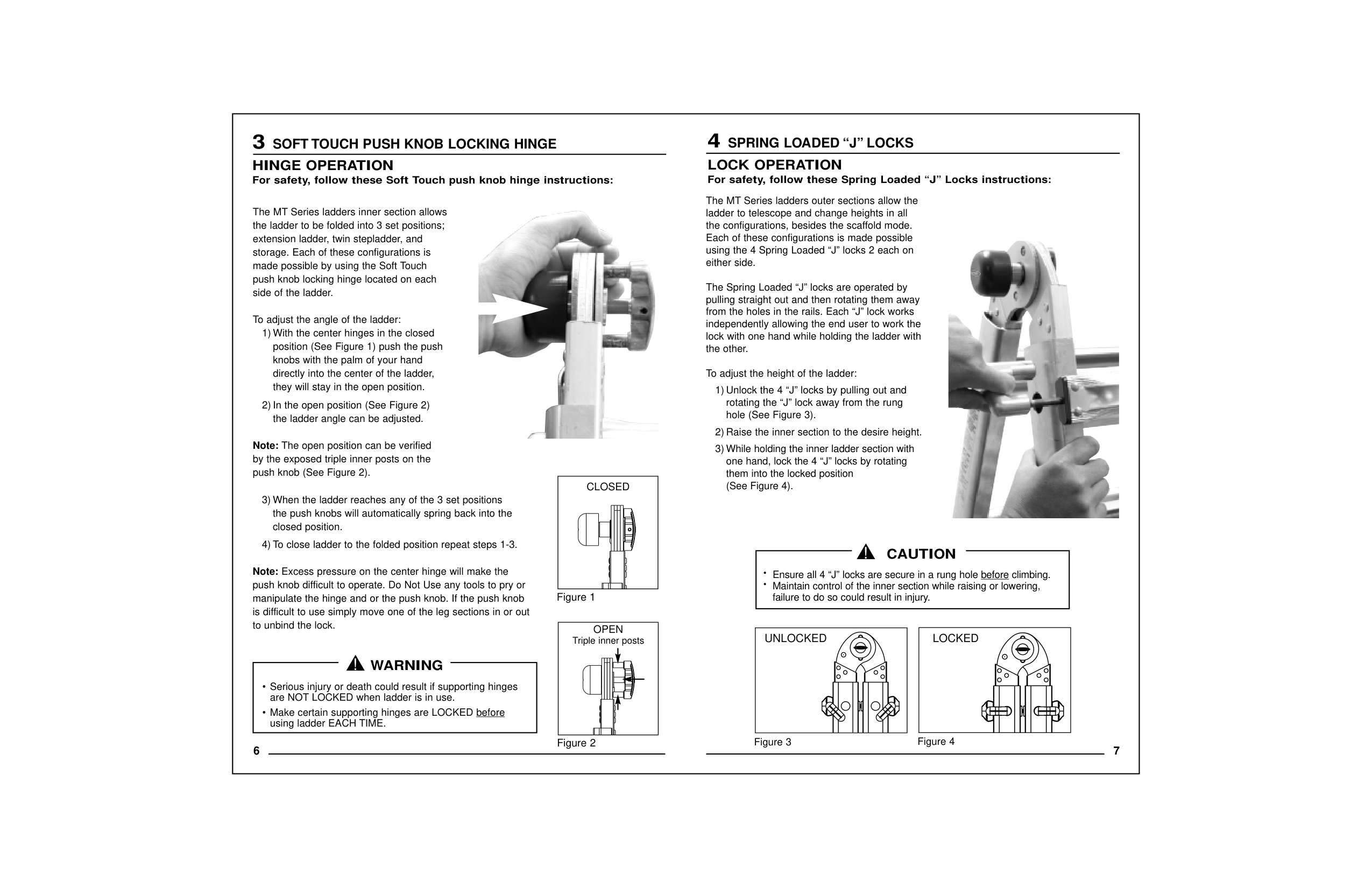
push knob (See Figure 2). CLOSED
Note:The open position can be verified by the exposed triple inner posts on the
To adjust the angle of the ladder:
side of the ladder.
made possible by using the Soft Touch push knob locking hinge located on each
extension ladder, twin stepladder, and storage. Each of these configurations is
The MT Series ladders inner section allows the ladder to be folded into 3 set positions;
6
2) In the open position (See Figure 2) the ladder angle can be adjusted.
1) With the center hinges in the closed position (See Figure 1) push the push
closed position.
they will stay in the open position.
knobs with the palm of your hand directly into the center of the ladder,

Triple inner posts
OPEN
HINGE OPERATION For safety, follow these Soft Touch push knob hinge instructions:
3
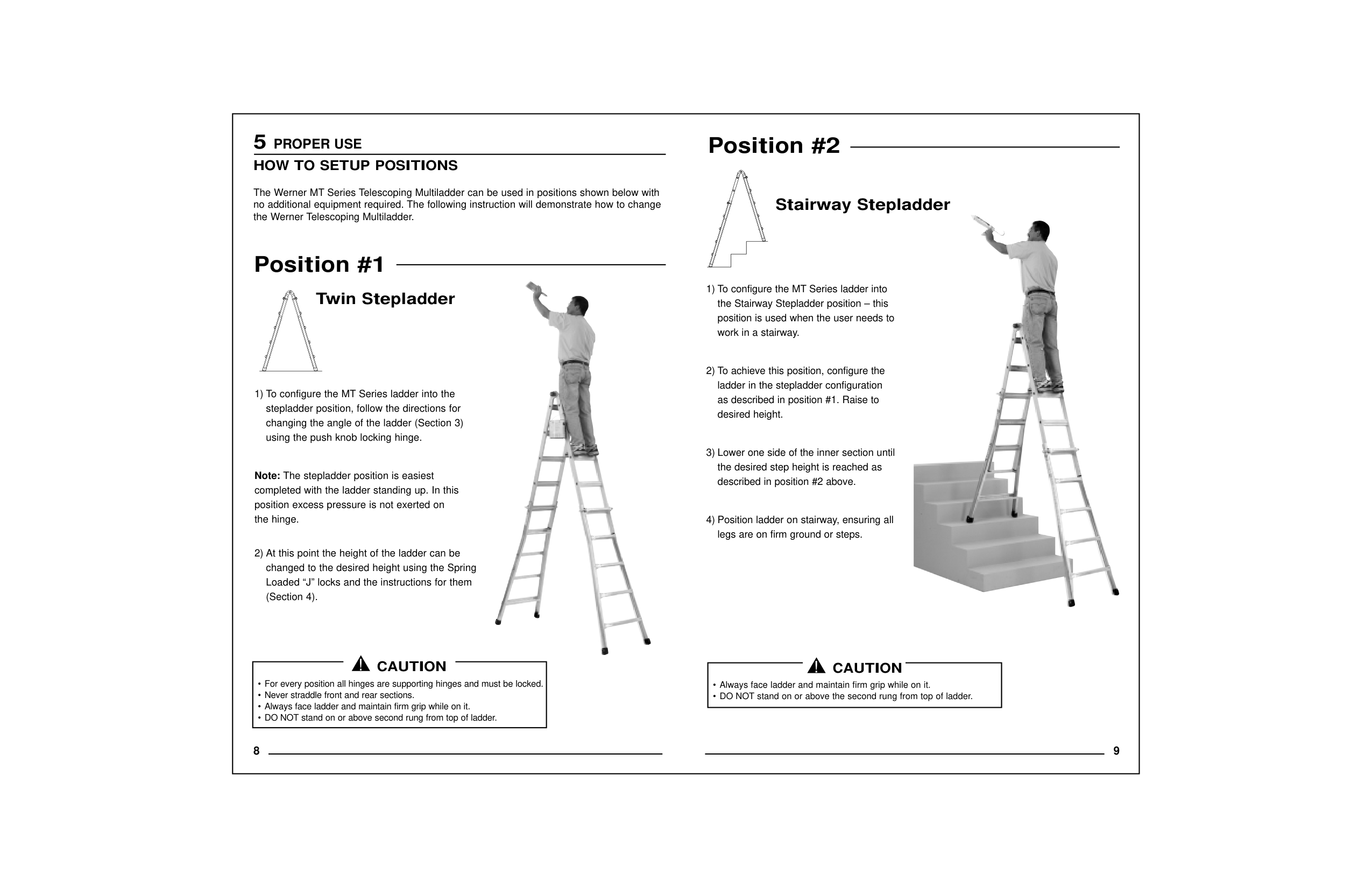
########### LOCKEDUNLOCKED
|•Ensure all 4 “J” locks are secure in a rung hole beforeclimbing.
•Maintain control of the inner section while raising or lowering,
failure to do so could result in injury.
CAUTION| |---|
3) While holding the inner ladder section with one hand, lock the 4 “J” locks by rotating
them into the locked position (See Figure 4).
the other. To adjust the height of the ladder:
independently allowing the end user to work the lock with one hand while holding the ladder with
pulling straight out and then rotating them away from the holes in the rails. Each “J” lock works
either side. The Spring Loaded “J” locks are operated by
Each of these configurations is made possible using the 4 Spring Loaded “J” locks 2 each on
1) Unlock the 4 “J” locks by pulling out and rotating the “J” lock away from the rung
hole (See Figure 3).

LOCK OPERATION For safety, follow these Spring Loaded “J” Locks instructions:
#### 4SPRING LOADED “J” LOCKS
|8
5PROPER USE
HOW TO SETUP POSITIONS
The Werner MT Series Telescoping Multiladder can be used in positions shown below with no additional equipment required. The following instruction will demonstrate how to change
the Werner Telescoping Multiladder.
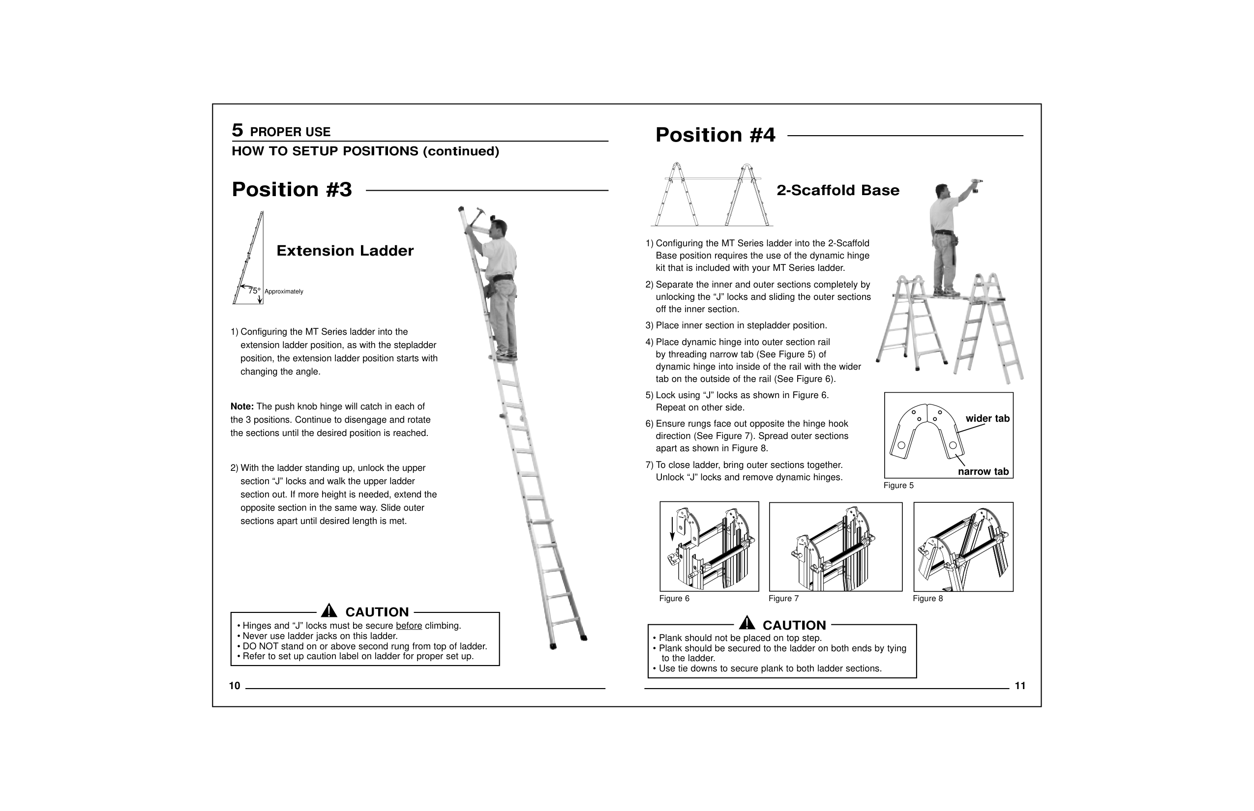
Position #1
Twin Stepladder
1) To configure the MT Series ladder into the stepladder position, follow the directions for
changing the angle of the ladder (Section 3) using the push knob locking hinge.
Note:The stepladder position is easiest completed with the ladder standing up. In this
position excess pressure is not exerted on the hinge.
2) At this point the height of the ladder can be changed to the desired height using the Spring
Loaded “J” locks and the instructions for them (Section 4).

1) To configure the MT Series ladder into the Stairway Stepladder position – this
position is used when the user needs to work in a stairway.
2) To achieve this position, configure the ladder in the stepladder configuration
as described in position #1. Raise to desired height.
3) Lower one side of the inner section until the desired step height is reached as
described in position #2 above.
4) Position ladder on stairway, ensuring all legs are on firm ground or steps.

|• Never straddle front and rear sections.
• Always face ladder and maintain firm grip while on it.
CAUTION|

|---|
| | |---|
Position #2| |---|
|10
1) Configuring the MT Series ladder into the extension ladder position, as with the stepladder
position, the extension ladder position starts with changing the angle.
Note:The push knob hinge will catch in each of the 3 positions. Continue to disengage and rotate
the sections until the desired position is reached.
2) With the ladder standing up, unlock the upper section “J” locks and walk the upper ladder
section out. If more height is needed, extend the opposite section in the same way. Slide outer
sections apart until desired length is met.
75°Approximately

2) Separate the inner and outer sections completely by unlocking the “J” locks and sliding the outer sections
off the inner section.
3) Place inner section in stepladder position.
4) Place dynamic hinge into outer section rail by threading narrow tab (See Figure 5) of
tab on the outside of the rail (See Figure 6).
5) Lock using “J” locks as shown in Figure 6. Repeat on other side.
6) Ensure rungs face out opposite the hinge hook direction (See Figure 7). Spread outer sections
apart as shown in Figure 8.
7) To close ladder, bring outer sections together. Unlock “J” locks and remove dynamic hinges.
Figure 6Figure 7Figure 8
|wider tab
narrow tab
| |---|
Figure 5

|• Hinges and “J” locks must be secure before
• Never use ladder jacks on this ladder.
| |---|
CAUTION
| | |---|
5PROPER USE
Position #3
Extension Ladder
Position #4| |---|
|NOTES| |---|