
Ask AI
— answers from the official manualAnswers from the official manual.
Common questions
Common Questions
8 totalWhat accuracy class does the SEL-735 meter comply with?
The SEL-735 outperforms ANSI C12.20-2015 Class 0.1 and IEC 62053-22 Accuracy Class 0.1 S standards over an extended operating range, guaranteeing a maximum error of 0.06 percent Wh.
How do I configure the meter form on the SEL-735?
Use the FORM terminal command to change internal connections and configure the meter as Form 5, 9, or 36. This allows field upgradability for different applications.
What are the voltage sag, swell, interruption recorder specifications?
The SEL-735 stores and reports summary events with a typical number of 260 events and detailed rows up to 130,000 for interruptions, dips, swells. The minimum disturbance duration is one-quarter cycle.
What communication protocols does the SEL-735 support?
The meter supports DNP3, synchrophasor measurements (IEEE C37.118.1a-2014), Modbus RTU/TCP, IEC 61850, and SNTP among others.
How much data storage does the SEL-735 have?
It varies by option - The Advanced PQ package offers up to 1 GB of onboard storage for power quality reports. Load profile recording has up to 20 years with 512 channels.
Can the SEL-735 be used in hazardous locations?
Yes, it is rated UL listed under ANSI/ISA 12.12.01-2015 and CSA C22.2 No. 213-15 for Class I Division 2 Hazardous Locations.
Full Manual
20 pages
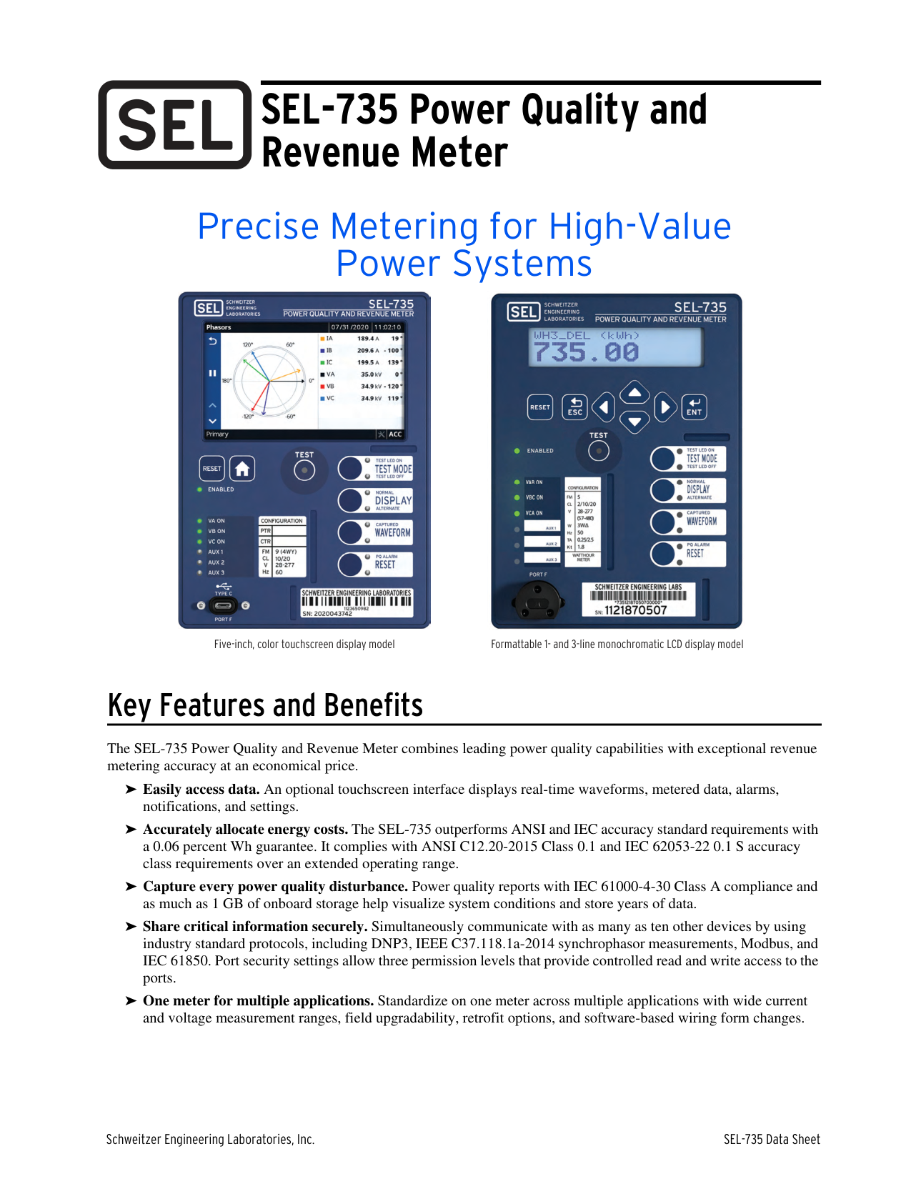
SEL-735 Power Quality and Revenue Meter
Precise Metering for High-Value Power Systems


Five-inch, color touchscreen display model Formattable 1- and 3-line monochromatic LCD display model
Key Features and Benefits
The SEL-735 Power Quality and Revenue Meter combines leading power quality capabilities with exceptional revenue metering accuracy at an economical price.
➤ Easily access data. An optional touchscreen interface displays real-time waveforms, metered data, alarms,
notifications, and settings.
➤ Accurately allocate energy costs. The SEL-735 outperforms ANSI and IEC accuracy standard requirements with a 0.06 percent Wh guarantee. It complies with ANSI C12.20-2015 Class 0.1 and IEC 62053-22 0.1 S accuracy class requirements over an extended operating range.
➤ Capture every power quality disturbance. Power quality reports with IEC 61000-4-30 Class A compliance and
as much as 1 GB of onboard storage help visualize system conditions and store years of data.
➤ Share critical information securely. Simultaneously communicate with as many as ten other devices by using
industry standard protocols, including DNP3, IEEE C37.118.1a-2014 synchrophasor measurements, Modbus, and IEC 61850. Port security settings allow three permission levels that provide controlled read and write access to the ports.
➤ One meter for multiple applications. Standardize on one meter across multiple applications with wide current and voltage measurement ranges, field upgradability, retrofit options, and software-based wiring form changes.
One Package, Three Flexible Solutions
Three SEL-735 variants provide a meter for any application and any budget. The 5.0" color touchscreen model comes standard with the Advanced PQ and Recording package. Table 1 SEL-735 Power Quality and Recording Options
|PQ and Recording|SEL-735 Basic|SEL-735 Intermediate|SEL-735 Advanced| |---|---|---|---| |Memory|128 MB|256 MB|1 GB| |Max Harmonic Order|15th|63rd|63rd| |Interharmonic Quantities|No|No|Yes| |Harmonic Angles|No|No|Yes| |Power Harmonics|No|No|Yes|
Waveform Capture Event Reports
|Samples Per Cycle|16|16, 128|16, 128, 512| |---|---|---|---| |Duration (cycles)|15|15–600|15–600| |Number of Events|256|33–6,200|101–10,000| |COMTRADE Reports|Y|Y|Y| |Wave View Oscillography|N|N|Y|
Load Profile Recorder
|Recorders x channels|1 x 16|12 x 16|32 x 16| |---|---|---|---| |Acquisition rates|1–120 minutes|3–59 s, 1–120 minutes|3–59 s, 1–120 minutes|
Storage duration for 10 minute interval data
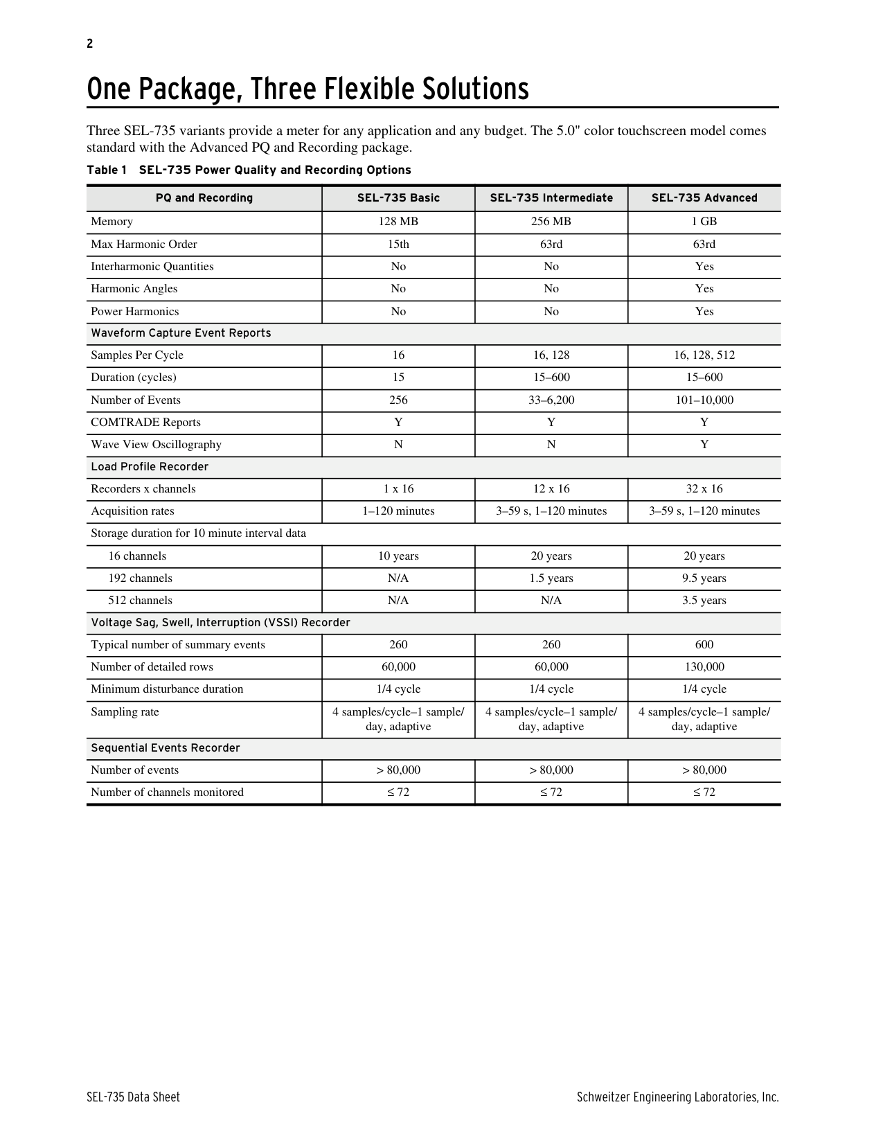
|16 channels|10 years|20 years|20 years| |---|---|---|---| |192 channels|N/A|1.5 years|9.5 years| |512 channels|N/A|N/A|3.5 years|
Voltage Sag, Swell, Interruption (VSSI) Recorder
|Typical number of summary events|260|260|600| |---|---|---|---| |Number of detailed rows|60,000|60,000|130,000| |Minimum disturbance duration|1/4 cycle|1/4 cycle|1/4 cycle| |Sampling rate|4 samples/cycle–1 sample/ day, adaptive|4 samples/cycle–1 sample/ day, adaptive|4 samples/cycle–1 sample/ day, adaptive|
Sequential Events Recorder
|Number of events|> 80,000|> 80,000|> 80,000| |---|---|---|---| |Number of channels monitored|≤ 72|≤ 72|≤ 72|
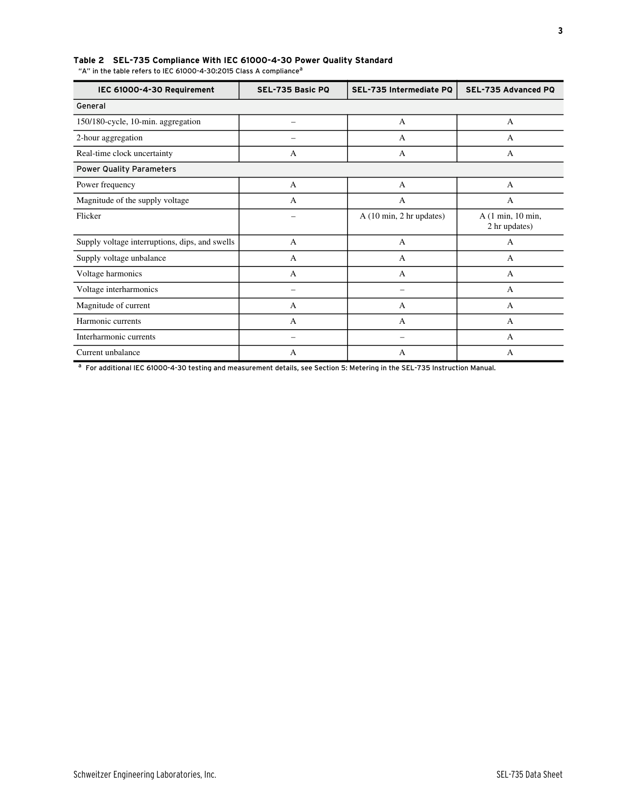
Table 2 SEL-735 Compliance With IEC 61000-4-30 Power Quality Standard
“A” in the table refers to IEC 61000-4-30:2015 Class A compliancea
IEC 61000-4-30 Requirement SEL-735 Basic PQ SEL-735 Intermediate PQ SEL-735 Advanced PQ General
|150/180-cycle, 10-min. aggregation|–|A|A| |---|---|---|---| |2-hour aggregation|–|A|A| |Real-time clock uncertainty|A|A|A|
Power Quality Parameters
|Power frequency|A|A|A| |---|---|---|---| |Magnitude of the supply voltage|A|A|A| |Flicker|–|A (10 min, 2 hr updates)|A (1 min, 10 min, 2 hr updates)| |Supply voltage interruptions, dips, and swells|A|A|A| |Supply voltage unbalance|A|A|A| |Voltage harmonics|A|A|A| |Voltage interharmonics|–|–|A| |Magnitude of current|A|A|A| |Harmonic currents|A|A|A| |Interharmonic currents|–|–|A| |Current unbalance|A|A|A|
a For additional IEC 61000-4-30 testing and measurement details, see Section 5: Metering in the SEL-735 Instruction Manual.
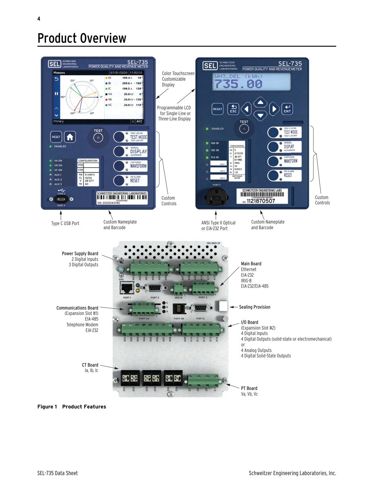
Product Overview


n
Color Touchscreen Customizable Display


Programmable LCD
for Single-Line or Three-Line Display


Custom Controls
Custom Controls
Custom Nameplate and Barcode
Type C USB Port ANSI Type II Optical or EIA-232 Port
Custom Nameplate and Barcode
Power Supply Board
Communications Board (Expansion Slot #1)
EIA-485 Telephone Modem
EIA-232
CT Board Ia, Ib, Ic


Main Board Ethernet EIA-232 IRIG-B EIA-232/EIA-485
Sealing Provision

I/O Board (Expansion Slot #2) 4 Digital Inputs 4 Digital Outputs (solid-state or electromechanical) or 4 Analog Outputs 4 Digital Solid-State Outputs
PT Board Va, Vb, Vc
Figure 1 Product Features
Features High-Accuracy Metering
Security Gateway
Ethernet

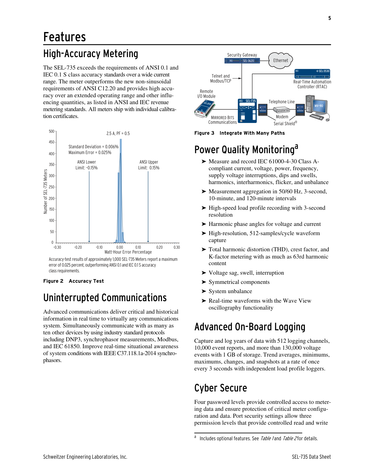
The SEL-735 exceeds the requirements of ANSI 0.1 and IEC 0.1 S class accuracy standards over a wide current range. The meter outperforms the new non-sinusoidal requirements of ANSI C12.20 and provides high accuracy over an extended operating range and other influencing quantities, as listed in ANSI and IEC revenue metering standards. All meters ship with individual calibration certificates.
SEL-3530
Telnet and Modbus/TCP
Real-Time Automation Controller (RTAC)
Remote I/O Module
Telephone Line
SEL-735
SEL-2515
MV-90


Modem
MIRRORED BITS Communications
Serial Shield®
500
Figure 3 Integrate With Many Paths
2.5 A, PF = 0.5
450
#### Power Quality Monitoringa
Standard Deviation = 0.006% Maximum Error = 0.025%
400
➤ Measure and record IEC 61000-4-30 Class Acompliant current, voltage, power, frequency, supply voltage interruptions, dips and swells, harmonics, interharmonics, flicker, and unbalance
ANSI Lower Limit: –0.15%
ANSI Upper Limit: 0.15%
350
Number of SEL-735 Meters
300
250
➤ Measurement aggregation in 50/60 Hz, 3-second,
10-minute, and 120-minute intervals
200
➤ High-speed load profile recording with 3-second
150
resolution
100
➤ Harmonic phase angles for voltage and current ➤ High-resolution, 512-samples/cycle waveform
50
capture
0
–0.30 –0.20 -0.10 0.00 0.20 0.300.10
➤ Total harmonic distortion (THD), crest factor, and K-factor metering with as much as 63rd harmonic content
Watt-Hour Error Percentage
Accuracy-test results of approximately 1,000 SEL-735 Meters report a maximum error of 0.025 percent, outperforming ANSI 0.1 and IEC 0.1 S accuracy class requirements.
➤ Voltage sag, swell, interruption
Figure 2 Accuracy Test
➤ Symmetrical components
➤ System unbalance
#### Uninterrupted Communications
➤ Real-time waveforms with the Wave View
oscillography functionality
Advanced communications deliver critical and historical information in real time to virtually any communications system. Simultaneously communicate with as many as ten other devices by using industry standard protocols including DNP3, synchrophasor measurements, Modbus, and IEC 61850. Improve real-time situational awareness of system conditions with IEEE C37.118.1a-2014 synchrophasors.
#### Advanced On-Board Logging
Capture and log years of data with 512 logging channels, 10,000 event reports, and more than 130,000 voltage events with 1 GB of storage. Trend averages, minimums, maximums, changes, and snapshots at a rate of once every 3 seconds with independent load profile loggers.
#### Cyber Secure
Four password levels provide controlled access to metering data and ensure protection of critical meter configuration and data. Port security settings allow three permission levels that provide controlled read and write
a Includes optional features. SeeTable 1andTable 2for details.
access to the ports. The meter verifies the authenticity and integrity of firmware files during upgrades by using a checksum and cryptographic signature.
#### Transformer/Line-Loss Compensation
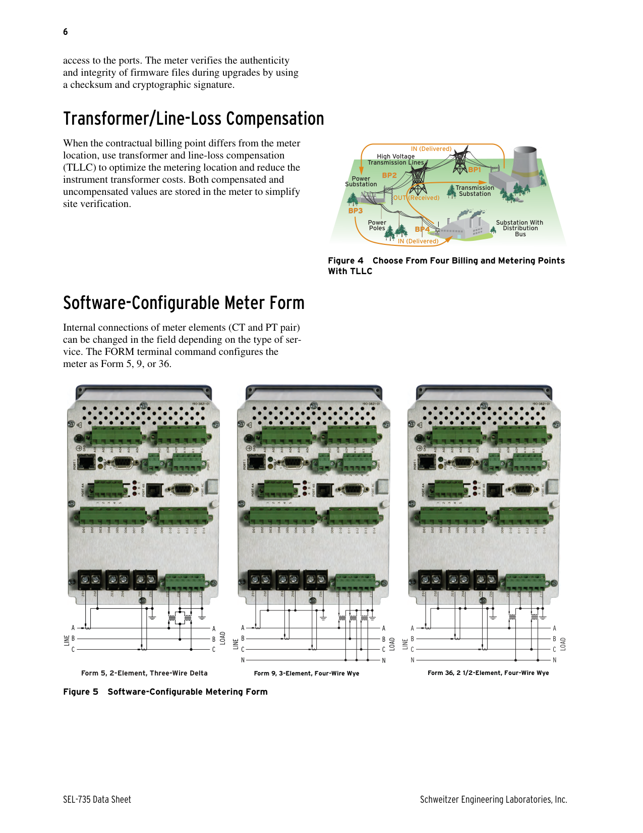
When the contractual billing point differs from the meter location, use transformer and line-loss compensation (TLLC) to optimize the metering location and reduce the instrument transformer costs. Both compensated and uncompensated values are stored in the meter to simplify site verification.
IN (Delivered)

High Voltage Transmission Lines

BP1 BP2

Power Substation
Transmission Substation

OUT (Received)


BP3


Power Poles
Substation With Distribution Bus
BP4
IN (Delivered)
Figure 4 Choose From Four Billing and Metering Points With TLLC
#### Software-Configurable Meter Form
Internal connections of meter elements (CT and PT pair) can be changed in the field depending on the type of service. The FORM terminal command configures the meter as Form 5, 9, or 36.


A
A
LOAD
B
B
LINE
C
C
Form 5, 2-Element, Three-Wire Delta


A
A
A
A
B
B
B
B
LOAD
LOAD
LINE
LINE
C
C
C
C
N
N
N
N
Form 36, 2 1/2-Element, Four-Wire WyeForm 9, 3-Element, Four-Wire Wye
Figure 5 Software-Configurable Metering Form
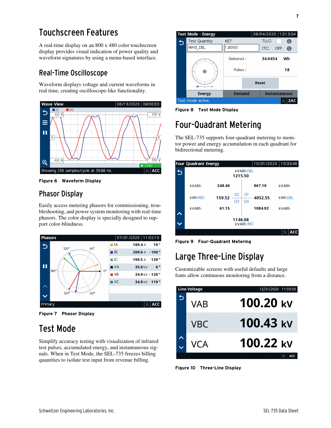
#### Touchscreen Features
A real-time display on an 800 x 480 color touchscreen display provides visual indication of power quality and waveform signatures by using a menu-based interface.
Real-Time Oscilloscope
Waveform displays voltage and current waveforms in real time, creating oscilloscope-like functionality.

Phasor Display
Easily access metering phasors for commissioning, troubleshooting, and power system monitoring with real-time phasors. The color display is specially designed to support color-blindness.

#### Test Mode
Simplify accuracy testing with visualization of infrared test pulses, accumulated energy, and instantaneous signals. When in Test Mode, the SEL-735 freezes billing quantities to isolate test input from revenue billing.

#### Four-Quadrant Metering
The SEL-735 supports four-quadrant metering to monitor power and energy accumulation in each quadrant for bidirectional metering.

#### Large Three-Line Display
Customizable screens with useful defaults and large fonts allow continuous monitoring from a distance.

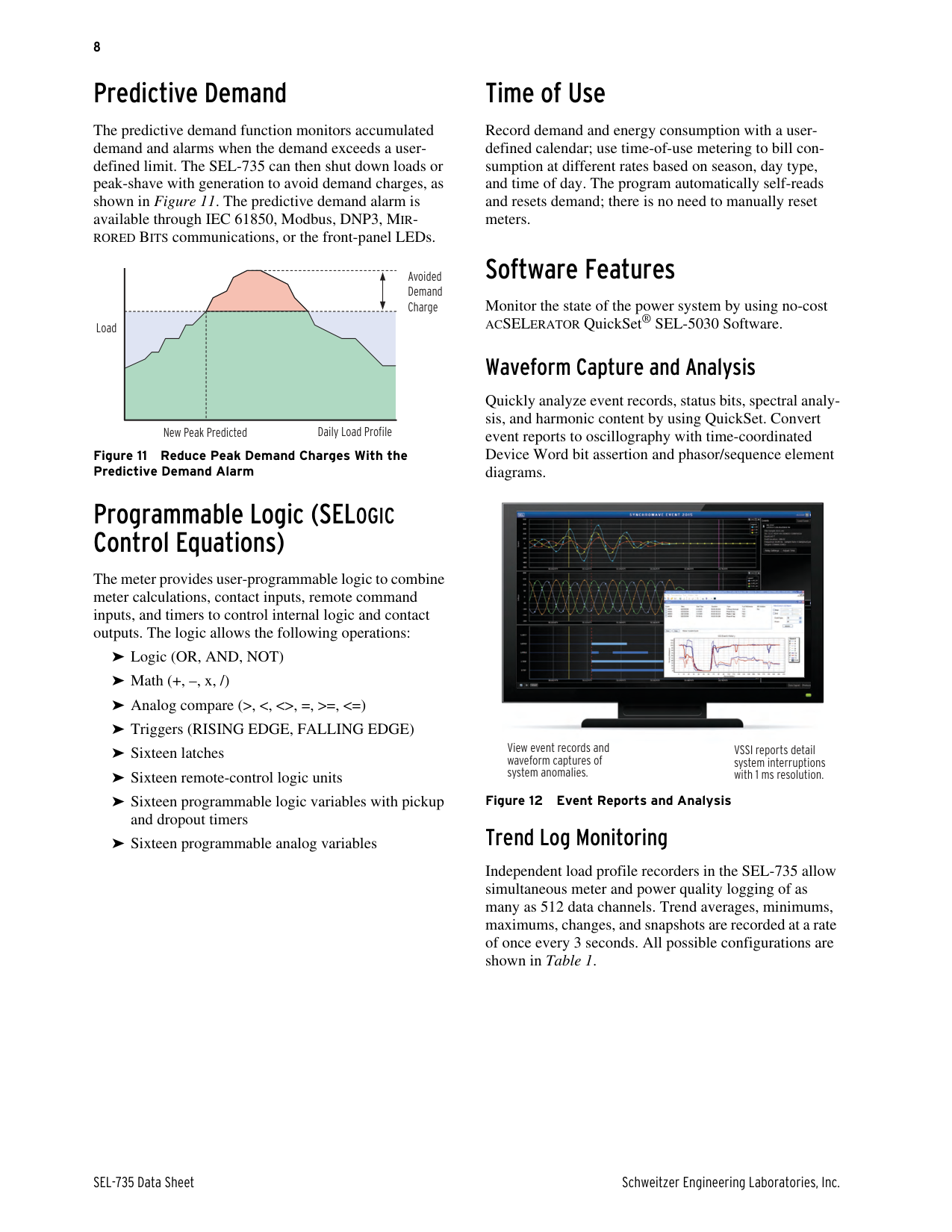
#### Predictive Demand
The predictive demand function monitors accumulated demand and alarms when the demand exceeds a userdefined limit. The SEL-735 can then shut down loads or peak-shave with generation to avoid demand charges, as shown in Figure 11. The predictive demand alarm is available through IEC 61850, Modbus, DNP3, MIRRORED BITS communications, or the front-panel LEDs.
Load
Daily Load Profile
New Peak Predicted
Avoided Demand Charge
Figure 11 Reduce Peak Demand Charges With the Predictive Demand Alarm
#### Programmable Logic (SELOGIC Control Equations)
The meter provides user-programmable logic to combine meter calculations, contact inputs, remote command inputs, and timers to control internal logic and contact outputs. The logic allows the following operations:
➤ Logic (OR, AND, NOT)
➤ Math (+, –, x, /)
➤ Analog compare (>, <, <>, =, >=, <=)
➤ Triggers (RISING EDGE, FALLING EDGE)
➤ Sixteen latches
➤ Sixteen remote-control logic units
➤ Sixteen programmable logic variables with pickup
and dropout timers
➤ Sixteen programmable analog variables
#### Time of Use
Record demand and energy consumption with a userdefined calendar; use time-of-use metering to bill consumption at different rates based on season, day type, and time of day. The program automatically self-reads and resets demand; there is no need to manually reset meters.
#### Software Features
Monitor the state of the power system by using no-cost ACSELERATOR QuickSet® SEL-5030 Software.
Waveform Capture and Analysis
Quickly analyze event records, status bits, spectral analysis, and harmonic content by using QuickSet. Convert event reports to oscillography with time-coordinated Device Word bit assertion and phasor/sequence element diagrams.


View event records and waveform captures of system anomalies.
VSSI reports detail system interruptions with 1 ms resolution.
Figure 12 Event Reports and Analysis
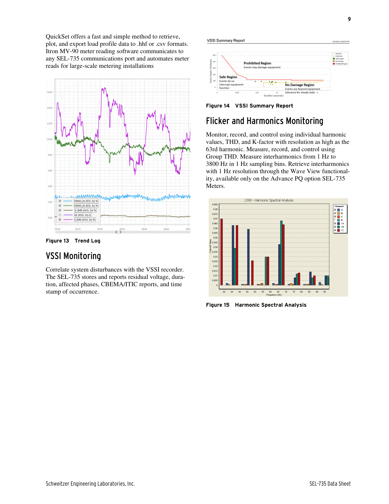
Trend Log Monitoring
Independent load profile recorders in the SEL-735 allow simultaneous meter and power quality logging of as many as 512 data channels. Trend averages, minimums, maximums, changes, and snapshots are recorded at a rate of once every 3 seconds. All possible configurations are shown in Table 1.
QuickSet offers a fast and simple method to retrieve, plot, and export load profile data to .hhf or .csv formats. Itron MV-90 meter reading software communicates to any SEL-735 communications port and automates meter reads for large-scale metering installations

Figure 13 Trend Log
##### VSSI Monitoring
Correlate system disturbances with the VSSI recorder. The SEL-735 stores and reports residual voltage, duration, affected phases, CBEMA/ITIC reports, and time stamp of occurrence.

##### Flicker and Harmonics Monitoring
Monitor, record, and control using individual harmonic values, THD, and K-factor with resolution as high as the 63rd harmonic. Measure, record, and control using Group THD. Measure interharmonics from 1 Hz to 3800 Hz in 1 Hz sampling bins. Retrieve interharmonics with 1 Hz resolution through the Wave View functionality, available only on the Advance PQ option SEL-735 Meters.

Application Examples
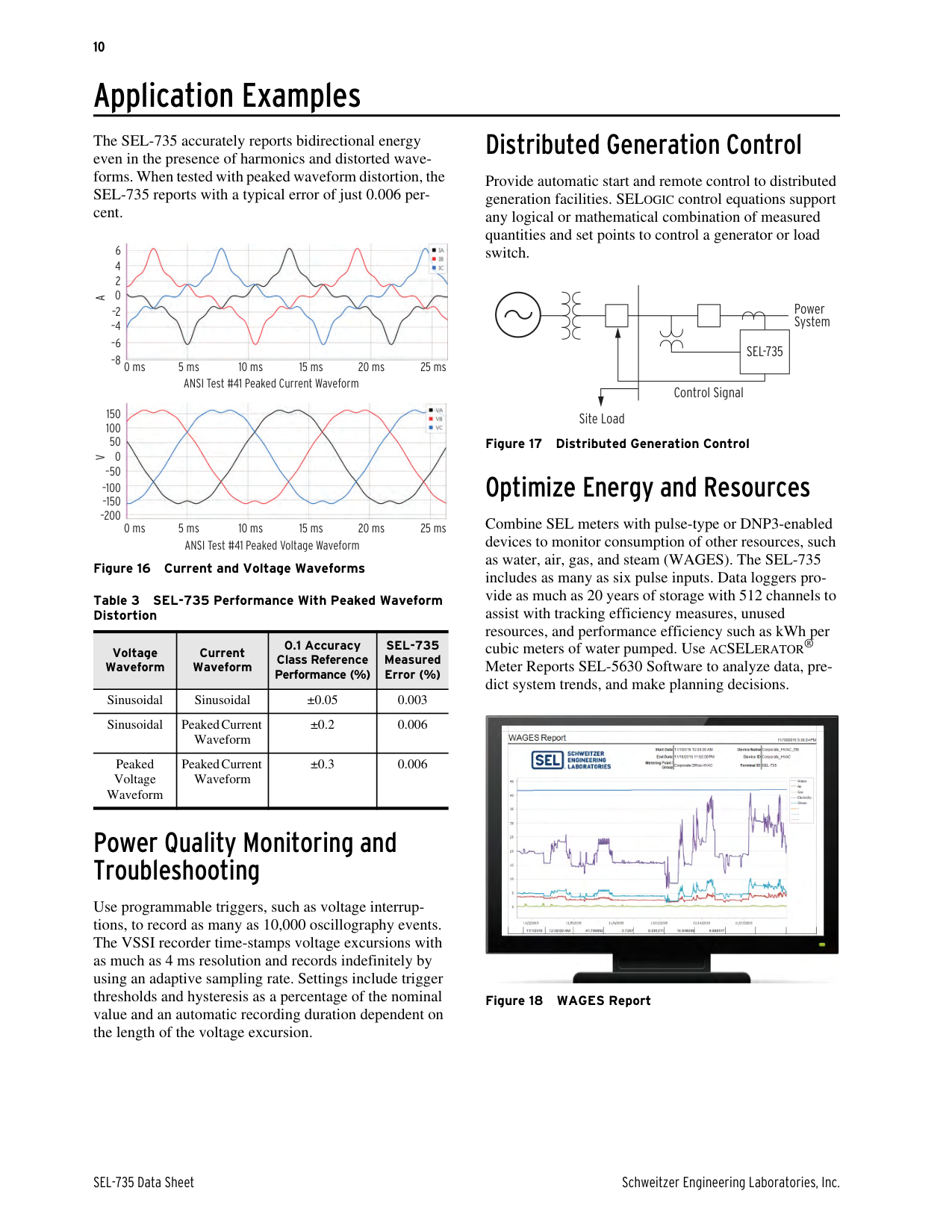
The SEL-735 accurately reports bidirectional energy even in the presence of harmonics and distorted waveforms. When tested with peaked waveform distortion, the SEL-735 reports with a typical error of just 0.006 percent.

6 4 2 0
AV
0 ms 5 ms 10 ms 15 ms 20 ms 25 ms
ANSI Test #41 Peaked Current Waveform

150 100
50 0
ANSI Test #41 Peaked Voltage Waveform
Figure 16 Current and Voltage Waveforms Table 3 SEL-735 Performance With Peaked Waveform Distortion
|Voltage Waveform|Current Waveform|0.1 Accuracy Class Reference Performance (%)|SEL-735 Measured Error (%)| |---|---|---|---| |Sinusoidal|Sinusoidal|±0.05|0.003| |Sinusoidal|Peaked Current Waveform|±0.2|0.006| |Peaked Voltage Waveform|Peaked Current Waveform|±0.3|0.006|
Power Quality Monitoring and Troubleshooting
Use programmable triggers, such as voltage interruptions, to record as many as 10,000 oscillography events. The VSSI recorder time-stamps voltage excursions with as much as 4 ms resolution and records indefinitely by using an adaptive sampling rate. Settings include trigger thresholds and hysteresis as a percentage of the nominal value and an automatic recording duration dependent on the length of the voltage excursion.
Distributed Generation Control
Provide automatic start and remote control to distributed generation facilities. SELOGIC control equations support any logical or mathematical combination of measured quantities and set points to control a generator or load switch.
Power System
SEL-735
Control Signal
Site Load
Optimize Energy and Resources
Combine SEL meters with pulse-type or DNP3-enabled devices to monitor consumption of other resources, such as water, air, gas, and steam (WAGES). The SEL-735 includes as many as six pulse inputs. Data loggers provide as much as 20 years of storage with 512 channels to assist with tracking efficiency measures, unused resources, and performance efficiency such as kWh per cubic meters of water pumped. Use ACSELERATOR® Meter Reports SEL-5630 Software to analyze data, predict system trends, and make planning decisions.

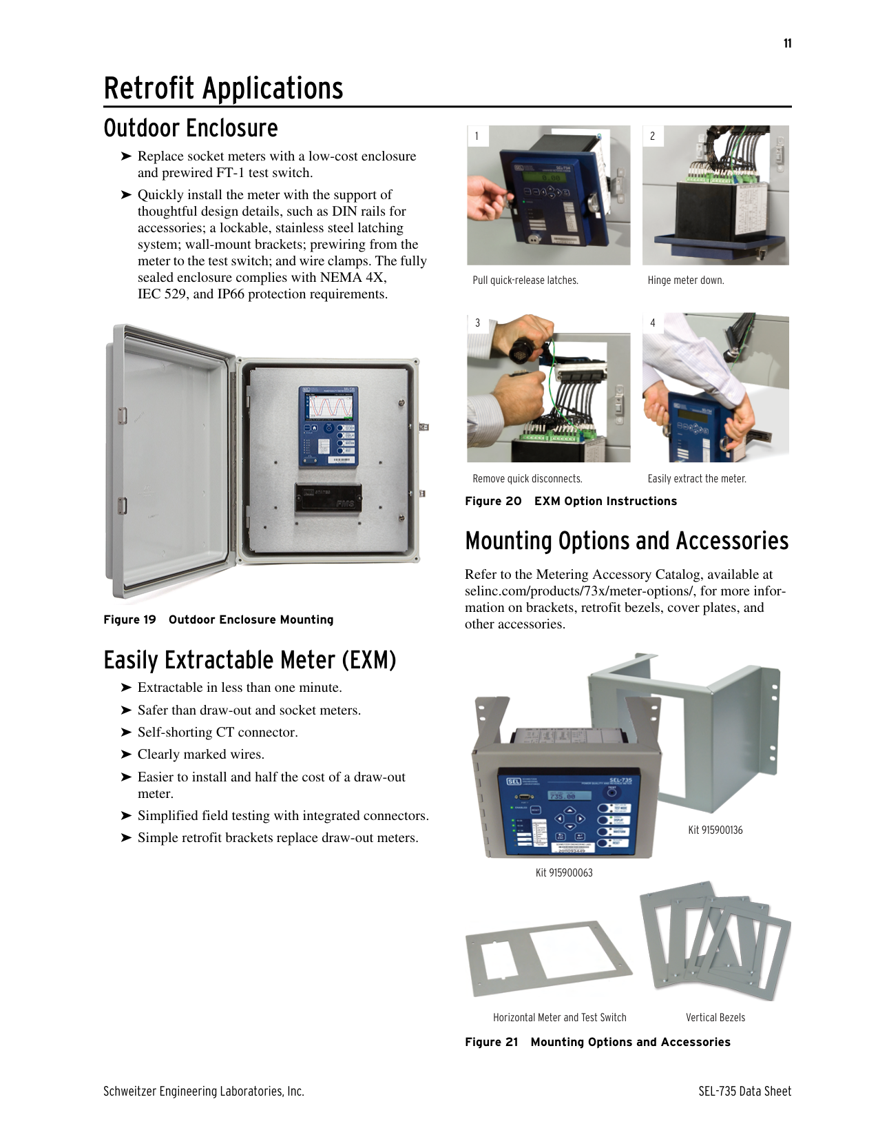
Retrofit Applications Outdoor Enclosure


1 2
➤ Replace socket meters with a low-cost enclosure
and prewired FT-1 test switch.
➤ Quickly install the meter with the support of thoughtful design details, such as DIN rails for accessories; a lockable, stainless steel latching system; wall-mount brackets; prewiring from the meter to the test switch; and wire clamps. The fully sealed enclosure complies with NEMA 4X, IEC 529, and IP66 protection requirements.
Pull quick-release latches. Hinge meter down.


3 4

Remove quick disconnects. Easily extract the meter.
Mounting Options and Accessories
Refer to the Metering Accessory Catalog, available at selinc.com/products/73x/meter-options/, for more information on brackets, retrofit bezels, cover plates, and
other accessories.Figure 19 Outdoor Enclosure Mounting
Easily Extractable Meter (EXM)

➤ Extractable in less than one minute.
➤ Safer than draw-out and socket meters.
➤ Self-shorting CT connector.
➤ Clearly marked wires.
➤ Easier to install and half the cost of a draw-out
meter.
➤ Simplified field testing with integrated connectors.
Kit 915900136
Kit 915900136

➤ Simple retrofit brackets replace draw-out meters.
Kit 915900063


Horizontal Meter and Test Switch Vertical Bezels
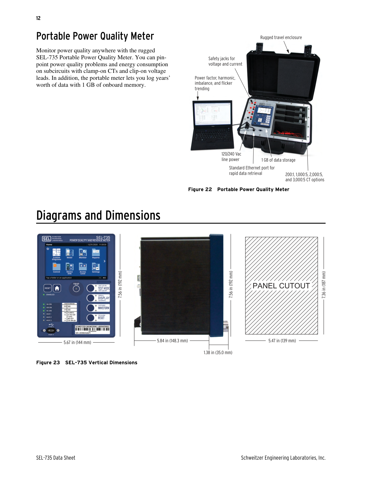
Portable Power Quality Meter
Monitor power quality anywhere with the rugged SEL-735 Portable Power Quality Meter. You can pinpoint power quality problems and energy consumption on subcircuits with clamp-on CTs and clip-on voltage leads. In addition, the portable meter lets you log years’ worth of data with 1 GB of onboard memory.
Rugged travel enclosure

Safety jacks for voltage and current
Power factor, harmonic, imbalance, and flicker trending
120/240 Vac line power
1 GB of data storage
Standard Ethernet port for rapid data retrieval
200:1, 1,000:5, 2,000:5, and 3,000:5 CT options
Figure 22 Portable Power Quality Meter
Diagrams and Dimensions

7.56 in (192 mm)

5.67 in (144 mm)

7.56 in (192 mm)
5.84 in (148.3 mm)
1.38 in (35.0 mm)
Figure 23 SEL-735 Vertical Dimensions
| | |---|
7.36 in (187 mm)
5.47 in (139 mm)


5.47 in (139 mm)
5.67 in (144 mm)
5.67 in (144 mm)
7.36 in (187 mm)7.56 in (192 mm)
5.80 in (147.4 mm)
0.84 in (21.4 mm)
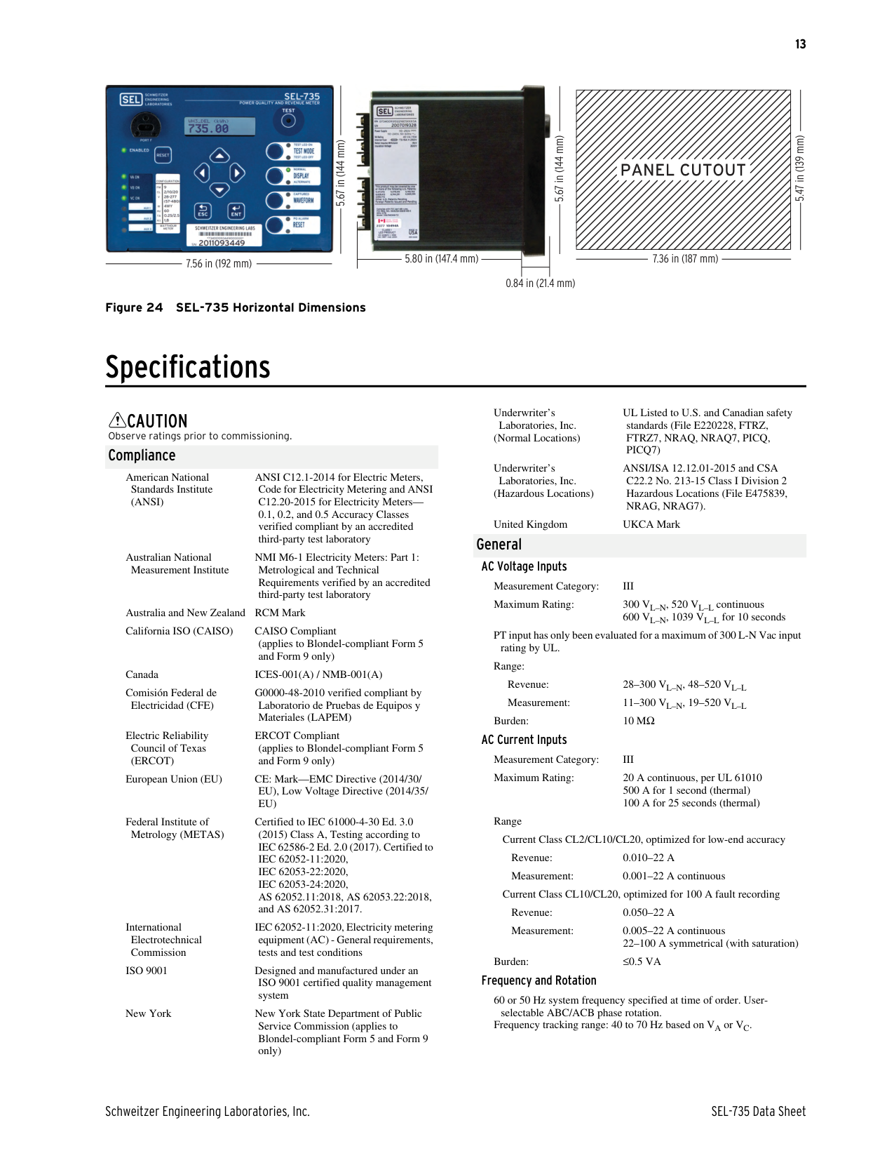
Figure 24 SEL-735 Horizontal Dimensions
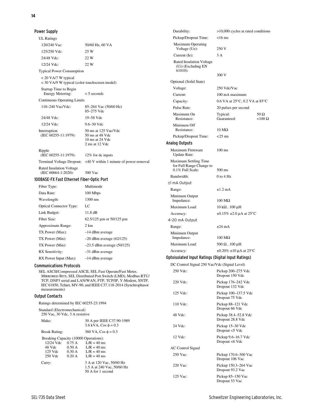
Specifications
CAUTION
Observe ratings prior to commissioning.
Compliance
ANSI C12.1-2014 for Electric Meters, Code for Electricity Metering and ANSI C12.20-2015 for Electricity Meters0.1, 0.2, and 0.5 Accuracy Classes verified compliant by an accredited third-party test laboratory
American National Standards Institute (ANSI)
Australian National Measurement Institute
NMI M6-1 Electricity Meters: Part 1: Metrological and Technical Requirements verified by an accredited third-party test laboratory
Australia and New Zealand RCM Mark California ISO (CAISO) CAISO Compliant
(applies to Blondel-compliant Form 5 and Form 9 only)
Canada ICES-001(A) / NMB-001(A) Comisión Federal de Electricidad (CFE)
G0000-48-2010 verified compliant by Laboratorio de Pruebas de Equipos y Materiales (LAPEM)
ERCOT Compliant (applies to Blondel-compliant Form 5 and Form 9 only)
Electric Reliability Council of Texas (ERCOT)
European Union (EU) CE: Mark—EMC Directive (2014/30/ EU), Low Voltage Directive (2014/35/ EU)
Federal Institute of Metrology (METAS)
Certified to IEC 61000-4-30 Ed. 3.0
(2015) Class A, Testing according to IEC 62586-2 Ed. 2.0 (2017). Certified to
International Electrotechnical Commission
IEC 62052-11:2020, Electricity metering equipment (AC) - General requirements, tests and test conditions
ISO 9001 Designed and manufactured under an ISO 9001 certified quality management system
New York New York State Department of Public Service Commission (applies to Blondel-compliant Form 5 and Form 9 only)
UL Listed to U.S. and Canadian safety
Underwriter’s
standards (File E220228, FTRZ, FTRZ7, NRAQ, NRAQ7, PICQ, PICQ7)
Laboratories, Inc. (Normal Locations)
ANSI/ISA 12.12.01-2015 and CSA
Underwriter’s Laboratories, Inc. (Hazardous Locations)
C22.2 No. 213-15 Class I Division 2 Hazardous Locations (File E475839, NRAG, NRAG7).
United Kingdom UKCA Mark General
AC Voltage Inputs Measurement Category: III Maximum Rating: 300 VL–N, 520 VL–L continuous
600 VL–N, 1039 VL–L for 10 seconds PT input has only been evaluated for a maximum of 300 L-N Vac input
rating by UL. Range:
Revenue: 28–300 VL–N, 48–520 VL–L Measurement: 11–300 VL–N, 19–520 VL–L
Burden: 10 MΩ
AC Current Inputs Measurement Category: III Maximum Rating: 20 A continuous, per UL 61010
500 A for 1 second (thermal) 100 A for 25 seconds (thermal)
Range
Current Class CL2/CL10/CL20, optimized for low-end accuracy Revenue: 0.010–22 A Measurement: 0.001–22 A continuous
Current Class CL10/CL20, optimized for 100 A fault recording Revenue: 0.050–22 A Measurement: 0.005–22 A continuous
22–100 A symmetrical (with saturation) Burden: ≤0.5 VA
Frequency and Rotation
60 or 50 Hz system frequency specified at time of order. Userselectable ABC/ACB phase rotation. Frequency tracking range: 40 to 70 Hz based on VA or VC.
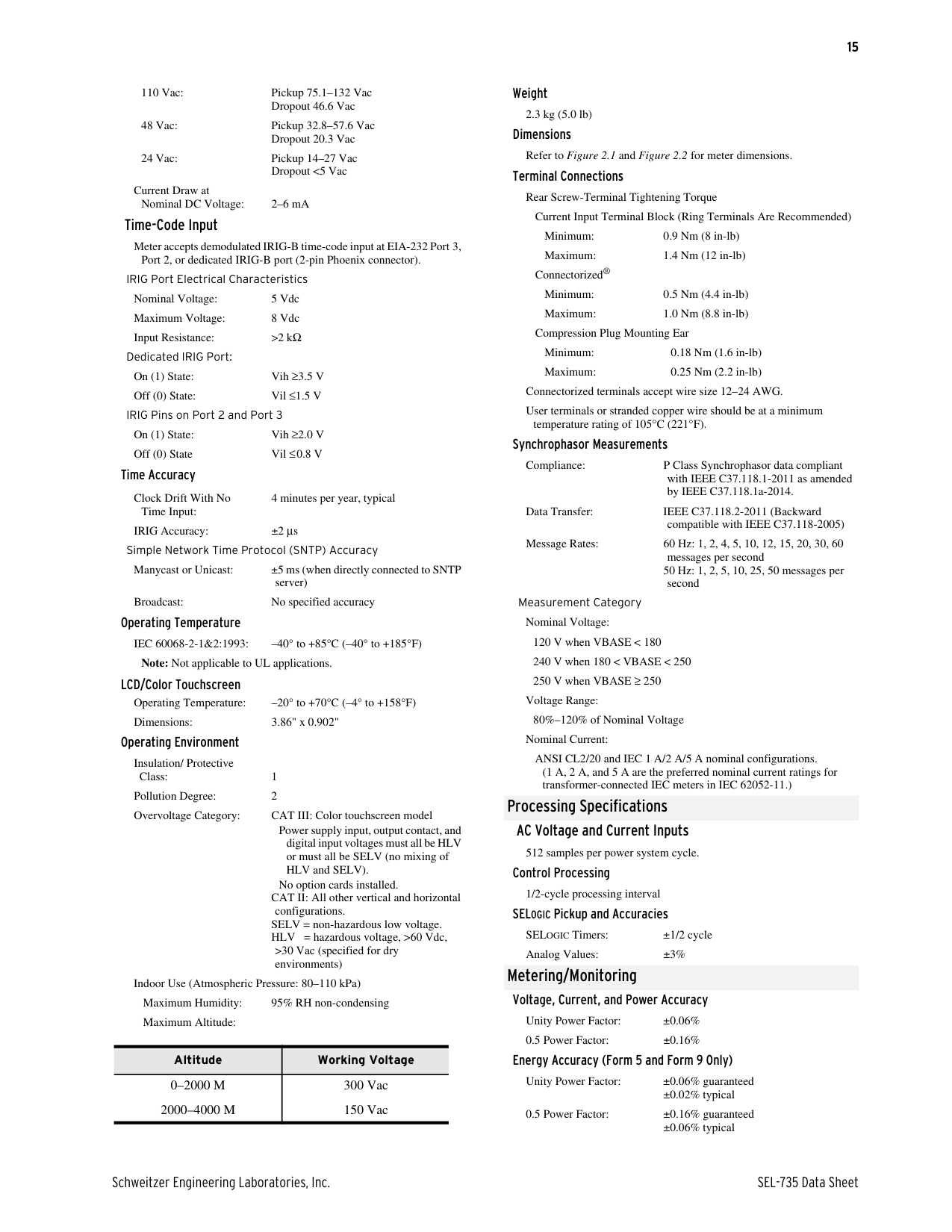
Power Supply
UL Ratings 120/240 Vac: 50/60 Hz, 60 VA 125/250 Vdc: 25 W 24/48 Vdc: 22 W 12/24 Vdc: 22 W
Typical Power Consumption
< 20 VA/7 W typical < 30 VA/9 W typical (color touchscreen model)
Startup Time to Begin
Energy Metering: < 5 seconds Continuous Operating Limits
110–240 Vac/Vdc: 85–264 Vac (50/60 Hz)
85–275 Vdc 24/48 Vdc: 19–58 Vdc 12/24 Vdc: 9.6–30 Vdc
Interruption (IEC 60255-11:1979):
50 ms at 125 Vac/Vdc 50 ms at 48 Vdc 10 ms at 24 Vdc 2 ms at 12 Vdc
Ripple
(IEC 60255-11:1979): 12% for dc inputs Terminal Voltage Dropout: <40 V within 1 minute of power removal Rated Insulation Voltage
(IEC 60664-1:2020): 300 Vac
100BASE-FX Fast Ethernet Fiber-Optic Port Fiber Type: Multimode Data Rate: 100 Mbps Wavelength: 1300 nm Optical Connector Type: LC Link Budget: 11.8 dB Fiber Size: 62.5/125 μm or 50/125 μm Approximate Range: 2 km TX Power (Max): –14 dBm average TX Power (Min): –20 dBm average (62/125) TX Power (Min): –23.5 dBm average (50/125) RX Sensitivity: –31 dBm average RX Power Input (Max): –14 dBm average
Communications Protocols
SEL ASCII/Compressed ASCII, SEL Fast Operate/Fast Meter, MIRRORED BITS, SEL Distributed Port Switch (LMD), Modbus RTU/ TCP, DNP3 serial and LAN/WAN, FTP, TCP/IP, Y-Modem, SNTP, IEC 61850, Telnet, MV-90, and IEEE C37.118-2014 (Synchrophasor measurements)
Output Contacts Ratings determined by IEC 60255-23:1994 Standard (Electromechanical)
250 Vac, 30 Vdc, 3 A resistive Make: 30 A per IEEE C37.90-1989
3.6 kVA, Cos φ = 0.3 Break Rating: 360 VA, Cos φ = 0.3 Breaking Capacity (10000 Operations):
12/24 Vdc 0.75 A L/R = 40 ms 48 Vdc 0.50 A L/R = 40 ms 125 Vdc 0.30 A L/R = 40 ms 250 Vdc 0.20 A L/R = 40 ms
Carry: 3 A at 120 Vac, 50/60 Hz 1.5 A at 240 Vac, 50/60 Hz 50 A for 1 second
Durability: >10,000 cycles at rated conditions Pickup/Dropout Time: <16 ms Maximum Operating
Voltage (Ue): 250 V Current (Ie): 3 A Rated Insulation Voltage
(Ui) (Excluding EN 61010):
300 V
Optional (Solid State) Voltage: 250 Vdc/Vac Current: 100 mA maximum Capacity: 0.6 VA at 25°C, 0.2 VA at 85°C Pulse Rate: 20 pulses per second Maximum On Resistance:
Typical: 50 Ω Guaranteed: <100 Ω
Minimum Off Resistance: 10 MΩ
Pickup/Dropout Time: < 25 ms Analog Outputs
Maximum Firmware Update Rate:
100 ms
Maximum Settling Time for Full Range Change to 0.1% Full Scale: 500 ms
Bandwidth: 0 to 4 Hz
±1 mA Output Range: ±1.2 mA Minimum Output
Impedance: 100 MΩ Maximum Load: 10 kΩ , 100 μH Accuracy: ±0.15% ±2.0 μA at 25°C
4–20 mA Output Range: ±24 mA Minimum Output
Impedance: 100 MΩ Maximum Load: 500 Ω , 100 μH Accuracy: ±0.20% ±10 μA at 25°C
Optoisolated Input Ratings (Digital Input Ratings) DC Control Signal 250 Vac/Vdc (Signal Level)
250 Vdc: Pickup 200–275 Vdc Dropout 150 Vdc
220 Vdc: Pickup 176–242 Vdc Dropout 132 Vdc
125 Vdc: Pickup 100–137.5 Vdc Dropout 75 Vdc
110 Vdc: Pickup 88–121 Vdc Dropout 66 Vdc
48 Vdc: Pickup 38.4–52.8 Vdc
Dropout 28.8 Vdc 24 Vdc: Pickup 15–30 Vdc
12 Vdc: Pickup 9.6–16.7 Vdc
AC Control Signal 250 Vac: Pickup 170.6–300 Vac Dropout 106 Vac 220 Vac: Pickup 150.3–264 Vac Dropout 93.2 Vac 125 Vac: Pickup 85–150 Vac Dropout 53 Vac
110 Vac: Pickup 75.1–132 Vac Dropout 46.6 Vac
48 Vac: Pickup 32.8–57.6 Vac
Dropout 20.3 Vac 24 Vac: Pickup 14–27 Vac
Dropout <5 Vac Current Draw at
Nominal DC Voltage: 2–6 mA Time-Code Input
Meter accepts demodulated IRIG-B time-code input at EIA-232 Port 3,
Port 2, or dedicated IRIG-B port (2-pin Phoenix connector). IRIG Port Electrical Characteristics Nominal Voltage: 5 Vdc Maximum Voltage: 8 Vdc Input Resistance: >2 kΩ
Dedicated IRIG Port: On (1) State: Vih ≥3.5 V Off (0) State: Vil ≤1.5 V
IRIG Pins on Port 2 and Port 3
On (1) State: Vih ≥2.0 V Off (0) State Vil ≤0.8 V
Time Accuracy
Clock Drift With No Time Input:
4 minutes per year, typical
IRIG Accuracy: ±2 μs Simple Network Time Protocol (SNTP) Accuracy Manycast or Unicast: ±5 ms (when directly connected to SNTP server)
Broadcast: No specified accuracy Operating Temperature
IEC 60068-2-1&2:1993: –40° to +85°C (–40° to +185°F)
Note: Not applicable to UL applications.
LCD/Color Touchscreen Operating Temperature: –20° to +70°C (–4° to +158°F) Dimensions: 3.86" x 0.902"
Operating Environment
Insulation/ Protective
Class: 1 Pollution Degree: 2 Overvoltage Category: CAT III: Color touchscreen model
Power supply input, output contact, and digital input voltages must all be HLV or must all be SELV (no mixing of HLV and SELV).
No option cards installed. CAT II: All other vertical and horizontal
configurations. SELV = non-hazardous low voltage. HLV = hazardous voltage, >60 Vdc,
>30 Vac (specified for dry environments)
Indoor Use (Atmospheric Pressure: 80–110 kPa) Maximum Humidity: 95% RH non-condensing Maximum Altitude:
|Altitude|Working Voltage|
|---|---| |0–2000 M 2000–4000 M|300 Vac 150 Vac|
Weight
2.3 kg (5.0 lb) Dimensions
Refer to Figure 2.1 and Figure 2.2 for meter dimensions. Terminal Connections
Rear Screw-Terminal Tightening Torque
Current Input Terminal Block (Ring Terminals Are Recommended) Minimum: 0.9 Nm (8 in-lb) Maximum: 1.4 Nm (12 in-lb)
Connectorized®
Minimum: 0.5 Nm (4.4 in-lb) Maximum: 1.0 Nm (8.8 in-lb)
Compression Plug Mounting Ear
Minimum: 0.18 Nm (1.6 in-lb) Maximum: 0.25 Nm (2.2 in-lb) Connectorized terminals accept wire size 12–24 AWG. User terminals or stranded copper wire should be at a minimum
temperature rating of 105°C (221°F). Synchrophasor Measurements
Compliance: P Class Synchrophasor data compliant with IEEE C37.118.1-2011 as amended by IEEE C37.118.1a-2014.
Data Transfer: IEEE C37.118.2-2011 (Backward
compatible with IEEE C37.118-2005) Message Rates: 60 Hz: 1, 2, 4, 5, 10, 12, 15, 20, 30, 60
messages per second 50 Hz: 1, 2, 5, 10, 25, 50 messages per
second Measurement Category
Nominal Voltage: 120 V when VBASE < 180 240 V when 180 < VBASE < 250 250 V when VBASE ≥ 250
Voltage Range:
80%–120% of Nominal Voltage Nominal Current:
ANSI CL2/20 and IEC 1 A/2 A/5 A nominal configurations. (1 A, 2 A, and 5 A are the preferred nominal current ratings for transformer-connected IEC meters in IEC 62052-11.)
Processing Specifications
AC Voltage and Current Inputs
512 samples per power system cycle. Control Processing
1/2-cycle processing interval SELOGIC Pickup and Accuracies SELOGIC Timers: ±1/2 cycle Analog Values: ±3%
Metering/Monitoring
Voltage, Current, and Power Accuracy Unity Power Factor: ±0.06% 0.5 Power Factor: ±0.16%
Energy Accuracy (Form 5 and Form 9 Only)
Unity Power Factor: ±0.06% guaranteed ±0.02% typical
0.5 Power Factor: ±0.16% guaranteed ±0.06% typical
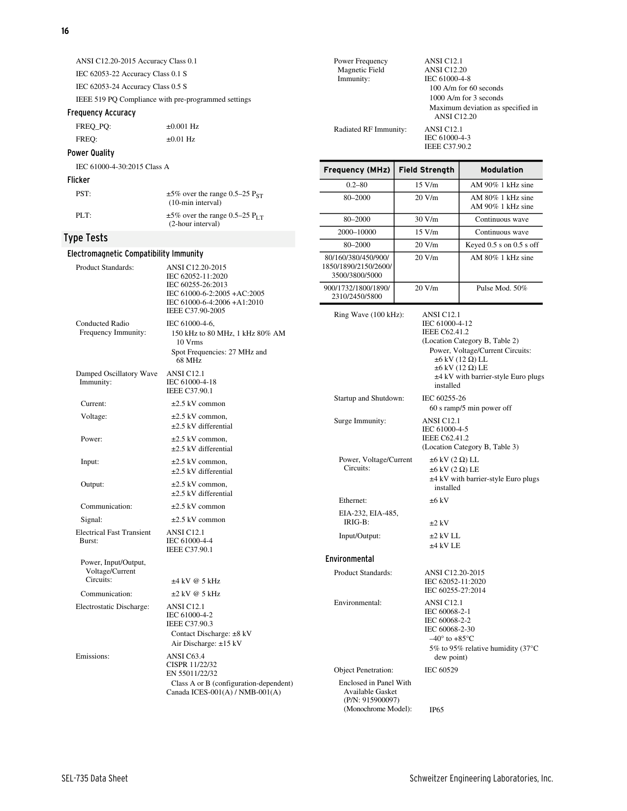
ANSI C12.20-2015 Accuracy Class 0.1 IEC 62053-22 Accuracy Class 0.1 S IEC 62053-24 Accuracy Class 0.5 S IEEE 519 PQ Compliance with pre-programmed settings
Frequency Accuracy FREQ_PQ: ±0.001 Hz FREQ: ±0.01 Hz
Power Quality
IEC 61000-4-30:2015 Class A Flicker
PST: ±5% over the range 0.5–25 PST (10-min interval)
PLT: ±5% over the range 0.5–25 PLT
(2-hour interval) Type Tests
Electromagnetic Compatibility Immunity
Product Standards: ANSI C12.20-2015 IEC 62052-11:2020 IEC 60255-26:2013 IEC 61000-6-2:2005 +AC:2005 IEC 61000-6-4:2006 +A1:2010 IEEE C37.90-2005
Conducted Radio Frequency Immunity:
IEC 61000-4-6, 150 kHz to 80 MHz, 1 kHz 80% AM 10 Vrms Spot Frequencies: 27 MHz and
68 MHz Damped Oscillatory Wave
ANSI C12.1 IEC 61000-4-18 IEEE C37.90.1
Immunity:
Current: ±2.5 kV common Voltage: ±2.5 kV common,
±2.5 kV differential Power: ±2.5 kV common,
±2.5 kV differential Input: ±2.5 kV common,
±2.5 kV differential Output: ±2.5 kV common,
±2.5 kV differential
Communication: ±2.5 kV common Signal: ±2.5 kV common
Electrical Fast Transient Burst:
ANSI C12.1 IEC 61000-4-4 IEEE C37.90.1
Power, Input/Output, Voltage/Current Circuits: ±4 kV @ 5 kHz
Communication: ±2 kV @ 5 kHz Electrostatic Discharge: ANSI C12.1
IEC 61000-4-2 IEEE C37.90.3
Contact Discharge: ±8 kV Air Discharge: ±15 kV
Emissions: ANSI C63.4
CISPR 11/22/32 EN 55011/22/32
Class A or B (configuration-dependent) Canada ICES-001(A) / NMB-001(A)
Power Frequency Magnetic Field Immunity:
ANSI C12.1 ANSI C12.20 IEC 61000-4-8
100 A/m for 60 seconds 1000 A/m for 3 seconds Maximum deviation as specified in
ANSI C12.20 Radiated RF Immunity: ANSI C12.1

IEC 61000-4-3 IEEE C37.90.2
|Frequency (MHz)|Field Strength|Modulation| |---|---|---| |0.2–80|15 V/m|AM 90% 1 kHz sine| |80–2000|20 V/m|AM 80% 1 kHz sine AM 90% 1 kHz sine| |80–2000|30 V/m|Continuous wave| |2000–10000|15 V/m|Continuous wave| |80–2000|20 V/m|Keyed 0.5 s on 0.5 s off| |80/160/380/450/900/ 1850/1890/2150/2600/ 3500/3800/5000|20 V/m|AM 80% 1 kHz sine| |900/1732/1800/1890/ 2310/2450/5800|20 V/m|Pulse Mod. 50%|
Ring Wave (100 kHz): ANSI C12.1 IEC 61000-4-12 IEEE C62.41.2 (Location Category B, Table 2)
Power, Voltage/Current Circuits: ±6 kV (12 Ω) LL ±6 kV (12 Ω) LE ±4 kV with barrier-style Euro plugs installed
Startup and Shutdown: IEC 60255-26
60 s ramp/5 min power off Surge Immunity: ANSI C12.1
IEC 61000-4-5 IEEE C62.41.2 (Location Category B, Table 3)
±6 kV (2 Ω) LL ±6 kV (2 Ω) LE ±4 kV with barrier-style Euro plugs
Power, Voltage/Current Circuits:
installed Ethernet: ±6 kV EIA-232, EIA-485,
IRIG-B: ±2 kV Input/Output: ±2 kV LL
±4 kV LE Environmental
Product Standards: ANSI C12.20-2015 IEC 62052-11:2020 IEC 60255-27:2014
Environmental: ANSI C12.1
–40° to +85°C 5% to 95% relative humidity (37°C
dew point) Object Penetration: IEC 60529
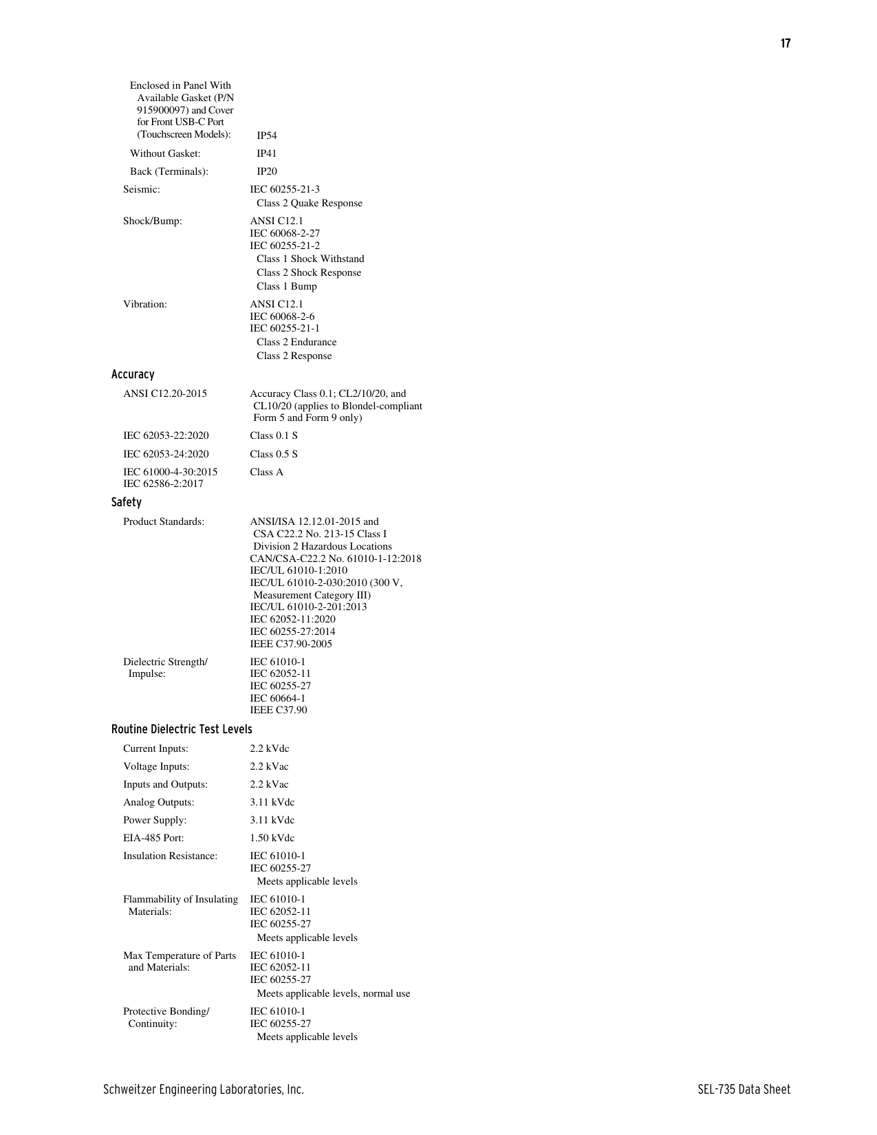
Enclosed in Panel With Available Gasket (P/N: 915900097) (Monochrome Model): IP65
Enclosed in Panel With
Available Gasket (P/N 915900097) and Cover for Front USB-C Port
(Touchscreen Models): IP54 Without Gasket: IP41 Back (Terminals): IP20
Seismic: IEC 60255-21-3
Class 2 Quake Response Shock/Bump: ANSI C12.1
IEC 60068-2-27 IEC 60255-21-2

Vibration: ANSI C12.1 IEC 60068-2-6 IEC 60255-21-1
Class 2 Endurance Class 2 Response
Accuracy
ANSI C12.20-2015 Accuracy Class 0.1; CL2/10/20, and CL10/20 (applies to Blondel-compliant Form 5 and Form 9 only)
IEC 62053-22:2020 Class 0.1 S IEC 62053-24:2020 Class 0.5 S IEC 61000-4-30:2015 IEC 62586-2:2017
Class A Safety
Product Standards: ANSI/ISA 12.12.01-2015 and CSA C22.2 No. 213-15 Class I Division 2 Hazardous Locations
CAN/CSA-C22.2 No. 61010-1-12:2018 IEC/UL 61010-1:2010 IEC/UL 61010-2-030:2010 (300 V,
Measurement Category III) IEC/UL 61010-2-201:2013 IEC 62052-11:2020 IEC 60255-27:2014 IEEE C37.90-2005
Dielectric Strength/ Impulse:
IEC 61010-1 IEC 62052-11 IEC 60255-27 IEC 60664-1 IEEE C37.90
Routine Dielectric Test Levels Current Inputs: 2.2 kVdc Voltage Inputs: 2.2 kVac Inputs and Outputs: 2.2 kVac Analog Outputs: 3.11 kVdc Power Supply: 3.11 kVdc EIA-485 Port: 1.50 kVdc Insulation Resistance: IEC 61010-1
IEC 60255-27
Meets applicable levels Flammability of Insulating
IEC 61010-1 IEC 62052-11 IEC 60255-27
Materials:
Meets applicable levels Max Temperature of Parts
IEC 61010-1 IEC 62052-11 IEC 60255-27
and Materials:
Meets applicable levels, normal use Protective Bonding/
IEC 61010-1 IEC 60255-27
Continuity:
Meets applicable levels
Technical Support
We appreciate your interest in SEL products and services. If you have questions or comments, please contact us at:
Schweitzer Engineering Laboratories, Inc. 2350 NE Hopkins Court Pullman, WA 99163-5603 U.S.A. Tel: +1.509.338.3838 Fax: +1.509.332.7990 Internet: selinc.com/support Email: info@selinc.com
Notes
© 2011–2024 by Schweitzer Engineering Laboratories, Inc. All rights reserved.
All brand or product names appearing in this document are the trademark or registered trademark of their respective holders. No SEL trademarks may be used without written permission. SEL products appearing in this document may be covered by U.S. and Foreign patents.
2350 NE Hopkins Court • Pullman, WA 99163-5603 U.S.A. Tel: +1.509.332.1890 • Fax: +1.509.332.7990 selinc.com • info@selinc.com

Schweitzer Engineering Laboratories, Inc. reserves all rights and benefits afforded under federal and international copyright and patent laws in its products, including without limitation software, firmware, and documentation.
The information in this document is provided for informational use only and is subject to change without notice. Schweitzer Engineering Laboratories, Inc. has approved only the English language document.
selinc.com or contact your customer service representative. *PDS735-01*
This product is covered by the standard SEL 10-year warranty. For warranty details, visit
###### SEL-735 Data Sheet Date Code 20240306