
Ask AI
— answers from the official manualAnswers from the official manual.
Common questions
Common Questions
10 totalHow do I reset my Tenda Ac1200 wifi 6 router to factory settings?
Press and hold the Power button for 8 seconds until the LED blinks fast to perform a factory reset. This clears all configurations but keeps your existing IP address. You will need to set up the router from scratch after a reset.
What is the default WiFi name and password for my Tenda Ac1200 WiFi 6 router?
The default WiFi name (SSID) and password are listed on the bottom label of the device, typically near the barcode. Use these credentials to connect wirelessly until you customize them.
How do I set up WISP connection for my Tenda Ac1200 WiFi 6 router?
In WISP mode, you need to configure the SSID and password of your ISP’s hotspot. Here are steps: Set Connection Type to Dynamic IP Address, Operating Mode to WISP, then provide the network's details.
How can I set up port forwarding on my Tenda Ac1200 WiFi 6 router?
Go to the Port Forwarding module (under Advanced) and add a new rule by entering an internal IP Address, internal service port, external port number, and selecting protocol type.
How do I change my Tenda Ac1200 WiFi 6 router's WiFi password?
To change your router’s WiFi password, navigate to Wireless Settings > WiFi Name and Password pages, enter a new name (SSID) if desired then set the Security Mode and input new WiFi password.
Where can I find my Tenda Ac1200 WiFi 6 router’s login IP address?
The default IP Address for logging into the web UI of your router is listed on its bottom label, typically in bold as the ‘IP Address’. Connect a device to the LAN and use this URL: tendawifi.com or the manual-provided address.
Full Manual
90 pages


AC1200 Dual-band Router User Guide
Copyright Statement © 2019 Shenzhen Tenda Technology Co., Ltd. All rights reserved.

is a registered trademark legally held by Shenzhen Tenda Technology Co., Ltd. Other brand and product names mentioned herein are trademarks or registered trademarks of their respective holders. Copyright of the whole product as integration, including its accessories and software, belongs to Shenzhen Tenda Technology Co., Ltd. No part of this publication can be reproduced, transmitted, transcribed, stored in a retrieval system, or translated into any language in any form or by any means without the prior written permission of Shenzhen Tenda Technology Co., Ltd.
##### Disclaimer
Pictures, images and product specifications herein are for references only. To improve internal design, operational function, and/or reliability, Tenda reserves the right to make changes to the products without obligation to notify any person or organization of such revisions or changes. Tenda does not assume any liability that may occur due to the use or application of the product described herein. Every effort has been made in the preparation of this document to ensure accuracy of the contents, but all statements, information and recommendations in this document do not constitute the warranty of any kind, express or implied.
i
Preface Thank you for choosing Tenda! Please read this user guide before you start.
Conventions This user guide is applicable to the following routers. AC8 is used for illustration in this guide unless it is specified. The contained images and UI screenshots are subject to the actual products.
Product model Description AC8 AC1200 Dual-band Gigabit Wireless Router AC7 AC1200 Smart Dual-Band WiFi Router AC5 AC1200 Smart Dual-band WiFi Router
Typographical conventions in this User Guide: Item Presentation Example Cascading Menus > Click Status > Device Status Parameter and value Bold Set User Name to Tom. UI control Bold On the Policy page, click the OK button. Variable Italic Format: XX:XX:XX:XX:XX:XX Message “ ” The “Success” message appears.
######### Symbols in this User Guide:
########## Item Meaning

This format is used to highlight information of importance or special interest. Ignoring this type of note may result in ineffective configurations, loss of data or damage to device.

This format is used to highlight a procedure that will save time or resources.
Acronyms and Abbreviations Acronym or Abbreviation Full Spelling DDNS Dynamic Domain Name System DHCP Dynamic Host Configuration Protocol DMZ Demilitarized Zone DNS Domain Name System IPTV Internet Protocol Television
ii
Acronym or Abbreviation Full Spelling IPv4 Internet Protocol Version 4 IPv6 Internet Protocol Version 6 ISP Internet Service Provider PPP Point To Point Protocol PPPoE Point-to-Point Protocol over Ethernet PPTP Point to Point Tunneling Protocol SSID Service Set Identifier
##### Technical Support
If you need more help, contact us by any of the following means. We will be glad to assist you as soon as possible.

Hotline
Global: (86) 755-27657180 (China Time Zone) United States: 1-800-570-5892 (Toll Free: 7 x 24 hours) Canada: 1-888-998-8966 (Toll Free: Mon - Fri 9 am - 6 pm PST) Hong Kong: 00852-81931998

support@tenda.cn
iii
Content
iv
v
Appendix ............................................................................................................................................77

1 Knowing your device
1.1 LED indicator
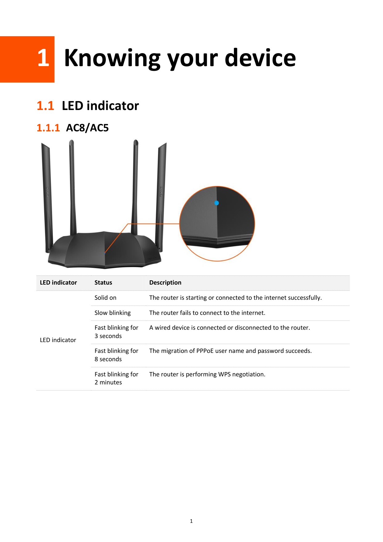
#### 1.1.1 AC8/AC5

########## LED indicator Status Description
LED indicator
Solid on The router is starting or connected to the internet successfully. Slow blinking The router fails to connect to the internet. Fast blinking for 3 seconds
A wired device is connected or disconnected to the router.
Fast blinking for 8 seconds
The migration of PPPoE user name and password succeeds.
Fast blinking for 2 minutes
The router is performing WPS negotiation.
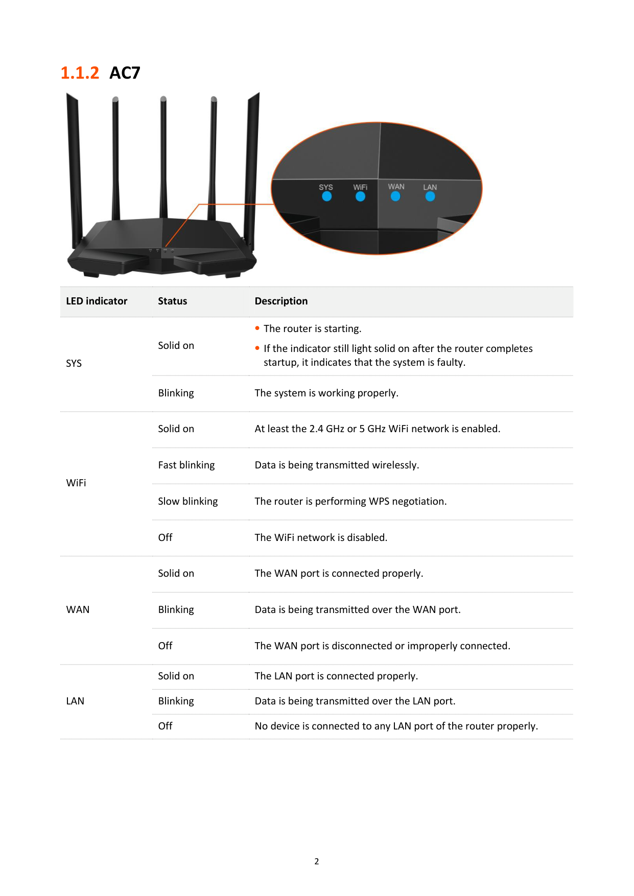
#### 1.1.2 AC7

########## LED indicator Status Description

SYS
Solid on
The router is starting.
If the indicator still light solid on after the router completes startup, it indicates that the system is faulty.
Blinking The system is working properly.
Solid on At least the 2.4 GHz or 5 GHz WiFi network is enabled.
WiFi
Fast blinking Data is being transmitted wirelessly.
Slow blinking The router is performing WPS negotiation.
Off The WiFi network is disabled.
Solid on The WAN port is connected properly.
WAN
Blinking Data is being transmitted over the WAN port.
Off The WAN port is disconnected or improperly connected.
Solid on The LAN port is connected properly. Blinking Data is being transmitted over the LAN port. Off No device is connected to any LAN port of the router properly.
LAN
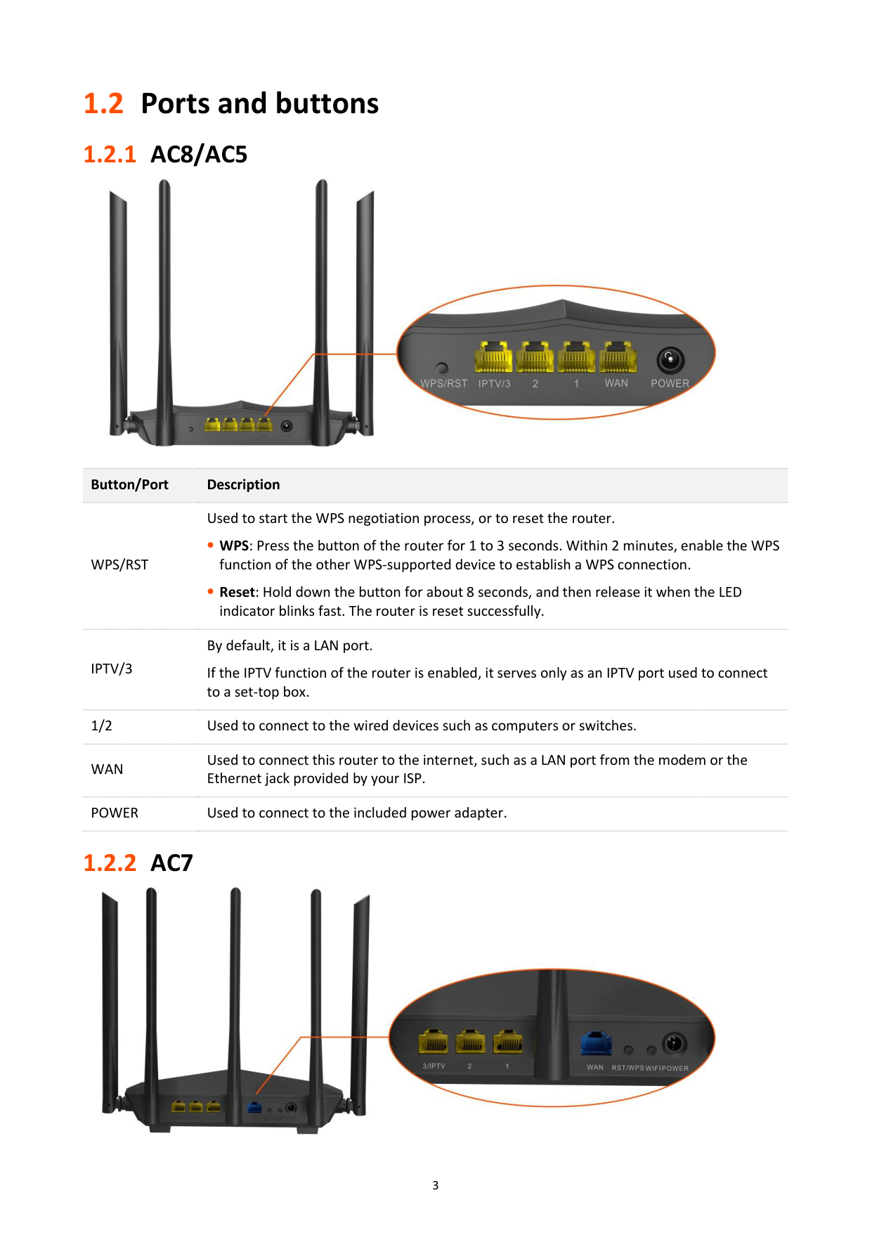
1.2 Ports and buttons
Button/Port Description
WPS/RST
Used to start the WPS negotiation process, or to reset the router.
WPS: Press the button of the router for 1 to 3 seconds. Within 2 minutes, enable the WPS function of the other WPS-supported device to establish a WPS connection.
Reset: Hold down the button for about 8 seconds, and then release it when the LED indicator blinks fast. The router is reset successfully.
IPTV/3
By default, it is a LAN port. If the IPTV function of the router is enabled, it serves only as an IPTV port used to connect to a set-top box.
1/2 Used to connect to the wired devices such as computers or switches.
WAN
Used to connect this router to the internet, such as a LAN port from the modem or the Ethernet jack provided by your ISP.
POWER Used to connect to the included power adapter.


########## Port/Button Description
POWER
Power jack. Used to connect to the included power adapter.
WIFI Used to enable/disable the WiFi network of the router.
Used to start the WPS negotiation process, or to reset the router.
RST/WPS
WPS: Press the button of the router for 1 to 3 seconds. Within 2 minutes, enable the WPS function of the other WPS-supported device to establish a WPS connection.
Reset: Hold down the button for about 8 seconds. Release it when all the LED indicators blink once. The router is reset successfully.
WAN
Used to connect this router to the internet, such as a LAN port from the modem or the Ethernet jack provided by your ISP.
1/2 They are LAN ports used to connect to the wired devices such as computers or switches.
By default, it is a LAN port. If the IPTV function of the router is enabled, it serves only as an IPTV port used to connect to a set-top box.
3/IPTV
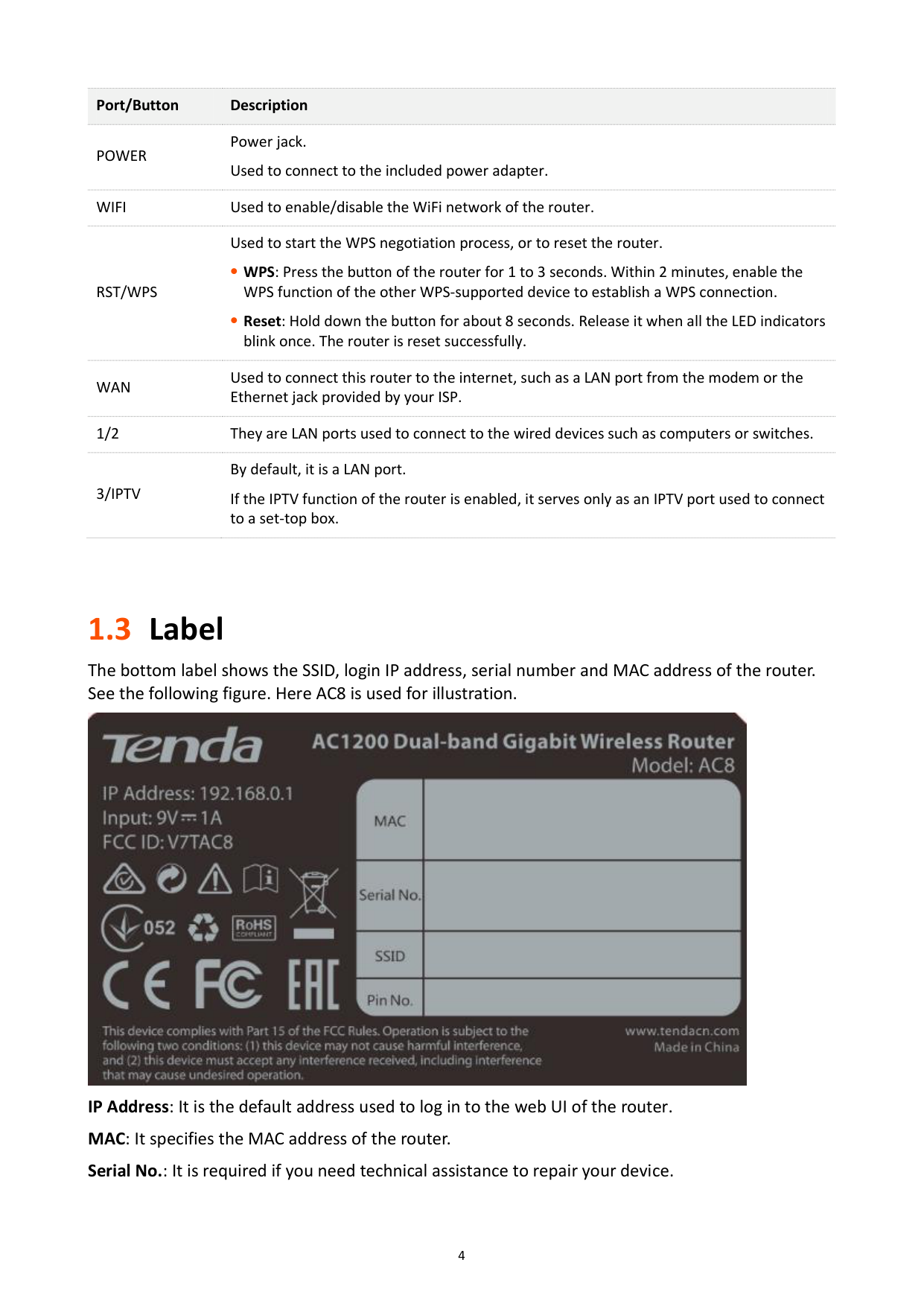
1.3 Label
The bottom label shows the SSID, login IP address, serial number and MAC address of the router. See the following figure. Here AC8 is used for illustration.

IP Address: It is the default address used to log in to the web UI of the router. MAC: It specifies the MAC address of the router. Serial No.: It is required if you need technical assistance to repair your device.
######### SSID: It specifies the default WiFi name of the router. Pin No.: It specifies the PIN code of the router.

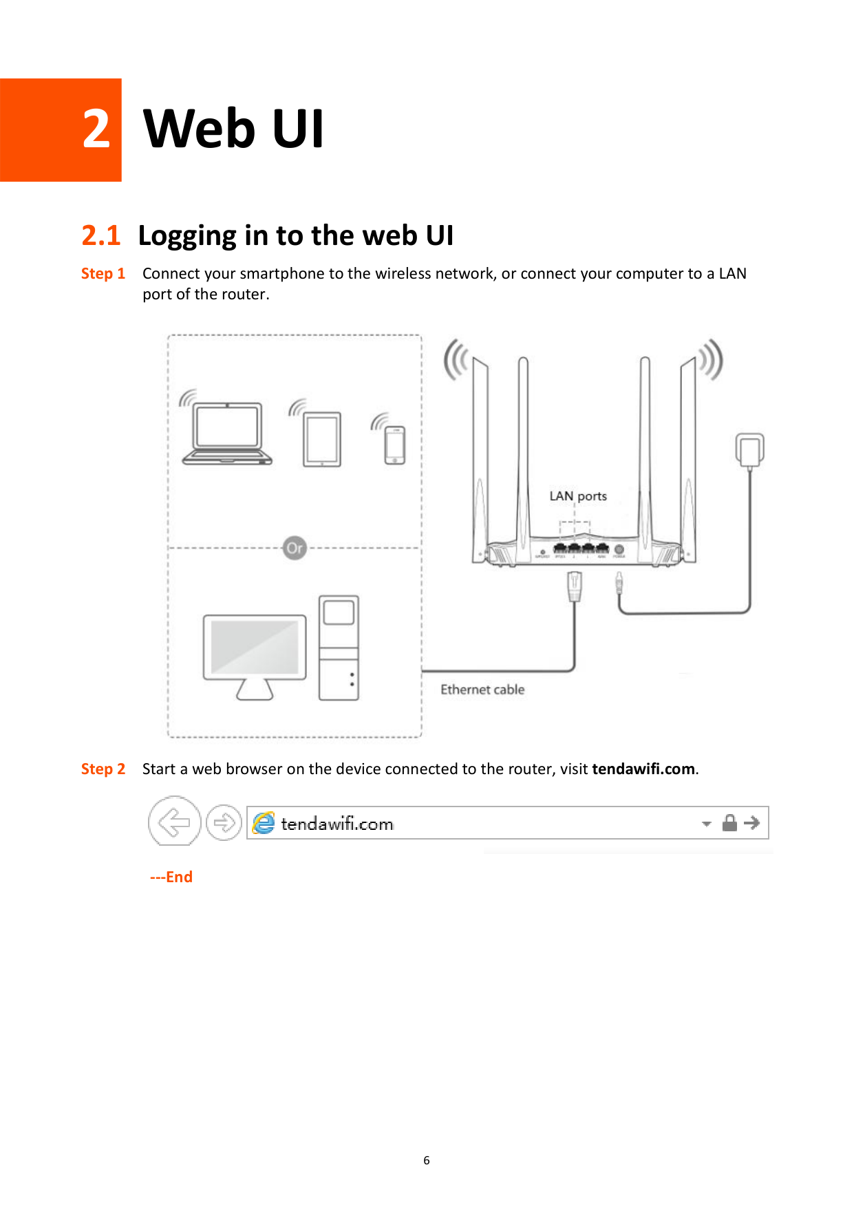
2 Web UI
2.1 Logging in to the web UI


######## ---End
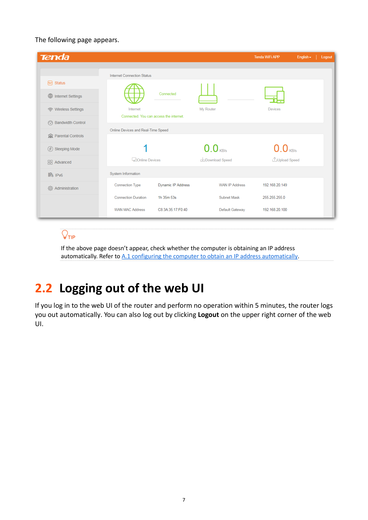
The following page appears.


If the above page doesn’t appear, check whether the computer is obtaining an IP address automatically. Refer to A.1 configuring the computer to obtain an IP address automatically.
2.2 Logging out of the web UI
If you log in to the web UI of the router and perform no operation within 5 minutes, the router logs you out automatically. You can also log out by clicking Logout on the upper right corner of the web UI.
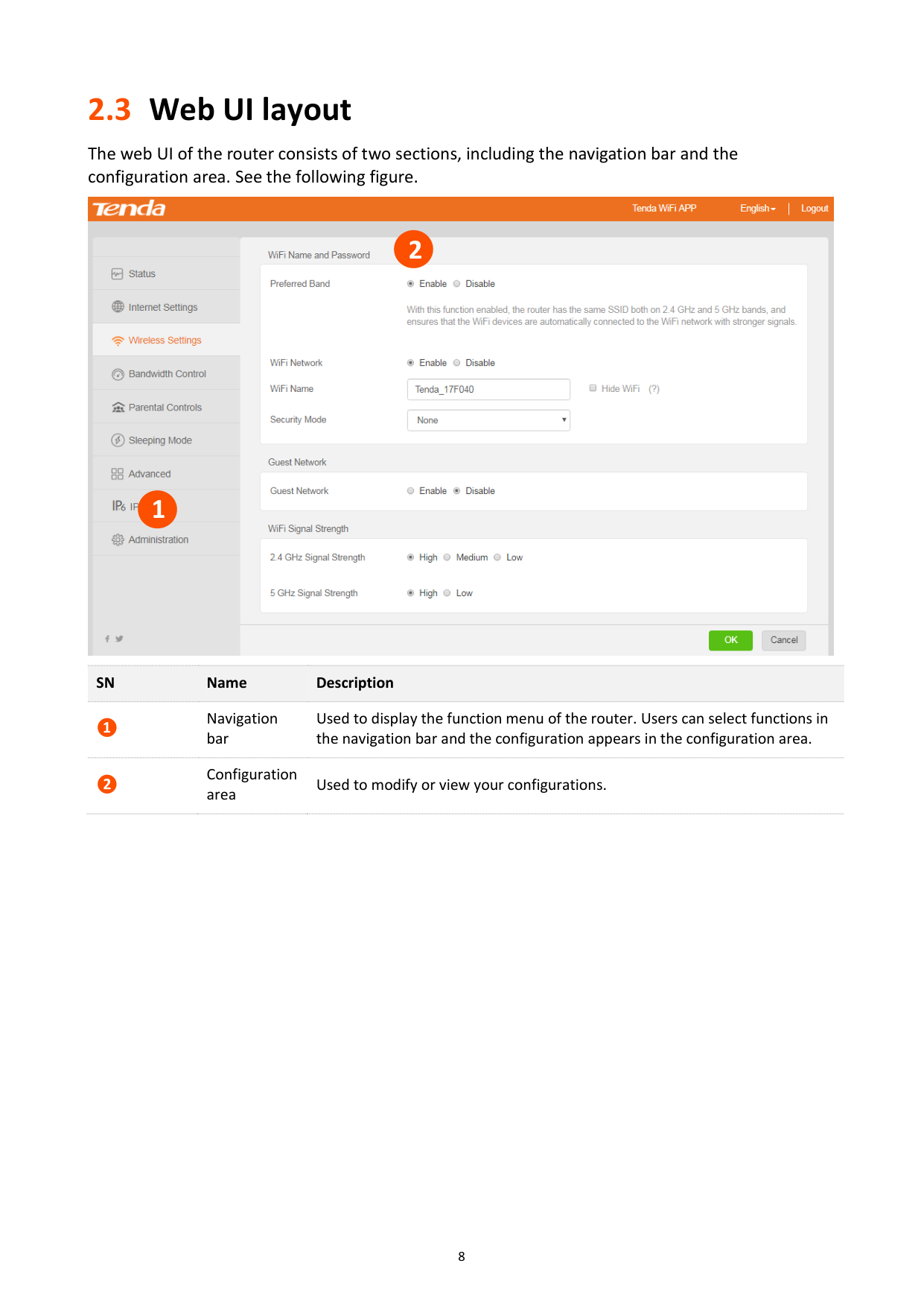
2.3 Web UI layout
The web UI of the router consists of two sections, including the navigation bar and the configuration area. See the following figure.


#### 2

1
SN Name Description
❶
Navigation bar
Used to display the function menu of the router. Users can select functions in the navigation bar and the configuration appears in the configuration area.
Configuration area
❷
Used to modify or view your configurations.

3 Status
Log in to the web UI of the router and choose Status to enter the page. On this page, you can:
− View internet connection status − View online devices information
View system information
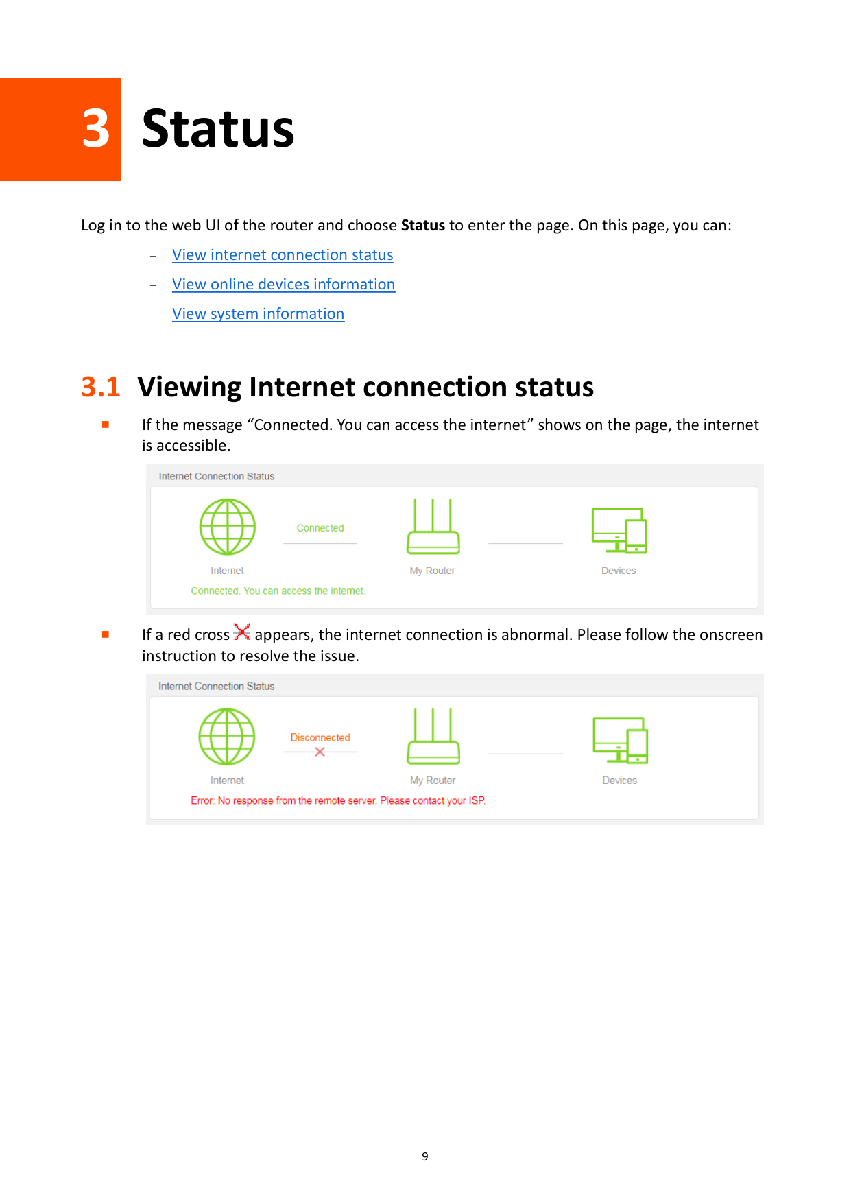
3.1 Viewing Internet connection status
If the message “Connected. You can access the internet” shows on the page, the internet is accessible.


If a red cross appears, the internet connection is abnormal. Please follow the onscreen instruction to resolve the issue.

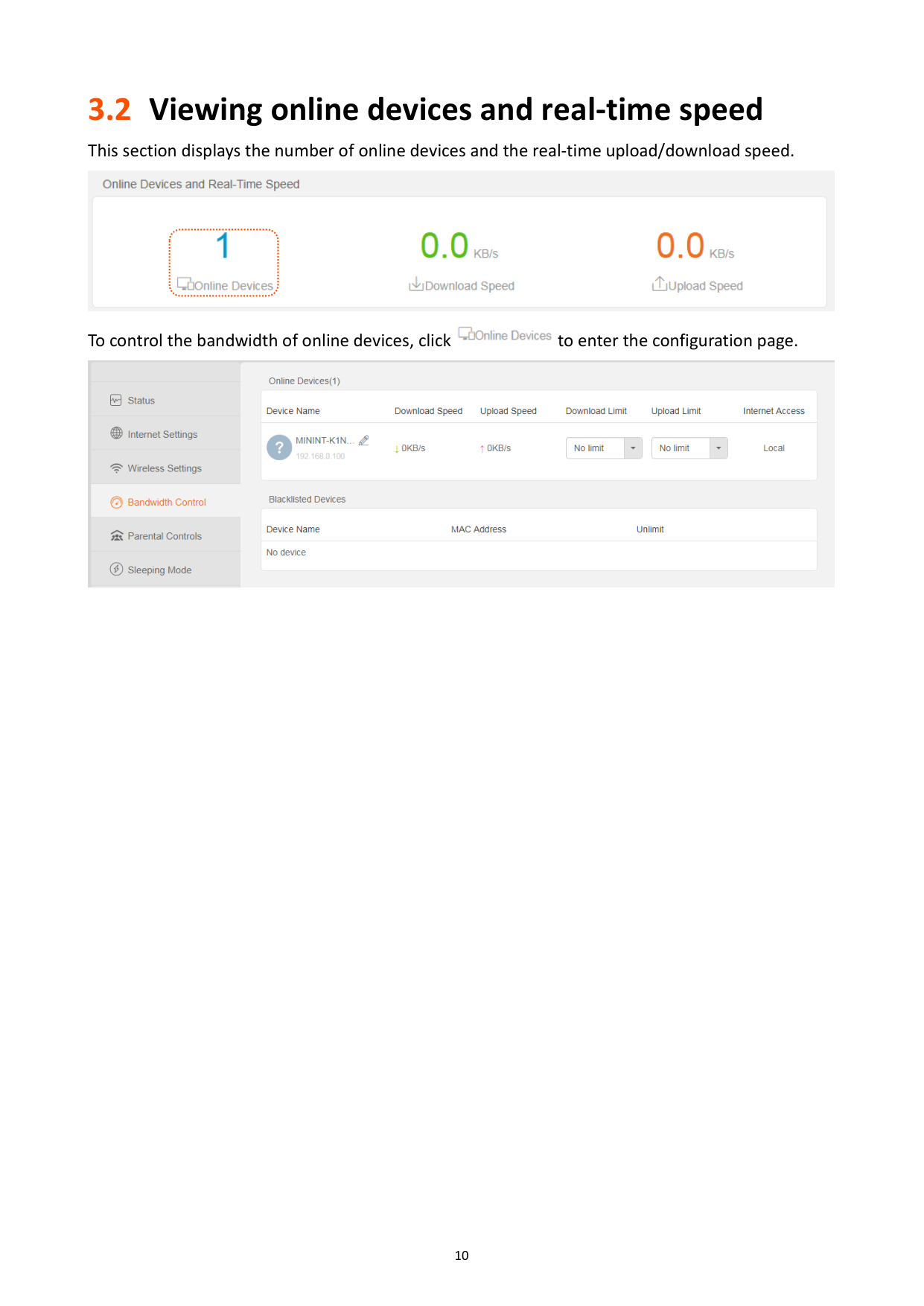
3.2 Viewing online devices and real-time speed
This section displays the number of online devices and the real-time upload/download speed.


To control the bandwidth of online devices, click to enter the configuration page.

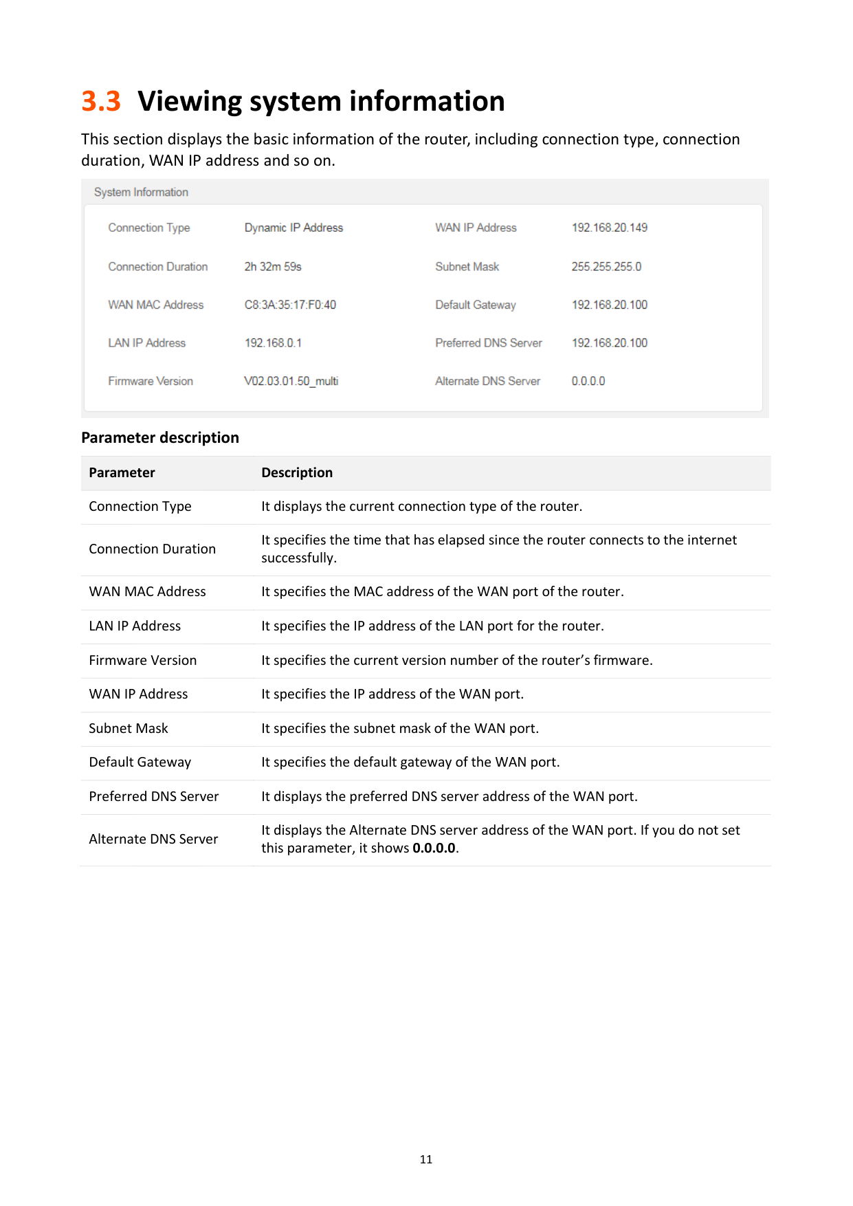
3.3 Viewing system information
######### This section displays the basic information of the router, including connection type, connection duration, WAN IP address and so on.

Parameter description Parameter Description Connection Type It displays the current connection type of the router. Connection Duration
It specifies the time that has elapsed since the router connects to the internet successfully.
WAN MAC Address It specifies the MAC address of the WAN port of the router. LAN IP Address It specifies the IP address of the LAN port for the router. Firmware Version It specifies the current version number of the router’s firmware. WAN IP Address It specifies the IP address of the WAN port. Subnet Mask It specifies the subnet mask of the WAN port. Default Gateway It specifies the default gateway of the WAN port. Preferred DNS Server It displays the preferred DNS server address of the WAN port. Alternate DNS Server
It displays the Alternate DNS server address of the WAN port. If you do not set this parameter, it shows 0.0.0.0.

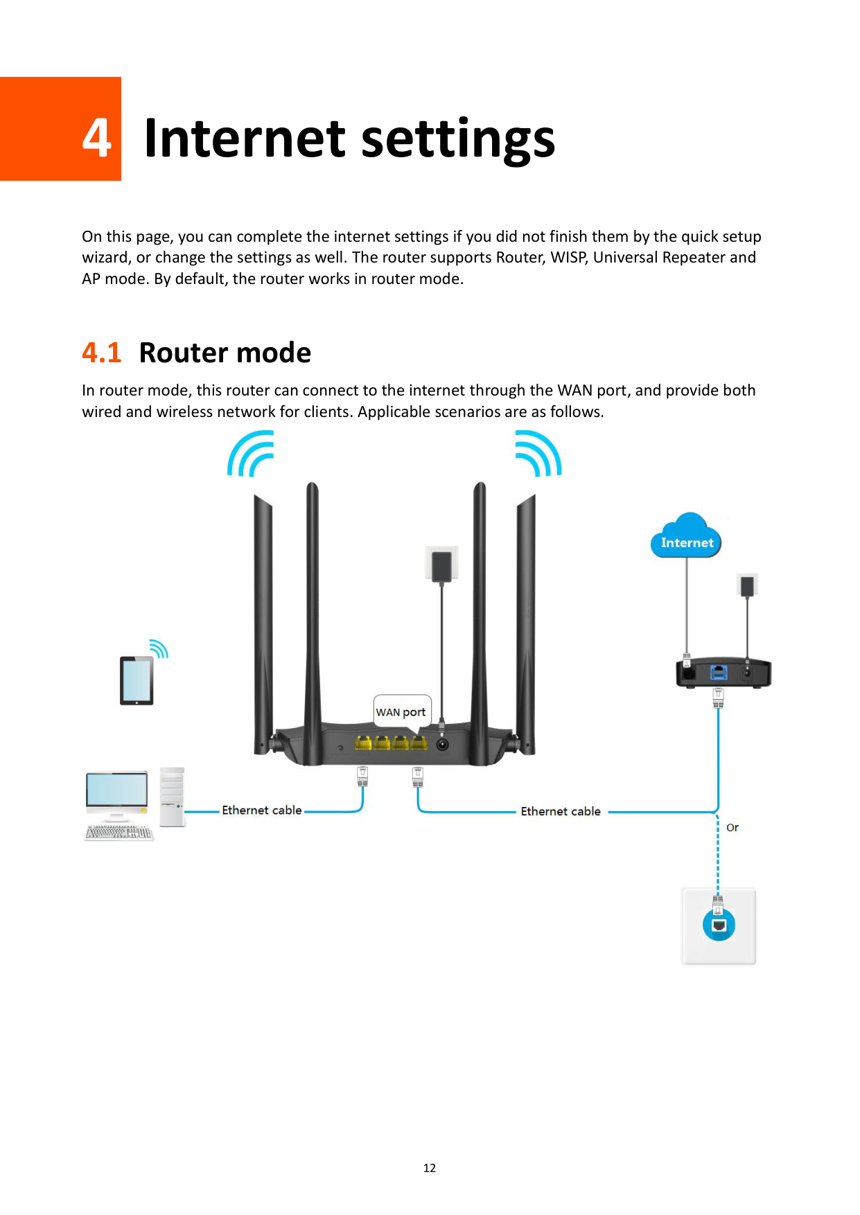
4 Internet settings
On this page, you can complete the internet settings if you did not finish them by the quick setup wizard, or change the settings as well. The router supports Router, WISP, Universal Repeater and AP mode. By default, the router works in router mode.
4.1 Router mode
In router mode, this router can connect to the internet through the WAN port, and provide both wired and wireless network for clients. Applicable scenarios are as follows.

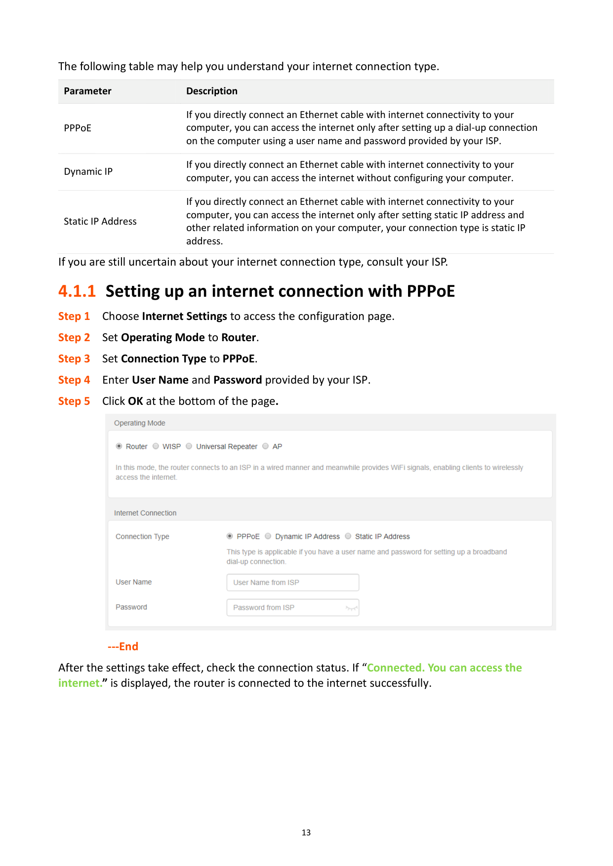
The following table may help you understand your internet connection type.
Parameter Description
PPPoE
If you directly connect an Ethernet cable with internet connectivity to your computer, you can access the internet only after setting up a dial-up connection on the computer using a user name and password provided by your ISP.
Dynamic IP
If you directly connect an Ethernet cable with internet connectivity to your computer, you can access the internet without configuring your computer.
If you directly connect an Ethernet cable with internet connectivity to your computer, you can access the internet only after setting static IP address and other related information on your computer, your connection type is static IP address.
Static IP Address
If you are still uncertain about your internet connection type, consult your ISP.
#### 4.1.1 Setting up an internet connection with PPPoE

######## ---End
After the settings take effect, check the connection status. If “Connected. You can access the internet.” is displayed, the router is connected to the internet successfully.

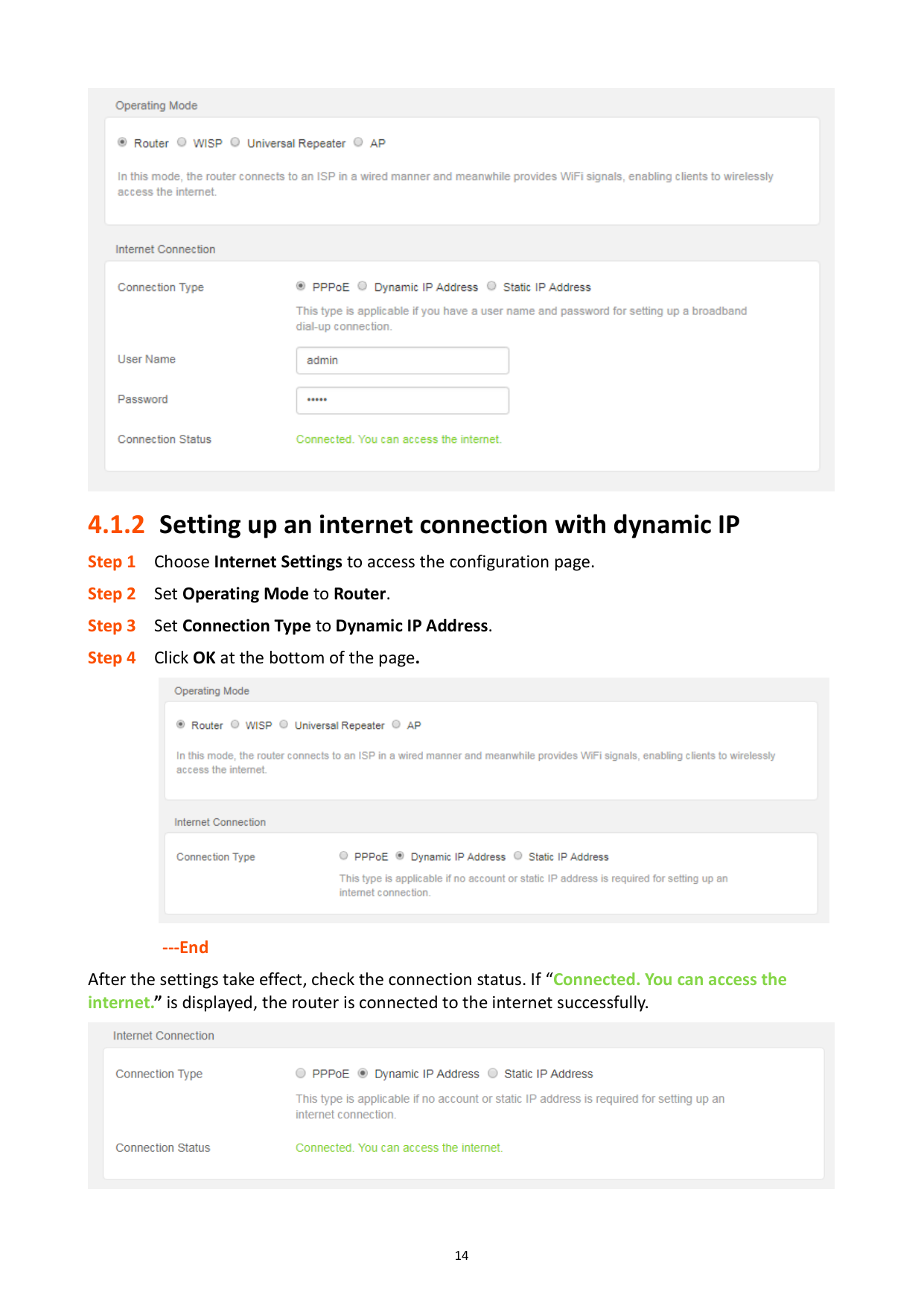
#### 4.1.2 Setting up an internet connection with dynamic IP

######## ---End
After the settings take effect, check the connection status. If “Connected. You can access the internet.” is displayed, the router is connected to the internet successfully.

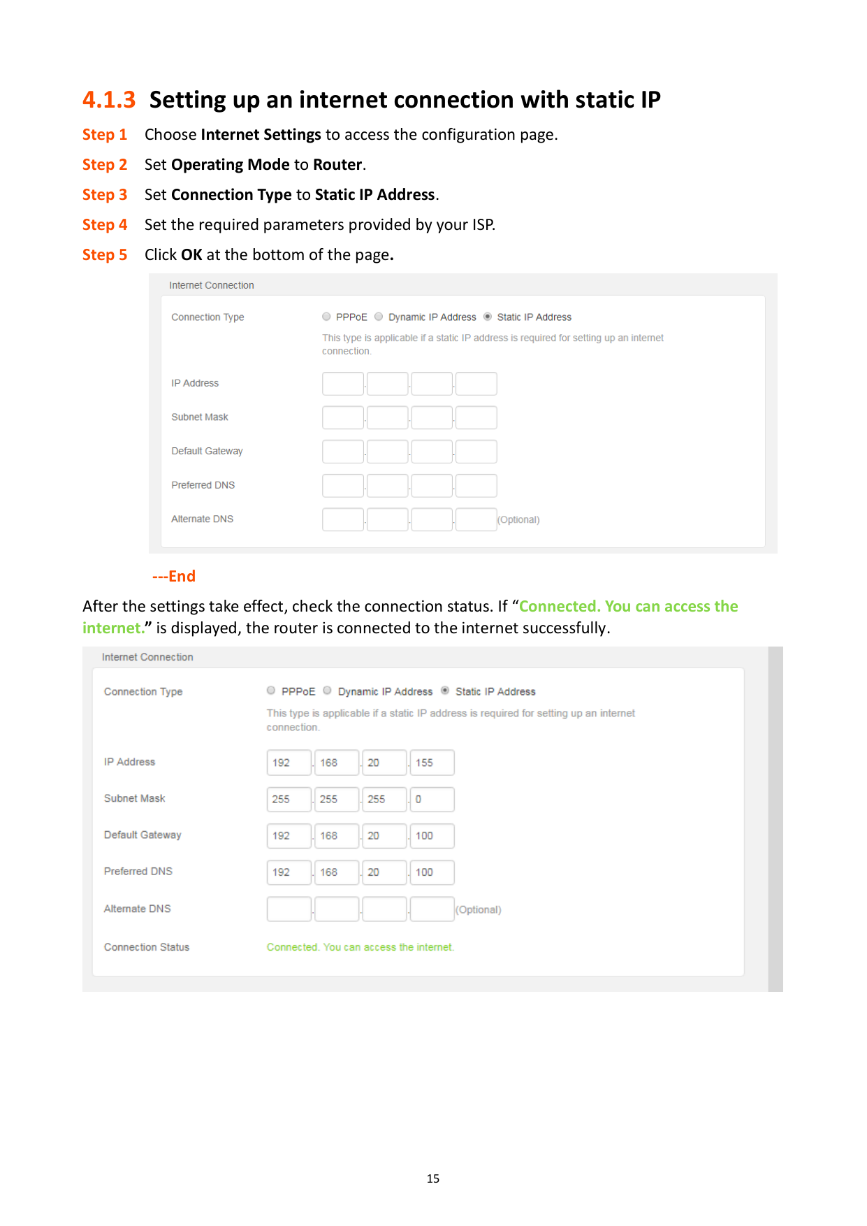
#### 4.1.3 Setting up an internet connection with static IP

######## ---End
After the settings take effect, check the connection status. If “Connected. You can access the internet.” is displayed, the router is connected to the internet successfully.

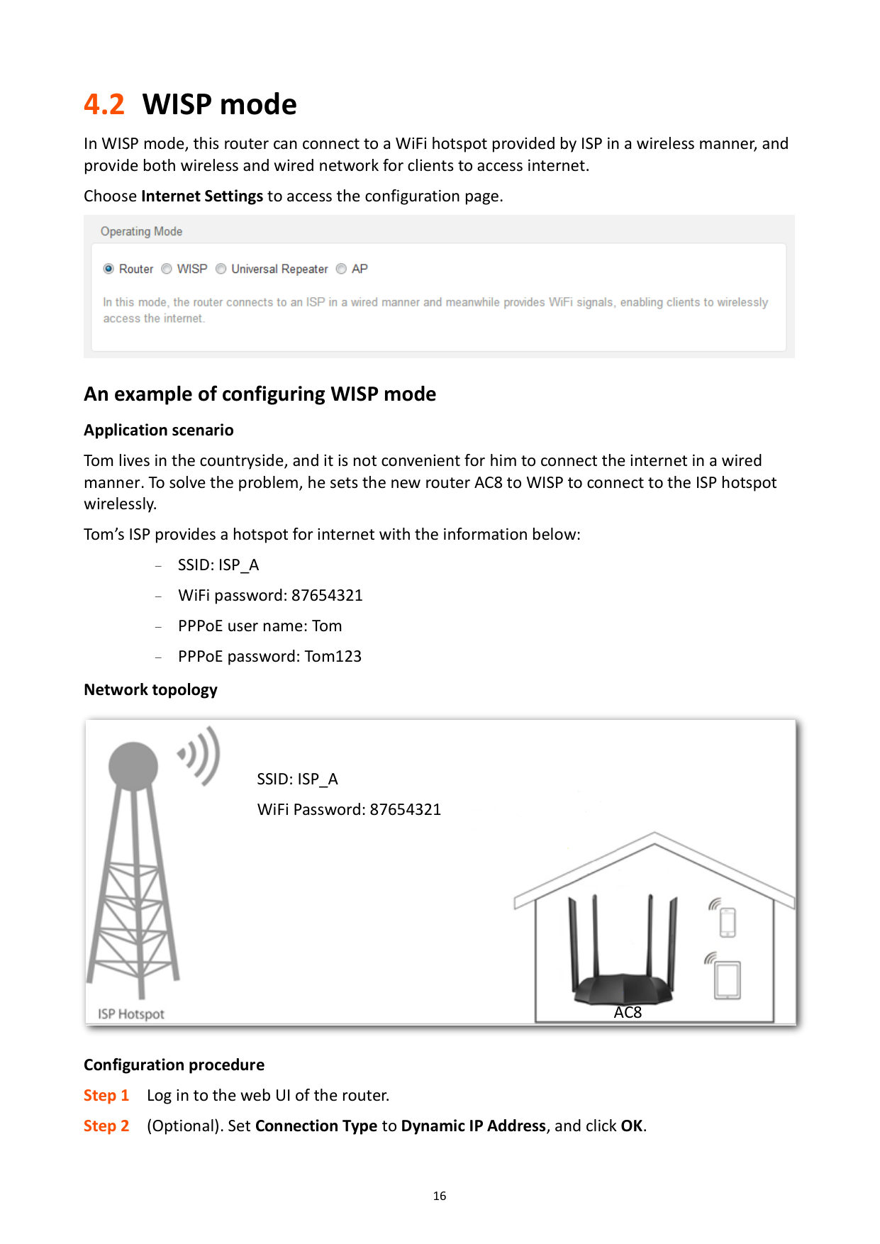
4.2 WISP mode
In WISP mode, this router can connect to a WiFi hotspot provided by ISP in a wireless manner, and provide both wireless and wired network for clients to access internet.
Choose Internet Settings to access the configuration page.

###### An example of configuring WISP mode Application scenario
Tom lives in the countryside, and it is not convenient for him to connect the internet in a wired manner. To solve the problem, he sets the new router AC8 to WISP to connect to the ISP hotspot wirelessly.
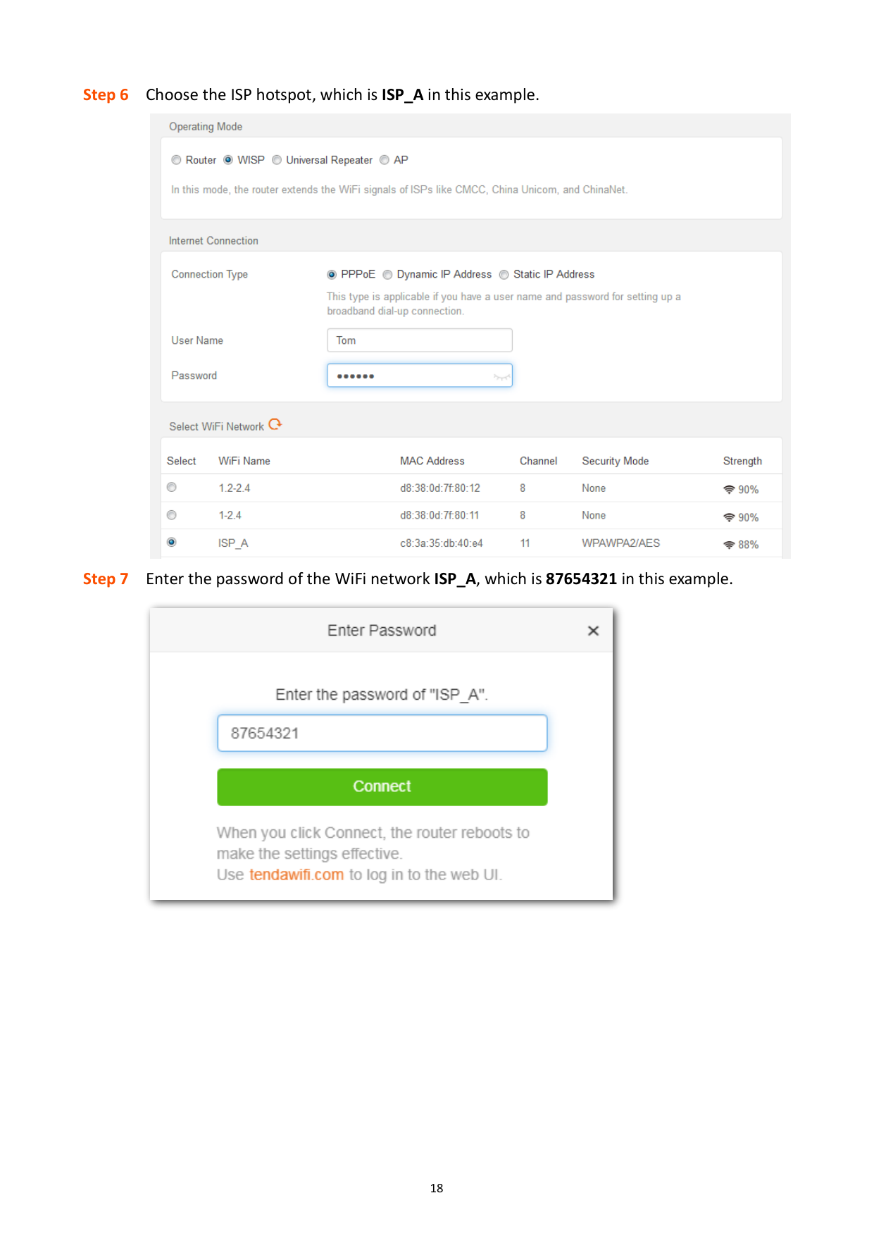
Tom’s ISP provides a hotspot for internet with the information below: − SSID: ISP_A − WiFi password: 87654321 PPPoE user name: Tom − PPPoE password: Tom123 Network topology


SSID: ISP_A WiFi Password: 87654321

AC8
######## Configuration procedure

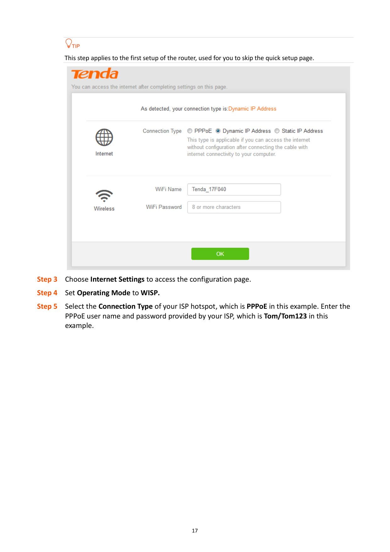
This step applies to the first setup of the router, used for you to skip the quick setup page.
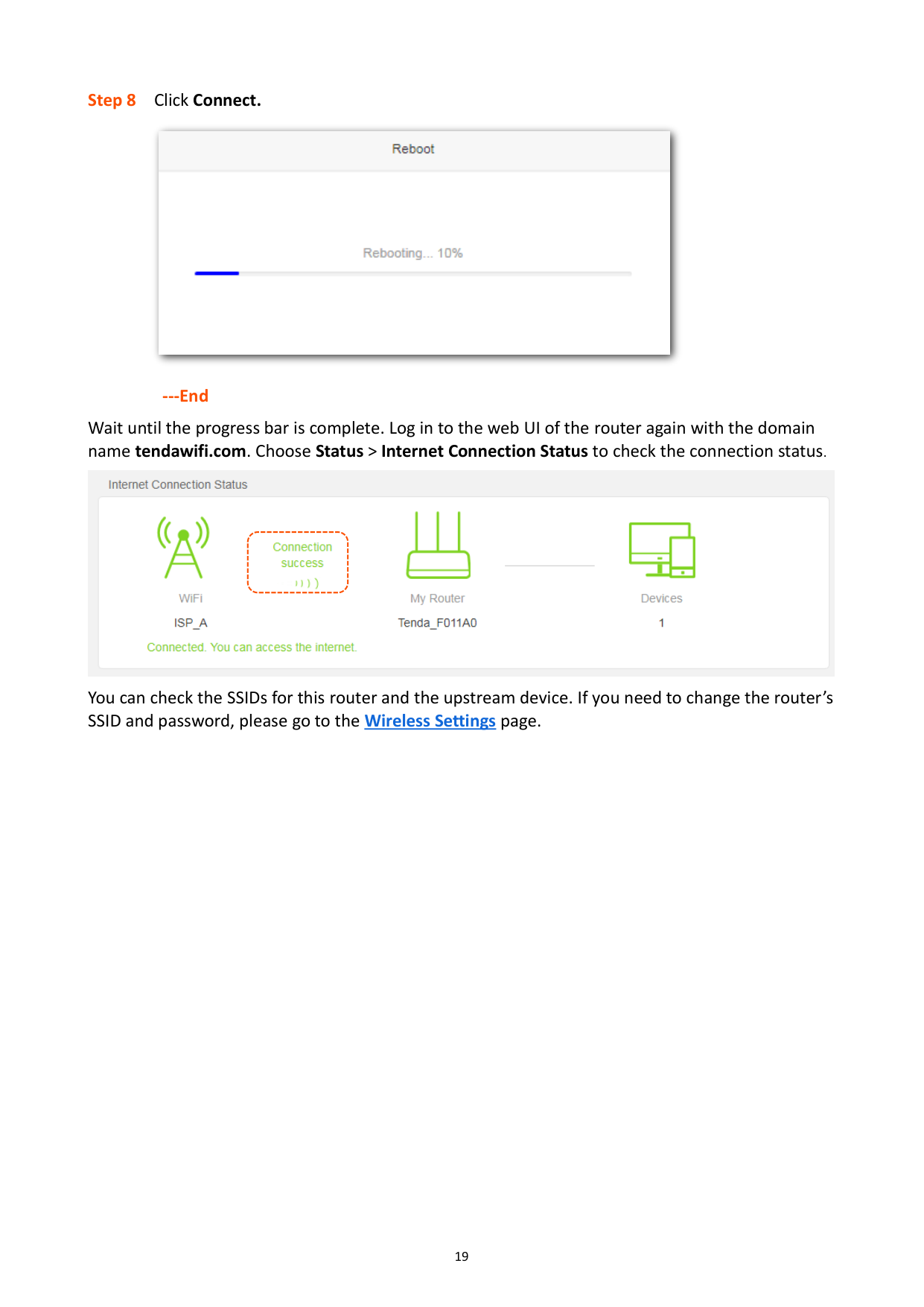


---End
Wait until the progress bar is complete. Log in to the web UI of the router again with the domain name tendawifi.com. Choose Status > Internet Connection Status to check the connection status.

You can check the SSIDs for this router and the upstream device. If you need to change the router’s SSID and password, please go to the Wireless Settings page.
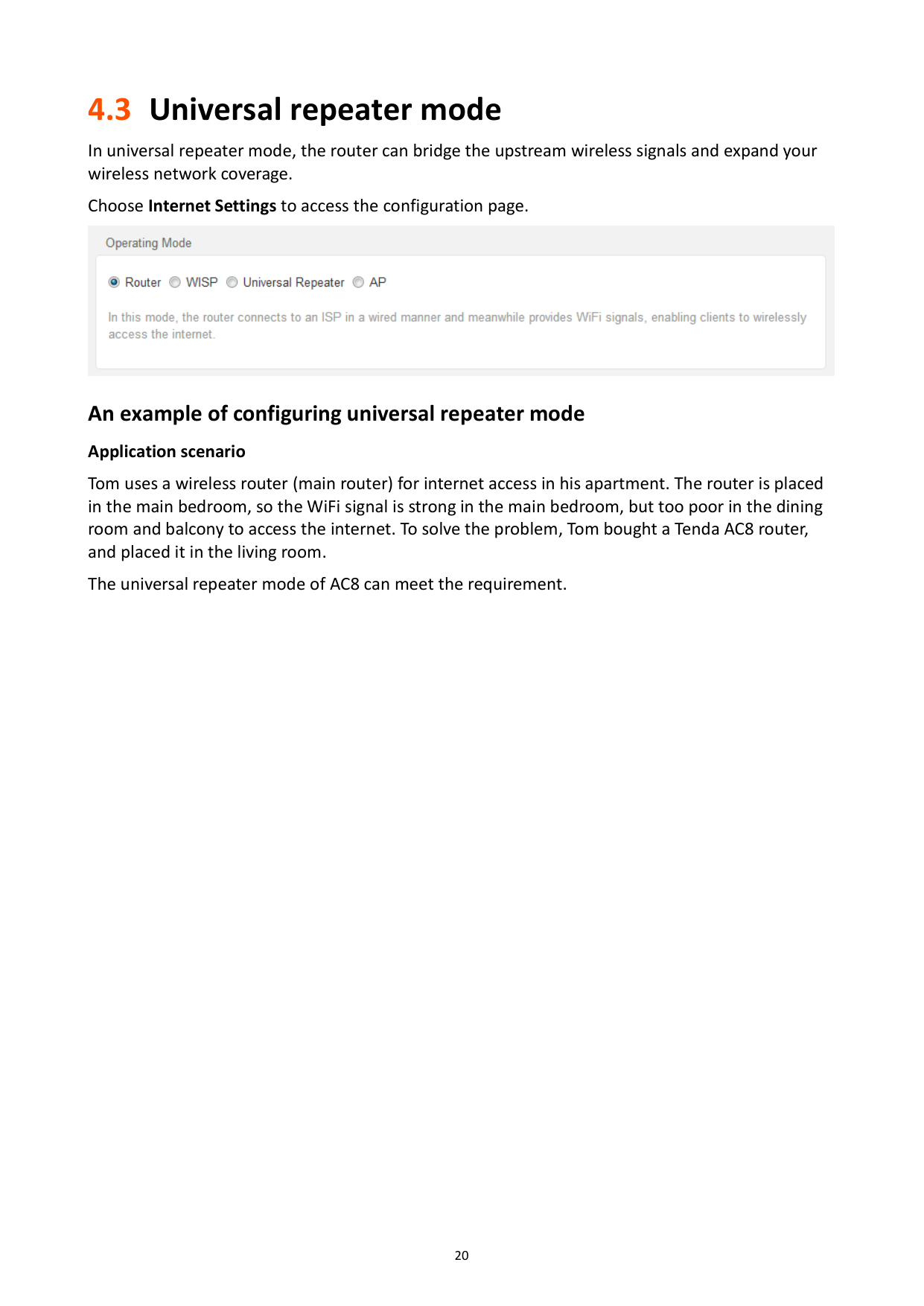
4.3 Universal repeater mode
In universal repeater mode, the router can bridge the upstream wireless signals and expand your wireless network coverage.
Choose Internet Settings to access the configuration page.

###### An example of configuring universal repeater mode Application scenario
Tom uses a wireless router (main router) for internet access in his apartment. The router is placed in the main bedroom, so the WiFi signal is strong in the main bedroom, but too poor in the dining room and balcony to access the internet. To solve the problem, Tom bought a Tenda AC8 router, and placed it in the living room.
The universal repeater mode of AC8 can meet the requirement.
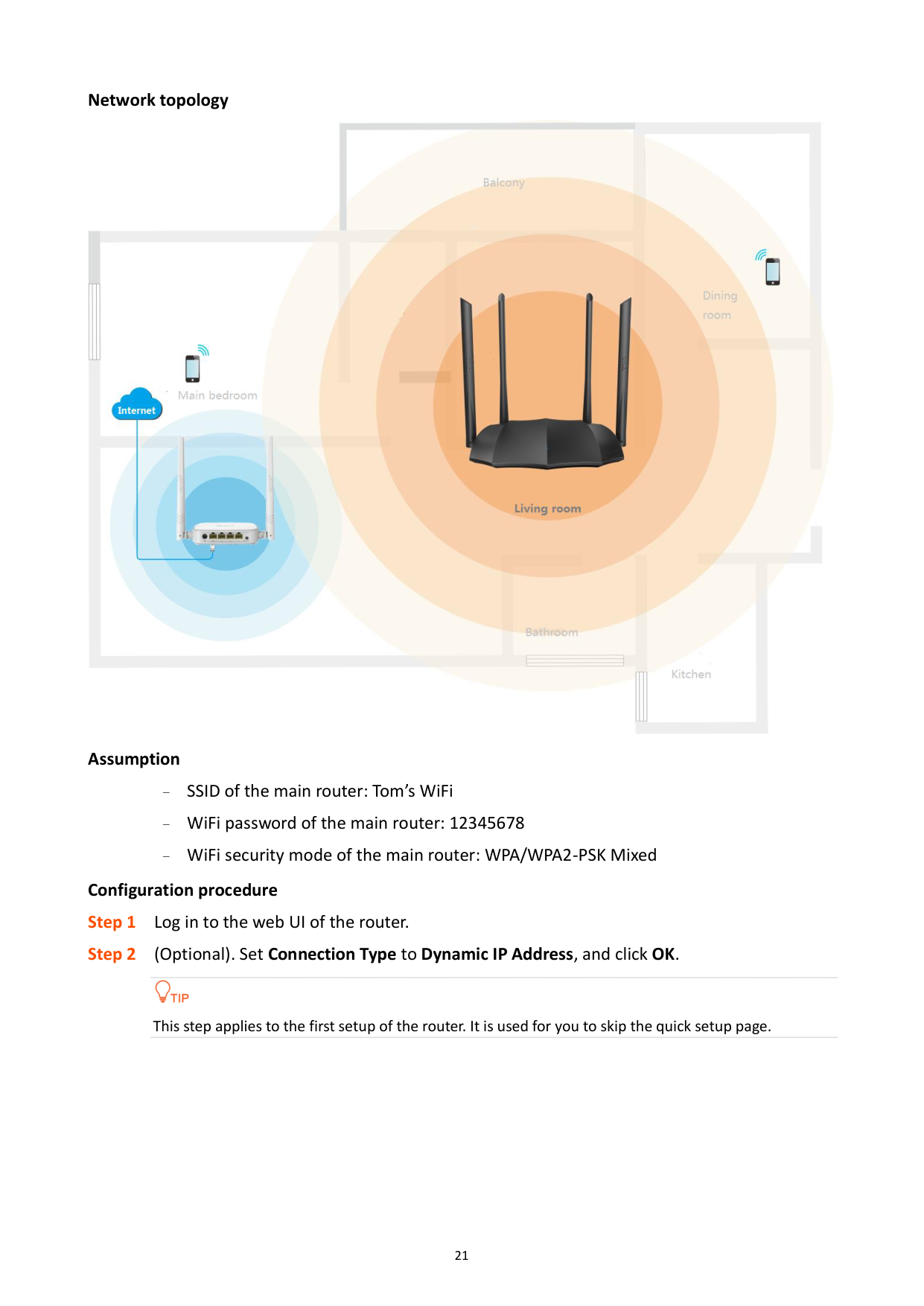
######## Network topology

Assumption − SSID of the main router: Tom’s WiFi − WiFi password of the main router: 12345678
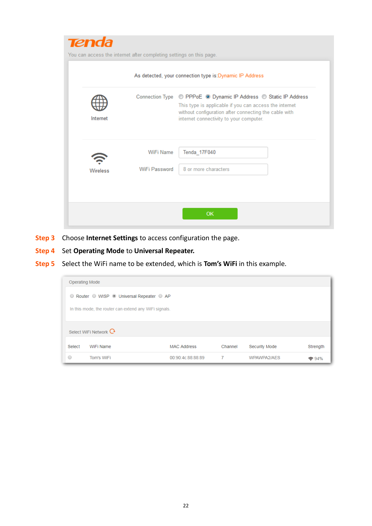
WiFi security mode of the main router: WPA/WPA2-PSK Mixed Configuration procedure

This step applies to the first setup of the router. It is used for you to skip the quick setup page.


######## ---End
Wait until the progress bar is complete. Log in to the web UI of the router again with the domain name tendawifi.com. Choose Status > Internet Connection Status to check the connection status andthe SSIDs for this router and the upstream device.

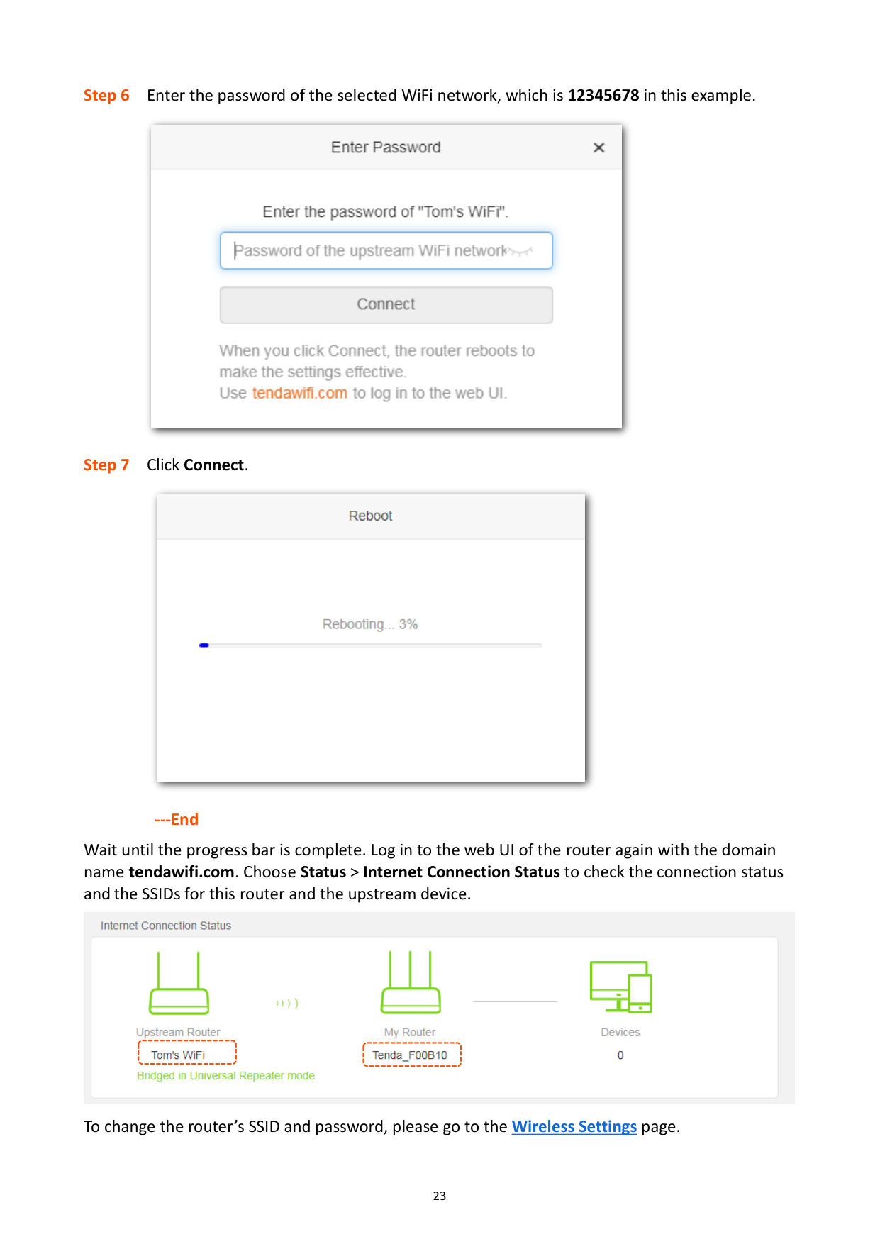
To change the router’s SSID and password, please go to the Wireless Settings page.
4.4 AP mode
In AP mode, the router connects to the internet using an Ethernet cable and converts wired network into wireless network to provide wireless network coverage. In AP mode, the WAN port also serves as a LAN port. Applicable scenarios are as follows.


Gateway
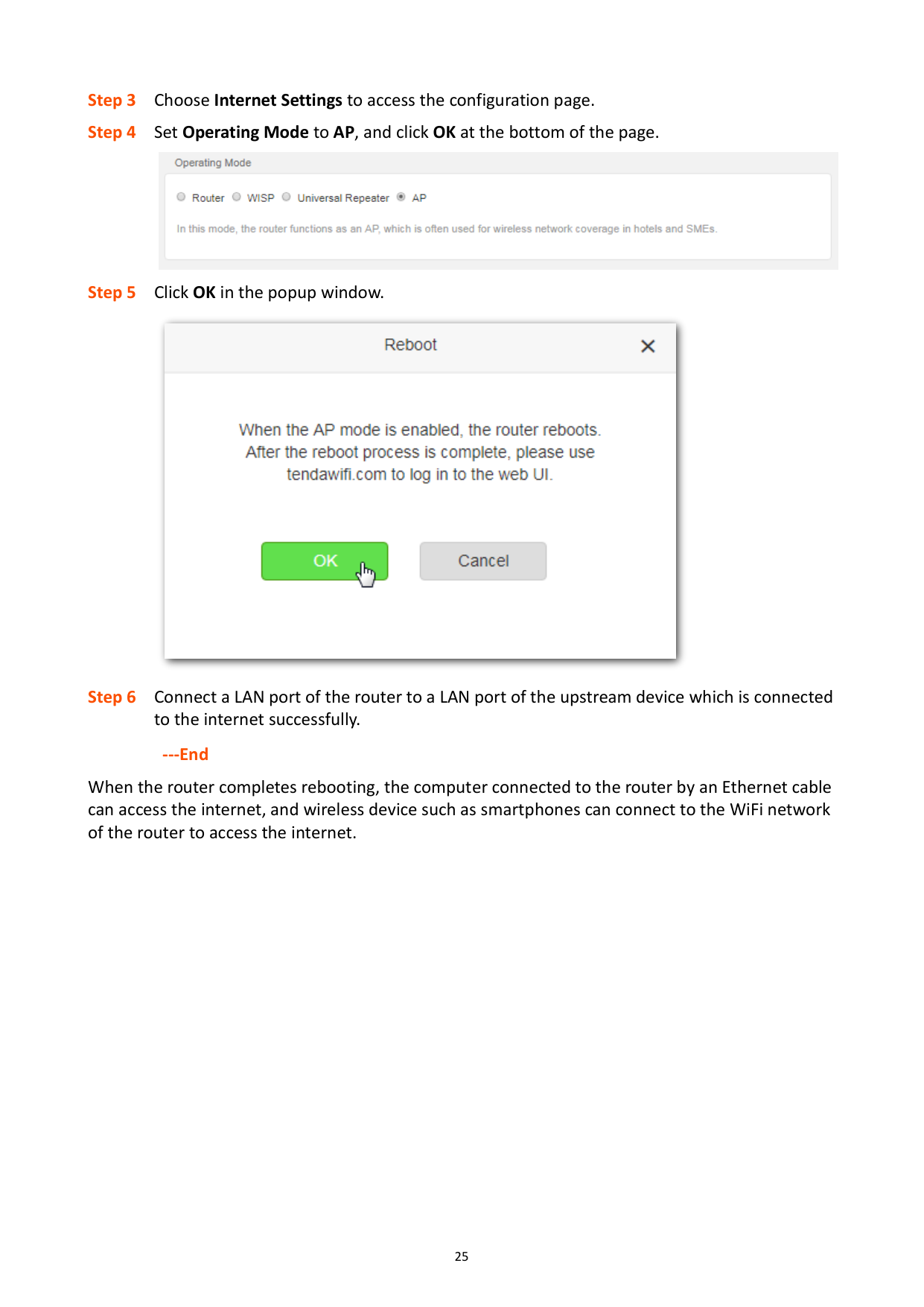
######## Configuration procedure

This step applies to the first setup of the router. It is used for you to skip the quick setup page.

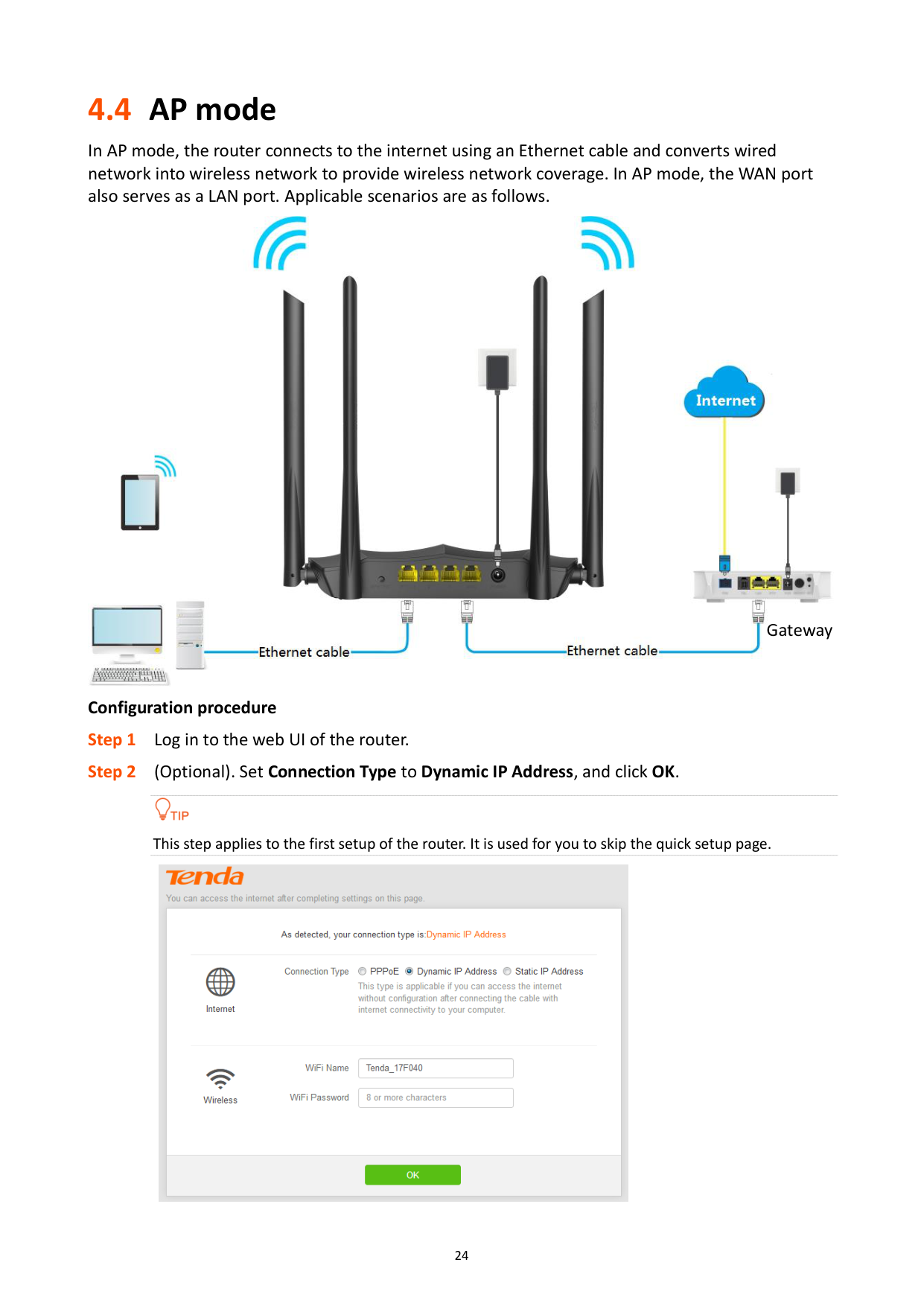


######## ---End
When the router completes rebooting, the computer connected to the router by an Ethernet cable can access the internet, and wireless device such as smartphones can connect to the WiFi network of the router to access the internet.

5 Wireless settings
5.1 WiFi name and password
#### 5.1.1 Overview
This router supports 2.4 GHz and 5 GHz WiFi networks. Features of these two signals are listed as follows.
2.4 GHz signal has longer wireless transmission distance than 5 GHz signal.
2.4 GHz signal has better wall penetration capacity than 5 GHz signal.
5 GHz signal has higher wireless transmission speed than 2.4 GHz signal.
5 GHz is less congestion, interference, and more stable than 2.4 GHz signal.
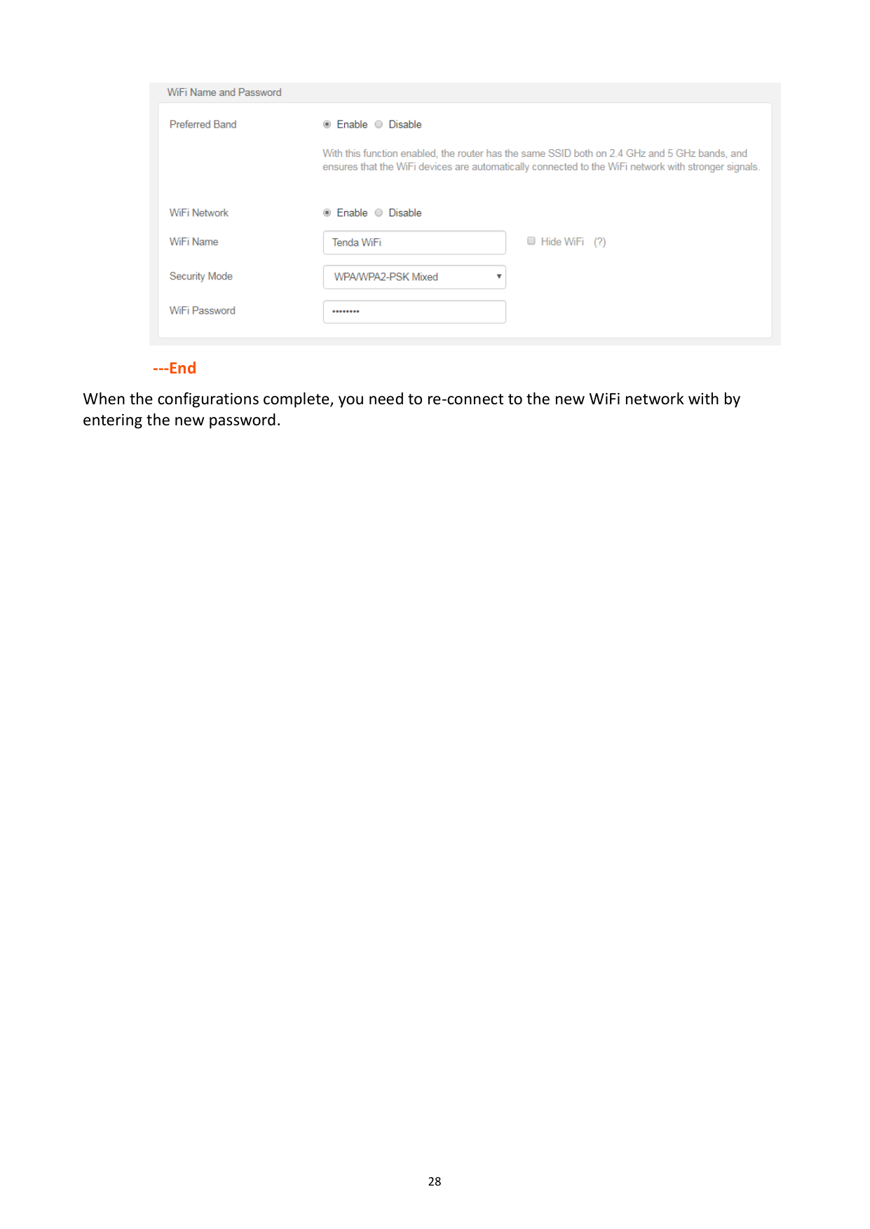
You can set the WiFi names, encryption modes, and WiFi passwords for two WiFi networks on the WiFi Name and Password page. To access the configuration page, click Wireless Settings and move to WiFi Name and Password module.

######## Parameter description
########## Parameter Description
Preferred Band
Used to turn on or off the Preferred Band function. When it is enabled, the WiFi names of 2.4 GHz and 5 GHz networks are the same. And only one WiFi signal is displayed. When you connect to the WiFi network, a betterquality WiFi signal will be automatically connected.
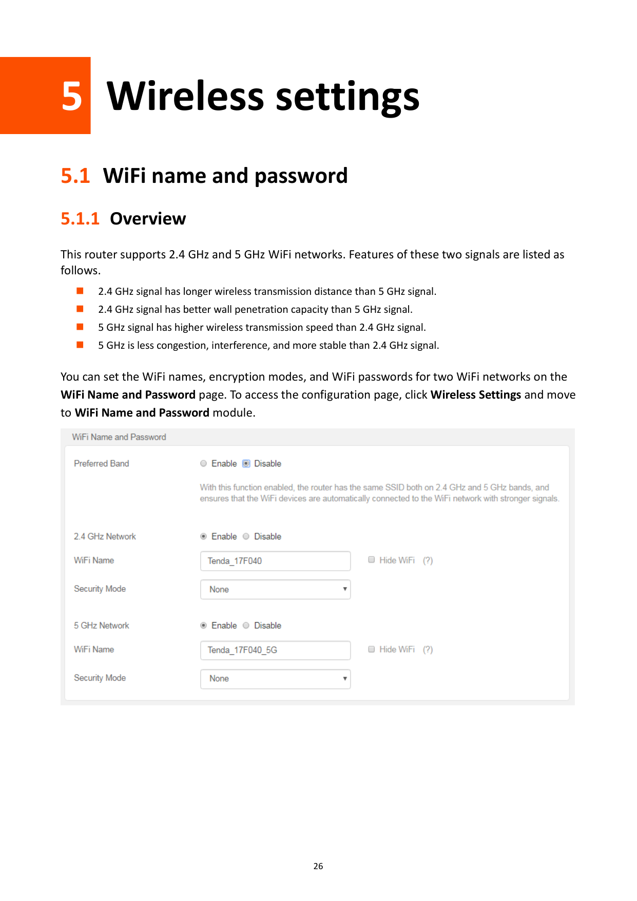
2.4 GHz Network/5 GHz network
Used to enable or disable the wireless networks of the router.
WiFi Name It specifies the wireless network name (SSID) of the WiFi network.
It specifies the encryption modes supported by the router, including:
Security Mode
None: It indicates that a wireless network is not encrypted and any clients can access the network without a password. This option is not recommended as it leads to low network security.
WPA-PSK: It indicates that WPA-PSK is adopted to authenticate users.
WPA2-PSK: It indicates that WPA2-PSK is adopted to authenticate users.
WPA/WPA2-PSK Mixed: It indicates that WPA-PSK and WPA2-PSK are adopted to authenticate users.
Used to connect a wireless network. You are recommended to use the combination of digits, letters and special characters for higher security.
WiFi Password
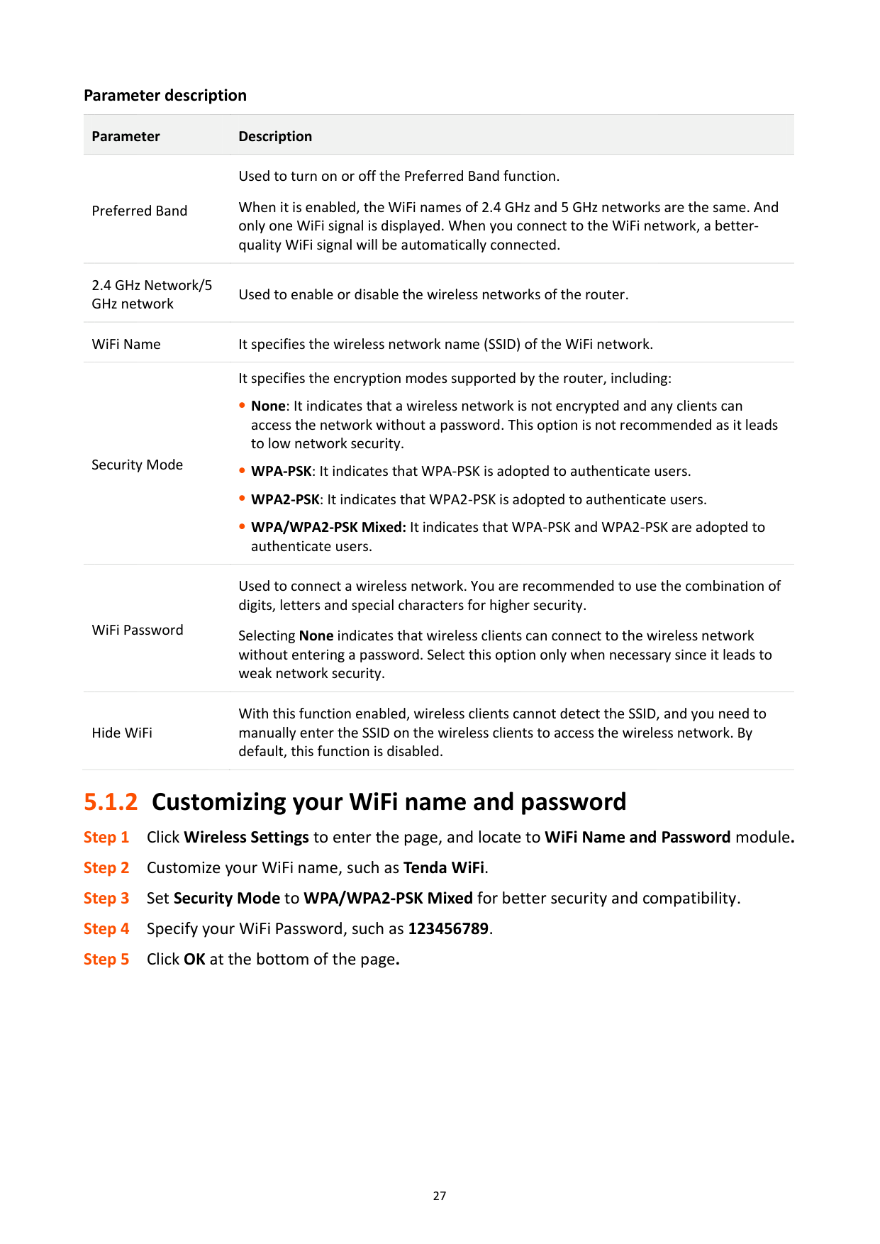
Selecting None indicates that wireless clients can connect to the wireless network without entering a password. Select this option only when necessary since it leads to weak network security.
With this function enabled, wireless clients cannot detect the SSID, and you need to manually enter the SSID on the wireless clients to access the wireless network. By default, this function is disabled.
Hide WiFi
#### 5.1.2 Customizing your WiFi name and password

######## ---End
When the configurations complete, you need to re-connect to the new WiFi network with by entering the new password.
5.2 Guest network
#### 5.2.1 Overview
In this module, you are able to enable/disable the Guest Network function and change guest network’s WiFi name and password.
A guest network can be set up with a shared bandwidth limit for visitors to access the internet, and isolated from the main network. It protects the security and ensures the bandwidth of your main network.
To access the configuration page, click Wireless Settings and move to Guest Network module. By default, the Guest Network function is disabled. The following figure shows the interface when the function is enabled.

Parameter description Parameter Description Guest Network Used to enable the Guest Network function.
2.4 GHz/5 GHz WiFi Name
It specifies the WiFi name of the router’s guest network. By default, Tenda_VIP is for 2.4 GHz WiFi network and Tenda_VIP_5G for 5 GHz WiFi network.
You can change the SSIDs if required. To distinguish the guest network from the main network, you are recommended not to set the same name for these four networks.
Guest Network Password
It specifies the password for the router’s two guest networks.
Validity
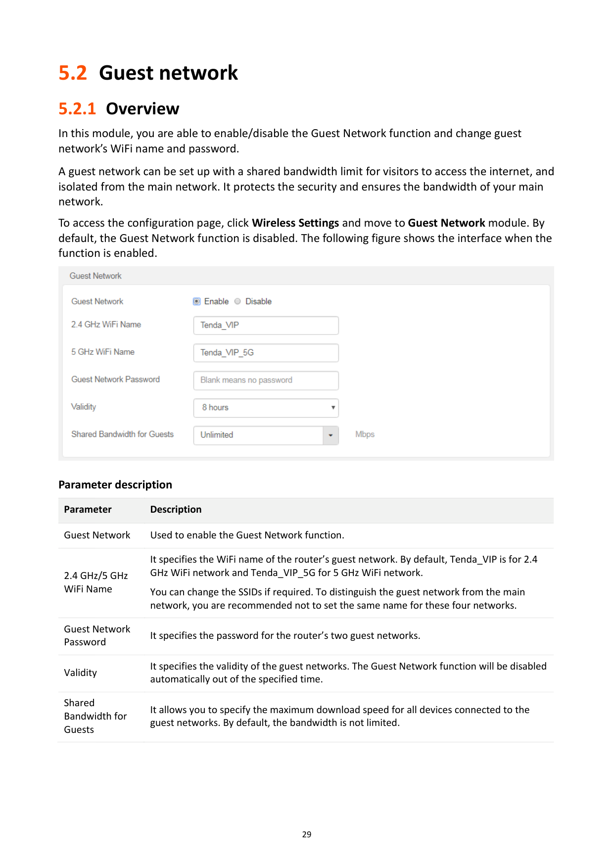
It specifies the validity of the guest networks. The Guest Network function will be disabled automatically out of the specified time.
Shared Bandwidth for Guests
It allows you to specify the maximum download speed for all devices connected to the guest networks. By default, the bandwidth is not limited.
#### 5.2.2 Setting up the guest network

######## ---End
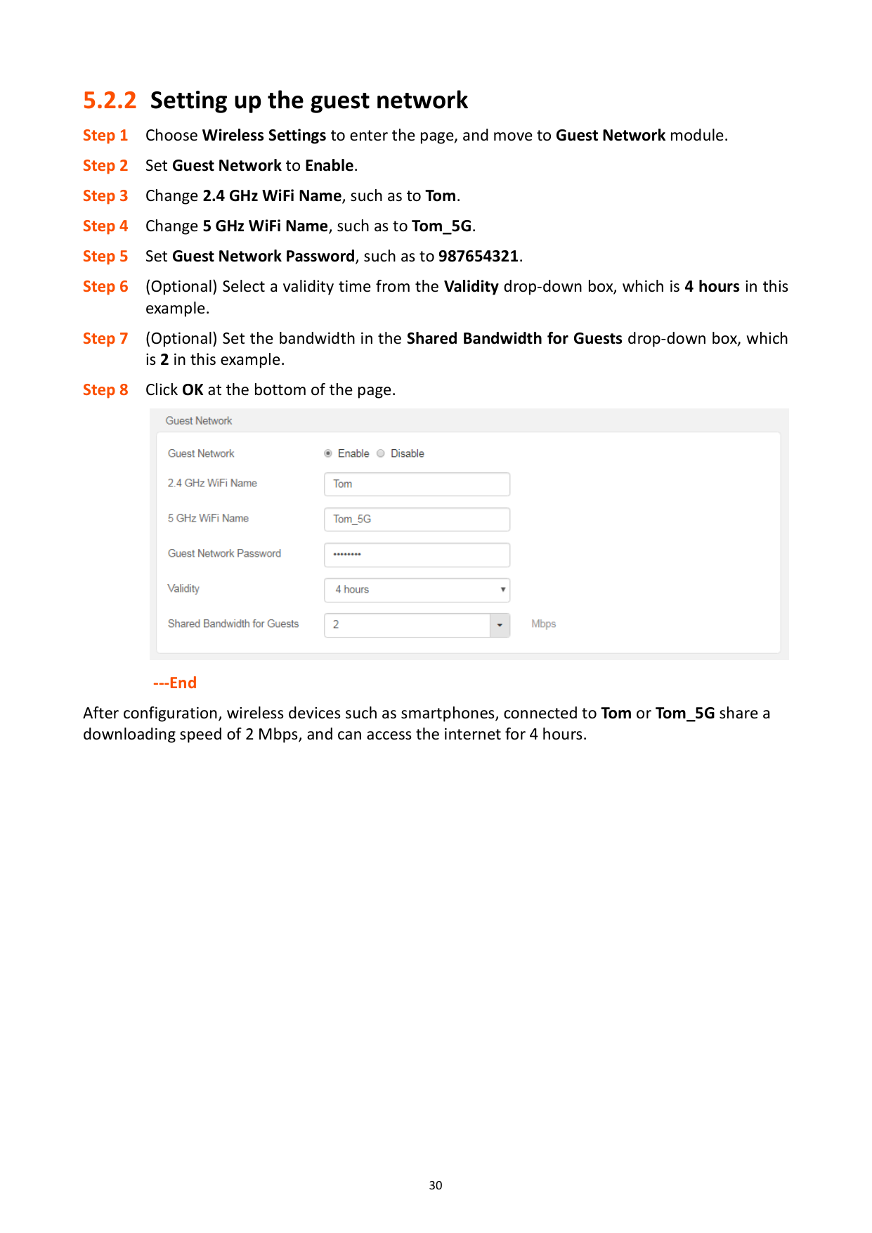
After configuration, wireless devices such as smartphones, connected to Tom or Tom_5G share a downloading speed of 2 Mbps, and can access the internet for 4 hours.
5.3 WiFi signal strength
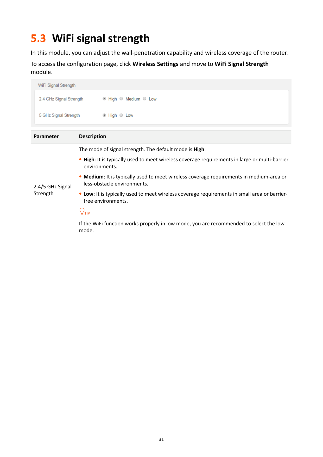
In this module, you can adjust the wall-penetration capability and wireless coverage of the router. To access the configuration page, click Wireless Settings and move to WiFi Signal Strength module.

Parameter Description
The mode of signal strength. The default mode is High.
High: It is typically used to meet wireless coverage requirements in large or multi-barrier environments.
2.4/5 GHz Signal Strength
Medium: It is typically used to meet wireless coverage requirements in medium-area or less-obstacle environments.
Low: It is typically used to meet wireless coverage requirements in small area or barrierfree environments.

If the WiFi function works properly in low mode, you are recommended to select the low mode.
5.4 Wireless parameters
In this section, you are allowed to change network mode, wireless channel, and wireless bandwidth of either 2.4 GHz or 5 GHz WiFi network.
To access the configuration page, click Wireless Settings and move to Wireless Parameters module.

######## Parameter description
########## Parameter Description
It specifies various protocols adopted for wireless transmission.
11b/g mixed: It indicates that devices compliant with IEEE 802.11b or IEEE 802.11g protocol can connect to the router.
Network Mode
11b/g/n mixed: It indicates that all devices can connect to the router if they are compliant with IEEE 802.11b or IEEE 802.11g protocol, or work at 2.4 GHz with IEEE 802.11n protocol.
11n: It indicates that devices compliant with IEEE 802.11n can connect to the router.
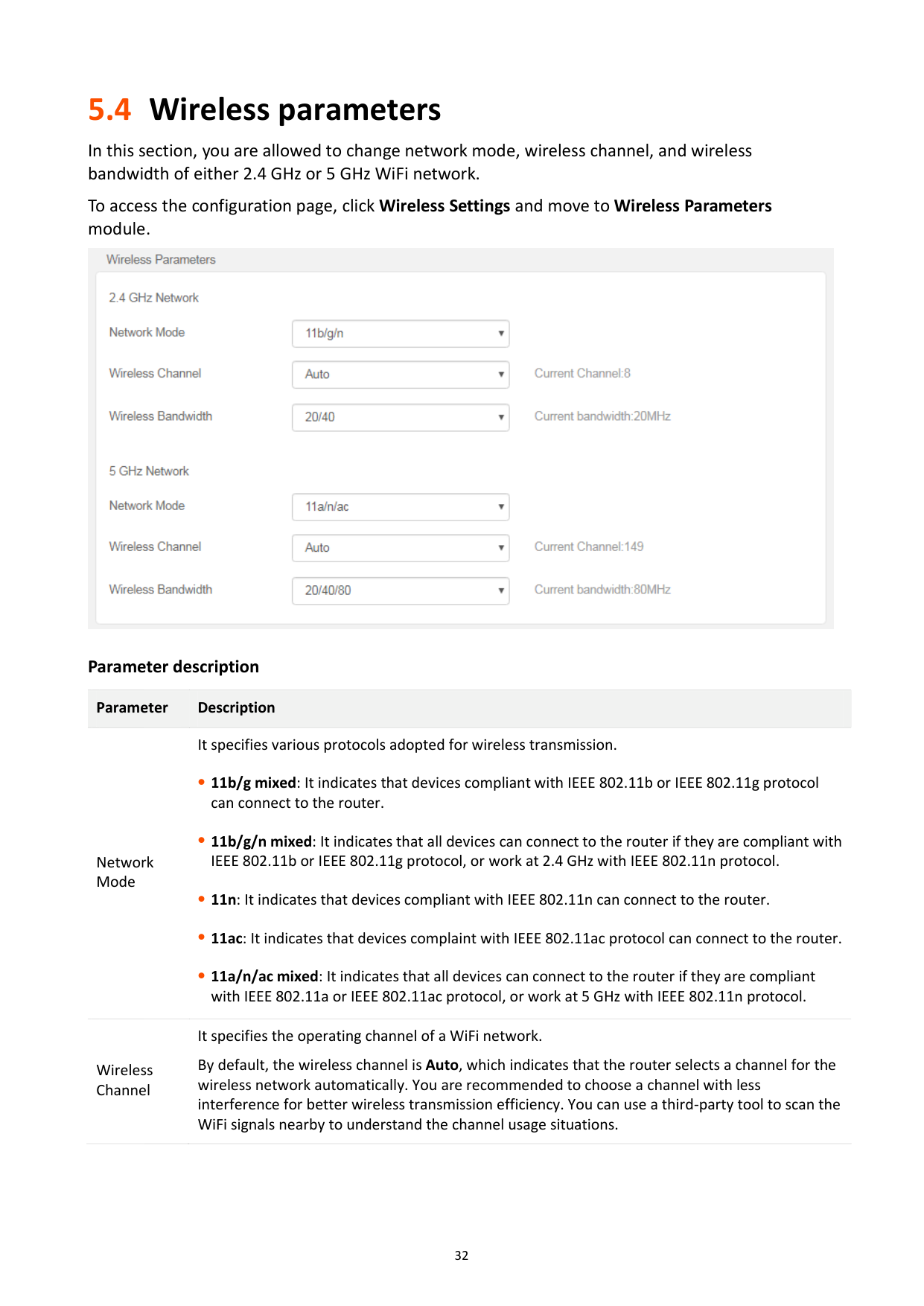
11ac: It indicates that devices complaint with IEEE 802.11ac protocol can connect to the router.
11a/n/ac mixed: It indicates that all devices can connect to the router if they are compliant with IEEE 802.11a or IEEE 802.11ac protocol, or work at 5 GHz with IEEE 802.11n protocol.
It specifies the operating channel of a WiFi network. By default, the wireless channel is Auto, which indicates that the router selects a channel for the wireless network automatically. You are recommended to choose a channel with less interference for better wireless transmission efficiency. You can use a third-party tool to scan the WiFi signals nearby to understand the channel usage situations.
Wireless Channel
########## Parameter Description
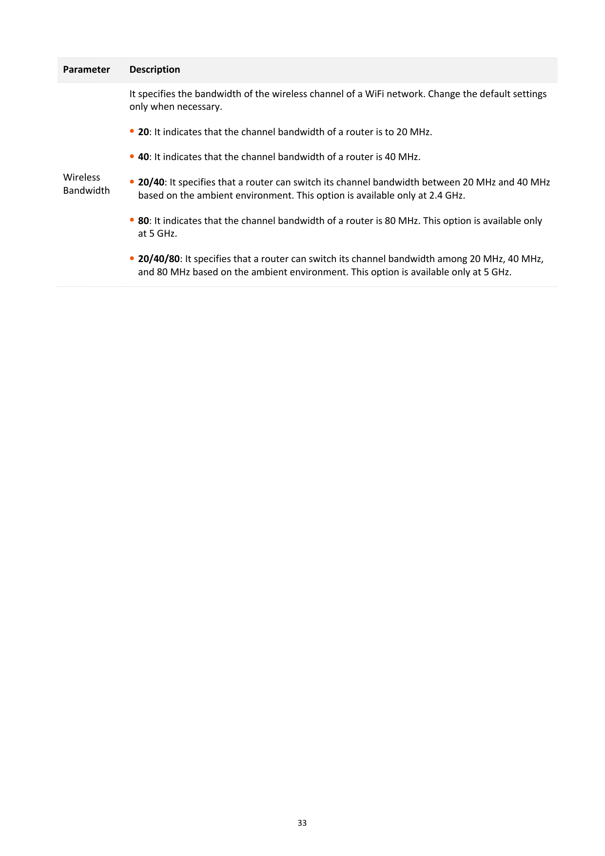
It specifies the bandwidth of the wireless channel of a WiFi network. Change the default settings only when necessary.
20: It indicates that the channel bandwidth of a router is to 20 MHz.
Wireless Bandwidth
40: It indicates that the channel bandwidth of a router is 40 MHz.
20/40: It specifies that a router can switch its channel bandwidth between 20 MHz and 40 MHz based on the ambient environment. This option is available only at 2.4 GHz.
80: It indicates that the channel bandwidth of a router is 80 MHz. This option is available only at 5 GHz.
20/40/80: It specifies that a router can switch its channel bandwidth among 20 MHz, 40 MHz, and 80 MHz based on the ambient environment. This option is available only at 5 GHz.
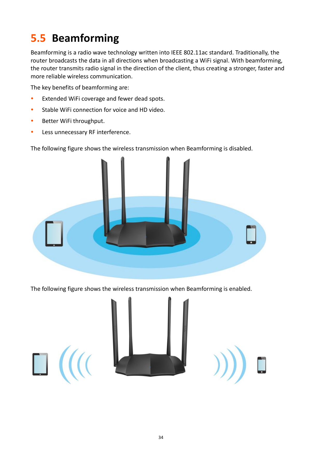
5.5 Beamforming
Beamforming is a radio wave technology written into IEEE 802.11ac standard. Traditionally, the router broadcasts the data in all directions when broadcasting a WiFi signal. With beamforming, the router transmits radio signal in the direction of the client, thus creating a stronger, faster and more reliable wireless communication.
The key benefits of beamforming are:
Extended WiFi coverage and fewer dead spots. Stable WiFi connection for voice and HD video. Better WiFi throughput.
Less unnecessary RF interference.
The following figure shows the wireless transmission when Beamforming is disabled.

The following figure shows the wireless transmission when Beamforming is enabled.

######### To access the configuration page, click Wireless Settings, and move to the Beamforming module. By default, the Beamforming function is enabled.

5.6 WPS
#### 5.6.1 Overview
The WPS function enables wireless devices such as smartphones to connect to WiFi networks of the router quickly and easily.
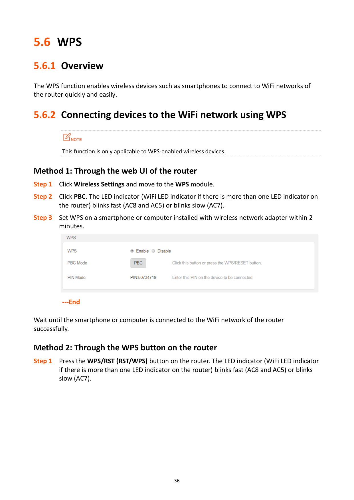
#### 5.6.2 Connecting devices to the WiFi network using WPS

This function is only applicable to WPS-enabled wireless devices.
###### Method 1: Through the web UI of the router

---End

Wait until the smartphone or computer is connected to the WiFi network of the router successfully.
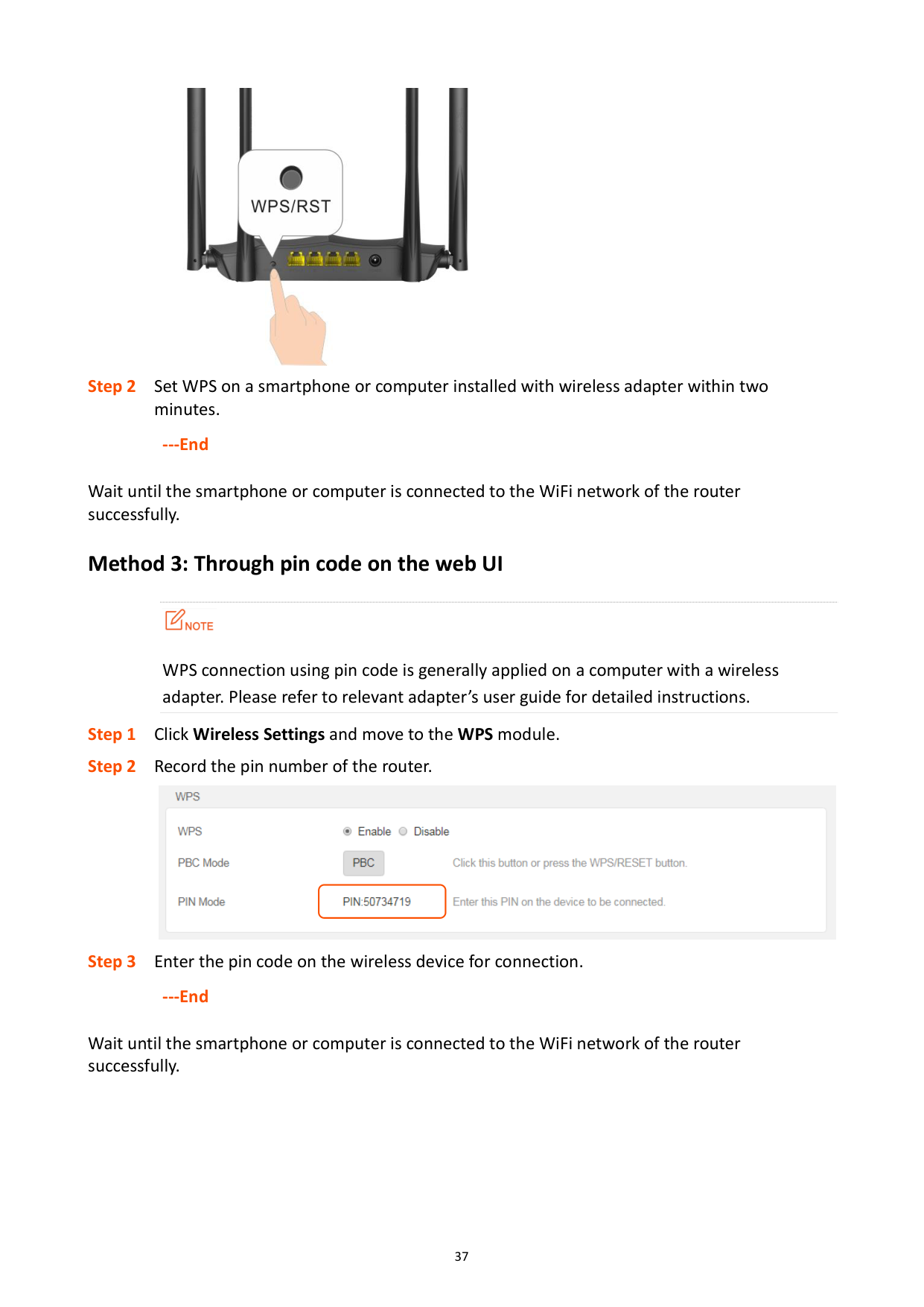
###### Method 2: Through the WPS button on the router

######## ---End
Wait until the smartphone or computer is connected to the WiFi network of the router successfully.
###### Method 3: Through pin code on the web UI

WPS connection using pin code is generally applied on a computer with a wireless adapter. Please refer to relevant adapter’s user guide for detailed instructions.
Step 1 Click Wireless Settings and move to the WPS module. Step 2 Record the pin number of the router.

Step 3 Enter the pin code on the wireless device for connection.
######## ---End
Wait until the smartphone or computer is connected to the WiFi network of the router successfully.
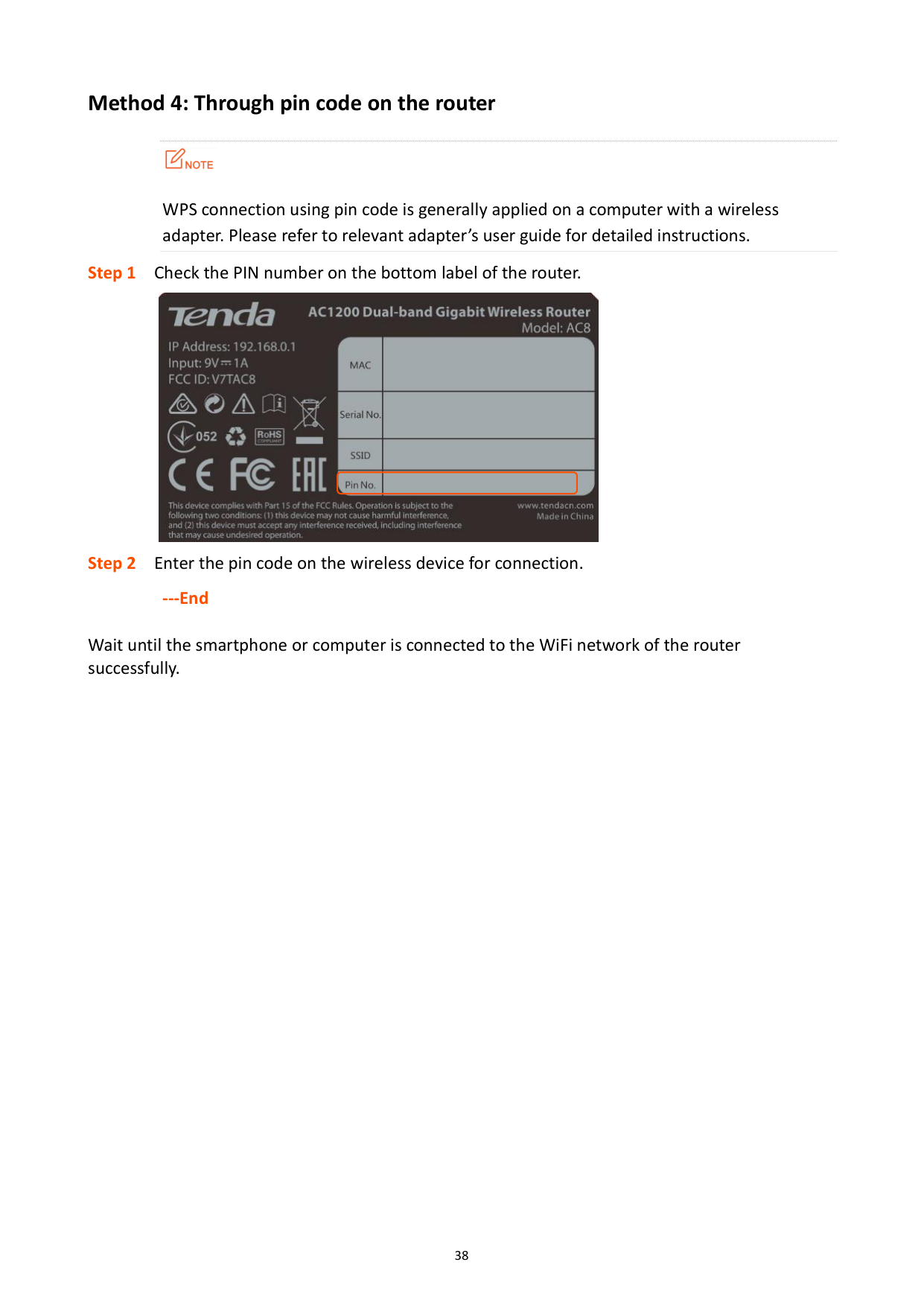
###### Method 4: Through pin code on the router

WPS connection using pin code is generally applied on a computer with a wireless adapter. Please refer to relevant adapter’s user guide for detailed instructions.

######## ---End
Wait until the smartphone or computer is connected to the WiFi network of the router successfully.

6 Bandwidth control
In this section, you are allowed to view on-line device(s), block unknown device(s), and set maximum download/upload speed for online devices.
Click Bandwidth Control to enter the configuration page.

######## Parameter description
########## Parameter Description
Device Name
It displays the information of the online device, including device name and IP address.

You can click to customize the device name for easier management.
Download/Upload Speed
It specifies the current upload and download speeds of the device.
Online Devices
Upload/Download Limit
It allows you to specify the maximum upload and download speeds for the device.
Internet Access
It allows you to allow/disallow the device to access the internet through the router. The current management computer cannot be controlled. Local stands for the device which is managing the router currently.

: It indicates that the device is able to access the internet. : It indicates that the device is unable to access the

internet.
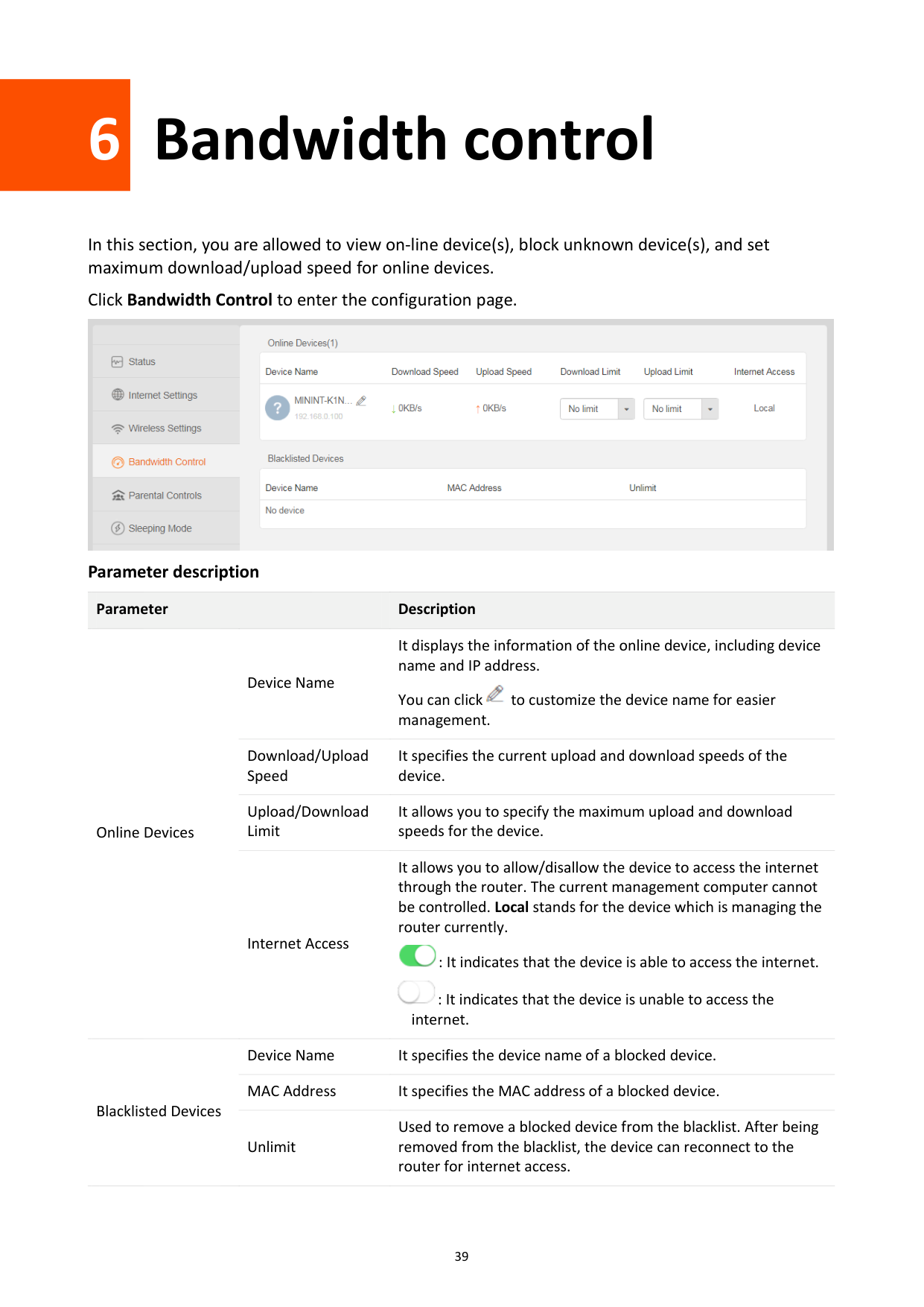
Device Name It specifies the device name of a blocked device. MAC Address It specifies the MAC address of a blocked device.
Blacklisted Devices
Used to remove a blocked device from the blacklist. After being removed from the blacklist, the device can reconnect to the router for internet access.
Unlimit
6.1 Configuring bandwidth control
---End
6.2 Blocking a device
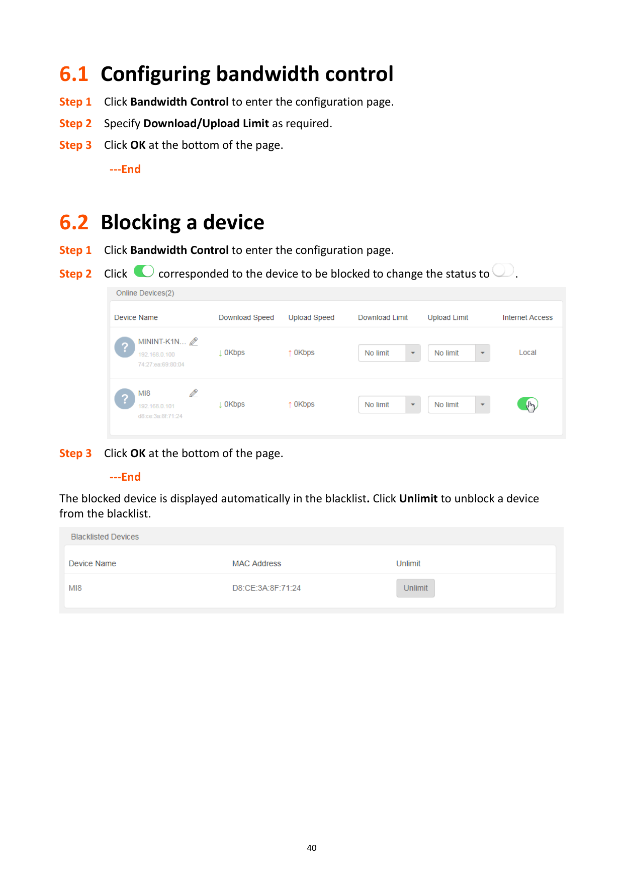


######## ---End
The blocked device is displayed automatically in the blacklist. Click Unlimit to unblock a device from the blacklist.


7 Parental controls
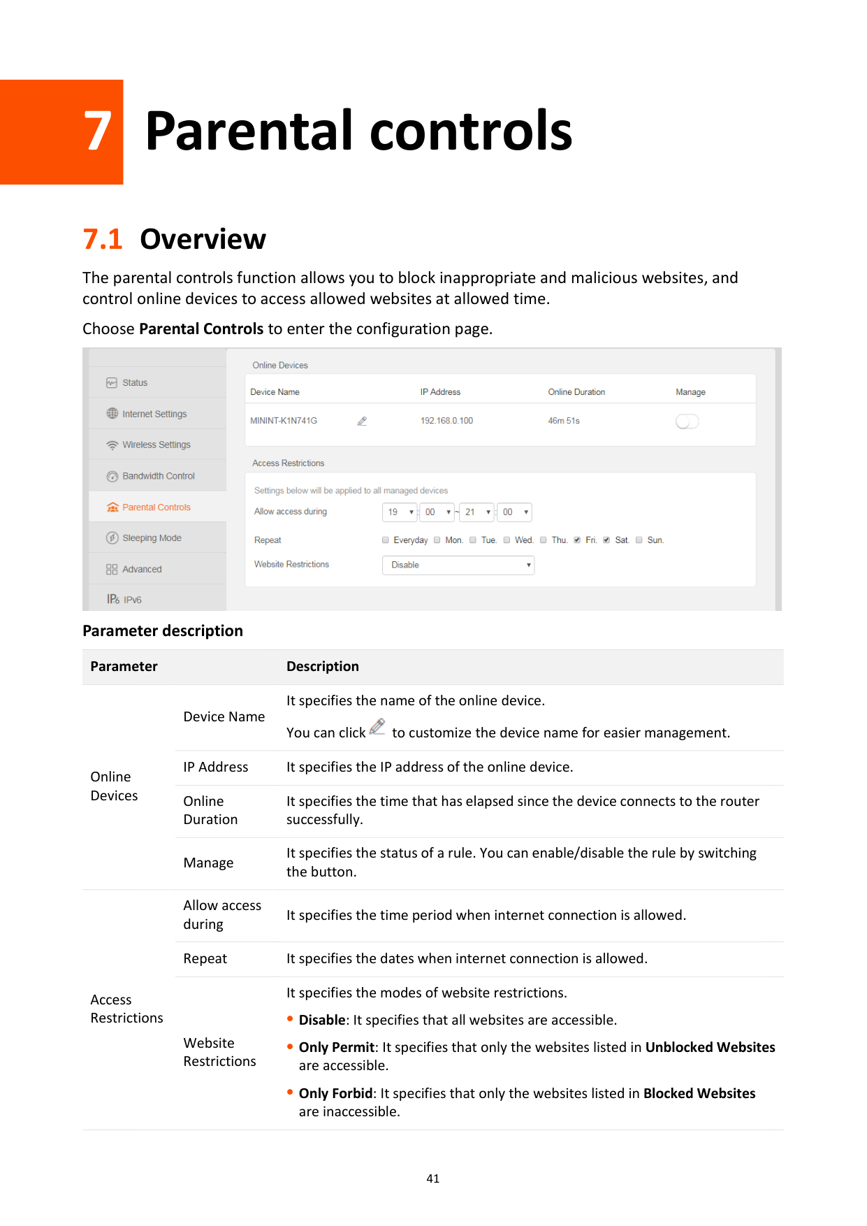
7.1 Overview
The parental controls function allows you to block inappropriate and malicious websites, and control online devices to access allowed websites at allowed time.
Choose Parental Controls to enter the configuration page.

######## Parameter description
########## Parameter Description
Device Name
It specifies the name of the online device. You can click to customize the device name for easier management.

Online Devices
IP Address It specifies the IP address of the online device. Online Duration
It specifies the time that has elapsed since the device connects to the router successfully.
Manage
It specifies the status of a rule. You can enable/disable the rule by switching the button.
Allow access during
It specifies the time period when internet connection is allowed.
Repeat It specifies the dates when internet connection is allowed.
Access Restrictions
Website Restrictions
It specifies the modes of website restrictions.
Disable: It specifies that all websites are accessible.
Only Permit: It specifies that only the websites listed in Unblocked Websites are accessible.
Only Forbid: It specifies that only the websites listed in Blocked Websites are inaccessible.
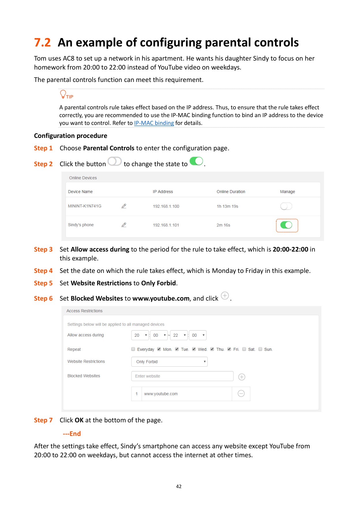
7.2 An example of configuring parental controls
Tom uses AC8 to set up a network in his apartment. He wants his daughter Sindy to focus on her homework from 20:00 to 22:00 instead of YouTube video on weekdays.
The parental controls function can meet this requirement.

A parental controls rule takes effect based on the IP address. Thus, to ensure that the rule takes effect correctly, you are recommended to use the IP-MAC binding function to bind an IP address to the device you want to control. Refer to IP-MAC binding for details.
######## Configuration procedure


######## ---End
After the settings take effect, Sindy’s smartphone can access any website except YouTube from 20:00 to 22:00 on weekdays, but cannot access the internet at other times.

8 Sleeping mode
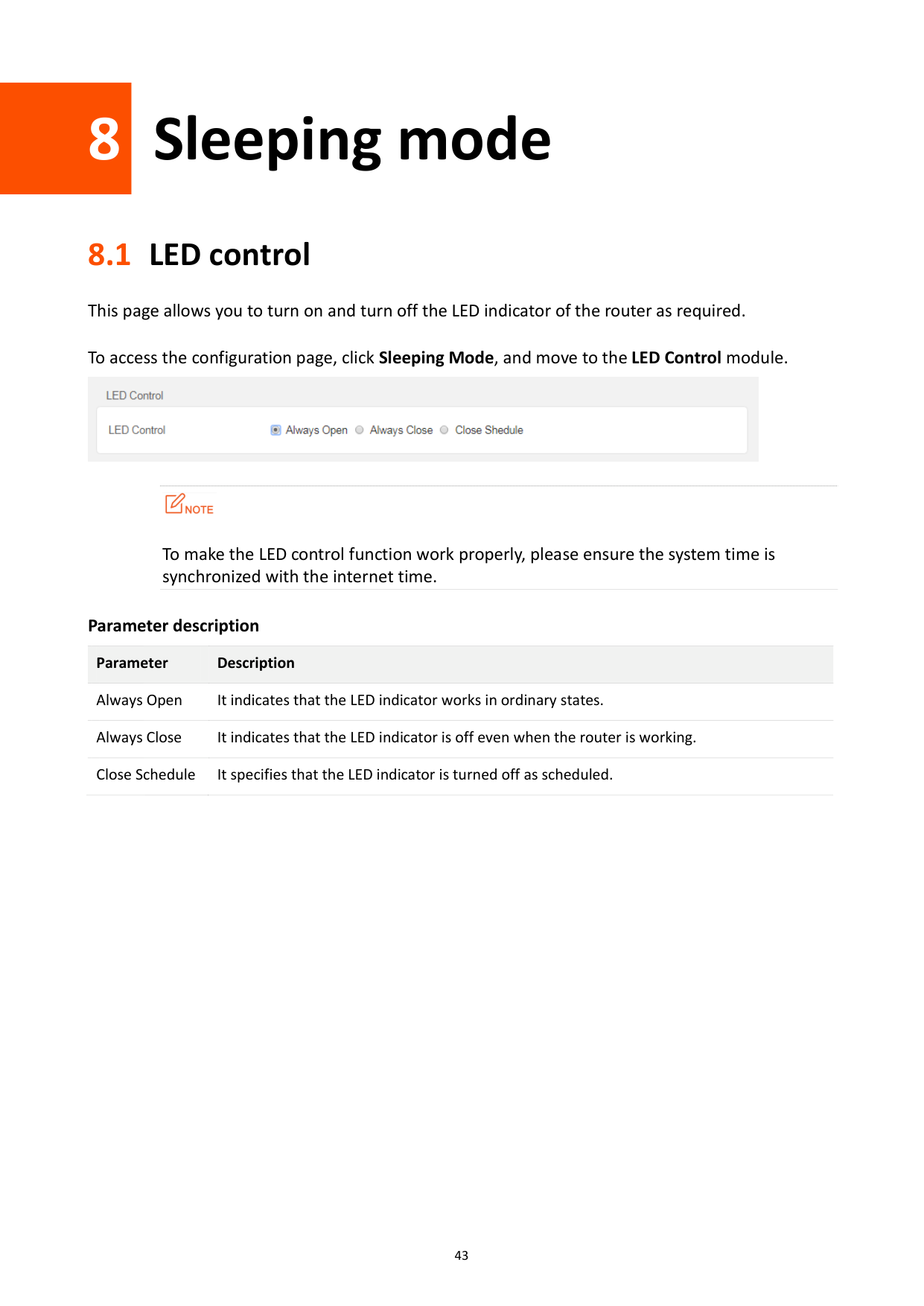
8.1 LED control
This page allows you to turn on and turn off the LED indicator of the router as required.
To access the configuration page, click Sleeping Mode, and move to the LED Control module.


To make the LED control function work properly, please ensure the system time is synchronized with the internet time.
Parameter description Parameter Description Always Open It indicates that the LED indicator works in ordinary states. Always Close It indicates that the LED indicator is off even when the router is working. Close Schedule It specifies that the LED indicator is turned off as scheduled.
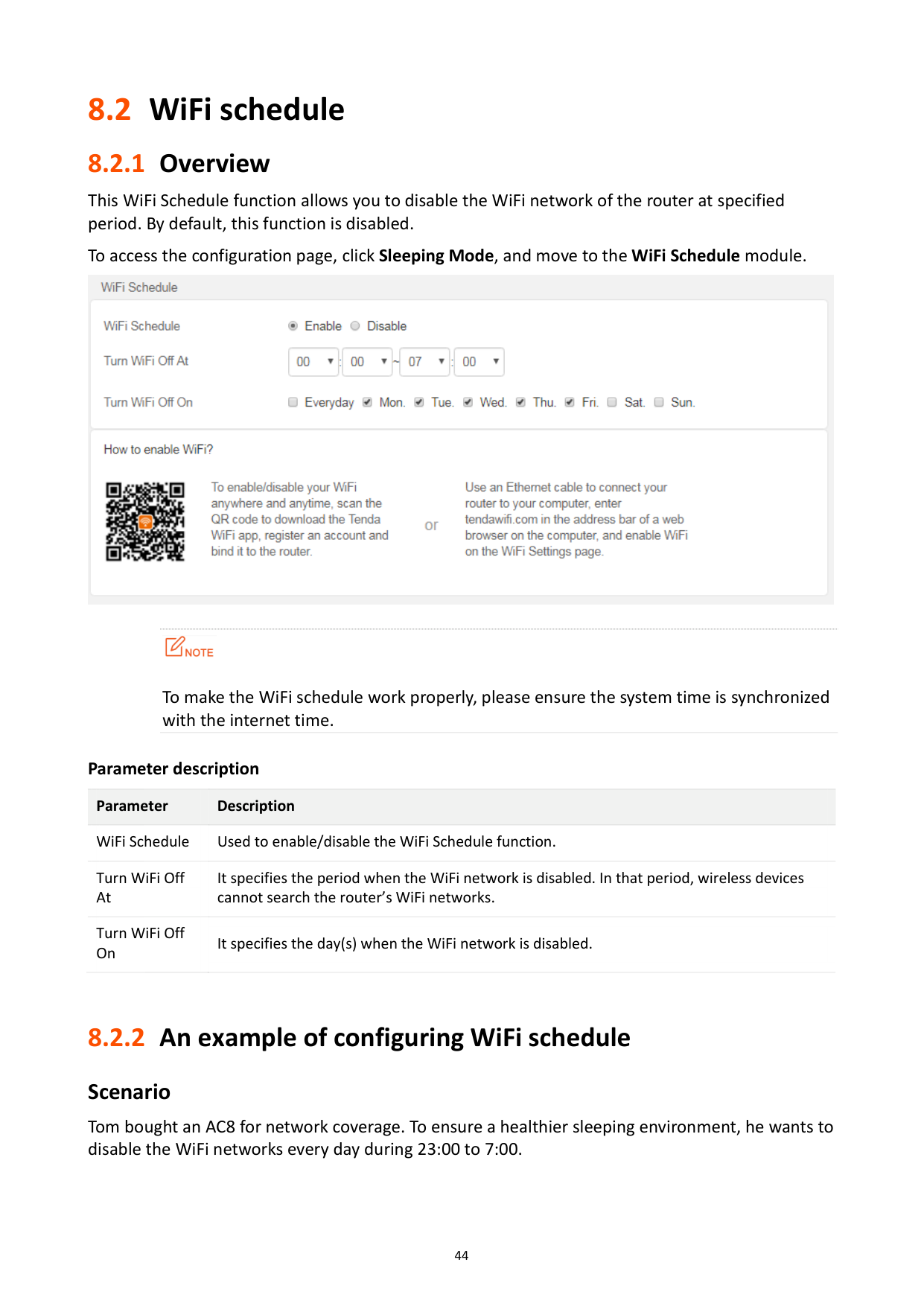
8.2 WiFi schedule
#### 8.2.1 Overview
This WiFi Schedule function allows you to disable the WiFi network of the router at specified period. By default, this function is disabled.
To access the configuration page, click Sleeping Mode, and move to the WiFi Schedule module.


To make the WiFi schedule work properly, please ensure the system time is synchronized with the internet time.
Parameter description Parameter Description WiFi Schedule Used to enable/disable the WiFi Schedule function. Turn WiFi Off At
It specifies the period when the WiFi network is disabled. In that period, wireless devices cannot search the router’s WiFi networks.
Turn WiFi Off On
It specifies the day(s) when the WiFi network is disabled.
#### 8.2.2 An example of configuring WiFi schedule
###### Scenario
Tom bought an AC8 for network coverage. To ensure a healthier sleeping environment, he wants to disable the WiFi networks every day during 23:00 to 7:00.
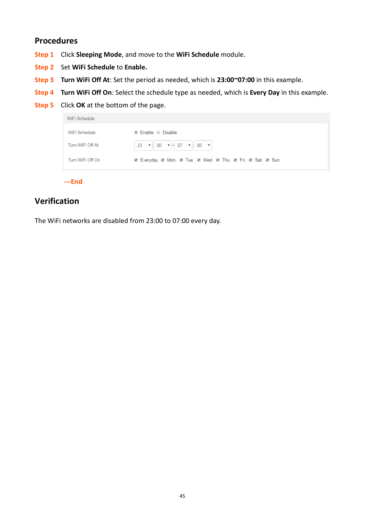
Procedures Step 1 Click Sleeping Mode, and move to the WiFi Schedule module. Step 2 Set WiFi Schedule to Enable. Step 3 Turn WiFi Off At: Set the period as needed, which is 23:00~07:00 in this example. Step 4 Turn WiFi Off On: Select the schedule type as needed, which is Every Day in this example. Step 5 Click OK at the bottom of the page.

###### ---End Verification
The WiFi networks are disabled from 23:00 to 07:00 every day.

9 Advanced
9.1 MAC address filter
#### 9.1.1 Overview
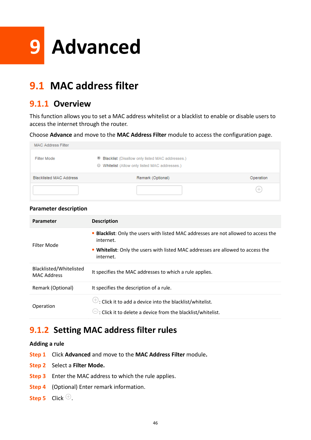
This function allows you to set a MAC address whitelist or a blacklist to enable or disable users to access the internet through the router.
Choose Advance and move to the MAC Address Filter module to access the configuration page.

Parameter description
Parameter Description
Filter Mode
Blacklist: Only the users with listed MAC addresses are not allowed to access the internet.
Whitelist: Only the users with listed MAC addresses are allowed to access the internet.
Blacklisted/Whitelisted MAC Address
It specifies the MAC addresses to which a rule applies.
Remark (Optional) It specifies the description of a rule.

: Click it to add a device into the blacklist/whitelist. : Click it to delete a device from the blacklist/whitelist.
Operation

#### 9.1.2 Setting MAC address filter rules
Adding a rule


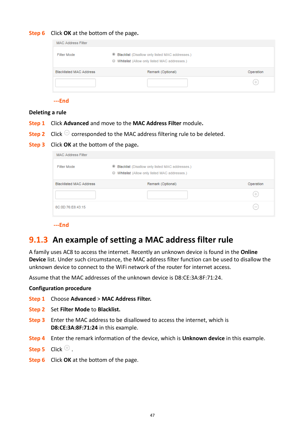
---End Deleting a rule


---End
#### 9.1.3 An example of setting a MAC address filter rule
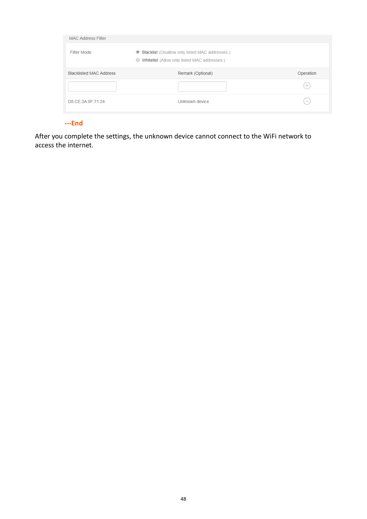
A family uses AC8 to access the internet. Recently an unknown device is found in the Online Device list. Under such circumstance, the MAC address filter function can be used to disallow the unknown device to connect to the WiFi network of the router for internet access. Assume that the MAC addresses of the unknown device is D8:CE:3A:8F:71:24. Configuration procedure


######## ---End
After you complete the settings, the unknown device cannot connect to the WiFi network to access the internet.
9.2 IPTV
#### 9.2.1 Overview
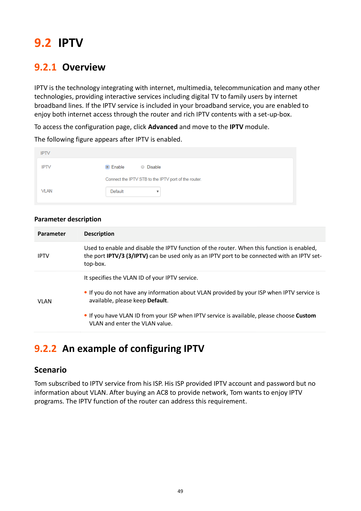
IPTV is the technology integrating with internet, multimedia, telecommunication and many other technologies, providing interactive services including digital TV to family users by internet broadband lines. If the IPTV service is included in your broadband service, you are enabled to enjoy both internet access through the router and rich IPTV contents with a set-up-box.
To access the configuration page, click Advanced and move to the IPTV module. The following figure appears after IPTV is enabled.

Parameter description
Parameter Description
IPTV
Used to enable and disable the IPTV function of the router. When this function is enabled, the port IPTV/3 (3/IPTV) can be used only as an IPTV port to be connected with an IPTV settop-box.
It specifies the VLAN ID of your IPTV service.
VLAN
If you do not have any information about VLAN provided by your ISP when IPTV service is available, please keep Default.
If you have VLAN ID from your ISP when IPTV service is available, please choose Custom VLAN and enter the VLAN value.
#### 9.2.2 An example of configuring IPTV
###### Scenario
Tom subscribed to IPTV service from his ISP. His ISP provided IPTV account and password but no information about VLAN. After buying an AC8 to provide network, Tom wants to enjoy IPTV programs. The IPTV function of the router can address this requirement.
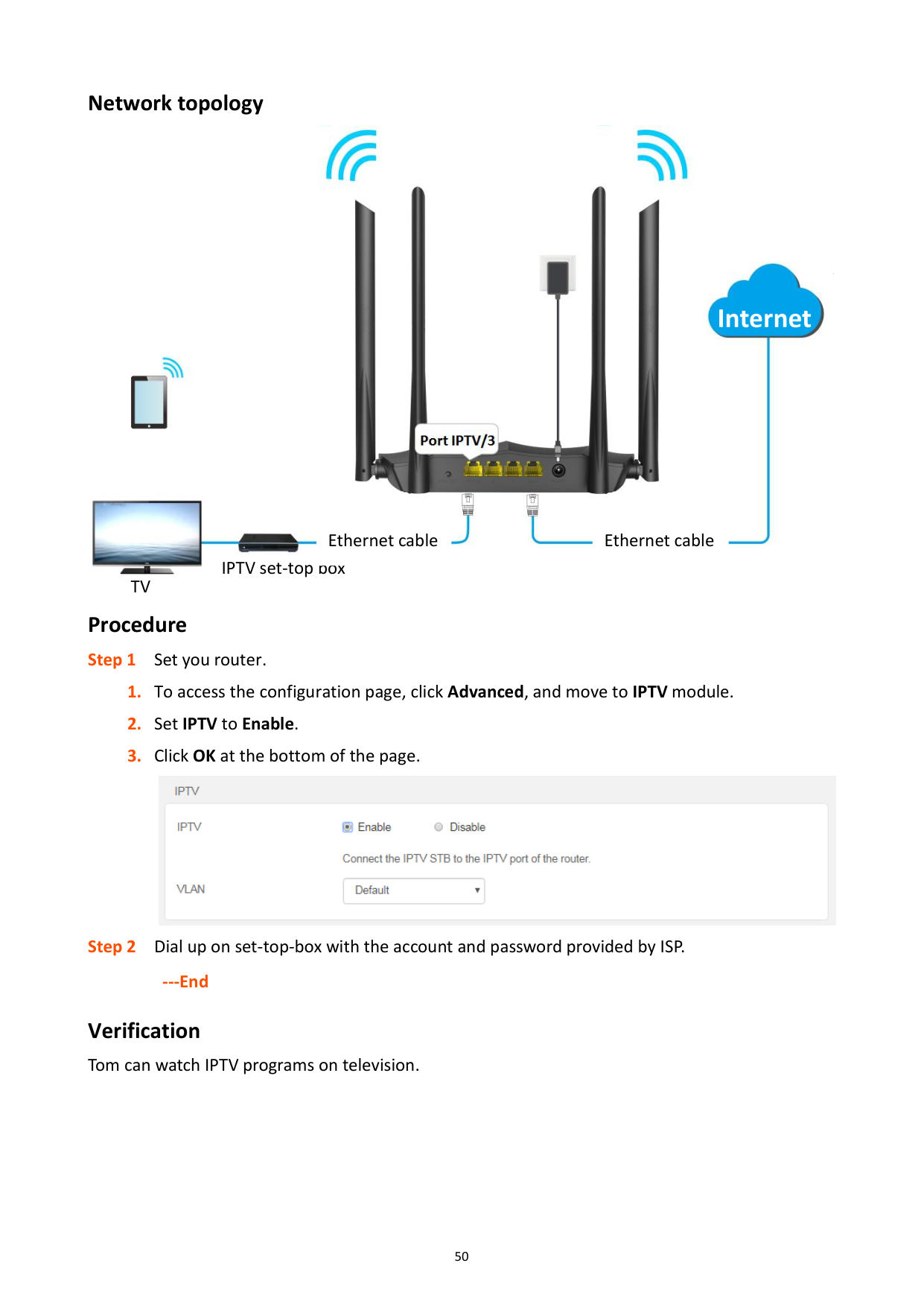
Network topology


#### Internet


Ethernet cableEthernet cable

IPTV set-top box

TV
Procedure

######## ---End
Verification Tom can watch IPTV programs on television.
9.3 IP-MAC binding
#### 9.3.1 Overview
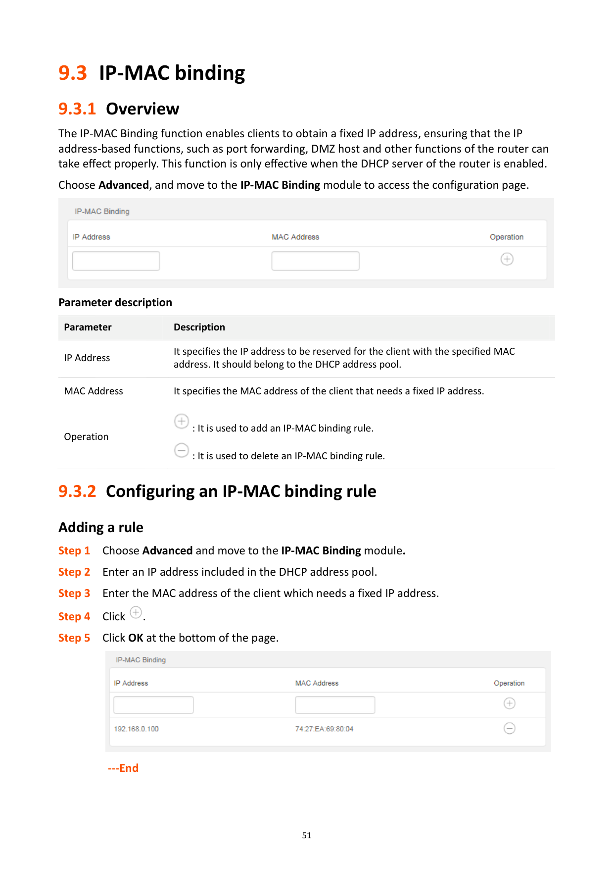
The IP-MAC Binding function enables clients to obtain a fixed IP address, ensuring that the IP address-based functions, such as port forwarding, DMZ host and other functions of the router can take effect properly. This function is only effective when the DHCP server of the router is enabled.
Choose Advanced, and move to the IP-MAC Binding module to access the configuration page.

Parameter description
Parameter Description
IP Address
It specifies the IP address to be reserved for the client with the specified MAC address. It should belong to the DHCP address pool.
MAC Address It specifies the MAC address of the client that needs a fixed IP address.

: It is used to add an IP-MAC binding rule.
Operation

: It is used to delete an IP-MAC binding rule.
#### 9.3.2 Configuring an IP-MAC binding ruleAdding a rule


---End
Deleting a rule Step 1 Choose Advanced and move to the IP-MAC Binding module. Step 2 Click corresponded to an entry to be deleted. Step 3 Click OK at the bottom of the page.

######## ---End
9.4 Port forwarding
#### 9.4.1 Overview
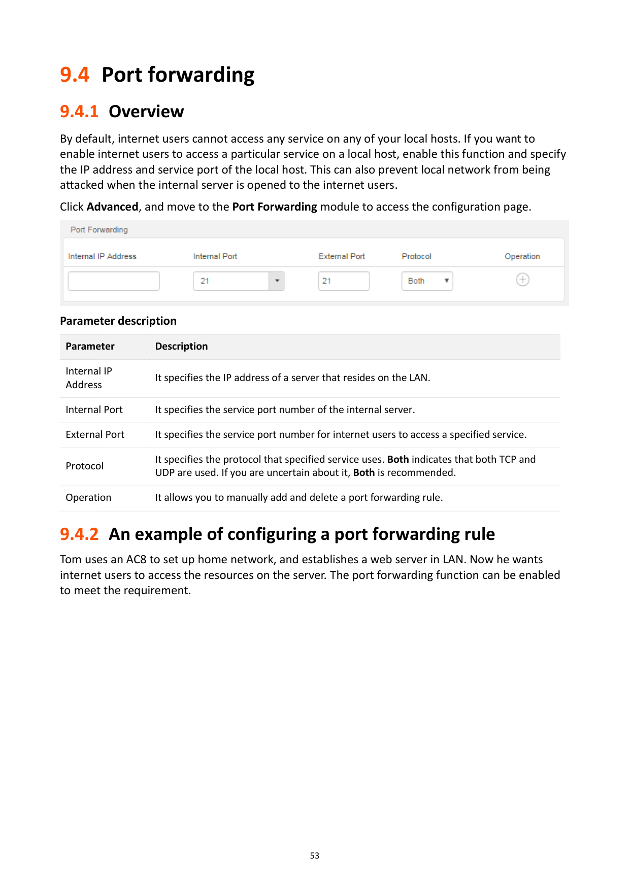
By default, internet users cannot access any service on any of your local hosts. If you want to enable internet users to access a particular service on a local host, enable this function and specify the IP address and service port of the local host. This can also prevent local network from being attacked when the internal server is opened to the internet users.
Click Advanced, and move to the Port Forwarding module to access the configuration page.

Parameter description
Parameter Description
Internal IP Address
It specifies the IP address of a server that resides on the LAN. Internal Port It specifies the service port number of the internal server. External Port It specifies the service port number for internet users to access a specified service. Protocol
It specifies the protocol that specified service uses. Both indicates that both TCP and UDP are used. If you are uncertain about it, Both is recommended.
Operation It allows you to manually add and delete a port forwarding rule.
#### 9.4.2 An example of configuring a port forwarding rule
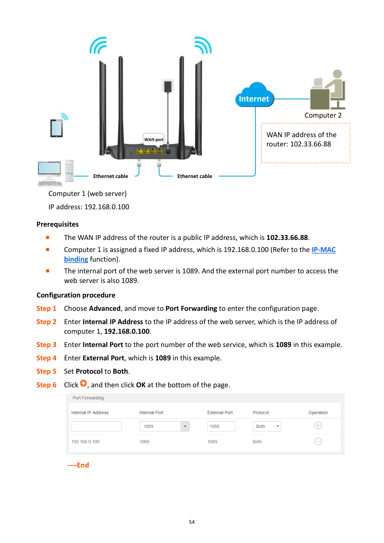
Tom uses an AC8 to set up home network, and establishes a web server in LAN. Now he wants internet users to access the resources on the server. The port forwarding function can be enabled to meet the requirement.


####### Internet

Computer 2
|
WAN IP address of the router: 102.33.66.88| |---|


Ethernet cable Ethernet cable

Computer 1 (web server) IP address: 192.168.0.100
######## Prerequisites
The WAN IP address of the router is a public IP address, which is 102.33.66.88.
Computer 1 is assigned a fixed IP address, which is 192.168.0.100 (Refer to the IP-MAC
binding function).
The internal port of the web server is 1089. And the external port number to access the
web server is also 1089. Configuration procedure


----End
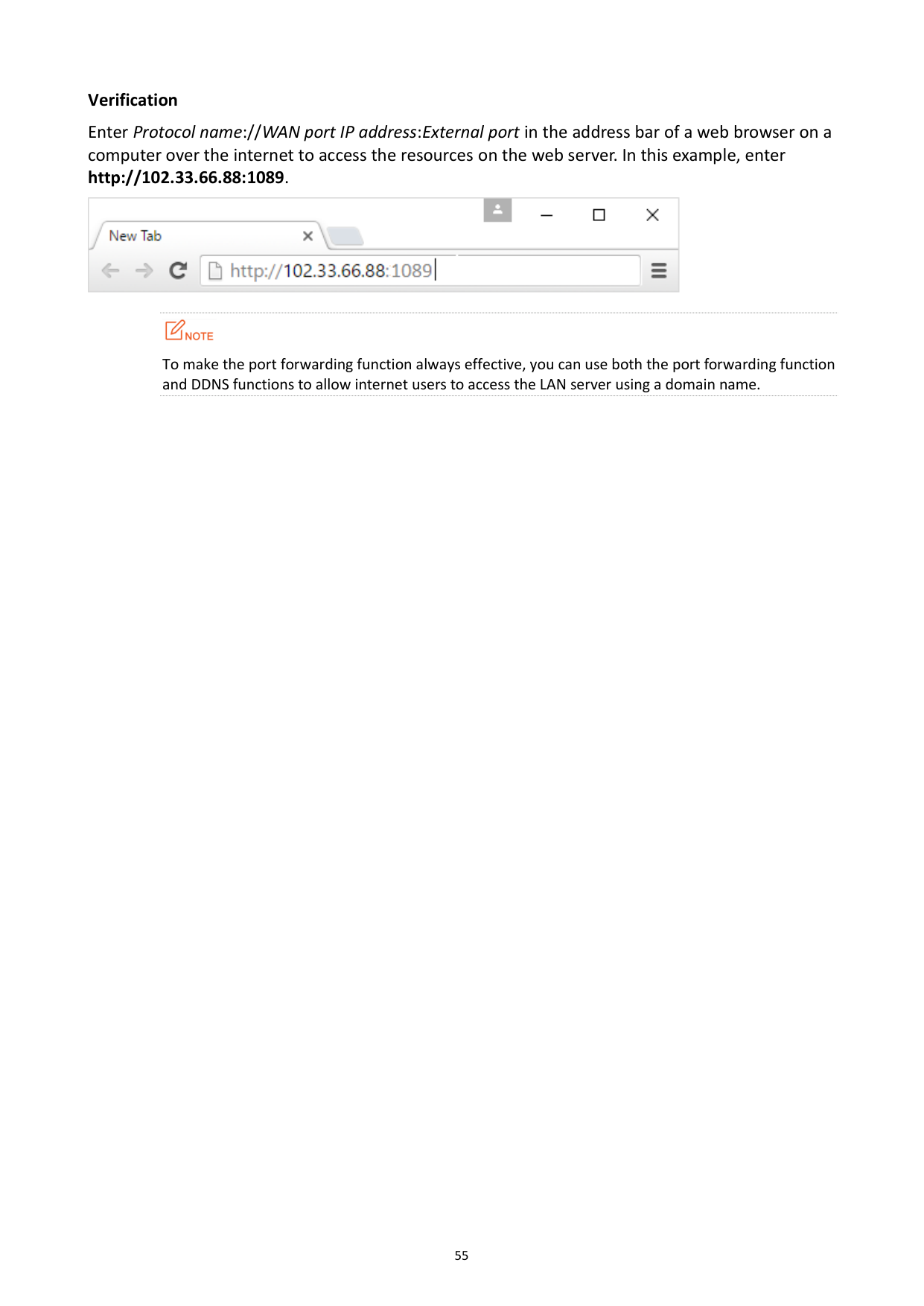
######## Verification
Enter Protocol name://WAN port IP address:External port in the address bar of a web browser on a computer over the internet to access the resources on the web server. In this example, enter http://102.33.66.88:1089.


To make the port forwarding function always effective, you can use both the port forwarding function and DDNS functions to allow internet users to access the LAN server using a domain name.
9.5 DDNS
#### 9.5.1 Overview
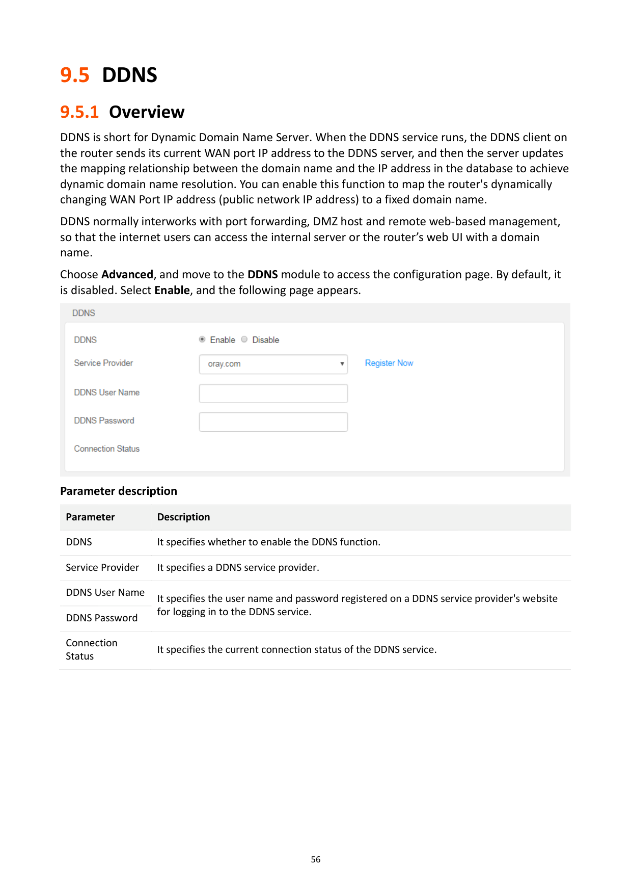
DDNS is short for Dynamic Domain Name Server. When the DDNS service runs, the DDNS client on the router sends its current WAN port IP address to the DDNS server, and then the server updates the mapping relationship between the domain name and the IP address in the database to achieve dynamic domain name resolution. You can enable this function to map the router's dynamically changing WAN Port IP address (public network IP address) to a fixed domain name.
DDNS normally interworks with port forwarding, DMZ host and remote web-based management, so that the internet users can access the internal server or the router’s web UI with a domain name.
Choose Advanced, and move to the DDNS module to access the configuration page. By default, it is disabled. Select Enable, and the following page appears.

Parameter description Parameter Description DDNS It specifies whether to enable the DDNS function. Service Provider It specifies a DDNS service provider. DDNS User Name
It specifies the user name and password registered on a DDNS service provider's website for logging in to the DDNS service.
DDNS Password Connection Status
It specifies the current connection status of the DDNS service.
#### 9.5.2 An example of configuring DDNS
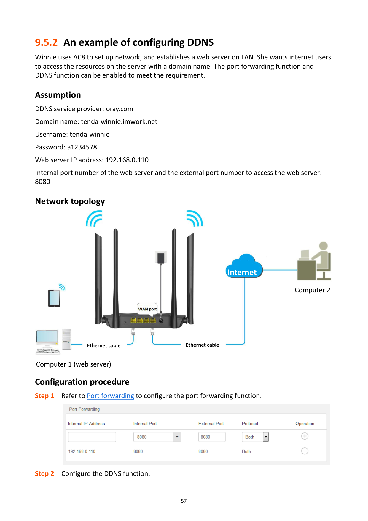
Winnie uses AC8 to set up network, and establishes a web server on LAN. She wants internet users to access the resources on the server with a domain name. The port forwarding function and DDNS function can be enabled to meet the requirement.
Assumption DDNS service provider: oray.com Domain name: tenda-winnie.imwork.net Username: tenda-winnie Password: a1234578 Web server IP address: 192.168.0.110 Internal port number of the web server and the external port number to access the web server: 8080
###### Network topology


####### Internet

Computer 2


Ethernet cable Ethernet cable

Computer 1 (web server)
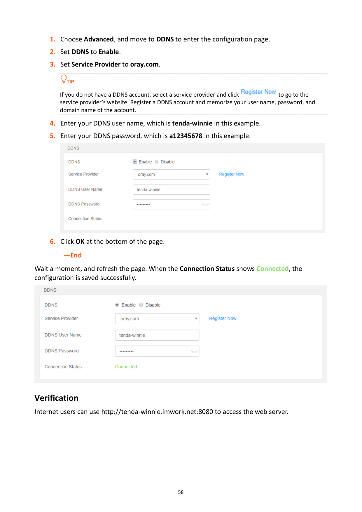
###### Configuration procedure


If you do not have a DDNS account, select a service provider and click to go to the service provider’s website. Register a DDNS account and memorize your user name, password, and domain name of the account.


######## ---End
Wait a moment, and refresh the page. When the Connection Status shows Connected, the configuration is saved successfully.

Verification Internet users can use http://tenda-winnie.imwork.net:8080 to access the web server.
9.6 DMZ host
A DMZ host on a LAN can be accessed by the internet users without limit. It is especially used for video conferences and online games. You can set a computer with these requirements as a DMZ host for better user experience.
Choose Advanced, and move to the DMZ Host module to access the configuration page. By default, it is disabled. It shows as the following figure when you enable it.


A DMZ host is not protected by the firewall of the router. A hacker may leverage the DMZ host to attack your LAN. Therefore, enable the DMZ function only when necessary.
Manually set the IP address of the LAN computer that functions as a DMZ host (Refer to IP-MAC binding function), as a changeable IP address may result in DMZ function failures.
Security software, antivirus software, and the built-in OS firewall of the computer may cause DMZ function failures. Disable them when using the DMZ function. If the DMZ function is not required, you are recommended to disable it and enable your firewall, security, and antivirus software.
######## Configuration procedure

######## ----End
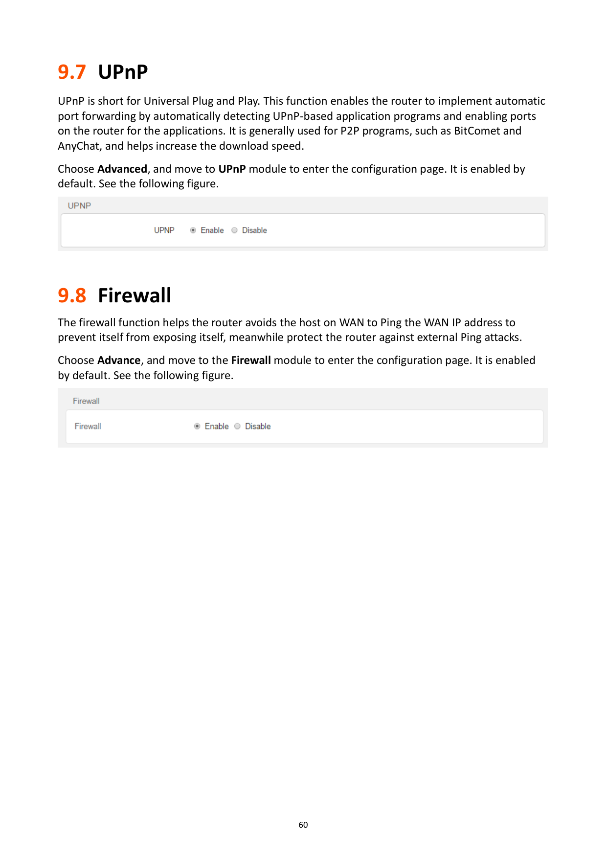
9.7 UPnP
UPnP is short for Universal Plug and Play. This function enables the router to implement automatic port forwarding by automatically detecting UPnP-based application programs and enabling ports on the router for the applications. It is generally used for P2P programs, such as BitComet and AnyChat, and helps increase the download speed.
Choose Advanced, and move to UPnP module to enter the configuration page. It is enabled by default. See the following figure.

9.8 Firewall
The firewall function helps the router avoids the host on WAN to Ping the WAN IP address to prevent itself from exposing itself, meanwhile protect the router against external Ping attacks.
Choose Advance, and move to the Firewall module to enter the configuration page. It is enabled by default. See the following figure.


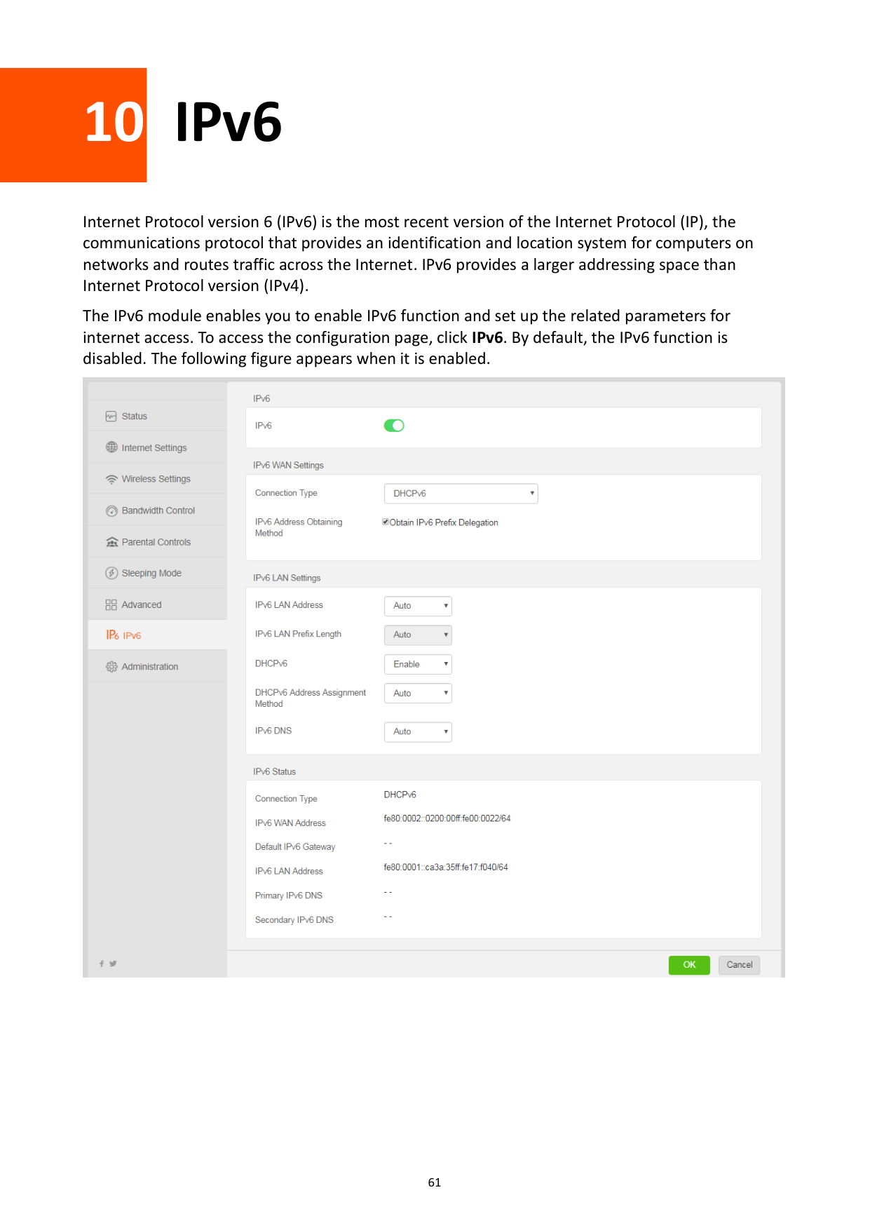
10 IPv6
Internet Protocol version 6 (IPv6) is the most recent version of the Internet Protocol (IP), the communications protocol that provides an identification and location system for computers on networks and routes traffic across the Internet. IPv6 provides a larger addressing space than Internet Protocol version (IPv4).
The IPv6 module enables you to enable IPv6 function and set up the related parameters for internet access. To access the configuration page, click IPv6. By default, the IPv6 function is disabled. The following figure appears when it is enabled.

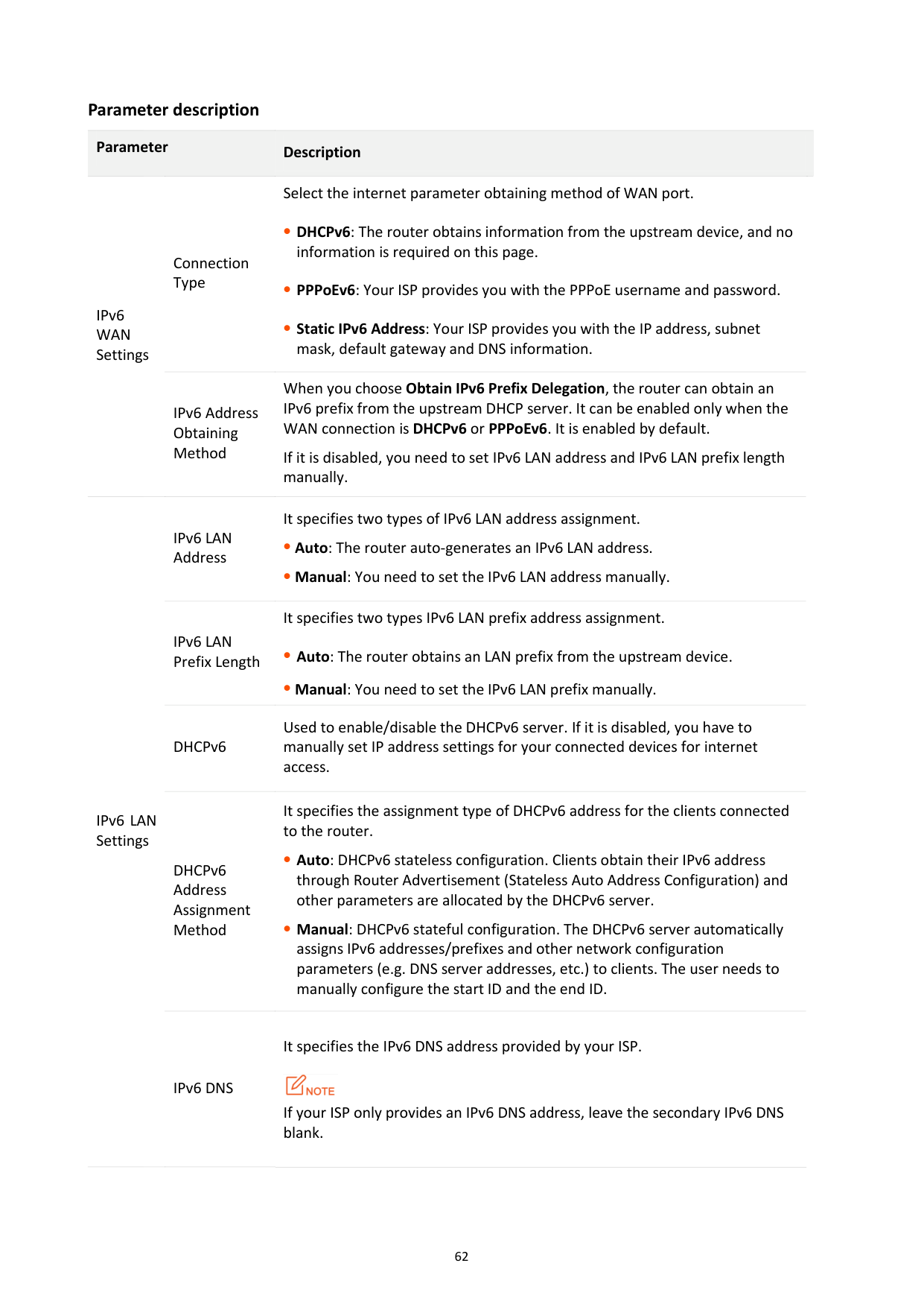
######## Parameter description
########## Parameter Description
Select the internet parameter obtaining method of WAN port.
IPv6 WAN Settings
Connection Type
DHCPv6: The router obtains information from the upstream device, and no information is required on this page.
PPPoEv6: Your ISP provides you with the PPPoE username and password.
Static IPv6 Address: Your ISP provides you with the IP address, subnet mask, default gateway and DNS information.
IPv6 Address Obtaining Method
When you choose Obtain IPv6 Prefix Delegation, the router can obtain an IPv6 prefix from the upstream DHCP server. It can be enabled only when the WAN connection is DHCPv6 or PPPoEv6. It is enabled by default.
If it is disabled, you need to set IPv6 LAN address and IPv6 LAN prefix length manually.
IPv6 LAN Address
It specifies two types of IPv6 LAN address assignment.
Auto: The router auto-generates an IPv6 LAN address.
Manual: You need to set the IPv6 LAN address manually.
IPv6 LAN Prefix Length
It specifies two types IPv6 LAN prefix address assignment.
Auto: The router obtains an LAN prefix from the upstream device.
Manual: You need to set the IPv6 LAN prefix manually.
DHCPv6
Used to enable/disable the DHCPv6 server. If it is disabled, you have to manually set IP address settings for your connected devices for internet access.
IPv6 LAN Settings
DHCPv6 Address Assignment Method
It specifies the assignment type of DHCPv6 address for the clients connected to the router.
Auto: DHCPv6 stateless configuration. Clients obtain their IPv6 address through Router Advertisement (Stateless Auto Address Configuration) and other parameters are allocated by the DHCPv6 server.
Manual: DHCPv6 stateful configuration. The DHCPv6 server automatically assigns IPv6 addresses/prefixes and other network configuration parameters (e.g. DNS server addresses, etc.) to clients. The user needs to manually configure the start ID and the end ID.
IPv6 DNS
It specifies the IPv6 DNS address provided by your ISP.

If your ISP only provides an IPv6 DNS address, leave the secondary IPv6 DNS blank.
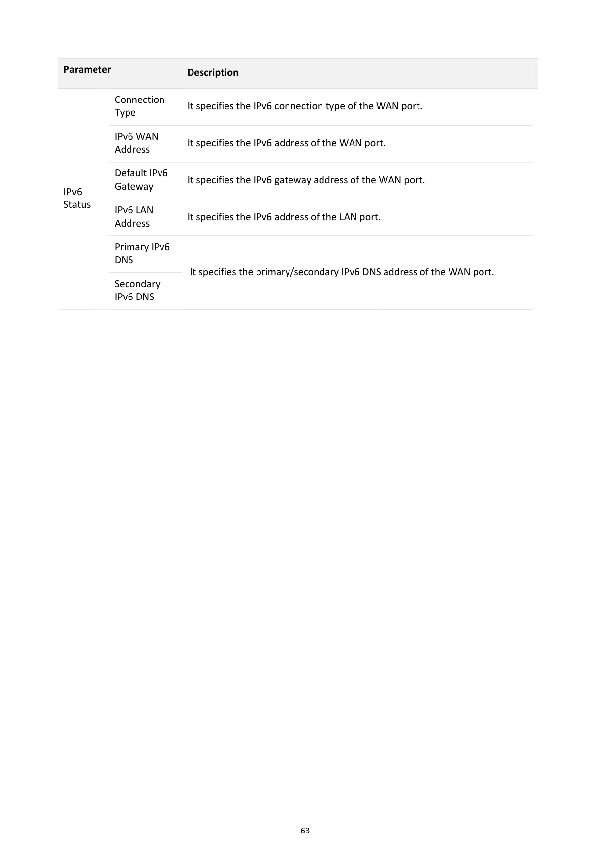
########## Parameter Description
Connection Type
It specifies the IPv6 connection type of the WAN port.
IPv6 WAN Address
It specifies the IPv6 address of the WAN port.
IPv6 Status
Default IPv6 Gateway
It specifies the IPv6 gateway address of the WAN port.
IPv6 LAN Address
It specifies the IPv6 address of the LAN port.
Primary IPv6 DNS
It specifies the primary/secondary IPv6 DNS address of the WAN port.
Secondary IPv6 DNS

11 Administration
This section describes how to manage and maintain your router and home network.
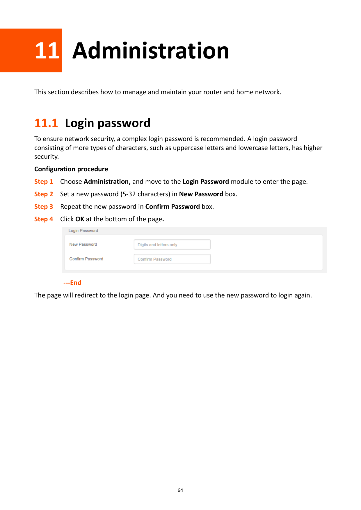
11.1 Login password
To ensure network security, a complex login password is recommended. A login password consisting of more types of characters, such as uppercase letters and lowercase letters, has higher security.
######## Configuration procedure

######## ---End
The page will redirect to the login page. And you need to use the new password to login again.
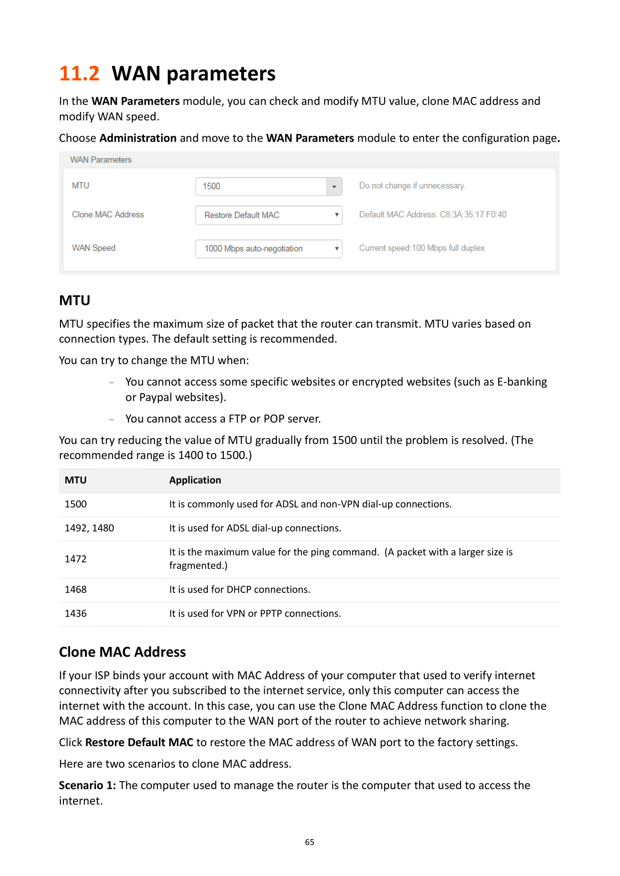
11.2 WAN parameters
In the WAN Parameters module, you can check and modify MTU value, clone MAC address and modify WAN speed.
Choose Administration and move to the WAN Parameters module to enter the configuration page.

###### MTU
MTU specifies the maximum size of packet that the router can transmit. MTU varies based on connection types. The default setting is recommended.
You can try to change the MTU when:
You cannot access some specific websites or encrypted websites (such as E-banking or Paypal websites).
− You cannot access a FTP or POP server.
You can try reducing the value of MTU gradually from 1500 until the problem is resolved. (The recommended range is 1400 to 1500.)
MTU Application 1500 It is commonly used for ADSL and non-VPN dial-up connections. 1492, 1480 It is used for ADSL dial-up connections. 1472
It is the maximum value for the ping command. (A packet with a larger size is fragmented.)
1468 It is used for DHCP connections. 1436 It is used for VPN or PPTP connections.
###### Clone MAC Address
If your ISP binds your account with MAC Address of your computer that used to verify internet connectivity after you subscribed to the internet service, only this computer can access the internet with the account. In this case, you can use the Clone MAC Address function to clone the MAC address of this computer to the WAN port of the router to achieve network sharing.
Click Restore Default MAC to restore the MAC address of WAN port to the factory settings. Here are two scenarios to clone MAC address.
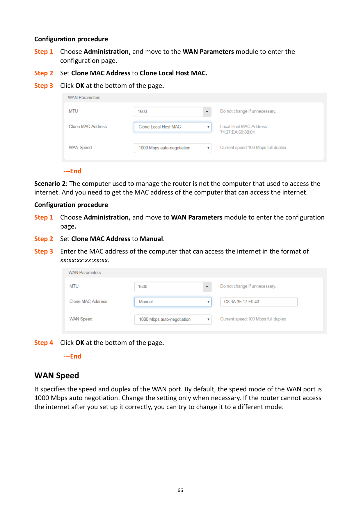
######## Configuration procedure

######## ---End

###### ---End WAN Speed
It specifies the speed and duplex of the WAN port. By default, the speed mode of the WAN port is 1000 Mbps auto negotiation. Change the setting only when necessary. If the router cannot access the internet after you set up it correctly, you can try to change it to a different mode.
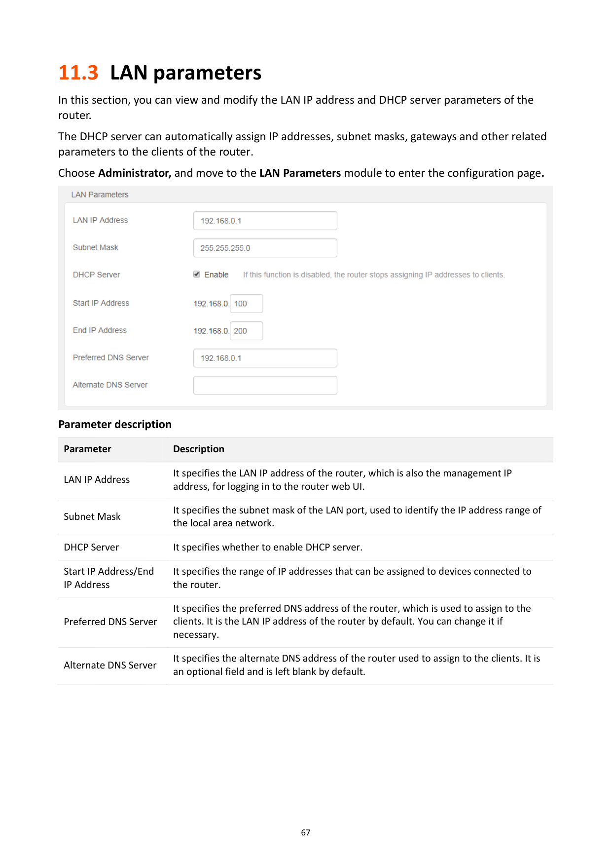
11.3 LAN parameters
In this section, you can view and modify the LAN IP address and DHCP server parameters of the router.
The DHCP server can automatically assign IP addresses, subnet masks, gateways and other related parameters to the clients of the router.
Choose Administrator, and move to the LAN Parameters module to enter the configuration page.

######## Parameter description
########## Parameter Description
LAN IP Address
It specifies the LAN IP address of the router, which is also the management IP address, for logging in to the router web UI.
Subnet Mask
It specifies the subnet mask of the LAN port, used to identify the IP address range of the local area network.
DHCP Server It specifies whether to enable DHCP server. Start IP Address/End IP Address
It specifies the range of IP addresses that can be assigned to devices connected to the router.
Preferred DNS Server
It specifies the preferred DNS address of the router, which is used to assign to the clients. It is the LAN IP address of the router by default. You can change it if necessary.
It specifies the alternate DNS address of the router used to assign to the clients. It is an optional field and is left blank by default.
Alternate DNS Server
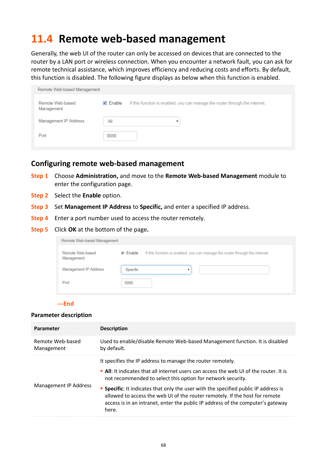
11.4 Remote web-based management
Generally, the web UI of the router can only be accessed on devices that are connected to the router by a LAN port or wireless connection. When you encounter a network fault, you can ask for remote technical assistance, which improves efficiency and reducing costs and efforts. By default, this function is disabled. The following figure displays as below when this function is enabled.

###### Configuring remote web-based management

######## ---End Parameter description
########## Parameter Description
Remote Web-based Management
Used to enable/disable Remote Web-based Management function. It is disabled by default.
Management IP Address
It specifies the IP address to manage the router remotely.
All: It indicates that all internet users can access the web UI of the router. It is not recommended to select this option for network security.
Specific: It indicates that only the user with the specified public IP address is allowed to access the web UI of the router remotely. If the host for remote access is in an intranet, enter the public IP address of the computer’s gateway here.
########## Parameter Description
Port
It specifies the port number to access the router remotely. Port 1 to 1024 are occupied by well-known services. It is recommended to modify the port to be in the range from 1025 to 65535. To access the web UI of the router by the URL: http://WAN IP address:port. If DDNS is enabled on the router, you can access the web UI by http://WAN domain name:port.
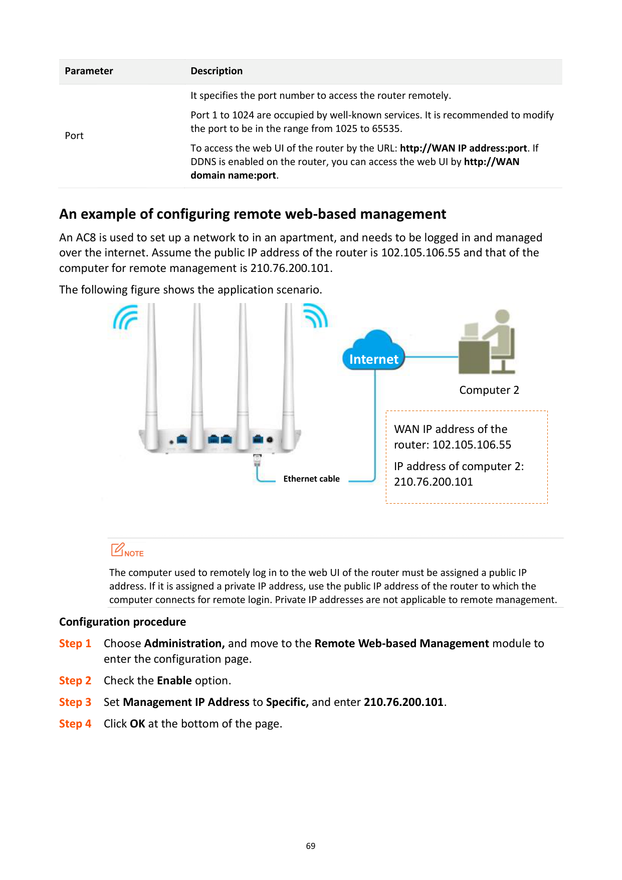
###### An example of configuring remote web-based management
An AC8 is used to set up a network to in an apartment, and needs to be logged in and managed over the internet. Assume the public IP address of the router is 102.105.106.55 and that of the computer for remote management is 210.76.200.101.
The following figure shows the application scenario.


####### Internet

Computer 2
|
WAN IP address of the router: 102.105.106.55
IP address of computer 2: 210.76.200.101| |---|

Ethernet cable

The computer used to remotely log in to the web UI of the router must be assigned a public IP address. If it is assigned a private IP address, use the public IP address of the router to which the computer connects for remote login. Private IP addresses are not applicable to remote management.
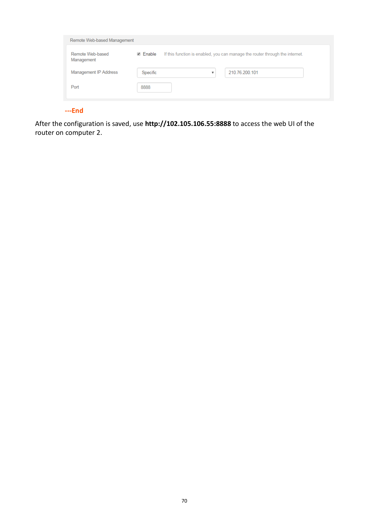
######## Configuration procedure

######## ---End
After the configuration is saved, use http://102.105.106.55:8888 to access the web UI of the router on computer 2.
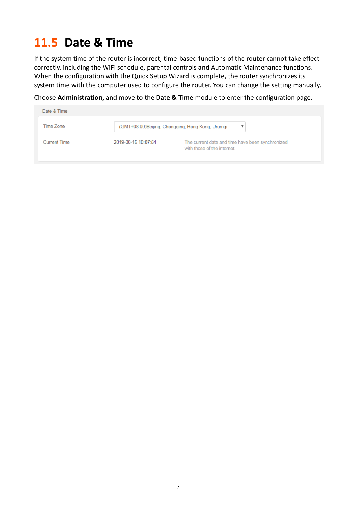
11.5 Date & Time
If the system time of the router is incorrect, time-based functions of the router cannot take effect correctly, including the WiFi schedule, parental controls and Automatic Maintenance functions. When the configuration with the Quick Setup Wizard is complete, the router synchronizes its system time with the computer used to configure the router. You can change the setting manually.
Choose Administration, and move to the Date & Time module to enter the configuration page.

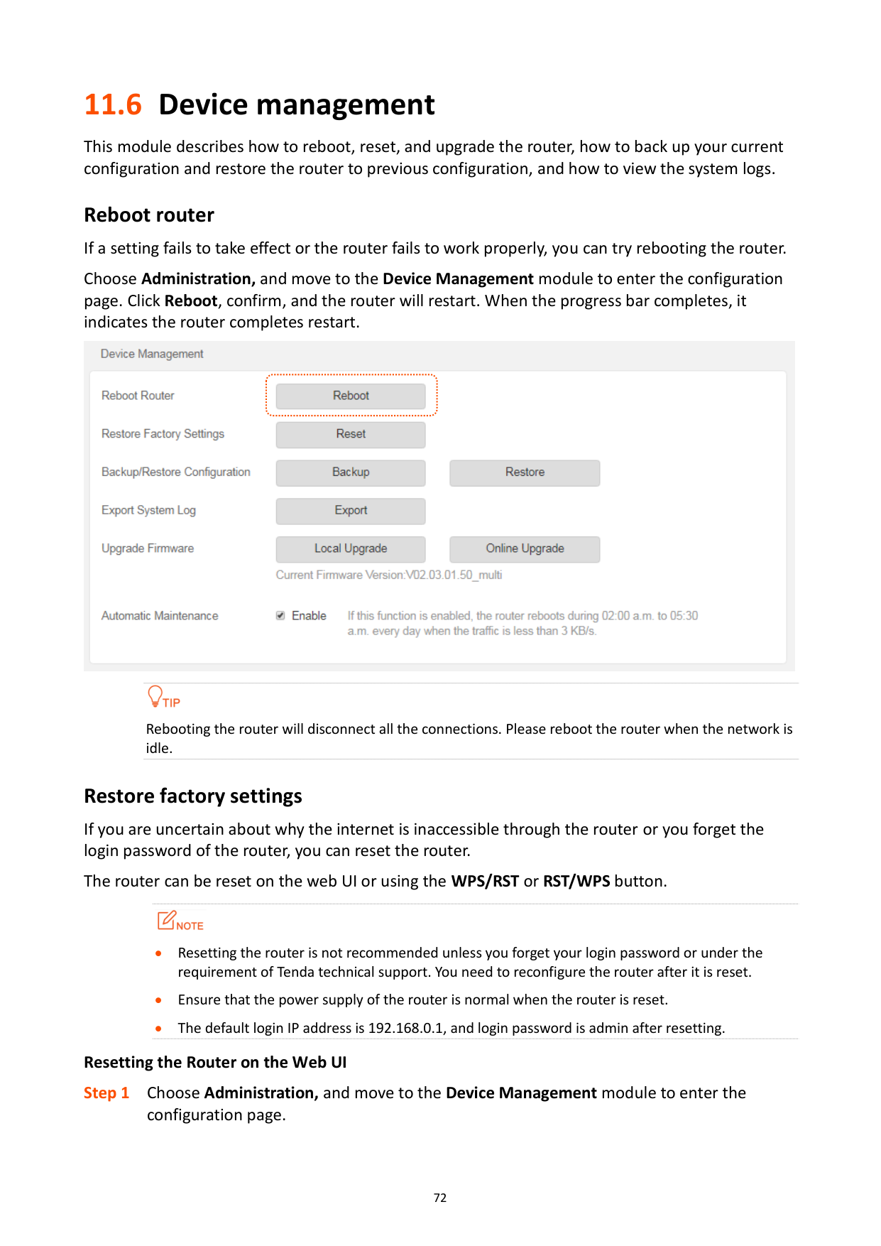
11.6 Device management
This module describes how to reboot, reset, and upgrade the router, how to back up your current configuration and restore the router to previous configuration, and how to view the system logs.
Reboot router If a setting fails to take effect or the router fails to work properly, you can try rebooting the router. Choose Administration, and move to the Device Management module to enter the configuration page. Click Reboot, confirm, and the router will restart. When the progress bar completes, it indicates the router completes restart.


Rebooting the router will disconnect all the connections. Please reboot the router when the network is idle.
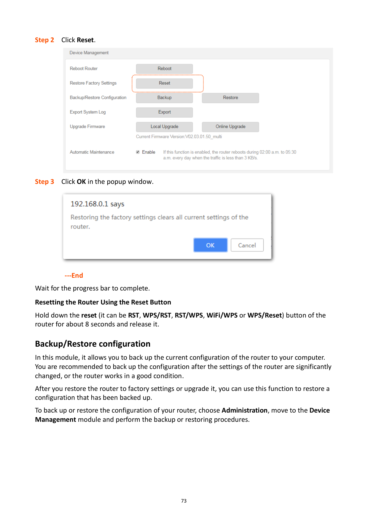
###### Restore factory settings
If you are uncertain about why the internet is inaccessible through the router or you forget the login password of the router, you can reset the router.
The router can be reset on the web UI or using the WPS/RST or RST/WPS button.

Resetting the router is not recommended unless you forget your login password or under the requirement of Tenda technical support. You need to reconfigure the router after it is reset.
Ensure that the power supply of the router is normal when the router is reset.
The default login IP address is 192.168.0.1, and login password is admin after resetting. Resetting the Router on the Web UI


---End Wait for the progress bar to complete. Resetting the Router Using the Reset Button
Hold down the reset (it can be RST, WPS/RST, RST/WPS, WiFi/WPS or WPS/Reset) button of the router for about 8 seconds and release it.
###### Backup/Restore configuration
In this module, it allows you to back up the current configuration of the router to your computer. You are recommended to back up the configuration after the settings of the router are significantly changed, or the router works in a good condition.
After you restore the router to factory settings or upgrade it, you can use this function to restore a configuration that has been backed up.
To back up or restore the configuration of your router, choose Administration, move to the Device Management module and perform the backup or restoring procedures.

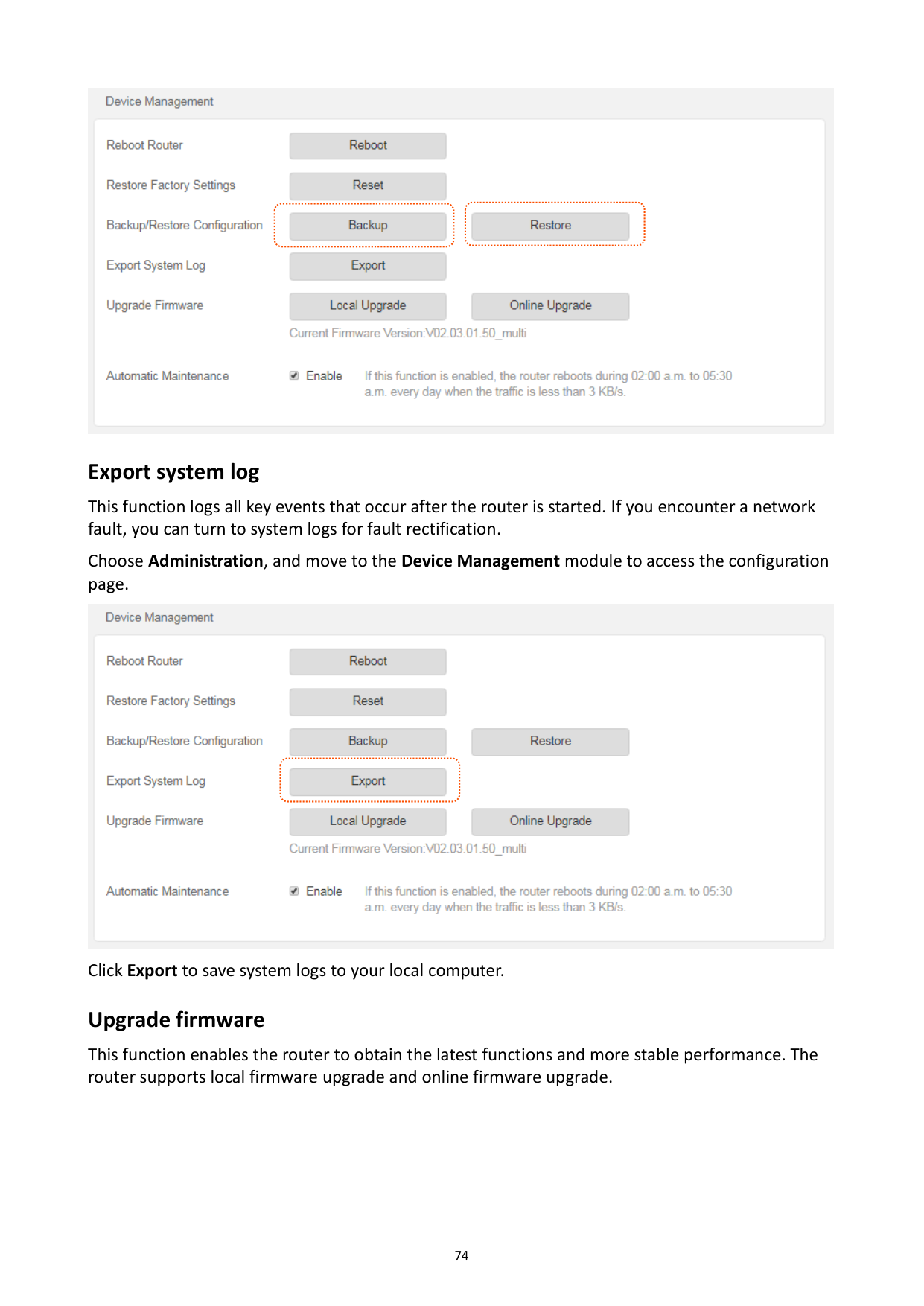
###### Export system log
This function logs all key events that occur after the router is started. If you encounter a network fault, you can turn to system logs for fault rectification.
Choose Administration, and move to the Device Management module to access the configuration page.

Click Export to save system logs to your local computer. Upgrade firmware
This function enables the router to obtain the latest functions and more stable performance. The router supports local firmware upgrade and online firmware upgrade.
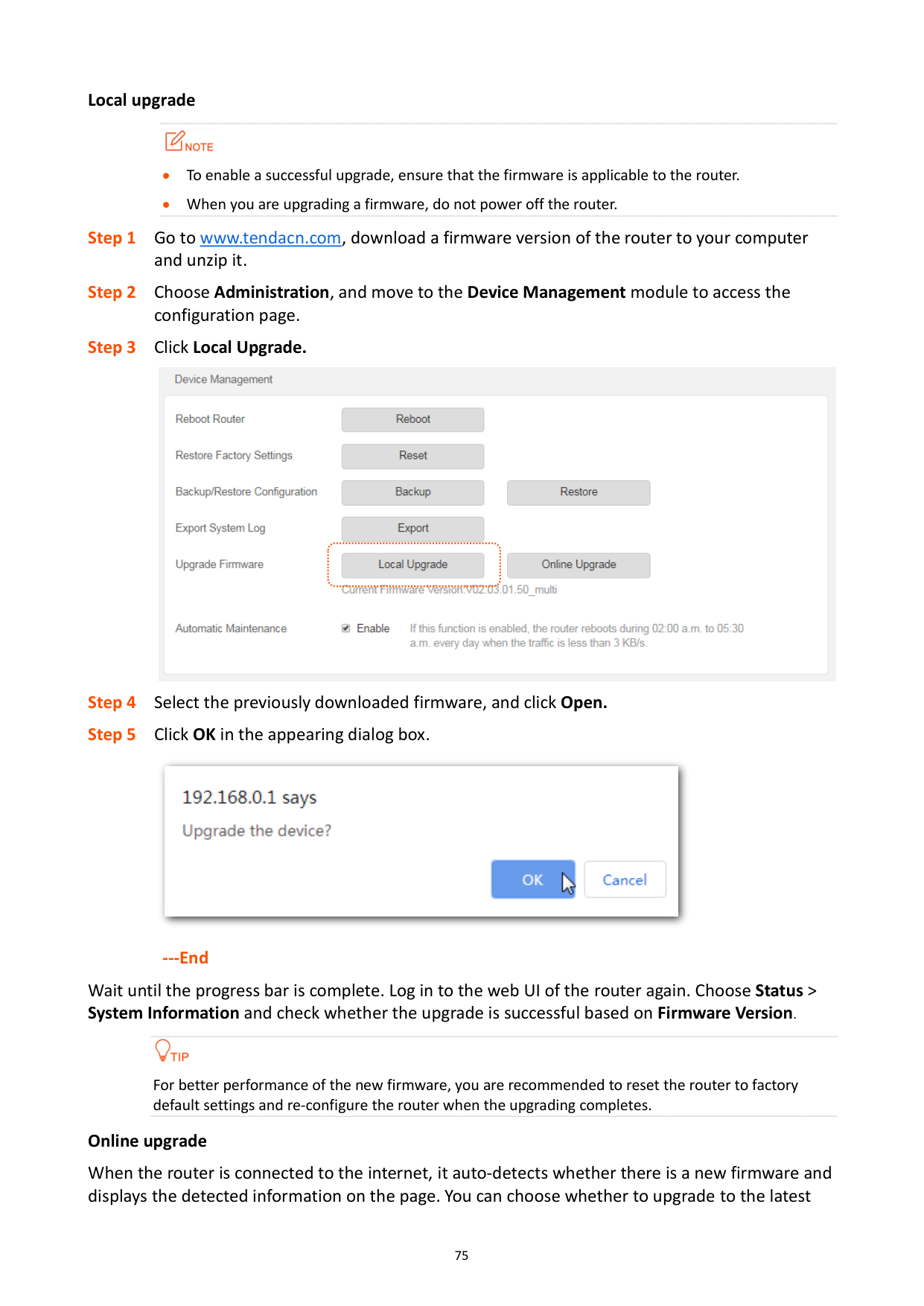
######## Local upgrade

To enable a successful upgrade, ensure that the firmware is applicable to the router.
When you are upgrading a firmware, do not power off the router.


######## ---End
Wait until the progress bar is complete. Log in to the web UI of the router again. Choose Status > System Information and check whether the upgrade is successful based on Firmware Version.

For better performance of the new firmware, you are recommended to reset the router to factory default settings and re-configure the router when the upgrading completes.
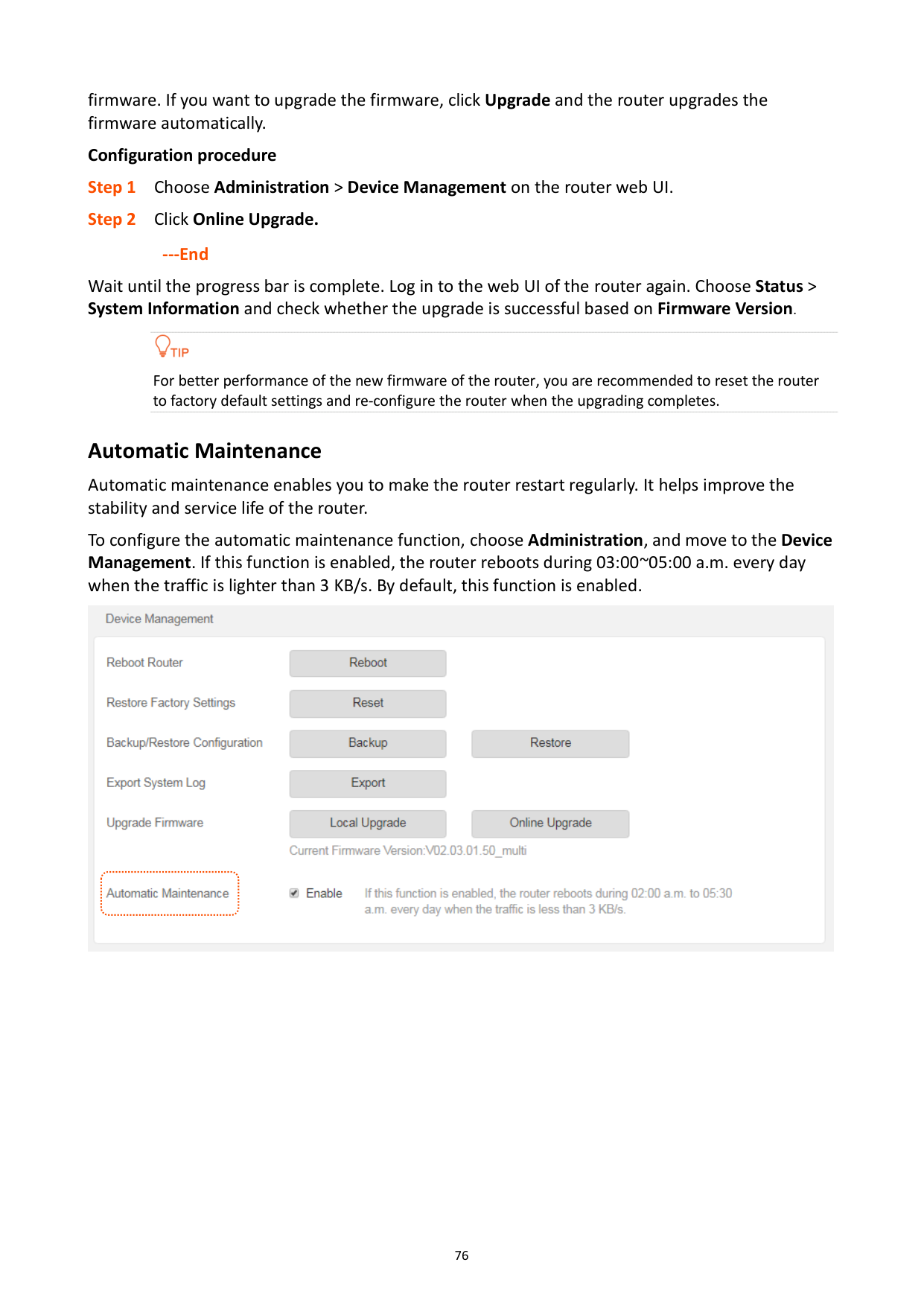
######## Online upgrade
When the router is connected to the internet, it auto-detects whether there is a new firmware and displays the detected information on the page. You can choose whether to upgrade to the latest
firmware. If you want to upgrade the firmware, click Upgrade and the router upgrades the firmware automatically.
Configuration procedure
---End
Wait until the progress bar is complete. Log in to the web UI of the router again. Choose Status > System Information and check whether the upgrade is successful based on Firmware Version.

For better performance of the new firmware of the router, you are recommended to reset the router to factory default settings and re-configure the router when the upgrading completes.
###### Automatic Maintenance
Automatic maintenance enables you to make the router restart regularly. It helps improve the stability and service life of the router.
To configure the automatic maintenance function, choose Administration, and move to the Device Management. If this function is enabled, the router reboots during 03:00~05:00 a.m. every day when the traffic is lighter than 3 KB/s. By default, this function is enabled.

Appendix
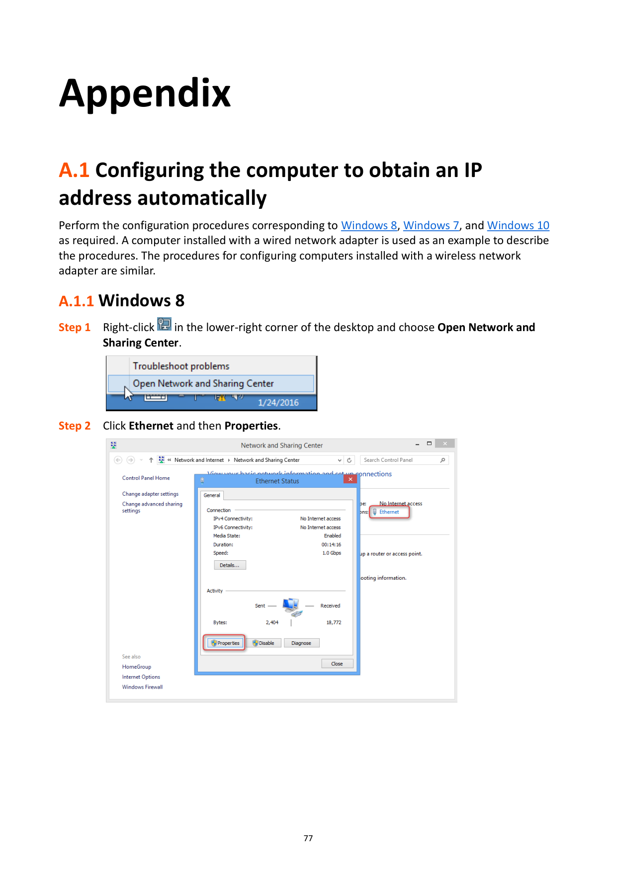
A.1 Configuring the computer to obtain an IP address automatically
Perform the configuration procedures corresponding to Windows 8, Windows 7, and Windows 10 as required. A computer installed with a wired network adapter is used as an example to describe the procedures. The procedures for configuring computers installed with a wireless network adapter are similar.
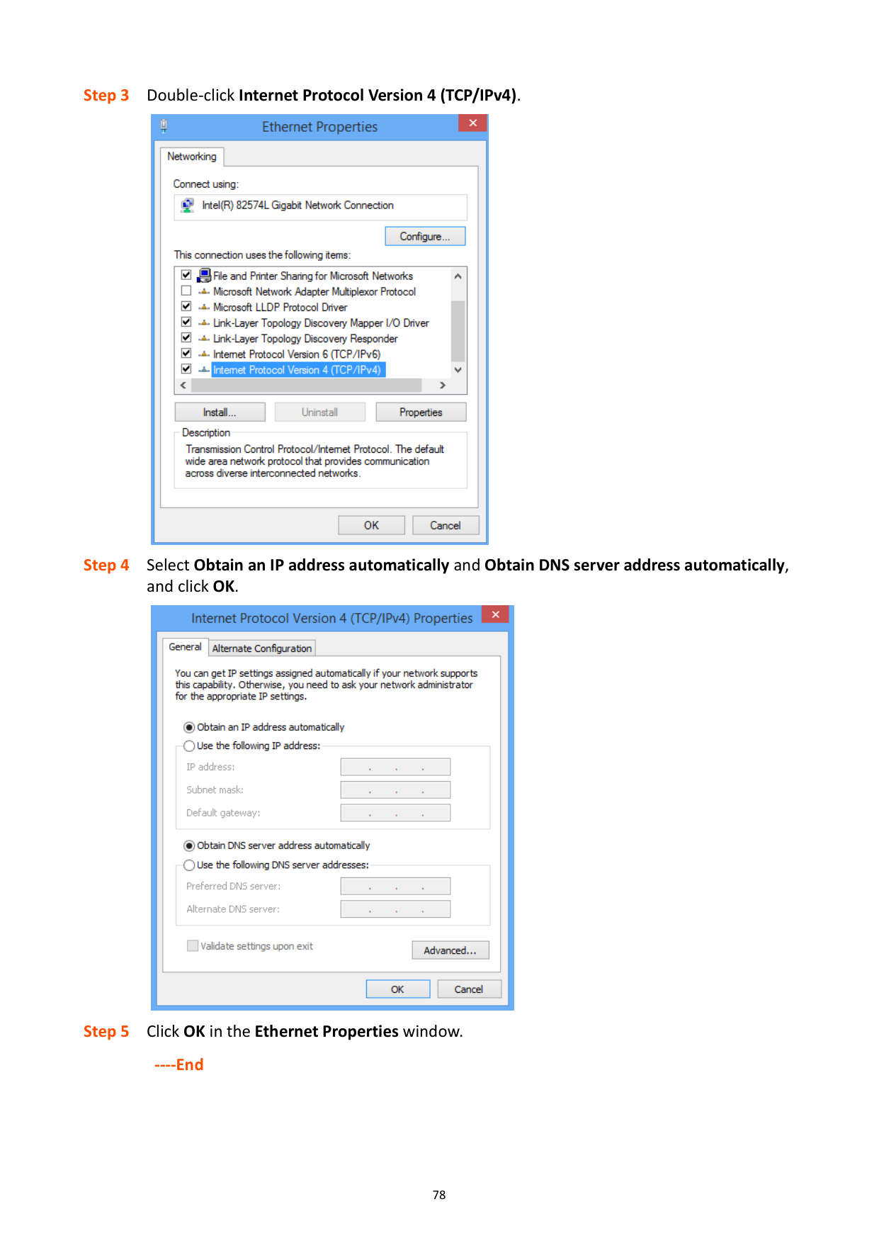
#### A.1.1 Windows 8

|| |---|


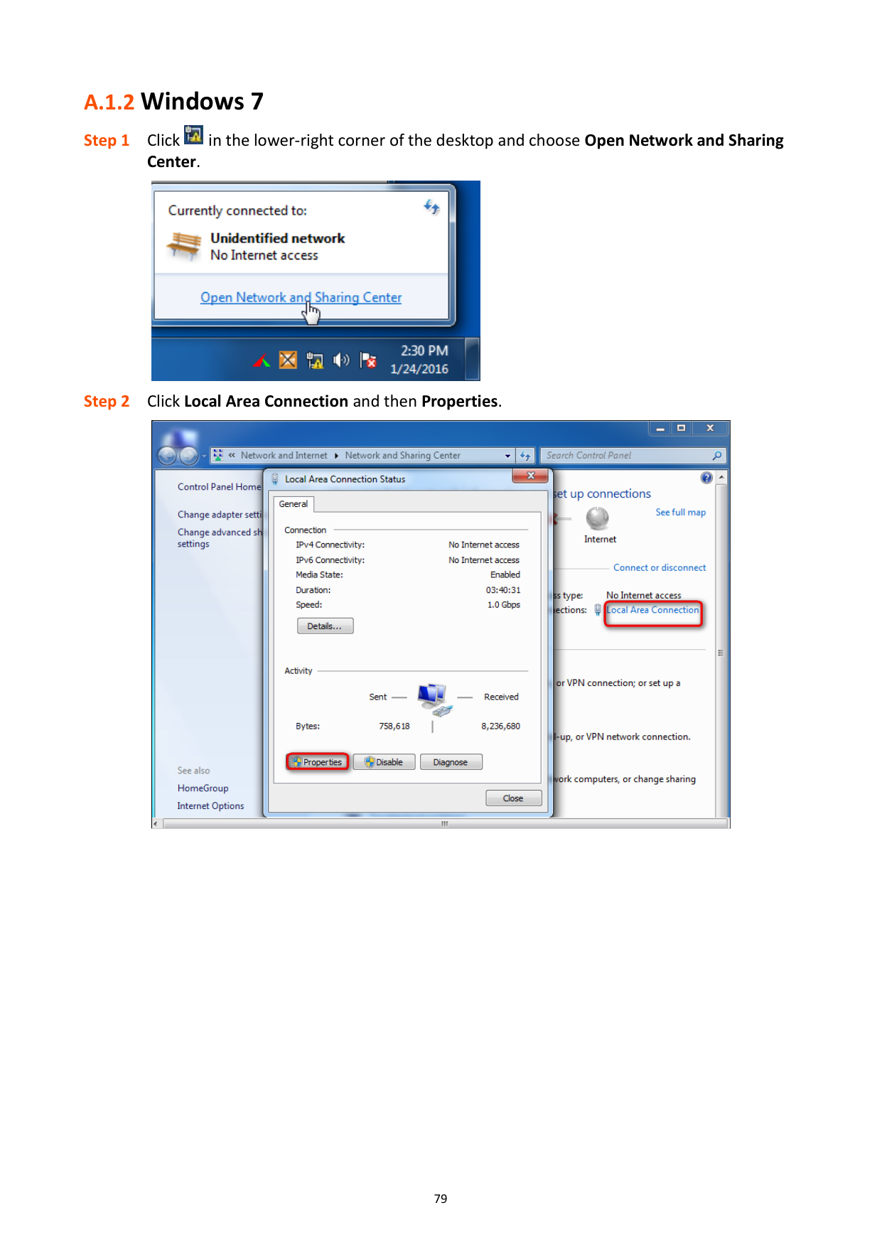
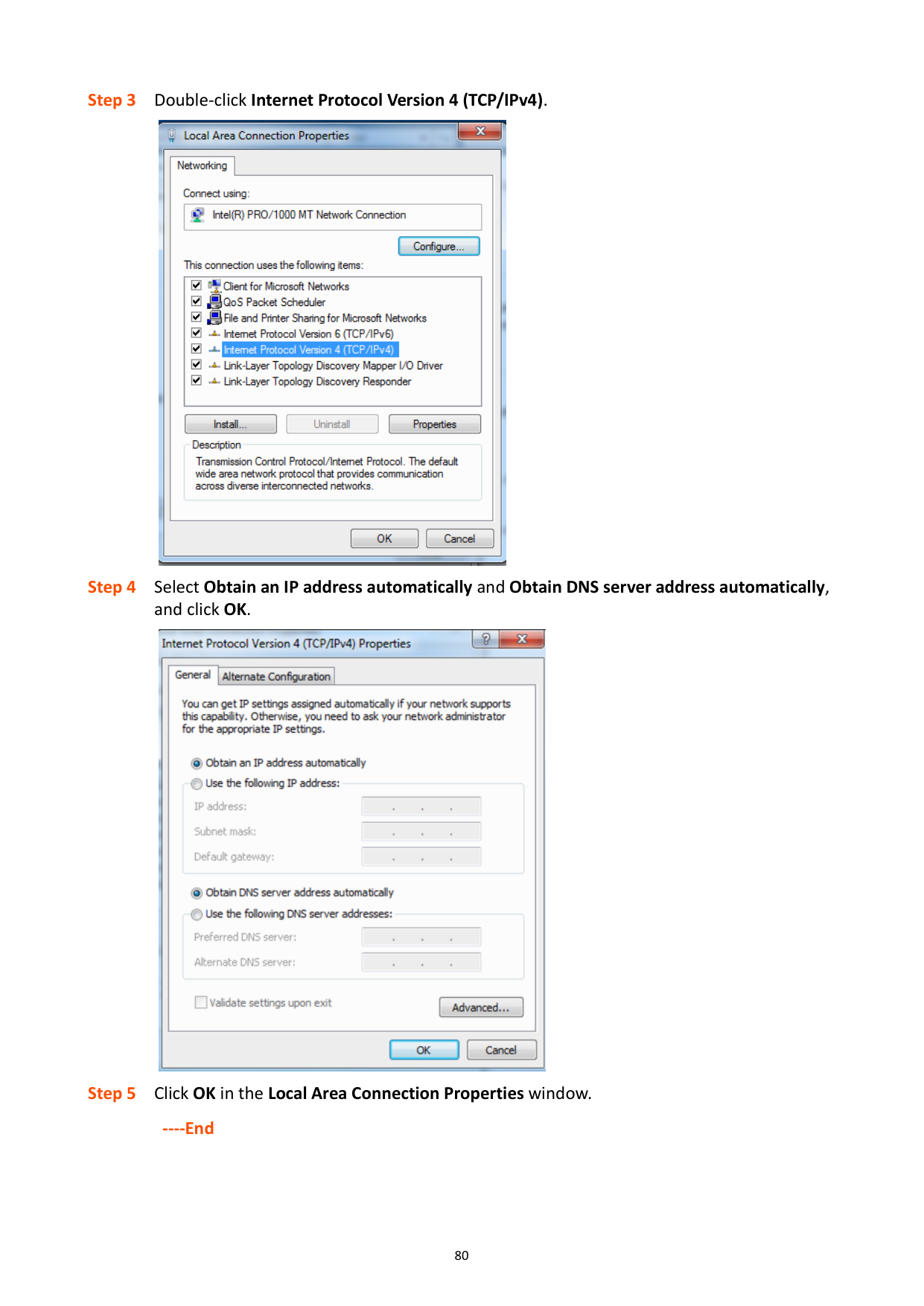
#### A.1.2 Windows 7


|| |---|


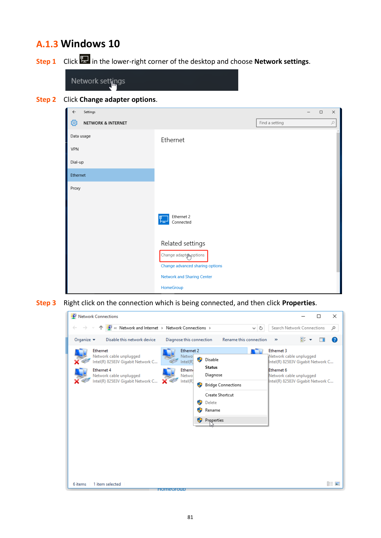
#### A.1.3 Windows 10


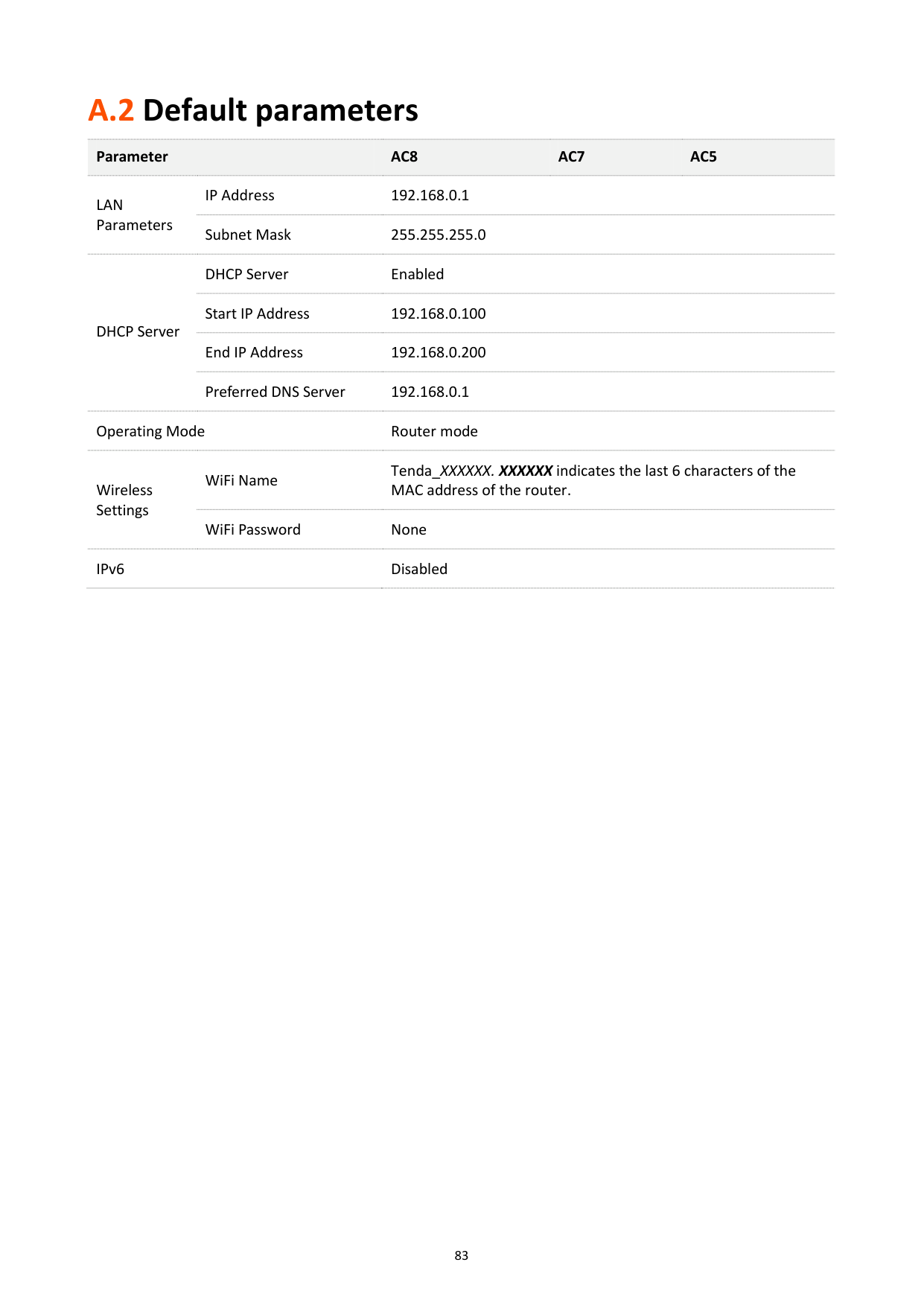
A.2 Default parameters
########## Parameter AC8 AC7 AC5
LAN Parameters
IP Address 192.168.0.1 Subnet Mask 255.255.255.0
DHCP Server
DHCP Server Enabled Start IP Address 192.168.0.100 End IP Address 192.168.0.200 Preferred DNS Server 192.168.0.1
Operating Mode Router mode
Tenda_XXXXXX. XXXXXX indicates the last 6 characters of the MAC address of the router.
WiFi Name
Wireless Settings
WiFi Password None IPv6 Disabled