Ask AI
— answers from the official manualAnswers from the official manual.
Common questions
Common Questions
20 totalHow long does assembly of the Weider 8630 take, and do I need a second person?
Assembly requires about six hours and should be done with the help of another person for convenience and safety. The manual suggests you may want to spread the assembly over a couple of evenings. The process is divided into four stages: frame assembly, arm assembly, cable assembly, and seat assembly. (Page 5)
What tools do I need to assemble the Weider 8630?
You will need two adjustable wrenches, one standard screwdriver, one phillips screwdriver, and one rubber mallet. You will also need grease or petroleum jelly, a small amount of soapy water, and clear tape or masking tape. A socket set or set of open-end or ratchet wrenches will make assembly more convenient. (Page 5)
What are the assembled dimensions of the Weider 8630?
The assembled dimensions of the Weider 8630 are 78 inches in height, 64 inches in width, and 70 inches in length. Make sure you have adequate space in your chosen location before beginning assembly. (Page 4)
How do I change the weight setting on the Weider 8630?
Insert a Weight Pin (93) under the desired Weight (90), pushing it in until the bent end touches the weights, then turn the bent end downward. The weight setting can be changed from 6.5 pounds to 106.5 pounds in increments of 12.5 pounds. Note that due to cables and pulleys, the actual resistance at each station may vary from the weight setting — refer to the Weight Resistance Chart on page 24. (Page 22)
How do I attach the lat bar to the high pulley station?
Attach the Lat Bar (36) to the High Cable (85) using a Cable Clip (33). For some exercises, the Chain (34) should be attached between the lat bar and the high cable using two cable clips, with the chain length adjusted so the lat bar is in the correct starting position. The Nylon Strap (96) can be attached in the same manner. (Page 22)
How do I adjust the leg press plate position?
Remove the Lock Pin (73) from the Adjustment Tube (10), then align the holes in the Leg Press Arm (9) with the desired set of holes in the Adjustment Tube (10). Re-insert the Lock Pin through the holes and make sure the hook on the Lock Pin is clipped in place on the Adjustment Tube. Always ensure the lock pin is fully inserted and clipped before use. (Page 23)
Show 14 more questions
What should I do if there is slack in the cables before resistance is felt?
What should I do if a cable keeps slipping off the pulleys?
What is the warranty on the Weider 8630?
How do I assemble the adjustment tube for the Leg Press Plate?
What cable diagram resources are available for assembly?
How do I clean the equipment without damaging it?
How do I fix an improperly routed cable?
How do I attach a lat bar or nylon strap at the high pulley station?
How do I disassemble the weights correctly?
How do I install the cable traps?
How do I order replacement parts for the Weider 8630?
How do I adjust the weight setting on the WEIDER 8630?
What should I do if a cable becomes slack when using the resistance machine?
How do I attach the seat frame to the upright?
Full Manual
36 pages
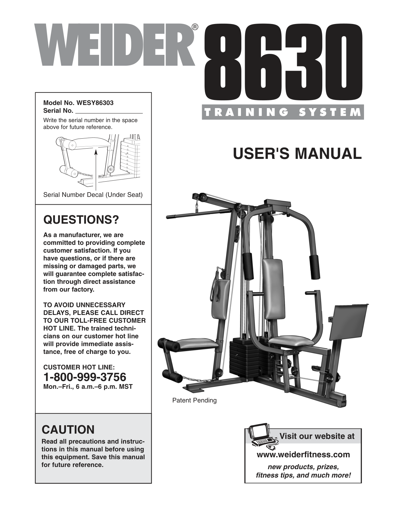
User'S Manual
Questions?
As a manufacturer, we are committed to providing complete customer satisfaction. If you have questions, or if there are missing or damaged parts, we will guarantee complete satisfac- tion through direct assistance from our factory.To Avoid Unnecessary
Delays, Please Call Direct
To Our Toll-Free Customer
HOT LINE. The trained techni- cians on our customer hot line will provide immediate assis- tance, free of charge to you.Customer Hot Line:
1-800-999-3756 Mon.–Fri., 6 a.m.–6 p.m. MST Model No. WESY86303 Serial No. Write the serial number in the space above for future reference. Patent PendingCaution
Read all precautions and instruc- tions in this manual before using this equipment. Save this manual for future reference. Serial Number Decal (Under Seat) Visit our website at www.weiderfitness.com new products, prizes, fitness tips, and much more!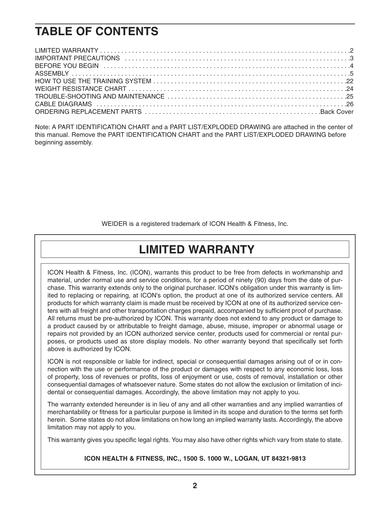
2
Table Of Contents
LIMITED WARRANTY . . . . . . . . . . . . . . . . . . . . . . . . . . . . . . . . . . . . . . . . . . . . . . . . . . . . . . . . . . . . . . . . . . . . . . .2 IMPORTANT PRECAUTIONS . . . . . . . . . . . . . . . . . . . . . . . . . . . . . . . . . . . . . . . . . . . . . . . . . . . . . . . . . . . . . . . .3 BEFORE YOU BEGIN . . . . . . . . . . . . . . . . . . . . . . . . . . . . . . . . . . . . . . . . . . . . . . . . . . . . . . . . . . . . . . . . . . . . . .4 ASSEMBLY . . . . . . . . . . . . . . . . . . . . . . . . . . . . . . . . . . . . . . . . . . . . . . . . . . . . . . . . . . . . . . . . . . . . . . . . . . . . . . .5 HOW TO USE THE TRAINING SYSTEM . . . . . . . . . . . . . . . . . . . . . . . . . . . . . . . . . . . . . . . . . . . . . . . . . . . . . . .22 WEIGHT RESISTANCE CHART . . . . . . . . . . . . . . . . . . . . . . . . . . . . . . . . . . . . . . . . . . . . . . . . . . . . . . . . . . . . . .24 TROUBLE-SHOOTING AND MAINTENANCE . . . . . . . . . . . . . . . . . . . . . . . . . . . . . . . . . . . . . . . . . . . . . . . . . . .25 CABLE DIAGRAMS . . . . . . . . . . . . . . . . . . . . . . . . . . . . . . . . . . . . . . . . . . . . . . . . . . . . . . . . . . . . . . . . . . . . . . .26 ORDERING REPLACEMENT PARTS . . . . . . . . . . . . . . . . . . . . . . . . . . . . . . . . . . . . . . . . . . . . . . . . . .Back Cover Note: A PART IDENTIFICATION CHART and a PART LIST/EXPLODED DRAWING are attached in the center of this manual. Remove the PART IDENTIFICATION CHART and the PART LIST/EXPLODED DRAWING before beginning assembly. WEIDER is a registered trademark of ICON Health & Fitness, Inc.Limited Warranty
ICON Health & Fitness, Inc. (ICON), warrants this product to be free from defects in workmanship and material, under normal use and service conditions, for a period of ninety (90) days from the date of pur- chase. This warranty extends only to the original purchaser. ICON's obligation under this warranty is lim- ited to replacing or repairing, at ICON's option, the product at one of its authorized service centers. All products for which warranty claim is made must be received by ICON at one of its authorized service cen- ters with all freight and other transportation charges prepaid, accompanied by sufficient proof of purchase. All returns must be pre-authorized by ICON. This warranty does not extend to any product or damage to a product caused by or attributable to freight damage, abuse, misuse, improper or abnormal usage or repairs not provided by an ICON authorized service center, products used for commercial or rental pur- poses, or products used as store display models. No other warranty beyond that specifically set forth above is authorized by ICON. ICON is not responsible or liable for indirect, special or consequential damages arising out of or in con- nection with the use or performance of the product or damages with respect to any economic loss, loss of property, loss of revenues or profits, loss of enjoyment or use, costs of removal, installation or other consequential damages of whatsoever nature. Some states do not allow the exclusion or limitation of inci- dental or consequential damages. Accordingly, the above limitation may not apply to you. The warranty extended hereunder is in lieu of any and all other warranties and any implied warranties of merchantability or fitness for a particular purpose is limited in its scope and duration to the terms set forth herein. Some states do not allow limitations on how long an implied warranty lasts. Accordingly, the above limitation may not apply to you. This warranty gives you specific legal rights. You may also have other rights which vary from state to state.Icon Health & Fitness, Inc., 1500 S. 1000 W., Logan, Ut 84321-9813
3
Important Precautions
WARNING: To reduce the risk of serious injury, read the following important precautions before using the training system.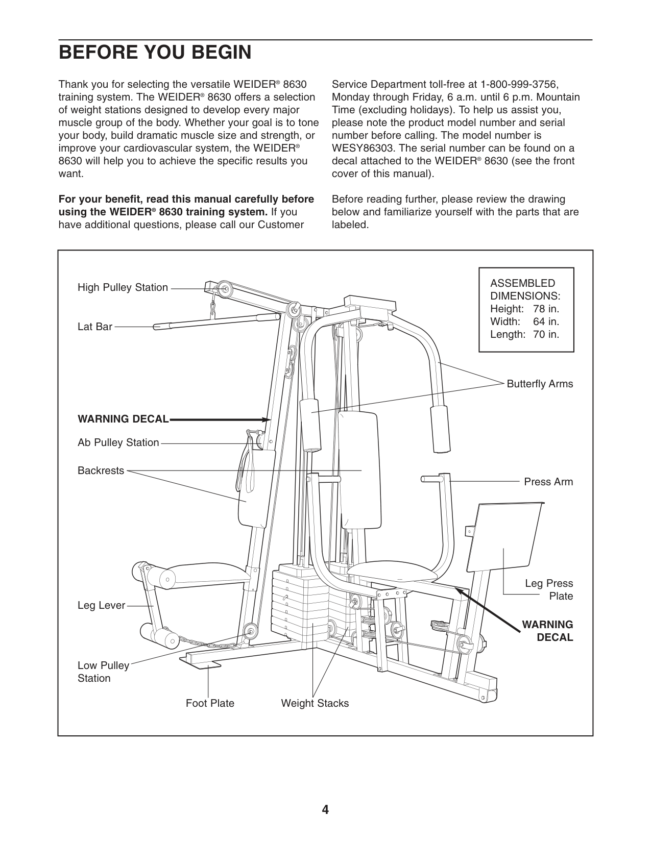
4
Before You Begin
Assembled
Dimensions:
Height: 78 in. Width: 64 in. Length: 70 in. Foot Plate Low Pulley Station High Pulley Station Lat Bar Leg Lever Butterfly Arms Press Arm Weight Stacks Backrests Leg Press Plate Ab Pulley StationWarning Decal
Warning
Decal
Thank you for selecting the versatile WEIDER® 8630 training system. The WEIDER® 8630 offers a selection of weight stations designed to develop every major muscle group of the body. Whether your goal is to tone your body, build dramatic muscle size and strength, or improve your cardiovascular system, the WEIDER® 8630 will help you to achieve the specific results you want. For your benefit, read this manual carefully before using the WEIDER® 8630 training system. If you have additional questions, please call our Customer Service Department toll-free at 1-800-999-3756, Monday through Friday, 6 a.m. until 6 p.m. Mountain Time (excluding holidays). To help us assist you, please note the product model number and serial number before calling. The model number is WESY86303. The serial number can be found on a decal attached to the WEIDER® 8630 (see the front cover of this manual). Before reading further, please review the drawing below and familiarize yourself with the parts that are labeled.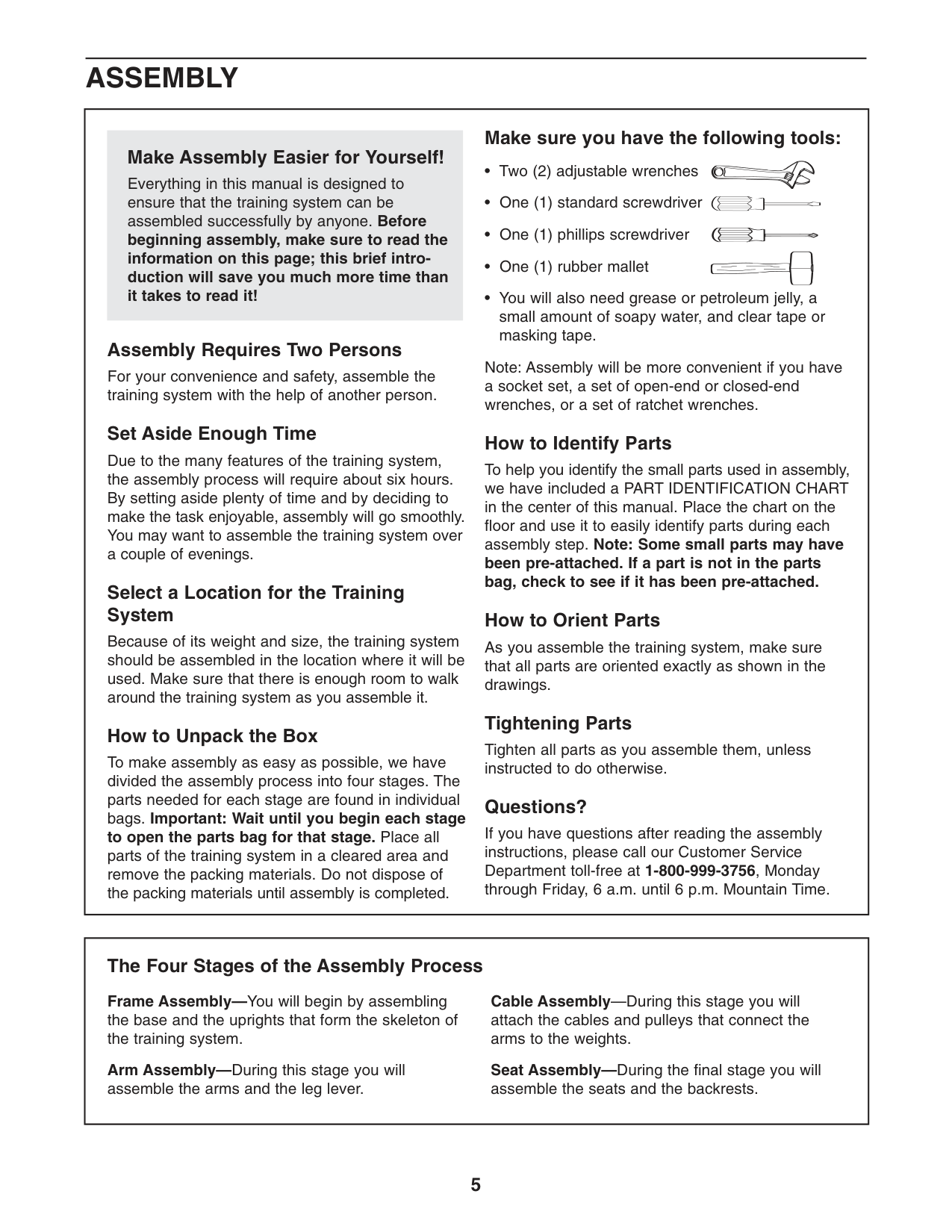
5
Assembly
Make sure you have the following tools: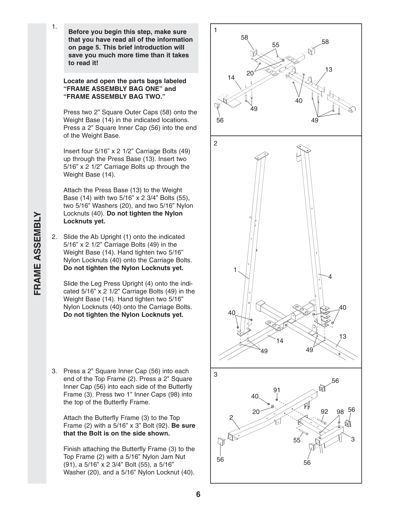
“Frame Assembly Bag Two.”
Press two 2” Square Outer Caps (58) onto the Weight Base (14) in the indicated locations. Press a 2” Square Inner Cap (56) into the end of the Weight Base. Insert four 5/16” x 2 1/2” Carriage Bolts (49) up through the Press Base (13). Insert two 5/16” x 2 1/2” Carriage Bolts up through the Weight Base (14). Attach the Press Base (13) to the Weight Base (14) with two 5/16” x 2 3/4” Bolts (55), two 5/16” Washers (20), and two 5/16” Nylon Locknuts (40). Do not tighten the Nylon Locknuts yet.Frame Assembly
6 1 4 40 40 49 49 13 2 3 14 55 40 20 56 56 56 56 92 98 91 1 56 58 58 55 20 49 40 49 13 14 Before you begin this step, make sure that you have read all of the information on page 5. This brief introduction will save you much more time than it takes to read it!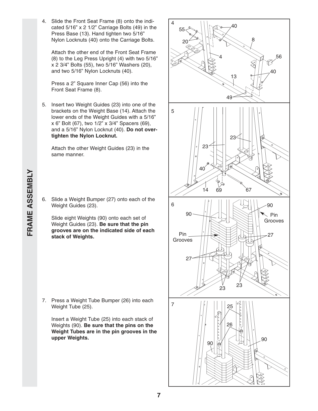
Frame Assembly
90 90 Pin Grooves 27 27 23 23 26 25 Pin Grooves 90 90 5 67 69 23 23 40 14 4 55 20 49 40 56 8 40 4 13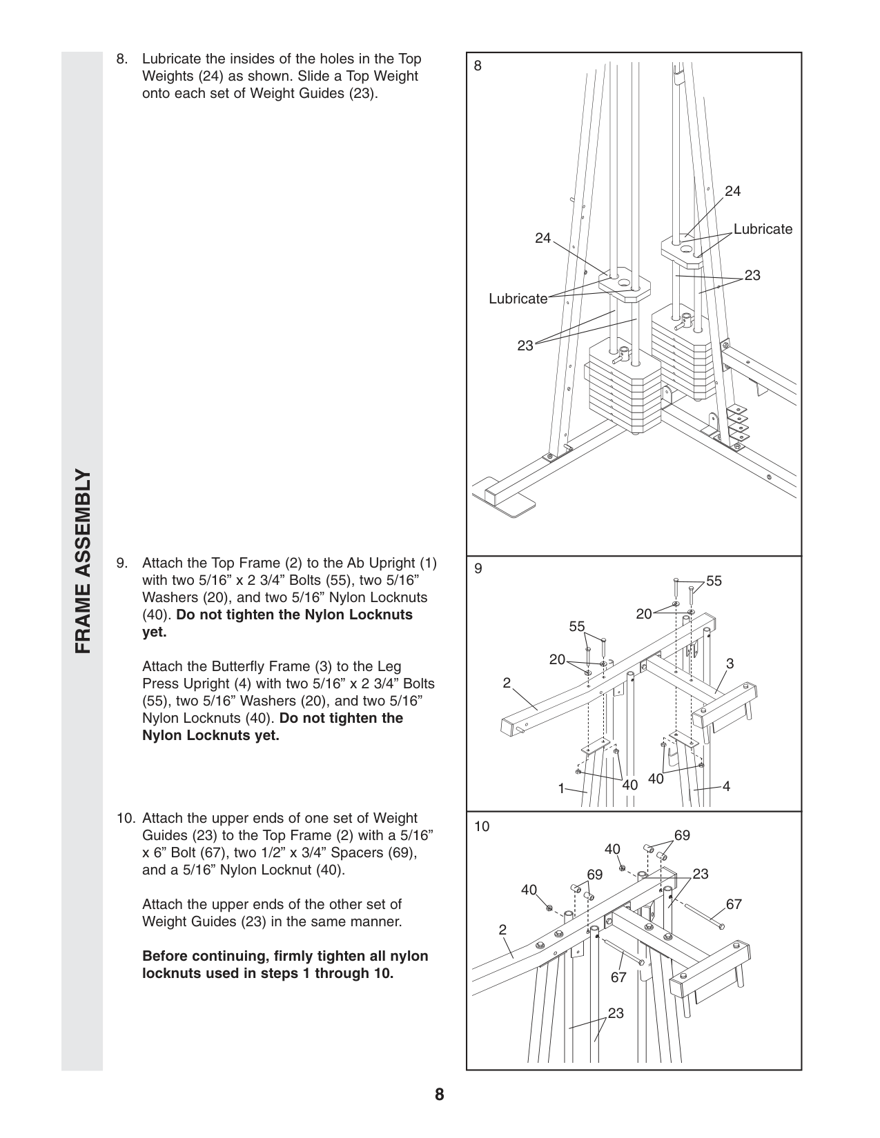
Frame Assembly
23 Lubricate Lubricate 23 23 69 40 67 67 40 2 69 24 24 23 9 55 55 20 20 40 40 4 3 2 1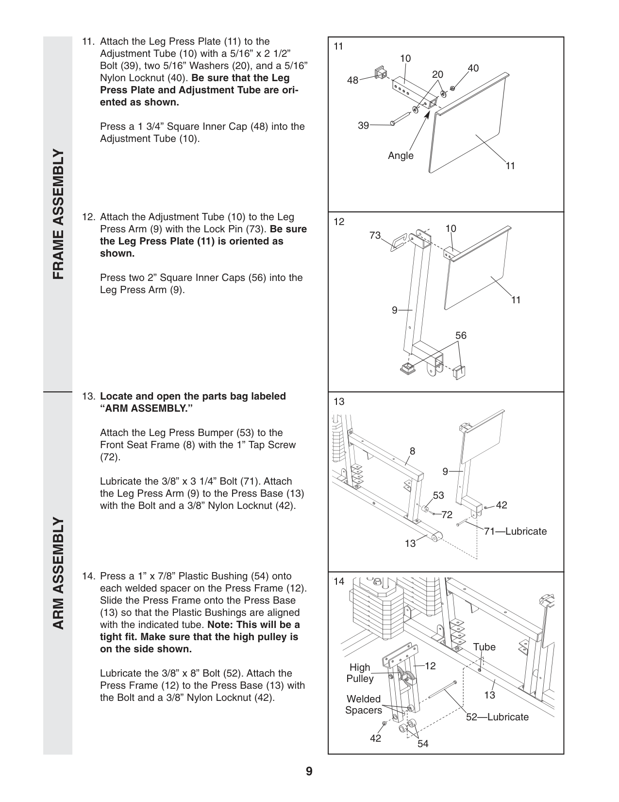
“Arm Assembly.”
Attach the Leg Press Bumper (53) to the Front Seat Frame (8) with the 1” Tap Screw (72). Lubricate the 3/8” x 3 1/4” Bolt (71). Attach the Leg Press Arm (9) to the Press Base (13) with the Bolt and a 3/8” Nylon Locknut (42).Arm Assembly
20 40 39 Angle 10 48 11 56 42 71—Lubricate 53 72 13 54 42 12 13 11 9 9 8 10 73 52—Lubricate Tube Welded Spacers High PulleyFrame Assembly
10
Arm Assembly
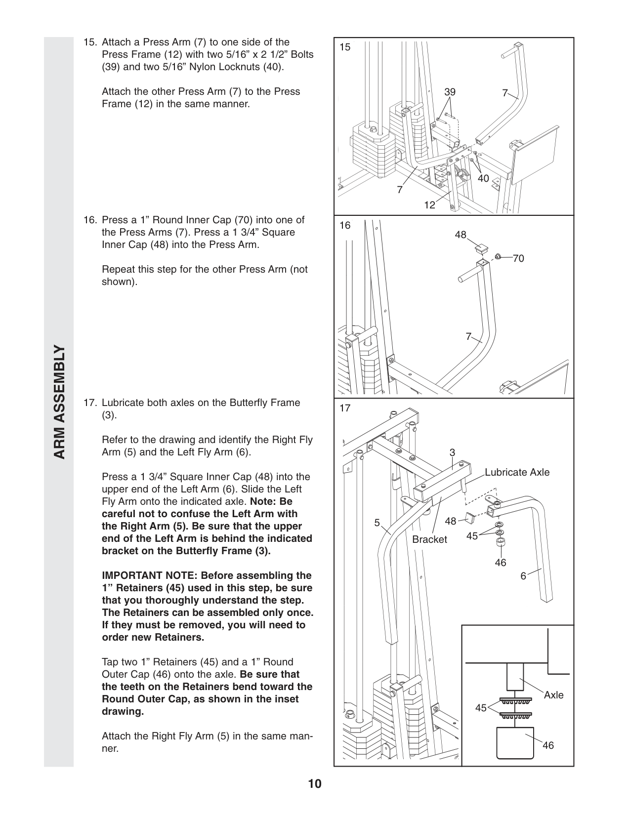
39 7 70 40 48 12 7 7 3 Lubricate Axle Axle 6 5 45 48 46 Bracket 45 46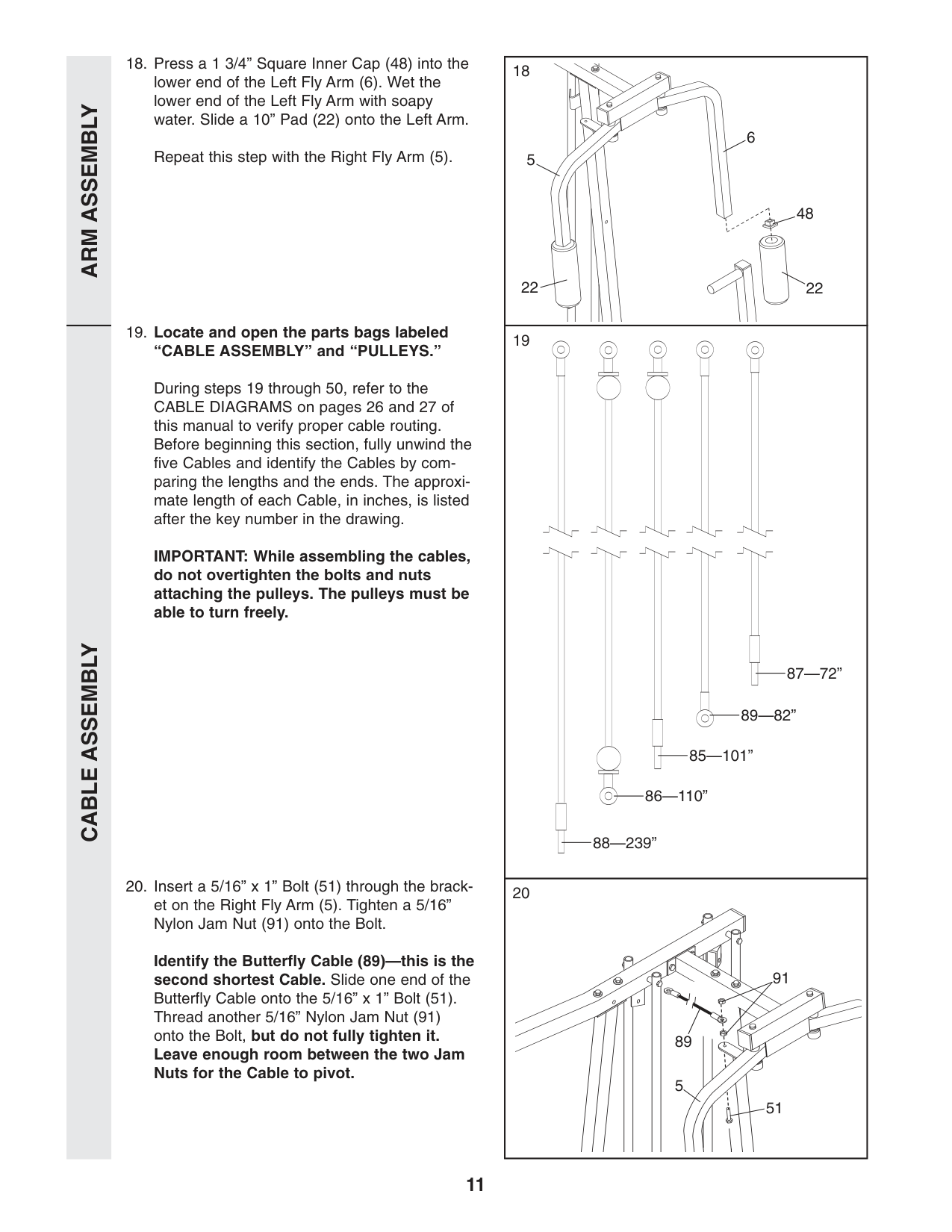
11
Cable Assembly
Arm Assembly
5 6 48 22 88—239” 51 5 91 89 22 86—110” 85—101” 89—82” 87—72”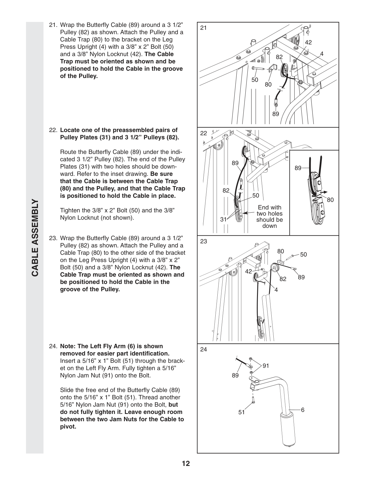
12
Cable Assembly
6 End with two holes should be down 82 31 4 89 82 50 80 4 42 89 82 50 80 89 89 50 80 51 91 89 42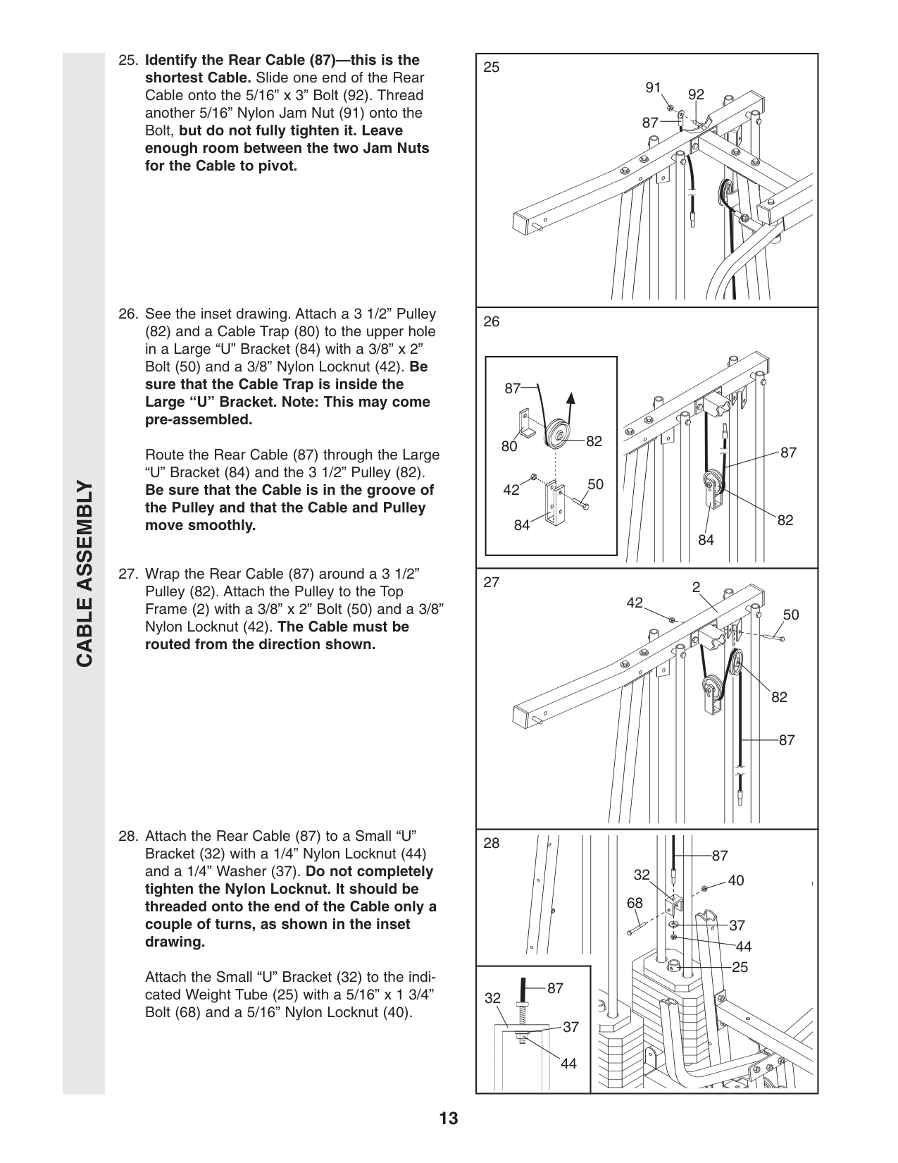
13
Cable Assembly
92 91 87 87 80 42 84 50 82 82 82 50 42 37 44 25 32 68 2 87 84 87 87 40 87 44 32 37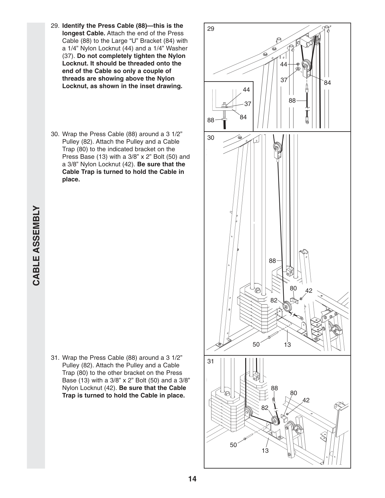
14
Cable Assembly
88 37 84 44 88 50 13 82 80 42 50 88 82 80 42 13 44 37 84 88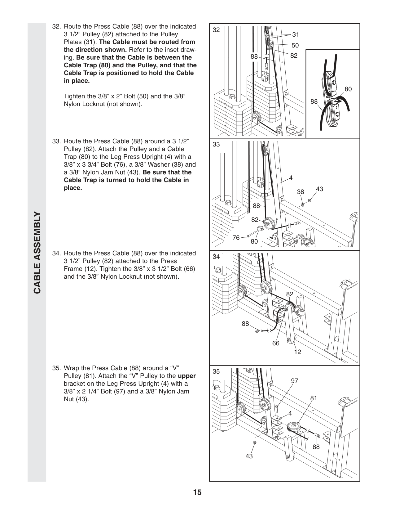
15
Cable Assembly
32 31 82 50 88 80 88 82 88 88 66 12 82 88 81 4 97 43 38 43 4 80 76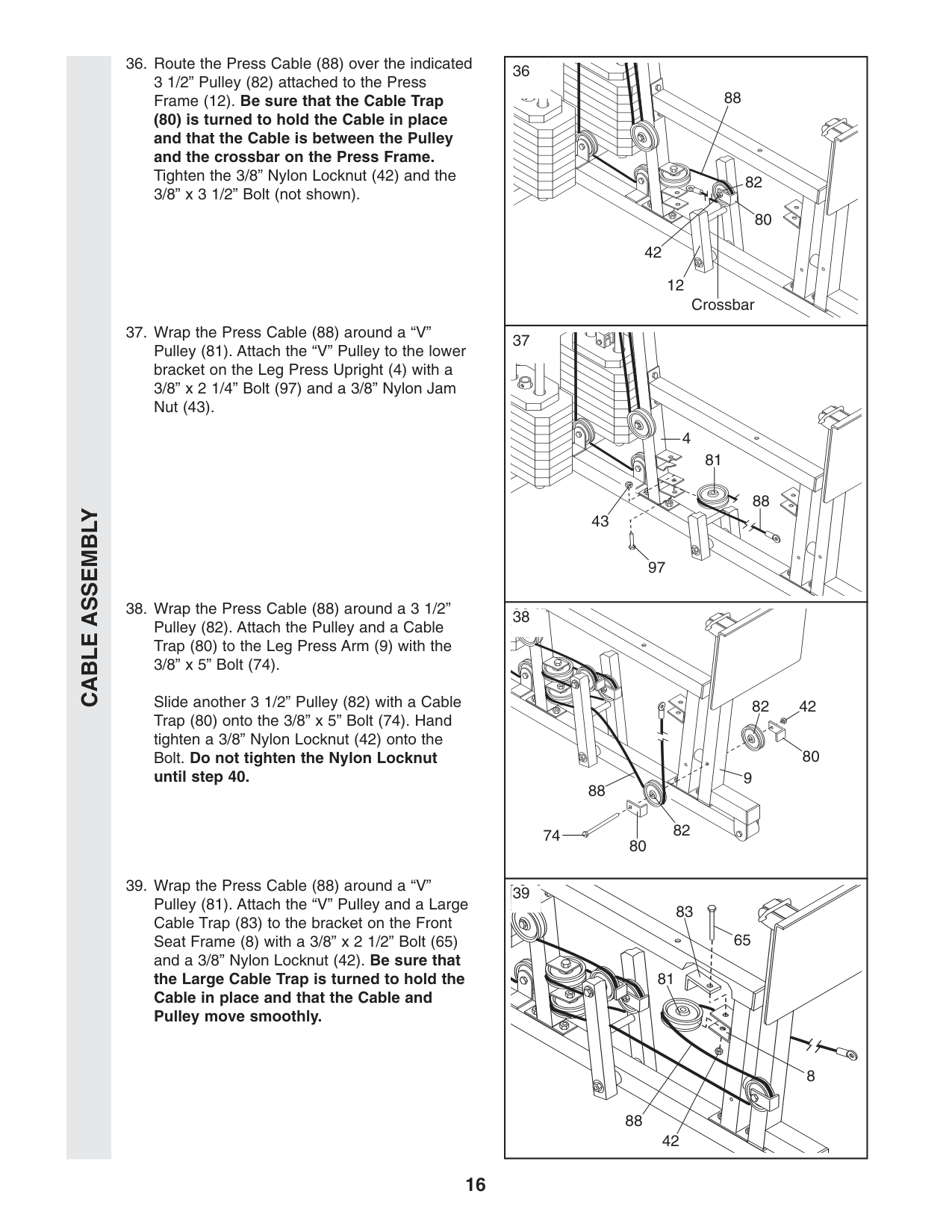
16
Cable Assembly
83 65 81 88 42 8 88 42 12 Crossbar 82 80 42 82 82 9 80 80 74 88 88 81 4 97 43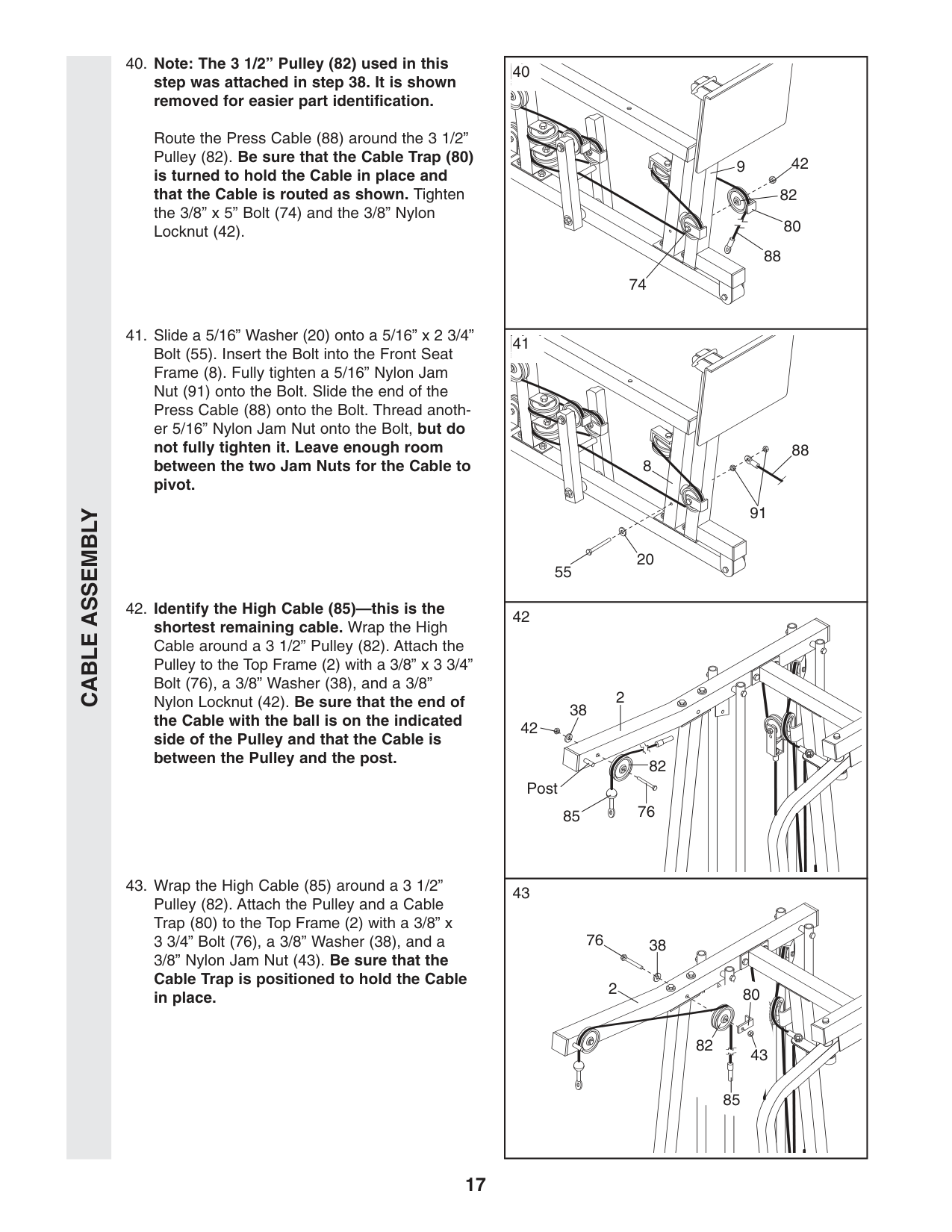
17
Cable Assembly
42 38 2 76 82 85 Post 85 80 38 76 2 82 43 40 9 82 42 80 88 91 8 88 20 55 74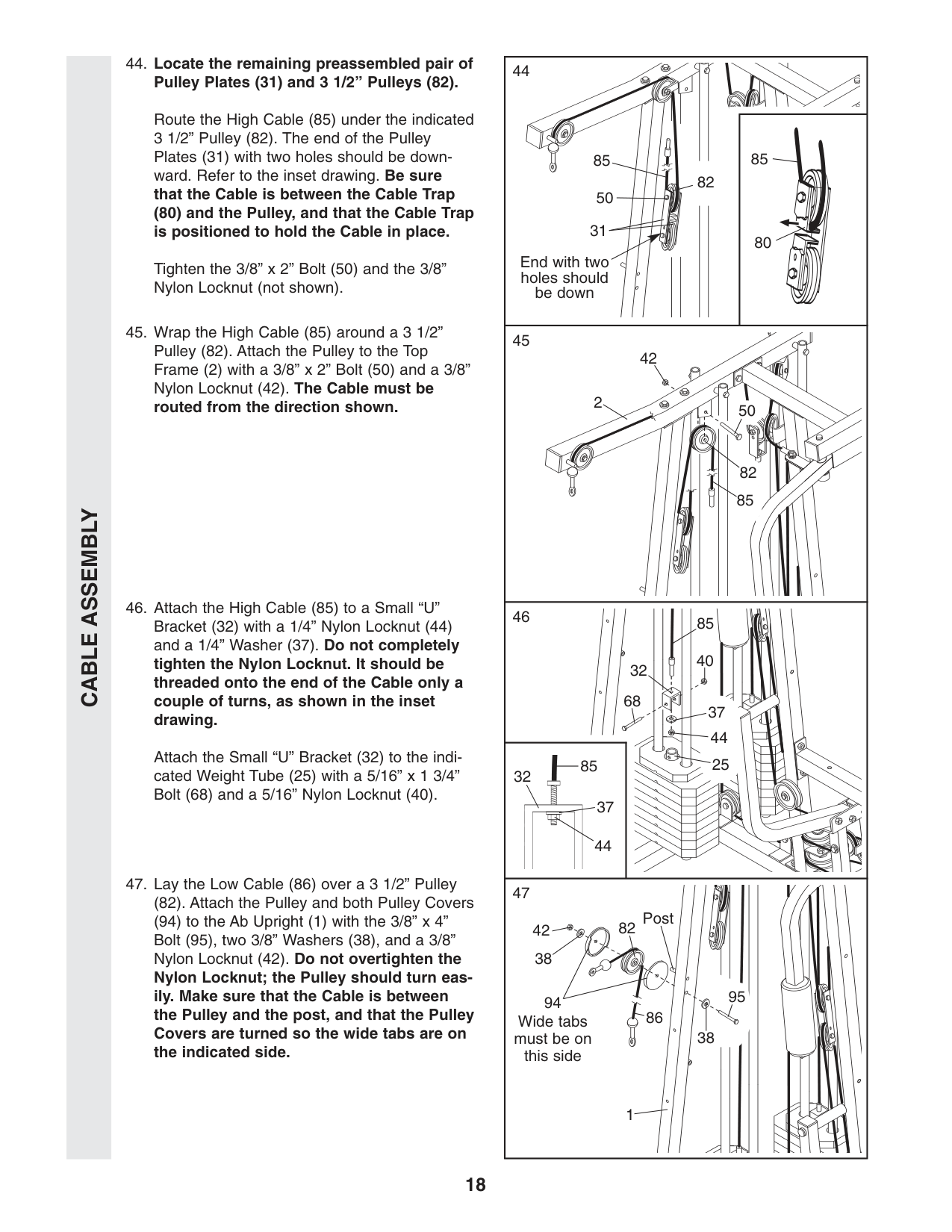
18
Cable Assembly
85 85 80 50 31 42 Post 1 86 Wide tabs must be on this side 38 38 95 94 82 End with two holes should be down 50 82 2 42 32 68 85 40 37 44 25 85 44 32 37 82 85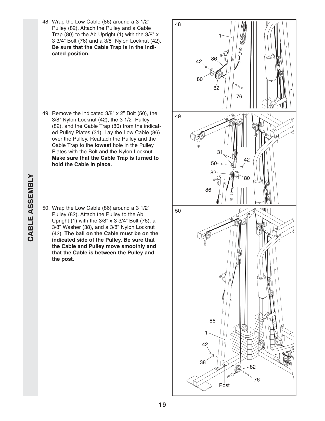
19
Cable Assembly
42 31 42 82 80 50 80 82 86 76 1 42 38 82 76 Post 86 1 86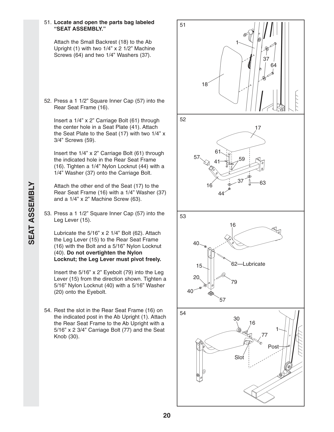
“Seat Assembly.”
Attach the Small Backrest (18) to the Ab Upright (1) with two 1/4” x 2 1/2” Machine Screws (64) and two 1/4” Washers (37).Seat Assembly
Slot 44 63 17 16 57 41 61 59 1 18 Post 1 77 16 30 16 62—Lubricate 57 40 20 40 15 79 37 64 37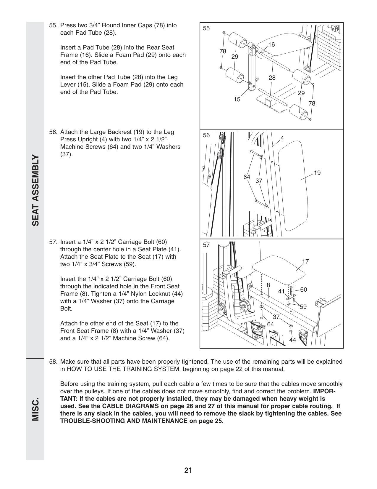
55 56 57
Seat Assembly
Misc.
21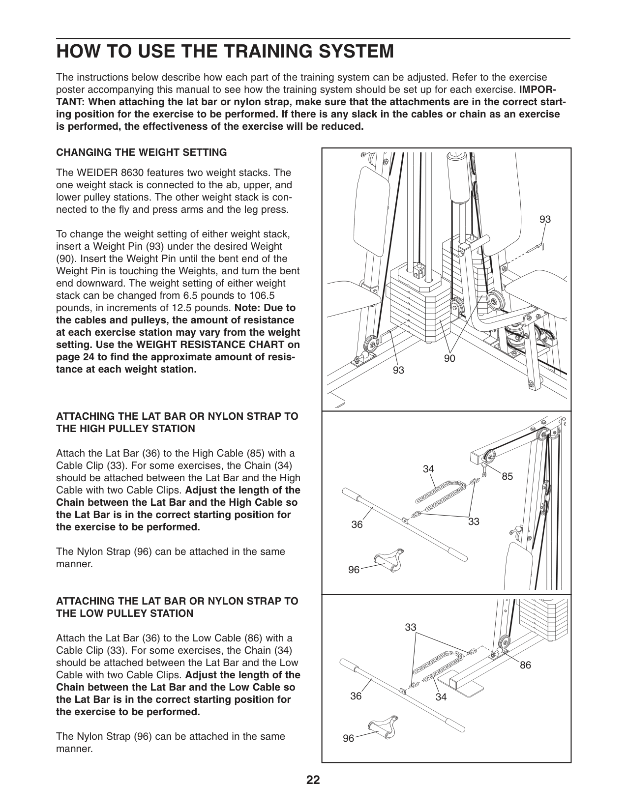
22
How To Use The Training System
The instructions below describe how each part of the training system can be adjusted. Refer to the exercise poster accompanying this manual to see how the training system should be set up for each exercise. IMPOR- TANT: When attaching the lat bar or nylon strap, make sure that the attachments are in the correct start- ing position for the exercise to be performed. If there is any slack in the cables or chain as an exercise is performed, the effectiveness of the exercise will be reduced. 96 85 33 34 36 93 93 90Changing The Weight Setting
The WEIDER 8630 features two weight stacks. The one weight stack is connected to the ab, upper, and lower pulley stations. The other weight stack is con- nected to the fly and press arms and the leg press. To change the weight setting of either weight stack, insert a Weight Pin (93) under the desired Weight (90). Insert the Weight Pin until the bent end of the Weight Pin is touching the Weights, and turn the bent end downward. The weight setting of either weight stack can be changed from 6.5 pounds to 106.5 pounds, in increments of 12.5 pounds. Note: Due to the cables and pulleys, the amount of resistance at each exercise station may vary from the weight setting. Use the WEIGHT RESISTANCE CHART on page 24 to find the approximate amount of resis- tance at each weight station.Attaching The Lat Bar Or Nylon Strap To
The High Pulley Station
Attach the Lat Bar (36) to the High Cable (85) with a Cable Clip (33). For some exercises, the Chain (34) should be attached between the Lat Bar and the High Cable with two Cable Clips. Adjust the length of the Chain between the Lat Bar and the High Cable so the Lat Bar is in the correct starting position for the exercise to be performed. The Nylon Strap (96) can be attached in the same manner.Attaching The Lat Bar Or Nylon Strap To
The Low Pulley Station
Attach the Lat Bar (36) to the Low Cable (86) with a Cable Clip (33). For some exercises, the Chain (34) should be attached between the Lat Bar and the Low Cable with two Cable Clips. Adjust the length of the Chain between the Lat Bar and the Low Cable so the Lat Bar is in the correct starting position for the exercise to be performed. The Nylon Strap (96) can be attached in the same manner. 96 86 33 34 36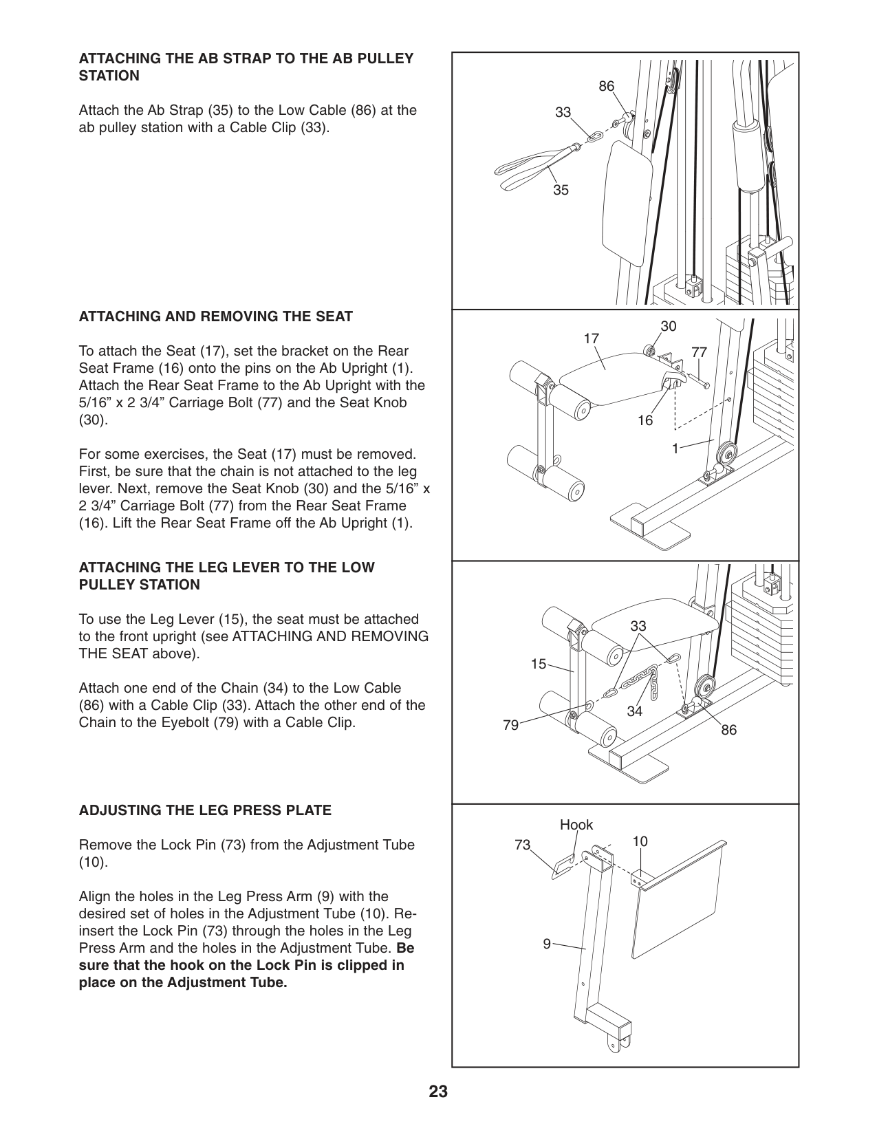
23
Attaching The Ab Strap To The Ab Pulley
Station
Attach the Ab Strap (35) to the Low Cable (86) at the ab pulley station with a Cable Clip (33).Attaching And Removing The Seat
To attach the Seat (17), set the bracket on the Rear Seat Frame (16) onto the pins on the Ab Upright (1). Attach the Rear Seat Frame to the Ab Upright with the 5/16” x 2 3/4” Carriage Bolt (77) and the Seat Knob (30). For some exercises, the Seat (17) must be removed. First, be sure that the chain is not attached to the leg lever. Next, remove the Seat Knob (30) and the 5/16” x 2 3/4” Carriage Bolt (77) from the Rear Seat Frame (16). Lift the Rear Seat Frame off the Ab Upright (1).Attaching The Leg Lever To The Low
Pulley Station
To use the Leg Lever (15), the seat must be attached to the front upright (see ATTACHING AND REMOVING THE SEAT above). Attach one end of the Chain (34) to the Low Cable (86) with a Cable Clip (33). Attach the other end of the Chain to the Eyebolt (79) with a Cable Clip.Adjusting The Leg Press Plate
Remove the Lock Pin (73) from the Adjustment Tube (10). Align the holes in the Leg Press Arm (9) with the desired set of holes in the Adjustment Tube (10). Re- insert the Lock Pin (73) through the holes in the Leg Press Arm and the holes in the Adjustment Tube. Be sure that the hook on the Lock Pin is clipped in place on the Adjustment Tube. 17 30 1 15 79 86 10 9 73 Hook 33 34 77 16 86 33 35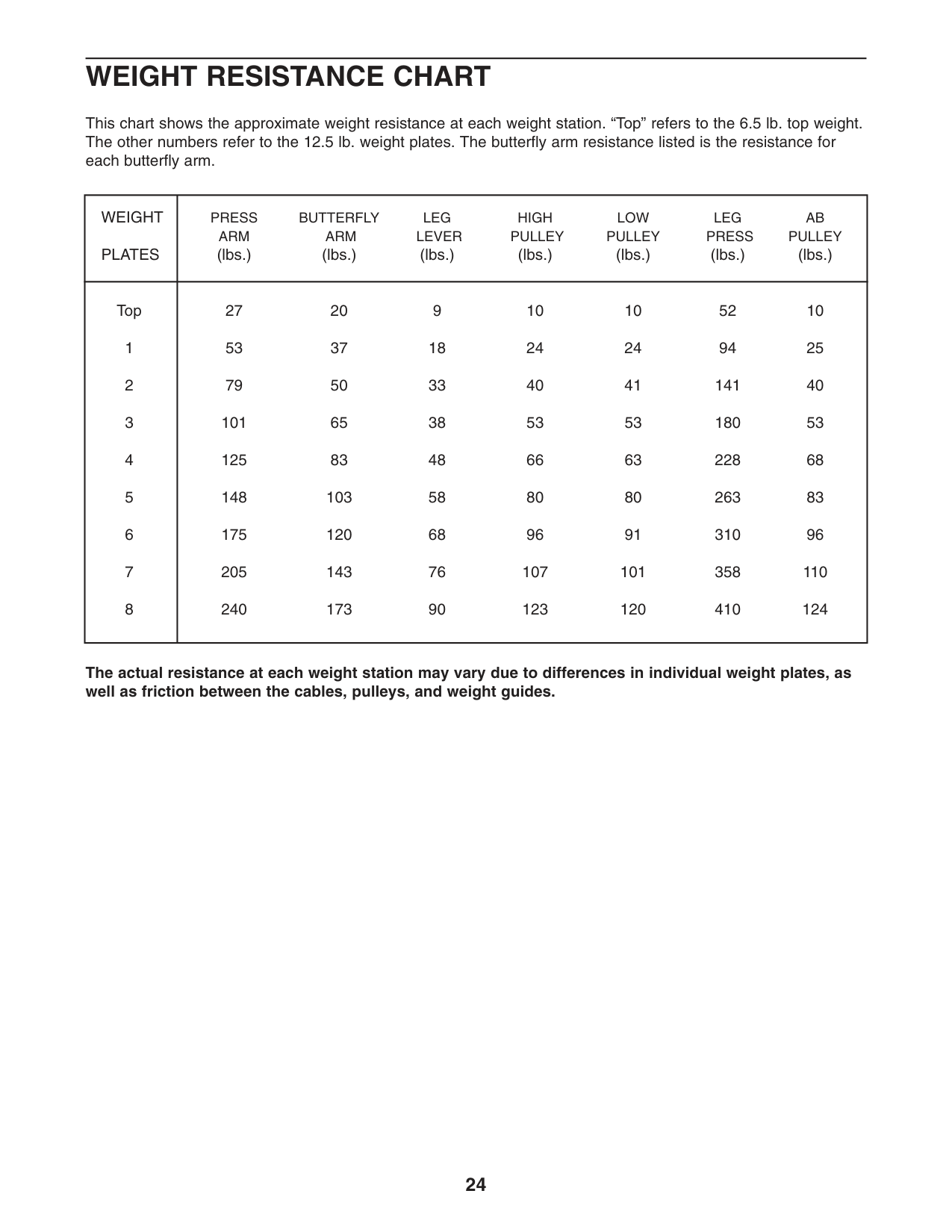
24
Weight Resistance Chart
This chart shows the approximate weight resistance at each weight station. “Top” refers to the 6.5 lb. top weight. The other numbers refer to the 12.5 lb. weight plates. The butterfly arm resistance listed is the resistance for each butterfly arm.Weight
Press
Butterfly
Leg
High
Low
Leg
Ab
Arm
Arm
Lever
Pulley
Pulley
Press
Pulley
Plates
(lbs.) (lbs.) (lbs.) (lbs.) (lbs.) (lbs.) (lbs.) Top 27 20 9 10 10 52 10 1 53 37 18 24 24 94 25 2 79 50 33 40 41 141 40 3 101 65 38 53 53 180 53 4 125 83 48 66 63 228 68 5 148 103 58 80 80 263 83 6 175 120 68 96 91 310 96 7 205 143 76 107 101 358 110 8 240 173 90 123 120 410 124 The actual resistance at each weight station may vary due to differences in individual weight plates, as well as friction between the cables, pulleys, and weight guides.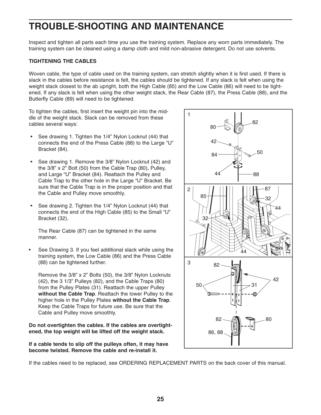
Trouble-Shooting And Maintenance
Inspect and tighten all parts each time you use the training system. Replace any worn parts immediately. The training system can be cleaned using a damp cloth and mild non-abrasive detergent. Do not use solvents.Tightening The Cables
Woven cable, the type of cable used on the training system, can stretch slightly when it is first used. If there is slack in the cables before resistance is felt, the cables should be tightened. If any slack is felt when using the weight stack closest to the ab upright, both the High Cable (85) and the Low Cable (86) will need to be tight- ened. If any slack is felt when using the other weight stack, the Rear Cable (87), the Press Cable (88), and the Butterfly Cable (89) will need to be tightened. To tighten the cables, first insert the weight pin into the mid- dle of the weight stack. Slack can be removed from these cables several ways: • See drawing 1. Tighten the 1/4” Nylon Locknut (44) that connects the end of the Press Cable (88) to the Large “U” Bracket (84). • See drawing 1. Remove the 3/8” Nylon Locknut (42) and the 3/8” x 2” Bolt (50) from the Cable Trap (80), Pulley, and Large “U” Bracket (84). Reattach the Pulley and Cable Trap to the other hole in the Large “U” Bracket. Be sure that the Cable Trap is in the proper position and that the Cable and Pulley move smoothly. • See drawing 2. Tighten the 1/4” Nylon Locknut (44) that connects the end of the High Cable (85) to the Small “U” Bracket (32). The Rear Cable (87) can be tightened in the same manner. • See Drawing 3. If you feel additional slack while using the training system, the Low Cable (86) and the Press Cable (88) can be tightened further. Remove the 3/8” x 2” Bolts (50), the 3/8” Nylon Locknuts (42), the 3 1/3” Pulleys (82), and the Cable Traps (80) from the Pulley Plates (31). Reattach the upper Pulley without the Cable Trap. Reattach the lower Pulley to the higher hole in the Pulley Plates without the Cable Trap. Keep the Cable Traps for future use. Be sure that the Cable and Pulley move smoothly. Do not overtighten the cables. If the cables are overtight- ened, the top weight will be lifted off the weight stack. If a cable tends to slip off the pulleys often, it may have become twisted. Remove the cable and re-install it. If the cables need to be replaced, see ORDERING REPLACEMENT PARTS on the back cover of this manual. 84 32 32 80 82 44 44 44 88 42 87 85 86, 88 82 82 31 80 42 50 2 3 1 50 25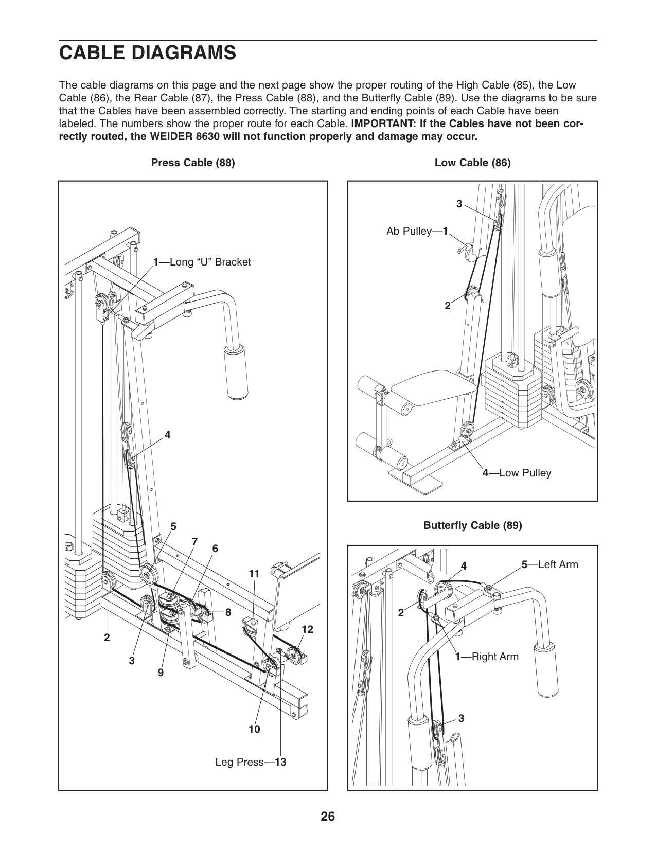
26
Cable Diagrams
The cable diagrams on this page and the next page show the proper routing of the High Cable (85), the Low Cable (86), the Rear Cable (87), the Press Cable (88), and the Butterfly Cable (89). Use the diagrams to be sure that the Cables have been assembled correctly. The starting and ending points of each Cable have been labeled. The numbers show the proper route for each Cable. IMPORTANT: If the Cables have not been cor- rectly routed, the WEIDER 8630 will not function properly and damage may occur. Low Cable (86) Butterfly Cable (89) Press Cable (88) 2 4 1—Right Arm 3 5—Left Arm 2 3 4—Low Pulley 1—Long “U” Bracket 8 9 7 6 3 Leg Press—13 Ab Pulley—1 4 5 2 10 12 11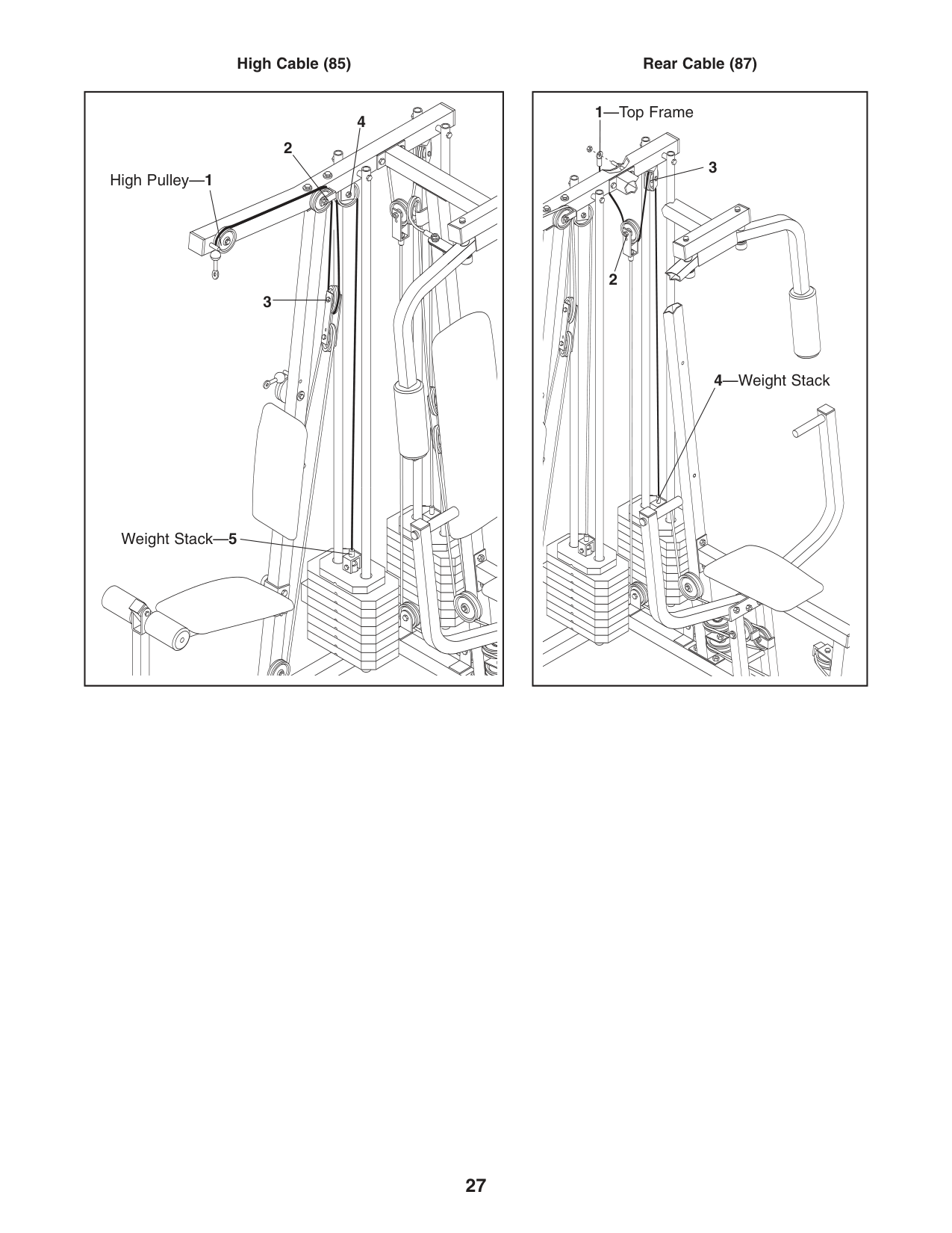
27 High Cable (85) Rear Cable (87) Weight Stack—5 High Pulley—1 2 2 3 3 1—Top Frame 4—Weight Stack 4
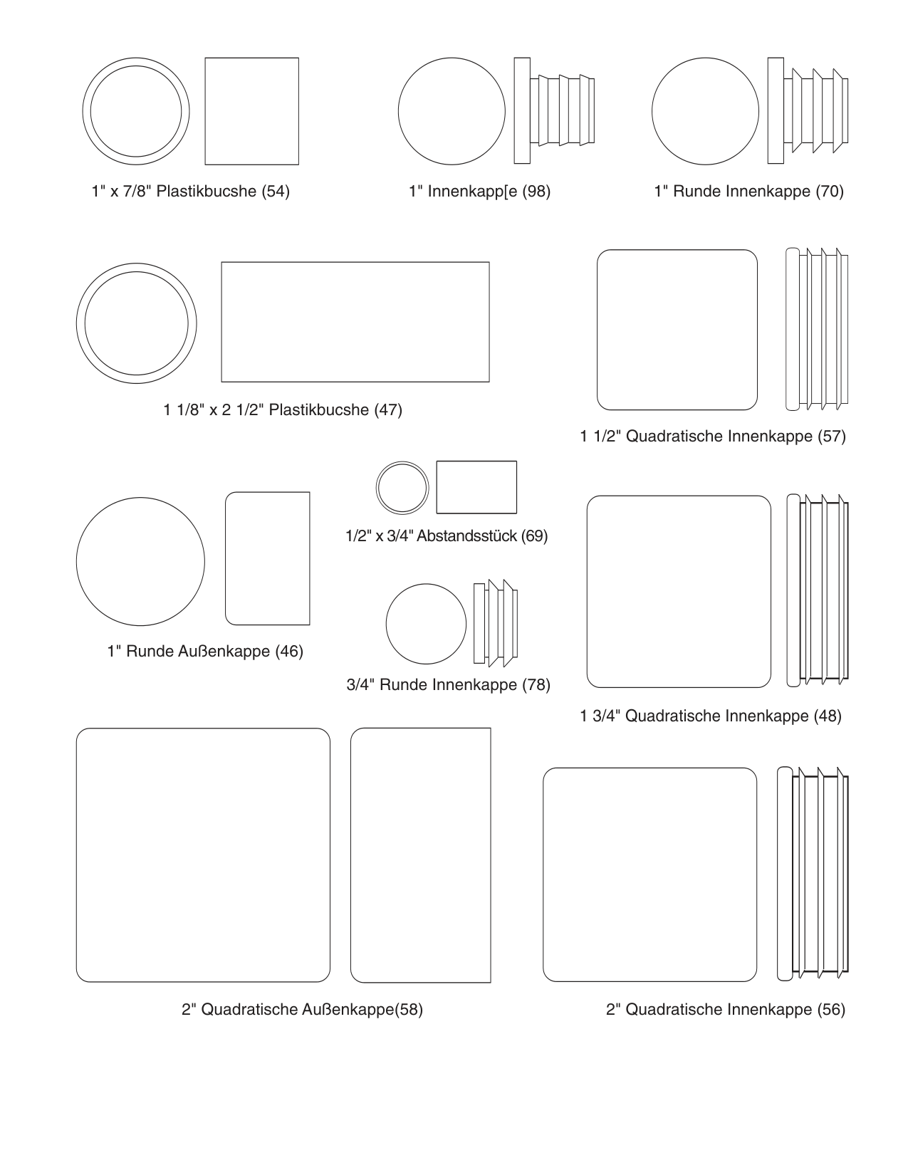
1/2" x 3/4" Abstandsstück (69) 2" Quadratische Innenkappe (56) 2" Quadratische Außenkappe(58) 1 3/4" Quadratische Innenkappe (48) 1" Runde Außenkappe (46) 1 1/2" Quadratische Innenkappe (57) 1" Runde Innenkappe (70) 1" x 7/8" Plastikbucshe (54) 1 1/8" x 2 1/2" Plastikbucshe (47) 3/4" Runde Innenkappe (78) 1" Innenkapp[e (98)
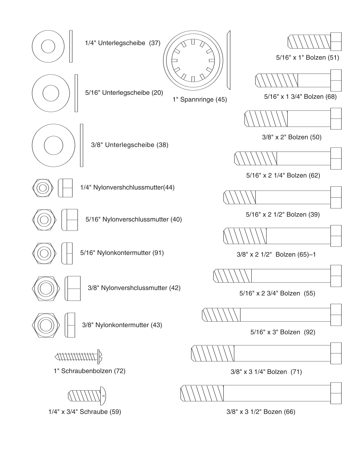
3/8" Nylonkontermutter (43) 5/16" x 1 3/4" Bolzen (68) 3/8" x 2" Bolzen (50) 5/16" x 2 1/4" Bolzen (62) 5/16" x 2 1/2" Bolzen (39) 3/8" x 2 1/2" Bolzen (65)–1 5/16" x 2 3/4" Bolzen (55) 5/16" x 3" Bolzen (92) 3/8" x 3 1/4" Bolzen (71) 3/8" x 3 1/2" Bozen (66) 1/4" x 3/4" Schraube (59) 1/4" Unterlegscheibe (37) 5/16" Unterlegscheibe (20) 3/8" Unterlegscheibe (38) 1/4" Nylonvershchlussmutter(44) 5/16" Nylonverschlussmutter (40) 5/16" Nylonkontermutter (91) 3/8" Nylonvershclussmutter (42) 1" Spannringe (45) 5/16" x 1" Bolzen (51) 1" Schraubenbolzen (72)
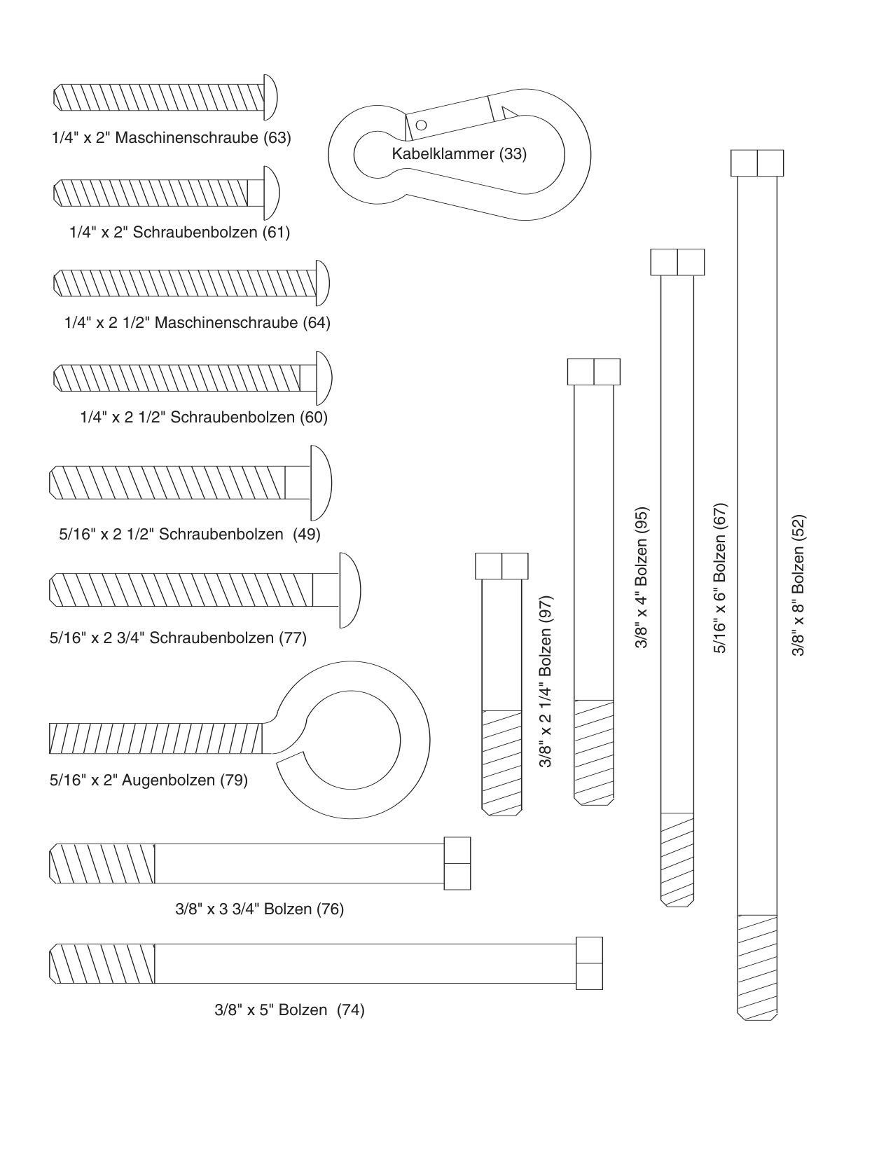
5/16" x 2" Augenbolzen (79) Kabelklammer (33) 3/8" x 5" Bolzen (74) 3/8" x 3 3/4" Bolzen (76) 5/16" x 2 3/4" Schraubenbolzen (77) 5/16" x 2 1/2" Schraubenbolzen (49) 1/4" x 2 1/2" Schraubenbolzen (60) 1/4" x 2 1/2" Maschinenschraube (64) 1/4" x 2" Schraubenbolzen (61) 1/4" x 2" Maschinenschraube (63) 5/16" x 6" Bolzen (67) 3/8" x 8" Bolzen (52) 3/8" x 4" Bolzen (95) 3/8" x 2 1/4" Bolzen (97)
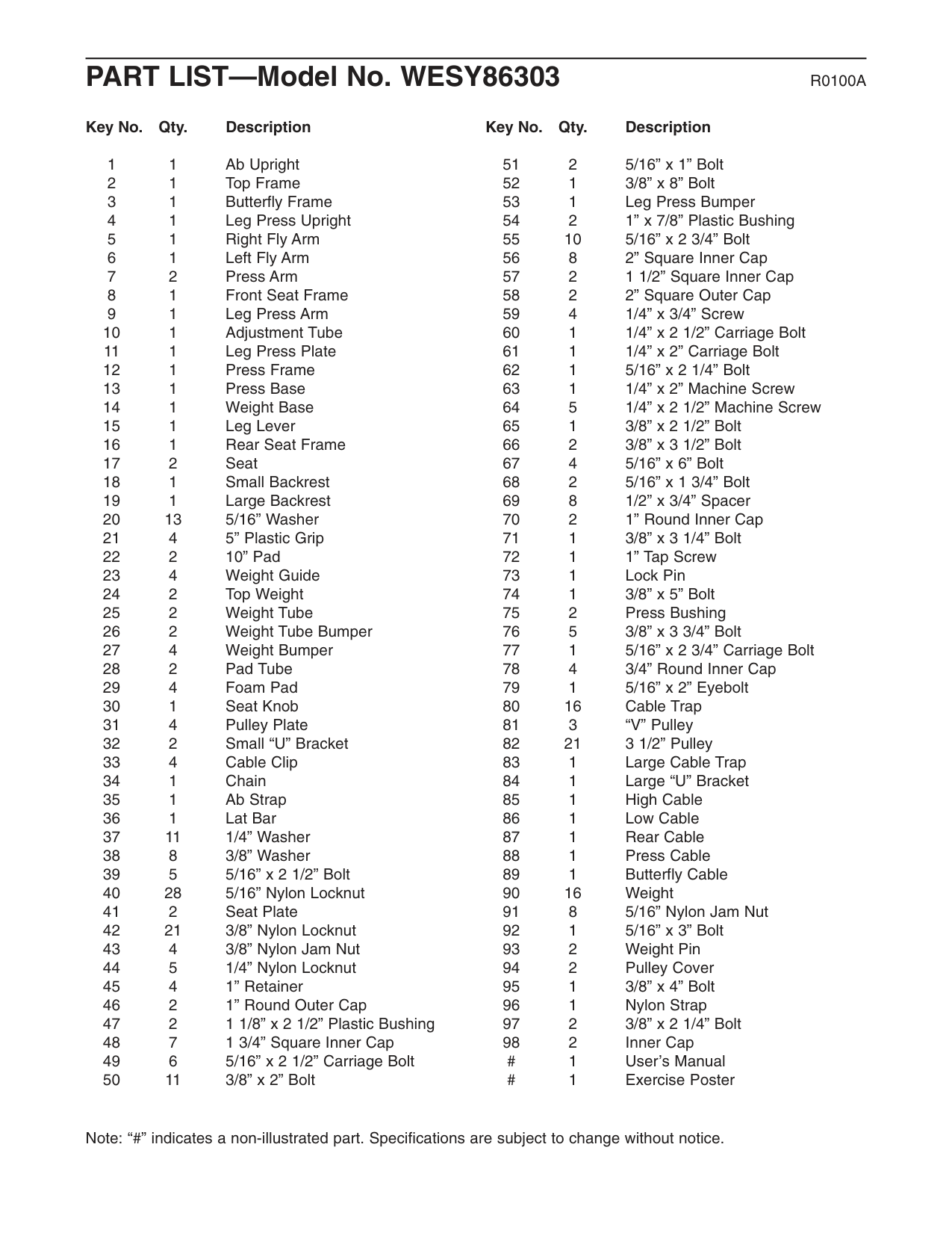
PART LIST—Model No. WESY86303
R0100A
Note: “#” indicates a non-illustrated part. Specifications are subject to change without notice. Key No. Qty. Description 1 1 Ab Upright 2 1 Top Frame 3 1 Butterfly Frame 4 1 Leg Press Upright 5 1 Right Fly Arm 6 1 Left Fly Arm 7 2 Press Arm 8 1 Front Seat Frame 9 1 Leg Press Arm 10 1 Adjustment Tube 11 1 Leg Press Plate 12 1 Press Frame 13 1 Press Base 14 1 Weight Base 15 1 Leg Lever 16 1 Rear Seat Frame 17 2 Seat 18 1 Small Backrest 19 1 Large Backrest 20 13 5/16” Washer 21 4 5” Plastic Grip 22 2 10” Pad 23 4 Weight Guide 24 2 Top Weight 25 2 Weight Tube 26 2 Weight Tube Bumper 27 4 Weight Bumper 28 2 Pad Tube 29 4 Foam Pad 30 1 Seat Knob 31 4 Pulley Plate 32 2 Small “U” Bracket 33 4 Cable Clip 34 1 Chain 35 1 Ab Strap 36 1 Lat Bar 37 11 1/4” Washer 38 8 3/8” Washer 39 5 5/16” x 2 1/2” Bolt 40 28 5/16” Nylon Locknut 41 2 Seat Plate 42 21 3/8” Nylon Locknut 43 4 3/8” Nylon Jam Nut 44 5 1/4” Nylon Locknut 45 4 1” Retainer 46 2 1” Round Outer Cap 47 2 1 1/8” x 2 1/2” Plastic Bushing 48 7 1 3/4” Square Inner Cap 49 6 5/16” x 2 1/2” Carriage Bolt 50 11 3/8” x 2” Bolt Key No. Qty. Description 51 2 5/16” x 1” Bolt 52 1 3/8” x 8” Bolt 53 1 Leg Press Bumper 54 2 1” x 7/8” Plastic Bushing 55 10 5/16” x 2 3/4” Bolt 56 8 2” Square Inner Cap 57 2 1 1/2” Square Inner Cap 58 2 2” Square Outer Cap 59 4 1/4” x 3/4” Screw 60 1 1/4” x 2 1/2” Carriage Bolt 61 1 1/4” x 2” Carriage Bolt 62 1 5/16” x 2 1/4” Bolt 63 1 1/4” x 2” Machine Screw 64 5 1/4” x 2 1/2” Machine Screw 65 1 3/8” x 2 1/2” Bolt 66 2 3/8” x 3 1/2” Bolt 67 4 5/16” x 6” Bolt 68 2 5/16” x 1 3/4” Bolt 69 8 1/2” x 3/4” Spacer 70 2 1” Round Inner Cap 71 1 3/8” x 3 1/4” Bolt 72 1 1” Tap Screw 73 1 Lock Pin 74 1 3/8” x 5” Bolt 75 2 Press Bushing 76 5 3/8” x 3 3/4” Bolt 77 1 5/16” x 2 3/4” Carriage Bolt 78 4 3/4” Round Inner Cap 79 1 5/16” x 2” Eyebolt 80 16 Cable Trap 81 3 “V” Pulley 82 21 3 1/2” Pulley 83 1 Large Cable Trap 84 1 Large “U” Bracket 85 1 High Cable 86 1 Low Cable 87 1 Rear Cable 88 1 Press Cable 89 1 Butterfly Cable 90 16 Weight 91 8 5/16” Nylon Jam Nut 92 1 5/16” x 3” Bolt 93 2 Weight Pin 94 2 Pulley Cover 95 1 3/8” x 4” Bolt 96 1 Nylon Strap 97 2 3/8” x 2 1/4” Bolt 98 2 Inner Cap # 1 User’s Manual # 1 Exercise Poster
Please Note: The assembly is divided into four stages: 1) frame assembly, 2) arm assembly, 3) cable assembly, and 4) seat assembly. The hardware for each stage is packaged separately. WAIT UNTIL
You Begin Each Assembly Stage To Open The Parts Bag
Labeled For That Assembly Stage.
This chart is provided to help you identify the small parts used in assembly. Important: Some parts may have been pre-assembled for shipping purposes. If you cannot find a part in the parts bags, check to see if it has been pre-assembled. The number in parenthesis following each part description refers to the key number of the part.Remove This Part Identification
Chart From The Manual
81
Remove This Part List/Exploded
Drawing From The Manual. Save
The Part List/Exploded Drawing
For Future Reference.
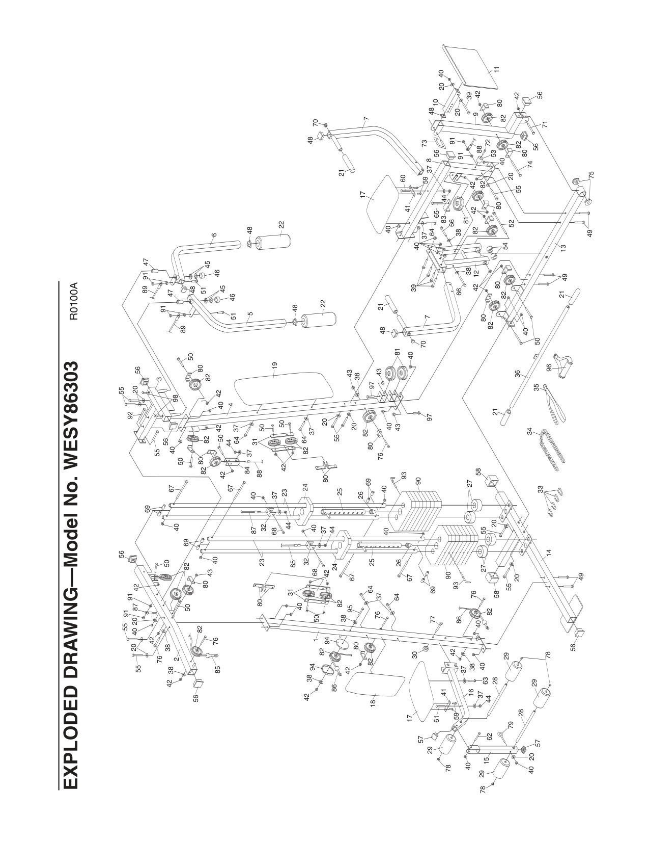
1 2 3 4 5 6 7 7 8 9 10 11 12 13 14 15 16 17 18 19 17 21 21 22 22 23 23 24 24 25 25 26 26 27 27 28 28 29 29 29 29 30 31 32 32 33 34 35 36 21 21 85 85 87 86 31 41 41 86 87 88 88 89 89 56 76 82 38 42 20 55 55 76 50 38 40 20 56 42 82 80 43 42 50 40 69 40 69 67 67 40 68 37 44 40 37 68 44 67 40 40 67 42 50 82 58 55 20 55 20 49 56 58 97 43 40 20 55 20 76 82 43 43 81 40 37 64 82 42 50 50 37 64 40 82 80 50 42 42 82 80 50 40 56 55 92 98 20 55 56 91 91 47 47 51 51 45 45 46 46 48 48 50 40 82 80 42 80 82 49 49 75 38 38 66 66 40 39 54 70 48 82 42 80 52 81 42 40 82 91 53 72 73 59 83 65 37 44 56 64 37 60 40 55 74 80 82 56 71 56 42 82 80 42 39 20 20 40 48 70 78 57 20 40 79 62 78 78 40 44 37 37 63 59 57 61 42 38 40 40 82 76 77 37 64 64 76 82 80 42 42 82 95 38 40 37 44 84 42 82 50 97 90 90 91 91 38 20 91 94 94 93 93 80 80 80 96 48 48 38 69 69 EXPLODED DRAWING—Model No. WESY86303
R0100A
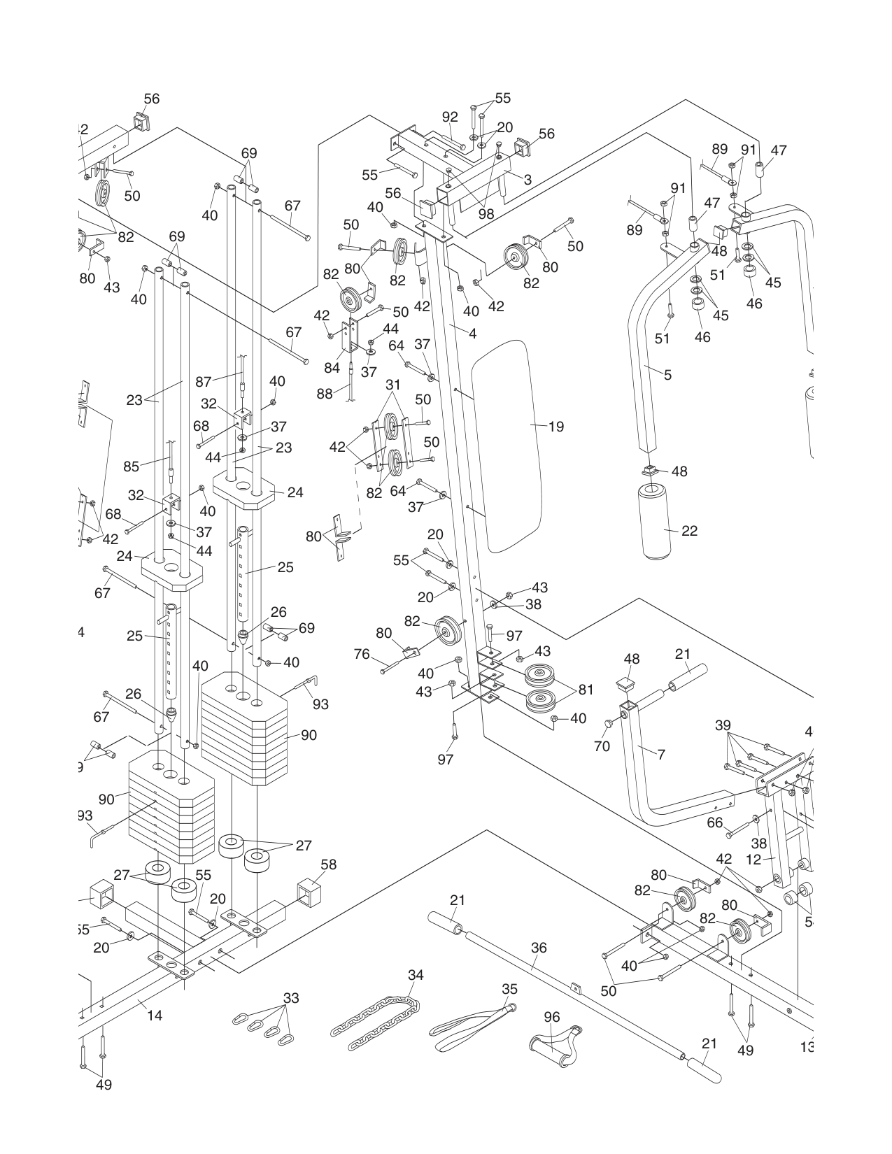
3 4 5 7 12 13 14 19 21 22 23 23 24 24 25 25 26 26 27 27 32 32 33 34 35 36 21 21 85 87 31 88 89 89 56 82 80 43 42 50 40 69 40 69 67 67 40 68 37 44 40 37 68 44 67 40 40 67 42 55 20 55 20 49 58 97 43 40 20 55 20 76 82 43 43 81 40 37 64 82 42 50 50 37 64 40 82 80 50 42 42 82 80 50 40 56 55 92 98 20 55 56 91 91 47 47 51 51 45 45 46 46 48 50 40 82 80 42 80 82 49 38 66 4 39 54 70 48 4 37 44 84 42 82 50 97 90 90 38 93 93 80 80 96 48 9 69